/


Теги: military affairs engineering design handbook
Год: 1964
Похожие


Текст
AMC PAMPHLET
ДМСР 706-106
ENGINEERING DESIGN HANDBOOK
ELEMENTS OF ARMAMENT ENGINEERING
PART ONE
SOORCES OF ENERGY
HEADQUARTERS, U. S. ARMY MATERIEL COMMAND
AUGUST 1964
HEADQUARTERS
UNITED STATES ARMY MATERIEL COMMAND
WASHINGTON. D.C, 20315
31 August 1964
AMCP 706-106, Elements of Armament Engineering, Part One,,
Sources of Energy, forming part of the Army Materiel Command
Engineering Design Handbook Series, is published for the information
and guidance of all concerned.
(AMCRD)
FOR THE COMMANDER:
SELWYN D. SMITH, JR.
Major General, USA
Chief of Staff
OFFICIAL:
DISTRIBUTION: Special
FOREWORD
This handbook is one of a series of three comprising Elements
of Armament Engineering and forms part of the Engineering Design
Handbook Series of the Army Materiel Command.
The three Parts of Elements of Armament Engineering were
produced from text material prepared for use at the United States
Military Academy. They are published as a part of the Handbook
Series to make generally available the wealth of fundamental infor-
mation contained in the text material, which is of value to those con-
cerned with military design, particularly to new engineers and to
contractors' personnel.
Arrangements for publication of the handbooks comprising
Elements of Armament Engineering were made under the direction
of the Engineering Handbook Office of Duke University, prime con-
tractor to the Army Research Office-Durham.
Agencies of the Department of Defense, having need for Hand-
books, may submit requisitions or official requests directly to
Publications and Reproduction Agency, Letterkenny Army Depot,
Chambersburg, Pennsylvania 17201. Contractors should submit
such requisitions or requests to their contracting officers.
Comments and suggestions on this handbook are welcome and
should be addressed to Army Research Office-Durham, Box CM,
Duke Station, Durham, North Carolina 27706.
i
FOREWORD TO ORIGINAL
TEXT MATERIAL
This text has been prepared to meet a specific
requirement as a reference for instruction in
“Elements of Armament Engineering,” a one-
semester course in applied engineering analysis
conducted by the Department of Ordnance at
the United States Military Academy, for mem-
bers of the First (Senior) Class. It represents the
application of military, scientific, and engineer-
ing fundamentals to the analysis, design and op-
eration of weapons systems, including nuclear
components. It is not intended to fully orient
or familiarize the student in weapons employ-
ment or nomenclature.
Of necessity, the large volume of classified
data used in presentation of this course has been
omitted; hence the text is intended to serve as a
point of departure for classroom discussions. The
text is revised annually by instructors of the
Department of Ordnance in an effort to assure
that subject presentation will keep pace with
development and changes in the field of wea-
pons design.
References cited are those available to the
student as the result of study in previous courses
at the United States Military Academy. Advanced
references are available at the Department of
Ordnance Reference Room.
Contributing authors for 1958-59 revision are:
Maj. W. E. Rafert, Ord Corps Asst. Professor
Capt. A. W. Jank, Ord Corps Instructor
Capt. С. M. Jaco, Jr., Ord Corps Instructor
Capt. J. M. Cragin, Ord Corps Instructor
Capt. G. K. Patterson, USAF Instructor
JOHN D. BILLINGSLEY
.Colonel, U. S. Army
Professor of Ordnance
August 1958
ii
PREFACE
The usefulness and dependability of systems which serve man are contingent upon the effective
performance of the components which make up those systems. So it is with the weapon systems of
war. In centuries past, vast effort has been expended in improving the performance of war machines.
Improvements of this century have included rigorous application of scientific principles to warfare in
an effort to optimize the performance of mechanisms of war. As the laws and rules of mathematics,
physics, and chemistry have been applied to war and its machines, war has become more complex
and more deadly.
Perhaps no component of weapon systems has been studied more thoroughly than sources from
which energy can be conveniently and quickly liberated in great quantity. From the days of Crecy
in 1346, when guns began competition with sharp-edged weapons, until the end of World War II,
when 85% of the casualties were attributed to conventional explosives, the trend toward more and
improved explosive has continued. Since 1945, the use of atomic energy has opened a vast new
magnitude of effectiveness from a new source of energy, the atom and its parts.
In this portion of the text those fundamental facts which must be known to permit the student
to understand how energy is stored, liberated, and applied in military devices will be discussed. Those
facts include a discussion of the theory of the release of chemical and nuclear energy, thermochemistry,
explosives classification, and the properties of representative explosives.
A reasonable knowledge of all these fundamental facts is required if the military leader is to
understand the performance, as well as the capabilities, of fiis increasingly complex weapons.
The study begins with a review of the theory of basic chemical energy reactiotis as they apply
to explosives.
iii
TABLE OF CONTENTS
Paragraph Page
CHAPTER 1
THE THEORY OF CHEMICAL EXPLOSIVE REACTIONS
1-1 INTRODUCTION ....................................... 1-1
1-2 HISTORICAL NOTES ................................... 1-1
1-3 DEFINITION ......................................... 1-2
1-3.1 Formation of Gas .................................. 1-2
1-3.2 Evolution of Heat ................................. 1-2
1-3.3 Rapidity of Reaction .............................. 1-2
1-3.4 Initiation of Reaction ............................ 1-2
1-4 CATEGORIZATION ..................................... 1-3
1-4.1 Low Explosives .................................... 1-3
1-4.2 High Explosives ................................... 1-3
1-5 CHEMICAL KINETICS .................................. 1-5
1-6 PROPERTIES OF MILITARY CHEMICAL EXPLOSIVES 1-7
1-6.1 Load Density (High Explosives) .................... 1-7
1-6.2 Hygroscopicity .................................... 1-7
1-6.3 Sensitivity ....................................... 1-7
1-6.4 Velocity of Detonation ............................. 1-7
1-6.5 Strength .......................................... 1-8
1-6.6 Brisance .......................................... 1-8
1-6.7 Power ............................................. 1-8
1-6.8 High Order of Detonation .......................... 1-8
1-6.9 Low Order of Detonation ........................... 1-8
1-6.10 Stability .......................................... 1-9
1-7 EXPLOSIVE TRAINS 1-9
1-7.1 Propelling Charge Explosive Train ................. 1-9
1-7.2 Bursting Charge Explosive Trains ................ 1-11
CHAPTER 2
THE THERMOCHEMISTRY OF CHEMICAL EXPLOSIVES
2-1 CHEMICAL REACTIONS OF EXPLOSIVES.......................... 2-1
v
TABLE OF CONTENTS (cont)
Paragraph Page
Chapter 2 (cont)
2-2 REVIEW OF BASIC DEFINITIONS AND
CHEMICAL FUNDAMENTALS 2-1
2-2.1 Gram Molecule .................................. 2-2
2-2.2 Gram Formula Weight ............................ 2-2
2-2.3 Specific Heat .................................. 2-2
2-2.4 Molecular Specific Heat ........................ 2-2
2-2.5 Specific Volume ................................ 2-2
2-2.6 Molecular Volume ............................... 2-2
2-2.7 Co-volume ...................................... 2-2
2-2.8 Specific Gravity ............................... 2-2
2-2.9 Density 2-2
2-2.10 Density of Loading ............................. 2-2
2-2.11 Calorie ........................................ 2-3
2-2.12 Kilocalorie .................................... 2-3
2-2.13 Heat of Formation .............................. 2-3
2-2.14 Principle of Initial and Final State ........... 2-3
2-2.15 Heat of Reaction ............................... 2-3
2-2.16 Potential of an Explosive.......................... 2-3
2-3 POTENTIAL ...................................... 2-4
2-4 QUANTITY OF HEAT LIBERATED AT
CONSTANT PRESSURE ............................... 2-4
2-5 VOLUME OF GAS LIBERATED ......................... 2-6
2-6 EXTERNAL WORK PERFORMED IN EXPANSION 2-7
2-7 QUANTITY OF HEAT LIBERATED AT
CONSTANT VOLUME .................................. 2-7
2-8 POTENTIAL OR WORK ............................... 2-8
2-9 SUMMARY OF CALCULATIONS 2-8
2-10 TEMPERATURE OF EXPLOSION ........................ 2-9
2-10.1 Temperature When Solid Products Are Formed .... 2-12
2-11 DETERMINATION OF PRESSURE IN A
CONSTANT VOLUME CHAMBER ........................ 2-12
2-11.1 Basic Equations ............................... 2-12
2-11.2 Pressure in a Gun Propellant Chamber .......... 2-13
vi
TABLE OF CONTENTS (cont)
Paragraph Page
Chapter 2 (cont)
2-11.3 Pressure When Solid Products Are Formed .......... 2-14
2-11.4 Actual Chamber Pressure .......................... 2-15
2-12 DETERMINATION OF WORK IN A SYSTEM OF
CHANGING VOLUME AND PRESSURE 2-15
CHAPTER 3
MILITARY EXPLOSIVE CHARACTERISTICS
3-1 INTRODUCTION 3-1
3-2 HIGH EXPLOSIVES 3-1
3-2.1 Greater Potential ...................................... 3-1
3-3 HIGH EXPLOSIVE CLASSES 3-3
3-3.1 Primary High Explosive ...................... 3-3
3-3.2 Secondary High Explosive .......................... 3-4
3-3.3 Comparison of Explosives .......................... 3-4
3-4 PRIMARY HIGH EXPLOSIVES...................... 3-5
3-4.1 Mercury Fulminate ........................... 3-5
3-4.2 Lead Azide ........................................ 3-6
3-4.3 Lead Styphnate .................................... 3-6
3-5 SECONDARY HIGH EXPLOSIVES 3-7
3-5.1 Tetryl ............................................ 3-7
3-5.2 Trinitrotoluene (TNT) ............................. 3-7
3-5.3 Tetrytol .......................................... 3-8
3-5.4 Amatol ............................................ 3-8
3-5.5 Explosive D ....................................... 3-8
3-5.6 RDX ............................................... 3-9
3-5.7 PETN ............................................. 3-10
3-5.8 Pentolite ........................................ 3-10
3-5.9 HMX .............................................. 3-10
3-5.10 Dynamites ........................................ 3-11
3-6 LIQUID HIGH EXPLOSIVES 3-11
3-7 METAL-HIGH EXPLOSIVE MIXTURES 3-12
3-7.1 Explosive Manufacturing Considerations ........... 3-13
vii
TABLE OF CONTENTS (cont)
Paragraph
Page
Chapter 3 (cent)
3-8 LOW EXPLOSIVES OR PROPELLANTS ........................ 3-13
3-8.1 Controlled Burning ................................... 3-14
3-8.2 Sensitivity .......................................... 3-14
3-8.3 Stability ............................................ 3-14
3-8.4 Residue .............................................. 3-14
3-8.5 Manufacture .......................................... 3-14
3-8.6 Erosive Action ....................................... 3-14
3-8.7 Flash ................................................ 3-14
3-8.8 Detonation ........................................... 3-14
3-8.9 Smoke ................................................ 3-14
3-9 BLACK POWDER ........................................... 3-14
3-10 SMOKELESS POWDERS ...................................... 3-15
3-10.1 Burning Time ......................................... 3-15
3-10.2 Burning Action ....................................... 3-17
3-10.3 Degressive Burning ................................... 3-17
3-10.4 Neutral Burning ...................................... 3-17
3-10.5 Progressive Burning .................................. 3-17
3-10.6 Web Thickness ........................................ 3-17
3-Ю.7 Single-Base Propellants .............................. 3-18
3-10.8 Donble-Base Propellants .............................. 3-19
3-Ю.9 Ball Powder ............................................... 8-19
3-Ю.Ю Nitroguanidiee Propellants ........................... 3-19
3-11 LIQUID GUN PROPELLANTS ................................. 3-20
3-12 GUN PROPELLANT IMPROVEMENTS ............................ 3-21
3-12.1 Flash ................................................ 3-21
3-12.2 Smoke ............................................ 3-21
3-12.3 Higher Potential ................................... 3-22
3-12.4 Erosion ............................................ 3-23
3-12.5 Greater Stability ................................... 3-23
3-13 PROPELLANTS FOR ROCKETS .............................. 3-23
3-13.1 Current Solid Propellants .......................... 3-24
3-13.2 Current Liquid Propellants ......................... 3-25
viii
TABLE OF CONTENTS (cont)
Paragraph Page
Chapter 3 (cent)
3-14 EXOTIC PROPELLANTS ..................................... 3-26
3-14.1 Metal Additives .................................. 3-27
3-14.2 Fluoro Compounds ................................. 3-27
3-14.3 Free Radicals .................................... 3-27
3-14.4 Ionic Fuels ...................................... 3-27
CHAPTER 4
FISSION-FUSION REACTIONS
4-1 INTRODUCTION .......................................... 4-1
4-2 ATOMIC STRUCTURE ............................... 4-2
4-2.1 Elements and Atoms ................................... 4-2
4-2.2 Nuclear Composition .................................. 4-2
4-2.3 Isotopes ............................................. 4-3
4-2.4 Symbols .............................................. 4-3
4-2.5 Mass of Nuclear Particles ............................ 4-3
4-2.6 Charge of Nuclear Particles .......................... 4-4
4-3 RADIOACTIVITY ........................................ 4-4
4-3.1 Nuclear Instability .................................. 4-4
4-3.2 Alpha Decay .......................................... 4-4
4-3.3 Beta Decay ........................................... 4-4
4-3.4 Gamma Rays ........................................... 4-4
4-3.5 Indoeed Reactions .................................... 4-5
4-3.6 Radioactive Series ................................... 4-5
4-4 ENERGY, FISSION, AND FUSION ........................ 4-5
4-4.1 Equivalence of Mass and Energy ....................... 4-5
4-4.2 Fission .............................................. 4-7
4-4.3 Fusion ............................................... 4-7
4-4.4 Nuclear Energy ....................................... 4-8
4-5 CROSS SECTION, THE CHAIN REACTION,
AND CRITICALITY ....................................... 4-9
4-5.1 Cross Section ........................................ 4-9
4-5.2 Chain Reaction ...................................... 4-10
TABLE OF CONTENTS (cont)
Paragraph Page
Chapter 4 (cent)
4-5.3 Neutron Reactions .............................. 4-10
4-5.4 Classes of Chain Reactions and Criticality ..... 4-10
4-5.5 Means of Increasing Criticality ................ 4-11
EXPLOSIVES ANNEX
EXPLOSIVES MANUFACTURE AND TESTING
A-l INTRODUCTION ...................................... A-l
A-2 MANUFACTURE OF TRINITROTOLUENE..................... A-l
A-3 MANUFACTURE OF SINGLE-BASE PROPELLANT............. A-2
A-4 MANUFACTURE OF PERCHLORATE PROPELLANT A-3
A-5 PHYSICAL TESTING OF EXPLOSIVES .................... A-4
A-5.1 Sensitivity to Shock ............................ A-4
A-5.2 Trauzl Lead Blocks .............................. A-4
A-5.3 Ballistic Mortar ................................ A-4
A-5.4 Velocity of Detonation .......................... A-4
A-5.5 Relative Brisance ............................... A-4
A-5.6 Additional Tests ................................ A-8
A-6 PHYSICAL TESTING OF ROCKET PROPELLANTS A-8
A-6.1 Solid Propellant Testing ........................ A-8
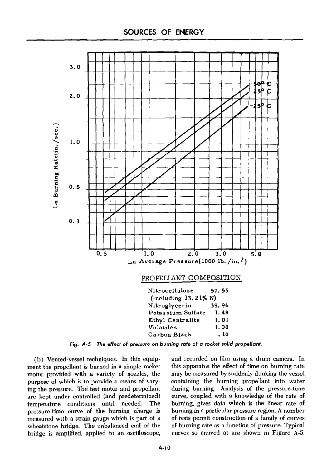
A-6.2 Measurement of Burning Rates .................... A-8
APPENDIX ........................................ A-ll
INDEX .............................................. 1-1
x
LIST OF ILLUSTRATIONS
Fig. No. Title Page
1-1 Schematic drawing of detonation showing progress through a
column of explosive ....................................................... 1-4
1-2 Nitroglycerin .................................................... 1-5
1-3 Toluene and trinitrotoluene ...................................... 1-6
1-4 Mercury fulminate and lead azide ................................. 1-6
1-5 Explosive trains 1-10
1-6 Schematic representation of explosive trains 1-11
2-1 Curves showing variation of mol specific heat with temperature
for several gaseous explosive products ................................... 2-10
3-1 Effect of oxygen balance on strength of explosives (compared
with TNT) in the lead block expansion test ................................ 3-2
3-2 Schematic representation of mercury fulminate .................... 3-5
3-3 Lead azide ....................................................... 3-6
3-4 Lead trinitrorescorcinate ........................................ 3-6
3-5 Tetryl ........................................................... 3-7
3-6 Trinitrotoluene (TNT) ............................................ 3-8
3-7 Ammonium picrate (Explosive D) ............................ 3-8
3-8 Cyclotrimethylenetrinitramine (RDX) .............................. 3-9
3-9 Pentaerythritetranitrate (PETN) .................................. 3-10
3-10 Cyclotetramethylene tetranitramine (HMX) ......................... 3-10
3-11 Typical shapes of powder grains .................................. 3-16
3-12 Sizes of some typical grains ..................................... 3-16
3-13 Web thickness and route of burning progress through a
progressively burning grain .............................................. 3-16
3-14 Relative areas of burning as a function of percent of individual
grain consumed, for several typical grain shapes ......................... 3-17
3-15 Flash suppressor on 75-mm gun tube 3-22
4-1 Isotopes of hydrogen ............................................. 4-3
4-2 Uranium (4N -f- 2) series .................................... 4-6
4-3 Pseudo-continuous plot of average mass per nucleon versus
atomic number ............................................................. 4-7
4-4 Particles entering a slab of material ................................. 4-9
xi
LIST OF ILLUSTRATIONS (cont)
Fig. No. Title Page
4-5 Idealized neutron population growth .............................. 4-11
A-l Tri-nitration equation showing some typical polynitrotoluenes .. A-2
A-2 Trauzl lead block after test, with section showing expansion
of cavity by explosive ..................................................... A-7
A-3 Ballistic mortar ...................................................... A-7
A-4 Pressure vessel for measuring burning rates of propellant as
a function of pressure ..................................................... A-9
A-5 The effect of pressure on burning rate of a rocket solid propellant A-10
xii
CHAPTER 1
THE THEORY OF CHEMICAL EXPLOSIVE REACTIONS
1-1 INTRODUCTION
In explosive chemistry the energy released by
rapid chemical reaction is used to provide heat,
expand gas, create blast and shock, provide
fragmentation and fragmentation velocity, and
to create forces for propulsion.
How this energy is best contained and con-
trolled is left to later chapters on exterior
ballistics, principles of propulsion, and gun
barrel design. This chapter discusses how such
energy is stored and liberated, and how this
can be done efficiently, safely, and conveniently.
1-2 HISTORICAL NOTES
Great strides forward have been made in
explosives since their inception. The earliest
known explosive, called gunpowder or black
powder, is generally conceded to have been the
mixture of saltpeter, sulfur, and charcoal, first
described by the English friar, Roger Bacon, in
the year 1242. This mixture, at that time, was
not thought of as a propellant, but rather as an
explosive which would cause terror among the
enemy with its bright flash and thundering noise.
To Berthold Schwartz, a German monk, is given
the credit for having invented, about 1313, a
firearm using gunpowder as the propellant. The
first organized use of guns in open battle was
by the English at the Battle of Crecy in 1346.
Prior to the military use of explosives, which
was as early as the seventh century, there were
recorded uses of chemicals in forms such as
“Greek fire” and Chinese rocket-propelled “fire
arrows.” The prinicpal ingredient of Greek fire
was probably naphtha, mixed with sulfur and
pitch. Chinese rockets were propelled by a
combination of sodium chlorate or sodium nitrate
and some combustible material. These chemical
mixtures were the forerunners of gunpowder.
The discovery of gunpowder was followed in
1838 by the preparation of nitrocellulose by
T. J. Pelonze, a Frenchman, and later the de-
velopment, in 1846, of nitroglycerin by an Italian,
Ascanio Sobrero. It remained for Alfred Nobel
(1833-1896) of Sweden, a man of practical as
well as scientific bent, to develop explosives of
usable physical properties from nitroglycerin.
Nobel included among his many accomplish-
ments (1) the method of initiating high explosives
by detonation to secure their full power; (2) the
theory of explosive action; (3) the production
of dynamite; and (4) design of double-base
propellants.
The great number of achievements in the
science of explosives accelerated by two great
world wars, make necessary a second look at
the basic changes which have taken place in
the field of military explosives. World War I
was fought with only a few standard high
explosives, together with some inferior substi-
tutes necessitated by material shortages. These
shortages permitted little choice of explosives for
special application or specific requirements.
Today the field has been greatly enlarged with
many types as well as large numbers of explosives
together with new ranges and increased scope
of application.
1-1
SOURCES OF ENERGY
1-3 DEFINITION
An explosive is a chemical compound or
mixture which upon the application of heat or
shock decomposes or rearranges with extreme
rapidity, yielding much gas and heat. Many
substances not ordinarily classed as explosives
may do one, or even two, of these things. A mix-
ture of nitrogen and oxygen, for example, can
be made to react with great rapidity to yield the
gaseous product nitric oxide, yet the mixture is
not an explosive since it does not evolve heat
but rather absorbs heat during the reaction. To
be an explosive a substance must exhibit all of
the phenomena mentioned: formation of gases;
evolution of heat; rapidity of reaction; and initia-
tion of reaction by shock or heat. To be a military
explosive, an explosive must also be suitable for
and used for military purposes.
1-3.1 FORMATION OF GAS
The student is familiar with the burning of
wood or coal in the atmosphere. In this reaction
the carbon and hydrogen in the wood or coal
combine with the oxygen in the atmosphere to
form carbon dioxide and steam, together with
flame and smoke. If the wood or coal is
pulverized so that the total surface in contact
with oxygen is increased, and it is burned in a
furnace or forge where more air can be supplied,
the burning can be made more rapid and the
combustion more complete. If the wood or coal
is immersed in liquid oxygen or suspended in air
in the form of dust, the burning takes place with
explosive violence. In each case the action is the
same; the burning of a combustible to form a gas.
The difference is the speed with which the re-
action takes place. Thus, materials which will
burn can be made to explode if sufficient oxygen
is made available rapidly. This fact is demon-
strated by the explosion within internal combus-
tion engines where combustible mixtures of
gasoline and air explode to operate the engine.
In coal mines methane gas and coal dust combine
with air to produce explosive mixtures, and in
grain elevators minute particles of dust form
explosive mixtures with air. Most explosives
utilize this principle except for the fact that they
usually contain their own oxygen integrally and
so are independent of oxygen supplied from
the air.
1-3.2 EVOLUTION OF HEAT
The evolution of heat during the reaction
causes a large increase in the temperature of the
gases. This increase results in the rapid expan-
sion of the gases and the generation of a very
high pressure. A reaction which fails to produce
this high pressure will not fill the requirements
of an explosion.
1-3.3 RAPIDITY OF REACTION
Unless the reaction occurs rapidly the ther-
mally expanded gases will be dissipated in the
atmosphere and there will be no explosion. Again
consider a wood or coal fire; in the fire there is
evolution of heat and formation of gases but
these are not liberated rapidly enough to cause
an explosion.
1-3.4 INITIATION OF REACTION
The fourth factor is the requirement that to
qualify as an explosive the material must readily
undergo rapid reaction upon the application of
a certain amount of energy, in the form of shock
or heat, to a small portion of its mass. A material
in which the first three factors exist is not suitable
as an explosive unless the reaction can be made
to occur at will.
1-2
CHEMICAL EXPLOSIVE REACTIONS
1-4 CATEGORIZATION
The chemical decomposition of an explosive
may take years, days, hours, or a fraction of a
second. The slower forms of decomposition take
place in storage and are of interest only from a
stability standpoint. Of more interest are the
two rapid forms of decomposition, burning and
detonation. The term “detonation” is used to
describe an explosive phenomenon of almost
instantaneous decomposition. Explosives are
classified as low or high explosives according to
their rates of decomposition. Low explosives
burn rapidly. High explosives ordinarily deto-
nate. There is no sharp line of demarcation
between low and high explosives. The properties
of the explosive indicate the class into which it
falls. In some cases explosives may be made to
fall into either class by the conditions under
which they are initiated.
1-4.1 LOW EXPLOSIVES
Low explosives are those materials which
undergo rapid decomposition by burning from
the surface inward. They are usually manu-
factured in the form of “grains” and used as
propellants. Consider that a number of grains
of powder have been placed in the breech of a
gun. Sufficient heat is applied so that the powder
will ignite. Ignition occurs when a temperature
is attained which will cause the combustibles
to react with the self-contained oxygen to form
gas and liberate heat. Since this heat cannot
escape because of the confinement of the breech,
it will heat the next inner layer of powder ex-
posed by the burning away of the original sur-
face layer, ignite it, further increasing and
expanding the gases. This continues until the
grain is completely consumed; concurrently,
each grain ignites adjacent grains until the en-
tire charge is consumed. While confined these
individual grains bum from the outside toward
the center at the rate of about 5 feet per second.
In open air where the pressure will not rise
appreciably the rate of combustion would be
about 0.01 feet per second. As the burning
continues through the charge, the pressure and
temperature rise and the burning becomes more
and more rapid. The rate of burning is approxi-
mately doubled for every 10°C rise in tempera-
ture. This form of decomposition results in the
liberation of large quantities of gas which yield
high pressures making the explosive valuable as
a propellant. In the barrel of a gun, the shell will
begin to move before expansion is complete,
leaving room for more expansion and thus pre-
venting the barrel from bursting.
1-4.2 HIGH EXPLOSIVES
High or detonating explosives decompose
almost instantaneously by a rupture or splitting
of the molecule and the rearrangement of the
atoms into other molecules, mostly gaseous.
Present day explosive molecules are comprised
of atoms, most of which are carbon, hydrogen,
nitrogen, and oxygen. While carbon and hydro-
gen tend to unite with oxygen, nitrogen usually
returns to its elemental form. The explosive
molecule should be considered an unstable mole-
cule which tends to revert to a more stable state.
There are several theories as to the mechanics of
detonation; the following is one.
(a) First phase. The first phase is initiated
by supplying enough energy to an explosive,
usually in the form of shock, so that the dis-
ruptive forces set up within the molecule exceed
the attractive forces between some of the atoms,
and decomposition is started. The tendency
toward disruption is caused by the instability of
the high explosive molecule. The molecular and
atomic attractive forces are the normal bonds
tying the molecule together. When they are
broken, and the molecule is rearranged, con-
centrated energy is released, which disrupts
adjacent molecules. If the initial shock wave
energy is sufficient, this wave will proceed
through the entire mass of explosive until it has
completely detonated, provided the energy
released by the splitting of one molecule is
sufficient to detonate more than one adjacent
molecule.
(b) Second phase. The second phase of deto-
nation consists of the formation and expansion
of gas molecules. When the original molecule is
1-3
ORDP 20-106
SOURCES OF ENERGY
split, the heat of the detonating wave causes the
carbon and hydrogen atoms to oxidize thus ex-
panding their volume greatly. The entire process
of detonation takes place almost instantaneously
Explosives with extreme rates of detonation are
no useful as propellants as the pressure developed
would burst ihe barrel of a gun before it over-
came the inertia of the shell.
The mechanism of detonation may be visu-
alized by referring to Figure 1-1. This figure was
developed from facts resulting from hydro-
dynamic studies which showed that after the
detonator functioned, a detoi.btion zone which
includes a zone of chemical reaction, travels
extremely rapidly through the column of the
explosive. This detonation zone is generally
considered to include e very thin (10”s cm) shock
zone or shoe? wave. Lit'-e or no cbt.nical re-
action occurs in this shock zone, but here pressure
reaches its peak. The detonation zone .includes
not only this shock front, but also the chemical
reaction zone (0.1-1.0 cm). Behind this detona-
tion zone are the detonation products. In front
of the shock zone is the unreacted explosive
in its original state of density, pressure, and
temperature. At or near the beginning of the
chemical reaction zone, the high temperature
to which the material is raised by compression in
the shock zone initiates chemical reaction. Maxi-
mum density and pressure occur at the beginning
of the reaction zone, while the temperature and
velocity reach their peak at the completion of
the chemical reaction. The detonation products
flow with great velocity (but with less velocity
than does the detonation zone) through the un-
detonated explosive. This is characteristic of
detonation in contradistinction to deflagration, in
which case the reaction products flow away from
the unreacted material. The velocity of advance
of the detonation zone is termed the detonation
rate, or velocity.
Detonato* Explosive
A • Explosive before detonation
В - Explosive partially detonated
Fig. I-1 Schematic drawing of datamation showing prog гм through a column
of explosive.
1-4
CHEMICAL EXPLOSIVE REACTIONS
1-5 CHEMICAL KINETICS
Explosives are chemical compounds or mix-
tures of chemical compounds, and like different
chemical compounds and mixtures have different
physical properties. Their melting points, freez-
ing points, density, and chemical stability may
vary widely. Of particular interest to the explo-
sives user is the stability of the explosive, for
upon this property depends the power, sensitivity,
and ease of handling of the ammunition item in
which the explosive is used.
Explosives and propellants generally are
organic compounds made up of varying amounts
of nitrogen, oxygen, hydrogen, carbon, and
metallic atoms. Some of the newer propellants,
low explosives, contain boron, lithium, and
fluorine. The arrangement and proportion of
these various basic constituents determine, in
large measure, the physical behavior of the
explosive.
As an integral part of nearly all explosives and
of fundamental importance to the family of ex-
plosive organic compounds is the intractable
element nitrogen. Unlike its behavior in air,
which is four-fifths nitrogen, as a part of an
organic compound, nitrogen is not an unreactive
bystander, but is combined with difficulty and in
relatively loose union with its neighboring ele-
ments. Its bonds are easily broken. When these
bonds are broken they rupture suddenly and
violently with the accompanying liberation of
relatively large amounts of energy.
Also present in most explosives is the element
oxygen. Oxygen is relatively easily, but loosely,
bound in union with other elements. It may be
joined with nitrogen but can be caused to break
away easily in order to join elements such as H,
C, S, or itself. A union of greater stability results.
Fluorine when present is, like oxygen, an oxi-
dizer. It too removes electrons. Hence, in terms
of the reactivity of N and О the explosion of
gunpowder can be explained. In the pulverized
mixture of charcoal (C), sulfur (S), and salt-
peter (KNO3, potassium nitrate) are seen the
requirements of unstable union of nitrogen,
mixed so that excess S and C are readily available
for a more stable union once an initiating impe-
tus, such as flame, is applied. The N breaks away,
reuniting with either the sulfur, carbon, or itself.
Heat and large quantities of gas are liberated.
The reaction is represented by the equation:
IOKNO3 + 3S + 8C-------> 3K2SO4
(heat)
+ 2K2CO3 + 6CO2 + 5N2 + heat
Application over the years of these ideas to
more complex organic compounds, containing
within themselves all the required ingredients
for reaction, has yielded a variety of explosives
with a wide range of physical and reactive
properties. For example, the addition of nitrogen
and oxygen in the form of —NO2 groups to
glycerin yields nitroglycerin.
The structural formula (schematic) of this
unstable, reactive explosive is:
H
I
H - c -
I
о
I
N
/W
О о
н
I
- с - н
I
о
I
N
,\\
о о
н
I
с
I
о
I
N
/\\
о о
Note: One of the oxygens in the nitrate groups is bound
weakly to the N. This linkage is shown by the
dashed line.
Fig. 1-2 Nitroglycerin.
The joining of additional nitrogen and oxygen
(nitrating) with toluene gives trinitrotoluene,
TNT.
Compare nitroglycerin and trinitrotoluene:
Both contain unstable nitrogen; both give off
appreciable energy when they rearrange. In the
nitroglycerin the nitrogen is linked only with
oxygen. Nitrogen would be in a more stable
state if linked with itself; oxygen more stable if
1-5
SOURCES OF ENERGY
T rinitrotoluene
Toluene
Fig. 1-3 Toluene and trinitrotoluene.
C=N — O —Hg —O —N=C
Lead Azide
Mercury Fulminate
Fig. 1-4 Mercury fulminate and lead azide.
joined with carbon or hydrogen; carbon and
hydrogen more stable if bonded to oxygen. Thus
great instability exists and, as is well known, the
compound is very sensitive or reactive and will
explode when subject to even a jar. On the other
hand, the TNT molecule also contains nitrogen
in unstable union, but here the link is with
carbon. Also all carbon atoms are joined into a
ring of carbon atoms, some bound by reactive
double bonds. The ring (or cyclic) configuration
serves also to hold the reaction prone “arms” of
the molecule farther apart, whereas in the nitro-
glycerin the “arms” of the NO2 groups were
closer together. Hence, TNT, although rapidly
liberating large amounts of energy and gas when
once detonated, does not fracture easily and may
be handled without excessive danger.
In summary, it may be said then that the
presence of unstable nitrogen and other reactive
elements such as oxygen, carbon, hydrogen, and
active metals is essential to explosive compounds.
The relative amounts of these elements, their ar-
rangement within the compound, and the nature
of their bonding all affect the stability and thus
the reactivity or sensitivity of the compound.
The degree of ease of exploding unstable
chemical compounds may be an advantage or a
disadvantage in the usefulness of an explosive.
The instability of the —C—O—N = О linkage
in nitroglycerin makes it easy to detonate, but
difficult to transport. Thus, the end use of the
explosive compound often prescribes its con-
stituency. In uses where extremely sensitive
but easily detonated compounds are desired,
more unstable linkages and arrangements are
prescribed.
In mercury fulminate for example, not only is
the О — N bond easily broken, but mercury, a
noble metal, is only loosely joined with oxygen.
In lead azide the nitrogen atoms are mostly
joined only with themselves. They are in only a
weak union with the lead, a metal of low activity.
These compounds are very unstable and ex-
tremely sensitive. These easily exploded com-
pounds are useful in small amounts to set off
larger amounts of less sensitive explosives, as will
be seen in later lessons.
1-6
CHEMICAL EXPLOSIVE REACTIONS
1-6 PROPERTIES OF MILITARY CHEMICAL EXPLOSIVES
Almost all physical properties of an explosive
substance must be investigated to determine its
suitability for military use. Before an explosive’s
usefulness can be fully appreciated these prop-
erties and the factors which affect them should
1-6.1 LOAD DENSITY (HIGH EXPLOSIVES)
The final step in the manufacture of artillery
projectiles and bombs involves filling them with
a high explosive. Depending on the character-
istics of the particular high explosive several
methods may be employed, i.e., cast, pellet, or
press loading. Shells loaded with TNT require
an average load density of not less than 1.52
(weight of explosive per unit volume in cgs units)
with pellet loading, and an average load density
of not less than 1.55 with the casting method of
loading. Armor piercing shells are press loaded
with Explosive D resulting in an average load
density which varies from 1.45 to 1.55. An in-
crease in the load density of the charge is highly
desirable. Hence, by pressing, an average density
of the loaded charge is obtained which is greater
than the actual density of the particular explosive
as listed in Table A-l in the Annex to Part 1.
High load density reduces sensitivity by making
the mass more resistant to internal friction and
to the creation of hot spots. By increasing the
continuity of the explosive mass, velocity of
detonation is increased, the load is made more
dense, and the tendency for cavities to form is
decreased. Cavities may cause misfires or pre-
mature detonations. In addition, increased load
density permits the use of more explosive in the
space provided, thereby increasing the strength
of the ammunition. Given two explosives of equal
power per pound, if one has an average density
of 1.0 and the other 2.0 after loading, twice the
weight of the second explosive can be carried in
the same space. Thus, essentially twice the
energy to do work is available.
1-6.2 HYGROSCOPICITY
Hygroscopicity is the tendency of a material to
absorb moisture. It affects explosives by the
introduction of an inert material which when
vaporized absorbs heat, and by providing a
be thoroughly understood. The more important
characteristics are the load density, hygrosco-
picity, sensitivity, velocity of detonation, strength,
brisance, power, order of detonation, and
stability.
solvent medium which promotes undesirable
chemical reactions. Since inert materials reduce
the continuity of the explosive mass and since
cooling reduces the temperature of reaction,
moisture reduces sensitivity, strength, and ve-
locity of detonation. In the case of ammonium
nitrate explosives, it may even cause the explo-
sives to become so insensitive that they will not
detonate. In addition, the presence of moisture
promotes decomposition, thereby affecting sta-
bility. Still another effect may be the corrosion of
the metal containing the explosive.
1-6.3 SENSITIVITY
The term “sensitivity” as applied to explosives
means the ease with which they may be ignited
or detonated or, in other words, the amount and
intensity of shock, friction, or heat required for
ignition or detonation. Whether an explosive is
sensitive or not depends in part upon the molec-
ular make-up of the explosive, and also upon the
crystal size and distortion, coating of crystals,
density, moisture, and temperature. High density,
increased moisture, and coating of crystals with
wax or a similar substance will tend to reduce
sensitivity. Increased temperature and distortion
of the crystalline structure will increase sensi-
tivity. The size of the crystals may increase or
decrease the sensitivity depending on the ex-
plosive considered and the amount of internal
strain within, or between crystals.
1-6.4 VELOCITY OF DETONATION
When a high explosive detonates, the action
proceeds in a wave through the column of
explosive. The speed with which this wave
progresses is termed the “velocity of detonation”
and is usually expressed in meters per second.
Under identical conditions, different explosives
detonate at different velocities (see Table A-l in
the Annex to Part 1). The factors which ma-
teriaUv affect the velocity of detonation are
1-7
SOURCES OF ENERGY
reactivity, diameter of the column of explosive,
amount of confinement, crystal size, crystal
coating, density, and moisture. Increasing the
explosive column diameter, the amount of con-
finement, or the density will increase the velocity.
Moisture, coating of crystals, or decreasing the
crystal size will decrease the velocity.
1-6.5 STRENGTH
The strength of an explosive is its ability to do
work. It may be defined and measured in two
ways. From the user or testing standpoint, it is
defined as the ability of the explosive to displace
the medium which confines it. From the engineer-
ing point of view it is the amount of energy
liberated by the explosion or detonation. The
constituent atoms and their arrangement deter-
mines the energy available in an explosive. The
degree of rearrangement, the rate of decomposi-
tion, and the quantity of gas liberated determines
the amount of work done by the explosive.
1-6.6 BRISANCE
When a force displaces a mass through a
distance, the result is work done. The amount
of work done by a given amount of explosive is
determined by the strength of the explosive. The
speed of the reaction, or the rate of doing work is
called power. Explosives have both strength and
power. They also possess a third characteristic
which is their shattering effect or brisance (from
the French, meaning “to break”). Brisance is a
unique characteristic of explosives. There is no
universally accepted precise meaning of brisance
as applied to explosives. Brisance describes the
extremely disruptive effect resulting from the
almost instantaneous decomposition of a high
explosive. The causes of this effect are fairly
well understood. Decomposition proceeds in a
self-sustaining wave called the detonation wave.
This wave traveling at a high velocity is sur-
rounded by extreme pressures (of the order of
2,000,000 Ib/sq in.) capable of producing mo-
mentary shocks of terrific intensity on contiguous
material. It is known that the foregoing qualities
are critically affected by load density. Brisance
is therefore proportional to the product of load
density, reaction zone pressure, and detonation
velocity. An explosive with great strength and a
high detonation velocity will have high brisance.
Brisance is sometimes expressed as the ability
of an explosive to do damage in the close vicinity,
or its ability to shatter its confining medium.
1-6.7 POWER
Power is defined as the rate of doing work.
This definition applies to an explosive As well as
to a machine. In explosives power is dependent
upon strength and detonation velocity, i.e., the
amount of energy released and the speed with
which it is released. Strength, brisance, and
power are closely related. Generally speaking,
given two explosives of equal strength, the one
detonating at the highest velocity will not only
have the greatest brisance but will be more
powerful. It will be more brisant because of
the sharpness of the blow and more powerful
because of the speed with which the energy is
delivered.
Of two explosives of equal velocity, the
stronger will be more brisant because there is
more force back of the blow. The stronger ex-
plosive will also be more powerful, because more
energy is delivered in the same time. It is pos-
sible to increase velocity and reduce strength,
thereby increasing both brisance and power.
It is also possible to slightly reduce velocity and
greatly increase strength to increase both bri-
sance and power. In the first case, brisance is
increased by the sharpness of the blow, and
power is increased by the increased speed with
which the blow is delivered. In the second case,
both power and brisance are increased by the
weight of the blow, in spite of the fact that time
of delivery is increased. Power sometimes is
expressed as the ability of an explosive to do
damage at a distance.
1-6.8 HIGH ORDER OF DETONATION
This is the detonation of nearly all of the
explosive at the highest velocity possible under
existing conditions. In detonations, a high order
of detonation is desirable in order to produce the
maximum shock wave effect and hence blast
damage in the proximity of the explosive.
1-6.9 LOW ORDER OF DETONATION
This is incomplete detonation in which all the
explosive is not detonated. It is inefficient and
undesirable. Low order detonations may be
caused by:
1-8
CHEMICAL EXPLOSIVE REACTIONS
(a) Initiator of inadequate power.
(b) Deterioration of the explosive.
(c) Poor contact with the initiator or lack of
continuity in the charge.
1-6.10 STABILITY
In non-technical language the term "stability”
often is used to mean the opposite of sensitivity,
but from a military standpoint, it is used cor-
rectly to indicate stability in storage or the
ability of the explosive to stand storage under all
conditions without deterioration. The fact that
a material is very sensitive does not imply that
it is unstable in storage, nor does the fact that it
is insensitive mean that it will be stable in
storage. A substance may be extremely reactive
chemically, but at the same time may be stable
in the absence of anything with which to react.
For example, lead azide may explode from a
slight shock, although it is stable if properly
stored. It is repeated that by stability is meant
ability to be stored, not sensitivity. The following
factors affect the stability of an explosive:
(a) Chemical constitution. Certain explosives,
nitrates, for example, will decompose at ordinary
temperatures. This is caused by a change in the
molecular structure at these temperatures, and
the reaction can only be minimized by the addi-
tion of stabilizing substances which lower the
rate of reaction.
(b) Temperature of decomposition. If the
decomposition in storage evolves heat, the reac-
tion will be accelerated and a rate of reaction
sufficient to cause spontaneous combustion may
result.
(c) Temperature of storage. Certain explo-
sives, such as mercury fulminate, are stable at
ordinary temperatures but will decompose at
elevated temperatures. The rate of decomposition
of explosives increases at higher temperatures.
(d) Reaction of decomposition products. The
products of decomposition may accelerate the
reaction or they may start a different reaction.
For example, ammonium nitrate will hydrolize to
ammonia, which will then react with TNT.
(e) Presence of impurities. Impurities may
make aromatic compounds unstable. For ex-
ample, certain impurities such as dinitrotoluene
(DNT) lower the melting point of TNT, causing
a sensitive eutectic mixture which may liquefy at
storage temperatures and exude from the solid
TNT.
(f) Presence of moisture. This will affect some
explosives by promoting decomposition at storage
temperatures.
(g) Exposure to sun. Explosives, many of
which contain nitro compounds, are rapidly
decomposed by the ultraviolet rays of the sun.
This decomposition may increase their sensitivity.
1-7 EXPLOSIVE TRAINS
A designed arrangement of a single series of
explosives beginning with a small quantity of
sensitive explosive and terminating with a rela-
tively large quantity of comparatively insensitive
though powerful explosive, is termed an “explo-
sive train.” A high explosive artillery round has
both a propelling charge explosive train and a
1-7.1 PROPELLING CHARGE
EXPLOSIVE TRAIN
The propelling charge explosive train ejects
the projectile from the weapon. This train usually
consists of a primer, an igniter or igniting charge,
and a propelling charge. Thus a spit of fire from
a small quantity of sensitive explosive, the primer,
bursting charge explosive train. A round of small-
arms ball ammunition has an explosive train only
for the propelling charge. A bomb has no pro-
pelling charge but may have one or two bursting
charge explosive trains, depending on the number
of fuzes used.
initiated by a blow from the firing pin, is trans-
mitted and intensified by the igniter so that the
large, relatively insensitive propelling charge
burns in the proper manner and ejects the pro-
jectile from the bore.
In small arms cartridges, where the propelling
charge is small enough to be ignited by the
1-9
SOURCES OF ENERGY
FOR
SUPERQUICK
ACTION
FUZE
BURSTING
CHARGE (HIBH)
> EXPLOSIVE
TRAIN
(UPON IMPACT)
BURNING
PROPELLING
CHARGE (LOW)
EXPLOSIVE
TRAIN
(UPON PIPING)
jp_______- FIRING PIN OF WEAPON
RA PD 80672
Fig. 1-5 Explosive trains.
1-10
CHEMICAL EXPLOSIVE REACTIONS
primer, an igniter is not required. The compo-
nents in this train are a percussion primer and a
propelling charge. The firing pin explodes the
primer, and the flame passes through a vent lead-
ing to the powder and ignites the propelling
charge. Pressure of the resultant gases then
accelerates the bullet through the bore.
The propelling charge of a round of artillery
ammunition acts somewhat differently from small
arms ammunition. In artillery ammunition it is
necessary to place an auxiliary charge of black
powder, called the igniter, between the primer
and the propelling charge. The addition of the
igniter charge is necessary because the small
flame produced by the primer composition is not
of sufficient ma; nitude to initiate properly the
large quantity o' propellant powder. The igniter
charge may be contained in the body of the
primer, making one assembly of the percussion
element of the primer and the igniter charge as
in fixed ammunition, or it may be divided be-
tween the primer body and the igniter pad of
separate-loading propelling charges.
1-7.2 BURSTING CHARGE
EXPLOSIVE TRAINS
Although there are two explosive trains, the
propelling charge explosive train and the burst-
ing charge explosive train, the term “explosive
train,” as commonly used, often refers to the
bursting charge explosive train.
Upon impact, or at some point at which the
missile is desired to function, a series of explo-
sive elements known as the bursting charge
train or the high explosive train detonates the
missile. Basic components which must be pres-
ent in practically all high explosive trains are:
primer, detonator, booster, and bursting charge.
Other elements are sometimes required, but these
four charges are basic.
The detonator sets up a detonation wave when
initiated by the primer, but this detonation is so
small and weak that it will not properly initiate
a high order detonation in the bursting charge
unless a booster is placed between the two. The
booster does detonate from the small explosive
wave of the detonator and in turn detonates the
bursting charge with a high order detonation
(Figures 1-5 and 1-6).
In order to obtain a particular kind of function-
ing of the missile it may be necessary to incorpo-
rate other components in the high explosive train.
The desired action may be an air burst, an in-
stantaneous burst upon impact with the target,
a. PROPELLING CHARGE EXPLOSIVE TRAIN
IMPETUS PRIMER DETONATOR BOOSTER
BURSTING CHARGE
_ DETONATION WAVES ч 4 .
b. BURSTING CHARGE EXPLOSIVE TRAIN
Fig. 1-6 Schematic representation of explosive trains.
1-11
SOURCES OF ENERGY
or a delayed burst shorily after the pojectik
has penetrated the target. The components which
may be used to produce tl 'se various actions
are: primer, black powder delay pellet or train,
upper detonator, lower detonator, or some com-
bination of these components. Regardless or the
arrangement of th; components, the basic cha.n
of events must be provided.
The action which cause*, a projectile to burst
in the air may be obtained by placing a primer
(which is fired when the projectile leaves the
weapon or when the bomb is dropped) and a
black powder time train in front of the basic
chain. The primer ignites the time train rings,
which burn for the length of time for which the
fuze is set, and then in turn initiate the action of
the detonator, booster, and bursting charge.
Other methods for accomplishing the same end
result will be dfivussed under "Fuzes” later in
the text.
To burst the projectile promptly upon impact
with the target, a superquick or instantaneous
fuze action is necessary. Such action is usually
obtained by placing an upper detonator in the
extreme front of the fuze and a lower detonator
in the body near the booster charge, in this
manner the detonating wave is transmitted in-
stantly to the bursting charge.
The upper detonator is an assembly which
contains the primer and detonator. The lower
detonator is an assembly which contains i'he
detonator and some booster explosive to lead
into the booster.
In order to permit penetration of the target by
the projectile before bursting, a delay action is
necessary. This is obtained by placing a primer
and delay element ahead of th; detonator.
In some cases this combination of primer and
delay is inserted between an upper and lower
detonator.
A variation of the high explosive train is found
in chemical shells. In this train there is no large
bursting charge such as is found in high explo-
sive projectiles, as it is often desirable to only
rupture the shell case and allow the chemical
contends to escape, not to diffuse the chemical
filler. The actual bursting of the case is accom-
plished by an enlarged booster, known as a
burster charge, contained in a tube running the
leng'h of the shell along its axis.
REFERENCES
1 T. L. Davis, The Chemistry of Powder and
Explosives, John Wiley and Sons, Inc., N. Y.,
1842, Chapter 1.
2 P. R. Frey, Chemistry, Prentice-Hali, Inc.,
N. Y„ 1952, Chapter 2.
3 M. Meyer, The Science of Explosives, T. Y.
Crowell Co., N. Y., 1943, Chapter 2.
4 Richardson and Scarlett, Brief College Chem-
istry, Henry Ho’-t, N. Y., 1942, Paragraph 52.
1-12
CHAPTER 2
THE THERMOCHEMISTRY OF CHEMICAL EXPLOSIVES
2-1 CHEMICAL REACTIONS OF EXPLOSIVES
The development of i-sw and improved types
of ammunition requires a continuous program
of research and development. Adoption of an
explosive for a particular use is based upon
both, proving ground and service tests. Before
these tests, however, preliminary estimates of
the characteristics of the explosive should be
made by theoretical calculations and compari-
sons with laboratory and smaller scole experi-
mental tests. Such calculations are made using
the principles of thermochemistry.
Thermochemistry is concerned with the
changes in internal energy, principally as heat,
in chemical reactions An explosion consists of
a series of reactions, highly exothermic in their
summation, involving decomposition of the in-
gredients and recombination to form *he prod-
ucts of explosion. Energy changes in explosive
reactions are calculated either from known
chemical laws or by analysis of the products.
For most common reactions, tables based, on
previous investigations permit rapid calcula-
tion of energy changes. Products of an explosion
remaining in a closed calorimetric bomb (a
constant volume explosion) after cooling the
bomb back to room temperature are rarely those
present at the instant of maximum temperature
and pressure. Since only the final products mny
be analyzed conveniently, indirect or theoretical
methods often are used to determine the maxi-
mum temperature and pressure values.
Some of the important characteristics of an
explosive which can he determined by such
theoretical computations and which are discussed
in this chapter are:
(a) Heat of explosion.
(b) Volume of products of explosion.
(c) Potential of the explosive.
(d) Maximum temperature of reaction.
(e) Maximum pressure developed in a closed
chamber.
2-2 REVIEW OF BASIC DEFINITIONS AND CHEMICAL FUNDAMENTALS
An explanation of the chemical (stoichio-
metric) terms used in ths discussion follows.
The metric system of weights and measures is
used in explosives calculations and all tabula-
tions of values of factors and constants are given
in metric units. Problem solutions are simplified
accordingly by using metric units in calculation
ar.d then, if desirable, by transforming the re-
sults into engineering units.
2-1
SOURCES OF ENERGY
2-2.1 GRAM MOUCULE
A gram molecule of a compound is a precise
weight of that compound: it is the gram-molecu-
lar weight, or the weight in grams, numerically
equal to its molecular weight. The molecular
weight of mercury fulminate. Hg(CNCj2, is
284.6, and one gram molecule of this explosive is
284.6 grams (see Table A-5, Appendix). This
term is usually written gm mol
2-2.2 GRAM FCmUU WEIGHT
When the explosive is a mixture instead of a
compound, the virm gram formula weight is used
in lieu of gram molecular weight, it indicates a
weight in grams equal to the sum of the molecu-
lar weights of as many molecules of each in-
gredient as appear in ti>e formula of the mixture.
Thus, a gram, formula weight of black powder,
lOKNOj + 3S + 8C, is (JO X 101.1 + 3 X 32
4- > X 12) grams, or 1203 grams. Similarly, a
gran formula weight of a mixture of TNT and
ammonium nitrate represented by the formula
C.H, (NO.),CHS J-’3NK,NOS is (227.1 + 3
X 80) grams, or 467.1 gran*'.
2-2Д SPECIFIC HEAT
The specific heat of a substance is tl?e quantity
of heat required to produce a unit change in
temperature in a unit of mass of the substance.
Only small error results if the specific heat of
solids is assumed to '*>е constant through wide
ranges in temperature, provided temperatures
not too near their melting or their dissociation
temperatures are approached. A similar assump-
tion may be made as to the specific heats of
liquids, except in ranges close to their freezing,
boiling, or dissociation temperatures. The spe-
cific heats of gases vary with the temperature,
and the specific heat of any gas at constant
pressure C„, is always greater than that at con-
stant volume Cr, since in the former case the
work of expansion is involved.
1-2Л MOLECULAR SPECIFIC HEAT
The molecular specific heat of a gas is the
quantity of heat necessary to raise the tempera-
ture of a gram molecule of the gas 1 °C. It varies
with the temperature, and can be defined for
constant pressure or constant volume. The ratio
of the specific heat at constant pressure to that
it constant volume is termed k. It is typically
Jar? r than i, actually about 1.2-1.5. Its value is
л function of the gas.
2-2Л SPECIFIC VOLUME
The specific volume cf a gas is the volume of
a unit weight of a gas at 0°C and noimal at-
mospheric pressure (103.33 kg/dm2).
2-2.6 MOLECULAR VOLUME
The molecular volume is the volume of a gram
molecule of the gas at 0°C and normal atmos-
pheric pressure.
2-2.7 CO-VOLUME
The '.o-volume of a gas is defined as the
smillest volume into which a unit weight of
the gas can be compressed. In this course for the
ga-eous products of explosion, the co-volume
will be assumed to be 1/100C of the specific
volume. This is of course not precisely true, but
litde error results.
2-2Л SPECIFIC GRAVITY
The specific gravity of an explosive is the
re.tio of its weight to the weight of an equal
volume of water at 4°C.
2-2.9 DENSITY
The density of an explosive may be expressed
in grams per cubic centimeter. In the metric
system, since one cubic centimeter of water
weighs one gram, ti.<e numerical expressions for
density and specific grrr у are the same. In
engineering units specific gravity and density
are not identical values. The term load density
refers to density (or specific gravity in cgs units)
of the explosive when loaded. This value is often
slightly larger tnan explosive density before
loading since explosives are sometimes com
pressed during loading.
2-2.10 DENSITY OF LOADING
The density of loading, as used in calculating
pressure in a closed chamber, is the ratio of the
weight of the explosive charge to the v eight of
the volume of water which would fill the total
chamber in which the charge is to be burned.
Note that this is not the same as load density.
2-2
THERMOCHEMISTRY
2*2.11 CALORIE
A calorie is the quantity of heat required to
raise the temperature of one gram of water (one
cubic centimeter) from 14 to 15°C. This quan-
tify oi heat is sometimes called a small calorie.
2-2 J 2 KILOCALORIE
A kilocalorie is 1000 small calories. In explo-
sive technology a kilocalorie (kcal) is called also
a large calorie and is abbreviated L.C.
The mechanical equivalent of a large calorie
unit of boat, that is, the corresponding amount of
work, is approximately 4270 kilogram-decimeters.
This value is a conversion factor useful in
converting heat energy to work energy. In
explosive calculations, work is expressed in kg-
decimeters (kg-dm) because it is convenient.
2*2.13 HEAT OF FORMATION
When a chemical compound is formed rrom
its constituents, the reaction may either absorb
or give off heat. The quantity of heat absorbed
or given off during \ ansformation is called the
heat of formation. The heats of formations for
solids and gases found in explosive reactions
have been determined for a temperature of 15°C
and atmospheric pressure, and ate tabulated in
units of kilocalories per gram molecule. They
are listed in the Appendix of Part 1. Where a
negative value is given, it indicates that heat is
absorbed during the formation of the compound
from its elements. Such a reaction is called an
endothermic reaction. The convention usually
employed in simple thermochemical calculations
is arbitrarily to take the heat contents of all ele-
ments as zero in their standard states* at all
temperatures. Since the heat of formation cf a
compound is the net difference between the
heat content of the compound and that of its
elements, and since the latter are taken as zero
by convention, it follows that the heal content
of a compound is equal to its heat of formation
in such nonrigorous calculations.
2*2.14 PRliJClPU OF INITIAL
AND FINAL STATE
The principle of the initial and final state may
be expressed as follows: The net quantity of
* The standard state being defined as the stat? at
which the elements are found under natural or ambient
conditions. The standard state temperature in this text
is taken as 15*C.
heat liberated or ab-’orbed in any chemical
modification of a system depends sokly upon the
initial and final states of the system, provided
the transformation takes place at constant vol-
ume or at constant pressure. It is completely
independent of the intermediate transformations
and of the time required for the reactions.
From this it follows that the heat liberated in
ar.y transformation accomplished through suc-
cessive reactions, is the algebraic >um of the
heats liberated or absorbed in the <iifferent le-
actions. Consider the formation of the original
explosive from its elements as an i л termediate
reaction in the formation of the products of
explosion. The net amount of heat liberated
during an explosion is the sum of ihe heats of
formation of the products of explosion, minus the
heat of formation of the original explosive. The
effect of this principle will be first observed in
the calculation of the quantity of heat liberated
at constant pressure.
2-2.15 HEAT OF REACTION
The net heat difference between heats of for-
mations of the r’actants and products in a
chemical reaction is termed the heat of reaction.
For oxidations this heat of reaction may be
termed heat of combustion. In explosive tech-
nology only materials which are exothermic,
that is, have a heat of reaction which causes
net liberation of heat, are of interest. Hence, in
this text heats of reaction are virtually all posi-
tive.
Since reactions may occur either under con-
ditions of constant pressure or constant volume,
the heat of reaction can be expressed at con-
stant pressure or at constant volume. As will be
seen in Par. 2-4, the heat of reaction at constant
pressure is equivalent to a change in enthalpy
of the constituents of ths reaction.
2-2.16 POTENTIAL OF AN EXPLOSIVE
The potential of an explosive is the total work
that can be performed by the gas resulting from
its explosion, when expanded adiabatically from
its original volume until its pressure is reduced to
atmospheric pressure and its temperature to
15°C. The potential is therefore the total quan-
tity of heat given off at constant volume when
expressed in equivalent work units and is a
measure of the strength of the explosive.
2-3
SOURCES OF ENERGY
2*3 FOTENTIAL
The potential, >w the total work that Is avail-
able as a resub of expls sicn under conditions of
constant volume from a given wiright ' an
explosive, is a useful in describing the
effectiveness of an explosive.
Using the principle of the initial end final
state, and heat of formation tables (resulting
from experimental dab), the heat released at
constant pressure mny he readJy calculated.
This quantity of beat is different fions the
amount of useful heat actually released by an
explosive in a gun diamber, since in a gur con-
ditions approaching constant volume not con-
stant pressure are met in practice. Thus, an
explosion may occur under two general con-
ditions: the first, tmeonfined, as in the open air
where the ?Tessa;e (atmospheric) is constant;
the second, confined, as in a closed chamber
where the volume is constant. The same amount
of heat energy i«. liberated in each case, but in
the unconfined explosion a certain amount s
used as work energy in pushing back the sur-
rounding air, and therefore is lost as heat. Tn a
confined explosion where the explosive volume is
small, howr/er (such as occurs in the powder
chamber of a firearm) practically all the heet of
explosion is conserved as useful energy. If the
quantity of beat liberated at constant volume
horn a weight of exp’osive under adiabatic con-
ditions is c;j,.culsfed and converted fro-n heat into
sKi'Jvcler.v >i3its, the potential or capacity
for work of п..' weight of ‘he ^.plosive results.
Hence, if:
represents uie total quantity cf neet given
off by a gram molecule of explosive at
1£UC and constant pressure (atmos-
pheric);
represents the total heat given off by a
gram molecule cf explosive at 15°C and
constant volume;
W represents th<? work energy’ expended in
pushing back the surrounding air in an
unconfined explosion and thus is not avail-
able as net theoretic?.’. heat;
E represents the mechanical equivalent of
heat (4270 kilogram-decimeters per kilo-
calorie, or large calorie):
Then, because of the conversion of energy to
work in the constant pressure case,
Q„ - + W/E (2-1)
from which the value of may be determined.
Subsequently, the potential, EQa,n of a gram mol
of an explosive may be calculated. Using this
value, the potential for any other weight of ex-
plosive may be determined by simple proportion.
2 4 QUANTITY OF HEAT LIBERATED AT CONSTANT PRESSURE
If the energy change in a reaction is known
this change c an be used as a basis for calculation
of work (and pressure) effects. However, the
absolute hc-:t contents of explosive compounds
are difficult to calculate, so the quantity of heat
liberated in any given reaction may be calculated
only from the ieactants* net change in energy.
Such a technique is used in detei. rrapg heat of
formation of explosive reactions. As a further
simplifi .nation in such calculations, the heat
contents of the elements in their uncombined,
“standard* or elemental state, are assumed to be
zero. As a result of this assumption, ine total
change in heat of the reaction may be assumed
to be the net change of heat between the ex-
plosive and its (nonelemental, or compound) end
proeben. For example, in the equation
C + 0,----------------------> CO,
(constant pressure)
+ heat liberated (94.03 kilocalories)
There arc 94.03 kilocalories “given off” by this
reaction, or a net gain of tliis amount of heat
energy if the end product, СОЪ is cooled back
io the original room temperature (15°C) of the
reactants. Looking at this change thermody-
namically, if this CO2 reaction is carried to
completion in the atmosphere, i.e., at constant
pressure, the heat change is я change in enthalpy
of the system (enthalpy Cct;,' eases). It will be
recalled by the student that heat change of
a system at constant pressure is a change of
enthalpy. Enthalpy is defined as; .
H - V + PV (2-2)
2-4
THERMOCHEMISTRY
or
(enthalpy) «= (internal energy)
+ (energy in preasure-volume terms of system)
Enthalpy is not heat. It has the dimensions of
energy, but while both of its terms are “energy"
terms it may not represent wholly available
energy. It is merely the sum of U (internal en-
ergy) and PV (pressure-volume energy). Substi-
tuting into (2-2) the value of U in the first law of
thermodynamics (conservation of energy law),
whiCn is:
Q = U + W (2-3)
(heat (internal .(work
energy) energy) energy)
then
U = Q - W
and (2-2) becomes:
H = (Q - W) + PV
or, differentiating,
4H « dQ - dW + PdV + VdP,
and if only the constant pressure case is consid-
ered, then, since dW = PdV,
dH = dQ ~ PdV + PdV + VdP
or, since VdP = 0,
dff = dQ (2-4)
Hence, under conditions of constant pressure, a
change in heat energy is equivalent to a change
in enthalpy.
Since enthalpy decreases when heat is given
off or lost, heats of formation of exothermic
reactions are given negative signs in many en-
gineering texts. However, in this text in order
to simplify calculations (since only explosions
which “give off” heat are of interest) for any
change where heat is “given off” the heat of
formation will be given a positive sign: The tables
and illustrative examples in this book are so
arranged. The CO2 reaction previously described,
would thus have a heat of formation of -j-P4.03
kcal For many reactions it is very difficult to
xuiui ccmpGunds frGiii their elements and sub-
sequently to determine the heat of formation.
Hence, for these reckons the heat of formation
must be arrived at by indirect means such as
algebraic addition of simple combustion equa-
tions. For example, the heat of formation of
carbon monoxide is calculated as follows:
C-I-Ot -СО, +МЛ8 kilocalorie?
CO--CO 4-1/2 0, -67 96 kilocalorie
adding:
'4-014-001-0014-004-1/2 О*.
O', cancelling CO2’s on each side of the equation
gives:
C 4 1 /2 Oi - CO 4-Й5.42 kilocalorie.
This is tire heat of formation per mol of carbon
monoxide formed.
Using similar reasoning on equations describ-
ing the formation of simple products, and by
actually measuring the heat evolved, tables for
the heat of formation (or enthalpy change) have
been compiled (see Table A-5, in the Appendix).
Such heats of formation are for conditions of
constant pressure and must be adjusted if con-
stant volume conditions are to be met Thus,
to calculate the quantity of heat liberated at
constant pressure, the net heat difference be-
tween the sums of the individual heats of reacuos
of the reactant: and Lie product» must be de-
termined. For exami .e, the chemical reaction
representing the explosion of nitroglycerin, with
the total molecular weights and heats of forma-
tion of the explosive (assuming that the products
of explosion will be as inci-cated) will be:
C|Ht(N0j)i —> ЗСО» + 2.5H»O
Mol Wt 227.1 3(44) 2.5(18)
H.F. (+85.3) 3(+94.39)
+ 1.5N1 + .250,
Mol Wt 1.5(28) .25(32)
H.F. 2.5(+57.8) (assumed 0)
This reaction can be expressed in words by
saying that 1 gram molecule (or 227.1 grams) of
nitroglycerin produces upon explosion 3 gram
molecules (or 132 grams) of CO,; 2.5 gram
molecules (or 45 grams) of H,O (gaseous); 1.5
gram molecules (or 42 grams) of Ns; and .25
gram molecule (or 8 grams) of O«. Hie heats of
formation in large calories per gram molecule
are: nitroglycerin, 35.3. CO., 94.39; water (gas-
eous), 57.81. The nitrogen and molecular oxygen
have not combined with other elements in die
reaction and hence do not give off heat. There-
fore, to calculate
Q-, = [3 (+94.39) + 2.5 (+57.8)]
- [+85.3] - +342.4 L.O.
2-5
SOURCES OF ENERGY
which is the number of large calories evolved by
the explosion of 1 gram molecule (or 227.1
grams) of nitroglycerin at constant pressure.
Observe that in calculating this quantity of
heat at constant pressure conditions, the assump-
tion was made that the products of combustion
had been reduced to atmospheric pressure and
to a temperature of 15°C.
It should be noted that the heat of formation
of water has been taken as that for water in a
gaseous state. At 15°C and atmospheric pressure
water is liquid, but at the moment of maximum
pressure and temperature during explosion, and
at all working temperatures, the products of
explosion, including water, are gaseous. Ac-
cordingly, in all thermochemical calculations in
this text, water is considered to exist as a gas.
Actually, to be consistent with the thermochem-
ical reaction in the explosion of nitroglycerin,
using heats of formation calculated at 15°C and
760 mm pressure, the heat of formation of H2O
should be considered for the liquid rather than
the gaseous state. However, by considering H2O
as a gas in all phases of these calculations the
results theoretically obtained are nearer to the
actual observed results. Thus, H2O will be con-
sidered to exist as a gaseous product at 15°C in
calculations in this text.
To convert the quantity of heat liberated per
mol, to the heat which would be liberated by
other weight of explosive such as a kilogram,
the procedure is as follows:
Since
Qkp = the total quantity of heat given off by a
kilogram of explosive at 15°C and con-
stant pressure (atmospheric);
Then, using a simple proportion:
Qtp = loop
Qmp mol wt
Thus, for nitroglycerin:
Qkp = 342.4 (1000/227.1) = 1507.7 kcal/kg
2-5 VOLUME OF GAS LIBERATED
The law of Avogadro, verified experimentally,
states that equal volumes of all gases under the
same conditions of temperature and pressure
contain the same number of molecules. From
this law it follows that the molecular volume of
one gas is equal to the molecular volume of any
other gas. The molecular volume of any gas at
0°C and under normal atmospheric pressure is
very nearly 22.4 liters or 22.4 cubic decimeters.
Thus, again considering the nitroglycerin re-
action,
C3H5(NO3)3->3CO2 + 2.5H2O + 1.5N2 + .25O2
the explosion of one gram molecule of nitro-
glycerin produces in the gaseous state: 3 gram
molecules of CO2; 2.5 gram molecules of H2O;
1.5 gram molecules of N2; and .25 gram mole-
cule of O2. Since a molecular volume is the
volume of one gram molecule of gas, one gram
molecule of nitroglycerin produces 3 —|— 2.5
1.5 4- .25 = 7.25 molecular volumes of gas; and
these molecular volumes at 0°C and atmospheric
pressure form an actual volume of 7.25 X 22.4 =
162.4 liters of gas. Hence, representative sym-
bols can be assigned where:
nm = the number of molecular volumes of gas
resulting from the explosion of one gram
molecule of explosive;
n* = the number of molecular volumes result-
ing from the explosion of one kilogram of
explosive;
Vm — the volume of gas in liters resulting from
one gram molecule of the explosive at any
stated temperature;
Vk = the volume of gas in liters resulting from
one kilogram, at any stated temperature.
Then:
n„, X 22.4= VmB, for 0°C and normal atmos-
pheric pressure; and if
nm = 7.25 molecular volumes then
Vmo = 7.25 X 22.4 = 162.4 liters since one
molecular of any gas at 0°C and atmos-
pheric pressure always equals 22.4 liters.
nk = 7.25 X 1000/227.1 = 31.92 molecular
volumes.
Vk0 = 162.4 X 1000/227.1 = 715.1 liters/kg.
The above value of Vm = 162.4 liters is the
volume of gaseous products from one gram
2-6
THERMOCHEMISTRY
molecule of nitroglycerin at atmospheric pres-
sure and 0°C. To determine the value of Vm at
15°C, which is the temperature for which the
heats of formation were calculated and tabu-
lated, use must be made of the law of Gay-
Lussac for perfect gases. This law states that^at
a constant pressure a perfect gas expands 1/273
of its volume at 0°C, for each degree of rise in
temperature.
Therefore, at 15°C the volume of gas from
one gram molecule of any explosive becomes
Tml5 = 22.4 (1 + 15/273) X nm = 23.63 X nm
(2-5)
or
Vml& = Vmo (1 + 15/273)
2-6 EXTERNAL WORK PERFORMED IN EXPANSION
Immediately upon explosion in the open air,
the volume of an explosive substance is greatly
increased. If the quantity of heat consumed in
the work of pushing back the surrounding air
is calculated and added to Qmp, the resulting
quantity is Qmv. The external work performed
in the expansion of the gas may be determined
as follows:
Let
p = pressure;
V = the volume of any given weight of gas at
any pressure p and any temperature;
s = the surface area of the envelope enclosing
the gas; and
и = the travel of the surface s, as the gas
expands.
The work of expansion is given by
(2-6) becomes
fv2 ^V2
W = I pdV = p I dV
Jv! Jvi
= Р<Уг~ 70 (2-7)
in which Vj represents the volume of the solid
explosive and V2 ^e volume of the gaseous
products. Here Vj is negligible compared with
V2 and may be disregarded. Therefore,
W = pV2 (2-8)
From (2-5) and (2-8), W = 2441.69 nm (kg-dm),
for the work of expansion of the gaseous prod-
ucts from one gram molecule of the explosive at
atmospheric pressure and 15°C. This is derived
as follows:
pdV
(2-6)
W (kg-dm) = pVmis = 103.33 (-----
\dm2,
In this case p is the constant normal atmospheric
pressure of 103.33 kilograms per square deci-
meter, and for the work performed in expansion,
/ 1
X 23.63 ( —,) X nm (mol)
\mol/
= 2441.69 nm (kg-dm)
(2-9)
2-7 QUANTITY OF HEAT LIBERATED AT CONSTANT VOLUME
The equivalent quantity of heat consumed in
expansion at 15°C and under constant atmos-
pheric pressure, but available in confined explo-
sion, is then
W/E = 2441.69 nm/4270
= 0.572 L.C. (kilocalories) (2-10)
Substituting this value in (2-1)
Qmv = Qmp + 0.572 nm (2-11)
For the nitroglycerin reaction, for example:
Qmv = 342.4 + (0.572 X 7.25)
= 346.5 L.C./gm mol
And
Qk, = 346.5 X 1000/227.1 = 1525.8 L.C./kg
2-7
SOURCES OF ENERGY
2-8 POTENTIAL OR WORK
It has been shown how the quantity of heat
given off at constant volume by the explosion of
any substance whose chemical reaction is known
may be calculated. These calculations are made
on a basis of cooling the products of explosion
to 15°C. Practically, the determination is ac-
complished by the use of the bomb calorimeter
immersed in a known quantity of water at a
known temperatine.
Having determined Qmv, the potential of any
weight of the explosive can now be found. For
one gram molecule of nitroglycerin,
P„ = X E = 346.5 X 4270
= 1,479,555 kg-dm/gm mol
Similarly, the potential of one kilogram is
Pk = 346.5 X 4270 X 1000/227.1
= 6,514,993 kg-dm/kilogram
Potential represents the quantity of work that a
given weight of the explosive can do.
2-9 SUMMARY OF CALCULATIONS
The nitroglycerin reaction, in which all prod-
ucts are gaseous, will now be examined as a
resume of the foregoing work.
СзН6(ХОз)з->ЗСО2 + 2.5H2O + 1.5N2 + .25O2
(a) The total heat given off per gram molecule
at constant pressure:
Qmf = 3(94.39) + 2.5(57.8) - 85.3
= 342.4 L.C./gm mol
(b) The number of molecular volumes per gram
molecule:
nm = 3 + 2.5 + 1.5 + .25
= 7.25 mol-volume/gm mol
(c) The total heat liberated per gram molecule
at constant volume:
Q™ = + 0.572 nm
= 342.4 + (0.572 X 7.25)
= 346.5 L.C./gm mol
(d) The volume of the gas produced per gram
molecule at 0°C:
= 7.25 X 22.4
= 162.4 liters/gm mol at 0°C
(e) The volume of gas produced per kilogram
at 0°C:
У*, = 162.4 X 1000/227.1
= 715.1 liters/kg at 0°C
(f) The volume of gas produced per kilogram
at 15°C:
У*15 = (1 + 15/273)
= 715.1 (1 + 15/273)
= 754.4 liters/kg at 15°C
(g) The potential (or capacity for work) of one
gram molecule at constant volume:
potential
gram molecule
= X 4270
Pm = 346.5 X 4270
Pm = 1,479,555 kg-dm/gm mol
(h) The potential of one kilogram
potential IQQQ
gram molecule 227.1
potential
kg
(i)
= 1,479,555 X
227.1
= 6,514,993 kg-dm/kg
The potential of one pound of nitroglycerin
in foot-pounds :
potential
lb
Pk
Pk
Pone lb
Pone lb
kg-dm hg
kg lb
= 6,514,993 X
ft-fe
X-------
kg-dm
—X .7233
2.205
= 2,137,095 —
lb
Note that potential has been calculated for
assumed constant pressure adiabatic conditions.
This does not mean to infer that explosives
liberate their energy only under constant pres-
sure conditions. They do not. Actually, neither
the gun chamber nor the rocket motor are con-
stant pressure adiabatic systems. Rather the use
2-8
THERMOCHEMISTRY
of the potential concept gives an easy and con-
venient method of comparing two or more
explosives under similar assumed conditions.
For rocket propellants as well as for gun
propellants, potential is a measure of energy.
For rocket fuels however, the term “specific
impulse” (defined as the pounds of thrust de-
livered per pound of fuel per second) is in more
common usage as a measure of performance.
The magnitude of specific impulse is not only
a function of propellant characteristics, but also
is dependent upon the characteristics of the
system in which reaction occurs. Rocket pro-
pulsion will be discussed more fully in Part 2.
Similarly, for rocket chamber temperature and
pressure calculations, the fact that in the rocket
motor, combustion of the propellant occurs dur-
ing a flow process, alters the method in that the
reaction occurs during motion of the reactants
and may not be complete before the products
are ejected from the nozzle. Further, in a rocket
nozzle chamber the ambient pressure character-
istics influence chamber pressure and therefore
temperature.
In a similar way, pressure in a rocket motor,
although calculated using the gas laws, is a
function of the rate of flow, nozzle character-
istics, and thermodynamic properties of the pro-
pellent gas mixture, and thus not a simple,
constant volume system.
2-10 TEMPERATURE OF EXPLOSION
In the analysis of an explosive, in addition to
an evaluation of the potential which it will
deliver, it is important to know to what maximum
temperatures the heat liberated will raise the
products of explosion, since these products sub-
ject the containing system to temperatures re-
lated to these heats. For example, gun tube
erosion is related to the temperature of explosion.
Explosion products are essentially a mixtine of
gases, each of which has a unique specific heat.
It should be noted that our calculations thus
far have assumed that reactions give off the
same products each time an explosion takes
place.
Explosions do not always yield similar prod-
ucts. For example, when propellants are burned
in a rocket motor, combustion products con-
sisting of varying sizes of molecules may be
formed. Discussion of temperature calculations
in this text assume constancy of groups of prod-
ucts as shown. In such mixtures, the collective
specific heat of the mixture is a weighted sum
of the individual specific heats of the mixture
components.
Also, since some component gases may have
different molecular configurations the specific
heat of each component may vary differently
with temperature. The curve for one such com-
ponent’s specific heat variation, as a function of
temperature is shown in Figure 2-1. Note that
the area beneath each curve represents heat;
hence, for a given mixture, if the heat for each
component can be determined between the limits
of temperature t0 and t, then the heat of the
mixture can be determined by calculation of the
weighted sum of the heats of all products. For
specific heats measured at constant pressure, as
in Figure 2-1, the derivation in total heat be-
tween two temperature limits, t0 and t„ is arrived
at either by rigorous integration, or by more
simple approximation.
For example, in Figure 2-1, the area beneath
the curve is:
/Tx
Cm, dt (2-12)
•0
The expression for Cmp as a function of tem-
perature is not known. However, a close ap-
proximation may be attained by the series:
C„ = a + fit + у t2 + . . . xP (2-13)
For use as constants of each term in this series,
values in Table 2-1 have been obtained for some
specific products of chemical explosives.
Using this specific heat-temperature relation-
ship, a general equation may be drafted which
can be solved for Tx, the explosion temperature.
First, a general heat balance equation can be
written as follows:
2-9
SOURCES OF ENERGY
Heat liberated by explosion'
under constant pressure con-
ditions between 15°C and Tx.
Heat liberated
between 0°C
and 15°C.
Substituting, keeping in mind that the specific
heat for all products is given by the expression:
C'p =a' + p’T + у’Тг (2-15)
where C'p is the weighted sum mol specific heat
of all explosive products, and a', fl', and y' are
weighted sum constants of (2-13) for all explosive
products. Then substitution in (2-14) gives:
fT*
/ C'mp dt + / C'mp dt a? Qmp (2-16)
"'15° •'0°
Simplifying and substituting values of (2-15) and
(2-16):
Heat available from explosive under con--
stant pressure conditions between 0°C and
Tx on a mol basis. This is approximately
_equal to Qmp as previously calculated.
(2-14)
sion temperature. The fact that the equation is
expressed as a cubic of temperature complicates
its solution; however, as an approximate solution
/
у
since the term “T- Tx3 is a relatively small per-
О
centage of Qmp, this term may be ignored in
order to obtain an approximate solution for Tx
so that a trial-and-error technique subsequently
may be used to give a more accurate value for
Tx. Once the cubic term is dropped the equation
becomes a quadratic which can be solved using:
_ —b == у/Ъг — 4ac
(a + fl't + y't2 + . . .) S Qmp
(2-17)
where
Integrating and simplifying:
/3' y'
y'Tx + - Tx* + - Tx3 ~ Qmp
2 3
(2-18)
This can be solved for Tx, the approximate explo-
b = +</
c = —1000 Qmp (since Qmp is expressed in kilo-
calories and the constants in Table 2-1 are
expressed in units of cal/°C mol)
Temperature (T)
Fig. 2-1 Curves showing variation of mol specific heat with temperature for several gaseous
explosive products.
2-10
THERMOCHEMISTRY
Substituting these values into (2-18) yields:
T _ + 2000
This relationship gives an approximate Tx which
can be used in a trial-and-error solution of (2-18)
by trying temperatures in the left side of (2-18)
until this side is identical in magnitude to Qmp
of the right side of the equation.
For a specific explosive, since Qmv = Qmp +
.572n,„, a similar equation for the approximate
value of Tx expressed as a function of the con-
stant volume enthalpy change is:
-a' + V«'! + 2000/3' (Qm, - ,572n„)
T‘ r
(2-21)
Note, that to be correct, a and ft’ are the
weighted sum of all the product gases’ as and ft’s
(weighted for the mol amounts of the products
liberated). Observe also that Tx is a function only
of a', ft', and Qmp (or Qmv and nm) and is inde-
pendent of such other factors as the density of
loading and the quantity of explosive.
Consider a typical example:
EXAMPLE: The temperature of the explosion
of nitroglycerin is:
C3H6(NO3)3 3CO2 + 2.5H2O
+ 1.5H2 + .25O2
a' = 3(6.396) + 2.5 (7.219) + 1.5 (6.947)
+ 0.25 (6.096) = +49.194
/3' = [3(10.100) + 2.5 (2.372) + 1.5 (-0.200)
+ 0.25 (3.253)] • IO”3
/3' = [36.84] • IO”3
/3' = +0.03684
у = [3( —3.405) + 2.5 (0.267) + 1.5 (0.4808)
+ 0.25 (-1.017)] 10”6
y' = -.000009051 = -9.051 • 10“6
Qmp = 342.4
mol
Hence, substituting these value into (2-20):
_ -(49,194) +V(49.194)2 + 2000 (.03684) (342.4)
1 “ (.03684)
Tz = 3170°C
Solving (2-18) by trial-and-error using this value
as the first trial temperature a value of Tx =
3240°C (= Tx = 3513°K) is obtained by succes-
sive approximation as shown in Table 2-2.
TABLE 2-1 HEAT CAPACITY (C„) CONSTANTS
FOR EXPLOSIVE PRODUCTS AT ONE ATMOS-
PHERE PRESSURE EXPRESSED IN CALORIES
PER DEGREE CENTIGRADE PER GRAM
MOLECULE
Product a 0 (X 10-3) 7 (X 10“6)
H2 6.947 -0.200 0.4808
o2 6.095 3.253 -1.017
n2 6.449 1.413 -0.0807
H2O 7.219 2.374 0.267
co 6.342 1.836 -0.2801
co2 6.396 10.100 -3.405
NH3 6.189 7.787 -0.728
CH, 3.381 14.450 0.267
Note: Data from Thermodynamics for Chemists, Samuel
Glasstone, Van Nostrand, Inc., N. Y., 1947
TABLE 2-2 TRIAL-AND-ERROR METHOD FOR OBTAINING APPROXIMATE
EXPLOSION TEMPERATURE
Value of
Tx tried (°C) 49.194 Tx + 3 684 ' 10~2 T* - 9 051 ' 10~6 T? VaQmep >f 2 3 (cal/gm mol) (calories/gm mol)
3170 331,390 342,400
3360 358,100 342,400
3290 349,450 342,400
3240 342,400 342,400
2-11
SOURCES OF ENERGY
It should be noted that the temperature of
explosion calculated above neglects heat lost to
the confining vessel, energy lost in expanding
the container, and the heat content of products
between 15° C and absolute zero.
2-10.1 TEMPERATURE WHEN SOLID
PRODUCTS ARE FORMED
In those explosives which are not entirely
converted to gas, the heat absorbed by the solid
products must be considered in determining the
temperature of explosion. Equation (2-18) was
derived on the basis of all the products of explo-
sion being gaseous. Assume that in addition to
the gases there are x gram molecules of a solid
product having a molecular specific heat of all
the products, and the value of a' for the mixture
of gases must be increased by a quantity rep-
resenting the heat content of the solid product.
As in the case of all gaseous products, (2-17)
may be used to determine the temperature of
explosion when solid products are formed, it
being necessary only to use a value of a" and ft"
for all the products, both solid and gaseous.
EXAMPLE: The explosion of ammonium
picrate can be represented by the following
reaction:
C6H2(NO2)3ONH4 1.5CO2 + 4C0
+ 3H2 + 2N2 + .5C
Qmp = 1.5(94.39) + 4(26.43) - (78)
= 169.3 L.C.
Considering carbon as a solid product with a
constant specific heat of 1.98 calories per gram
molecule, then
a" = 1.5 (6.396) + 4(6.342) +’3(6.947)
+ 2(6.449) + .5(1.98) = +69.591
/3" = 0' = 1.5 (10.100) + 4 (1.836)
+ 3(-0.200)+2(1.413) + (0) .10-’= +.02472
which gives an approximate value of Tx of
T _ (-69.591) = -\/(69.591)2 + 2000(.02472)(169.3)
x~ (+.02472)
Tx = +46 5 = 1879°c (or 2152°K)
+ .02472
Or by trial-and-error using (2-17) where
69.591 Tx + .02472 T? -4.95 • 10-6 T*
= 169,300
Tx 1740°C (2013°K)
2-11 DETERMINATION OF PRESSURE
IN A CONSTANT VOLUME CHAMBER
The pressure developed by an explosive on
being fired in a closed chamber will now be
2-11.1 BASIC EQUATIONS
From thermodynamic characteristics of all
perfect gases for any gas PV = nRT (where n is
the number of mols). For a unit weight of a
specific gas
pv = RT (2-22)
Equation (2-22) is called the perfect specific
gas equation and states that the product of the
pressure and volume of a unit weight of one
known specific gas (or mixture) varies directly
with the absolute temperature of that gas. Thus,
written for a specific gas, R, the gas constant,
must be a specific and unique constant for that
gas. Thus, for a given gas, R becomes
considered. Its value determines the strength,
and thus the thickness of the container wall.
R —-----or for standard conditions at 0° centi-
R grade absolute
Ro Vo
R =------- (2-23)
273
The arbitrary “unit” amount for a given gas
(or mixture of gases) used in this text is one
kilogram. Thus defined, R is measured in kilo-
gram-decimeters per degree kelvin for one
kilogram, and actually is the amount of external
work performed when a unit weight (kilogram)
of gas (or mixture of gases), expands against
atmospheric pressure owing to a unit increase of
temperature. R varies from gas to gas. Use of the
2-12
THERMOCHEMISTRY
phrase “a unit weight of gas (or a mixture of
gases),” stems from Avogadro’s law which states:
At identical temperatine and pressure, equal
volumes of all gases contain the same number of
molecules; and to Dalton’s law which states:
If two or more different gases exist as a mixture
in a closed vessel, the total pressure exerted by
the mixture on the walls of the vessels will be
equal to the sum of the individual pressures
exerted by the gases making up the mixture.
Therefore, in accordance with these laws, the
assumption that each constituent of a mixture of
gases has the same volume and temperature as
the entire mixture, is a valid one.
For real gases (2-22) is only approximately
correct and must be corrected for the behavior
of actual gases which are not frictionless in their
behavior and are composed of particles of finite
(though small) volume.
In this text this correction is handled as a co-
volume correction in which the calculated ideal
volume is reduced by a correction volume a. a
is defined as the smallest volume to which a unit
weight of the gas can be compressed whatever
the amount of pressure used. It represents the
space occupied by the gas molecules when all
the space between them is gone. Equation
(2-22) then becomes:
P (v - a) = RT (2-24)
Such a correction, though accurate enough for
the purposes of this text, is a crude method of
adjusting the ideal gas law for real gas behavior.
Van der Waals, Berthelot, or Virial coefficient
equation techniques provide more accurate
methods for corrections of this type. For ex-
ample, Comer, in his book Internal Ballistics,
uses the relationship
PV = nRT (1 + - + —
\ V V4
where В and C are constants which are func-
tions of the gas under consideration.
For weights of gas (ш) greater than unity,
(2-22) becomes
PV = wRT
(2-25)
or,
P(V- wa) = wRT
or,
(2-26)
“RT
V -c^
Since the co-volume is the limiting volume be-
yond which a unit weight of gas cannot be
compressed, the expression (i> — a) is sometimes
called the effective volume of the gas.
For powder gases the co-volume is generally
taken as 1/1000 of the specific volume of the
gas, that is, 1/1000 of the volume of a kilogram
of the gas at 0°C and atmospheric pressure, a
kilogram being the weight on which all calcula-
tions in the analysis are based. Thus, a becomes
Vko
1000
(2-27)
GUN PROPELLANT
provide a means of
in a closed chamber
2-11.2 PRESSURE IN A
CHAMBER
The calculations above
determining the pressure
where the explosive itself fills the entire volume.
A method of determining pressures developed in
the chamber of a gun, capable of variations in
charge size, will now be considered.
The density of loading, designated by A, has
been defined as the ratio between the weight of
the explosive charge and the weight of water
which would fill the entire explosive chamber.
The term should not be confused with the den-
sity of the explosive, p.
If the weight of explosive, u>, is given in kilo-
grams and the weight of water (W) to fill the
chamber is given in kilograms, then
0),
(2-28)
w ш
A = — or W = -
W 4
Numerically, the chamber volume in cubic deci-
meters is equal to the weight in kilograms of an
equal volume of water, thus W represents not
only the weight of water to fill the chamber but
also (in metric units) the volume of the cham-
ber in liters (or cubic decimeters). Thus, substi-
tuting this value of W for V in (2-26):
(2-29)
P= ART
1 - a4
Equation (2-29) gives the expression for maxi-
mum pressure to be expected in a chamber of
fixed volume.
2-13
SOURCES OF ENERGY
It must be borne in mind that the derivation of
(2-29) is based upon the characteristic behavior
of perfect gases only grossly corrected. The
actual gases evolved in an explosion are not
perfect gases, and for this reason the use of (2-
29) must be restricted even with the correction
to values of A which in general are less than one.
It should also be noted that (2-29) was derived
using the metric system in which the density of
water is 1.
Consider an example:
EXAMPLE: The explosion of nitrocellulose
smokeless powder may be represented by the
following equation:
C24H3o(N02) 10O20—> 14CO2 + ЮСО
+ 2H2O + 13H2 + 5N2
Calculations previously carried out with the
method used for nitroglycerin gave VK.„ = 896
liters and T = 2733°K (centigrade, absolute).
Assuming a A of 0.12, then, since
ART
laA
0.12 X
103.33 X 896
273
X 2733
P =
1 - (.896) (0.12)
where
Po Vk0
R =------
273
and
Po = 103.33 kg/sq dm or atmospheric pressure
Therefore:
0.12 X 339 X 2733
.8926
P = 124,200 kg/sq dm
or
P = 17,420 psia.
2-11.3 PRESSURE WHEN SOLID PRODUCTS
ARE FORMED
Some explosives, upon combustion, are not
entirely converted into gas. Consider the re-
action for black powder:
10KNO3 + 3S + 8C -> 3K2SO< + 2K2CO3 + 6CO2 + 5N.
Molecular
weights 1203.26 174.3 138.2
The potassium sulfate and potassium carbonate
are solid products. In such instances the solid
products occupy space and must be included in
the co-volume. Equation (2-29) so adjusted then
becomes:
in which a' represents the volume occupied by
the solid products of a unit weight of the
explosive.
EXAMPLE: Consider the reaction for black
powder given above and assume that previous
calculations have been made giving VK.O = 204.8
liters and tx = 2800°C. For a density of loading
of A = 0.6 find the pressure in a closed chamber.
The solid products of explosion are K2SO4 and
K2CO3 and the computation of a' is as follows:
1. Weight of K2SO4 based on a kilogram of
explosive
= X 3(174.3) = 434.52 gm
1203.26
Similarly, weight of K2CO3 =
1203.26
X 2(138.2) = 229.68 gm
2. The specific gravity of K2SO4 = 2.66 and
that of K2CO3 = 2.29. Since in the metric
system specific gravity and density are nu-
merically equal, then the volume of
X2SO4 =
2.66
= 163.35 cc, and the volume of K2C0
= 229^8 = 100.29 cc.
2.29
3. From 2. above, the total volume of solid
products in liters
= (163.35 + 100.29) X — = .2636 = a'
1000
4. Then using (2-29)
.6 x x 3073
P ~ 1 - (.2048 + .2636) .6
P = 198,794 kg/dm1 2
2-14
THERMOCHEMISTRY
2-11.4 ACTUAL CHAMBER PRESSURE
This simplified method of pressure determina-
tion gives the maximum pressure that might be
encountered in a weapon if the projectile did
not move. Actually, the projectile does move
which increases the size of the closed chamber
before the propellant is completely burned.
Now consider briefly the general case where
volume changes during burning.
2-12 DETERMINATION OF WORK IN A SYSTEM OF
CHANGING VOLUME AND PRESSURE
The calculations thus far considered have been
for systems such as artillery propellant cham-
bers, in which it was assumed that the volume
has remained constant' during the progress of
the explosive reaction. For propulsion devices
such as rocket motors, the energy released dur-
ing the explosive chemical reaction is released
into an unsealed chamber in which the pressure
is not constant. Nor is the system purely adia-
batic since hot gases are lost in the jet out the
nozzle. In addition, the quantity of explosive
may be changing since the fuel is in motion dur-
ing its reaction and some may be lost through the
nozzle. For rocket motors, the amount of energy
liberated per unit weight of explosive is only
one variable affecting the changes in chamber
pressure and temperature. Also of importance in
rockets are:
(a) Rate at which the gases are produced.
(b) Rate at which gases are discharged
(area of throat of nozzle and discharge co-
efficient ).
(c) Thermodynamic properties of the ex-
haust gases.
(d) Conditions on either side of, and shape
of the exit section.
It is repeated that in spite of these differences
in use, however, the basic calculations of po-
tential, temperature, and pressure are applicable
to rockets as well as to guns. For rockets, a
steady state flow adiabatic condition must be
assumed, and in addition, a solution of several
simultaneous equations (required as a result of
differing exhaust products) must be solved by
trial-and-error methods.
A more detailed discussion of propulsion is
included later in the text.
REFERENCES
1 J. Corner, Internal Ballistics, Philosophical
Library, N.Y., 1951, Chapter II.
2 Durham, Thermodynamics, Prentice-Hall,
N.Y., 1954, Chapter II.
3 P. R. Frey, College Chemistry, Prentice-Hall,
N.Y., 1952, Chapter 8, Paragraphs 9-3
through 9-10.
4 Samuel Glasstone, The Elements of Physical
Chemistry, D. Van Nostrand Co., N.Y.,
1946, Chapter 7.
5 Samuel Glasstone, Thermodynamics for
Chemists, D. Van Nostrand Co., N.Y., 1947,
Chapters I, III, and V.
6 Hausman and Slack, Physics, Van Nostrand,
N.Y., 3rd Ed., 1948, Paragraphs 137, 139-40,
167-68, 181-3.
7 James Kendall, Smith’s College Chemistry,
D. Appleton, Century Co., N.Y., 1935,
p. 206.
2-15
CHAPTER 3
MILITARY EXPLOSIVE CHARACTERISTICS
3-1 INTRODUCTION
In Chapter 1 it was pointed out that explosive
compounds or mixtures decompose at differing
rates. When this rate is sufficiently rapid to
cause nearly instantaneous decomposition, the
explosion is called a detonation and the explosive
is termed a high explosive. On the other hand,
compounds or mixtures with lesser rates of de-
composition, which burn beginning at the sur-
face of the explosive and progressing inwards,
3-2 HIGH
In all military applications of high explosives,
the requirement has been to increase effects
such as fragmenting power, blast, and fragment
velocity. This increase requires improvement
of the two major characteristics, strength and
brisance, without changing the uniformity of
functioning and ability to withstand adverse
are termed low explosives and are used prin-
cipally as propellants.
This chapter deals with the physical property
and military requirements for each of these
explosive classes. It should be noted that the
characteristics of low explosives used as gun
propellants and rocket propellants differ some-
what, and therefore are discussed separately.
EXPLOSIVES
conditions of storage. This requirement in am-
munition improvement has tended to the utiliza-
tion of the more potent compounds such as RDX
and PETN. Their application to ammunition
may be considered the most important develop-
ment in the high explosives field during World
War II.
3-3.1 etum POKNTiAi
There is a definite correlation between the
potential of an explosive and the degree to
which the explosive has been oxidized. To ex-
press the latter the term oxygen balance is
useful. Oxygen balance is defined as the ratio
(converted to a percentage) of oxygen surplus
or lack, to that amount required for complete
conversion of the end products, carbon and
hydrogen, to carbon dioxide and water. A zero
oxygen balance means that oxygen present cor-
responds exactly to the amount needed for
complete oxidation of all products. If there is an
excess of oxygen, this percentage over is used
and given a positive sign. If there is a shortage
of oxygen, the percentage short is used and given
a negative sign. Thus, an explosive having per-
fect balance to yield carbon dioxide and water
has zero balance; one lacking sufficient oxygen
has a negative balance; and one containing excess
oxygen has a positive balance. An oxygen bal-
ance of —20% indicates that there is only
80% enough oxygen to fully oxidize the carbon
and hydrogen present in the explosive. This
means that other, not fully oxidized products,
such as H2, C, CO, and CH4, would be formed
with less liberation of heat. The following
simple reactions illustrate this reduction in heat.
2C + O2 —> 2CO + 2(26.43) kcal (L.C.)
whereas:
2C + 2O2 2CO2 + 2(94.39) kcal
3-1
SOURCES OF ENERGY
The volume of gas liberated in each reaction
is the same, but in the latter case 67.96 L.C. of
additional heat are liberated. On a weight basis,
2C + O2--------> 2CO + 2(26.43) kcal
2(12) + 32—»2(26.43) kcal
28 grams of the reacting substance would yield
26.43 kcal, or we would derive .944 kcal/gram of
explosive.
whereas:
2C + 2O2--------> 2CO2 + 2(94.39) kcal
2(12) + 2(32) -» 2(94.39) kcal
44 grams of the reacting substance would yield
94.39 L.C., or we would derive 2.143 kcal/gram.
Thus the complete oxidation of C to CO2, not
CO, yields (on a weight basis) some 128% more
heat.
In Figure 3-1, groups of compounds are graph-
ically compared in strength and oxygen balance.
Considering that all the data available have
been used without regard to quality of source,
and that some of them have been interpolated
from ballistic mortar results by the use of calcu-
lated factors, the family of curves which results
is remarkably consistent. The conclusion is in-
escapable: Strength is directly related to oxygen
balance for these compounds; It is at a maxi-
mum in compounds whose balance is close to
zero; The four types of explosives are roughly
equal to each other at a given balance, although
their indicated maxima may not exactly coincide.
It can also be demonstrated that the sensitivity,
power, and brisance of these componds increase
rapidly with increasing oxygen balance, to reach
a maximum at the zero balance point. However,
there appears to be a less rapid falling off of
sensitivity in the region of positive balance than
in the case of strength. It should be noted that
with very few exceptions, explosives are of a
decidedly negative balance.
TNT, CH3C6H2(NO2)3, may react as follows
and in so doing has an oxygen balance of —63.6%:
OXYGEN BALANCE TO COg + Hg0 ♦ Ng
Fig. 3-1 Effect of oxygen balance on strength of explosives (compared with TNT) in the lead
block expansion test.
3-2
MILITARY EXPLOSIVE CHARACTERISTICS
CALCULATION:
2CH3C6H^NO2)3-> 12CO + 2CH4 + H2 + 2N2
Oxygen available:
In 12 mols of CO there are 1/2(12)= ^mo^s^2
2 mols TNT
or 3 mols O2 are available in TNT per mol
of TNT
Oxygen needed:
For 14 C’s are needed: 14 mols O2
For 10 H’s are needed: 2.5 mols O2
Total O2 needed: 16.5 mols O2
or
= 8.25 m°ls Q2 are needed for complete
2 mol TNT
oxidation of TNT.
Hence there is a shortage of:
8.25 - 3 = 5.25
mols O2
mol TNT
Or there is a negative O2 balance of:
X 100 = -63.6%
8.25
If a sample of TNT is exploded in a calorimeter
bomb, containing in addition to the TNT a
sufficient quantity of TNM (tetranitromethane,
an organic compound readily affording oxygen
to the reaction) to make the oxygen balance more
nearly perfect, the explosive power is greatly
increased.
The relationship between oxygen balance and
potential is a tool in the hands of the explosives
research worker. It is not the complete answer in
the search for stronger explosives. It is quite
conceivable that future work will show that
certain new arrangements of atoms may give
enhanced performance beyond that which would
be expected from oxygen balance or from calcu-
lated heats of explosion. Such increased perform-
ance might result, for example, as a result of the
arrangement as well as the constituency of the
explosion.
3-3 HIGH EXPLOSIVE CLASSES
High explosives are divided into two classes
distinguished according to their sensitivity. These
classes are primary high explosives and second-
ary high explosives. Primary high explosives are
extremely sensitive to shock, friction, and heat.
They will not burn, but will detonate if ignited.
Their strength and brisance are inferior, but are
sufficient to detonate secondary high explosives.
Because of this inherent sensitivity they are used
only in primers and detonator mixtures. Second-
ary high explosives are relatively insensitive to
shock, friction, and heat. They will usually bum
rather than detonate when ignited in small un-
confined quantities. They are used for boosters
and bursting charges.
3-3.1 PRIMARY HIGH EXPLOSIVE
The following requirements are considered in
selecting an explosive substance as a primary
high explosive:
(a) Sensitivity. The explosive must be quite
sensitive, compatible with an acceptable degree
of safety in manufacture, transportation, storage,
and use.
(b) Velocity of detonation. The explosive
must attain maximum velocity of detonation in
a very short column since very small amounts of
the explosives are used. A moderately high ve-
locity of detonation is acceptable for primary
high explosives used as booster or bursting
charges.
(c) Stability. Good stability is important in
primary high explosives. Deterioration in storage
may result in, a low order of detonation for a
primer or detonator which would render an entire
ammunition item ineffective.
(d) Hygroscopicity. Absorption of moisture
affects stability, sensitivity, and velocity. Thus,
hygroscopicity is to be avoided, particularly in
3-3
SOURCES OF ENERGY
this class of sensitive explosives.
Since only small amounts of primary high
explosive are used, neither the cost of manu-
facture nor the availability of raw materials are
important factors. Their melting points are not
a consideration except as they affect storage
characteristics, and any tendency to react with
metals can be readily avoided. Strength is not
always a factor for, in many cases, a long hot
flame, not strength, is the principal requirement.
3-3.2 SECONDARY HIGH EXPLOSIVE
The following requirements must be con-
sidered in selecting an explosive substance as a
secondary high explosive for use in components
of ammunition.
(a) Velocity of detonation. A pound of coal
has five times the energy of a pound of explosive.
Thus it is easy to see that the rate with which
energy is released is important to explosives.
This is of special importance from a military
standpoint since military high explosives must
often be detonated without tamping. They must
detonate rapidly in order that Лёу may attain a
maximum gas pressure before the gases are
appreciably dissipated in the atmosphere. For
example, in a 2000-pound bomb detonated by a
nose fuze, if the explosive detonates slowly, the
expanding gases from the nose will start toward
the objective before the tail part has detonated.
If a fast-acting explosive is used, the pressure
build-up is faster, and a larger amount of energy
will be delivered at one time. Therefore, the
faster the explosive velocity the more violent the
action of the explosive mass.
(b) Strength and power. The total capacity
of an explosive is a function of the total available
heat liberated during detonation. The ability of
an explosive to deliver this work energy is a
measure of its strength. Strength is of particular
importance when the explosive is confined. In
an underwater detonation, water “tamps” the
gases and permits a high pressure to be built up
before the energy is dissipated throughout a
great volume. An explosion in water is thus four
and one-half times more effective at the point of
explosion than in air. If the explosive detonates
adequately, the more energy liberated, the
greater is its strength.
Power is determined not only by the strength
of the explosive, i.e., its ability to liberate much
energy, but also by the rate at which this energy
is liberated. An explosive can conceivably be
strong but not very powerful, if it liberates energy
slowly. This is not usually the case since, if
detonation occurs, it provides for very rapid
liberation of energy.
(c) Sensitivity. The explosive must be safe to
manufacture, transport, store, load, and use. It
must withstand the force of setback when used ip
shells, and must be safe to jettison in the case of
bombs. At the same time, it must be readily
detonated by the action of a suitable explosive
train.
(d) Stability. Explosives must be able to re-
main unchanged after long periods of storage in
any climate.
(e) Hygroscopicity. Absorption of moisture
must be low because of its effect on stability,
sensitivity, velocity, and strength.
(f) Melting point. This is important particu-
larly for those explosives which are cast (melt)
loaded. The melting point should be between
80 and I00°C. If it is much higher than I00°C,
the explosive cannot be melted by low pressure
steam and the use of other forms of heat for
melting has been found to be more hazardous.
(g) Reaction with metals. The tendency to
react with metals is undesirable but is not a
controlling factor in the selection of an explosive.
Metal containers can now be insulated from their
fillers with unreactive substances.
(h) Availability and cost. The best explosive
known could not be used if its raw materials
were not plentiful. For this reason, in the past,
many reserve explosives such as the Amatols,
became first-line explosives during wars: Cost is
not critical in time of war. However, if other
factors were equal, it would be the deciding
factor.
3-3.3 COMPARISON OF EXPLOSIVES
The important characteristics of the more
commonly used explosives may be studied on
Table A-l in the Annex of Part 1. Explosives are
listed in the order of their sensitivity and are
compared to TNT, the characteristics of which
are well known. The methods of conducting the
tests, from which the table was compiled, are
discussed in the Part 1 Annex.
3-4
MILITARY EXPLOSIVE CHARACTERISTICS
3-4 PRIMARY HIGH EXPLOSIVES
Primary high explosives are used principally
an initiating agents in items of ammunition. As
such, they are used in both priming compositions
and as initial detonating agents.
Priming compositions are mixtures of com-
pounds or materials which by their chemical
and/or physical nature are very sensitive to
impact or percussion. When set off, they undergo
very rapid decomposition. This decomposition
is generally auto-combustion, and not detonation.
When initiated, they give off hot gases and
incandescent solid particles. Initial detonating
agents likewise are sensitive to heat, friction, or
impact, but detonate rather than burn when
set off.
Materials such as lead azide, mercury fulmi-
nate, or lead styphnate are used as initiating
agents. These compounds may be used as prim-
ing compositions which burn only if they are
combined with less active ingredients such as
ground glass, sulfur, lead thiocyanate, or anti-
mony sulfide. Mercury fulminate will burn if its
particles are only one crystal in thickness or when
desensitized by pressing to 25,000 psi or more
(dead pressing).
For initial detonating agents, azides, fulminate,
diazo, nitro, and ni.troso compounds are often
used. These compounds will detonate. Many
compounds that have good initiating character-
istics are too sensitive or unstable to be used in
ammunition. Most initiating agents have a dis-
tinctly lower velocity of detonation and brisance
than do the high explosives which they initiate.
3-4.1 MERCURY FULMINATE
Mercury fulminate is the oldest primer and
detonator. It is extremely sensitive to shock,
friction, and heat. It produces a strong, hot flame.
C = N - О - Hg - О - N = C
Fig. 3-2 Schematic representation
of mercury fulminate.
Because of its sensitivity to flame and percussion,
it was for many years the most important material
used in primer composition and detonators. Since
1930, it has been replaced in most military am-
munition by lead azide.
Mercury fulminate is a crystalline solid, white
when pure, but in actual use usually grayish-
yellow. It discolors with deterioration. As
mercury fulminate explodes before it melts, it
is press-loaded.
Its sensitivity increases with the crystal size
due to increase in internal stress. The presence
of any foreign material, such as sand, will in-
crease its sensitivity to friction. It detonates at
145 to 215°C under normal conditions. How-
ever, it can be dead-pressed at 28,500 psi. In this
condition, hot gases will not penetrate into the
interior portion of the explosive, and it will
burn without detonating although it will detonate
from a mercury fulminate priming charge.
Mercury fulminate is unstable. Decomposition
begins after storage for 10 months at 50°C, or
for 3 years at 35° C after which it will not deto-
nate from impact or flame. After 17 months at
50°C, the brisance decreases by over 50%. This
characteristic makes it unsuitable for use in the
tropics. The fact that moisture will prevent func-
tioning is usually immaterial as it is loaded into
a sealed container.
Mercury fulminate is used in primer composi-
tions and detonators in the explosive train. As
a primer, about 30% mercury fulminate is usually
combined with potassium chlorate, antimony
sulfide, and quite often with an abrasive. The
chlorate will oxidize the carbon in the compound
to carbon dioxide, increasing the completeness
of combustion and the efficiency of the explo-
sive. An 80:20 (potassium chlorate: antimony
sulfide) mixture is considered most efficient.
Mercury is a semistrategic short supply metal
in time of war in the U.S. Mercury fulminate will
not detonate cast TNT and Explosive D (unless
an unsafe quantity is used).
3-5
SOURCES OF ENERGY
3-4.2 LEAD AZIDE
Lead azide is perhaps the most important
primer-detonator explosive now in general use.
Although less sensitive than mercury fulminate,
lead azide is extremely sensitive to shock, heat,
and friction. Lead azide is one of the few
explosives that contain no oxygen. The azide
breaks down into lead and nitrogen with the
evolution of much heat.
Fig. 3-3 Lead azide.
It is white to buff in color, but will become gray-
brown if exposed to light. Since it explodes
before melting it is pressed into its container to
a specific gravity of about 3.8. It cannot be dead-
pressed. It is transported and stored in, or under
water to reduce danger of ignition. Its sensitivity
to impact depends on the crystal size. If the
largest dimension of each crystal is over 1 milli-
meter, it may detonate spontaneously. This is
due to an increase in crystalline internal stresses
with increased crystal size. It requires a heat of
245 to 330°C to detonate and will always deto-
nate if ignited. Lead azide is inferior in strength
(40% of TNT) but this is not important to its use
as a primary explosive. Lead azide is stable under
the most adverse storage conditions. It will
detonate with as much as 50% moisture present.
After hot storage, it becomes slightly more sensi-
tive to shock. It reacts with copper to form super-
sensitive copper azides and, for this reason, is
pressed into aluminum containers.
Lead azide is used both as a primer and a deto-
nator. As it is not sufficiently sensitive either to
stab action or flame to insure 100% operating
efficiency, about 30% lead azide is usually used
with other ingredients such as antimony sulfide,
potassium chlorate, and an abrasive. As a
detonator, it is generally sensitized by the ad-
dition of lead styphnate to lower the ignition
temperature.
Lead azide overcomes most of the disadvan-
tages of mercury fulminate. Although brisance
figures show mercury fulminate to be slightly
superior to lead azide, the latter is a much more
efficient detonator. This efficiency is due to the
fact that lead azide attains its maximum velocity
of detonation in a shorter column than mercury
fulminate. This permits a one-third reduction
in the amount of the detonator, and the use of a
longer column of tetryl booster.
The disadvantages of lead azide are its lack of
sensitivity to stab action and flame, and the fact
that it does not produce an intense flame. The
first two objections are easily eliminated but
mercury fulminate is generally used when flame
is desired, as with delays.
3-4.3 LEAD STYPHNATE
This primary high explosive whose basic
chemical designation is lead trinitrorescorcinate,
has largely replaced mercury fulminate in prim-
ing compositions. It is very sensitive, stable, and
produces a strong flame. It has limited use as a
detonator except as a sensitizing agent, although
its power and velocity of detonation is good. It
cannot detonate TNT, tetryl, PETN, or RDX.
It is used to lower the ignition temperature of
lead azide.
no2
Fig. 3-4 Lead trinitrorescorcinate.
Lead styphnate varies in color and may be a
light straw to red-brown. It is press-loaded.
Lead styphnate is very slightly less sensitive then
mercury fulminate. Its sensitivity is increased
considerably after two months’ storage at 75°C.
It detonates at temperatures from 200 to 300°C. It
has about the same strength as lead azide. When
properly primed, it detonates with a brisance of
21.4, compared with 20.3 for mercury fulminate.
However, when ignited by flame its brisance is
only 9.5 compared with 17.0 for mercury fulmi-
nate. It can be made from nonstrategic materials.
3-6
MILITARY EXPLOSIVE CHARACTERISTICS
3-5 SECONDARY HIGH EXPLOSIVES
This class of high explosives, though less sensi-
tive than primary high explosives, might be
thought of as noninitiating high explosives. They
are used as boosters, bursting charges, or demo-
lition charges. They require initiation to deto-
nation by a primary high explosive. Secondary
high explosives may be divided into the follow-
ing types: single-compound, binary, plastics, and
dynamites. Chemically, these explosives are most
often aliphatic, aromatic, and heterocylic com-
pounds which include nitro compounds, nitrates,
and nitramines. Of the many hundreds of com-
pounds which have secondary high explosive
characteristics, only a few meet the tough sensi-
tivity, stability, brisance, hygroscopicity, and
availability requirements.
3-5.1 TETRYL
Tetryl (2, 4, 6-trinitrophenylmethylnitramine)
is the standard booster explosive. It is also used
as an ingredient in binary explosives and in deto-
nators and blasting caps. Its violence of detona-
tion insures a high-order detonation. Brisance
tests show tetryl to have a very high shattering
power. It has brisance superior to picric acid or
TNT, and its brisance is exceeded only by PETN
and some of the newer military explosives such
as RDX.
Fig. 3-5 Tetryl.
Tetryl is sufficiently insensitive when com-
pressed to be used safely as a booster explosive.
It is used in the form of pressed cylinders (called
pellets). Tetryl is the standard bursting charge
for 20-mm and 37-mm projectiles. It produces
appreciably better fragmentation of these shells
than TNT. It is also more readily detonated, yet
in small caliber shells better withstands the force
of setback in the weapon. It is also a component
of tetrytol (75/25, tetryl/TNT), a demolition.
Tetryl, when pure and freshly prepared, is
colorless but will yellow when exposed to light.
It melts at 129.45°C (265°F). When heated,
tetryl first melts and then decomposes and deto-
nates. It is quite sensitive, can be detonated in
storage, and is very nearly nonhygroscopic.
3-5.2 TRINITROTOLUENE (TNT)
This secondary explosive, the most widely used
bursting charge explosive, commonly known as
TNT, is also a constituent of many explosives,
such as amatol, pentolite, tetrytol, torpex, tritonal,
picratol, cyclotol (Composition B), and ednatol.
It is known by such nicknames as triton, trotyl,
trilite, trinol, and tritolo.
TNT is relatively insensitive to blows or fric-
tion. It is slow to detonate when ignited by a
flame. If unconfined it burns slowly, without
explosion, giving off a heavy oily smoke. How-
ever, burning or rapid heating of large quantities
of TNT, especially in closed vessels, may cause
violent detonation. TNT in crystalline form can
be detonated readily by a blasting cap, but when
cast it is necessary to use a booster charge of
pressed tetryl or an explosive of similar brisance
to insure complete detonation. Although it does
not form sensitive compounds with metals, TNT
is readily acted upon by unstable compounds
which are very sensitive to heat and impact.
When stored in warm climates or during warm
summer months, some ammunition loaded with
TNT may exude an oily brown liquid. This
3-7
SOURCES OF ENERGY
exudate oozes out around the threads at the
nose of the shell and may form a pool on the
floor. The exudate is a mixture of TNT and
impurities (such as DNT), and is highly explosive.
Fig. 3-6 Trinitrotoluene (TNT).
TNT is used as a bursting charge for high
explosive shells and bombs, either alone or mixed
with ammonium nitrate to form 50/50 or 80/20
amatol. Flake TNT is used in 37-mm shells and
in fragmentation hand grenades. Other military
uses of TNT are in mines and for parts of certain
shell and bomb bursters.
TNT is used for demolition of bridges, rail-
roads, fortifications and other structures, and for
land mines. For such purposes TNT is formed
into a large-shaped charge or a small, highly
compressed block and enclosed in a fiber con-
tainer which makes it waterproof and protects it
from crumbling in handling.
TNT is suitable for all types of blasting. It
produces approximately the same effect as the
same weight of dynamite of 50% to 60% grade.
It is manufactured from toluene and nitric acid.
In the prime state it is crystalline and nearly
white, but usually it resembles a light brown
sugar. Pure TNT has a freezing point of about
177°F. The freezing point is more reproducible
than the boiling point. Unlike some high explo-
sives, TNT does not undergo partial decom-
position when melted and can be remelted and
solidified without significant change in its freez-
ing point.
3*5.3 TETRYTOL
Tetrytol is a mixture of 75% tetryl and 25% TNT.
It has higher brisance than TNT and is more ef-
fective in cutting through steel and in demolition
work. It is less sensitive to shock and friction
than tetryl and only slightly more sensitive than
TNT. Tetrytol is nonhygroscopic and is suitable
for underwater demolition since submergence for
24 hours does not appreciably affect its character-
istics. Tetrytol is used as a burster charge in
chemical and smoke shells, and demolition blocks.
3-5.4 AMATOL
This explosive is a mechanical mixture of
ammonium nitrate and TNT, and has approxi-
mately the same general characteristics as TNT.
It is crystalline, yellow to brownish, and insensi-
tive to friction; but it may be detonated by severe
impact. It is less likely to exude than TNT. It is
hygroscopic and in the presence of moisture
attacks copper, brass, and bronze, forming dan-
gerously sensitive compounds.
Amatol 50/50 consists of 50% ammonium
nitrate and 50% TNT by weight. When hot, it
is sufficiently fluid to be poured or cast like TNT.
Amatol 80/20 consists of 80% ammonium nitrate
and 20% TNT. It resembles wet brown sugar.
When hot, it becomes plastic, and in that state is
pressed into shells and bombs. Amatol is a
substitute for TNT in bangalore torpedoes.
Amatol 50/50 is used for 3-inch and larger shells,
and amatol 80/20 is used for 155-mm (and larger)
shells. Amatol is also used in large bombs.
3-5.5 EXPLOSIVE D
Ammonium picrate, or Explosive D, is the
least sensitive to shock and friction of military
explosives. Hence it is well suited as a bursting
charge in armor-piercing projectiles. It also
is used as an ingredient of picratol and some
Fig. 3-7 Ammonium picrate
(Explosive D).
3-8
MILITARY EXPLOSIVE CHARACTERISTICS
It is slightly weaker in explosive strength than
TNT. When heated it does not melt but de-
composes. It is nonhygroscopic in humid air,
but moisture has a marked effect on its sensitiv-
ity making it more sensitive. Explosive D is
yellow to orange in color and is not very reactive.
3-5.6 RDX
This explosive (cyclotrimethylenetrinitramine)
was patented in Germany in 1899, as a medicine.
The British patented it as an explosive in 1920,
and termed it Research Department EXplosive,
RDX. It achieved prominence during World
War II as a “super” explosive. In recent years it
has become widely used as a base for many
explosive mixtures of which Composition В and
Composition C are examples. Note that this a
heterocyclic, not a benzene ring compound. In
addition to its true chemical name, it is also
called:
Cyclonite or RDX— United States
RDX (Research Dept. Explosive)—Great Britain
T4— Italy
Hexogen (H)— Germany
Tanoyaku— Japan
H2 C C H2
O^-N N-NO2
i
H2
Fig. 3-8 Cyclotrimethylene-
trinitramine (RDX).
RDX is manufactured synthetically using
formaldehyde, ammonia, and nitric acid. For-
maldehyde and ammonia are condensed to form
hexamethylenetetramine (hexamine) which is
nitrated to RDX. Earlier use of RDX was pre-
vented by the large methyl alcohol requirements,
and the fact that eleven pounds of nitric acid are
required to produce one pound of RDX. It is
difficult to recover the nitric acid after manu-
facture, due to the reaction between liberated
formaldehyde and the spent acid. The first
obstacle has been overcome by the production
of synthetic methyl alcohol, and the second
partially overcome by improved manufacturing
processes.
All nations are interested in devising means of
utilizing RDX in a desensitized form. It is being
combined with nitro hydrocarbons, which will
permit cast loading, or with waxes or oils in
press loading. At present the chief advantages
of RDX are its tremendous power, good stabil-
ity, and the fact that it uses nonstrategic raw
materials. Its disadvantages are its high melting
point, its sensitivity, and its low yield with, result-
ing high cost in manufacture.
(a) RDX wax mixtures. Composition A is
the U.S. name for the RDX mixture which uses
wax as a desensitizer. The original mixture,
which included beeswax, was not a particularly
good explosive as the wax did not enter into the
detonation, and therefore, reduced the detona-
tion velocity. In burning, it also took some of the
oxygen from the explosive, reducing its strength.
This mixture was used by the U.S. for press load-
ing 20-mm, 37-mm, and 40-mm shells. It has
been used in foreign countries as a booster,
bursting charge for grenades, and for armor
piercing shells.
The composition of prime interest at present
is A-3. This uses a hydrocarbon wax as the de-
sensitizer and gives excellent performance
compared to Composition A. It is used in 5-inch
naval shells and in high explosive rounds.
(b) Cyclotol. This was the most popular
RDX derivative in use during World War II. In
this country it is called Composition B, and con-
sists of 60% RDX and 40% TNT with 1% hydro-
carbon wax added. Foreign nations use other
percentages, 50:50 being the most popular. The
Italians call it tritolite.
Composition В is cast-loaded, with a pouring
temperature between 85 and 100°C and a den-
sity of 1.65. It is entirely stable but corrodes
steel, magnesium, copper, and copper alloys very
slightly. Its main disadvantage is its sensitivity.
Table 3-1 compares its efficiency with that of
TNT.
TABLE 3-1 EFFICIENCY COMPARISON
OF TNT AND CYCLOTOL
Explosive Peak Pressure Impulse Water Shock Shaped Charge Efficiency
TNT 109 100 100 100
Cyclotol
(Comp B) 110 110 123 169
3-9
SOURCES OF ENERGY
3-5.7 PETN
Pentaerythritetetranitrate (or its acronym,
PETN) is restricted in its use because of its
sensitivity. It is one of the strongest known
explosives, being 66% stronger than TNT. Its
primary use originally was for boosters and
bursting charges in small caliber ammunition;
later it was used very extensively as a TNT
diluent. Specific uses by the U.S. are for the
upper detonator in some land mines and shells,
and in primacord (velocity 6200 meters per
sec).
ch2o-no2
o2noh2c - C - CH2 ono2
с н2 о - no2
Fig. 3-9 Penfaeryfhrifeiefranitraie
(PETN).
This material was patented in Germany in
1894. Although it has been used commercially
since 1937, little cr no use was made of it for
military purposes until World War II. In this
country interest was awakened by reports that
the Germans had replaced TNT with a more
brisant explosive, believed to be PETN mixed
with TNT, in charges to be detonated under
water. The effectiveness of the new filler was
demonstrated in World War II when the British
battleship “Royal Oak” was sunk with a single
torpedo. When used alone it is pressed, as its
melting point of 138 to 141 °C prevents casting.
PETN is the most sensitive of the secondary
high explosives in general use. It will always
detonate from the impact of a rifle bullet, and it
has an ignition temperature of 172 to 210°C. It
is a white to light-buff crystalline solid, and the
military grade must be about 99% pure because it
is quite sensitive, particularly to gritty impurities.
3-5.8 PENTOLITE
This has been the most widely used PETN-
base explosive. It is also known as pentol (Ger-
man ) and pentritol. The usual mixture is PETN
and TNT (50:50), with wax added as a de-
sensitizer.
Because PETN is so sensitive, pentolite is pre-
pared by coating the PETN grains with TNT,
thus reducing the overall sensitivity. Pentolite is
not entirely stable in storage. The TNT, acting
as a solvent for PETN, accelerates the natural
tendency of the PETN to decompose. Storage at
high temperatures may actually result in separa-
tion of the two explosives.
Pentolite is a very effective explosive and is
49% more efficient in shaped charges than TNT.
Its high sensitivity precludes its use in ammu-
nition, which should not detonate from shock
impact. Pentolite has been used for bursting
charges in small caliber shells (e.g., 20-mm);
shaped charge ammunition of all types (e.g., AT,
rifle grenade and bazooka); and shaped demo-
lition charges. Currently, Composition В is re-
placing pentolite for use in shaped charge
ammunition.
3-5.9 HMX
Cyclotetramethylene tetranitramine, like RDX,
is a nitrated cyclic (heterocyclic) compound. As
would be expected from its configuration and
constituency, its properties are similar to those
of RDX, being nearly equal in sensitivity, 91%
as brisant, and 90% as powerful.
Fig. 3-10 Cyclofeframeihylene
fetranitramine (HMX).
HMX, a hard, dense, white solid is a by-
product in the RDX manufacturing cycle. As a
result of the rupture and degradation of hexa-
methylene tetramine, HMX is produced in very
3-10
MILITARY EXPLOSIVE CHARACTERISTICS
small quantities. If acetic anhydride is added to
the nitration vat, yield is approximately 10 per-
cent.
Since separation and vigorous purification are
subsequently required, this explosive is quite
expensive and has not met general purpose use
as a high explosive, but does enjoy increasing
special purpose use.
3-5.10 DYNAMITES
Nobel gave the name dynamite to a mixture
of nitroglycerin and kieselguhr. The strength of
dynamite was indicated by the percentage of
nitroglycerin in the mixture. Later it was dis-
covered that stronger dynamites could be made
using either sodium or ammonium nitrate and a
combustible binder (such as wood pulp). These
have been called gelignite or “active dope” dyna-
mites. By including nitrocellulose with “active
dope” dynamites the gelatin dynamites were
formulated.
Dynamites have been the chief commercial
blasting explosive for years. They have little
military application except for demolition pur-
poses, because of their sensitivity. Dynamites
are usually brownish in color. In form they may
be either a powder or a plastic, putty-like ma-
terial. The two types in general military use
are 50% nitroglycerin dynamite and gelignites.
Dynamites are all very sensitive to shock,
friction, and heat, and will definitely detonate
from the impact of a bullet unless they are de-
sensitized by addition of inert materials, which
in turn would reduce explosive power. When
frozen they become extremely sensitive due to
segregation of the nitroglycerin. For the same
reason they are less efficient and may give a low
order detonation. Dynamites are approximately
equal to TNT in strength, but in velocity and
brisance they are inferior to TNT, having a
rate of detonation of about 6000 meters per sec-
ond and a brisance figure of about 35. They are
considered unstable due to the hygroscopicity
of certain ingredients, and the tendency of nitro-
glycerin to segregate after prolonged storage.
The United States Engineers use 50% dynamite
for demolitions in this country. The British use
gelignites under the names of Nobel’s 803, 808,
823. The Germans used gelignites for a variety
of purposes, particularly in grenades. Dyna-
mites are used for military purposes primarily
for their economy. Also, they do not require a
booster and are very sensitive to detonation by
propagation. Their main disadvantages are their
sensitivity and lack of stability. The British use
one pound of gelignite to detonate bombs up to
250 kilograms and five pounds for bombs over
250 kilograms.
3-6 LIQUID HIGH EXPLOSIVES
Periodically, there are reports of new.liquid
superexplosives, many times more powerful than
the standard high explosives. Such reports should
be studied with care. From the previous discus-
sions concerning the nature of explosions and the
example of nitroglycerin which, even with com-
plete oxidation, is only 60% stronger than TNT,
it would not seem very probable that this figure
could be exceeded by very much unless nuclear
energy is utilized.
The following is a list of typical liquid high
explosives. They are compared with picric acid
in strength and sensitivity.
Explosive Strength i Sensitivity
Picric acid 100 100
Methyl nitrate 174 29
Ethyl nitrate 128 —
Ethylene glycol dinitrate 170 13 plus
Diethylene glyco] dinitrate 130 127
Nitroglycerin 160 13
Chlorhydrindinitrate 125 120 plus
Nitromethane 127 100
Anilite (nitrogen peroxide/butane) 161 sensitive
Dithekite (nitric acid/ nitrobena ne/water) 110 100
Liquid oxygen, lampblack 100 50
3-11
SOURCES OF ENERGY
Most of the presently proposed liquid high ex-
plosives are too sensitive for general military use.
Some are unstable in storage. Others, such as
anilite, must have their components in separate
compartments with the mixing taking place just
before detonation. Some, such as liquid oxygen,
must be used shortly after manufacture or they
evaporate. If high vapor pressure liquids are
sealed in a thin-walled container, the evapora-
tion and condensation can rupture ' or collapse
the container. While some liquid explosives are
stronger than standard explosives, this advantage
often is offset by low density. Since liquid high
explosives present many problems and few ad-
vantages much development remains to be done
upon them before they become generally useful,
except possibly to circumvent material shortages.
However, if further research yielded a stable,
high energy, explosive, temperature-insensitive
liquid, it would be of great interest as a high
explosive.
3-7 METAL-HIGH EXPLOSIVE MIXTURES
In recent years the effect of the addition of
metals such as boron, zinc, beryllium, lithium,
silicon, magnesium, and aluminum to explosives
has been studied extensively, because of the ex-
cellent results predicted by theoretical thermo-
dynamic computations. These predictions proved
inadequate, in that reactions were not as ex-
pected and the metal was not oxidized ap-
preciably in the detonation reaction. High
detonation rates were not observed; in fact, rates
were lowered and brisance characteristics re-
duced. Surprisingly enough, however, it was
found that in the case of aluminum that the oxi-
dation of the aluminum did occur after detona-
tion was complete, and that the energy so released
contributed markedly to the power and blast ef-
fects of the aluminized products. The nature of
the expanding flame-gas surface provided a
mechanism by which external oxygen reached
the aluminum. The oxygen thus utilized, effec-
tively increased the performance of the filler
weight of the component. Expanding products
have been observed to occupy about thirty times
the volume that would be predicted on the as-
sumption that the expanding products merely
push the surrounding atmosphere ahead of them.
This discovery led to the development of several
castable aluminized materials for bomb filling,
e.g., Minol, Torpex, Tritonal, DBX, etc. It was
found after considerable testing that aluminized
explosives had significantly greater blast effects,
or damage radii, than their nonaluminized coun-
terparts. Particularly strong effects resulted from
underwater, and underground explosion. HBX
(70% Comp B/12% TNT/18% Al/5% waxes, nitro-
cellulose, lecithin) has been developed to fill the
need for an aluminized explosive with high re-
sistance to impact. As indicated previously it
achieves this by the addition of wax to the com-
position.
To illustrate how the aluminum can increase
the blast effect of an explosive consider the deto-
nation of Torpex. Torpex is composed of 40%
TNT, 42% RDX, and 18% powdered aluminum.
(Proportions may vary slightly from this general
formulation.) When pure TNT or RDX react,
one of the products of the explosion is CO2, ac-
cording to the following thermochemical re-
action.
C + Ch —» CO2 + 94.39 L.C. (kilocalories)
Powdered aluminum at the temperatures prevail-
ing in the explosion is a more powerful reducing
agent than carbon. As a result, instead of CO2
being formed, the products are CO and A12O3,
according to this reaction:
C + 20 + 2A1 -» CO + A1O + 26.43 L.C.
+ 389.49 L.C. + 415.92 L.C.
The weight of the reactants in the first in-
stance is 12 -|- 32 = 44. In the second case the
weight of the reactants is 12 -f- 2(32) -|- 2(26.97)
= 129.94. The heat liberated in the first case is:
94.39 о no т
----- = 2.143 L.C. per gram
44
3-12
MILITARY EXPLOSIVE CHARACTERISTICS
The heat liberated in the second case is:
415.92 _ _ T „
------ = 3.2 L.C. per gram
129.94
Thus, the reaction involving aluminum is about
150% more efficient as a heat producing reaction,
while at the same time an equal volume of gas
is evolved. In addition the aluminum is oxidized
by the oxygen in the air, which in effect allows
the explosive-contained oxygen to be used more
effectively.
Composition В consists of a mixtine of 60%
RDX and 40% TNT. A comparison between Tor-
pex and Composition В shows that Torpex pro-
duces an area of blast damage about 30% greater
than the same volume of Composition B.
The addition of metals to low explosives pro-
vides comparable increases in propellant per-
formance, but since slower rates of energy
liberation are desirable in a propellant, the en-
ergy per unit weight improvement is generally
lower, and thus, this technique has not enjoyed
wide acceptance for propellants.
3-7.1 EXPLOSIVE MANUFACTURING
CONSIDERATIONS
Since funds (in time of peace) are not avail-
able to maintain large establishments for the
preparation of explosives, it is highly desirable
that any standard military explosive be capable
of being made in existing chemical plant facili-
ties. Preparation should not introduce extreme
safety or corrosion problems, nor should it re-
quire excessively large quantities of strategic raw
materials. Of course, no explosive which would
require an imported raw material would be con-
sidered. The considerations have led to an ex-
tensive examination of the field of synthetics for
use as raw materials in military explosives. The
development of improved manufacturing tech-
niques to obtain greater yield, safety, and more
stable explosives is a continuing problem. For
example, Tetryl of acceptably good quality can
be produced from dimethylanihne by a two-
stage, continuous process. Current research is
being directed so as to determine whether
equally good results can be obtained with a
single-stage, continuous process which would ap-
pear to offer advantages with respect to design
and operation of equipment and savings in manu-
facturing costs. It would also be safer since less
Tetryl would be in process at any time.
Efforts are constantly being made to improve
the storage life of explosives. In World War I
a considerable quantity of TNA (tetranitroani-
line) was manufactured as an experimental shell
filler. After being stored for several years it un-
derwent an autocatalytic reaction with the for-
mation of highly sensitive compounds which led
to explosions in storage. TNA therefore is not
used today by the United States as a shell filler.
This type of failure points out that it sometimes
takes ten or fifteen years to uncover stability flaws
in an otherwise acceptable explosive. Ammunition
must be capable of long storage, sometimes as
long as twenty-five years, with no loss in ballistic
efficiency or safety.
3-8 LOW EXPLOSIVES OR PROPELLANTS
The second family of explosives, called pro-
pellants or low explosives, differs from high ex-
plosives in that their rate of decomposition is
slower. They burn rather than detonate.
The general properties of low explosives which
distinguish them from high explosives were cov-
ered in Chapter 1. The major use of low ex-
plosives is as a propelling charge. A propelling
charge is defined as a powder charge used in a
weapon which when ignited produces large
volumes of gas which rapidly force the projectile
out the barrel. Although for several hundred
years black powder was the only practicable
propellant, it has many undesirable features.
Consequently, it has been replaced in most uses
as a low explosive. (It is still used as an igniter
3-13
SOURCES OF ENERGY
compound.) All explosives currently in use as
gun propellants have a nitrocellulose base and
are commonly known as “smokeless powders.”
These substances are not powders in the true
sense of the word nor are they smokeless. Rather
they are manufactured as flakes, strips, pellets,
spheres, or cylinders. The last type of grain is
by far the most common, especially in this coun-
try. Continuous effort has been expended to de-
sign a smokeless, flashless powder. However,
as will be explained later, the complete absence
of smoke or flash can be accomplished only by
accepting other unfavorable characteristics.
The qualities desirable in a good gun propel-
lant will now be considered.
3-8.1 CONTROLLED BURNING
Any good propellant should produce a large
volume of hot gas and should bum at a controlled
rate. Guns are designed to withstand a maxi-
mum gas pressure which occurs when the pro-
jectile has moved only a short distance in the
bore. It is desirable for the propellant to attain
this maximum gas pressure by a gradual and pro-
gressive rise in pressure. Control of this pressure
lies in the composition of the powder, the form
or shape of the individual grains, and the dimen-
sions of any particular form of grain. Granula-
tion determines the area of the burning surface
of the grain. This, in turn, partly controls the
rate of combustion and pressure.
3-8.2 SENSITIVITY
The propellant should be readily ignited but
safe to manufacture, transport, load, and store.
It should not burn or detonate under the shock
of being struck by a nonexplosive bullet or a
shell fragment.
3-8.3 STABILITY
The propellant must be able to withstand long
storage under all climatic conditions without
deterioration. This means lack of hygroscopicity
3-9 BLACK
Black powder is manufactured in small shiny
black grains. The ingredients are usually finely
pulverized potassium or sodium nitrate, charcoal,
and sulfur which are incorporated into an inti-
as well as freedom from changes in chemical
composition.
3-8.4 RESIDUE
The exploded propellant should leave little or
no residue. Unexploded powder and unoxidized
residue will corrode gun barrels, create smoke,
and reduce efficiency.
3-8.5 MANUFACTURE
The propellant should be easy to produce in
quantity from plentiful raw materials.
3-8.6 EROSIVE ACTION
The burning temperature should be kept at
a minimum to prevent erosion of the gun barrel.
3-8.7 FLASH
The explosive gases must be as cool as possible
to prevent muzzle flash which will indicate the
position of a gun fired at night.
3-8.8 DETONATION
The propellant should be incapable of detona-
tion as this will burst the barrel of the gun. This
implies no tendency for the grains to break up
under stress of firing.
3-8.9 SMOKE
The explosion should be smokeless, or the posi-
tion of a gun fired during the day will be revealed.
Whether ammunition upon firing is flashless,
smokeless, or both, depends upon the weapons in
which used, the type of ignition used, weapon
wear, the temperature of the tube of the weapon,
as well as the quantity and design of the pro-
pellant powder. “Flashless” and “smokeless” are
relative terms and have been defined as follows:
flashless ammunition does not flash more than
5% of the time in weapons of average life under
standard conditions; smokeless ammunition pro-
duces less than half the amount of smoke pro-
duced by ammunition not so designated. A
complete round having both these characteris-
tics is designated “flashless-smokeless.”
POWDER
mate mechanical mixture. The charge is pressed
into a cake and pressed or extruded to the de-
sired grain size and shape. The grains are glazed
with graphite to prevent caking and accumula-
3-14
MILITARY EXPLOSIVE CHARACTERISTICS
tion of static electricity. The potassium or sodium
nitrate (about 75%) acts as an oxidizing agent,
while charcoal (about 15%), and sulfur (about
10%) are combustibles. Sulfur also lowers the
ignition temperature of the mixture from 340
to 300°C. The sulfur ignites first and communi-
cates the flame throughout the mass. Sulfur has
colloidal qualities and fills the spaces between
other components. It also acts as a catalyst and
reduces the solid residue. Potassium nitrate is
expensive but only slightly hygroscopic, so it is
used in fuze powders, while sodium nitrate, be-
ing cheap but very hygroscopic, is used in blanks
and spotting charges..
Black powder is no longer considered suitable
as a propellarc because of its many objection-
able features г.nd because of the development of
newer powders in which the undesirable quali-
ties have been overcome or improved. It is
difficult to control accurately the burning speed
of black powder. Consequently, the range of a
projectile propelled by it may vary. Black pow-
der is Loo easily ignited, being extremely sensitive
to heat and friction, and therefore, must be
handled very carefully. It is hygroscopic which
requires that sealing precautions be taken to re-
tain stability. Its strength is relatively low and
the large amount of solid residue which it leaves
makes smoke reduction difficult. Flash reduc-
tion is also a problem with black powder.
The manufacturing process is both easy and
cheap. The required raw materials are plentiful.
An advantage for certain uses is that black pow-
der, in small quantities (such as those used in
military applications), does not detonate.
Black powder, in its • several grades, is still
used for the following military purposes:
(a) Igniters in artillery shell.
(b) Delay elements in fuzes.
(c) Saluting and blank charges.
(d) Spotting charges for practice ammunition.
(e) Safety fuse’ (burning rate, 1 ft in 30-40
seconds).
(f) Quickmatch (burning rate, 9-120 ft per
second).
3-10 SMOKELESS POWDERS
Smokeless powders are forms of nitrocellulose
explosives with various organic and inorganic
additives and are used as propellants. They may
be divided by composition into classes of which
two, the single-base and double-base, are the
most common. Both classes are manufactured
in quantity in a variety of shapes including flakes,
strips, sheets, pellets, or perforated cylindrical
grains (Figure 3-11). The cylindrical grains are
made in various diameters and lengths depend-
ing on the size of the gun. Figure 3-12 shows
how size of grain varies for the various calibers
of gun. The grains for a cal. .30 cartridge are
0.032 inches in diameter and 0.085 inches long,
while those for a 16-inch round are 0.947 inches
in diameter and 2-7/16 inches long. The per-
forations shown in Figure 3-11 are for the pur-
pose of controlling the rate of gas liberation as
well as burning time. The single perforated
grain is used in small arms, while those with
seven perforations are used in large caliber
weapons.
3-10.1 BURNING TIME
The burning time can be controlled by the fol-
lowing means:
(a) The size and shape of the grains including
the number of perforations (Figure 3-11).
(b) The web thickness or amount of soHcl
powder between burning surfaces; the thicker
the web, the longer the burning time (Figure
3-13).
(c) The quickness or rate of burning of the
powder.
(d) The percentages of volatile materials,
inert materials, and moisture present. A 1%
change in volatiles in a low volatile content pro-
pellant may cause as much as a 10% change in
burning rate.
3-15
SOURCES OF ENERGY
PELLET
Q
BALL
Fig. 3-11 Typical shapes of powder grains.
Fig. 3-13 Web thickness and route of burning progress through a
progressively burning grain.
3-16
MILITARY EXPLOSIVE CHARACTERISTICS
3-10.2 BURNING ACTION
Unconfined smokeless powder burns with little
ash or smoke. When confined, its rate of burn-
ing increases with temperature and pressure. In
order not to exceed the permissible chamber
pressure of the weapon, the time of burning of
the propellant is controlled. At constant pressure
the time of burning is proportional to the amount
of exposed powder surface. Therefore, powder
is made into accurately sized grains of selected
shapes.
Since powder burns only on its exposed sur-
faces, the rate of gas evolution for a given powder
will depend upon the area of the burning sur-
face. For a given weight of powder the initial
burning surface will depend upon the form and
dimensions of the grains. As burning continues,
the rate of combustion and of pressure variation
will depend upon how the area of surface
changes, that is, upon the rate of area increase
or decrease.
The rapidity with which a powder will burn
depends upon the chemical composition, pres-
sure, and area exposed to burning. The quickness
of a powder is a relative term only, express-
ing its rate of burning compared with other
powders. A quick powder will bum more rapidly
and produce a higher pressure in a given gun
than a slow powder. Powders of fixed weight,
chemical composition, and grain geometry may
be made quicker by decreasing size, thus in-
creasing burning area.
3-10.3 DEGRESSIVE BURNING
As the total surface of smokeless powder
changes with burning, on cord and strip forms
the surface area of the grain decreases. The
burning action of these grains is classified as
degressive.
3-10.4 NEUTRAL BURNING
As a single-perforated grain burns, the outer
surface decreases and the inner surface increases.
The result of the two actions is that the net burn-
ing surface remains approximately the same.
The burning of this type of grain is known as
neutral.
PERCENT BY WEIGHT
OF GRAIN CONSUMED
Fig. 3-14 Relative areas of burning as a func-
tion of percent of individual grain consumed,
for several typical grain shapes.
3-10.5 PROGRESSIVE BURNING
When the multiperforated grain burns, the to-
tal surface area increases since the perforated
grain burns from the inside and outside at
the same time. This type of burning is called
progressive (Figure 3-13). When a multiper-
forated grain is not completely consumed, por-
tions of the grain remain in the form of slivers
and may be ejected as such from the weapon.
3-10.6 WEB THICKNESS
Web thicknesses for most rocket propellant
grains are considerably larger than for gun pro-
pellant grains, making burning time longer. For
thick-webbed propellant it is difficult and expen-
sive to remove solvent from a solvent-type
extruded grain. To avoid this problem, dry ex-
trusion, lamination, and casting are used. The
added expense, and often unpredictable per-
formance of large grains formed by these
techniques has limited the popularity of nitro-
cellulose-base propellant in large rocket motor
applications.
3-17
SOURCES OF ENERGY
3-10.7 SINGLE-BASE PROPELLANTS
Single-base propellants are essentially gelat-
inized nitrocellulose to which various organic
substances are added either to produce improved
qualities or for special purposes. Single-base
propellants are amber, brown, or black in color,
depending on the additives present.
Single-base powder is rather insensitive. In
fact, it is difficult to ignite, requiring a power-
ful primer and additionally, in large ammunition,
a black powder igniter. It ignites at 315°C. In
the open, single-base powder burns very much
like celluloid. Seemingly, this explosive is very
safe but the fact should not be overlooked that,
although it is used as a low explosive, single-
base powder is an organic nitrate and may deto-
nate if burned in large quantities. (Single-base
powder detonates with a velocity of 4600 meters
per second.) It may also detonate sympathetically
from the detonation of other explosives, al-
though in actual practice this rarely occurs.
Single-base powder is stronger than black pow-
der, giving off 1000 calories and 900 cubic centi-
meters of gas per gram, compared with 700
calories and 300 cubic centimeters per gram of
black powder. It has a burning speed of 0.1 to
18 centimeters per second at pressures up to
60,000 pounds per square inch.
Single-base powder is unstable and decom-
poses in hot moist storage. It is hygroscopic, al-
though not as hygroscopic as black powder.
Nitrocellulose in the presence of moisture hy-
drolizes to free acid, which takes the form of
oxides of nitrogen. These oxides accelerate the
decomposition, building up heat to an ignition
temperature, and spontaneous combustion may
result.
Nitrocellulose is one of several nitrated cellu-
lose compounds useful as explosive compounds.
The nitration effect of nitric acid on cotton was
first observed in 1838. Nitroglycerin was pro-
duced in 1846, and guncotton in 1848. Around
1880, the gelatinizing effect of combining nitro-
glycerin and nitrocellulose was discovered and
led to the production of blasting gelatin, which
is still one of the strongest explosives known.
Smokeless powder (nitrocellulose) was first
used for blasting, but was gradually developed
as a propellant to overcome the objectionable
features of black powder. About 1886, pyro-
cotton, cordite, and ballistite were all developed
and gradually replaced black powder. At
present, all nations use some form of gelatinized
nitrocotton as a propellant. This type of ex-
plosive is referred to by various names as fol-
lows:
(a) Nitrocellulose: A highly purified com-
pound produced from a combination of cellulose
and nitric acid.
(b) Nitrocotton: Nitrated cotton.
(c) Pyroxylin: Nitrocellulose containing less
than 12% nitrogen.
(d) Collodion cotton: That type of nitro-
cotton which dissolves most readily in a solvent.
It usually contains about 12.1% nitrogen.
(e) Pyrocotton (Pyrocellulose): Nitrocellu-
lose containing about 12.6% nitrogen.
(f) Guncotton: Nitrocellulose containing
13.35% or more nitrogen.
To summarize, the characteristics of single-base
propellants are:
(a) Controlled burning. The burning time of
single-base powder can be controlled to a point
where the maximum propelling effect is obtained.
(b) Sensitivity. Ignition is difficult, and the
powder is reasonably safe.
(c) Stability. The powder is unstable, but
this can be controlled to within acceptable limits.
(d) Residue. There is some residue and
smoke.
(e) Manufacture. This is complicated but
safe. Raw materials are plentiful.
(f) Erosive action. Single-base powder erodes
the bore, but not quite as much as black powder.
Its combustion temperature is 2700 to 3500°C.
(g) Flash. This is caused bv hot gases which
ignite when they come into contact with oxygen
at the muzzle. It can be controlled by adding
cooling materials to the powder.
Single-base powder can be produced in a form
lacking most of the objectionable features. For
this reason, it has been adopted as the standard
U.S. propellant for small arms and artillery wea-
pons.
The powder for small arms is usually glazed
with graphite to facilitate machine loading and
to prevent the accumulation of large charges of
static electricity, and thus presents a black,
polished appearance. Since the powder grains
are small, they ignite more readily and burn
more freely than cannon powder. When mois-
ture is present or abnormal temperatures prevail,
3-18
MILITARY EXPLOSIVE CHARACTERISTICS
they are subject to more rapid deterioration than
the larger grains.
3-10.8 DOUBLE-BASE PROPELLANTS
This form of smokeless powder is known as
ballistite in the U.S., and as cordite in Britain. It
is essentially a combination of nitroglycerin and
nitrocellulose with certain additives to give spe-
cial properties. The nitroglycerin, usually 30 to
40% by weight, serves to increase the potential
and reduces hygroscopicity, the latter improving
stability of the powder. The color of the grains is
gray-green to black, and the forms are the same
as for single-base powders.
Double-base gun powders are more sensitive
than single-base powders, igniting at 150 to
160°C. They detonate more readily than do
single-base powders, and can be made to yield- a
higher potential and liberate more heat, but
produce a smaller volume of gas. The burning
rate, generally faster than that of single-base
powder, can be controlled similarly.
The desired characteristics of these propellants
are, in summary:
(a) Controlled burning. Burning can be con-
trolled, as with single-base powders.
(b) Sensitivity. This is greater than for single-
base powder, and slightly more hazardous.
(c) Stability. Double-base powders can be
made stable by the addition of stabilizing ingre-
dients.
(d) Residue. Since there is not so much inert
material, there is little solid residue. Smoke can
be controlled.
(e) Manufacture. 'Not as safe as single-base
powder due to presence of nitroglycerin. Raw
materials are readily available.
(f) Erosive action. High temperature and
heat of explosion from the higher potential
double-base powders cause more erosion than
single-base powders.
(g) Flash. As is the case with single-base pro-
pellants, flash can be controlled to a certain
extent by the use of additives. The presence of
nitroglycerin accentuates the tendency to flash
by increasing the flame temperature.
Double-base powders have limited use in artil-
lery weapons in the U.S. However, they are
used as the standard propellants in most other
countries. The U.S. Army and Navy both evalu-
ated single-base and double-base powders prior
to World War I and decided in favor of the former
due to the great erosive effect of ballistite on the
guns. In various forms and compositions, double-
base powders are used in the U.S. in mortar
propellants, small rocket engines, shotgun shells,
and the new T65 cal. .30 NATO rifle cartridge.
3-10.9 BALL POWDER
With the standardization of the caliber .30
carbine by this nation, another form of double-
base propellant became standard. This configu-
ration of ballistite in the form of spheres
0.02—0.03 inch in diameter is called ball powder.
It is produced by dissolving wet nitrocellulose
in a solvent (ethyl acetate) with additives. When
a protective colloid is added and the solution is
agitated, small globules are formed. When the
volatile solvent is removed by evaporation the
globules solidify, and when coated, dried, and
graphited, become balls or spheres. A wide va-
riety of double-base (and single-base as well)
compositions may be produced by this technique.
Because of the economy and speed with which
ball powder can be manufactured, this propellant
has promise in future applications not limited to
small arms.
3-1O.1O NITROGUANIDINE PROPELLANTS
A double-base propellant containing nitro-
guanidine in addition to nitroglycerin and nitro-
cellulose as principal ingredient, is sometimes
referred to as “double-base” propellant, although
it is more specifically a “poly-base” propellant.
This type of propellant was developed by Great
Britain as a result of research for a powder with
desirable properties such as cool burning, low
erosion, and flashlessness, without decrease in
stability or potential. The British have desig-
nated their nitroguanidine propellant as Cordite
N. The nitroguanidine propellant, designated
M-15, developed by the United States, represents
an interim solution for selected rounds of ammu-
nition where the obscuration problem is critical
and where its special properties are particularly
needed.
The M-15 propellant has a ballistic potential
comparable to single-base powders currently in
use but with a lower erosive effect and less ten-
dency to flash.
The major drawback to the use of this new
propellant is the small number of domestic
3-19
SOURCES OF ENERGY
facilities for the manufacture of the principal
ingredient, nitroguanidine. Our major supplier
of this item is Canada. Even if facilities are ex-
panded, production would be limited in that the
basic raw material, cyanamide, must be imported
and was in short supply during World War II.
The current method of producing nitroguanidine
has two undesirable features: the large amount
of electrical power required and the inability to
recover the sulphuric acid which must be used.
One production advantage is that M-15 propel-
lant can be manufactured by any facility which
is equipped to make double-base powder.
Nitroguanidine propellants are currently used
in this country for a 90-mm round and the M-35
bazooka round.
3-11 LIQUID GUN PROPELLANTS
For a number of years the feasibility of em-
ploying liquid propellants for high pressure pro-
jectile launchers has been considered. A vigorous
program to investigate this possibility has been
initiated. Numerous improvements over conven-
tional solid propellants are conceivable if such
an application can be successfully reduced to
practice. Among these may be mentioned the
following:
(a) Elimination of the cartridge case.
(b) Shaped propellant tanks in remote (safer)
location in aircraft, ships, and tanks, with pipe-
line transfer to gun or launcher.
(c) Reduced gun length and weight.
(d) Higher velocities by reason of higher pro-
pellant potential of some liquid propellants.
(e) Control over chamber pressure-time curves
by control of rate of propellant injection, employ-
ing hypergolic bi-propellant systems such as
hydrazine-hydrogen peroxide or hydrazine-nitric
acid. This in turn would give higher velocities
at lower peak chamber pressures.
The work thus far performed on the project
indicates that several of the above advances may
be realized in a weapon of practical design.
Initial experiments employed a caliber .50 tube
attached to a block incorporating a combustion
chamber and piston injectors for introducing
N2H4 and H2O2 over a very short time interval.
Pressure for liquid propellant injection was sup-
plied by igniting a charge of powder in a sub-
chamber behind the injection system. With such
a gun system, muzzle velocities above 8000 ft/sec
were obtained at lower peak chamber pressures
than have been observed with solid propellants
for corresponding performance.
Two additional types of systems were sub-
sequently investigated. The first, a “preloaded
chamber” gun utilized separate containers of
N2H4 and H2O2 initially located in the gun cham-
ber, with firing initiated by container rupture
and propellant mixing through mechanical
means. Velocities in the 11,000 ft/sec range could
be reached with this launcher. Second, it was
considered desirable to revise the earlier “ex-
ternally pressurized” injection gun to provide for
propellant introduction at a controlled rate with-
out the use of auxiliary sources of high pressure.
Consequently, several systems were built and
successfully operated on a “regenerative injec-
tion” principle, in which the injection pressure
was derived from the chamber pressure through
the use of differential area pistons. Experimental
models of both caliber .50 and 37-mm launchers
were employed in tests of this principle.
In the course of the exploratory work per-
formed during the contract, a number of engi-
neering problems were uncovered, practical
solutions to which are necessary before prototype
models of any conceivable field weapons can be
designed. For injection launchers, improved
methods of sealing liquid propellants at high
pressures are required. Correspondingly, meth-
ods for absorbing the high impact loads at the
end of the injection stroke must be improved or
developed, if a reasonable launcher life is to
be achieved. For both preloaded chamber and
injection launchers, a more thorough understand-
ing of the propellant mixing and combustion
process is necessary in order to eliminate pres-
sure fluctuations of considerable magnitude.
These problems are under current investigation.
3-20
MILITARY EXPLOSIVE CHARACTERISTICS
3-14.1 METAL ADDITIVES
Metal additives such as boron are increasingly
popular. Most typical forms of boron fuels now
in use (or study) are the boranes, such as
diborane (B2He) a poisonous gas, pentaborane
(B5H9) a volatile liquid, and decaborane
(B1ftHl4) a solid. In liquid propellants, such as
hydrocarbons, these can be premixed with the
liquid petroleum base. They may be used alone
as fuel, or they can be combined with polymeric
binders and used as a solid fuel constituent.
Toxicity, and the fact that combustion of fuels
with some borane additives often produces a
readily depositing crust or syrup on adjacent
parts, has deferred their popularity.
3-14.2 FLUORO COMPOUNDS
Compounds containing fluorine show promise
as oxidizers for propellants. Some fluorine com-
pounds presently under investigation include ele-
mental fluorine, halogen fluorides, nitrogen
trifluoride, and oxygen difluoride. Fluorides are
corrosive and often unstable. Hence, some em-
phasis is placed on compound stability. In
rockets fluoride fuels offer a good balance be-
tween low molecular weight combustion products
and high flame temperature.
Lithium fuels, such as LiNF2, which utilize
fluorine, are also of current interest.
3-14.3 FREE RADICALS
Potentially more powerful rocket propellants
than the newer chemical energy fuels discussed
above are the “free radicals,” or unstable mole-
cule fragments. These particles are of interest in
rocket propulsion since their presence gives a
rocket much higher thrust (through increased
momentum discharge) than do chemical fuels.
These pieces of fuel are at present difficult to
create, have a lifetime of only a few millionths of
a second. They recombine readily. The fact that
they are present in flames and in common chemi-
cal reactions does, however, give promise of their
use as efficient fuels if economical ways can be
found to generate and use them, before they re-
combine.
3-14.4 IONIC FUELS
Still further in the future lies the use of ionic
propellants. These fuels, as exemplified by the
metal cesium, would owe their use to their ability
to be readily ionized and discharged as charged
ionic particles.
As a rocket fuel, such materials would yield
efficient thrust by a contribution to rocket mo-
mentum since their discharge velocities would be
very high (1.4 107 ft/sec), and would be sub-
ject to magnetic acceleration.
The use of ionic fuels would be limited to
space where drag is negligible since the total
thrust produced by the ion discharge motor
would be very small (about .01 pounds of force,
for example, for a 150 kw motor) even though
the particle velocities are very high (13.0 • 107
ft/sec) since mass rate of discharge is so low.
REFERENCES
1 J. Corner, The Theory of Internal Ballistics of
Guns, Philosophical Library, N. Y., 1951,
Chapter 2.
2 T. L. Davis, The Chemistry of Powder and
Explosives, John Wiley and Sons, N. Y.,
1941, Vol. I, Chapters I, IV; Vol. II, Chapters
VI, VII, and IX.
3 P. R. Frey, College Chemistry, Prentice-Hall,
N. Y„ 1954, Chapters 26 and 27.
4 Hausman and Slack, Physics, Van Nostrand,
N. Y., 3rd Ed., 1948, Paragraphs 173, 174,
176, and 346.
3-27
MILITARY EXPLOSIVE CHARACTERISTICS
3-12 GUN PROPELLANT IMPROVEMENTS
The principal aim in low explosives research
for guns has been to find the ideal propellant.
This propellant would have to meet many re-
quirements, the foremost of which are the elimi-
nation of flash while still retaining the property
of being substantially smokeless; high stability to
permit peacetime storage; and high potential
with minimum erosion effect on the weapon.
Although work is underway to find new composi-
tions based on nitrocellulose powder, the most
extensive effort is directed toward the develop-
ment of new double-base combinations.
3-12.1 FLASH
True muzzle flash is a secondary explosion
phenomenon as distinguished from the muzzle
glow caused by incandescent gas or powder par-
ticles that have not, up to that point, been
burned. The emerging powder-gas mixture con-
tains hot combustible gases, such as CO and H2.
These gases react with the atmospheric oxygen
outside the muzzle and even though they are so
diluted, they are above their ignition tempera-
ture (750°C), and subsequently may explode.
The resulting muzzle flash appears from a dis-
tance as a ball of fire. Flash effects are pro-
moted by moderate humidity. They will increase
with rapid firing of the gun due to heating of
the barrel. On the other hand, high humidity,
fog, dew, formation of drops, and low air tem-
perature hinder muzzle flash but increase forma-
tion of smoke. Both chemical and mechanical
means have been developed for reduction of
muzzle flash. Both methods have the same basic
objectives; to completely oxidize the gases within
the tube, or to reduce the temperature of the
gases below ignition temperature prior to their
leaving the tube.
The chemical method introduces an additive
to the propellant. Most flash reducing agents
simply evolve considerable gas. This gas in heat-
ing to explosion temperature cools the com-
bustible gases below their ignition points. This,
of course, reduces the energy of the explosion;
however, the loss can be partly overcome by use
of additives, such as DNT, which are partially
combustible themselves. The increase in gas
volume keeps up pressure and work done by gas,
while permitting lower temperature. The potas-
sium salts which are used extensively are thought
to suppress re-ignition by their anticatalytic ac-
tion. They somehow interrupt the reaction be-
tween powder gases and oxygen.
Mechanical methods of suppressing flash in-
clude increasing tube length and use of flash
hiders and flash suppressors. Increasing the
length of the tube will cause a lowering of the
temperature of the gases as they are discharged
into the atmosphere. This has practical limita-
tions. A flash hider is a conical shaped nozzle
attached to the muzzle and acts mainly to con-
ceal the flash from observers not in the direct
line of fire. Flash hiders do not actually reduce
the volume of flame although they may cause it
to become narrower and longer. The flash sup-
pressor (Figure 3-15) now in use is a three
pronged elongation of the barrel. The reason as
to why this suppressor reduces flash is not com-
pletely understood. However, firings indicate
excellent results in eliminating flash, probably
because of the suppression of intermediate, high-
energy, luminescent, chemical-reaction radicals
in the hot gas envelope as a result of the presence
of a metallic surface in the envelope.
3-12.2 SMOKE
Frequently a promising development from one
point of view has disadvantages when viewed
from another. So it is with chemical flash re-
ducers, the use of which leads to an unacceptable
amount of smoke. For daytime use the smoke is
nearly as objectionable as the night-time flash.
For this reason some weapons have flash elimi-
nation pads only for night firing, flash being ac-
cepted in day firing in preference to smoke.
Research organizations presently are working
to determine the nature of the smoke from
weapons. The smoke from actual gun firings is
collected and analyzed for composition. At the
same time optical measurements are made for
the computation of distances at which the smoke
is visible. It has been determined that the visible
smoke from artillery powder is due principally
3-21
SOURCES OF ENERGY
to unbumed carbon, inorganic noncombustible
constituents, and metallic vapors from the ro-
tating band of the projectile. Recommendations
which have been made to minimize smoke in-
clude the elimination of hygroscopic salts from
the products of combustion and the use of un-
sulfated powder.
Another method of reducing smoke is to les-
sen the quantity of black powder used in ignition
of the propellant. Beyond a certain point, how-
ever, such reduction of black powder is unde-
sirable because it is accompanied by an increased
tendency to flash and unfavorable ballistic uni-
formity.
While a truly smokeless powder has not yet
been attained, propellants which are practically
free of smoke have been developed for specific
weapons. It has become obvious that more can
be accomplished in fitting powders, if the overall
weapons system is considered from the begin-
ning. Previously the weapon dimensions, pro-
jectile weight, and velocity requirements were
set and then the propellant was designed to
make them function efficiently. Now considera-
tion is given to designing weapons systems,
including ballistics, as well as performance param-
eters. Such design is termed “weapons system”
design and differs from the old “component” de-
sign.
3-12.3 HIGHER POTENTIAL
The current trend in weapons development is
toward higher muzzle velocities. Such velocities
make possible longer ranges for artillery, greater
penetration depth for armor-piercing projectiles,
and a shorter time of flight for antiaircraft pro-
jectiles. In addition, higher-potential propellants
make possible lighter-weight ammunition and
smaller weapons, provided no increase in per-
formance is sought. For example, a rifle propel-
lant has been developed using nitroglycerin as
one of the ingredients. Use of this propellant
makes possible a smaller cartridge case and hence
a lighter weight of the complete round.
Once again, however, a gain in one direction
may cause losses in another. Generally speaking,
the propellants of increased potential cause more
erosion and greater flash. This requires that
efforts be directed towards the development of
propellant compositions which will provide min-
imum flame temperatures (low erosion) at maxi-
mum performance (a combination which implies
high gas volume and low heat of combustion).
The M-15 (nitroguanidine) propellant was de-
veloped as a result of the search for high poten-
tial and low erosion and flash,
In developing powders of higher potential the
search has led to double-base propellants. In
past years the undesirable features of nitro-
glycerin have restricted their use in this coun-
try. Explosives chemists have been searching
for many years for a material which imparts to a
powder the same desirable properties as does
nitroglycerin, with superior waterproofing prop-
erties, superior igniting properties, and excellent
ballistic uniformity, and which does not have the
manufacturing hazards of nitroglycerin. A num-
ber of substances show promise for use as nitro-
glycerin replacements but none have been
developed to the point where a new double-base
3-22
MILITARY EXPLOSIVE CHARACTERISTICS
powder can be standardized.
It has been the policy of the Ordnance Corps
to use nitroglycerin in the propellant powder
only when a definite improvement in the specific
weapon which fires the round is needed. Such
has been the case of the rifle propellant or when
ease of ignition is required to give acceptable
velocity uniformity. In mortar ammunition, espe-
cially in the lower zones, the double-base roll
sheet powders show vast improvement over
granular powders. In this case higher production
costs of roll sheets and greater hazards of nitro-
glycerin manufacture are justifiable to obtain
ballistic requirements.
Although foreign powers have tended (in gen-
eral ) to use nitroglycerin in double-base artillery
propellants, early in World War II the Germans
showed a tendency to drift away from the use
of nitroglycerin propellants. The main reason
was the difficulty and danger of manufacturing
nitroglycerin, as well as shortage of raw ma-
terials. Contributing factors included the storage
difficulties of nitroglycerin powder in hot climates
such as Africa where the high temperatures
caused shorter storage life, as well as great ero-
sion of gun bores. The Germans made use of a
propellant having nitrocellulose and diethylene-
glycol-dinitrate as its principal explosive ingredi-
ents and called this “Diglykol.” It was used in 88-
mm ammunition, and rockets.
The British developed Cordite N for many of
the same reasons that the Germans developed
“Diglykol,” as the result of a search, started years
before, for the ideal propellant. The U.S. Army
also took part in this search and developed its
Nitroguanidine Propellant (similar to Cor-
dite N).
3-12.4 EROSION
This is a three-fold problem inasmuch as the
extent of the erosion can be minimized by char-
acteristics of the propellant, the projectile, and
the physical properties and compositions of the
alloys used in the gun tube.
Considering propellant requirements only, the
problem is to achieve high potential (which gives
high muzzle velocities) and yet have low tem-
peratures of combustion. The use of additives
has helped a great deal in this requirement.
3-12.5 GREATER STABILITY
A major recurring expense to the armed serv-
ices is the necessity for maintaining continual
surveillance of ammunition. In order to help
keep this expense low it is essential that propel-
lants have as long a storage life as possible. For
example, a large number of 90-mm H.E. rounds
were loaded during World War II. Post-war
surveillance tests showed that the propellant in
these rounds had deteriorated to such an extent
that the original ballistic performance could no
longer be expected. As a result, these rounds
had to be opened and the propellant charges
adjusted.
3-13 PROPELLANTS FOR ROCKETS
A propellant is a compound or mixture which
contains in the correct proportions a fuel and an
oxidizer which will support high-performance
combustion. While oxygen is the most common
oxidizer, fluorine, chlorine and other elements
will likewise oxidize fuels.
Such propellants may be solid, liquid, or
gaseous. In gun propellants solids have been in
favor up until recent years; in rockets both solid
and liquid propellants have found wide-spread
use. Gases are too bulky per unit weight to be
efficient propellants. The type of propellant most
suitable for use depends upon the demands
placed upon the rocket. In general, small, smaller
thrust, quick-burning, but high pressure motors,
use solid propellants while large, high-thrust,
long-burning, low-pressure motors use liquid
propellants.
An ideal rocket propellant should possess the
following characteristics:
(a) Uniform ignition and burning.
(b) Reproducible composition with constant
heat of explosion.
(c) Smokelessness.
3-23
SOURCES OF ENERGY
(d) Flashlessness.
(e) Stability in storage.
(f) Low sensitivity to temperature variation
and high resistance to fracture or deformation at
extremes of temperature.
(g) Availability, cheapness, and safety in
manufacture.
In addition to these, solid propellants should
possess:
(a) Well-defined, reproducible, and near con-
stant rate of burning.
(b) Nonhygroscopicity.
(c) Ability to be worked into grains of widely
varying sizes, shapes, and burning times.
(d) Adequate mechanical and physical prop-
erties to allow it to be “cycled” through extremes
of temperature without cracking and have suffi-
cient strength to prevent “sagging” at higher
temperatures, or imbrittlement at low tempera-
tures.
Liquid propellants should additionally possess:
(a) Low toxicity.
(b) Low corrosiveness.
(с) E ase of handling.
Of all propellants yet considered, no single pro-
pellant possesses all of these characteristics, for
some are obtained at the expense of others.
Propellants particularly must be rated or com-
pared from a performance standpoint, because a
logistically perfect propellant might have such a
low performance rating as to render it useless
from strictly military considerations. The two
most important rocket performance parameters
are the constancy of burning rate over the re-
quired temperature range and specific impulse.
It should be remembered that rocket motors are
thrust-producing power plants and that the
greater the thrust per pound of motor weight,
the more desirable the unit. Specific impulse I ,
is the ratio between the thrust and the number
of pounds of propellant consumed per second.
In other words, it is the thrust that would be
delivered if the propellant were consumed at the
rate of one pound per second. The equation for
specific impulse is:
pounds force of thrust
J —
pounds of propellant consumed per second
(with units of — sec |
\ lb /
Application of this concept to rocket propul-
sion theory will be discussed in Part 2 of the
text.
3-13.1 CURRENT SOLID PROPELLANTS
Solid rocket propellants may be classed into
three general groups: double-base propellants;
cast perchlorate propellants; and composite pro-
pellants.
(a) Double-base propellants. These propel-
lants usually are known under the trade name
“Ballistite.” Ballistite as used in rockets is a solid
solution of nitrocellulose and nitroglycerin in
roughly equal proportions with usually about 5
to 15? additives. It has good performance, an
I,p of over 200 seconds, and produces negligible
smoke. It is limited by its temperature sensitivity
(almost 1? per °F). It is fairly difficult and dan-
gerous to manufacture.
(b) Cast perchlorate propellants. This type
comprises our largest tonnage of solid rocket
propellants. Two of the better known ones are
Galcit and Thiokol. Galcit is a heterogeneous
mixture of about К asphalt-oil fuel with about %
perchlorate oxidizer, having a specific impulse
around 185 seconds. It was developed at Cali-
fornia Institute of Technology during World
War II. Thiokol propellants incorporate the
perchlorate oxidizers in a matrix of polysulfide
rubber. They have a specific impulse of about
180-215 seconds, good temperature limits, and
reduced temperature sensitivity.
(c) Composite propellants. These propellants
contain ammonium picrate, potassium or sednun
nitrate, aud a plastic binder. They tend to be
brittle at tew temperatures.
Small (6-8 meh diameter of motor and smaller)
solid propellant rockets have in recent years
enjoyed a wide variety of uses because of their out-
standing thrust-to-weight ratio and relative sim-
plicity. However, because of limited web thick-
nesses in double-base propellant motors (difficult
solvent evaporation limits web), and because of
slump (sag due to cantilever loading by its own
weight) and nozzle burn-out in single-base pro-
pellants, only today are large solid propellant
rockets enjoying wide acceptance. Also, the lack
of ability for precise fuel shut-off has deterred
the use of large solid propellant rocket motors in
missiles. This deficiency tooi has been recently
3-24
MILITARY EXPLOSIVE CHARACTERISTICS
overcome. To overcome initially these undesira-
ble features, liquid propellant rockets were de-
veloped.
3*13.2 CURRENT LIQUID PROPELLANTS
Liquid propellants for rockets usually consist
of two liquid elements, an oxidizing agent such
as liquid oxygen, and a reducing agent, often a
hydrocarbon fuel. Both the oxidizer and the re-
ducer may, however, be an integral part of the
same compound. Nitromethane (in Table 3-2)
is an example of such a monopropellant. Such
single compound propellants, however, are often
unstable and have low specific impulse. Many
propellant combinations are feasible. In recent
years many new ones have been tested. Liq-
uid propellants which ignite spontaneously when
mixed are termed “hypergols” and their self-
ignition, “hypergolic.” Table 3-2 gives the im-
portant characteristics of some common liquid
rocket propellants. The oxidizer-to-fuel weight
ratio is the ratio of the weight of the oxidizer to
the weight of the fuel.
In addition to burning requirements (of differ-
ing duration), which have made liquid propel-
lants popular for weapons requiring long
duration of thrust, solids are most useful for short
duration high total impulse requirements.
With liquid fuels, tremendous numbers of po-
tential fuel combinations are available and have
been tested. The German В. M. W. concern alone
tested more than 3000 differing combinations
during World War II. Liquids which have a high
heat of combustion per pound of propellant and
give both a high chamber temperature and re-
action products of low mean molecular weights
TABLE 3-2 REPRESENTATIVE LIQUID PROPELLANTS
Oxidizer Fuel Oxidizer- Fuel Ratio J •» (sec) Remarks
Liquid Oxygen O2 Gasoline C8H18 2.5/1 248 Low boiling point of liquid oxygen, —298°F, makes it difficult to handle and impossible to store.
Liquid Oxygen Alcohol C2HSOH 1.5/1 244 Alcohol requires less oxygen for its burning than gasoline does. Both gasoline and alcohol are satisfactory.
Liquid Oxygen Hydrazine (CH3)2NNH2 0.5/1 259 Hydrazine is flammable, toxic, a strong solute with a high vapor pressure.
Liquid Oxygen O2 Liquid Hydrogen H2 3.8/1 353 Has highest I,p of any known fuel. Impractical because of low tempera- tures, — 424°F, and density, .07, of liquid hydrogen.
Red-fuming Nitric Acid HNO3-NO2 Aniline c6h6nh2 3/1 221 Hypergolic (self-igniting). Nitric acid is highly corrosive and requires special handling technique. Aniline is toxic.
Fluorine Hydrazine 1.9/1 299 Fluorine is extremely corrosive, poi- sonous, reactive, and expensive.
Hydrogen Peroxide H2O2 Alcohol C2H6OH 3.66/1 225 Hydrogen peroxide is quite unstable and requires special handling tech- nique.
(O2 con- tained with- in fuel) Nitromethane CH3NO2 218 This is a monopropellant, that is, only one chemical is needed. It is unstable and requires special handling techniques.
3-25
SOURCES OF ENERGY
are best. Generally, propellants having a large
weight percent of hydrogen in preference to car-
bon meet these conditions best because of the
higher heat of combustion of hydrogen and be-
cause the products of the hydrogen reaction (H2
and H2O) are lighter than the carbon end prod-
ucts (CO and CO2).
Liquid propellant rockets currently are most
useful where long thrust durations are typical.
Hence large quantities of propellant usually are
required. For this reason what apparently at first
glance appears to be a small difference in density
of the propellant may be, on closer scrutiny, of
interest. Thus, liquid propellants are judged in
part by their density impulse. This parameter is
obtained by multiplying the specific impulse by
the propellant’s specific gravity. The resulting
“density impulse” is a measure of the propellant
impulse as a function of its density. Many of the
propellant combinations which the German
rocket scientists used rated well on this evalua-
tion. Nitric acid-aniline has a density impulse of
290 seconds. Surprisingly, liquid oxygen-hydro-
gen is very poor in this regard yielding only 85
seconds in density impulse.
In liquid propellants too, due to the highly
oxidizing (and hypergolic) nature of some, scru-
pulous care of handling is required. Concen-
trated hydrogen peroxide, for example, if
contaminated with organic matter such as wood,
rags, gasket bits, etc., may ignite. This hazard
has probably been overemphasized in test situa-
tions, but will require considerable work in future
years if liquid rockets are to be truly mobile and
easily serviced.
Present work on liquid propellants is directed
in large measure today to combustion problems
and handling considerations. Handling difficul-
ties of some liquid propellants are one reason
that solid propellants for intermediate size rocket
engines are increasing in the favor of the services.
The previous discussion of rocket propellants
makes it clear that solid propellants are nr>t ideal
rocket propellants. While some of the disadvan-
tages can be minimized by careful choice of the
ingredients and proportions, as yet no new ma-
terials have been found which, when used in
conventional propellants, produce large scale im-
provements in ballistic properties; nor are the
potentials (in rocketry specific impulse) for
either solid or liquid propellants high enough.
Consequently, in the hope of producing new pro-
pellants with few disadvantages and greater
strength, considerable work has been directed
towards entirely new rocket propellants.
3-14 EXOTIC
The conventional fuels of the future are the
exotic fuels of today. In the popular press the
word “exotic” has been applied in recent years,
not to foreign or outlandish fuels, but only to
unusual ones. A few years ago JP-4 and chemical
additive (commonly boron) fuels (“zip” fuels)
were not in common usage. In a few years
perhaps lithium, fluorine, and even ion fuels
(such as cesium) will be as commonplace as JP-4
is today. A more proper name for the new fuels
would be new or novel rather than “exotic.”
Chemical fuels liberate energy of association
by decomposition and reassociation. Oxidation
(removal of electrons) is most frequently used as
the mechanism for such a change. Fuels most
commonly used in past years were predominantly
PROPELLANTS
of the hydrocarbon petroleum base variety. Oxi-
dation of these fuels caused oxidation of mostly
hydrogen and carbon by rupture of С—H and
С—C linkages.
Propellants which have different common link-
ages such as В—H and C—F can theoretically
liberate greater energy by oxidation than can the
common hydrocarbon propellants since greater
net energy is available after oxidation of such
linkages. Note that fluorine is the oxidizer and
boron is the reducing agent in such arrange-
ments. It is also important to remember that
boron, used as a fuel alone liberates some 29,000
BTU’s per pound when oxidized which compares
with some 19,000 BTU’s per pound liberated by
hydrocarbons, a 40% increase.
3-26
CHAPTER 4
FISSION-FUSION REACTIONS
4-1 INTRODUCTION
Thus far the text material has been confined to a
discussion of the liberation of energy from chemi-
cal reactions. In this chapter attention will be
focused on another source of energy, that which
holds together the particles of atomic nuclei.
Such energy might be thought of as that which
binds together the sub-atomic particles of mat-
ter, nuclear energy.
There is a vast difference in the magnitude of
energy available from nuclear, as opposed to
chemical reactions. Chemical explosives, such
as TNT, can be made to release on the order of
84,000 foot-pounds of work per pound, whereas
plutonium, a nuclear explosive, may deliver
about 3.0 X Ю1В foot-pounds, per pound. This
vast potential of work is of interest to the military
engineer because of its application to the
weapons of war.
Man’s successful exploitation of atomic en-
ergy in the form of an explosive device took only
five years to accomplish. Behind that “bomb,”
however, there stand thousands of years of study
and research, theory and experiment. It was only
after decades of effort that investigators by the
thousands in every civilized country of the world
have built up, bit by bit, today’s broad under-
standing of how nuclear energy is liberated and
how the different elements are constructed (see
Table 4-1).
The first step was the discovery that all matter,
whether in the liquid, solid, or gaseous state, is
composed of extremely tiny particles, atoms, and
that all the millions of different substances on
the face of the earth are only different combina-
tions of the atoms of 98 different elements. With
this discovery came the development of chemis-
try and all its subsequent contributions to man’s
comfort and convenience.
The next big step forward did not take as long
to achieve, but it has resulted in even more ex-
citing applications. This was the discovery that
the atom is not a single solid unit, but con-
tains particles much smaller yet, electrons, which
through their application in electricity and ё1ес-
tronics, enable man to develop and efficiently
handle far greater amounts of power than before.
TABLE 4-1 PROGRESS OF NUCLEAR PHYSICS
1811—Avogadro’s Law
1831—Faraday’s Law
1881—Helmholtz “Element of Charge”
1895—Discovery of X-rays
1896—Discovery of natural radioactivity
1897—Discovery of the electron
1902—Theory of radioactive decay
1905—Special theory of relativity
1911—Theory of the atomic nucleus and
Millikan oil drop experiment
1912—Theory of isotopes of the elements
1913—Theory of atomic structure
1913—Atomic numbers of the elements
1915—General theory of relativity
1919—First experimental nuclear reaction
1920—Discovery of the proton
1928—Theory of alpha particle emission
1932—Discovery of the neutron
1933—Discovery of artificial radioactivity
1939—Discovery of nuclear fission
1942—First successful atomic pile
1945—First atomic (fission) device
1953—First fusion device
4-1
SOURCES OF ENERGY
The third, and to date, the most spectacular
step, has been the discovery that the heart of the
atom, the nucleus, is also composed of small in-
dividual particles; that one element differs from
another only in the number of these particles
in its nucleus; that one element can be converted
into another by changing the number of these
particles; and that such changes can be utilized
to produce millions of times as much energy as
any electrical or chemical process known.
Until 1945, only the comparatively tiny
amounts of energy stored in the outermost fringes
of the atom could be utilized. In every type of
chemical reaction for securing power, such as
the burning of coal, wood, or gasoline, the power
produced comes only from the rearrangement of
the atoms in the substance. In a typical mole-
cule of coal, wood, or gasoline, the atoms are
arranged in one way, and in the products of
combustion, the atoms are arranged in a different
way. There is no change in the number or char-
acter of the atoms, only in their arrangement,
and in this change, the energy holding them to-
gether is released. This is true whether the
energy comes from the burning of coal, wood, or
gasoline; from the explosion of TNT; or from
chemical reaction in storage batteries.
4-2 ATOMIC STRUCTURE
4-2.1 ELEMENTS AND ATOMS
An element may be defined as a substance
which cannot be separated by chemical means
into substances different from itself. The proper-
ties of an element originate in the atoms that
make up the element; consequently, the atoms
of different elements are not the same. An atom
then is the smallest part of an element that still
retains the properties of the element.
Although atoms of one element differ from
those of another, all atoms have the same general
structure and often are described by comparing
them with our solar system. At the center of
every atom is a nucleus with positive electrical
charge. Moving, about the nucleus in orbits,
much like planets move around the sun, are a
number of particles called electrons. The elec-
trons have a negative charge and are held within
the atom by the attraction of the positive nucleus.
For convenience, the charge of an electron is
assigned the unit —1.
4-2.2 NUCLEAR COMPOSITION
Physicists now recognize at least ten different
nuclear particles. This text discusses, however,
just two of these particles, the proton and neu-
tron. The positive charge of a nucleus is at-
tributed to component particles called protons.
The charge of a proton is +1. A second type of
particle, called a neutron, also exists within the
nucleus. The neutron has a neutral charge. Pro-
tons and neutrons often are referred to as nu-
cleons because both exist within nuclei. A
nucleon is much heavier than an electron. It
takes about 1840 electrons to weigh as much as
one nucleon. Therefore, most of the weight of
an atom is concentrated within its nucleus (see
Table 4-2).
The number of protons in an uncharged atom
is equal to the number of electrons. There can
be from 1 to 100 or more protons in an atom.
The number of protons in an atom determines its
characteristics as an element. For example, all
atoms of hydrogen have 1 proton; all atoms of
helium have 2 protons; all atoms of oxygen have
8 protons; and all atoms of uranium have 92 pro-
tons. The number of protons in an atom is the
atomic number of the atom, while the total num-
ber of nucleons (number of protons plus the
number of neutrons) in an atom is the atomic
mass number.
TABLE 4-2 ATOMIC PARTICLES
Particle Charge Mass (amu)*
Proton + 1 1.00758
Neutron 0 1.00894
Electron -1 0.00055
* An amu (atomic mass unit) is equivalent to 1.6603 X
10’“ grams = He mass of sO’e atom.
4-2
FISSION-FUSION REACTIONS
4-2.3 ISOTOPES
Since atoms were thought of as the smallest
divisible particles of matter for many years, and
it was known that the number and arrangement
of atoms gave elements their properties, the pos-
sibility that atoms with slightly differing masses
might possess identical chemical properties was
delayed until after the discovery of radioactivity.
In an effort to logically support the arrangement
of the periodic table, the possibility of isotopes,
atoms with different masses but identical chemi-
cal properties, was suggested by Frederick
Soddy, an English physicist, in 1912. The num-
ber of isotopes now known totals several hun-
dred. Among them are many artificially produced
isotopes, including at least 1 radioactive isotope
for every known element. Isotopes are atoms
with the same atomic number (number of pro-
tons) but different total numbers of nucleons.
For instance, 92U234, and e2U238, are different va-
rieties or isotopes of the same element, uranium.
The element hydrogen has three known isotopes
indicated schematically in Figure 4-1.
4-2.4 SYMBOLS
Chemists many years ago prescribed a short-
hand system for describing elements. Instead of
the full name of an element, a brief symbol is
used, e.g., the symbol for hydrogen is the letter
H; the symbol for helium is He.
In nuclear physics a subscript is added to the
symbol to show the atomic number of the ele-
ment and superscript is used to show which iso-
tope of the element is being considered. This
superscript is the atomic mass number of the
isotope.
Thus, the three isotopes of hydrogen are
written:
.H’
Common
Hydrogen
(Hydrogen-1)
iH2
Deuterium
(Hydro gen-2)
jH3
Tritium
(Hydrogen-3)
The four isotopes of helium are written:
2He3 2He4 2 He5 2 He6
Helium-3 Helium-4 Helium-5 Helium-6
The general symbol for any atom is then:
zXA
where,
X = symbol of the element.’
Z = the atomic number (number of protons).
A = the atomic mass number (the sum of the
number of protons and the number of
neutrons, i.e., the number of nucleons).
Thus, A — Z = the number of neutrons.
4-2.5 MASS OF NUCLEAR PARTICLES
The mass of nuclei and nuclear particles is
based on a system in which the mass of the eOie
atom is 16.00000. The unit of mass is called a
mass unit; it is 1/16 of the mass of this isotope of
oxygen, and equals 1.6603 X 10~ 24 gram. The
atomic weight M, of an atom is its mass written
in mass units. The mass of an atom to the
nearest whole number is called its mass number,
A.
* Those sub-atomic particles with no chemical ele-
ment symbols are given a letter abbreviation. Thus, the
electron, with a charge of —1 and negligible mass is writ-
ten -ie°; the neutron is written „n1; the proton (hydrogen
nucleus) is written ,p'.
Deuterium
Fig. 4-1 Isolopes of hydrogen.
Tritium
Common Hydrogen
4-3
SOURCES OF ENERGY
4-2.6 CHARGE OF NUCLEAR PARTICLES
In nuclear physics, the unit of electric charge
is the positive charge of the proton. This charge
is often called the electronic charge, or the
electronic unit of charge, because the electron
has a charge of the same magnitude (but of
opposite sign). By various ingenious experiments
the magnitude of the electronic charge has been
accurately determined to be 4.8024 X 10⁻¹⁰
electrostatic units (esu), or about 1.60 X 10⁻¹⁹
coulomb.
4-3 RADIOACTIVITY
4-3.1 nuclear instability
Negative electrons are bound to the atom by
the attraction of the positive protons. Within the
nucleus, however, only positive charges exist, and
these charges should repel each other. There-
fore, other forces strong enough to overcome
the repelling forces of the protons, must exist
between nucleons. Since these forces are of
very short range, acting only between nucleons
close to one another, it is possible in isotopes
of heavier elements for the electrostatic forces
between protons to overcome the strong nuclear
forces. If this happens, part of the nucleus actu-
ally may break off and escape. In other cases,
rearrangements may take place which lead to
more stable configurations within the nucleus.
Nuclei in which this happens are said to be
unstable or radioactive. All isotopes with atomic
number greater than 83 are naturally radioactive
and many more isotopes can be made artifi-
cially radioactive by adding neutrons, protons,
or groups of these to a normally stable configura-
tion. The time that it takes for the product to
be half-transformed into the succeeding product
is called its halflife. It is a measure of the relative
stability of the radioactive element. In most cases
an atom always breaks up in the same way, giving
a second atom and an a or ft particle. In certain
cases, some atoms break up in two distinct ways,
giving rise to what are called branch products.
4-3.2 ALPHA DECAY
Natural radioactivity occurs in three basic
ways. Many unstable nuclei emit a particle
composed of 2 protons and 2 neutrons, called an
alpha particle (symbol a). This configuration is
also the nucleus of a helium (2He4) atom and is
very stable. To evaluate what results from alpha
particle emission, consider the isotope of uranium
with 146 neutrons and 92 protons (92U238). This
is a naturally occurring isotope but is radioactive
and an alpha particle emitter. Since the alpha
particles take away two protons, the uranium
changes to an entirely new element, thorium, with
90 protons and 234 nucleons.
4-3.3 BETA DECAY
It often happens that unstable nuclei emit
high-speed electrons called beta particles (sym-
bol /?), to indicate that they originate in the
nucleus instead of outside the nucleus. The
source of ft particles is interesting since there are
no electrons in a nucleus. The paradox is ex-
plained by breakdown of a neutron into a proton
and an electron. When this happens, the electron
(ft particle) is ejected from the nucleus while the
proton is left behind.
4-3.4 GAMMA RAYS
Previously it was said that an unstable con-
figuration of neutrons and protons in a nucleus is
sometimes made more stable by a rearrangement
of the components with no particles emitted. Such
changes are accompanied by radioactivity in the
form of energy. With different configurations of
the nucleus the components are bound with
different energies, and so upon rearrangement
energy is often released in the form of electro-
magnetic waves called gamma rays (symbol y).
They come from the nucleus rather than from
the excitation of planetary electrons, as in the
case of X-rays. No change in atomic structure
accompanies у emission (A and Z numbers remain
the same); the only effect upon the nucleus in-
volved is to leave it with less energy and usually
with less tendency for further decay.
4-4
FISSION-FUSION REACTIONS
4-3.5 INDUCED REACTIONS
While only three radioactive particles are
emitted from naturally occurring radioisotopes,
there are a great many more types of decay from
artificial isotopes. In addition to alpha and beta
particles and gamma rays, certain nuclei may
emit neutrons, positive electrons, or other parti-
cles. The neutrons are especially important in
applications of atomic energy for they can cause
nuclear fission, a reaction fundamental to atomic
explosions and sources of atomic power. The
surplus neutrons from atomic explosions which
impinge on atoms of the earth, induce sufficient
radioactivity in some elements found in the earth
in the vicinity of ground zero to be of military
importance.
4-3.6 RADIOACTIVE SERIES
The step-by-step process by which radioactive
elements emit radiations and change into other
elements and finally reach a more stable state is
called a decay series. The steps from 92U238 to
eoTh234 to 9iPa234 described above, represent two
steps in what is called the natural radioactive
uranium series, 92U238 being the original element
in the series. Several other steps, not described
here, occur in this uranium series before stability
is reached and radioactivity no longer exists. The
last step in this process occurs when the element
polonium (84Po210) emits an alpha particle and
becomes the element lead (агРЬ208), which is
stable. This terminates the uranium series. There
are four radioactive decay series (see Figure 4-2).
4-4 ENERGY, FISSION, AND FUSION
Until a few decades ago two separate laws de-
scribed the conservation of mass and the con-
servation of energy. These laws were: In any
reaction or system, the amount of mass existing
prior to a given reaction must be equal to the
amount of mass present after the reaction; and,
The amount of energy inherent in the system
before a reaction must be equal to the amount
of energy present after the reaction. These laws
of conservation were used for many years with-
out disproof until deviations were detected by
research scientists using refined techniques of
measurement. One such deviation was a loss in
mass within the atomic nucleus. For example, it
was known that a free neutron mass is 1.00894
amu; and a free proton, 1.00758 amu. When 79
protons are combined with 118 neutrons to form a
gold nucleus for example, a mass of 79 X 1.00758
plus 118 X 1.00894 = 198.654 amu would be ex-
pected if the law of conservation of mass held.
It was found by experiment, however, that a gold
nucleus has a mass of only 196.996 amu; a loss
of 1.657 amu. Similar discrepancies have since
been found for every type of nucleus. These dis-
turbing violations of hitherto accepted laws of
physics were resolved in a brilliant work in 1905,
by Albert Einstein, in which he showed that mass
of all matter and energy are equivalent, and that
it is possible for one to be changed into the other.
Although this would seem to negate the laws of
conversation, it did not. Rather, energy and
mass are conserved as a sum, that is:
(mass + energy) before = (mass + energy)after
4-4.1 EQUIVALENCE OF MASS
AND ENERGY
A major result of Einstein’s theory was that
if a quantity of matter of mass m, is converted
completely into energy, the amount of energy
created is given by the equation:
£/(ergs) = m(grams) • c2
where c is the velocity of light (3 X Ю10 cm/sec).
For example, if 1 gram is converted into energy,
the result is 9 X Ю20 ergs of energy.
E = me2 = (1 gm) (3 X 1010cm/sec)2
= 9 X 10²⁰ ergs
A conception of the tremendous amount of en-
ergy thus liberated can be judged better if it is
4-5
SOURCES OF ENERGY
о
„238 4,4 x 10' yrs „,234 24. 5 days „ 234 1.14 min
92u ----5-------* 90Th -p----------91Pa -p-----------------*
Note: N = an integer between 52 and 59, thus the (4N + 2) Series is the 4 X 59 + 2 =
238 or Uranium Series. Other Series are Thorium (4N), Neptunium (4N + 1),
and Actinium (4N + 3).
Fig. 4-2 Uranium (4N + 2) series.
conceived that it would take about 20,000 tons
of TNT to release the same energy by chemical
means.
Consider the example of gold again. The mass
of 1.657 amu lost by the neutrons and protons
when they were combined into a nucleus must
have gone int6 energy. Consequently, this
amount of energy must be supplied to the gold
nucleus in order to completely separate all of
the component particles. Energy of this type is
called the binding energy, of the nucleus.
4-6
FISSION-FUSION REACTIONS
Fig. 4-3 Pseudo-continuous plot of average mass per nucleon
versus atomic number.
4-4.2 FISSION
If a nucleus has a mass greater than the sum
of masses of the particles into which it may be
subdivided, then such subdivision wpuld yield
energy. Our problem then is to cause subdivisions
of large nuclei. It has been found that certain
large nuclei, notably U235 and Pu239, will sub-
divide or fission when struck by a neutron. The
nuclear reaction equations are:
92U235 + on1 [92U236]’ г1ХЛ1
+ 22Ул2 + Son1 + energy (4-1)
where X and Y are fission fragments with a bi-
nodal frequency distribution such that
Zi -f- Z2 = 92, and 236
94Pu239 + on1 —» Son1
+ 2 fission fragments + energy (4-2)
The energy results from a conversion of mass,
i.e., the mass of the right side of the equation is
less than the mass of the left side:
E = (mieft — mrigh>)c2 = Amc2
Hence, new “structures” have been created
which have less mass but the same number of
nucleons. Thus, the average mass per nucleon is
less for the fission fragments than for the heavy
atoms. Figure 4-3 is a plot of the average mass
per nucleon versus atomic number. The varia-
tion is explained by the difference in energy re-
quired to hold the various configurations.
* The brackets around the mU2” indicate a compound
nucleus which is short lived.
To completely dismember an atom of atomic
number about 80 into its constituent sub-atomic
particles would require the addition of mass
(initially in the form of energy) to bring the av-
erage mass per nucleon up from about .998 to
about 1.008 amu.
Of the fission energy released in the reactions
described by (4-1) and (4-2) about 80% takes
the form of kinetic energy of fission fragments;
about 2% kinetic energy of prompt neutrons;
about 2% gamma radiation; about 12% /3-decay
of fission fragments; and about 4% is lost to de-
layed neutrons. The delay of a portion of the
neutrons allows time to control (by neutron cap-
ture in control rods) an atomic reactor which
may be operating at too high an energy level.
4-4.3 FUSION
Since nucleons in the very light nuclei are
heavier than those in nuclei of intermediate mass
(see Figure 4-3), the fusing together of light
nuclei to form a larger nucleus should result in
the release of energy. It has been found that
extremely high temperatures are required to pro-
duce a fusion reaction. Hence, the name thermo-
nuclear is often applied to fusion reactions.
Some examples of fusion reactions follow:
1H2 + )H2 -> 4H3 + jH1 + energy (4-3)
iH2 + 1H2 —> 2He3 + 0№ + energy (4-4)
In each case the mass on the right side is less
than the initial mass, thus:
Energy = (mi.M. — wir.h.s.) c2 = Лтс2
4-7
SOURCES OF ENERGY
4-4.4 NUCLEAR ENERGY
Since nuclear masses are ordinarily given in
amu (1/16 the mass of an 8Oie atom), it will be
instructive to compute the energy which is
equivalent to 1 amu.
E = тс2, 1 amu = 1.66 X 10⁻²⁴ gm
E (ergs) = 1.66 X 10⁻²⁴ X З2 X (IO10)2
= 14.92 X 10⁻⁴ ergs
= 9.31 X 10³ ev = 931 Mev
Assuming the mass of right side of (4-1) is .215
amu less than the mass of the left side, the energy
released by this fission is:
931 X .215 = 200 Mev
Table 4-3 gives the masses of several different
isotopes. With the aid of this table, the Дт for
several promising fusion reactions can be com-
puted.
TABLE 4-3 ATOMIC MASSES OF SOME
PARTICLES AND LIGHT ISOTOPES
z Element A Mass (amu)
0 Electron 0 0.00055
0 Neutron 1 1.00894
1 Proton 1 1.00758
1 Hydrogen 1 1.00813
(Deuterium) 2 2.01471
(Tritium) 3 3.01702
2 Helium 3 3.01700
4 4.00390
6 6.02090
3 Lithium 6 6.01697
7 7.01822
8 8.02502
To find the energy released by the deuterium-
deuterium reactions (4-3) and (4-4), the follow-
ing simple calculations can be carried out.
very
hi
xH2 + xH2-----> 1H3 + xH1 (4-5)
temp
2.01471 3.01702
2.01471 1.00813
4.02942 4.02515
4.02942
-4.02515
Am = .00427
E = .00427 X 931 = 3.98 Mev
jH2 -f- xH2 —» 2He3 -f- on1 (4-6)
4.02942 3.01700
1.00894
4.02594
4.02942
-4,02594
Am = .00348
E = .00348 X 931 = 3.24 Mev
Other fusion reactions might prove useful.
Consider, for example, a lithium (4-6) tritium
reaction.
very hi
3Li« + xH3------> on1 + 22He4
temp
1.00894
6.01697 4.00390
3.01702 4.00390
9.03399 9.01674
9.03399
-9.01674
Am = .01725
E = .01725 amu X 931 Mev/amu
= 16 Mev
Note that besides 16 Mev of energy we have also
gained, by this reaction, a neutron which might
be useful to produce fission.
The possible use of deuterium, tritium, and
lithium in fusion reactions of commercial or
military importance would be influenced by cer-
tain of their characteristics. Deuterium occurs
naturally (about .015? of all hydrogen is jH2); it
can be separated (at considerable expense) from
water. It is useful since it can be made to fuse
more easily than xH1.
Tritium does not occur naturally and must
therefore be produced in an atomic reactor (at
tremendous expense). Further, tritium is radio-
active and has a short halflife (or the order of 12
years). This means that it is dangerous and has
a limited shelflife. However, it can be made to
fuse more easily than deuterium.
Lithium occurs naturally and is, relatively
speaking, cheap.
The tremendously high temperatures required
to produce fusion reactions can be attained most
simply by fission reactions. Fission reactions are
controllable. It is desirable, therefore, to go to
a more detailed examination of these reactions.
4-8
FISSION-FUSION REACTIONS
4-5 CROSS SECTION, THE CHAIN REACTION,
AND CRITICALITY
4-5.1 CROSS SECTION
Consider an incident beam of particles (Zo)
entering a slab of material within which inter-
actions will occur (see Figure 4-4).
Fig. 4-4 Particles entering a slab of material.
Let N = number of nuclei/cc
a = microscopic cross section or the ef-
fective area of an individual nucleus
of the slab (or target) material
The decrease in intensity (— di) of the beam as
it travels the infinitesimal distance dx, will be
IrrNdx. The intensity (I) at any point (x) in the
slab is a function of the distance the beam has
traveled.
— di = laNdx
Solve by separation of variables.
or
I = Io fT'NX (4-7)
This general type of equation may be described
as an exponential attenuation.* *
* The same form of equation describes radioactive decay.
Thus, N = Nte ~Xt where N, the number of undecayed
nuclei, is a function of the number with which we start
(Nt), the time (t), and a decay constant (X) which is
a property of the particular material. Elsewhere, X de-
notes mean free path; the different uses of the symbol
should be noted to avoid confusion.
The greater <r, the greater the probability of
interaction. Hence <r gives an indication of the
probability of a given interaction. The unit in
which <r is usually given is the barn (1 barn =
10-24 cm2). Since heavy nuclei have a diameter
of the order 10-12 cm, 10-24 cm2 is relatively
“big as a barn.”**
We are interested in neutron interactions, par-
ticularly that one which fissions 92U235. The fis-
sion cross section <rz, gives a measure of the
probability that a neutron incident on 92U235
will produce a fission. But there are other pos-
sible interactions, e.g., scattering and capture.
The total cross section, <r(, which is a measure of
the likelihood of some interaction, is given by
<r« = <7, + Oc + <7/ + ...
The microscopic (very small scale) cross sec-
tion <r can be converted to a macroscopic (large
scale) cross section S, by multiplying it by the
number of nuclei per cc (N).
.. nuclei cm2
2 s No- = -—г- X------------ = cm 1
cm nucleus
Avogadro’s No.
Since N -------------------- X density
atomic wt.
= — p, it follows:
A
2 = . (4-8)
A
The reciprocal of S has the units of length and is
called mean free path:
X = - = average distance a particle goes before
2 interaction.***
It will be remembered that moderators are
used in some atomic reactors to slow down neu-
trons because slow neutrons cause fissions of
** Improbable interactions have cross sections given in
“sheds” or even "out-houses.”
** * By setting X in (4-1) equal to X, we find Io is reduced
by a factor — ; thus X is sometimes called the “e-folding
e
thickness.”
4-9
SOURCES OF ENERGY
U237' better than fast neutrons. This fact is more
properly stated: The fission cross section for
U237’ is greater when the velocity (and thus
kinetic energy) of the incident neutrons has a
certain range of values. In general we may say
that cross sections are highly energy depend-
ent.*
The idea that only U237' and plutonium are fis-
sionable is erroneous. With neutrons of sufficient
energy U23K, protactinium, and thorium can be
fissioned. The reason these reactions are not
more important is that neutrons of required en-
ergy are hard to obtain.
4-5.2 CHAIN REACTION
When it was discovered that the fission of a
nucleus, caused by a neutron, results in the emis-
sion of 2 to 3 neutrons, a startling possibility was
suggested. If most of the neutrons emitted could
each be made to cause another fission resulting in
the emission of more neutrons, in a few genera-
tions the number of free neutrons present could
be made to increase astronomically. The fission
process then would proceed at an exponentially
increasing rate until all of the fissionable ma-
terial had been disintegrated. Due to the high
speeds of these fission neutrons and due to the
negligible time required for a fission to be com-
pleted, it might be possible for a tremendous
amount of energy to be released in a small frac-
tion of a second. The process could result in an
explosion; or if the process could be controlled,
it could serve as a nuclear source of usable
power. This process, where the product neutrons
of an initial fission produce additional fissions, as
described above, is called a chain reaction.
4-5.3 NEUTRON REACTIONS
Several possibilities, which tend to impede the
occurrence of a chain reaction, exist for fission
neutrons. Often, neutrons are captured by a
nucleus without producing a fission: they may be
captured by a nonfissioning impurity; they may
’ This fact can be explained qualitatively by realizing
that there is a wave length associated with a moving par-
ticle which depends on its velocity. When the velocity
(and thus the wave length) of the particle attains a
resonant value, the probability of interaction is dra-
matically increased.
escape from the mass of fissionable material with-
out having entered into a fission; or, many are
merely scattered and slowed down to impotent
velocity by “billiard ball”-type impacts with
nuclei.
4-5.4 CLASSES OF CHAIN REACTIONS
AND CRITICALITY
Depending upon the relative frequency of these
events, chain reactions have been classified in
three types that may occur in a mass containing
fissionable material: (1) nonsustaining or con-
vergent; (2) sustaining; and (3) multiplying or
divergent. In a nonsustaining reaction, the
chance that a neutron will escape or become
captured is much larger than the chance that it
will cause fission; therefore, the chain reaction
dies out quickly if started. In a sustaining reac-
tion the chances of neutron capture or escape are
less, such that on the average, 1 of the 2 or 3
neutrons produced per fission in turn will pro-
duce a fission itself, and the number of free
neutrons remains fairly constant with time. This
is the desired condition for a source of nuclear
power since a constant energy output results.
Finally, in a multiplying chain reaction, an av-
erage of more than one neutron per fission will
go on to produce additional fissions with a rapid
increase in neutron population and fissions oc-
curring per unit time. This type of reaction is
essential to a nuclear weapon.
One thing that must be done to achieve a mul-
tiplying chain reaction is to minimize escape and
capture, for these effects result in an unproduc-
tive loss of neutrons. Studies of capture effects
have been made and, briefly, it has been found
that capture varies with the energy (or speed)
of the neutrons which strike a nucleus. Fortu-
nately, for pure samples of some materials, there
are fairly wide ranges of energy for which fission
processes dominate over capture. However, the
loss of neutrons through the surface can retard
a chain reaction even in the best materials, if the
mass is small. By increasing the amount of ma-
terial, the probability that a neturon will escape
can be reduced because a larger volume contains
more nuclei with which a neutron can interact
before reaching the surface, or, in other words,
increasing the diameter of a sphere, for example,
will add more volume, but the volume increases
at a faster rate than the surface area. Therefore,
4-10
FISSION-FUSION REACTIONS
it is found that there is a certain volume, or, in
weight, a specific mass necessary to sustain a
chain reaction. This amount is called a critical
mass. Similarly, a mass is said to be subcritical
or supercritical if it is capable of a nonsustaining
or a multiplying chain reaction, respectively.
The multiplying chain reaction can be under-
stood qualitatively as a population growth.
Assume, for example, that each free neutron pro-
duces a fission which, in turn, produces 2 more
neutrons (these conditions are optimistically
over-simplified). Figure 4-5 shows the growth
schematically.
ETC.
Fig. 4-5 Idealized neutron population growth.
At the end of 20 generations, each initial
neutron will have produced 220 = 1,048,576
neutrons; at the end of 4 generations over
1,000,000,000,000 will have been produced. Gen-
erations are in the order of 10“14 sec, hence,
after 1 sec, 2I0o-oo0'M°'MO'0oa neutrons will have
descended from one neutron.
4-5.5 MEANS OF INCREASING CRITICALITY
Many things can affect the size of a critical
mass. It is possible to reduce this size by opera-
tion such as the following:
(a) Enrichment. Purify the material so that
the number of nuclei capable of capture, but not
fission (i.e., impurities), is minimized.
(b) Compression. Increase the amount of
fissionable material in a given volume by com-
pression. This increases the density of the fission-
able material, and thus [by (4-2)] 2.
(c) Reflect neutrons. Surround the active
material with a material that will scatter the
escaping neutrons back into the fissionable
material.
(d) Best shape. Use shapes with low surface-
to-volume ratios to reduce escape, and to increase
volume within which interactions take place.
(e) Moderate. Surround the active material
with material that will slow the velocity of the
liberated neutrons thereby increasing the fission
cross section.
This last method is used especially in nuclear
power plants. The materials used for slowing
down neutrons are called moderators. Nearly
all light elements are good moderators, especially
those with small tendencies for neutron capture.
Moderators have little value in weapon use, how-
ever, because there is no time for significant
slowing down of neutrons during explosion. The
other four means are applicable to weapons.
Application of these principles to an ordnance
device was accomplished in strictest secrecy by
members of the Manhattan Project during World
War II. The project’s success introduced a new
era in warfare when in August of 1945, the first
atomic bombs were dropped on Hiroshima and
Nagasaki. This was the first time that nuclear
energy had been used in military operations
against an enemy. The devastating effects of
these weapons have been adequately reported.
At these two locations approximately 10 square
miles were destroyed and more than 100,000
casualties resulted. The energy released by each
of these bombs was roughly equivalent to that
produced by the explosion of 20,000 tons (20 KT)
of high explosive (TNT).
The research and testing of nuclear reactions
and their application to atomic weapons have
continued up to the present time. Military nu-
clear weapons in our stockpile now include the
use of fusion as well as fission type reactions, and
include artillery projectiles, missile warheads,
demolitions, and bombs. In post-war tests, yields
equivalent to approximately 10-20 million tons
of TNT (20 MT) have been attained.
REFERENCES
1 Samuel Glasstone, Sourcebook on Atomic 2 Otto Oldenberg, Introduction to Atomic Phys-
Energy, D. Van Nostrand Co., Inc., N.Y., ics, McGraw-Hill Book Co., Inc., N. Y., 1954,
1950. 2nd Edition.
4-11
EXPLOSIVES ANNEX
EXPLOSIVES MANUFACTURE AND TESTING
A-l INTRODUCTION
As has been learned in earlier chapters, within
the family of explosives, different chemical ex-
plosive molecules have different make-up and
configurations. Such characteristics determine, to
a large degree, the explosive behavior of such
compounds. As might be expected, such unique
characteristics mean a dissimilarity of problems
in the manufacture of these compounds. In order
to better understand the problems, consider these
typical examples:
(a) The manufacture of TNT, the most used
high explosive compound.
(b) The manufacture of the single-base pro-
pellant, nitrocellulose, a typical cannon powder.
(c) The manufacture of one type of rocket
propellant, the polymer-perchlorate type, fre-
quently used in booster units and aircraft rockets.
Following the discussion of these examples,
typical tests to which high explosives and pro-
pellants are subjected are discussed.
A-2 MANUFACTURE
OF TRINITROTOLUENE
Of various high explosives expended during
World War II, TNT was the greatest in tonnage.
For this reason it was essential that national
sources of raw materials, particularly toluene,
were readily available for TNT production.
During World War I and until about 1939,
toluene was procurable from two sources. Prima-
rily it was available as a by-product of coke. A
lesser amount was found to occur naturally in
certain petroleum deposits, but these two sources
together were unable to satisfy the U.S. require-
ments in World War I. Consequently, vigorous
measures were taken to increase the supply of
toluene. City gas mains were stripped of their
small quantities of toluene but still there was an
insufficient amount. The dilution of TNT with
ammonium nitrate was tried; however, the result-
ing product, amatol, lacked the brisance and blast
effects of TNT. Ammunition loaded with amatol
was not as effective as desired.
It is doubtful that the United States Army
could have conducted the vast operations of
World War II, consuming millions of tons of
TNT, if their sources of toluene had been those of
World War I. Fortunately, a process was de-
veloped in 1939 by which toluene could be
A-
synthesized from fractionated or cracked pe-
troleum. Facilities for the manufacture of toluene
were established so that approximately twice as
much toluene was available as was required for
the manufacture of TNT. This manufacture of
toluene actually consumed about 0.5 to 1% of the
amount of crude petroleum that was used in the
manufacture of gasoline during the same years.
This had little effect on the supply of motor fuel.
As exemplified by this case of toluene, and in
the more recent synthesis of some rocket fuels,
the petrochemicals industry has become one
of the most important industries which support
the manufacture of explosives.
The other raw material required in the manu-
facture of TNT, nitric acid, is obtained by nitro-
gen fixation. In peacetime, nitrogen is mainly
used in the manufacture of fertilizer. Today, the
nitrogen fixation facilities which were built and
expanded during the war are for the most part
busily engaged in supplying the great domestic
and foreign demand for fertilizers, chiefly am-
monium nitrate and anhydrous ammonia. As a
result of World War II expansion, these facilities
are sufficient to rapidly and quickly supply large
quantities of explosives raw materials. Using
SOURCES OF ENERGY
Stage 1 Stage 2 Stage 3
Toluene
mono-
Nitrotoluene
no2
Dinitrotoluene
Trinitrotoluene
Fig. A-J Tri-nitration equation showing some typical polynitrotoluenes.
toluene, the manufacture of TNT involves the
following processes:
(a) Three stages of nitration: toluene to mono-
nitrotoluene, to dinitrotoluene, to trinitrotoluene.
(b) Washing finished product in water until
free of acid.
(c) Purification by remelting and chemical
treatment.
(d) Drying and flaking.
Since so many present day explosives must be
nitrated, a summary of nitration fundamentals
is of interest. When the organic compound
toluene (cold), is treated with concentrated nitric
acid, the following reaction occurs:
CH3C6H5 + HNO3 <=* CH3C6H4NO2 + H2O
The end products are water and mononitro-
toluene, one of the hydrogens on the toluene
having been replaced by the — NO2 group, giving
the toluene explosive characteristics. However,
as soon as the concentration of the nitric acid
drops below a certain lower limit, the reaction
stops and an equilibrium condition is reached
due to the presence of excess H2O. Thus, in order
to tri-nitrate, or replace three hydrogens with
three — NO2 groups, water must be removed,
the temperature raised, and the concentration of
the nitric acid increased. Since chemically it is
easier to substitute the first —NO2 group than the
second, and easier to replace the second than the
third, the strength and temperature of the nitrat-
ing mixture should be highest for tri-nitration,
and lowest for mono-nitration. Thus, tri-nitration
of toluene is carried out in three stages.
A three-stage process, in which heated toluene
was passed successively through a series of vats
provided with agitators, and with acid flowing
countercurrently, was used extensively before
and during World War II. Sulfuric acid, an in-
expensive and effective dehydrating agent, was
used throughout the process to remove the H2O.
The resulting TNT was collected, washed, puri-
fied by remelting, and dried into a finished form.
A-3 MANUFACTURE OF SINGLE-BASE PROPELLANT
Single-base powder consists mainly of nitro-
cellulose into which various additives are in-
corporated to give improved qualities. These
additives are frequently inert materials which
absorb heat, increase stability, or reduce smoke.
These inert materials, of course, decrease the
potential of the powder. However, the resulting
product is improved in certain useful qualities.
The additives generally found in single-base
powders are:
A-2
EXPLOSIVES MANUFACTURE AND TESTING
Diphenylamine as a stabilizer;
Dibutylphthalate as a coolant;
Dinitrotoluene or trinitrotoluene to control
burning rate and reduce hygroscopicity;
Triacetin as a gelatinizing agent;
Centrolite as a stabilizer and coolant;
Vaseline as a stabilizer and coolant.
In the preparation of nitrocellulose, cotton
linters (cellulose) are digested by caustic soda
under pressure in order to eliminate oils and
resinous materials, and then are washed and
bleached. After drying, nitration is done at 30°C
(86°F) with a mixture of nitric and sulfuric acids.
After nitration, the acid and most of the water
are removed. Alcohol under pressure is then
forced into the block of nitrocellulose to displace
the remainder of the water; ether is used to help
the alcohol disperse the disintegrated nitrocellu-
lose into a colloidal state; then additives are
mixed in. Next, the powder is forced through
extrusion dies to give it the desired shape. The
long tubes of extruded powder are then chopped
into grains of the proper length and allowed to
dry until they contain about 0.3% to 0.4% of the
volatile alcohol-ether solvent.
After a considerable quantity of powder has
been prepared as described, it is passed through
a blending tower where each batch is thoroughly
mixed with each other batch so that the final
powder lot will be as homogeneous as possible.
(A blending tower may have a capacity of
1,000,000 lb of powder which represents on the
order of two weeks production.) The ballistic
properties of the lot are then tested and analyzed
so that the proper amount of each lot of powder
can be loaded into the cartridge cases or powder
bags to secure uniformity of ballistic perform-
ance to meet specifications.
A-4 MANUFACTURE OF PERCHLORATE PROPELLANT
As was mentioned in an earlier chapter, pro-
pellants formulated of organic fuel, such as an
asphalt-oil mixture and an oxidizer (potassium
or ammonium perchlorate), offer the advantages
of high specific impulse (about 185 seconds), a
wide range of desirable physical characteristics,
and competitive cost. Such propellants have the
advantages of a very wide range of temperature
limits, rugged handling characteristics, ease of
loading, and simplicity of manufacture. They
were originally thought of as useful for only
small rocket motors and jatos carrying not more
than a few hundred pounds of propellant. Future
years will see the use of very large rocket motors
loaded with this type of propellant.
Thiokol, one popular propellant of this type,
is made using a polymerizable rubber base as the
fuel, to which carefully sized granular perchlorate
is added. The general scheme is to create a
carefully blended slurry of the polymer, and
while mixing, blend in the perchlorate.
Mixing is done in a slurry tank or kettle.
Viscosity control is critical; into the viscous
liquid polymer, only particles of great purity and
controlled size (or size distribution) are blended.
This mix is used to fill the rocket motors by pour-
ing around a removable mandrel. The rocket
motors are then cured, i.e., the rubber polymer
is polymerized by resting the filled motors in
a heated, constant high-temperature chamber.
After several hours the mandrel is removed from
each motor and the motor is ready for inspection
(often radiographic) and shipment, or assembly.
Manufactured in this way the propellant is
extremely sensitive to curing (i.e., heat transfer)
rates during polymerization. In addition, homo-
geneity is of considerable importance. The distri-
bution, size, and size distribution of the oxidizer
influence the rate of burning. Engineering ad-
vances in this method of manufacture have been
great in the last decade.
A-3
SOURCES OF ENERGY
A-5 PHYSICAL TESTING OF EXPLOSIVES
The present standard military explosives have
been tested by actual use over a long period of
time and their points of superiority and weak-
nesses are known. When a hew explosive is
proposed to meet a particular use, it is compared
with the explosive it is intended to replace. It
is impossible to obtain a satisfactory comparison
by subjecting the new explosive to the test of
actual use, because the period of time in which
the old explosive has been so tested comprises
many years. A new explosive, therefore, is com-
pared with the old, or accepted explosive, by
subjecting both to certain arbitrary tests, and in
the interests of economy, rapidity of examination,
and safety, the preliminary comparison tests are
made on a small scale in the laboratory. If the
laboratory results seem promising, further tests
are conducted on a larger scale.
Practically all tests of high explosives (both
small and large scale) are empirical because the
very nature of high explosives sometimes pre-
vents the use of highly refined or delicate appara-
tus. Because of such limitations, it is difficult to
devise tests of a rigidly scientific type. The re-
sults obtained by standard tests on high explo-
sives usually consist of the measurement of that
specific characteristic for which the test was de-
veloped. Often such tests are so encumbered
with partial measurements of several other char-
acteristics that it is difficult to estimate or sepa-
rate their relative magnitudes. For this reason
it is necessary to consider the results of the en-
tire series of tests before a verdict is rendered on
the relative merits of two different high ex-
plosives.
The chart of high explosives (Table A-l)
contains the results of some important physical
tests. The methods employed to obtain the in-
formation listed on this table are as follows:
A-5.1 SENSITIVITY TO SHOCK (COLUMN 5)
This test is conducted by loading 0.02 gram
of the explosive in a cup and dropping a 2-kilo-
gram weight on it. By this method the distance
through which it is necessary to drop the weight
in order to secure one detonation in ten drops,
is determined in inches and given as the sensi-
tivity of the explosive. The higher the value, the
lower the sensitivity. The figures given in column
5 are the averages of many figures and are cal-
culated to show the sensitivity of the various ex-
plosives as compared with TNT.
A-5.2 TRAUZL LEAD BLOCKS (COLUMN 6)
The trauzl lead block test measures the com-
parative disruptive effect of an explosive when
fired in a lead block. The volume of the bore
hole is measured before and after the explosion
and the expansion caused by the explosion is
computed to the nearest cubic centimeter. This
gives a measure of the strength of the explosive
(Figure A-2).
A-5.3 BALLISTIC MORTAR (COLUMN 7)
The ballistic mortar tests the strength of an
explosive. The mortar is suspended by a pen-
dulum supported on knife edges. The explosive
to be tested is placed in the mortar and deto-
nated. The deflection of the mortar resulting
from the explosion is measured and compared
with that resulting from a standard explosive,
usually TNT (Figure A-3).
A-5.4 VELOCITY OF DETONATION
(COLUMN 8)
This test is usually conducted by detonating
an unconfined tube of explosive of a given length
and one inch in diameter. The time for the deto-
nating wave to pass from one end of the tube
to the other is recorded and the velocity in meters
per second computed.
A-5.5 RELATIVE BRISANCE (COLUMN 9)
The figures are grams of a unique sand which
will be crushed by 0.4 gram of the explosive. The
test is conducted by loading 0.4 gram of the
explosive into a gilding metal shell. The shell is
placed in a bomb containing 200 grams of Ottawa
silica sand which will pass through a twenty-
mesh screen and still be retained by a thirty-mesh
screen. After firing, the number of grams of sand
that will be sifted by a shaker through the thirty-
mesh screen in three minutes is measured and
listed as the brisance of the explosive.
A-4
TABLE A-l PROPERTIES О
Explosive* (1) Formula or Proportions (2) Color (3)
1. Mercury Fulminate Hg(ONC)2 White - Grayish Yellow
2. Nitroglycerin C3H5(ONO2)3 Pale Yellow Liquid
3. Lead Styphnate C6H(NO2)3(O2Pb) Deep Yellow
4. Lead Azide PbN6 White - Buff
5. PETN C(CH2ONO2)4 White
6. Cyclonite (RDX) (CH2)3N3(NO2)3 White
7. Tetryl C6H2(NO2)3(NCH3NO2) Buff - Lemon Yellow
8. Nitrostarch 40/37.7/20/0.8/1.5, NS/SodNit/ BarNit/Oil/Stabilizer Gray
9. Pentolite 50/50, PETN/TNT Dirty White - Buff
10. Torpex 42/40/18, RDX/TNT/AL Gray
11. Tetrytol 75/25, Tetryl/TNT Light Yellow
12. Minol II 40/40/20, NH4NO3/TNT/AL Gray
13. Cyclotol (Comp B) 60/40, RDX/TNT Dirty White - Buff
14. Tritonal 80/20, TNT/AL Gray
15. Composition C2 80.1/4/10/4/1 /. 9, RDX/MNT/DNT/TNT/ Collodion Cotton/Dimethyl Formamide Yellow Brown
16. Picric Acid C6H2OH(NO2)3 Light Cream
17. TNT C6H2CH3(NO2) з Buff - Light Brown
18. Composition C 88/12, RDX/Oil Brown
19. Amatol 50/50 50/50, Ammonium Nitrate/TNT Buff - Dark Brown
20. Composition A-3 91/9, RDX/Wax White - Buff
21. Amatol 80/20 80/20, Ammonium Nitrate/TNT Buff - Dark Brown
22. Picratol 52/48, ExD/TNT Brownish Yellow
23. Explosive D C6H2(ONH4)(NO2)3 Lemon Yellow Orange - Reddish Brow
• Listed in order of their sensitivity.
Explosives 1 thru 4 are primary high explosives.
Explosives 5 thru 23 are secondary high explosives.
EXPLOSIVES MANUFACTURE AND TESTING
F SOME TYPICAL MILITARY HIGH EXPLOSIVES
Density (4) Sensitivity to Shock (Drop Test) Inches (5) Trauzl Block Test (Strength) Cubic Centimeters (6) Ballistic Mortar (Strength) % of TNT (7) Detonation Velocity Meters per Second (8) Brisance Grams of Sand (9) Melting Point °C (Castability) (10) Use (H)
3.55 2 150 — 4700 - 5400 15.5-22.4 Explodes Primers and Detonators
1.60 2-3 515-600 156 8400 60.0 13 Double-Base Powder, Dynamite
3.1 2-3 120 — 4900-5200 9.5-21.4 Explodes Primers, Sensitizer for Primers and Detonators
3.8 3-4 115 — 4000 - 5000 13.9-18 Explodes Detonators and Primers
1.63 6 500 - 560 166 8300 61.9 138-141 Booster Mixtures, Primacord
1.65 7 525 162 8400 61.0 200 - 203.5 Booster Mixtures
1.57 8 375 120-125 7500 53.5 128.5 - 130 Booster Mixtures
1.6 8 275 96 6100 37.7 Explodes Demolitions
1.56-1.63 9 345 130 7500 53.0 80-90 Bursting Charge
1.73 9 475 140 - 170 7300 57.9 88-95 Bursting Charge
1.60 10 350 120 7300 50.0 65-90 Burster, Chemical Shell Demolitions
1.65 10-11 465 143 5400 - 5700 40-41 80-90 Bursting Charge
1.65 11 375 135 7800 51.8 85 - 100 Bursting Charge
1.7 12 360 118 5500 42.0 80-90 Bursting Charge
1.57 12.5 450 135 8000 55.0 67 Bursting Charge, Demolitions
1.6 12-13 300 106 7200 45.0 120.3-122.5 Mixtures
1.55 14 285 100 6900 43.0 80.2 Bursting Charge
1.50 14 360 125 7400 46.5 200-203.5 Demolitions, Bursting Charges
1.54 14 330 109 6500 38.0 80-85 Bursting Charge
1.62 14 410 130 7500 49.6 200-203.5 Bursting Charge
1.38 15 360 117 5400 32.0 76 (Softens) Bursting Charge
1.61 18 280 (?) 100 6972 43.0 (?) Castable Bursting Charge
i 1.48 18 275 96 6500 35.0 Decomposes 265 Bursting Charge
A-5/A-6
EXPLOSIVES MANUFACTURE AND TESTING
Fig. A-2 Trauzl lead block after test, with section showing expansion
of cavity by explosive.
Fig. A-3 Ballistic mortar.
A-7
SOURCES OF ENERGY
A-5.6 ADDITIONAL TESTS
Still other physical tests are conducted to
determine the suitability of explosives for military
purposes.
For all types of explosives, the bomb calorime-
ter is used to obtain the quantity of heat given
off in a closed chamber, the volume of gases
produced, and the pressure developed. From this
data the potential of the explosive or its capacity
for doing work is determined. For low explosives
the products obtained from the explosion in the
bomb calorimeter can be analyzed to determine
smokiness.
The rate of combustion of propellants varies
with the specific rate of burning and the pressure,
and may be computed by empirical formulas
based upon experimentally determined values.
The specific rate of burning is the depth or thick-
ness of the layer burned, measured normal to the
burning surface, per unit time under specified
conditions. The rate of burning of a propelling
charge profoundly influences the ballistic effects
produced in a weapon. The temperatures of
flames or explosions can be determined by optical
or spectroscopic methods.
For high explosives, in addition to impact
sensitivity, the explosive is tested for sensitivity
to detonation by heat and friction. Large scale
tests are conducted outside the laboratory to
determine other qualities such as:
(a) Explosive train tests, to determine the
functioning and effectiveness of each element in
the explosive train.
(b) Setback tests, to insure safety and cer-
tainty of action of all components after under-
going setback in the gun or set forward on
impact.
(c) Fragmentation tests, to determine the
effectiveness with which a high explosive filler
will fragment a standard shell.
For primers the tests include the comparative
effect of a black powder flame on the form,
volume, and duration of the primer blast. The
duration of primer flames is measured in order to
determine their suitability for the low explosive
train. The impulse (or shock action) at the primer
is also tested.
In addition, there are many other physical tests
of explosives. The student can appreciate the
magnitude of the test program by recalling that
many hundreds of explosive compounds have
been or are in the process of being tested.
A-6 PHYSICAL TESTING
A-6.1 SOLID PROPELLANT TESTING
Evaluation of rocket propellants depends in
large measure upon the evalution of their chem-
ical kinetics. Problems of principal interest are:
(a) The effect of pressure, temperature, and
composition on the linear burning rate of the
propellants.
(b) The temperature gradients in the pro-
pellant while burning in the motor.
(c) The determination of intermediate chem-
ical reactions, their mechanisms, and effects on
the burning reaction.
(d) Final products at reaction temperature.
(e) Effects of composition changes on the
above parameters.
In recent years each of the above problems has
received much investigation, but by far the most
effort has been devoted to those characteristics
enumerated in (a), above.
OF ROCKET PROPELLANTS
A-6.2 MEASUREMENT OF BURNING RATES
Measurement of rates of burning of solid pro-
pellants requires specialized equipment and
experience. Measurements should be made under
conditions which approach as closely as possible
those which the propellant is to meet in actual
use, since the combustion reaction is influenced
by a large, and not individually predictable,
number of factors. During tests the propellant is
immersed in its own propellant gases at high
pressures. Since rates of burning are on the
order of 1 to 2 inches per second, very good
resolution in time is required in order to obtain
acceptable experimental accuracy. Since scaling
up of results on small lots of propellant introduces
errors, a number of separate propellant tests
must be made. This introduces a safety require-
ment for small lot manufacturing and calls for
specialized facilities. To illustrate measurement
A-8
EXPLOSIVES MANUFACTURE AND TESTING
Pressurizing tap
Fig. A-4 Pressure vessel for measuring burning rates of propellant as a function of pressure.
of burning rates consider two typical methods:
(a) Strand burning. A strand of the test pro-
pellant about la inch in diameter and 6-8 inches
long, coated with some inert plastic to restrict
burning to the ends only, is supported by a wire
bracket in a heavy-walled bomb pressurized to
the desired value with inert gas. Through the
strand are passed two electric leads of fine wires
located a known distance apart along the strand.
The strand is ignited and as the strand burns
an electrical impulse passes into a recording
device, through each wire in turn, as the com-
bustion consumes the strand. Thus, a measure-
ment can be taken of the effect of pressure on
the time taken for the burning to travel between
the accurately known distance along the strand.
This method is well suited to laboratory investi-
gation in that only small quantities of propellant
are required for each test. However, the strands
must be carefully formulated and extruded. Prop-
erties of propellants of differing compositions
may be checked in this way. In this method
results must be adjusted using empirical data
in order to correct them to actual burning rates
of propellants immersed in their own propellant
gases. A drawing of a typical strand burning
apparatus is shown in Figure A-4.
A-9
SOURCES OF ENERGY
PROPELLANT COMPOSITION
Nitrocellulose 57. 55
(including 13. 21% N)
Nitroglycerin 39. 96
Potassium Sulfate 1.48
Ethyl Centr alite 1.01
Volatiles 1.00
Carbon Black . 10
Fig. A-5 The effect of pressure on burning rate of a rocket solid propellant.
(b) Vented-vessel techniques. In this equip-
ment the propellant is burned in a simple rocket
motor provided with a variety of nozzles, the
purpose of which is to provide a means of vary-
ing the pressure. The test motor and propellant
are kept under controlled (and predetermined)
temperature conditions until needed. The
pressure-time curve of the burning charge is
measured with a strain gauge which is part of a
wheatstone bridge. The unbalanced emf of the
bridge is amplified, applied to an oscilloscope,
and recorded on film using a drum camera. In
this apparatus the effect of time on burning rate
may be measured by suddenly dunking the vessel
containing the burning propellant into water
during burning. Analysis of the pressure-time
curve, coupled with a knowledge of the rate of
burning, gives data which is the linear rate of
burning in a particular pressure region. A number
of tests permit construction of a family of curves
of burning rate as a function of pressure. Typical
curves so arrived at are shown in Figure A-5.
A-10
APPENDIX
TABLE A-2 INTERNATIONAL ATOMIC WEIGHTS, 1937
Symbol Atomic Number Atomic Weight Symbol Atomic Number Atomic Weight
Aluminum.... Al 13 26.97 Mercury Hg 80 200.61
Antimony.... Sb 51 121.76 Molybdenum... Mo 42 96.0
Argon A 18 39.944 Neodymium. . . Nd 60 144.27
Arsenic As 33 74.91 Neon Ne 10 20.183
Barium Ba 56 137.36 Nickel Ni 28 58.69
Beryllium Be 4 9.02 Nitrogen N 7 14.008
Bismuth Bi 83 209.00 Osmium Os 76 191.5
Boron В 5 10.82 Oxygen 0 8 16.0000
Bromine Br 35 79.916 Palladium Pd 46 106.7
Cadmium.... Cd 48 112.41 Phosphorus P 15 31.02
Calcium Ca 20 40.08 Platinum Pt 78 195.23
Carbon . . C 6 12.01 Potassium К 19 39.096
Cerium .. Ce 58 140.13 Praseodymium. Pr 59 140.92
Cesium .. Cs 55 132.81 Radium Ra 88 226.05
Chlorine Cl 17 35.457 Radon Rn 86 222.
Chromium.... Cr 24 52.01 Rhodium Rh 45 102.91
Cobalt Co 27 58.94 Rubidium Rb 37 85.48
Columbium... .. Cb 41 92.91 Ruthenium.... Ru 44 101.7
Copper . . Cu 29 63,57 Samarium Sm 62 150.43
Dysprosium... Dy 66 162.46 Scandium Sc 21 45.10
Erbium Er 68 167.64 Selenium . Se 34 78.96
Europium.... Eu 63 152.0 Silicon Si 14 28.06
Fluorine F 9 19.00 Silver Ag 47 107.880
Gadolinium... Gd 64 156.9 Sodium . Na 11 22.997
Gallium Ga 31 69.72 Strontium Sr 38 87.63
Germanium... Ge 32 72.60 Sulphur S 16 32.06
Gold Au 79 197.2 Tantalum Ta 73 180.88
Hafnium Hf 72 178.6 Tellurium Те 52 127.61
Helium He 2 4.002 Terbium Tb 65 159.2
Holmium Ho 67 163.5 Thallium T1 81 204.39
Hydrogen.... H 1 1.0078 Thorium Th 90 232.12
Indium In 49 114.76 Thulium Tm 69 169.4
Iodine I 53 126.92 Tin Sn 50 118.70
Iridium Ir 77 193.1 Titanium Ti 22 47.90
Iron Fe 26 55.84 Tungsten w 74 184.0
Krypton Kr 36 83.7 Uranium и 92 238.07
Lanthanum... La 57 138.92 Vanadium V 23 50.95
Lead Pb 82 207.21 Xenon Xe 54 131.3
Lithium .. Li 3 6.940 Ytterbium Yb 70 173.04
Lutecium Lu 71 175.0 Yttrium Y 39 88.92
Magnesium.. . • Mg 12 24.32 Zinc Zn 30 65.38
Manganese. .. Mn 25 54.93 Zirconium Zr 40 91.22
Data for this Table furnished by Picatinny Arsenal,
A-11
SOURCES OF ENERGY
TABLE A-3 DENSITIES OF CERTAIN GASES AT 0°C AND 760 MM PRESSURE
Gas Formula Density Air = 1 lb per cu ft cu ft per lb
Acetylene C2H2 0.9073 .07324 13.654
Air1 ,. . 1.0000 .08072 12.390
Ammonia NH3 0.5963 .04813 20.777
Bromine2 Br2 5.516 .44525 2.246
Carbon dioxide co2 1.5290 .12342 8.102
Carbon monoxide co 0.9671 .07806 12.810
Chlorine Cl2 2.49 .20099 4.975
Coal gas . . — 0.504 .04068 24.58
Cyanogen 1.804 .14562 6.867
Ethane C2H6 1.0493 .08470 11.806
Ethylene C2H4 0.9710 .07838 12.758
Fluorine f2 1.312 .1059 9.443
Helium He 0.1381 .01115 89.69
Hydrogen H2 0.06952 .005612 178.19
Hydrogen bromide HBr 2.8189 .22754 4.395
Hydrogen chloride HC1 1.2678 .10234 9.771
Hydrogen fluoride HF 0.713 .0576 17.361
Hydrogen iodide HI 4.4776 .3614 2.767
Hydrogen sulphide H2S 1.190 .09606 10.411
Methane CH4 0.5544 .0448 22.32
Nitric oxide NO 1.0366 .08367 11.953
Nitrogen n2 0.9673 .07808 12.807
Nitrogen dioxide2 no2 1.588 .1282 7.800
Nitrogen tetroxide2 n2o4 3.176 .2564 3.900
Nitrous oxide 1.530 .12350 8.097
Oxygen 02 1.1053 .08922 11.208
Steam (at 100°C.) H2O 0.46183 .03728 26.824
Sulphur dioxide so2 2.2638 .18273 5.473
Water gas 0.684 .05521 18.11
1 Dry atmospheric air at sea level has approximately the following composition by volume:
Per Cent Per Cent
N2 78.03 CO2 .... 0.03
o2 2099 H, 0.01
A 0.94 Hare gases 0.002
2 Not gaseous under standard conditions. Density is calculated assuming molecular volume
equal to 22.411 liters.
3 Compared to air at O°C.
Data for this Table furnished by Picatinny Arsenal.
A-12
APPENDIX
TABLE A-4 SPECIFIC HEATS AT ROOM TEMPERATURES, SOLIDS AND LIQUIDS
Name Formula Molecular Weight Specific Heats
Calories per Gram Calories per Gram Molecule or Gram Atom
Alcohol (liquid) C2H5OH 46.1 0.581 26.8
Aluminum oxide A12O3 101.9 0.188 19.2
Ammonium chloride NH4CL 53.5 0.376 20.1
Ammonium nitrate nh4no3 80.0 0.4C7 32.6
Antimony Sb 121.76 0.0503 6.12
Antimonous oxide ЗЬгОз 291.5 0.0829 24.2
Arsenic (metallic) As 74.91 0.0822 6.16
Barium carbonate BaCO3 197.4 0.1030 20.3
Barium chloride BaCl2 208.3 0.0875 18.2
Barium nitrate Ba(NO3)2 261.4 0.1523 39.8
Benzene (liquid) c6H6 78.1 0.406 31.7
Calcium carbonate CaCO3 100.1 0.206 20.6
Calcium chloride CaCl2 111.0 0.1642 18.2
Calcium sulphate (cryst. anhyd.).. . CaSO4 136.1 0.169 23.0
Carbon (graphite) C 12.01 0.165 1.98
Chromium trioxide Cr2O3 152.0 0.178 27.1
Copper sulphate (anhydrous) CuSO4 159.6 0.157 25.1
Glycerin (liquid) C3H5(OH)3 92.1 0.580 53.4
Iron sulphide FeS 87.9 0.139 12.2
Lead Pb 207.21 0.0305 6.32
Lead carbonate PbCO3 267.2 0.0971 26.0
Lead nitrate Pb(NO3)2 331.2 0.1173 38.8
Magnesia MgO 40.3 0.235 9.46
Mercury (liquid) Hg 200.61 0.03325 6.67
Nitric acid (liquid) HNO3 63.02 0.476 30.00
Phosphorus (Red) P4 124.08 0.1829 22.7
Potassium dichromate K2CR2O7 294.2 0.182 53.5
Potassium carbonate K2CO3 138.2 0.2162 29.9
Potassium chlorate KC103 122.6 0.196 24.00
Potassium chloride KC1 74.6 0.164 12.2
Potassium ferrocyanide K4Fe(CN)6 368.3 0.218 80.3
Potassium nitrate KNO3 101.1 0.220 22.2
Potassium perchlorate KC104 138.6 0.191 26.5
Potassium sulphate (cryst ) K2SO4 174.3 0.182 31.7
Potassium sulphide K2S 110.3 0.091 10.0
Silica (quartz) SiO2 60.1 0.188 11.3
Silver Ag 107.880 0.05625 6.07
Silver chloride (cryst.) AgCl 143.3 0.0878 12.6
Silver nitrate (fused) AgNO3 169.9 0.144 24.5
Sodium carbonate Na2CO3 106.0 0.2728 28.9
Sodium chloride NaCl 58.5 0.208 12.2
Sodium nitrate NaNO3 85.0 0.259 22.0
A-13
SOURCES OF ENERGY
TABLE A-4 (CONTINUED) SPECIFIC HEATS AT ROOM TEMPERATURES,
SOLIDS AND LIQUIDS
Specific Heats
Name Formula Molecular Weight Calories per Gram Calories per Gram Molecule or Gram Atom
Sodium sulphate Na2SO4 142.1 0.207 29.4
Sodium sulphide Na2S 78.1 0.091 7.11
Strontium nitrate Sr(NO3)2 211.6 0.182 38.5
Strontium sulphate SrSO4 183.7 0.1428 26.2
Sulphur (Rhombic) S2 64.12 0.1728 11.1
Sulphuric acid (liquid) H2SO4 98.1 0.345 33.8
Water H2O 18.0 1.000 18.0
A.12
APPENDIX
TABLE A-5 HEATS OF FORMATION FROM THE ELEMENTS AT 15°C AND 760 MM PRESSURE
Name Formula Molec- ular _ Weight Heats of Formation in Large Calories per Gram Molecule
Gas Liquid Solid solved
Acetone СНзСОСНз 58.1 53.4 61.5 — 64.0
Acetylene C2H2 26.0 -54.86 — — 19.1
Ammonia NH3 17.0 10.9 15.8 —
Ammonium bicarbonate .. NH4HCO3 79.1 — — 208.6
Ammonium chloride NH4C1 53.5 38.9 — 76.8 72.8 407.4 82.8 69.3 -6.6
Ammonium dichromate... (NH4)2Cr2O, 252.1 — — 420.1
Ammonium nitrate nh4no3 80.0 — — 88.1
Ammonium picrate. C6H2(NO2)3ONH4 246.1 — — 78.0
Aniline c6h6nh2 93.1 — -6.4 — 4.3
Antimonic oxide Sb2O5 323.5 — — 230.9 —
Antimonous oxide Sb2O3 291.5 —- — 166.9
Antimony sulphide йЬгйз 339.7 — 34.4 167.2 169.1
Barium chlorate Ва(С10з)2 304.3 — — 171.2
Barium oxide BaO 153.4 —• — 133.1
Barium nitrate Ba(NO3)2 261.4 — — 238.3 180.0
Barium peroxide BaO2 169.4 — — 151.7 —
Benzene C6H6 78.1 -16.8 -12.0 -9.7 —
Calcium picrate [C6H2(NO2)3O]2Ca 496.3 — — 185.4 187.6
Camphor CioHieO 152.2 —. — 79.8
Cane sugar C12H22O11 342.3 — 535.0
Carbon dioxide co2 44.0 94.39 — 100.3 99.1
Carbon disulphide cs2 76.1 -25.4 -19.0 —
Carbon monoxide co 28.0 26.43 — —
Cellulose C24H4o02o 648.6 —- — 920.9 —
Cellulose acetate (penta).. C6H5(O2CCH3)5 372.3 — — 520.0
Copper picrate [CeH2(NO2)3O]2Cu 519.8 — — 60.4 63.7 -64.0
Cyanogen c2n2 52.0 -66.7 — 65.5 —
Dextrine c6h10o5 162.1 —- — 242.0
Dibutylphthalate C.H4(CO2CtH9)2 278.3 — — 199.8 —
Diethylphthalate C6H4(CO2C2H5)2 222.2 —- — 180.3
Dinitrobenzene (ortho).. . CeH4(NO2)2 168.1 —- — -0.2
Dinitrobenzene (meta)... . C6H4(NO2)2 168.1 — — 6.0
Dinitrobenzene (para).... C6H4(NO2)2 168.1 — — 8.0
Dinitronaphthalene (1 :8) C1oH6(NO2)2 218.2 — — -2.7
Dinitrophenol (2:3) C6H3OH(NO2)2 184.1 — — 14.0
Dinitrophenol (2:4) C6H3OH(NO2)2 184.1 — — 55.6
Dinitrophenol (2:6) CeH3OH(NO2)2 184.1 — — 170
Dinitrotoluol (2 :4) C6H3CH3(NO2)2 182.1 —' — 12.2
Dinitrotoluol (3:4) C6H3CH3(NO2)2 182.1 — — 5.1 —
Dinitrotoluol (3 : 5) C6H3CH3(NO2)2 182.1 — — 12.0 —
Diphenylamine C6HSNHC6HS 169.2 — -22.2 -27.6 —
Ethane C2H6 30.1 25.5 — —
Ethyl alcohol C2H6OH 46.1 56.0 66.3 — 69.2
A-15
SOURCES OF ENERGY
TABLE A-5 (CONTINUED) HEATS OF FORMATION FROM THE ELEMENTS AT
15°C AND 760 MM PRESSURE
Molec- ular . Heats of Formation in Large
Name Formula Calories per Gram Molecule
Weight Gas Liquid Solid Dis- solved
Ethyl ether (C2H5)2O 74.1 39.1 46.8 — —
Ethylene C2H4 28.1 -6.5 — — —
Formaldehyde CH20 30.0 28.8 — — 40.4
Glucose CH2OH(CHOH)4CH 0 180.2 — — 303.6 276.
Glycerin (glycerol) CH20H CHOH CH20H 92.1 — 159.7 163.6 165.1
Glycol (CH2OH)2 62.1 99.9 112.0 — 99.9
Glycol dinitrate C2H4(NO3)2 152.1 — 58.7 — —
Guanidine C(NH)(NH2)2 59.1 — — 19.2 28.4
Guanidine nitrate ch5n3no3h 122.1 — — 79.3 89.2
Hydrocellulose Ci2H22O)i 342.3 — — 453.8 —
Hydrogen peroxide H2O2 34.0 — 46.84 56.0 45.3
Hydrogen sulphide H2S 34.1 5.26 9.26 — 9.32
Lead azide PbNe 291.3 — — -105.9 —
Lead oxide PbO 223.2 — — 52.47 —
Lead nitrate Pb(NO3)2 331.2 — — 108.3 101.7
Lead picrate [C6H2(NO2)3O]2Pb 663.4 — — 82.2 75.1
Magnesium picrate [C6H2(NO2)3O]2Mg 480.5 — — 172.6 187.3
Mannite (CH2OH)2(CHOH)4 182.2 — — 317.9 282.4
Mannitol hexanitrate C6H8(NO3)6 452.2 — 179.1 — —
Mercuric oxide HgO 216.6 — — 21.7 —
Mercury fulminate Hg(CN0)2 284.6 — — -64.5 —
Mercury picrate [C6H2(NO2)3O]2Hg 656.3 — — 42.8 38.1
Methane CH4 16.0 20.3 — — —
Methyl nitrate CH3ONO2 77.0 39.9 — — —
Mononitrobenzene c6h5no2 123.1 -11.7 -2.0 0.7 —
Nitric acid HN03 63.0 35.3 42.4 43.0 49.8
Nitric oxide NO 30.0 -21.6 — — —
Nitroacetanilide (ortho) .. CgH 8N2O3 180.2 — — 52.6 —
Nitroacetanilide (meta)... C8H8N 2O3 180.2 — — 54.6 —
Nitroacetanilide (para) .. . CgHgNaOs 180.2 — — 60.6 —
Nitrobenzaldehyde (ortho) C6H4CHONO2 151.1 — 19.9 — —
Nitrobenzaldehyde (meta). c6h4chono2 151.1 — 19.9 31.6 —
Nitrobenzaldehyde (para). C6H4CHONO2 151.1 — 19.9 44.1 —
Nitrocamphor (alpha).... C10H15(NO2)O 197.2 — — 85.4 —
Nitrocamphor (phenol).. . C10H15(NO2)O 197.2 — — 125.2 —
Nitrocellulose (12.6% N).. C24H30. l9O10.19(NO3)9.81 1090.0 — — 665.5 —
Nitrocellulose (12.75% N). C24H3o01o(N03)lo 1098.6 — — 659.3 —
Nitrocellulose (13.15% N). C24H29.430g. 43(NO3) 10.53 1123.3 — — 643.1 —•
Nitrocellulose (13.75% N). C2 4H29.320g. 31(NO3) 10.69 1129.6 — — 639.9 —•
Nitroethane c2h5no2 75.1 30.6 37.5 — —
Nitrogen chloride NC13 120.4 — -38.5 — -54.8 in CC14
Nitrogen pentoxide N2O5 108.0 -1.2 3.6 14.6 28.6
A-16
APPENDIX
TABLE A-5 (CONTINUED) HEATS OF FORMATION FROM THE ELEMENTS AT
15°C AND 760 MM PRESSURE
Name Formula^ Molec- ular — Weight Heats of Formation in Large Calories per Gram Molecule
Gas Liquid Solid Un- solved
Nitrogen peroxide NO2 46.0 -7.4 -12.6 —- 25.6
Nitrogen sulphide n4s4 184.3 -19.0 —. — 31.9
Nitrogen trioxide n2o3 76.0 -21.4 —. — 14. /
Nitroglycerin C3H5(NO3)3 227.1 — 85.3 —-
Nitroguanidine C NH NH2 NHNO2 104.1 — —“ 12.6
Nitromethane ch3no2 61.0 14.0 27.6 —
Nitronaphthalene (alpha). c10h7no2 173.2 -2.2 -7.1
Nitrophenol (ortho) c6h4no2oh 139.1 — — 56.1 47.2
Nitrophenol (para) c6h4no2oh 139.1 — -57.0 50.1
Nitrous oxide n2o 44.0 — 17.0 -18.7 — —14.4
Ozone Оз 48.0 -34.4 — —— — 32.5
Picric acid C6H2(NO2)3OH 229.1 —. — 56.0 —
Potassium carbonate K2CO3 138.2 — — 275.0 .5
Potassium chlorate КСЮз 122.6 —• — 89.9 79.5
Potassium chloride KC1 74.6 — — 104.3 99.9
Potassium dichromate.. . . К2СГ2О7 294.2 — —- 481.7 —
Potassium nitrate KNO3 101.1 —• 114.2 119.0 110.14
Potassium perchlorate.. . . KC104 138.6 — — 113.5 100.2
Potassium picrate C6H2(NO2)3OK 267.2 — — 110.1 100.1
Potassium sulphate K2SO4 174.3 — — 338.5 —
Silver nitrates AgN03 169.9 — 16.0 30.11 24.66
Sodium carbonate Na2CO3 106.0 — — 272.6 276.2
Sodium chlorate NaC103 106.5 — 79.6 82.34 77.06
Sodium chloride NaCl 58.5 — 90.7 98.4 97.1
Sodium nitrate NaN03 85.0 — 106.0 112.5 107.4
Sodium perchlorate NaC104 122.5 — — 100.3 97.25
Sodium picrate C6H2(NO2)3ONa 251.1 — —• 103.4 97 n
Sodium sulphide Na2S 78.1 — — 89.7 1055
Starch (CeHioOs)x 162.1 — — 230.8
Strontium nitrate Sr(NO3)2 211.6 — — 234.4 230.6
Strontium oxide SrO 103.6 — — 140.7 237.1
Strontium picrate [C6H2(NO2)3O]2Sr 543.8 — —• 196.0 196.8
Sulphur dioxide SO2 64.1 69.3 75.3 — 77.9
Sulphuric acid H2SO4 98.1 188.4 189.8 192.2 208.8
Sulphur trioxide so3 80.1 91.5 101.1 103.2 139.0
Tetryl C7H5N(NO2)4 287.1 — — -10.4 —
•Toluene (toluol) C6H5CH3 92.1 — 9.0 0 '
Triacetin C3H6(CH3COO)3 218.2 — 307.3 — —
Trinitrobenzene (1 : 2 : 4). C6H3(NO2)3 213.1 — — — 5.4 —
Trinitrobenzene (1 : 3 ; 5). C6Hs(NO2)3 213.1 — — 4.9 —
Trinitronaphthalene
(1:3:8) c10h6(no2)3 263.2 — — 5.7
Trinitrophenol (Same as Picric Acid)
A-l 7
SOURCES OF ENERGY
TABLE A-5 (CONTINUED) HEATS OF FORMATION FROM THE ELEMENTS AT
15°C AND 760 MM PRESSURE
Name Formula Molec- ular _ Weight Heats of Formation in Large Calories per Gram Molecule
Gas Liquid Solid Dis- solved
Trinitrotoluene (2:4 : 6).. C6H2(NO2)3CH3 227.1 — — 16.5 —
Urea CO(NH2)2 60.1 — — 79.1 77.2
Urea nitrate CO(NH2)2HNO3 123.1 — — 136.8 126.0
Water Wood meal (hardened) H20 18.0 57.81 68.38 69.7 —
corresponding to C50H72O33 1201.1 — — 1494. —
Zinc picrate [C6H2(NO2)3O]2Zn 521.6 — — 102.8 114.3
Data for this Table furnished by Picatinny Arsenal.
A-18
INDEX
Alpha decay, 4-4
Aluminized explosives, 3-12
Amatol, 3-8
Ammonium picrate, 3-8
explosion of, 2-12
Atomic mass number, 4-2
structure, 4-2
weight, A-ll
Average density, 1-7
Avogadro’s law, 2-6, 2-13
Bangalore torpedoes, 3-8
Beta decay, 4-4
Black powder, 3-14
Booster, 3-3
Brisance, 1-8
relative, A-4
Burning action of smokeless powder, 3-17
Burning, controlled, 3-14
degressive, 3-17
neutral, 3-17
progressive, 3-17
relative areas, 3-17
Burning rates, measurement, A-8
Burning time of smokeless powder, 3-15
Ballistic potential, 3-19
Ballistite, 3-24
Bursting charge explosive train, 1-11
Calorie, 2-3
Categorization of explosives, 1-3
Chain reaction, 4-10
Chamber pressure, actual, 2-15
Charge of nuclear particles, 4-4
Chemical explosive reactions, 1-1
Chemical explosives, properties, 1-7
thermochemistry, 2-1
Chemical kinetics, 1-5
Chemical reactions of explosives, 2-1
Composition A, 3-9
Composition B, 3-9
Cordite N, 3-23
Co-volume, 2-2
Criticality, 4-10
increase of, 4-11
Critical mass, 4-11
Cross section, fission, 4-9
Cyclotetramethylenetetranitramine
(see HMX)
Cyclotol, 3-9
Cyclotrimethylenetrinitramine
(see RDX)
Decomposition of explosives, 3-5
lead azide, 3-6
mercury fulminate, 3-5
trinitrotoluene, 3-7
Density, 2-2
average, 1-7
impulse, 3-26
load, 1-7
of loading, 2-2
Detonation, 1-4
high order of, 1-8
low order of, 1-8
velocity of, 1-7
test for, A-4
Diglycol, 3-23
Dynamites, 3-11
Electron charge, 4-2
Elements, symbols, 4-3
Energy, equivalence with mass, 4-5
nuclear, 4-8
Enthalpy, 2-4
Erosion of gun tube, 2-9
Expansion, work performed in, 2-7
Explosion, ammonium picrate, 2-12
smokeless powder, 2-14
temperature, 2-9, 2-11
1-1
Explosive D, 3-8
(see also Ammonium picrate)
Explosives, 3-1
aluminized, 3-12
categorization, 1-3
characteristics, 3-1
chemical, 1-7
comparison, 3-4
decomposition of
(see Decomposition of explosives)
definition, 1-2
high
(see High explosives)
low
(see Low explosives)
manufacture, A-l
military, 3-1
mixtures with metals, 3-12
potential of, 2-3
primary high, 3-3, 3-5
properties of, A-5, A-6
reactions of
(see Reactions of explosives)
secondary high, 3-3, 3-7
testing
(see Testing of explosives)
Explosive trains, 1-9
Fission, 4-7
Fission cross section, 4-9
Fission-fusion reactions, 4-1
Flash, 3-21
Flash hider, 3-21
Flash suppressor, 3-22
Fusion, 4-7
Gamma rays, 4-4
Gases, densities, A-12
formation, 1-2
Gas liberated, volume, 2-6
Gelignite, 3-11
Gram formula weight, 2-2
Gram molecule, 2-2
Gunpowder, 1-1
Half life, 4-8
Heat, evolution of, 1-2
of formation, 2-3
at STP, A-15
of carbon monoxide, 2-5
of nitroglycerin, 2-5
of reaction, 2-3
Heat capacity constants, 2-11
High explosives, 1-3, 3-1
classes, 3-3
primary, 3-3, 3-5
secondary, 3-3, 3-7
liquid, 3-11
load density of, 1-7
High order of detonation, 1-8
HMX, 3-10
Hygroscopicity, 1-7
Impulse, specific, 2-9
Initial and final state, principle of, 2-3
Isotopes, 4-3
masses of, 4-8
Kilocalorie, 2-3
Kinetics, chemical, 1-5
Law of Avogadro, 2-6, 2-13
of Gay-Lussac, 2-7
Lead azide, 1-6, 3-6
Lead styphnate, 3-6
Lead trinitrorescorcinate, 3-6
Liquid high explosives, 3-11
Load density, 1-7
Loading, density of, 2-2
Low explosives, 1-3, 3-13
sensitivity, 3-14
stability, 3-14
Low order of detonation, 1-8
Mass, critical, 4-11
equivalence of with energy, 4-5
of isotopes, 4-8
of nuclear particles, 4-3, 4-7, 4-8
Mean free path, 4-9
Melting point, 3-4
1-2
Mercury fulminate, 1-6, 3-5
Metal-explosive mixtures, 3-12
Military explosives, 3-1
Molecular specific heat, 2-2
volume, 2-2
Neutron reaction, 4-10
Nitration, A-2
Nitrocellulose, 3-18
Nitroglycerin, 1-5
Nobel, Alfred, 1-1
Nuclear energy, 4-8
particle charge, 4-4
Pentolite, 3-10
Perchlorate propellant, A-3
Perfect gas law, 2-7
PETN, 3-10
Poly-base propellants, 3-19
(see also Propellants, double-base)
Potential, 2-4, 2-8
of an explosive, 2-3, 3-1
Powder, ball, 3-19
black, 3-14
gun, 1-1
smokeless, 3-15
Powder grains, sizes, 3-16
shapes, 3-16
Power of an explosive, 1-8
Pressure, basic equations of, 2-12
chamber, 2-15
Pressure determination at constant volume, 2-12
Pressure in propellant chamber, 2-13
Pressure of solid product formation, 2-14
Primer, 1-9
Propellant chamber pressure, 2-13
Propellants, 3-19
composite, 3-24
double-base, 3-19
exotic, 3-26
fluoro, 3-27
free radical, 3-27
high-potential, 3-22
hypergolic, 3-25
improvements in, 3-21
ionic, 3-27
liquid, 3-25
liquid gun, 3-20
metal-additive, 3-27
nitroguanidine, 3-19
perchlorate, A-3
rocket, 3-23
testing, A-8
single-base, 3-18
(see also Single-base propellants)
solid, 3-24
testing, A-8
Propelling charge explosive train, 1-9
Properties of explosives, 1-7, A-5
Proton charge, 4-2
Radioactive series, 4-5
Radioactivity, 4-4
RDX, 3-9
Reaction, heat of, 2-3
Reactions, fission-fusion, 4-1
induced nuclear, 4-5
neutron, 4-10
reactions of explosives, chemical, 1-1
decomposition products, 1-9
initiation of, 1-2
rapidity of, 1-2
with metals, 3-4
Rocket propellants, 3-23
physical testing, A-8
Rockets, liquid propellant, 3-26
Sensitivity of explosives, 1-7
low explosives, 3-14
to shock, A-4
Single-base propellants, 3-18
additives, A-3
manufacture, A-2
Smoke, 3-21
Smokeless powder, burning action, 3-17
burning time, 3-15
Solid propellants, testing, A-8
Specific gravity, 2-2
1-3
Specific heat, 2-2
molecular, 2-2
variation with temperature, 2-10
of solids and liquids, A-13
Specific impulse, 2-9, 3-24
Specific volume, 2-2
Stability of explosive, 1-9
low explosive, 3-14
Standard state, 2-3
Strength, 1-8
Structure, atomic, 4-2
Temperature of decomposition, 1-9
of explosion, 2-9, 2-11
of solid product formation, 2-12
of storage, 1-9
Testing of explosives, A-l, A-4
ballistic mortar, A-7
explosive train tests, A-8
fragmentation tests, A-8
relative brisance, A-4
sensitivity to shock, A-4
setback tests, A-8
trauzl lead blocks, A-4, A-7
velocity of detonation, A-4
Tetranitroaniline, 3-13
Tetryl, 3-7
Tetrytol, 3-8
Thermochemistry of chemical explosives, 2-1
TNT, 3-7
efficiency, 3-9
Toluene, 1-6
Torpedoes, bangalore, 3-8
Trinitrotoluene, 1-6, 3-7, 3-8
manufacture, A-l
Uranium series, 4-6
Velocity of detonation, 1-7
test for, A-4
Volume, molecular, 2-2
specific, 2-2
Web thickness, 3-16, 3-17
Weight, atomic, A-ll
Work, 2-8
(see also Potential)
Work determination in dynamic system, 2-15
Work performed in expansion, 2-7
* u. S. GOVERNMENT PRINTING OFFICE : 1965 О - 784-93/
1-4
ENGINEERING DESIGN HANDBOOK SERIES
Listed b- ow ar® the 'Handbooks which have been published submitted Cor publics lion. Handbooks лЬ publica-
tion prior to . Auguat lyo2 . ur® published a 20-series Ot dnance Corps pai dets. A. 3 Circular jlO-38, 19
, 1963 de-: a J those publications a£> 706 series Ai pamphlets (i. e. , -PJjF 20-138 v.us redesignated AJ.JCP
706- 138). ? 11 new, reprinted, c, . .; 1$ •- d Hand1 . are beu.,; ?ql>:.„ ,>*.d as 706-senc. AMC pd nphUu .
Gen and !' s Subject
No. Title
106 L t*menr.9 ox nament Engineering, Part One,
5o>. CCli» *’jf Enc r gy
107 Elements oi name- Engine e - .ng, Part Two,
Ballistic a
103 E । о: Armament Engineering. Pa
Th . Л< on t лт&. and Co nponents
110 S /isucs, Section , Basic Con-
c< arid A il; ci or measurement. Data
l Expe ••otal ' -t;cs SecHon 2, Analysis of
Enu ierai a- Cl . .-sif cato ' Data
11 Z Ex; rirnent^iif isucs, S- tlon 3, Planni .
and Агл1у. is of Compa. itive Ex rindents
113 Expet mental : iu titles, Section 4, Special
Topics
1J L pt run cal Statistics Section 5, Tables
1.П Pack-4 gin, ai Рас 2 Engineering
134 M iv • ° - Engineering Guide for Ordnance
D' sign
135 n\ r lions, r.ji fits, and Related Matters
(Revised I
136 S' necharirms, Section 1, Theory
137 Servomechanisn , Section 2, Measurement
ai.d Signal Convt i ters
1Л8 S v nechanisr >. Section 3, Amplification
la? Servo echanian , Section 4, Power Elements
ana System Design
170(C) Armor and Its Application to Vehicles (U)
2.50 Gurus--Gene-- 1 (Guns Series)
252. G -x* Tubes (Gt Series)
2' 7b Propell Actuated Devices
290(C) Warheads--', several (U)
331 Compensating El" >ru nts (Fire Control Series)
355 The Automotive Assembly (Automotive Series)
(Revised)
Au .munition, and Expl os c r i e s
175 Solid Propel nts, Pai t One
.76(C) Solid Propellants, f t r.- > (U)
177 Propt г ties of Explosives of Military Interest,
Section 1
17 8(C) Property of Explosives of Military Interest,
Section 2 (C )
179 Explosive Tr .ins
210 Fu -3 General and Mechanical
211(C) Fu. 3, P o:u i l’1, , Electrical, Part One (U)
212(S) Fuses, Proximity, Electrical, Part Two (U)
213(S) Fuzes. Pro dmity, Electrical, Part Three (U)
214(S) Fu ;s, Fr -amity. Electrical, Part our (U)
215(C) Fuses, Proximity, Electrrral, Part Five (U)
244 Secti il, Artillery Ammunition--General,
with Tab! of Contents, Glossary and
Index for Series
2r >(G) Section 2, Design, for Terminal Effects (U)
246 Section 3, I 'es ;n for ’ r tvol of Flight
Characteristics
247 Section 4, Хь . for Projection
248 Section 5, Inspection Aspects of Artillery
A m muni t io a I e s i gn
249 сгд. 6, lanufacture of Metallic Comp . , ents
of ' title Ammunition
Ballistic Li . 1c ^r'.es
No. Title
231(3- RO) Weapon System Effective! s»s (U)
282 Propulsion and Pro^ -Hants
283 Aerodynamics
284(C) Trajectories (U)
286 Structures
Ballistics Series
140 Trajectories, Differ -ntial Effects, and Data for Project' es
150 Interic;. Balli-tics of G!ins
160(3) Elem .me 01 Terminal Ballistics, Part
One, Introduction, Kill Mechanisms,
and Vuin«>1 ability (U)
161(3) Element, of Terminal Ballistics, Part
Two. Collection and Analysis of Data
Concerning Targets (U)
162(3- . D) Elem is of Terminal Ballistics, Part
Three, Application to Missile and
Space Targets (U)
Carriag' es and ounts Series
340 Carriages and Mounts -General
341 Cradles
342 Recoil Systems
343 Top Carriages
344 Bottom Carriages
345 Equilib ors
346 Ele Ling Mechanisms
347 Traversing Mechanisms
Military Pyrotechnics Series
186 Part Two, Safety, Procedures and
Glossary
187 Part Three, Proper ties of Materials
Used in Pyrotechnic Compositions
Surface- -to- a ' issile Series
291 Part One, System Integration
292 Part Two, W eapon Control
293 Part Three, Computers
294(3) Part Four, Missile Armament (U)
295(S) Part Five, Countermeasures (U)
296 Part Six, Structures and Power Sources
297(S) Part Seven, Sample Problem (U)
Materials Series'*
149 Rubber and Rubber-Like Materials
212 Gasket ate rials (Nonmetal lie)
691 Adhesives
692 Guide to Selection of Rubber O-Rings
693 1.'.agnesiurn and Magnesium Alloys
694 Aluminum and Aluminum Alloys
697 Titanium and Titanium Alloys
698 Copper and Copper Alloys
699 Guide to Specifications for Flexible Rubber
Produ ct .s
700 Plastics
721 Co r jsion and Corrosion Protection of
Metals
722 Glass
"^ТТГе 5 i о is b ix. , published as MiUtar* Handbooks (MIL-HDBK-) which are available to Department of
b-it-n e Agencies rom the Naval Supply Depot, 580 Tabor Avenue, Philadelphia, Penne /ania 19120.