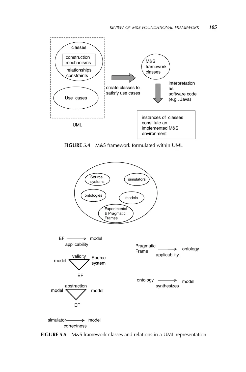
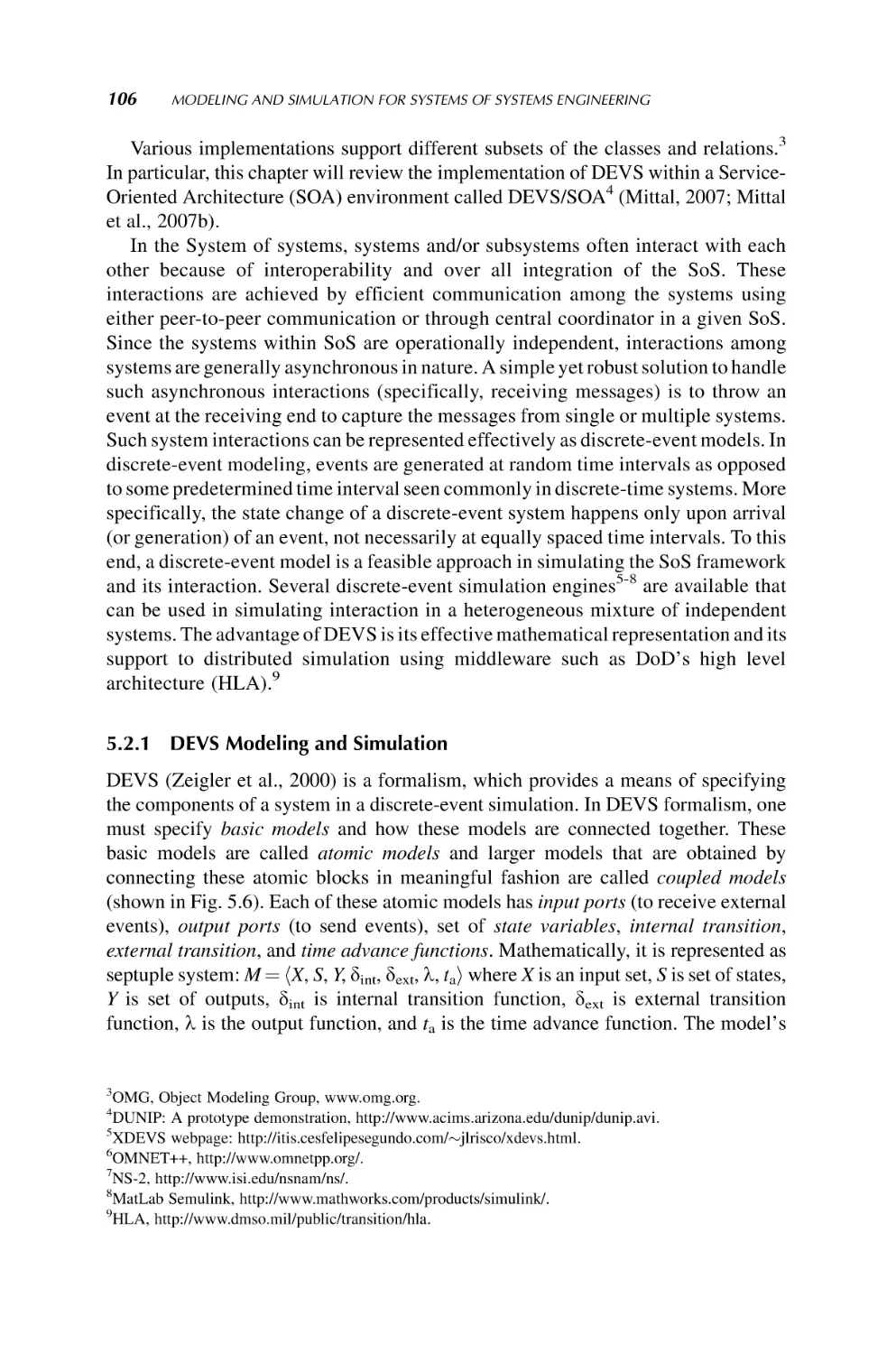
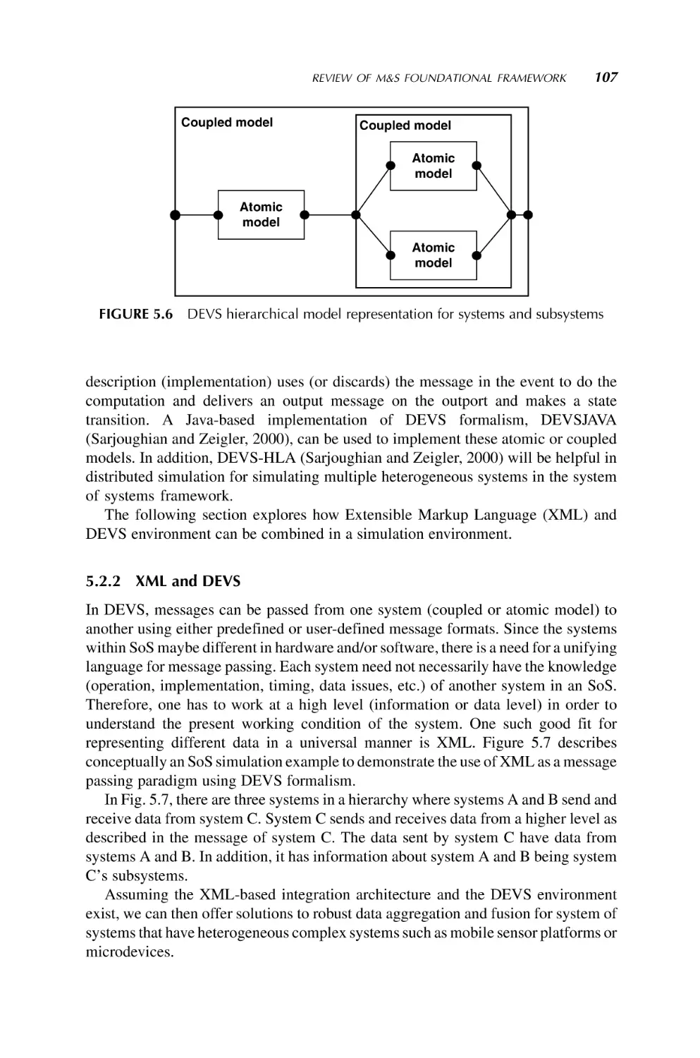
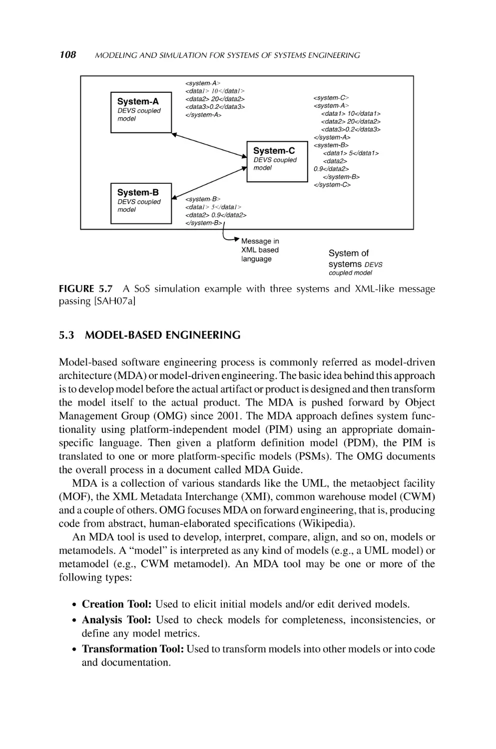
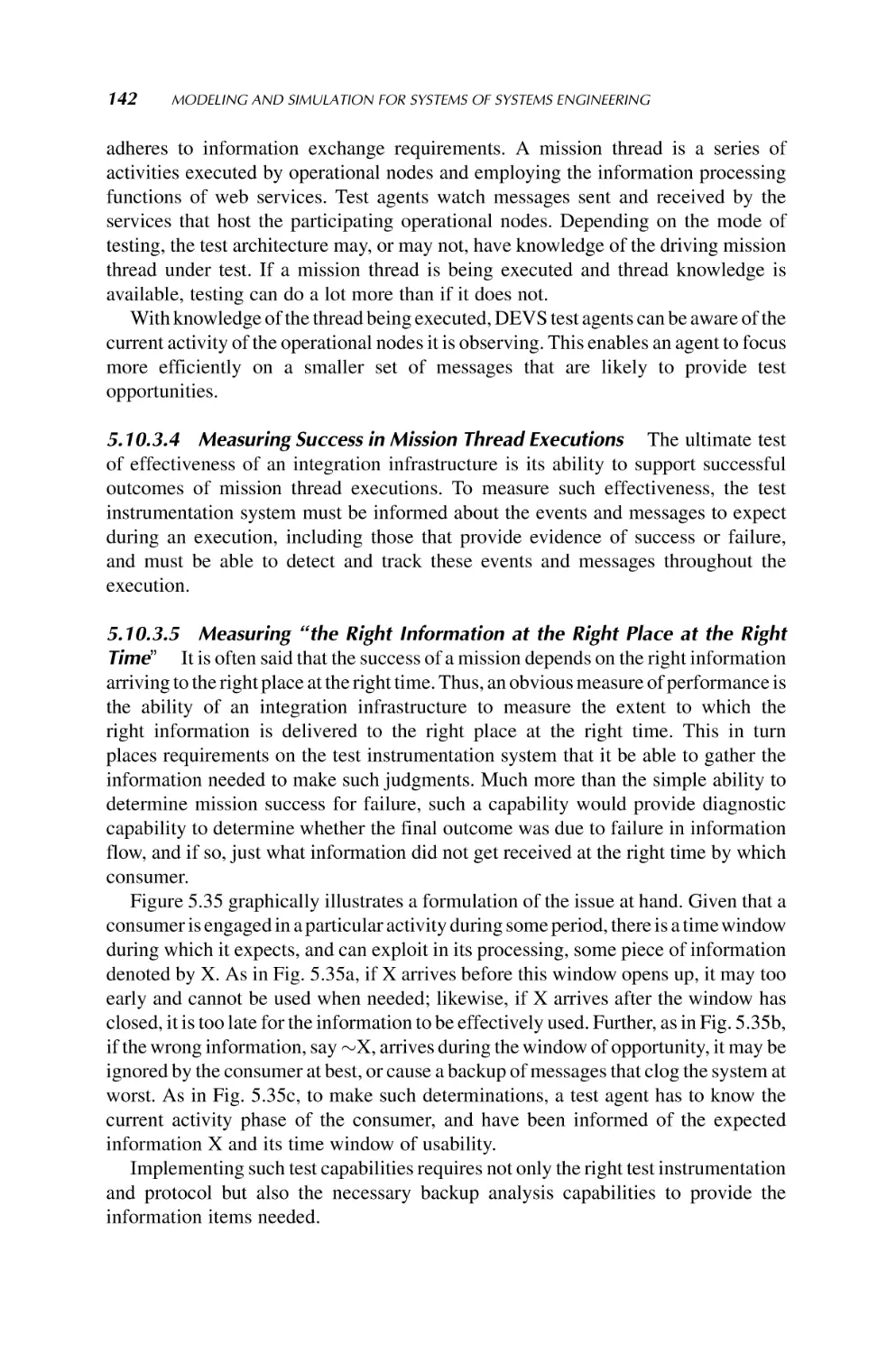
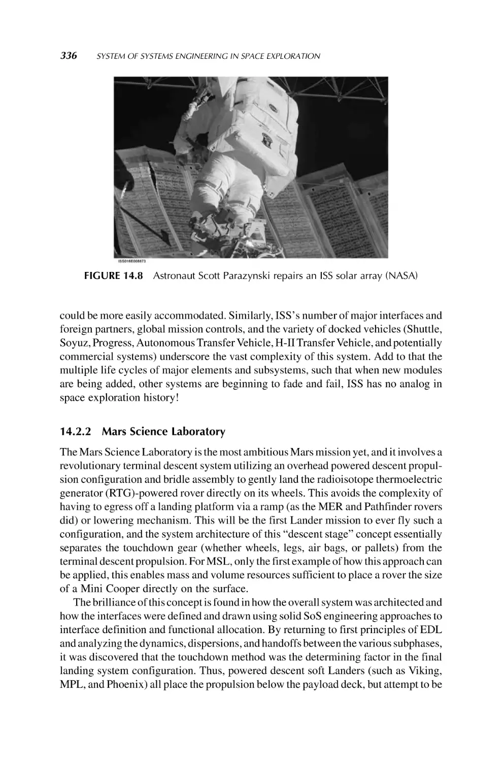
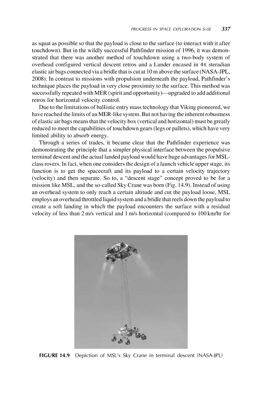
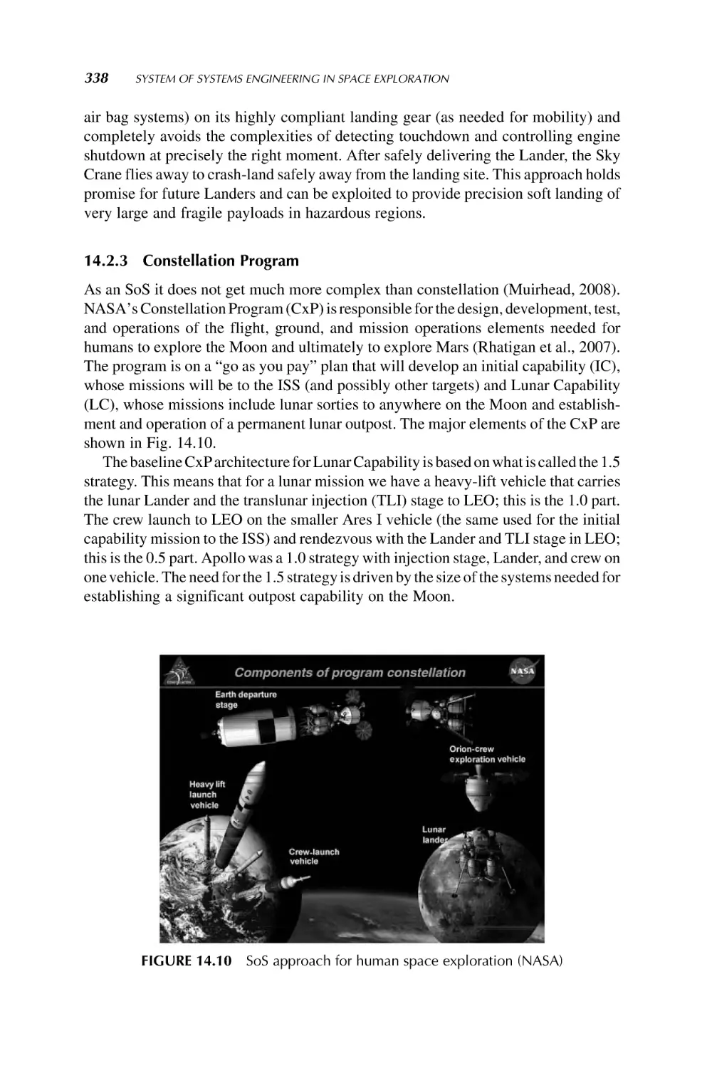
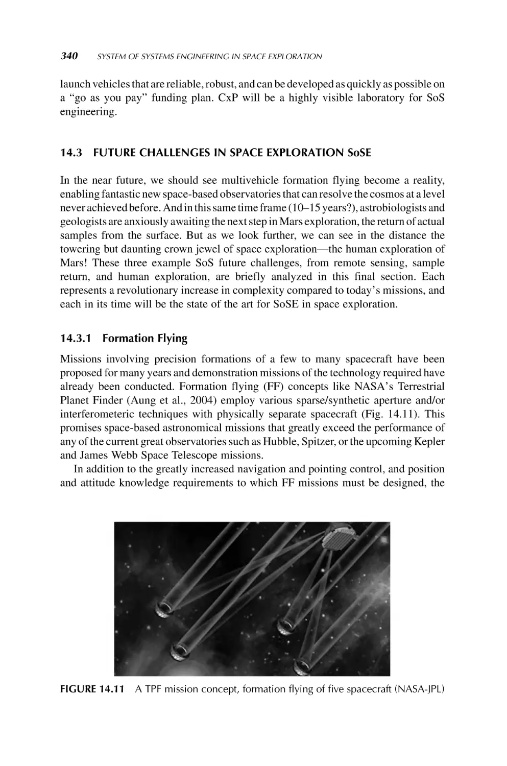
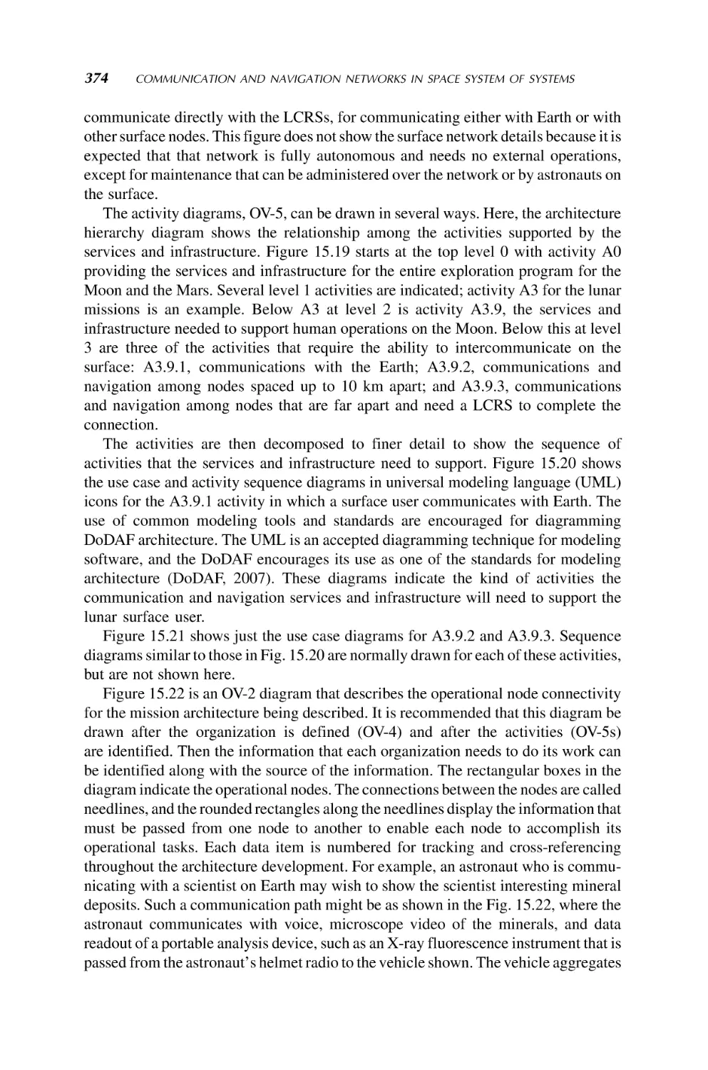
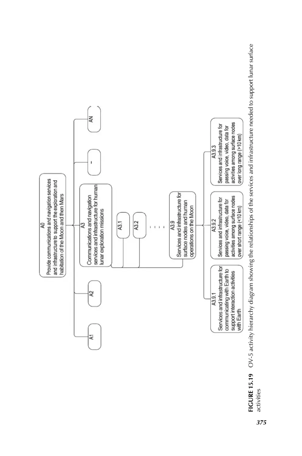
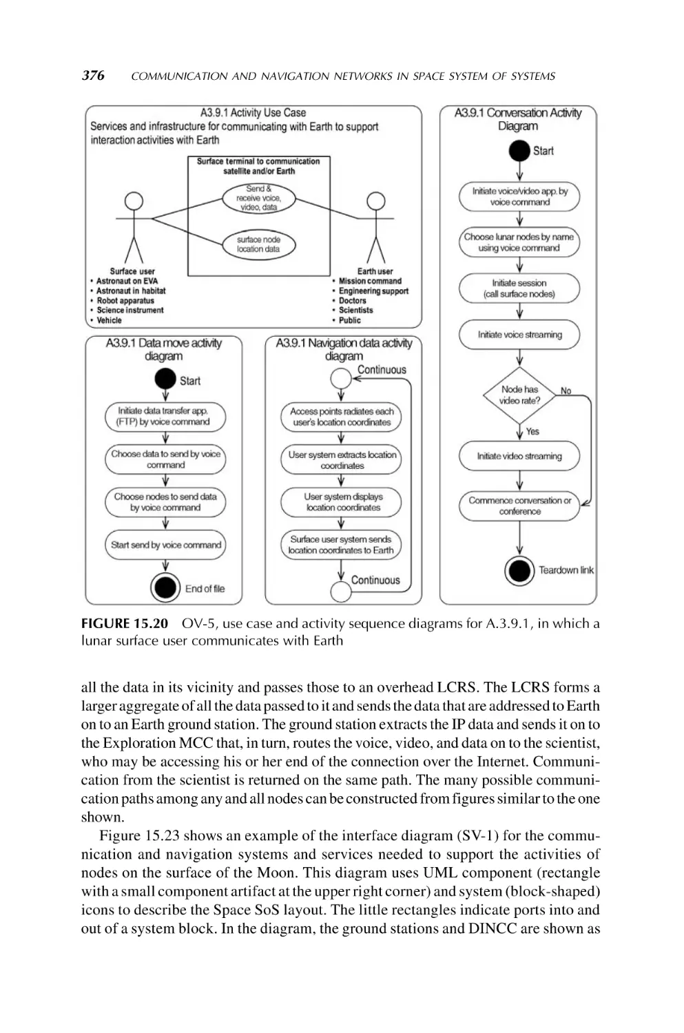
/


Автор: Mohammad Jamshidi
Теги: engineering electronics technical literature
ISBN: 978-0-470-19590-1
Год: 2009


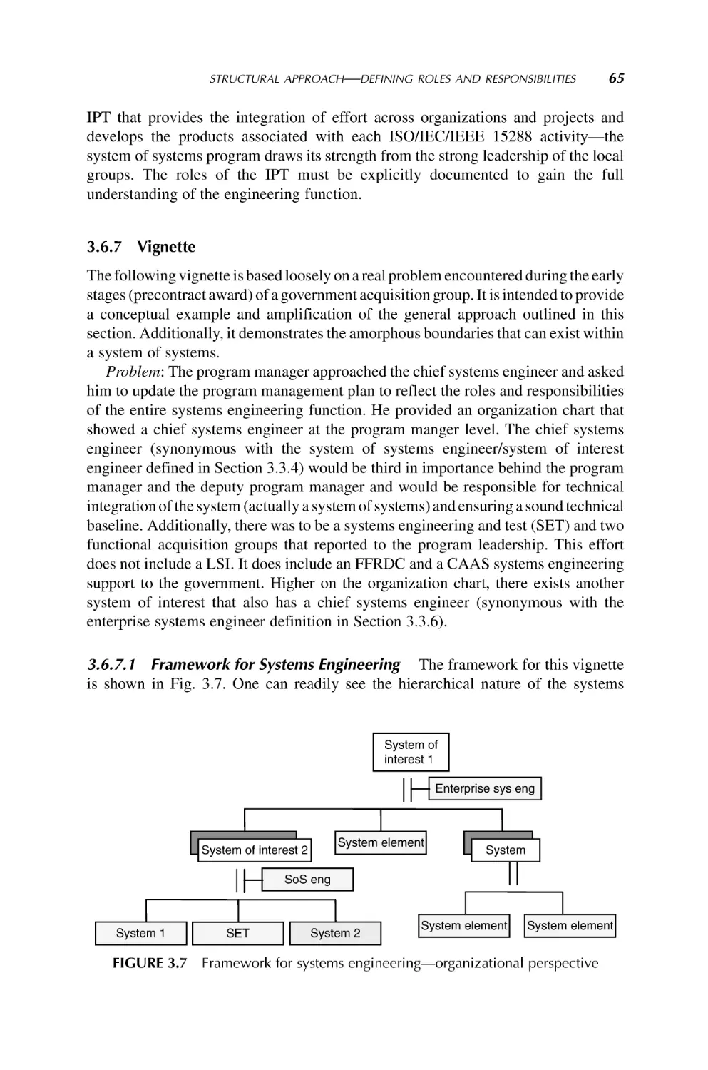
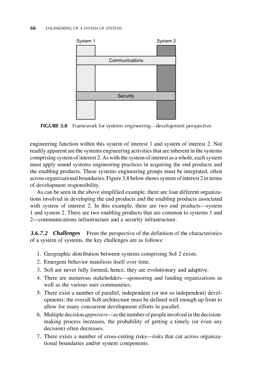
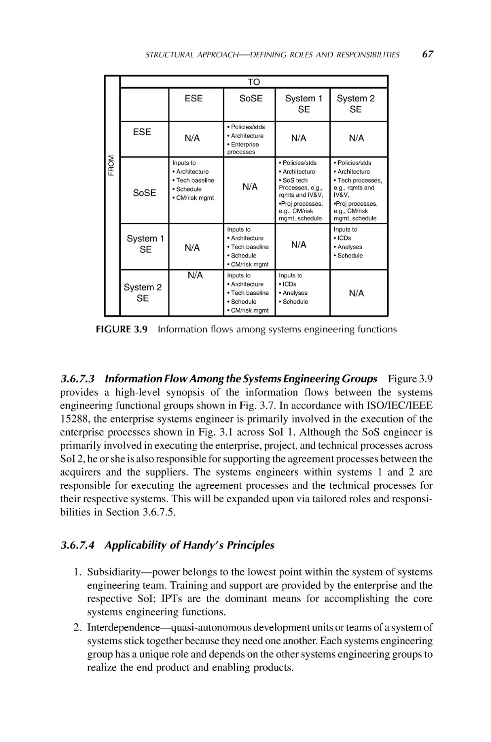
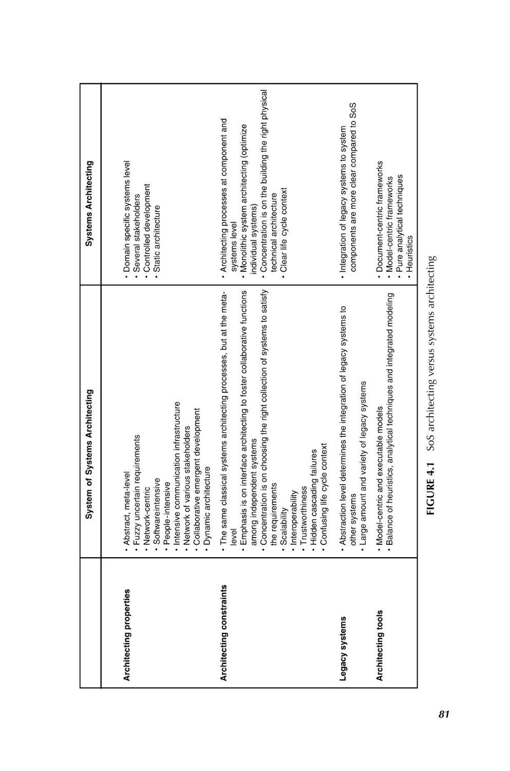
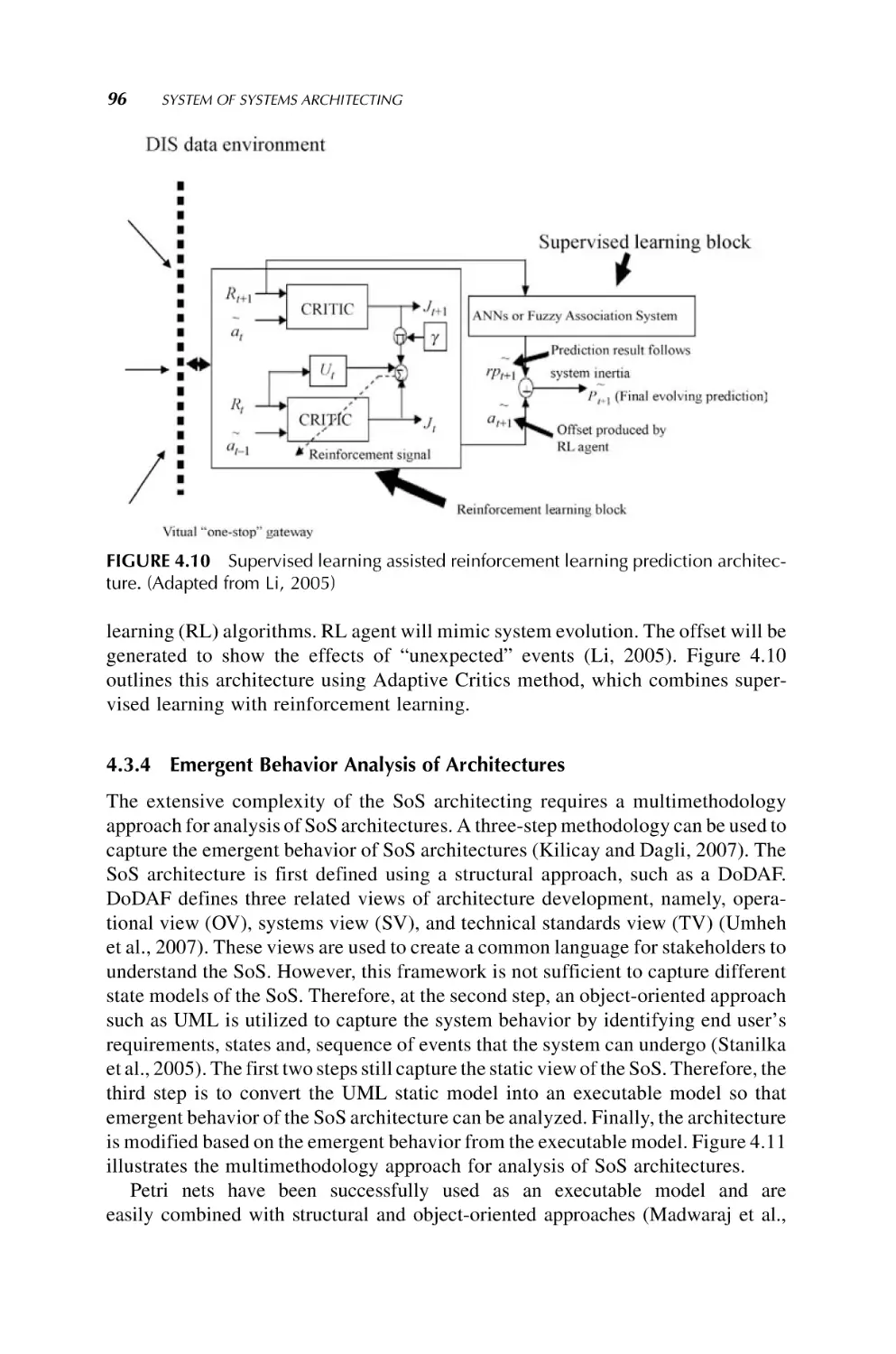
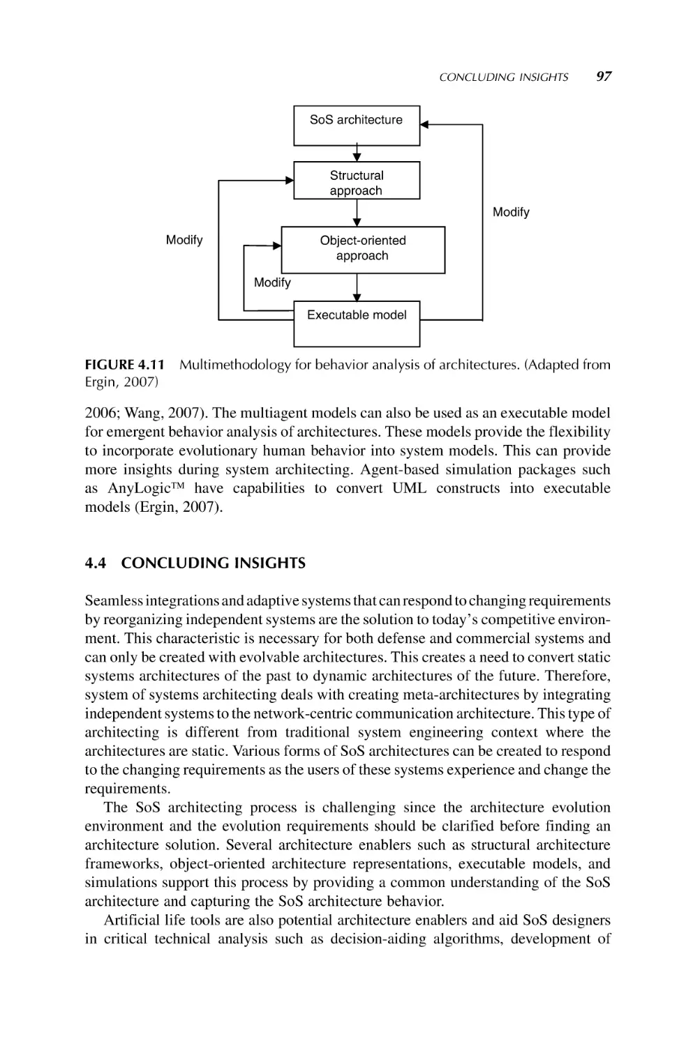
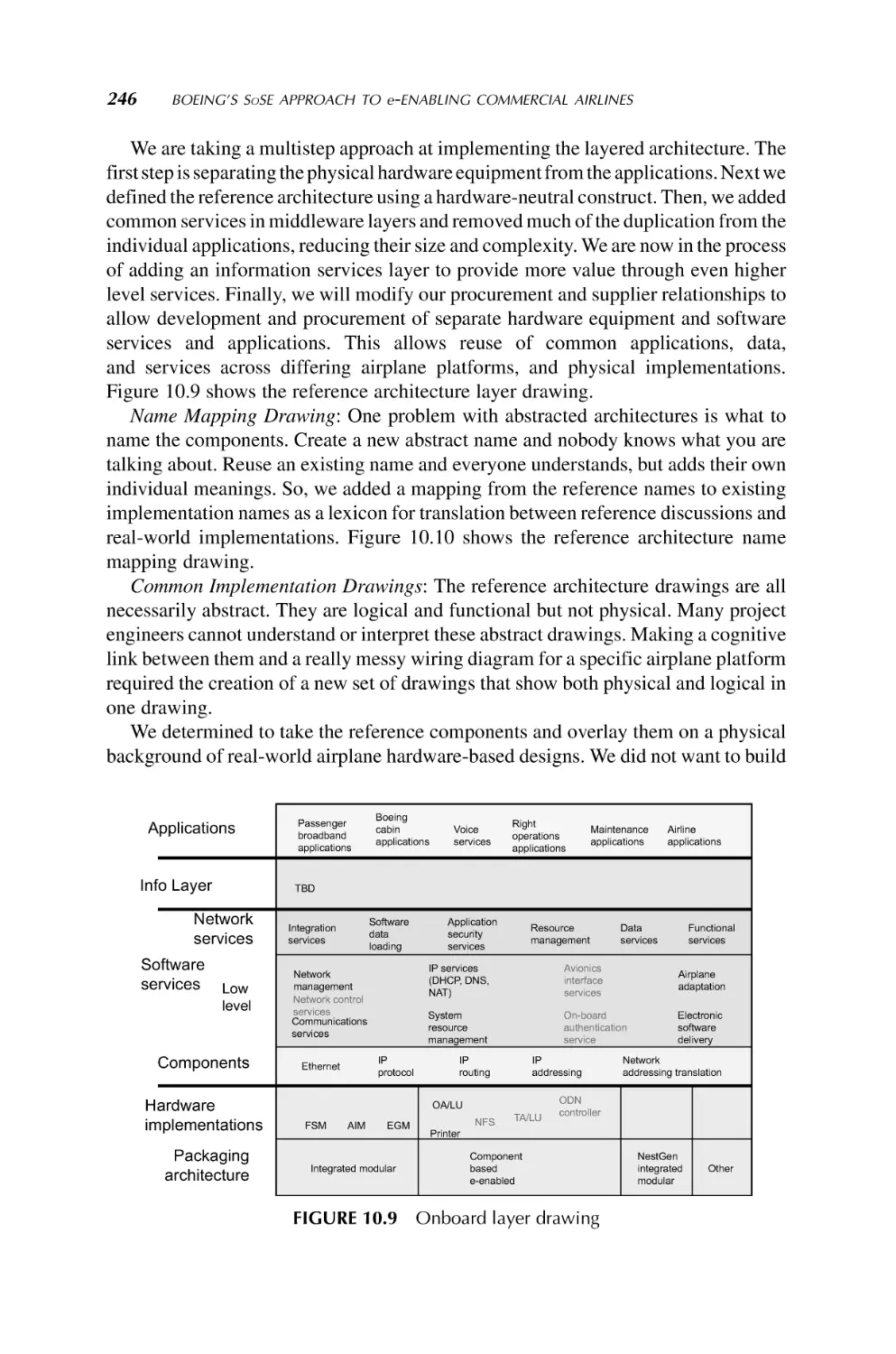
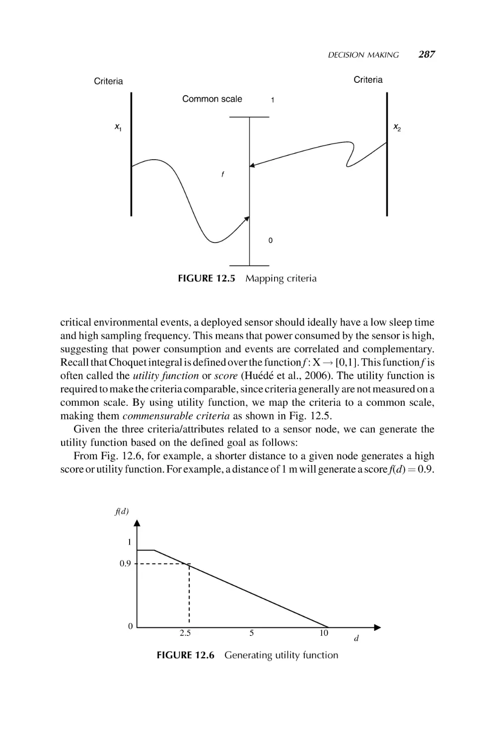
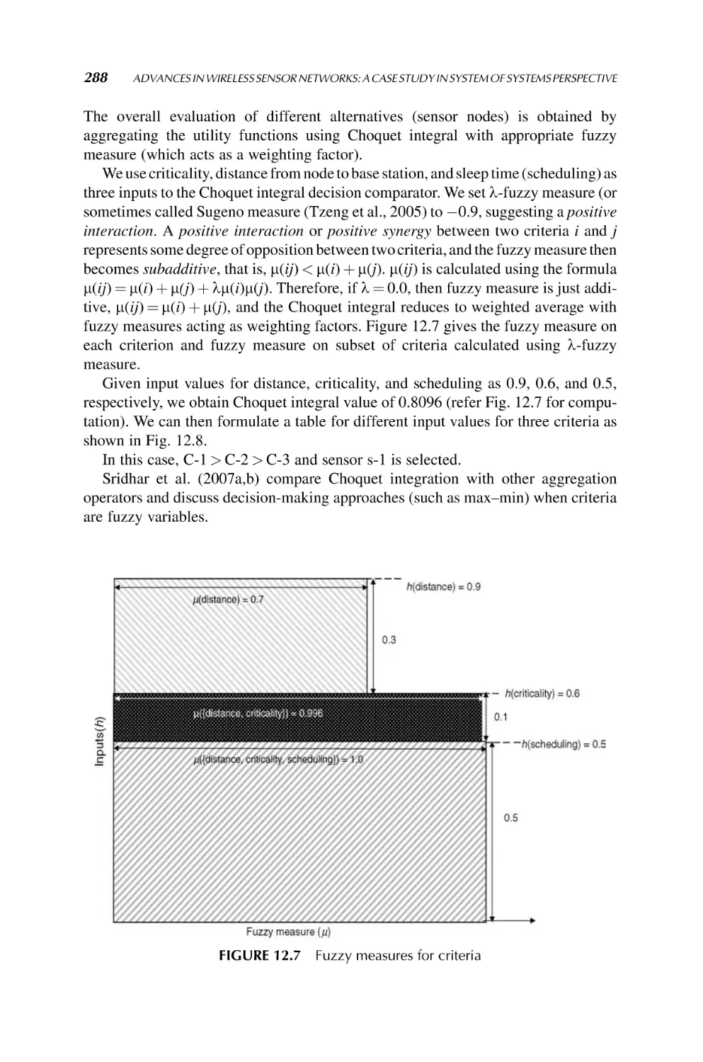
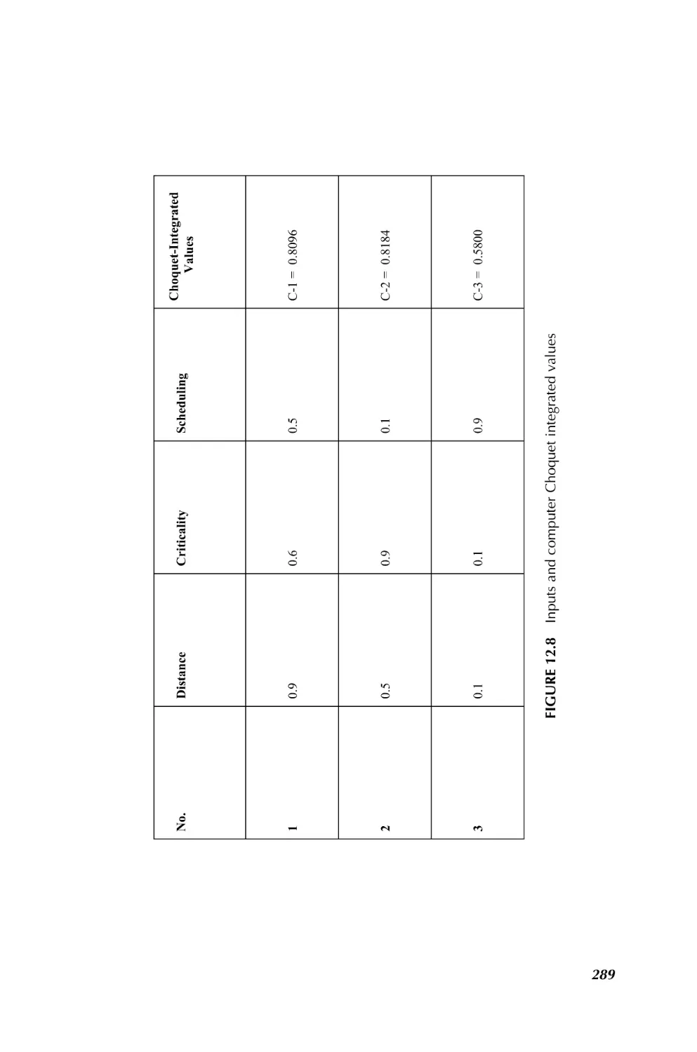
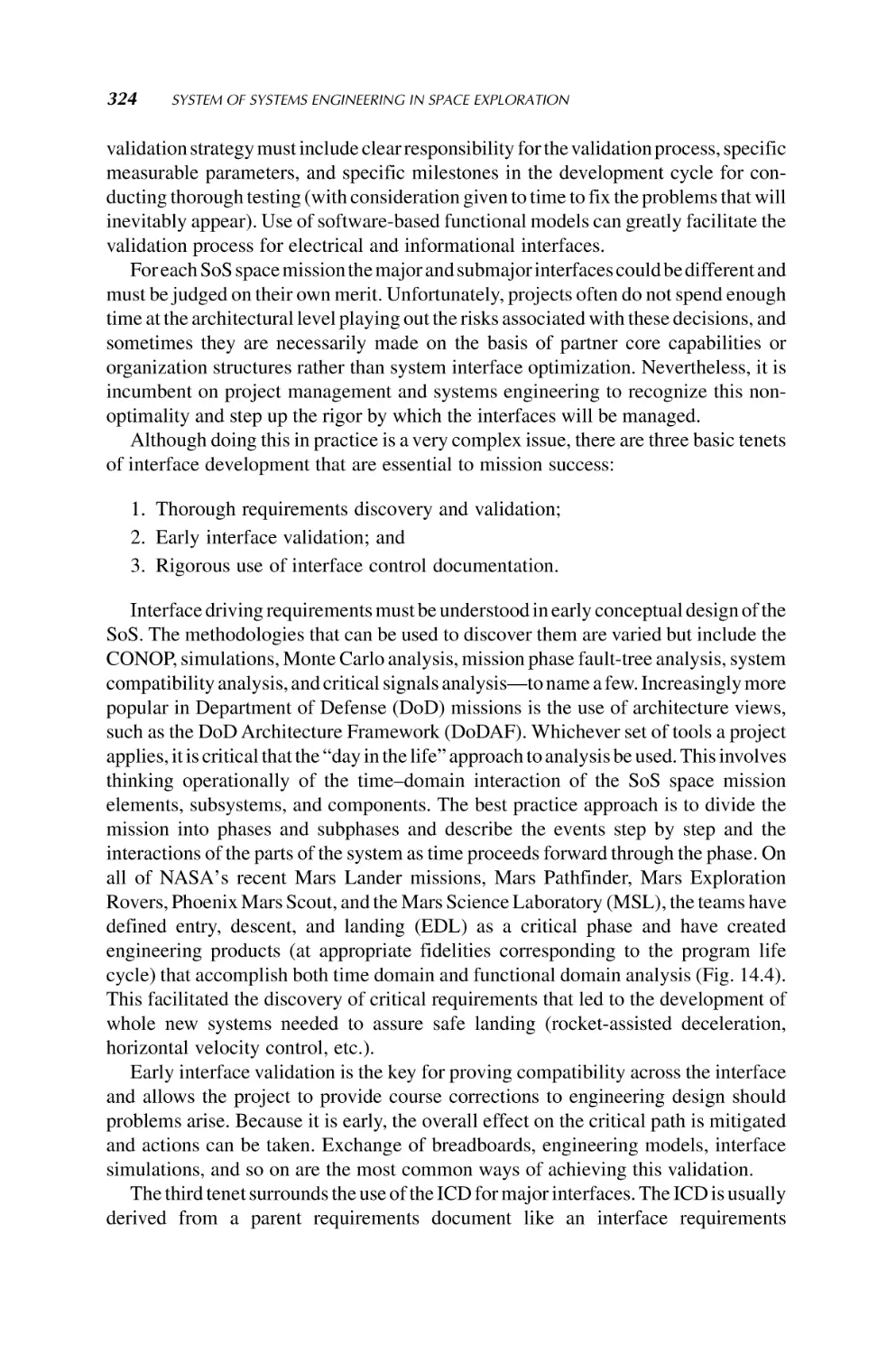
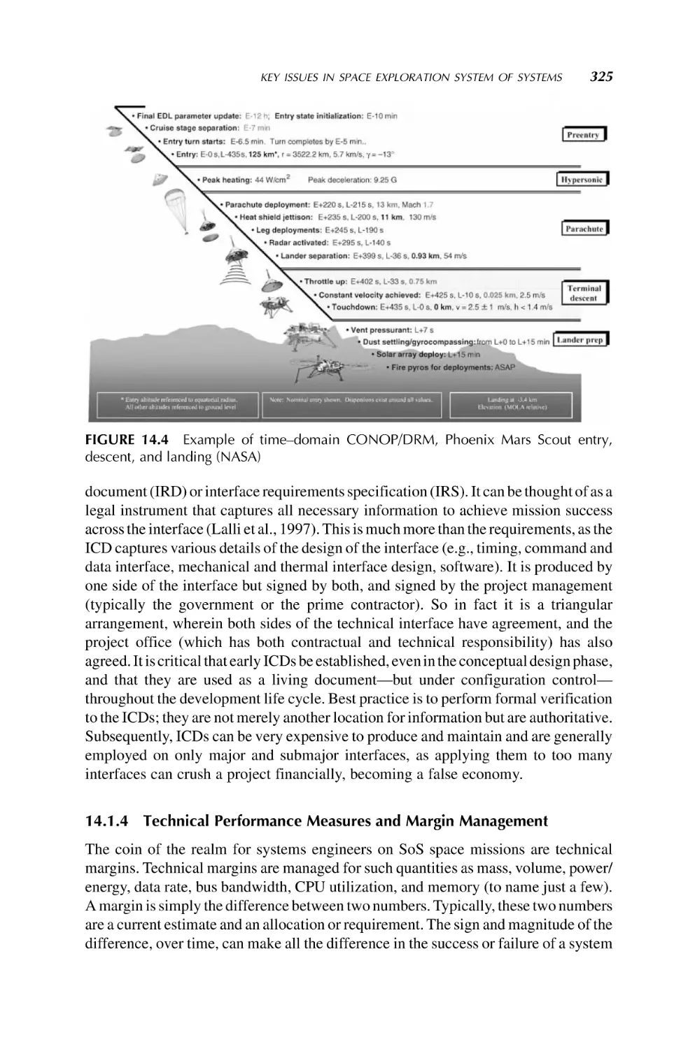
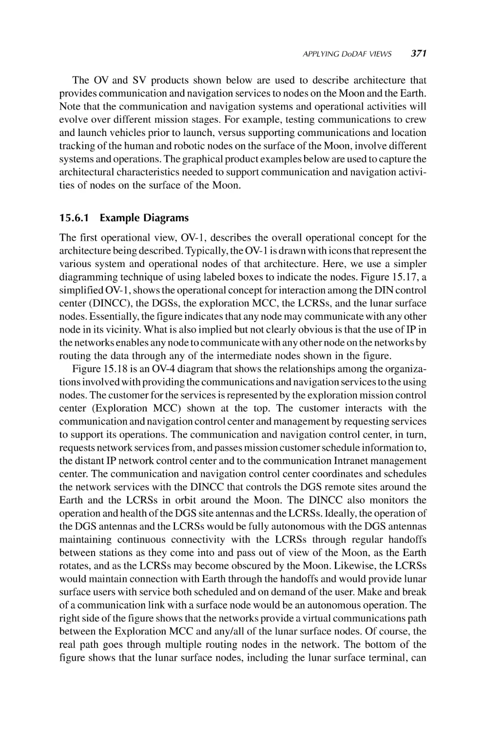
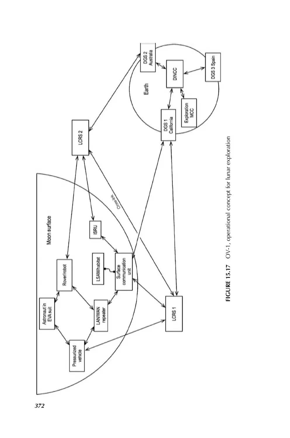
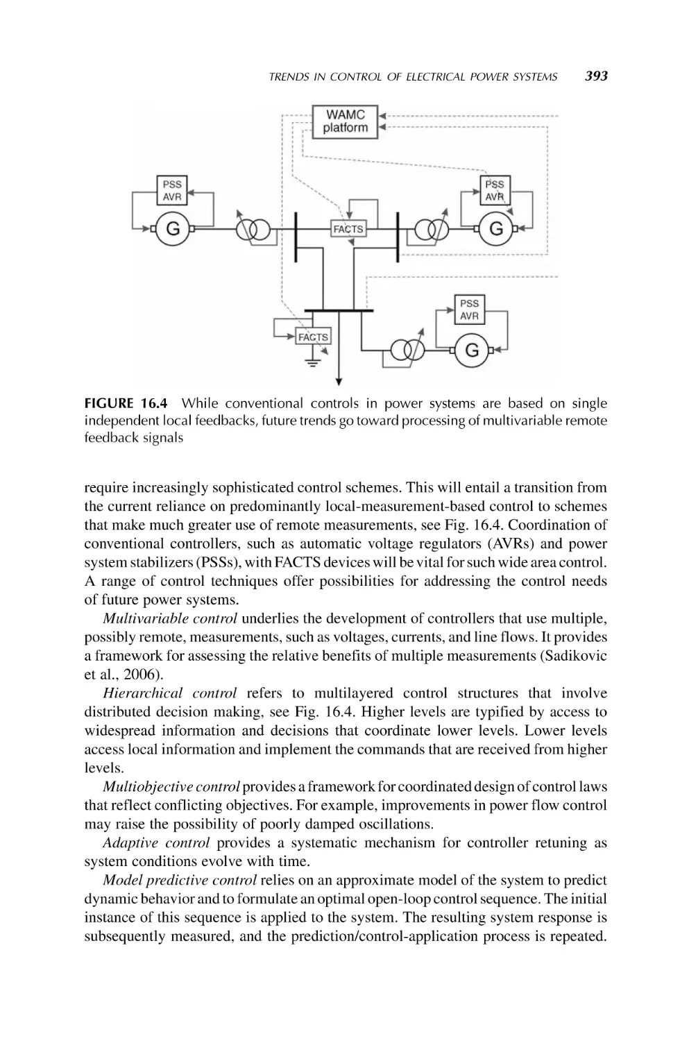
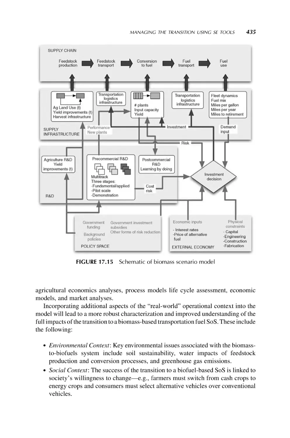
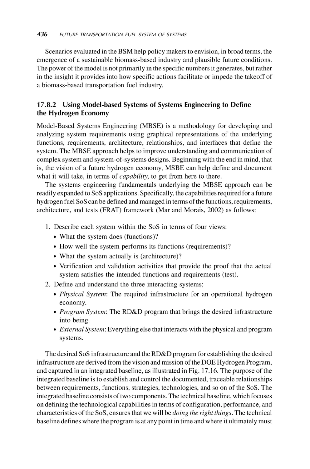
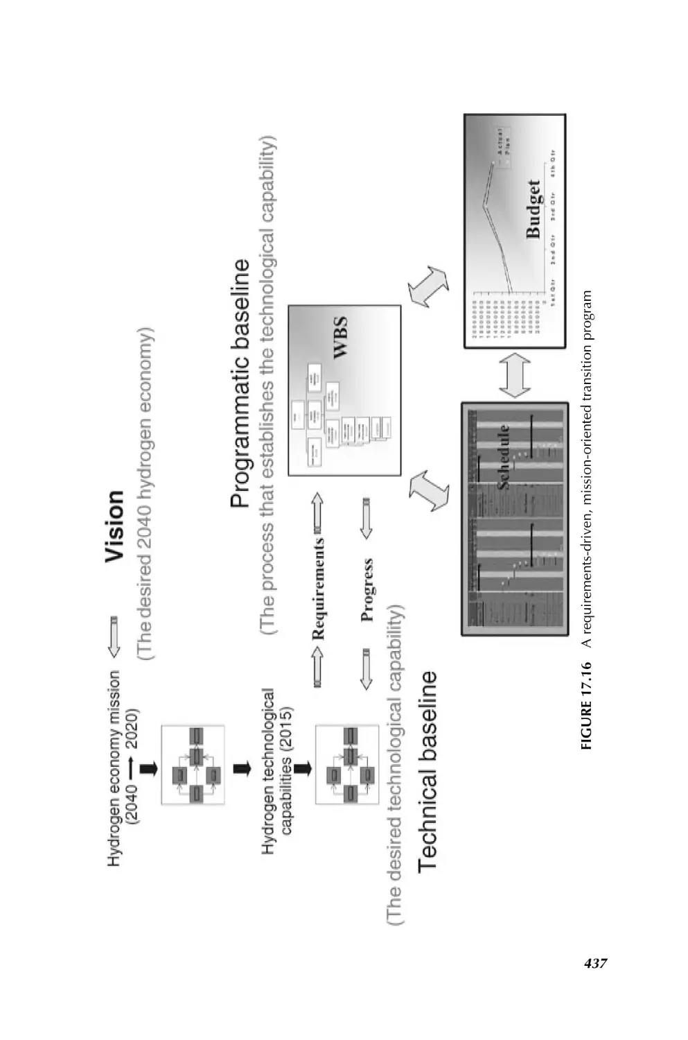
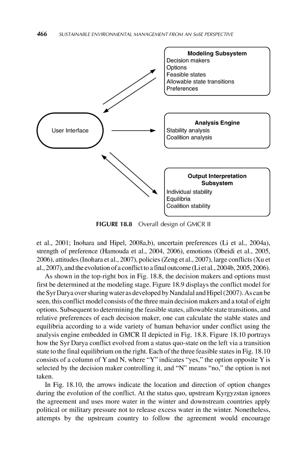
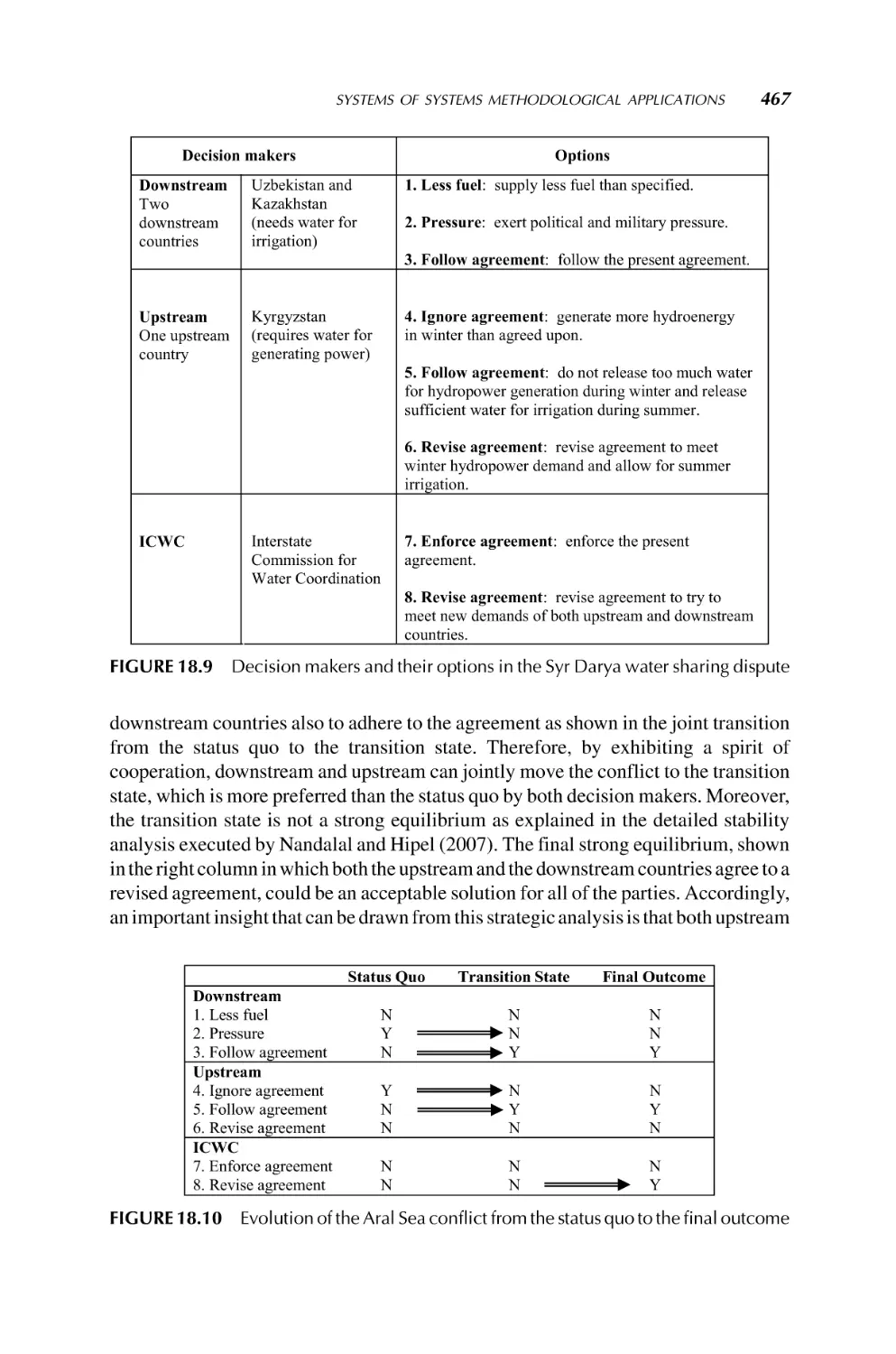
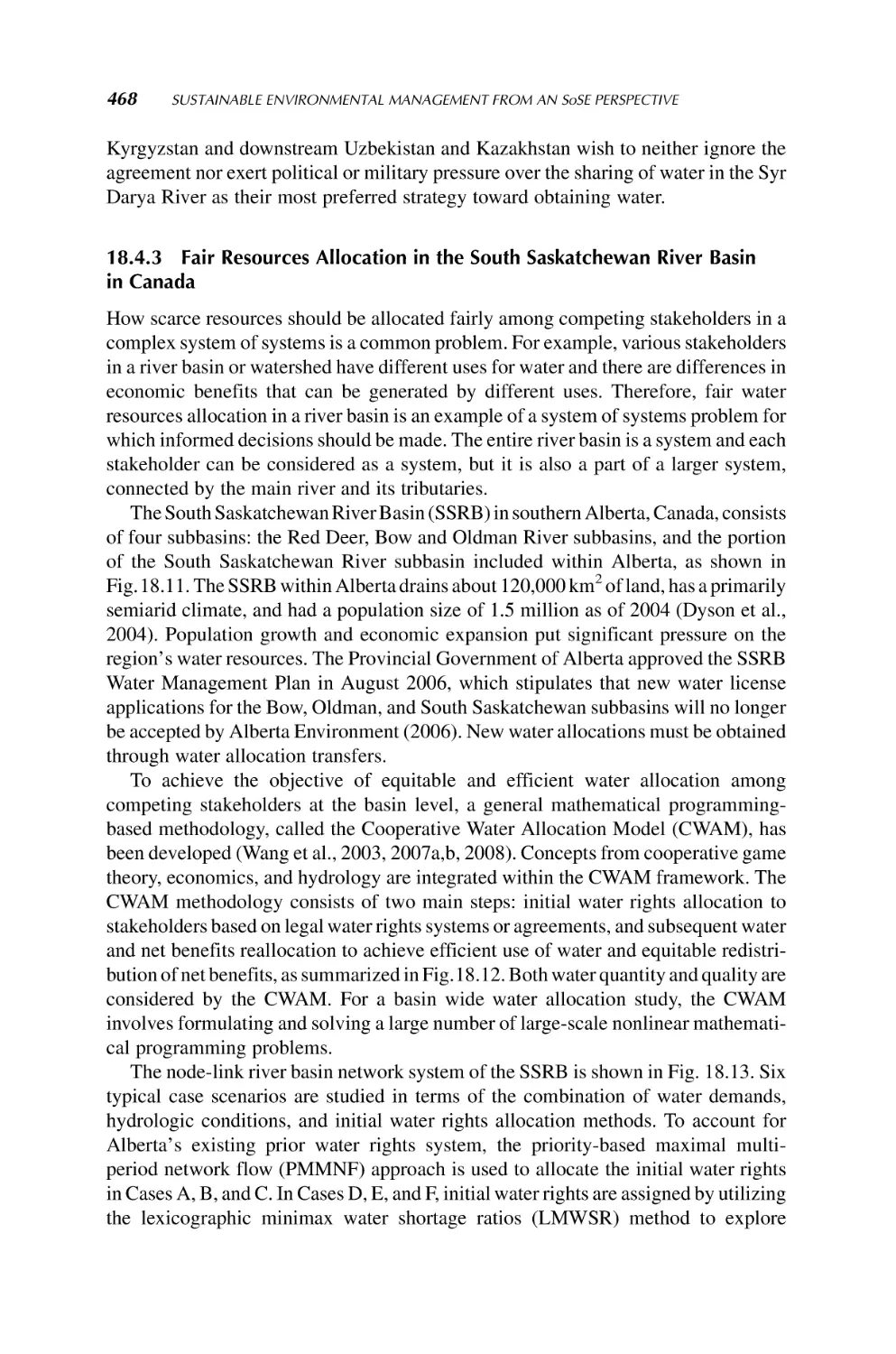
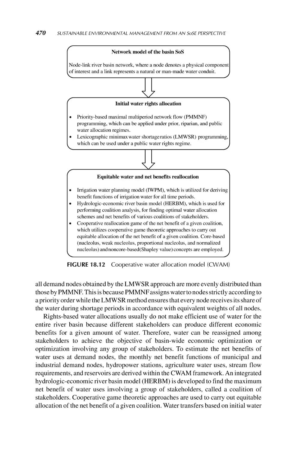
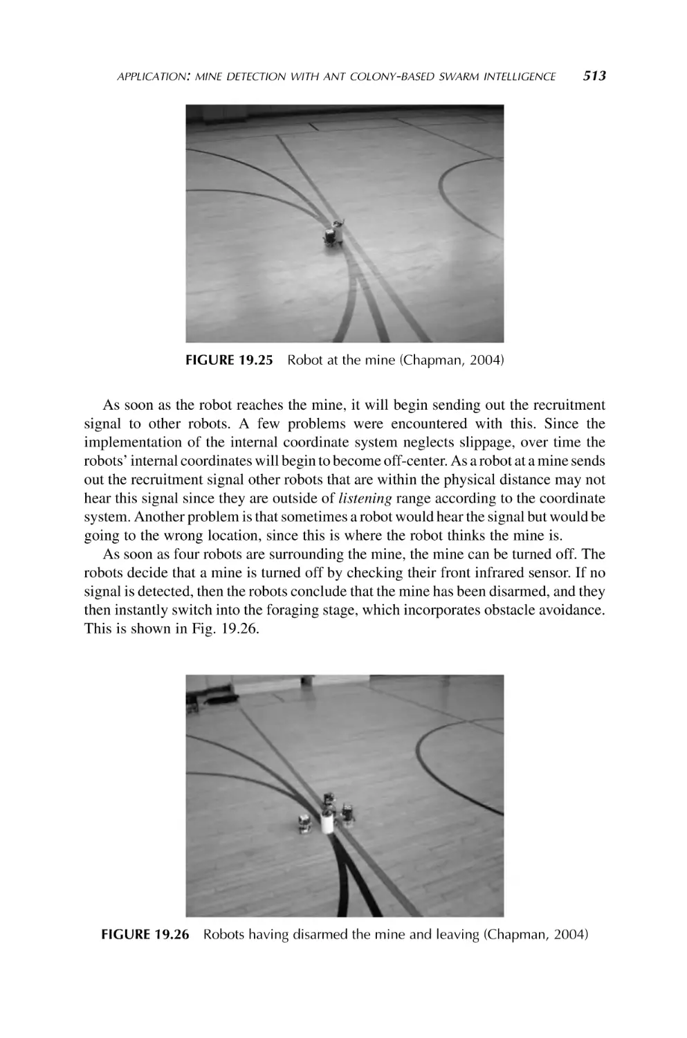
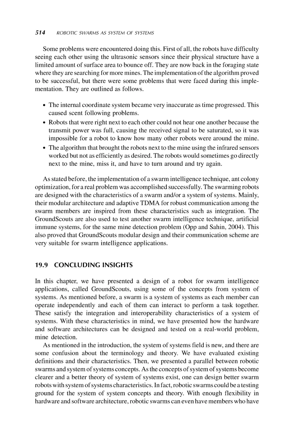
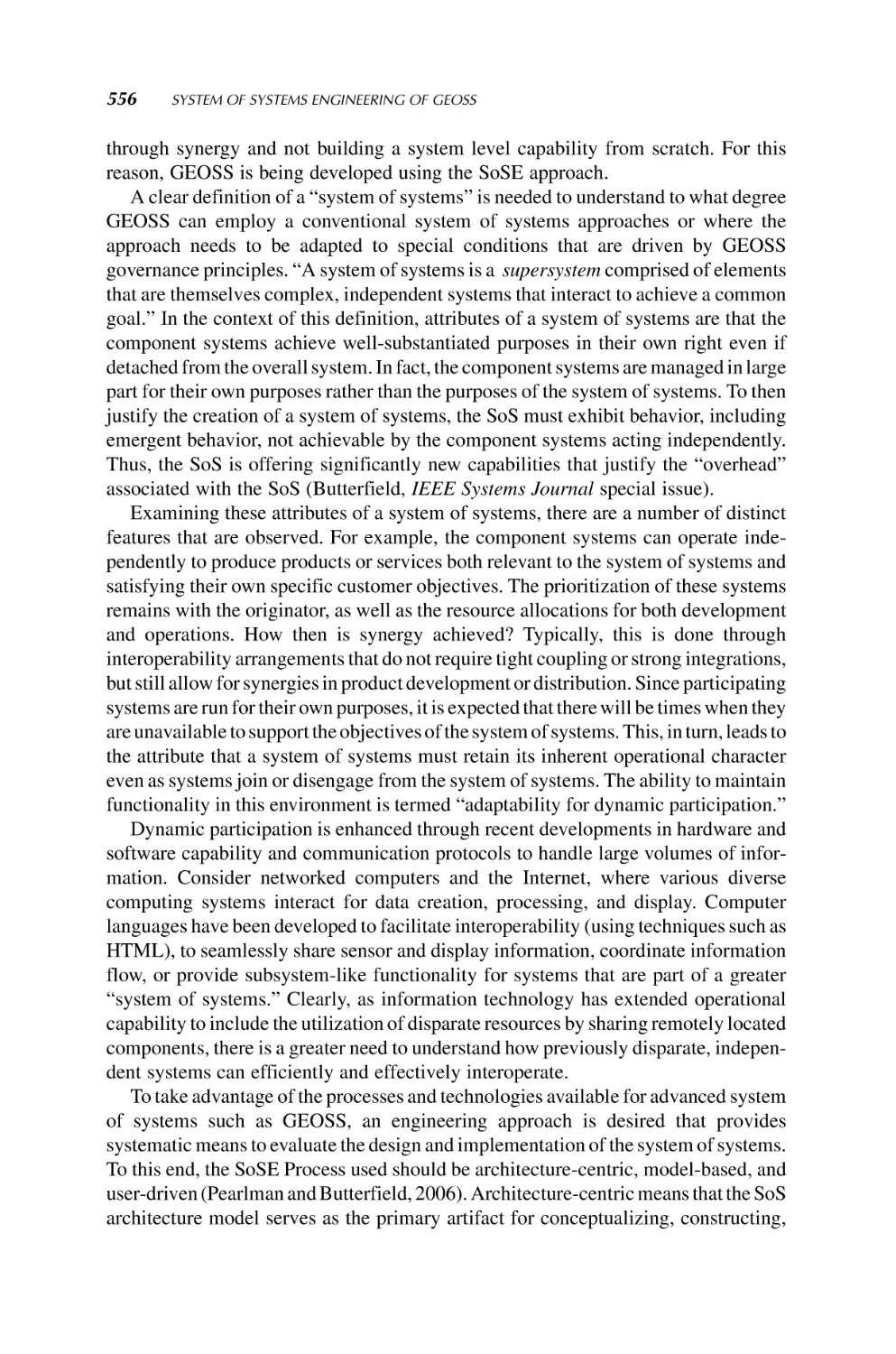
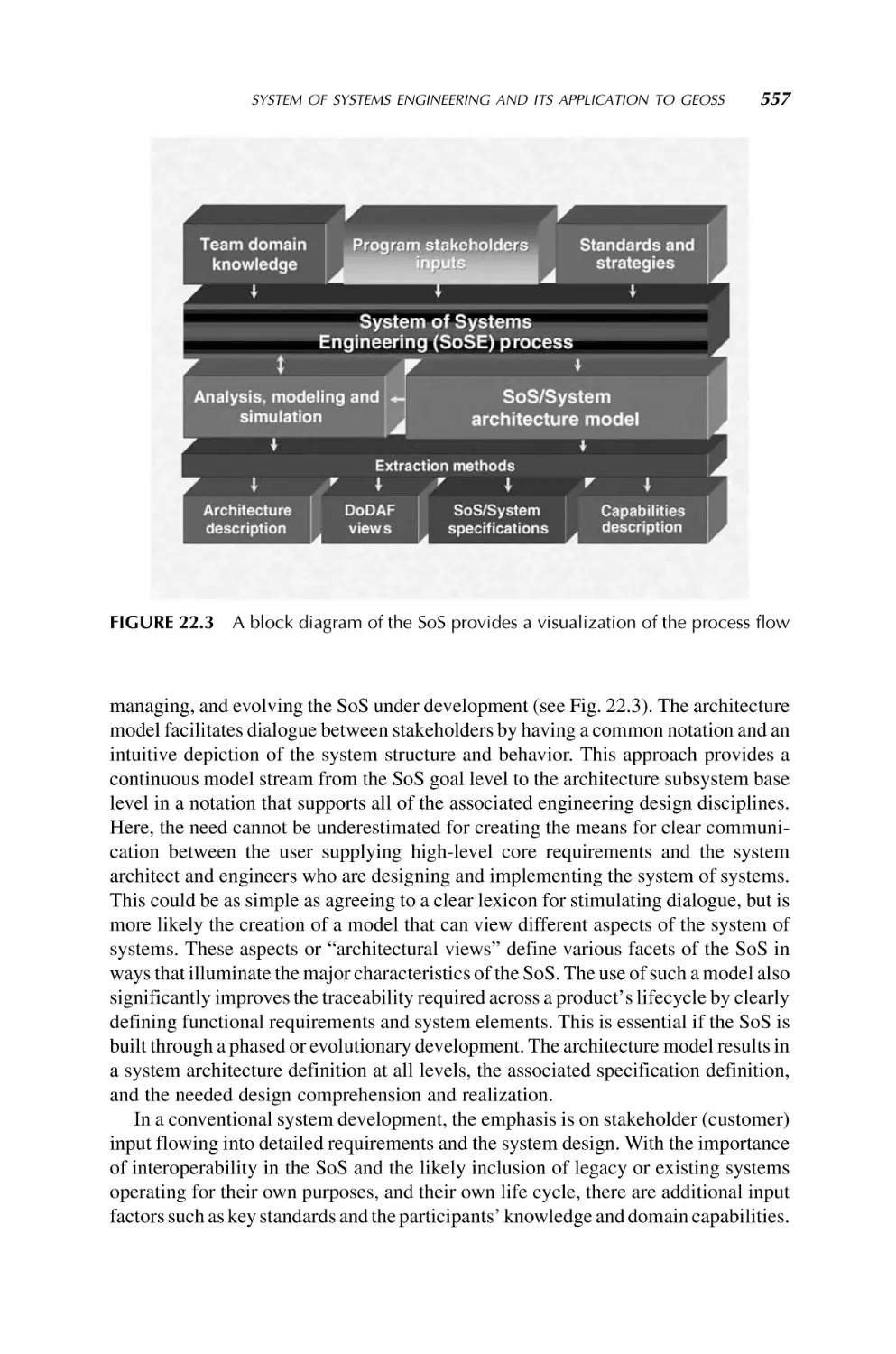
Текст
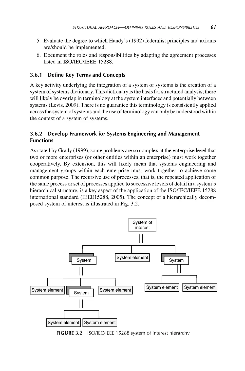
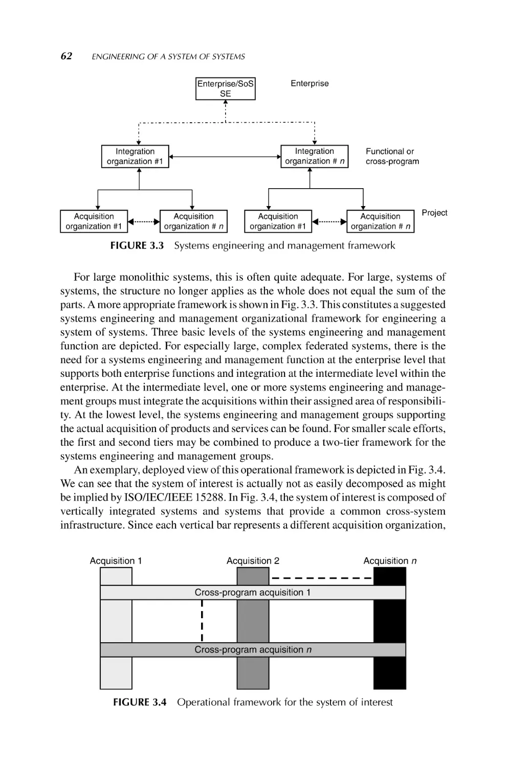
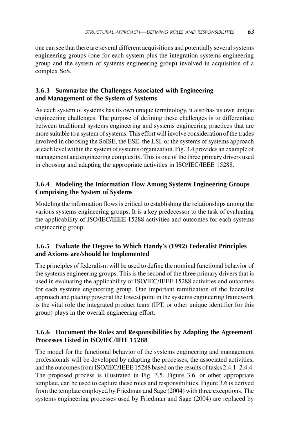
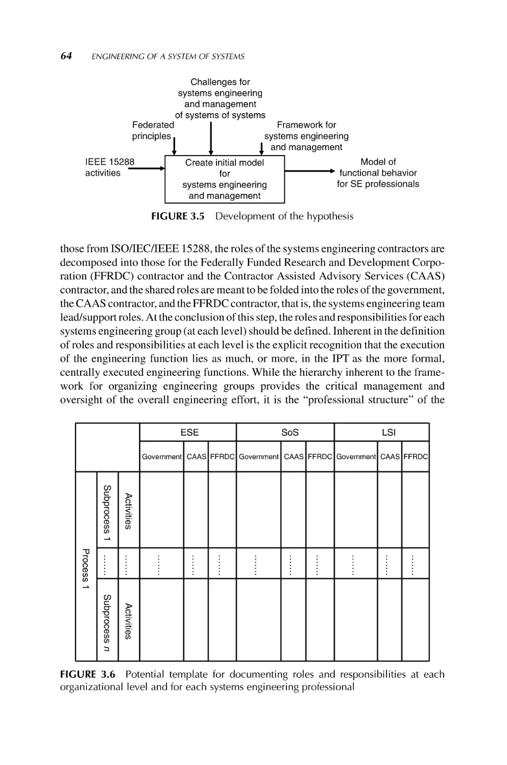
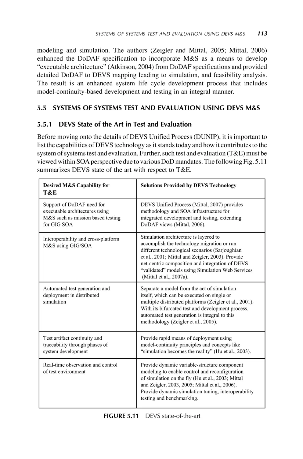
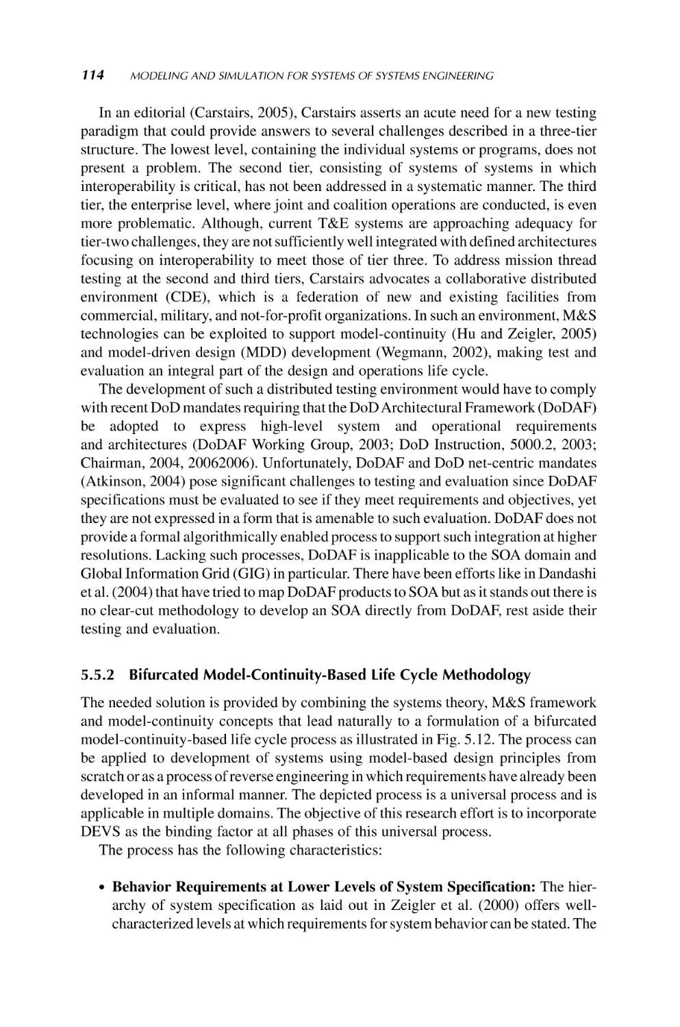
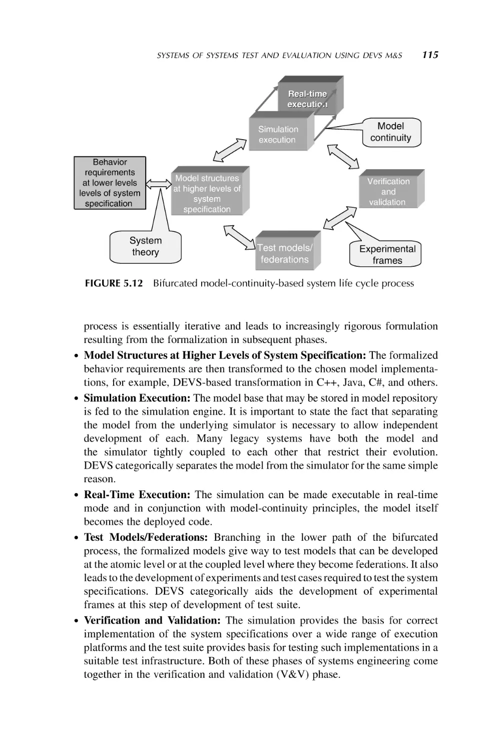
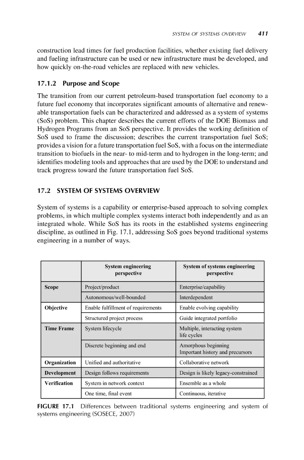
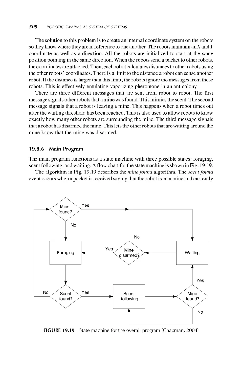
SYSTEM OF SYSTEMS
ENGINEERING
INNOVATIONS FOR THE 21st CENTURY
Edited by
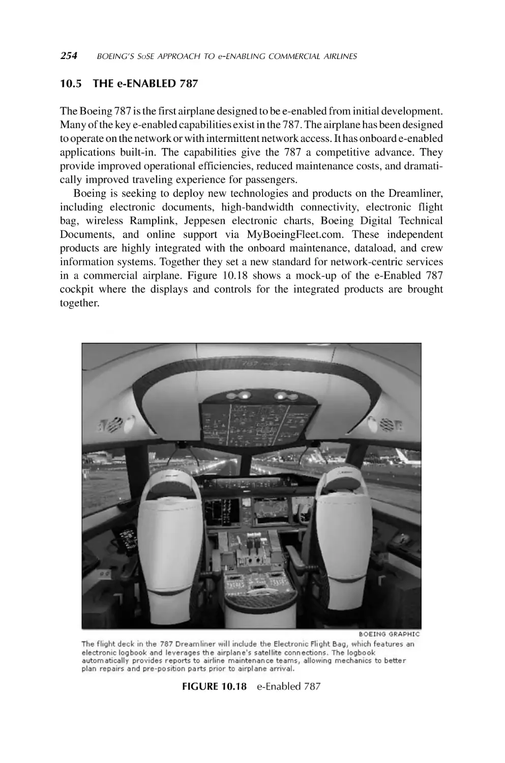
MO JAMSHIDI
SYSTEM OF SYSTEMS
ENGINEERING
SYSTEM OF SYSTEMS
ENGINEERING
INNOVATIONS FOR THE 21st CENTURY
Edited by
MO JAMSHIDI
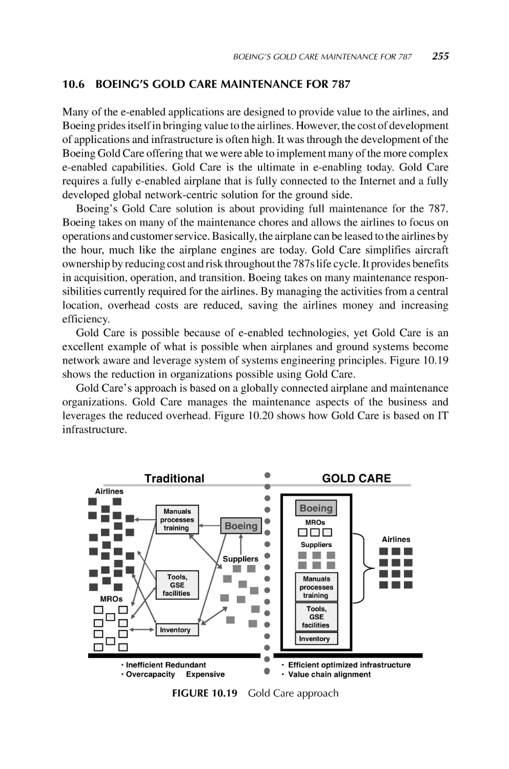
Copyright Ó 2009 by John Wiley & Sons, Inc. All rights reserved
Published by John Wiley & Sons, Inc., Hoboken, New Jersey
Published simultaneously in Canada
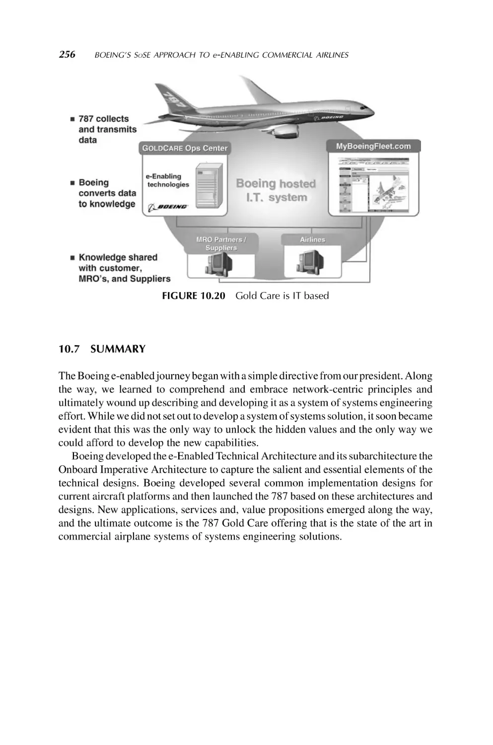
No part of this publication may be reproduced, stored in a retrieval system, or transmitted in any form or
by any means, electronic, mechanical, photocopying, recording, scanning, or otherwise, except as
permitted under Section 107 or 108 of the 1976 United States Copyright Act, without either the prior
written permission of the Publisher, or authorization through payment of the appropriate per-copy fee to
the Copyright Clearance Center, Inc., 222 Rosewood Drive, Danvers, MA 01923, (978) 750-8400, fax
(978) 750-4470, or on the web at www.copyright.com. Requests to the Publisher for permission should be
addressed to the Permissions Department, John Wiley & Sons, Inc., 111 River Street, Hoboken, NJ
07030, (201) 748-6011, fax (201) 748-6008, or online at http://www.wiley.com/go/permission.
Limit of Liability/Disclaimer of Warranty: While the publisher and author have used their best efforts in
preparing this book, they make no representations or warranties with respect to the accuracy or completeness
of the contents of this book and specifically disclaim any implied warranties of merchantability or fitness
for a particular purpose. No warranty may be created or extended by sales representatives or written
sales materials. The advice and strategies contained herein may not be suitable for your situation. You
should consult with a professional where appropriate. Neither the publisher nor author shall be liable for any
loss of profit or any other commercial damages, including but not limited to special, incidental,
consequential, or other damages.
For general information on our other products and services or for technical support, please contact our
Customer Care Department within the United States at (800) 762-2974, outside the United States
at (317) 572-3993 or fax (317) 572-4002.
Wiley also publishes its books in a variety of electronic formats. Some content that appears in print may
not be available in electronic formats. For more information about Wiley products, visit our web site at
www.wiley.com.
Library of Congress Cataloging-in-Publication Data:
Systems of systems engineering : innovations for the 21st century / edited by Mo Jamshidi.
p. cm. – (Wiley series in systems engineering and management)
Includes bibliographical references and index.
ISBN 978-0-470-19590-1 (cloth : alk. paper)
1. Systems engineering–Technological innovations. 2. Large scale systems. I. Jamshidi, Mohammad.
TA168.S8885 2009
620.001’171–dc22
2008018996
Printed in the United States of America
10 9 8 7 6 5 4 3 2 1
THIS VOLUME IS DEDICATED JOINTLY TO:
All my mentors, in alphabetical order:
George Bekey (USC)
Joe Cruz (UIUC)
Joe Engelberger (Unimation)
Ali Javan (MIT)
Eli Jury (UC-Berkeley)
Petar Kokotovic (UIUC)
Bill Perkins (UIUC)
Faz Reza (Syracuse U)
Andy Sage (UVA)
Solon Stone (OSU)
Lotfi Zadeh (UC-Berkeley)
who directly or indirectly taught me systems and control engineering throughout
my career
Contents
Preface
ix
About the Editor
xi
Contributors
1. Introduction to System of Systems
xiii
1
Mo Jamshidi
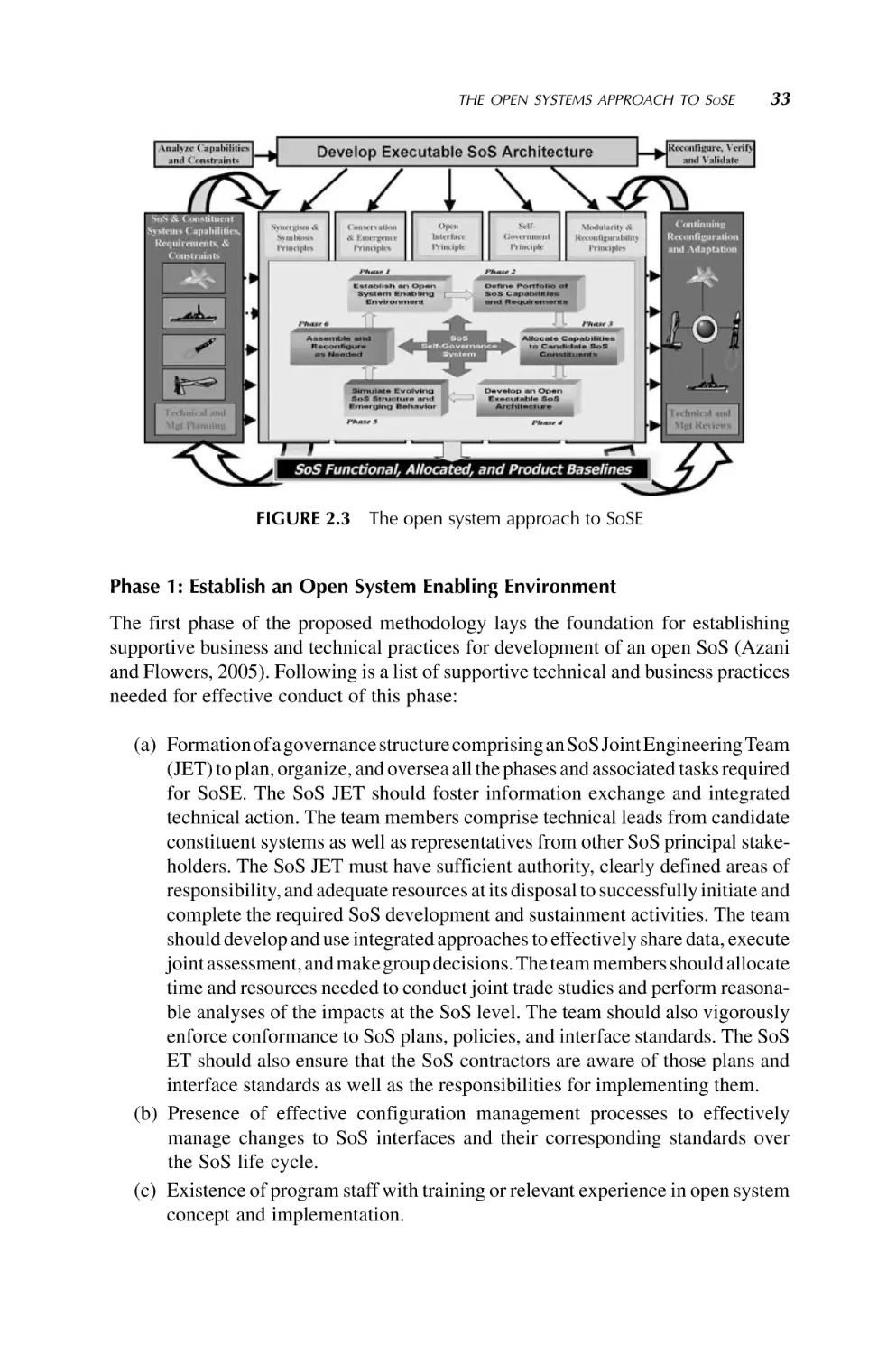
2. An Open Systems Approach to System of Systems Engineering
21
Cyrus Azani
3. Engineering of a System of Systems
44
Gary D. Wells and Andrew P. Sage
4. System of Systems Architecting
77
Cihan H. Dagli and Nil Kilicay-Ergin
5. Modeling and Simulation for Systems of Systems Engineering
101
Saurabh Mittal, Bernard P. Zeigler, Jos
e L. Risco Martın, Ferat Sahin,
and Mo Jamshidi
6. Net Centricity and System of Systems
150
Robert J. Cloutier, Michael J. DiMario, and Hans W. Polzer
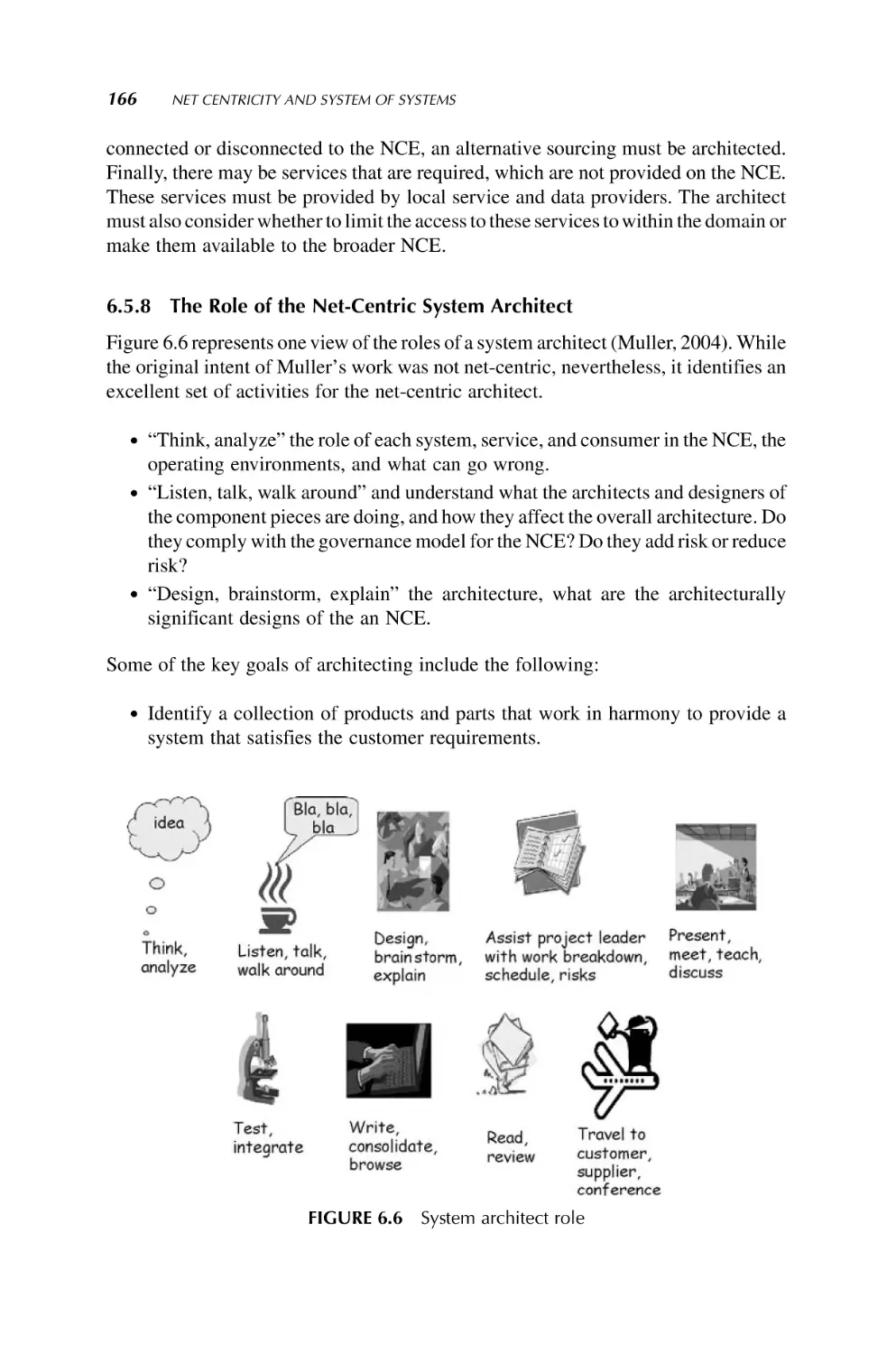
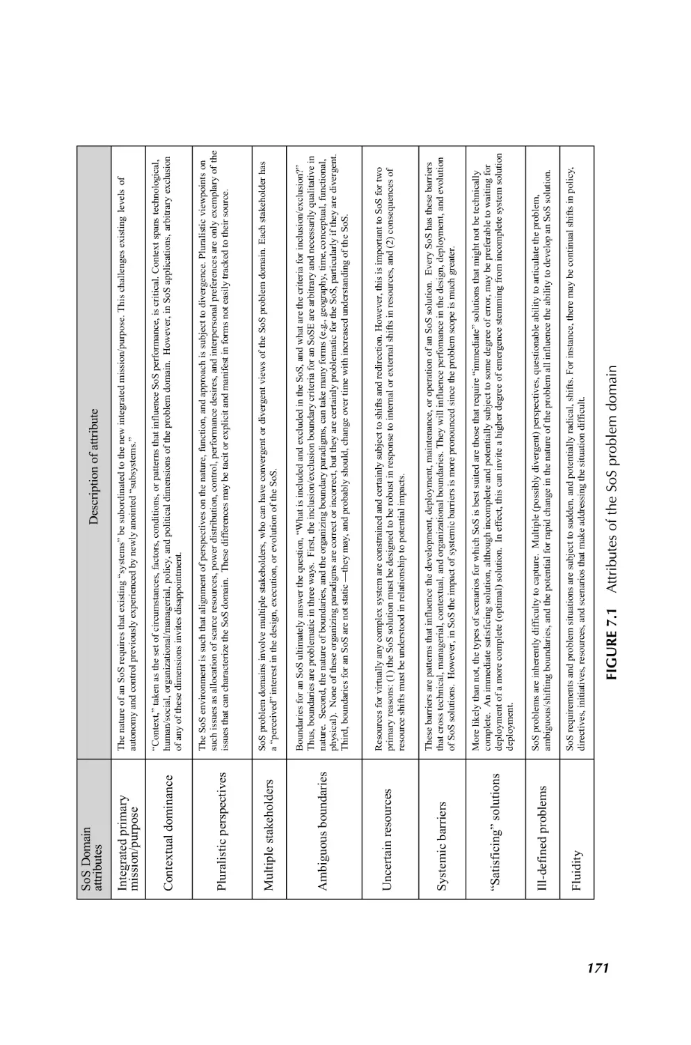
7. Emergence in System of Systems
169
Charles B. Keating
8. System of Systems Management
191
Brian Sauser, John Boardman, and Alex Gorod
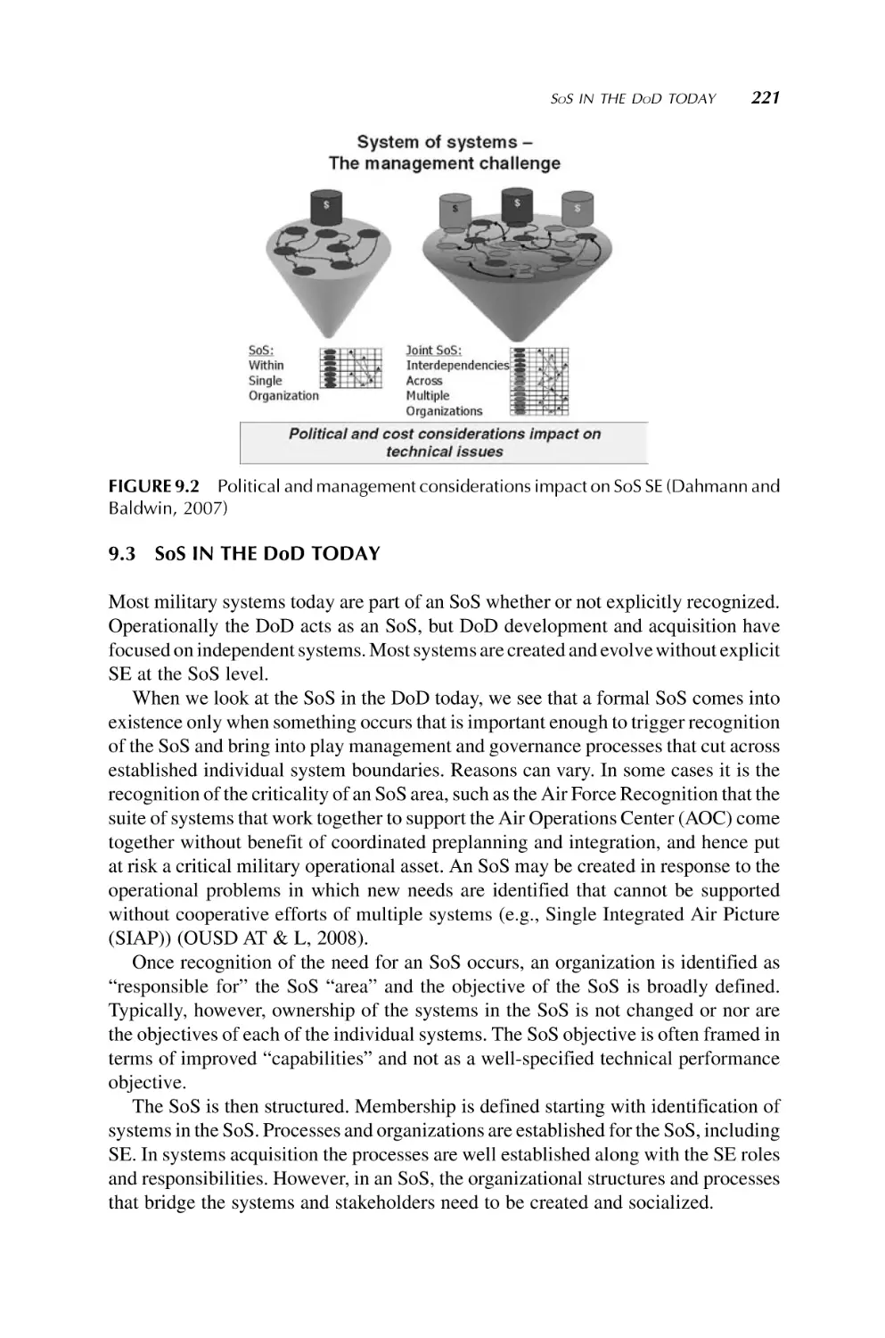
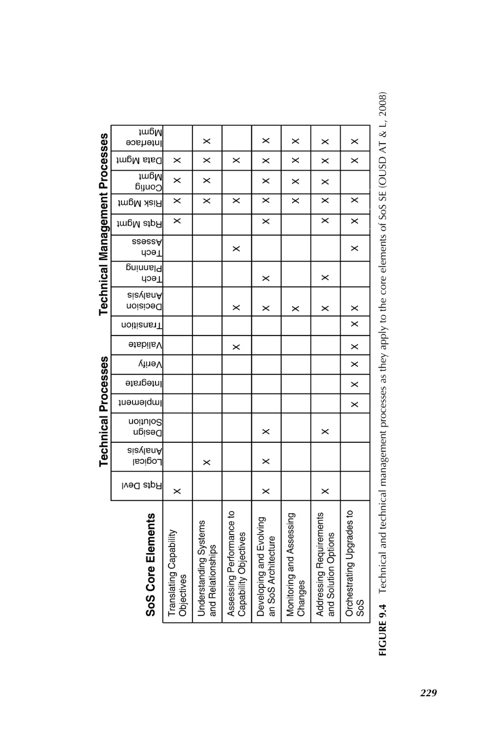
9. Systems Engineering for Department of Defense Systems
of Systems
218
Judith S. Dahmann
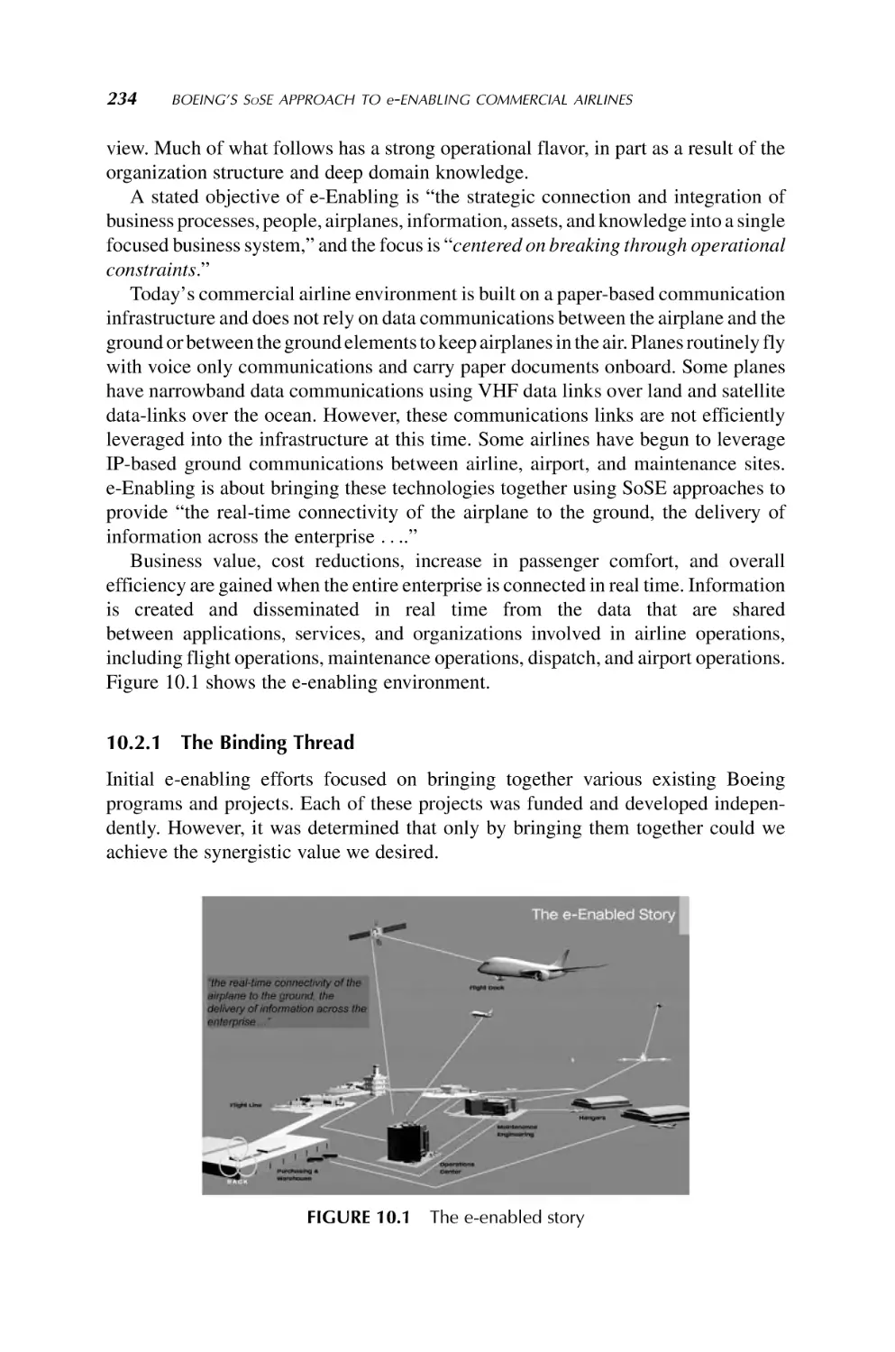
10. Boeing’s SoSE Approach to e-Enabling Commercial Airlines
232
George F. Wilber
vii
viii
CONTENTS
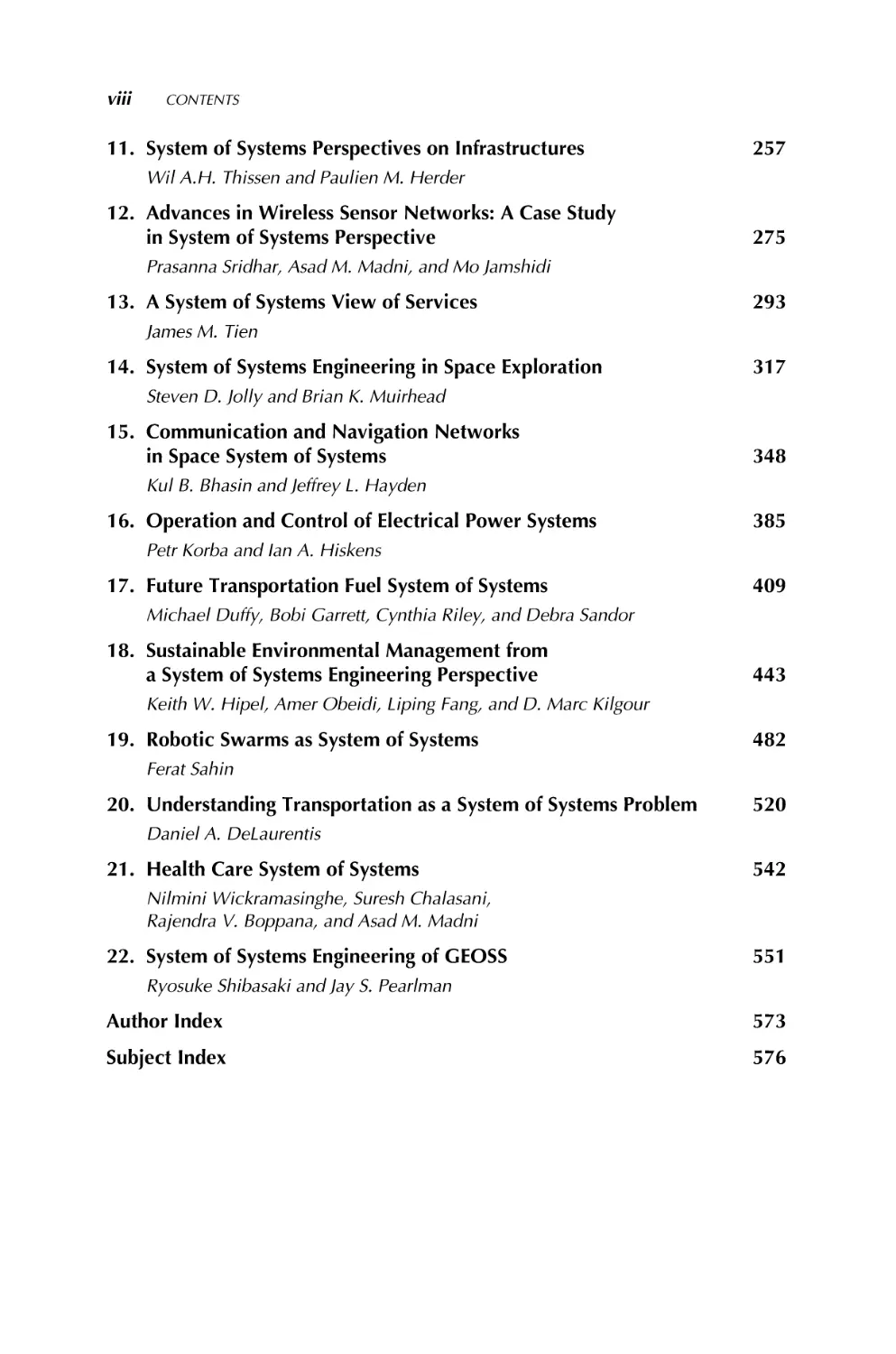
11. System of Systems Perspectives on Infrastructures
257
Wil A.H. Thissen and Paulien M. Herder
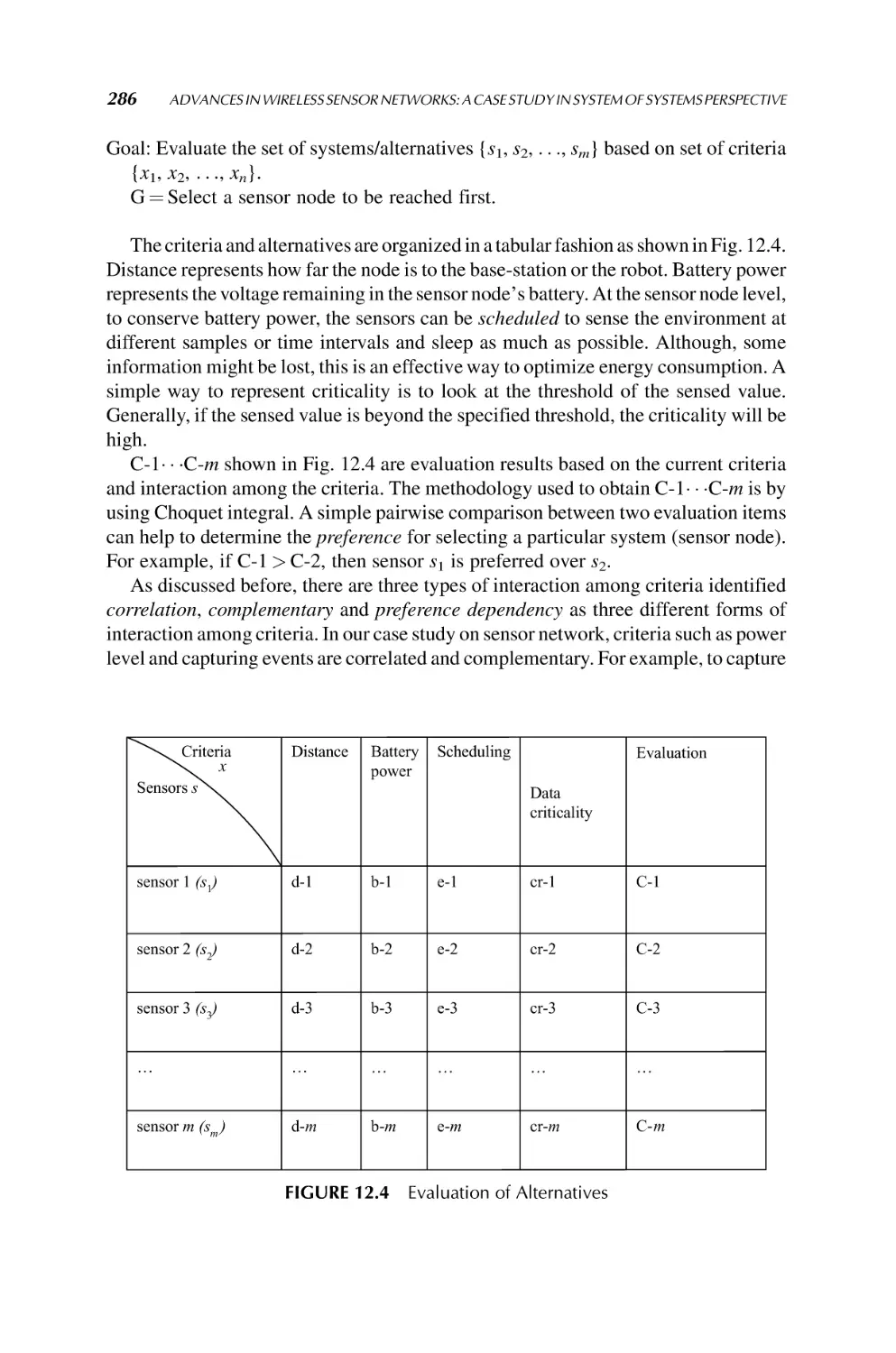
12. Advances in Wireless Sensor Networks: A Case Study
in System of Systems Perspective
275
Prasanna Sridhar, Asad M. Madni, and Mo Jamshidi
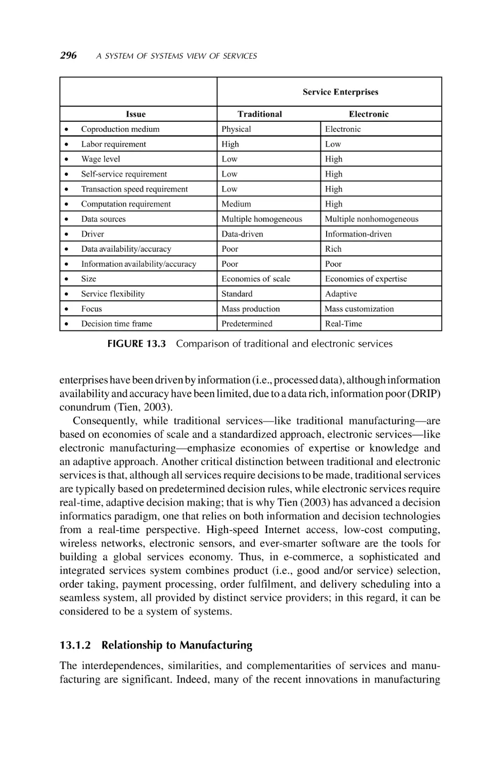
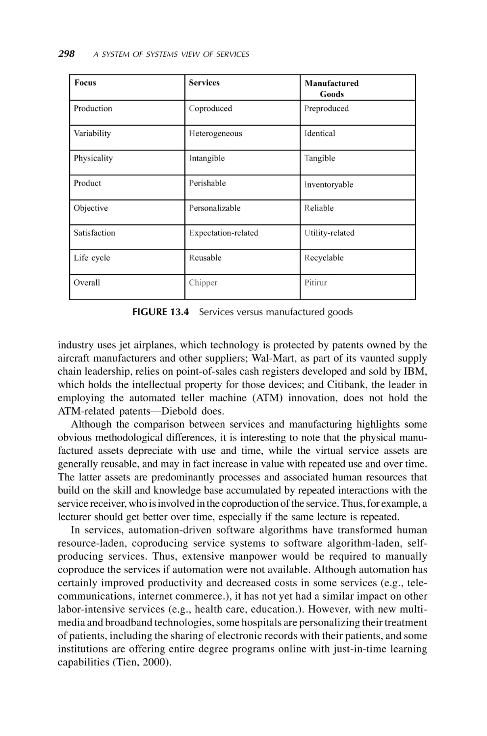
13. A System of Systems View of Services
293
James M. Tien
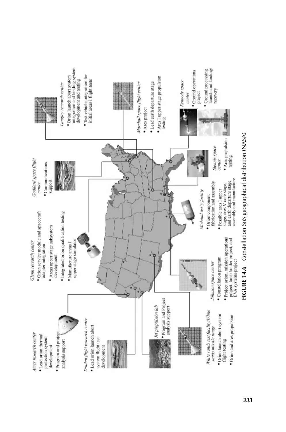
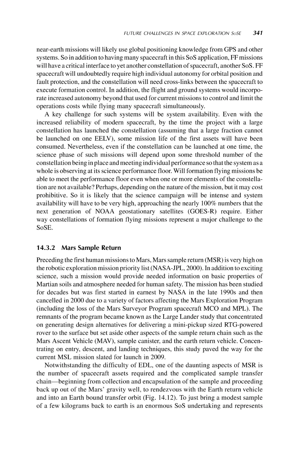
14. System of Systems Engineering in Space Exploration
317
Steven D. Jolly and Brian K. Muirhead
15. Communication and Navigation Networks
in Space System of Systems
348
Kul B. Bhasin and Jeffrey L. Hayden
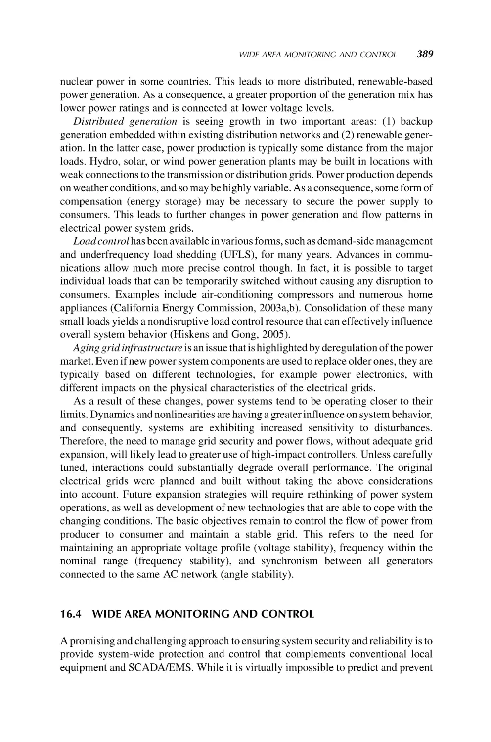
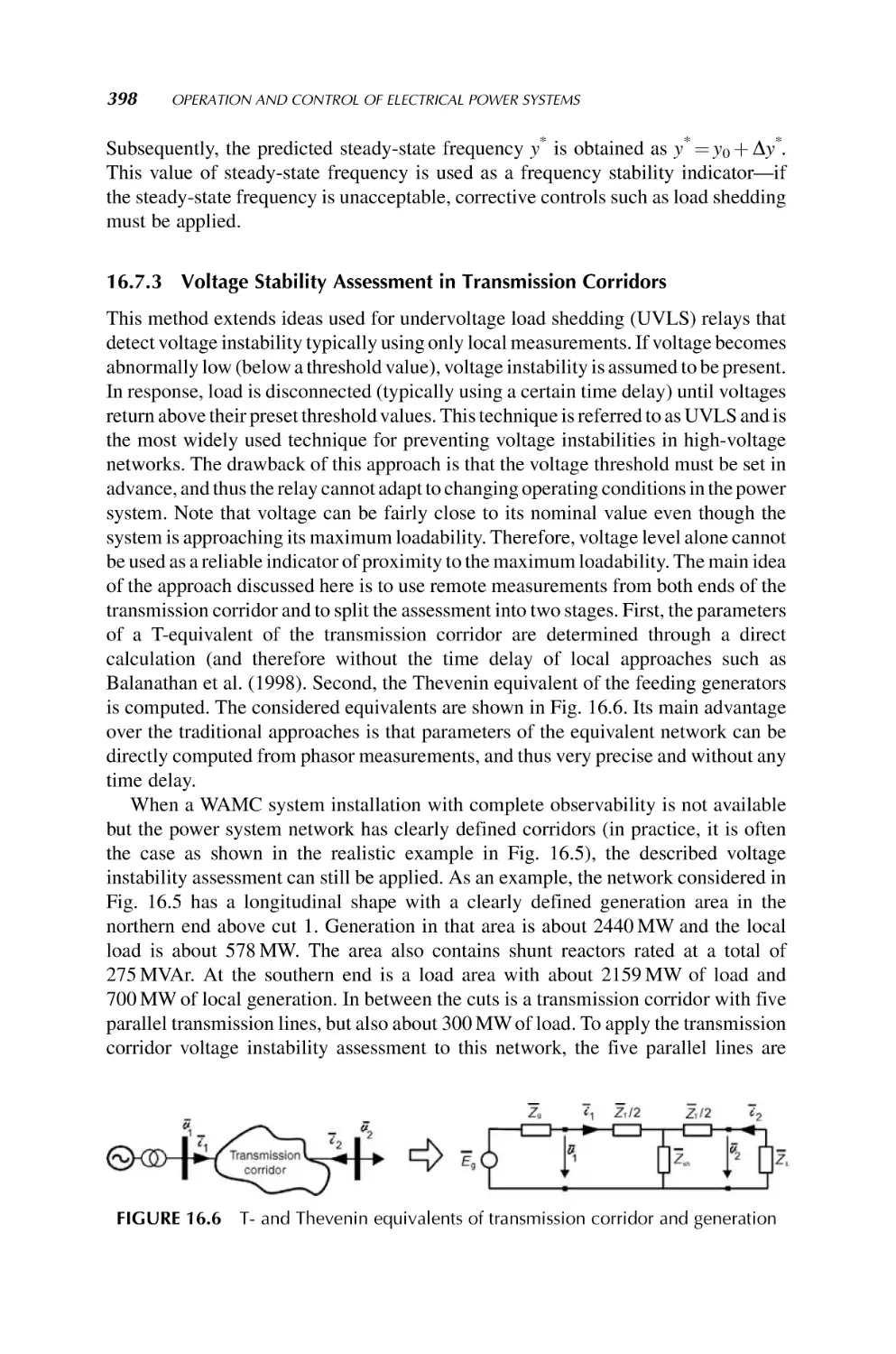
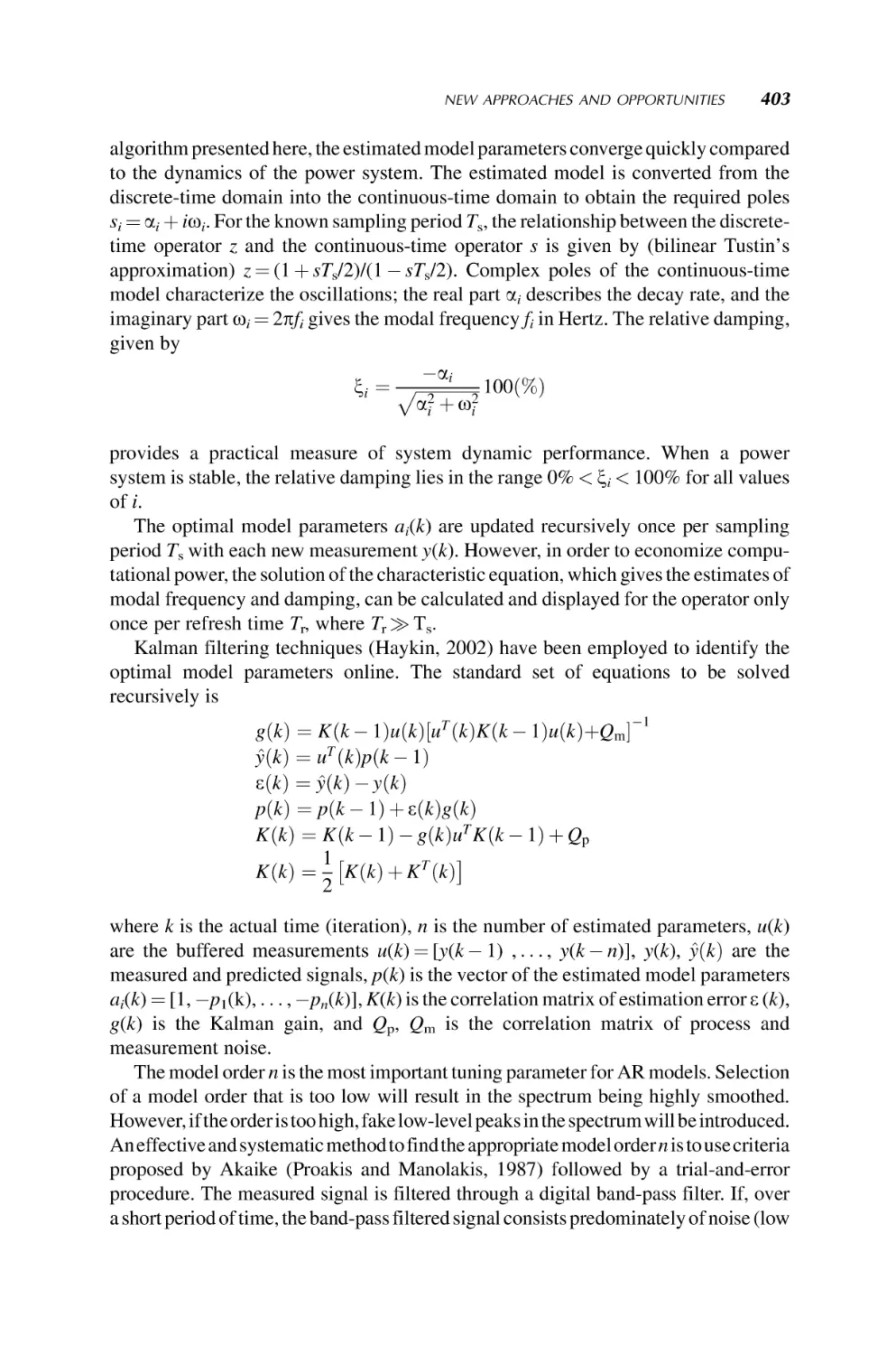
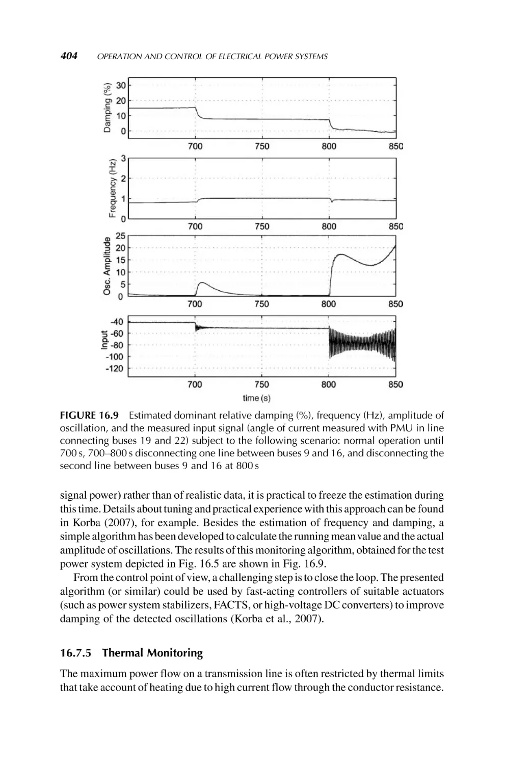
16. Operation and Control of Electrical Power Systems
385
Petr Korba and Ian A. Hiskens
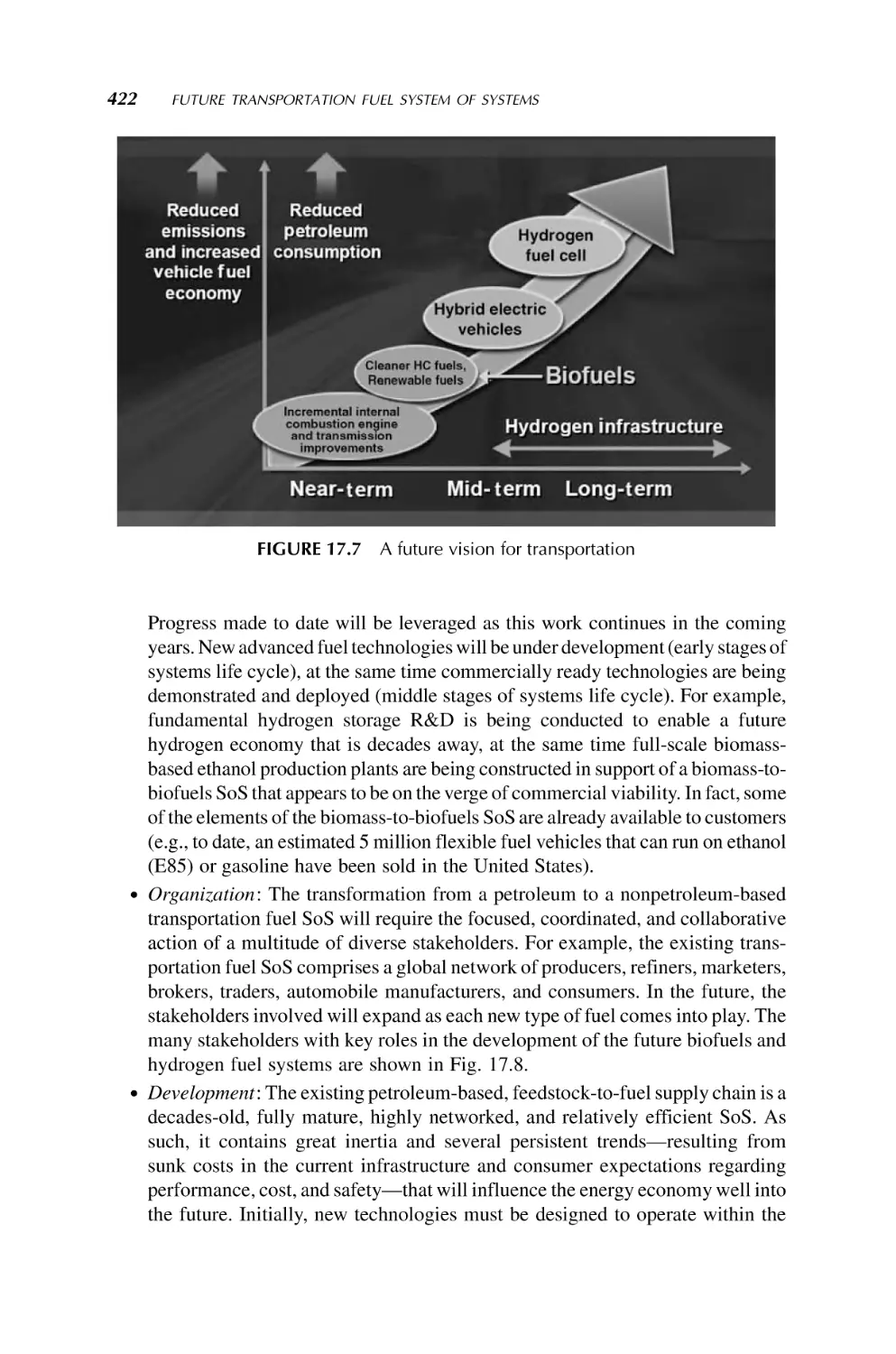
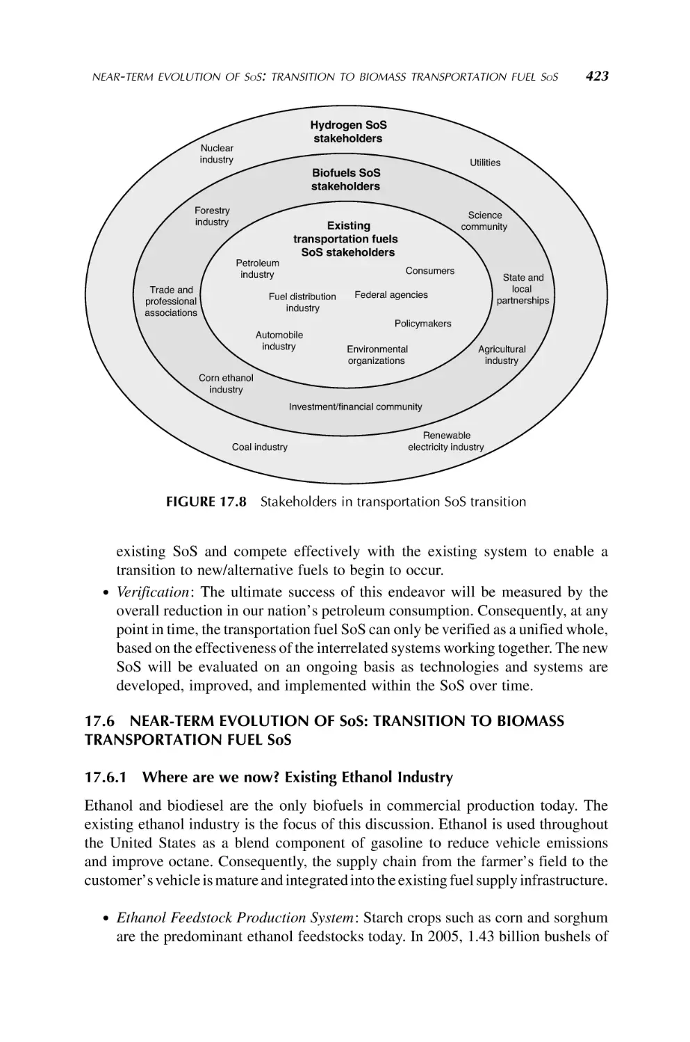
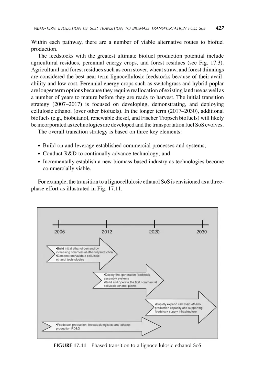
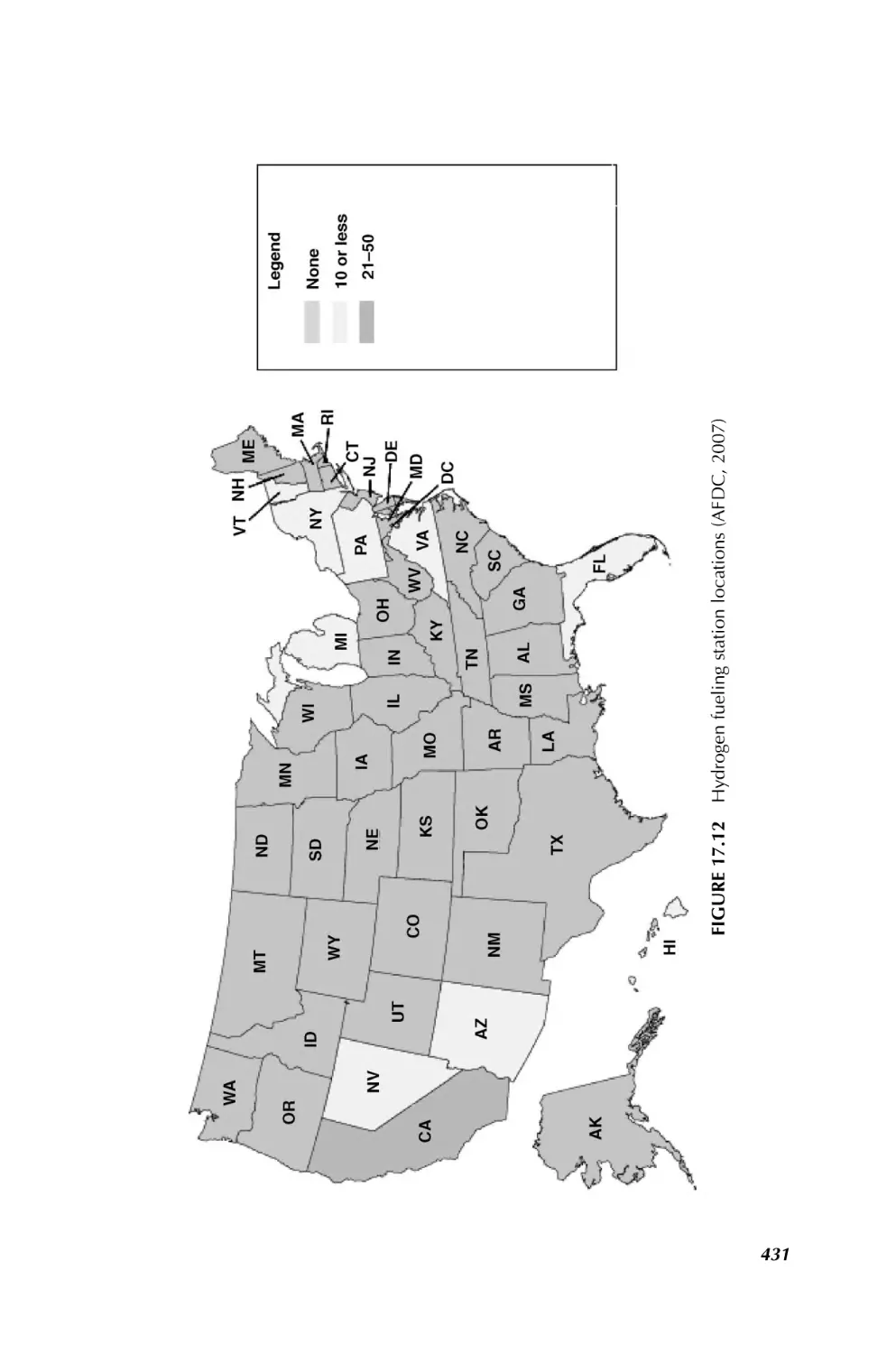
17. Future Transportation Fuel System of Systems
409
Michael Duffy, Bobi Garrett, Cynthia Riley, and Debra Sandor
18. Sustainable Environmental Management from
a System of Systems Engineering Perspective
443
Keith W. Hipel, Amer Obeidi, Liping Fang, and D. Marc Kilgour
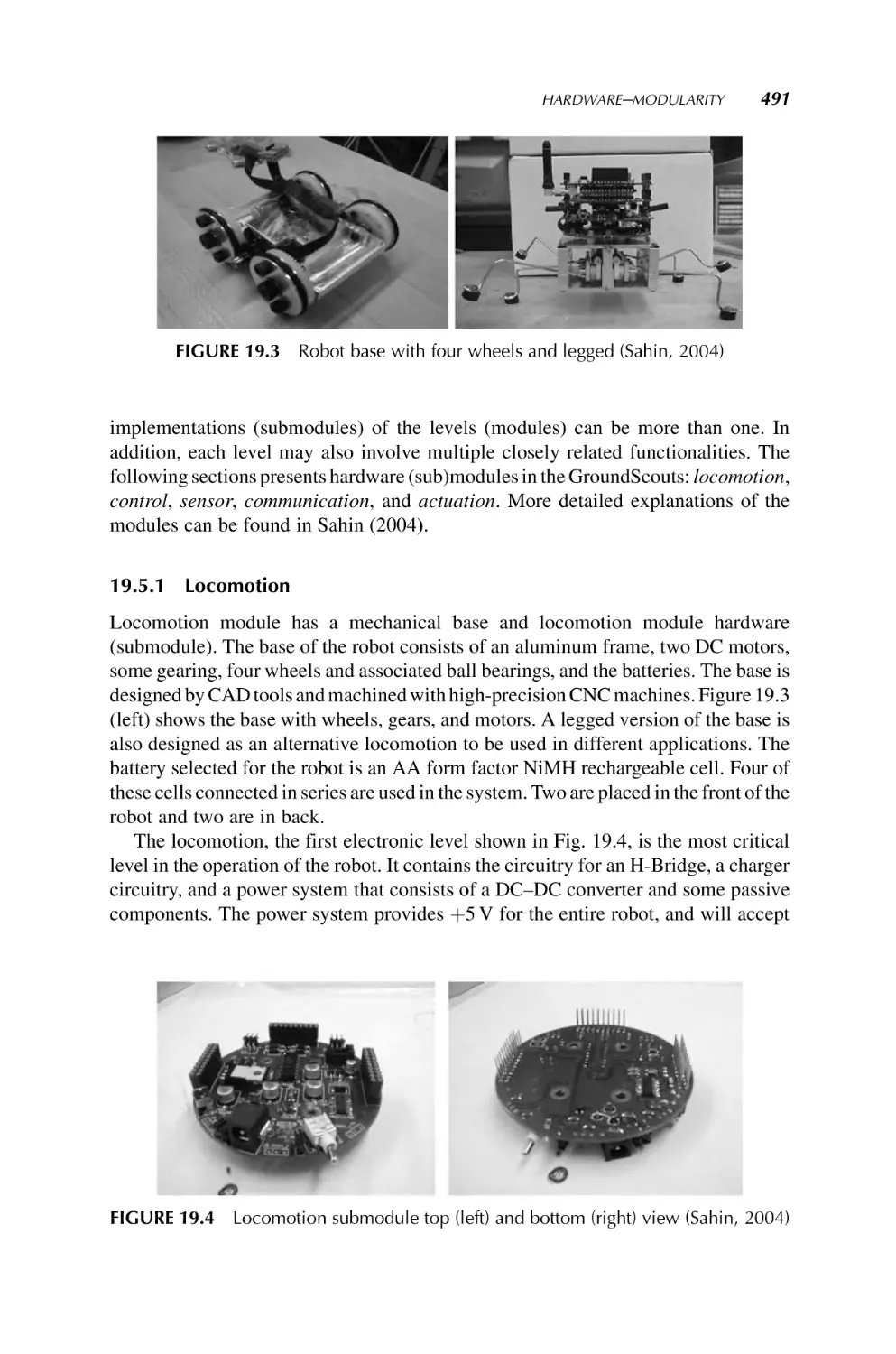
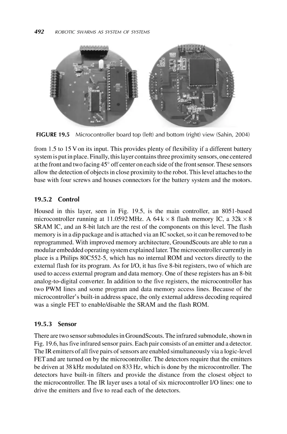
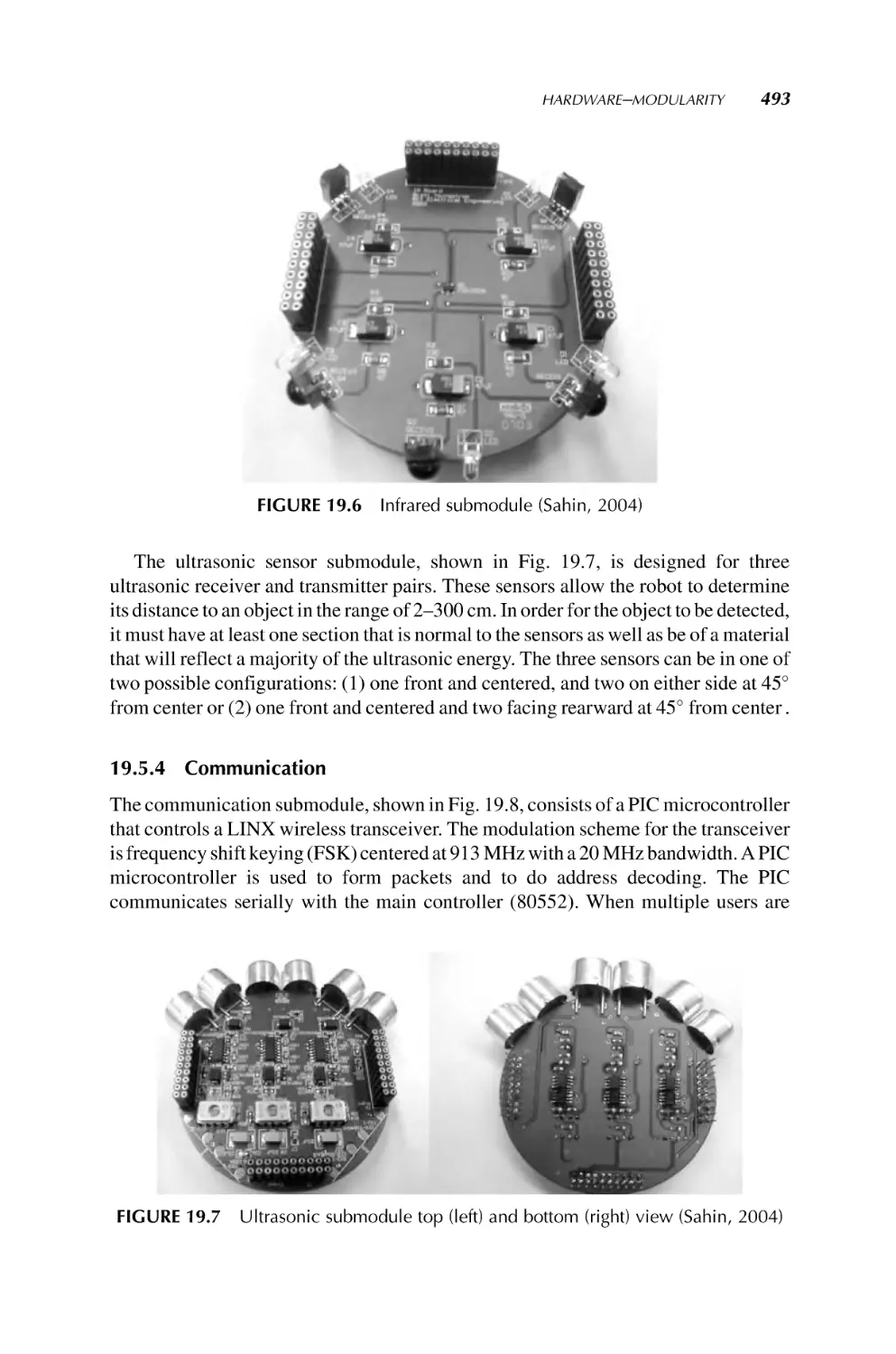
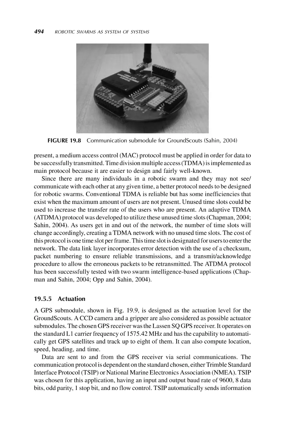
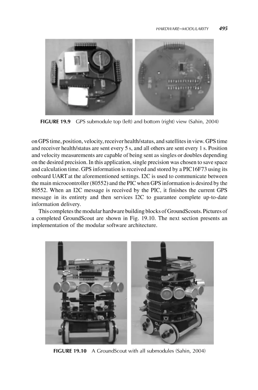
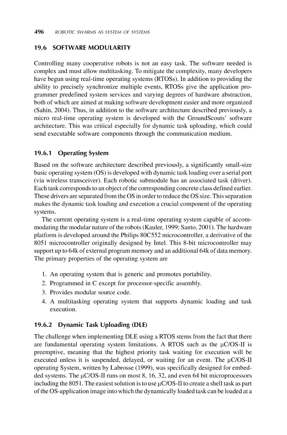
19. Robotic Swarms as System of Systems
482
Ferat Sahin
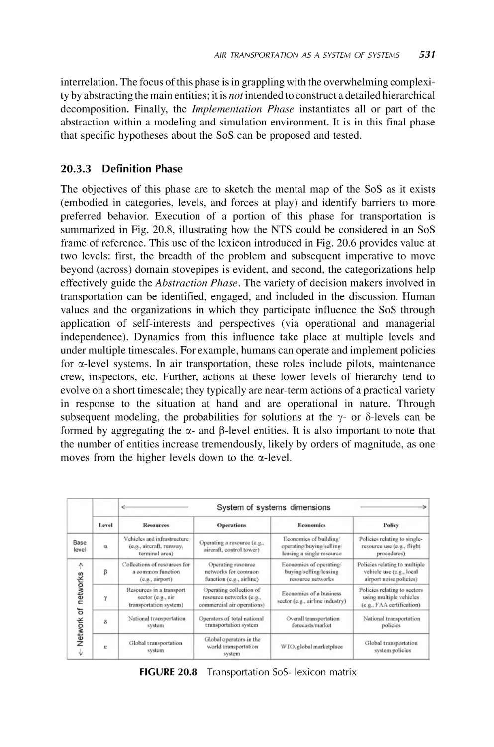
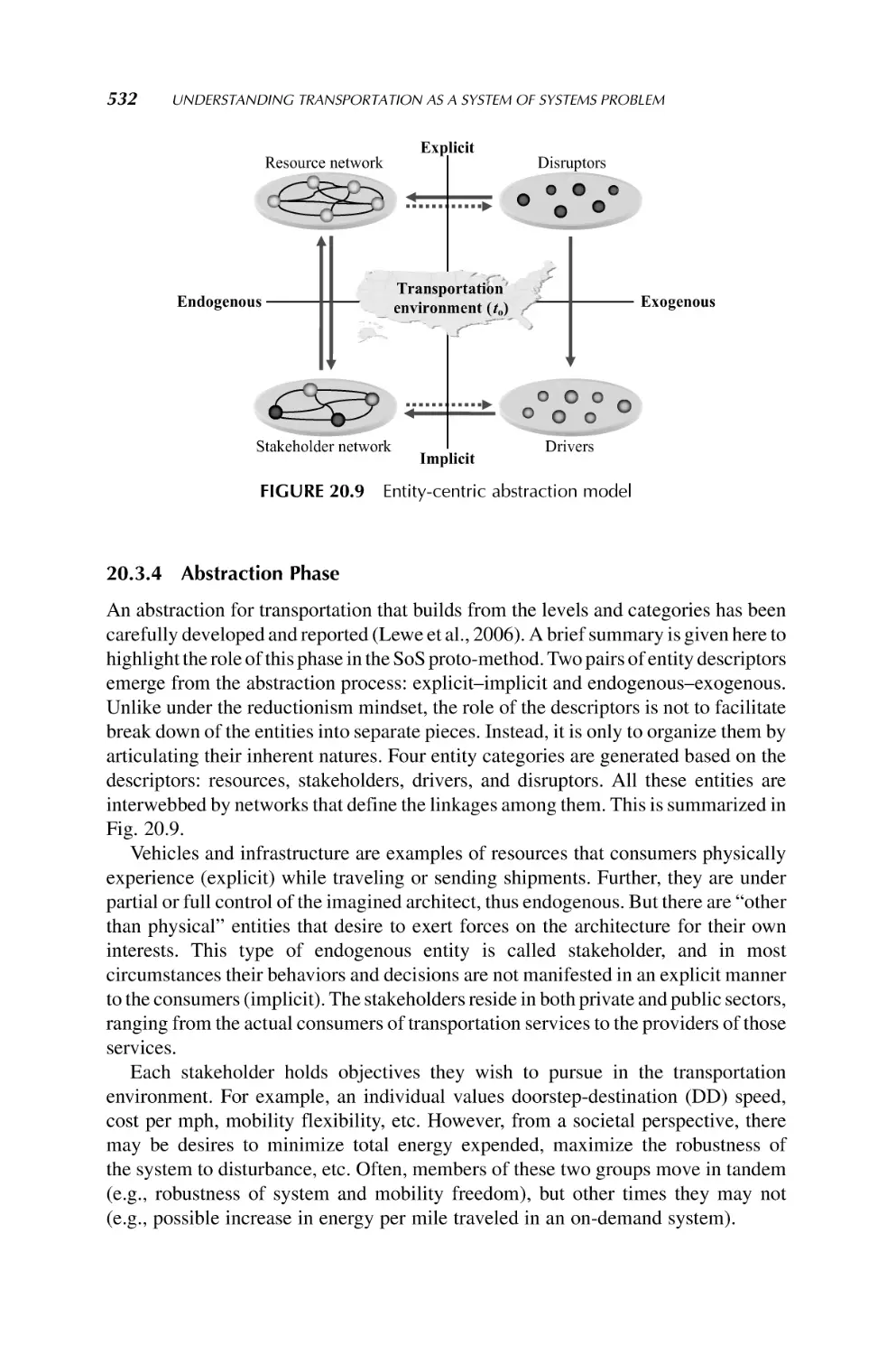
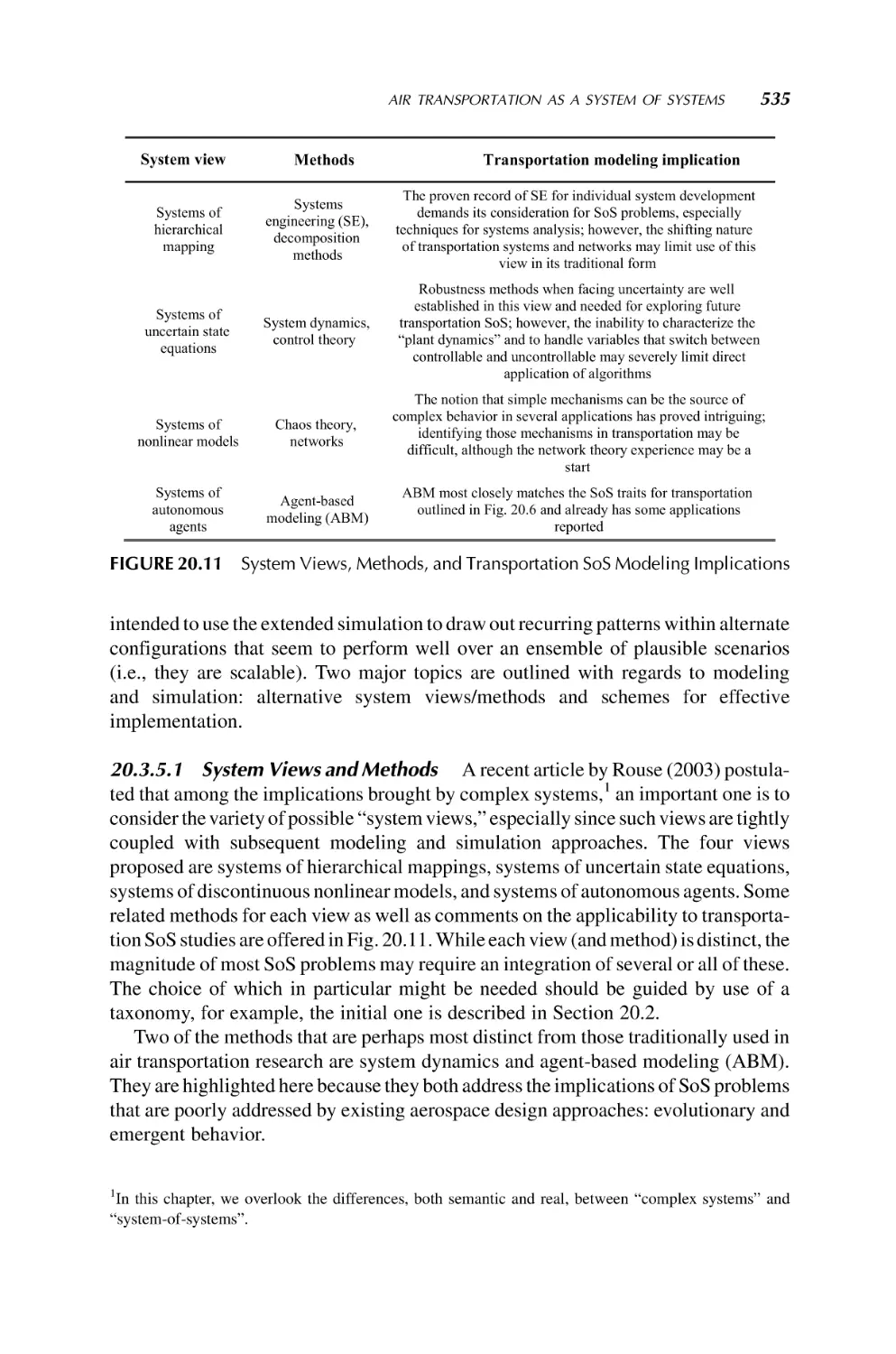
20. Understanding Transportation as a System of Systems Problem
520
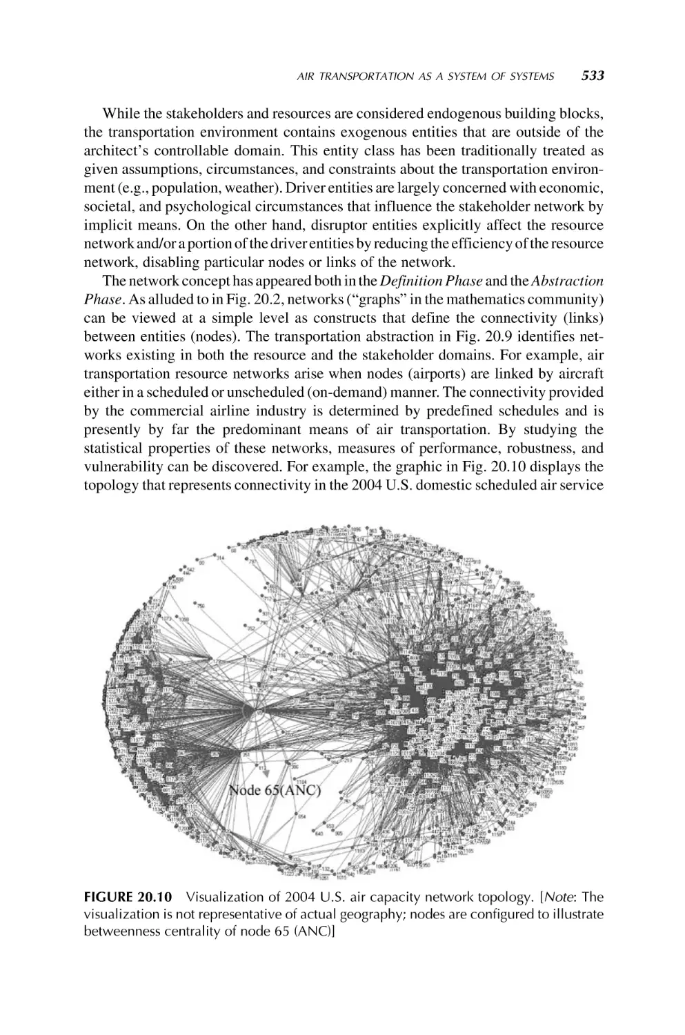
Daniel A. DeLaurentis
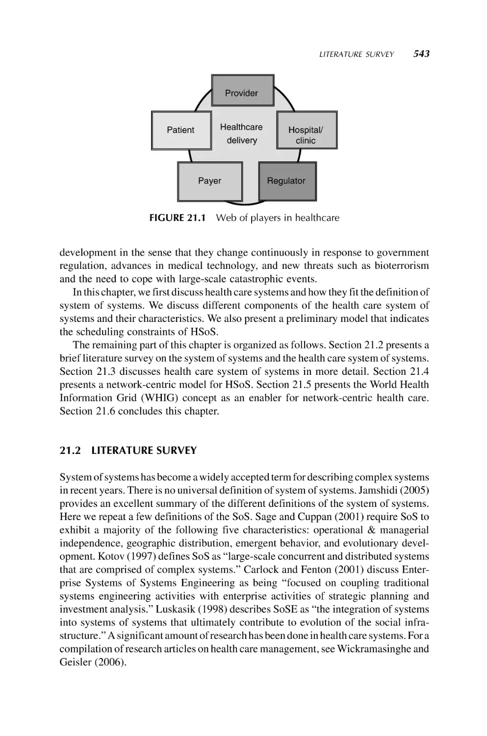
21. Health Care System of Systems
542
Nilmini Wickramasinghe, Suresh Chalasani,
Rajendra V. Boppana, and Asad M. Madni
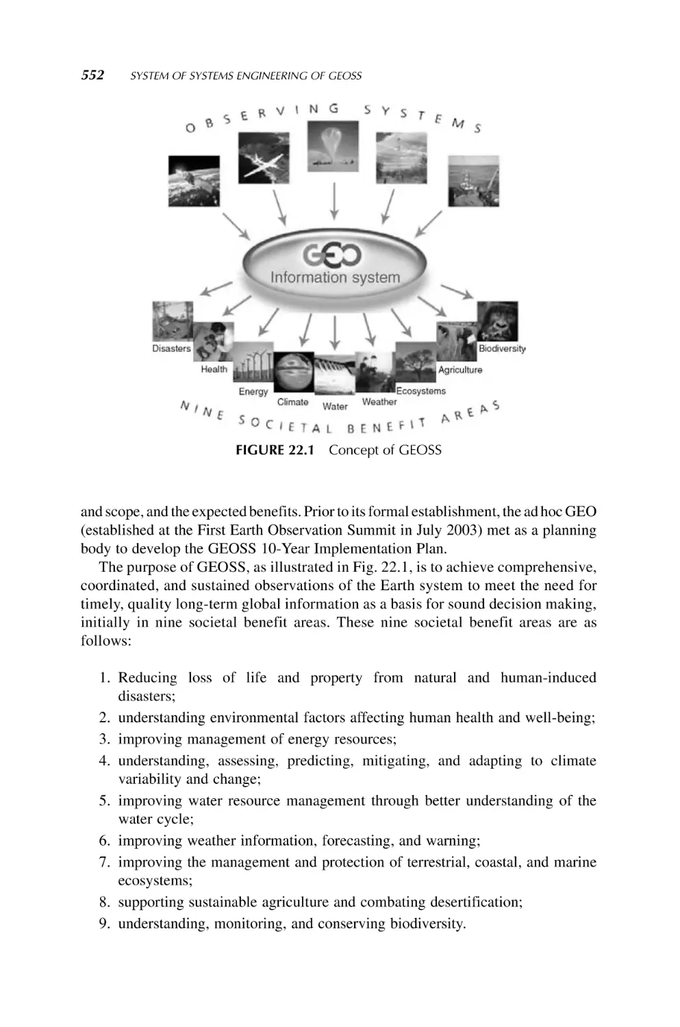
22. System of Systems Engineering of GEOSS
551
Ryosuke Shibasaki and Jay S. Pearlman
Author Index
573
Subject Index
576
Preface
In the twenty-first century, information science and technology continues to be critical
benefactors of systems engineering that continue to redefine the design problem in
industry, energy, defense, security, environment, and so on. Systems engineering is
currently undergoing a major change to extend itself beyond a single system
framework. Recently, there has been a growing interest in a class of complex systems
whose constituents are themselves complex. These systems are sometimes called
system of systems (SoS) or federation of systems (FoS). Performance optimization,
robustness, and reliability among an emerging group of heterogeneous systems in
order to realize a common goal have become the focus of various applications
including military, security, aerospace, space, manufacturing, service industry, environmental systems, and disaster management, to name a few. There is an increasing
interest in achieving synergy between these independent systems to achieve the
desired overall system performance. Critical issues that deserve attention are coordination and interoperability in an SoS. SoS technology is believed to more effectively
implement and analyze large, complex, independent, and heterogeneous systems
working (or made to work) cooperatively. The main thrust behind the desire to view the
systems as an SoS is to obtain higher capabilities and performance than would be
possible with a traditional system view. The SoS concept presents a high-level
viewpoint and explains the interactions between each of the independent systems.
However, when it comes to engineering and engineering tools of SoS, we have a long
way to go. This is the main goal of this volume. Here, we have put together 22 chapters,
8 on such fundamental issues as openness, engineering, architecture, modeling,
simulation, net centricity (integration), emergence, technical evaluation, and management of SoS. In addition, a set of chapters indicative of the state of the art in current
or potential applications of the technology of SoS such as defense, services, commercial airlines, transportation systems, health care, space exploration, space communication, global earth oberservation, robotics, infrastructures, electric power systems,
microgrid systems, and environmental impacts are all included. Experts from all over
the globe have been recruited to contribute to it. The structure of the book is as follows:
Chapter 1 is a brief introduction, and Chapters 2–8 examine the fundamental issue of
systems engineering as outlined from SoS point of view. Application areas are covered
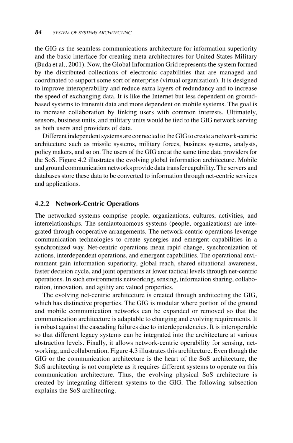
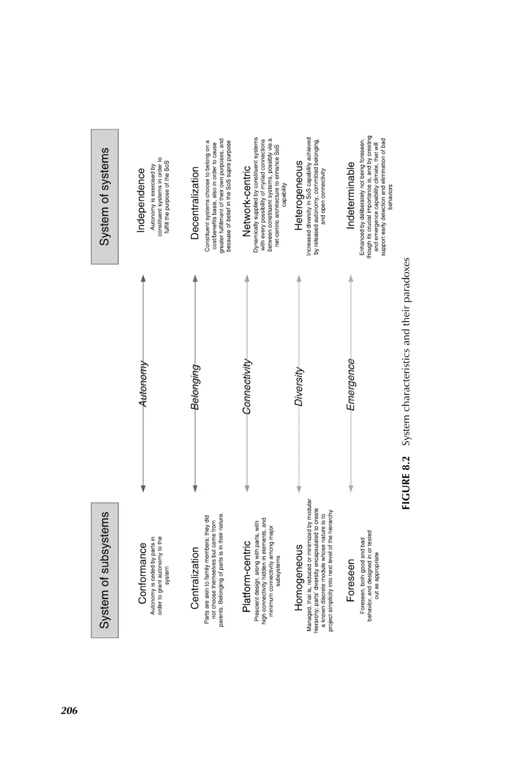
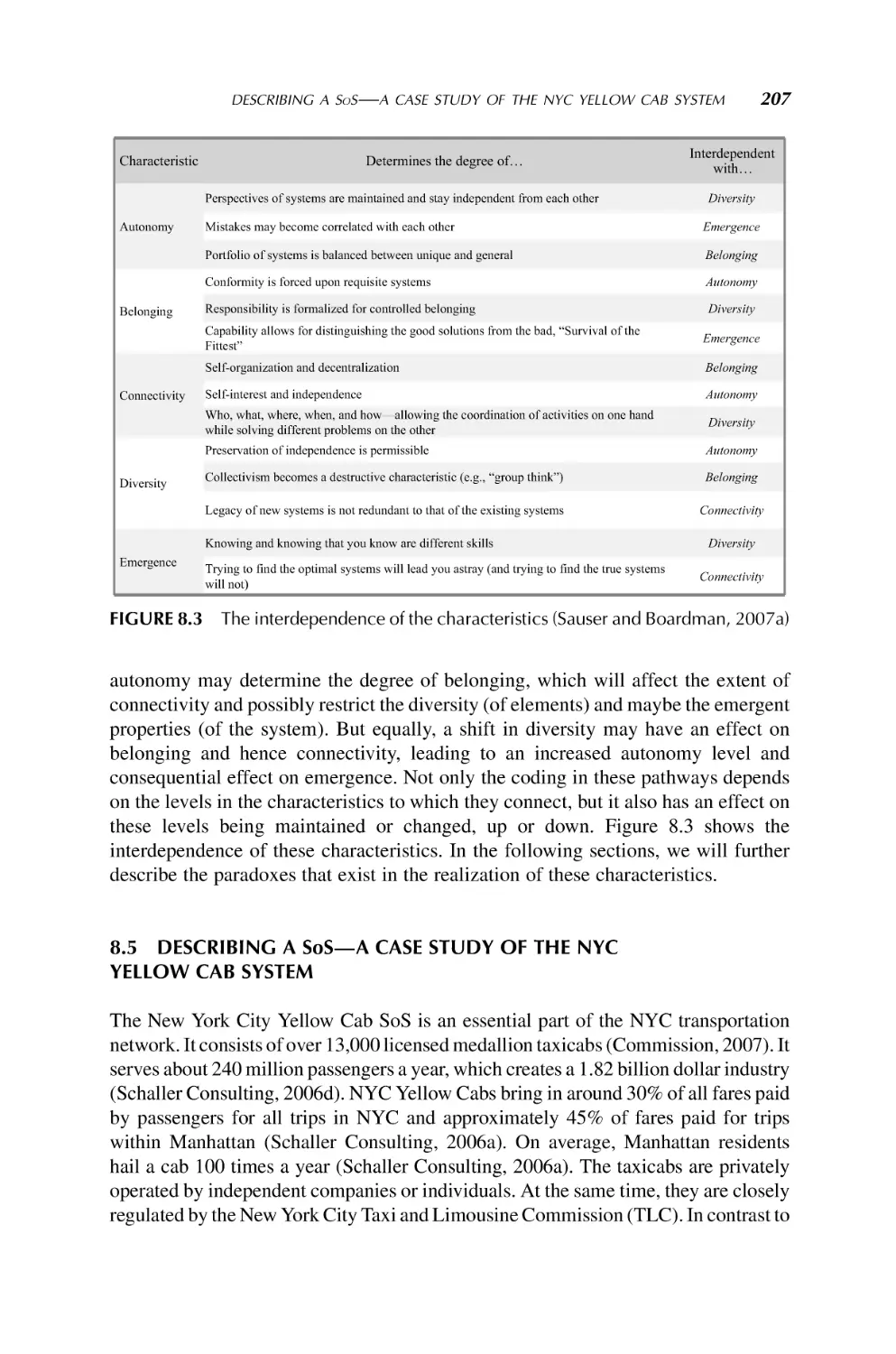
in Chapters 8–22.
ix
x
PREFACE
This volume in the Wiley Series on System Engineering and Management would
not have been possible without the diligent work and support of the contributing
authors from industry, academia, The United States, Japan, the Netherlands, Canada,
and so on. The editor thanks all of them for their contributions to SoS technology and to
this volume. I wish to express my sincere appreciation and thanks to Professor Andrew
P. Sage, Series Editor and an author of Chapter 3, for his encouragement to make this
volume a reality. I wish to thank him, among 10 other mentors, to whom I have
dedicated this volume—from my days at Oregon State University (1963–1967) to
University of Illinois at Urbana-Champaign (1967–1971) to the formation of my
professional career after I finished my systems and control education. Last, but by no
means least, I wish to thank my dear wife, Jila Salari Jamshid, for her continuous love
and support in all that I have undertaken in 34 years of companionship.
MO JAMSHIDI
San Antonio, Texas, USA
May 10, 2008
About the Editor
Mo M. Jamshidi (Fellow IEEE, Fellow ASME, Associate Fellow AIAA, Fellow
AAAS, Fellow TWAS, Fellow NYAS) received a B.S. in Electrical Engineering from
Oregon State University in June 1967 and the M.S and the Ph.D. degree in Electrical
Engineering from the University of Illinois at Urbana-Champaign in February 1971.
He holds three honorary doctorate degrees from Azerbaijan National University,
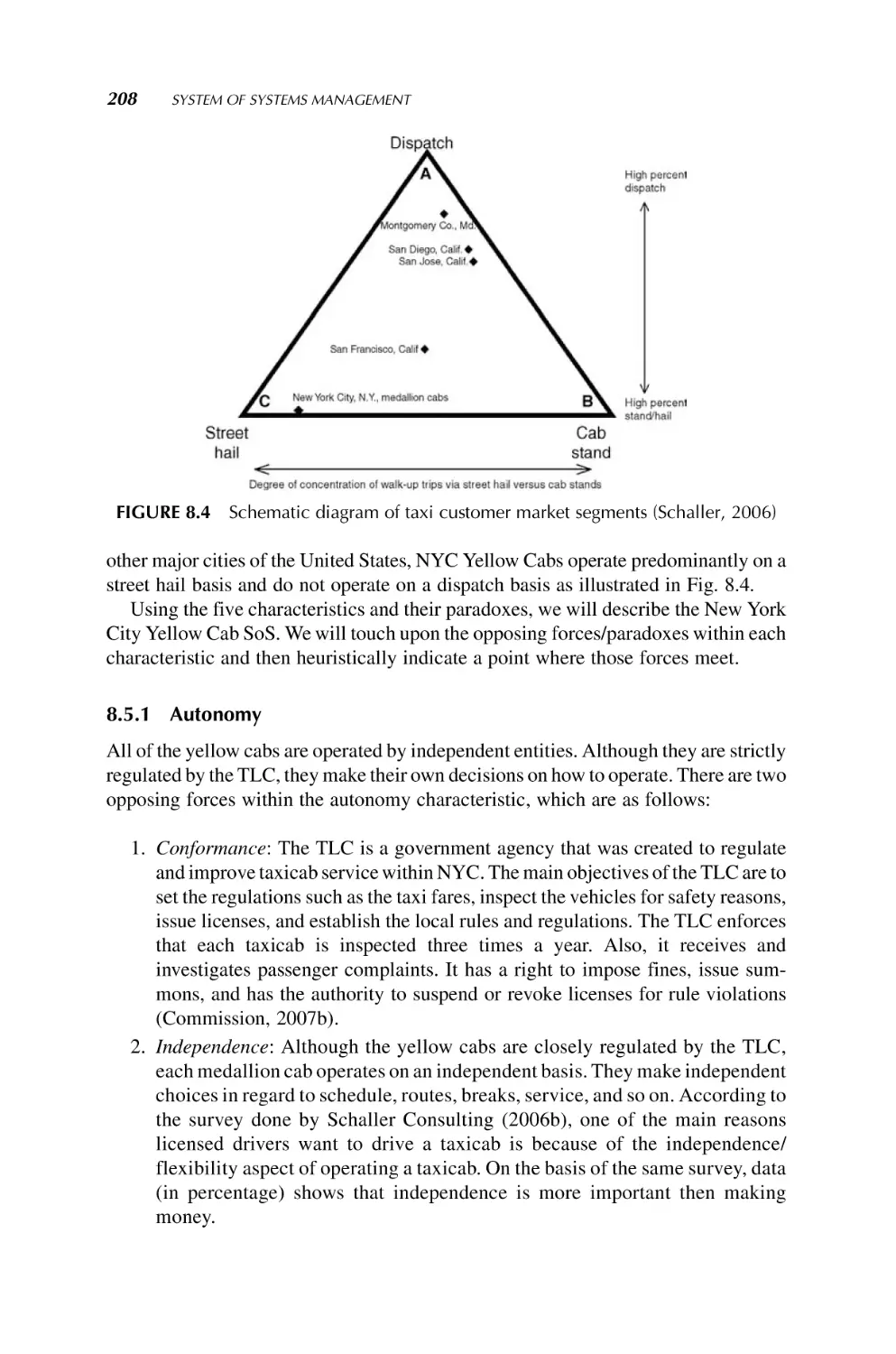
Baku, Azerbaijan, 1999, University of Waterloo, Canada and Technical University of
Crete, Greece, both in 2004. Currently, he is Lutcher Brown Endowed Chaired
Professor at the University of Texas, San Antonio, TX, USA. He is also the Regents
Professor Emeritus of Electrical and Computer Engineering, the AT&T Professor of
Manufacturing Engineering, and founding Director of the Center for Autonomous
Control Engineering (ACE) at the University of New Mexico, Albuquerque, NM,
USA. He has been a consultant and special government employee with the U.S.
Department of Energy, NASA Headquarters and Jet Propulsion Laboratory, and the
U.S. Air Force Research Laboratory for a combined 25-year period. He has worked
in various academic and industrial positions at various national and international
locations including with IBM and GM Corporations. In 1999, he was a NATO
Distinguished Professor in Portugal conducting lectures on intelligent systems and
control. He has over 600 technical publications including 63 books (12 textbooks) and
edited volumes. Six of his books have been translated into at least one foreign
language. He is the founding editor or cofounding editor or editor-in-chief of
many journals (including Elsevier’s International Journal of Computers and Electrical Engineering Elsevier, UK, Intelligent Automation and Soft Computing, TSI Press,
USA) and one magazine (IEEE Control Systems Magazine). He is editor-in-chief of the
new IEEE Systems Journal (inaugurated in 2007) and coeditor-in-chief of the
International Journal on Control and Automation. He has been the General Chairman
of the World Automation Congress (WAC, wacong.org) from its inception. He has
been active within the IEEE for 42 years. Dr. Jamshidi is a Fellow of the IEEE for
contributions to ‘‘large-scale systems theory and applications and engineering education,” a Fellow of the ASME for contributions to ‘‘control of robotic and manufacturing systems,” Fellow of the AAAS—the American Association for the Advancement
of Science for contributions to ‘‘complex large-scale systems and their applications to
controls and optimization,” a Fellow of Academy of Developing Nations (Trieste,
Italy), Member of the Russian Academy of Nonlinear Sciences, Associate Fellow,
xi
xii
ABOUT THE EDITOR
Hungarian Academy of Engineering, a Fellow of the New York Academy of Sciences,
and recipient of the IEEE Centennial Medal and IEEE Control Systems Society
Distinguished Member Award and the IEEE CSS Millennium Award. In October
2005, he was awarded the IEEE SMC Society’s Norbert Weiner Research Achievement Award and in October 2006, he received the IEEE SMC Society Outstanding
Contribution Award. As an OSU Alumni, he was inducted into Oregon State University’s Academy of Distinguished Engineers in February 2007. He is the founding
Chair and Chair of the IEEE International Conference on System of Systems
Engineering since 2006–2009.
Contributors
Cyrus Azani is a Senior Systems Engineer at Northrop Grumman Corporation and an
Adjunct Professor at University of Maryland, MD, USA. His areas of research are
system of systems engineering, architecture, and assessment; open architecture
strategy, implementation and assessment; and multicriteria decision-making models
and approaches.
Kul B. Bhasin leads the architecture development team for NASA’s SCaN-Constellation Integration Project at NASA Glenn Research Center in Cleveland, OH, USA. He
develops communication network architectures within a system of systems environment for the upcoming exploration missions of NASA.
John Boardman graduated with 1st Class Honors in Electrical Engineering from the
University of Liverpool, from where he also obtained his PhD. He is currently a
Distinguished Service Professor in the School of Systems and Enterprises at Stevens
Institute of Technology. Before coming to Stevens Institute of Technology he held
positions at the University of Portsmouth as the GEC Marconi Professor of Systems
Engineering and Director of the School of Systems Engineering and later Dean of the
College of Technology. He is a Chartered Engineer and Fellow of the Institute of
Engineering and Technology and the International Council on Systems Engineering
(INCOSE).
Rajendra V. Boppana is a Professor of Computer Science at the University of Texas at
San Antonio, TX, USA. His research interests include wireless and sensor networks,
secure routing and intrusion detection techniques, and autonomic computing and
communications.
Suresh Chalasani is an Associate Professor and the Chair of the Business Department
at the University of Wisconsin-Parkside, WI, USA. His research interests include
supply chain management, health care management, and emerging technologies.
Robert J. Cloutier is a Research Associate Professor in the School of Systems and
Enterprises at Stevens Institute of Technology Hoboken, NJ, USA. His research
interests include model-based systems engineering and systems architecting, reference architectures, systems engineering patterns, and model-driven architecture. Rob
has over 20 year’s experience in systems engineering and architecting software
engineering, and project management in both commercial and defense industries.
xiii
xiv
CONTRIBUTORS
Cihan H. Dagli, Cihan Dagli is Professor of Systems Engineering and Engineering
Management and also a Professor Computer and Electrical Engineering, Missouri
University of Science & Technology, USA. Dr. Dagli is also the Intelligent Systems
Design Area Editor for the International Journal of General Systems and the director
of the Smart Engineering Systems Lab (SESL) at the Missouri S&T. He received B.S.
and M.S. degrees in Industrial Engineering from the Middle East Technical University
and a Ph.D. Applied Operations Research in Large Scale Systems Design and
Operation from the University of Birmingham, UK.
Judith S. Dahmann, Ph.D., is a principal Senior Scientist in the MITRE Corporation
Center for Acquisition and Systems. Prior to this, Dr. Dahmann was Chief Scientist for
the Defense Modeling and Simulation Office for the U.S. DoD, where she led the
development of the High-Level Architecture for simulations, now IEEE 1516.
Dr. Dahmann holds a B.A. from Chatham with a year as a special student at Dartmouth
College, an M.A. from The University of Chicago, and a Ph.D. from Johns Hopkins
University.
Daniel A. DeLaurentis is an Assistant Professor of Aeronautics and Astronautics at
Purdue University, joining the University in 2004 under the System of Systems Signature
Area. His areas of interests are system of systems modeling and analysis methodologies
and advanced design techniques applied to air and space transportation systems.
Michael J. DiMario, as a Senior Program Manager at Lockheed Martin, manages
System of Systems Command and Control programs and is a Ph.D. candidate in the
School of Systems and Enterprises at Stevens Institute of Technology. His research
interests include system of systems and interoperability of complex systems. Michael has
over 25 years of experience in managing and engineering systems and software programs.
Michael Duffy, Ph.D., is the Lead Systems Engineer for the U.S. Department of
Energy Hydrogen Program at the National Renewable Energy Laboratory. He has over
35 years of systems engineering experience in energy, safeguards and security, nuclear
waste management, national defense, transportation, and space programs.
Liping Fang is a Professor and Chair of Mechanical and Industrial Engineering at
Ryerson University, Toronto, Canada. His research interests are systems engineering,
industrial engineering, multiple participant-multiple objective decision making, and
decision support systems.
Bobi Garrett is the Associate Director for Strategic Development and Analysis at the
National Renewable Energy Laboratory. She has 29 years of technical leadership
experience, focused on advancing new technologies in the energy, environmental,
defense, and health care sectors.
Alex Gorod received a B.S. in Information Systems and a M.S. in Telecommunications from Pace University. Prior to his graduate studies he held a Research Analyst
position at Salomon Smith Barney. He is currently a Robert Crooks Stanley Doctoral
Fellow in Engineering Management at Stevens Institute of Technology, with
research interests in the area of management of complex systems. He is also the
Vice President of the Stevens Student Chapter of the International Council on
Systems Engineering (INCOSE).
CONTRIBUTORS
xv
Jeffery L. Hayden is a Space Systems Engineer and Communication Architecture
Consultant for NASA and the DoD. His areas of interest include space communication
system of systems and network of networks architecture development, space communication network design tools and databases, spacecraft design, exploration
mission concepts of operation, and scientific instrument design.
Paulien M. Herder is an Associate Professor and holds an M.Sc. degree in chemical
engineering (1994) and a Ph.D. degree in systems engineering (1999), both from Delft
University of Technology. She works at the faculty of Technology, Policy, and
Management and is coleader of the ‘‘Flexible Infrastructures” subprogramme within
the Next Generation Infrastructures (NGInfra) programme. Her research focuses on
design of large-scale networked systems.
Keith W. Hipel is a University Professor of Systems Design Engineering at the
University of Waterloo in Canada. His research interests are the development of
conflict resolution, multiple objective decision making, and time series analysis
techniques, with applications in water resources management, hydrology, environmental engineering, and sustainable development.
Ian A. Hiskens is a Professor of Electrical and Computer Engineering at the University
of Wisconsin-Madison WI, USA. His major research interests lie in the area of power
system analysis, in particular system dynamics, security, and numerical techniques.
Other research interests include nonlinear and hybrid dynamical systems, and control.
Mo Jamshidi is the Lutcher Brown Endowed Chaired Professor of Electrical and
Computer Engineering, University of Texas, San Antonio, TX, USA. His areas of
interests are system of systems simulation, architecture, and control with application
to land, sea, and air rovers.
Steve D. Jolly is a Senior Systems Engineer with Lockheed Martin Space Systems and
has worked many deep space missions including Mars 98, Mars Odyssey, and Mars
Reconnaissance Orbiter. More recently, he is supporting the Orion Program (Crew
Exploration Vehicle), the Geostationary Environmental Operational Satellite Program
(GOES-R), and the Mars Science Laboratory (MSL) Program. He is also instrumental
in the development of a three-course graduate series in systems engineering at the
University of Colorado, Denver, CO, USA.
Charles B. Keating is a Professor of Engineering Management and Systems
Engineering and Director, National Centers for System of Systems Engineering at
Old Dominion University in Norfolk, VA, USA. His research interests include system
of systems engineering, complex systems exploration methodologies, and R&D
systems management.
D. Marc Kilgour is a Professor of Mathematics at Wilfrid Laurier University,
Research Director: Conflict Analysis for the Laurier Centre for Military Strategic
and Disarmament Studies, and Adjunct Professor of Systems Engineering at the University of Waterloo. His main research interest is optimal decision making in multidecision maker and multicriteria contexts, including deterrence and counterterrorism,
power sharing, fair division, voting, negotiation, and infrastructure management.
xvi
CONTRIBUTORS
Nil Kilicay-Ergin is a Postdoctoral Research Fellow in Systems Engineering at the
Missouri University of Science & Technology (Missouri S&T). She received her
Ph.D. degree in Systems Engineering from the University of Missouri-Rolla. Her
research interests are analysis of system of systems, complex adaptive systems,
artificial life, and financial markets.
Petr Korba, Ph.D., is a Principal Scientist in the field of power and control systems at
ABB Corporate Research Ltd., Baden, Switzerland. His areas of interest include
robust and adaptive control, model identification and parameter estimation techniques, and their applications to power systems.
Asad M. Madni is Retired President and Chief Operating Officer of BEI Technologies
Inc., and is currently the Executive Managing Director and Chief Technology Officer of
Crocker Capital, San Francisco, CA, USA. His areas of interest are wireless sensor
networks, miniaturized ‘‘intelligent” sensors and systems, and signal processing for
aerospace and defense, automotive and transportation, and industrial and commercial
applications.
Jose Luis Risco Martın is an Assistant Professor in Complutense University
of Madrid, Spain. He received his Ph.D. from Complutense University of Madrid
in 2004. His research interests are computational theory of modeling and simulation,
with emphasis on DEVS, dynamic memory management of embedded systems, and
net-centric computing.
Saurabh Mittal is the founder and CEO of Dunip Technologies, New Delhi, India.
Previously he worked as Research Assistant Professor at the Department of Electrical
and Computer Engineering at the University of Arizona, USA where he received his
Ph.D in 2007. His areas of interest include Web-based M&S using SOA, executable
architectures, Distributed Simulation, and System of Systems engineering using
DoDAF. He can be reached at saurabh.mittal@duniptechnologies.com
Brian K. Muirhead is the Program Systems Engineer for NASA’s Constellation
Program, Johnson Space Center, Houston, TX, USA. He is responsible for the program
architecture for the United States’ human exploration of the Moon and beyond.
Amer Obeidi is a Lecturer at the Department of Management Sciences, University of
Waterloo, Canada. His research interest is in the development of integrated systems of
decision and conflict models that incorporate emotions with complex levels of
perception and awareness, with applications in military and national security strategic
and tactical planning, as well as environmental and societal concerns.
Jay S. Pearlman, Ph.D. is a Chief Engineer of NCOC&EM at Boeing and is
Cochair of the GEO Architecture and Data Committee. His areas of interest are
system of systems architecture, ocean studies, and information systems. He is also
active in remote sensing sensors and applications and aerial observation.
Hans W. Polzer is a Lockheed Martin Fellow working for the Network Centric
Integration Department within the Advanced Concepts Division of the Lockheed
Martin Corporate Engineering and Technology organization. Hans conducts
CONTRIBUTORS
xvii
network-centric assessments of Lockheed Martin programs and pursuits and is the
Technical Lead for the corporation’s participation in the Network-Centric
Operations Industry Consortium (NCOIC). He is interested in measures of diversity
in perspectives, context, and scope across systems and the institutions that sponsor
them.
Cynthia Riley is the Lead Systems Integrator for the U.S. Department of Energy
Biomass Program at the National Renewable Energy Laboratory. She has over 30 years
of engineering experience in the energy and environmental industries, focused on
analysis and evaluation of emerging alternative energy technologies.
Andrew P. Sage received the BSEE degree from the Citadel, the SMEE degree from
MIT, and the Ph.D. from Purdue, the latter in 1960. He received honorary Doctor of
Engineering degrees from the University of Waterloo in 1987 and from Dalhousie
University in 1997. He has been a faculty member at the University of Arizona, the
University of Florida, and the Southern Methodist University. Following 10 years of
service at the University of Virginia, where he held a named professorship and was the
first chair of their systems engineering department, he became first American Bank
Professor of Information Technology and Engineering in 1984 at George Mason
University and the first Dean of the School of Information Technology and Engineering. In May 1996, he was elected Founding Dean Emeritus of the School and also
was appointed a University Professor. He is an elected Fellow of the Institute of
Electrical and Electronics Engineers, the American Association for the Advancement
of Science, and the International Council on Systems Engineering. He is editor of the
John Wiley textbook series on Systems Engineering and Management, the INCOSE
Wiley journal Systems Engineering, and coeditor of Information, Knowledge, and
Systems Management. He was elected to membership in the National Academy of
Engineering in 2004. His interests include systems engineering and management
efforts in a variety of application areas including systems integration and architecting,
reengineering, and industrial ecology and sustainable development.
Ferat Sahin is an Associate Professor of Electrical Engineering, Rochester Institute
of Technology, Rochester, NY, USA. His areas of interests are swarm robotics,
multiagent systems, system of systems simulation for autonomous rovers, and
MEMS-based microrobots.
Debra Sandor is the Lead Systems Engineer for the U.S. Department of Energy
Biomass Program at the National Renewable Energy Laboratory. She has 18 years of
experience in engineering and energy R&D focused on evaluating and reporting
advances in alternative transportation fuels and renewable energy technologies.
Brian Sauser holds a B.S. from Texas A&M University, a M.S. from Rutgers, The
State University of New Jersey, and a Ph.D. from Stevens Institute of Technology. He
is currently an Assistant Professor in the School of Systems and Enterprises at Stevens
Institute of Technology. His research interests are in theories, tools, and methods for
bridging the gap between systems engineering and project management for managing
complex systems. This includes the advancement of systems theory in the pursuit of a
xviii
CONTRIBUTORS
Biology of Systems, system and enterprise maturity assessment for system and
enterprise management, and systems engineering capability assessment.
Ryosuke Shibasaki is a professor and director of Center for Spatial Information
Science, University of Tokyo. His research interests cover mapping/tracking technologies for mobile and immobile objects in urban environment, context-aware services
based on human behavior sensing, planning and design of spatial data infrastructure
(SDI) and its application to the integration of heterogeneous systems. He graduated
department of civil engineering, University of Tokyo in 1980. After working for Public
Works Research Institute, Minisitry of Construction for six years, he returned to Univ.
of Tokyo as an associate professor. In 1998, he became a professor of Center for Spatial
Information Science, University of Tokyo and since 2006 he serves as a director. In
2006, he became one of the co-chairs of ADC (Architecture and Data Committee) of
GEO (Group of Earth Observation).
Prasanna Sridhar received the Bachelor of Engineering degree in Computer Science
and Engineering from Bangalore University, India, in 2000, Master of Science degree
in Computer Science in 2003, and Ph.D. degree in Computer Engineering in 2007, the
last two from the University of New Mexico. In 2006, he joined the University of Texas
at San Antonio as a Research Scientist Assistant. His current research interests are
embedded sensor networks, mobile robotics, modeling and simulation, and computational intelligence. Currently, he is with Microsoft Corporation.
Wil A.H. Thissen, M.Sc. in Physics and Ph.D. in Systems and Control Engineering, is
a Professor and Head of the Policy Analysis Department, Faculty of Technology,
Policy and Management, Delft University of Technology. His research interests are in
the development of concepts, methods, and tools to deal with the complexity of largescale, multiactor systems, in particular infrastructure systems.
James M. Tien received the B.E.E. from Rensselaer Polytechnic Institute (RPI) and
the SM, E.E. and Ph.D. from the Massachusetts Institute of Technology. He has held
leadership positions at Bell Telephone Laboratories, at the Rand Corporation, and at
Structured Decisions Corporation (which he cofounded in 1974). He joined the
Department of Electrical, Computer, and Systems Engineering at RPI in 1977,
became the Acting Chair of the department, joined a unique interdisciplinary
Department of Decision Sciences and Engineering Systems as its founding Chair,
and twice served as the Acting Dean of Engineering. In 2007, he joined the University
of Miami as a Distinguished Professor and Dean of its College of Engineering. His
areas of research interest include the development and application of computer and
systems analysis techniques to information and decision systems. He has published
extensively, been invited to present dozens of plenary lectures, and been honored
with both teaching and research awards, including being elected a Fellow in
IEEE, INFORMS, and AAAS and being a recipient of the IEEE Joseph G. Wohl
Outstanding Career Award, the IEEE Major Educational Innovation Award, the IEEE
Norbert Wiener Award, and the IBM Faculty Award. He is an Honorary Professor at a
number of non-U.S. Universities. Dr. Tien is also an elected member of the U. S.
National Academy of Engineering.
CONTRIBUTORS
xix
Gary D. Wells works as a Senior Systems Engineer within the federal government
with over 15 year’s experience in supporting the acquisition and systems engineering
of national space systems. Gary is a Ph.D. candidate at George Mason University. His
research interests involve management and systems engineering of systems of
systems.
Nilmini Wickramasinghe is an Associate Professor and Associate Director of the
Center for the Management of Medical Technologies at Stuart Graduate School of
Business, Illinois Institute of Technology. Her research interests include management
aspects of medical technology, e-health, and knowledge management in health care.
George F. Wilber is a Technical Fellow in the Phantom Works Research and
Development Group within the Boeing Company. His areas of expertise are complex
software computing algorithms and systems architecture and design for airborne
computing and networking systems.
Bernard P. Ziegler is a Professor of Electrical and Computer Engineering at the
University of Arizona, Tucson, and Director of the Arizona Center for Integrative
Modeling and Simulation. He is developing DEVS-methodology approaches for
testing mission thread end-to-end interoperability and combat effectiveness of
Defense Department acquisitions and transitions to the Global Information Grid
with its Service-Oriented Architecture (GIG/SOA).
Chapter 1
Introduction to
System of Systems
MO JAMSHIDI
The University of Texas, San Antonio, TX, USA
1.1 INTRODUCTION
Recently, there has been a growing interest in a class of complex systems whose
constituents are themselves complex. Performance optimization, robustness, and
reliability among an emerging group of heterogeneous systems in order to realize a
common goal have become the focus of various applications including military,
security, aerospace, space, manufacturing, service industry, environmental systems,
and disaster management, to name a few (Crossley, 2004; Lopez, 2006; Wojcik and
Hoffman, 2006). There is an increasing interest in achieving synergy between these
independent systems to achieve the desired overall system performance (Azarnoosh
et al., 2006). In the literature, researchers have addressed the issue of coordination
and interoperability in a system of systems (SoS) (Abel and Sukkarieh, 2006;
DiMario, 2006). SoS technology is believed to more effectively implement and
analyze large, complex, independent, and heterogeneous systems working (or made
to work) cooperatively (Abel and Sukkarieh, 2006). The main thrust behind the
desire to view the systems as an SoS is to obtain higher capabilities and performance
than would be possible with a traditional system view. The SoS concept presents a
high-level viewpoint and explains the interactions between each of the independent
systems. However, the SoS concept is still at its developing stages (Abbott, 2006;
Meilich, 2006).
The next section will present some definitions out of many possible definitions
of SoS. However, a practical definition may be that a system of systems is a
“supersystem” comprised of other elements that themselves are independent complex
System of Systems Engineering: Innovations for the 21st Century, Edited by Mo Jamshidi
Copyright Ó 2009 John Wiley & Sons, Inc., Publication
1
2
INTRODUCTION TO SYSTEM OF SYSTEMS
operational systems and interact among themselves to achieve a common goal. Each
element of an SoS achieves well-substantiated goals even if they are detached from the
rest of the SoS. For example, a Boeing 747 airplane, as an element of an SoS, is not SoS,
but an airport is an SoS, or a rover on Mars is not an SoS, but a robotic colony (or a
robotic swarm) exploring the red planet, or any other place, is an SoS. As will be
illustrated shortly, associated with SoS, there are numerous problems and open-ended
issues that need a great deal of fundamental advances in theory and verifications. It is
hoped that this volume will be a first effort toward bridging the gaps between an idea
and a practice.
1.2 DEFINITIONS OF SYSTEM OF SYSTEMS
Based on the literature survey on system of systems, there are numerous definitions
whose detailed discussion is beyond the space allotted to this chapter (Kotov, 1997;
Luskasik, 1998; Pei, 2000; Carlock and Fenton, 2001; Sage and Cuppan, 2001;
Jamshidi, 2005). Here we enumerate only six of many potential definitions:
Definition 1: Systems of systems exist when there is a presence of a majority of the
following five characteristics: operational and managerial independence, geographic distribution, emergent behavior, and evolutionary development (Jamshidi,
2005).
Definition 2: Systems of systems are large-scale concurrent and distributed
systems that are comprised of complex systems (Carlock and Fenton, 2001;
Jamshidi, 2005).
Definition 3: Enterprise system of systems engineering is focused on coupling
traditional systems engineering activities with enterprise activities of strategic
planning and investment analysis (Carlock and Fenton, 2001).
Definition 4: System of systems integration is a method to pursue development,
integration, interoperability, and optimization of systems to enhance performance
in future battlefield scenarios (Pei, 2000).
Definition 5: SoSE involves the integration of systems into systems of systems that
ultimately contribute to evolution of the social infrastructure (Luskasik, 1998).
Definition 6: In relation to joint warfighting, system of systems is concerned with
interoperability and synergism of command, control, computers, communications,
and information (C4I) and intelligence, surveillance, and reconnaissance (ISR)
systems (Manthorpe, 1996).
Detailed literature survey and discussions on these definitions are given in Jamshidi
(2005, 2008). Various definitions of SoS have their own merits, depending on their
application. Favorite definition of this author and the volume’s editor is systems of
systems are large-scale integrated systems that are heterogeneous and independently
operable on their own, but are networked together for a common goal. The goal, as
mentioned before, may be cost, performance, robustness, and so on.
CHALLENGING PROBLEMS IN SYSTEM OF SYSTEMS
3
1.3 CHALLENGING PROBLEMS IN SYSTEM OF SYSTEMS
In the realm of open problems in SoS, just about anywhere one touches, there is an
unsolved problem and immense attention is needed by many engineers and scientists.
No engineering field is more urgently needed in tackling SoS problems than system
engineering (SE). On top of the list of engineering issues in SoS is the “engineering of
SoS,” leading to a new field of SoSE (see Chapter 3). How does one extend SE concepts
such as analysis, control, estimation, design, modeling, controllability, observability,
stability, filtering, simulation, and so on that can be applied to SoS? Among numerous
open questions are how can one model and simulate such systems (see Chapter 5 by
Mittal et al.). In almost all cases, a chapter in this volume will accommodate the topic
raised.
1.3.1 Theoretical Problems
In this section, a number of urgent problems facing SoS and SoSE are discussed. The
major issue here is that a merger between SoS and engineering needs to be made. In
other words, SE needs to undergo a number of innovative changes to accommodate and
encompass SoS.
1.3.1.1 Open Systems Approach to System of Systems Engineering Azani, in
Chapter 2, discusses an open systems approach to SoSE. The author notes that SoS
exists within a continuum that contains ad-hoc, short-lived, and relatively speaking
simple SoS on one end, and long-lasting, continually evolving, and complex SoS on
the other end of the continuum. Military operations and less sophisticated biotic
systems (e.g., bacteria and ant colonies) are examples of ad-hoc, simple, and shortlived SoS, while galactic and more sophisticated biotic systems (e.g., ecosystem,
human colonies) are examples of SoS at the opposite end of the SoS continuum. The
engineering approaches utilized by galactic SoS are at best unknown and perhaps
forever inconceivable. However, biotic SoS seem to follow, relatively speaking, less
complicated engineering and development strategies allowing them to continually
learn and adapt, grow and evolve, resolve emerging conflicts, and have more
predictable behavior. Based on what the author already knows about biotic SoS, it
is apparent that these systems employ robust reconfigurable architectures enabling
them to effectively capitalize on open systems development principles and strategies
such as modular design, standardized interfaces, emergence, natural selection,
conservation, synergism, symbiosis, homeostasis, and self-organization. Chapter 2
provides further elaboration on open systems development strategies and principles
utilized by biotic SoS, discusses their implications for engineering of man-made SoS,
and introduces an integrated SoS development methodology for engineering and
development of adaptable, sustainable, and interoperable SoS based on open systems
principles and strategies.
1.3.1.2 Engineering of SoS Emerging needs for a comprehensive look at the
applications of classical systems engineering issue in SoSE will be discussed in this
4
INTRODUCTION TO SYSTEM OF SYSTEMS
volume. The thrust of the discussion will concern the reality that the technological,
human, and organizational issues are each far different when considering a system of
systems or federation of systems and that these needs are very significant when
considering system of systems engineering and management.
As we have noted, today there is much interest in the engineering of systems that are
comprised of other component systems, and where each of the component systems
serves organizational and human purposes. These systems have several principal
characteristics that make the system family designation appropriate: operational
independence of the individual systems; managerial independence of the systems;
often large geographic and temporal distribution of the individual systems; emergent
behavior, in which the system family performs functions and carries out purposes that
do not reside uniquely in any of the constituent systems but which evolve over time in
an adaptive manner and where these behaviors arise as a consequence of the formation
of the entire system family and are not the behavior of any constituent system. The
principal purposes supporting engineering of these individual systems and the
composite system family are fulfilled by these emergent behaviors. Thus, a system
of systems is never fully formed or complete. Development of these systems is
evolutionary and adaptive over time, and structures, functions, and purposes are added,
removed, and modified as experience of the community with the individual systems
and the composite system grows and evolves. The systems engineering and management of these systems families pose special challenges. This is especially the case with
respect to the federated systems management principles that must be utilized to deal
successfully with the multiple contractors and interests involved in these efforts.
Please refer to the paper by Sage and Biemer (2007) and DeLaurentis et al. (2007) for
the creation of a SoS Consortium (i.e., International Consortium on System of Systems
(ICSoS)) of concerned individuals and organizations by the author of this chapter.
Chapter 3 by Wells and Sage discusses the challenges of engineering of SoS.
1.3.1.3 Standards of SoS System of systems literature, definitions, and perspectives are marked with great variability in the engineering community. Viewed as an
extension of systems engineering to a means of describing and managing social
networks and organizations, the variations of perspectives lead to difficulty in
advancing and understanding the discipline. Standards have been used to facilitate
a common understanding and approach to align disparities of perspectives to drive a
uniform agreement to definitions and approaches. By having the ICSoS (DeLaurentis
et al., 2007) represent to the IEEE and INCoSE for support of technical committees to
derive standards for system of systems will help unify and advance the discipline for
engineering, healthcare, banking, space exploration, and all other disciplines that
require interoperability among disparate systems.
1.3.1.4 System of Systems Architecting Dagli and Kilicay-Ergin in Chapter 4
provide a framework for SoS architectures. As the world is moving toward a networked
society, the authors assert the business and government applications require integrated
systems that exhibit intelligent behavior. The dynamically changing environmental
and operational conditions necessitate a need for system architectures that will be
CHALLENGING PROBLEMS IN SYSTEM OF SYSTEMS
5
effective for the duration of the mission but evolve to new system architectures as the
mission changes. This new challenging demand has led to a new operational style:
instead of designing or subcontracting systems from scratch, business or government
gets the best systems the industry develops and focuses on becoming the lead system
integrator to provide SoS. SoS is a set of interdependent systems that are related or
connected to provide a common mission. In the SoS environment, architectural
constraints imposed by existing systems have a major effect on the system capabilities,
requirements, and behavior. This fact is important, as it complicates the systems
architecting activities. Hence, architecture becomes a dominating but confusing
concept in capability development. There is a need to push system architecting
research to meet the challenges imposed by new demands of the SoS environment.
This chapter focuses on system of systems architecting in terms of creating metaarchitectures from collections of different systems. Several examples are provided to
clarify system of systems architecting concept. Since the technology base, organizational needs, and human needs are changing, the system of systems architecting
becomes an evolutionary process. Components and functions are added, removed, and
modified as owners of the SoS experience and use the system. Therefore, in Chapter 4
evolutionary system architecting is described and the challenges are identified for this
process. Finally, the authors discuss the possible use of artificial life tools for the design
and architecting of SoS. Artificial life tools such as swarm intelligence, evolutionary
computation, and multiagent systems have been successfully used for the analysis of
complex adaptive systems. The potential use of these tools for SoS analysis and
architecting is discussed, by the authors, using several domain application specific
examples.
1.3.1.5 SoS Simulation Sahin et al. (2007) have presented an SoS architecture
based on Extensible Markup Language (XML) in order to wrap data coming from
different systems in a common way. The XML can be used to describe each component
of the SoS and their data in a unifying way. If XML-based data architecture is used in an
SoS, the only requirement for the SoS components is to understand/parse XML file
received from the components of the SoS. In XML, data can be represented in addition
to the properties of the data such as source name, data type, importance of the data, and
so on. Thus, it does not only represent data but also gives useful information that can be
used in the SoS to take better actions and to understand the situation better. The XML
language has a hierarchical structure where an environment can be described with a
standard and without a huge overhead. Each entity can be defined by the user in
the XML in terms of its visualization and functionality. As a case study in this effort
(see Chapter 5 by Mittal et al.), a master-scout rover combination represents an SoS
where for the first time a sensor detects a fire in a field. The fire is detected by the master
rover and commands the scout rover to verify the existence of the fire. It is important to
note that such an architecture and simulation do not need any mathematical model for
members of the systems.
1.3.1.6 SoS Integration Integration is probably the key viability of any SoS.
Integration of SoS implies that each system can communicate and interact (control)
6
INTRODUCTION TO SYSTEM OF SYSTEMS
with the SoS regardless of their hardware, software characteristics, or nature. This
means that they need to have the ability to communicate with the SoS or a part of the
SoS without compatibility issues such as operating systems, communication hardware, and so on. For this purpose, an SoS needs a common language the SoS’s systems
can speak. Without having a common language, the systems of any SoS cannot be fully
functional and the SoS cannot be adaptive in the sense that new components cannot be
integrated to it without major effort. Integration also implies the control aspects of the
SoS because systems need to understand each other in order to take commands or
signals from other SoS systems. See Chapter 6 by Cloutier et al. on network centric
architecture of SoS.
1.3.1.7 Emergence in SoS Emergent behavior of an SoS resembles the slowdown of the traffic going through a tunnel, even in the absence of any lights, obstacles,
or accident. A tunnel, automobiles, and the highway, as systems of an SoS, have an
emergent behavior or property in slowing down (Morley, 2006). Fisher (2006) has
noted that an SoS cannot achieve its goals depends on its emergent behaviors. The
author explores “interdependencies among systems, emergence, and interoperation”
and develops maxim-like findings such as these: (1) Because they cannot control one
another, autonomous entities can achieve goals that are not local to themselves only by
increasing their influence through cooperative interactions with others. (2) Emergent
composition is often poorly understood and sometimes misunderstood because it
has few analogies in traditional systems engineering. (3) Even in the absence of
accidents, tight coupling can ensure that a system of systems is unable to satisfy its
objectives. (4) If it is to remain scalable and affordable no matter how large it may
become, a system’s cost per constituent must grow less linearly with its size. (5) Delay
is a critical aspect of systems of systems. Chapter 7 by Keating will provide a detailed
perspective into emergence property of SoS.
1.3.1.8 SoS Management: The Governance of Paradox Sauser and Boardman,
in Chapter 8, present an SoS approach to the management problem. They note that
the study of SoS has moved many to support their understanding of these systems
through the groundbreaking science of networks. The understanding of networks and
how to manage them may give one the fingerprint that is independent of the specific
systems that exemplify this complexity. The authors point out that it does not matter
whether they are studying the synchronized flashing of fireflies, space stations,
structure of the human brain, the internet, the flocking of birds, a future combat
system, or the behavior of red harvester ants. The same emergent principles apply:
large is really small, weak is really strong, significance is really obscure, little means a
lot, simple is really complex, and complexity hides simplicity. The conceptual
foundation of complexity is paradox, which leads us to a paradigm shift in the SE
body of knowledge.
Paradox exists for a reason and there are reasons for systems engineers to appreciate
paradox even though they may be unable to resolve them as they would a problem
specification into a system solution. Hitherto paradoxes have confronted current logic
only to yield at a later date to more refined thinking. The existence of paradox is always
CHALLENGING PROBLEMS IN SYSTEM OF SYSTEMS
7
the inspirational source for seeking new wisdom, attempting new thought patterns, and
ultimately building systems for the “flat world.” It is our ability to govern, not control,
these paradoxes that will bring new knowledge to our understanding on how to manage
the emerging complex systems called system of systems.
Chapter 8 establishes a foundation in what has been learnt about how one practices
project management, establishes some key concepts and challenges that make the
management of SoS different from our fundamental practices, presents an intellectual
model for how they classify and manage an SoS, appraises this model with recognized
SoS, and concludes with grand challenges for how they may move their understanding
of SoS management beyond the foundation.
In the previous section, a brief introduction was presented for six theoretical issues
of SoS, that is, integration, engineering, standards, open and other architectures,
modeling, infrastructure, and simulation. These topics are discussed in great detail by a
number of experts in the field in chapters in the book.
1.3.2 Implementation Problems
Besides from many theoretical and essential difficulties with SoS, there are many
implementation challenges facing SoS. Here, some of these implementation problems
are briefly discussed and references are made to some with their full coverage.
1.3.2.1 Systems Engineering for the Department of Defense System of Systems
Dahmann and Baldwin, in Chapter 9, have addressed the national defense aspects of
SoS. Military operations are the synchronized efforts of people and systems toward a
common objective. In this way from an operational perspective, defense is essentially
a “system of systems” enterprise. However, despite the fact that today almost every
military system is operated as part of a system of systems, most of these systems were
designed and developed without the benefit of systems engineering at the SoS level
factoring the role the system will play in the broader system of systems context. With
changes in operations and technology, the need for systems that work effectively
together is increasingly visible. Chapter 9 outlines the changing situation in the
defense department and the challenges it poses for systems engineering.
1.3.2.2 e-Enabling and SoS Aircraft Design Via SoSE A case of aeronautical
application of SoS worth noting is that of e-enabling in aircraft design as a system of an
SoS at Boeing Commercial Aircraft Division (Wilber, 2007). The project focused on
developing a strategy and technical architecture to facilitate making the airplane
(Boeing 787, see Fig. 1.1) network-aware and capable of leveraging computing and
network advances in industry. The project grew to include many ground-based
architectural components at the airlines and at the Boeing factory, as well as other
key locations such as the airports, suppliers, and terrestrial Internet Service Suppliers
(ISPs).
Wilber (2007) points out that the e-enabled project took on the task of defining a
system of systems engineering solution to problem of interoperation and communication with the existing, numerous, and diverse elements that make up the airlines’
8
INTRODUCTION TO SYSTEM OF SYSTEMS
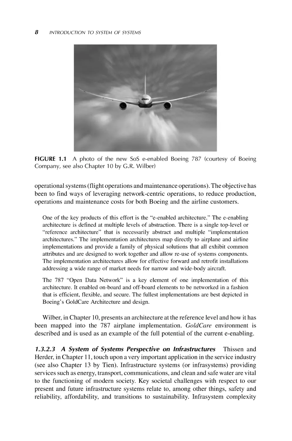
FIGURE 1.1 A photo of the new SoS e-enabled Boeing 787 (courtesy of Boeing
Company, see also Chapter 10 by G.R. Wilber)
operational systems (flight operations and maintenance operations). The objective has
been to find ways of leveraging network-centric operations, to reduce production,
operations and maintenance costs for both Boeing and the airline customers.
One of the key products of this effort is the “e-enabled architecture.” The e-enabling
architecture is defined at multiple levels of abstraction. There is a single top-level or
“reference architecture” that is necessarily abstract and multiple “implementation
architectures.” The implementation architectures map directly to airplane and airline
implementations and provide a family of physical solutions that all exhibit common
attributes and are designed to work together and allow re-use of systems components.
The implementation architectures allow for effective forward and retrofit installations
addressing a wide range of market needs for narrow and wide-body aircraft.
The 787 “Open Data Network” is a key element of one implementation of this
architecture. It enabled on-board and off-board elements to be networked in a fashion
that is efficient, flexible, and secure. The fullest implementations are best depicted in
Boeing’s GoldCare Architecture and design.
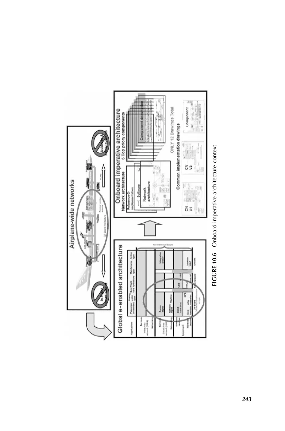
Wilber, in Chapter 10, presents an architecture at the reference level and how it has
been mapped into the 787 airplane implementation. GoldCare environment is
described and is used as an example of the full potential of the current e-enabling.
1.3.2.3 A System of Systems Perspective on Infrastructures Thissen and
Herder, in Chapter 11, touch upon a very important application in the service industry
(see also Chapter 13 by Tien). Infrastructure systems (or infrasystems) providing
services such as energy, transport, communications, and clean and safe water are vital
to the functioning of modern society. Key societal challenges with respect to our
present and future infrastructure systems relate to, among other things, safety and
reliability, affordability, and transitions to sustainability. Infrasystem complexity
CHALLENGING PROBLEMS IN SYSTEM OF SYSTEMS
9
precludes simple answers to these challenges. While each of the infrasystems can be
seen as a complex system of systems in itself, increasing interdependency among these
systems (both technologically and institutionally) adds a layer of complexity.
One approach to increased understanding of complex infrasystems that has
received little attention in the engineering community thus far is to focus on the
commonalities of the different sectors and to develop generic theories and approaches
such that lessons from one sector could easily be applied to other sectors. The system of
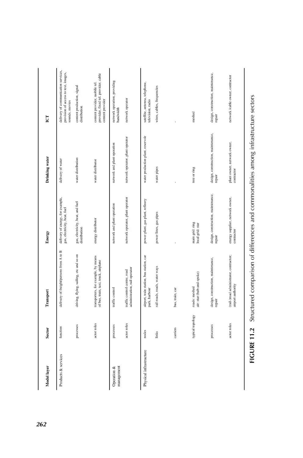
systems paradigm offers interesting perspectives in this respect. The authors present,
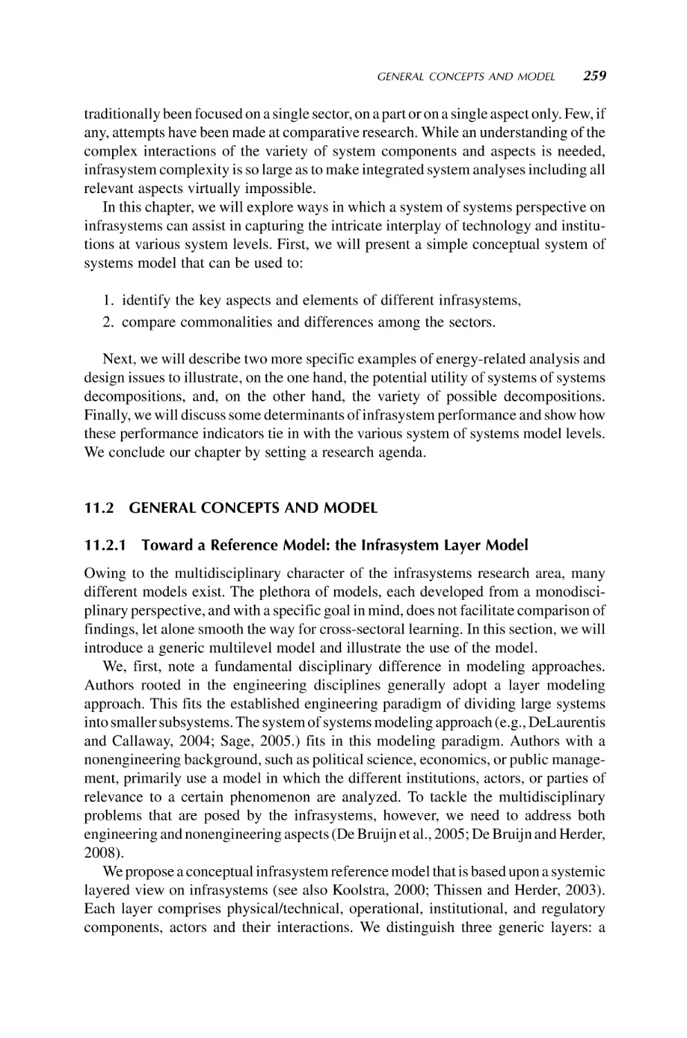
as an initial step in this direction, a fairly simple three-level model distinguishing
the physical/technological systems, the organization and management systems,
and the systems and organizations providing infrastructure-related products and
services. The authors use the model as a conceptual structure to identify a number
of key commonalities and differences between the transport, energy, drinking water,
and ICT sectors. Using two energy-related examples, the authors further illustrate
some of the system of systems related complexities of analysis and design at a more
operational level. The authors finally discuss a number of key research and engineering challenges related to infrastructure systems, with a focus on the potential
contributions of systems of systems perspectives.
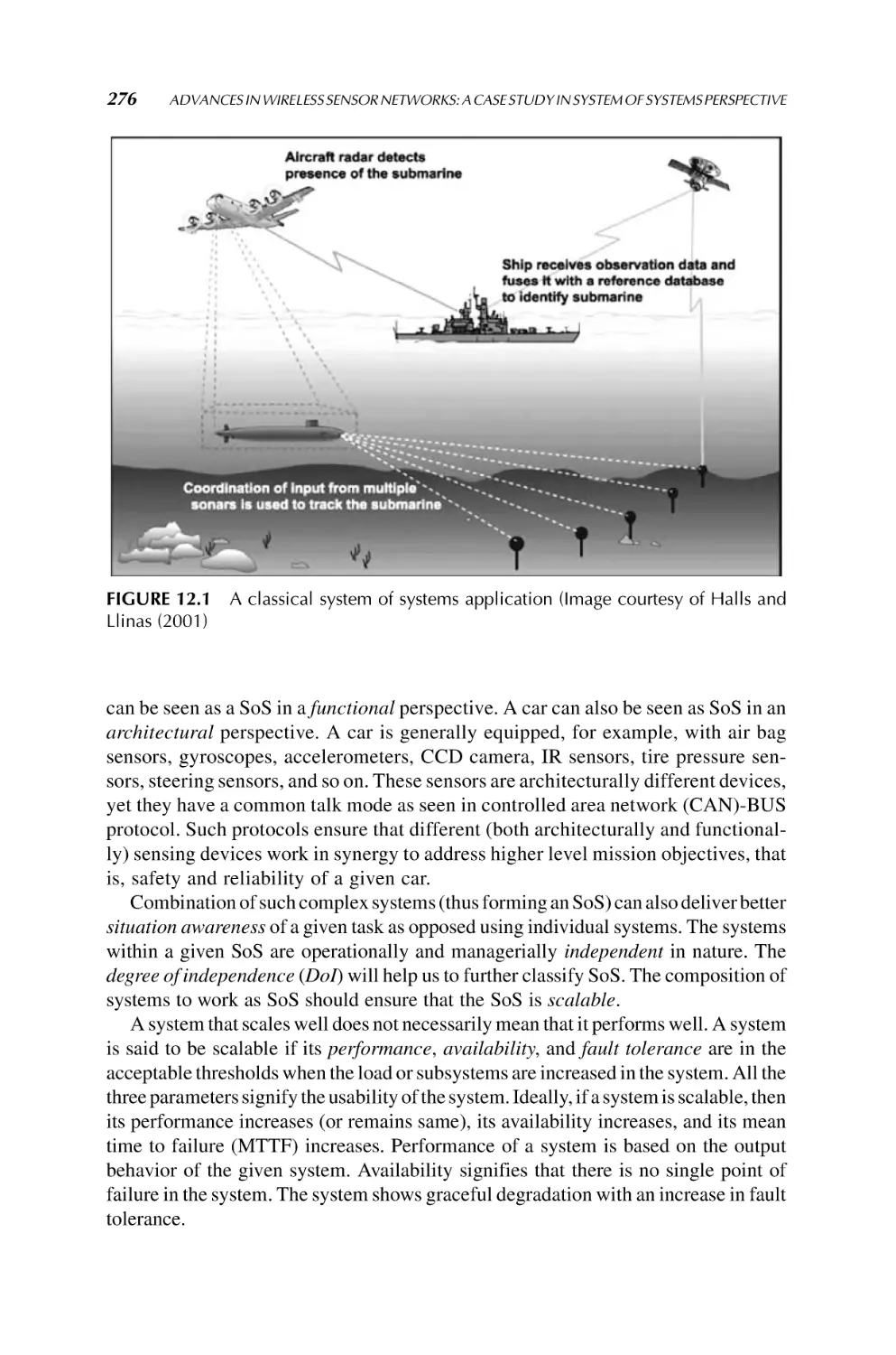
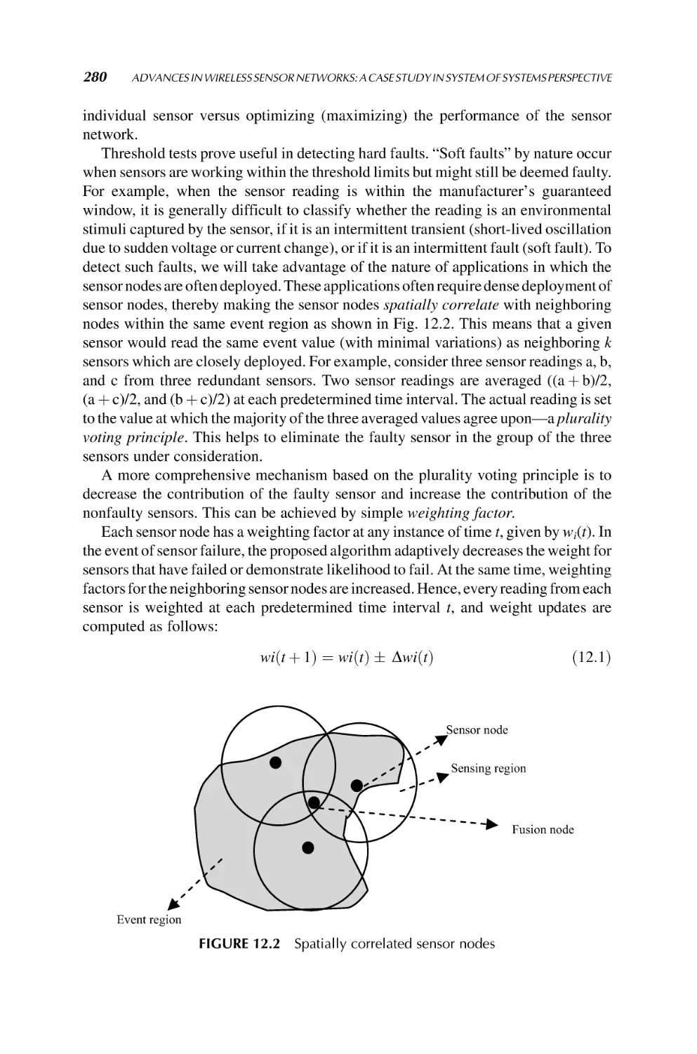
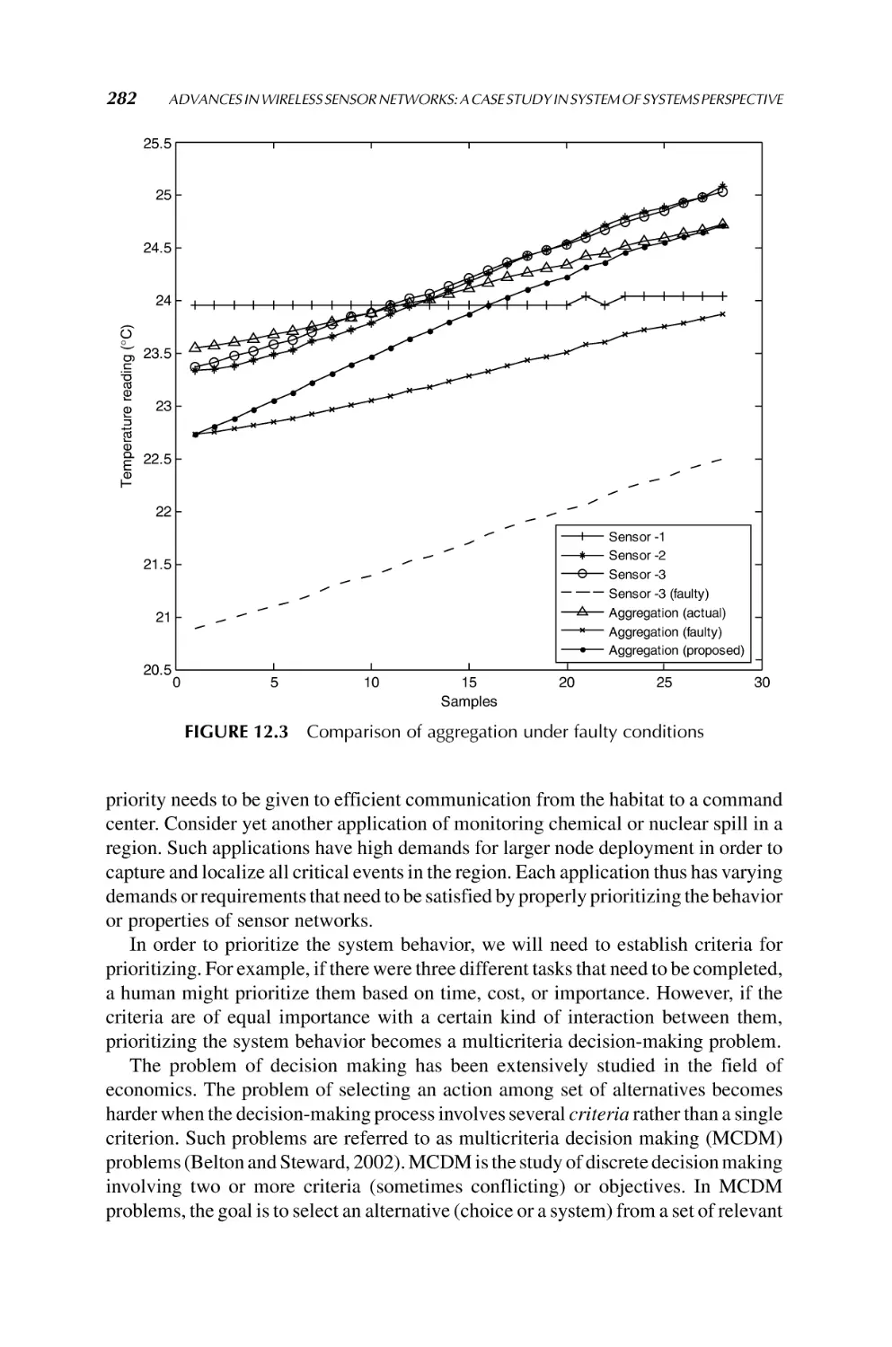
1.3.2.4 Sensor Networks The main purpose of sensor networks is to utilize the
distributed sensing capability provided by tiny, low-powered, and low-cost devices.
Multiple sensing devices can be used cooperatively and collaboratively to capture
events or monitor space more effectively than a single sensing device (Sridhar et al.,
2007). The realm of applications for sensor networks is quite diverse, which include
military, aerospace, industrial, commercial, environmental, and health monitoring, to
name a few. Applications include traffic monitoring of vehicles, cross-border infiltration detection and assessment, military reconnaissance and surveillance, target
tracking, habitat monitoring and structure monitoring, and so on.
Communication capability of these small devices and often with heterogeneous
attributes makes them good candidates for system of systems. Numerous issues with
sensor networks such as data integrity, data fusion and compression, power consumption, multidecision making, and fault tolerance all make these SoS very challenging
just like other SoS. It is thus necessary to devise a fault-tolerant mechanism with a low
computation overhead to validate the integrity of the data obtained from the sensors
(systems). Moreover, a robust diagnostics and decision-making process should aid in
monitoring and control of critical parameters to efficiently manage the operational
behavior of a deployed sensor network. Specifically, Chapter 12 by Sridhar et al. will
focus on innovative approaches to deal with multivariable multispace problem domain
as well as other issues, in wireless sensor networks within the framework of an SoS.
1.3.2.5 A System of Systems View of Services Tien, in Chapter 13, covers a
very important applications of SoS in our today’s global village — service industry.
The services sector employs a large and growing proportion of workers in the
industrialized nations, and it is increasingly dependent on information technology.
While the interdependences, similarities, and complementarities of manufacturing
10
INTRODUCTION TO SYSTEM OF SYSTEMS
and services are significant, there are considerable differences between goods and
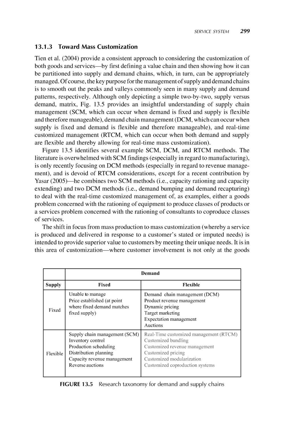
services, including the shift in focus from mass production to mass customization
(whereby a service is produced and delivered in response to a customer’s stated or
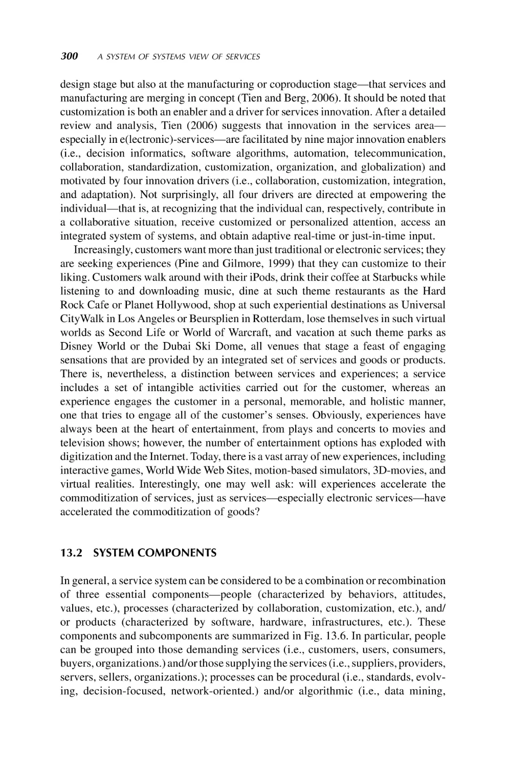
imputed needs). In general, a service system can be considered to be a combination or
recombination of three essential components — people (characterized by behaviors,
attitudes, values, etc.), processes (characterized by collaboration, customization, etc.),
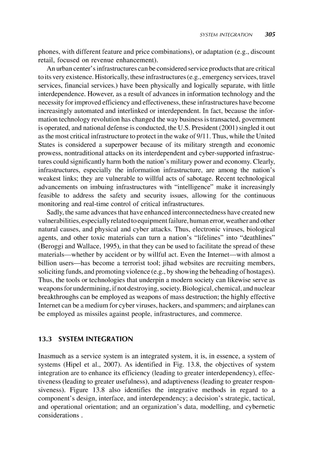
and products (characterized by software, hardware, infrastructures, etc.). Furthermore, inasmuch as a service system is an integrated system, it is, in essence, a system of
systems whose objectives are to enhance its efficiency (leading to greater interdependency), effectiveness (leading to greater usefulness), and adaptiveness (leading to
greater responsiveness). The integrative methods include a component’s design,
interface, and interdependency; a decision’s strategic, tactical, and operational
orientation; and an organization’s data, modelling, and cybernetic consideration. A
number of insights are also provided, including an alternative system of systems view
of services; the increasing complexity of systems (especially service systems), with all
the attendant life cycle design, human interface, and system integration issues; the
increasing need for real-time, adaptive decision making within such systems of
systems; and the fact that modern systems are also becoming increasingly more
human centered, if not human focused — thus, products and services are becoming
more complex and more personalized or customized.
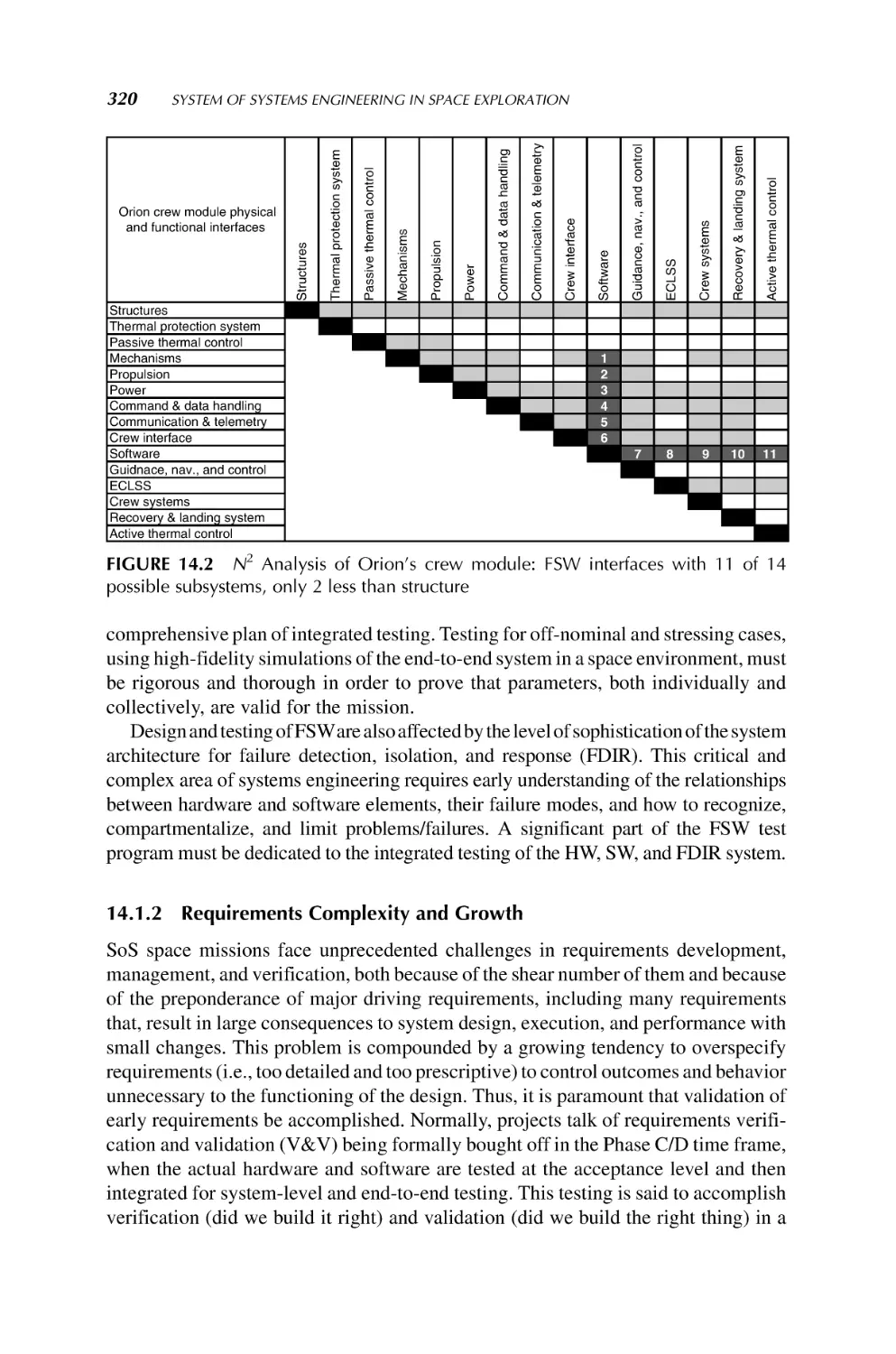
1.3.2.6 System of Systems Engineering in Space Exploration Jolly and Muirhead,
in Chapter 14, cover SoSE topics that are largely unique for space exploration with the
intent to provide the reader a discussion of the key issues, the major challenges of the
twenty-first century in moving from systems engineering to SoSE, potential applications in the future, and the current state of the art. Specific emphasis is placed on how
software and electronics are revolutionizing the way space missions are being
designed, including both the capabilities and vulnerabilities introduced. The role of
margins, risk management, and interface control is all critically important in current
space mission design and execution, but in SoSE applications they become paramount.
Similarly, SoSE space missions will have extremely large, complex, and intertwined
command and control and data distribution ground networks, most of which will
involve extensive parallel processing to produce tera-to-petabytes of products per day
and distribute them worldwide.
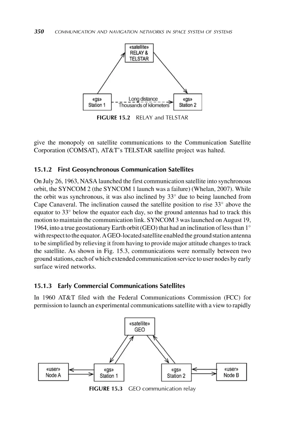
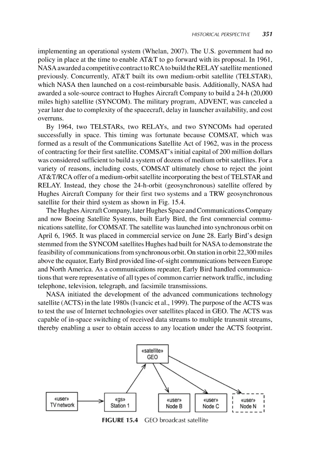
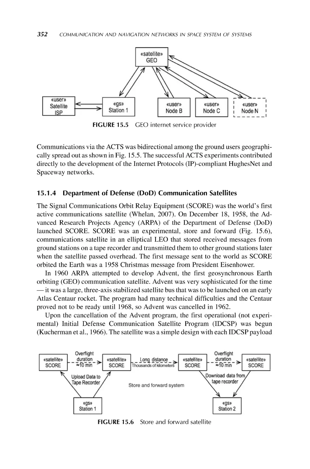
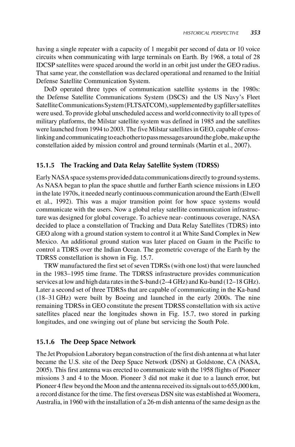
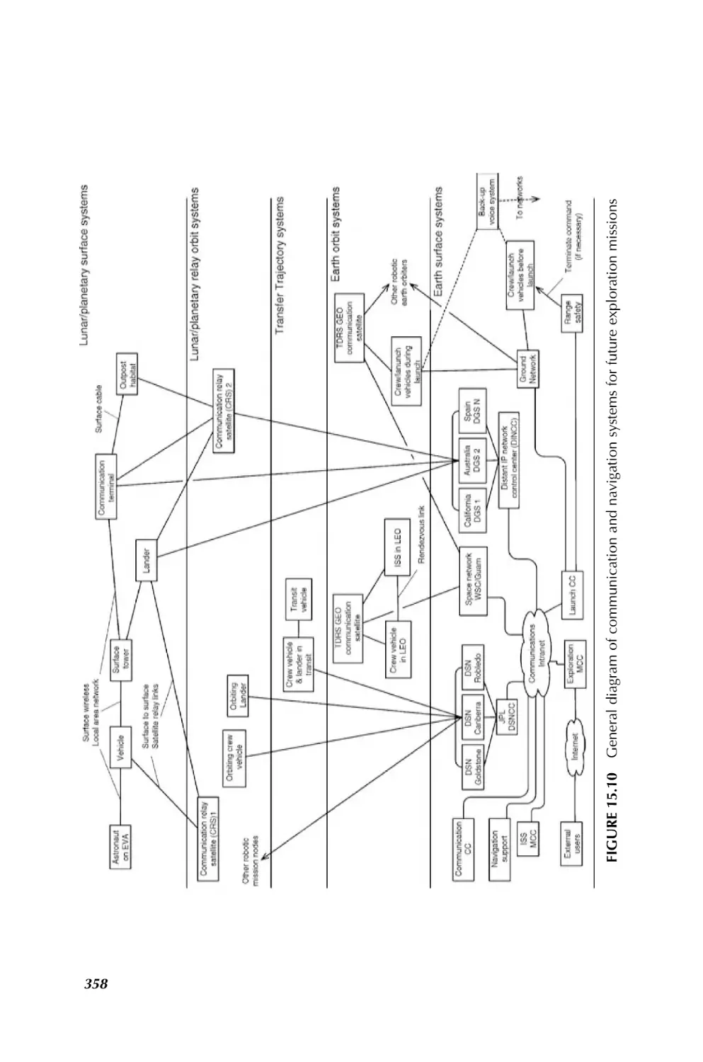
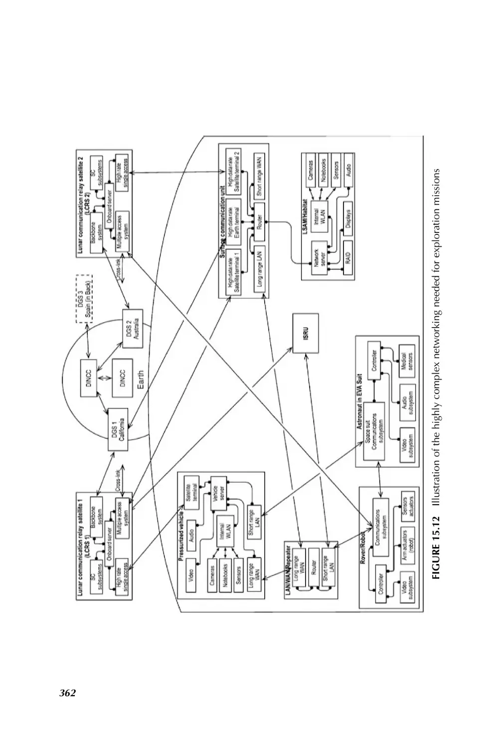
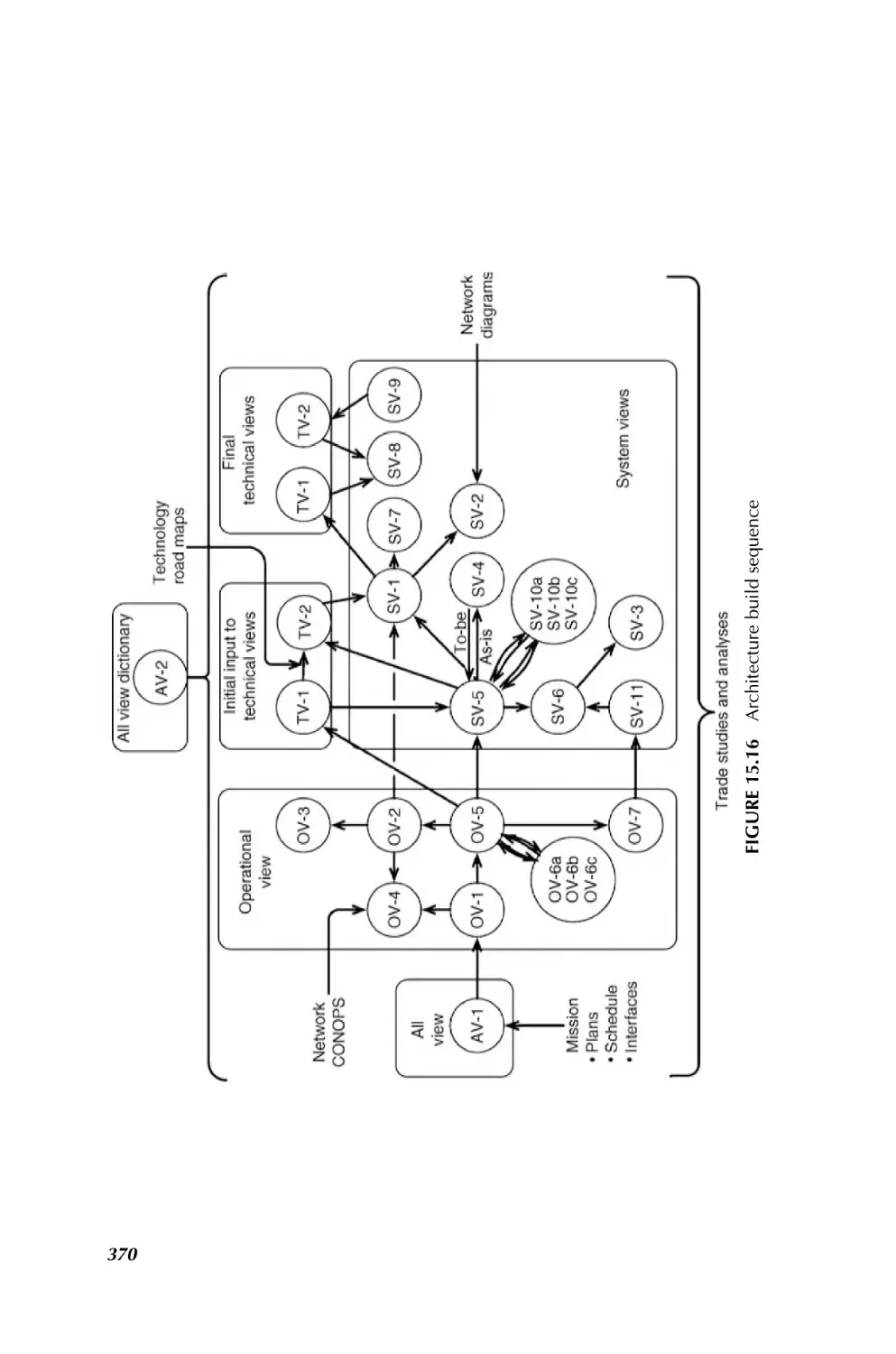
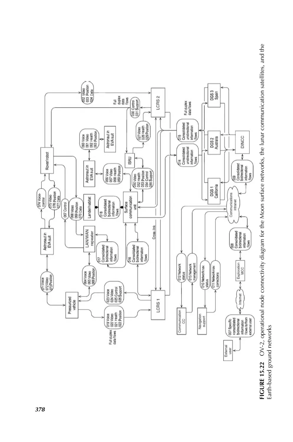
1.3.2.7 Communication and Navigation in Space SoS Bhasin and Hayden, in
Chapter 15, have taken upon the challenges in communication and navigation for
space SoS. They indicate that communication and navigation networks provide
critical services in the operation, system management, information transfer, and
situation awareness to the space system of systems. In addition, space systems of
systems are requiring system interoperability, enhanced reliability, common interfaces, dynamic operations, and autonomy in system management. New approaches to
communications and navigation networks are required to enable the interoperability
needed to satisfy the complex goals and dynamic operations and activities of the space
system of systems. Historically, space systems had direct links to Earth ground
CHALLENGING PROBLEMS IN SYSTEM OF SYSTEMS
11
communication systems, or they required a space communication satellite infrastructure to achieve higher coverage around the Earth. It is becoming increasingly apparent
that many systems of systems may include communication networks that are also
systems of systems. These communication and navigation networks must be as nearly
ubiquitous as possible and accessible on the demand of the user, much like the cell
phone link is available at any time to an Earth user in range of a cell tower. The new
demands on communication and navigation networks will be met by space Internet
technologies. It is important to bring Internet technologies, Internet Protocols (IP),
routers, servers, software, and interfaces to space networks to enable as much
autonomous operation of those networks as possible. These technologies provide
extensive savings in reduced cost of operations. The more these networks can be made
to run themselves, the less humans will have to schedule and control them. The Internet
technologies also bring with them a very large repertoire of hardware and software
solutions to communication and networking problems that would be very expensive to
replicate under a different paradigm. Higher bandwidths are needed to support the
expected voice, video, and data transfer traffic for the coordination of activities at each
stage of an exploration mission.
Existing communications, navigation, and networking have grown in an independent fashion with experts in each field solving the problem just for that field. Radio
engineers designed the payloads for today’s “bent pipe” communication satellites.
The Global Positioning Satellite (GPS) system design for providing precise Earth
location determination is an extrapolation of the Long Range Navigation (LORAN)
technique of the 1950s where precise time is correlated to precise position on the Earth.
Other space navigation techniques use artifacts in the RF communication path
(Doppler shift of the RF and transponder-reflected ranging signals in the RF) and
time transfer techniques to determine the location and velocity of a spacecraft within
the solar system. Networking in space today is point-to-point among ground terminals
and spacecraft, requiring most communication paths to/from space to be scheduled
such that communications is available only on an operational plan and is not easily
adapted to handle multidirectional communications under dynamic conditions.
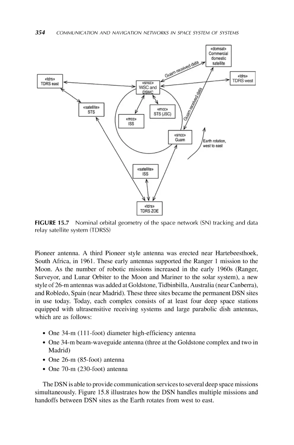
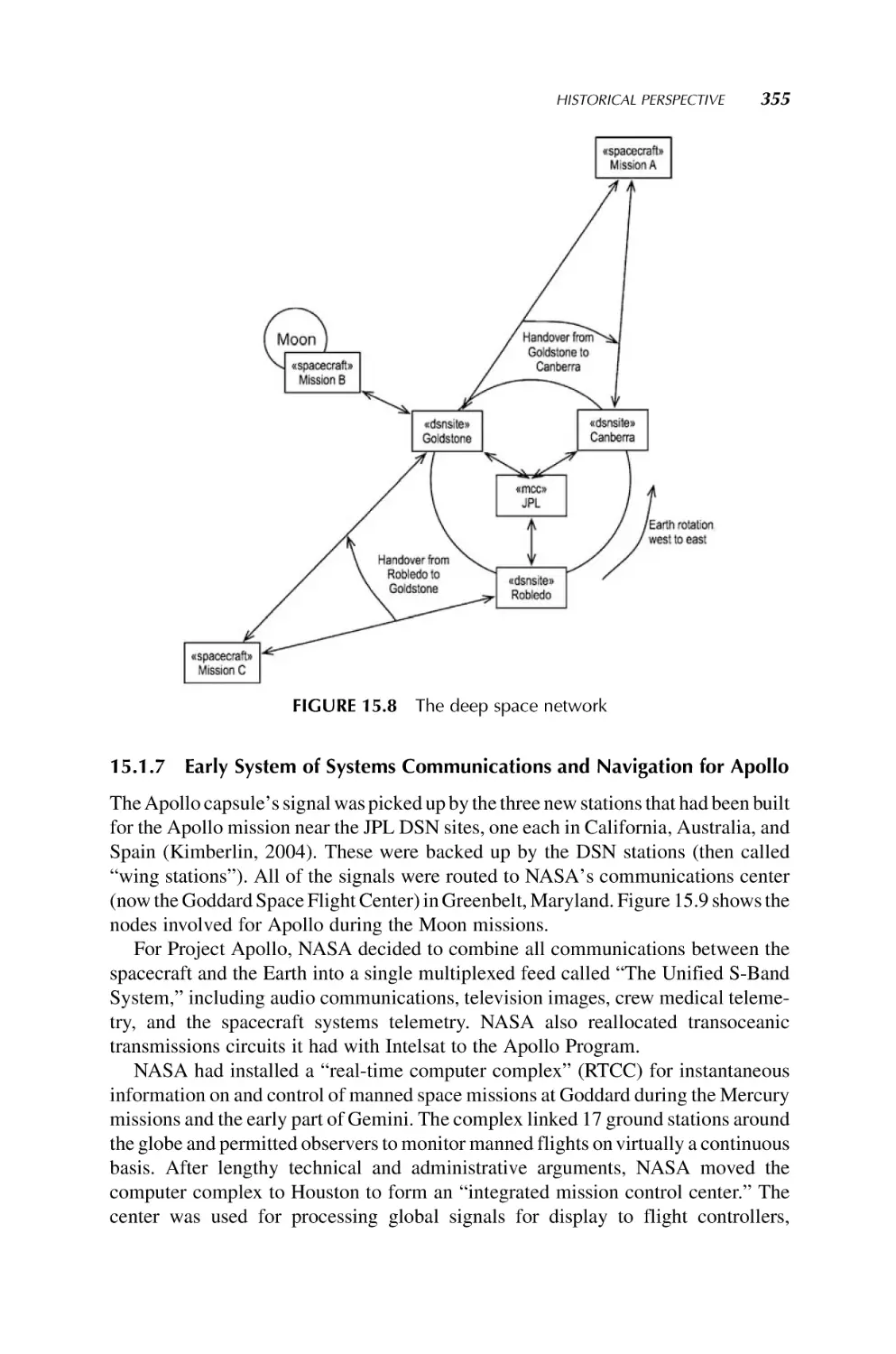
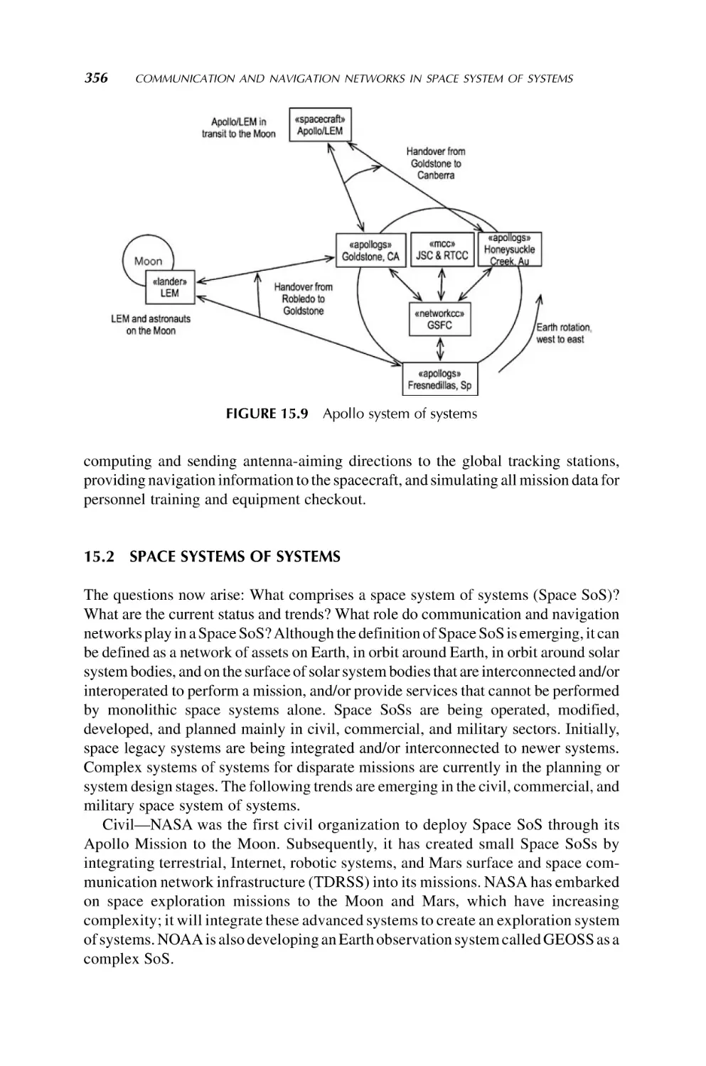
Chapter 15 begins with a brief history of the communications, navigation, and
networks of the 1960s and 1970s in use by the first system of systems, the NASA
Apollo missions; it is followed by short discussions of the communication and
navigation networks and architectures that the DoD and NASA employed from the
1980s onward. Next is a synopsis of the emerging space system of systems that will
require complex communication and navigation networks to meet their needs.
Architecture approaches and processes being developed for communication and
navigation networks in emerging space system and systems are also described.
Several examples are given of the products generated in using the architecture
development process for space exploration systems. The architecture addresses the
capabilities to enable voice, video, and data interoperability needed among the
explorers during exploration, while in habitat, and with Earth operations. Advanced
technologies are then described that will allow space system of systems to operate
autonomously or semiautonomously. Chapter 15 ends with a summary of the
challenges and issues raised in implementing these new concepts.
12
INTRODUCTION TO SYSTEM OF SYSTEMS
1.3.2.8 Electric Power Systems Grids as SoS Hiskens and Korba, in Chapter 16,
provide an overview of the systems of systems that are fundamental to the operation
and control of electrical power systems. Perspectives are drawn from industry and
academia, and reflect theoretical and practical challenges that are facing power
systems in an era of energy markets and increasing utilization of renewable energy
resources (see also Chapter 17 by Duffy et al.). Power systems cover extensive
geographical regions and are composed of many diverse components. Accordingly,
power systems are large-scale, complex, dynamical systems that must operate reliably
to supply electrical energy to customers. Stable operation is achieved through
extensive monitoring systems and a hierarchy of controls that together seek to ensure
total generation matches consumption and voltages remain at acceptable levels. Safety
margins play an important role in ensuring reliability, but tend to incur economic
penalties. Significant effort is therefore being devoted to the development of demanding control and supervision strategies that enable reduction of these safety margins,
with consequent improvements in transfer limits and profitability. Recent academic
and industrial research in this field will also be addressed in Chapter 16.
1.3.2.9 SoS Approach for Renewable Energy Duffy et al., in Chapter 17, have
provided the SoS approach to sustainable supply of energy. They note that over one
half of the petroleum consumed in the United States is imported, and that percentage is
expected to rise to 60% by 2025. America’s transportation system of systems relies
almost exclusively on refined petroleum products, accounting for over two thirds of the
oil used. Each day, over 8 million barrels of oil are required to fuel over 225 million
vehicles that constitute the United States light-duty transportation fleet. The gap
between the United States oil production and transportation oil needs is projected to
grow, and the increase in the number of light-duty vehicles will account for most of that
growth. On a global scale, petroleum supplies will be in increasingly higher demand as
highly populated developing countries expand their economies and become more
energy intensive. Clean forms of energy are needed to support sustainable global
economic growth while mitigating impacts on air quality and the potential effects of
greenhouse gas emissions. Growing dependence of the united states on foreign sources
of energy threatens her national security. As a nation, the authors assert that we must
work to reduce our dependence on foreign sources of energy in a manner that is
affordable and preserves environmental quality.
1.3.2.10 Sustainable Environmental Management from a System of Systems
Engineering Perspective Hipel et al., in Chapter 18, provide a rich range of
decision tools from the field of SE that are described for addressing complex
environmental SoS problems in order to obtain sustainable, fair, and responsible
solutions to satisfy as much as possible the value systems of stakeholders, including the
natural environment and future generations who are not even present at the bargaining
table. To better understand the environmental problem being investigated and thereby
eventually reach more informed decisions, the insightful paradigm of a system of
systems can be readily utilized. For example, when developing solutions to global
warming problems, one can envision how societal systems, such as agricultural and
CHALLENGING PROBLEMS IN SYSTEM OF SYSTEMS
13
industrial systems, interact with the atmospheric system of systems, especially at the
tropospheric level. The great import of developing a comprehensive toolbox of
decision methodologies and techniques is emphasized by pointing out many current
pressing environmental issues, such as global warming and its potential adverse
affects, and the widespread pollution of our land, water, and air systems of systems. To
tackle these large-scale complex systems of systems problems, systems engineering
decision techniques that can take into account multiple stakeholders having multiple
objectives are explained according to their design and capabilities. To illustrate how
systems decision tools can be employed in practice to assist in reaching better
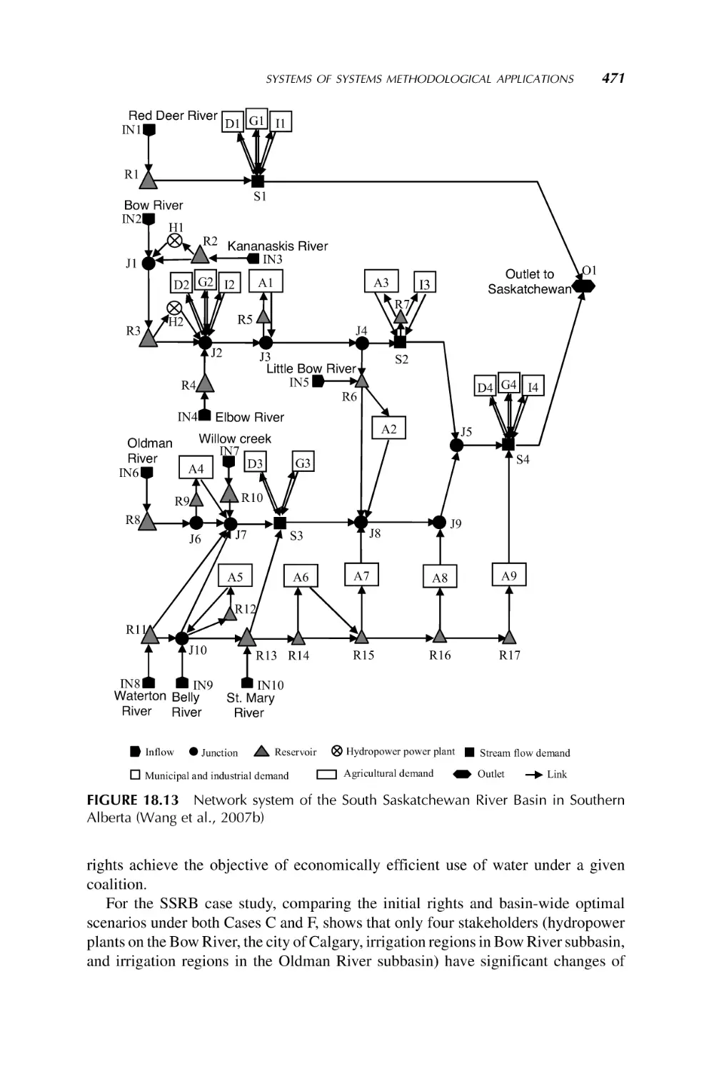
decisions for benefiting society, different decision tools are applied to three realworld systems of systems environmental problems. Specifically, the Graph Model for
Conflict Resolution is applied to the international dispute over the utilization of water
in the Aral Sea Basin; a large-scale optimization model founded upon concepts from
cooperative game theory, economics, and hydrology is utilized for systematically
investigating the fair allocation of scarce water resources among multiple users in the
South Saskatchewan River Basin in Western Canada; and multiple criteria decision
analysis methods are used to evaluate and compare solutions to handling fluctuating
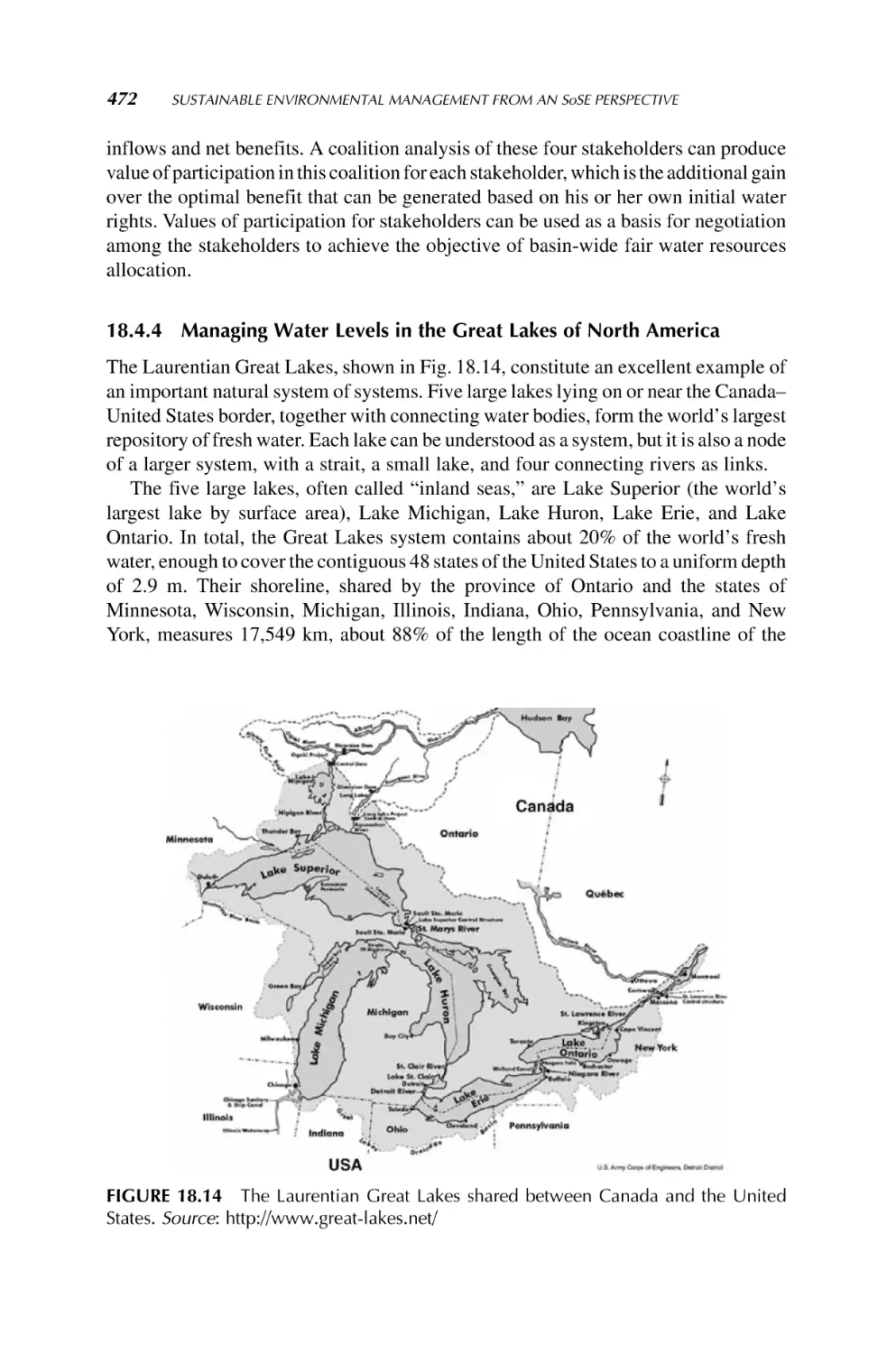
water levels in the five Great Lakes located along the border of Canada and the United
States (Wang et al., 2007).
1.3.2.11 Robotic Swarms as an SoS As another application of SoS, a robotic
swarm is considered by Sahin in Chapter 19. Here a robotic swarm based on ant colony
optimization and artificial immune systems is considered. In the ant colony optimization, the author has developed a multiagent system model based on the food
gathering behaviors of the ants. Similarly, a multiagent system model is developed
based on the human immune system. These multiagent system models, are then tested
on the mine detection problem. A modular microrobot is designed to perform to
emulate the mine detection problem in a basketball court. The software and hardware
components of the modular robot are designed to be modular so that robots can be
assembled using hot swappable components. An adaptive TDMA communication
protocol is developed in order to control connectivity among the swarm robots without
the user intervention. Details are given in Chapter 19.
1.3.2.12 Transportation Systems The National Transportation System (NTS)
can be viewed as a collection of layered networks composed by heterogeneous systems
for which the Air Transportation System (ATS) and its National Airspace System
(NAS) is one part. At present, research on each sector of the NTS is generally
conducted independently, with infrequent and/or incomplete consideration of scope
dimensions (e.g., multimodal impacts and policy, societal, and business enterprise
influences) and network interactions (e.g., layered dynamics within a scope category).
This isolated treatment does not capture the higher level interactions seen at the NTS or
ATS architecture level; thus, modifying the transportation system based on limited
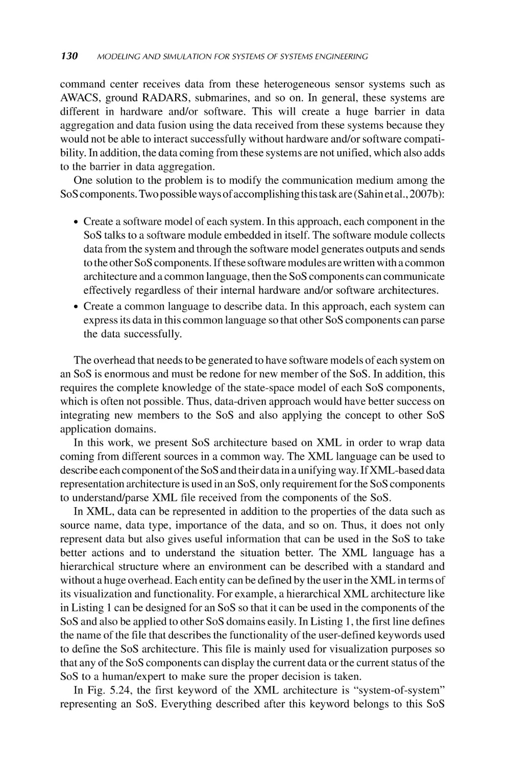
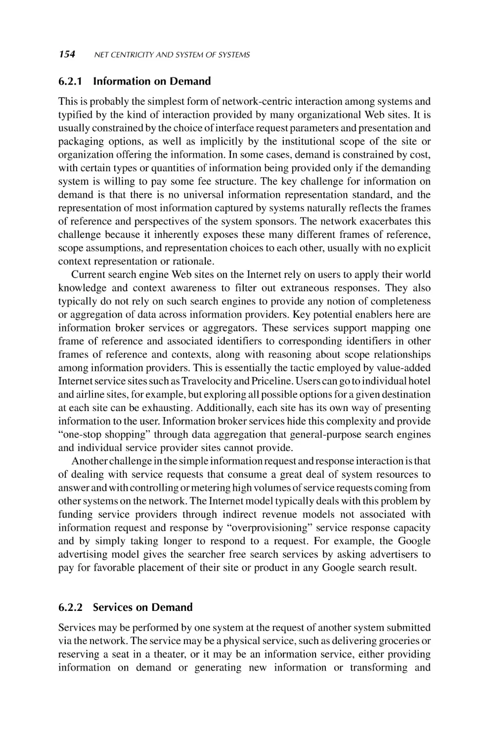
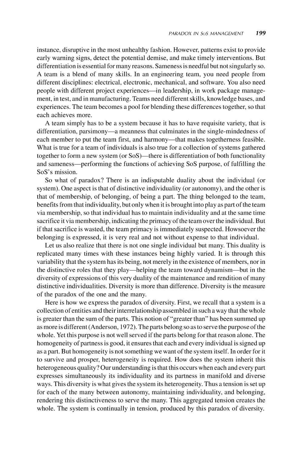
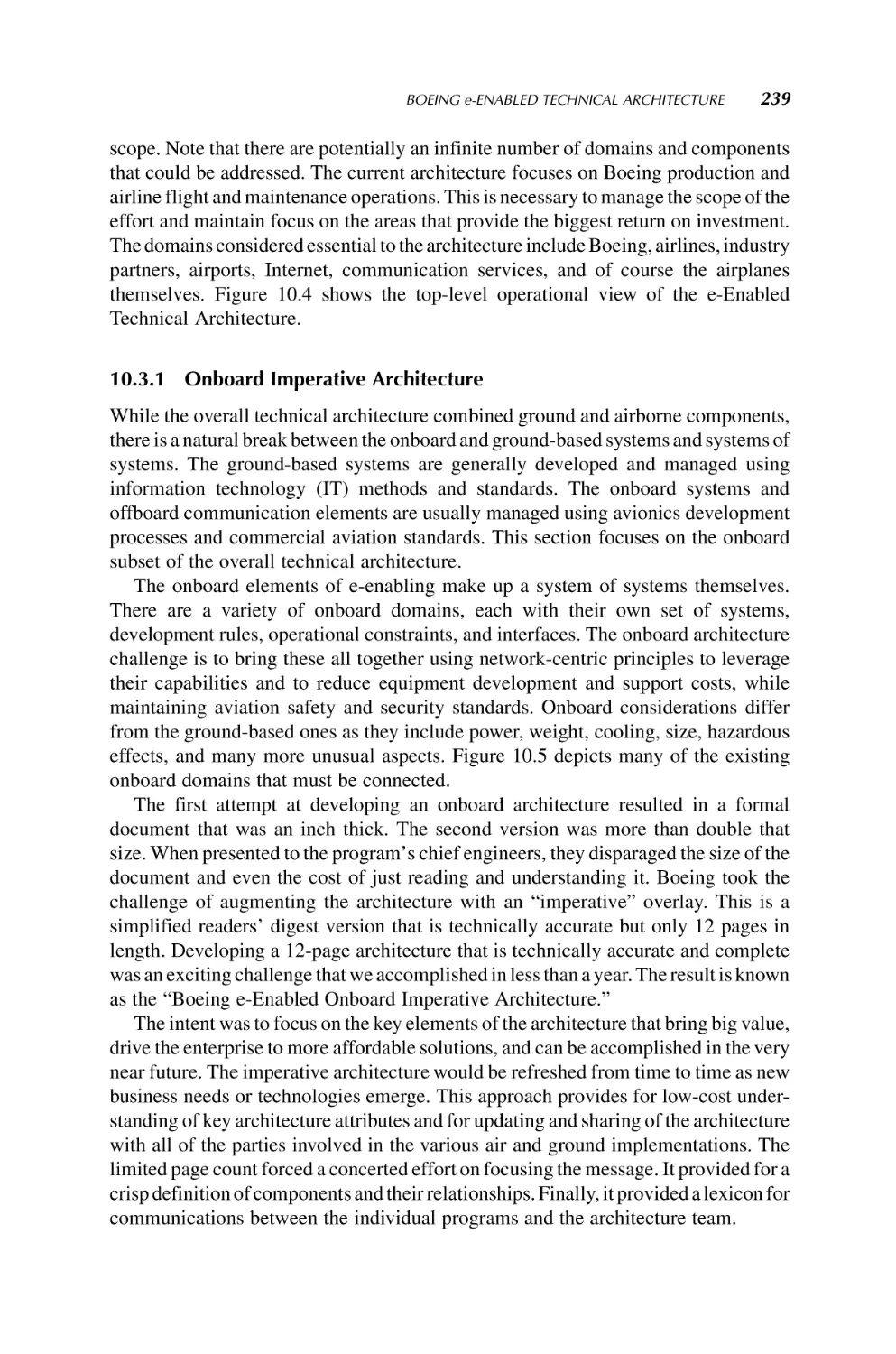
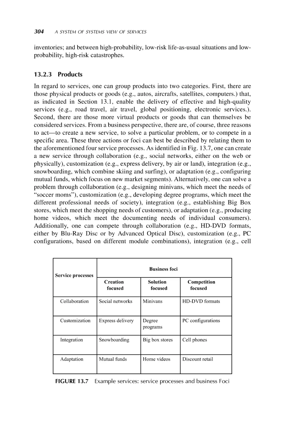
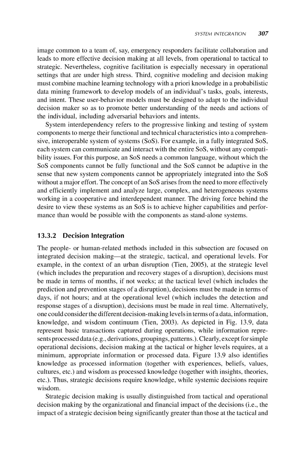
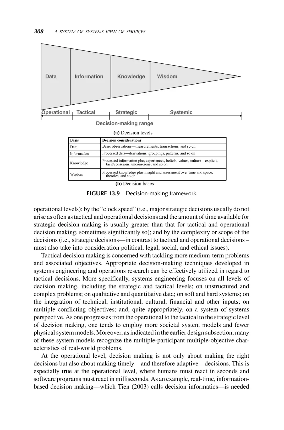
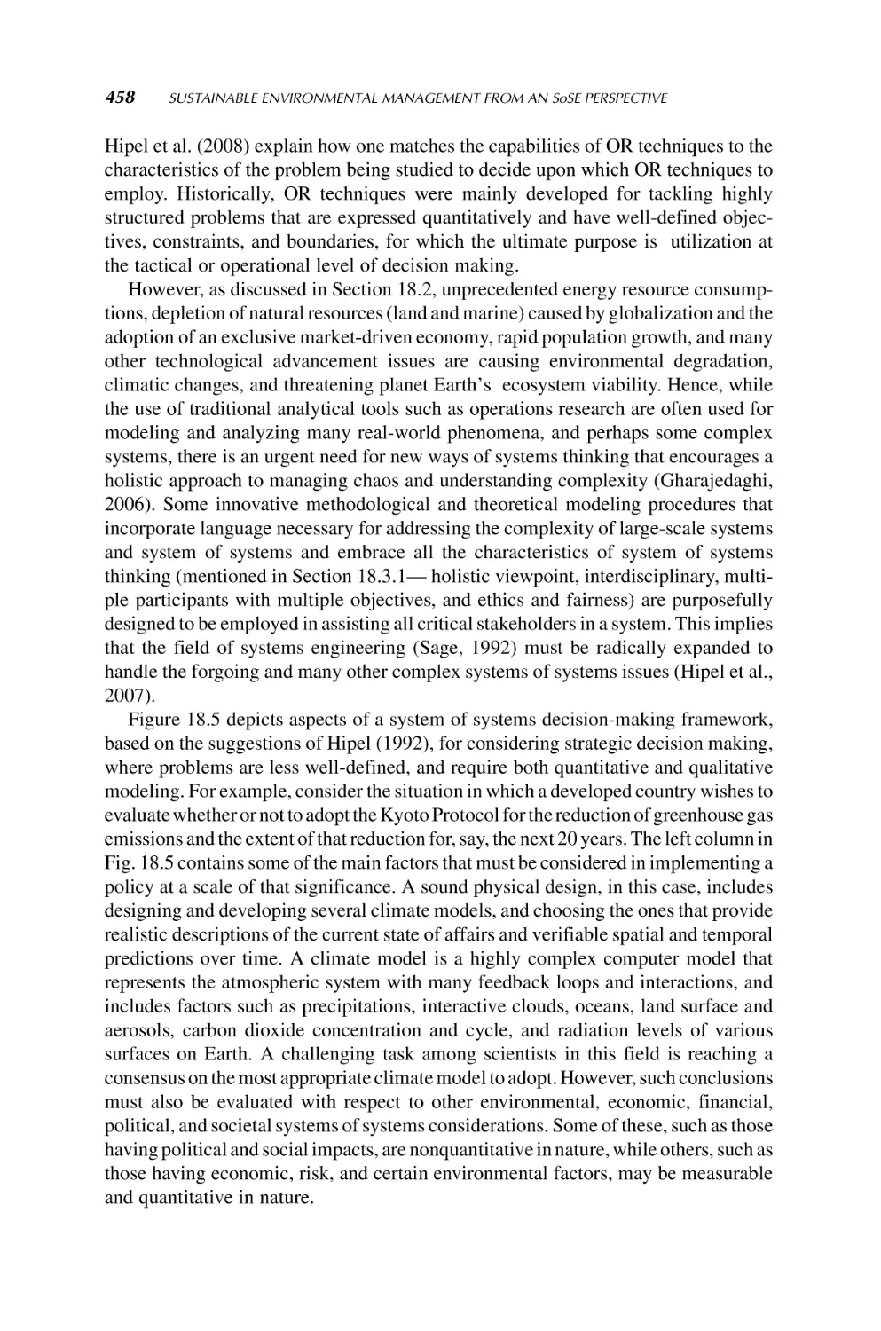
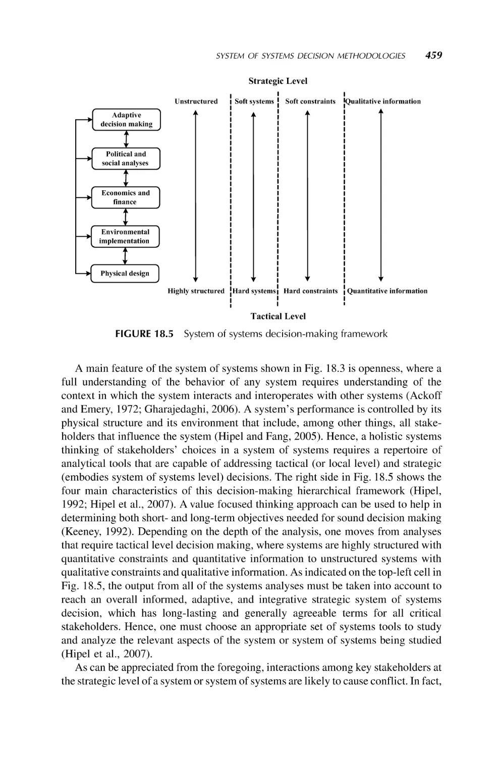
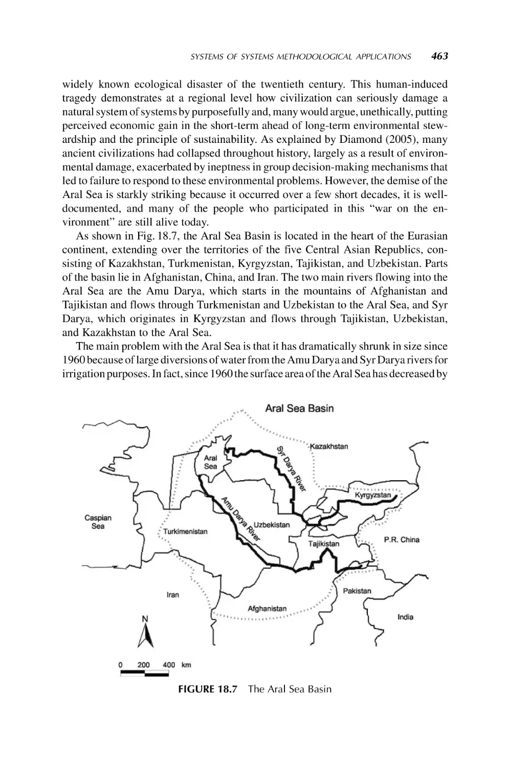
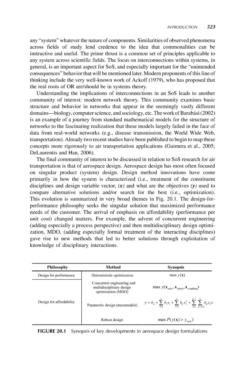
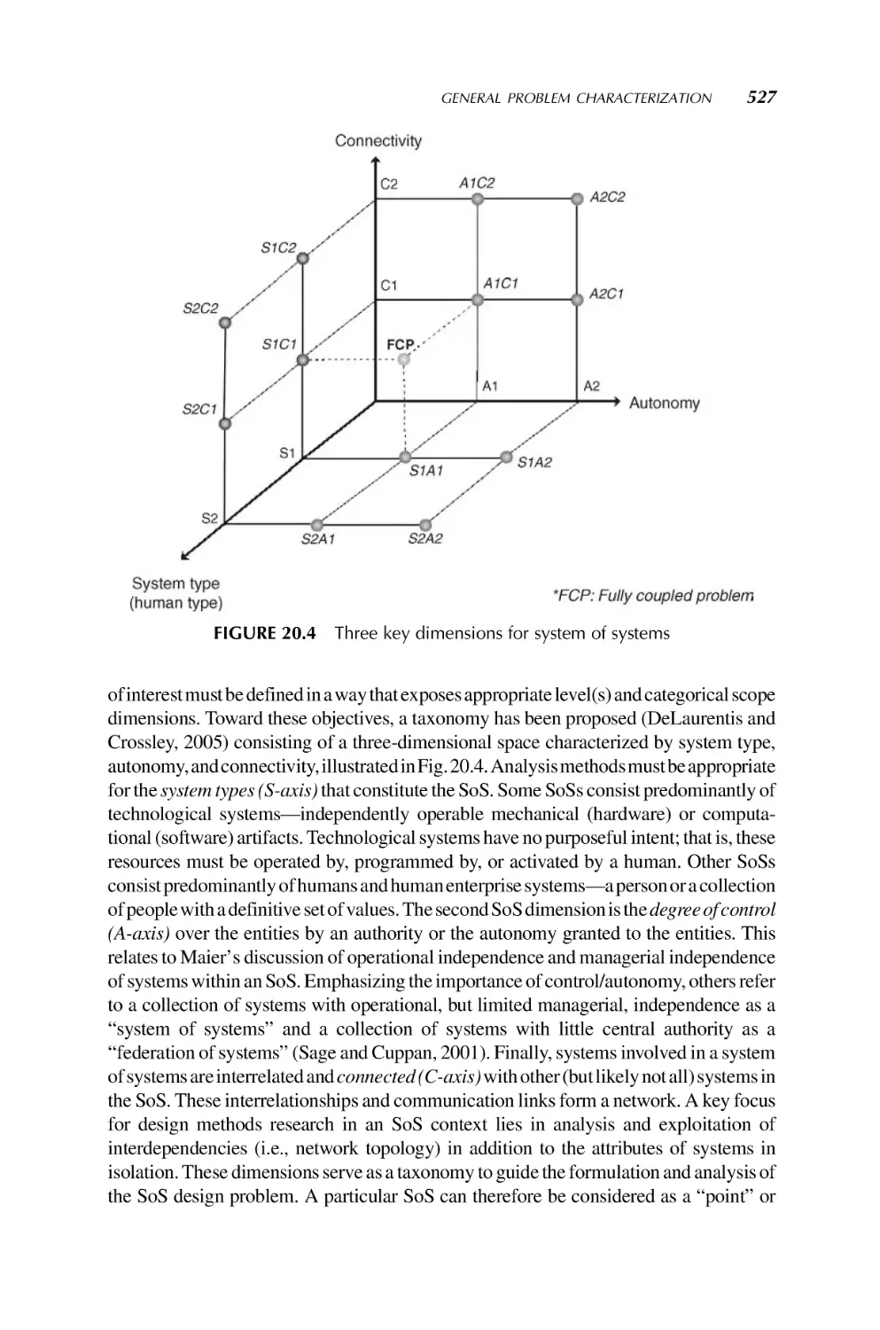
observations and analyses may not necessarily have the intended effect or impact. A
systematic method for modeling these interactions with a system of systems (SoS)
approach is essential to the formation of a more complete model and understanding of
14
INTRODUCTION TO SYSTEM OF SYSTEMS
the ATS, which would ultimately lead to better outcomes from high-consequence
decisions in technological, socioeconomic, operational, and political policy-making
context (DeLaurentis, 2005). This is especially vital as decision makers in both the
public and the private sector, for example, at the interagency Joint Planning and
Development Office (JPDO), which is charged with transformation of air transportation, are facing problems of increasing complexity and uncertainty in attempting to
encourage the evolution of superior transportation architectures (DeLaurentis and
Callaway, 2006). Chapter 20 by DeLaurentis will be addressing this application.
1.3.2.13 Healthcare Systems Under a 2004 Presidential Order, the U.S. Secretary of Health has initiated the development of a National Healthcare Information
Network (NHIN), with the goal of creating a nationwide information system that can
build and maintain Electronic Health Records (EHRs) for all citizens by 2014. The
NHIN system architecture currently under development will provide a near-real-time
heterogeneous integration of disaggregated hospital, departmental, and physician
patient care data and will assemble and present a complete current EHR to any
physician or hospital a patient consults (Sloane, 2006). The NHIN will rely on a
network of independent Regional Healthcare Information Organizations (RHIOs) that
are being developed and deployed to transform and communicate data from the
hundreds of thousands of legacy medical information systems presently used in
hospital departments, physician offices, and telemedicine sites into NHIN-specified
metaformats that can be securely relayed and reliably interpreted anywhere in the
country. The NHIN “network of networks” will clearly be a very complex SoS, and the
performance of the NHIN and RHIOs will directly affect the safety, efficacy, and
efficiency of healthcare in the United States. Simulation, modeling, and other
appropriate SoSE tools are under development to help ensure reliable, cost-effective
planning, configuration, deployment, and management of the heterogeneous, lifecritical NHIN and RHIO systems and subsystems (Sloane et al., 2007). ICSoS
represents an invaluable opportunity to access and leverage SoSE expertise already
under development in other industry and academic sectors. ICSoS also represents an
opportunity to discuss the positive and negative emergent behaviors that can significantly affect personal and public health status and the costs of healthcare in the United
States (DeLaurentis et al., 2007). See Chapter 21 by Chalasani et al.
1.3.2.14 Global Earth Observation System of Systems GEOSS is a global
project consisting of over 60 nations whose purpose is to address the need for timely,
quality, long-term, global information as a basis for sound decision making (Butterfield
et al., 2006). Its objectives are: (i) improved coordination of strategies and systems for
Earth observations to achieve a comprehensive, coordinated, and sustained Earth
observation system or systems; (ii) a coordinated effort to involve and assist developing
countries in improving and sustaining their contributions to observing systems, their
effective utilization of observations, and the related technologies; and (iii) the
exchange of observations recorded from in situ, air full and open manner with
minimum time delay and cost. In GEOSS, the “SoSE process provides a complete,
detailed, and systematic development approach for engineering systems of systems.
CHALLENGING PROBLEMS IN SYSTEM OF SYSTEMS
15
Boeing’s new architecture-centric, model-based systems engineering process emphasizes concurrent development of the system architecture model and system
specifications. The process is applicable to all phases of a system’s life cycle. The
SoSE process is a unified approach for system architecture development that integrates
the views of each of a program’s participating engineering disciplines into a single
system architecture model supporting civil and military domain applications” (Pearlman, 2006). ICSoS will be another platform for all concerned around the globe to bring
the progress and principles of GEOSS to formal discussions and examination on an
annual basis. Chapter 22 by Shibasaki and Pearlman will be addressing GEOSS
application. Figure 1.2 shows a number of systems in GEOSS .
1.3.2.15 Deepwater Coastguard Program One of the earliest realization of
an SoS in the United States is the so-called Deepwater Coastguard Program shown in
Fig. 1.3. As seen here, the program takes advantage of all the necessary assets at their
disposal, for example, helicopters, aircrafts, cutters, satellite (GPS), ground station,
human, computers, and so on — all systems of the SoS integrated together to react to
unforeseen circumstances to secure the coastal borders of the southeastern United
States, for example, Florida Coast. The Deepwater program is making progress in the
development and delivery of mission effective command, control, communications,
computers, intelligence, surveillance, and reconnaissance (C4ISR) equipment
(Keeter, 2007). The SoS approach, the report goes on, has “improved the operational
capabilities of legacy cutters and aircraft, and will provide even more functionality
when the next generation of surface and air platforms arrives in service.” The key
FIGURE 1.2 SoS of the GEOSS project (courtesy, Jay Pearlman, Boeing Company, see
also Chapter 22 by Shibasaki and Pearlman)
16
INTRODUCTION TO SYSTEM OF SYSTEMS
FIGURE 1.3 A security example of an SoS — deepwater coastguard configuration in
United States
feature of the system is its ability to interoperate among all Coast Guard mission assets
and capabilities with those of appropriate authorities at both local and federal levels.
1.3.2.16 Future Combat Missions Another national security or defense application of SoS is the future combat mission (FCM). Figure 1.4 shows one of the
numerous possible configurations of an FCM. The FCM system is “envisioned to be an
ensemble of manned and potentially unmanned combat systems, designed to ensure
that the future force is strategically responsive and dominant at every point on the
spectrum of operations from nonlethal to full-scale conflict. FCM will provide a
rapidly deployable capability for mounted tactical operations by conducting direct
combat, delivering both line-of-sight and beyond-line-of-sight precision munitions,
providing variable lethal effect (nonlethal to lethal), performing reconnaissance, and
FIGURE 1.4 A defense example of a SoS (courtesy, Don Walker, Aerospace
Corporation)
CHALLENGING PROBLEMS IN SYSTEM OF SYSTEMS
17
transporting troops. Significant capability enhancements will be achieved by developing multifunctional, multimission, and modular features for system and component
commonality that will allow for multiple state-of-the-art technology options for
mission tailoring and performance enhancements. The FCM force will incorporate
and exploit information dominance to develop a common, relevant operating picture
and achieve battle space situational understanding” (Global Security Organization,
2007). See also Chapter 9 by Dahmann and Baldwin for insights in this and other
defense applications.
1.3.2.17 National Security Perhaps one of the most talked-about application
areas of SoSE is national security. After many years of discussion of the goals, merits,
and attributes of SoS, very few tangible results or solutions have appeared in this or
other areas of this technology. It is commonly believed that “systems engineering
tools, methods, and processes are becoming inadequate to perform the tasks needed to
realize the systems of systems envisioned for future human endeavors. This is
especially becoming evident in evolving national security capabilities realizations
for large-scale, complex space, and terrestrial military endeavors. Therefore, the
development of systems of systems engineering tools, methods, and processes is
imperative to enable the realization of future national security capabilities” (Walker,
2007). In most SoSE applications, heterogeneous systems (or communities) are
brought together to cooperate for a common good and enhanced robustness and
performance. “These communities range in focus from architectures, to lasers, to
complex systems, and will eventually cover each area involved in aerospace-related
national security endeavors. These communities are not developed in isolation in that
cross-community interactions on terminology, methods, and processes are done”
(Walker, 2007). The key is to have these communities work together to guarantee the
common goal of making our world a safer place for all. See Chapter 9 by Dahmann and
Baldwin for insights in this and other security applications.
1.3.2.18 Critical Infrastructure and Air Transportation Security Air transportation networks consist of concourses, runways, parking, airlines, cargo terminal
operators, fuel depots, retail, cleaning, catering, and many interacting people including travelers, service providers, and visitors. The facilities are distributed and fall
under multiple legal jurisdictions in regard to occupational health and safety, customs,
quarantine, and security.
Currently decision making in this domain space is focused on individual systems.
The challenge of delivering improved nationwide air transportation security, while
maintaining performance and continuing growth, demands a new approach. In
addition, information flow and data management are a critical issue, where trust
plays a key role in defining interactions of organizations.
SoS methodologies are required to rapidly model, analyze, and optimize air
transportation systems (Nahavandi, 2007). In any critical real-world system there is
and must be a compromise between increased risk and increased flexibility and
productivity. By approaching such problem spaces from an SoS perspective the
authors are in the best position to find the right balance (DeLaurentis et al., 2007).
18
INTRODUCTION TO SYSTEM OF SYSTEMS
1.4 CONCLUSIONS
This chapter is written to serve as an introduction to the book. The subject matter of this
book is an unsettled topic in engineering in general and in systems engineering in
particular. Attempt has been made to cover as many open questions in both theory and
applications of SoS and SoSE. It is our intention that this book would be the beginning
of much debate and challenges among and by the readers of this book. The book is
equally intended to benefit industry, academia, or government. A sister volume, by the
author, on the subject is under press at the present time and can give readers further
insight into SoS (Jamshidi, 2008).
REFERENCES
Abbott, R., 2006, Open at the top; open at the bottom; and continually (but slowly) evolving,
Proceedings of IEEE International Conference on System of Systems Engineering, April
2006, Los Angeles.
Abel, A., Sukkarieh, S., 2006, The coordination of multiple autonomous systems using
information theoretic political science voting models, Proceedings of IEEE International
Conference on System of Systems Engineering, April 2006, Los Angeles.
Azarnoosh, H., Horan, B., Sridhar, P., Madni, A.M., Jamshidi, M., 2006, Towards optimization
of a real-world robotic-sensor system of systems, Proceedings of World Automation
Congress (WAC) 2006, July 24–26, Budapest, Hungary.
Butterfield, M.L., Pearlman, J., Vickroy, S.C., 2006, System-of-systems engineering in a global
environment, Proceedings of International Conference on Trends in Product Life Cycle,
Modeling, Simulation and Synthesis PLMSS.
Carlock, P.G., Fenton, R.E., 2001, System of systems (SoS) enterprise systems for informationintensive organizations, Systems Engineering, 4(4): 242–261.
Crossley, W.A., 2004, System of systems: an introduction of Purdue University Schools of
Engineering’s Signature Area, Engineering Systems Symposium, March 29–31, 2004, Tang
Center, Wong Auditorium, MIT.
DeLaurentis, D.A., 2005, Understanding transportation as a system-of-systems design,
problem, AIAA Aerospace Sciences Meeting and Exhibit, January 10–13, 2005. AIAA2005-123.
DeLaurentis, D.A., Callaway, R.K., 2006, A system-of-systems perspective for future public
policy, Review of Policy Research, 21(6): 2006.
DeLaurentis, D., Dickerson, C., Di Mario, M., Gartz, P., Jamshidi, M., Nahavandi, S., Sage, A.,
Sloane, E., Walker, D., 2007, A case for an international consortium on system of systems
engineering, IEEE Systems Journal, 1(1): 68–73.
DiMario, M.J., 2006, System of systems interoperability types and characteristics in joint
command and control, Proceedings of IEEE International Conference on System of Systems
Engineering, April 2006, Los Angeles.
Fisher, D., 2006, An Emergent Perspective on Interoperation in Systems of Systems, (CMU/SEI2006-TR- 003). Software Engineering Institute, Carnegie Mellon University, Pittsburgh,
PA.
REFERENCES
19
Global Security Organization, 2007, http://www.globalsecurity.org/military/systems/ground/
fcs-back.htm.
Jamshidi, M. 2005, Theme of the IEEE SMC 2005, Waikoloa, Hawaii, USA, http://
ieeesmc2005.unm.edu/, October 2005.
Jamshidi, M., 2008, System of Systems Engineering – Principles and Applications, Taylor
Francis CRC Publishers, Boca Raton, FL, USA.
Keeter, H.C., 2007, Deepwater command, communication, sensor electronics build enhanced
operational capabilities, US Coastguard Deepwater Prorgam site, http://www.uscg.mil/
deepwater/media/feature/july07/c4isr072007.htm.
Kotov, V., 1997, Systems of systems as communicating structures, Hewlett Packard Computer
Systems Laboratory Paper HPL-97-124, pp. 1–15.
Lopez, D., 2006, Lessons learned from the front lines of the aerospace, Proceedings of IEEE
International Conference on System of Systems Engineering, April 2006, Los Angeles.
Luskasik, S.J., 1998, Systems, systems of systems, and the education of engineers, Artificial
Intelligence for Engineering Design, Analysis, and Manufacturing, 12(1): 11–60.
Meilich, A., 2006, System of systems (SoS) engineering & architecture challenges in a net
centric environment, Proceedings of IEEE International Conference on System of Systems
Engineering, April 2006, Los Angeles.
Manthorpe, W.H., 1996, The emerging joint system of systems: a systems engineering
challenge and opportunity for APL, John Hopkins APL Technical Digest, 17(3): 305–310.
Morley, J., 2006, Five Maxims about Emergent Behavior in Systems of Systems, http://www.
sei.cmu.edu/news-at-sei/features/2006/06/feature-2-2006-06.htm.
Nahavandi, S., 2007, Modeling of large complex system from system of systems perspective, Keynote presentation, 2007 IEEE SoSE Conference, April 18, 2007, San Antonio,
USA.
Pearlman, J., 2006, GEOSS- global Earth observation system of systems, Keynote presentation,
2006 IEEE SoSE Conference, April 24, 2006, Los Angeles, CA, USA.
Pei, R.S., 2000, Systems of systems integration (SoSI): a smart way of acquiring army C4I2WS
systems, Proceedings of the Summer Computer Simulation Conference, pp. 134–139.
Sage, A.P., Biemer, S.M., 2007, Processes for system family architecting, design, and
integration, IEEE Systems Journal, 1(1): 5–16.
Sage, A.P., Cuppan, C.D., 2001, On the systems engineering and management of systems of
systems and federations of systems, Information, Knowledge, Systems Management, 2(4):
325–334.
Sahin, F., Jamshidi, M., Sridhar, P., 2007, A discrete event XML based simulation framework
for system of systems architectures, Proceedings of the IEEE International Conference on
System of Systems, April 2007.
Sloane, E., 2006, Understanding the emerging national healthcare IT infrastructure, 24 7
Magazine, December 2006.
Sloane, E., Way, T., Gehlot, V., Beck, R., 2007, Conceptual SoS model and simulation systems
for a next generation national healthcare information network (NHIN-2), Proceedings of the
1st Annual IEEE Systems Conference, April 9–12, 2007, Honolulu, HI.
Sridhar, P., Madni, A.M., Jamshidi, M., 2007, Hierarchical aggregation and intelligent
monitoring and control in fault-tolerant wireless sensor networks, IEEE Systems Journal,
1(1): 38–54.
20
INTRODUCTION TO SYSTEM OF SYSTEMS
Walker, D., 2007, Realizing a Corporate SOSE Environment, Keynote presentation, 2007 IEEE
SoSE Conference, April 18, 2007, San Antonio, TX, USA.
Wang, L., Fang, L., Hipel, K.W., 2007, On achieving fairness in the allocation of scarce
resources: measurable principles and multiple objective optimization approaches, IEEE
Systems Journal, 1(1): 17–28.
Wilber, F.R., 2007, A system of systems approach to e-enabling the commercial airline
applications from an airframer’s perspective, Keynote presentation, 2007 IEEE SoSE
Conference, April 18, 2007, San Antonio, TX, USA.
Wojcik, L.A., Hoffman, K.C., 2006, Systems of systems engineering in the enterprise context: a
unifying framework for dynamics, Proceedings of IEEE International Conference on
System of Systems Engineering, April 2006, Los Angeles.
Chapter 2
An Open Systems Approach to
System of Systems Engineering
CYRUS AZANI1,2
1
Northrop Grumman Technical Services, Herndon, VA, USA
2
University of Maryland, College Park, MD, USA
2.1 INTRODUCTION
The twenty-first century engineering is witnessing an unprecedented change in the
way we conceive, develop, field, and sustain systems. Many of the premises
underlying the traditional systems engineering (SE) strategies are no longer valid.
Traditional SE has been focusing on developing stand-alone systems with stable
architecture and static technology base in which improvements were slow and very
costly (Azani and Khorramshahgol, 2005). These strategies incorrectly assume that
all the system of systems (SoS) requirements are known in the beginning of the
development process and can be frozen in time or assumed to be stable. The
traditional SE strategies also wrongly assume that the concepts of operation and
various technologies used for constructing today’s SoS are static and are subject to
minor future changes.
Organizations can no longer afford to develop SoS based on traditional systems
engineering approaches characterized by frozen requirements, reactive design, poor
architecture archeology, and lack of understanding and consideration of elaborative
interactions and interdependencies that exist among systems, processes, practices, and
stakeholder organizations. It is apparent that traditional system engineering strategies
are less effective in developing complex, dynamic, and evolving SoS. Traditional
system engineering strategies are slow and result in excessive total system life cycle
cost and unacceptable schedule delays. Such strategies are also less responsive to
evolving needs of multiple stakeholders, rapidly changing technologies, and other
System of Systems Engineering: Innovations for the 21st Century, Edited by Mo Jamshidi
Copyright Ó 2009 John Wiley & Sons, Inc., Publication
21
22
AN OPEN SYSTEMS APPROACH TO SYSTEM OF SYSTEMS ENGINEERING
challenged faced the twenty-first century systems (Azani and Khorramshahgol, 2006).
In the twenty-first century, systems engineers must deliver systems with the capability
to be self-organized and self-regulated, and be reconfigured affordably and very
quickly in response to evolving needs and rapidly changing technologies.
Although SoSE is a new concept, the SoS development is not new. Natural systems
of systems have been in existence and are subject to continuous development and
evolution for millions of years. Most of the challenges faced by an engineered or
synthetic SoS are indeed the same challenges encountered for millions of years by
many natural SoS. To survive and sustain, natural systems of systems had no choice but
to adopt and follow certain fundamental open systems characteristics and principles.
For example, they had to have open interfaces (i.e., permeable boundaries) in order
to interact with their environment and had to adopt modular design principles (e.g.,
cohesiveness, encapsulation, and self-containment) in order to multiply themselves
quickly and join forces to protect themselves and survive. The natural systems of
systems have also created elaborative self-government systems through homeostasis,
synergism, cybernetic control systems, and reconfigurable architectures in order to
adapt and evolve in their harsh environment.
This chapter contends that the SoSE can consciously mimic the natural development processes and capitalize on natural development approaches such as the open
systems strategy to build evolvable, affordable, and sustainable systems. Similar to
a living organism, an engineered SoS is a whole greater than the sum of its parts; is
capability rather than system based; has requirements and behavior that are both
emergent and prespecified; has an encapsulated, self-contained, and cohesive structure; has different motivation, priorities, values, and practices compared to other
systems; is network centric; is subject to predetermined blueprints and interface
standards; and depends on symbiotic relationships and open interfaces to function and
evolve within an uncertain environment.
2.2 THE OPEN SYSTEM CONCEPT
Systems that can exchange energy, material, and information with the outside world
are called open systems. The open system concept is not new. It was first originated in
biological and physical sciences and then migrated into physical and social sciences in
the early parts of the twentieth century (Azani, 2001). In the late 1960s and early 1970s,
the concept began to be applied in commercial information technology. The largest
natural SoS on our planet (i.e., the ecosystem) and all the organisms living in it are
considered open systems (Kay, 2000). These systems have been evolved and sustained
for millions of years by being open. Commercial and social entities are also considered
open systems because they are constantly exchanging energy (e.g., power that
illuminates offices and factories and runs machineries and computers), material
(e.g., raw material, labor, tools, hardware and software products), and information
(e.g., knowledge, technical and nontechnical data) among each other and with their
surrounding environment. Such entities cease to exist when they become closed
systems.
THE OPEN SYSTEM CONCEPT
23
Besides the ability to exchange energy, material, and information, open systems
also possess capability to form complex hierarchical structures enabling them to
cooperate and compete at the same time. As Ben-Jacob (2003) contends, open systems
behavior and structures are governed by both competitive tendencies and collaborative
exchange of information. In addition to exchange of information, competition for
survival also plays an important role in enhancing cooperation among open systems. In
fact, complex structures emerge in open systems only when there is competition
between two or more tendencies (Turing, 1952). For example, although the notions of
freedom and cooperation are usually perceived as contradictory (Poundstone, 1992),
bacteria solved this apparent paradox by forming complex hierarchical colonial
modular structures. The bacteria have also realized, over their course of evolution,
that increasing informative communication among individual bacterium will result in
increased freedom and cooperation among them (Shapiro 1992; Ben-Jacob 1997).
Therefore, diverse open systems, living and nonliving alike, respond to externally
imposed conditions by forming complex hierarchical spatiotemporal patterns
(Thompson, 1944; Stevens, 1974; Ben-Jacob and Levine, 1998, 2001; Ball, 1999).
Such structural patterns simultaneously elevate the degree of freedom of the individual
cells and the level of cooperation among them.
Through openness, the biotic systems are enabled to capitalize on complexity to
become more flexible and adaptable. In open systems, complexity does not have a
negative connotation and plays an important role in enabling systems to adapt and
evolve. According to Ben-Jacob (1997, 2003), structural complexity might be a more
appropriate concept instead of entropy production to describe the response of open
systems to external imposed conditions especially when these conditions vary in time
and/or space. This argument is centered on the notion that stability, as used for closed
systems, or open systems in steady states, is not valid for the hierarchical or scale-free
spatiotemporal complex patterns formed during abiotic self-organization. In such
cases, higher complexity elevates the flexibility of the system, thus imparting it
higher tolerance and robustness so that it can better adapt to the external variable
stimuli (Ben-Jacob, 2003).
Self-organization and complexity are closely related concepts in open systems. For
example, a typical bacterial colony that consists of billions of bacteria is not created by
predesign, but through the process of biotic self-organization. The bacteria store the
information for creating the needed “tools” and the guiding principles needed for the
colonial self-organization. Additional information is cooperatively generated, in
response to environmental conditions, to create an adaptable complex system that
can perform many tasks and is capable to learn and change itself accordingly
(Ben-Jacob and Levine, 2006). In a way, the colony can self-organize itself to cope
with adverse external conditions, because each bacterium is, by itself, a biotic
autonomous system with its own internal cellular informatics capabilities such as
storage, processing, and evaluation of information (Ben-Jacob and Levine, 2001).
New features can collectively emerge during self-organization from the intracellular
level to the whole colony. The cells thus assume newly cogenerated traits and abilities
that are not explicitly stored in the genetic information of the individuals (Ben-Jacob
and Levine, 2006).
24
AN OPEN SYSTEMS APPROACH TO SYSTEM OF SYSTEMS ENGINEERING
Ad
co apta
nf
igu bilit
ra y &
bil
ity
Access to
multiple sources
of supply
re
A
su ffo
st rd
ai ab
nm le
en
t
Open systems are also characterized by emerging behavior and evolving
structure. The emerging behavior and evolving structure of an open system is a
function of its permeability to outside influence, inherited guidelines, ability to
self-govern, and the degree of synergistic effects created as the system interacts
with other systems and with its environment. The synergistic effects produced by
wholes are considered the very cause of the evolution of complexity in natural
systems (Koestler, 1969). Therefore, to understand an SoS emerging behavior and
evolving structure, one should study the extent of SoS openness and multiplicity of
interactions among constituent parts and dynamic processes that take place as a
result of such interactions. The knowledge of the individual properties of the parts
and the way they are connected to and act on one another allows us to compute the
behavior of the whole (Atlan, 2003).
Timely reaction to evolving needs and technology requires agile open SoS that
could quickly and cost effectively be integrated and reconfigured within an SoS
environment. Affordable agility and adaptable sustainment of an SoS will demand
engineering of openness attributes into an SoS from early phases of development life
cycle. When applied effectively, a truly open SoS can enhance the adaptability of the
system to changes in requirements and technology, will reduce the total ownership
costs of the system, and will improve its overall life cycle supportability. Moreover, by
following an open system approach in acquisition of an SoS, the program and project
managers will be in a better position to leverage investments made in commercial
products, practices, and technologies by other organizations and industries to field
superior capability more quickly and affordably (Azani, 2005). Furthermore, an
open system strategy considers life cycle support requirements up front, facilitates
e
abl
ord ment
f
f
A lop
e
dev
Self-organization
and regulation
de Fas
ve ter
lop
me
nt
Better interoperability
and integration
FIGURE 2.1
Flexibility
and ease
of change
Effective
technology
management
Open systems benefits
OPEN SYSTEM PRINCIPLES
25
integration of component systems into the SoS and the SoS integration with its
environment, and permits system evolution with technology development and
continuing technology insertion throughout the SoS life cycle. Figure 2.1 shows the
benefits of an open SoS.
2.3 OPEN SYSTEM PRINCIPLES
The open systems development approaches are among the most adaptive system
development efforts known to humankind. Although the engineering approaches
utilized by biotic natural system of systems and living organisms are complex and
very sophisticated, they are governed by a number of fundamental open systems
principles or attributes. These principles depicted in Fig. 2.2 are synergism (e.g.,
holistic relationships), open interfaces (e.g., permeable boundaries), conservation
(e.g., least amount of waste), modularity (e.g., self-containment and encapsulation), self-governance (e.g., self-organization, homeostasis, and self-regulation),
emergence (e.g., emerging structure and behavior), symbiosis (e.g., mutual selfrewarding relationships), and reconfigurability (e.g., ability to change and adapt).
Through adherence to these principles, open systems maintain system efficiency
and flexibility, collaborate and compete with each other, protect themselves and
become cohesive, reach a steady-state equilibrium, effectively handle complexity,
determine and manage their emerging behavior and evolving structure, conserve
resources, and above all adapt and sustain. Let us briefly examine the concepts
underlying each of these strategies or attributes and their implications for SoS
engineering.
Open interfaces
Reconfigurability
Conservation
Selfgovernance
Synergism
Emergence
Symbiosis
Modularity
FIGURE 2.2 Fundamental open system principles
26
AN OPEN SYSTEMS APPROACH TO SYSTEM OF SYSTEMS ENGINEERING
2.3.1 Open Interface Principle
In contrast to closed systems, natural open systems have permeable boundaries
enabling them to exchange energy, matter, and information with other systems and
with the environment surrounding them. Open systems, through permeable interfaces,
exchange resources and information among themselves enabling them to learn, adapt,
and evolve. Therefore, through open interfaces, for a limited time, which for most
natural open systems have taken millions of years, natural open systems maintain
themselves away from thermodynamic equilibrium (i.e., entropy) and live in a locally
produced quasi-steady state (Kay, 2000). Such condition does not exist in closed
systems, because in systems with closed interfaces, entropy is continually being
maximized and disorder will ultimately rule. However, in open systems order is
continually evolving from both order and disorder (Schrodinger, 1994), which
postpones the ultimate state of entropy for the system.
Genetic blueprints and specifications govern the openness of interfaces within
biotic systems. Such standards will enable the fittest of such systems to survive and
sustain. In an engineered SoS, evolving technical baselines (functional, allocated, and
product baselines), widely used standards and protocols and configuration control
documents constitute the genetic makeup of the engineered system. In engineered
SoS, interfaces are governed through adherence to widely supported and consensusbased standards (i.e., open standards) that are publicly available at nominal cost to all
potential users (Azani, 2001a). Because these standards are reasonably stable, as well
as widely distributed, competent vendors can create compliant products that work
together with related products of other vendors to form a viable and evolvable SoS. The
role of the builder of an SoS then changes from that of designer to that of architect
and integrator (Azani, 2001b).
2.3.2 Synergism Principle
Synergism is the cooperative interaction among constituent parts of a system so that
their combined effect is greater than the sum of their individual effects. Such
cooperative interaction is enabled through open interfaces. In nature, system development is not performed in isolation from the system surrounding. Through open
interfaces, natural systems are continually being influenced by their environment
and, in turn, influence their surrounding. Based on the synergism principle, the
knowledge gathered from the study of autonomous constituent systems is necessary,
but not sufficient for understanding their cooperative behavior in an SoS. Therefore,
one also needs to study the cooperative behavior of SoS constituent systems for full
understanding of the SoS emerging behavior and the constituent systems response to
SoS dynamic behavior.
The open systems approach to systems development and sustainment teaches us to
always focus on systems development from a broader SoS perspective and take into
consideration the interrelationships and interdependencies within a system, among
systems, and between the system and its surrounding suprasystem. Such synergism
implies an all-inclusive SoS design perspective. This holistic design perspective is a
OPEN SYSTEM PRINCIPLES
27
sustained development with minimum resource consumption and maximum return
proven by millions of years of survival and sustainment. When engineered SoS are
developed as closed systems (in a stove-piped manner and as end into themselves),
they disturb the delicate synergistic equilibrium that exists among various types of
systems within their environment. Consequently, they start to degrade their own shortand long-term functioning and sustainment through industrial waste, deteriorated
ecosystem, increased pollution, obsolescence, and other intended or unintended
consequences associated with closed systems.
2.3.3 Self-Government Principle
True open systems are characterized by self-governance tenets such as cybernetic
control (self-control), homeostasis (self-regulation), and self-organization. Cybernetic
control is the ability to predict and control a system’s behavior through proactive
(feedforward) as well as reactive (feedback) mechanisms to process information,
react to information, and change to adapt. Homeostasis concept was first coined by
Cannon (1932) to explain the mechanisms (e.g., cooperating methods or means acting
simultaneously or successively) used by living organisms to maintain their constancy
or steady-state operating conditions. It is the ability of an open system to self-regulate
itself and maintain the system on an evolving steady state. Homeostasis does not occur
by chance, but is the result of organized self-government (Cannon, 1932). In natural
systems, homeostasis is the maintenance of temperature, fluid levels, blood sugar,
acid–base balance, and other conditions. Self-organization is a concept with roots in
physics and biology. It is a process by which the inherent order of a system increases
and its internal organization becomes more complex without intervention by an
outside source. In an engineered SoS, the self-governance should be built into the
system through sensors, expert systems, and proactive system design that can continually monitor the environment and flow of resources into the system and adjust the
emerging SoS behavior and structure accordingly and automatically.
By its very nature, self-organization determines the SoS freedom of response,
which should not be completely predetermined but also regulated. Regulated
freedom means that the communication biases the constituent systems toward a
preferred range of responses not strictly defined by the SoS. It is possible that a
component system misbehaves and produces a response that is not acceptable or
even destructive to the SoS. However, the destructive ability of such individual
system should be regulated by the SoS governance. It seems, on the surface, that
regulation and freedom are competitive. However, as seen in the bacteria, the
appropriate colonial organization can lead to an increase in both freedom and
cooperation (Ben-Jacob, 2003). Similar to a biotic system, a message, for example, a
chemical agent, may trigger a specific, predetermined pathway within a constituent
receiving system, which in turn induces an automatic, predetermined response of
the SoS. With informative communication, the message initiates in the receiving
constituent system an individual interpretation process, involving internal restructuring (self-organization) based on its current internal state and previously accumulated information. The new structure enables the system the freedom to select its
28
AN OPEN SYSTEMS APPROACH TO SYSTEM OF SYSTEMS ENGINEERING
response to the message. Such freedom implies that the internal self-organization is
connected with generation of new information.
In engineered systems, self-governance is represented by routine administrative
and managerial activities contemplated to create and maintain SoS equilibrium
(homeostasis) within tolerable limits. Such equilibrium will ensure SoS hygiene and
will enable the SoS to create balances between the inflow and outflow of energy,
material, and information into and from the system on one hand and between
conflicting demands/interests of various SoS stakeholders on the other hand. Similar
to living organisms, an engineered SoS can be built to have conformer, regulator, and
negative as well as positive feedback control mechanisms. The regulator mechanisms
(e.g., sensors) built into an SoS should maintain the SoS at a constant level over
possibly wide ambient environmental variations and diverse stakeholders demands.
The conforming control mechanisms built into an SoS, can enable the SoS environment to shape and sustain the SoS at a steady-state equilibrium through constant flow
of information and insertion of new technology. The negative and positive feedback
control loops (i.e., cybernetic control systems) should be built into an SoS in such a
way as to keep conditions from exceeding tolerable limits and to push levels out of
normal ranges to ensure SoS sustainment under predefined critical conditions.
2.3.4 Emergence Principle
Emergence is the occurrence of novel and coherent structures, patterns, and properties
during the process of self-organization in complex systems (Goldstein, 1999). When a
large number of systems or elements are assembled and linked to form a complex new
system, new qualities and properties of the system as a whole, but not of its parts,
emerge (Langton, 1989; Waldorp, 1993; Gell-Mann, 1994; Horgan, 1995; Badii and
Politi, 1997; Goldenfeld and Kadanof, 1999; Vicsek, 2001). Knowledge of the
individual properties of the modules and the way they are connected to and act on
one another allows us to compute the behavior of the whole (Atlan, 2003).
The emerging behavior of an SoS is the direct result of synergy among its
constituent systems, interaction of each constituent system with its immediate
surroundings, and the interaction between the SoS and its environment. Based on
this principle, the behavior of a system cannot be predicted by the behavior of its
constituent parts taken separately. For example, no physical property of an individual
molecule of air would lead one to conclude that a large collection of them will transmit
sound. In addition, hurricane is the result of synergy of water, wind, and high and
low pressures. Individually, these elements are generally stable, but as they interact,
they can yield a tremendous force.
2.3.5 Conservation Principle
In natural open systems, materials are cycled back through the systems and everything
that is produced is used in some fashion by other systems for their own benefit.
Consequently, the boundary between resources and wastes does not exist in natural
open systems, since output from systems is input for other systems. Therefore, the
OPEN SYSTEM PRINCIPLES
29
efficiency of an open systems development approach can be observed in how little
natural systems waste. In building an SoS, nature utilizes multipurpose and complementary constituent systems that conserve energy and material to sustain themselves
and their encompassing SoS. In open systems, there is no distinction between
resources and wasteful products. For example, plants as systems absorb their necessary inputs (e.g., light, nutrients, and liquids) from the air and soil effortlessly with
least amount of energy and waste. They then convert these inputs into finished rich
products by delicate chemical and biological processes, and with a very high degree
of efficiency, precision, and quality. Moreover, in their process of development and
daily production, plants also do their huge share of contribution to the sustainment
of environment and ecosystem by absorbing the harmful CO2 and releasing the
much-needed oxygen into the environment. Additionally, plants’ waste is food for
other plants or organisms. Animals and microorganisms for the most part (except for
humans) develop their systems in a similar fashion—very effortlessly with minimum
expenditure of resources and maximum possible return to themselves and to the
ecosystem.
In engineering systems, man has not yet been able to remove the boundaries
between resources and waste. Systems engineering and development has still a long
way to go in minimizing waste and conserving energy and material. To conserve
resources, SoS engineers should consider all the interrelationships and interdependencies that exist within the SoS environment and among its constituent systems to
identify the sources of waste in an SoS and formulate strategies to conserve material
and energy through an open systems design. An open systems approach to SoS
development focuses on system life cycle supportability by considering life cycle
support requirements up front, permitting system evolution with technology development, anticipating technology obsolescence in system design, and by supporting
technology insertion.
2.3.6 Reconfiguration Principle
Natural open systems continually reconfigure themselves to become more adaptable
to the changes in their environment. Rather than a reactive and rigid design strategy,
they use proactive and flexible approaches to development and sustainment. As the
environment changes, such systems reconfigure themselves to adapt to the changes
without external intervention. Adaptation is a slow process caused by natural selection. Natural selection is the process by which specific traits of an open system that
helps it to survive become more common in successive generations of that system.
A system’s genetic makeup and the environment in which the system lives determine
the traits. Natural selection often results in the maintenance of the status quo by
survival of the fittest or eliminating less fit variants.
Open systems adaptive reconfiguration can be structural, behavioral, or physiological. Structural reconfigurations are enabled by flexible open architecture used by
the system to help it survive in its natural habitat. For example, coniferous trees have
cone shape and needlelike leaves to better adapt to severe cold conditions. Other
examples of structural adaptation are skin color of snakes, shape of a tree, and body
30
AN OPEN SYSTEMS APPROACH TO SYSTEM OF SYSTEMS ENGINEERING
covering of animals. Behavioral adaptations are unique ways a particular organism
behaves to survive in its natural habitat. For example, adaptability of a bacterial
colony depends on communication among bacteria (Joset and Guespin-Michel, 1993;
Rosenberg, 1999; Nester et al., 2001). The communication induces changes in cell
behavior by direct biochemical pathways or by triggering internal self-organization.
Bacterial colonies have developed these intricate communication capabilities to
evolve and sustain based on sophisticated modes of cooperative behavior and colonial
self-organization (Huberman and Hugg, 1986). Physiological adaptations are innate
characteristics that allow an organism to perform certain biochemical reactions (e.g.,
making venom, secreting slime, being able to keep a constant body temperature) to
survive in its environment.
An engineered SoS adaptation to a large extent is determined by its proactive and
flexible executable architecture, open standards used in defining its interfaces, and
adequacy of its technical baseline and configuration control documents. One of the main
differences between engineering and nature is the use of some degree of randomness—
classically considered as a source of disorganization—to increase the efficiency of a
system (Atlan, 2003). SoS engineers should integrate this concept into their own
engineering methods to improve SoS efficiency and design an adaptive SoS. Moreover,
they should strive to tailor SoSE processes and models for each SoS. For example,
simulation methods used should enable SoS engineers to model SoS configuration and
behavior under different scenarios to identify constituent systems that cannot adapt to
the SoS requirements before they are integrated into the SoS architecture.
2.3.7 Symbiosis Principle
Symbiosis is a mutually beneficial relationship between open systems. Every organism has many internal parasites that help it to digest food and survive. For example,
there is a symbiotic relationship between small fishes and sharks. Small fishes ride
along the side of the shark, rub up against the shark’s sandpaper-like skin to rid
themselves of parasites, and not only clean the shark of parasites but also get a free
meal from bits of the shark. Cross-pollination is another example of symbiotic
relationship, which improves the genetic variations and allows systems to better
adapt to changes in environmental conditions. Evolution is strongly based on
symbiotic relationships rather than competition among species. Consequently, the
organisms that cooperate with each other or members of different species often
outcompete those that do not (Margulis et al., 1986).
Successful development and sustainment of an SoS is to a large extent dependent
on symbiotic collaboration among stakeholders of systems comprising it. The most
beneficial type of symbiosis for an engineered SoS is mutualism. With this type of
relationship, all the constituent systems comprising an SoS benefit from the mutually
beneficial network of relationship and neither suffers. Symbiosis is needed among
diverse SoS stakeholders to create a win–win situation for all. This can be accomplished by creating overarching integrated product and process teams comprising
of representatives from principal SoS stakeholders. The team needs to understand
interrelationships operational within the SoS in order to prescribe changes necessary
THE OPEN SYSTEMS APPROACH TO SOSE
31
to affect the desired outcome and planned improvements that benefit all the
constituent systems.
2.3.8 Modularity Principle
In the hierarchical organization of nature, each level and each system is independent,
to a certain degree, of the others (Anderson, 1972). In nature, modular design is very
prevalent. In fact, complex organisms have evolved and thrived because of modularity.
Although galactic systems, planets, and organisms are interdependent and intertwined, they also retain modular design characteristics. They are self-contained,
decoupled, scalable, and highly cohesive by design. Modularity is an important
enabler to standardization and customization of natural entities as well as engineered
systems. It provides some degree of autonomy to each modular element enabling
modules to more easily evolve and be more affordably sustained and substituted.
Since open systems maintain their autonomy through modularity, modular design
is an enabler for effective management of complexity. For example, each bacterium is,
by itself, a biotic autonomous system with its own internal cellular gel that posses
information processing capabilities (storage, processing, and interpretation of information). These capabilities allow the cell a certain freedom to select its response to
biochemical messages it receives, including self-alteration and broadcasting messages to initiate alteration in other bacteria. Such self-plasticity and decision-making
capabilities elevate the level of bacterial cooperation during colonial self-organization.
Since each bacterium is an autonomous self-contained living system, colonial developments provide for even more sophisticated means of engineered self-organization
(Ben-Jacob and Levine, 2006).
Modularity should play a more important role in design and development of an
engineered SoS. By partitioning the SoS into constituent autonomous modules and
using open standards to define the interfaces among these modules, access to multiple
sources of supply becomes a reality and changes become less difficult and more
affordable to make (Azani, 2001b). The constituent systems comprising an SoS must
follow modular design principles so that the design decisions in each module (i.e.,
system) do not affect decisions in other modules. Modularity should also be used in
design of engineered SoS to facilitate division of design tasks among group of
designers responsible for designing each system and enable them to work independently for different firms operating at different geographical locations. In applying
modular design tenets, SoS designers should watch for hidden and unexpected
dependencies (e.g., unwarranted extensions to open standards) among constituent
systems and analyze design options to accommodate future changes. Modular SoS
architectures allow plug-and-play, mix-and-match, ability to evolve and be compatible, and capability to change as technology and needs change.
2.4 THE OPEN SYSTEMS APPROACH TO SoSE
As shown in the preceding sections, open system principles play a very important
role in development and sustainment of complex natural systems and are equally
32
AN OPEN SYSTEMS APPROACH TO SYSTEM OF SYSTEMS ENGINEERING
important considerations for design and development of engineered SoS. Similar to
a natural SoS, an engineered SoS should be designed and developed as an open
system in order to continually exchange material (e.g., constituent systems,
hardware and software modules, resources), energy (e.g., power and signals), and
information (e.g., meaningful data) with the environment encompassing it. In
addition, similar to natural systems, engineered SoS must use open architectures to
ensure modularity, reconfigurability, interoperability, evolvability, and effective
management of change and emerging behaviors. Open architectures should depict
the decomposition of the overall functionality of an engineered SoS into a set of
well-defined and synergistic functions. Such architectures should also identify the
modular components that provide such functionality and define the specifications
of the interfaces among components by widely supported and consensus-based
standards to create an overall SoS functionality greater than the sum of the
functionalities of its constituent parts.
The open systems approach to SoS engineering is an integrative methodology that
will apply the fundamental open systems principles discussed earlier to build affordable, adaptable, sustainable, and interoperable SoS. It capitalizes on the synergism
principle of open systems to integrate the capabilities of a mix of existing and new
systems into a system of systems capability greater than the sum of the capabilities of
the constituent parts. It applies the open systems principle of modularity to build
expandable, adaptable, self-contained, and loosely coupled systems that comprise the
portfolio of an SoS. The approach also utilizes the open interface and self-government
principles to effectively manage the SoS processes and behavior, build interoperability
into the SoS, enable the SoS to more easily integrate or remove constituent systems
from its capability portfolio, insert new technology, and improve performance.
Additionally, the approach capitalizes on the symbiosis and homeostasis principles
of open systems to build a collaborative environment for engineering of an evolving
SoS and regulate its internal environment to maintain a stable balance (dynamic
equilibrium) of governance, resources, and operation for the system.
The open system approach to SoSE (Fig. 2.3) consists of six integrated phases. Each
phase will capitalize on one or more of the open system principles identified earlier
to effectively engineer, develop, and integrate affordable, sustainable, interoperable,
and reconfigurable systems of systems needed for twenty-first century. The phases are
as follows:
Phase
Phase
Phase
Phase
Phase
Phase
1:
2:
3:
4:
5:
6:
Establish an open system enabling environment.
Define portfolio of SoS capabilities and requirements.
Allocate capabilities to candidate constituent systems.
Develop an open executable SoS architecture.
Simulate evolving SoS structures and emerging behaviors.
Assemble and reconfigure the SoS as needed.
The remainder of this chapter will concentrate on specific tasks and important open
system considerations at each of the above-mentioned phases.
THE OPEN SYSTEMS APPROACH TO SOSE
33
FIGURE 2.3 The open system approach to SoSE
Phase 1: Establish an Open System Enabling Environment
The first phase of the proposed methodology lays the foundation for establishing
supportive business and technical practices for development of an open SoS (Azani
and Flowers, 2005). Following is a list of supportive technical and business practices
needed for effective conduct of this phase:
(a) Formation ofa governance structure comprising an SoS Joint Engineering Team
(JET) to plan, organize, and oversea all the phases and associated tasks required
for SoSE. The SoS JET should foster information exchange and integrated
technical action. The team members comprise technical leads from candidate
constituent systems as well as representatives from other SoS principal stakeholders. The SoS JET must have sufficient authority, clearly defined areas of
responsibility, and adequate resources at its disposal to successfully initiate and
complete the required SoS development and sustainment activities. The team
should develop and use integrated approaches to effectively share data, execute
joint assessment, and make group decisions. The team members should allocate
time and resources needed to conduct joint trade studies and perform reasonable analyses of the impacts at the SoS level. The team should also vigorously
enforce conformance to SoS plans, policies, and interface standards. The SoS
ET should also ensure that the SoS contractors are aware of those plans and
interface standards as well as the responsibilities for implementing them.
(b) Presence of effective configuration management processes to effectively
manage changes to SoS interfaces and their corresponding standards over
the SoS life cycle.
(c) Existence of program staff with training or relevant experience in open system
concept and implementation.
34
AN OPEN SYSTEMS APPROACH TO SYSTEM OF SYSTEMS ENGINEERING
(d) Program management and acquisition planning efforts conducive to open
systems implementation. The SoS systems engineering plan (SEP) and strategies for technology development, acquisition, test and evaluations, and product
support should all be supportive of open systems implementation. The SoS SEP
should encourage adherence to open systems principles identified earlier.
(e) Effective identification and mitigation of barriers or obstacles that can
potentially slow down or even, in some cases, undermine compliance with
open systems principles. The tendency of human participants or stakeholders
(SoS owners, users, developers, suppliers, financiers, engineers, etc.) to pursue
self-interest and continue to suboptimize the principal requirements and goals
of an SoS create numerous formidable obstacles/barriers that must effectively
be dealt with by the JET. For example, the engineering team needs to remove or
at least neutralize the predicted resistance to changes brought about by a new
SoS and control the tendency of stakeholders to politicize the SoS development and sustainment processes for their personal or group gain. None of such
tendencies seems to exist or manifest in natural biotic systems of systems.
However, in engineered SoS, they are perhaps the main contributing factors
causing unpredicted emergent SoS behavior and are the principal reasons why
most of manmade systems development projects fail. The JET should identify
such obstacles/barriers in advance and establish plans to effectively mitigate
their risks.
(f) Continuing market research and analysis to analyze commercial market
capabilities and trends, collect and evaluate data on available and emerging
interface standards to determine whether or not they are applicable to the
particular SoS, and assess the breadth of open and de facto standard compliant
products to determine if suppliers will continue to produce or support the
standards selected.
(g) A list of current and future SoS stakeholders, their roles, needs, capabilities,
level of expertise, and disposable resources.
(h) A comprehensive SoS database of information that among other things
includes timely and sufficient information about existing and planned systems
that will comprise the SoS.
Phase 2: Define Portfolio of SoS Capabilities and Requirements
During this phase, the SOS JET should identify changing needs and technologies, key
performance and operational parameters, the required level of technical maturity,
expected integration complexity, and imposing constraints (e.g., required interfaces,
operating environment, and resources) on the SoS. The SoS capabilities and requirements are owned by SoS constituent systems and should be prioritized in collaboration
with the community of users and sustainers. The identification and management
of new requirements over time and the correlation and traceability between the
desired capabilities and the configuration of the deployed SoS are paramount in an
SoS environment characterized by evolving threats, technologies, and concept of
THE OPEN SYSTEMS APPROACH TO SOSE
35
operations. The communications and connectivity requirements such as consistency
in ontology and semantic and syntactic interoperability must be managed with
extreme care and fidelity. It should be noted that the traditional requirements
prioritization processes may “engineer out” unnecessary redundant requirements.
Within the context of an SoS, these requirements may still be valid for individual
constituent systems, and removing requirements to avoid unnecessary redundancy
may limit the capability of the constituent systems.
The team should use collaborative engineering tools and dynamic cost models to
establish an integrated roadmap for funding, engineering, development, and evolution
of the SoS. An integrated development environment (IDE) may provide bridging and
integration among the individual constituent requirements systems to support collaboration and create the needed synergism. Within this phase, the SoS JET should
also determine the scope of SoS, set SoS boundary, and identify operational scenarios.
The team should also compile and correlate multidimensional data sets that besides
supporting group decision making may also depict and explain synergistic effects.
Such effects may be resulting from capability relationships (e.g., interoperability
requirements), architectural relationships, and functional and programmatic interdependencies (e.g., schedule, cost, and functionality relationships) among programs/
systems, and their encompassing SoS.
Phase 3: Allocate Capabilities to Candidate Constituent Systems
This phase begins with a notional or conceptual SoS framework, reference model, or
architecture that depicts candidate constituent systems functionality, their relationships to each other, and candidate interface standards that might be used to govern
the constituent systems behavior and evolution. In allocation of SoS capabilities to
constituent systems, the SoS JET should ensure constituent systems’ autonomy (e.g.,
independent management and operations) using modularity, symbiosis, and selfgovernance principles. While it is true that minor constituent program risks could be
major risks to the SoS, it is also true that significant system risks may have little or no
impact on the SoS functionality. Major risks associated with capability allocation
may include risks associated with unwanted emergent behavior, inconsistent infrastructure, complex and costly integration, and technical risks associated with the
constituent systems not meeting the SoS mission and objectives. An integrated risk
management board should be established with members from constituent systems to
analyze and formulate mitigation strategies for SoS that may include reallocation of
SoS capabilities to substitute constituents, especially if some of the constituents are
reaching their service life.
The SoS configuration will need to reflect all the available options in the available
and relevant assets of constituent systems, along with their integration needs and
evolution. An SoS configuration control board with representation from each of the
constituent programs is essential to provide SoS configuration management and to
ensure that key elements and interfaces are implemented as planned. Configuration identification will be accomplished at the SoS level through the allocation
process; each SoS constituent system will likely become a configuration item.
36
AN OPEN SYSTEMS APPROACH TO SYSTEM OF SYSTEMS ENGINEERING
Centralized management for key interfaces, data, and system characteristics that
ensure interoperability and integration is essential. Moreover, all stakeholder
organizations should participate in baseline management activities of constituent
systems and vice versa. An engineering review board at the SoS level can be
established to examine the impact of constituent program changes on the SoS and
vice versa.
Allocation of capabilities should be done in a manner to enhance synergism and
improve symbiosis. A fundamental requisite to the development of a symbiotic SoS
is the self-governance process and the manner in which constituent systems’ SEPs
are included and integrated in the SoS SEP. The SoS governance and management
processes utilized by the SoS JET should be robust enough to meet the diverse needs
of large groups of stakeholders and address their multiple perspectives. The technical
management processes established by the SoS JET must ensure that the views,
expertise, and interests of constituent systems are factored into the processes.
Technical planning for an SoS will need to augment as well as take into account the
plans of those constituent systems. It must also be initiated top-down but iterated
with the constituent systems until a consensus (not necessarily optimum) solution is
agreed upon and resourced. Open and active exchange of information, plans, and
experimentations among members of the SoS JET is important for supporting the
SoS technical planning process. A key tool for accomplishing this is the development
of an integrated master schedule (IMS) for the SoS. The SoS JET should consider the
constituent systems analysis plans and integrate their relevant aspects (e.g., housekeeping, requirements, engineering, sustainment) into the SoS systems engineering
plan.
Phase 4: Develop an Open Executable SoS Architecture
In this phase, the notional or conceptual SoS framework, reference model, or
architecture, referenced in the previous phase, will evolve into an open executable
SoS architecture. Such SoS architecture will capitalize on open interface and other
principles of the open systems approach, will reside in executable code, and can be
represented or visualized by dynamic executable and time-dependent behavior
models. The SoS architecture should describe the rationale for selection of
constituent systems, define synergistic relationships and symbiotic interactions
among them, and delineate the overall behavior of the SoS as a whole. The SoS
architecture is a living and evolving document that should represent an enterprise
view rather than the structured hierarchy of constituent systems. It should set the
context for design and implementation of an SoS and establish and document
significant decisions about the organization of the SoS and structural elements
and interfaces comprising it. The SoS architectural analysis and development is an
iterative process of elaborating, partitioning, decomposing, and allocating the SoS
functional and performance requirements across the constituent systems. The focal
point of an SoS architecting is significant design decisions that are both structurally
and behaviorally important and have a lasting impact on the SoS as well as its
constituent systems’ performance, evolution, and resilience. Constituent systems
THE OPEN SYSTEMS APPROACH TO SOSE
37
will likely be treated as configuration items or modules from a traditional SE
perspective or as network nodes or services from an information perspective. The
SoS architectural analysis involves a bottom-up assessment of available (current
and legacy) systems, systems under development, and systems under planning.
These assessments are merged with a top-down allocation of desired capabilities
discussed earlier.
The output of the architectural analysis process is an executable SoS architecture
baseline that elaborates and decomposes the SoS operational requirements, defines
functional flows and open interfaces, and identifies data and control flows across the
SoS. Most SoS are systems within which software is the principal, necessary, and
indispensable element within the SoS itself and most of its constituent systems.
Consequently, the SoS architecture should reside in executable code and be represented or visualized by dynamic executable and time-dependent behavior models of
SoS processes, organization, and resources. The SoS JET should ensure that the SoS
architecting will develop executable architectures with dynamic representation and
reconfiguration capability enabling continuing SoS performance and effectiveness
analysis under various conditions and procedures. Static architecture representations
and products are not effective tools for analysis of SoS evolving structure and
emerging behavior.
The SoS architecture should also enable continuous and effective exchange of
resources, products, and information among the independent systems comprising the
SoS and between the SoS and its environment. The SoS JET should capitalize on
evolutionary development and acquisition strategies and service-oriented architectures to synchronize architecture configuration and reconfiguration. The JET may
want to establish a set of descriptors to facilitate binding architecture data from
different sources. One approach would be to capitalize on integrated architecture
behavior models such as the one being developed by DoD Joint Systems Engineering
Task Force to provide dynamic specification of component behavior as well as the
emerging behavior of the SoS.
The SoS JET should ensure that open standards are used for data exchange and
representations as well as for other SoS interfaces to develop a standard-based SoS
architecture. Such architecture enables other systems to participate in the SoS in the
future and use their existing interfaces, developed for other purposes, to support new
SoS requirements. Having an open systems architecture is especially important to
ensure sustainability given the number and the complexity of the interfaces. A modular
and open SoS architecture creates a flexible and agile SoS by facilitating technology
refreshment and insertion opportunities, while also providing for a more sustainable
SoS. An open systems approach must account for varying levels of constituent system
openness, as many legacy systems may have proprietary issues that can influence any
middleware development.
Phase 5: Simulate Evolving SoS Structures and Emerging Behaviors
Open systems principles such as self-governance, open interfaces, reconfigurability,
and modularity should provide the framework for defining the SoS architecture and
38
AN OPEN SYSTEMS APPROACH TO SYSTEM OF SYSTEMS ENGINEERING
federations of simulations needed to represent mission threads, communications
networks, and the operational environment needed for examining costs and effectiveness associated with execution of SoS business and technical processes. The SoS
openness will also facilitate the connectivity and integration of multiple models and
multiple modeling tools needed for simulating emerging SoS structure and behavior. The SoS evolving structure and emerging behavior are a function of synergistic
effects created as a result of dynamic interactions among diverse autonomous
systems comprising the SoS and the interaction between the SoS and its evolving
environment.
To facilitate simulation, an SoS should employ executable architecture models,
prototyping, and advanced tools to conduct experimentation in the SoS operational
context. The experimentation will assist in establishing the SoS boundary, range of
feasible capabilities, and dynamic interface requirements. The boundary for an SoS
should be examined periodically and modified as needed in response to evolving
mission and architectures rather than taken as constraints at face value. The SoS
simulation will also assist in better understanding of the constituent system characteristics, functionality, architecture, and interfaces. Testing along with simulations
in an integrated simulation environment will also be needed to evaluate the SoS
architecture viability and assess the technical maturity and feasibility of integrating
constituent systems. The SoS JET should also establish mechanisms such as
“community of stakeholders” as early as possible to provide visibility into SoS
dynamic interactions and conflicting requirements. Requirement conflicts with
constituent systems must be identified and adjudicated via the prototype model as
early as possible.
Timely, accessible, and accurate information with regard to obsolescence, technology refreshment, compliance of current and likely constituent systems with the SoS
communications and connectivity protocols and standards, and the general evolution
of each of the constituent systems, particularly where such changes are likely to have
an impact on the SoS capabilities, is very critical for modeling the SoS behavior. In
addition, different types of data will be required for decision making at different levels
(i.e., constituent system level, integration level, and SoS level). For example, there
may be proprietary or restricted data tied to the constituent systems that must be
managed within the SoS to protect intellectual and proprietary data. To affordably
simulate the SoS emerging behavior and structure and to share and exchange program
data, an integrated SoS database will be required with links to constituent systems
databases. It should have syntactic correctness and retain semantic context of data
across all the systems.
Phase 6: Assemble and Reconfigure the SoS as Needed
The SoS integration is not a onetime assembly of constituent components at the
conclusion of design development. It is typically incremental, using an iterative
process of assembling/integrating components, simulating their combined interaction, evaluating interrelationships, then reassembling, simulating, and integrating
THE OPEN SYSTEMS APPROACH TO SOSE
39
more components. SoS engineering and development is an ongoing process and will be
subject to continuing refinement and reconfiguration. Through continuing assembly
(integration) and reconfiguration, the SoS JET will ensure that the SoS, as developed
and integrated, functions properly.
Modeling and simulation plays an important role in test and evaluation of SoS
solutions. Through modeling and simulation, the SoS JET needs to ensure the
readiness of integration environment and confirm that the SoS components are
compliant with the SoS interface requirements. This phase also encompasses formal
product verification and validation to verify component requirements, interfaces, and
their integrated behavior. Assembly and reconfiguration is undertaken under the
premise that the SoS constituent systems and their components (SW and/or HW) are
tested and ready for integration and higher level testing. As part of this phase, the team
should also establish strategies for conduct of integration and identify integration
plans, procedures, and criteria. The integration strategy and reconfiguration should
focus on the following factors:
.
.
.
.
.
.
.
.
.
.
Determining whether the SoS integration begins with simulators and prototypes
and steadily progresses to the “real” system or starts with building the real
system.
Identifying number and complexity of component systems: their stability,
readiness, symbiosis, true openness and modularity, operational requirements,
required interfaces, and management schemes.
Identifying potential suppliers and their record of accomplishment and the extent
of experience of the integration team.
Assessing the processes, steps, complexity of the integration, and the types of
risks to be mitigated before integration begins.
The extent of COTS solutions in component systems and their future
implications.
Understanding what components must be integrated and in what order. For
example, should SoS integration order be based on need, complexity, critical
dependencies, or high-risk areas.
Recognizing the requirements, test plans, and procedures approved and under
configuration control. Also, understanding what simulators, tools, and COTS are
under configuration control.
Evaluating whether or not all the key players are clear on their roles and
responsibilities, and what resources are required (e.g., people, facilities, test
stubs/drivers, simulators, etc.).
Establishing an integration schedule and integration entry and exit
criteria.
Establishing a list of integration activities and their sequence as well as the type
of tools needed (e.g., automated test tools, debuggers, script generators, simulators, test injectors, etc.).
40
AN OPEN SYSTEMS APPROACH TO SYSTEM OF SYSTEMS ENGINEERING
As the SoS integration proceeds within each iteration, there is need for continuing interface management. Interface management is a critical SoSE technical
management function that provides a process for managing interface baselines
and the means to identify and resolve interface issues among constituent systems
and between the SoS and its environment. It includes ongoing assessment of the
adequacy of the SoS interface descriptions, documentation of interface designs
(e.g., interface control documents, interface design documents), management of
SoS interfaces via integrated interface control working groups or other control
boards, and establishing traceability matrices to ensure that SoS interface requirements and designs stay in sync.
As part of final SoS readiness review, the SoS governance should conduct
assessments aimed at evaluating the composite readiness/maturity of the mix of
constituent systems and their interaction, as well as the configuration of the SoS in
response to the set of defined capabilities and constraints. It should also evaluate the
external interfaces of the constituent systems, their compliance with the SoS connectivity and communication protocols and open standards, and their compatibility with
the other constituent systems. Experimentation with the user becomes extremely
important. In this context, the SoS becomes the “system of interest,” and the necessary
acceptance criteria and relevant technical performance measures must be developed
and tracked. Technical assessments must look beyond the basics of the maturity of
specific technologies and systems to their maturity with regard to integration within
the context of an SoS. A multidimensional review correlation matrix may be necessary
to support a final review for the total SoS. In addition, specific entry and exit criteria for
technical reviews should be developed based on the required linkages or dependencies
between constituent system reviews to assess the total SoS composite maturity and
readiness level.
2.5 CONCLUSION
This chapter discussed an integrated business and technical methodology for development of an SoS based on open systems development principles. The chapter
elaborated on a number of fundamental open system development principles; integrated these principles into an integrative and systematic methodology for engineering
and development of affordable, interoperable, adaptable, and evolvable system of
systems; and presented a number of guidelines for effective utilization of the proposed
methodology. It should be emphasized that compliance with open system principles
imposes constraints and discipline (as does any approach). For example, if the integrity
of the interfaces is not maintained, or if SoS developers attach unwarranted extensions
to interface standards, then system design may cease to be open, the benefits of
openness are lost, and the design becomes more like a traditional point solution rather
than an open system solution.
An open systems approach to SoSE considers life cycle support requirements up
front, permitting system evolution with capability and technology development, and
REFERENCES
41
anticipates malfunctioning and obsolescence in system design as the SoS changes
and evolves. Furthermore, by utilizing this approach, organizations are enabled to
maintain the superiority of a modern complex SoS within constantly changing
requirements, growing resource constraints, and unprecedented rate of technological
change. Finally, through openness of an SoS and its constituent systems, an organization will be in a better position to continually leverage the investments made in
commercial products, practices, and technologies of the global market place and
adapt its behavior without external intervention.
2.6 DISCUSSION QUESTIONS
1. What are the main similarities and distinctions between natural and engineering
development approaches? Why an open systems approach is needed for
engineering and development of an SoS?
2. How should SoS engineers design and develop an SoS based on system
development and sustainment approaches used by Nature?
3. Which open system principles should be emphasized or deemphasized in
engineering and development of a typical SoS? Are these principles equally
important in all circumstances?
4. What characteristics should an SoS architecture possess to make it reconfigurable, adaptable, and evolvable?
5. What causes an emerging behavior in an SoS? How could one predict the
direction of such behavior and what factors should an SoS engineering
team consider to proactively prepare for and manage an SoS emerging
behavior?
REFERENCES
Anderson, P., 1972, More is different, Science, 177: 393–396.
Atlan, H., 2003, The living cell as a paradigm for complex natural systems, Complexus,
1: 1–3.
Azani, C.H., 2001a, The test and evaluation challenges of following an open system strategy.
The ITEA Journal of Test and Evaluation, 22(3).
Azani, C.H., 2001b, Joint space operations via secured integrated network of modular open
architectures, Proceedings of the Joint Aerospace Weapons Systems Support, Sensors, and
Simulation Symposium and Exhibition, July 23–27, 2001, San Diego, CA.
Azani, C.H., 2005, Enabling net centric capability through secured integrated networks of
modular and open architectures, Proceedings of 8th Annual Systems Engineering Conference Sponsored by National Defense Industrial Association and International Council on
Systems Engineering, October 24–27, 2005, San Diego, CA.
Azani, C.H., Flowers, K., 2005, Integrating business and engineering strategy through modular
open systems approach, Defense AT&L Magazine, January–February 2005.
42
AN OPEN SYSTEMS APPROACH TO SYSTEM OF SYSTEMS ENGINEERING
Azani, C.H., Khorramshahgol, R., 2005, The open system strategy: an integrative business
and engineering approach for building advanced complex systems, Proceedings of the 9th
World Multiconference on Systemics, Cybernetics and Informatics, July 10–13, 2005,
Orlando, FL.
Azani, C.H., Khorramshahgol, R., 2006, The open software intensive system strategy: an
integrative approach for building software intensive systems, Journal of Computer Information Systems, 47(1).
Badii, R., Politi, A., 1997, Complexity Hierarchical Structures and Scaling in Physics,
Cambridge University Press.
Ball, P., 1999, The Self-made Tapestry. Pattern Formation in Nature, Oxford University Press.
Ben-Jacob, E., 1997, From snowflake to growth of bacterial colonies: cooperative formation of
complex colonial patterns, Contemporary Physics, 38: 205–241.
Ben-Jacob, E., 2003, Bacterial self-organization: coenhancement of complexification and
adaptability in a dynamic environment, Philosophical Transactions Royal Society of
London A, 361: 1283–1312.
Ben-Jacob, E., Levine, H., 1998, The artistry of microorganisms, Scientific American, 279:
82–87.
Ben-Jacob, E., Levine, H., 2001, The artistry of nature, Nature, 409: 985–986.
Ben-Jacob, E., Levine, H., 2006, Self-engineering capabilities of bacteria, Journal of the
Royal Society Interface, 3(6): 197–214.
Cannon, W.B., 1932, The Wisdom of the Body, W. W. Norton Publication.
Gell-Mann, M., 1994, The Quark and the Jaguar, Freeman Publication, New York.
Goldstein, J., 1999, Emergence as a construct: history and issues, Emergence: Complexity and
Organization, 1: 49–72.
Goldenfeld, N., Kadanof, L.P., 1999, Simple lessons from complexity, Science, 284:
87–89.
Horgan, J., 1995, From complexity to perplexity, Scientific American, 272: 104–109.
Huberman, B.A., Hugg, T., 1986, Complexity and adaptation, Physica D, 22: 376–384.
Joset, F., Guespin-Michel, J., 1993, Prokaryotic Genetics: Genome Organization Transfer and
Plasticity, Blackwell Scientific, Oxford.
Kay, J., 2000, Ecosystems as self-organizing holarchic open systems, in: Jorgensen, S.E.,
Muller, F. (Eds.), Handbook of Ecosystems Theories and Management, CRS Press, Lewis
Publishers.
Koestler, A., 1969, Beyond Reductionism: New Perspectives in the Life Sciences, Beacon Press.
Langton, C., 1989, Artificial Life, Addison-Wesley, New York.
Margulis, L., Chase, D., Guerrero, R., 1986, Microbial communities, Bioscience, 36(3):
160–170.
Nester, E.W., Anderson, D.G., Roberts, C.E., Pearsall, N.N., Nester, M.T., 2001, Microbiology:
A Human Perspective, 3rd Edition, McGraw Hill.
Poundstone, W., 1992, Prisoner’s Dilemma, Oxford University Press.
Rosenberg, E., 1999, Microbial Ecology and Infectious Disease, ASM Press, Washington, DC.
Schrodinger, E., 1994, What is Life? Cambridge University Press.
Shapiro, J.A., 1992, Natural genetic engineering in evolution, Genetica, 86: 99–111.
Stevens, F.S., 1974, Patterns in Nature, Little Brown, Boston.
REFERENCES
43
Thompson, D.W., 1944, On Growth and Form, Cambridge University Press.
Turing, A.M., 1952, The chemical basis of morphogenesis, Philosophical Transactions Royal
Society of London B, 237: 37–72.
Vicsek, T., 2001, The bigger picture, Nature, 409: 985–986.
Waldorp, M., 1993, Complexity, Simon and Schuster, New York.
Chapter 3
Engineering of a System
of Systems
GARY D. WELLS and ANDREW P. SAGE
George Mason University, Fairfax, VA, USA
3.1 INTRODUCTION
The key challenges associated with engineering a system of systems (SoS) concern
needs to manage interfaces among component systems that are generally individually
acquired and integrated, the distributed systems management environment (systems
engineering and program management), and the challenge associated with adaptive
and emergent behavior of the composite systems. Systems of systems occur on a
continuum in terms of complexity and there are many variations, such as the federation
of systems. The individual systems comprising a system of systems may be relatively
low on a complexity continuum, or they may be large, complex systems (each one a
system of systems). One trait associated with a system of systems is managerial
independence of the individual systems that constitute the complete system. Managerial independence can drive the need for appropriate systems engineering groups to
manage the cost, schedule, and technical aspects of the individual systems and for a
separate systems engineering functional group to manage the cross-system cost,
schedule, risk, and technical facets of the system of systems. In other words, there is a
great need for vertical and horizontal integration (Maier, 1998). An early work
addressing the characteristics of systems of systems and federations of systems is
provided by Sage and Cuppan (2001). We discuss and extend some of this work here.
The engineering environment must be defined in terms of management principles and structural aspects, including definition of roles and responsibilities. In
physical terms, the engineering of a system of systems often requires an organizational structure where separate systems engineering groups are responsible for
System of Systems Engineering: Innovations for the 21st Century, Edited by Mo Jamshidi
Copyright Ó 2009 John Wiley & Sons, Inc., Publication
44
INTRODUCTION
45
managing/optimizing the individual systems, while other systems engineering
groups are responsible for the enterprise and cross-program aspects of these
systems, including the enterprise (or corporate) systems engineering function.
Guidance for establishing the structural aspect of engineering a system of systems
is provided by the various systems engineering standards, as defined by the various
international standards bodies (International Organization for Standardization (ISO),
International Electrotechnical Commission (IEC), and Institute of Electrical and
Electronics Engineers (IEEE)). Integration of effort is potentially achieved through
appropriate standards (Sage and Biemer, 2007) and clear definition of roles and
responsibilities, including the designation of system of interest systems engineer
(SoISE), lead system integrator (LSI), enterprise systems engineer (ESE), and/or
system of systems engineer (SoSE) roles and responsibilities. According to Grady
(1995), an enterprise that develops and manufactures complex products should be
guided by a standard, documented process for performing work. Definition of these
roles and responsibilities via a standardized process allows more work to be transferred
from the pool requiring new and original thinking into the pool of standard responses,
and it allows more mental capacity to be applied to the really difficult problems that
cannot be solved by a cookie cutter approach (Grady, 1999).
The authors of ISO/IEC/IEEE 15288, systems engineering—system life cycle
process, have attempted to provide an unambiguous definition of systems engineering
roles and responsibilities for each organizational level for systems of interest (Arnold
and Lawson, 2004). It suggests the recursive use of processes, that is, the repeated
application of the same process or set of processes applied to successive levels of
detail in a system’s hierarchical structure, is a key aspect of the application of this
international standard (IEEE 15288, 2005). While it may very well include an
all-encompassing set of processes and very useful expansion of outcomes, its treatment
of roles and responsibilities above the system of interest level is incomplete for
addressing a complex system. For instance, the assumption of recursive use of processes
implies the system of interest can be represented as the sum of its parts (an assumption of
linearity), and this is generally not a valid assumption for a complex system.
On the philosophical as well as pragmatic side, Charles Handy’s (1992) new
“federalist” principles provide insight into many of the considerations necessary to
engineer the more complex forms of a system of systems. Handy (1992,1995) speaks
to the necessary considerations for the structuring of loosely coupled organizations.
This federalist approach is necessary to obtain a systems engineering ecology—in
other words, a sustainable systems engineering approach, in systems of systems and
federation of systems management. The concept of federalism is particularly appropriate since it offers a well-recognized way to deal with the systems engineering
management paradoxes of power and control such that the desired systems ecological
balance is obtained within an enterprise.
Needless to say, an effective systems management structure must be in place to
address these challenges. To be effective, the management environment and systems
engineering roles and responsibilities of these systems engineering professionals must
be appropriately defined and understood. Effectiveness is achieved through properly
adapting and integrating the physical, functional, and philosophical domains.
46
ENGINEERING OF A SYSTEM OF SYSTEMS
3.2 BACKGROUND
There are a number of key challenges in engineering a system of systems. Here, we
outline many of these.
3.2.1 Roles and Responsibilities
Engineering a system of systems is replete with challenges. One important challenge
involves the increase in requirements for integrating systems with other systems while
delivering them in a trustworthy manner within risk, cost, and schedule management
constraints. As systems become more and better integrated, there is an accompanying
need to manage more interfaces. Additionally, engineering a system of systems depends
on the effective integration of technical processes with the human and organizational
considerations (Brooks and Sage, 2006). Thus, the complexity of the systems engineering and enterprise management efforts is increased accordingly. As the number of
systems engineering groups grows, the need to integrate their efforts increases. At best,
only general systems engineering guidance presently exists to help define the roles and
responsibilities for each of the higher level systems engineering groups.
3.2.2 Traditional Versus System of System Engineering
Keating et al. (2003) make several observations relevant to engineering a system of
systems and why traditional systems engineering practices are often not sufficient for
engineering a system of systems. Many authors have also addressed these needs, as
discussed in Sage and Cuppan (2001) and Sage and Biemer (2007). Sage and Biemer
(2007) define a suggested process for systems of systems engineering based on the
“current” systems engineering standards. Their process flow complements the
discussion on how to use ISO/IEC/IEEE 15288 to define roles and responsibilities
that will be addressed later in this chapter. Keating et al. (2003) note several important
realities concerning an SoS.
.
.
.
.
.
Traditional systems engineering focuses on a single (often complex) system,
whereas engineering a system of systems focuses on integrating multiple,
asynchronous (but interdependent) complex systems.
Traditional systems engineering focuses on optimisation, whereas engineering a
systemof systems focuses onsatisficingto achieve realisticcostand schedulegoals.
Traditional systems engineering focuses on a final end product or enabling
system; engineering a system of systems focuses on delivering an initial
deployment. Systems of systems evolve over time, and the concept of a final
end product may be impossible to achieve.
Traditional systems engineering deals with requirements that remain fixed
throughout development; engineering a system of systems focuses on developments where the requirements evolve over time.
Traditional systems have well-defined boundaries; systems of systems do not.
BACKGROUND
47
3.2.3 ISO/IEC/IEEE 15288 Systems Engineering—System Life Cycle Processes
The authors of ISO/IEC/IEEE 15288 intend it to be broadly applicable. It applies to
.
.
.
.
the full life cycle and to the acquisition and supply of systems, whether performed
internally or externally to an organization;
a wide variety of systems in terms of their purpose, domain of application,
complexity, size, novelty, adaptability, quantities, locations, and evolutions;
organizations in their role as acquirers and suppliers—parties can be from the
same organization or different organizations; and
creation of business environments, for examples: methods, tools, techniques,
and trained personnel.
ISO/IEC/IEEE 15288 provides a high-level approach to defining organizational
roles and responsibilities. The standard acknowledges that organizations typically
distinguish different areas of managerial responsibility and that together these
areas contribute to the organization’s overall capability to trade (or effectiveness).
ISO/IEC/IEEE 15288 employs a process model based on three primary organizational
areas (or levels) of responsibility: enterprise, project, and technical. Within each
organization, a coordinated set of enterprise, project, and technical processes contribute to the effective creation and use of systems and to achieving the organization’s
goals. The processes contained in ISO/IEC/IEEE 12588 are shown in Fig. 3.1 and
discussed below.
At the enterprise level, different organizations and different areas of responsibility
with an organization mutually establish their working relationships and acknowledge
Enterprise processes
Project processes
Technical processes
Enterprise environment
management process
Project planning process
Stakeholder requirements
definition process
Investment
management process
Project assessment process
Requirements analysis
process
System life cycle processes
management process
Project control process
Architectural design process
Resource
management process
Quality
management process
Agreement processes
Decision-making process
Implementation process
Integration process
Risk management process
Verification process
Configuration
management process
Transition process
Information
management process
Validation process
Operation process
Acquisition process
Maintenance process
Supply process
Disposal process
FIGURE 3.1 ISO/IEC/IEEE 15288 processes
48
ENGINEERING OF A SYSTEM OF SYSTEMS
their respective areas of responsibilities by making agreements. These agreements
unify and coordinate the contributions made by different areas of responsibility in
order that they can meet a common business purpose.
The enterprise processes are concerned with ensuring that the needs and expectations of the organization’s interested parties are met. The enterprise processes are
typically concerned at a strategic level with the management and improvement of the
organization’s business or undertaking, with the provisionand deployment of resources
and assets and its management of risks in competitive or uncertain situations.
Responsibility for these processes is typically at the highest level in the organization.
The project processes are concerned with managing resources and assets allocated by
enterprise management and applying them to fulfill the agreements into which that
organization enters. They relate to the management of projects, in particular to the
planning in terms of cost, timescales, and achievements, to the checking of actions to
ensure that they comply with plans and performance criteria, and to the identification and
selection of corrective actions that recover shortfalls in progress and achievement. The
project processes can be employed to provide, at the corporate level, an organization’s
infrastructure, for example, facilities, enabling services, and technology base.
The technical processes are concerned with technical actions throughout the life
cycle. They transform the needs of stakeholders first into a product and then, by
applying that product, provide a sustainable service when and where needed to achieve
customer satisfaction. The technical processes are applied to create and use a system,
and they apply at any level in a hierarchy of system structure.
Arnold and Lawson (2004) provide an excellent characterization of this standard,
and Sage and Biemer (2007) provide a comparison of it and other recent standards for
use in engineering a system of systems. Two criticisms of ISO/IEC/IEEE 15288 are
that the standard does not have requirements to “continually analyze and assess system
of systems capabilities,” and it does not “allow for incremental deployment of
systems.” Additionally, Sage and Biemer (2007) point out that this standard does
not differentiate between the program manager’s and the system engineer’s responsibilities for project processes. In addition, there is some uncertainty with respect to the
system engineer’s responsibilities regarding enterprise processes. While it is indeed
vague, a reasonable interpretation of this standard is that it includes processes for
which the system engineer is directly responsible (technical processes) and those
where the systems engineer acts in a supporting role (agreement, enterprise, and
project processes).
3.3 DEFINITIONS
There are no commonly accepted definitions for many of the terms used in the context
of a system of systems. However, establishing a set of appropriate and accepted
definitions is critical to progress in this area as these establish boundaries and provide a
common basis for discussion and analysis. So, it will be generally incumbent on system
of systems engineering groups to establish common definitions for their specific
application until truly and fully appropriate standards in this area have evolved.
DEFINITIONS
49
3.3.1 System (System of Interest)
A system is a collection of things or elements that, working together, produce a result
not achievable by the things alone (Maier and Rechtin, 2000).
ISO/IEC/IEEE 15288 defines a system of interest as the system whose life cycle is
under consideration in the context of ISO/IEC/IEEE 15288. Systems of interest
considered are man-made, created and utilized to provide services in defined
environments for the benefit of users and other stakeholders. These systems may
consist of one or more of the following: hardware, software, humans, processes,
procedures, facilities, and naturally occurring entities. They can be products or
services. The definition of a particular system of interest is contextual—one person’s
system of interest could be perceived to be a system element to another person. The
hierarchy within ISO/IEC/IEEE 15288 is system of interest (uppermost), system, and
system element (lowest).
A system of interest has the following attributes:
.
.
.
.
.
.
.
Defined boundaries that encompass meaningful needs and practical solutions;
A hierarchical depiction of the physical structure of the system;
Entities at any level in a hierarchical structure can be viewed as a system;
A fully integrated, defined set of subordinate systems;
A set of characteristic properties at a system’s boundary arising from the
interactions between system elements;
Humans, who can be users external to a system and as system elements within a
system; and
An entity capable of interacting with its surrounding environment.
3.3.2 System of Systems
Very early references to “systems within systems” or “system of systems” can be
found in Berry (1964) and Ackoff (1971). Some of the early definitions compiled by
Jamshidi (2005) and reiterated by Lane and Valerdi (2007) are as follows:
Early System of Systems Definitions
Source
Definition
Kotov (1997)
Systems of systems are large-scale concurrent and distributed
systems that are comprised of complex systems.
In relation to joint warfighting, a system of systems is concerned
with interoperability and synergism of command, control,
computers, communications, and information and intelligence,
surveillance, and reconnaissance systems. Primary focus:
information superiority.
Systems of systems are large geographically distributed assemblages
developed using centrally directed development efforts in which
the component systems and their integration are deliberately, and
centrally, planned for a particular purpose.
Manthorpe (1996)
Eisner (1993)
50
ENGINEERING OF A SYSTEM OF SYSTEMS
Early System of Systems Definitions (Continued )
Source
Definition
Shenhar (1994)
An array system (system of systems) is a large widespread collection
or network of systems functioning together to achieve a common
purpose.
A system of systems is a set of collaboratively integrated systems
that possess two additional properties: operational independence
of the components and managerial independence of the
components.
A system of systems is a set of different systems so connected or
related as to produce results unachievable by the individual
systems alone.
Maier (1998)
Krygiel (1999)
Many characterizations of a system of systems suggest that such systems have the
following properties:
1. Operational Independence of the Individual Systems. This suggests that a
system of systems is composed of systems that are independent and useful in
their own right, and if a system of systems is disassembled into the constituent
systems, these constituent systems are capable of independently performing
useful operations by themselves and independently of one another.
2. Managerial Independence of the Systems. This suggests that the component
systems generally operate independently to achieve the technological, human,
and organizational purposes of the individual organizational unit that operates
the system. These component systems are generally individually acquired,
serve an independently useful purpose, and often maintain a continuing
operational existence that is independent of the larger system of systems.
3. Geographic Distribution. Geographic dispersion of the constituent systems in a
system of systems is often very large. Often, the individual constituent systems
can readily exchange only information and knowledge with one another, and
not any substantial quantity of physical mass or energy.
4. Emergent Behavior. The system of systems performs functions and carries out
purposes that may not reside uniquely in any of the individual constituent
systems. The principal purposes supporting engineering of these individual
systems and the composite system of systems are fulfilled by these emergent
behaviors.
5. Evolutionary and Adaptive Development. A system of systems is never fully
formed or complete. Development is evolutionary and adaptive over time, and
where structures, functions, and purposes are added, removed, and modified as
experience of the community with the individual systems and the composite
system grows and evolves.
These were initially described in this format by Maier (1998), based on his study of
works at the time, and they form the basis of his study and are the ones used by Sage and
DEFINITIONS
51
Cuppan (2001) in their efforts. The Department of Defense (DoD) has developed an
excellent and recent System of Systems Engineering Guide, which may be found
at http://www.acq.osd.mil/se/to%20be%20posted/SOSE%20Guide%20Dec%2022%
20PDF.pdf.
3.3.3 Federation of Systems
Quite often, there are appropriate missions for relatively large systems of systems in
situations where there is a very limited amount of centralized command-and-control
authority that can be used to exercise systems engineering development options.
Instead, there is a coalition of partners having decentralized power and authority and
potentially differing perspectives of situations. It is useful to term such a system a
“federation of systems” and sometimes a “coalition of systems.” The participation of
the federation partners is based upon collaboration and coordination to meet the needs
of the federation.
Here, innovation includes both technological innovation and organizational and
human conceptual innovation. The systems fielded to obtain desired capabilities will
not be monolithic structures in terms of either operations or acquisition. Rather, they
will be systems of systems, coalitions of systems, or federations of systems that are
integrated in accordance with appropriate architectural constructs to achieve the
evolutionary, adaptive, and emergent cooperative effects that will be required to
achieve human and organizational purposes and to take advantage of rapid changes in
technologies. They can potentially accommodate system life cycle change, in which
the life cycle associated with use of a system family evolves over time; system purpose
change, in which the focus on use of the system emerges and evolves over time; and
environment change, in terms of alterations in the external context supporting differing
organizational and human information and knowledge needs, as well as in the
technological products that constitute constituent systems.
We can contrast system families and identify relationships between conventional
systems, systems of systems, and federations or coalitions of systems with regard to
three characteristics as initially noted by Krygiel (1999): autonomy, heterogeneity, and
dispersion. A federation of systems, federated system of systems, or coalition of
systems will generally have greater values of these characteristics than a (nonfederated)
system of systems.
A system of systems generally has achieved integration of the constituent systems
across communities of contractors, and sometimes across multiple customer bases,
and is generally managed by more horizontally organized program management
structures, such as integrated product and process development (IPPD) teams. When
the IPPD team effort is well coordinated, the team is generally better able to deal with
conflict issues that arise due to business, political, and other potentially competing
interests.
Federations of systems face the same dilemmas identified for systems of systems
but are generally much more heterogeneous along transcultural and transnational
sociopolitical dimensions, are often managed in an autonomous manner without great
central authority and direction such that they satisfy the objectives and purpose of
52
ENGINEERING OF A SYSTEM OF SYSTEMS
an individual unit in the federation, and often accommodate a much greater geographic
dispersion of organizational units and systems. Thus, the delimiters between systems
of systems and federations of systems or coalitions of systems, while generally
subjective, are nonetheless very principled.
The concept of federalism is particularly appropriate since it offers a wellrecognized way to deal with the systems engineering and systems management
paradoxes of power and control such that the desired systems ecological balance is
obtained. Generally, this is accomplished by making things big by keeping them small,
a goal which, in turn, is accomplished by expanding the domain of an enterprise by
instantiating multiple quasi-autonomous units as opposed to acquiring mass by
aggregation around a centralized command-and-control authority base, encouraging
autonomy but within appropriate bounds set by process and architecture standards, and
combining variety with shared purpose and individuality with partnerships at national
and global levels. As we have noted, federalism is based on five principles of Handy:
subsidiarity, interdependence, a uniform and standardized way of doing business,
separation of powers, and dual citizenship. These systems of systems and federations
of systems concepts have numerous implications for systems engineering and
management.
3.3.4 System of Systems Engineering and System of Interest Engineering
System of systems (interest) engineering is the process of planning, analyzing,
organizing, and integrating the capabilities of a mix of existing and new systems
into a system of systems capability that is greater than the sum of the capabilities of the
constituent parts. This process emphasizes the process of discovering, developing, and
implementing standards that promote interoperability among systems developed
under different sponsorship, management, and primary acquisition processes as
described in http://stinet.dtic.mil/cgi-bin/GetTRDoc?AD¼ADA429180&Location¼
U2&doc¼GetTRDoc.pdf. (USD/AT&L, 2003).
3.3.5 Lead System Integrator
The role of the LSI can vary widely from acquisition to acquisition, especially in the
role the LSI plays in the selection of the development contractor(s). In many cases, the
LSI is responsible for integrating systems into a system of systems, but the LSI is
generally not directly involved in source selection. Three definitions for the LSI are as
follows:
.
.
The LSIs are visionaries and leaders who can coordinate, motivate, and work
closely with a set of contractors to achieve the ultimate objective in an optimal
manner. The LSI seeks to perform its mission by leveraging the work that is being
done by other contractors (Gupta, 2003).
A LSI has the authority to acquire and integrate assets from a variety of potential
system suppliers on behalf of an organization that is acquiring a complex
software-intensive system. The LSI has the authority to contract with and
DEFINITIONS
.
53
manage other suppliers on behalf of the acquirer. A primary task of the LSI is to
determine early in the integration cycle whether required software assets can be
mined from existing assets, can be purchased as (commercial-off-the-shelf
systems) COTS components, or need to be developed from scratch (Bergy
et al., 2003).
The LSI can be government, a contractor, or a contractor team (Flood and
Richard, 2005; Lane and Boehm, 2008). The LSI defines the scope of the
system of systems, plans the activities to be performed, analyzes the requirements, and starts developing the system of systems architecture. As the scope,
requirements, and architecture start to firm up, the LSI begins source selection
activities to identify the desired system component suppliers. As the suppliers
start coming on board, the LSI organization must focus on team building,
rearchitecting, and feasibility assurance with selected suppliers. The LSI must
periodically rearchitect to make adjustments for the selected system components that may not be compatible with the initial system of systems architecture or other selected components. Feasibility studies are conducted to better
evaluate technical options and their associated risks. Many of the technical
risks in a system of systems are due to incompatibilities between different
system components or limitations of integrating older system components
with today’s technology.
A discussion of some of the issues associated with the lead systems integrator
concept is presented in Brooks and Sage (2006).
3.3.6 Enterprise System Engineering
Enterprise systems engineering is focused on coupling traditional systems engineering
activities with enterprise activities of strategic planning and investment analysis to
enable appropriate transformation (Carlock and Fenton, 2001; Rouse, 2006). From the
perspective of ISO/IEC/IEEE 15288, it is the coupling of the enterprise and,
potentially, the agreement, the project, and the technical processes.
3.3.7 Complex Systems
Sage and Rouse (2009) and Rouse (2007) provide an overview of complex systems
based on their study of the literature—“a system is complex when we cannot
understand it through simple cause-and-effect or other standard methods of systems
analysis. A system is complex when we cannot reduce the interplay of individual
elements to the study of the individual elements considered in isolation. Often, several
different models of the complete system, each at a different level of abstraction, are
needed.” One of the characteristics of large (and complex) systems is that they are
often formed from a variety of component systems: newly engineered from the ground
up, custom systems, potentially tailored existing commercial-off-the-shelf systems,
and existing systems.
54
ENGINEERING OF A SYSTEM OF SYSTEMS
3.3.8 Complex Adaptive Systems
An understanding of complex adaptive systems provides a framework for understanding
the behavior of enterprises. Complex adaptive system theory is potentially applicable to
resolving a number of frustrations associated with engineering a system of systems: lack
of control, where we are often unable to dowhat is best even though there is a clear idea of
what that is; lack of predictability; a lack of willingness to cooperate; and a lack of system
interoperability.Amongthemanycontributorstocomplexadaptivesystems,theworksof
Rouse (2007), Sage (2002), and Sheard (2009a, 2008b) have strong relevance to systems
engineering. There is much work to be done to fully interrelate complex adaptive system
concepts with the engineering of a system of systems.
3.4 MOTIVATION FOR THE ENGINEERING OF A SYSTEM OF SYSTEMS
There is much motivation for the study of the engineering of systems of systems or
system families. This section will describe examples relating to space systems and
summarize some of the unique challenges associated with engineering these systems
of systems.
3.4.1 Government Accounting Office Studies
On April 6, 2006, the United States Government Accounting Office (http://www.gao.
gov/new.items/d06776r.pdf) (GAO, 2006) provided testimony before a subcommittee
on the Department of Defense’s space acquisition programs. This testimony stated that
“the DoD intends to spend nearly $7 billion in fiscal year 2007 to acquire space-based
capabilities to support current military and other government operations as well as to
enable DoD to transform the way it collects and disseminates information, gathers data
on its adversaries, and attacks targets. Despite its growing investment in space, however,
DoD’s space system acquisitions have experienced problems over the past several
decades that have driven up costs by hundreds of millions, even billions, of dollars;
stretched schedulesbyyears; andincreasedperformancerisks. Insomecases, capabilities
have not been delivered to the warfighter after decades of development” (GAO, 2006).
In their Framework for Assessing the Acquisition Function at Federal Agencies, the
GAO (http://www.gao.gov/new.items/d05218g.pdf) (GAO, 2005) set forth four cornerstones—organizational alignment and leadership, policies and processes, human
capital, and knowledge and information management. Clearly defining and integrating
roles and responsibilities, effective communication and continuous improvement,
empowering cross-functional teams, and monitoring and providing oversight to
achieve desired outcomes were identified among the critical success factors.
3.4.2 Defense Science Board/Air Force Scientific Advisory Board Study
on Acquisition of National Security Space Programs
In May 2003, the Defense Science Board (DSB)/Air Force Scientific Advisory Board
(AFSAB) Task Force on Acquisition of National Security Space Programs issued
MOTIVATION FOR THE ENGINEERING OF A SYSTEM OF SYSTEMS
55
their final report (USD/AT&L, 2003) on systemic issues affecting the acquisition
of space systems, including all aspects from requirements definition and budgetary
planning through staffing and execution. This task force was chartered by the Under
Secretary of Defense for Acquisition, Technology, and Logistics; the Secretary of
the Air Force; and the Under Secretary of the Air Force/Director of the National
Reconnaissance Office. The task force provided recommendations for improvements to the acquisition process applicable to the initiation through deployment life
cycle phases.
Key findings of the task force included the following:
1. U.S. national security is highly reliant on space capabilities, and this reliance
will continue to grow. Requirements exist to monitor events on a global basis, to
transfer enormous quantities of data, and to project force worldwide. There is no
viable alternative to the unique capabilities provided by these space systems.
2. Cost has replaced mission success as the primary driver in managing acquisitions, resulting in excessive technical and schedule risk. “Space is unforgiving;
thousands of good decisions can be undone by a single engineering flaw or
workmanship error, and these flaws and errors can result in a catastrophe.”
3. The space acquisition system is strongly biased to produce unrealistically lowcost estimates; these estimates lead to unrealistic budgets and unexecutable
programs.
4. Government capabilities to lead and manage the acquisition process have
seriously eroded. In many cases, the proliferation of requirements involving
space systems “involve multiple systems and require a system of systems
approach to properly resolve and allocate the user needs. The space acquisition
system lacks a disciplined management process able to approve and control
requirements in the face of these (growing user base) trends. Clear trade-offs
among cost, schedule, and requirements are not well supported by rigorous
system engineering, budget, and management processes.”
5. While the space industrial base is adequate to support current programs,
long-term concerns exist. This erosion can be traced back, in part, to the
acquisition reform initiatives of the 1990s. This policy marginalized the
government program management role and replaced traditional government
“oversight” with “insight.” This authority of program managers and other
working-level (e.g., system engineers) officials subsequently eroded to the
point where it reduced their ability to succeed on development programs.
Policies and practices inherent in acquisition reform inordinately devalued
the systems acquisition engineering workforce. As a result, today’s government systems engineering capabilities are not adequate to support the
assessment of requirements, conduct trade studies, develop architectures,
define programs, oversee contractor engineering, and assess risk. With the
growing emphasis on effect-based capabilities and cross-system integration,
systems engineering becomes even more important, and interim corrective
action must be considered.
56
ENGINEERING OF A SYSTEM OF SYSTEMS
3.4.3 Space Systems
The acquisition of space systems, an example of one system of systems domain,
presents unique challenges. First, the system of systems concept of evolutionary
development does not apply to the individual spacecraft since few spacecraft were ever
designed for on-orbit maintenance or upgrade, and most orbital domains are not
reachable by the space shuttle. Incremental or evolutionary development occurs at the
ensemble of spacecraft level or the architecture level. It is also possible within the
ground segment. Second, space architectures tend to be quite complex. Space systems
require years to develop and because of their expense are often designed to be operated
over a 5–10-year period. This may require that the system be validated for a period of
up to two decades, for example, 10 years development and 10 years operation. Finally,
space systems must be highly reliable. The quality and test programs are challenged to
deliver these systems in the face of cost and schedule pressures, the lack of a highly
reliable industrial base supporting space acquisitions, and the emergent behavior (the
so-called unknown unknowns) associated with any complex system.
3.5 FEDERALIST MANAGEMENT PRINCIPLES
Establishing management principles is a top-down process; that is, setting organizational standards, policies, and vision are responsibilities of senior management,
possibly with the help of the enterprise systems engineering group or the system of
systems engineering group. Charles Handy (1992) has provided an excellent examination of the principles of federalism that are often associated with a system of
systems.
3.5.1 Handy’s Five Principles
Federalism is based on five principles and five axioms. These must be adopted “inside
out” (Handy, 1992). A summary of Handy’s five principles tailored to the domain of
systems engineering and management is as follows:
1. Subsidiarity is the Most Important of Federalism’s Principles. It means that
power belongs to the lowest point within the system of systems engineering
team. Subsidiarity requires that the manager enables engineering professionals
by training, advice, and support to execute their responsibilities better. Subsidiarity is the reverse of empowerment in that it is not the system of systems
manager who is delegating power. Instead, power is assumed to lie at the lowest
point in the organization and should be taken away only by agreement between
the engineering professional and the manager. The result is multiple quasiautonomous units. Subsidiarity is an awesome responsibility because it imposes on the engineering professional or group “type-II” accountability, or
accountability for solving the correct problem. Traditional engineering management structures generally operate on the basis of “type-I” accountability,
FEDERALIST MANAGEMENT PRINCIPLES
2.
3.
4.
5.
57
that is, solving the problem correctly by making sure that no mistakes are made.
To be effective, subsidiarity has to be formalized by management through
“contracts” or agreements.
Interdependence is a Reality in Federalism. The quasi-autonomous development units or teams of a system of systems stick together because they
need one another. This concept is known as pluralism. Federalism encourages
combination when and where appropriate but not the centralization of services.
Achieving this interdependence, or pluralism, is necessary in federalism
because it distributes power. While this avoids the risks of overcontrol of the
typical centralized program management bureaucracy, in a system of systems
program management is still the focal point for action.
There is a Uniform and Standardized Way of Doing Business. Interdependence
within federated system of systems engineering organizations requires agreement on a basic set of standardized processes, common agreements for
communicating, and common units for measurement of progress and quality.
Separation of Powers is also Required. Federalism requires that management,
monitoring, and governing aspects of system of systems engineering projects be
viewed as separate functions to be accomplished by separate bodies even if the
membership of these bodies may in fact overlap. Management is the executive
function responsible for delivering the discrete “engineering goods.” Monitoring is the quality/judicial function responsible for seeing that the “engineering
goods” are delivered in accordance with the “laws of the federation” (e.g.,
architectural standards, build-to requirements, and quality objectives). Governance (e.g., senior program manager or program executive officer) is responsible for overseeing the management and the monitoring functions. The
governance function is also responsible for establishing the a priori strategy,
policy, and direction to be followed by the system of systems engineering
organization. When these three functions are combined into one body, shortterm needs generally drive out long-term considerations.
Dual Citizenship Exists in a Federated Engineering Development Project.
Every individual is a “citizen” in two communities—the local development
group/professional group/union and the overall system of systems program.
Local citizenship seldom needs much support, and the system of systems
program draws its strength from the strong leadership of the local groups. It is
the federated “citizenship” that requires emphasis if the benefits of subsidiarity
and interdependence are to be realized by sponsors and customers of a system of
systems engineering program. In a federated engineering development project,
strong leadership of the local groups results in the dual citizenship needed. This
is another of federalism’s paradoxes and the one that ensures a strong local
identity, similar to the tagging mechanism of Holland (1995,1998). This also
results in the willingness to reach out and to avoid committing the “type-II”
(wrong problem) errors previously discussed relative to subsidiarity. This
directly leads to the psychosocial notion of shared values as initially demonstrated by successful Pacific-Rim corporations (i.e., what the Japanese would
58
ENGINEERING OF A SYSTEM OF SYSTEMS
recognize as the “spiritual fabric” of their federations). It must be recognized
that accomplishing this requires more than the group’s need to improve the
bottom line. According to Handy (1992), it must be some modern-day
equivalent of the citizens of Elizabethan England collectively acting for “the
Queens Great Matter” (i.e., world stability and strategic domination over
competitors).Application of these five principles creates a federalized systems
engineering ecology for the system of systems.
3.5.2 Handy’s Five Axioms
Once the five key principles of federalism have been incorporated, five additional
guidelines, or axioms, must be implemented by the leadership and communicated
throughout the distributed organization for the benefits of federalism to be realized.
A brief description of Handy’s (1992) leadership axioms, within a systems engineering and management context, suggests the following potential benefits associated with
federalism:
1. Authority Must Be Earned from Those over Whom it is Exercised. Quality
engineering professionals require management by consent if they are to give
their best. It must be acknowledged by system of systems or federation of
systems development project leadership that the engineering professional
should give or withhold the consent.
2. Engineering Professionals Have Both the Right and the Duty/Responsibility to
Sign Their Work. Subsidiarity requires that people take responsibility for their
decisions by “signing their work” (e.g., configuration items and document
artifacts) both literally and metaphorically. This is a key aspect of performance
in other professions (e.g., doctors, lawyers, professors). A signature on one’s
work may be the best single guarantee of quality.
3. Autonomy Means Managing Empty Spaces. In a federated system of systems or
federation of systems development program, groups and individuals live within
two concentric circles of responsibility. The inner circle represents their
minimally acceptable responsibilities, that is, everything they have to do or
risk failure. The larger circle marks the limits of their authority. The in-between
area is their area of discretion; this area is the space in which they have both the
freedom and the responsibility to initiate action. Engineering professionals
within a system of systems or federation of systems project must fill this space —
it is their “type-II” accountability. Where no mistakes are tolerated (conventional
“type-I” project management ideology), no professional initiative will be risked.
Forgiveness, providing an individual or group “learns”, is a necessary part of
federalist thinking in an engineering context.
4. Twin Hierarchies are Both Necessary and Useful. Twin hierarchies demonstrate federalism’s principle of interdependence. There is, in every organization, a clear status hierarchy. Some people are justifiably senior to others
because of their proven knowledge, experience, and ability. However, in the
engineering task hierarchy of a federated system of systems program, the
FEDERALIST MANAGEMENT PRINCIPLES
59
role dictates who is who (i.e., the junior configuration identification engineer
may direct the proven senior test engineer). Distinguishing between status
and task hierarchies allows organizations to be much flatter without losing
effectiveness.
5. What is Good for Me Should be Good for the Organization. This is the twin
citizenship principle brought down to the level of the individual. Successful
professionals believe the necessity of self-improvement. They know that if they
do not continually invest in their own learning and development, they will
become obsolete. What they ask of federated system of systems program
management is that it facilitates and encourages the process of self-improvement. In turn, the professional owes a loyalty to the federated entity. Federated
system of systems or federation of systems program management must never
take this loyalty for granted; it must be carefully nurtured. Otherwise, the
professional may feel released from any sense of obligation.
Thus, we see that federalism is not just another word for restructuring conventional
systems engineering management lines of authority. The ecology-based thinking
behind it is simply that “autonomy releases energy; energy fuels innovation, which
is required for survival in adaptive environments; people have the right to do things their
own way as long as it is in the common interest of the project; people need to be wellinformed, well-intentioned, and well-educated to interpret that common interest; and
individuals prefer to be led rather than centrally managed.”
Summarizing Sage and Cuppan’s (2001) discussions on federalism, there are at
least three paradoxes of power and control associated with these observations. The first
paradox is that system of systems engineering organizations need to be both big and
small at the same time. Federalism responds to the pressures of this paradox by
balancing power among the following:
.
.
.
Those at the center of the organization;
Those at the centers of expertise; and
Those at the center of the action, such as the line engineers and developers.
The second system of systems paradox lies in declared preferences for the equivalent
to “free and open markets,” which requires some level of competition among the
members of the federation, as the best guarantee of efficiency, as its managers organize
their own operations for centralized control. Handy (1992) observes that open markets,
on their own, do not work any better than central planning. A bit of both is needed, and
this circumscribes the federalist compromise.
The third paradox is best summed up by the phrase: “What you do not own you
cannot command.” More to the point, the third paradox is the desire by engineering
leadership to run a system of systems program as if it were yours when in fact you
cannot afford, or may not want, to make it yours. This leads to the notion of alliances,
which are notoriously difficult to manage or lead. Each alliance is unique, to be “lived
with” rather than managed, better built on mutual respect and shared interests than on
administrative or legal documents and tight controls.
60
ENGINEERING OF A SYSTEM OF SYSTEMS
3.6 STRUCTURAL APPROACH—DEFINING ROLES AND
RESPONSIBILITIES FOR ENGINEERING A SYSTEM OF SYSTEMS
Systems engineers will generally benefit from guidance as to how the application of
traditional systems engineering practices, as defined by the ISO/IEC/IEEE 15288,
must be modified in order to help an organization cope with the challenges associated
with engineering a system of systems, especially the definition of the roles and
responsibilities of the SoISE, ESE, SoSE or LSI charged with overseeing and ensuring
the success of systems engineering and integration efforts.
Many studies addressing complex systems, federation of systems, or system
of systems issues either define complex system, federation of systems, or system of
systems traits or document the challenges associated with the complex system, federation of systems, or system of systems. They do not have much in the way of practical guidance for engineering a complex system exhibiting federation of systems or
system of systems traits; the insight provided is more often than not a list of heuristics.
Systems engineering standards exist that document the established processes for
systems engineering and systems management throughout the product life cycle.
However, the authors of these standards provide only a list of processes for engineering
a system, and these processes must be adapted to the complex system, federation of
systems, or system of systems domain. They contain little guidance as to how this
should be accomplished.
The opportunity exists to build on the established practices for systems engineering
a system to create practical guidance on how to engineer a system of systems.
The focus of this section is the creation of standardized guidance, even if it must be
further adapted for unique and specific situations, to assist such systems engineering
professionals as the SoISE, ESE, SoSE, or LSI with the task of managing and executing
the systems engineering function applicable to a system of systems. This should lead to
an enterprise systems engineering and management environment that is more
effective in supporting an organization’s systems engineering efforts, in evaluating
and managing its resource needs, in employing Handy’s (1992) federalist principles,
and in evaluating the proper skill mix for the effort at hand. It should also support
greater cohesion within the enterprise (organizational) systems engineering function
and lead to unity of purpose. Unity of purpose is an especially valuable outcome as
much time can be wasted in debating roles and responsibilities, and an important
role could potentially be omitted due to a lack of common understanding of roles
and responsibilities, adding unnecessary risk to an already risk-filled undertaking.
The following steps summarize the proposed approach to defining roles and
responsibilities:
1. Define key terms and concepts; create a common data dictionary.
2. Develop a framework for the systems engineering and management functions.
3. Summarize the challenges associated with engineering and management of the
system of systems.
4. Model the information flow among systems engineering groups constituting the
system of systems.
STRUCTURAL APPROACH—DEFINING ROLES AND RESPONSIBILITIES
61
5. Evaluate the degree to which Handy’s (1992) federalist principles and axioms
are/should be implemented.
6. Document the roles and responsibilities by adapting the agreement processes
listed in ISO/IEC/IEEE 15288.
3.6.1 Define Key Terms and Concepts
A key activity underlying the integration of a system of systems is the creation of a
system of systems dictionary. This dictionary is the basis for structured analysis; there
will likely be overlap in terminology at the system interfaces and potentially between
systems (Levis, 2009). There is no guarantee this terminology is consistently applied
across the system of systems and the use of terminology can only be understood within
the context of a system of systems.
3.6.2 Develop Framework for Systems Engineering and Management
Functions
As stated by Grady (1999), some problems are so complex at the enterprise level that
two or more enterprises (or other entities within an enterprise) must work together
cooperatively. By extension, this will likely mean that systems engineering and
management groups within each enterprise must work together to achieve some
common purpose. The recursive use of processes, that is, the repeated application of
the same process or set of processes applied to successive levels of detail in a system’s
hierarchical structure, is a key aspect of the application of the ISO/IEC/IEEE 15288
international standard (IEEE15288, 2005). The concept of a hierarchically decomposed system of interest is illustrated in Fig. 3.2.
System of
interest
System element
System
System element
System
System element
FIGURE 3.2
System element
System
System element
element
System
System element
element
System
System element
ISO/IEC/IEEE 15288 system of interest hierarchy
62
ENGINEERING OF A SYSTEM OF SYSTEMS
Enterprise/SoS
SE
Integration
organization # n
Integration
organization #1
Acquisition
organization #1
Enterprise
Acquisition
organization # n
Acquisition
organization #1
Functional or
cross-program
Acquisition
organization # n
Project
FIGURE 3.3 Systems engineering and management framework
For large monolithic systems, this is often quite adequate. For large, systems of
systems, the structure no longer applies as the whole does not equal the sum of the
parts. A more appropriate framework is shown in Fig. 3.3. This constitutes a suggested
systems engineering and management organizational framework for engineering a
system of systems. Three basic levels of the systems engineering and management
function are depicted. For especially large, complex federated systems, there is the
need for a systems engineering and management function at the enterprise level that
supports both enterprise functions and integration at the intermediate level within the
enterprise. At the intermediate level, one or more systems engineering and management groups must integrate the acquisitions within their assigned area of responsibility. At the lowest level, the systems engineering and management groups supporting
the actual acquisition of products and services can be found. For smaller scale efforts,
the first and second tiers may be combined to produce a two-tier framework for the
systems engineering and management groups.
An exemplary, deployed view of this operational framework is depicted in Fig. 3.4.
We can see that the system of interest is actually not as easily decomposed as might
be implied by ISO/IEC/IEEE 15288. In Fig. 3.4, the system of interest is composed of
vertically integrated systems and systems that provide a common cross-system
infrastructure. Since each vertical bar represents a different acquisition organization,
Acquisition 1
Acquisition 2
Acquisition n
Cross-program acquisition 1
Cross-program acquisition n
FIGURE 3.4 Operational framework for the system of interest
STRUCTURAL APPROACH—DEFINING ROLES AND RESPONSIBILITIES
63
one can see that there are several different acquisitions and potentially several systems
engineering groups (one for each system plus the integration systems engineering
group and the system of systems engineering group) involved in acquisition of a
complex SoS.
3.6.3 Summarize the Challenges Associated with Engineering
and Management of the System of Systems
As each system of systems has its own unique terminology, it also has its own unique
engineering challenges. The purpose of defining these challenges is to differentiate
between traditional systems engineering and systems engineering practices that are
more suitable to a system of systems. This effort will involve consideration of the trades
involved in choosing the SoISE, the ESE, the LSI, or the systems of systems approach
at each level within the system of systems organization. Fig. 3.4 provides an example of
management and engineering complexity. This is one of the three primary drivers used
in choosing and adapting the appropriate activities in ISO/IEC/IEEE 15288.
3.6.4 Modeling the Information Flow Among Systems Engineering Groups
Comprising the System of Systems
Modeling the information flows is critical to establishing the relationships among the
various systems engineering groups. It is a key predecessor to the task of evaluating
the applicability of ISO/IEC/IEEE 15288 activities and outcomes for each systems
engineering group.
3.6.5 Evaluate the Degree to Which Handy’s (1992) Federalist Principles
and Axioms are/should be Implemented
The principles of federalism will be used to define the nominal functional behavior of
the systems engineering groups. This is the second of the three primary drivers that is
used in evaluating the applicability of ISO/IEC/IEEE 15288 activities and outcomes
for each systems engineering group. One important ramification of the federalist
approach and placing power at the lowest point in the systems engineering framework
is the vital role the integrated product team (IPT, or other unique identifier for this
group) plays in the overall engineering effort.
3.6.6 Document the Roles and Responsibilities by Adapting the Agreement
Processes Listed in ISO/IEC/IEEE 15288
The model for the functional behavior of the systems engineering and management
professionals will be developed by adapting the processes, the associated activities,
and the outcomes from ISO/IEC/IEEE 15288 based on the results of tasks 2.4.1–2.4.4.
The proposed process is illustrated in Fig. 3.5. Figure 3.6, or other appropriate
template, can be used to capture these roles and responsibilities. Figure 3.6 is derived
from the template employed by Friedman and Sage (2004) with three exceptions. The
systems engineering processes used by Friedman and Sage (2004) are replaced by
64
ENGINEERING OF A SYSTEM OF SYSTEMS
Challenges for
systems engineering
and management
of systems of systems
Federated
principles
IEEE 15288
activities
Framework for
systems engineering
and management
Model of
functional behavior
for SE professionals
Create initial model
for
systems engineering
and management
FIGURE 3.5 Development of the hypothesis
those from ISO/IEC/IEEE 15288, the roles of the systems engineering contractors are
decomposed into those for the Federally Funded Research and Development Corporation (FFRDC) contractor and the Contractor Assisted Advisory Services (CAAS)
contractor, and the shared roles are meant to be folded into the roles of the government,
the CAAS contractor, and the FFRDC contractor, that is, the systems engineering team
lead/support roles. At the conclusion of this step, the roles and responsibilities for each
systems engineering group (at each level) should be defined. Inherent in the definition
of roles and responsibilities at each level is the explicit recognition that the execution
of the engineering function lies as much, or more, in the IPT as the more formal,
centrally executed engineering functions. While the hierarchy inherent to the framework for organizing engineering groups provides the critical management and
oversight of the overall engineering effort, it is the “professional structure” of the
ESE
SoS
LSI
Government CAAS FFRDC Government CAAS FFRDC Government CAAS FFRDC
…….
…….
…….
…….
…….
…….
Activities
…….
…….
Subprocess n
…….
Activities
…….
…….
Subprocess 1
Process 1
FIGURE 3.6 Potential template for documenting roles and responsibilities at each
organizational level and for each systems engineering professional
STRUCTURAL APPROACH—DEFINING ROLES AND RESPONSIBILITIES
65
IPT that provides the integration of effort across organizations and projects and
develops the products associated with each ISO/IEC/IEEE 15288 activity—the
system of systems program draws its strength from the strong leadership of the local
groups. The roles of the IPT must be explicitly documented to gain the full
understanding of the engineering function.
3.6.7 Vignette
The following vignette is based loosely on a real problem encountered during the early
stages (precontract award) of a government acquisition group. It is intended to provide
a conceptual example and amplification of the general approach outlined in this
section. Additionally, it demonstrates the amorphous boundaries that can exist within
a system of systems.
Problem: The program manager approached the chief systems engineer and asked
him to update the program management plan to reflect the roles and responsibilities
of the entire systems engineering function. He provided an organization chart that
showed a chief systems engineer at the program manger level. The chief systems
engineer (synonymous with the system of systems engineer/system of interest
engineer defined in Section 3.3.4) would be third in importance behind the program
manager and the deputy program manager and would be responsible for technical
integration of the system (actually a system of systems) and ensuring a sound technical
baseline. Additionally, there was to be a systems engineering and test (SET) and two
functional acquisition groups that reported to the program leadership. This effort
does not include a LSI. It does include an FFRDC and a CAAS systems engineering
support to the government. Higher on the organization chart, there exists another
system of interest that also has a chief systems engineer (synonymous with the
enterprise systems engineer definition in Section 3.3.6).
3.6.7.1 Framework for Systems Engineering The framework for this vignette
is shown in Fig. 3.7. One can readily see the hierarchical nature of the systems
System of
interest 1
Enterprise sys eng
System element
System of interest 2
System
SoS eng
System 1
SET
System 2
System element
System element
FIGURE 3.7 Framework for systems engineering—organizational perspective
66
ENGINEERING OF A SYSTEM OF SYSTEMS
System 1
System 2
Communications
Security
FIGURE 3.8 Framework for systems engineering—development perspective
engineering function within this system of interest 1 and system of interest 2. Not
readily apparent are the systems engineering activities that are inherent in the systems
comprising system of interest 2. As with the system of interest as a whole, each system
must apply sound systems engineering practices in acquiring the end products and
the enabling products. These systems engineering groups must be integrated, often
across organizational boundaries. Figure 3.8 below shows system of interest 2 in terms
of development responsibility.
As can be seen in the above simplified example, there are four different organizations involved in developing the end products and the enabling products associated
with system of interest 2. In this example, there are two end products—system
1 and system 2. There are two enabling products that are common to systems 1 and
2—communications infrastructure and a security infrastructure.
3.6.7.2 Challenges From the perspective of the definition of the characteristics
of a system of systems, the key challenges are as follows:
1.
2.
3.
4.
Geographic distribution between systems comprising SoI 2 exists.
Emergent behavior manifests itself over time.
SoS are never fully formed; hence, they are evolutionary and adaptive.
There are numerous stakeholders—sponsoring and funding organizations as
well as the various user communities.
5. There exist a number of parallel, independent (or not so independent) developments; the overall SoS architecture must be defined well enough up front to
allow for many concurrent development efforts in parallel.
6. Multiple decision approvers—as the number of people involved in the decisionmaking process increases, the probability of getting a timely (or even any
decision) often decreases.
7. There exists a number of cross-cutting risks—risks that cut across organizational boundaries and/or system components.
STRUCTURAL APPROACH—DEFINING ROLES AND RESPONSIBILITIES
67
TO
ESE
FROM
ESE
SoSE
System 1
SE
N/A
Inputs to
• Architecture
• Tech baseline
• Schedule
• CM/risk mgmt
N/A
N/A
System 2
SE
SoSE
• Policies/stds
• Architecture
• Enterprise
processes
N/A
Inputs to
• Architecture
• Tech baseline
• Schedule
• CM/risk mgmt
Inputs to
• Architecture
• Tech baseline
• Schedule
• CM/risk mgmt
System 1
SE
N/A
• Policies/stds
• Architecture
• SoS tech
Processes, e.g.,
rqmts and IV&V,
•Proj processes,
e.g., CM/risk
mgmt, schedule
N/A
Inputs to
• ICDs
• Analyses
• Schedule
System 2
SE
N/A
• Policies/stds
• Architecture
• Tech processes,
e.g., rqmts and
IV&V,
•Proj processes,
e.g., CM/risk
mgmt, schedule
Inputs to
• ICDs
• Analyses
• Schedule
N/A
FIGURE 3.9 Information flows among systems engineering functions
3.6.7.3 Information Flow Among the Systems Engineering Groups Figure 3.9
provides a high-level synopsis of the information flows between the systems
engineering functional groups shown in Fig. 3.7. In accordance with ISO/IEC/IEEE
15288, the enterprise systems engineer is primarily involved in the execution of the
enterprise processes shown in Fig. 3.1 across SoI 1. Although the SoS engineer is
primarily involved in executing the enterprise, project, and technical processes across
SoI 2, he or she is also responsible for supporting the agreement processes between the
acquirers and the suppliers. The systems engineers within systems 1 and 2 are
responsible for executing the agreement processes and the technical processes for
their respective systems. This will be expanded upon via tailored roles and responsibilities in Section 3.6.7.5.
3.6.7.4 Applicability of Handy’ s Principles
1. Subsidiarity—power belongs to the lowest point within the system of systems
engineering team. Training and support are provided by the enterprise and the
respective SoI; IPTs are the dominant means for accomplishing the core
systems engineering functions.
2. Interdependence—quasi-autonomous development units or teams of a system of
systems stick together because they need one another. Each systems engineering
group has a unique role and depends on the other systems engineering groups to
realize the end product and enabling products.
68
ENGINEERING OF A SYSTEM OF SYSTEMS
3. It is the responsibility of a higher level (in the organizational structure) to
establish a uniform and standardized way of doing business for themselves and
the next lower level systems engineering group(s).
4. Management, monitoring, and governing aspects of system of systems engineering projects must be separate functions to be accomplished by separate
bodies even if the membership of these bodies may in fact overlap.
5. Each system engineer is a member of their “local” systems engineering team
and/or the overall SoI or system to which they belong.
3.6.7.5 Defined Roles and Responsibilities Figures 3.10, 3.11, and 3.12 provide a high-level summary of each systems engineering function’s responsibilities.
For illustrative purposes, only one process for each applicable process group
(enterprise, agreement, project, and technical) and one to three activities per process
will be shown. With the exception of Fig. 3.12, which may be performed at the SoI/
SoS levels, the remaining two, Figs. 3.10 and 3.11, are meant to reflect responsibilities
unique to that position given the context of the vignette.
3.7 CASE STUDIES INVOLVING THE ENGINEERING OF A SYSTEM
OF SYSTEMS
Friedman and Sage (2004) investigated the role that case studies can play in systems
engineering and systems engineering management, especially case studies that
involve the acquisition of systems. Their efforts were driven by two main considerations: (1) a belief that case studies potentially expose realities of the world of
professional practice and (2) to show that case studies may be employed to help
make the distinction between the systems engineering duties and the responsibilities
of the public sector and the government.
Friedman and Sage developed a two-dimensional framework for systems engineering case study research. This framework is a 9 3 matrix, where the three
columns represent the responsibility domain—the systems engineering contractor responsibilities, shared responsibilities, and government system engineering
responsibilities—and the nine rows represent systems engineering activities. Six of
the systems engineering activities represent the systems engineering life cycle
phases, and three systems engineering activities represent necessary systems engineering process and systems management support.
3.7.1 Validation
This case study effort does not conclude with the definition of these roles and
responsibilities. Like the systems, they are responsible for, systems engineering roles
and responsibilities are likely to evolve over time. Case studies provide an important
analysis methodology for periodically assessing the continued relevance of defined
roles and responsibilities. An ongoing task involves the validation of the utility of
systems engineering standards for defining and predicting the functional behavior of
E s ta b lis h p la n s fo r
e a c h b u s in e s s a re a
P re p a re s y s te m
life c y c le
p o lic ie s a n d
p ro c e d u re s th a t
im p le m e n t th e
re q u ire m e n ts o f
IS O /IE C /IE E E
1 5 2 8 8 , a n d a re
c o n s is te n t w ith
e n te rp ris e
s tra te g ic p la n s
D e fin e c rite ria th a t
c o n tro l p ro g re s s io n
th ro u g h th e s y s te m
life c y c le
E n te rp ris e e n v iro n m e n t m a n a g e m e n t p ro c e s s
E n te rp ris e p ro c e s s e s
69
Go v er n m en t
Augment the government staff by
providing expertise in life cycle policies;
prepare policies and procedure
documents for government approval
Augment the government staff by
providing expertise in organizational
strategic planning and with specific
knowledge of the organizations strategic
planning processes; prepare a proposed
set of objectives and projects to achieve
these objectives, for government approval
FIGURE 3.10
Enterprise systems engineer responsibilities
Establish the decision-making criteria regarding Augment the government staff by
entering and exiting each life cycle stage and for preparing, for government approval
other key milestones
entry and exit criteria for each
life cycle stage and for other key
milestones
Prepare system life cycle policies consistent with
the complexity of the work, the methods used,
and the skills/training of personnel involved-relevant policies and procedures include risk
management, quality management and resource
management.
Identify the short-term objectives that contribute
to achieving strategic SoI 1's objectives and the
development systems that will be undertaken to
accomplish the strategic objectives.
ESE
CAAS
FFRDC
Augment the government staff by providing
independent analyses and advice; provide
access to and surge capability to bring worldclass experts to assist, when required
Augment the government staff by providing
independent analyses and advice in
organizational life cycle policies and
procedures; provide access to and surge
capability to bring world-class experts to
assist, when required
Augment the government staff by providing
independent analyses and advice in
organizational strategic planning and with
specific knowledge of the organizations
strategic planning processes; provide access
to and surge capability to bring world-class
experts to assist, when required
Identify the
individual
stakeholders or
stakeholder classes
70
Elicit stakeholder
requirem ents
Define the
constraints on a
system solution
Stakeholder requirements definition process
Technical processes
Augment the government staff by
providing expertise in eliciting and
documenting stakeholder requirements;
provide domain-specific expertise
Elicit stakeholder requirements in terms of the
needs, wants, desires, expectations and
perceived constraints. The requirements should
focus on system purpose and behavior in the
context of the operational environment and
conditions
FIGURE 3.11 System of systems engineer responsibilities
Note: This role is unique to the SoS engineer
Define the constraints on a system solution that Augment the government staff by
are unavoidable consequences of existing
supporting the identification and
agreements, management decisions and
capture of system constraints
technical decisions
Augment the government staff by
supporting the identification of
individual stakeholders or stakeholder
classes
SoS engineer
CAAS
Identify the individual stakeholders or
stakeholder classes who have a legitimate
interest in the system of systems
throughout its life cycle, including users,
supporters, developers, maintainers, disposers,
and regulatory bodies
Go v er n m en t
FFRDC
Augment the government staff by providing
independent analyses and advice by providing
domain-specific expertise; provide access to
and surge capability to bring world-class
experts to assist, when required
Augment the government staff by providing
independent analyses and advice by providing
domain-specific expertise; provide access to
and surge capability to bring world-class
experts to assist, when required
Augment the government staff by providing
independent analyses and advice supporting
the identification of individual stakeholders or
stakeholder classes; provide access to and
surge capability to bring world-class experts to
assist, when required
D efine a verification
plan based o n system
requ irem ents
Iden tify poten tial constraints
o n design d ecision s
C o ndu ct
verification to
dem onstrate
co m pliance to th e
specified design
requ irem en ts
V erification p ro cess
T ech n ical p ro cesses
71
Augment the government staff by providing
independent analyses and advice by providing
domain-specific expertise; provide access to
and surge capability to bring world-class
experts to assist, when required
Augment the government staff by
providing expertise in verifying system
requirements; provide domain-specific
expertise.
Conduct verification in a manner, consistent with
organizational constraints, such that uncertainty
in the replication of verification actions, conditions
and outcomes is minimized. Approved records of
verification actions and outcomes are archived.
FIGURE 3.12 Systems engineer responsibilities (system level)
Augment the government staff by providing
independent analyses and advice by providing
domain-specific expertise; provide access to
and surge capability to bring world-class
experts to assist, when required
Augment the government staff by
providing expertise in verifying system
requirements; provide domain-specific
expertise.
Identify verification constraints, including practical
limitations of accuracy, uncertainty, repeatability
imposed by the verification enabling systems, the
associated measurement methods, and the
availability of enabling systems
FFRDC
Augment the government staff by providing
independent analyses and advice by providing
domain-specific expertise; provide access to
and surge capability to bring world-class
experts to assist, when required
Augment the government staff by
providing expertise in verifying system
requirements; provide domain-specific
expertise.
Systems engineer (system level)
CAAS
Define a verification plan for the system that
accounts for the sequence of configurations
defined in the integration strategy and, where
appropriate, takes account of disassembly
strategies for fault diagnosis. The schedule
typically defines risk-managed verification steps
that progressively build confidence in compliance
of the fully configured product
Go v er n m en t
72
ENGINEERING OF A SYSTEM OF SYSTEMS
Questionnaire
Documented
results
R&R
Interview
results
IEEE 15288
Systems of systems
SE R&R
Cross-program SE
R&R
Validate
“should be”
roles &
responsibilities
“Should be” R&R
FIGURE 3.13
Proposed validation process
the systems engineering professionals and how this behavior evolves over time. These
validation activities will focus on documenting “as built” practices and comparing
them to the proposed “should be” practices derived from ISO/IEC/IEEE 15288. This
process is diagrammed in Figs. 3.10 and 3.11. Figure 3.10 depicts the proposed
approach to validation showing the key inputs and controls and the two anticipated
outcomes. The “as built” practices can be derived from existing documentation,
interviews, and surveys. Figure 3.6 provides a potential template for recording the “as
built” roles and responsibilities based on the case study results. Figure 3.13 must be
developed for each level in the framework. Figure 3.14 amplifies the approach shown
in Fig. 3.13 and shows the steps involved in validating and adapting the “should be”
implementations. As before, there are two emphasis areas—the roles and responsibilities of the systems engineering professionals and how these roles and responsibilities are driven, if at all, by Handy’s federalist approach.
3.7.1.1 Analyze the Contributions of such Systems Engineering Professionals
as the SoISE, the ESE, the SoSE, and the LSI Within the context of the case study,
it is important to document the functional behavior of such systems engineering
Existing
documentation
Survey
results
IEEE 15288
Hypotheses
Build
“Should be”
roles &
responsibilities
model
“Should be”
model
Interview
results
Validate
model
Lessons
learned
Lessons learned
Lessons
Learned
FIGURE 3.14
Validation approach
Revise
model
Final
implementation
SUMMARY
73
professionals as the SoISE, the ESE, the SoSE, and the LSI. This will provide
invaluable insight into how these professionals are employed and the lessons learned
in each case.
3.7.1.2 Evaluate the Degree to Which Handy’ s Federalist Principles
and Axioms, as Implemented, Drive the Definition of Systems Engineering
Functional Behavior In this instance, we are concerned with understanding the
degree to which Handy’s principles and axioms are implemented and how this
influences the roles and responsibilities and functional behavior of the systems
engineering professionals.
3.7.2 Benefits of Case Study Research
In addition to keeping pace with the evolving requirements for engineering the system
of systems, the anticipated contributions of systems engineering case study research
will be the following:
1. An extension of the applicability of exiting systems engineering standards by
more explicitly treating the systems engineering functions associated with
systems of systems.
2. Validation of the sufficiency of ISO/IEC/IEEE 15288 for establishing roles and
responsibilities for the systems engineering of complex systems comprising a
variety of enterprises and applications.
3. Documentation of the realities of the world of professional practice regarding
large, complex systems.
4. Insight into the distinction between the systems engineering duties and the
responsibilities of the public sector and the government.
5. Determination of the validity of the assumption of recursiveness employed by
current systems engineering standards.
6. Guidance, based on established systems engineering practices, on how to
organize the systems engineering functions responsible for supporting the
acquisition of complex systems and system of systems, especially an expansion
of our understanding of the roles and responsibilities of the SoSE or LSI
charged with overseeing and ensuring the success of systems engineering and
integration at the system level.
7. Recommendations for further study and activities.
3.8 SUMMARY
In this chapter, we have attempted to summarize the essential ingredients associated
with the challenging and needed efforts to engineer a system of systems, especially
systems operating in a federated systems management environment. The key
challenges concern needs to manage interfaces among component systems that
74
ENGINEERING OF A SYSTEM OF SYSTEMS
are generally individually acquired and integrated, the distributed systems engineering and program management environments, and the challenge associated with
adaptive and emergent behavior of the composite systems. Additionally, these
systems must be integrated with other systems while being delivered in a trustworthy manner within risk, cost, and schedule management constraints. Studies to date
have clearly indicated that the lack of clearly defined, effective processes for
systems engineering and management and unrealistic budgets are primary contributors to cost and schedule overruns for many systems.
The engineering environment must be defined in terms of management principles
and structural aspects, including definition of roles and responsibilities. In physical
terms, the engineering of a system of systems often requires an organizational structure where separate systems engineering groups are responsible for managing/
optimizing the individual systems, while other systems engineering groups are
responsible for the enterprise and cross-program aspects of these systems, including
the enterprise (or corporate) systems engineering function. Guidance for establishing
the structural aspect of engineering a system of systems is provided by the various
systems engineering standards, as defined by the various international standards
bodies. Additionally, engineering a system of systems depends on the effective
integration of technical processes with the human and organizational considerations
(Brooks and Sage, 2006).
On the philosophical as well as pragmatic side, Handy’s (1992) new “federalist”
principles provide insight into many of the considerations necessary to engineer the
more complex forms of a system of systems. This federalist approach is necessary to
obtain a systems engineering ecology–in other words, a sustainable systems engineering approach for systems of systems management.
ISO/IEC/IEEE 15288 provides a high-level approach to defining roles and
responsibilities for the systems engineering professionals. ISO/IEC/IEEE 15288
employs a process model based on three primary organizational areas (or
levels) of responsibility: enterprise, project, and technical. Within each organization, a coordinated set of enterprise, project, and technical processes contribute
to the effective creation and use of systems and to achieve the organization’s
goals.
The key steps for defining the unique roles and responsibilities for each systems
engineering group involve defining key terms and concepts — creating a common data
dictionary, developing the framework for the systems engineering and management
functions, summarizing the challenges associated with engineering and management
of the system of systems being evaluated, modeling the information flow among
systems engineering groups comprising the system of systems, evaluating the degree
to which federalist principles and axioms are/should be implemented, and documenting the roles and responsibilities by adapting the agreement processes listed in
ISO/IEC/IEEE 15288.
Periodically, the definition of roles and responsibilities will need to be revalidated.
Case studies can serve this function well by extending the applicability of exiting
systems engineering standards by more explicitly treating the systems engineering
functions associated with engineering systems of systems or system families and
identifing areas for further research.
REFERENCES
75
REFERENCES
Ackoff, R., 1971, Towards a system of systems concepts, Management Science, Vol. 17, No. 11,
Theory Series, pp. 661–671, July.
Arnold, S., Lawson, H.W., 2004, Viewing systems from a business management perspective:
the ISO/IEC 15288 standard, Systems Engineering, 7(3): 229–242.
Bergy, J., O’Brien, L., Smith, D., 2003, Application of options analysis for reengineering in a
lead system integrator environment, CMU/SEI-2003-TN-009.
Berry, B., 1964, Cities as systems with systems of cities, Papers and Proceedings of Regional
Science Association, 13:147:164.
Brooks, R.T., Sage, A.P., 2006, System of systems integration and test, Information, Knowledge, and Systems Management, 5(4): 261–280.
Carlock, P.G., Fenton, R.E., 2001, Systems of systems (SoS) enterprise systems engineering
for information-intensive organizations, Systems Engineering, 4(4): 242–261.
Checkland, P., 1999, Systems Thinking, Systems Practice, John Wiley & Sons, Inc., Hoboken, NJ.
Eisner, H., 1993, RCASSE: rapid computer-aided systems of systems engineering, Proceedings
of the 3rd International Symposium of the National Council of System Engineering, NCOSE,
Vol. 1, pp. 267–273.
Eisner, H., Marciniak J., McMillan R., 1991, Computer-aided system of systems engineering,
Proceedings IEEE Conference on Systems, Man, and Cybernetics, pp. 531–537.
Flood, S., Richard P., 2005, An Assessment of the lead systems integrator concept as applied to
the future combat system program, Defense Acquisition Review Journal, DAU Press,
December ( http://findarticles.com/p/articles/mi_m0SVI/is_4_12/ai_n16128490/pg_11).
Friedman, G., Sage, A.P., 2004, Case studies of systems engineering and management in
systems acquisition, Systems Engineering, 7(1): 84–97.
GAO, 2005, Framework for Assessing the Acquisition Function at Federal Agencies, GAO-05218G, Washington, DC, September (http://www.gao.gov/new.items/d05218g.pdf).
GAO, 2006, Letter to the Subcommittee on Strategic Forces, Committee on Armed Services,
Defense Acquisitions: Space System Acquisition Risks and Keys to Addressing Them,
Washington, DC, June (http://www.gao.gov/new.items/d06776r.pdf).
Grady, J.O., 1995, System Engineering Planning and Enterprise Identity, CRC Press, Boca
Raton, FL.
Grady, J.O., 1999, System Engineering Deployment, CRC Press, Boca Raton, FL.
Gupta, A., 2003, Role and Importance of Lead System Integrator in Context of New Air
Operations Centers, MIT Sloan School of Management White Paper.
Handy, C., 1992, Balancing corporate power: a new federalist paper, Harvard Business Review,
70(6): 59–72.
Handy, C., 1995, Trust and the virtual organization, Harvard Business Review, 73(3): 40–50.
Holland, J.H., 1995, Hidden Order—How Adaptation Builds Complexity, Addison Wesley,
Reading, MA.
Holland, J.H., 1998, Emergence—From Chaos to Order, Addison Wesley, Reading, MA.
IEEE 15288, 2005, Adoption of ISO/IEC 15288:2002 systems engineering—system life cycle
processes, IEEE, New York, NY.
Jamshidi, M., 2005, System of systems engineering definitions, Proceedings IEEE Systems,
Man, and Cybernetics Conference, October, Waikoloa, HI http://ieeesmc2005. unm.edu/
SoSE_Defn.htm.
76
ENGINEERING OF A SYSTEM OF SYSTEMS
Keating, C., Rogers, R., Unal, R., Dryer, D., Sousa-Poza, A., Safford, R., Peterson, W., Rabadi,
G., 2003, System of systems engineering, Engineering Management Journal, 15(2): 36.
Kotov, V., 1997, Systems of systems as communicating structures, Hewlett Packard Computer
Systems Laboratory Paper HPL-97-124, pp. 1–15.
Krygiel, A.J., 1999, Behind the Wizard’s Curtain: An Integration Environment for a System of
Systems, CCRP Publication Series, Vienna, VA.
Lane, J., Boehm, B., 2008, System of systems lead system integrators: where do they spend
their time and what makes them more/less efficient, Systems Engineering, 11(1): 81–91.
Lane, J., Valerdi, R., 2007, Synthesizing SOS concepts for use in cost modeling. Systems
Engineering, 10(2): 23–32.
Levis, A.H., 2009, System Architectures, Handbook of Systems Engineering and Management,
2nd edition, John Wiley & Sons, Hoboken, NJ.
Maier, M.W., 1998, Architecting principles for systems-of-systems, Systems Engineering, 1(4):
267–284.
Maier, M.W., Rechtin, E., 2000, The Art of Systems Architecting, CRC Press, Boca Raton, FL.
Manthorpe, W., 1996, The emerging joint system of systems: a systems engineering challenge
and opportunity for APL, John Hopkins APL Technical Digest, 17(3): 305–311.
Office of the Under Secretary of Defense for Acquisition, Technology, and Logistics (USD/
AT&L), 2003, Report of the Defense Science Board/Air Force Scientific Advisory Board
Joint Task Force on Acquisition of National Security Space Programs, Washington, DC,
May (http://stinet.dtic.mil/cgi-bin/GetTRDoc?AD¼ADA429180&Location¼U2&doc¼
GetTRDoc.pdf).
Rouse, W.B. (Ed.), 2006, Enterprise Transformation: Understanding and Enabling Fundamental Change, John Wiley & Sons, Hoboken, NJ.
Rouse, W.B., 2007, Complex engineered, organizational and natural systems, Systems Engineering, 10(3): 260–271.
Sage, A.P., 2002, Complex adaptive systems, in McGraw Hill Yearbook of Science and
Technology, pp. 51–53.
Sage, A.P., Cuppan, C.D., 2001, On the systems engineering and management of systems of
systems and federations of systems, Information, Knowledge, Systems Management, 2(4):
325–345.
Sage, A.P., Biemer, S.M., 2007, Processes for system family architecting, design, and
integration, IEEE Systems Journal, 1(1): 5–16.
Sage, A.P., Rouse, W.B., 2009, Information technology and knowledge management,
chapter 35 in Handbook of Systems Engineering and Management, 2nd edition, John
Wiley & Sons, Inc., Hoboken, NJ.
Sheard, S., 2009a, Principles of complex systems for systems engineering, Systems Engineering, Vol. 12, No. 2. Forthcoming.
Sheard, S., 2008b, Complex adaptive systems in systems engineering and management, in:
Sage, A.P., Rouse, W.B. (Eds.) Handbook of Systems Engineering and Management,
2nd edition, John Wiley & Sons, Hoboken, NJ.
Shenhar, A., 1994, A New systems engineering taxonomy, Proceedings of the 4th International
Symposium of the National Council of System Engineering, NCOSE, Vol. 2, pp. 261–276.
Chapter 4
System of Systems Architecting
CIHAN H. DAGLI and NIL KILICAY-ERGIN
Missouri University of Science & Technology, Rolla, MO, USA
4.1 COMPLEX SYSTEM ARCHITECTING
Architecting is the process of structuring the components of a system, their interrelationships, and their evolution over time. It is related to the structural properties of a
system. Successful architecture development is important as it plays a dominating role
in integration of component systems (Sage, 2005). However, classical system architecting is changing as we are increasingly becoming a networked society. This is true in
industry, individuals, and all forms of government. Society is becoming increasingly
dependent on these networks. It is possible to combine these systems and make them
transnational; it thus provides an opportunity to respond to the dynamically changing
needs imposed by global events. Consequently, this creates a need for systems architectures that will be in effect for the duration of the event, possibly necessitating the
need to develop a new systems architecture for the next mission or event. This fact is
important, as it complicates the systems architecting activities. Hence, architecture
becomes a dominating but confusing concept in capability development. These
systems are generally referred as system of systems (SoS), which is a collaborative
meta-level system structure where independent complex systems are integrated to
provide increased functionality and performance capabilities.
The loss of any part of the system will degrade the performance or the capabilities of
the whole. They need to evolve in time to accommodate changes in requirements and
technology. Hence, systems engineers need to monitor and evolve/adapt systems
architectures in a timely manner. This eliminates the classical concept that was used in
the past, namely, that architectures are static.
These systems evolve by adding components, and as in the case of electrical
utilities, creating a potential for hidden robustness, for example, load sharing across
electric utilities, and also giving rise to a potential for cascading failures, as
System of Systems Engineering: Innovations for the 21st Century, Edited by Mo Jamshidi
Copyright Ó 2009 John Wiley & Sons, Inc., Publication
77
78
SYSTEM OF SYSTEMS ARCHITECTING
characterized by the August 14, 2003 blackout in Northeast United States. Individual
systems within the SoS may be developed to satisfy the peculiar needs of a given group,
the information they share being so important that the loss of a single system may
deprive other systems of the data needed to achieve even minimal capabilities.
Unfortunately, the current body of knowledge in systems research is not sufficient
for effective design and operation of these types of systems. There is a need to push the
boundaries of technology and systems engineering and systems architecting research
in both industry and research universities to meet the challenges imposed by new
demands. There is an increased uncertainty about system requirements coupled with
continuous changes in technology and organization structures. Diverse spectrums of
missions and operations require the development of system architectures that can
adapt and evolve.
The following subsections identify the attributes of complex systems to define
various forms of complex systems and then focus on distinguishing characteristics and
types of system of systems. The core differences between SoS architecting and
systems architecting along with SoS architecting challenges are discussed. The rest of
the chapter describes evolutionary SoS architecting in terms of creating metaarchitectures and methodologies for architecting these systems with specific focus
on the potential use of artificial life techniques.
4.1.1 Attributes of Complex Systems
Different complex systems can be identified by analyzing the system attributes such as
interdependent, independent, distributed, cooperative, competitive, and adaptive. Recent system definitions can be based on these attributes. For example, it is possible to
define a family of systems (FoS) as a set or arrangements ofindependent systems that can
be arranged or interconnected in various ways to provide capabilities. The mix of
systems can be tailored to provide desired capabilities, dependent on the situation.
Although these systems can be providing useful capabilities independently, in collaboration they can more fully satisfy a more complex and challenging capability. We can
also define intelligent enterprise systems in terms of cooperative, competitive, and adaptive systems that evolve to respond to changing business conditions. System of systems
can be defined in terms of interdependence attribute where a set or arrangements of
interdependent systems are connected to provide a given capability. While individual
systems within the SoS may be developed to satisfy the peculiar needs of a given user
group, the information they share is so important that the loss of a single system may
deprive other systems of the data needed to achieve even minimal capabilities.
Complexity theory is a beneficial approach to define and understand the identity of
a system. It helps in understanding how complex systems are affected from their
environments and how a system learns by proposing alternative ways for improvement. It also answers the question that why some good predictions and solutions can be
obstructed by dynamic nature of the environment. There are some conclusions that
complexity theory arrives (Levy, 2000), which are applicable to SoS:
1. Long-term planning is impossible: There are nonlinear relationships among
components of complex systems. Therefore, long-term planning is impossible.
COMPLEX SYSTEM ARCHITECTING
79
Systems of systems are composed of complex systems, and a metasystem
behavior cannot be derived by analyzing the behavior of the component
subsystems.
2. Dramatic change can occur unexpectedly: Complexity theory claims that small
perturbations can also cause huge changes in the overall system behavior.
Changes are inevitable and impact of changes is not always obvious. This
property is the reason for cascading failures in system of systems. Since there is
strong interdependency among systems, a small change can cause a chain
reaction and result in cascading failures.
3. Complex systems exhibit patterns and short-term predictability: Long-term
forecasting is impossible, but short-term forecasting and describing the behavioral model of systems is possible. Therefore, next time period behavior of
systems can be predicted when reasonable specifications of conditions at one
time period are given. System of system testing and validation is based on
this characteristic. Architecture performance evaluations focus on short-term
forecasting of system architecture behavior.
4. Organizations can be turned to be more innovative and adaptive: Complexity
theory suggests that emergent order and self-organization provide a robust
solution for organic networks to be successful in competitive and rapidly
changing environmental conditions. The evolutionary characteristic of the SoS
architecting results in emergent capabilities that individual systems are not
capable of achieving. System architects can benefit from this property by
designing SoS components that can self-adapt and self-organize to changing
environmental conditions.
4.1.2 System of Systems
There are many definitions of SoS depending on the application area and focus
(Carlock and Fenton, 2001; Sage and Cuppan, 2001; Maier, 2005.). Future Combat
Systems (FCS), NATO, transnational virtual enterprises, and intelligent transportation
systems are some of the networked systems that we observe in governments and
commercial enterprises.
Maier (1998) highlights two principal characteristics for distinguishing SoS
from other complex systems: operational independence of the components and
managerial independence of the components. System of system components must
operate independently when separated from the main system. The components
must also maintain their existence independent of the SoS. As a result of these
characteristics, SoS fulfills a common purpose as well as additional purposes of
the individual subsystems. This causes inherent redundancy and increases the
development cost of SoS. Maier (1998) classifies SoS into different types based
on the SoS development process. If the system is developed through formal
organizations to fulfill a common purpose, it is a directed SoS. If the system is
developed through the collaboration of its participants, it is a collaborative SoS.
Chen and Clothier (2003) classify SoS into two types based on architecture
structure. If the component systems are architected so that they can be integrated
to work together to fulfill a goal, it is a dedicated SoS. If subsystems are previously
80
SYSTEM OF SYSTEMS ARCHITECTING
existing architectures that are integrated to meet an immediate mission requirement, it is a virtual SoS.
4.1.3 System of Systems Architecting Versus Systems Architecting:
Architecting Challenges
SoS conceptual framework identifies three components: physical networks such as
roads and power grids, information networks such as Intranets and databases, and
social networks such as people, organizations, and processes. The ultimate goal of SoS
is to create robust physical networks, information networks, and social networks and
integrate these three main components seamlessly. This can be achieved through
better networking and information sharing leading to improved situation awareness/
understanding, which enhances collaboration and interactions in social networks
leading toward more agile SoS elements and effective SoS.
Even though the SoS conceptual framework outlines the steps to successful SoS
formation, there are many architecting challenges when compared to classical systems
architecting. System of systems architecting process is similar to systems architecting
processes in terms of scoping, aggregation, partitioning, and certification, but it is at a
meta-level. The meta-level architecting will be elaborated in the following sections.
While the process shares common properties, there are various deviations from
classical systems architecting. Classical systems architecting concentrates on optimizing individual stand-alone systems, while SoS architecting concentrates on selecting
the right collection of systems to satisfy the customer requirements. Therefore, the SoS
architecting process spans through multiple abstraction layers and domains to foster
collaborative functions among independent systems. Collaboration requires more
emphasis on interface architecting, which brings along many challenges such as
interoperability, scalability, and security issues.
In the SoS environment, architecture has more influence on requirements than it
does in an environment dominated by a stand-alone complex system. In a stand-alone
system, architecture is the implementation solution for the client requirements.
However, in SoS environment architectural constraints imposed by existing systems
can have a major influence on overall capabilities and system behavior. Specifically,
the amount and variety of the legacy systems impose interoperability constraints in
SoS architecting processes. This is a major challenge since integration of these legacy
systems to other systems depends on the abstraction level, which is not as clear as in
classical systems architecting.
Different architecting tools are required at high levels of complexity. In SoS
architecting, the use of many architecture and interoperability-related enablers, such
as levels of information systems interoperability, architecture frameworks, technical
architectures, and other elements, have missing linkages to system engineering processes (Chen and Clothier, 2003). A good balance of heuristics, analytical techniques,
and integrated modeling is necessary as architecting tools for SoS. Specifically,
model-centric frameworks and executable models become important tools for SoS
analysis and architecting as they provide insights into SoS architecture behavior.
Figure 4.1 highlights the deviations from classical system architecting for SoS.
81
Architecting tools
Legacy systems
Architecting constraints
Architecting properties
Systems Architecting
. Document-centric frameworks
. Model-centric frameworks
. Pure analytical techniques
. Heuristics
components are more clear compared to SoS
. Integration of legacy systems to system
. Architecting processes at component and
systems level
. Monolithic
system architecting (optimize
individual systems)
. Concentration is on the building the right physical
technical architecture
. Clear
life cycle context
. Domain specific systems level
. Several stakeholders
. Controlled development
. Static architecture
FIGURE 4.1 SoS architecting versus systems architecting
. Abstract, meta-level
. Fuzzy uncertain requirements
. Network-centric
. Softwareintensive
. People-intensive
. Intensive
infrastructure
. Network ofcommunication
various stakeholders
. Collaborative emergent development
. Dynamic
architecture
. The same classical systems architecting processes, but at the meta. level
Emphasis is on interface architecting to foster collaborative functions
among independent systems
. Concentration is on choosing the right collection of systems to satisfy
requirements
. the
Scalability
. Interoperability
. Trustworthiness
. Hidden cascading failures
. Confusing life cycle context
. Abstraction level determines the integration of legacy systems to
systems
. other
Large amount and variety of legacy systems
. Model-centric and executable models
. Balance of heuristics, analytical techniques and integrated modeling
System of Systems Architecting
82
SYSTEM OF SYSTEMS ARCHITECTING
System of system architecting and evolution presents challenges due to changes in
the system engineering context (Chen and Clothier, 2003). As different systems are
integrated, the system life cycle context becomes a confusing issue for SoS. The
existing component systems’ life cycle and the recently added systems’ life cycle
complicate the SoS life cycle definition. Additionally, the diversity of the engineering
focus and the engineering environment bring up additional challenges. For example,
dynamically changing requirements increase uncertainty, and systems need to be
designed for fuzzy attributes. Diverse spectrum of missions and operations increase
complexity of architecting SoSs. Besides, the need to develop dynamic and evolving
communication architecture dominates the SoS architecting processes. All these
challenges open various research needs for SoS. There is a need for research to find
answers to the following questions:
.
.
.
.
.
.
.
How
How
How
How
How
How
How
can
can
can
can
can
can
can
we assure trustworthiness?
we assure interoperability?
we assure large-scale design along with distributed testing?
we assure evolutionary growth?
we deal with hidden interdependencies?
we guard against hidden cascading failures?
we deal with complexity?
Maier (2005) identifies several research areas specific to SoS. One area is to balance
the sociotechnical equilibrium of SoS. This becomes important in social SoS such as
intelligent transportation systems. Designers are challenged with explicitly incorporating interactive social and technical effects into system design. This enhances the
need for incorporation of human systems into models of SoS. Another challenging
research area is the adjustment of optimization techniques for identifying invariant
architectures that will be useful for many design solutions rather than an optimal
solution to a specific problem.
Having identified the core differences between classical systems architecting and
SoS architecting and the associated challenges, the following sections elaborate on the
meta-level evolutionary SoS architecting.
4.2 EVOLUTIONARY SYSTEM ARCHITECTING
Evolutionary system architecting is a distinguishing characteristic of system of
systems. Complex stand-alone system architectures are static, whereas an SoS architecture is dynamic because it may not be fully formed initially. As the client of the SoS
experiences with the SoS, functions and subsystems are added, removed, or modified.
Therefore, while the classical system architecting is a controlled development, the
architecting of SoS is a collaborative evolutionary development. As a consequence of
this evolutionary architecting, SoS exhibits emergent behavior such that it achieves
purposes that are not possible by its component subsystems (Sage, 2005).
EVOLUTIONARY SYSTEM ARCHITECTING
83
SoS evolution can occur in various forms. When a subsystem is modified or
improved without changing the interfaces to other subsystems, self-evolution occurs.
When two or more subsystems are integrated, SoS undergoes joint evolution.
Emergent evolution is observed when a new system is architected from subsystems
with new capabilities (Chen and Clothier, 2003). In traditional system engineering
practice, these evolutionary phases are not addressed or at most considered at the end
of the life cycle of the architecture. This fact along with increased technical and
managerial complexity causes problems in application of traditional system engineering practices to SoS context.
Evolutionary SoS architecting starts with addressing the business and operational
requirements, the technology options, and the existing architecture interfaces. Chen
and Han (2001) introduce architecture evolution environment, where they define the
architecture interfaces in layered structures such as operational interfaces, application interfaces, data interfaces, software platform interfaces, and hardware platform
interfaces. This layered structure is necessary due to the interoperability challenges
stemming from the complexity of the subsystem architectures. Evolution requirements are identified from business requirements and technological options. Architecture gaps are identified by checking the current architecture against the new
requirements. A new architecture solution can be generated by considering these
gaps and the new technological options. Then the solution can be implemented (Chen
and Han, 2001; Chen and Clothier, 2003) and the implemented architecture becomes
the input to the evolutionary architecting process.
Another distinctive characteristic of SoS architecting is its emphasis on
creating an evolvable communication architecture, which is the backbone for
collaborative capabilities of the SoS. The following subsections focus on the
communications architecture of SoS, the Global Information Grid (GIG), and the
network-centric capabilities the communication architecture provides. Then, SoS
architecting is described from another perspective as a meta-level architecture
generation process.
4.2.1 Global Information Grid
Complex systems architecting is an attempt to integrate several complex systems
into meta-architectures. From many potential component systems, a set must be
selected to construct the meta-architecture for SoS. The selection of the set depends
on the requirements, functionalities, and capabilities desired from the SoS to
achieve the common mission. Since the meta-architecture operates in continuously
changing environments, multiple system states and actions must be explored during
the complex system architecting processes. Also, spiral development of SoS
necessitates dynamically changing evolving architectures (Kilicay and Dagli,
2007). This requires the creation of a meta-architecture consisting of core components that remain unchanged for a given period as other components are evolved
in time.
To achieve architecting such a metasystem, all component systems need a
physical global interface to function. Initially, the Department of Defense defined
84
SYSTEM OF SYSTEMS ARCHITECTING
the GIG as the seamless communications architecture for information superiority
and the basic interface for creating meta-architectures for United States Military
(Buda et al., 2001). Now, the Global Information Grid represents the system formed
by the distributed collections of electronic capabilities that are managed and
coordinated to support some sort of enterprise (virtual organization). It is designed
to improve interoperability and reduce extra layers of redundancy and to increase
the speed of exchanging data. It is like the Internet but less dependent on groundbased systems to transmit data and more dependent on mobile systems. The goal is
to increase collaboration by linking users with common interests. Ultimately,
sensors, business units, and military units would be tied to the GIG network serving
as both users and providers of data.
Different independent systems are connected to the GIG to create a network-centric
architecture such as missile systems, military forces, business systems, analysts,
policy makers, and so on. The users of the GIG are at the same time data providers for
the SoS. Figure 4.2 illustrates the evolving global information architecture. Mobile
and ground communication networks provide data transfer capability. The servers and
databases store these data to be converted to information through net-centric services
and applications.
4.2.2 Network-Centric Operations
The networked systems comprise people, organizations, cultures, activities, and
interrelationships. The semiautonomous systems (people, organizations) are integrated through cooperative arrangements. The network-centric operations leverage
communication technologies to create synergies and emergent capabilities in a
synchronized way. Net-centric operations mean rapid change, synchronization of
actions, interdependent operations, and emergent capabilities. The operational environment gain information superiority, global reach, shared situational awareness,
faster decision cycle, and joint operations at lower tactical levels through net-centric
operations. In such environments networking, sensing, information sharing, collaboration, innovation, and agility are valued properties.
The evolving net-centric architecture is created through architecting the GIG,
which has distinctive properties. The GIG is modular where portion of the ground
and mobile communication networks can be expanded or removed so that the
communication architecture is adaptable to changing and evolving requirements. It
is robust against the cascading failures due to interdependencies. It is interoperable
so that different legacy systems can be integrated into the architecture at various
abstraction levels. Finally, it allows network-centric operability for sensing, networking, and collaboration. Figure 4.3 illustrates this architecture. Even though the
GIG or the communication architecture is the heart of the SoS architecture, the
SoS architecting is not complete as it requires different systems to operate on this
communication architecture. Thus, the evolving physical SoS architecture is
created by integrating different systems to the GIG. The following subsection
explains the SoS architecting.
85
GIG
FIGURE 4.2 An evolving global physical architecture
Ground communication
networks
Mobile network,
satellites
Data transfer
Servers, databases
Net-centric services
Applications
86
SYSTEM OF SYSTEMS ARCHITECTING
Net-centric architecture
Robust
G
I
G
Adaptable
Modular
Flexible
Interoperable
FIGURE 4.3 The evolving net-centric architecture
4.2.3 Dynamically Changing Meta-Architectures
The evolving physical architecture is created by connecting operationally and
managerially independent systems to the GIG. This net-centric architecture is also
evolving to meet the changes in system requirements and objectives. It is the
dynamically changing architecture that creates the best net-centric systems, although
data and the communication architecture are a necessity for the system to function. A
dynamically changing meta-architecture for system of systems can be defined as a
collection of different complex adaptive systems that are readily available to be
plugged into the evolvable net-centric communications architecture. The challenge is
to identify the right collection of systems that will collaborate to satisfy the client
requirements. This shifts the focus from component and individual system level to
meta-level architecting. Figure 4.4 illustrates this meta-architecture (Dagli and
Kilicay, 2007).
This “plug and play” concept of assembling and organizing coalitions from
different systems provides flexibility to respond to changing operational and environmental situations, but requires high level of interoperability in the information
architecture that supports the coalition units.
The idea of creating meta-architectures can be clarified by looking at the net-centric
manufacturing SoS architecture created for the production of Boeing 787. Figure 4.5
FIGURE 4.4 Dynamically changing meta-architecture for SoS
87
Horizontal stabilizer, center fuselage, aft fuselage
Airplane development, integration, final assembly, program leadership
787 Work Statement
Center wing box, integration of the center wing box with the main landing gear wheel well
Japan
Japan
Japan
Connecticut
Fuji Heavy Industries
(announced November 2003)
Kawasaki Heavy Industries (announced
November 2003)
Mitsubishi Heavy Industries (announced
November 2003)
Hamilton Sundstrand (announced February
2004, March 2004, July 2004,
September 2004)
Common core system, landing gear actuation and control system, high lift actuation system
Smiths (announced February 2004,
June 2004)
FIGURE 4.5 The Boeing 787 example
United Kingdom
Displays, communications/ surveillance systems
Rockwell Collins (announced February 2004) Iowa
Auxilary power unit, environmental control system, remote power distribution units, electrical power
generating and start system, primary power distribution, nitrogen generation, ram air turbine
emergency power system, electric motor hydraulic pump subsystem.
Wing box
Main landing gear wheel well, main wing fixed trailing edge, part of forward fuselage
Fixed and movable leading edges, flight deck, part of forward fuselage, engine pylons
Boeing Wichita (announced November 2003; Kansas, Oklahoma
April 2004)
Washington, Canada, Vertical tail assembly, movable trailing edges, wing-to-body fairing, interiors
Australia
Italy, Texas
Alenia/Vought Aircraft Industries
(announced November 2003)
Boeing Fabrication
(announced November 2003)
Washington
Main Location
Boeing Commercial Airplanes (announced
November and December 2003)
Company/Business Unit
88
SYSTEM OF SYSTEMS ARCHITECTING
provides a portion of the companies involved in the production of Boeing 787. A
total of 42 national and international companies are connected to the global
company information grid. Each company is operationally and managerially
independent and has different organizational architectures and legacy systems.
The focus of the SoS architecting for this domain is to choose the right collection of
component manufacturing companies to produce Boeing 787. The emphasis is on
interface architecting to achieve collaborative functions among these manufacturing companies. The Boeing information grid (GIG) provides the net-centric
capabilities, and the way these independent companies are connected to the Boeing
information grid creates the meta-architecture for Boeing enterprise. The information grid architecture is the backbone of the SoS architecture, but the SoS virtual
manufacturing meta-architecture can achieve its mission through the independent companies connected to the information grid. As the requirements or fuzzy
system attributes change or evolve over time, new manufacturing companies
are added to this information grid. Hence, the meta-architecture is evolutionary.
Figure 4.6 illustrates the Boeing global information grid and the various companies connected to its functional and mission networks. The architecting process spans through different abstraction layers, and in this case functional and
mission layers.
System of systems is not always created with a directed mission, but can also be
created by the collaboration of its users (Maier, 1998). One example of such a system is
the financial market organization. The market organization and the rules for trading at
the market create a meta-architecture similar to the SoS meta-architecture described in
this section. Traders are connected to the market trading grid through some communication architecture, and different system dynamics are observed based on trader
behaviors. Since the subsystems (traders) are connecting without any direction, the
SoS architecting focuses on creating the communication grid with net-centric
capabilities and designing the right price formation mechanism, the rules for trading
at the market. The way the traders are connected to this architecture and their behavior
form the market SoS architecture. Other SoS architectures can be created by
Virtual functional
networks
Virtual mission
networks
Rolls-royce
Latecoere
General electric
Messier-bugatti
Fuji heavy industries
Alenia/vought aircraft
Boeing commercial airplanes
FIGURE 4.6 Global company information grid
SOS ARCHITECTING ENABLERS: THE ROLE OF ARTIFICIAL LIFE
89
Market meta-architecture
Trader 1
Trader 2
Trader 4
Net-centric architecture
Modular
Trading grid
NASDAQ
Adaptable
Trader n-1
Flexible
Trader 3
Price formation
Trading rules
Trader n
FIGURE 4.7 Meta-architecture generation for financial markets. (Adapted from Ergin,
2007)
connection of other systems such as trust funds, and so on (Ergin, 2007). Figure 4.7
illustrates the financial market meta-architecture.
4.3 SoS ARCHITECTING ENABLERS: THE ROLE OF ARTIFICIAL LIFE
There is a diversity of architecture frameworks and methodologies for enabling
architecture developments. The fundamental goal of all these enablers is to capture
a detailed description of the SoS architecture based on different architectural views,
develop an implementation process by utilizing available technological options and
knowledge, and then conduct performance evaluations. The architecture enablers can
be classified into three types based on their support on the architecture design process.
These are mainly enablers for static representation of the architecture, enablers for
creating an executable model of the architecture, and enablers for logical, behavioral,
and performance evaluation of the architecture (Wagenhals et al., 2003).
Department of Defense Architectural Framework (DoDAF) is an architecture
representation standard to provide a common communication language in systems
architecting for the design and operation of system of systems. It is a descriptive
framework that captures operational, technical, and systems views of the architecture.
The framework is important for capturing a common understanding of the architecture, but it does not provide a procedure for developing the architectures.
Zachman’s Enterprise Architecture Framework (Zachman, 1987) is another enabler for static representation of the enterprise architecture. The idea of this framework
is that the overall enterprise architecture is made up of other architectures that are
focused on different specific areas of concern. Therefore, different architectural
abstractions can be designed by different perspectives. For example, enterprise
strategy architecture can be defined by the planners, an enterprise conceptual model
can be created by the owner, a logical system model can be created by the designer, a
physical technology model can be designed by the builder, a detailed architecture
90
SYSTEM OF SYSTEMS ARCHITECTING
model can be created by the subcontractor, and so on. These architecture abstractions
from various perspectives are integrated together taking into account the external
inputs such as user requirements, concept of operations, business plans, laws, and
regulations. The final architectural framework is a 6 6 matrix that describes overall
enterprise architecture. The framework is useful in capturing the static view of the
system, but does not help architects to understand how a specific change in a business
process might lead to a change in business functions or software applications.
ISO Reference Model for Distributed Processing, Federal Enterprise Architecture,
DoD’s Technical Reference Model, Net-Centric Enterprise Services, and Net-Centric
Enterprise Solutions for Interoperability are some of the other descriptive frameworks
used for SoS analysis.
The object-oriented methodology is used as an alternative method for representation of architectures. Since most software systems tend to be object-oriented constructs, the transition from an object-oriented representation to system design is easier
compared to structural representation frameworks (Wagenhals et al., 2003). For this
purpose, UML and SysML are utilized to capture the system state models, user
requirements, and other sets of complex relationships between the components of the
system.
Petri nets and colored Petri nets are utilized as enablers for executable model
generation. They visualize the system communications and processes through graph
theoretic methods. Since these tools support simulation, architecture behavior can be
analyzed to capture a dynamic view of the SoS. These tools have been successfully
utilized in SoS architecture analysis. (Wagenhals et al., 2003; Madwaraj et al., 2006;
Wang, 2007).
The executable models also serve as a performance evaluation enabler. The
simulation models and state space analysis can identify deadlocks within the architecture, lower and upper bound system behaviors that may occur in the architecture.
State models and simulation of state models have been used in performance assessments of Future Combat Systems (Campbell et al., 2005).
Heuristics techniques are utilized in system architecting to restrict the architecture
search space by eliminating the past mistakes in system design. Maier (1998)
highlights several well-known heuristics important for SoS architecting. Leverage
is at the interfaces heuristic (Rechtin and Maier, 1997) becomes more important for
SoS since components are highly independent. Successful SoS architecting lies in
designing and leveraging the interfaces. The architecture evolution can be more rapid
if stable intermediate forms exist (Rechtin and Maier, 1997) because there is no
guarantee that all components will continuously collaborate. The policy triage: Let the
dying die; ignore the ones that will cover on their own and treat only those that would
die without help heuristic (Rechtin and Maier, 1997) puts emphasis on balancing the
control and authority mechanism in SoS. Natural systems do not forecast or schedule.
They respond quickly, robustly, and adaptively. SoS architecture can balance the
control mechanism if the component systems are designed to have the capability of
self-organization and self-adaptation.
In system of system analysis, the architecture efforts are focused on the evolution of
the existing communications and processing systems, moving toward the creation of
SOS ARCHITECTING ENABLERS: THE ROLE OF ARTIFICIAL LIFE
91
an integrated system that can provide a seamless physical, information, and social
network. This brings the focus on understanding the system-level behavior emerging
from these subsystems. It is feasible to understand any system of systems as an
artificial complex adaptive system. The relation of SoS characteristics and complex
adaptive systems (CAS) characteristics are outlined in Correa and Keating (2003).
Artificial life tools have been successfully used in analysis of complex adaptive
systems. Since system of systems is collection of several complex adaptive systems,
we can utilize these tools for analysis of SoS behavior. The following subsections
illustrate how artificial life tools can be utilized as architecting enablers.
4.3.1 Swarm Intelligence
Swarm intelligence specifically focuses on collective intelligence where many agents
run concurrently performing actions that affect the behavior of other agents. There is
no central communication and a well-specified task is set for the entire distributed
system. The system focuses on maximizing some utility function to achieve the
specified task. Bonabeau et al. 1999 provide a comprehensive survey of swarm
intelligence systems that have been inspired by social insects.
Swarm intelligence is a good architecture enabler for SoS because characteristics of
swarm intelligence are common with characteristics of system of systems. Figure 4.8
summarizes and compares swarm intelligence characteristics and SoS characteristics.
Various applications utilized swarm intelligence for modeling and solving system of
system architecture problems including collaborative robots architecture development, swarm routing in communications networks, and military swarm scenario
modeling (Lambert, 2003).
Meyyappan (2006) presents a self-adaptive, swarm-based control model for realtime part routing in a flexible flow shop environment. The control model is a
multiagent system that exhibits adaptive behavior, which has been inspired from the
natural system of the wasp colony. The production problem consists of assigning
trucks to paint booths in real time in a flexible flow shop environment with the
objective of throughput maximization and minimization of number of paint flushes
accrued by the production system, assuming no a priori knowledge of the color
sequence or color distribution of trucks is available. The flexible flow shop environment is a dynamic environment where the product mix is not known prior to
production. This is a good example of a system where changes in environmental
conditions are not known and the system has to adapt quickly to changes. The selfadaptation capability is an important feature that provides evolving SoS architectures.
Figure 4.9 summarizes how swarm intelligence is used for the advanced manufacturing system analysis.
For the flexible flow shop environments, three-layer software architecture is
developed to conduct experiments and collect data. The software architecture includes
execution layer, communications layer, and control layer. The execution layer
includes the simulated flexible flow shop, developed in ARENAÒ. Transactions
among different events, such as arrival of trucks, in the simulated model are executed
by modules developed in Visual Basic (VBÒ) in the communications layer. An MS
92
X
X
X
X
X
X
X
X
Local interactions
Autonomy of units
Stigmergy
Self organization
Distributed
Simple rules
Flexible and robust
Large number
FIGURE 4.8 Characteristics of swarm intelligence versus SoS
X
Common goal
Characteristics of Swarm
X
X
X
X
X
X
X
Characteristics of SoS
93
Machines specialize to process particular part types and avoid additional
setups
Wasps specialize to gather food or build nest or lay
eggs
Force variable of wasp
Threshold of wasp
Scent of food
Work specialization
Force
Threshold
Stimulus
FIGURE 4.9 Manufacturing system and swarm intelligence. (Adapted from Meyyappan, 2006)
Waiting times of parts
Setup requirements
Remaining processing times, setup times, wait times of machines
Machines
Wasps
Agents
To maximize throughput, minimize number of setups incurred, minimize
average cycle time
To maximize food collection, egg laying, nest
building
Manufacturing System
Goal
Wasps
94
SYSTEM OF SYSTEMS ARCHITECTING
AccessÒ database to keep track of performance measures also resides in this layer. The
communications layer facilitates integration and information flow between the
execution and control layers. Due to its modular structure, this software architecture
easily allows replacement of one model with another and facilitates faster experimentation. This type of modular software architecture is necessary for behavior analysis of
system of systems, so that various scenarios and architectures can be analyzed.
4.3.2 Multiagent Modeling
Multiagent modeling by its modular characteristic provides a valuable engineering
abstraction for analysis of system of systems. There is a need for frameworks that can
capture emergent behavior of system architectures. Human performance as a system
parameter becomes more significant and dominant in SoS architecting. Human
systems make decisions and facilitate the interactions between systems in the SoS.
Therefore, there is a need to incorporate human behavior into architecture analysis.
Multiagent modeling systems are used as architecting enablers for incorporating
human behavior into analysis and capturing the emergent behavior of the architectures.
Multiagent studies focus on design aspects of the agents. Some of the major study
areas can be described as follows (Ferber, 1999):
.
.
.
Agent architectures
Agent–system architectures
Agent infrastructures
Agent architecture studies focus on internal architecture of agents such as perception, reasoning, and action components. Since multiagent systems are constructed
without any global control, one way to prevent chaotic behavior of the system is to
design perception and reasoning into agents. Therefore, cognitive architectures
(Madni et al., 2005) provide the underlying foundations for a multiagent intelligent
system. This component is actually a good way of incorporating humans into SoS
architecture analysis.
Agent–system architecture studies analyze agent interactions and organizational
architectures where agents operate and interact under specified environmental constraints. This component is analogous to the SoS meta-architecture. The way the
agents are connected to the environment and their interactions create the metaarchitecture for the system analysis.
Agent infrastructure studies focus on interface mechanisms of the multiagent
systems, which is mainly communication aspects between agents. These studies try to
achieve common agent communication language and protocols, common format for
the content of communication, and shared ontology between agents. This component
of the multiagent systems is analogous to the Global Information Grid of the SoS. It is
the physical interface where agents interact to achieve some goals.
Multiagent systems have been successfully used in what-if scenario analysis and
system structure analysis for system of systems such as Future Combat Systems.
SOS ARCHITECTING ENABLERS: THE ROLE OF ARTIFICIAL LIFE
95
Kewley (2004) utilizes multiagent modeling to simulate combat simulation with
embedded tactical decision agents to test the effects of different command and
control structures of Future Combat Systems. The model also serves as a performance evaluation enabler to estimate the effects of command and control techniques
given certain information is available to the force. Dekker (2003) focuses on organizational architecture in the presence of cultural differences similar to NATO
organization. The performance of a military force composed of friendly and opposing units is analyzed. Both friendly and opposing units are assumed to come from two
different nations and two different services such as Air Force and Army. The
performances of four different organizational architectures are analyzed in the
model. Both the studies provide a good illustration of how humans can be incorporated into system architecture analysis.
4.3.3 Evolutionary Modeling
Models of elements of system of systems deploy all types of evolutionary algorithms.
These algorithms provide self-adaptation capability to SoS architecture components.
For example, learning classifier system is a suitable tool for SoS architecture analysis
and design because it provides a good combination of exploitation and exploration.
The learning classifier system has three main components: the performance component, the reinforcement component, and the discovery component (Wilson, 1995).
Successful rule strategies are exploited through reinforcement component, whereas
new rule strategies are discovered through the genetic algorithm discovery component. Unmanned vehicles and autonomous robots are an important component of
Future Combat Systems. Learning Classifiers is utilized in Cazangi et al. (2003) to
model control mechanisms of robots in unknown environments. In their study,
classifier rules consist of obstacle avoidance and target capture behaviors. Their
results reveal that robot controller is able to generalize properly, and thus robots are
able to adapt to different environments.
Another important task in SoS environment is data analysis and prediction.
There are many challenges for prediction under distributed information sharing
(DIS) environment. First of all, no supervised learning technique can handle
highly nonstationary evolving system’s forecasting (Dagli and Kilicay, 2007).
There is no good explanation why historical patterns should be expected to repeat.
The enhancement for existing teacher-based learning such as Artificial Neural
Network and Fuzzy Association is either too time consuming or too hard to
maintain consistency. Therefore, there are a few solutions that can be applied to
solve prediction problems under DIS environment. One solution is that core
prediction engine can adopt supervised learning that is assisted by reinforcement
learning architecture. Adaptive Critic Designs and Q-learning can be considered
as potential reinforcement learning candidates. Supervised learning blocks such
as ANNs and Fuzzy Association System can be used to make coarse learning, and
the “normal” system patterns can be generalized from historical data. After
sufficient coarse learning, fine learning is applied that employs reinforcement
96
SYSTEM OF SYSTEMS ARCHITECTING
FIGURE 4.10 Supervised learning assisted reinforcement learning prediction architecture. (Adapted from Li, 2005)
learning (RL) algorithms. RL agent will mimic system evolution. The offset will be
generated to show the effects of “unexpected” events (Li, 2005). Figure 4.10
outlines this architecture using Adaptive Critics method, which combines supervised learning with reinforcement learning.
4.3.4 Emergent Behavior Analysis of Architectures
The extensive complexity of the SoS architecting requires a multimethodology
approach for analysis of SoS architectures. A three-step methodology can be used to
capture the emergent behavior of SoS architectures (Kilicay and Dagli, 2007). The
SoS architecture is first defined using a structural approach, such as a DoDAF.
DoDAF defines three related views of architecture development, namely, operational view (OV), systems view (SV), and technical standards view (TV) (Umheh
et al., 2007). These views are used to create a common language for stakeholders to
understand the SoS. However, this framework is not sufficient to capture different
state models of the SoS. Therefore, at the second step, an object-oriented approach
such as UML is utilized to capture the system behavior by identifying end user’s
requirements, states and, sequence of events that the system can undergo (Stanilka
et al., 2005). The first two steps still capture the static view of the SoS. Therefore, the
third step is to convert the UML static model into an executable model so that
emergent behavior of the SoS architecture can be analyzed. Finally, the architecture
is modified based on the emergent behavior from the executable model. Figure 4.11
illustrates the multimethodology approach for analysis of SoS architectures.
Petri nets have been successfully used as an executable model and are
easily combined with structural and object-oriented approaches (Madwaraj et al.,
CONCLUDING INSIGHTS
97
SoS architecture
Structural
approach
Modify
Modify
Object-oriented
approach
Modify
Executable model
FIGURE 4.11 Multimethodology for behavior analysis of architectures. (Adapted from
Ergin, 2007)
2006; Wang, 2007). The multiagent models can also be used as an executable model
for emergent behavior analysis of architectures. These models provide the flexibility
to incorporate evolutionary human behavior into system models. This can provide
more insights during system architecting. Agent-based simulation packages such
as AnyLogicÔ have capabilities to convert UML constructs into executable
models (Ergin, 2007).
4.4 CONCLUDING INSIGHTS
Seamless integrations and adaptive systems that can respond to changing requirements
by reorganizing independent systems are the solution to today’s competitive environment. This characteristic is necessary for both defense and commercial systems and
can only be created with evolvable architectures. This creates a need to convert static
systems architectures of the past to dynamic architectures of the future. Therefore,
system of systems architecting deals with creating meta-architectures by integrating
independent systems to the network-centric communication architecture. This type of
architecting is different from traditional system engineering context where the
architectures are static. Various forms of SoS architectures can be created to respond
to the changing requirements as the users of these systems experience and change the
requirements.
The SoS architecting process is challenging since the architecture evolution
environment and the evolution requirements should be clarified before finding an
architecture solution. Several architecture enablers such as structural architecture
frameworks, object-oriented architecture representations, executable models, and
simulations support this process by providing a common understanding of the SoS
architecture and capturing the SoS architecture behavior.
Artificial life tools are also potential architecture enablers and aid SoS designers
in critical technical analysis such as decision-aiding algorithms, development of
98
SYSTEM OF SYSTEMS ARCHITECTING
command and control architecture, communication links, logistic infrastructure, sensor
technologies, and platform capabilities. Modular architectures that utilize one or a
combination of these methodologies promise more adaptability and robustness for SoS
architecture design and analysis. Swarm intelligence, agent technology, and artificial
intelligence can be applied wherever applicable to achieve robustness, reliability,
scalability, and flexibility in SoS architecture. Therefore, new modeling and simulation
algorithms based on biologically inspired approaches should be added to systems
engineer’s tool box to cope with modeling and analysis of emerging systems.
Evolutionary modeling and learning are essential components of system of
systems. Current supervised learning techniques cannot handle rapidly evolving SoS.
Reinforcement learning candidates combined with other learning mechanisms such as
a supervised learning-assisted reinforcement learning architecture or classifier systems are more suitable for developing self-adaptation capabilities to the SoS architecture and its components.
Performance, risk, schedule, and cost are some of the system attributes for
comparing and selecting architectures. Ability to learn and evolve new architectures
from the previously generated architectures, based on system attributes’ values, needs
to be incorporated in modeling and simulation process.
For SoS architecting finding optimal solutions and efficiency is not as important as
run-time interoperability. Flexibility and extensibility are more important compared to
traditional system architecting. The dynamics of cognitive and social processes do not
obey the static representations and rules of the architecture. Therefore, both structural
and object-oriented analyses are required for comprehension of SoS. Simulation tools
that combine various modeling paradigms (discrete, agent based, and system dynamics) should be used in analysis of SoS to capture different behavioral views.
Understanding and designing system architectures that can self-organize and adapt
without any outside control is the solution to successful system of systems. How this can
be achieved is the challenge that today’s system engineers must face and solve.
REFERENCES
Bonabeau, E., Dorigo, M., Theraulaz, G., 1999, Swarm Intelligence: From Natural to Artificial
Systems, Oxford University Press, New York.
Buda, G., Choi, D., Graveman, R., Kubic, C., 2001, Security standards for the global
information grid, IEEE Military Communications Conference, 1: 617–621.
Campbell, J., Anderson, D., Lawton, C., Shirah, D., Longsine, D., 2005, System of systems
modeling and simulation, Proceedings of Conference on Systems Engineering Research
2005, March 23–25, NJ, USA.
Carlock, P.G., Fenton, R.E., 2001, System-of-systems (SoS) enterprise systems for
information-intensive organizations, Systems Engineering, 4(4): 242–261.
Cazangi, R., Zuben, F., Figueiredo, M., 2003, A classifier system in real applications for robot
navigation, The 2003 Congress on Evolutionary Computation, 1: pp. 574–580.
Chen, P., Clothier, J., 2003, Advancing systems engineering for systems-of-systems challenges,
Systems Engineering, 6(3): 170–183.
REFERENCES
99
Chen, P., Han, J., 2001, Facilitating system-of-systems evolution with architecture support,
Proceedings of the International Workshop Principles Software Evolution (IWPSE),
Vienna, Austria, pp. 130–133.
Correa, Y., Keating, C., 2003, An approach to model formulation for systems of systems, IEEE
Conference on Systems, Man and Cybernetics, 4: 3553–3558.
Dagli, C., Kilicay, N., 2007, Understanding behavior of system of systems through computational intelligence techniques, CD Proceedings of 1st Annual IEEE Systems Conference,
April 9–12, Honolulu, Hawaii.
Dekker, A.H., 2003, Using agent-based modeling to study organizational performance and
cultural differences, Proceedings of the MODSIM 2003 International Congress on Modeling and Simulation, Vol. 4, Townsville, Queensland, pp. 1793–1798.
Ergin, N.H., 2007, Architecting system of systems: artificial life analysis of financial market
behavior, Dissertation, University of Missouri-Rolla, July 2007.
Ferber, J., 1999, Multi-Agent Systems: An Introduction to Distributed Artificial Intelligence
Addison-Wesley.
Kilicay, N., Dagli, C., 2007, Methodologies for understanding behavior of system of
systems, CD Proceedings of Conference on System Engineering Research, March
14–16, Hoboken, NJ.
Kewley, R., 2004, Agent-based model of Auftragstaktik; self-organization in command
and control of future combat forces, Proceedings of the 2004 Winter Simulation Conference,
Vol. 1, No. 5–8, December 2004, pp. 930.
Lambert, J., 2003, UUV program and potential swarming applications, Swarming Network
Enabled C4ISR Conference, January 13–14, 2003, McLean, VA, Section D, pp. 28–33.
Levy, D., 2000, Applications and limitations of complexity theory in organizational theory and
strategy, Handbook of Strategic Management, Marcel Decker, NY, pp. 67–87.
Li, H., 2005, Financial prediction and trading via reinforcement learning and soft computing,
Dissertation, University of Missouri-Rolla, December 2005.
Madni, A.M., Sage, A.P., Madni, C., 2005, Infusion of cognitive engineering into systems
engineering processes and practices, IEEE International Conference on Systems, Man and
Cybernetics, 1: 960–965.
Madwaraj, R., Ramakrishnan, S., Dagli, C., Miller, A., 2006, Modeling the global earth
observation system of systems, Industrial Engineers Research Conference, FL, USA.
Maier, M., 1998, Architecting principles for systems-of-systems, Systems Engineering, 1(4):
267–284.
Maier, M.W., 2005, Research challenges of system-of-systems, IEEE International Conference
on Systems Man and Cybernetics, 4: 3149–3154.
Meyyappan, L., 2006, Domain adaptive control architecture for advanced manufacturing
systems, Dissertation, University of Missouri-Rolla, July 2006.
Rechtin, E., Maier, M., 1997, The Art of Systems Architecting, CRC Press, Boca Raton, Florida.
Sage, A.P., 2005, System of systems: architecture based systems design and integration,
Keynote Speech of International Conference on Systems, Man and Cybernetics, October
10–12, Hawaaii, USA, http://ieeesmc2005. unm.edu/, accessed 2007.
Sage, A.P., Cuppan, C.D., 2001, On the systems engineering and management of systems-ofsystems and federations of systems, information, knowledge, Systems Management, 2(4):
325–345.
100
SYSTEM OF SYSTEMS ARCHITECTING
Stanilka, S.P., Miller, A., Dagli, C., 2005, Object-oriented development for DoDAF system of
systems, CD Proceedings of INCOSE 2005, July 10–14, Rochester, NY.
Umheh, N., Miller, A., Dagli, C., 2007, TOGAF vs. DoDAF: architecting frameworks for Netcentric systems, CD Proceedings of IERC Industrial Engineering Research Conference,
May 19–23, Nashville, TN.
Wagenhals, L.W., Haider, S., Levis, A.H., 2003, Synthesizing executable models of object
oriented architectures, Systems Engineering, 6: 266–300.
Wang, R., 2007, Executable system architecting using systems modeling language in conjunction with colored petri nets: a demonstration using the GEOSS network centric system,
Master Thesis, University of Missouri-Rolla, July 2007.
Wilson, W.S., 1995, Classifier fitness based on accuracy, Evolutionary Computation, 3(2):
149–175.
Zachman, J., 1987, A framework for information systems architecture, IBM Systems Journal,
26(3): 276–292.
Chapter 5
Modeling and Simulation for
Systems of Systems Engineering
SAURABH MITTAL,1 BERNARD P. ZEIGLER,2 JOSÉ L. RISCO MARTIN,3
FERAT SAHIN,4 and MO JAMSHIDI5
1
Dunip Technologies, New Delhi, India
Arizona Center for Integrative Modeling and Simulation, Electrical and Computer
Engineering, University of Arizona, Tucson, AZ, USA
3
Departamento de Arquitectura de Computadores y Automatica, Facultad de Informatica,
Universidad Complutense de Madrid, Madrid, Spain
4
Multi Agent Bio-Robotics Laboratory, Electrical Engineering, Rochester Institute of
Technology, Rochester, NY, USA
5
Lutcher Brown Endowed Chair, Electrical and Computer Engineering, University of Texas
San Antonio, San Antonio, TX, USA
2
5.1 INTRODUCTION
The system of systems (SoS) concept, originally suggested as a method to describe the
use of different systems interconnected to achieve a specific goal, has grown in its
myriad of definitions and concepts (DiMario, 2006, 2007). Nevertheless, a common
defining attribute of an SoS that critically differentiates it from a single monolithic
system is interoperability, or lack thereof, among the constituent disparate systems.
The plethora of perspectives on SoS problems evident in the literature (Sage and
Cuppan, 2001; Morganwalp and Sage, 2004; Sage, 2007) suggests that interoperability may take the form of integration of constituent systems (e.g., element A is
hierarchically superior to element B) or interoperation of constituent systems (e.g., two
or more independent elements or systems with no identified hierarchy). In this chapter
we focus less on SoS problems per se than on the role that modeling and simulation
(M&S) can play in helping to address these problems.
System of Systems Engineering: Innovations for the 21st Century, Edited by Mo Jamshidi
Copyright Ó 2009 John Wiley & Sons, Inc., Publication
101
102
MODELING AND SIMULATION FOR SYSTEMS OF SYSTEMS ENGINEERING
FIGURE 5.1
System composite of components systems or coupled model
Systems theory, especially as formulated by Wymore (1967, 1992), provides a
conceptual basis for formulating the interoperability problem of SoS. Systems are
viewed as components to be coupled together to form a higher level system, the SoS.
As illustrated in Fig. 5.1, components have input and output ports (indicated with
arrows) that allow couplings (indicated in dashed connectors) to be defined through
which information can flow from output ports to input ports. The discrete event system
specification (DEVS) formalism (Zeigler et al., 2000), based on systems theory,
provides a computational framework and tool set to support systems concepts in
application to SoS.
Information flow in the DEVS formalism, as implemented on an object-oriented
substrate, is mediated by the concept of DEVS message, a container for port-value
pairs. In a message sent from component A to component B, a port-value pair is a pair
in which the port is an output port of A, and the value is an instance of the base class of a
DEVS implementation, or any of its subclasses. A coupling is a quadruple of the form
(sending component A, output port of A, receiving component B, input port of B). This
sets up a path where by a value placed on an output port of A by A’s output function is
transmitted, in zero time, to the input port of B, to be consumed by the latter’s external
transition function.1
In systems or simulations implemented in DEVS environments the concepts of
ports, messages, and coupling are explicit in the code. However, for systems/simulations that were implemented without systems theory guidance, in legacy or non-DEVS
environments, these concepts are abstract and need to be identified concretely with the
constructs offered by the underlying environment. For SoS engineering, where legacy
components are the norm, it is worth starting with the clear concepts and methodology
offered by systems theory and DEVS, getting a grip on the interoperability problems,
and then translating backward to the non-DEVS concepts as necessary.
1
The confluent function may also be involved; (see Zeigler et al., 2000 for details).
INTRODUCTION
103
HLA
middleware
(a)
pragmatic
pragmatic
semantic
semantic
syntactic
syntactic
(a)
FIGURE 5.2
Interoperability levels in distributed simulation
5.1.1 Levels of Interoperability
With the conceptual basis offered by the DEVS formalism in mind, we briefly review
experience with interoperability in the distributed simulation context and a linguistically based approach to the SoS interoperability problem (Carstairs, 2005; DiMario,
2006). Sage (2007) drew the parallel between viewing the construction of SoS as
federation of systems and the federation that is supported by the High Level
Architecture (HLA), an IEEE standard fostered by the Department of Defense (DoD)
to enable composition of simulations (Dahmann et al., 1998; Sarjoughian and Zeigler,
2000). As illustrated in Fig. 5.2, HLA is a network middleware layer that supports
message exchanges among simulations, called federates, in a neutral format.2
However, experience with HLA has been disappointing and forced acknowledging
the difference between enabling heterogeneous simulations to exchange data (socalled technical interoperability) and the desired outcome of exchanging meaningful
data so that coherent interaction among federates takes place, the so-called substantive
interoperability (Ylmaz and Oren, 2004). Tolk introduced the levels of conceptual
interoperability model (LCIM) which identified seven levels of interoperability
among participating systems (Tolk and Muguira, 2003). These levels can be viewed
as a refinement of the operational interoperability type which is one of three defined by
DiMario (2006). The operational type concerns linkages between systems in their
interactions with one another, the environment, and with users. The other types apply
to the context in which systems are constructed and acquired. They are constructive—
relating to linkages between organizations responsible for system construction and
programmatic—linkages between program offices to manage system acquisition.
2
HLA also provides a range of services to support execution of simulations.
104
MODELING AND SIMULATION FOR SYSTEMS OF SYSTEMS ENGINEERING
Linguistic
level
A collaboration of systems or services
interoperates at this level if:
Pragmatic
––
how
information in messages is
used
The receiver reacts to the message in a
manner that the sender intends (assuming
nonhostility in the collaboration).
Semantic
––
shared
understanding of meaning of
messages
The receiver assigns the same meaning as the
sender did to the message.
Syntactic –– common rules
governing composition and
transmitting of messages
The consumer is able to receive and parse the
sender’s message
FIGURE 5.3 Linguistic levels
Subsequently, one of the present authors coauthored a book in which the LCIM was
mapped into three linguistically inspired levels: syntactic, semantic, and pragmatic.
The levels are summarized in Fig. 5.3. More detail is provided in Zeigler and
Hammonds (2007).
In this interoperability framework, the question to be addressed here is how M&S
can help to achieve all three linguistic levels of interoperability. To discuss this
question in more depth, we proceed to a brief review of the formal foundations of M&S
that will allow us to frame the question and discuss the support available now and
possible in the future.
5.2 REVIEW OF M&S FOUNDATIONAL FRAMEWORK
The theory of modeling and simulation presented in Zeigler et al. (2000) provides a
conceptual framework and an associated computational approach to methodological
problems in M&S. The framework provides a set of entities (real system, model,
simulator, experimental frame (EF)) and relations among the entities (model validity,
simulator correctness, among others) that, in effect, present an ontology of the M&S
domain. The computational approach is based on the mathematical theory of systems
and works with object orientation and other computational paradigms. It is intended to
provide a sound means to manipulate the framework elements and to derive logical
relationships among them that are usefully applied to real-world problems in
simulation modeling. The framework entities are formulated in terms of the system
specifications provided by systems theory, and the framework relations are formulated
in terms of the morphisms (preservation relations) among system specifications.
Conversely, the abstractions provided by mathematical systems theory require
interpretation, as provided by the framework, to be applicable to real-world problems.
In its computational realization, the framework is based on the DEVS formalism
and implemented in various object-oriented environments. Using Unified Modeling
Language (UML) we can represent the framework as a set of classes and relations as
illustrated in Figs. 5.4 and 5.5.
REVIEW OF M&S FOUNDATIONAL FRAMEWORK
classes
construction
mechanisms
M&S
framework
classes
relationships
constraints
interpretation
as
software code
(e.g., Java)
create classes to
satisfy use cases
Use cases
instances of classes
constitute an
implemented M&S
environment
UML
FIGURE 5.4 M&S framework formulated within UML
Source
systems
simulators
ontologies
models
Experimental
& Pragmatic
Frames
EF
model
applicability
validity
model
Pragmatic
Frame
Source
system
ontology
applicability
EF
ontology
model
model
synthesizes
abstraction
model
EF
simulator
model
correctness
FIGURE 5.5 M&S framework classes and relations in a UML representation
105
106
MODELING AND SIMULATION FOR SYSTEMS OF SYSTEMS ENGINEERING
Various implementations support different subsets of the classes and relations.3
In particular, this chapter will review the implementation of DEVS within a ServiceOriented Architecture (SOA) environment called DEVS/SOA4 (Mittal, 2007; Mittal
et al., 2007b).
In the System of systems, systems and/or subsystems often interact with each
other because of interoperability and over all integration of the SoS. These
interactions are achieved by efficient communication among the systems using
either peer-to-peer communication or through central coordinator in a given SoS.
Since the systems within SoS are operationally independent, interactions among
systems are generally asynchronous in nature. A simple yet robust solution to handle
such asynchronous interactions (specifically, receiving messages) is to throw an
event at the receiving end to capture the messages from single or multiple systems.
Such system interactions can be represented effectively as discrete-event models. In
discrete-event modeling, events are generated at random time intervals as opposed
to some predetermined time interval seen commonly in discrete-time systems. More
specifically, the state change of a discrete-event system happens only upon arrival
(or generation) of an event, not necessarily at equally spaced time intervals. To this
end, a discrete-event model is a feasible approach in simulating the SoS framework
and its interaction. Several discrete-event simulation engines5-8 are available that
can be used in simulating interaction in a heterogeneous mixture of independent
systems. The advantage of DEVS is its effective mathematical representation and its
support to distributed simulation using middleware such as DoD’s high level
architecture (HLA).9
5.2.1 DEVS Modeling and Simulation
DEVS (Zeigler et al., 2000) is a formalism, which provides a means of specifying
the components of a system in a discrete-event simulation. In DEVS formalism, one
must specify basic models and how these models are connected together. These
basic models are called atomic models and larger models that are obtained by
connecting these atomic blocks in meaningful fashion are called coupled models
(shown in Fig. 5.6). Each of these atomic models has input ports (to receive external
events), output ports (to send events), set of state variables, internal transition,
external transition, and time advance functions. Mathematically, it is represented as
septuple system: M ¼ hX, S, Y, dint, dext, l, tai where X is an input set, S is set of states,
Y is set of outputs, dint is internal transition function, dext is external transition
function, l is the output function, and ta is the time advance function. The model’s
3
OMG, Object Modeling Group, www.omg.org.
DUNIP: A prototype demonstration, http://www.acims.arizona.edu/dunip/dunip.avi.
5
XDEVS webpage: http://itis.cesfelipesegundo.com/jlrisco/xdevs.html.
6
OMNET++, http://www.omnetpp.org/.
7
NS-2, http://www.isi.edu/nsnam/ns/.
8
MatLab Semulink, http://www.mathworks.com/products/simulink/.
9
HLA, http://www.dmso.mil/public/transition/hla.
4
REVIEW OF M&S FOUNDATIONAL FRAMEWORK
Coupled model
107
Coupled model
Atomic
model
Atomic
model
Atomic
model
FIGURE 5.6 DEVS hierarchical model representation for systems and subsystems
description (implementation) uses (or discards) the message in the event to do the
computation and delivers an output message on the outport and makes a state
transition. A Java-based implementation of DEVS formalism, DEVSJAVA
(Sarjoughian and Zeigler, 2000), can be used to implement these atomic or coupled
models. In addition, DEVS-HLA (Sarjoughian and Zeigler, 2000) will be helpful in
distributed simulation for simulating multiple heterogeneous systems in the system
of systems framework.
The following section explores how Extensible Markup Language (XML) and
DEVS environment can be combined in a simulation environment.
5.2.2 XML and DEVS
In DEVS, messages can be passed from one system (coupled or atomic model) to
another using either predefined or user-defined message formats. Since the systems
within SoS maybe different in hardware and/or software, there is a need for a unifying
language for message passing. Each system need not necessarily have the knowledge
(operation, implementation, timing, data issues, etc.) of another system in an SoS.
Therefore, one has to work at a high level (information or data level) in order to
understand the present working condition of the system. One such good fit for
representing different data in a universal manner is XML. Figure 5.7 describes
conceptually an SoS simulation example to demonstrate the use of XML as a message
passing paradigm using DEVS formalism.
In Fig. 5.7, there are three systems in a hierarchy where systems A and B send and
receive data from system C. System C sends and receives data from a higher level as
described in the message of system C. The data sent by system C have data from
systems A and B. In addition, it has information about system A and B being system
C’s subsystems.
Assuming the XML-based integration architecture and the DEVS environment
exist, we can then offer solutions to robust data aggregation and fusion for system of
systems that have heterogeneous complex systems such as mobile sensor platforms or
microdevices.
108
MODELING AND SIMULATION FOR SYSTEMS OF SYSTEMS ENGINEERING
System-A
DEVS coupled
model
<system-A>
<data1> 10</data1>
<data2> 20</data2>
<data3>0.2</data3>
</system-A>
System-C
DEVS coupled
model
System-B
DEVS coupled
model
<system-C>
<system-A>
<data1> 10</data1>
<data2> 20</data2>
<data3>0.2</data3>
</system-A>
<system-B>
<data1> 5</data1>
<data2>
0.9</data2>
</system-B>
</system-C>
<system-B>
<data1> 5</data1>
<data2> 0.9</data2>
</system-B>
Message in
XML based
language
System of
systems DEVS
coupled model
FIGURE 5.7 A SoS simulation example with three systems and XML-like message
passing [SAH07a]
5.3 MODEL-BASED ENGINEERING
Model-based software engineering process is commonly referred as model-driven
architecture (MDA) or model-driven engineering. The basic idea behind this approach
is to develop model before the actual artifact or product is designed and then transform
the model itself to the actual product. The MDA is pushed forward by Object
Management Group (OMG) since 2001. The MDA approach defines system functionality using platform-independent model (PIM) using an appropriate domainspecific language. Then given a platform definition model (PDM), the PIM is
translated to one or more platform-specific models (PSMs). The OMG documents
the overall process in a document called MDA Guide.
MDA is a collection of various standards like the UML, the metaobject facility
(MOF), the XML Metadata Interchange (XMI), common warehouse model (CWM)
and a couple of others. OMG focuses MDA on forward engineering, that is, producing
code from abstract, human-elaborated specifications (Wikipedia).
An MDA tool is used to develop, interpret, compare, align, and so on, models or
metamodels. A “model” is interpreted as any kind of models (e.g., a UML model) or
metamodel (e.g., CWM metamodel). An MDA tool may be one or more of the
following types:
.
.
.
Creation Tool: Used to elicit initial models and/or edit derived models.
Analysis Tool: Used to check models for completeness, inconsistencies, or
define any model metrics.
Transformation Tool: Used to transform models into other models or into code
and documentation.
MODEL-BASED ENGINEERING
.
.
.
.
109
Composition Tool: Used to compose several source models, preferably conforming to the same metamodel.
Test Tool: Used to “test” models. A mechanism in which test cases are derived in
whole or in part from a model that describes some aspects of system under test
(SUT).
Simulation Tool: Used to simulate the execution of system represented by a
given model. Simply speaking, is the mechanism by which model is “executed”
using a programming language
Reverse Engineering Tool: Intended to transform a particular legacy or
information artifact into full-fledged models.
It is not required that one tool may contain all of the features needed for modeldriven engineering. UML is a small subset of much broader scope of UML. Being a
subset of MDA, the UML is bounded by its own UML metamodel. Progress has been
made to develop executable UML models but it has not gained industry wide
mainstream acceptance for the same limited scope. Potential concerns with the current
MDA state of art include:
.
.
.
.
.
MDA approach is underpinned by a variety of technical standards, some of
which are yet to be specified (e.g., executable UML).
Tools developed by many vendors are not interoperable.
MDA approach is considered too idealistic lacking iterative nature of software
engineering process.
MDA practice requires skilled practitioners and design requires engineering
discipline not commonly available to code developers.
OMG sponsored CORBA project after much promises but it failed to materialize
as a widely accepted standard.
Model-based testing is a variant of testing that relies on explicit behavior models
that encode the intended behavior of the system and possibly the behavior of its
environment (Utting et al., 2006). Pairs of input and output of the model of the
implementation are interpreted as test cases for this implementation: the output of the
model is the expected output of the SUT. This testing methodology must take into
account the involved abstractions and the design issues that deal with lumping
different aspects as these can not be tested individually using the developed model.
Following is the process for model-based testing technique (Utting et al., 2006) as
shown in Fig. 5.8:
.
.
A model of the SUT is built on existing requirements specification with desired
abstraction levels.
Test selection criteria are defined with an objective to detect severe and likely
faults at an acceptable cost. These criteria informally describe the guidelines for
a test suite.
110
MODELING AND SIMULATION FOR SYSTEMS OF SYSTEMS ENGINEERING
FIGURE 5.8 Graphical process extended further from (Utting et al., 2006)
.
.
.
Test selection criteria are then translated into test case specifications. It is an
activity where a textual document is turned “operational”. Automatic test case
generators fall into this step of execution.
A test suite is “generated” that is built upon the underlying model and test case
specifications.
Test cases from the generated test suite are run on the SUT after suitable
prioritization and selection mechanism. Each run results in a verdict of “passed”
or “failed” or “inconclusive.”
A summary of contributions to the model-based testing domain can be seen at
(Utting et al., 2006).
5.4 SoS ARCHITECTURE MODELING: DoDAF, UML, AND SYSTEMS
ENGINEERING PRINCIPLES
Unified Modeling Language (UML)10has been widely adopted by the industry as the
preferred means of architecture specification due to its multimodel expressive power.
However, UML constructs are not sufficient to specify the complete set of SoSE
processes. A more extensive architectural framework is needed for better organization
and management of SoSE artifacts. Frameworks such as Wymore’s (1967, 1992), the
Department of Defense Architecture Framework (DoDAF) (DoDAF Working Group,
2003, 2004), and Zachman’s (O’Rourke and Fishman, 2003), are examples that may
use UML as a means of presenting the concepts of SoSE. There are other representation
10
UML, Unified Modeling Language, http://www.omg.org/technology/documents/formal/uml.htm.
SOS ARCHITECTURE MODELING: DODAF, UML, AND SYSTEMS ENGINEERING PRINCIPLES
111
FIGURE 5.9 Role of M&S in Wymorian tricotyledon theory for systems engineering
mechanisms like IDEF11 notation that help understand various SE perspectives.
However, UML is more comprehensive in its graphical representations and these can
aid SoSE frameworks in their descriptions of various portions of SE processes.
Figure 5.9 represents the integral role that M&S plays in SoSE processes with
respect to Wymore’s theory for systems engineering. DEVS is strategically placed
between the I/O requirements and the technology requirements to provide M&S at
“design” level, before a design is deemed “feasible.” DEVS is based on “port”
identification and is component-based modeling and simulation formalism that meets
at the crossroads of the two cotyledons of Wymore’s theory.
Wymore’s theory of systems engineering also underlies our system theory and
DEVS-based approach to SoSE, namely, integrated M&S for testing and evaluation
strategy as described in sections ahead.
DoDAF is the basis for the integrated architectures mandated in DoD Instruction
5000.2 (2003) and provides broad levels of specification related to operational,
system, and technical views. Integrated architectures are the foundation for interoperability in the Joint Capabilities Integration and Development System (JCIDS)
prescribed in CJCSI 3170.01D and further described in CJCSI 6212.01D (Chairman,
2004, 2006). DoDAF seeks to overcome the plethora of “stove-piped” design models
that have emerged. Integration of such legacy models is necessary for two reasons. One
is that, as systems, families of systems, and systems of systems become more broad and
heterogeneous in their capabilities, the problems of integrating design models
developed in languages with different syntax and semantics have become a serious
bottleneck to progress. The second is that another recent DoD mandate also intended to
break down this “stove-piped” culture requires the adoption of the SOA paradigm as
11
IDEF Functional modeling method, http://www.idef.com/.
112
MODELING AND SIMULATION FOR SYSTEMS OF SYSTEMS ENGINEERING
FIGURE 5.10 Role of M&S in DoDAF design process
supported in the development of Network-Centric Enterprise Services (NCES).12
However, anecdotal evidence suggests that a major revision of the DoDAF to support
net centricity is widely considered to be needed and efforts are underway toward a
SOA-based DoDAF.
DoDAF consists of three views, namely, operational view (OV), systems view (SV),
and technical view (TV). OV is a description of the tasks and activities, operational
elements, and information exchanges required to accomplish DoD missions. DoD
mission includes both the warfighting missions and business process. These are further
decomposed into separate mission threads. SVis a set of graphical and textual products
that describes systems and interconnections providing for, or supporting, DoD
functions. SV associates system resources to the requirements of OV. TV is the
minimal set of rules governing the arrangement, interaction, and interdependence of
system parts or elements, whose purpose is to ensure that a conformant system satisfies
a specified set of requirements.
M&S is introduced at the intersection of the modeling and technology cotyledons in
Wymore’s theory (recall Fig. 5.9) to help bridge the gap between the desired and the
possible. Similarly, we can augment DoDAF by introducing M&S at a place where the
design goes from abstraction to realism, that is, from OV specifications to SV
implementations. Figure 5.10 depicts the fact that M&S can contribute to the system
design process as well.
Although the current DoDAF specification provides an extensive methodology for
system architectural development, it is deficient in several related dimensions—
absence of integrated modeling and simulation support, especially for model continuity throughout the development process, and lack of associated testing support. To
overcome these deficiencies, we described an approach to support specification of
DoDAF architectures within a development environment based on DEVS-based
12
DoD Metadata registry and clearinghouse, http://www.xml.gov/presentations/fgm/dodregistry.htm.
SYSTEMS OF SYSTEMS TEST AND EVALUATION USING DEVS M&S
113
modeling and simulation. The authors (Zeigler and Mittal, 2005; Mittal, 2006)
enhanced the DoDAF specification to incorporate M&S as a means to develop
“executable architecture” (Atkinson, 2004) from DoDAF specifications and provided
detailed DoDAF to DEVS mapping leading to simulation, and feasibility analysis.
The result is an enhanced system life cycle development process that includes
model-continuity-based development and testing in an integral manner.
5.5 SYSTEMS OF SYSTEMS TEST AND EVALUATION USING DEVS M&S
5.5.1 DEVS State of the Art in Test and Evaluation
Before moving onto the details of DEVS Unified Process (DUNIP), it is important to
list the capabilities of DEVS technology as it stands today and how it contributes to the
system of systems test and evaluation. Further, such test and evaluation (T&E) must be
viewed within SOA perspective due to various DoD mandates. The following Fig. 5.11
summarizes DEVS state of the art with respect to T&E.
Desired M&S Capability for
Solutions Provided by DEVS Technology
T&E
Support of DoDAF need for
executable architectures using
M&S such as mission based testing
for GIG SOA
DEVS Unified Process (Mittal, 2007) provides
methodology and SOA infrastructure for
integrated development and testing, extending
DoDAF views (Mittal, 2006).
Interoperability and cross-platform
M&S using GIG/SOA
Simulation architecture is layered to
accomplish the technology migration or run
different technological scenarios (Sarjoughian
et al., 2001; Mittal and Zeigler, 2003). Provide
net-centric composition and integration of DEVS
“validated” models using Simulation Web Services
(Mittal et al., 2007a).
Automated test generation and
deployment in distributed
simulation
Separate a model from the act of simulation
itself, which can be executed on single or
multiple distributed platforms (Zeigler et al., 2001).
With its bifurcated test and development process,
automated test generation is integral to this
methodology (Zeigler et al., 2005).
Test artifact continuity and
traceability through phases of
system development
Provide rapid means of deployment using
model-continuity principles and concepts like
“simulation becomes the reality” (Hu et al., 2003).
Real-time observation and control
of test environment
Provide dynamic variable-structure component
modeling to enable control and reconfiguration
of simulation on the fly (Hu et al., 2003; Mittal
and Zeigler, 2003, 2005; Mittal et al., 2006).
Provide dynamic simulation tuning, interoperability
testing and benchmarking.
FIGURE 5.11 DEVS state-of-the-art
114
MODELING AND SIMULATION FOR SYSTEMS OF SYSTEMS ENGINEERING
In an editorial (Carstairs, 2005), Carstairs asserts an acute need for a new testing
paradigm that could provide answers to several challenges described in a three-tier
structure. The lowest level, containing the individual systems or programs, does not
present a problem. The second tier, consisting of systems of systems in which
interoperability is critical, has not been addressed in a systematic manner. The third
tier, the enterprise level, where joint and coalition operations are conducted, is even
more problematic. Although, current T&E systems are approaching adequacy for
tier-two challenges, they are not sufficiently well integrated with defined architectures
focusing on interoperability to meet those of tier three. To address mission thread
testing at the second and third tiers, Carstairs advocates a collaborative distributed
environment (CDE), which is a federation of new and existing facilities from
commercial, military, and not-for-profit organizations. In such an environment, M&S
technologies can be exploited to support model-continuity (Hu and Zeigler, 2005)
and model-driven design (MDD) development (Wegmann, 2002), making test and
evaluation an integral part of the design and operations life cycle.
The development of such a distributed testing environment would have to comply
with recent DoD mandates requiring that the DoD Architectural Framework (DoDAF)
be adopted to express high-level system and operational requirements
and architectures (DoDAF Working Group, 2003; DoD Instruction, 5000.2, 2003;
Chairman, 2004, 20062006). Unfortunately, DoDAF and DoD net-centric mandates
(Atkinson, 2004) pose significant challenges to testing and evaluation since DoDAF
specifications must be evaluated to see if they meet requirements and objectives, yet
they are not expressed in a form that is amenable to such evaluation. DoDAF does not
provide a formal algorithmically enabled process to support such integration at higher
resolutions. Lacking such processes, DoDAF is inapplicable to the SOA domain and
Global Information Grid (GIG) in particular. There have been efforts like in Dandashi
et al. (2004) that have tried to map DoDAF products to SOA but as it stands out there is
no clear-cut methodology to develop an SOA directly from DoDAF, rest aside their
testing and evaluation.
5.5.2 Bifurcated Model-Continuity-Based Life Cycle Methodology
The needed solution is provided by combining the systems theory, M&S framework
and model-continuity concepts that lead naturally to a formulation of a bifurcated
model-continuity-based life cycle process as illustrated in Fig. 5.12. The process can
be applied to development of systems using model-based design principles from
scratch or as a process of reverse engineering in which requirements have already been
developed in an informal manner. The depicted process is a universal process and is
applicable in multiple domains. The objective of this research effort is to incorporate
DEVS as the binding factor at all phases of this universal process.
The process has the following characteristics:
.
Behavior Requirements at Lower Levels of System Specification: The hierarchy of system specification as laid out in Zeigler et al. (2000) offers wellcharacterized levels at which requirements for system behavior can be stated. The
SYSTEMS OF SYSTEMS TEST AND EVALUATION USING DEVS M&S
115
RealReal-time
execution
Simulation
execution
Behavior
requirements
at lower levels
levels of system
specification
Model structures
at higher levels of
system
specification
System
theory
FIGURE 5.12
.
.
.
.
.
Model
continuity
Verification
and
validation
Test models/
federations
Experimental
frames
Bifurcated model-continuity-based system life cycle process
process is essentially iterative and leads to increasingly rigorous formulation
resulting from the formalization in subsequent phases.
Model Structures at Higher Levels of System Specification: The formalized
behavior requirements are then transformed to the chosen model implementations, for example, DEVS-based transformation in C++, Java, C#, and others.
Simulation Execution: The model base that may be stored in model repository
is fed to the simulation engine. It is important to state the fact that separating
the model from the underlying simulator is necessary to allow independent
development of each. Many legacy systems have both the model and
the simulator tightly coupled to each other that restrict their evolution.
DEVS categorically separates the model from the simulator for the same simple
reason.
Real-Time Execution: The simulation can be made executable in real-time
mode and in conjunction with model-continuity principles, the model itself
becomes the deployed code.
Test Models/Federations: Branching in the lower path of the bifurcated
process, the formalized models give way to test models that can be developed
at the atomic level or at the coupled level where they become federations. It also
leads to the development of experiments and test cases required to test the system
specifications. DEVS categorically aids the development of experimental
frames at this step of development of test suite.
Verification and Validation: The simulation provides the basis for correct
implementation of the system specifications over a wide range of execution
platforms and the test suite provides basis for testing such implementations in a
suitable test infrastructure. Both of these phases of systems engineering come
together in the verification and validation (V&V) phase.
116
MODELING AND SIMULATION FOR SYSTEMS OF SYSTEMS ENGINEERING
5.6 EXPERIMENTAL FRAME CONCEPTS
An experimental frame is a specification of the conditions under which the system is
observed or experimented with. As such an experimental frame is the operational
formulation of the objectives that motivate a modeling and simulation project. Many
experimental frames can be formulated for the same system (both source system and
model) and the same experimental frame may apply to many systems. Why would we
want to define many frames for the same system? Or apply the same frame to many
systems? For the same reason that we might have different objectives in modeling the
same system, or have the same objective in modeling different systems. There are two
equally valid views of an experimental frame. One, views a frame as a definition of the
type of data elements that will go into the database. The second views a frame as a
system that interacts with the system of interest to obtain the data of interest under
specified conditions. In this view, the frame is characterized by its implementation as a
measurement system or observer. In this implementation, a frame typically has three
types of components (as shown in Fig. 5.13): generator that generates input segments
to the system, acceptor that monitors an experiment to see the desired experimental
conditions are met, and transducer that observes and analyzes the system output
segments.
Figure 5.13b illustrates a simple, but ubiquitous, pattern for experimental frames
that measure typical job processing performance metrics, such as relate to round trip
time and throughput. Illustrated in the web context, a generator produces service
request messages at a given rate. The time that has elapsed between sending of a
request and its return from a server is the round trip time. A transducer notes the
Generator
System or
model
(b)
agent
EF
portal
or server
service
request
Experimental frame
Generator
Acceptor
Transducer
round trip time =
time received – time sent
throughput =
number received/observation period
(a)
Transducer
Acceptor
lost request =
number sent – number received
Is service level agrement satisfied?
e.g., throughput > objective?
FIGURE 5.13 Experimental frame and components
time
EXPERIMENTAL FRAMES FOR SOS TEST AND EVALUATION
117
departures and arrivals of requests allowing it to compute the average round trip time
and other related statistics, as well as the throughput and unsatisfied (or lost) requests.
An acceptor notes whether performance achieves the developer’s objectives, for
example, whether the throughput exceeds the desired level and/or whether say 99% of
the round trip times are below a given threshold.
Objectives for modeling relate to the role of the model in systems design,
management, or control. Experimental frames translate the objectives into more
precise experimentation conditions for the source system or its models. A model is
expected to be valid for the system in each such frame. Having stated our objectives,
there is presumably a best level of resolution to answer the questions raised. It is
usually the case that the more demanding the question, the greater the resolution
needed to answer it. Thus, the choice of appropriate levels of abstraction also hinges on
the objectives and their experimental frame counterparts.
Methods for transforming objectives into experimental frames have been discussed
in the literature (Zeigler et al., 2000; Traore and Muxy, 2004). In the context of SoS
engineering, modeling objectives support development and testing of SoSs. Here we
need to formulate measures of the effectiveness (MOE) of an SoS in accomplishing its
goal to allow us to rigorously evaluate the architectural and design alternatives. We call
such measures, outcome measures. In order to compute such measures, the model must
include certain variables; we’ll call output variables, whose values are computed
during execution runs of the model. The mapping of the output variables into outcome
measures is performed by the transducer component of the experimental frame. Often
there may be more than one layer of variables intervening between output variables
and outcome measures. For example, in military simulations, measures of performance (MOP) are output variables that typically judge how well parts of a system are
operating. Such measures enter as factors into MOEs.
5.7 EXPERIMENTAL FRAMES FOR SoS TEST AND EVALUATION
The DoD’s concept of jointness, in which assets of Army, Navy, Air Force, and other
military services are brought together to execute a mission, offers a progenitor for
numerous SoS examples. Joint critical mission threads for a proposed SoS are
intended to capture how the SoS’s capabilities will be used in real-world situations.
The capability to measure effectiveness of joint missions requires the ability to
execute such mission threads in operational environments, both live and virtual.
Experimental frame concepts offer an approach to enable simulated and real-time
observation of participant system information exchanges and processing of acquired
data to allow mission effectiveness to be assessed. Relevant Measures of Performance
(MOPs) include quality of shared situational awareness, quality and timeliness of
information, and extent and effectiveness of collaboration. Measures of Evaluation
(MOEs) concern measures of the desired benefits such as increase in combat power,
increase in decision-making capability, and increase in speed of command. Such
metrics must be modeled with mathematical precision so as to be amenable to
collection and computation with minimally intrusive test infrastructure to support
118
MODELING AND SIMULATION FOR SYSTEMS OF SYSTEMS ENGINEERING
Theater strategic HQ planning
(Contingency / focus area planning)
mission thread
Combatant command
HQ receives mission
HQ staff initiate
mission analysis
process
outputs/
products
Joint Planning Group conducts
course of action development,
analysis and comparison & selection
Development teams
undertake effects
development
Application Types:
•Planning process
•Orders development process
•Building demolition process.
Participants:
•Combatant command HQ
•Staff
•Joint Planning Group
•Development teams
Scenario Environments
•humanitarian assistance
•disaster relief
•major combat operations.
Develop and issue operational orders
FIGURE 5.14 Illustrating a Joint Mission Thread and its dimensions for variation
rigorous, repeatable, and consistent testing and evaluation. An example of a mission
thread is the Theater Strategic Head Quarter Planning at the Combatant Command
Level (NSB, 2000).
As illustrated in Fig. 5.14, this thread starts when the Combatant Command HQ
receives a mission that is delegated to HQ Staff. The staff initiates the mission analysis
process that returns outputs and products to the commander. Then the Joint Planning
Group and the development teams develop courses of action and perform effects
analysis, respectively. The thread ends with the issue of operational orders. The MOP
of interest might include various ways of measuring extent and effectiveness of
collaboration, while the MOE might be the increase in speed of command.
These measures might be collected in assessing the value added of a collaboration
support system in an operationally realistic setting. An informally presented mission
thread can be regarded as a template for specifying a large family of instances.
As illustrated in Fig. 5.15, such instances can vary in several dimensions, including
the objectives of interest (the desired MOP and MOE), the type of application,
the participants involved, and the operational environments in which testing will
occur. Furthermore, mission threads can be nested, so that, for example, mission
analysis is a subthread that is executed within the theater planning thread. An
instance of a collaboration mission thread can be modeled as a coupled model in
DEVS (recall Fig. 5.1), in which the components are participants in the collaboration
and couplings represent the possible information exchanges that can occur among
them.
This formulation offers an approach to capturing and implementing joint mission
threads in the form of test model federations that can be deployed in a net-centric
integration infrastructure such as the Global Information Grid/Service-Oriented
Architecture (GIG/SOA) (Chaum et al., 2005). As illustrated in Fig. 5.15a, such an
DEVS UNIFIED PROCESS AND ITS SERVICE-ORIENTED IMPLEMENTATION
MOEs, MOPs
Experimental frame
119
Observers
Generators
Transducers
Acceptors
Mission thread
with actors and
interactions
Coupled model
Implementation
on integration
infrastructure
(a)
Mission thread
with actors,
interactions and
MOEs, MOPs
Integration
infrastructure
(b)
Instrumented
test system
How well does the
infrastructure support
the T&E of the mission
thread?
FIGURE 5.15 Mission thread implementation in an integration environment
infrastructure offers environment in which to deploy the participants in a mission thread
together with network and web services that allow them to collaborate to achieve the
mission objectives. As we shall see, formulation of a mission thread instance as a
coupled model allows us to provide a rigorous method for realizing the thread within the
integration infrastructure. At the same time, the MOEs and MOPs that have been
formulated for assessing the outcome of the mission execution need to be translated into
an appropriate experimental frame. In this case, the distributed nature of the execution
will often require the frame to be distributed as well. The distributed frame will have
such components as observers for the participant activities and message exchanges as
well as the generators, transducers, and acceptors previously discussed. Indeed, as in
Fig. 5.15b, the problem of assessing how well an integration infrastructure supports the
collaboration requirements of a mission thread can be formulated as one of designing an
Instrumented Test System where the latter is taken as an SoS and which therefore, can be
addressed with M&S approach discussed here.
5.8 DEVS UNIFIED PROCESS AND ITS SERVICE-ORIENTED
IMPLEMENTATION
This section describes the refined bifurcated model-continuity process and how
various elements like automated DEVS model generation, automated test-model
120
MODELING AND SIMULATION FOR SYSTEMS OF SYSTEMS ENGINEERING
generation (and net-centric simulation over SOA are put together in the process,
resulting in DUNIP (Mittal, 2007). The DUNIP is built on the bifurcated modelcontinuity-based life cycle methodology. The design of simulation-test framework
occurs in parallel with the simulation-model of the system under design. The DUNIP
process consists of the following elements:
1. Automated DEVS Model Generation from various requirement specification
formats.
2. Collaborative model development using DEVS Modeling Language
(DEVSML).13
3. Automated generation of test-suite from DEVS simulation model.
4. Net-centric execution of model as well as test-suite over SOA.
Considerable amount of effort has been spent in analyzing various forms of
requirement specifications, namely, state-based, natural language-based, Rulebased, BPMN/BPEL-based, and DoDAF-based, and the automated processes, which
each one should employ to deliver DEVS hierarchical models and DEVS-state
machines (Mittal, 2007 and Mittal et al., 2008, Forthcoming). Simulation execution
today is more than just model execution on a single machine. With Grid applications
and collaborative computing the norm in industry as well as in scientific community,
a net-centric platform using XML as middleware results in an infrastructure that
supports distributed collaboration and model reuse. The infrastructure provides for a
platform-free specification language DEVSML (Mittal et al., 2007a) and its netcentric execution using service-oriented architecture called DEVS/SOA (Mittal
et al., 2007b). Both the DEVSML and DEVS/SOA provide novel approaches to
integrate, collaborate, and remotely execute models on SOA. This infrastructure
supports automated procedures is the area of test-case generation leading to testmodels. Using XML as the system specifications in rule-based format, a tool known
as Automated Test Case Generator (ATC-Gen) was developed that facilitated the
automated development of test models (Zeigler et al., 2005; Mak, 2006; Mak et al.,
Forthcoming).
The integration of DEVSML and DEVS/SOA is performed with the layout as
shown below in Fig. 5.16.
Various model specification formalisms are supported and mapped into DEVSML
models including UML state charts (Martin et al., 2007), an exhibit driven state-based
approach (Mittal et al., Forthcoming), Business Process Modeling Notation
(BPMN)14,15 or DoDAF-based (Mittal, 2006). A translated DEVSML model is fed
to the DEVSML client that coordinates with the DEVSML server farm. Once the client
has DEVSJAVA models, a DEVSML server can be used to integrate the client’s model
with models that are available at other sites to get an enhanced integrated DEVSML
file that can produce a coupled DEVSML model. The DEVS/SOA enabled server can
13
DEVSML: A Web service demonstration, http://150.135.218.205:8080/devsml/.
Business Process Modeling Notation (BPMN) www.bpmn.org.
15
Business Process Execution Language (BPEL) http://en.wikipedia.org/wiki/BPEL.
14
DEVS UNIFIED PROCESS AND ITS SERVICE-ORIENTED IMPLEMENTATION
1
Message-based
scenario
specs with
restricted
NLP
BPMN/BPEL
– based
scenario
specs
DoDAF
– based
scenario
specs
FIGURE 5.16
XML-based data extraction toward DEVS elements
State-based
specs
121
DEVSAtomic
Atomic
DEVS
4a
Skeletons
withBPEL
BPEL
DEVS atomic
Skeletons
with
Web-port
Hooks
in
DEVSML
Web-port
Hooks
2
Automated DEVS
atomic behavior
3
DEVS
model
generator in
DEVSML
Automated DEVS
coupled scenario
DEVSML
composition
5
6
DEVSML
server
6
Distributed
DEVS execution
over SOA
SIMULATION
services
DEVS
DEVS
DEVS
Web-Service
Web-Service
Web-service
Engine
Engine
engines
DEVSML
integration
DEVS coupled
in DEVSML
4b
Simulationbased
testing
Net-centric collaboration and execution using DEVSML and DEVS/SOA
use this integrated DEVSML file to deploy the component models to assigned DEVS
web server simulated engines. The result is a distributed simulation, or alternatively,
a real-time distributed execution of the coupled model.
5.8.1 DEVSML Collaborative Development
DEVSML is a way of representing DEVS models in XML language. This DEVSML is
built on JAVAML (Badros, 2000), which is XML implementation of JAVA. The current
development effort of DEVSML takes its power from the underlying JAVAML that is
needed to specify the “behavior” logic of atomic and coupled models. The DEVSML
models are transformable back and forth to Java and to DEVSML. It is an attempt
to provide interoperability between various models and create dynamic scenarios.
The key concept is shown in the Fig. 5.16.
The layered architecture of the said capability is shown in Fig. 5.17. At the top is
the application layer that contains model in DEVS/JAVA or DEVSML. The second
layer is the DEVSML layer itself that provides seamless integration, composition,
and dynamic scenario construction resulting in portable models in DEVSML that
are complete in every respect. These DEVSML models can be ported to any remote
location using the net-centric infrastructure and can be executed at any remote
location. Another major advantage of such capability is total simulator
“transparency.” The simulation engine is totally transparent to model execution over
the net-centric infrastructure. The DEVSML model description file in XML contains
metadata information about its compliance with various simulation “builds” or
versions to provide true interoperability between various simulator engine
implementations. This has been achieved for at least two independent simulation
engines as they have an underlying DEVS protocol to adhere to. This has been made
possible with the implementation of a single atomic DTD and a single coupled DTD
122
MODELING AND SIMULATION FOR SYSTEMS OF SYSTEMS ENGINEERING
FIGURE 5.17 DEVS transparency and net-centric model interoperability using DEVSML.
Client and server categorization is done for DEVS/SOA implementation
that validates the DEVSML descriptions generated from these two implementations.
Such run-time interoperability provides great advantage when models from different
repositories are used to compose bigger coupled models using DEVSML seamless
integration capabilities. More details about the implementation can be seen at Mittal
et al. (2007a).
5.8.2 DEVS/SOA: Net-Centric Execution Using Simulation Service
The fundamental concept of web services is to integrate software application as
services. Web services allow the applications to communicate with other applications
using open standards. We are offering DEVS-based simulators as a web service, and
they must have these standard technologies: communication protocol (Simple Object
Access Protocol, SOAP), service description (Web Service Description Language,
WSDL), and service discovery (Universal Description Discovery and Integration,
UDDI).
The complete setup requires one or more servers that are capable of running DEVS
simulation service, as shown in Fig. 5.18. The capability to run the simulation service
is provided by the server side design of DEVS simulation protocol supported by the
latest DEVSJAVA Version 3.1 (ACIMS, 2006). The simulation service framework is
two layered framework. The top-layer is the user coordination layer that oversees the
lower layer. The lower layer is the true simulation service layer that executes the DEVS
simulation protocol as a service.
From multifarious modes of DEVS model generation, the next step is the simulation of these models. The DEVS/SOA client takes the DEVS models package and
through the dedicated servers hosting simulation services, it performs the following
operations:
DEVS UNIFIED PROCESS AND ITS SERVICE-ORIENTED IMPLEMENTATION
FIGURE 5.18
1.
2.
3.
4.
123
Execution of DEVS SOA-based M&S
Upload the models to specific IP locations, that is, partitioning.
Run-time compile at respective sites.
Simulate the coupled-model.
Receive the simulation output at client’s end.
The main server selected (corresponding to the top-level- coupled model) creates a
coordinator that creates simulators in the server where the coordinator resides and/or
over the other remote servers selected. The DEVS/SOAweb service client as shown in
Fig. 5.19 below operates in the following sequential manner:
1. The user selects the DEVS package folder at his machine.
2. The top-level-coupled model is selected as shown in Fig. 5.19.
3. Various available servers are selected. Any number of available servers can be
selected. Figure 5.20 shows how servers are allocated on per-model basis. The
user can specifically assigned specific IP to specific models at the toplevel-coupled domain. The localhost (Fig. 5.19) is chosen using debugging
sessions.
4. The user then uploads the model by clicking the upload button. The models are
partitioned in a round-robin mechanism and distributed among various chosen
servers.
5. The user then compiles the models by clicking the compile button at server’s end.
6. Finally, simulate button is pressed to execute the simulation using simulation
service hosted by these services.
7. Once the simulation is over, the console output window displays the aggregated
simulation logs from various servers at the client’s end.
124
MODELING AND SIMULATION FOR SYSTEMS OF SYSTEMS ENGINEERING
FIGURE 5.19
GUI snapshot of DEVS/SOA client hosting distributed simultion
FIGURE 5.20 Server assignment to models
DEVS UNIFIED PROCESS AND ITS SERVICE-ORIENTED IMPLEMENTATION
125
In terms of net-ready capability testing, what is required is the communication
of live web services with those of test models designed specifically for them.
The approach has the following steps
1.
2.
3.
4.
5.
6.
7.
8.
Specify the scenario
Develop the DEVS model
Develop the test model from DEVS models
Run the model and test model over SOA
Execute as a real-time simulation
Replace the model with actual web service as intended in scenario.
Execute the test-models with real-world web services
Compare the results of steps 5 and 7.
One other section that requires some description is the multiplatform simulation
capability as provided by DEVS/SOA framework. It consists of realizing distributed
simulation among different DEVS platforms or simulator engines such as DEVSJAVA,
DEVS-C++, and so on on Windows or Linux platforms. In order to accomplish that, the
simulation services will be developed that are focused on specific platforms, however,
managed by a coordinator. In this manner, thewhole model will be naturally partitioned
according to their respective implementation platform and executing the native
simulation service. This kind of interoperability where multiplatform simulations can
be executed with our DEVSML integration facilities. DEVSML will be used to
describe the whole hybrid model. At this level, the problem consists of message
passing, which has been solved in this work by means of an adapter pattern in the design
of the “message” class (Mittal et al., 2007b). Figure 5.21 shows a first approximation.
The platform-specific simulator generates messages or events, but the simulation
services will transform these platform-specific-messages (PSMsg) to our current
platform-independent-message (PIMsg) architecture developed in DEVS/SOA.
Hence, we see that the described DEVS/SOA framework can be extended toward
net ready capability testing. The DEVS/SOA framework also needs to be extended
toward multiplatform simulation capabilities that allow test-models be written in any
DEVS implementation (e.g., Java and C++) to interact with each other as Services.
5.8.3 The Complete DEVS Unified Process
DUNIP can be summarized as the sequence of the following steps:
1. Develop the requirement specifications in one of the chosen formats such as
BPMN, DoDAF, Natural Language Processing (NLP)-based, UML-based, or
simply DEVS-based for those who understand the DEVS formalism.
2. Using the DEVS-based automated model generation process, generate the
DEVS atomic and coupled models from the requirement specifications using
XML.
126
MODELING AND SIMULATION FOR SYSTEMS OF SYSTEMS ENGINEERING
Coordinator
(Waiting)
Output
propagation
0.- nextTN
0.- nextTN
Simulation
Service
DEVSJAVA
Internal
transition
1.- nextTN
3.- PIMsg
serialized
External
transition
Simulation
Service
DEVS-C++
4.- PSMsg’
2.- PSMsg
Simulator
DEVSJAVA
FIGURE 5.21
Simulator
DEVS-C++
Interoperable DEVS simulation protocol in DEVS/SOA
3. Validate the generated models using DEVS W3C atomic and coupled schemas
to make them net ready capable for collaborative development, if needed. This
step is optional but must be executed if distributed model development is
needed. The validated models that are which are PIMs in XML can participate
in collaborative development using DEVSML.
4. From Step 2, either the coupled model can be simulated using DEVS/SOA or a
test-suite can be generated based on the DEVS models.
5. The simulation can be executed on an isolated machine or in distributed manner
using SOA middleware if the focus is net-centric execution. The simulation can
be executed in real time as well as in logical time.
6. The test-suite generated from DEVS models can be executed in the same
manner as laid out in Step 5.
7. The results from Step 5 and Step 6 can be compared for V&V process.
The basic bifurcated model continuity-based Life cycle process for systems
engineering in Fig. 5.10 in light of the developments in DEVS area is summarized
in Fig. 5.22 above. The gray boxes show the original process and the colored boxes
show the extensions that were developed to make it a DEVS compliant process.
A sample demo movie is available at http://150.135.218.205:8080/devsml.
Many case studies came about as DUNIP was defined and developed. Many of the
projects are currently active at Joint Interoperability Test Command (JITC) and others
are at concept validation stage toward a deliverable end. Each of the projects either uses
the complete DUNIP process or a subset of it. As we shall see on a case by case basis,
DEVS emerge as a powerful M&S framework contributing to the complete
systems software engineering process. With the proposed DEVS-based bifurcated
DEVS UNIFIED PROCESS AND ITS SERVICE-ORIENTED IMPLEMENTATION
State-based
Specs
Message-based
scenario
specs with
restricted
NLP
BPMN/BPEL
-based
scenario
Specs
127
DoDAF
-based
scenario
Specs
XML-based data extraction toward DEVS elements
RealReal-time
execution
Simulation
execution
SOADEVS
Models
to
services
Transparent simulators
DEVS
Behavior
requirements
at lower levels
levels of
system
specification
DEVS model
structures at
higher levels of
system
specification
System
theory
DEVSML
platform
independent
models
Platform specific models
Test models/
federations
FIGURE 5.22
Verification and
validation
Experimental
frames
The complete DEVS Unified Process
model-continuity Life cycle process, systems theory with its DEVS implementation
can support the next generation net-centric application development and testing.
A recent Doctoral Thesis (Mittal, 2007) provides a number of examples that
illustrate how the DUNIP can be applied to import real-world simulation-based design
applications. Here, we review briefly the following case studies that were developed in
more detail in Mittal (2007):
.
.
.
.
Joint Close Air Support (JCAS) model
DoDAF-based activity scenario
Link-16 Automated Test Case Generator (ATC-Gen project at JITC)
Generic Network for Systems Capable of Planned Expansion (GenetScope
project at JITC, 2006).
Each of the projects has been developed independently and ATC-Gen and GenetScope are team projects. All of the projects stand alone and each applies DUNIP
(Fig. 5.22 in full or in part. Figure 5.23 below provides an overview of the DUNIP
elements used in each of the projects. All of the DUNIP elements have been applied at
least once in one of the projects.
The JCAS system requirements come in many formats and served as a base example
to test many of the DUNIP processes for requirements-to-DEVS transformation. JCAS
requirements were specified using the state-based approach, BPEL-based approach
128
DUNIP elements
X
X
Message-based Specs with restricted NLP
BPMN/BPEL based Specs
X
X
X
X
X
Project
FIGURE 5.23 Overview of DUNIP application in available case studies
DEVS/SOA net-centric simulation
X
X
Test model development
Verification and validation using experimental frames
X
DEVSML platform Independent models
X
X
X
DEVS model structure at lower levels of Specification
DEVS model structure at higher levels of System
specification
X
X
X
Scenario
XML-based data extraction
DoDAF-based scenario Specs
X
X
State-based Specs
Requirement specification formats
X
X
X
X
APPLICATION: SYSTEM OF SYSTEMS SIMULATION
129
and restricted natural language approach. The JCAS case study describes how each of
the three approaches led to executable DEVS models with identical simulation results.
Finally, the simplest executable model (that specified by the state-based approach) was
executed over a net-centric platform using DEVSML and DEVS/SOA architectures.
The DODAF-based activity scenario was specified using the UML-based activity
diagrams. It illustrates the process needed to transform various DoDAF documents
into DEVS requirement specifications. New Operational View documents OV-8 and
OV-9 were proposed (Mittal, 2006) to facilitate the transformation of DoDAF
requirements into a form that could be supported by DEVS-based modeling and
simulation. The population of these new documents was described as well as how
DEVS models could be generated from them.
The ATC-Gen project at JITC is the project dealing with automated Link-16 testing
environment and the design of ATC-Gen tool. A detailed discussion and complete
example are presented in Mak (2006).
The GenetScope project at JITC is another project that employs the complete
DEVS software engineering process. Using automated XML data mining, a 10-yearold legacy model written in the C language was transformed to an object-oriented
DEVS model with enhanced model view simulation and control paradigm (Mittal
et al., 2006). The design elements of GENETSCOPE tool (GenetScope Project at
JITC, 2006) were discussed and as was its relationship with the overarching DoDAF
framework (Mittal et al., 2006).
Although the DUNIP was applied in part to each of the above projects, presently,
there is no live case study that implements all the aspects of DUNIP elements. Recall that
DUNIP was researched and developed in the context of the above active projects.
To summarize, with the DUNIP we have the capability to:
1. Transform various forms of requirement specifications to DEVS models in an
automated manner.
2. Transform any DEVS model to a PIM by using DEVSML for model and library
reuse and sharing, thus supporting collaborative development.
3. Simulate any valid DEVSML using the DEVS/SOA architecture, thus exploiting
theabstractDEVSsimulatorparadigmtoachieveinteroperabilityofDEVSmodel
execution (for models implemented in disparate languages e.g., Java and C++).
4. Transform any DEVSML model to a service component in SOA and any
coupled model into a deployable collaboration of such service components.
5.9 APPLICATION: SYSTEM OF SYSTEMS SIMULATION
FOR HETEROGENEOUS MOBILE SENSOR NETWORKS
In real-world systems, the system of systems concept is addressed in a higher level
where the systems send and receive data from other systems in the SoS and make a
decision that leads the SoS to its global goals. Let us take the military surveillance
example where different units of the army collect data through their sensors trying to
locate a threat or determine the identity of a target. In this type of situations, army
130
MODELING AND SIMULATION FOR SYSTEMS OF SYSTEMS ENGINEERING
command center receives data from these heterogeneous sensor systems such as
AWACS, ground RADARS, submarines, and so on. In general, these systems are
different in hardware and/or software. This will create a huge barrier in data
aggregation and data fusion using the data received from these systems because they
would not be able to interact successfully without hardware and/or software compatibility. In addition, the data coming from these systems are not unified, which also adds
to the barrier in data aggregation.
One solution to the problem is to modify the communication medium among the
SoS components. Two possibleways of accomplishing this task are (Sahin et al., 2007b):
.
.
Create a software model of each system. In this approach, each component in the
SoS talks to a software module embedded in itself. The software module collects
data from the system and through the software model generates outputs and sends
to the other SoS components. If these software modules are written with a common
architecture and a common language, then the SoS components can communicate
effectively regardless of their internal hardware and/or software architectures.
Create a common language to describe data. In this approach, each system can
express its data in this common language so that other SoS components can parse
the data successfully.
The overhead that needs to be generated to have software models of each system on
an SoS is enormous and must be redone for new member of the SoS. In addition, this
requires the complete knowledge of the state-space model of each SoS components,
which is often not possible. Thus, data-driven approach would have better success on
integrating new members to the SoS and also applying the concept to other SoS
application domains.
In this work, we present SoS architecture based on XML in order to wrap data
coming from different sources in a common way. The XML language can be used to
describe each component of the SoS and their data in a unifying way. If XML-based data
representation architecture is used in an SoS, only requirement for the SoS components
to understand/parse XML file received from the components of the SoS.
In XML, data can be represented in addition to the properties of the data such as
source name, data type, importance of the data, and so on. Thus, it does not only
represent data but also gives useful information that can be used in the SoS to take
better actions and to understand the situation better. The XML language has a
hierarchical structure where an environment can be described with a standard and
without a huge overhead. Each entity can be defined by the user in the XML in terms of
its visualization and functionality. For example, a hierarchical XML architecture like
in Listing 1 can be designed for an SoS so that it can be used in the components of the
SoS and also be applied to other SoS domains easily. In Listing 1, the first line defines
the name of the file that describes the functionality of the user-defined keywords used
to define the SoS architecture. This file is mainly used for visualization purposes so
that any of the SoS components can display the current data or the current status of the
SoS to a human/expert to make sure the proper decision is taken.
In Fig. 5.24, the first keyword of the XML architecture is “system-of-system”
representing an SoS. Everything described after this keyword belongs to this SoS
131
FIGURE 5.24 An XML based system of systems architecture
<systemofsystem>
<id> Id of the System of systems </id>
<name> The name of the System of System</name>
<system>
<id>Id of the first system</id>
<name> The name of the first system </name>
<description> The description of the first system </description>
<dataset>
<Output>
<id>Id of the first output</id>
<data>Data of the first output</data>
</Output>
<Output>
<id>Id of the second output</id>
<data>Data of the second output</data>
</Output>
</dataset>
<subsystem>
<id>Id of the subsystem of the first System</id>
<name>The name of the subsystem</name>
<description>This is a subsystem of the system in a SoS</description>
<dataset>
<Output>
<data> Data of the subsystem </data>
</Output>
</dataset>
</subsystem>
</system>
</systemofsystem>
<!--Created 11/8/2006 Author @ Ferat Sahin-->
<?xml-stylesheet type="text/css" href="genericxml.css"?>
132
MODELING AND SIMULATION FOR SYSTEMS OF SYSTEMS ENGINEERING
based on the XML architecture. The following keywords, “id” and “name,” are used to
describe the system of systems.
Then, the keyword “system” is used to declare and describe the first system of the
SoS. In addition to “id” and “name,” two more keywords, “description” and “data set,”
are used to describe the properties of the system and to represent the data coming out of
this system. Data sources are denoted by “output” keyword and data are provided with
the keyword “data”. After representing data from two sources, a subsystem is
described by the keyword “subsystem.” The subsystem and its data are presented
in a similar manner. Other subsystems can be described in this subsystem or in parallel
to this subsystem as well as additional systems can be described in the system of
systems.
Next, we will present a simulation case study to demonstrate SoS simulation
framework for threat detection in a heterogeneous mobile sensor networks. In this
scenario, there is a haptic-controlled base robot (Fig. 5.25a), a swarm robot, and two
sensor modules, shown in Fig. 5.25b. Before these systems are put in the field to do
threat detection, the system of system concepts should be simulated using suitable
simulation tools to test the performance of these SoS concepts.
In addition, a simulation environment can also assist us to evaluate our robust data
aggregation, fusion, and decision-making techniques. The next section explores
a possible simulation environment that can accommodate asynchronous system
interactions and data exchange using XML.
FIGURE 5.25 (a) Base robot with haptic control, (b) Components of multisensor data
aggregation and fusion system of systems (Sahin et al., 2007a). (c) Base and scout robots in
a field mission at University of Texas, San Antonio
APPLICATION: SYSTEM OF SYSTEMS SIMULATION
133
5.9.1 SoS Simulation of Threat Detection (Data Aggregation)
Multiagent robotic systems can also be successfully demonstrated using the DEVS
formalism and DEVSJAVA software (Sarjoughian et al., 2001). A multiagent simulation framework, Virtual Laboratory (V-LabÒ), was developed for such multiagent
simulation with DEVS modeling framework (Sridhar et al., 2003; Sridhar and
Jamshidi, 2004).
Based on the tiered system of systems architecture (Sridhar et al., 2006, 20072006),
we have simulated a data aggregation scenario where there are two robots (a base
robot, a swarm robot), two sensors, and a threat (Sahin et al., 2007a). When the sensors
detect the threat, they notify the base robot about the presence of a threat. Upon
receiving such notification, the base robot notifies the swarm robot the location of the
threat based on the information sent by the sensors.
An XML-based SoS message architecture is implemented in DEVSJAVA
software (Sarjoughian and Zeigler, 2000). In this XML-based message architecture
(Sahin et al., 2007a,b), each system has an XML-like message consisting of their name
and a data vector. The name of each system represents an XML tag. The data vectors
are used to hold the data of the systems. The length of the vectors in each system can be
different based on the amount of data each system contains. For instance, the XML
message of the sensors has the sensor coordinates and the threat level. The threat level
is set when a threat gets in the coverage area of the sensors. However, the base robot’s
XML message has its coordinates, the threat level, and the coordinates of the sensor
who is reporting a threat. Thus, the data vector length of base robot XML message has
five elements whereas the data vector of an XML message of a sensor has three
elements. Figure 5.26 presents the names and the length of the vector data of each
system in the system of systems.
The data vectors are made of “double” variables in order to keep track of the
positions accurately. The “threat” element in the data vector is a flag representing
threat (1.0) or no threat (0.0). The elements “Xt” and “Yt” are used the destination
coordinates in the XML messages of the base robot and swarm robot. These represent
the coordinates of the sensor who reported a threat. The threat is named as “fire” for
obvious reasons and it only has two elements in its data vector for its coordinates.
In order to generate these XML-like messages, a data structure, called “XmlEntity,”
is created based on the “entity” data structure in DEVSJAVA environment. This data
System
Name
Vector Data Length
Base robot
Base robot
5 (X, Y, Threat, Xt, Yt)
Swarm robot
Swarm robot
5 (X, Y, Threat, Xt, Yt)
Sensor
Sensor 1
3 (X, Y, Threat)
Sensor
Sensor 2
3 (X, Y, Threat)
Threat
Fire
2 (X, Y)
FIGURE 5.26 XML message components for the systems in the SoS
134
MODELING AND SIMULATION FOR SYSTEMS OF SYSTEMS ENGINEERING
FIGURE 5.27 The DEVSJAVA atomic and coupled modules for XML base SoS simulation
(Sahin et al., 2007b)
structure is used to wrap/represent the data of each system. The structures/behaviors of
the systems in the SoS are created/simulated by DEVSJAVA atomic or coupled
models. Figure 5.27 is a screen shot of the DEVS model of the system of systems
described above.
Figure 5.28 shows a DEVS simulation step with the XML messages sent among
the systems in the system of systems. As can be seen in Fig. 5.27, each system sends
XML-like messages that consist of the name of the system and the data vector related to
its characteristics.
Finally, Fig. 5.29 shows the simulation environment created by the “Plot Module”
atomic model in DEVS. In the environment, the two sensors are located next to each
other representing a border. The “threat” (Fire), red dot, is moving in the area. When
the threat is in one of the sensor’s coverage area, the sensor signals the base robot.
Then, base robot signals the swarm robot so that it can go and check whether the threat
is real or not. The behavior of the system of systems components can also be seen in
Fig. 5.28 as the movements of the “threat” and the “swarm robot” are captured. The
green dot represents the Swarm Robot. The base robot is not shown since it does not
move in the field. When the threat enters into the coverage area of a sensor, that sensor
area filled with red color to show the threat level in the coverage area. The sensor then
reports the threat to the base robot. Then, the base robot issues a command to a swarm
robot closest to the sensor area. Finally, the swarm robot, green dot, moves into the
sensor coverage area based on the coordinates sent by the base robot to check whether
the threat is real. When the swarm robot reaches the sensor coverage area, it
determines the threat level with its own sensor and report it the base robot. If the
APPLICATION: SYSTEM OF SYSTEMS SIMULATION
135
FIGURE 5.28 The DEVSJAVA simulation with XML-based messages shown at the
destination (Sahin et al., 2007a)
FIGURE 5.29
The progress of the DEVSJAV simulation on data aggregation
136
MODELING AND SIMULATION FOR SYSTEMS OF SYSTEMS ENGINEERING
threat is not real, the swarm robot moves away from the sensor’s coverage area and
waits another command from the base robot .
5.9.2 Concluding Remarks
In this section, we have presented a framework to simulate a system of systems and
discussed a simulation case study (threat detection) with multiple systems working
collaboratively as an SoS. While DEVS formalism helps to represent the structure of
an SoS, the XML provides a way to represent the data generated by each system.
Together, DEVS formalism and XML form a powerful tool for simulating any given
SoS architecture. To the best of our knowledge, there has been very little research
directed toward the development of a generic framework for architectural representation and simulation of an SoS. Currently, we are working on extending the XML data
representation in DEVS and making it more generic and dynamic so that when a new
system is added to an SoS, it will automatically generate its XML message to send its
data to other components of the SoS.
5.10 APPLICATION: AGENT-IMPLEMENTED TEST INSTRUMENTATION
SYSTEM
The test instrumentation system (TIS) should provide a minimally intrusive test
capability to support rigorous, ongoing, repeatable and consistent testing and evaluation. Requirements for such a test implementation system include ability to
.
.
.
.
.
.
.
deploy agents to interface with SoS component systems in specified
assignments;
enable agents to exchange information and coordinate their behaviors to achieve
specified experimental frame data processing;
respond in real time to queries for test results while testing is still in progress;
provide real-time alerts when conditions are detected that would invalidate
results or otherwise indicate that intervention is required;
centrally collect and process test results on demand, periodically, and/or at
termination of testing;
support consistent transfer and reuse of test cases/configurations from past test
events to future test events, enabling life cycle tracking of SoS performance; and
enable rapid development of new test cases and configurations to keep up with
the reduced SoS development times expected to characterize the reusable web
service-based development supported on the GIG/SOA.
Many of these requirements are not achievable with current manually based data
collection and testing. Instrumentation and automation are needed to meet these
requirements.
APPLICATION: AGENT-IMPLEMENTED TEST INSTRUMENTATION SYSTEM
137
Before proceeding we present an example that provides an exemplar of the design
approach to follow.
5.10.1 Example: Collaboration Session Timing Instrumentation
The experimental frame coupled to the activity model through observers is shown in
Fig. 5.30. In the activity model, users can interact with each other through a
collaboration service and also independently interact with a portal for other services,
such as searching a database, checking accounting data, and so on. Information about
user activity is collected by observers, shown in pink, and individually coupled with
users (black arrows).
These observers are implemented as DEVS agents that are deployed in one–one
fashion to user work sites. In the current example, these agents appear as applet
clients with GUIs that enable users to generate status events by clicking a check box
to indicate having just joined a collaboration session or having just quit one. Note
that this information is obtained independently of the collaboration tool and does not
rely on the latter’s own status tracking. Such independent information, which might
otherwise be obtained by human observers taking notes, is necessary to independently validate the collaboration tool’s own logging and statistics computations.
Status events generated by observers are sent to frame components, shown in yellow,
for processing into performance statistics concerning the success rate in establishing collaboration sessions, the time required to establish such sessions and their
duration. A somewhat different observer, that for portal services, collects user
service requests sent to, and received from, the portal. This observer passes on such
request messages to a frame component that computes throughput and response time
statistics for portal services.
FIGURE 5.30
DEVSJAVA model of a collaboration
138
MODELING AND SIMULATION FOR SYSTEMS OF SYSTEMS ENGINEERING
5.10.2 Distributed Test Federations
A DEVS distributed federation is a DEVS-coupled model whose components reside
on different network nodes and whose coupling is implemented through middleware
connectivity characteristic of the environment, for example, SOAP for GIG/SOA. The
federation models are executed by DEVS simulator nodes that provide the time and
data exchange coordination as specified in the DEVS abstract simulator protocol.
As discussed earlier, in the general concept of EF, the generator sends inputs to the
SUT, the transducer collects SUT outputs and develops statistical summaries, and the
acceptor monitors SUT observables making decisions about continuation or termination of the experiment (Zeigler et al., 2005). Since the SoS is composed of system
components, the EF is distributed among SoS components, as illustrated in Fig. 5.31a.
Each component may be coupled to an EF consisting of some subset of generator,
acceptor, and transducer components. As mentioned, in addition an observer couples
the EF to the component using an interface provided by the integration infrastructure.
We refer to the DEVS model that consists of the observer and EF as a test agent.
Net-centric SOA provides a currently relevant technologically feasible realization
of the concept. As discussed earlier, the DEVS/SOA infrastructure enables DEVS
models, and test agents in particular, to be deployed to the network nodes of interest.
As illustrated in Fig. 5.31b, in this incarnation, the network inputs sent by EF generators
are SOAP messages sent to other EFs as destinations; transducers record the arrival of
messages and extract the data in their fields, while acceptors decide on whether the
gathered data indicates continuation or termination is in order (Mittal, 2007).
Since EFs are implemented as DEVS models, distributed EFs are implemented as
DEVS models, or agents as we have called them, residing on network nodes. Such a
federation, illustrated in Fig. 5.32, consists of DEVS simulators executing on web
servers on the nodes exchanging messages and obeying time relationships under the
rules contained within their hosted DEVS models .
observer`
observer
SoS
component
system
SoS
component
system`
agent
EF
agent
EF`
Integration infrastructure
(a)
web
sever/
client
observer
web
sever/
client`
agent
EF
observer`
agent
EF`
Network infrastructure
(b)
FIGURE 5.31 Deploying experimental frame agents and observers
APPLICATION: AGENT-IMPLEMENTED TEST INSTRUMENTATION SYSTEM
139
FIGURE 5.32 DEVS test federation in GIG/SOA environment
5.10.3 Distributed Multilevel Test Federations
The linguistic levels of interoperability discussed earlier provide a basis for further
structuring the test instrumentation system. In the following sections, we discuss the
implementation of test federations that simultaneously operate at the syntactic,
semantic, and pragmatic levels (Fig. 5.33) .
5.10.3.1 Syntactic Level—Network Health Monitoring From the syntactic
perspective, testing involves assessing whether the infrastructure can support the
speed and accuracy needed for higher level exchange of information carried by
multimedia data types, individually and in combination. We now consider this as a
requirement to continually assess whether the network is sufficiently “healthy” to
support the ongoing collaboration. Figure 5.34 illustrates the architecture that is
implied by the use of subordinate probes. Nodal generator agents activate probes to
meet the health monitoring Quality of Service (QOS) thresholds determined from
information supplied by the higher layer test agents, namely, the objectives of the
higher layer tests.
Probes return statistics and alarm information to the transducers/acceptors at the
DEVS health layer, which in turn may recommend termination of the experiment at the
test layer when QOS thresholds are violated.
In an EF for real-time evaluation of network health, the SUT is the network
infrastructure (OSI layers 1–5) that supports higher session and application layers.
140
MODELING AND SIMULATION FOR SYSTEMS OF SYSTEMS ENGINEERING
Test agent
Pragmatic level
System or
collaboration of
services
Cross level coordination
among test agents
Semantic level
Syntactic level
FIGURE 5.33
Simultaneous testing at multiple levels
Higher
layer test
agents
Concurrent higher
layer tests
Higher layer agents
inform EF nodal agents
of the objectives for
health monitoring
DEVS acceptors alert
higher layer agents of
network conditions
that invalidate test
results
DEVS network health
layer
generator agent
activate probes at
lower layer
network probes return
statistics and alarms
to DEVS transducers/
acceptors
Probe layer
FIGURE 5.34 Multilayer testing with network health monitoring
APPLICATION: AGENT-IMPLEMENTED TEST INSTRUMENTATION SYSTEM
141
QOS measures are at the levels required for meaningful testing at the higher layers to
gather transit time and other statistics, providing quality of service measurements.
For messages expressed in XML and carried by SOAP middleware such messages
are directly generated by the DEVS generators and consumed by the DEVS transducers/acceptors. Such messages experience the network latencies and congestion
conditions experienced by messages exchanged by the higher level web servers/
clients. Under certain QOS conditions however, video streamed and other data typed
packets may experience different conditions than the SOAP-borne messages. For
these we need to execute lower layer monitoring under the control of the nodal EFs.
The collection of agent EFs has the objective of assessing the health of the network
relative to the QOS that it is providing for the concurrent higher level tests. Thus, such a
distributed EF is informed by the nature of the concurrent test for which it monitoring
network health. For example, if a higher level test involves exchanges of a limited
subset of media data types (e.g., text and audio), then the lower layer distributed EF
need only monitor the subset of types.
5.10.3.2 Semantic Level—Information Exchange in Collaborations Mission
threads consist of sequences of discrete information exchanges. A collaboration
service supports such exchanges by enabling collaborators to employ a variety of
media, such as text, audio, and video, in various combinations. For example, a drawing
accompanied by a voice explanation involves both graphical and audio media data.
Further, the service supports establishing producer/consumer relationships. For
example, the graphical/audio combination might be directed to one or more participants interested in that particular item. From a multilevel perspective, testing of such
exchanges involves pragmatic, semantic, and syntactic aspects. From the pragmatic
point-of-view, the ultimate worth of an exchange is how well it contributes to the
successful and timely completion of a mission thread. From the semantic perspective,
the measures of performance involve the speed and accuracy with which an information item, such as a graphical/audio combination, is sent from producer to consumer.
Accuracy may be measured by comparing the received item to the sent item using
appropriate metrics. For example, is the received graphic/audio combination within an
acceptable “distance” from the transmitted combination, where distance might be
measured by pixel matching in the case of graphics and frequency matching in the case
of audio. To automate this kind of comparison, metrics must be chosen that are both
discriminative and quick to compute. Further, if translation is involved, the “meaning”
of the item must be preserved as discussed above. Also, the delay involved in sending
an item from sender to receiver, must be within limits set by human psychology and
physiology. Such limits are more stringent where exchanges are contingent on
immediately prior ones as in a conversation. Instrumentation of such tests is similar
to that at the syntactic level to be discussed next, with the understanding that
the complexity of testing for accuracy and speed is of a higher order at the semantic
level.
5.10.3.3 Pragmatic Level—Mission Thread Testing A test federation observes
an orchestration of web services to verify the message flow among participants
142
MODELING AND SIMULATION FOR SYSTEMS OF SYSTEMS ENGINEERING
adheres to information exchange requirements. A mission thread is a series of
activities executed by operational nodes and employing the information processing
functions of web services. Test agents watch messages sent and received by the
services that host the participating operational nodes. Depending on the mode of
testing, the test architecture may, or may not, have knowledge of the driving mission
thread under test. If a mission thread is being executed and thread knowledge is
available, testing can do a lot more than if it does not.
With knowledge of the thread being executed, DEVS test agents can be aware of the
current activity of the operational nodes it is observing. This enables an agent to focus
more efficiently on a smaller set of messages that are likely to provide test
opportunities.
5.10.3.4 Measuring Success in Mission Thread Executions The ultimate test
of effectiveness of an integration infrastructure is its ability to support successful
outcomes of mission thread executions. To measure such effectiveness, the test
instrumentation system must be informed about the events and messages to expect
during an execution, including those that provide evidence of success or failure,
and must be able to detect and track these events and messages throughout the
execution.
5.10.3.5 Measuring “the Right Information at the Right Place at the Right
Time” It is often said that the success of a mission depends on the right information
arriving to the right place at the right time. Thus, an obvious measure of performance is
the ability of an integration infrastructure to measure the extent to which the
right information is delivered to the right place at the right time. This in turn
places requirements on the test instrumentation system that it be able to gather the
information needed to make such judgments. Much more than the simple ability to
determine mission success for failure, such a capability would provide diagnostic
capability to determine whether the final outcome was due to failure in information
flow, and if so, just what information did not get received at the right time by which
consumer.
Figure 5.35 graphically illustrates a formulation of the issue at hand. Given that a
consumer is engaged in a particular activity during some period, there is a time window
during which it expects, and can exploit in its processing, some piece of information
denoted by X. As in Fig. 5.35a, if X arrives before this window opens up, it may too
early and cannot be used when needed; likewise, if X arrives after the window has
closed, it is too late for the information to be effectively used. Further, as in Fig. 5.35b,
if the wrong information, say X, arrives during the window of opportunity, it may be
ignored by the consumer at best, or cause a backup of messages that clog the system at
worst. As in Fig. 5.35c, to make such determinations, a test agent has to know the
current activity phase of the consumer, and have been informed of the expected
information X and its time window of usability.
Implementing such test capabilities requires not only the right test instrumentation
and protocol but also the necessary backup analysis capabilities to provide the
information items needed.
APPLICATION: AGENT-IMPLEMENTED TEST INSTRUMENTATION SYSTEM
143
consumer’s time window of useability
for information piece X
X arrives
too early
(a)
X arrives
too late
time
~X
= not right
(b)
activity
phase of
consumer
(c)
DEVS
agent
too early/
too late/
not right/
inputs from
producers
FIGURE 5.35 Instrumentation for “the right information at the right place at the right
time”
5.10.4 Analysis Capabilities
A mathematical model, such as the DEVS coupled model, allows the use of analysis
tools to derive useful information to support testing. As illustrated in Fig. 5.36, given a
DEVS model of a mission thread, with upper and lower bounds on the times for
individual activities, it is possible to derive time windows for the occurrence of events
and arrival of messages. In the case of analysis, even more so than for simulation, it is
important to down-select to the events and messages of particular interest, as derived
from the MOPs and MOEs in the experimental frame. This is so because, unless
appropriately constrained, analysis is typically intractable since it suffers from “global
state explosion.”
Algorithms are being developed that, under suitable restrictions of the class
of models, can derive the time window specifications needed to inform the
DEVS agents monitoring the related mission thread actors (Zeigler et al., 2005;
Mittal, 2007).
5.10.5 Verification/Validation of the Test Instrumentation System
How do we validate/verify the TIS itself? Figure 5.37 presents the development of such
a system as itself an application of the DUNIP. The overall requirements for the TIS
were laid out earlier in this section and can be phrased in terms of testing for
infrastructure support of a family of mission threads of interest. These requirements
can be formalized in terms of DEVS-coupled models of mission threads and in terms of
related measures of performance and effectiveness formulated as experimental
frames. From this formal basis, the DEVS/SOA environment provides an infrastructure and tool set for implementing the TIS using DEVS test agents. An essential
component of the tool set is the analytic capability to derive time windows for events
and messages that determine the temporal usability of information to facilitate testing
of MOPs for right place/right time arrival.
144
MODELING AND SIMULATION FOR SYSTEMS OF SYSTEMS ENGINEERING
Mission thread
expressed as
DEVS coupled
model
MOPs, MOEs,
experimental
frame
Messages
of interest
Events of
interest
Analysis of model
(Minimum,
maximum) times
at message is
sent (received)
(Minimum,
maximum) times
at which events
occur
FIGURE 5.36 Analysis of mission thread models to derive test-supporting temporal
information
The DUNIP process requires that in parallel, a testing process for the implementation of the TIS be developed from the same formalized basis. We could of course, apply
the TIS to itself—in other words, using DEVS agents to monitor the activities of DEVS
agents in their primary test federation application. However, taken literally, this could
lead to an infinite regress in which another level is always needed to test the current
Real-time
Federation
DEVS execution
agent
federation
to implement
TIS
Behavio
requirements
for infrastructure
support for Test
instrumentation
System (TIS)
DEVS coupled
models for mission
threads
with MOEs/MOPs
Verification and
validation
Test process
for TIS
FIGURE 5.37
Bifurcated approach applied to design of test instrumentation system
APPLICATION: AGENT-IMPLEMENTED TEST INSTRUMENTATION SYSTEM
145
level. Suitably restricted, this approach might be useful at a later stage of development
after a first order level of confidence has been established. Early on, to get such
confidence, the TIS should be tested on a simulated collaboration in a controlled
setting where timings and behaviors of the simulated actors are controlled experimentally. For example, the collaboration model described in Fig. 5.30 could be used
where faults such as communication breakdowns and unresponsive elements can be
introduced to establish anomalous test cases. The extent to which the TIS responds
properly to both normal and abnormal test cases is a useful measure of its performance.
5.10.6 Potential Issues and Drawbacks
Building upon and integrating earlier systems theoretic and architectural methodologies, DUNIP inherits many of the advantages that such methodologies afford and
attempts to fill in the holes that they still leave. However, as with the methodologies it
draws upon, and is inspired by, there are potential issues and drawbacks that may be
expected to emerge in its application. Predictably, the current culture of system
development still places more incentive on quickly finishing a project for an
incremental development rather than on spending the extra resources needed to assure
the existence of benefits such as reusability and extensibility that only provide
cost-justification in the longer term. Until cultural change takes place to place greater
emphasis on the fruits of well-founded methodological work, there is a risk that
adopting DUNIP will create a situation in which schedules are missed and costs
overrun. Particularly, personnel employed in DUNIP-based development must be
adequately trained on all its supporting intellectual and technological components—
system theory, DEVS, object-based software architecture, and so on. Such prior
education and experience should be regarded as mandatory for DUNIP adoption and, if
not present, steps must be taken to provide the necessary training, education, and
experience. Further, training in one foundational element, such as software architecture, alone does not reduce the risk, and may even intensify it — in the spirit of a “little
knowledge is a dangerous thing.” Hopefully, books like the one in which this chapter
resides and others such as those mentioned earlier (Zeigler et al., 2000; Zeigler and
Hammonds, 2007) will take their place in the curricula that provide education and
training the emerging SoSE field.
Further, the complexity and quality assurance issues associated with the proposed
methodology need to be mitigated with the development of appropriate tools and
interfaces to simplify working with the methodology. The need for such complexityreduction tools underlies the extended discussions of tools and interfaces that have
been provided here. Further quality assurance demands provision of approaches to
self-checking DUNIP and its supporting infrastructures. The discussion of the test
instrumentation system and its verification and validation provides an example of
approaches to such assurance.
Finally, there remain many issues to resolve in the manner in which the DUNIP
methodology relates to the defense-mandated DODAF. The latter is a representational
mechanism, not a methodology, and does not discuss how an integrated architecture
should be constructed and evolved from existing systems. DUNIP offers an approach
146
MODELING AND SIMULATION FOR SYSTEMS OF SYSTEMS ENGINEERING
based on systems theory and supported by DEVS-based modeling and simulation to
tackle integration and interoperability issues, but the integration with DODAF remains
for future consideration.
5.11 SUMMARY
In this chapter we have taken the challenge of constructing an SoS as one of
designing an infrastructure to integrate existing systems as components, each with
its own structure and behavior. The SoS can be specified in many available
frameworks such as DoDAF, system theory, UML, or by using an integrative
systems engineering-based framework such as DEVS. In this chapter, we have
discussed the advantages of employing an M&S-integrated framework such as
DUNIP and its supporting DEVS/SOA infrastructure. We illustrated how M&S can
be used strategically to provide early feasibility studies and aid the design process.
As components comprising SoS are designed and analyzed, their integration and
communication is the most critical part that must be addressed by the employed
SoS M&S framework. The integration infrastructure must support interoperability
at syntactic, semantic, and pragmatic levels to enable such integration. We have
illustrated, with an SoS consisting of heterogeneous robotic sensors and
decision components, how the integration infrastructure must support interoperability at syntactic, semantic, and pragmatic levels to achieve the requisite interoperation.
We discussed DoD’s Global Information Grid as providing an integration
infrastructure for SoS in the context of constructing collaborations of web services
using the SOA. The DUNIP, in analogy to the Rational Unified Process based
on UML, offers a process for integrated development and testing of systems that
rests on the SOA infrastructure. The DUNIP perspective led us to formulate a
methodology for testing any proposed SOA-based integration infrastructure, such as
DISA’s Net-Centric Enterprise Services. To support such a methodology we
proposed a TIS built upon the integrated infrastructure that employs DEVS Agents
to perform simultaneous testing at the syntactic, semantic, and pragmatic levels.
Clearly, the theory and methodology for such SoS development and testing are at
their early stages. While one book as appeared on the subject (Zeigler and
Hammonds, 2007), we challenge the reader to explore the issues involved and
come up with more incisive solutions that extend the very essence of systems
engineering theory.
A reviewer’s comments provide a well-stated summary of the chapter—“the
proposed methodology can be used for integrating heterogeneous constituents of an
SoS and assessing their real-time interactions and interoperability. The proposed
methodology encompasses the advantages of several interrelated concepts such as
the systems theory, DEVSML and DEVS/SOA, M&S framework, and the model
continuity concepts. Especially, since it separates models from their underlying
simulators, enables real-time execution and testing at multiple levels and over a wide
rage of execution platforms, uses open standards, supports collaborative development,
and has the potential to provide additional SoS architectural views.”
REFERENCES
147
REFERENCES
ACIMS, 2006, software site: http://www.acims.arizona.edu/SOFTWARE/software.shtml. Last
accessed Nov 2006.
Atkinson, K., 2004, Modeling and simulation foundation for capabilities based planning,
Simulation Interoperability Workshop Spring.
Badros, G., 2000, JavaML: a markup language for java source code, Proceedings of the 9th
International World Wide Web Conference on Computer Networks: The International
Journal of Computer and Telecommunication networking, pp. 159–177.
Carstairs, D.J., 2005, Wanted: a new test approach for military net-centric operations, Guest
Editorial, ITEA Journal, 26(3).
Chaum, E., Hieb, M.R., Tolk, A., 2005, M&S and the Global Information Grid, Proceedings
Interservice/Industry Training, Simulation and Education Conference (I/ITSEC).
Chairman, J.C.S., Instruction 3170.01D, Joint Capabilities Integration and Development
System, March 12, 2004.
Chairman, J.C.S., 2006, Instruction 6212.01D, Interoperability and Supportability of Information Technology and National Security Systems, March 8, 2006, 271.
Dahmann, J.S., Kuhl, F., Weatherly, R., 1998, Standards for simulation: as simple as possible
but not simpler the high Level architecture for simulation, Simulation, 71(6): 378.
Dandashi, F., Ang, H., Bashioum, C., 2004, Tailoring DoDAF to support a Service Oriented
Architecture, White Paper, Mitre Corp.
DiMario, M.J., 2006, System of systems interoperability types and characteristics in joint
command and control, Proceedings of the 2006 IEEE/SMC International Conference on
System of Systems Engineering, April 2006, Los Angeles, CA, USA.
DiMario, M.J., 2007, SoSE discussion panel introduction, from systems engineering to system
of systems engineering, 2007 IEEE International Conference on System of Systems
Engineering (SoSE). April 16–18th, 2007, San Antonio, Texas.
DoDAF Working Group, 2003, DoD Architecture Framework Version 1.0 Vol. 3: Deskbook,
DoD, August 2003.
DoD Architecture Framework Working Group, 2004, DoD Architecture Framework Version 1.0
Vol. 1, Definitions and Guidelines, February 9, 2004, Washington, DC.
DoD Instruction 5000.2, 2003, Operation of the Defense Acquisition System, May 12, 2003.
GenetScope Project at JITC 2006, (Beta Verson) Software User’s Manual, available
from ACIMS center, University of Arizona, available at:http://www.acims.arizona.edu/
SOFTWARE/SCOPE/GenetScopeNetsim2_Manual.pdf.Accessed August 2008.
Hu, X., Zeigler, B.P., 2005, Model continuity in the design of dynamic distributed real-time
systems, IEEE Transactions on Systems, Man and Cybernetics—Part A: Systems And
Humans, 35(6): 867–873.
Hu, X., Zeigler, B.P., Mittal, S., 2003, Dynamic configuration in DEVS component-based
modeling and simulation, Simulation: Transactions of the Society of Modeling and
Simulation International, November 2003.
JITS, 2005, JITC reports for SCOPE command for year 2005, latest data as of October
2005.
Mak, E., 2006, Automated Testing using XML and DEVS, Thesis, University of Arizona, http://
www.acims.arizona.edu/PUBLICATIONS/PDF/Thesis_EMak.pdf.
148
MODELING AND SIMULATION FOR SYSTEMS OF SYSTEMS ENGINEERING
Mak, E., Mittal, S., Hwang, M.H. Automating Link-16 Testing using DEVS and XML, Journal
of Defense Modeling and Simulation, Forthcoming.
Martin, J.L.R, Mittal, S., Zeigler, B.P., Manuel, J., 2007, From UML statecharts to DEVS state
machines using XML, IEEE/ACM Conference on Multiparadigm Modeling and Simulation,
September 2007, Nashville.
Mittal, S., 2006, Extending DoDAF to allow DEVS-based modeling and simulation, Special
issue on DoDAF, Journal of Defense Modeling and Simulation JDMS, 3(2): 95–123
Mittal, S., 2007, DEVS unified process for integrated development and testing of service
oriented architectures, Ph. D. Dissertation, University of Arizona.
Mittal, S., Zeigler, B.P., 2003, Modeling/simulation architecture for autonomous computing,
Autonomic Computing Workshop: The Next Era of Computing, January 2003, Tucson.
Mittal, S., Zeigler, B.P., 2005, Dynamic simulation control with queue visualization, Summer
Computer Simulation Conference, SCSC’05, July 2005, Philadelphia.
Mittal, S., Mak, E., Nutaro, J.J., 2006, DEVS-based dynamic modeling & simulation reconfiguration using enhanced DoDAF design process, special issue on DoDAF, Journal of
Defense Modeling and Simulation, 3(4): 239–267.
Mittal, S., Risco-Martin, J.L., Zeigler, B.P., 2007a, DEVSML: automating DEVS Simulation
over SOA using Transparent simulators, DEVS Symposium.
Mittal, S., Risco-Martin, J.L., Zeigler, B.P., 2007b, DEVS-Based Web Services for Net-centric
T&E, Summer Computer Simulation Conference.
Mittal, S., Hwang, M.H., Zeigler, B.P., 2008, “XFD-DEVS: An Implementation of W3C Schema
for Finite Deterministic DEVS”, Demo available at: http://www.u.arizona.edu/saurabh/
fddevs/FD-DEVS.html. Forthcoming.
Morganwalp, J., Sage, A.P., 2004, Enterprise architecture measures of effectiveness, International Journal of Technology, Policy and Management, 4: 81–94.
Naval Studies Board (NSB), 2000, Network-Centric Naval Forces — Overview: a Transition
Strategy for Enhancing Operational Capabilities.
O’Rourke, C., Fishman, N., Selkow, W., 2003, Enterprise Architecture Using the Zachman
Framework, ISBN 0-619-06446-3, Course Technology. Available at www.eabook.info.
Sage A.P., 2007, From engineering a system to engineering an integrated system family, from
systems engineering to system of systems engineering, 2007 IEEE International Conference on System of Systems Engineering (SoSE). April 16–18th, 2007, San Antonio, Texas.
Sage, A.P., Cuppan, C.D., 2001, On the systems engineering and management of systems of
systems and federation of systems, Information Knowledge Systems Management, 2:
325–345.
Sahin, F., Jamshidi M., Sridhar, P., 2007a, A discrete event XML based simulation framework
for system of systems architecture, Proceedings of IEEE Internationla Conference on
Systems of Systems Engineering.
Sahin, F., Sridhar, P., Horan, B., Raghavan, V., Jamshidi, M., 2007b, System of systems
approach to threat detection and integration of heterogeneous independently operable
systems, Proceedings of IEEE International Conference Systems, Man and Cybernetics.
Sarjoughian, H.S., Zeigler, B.P., 2000, DEVS and HLA: complimentary paradigms for M&S?
Transactions of the SCS, 17(4): 187–197.
Sarjoughian, H.S., Zeigler, B.P., Hall, S., 2001, A layered modeling and simulation architecture
for agent-based system development, Proceedings of the IEEE, 89(2): 201–213.
REFERENCES
149
Sridhar, P., Jamshidi, M., 2004, Discrete event modeling and simulation: V-Lab, IEEE
International Conference on Systems, Man and Cybernetics.
Sridhar, P., Sheikh-Bahaei, S., Xia, S., Jamshidi, M., 2003, Multi-agent simulation using
discrete event and soft-computing Methodologies, IEEE International Conference on
Systems, Man and Cybernetics.
Sridhar, P., Asad, A.M., Jamshidi, M., 2006, Hierarchical data aggregation in spatially
correlated distributed sensor networks, IEEE Co-Sponsored World Automation Congress International Symposium on Robotics and Applications, Budapest.
Sridhar, P., Asad, A.M., Jamshidi, M., 2007, Hierarchical aggregation and intelligent monitoring and control in fault-tolerant wireless sensor networks, IEEE Systems Journal, 1: 38–54.
Tolk, A., Muguira, J.A., 2003, The levels of conceptual interoperability model (LCIM).
Proceedings Fall Simulation Interoperability Workshop.
Tolk, A., Solick, S., 2003, Using the C4ISR architecture framework as a tool to facilitate V&V
for simulation systems within the military application domain, Simulation Interoperability
Workshop, Spring 2003.
Traore, M., Muxy, A., 2004, Capturing the dual relationship between simulation models and
their context, SIMPRA (Simulation Practice and Theory), Elsevier.
Utting, M., Pretshner, A., Legeard, B., 2006, A taxonomy of model-based testing, working
paper, University of Waikato , Hamilton, New Zealand, April 2006.
Wagenhals, L.W., Haider, S., Levis, A.H., 2002, Synthesizing executable models of object
oriented architectures, Workshop on Formal Methods Applied to Defense Systems, June
2002, Adelaide, Australia.
Wegmann, A., 2002, Strengthening MDA by drawing from the living systems theory, Workshop
in Software Model Engineering.
Wymore, W.A., 1967, A Mathematical Theory of Systems Engineering: the Elements, Krieger,
Huntington, NY.
Wymore,W.A.,Chapman,B.,Bahill,A.T.,1992,EngineeringModelingandDesign,CRCPressInc.
Ylmaz, L., Oren, T.I., 2004, A conceptual model for reusable simulations within a
model-simulator-context framework conference on conceptual modeling and simulation,
Conceptual Models Conference, October 28–31, 2004, Genoa, Italy.
Zeigler, B.P., Hammonds, P., 2007, Modeling & Simulation-Based Data Engineering: Introducing Pragmatics into Ontologies for Net-Centric Information Exchange, Academic Press,
New York, NY.
Zeigler, B.P., Mittal, S., 2005, Enhancing DoDAF with DEVS-based system life-cycle process,
IEEE International Conference on Systems, Man and Cybernetics, October 2005, Hawaii.
Zeigler, B.P., Kim, T.G., Praehofer. H., 2000, Theory of Modeling and Simulation, Academic
Press, New York, NY.
Zeigler, B.P., Fulton, D., Hammonds P., Nutaro, J., 2005, Framework for M&S—Based System
Development and Testing In a Net-Centric Environment, ITEA Journal of Test and
Evaluation, 26(3): 21–34.
Chapter 6
Net Centricity and System
of Systems*
ROBERT J. CLOUTIER,1 MICHAEL J. DIMARIO,1,2 and HANS W. POLZER2
1
Stevens Institute of Technology, Hokoben, NJ, USA
2
Lockheed Martin Company, Fairfax, VA, USA
6.1 NET CENTRICITY OVERVIEW
Although systems have connected electronically with each other for more than a
century, the widespread adoption of local area networks in the 1980s and the Internet
explosion of the 1990s have dramatically increased the range of possible interactions
among systems and the number of systems that can interact with each other. More
significantly, systems can now routinely connect with systems that belong to different
enterprises, jurisdictions, and nationalities. This ubiquitous and dynamic connectivity
among systems has spawned a new class of systems of systems (SoS) in which the
primary interaction among the systems is via information exchanges over a data
communications network.
While this property might be viewed as sufficient to label such systems of systems
as being “net-centric,” an important additional aspect of net centricity is that of more
rapid formation of systems of systems than traditional system engineering processes
would otherwise support (Wang et al., 2006). Net-centric SoS (NCSoS) incorporate
significant discovery and adaptive or dynamic binding components in the participating
systems, allowing them to rapidly connect to other systems that did not exist at system
design time. If SoS merely use the network as a transport or connectivity mechanism
among prespecified systems, they lack an important attribute of net centricity. The
network conceptually represents access to an open-ended set of other systems. If
*
The opinions and concepts expressed by the authors reflect their personal experiences and observations,
and do not necessarily reflect the views or represent any position of Lockhead Martin Corporation.
System of Systems Engineering: Innovations for the 21st Century, Edited by Mo Jamshidi
Copyright Ó 2009 John Wiley & Sons, Inc., Publication
150
NET CENTRICITY OVERVIEW
151
systems have no ability to deal with this dynamism, they cannot take advantage of a key
attribute that distinguishes a network from a collection of point-to-point data communications links.
To see why this is so, we need to explore the origin of the term “net-centric.” The
term first surfaced as “network-centric warfare” in Alberts et al. (1999) under
sponsorship by the U.S. Department of Defense (DoD) Office of Force Transformation.
While the reference focused on the operational warfighting impact of connecting
systems and people via a network, many people objected to the term “network-centric”
because it conceptually made the specific technology of networking the center of
attention. This caused some to adopt the term “net-centric” as a substitute because it
was perceived that the term “net” evoked the conceptual connection among participants more than the specific technology that might be used to implement that
connection. It was also a useful abstraction if the participants in a net-centric
interaction were not all connected to the same specific network or networking
technology (e.g., an IP network and a Link-16 network). This abstraction emphasized
that it was the notion of users and systems interacting and collaborating with each other
over the network in response to operational needs and in operational time frames that
was key to net centricity as well as the open-ended nature of possible operational needs
put a premium on being able to interact with whatever people, institutions, and systems
might be available to address those needs. Nondefense organizations and commercial
industry are also beginning to use the term net-centric for similar reasons.
While there has been much debate about the different meanings and nuances of
the terms “network-centric” and “net-centric,” we think both terms can be used to
denote essentially the same conceptual model of dynamic systems of systems
enabled by network connectivity and some level of environmental discovery and
adaptability on the part of the participating systems and users. This system-level
discovery and adaptability may be augmented by network-level enabling services,
such as service directories, provided by some enterprise or transenterprise entity.
Other nations have used the term “network-enabled” capability to convey the same
general model, using “enabled” to avoid making the network the focal point of the
intended operational capabilities. While these terminology nuances reflect
legitimate concerns, we will use the term “net-centric” to denote the overall
conceptual model for systems of systems that form and interact with each other
primarily over a network. Further discussion regarding net centricity can be found in
(Polzer 2006a,b).
Additional implications of the top-level model for an NCSoS and Communities of
Interest (COI), which are composed of all of the actors that can influence decisions and
their respective services (Alberts, 2006), are shown in Fig. 6.1 and summarized as
follows:
.
.
.
Physical interaction among the systems may occur but is not required to form an
NCSoS.
Geospatial proximity of the participating systems is not required.
The number of participating systems in an NCSoS is constrained only by
network scope and capacity.
152
NET CENTRICITY AND SYSTEM OF SYSTEMS
FIGURE 6.1
.
.
.
.
.
Net-centric community of interest system of systems ecology
Organizational affiliation, functional domains, and operational domains of the
systems in an NCSoS are constrained only by the supporting network scope.
Systems on the network may be, and probably are, members of multiple NCSoS
simultaneously.
The network transcends any individual SoS and is a SoS in its own right. It
provides services to all the participating systems such as directory and discovery
services, security services, and presence awareness services.
Systems may encounter each other on the network and begin interacting without
any explicit sponsoring entity interaction or venue, legal or contractual. By
contrast, physical systems interact with each other in a particular jurisdiction or
institutional frame of reference, such as the law of the sea or a company’s
policies. For example, as yet there is no universal institutional frame of reference
at the “network” level, aside from the Internet Corporation for Assigned Names
and Numbers (ICANN) for the public Internet, which manages allocation of
Internet domain names.
Although systems can potentially connect with any other system on the network,
in practice this is constrained by the complexity and cost associated with broadbased semantic interoperability and the law of diminishing returns regarding the
NETWORK-ENABLED SYSTEMS INTERACTION
.
.
.
153
potential operational benefit from doing so. This has famously been summarized
in the quip that “just because your dishwasher can talk to your refrigerator,
doesn’t mean that it should.”
Semantic interoperability challenges will tend to limit system interaction over
the network to systems belonging to specific communities of mutual interest,
or with systems in “adjacent” communities. The exception will be interaction
domains that have broad applicability and widespread adoption of specific
standards such as in the geospatial information domain and the financial
domain.
The network, its enabling services, and the systems connected to it create a
network ecology or business/operational environment that enables new types of
systems to become viable, a form of “emergent properties” thought to characterize an SoS.
General semantic interoperability is a difficult problem and expensive for
individual systems on the network to implement. Community of Interest level
services devoted to brokering interactions among systems in diverse communities of interest and semantic domains will become operational enablers of
increasingly net-centric systems of systems by off-loading some of this complexity from individual systems.
These characteristics have important consequences in architecting and engineering
NCSoS and present a number of challenges that we will explore further in this chapter.
We will start with the nature of the interactions between systems enabled by the typical
network, their possible benefits, as well as their challenges and risks. We will then
examine the nature of net-centric system of system architectures, with a focus on
service orientation. Finally, we will examine the architecting and engineering process
implications of net-centric systems of systems, as well as some of the business,
governance, and policy implications of net-centric systems of systems.
6.2 NETWORK-ENABLED SYSTEMS INTERACTION
Interactions among systems over a network can range from simple ad hoc and atomic
information requestandresponsestomorecomplexandcriticaloperationalandbusiness
interdependencies. They can also range from specific interactions among systems
defined at system requirements or design time to dynamic discovery of systems and
services and dynamic binding to specific services at run time. Interactions can be
unconstrained by the participating systems or constrained by an explicit business model
or trust relationship with other systems or with the network provider(s). The interactions
can be implicitly bounded such as Google results, which are based on publicly visible
Web sites, or explicitly bounded whereby a system only accepts certain request
parameter types or only certain parameter value ranges such as only locations in the
United States or only certain product types. We will explore each of these interaction
dimensions in turn.
154
NET CENTRICITY AND SYSTEM OF SYSTEMS
6.2.1 Information on Demand
This is probably the simplest form of network-centric interaction among systems and
typified by the kind of interaction provided by many organizational Web sites. It is
usually constrained by the choice of interface request parameters and presentation and
packaging options, as well as implicitly by the institutional scope of the site or
organization offering the information. In some cases, demand is constrained by cost,
with certain types or quantities of information being provided only if the demanding
system is willing to pay some fee structure. The key challenge for information on
demand is that there is no universal information representation standard, and the
representation of most information captured by systems naturally reflects the frames
of reference and perspectives of the system sponsors. The network exacerbates this
challenge because it inherently exposes these many different frames of reference,
scope assumptions, and representation choices to each other, usually with no explicit
context representation or rationale.
Current search engine Web sites on the Internet rely on users to apply their world
knowledge and context awareness to filter out extraneous responses. They also
typically do not rely on such search engines to provide any notion of completeness
or aggregation of data across information providers. Key potential enablers here are
information broker services or aggregators. These services support mapping one
frame of reference and associated identifiers to corresponding identifiers in other
frames of reference and contexts, along with reasoning about scope relationships
among information providers. This is essentially the tactic employed by value-added
Internet service sites such as Travelocity and Priceline. Users can go to individual hotel
and airline sites, for example, but exploring all possible options for a given destination
at each site can be exhausting. Additionally, each site has its own way of presenting
information to the user. Information broker services hide this complexity and provide
“one-stop shopping” through data aggregation that general-purpose search engines
and individual service provider sites cannot provide.
Another challenge in the simple information request and response interaction is that
of dealing with service requests that consume a great deal of system resources to
answer and with controlling or metering high volumes of service requests coming from
other systems on the network. The Internet model typically deals with this problem by
funding service providers through indirect revenue models not associated with
information request and response by “overprovisioning” service response capacity
and by simply taking longer to respond to a request. For example, the Google
advertising model gives the searcher free search services by asking advertisers to
pay for favorable placement of their site or product in any Google search result.
6.2.2 Services on Demand
Services may be performed by one system at the request of another system submitted
via the network. The service may be a physical service, such as delivering groceries or
reserving a seat in a theater, or it may be an information service, either providing
information on demand or generating new information or transforming and
NETWORK-ENABLED SYSTEMS INTERACTION
Service attributes
Generality of the service and frequency
of use
155
Business model issues
Affects the size of the market for the service – the more
use, the more likely a fee for service model will
motivate industry
Criticality to mission success and
importance of mission/capability
Decreases coupling of service cost to service delivery –
fee for service models become less
appropriate
Service statelessness or fungibility
Determines whether multiple service providers are
feasible or practical and competition among
providers is possible
Cost of providing and using the service
Fee for service incentives do not work well when a
service is critical but expensive to build, deliver,
and use
Service enterprise scope
Related to generality and statelessness; this can
limit the market size and increase cost for
delivering the service. It also places the burden on
the service consumer to determine how a given
service instance might need to be combined with
other service requests to meet operational needs.
FIGURE 6.2 Services on demand characteristics
aggregating existing information or information representations such as providing
correlations among sensor data or indexing text messages. Because the interaction for
such service requests typically entails considerable resource expenditure or future
commitment of assets, services on demand usually require a more explicitly defined
business model or organizational relationship among the sponsors of the systems
providing and consuming services. Conversely, the service requestor’s business or
mission operations may depend critically on the service performing as expected and
within a specified time frame. This requires some means of monitoring and enforcing
service quality measures, accessible to systems participating in the NCSoS, but
supported by a network or COI-level service provider.
Both financial relationships and incentive models as well as authoritarian models
for managing services on demand are feasible and appropriate, but under different
institutional service contexts and service attributes. The service/context characteristics and their impact on possible business models for service providers and service
consumers are provided in Fig. 6.2.
6.2.3 Ubiquity and Degrees of Connectivity
Depending on the physical network infrastructure deployed, an NCSoS can form
between any given set of physical systems, regardless of location. However, the
156
NET CENTRICITY AND SYSTEM OF SYSTEMS
network connection may not be permanent or continuous, and it may be subject to
physical latency due to speed of light, congestion limitations, or specific network
infrastructure geospatial deployment decisions. Ubiquity of network access determines whether a given system can connect to an NCSoS depending on its current
geospatial location or jurisdictional environment. The degree of connectivity may be
likewise constrained by available bandwidth in a given location or the local jurisdictional environment, such as a coalition operations center or one system operating
inside another system’s enterprise network environment. The important point here is
that physical connectivity to the network, such as wired or wireless, is not the only
constraint on ubiquitous network access. The local policy, regulatory, or business
environment may also limit connectivity among systems in a variety of ways. For
example, privacy laws might limit what data can be exposed in services accessible over
the network, and intellectual property rights might require that only systems whose
sponsor have completed certain licensing or disclosure agreements can access certain
data over the network.
6.2.4 Syntactic and Semantic Interoperability
Systems interacting with each other over the network are dependent on some
agreement or understanding of the syntax used for representing and transporting
information chunks between systems, including service requests and responses. In
addition, systems depend on understanding the meaning of the interaction in
institutional or specific mission or business process and language contexts referred
to as the semantics. Web Services and Representational State Transfer (REST), which
applies the principles of the Web to transaction-oriented services rather than
publishing-oriented sites, provides a significant degree of syntactic interoperability
and a modicum of semantic interoperability. However, XML and Web Services
Description Language (WSDL) provide rather limited semantic capabilities. Ontologybased approaches to semantic interoperability show some promise, but automatic
mapping between different ontologies is still a major challenge to research
community.
There have been numerous efforts to develop formalism for characterizing
syntactic and semantic interoperability among systems interacting via network
technology. One of the more notable efforts was that of the U.S. Department of
Defense Command, Control Computers, Communication, Intelligence, Surveillance,
and Reconnaissance (C4ISR) Working Group, developer of the DoD Architecture
Framework (DoDAF), in the late 1990s. The C4ISR Working Group developed the
“Levels of Information System Interoperability (LISI)” model (C4ISR, 1998) to help
guide the growing number of interfaces being implemented across a variety of
networks among DoD information systems. The LISI model recognized the importance of syntax and semantic alignment among systems over and above the network
protocols that the systems used to communicate with each other. It pointed out that the
information models among the interacting systems had to be sufficiently congruent to
support the “enterprise” purpose of the information exchange among the systems.
However, it did not address what to do if the alignment among the information models
INSTITUTIONAL SCOPE AND CONTEXT REPRESENTATION IN SERVICE INTERACTION
157
was insufficient for the purpose at hand, or how to deal with dissimilar semantic
models among the interacting systems. Nor did it address the institutional scope,
context, and frame of reference issue discussed in the next section.
As discussed in the section on simple information request and response interactions, information brokers can be a key enabler of semantic interoperability among
systems on the network. Generally, it is not possible, or even desirable, for every
system in a SoS to implement the same information model and to utilize only that
model in the service interactions it has with other systems on the network. As Fig. 6.1
illustrates, information brokers are a class of COI-level or network-level services that
facilitate interaction between systems in a given COI. This ecosystem positioning also
makes them a natural interface point between different COIs and with systems in other
enterprises. Semantic mapping between dissimilar domains and institutions is a
complex topic and costly to implement, especially in nonstatic environments such
as net-centric systems of systems (DiMario, 2006). Off-loading much of this cost and
complexity from individual systems and concentrating it at the COI level or higher in
the net-centric ecosystem enables economies of scale and greater discoverability and
adaptability for a given level of engineering investment (Polzer, 2005).
6.3 INSTITUTIONAL SCOPE AND CONTEXT REPRESENTATION
IN SERVICE INTERACTION
Scope and context provide additional aids to understanding the semantics of any given
set of systems via the network. The scope and context create the frame of reference of
information and services along with their associated data representation provided by
one system to another over the network. The scope and context provide in addition the
purpose, the breadth, and the depth of coverage of any services or information that
might be accessed by one system from another system or organization. Much of this
may also apply to nonnetwork-connected SoS, but the lack of discernable physical
attributes and interactions with inherent geospatial proximity make explicit representation of operational and organizational context and scope that much more important
for network-centric systems of systems. While the representation of institutional
scope, context, and frames of reference could be considered a specific aspect of
semantic interoperability, we call it out separately here because it is an area that has not
received a lot of attention from the semantic technology community.
Semantic technologies rightfully focus on the meaning of words, sentences,
concepts, and world models, but usually do so outside any specific institutional frame
of reference—a science, a topic, a body of knowledge, and a context that transcends
individual institutions. However, most systems that connect to a network are commissioned by some institution to support specific institutional objectives and capabilities.
The representation of concepts and entities in such systems invariably reflects the
frame of reference of the sponsoring institution. For example, employee number,
customer ID, product model number, and part number are all examples of data
elements in an information model that is of very limited utility unless one adds the
name of the enterprise to which these concepts apply. Likewise, institutions have
158
NET CENTRICITY AND SYSTEM OF SYSTEMS
context and scope. For example, Lockheed Martin, a large U.S. Government contractor,
does not typically produce consumer products and is therefore unlikely to have an
e-commerce Web site to support retail customers. Lockheed Martin builds only certain
kinds of systems and certain specific platforms and thus any spare parts he makes
available via a service offering on the network is unlikely to include those made by a
competitor, even if the name of the ordering service and the service parameters are
otherwise identical with those offered by one of the competitors.
Identities of physical and conceptual entities are the information elements most
likely to be constrained by institutional context and scope, and valued within a specific
institutional frame of reference. Such identities are critical to correct processing of
information exchanges among systems via a network. Information brokers can help
here as well, but it is also important to remember that institutional scope and context
have additional dimensionalities that need to be captured and represented in system or
service interfaces offered on the network. One of the early study teams to explore and
document this context and scope dimensionality was that of the NATO Industrial
Advisory Group, Study Group (SG)-76, on naval command and control interoperability. The final report (NATO, 2003) of the study group includes an annex that
explores the dimensionality of NCSoS from an institutional scope and context
perspective. This annex became the starting point for the Systems, Capabilities,
Operations, Programs, and Enterprises (SCOPE) model for characterizing NCSoS,
currently under development by the Network-Centric Operations Industry Consortium (NCOIC), with the institutional frame of reference, multiple perspectives, and
context representation further explored in DeLaurentis (2007) suggesting that systems
on the network are typically brought into initial contact with each other because some
“context-shifting” event occurs that breaks the context assumptions made by the
original system engineers.
6.4 INFORMATION ASSURANCE
For net-centric systems of systems, information assurance is the primary net-centric
surrogate or analog for physical security, safety, and reliability measures in physical
systems of systems. Systems need to be able to assure themselves of each other’s
identities and that they are requesting and receiving information and services from the
system they think they are connected to via the network. Again, this is not unique to
network-centric systems of systems (as many banking ATM physical device add-on
scams have shown), but the lack of physical proximity does create new identity
determination, information quality, and transport assurance/protection challenges. In
addition, the degree of trust and reliance on particular systems might vary more
dynamically than is typically the case in physical system interactions. This also goes
beyond what has traditionally been addressed by single-system information assurance
approaches in which the focus was on user authentication to the system and not vice
versa.
Because the network is typically not considered to be part of a given NCSoS, the
participating systems generally should not trust the network to protect the information
ARCHITECTING AN NCSOS
159
en route between systems. The network may be monitored or compromised in some
way, and even authorized users and systems on the network can be the source of
information leaks or malicious actions. That is why one sees increasing emphasis on
encryption at the source of information in net-centric systems of systems, as well as
bilateral authentication for service invocations and responses. If any of the service
request parameter values or service response elements have special protection
requirements or security labels, these need to be explicitly labeled as such in the
service descriptions and in the invocation and response data exchanges, over and above
any encryption of the exchange content itself.
While the information assurance community tends to focus on security policy and
enforcement/protection, it is worth noting that an NCSoS puts a premium on
information sharing as well. However, the emphasis is on risk management more
than risk avoidance. Anonymous users are not permitted, but information requested by
a bono fide user will generally be made accessible upon presentation of appropriate
credentials. The network information assurance (IA) mechanisms will generally
capture this transaction for security monitoring and enforcement purposes. Users
and service providers will be required to apply appropriate security labels to any
information that leaves their system, as well as encrypting the data. Verification that
the requestor meets the trust policy and authentication requirements for the requested
service will generally be the role of an IA service at the network level.
6.5 ARCHITECTING AN NCSoS
6.5.1 Service-Oriented Architecture
While we made the statement that the network is typically not considered to be part of a
given NCSoS, many have come to think of the DoD Global Information Grid (GIG) as
the ultimate concept of an NCSoS. Others may still argue that the Internet is the
ultimate NCSoS. While the GIG, like the Internet that it is patterned after (and which it
uses), is generally considered a globally interconnected network, what distinguishes it
from a more straightforward network such as the Internet is that it provides a more
comprehensive and complete set of services that will connect personnel, organizations, and their systems with each other, supplying the right information at the right
time. The Internet governance framework is pretty much limited to the Domain Name
System (DNS) and the Internet Engineering Task Force (IETF). In contrast to the GIG,
neither there is global user identity management and authentication services on the
Internet, nor there is a set of core enterprise services provided by a central agency or a
service governance framework. These core services and government structures are key
enablers for net-centric operations via systems interacting with each other and with
users over a network.
Most net-centric architectures are based on service-oriented architecture (SOA)
concepts of service providers, service consumers, and a service registry. However, as
those implementing SOA find, it is not just about technology. SOA encompasses the
business, the people, the organization, and the information technology. It also includes
160
NET CENTRICITY AND SYSTEM OF SYSTEMS
FIGURE 6.3 SOA publish and discover
business process integration, optimization and specialization, standardized business
products, and application delivery across the network and around the world
(Vietmeyer, 2005).
Figure 6.3 shows a simple model where there is a service or information that is
published and a consumer that wants to discover whether a service or information is
available. Both interact with a registry through a query. Once it is determined that the
service or information is available to the consumer, the consumer will use that service
using the publicly defined interface to that service or information as shown in Fig. 6.4.
To do this, the services and processes have to also provide the capability to collect,
process, disseminate, and store vast amounts of information. Other services will be
necessary to manage these vast stores—providing data adjudication and fusion in a
near real-time environment. The right information at the right time, in the correct
context, is a daunting task and will require that net-centric architecting principles be
defined and that architects strictly adhere to these principles as new capability is added
to the network.
The Organization for the Advancement of Structured Information Standards
(OASIS) released committee specification 1 of their reference model for serviceoriented architecture (OASIS, 2006). This reference model is presented as a framework for understanding the concept of service-oriented environments, based on the
unifying concept of a service-oriented architecture addressing a number of critical
aspects that should be considered while architecting a net-centric environment (NCE).
FIGURE 6.4 Using a service in an SOA
ARCHITECTING AN NCSOS
161
The key concepts are visibility, interaction, and effect. In the context of the previous
discussion, visibility is related to the service(s) being offered by the service
providers visible to the service consumers interested in using those services,
interaction simply means that there is a path or vehicle for the consumer and
provider to interact, and effect is the outcome of the consumer partaking of the
offered service. This point is often lost in the implementation discussions of SOA,
but SOA is about providing a “real-world effect” (OASIS, 2006) for the service
consumer. The OASIS reference model states “SOA is a means of organizing
solutions that promotes reuse, growth, and interoperability. It is not itself a solution
to domain problems but rather an organizing and deliver paradigm that enables one
to get more value from use both of capabilities which are locally ‘owned’ and those
under the control of others” (OASIS, 2006, p. 9).
6.5.2 A Simple NCSoS Architecture Example
A commonly used example of an NCE is the provisioning of electricity to residential
consumers. With the deregulation of electricity production and distribution around the
world, the example becomes an easily understood and boundable case. In the most
basic form, consider a gasoline-powered generator providing electricity to a mobile
home. The generator creates electricity and offers it to a consumer who wants to turn on
lights in the mobile home. The service and the consumer are connected through an
extension cord. While this is a simple example, there are implied architecture
decisions that would be made—would the service be a generator or a battery? What
is the voltage/power level supplied by the service provider, and does it match the
requirements of the service consumer? If the generator provides 220 V, and the
consumer needs 110 V, then something is required to resolve the difference. Does
the generator have the ability to provide enough power if the refrigerator and the water
heater in the mobile home come on at the same time? Does the extension cord have the
correct connectors at each end? Is it rated for the amount of power provided and to be
used by the consumer? This represents what might be referred to as a simple point-topoint SOA.
While our ancestors may have lived in caves and later in grass huts, today many live
in elaborate collections of single-family dwellings. Today, each of those homes
requires electricity to operate our many necessities and luxuries. Early in the twentieth
century, it became the goal of the U.S. Government to electrify all the homes in the
United States, and power plants and transmission lines were deployed across the
country. It became impossible to provide point-to-point power to each home so
architects devised the concept of power transmission lines that would carry high
amounts of power over large transmission lines to a collection of electric substations,
which would then redistribute the electricity to the homes in a format they could use.
Meters were installed at each residence so that the electric company would know how
much of the power produced was consumed at each home. Some of the many
architecture decisions that had to be made included power output levels, distribution
means, substation location and design, and usage estimates to size the substation
properly. There were also service-level agreements—implied or inferred—that the
162
NET CENTRICITY AND SYSTEM OF SYSTEMS
electric company would produce all the electricity a home might need, though the
individual homes had no requirement to notify the electric company if they added a
new appliance.
6.5.3 Birth of a Net-Centric SOA
To be able to provide power in peak load scenarios, the power system architect had to
trade-off designing the power plant for some unpredictable peak load (rather than a
more predictable average load), or devise a method to find more electricity in time of
peak demand, without incurring the cost of additional power plants. The solution was to
devise a capability to purchase more power from a neighboring power company. Thus
the electric grid was born. The same concepts from the simple example are present—an
electric service providing electrons across a wire to be used by a consumer to drive
an electric appliance, thereby resulting in a real-world effect. Occasional power
outages in extreme situations aside, many of the architecture decisions made early
have made the U.S. power grid an extensible and robust system. More service
consumers are added every day, and new power services are added as necessary.
The ability to cross connect regions and the government deregulation have made it
possible for an individual to “purchase” power from hundreds of miles away. It gives
the consumer choices of service providers. Viola, we have an NCSoS—service
providers are each a system—they stand alone and they satisfy their mission. Each
home satisfies the IEEE and INCOSE (IEEE, 2000; INCOSE, 2006) definition of a
system, and each residential house can be thought of a system—it is a collection of
parts assembled to satisfy a mission, that is to provide shelter and community for a
family. The electric grid enables service consumers to utilize a service offered by a
service provider, without being concerned of the mechanics. The collection of electric
service providers easily fits into Maier’s definition of an SoS (Maier, 1996). Each plant
is independent from the other, with independent missions, and each has programmatic
independence and when operated as an SoS, each displays emergent behavior.
6.5.4 The Role of the Human in SOA
For the most part, without the human, the requirement for an NCE would be greatly
diminished. There are some key concepts regarding human systems integration that
must be taken into consideration when architecting the NCE. Some of the more
important considerations include (Polzer, 2006a,b) the following:
.
.
.
.
.
.
The NCE does not “own” the user or the complete user experience.
Users need to access other systems/information/services on the net.
Users have properties that transcend individual systems, for example, identity.
Systems on the NCE may capture/convey information/actions from/to other
users using other systems.
Authorship/source/pedigree of information needs to be explicit.
“Data” may be opinions, assessments, observations, and so on.
ARCHITECTING AN NCSOS
.
.
.
.
.
.
.
.
.
163
Systems are authoritative only in certain contexts for certain purposes, and users
need to understand those contexts and scope of applicability.
Human resources for operating/using the system may be drawn from “foreign”
organizations via the net.
Doctrine and rules of engagement (or business processes) may be different for
different users on the net.
Business models for using systems may not be obvious to users, and resource
prioritization among uses may be explicit user functionality.
Users may have no prior training on the systems in question.
Certain standards for user interface elements/cues to convey via the net,
independent of end-user interaction means, will be needed. An example of this
is that data may be coming from another user via a system.
Systems will need to dynamically determine user context. They cannot assume
user context based solely on the fact that the user is accessing the system (current
default in most systems). And, users may be anywhere, using a foreign access
device.
Systems on the NCE should also consider other users as possible sources of
knowledge/data or processing capability (e.g., assessment of intent).
Discovery services need to include expertise of other users on the NCE, not just
data base or document discovery.
6.5.5 Documenting Net-Centric Architectures
When architecture decisions and strategies are documented, they need to be published
for all other architects to follow. This meta-architecture must support the overall
organizational or business strategy in which the NCSOS is supporting. Just as if metadata are information about the data, meta-architecture must describe information
about the broad architecture—critical architectural significant strategies and architectural structures.
6.5.6 Common Parts of a Net-Centric SOA
Definitions of what constitute system services, management of these services, and
accessing these services may fall into the category of meta-architecture, while not
getting into the details of implementation. Other meta-architecture issues may include
architecting patterns, and reference architectures for participating systems. The list
below is a summary of the core services as specified by DISA1:
Registry
Discovery
* Messaging
* Mediation
*
*
*
*
*
Collaboration
Storage
User assistant
*
*
*
*
Metadata
Application
IA security
Enterprise service management
1
DISA, Defense Information Systems Agency, Core Enterprise Services, http://www.disa.mil/nces/
enterprise_services.html.
164
NET CENTRICITY AND SYSTEM OF SYSTEMS
When there are multiple systems, each based on an SOA, the question arises on how
do clients on one SOA system become aware of services available on another system?
A solution adopted by the DoD is to implement at federation of registry services
(DoDAF2). That is, when a new SOA-based system joins the network, it is required to
start a repository client, which can then communicate with the enterprise service
registry. While the system registry contains metadata about the services offered on the
system, the enterprise service registry contains meta-metadata about all of the services
offered across the SoS. This allows a consumer on one SOA-based system to discover
interesting available services on another available system.
The system architect must be concerned with the implementation of the definition
and description of meta-metadata to ensure effective use and searching across this
federation of SOA-based systems. Four key concepts that enable this federation towork
are visibility, accessibility, accessibility, understandability, and trust (OASIS, 2006).
What becomes important here is that a traditional reductionism approach to
systems architecting will not suffice. The traditional system architect decomposes
system requirements into more understandable collections of requirements and breaks
the requisite system into smaller, more understandable subsystems. The SoS architect
must take a combinatorial approach of combining complete systems to construct a
greater whole.
Other challenges for the SoS architect include security. Major security issues
encompass multilevel security across multiple domains. This includes security level of
another system attempting to connect to an NCE, as well as consumers attempting to
gain access to a service for which they are not authorized. Included in this is the
certification of security level of the consumer or system.
Figure 6.5 captures many of these concepts in a block definition diagram using
SysML. The left side of the diagram represents the services available on the NCE. The
include services such as messaging, registry, information assurance and security, and
so on. There are also specialized services that we have called “COI_Services,” or
community of interest services. These are services that a special group may be more
likely to use. An example might be a data fusion service, or a service providing access
to supercomputing. Another service provided is a composeable service. Services of
this type are created by aggregating multiple services into a single service to facilitate
ease of access or execution. All of these services are provided to the network. Also
represented are actors representing those that create and provide the services and data
made available to others on the net. The right portion of Fig. 6.5 represents domains that
have subscribed or attached to the NCE. They have been labeled ConsumerDomain_1
and ConsumerDomain_n. There can be 1..n domains participating in the an NCE at any
given time.
6.5.7 NCE Architecting Considerations
Looking at ConsumerDomain_1, you will notice that what appear to be duplicates of
some of the services we discussed are already available on the NCE. This is an
2
DoDAF Ver.1.5, Vol.2, Department of Defense Architecture Framework.
ARCHITECTING AN NCSOS
FIGURE 6.5
165
Net-centric environment services architecture
architecture decision that must be considered by each domain architect. If there is
never going to be a condition where the domain does not have access to the broader
NCE, and it is operationally acceptable to not have services available during
disconnected times, then this may not be required. However, if some availability to
some services is required during when the domain may be disconnected, whether it is a
planned or unplanned disconnection, then the architect must consider how those
services will be provided. Additionally, it is important to consider which services are
more critical and whether a “lighter weight” service may be sufficient during
disconnected operations. For those critical services that must be available whether
166
NET CENTRICITY AND SYSTEM OF SYSTEMS
connected or disconnected to the NCE, an alternative sourcing must be architected.
Finally, there may be services that are required, which are not provided on the NCE.
These services must be provided by local service and data providers. The architect
must also consider whether to limit the access to these services to within the domain or
make them available to the broader NCE.
6.5.8 The Role of the Net-Centric System Architect
Figure 6.6 represents one view of the roles of a system architect (Muller, 2004). While
the original intent of Muller’s work was not net-centric, nevertheless, it identifies an
excellent set of activities for the net-centric architect.
.
.
.
“Think, analyze” the role of each system, service, and consumer in the NCE, the
operating environments, and what can go wrong.
“Listen, talk, walk around” and understand what the architects and designers of
the component pieces are doing, and how they affect the overall architecture. Do
they comply with the governance model for the NCE? Do they add risk or reduce
risk?
“Design, brainstorm, explain” the architecture, what are the architecturally
significant designs of the an NCE.
Some of the key goals of architecting include the following:
.
Identify a collection of products and parts that work in harmony to provide a
system that satisfies the customer requirements.
FIGURE 6.6 System architect role
REFERENCES
.
.
.
.
.
167
Identify the communication needs between those parts and ensure those needs
are addressed.
Identify the data needs of the system and ensure the right data are available at the
right time.
Analyze and synthesize architectural-level data gathered.
Document the architecture in a manner that can be communicated to the
customer and the designers.
Document the architecture and design, including key architecturally significant
decisions.
6.6 CONCLUSIONS
As has been shown, architecting an NCSoS requires many of the same skills that are
necessary for architecting any complex system. However, there are differences
including the recognition that the net-centric architect does not have control, or the
ability to change many of the systems that are present on the NCE. This may have the
result of conflicting and/or competing requirements that must be accommodated or
resolved. In addition, because of the ubiquitous and dynamic connectivity opportunities, the architect must understand that the human participants may or may not be
known, and may not be distinguishable from a participating system. Finally, if the NCE
SoS architect is connecting a new domain to the NCE, service availability must be
considered in light of connectivity and operational need. If the local domain must
function during limited or no connectivity, then local services must be provided,
considering the degree of functionality needed.
REFERENCES
Alberts, D.S., Garstka, J.J., Stein, F.P., 1999, Network Centric Warfare, Command and Control
Research Program (CCRP).
Alberts, D.S., Hayes, R.E., 2006, Understanding Command And Control, CCRP, Washington
DC.
C4ISR Architecture Working Group, Levels of Information System Interoperability, March
1998.
DeLaurentis, D.A., Polzer, H.W., Fry, D.N., 2007, Multiplicity of perspectives, context scope,
and context shifting events, Proceedings of the IEEE International Conference on System of
Systems Engineering, April 2007, Antanio, TX.
DiMario, M.J., 2006, System of systems interoperability types and characteristics in joint
command and control, IEEE Conference on System of Systems Engineering, Los Angeles,
CA.
INCOSE, 2006, Systems Engineering Handbook, Version 3.
IEEE Institute of Electrical and Electronics Engineers, 2000, IEEE Std 1471-2000: IEEE
Recommended Practice for Architectural Description of Software-Intensive Systems, IEEE,
Piscataway, NJ.
168
NET CENTRICITY AND SYSTEM OF SYSTEMS
Maier, M.W., 1996, Architecting principles for systems-of-systems, Proceeding of the 6th
Annual INCOSE Symposium.
Muller, G., 2004, System Architecting, Embedded Systems Institute, Eindhoven, The
Netherlands, 2004, Version 1.3, retrieved December 20, 2004 from http://www.extra.
research.philips.com/natlab/sysarch/.
NATO Industrial Advisory Group (NIAG)/SG-76, 2003, Naval C2 Interoperability Final
Report, September 2003.
OASIS, 2006, Reference Model for Service Oriented Architecture, OASIS committee specification August 1, 2, 2006, http://www.oasis-open.org/committees/tc_home.php?wg_
abbrev¼soa-rm.
Polzer, H.W., 2005, Evolving Capabilities in a Net-Centric Eco-System, April 2005, Lockheed
Martin White Paper. The Road Toward Net-centric Operations, Rob Vietmeyer, NCES Chief
Engineer, DISA, March 2005, presentation to SOA Forum.
Polzer, H.W., 2006a, The Essence of Net-Centricity white paper, October 2006, Association
for Enterprise Integration (AFEI), http://colab.cim3.net/file/work/SICoP/2007-08-09/
HPlozer10122006.doc.
Polzer, H., 2006b, NCOIC and Industry Perspectives on Human Systems Integration in a Net
Centric Environment, Net Centric Human Systems Integration Workshop, November 30,
2006.
Vietmeyer, R., 2005, The road toward net-centric operations, Presentation to SOA Forum,
DISA, March 2005.
Wang, G., Valerdi, R., Lane, J., Boehm, B., 2006, Towards a work breakdown structure for net
centric system of systems engineering and management. INCOSE 2006—16th Annual
International Symposium Proceedings, System Engineering: Shining Light on the Tough
Issues, Orlando, FL.
Chapter 7
Emergence in System of Systems
CHARLES B. KEATING
Old Dominion University, Norfolk, VA, USA
7.1 THE SYSTEM OF SYSTEMS PROBLEM DOMAIN
The future landscape and evolution for engineering solutions to increasingly complex
system of systems (SoS) requires a different level of thinking and practice for design,
deployment, operation, maintenance, and transformation. There appear to be few
modern age systems that practitioners would claim are not fraught with excessive
complexities. Traditional systems engineering approaches (Blanchard and Fabracky,
1998; Sage, 2000; Kossiakof and Sweet, 2002; Blanchard, 2004) have proven effective
in addressing complex systems problems where technical aspects dominate the
solution space and boundaries are clearly discernable. However, a new class of
complex systems problems has begun to emerge. This class of systems is referred
to as a “system of systems” and has been receiving increased attention (Keating et al.,
2003a,b). In short, these SoS represent an integration of multiple complex systems to
perform a singular mission or purpose. These systems appear ephemeral, existing
beyond our grasp to adequately comprehend and influence to achieve the levels of
desired performance. They are problematic across the spectrum of technical, human/
social, organizational, resource, policy, political, and managerial constraints. For
example, current problems in such diverse areas as integrated transportation systems,
homeland security, military transformation, and critical infrastructures are all exemplars of “system of systems” problems.
The need for new approaches to deal with increasingly complex SoS is exacerbated
by (1) an exponential rise in the demand, accessibility, and proliferation of information,
(2) increasing requirements for interdependence between systems that have previously
been conceived, developed, and deployed as independently functioning systems,
(3) demands for engineering solutions willing to trade completeness for accelerated
deployment, and (4) holistic solutions that exist beyond technical (hardware/software)
System of Systems Engineering: Innovations for the 21st Century, Edited by Mo Jamshidi
Copyright Ó 2009 John Wiley & Sons, Inc., Publication
169
170
EMERGENCE IN SYSTEM OF SYSTEMS
resolution. These demands have strained the capability of traditional system engineering approaches to effectively engineer solutions to SoS problems.
A classical systems principle affecting effectiveness in SoS solutions is emergence.
In short, emergence holds that patterns/properties in a complex system will come
about (emerge) through operation of the system. These patterns/properties cannot be
anticipated beforehand and are not capable of being deduced from understanding of
system constituents or their individual properties. Emergence has always existed in
engineering of complex system solutions, most commonly know as the “law of
unintended consequences.” This catchall concept somehow assures us that we are not
hostage to pure mysticism in our attempts to understand apparent unexplainable
behaviors as we deploy system solutions that produce unexpected consequences.
However, for SoS, emergence has increased significance for two primary reasons.
First, the scope of an SoS (e.g., integrated border security system) is beyond a singlesystem solution. This requires the integration and function of many, potentially
disparate, systems to perform as an SoS. Second, the nature of an SoS solution is
“holistic,” with emergence occurring across the range of technical, human/social,
managerial/organizational, policy, and political dimensions that characterize the SoS
context.
Prior to proceeding with the discussion of emergence, the nature of the SoS problem
domain bears a more critical examination. This is important since the emergence we
seek to explore stems from the unique characteristics of the SoS problem domain.
7.1.1 Attributes of the System of Systems Problem Domain
Engineering SoS solutions is a relative new and immature field. Not every problem is
an SoS problem, and therefore may not require the commitment of intellectual, fiscal,
and political resources necessary to generate an SoS-based solution. However, a
legitimate question is “how do we know if it is an SoS problem?” There are a set of
characteristic attributes that we can use to capture the essence of the SoS problem
domain and identify whether or not a particular problem fits the SoS profile. For
conciseness, a set of attributes of complex system problems most appropriately
addressed by SoS has been identified in Fig. 7.1. An SoS problem may have one
or more of the attributes.
The attributes from Fig. 7.1 suggest that the SoS problem domain is significantly
different from that of traditional systems engineering. Unfortunately, traditional
systems engineering continues to be projected as a viable alternative for addressing
SoS problems. The outcome is likely to result in disappointment and failure—
traditional systems engineering is simply not equipped to adequately address the
SoS problem domain.
Although a widely accepted approach to engineering SoS solutions does not
currently exist, it is a reasonable conclusion that the significant differences in the SoS
problem domain necessitate a different approach, driven from different paradigms,
methodologies, and toolsets. System of systems engineering (SoSE) has been developing in response. Although it is still a relative immature field, SoSE shows promise for
more effectively addressing SoS problems. There have been numerous attempts to
171
Resources for virtually any complex system are constrained and certainly subject to shifts and redirection. However, this is important to SoS for two
primary reasons: (1) the SoS solution must be designed to be robust in response to internal or external shifts in resources, and (2) consequences of
resource shifts must be understood in relationship to potential impacts.
These barriers are patterns that influence the development, deployment, maintenance, or operation of an SoS solution. Every SoS has these barriers
that cross technical, managerial, contextual, and organizational boundaries. They will influence perfomance in the design, deployment, and evolution
of SoS solutions. However, in SoS the impact of systemic barriers is more pronounced since the problem scope is much greater.
More likely than not, the types of scenarios for which SoS is best suited are those that require “immediate” solutions that might not be technically
complete. An immediate satisficing solution, although incomplete and potentially subject to some degree of error, may be preferable to waiting for
deployment of a more complete (optimal) solution. In effect, this can invite a higher degree of emergence stemming from incomplete system solution
deployment.
SoS problems are inherently difficulty to capture. Multiple (possibly divergent) perspectives, questionable ability to articulate the problem,
ambiguous/shifting boundaries, and the potential for rapid change in the nature of the problem all influence the ability to develop an SoS solution.
SoS requirements and problem situations are subject to sudden, and potentially radical, shifts. For instance, there may be continual shifts in policy,
directives, initiatives, resources, and scenarios that make addressing the situation difficult.
Ambiguous boundaries
Uncertain resources
Systemic barriers
“Satisficing” solutions
Ill-defined problems
Fluidity
Attributes of the SoS problem domain
Boundaries for an SoS ultimately answer the question, “What is included and excluded in the SoS, and what are the criteria for inclusion/exclusion?”
Thus, boundaries are problematic in three ways. First, the inclusion/exclusion boundary criteria for an SoSE are arbitrary and necessarily qualitative in
nature. Second, the nature of boundaries, and the organizing boundary paradigms, can take many forms (e.g., geography, time, conceptual, functional,
physical). None of these organizing paradigms are correct or incorrect, but they are certainly problematic for the SoS, particularly if they are divergent.
Third, boundaries for an SoS are not static ––they may, and probably should, change over time with increased understanding of the SoS.
FIGURE 7.1
SoS problem domains involve multiple stakeholders, who can have convergent or divergent views of the SoS problem domain.
domain.Each
Eachstakeholder
stakeholderhas
has
a “perceived” interest in the design, execution, or evolution of the SoS.
Multiple stakeholders
Multiple
stakeholders
Pluralistic perspectives
Pluralistic
perspectives
“Context,” taken as the set of circumstances, factors, conditions, or patterns that influence SoS performance, is critical. Context spans technological,
human/social, organizational/managerial, policy, and political dimensions of the problem domain. However, in SoS applications, arbitrary exclusion
of any of these dimensions invites disappointment.
Contextual dominance
Contextual
dominance
The SoS environment is such that alignment of perspectives on the nature, function, and approach is subject to divergence. Pluralistic viewpoints on
such issues as allocation of scarce resources, power distribution, control, performance desires, and interpersonal preferences are only exemplary of the
track edto
totheir
theirsource.
source.
issues that can characterize the SoS domain. These differences may be tacit or explicit and manifest in forms not easily tracked
The nature of an SoS requires that existing “systems” be subordinated to the new integrated mission/purpose. This challenges existing levels of
autonomy and control previously experienced by newly anointed “subsystems.”
Description of attribute
Description
of attribute
Integrated
Integrated
primary
primary
mission/purpose
mission/purpose
SoSDOMAIN
SoS
Domain
attributes
attributes
172
EMERGENCE IN SYSTEM OF SYSTEMS
define, classify, and categorize SoSE. The following section elaborates SoSE and
establishes the context for exploration of emergence as a central tenant of SoS.
7.1.2 Engineering of Systems of Systems
The difficulty in engineering solutions to complex SoS problems is well known. This is
particularly true with recognition of the limitations of traditional systems engineering
to address SoS problems. In fact, several early authors recognized the need to move
systems engineering beyond limited perspectives to more holistic systems-based
approaches (Weinberg, 1975; Beer, 1979; Checkland, 1981, 1999; Gibson, 1991;
Flood and Carson, 1993). This is not meant to disparage the role of traditional systems
engineering, or associated disciplines, in addressing complex problems that are well
bounded, stable, and conducive to detailed analysis. However, the SoS problem
domain lies beyond the grasp of traditional technical approaches (e.g., systems
engineering).
The engineering of systems of systems (SoSE) is directed at a different class of
problems. As we established in the preceding section, these problems are characterized by high degrees of complexity, ambiguity, uncertainty, and potentially divergent
perspectives—in other words, they are what we would classify as “messes” (Ackoff,
1999) or “wicked problems” (Rittel and Webber, 1973). These problems define the
landscape of the modern technical manager, destined only to escalate in both scope and
criticality in the future. For SoS problem “messes,” there may be a lack of consensus
concerning the nature of the problem, the strategy to proceed, or whether a problem
even exists at all. Addressing these problems requires one to navigate a tangled array of
interrelated issues that span technical, organizational, managerial, human, social,
policy, and political dimensions—all with varying degrees of influence on the
development, deployment, and effectiveness of complete SoS solution strategies.
“Getting it wrong” comes at great costs, not only in wasted resources (e.g., time,
manpower, money, material) but also in human costs (e.g., satisfaction, suffering,
careers) and the potential catastrophic consequences stemming from the SoS vulnerabilities left from the unresolved issue(s). SoSE has been attempting to develop
approaches to help guide engineering of solutions to this troublesome class of
problems (Keating et al., 2003).
Multiple authors have elaborated on the nature and meaning of SoS/SoSE (Maeir,
1998; Carlock and Fenton, 2001; Sage and Cuppan, 2001; Hitchins, 2003; Keating
et al., 2003a; Ring and Madni, 2005; DeLaurentis et al., 2007). Although this has led to
a constructive exploration, there is currently no widely accepted perspective of SoS/
SoSE. However, it appears that there are several themes of convergence in the SoS/
SoSE literature (Keating, 2005). In summary, these areas include the following:
.
.
An SoS involves the integration of multiple, potentially previously independent,
systems into a higher level system (metasystem) to perform a mission/purpose
for which each member plays an integral role.
An SoS generates capabilities beyond which any of the constituent member (sub)
systems is independently capable of producing.
NATURE OF EMERGENCE IN SYSTEMS OF SYSTEMS
.
.
173
Integration into an SoS evokes some degree of constraint (surrender of autonomy) for previously independent systems.
An SoS is a complex system and as such exhibits dynamic and emergent
behavior, is difficult to grasp, and problematic to engineer.
Of particular interest is the fact that the primary points of convergence appear to
focus on the attributes of what constitutes an SoS. This is somewhat superficial, even
for a maturing field, given the range of philosophical, axiomatic, methodological, and
application issues essential for a more complete field development (Keating, 2005).
A primary thrust of SoSE is establishing a “holistic” frame of reference—one that
guides balanced inquiry, decision, action, and interpretation appreciative of the rich
texture of the SoS problem domain. This framing is critical to bring essential structure
and order to the problem domain, and above all, avoid the trap too often fallen into—
efficient development of an elegant solution to the wrong problem—destined never to
be implemented, or even worse, be implemented only to cause more harm than good. In
effect, SoSE is about enabling practitioners—through development of essential
methods, techniques, tools, and thinking—to be more effective in addressing complex
SoS problems. SoSE has been described as: “The design, deployment, operation, and
transformation of metasystems that must function as an integrated complex system to
produce desirable results” (Keating et al., 2003a, p. 35). An essential aspect of
accomplishing SoSE is “holistic” articulation and framing of the complex SoS
problem. The correct framing of system problems is so critical that subsequent efforts
are of little consequence if it is not done effectively.
Too often, it is easy for systems engineers to quickly fix attention on the technical
aspects of the system being developed. This is frequently achieved through processes
of reduction, often moving critical nontechnical constraints and barriers into the
background or making simplifying assumptions that eliminate their consideration
altogether. The assumption is that system solutions can be developed with a level of
independence from their context. However, as experienced systems engineers know
well, the most elegant system solution will be ineffective if it does not address the
“whole” of the problem, which includes those contextual aspects that might appear to
be messy. For example, it would be naive to engage in SoSE analysis of a transportation
SoS without considering the prevailing political climate. However convenient it might
be to place political dimensions outside the bounds of inquiry, the most novice of
transportation engineers recognize the dire consequences of not considering the play
of politics in the “whole” system solution development for a transportation problem.
7.2 NATURE OF EMERGENCE IN SYSTEMS OF SYSTEMS
Emergence exists in all SoS and must be dealt with to effectively address the SoS
problem domain. Emergence is a principle in classical systems theory that generally
suggests that system properties (patterns, capabilities, structure, behaviors) develop
from interaction of system elements (Hitchins, 2003). These emergent properties are
not ascribable to any of the system elements and cannot be understood/predicted from
174
EMERGENCE IN SYSTEM OF SYSTEMS
the properties of the system elements. This general concept has existed for some time,
finding roots back to Aristotle who suggested that the whole is more than the sum of its
parts (Checkland, 1999). However, the utility of “emergence,” beyond informed
thinking, continues to be questioned. Holland (1998, p. 3) stated, “Despite its ubiquity
and importance, emergence is an enigmatic, recondite topic, more wondered at than
analyzed. What understanding we do have is mostly through a catalog of instances,
augmented in some cases by rules of thumb . . ..” Nevertheless, emergence exists in
SoS and can provide insights into how we design, analyze, and transform SoS.
Emergence in complex systems generally includes the following commonly
held points:
.
.
.
.
System-level properties exist only at the system level as it functions, being
different from and existing beyond the constituent element, or subsystem,
properties.
System-level properties are not held by any of the isolated elements.
System-level properties are irreducible. They simply cannot be understood,
explained, or inferred from the structure or behavior of constituent elements or
their local properties.
Understanding cause–effect relationships can only be established through
retrospective interpretation. This renders traditional reduction-based analytic
techniques incapable of useful predictions of emergent system-level behavior.
In addition to these characterizations of emergence, Holland (1998) makes an
important point in identifying that emergent patterns are not adequately understood
without the appreciation of the context within which the patterns exist. Thus, with
respect to SoS, emergence has far-reaching implications for how we think, make
decisions, and interpret results related to design, deployment, and transformation of
SoS solutions. To effectively deal with emergence requires an appreciation of the
philosophical, methodological, and axiomatic underpinnings.
A deeper examination of the nature of emergence in SoS can be centered on three
central questions related to philosophical, methodological, and axiomatic predispositions. How these questions are answered determine how we think, decide, act, and
interpret within the SoS problem domain. The first question focuses on how we think
and drive decisions in the face of emergence—the question is, “What is our
philosophical perspective regarding emergence in SoS?” Ultimately, our philosophical disposition, or worldview, will determine the range of response to SoS emergence.
Therefore, it is important to take account of our philosophical disposition and
understand the implications for different philosophical perspectives concerning
emergence.
A second major question deals with methodological influences based on emergence in SoS. Methodology is taken, in the sense of Checkland (1999), as a broad
framework that provides guidance for addressing complex systems problems. Our
question becomes, “What are the methodological considerations necessary to account
for emergence in SoS?” Thus methodology is general, not prescriptive, and adaptable
NATURE OF EMERGENCE IN SYSTEMS OF SYSTEMS
175
to specific contexts and problem domains that are the subject of SoS inquiry.
Methodology is critical because it provides the approach taken to address SoS
problems. Thus, methodologies undertaken with respect to SoS will determine the
degree to which emergence has been considered a factor in approaching the problem
domain.
The third major question that must be addressed is, “What are the axiomatic
principles that support a robust perspective for emergence in SoS?” Emergence is a
central concept in SoS. However, emergence does not exist in isolation or mutual
exclusivity from other important axiomatic principles. Instead, the perspective of
emergence can be enhanced by understanding several related system principles. These
principles can be instrumental in developing a more informed understanding and
appreciation of the nature and implications of emergence for SoS.
In the following sections, we will deal each of these question areas in greater
depth. Our objective is to provide a deeper appreciation of the nature of emergence
and the implications for those tasked with operating in SoS problem domains.
However, we should note that the philosophical, methodological, and axiomatic
levels are (1) interrelated, (2) serve to determine the limits in the range of our
decision, action, and interpretation related to emergence in SoS, and (3) exist, either
explicitly or tacitly, to determine how we deal with SoS . Therefore, a more thorough
accounting of the philosophical, methodological, and axiomatic implications will
only strengthen our abilities to more effectively deal with emergence in the
SoS problem domain.
7.2.1 Philosophical Perspective of Emergence in System of Systems
Addressing philosophical questions in SoS is at first difficult for engineers. Considering the background, education, experience, and training for most engineers, the
nature and role of philosophy is frequently viewed with skepticism and considered of
little relevance to the “engineering” problem at hand. However, nothing could be
farther from the truth. Understanding our own philosophical leanings, as well as those
of others critical to the SoS effort, is crucial. This is particularly the case when we are
dealing with complex system problems that involve multiple perspectives, disciplines,
and potentially conflicting values/beliefs. Ultimately, philosophical disposition will
establish the acceptable range of decisions, actions, and interpretations necessary to
deal with emergence inherent in SoS.
Philosophy establishes the worldview that allows us to frame a situation. Aerts et al.
(1994, p. 9) present worldview as “. . . a worldview is a system of co-ordinates or a
frame of reference in which everything presented to us by our diverse experiences can
be placed.” In effect, worldview permits us to give meaning to actions, decision, and
events as they unfold. This worldview is what Checkland (1999) refers to as
weltanschauung, the image or model of the world that provides meaning. Aworldview
is based on philosophical underpinnings (epistemological and ontological) that inform
the perspective of SoS and drive purposeful decision, action, and interpretation from
an internally consistent reference point. Thus, for SoS, how emergent conditions are
176
EMERGENCE IN SYSTEM OF SYSTEMS
Epistemological Spectrum
Positivism
Antipositivism
Knowledge is absolute,
objective, and can be
transmitted as tangible
elements
Knowledge is soft,
subjective, and a
function of the individual
Ontological Spectrum
Realism
Reality is external to
the individual and
objective
Nominalism
Reality is an attribution
of the individual and
subjective
FIGURE 7.2 Philosophic-level spectrum
perceived is first based on a philosophical perspective. Following the work of Flood
and Carson (1993), A brief summary of end points of the philosophical spectrum for
epistemology (concerned with how knowledge of a system is gained and how that
knowledge is communicated externally) and ontology (the nature of reality from
which system knowledge is derived) is provided in Fig. 7.2.
Divergence at the philosophic level can result in conflict with respect to
how emergence is viewed and dealt with in an SoS endeavor. For example, from
an epistemological positivism worldview, emergence would quite probably be
viewed as something that could/should be predicted based on absoluteness of
system knowledge. There might be little tolerance of SOS approaches not based
on the production of tangible products, in an objective manner, with little acknowledgement or tolerance for “emergence.” On the contrary, from an antipositivism
perspective, there might be more acceptance of emergent SoS conditions,
since absolute knowledge of a system is not expected and multiple interpretations
are anticipated. Likewise, an ontologically realist worldview would not necessarily
be inclined to accept that an SoS would produce patterns not understandable
through reduction-based analytical techniques. In contrast, an ontologically nominalist position might be more prone to accept that patterns, behaviors, and properties
might indeed exist beyond the level of understanding capable from analysis.
The point is not whether or not the ends of the spectrums are “correct” or “incorrect.”
Instead, it is important to understand where we place our worldview of SoS and the
implications that has for how emergence is viewed. Ultimately, consideration for how
we philosophically view emergence in an SoS is instrumental to the range of
acceptable decisions, actions, and interpretations in addressing SoS problems.
A philosophical disposition inconsistent with the ephemeral nature of emergence is
likely to result in failure to meet expectations for SoS problem framing, approach, or
results.
NATURE OF EMERGENCE IN SYSTEMS OF SYSTEMS
177
7.2.2 Methodological Perspective for Emergence in Systems of Systems
Effectiveness in dealing with SoS is largely dependent on effective systems-based
approaches (methodologies). Methodology has a relationship to philosophy. Skyttner
(1996) suggests that philosophy provides a broad and nonspecific guideline for action.
In contrast, methodology is concerned with being a more definitive guide to action
than philosophy, yet not as precise or prescriptive as a technique. In sum, a
methodology is rooted in underlying philosophy and provides a general framework
within which specific techniques can be integrated.
There have been a host of systems engineering processes developed and successfully executed (Gibson, 1991; Martin, 1996; Blanchard and Fabracky, 1998; Grady,
2000; Sage, 2000; Westerman, 2001). Although each of these processes has been
successfully applied in a variety of circumstances, we suggest that they fall short of
being classified as a methodology. At first glance, the distinction between “process”
and “methodology” might appear trivial. However, for the practice of SoSE, it is a
critical distinction with broad-ranging implications.
There are three primary distinctions to be made between a systems engineering
process and a systems-based methodology. First, a systems engineering process is
systematic in that it offers a sequential set of steps that must be accomplished
(sometimes in strict linear fashion). Second, a process is prescriptive, providing
detailed direction for application. Although many authors have not intended for their
processes to take on a rigid adherence to “n-step” sequential application, nevertheless
they are frequently deployed as such. Third, a process is specific in approach yet
projected as applicable across a broad range of applications. This suggests that the
process is “context” free in application. On the contrary, a systems-based methodology
is not a sequential set of steps. Instead, a methodology offers a general framework with
sufficient detail to guide formulation of a high-level approach. Methodology is
concerned with providing guidance that is more specific than philosophy (theory)
yet not as prescriptive or precise as a method/process (Checkland, 1999). Rigid
process-based approaches are too restrictive to deal with the inherent emergence in
SoS endeavors. Flexibility to adjust to shifting problem contexts and conditions are
essential for dealing with the SoS problem domain. For complex SoS problems, it is
naive to assume that a “one size fits all” n-step sequential process can be successfully
applied to all SoS problems with equivalent results.
There are six primary conditions that suggest a methodology may be preferable to
traditional systems engineering approaches (processes) to address SoS problems:
1. Turbulent Environmental Conditions: the environment for the effort is highly
dynamic, uncertain, and rapidly changing.
2. Ill-defined Problem Conditions: the circumstances and conditions surrounding
the problem are in dispute, not readily accessible, or lack sufficient consensus
for initial problem formulation and bounding.
3. Contextual Dominance: the technical “hard” aspects of a problem are
overshadowed by the contextual “soft” (circumstances, conditions, factors)
aspects.
178
EMERGENCE IN SYSTEM OF SYSTEMS
4. Uncertain Approach: the path of progression on how “best” to proceed with the
effort is indeterminate. Standard processes may have failed, be failing, or likely
to fail to adequately address the situation.
5. Ambiguous Expectations and Objectives: the ability to establish measures of
success, system objectives, or requirements is questionable. This may be a
result of inadequate understanding, hidden motives, or lack of technical
competence to proceed with the effort.
6. Excessive Complexity: the bounds of the system of interest may be such that the
complexities are beyond capabilities of traditional systems engineering approaches. To proceed using traditional approaches requires significant reduction, assumptions, and potential oversimplification of the problem domain.
Any or all of these conditions may support taking an SoSE perspective and
approach as an useful alternative. The attributes for systems-based methodologies
have been previously established (Keating et al., 2003b) and are summarized in
Fig. 7.3. Although the listing is certainly not intended to be exhaustive, it does provide
guidance for thinking with respect to development of methodologies appropriate to the
SoSE problem domain. These attributes have been adapted for SoS and should serve as
a benchmark to determine the nature of proposed approaches. Failure of any
methodology to meet these attributes should call to question the legitimacy of
application in the SoS problem domain and potential effectiveness in dealing with
the inherent emergence for SoS.
7.2.3 Axiomatic Basis for Emergence in Systems of Systems
The axiomatic perspective involves what is accepted as source knowledge for the
SoS field. For SoS, this knowledge is still in its infancy as the laws, principles,
concepts, and theories are still developing. At this point in SoS, it is fair to say that
there has not been a rigorous development of this base knowledge. However, there have
been significant explications of systems principles, concepts, and laws that might be
considered foundational to SoS (Clemson, 1994; Skyttner, 1996). Additionally,
Maier (1998) has provided architecting principles for SoS. Nevertheless, the axiomatic base for SoS has not been significantly developed to provide the foundations that
are necessary to provide sufficient grounding for the field. Axiomatic inquiry
involves the search for a consistent set of principles, concepts, and laws that are
applicable across the SoS domain. Emergence might be considered axiomatic to
SoS. In addition, there are several other systems-based concepts that are supportive of
the emergence perspective for SoS.
Ten systems concepts have been selected to support a developing axiomatic basis
for SoS. These concepts are discussed for their implications for SoS and emergence in
SoS. Consideration of these concepts provides a foundation for more effective
thinking, decision, and action related to the SoS problem domain, particularly with
respect to dealing more effectively with emergence.
Holism suggests that we cannot understand a complex system through reduction to
the component or entity level (Skyttner, 1996). This is consistent with our prior
development of emergence. The very nature of SoS suggests that traditional systems
179
Multiple utility
Rigorous
Supports a variety of applications with respect to complex SoS, including new system design, existing system transformation, and assessment of
existing complex SoS initiatives. The methodology must provide for higher levels of inquiry and exploration of problematic situations, generating
sufficient structuring and ordering necessary to move forward.
FIGURE 7.3
Attributes of a systems-based methodology
Capable of withstanding scrutiny with respect to (1) identified linkage/basis in a body of theory and knowledge, (2) sufficient depth to demonstrate
detailed grounding in relationship to systemic underpinnings, including the systems engineering discipline, and (3) capable of providing transparent
results that are replicable with respect to results achieved and accountability for explicit logic used to draw conclusions/interpretations.
The methodology attempts to minimize and account for external influences in application and interpretation. Provides sufficient transparency in
approach, execution, and interpretation such that biases, assumptions, and limitations are capable of being made explicit and challenged within the
methodology application.
Capable of flexing and modifying the approach configuration, execution, or expectations based on changing conditions or circumstances––remaining
within the framework of the guidance provided by the methodology but adapting as necessary to facilitate systemic inquiry.
Capable of providing replicability of approach and results interpretation based on deployment of the methodology in similar contexts. The
methodology is transparent, clearly delineating the details of the approach for design, analysis, and transformation of the SoS.
The methodology must exhibit the “holistic” capacity to address multiple problem system domains, minimally including contextual, human,
organizational, managerial, policy, technical, and political aspects of a SoS problem.
The methodology must provide sufficient detail to frame appropriate actions and guide direction of efforts to implement the methodology. While not
prescriptively defining “how”execution must be accomplished, the methodology must establish the high-level “whats” that must be performed.
Linkage of the methodology to a theoretical body of knowledge aswell as philosophical underpinnings that form the basis for the methodology and its
application.
Capable of application across a spectrum of complex systems engineering problems and contexts. The appropriateness (applicability) of the
methodology to a range of circumstances and system problem types must be clearly established as the central characteristic of transportability.
Methodology attribute description
Neutrality
Adaptable
Consistency
Significance
Guide to action
Theoretical and philosophical
grounding
Transportable
Methodology
attribute
180
EMERGENCE IN SYSTEM OF SYSTEMS
engineering approaches, based on reduction to perform analysis at increasingly finer
levels of detail, are ill equipped for the SoS problem domain. Senge (1990, p. 9) states,
“We intuitively attempt to simplify, reduce and break problems into discrete manageable elements. While appropriate in the idealistic academic problems, this concept
fails to work when applied to ‘real-life’.” For SoS, there is a point beyond which
understanding of the whole simply cannot be accomplished by reduction. For
emergence, limitations based on holism are amplified since (1) the system cannot
be disassembled, analyzed, and “put back together” with any level of confidence in
system-level understanding, and (2) all system-level properties cannot be known or
predicted in advance of their manifestation.
The concept of system purpose suggests that the purpose of a system is “what it does”
(Beer, 1979, 1985). Although this point seems trivial, it is not. In considering the
purpose of a system, the output (tangible patterns, products, and services) and outcomes
(impacts) of the system must be considered. Complex systems are designed and
operated to produce outputs and achieve objectives. The systems perspective of purpose
does not confuse intention with results. Regardless of the well-meaning intentions for
an SoS design, purpose is based on “actual” outcomes, not those that were “intended.”
Therefore, it is a fundamental error to analyze an SoS based on design intentions or
desires. In this sense, we conclude that every SoS is actually two systems. The first SoS
is the SoS-as-designed. This system is the SoS as it was intended to operate and meet the
desired performance objectives. The second SoS is the SoS-as-performed. This SoS
emerges as the SoS-as-designed is deployed in an operational setting. The result is
usually less than ideal as the SoS produces intended as well as unintended consequences. Thus, system purpose must be derived from the SoS-as-performed.
Although SoS purpose may be specified in advance, only after operation of the
system can the achievement of the designed purpose be confirmed. Beer (1985) also
adds that the system purpose is dependent on the perspective of the observer of the
system. Therefore, multiple vantage points of a system may yield multiple purposes.
This implies that system purpose is observer dependent and should not be considered an
a priori property for an operational system. The implications of system purpose for
emergence suggest that (1) differential between the “as-designed” and “as-performed”
SoS is a function of the emergence inherent in deployment of the SoS, and (2) purpose
is subject to interpretation and might “shift” over time as the SoS operates.
Complementarity suggests that any two different perspectives (or models) of a
system will provide different knowledge about the system. This knowledge is neither
entirely independent nor is it entirely compatible (Clemson, 1984). Each SoS
perspective is correct from a particular vantage point. In addition, each SoS perspective may also be considered, to some degree, to be incorrect from an alternate system
vantage point. The important argument is that there are multiple SoS vantage points,
each adding to a more holistic impression of the system. Shifts in vantage points,
environmental conditions, or maturing knowledge will influence perspectives of an
SoS as well as its performance. It is naive to consider that there is only one SoS
perspective, or representation (model) that is “correct.” A representation (model) of an
SoS is not the SoS but only an abstraction that represents the SoS. Therefore, it is a
mistake to conduct inquiry as to which SoS perspective is “correct.” Assumption of a
NATURE OF EMERGENCE IN SYSTEMS OF SYSTEMS
181
“correct” SoS perspective encourages advocacy and competition instead of dialogue
and collaboration. The conditions for complementary perspectives are amplified
under high emergence in SoS.
Pluralism is a systems concept that recognizes there may be multiple purposes/
objectives in play at the individual, entity, and enterprise levels (Jackson and Keys,
1984). These differences may be tacit, undiscussable, and a source of conflict at
various points in the development and execution of an SOS due to differing theories in
use (Argyris and Sch€
on, 1978, 1996) or worldviews (Aerts et al., 1994; Kovacic et al.,
2007). The assumption (unitary) that we have a singular set of agreed-upon requirements and shared understandings for an SoS may be questionable. This becomes
problematic for systems-based approaches that rely on rational–logical assumptions
of objective/requirement alignment. In relationship to emergence, pluralism suggests
that there may be differences in objectives pursued in response to patterns and
properties that manifest through SoS operation.
The knowledge of a complex SoS is always incomplete and speculative. System
darkness is a systems concept that recognizes there can never be complete knowledge
of a system (Skyttner, 1996). Therefore, it is fallacious to think that there can ever be
complete understanding of an SoS, or the context within which the SoS exists. On the
contrary, as an SOS unfolds, so does our knowledge of the SoS and the emergent
patterns/properties observed. In this respect, the notion that understanding will be
static and capable of absolute/definitive articulation, at any point in time, is somewhat
illusionary for SoS.
Boundaries in an SoS are ambiguous, fluid, and negotiable. They provide the criteria
for what is included and excluded in an SoS. Therefore, they are subject to value
judgments and not necessarily static. Boundaries may form around geographic, time,
spatial, or conceptual delineations. SoS boundaries might very well shift radically,
particularly in the initial formulation of the SoS problem domain. Ultimately, SoS
boundaries—temporal, geographic, conceptual, or spatial—can and will shift throughout the performance of SoSE. This is not to suggest sloppy engineering. Instead,
boundary shifts in SoS are expected and should be embraced as symbolic of our
advancing understanding of the problem domain and recognized emergence in the SoS.
The metasystem (Beer, 1979, 1981) provides the structure of relationships that
integrates the SoS. It is the metasystem that structures the appropriate balance to
relieve tensions (Fig. 7.4) between (1) the autonomy of subsystems and the integration
of the SoS as a whole, (2) purposeful design and self-organization, and (3) focus on
maintaining stability or pursuing change . In the formation of an SoS, there are formal
structural relationships that are imposed. However, through emergence, patterns,
structures, and behaviors are exhibited by the SoS at the metasystem level that are not
formally specified or known in advance of their development. Therefore, emergence
will produce those patterns/properties that are necessary to resolve structural tensions
and maintain SoS viability. At times, this may be in spite of formally specified
metasystem (SoS) structures. There is not a single “correct” balance point for an SoS,
and the appropriate balance in tensions might shift throughout the life of the SoS.
However, a poorly performing SoS might be suspected for an inappropriate balancing
in the structural tensions.
182
EMERGENCE IN SYSTEM OF SYSTEMS
Every metasystem
structure achieves a
balance point in
addressing structural
tensions
Integration
Primary concern for
performance of SoS
Purposeful design
Active development of
structure
Stability
Change
Adapting to maintain
performance levels
Minimizing change to maintain
current performance
Self-organization
Allowing structure to
emerge without interference
Autonomy
Primary concern for independence
of subsystems
FIGURE 7.4 Balance in metasystem structural tensions
Context is the circumstances, factors, conditions, and patterns that both enable and
constrain a complex system solution, deployment of that solution, and interpretation of
the results of solution deployment (Keating et al., 2003). For SoS, the context can
dominate the solution space and may be more important than technical aspects of a
solution. As opposed to traditional systems engineering, context is critical to development of the SoS solution for SoSE. In addition to technical aspects of the SoS
solution space, associated “soft dimensions” (human/social, managerial, organizational, policy, political) are also a primary consideration. Without consideration of the
role of context, and its inevitable emergence, in SoS formulation, articulation,
interpretation, and evolution, a significant and influential portion of the SoS problem
domain is potentially ignored.
Dynamic stability holds that a system remains stable as long as it can continue to
produce required performance during environmental turbulence and changing conditions. Maintenance of stability, or dynamic equilibrium (Skyttner, 1996), in complex
systems is achieved through adjustments to shifts and disturbances (internally or
externally generated) that impact system performance. Neither SoS nor their environments remain static and free from change. Therefore, as the SOS environment and
context change, commensurate patterns/properties emerge to make the appropriate
compensations necessary for maintenance of stability.
The preceding concepts for SoS are complementary to the concept of emergence.
They are important in developing the system-based perspective essential to appreciate
the nature of SoS. Although these concepts are drawn from systems theory, they are
DEALING WITH EMERGENCE IN SYSTEM OF SYSTEMS PROBLEM DOMAINS
183
insightful for the SoS problem domain. However, in the future, we might expect to see
SoS build new axiomatic foundations as the field matures. In the next section, we
explore guidance for dealing with emergence in SoS.
7.3 DEALING WITH EMERGENCE IN SYSTEM OF SYSTEMS
PROBLEM DOMAINS
Thus far we have established the nature of the SoS problem domain, explored the
concept of emergence, and established related and supporting system concepts. While
philosophical, methodological, and axiomatic grounding are essential for higher
levels of success in SoS, they are not sufficient to guarantee success. Therefore, the
need still exists to provide practitioners with some level of response to more effectively
deal with emergence in SoS. In this section, direction for dealing with emergence in the
SoS problem domain is offered. The material is presented as themes, organized around
dealing with emergence along two facets of SoS: design of SoS and operation and
maintenance of SoS.
7.3.1 Design Considerations for Emergence in System of Systems
Design plays a critical role in SoS. For SoS, it is naive to think that the effort will start
from a “clean sheet,” void of any predispositions. In the case of SoS, there generally
already exist “legacy” systems that will be integrated to perform a new mission/
purpose. The SoS design must include the integration of the technical, organizational,
managerial, human/social, policy, and political aspects of the SoS itself. In addition, it
is unrealistic to think that design can be separated from deployment, particularly where
high levels of emergence are characteristic of the problem domain. For many, if not
most, cases SoS design and deployment are simultaneous activities. Three primary
design themes are presented below for dealing with emergence in SoS.
Design Theme 1: Robustness to changes in understanding, interpretation, and
context must be built into the SoS to maintain solution viability (continued existence).
The very nature of the SoS problem domain hinges on the fact that perturbation is
inevitable, cannot be known beforehand, and emergent patterns/properties will
develop in response. Therefore, design for maintenance of stability must be built
into the SoS solution design to continuously adjust and compensate for inevitable
shifts. Stability of SoS must be achieved through robust designs that provide for
dynamic stability over a wide range of fluctuating conditions. This occurs through
system environment scanning, internal monitoring, feedforward in response to
anticipated SoS deviations, and feedback to provide for continued adjustment over
the mission performance of the SoS. An important distinction for emergence is that it
cannot be know in advance. Unlike engaging in good risk management, where
potential risk events are identified and classified, and mitigation strategies are
developed, emergence is a different class, without preconception or prior probabilistic
knowledge of event occurrence. Therefore, robustness in the SoS solution is essential
to maintain SoS viability over a wide range of perturbations.
184
EMERGENCE IN SYSTEM OF SYSTEMS
With respect to emergence, the actual design of an SoS can only be partially
specified in advance of system operation. From the systems perspective, this explains
why the most thoughtful and carefully designed SoS will have unintended consequences once the solution is deployed. In essence, SoS behavior and informal structure
emerge only through system operation, regardless of the detailed design efforts
conducted prior to SoS deployment. Hence, robustness in SoS solutions is essential
to ensure adaptability, flexibility, and responsiveness to changing (emergent) conditions following deployment. Effective design of SoS ensures that only the minimal
essential constraints, necessary to achieve the desired level of output/outcome
performance, are imposed on the SoS constituent subsystems. In this sense, maximum
subsystem autonomy is preserved, and therefore its maximum responsiveness at the
point most capable of mounting a response to the system perturbation. In systems
theory, this concept of minimal system level constraint is also known as minimum
critical specification (Cherns, 1976, 1987). Overspecification of system-level requirements (1) is wasteful of scarce resources necessary to monitor and control system
level performance, (2) reduces subsystem autonomy, which in turn restricts the agility
and responsiveness of the system to compensate for environmental shifts, and (3) fails
to permit subsystem elements to self-organize based on their contextual knowledge,
understanding, and proximity to the operating environment . Therefore, designers of
SoS should specify only the minimal SoS-level constraints necessary to achieve
desired SoS-level performance.
Design Theme 2: Communications, within and external to the SoS, are essential to
ensure solution viability in the face of emergence. There is generally little
argument that communications are essential to performance in any complex system.
However, we frequently see communications relegated to technology or high-level
frameworks that provide little in the way of practical guidance. However, Beer, (1979,
1981) has provided a systems-based framework for analysis of communications in
complex systems. This communication framework is based on channels. The framework is instructive for designers of SoS and can assist with higher levels of
effectiveness in identifying, processing, and responding to emergence. The communication channels in an SoS are performed by “mechanisms,” which are the specific
vehicles to implement the channel in a complex system. The channels support design
of robust SoS communications by asking two central questions: (1) are their sufficient
mechanisms to fulfill the objective of each channel, based on the nature of the SoS?
and (2) for existing SoS, are the individual mechanisms functioning effectively?
Drawing from Beer’s (1979) communications channel description, and including
extensions (Keating, 2000), the following communications are provided to guide
design for effectiveness in SoS communications to deal with emergence.
.
Operations channel provides for the direct exchange between major
SoS subsystems responsible for producing the value inherent in the mission for
the SoS. It is a routine transmission of information necessary to allow operations
to flow smoothly. Example: SoS entities exchanging scheduling and resource
data.
DEALING WITH EMERGENCE IN SYSTEM OF SYSTEMS PROBLEM DOMAINS
.
.
.
.
.
.
.
.
185
Coordination channel exists to design and monitor regulatory mechanisms to
ensure that sufficient SoS-level standardization (constraint) is in place to prevent
unnecessary oscillation among SoS entities. Example: A standardized framework for verification and validation of models used within the SoS.
Algedonic channel exists so that the SoS operational subsystems can have a
direct link, bypassing routine communications protocols/channels, to the SoS
level. The purpose of the link is to identify high-level threats that may be
catastrophic to the survival of the SoS in a timely manner. In effect, other routine
communications channels are bypassed when system survival is potentially in
question. Example: Direct transmission of a breach of security at a subsystem
level that could threaten the entire SoS.
Command channel provides high-level direction throughout the SoS. This exists
at the policy or regulatory levels, not in direction of SoS day-to-day operations,
decisions, or actions. Example: Alert to a new external regulatory statute that
must be invoked throughout the SoS.
Audit or operational monitoring channel is designed to provide investigation to
examine the nature of SoS disturbances or particular performance issues that
impact SoS-level performance. The channel may also be used to routinely assess
the health of the SoS. Example: An incident investigation or a routine audit of
SoS financial performance.
Environmental scanning channel provides for continuous monitoring of trends,
patterns, and events occurring in the SoS environment that may have an
immediate or future impact on the SoS. Example: Identification of a change
in external leadership that may influence SoS funding.
Resource bargain – accountability channel provides for the negotiation between
the SoS and constituent subsystems concerning resource distribution. The
“bargain” is developed as an explicit agreement concerning the resources
provided and the expected level of performance expectation (accountability)
based on those allocated resources. Thus, there is clarity in expectations for
producing SoS contribution based on allocated resources. Changes in resource
allocation require a renegotiation for commensurate adjustment in performance expectations. Example: Capital budgeting allocations for new system
functionality.
Dialog channel has the primary purpose of providing for examination and
interpretation of SoS decisions, actions, and events. This provides for alignment
of perspectives and shared understanding of SoS decisions and actions in light of
the purpose and identity of the SoS. Example: Staff workshop to examine recent
failures and SoS implications.
Learning channel provides for detection and correction of SoS errors, testing
of assumptions, and identification of SoS design deficiencies. This ensures that
the SoS continually questions the adequacy of its design to meet mission
expectations. Example: The examination of the continued relevance of an
SoS protocol.
186
.
.
EMERGENCE IN SYSTEM OF SYSTEMS
Informing channel provides for routine transmission of information throughout
the SoS. Thus, information that is not appropriate for other channels is made
accessible across the entire SoS through this channel, avoiding unnecessary
clutter in other channels. Example: Routine SoS actions that have been taken in
the previous month.
Identity channel provides for exploration of the essence of the SoS and the
inculcation of that essence throughout the SoS. Emphasis is placed on maintaining consistency in perspective for the purpose, mission, and character that
establishes the uniqueness of the SoS. Exploration of identity provides higher
probability of decisions, actions, and interpretations that are consistent with the
nature of the SoS. Example: Examination of the consistency between the SoS
purpose and nature of execution.
Design Theme 3: Learning in an SoS must be designed such that higher levels of
inquiry can result in continuous adjustment to emergence. Learning in SoS includes
(1) identification of unexpected results, patterns, structure, or properties, (2) processing what the results mean for the SoS and constituent subsystems, and (3) mounting
an appropriate response . From a systemic perspective, the work of Argyris and Sch€on
(1978, 1996) is instructive to think about learning in SoS. They make a critical
distinction in three types of learning in which systems are capable of engaging. The
three basic types of learning include single-loop, double-loop, and deutero learning.
These learning types are important considerations for design of SoS to effectively deal
with high levels of emergence.
Single-loop learning (first-order learning) involves detecting and correcting
system errors (deviations from expected results) through processes of inquiry that
stay within established assumptions, constraints, boundaries, and system norms. For
example, an SoS might miss a deadline for integration of a particular protocol. The
response might be to simply make necessary adjustments such that the protocol will
not be missed again. In contrast, double-loop learning (second-order learning)
involves detection and correction of system error based on inquiry that calls into
question operating assumptions, norms, and objectives, which may be driving the
aberrant condition. For an SoS, double-loop learning challenges error in ways that call
into question the ways an SoS has been designed and is operating. This is especially
important where there are high levels of emergence and rapidly shifting contexts. What
was once essential may no longer be appropriate for an SoS. Following the example, a
double-loop learning scenario might challenge the very need for the protocol,
questioning its continued legitimacy. The result of a double-loop learning episode
might be abolition or redesign of the protocol requirements. Effective SoS learning
must involve both types of learning at points of time and under circumstances that
make them useful. A third type of learning is deutero learning. Deutero learning
involves “learning to learn” and results in getting better at inquiry that applies the
correct type of learning to the situation and finding novel responses to familiar
circumstances. The important point in relationship to emergence in SoS is that each of
the three levels of learning is necessary. However, designs must allow for engaging the
appropriate learning level. Every occurrence of emergence in SoS represents a
DEALING WITH EMERGENCE IN SYSTEM OF SYSTEMS PROBLEM DOMAINS
187
potential opportunity for inquiry-based learning with the potential to modify the SoS
in response.
7.3.2 Operation and Maintenance Considerations for Emergence
in System of Systems
Emergence is going to occur in SoS. Regardless of how much effort is placed on
planning, analysis, and deployment preparation, emergence is going to occur in SoS.
Emergence is not good or bad. It is simply a given for dealing with the SoS problem
domain. However, there are several considerations that can ease the burden of
emergence for practitioners in SoS. Three themes have been selected for operation
and maintenance of SoS that are particularly relevant to more effectively dealing with
emergence.
Operation and Maintenance Theme 1: SoS must continuously scan, internally
and externally, to identify emergent trends, patterns, and conditions that may have
an impact on performance. Scanning involves the acquisition, processing, and
response to information with consequences for the SoS. In effect, scanning can
provide the first indication of emergent conditions. Effectiveness in dealing
with emergence will in large part be determined by how (1) quickly emergent
patterns/properties are identified, (2) effective and timely analyses of the emergent conditions are conducted—at the appropriate level of depth and learning type,
(3) appropriate the SoS response is, based on the results of analysis, and (4) the SoSlevel follow-through is conducted . Although the time and form of emergence in SoS
cannot be known in advance, the better prepared the SoS is to continuously scan,
both internally and externally, to identify and deal with emergence the more effective
the SoS is.
Operation and Maintenance Theme 2: Maintenance of a strong SoS identity is key to
generating consistent responses to emergence. Emergence will happen at all levels of
an SoS, without consideration for timing, severity, or locality. There are an incalculable number of decisions, actions, and interpretations that are necessary for an SoS to
function as it maintains viability in the face of emergence. Therefore, it is necessary to
establish some stabilizing force that acts as a reference point for consistency in
decisions, actions, and interpretations within an SoS. Identity is the driving force that
establishes the set of characteristics that is the essence of the SoS. A strong SoS identity
is enduring and can provide consistency in response to emergence at all levels in an
SoS. Without a strong SOS identity, the probability of consistent decisions/action on
behalf of the SoS is diminished.
Operation and Maintenance Theme 3: Compatibility between SoS objectives and
the technical, contextual, and conceptual/strategic support structures is essential to
effectively deal with emergence. An SoS is not simply a bringing together of formerly
disparate systems to function as a unity. The formation of an SoS requires that the
support structures are compatible with the expectations for the SoS. Support structures
include technologies consistent with expectations of the SoS, context that is not in
opposition to what the SoS has been embodied to achieve, and conceptual/strategic
alignment with the strategic intent and the conceptual basis for the SoS. In addition,
188
EMERGENCE IN SYSTEM OF SYSTEMS
there must be compatibility between the aims of the SoS and the resources (manpower,
material, time, methods, funding) allocated to achieve those aims. Without compatible
resources, it is doubtful that SoS sustainability can be achieved. However, it is
important to note that without an adequate conceptual/strategic support structure,
resources alone will not be sufficient to sustain the SoS through high emergence. High
emergence only amplifies the need for compatibility.
7.4 CONCLUDING INSIGHTS AND CHALLENGES
Effectively dealing with emergence is critical to effectiveness in the SoS problem
domain. As a concept, emergence is not difficult to grasp. In effect, we have established
that emergence is simply the development of patterns, structure, or properties within a
SoS that exist beyond any of the constituent subsystems, cannot be analyzed or
understood as a simple manifestation from subsystem properties, and cannot be known
in advance of the manifestation. However, beyond the conceptual level, dealing with
emergence in SoS becomes problematic. From the preceding discussions, there are
a number of insights and implications that can be taken for dealing with emergence
in SoS.
First, dealing with emergence in SoS is not simply a straightforward pursuit of new
techniques or methods based on traditional system development. On the contrary, the
SoS problem domain was presented as a significant departure from the historically
well-bounded problems that have dominated the traditional systems engineering
landscape. The wider array of philosophical, methodological, and axiomatic underpinnings for emergence in SoS was presented. Understanding and effectively dealing
with emergence in SoS requires appreciation of these underpinnings. They are
essential to ensure development of more informed and robust responses to emergence
in the SoS problem domain.
Second, design of SoS solutions requires purposeful inculcation of mechanisms to
manage emergent patterns/properties as the SoS is operated. This does not assume that
emergent patterns/properties are known, or can be predicted, in advance. However, the
design for dealing with emergent conditions can be developed in advance. For SoS
engineering, this is a necessity for generating more robust solutions. Capability to
quickly identify, process, and respond to emergent conditions is to a large degree a
function of effective design, which can be achieved in advance of particular emergent
conditions coming to fruition. Failure to think in terms of designing for emergence in
SoS is an invitation to engage solely at the reactive level. Although the specifics of the
emergence in an SoS will never be routine, the robust SoS design to deal with
emergence can be designed to be routine.
Third, the operation and maintenance of an SoS require that emergence be a major
part of the landscape. The one consistent theme for emergence in SoS is that we must
expect to be surprised. Effectiveness during SoS operation will not be so much a
function of what particular emergent patterns/properties/conditions occur. On the
contrary, effectiveness depends more on how the response is mounted in the light of the
emergent conditions. This response must include what is necessary to address both
REFERENCES
189
immediate and longer term SoS needs. Long-term sustainability in the face of
emergence is enhanced through the maintenance of a strong identity. This provides
a reference point for action, decision, and interpretations that are consistent with the
fundamental nature of the purpose of the SoS.
In closing, the following questions are provided to stimulate implications and
further discussion of the material presented on emergence in SoS:
1. What is different about the nature of the SoS problem domain in contrast to
more traditional problem domains?
2. How do philosophical, methodological, and axiomatic perspectives influence
effectiveness in dealing with emergence in the SoS problem domain?
3. Given that emergence is going to occur in SoS, what are the implications for
designing methodologies (approaches) that will enhance effectiveness in
dealing with emergence?
4. What are the primary considerations that a designer of SoS should think about
with respect to effectively dealing with emergence?
5. How might we assess the degree to which emergence is going to be problematic
in an SoS effort?
6. What guidance for emergence might we give an engineering team getting ready
to engage in an SoS problem?
REFERENCES
Ackoff, R., 1999, Ackoff’s Best: His Classic Writings on Management, Wiley, New York, NY.
Aerts, D., Apostel, L., De Moor, B., Hellemans, S., Maex, E., Van Belle, H., Van der
Veken, J., 1994, World Views: From Fragmentation to Integration, VUB Press, Brussels,
Belgium.
Argyris, C., Sch€on, D., 1978, Organizational Learning: A Theory of Action Perspective,
Addison-Wesley, New York.
Argyris, C., Sch€on, D., 1996, Organizational Learning II, Addison-Wesley, New York.
Beer, S., 1979, The Heart of Enterprise, Wiley, Suffolk, UK.
Beer, S., 1981, Brain of the Firm, Wiley, Suffolk, UK.
Beer, S., 1985, Diagnosing the System for Organizations, Wiley, Suffolk, UK.
Blanchard, B., Fabracky, W., 1998, Systems Engineering and Analysis, 3rd edition, Wiley,
New York, NY.
Blanchard, B., 2004, Systems Engineering Management, 3rd edition, Wiley, New York, NY.
Carlock, P.G., Fenton, R.E., 2001, SoS enterprise SE for information-intensive organizations,
Systems Engineering, 4(4): 242–261.
Checkland, P., 1981, Systems Thinking, Systems Practice, 1st edition, Wiley, New York, NY.
Checkland, P., 1999, Systems Thinking, Systems Practice, 2nd edition, Wiley, New York, NY.
Cherns, A., 1976, The principles of sociotechnical design, Human Relations, 29(8): 783–792.
Cherns, A., 1987, The principles of sociotechnical design revisited, Human Relations, 40(3):
153–161.
190
EMERGENCE IN SYSTEM OF SYSTEMS
Clemson, B., 1984, Cybernetics: A New Management Tool, Abacus, Chichester, UK.
DeLaurentis, D., Dickerson, C., DiMario, M., Gartz, P., Jamshidi, M., Nahavandi, S., Sage, A.,
Sloane, E., Walker, D., 2007, A case for an international consotrium on system-of-systems
engineering, IEEE Systems Journal, 1(1): 68–73.
Flood, R., Carson, E., 1993, Dealing with Complexity, 2nd edition, Plenum, New York, NY.
Gibson, J., 1991, How to do Systems Analysis, unpublished manuscript.
Grady, J., 2000, Systems Engineering Deployment, CRC Press, Boca Raton, FL.
Hitchins, D., 2003, Advanced Systems Thinking, Engineering, and Management, Artech House,
Norwood, NJ.
Holland, J., 1998, Emergence, Plenum, New York, NY.
Jackson, M., Keys, P., 1984, Toward a system of systems methodologies, Journal of the
Operational Research Society, 35: 473–486.
Keating, C., 2000, A systems-based methodology for structural analysis of health care
operations, Journal of Management in Medicine, 4(3–4): 179–198.
Keating, C., 2005, Research foundations for system of systems engineering, IEEE International Conference on Systems, Man and Cybernetics, October 10–12, Waikoloa, Hawaii,
pp. 2720–2725.
Keating, C., Rogers, R., Dryer, D., Sousa-Poza, A., Safford, R., Peterson, W., Rabadi, G., 2003a,
System of systems engineering, Engineering Management Journal, 15(3): 36–45.
Keating, C., Sousa-Poza, A., Mun, J., 2003b, Toward a methodology for system of systems
engineering, Proceedings of the American Society for Engineering Management, October
21–24, Norfolk, VA, pp. 1–8.
Kossiakof, A., Sweet, W., 2002, Systems Engineering and Practice, Wiley, New York, NY.
Kovacic, S., Sousa-Poza, A., Keating, C., 2007, Type III: the theory of the observer, IEEE SMC
International Conference on System of Systems Engineering Proceedings, April 16–18, Los
Angles, CA, pp. 107–115.
Maeir, M., 1998, Architecting principles for systems-of-systems, Systems Engineering, 1(4):
267–284.
Martin, J., 1996, Systems Engineering Guidebook, CRC Press, Boca Raton, FL.
Ring, J., Madni, A., 2005, Key challenges and opportunities in ‘system of systems’ engineering,
IEEE International Conference on Systems, Man and Cybernetics, October 10–12,
Waikoloa, Hawaii, pp. 973–978.
Rittel, H., Webber, M., 1973, Dilemmas in a general theory of planning, Policy Sciences, 4:
155–169.
Sage, A., 2000, Systems Engineering, Wiley, New York, NY.
Sage, A., Cuppan, C., 2001, On the systems engineering and management of systems of systems
and federations of systems, Information, Knowledge, Systems Management, 2(4): 325–345.
Senge, P., 1990, The Fifth Discipline, Doubleday, New York, NY.
Skyttner, L., 1996, Introduction to General Systems Theory, Plenum, New York, NY.
Weinberg, G., 1975, An Introduction to General Systems Thinking, Dorset House,
New York, NY.
Westerman, H., 2001, Systems Engineering Principles and Practices, Artech House,
New York, NY.
Chapter 8
System of Systems Management
BRIAN SAUSER, JOHN BOARDMAN, and ALEX GOROD
Stevens Institute of Technology, Hoboken, NJ, USA
8.1 INTRODUCTION
Currently, the attempt to understand the life cycle of modern systems has been through
the engineering of systems or systems engineering (SE), and the process by which the
organization, application, and delivery of systems can be managed has been called
systems engineering management (Sage and Rouse, 2008; Shenhar and Sauser, 2008).
A key success driver in these two fields is the process by which the integration of
people, processes, problem-solving mechanisms, and information come together
(Kusiak and Larson, 1999). Historically, principles of systems engineering management and systems engineering have largely been utilized and developed in the
government with projects such as manned space flight, nuclear-powered submarines,
communications satellites, launch vehicles, aircraft, and deep-space probes. It is the
projects such as these that carry distinctions such as high complexity of the system with
high technological risk, extreme design constraints, desire for complete answers, and
auditability (Parth, 1998). Although the complexity of these systems, both in
knowledge and connectivity, may not have been foreseeable by some of the forefathers
of systems theory, like von Bertalanffy (1968) and Beer (1966), the most complex
projects that have been or will be developed are of systems to solve complex
engineering problems. Thus, many have argued for decades that there are fundamental
differences in how we manage complex systems from simple systems (Davies and
Brady, 1998; Nightingale, 1998; Shenhar, 1998; Hobday et al., 2000; Miller and
Lessard, 2000; Floricel and Miller, 2001).
Opportunistically, the knowledge for the engineering of these systems is advancing rapidly but in recent years has failed to keep pace with the increasing
complexity and integration of the systems themselves. While we may be able to
System of Systems Engineering: Innovations for the 21st Century, Edited by Mo Jamshidi
Copyright Ó 2009 John Wiley & Sons, Inc., Publication
191
192
SYSTEM OF SYSTEMS MANAGEMENT
measure and possibly predict the advancement of technology-intensive systems, we
are unable to effectively measure or predict the pace at which we correlate or
advance our management practices of these complex systems. We have moved to an
era in which some of these complex systems are being further defined as system of
system (SoS). Considering that the recognition of complex systems can be traced
back to post-World War II and the complex system entitled a “system of systems” to
the Strategic Defense Initiative in he early 1980s (GPO, 1989), our establishment of
fundamentals is far surpassed by the realization of how to manage systems of greater
complexity. Only in the last 10 years have time-honored organizations such as the
Project Management Institute (PMI) (2004), the International Council on Systems
Engineering (INCOSE) (2006), and the International Organization for Standardization (ISO) (ISO/IEC, 2002) begun to provide fundamentally accepted guidance
on how we perform project management or systems engineering. While these
fundamental bodies of knowledge have made great advancements, Shenhar and Dvir
(2007) have shown through extensive empirical research that there are fundamental
distinction that exist in these bodies of knowledge and how we manage systems of
increasing complexity.
There is limited theory on how SoS develop and are managed. This has become
even more important as there has been increasing attention in the economic activities
of firms, industries, and nations to these systems. SoS differ notably from smaller,
mass-produced projects and thus require different management techniques (Keating
et al., 2003). Therefore, the study of SoS has moved many to support their understanding of these systems through the groundbreaking science of networks and
complexity. Our understanding of networks and how to manage them may give us
the fingerprint that is independent of the specific systems that exemplify this
complexity. It does not matter whether we are studying the synchronized flashing
of fireflies, the space stations, the structure of the human brain, the Internet, the
flocking of birds, a future combat system, or the behavior of red harvester ants, the
same emergent principles apply: large is really small, weak is really strong, significance is really obscure, little means a lot, simple is really complex; and complexity
hides simplicity. The conceptual foundation of complexity is paradox that leads us to a
paradigm shift in the SE body of knowledge.
Paradox exists for a reason, and there are reasons for systems engineers to appreciate
paradox even though they may be unable to resolve them as they would a problem
specification into a system solution. Till now paradoxes have confronted current logic
only to yield at a later date to more refined thinking. The existence of paradox is always
the inspirational source for seeking new wisdom, attempting new thought patterns, and
ultimately building systems for the “flat world” (Friedman, 2006). It is our ability to
govern, not control, these paradoxes that will bring new knowledge to our understanding on how to manage the emerging complex systems of SoS. For SoS, we contend that
management is replaced by governance to cope with paradox.
We will present in this chapter a paradigm shift in how we think of managing
systems, in this case SoS, and begin to understand the paradoxical relationship that
exist in realizing them. We will establish some key concepts and challenges that
BUILDING A FOUNDATION: AN SOS PHILOSOPHY
193
make the management of SoS different from our fundamental practices, present an
intellectual characterization model for how we classify and manage an SoS,
appraise this model with an SoS case, and conclude with grand challenges for
how we may move our understanding of SoS management beyond the foundation.
First, in our pursuit to understand how we can manage this emerging era of SoS, we
believe it is important to reflect back on our understanding of system theory and
systems thinking to help us to distinguish what makes an SoS different and just like
our understanding of systems, it must transcend domains (Boardman and Sauser,
2008).
8.2 BUILDING A FOUNDATION: AN SoS PHILOSOPHY
There is a saying: “When the going gets tough, the tough get going.” For traditional
systems engineering managers, this means that the classical response to a complex
challenge is to knuckle down, be determined, muster your strength, and dig in until the
challenge is overcome. This philosophy characterizes so much of engineering culture
in the face of increasing complexity in the challenges that this community confronts.
For SoS this becomes an entirely incorrect response, and more than that, it is
wholly counterproductive. The tougher you become in the face of tough going, the
tougher the going becomes, with only defeat and catastrophe awaiting. SoS represent
a uniquely complex challenge, in terms of conception, design, development, deployment, and management. The correct response to this challenge is counterintuitive
insofar as contemporary engineering culture is concerned. It is not to rise to the
challenge in terms of increased complexity—of logic, strength, effort, or the usual
dimensions that call for reinforcement. The correct response is essentially asymmetric: to be deliberately simple; to think counterintuitively; to behave paradoxically;
to change the way we think, what people call paradigm shift; and to invert many
of the traditional actions with which we have been programmed. In one vernacular, it
is “to work smarter not harder.” It is a matter not of reinforcement but rather
reprogramming.
With increasingly inextricable links between business models and technology
development, there are three forces at work: First, there is the lack of synchronicity
between systems development—and their subsequent management—and knowledge development, to support that systems development and management. Second,
confusion abounds as to what exactly constitutes an SoS, with intense polarization
between two camps: those who attest they are “merely” systems (and so whatever is
at our disposal for systems development works equally well, more or less, for these
new fangled systems), and those who assert there is a fundamental difference (but
who patently fail to articulate what this is, much to the amusement of the opposition
and their personal chagrin). Third, there exists a huge gap between engineers who
design and develop complex systems (systems engineers or complex systems
engineers?) and scientists who formally study complexity and articulate complexity
theory (e.g., “the groundbreaking science of networks). This gap, essentially a
194
SYSTEM OF SYSTEMS MANAGEMENT
separation of knowledge and practice, creates a force that makes any perceptible
shift in understanding of what complexity really means and how its peculiar
challenge can be overcome distinctly unachievable. As we see these three forces
at work, and interacting in complex ways, we are bound to produce a philosophical
stance that asks and begins to explain why do we have this asynchronicity and how
might it be overcome; what is the essence of a system and how can this be leveraged
to explain the fundamental distinction between a system that is truly an SoS and one
that is “merely” a system (of parts); and, finally, why is it imperative to shift our way
of thinking and what are the pivots for accomplishing this paradigm shift? Is the
answer in paradox?
8.3 PARADOX IN SoS MANAGEMENT
What is the meaning of simultaneously applicable opposites? What has such a
question got to do with SoS management, especially its application to SoS and to
enterprises that either execute such development programs or are themselves enabled
by the SoS? We contend that this is realized through paradox.
Paradox signifies “contradictory, yet interrelated elements” (Lewis, 2000). For
example, on a single sheet of paper appear two statements, one written on each side. On
the first side we find, “The statement on the other side of this paper is true,” and on the
other side we have, “The statement on the other side of this paper is false.” There is more
endless circularity. Does this lead us anywhere? Cameron and Quinn (1988) proclaimed that the exploration of paradox can allow us to move outside oversimplified
and polarized thinking to recognize the complexity, diversity, and ambiguity of life.
Here is what we have to say about paradox:
A paradox is an apparent contradiction; however, things are not always as they seem. A
paradox can be explained, but only by seeking wisdom from above; for the systems
person, this means looking upwards and outwards, not just down and in. Paradoxical
thinking is systems thinking at its best.
When we use the word apparent, we give ourselves the opportunity to introduce
viewpoint or perspective that is personal or subjective to some individual (person or
group), and this notion, sometimes labeled stakeholder, is germane to SoS SE. Further,
we hold out the hope of resolution as opposed to the sense of despair or confusion that
can befall those who get trapped in the endless circularity of evident paradoxes. Handy
(1994) stated that a paradox framework shifts the model of “managing” from modern
definitions based on planning and control to coping. Many apparent paradoxes that
once confused the greatest minds of the day were later explained by new concepts and
new ways of thinking.
The essence of paradox is tension—two statements claiming to be true and at the
same time contradicting each other (Schneider, 1990). The ultimate release of that
tension, not found in the resolution of the conflict within the paradox itself but rather in
the recognition of the virtue of the paradox as a whole, always leads to new ways of
PARADOX IN SOS MANAGEMENT
195
thinking. For this reason, as much as paradox is unpalatable, especially to actionoriented people such as engineers, technologists, and business executives, it can be
valued as a lever to change mindsets, to shift thinking, and a potential wellspring of
new ideas leading to more effective action.
We assert that resolving this tension prematurely, for the sake of taking action,
always leads to ineffective action and, more expensively, to miss an opportunity to
change your way of thinking and gain breakthrough knowledge. Likewise, to ignore
this tension, to pretend as it were that the paradox is unreal or irrelevant is to preserve
the status quo, maintain the same old grid lines of thought and inevitably head for
disaster.
Paradox is a reality of our lives. Tension is too. We have chosen to feature paradox as
a significant element of SoS management because we see paradox less as a source of
confusion, which at face value it certainly is, and more as a portal into new ways of
thinking, new modes of working, and better ways of living. A source of tension in the
development an SoS is the demand to increase efficiency, cultivate inventiveness, build
individualistic teams, and think globally while acting locally—a paradox (Lewis,
2000).
We want to explore what we call “the world of both.” In a paradox, there are two
opposites that compete for our attention, and each demands that we make a choice.
However, the very existence of the paradox itself demands that we do not choose
but accept both and therefore the nature of the relationship between the parts,
manifested as a conflict, contradiction, or something other that runs counter to
common sense or conventional wisdom. Systemically, the parts of the paradox
demand choice but the whole of the paradox requires acceptance of both, as
illogical as that seems. It is as if parts and whole cannot agree, and yet parts make
the whole and parts they be.
In our experience, neither engineers nor managers are comfortable with the notion
of both, of holding onto a tension that must be resolved. As system engineers, we are
trained to put boundaries around the system of interest. We like choice, perhaps not an
overabundance of choice, and we are required to choose. It is our nature of being (Ford
and Ford, 1994).
We believe that systems engineers and systems managers need to be, or learn to be,
comfortable with both. Scientists have had to learn to accept subatomic matter to be
both particle and wave, while technologists in pursuit of the quantum computing
dream postulate the qubit, a binary digit that is both one and zero, and consequently are
able to leverage computing power exponentially. Both, if not as yet “in,” are on the
scene, and we are offering our own thoughts and examples to make it easier for
decision makers to accept simultaneous opposites (i.e., conflicting perspectives)
leveraging these into richer realms of decision making.
8.3.1 The Boundary Paradox
The notion of boundary is inseparable from that of system. As problematic as it might
be to locate or articulate the boundary of a system that it exists relative to the system
itself is incontestable. The boundary may be defined by geography or other dimensions
196
SYSTEM OF SYSTEMS MANAGEMENT
such as culture, organizational structure, or IT infrastructure, but howsoever it is
defined it fundamentally speaks of separation, distinction, limitation, and approximation. The boundary shows who and what is in and out (Bernard, 1952).
If a system is a collection of parts and their interrelationships assembled together to
form a whole for a given purpose, then the parts and their relationships are in (the
system). What lies beyond the boundary is not part of the system. It may be coveted by
the system and in due time be acquired and integrated into the new whole but while it
lies outside the boundary, it cannot be considered part of the system and may even be
considered hostile to the system.
The parts of the system can be controlled so as to serve the system, or in selforganizing style relied upon to control themselves autonomously and bring even greater
well-being to the system. The externalities cannot be controlled; they may even need
to be combated, if regarded as foe rather than friend. Possibly they can be influenced,
thereby rendering docile an otherwise adversarial influence on the system itself.
System managers must be perpetually mindful of the boundary. The system
boundary separates what belongs to the system from what does not belong. As much
as the human body prefers not to be invaded by unwanted bacteria, immunization
(letting a specified amount of negative bacteria in) enables the positives to get better at
dealing with the negatives so when large numbers of these try to invade, the body’s
defenses have significantly improved. If this is a beneficial tension of a boundary, how
many should belong, what boundaries do we open, how large are the openings, what
does that mean to a defined system boundary?
Our boundary paradox can be stated as follows: “You have to have a boundary (in
order to nurture and develop specialization in functional expertise, for example). But
you must also not have a boundary (in order to allow that specialization to be rendered
as a service, otherwise why has it, and to allow that expertise to be resourced via
interactions with others). So the boundary must exist and must not exist—it must do
both at the same time. The boundary must keep things out and keep things in, but it
must also let things out and let things in. The boundary paradox is a realm systems
engineering managers have yet to enter but to which they must journey.
8.3.2 The Control Paradox
How many people and firms do you think are involved in the end-to-end process of
conceiving, making, and selling a Grand Cherokee Jeep? From initial product concept
through to satisfied customers driving their new purchase of a dealer’s lot. It is perhaps
not a question that interests many but the answer that usually startles most.
When Thomas Stallkamp, former Vice President of Chrysler, asked this question of
his line managers, it took them a little while to find the numbers. In the end, they came
back with the answer: 100,000 firms and 2 million people. Stallkamp followed this
question with, “Who is managing this enterprise?” The real answer is a paradox—no
one is and lots of people are. Yet another time to make your mind up? Or a time to
recognize and respect the paradox, waiting until the appropriate moment to release the
tension and to achieve breakthrough thinking.
PARADOX IN SOS MANAGEMENT
197
No one sits atop the Chrysler Grand Cherokee Jeep “experience.” Perhaps
notionally people do but in no way can they be said to be its manager. Littered
throughout the management hierarchy, or network if you prefer, are hundreds of
personnel, each with individual spans of care. But in what ways can this diverse
collective be said to be in control of the whole experience when it is probably the
case that they are largely unknown to one another? Do these managers perform like
ants and somehow support excellent behavior for the Cherokee colony? And if so,
understanding that the ant has no commander directing colonial affairs, are we to
understand control to be just as effective, if not more so, if it is distributed rather than
precisely located in a central commander? And can we really trust distributing
control to a constituency that is largely unaware of the affairs and actions of its
neighbors?
So when we ask “can we really trust distributing control to . . .,” maybe we are
asking the wrong question. Just like when Stallkamp asked who (in particular rather
than plurality) is in control of this vast extended enterprise (or SoS), maybe he was
asking the wrong question. We ask the wrong questions when we are in the wrong
mindset. And the purpose of paradox is to confront that mindset, to force us to ask
wrong questions, and to be prepared to change our mindsets, thereby releasing the
tension in the paradox and moving to breakthrough thinking. So what are the right
questions? Well, stepping back, What is the right mindset? Maybe, control is or at
least starts with self—self-control. After all, you have to exercise self-control in
response to an order, be it in the military, civil, or family domains. What is more the
one issuing the order expects this, relying on this self-control and in some way is
developing this in the one to whom the imperative is directed. Command assumes
self-control. The question now is, “Is there an extension to command that is of a
controlling nature (i.e., the communication of command carries with it or in it a
controlling influence).
At this point, we are beginning to recognize the polarities. One is the command and
control version by which authority located “at the top” issues directives that get
resolved into executive action by a large group of people. The other is the selforganizing notion of an idea that (from the bottom) infects, propagates, and galvanizes
a large group of people who then take action, as though they were a unit and had been
commanded by a governing authority.
Put in other ways
.
.
.
Authority must exist at the top representing order, but it must also exist at the
bottom representing autonomy;
Command must exist and orders from an external source be obeyed but so also
must the power to be insubordinate operating alongside a self-will that knows its
own order and orders;
Finally, not only control must operate within a framework (a one) that grants
liberty to its constituents (the many) but also control must be manifest in the self
(a one) in terms of self-control and self-discipline to make a framework (for the
many) work.
198
SYSTEM OF SYSTEMS MANAGEMENT
What are the ways in which this paradox might be resolved and its tension released?
We propose that find a lesson from history in the command of Admiral Horatio Lord
Nelson to be of guidance in these three concepts (Kimmel, 1998):
.
.
.
Creative disobedience flowed naturally from his philosophy of independence of
command. If his subordinates should have the freedom to deal with situations as
they came up, he should be able to take the initiative as a subordinate in a battle,
even if it meant ignoring orders.
Reciprocal loyalty is the idea that one must give loyalty down the command
hierarchy in order to gain true loyalty (as opposed to obedience through fear).
Servant leadership that has been so supremely exemplified in the inspirer of the
many faiths whose teachings can be incomparably paradoxical.
8.3.3 The Team Paradox
“Together each achieves more.” This phrase epitomizes togetherness. It gives a sense
of fulfillment that is somehow eluded by the mindset of going it alone. It seems to
make selfishness redundant and self-achievement more rewarding because self is
being helped by others and self is helping others simultaneously. It also conjures the
notion of being coached or mentored or somehow developed as a consequence of
which life is more rewarding, learning is gained, and transferable skills acquired. It
is almost so engrained nowadays that you cannot be in a team without realizing that
while more is the goal of each and everyone, it comes at the expense of being
together.
A team simply has to be a system. It may be a poorly performing team and therefore
a failing system, but a system nonetheless. It is worth our while spending some time
looking at what a team is and what it means, as an example of a system, to discover yet
another interesting and rather fundamental paradox that can so easily go unnoticed by
system designers and operators, as a consequence of which we have more bad systems
than we need.
In a team, we find both sameness and differentiation. Sameness is exhibited in
uniformity. Everybody on the team and associated with the team identifies with the
unifying themes and artifacts. They become recognizable and identifiable. They help to
define the personality of the team distinguishing it from other teams. It is an emergent
oneness that covers the many identically. Sameness is also exhibited in the common
aim of success, of achieving more. A team has no room for mavericks, loners, rebels,
dissidents, and the like, regardless of individual expertise, no matter how exceptional.
A member not committed to togetherness cannot be on the team. Indeed, different team
members have differing views on what constituted team success. Ironically, this
apparent sameness can be highly distinctive, though improbably divergent. But this
distinctiveness is unimportant because at a deep-rooted level the sameness, the single
commitment to team success and achieving more together, is overpoweringly unifying.
From time to time, the sharp distinctions in subjective interpretations of togetherness can be a powerful disintegrating force, that is, the price of differentiation
operating simultaneously with sameness. The tension between the two is, in this
PARADOX IN SOS MANAGEMENT
199
instance, disruptive in the most unhealthy fashion. However, patterns exist to provide
early warning signs, detect the potential demise, and make timely interventions. But
differentiation is essential for many reasons. Sameness is needful but not singularly so.
A team is a blend of many skills. In an engineering team, you need people from
different disciplines: electrical, electronic, mechanical, and software. You also need
people with different project experiences—in leadership, in work package management, in test, and in manufacturing. Teams need different skills, knowledge bases, and
experiences. The team becomes a pool for blending these differences together, so that
each achieves more.
A team simply has to be a system because it has to have requisite variety, that is
differentiation, parsimony—a meanness that culminates in the single-mindedness of
each member to put the team first, and harmony—that makes togetherness feasible.
What is true for a team of individuals is also true for a collection of systems gathered
together to form a new system (or SoS)—there is differentiation of both functionality
and sameness—performing the functions of achieving SoS purpose, of fulfilling the
SoS’s mission.
So what of paradox? There is an indisputable duality about the individual (or
system). One aspect is that of distinctive individuality (or autonomy), and the other is
that of membership, of belonging, of being a part. The thing belonged to the team,
benefits from that individuality, but only when it is brought into play as part of the team
via membership, so that individual has to maintain individuality and at the same time
sacrifice it via membership, indicating the primacy of the team over the individual. But
if that sacrifice is wasted, the team primacy is immediately suspected. Howsoever the
belonging is expressed, it is very real and not without expense to that individual.
Let us also realize that there is not one single individual but many. This duality is
replicated many times with these instances being highly varied. It is through this
variability that the system has its being, not merely in the existence of members, nor in
the distinctive roles that they play—helping the team toward dynamism—but in the
diversity of expressions of this very duality of the maintenance and rendition of many
distinctive individualities. Diversity is more than difference. Diversity is the measure
of the paradox of the one and the many.
Here is how we express the paradox of diversity. First, we recall that a system is a
collection of entities and their interrelationship assembled in such a way that the whole
is greater than the sum of the parts. This notion of “greater than” has been summed up
as more is different (Anderson, 1972). The parts belong so as to serve the purpose of the
whole. Yet this purpose is not well served if the parts belong for that reason alone. The
homogeneity of partness is good, it ensures that each and every individual is signed up
as a part. But homogeneity is not something we want of the system itself. In order for it
to survive and prosper, heterogeneity is required. How does the system inherit this
heterogeneous quality? Our understanding is that this occurs when each and every part
expresses simultaneously its individuality and its partness in manifold and diverse
ways. This diversity is what gives the system its heterogeneity. Thus a tension is set up
for each of the many between autonomy, maintaining individuality, and belonging,
rendering this distinctiveness to serve the many. This aggregated tension creates the
whole. The system is continually in tension, produced by this paradox of diversity.
200
SYSTEM OF SYSTEMS MANAGEMENT
8.4 BUILDING A CONTEXT: SoS CHARACTERISTICS
We are striving to understand the paradox that resonates in the realization of an
SoS management. Thus, in this section, we propose a context based on a characterization of an SoS so we may identify its paradoxical challenges. In our first cognition of
what an SoS was by definition, we were enlightened by others who had previously
defined SoS, such as Bar-Yam (2004), Carlock and Fenton (2001), DeLaurentis
(2005), Maier (1998), Sage and Cuppan (2001) to name a few of the over 40 definitions
we discovered (Boardman et al., 2006). While many have pursued a definition of SoS,
like Sage and Cuppan and Bar-Yam, we have pursued a characterization of SoS. In an
earlier paper, we presented these characteristics that enable the differentiation
between an SoS and a system and then used qualitative techniques in pattern formation
of text to validate cross-references from our literature search where we believe others
were articulating our chosen discriminating characteristics (Boardman and Sauser,
2006). We will describe these characteristics in the realization of managing an SoS in
the following sections. Figure 8.1 is a summary of the five characteristics, their
definition, their motivation, and the origin of their understanding.
Definition
Motivation
The ability to make
independent choices; the right
to pursue reasons for being and
fulfilling purposes through
behaviors.
Happiness found in a secure
relationship.
Legacy systems are
indispensable to an SoS; the
SoS has a higher purpose than
any of its constituent systems,
independently or additively.
Legacy systems may need to
undergo (radical) change in
order to serve in an SoS.
Connectivity
The ability of a system to link
with other systems.
Legacy systems targeted for an Interdependence, distributed,
envisioned SoS are very likely networked, multiple
solutions, interoperability
highly heterogeneous and
unlikely to conform to a priori
connectivity protocols; the SoS
places a huge reliance on
effective connectivity in
dynamic theaters of operations.
Diversity
Noticeable heterogeneity,
having distinct or unlike
elements or qualities in a
group; the variation of social
and cultural identities among
people existing together in an
operational setting.
Emergence
The appearance of new
properties in the course of
development or evolution.
Legacy systems were most
Independence, diversity,
unlikely to have been purposed heterogeneous
to work together prior to
targeting the envisioning of the
SoS; the SoS can only achieve
its higher purpose(s) by
leveraging the diversity of its
constituent systems.
A boundary is indispensable to Evolving, intelligence,
a system; all systems are
synergy, dynamic, adaptive
emergent; emergence requires
a well-defined boundary; an SoS
has dynamic boundaries but
always clearly defined; ergo, an
SoS should be capable of
developing an emergence
culture with enhanced agility
and adaptability.
Characteristic
Autonomy
Belonging
Provenance
Managerial and operational
independence
Shared mission
FIGURE 8.1 Foundations and descriptions of the SoS characteristics
BUILDING A CONTEXT: SOS CHARACTERISTICS
201
8.4.1 Autonomy
The reality of legacy systems relative to an envisioned SoS is inescapable just as an
individual freedom of choice is incontestable. For human beings, autonomy is defined
as a person’s ability to make independent choices. What of a system? Each legacy
system that is envisaged to become a constituent system in the SoS must be accorded
autonomy, the right to pursue reasons for being, and to fulfill purposes through
behaviors. Respect for this autonomy is paramount, and it is a respect that the SoS itself
must pay. That is, not to argue that the legacy systems cannot be migrated or morphed
to more aptly serve the SoS, but it is to argue that such transformation must be out of
respect for that constituent system’s autonomy. To do otherwise is to imperil that
constituent system’s functionality and essence of being that might then be lost to the
SoS, a foolish thing since it is these features that are wanted for inclusion. We argue that
the capabilities of the SoS are enhanced by the exercising of constituent systems’
autonomy and that the opposite is true of a system that is not an SoS, whereby its parts
must cede whatever autonomy they might have had in a totally subservient act of
granting autonomy to the system.
Smuts (1926) introduced the term “holon,” which later was explained in more detail
by Koestler (1990) as being both whole and part. This term aptly fits constituent
systems relative to an SoS. However, it is proposed that an SoS cannot be so called on
the basis of structure alone, including hierarchies and holarchies. It must also qualify
on the basis of dynamics, for which the remaining distinguishing characteristics
provide further explanation.
8.4.2 Belonging
Just as legacy systems are a reality so also is the problematique, which goes unsolved
by these systems, singly and additively. By the same token, the envisioned SoS is a
reality, if only in concept. Someone or some persons see that the SoS, by making use of
the constituent systems via a new framework, will in a real sense deal with the
problematique. So there are two new realities: the problematique and the envisioned
SoS. This makes the second differentiating characteristic, belonging, a key one. The
SoS cannot translate from conceptual reality into physical reality without the
constituent systems belonging. But why should they? What is in it for them? Who
can make them belong? What will become of them once they do belong, given that they
will not lose autonomy? How will they belong? Will they continue to belong, come
what may, or will their belonging be strictly conditionally? Can they exit without
hurting the SoS and/or themselves?
The parts of a system (that is not an SoS) have no choice in the matter of
belonging since they have no reason for existence and no dynamics to contribute
without belonging. Parts in such a system are integral, and the system cannot
function without them. In an SoS the parts, also wholes and therefore holons, are
integrable, that is, capable of being integrated. It is proposed that for an SoS there
must be negotiation between it and each constituent system about the latter’s
belonging and the former’s acceptance. There will be manifestations of the
202
SYSTEM OF SYSTEMS MANAGEMENT
problematique when it is better for a constituent system to unbelong or for it to be
believed that they do not belong when they actually do. We must continually bear in
mind that the existence of the SoS is to confront a perpetual problematique for which
no single point solution, no single system, is adequate. It is not about the system as
such but about the SoS capabilities for resolving or addressing the problematique.
Hence “belonging” becomes a core competence or stratagem available to the SoS for
dealing with the problematique.
8.4.3 Connectivity
For the U.S. military, interoperability translates into net-centricity (Stenbit et al.,
2003). They want the same powers of connectivity between their warfighters,
commanders, and others who “need to know” that global commerce has acquired,
via the Internet and the World Wide Web, instruments that have transformed business
models. No surprises there, except there is an irony considering that the Department of
Defense’s (DoD) chief concern is with an enemy that is organized as a network,
testimony to the maxim “fight fire with fire?” Later we will get into the practical
application of the “connectivity” distinguishing characteristic, but for now we want to
explain its central importance.
Most designed systems require the relationships between elements to be designed
simultaneously with the design of the elements themselves. Hence, connectivity
between components is considered alongside the design of these components,
regardless of the topology of the connections be this integrated, distributed, hub and
spoke, or whatever. This design pattern normally leads to hierarchies (or holarchies)
and a valued stability in development, whereby parts or subsystems are themselves
stable enabling a gradual build up of the designed whole, which of course must also be
stable. However, many such wholes or systems (that are not of the SoS kind) have
designed connectivity to their environment, and this is fixed; it cannot emerge. The
problematique that confronts an SoS will ensure that such limited, presciently
designed connectivity leads to inevitable system failure.
Therefore, we argue that a distinguishing feature of an SoS is that the internal
connectivity of the SoS is not presciently designed but emerges as a property of
present interactions among holons. Net-centricity is a form of prescient design,
enabling full connectivity by supporting interactions and connections between all
the elements, according to defined protocols. Further, it supports extension as more
holons are added to the SoS, provided that these holons conform to the protocols.
In our scheme for an SoS, this connectivity is itself adapted as holons enter and exit
the SoS. And this takes place in a way that enhances the connectivity or
interactivity of the SoS with its environment, that is, dealing with the problematique. In the context of this discussion, connectivity has to do with a lot more than
just topologies and protocols and interoperability standards, although it does
address these practical matters and is more concerned with the agility of structures
for essential connectivity in the face of a dynamic problematique that defies
prescience.
BUILDING A CONTEXT: SOS CHARACTERISTICS
203
8.4.4 Diversity
Imagine soldiers who are not soldiers but who wage war that is not war. Citizens
who are loyal to no nation state to which they notionally belong, but who really
belong to the vision of an integrated, faith-based, global-wide superpower governed by a single ruler headquartered in the Middle East. Imagine warriors who are
not trained in their country of origin but in foreign lands including that of their
enemy and trained by that enemy in skills needed for battle. Fighters who have
neither armor nor weapons to speak of save the legacy systems of their enemy,
namely, Internet, cell phone technology, Boeing aircraft, air transport infrastructure, up to a point, and box cutters. Can you imagine that? If we had, could 9/11
have been averted? Our problem in perceiving these threats to an extent lies in our
inability to cope with diversity. Ashby (1956) posited a law of requisite variety
asserting that for a system to be sustained, it must have at least the same number of
degrees of freedom as the environment in which it operates. To paraphrase, interior
diversity must match exterior diversity, or the boundary that separates them is
futile. Post 9/11 efforts have largely concentrated on the boundary—understanding
it, strengthening it, and in one sense extending it, for example, by military
occupation of some nation states. Greater attention is now being given to increasing
interior diversity and reducing exterior diversity a role, we argue, that falls to SoS
thinking and acting.
Engineers have a problem with diversity, summarized in the maxim “keep it simple,
stupid (KISS).” In an age when complex systems give rise to simple patterns and
simple systems produce complex behavior (Waldrop, 1992), perhaps it is time for
diversity to be seen less as a problem and more as an opportunity. There is still ample
scope to apply KISS and this will undoubtedly continue in traditional systems
engineering. Given that legacy systems ab initio present a given and possibly great
diversity, what should the SoS designer do? The purpose of the interoperability
framework is to get the legacy systems, holons, to work together, and to do so not
additively as in the current underachieving case but synergistically. Does this mean
reducing diversity, and if so, how can the SoS match the huge diversity in the
problematique it faces? The opportunity for the SoS is to increase connectivity, which
probably translates into standard protocols and specific architectures or topologies, an
imperative for uniformity, and increase diversity. This respects the autonomy of the
holons, allowing them to maximize their contributions to the SoS but within the
context of the SoS.
Increasing diversity is not a license for anarchic design, but it is a spur to realizing
resilient capability. Situational awareness is enhanced by multiple perspectives. But in
the end a common operating picture that informs command decision is just that: a final
conclusion. But no one wants to make decisions based on a conclusion that is not richly
informed, that is, lacking a vital piece of data, information, knowledge, or wisdom.
Diversity, through a variety of viewpoints, processes, technologies, and functionalities, ensures richness, and the SoS must be able to leverage this, in an unencumbered
fashion.
204
SYSTEM OF SYSTEMS MANAGEMENT
8.4.5 Emergence
The terms emergent and system are inseparable. By definition, when parts and their
relationships are assembled together what emerges is the system. All systems are
emergent. Simon (1996), a Nobel Prize winner, said this another way when he argued
that complex systems will evolve from simple systems much more rapidly if there are
stable intermediate forms than if there are not; the resulting complex systems in the
former case will be hierarchic.
The properties, behaviours, and purposes attributed to systems can also be said to be
emergent. Some of these, for designed systems including the engineered variety, are
intended. For example, it is intended that an automobile serves the purpose of
transporting goods and people across reasonable distances and terrains safely,
comfortably, and in timely fashion. This is an emergent or resulting property of that
system. The same emergent property cannot be attributed to any of the parts therein,
although every one of these will have its own emergence. Each one is engineered to a
specific purpose to deliver an emergent property, for example, the power train to provide propulsion, the wheels to provide traction, and the steering to provide guidance
control. With this example in mind, one can move up and down the scale of systems
enumerating specific emergent properties for each part, subsystem, and system.
Some emergent properties are unintended, and of these, some are undesirable and
others serendipitous. Relative to the auto, perhaps the chief undesirable and unintended behavior is atmospheric pollution most acutely experienced in city traffic. At
that level, traffic jams are another example of unintended emergence: not a single
vehicle is responsible for a traffic jam, and it takes a bunch of interacting autos to make
one of these. Yet a desirable emergent property at that level is a personal mass transit
system, highly convenient if not altogether rapid, one that obviates the need for
investment in alternatives such as subways (for cities) and rail networks (for intercity
travel).
The question arises, if all systems are emergent, is there anything different or
special about an SoS? An SoS must match the agility of the problematique, which calls
for greater emphasis on strategic capability than on rigid tactical measures. The exact
nature of the SoS is often determined in real time and indeed at higher clock speed than
that of the environment (or the threat within that environment). The simplest way this
can be further explained is to draw a comparison between a system and an SoS.
A system provides a response to a set of predetermined “requests,” that is, threats or
opportunities arising from the environment in which it operates. By contrast, an SoS is
an anticipatory responder having an a priori undetermined and unknowable range of
responses subordinated to auxiliary mechanisms for anticipation, including disturbing
the ability of the environment to pose threats or limit opportunity. In the next section,
we will use a case example of a proclaimed SoS to show how these characteristics may
define and realize an SoS.
For an SoS, we contend that the realization of these characteristics or the life cycle
of a SoS is an evolutionary, self-synchronization by which the SoS will define itself
when it has reached a state of optimum performance. This differentiates SoS from
other systems because it is not the manager of the system that governs the life cycle. In
BUILDING A CONTEXT: SOS CHARACTERISTICS
205
an evolutionary state, the rates at which change will occur, the order of change, the
legacy information upon which changes are imposed, and the environmental challenges during the periods of the change are all unknown. The error in the design of an
SoS is that change may be seeking a specific goal, and basic to the assumption of evolution is that no goal exists. The lack of a goal limits the analysis and ability to calculate a
likelihood or failure, and thus most of the assumptions in an SoS are not verifiable.
8.4.6 Characteristics as Paradoxes
Glass’ chaos theory (1996) explains that most organizations believe that there is a state
of equilibrium that management tries to balance around. Fundamental to Glass’
theories and chaos theory is that the environment is not inherently stable, and there is a
fine balance that produces order from disorder. This becomes a balance on the edge of
chaos while letting a certain level of disorder bring order and direction. Brown and
Eisenhardt (1998) refer to chaos theory in management as structured chaos (figuring
out what to structure and not to structure, on both an organizational level and a
managerial level).
Likewise, for each of the five characteristics presented in Section 8.4, there are
opposing forces or paradoxes that are influenced by fluxes in realizing or recognizing a system (Sauser and Boardman, 2007a; Sauser and Boardman, 2007b).
While this balance may be considered reversible, the reversible is conditions under
which the forces are so nearly balanced that an infinitesimal change in one or
the other would reverse the realization of the system. In any system, we seek ideal
conditions that the realization of the system is carried out reversibly. Under these
conditions, the realization of the system yields the maximum possible performance,
although reversibility does not hold true in practice. The flow of these forces and
their relationship work in distinguishing types of systems and determine the
togetherness of a system that fortifies its realization.
We want to establish a fundamental construct that provides a scaffold for
paradoxical reasoning that further distinguishes systems from SoS. Our reason for
doing so is twofold. First, it is important to develop frameworks that provide a holistic
view of the subject matter since we know that in any whole the parts are interconnected, and thus the effects produced by however small a change can be highly
significant and lasting. Interconnectedness, interdependency, and for that matter
interoperability demand a holistic approach. Second, the principles that have served
as well before complexity theory are being assailed by uncertainty, indeterminacy,
and paradox. This is not to say that they are rendered useless but that they have to be
reviewed with these dynamics in mind.
By comparison, we believe the characteristics presented in Section 8.4 have a
paradoxical nature that governs their expression and potential architecture. Figure 8.2
shows the paradoxical tensions that exist for each of the characteristics and what it
means to describe types of systems. That is, suppressing or avoiding one side of a
polarity intensifies pressure from the other (Hofstadter, 1979).
Likewise, the expression of any one of these characteristics is interrelated to the
expression of another that exemplifies the tensions. For example, the level of
206
Foreseen, both good and bad
behavior, and designed in or tested
out as appropriate
Foreseen
Emergence
Diversity
Connectivity
Belonging
Autonomy
Indeterminable
Increased diversity in SoS capability achieved
by released autonomy, committed belonging,
and open connectivity
Heterogeneous
Dynamically supplied by constituent systems
with every possibility of myriad connections
between constituent systems, possibly via a
net-centric architecture to enhance SoS
capability
Network-centric
Constituent systems choose to belong on a
cost/benefits basis, also in order to cause
greater fulfillment of their own purposes, and
because of belief in the SoS supra purpose
Decentralization
Autonomy is exercised by
constituent systems in order to
fulfill the purpose of the SoS
Independence
System of systems
Enhanced by deliberately not being foreseen,
though its crucial importance is, and by creating
and emergence capability climate, that will
support early detection and elimination of bad
behaviors
FIGURE 8.2 System characteristics and their paradoxes
Managed, that is, reduced or minimized by modular
hierarchy; parts’ diversity encapsulated to create
a known discrete module whose nature is to
project simplicity into next level of the hierarchy
Homogeneous
Prescient design, along with parts, with
high connectivity hidden in elements, and
minimum connectivity among major
subsystems
Platform-centric
Parts are akin to family members; they did
not choose themselves but came from
parents. Belonging of parts is in their nature.
Centralization
Autonomy is ceded by parts in
order to grant autonomy to the
system
Conformance
System of subsystems
DESCRIBING A SOS — A CASE STUDY OF THE NYC YELLOW CAB SYSTEM
Characteristic
Determines the degree of…
Perspectives of systems are maintained and stay independent from each other
Autonomy
Belonging
Connectivity
Diversity
Interdependent
with…
Diversity
Mistakes may become correlated with each other
Emergence
Portfolio of systems is balanced between unique and general
Belonging
Conformity is forced upon requisite systems
Autonomy
Responsibility is formalized for controlled belonging
Diversity
Capability allows for distinguishing the good solutions from the bad, “Survival of the
Fittest”
Emergence
Self-organization and decentralization
Belonging
Self-interest and independence
Autonomy
Who, what, where, when, and how––allowing the coordination of activities on one hand
while solving different problems on the other
Diversity
Preservation of independence is permissible
Autonomy
Collectivism becomes a destructive characteristic (e.g., “group think”)
Belonging
Legacy of new systems is not redundant to that of the existing systems
Connectivity
Knowing and knowing that you know are different skills
Emergence
207
Trying to find the optimal systems will lead you astray (and trying to find the true systems
will not)
Diversity
Connectivity
FIGURE 8.3 The interdependence of the characteristics (Sauser and Boardman, 2007a)
autonomy may determine the degree of belonging, which will affect the extent of
connectivity and possibly restrict the diversity (of elements) and maybe the emergent
properties (of the system). But equally, a shift in diversity may have an effect on
belonging and hence connectivity, leading to an increased autonomy level and
consequential effect on emergence. Not only the coding in these pathways depends
on the levels in the characteristics to which they connect, but it also has an effect on
these levels being maintained or changed, up or down. Figure 8.3 shows the
interdependence of these characteristics. In the following sections, we will further
describe the paradoxes that exist in the realization of these characteristics.
8.5 DESCRIBING A SoS—A CASE STUDY OF THE NYC
YELLOW CAB SYSTEM
The New York City Yellow Cab SoS is an essential part of the NYC transportation
network. It consists of over 13,000 licensed medallion taxicabs (Commission, 2007). It
serves about 240 million passengers a year, which creates a 1.82 billion dollar industry
(Schaller Consulting, 2006d). NYC Yellow Cabs bring in around 30% of all fares paid
by passengers for all trips in NYC and approximately 45% of fares paid for trips
within Manhattan (Schaller Consulting, 2006a). On average, Manhattan residents
hail a cab 100 times a year (Schaller Consulting, 2006a). The taxicabs are privately
operated by independent companies or individuals. At the same time, they are closely
regulated by the New York City Taxi and Limousine Commission (TLC). In contrast to
208
SYSTEM OF SYSTEMS MANAGEMENT
FIGURE 8.4 Schematic diagram of taxi customer market segments (Schaller, 2006)
other major cities of the United States, NYC Yellow Cabs operate predominantly on a
street hail basis and do not operate on a dispatch basis as illustrated in Fig. 8.4.
Using the five characteristics and their paradoxes, we will describe the New York
City Yellow Cab SoS. We will touch upon the opposing forces/paradoxes within each
characteristic and then heuristically indicate a point where those forces meet.
8.5.1 Autonomy
All of the yellow cabs are operated by independent entities. Although they are strictly
regulated by the TLC, they make their own decisions on how to operate. There are two
opposing forces within the autonomy characteristic, which are as follows:
1. Conformance: The TLC is a government agency that was created to regulate
and improve taxicab service within NYC. The main objectives of the TLC are to
set the regulations such as the taxi fares, inspect the vehicles for safety reasons,
issue licenses, and establish the local rules and regulations. The TLC enforces
that each taxicab is inspected three times a year. Also, it receives and
investigates passenger complaints. It has a right to impose fines, issue summons, and has the authority to suspend or revoke licenses for rule violations
(Commission, 2007b).
2. Independence: Although the yellow cabs are closely regulated by the TLC,
each medallion cab operates on an independent basis. They make independent
choices in regard to schedule, routes, breaks, service, and so on. According to
the survey done by Schaller Consulting (2006b), one of the main reasons
licensed drivers want to drive a taxicab is because of the independence/
flexibility aspect of operating a taxicab. On the basis of the same survey, data
(in percentage) shows that independence is more important then making
money.
DESCRIBING A SOS — A CASE STUDY OF THE NYC YELLOW CAB SYSTEM
209
As a result, the point where conformance and independence meet leans toward the
independence side within autonomy.
8.5.2 Belonging
The entire NYC medallion cab SoS shares the same mission, which is to serve NYC
customers. It has to be done in a safe, efficient, and affordable manner. Licensed
operators have the option, ability, and the rights to either belong to the SoS or not. For
example, NYC ridership took a downfall between 1963 and 1977 as New York City
went through a deep economic decline in the 1970s, and many taxicabs were sold or
operated one shift instead of two shifts per day. It triggered a sharp decline in medallion
prices. They went from $30,000 in 1960s to $10,000 in 1971 (Schaller Consulting,
2006c; Schaller Consulting, 2006g). Today, the medallion price can be as high as
$420,000 for an individual and almost $600,000 for a corporate (fleet owned) license
(TLC, 2007a). Giving individual cab owners/operators incentives based on the overall
yellow cab SoS performance encourages cooperation among them toward a common
goal. The opposing forces for belonging are
.
.
Centralization: NYC Yellow Cabs are regulated by one single agency, which is
the TLC. It acts as a centralized body that sets the overall transportation policy
governing NYC Yellow Cab services.
Decentralization: Taxicabs are privately operated and cannot be prearranged for
pickup. They provide transportation exclusively via street hails/cab stands,
because there is no central dispatcher.
Overall, there is a minimum set of constraints and maximum freedom for Yellow
Cab drivers and/or operators to make decisions. As a result, the meeting point for the
opposing forces is close to the decentralization side.
8.5.3 Connectivity
Yellow cabs that operate in NYC are connected through the transportation and social
networks. The New York City infrastructure, which includes roads, bridges, tunnels,
gas stations, parking lots, and repair shops, enables the yellow cab SoS to work in a
continuous manner without any interruptions. The social networking provides access
to the workers’ alliances to protect drivers’ rights, traffic news reports, hints on how to
avoid traffic, and tips where most customers are (i.e., events, concerts, games, etc.).
While there is a strong net-centricity in the structure of the yellow cab SoS, each driver
pursues his/her own interests. Therefore, the opposing forces for the connectivity are
.
Platform-Centric: Driver’s income, which averaged $158 per shift in 2005
(Schaller Consulting, 2006e) depends on the cab mileage driven with passengers. It is also referred to as “paid mileage.” In 2005, only 61% of the total cab
mileage was “paid mileage” (Schaller Consulting, 2006l). Consequently, there is
a fierce competition among the yellow cab drivers for customers.
210
.
SYSTEM OF SYSTEMS MANAGEMENT
Network-Centric: On the other hand, all of the yellow cabs have the same power
of connectivity. All have the same equal access to the infrastructure. Each yellow
cab within the SoS is a whole on its own and also a part of the SoS network.
Operating cabs form a taxi network and share the same goal, which is to serve
NYC customers, while individually optimizing different success criteria.
Therefore, the opposing forces of the connectivity intersect in close proximity to the
network-centric side. The heterarchy of the NYC Yellow Cab structure combines the
hierarchy and the network:
8.5.4 Diversity
Although all NYC taxicabs are yellow in color, there is noticeable heterogeneity in a
number of aspects such as:
.
.
.
Diversity of Cars (i.e., hybrid, van, SUV, old, new, etc.): The majority of the taxicabs
are Ford Crown Victoria. They accounted for 92% of all taxicabs in 2005 (Schaller
Consulting, 2006j). The rest of the vehicles constitute Toyota, Mercury, Saturn,
Lexus, Honda, and others. Some of them are hybrid, vans, and SUVs (TLC, 2007b).
As of April 2005, 72% of all cabs were cars of year 2003 or newer, 19% were
models produced in year 2001/2002, and 9% were of year 2000 or older (Schaller
Consulting, 2006i). Of all the cabs, only 52% passed the initial inspection in
2005 (Schaller Consulting, 2006h). Recently, Mayor Bloomberg has proposed a
law that states that all NYC operating taxicabs must be hybrid by 2012
(Mayor, 2007).
Diversity of Drivers (i.e., background, ethnicity, age, experience, etc.): In 2005
48% of the drivers were identified as Asian, 25% as Black, 18% as White, and
7% as Hispanic (Schaller Consulting, 2006f). During the same year, the average
age for licensed driver was 44 (Schaller Consulting, 2006f). According to the
1991 data, only 44% of the new applicants indicated that they had previous taxi
driving experience (Schaller Consulting, 2006f). Another interesting fact is that
only 9% of the drivers were born in the United States (Schaller Consulting, 2004;
Schaller Consulting, 2006p).
Diversity in Operators: NYC taxicab operators can be divided into three groups
(Schaller Consulting, 2006o):
1. Owner Operators: The owner of the medallion is also the driver.
2. Fleet-Type Operators: Leased to the drivers by the shift.
3. Long-Term Leasing: Leased to drivers for a period of months.
Mileage differs substantially between operators. Usually fleet-type operators
utilize two shifts per day 7 days a week averaging 72,000 miles per year. Long-term
leased cabs average 62,000 miles per year. Finally, owner operators use their cars only
one shift a day five to six days a week averaging 42,000 miles per year (Schaller
Consulting, 2006i). Thus, the tensions for the diversity are as follows:
DESCRIBING A SOS — A CASE STUDY OF THE NYC YELLOW CAB SYSTEM
.
.
211
Homogeneous: Medallion cab operators are predominantly male. Only 1% of
drivers were female in 2005 (Schaller Consulting, 2006f). Standards that are set
by the TLC (i.e., requirement for all medallion taxicabs to be painted yellow,
driver licensing requirements, safety requirements, etc.) also contribute to the
level of homogeneity of the NYC Yellow Cab SoS.
Heterogeneous: The diversity of cars, drivers (aside from gender), and operators
makes NYC Yellow Cab SoS very heterogeneous.
As a result, the point where paradoxes within the diversity characteristic meet is
very close to the heterogeneous side.
8.5.5 Emergence
As we have mentioned earlier, all systems are emergent, and this emergence is
classified as intended and unintended. The intended emergent property of a NYC
Yellow Cab SoS is to safely, comfortably, and efficiently transport NYC passengers. A
single cab cannot achieve this result on its own. In the yellow cab SoS, the removal of
one cab will not change the overall performance of the SoS. When a single cab is taken
out of service, another one will emerge to take its responsibility.
In 1998, a New York Taxi Workers Alliance emerged to protect the interest of the
taxicab workers. The formation of this union was the result of the April 1998 TLC’s
declaration that involved passing of new rules to increase the summons to the taxicab
drivers for small violations. Thus, an organized strike with about 40,000 taxicab
drivers was formed lasting for 24 hours (York, 2007; Press, 1998). This is an example
of unintended emergent behavior.
Also, as we write this case, another unintended development emerged. This issue
concerns the use of technology within the cabs. Recently, the TLC has announced
plans to require the global positioning system (GPS) to be installed in every cab. The
New York Taxi Workers Alliance opposed this because the taxicab drivers believe that
the new device will track their whereabouts, and it will be very costly to install (Jones,
2007). This new law could potentially affect the emergence and all the other
characteristics of the yellow cab SoS. Therefore, the union has threatened to strike
against this law.
Finally, the tensions for the emergence are
.
.
Foreseen: Taxi riders expect from NYC Yellow Cabs personal security, comfort,
cleanliness inside the vehicles, fast and reliable service, and being charged the
correct fee.
Indeterminable: As opposed to the foreseen factor, in reality, customer
satisfaction of NYC Yellow Cab service is not always met. In 2004, the
New York City Transit Transportation Panel Survey revealed that in comparison to the other means of transportation, the New York City’s overall taxicab
customer satisfaction rating is below private cars, subway, car service, and
local buses (Panel, 2004; Schaller Consulting, 2006k; Schaller Consulting,
212
SYSTEM OF SYSTEMS MANAGEMENT
Conformance
Autonomy
Centralization
Belonging
Platform-centric
Homogeneous
Foreseen
Independence
A
Connectivity
Network-centric
C
Diversity
Emergenee
Decentralization
B
D
E
Heterogeneous
Indeterminable
FIGURE 8.5 Distinguishing characteristics of NYC Yellow Cab SoS
2006n). Also, passengers filed over 18,000 individual complaints with the
TLC in 2004 (Schaller Consulting, 2006m).
As it is evident from the above analysis, the NYC Yellow Cab SoS is highly
adaptable to the environment, whether it is intended or unintended. As a result, the
NYC Yellow Cab SoS leans toward the indeterminable side within the emergence.
Figure 8.5 is a qualitative representation of the yellow cab SoS as we have described
in the five characteristics and their paradoxes. Due to the high number of constituent
systems, highly dynamic and complex environment, and the involvement of the human
factor, this picture can be viewed differently in the future. The NYC Yellow Cab SoS is
constantly attempting to find a point of balance where the opposing forces meet and
find equilibrium. A nonprofit group called “Design Trust for Public Space,” in
collaboration with the TLC, is working on the taxi system report called “Taxi 07:
Roads Forward” (Space, 2007). The report examines the present taxi system situation
and accesses the developmental and enhancement strategies for the next decade.
8.6 CONCLUSION
There exists a lack of development as being a product of two entities: first, because
knowledge developers are looking in one direction, namely reinforcement, the
addition of knowledge is essentially incremental, whereas the growth in complexity
of systems is very real, driven by exponentially rising customer expectations coupled
with unbridled innovation in companies; second, because knowledge developers are
looking in one direction and not in other directions, such as what the complexity
science knowledge developers have discovered and are continuing to explore, there is
inevitably a paucity of thinking and of thought processes, which could otherwise
provide an immensely valuable asset for the systems engineering community.
We believe that there is a fundamental distinction to be made between a system (of
parts) and a system of systems (Boardman and Sauser, 2006; Boardman and Sauser,
CONCLUSION
213
2008), in keeping with the spirit of complexity that significant difference is to be found
in the obscure, that is, the word of is what matters most, rather than the systems (or
parts) that make up the system (of parts or systems) itself. We have explained this
significance and provided a framework for identifying how, when, and why a system
takes on one manifestation or another, and therefore provides an opportunity for
managing the system appropriately.
Our perception that there exists a lack of inclination to shift the line of thinking
among the engineering (and business communities) and what can be done about this,
that is, to accomplish a paradigm shift is grounded in the notion of complexity and how
it applies to the different communities—engineering and complexity science.
The term complex derives from the Latin word complexus meaning to entwine. Its
meaning today as an adjective is “consisting of interconnected or interwoven parts.”
As a noun, it means “a whole composed of interconnected or interwoven parts.” A
complex really is a system, and being complex means being interconnected or
interwoven, as for example, a tapestry. The fact that the Bayeux Tapestry is not really
a tapestry, is probably incomplete and inaccurate, in addition to being anomalous, adds
spice to what we have to say about complex, because we now understand complex to be
replete with paradox.
The science of complexity is relatively new. A scintillating account of its origins,
historical and technical, is provided by Waldrop (1992). A comparative newcomer to
the science family, it is nevertheless possible to demarcate phases in our understanding
of complexity. The initial phase was occupied by understanding the forces of selforganization, not realizing that self-organization was a “system” in its own right for
example Smith (1759, 17761968), Engels (1884), Darwin (1859), and Turing (1950).
This was followed by seeing self-organization as a problem that transcended local
disciplines and solving that problem, partially by comparing behavior in one area with
that of another, for example, comparing slime molds and ant colonies. We might well
consider to have now entered a new phase that concerns the creation of self-organizing
systems and the invention of artificial emergence: systems built with a conscious
understanding of what emergence is, and systems designed to exploit those laws, for
example, software that makes book recommendations on Amazon, does voice
recognition on our cell phone, and finds mates over the Internet.
The entire process of complexity understanding is driven by the paradoxical theme
of unraveling that which is interwoven in order to understand the parts, their
interactions, and their interweaving, while keeping it in its whole state since the
unraveling will fail to produce the extraordinary emergent behaviors attributable
solely to the existence of that whole and to that whole’s properties meaningful only to it
and remarkably different from properties attributable to the interwoven parts.
In summary, the paradoxes we have observed from our own studies and experiences
of complexity include the following:
.
.
.
Complexity is much simpler than it first appears;
Simple things exhibit very complex behavior;
Little things mean a lot;
214
.
.
.
.
.
SYSTEM OF SYSTEMS MANAGEMENT
Myriad things are closer than we think;
Significant things are both vital and obscure;
Weak relationships bring strength and security;
To those who have yet more shall be given and yet to those who have little even
this will mean less; and
perhaps the ultimate paradox, the reality that a complex is both a one and a many
simultaneously.
Therefore, our philosophy can be found in our treatments of the meaning of of and in
the reestablishment of the virtue of paradox as a pivot for shifting thinking (Boardman
and Sauser, 2008). In our treatment of of, we try to establish the significant
architectures that draw whole systems together to produce not simply emergence
but an emergent culture, one that relies on emergence, the element of surprise, and the
risk of chaos to produce new patterns of simplicity and elegance about which we could
not know or foresee.
In our treatment of paradox, we try to reestablish the significance of wisdom and
where it might be found:
.
.
.
.
In the multiplicity and simultaneity of viewpoints;
In respect for competing perspectives;
In the duality of the one and the many; and
In the conflict and the confusion that arise when we refuse to accept simple
choices and with wisdom find a simplicity unforeseeable by mere resolution—
something that is hidden and can only be found in the unthinkable.
So we conclude with these future challenges:
1. How can we design and manage autonomy, belonging, diversity, connectivity,
and emergence?
2. How do enterprises build project capabilities needed for SoS when managing
paradox?
3. How do we learn about “best practices” or attributes in the management of SoS?
4. How can we measure the breadth and depth of the capabilities of an SoS?
5. What frameworks can best explain the definition, initiation, planning, execution, and controlling of an SoS?
6. What kind of product life cycle models fit an SoS?
7. How does a system relate to the wider technological SoS in which they are
embedded and vice versa?
8. How can the notion of network be applied to the levels of process and
organization in an SoS?
9. Can we provide a context or system through which to interpret, define, and
establish the boundaries of an SoS?
REFERENCES
215
REFERENCES
Anderson, P.W., 1972, More is difficult, Science, 1777(4047): 393–396.
Ashby, R., 1956, Introduction to Cybernetics, Chapman Hall, London.
Bar-Yam, Y., 2004, The characteristics and emerging behaviors of system of systems, NECSI:
Complex Physical, Biological and Social Systems Project, pp. 1–16.
Beer, S., 1966, Decision and Control: The Meaning of Operational Research and Management
Cybernetics, Wiley & Sons, New York.
Bernard, C., 1952, Introduction a la Medecine Experimentale, Flammarion, Paris.
Bertalanffy, L.V., 1968, General System Theory: Foundations, Development, Applications.
New York, George Braziller.
Boardman, J., Sauser, B., 2006, System of systems: the meaning of, IEEE International System
of Systems Conference.
Boardman, J., Pallas, S., Sauser, B.J., Verma, D., 2006, Report on system of systems
engineering, Final Report for the Office of Secretary of Defense, Stevens Institute of
Technology, Hoboken, NJ.
Boardman, J., Sauser, B., 2008, Systems Thinking: Coping with 21st Century Problems, CRC
Press/Taylor & Francis Group, Boca Raton, Florida.
Brown, S.L., Eisenhardt, K.M., 1998, Competing on the Edge: Strategy as Structured Chaos,
Harvard Business School, Boston.
Cameron, K.S., Quinn, R.E., 1988, Organizational paradox and transformation, In:
Quinn, R.E. and Cameron, K.S. (Eds.), Paradox and Transformation: Toward a
Theory of Change in Organization and Management, Cambridge, MA, Ballinger,
pp. 12–18.
Carlock, P.G., Fenton, R.E., 2001, System of systems (SoS) enterprise systems engineering for
information-intensive organizations, Systems Engineering, 4(4): 242.
Commission, N.Y.T.C.T.L., 2007, Current Medallions—sorted by TLC Medallion Number,
current_medallions.xls (Ed.), TLC.
Commission, T.N.Y.C.T.a. L. 2007b, About TLC, Vol. 2007.
Schaller Consulting, 2006a, The New York City Taxicab Fact Book, pp. 2.
Schaller Consulting, 2006b, The New York City Taxicab Fact Book, pp. 60.
Schaller Consulting, 2006c, The New York City Taxicab Fact Book, pp. 41.
Schaller Consulting, 2006d, The New York City Taxicab Fact Book, pp. 1.
Schaller Consulting, 2006e, NYC Taxicab Fact Book, pp. 37.
Schaller Consulting, 2006f, NYC Taxicab Fact Book, pp. 55.
Schaller Consulting, 2006g, NYC Taxicab Fact Book, pp. 25.
Schaller Consulting, 2006h, NYC Taxicab Fact Book, pp. 44.
Schaller Consulting, 2006i, NYC Taxicab Fact Book, pp. 42.
Schaller Consulting, 2006j, NYC Taxicab Fact Book, pp. 43.
Schaller Consulting, 2006k, NYC Taxicab Fact Book, pp. 29.
Schaller Consulting, 2006l, NYC Taxicab Fact Book, pp. 35.
Schaller Consulting, 2006m, NYC Taxicab Fact Book, pp. 13.
Schaller Consulting, 2006n, NYC Taxicab Fact Book, pp. 12.
216
SYSTEM OF SYSTEMS MANAGEMENT
Schaller Consulting, 2006o, NYC Taxicab Fact Book, pp. 31.
Schaller Consulting, 2006p, NYC Taxicab Fact Book, pp. 57.
Darwin, C., 1859, On the Origin of Species by Means of Natural Selection, or the Preservation
of Favoured Races in the Struggle for Life, John Murray, London.
Davies, A., Brady, T., 1998, Policies for complex product system, Futures, 30(4): 293–
304.
DeLaurentis, D., 2005, Understanding transportation as a system of systems design problem,
43rd AIAA Aerospace Sciences Meeting.
Engels, F., 1884, The Origin of the Family Private Property, and the State.
Floricel, S., Miller, R., 2001, Strategizing for anticipating risks and turbulence in
large-scale engineering projects, International Journal of Project Management, 19:
445–455.
Ford, J.D., Ford, L.W., 1994, Logics of identity, contradiction, and attraction in change,
Academy of Management Review, 19: 756–795.
Friedman, T.L., 2006, The World is Flat: A Brief History of the Twenty-First Century, Farrar,
Straus and Giroux, New York.
GPO, U.S., 1989, Restructuring of the Strategic Defense Initiative (SDI) Program, Services,
U.S.C.S.C. o. A. (Ed.), United States Congress, pp. 16.
Glass, N., 1996, Chaos, non-linear systems and day-to-day management, European Management Journal, 14(1): 98–106.
Handy, C., 1994, The Age of Paradox, Harvard Business School, Cambridge, MA.
Hobday, M., Rush, H., Tidd, J., 2000, Innovation in complex products and system, Research
Policy, 29(7–8): 793–804.
Hofstadter, D.R., 1979, Godel, Escher, Bach: An eternal golden braid, Norton, New York.
INCOSE 2006, INCOSE Systems Engineering Handbook, Vol. 3.
ISO/IEC 2002, Systems Engineering—Systems Life Cycle process, Vol. ISO/IEC-15288.
Jones, K.C., 2007, New York Cabbies may strike over GPS tracking, InformationWeek, July 25,
2007.
Keating, C., Rogers, R., Unal, R., Dryer, D., Sousa-Poza, A., Safford, R., Peterson, W.,
Rabadi, G., 2003, System of systems engineering, Engineering Management Journal, 15(3):
36.
Kimmel, L., 1998, Lord Nelson and Sea Power, http://www.geocities.com/Athens/3682/
nelsonsea.html.
Koestler, A., 1990, The Ghost in the Machine, Penguin, London.
Kusiak, A., Larson, N., 1999, Concurrent engineering, in: Sage, A.P. Rouse, W.R.(Eds.),
Handbook of Systems Engineering and Management, Wiley & Sons, New York, pp. 327–
370.
Lewis, M.W., 2000, Exploring paradox: toward a more comprehensive guide, Academy of
Management Review, 25(4): 760–776.
Maier, M., 1998, Architecting principles for system-of-systems, Systems Engineering, 1(4):
267–284.
Mayor, N.O.o.t., 2007, Mayor Bloomberg announces taxi fleet to be fully hybrid by 2012.
Miller, R., Lessard, D.R., 2000, The Strategic Management of Large Engineering Projects, MIT
Press, Boston.
REFERENCES
217
Nightingale, P., 1998, A cognitive model of innovation, Research Policy, 27: 689–709.
Panel, N.T.T., 2004, New York City Transit Transportation Panel Survey.
Parth, F.R., 1998, Systems engineering drivers in defense and in commercial practice, Systems
Engineering, 1: 82–89.
PMI 2004, (Ed.), Guide to the Project Management Body of Knowledge, Project Management
Institute, Newtown Square, PA.
Press, T.A., 1998, “New York cabbies stage boycott over tougher rules,” U. S. News.
Sage, A., Cuppan, C.D., 2001, On the systems engineering and management of systems of
systems and federations of systems, Information, Knowledge, Systems Management, 2(4):
325–345.
Sage, A., Rouse, W.B. 2008, An Introduction to systems engineering and systems management,
in: Sage, A., Rouse, W.B. (Eds.), Handbook of Systems Engineering and Management,
Wiley & Sons, Hoboken, NJ.
Sauser, B.J., Boardman, J., 2007a, Taking Hold of System of Systems Management, Engineering Management Journal, Vol. forthcoming, pp.
Sauser, B.J., Boardman, J., 2007b, Complementarity: In Search of the Biology of Systems,
IEEE International Conference on Systems of Systems Engineering, IEEE, pp. 1–5.
Schaller Consulting, 2004, NYC Taxicab Fact Book.
Schaller, B., 2006, Entry Controls in Taxi Regulation: Regulatory Policy Implications of U.S.
and Canadian Experience, pp. 1–17.
Schneider, K.J., 1990, The paradoxical Self: Toward an Understanding of Our Contradictory
Nature, Insight Books, New York.
Shenhar, A.J., 1998, From Theory to Practice: Toward a Typology of Project Management
Style, IEEE Transactions on Engineering Management, 45(1): 33–47.
Shenhar, A.J., Dvir, D., 2007, Reinventing Project Management: The Diamond Approach to
Successful Growth and Innovation, Harvard Business School, Boston.
Shenhar, A.J., Sauser, B.J., 2008, Systems engineering management: the multidisciplinary
discipline, In: Sage, A.P., Rouse, W.R. (Ed.), Handbook of Systems Engineering and
Management, Wiley & Sons, Hoboken, NJ, pp. 113–136.
Simon, H.A., 1996, The Sciences of the Artificial, MIT Press, Cambridge.
Smith, A., 1759, The Theory of Moral Sentiments, Library of Economics and Liberty.
Smith, A., 1776, An Inquiry into the Nature and Causes of the Wealth of Nations, MetaLibri
Digital Library.
Smuts, J., 1926, Holism and Evolution, Macmillan, London.
Space, T.D.T.f.P., 2007, The Design Trust for Public Space.
Stenbit, J.P., Wells, L., Alberts, D.S., 2003, Complexity Theory and Network Centric Warfare,
DoD Command and Control Research Program.
TLC, 2007a, Monthly Medallion Sales—Average Prices & Number of Transfers.
TLC, 2007b, Saturn Vue and Toyota Camry Hybrids Join List of Approved Taxicab Models.
Turing, A.M., 1950, Computing machinery and intelligence, Mind, 59: 433–460.
Waldrop, M., 1992, Complexity: The Emerging Science at the Edge of Order and Chaos, Simon
& Schuster, New York.
York, F.f.t.C.o.N., 2007, New York Taxi Workers’ Alliance.
Chapter 9
Systems Engineering
for Department of Defense
Systems of Systems
JUDITH S. DAHMANN
Center for Acquisition and Systems Analysis, MITRE Corporation, McLean, VA, USA
9.1 BACKGROUND
The Department of Defense (DoD) recognizes systems engineering (SE) as an
important enabler to successful defense systems acquisition. In the face of rising
acquisition costs and growing time to deliver, there has been a push to revitalize SE
with a focus on major defense acquisition programs (which account for about 40% of
DoD acquisition investment funding). The Department has enacted a set of SE policies
that emphasize technical planning, technical authority, and substantive technical
reviews. All of these policies are designed to give weight to the influence of systems
engineering in the design and management of new defense systems development.
Systems engineering processes are closely tied to the defense processes and procedures for acquisition of military systems, with systems engineering reviews playing an
increasingly important role in oversight of large systems acquisition. The Defense
Acquisition Guidebook (DoD, 2004a) lays out the core SE technical and management
processes (Fig. 9.1) and aligns these with the phases of acquisition of a defense
systems.
At the same time that the role of SE in individual acquisition programs has been
strengthened, other changes have been taking place in the Department of Defense that
contribute to an increased focus on the broader capabilities needed by the military as
System of Systems Engineering: Innovations for the 21st Century, Edited by Mo Jamshidi
Copyright Ó 2009 John Wiley & Sons, Inc., Publication
218
BACKGROUND
219
FIGURE 9.1 Systems engineering technical and technical management processes
(DoD, 2004a)
basis for investment and acquisition decisions. Changes have been made in the defense
requirements definition process (CJCS, 2007) to focus on desired battle space effects,
capabilities needed to achieve these effects, and gaps in those capabilities that need to
be addressed to meet DoD objectives. Acquisition Reform Initiatives (DoD, 2003;
DoD, 2004b; Durham, 2006, 2007) call for an assessment of alternatives with broader
trade space, weighing affordability, and capability needs with technical feasibility.
This evaluation of options for investment is made in light of the broader portfolio of
capabilities in place and considering the Department’s strategic direction. Recognition of the power of information exchange in the battle space (DoD CIO, 2004; DoD
CIO, 2005) is high on the list of priorities supported by policy to enable net-centric
operations through battle space networks and broad-based, flexible information
sharing (DoD CIO, 2003; DoD, 2004c). This net-centric strategy calls for investment
in common communication, networking, and data sharing capabilities that will allow
for cooperation among users and systems across the battle space. These capabilities
are needed to support joint and coalition operations, which require a higher degree of
coordination and synchronization of forces.
As a consequence, the Department is increasingly aware of the need for more
focused attention on the design and development of systems based on the way those
systems function as part of the larger environment and the joint capabilities desired.
This growing awareness has led to increased attention on the management and
engineering of solutions at a systems of systems (SoS) level.
In particular, in 2006 the DoD Deputy Under Secretary of Defense for Acquisition
and Technology (DUSD A&T) initiated an effort to develop a guide on systems
engineering for systems of systems. In the Department of Defense, SoS is defined as
“a set or arrangement of systems that results when independent and useful systems
220
SYSTEMS ENGINEERING FOR DEPARTMENT OF DEFENSE SYSTEMS OF SYSTEMS
are integrated into a larger system that delivers unique capabilities” (DoD, 2004a).
This guidebook effort serves as a vehicle to raise awareness of the need for SE beyond
individual systems and has provided an opportunity to identify and begin to address
issues in this area of growing interest and importance for DoD.
9.2 DEFENSE CONSIDERATIONS IN SoS SE
With the focus on joint and coalition warfighting capabilities, many DoD capability
needs will be satisfied by groupings of legacy systems, new programs, and technology
insertion, in short by SoS. A number of considerations affect how DoD approaches
SoS and SoS SE.
First and perhaps most important is the current governance and management
structure of defense systems. Today, individual systems are owned by the military
services or agencies that define their own approaches to addressing user needs and
to equipping and training their forces. Although there are broad joint and DoD-wide
crosscutting processes, as a practical matter, each of the services has its own
processes, lines of authority, and funding mechanisms for systems. Systems of
systems, when recognized by the DoD, are addressed as an overlay to these service
processes, which continue to be the dominant drivers in defense acquisition
management.
In addition, the DoD has a large inventory of legacy systems that will be part of
the defense inventory for the long term and will need to be factored into any
approach to SoS. Defense budgets are stagnant or declining. Time and costs of new
developments are staggering, reinforcing the need to leverage current investments.
As a result, there will be a strong push to look for ways to use the systems we have
today in different combinations to meet new needs, all of this at a time when the
operational environment is calling for greater agility and creativity in addressing
changing threat scenarios.
DoD is responding in a number of ways. The Department is moving toward
increased network dependence and recognizing the criticality of software as an
enabler in constructing cooperative or distributed SoS. There is also a move to align
the Department’s investment into a series of capability portfolios, forcing a linkage
to strategic and joint warfighting priorities. Investment decisions can be made in the
context of related capabilities and systems. Systems engineering provides the technical base for selecting components of the systems needed to support portfolio
objectives.
These considerations taken together contribute to a sizable management
challenge to SoS systems engineers that has a direct impact in terms of technical
issues for systems engineering as illustrated in Fig. 9.2. The issues of coordination
and synchronization are present in all situations when you are bringing together
multiple existing systems, In the DoD, when these systems are owned, managed,
and funded by a single service or agency, there is a common funding authority to
set priorities. In SoS incorporating systems from multiple services or agencies, the
problems are compounded because of the multiple funding authorities.
SOS IN THE DOD TODAY
221
FIGURE 9.2 Political and management considerations impact on SoS SE (Dahmann and
Baldwin, 2007)
9.3 SoS IN THE DoD TODAY
Most military systems today are part of an SoS whether or not explicitly recognized.
Operationally the DoD acts as an SoS, but DoD development and acquisition have
focused on independent systems. Most systems are created and evolve without explicit
SE at the SoS level.
When we look at the SoS in the DoD today, we see that a formal SoS comes into
existence only when something occurs that is important enough to trigger recognition
of the SoS and bring into play management and governance processes that cut across
established individual system boundaries. Reasons can vary. In some cases it is the
recognition of the criticality of an SoS area, such as the Air Force Recognition that the
suite of systems that work together to support the Air Operations Center (AOC) come
together without benefit of coordinated preplanning and integration, and hence put
at risk a critical military operational asset. An SoS may be created in response to the
operational problems in which new needs are identified that cannot be supported
without cooperative efforts of multiple systems (e.g., Single Integrated Air Picture
(SIAP)) (OUSD AT & L, 2008).
Once recognition of the need for an SoS occurs, an organization is identified as
“responsible for” the SoS “area” and the objective of the SoS is broadly defined.
Typically, however, ownership of the systems in the SoS is not changed or nor are
the objectives of each of the individual systems. The SoS objective is often framed in
terms of improved “capabilities” and not as a well-specified technical performance
objective.
The SoS is then structured. Membership is defined starting with identification of
systems in the SoS. Processes and organizations are established for the SoS, including
SE. In systems acquisition the processes are well established along with the SE roles
and responsibilities. However, in an SoS, the organizational structures and processes
that bridge the systems and stakeholders need to be created and socialized.
222
SYSTEMS ENGINEERING FOR DEPARTMENT OF DEFENSE SYSTEMS OF SYSTEMS
SoS are not typically new acquisitions. Rather they usually take the form of an
overlay to an ensemble of existing systems with the objective of improving the way the
systems work together to meet a new user need. This runs counter to the prevailing
notion that the prime example of a DoD SoS is the Army Future Combat Systems
(FCS). FCS is a mammoth effort to build 18 new systems concurrently to create a broad
new Army combat capability. In fact, FCS is a unique undertaking and is not typical of
the defense realization of SoS. Furthermore, as FCS matures, it has evolved to an
incremental technology insertion program. FCS leverages new technologies and
capabilities into the stable of legacy systems currently in the Army inventory. This
process resembles the more common form of an SoS, that of an evolution or upgrade to
a group of existing or planned systems.
Under these circumstances, Defense SoS managers, when designated, typically
do not control the requirements or funding for all of the individual systems in the SoS
and consequently find themselves in a position of influencing rather than directing
as they work with systems to meet the SoS need. This affects the SE approach for
the SoS, which has to accommodate the fact that the SoS needs may not be able to
influence the individual systems development.
The focus of the SoS can be on the evolution of capability over time. Initial efforts
may enhance the way current systems work together, anticipating change in internal or
external effects on SoS. Only eventually, new functionality may be added through new
systems or changes in existing systems. In some cases, the aim may be to eliminate
systems or reengineer systems to provide better or more efficient capability. The latter
is often problematic when the redundant systems features have been created to meet
specific user needs beyond the reach of the SoS.
Because of the prevailing system-level environment, the startup of a functioning
SoS can take time. Identifying the right systems and stakeholders, gaining their
attention given the other demands on their time and resources and focusing them
productively on their role in the SoS can be challenging. Individual systems will have
their own user needs and development schedules, contractual issues can take time and
synchronization can be difficult. Once formed and in a steady state, functioning SoS
seem well suited to incremental development, allowing for improvements in different
parts of the SoS on independent schedules with full benefit to the SoS awaiting the full
mix of changes over time.
9.4 COMPARING SYSTEMS ENGINEERING AT A SYSTEM LEVEL
WITH SYSTEMS OF SYSTEMS
There are some clear differences between systems and SoS in areas that influence
systems engineering. (Fig. 9.3)
First, from the perspective of community involvement, systems differ from SoS
in the nature and mix of stakeholders and in their governance. For individual
systems, there is typically a single program manager with authority across the
elements of the acquisition program, a funding line to support system acquisition,
and a set of stakeholders committed to that system. With an SoS however, the
structure is rarely if ever that clean. There is often a program manager (PM) for the
COMPARING SYSTEMS ENGINEERING AT A SYSTEM LEVEL WITH SYSTEMS OF SYSTEMS
System
223
System of Systems
Management /Oversight
Stakeholder Involvement
Clear set of stakeholders
Added levels of complexity;
stakeholders at both system level
and levels with competing interests
and priorities; in some cases
the system stakeholder has no
vested interest in the SoS
Governance
Single PM and funding
May have management and
funding for the SoS but also have
management and funding of
for individual systems
The systems are designed and
developed to meet operational
objectives
SoS is called upon to meet a
set of operational objectives
using systems whose objectives
may or may not align with the
SoS objectives
Established process aligned to
ACAT milestones, specified
requirements, SE with a
systems engineering plan
(SEP)
No established process across
multiple system lifecycles
across acquisition programs,
involving legacy systems,
developmental systems, and
technology insertion
Testing or validating the system
is possible
Testing is more challenging
due to the difficulty of
synchronizing across multiple
systems life cycles; testing all
permutations, given the
complexity of all the moving
parts, is not possible
Focuses on boundaries and
interfaces for the single
system
In SoS the focus is on
identifying the systems that
contribute to the SoS
objectives and enabling the
flow of data, control and
functionality of the SoS within the
constraints of the systems
Optimize performance of the
system to meet performance
objectives
Provide end-to-end
performance across the SoS
that satisfies user capability
needs within the context and
constraints of the systems
Operational Environment
Operational Focus
Implementation
Acquisition/Test &
Validate
Engineering
Boundaries and Interfaces
Performance & Behavior
FIGURE 9.3 Comparing a system with a system of systems (OUSD AT & L, 2008)
SoS who may have fun- ding for SoS development and a set of stakeholders with
vested interests in the SoS.
However, in an SoS, there are also PMs for the individual systems with their own
set of requirements and independent funding for system development as well as
stakeholders focused on the capabilities of the individual systems who may not have
224
SYSTEMS ENGINEERING FOR DEPARTMENT OF DEFENSE SYSTEMS OF SYSTEMS
any interest in the larger SoS. This mix of stakeholders at both the systems and SoS
levels means that the SoS SE must forge a plan for the SoS in light of these different sets
objectives and priorities as well as mandates, plans, and funding to accomplish them.
Changes to ownership of individual systems supporting a newly “formalized” SoS
usually are not done because those individual systems often support other SoS.
Balancing the autonomy and multiple needs of the individual systems against those
of the multiple larger SoS that they support is a core issue for SoS.
Second, from the perspective of the employment environment, systems differ from
SoS in the complexity and variability of the mission environment and operational
focus of the system as compared with an SoS. While faced with the inevitable
change that characterizes defense today, for systems the target mission environment is
relatively stable with clear operational focus on priority capabilities. However, the SoS
mission objectives tend to be stated in terms of broad capabilities. Beyond this, the SoS
is charged with meeting this new set of mission objectives at the same time that the
systems continue to meet their own objectives. These sets of objectives may or may
not be mutually supportive or even consistent.
Finally, when considering implementation, there are significant differences between the individual systems of the DoD and the SoS. Individual systems have welldefined SE processes aligned to the DoD acquisition process. These systems have
system-level requirements under the auspices of a single PM and a chief engineer. The
acquisition process requires the PM to deliver a Systems Engineering Plan (SEP) and
Test and Evaluation Master Plan (TEMP). However, an SoS typically involves legacy
and new systems with multiple PMs and operational and support communities. SoS
efforts seek to improve the ability of the systems to work together to meet a broad
user capability need over time, often without any clear completion. SoS synchronization across program development paths can be hard and testing is more difficult. In
fact with SoS, the line between development and maintenance tends to blur.
9.5 CORE ELEMENTS OF SoS SE
The core elements of SoS SE provide the context for the application of SE processes.
By understanding the tasks facing the SoS systems engineer, we can better appreciate
how basic SE processes are applied in an SoS environment and identify some emerging
principles for SoS SE.
9.5.1 Translating SoS Capability Objectives into High-Level
Requirements over Time
From the outset of the formation of an SoS, the SE is called upon to understand and
articulate the technical level expectations for the SoS. SoS objectives are typically
couched in terms of needed capabilities, and the systems engineer is responsible for
translating these capabilities into high-level requirements that can provide the
foundation for the technical planning to improve the capability over time. Unlike
the experience of an individual systems for which the technical requirements
CORE ELEMENTS OF SOS SE
225
are understood up front and the systems engineer is responsible for assessing
alternative approaches to meeting these requirements, with SoS the SE has an active
role in the process of translating capability needs into technical requirements. For an
SoS, this process is an and needs to reflect changes in needs and options as the SoS
evolves over time.
9.5.2 Understanding the Components of the SoS and Their Relationships
over Time
One of the most important aspects of the SoS SE role is the development of an
understanding of the systems involved in the SoS and their relationships and interdependencies. In an individual system acquisition, the SE is typically able to clearly
establish boundaries and interfaces for the new system. In an SoS, the problem is more
of understanding the ensemble of systems that affect the SoS capability and the way
they interact and contribute to the capability objectives. Definition of what is “inside”
the SoS is somewhat arbitrary because there are typically key systems outside of the
control of the SoS management that have large impacts on the SoS objectives. What is
most important here is understanding the players, their relationships, and their drivers
so options for addressing SoS objectives can be identified and evaluated, and impacts
of external changes can be anticipated and addressed. The SoS SE needs to identify the
stakeholders, including users, of SoS and systems, including their organizational
context as a foundation for their role as the SoS SE.
9.5.3 Assessing Extent to Which the SoS Meets Capability Objectives
over Time
In an SoS environment, there may be a variety of ways to address objectives. This
means that independent of the alternative approaches, the SoS SE needs to establish
metrics and methods for assessing performance of the SoS in terms of objective
capabilities. Since SoS are often fielded suites of systems, feedback on SoS performance may be based on operational experience and issues arising from operational
settings. By monitoring performance in the field or in exercise settings, areas for
attention can be identified and impacts of unplanned change in constituent systems
can be assessed.
9.5.4 Developing, Evolving, and Maintaining a Design for the SoS
Once an SoS has clarified the high-level technical objectives of the SoS, identified
the systems key to SoS objectives, and assessed the current performance of the SoS, a
technical plan is developed, beginning with a design for the SoS. The SoS design
addresses the concept of operations for the SoS; the systems’ functions, relationships,
and dependencies; and the end-to-end functionality, data flow, and communications.
The SoS design (or architecture) provides the technical framework for assessing
changes needed in systems or options for addressing requirements. In the case of a new
system development, the systems engineer can begin with a “clean sheet” approach to
226
SYSTEMS ENGINEERING FOR DEPARTMENT OF DEFENSE SYSTEMS OF SYSTEMS
design. In an SoS, on the contrary, the current state of the individual systems is an
important factor in the design process.
9.5.5 Monitoring and Assessing Potential Impacts of Changes
on SoS Performance
An SoS is comprised of multiple independent systems. These systems evolve
independently of the SoS, possibly in ways that could affect the SoS. Consequently,
a big part of SoS SE is anticipating change that will impact SoS functionality or
performance. These may be changes in the systems within the SoS as well as changing
external demands on SoS. By understanding impacts of proposed or potential changes,
the SoS SE can either intervene to preclude problems or develop strategies to mitigate
the impact on the SoS.
9.5.6 Addressing New Requirements on SoS and Solution Options
In an SoS, requirements reside both at the level of the SoS and at the level of the
individual systems. Depending on the circumstances, the SoS systems engineer may
have a role at one or both levels. At the SoS level, as with systems, a process is needed to
collect, assess, and prioritize user needs, and then to evaluate options for addressing
these needs. It is important for the SoS systems engineer to understand the individual
systems and their technical and organizational context and constraints so they can
anticipate the affect of SoS options on the systems. This can be difficult because of
the multiple requirements and acquisition stakeholders that are engaged in an SoS.
The SoS design, if done well, will provide the framework for both identifying and
assessing alternatives, and will provide stability as different requirements come to
fore for consideration, hopefully moderating the impact of changes in one area on
other parts of the SoS.
9.5.7 Orchestrating Upgrades to SoS
Once an option for addressing a need has been selected, it is the SoS systems engineers’
role to work with the SoS PM and the system PMs and systems engineers to plan,
facilitate, integrate, and test upgrades to the SoS. The actual changes are made by the
systems themselves and it is the role of the SoS SE to orchestrate this process, taking
a lead role in the synchronization, integration, and test across the SoS.
9.6 EMERGING PRINCIPLES FOR SoS SE
Given these core elements of SoS SE, what are some approaches that seem to be well
suited to SE in this environment? We conducted reviews with a set of pilot programs,
programs that were nominated by the military services as examples of SoS. The
systems engineers in these SoS took the time to review their current approaches to
SE and their views about how the current SE processes applied to their experiences.
EMERGING PRINCIPLES FOR SOS SE
227
Based on these reviews, there were several common approaches that were generally
useful to the systems engineers in executing their SE role in the SoS environment.
First, SoS SE addresses organizational as well as technical issues in making SE
trades and decisions. When assessing how to support SoS functions, it is important to
develop a solid technical understanding of the functionality, interrelationship, and
dependencies of the constituent systems. In an SoS, however, it is equally important
to understand the objectives, motivations, and plans of systems, since these factors
play a large role in the SE trades in an SoS. In many cases, decisions about where to
implement a needed function are based on development schedules or funding as much
as on optimized technical allocations. When a needed function is aligned with the
longer term goals of a systems owner, it is often logical to select that system to host
the function even if there are other more technically favorable alternatives. Funding is
more likely to be available for development and maintenance, and the program
sponsor will be more motivated to adjust schedules and make alterations if the SoS
functionality benefits the system’s owning organization in the long term.
One of the big issues in an SoS is the need to acknowledge the role and relationship
between the SE conducted at the systems versus the SoS level. Systems engineers of
SoS find it is important for them to focus on those areas that are critical to the SoS
success and leave the remainder of the SE to the systems engineers of the systems.
The systems engineers at the system level have the knowledge and responsibility to
address implementation details, and they are in the best position to do this. The
biggest challenges are determining the areas that need to be addressed at the SoS level
and focusing the limited SoS SE attention on those areas. SoS systems engineers
typically focus on risk, configuration management, and data as they apply across the
SoS. For SoS, a key area of concern is the synchronization across development cycles
of the systems. The SoS integrated master schedule (IMS) focuses on key intersection
points and dependencies across the SoS rather than focusing on individual systems
schedule details. In general, the more SE the SoS can leave to the systems engineers of
the individual systems the better.
Technical management of the SoS, particularly the level of participation required
on the part of the systems, can be a challenge. Particularly during the early formative
stage of an SoS, the tendency can be to ask the systems engineers of the systems to
participate in all aspects of the SoS SE process. Given the workload of these systems
engineers, this amount of support is simply not sustainable. A successful SoS technical
management approach reflects the need for transparency and trust along with focused
active participation by the system-level systems engineers. Once a level of understanding and trust has been developed, then a pattern of participation can be created
and sustained.
Given the tension between the needs of systems themselves and the demands of the
SoS, there is a real advantage to an SoS design based on open systems and loose
coupling that impinges on the systems as little as possible. This type of design
approach provides systems with maximum flexibility to address changing needs of
original users, and permits engineers to apply technology best suited to those needs
without affecting the SoS. SoS design trades hence may place a greater emphasis on
approaches that are extensible, flexible, and persistent over time and that allow the
228
SYSTEMS ENGINEERING FOR DEPARTMENT OF DEFENSE SYSTEMS OF SYSTEMS
addition or deletion of systems and changes in systems without affecting other
systems or the SoS as a whole.
Specific attention needs to be focused on the design strategy and trades both upfront
in the formation of the SoS and throughout the SoS evolution. A traditional systems
acquisition program benefits by focusing analysis upfront in the design process. An
SoS, however, benefits by conducting this type of analysis on an ongoing basis, since
the SoS SE’s success depends on a robust understanding of internal and external
sources of change. Having understood the sources of change, the SE is then able to
anticipate changes and their effects on the SoS.
9.7 FUTURE DIRECTION
So what does this mean for the current DoD guidance for SE for SoS?
As stated earlier, the DoD has identified 16 technical and technical management
processes for DoD SE (see Fig. 9.1). These processes are drawn from international
standards for SE (International Organization for Standardization, 2002). Given the
state of SoS in the DoD and the elements and emerging principles for SoS SE described
in the preceding sections, do these basic SE processes still apply in the DoD SoS SE
environment?
The processes themselves are fundamental and at the level at which they are
specified it is hard to see how these would not apply to SE for SoS. What is different for
SoS is the context in which these processes are conducted (Fig. 9.4). Decision analysis,
for example, is a basic process in SE. In an SoS context, the decisions are somewhat
different and the SoS context means that decisions for the SoS need to be considered
in light of the impact on the systems themselves. Likewise areas such as configuration
management and data management may be needed at the SoS level but only to address
aspects of the SoS not addressed in the SE of the individual systems.
The elements and principles of SoS discussed here are intended to augment current
DoD SE practice to account for the SoS challenges.
How much these processes are affected by the SoS context and what added areas
the SOS SE needs to address are open questions. It will be important to address
these questions as we get more SoS experience in the SE community. This will be
particularly important if, as is the case in the DoD, SoS becomes a more prevalent
aspect of systems development and employment and systems engineers are called
upon to provide the type disciplined technical foundation to SoS that SE has
traditionally provided to systems.
In particular:
.
.
What are the real constraints to testing in an SoS environment? How do we address
the objectives of testing in ways that acknowledge the complexity and asynchronous development and deployment patterns that characterize SoS environments?
What are the risk and cost drivers in SoS? How do we identify these, accommodate them, and where possible mitigate against their adverse effects on SoS
evolution?
229
Rqts Devl
Design
Solution
Implement
X
Integrate
X
X
X
X
X
X
X
Tech
Planning
X
X
Tech
Assess
X
X
Rqts Mgmt
X
X
X
X
X
X
X
X
X
X
X
Risk Mgmt
X
X
X
X
X
X
X
X
X
X
X
X
X
X
X
X
X
FIGURE 9.4 Technical and technical management processes as they apply to the core elements of SoS SE (OUSD AT & L, 2008)
Orchestrating Upgrades to
SoS
X
X
Verify
X
X
X
Validate
Addressing Requirements
and Solution Options
X
Logical
Analysis
X
Transition
X
X
X
Decision
Analysis
Monitoring and Assessing
Changes
Developing and Evolving
an SoS Architecture
Assessing Performance to
Capability Objectives
Understanding Systems
and Relationships
Translating Capability
Objectives
SoS Core Elements
Config
Mgmt
Technical Management Processes
Data Mgmt
Technical Processes
Interface
Mgmt
230
.
SYSTEMS ENGINEERING FOR DEPARTMENT OF DEFENSE SYSTEMS OF SYSTEMS
Finally, what are the enablers to allow systems engineers to better operate in SoS
environments? Are there additional processes that need to be considered as part
of the SoS SE toolbox when operating in an SoS environment? Are their new
ways to implement current processes that are amenable to SoS characteristics?
What incentives could be established for systems to participate in SoS developments? Are there management tools, new contracting methods, or new models
of governance that need to be addressed to enable the effective conduct of SE in
this new and changing environment?
The questions will form the basis for the investigation of future directions for SE in
defense, as the Department works to better support the warfighter capability needs by
addressing SoS issues in developing and engineering defense systems as well as in
defining capability needs and supporting warfighting operations.
ACKNOWLEDGMENT
The authors would like to express their appreciation to Ralph Lowry, Jo Ann Lane,
George Rebovitch, and Bebe Hollingshead for their work conducting the pilot SoS
reviews and analysis of the pilot data, which provided the basis for this chapter. They
also thank the programs and community stakeholders for sharing their time and
experiences that have helped shape this research.
REFERENCES
Chairman of the Joint Chiefs of Staff (CJCS), 2007, CJCSI 3170.01F, Joint Capabilities
Integration and Development System, May 1, Pentagon, Washington, DC.
Department of Defense (DoD), 2003, DoD Instruction 5000.2, Operation of the Defense
Acquisition System, Ch. 3.5, Concept Refinement, May 12, Pentagon, Washington, DC.
Department of Defense (DoD), 2004a, Defense Acquisition Guidebook, Ch. 4.2.6., System of
Systems Engineering, October 14, Pentagon, Washington, DC.
Department of Defense (DoD), 2004b, Defense Acquisition Guidebook, Ch. 10.1, Decisions,
Assessments, and Periodic Reporting, October 14, Pentagon, Washington, DC.
Department of Defense (DoD), 2004c, DoD Directive 8320.2, Data Sharing in a Net-Centric
Department of Defense, December 2, Pentagon, Washington, DC.
Department of Defense Chief Information Officer (DoD CIO)/Assistant Secretary of
Defense for Networks and Information Integration, 2003, DoD Net-Centric Data Strategy,
May 9, Pentagon, Washington, DC.
Department of Defense Chief Information Officer (DoD CIO)/Assistant Secretary of
Defense for Networks and Information Integration, 2004, Net-Centric Checklist, V2.1.3,
May 12, Pentagon, Washington, DC.
Department of Defense Chief Information Officer (DoD CIO)/Assistant Secretary of Defense
for Networks and Information Integration, 2005, Net-Centric Operations and Warfare
Reference Model (NCOW RM), V1.1, November 17, Pentagon, Washington, DC.
REFERENCES
231
Durham, J.M., 2006, Defense Acquisition University Presentation, AT&L Hot Topics in Acquisition, August 9, https://acc.dau.mil/CommunityBrowser.aspx?id¼ 120571&lang¼en-US.
Durham, J.M., 2007, Defense Acquisition University Presentation, Acquisition Reform
Initiatives Concept Decision: a Strategic Choice, February14, http://dodcas.org/DoDCAS2007presentations/Track2/Session1.1Durham.pdf.
International Organization for Standardization, 2002, ISO/IEC 15288, Systems Engineering –
System Life Cycle Processes, http://www.iso.org/iso/iso_catalogue/catalogue_tc/catalogue_detail.htm?csnumber¼27166.
Under Secretary of Defense for Acquisition, Technology and Logistics (OUSD AT&L),
2004a, Memorandum on Policy for Systems Engineering in DoD, February 20, Pentagon,
Washington, DC.
Under Secretary of Defense for Acquisition, Technology and Logistics (OUSD AT&L), 2004b,
Memorandum on Policy Addendum for Systems Engineering, October 22, Pentagon,
Washington, DC.
Under Secretary of Defense for Acquisition, Technology and Logistics (OUSD AT&L), 2008,
System of Systems System Engineering Guide: Considerations for Systems Engineering in
a System of Systems Environment, V1.0, Pentagon, Washington, DC.
Chapter 10
Boeing’s SoSE Approach to
e-Enabling Commercial Airlines
GEORGE F. WILBER
Boeing Company, Seattle, WA, USA
10.1 BOEING e-ENABLING INTRODUCTION
Alan Mullaly, the then Boeing Commercial Airplane Company President, challenged
Boeing leadership to develop a comprehensive approach to “e-enabling” the Boeing
commercial airplane fleet. While concrete objectives were yet to be defined, the
intent was to accelerate progress in developing a network-centric vision and implementation plan for the commercial airplane fleet and its connectivity into the vast
terrestrial-based commercial aviation support infrastructure.
Boeing launched an “e-Enabled Airplane Project.” The project focused on developing an enterprise strategy and a technical architecture. These documents were to
serve as the framework for making the airplane more network aware and more capable
of leveraging industry advances in computing and network technologies. Shortly after
launching this project, it became apparent that providing the real value would require
broadening the scope of the project to include the entire airline perspective. We needed
to view the airplane as only one key component of a much larger system. As a result the
e-Enabled Airlines Project was initiated. The project grew to include many groundbased architectural components at the airlines and at the Boeing factory, as well as
other key locations such as the airports, suppliers, and terrestrial Internet Service
Suppliers (ISPs).
The e-Enabled Airlines Project took on the task of defining a system of systems
engineering (SoSE) solution to the problem of interoperation and communication with
and between the existing numerous and diverse elements that make up the airlines’
System of Systems Engineering: Innovations for the 21st Century, Edited by Mo Jamshidi
Copyright Ó 2009 John Wiley & Sons, Inc., Publication
232
BOEING’S e-ENABLED AIRLINE PROGRAM
233
operational systems. The focus was flight operations and maintenance operations, the
areas of Boeing expertise. Since that time, the goal has been to find ways of leveraging
network-centric operations and systems of system engineering principles to reduce
production, operations, and maintenance costs for Boeing, airlines, and key partners,
and to leverage e-enabling to provide additional value for the Boeing fleet of aircraft.
One of the key products of this effort is the “Boeing e-Enabled Technical
Architecture.” The architecture is critical to developing the right technical solutions
and unlocking the value of truly network-centric or e-Enabled airline. The architecture is defined at multiple levels of abstraction. At the top, there is a
single “reference architecture” that is necessarily highly abstract. Below this there
are multiple “implementation architectures” that are very precise and accurate. The
reference architecture maps directly to the enterprise strategy. The implementation
architectures map directly to real-world airplane and airline implementations.
Together they provide a family of physical solutions that have common attributes
that exhibit the behavior necessary for the systems to work together and allow reuse
of systems components across dissimilar airplane platforms.
The 787 is the first commercial airplane designed from the bottom up to be
e-Enabled and implemented network-centric principles from inception. The 787 open
data network (ODN) provides a network-centric infrastructure based on the RockwellCollins core network. It is one implementation of the e-Enabling architecture. The 787
ODN enables onboard and offboard elements to be networked in a fashion that is
efficient, flexible, and secure. The fullest implementations of network-centric principles are best depicted in Boeing’s Gold Care Architecture and design. Boeing’s
“Gold Care” solution, for the 787, leverages global network-centric and SoSE
principles and practices. It implements a state-of-the-art solution for airline maintenance operations and support. It is based on emerging onboard and onground
computing and networking technologies, combined with real-time air-to-ground
communications via satellite and VHF links.
The following lays out Boeing’s e-Enabled Airlines Project and its objectives. The
focus is on the technical aspects of the problem and chosen solutions. The e-Enabled
Technical Architecture is presented at the reference level and is mapped to the 787
airplane implementation. The Gold Care maintenance solution and top-level design is
described and is used as an example of the potential of current Boeing e-Enabling
capabilities.
10.2 BOEING’S e-ENABLED AIRLINE PROGRAM
Boeing’s e-Enabled Airline Program evolved from a small airplane-centric project
into a very robust and well-organized program with dedicated leadership, technical
staffing, and a deep support infrastructure. The program is housed in the Commercial
Aviation Services (CAS) organization with the Commercial Airplane Group. Placing
the program in CAS facilitates an understanding of airlines’ perspectives since CAS
routinely supports airline operations. This adds flight operations and maintenance
operations perspectives to the already existing production and development point of
234
BOEING’S SOSE APPROACH TO e-ENABLING COMMERCIAL AIRLINES
view. Much of what follows has a strong operational flavor, in part as a result of the
organization structure and deep domain knowledge.
A stated objective of e-Enabling is “the strategic connection and integration of
business processes, people, airplanes, information, assets, and knowledge into a single
focused business system,” and the focus is “centered on breaking through operational
constraints.”
Today’s commercial airline environment is built on a paper-based communication
infrastructure and does not rely on data communications between the airplane and the
ground or between the ground elements to keep airplanes in the air. Planes routinely fly
with voice only communications and carry paper documents onboard. Some planes
have narrowband data communications using VHF data links over land and satellite
data-links over the ocean. However, these communications links are not efficiently
leveraged into the infrastructure at this time. Some airlines have begun to leverage
IP-based ground communications between airline, airport, and maintenance sites.
e-Enabling is about bringing these technologies together using SoSE approaches to
provide “the real-time connectivity of the airplane to the ground, the delivery of
information across the enterprise . . ..”
Business value, cost reductions, increase in passenger comfort, and overall
efficiency are gained when the entire enterprise is connected in real time. Information
is created and disseminated in real time from the data that are shared
between applications, services, and organizations involved in airline operations,
including flight operations, maintenance operations, dispatch, and airport operations.
Figure 10.1 shows the e-enabling environment.
10.2.1 The Binding Thread
Initial e-enabling efforts focused on bringing together various existing Boeing
programs and projects. Each of these projects was funded and developed independently. However, it was determined that only by bringing them together could we
achieve the synergistic value we desired.
FIGURE 10.1 The e-enabled story
BOEING e-ENABLED TECHNICAL ARCHITECTURE
235
The first step in enabling network-centric airline operations is developing the
communications infrastructure. A communication infrastructure based on Internet
protocols, Internet infrastructure, LAN-based computing, wireless communications,
and low-cost, pervasive computing provides a basis for sharing of data over a global,
mobile, ad hoc, and dynamic network. The next step is developing airline applications
and services and layering them on this emerging infrastructure. The applications
convert the newly available data into useful information. They then provide the
information to the appropriate decision makers. e-Enabling provides the binding
thread between the application and service-oriented programs. Figure 10.2 depicts the
“binding thread” of e-enabling.
One example of new emergent capability is performing real-time maintenance.
Bringing together networked avionics, onboard maintenance systems, pilot communications with ground-based maintenance teams, automated sparing, and inventory
management systems using air-to-ground data links and the e-enabling infrastructure
has opened the door for a more efficient paperless solution to the flight line
maintenance problem. We simply needed to identify the final ingredient, the creation
of an electronic logbook. The electronic logbook replaces the paper for documenting,
managing, and sharing the list of maintenance defects on the airplane. Making it
electronic allows it to be shared quickly and easily with all of the organizations and
systems involved in the maintenance support process. While the additional effort was
small, the emergent value was huge.
The result is the capability to monitor airplane health, determine corrective action,
and position maintenance resources in real time, while the airplane is still in flight.
This emergent capability relies primarily on existing capabilities: applications,
airplane functionality, maintenance, and operational support processes. We leveraged
existing airplane capabilities and those of emerging maintenance support projects
that were already in place with independent business cases. Each function was
independently designed to provide a unique solution to a piece of the airplane
maintenance problem. Linking them together resulted in additional capabilities
and more efficient solutions to the maintenance support problem than originally
anticipated. It created tremendous new value for the airlines. This is possible because
the airplane is a very high-value resource and small increases in efficiency provide
large increases in value. Figure 10.3 shows the real-time maintenance example of
e-enabling emergent behavior.
10.3 BOEING e-ENABLED TECHNICAL ARCHITECTURE
One of the major products developed by the e-Enabled Airline Program is the “Boeing
e-Enabled Technical Architecture.” This architecture has been developed to provide a
common technical approach and framework for the enterprise. It has been designed to
map the enterprise strategy and vision into the technical world that builds, flies, and
maintains the airplanes.
The architecture embodies the enterprise strategy and vision by ensuring all
projects, features, and capabilities are included and leveraged. Further, it contains
236
FIGURE 10.2 The binding thread
237
FIGURE 10.3
Real-time maintenance example
238
BOEING’S SOSE APPROACH TO e-ENABLING COMMERCIAL AIRLINES
interconnections, data links, applications, and support services deemed essential by
each individual program for that program’s independent success. It functions across
the enterprise, yet embodies the needs and expectations of each individual program. It
provides the glue that allows these individual programs and projects to function as a
whole. Each program is its own independent entity with its own system. Together they
form a system of systems.
The architecture is designed to facilitate the implementation of network-centric and
SoSE principles and to remove SoSE roadblocks. Roadblocks arise when individual
programs are unable to achieve the greater value of the enterprise due to suboptimal
pressures on the individual program. There is usually a cost associated with joining a
system or project into a larger system or system of systems. The architecture is
designed to show the value of the investment, reduce integration costs, maximize
interoperability, and maximize reuse of the already developed and emerging components. The benefits must outweigh the cost of implementation for the architecture to be
adopted. If the costs are not balanced against the overall and program-level values,
then some seed money must accompany the architecture to ensure its adoption and
compliance.
Projects adopting the architecture have access to new, already developed capabilities and features built-in to the architecture. The value obtained by any emergent
behavior from adopting the architecture is immediately available to the participating
projects. The most significant benefits of adhering to the architecture are reuse,
reduced development time, reduced application complexity, and increased design
stability. These benefits result from efficient use of existing capabilities, services, and
resources. There are many forms of reuse, including direct reuse of a component
(software or hardware), reuse of services, reuse of infrastructure, reuse across airplane
types, reuse across airlines, reuse of certification basis and related paperwork, and
reuse of the interfaces.
The architecture is made up of components and their relationships. The components
are reusable and their relationships are both logical and physical. Components may be
hardware elements or software services and applications. Physical relationships are
based on off-the-shelf protocols, standards, and communication mediums.
The architecture needs to be simple to understand and convey key principles, yet it
needs to be comprehensive to be readable by the detailed technical team members who
will implement it. The resulting architecture has a single reference architecture
component, with several different views. It also contains implementation drawings
that map the simple, high-level reference architecture to real-world, complex
implementations. It is viewed from the top-down by the reference drawings and from
the bottom-up by the implementation drawings.
The reference drawings are developed, maintained, and controlled in a single
organization for the entire enterprise. The implementation drawings are developed and
maintained by coordinated architecture and project teams and are then controlled and
maintained by the program or project team that is implementing the actual equipment,
airplane, or system.
The Boeing e-Enabled Technical Architecture top-level reference drawings
include an operational view of the key components and domains in the architecture’s
BOEING e-ENABLED TECHNICAL ARCHITECTURE
239
scope. Note that there are potentially an infinite number of domains and components
that could be addressed. The current architecture focuses on Boeing production and
airline flight and maintenance operations. This is necessary to manage the scope of the
effort and maintain focus on the areas that provide the biggest return on investment.
The domains considered essential to the architecture include Boeing, airlines, industry
partners, airports, Internet, communication services, and of course the airplanes
themselves. Figure 10.4 shows the top-level operational view of the e-Enabled
Technical Architecture.
10.3.1 Onboard Imperative Architecture
While the overall technical architecture combined ground and airborne components,
there is a natural break between the onboard and ground-based systems and systems of
systems. The ground-based systems are generally developed and managed using
information technology (IT) methods and standards. The onboard systems and
offboard communication elements are usually managed using avionics development
processes and commercial aviation standards. This section focuses on the onboard
subset of the overall technical architecture.
The onboard elements of e-enabling make up a system of systems themselves.
There are a variety of onboard domains, each with their own set of systems,
development rules, operational constraints, and interfaces. The onboard architecture
challenge is to bring these all together using network-centric principles to leverage
their capabilities and to reduce equipment development and support costs, while
maintaining aviation safety and security standards. Onboard considerations differ
from the ground-based ones as they include power, weight, cooling, size, hazardous
effects, and many more unusual aspects. Figure 10.5 depicts many of the existing
onboard domains that must be connected.
The first attempt at developing an onboard architecture resulted in a formal
document that was an inch thick. The second version was more than double that
size. When presented to the program’s chief engineers, they disparaged the size of the
document and even the cost of just reading and understanding it. Boeing took the
challenge of augmenting the architecture with an “imperative” overlay. This is a
simplified readers’ digest version that is technically accurate but only 12 pages in
length. Developing a 12-page architecture that is technically accurate and complete
was an exciting challenge that we accomplished in less than a year. The result is known
as the “Boeing e-Enabled Onboard Imperative Architecture.”
The intent was to focus on the key elements of the architecture that bring big value,
drive the enterprise to more affordable solutions, and can be accomplished in the very
near future. The imperative architecture would be refreshed from time to time as new
business needs or technologies emerge. This approach provides for low-cost understanding of key architecture attributes and for updating and sharing of the architecture
with all of the parties involved in the various air and ground implementations. The
limited page count forced a concerted effort on focusing the message. It provided for a
crisp definition of components and their relationships. Finally, it provided a lexicon for
communications between the individual programs and the architecture team.
240
FIGURE 10.4
Boeing e-enabled technical architecture operational view
241
FIGURE 10.5 e-Enabled onboard domains
242
BOEING’S SOSE APPROACH TO e-ENABLING COMMERCIAL AIRLINES
The decision was made to develop 12 drawings with one view graph and one page of
notes for each drawing. Three drawings would represent the reference architecture, six
drawings would describe the most strategic components, and three drawings would
map common implementations to the reference architecture. Figure 10.6 shows the
Onboard Imperative Architecture context.
10.3.2 Onboard Imperative Architecture Elements
The imperative architecture contains only 12 drawings (with notes).
Three reference architecture drawings include (1) a connectivity drawing that
defines the reference components, domains and interconnections; (2) a layers charts
that shows components and hierarchical relationships with each other; and (3) a
reference-to-implementation names drawing that provides the lexical conversions
between naming conventions of the reference components and the real-world
equipment in the implementations .
The top six strategic components are represented in drawings. These are the key
components for today. The components were selected from the larger set, as those with
strategic value. They are important to more than one project, need interproject
management attention, and/or critical to deployment of the overall architecture. Each
component drawing describes the component, includes a development roadmap for
component implementations, provides links to owners and developers, and contains
mapping to detailed descriptions in the larger technical architecture document(s).
Three common implementation drawings are also provided. The initial attempt
at getting working level buy-in from implementation team engineers made it clear
that high-level abstracted architectures do not map quickly to real-world implementations since the working level architectures are mired in real-world designs,
issues, and drawings. These drawings provide a bridge between the high-level
abstraction and the plethora of detailed implementations and drawings. A close
look at current and near-term production technologies revealed the need for three
classes of hardware implementations. So, we determined to develop one common
and reusable drawing for each of these classes of hardware. These represent the
current state of the art in onboard aviation design and packaging. The three
drawing include (1) an integrated modular solution with a version one system, (2)
the 787’s second-generation integrated modular solution, and (3) a federated or
individual component-based implementation suitable for very small airplane
platform types and retrofit implementations. Figure 10.7 shows the 12 drawings
in the Onboard Imperative Architecture.
The connectivity drawing provides a graphical representation of all of the key
onboard reference components. They are organized by onboard network domains.
Each domain has unique handling characteristics from other domains. Intercomponent
communication is shown by connecting lines. Most of the intercomponent communication is by IP over Ethernet; however, some connectivity is accomplished using native
avionics busses or wireless techniques. Figure 10.8 shows the reference architecture
Connectivity Drawing.
243
FIGURE 10.6
Onboard imperative architecture context
244
BOEING’S SOSE APPROACH TO e-ENABLING COMMERCIAL AIRLINES
FIGURE 10.7
Onboard imperative architecture drawings
The domains provide for common security management within the domain. The
private airplane domain contains applications and services that augment the avionics
systems. These components are relatively stable over time. They also require some highlevel security protections and even safety-related evaluations. The cabin and airline
services domain contains components designed to serve the flight attendants and cabin
crew. They are moderately stable applications and require moderate security to protect
data but are not safety critical. The network control domain contains all of the network
operations, management, and control elements and must not be tampered with by outside
forces. The passenger services domain contains in-flight entertainment access and
passenger business services.This domain is very fluid and includes passenger computing
and telecommunications equipment, such as laptops, PDAs, and cell phones.
The layer drawing shows the reference components and their relationships based on
architecture layers. This is similar to protocol layers, except that strict communication
between layers is not implied. The objective is to migrate from vertical solution-based
designs. Today’s designs are implemented such that the applications and services are
tied to the specific hardware equipment. Services are rarely exported from the specific
hardware component in today’s architecture. Moving to a service-oriented approach
facilitates software reuse, minimizes redevelopment costs, and isolates the impacts of
hardware and application changes. The transition to a service-oriented open architecture requires significant changes in our system engineering and procurement processes
as it affects all aspects of avionics design, development, procurement, and supplier
relations.
245
FIGURE 10.8
Onboard connectivity drawing
246
BOEING’S SOSE APPROACH TO e-ENABLING COMMERCIAL AIRLINES
We are taking a multistep approach at implementing the layered architecture. The
first step is separating the physical hardware equipment from the applications. Next we
defined the reference architecture using a hardware-neutral construct. Then, we added
common services in middleware layers and removed much of the duplication from the
individual applications, reducing their size and complexity. We are now in the process
of adding an information services layer to provide more value through even higher
level services. Finally, we will modify our procurement and supplier relationships to
allow development and procurement of separate hardware equipment and software
services and applications. This allows reuse of common applications, data,
and services across differing airplane platforms, and physical implementations.
Figure 10.9 shows the reference architecture layer drawing.
Name Mapping Drawing: One problem with abstracted architectures is what to
name the components. Create a new abstract name and nobody knows what you are
talking about. Reuse an existing name and everyone understands, but adds their own
individual meanings. So, we added a mapping from the reference names to existing
implementation names as a lexicon for translation between reference discussions and
real-world implementations. Figure 10.10 shows the reference architecture name
mapping drawing.
Common Implementation Drawings: The reference architecture drawings are all
necessarily abstract. They are logical and functional but not physical. Many project
engineers cannot understand or interpret these abstract drawings. Making a cognitive
link between them and a really messy wiring diagram for a specific airplane platform
required the creation of a new set of drawings that show both physical and logical in
one drawing.
We determined to take the reference components and overlay them on a physical
background of real-world airplane hardware-based designs. We did not want to build
Applications
Info Layer
Boeing
cabin
applications
Voice
services
Right
operations
applications
Maintenance
applications
Airline
applications
TBD
Network
services
Software
services
Passenger
broadband
applications
Low
level
Components
Hardware
implementations
Packaging
architecture
Software
data
loading
Integration
services
Network
management
Network control
services
Communications
services
IP
protocol
Ethernet
Application
security
services
Resource
management
AIM
EGM
Integrated modular
FIGURE 10.9
Functional
services
IP services
(DHCP, DNS,
NAT)
Avionics
interface
services
Airplane
adaptation
System
resource
management
On-board
authentication
service
Electronic
software
delivery
IP
routing
IP
addressing
OA/LU
FSM
Data
services
NFS
TA/LU
Network
addressing translation
ODN
controller
Printer
Component
based
e-enabled
Onboard layer drawing
NestGen
integrated
modular
Other
BOEING e-ENABLED TECHNICAL ARCHITECTURE
FIGURE 10.10
247
Reference to implementation name lexicon
one for each unique airplane model and submodel but chose to build the drawings
based on common topologies and architectural solutions. We have two types of
physical architectures. The first is based on highly integrated solutions, with few big
boxes. The second is based on highly federated solutions with many small boxes. The
first is more efficient for a new larger airplane, while the later is more efficient for
smaller and older aircraft.
We created three reusable or common implementation drawings based on the three
existing hardware architectures used in Boeing airplanes. The first is based on
Connexion by Boeing first-generation integrated solution. The second is based on
787’s second-generation hardware implementation. The third is based on a federated
solution of small ARINC 600 hardware boxes like that required for the 737 NG.
Figure 10.11 shows the three reference architecture common implementation
drawings.
10.3.3 Mapping to Implementations
The architecture with reference and common implementation drawings are provided
to all Boeing commercial airplane project teams. Project teams builds a set of
implementation drawings for their particular project based on their specific needs.
We, e-Enabled Airlines Project Architecture Team, work with the BCA project team to
ensure the project team’s implementation maps to the overall architecture. There are
no formal mapping procedures at this time. The manual review process is a key part of
getting agreement on the architecture being adopted by the projects and understood by
the working-level engineers across the enterprise. It facilitates discussion and communication about the architecture, critical strategies, and driving principles, allows us
to create a common set of terms and descriptions of baseline functionality, and
allows us to level set expectations for the common reuse of applications and services.
248
BOEING’S SOSE APPROACH TO e-ENABLING COMMERCIAL AIRLINES
FIGURE 10.11
Common implementation drawings
Figure 10.12 shows how the On-Board Imperative Architecture maps to program
implementation drawings.
10.3.4 Infrastructure Implementations
The architecture is designed in layers to allow applications and services to be
abstracted from the hardware. This facilitates the continual rollout of equipment and
support for the life span of the airplane, which is in excess of 30 years. Working
hardware is the key to delivering the systems. There are two approaches to developing
flight hardware. The first is using integrated modular techniques, putting everything in
a box. The second is a federated or component-based solution that leverages many
smaller and reusable boxes.
The core network component developed by Rockwell-Collins is an integrated
modular solution that is used on airplanes equipped with the Connexion by Boeing and
on the 787. It is a network in a box. Core network provides a single box solution to an IP
network designed from the ground up to operate in the hostile and unique airplane
environment with a broad set of interfaces developed specifically to link to the variety
BOEING e-ENABLED TECHNICAL ARCHITECTURE
249
FIGURE 10.12 Projects drawing relationships to reference architecture
of existing and emerging avionics architectures in the fleet today. One box has five
computers, 24-port Ethernet/IP router, firewalled avionics interfaces, internal firewalls and border routers, and a robust power supply. Usually, it is much less expensive
to buy and install one bigger box than numerous small ones. Figure 10.13 shows the
Core Network version 2.
Federated solutions use many smaller components and offer a broader scale of
solutions. Small-size aircraft often find it easier to fit in several smaller boxes than one
large one. Federated solutions are essential to fill the needs of minimally equipped
e-enabled airplanes and provide the physical attributes necessary to retrofit e-enabling
into the older, existing fleet.
250
BOEING’S SOSE APPROACH TO e-ENABLING COMMERCIAL AIRLINES
FIGURE 10.13
Rockwell-Collins core network equipment
10.4 e-ENABLED APPLICATIONS
While the first steps in implementing the e-enabled airline solution are developing
the architecture and implementing the network, computing, and communications
infrastructures, the real value exists in the applications that are built on them. The
e-Enabled Airline Program is responsible for developing the infrastructure
and application enablers, not the applications themselves. The e-Enabled Airlines
Program does, however, provide seed funding and evangelization to the projects,
program, and application teams to energize them to become part of the broader
enterprise-wide e-enabling team. Each application or program is independent, each is
a system that stands alone, each must support its own business case, and each must
meet its internal development plans and schedules. Like any system of systems
development, the end product results by bringing numerous independent, yet cooperative applications to the end users where the emergent behavior provides additional
business capabilities.
10.4.1 Electronic Flight Bag
The electronic flight bag (EFB) is a critical element of the e-Enabled vision. The
Boeing EFB is a class 3 device that provides the flight crew, both pilot and copilot,
color graphic displays and controls. It consists of four computers and hosts numerous
applications.
The EFB has many built-in applications and displays, including en route
charts, terminal charts, video surveillance, and access to electronic documents and
specifications. One emerging application is the electronic logbook. This is the
application that enables real-time maintenance capabilities by keeping maintenance
record in electronic format. Figure 10.14 shows the Boeing Class 3 EFB installed in
captain’s side of cockpit. Figure 10.15 shows some of the EFB applications displays
for the flight crew.
e-ENABLED APPLICATIONS
FIGURE 10.14
251
Pilots EFB
10.4.2 Airplane Health Management
Boeing’s Airplane Health Management (AHM) system provides “real-time fix or fly
decision support.” AHM is a hosted software application that combines data and
information into an integrated decision support tool. It is designed to improve
airplane availability while providing maintenance and engineering efficiencies. Its
users include maintenance controllers, real-time fleet management, engineers, and
mechanics. AHM provides in-depth analysis and trending of maintenance
problems and solutions and advance awareness of inbound airplane health conditions.
Figure 10.16 shows AHM data flow concepts.
10.4.3 Maintenance Performance Toolbox
Boeing’s maintenance performance toolbox is an online, browser-delivered suite of
services that combine intelligently linked documents with visual navigation methods to
support efficiency and effectiveness of maintenance operations. Toolbox services are
accessed through MyBoeingFleet.com to support airplane system troubleshooting and
research, structural repair record management, job card management, customer
content authoring, and document and hosting. Modules are combined to form solutions
for aircraft maintenance operations. Solutions are designed to dramatically improve
the efficiency and capabilities of the maintenance and engineering staffs; find critical
information faster; collaborate internally, with partners and with Boeing; control
airline content; and raise level of proficiency through on-demand training. Figure 10.17
shows two maintenance performance toolbox displays.
252
FIGURE 10.15 EFB displays
e-ENABLED APPLICATIONS
FIGURE 10.16
Airplane health management
FIGURE 10.17 Boeing’s maintenance performance toolbox
253
254
BOEING’S SOSE APPROACH TO e-ENABLING COMMERCIAL AIRLINES
10.5 THE e-ENABLED 787
The Boeing 787 is the first airplane designed to be e-enabled from initial development.
Many of the key e-enabled capabilities exist in the 787. The airplane has been designed
to operate on the network or with intermittent network access. It has onboard e-enabled
applications built-in. The capabilities give the 787 a competitive advance. They
provide improved operational efficiencies, reduced maintenance costs, and dramatically improved traveling experience for passengers.
Boeing is seeking to deploy new technologies and products on the Dreamliner,
including electronic documents, high-bandwidth connectivity, electronic flight
bag, wireless Ramplink, Jeppesen electronic charts, Boeing Digital Technical
Documents, and online support via MyBoeingFleet.com. These independent
products are highly integrated with the onboard maintenance, dataload, and crew
information systems. Together they set a new standard for network-centric services
in a commercial airplane. Figure 10.18 shows a mock-up of the e-Enabled 787
cockpit where the displays and controls for the integrated products are brought
together.
FIGURE 10.18
e-Enabled 787
BOEING’S GOLD CARE MAINTENANCE FOR 787
255
10.6 BOEING’S GOLD CARE MAINTENANCE FOR 787
Many of the e-enabled applications are designed to provide value to the airlines, and
Boeing prides itself in bringing value to the airlines. However, the cost of development
of applications and infrastructure is often high. It was through the development of the
Boeing Gold Care offering that we were able to implement many of the more complex
e-enabled capabilities. Gold Care is the ultimate in e-enabling today. Gold Care
requires a fully e-enabled airplane that is fully connected to the Internet and a fully
developed global network-centric solution for the ground side.
Boeing’s Gold Care solution is about providing full maintenance for the 787.
Boeing takes on many of the maintenance chores and allows the airlines to focus on
operations and customer service. Basically, the airplane can be leased to the airlines by
the hour, much like the airplane engines are today. Gold Care simplifies aircraft
ownership by reducing cost and risk throughout the 787s life cycle. It provides benefits
in acquisition, operation, and transition. Boeing takes on many maintenance responsibilities currently required for the airlines. By managing the activities from a central
location, overhead costs are reduced, saving the airlines money and increasing
efficiency.
Gold Care is possible because of e-enabled technologies, yet Gold Care is an
excellent example of what is possible when airplanes and ground systems become
network aware and leverage system of systems engineering principles. Figure 10.19
shows the reduction in organizations possible using Gold Care.
Gold Care’s approach is based on a globally connected airplane and maintenance
organizations. Gold Care manages the maintenance aspects of the business and
leverages the reduced overhead. Figure 10.20 shows how Gold Care is based on IT
infrastructure.
GOLD CARE
Traditional
Airlines
Manuals
processes
training
Boeing
Boeing
MROs
Suppliers
Airlines
Suppliers
MROs
Tools,
GSE
facilities
Inventory
Manuals
processes
training
Tools,
GSE
facilities
Inventory
• Inefficient Redundant
• Overcapacity Expensive
FIGURE 10.19
• Efficient optimized infrastructure
• Value chain alignment
Gold Care approach
256
BOEING’S SOSE APPROACH TO e-ENABLING COMMERCIAL AIRLINES
FIGURE 10.20
Gold Care is IT based
10.7 SUMMARY
The Boeing e-enabled journey began with a simple directive from our president. Along
the way, we learned to comprehend and embrace network-centric principles and
ultimately wound up describing and developing it as a system of systems engineering
effort. While we did not set out to develop a system of systems solution, it soon became
evident that this was the only way to unlock the hidden values and the only way we
could afford to develop the new capabilities.
Boeing developed the e-Enabled Technical Architecture and its subarchitecture the
Onboard Imperative Architecture to capture the salient and essential elements of the
technical designs. Boeing developed several common implementation designs for
current aircraft platforms and then launched the 787 based on these architectures and
designs. New applications, services and, value propositions emerged along the way,
and the ultimate outcome is the 787 Gold Care offering that is the state of the art in
commercial airplane systems of systems engineering solutions.
Chapter 11
System of Systems Perspectives
on Infrastructures
WIL A.H. THISSEN and PAULIEN M. HERDER
Delft University of Technology, The Netherlands
11.1 INTRODUCTION
The functioning of modern society to a large degree depends on the quality of the
infrastructural facilities available. Physical infrastructures such as networks for
transport, water and energy provision, waste removal, and telecommunications
provide the basic conditions for the functioning of individuals and businesses.
Technological progress and the shift to a predominantly service-oriented economy
have brought the information, telecommunication, and knowledge infrastructures to
the forefront.
Over time, infrastructures have become increasingly critical to the functioning of
society, as economic and social processes to a large extent rely on the services provided
by such systems. Failure of these infrastructures is one of the most important
vulnerabilities of modern society as has been demonstrated by the detrimental effects
of interrupted water provision, electricity blackouts, or failing telecommunications in
the past.
Historically, infrastructures have been physically and logically separated systems. Advances in technology, and especially in information technology, however,
have led to an integration and interlinking of the various infrastructures. Many of the
critical infrastructures depend upon a stable and reliable electricity supply. Failure in
the electricity infrastructure consequently harms many aspects of society. Similarly,
information and communication technology (ICT) systems have become crucial for
System of Systems Engineering: Innovations for the 21st Century, Edited by Mo Jamshidi
Copyright Ó 2009 John Wiley & Sons, Inc., Publication
257
258
SYSTEM OF SYSTEMS PERSPECTIVES ON INFRASTRUCTURES
the functioning of most if not all other infrastructure systems (and for many other
sectors as well).
In addition to the inherent vulnerability of the interconnected infrastructures, many
of them are or have been in institutional change processes, such as privatization and
liberalization processes. This seriously complicates the matter of reliable and safe
design and operation of the infrastructures, because many more actors are involved in
the system, each with their own goals and objectives. Especially the interplay between
technological, behavioural, and institutional factors and sometimes the rapid expansion of the number of public and private parties involved increase the complexity of the
infrasystem. Further, the increasing transboundary dependencies require analysis and
design at the international level for technological and institutional innovations.
Finally, the tensions between market concerns addressing (short term) economic
gains and quality of service, issues of equity and fairness, and long-term sustainability
requirements complicate the design and operation of infrasystems.
These changes pose formidable challenges to policy makers, business innovators,
system designers, infrastructure operators, and scientists alike. The infrasystem
research field therefore covers a broad spectrum of subjects, which can be viewed
from different angles, exist in different contexts, give rise to different questions, and
may lead to different solutions. There are, however, a number of common aspects
among the infrasystems and their associated research (Herder and Thissen, 2001):
.
.
.
.
.
.
Infrasystems display spatial, networked characteristics.
Ongoing change in technology and institutions, such as privatization and
liberalization in many sectors.
There is a need to consider sometimes conflicting performance indicators. These
include reliability of infrasystems, quality of service, costs, public access, and
environmental and other impacts Van de Riet, (2003).
The efficacy of infrasystems depends on the complex interplay of technological,
institutional, and human factors.
Infrasystems converge, that is, they become more and more intertwined and
interdependent. Technologically, many if not all infrasystems depend on the
energy system and, increasingly, on the ICT infrastructure. Institutionally, more
and more companies through mergers or takeovers exploit different infrasystems
such as energy and water provision (CMIIP, 1995 and GAO, 2003).
Infrasystems display all characteristics of systems of systems (Sage, 2005): they
consist of multiple systems that are governed independently, contain strong
legacy elements, contain both technological and behavioral elements, display
emergent behavior, and so on.
Because of these commonalities, lessons learned in one infrastructural sector may
be transferable to other sectors and the exchange of research approaches, findings, and
solutions may be rewarding. However, this is not an easy task. First, because numerous
differences exist among the sectors, an adequate framework for identification of
commonalities and differences is virtually missing. Second, because research has
GENERAL CONCEPTS AND MODEL
259
traditionally been focused on a single sector, on a part or on a single aspect only. Few, if
any, attempts have been made at comparative research. While an understanding of the
complex interactions of the variety of system components and aspects is needed,
infrasystem complexity is so large as to make integrated system analyses including all
relevant aspects virtually impossible.
In this chapter, we will explore ways in which a system of systems perspective on
infrasystems can assist in capturing the intricate interplay of technology and institutions at various system levels. First, we will present a simple conceptual system of
systems model that can be used to:
1. identify the key aspects and elements of different infrasystems,
2. compare commonalities and differences among the sectors.
Next, we will describe two more specific examples of energy-related analysis and
design issues to illustrate, on the one hand, the potential utility of systems of systems
decompositions, and, on the other hand, the variety of possible decompositions.
Finally, we will discuss some determinants of infrasystem performance and show how
these performance indicators tie in with the various system of systems model levels.
We conclude our chapter by setting a research agenda.
11.2 GENERAL CONCEPTS AND MODEL
11.2.1 Toward a Reference Model: the Infrasystem Layer Model
Owing to the multidisciplinary character of the infrasystems research area, many
different models exist. The plethora of models, each developed from a monodisciplinary perspective, and with a specific goal in mind, does not facilitate comparison of
findings, let alone smooth the way for cross-sectoral learning. In this section, we will
introduce a generic multilevel model and illustrate the use of the model.
We, first, note a fundamental disciplinary difference in modeling approaches.
Authors rooted in the engineering disciplines generally adopt a layer modeling
approach. This fits the established engineering paradigm of dividing large systems
into smaller subsystems. The system of systems modeling approach (e.g., DeLaurentis
and Callaway, 2004; Sage, 2005.) fits in this modeling paradigm. Authors with a
nonengineering background, such as political science, economics, or public management, primarily use a model in which the different institutions, actors, or parties of
relevance to a certain phenomenon are analyzed. To tackle the multidisciplinary
problems that are posed by the infrasystems, however, we need to address both
engineering and nonengineering aspects (De Bruijn et al., 2005; De Bruijn and Herder,
2008).
We propose a conceptual infrasystem reference model that is based upon a systemic
layered view on infrasystems (see also Koolstra, 2000; Thissen and Herder, 2003).
Each layer comprises physical/technical, operational, institutional, and regulatory
components, actors and their interactions. We distinguish three generic layers: a
260
SYSTEM OF SYSTEMS PERSPECTIVES ON INFRASTRUCTURES
Public decision
maker / regulator
Consumer
Products and
services
on infrastructures
3
Operation and
management
of infrastructures
2
Physical
Infrastructures
1
infrasystem
FIGURE 11.1 Infrasystem layer model
physical infrastructure layer, an operational layer, and a services layer. The distinction
between the layers is based on functionality: the lower layer systems provide the
conditions necessary for the existence and proper functioning of the higher layer
systems. This infrasystem layer model is depicted in Fig. 11.1.
The bottom layer of the three layers covers the physical infrastructure, that is, the
links (roads, pipelines, cables, etc.) and nodes (power plants, waste incinerators, water
buffers, etc.). The processes concerning the design, construction, and maintenance of
the infrastructure are also included in this layer, and executed by actors such as
physical infrastructure owners, designers, project commissioners, contractors, and the
like. This bottom layer lays the foundation for the “higher level” processes that take
place in layer two and three.
The second layer of the general infrasystem model encompasses the network
operation and management processes and actors. Processes in this layer deal with
network control, capacity management, and routing on the network. For example, the
stability of the national electricity grid, traffic control at airports and on roads, and
Internet routing algorithms are processes that are executed in this layer by the
coordinated actions of network operators and capacity managers. The processes in
this layer interact systematically with the top layer via the capacity assigned to various
service providers acting in the top layer.
The third and top layer of our layer model concerns the supply and use of
infrastructure-based products and services, such as energy provision, public transportation, communication, drinking water provision, or wastewater removal. In some
infrastructure sectors, such as in the electricity or water infrastructure, specific
tangible products, produced by a single or a few large producers, can be identified.
Other infrasystems, such as the transportation and ICT sectors, do not include
producers of tangible, physical products. In these sectors, service providers supply
services instead of concrete products to the consumers, for example, train companies
that run transport services on railroads, or telecommunication service providers.
GENERAL CONCEPTS AND MODEL
261
Processes in the model’s top layer interact with other societal processes that determine
service demand.
Finally, a public decision maker/regulator is introduced in the model. This actor is
represented in all levels of the model. The visibility and influence of this actor on the
systems and processes within the infrastructure varies among the infrastructures.
Some have strong regulators that regulate the physical infrastructures as well as the
operation and services levels, whereas other infrastructures have regulators that
mainly operate on the services level.
11.2.2 Sector Comparison
Using the layer model introduced in the previous section, we are able to identify
a number of fundamental commonalities and differences between the sectors.
Figure. 11.2 (adapted and extended from Thissen and Herder, 2003) provides an
indicative overview of the way key elements in different sectors fit in the three-layer
model. For each layer and sector, we indicate roughly:
.
.
.
the key processes and/or services,
the key actors/roles, and
the key components.
Concerning the bottom or physical layer, not all infrasystems appear to have a
well-defined physical network structure, nor do actual physical goods always flow
through the links and nodes of the infrastructure. In addition, some infrastructures
comprise “active” nodes, where a physical good is processed, changed, or converted,
whereas other infrastructures comprise mainly “passive” nodes, where only buffering
or (re-)routing activities take place. Finally, the physical layer contains differences
with respect to the existence of sources and sinks: the energy infrastructure has welldefined large-scale sources, while other infrastructures, such as the telecommunications infrastructure contain no large-scale sources or sinks, as consumers and
providers play both small scale roles. Therefore, some problems associated with
infrasystems, such as the vulnerability of an infrasystem to large-scale source outages
are not found in every infrasystem, due to the sheer physical structure and workings of
some infrasystems.
In the middle layer, fundamental differences are noted with respect to the ways the
network is operated and with respect to the ways the capacity is managed on the
networks. Some infrasystems have few means of network control or management, for
example, road infrastructures, whereas other infrasystems are strongly controlled,
such as a rail infrastructure. A general development recognized in all infrasystems is
the penetration of ICT into the infrasystem’s control and management layer. ICT
enables more efficient data capturing and processing, enabling a more effective and
efficient use of the infrasystem.
Furthermore, ICT has a strong impact on the service layer of the infrasystem.
It enables more diverse services, and better service, by allowing the consumer to buy
262
driving, flying, sailing, etc and so on
transporters, for example, by means
of bus, train, taxi, truck, airplane
traffic control
traffic control centre, road
administration, rail operator
airport, train station, bus station, car
park, harbour
rail roads, roads, water ways
bus, train, car
roads: meshed
air: star (hub-and-spoke)
design, construction, maintenance,
repair
(rail-)road administrator, contractor;
airport authority
processes
actor roles
processes
actor roles
nodes
links
carriers
typical topology
processes
actor roles
FIGURE 11.2
Physical infrastructure
energy supplier, network owner,
contractor
design, construction, maintenance,
repair
main grid: ring
local grid: star
-
power lines, gas pipes
power plant, gas plant, refinery
network operator, plant operator
network and plant operation
energy distributor
plant owner, network owner,
contractor
design, construction, maintenance,
repair
tree or ring
-
water pipes
water production plant, reservoir
network operator, plant operator
network and plant operation
water distributor
water distribution
delivery of water
delivery of energy, for example,
gas, electricity, heat, fuel
gas, electricity, heat, and fuel
distribution
Drinking water
Energy
network /cable owner, contractor
design, construction, maintenance,
repair
meshed
-
wires, cables, frequencies
satellite, antenna, telephone,
television, radio
network operator
network operation, providing
bandwidth
content provider, mobile tel.
provider, fixed tel. provider, cable
content provider
content production, signal
distribution
delivery of communication services,
provision of access to text, images,
sounds, movies
ICT
Structured comparison of differences and commonalities among infrastructure sectors
delivery of freight/persons from A to B
function
Products & services
Operation &
management
Transport
Sector
Model layer
GENERAL CONCEPTS AND MODEL
263
tailor-made solutions. The trend toward the branching out of services appears to be
more pronounced in some sectors than in others. For example, tailor-made services can
be bought quite easily in the transportation sector, whereas customized services are
rare in the electricity sector. Reasons for these differences can be found in the nature of
the service provided, and in the extent to which the sector has been liberalized.
Multiple service providers are present in highly liberalized sectors, whereas only one
service provider may be available to a customer in an oligopolistic or monopolistic
setting.
The multilayer system of systems model can also be used to analyze and compare
the various changes that are taking place. Change and innovation occur along various
relevant dimensions simultaneously: technological development, institutional
change, and changes and innovations in the product spectrum. Technological change
may occur at all levels, but primarily at the physical and operational (control systems,
ICT) levels. Technological change has been most visible in the ICT sector.
Institutional change takes place at all three levels: Privatization and liberalization
have transformed a largely monopolistic situation to a situation where many actors
compete. For the ICT sector, this has happened at all three levels. In the energy sector,
competition has developed with respect to energy production (infrastructure layer) and
delivery (products and services layer), but not with respect to the energy distribution
networks and their operation. A similar situation occurs in transport, where the
physical networks and nodes have largely remained under monopolistic control while,
for example, in the rail sector, experiments have been introduced with competition at
the service level. Relatively little institutional change has occurred in the drinking
water sector, where, typically, all layers have remained in the same hands (but in some
countries have been privatized).
Changes in the products delivered/markets served have also been most pronounced
in the ICT sector, while being virtually absent in the drinking water sector. Figure 11.3
provides a comparative overview of the rates and types of change in the four sectors.
Two important changes related to increased interaction and interdependency
between sectors are not included in this figure: the increased dependency on energy
provision and ICT of all sectors, and the institutional convergence. The latter means
that utility companies have started to broaden their operations to different sectors,
mostly by takeovers and mergers, resulting in large corporations active in, notably,
both the energy and water sectors (like, e.g., SUEZ).
The differences in the rates and types of change have implications for the choice
of strategies for infrastructure designers, operators, and the like, in view of future
Speed/intensity
of change
ICT
Energy
Water
Transport
Technological
+++
+
+
+
Institutional
+++
++
+
++
Product/market
+++
++
0
+
FIGURE 11.3
Rates and types of changes compared across sectors
264
SYSTEM OF SYSTEMS PERSPECTIVES ON INFRASTRUCTURES
uncertainties. For example, the stability in the market (type of product) in the drinking
water sector suggests that a robustness strategy (essentially designing the system such
that it will be able to adapt to changes in the amounts of demand) may be the most
appropriate in designing new infrastructure elements for the long term. However, in
the ICT sector, the fast changes at all levels rather suggest a flexibility strategy, where
the system is designed in such a way that it can easily be adapted to changes in
technology, type and size of demand, and so on.
11.3 SUSTAINABLE RESIDENTIAL ENERGY INFRASYSTEM
We now illustrate the application of systems of systems concepts with reference to a
more specific case: a possible transition of the energy system toward sustainability
(see also Pruyt and Thissen, 2007). For the sake of simplicity, we limit ourselves to a
small but important component of the energy system, namely energy use for residential
heating. In the Netherlands, this accounts for roughly 20% of total energy use and
related CO2 emissions. The question is what kind of government policies would be
needed to significantly reduce CO2 emissions related to residential heating.
Taking a model-based, systems analytic approach, one quickly faces difficult
questions regarding the most appropriate model boundaries. Although energy use for
residential heating is only part of the overall energy system, its evolution is
codetermined by many factors and mechanisms related to the choice of energy
resources and energy production technology as a whole, to investment in and
exploitation of dwellings, to technology innovation, and so on. Including all these
in a detailed modeling effort will quickly lead to a very complex model covering
multiple levels, processes operating at very different timescales, and so on. But
excluding many of these mechanisms from the model may easily lead to leaving
important if not crucial processes out of the analysis. A conceptual systems of
systems approach can be of help to put modeling efforts in perspective, and make
deliberate choices with respect to model boundaries. Key to the approach is the
identification of different systems that, in mutual interaction, determine CO2
emissions from residential heating. Here, we limit ourselves to a simplified presentation of the approach followed in Agusdinata and Dittmar (2007), Agusdinata,
(2008) and Agusdinata and DeLaurentis (2008), and distinguish the following
systems that codetermine residential emissions:
.
.
The physical heat consumption system is, of course, at the core of the analysis. It
represents actual heat consumption in dwellings, as influenced by, among other
things, tenant behavior and preferences, and physical dwelling properties such as
the degree of insulation, and the type of heat generation system used.
The dwelling investors system represents the decisions and actions by dwelling
owners and investors related to dwelling refurbishment, investment in newer
and/or more efficient heat generation technology, and the like. These decisions,
of course, are determined by the business/economic interests and position of the
dwelling owners, which only to a limited extent will be energy emissions related.
SUSTAINABLE RESIDENTIAL ENERGY INFRASYSTEM
.
.
.
265
Costs of refurbishment and costs and availability of new technology will, of
course, affect these decisions.
The heat technology innovation system represents the mechanisms and actors
working on R&D in heat technology, leading to the availability on the market of
new products and installations for heat generation, such as Micro-CHP installations, more efficient heat pumps, solar collectors, and the like.
The heating infrastructure system consists of the available hard- and software for
distribution and delivery of heat or energy carriers to the individual dwellings.
Key actors include local, regional, and perhaps national energy companies.
Components may include local heat distribution systems, networks for gas and
electricity delivery, the fuel distribution system, and so on. Important attributes
from the perspective of CO2 emissions include the mix of energy carriers, the
type of primary energy source used, conversion efficiencies, and — related to the
energy sources — CO2 emission per unit of energy delivered.
The national energy system consists of the total of energy sources, carriers,
conversions and distribution systems, including energy provision for industry,
agriculture, and transport. Major players here are the national and international
energy companies, network owners and operators, and the like.
Figure 11.4 illustrates some of the key linkages between these systems. We note that
each of the identified systems is managed or governed by a different set of actors, each
having their own goals and objectives, many of which are not or only partially related
to CO2 emissions from residential heating. This makes governance of the system of
Heating
technology
innovation system
Heating
consumption
system
Dwelling
investors
system
CO2 emissions
resulting from
residential heating
Heating
infrastructure
system
National
energy
system
FIGURE 11.4 Simplified representation of residential housing emission system of
systems
266
SYSTEM OF SYSTEMS PERSPECTIVES ON INFRASTRUCTURES
systems a nontrivial task. The conceptualization as illustrated here, however, assists in
identifying the points of leverage a (national) policy maker may have. For example,
.
.
.
.
Research budgets may be set aside, and subsidies may be given for R&D in the
heating technology innovation system.
subsidies or other mechanisms (such as the requirement of a heating efficiency
report for each dwelling being sold or rented) may be used to trigger dwelling
owners and investors to adopt new technology, thus creating a market for new
products.
public campaigns may be held to sensitize the public to the potential consequences of CO2 emissions in hope of affecting consumer behavior; environment taxes (such as a tax on CO2 emissions or a CO2 emission permit trading
system as currently under development in the EU) may be installed to create cost
differences between different types of energy carrier of energy sources, and this
also may affect consumer behavior as well as the market for more efficient and/or
more sustainable technology.
Incentives may be given and regulations installed at the national level to
stimulate development and use of renewable energy sources (such as solar,
wind, tidal).
The conceptualization described here shows the system of systems character
of even limited parts of the energy system. First, illustrates how such a conceptualization can help identify the variety of levers available to policy makers. It, thereby,
points to the necessity of concerted policy development, such that an appropriate mix
of complementary policy measures targeted at the different component systems
is chosen. This is, at present, not always the case, as recently illustrated by the
Netherlands government when, for strictly budgetary reasons, subsidies for development of sustainable energy sources at national level were stopped, eliminating an
important element from an otherwise reasonably coherent set of policy measures.
A second, important feature of the system of systems conceptualization is that it
puts the multiactor character of the system of systems in the spotlight. Different
systems are controlled by different actors being guided by different values and
objectives. Such a system of systems cannot be controlled in a technocratic way.
Knowledge of markets, motives for actor behavior, and so on are required, and policy
makers may also benefit from entering into negotiations with different parties (such as
large scale dwelling exploiters, energy companies, etc.) about their commitment to
contributing to sustainability targets.
When compared to the three-layer system of systems conceptualization presented
in Section 11.2, the decomposition in this example shows remarkable differences.
First, the distinction between the two bottom layers in Fig. 11.1 is not made in Fig.
11.4: the heating infrastructure system contains elements of both. Second, in Fig. 11.4,
a distinction is made between a specific infrasystem (heating infra) and a broader
national energy infrasystem — while such a distinction has not been made in Fig. 11.1.
Third, the heating technology innovation system is a very relevant system when
FLEXIBLE SYNTHESIS GAS INFRASYSTEM
267
considering transitions to more sustainable heating, while in Fig. 11.1 technological
innovation systems are not included.
These differences illustrate a more general principle: it is the specific purpose of
analysis that determines what scope and what decomposition and selection of systems
is relevant.
11.4 FLEXIBLE SYNTHESIS GAS INFRASYSTEM
The second example to illustrate the application of different system of systems
modeling techniques concerns the possible design and implementation of a flexible
multifuel energy provision in The Netherlands (Herder et al., 2008a,2008b). The
current energy infrastructure in the Netherlands is rigid and inflexible: capitalintensive units like power stations and oil refineries convert one specific source of
energy into just a few products; most coal becomes electricity, crude oil is turned into
transport fuels, and natural gas is used to produce power and heat. At none of the plants
involved it is possible to change the energy source easily, if at all, in the short term.
Moreover, even long-term modification opportunities are limited and expensive.
Given the uncertainty in available energy resources mix for the Netherlands in the
near and far future, it is strategically desirable that the national energy provision be
made more independent of specific fuels. An idea to realize this is by using synthesis
gas (or syngas, a mixture of hydrogen and carbon monoxide) as the key energy carrier.
We have used a systems of systems modeling approach to explore such a multifuel
syngas infrastructure system. It consists of a distribution network of large but flexible
multifuel gasifiers producing raw synthesis gas of various qualities, of units to refine
that gas to set specifications, and of industrial processes that convert it into useable
products. A multifuel syngas plant can turn solid, liquid, and gaseous raw materials
into synthesis gas.
Figure 11.5 illustrates this possible future energy infrastructure. Key advantages as
compared to the present situation are (1) the significantly increased flexibility of
switching between crude energy sources, and (2) the increased flexibility in usage
functions toward which the intermediate energy carrier (syngas) can be applied .
The syngas infrasystem comprises the following systems:
.
.
The physical syngas production system is the central physical system (Level 1).
It concerns syngas production in a network of gasifiers, including the selection of
feedstock for the gasifiers. Other relevant variables are gasifier properties and
efficiencies, with feedstock market behavior, and actual syngas consumption, as
constraints that are influenced by the demand for chemical and energy products.
The syngas infrastructure (Levels 1 and 2) is the physical network of compressors, pumps, and pipes that transport and distribute the syngas. In addition, it
represents the control and safety mechanisms, which are operated by controllers,
and rules and regulations concerning the physical connections to the main
infrastructure.
268
SYSTEM OF SYSTEMS PERSPECTIVES ON INFRASTRUCTURES
Source
Conversion
Product
Crude oil
Design fuel
Coal
Petrochemicals
Biomass
Customer
Transports
Multifuel gasifier
Syngas complex
Residues
Heat
Natural gas
Industry
Gas
Water
Wind
Trubine
Uranium
Nuclear IPP
Electricity
Services/
households
FIGURE 11.5 The system elements of the suggested energy infrastructure for the
Netherlands in 2040
.
.
.
The syngas market system (Levels 2 and 3) overlaying the physical
system deals with issues such as the economics of a flexible multifuel
syngas complex compared to those of specialist conversion businesses. It also
comprises the internal syngas market, contractual arrangements, ownership
issues, pools, and exchanges. It interacts with the conventional oil and gas
markets worldwide.
The technology innovation system (Level 3) represents the mechanisms and
actors working on R&D in gasifier technology, leading to the availability on the
market of new products and installations for syngas generation and use, and on
R&D in syngas applications, leading to new technologies and products, and to
more efficient existing technologies.
The worldwide energy and syngas products market (Level 3) serves as the system
in which the syngas infrastructure is embedded. It represents the interactions of
the syngas infrastructure with its physical and economic surroundings.
For the syngas infrastructure system, a more detailed example of a system model is
depicted in Fig. 11.6. It consists of a double bus network: one pipeline contains
pressurized “high-quality” (HQ) syngas with a high CO/H2 ratio, enough to satisfy the
most demanding production processes. The other bus contains syngas with a lower
ratio that supplies to users who do not require high-ratio syngas.
By means of illustration, Fig. 11.7 represents a more detailed system description of
the syngas market system. For suppliers and users on the HQ line, two options are
269
FLEXIBLE SYNTHESIS GAS INFRASYSTEM
Industrial
product
Industrial
feedback
Industrial
product
Industrial
process
Industrial
feedback
Low quality
gasification
Industrial
process
High quality
gasification
Ancillary
Ancillary
High quality
gasification
Pipeline
high ratio
Pipeline
low ratio
Electricity
production
Low quality
gasification
FIGURE 11.6
2006)
Electricity
production
other
DRI
Low quality
gasification
The infrastructure system design: a double bus network (Apotheker et al.,
included: transactions through bilateral contracts or syngas trading on a syngas spot
market. For actors on the low-quality (LQ) pipeline bilateral deals and a syngas pool
are included, from which users can buy the quantities they need. In addition, market
balancing tasks are assigned to specific actors (see Fig. 11.7).
Low quality
gasification
Low quality
gasification
High quality
gasification
Stream
reforming
High quality
users
Rotterdam syngas
exchange
Autothermic
reforming
Coal
gasification
Multi-fuel
gasification
Market low quality syngas
Market high quality syngas
bilateral
market
Low quality
users
DRI
GTL
bilateral
market
balancing/
flexibility
services
Methanol/
MTBE
Other
Electricity
production
Syngas
pool
Other
Syngas transport services
FIGURE 11.7 The market system (Apotheker et al., 2006) GTL— Gas to liquids processes;
MTBE— Methyltertbutylether production process; DRI–Direct reduction of iron process
270
SYSTEM OF SYSTEMS PERSPECTIVES ON INFRASTRUCTURES
The transition over time of the current cluster into a syngas cluster like the one
illustrated here is far from trivial. Creating it will cost several billion euros in all.
The development and completion process will last decades, and will cover a large
region. A highly developed cluster of capital-rich companies is probably needed to
attract the necessary funds. Many physical as well as social and economic systems
have to be designed or shaped. This design is complicated by the combination of many
systems incurring emergent behavior, by deep uncertainty, and because of strong
interaction between the various physical and socioeconomic systems. The establishment of a large-scale syngas infrastructure and the investment required are far beyond
the means of any single company or local government.
A system of systems description of the syngas infrasystem is helpful in this respect
because it shows that systems and system layers (as indicated in Fig. 11.1) are
intricately interwoven, requiring an integrated modeling and design approach. By
initially separating the analysis and design tasks into tasks for the different systems and
for the three different layers, more adequate models can be made. The impact of other
system’s and other layer’s variables can initially be accounted for in the form of
constraints that befit the system model. For example, variables from an economic
market model can be translated into relevant variables or inputs in different physical or
chemical models, without losing the strengths of either modeling technique.
11.5 RESEARCH AGENDA
Without any pretension of completeness, we will conclude this chapter with a selection
of subjects for a research agenda into infrasystems as systems of systems. Most
research on infrasystems concentrates on one sector, one layer, and a single aspect.
Many of the contributions have been restricted to one layer, focusing on layer structure,
or at best to two layers, focusing on layer interaction, as the intricate inclusion of three
layers into one research project is considered to be very complex. Yet, efforts to
increase understanding at the overall system of systems level are much needed, in view
of the fact that the key performance indicators of infrasystems are in the end determined
by the interplay of most, if not all the component systems. Modeling and researching
the interplay of the various component systems to fully study the determinants of
overall system performance will require the integration of different disciplinary
perspectives, different timeframes, and different cultures in research and practice.
There is, for example, a need to understand better the interplay of technological,
institutional, and behavioral factors (Weijnen et al., 2003). This requires extensive
efforts to analyze the effects of particular changes and the interplay of changes in
different dimensions. Such efforts cannot succeed except in a multidisciplinary setting
that combines qualitative and quantitative approaches, recognizing both social and
technical complexity and combines multiactor with physical network perspectives.
This will also require novel research concepts and methods that are able to include
behavioral elements, for example, gaming simulations (Mayer and Veeneman, 2002)
and agent-based modeling (Nikolic, 2008).
RESEARCH AGENDA
271
In addition to these general questions and requirements for infrasystem research,
we identify five important prominent topics requiring a system of systems perspective,
all related to the present changes and transitions in some of the sectors.
11.5.1 Reliability and Criticality of Infrasystems
Little insight still exists into the consequences of unbundling and other rapid
changes for an infrasystem’s reliability. A key unresolved question is whether and
how the system’s reliability can be guaranteed in a context where independent actions
of interacting organizations, many with competing goals and interests, instead
of single organizations, are determining infrasystem reliability. What factors are
crucial? Can technological solutions compensate for the loss of central control? Can
smart incentive and tariff structures guarantee sufficient attention for overall system
integrity in times of rapid change?
11.5.2 Designing Infrasystems Amidst Uncertainty
Infrastructures are large-scale systems with long lifetimes. Many uncertainties
therefore pertain during the system’s life. New ways to deal with such inherent
uncertainties both in the design stage and in the operational stages need to be
developed, such as flexible designs, real options and adaptive strategies, or even
designing evolutionary, self-learning systems.
11.5.3 How to Safeguard Public Objectives?
The current focus on increasing infrasystem efficiency and innovative power may not
only put system reliability, but also other public objectives such as equal access,
sustainability, health, and so on at risk (De Vries, 2004). Similar research questions
come up as for the case of reliability: What institutional arrangements, incentive
structures, regulations, and the like are required? Under what conditions and technologies will they work efficiently?
11.5.4 How to Manage Transitions?
Policy makers have introduced the market paradigm with a view to overall system
efficiency. While the envisioned end situation, open competition with a sufficient
number of market players, would indeed seem effective from the economic perspective, experiences show that the transition to such a situation is not self-evident.
At longer term, and from a different perspective, transitions to more sustainable
infrasystems (notably transport, energy) are called for. Research is needed to understand further these mechanisms and design appropriate regulatory frameworks for
transition periods.
272
SYSTEM OF SYSTEMS PERSPECTIVES ON INFRASTRUCTURES
11.5.5 Cross Sectoral and Generic Questions
Last but not least, there is cross-sectoral and generic infrasystem research.
Key questions include:
.
.
.
What are the commonalities and differences across sectors, as illustrated in
Figs. 11.2 and 11.3, perhaps extended to other sectors than the four sectors
mentioned, for example, waste? How can commonalities and differences be
explained?
To what extent is it possible to transplant lessons from one sector to other
sectors?
To what extent, and for which subjects, is it possible to develop generic theories
about infrasystems? Which subjects cannot be adequately dealt with at the
generic level, requiring deep studies while taking the peculiarities of the
individual sectors into account?
11.6 CONCLUSIONS AND DISCUSSION
Infrastructure systems are crucial to the functioning of modern society. Significant
changes and developments in technology, institutional setup, and economic position
are taking place in many infrastructures, yet little is known how these and other changes
do and will affect key infrastructure performance indicators such as reliability, costs,
quality of service, public accessibility, and environmental impacts. Understanding the
mechanisms and factors affecting these performance indicators will require a true
system of systems approach.
We have illustrated the application of system of systems concepts with reference to
a comparison of different infrastructure sectors, introducing a three-layer decomposition distinguishing between systems at the physical infrastructure level, at the
operation and management level, and at the products and services level. Next, we have
illustrated a conceptual system of systems approach for analysis and design in two
more specific energy-related cases.
We conclude that systems of systems approaches can significantly contribute to
(see also Pruyt and Thissen, 2007):
1. describe and analyze different levels in infrasystems, and the interactions (within
and between the different levels) before (re-) designing a system of systems;
2. clearly uncover the multiactor nature of infrasystems
3. reflect on positioning, omissions, boundaries, interfaces, and interactions with
other component systems at the same or at different levels;
4. put models/analyses insight/results of component system analyses into
perspective;
5. describe and communicate clearly the structure, dynamics, and insights
developed within infrasystems and among infrasystems; and
6. reflect on the differences and commonalities between different infrastructure
sectors.
REFERENCES
273
There exist, however, also potential traps related to the use of system of systems
concepts (and other conceptual decomposition frameworks) in infrasystem modeling.
First, there are many different ways to decompose infrasystems into systems of
systems. Boundaries could, for example, be drawn on the basis of the internal
governance structure, the physical system boundaries, the geographic boundaries,
the policy system boundaries, the technological boundaries, the market boundaries,
or the outputs of interest. But the basic assumptions of the decomposition actually lead
to a specific perspective on the infrasystem that influences the outcomes of the
analyses.
Second, the noncritical use of such frameworks could also be dangerous because
each one of these frameworks contains a set of basic assumptions that lead to a specific
perspective (of many possible perspectives) on the issue. And many (pre-) analytic
choices — such as the choice of the level of analysis — are in fact implicit (ethical)
choices: the level chosen partly determines the perspectives and goals adopted. It is,
therefore, important to critically reflect on the decomposition and -if possible- to
explore several alternative decompositions to put them into perspective and to
generate an understanding of their influence on the design choices and policy
recommendations.
Many publications illustrate the potential of crosscutting, generic analyses in the
areas of evolutionary economics, political science, law, and public management. A
similar body of knowledge on infrastructures and infrastructure behavior is virtually
absent in the realm of science and engineering. Present technological research and
development generally focus on a single sector. Generic, formal specification methodologies, design methods, or models are lacking. We believe that a system of systems
paradigm could aid in drawing lessons and sharing these lessons among different
infrasystems.
REFERENCES
Agusdinata, D.B., 2008, Exploratory modeling and analysis: A promising method to deal with
deep uncertainty, PhD Thesis, Delft University of Technology, The Netherlands.
Agusdinata, D.B., DeLaurentis, D., 2008, Specification of systems of systems for policy
making in the energy sector, Journal of Integrated Assessment. Forthcoming.
Agusdinata, D.B., Dittmar, L., 2007, System-of-systems perspective and exploratory modeling
to support the design of adaptive policy for reducing carbon emission, Proceedings of
System of Systems Engineering, 2007. SoSE ’07. IEEE International Conference, April 16–
18, 2007.
Apotheker, D., van der Elst, D.J., Gaillard, M., van den Heuvel, M., van Lelyveld, W., 2006,
Design of a Syngas Infrastructure, Report of MSc SEPAM Design Project, Delft University
of Technology.
CMIIP, Committee for Measuring and Improving Infrastructure Performance, 1995, Measuring
and Improving Infrastructure Performance, National Academy Press, Washington, DC.
De Bruijn, J.A., Herder, P.M., Priemus, H., 2005, Systems and actors, Proceedings of
Foundations of Engineering Systems,University Council on Engineering Systems,
December 14th, 2005, Georgia University of Technology, Atlanta, USA.
274
SYSTEM OF SYSTEMS PERSPECTIVES ON INFRASTRUCTURES
De Bruijn, J.A., Herder, P.M., 2008, Systems and actors, IEEE Transactions on Systems Man
and Cybernetics Part A-Systems and Humans, Accepted for Publication.
De Vries, L.J. 2004, Securing the public interest in electricity generation markets, The myths of
the invisible hand and the copper plate; PhD thesis, Delft University of Technology,
available online via www.tbm.tudelft.nl/webstaf/laurensv.
DeLaurentis, Dan, Callaway Robert, K., ‘CAB’ 2004, A system of systems perspective for
public policy decisions, Review of Policy Research, 21(6): 829–837.
General Accounting Office: Critical Infrastructure protection. Challenges for Selected Agencies and Industry Sectors. report to the Committee on Energy and Commerce, GAO-03-233,
US General Accounting Office, Washington, DC., 2003-07-06
Herder P.M., Thissen, W.A.H., (Eds.) 2001, Proceedings Critical Infrastructures, Delft 2001,
5th International Conference on Technology, Policy and Innovation (Den Haag, June 26–29,
2001), Lemma Publishers, Utrecht, The Netherlands.
Herder, P.M., Stikkelman, R.M., Dijkema, G.P.J., Correlje, A.F., 2008a, Design of a syngas
Infrastructure, Proceedings of Escape-18, European Symposium on Computer-Aided
Process Engineering, Lyon, France.
Herder, P.M., Weijnen, M.P.C., Bouwmans, I., 2008b, Designing Infrastructures from a
Complex Systems Perspective, Journal of Design Research, 7(1): 17–34.
Koolstra, K., 2000, Slot allocation in different transport sectors, in: Weijnen et al., (Ed.),
Walking a Thin Line in Infrastructures, Balancing Short Term Goals and Long Term Nature,
Delft University Press, Delft, The Netherlands.
Mayer I., Veeneman, W.W., (Eds.), 2002, Games in a World of Infrastructures – Simulationgames for Research, Learning and intervention, Eburon Publishers, Delft, The Netherlands.
Nikolic, I., Dijkema, G.P.J., Van Dam, K., 2008, Understanding and shaping the evolution of
sustainable large-scale sociotechnical systems. towards a framework for action-oriented
industrial ecology, in: Ruth, M., Davidsdottir, B., Dynamics of Industrial Ecosystems,
Edward Elgar. Forthcoming.
Pruyt, E., Thissen, W., 2007, Transition of the european electricity system and system of
systems concepts, Proceedings of IEEE Conference on System of Systems Engineering,
April 2007, San Antonio, Texas.
Sage, A.P., 2005, Presentation at Systems of Systems Engineering IEEE SMC2005 Conference:
http://ieeesmc2005.unm.edu/smc_keynote_sage.pdf.
Thissen W.A.H., Herder, P.M., (Eds.) 2003, Critical Infrastructures - State of the Art in
Research and Application, Kluwer Academic Publishers, Boston/Dordrecht/London, USA,
pp. 283–300.
Van de Riet, O.A.W.T., 2003, Policy Analysis in Multi-Actor Policy Settings, Navigating
Between Negotiated Nonsense and Superfluous Knowledge, Eburon, Delft.
Weijnen, M.P.C., ten Heuvelhof, E.F., Herder, P.M., Kuit, M., 2003, Next Generation
Infrastructures, Bsik Research Programme Proposal, Delft University of Technology,
The Netherlands.
Chapter 12
Advances in Wireless Sensor
Networks: A Case Study in
System of Systems Perspective
PRASANNA SRIDHAR,1 ASAD M. MADNI,2 and MO JAMSHIDI1
1
University of Texas, San Antonio, TX, USA
2
Crocker Capital, San Francisco, CA, USA
12.1 SYSTEM OF SYSTEMS OVERVIEW
As seen from previous chapters, there is no universally accepted definition of system
of systems (SoS). Therefore, we will describe rather than define some important
properties that will constitute an SoS. We will extend and refine some of the
properties that are already found in literature (Maier, 1998, 2005; Keating, 2005).
The word SoS and system of systems engineering (SoSE) is beginning to gain some
visibility in aerospace and defense research (Defence Acquisition Guidebook.1
DiMario, 2006; IEEE, 2006; Keating et al., 2003; Meilich, 2006; Wojcik and
Hoffman, 2006). The components in the SoS, which are themselves systems, are
sufficiently complex as shown in Fig. 12.1. Added to this complexity, the systems
can be heterogeneous in nature. Heterogeneity of individual systems could be
architectural or functional or a combination of both. Therefore, SoS can be a
combination of functionally and/or architecturally different systems. Consider, for
example, a car (or any land vehicle) that is equipped with different sensors that serve
different purposes. The functionality of each sensor is very specific. However, when
operations of all these functionally independent sensors are considered, they ensure
safety, efficiency, and situational awareness (in this case traffic). Therefore, a car
1
Defense Acquisition Guidebook, System of Systems Engineering, Chapter 4, Section 4.2.6., Electronic
Book at http://akss.dau.mil/dag/Guidebook/Common_ InterimGuidebook.asp
System of Systems Engineering: Innovations for the 21st Century, Edited by Mo Jamshidi
Copyright 2009 John Wiley & Sons, Inc., Publication
275
276
ADVANCES IN WIRELESS SENSOR NETWORKS: A CASE STUDY IN SYSTEM OF SYSTEMS PERSPECTIVE
FIGURE 12.1
Llinas (2001)
A classical system of systems application (Image courtesy of Halls and
can be seen as a SoS in a functional perspective. A car can also be seen as SoS in an
architectural perspective. A car is generally equipped, for example, with air bag
sensors, gyroscopes, accelerometers, CCD camera, IR sensors, tire pressure sensors, steering sensors, and so on. These sensors are architecturally different devices,
yet they have a common talk mode as seen in controlled area network (CAN)-BUS
protocol. Such protocols ensure that different (both architecturally and functionally) sensing devices work in synergy to address higher level mission objectives, that
is, safety and reliability of a given car.
Combination of such complex systems (thus forming an SoS) can also deliver better
situation awareness of a given task as opposed using individual systems. The systems
within a given SoS are operationally and managerially independent in nature. The
degree of independence (DoI) will help us to further classify SoS. The composition of
systems to work as SoS should ensure that the SoS is scalable.
A system that scales well does not necessarily mean that it performs well. A system
is said to be scalable if its performance, availability, and fault tolerance are in the
acceptable thresholds when the load or subsystems are increased in the system. All the
three parameters signify the usability of the system. Ideally, if a system is scalable, then
its performance increases (or remains same), its availability increases, and its mean
time to failure (MTTF) increases. Performance of a system is based on the output
behavior of the given system. Availability signifies that there is no single point of
failure in the system. The system shows graceful degradation with an increase in fault
tolerance.
SENSOR NETWORKS AS SYSTEM OF SYSTEMS
277
A system can be
.
.
Geographically scalable—usability is still good no matter how geographically
far the system is located from the users. However, usability also depends on the
system’s sensitivity, range, power, and other parameters.
Load scalable—usability is still good even with the increase in load on the
system.
SoS also exhibits emergent and evolutionary properties (DeLaurentis, 2005). Some
behaviors are not seen in individual systems (components of SoS) but exhibit or
emerge new behaviors when seen within an SoS framework.
An important feature that is to be considered is the application that requires several
complex large-scale systems to work in synergy to accomplish a common goal. The
combination of two or more systems is entirely necessitated by the application under
consideration. Therefore, a single scalable system would not have accomplished the
task efficiently as compared to multiple scalable systems working in tandem.
12.2 SENSOR NETWORKS AS SYSTEM OF SYSTEMS
Each of the sensor nodes has multiple sensors onboard along with limited processing
and storage capabilities. Therefore, each of them is sufficiently complex and operationally independent in nature. The hardware characteristics provided by these sensor
nodes make it feasible to load software (and operating system) on these nodes. These
software tools along with operating system make the nodes managerially independent.
The type of sensors onboard a givennode determines if the node is functionally different
from other nodes. Within a given sensor network, the sensor nodes can have different
processors (ARM, Intel XScale, etc), different RF technologies (ZigBee, 802.11, etc),
and even different software layers on top of hardware. These characteristics make
them architecturally different. Having multiple sensor nodes clearly demonstrates
the advantage of increased situational awareness. For example, multiple sensors
deployed in a vast geographical area can provide better coverage than a single sensor.
As described earlier, the system of sensors (or simply sensor network) is said to be
scalable if its performance, availability, and fault tolerance increase as the sensor
nodes in the system increase. As a motivating example, we consider a system of in-situ
sensing devices and a colony of mobile sensor nodes as two interacting systems in the
system of systems platform. In sensor networks, we identify coverage criteria as an
output behavior or a metric for performance. We can consider an idealistic situation
where the sensor nodes are placed in such a way that sensing regions of two or more
sensor nodes do not overlap (dead region). In such situations, an increase in sensor
node deployment will increase the coverage of the area, thereby increasing the
performance. However, this might not be a linear increase due to the failure of some
of the already deployed nodes (dead nodes). The availability and failure of the entire
network also increase due to increase in node density (as some nodes can act as
redundant backup nodes). This method of scaling is sometimes referred to as scale-out,
278
ADVANCES IN WIRELESS SENSOR NETWORKS: A CASE STUDY IN SYSTEM OF SYSTEMS PERSPECTIVE
where more load (nodes) is added to a given system. In scale-up, one can add more
resources (memory, processor power, low power usage, etc.) to a single sensor node so
as to increase its performance (coverage), which in turn can affect the scalability of the
entire network. In a mobile sensor network, each of the sensor nodes is capable of
navigating and sensing the region from a given point A to a given point B. For these
systems, we impose a hard-real time constraint of achieving the sensing task from
point A to point B within a specified time T. This system can scale out by increasing the
number of mobile nodes to sense a given area faster (acceptable time limit) than fewer
sensor nodes.
By simply introducing another system to cooperate in achieving a common task
will change overall system performance. The interaction among the systems influences each system by changing the acceptance threshold for performance, availability,
and fault tolerance which the system designer would not have considered prior to
the introduction of the new system. From a systems engineering (SE) perspective, the
systems would have been optimally designed, developed, and deployed to meet the
requirement specifications (RS) and to ensure increased performance and capacity of
the system. SE is a management technology to assist and support policy making,
decision making, scheduling, and resource allocation (Sage, 1992). SE consists of
formulation, analysis, and interpretation as various ingredients in its life cycle.
However, due to the introduction of new systems generally with different dynamics
and different timescales for a given application, we obtain an assemblage of systems
that interact with each other. This results in emergent behavior that is normally not
formulated during the SE design process.
A generic solution then would be to centralize the complex decentralized SoS. To
bring in the effect of interaction among systems, we centralize the control and
information flow between the systems through a central command called coordinator.
The coordinator acts as a central manager to make decisions on the acceptable
threshold levels for the SoS in the given application scenario.
The role of coordinator can influence the classification of SoS as follows:
1. Central or Closed SoS: The coordinator has complete control of collaboration
among the systems. Generally, all information and control flow among systems
pass through the coordinator.
2. Decentralized or Open SoS: The coordinator exists, but it does not have
complete control over all the components (systems). Each of the systems
generally has a local controller, and the systems can directly interact with each
other. Only critical and advisory information is controlled by the coordinator.
3. Virtual SoS: The coordinator does not exist in such SoS. The systems
interact with other. The elements of SoS exhibit self-configuration and selforganization to fulfill the high-level objectives.
In this chapter, we will investigate two parameters related to scalability—fault
tolerance and performance improvement of a sensor network within SoS context. We
will consider decentralized form of SoS in order to propose our algorithms.
FAULT-TOLERANT DESIGN
279
12.3 FAULT-TOLERANT DESIGN
The principle idea behind fault tolerance is the system’s ability to perform or operate
correctly even in the presence of faults. The problem of fault identification and
isolation is generally a hard task in sensor networks due to the very nature of their
construction and deployment. Moreover, due to the low computation and communication capabilities of the sensor nodes, the fault-tolerant mechanism should have a
very low computation overhead. It is an intractable problem to actually detect whether
a sensor is faulty by looking at the raw data acquired from the sensors. A simple
mechanism to detect and isolate faults in sensors is to use range tests. A sensor is
deemed to be faulty if its reading exceeds the threshold limits (minimum and
maximum values specified). Such tests are commonly used to capture “hard faults”
that occur rapidly and are termed as built-in self test (BIST) (Madni and Costlow,
2003). Although this threshold mechanism proves useful in capturing faults, they do
not necessarily capture the performance degradation of a given sensor. We can refine
such threshold scheme by a simple windowing scheme.
The design of threshold limits for a given sensor should be meaningful. If the limits
(min and max values) are tight, we obtain high false alarms. If the limits are relaxed,
then we will capture very few faults. We will assume that each sensor within a node is
assumed to work within a usable threshold window (min, max). A built-in test is said to
have passed if the sensor reading r is within this window. That is, reading r should
follow the equation min < r < max, where min and max are chosen appropriately for
a given sensor and a given application, which constitute the operational behavior of the
sensor. Every sensor is guaranteed to work “correctly” within a given operating range
specified by the manufacturer. For example, a manufacturer could specify an operating
range for a temperature sensor as from 25 to 125 C. Similarly, a chemical sensor
(such as carbon monoxide sensor) can have an operating range from 0 to 500 ppm
(parts per million). We call this operating range as guaranteed window. This window is
usually obtained from the sensor manufacturer. The usable threshold window (min,
max) will incorporate the guaranteed window for a given sensor. That is, min of the
usable threshold window will be lesser than the minimum range of operation defined
by the guaranteed window and max will be greater than the maximum operating range
of the sensor. For example, we can define from 40 to þ150 C as usable threshold
window for a temperature sensor that is guaranteed to sense temperature within the
range from 25 to þ125 C with a specified accuracy. The sensor might still work
outside this guaranteed window, however, with a much lesser accuracy. We can assign
a weighting factor to each of the sensors in a sensor node based on the reading r.
Depending on how close the reading is to the usable window boundaries, the weight
can be adaptively decreased. As described earlier, each sensor can operate within a
guaranteed window, and the weight is set to 1 if the output of the sensor is within this
window, that is, wij ¼ 1, where i ¼ (1, . . ., m) signifies the sensor node number and
j ¼ (1, . . ., n) signifies the sensors onboard the ith sensor node. If the sensor reading
goes beyond the guaranteed window and approaches the usable window boundary, the
weights are decreased. By using the concept of an added usable window versus a
guaranteed window alone, we are trading off the performance optimization of the
280
ADVANCES IN WIRELESS SENSOR NETWORKS: A CASE STUDY IN SYSTEM OF SYSTEMS PERSPECTIVE
individual sensor versus optimizing (maximizing) the performance of the sensor
network.
Threshold tests prove useful in detecting hard faults. “Soft faults” by nature occur
when sensors are working within the threshold limits but might still be deemed faulty.
For example, when the sensor reading is within the manufacturer’s guaranteed
window, it is generally difficult to classify whether the reading is an environmental
stimuli captured by the sensor, if it is an intermittent transient (short-lived oscillation
due to sudden voltage or current change), or if it is an intermittent fault (soft fault). To
detect such faults, we will take advantage of the nature of applications in which the
sensor nodes are often deployed. These applications often require dense deployment of
sensor nodes, thereby making the sensor nodes spatially correlate with neighboring
nodes within the same event region as shown in Fig. 12.2. This means that a given
sensor would read the same event value (with minimal variations) as neighboring k
sensors which are closely deployed. For example, consider three sensor readings a, b,
and c from three redundant sensors. Two sensor readings are averaged ((a þ b)/2,
(a þ c)/2, and (b þ c)/2) at each predetermined time interval. The actual reading is set
to the value at which the majority of the three averaged values agree upon—a plurality
voting principle. This helps to eliminate the faulty sensor in the group of the three
sensors under consideration.
A more comprehensive mechanism based on the plurality voting principle is to
decrease the contribution of the faulty sensor and increase the contribution of the
nonfaulty sensors. This can be achieved by simple weighting factor.
Each sensor node has a weighting factor at any instance of time t, given by wi(t). In
the event of sensor failure, the proposed algorithm adaptively decreases the weight for
sensors that have failed or demonstrate likelihood to fail. At the same time, weighting
factors for the neighboring sensor nodes are increased. Hence, every reading from each
sensor is weighted at each predetermined time interval t, and weight updates are
computed as follows:
wiðt þ 1Þ ¼ wiðtÞ DwiðtÞ
ð12:1Þ
Sensor node
Sensing region
Fusion node
Event region
FIGURE 12.2 Spatially correlated sensor nodes
DECISION MAKING
281
A coordinator in SoS framework (a cluster head in sensor network) can simply
query the nodes for sensor reading in the event region. On the basis of a specific
timeout, the fusion node performs weighted average aggregation based on the data it
has currently received from the sensors.
In traditional neural networks, the change in weights Dwi(t) is a function of the error
estimate, which is based on the difference between the expected reading and the actual
reading. However, in sensor nodes, we do not know the expected or desired reading a
priori. To estimate Dwi(t), we use the concept of spatial correlation as explained earlier.
To estimate Dwi(t), we propose the following model:
Dwi ðtÞ ¼ jti j e
ð12:2Þ
where, t, the adaptation parameter is given by
ti ¼
r1 þ r2 . . . ri1 þ riþ1 . . . rk þ 1
ri
k
ð12:3Þ
ri is the reading from the ith sensor, k is the number of neighboring sensors, and e,
the scaling factor, is a small value 0 < e < 1 chosen appropriately for a given
application. The scaling factor ensures that 0 < Dwi(t) < 1. A complete implementation can be found in (Sridhar et al., 2006a,b).
To validate our algorithm, we aggregated the data based on the obtained weighting
factor. We compared this weighted average data to a simple average of three sensory
data without fault correction as shown in Fig. 12.3. Detailed real-world experimentation can be found in (Sridhar et al., 2007a,b).
12.4 DECISION MAKING
Fault-tolerant calibration mechanism when done at a local system level (sensor node
level) can have tremendous impact on a global SoS level (sensor network level).
Certain critical control, policy, and decision making need to be carried out at the
coordinator level. Such control and decision making help to improve the performance
of a sensor node and of the network in general. For example, a fuzzy logic-based
controller at a coordinator (base station) for sensor network has been proposed in
(Sridhar et al., 2006a,b). In this section, we will propose an innovative mechanism for
decision making at the coordinator level based on several competing and/or contradicting criteria that exists in systems within an SoS.
Consider the application of monitoring a large structure such as a bridge. Using
sensor networks would ideally require sustaining the lifetime of the deployed sensors
for a long time, since the redeployment generally can be difficult, in terms of both ease
and cost of deployment. In this case, network lifetime is more important than criteria
such as accuracy of data, and hence we assign network lifetime a higher weighting
factor. Consider another instance, an application such as habitat monitoring. High
network lifetime is desired but not a required behavior. However, more importance or
282
ADVANCES IN WIRELESS SENSOR NETWORKS: A CASE STUDY IN SYSTEM OF SYSTEMS PERSPECTIVE
25.5
25
24.5
Temperature reading (°C)
24
23.5
23
22.5
22
Sensor -1
Sensor -2
Sensor -3
Sensor -3 (faulty)
Aggregation (actual)
Aggregation (faulty)
Aggregation (proposed)
21.5
21
20.5
0
5
FIGURE 12.3
10
15
Samples
20
25
30
Comparison of aggregation under faulty conditions
priority needs to be given to efficient communication from the habitat to a command
center. Consider yet another application of monitoring chemical or nuclear spill in a
region. Such applications have high demands for larger node deployment in order to
capture and localize all critical events in the region. Each application thus has varying
demands or requirements that need to be satisfied by properly prioritizing the behavior
or properties of sensor networks.
In order to prioritize the system behavior, we will need to establish criteria for
prioritizing. For example, if there were three different tasks that need to be completed,
a human might prioritize them based on time, cost, or importance. However, if the
criteria are of equal importance with a certain kind of interaction between them,
prioritizing the system behavior becomes a multicriteria decision-making problem.
The problem of decision making has been extensively studied in the field of
economics. The problem of selecting an action among set of alternatives becomes
harder when the decision-making process involves several criteria rather than a single
criterion. Such problems are referred to as multicriteria decision making (MCDM)
problems (Belton and Steward, 2002). MCDM is the study of discrete decision making
involving two or more criteria (sometimes conflicting) or objectives. In MCDM
problems, the goal is to select an alternative (choice or a system) from a set of relevant
DECISION MAKING
283
alternatives by evaluating a set of criteria. For example, consider the problem of
selecting a car from a given set of three cars S ¼ {A, B, C}. This set S represents our set
of alternatives. Selecting a car of our choice is the action. The sample set of criteria to
be evaluated can be CS ¼ {Fuel efficiency, Luxury, Price}. A conventional methodology to select a car is based on prioritizing the criteria for selection. Such priorities are
generally user dependent. A simple weighting factor for each criterion can prioritize
the selection process.
Let us now generalize the problem of MCDM by taking finite number of actions and
criteria. Let W ¼ {s1, s2, . . ., sm} and X ¼ {x1, x2, . . ., xn} be set of alternatives and set
of criteria, respectively. The decision-making process proceeds by formulating a
matrix A with set of criteria and set of alternatives given by
A ¼
s1
s2
..
.
sm
0
B
B
B
@
a11
a21
..
.
am1
x1
a12
a22
..
.
am2
x2
...
...
...
...
a1n
a2n
..
.
amn
xn
1
C
C
C
A
ð12:4Þ
Each entry aij denotes the degree to which the criterion xj is satisfied by the alternative
si. The idea is to now reduce the multicriteria problem into a single global criterion
problem by aggregating all the elements of matrix A, given by a ¼ H(a1j, a2j, . . ., amj),
where H is the aggregation operator. Most common aggregation operator is
the weighted arithmetic mean. We will now investigate the necessity of MCDM in
sensor networks, the pitfalls of common aggregation operators (such as weighted
mean) and provide a countermeasure for aggregating criteria without using common
aggregators.
12.4.1 Interacting Criteria
A common method as discussed earlier to evaluate set of criteria is to use aggregator
operator to reduce the multicriteria problem to a single global criterion problem by
aggregating all the elements of matrix A. A tradition method is to use weight sum (or
weighted mean) on the row of matrix A given by
n
X
wi a1i
ð12:5Þ
i¼1
While this is a simple approach, however, it has drawback in that it assumes that the
criteria are independent. The criteria can interact with each other, which requires the
replacement of weighting factor w by a more comprehensive nonadditive set function
on set X (set of criteria) that considers not only weighting factor on each criterion but
also weighting on each subset of criteria. Marichal (2000) gives an overview of
different types of interaction among criteria that could exist in the decision-making
284
ADVANCES IN WIRELESS SENSOR NETWORKS: A CASE STUDY IN SYSTEM OF SYSTEMS PERSPECTIVE
problem. Three kinds of interaction defined and described in (Marichal, 2000) are as
follows: correlation, complementary, and preferential dependency.
Correlation can be further divided into positive correlation and negative correlation. Positive correlation is existent when two or more criteria present some form of
redundancy. For example, consider again the problem of evaluating a given car based
on three criteria {fuel efficiency, luxury, and price}. A highly luxurious car generally
comes with a higher cost. In this case, luxury and price form positive correlating
criteria, and the evaluation will be an overestimate. As discussed before, this
problem can be overcome by using weighting factor on subset of criteria, such that
w(ij) < w(i) þ w(j), where i and j are two criteria, and subadditive feature overcomes
the overestimate during the criteria evaluation. In the reverse case (negative correlation), weighting factor w(ij) will be superadditive, given by w(ij) > w(i) þ w(j).
In complementary type of interaction, one criterion can replace the effect of
multiple criteria. This means that importance of criteria pair (ij) is close to the
importance of having single criterion i or j. Clearly, when such criteria pair exists, a
weighted sum cannot be helpful during the evaluation process. A more complex
weighting factor needs to be considered.
The third type of interaction is the preferential dependence. In this type of
interaction, the decision maker’s preference for selecting an alternative is simply
given by a logical comparison; that is, if there exists a function M such that, for any
two alternatives a1 and a2, the decision maker selects one of the alternatives (say a1) if
M(a1) > M(a2).
Clearly, when such complex interactions exist among criteria, it is necessary to use
a well-defined weighting function on subset of criteria rather than a single criterion
during global evaluation. One such methodology for evaluation is the Choquet integral
with the use of fuzzy measure as weighting function.
12.4.2 Choquet Integral
A fuzzy measure (Grabisch, 1995) on a set of criteria (X) is defined as a mapping
function m: 2X ! [0,1], where 2X is the power set of X. Additionally, m should satisfy the
following properties:
1. m(˘) ¼ 0 and m(X) ¼ 1, where ˘ represents the null set
2. If A is a subset of B, then m(A) m(B)
For example, consider a set X ¼ {x1, x2}. Power set of X is given by, P(X) ¼ {˘,
{x1}, {x2},{x1, x2}}. The fuzzy measure on the elements of set P, for example, can be
defined as m(˘) ¼ 0, m({x1}) ¼ 0.4, m({x2}) ¼ 0.5, and m({x1, x2}) ¼ 1. If m is the fuzzy
measure on X (set of criteria), then the Choquet integral (Denguir-Rekik et al., 2006;
Grabisch, 2000) of a function f: X ! [0,1] with respect to m is defined as
Cm ðf ðx1 Þ . . . f ðxn ÞÞ ¼
n
X
i¼1
ðf ðxðiÞ Þ f ðxði 1Þ ÞÞ mðYðiÞ Þ
ð12:6Þ
DECISION MAKING
285
where x(i) indicates that the indices have been permuted such that f(x(1)) < f(x(2)) <. . .
< f(x(n)) and Y(i) ¼ {x(i), . . ., x(n)}. If the fuzzy measure m is additive (i.e., m(xy) ¼
m(x) þ m(y)), then Cm represents discrete Lebesgue integral (Wang et al., 1995). The
m above equation for discrete Choquet integral can also be given as
Cm ðf ðx1 Þ f ðxn ÞÞ ¼
n
X
i¼1
f ðxðiÞ Þ ðmðYðiÞ ÞmðYðiþ1Þ ÞÞ
ð12:7Þ
12.4.3 Motivating Example
We propose a case study for multicriteria decision making in mobile robot path
planning in an environment deployed with sensor nodes. We can generalize such a
decision-making process to a more complex system management. We develop an
efficient data collection and sensor node replacement scheme for sensor network in
a cluttered environment. The autonomous sensor nodes embedded in the environment are generally low-powered devices. High events in the environment usually
require constant monitoring and dense deployment for precisely localizing the
threat events. To capture all important events, we would ideally want more nodes
deployed in the region of event compared to other regions in the environment. Any
dying nodes would also require a replacement (redeployment) to sustain the
lifetime of entire network. This is a novel methodology for a mobile robot to
collect data, replace any dying node, and deploy more nodes in the region of higher
events.
The decision-making problem for the robot is to efficiently navigate through the
sensor field to reach all the nodes. In the event of multiple paths available to the robot,
the robot path planning algorithm would intelligently decide which node to reach first.
The robot is challenged with equally “important” paths to navigate in order to fulfill its
goal. The goal is to collect data and/or to deploy a node. With advanced technology,
robots may be able to even recharge the battery on the sensor node. However, due to
low cost in sensor node construction, we assume that it is economical to redeploy a
node instead of recharging the battery. The importance of a given path is based on
several parameters relating to the sensor nodes in the field. Given a deployed
embedded network of sensors, the task of the robot is to reach the sensor nodes based
on several competing criteria. For example, a sensor could have critical data that need
to be collected. At the same time, another sensor node may be dying due to low battery
power, requiring immediate attention.
We formulate the above problem by defining the set of criteria, alternatives, and the
goal as follows:
Criteria: X ¼ {x1, x2, . . ., xn} set of criteria
X ¼ {distance, battery power, scheduling, data criticality}
Alternatives: W ¼ {s1, s2, . . ., sm} set of systems on which criteria is to be evaluated
W ¼ set of sensor nodes
286
ADVANCES IN WIRELESS SENSOR NETWORKS: A CASE STUDY IN SYSTEM OF SYSTEMS PERSPECTIVE
Goal: Evaluate the set of systems/alternatives {s1, s2, . . ., sm} based on set of criteria
{x1, x2, . . ., xn}.
G ¼ Select a sensor node to be reached first.
The criteria and alternatives are organized in a tabular fashion as shown in Fig. 12.4.
Distance represents how far the node is to the base-station or the robot. Battery power
represents the voltage remaining in the sensor node’s battery. At the sensor node level,
to conserve battery power, the sensors can be scheduled to sense the environment at
different samples or time intervals and sleep as much as possible. Although, some
information might be lost, this is an effective way to optimize energy consumption. A
simple way to represent criticality is to look at the threshold of the sensed value.
Generally, if the sensed value is beyond the specified threshold, the criticality will be
high.
C-1 C-m shown in Fig. 12.4 are evaluation results based on the current criteria
and interaction among the criteria. The methodology used to obtain C-1 C-m is by
using Choquet integral. A simple pairwise comparison between two evaluation items
can help to determine the preference for selecting a particular system (sensor node).
For example, if C-1 > C-2, then sensor s1 is preferred over s2.
As discussed before, there are three types of interaction among criteria identified
correlation, complementary and preference dependency as three different forms of
interaction among criteria. In our case study on sensor network, criteria such as power
level and capturing events are correlated and complementary. For example, to capture
Criteria
x
Sensors s
Distance
Battery
power
sensor 1 (s1)
d-1
b-1
e-1
cr-1
C-1
sensor 2 (s2)
d-2
b-2
e-2
cr-2
C-2
sensor 3 (s3)
d-3
b-3
e-3
cr-3
C-3
…
…
…
…
…
…
sensor m (sm )
d-m
b-m
e-m
cr-m
C-m
Scheduling
Evaluation
Data
criticality
FIGURE 12.4
Evaluation of Alternatives
DECISION MAKING
287
Criteria
Criteria
Common scale
1
x1
x2
f
0
FIGURE 12.5 Mapping criteria
critical environmental events, a deployed sensor should ideally have a low sleep time
and high sampling frequency. This means that power consumed by the sensor is high,
suggesting that power consumption and events are correlated and complementary.
Recall that Choquet integral is defined over the function f : X ! [0,1]. This function f is
often called the utility function or score (Huede et al., 2006). The utility function is
required to make the criteria comparable, since criteria generally are not measured on a
common scale. By using utility function, we map the criteria to a common scale,
making them commensurable criteria as shown in Fig. 12.5.
Given the three criteria/attributes related to a sensor node, we can generate the
utility function based on the defined goal as follows:
From Fig. 12.6, for example, a shorter distance to a given node generates a high
score or utility function. For example, a distance of 1 m will generate a score f(d) ¼ 0.9.
f(d)
1
0.9
0
2.5
5
10
FIGURE 12.6 Generating utility function
d
288
ADVANCES IN WIRELESS SENSOR NETWORKS: A CASE STUDY IN SYSTEM OF SYSTEMS PERSPECTIVE
The overall evaluation of different alternatives (sensor nodes) is obtained by
aggregating the utility functions using Choquet integral with appropriate fuzzy
measure (which acts as a weighting factor).
We use criticality, distance from node to base station, and sleep time (scheduling) as
three inputs to the Choquet integral decision comparator. We set l-fuzzy measure (or
sometimes called Sugeno measure (Tzeng et al., 2005) to 0.9, suggesting a positive
interaction. A positive interaction or positive synergy between two criteria i and j
represents some degree of opposition between two criteria, and the fuzzy measure then
becomes subadditive, that is, m(ij) < m(i) þ m(j). m(ij) is calculated using the formula
m(ij) ¼ m(i) þ m(j) þ lm(i)m(j). Therefore, if l ¼ 0.0, then fuzzy measure is just additive, m(ij) ¼ m(i) þ m(j), and the Choquet integral reduces to weighted average with
fuzzy measures acting as weighting factors. Figure 12.7 gives the fuzzy measure on
each criterion and fuzzy measure on subset of criteria calculated using l-fuzzy
measure.
Given input values for distance, criticality, and scheduling as 0.9, 0.6, and 0.5,
respectively, we obtain Choquet integral value of 0.8096 (refer Fig. 12.7 for computation). We can then formulate a table for different input values for three criteria as
shown in Fig. 12.8.
In this case, C-1 > C-2 > C-3 and sensor s-1 is selected.
Sridhar et al. (2007a,b) compare Choquet integration with other aggregation
operators and discuss decision-making approaches (such as max–min) when criteria
are fuzzy variables.
FIGURE 12.7 Fuzzy measures for criteria
289
0.9
0.1
0.5
0.1
2
3
0.9
0.1
0.5
Scheduling
Inputs and computer Choquet integrated values
0.6
0.9
1
FIGURE 12.8
Criticality
Distance
No.
C-3 = 0.5800
C-2 = 0.8184
C-1 = 0.8096
Choquet-Integrated
Values
290
ADVANCES IN WIRELESS SENSOR NETWORKS: A CASE STUDY IN SYSTEM OF SYSTEMS PERSPECTIVE
12.5 CONCLUDING REMARKS
The concept of SoS arises from the need to more effectively implement and analyze
large, complex, independent, heterogeneous, and autonomous systems working
cooperatively. The driving force behind the desire to view these systems as an SoS
is to achieve higher capabilities and performance than would be possible with a
traditional stand-alone system. However, when systems interact (and often cooperate
and coordinate) with each to address the defined high-level objectives, the performance of the entire SoS could degrade due to scalability, optimization, autonomy, and
so on.
We have addressed the scalability issue in sensor networks as case study by
proposing innovative solution to fault tolerance and policy/decision making. The
solution provided is generic in nature and can be extended to any system of systems
applications. The coordinator takes critical managerial operations (for performance
improvement), whereas each system takes local hard-real-time operations (for fault
isolation in this case study). Other factors that could influence the performance of SoS,
such as optimization, can also be carried out at a coordinator level. For example,
Azarnoush et al. (2006) address and formulate an optimization problem when system
of sensors works cooperatively with system of robots with varying degree of autonomy
for a specific application. Such analysis and modeling can be generalized to any SoS
application.
Although this chapter presented a case study given a specific SoS (sensor network),
it is generally hard to identify whether a given application is truly an SoS application.
Moreover, when issues such as scalability, optimization, and so on are considered for a
given SoS and application, the ability to control information and decision becomes
more complex.
REFERENCES
Azarnoush, H., Horan, B., Sridhar P., Madni, A.M., Jamshidi, M., 2006, Towards optimization
of a real-world robotic-sensor system of systems, Proceedings of the World Automation
Congress, Budapest, Hungary, 2006.
Belton, V., Steward, T.J., 2002, Multiple criteria decision analysis: an integrated approach,
Kluwer Academic Publishers, 2002.
DeLaurentis, D., 2005, Understanding transportation as a system-of-systems design problem,
43rd AIAA Aerospace Sciences Meeting and Exhibit, Reno, Nevada, 2005.
Denguir-Rekik, A., Mauris, G., Montmain, J., 2006, Propagation of uncertainty by the
possibility theory in choquet integral-based decision making: application to an e-commerce
website choice support, IEEE Transactions on Instrumentation and Measurement, 55(3):
721:728.
DiMario, M.J., 2006, System of systems interoperability types and characteristics in joint
command and control, Proceedings of the IEEE Conference on System of Systems
Engineering, April 2006, Los Angeles.
REFERENCES
291
Grabisch, M., 1995, The application of fuzzy integral in multicriteria decision making,
European journal of operational research, 89: 445–456.
Grabisch, M., 2000, A graphical interpretation of the Choquet integral, IEEE Transactions on
Fuzzy Systems, 8(5): 627–631.
Hall, D., Llinas, J., 2001, Handbook of Multisensor Data Fusion, CRC Press, 2001.
Huede, F., Grabisch, M., Labreuche, C., Saveant, P., 2006, Integration and propagation of
a multi-criteria decision making model in constraint programming, Journal of Heuristics,
12(4–5): 329–346.
IEEE, 2006, Proceedings of the IEEE International Conference On System of Systems
Engineering, April 2006 Los Angeles.
Keating, C., Rogers, R. Unal, R., Dryer, D., Sousa-Poza, A., Safford, R., Peterson, W.,
Rabadi, G., 2003, System of systems engineering, Engineering Management Journal,
15(3): 36–45.
Keating, C., 2005, Research foundations for system of systems engineering, Proceeding of the
IEEE System, Man and Cybernetics, 3: 2720–2725.
Madni, A.M., Costlow, L., 2003, Common design techniques for BEI GyroChip quartz rate
sensors for both automotive and aerospace/defense markets, IEEE Transactions on Sensors
Journal, 3(5): 569–578.
Maier, M., 1998, Architecting principles for system-of-systems, Systems Engineering, 1:
267–284.
Maier, M., 2005, Research challenges for system-of-systems, Proceedings of the IEEE System,
Man and Cybernetics, 4: 3149–3154.
Marichal, J-L., 2000, An Axiomatic approach of the discrete choquet integral as a tool
to aggregate interacting criteria, IEEE Transactions on Fuzzy Systems, 8(6): 800–
807.
Meilich, A., 2006, System of systems (SoS) engineering & architecture challenges in a net
centric environment, Proceedings of the IEEE Conference on System of Systems Engineering, April 2006, Los Angeles.
Sage, A. 1992, Systems engineering, Wiley IEEE, 1992.
Sridhar, P., Madni, A.M., Jamshidi, M., 2006a, Hierarchical data aggregation in spatially
correlated distributed sensor network, Proceedings of the World Automation Congress,
2006.
Sridhar, P., Madni, A.M., Jamshidi, M., 2006b, Intelligent monitoring of sensor networks using
fuzzy logic based control, Proceeding of the IEEE International Conference on Systems,
Man and Cybernetics, 2006.
Sridhar, P., Madni, A.M., Jamshidi, M., 2007a, Hierarchical aggregation and intelligent
monitoring and control in fault-tolerant wireless sensor networks, IEEE Systems Journal
(Inaugural Issue), 1(1): 38–54.
Sridhar, P., Madni, A.M., Jamshidi, M., 2007b, Multi-criteria decision making and behavior
assignment in sensor networks, Proceedings of the First Annual IEEE Systems Conference,
April 2007, Hawaii.
Tzeng, G-H., Yang, Y-P., Lin, C-T., Chen, C-B., 2005, Hierarchical MADM with fuzzy integral
for evaluating enterprise intranet web sites, Journal of Information Sciences—Informatics
and Computer Sciences, 169(3–4): 409–426.
292
ADVANCES IN WIRELESS SENSOR NETWORKS: A CASE STUDY IN SYSTEM OF SYSTEMS PERSPECTIVE
Wang Z., Klir, G.J., Wang, W., 1995, Determining fuzzy measures by Choquet integral,
Proceedings of the 3rd International Symposium on Uncertainty Modeling and Analysis,
p. 724.
Wojcik, L.A., Hoffman, K.C., 2006, Systems of systems engineering in the enterprise context: a
unifying framework for dynamics, Proceedings of the IEEE Conference on System of
Systems Engineering, April 2006, Los Angeles.
Chapter 13
A System of Systems View
of Services
JAMES M. TIEN
University of Miami, Miami, FL, USA
13.1 SERVICE SYSTEM
Before viewing a service system as an integrated system of systems in Section 13.3, it
is helpful to define the individual systems or system components that comprise a
service system in Section 13.2. Moreover, it is critical to first define a service system
in this section. Some concluding insights are included in Section 13.4.
As detailed in Tien and Berg (1995, 2003, 2006, 2007), the importance of the
services sector cannot be overstated; it employs a large and growing proportion of
workers in the industrialized nations. As reflected in Fig. 13.1, the services sector
includes a number of large industries; indeed, services employment in the United
States is at 82.1%, while the remaining four economic sectors (i.e., manufacturing,
agriculture, construction, and mining), which together can be considered to be the
physical “goods” sector, employ the remaining 17.9%. Alternatively, one could look at
the distribution of employers for graduates from such technological universities as
Rensselaer Polytechnic Institute (RPI); not surprisingly, as indicated in Fig. 13.2, there
has been a complete flip of employment statistics within the past twenty years—from
71% being hired into manufacturing jobs in 1984–1985 to 69% entering the services
sector in 2004–2005.
Clearly, the manufacturing sector provides critical goods or products (e.g., autos,
aircrafts, satellites, computers.) that enable the delivery of effective and high-quality
services; equally clear, the services sector provides critical services (e.g., financial,
transportation, design, supply chain.) that enable the production, distribution and
consumption of efficient, and high-quality products. Moreover, such traditional
System of Systems Engineering: Innovations for the 21st Century, Edited by Mo Jamshidi
Copyright Ó 2009 John Wiley & Sons, Inc., Publication
293
294
A SYSTEM OF SYSTEMS VIEW OF SERVICES
Industries
Employment (M)
Percent
Trade, Transportation & Utilities
26.1 M
19.0%
Professional & Business
17.2
12.6
10.8
Health Care
14.8
Leisure & Hospitality
13.0
9.5
Education
13.0
9.5
Government (except education)
11.7
8.5
Finance, Insurance & Real Estate
8.3
6.1
Information & Telecommunication
3.1
2.2
Other
5.4
3.9
Services Sector
112.6
82.1
Manufacturing
14.3
10.3
Construction
7.5
5.5
Agriculture
2.2
1.6
Mining
Goods Sector
Total
0.7
0.5
24.7
17.9
137.3
100.0
FIGURE 13.1 Scope and size of U.S. employment. Source: Bureau of Labor Statistics,
April 2006
manufacturing powerhouses like GE and IBM have become more vertically integrated
and are now earning an increasingly larger share of their income and profit through
their services—including maintenance—operation. For example, in 2006, IBM’s
pretax income was $13.3 billion (based on a total revenue stream of $91.4 billion) and
it was divided into three parts: 23% from systems and technology, 40% from software
(which can be considered to be a service activity), and 37% from global services. Thus,
Economic sector
1984–1985 Graduates
2004–2005 Graduates
Services
29%
69%
Manufacturing
71%
29%
Agriculture
0%
0.0%
Construction
0%
2%
Mining
0%
0%
100%
100%
Total
FIGURE 13.2 Reported jobs by graduating students. Source: Career Development
Center, Rensselaer Polytechnic Institute
SERVICE SYSTEM
295
IBM earned 23 and 77% of its net revenues from goods and services, respectively; as
a result, IBM no longer considers itself a computer company. Instead, it offers itself
as a globally integrated innovation partner, one which is able to integrate expertise
across industries, business processes, and technologies.
Yet, as Tien and Berg augur (2006), university research and education have not
followed suit; the majority of research is still manufacturing- or hardware-related
and degree programs are still in those traditional disciplines that were established in
the early 1900s. As a consequence, Hipel et al. (2007) maintain that services research
and education deserve more attention and support in this twenty-first century when
the computer chip, the information technology, and the Internet and the flattening of
the world (Friedman, 2005) have all combined to make services—and services
innovation—the new engine for global economic growth.
What constitutes the services sector? It can be considered “to include all economic
activities whose output is not a physical product or construction, is generally consumed
at the time it is produced and provides added value in forms (such as convenience,
amusement, timeliness, comfort or health) that are essentially intangible . . .” (Quinn
et al., 1987). Implicit in this definition is the recognition that services production and
services delivery are so integrated that they can be considered to be a single, combined
stage in the services value chain, whereas the goods sector has a value chain that
includes supplier, manufacturer, assembler, retailer, and customer.
The following subsections consider, respectively, the emergence of electronic
services, the relationship of services to manufacturing, and the movement toward
mass customization of both goods and services.
13.1.1 Emerging Electronic Services
Prospectively, it is perhaps more appropriate to focus on emerging e(lectronic)services. e-Services are, of course, totally dependent on information technology;
they include, as examples, financial services, banking, airline reservation systems,
and consumer goods marketing. As discussed by Tien and Berg (2003) and detailed
in Fig. 13.3, e-service enterprises interact or “co-produce” with their customers in a
digital (including e-mail and Internet) medium, as compared to the physical
environment in which traditional or bricks-and-mortar service enterprises interact
with their customers. Similarly, in comparison to traditional services, which include
low-wage jobs, e-services typically employ high-wage earners—and such services
are more demanding in their requirements for self-service, transaction speed, and
computation.
In regard to data sources that could be used to help make appropriate service
decisions, both sets of services rely on multiple data sources; however, traditional
services typically require homogeneous (mostly quantitative) sources, while e-services
increasingly require nonhomogeneous (i.e., both quantitative and qualitative) sources.
Paradoxically, the traditional service enterprises have been driven by data, although
data availability and accuracy have been limited (especially before the pervasive use
of the Universal Product Code (UPC) and the more recent deployment of radio
frequency location and identification (RFLID) tags); likewise, the emerging e-service
296
A SYSTEM OF SYSTEMS VIEW OF SERVICES
Service Enterprises
Issue
•
Traditional
Electronic
Coproduction medium
Physical
Electronic
Low
•
Labor requirement
High
•
Wage level
Low
High
•
Self-service requirement
Low
High
•
Transaction speed requirement
Low
High
•
Computation requirement
Medium
High
•
Data sources
Multiple homogeneous
Multiple nonhomogeneous
•
Driver
Data-driven
Information-driven
Rich
•
Data availability/accuracy
Poor
•
Information availability/accuracy
Poor
Poor
•
Size
Economies of scale
Economies of expertise
•
Service flexibility
Standard
Adaptive
•
Focus
Mass production
Mass customization
•
Decision time frame
Predetermined
Real-Time
FIGURE 13.3
Comparison of traditional and electronic services
enterprises have been driven by information (i.e., processed data), although information
availability and accuracy have been limited, due to a data rich, information poor (DRIP)
conundrum (Tien, 2003).
Consequently, while traditional services—like traditional manufacturing—are
based on economies of scale and a standardized approach, electronic services—like
electronic manufacturing—emphasize economies of expertise or knowledge and
an adaptive approach. Another critical distinction between traditional and electronic
services is that, although all services require decisions to be made, traditional services
are typically based on predetermined decision rules, while electronic services require
real-time, adaptive decision making; that is why Tien (2003) has advanced a decision
informatics paradigm, one that relies on both information and decision technologies
from a real-time perspective. High-speed Internet access, low-cost computing,
wireless networks, electronic sensors, and ever-smarter software are the tools for
building a global services economy. Thus, in e-commerce, a sophisticated and
integrated services system combines product (i.e., good and/or service) selection,
order taking, payment processing, order fulfilment, and delivery scheduling into a
seamless system, all provided by distinct service providers; in this regard, it can be
considered to be a system of systems.
13.1.2 Relationship to Manufacturing
The interdependences, similarities, and complementarities of services and manufacturing are significant. Indeed, many of the recent innovations in manufacturing
SERVICE SYSTEM
297
are relevant to the service industries. Concepts and processes such as cycle time,
total quality management, quality circles, six-sigma, design for assembly, design
for manufacturability, design for recycling, small-batch production, concurrent
engineering, just-in-time manufacturing, rapid prototyping, flexible manufacturing,
agile manufacturing, distributed manufacturing, and environmentally sound
manufacturing can, for the most part, be recast in services-related terms. Thus,
many of the engineering and management concepts and processes employed in
manufacturing can likewise be used to deal with problems and issues arising in the
services sector.
Nevertheless, there are considerable differences between goods and services.
Tien and Berg (2003) provide a comparison between the goods and services
sectors. The goods sector requires material as input, is physical in nature, involves
the customer at the design stage, and employs mostly quantitative measures to
assess its performance. However, the services sector requires information as input,
is virtual in nature, involves the customer at the production/delivery stage, and
employs mostly qualitative measures to assess its performance. Of course, even
when there are similarities, it is critical that the coproducing nature of services be
carefully taken into consideration. For example, in manufacturing, physical
parameters, statistics of production, and quality can be more precisely delineated;
however, since a services operation depends on an interaction between the process
of producing the service and the recipient, the characterization is necessarily
more subjective and different. Consequently, since services are to a large extent
subject to customer satisfaction and since, as Tien and Cahn (1981) postulated
and validated, “satisfaction is a function of expectation,” service performance or
satisfaction can be enhanced through the effective “management” of expectation.
A more insightful approach to understanding and advancing services research
is to explicitly consider the differences between services and manufactured goods.
As identified in Fig. 13.4, services are, by definition, coproduced; quite variable or
heterogeneous in their production and delivery; physically intangible; perishable if
not consumed as it is being produced or by a certain time (e.g., before a flight’s
departure); focused on being personalizable; expectation related in terms of customer
satisfaction; and reusable in its entirety. However, manufactured goods are preproduced; quite identical or standardized in their production and use; physically
tangible; “inventoryable” if not consumed; focused on being reliable; utility related in
terms of customer satisfaction; and recyclable in regard to its parts. In mnemonic terms
and referring to Fig. 13.4, services can be considered to be “chipper,” while
manufactured goods are a “pitirur.”
Another critical difference between manufacturing and services concerns their
intellectual property (Tien and Berg, 2006). More specifically and in contrast to a
manufactured product, services are based on intellectual property that is rarely
protected by any patents belonging to the service provider. Usually, the service
provider uses physical technologies or products that belong to outside suppliers
who protect their intellectual property by patents. However, the use of the
intellectual property, either by-product purchase or by license, is available nonexclusively to all competing service providers. Examples abound: the airline
298
A SYSTEM OF SYSTEMS VIEW OF SERVICES
Focus
Services
Manufactured
Goods
Production
Coproduced
Preproduced
Variability
Heterogeneous
Identical
Physicality
Intangible
Tangible
Product
Perishable
Inventoryable
Objective
Personalizable
Reliable
Satisfaction
Expectation-related
Utility-related
Life cycle
Reusable
Recyclable
Overall
Chipper
Pitirur
FIGURE 13.4 Services versus manufactured goods
industry uses jet airplanes, which technology is protected by patents owned by the
aircraft manufacturers and other suppliers; Wal-Mart, as part of its vaunted supply
chain leadership, relies on point-of-sales cash registers developed and sold by IBM,
which holds the intellectual property for those devices; and Citibank, the leader in
employing the automated teller machine (ATM) innovation, does not hold the
ATM-related patents—Diebold does.
Although the comparison between services and manufacturing highlights some
obvious methodological differences, it is interesting to note that the physical manufactured assets depreciate with use and time, while the virtual service assets are
generally reusable, and may in fact increase in value with repeated use and over time.
The latter assets are predominantly processes and associated human resources that
build on the skill and knowledge base accumulated by repeated interactions with the
service receiver, who is involved in the coproduction of the service. Thus, for example, a
lecturer should get better over time, especially if the same lecture is repeated.
In services, automation-driven software algorithms have transformed human
resource-laden, coproducing service systems to software algorithm-laden, selfproducing services. Thus, extensive manpower would be required to manually
coproduce the services if automation were not available. Although automation has
certainly improved productivity and decreased costs in some services (e.g., telecommunications, internet commerce.), it has not yet had a similar impact on other
labor-intensive services (e.g., health care, education.). However, with new multimedia and broadband technologies, some hospitals are personalizing their treatment
of patients, including the sharing of electronic records with their patients, and some
institutions are offering entire degree programs online with just-in-time learning
capabilities (Tien, 2000).
SERVICE SYSTEM
299
13.1.3 Toward Mass Customization
Tien et al. (2004) provide a consistent approach to considering the customization of
both goods and services—by first defining a value chain and then showing how it can
be partitioned into supply and demand chains, which, in turn, can be appropriately
managed. Of course, the key purpose for the management of supply and demand chains
is to smooth out the peaks and valleys commonly seen in many supply and demand
patterns, respectively. Although only depicting a simple two-by-two, supply versus
demand, matrix, Fig. 13.5 provides an insightful understanding of supply chain
management (SCM, which can occur when demand is fixed and supply is flexible
and therefore manageable), demand chain management (DCM, which can occur when
supply is fixed and demand is flexible and therefore manageable), and real-time
customized management (RTCM, which can occur when both demand and supply
are flexible and thereby allowing for real-time mass customization).
Figure 13.5 identifies several example SCM, DCM, and RTCM methods. The
literature is overwhelmed with SCM findings (especially in regard to manufacturing),
is only recently focusing on DCM methods (especially in regard to revenue management), and is devoid of RTCM considerations, except for a recent contribution by
Yasar (2005)—he combines two SCM methods (i.e., capacity rationing and capacity
extending) and two DCM methods (i.e., demand bumping and demand recapturing)
to deal with the real-time customized management of, as examples, either a goods
problem concerned with the rationing of equipment to produce classes of products or
a services problem concerned with the rationing of consultants to coproduce classes
of services.
The shift in focus from mass production to mass customization (whereby a service
is produced and delivered in response to a customer’s stated or imputed needs) is
intended to provide superior value to customers by meeting their unique needs. It is in
this area of customization—where customer involvement is not only at the goods
Demand
Supply
Fixed
Flexible
Fixed
Flexible
Unable to manage
Price established (at point
where fixed demand matches
fixed supply)
Demand chain management (DCM)
Product revenue management
Dynamic pricing
Target marketing
Expectation management
Auctions
Supply chain management (SCM)
Inventory control
Production scheduling
Distribution planning
Capacity revenue management
Reverse auctions
Real-Time customized management (RTCM)
Customized bundling
Customized revenue management
Customized pricing
Customized modularization
Customized coproduction systems
FIGURE 13.5
Research taxonomy for demand and supply chains
300
A SYSTEM OF SYSTEMS VIEW OF SERVICES
design stage but also at the manufacturing or coproduction stage—that services and
manufacturing are merging in concept (Tien and Berg, 2006). It should be noted that
customization is both an enabler and a driver for services innovation. After a detailed
review and analysis, Tien (2006) suggests that innovation in the services area—
especially in e(lectronic)-services—are facilitated by nine major innovation enablers
(i.e., decision informatics, software algorithms, automation, telecommunication,
collaboration, standardization, customization, organization, and globalization) and
motivated by four innovation drivers (i.e., collaboration, customization, integration,
and adaptation). Not surprisingly, all four drivers are directed at empowering the
individual—that is, at recognizing that the individual can, respectively, contribute in
a collaborative situation, receive customized or personalized attention, access an
integrated system of systems, and obtain adaptive real-time or just-in-time input.
Increasingly, customers want more than just traditional or electronic services; they
are seeking experiences (Pine and Gilmore, 1999) that they can customize to their
liking. Customers walk around with their iPods, drink their coffee at Starbucks while
listening to and downloading music, dine at such theme restaurants as the Hard
Rock Cafe or Planet Hollywood, shop at such experiential destinations as Universal
CityWalk in Los Angeles or Beursplien in Rotterdam, lose themselves in such virtual
worlds as Second Life or World of Warcraft, and vacation at such theme parks as
Disney World or the Dubai Ski Dome, all venues that stage a feast of engaging
sensations that are provided by an integrated set of services and goods or products.
There is, nevertheless, a distinction between services and experiences; a service
includes a set of intangible activities carried out for the customer, whereas an
experience engages the customer in a personal, memorable, and holistic manner,
one that tries to engage all of the customer’s senses. Obviously, experiences have
always been at the heart of entertainment, from plays and concerts to movies and
television shows; however, the number of entertainment options has exploded with
digitization and the Internet. Today, there is a vast array of new experiences, including
interactive games, World Wide Web Sites, motion-based simulators, 3D-movies, and
virtual realities. Interestingly, one may well ask: will experiences accelerate the
commoditization of services, just as services—especially electronic services—have
accelerated the commoditization of goods?
13.2 SYSTEM COMPONENTS
In general, a service system can be considered to be a combination or recombination
of three essential components—people (characterized by behaviors, attitudes,
values, etc.), processes (characterized by collaboration, customization, etc.), and/
or products (characterized by software, hardware, infrastructures, etc.). These
components and subcomponents are summarized in Fig. 13.6. In particular, people
can be grouped into those demanding services (i.e., customers, users, consumers,
buyers, organizations.) and/or those supplying the services (i.e., suppliers, providers,
servers, sellers, organizations.); processes can be procedural (i.e., standards, evolving, decision-focused, network-oriented.) and/or algorithmic (i.e., data mining,
SYSTEM COMPONENTS
System
Sub
components
301
System Components (Elements)
People
(Behaviors, attitudes,
values, etc.)
Demand
Customers, users,
consumers, buyers,
organizations, etc.
Supply
Suppliers, providers,
servers, sellers,
organizations, etc.
Processes
(collaboration,
customization, etc.)
Procedural
Standards, evolving,
decision-focused, networkoriented, etc.
Algorithmic
Data mining, decision
modeling, systems
engineering, etc.
Products
(software, hardware,
infrastructures, etc.)
Physical
Facilities, sensors,
information technologies,
etc.
Virtual
e-commerce, simulations,
Web 2.0, e-collaboration,
etc.
FIGURE 13.6
Services system: components and subcomponents
decision modeling, systems engineering.) in structure; and products can be physical
(i.e., facilities, sensors, information technologies.) and/or virtual (i.e., e-commerce,
simulations, e-collaboration.) in form.
13.2.1 People
Given the coproducing nature of services, it is obvious that people constitute the
most critical component of a service system. In turn, because people are so unpredictable in their behaviors, attitudes, and values, they can raise the complexity of a
service system. Moreover, the multistakeholder—and related multiobjective—nature
of such systems serve to only intensify the complexity level and may render the system
to be indefinable, if not unmanageable. Human performance, social networks, and
interpersonal interactions combine to further aggravate the situation. People-oriented,
decision-focused methods are discussed in Section 13.3.
The U.S. health care system is a good example of a people-intensive service system
that is in disarray. It is the most expensive and, yet, among the least effective system for
a developed country; a minority of the population receives excellent care, while an
equal minority receives inadequate care (National Academies, 2006). This situation
is not due to a lack of well-trained health professionals or to a lack of innovative
technologies; it is due to the fact that it is based on a fragmented group of mostly small,
independent providers driven by cost-obsessed insurance companies—clearly, it is a
nonsystem. As a consequence, a coordinated and integrated health care system
must evolve, one requiring the participation and support of a large number of
stakeholders (i.e., consumers, doctors, hospitals, insurance companies.). For example,
302
A SYSTEM OF SYSTEMS VIEW OF SERVICES
patients must take increased responsibility for their own health care in terms of
access and use of validated information.
13.2.2 Processes
In general and as detailed in Tien (2006), customers would like to be empowered
as individuals; that is, as individuals, they should be able to (a) contribute in a
collaborative situation, (b) receive customized or personalized attention, (c) access an
integrated system or process, and (d) obtain adaptive real-time or just-in-time input .
Thus, services—and service innovations—should be about how best to (a) collaborate
(especially in regard to self-serving, contributing, communicating, standardizing, and
globalizing issues), (b) customize (especially in regard to profiling and personalizing
issues), (c) integrate (especially in regard to supply chaining, demand chaining, data
warehousing, and systematizing issues), and (d) adapt (especially in regard to realtiming, automating, organizing and motivating issues). In sum, collaboration, customization, integration, and adaptation may be considered to be the four major service
processes.
Collaboration—especially intercompany collaboration—is perhaps the most surprising service process. After all, patents were established to protect intellectual
property, long enough for the inventors to recoup a good return on their creative
investment. However, since services are, by necessity, cocreated or coproduced,
collaboration is essential. As noted by Palmisano (2004), innovation in services is
becoming too complex; it requires collaboration across disciplines, specialties,
organizations, and cultures. Govindarajan and Trimble (2005) recommend that past
assumptions, mindsets, and biases must be forgotten (especially in regard to collaboration), and Sanford and Taylor (2005) further underscore this point by suggesting that
companies must “let go to grow.” Indeed, individuals are collaborating—for free—to
enhance an open source software (e.g., Apache), to network, including meeting new
friends, sharing photos, or emailing internally (e.g., MySpace), to play a global game
with guilds and imaginary gold (e.g., World of Warcraft), or even to live in a virtual
world with individualized avatars and Linden dollars (e.g., Second Life), all to satisfy
their creative, if not altruistic, and competitive needs. There is much to learn about
collaboration, organization, and other real-time business applications from the
always-on virtual world. In fact, the real world is using Second Life type of environments to introduce and test new ads, to train new hires, and to design and market new
products. Of course, the two worlds are becoming more intertwined when virtual land
development companies act in a very realistic manner and when 300 Linden dollars
can be exchanged for $1.
Customization is a critical by-product of collaboration. Tien et al. (2004) have
identified several levels of customization. Partial customization occurs in an
assemble-to-order environment; that is, upon the arrival of a customer order, the
stocked components are assembled into a finished product. As examples, in
addition to computer assemblers like Dell and Gateway, Nike offers a program
called NikeiD that allows customers to choose the color, material, cushioning, and
other attributes of their athletic shoe order, and Procter & Gamble allows women
SYSTEM COMPONENTS
303
to create and order custom personal-care products such as cosmetics, fragrances,
and shampoos. Mass customization occurs when the customer market is partitioned
into a very large number of segments, with each segment being a single individual.
Customization of clothing, car seats, and other body-fitted products is being
advanced through laser-based, 3D body scanners that not only capture a “point
cloud” of the targeted body surface (e.g., some 150,000 points are required to
create a digital skin of the entire body) but also the software algorithms that
integrate the points and extract the needed size measurements. For example,
European shoe makers recently initiated a project called EUROShoE, in which
an individual’s feet are laser scanned and the data are forwarded to a CAD/CAM
computer that controls the manufacturing process. Real-time mass customization
occurs when the needs of an individualized customer market are met on a real-time
basis (e.g., a tailor who laser scans an individual’s upper torso and then delivers a
uniquely fitted jacket within a reasonable period, while the individual is waiting).
Tien et al. (2004) also suggest that goods and services will become indistinguishable when real-time mass customization becomes a reality.
Integration in regard to services allows for “one-stop shopping,” a highly desirable
situation for a consumer or customer. Integration of financial services has resulted
in giant banks (e.g., Citigroup); integration of home building goods and services has
resulted in super stores (e.g., Home Depot); and integration of software services
has resulted complex software packages (e.g., Microsoft Office). Integration also
enhances system efficiency, if not its effectiveness. For example, the radio frequency
identification (RFID) tag—or computer chip with a transmitter—serves to integrate
the supply chain. The tags are being placed on pallets or individual items passing
through the supply chain. In essence, RFID serves to make the supply chains more
visible in real time, and as the price of tags decreases, RFID will become ever more
popular and critical to the efficient functioning of any supply chain, including the
distribution and shipping of goods.
Finally, adaptation is yet another highly desirable service process, especially in
regard to electronic services. As detailed in Section 13.3, decision informatics
facilitates adaptation in real time. For example, Tien (2005) demonstrates why
adaptive decision making is critical when confronting urban disruptions. While
terrorist acts are the most insidious and onerous of all urban disruptions, it is obvious
that there are many similarities in the way one should deal with these willful acts and
those caused by natural and accidental incidents that have also resulted in adverse and
severe consequences. However, there is one major and critical difference between
terrorist acts and the other types of disruptions: the terrorist acts are willful and
therefore also adaptive. One must counter these acts with the same, if not more
sophisticated, willful, and adaptive and informed approach. The right decisions must
be made at the right time and for the right reason, including those concerned with the
preparation for a major disruption, the prediction of such a disruption, the prevention
or mitigation of the disruption, the detection of the disruption, the response to the
disruption, and the recovery steps that are necessary to adequately, if not fully,
recuperate from the disruption. As a consequence, one must trade off between
productivity and security; between just-in-time interdependencies and just-in-case
304
A SYSTEM OF SYSTEMS VIEW OF SERVICES
inventories; and between high-probability, low-risk life-as-usual situations and lowprobability, high-risk catastrophes.
13.2.3 Products
In regard to services, one can group products into two categories. First, there are
those physical products or goods (e.g., autos, aircrafts, satellites, computers.) that,
as indicated in Section 13.1, enable the delivery of effective and high-quality
services (e.g., road travel, air travel, global positioning, electronic services.).
Second, there are those more virtual products or goods that can themselves be
considered services. From a business perspective, there are, of course, three reasons
to act—to create a new service, to solve a particular problem, or to compete in a
specific area. These three actions or foci can best be described by relating them to
the aforementioned four service processes. As identified in Fig. 13.7, one can create
a new service through collaboration (e.g., social networks, either on the web or
physically), customization (e.g., express delivery, by air or land), integration (e.g.,
snowboarding, which combine skiing and surfing), or adaptation (e.g., configuring
mutual funds, which focus on new market segments). Alternatively, one can solve a
problem through collaboration (e.g., designing minivans, which meet the needs of
“soccer moms”), customization (e.g., developing degree programs, which meet the
different professional needs of society), integration (e.g., establishing Big Box
stores, which meet the shopping needs of customers), or adaptation (e.g., producing
home videos, which meet the documenting needs of individual consumers).
Additionally, one can compete through collaboration (e.g., HD-DVD formats,
either by Blu-Ray Disc or by Advanced Optical Disc), customization (e.g., PC
configurations, based on different module combinations), integration (e.g., cell
Business foci
Service processes
Creation
focused
Solution
focused
Competition
focused
Collaboration
Social networks
Minivans
HD-DVD formats
Customization
Express delivery
Degree
programs
PC configurations
Integration
Snowboarding
Big box stores
Cell phones
Adaptation
Mutual funds
Home videos
Discount retail
FIGURE 13.7
Example services: service processes and business Foci
SYSTEM INTEGRATION
305
phones, with different feature and price combinations), or adaptation (e.g., discount
retail, focused on revenue enhancement).
An urban center’s infrastructures can be considered service products that are critical
to its very existence. Historically, these infrastructures (e.g., emergency services, travel
services, financial services.) have been physically and logically separate, with little
interdependence. However, as a result of advances in information technology and the
necessity for improved efficiency and effectiveness, these infrastructures have become
increasingly automated and interlinked or interdependent. In fact, because the information technology revolution has changed the way business is transacted, government
is operated, and national defense is conducted, the U.S. President (2001) singled it out
as the most critical infrastructure to protect in the wake of 9/11. Thus, while the United
States is considered a superpower because of its military strength and economic
prowess, nontraditional attacks on its interdependent and cyber-supported infrastructures could significantly harm both the nation’s military power and economy. Clearly,
infrastructures, especially the information infrastructure, are among the nation’s
weakest links; they are vulnerable to willful acts of sabotage. Recent technological
advancements on imbuing infrastructures with “intelligence” make it increasingly
feasible to address the safety and security issues, allowing for the continuous
monitoring and real-time control of critical infrastructures.
Sadly, the same advances that have enhanced interconnectedness have created new
vulnerabilities, especially related to equipment failure, human error, weather and other
natural causes, and physical and cyber attacks. Thus, electronic viruses, biological
agents, and other toxic materials can turn a nation’s “lifelines” into “deathlines”
(Beroggi and Wallace, 1995), in that they can be used to facilitate the spread of these
materials—whether by accident or by willful act. Even the Internet—with almost a
billion users—has become a terrorist tool; jihad websites are recruiting members,
soliciting funds, and promoting violence (e.g., by showing the beheading of hostages).
Thus, the tools or technologies that underpin a modern society can likewise serve as
weapons for undermining, if not destroying, society. Biological, chemical, and nuclear
breakthroughs can be employed as weapons of mass destruction; the highly effective
Internet can be a medium for cyber viruses, hackers, and spammers; and airplanes can
be employed as missiles against people, infrastructures, and commerce.
13.3 SYSTEM INTEGRATION
Inasmuch as a service system is an integrated system, it is, in essence, a system of
systems (Hipel et al., 2007). As identified in Fig. 13.8, the objectives of system
integration are to enhance its efficiency (leading to greater interdependency), effectiveness (leading to greater usefulness), and adaptiveness (leading to greater responsiveness). Figure 13.8 also identifies the integrative methods in regard to a
component’s design, interface, and interdependency; a decision’s strategic, tactical,
and operational orientation; and an organization’s data, modelling, and cybernetic
considerations .
306
A SYSTEM OF SYSTEMS VIEW OF SERVICES
Objectives
Methods
Efficient Effective Adaptive
Component integration:
• Design: creativity, computer-aided, holistic
• Interface: human factors, cognition, visualization
• Interdependency: complexity, multidisciplinary
Decision integration:
• Strategic: values, simulation, optimization
• Tactical: risk/decision analysis, game theory
• Operational: decision informatics, improvisation
Management integration:
• Data: fusion, mining, visualization
• Modeling: architecting, adaptive learning
• Cybernetic: monitoring, real-time control
FIGURE 13.8 System of systems: integrative methods and objectives
13.3.1 Component Integration
Systems design, interface, and interdependency constitute the foundation upon which
systems research methods can be supported and broadened in scope. Design, or
creative problem solving, constitutes the philosophical foundation upon which all
engineering disciplines can flourish and mature. The design process permits humans
to employ the imaginative or “right brain” component of their intelligence in concert
with their analytical or “left brain” capabilities to creatively solve, often in an iterative
manner, tough problems, ranging from designing intelligent transportation systems to
developing effective government policies. The information technology revolution has
permitted the analysis part of design to be largely replaced by computers. For example,
a human can tentatively imagine the main features of an advanced transportation
vehicle having certain capabilities for satisfying transportation objectives, which
can then be rigorously analyzed and viewed graphically using a Computer Aided
Design (CAD)/Computer Aided Manufacturing (CAM) program. Based on this
analytical and visual feedback, the vehicle can be redesigned and analyzed again
in an iterative manner until a satisfactory design is achieved that meets specified
performance (i.e., human interface, environmental, fuel efficiency) criteria.
System interface could include the interactions between and among software
agents, humans, machines, subsystems, and systems of systems. Human factors
constitute a discipline that deals with many of these interactions. However, another
critical interface concerns how humans interact with information. In developing
appropriate human–information interfaces, one must pay careful attention to a number
of factors. First, human–information interfaces are actually a part of any decision
support model; they structure the manner in which the model output or information is
provided to the decision maker. Cognition represents the point of interface between
the human and the information presented. The presentation must enhance the
cognitive process of mental visualization, capable of creating images from complex
multidimensional data, including structured and unstructured text documents, measurements, images, and video. Second, constructing and communicating a mental
SYSTEM INTEGRATION
307
image common to a team of, say, emergency responders facilitate collaboration and
leads to more effective decision making at all levels, from operational to tactical to
strategic. Nevertheless, cognitive facilitation is especially necessary in operational
settings that are under high stress. Third, cognitive modeling and decision making
must combine machine learning technology with a priori knowledge in a probabilistic
data mining framework to develop models of an individual’s tasks, goals, interests,
and intent. These user-behavior models must be designed to adapt to the individual
decision maker so as to promote better understanding of the needs and actions of
the individual, including adversarial behaviors and intents.
System interdependency refers to the progressive linking and testing of system
components to merge their functional and technical characteristics into a comprehensive, interoperable system of systems (SoS). For example, in a fully integrated SoS,
each system can communicate and interact with the entire SoS, without any compatibility issues. For this purpose, an SoS needs a common language, without which the
SoS components cannot be fully functional and the SoS cannot be adaptive in the
sense that new system components cannot be appropriately integrated into the SoS
without a major effort. The concept of an SoS arises from the need to more effectively
and efficiently implement and analyze large, complex, and heterogeneous systems
working in a cooperative and interdependent manner. The driving force behind the
desire to view these systems as an SoS is to achieve higher capabilities and performance than would be possible with the components as stand-alone systems.
13.3.2 Decision Integration
The people- or human-related methods included in this subsection are focused on
integrated decision making—at the strategic, tactical, and operational levels. For
example, in the context of an urban disruption (Tien, 2005), at the strategic level
(which includes the preparation and recovery stages of a disruption), decisions must
be made in terms of months, if not weeks; at the tactical level (which includes the
prediction and prevention stages of a disruption), decisions must be made in terms of
days, if not hours; and at the operational level (which includes the detection and
response stages of a disruption), decisions must be made in real time. Alternatively,
one could consider the different decision-making levels in terms of a data, information,
knowledge, and wisdom continuum (Tien, 2003). As depicted in Fig. 13.9, data
represent basic transactions captured during operations, while information represents processed data (e.g., derivations, groupings, patterns.). Clearly, except for simple
operational decisions, decision making at the tactical or higher levels requires, at a
minimum, appropriate information or processed data. Figure 13.9 also identifies
knowledge as processed information (together with experiences, beliefs, values,
cultures, etc.) and wisdom as processed knowledge (together with insights, theories,
etc.). Thus, strategic decisions require knowledge, while systemic decisions require
wisdom.
Strategic decision making is usually distinguished from tactical and operational
decision making by the organizational and financial impact of the decisions (i.e., the
impact of a strategic decision being significantly greater than those at the tactical and
308
A SYSTEM OF SYSTEMS VIEW OF SERVICES
Data
Operational
Information
Tactical
Knowledge
Strategic
Wisdom
Systemic
Decision-making range
(a) Decision levels
Basis
Decision considerations
Data
Basic observations––measurements, transactions, and so on
Information
Processed data––derivations, groupings, patterns, and so on
Knowledge
Processed information plus experiences, beliefs, values, culture––explicit,
tacit/conscious, unconscious, and so on
Wisdom
Processed knowledge plus insight and assessment over time and space,
theories, and so on
(b) Decision bases
FIGURE 13.9 Decision-making framework
operational levels); by the “clock speed” (i.e., major strategic decisions usually do not
arise as often as tactical and operational decisions and the amount of time available for
strategic decision making is usually greater than that for tactical and operational
decision making, sometimes significantly so); and by the complexity or scope of the
decisions (i.e., strategic decisions—in contrast to tactical and operational decisions –
must also take into consideration political, legal, social, and ethical issues).
Tactical decision making is concerned with tackling more medium-term problems
and associated objectives. Appropriate decision-making techniques developed in
systems engineering and operations research can be effectively utilized in regard to
tactical decisions. More specifically, systems engineering focuses on all levels of
decision making, including the strategic and tactical levels; on unstructured and
complex problems; on qualitative and quantitative data; on soft and hard systems; on
the integration of technical, institutional, cultural, financial and other inputs; on
multiple conflicting objectives; and, quite appropriately, on a system of systems
perspective. As one progresses from the operational to the tactical to the strategic level
of decision making, one tends to employ more societal system models and fewer
physical system models. Moreover, as indicated in the earlier design subsection, many
of these system models recognize the multiple-participant multiple-objective characteristics of real-world problems.
At the operational level, decision making is not only about making the right
decisions but also about making timely—and therefore adaptive—decisions. This is
especially true at the operational level, where humans must react in seconds and
software programs must react in milliseconds. As an example, real-time, informationbased decision making—which Tien (2003) calls decision informatics—is needed
SYSTEM INTEGRATION
Multiple
data sources
309
Real-time
decision
Abstracted
information
Modeling
Fusion/Analysis
Systems Engineering
(a) Paradigm
Disciplinary core
Related methods
Decision foci (for
services innovation)
• Collaboration: self-serving, contributing, communicating, networking,
standardizing, globalizing
• Customization: profiling, personalizing
• Integration: supply chaining, demand chaining, data warehousing, systematizing
• Adaptation: real-timing, automating, organizing, motivating
Data mining (fusion and
analysis)
• Statistics: nonhomogeneous data fusion, fuzzy logic, neural networks,
biometrics
• Mathematics: probability, classification, clustering, association, sequencing
• Management science: expectation management, yield management
• Cognitive science: visualization, cognition
Decision modeling
• Operations research: optimization, simulation, prediction
• Decision science: game theory, risk analysis, dynamic pricing, Bayesian
networks
• Computer science: service-oriented architecture (SOA), XML, genetic
algorithms
• Industrial engineering: project management, scheduling,
Systems engineering
•
•
•
•
Electrical engineering: cybernetics, networks, pattern recognition
Human machine systems: human factors, cognitive ergonomics, ethnography
System performance: life cycle, value chain
System biology: predictive medicine, preventive medicine, personalized
medicine
(b) Methods
FIGURE 13.10
Operational development: a decision informatics paradigm
for enhancing the production and delivery of services, especially emerging e-services.
As shown in Fig. 13.10, the nature of the required real-time decision (e.g., regarding
the production and/or delivery of a service) determines, where appropriate and from
a systems engineering perspective, the data to be collected (possibly, from multiple,
nonhomogeneous sources) and the real-time fusion/analysis to be undertaken to obtain
the needed information for input to the modeling effort which, in turn, provides the
knowledge to support the required decision in a timely and informed manner. The
feedback loops in Fig. 13.10 are within the context of systems engineering; they serve
to refine the analysis and modeling steps.
Thus, operational decision making or decision informatics is supported by
two sets of technologies (i.e., information and decision technologies) and underpinned by three disciplines: data fusion/analysis, decision modeling, and systems
310
A SYSTEM OF SYSTEMS VIEW OF SERVICES
engineering. Data fusion/analysis methods include data mining, visualization, data
management, probability, statistics, quality, reliability, fuzzy logic, multivariable
testing, and pattern analysis; however, real-time data fusion/analysis is more complex
and requires additional research. Decision-modeling methods include discrete simulation, finite element analysis, stochastic methods, neural networks, genetic algorithms, optimization, and so on; however, real-time decision modeling, like real-time
data fusion/analysis, also requires additional research, especially since all steadystate models become irrelevant in a real-time environment. Systems engineering
includes cybernetics or feedback and control; it integrates people, processes and
products from a holistic perspective, especially human-centered systems that
are computationally-intensive and intelligence-oriented. Similarly, undertaking systems engineering within a real-time environment requires additional thought
and research.
Finally, it should be noted that the decision informatics paradigm depicted in
Fig. 13.10 is, as a framework, generic and applicable to most, if not all, decision
problems. In fact, since any data analysis or modeling effort should only be undertaken
in support of some kind of a decision (including the design of a product or a service), all
analyses and modeling activities should be able to be viewed within the decision
informatics framework. Thus, the framework can be very appropriately applied to
critical issues in regard to a particular service, product, and infrastructure or transportation system. Additionally, the adaptive nature of decision informatics is very
much akin to the evidence-based—or, more appropriately, risk-based—medicine that
is becoming increasingly employed in health care.
13.3.3 Organizational Integration
Organizational or management integration relies on data, models, and cybernetic
control. Data are acquired by sensors, which could be in the form of humans, robotic
networks, aerial images, radio frequency signals, and other measures and signatures. In regard to tsunamis, for example, seismographs, deep ocean detection
devices with buoy transmitters, and/or tide gauges can all sense a potential tsunami.
More recently, data warehouses are proliferating and data mining techniques are
gaining in popularity. No matter how large a data warehouse and how sophisticated
a data mining technique, problems can, of course, occur if the data do not possess
the desirable attributes of measurability, availability, consistency, validity, reliability, stability, accuracy, independence, robustness, and completeness. Nevertheless,
through the careful analysis or mining of the data, Davenport and Harris (2007)
describe how high-performing companies are developing their competitive strategies around data-driven insights based on sophisticated statistical analysis
and predictive modeling. Companies as diverse as Capital One, Procter & Gamble,
the Boston Red Sox, Best Buy, and Amazon have made better decisions by
identifying profitable customers, accelerating innovation, optimizing supply chains
and pricing, and discovering new measures of performance. However, in most
situations, data alone are useless unless access to and analysis of the data are in
real time.
SYSTEM INTEGRATION
311
In developing real-time, adaptive data processors, one must consider several
critical issues. First, as depicted in Fig. 13.10, these data processors must be able
to combine (i.e., fuse and analyze) streaming data from sensors and appropriate input
from knowledge bases (including output from tactical and strategic databases) to
generate information that could serve as input to operational decision support
models and/or provide the basis for making informed decisions. Second, as also
shown in Fig. 13.10, the type of data to collect and how to process it depend on what
decision is to be made; these dependencies highlight the difficulty of developing
effective and adaptive data processors or data miners. Further, once a decision is made,
it may constrain subsequent decisions that, in turn, may change future data requirements and information needs. Third, inasmuch as the data processors must function
in real time and be adaptable to an ongoing stream of data, genetic algorithms, which
equations can mutate repeatedly in an evolutionary manner until a solution
emerges that best fit the observed data, are becoming the tools of choice in this area.
In regard to models at the strategic or policy level, there are a number of
appropriate models that can support decisions. As examples, Kaplan et al. (2002)
have developed a set of complex models to demonstrate that the best prevention
strategy to a smallpox attack would be to undertake immediate and widespread
vaccination. Unfortunately, models, including simulations, dealing with multiple
systems are still relatively immature and must be the focus of additional research and
development. Such system of systems models are quite complex and will require a
multidisciplinary approach. At the tactical level and as Larson (2005) details, there is
a range of decision models for, say, response planning. Indeed, response is about
allocating or reallocating resources, which is the essence of operations research—a
science that helped the United States minimize shipping losses during World War II,
brought efficiencies in production, and developed optimal scheduling of personnel.
Another set of critical emergency response models includes those that can simulate,
as examples, the impact of an airliner hitting a chemical plant, the dispersion of
radioactive material following the explosion of a dirty bomb, and the spread of illness
due to a contaminated water supply.
At the operational level, there is a need for real-time decision support models. In
such a situation, it is not just about speeding up steady-state models and their solution
algorithms; indeed, steady-state models become irrelevant in real-time environments. In essence, it concerns reasoning under both uncertainty and severe time
constraints. The development of operational decision support models must recognize
several critical issues. First, in addition to defining what data to collect and how they
should be fused and analyzed, decisions also drive what kind of models or simulations are needed. These operational models are, in turn, based on abstracted
information and output from tactical and strategic decision support models. The
models must capture changing behaviors and conditions and adaptively—usually, by
employing Bayesian networks—be appropriately responsive within the changing
environment. Second, most adaptive models are closely aligned with evolutionary
models, also known as genetic algorithms; thus, they function in a manner similar to
biological evolution or natural selection. Today, computationally intensive evolutionary algorithms have been employed to coordinate airport operations, to enhance
312
A SYSTEM OF SYSTEMS VIEW OF SERVICES
autonomous operations in unmanned aircrafts, and to determine sniper locations
while on patrol in Iraq. Third, computational improvisation is another operational
modeling approach that can be employed when one cannot predict and plan for every
possible contingency. (Indeed, much of what happened on 9/11 was improvised,
based on the ingenuity of the responders.) Improvisation involves reexamining and
reorganizing past knowledge in time to meet the requirements of an unexpected
situation; it may be conceptualized as a search and assembly problem, influenced by
such factors as time available for planning, prevailing risk, and constraints imposed
by prior decisions (Mendonca and Wallace, 2004).
At all levels of decision making, there are a range of possible simulation models
that can be utilized, ranging from those that can be regarded as supporting war games
to those with avatars and virtual environments. The World Wide Web will soon be part
of a World Wide Simulation where an immersive, three-dimensional environment
may well combine elements of such virtual worlds as Second Life with such mapping
tools as Google Earth. Moreover, sight and sound will be complemented with virtualtouch technology or haptics, which can give users the sensation that they are feeling
solid objects through tactile interfaces and physical resistance.
Cybernetics is derived from the Greek word “kybernetics,” which refers to a
steersman or governor. Within a system and as indicated earlier, cybernetics is about
feedback (through evaluation of performance relative to stated objectives) and control
(through communication, self-regulation, adaptation, optimization, and/or management). In regard to system control, it is perhaps the most critical challenge facing SoS
designers. Due to the difficulty or impossibility of developing a comprehensive SoS
model, either analytically or through simulation, SoS control remains an open problem
and is, of course, different for each application domain. Moreover, real-time control—
which is required in almost all application domains—of interdependent systems poses
an especially difficult problem. The cooperative control of an SoS assumes that it can
be characterized by a set of interconnected systems or agents with a common goal.
Classical techniques of control design, optimisation, and estimation could be used to
create parallel architectures for, as an example, coordinating numerous sensors.
However, many issues dealing with real-time cooperative control have not been
addressed, even in non-SoS structures. A critical issue concerns controlling an SoS in
the presence of communication delays to and among the SoS systems.
Autonomous control of an SoS assumes that it can be characterized by a set of
“intelligent systems” that can be implicitly or autonomously controlled. Although the
concept of autonomous or intelligent control was first introduced three decades ago by
Gupta et al. (1977), the control community has only recently paid substantial attention
to such an approach, especially in regard to a variety of industrial applications
(e.g., cameras, dishwashers, automobiles.). Most of these applications are due to
Zadeh (1996) and involve fuzzy logic, neural networks, evolutionary algorithms, and
soft computing; the strength of these methods is in its ability to cope with imprecision,
uncertainties, and partial truth. Moreover, the methods can be used to process
information, adapt to changing environmental conditions, and learn from the environment; thus, they are adaptive and, to a large extent, responsive to real-time input.
However, additional research is required before autonomous control can make full
CONCLUDING INSIGHTS
Dimensions of Integration
Attribute
Definition
313
Levels of Integration:Examples (Component Systems)
Low
Medium
High
Physical
Degree of
systems colocation
Marketing
(consumers, data
mining, algorithms)
Virtual experiences
(customers,
algorithms)
Security (users,
biometrics,
identification,
verification, algorithms)
Temporal
Degree of
systems cotiming
eBay (sellers,
buyers, algorithms)
Travelocity (travelers,
suppliers, algorithms)
Global positioning
(satellites, electronics,
maps, users,
algorithms)
e-training (trainees,
curricula,
algorithms)
Government services
(users, civil servants,
procedures/algorithms)
Health/wellness
(customers, one-stop
facilities , procedures)
Standards (interfaces,
interoperability,
procedures/algorithms)
Degree of
Organizational systems comanagement
Operational
Degree of
systems codependency
credit ratings
(consumers,
providers, data
bases, algorithms)
e-health (imaging,
monitoring, triaging,
algorithms)
Functional
Degree of
systems cofunctioning
My space
(customers,
networking,
algorithms)
Amazon.com (ordering, FedEx (packaging,
shipping, algorithms)
shipping, routing,
delivering,
procedures/algorithms)
FIGURE 13.11 Service system of systems: dimensions and levels of integration
use of a continuous data stream, including taking into consideration the possible future
state of a system of systems.
13.4 CONCLUDING INSIGHTS
A number of insights can be made concerning a system of systems view of services.
First, it is obvious that such a view can be taken from several perspectives. In addition
to the system components and integration perspective detailed herein, Fig. 13.11
considers a service system of systems in terms of its dimensions and levels of
integration. The systems that underpin a service SoS can be integrated in a physical
(i.e., degree of systems colocation), temporal (i.e., degree of systems cotiming),
organizational (i.e., degree of systems comanagement), operational (i.e., degree of
systems codependency), and/or functional (i.e., degree of systems cofunctioning)
dimension. Along each dimension or attribute, the level of integration can be low,
medium, or high. Within each attribute, Fig. 13.11 identifies a low, medium, and high
level of service integration example, including their respective underlying systems.
Second, it is obvious that systems – especially service systems – are becoming
increasingly more complex; indeed, each system can be regarded as a system of
systems, together with all the attendant life cycle design, human interface, and system
integration issues. For example, central to the mission of transforming the current
U.S. Army into a leaner, more technologically advanced fighting force is a vast
computerized network—called the Future Combat Systems (FCS) – that would link
humans (i.e., soldiers, commanders.) to a panoply of sensors, satellites, robots, drones,
and armored vehicles. Initiated in 2002, FCS has a projected price tag of $230 billion
314
A SYSTEM OF SYSTEMS VIEW OF SERVICES
through 2030; it would require the writing of over 60 million lines of computer code,
the most ever for any system. The Boeing Company and its main subcontractor,
Science Applications International Corporation (SAIC), are managing this very
complex effort that, if successful, could change the nature of warfare and lift the
proverbial fog of war from the battlefield. The decision informatics paradigm (Tien,
2003) must, of course, be at the heart of any FCS that requires adaptive, real-time
decision making.
Third, as real-time decisions must be made in an accelerated and coproduced
manner, the human service provider will increasingly become a bottleneck; he/she
must make way for a smart robot or software agent. For example, everyone could use a
smart alter ego or agent that could analyze, and perhaps fuse, all the existing and
incoming e-mails, phone calls, Web pages, news clips, and stock quotes, and assigns
every item a priority based on the individual’s preferences and observed behaviors.
It should be able to perform a semantic analysis of a message text, judge the senderrecipient relationships by examining an organizational chart and recall the urgency of
the recipient’s responses to previous messages from the same sender. To this, it might
add information gathered by watching the user via a video camera or by scrutinizing
his/her calendar. Most probably, such an agent would be based on a Bayesian statistical
model—capable of evaluating hundreds of user-related factors linked by probabilities,
causes and effects in a vast web of contingent outcomes—that infers the likelihood that
a given decision on the software’s part would lead to the user’s desired outcome. The
ultimate goal is to judge when the user can safely be interrupted, with what kind of
message, and via which device. Perhaps the same agent could serve as a travel agent by
searching the Internet and gathering all the relevant information about airline
schedules and hotel prices, and, with the user’s consent, returning with the electronic
tickets and reservations. Clearly, such agents must be a part of any complex service
system.
Finally, as a critical aspect of complexity, modern systems of systems are also
becoming increasingly more human centered, if not human focused; thus, products and
services are becoming more personalized or customized. Certainly, services coproduction implies the existence of a human customer, if not a human service provider. The
implication is profound: a multidisciplinary approach must be employed—it must also
include techniques from the social sciences (i.e., sociology, psychology, and philosophy) and management (i.e., organization, economics, and entrepreneurship). As a
consequence, researchers must expand their systems (i.e., holistic-oriented), man (i.e.,
decision-oriented), and cybernetic (i.e., adaptive-oriented) methods to include and be
integrated with those techniques that are beyond science and engineering. For example,
higher customer satisfaction can be achieved not only by improving service quality but
also by lowering customer expectation. In essence, as stated by Hipel et al. (2007),
systems, man, and cybernetics constitute an integrative, adaptive, and multidisciplinary
approach to creative problem solving, which takes into account stakeholders’ value
systems and satisfies important societal, environmental, economic, and other criteria to
enhance the decision-making process when designing, implementing, operating, and
maintaining a system or system of systems to meet societal needs in a fair, ethical, and
sustainable manner throughout the system’s life cycle.
REFERENCES
315
ACKNOWLEDGMENT
The author would like to express his appreciation to Dr. Anuj Goel, a recent graduate of
Department of Decision Sciences & Engineering Systems at Rensselaer Polytechnic
Institute. He has contributed to the resultant Chapter.
REFERENCES
Beroggi, B.E.G., Wallace, W.A., 1995, Real-time decision support for emergency management:
an integration of advanced computer and communications technology, Journal of Contingencies and Crisis Management, 3(1): 18–26.
Davenport, T.H., Harris, J.G., 2007, Competing on Analytics: The New Science of Winning,
Harvard Business School Press, Boston, MA.
Friedman, T.L., 2005, The World is Flat: a Brief History of the Twenty-First Century, Farrar,
Strauss & Giroux, New York, NY.
Govindarajan, V., Trimble, C., 2005, Ten Rules for Strategic Innovators: from Idea to Execution,
Harvard Business School Press, Boston, MA.
Gupta, M., Saridis, G., Gaines, B., 1977, Fuzzy Automata and Decision Processes,
North-Holland, New York.
Hipel, K.W., Jamshidi, M.M., Tien, J.M., White, C.C., 2007, The future of systems, man and
cybernetics: application domains and research methods, IEEE Transactions on Systems,
Man, and Cybernetics Part C, 30(2): 213–218.
Kaplan, E.H., Craft, D.L., Wein, L.M., 2002, Emergency response to a smallpox attack: the
case for mass vaccination, Proceedings of the National Academy of Sciences, 99(16):
10935–10940.
Larson, R.C., 2005, Decision models for emergency response planning, In Kamien, D. (Ed.),
Handbook of Homeland Security, McGraw-Hill, New York, NY.
Mendonca, D., Wallace, W.A., 2004, Studying organizationally-situated improvisation in
response to extreme events, International Journal of Mass Emergencies and Disasters,
22(2): 5–29.
National Academies, 2006, Engineering the Health Care System, National Academies Press,
Washington, DC.
Palmisano, S.J., 2004, Global Innovation Outlook, IBM, Armonk, NY.
Pine B.J., II, Gilmore, J.H., 1999, The Experience Economy, Harvard Business School Press,
Boston, MA.
Quinn, J.B., Baruch, J.J., Paquette, P.C., 1987, Technology in services, Scientific American,
257(6):50–58.
Sanford, L.S., Taylor, D., 2005, Let Go to Grow: Escaping the Commodity Trap, Upper Saddle
River, Pearson Education, NJ.
Tien, J.M., 2000, Individual-centered education: an any one, any time, any where approach to
engineering education, IEEE Transactions on Systems, Man, and Cybernetics Part C,
Special issue on Systems Engineering Education, 30(2): 213–218.
Tien, J.M., 2003, Towards a decision informatics paradigm: a real-time, information-based
approach to decision making, IEEE Transactions on Systems, Man, and Cybernetics,
Special issue, Part C, 33(1): 102–113.
316
A SYSTEM OF SYSTEMS VIEW OF SERVICES
Tien, J.M., 2005, Viewing urban disruptions from a decision informatics perspective, Journal of
Systems Science and Systems Engineering, 14(3): 257–288.
Tien, J.M., 2006, Services innovation: decision attributes, innovation enablers, and innovation
drivers, Chapter 2, In Cheng Hsu,(Ed.), Service Enterprise Integration: an Enterprise
System Engineering Perspective, Springer Science, Norwell, MA.
Tien, J.M., Berg, D., 1995, Systems engineering in the growing service economy, IEEE
Transactions on Systems, Man, and Cybernetics, 25(5): 321–326.
Tien, J.M., Berg, D., 2003, A case for service systems engineering, Journal of Systems Science
and Systems Engineering, 12(1): 13–38.
Tien, J.M., Berg, D., 2006, On services research and education, Journal of Systems Science and
Systems Engineering, 15(3): 257–283.
Tien, J.M., Berg, D., 2007, A calculus for services innovation, Journal of Systems Science and
Systems Engineering, 16(2): 129–165.
Tien, J.M., Cahn, M.F., 1981, An Evaluation of the Wilmington Management of Demand
Program, National Institute of Justice, Washington, DC.
Tien, J.M., Krishnamurthy, A., Yasar, A., 2004, Towards Real-Time Customized Management
of Supply and Demand Chains, Journal of Systems Science and Systems Engineering, 13(3):
257–278.
U.S. President 2001, Executive Order on Critical Infrastructure Protection, October 16,
The White House, Washington, DC.
Yasar, A. 2005, Real-time and simultaneous management of supply and demand chains,
Ph.D. Thesis, Rensselaer Polytechnic Institute, Troy, NY.
Zadeh, L.A., 1996, The evolution of systems analysis and control: a personal perspective, IEEE
Control Systems Magazine, 16(3): 95–98.
Chapter 14
System of Systems Engineering
in Space Exploration
STEVEN D. JOLLY1 and BRIAN K. MUIRHEAD2
1
Lockheed Martin Space Systems, Littleton, CO, USA
NASA Jet Propulsion Laboratory, Pasadena, CA, USA
2
14.1 KEY ISSUES IN SPACE EXPLORATION SYSTEM OF SYSTEMS
As demonstrated in the International Council on Systems Engineering (INCOSE)
systems engineering handbook (INCOSE, 2006), the application of SoSE principles
does not require that the system be very large in physical size or employ hundreds or
thousands of people for many, many years. This is also true in the space exploration
world. Even the most austere deep space mission consists of an enormous complexity of other systems to achieve success (e.g., flight system, ground data system,
Deep Space Network System, etc.) Regardless of the terms, current and future
missions are requiring greater and greater interdependency between physically
separate elements, in the limit acting as a single system of systems (SoS). This not
only increases the likelihood and consequence of traditional design and development issues (like critical path management) but also introduces new problems that
can threaten mission success (e.g., geographical dispersion). Since the beginning of
the space age, systems engineers have had to find ways to exploit the technology of
their day to perform extraordinary missions. While the physics governing space
exploration has not changed, the technology is in constant upward flux in capability,
and yet in some ways has become more vulnerable to human error and more
susceptible to certain aspects of the space environment (like radiation). This section
highlights 10 important issues that every space exploration SoS system engineer
(SoSE) must understand, ranging from technical issues like software and computation to seemingly esoteric and bothersome issues like International Traffic in Arms
System of Systems Engineering: Innovations for the 21st Century, Edited by Mo Jamshidi
Copyright Ó 2009 John Wiley & Sons, Inc., Publication
317
318
SYSTEM OF SYSTEMS ENGINEERING IN SPACE EXPLORATION
Regulation (ITAR) and proprietary information. These were not chosen at random.
For the SoSE, these are important topics of our time (and the foreseeable future).
These are issues that have demonstrably defined the thin margin between mission
success or mission loss.
14.1.1 What Software has Become
Space systems today have fundamentally changed from systems in the 1980s and even
the early 1990s, probably nowhere more than in the area of software and computation,
both flight and ground. Spacecraft and their associated ground stations in the first 30–
40 years of spaceflight were fundamentally limited by the speed of processors and the
limited availability of data and code storage. Thus, early systems like the Gemini flight
computer or later with the Apollo Guidance Computer (AGC) had 13–36K words of
storage for the flight code (Tomayko, 1988). So by necessity the software was focused
on the key disciplines of guidance and control, and some mission critical sequencing
that could not be done reliably in hardware. The flight software (FSW) code was
heavily optimized in assembly language to fit in the available memory.
Since the FSW size and functionality were limited by hardware performance, these early
space systems relied heavily on ground commanding for sequencing and timing (for
unmanned missions) or astronauts (Fig. 14.1), or hardware—executed in largely analog
electrical designs. This limited the number of interfaces that FSW had with hardware, and
FSW could be more easily viewed as a bounded subsystem of the larger spacecraft system.
FIGURE 14.1 Apollo guidance computer user interface (NASA). Source: http://www.
nasa.gov/centers/dryden/images/content/86985main_TF-2001-02_popup2.jpg
KEY ISSUES IN SPACE EXPLORATION SYSTEM OF SYSTEMS
319
As Moore’s law would dictate, processors and memory devices (as well as the entire
area of integrated digital circuits) progressed in an exponential fashion and forever
changed the way spacecraft are designed. The 13 K words of assembly language
instructions running on early processors and ferrous rope memory of the Gemini era
grew into 40,000 lines of code (LOC)—high-level C code running on reduced
instruction set commands (RISC)-based processors and integrated circuit dynamic
random access memory—for Mars Surveyor missions of the late 1990s, and now
166,000 LOC for NASA’s recent Mars Reconnaissance Orbiter (MRO). The human
exploration program was even more profound as it grew from an Apollo era assembly
language instruction set of 36 K words executing on the AGC to Orion, which will have
an estimated 1–1.5 million LOC running on advanced avionics employing selfchecking processor pairs.
Why did this happen? It was because the revolution in the processor and electronics
worlds (themselves linked) overtook and drew the space program along. Today’s space
programs exploit commercial electronics development not just because of the
increased performance but also to avoid obsolescence and reduce life cycle costs.
Hardware-based timing and sequencing as known in the early days was gone, replaced
by large FSW loads running on ever-faster processors, application-specific integrated
circuits (ASIC), and field-programmable gate arrays (FPGA).
What does all this mean? The answer is best illustrated by thinking about the
technique of the N-squared diagram. This diagram is used by systems engineers to
understand which elements, subsystems, and components of the end-to-end system
have an interface with one another (Lalli et al. 1997). The greater the number of
interfaces between pieces of the system, the greater the complexity and the risk
(development and flight) to the space mission. For software, space and ground, the
N-squared diagrams have exponentially progressed from lightly populated diagrams
to diagrams that show software has an interface to virtually everything (Fig. 14.2). One
result is that software cannot readily be developed and managed as a subsystem
anymore—but is now clearly the domain of the SoSE.
The implication of this on SoS engineering for space exploration is absolutely
profound. First, new approaches are needed to promote and control horizontal
integration (across all those interfaces), and simply attempting to employ traditional
interface techniques such as interface control drawings (ICDs) will bring the program
to ruin due to the overhead cost to produce and maintain them. Similarly, vertical
integration (including top-down requirements derivation) cannot be relegated to the
software subsystem or integrated product team (IPT) but must be the purview of the
systems engineering and integration team (SEIT). In addition to the software and
firmware, the SoSE faces an equally difficult challenge in dealing with the parameterization of software. There are literally hundreds of thousands of parameters
(numerical data) that are uploaded and ingested by software, parameters that can
subtly or radically change the behavior of software and result in the difference between
mission success and failure. For reference, MRO has approximately 120 K parameters
of which 25 K are assumed to be mission critical. If there is an error in any one of
the critical parameters, it could lead to failure. Therefore, with this difficulty
and complexity of validating SW systems, today it is necessary to formulate a
ECLSS
Crew systems
Recovery & landing system
Active thermal control
Software
Crew interface
Guidance, nav., and control
Structures
Thermal protection system
Passive thermal control
Mechanisms
Propulsion
Power
Command & data handling
Communication & telemetry
Crew interface
Software
Guidnace, nav., and control
ECLSS
Crew systems
Recovery & landing system
Active thermal control
Communication & telemetry
Command & data handling
Power
Propulsion
Mechanisms
Structures
Orion crew module physical
and functional interfaces
Passive thermal control
SYSTEM OF SYSTEMS ENGINEERING IN SPACE EXPLORATION
Thermal protection system
320
7
8
9
10
11
1
2
3
4
5
6
FIGURE 14.2 N2 Analysis of Orion’s crew module: FSW interfaces with 11 of 14
possible subsystems, only 2 less than structure
comprehensive plan of integrated testing. Testing for off-nominal and stressing cases,
using high-fidelity simulations of the end-to-end system in a space environment, must
be rigorous and thorough in order to prove that parameters, both individually and
collectively, are valid for the mission.
Design and testing of FSWare also affected by the level of sophistication of the system
architecture for failure detection, isolation, and response (FDIR). This critical and
complex area of systems engineering requires early understanding of the relationships
between hardware and software elements, their failure modes, and how to recognize,
compartmentalize, and limit problems/failures. A significant part of the FSW test
program must be dedicated to the integrated testing of the HW, SW, and FDIR system.
14.1.2 Requirements Complexity and Growth
SoS space missions face unprecedented challenges in requirements development,
management, and verification, both because of the shear number of them and because
of the preponderance of major driving requirements, including many requirements
that, result in large consequences to system design, execution, and performance with
small changes. This problem is compounded by a growing tendency to overspecify
requirements (i.e., too detailed and too prescriptive) to control outcomes and behavior
unnecessary to the functioning of the design. Thus, it is paramount that validation of
early requirements be accomplished. Normally, projects talk of requirements verification and validation (V&V) being formally bought off in the Phase C/D time frame,
when the actual hardware and software are tested at the acceptance level and then
integrated for system-level and end-to-end testing. This testing is said to accomplish
verification (did we build it right) and validation (did we build the right thing) in a
KEY ISSUES IN SPACE EXPLORATION SYSTEM OF SYSTEMS
321
FIGURE 14.3 Example of the CONOP’s role in SoS development: Davis time phase state
diagram (NASA). Source: Coauthor Muirhead
mostly simultaneous manner. But how can a project know that it has the necessary and
sufficient requirements that lead to the right system being designed? How can it know
sufficiently early in the life cycle so as to make course corrections without huge cost,
schedule, or performance penalties? The answer lies in a more specific pursuit of
validation (as opposed to verification), and how it can be achieved regarding
requirements in the early phases.
The process begins with the discipline of developing a technical concept of
operations (CONOP). This is not a one-time, high-level mission description that is
put on a shelf and forgotten (Fig. 14.3). This is a living document that develops
throughout the project’s life cycle, a document that increases in fidelity at every major
milestone. The CONOP provides the context in which requirements have their
meaning, and without sufficiently detailed CONOPs or design reference missions
(DRMs), the project cannot be certain that its top-level requirements (much less the
other derived specifications) are valid. The CONOP should be time-domain oriented
and become sufficiently detailed so that it provides the story of how this SoS space
mission will unfold and perform (eventually becoming the basis of mission operation
procedures).
With the CONOP/DRM as the backdrop, early requirements validation methodologies are developed using combinations of analysis, simulations, test beds, and tests/
demonstrations that completely cover the operational timeline. For in addition to the
CONOP, the project needs a physical and functional concept of how requirements
would be satisfied in a conceptual design. The design concept or particular aspects of it
are represented by these tools. Together with the CONOP (the story) and these tools
(a possible instantiation of a design), one can explore the validity of the requirements
set. It is important not to attempt to validate the entirety of the requirements all at once,
but to start with the critical-to-customer subset, and then incrementally approach
validation on the larger set as the life cycle unfolds (targeting completion between
PDR and CDR of this early effort). Proportional to the complexity of the project will be
322
SYSTEM OF SYSTEMS ENGINEERING IN SPACE EXPLORATION
the levels of hardware/software demonstration employed, which should be built-in to
the integrated master plan and integrated master schedule (IMP/IMS).
In SoS-class missions, the system under development will almost always require a
staged or block implementation (sometimes called preplanned product improvement)
to achieve the final state. So in designing an element of an SoS like Constellation’s
Orion (the Crew Exploration Vehicle), which over its life cycle first visits the
International Space Station (ISS) and later on experiences progressively more difficult
Lunar missions (shorter “sorties” followed by 6 months long “outpost” missions),
needs special consideration in the requirements process to not overconstrain the
system. In this example, the reliability requirements defined for initial capability
missions to ISS, currently 1 in 200 for loss of mission, are unrealistic for the much more
complex lunar missions (current requirement is 1 in 20 for loss of mission), and so Orion
is being designed to have the capability to evolve or upgrade from the ISS to lunar
expedition missions.
Another key challenge facing the SoS space missions is the general area of
requirements creep. It is true that requirements growth, whether creep or avalanche,
leads to cost and schedule increases, as well as potentially threatening mission success
(Rustan, 2005). There are many causes, both external and internal to the project. The
shear size of SoS projects means that both the probability and the consequences of
creep are greatly increased. A chief issue with new requirements is being able to
correctly estimate their affect on cost and schedule. In the early phases of development,
like the conceptual design phase, the design is more flexible and the team is able to
more readily balance out the effects of mutually exclusive requirements and constraints to size a system that can close. As the system design matures forward through
SRR to PDR, there is inherently less flexibility to adapt the architecture and rebalance
to new or changing requirements. By the time the project gets to PDR, the only way to
accommodate changing and new requirements is to force fit them into the existing
design. If allowed to proceed, performance margins begin to erode and the many
requirements that were previously thought to be independent collectively conspire to
break the system. There is also the reality that not all requirements are created equal, so
small changes in a driving requirement can produce the same effect. Bottom line:
undisciplined requirements management will lead to cost and schedule growth, which
can lead to program cancellation (GAO, 2006).
14.1.3 Interface Complexity and Growth
The design and execution of SoS Space Exploration missions is basically an extreme
exercise ofinterface definition and control. These systems are so large and complex that
they must be parsed into manageable elements, and then likewise the elements into
subsystems and so forth. But the real challenge for the SoSE is recombining the parts
into a functioning whole. It is the nature of such missions that they involve many
government and industrial partners, teammates, contractors, and subcontractors—with
many diverse institutions and cultures. With such intertwining and interleaving of
responsibility and the resulting contractual complexity, it is imperative that a rigorous
interface control strategy be invoked or the critical path will be at risk with enormous
KEY ISSUES IN SPACE EXPLORATION SYSTEM OF SYSTEMS
323
potential for schedule delays and cost growth. The consequences of poor interface
control are not limited to development—they can lead to mission failures that can be
devastating not only to individual teams but to a whole industry! Though there are many
interfaces to be controlled in an SOS space exploration mission other than strictly
technical, we will focus here on technical interface control of the overall system.
An interface in an SOS is simply the boundary between two or more entities,
software, hardware, and/or a user. The interface defines how an element interacts with
the outside world and as such must provide the translation of an element’s internal
functionality to its broader or higher system function. Interfaces range from very
simple, low levels, such as 0 or 1 discrete commands between software and hardware,
to complex human–machine interactions. Many of the most difficult problems and
greatest potential for mistakes show up at interfaces. The most difficult to define,
understand, and manage/control are between different disciplines, different subsystems, and/or between people and organizations. A good rule of thumb is always to
minimize the number of interfaces, however, for SoS a large number of complex
interfaces cannot be avoided.
The number of interfaces between elements that are point-to-point interconnected (e.g., must communicate/interact with each other in some way) is equal to
n(n 1)/2, where n is the number of elements. So, for example, a flight system
within a single project, with eight subsystems plus a system engineering organization and a management office could have 45 technical and management
interfaces to define and manage. Although interfaces may be documented through
various types of interface requirements/control documents (mechanical, electrical,
informational, and organizational), they also need a mechanism for effective
communication between the elements to work problems and be sure that the
interfaces are understood. Obviously, for a large SoS the combinatorics can result
in a large number of possible interfaces. This forces much greater responsibility
onto the SoS engineering team to define, develop, and manage increasingly clever
techniques for effective interface definition and control.
Some of the most complex and important interfaces are the user interface for safetycritical or mission-critical systems, where the user (ground or crew) has time
limitations within which to make correct decisions. User interfaces for these types
of systems must be well designed, easily understood, easily used, and capable of
thorough validation with humans in the loop.
Among options for more efficient techniques to help understand and manage
interfaces are use of model-based representations of elements (i.e., functional
software models as opposed to discrete parameters and requirements) and standards
(e.g., standard communication protocols) (Watson, 2003). Other options include use
of interface description languages for bridging between different software languages
and state-of-the-art electronic information management systems that ensure control,
accuracy, and rapid access to the most current data.
Obviously, the validation of interfaces is critical to the success of any SoS. How an
interface is to be tested and validated must be fully thought through at the time in
interface definition. Given that complexity of the interfaces in an SoS, the validation
must be done early and repeated at higher and higher levels of integration. The
324
SYSTEM OF SYSTEMS ENGINEERING IN SPACE EXPLORATION
validation strategy must include clear responsibility for the validation process, specific
measurable parameters, and specific milestones in the development cycle for conducting thorough testing (with consideration given to time to fix the problems that will
inevitably appear). Use of software-based functional models can greatly facilitate the
validation process for electrical and informational interfaces.
For each SoS space mission the major and submajor interfaces could be different and
must be judged on their own merit. Unfortunately, projects often do not spend enough
time at the architectural level playing out the risks associated with these decisions, and
sometimes they are necessarily made on the basis of partner core capabilities or
organization structures rather than system interface optimization. Nevertheless, it is
incumbent on project management and systems engineering to recognize this nonoptimality and step up the rigor by which the interfaces will be managed.
Although doing this in practice is a very complex issue, there are three basic tenets
of interface development that are essential to mission success:
1. Thorough requirements discovery and validation;
2. Early interface validation; and
3. Rigorous use of interface control documentation.
Interface driving requirements must be understood in early conceptual design of the
SoS. The methodologies that can be used to discover them are varied but include the
CONOP, simulations, Monte Carlo analysis, mission phase fault-tree analysis, system
compatibility analysis, and critical signals analysis—to name a few. Increasingly more
popular in Department of Defense (DoD) missions is the use of architecture views,
such as the DoD Architecture Framework (DoDAF). Whichever set of tools a project
applies, it is critical that the “day in the life” approach to analysis be used. This involves
thinking operationally of the time–domain interaction of the SoS space mission
elements, subsystems, and components. The best practice approach is to divide the
mission into phases and subphases and describe the events step by step and the
interactions of the parts of the system as time proceeds forward through the phase. On
all of NASA’s recent Mars Lander missions, Mars Pathfinder, Mars Exploration
Rovers, Phoenix Mars Scout, and the Mars Science Laboratory (MSL), the teams have
defined entry, descent, and landing (EDL) as a critical phase and have created
engineering products (at appropriate fidelities corresponding to the program life
cycle) that accomplish both time domain and functional domain analysis (Fig. 14.4).
This facilitated the discovery of critical requirements that led to the development of
whole new systems needed to assure safe landing (rocket-assisted deceleration,
horizontal velocity control, etc.).
Early interface validation is the key for proving compatibility across the interface
and allows the project to provide course corrections to engineering design should
problems arise. Because it is early, the overall effect on the critical path is mitigated
and actions can be taken. Exchange of breadboards, engineering models, interface
simulations, and so on are the most common ways of achieving this validation.
The third tenet surrounds the use of the ICD for major interfaces. The ICD is usually
derived from a parent requirements document like an interface requirements
KEY ISSUES IN SPACE EXPLORATION SYSTEM OF SYSTEMS
325
FIGURE 14.4 Example of time–domain CONOP/DRM, Phoenix Mars Scout entry,
descent, and landing (NASA)
document (IRD) or interface requirements specification (IRS). It can be thought of as a
legal instrument that captures all necessary information to achieve mission success
across the interface (Lalli et al., 1997). This is much more than the requirements, as the
ICD captures various details of the design of the interface (e.g., timing, command and
data interface, mechanical and thermal interface design, software). It is produced by
one side of the interface but signed by both, and signed by the project management
(typically the government or the prime contractor). So in fact it is a triangular
arrangement, wherein both sides of the technical interface have agreement, and the
project office (which has both contractual and technical responsibility) has also
agreed. It is critical that early ICDs be established, even in the conceptual design phase,
and that they are used as a living document—but under configuration control—
throughout the development life cycle. Best practice is to perform formal verification
to the ICDs; they are not merely another location for information but are authoritative.
Subsequently, ICDs can be very expensive to produce and maintain and are generally
employed on only major and submajor interfaces, as applying them to too many
interfaces can crush a project financially, becoming a false economy.
14.1.4 Technical Performance Measures and Margin Management
The coin of the realm for systems engineers on SoS space missions are technical
margins. Technical margins are managed for such quantities as mass, volume, power/
energy, data rate, bus bandwidth, CPU utilization, and memory (to name just a few).
A margin is simply the difference between two numbers. Typically, these two numbers
are a current estimate and an allocation or requirement. The sign and magnitude of the
difference, over time, can make all the difference in the success or failure of a system
326
SYSTEM OF SYSTEMS ENGINEERING IN SPACE EXPLORATION
System resource/mission phase
Mass
Energy/power
Power switches
CPU utilization
Memory
SSR (bulk storage)
DRAM
NVM (flash)
SFC EEPROM
Avionics
Serial port assignments
Bus slot assignments
Discrete I/O
Analog I/O
Earth to S/C link(C)
Link margin bit error rate (3 sigma)
Bus bandwidth
Mission data volume
ASIC/FPGA gates remaining
Crew IVA time
SDR
25%
30%
35%
75%
PDR
20%
20%
30%
60%
CDR
15%
15%
20%
50%
ATLO start
10%
10%
15%
30%
Launch
3%
10%
10%
20%
30%
75%
75%
75%
20%
60%
60%
60%
20%
50%
50%
50%
15%
30%
40%
40%
10%
20%
30%
30%
2
1
12.50%
12.50%
3 db
1.00E-05
55%
10%
15%
10%
2
1
10%
10%
3 db
1.00E-05
50%
10%
10%
10%
3
3
30%
30%
3 db
1.00E-06
60%
20%
40%
40%
3
2
2
2
20%
15%
20%
15%
3 db
3 db
1.00E-05 1.00E-05
60%
55%
20%
15%
30%
20%
30%
20%
FIGURE 14.5 Example margins table from constellation (NASA)
development. For SoS space missions resources and need for margins can cut across
systems and therefore require a hierarchy of allocations and management techniques
consistent with the systems engineering structure of the effort.
Required margins, throughout the development life cycle, are a strong function of
requirements stability, technology readiness, and design maturity, generally in that
order. Margins-use schedules, that are typically historically based, need to be adjusted
for other factors including amount and readiness levels of new technology and
complexity of interfaces.
It is up to the SoSE to specify the technical parameters that need to be defined,
understood, tracked, and managed. The following table (Fig. 14.5) is representative of
technical margins a spaceflight mission manages over time.
At the top of the technical margins for space exploration list is almost always mass.
This is certainly the case for SoS space missions, at least in the initial development.
Mass at launch, mass at injection to a specific orbit or trajectory, mass at entry, mass at
landing all need to be tracked and managed. Mass is broken down into various ways,
but of particular interest is dry mass and usable propellant (wet mass). Mass
management often starts out as a bookkeeping process but sooner or later (generally
sooner, when the first mass margin crisis hits) becomes a major systems engineering
focus and challenge that lasts the life of the program.
The art of margins management is metering them out at the right time to handle
problems and reduce risks while preserving the right amount for future needs. This
includes brokering margin across major elements or subsystems to balance risk. It is
the role of systems engineering to define the margins tracking metrics and review them
on a regular basis. Systems engineering also needs to have clear criteria for knowing
when the margins are inadequate and leading the charge to reconstitute them. This may
KEY ISSUES IN SPACE EXPLORATION SYSTEM OF SYSTEMS
327
include descoping capability, changing operational approaches, and/or spending
money to change/improve designs. Obviously, later in the life cycle one runs out
of margin the more expensive it gets. On an interplanetary robotic mission, a rate
of >$200K/kg might be the cost of reconstituting mass late in the development cycle.
For human missions, the cost can easily be 10 greater.
Active use of a comprehensive threats and opportunities (T/Os) list is essential to
manage margin risk. Identification and management of T/Os need to be layered
consistent with the SoS engineering structure and covered by management reserves at
these levels. Monte Carlo techniques are being developed and utilized to bring more
rigor and ease of use to effectively quantify margin risk. A fraction of management
reserves also need to be unencumbered to handle completely unanticipated problems
(commonly referred to as unknown-unknowns).
In multistaged SoS (e.g., launch vehicles, lunar/planetary Landers), the mass, gear
ratios associated with the physics of the rocket equation need to be considered (NASA,
2005). This effect concerns margin compounding, where mass margin on a downstream system, for example, a Lander, has additional margin applied to every element
that carries it. This results in margin being piled on top of margin, generally resulting in
excessive margin requirements. Here again development and use of Monte Carlo
techniques can help optimize the allocation and management of mass margin.
14.1.5 Electronic, Electrical, and Electromechanical (EEE) Parts
and Common-Cause Failure
In the distant past, the space mission design and the push for advancement in the
military and aerospace sectors heavily influenced the development of EEE parts to be
used in extreme environments. But with the advent of the electronics “explosion” in
commercial markets, space missions are the users, rather than the developers of this
technology and more and more missions are developed and flown with commercial
hardware, some of it radiation hardened, some of it up-screened, and some of it just as it
is. There are at least three major implications for the designers of SoS space missions
that need to be considered:
1. Feature size
2. Common-cause failure
3. Obsolescence
With the smaller feature size of the each new generation of EEE digital devices
(now in the sub-100 nm range), the aerospace industry is experiencing decreased
robustness in the area of radiation tolerance (e.g., single event effects). In fact, certain
phenomenological effects associated with even low-dose radiation are causing some
newer devices to fail, a susceptibility only relatively recently experienced (Sarsfield,
1998). Systems must not only be designed with combinations of shielding and
redundancy, but extensive testing and characterization of the parts must also be
accomplished. In addition, denser device structures enabled by reduced feature size
328
SYSTEM OF SYSTEMS ENGINEERING IN SPACE EXPLORATION
can result in potential thermal runaway problems in the severe environments of space.
The implications on reliability and fault detection, isolation, and response can be
daunting (Seale, 2003). With the potential for more upsets on these parts, space assets
must have both graceful degradation modes and what are being termed “absolute
safety nets” using not only dissimilar technology but also “harder” technology.
This leads directly to the issue of common-cause failure in EEE devices and the
implications on system design and operations. There is the probability that all the
devices of the same type can fail in a certain period and cause complete loss of some
functionality onboard a spacecraft—or on the ground. From a parts reliability
perspective, the root cause may be a flaw in the device common to all of them or
a certain lot. From a component or subsystem perspective the root cause may the
implementation (how the part is being used in the design). But from a systems
perspective, one can postulate and observe other root causes that cause the same
effect—causes external to the device or the subsystem. A good example was the
simultaneous loss of four of six Russian module computers on ISS in 2007 due to water
condensation in a zero-g environment (Oberg, 2007), or the loss of attitude and all
computer control onboard the Stardust mission in 2004 for an extended period while
the vehicle was bombarded by solar protons and the computers and star cameras were
unusable. The increased susceptibility of modern EEE parts combined with the
increased reliance on such devices (like ASICs and FPGAs) for all mission critical
events only underscores the challenge for the space mission designer. For SoS
programs like constellation, the system engineers are developing concepts like
emergency return mode to battle this susceptibility. Rather that adding additional
strings of equipment—which themselves do not escape these common mode failures—NASA and their contractors are considering adding the capability for the
astronauts to intercede and control propulsion actuators, pyrotechnic events, and
environmental functions with very simple, high reliability devices such as circuit
breakers, hand controllers, and valves.
Finally, for big systems that must operate over multiple decades (or even one), parts
obsolescence is a major challenge. It is less and less common to rapidly produce all the
space vehicles in a short period, put them in storage, and then launch them to replace
ailing assets. The Space Shuttle is still sporting technology that is 30 years old. Today’s
ongoing revolution in EEE parts and the near-total reliance that modern space missions
have on the commercial sector implies that the build-and-store design model would
require buying large quantities of these parts before they are discontinued and hope for
technical support from the manufacturer. This is not a good model. Thankfully, more
typical of today’s SoS missions is the notion that the space vehicles will have preplanned
product improvements (P3I) and therefore through evolution or block upgrade to both
capability and obsolescence can be addressed (Naegeli et al., 2004). Of course, this
increases the risk of the unwanted phenomena of requirements creep and cost growth.
14.1.6 Integrated Risk Management
Risk management has existed in many forms in the history of space missions, although it
is only in the past 15 years or so that it has become a formal part of program management
KEY ISSUES IN SPACE EXPLORATION SYSTEM OF SYSTEMS
329
with separate terminologies and processes. In some ways, what was previously intrinsic
in engineering practice has now become so formal that the overhead associated with
labeling something a risk and maintaining it (tracking, mitigating/handling) self-limits
the numbers and types of risk that can have program-level attention. This has resulted in
mission losses. This is not to say that only those risks having program level attention get
handled correctly, but rather risk management needs to be integrated into the broad SoS
engineeringcultureatalllevels—andnotjustbeseenasaseparatediscipline.TomYoung,
former president of Martin Marietta, once said “We’re in a one strike and you’re out
business.” (NASA, 2004) Therefore, every engineer needs to think like a systems
engineer when it comes to risks on space missions.
For SoS space missions the numbers of risks that need to be identified and
mitigated at any one time can range from hundreds to thousands and span all the
way from component development through integration of the systems into flight
operations. Labeling and handling all those risks through a single database at the
program level would be cumbersome, costly, and ineffective. In contrast, worldclass SoSE teams integrate risk thinking into all the engineering disciplines, and
although there will always be the more formal organizational and process evidence
of risk management, the average engineer on the program would plan and execute
his or he day-to-day technical activities around a risk paradigm. Literally, everything that an engineer does, especially in the early program phases, can be directly
mapped to reducing risk, technical and programmatic. Moreover, it is the job of the
SoSE team and management to achieve the right balance between risk and
performance, and cost and schedule.
A critical factor in integrated risk management for SoS space missions is the
nonlinear affect of accumulated risk. This is best illustrated by considering the
losses of the Mars Climate Orbiter and the Mars Polar Lander in 1999 (NASA,
1999). The missions were very aggressive in nature, both in the technical aspects of
capturing or landing at Mars and in the low costs for the missions. Every week the
development team (codeveloping both missions simultaneously) had to make risk
decisions at the engineering review board level, approving or disapproving designs
and design changes. Each was considered on its own merit and although the
mission context was always used in making decisions, the decision to approve or
disapprove was essentially atomic in nature. Yes, there were changes and designs
that clearly had dependent risks, and those were considered together, but those that
were considered independent were judged on their own merit. In retrospect,
following the losses of the missions and the resulting failure review boards, the
projects had accumulated risk to a level that was not understood (Euler et al.,
2001). In fact, many independent risks somehow combined to raise the overall
level in a nonlinear fashion—it is not the mere addition of risk after risk. Best
practice techniques of mission phase fault-tree analysis (Beutelschies, 2002),
mission stress (including off-nominal conditions) testing, and test-like-you-fly
processes (White and Wright, 2005) measure, expose, and control accumulated
risk for today’s SoS space missions.
Other techniques should also be employed such as “pause and learn” events
(used by NASA, adapted from the U.S. Army’s “after action review” AAR (Rogers
330
SYSTEM OF SYSTEMS ENGINEERING IN SPACE EXPLORATION
and Milam, 2005)) and the use of retired engineers/managers to help identify risks.
Similarly, use of probabilistic risk assessment (PRA) techniques can be helpful in
the risk assessment of SoS missions (NASA, 2007) and is often required, especially
in understanding the relative improvement in reliability to a system between
different architectures (e.g., single-and two-fault tolerance). But it should always
be used by the SoSE in conjunction with many other sources of data for risk
mitigation (including engineering intuition, resulting system complexity, and
interactions that cannot be modeled well within such techniques).
14.1.7 Critical Path Execution and Consequences of Failure
As systems are added to systems to create the large complex infrastructure of an overall
space exploration SoS (like NASA’s Constellation Program), the number of major
interfaces between these systems results in multiple critical or near-critical paths and
potentially enormous penalties in cost and schedule as execution problems inevitably
arise. Due to the large numbers of personnel working on such a project, even a delay of
only weeks or a few months can result in many millions of dollars cost increase due to
the marching army effect. As dramatic cost increases occur, SoS projects can breach
the recognized cost constraint (for example, the Nunn-McCurdy 25% growth limit,
which if breached requires Congressional recertification to proceed), raising the
possibility of project cancellation or major restructuring. Add to this situation
planetary launch windows that have typically short durations (20 days), or the need
to get critical assets launched on time to replace aging or damaged spacecraft, or even
time-critical deployment of ground systems to meet the country’s needs for protection
of life, property and defense—the result of not making critical path has staggering
consequences.
There are basic tenets of systems engineering that work in smaller systems and
can be effectively applied to the SoS to avoid or reduce the consequences of
failures in critical path execution. An example is early interface validation between
the major systems of the SoS through deliberate usage of the integrated master plan
and integrated master schedule. In SoS engineering, this is more difficult than
smaller systems because each system or segment of the SoS is a major project in its
own right and has different teams performing the development, different prime
contractors, and different government customers. This results in much more
challenging (and expensive) collaboration between leaders and engineers across
the interface in order to create early, effective interface validation demonstrations
and tests. It is not unusual for SoS projects to employ a separate system integrator
(SI) to achieve integration of the various interfaces at the SoS level. Whether this
approach is used or not, the major interfaces should be of ultimate concern for the
SoS systems engineer and must be addressed with explicit planning and control
through the IMP/IMS.
Another example of critical path mitigation that is crucial to SoSE is new
technology management. This includes early identification of new technology and
the creation of technology “on ramps,” fallback technologies, or even competing
KEY ISSUES IN SPACE EXPLORATION SYSTEM OF SYSTEMS
331
technology developments. These plans must be laid in the early stages of project
development, not reactively later in the project when difficulties occur.
14.1.8 ITAR and Proprietary Issues Across Vast Teams
International Traffic in Arms Regulations has become a major issue for all space
system developers. In SoS projects, the use of non-U.S. contractors/subcontractors
and technology poses special challenges to the successful deployment of the system. It
is imperative that projects and individuals comply with ITAR (and other similar trade
regulations), and therefore the system engineers and architects must carefully reflect
on the execution and mission success impacts of having, in particular, major technical
interfaces that are international. This is not to discourage such interfaces but due to the
limits of ITAR, it is necessary to make the technical interface clean and simple. The
project needs to very early on develop and get approval of the technical assistance
agreement (TAA) and ensure that interface is specified sufficiently to achieve mission
success, within the scope of the TAA.
Protecting the proprietary rights of the various contractors, teammates, and partners
in SoS projects is greatly complicated due to the very large size of these projects and
their many interfaces, both major and minor. The actual system architecture and
parsing of functionality across the systems and the subsystems can have an effect on
the difficulty in protecting these rights while simultaneously meeting performance,
cost, and schedule. Although the system engineer would rather relegate this topic to the
program management and contracting officials, it must be realized that poor system
architectures can manifest themselves as impediments to mission success during
development or operations when critical information cannot be shared in a timely
fashion to resolve a situation or anomaly. It is one thing to experience it before
deployment of a space exploration SoS, it is quite another in the post-launch operations
arena where time is of the essence. This is true of both proprietary issues and ITAR
issues.
14.1.9 Geographical Distribution
As would be expected, the SoSE faces enormous challenges in the area of communications and the development, control, and distribution of requirements, design
specifications, data, processes, notes, technical memos, analyses, and myriads of other
products. Trying to actually perform work and not find oneself in continuous telecons,
videocons, net meetings—and airplanes—is most frustrating for engineers and leaders
alike. These projects are not, and in the future will not, be colocated. Geographical
distribution of SoS projects is a reality and with international participation, it becomes
even more challenging.
Even as Internet technology and processing power and storage continue to climb
exponentially and indeed offer tremendous advantages for technical collaboration, the
engineer faces an inevitable data overload situation and control of the technical
baseline is at risk due to too many servers, too many desktops, and too many
332
SYSTEM OF SYSTEMS ENGINEERING IN SPACE EXPLORATION
engineering review boards. The successful space exploration SoS must not only
establish business rhythms and processes that create time for collaboration (and work),
but again, the very system architecture itself must also be constructed to promote
execution. Architectures with unclear and overly complex segmentation and interfaces will simply amplify the disadvantages of geographical distribution, and the
project will struggle. This can map directly into critical path problems and even
mission success failures as illustrated with the loss of the Mars Climate Orbiter in 1999
due in part to geographical dispersion of the project team and misunderstandings
regarding the design and navigation of the orbiter (Euler et al., 2001). Project
Constellation faces challenges as it is not only distributed across NASA and its
contractors, but also across all the NASA centers themselves (NASA, 2006) as
depicted in Fig. 14.6. This requires special attention in setting up collaborative
working groups, system integration groups (SIGs), integrated product teams, and
the IT systems that capture, store, and share data, while adjusting management
infrastructures to accomplish both horizontal and vertical integration to overcome
both geographical and time zone differences, while preserving centers of excellence .
14.1.10 Key Qualities, Training, and Practices of SoS Engineers
Systems engineering is not cookbook engineering, how much more so for tomorrow’s
SoSE. It is all about analysis, synthesis, and optimization of solutions to complex
problems in a highly resource-constrained environment. While there is a common
thread of the systems thinking (Davidz, 2007) that so characterizes all systems
engineer, within space exploration it can be seen that there are at least two primary
vocations for SEs: system design and integration leaders and system engineers/
analysts, and the necessary training and personality traits for each are different.
The system design and integration leaders can be described as engineers endowed
with strong leadership/people skills and have a work experience background that could
be described as a so-called “T profile.”1 The vertical trunk of the T is indicative of
their deep technical knowledge in one or more spacecraft subsystems/disciplines—
particularly of having really delivered hardware and/or software and experienced
flight operations. The horizontal member that caps the trunk of the T represents their
broad experience across many disciplines and their ability to understand, probe, and
comprehend the overall system of system’s function. This is their mental model of how
the entire system functions. Their people skills combined with these technical skills
equip them to be the technical leaders of SoS development, and they often represent the
future program managers and chief engineers.
System engineers/analysts are the highly skilled engineers that perform a variety of
critical functions within the discipline of SE including mathematical simulations,
compatibility and specialty engineering, power, mass, and pointing budgets, technical
performance measures, requirements verification and validation, and so on. While
multidisciplined within SE, it is not necessary that these personnel have spent time in
1
A concept popularized by George W. Morgenthaler, formerly of Martin Marietta Corporation and the
University of Colorado.
333
FIGURE 14.6 Constellation SoS geographical distribution (NASA)
334
SYSTEM OF SYSTEMS ENGINEERING IN SPACE EXPLORATION
Developing system of systems engineers
General characteristics
Elements of training
Seen in practice
Generalist, architect,
firefighter
On the job training, how
work gets done, mentoring
Know what they know and
what they do not know
Intellectually curiosity, selfconfident, energetic
Hands-on experience, endto-end ownership develops
judgment
Big picture, end to end,
concept to operations, the
systems view
Big picture oriented, endto-end and concept- tooperations thinker
Working across
subsystems and with new
technologies
Tracks and knows state of
key technical /program
resources and their margin
Comfortable with change
and uncertainty
Classes for fundamentals,
familiarity with tools,
lessons learned
Understands difference
between requirements &
capabilities
Good communicator and
listener
Learn processes as useful
tools
Knows processes are
tools and not an end to
themselves
Healthy paranoia
Multiple job and project
experience
Builds in robustness,
overlapping capability
Team player, works well as
part of a diverse team
Test and tune decisionmaking skills and judgment
Conducts objective trade
studies, balances technical
and programmatic
FIGURE 14.7
Training system of system engineers for space exploration
subsystem disciplines and many will have been hired into SE early in their career. This
is in contrast to the system design and integration leaders that have had to spend their
early career distinguishing themselves within a subsystem. Similarly, while superior
people skills are very helpful for this category of SE, it is really not necessary—for
their strengths lie in their analytical skill set.
In both cases, SoS projects face the daunting challenge of identifying, recruiting, and shaping the development of these system engineers—especially in the face
of an aging technical workforce. Preferably, the development of these systems
engineers will start at the university where they could experience many elements of
complex project development in the form of senior or graduate design projects, or
better yet, real spacecraft development experience on university projects with
sponsorship from NASA or other government agencies. Combined with internships
with the government and its contractors, entry level professionals can then be more
effectively guided into SoS systems engineering career development. Figure 14.7
summarizes the overall characteristics, training, and practice of tomorrow’s SoS
systems engineer.
14.2 PROGRESS IN SPACE EXPLORATION SoSE
This section outlines three projects that are currently engaged in various stages of the
SoSE challenge. ISS is in the final stages of space-based assembly that involves
international partners and many, many years of design and development. MSL has
passed the critical design review phase (as of this writing) and is in final development,
headed for launch in 2009. And finally, constellation is approaching the preliminary
design maturity for Orion (the crew exploration vehicle, CEV) and Ares I, the launch
PROGRESS IN SPACE EXPLORATION SOSE
335
system for Orion. Similarly, Altair (the Constellation Program Lunar Lander) design is
underway and will reach PDR maturity somewhere in the next several years.
14.2.1 International Space Station
One of the longest ongoing missions in NASA’s history, the SoS International Space
Station is nearing its completion of assembly at the end of this decade. It has a long and
interesting development life cycle that stretches back into the late 1980s. Consisting of
many pressurized modules, load carrying truss structures, and enormous 78 m
(256 feet) solar arrays, this the largest and heaviest (over 218,000 kg, 482,000 lbs)
orbiting man-made device in the history of the space age that can be seen easily with
the human eye at night. ISS construction began with the launch of the Russian-built
Zarya Control Module on a Proton Rocket in 1998 and evolved through a long series of
assembly flights of the Space Shuttle, 23 at the time of this writing. In every aspect the
design, development, assembly, and operation of the ISS represent the greatest SoS
achievement to date for space exploration, rivaled only perhaps by the Apollo
program. This is especially true when one considers how the Space Shuttle and
Soyuz missions are integral to the ISS mission success, both from an assembly and
sustaining operations perspective.
Notwithstanding the ISS’s stated purpose of providing a scientific laboratory in
space for research and development, from an engineering perspective, it is a fabulous
pathfinder for in-space assembly, repair, replacement, and very complex mission
operations with humans and machines in the loop. One of the most complex ISS
missions in the entire construction sequence STS-120 became even more challenging
when a solar array was damaged during unfurling after being relocated from one
position in the station to another. At the same time, the crew also discovered debris
from one of the large solar array gimbals indicating internal damage, unrelated to the
other incident. In a dazzling display of what only humans in space can do, EVAs were
planned and executed to affect repairs on the solar array (Fig. 14.8)—the suited
astronaut attached at the end of the very limit of the reach of the robotic arm carefully
using makeshift electrically insulated tools around the high-voltage array (Schwartz,
2007). This adaptation to the unknown-unknowns has been the hallmark of space
exploration from the very beginning for both robotic and human missions, and it is
magnified in complexity and risk when dealing with an SoS like ISS. The numerous
lessons learned from ISS are influencing the approach for human missions to the Moon
and Mars.
Clearly, one of the most challenging aspects for the ISS has been managing the
enormous number of technical interfaces in the system, an extraordinarily large
number of which are international (NASA, 2007). System architecture defined most of
these interfaces at the major assembly level. In addition to the Zarya module discussed
above, examples are the Russian Zvezda Service Module, the European Columbus
Module, the Italian-built Multipurpose Logistics Module, the Russian Progress and
Soyuz spacecraft, and the Japanese Kibo Experiment Module. Modular system
architecture promoted cleaner interfaces in which ITAR and proprietary constraints
336
SYSTEM OF SYSTEMS ENGINEERING IN SPACE EXPLORATION
FIGURE 14.8
Astronaut Scott Parazynski repairs an ISS solar array (NASA)
could be more easily accommodated. Similarly, ISS’s number of major interfaces and
foreign partners, global mission controls, and the variety of docked vehicles (Shuttle,
Soyuz, Progress, Autonomous Transfer Vehicle, H-II Transfer Vehicle, and potentially
commercial systems) underscore the vast complexity of this system. Add to that the
multiple life cycles of major elements and subsystems, such that when new modules
are being added, other systems are beginning to fade and fail, ISS has no analog in
space exploration history!
14.2.2 Mars Science Laboratory
The Mars Science Laboratory is the most ambitious Mars mission yet, and it involves a
revolutionary terminal descent system utilizing an overhead powered descent propulsion configuration and bridle assembly to gently land the radioisotope thermoelectric
generator (RTG)-powered rover directly on its wheels. This avoids the complexity of
having to egress off a landing platform via a ramp (as the MER and Pathfinder rovers
did) or lowering mechanism. This will be the first Lander mission to ever fly such a
configuration, and the system architecture of this “descent stage” concept essentially
separates the touchdown gear (whether wheels, legs, air bags, or pallets) from the
terminal descent propulsion. For MSL, only the first example of how this approach can
be applied, this enables mass and volume resources sufficient to place a rover the size
of a Mini Cooper directly on the surface.
The brilliance of this concept is found in how the overall system was architected and
how the interfaces were defined and drawn using solid SoS engineering approaches to
interface definition and functional allocation. By returning to first principles of EDL
and analyzing the dynamics, dispersions, and handoffs between the various subphases,
it was discovered that the touchdown method was the determining factor in the final
landing system configuration. Thus, powered descent soft Landers (such as Viking,
MPL, and Phoenix) all place the propulsion below the payload deck, but attempt to be
PROGRESS IN SPACE EXPLORATION SOSE
337
as squat as possible so that the payload is close to the surface (to interact with it after
touchdown). But in the wildly successful Pathfinder mission of 1996, it was demonstrated that there was another method of touchdown using a two-body system of
overhead configured vertical descent retros and a Lander encased in 4p steradian
elastic air bags connected via a bridle that is cut at 10 m above the surface (NASA-JPL,
2008). In contrast to missions with propulsion underneath the payload, Pathfinder’s
technique places the payload in very close proximity to the surface. This method was
successfully repeated with MER (spirit and opportunity)—upgraded to add additional
retros for horizontal velocity control.
Due to the limitations of ballistic entry mass technology that Viking pioneered, we
have reached the limits of an MER-like system. But not having the inherent robustness
of elastic air bags means that the velocity box (vertical and horizontal) must be greatly
reduced to meet the capabilities of touchdown gears (legs or pallets), which have very
limited ability to absorb energy.
Through a series of trades, it became clear that the Pathfinder experience was
demonstrating the principle that a simpler physical interface between the propulsive
terminal descent and the actual landed payload would have huge advantages for MSLclass rovers. In fact, when one considers the design of a launch vehicle upper stage, its
function is to get the spacecraft and its payload to a certain velocity trajectory
(velocity) and then separate. So to, a “descent stage” concept proved to be for a
mission like MSL, and the so-called Sky Crane was born (Fig. 14.9). Instead of using
an overhead system to only reach a certain altitude and cut the payload loose, MSL
employs an overhead throttled liquid system and a bridle that reels down the payload to
create a soft landing in which the payload encounters the surface with a residual
velocity of less than 2 m/s vertical and 1 m/s horizontal (compared to 100 km/hr for
FIGURE 14.9 Depiction of MSL’s Sky Crane in terminal descent (NASA-JPL)
338
SYSTEM OF SYSTEMS ENGINEERING IN SPACE EXPLORATION
air bag systems) on its highly compliant landing gear (as needed for mobility) and
completely avoids the complexities of detecting touchdown and controlling engine
shutdown at precisely the right moment. After safely delivering the Lander, the Sky
Crane flies away to crash-land safely away from the landing site. This approach holds
promise for future Landers and can be exploited to provide precision soft landing of
very large and fragile payloads in hazardous regions.
14.2.3 Constellation Program
As an SoS it does not get much more complex than constellation (Muirhead, 2008).
NASA’s Constellation Program (CxP) is responsible for the design, development, test,
and operations of the flight, ground, and mission operations elements needed for
humans to explore the Moon and ultimately to explore Mars (Rhatigan et al., 2007).
The program is on a “go as you pay” plan that will develop an initial capability (IC),
whose missions will be to the ISS (and possibly other targets) and Lunar Capability
(LC), whose missions include lunar sorties to anywhere on the Moon and establishment and operation of a permanent lunar outpost. The major elements of the CxP are
shown in Fig. 14.10.
The baseline CxP architecture for Lunar Capability is based on what is called the 1.5
strategy. This means that for a lunar mission we have a heavy-lift vehicle that carries
the lunar Lander and the translunar injection (TLI) stage to LEO; this is the 1.0 part.
The crew launch to LEO on the smaller Ares I vehicle (the same used for the initial
capability mission to the ISS) and rendezvous with the Lander and TLI stage in LEO;
this is the 0.5 part. Apollo was a 1.0 strategy with injection stage, Lander, and crew on
one vehicle. The need for the 1.5 strategy is driven by the size of the systems needed for
establishing a significant outpost capability on the Moon.
FIGURE 14.10
SoS approach for human space exploration (NASA)
PROGRESS IN SPACE EXPLORATION SOSE
339
The SoS engineering structure of CxP starts with a large systems engineering and
integration (SE&I) organization at the program level. This organization is mirrored on
a smaller scale in each of the four current major projects. There are SIGs responsible
for developing requirements and doing system analysis and trades across major
discipline areas including flight performance, loads/structures/mechanisms, software,
avionics, human systems, thermal, environments, and ground/mission operations.
There are also significant horizontal and vertical integration activities associated
with schedule, risk, resources, architecture, analysis, and process management.
The challenge within a program of this scale is to establish and maintain clear
communications, and there is a significant effort to do so through face-to-face interactions as well as every form of electronic communication.
The current culture of the aerospace industry has become driven by and obsessed
with requirements. The tendency of management at all levels is to use requirements to
control outcomes and behaviors, with the generally unintended consequence of
stifling creativity in the design process. Of course, in a large program and with
numerous industrial partners requirements are needed. However, the tendency is to
overspecify requirements, often resulting in overly constrained design conditions for
which there is no reasonable design solution that works within the overall mission
constraints. One of the roles of the SoSE is to identify where overly constraining
requirements are driving potentially bad design decisions (e.g., the flight loads
environments) and advocating/leading reassessment/elimination of the low probability design cases. The basic strategy is then, to work to a reasonable design capability as
the designs progress, reassess the various failure modes or contingency scenarios for
increases in likelihood of occurrence and, if necessary, either incorporate design
changes or make other changes to “guarantee” that such conditions will not occur in
flight.
Based on Shuttle and ISS heritage, the initial CxP approach was to design the
existing human rating requirement to be two-failure tolerant (i.e., at least three
strings of everything), fail-operational, then fail-safe. However, the mass limitations of travel beyond Earth orbit can allow very limited, if any, application of a
blind cookbook adherence to a two-failure-tolerant requirement. NASA has
recognized this and modified the governing document for human rating requirements, NPR 8705.2B. The current wording does not explicitly specify a level of
fault tolerance but instead states that “The space system shall provide failure
tolerance to catastrophic events, with the specific level of failure tolerance (1, 2 or
more) and implementation (similar or dissimilar redundancy) derived from an
integrated design and safety analysis.” This requirement puts the responsibility for
meeting it squarely in the hands of the SoSE, which must work with design
engineers, technical authorities (engineering, safety, and medical), and program/
project management to meet the intent of the requirement.
History has shown that exploration is one of the most exciting and dangerous of
human endeavors. In addition, the exploration of space by machines or humans
continues in that rich and risky tradition. The CxP is on a course to explore the Moon
and Mars while facing many of the same challenges that Apollo faced. At this point in
time, the greatest challenge is establishing preliminary designs for crew and
340
SYSTEM OF SYSTEMS ENGINEERING IN SPACE EXPLORATION
launch vehicles that are reliable, robust, and can be developed as quickly as possible on
a “go as you pay” funding plan. CxP will be a highly visible laboratory for SoS
engineering.
14.3 FUTURE CHALLENGES IN SPACE EXPLORATION SoSE
In the near future, we should see multivehicle formation flying become a reality,
enabling fantastic new space-based observatories that can resolve the cosmos at a level
never achieved before. And in this same time frame (10–15 years?), astrobiologists and
geologists are anxiously awaiting the next step in Mars exploration, the return of actual
samples from the surface. But as we look further, we can see in the distance the
towering but daunting crown jewel of space exploration—the human exploration of
Mars! These three example SoS future challenges, from remote sensing, sample
return, and human exploration, are briefly analyzed in this final section. Each
represents a revolutionary increase in complexity compared to today’s missions, and
each in its time will be the state of the art for SoSE in space exploration.
14.3.1 Formation Flying
Missions involving precision formations of a few to many spacecraft have been
proposed for many years and demonstration missions of the technology required have
already been conducted. Formation flying (FF) concepts like NASA’s Terrestrial
Planet Finder (Aung et al., 2004) employ various sparse/synthetic aperture and/or
interferometeric techniques with physically separate spacecraft (Fig. 14.11). This
promises space-based astronomical missions that greatly exceed the performance of
any of the current great observatories such as Hubble, Spitzer, or the upcoming Kepler
and James Webb Space Telescope missions.
In addition to the greatly increased navigation and pointing control, and position
and attitude knowledge requirements to which FF missions must be designed, the
FIGURE 14.11 A TPF mission concept, formation flying of five spacecraft (NASA-JPL)
FUTURE CHALLENGES IN SPACE EXPLORATION SOSE
341
near-earth missions will likely use global positioning knowledge from GPS and other
systems. So in addition to having many spacecraft in this SoS application, FF missions
will have a critical interface to yet another constellation of spacecraft, another SoS. FF
spacecraft will undoubtedly require high individual autonomy for orbital position and
fault protection, and the constellation will need cross-links between the spacecraft to
execute formation control. In addition, the flight and ground systems would incorporate increased autonomy beyond that used for current missions to control and limit the
operations costs while flying many spacecraft simultaneously.
A key challenge for such systems will be system availability. Even with the
increased reliability of modern spacecraft, by the time the project with a large
constellation has launched the constellation (assuming that a large fraction cannot
be launched on one EELV), some mission life of the first assets will have been
consumed. Nevertheless, even if the constellation can be launched at one time, the
science phase of such missions will depend upon some threshold number of the
constellation being in place and meeting individual performance so that the system as a
whole is observing at its science performance floor. Will formation flying missions be
able to meet the performance floor even when one or more elements of the constellation are not available? Perhaps, depending on the nature of the mission, but it may cost
prohibitive. So it is likely that the science campaign will be intense and system
availability will have to be very high, approaching the nearly 100% numbers that the
next generation of NOAA geostationary satellites (GOES-R) require. Either
way constellations of formation flying missions represent a major challenge to the
SoSE.
14.3.2 Mars Sample Return
Preceding the first human missions to Mars, Mars sample return (MSR) is very high on
the robotic exploration mission priority list (NASA-JPL, 2000). In addition to exciting
science, such a mission would provide needed information on basic properties of
Martian soils and atmosphere needed for human safety. The mission has been studied
for decades but was first started in earnest by NASA in the late 1990s and then
cancelled in 2000 due to a variety of factors affecting the Mars Exploration Program
(including the loss of the Mars Surveyor Program spacecraft MCO and MPL). The
remnants of the program became known as the Large Lander study that concentrated
on generating design alternatives for delivering a mini-pickup sized RTG-powered
rover to the surface but set aside other aspects of the sample return chain such as the
Mars Ascent Vehicle (MAV), sample canister, and the earth return vehicle. Concentrating on entry, descent, and landing techniques, this study paved the way for the
current MSL mission slated for launch in 2009.
Notwithstanding the difficulty of EDL, one of the daunting aspects of MSR is
the number of spacecraft assets required and the complicated sample transfer
chain—beginning from collection and encapsulation of the sample and proceeding
back up out of the Mars’ gravity well, to rendezvous with the Earth return vehicle
and into an Earth bound transfer orbit (Fig. 14.12). To just bring a modest sample
of a few kilograms back to earth is an enormous SoS undertaking and represents
342
SYSTEM OF SYSTEMS ENGINEERING IN SPACE EXPLORATION
FIGURE 14.12 Mars ascent vehicle fires to carry sample canister into Mars orbit for
rendezvous with Earth return vehicle (NASA-JPL)
the most complex deep space mission ever conceived to date. The physics involved
and the nature of the rocket equation demand that the sample be placed in low Mars
orbit and then an Earth return vehicle rendezvous and capture the sample canister
before initiating the Earth-return burn. There are other significant challenges
associated with forward and back contamination of biological organisms that add
significant complications to the mission and hardware design and affect the way
that the space hardware is processed and how the sample is contained and possibly
sterilized for Earth return.
For all deep space missions (including constellation), the most serious aspect of
SoSE design is that of the complex CONOP/DRM. These missions undergo many
different critical events, far more than near-Earth nonreturn missions, including
planetary capture with combinations of propulsive deceleration and aerodynamic
techniques like aerobraking/aerocapture and hypersonic entry (where atmospheres are
present). Similarly, these missions involve time-domain changes in spacecraft physical and nonphysical configuration that are radical. Envision a Lander packaged inside
an aeroshell with multiple staging events undergoing EDL, or an orbiter repositioning
appendages to achieve aerostability as it enters the outer atmosphere to scrub orbital
velocity.
MSR has all of these aspects but multiplied by 5 or 10. It is essential that time and
functional domain aspects of the mission be architected in detail to ensure mission
success. The interfaces on this type of mission cannot be easily simplified due to the
operational complexity, and the international partnerships anticipated will only
underscore the need for a sophisticated CONOP/DRM that provides for both derived
requirements and the context in which they are understood.
FUTURE CHALLENGES IN SPACE EXPLORATION SOSE
343
14.3.3 Human Exploration of Mars
Probably the penultimate goal in space exploration is the human exploration of Mars,
dreamed for many years by writers and engineers alike (Aldridge, 2004). Considering
Apollo, ISS, and even the lunar outpost missions anticipated in the next 15 years,
human missions to Mars are the greatest technological and logistical challenge that
humans will have ever faced in exploration (Fig. 14.13). MSR’s time-domain and
functional domain complexity represents only a fraction of that required to safely
transport humans to and from the surface of Mars (NASA, 2005). However, the issue
facing SoS engineers is not really the individual technologies required to enable such
exploration, for they largely exist today (with a few notable exceptions). The issue is
the SoSE aspect of designing and developing cost-effective, reliable system architectures within the limitations of the next generation of launch vehicles. As will be
demonstrated with the upcoming Orion missions, a human mission to Mars will
require that major elements be launched into low Earth orbit where they rendezvous,
perform proximity operations and then dock (RPOD), and then perform a burn as a
larger system for the Earth departure into a Mars trajectory. A major challenge will be
the timing of the Earth departure burns for Mars (Fig. 14.14), which will be
undoubtedly bounded by similar launch windows by which current robotic missions
are constrained (optimally every 26 months). Thus, we again see an SoSE design that is
governed by serious time–domain requirements, all the necessary launches and RPOD
operations must be completed and the burn initiated within a time constraint probably
measured in weeks, but not months (given conventional propulsion technology or even
nuclear thermal).
FIGURE 14.13
SoS challenge of the human exploration of Mars (NASA)
344
SYSTEM OF SYSTEMS ENGINEERING IN SPACE EXPLORATION
FIGURE 14.14 earth departure stage fires engines to leave Earth’s orbit (NASA/John
Frassanito and Associates)
There are numerous decisions that need to be made in this architecture, and many
trade studies that need completion. The duration of the stays at Mars is a direct function
of interplanetary trajectories and the choice of propulsion (e.g., conventional versus
nuclear thermal) that, ultimately governed by the rocket equation, limits the mass that
can be delivered. How will entry descent and landing be accomplished? Propulsive
capture or aerocapture? Or perhaps direct entry like the Mars Exploration Rovers
(MER) and Phoenix? Does the architecture exploit in-situ resource utilization (ISRU)
such as the manufacture of propellants and breathing air from ice or water below the
surface? These are just the beginning of many architecture questions for this SoS,
introducing many permutations of the system design and underscoring the immense
complexity of this mission.
As with MSR, exploitation of the practice of detailed CONOP/DRM derivation and
the functional architecture of the overall system will be imperative for mission
success. Similarly, when planetary launch windows are involved (not true for lunar
missions where constellation can design for access almost anytime), then critical path
issues can bring about consequences that even more money cannot solve. With
windows that constrain schedule, a poorly architected and executed human exploration SoS will only have cost and risk to trade—an unfortunate and unacceptable
situation to face. In contrast, upfront SoSE, using hard-won and proven system
engineering techniques, can achieve world-class performance and a launch-on-time
record, ultimately rewarded by mission success!
14.4 CONCLUSIONS
Space exploration has long captured the imagination of the public and serves an
important role in allowing people to interact and learn about our solar system and the
ACKNOWLEDGMENT
345
universe beyond. Perhaps more importantly, it encourages young people to pursue
high technology careers. Advanced technology and the people who develop and apply
it are what enable both human and robotic missions—as well as contribute significantly to the health and welfare of our country in areas of defense and commerce.
Even as the International Space Station nears completion and the Space Shuttle retires
after a noble career of 30 years, amazing pictures and science data are streaming in
from dozens of robotic missions across our solar system over the last 40 years—
including more data from one mission at Mars than all previous Mars missions
combined! And now, poised on the frontier of the largest, most complex human
mission ever undertaken, the Orion and Ares I projects, being joined by the Altar Lunar
lander and heavy-lift Ares V, NASA and its contractors are building hardware to
take humans back to the Moon and beyond. At the same time, robotic missions are
increasing in performance, size, and complexity, as in the revolutionary development
of the MSL’s “Sky Crane” approach to landing a RTG-powered rover on the surface
of Mars.
From each of these SoS missions, engineers and scientists are experiencing
challenges not only proportional to the increased complexity, but many that are
nonlinear. To achieve mission success, tomorrow’s space exploration SoSE teams
need to be greatly strengthened in many areas ranging from understanding how
software is a system in its own right (i.e., no longer a subsystem) to dealing with
complex interface management and requirements validation. And they must tackle
head-on, difficult problems presented by ITAR and geographical dispersion. Even as
the much needed tools and processes are developed for these various challenges, at the
root of the practice of SoSE will always remain the system engineer. Training and
grooming of world-class systems engineers that have the “systems view” must begin in
the university with real project experience, followed by thoughtful, customized career
path guidance from mentors and senior management.
Space exploration has long been the crucible in which the practice of systems
engineering is tried and tested in a very visible and accountable fashion. From the
most stunning successes of the past, such as Apollo and Viking, to those of the
present, such as the Space Shuttle, ISS, MER, Deep Impact, Stardust, and MRO
(naming only a few), these successes were all hard won. They result in great part
from the incorporation of lessons learned from near misses and, unfortunately,
tragic mission losses—some of which cost much more than hardware. Space
exploration is as exhilarating, dangerous, and potentially rewarding as the early
exploration of our planet. As space exploration projects increase in their size and
complexity, the practice of SoSE will remain the crucial discipline to ensure mission
success.
ACKNOWLEDGMENT
The authors would like to thank Lisa Guerra of NASA-HQ, Rob Manning of NASAJPL, and Greg Bollendonk of Lockheed Martin Space Systems for their inputs and
guidance in preparing this chapter.
346
SYSTEM OF SYSTEMS ENGINEERING IN SPACE EXPLORATION
REFERENCES
Aldridge, E., 2004, Report of the President’s Commission on Implementation of United States
Space Exploration Policy, June 2004.
Aung, M., Ahmed, A., Wette, M., Scharf, D., Tien, J., Purcell, G., Regehr, M., Landin, B., 2004,
An overview of formation flying technology development for the terrestrial planet finder
mission, IEEE, Aerospace Conference, Vol. 4, pp. 2667–2679.
Beutelschies, G., 2002, That one’s gotta work’ Mars Odyssey’s use of a Fault Tree
Driven Risk Assessment Process, IEEE Aerospace Conference Proceedings, Vol. 2,
pp. 651–671.
Davidz, H., 2007, Developing the Next Generation of Systems Engineers, Crosslink, The
Aerospace Corporation, Spring 2007.
Euler, E., Jolly, S., Curtis, H., 2001, Failures of the Mars Climate Orbiter and Mars Polar
Lander: a Perspective from the People Involved, AAS 01-074, American Astronautical
Society 24th Annual Guidance and Control Conference, Breckenridge 2001.
GAO, 2006, Space Acquisitions Improvements Needed in Space Systems Acquisitions and
Keys to Achieving Them, United States Government Accountability Office, GAO-06-626T,
2006.
INCOSE, 2006, Systems Engineering Handbook Version 3, p. 2.4.
Lalli, V., Kastner, R., Hartt, H., 1997, Training Manual for Elements of Interface Definition and
Control, NASA Reference Publication 1370.
Muirhead, B., Constellation Major Technical Challenges of 2007, IEEE Aerospace Conference,
2008.
Naegeli, C., Sjoberg, B., Schneider, S., Lee, P., Fara, D., Adkins, D., Andreoli, L., 2004,
National Polar-orbiting Operational Environmental Satellite System (NPOESS) Potential
Pre-Planned Product Improvement (P3I) Status, AIAA 2004-6058, Space 2004 Conference
and Exhibit, San Diego.
NASA, 1999, Mars Climate Orbiter Mishap Investigation Board Phase I Report, November 10,
1999.
NASA, 2004, Lessons Learned Study Final Report for the Exploration Systems Mission
Directorate.
NASA, 2005, Exploration Systems Architecture Study Final Report, NASA-TM-2005214062.
NASA, 2006, NASA Announces Distribution of Constellation Work, NASA Press Release
06-233, June 5, 2006.
NASA, 2007, Final Report of the International Space Station Independent Safety Task Force,
February 2007.
NASA-JPL, 2000, NASA Outlines Mars Exploration Program for Next Two Decades, NASAJPL Press Release 2000-104, October 26, 2000.
NASA-JPL, 2008, Mars Exploration Rovers web page. http://marsrovers.jpl.nasa.gov/mission/
tl_entry1.html.
Oberg, J., 2007, Space Station: Internal NASA Report Explains Origins of June Computer
Crisis, IEEE Spectrum, October 2007.
Rhatigan, J., Hanley, J., Geyer, M., 2007, Formulation of NASA’s Constellation Program, IAC07-B3.1.06, NASA-JSC.
REFERENCES
347
Rogers, E., Milam, J., 2005, Pausing for learning: applying the after action review
process at the NASA Goddard Space Flight Center, IEEE Aerospace Conference
Proceedings, pp. 4383–4388.
Rustan, P., 2005, Testimony of Dr. Pedro “Pete” L. Rustan, Director Advanced Systems and
Technology National Reconnaissance Office, United States House of Representatives
House Armed Services Committee Hearing Space Acquisition.
Sarsfield, L., 1998, The Cosmos on a Shoestring, RAND, p. 143, Santa Monica, CA.
Schwartz, J., 2007, Space Station is repaired in spacewalk, The New York Times, November 4,
2007.
Seale, E., 2003, The Evolution of SPIDER fault protection, incremental development, and the
Mars Reconnaissance Orbiter Mission, IEEE Aerospace Conference Proceedings, Vol. 5,
pp. 2493–2499.
Tomayko, J., 1988, Computers in Spaceflight The NASA Experience, NASA Contractor Report
182505, NASA History Office.
Watson, D., 2003, Model-based autonomy in deep space missions, IEEE Intelligent Systems,
18(3):8–11.
White, J., Wright, C., 2005, Presentation: Test Like You Fly: A Risk Management Approach,
Space Systems Engineering & Risk Management Symposium, The Aerospace Corporation.
Chapter 15
Communication and Navigation
Networks in Space System
of Systems
KUL B. BHASIN and JEFFREY L. HAYDEN
NASA Glenn Research Center, Cleveland, OH, USA
15.1 HISTORICAL PERSPECTIVE
Since the development of rocketry, the space system of systems (space SoS) definition
has been emerging. Space systems architecturally consist of three main segments:
(1) space, (2) launch, and (3) ground. The space segment contains satellites, the
International Space Station (ISS), the Space Shuttle, and other spacecraft as its
elements. The launch segment consists of launch vehicles, launch pads, and platforms, as well as the supporting infrastructure. The ground segment includes large and
small antennas and communication stations, ground data distribution infrastructure,
and operations control centers. As we begin to follow the Vision for Space Exploration
(The White House, 2004) and explore the Moon and Mars surfaces (NASA, 2006), the
space systems can be defined within frameworks based on the same three segments.
That is, the Moon has a space segment with orbiting elements, a launch segment for
leaving the surface of the Moon, and a Lunar surface segment for interfacing with the
space segment and for handling local communications. A space system, for the
purpose of this chapter, is defined as space system elements, their supporting
infrastructure, and managing and supporting organizations.
In the beginning, space systems directly connected to Earth ground systems for
telemetry, command and control, and data delivery. As a result, existing communications, navigation, and networking for space systems have grown in an independent
fashion with experts in each field solving the problem just for that field. Radio
System of Systems Engineering: Innovations for the 21st Century, Edited by Mo Jamshidi
Copyright Ó 2009 John Wiley & Sons, Inc., Publication
348
HISTORICAL PERSPECTIVE
349
engineers designed the payloads for today’s “bent pipe” communication satellites.
The Global Positioning Satellite (GPS) system design for providing precise Earth
location determination is an extrapolation of the LOng RAnge Navigation (LORAN)
technique of the 1950s. In this technique, precise reception of time markers relative to
reference emitter positions are correlated to precise position on the Earth. Other space
navigation techniques use artifacts in the radio frequency (RF) communication path
and time transfer techniques to determine the location and velocity of a spacecraft
within the solar system. Networking in space today is point to point among ground
terminals and spacecraft, requiring most communication paths to/from space to be
scheduled such that communication is available only on an operational plan and is not
easily adapted to handle multidirectional communications under dynamic conditions.
15.1.1 Early Communications Satellites
After the Russian launch of Sputnik I on October 4, 1957, the U.S. government got
serious about exploring and using space. The Congress and President Eisenhower
created the National Aeronautics and Space Administration (NASA) on October 1,
1958 “to provide for research into the problems of flight within and outside the Earth’s
atmosphere and for other purposes.” NASA launched the first American communication satellite, the passive 100- foot diameter, RF reflector, Echo balloon, into an
elliptical, low-altitude Earth orbit (LEO) on August 12, 1960 (Pierce, 1990). Two-way
voice links were accomplished between Bell Laboratories in Holmdel, NJ, and the
NASA station at Goldstone, CA, by bouncing RF transmissions off the surface of Echo
as shown in Fig. 15.1.
In 1961, NASA awarded a contract to RCA to build RELAY, a medium Earth orbit
(MEO — 4000 miles high) active communication satellite (Whelan, 2007). RELAY 1
was launched on December 13, 1962, and RELAY 2 was launched on January 21,
1964. The RELAY satellites were small and simply transmitted a received signal from
one ground station to another as shown in Fig. 15.2. During that same period, NASA
assisted AT&T by launching TELSTAR 1 on July 10, 1962 and TELSTAR 2 on May 7,
1963. These were medium orbit prototype relay satellites that AT&T intended to be the
forerunners of a 50-satellite constellation spaced around the Earth to provide global
commercial telecom services. However, when the Kennedy administration decided to
FIGURE 15.1 ECHO balloon experiment
350
COMMUNICATION AND NAVIGATION NETWORKS IN SPACE SYSTEM OF SYSTEMS
FIGURE 15.2 RELAY and TELSTAR
give the monopoly on satellite communications to the Communication Satellite
Corporation (COMSAT), AT&T’s TELSTAR satellite project was halted.
15.1.2 First Geosynchronous Communication Satellites
On July 26, 1963, NASA launched the first communication satellite into synchronous
orbit, the SYNCOM 2 (the SYNCOM 1 launch was a failure) (Whelan, 2007). While
the orbit was synchronous, it was also inclined by 33 due to being launched from
Cape Canaveral. The inclination caused the satellite position to rise 33 above the
equator to 33 below the equator each day, so the ground antennas had to track this
motion to maintain the communication link. SYNCOM 3 was launched on August 19,
1964, into a true geostationary Earth orbit (GEO) that had an inclination of less than 1
with respect to the equator. AGEO-located satellite enabled the ground station antenna
to be simplified by relieving it from having to provide major attitude changes to track
the satellite. As shown in Fig. 15.3, communications were normally between two
ground stations, each of which extended communication service to user nodes by early
surface wired networks.
15.1.3 Early Commercial Communications Satellites
In 1960 AT&T filed with the Federal Communications Commission (FCC) for
permission to launch an experimental communications satellite with a view to rapidly
FIGURE 15.3
GEO communication relay
HISTORICAL PERSPECTIVE
351
implementing an operational system (Whelan, 2007). The U.S. government had no
policy in place at the time to enable AT&T to go forward with its proposal. In 1961,
NASA awarded a competitive contract to RCA to build the RELAY satellite mentioned
previously. Concurrently, AT&T built its own medium-orbit satellite (TELSTAR),
which NASA then launched on a cost-reimbursable basis. Additionally, NASA had
awarded a sole-source contract to Hughes Aircraft Company to build a 24-h (20,000
miles high) satellite (SYNCOM). The military program, ADVENT, was canceled a
year later due to complexity of the spacecraft, delay in launcher availability, and cost
overruns.
By 1964, two TELSTARs, two RELAYs, and two SYNCOMs had operated
successfully in space. This timing was fortunate because COMSAT, which was
formed as a result of the Communications Satellite Act of 1962, was in the process
of contracting for their first satellite. COMSAT’s initial capital of 200 million dollars
was considered sufficient to build a system of dozens of medium orbit satellites. For a
variety of reasons, including costs, COMSAT ultimately chose to reject the joint
AT&T/RCA offer of a medium-orbit satellite incorporating the best of TELSTAR and
RELAY. Instead, they chose the 24-h-orbit (geosynchronous) satellite offered by
Hughes Aircraft Company for their first two systems and a TRW geosynchronous
satellite for their third system as shown in Fig. 15.4.
The Hughes Aircraft Company, later Hughes Space and Communications Company
and now Boeing Satellite Systems, built Early Bird, the first commercial communications satellite, for COMSAT. The satellite was launched into synchronous orbit on
April 6, 1965. It was placed in commercial service on June 28. Early Bird’s design
stemmed from the SYNCOM satellites Hughes had built for NASA to demonstrate the
feasibility of communications from synchronous orbit. On station in orbit 22,300 miles
above the equator, Early Bird provided line-of-sight communications between Europe
and North America. As a communications repeater, Early Bird handled communications that were representative of all types of common carrier network traffic, including
telephone, television, telegraph, and facsimile transmissions.
NASA initiated the development of the advanced communications technology
satellite (ACTS) in the late 1980s (Ivancic et al., 1999). The purpose of the ACTS was
to test the use of Internet technologies over satellites placed in GEO. The ACTS was
capable of in-space switching of received data streams to multiple transmit streams,
thereby enabling a user to obtain access to any location under the ACTS footprint.
FIGURE 15.4
GEO broadcast satellite
352
COMMUNICATION AND NAVIGATION NETWORKS IN SPACE SYSTEM OF SYSTEMS
FIGURE 15.5
GEO internet service provider
Communications via the ACTS was bidirectional among the ground users geographically spread out as shown in Fig. 15.5. The successful ACTS experiments contributed
directly to the development of the Internet Protocols (IP)-compliant HughesNet and
Spaceway networks.
15.1.4 Department of Defense (DoD) Communication Satellites
The Signal Communications Orbit Relay Equipment (SCORE) was the world’s first
active communications satellite (Whelan, 2007). On December 18, 1958, the Advanced Research Projects Agency (ARPA) of the Department of Defense (DoD)
launched SCORE. SCORE was an experimental, store and forward (Fig. 15.6),
communications satellite in an elliptical LEO that stored received messages from
ground stations on a tape recorder and transmitted them to other ground stations later
when the satellite passed overhead. The first message sent to the world as SCORE
orbited the Earth was a 1958 Christmas message from President Eisenhower.
In 1960 ARPA attempted to develop Advent, the first geosynchronous Earth
orbiting (GEO) communication satellite. Advent was very sophisticated for the time
— it was a large, three-axis stabilized satellite bus that was to be launched on an early
Atlas Centaur rocket. The program had many technical difficulties and the Centaur
proved not to be ready until 1968, so Advent was cancelled in 1962.
Upon the cancellation of the Advent program, the first operational (not experimental) Initial Defense Communication Satellite Program (IDCSP) was begun
(Kucherman et al., 1966). The satellite was a simple design with each IDCSP payload
FIGURE 15.6
Store and forward satellite
HISTORICAL PERSPECTIVE
353
having a single repeater with a capacity of 1 megabit per second of data or 10 voice
circuits when communicating with large terminals on Earth. By 1968, a total of 28
IDCSP satellites were spaced around the world in an orbit just under the GEO radius.
That same year, the constellation was declared operational and renamed to the Initial
Defense Satellite Communication System.
DoD operated three types of communication satellite systems in the 1980s:
the Defense Satellite Communications System (DSCS) and the US Navy’s Fleet
SatelliteCommunicationsSystem (FLTSATCOM),supplemented bygapfiller satellites
were used. To provide global unscheduled access and world connectivity to all types of
military platforms, the Milstar satellite system was defined in 1985 and the satellites
were launched from 1994 to 2003. The five Milstar satellites in GEO, capable of crosslinking and communicating to each other to pass messages aroundtheglobe, make up the
constellation aided by mission control and ground terminals (Martin et al., 2007).
15.1.5 The Tracking and Data Relay Satellite System (TDRSS)
Early NASA space systems provided data communications directly to ground systems.
As NASA began to plan the space shuttle and further Earth science missions in LEO
in the late 1970s, it needed nearly continuous communication around the Earth (Elwell
et al., 1992). This was a major transition point for how space systems would
communicate with the users. Now a global relay satellite communication infrastructure was designed for global coverage. To achieve near- continuous coverage, NASA
decided to place a constellation of Tracking and Data Relay Satellites (TDRS) into
GEO along with a ground station system to control it at White Sand Complex in New
Mexico. An additional ground station was later placed on Guam in the Pacific to
control a TDRS over the Indian Ocean. The geometric coverage of the Earth by the
TDRSS constellation is shown in Fig. 15.7.
TRW manufactured the first set of seven TDRSs (with one lost) that were launched
in the 1983–1995 time frame. The TDRSS infrastructure provides communication
services at low and high data rates in the S-band (2–4 GHz) and Ku-band (12–18 GHz).
Later a second set of three TDRSs that are capable of communicating in the Ka-band
(18–31 GHz) were built by Boeing and launched in the early 2000s. The nine
remaining TDRSs in GEO constitute the present TDRSS constellation with six active
satellites placed near the longitudes shown in Fig. 15.7, two stored in parking
longitudes, and one swinging out of plane but servicing the South Pole.
15.1.6 The Deep Space Network
The Jet Propulsion Laboratory began construction of the first dish antenna at what later
became the U.S. site of the Deep Space Network (DSN) at Goldstone, CA (NASA,
2005). This first antenna was erected to communicate with the 1958 flights of Pioneer
missions 3 and 4 to the Moon. Pioneer 3 did not make it due to a launch error, but
Pioneer 4 flew beyond the Moon and the antenna received its signals out to 655,000 km,
a record distance for the time. The first overseas DSN site was established at Woomera,
Australia, in 1960 with the installation of a 26-m dish antenna of the same design as the
354
COMMUNICATION AND NAVIGATION NETWORKS IN SPACE SYSTEM OF SYSTEMS
FIGURE 15.7 Nominal orbital geometry of the space network (SN) tracking and data
relay satellite system (TDRSS)
Pioneer antenna. A third Pioneer style antenna was erected near Hartebeesthoek,
South Africa, in 1961. These early antennas supported the Ranger 1 mission to the
Moon. As the number of robotic missions increased in the early 1960s (Ranger,
Surveyor, and Lunar Orbiter to the Moon and Mariner to the solar system), a new
style of 26-m antennas was added at Goldstone, Tidbinbilla, Australia (near Canberra),
and Robledo, Spain (near Madrid). These three sites became the permanent DSN sites
in use today. Today, each complex consists of at least four deep space stations
equipped with ultrasensitive receiving systems and large parabolic dish antennas,
which are as follows:
.
.
.
.
One 34-m (111-foot) diameter high-efficiency antenna
One 34-m beam-waveguide antenna (three at the Goldstone complex and two in
Madrid)
One 26-m (85-foot) antenna
One 70-m (230-foot) antenna
The DSN is able to provide communication services to several deep space missions
simultaneously. Figure 15.8 illustrates how the DSN handles multiple missions and
handoffs between DSN sites as the Earth rotates from west to east.
HISTORICAL PERSPECTIVE
355
FIGURE 15.8 The deep space network
15.1.7 Early System of Systems Communications and Navigation for Apollo
The Apollo capsule’s signal was picked up by the three new stations that had been built
for the Apollo mission near the JPL DSN sites, one each in California, Australia, and
Spain (Kimberlin, 2004). These were backed up by the DSN stations (then called
“wing stations”). All of the signals were routed to NASA’s communications center
(now the Goddard Space Flight Center) in Greenbelt, Maryland. Figure 15.9 shows the
nodes involved for Apollo during the Moon missions.
For Project Apollo, NASA decided to combine all communications between the
spacecraft and the Earth into a single multiplexed feed called “The Unified S-Band
System,” including audio communications, television images, crew medical telemetry, and the spacecraft systems telemetry. NASA also reallocated transoceanic
transmissions circuits it had with Intelsat to the Apollo Program.
NASA had installed a “real-time computer complex” (RTCC) for instantaneous
information on and control of manned space missions at Goddard during the Mercury
missions and the early part of Gemini. The complex linked 17 ground stations around
the globe and permitted observers to monitor manned flights on virtually a continuous
basis. After lengthy technical and administrative arguments, NASA moved the
computer complex to Houston to form an “integrated mission control center.” The
center was used for processing global signals for display to flight controllers,
356
COMMUNICATION AND NAVIGATION NETWORKS IN SPACE SYSTEM OF SYSTEMS
FIGURE 15.9
Apollo system of systems
computing and sending antenna-aiming directions to the global tracking stations,
providing navigation information to the spacecraft, and simulating all mission data for
personnel training and equipment checkout.
15.2 SPACE SYSTEMS OF SYSTEMS
The questions now arise: What comprises a space system of systems (Space SoS)?
What are the current status and trends? What role do communication and navigation
networks play in a Space SoS? Although the definition of Space SoS is emerging, it can
be defined as a network of assets on Earth, in orbit around Earth, in orbit around solar
system bodies, and on the surface of solar system bodies that are interconnected and/or
interoperated to perform a mission, and/or provide services that cannot be performed
by monolithic space systems alone. Space SoSs are being operated, modified,
developed, and planned mainly in civil, commercial, and military sectors. Initially,
space legacy systems are being integrated and/or interconnected to newer systems.
Complex systems of systems for disparate missions are currently in the planning or
system design stages. The following trends are emerging in the civil, commercial, and
military space system of systems.
Civil—NASA was the first civil organization to deploy Space SoS through its
Apollo Mission to the Moon. Subsequently, it has created small Space SoSs by
integrating terrestrial, Internet, robotic systems, and Mars surface and space communication network infrastructure (TDRSS) into its missions. NASA has embarked
on space exploration missions to the Moon and Mars, which have increasing
complexity; it will integrate these advanced systems to create an exploration system
of systems. NOAA is also developing an Earth observation system called GEOSS as a
complex SoS.
SPACE SYSTEMS OF SYSTEMS
357
Commercial—The commercial sector has deployed large space systems for
communication applications such as the Iridium satellite constellation. Iridium mainly
provides voice services. By integrating terrestrial phone networks with a space
network of interconnected satellites, it becomes an SoS.
Military—Military space organizations are using space to communicate, navigate,
command, control, gather intelligence, obtain weather conditions and weather forecasts, and execute strategic and tactical plans for defense. With the advent of space and
terrestrial communication networks, computers, and software, complex Space SoS are
emerging.
15.2.1 Communication and Navigation Network of Networks
Communications and navigation networks are architected, designed, developed, and
deployed based on the type of Space SoS services needed. Communications and
navigation networks of the future will be architected as an integrated set of new assets
and a federation of upgraded legacy systems capable of routing IP traffic from any
node to any other node on the network (Hayden, 2000). Figure 15.10 depicts a complex
yet generic set of system of system node types that are expected to be involved in
missions of exploration.
The bottom of the figure indicates the Earth ground systems involved in support of
exploration missions. Legacy systems shown include the DSN and its control center,
the TDRSS and its controlling ground stations, and the navigation support center. The
communication user control centers are shown for exploration missions, launch, and
ISS. A new Distant IP Network Control Center and its ground stations around the Earth
are included in the diagram. The ground stations of this network addition may be
collocated at the DSN sites; however, they will likely require new system hardware and
antennas to handle high communication data rates at long distances, new navigational
services, and modern networking technologies. This new or highly modified legacy
equipment must be dedicated full- time to the exploration missions. These ground
stations will handle direct communications to and control of communication relay
satellites in orbit around the solar system body, as well as direct communications to any
visible lunar or planetary surface communication terminal.
As shown at the lower right in the figure, ground network sites handle capturing data
from the crew launch vehicle before and during launch. Range safety is also on hand to
send a flight termination signal in the event the launch goes astray. Additionally, a
contingency voice system is available in the event normal communication is lost to the
flight vehicle.
The next level up, the Earth orbit systems, displays the communications needed at
that level. Communication support needs are provided by the legacy TDRSS to support
crew vehicle rendezvous with the ISS as the crew vehicle replaces the Shuttle in
replenishing and recrewing the ISS. The TDRSS can also support the launch vehicle
and crew vehicle during launch and rendezvous of the crew vehicle with the lander and
Earth departure rocket to get ready for the transfer to the Moon, Mars, or elsewhere.
The Space network can also support communications to the crew return capsule during
descent and landing.
358
FIGURE 15.10
General diagram of communication and navigation systems for future exploration missions
COMMUNICATIONS AND NAVIGATION NETWORK ARCHITECTURES
359
The third level (transfer trajectory systems) shows a crew vehicle and lander in
transit to the solar system object. The legacy DSN system can be modified to provide
communications to support this phase and also the in-orbit crew vehicle and lander,
shown before landing on the solar system object at level 4 (lunar/planetary relay orbit
systems).
The fourth level also includes communication relay satellites in orbit around the
Moon or Mars. These satellites support communication networking among surface
nodes that are spread widely apart, such as astronauts, surface vehicles, and fixed
habitats. They also provide high-rate trunks to route communications to and from
Earth. These satellites may include cross-links among them to route networks from
the backside to the front side of the body being explored (Bhasin and Hayden,
2001).
The fifth level shows communications with the relay satellites, the Earth’s surface,
and over the surface of the solar system body. The network over the surface will be of
short range and limited by line of sight. However, the surface local area networks can
be extended with towers similar to the architecture used in cell phone networks on
Earth (Bhasin et al., 2005).
It is imperative to implement a system of systems at the lowest cost of operations in
an infrastructure such as this one for space exploration. Automation of ground
systems, modernization of legacy assets, highly capable new assets, autonomy of
operations of in-space communications assets, and fully IP-compliant networking
technologies will be necessary for maintaining a low cost of operations (Bhasin and
Hayden, 2002). Cost of development will not be insignificant but in the very extended
long-range plans being considered, the cost of operations will dwarf the cost of
improvement in technologies. Much of the cost of the new technologies has already
been carried by the commercial world. IP networking solutions are largely available
for direct use. Work in this area does need to be done to handle IP addressing and
networking among moving nodes.
15.3 COMMUNICATIONS AND NAVIGATION NETWORK
ARCHITECTURES
15.3.1 Space Communication Architecture Types
Communication and navigation architecture has evolved from those shown in Fig. 15.1
through Fig. 15.9 and summarized in Fig. 15.11. The most complex of these
architectures are the SN and today’s DSN that are controlled by a combination of
antenna scheduling computers and human operators. The communication processing
in the TDRSS low data rate multiple access (MA) equipment at WSC has recently been
modified to provide IP-compliant communication service autonomously on demand
of the user. It is not possible to obtain service on demand from the high data rate
TDRSS or the DSN systems as these services are under preprogrammed automatic and
human operator control and must be scheduled in advance, or coordinated with the
network’s operations when needed, usually to support an emergency.
360
FIGURE 15.11
Progression of complexity in communication and navigation network
COMMUNICATIONS AND NAVIGATION NETWORK ARCHITECTURES
361
A much more complex system of systems will be required in an architecture that
provides space communications and navigation services for space exploration. Some
services will be provided by legacy systems such as the DSN (Fig. 15.8) and the SN
(Fig. 15.7) that will have to be modified to handle modern networking technologies.
Other services, particularly the very high data rate communications, new navigational
aids, and modern networking capabilities, will be provided when they are needed by
new systems designed to provide them. This federation of systems shown in Fig. 15.10
will work as an integrated Space SoS for supporting future space exploration missions.
Communication systems that must interoperate are included in the crew vehicle, Earth
relay satellites such as TDRSS, communication relay satellites, and surface communication infrastructures such as might be in orbit around (Sand et al., 2002) and on the
surface of the Moon or Mars. The complexity of architecture for a Space SoS that
provides communication and navigation services to astronauts and systems on the
Moon becomes apparent in Fig. 15.12 (Bhasin et al., 2006). This figure illustrates
several different types of communication links, including the long-range high data rate
trunk lines reaching from the distant IP network’s (DIN) ground stations (DGS) to the
communication relay satellites (CRS) (Soloff et al., 2005) in lunar orbit (LCRS) and
directly to the communication unit on the lunar surface (if that unit is in view of the
Earth); the shorter range high data rate links from a LCRS to the surface communication unit or human occupied vehicles; the low data rate links from a LCRSs’ multiple
access subsystems to rovers, robots, science instruments, fuel extraction equipment
(in-situ resource unit, ISRU), and astronauts performing extra-vehicular activities
(EVAs) on the surface; long range surface wireless wide area networks (WANs) that
interconnect the surface communication unit, human occupied vehicles, rovers,
robots, and network repeaters; and short range surface wireless local area networks
(LANs) that interconnect astronauts on EVA, in vehicles, and in habitat, with each
other and with rovers, robots, and scientific instruments in close proximity. The
acronyms DIN, DGS, CRS, LCRS, and their terms were fabricated solely to describe
architecture in this chapter separately from the existing legacy architecture and are not
terms in general use.
The LANs and WANs enable astronauts to collaborate on their activities by
conversing, sharing their data, and sharing their vision by passing video among them
while performing construction duties or exploring. The low data rate links to relay
satellites enable communications among astronauts, vehicles, and other surface nodes
that are widely spread apart beyond the line of sight of a WAN. The high data rate links
enable the Earth operations centers to send voice, video, directives, commands,
software, and data to surface nodes on the Moon. Likewise, they enable the astronauts
and other surface nodes to send voice, video, and science data from exploration
activities; health data; navigational location coordinates; and engineering data to
interested parties on the Earth.
The complexity of communication on the Moon is further illustrated in Fig. 15.12
by showing the types of networks that may reside within the communication relay
and surface nodes. In the figure, the onboard communication subsystems and the
control subsystems in a communication relay satellite are interconnected with an IPcompliant network. Each subsystem has its own IP address dispensed by the central
362
FIGURE 15.12
Illustration of the highly complex networking needed for exploration missions
COMMUNICATIONS AND NAVIGATION INFRASTRUCTURE-BASED APPROACH
363
computer or server for configuring, operating, and monitoring each of the subsystems on the satellite. The satellites provide IP-compliant communication services
on demand of the using nodes and, along with a high degree of autonomy, reduce the
need for continuous human operations for operating the satellites and for scheduling
the services they provide. The other surface nodes in the figure have their own
controlling computers/servers and internal IP-compliant networks to interconnect
all the subsystems within each node. The IP-compliant interfaces and routers,
prevalent throughout the networks and user nodes, can route data throughout the
infrastructure over the tortuous path between any two (or more) nodes on the Moon
and/or the Earth.
The architecture must describe the joining of these disparate systems so they can
intercommunicate and hand off communication links among each other as an
exploration mission vehicle passes from one system’s domain to another’s. Furthermore, the communication services must join so that an exploration customer node may
communicate with another node across system domains. The development process for
this architecture must lay out the methods, operations, and interfaces needed to join
together a federation of multiple, heterogeneous, legacy, and new systems that
incorporate networks at multiple levels and in multiple domains. The architecture
must address the resolution of the problems and incompatibilities associated with
incorporating those disparate systems into a federation of communication and
navigation services for space exploration.
All of the existing and future infrastructure must interoperate to achieve the high
capacity, high performance Space SoS attributes needed to provide superior communication, navigation, timing, and information services. These capabilities, driven
by emerging exploration requirements, will enable future astronauts to conduct
space exploration, communicate with Earth-based scientists, excite future generations of explorers with high definition video to enable a virtual-presence participation in the astronauts’ exploration activities, and return safely to Earth at the end of
the mission.
15.4 COMMUNICATIONS AND NAVIGATION INFRASTRUCTURE-BASED
APPROACH
15.4.1 Architecture Decomposition Process
The process for describing the needed communications, navigation, and networking
entities as a Space SoS construct is accomplished by using standard system engineering methods for defining and gathering capability requirements and identifying a
generalized initial architecture (Maier, 1998). Additional steps include decomposing
the architecture and using the Department of Defense Architecture Framework
(DoDAF) operational, system, and technical view diagrams (Bhasin et al., 2007),
and then refining the architecture as actual operational activities and functional
requirements are identified during the architecture development process (DoDAF,
2003; DoDAF, 2007).
364
COMMUNICATION AND NAVIGATION NETWORKS IN SPACE SYSTEM OF SYSTEMS
The space communication and navigation networks must interface with all
exploration missions from prelaunch testing through crew recovery at the end of
each mission. The networks will support each mission at launch, in LEO, in early
docking, in transit to and orbit around the Moon or Mars, during lunar or Mars landing,
on the lunar or Mars surface, and during the trip back to Earth. The space networks will
be compatible with space exploration customers to provide seamless communication,
tracking, and timing services throughout their missions.
The system development of the space networks will take place over multiple
phases, each spanning multiple years during which the political, management, and
contractual arrangement can change. Further complexity is added by the fact that the
post-phase 1 system has to provide communication and tracking services to space and
planetary surface assets based on multilayered architectural information systems
while maintaining services for legacy missions.
The architecture views will convey the space communication and navigation
network architecture to all the stakeholders (astronauts, exploration mission customers, system engineers, implementers, test engineers, international partners, potential
equipment vendors, etc.) to assist them in verifying that the Space SoS will address
their concerns or to help them understand the Space SoS and how they may take part in
implementing it.
The network requires the integration of architectural practices across multiple
disciplines. Such practices are based on the views of stakeholders of varying
disciplines and managerial levels in the architecture; model-based analyses of
elements of the architecture by subject matter experts; and collaboration among the
stakeholders, the architect, and the experts during the evolution of the architecture (as
captured by view development) to final consensus.
The DoDAF methods of developing the architectural views were chosen for
describing the space communication and navigation networks Space SoS because
they are particularly suited to developing and defining complex communication
architecture and have been vetted by use in defining “as-is” and “to-be” communication architectures for major DoD communication projects. A hierarchical document and diagramming structure is used to present the complex communication and
navigation network architecture in an efficient manner to a variety of users with
differing needs. Thus, the amount of detail presented increases with each successive
level, as shown in Fig. 15.13. The network architecture is described in terms of its
operational, system, and technical attributes so that the user can gain insight into
how it fulfills its mission objectives. The network architecture is decomposed into
segments and elements. The purpose of the descriptions for each level is to show
how segments and elements support the operational, system, and technical aspects
of the architecture and thus to relate the parts of the network architecture to its
whole.
15.4.2 Defining Exploration Mission Systems and Their Interfaces
A number of NASA exploration architecture teams and study groups have defined the
systems to be deployed during the exploration missions. The crew vehicle is a critical
END-TO-END COMMUNICATION ARCHITECTING PROCESS
FIGURE 15.13
365
Architecture decomposition
system that will carry the astronauts to Earth orbit, beyond, and back to Earth. Several
additional systems come into play to carry the crew vehicle into space and then to the
Moon. An outpost developed on the surface of the Moon will require another set of
systems to support the lunar exploration missions that follow. In Fig. 15.10, the
notional communication and navigation systems shown provide the interfaces among
the explorations systems on the Earth surface, in Earth orbit, in translunar space, in
lunar orbit, and on the lunar surface. Many of the systems and interfaces are dynamic in
nature, which adds to the complexity that must be addressed during the development of
the architecture.
15.5 END-TO-END COMMUNICATION ARCHITECTING PROCESS
The communication and navigation network architecture must pursue an aggressive
adoption of common communications links and protocols, drawing from standardsbased IP network technology and effective use of layering to isolate functions,
aggregate common functions to maximize interoperability, provide autonomy in data
handling operations, and enable the overall architecture to evolve through frequent
system upgrades at minimum cost. The space communication and navigation network
architecture must be flexible and evolvable enough to adapt to technology, missions,
and user needs that will inevitably change dramatically over the next 20 years. With the
short Earth-based Internet generational life cycles and communication-rich application training of future astronauts, the space-based command, control, communication,
and information (C3I) capabilities will need to be raised to meet the expectations of
future users.
366
COMMUNICATION AND NAVIGATION NETWORKS IN SPACE SYSTEM OF SYSTEMS
15.5.1 IP-Centric Networks Architecture
The communication and navigation network architecture must provide end-to-end
connectivity services at low data rates in the S-band and at high data rates in the
Ka-band to the crew vehicle and end-to-end S-band services to the crew launch
vehicle during all mission phases. The end-to-end S-band and Ka-band services
will support communications, radiometric tracking, and timing synchronization
activities.
The communication and navigation network will consist of the SN, GN, and DSN
legacy system elements, the new communication Intranet, and the network elements,
previously identified by the fabricated acronyms DIN, DGS, and the CRS in lunar
orbit (LCRS) and later Mars orbit (MCRS), which will be added as space exploration
extends into distant and deep space. Some system elements, such as the DSN and the
mission control facilities at Johnson Space Center (JSC), have over 25 years of legacy
hardware, software, and policies. These networks are administered by different
control center software systems and operational policies. To put together, an IPcompliant end-to-end management system with human-rated real-time responsiveness requires stitching together numerous different administrative systems and
domains with different policies, priorities, and management systems to form an
integrated system that can plan, allocate, control, deploy, coordinate, and monitor the
resources of the network to support space exploration. Many of the legacy systems
supporting existing space missions also have to evolve into the future architecture to
meet the space exploration mission requirements. Currently, GN, SN, and DSN do
not provide a network interface to missions; however, they will need to extend
network layer capabilities to space. Quality of service (QoS) over different domains
poses another challenge in mapping and preserving QoS integrity over multiple
domains. With human lives at stake on Mars or the Moon, automation, automatic
error recovery, and local distributed control will have to be pervasive in the
architecture.
Later in the text after Fig. 15.22, an example in the section for applying DoDAF
views is discussed that describes the data on the needlines that need to be passed over
the communication path for an astronaut controlling an instrument while on EVA and
passing on instrument data to a collaborating scientist on Earth. The application and
capabilities of IP layer-based network architecture is illustrated in Fig. 15.14 by
building on the example described in that text. Figure 15.14 shows the naming of the
network layers and the type of data carried over them in the legend at the upper right of
the diagram. Starting at the lower left is a scientific instrument. The instrument has its
own simple internal network that begins at the top of a five-layer stack, the instrument
controlling application layer. The diagram is a network diagram concerned with
protocol processing, protocol interfaces, and transport mediums. While the protocols
reside in system blocks, the internal subsystems are not discussed in detail. The point
of this diagram is to follow the communication of scientific, voice, and video data
through protocol layers along a set of communication paths that provides communication and networking service between the Moon and the Earth. In the example, the
astronaut or scientist would initiate a voice and video connection with the other. Then
367
FIGURE 15.14
Layered IP network connects ground and space together
368
COMMUNICATION AND NAVIGATION NETWORKS IN SPACE SYSTEM OF SYSTEMS
the astronaut can initiate the transport of the instrument data by pressing buttons
on the instrument or by verbally commanding it to release its data to the scientist’s
address on Earth. The diagram indicates the paths through the protocol stacks,
routers, and gateways the instrument data must take to reach the scientist and then
stream the data to him or her. These same network paths also handle the voice and
video from the astronaut to the scientist in a separate parallel stream. The scientist,
in turn, converses with the astronaut on a return path through the same network
nodes.
15.5.2 Propagating Navigation Architecture to Space
As the network is deployed in space from Earth-based to lunar and Mars network
support, a system of coarse and fine-grained navigation references will be integrated
within the network to enable future space explorers and applications to access
navigation and position services and to have autonomy in choosing paths of navigation. In other words, astronauts must be able to “fly” crew vehicles and landers
independently from an Earth-based mission control center simply because a mission to
the Moon or Mars could result in a landing occurring out of sight of Earth. Furthermore, a landing on Mars will occur at a great distance from Earth, so far that real- time
communication from Earth to Mars is impossible. The astronauts will be in control of
their safe landing on Mars, and the networks must provide the communication and
navigation services to enable them to act autonomously.
15.6 APPLYING DoDAF VIEWS
The DoDAF methodologies and a few typical products are described below to
illustrate the architecture. Other crosscutting views of the multitude of “as-is” legacy
systems, “to-be” future systems, and future IP network decomposition views of the
network layers and network-centric architecture may also be useful in describing the
architecture. The architecture diagramming methods used range from the defined
DoDAF graphical views to custom diagrams that use pictorial icons to represent nodal
entities.
The DoDAF Deskbook for Version 1.0 recommends six general steps that should be
followed for developing the architecture and resultant products. Please refer to the
Deskbook for a more detailed description of the process steps illustrated in Fig. 15.15
(DoDAF, 2003).
Three general view categories are defined within DoDAF for an architectural
description, namely, operational views (OVs), system views (SVs), and technical
standard views (TVs). A fourth all view (AV) category is used to provide a written
summary description of the architecture and to maintain a dictionary of the terms used
in the architecture. Figure 15.16 shows a sequence for generating architectural view
that is recommended in the DoDAF Version 1.0, Deskbook instructions (DoDAF,
2003). While not all diagrams are displayed, the example diagrams given below, OV-1,
OV-4, OV-5, OV-2, and SV-1, were developed in the order indicated in Fig. 15.16.
369
FIGURE 15.15
Architecture development process
370
FIGURE 15.16 Architecture build sequence
APPLYING DoDAF VIEWS
371
The OV and SV products shown below are used to describe architecture that
provides communication and navigation services to nodes on the Moon and the Earth.
Note that the communication and navigation systems and operational activities will
evolve over different mission stages. For example, testing communications to crew
and launch vehicles prior to launch, versus supporting communications and location
tracking of the human and robotic nodes on the surface of the Moon, involve different
systems and operations. The graphical product examples below are used to capture the
architectural characteristics needed to support communication and navigation activities of nodes on the surface of the Moon.
15.6.1 Example Diagrams
The first operational view, OV-1, describes the overall operational concept for the
architecture being described. Typically, the OV-1 is drawn with icons that represent the
various system and operational nodes of that architecture. Here, we use a simpler
diagramming technique of using labeled boxes to indicate the nodes. Figure 15.17, a
simplified OV-1, shows the operational concept for interaction among the DIN control
center (DINCC), the DGSs, the exploration MCC, the LCRSs, and the lunar surface
nodes. Essentially, the figure indicates that any node may communicate with any other
node in its vicinity. What is also implied but not clearly obvious is that the use of IP in
the networks enables any node to communicate with any other node on the networks by
routing the data through any of the intermediate nodes shown in the figure.
Figure 15.18 is an OV-4 diagram that shows the relationships among the organizations involved with providing the communications and navigation services to the using
nodes. The customer for the services is represented by the exploration mission control
center (Exploration MCC) shown at the top. The customer interacts with the
communication and navigation control center and management by requesting services
to support its operations. The communication and navigation control center, in turn,
requests network services from, and passes mission customer schedule information to,
the distant IP network control center and to the communication Intranet management
center. The communication and navigation control center coordinates and schedules
the network services with the DINCC that controls the DGS remote sites around the
Earth and the LCRSs in orbit around the Moon. The DINCC also monitors the
operation and health of the DGS site antennas and the LCRSs. Ideally, the operation of
the DGS antennas and the LCRSs would be fully autonomous with the DGS antennas
maintaining continuous connectivity with the LCRSs through regular handoffs
between stations as they come into and pass out of view of the Moon, as the Earth
rotates, and as the LCRSs may become obscured by the Moon. Likewise, the LCRSs
would maintain connection with Earth through the handoffs and would provide lunar
surface users with service both scheduled and on demand of the user. Make and break
of a communication link with a surface node would be an autonomous operation. The
right side of the figure shows that the networks provide a virtual communications path
between the Exploration MCC and any/all of the lunar surface nodes. Of course, the
real path goes through multiple routing nodes in the network. The bottom of the
figure shows that the lunar surface nodes, including the lunar surface terminal, can
372
FIGURE 15.17
OV-1, operational concept for lunar exploration
373
FIGURE 15.18
OV-4 organizational relationships
374
COMMUNICATION AND NAVIGATION NETWORKS IN SPACE SYSTEM OF SYSTEMS
communicate directly with the LCRSs, for communicating either with Earth or with
other surface nodes. This figure does not show the surface network details because it is
expected that that network is fully autonomous and needs no external operations,
except for maintenance that can be administered over the network or by astronauts on
the surface.
The activity diagrams, OV-5, can be drawn in several ways. Here, the architecture
hierarchy diagram shows the relationship among the activities supported by the
services and infrastructure. Figure 15.19 starts at the top level 0 with activity A0
providing the services and infrastructure for the entire exploration program for the
Moon and the Mars. Several level 1 activities are indicated; activity A3 for the lunar
missions is an example. Below A3 at level 2 is activity A3.9, the services and
infrastructure needed to support human operations on the Moon. Below this at level
3 are three of the activities that require the ability to intercommunicate on the
surface: A3.9.1, communications with the Earth; A3.9.2, communications and
navigation among nodes spaced up to 10 km apart; and A3.9.3, communications
and navigation among nodes that are far apart and need a LCRS to complete the
connection.
The activities are then decomposed to finer detail to show the sequence of
activities that the services and infrastructure need to support. Figure 15.20 shows
the use case and activity sequence diagrams in universal modeling language (UML)
icons for the A3.9.1 activity in which a surface user communicates with Earth. The
use of common modeling tools and standards are encouraged for diagramming
DoDAF architecture. The UML is an accepted diagramming technique for modeling
software, and the DoDAF encourages its use as one of the standards for modeling
architecture (DoDAF, 2007). These diagrams indicate the kind of activities the
communication and navigation services and infrastructure will need to support the
lunar surface user.
Figure 15.21 shows just the use case diagrams for A3.9.2 and A3.9.3. Sequence
diagrams similar to those in Fig. 15.20 are normally drawn for each of these activities,
but are not shown here.
Figure 15.22 is an OV-2 diagram that describes the operational node connectivity
for the mission architecture being described. It is recommended that this diagram be
drawn after the organization is defined (OV-4) and after the activities (OV-5s)
are identified. Then the information that each organization needs to do its work can
be identified along with the source of the information. The rectangular boxes in the
diagram indicate the operational nodes. The connections between the nodes are called
needlines, and the rounded rectangles along the needlines display the information that
must be passed from one node to another to enable each node to accomplish its
operational tasks. Each data item is numbered for tracking and cross-referencing
throughout the architecture development. For example, an astronaut who is communicating with a scientist on Earth may wish to show the scientist interesting mineral
deposits. Such a communication path might be as shown in the Fig. 15.22, where the
astronaut communicates with voice, microscope video of the minerals, and data
readout of a portable analysis device, such as an X-ray fluorescence instrument that is
passed from the astronaut’s helmet radio to the vehicle shown. The vehicle aggregates
375
FIGURE 15.19 OV-5 activity hierarchy diagram showing the relationships of the services and infrastructure needed to support lunar surface
activities
376
COMMUNICATION AND NAVIGATION NETWORKS IN SPACE SYSTEM OF SYSTEMS
FIGURE 15.20 OV-5, use case and activity sequence diagrams for A.3.9.1, in which a
lunar surface user communicates with Earth
all the data in its vicinity and passes those to an overhead LCRS. The LCRS forms a
larger aggregate of all the data passed to it and sends the data that are addressed to Earth
on to an Earth ground station. The ground station extracts the IP data and sends it on to
the Exploration MCC that, in turn, routes the voice, video, and data on to the scientist,
who may be accessing his or her end of the connection over the Internet. Communication from the scientist is returned on the same path. The many possible communication paths among any and all nodes can be constructed from figures similar to the one
shown.
Figure 15.23 shows an example of the interface diagram (SV-1) for the communication and navigation systems and services needed to support the activities of
nodes on the surface of the Moon. This diagram uses UML component (rectangle
with a small component artifact at the upper right corner) and system (block-shaped)
icons to describe the Space SoS layout. The little rectangles indicate ports into and
out of a system block. In the diagram, the ground stations and DINCC are shown as
377
FIGURE 15.21
Use cases for surface user to surface user communications and navigation over short and long distances
378
FIGURE 15.22 OV-2, operational node connectivity diagram for the Moon surface networks, the lunar communication satellites, and the
Earth-based ground networks
379
FIGURE 15.23
SV-1 systems and services interface description
380
COMMUNICATION AND NAVIGATION NETWORKS IN SPACE SYSTEM OF SYSTEMS
components of the larger distant IP network system. Likewise, the LCRSs are
aggregated as components of a larger LCRS Constellation. It is possible to make this
simplification if all the satellites in the constellation are identical. If not, they should
be treated as unique individuals in the diagrams. The purpose of SV-1 is to identify
all the interfaces among all the system nodes; here, they are numbered. If a software
tool were to be used to build and track the evolution of the architecture, the interfaces
would also be numbered as they were entered into the tool’s database. SV-1 leads to
SV-2 (not shown), which is a similar diagram that shows the type of communication
that occurs on each interface line, such as radio frequency band or network type.
Ultimately, a system data exchange matrix (SV-6) is constructed that contains all the
pertinent information that can be identified or decided during architecture development that passes over each interface. Included for each interface in the matrix is
the needline and operational node information (obtained from the OV-2) that passes
over the interface. It is from this matrix that the system engineers can extract the
requirements for the interfaces.
15.7 MODELING, SIMULATION, AND SYSTEM ENGINEERING
OF COMMUNICATION AND NAVIGATION NETWORKS
The roles of architecture, system and network modeling, simulation, and emulation
for communication and navigation networks for Space SoS are becoming prominent
prior to their implementation (Endres, et al., 2004). In most of systems of systems,
the communication and navigation network consists of legacy, terrestrial Internet,
and modified networks. To interoperate these networks with the various systems,
extensive modeling and simulation are needed to save cost and increase reliability.
The modeling and simulation processes are rapidly evolving for the communications and navigation networks needed for Space SoS based on methodologies and
tools that are available for space and terrestrial communication and navigation
network currently deployed.
A top-level view of the architecture to modeling to simulation process for the
communications and navigation networks for Space SoS is shown in Fig. 15.24. The
use of an architecture framework for the communications and navigation networks
allows the creation of the architecture definition documents that contain diagrams and
tabular data sets needed as input for the architecture modeling and analysis. A number
of modeling tools are available to perform the design trade-off and performance
analysis. At this stage, data traffic models and analysis are needed for the data flow
among the systems of systems for optimization and to meet the constraints of the
communications and navigation network, especially for the legacy space communications and navigation networks. IP network centric communications and navigation networks are based on layered network architecture adding another level of
complexity. The network simulation and emulation tools based on space and terrestrial
protocols are being developed and used. Using the current Internet technologies,
distributed simulation test beds are being developed for the Space SoS during the
formulation design phases.
381
FIGURE 15.24
Modeling, designing, analyzing, and testing the architecture
382
COMMUNICATION AND NAVIGATION NETWORKS IN SPACE SYSTEM OF SYSTEMS
15.8 SUMMARY
Communication and navigation networks are essential elements of Space SoS. Their
level of involvement can range from a few space links to a complex infrastructure or
system of systems. The challenge to the communication and navigation networks is to
make them highly reliable, interoperable, easy to use, operationally simple, and easy to
manage. Additional challenges are presented below.
15.8.1 System Engineering Challenges
Success factors for communication and navigation networks for Space SoS will
require advanced planning and extensive formulation. System of system engineering
methodologies and tools will be equally applicable to development of communication
and navigation networks. During the architecture and requirements definition phases
of the Space SoS program, advanced architecture frameworks are used to study
architecture trade-offs for making key architectural decisions based on identified
driving requirements, validation of requirements feasibility, trade studies, performance optimization, and risk reduction by simulating the operational scenarios.
System engineering tools to manage requirements and architecture definition are
key in the automation of system engineering functions, such as requirement flowdown,
test planning, risk management, and functional and operational flow decompositions.
The next step is to pursue an aggressive plan to develop and use a rich suite of
integrated modeling and simulation processes and tools, a suite of system engineering
and integration tools, and a distributed network of testbeds in multiple system
integration laboratories. With effective integration of the development environment
and tool fidelities, the modeling and simulation tools can be useful in all phases of
implementation, including architecture definition, requirement decomposition, design, test definition, test validation, training, and resulting operations. During the test
phase, modeling and simulation tools integrated with an emulation test bed environment can cost-effectively reduce program risk by verifying and validating operational
test scenarios, identifying early integration and validation risk areas, performing
metric collection, and refining details for concept of operations (CONOPS) and
operational procedures.
15.8.2 Development and Operational Challenges
Integration of legacy space communication networks with IP networks, in addition to
design of new networks, will require management and operational reorganization. The
transformation of network management from scheduling, monitoring, and control to
an access on demand paradigm will require new techniques and approaches.
15.8.3 Technology Challenges
The technology challenges include the introduction of autonomous operations among
the nodes of the new Space SoS and the implementation of inexpensive, standardscompliant network interface radios and networks devices within those nodes.
REFERENCES
383
REFERENCES
Bhasin, K., Hayden, J., 2001, Inter-Spacecraft Communication Architectures and Technologies
for Coordinated Spacecraft Missions. AIAA 2001 Space Conference and Exposition, August
28–30, 2001 Albuquerque, NM. Available from the AIAA 2001-4709.
Bhasin, K., Hayden, J., 2002, Space internet architectures and technologies for NASA
enterprises, International Journal of Satellite Communications, 20(5): 311–332 ( DOI:10.
2002 sat. 727).
Bhasin, K., Linsky T., Hayden J., Tseng, S., 2005, Surface Communication Network Architectures for Exploration Missions AIAA Space 2005, Long Beach. Available from the
AIAA-2005-6695.
Bhasin, K., Hackenberg, Anthony W., Slywczak, R., Bose, P., Bergamo, M., Hayden, J.,
2006, Lunar relay satellite network for space exploration: architecture, technologies
and challenges, Proceedings 24nd AIAA International Communications Satellite
Systems Conference, June 12–14, 2006, San Diego, CA. Available from the AIAA2006-5363.
Bhasin K., Putt C., Hayden J., Tseng S., Biswas A., Kennedy B., Jennings E., Miller R.,
Hudiburg J., Miller D., Jeffries A., Sartwell T., 2007, Architecting the communication and
navigation networks for NASA’s space exploration systems, 2007 IEEE International
Conference on System of Systems Engineering, April 16–18, 2007, San Antonio, TX.
Available from the 2007 IEEE 1-4244-1160-2/07.
DoDAF V. 1.0, 2003, DoD Architecture Framework Version 1.0, the Deskbook and Volumes I &
II, Department of Defense Architecture Framework Working Group. Superceded by DoDAF
V. 1.5
DoDAF V. 1.5, 2007, DoD Architecture Framework Version 1.5, Volume I, II and III,
Department of Defense Architecture Framework Working Group. Available at https://
dars1.army.mil/IER/index.jsp. Accessed Dec 1 2007.
Elwell D.W., Levine A.J., Harris D.W., 1992, The tracking and data relay satellite system: an
historical perspective, AIAA 14th International Communication Satellite Systems Conference., pp. 92–1882.
Endres, S., Griffith, M., Malakooti B., Bhasin, K., Holtz A., 2004, Spaced-Based internet
network emulation for deep space mission applications, Proceedings 22nd AIAA International Communications Satellite Systems Conference, May 9–12, 2004, Monterey, CA.
Available from the AIAA-2004-3210.
Hayden, J., 2000, Spacecraft/ground architectures using internet protocols to facilitate autonomous mission operations. Proceedings of the 2000 IEEE Aerospace Conference, March,
2000. Available from the IEEE 0-7803-5846-5/00.
Ivancic W., Zernic M., Hoder D., Brooks D., Beering D., Welch A., 1999, ACTS 118X final
report high-speed tcp interoperability testing, 5th Ka-Band Utilization Conference.
Kimberlin D., 2004, Camelot on the Moon, Radio Guide, 7(12): 4, 6, 23.
Kucherman H.B., Pritcher W.L., Wall, V.W., 1966, The initial defense communication satellite
program, Paper 67–267, AIAA Communication Satellite Systems Conference.
Maier, M., 1998, Architecting principles for systems-of-systems, System Engineering, 1(4):
267–284.
Martin D.H., Anderson P.R., Bartamian L., 2007, Communications Satellites, 5th Edition,
Aerospace Press, California.
384
COMMUNICATION AND NAVIGATION NETWORKS IN SPACE SYSTEM OF SYSTEMS
NASA, 2005, History of the Deep Space Network. Available at http://deepspace.jpl.nasa.gov/
dsn/history/index.html. Accessed Dec 1, 2007.
NASA, 2006, AIAA 2nd Space Exploration Conference, Dec 4–6, 2006, Houston, TX.
Proceedings are available at http://www.nasa.gov/mission_pages/exploration/main/
2nd_exploration_conf.html. Accessed Dec 1, 2007.
Pierce J. 1990, ECHO — America’s First Communications Satellite, SMEC Vintage Electrics
Volume 2 #1.
Sand O.S., Bhasin K., Hayden J., 2002, Relay Station Based Architectures and Technology for
Space Missions to the Outer Planets, May 12–15, 2002, AIAA, Montreal, Canada.,
Available at the AIAA-2002-2066.
Soloff J., Israel D., Deutsch L., 2005, A sustained proximity network for multi-mission lunar
exploration, AIAA 1st Space Exploration Conference, Jan 30–Feb 1, 2005, Orlando, FL,
Available from the AIAA-2005-2505.
The White House, 2004, President Bush Announces New Vision for Space Exploration
Program, Available at http://www.whitehouse.gov/news/releases/2004/01/20040114-1.
html. Accessed Dec 1, 2007.
Whelan, D., 2007, Communications Satellites: Making the Global Village Possible. Available
at http://www.hq.nasa.gov/office/pao/History/satcomhistory.html. Accessed Dec1, 2007.
Chapter 16
Operation and Control
of Electrical Power Systems
PETR KORBA1 and IAN A. HISKENS2
1
ABB Corporate Research Ltd, Switzerland
University of Wisconsin-Madison, Madison, WI, USA
2
16.1 BACKGROUND
Modern society is dependent upon a highly reliable supply of electricity. Power
system operations must therefore seek to minimize interruptions to consumers, even
when the system is subjected to large disturbances. Operation and control strategies
are not straightforward though, because electrical energy cannot be stored on a
large scale. Generation must always closely match load, even though loads undergo
large variations throughout a daily cycle. Many important systems of systems
have been developed over the years to ensure the desired level of reliability is
achieved.
Power systems began as local, independent entities. Vertically integrated utilities
owned the generation facilities, and the transmission and distribution networks,
necessary to serve their customers. Over time it became apparent that there were
benefits to interconnecting with neighboring utilities. If a generator tripped off-line,
for example, the utility could “lean” on its neighbors for the additional power needed
to achieve generation–load balance. As a result, power systems have become more
and more interconnected.
Operating and control strategies are continually evolving to meet the needs of
larger, more tightly interconnected systems and to exploit improvements in computers, communications, and algorithms. A summary of current approaches to system
control is provided in Section 16.2. Power systems are facing numerous changes and
challenges though. Interconnected systems are growing ever larger, and market
System of Systems Engineering: Innovations for the 21st Century, Edited by Mo Jamshidi
Copyright 2009 John Wiley & Sons, Inc., Publication
385
386
OPERATION AND CONTROL OF ELECTRICAL POWER SYSTEMS
philosophies are altering traditional generating and power flow patterns.
Environmental concerns are providing the impetus for much greater utilization of
renewable-based generation. Meanwhile, the underlying physical infrastructure is
aging. These factors are considered in Section 16.3.
In the face of these changes, power systems must move to more sophisticated
monitoring and control strategies. Section 16.4 provides an overview of wide area
monitoring and control (WAMC) schemes, Section 16.5 discusses flexible AC transmission system (FACTS) devices, and Section 16.6 reviews trends in the application of
various control techniques to power systems. Section 16.7 brings together monitoring
and control, to present a number of examples of advanced strategies. Conclusions are
provided in Section 16.8, and future challenges are discussed in Section 16.9.
16.2 CURRENT PRACTICES IN OPERATION AND CONTROL
OF ELECTRICAL POWER SYSTEMS
Power systems experience many different forms of disturbances, from lightninginduced flashovers to large load fluctuations. To ensure robust response to disturbances, power systems employ a hierarchical control structure.
At the component level, protection schemes provide very fast, local response to
faults. Fault detection typically involves fairly simple measurement manipulation and
threshold comparisons. The resulting control action is discrete; the protected device
is either tripped or remains in service. The system-wide consequences of the control
action cannot be taken into account at this level. Without coordination at a higher
level, though, the global effects of these local decisions can be significant (Andersson
et al., 2005).
At a higher level, local feedback loops are responsible for regulating the active and
reactive power delivered by generating sources and for controlling voltages at strategic
nodes within the transmission/distribution network, including generator terminal
buses and load buses. Generator governors measure frequency deviation and adjust
the turbine mechanical power according to a droop characteristic of the form shown in
Fig. 16.1. System dynamics ensure that this process provides appropriate regulation of
the electrical power delivered to the network.
Bus voltages are regulated by numerous different types of devices, including
generators, transformers, and static var compensators (SVCs). In all cases, the
controller seeks to minimize the error between the measured voltage and its set-point
value. Often droop characteristics, similar to Fig. 16.1, are used to ensure an equitable
sharing of the reactive support role among sources.1
Oversight of power system operations is achieved through regional control centers
and “independent system operators” (ISO). Supervisory control and data acquisition
(SCADA) systems acquire measurements of key system quantities, such as generator
outputs, bus voltages, transmission line flows, and distribution substation loads.
1
In this case, though, the droop characteristic describes the relationship between reactive power along the
horizontal axis and voltage set oint on the vertical axis.
CURRENT PRACTICES IN OPERATION AND CONTROL OF ELECTRICAL POWER SYSTEMS
387
FIGURE 16.1 Governor droop characteristic
The SCADA system provides a two-way flow of signals. It allows operators to monitor
system performance and also communicates operator actions back to appropriate
control devices within the system. Typical operator actions could range from opening/
closing circuit breakers to remote control of hydropower plants.
SCADA systems are usually linked with an energy management system (EMS),
allowing operators to assess system security and economic performance. A state
estimator filters the SCADA measurements to provide a consistent estimate of all
system variables (Monticelli, 1999; Abur and Gómez Expósito, 2004). In most cases,
the filtering process is formulated as a weighted nonlinear least squares problem and
solved using a Gauss–Newton algorithm.
The state estimator output forms the basis for a power flow model of the system
(Monticelli, 1999). An automated process evaluates the likely system response for a
range of credible contingencies, such as line or generator outage scenarios. It is also
common for the state estimator model to be linked with load and generation forecasts,
to predict response to contingencies in the near future. If this contingency evaluation
process identifies system vulnerabilities, operators must decide whether to accept the
risk or improve system security by adjusting appropriate set points.
An increasing number of EMSs also incorporate an optimal power flow (OPF)
(Wood and Wollenberg, 1996), an optimization formulation that embeds the power
flow model within the constraint set. The objective of an OPF may take different forms,
with numerous implementations minimizing overall system losses, while others
minimize the reactive power output of sources such as generators or SVCs. The OPF
determines optimal values for operational parameters, such as set points for voltage
regulating devices. These optimal values may be telemetered directly to the actual
devices (Van Cutsem and Vournas, 1998) or may be used by operators as guidance in
tuning the system.
Load frequency control (LFC) has played a vital role in power system operations for
many years (Wood and Wollenberg, 1996). LFC is a decentralized control strategy that
relies upon decomposition of the power system into control areas. The control areas
often have historical significance, being closely aligned with the boundaries of the
original vertically integrated utilities. Within each control area, an area control error
388
OPERATION AND CONTROL OF ELECTRICAL POWER SYSTEMS
(ACE) signal is calculated from the frequency deviation and the net unscheduled
power interchange with neighboring areas. The ACE signal for each area drives the
adjustment, via integral control, of power set points for generators within the area. LFC
therefore restores frequency and tie-line power flows to their scheduled values, with
the control effort distributed across all participating generators. LFC is often combined
with a generation dispatch process2 to form automatic generation control (AGC)
(Wood and Wollenberg, 1996).
16.3 THE CHANGING NATURE OF ELECTRICAL POWER SYSTEMS
Many power systems were originally designed for local power supply needs, but are
now expanding beyond state borders. Furthermore, as a result of market deregulation,
they are operated in a very competitive environment. The deregulated market
has changed business philosophy and transmission network operating policies
considerably. In order to maximize profit, wheeling of electrical power from distant
generators is becoming a common practice for many power utilities. Competition and
deregulation have led to situations where multiple energy producers share the same
transmission network, which often lacks the necessary capacity and/or safety margins.
This leads frequently to transmission bottlenecks and overloads along the transmission
path (AutoSoft, 2006).
A reliable electricity grid is one of the main infrastructures supporting a developed
economy and one of the key premises for an economy to become developed. Reliable
delivery of electricity at an acceptable price depends on the electrical transmission and
distribution networks that link power generation with consumers. Electric power
supply has become so important for the entire society that every effort must be made to
prevent power systems from collapse scenarios that may lead to power system blackouts. A number of developments are driving changes in electrical power system grids.
The following list provides an indication of some of the changes that should be taken
into account in operation and control of modern power systems (Korba et al., 2005).
Interconnecting electrical grids is a common trend, with the European connection
to eastern grids providing a topical example. Such interconnections can lead to
synchronization difficulties that may have a negative effect on network angular
stability. Undesired, or even unstable, power oscillations can directly affect system
security.
Deregulated power markets are leading to heavily loaded transmission lines, as
large amounts of power are transported over long distances. Electricity does not even
have to be produced in the country where it is consumed. It gives rise to anomalous
situations where weak lines built in the past become major corridors. As a result,
undesirable power flows and oscillations occur.
Growing concern for environmental issues is reflected by the opposition of the
general public to overhead lines, the pressing CO2 problems, and phasing out of
2
Traditionally, economic dispatch was employed. The move toward electricity markets is bringing about
changes though, with a variety of approaches emerging.
WIDE AREA MONITORING AND CONTROL
389
nuclear power in some countries. This leads to more distributed, renewable-based
power generation. As a consequence, a greater proportion of the generation mix has
lower power ratings and is connected at lower voltage levels.
Distributed generation is seeing growth in two important areas: (1) backup
generation embedded within existing distribution networks and (2) renewable generation. In the latter case, power production is typically some distance from the major
loads. Hydro, solar, or wind power generation plants may be built in locations with
weak connections to the transmission or distribution grids. Power production depends
on weather conditions, and so may be highly variable. As a consequence, some form of
compensation (energy storage) may be necessary to secure the power supply to
consumers. This leads to further changes in power generation and flow patterns in
electrical power system grids.
Load control has been available invarious forms, such as demand-side management
and underfrequency load shedding (UFLS), for many years. Advances in communications allow much more precise control though. In fact, it is possible to target
individual loads that can be temporarily switched without causing any disruption to
consumers. Examples include air-conditioning compressors and numerous home
appliances (California Energy Commission, 2003a,b). Consolidation of these many
small loads yields a nondisruptive load control resource that can effectively influence
overall system behavior (Hiskens and Gong, 2005).
Aging grid infrastructure is an issue that is highlighted by deregulation of the power
market. Even if new power system components are used to replace older ones, they are
typically based on different technologies, for example power electronics, with
different impacts on the physical characteristics of the electrical grids.
As a result of these changes, power systems tend to be operating closer to their
limits. Dynamics and nonlinearities are having a greater influence on system behavior,
and consequently, systems are exhibiting increased sensitivity to disturbances.
Therefore, the need to manage grid security and power flows, without adequate grid
expansion, will likely lead to greater use of high-impact controllers. Unless carefully
tuned, interactions could substantially degrade overall performance. The original
electrical grids were planned and built without taking the above considerations
into account. Future expansion strategies will require rethinking of power system
operations, as well as development of new technologies that are able to cope with the
changing conditions. The basic objectives remain to control the flow of power from
producer to consumer and maintain a stable grid. This refers to the need for
maintaining an appropriate voltage profile (voltage stability), frequency within the
nominal range (frequency stability), and synchronism between all generators
connected to the same AC network (angle stability).
16.4 WIDE AREA MONITORING AND CONTROL
A promising and challenging approach to ensuring system security and reliability is to
provide system-wide protection and control that complements conventional local
equipment and SCADA/EMS. While it is virtually impossible to predict and prevent
390
OPERATION AND CONTROL OF ELECTRICAL POWER SYSTEMS
all contingencies that may lead to power system collapses, a wide area monitoring and
control system can provide reliable security predictions and optimized coordinated
actions to mitigate or prevent large area disturbances. The main tasks that are currently
being addressed include early recognition of instabilities, increased power system
availability, operation closer to limits, increased power transmission capability with
no reduction in security, better access to low-cost generation, fewer load shedding
events, and minimization of the amount of load shedding. The main disadvantages of
common monitoring and control systems lie in their inadequate view of the system
state and in uncoordinated local actions of decentralized protection and control
systems. The solution is to complement SCADA/EMS with a dynamic measurement
system using synchronized Phasor Measurement Units (PMU) (Phadke et al., 1986).
Together with stability assessment and stabilization algorithms, such a system is called
a WAMC system.
PMUs allow measurement of voltage and current phasors, together with a
satellite triggered time stamp, in time intervals of a few milliseconds. This is illustrated
in Fig. 16.2. Recently developed WAMC systems that address diverse phenomena will
be discussed in Section 16.7. The core idea of WAMC systems is the centralized
processing of data collected from various locations across a power system and
evaluation of the actual power system operating conditions with respect to stability
limits. Although the particular application range of WAMC is quite wide, the
fundamental structure remains the same. From the hardware point of view, there are
FIGURE 16.2 Wide area monitoring of electrical power systems
FLEXIBLE AC TRANSMISSION SYSTEMS
391
three stages of data handling: data acquisition, data delivery, and data processing, with
the latter stage incorporating algorithms for monitoring, protection, and control.
To properly observe overall system dynamics, the required measurements can be
characterized as follows: they must be taken from various network locations, with
sufficiently high sampling rates and synchronized sampling. Today, the only feasible
way of ensuring synchronization of many devices that are geographically distant is to
use Global Positioning System (GPS) time synchronization signals. This is the concept
employed in PMUs. Their outputs are collected centrally in a phasor data concentrating platform (PDC), without need for communication between the units themselves.
For this reason, they are ideal basic components of the centralized WAMC structure.
In addition, they have the capability of providing various types of data, and of
preprocessing that data.
The quantities to be measured by PMUs, and the locations for installation of the
PMUs, are dependent on many factors. The most significant criteria are the instability
phenomena that should be mitigated, followed by practical economic aspects such as
utilization of existing communication infrastructures. Transmission of the measured
data, and of control commands in the opposite direction, may require dedicated
communications channels, particularly if WAMC command execution is time critical.
Otherwise, the use of available TCP/IP networks in substations is recommended
(Zima et al., 2005).
16.5 FLEXIBLE AC TRANSMISSION SYSTEMS
A fundamental characteristic of alternating current (AC) electrical power systems is
the impossibility of controlling power flow along a specific “contract path” from a
generator to a (possibly geographically distant) load. The flow of electricity over each
path is determined by the physical characteristics of the transmission lines. Therefore,
“loop flows” may take power far away from the most direct route between a generator
and the load center and affect numerous interconnected utilities, even though they have
no interest in the intended transaction.
For any transmission line, three key parameters determine the power flow: terminal
bus voltages, line impedance, and the phase angle between the sending and receiving
ends of the line. Figure 16.3 shows a simplified two-bus transmission line. The bus
voltage magnitudes at the line ends are V1 and V2, and the angle across the line is
d ¼ d1 d2. The line is assumed to have inductive impedance X12, and the line’s
resistance and capacitance are ignored (Kundur, 1994). In this case, the expression for
active power flow can be written as.
P12 ¼
V1 V2
sind
X12
Figure 16.3 provides useful mathematical insights into the techniques available
for network-based power system control. Voltage magnitudes cannot be varied
significantly, since they must be kept within regulated limits, normally –5–10%,
392
OPERATION AND CONTROL OF ELECTRICAL POWER SYSTEMS
FIGURE 16.3 Principles of flexible AC transmission systems—examples of FACTS devices
and their influence on physical parameters of electrical power systems (SVC—static var
compensation,TCSC—thyristorcontrolledseriescompensation,TCPST—thyristorcontrolled
phase shifting transformer, UPFC—unified power flow controller)
providing very limited scope for power flow control. The line reactance and the voltage
angle difference are not bound by such restrictions though, and so provide the only
practical alternatives for power flow control. Present approaches to modifying these
parameters use a variety of mechanically switched devices, such as phase shifting
transformers or series capacitors. They have limited control capabilities and high
maintenance costs, however, and do not respond quickly to changing operational
conditions. Fortunately, recent developments in power electronics and semiconductor
technologies have enabled a new family of devices, which have acquired the common
name FACTS. These devices allow control of power flows over desired paths, allowing
vastly improved utilization of transmission line thermal capacity.
The basic idea of flexible AC transmission systems is depicted in Fig. 16.3. There
are two general groups of FACTS devices, categorized according to whether they are
series or shunt connected. Figure 16.3 illustrates how different FACTS devices
influence transmission line quantities, and hence affect power flow. Installation of
multiple FACTS devices offers unparalleled opportunities for system-wide power
flow control and congestion management. If poorly tuned, however, their control
actions may potentially have negative effects, which could reduce system security.
These issues have been the focus of considerable research and development activity in
the past decade. Theoretical analysis and practical investigations have demonstrated
the feasibility of a range of FACTS applications, including damping critical interarea
oscillations and optimally regulating power flows in electrical grids. These investigations have shown that coordinated control of multiple FACTS devices is effective in
managing system congestion in a continuously changing deregulated environment.
More details about recent achievements can be found, for example, in Oudalov et al.
(1999), Noroozian et al. (2004), AutoSoft (2006), Chaudhuri et al. (2006), Majumder
et al. (2006), and Oudalov et al. (2006).
16.6 TRENDS IN CONTROL OF ELECTRICAL POWER SYSTEMS
In response to large disturbances, heavily stressed systems tend to exhibit quite
complicated behavior. Operation of power systems closer to limits will therefore
TRENDS IN CONTROL OF ELECTRICAL POWER SYSTEMS
393
FIGURE 16.4 While conventional controls in power systems are based on single
independent local feedbacks, future trends go toward processing of multivariable remote
feedback signals
require increasingly sophisticated control schemes. This will entail a transition from
the current reliance on predominantly local-measurement-based control to schemes
that make much greater use of remote measurements, see Fig. 16.4. Coordination of
conventional controllers, such as automatic voltage regulators (AVRs) and power
system stabilizers (PSSs), with FACTS devices will be vital for such wide area control.
A range of control techniques offer possibilities for addressing the control needs
of future power systems.
Multivariable control underlies the development of controllers that use multiple,
possibly remote, measurements, such as voltages, currents, and line flows. It provides
a framework for assessing the relative benefits of multiple measurements (Sadikovic
et al., 2006).
Hierarchical control refers to multilayered control structures that involve
distributed decision making, see Fig. 16.4. Higher levels are typified by access to
widespread information and decisions that coordinate lower levels. Lower levels
access local information and implement the commands that are received from higher
levels.
Multiobjective control provides a framework for coordinated design of control laws
that reflect conflicting objectives. For example, improvements in power flow control
may raise the possibility of poorly damped oscillations.
Adaptive control provides a systematic mechanism for controller retuning as
system conditions evolve with time.
Model predictive control relies on an approximate model of the system to predict
dynamic behavior and to formulate an optimal open-loop control sequence. The initial
instance of this sequence is applied to the system. The resulting system response is
subsequently measured, and the prediction/control-application process is repeated.
394
OPERATION AND CONTROL OF ELECTRICAL POWER SYSTEMS
This repetition provides a feedback mechanism that compensates for model error
(Camacho and Bordons, 2004; Venkat et al., Forthcoming). Predictive control offers
strategies for maneuvering systems through highly disturbed conditions (Hiskens and
Gong, 2004).
16.7 NEW APPROACHES AND OPPORTUNITIES
A prerequisite for the realization of the described monitoring and control algorithms
is the existence of WAMC platforms. Such platforms preprocess and concentrate all
the necessary signals that are typically obtained from PMUs that are distributed
throughout the entire power system. Recent pioneering work has led to the
production of the first WAMC platforms (Zima et al., 2005; Leirbukt et al.,
2006). Current WAMC experience relates predominantly to wide area monitoring
(Larsson et al., 2007). Practical demonstrations have shown that applying advanced
algorithms to remote measurements enables monitoring of phenomena such as the
frequency and damping of electromechanical oscillations, line thermal overloads,
and voltage instability (Larsson et al., 2002; Zima et al., 2005; Leirbukt et al., 2006;
Korba, 2007). This was not possible prior to WAMC technology. Higher quality
information is now available to operators. That assists in decision making, but
ultimately the decisions are still the responsibility of human operators. The next
logical step is to route this additional information directly to fast-acting power
system controllers. Initial research has demonstrated the benefits of making full use
of wide area information. Powerful new approaches to damping electromechanical
oscillations, and to voltage and power flow control, have been developed and
evaluated in Oudalov et al. (1999), Rehtanz et al. (2002), Werner et al. (2003), Zima
et al. (2003), Noroozian et al. (2004), Sadikovic et al. (2004), Oudalov and Korba
(2005), Chaudhuri et al. (2006), Majumder et al. (2006), Oudalov et al. (2006)
Sadikovic et al. (2006) and Korba et al. (2007).
16.7.1 Examples
The nature of instability phenomena and the power system topology properties can be
used to categorize the WAMC algorithms, which have been developed so far and
published, into two groups: (a) algorithms requiring full observability of the network
(e.g., frequency instability assessment or voltage instability assessment of meshed
networks) and (b) algorithms not requiring entire network observation (e.g., assessment of power oscillation, voltage instability assessment of transmission corridors, or
line temperature monitoring). Wide area control of FACTS can make use of all
monitoring algorithms. The first group of monitoring algorithms needs, as a prerequisite, almost the complete network observation, which can be expressed in terms of
the following data availability/knowledge: network topology, all voltage magnitudes
and angles, all branch current magnitudes and angles, and current magnitudes and
angles of selected loads and generators (Zima et al., 2005). This is achieved by the
application of multistage linear state estimation using the measured PMU data.
NEW APPROACHES AND OPPORTUNITIES
395
The basic principles are described in Phadke et al. (1986) and Rehtanz et al. (2002).
Other algorithms are briefly explained in the following subsections.
A part of a real power system is shown in Fig. 16.5. It will be used here to describe
some wide area algorithms and methodologies. Note that in the considered power
system, the northern (upper) part represents the area with the dominant generation,
FIGURE 16.5 Example showing a part of an existing power network with a transmission
corridor enclosed by transfer cuts
396
OPERATION AND CONTROL OF ELECTRICAL POWER SYSTEMS
whereas the southern (bottom) part has dominant consumption. For this reason,
transmission lines connecting these two areas are subjected to a heavy power flow
loading. This leads to a high sensitivity of this power system to any outage and the
occurring problems include almost all types of known instabilities often having severe
consequences in the form of partial or even system wide blackouts. The installation of a
WAMC system could significantly reduce this risk as demonstrated in examples
described in the next sections.
16.7.2 Frequency Stability Assessment
Frequency stability is a major concern in the operation of power systems. Following
severe disturbances, such as an outage of a large generation station or an interconnection to a neighboring system, the average frequency will drop in the system. Unless the
frequency drop is arrested before the frequency reaches 47–48 Hz in a 50 Hz system
(or 57–58 Hz in a 60 Hz system), thermal units will be tripped since their turbines
might be damaged from prolonged underfrequency operation. A blackout is then
highly likely. It can therefore be necessary to disconnect loads to preserve system
integrity. UFLS is the most widely used protection against frequency instability.
Typically, load is shed based on a local frequency measurement in several steps of
5–20% each. Typical threshold values are 57–58.5 Hz for 60 Hz systems or 48–48.5 Hz
for a 50 Hz system. Usually, there is also a time delay intended for a noise rejection.
The drawback of these types of relays is their slow response since they have to wait
until the frequency is already low before ordering load shedding and since
overshedding is commonly ordered by these relays.
It is well known that the power mismatch DP following the outage of a generator or a
tie line can be estimated from the initial rate of change of the frequency do/dt and the
system inertia constant Hsystem according to the following formula
DP ¼ 2Hsystem
do
dt
This value can be used as an indication of the amount of load that has to be shed to arrest
further frequency decline. Several papers have proposed UFLS relays based on this
measurement. For example, in Anderson and Mirheydar (1990, 1992) and Huang and
Huang (2000) the so-called adaptive UFLS has been presented. The approaches use
only local measurements and can avoid the slow response associated with the
conventional approach. The disadvantage of these approaches is a lack of coordination
resulting in the fact that it is difficult to tune them in such a way that overshedding is
avoided. A further drawback of both types of relays is that their tuning depends on
off-line assumptions of load response to frequency deviations and of the remaining
system inertia. Since these vary from disturbance to disturbance, the relays must be
tuned for the worst-case scenario and may take excessive control action resulting in
overfrequency as well.
The proposed approach is based on a predictive method for frequency stability
and wide area phasor measurements and avoids the drawbacks of conventional relays.
NEW APPROACHES AND OPPORTUNITIES
397
The control actions are based on online measurements instead of conservative off-line
assumptions. A single-machine equivalent model is formed online and used for the
monitoring and control of frequency stability. This model is then used for monitoring
frequency stability and for calculating the amount of load or generation shedding that
is required to maintain the frequency within acceptable bounds. This method is also
applicable for generation-rich islands, where overfrequency might be a problem.
In this case, the control action reduces generation instead of load. The following
differential equations determine the frequency dynamics:
doavg
1
¼
ðPm Pe Þ
dt
2Hsystem
where
Hsystem ¼
X
Hi ;
i¼1...N
Pm ¼
X
Pm;i ;
Pe ¼ Ploss þ
i¼1...N
X
Pl;i
i¼1...M
for N generators, M load buses, and active power losses Ploss. The average frequency of
generators is oavg. Pm and Pe are the total mechanical power delivered to the generator
shafts by the turbines and the total electrical load (the sum of all active power losses
and loads Pl on M busses) on the generators, respectively. The linearized dynamics
of a single-machine model can be described using state–space equations as
dDx
¼ Aode Dx þ Bode Dk þ Eode Dd
dt
Dy ¼ Code Dx
where Dx is the dynamic state vector (containing the average frequency oavg), Dk is an
external input modeling load shedding, and Dd is a disturbance input modeling, for
example, generator tripping. With the matrices Aode, Bode, Code, and Eode containing
the corresponding sensitivity coefficients of the underlying ordinary differential
equation (ODE), the power mismatch in the system can now be calculated as below:
Dd ¼ 2Hsystem
doavg
dt
This power mismatch will change due to load frequency and voltage sensitivity as well
as applied control actions. The quantity doavg/dt can be obtained from measurements
and Hsystem is a parameter to be estimated by the wide area monitoring system (Scholtz
et al., 2007). The calculated power mismatch thus corresponds to the amount of
generation and load lost at the instant of disconnection. Using this power mismatch,
the predicted steady-state output (for s ¼ 0) can be calculated as in the following:
Dy* ¼ Code ðsI Aode Þ1 ðBode Dk þ Eode DdÞ
398
OPERATION AND CONTROL OF ELECTRICAL POWER SYSTEMS
Subsequently, the predicted steady-state frequency y* is obtained as y* ¼ y0 þ Dy*.
This value of steady-state frequency is used as a frequency stability indicator—if
the steady-state frequency is unacceptable, corrective controls such as load shedding
must be applied.
16.7.3 Voltage Stability Assessment in Transmission Corridors
This method extends ideas used for undervoltage load shedding (UVLS) relays that
detect voltage instability typically using only local measurements. If voltage becomes
abnormally low (below a threshold value), voltage instability is assumed to be present.
In response, load is disconnected (typically using a certain time delay) until voltages
return above their preset threshold values. This technique is referred to as UVLS and is
the most widely used technique for preventing voltage instabilities in high-voltage
networks. The drawback of this approach is that the voltage threshold must be set in
advance, and thus the relay cannot adapt to changing operating conditions in the power
system. Note that voltage can be fairly close to its nominal value even though the
system is approaching its maximum loadability. Therefore, voltage level alone cannot
be used as a reliable indicator of proximity to the maximum loadability. The main idea
of the approach discussed here is to use remote measurements from both ends of the
transmission corridor and to split the assessment into two stages. First, the parameters
of a T-equivalent of the transmission corridor are determined through a direct
calculation (and therefore without the time delay of local approaches such as
Balanathan et al. (1998). Second, the Thevenin equivalent of the feeding generators
is computed. The considered equivalents are shown in Fig. 16.6. Its main advantage
over the traditional approaches is that parameters of the equivalent network can be
directly computed from phasor measurements, and thus very precise and without any
time delay.
When a WAMC system installation with complete observability is not available
but the power system network has clearly defined corridors (in practice, it is often
the case as shown in the realistic example in Fig. 16.5), the described voltage
instability assessment can still be applied. As an example, the network considered in
Fig. 16.5 has a longitudinal shape with a clearly defined generation area in the
northern end above cut 1. Generation in that area is about 2440 MW and the local
load is about 578 MW. The area also contains shunt reactors rated at a total of
275 MVAr. At the southern end is a load area with about 2159 MW of load and
700 MW of local generation. In between the cuts is a transmission corridor with five
parallel transmission lines, but also about 300 MW of load. To apply the transmission
corridor voltage instability assessment to this network, the five parallel lines are
FIGURE 16.6 T- and Thevenin equivalents of transmission corridor and generation
NEW APPROACHES AND OPPORTUNITIES
399
modeled as a single corridor equivalent. Corridor boundaries are defined as the buses
neighboring the two cuts on either side of the corridor. After identifying the
boundaries given by the two transfer cuts, one can define two virtual buses; one
for each end of the transmission corridor. Buses 6, 13, and 14 of the original system
are grouped into virtual bus 1, and buses 24, 15, and 16 into virtual bus 2. The part of
the system between cuts 1 and 2 becomes the virtual transmission corridor. At least
one voltage in the area of each virtual bus and the currents on each line crossing the
cut must be measured. The currents at either end of the virtual transmission corridor
can be calculated as
pcuti þ jqcuti *
; i 2 1; 2
ii ¼
vi
For example, here pcuti and qcuti refer to the sum of the power transfers through cut i
and vi to the average of the voltages of the buses included in virtual bus i.
Figure 16.7 shows the simulation results where the two lines between buses 9 and 16
are tripped at 20 and 30 s, respectively. The latter makes the system unstable and
eventually the system collapses at about 82 s. The top-left plot shows the calculated
voltages of the two virtual buses, and the top-right plot illustrates the so-called
PV- curve, where the maximum power transfer is given by.
"
#
Eth 2
pLmax ¼ R Zth
2Z th
where
Zth þ ZL
Eth ¼ v2
ZL
and
ZT
þ
Zth ¼
2
1
Zsh
1
:
1
þ ZT =2þ
Zg
The rightmost point (nose) of this curve corresponds to the stability boundary where
k ¼ kcrit (or equivalently, Zth ¼ ZL ).
In this example, the stability boundary is crossed at about 60 s, and the collapse of
the system progresses rapidly after this point. The two lower plots show the estimated
Thevenin impedance Zth and voltage Eth as well as the estimated load impedance ZL .
In the bottom-left plot, the stability boundary is given by the intersection of the curves
for the Thevenin and load impedances. Using directly only the measured phasors v1 ; i1
and v2 ; i2 , the required impedances ZT ; Zsh and ZL are given by
v1 v2
ZT ¼ 2
i1 i2
v2 i1 v1 i2
Zsh ¼ 2
i1 i2 2
v2
ZL ¼
i2
400
FIGURE 16.7 Simulation results for tripping of the two lines between buses 9 and 16 at 20 and 30 s, respectively
NEW APPROACHES AND OPPORTUNITIES
401
However, the complex voltage Eg and the impedance of the equivalent voltage source
Zg cannot be calculated in the same straightforward manner. To avoid a time delay in
the estimation procedure, one of them is assumed to be known. If the generators have
voltage controllers operating within their limits, Eg can be assumed constant and Zg is
then calculated as
Eg v1
Zg ¼
i1
In most practical cases, it is more realistic to assume that Zg is known, since it typically
comprises the step-up transformers and short transmission line to the beginning of the
transmission corridor. It is therefore possible to calculate the equivalent complex
voltage of the generators as Eg ¼ v1 þ Zg i1 . In networks where transmission corridors
cannot be easily identified (or where generation and load are more evenly distributed),
yet another method can be applied (Zima et al., 2005). Hence, in a WAMC environment,
load shedding can be based on evaluation of the actual loading point on a PV curve, and
its proximity to the point of maximum loadability (distance to the “nose” of the PV
curve), or on a sudden drop in the estimated Thevenin voltage Eth instead of doing an
undervoltage load shedding.
16.7.4 Power Oscillation Assessment
Electromechanical oscillations occur in power systems due to a lack of damping torque
at the generator rotors. Oscillations of generator rotors induce oscillations of other
quantities, such as bus voltages, system frequency, and active and reactive power flows
on transmission lines. Depending on the number of oscillating generators and the size
of the power network, power system oscillations have been reported in the range of
0.1–2 Hz (Rogers, 2000; Korba et al., 2003; Leirbukt et al., 2006).
In general, power system oscillations are ever present, poorly damped and not
dangerous as long as they do not become unstable. The objective is to develop an
algorithm for real-time monitoring of oscillations from on line measured signals, that
is, to estimate the parameters that characterize the oscillations in terms of frequency,
damping, and amplitude. These parameters typically vary with time and can hardly be
obtained by watching the measured signals displayed on the screen of an operator
station. The algorithm presented here is model-based and utilizes an autoregressive
(AR) model
yðkÞ ¼
n
X
ai ðkÞyðk iÞ þ eðkÞ
i¼1
with e given by eðkÞ ¼ y^ðkjk 1Þ yðkÞ.
Figure 16.8 schematically shows the approach developed and productized recently
(Leirbukt et al., 2006; Korba, 2007). The power system is excited by a sequence of
disturbances represented by the noise e and modeled by a linear AR model with
402
OPERATION AND CONTROL OF ELECTRICAL POWER SYSTEMS
FIGURE 16.8 An algorithm for detection of power system oscillations
adjustable (time-varying) coefficients. The appropriate signal y (the measurement
provided by a PMU) is selected either based on results of modal analysis of the power
system model or by consulting an experienced operator, in order to ensure high
observability of the modes of interest, since the measured signal y may also contain
some measurement noise d. An adaptive algorithm recursively optimizes a criterion and
yields the AR model parameters that give the best match between the model output y^ and
measurement y. The overall goal is to estimate the frequency fi and the damping xi of the
detected oscillations. They are obtained repeatedly, once per given refresh time.
The first step is to estimate recursively the coefficients ai(k) that minimize the sum
of squared prediction errors:
X
X
eT e ¼ min
ð^
yðkjk 1Þ yðkÞÞ2
J ¼ min
ai ðkÞ
ai ðkÞ
where y^ðkjk 1Þ denotes the predicted value of y(k) based on the measurements
available only up to the time instant (k 1). This model captures the information about
the time-varying system dynamics, which depends on the operating point of the power
system. The poles of the resulting transfer function can be calculated by solving the
following characteristic equation for a set of ai(k) frozen at time k:
zn a1 ðkÞzn1 an1 ðkÞz an ðkÞ ¼ 0
It is assumed that the power system remains at an operating point long enough for the
estimated coefficients to converge. Indeed, this is not a constraint in practice. For the
NEW APPROACHES AND OPPORTUNITIES
403
algorithm presented here, the estimated model parameters converge quickly compared
to the dynamics of the power system. The estimated model is converted from the
discrete-time domain into the continuous-time domain to obtain the required poles
si ¼ ai þ ioi. For the known sampling period Ts, the relationship between the discretetime operator z and the continuous-time operator s is given by (bilinear Tustin’s
approximation) z ¼ (1 þ sTs/2)/(1 sTs/2). Complex poles of the continuous-time
model characterize the oscillations; the real part ai describes the decay rate, and the
imaginary part oi ¼ 2pfi gives the modal frequency fi in Hertz. The relative damping,
given by
ai
xi ¼ pffiffiffiffiffiffiffiffiffiffiffiffiffiffiffi 100ð%Þ
a2i þ o2i
provides a practical measure of system dynamic performance. When a power
system is stable, the relative damping lies in the range 0% < xi < 100% for all values
of i.
The optimal model parameters ai(k) are updated recursively once per sampling
period Ts with each new measurement y(k). However, in order to economize computational power, the solution of the characteristic equation, which gives the estimates of
modal frequency and damping, can be calculated and displayed for the operator only
once per refresh time Tr, where Tr Ts.
Kalman filtering techniques (Haykin, 2002) have been employed to identify the
optimal model parameters online. The standard set of equations to be solved
recursively is
gðkÞ ¼ Kðk 1ÞuðkÞ½uT ðkÞKðk 1ÞuðkÞþQm
y^ðkÞ ¼ uT ðkÞpðk 1Þ
eðkÞ ¼ y^ðkÞ yðkÞ
pðkÞ ¼ pðk 1Þ þ eðkÞgðkÞ
KðkÞ ¼ Kðk 1Þ gðkÞuT Kðk 1Þ þ Qp
1
KðkÞ ¼ KðkÞ þ K T ðkÞ
2
1
where k is the actual time (iteration), n is the number of estimated parameters, u(k)
are the buffered measurements u(k) ¼ [y(k 1) , . . . , y(k n)], y(k), y^ðkÞ are the
measured and predicted signals, p(k) is the vector of the estimated model parameters
ai(k) ¼ [1, p1(k), . . . , pn(k)], K(k) is the correlation matrix of estimation error e (k),
g(k) is the Kalman gain, and Qp, Qm is the correlation matrix of process and
measurement noise.
The model order n is the most important tuning parameter for AR models. Selection
of a model order that is too low will result in the spectrum being highly smoothed.
However, if the order is too high, fake low-level peaks in the spectrum will be introduced.
Aneffective and systematic method to findthe appropriate modelorder n is to usecriteria
proposed by Akaike (Proakis and Manolakis, 1987) followed by a trial-and-error
procedure. The measured signal is filtered through a digital band-pass filter. If, over
a short period of time, the band-pass filtered signal consists predominately of noise (low
404
OPERATION AND CONTROL OF ELECTRICAL POWER SYSTEMS
FIGURE 16.9 Estimated dominant relative damping (%), frequency (Hz), amplitude of
oscillation, and the measured input signal (angle of current measured with PMU in line
connecting buses 19 and 22) subject to the following scenario: normal operation until
700 s, 700–800 s disconnecting one line between buses 9 and 16, and disconnecting the
second line between buses 9 and 16 at 800 s
signal power) rather than of realistic data, it is practical to freeze the estimation during
this time. Details about tuning and practical experience with this approach can be found
in Korba (2007), for example. Besides the estimation of frequency and damping, a
simple algorithm has been developed to calculate the running mean value and the actual
amplitude of oscillations. The results of this monitoring algorithm, obtained for the test
power system depicted in Fig. 16.5 are shown in Fig. 16.9.
From the control point of view, a challenging step is to close the loop. The presented
algorithm (or similar) could be used by fast-acting controllers of suitable actuators
(such as power system stabilizers, FACTS, or high-voltage DC converters) to improve
damping of the detected oscillations (Korba et al., 2007).
16.7.5 Thermal Monitoring
The maximum power flow on a transmission line is often restricted by thermal limits
that take account of heating due to high current flow through the conductor resistance.
CONCLUDING INSIGHTS
405
These limit values are often established off-line and are based on worst-case
assumptions, such as high ambient temperature and no wind, that is, no cooling
factors. But this is a very rare situation and the limit is often conservative. An
online method for monitoring the actual line temperature has been proposed,
implemented, and productized (Zima et al., 2005). The principle is very simple and
is based on measuring the voltage and current phasors at both ends of the line.
Parameters of a model of the transmission line are calculated directly, as in the case
of the voltage stability assessment algorithm presented earlier. Using these
measurements, variations in line resistance can be determined. When the material
properties of the transmission line are known, in particular the thermoresistivity3, the
average temperature of the line can be calculated. This information can be used
in a wide area control scheme as an up-to-date upper limit for power flow control,
thereby ensuring that the power system is always operated within its true thermal
limits.
16.8 CONCLUDING INSIGHTS
A number of insights can be made concerning a system of systems view of
electrical power systems. They have attained high reliability through the use of
a hierarchical structure. At the lowest level, protection systems use local information to achieve very fast responses. However, operational decisions at the highest
level are based on centralized processing of remote data that are acquired
relatively slowly from across the power system that can be entirely spread over
a continent. Power systems are, however, experiencing numerous changes that are
challenging current control capabilities. These changes include deregulation, everlarger interconnections, environmental issues, distributed generation, and aging
infrastructure.
Wide area monitoring and control offers a promising approach to ensuring
system security. The monitoring features of WAMC are reliant upon PMUs for
providing fast, synchronized, system-wide data. FACTS technology provides
enhanced network-based control capabilities that integrate well with WAMC
concepts. Coordination of FACTS controllers with existing feedback controls is
vital though.
A number of WAMC applications have been discussed and demonstrated. First
installations of WAMC have shown in practice that conventional SCADA/EMS
systems can be successfully extended to incorporate dynamic phasor measurements.
Power system security has been enhanced through provision of real-time monitoring
of key quantities, and by enabling emergency controls. While the first wide area
monitoring platforms have already been commercialized, closing the control loops
using powerful FACTS devices and remote feedback signals is the subject of ongoing
research.
3
The thermoresistivity describes the thermal dependence of the material resistance.
406
OPERATION AND CONTROL OF ELECTRICAL POWER SYSTEMS
16.9 FUTURE CHALLENGES IN OPERATION AND CONTROL
OF ELECTRICAL POWER SYSTEMS
As mentioned previously, numerous changes are impacting power system operation
and control. Electricity market deregulation is resulting in less predictable generation and power flow patterns. Accordingly, off-line studies of postulated system
conditions are of limited use, placing greater reliance on measurements and online
analysis. A further consequence of the altered flow patterns, and of reluctance to
construct new transmission assets, is that power systems tend to be operating closer to
security limits. Maintaining high reliability will require increasingly sophisticated
control strategies, including closing feedback loops that are currently the domain of
human operators. WAMC systems that incorporate FACTS devices offer benefits for
enhancing system controllability. Such schemes must be carefully integrated though,
to prevent destabilizing interactions with existing controls.
Numerous challenges are arising with growth in the use of distributed generation.
Coordinated scheduling of many small sources is much more difficult than the
traditional dispatching of large generators. This is particularly so for renewable
generation, where primary energy source availability is often not well correlated
with demand. (For example, wind tends to be most plentiful over night, when load is
lowest.) Large-scale energy storage would be extremely useful, but it is not currently
technically feasible. Plug hybrid electric vehicles (PHEVs), and other forms of
nondisruptive load control, offer some possibilities, but investigations of the required
hierarchical control structures have only just begun. Furthermore, standard power
system analysis tools are not suited to such a proliferation of controllable devices. New
analysis techniques are required for assessing the impacts of many small devices on
overall system performance.
REFERENCES
Abur, A., Gómez Expósito, A., 2004, Power System State Estimation, Marcel Dekker,
New York, NY.
Anderson, P.M., Mirheydar, M., 1990, A low-order system frequency response model, IEEE
Transactions on Power Systems, 5(3): 720–729.
Anderson, P.M., Mirheydar, M., 1992, An adaptive method for setting under-frequency load
shedding relays, IEEE Transactions on Power Systems, 7(2) 647–655.
Andersson, G., Donalek, P., Farmer, R., Hatziargyriou, N., Kamwa, I., Kundur, P., Martins, N.,
Paserba, J., Pourbeik, P., Sanchez-Gasca, J., Schulz, R., Stankovic, A., Taylor, C., Vittal, V.,
2005, Causes of the 2003 major grid blackouts in North America and Europe, and
recommended means to improve system dynamic performance, IEEE Transactions on
Power Systems, 20(4): 1922–1928.
AutoSoft: International Journal on Automation and Soft Computing, Special Issue on Intelligent Automation of Power Systems, 12(1) January 2006.
Balanathan, R., Pahalawatha, N.C., Annakkage, U.D., Sharp, P.W., 1998, Under-voltage load
shedding to avoid voltage instability, IEE Proceedings of the Generation, Transmission &
Distribution, 145(2): 175–181.
REFERENCES
407
California Energy Commission, 2003a, Final Report Compilation for Smart Load Control and
Grid-Friendly Appliances, Technical Report P-500-03-096-A10, October 2003.
California Energy Commission, 2003b, Final Report Compilation for Aggregated Load
Shedding, Technical Report P-500-03-096-A12, October 2003.
Camacho, E., Bordons, C., 2004, Model Predictive Control, 2nd edition, Springer, Berlin.
Chaudhuri, B., Korba, P., Pal, B.C., 2006, Design of damping controllers through simultaneous
stabilization technique, International Journal on Automation and Soft Computing, 12(1):
41–50.
Haykin, S., 2002, Adaptive Filter Theory, 4th edition, Prentice Hall.
Hiskens, I.A., Gong, B., 2004, Voltage stability enhancement via model predictive control of
load, Proceedings of the Symposium on Bulk Power System Dynamics and Control VI,
August 2004, Cortina d’Ampezzo, Italy.
Hiskens, I.A., Gong, B., 2005, MPC-based load shedding for voltage stability enhancement,
Proceedings of the 44th IEEE Conference on Decision and Control, December 2005,
Seville, Spain, pp. 4463–4468.
Huang, S.-J., Huang, C.-C., 2000, An adaptive load shedding method with time-based design
for isolated power systems, Electrical Power and Energy Systems, 22: 51–58.
Korba, P., 2007, Real-time monitoring of electromechanical oscillations in power systems, IET
Generation Transmission & Distribution, 1: 80–88.
Korba, P., Larsson, M., Oudalov, A., Preiss, O., 2005, Towards the future of power system
control, ABB Review Journal, (2/05): 35–38.
Korba, P., Larsson, M., Rehtanz, C., 2003, Detection of oscillations in power systems using
kalman filtering techniques, Proceedings of the IEEE Conference on Control Applications,
Vol. 1, June 2003, Istanbul, Turkey, pp. 183–188.
Korba, P., Larsson, M., Sadikovic, R., Andersson, G., Chaudhuri, B., Pal, B., Majumder, R.,
2007, Towards real-time implementation of adaptive controllers for FACTS devices,
Proceedings of the IEEE Power Engineering Society General Meeting, June 28, 2007,
Tampa, FL.
Kundur, P., 1994, Power System Stability and Control, McGraw-Hill, NY.
Larsson, M., Korba, P., Zima, M., 2007, Implementation and applications of wide-area
monitoring systems, Proceeding of IEEE Power Engineering Society General Meeting,
June 28, 2007, Tampa, FL.
Larsson, M., Rehtanz, C., Bertsch, J., 2002, Real-time voltage stability assessment of
transmission corridors, IFAC Symposium on Power Plants and Power Systems Control,
Seoul, Korea.
Leirbukt, A.B., Korba, P., Gjerde, J.O., Uhlen, K., Vormedal, L.K., Warland, L., 2006, Wide
area monitoring experiences in Norway, Power Systems Conference & Exposition (PCSE),
October–November 1, 2006, Atlanta.
Majumder, R., Pal, B.C., Dufour, C., Korba, P., 2006, Design and real-time implementation of
robust FACTS controller for damping inter-area oscillation, IEEE Transactions on Power
Systems, 21(2): 809–816.
Monticelli, A., 1999, State Estimation in Electric Power Systems, Kluwer Academic Publishers,
Norwell, MA.
Noroozian, M., Halvarson, P., Rehtanz, C., Korba, P., Preiss, O., Pal, B., Chaudhuri B., Green,
T., 2004, Incorporating new development in control theory and wide-area measurement in
408
OPERATION AND CONTROL OF ELECTRICAL POWER SYSTEMS
SVC function for improving power system performance, Proceedings of 15th Conference on
Electric Power Supply Industry (CEPSI 2004), October 2004, Shanghai, China.
Oudalov, A., Korba, P., 2005, Coordinated power flow control using FACTS devices, Proceedings of the 16th IFAC World Congress, July 4–8, 2005, Prague.
Oudalov, A., Cherkaoui, R., Germond, A., 1999, Coordinated control of multiple FACTS
devices, Proceedings of 11th Power Systems. Automation and Control Conference, Bled,
Slovenia, pp. 71–77.
Oudalov, A., Korba, P., Cherkaoui, R., Germond, A.J., 2006, Fuzzy gain scheduling technique
for power flow control, International Journal of Computer Applications in Technology, 27
(2/3): 119–132.
Phadke, A., Thorpe, J.S., Karimi, J., 1986, State estimation with phasor measurements, IEEE
Transsactions on Power Systems, 1(1): 233–241.
Proakis, J., Manolakis, D.G., 1987, Introduction to Signal Processing, Macmillan.
Rehtanz, C., Larsson, M., Zima, M., Kaba, M., Bertsch, J., 2002, System for wide area
protection, control and optimization based on phasor measurements, Power Systems and
Communication Systems Infrastructures for the Future, September 23–27, 2002, Beijing.
Rogers, G., 2000, Power System Oscillations, Kluwer Academic Publishers.
Sadikovic, R., Andersson, G., Korba, P., 2004, Power flow control strategy for FACTS device,
Proceedings of WAC 2004, Vol. 15, June 28–July 1 2004, World Automation Congress,
Seville, Spain pp. 31–36.
Sadikovic, R., Korba, P., Andersson, G., 2006, Optimal location of FACTS devices for multiple
control objectives, Proceedings on Symposium of Specialist in Electric Operational and
Expansion Planning (X SEPOPE), May 21–25, 2006, Florianopolis, Brazil.
Scholtz, E., Larsson, M., Korba, P., 2007, Real-time parameter estimation of dynamic power
system models using multiple observers, Proceeding of IEEE PowerTech, July 1–5, 2007,
Lausanne, Switzerland, Paper 533.
Van Cutsem, T., Vournas, C., 1998, Voltage Stability of Electric Power Systems, Kluwer
Academic Publishers, Norwell, MA.
Venkat, A.N., Hiskens, I.A., Rawlings, J.B., Wright, S.J., Distributed MPC strategies with
application to power system automatic generation control, IEEE Transactions on Control
Systems Technology. Forthcoming.
Werner, H., Korba, P., Yang, T.S., 2003, Robust tuning of power system stabilizers using LMItechniques, IEEE Transactions on Control Systems Technology, 11(1): 147–152.
Wood, A.J., Wollenberg, B.F., 1996, Power Generation Operation and Control, John Wiley and
Sons, New York, NY.
Zima, M., Korba, P., Andersson, G., 2003, Power systems emergency control approach using
trajectory sensitivities, Proceedings of the IEEE Conference on Control Applications, Vol. 1,
June 2003, Istanbul, Turkey, pp. 189–194.
Zima, M., Larsson, M., Korba, P., Rehtanz, C., Andersson, G., 2005, Design aspects for wide
area monitoring and control systems, Proceedings of the IEEE, 93(5): 980–996.
Chapter 17
Future Transportation Fuel
System of Systems
MICHAEL DUFFY, BOBI GARRETT, CYNTHIA RILEY, and DEBRA SANDOR
National Renewable Energy Laboratory, Golden, CO, USA
17.1 INTRODUCTION
Ready access to affordable oil is the cornerstone of the U.S. economy. In 2004, the
United States consumed almost 21 million barrels of crude oil and refined products per
day (EIA, 2006)— one-quarter of the world’s total crude oil consumption of 84 million
barrels per day. Approximately, 60 percent of the U.S. demand was met by imports
(EIA, 2006). The transportation sector, which receives nearly all of its energy from
petroleum products, accounts for two-thirds of U.S. petroleum use. As President Bush
aptly noted in his 2006 State of the Union Address, “America is addicted to oil.”
The rest of the world is rapidly following suit. Global demand for petroleum and
other fuels is projected to grow from 84 million barrels of oil equivalent per day in 2004
to 97 million barrels per day in 2015 and 118 million barrels per day in 2030 (EIA,
2007). Most of this growth will occur in developing countries, driven both by
population growth and by realization of economic development aspirations. But
U.S. demand also continues to grow, with petroleum imports expected to top 26 million
barrels per day by 2025 (EIA, 2006). In the light of increasing worldwide oil demand,
our increased reliance on imported sources of energy threatens our national security,
economy, and future competitiveness.
How this growing demand for energy is met poses one of the most complex and
challenging issues of our time. The current national energy dialogue reflects the
challenge in simultaneously considering the social, political, economic, and environmental issues as the energy system is defined, necessary technological capabilities
are established, and programs and investments are implemented to meet those
System of Systems Engineering: Innovations for the 21st Century, Edited by Mo Jamshidi
Copyright Ó 2009 John Wiley & Sons, Inc., Publication
409
410
FUTURE TRANSPORTATION FUEL SYSTEM OF SYSTEMS
capabilities. Efforts to change energy infrastructure will require public and private
sector commitment and investment over a multidecade period.
17.1.1 First Steps: Federal Goals
In his 2003 State of the Union Address, President Bush announced a $1.2 billion
Hydrogen Fuel Initiative to reverse America’s growing dependence on foreign oil by
developing the technology needed for commercially viable, hydrogen-powered fuel
cells—a way to power cars, trucks, homes, and businesses—that produces no pollution
and no greenhouse gases. Through partnerships with the private sector, the President’s
Hydrogen Fuel Initiative seeks to develop hydrogen, fuel cell, and infrastructure
technologies needed to make it practical and cost-effective for a large number of
Americans to choose to use fuel cell vehicles by 2020 (Whitehouse, 2003).
In 2006, President Bush unveiled the Advanced Energy Initiative, which outlined
significant new investments and policies to (1) accelerate deployment of efficient
hybrid and clean diesel vehicles in the near-term, (2) develop domestic renewable
alternatives to gasoline and diesel fuels in the mid-term, and (3) invest in the advanced
battery and hydrogen fuel-cell technologies needed for substantial reductions in future
oil demand. Together, these efforts will help the United States reach the President’s
long-term goal of replacing more than 75 percent of U.S. oil imports from the Middle
East by 2025 (Bush, 2006).
As a follow-on supporting initiative, in the 2007 State of the Union address, the
President announced his “Twenty in Ten” goal to cut U.S. gasoline consumption by
20 percent over the next 10 years. His proposal focuses on two key elements
(Whitehouse, 2007):
.
.
Fuel Switching: Increase mandatory fuel standards to require the equivalent of
35 billion gallons of renewable and alternative fuels in 2017 (15 percent
reduction).
Increased Vehicle Efficiency: Tighten Corporate Average Fuel Economy
(CAFE) standards to reduce projected annual gasoline use by 8.5 billion gallons
in 2017 (5 percent reduction).
A variety of renewable and alternative fuels—ethanol, natural gas, propane, coal to
liquids, and electricity—will be required to meet the 35 billion gallon fuel target.
Deploying significant volumes of these types of fuels in this timeframe will require
significant technology advancements in concert with effective government policies to
motivate transformation of the current petroleum-based transportation fuel market.
Tasked with advancing reliable, clean, and affordable energy technologies, the U.S.
Department of Energy (DOE) is playing a key role in developing and implementing
strategies to bring renewable and alternative fuels to commercialization.
The federal initiatives provide a starting point for moving from virtual total reliance
on petroleum to other options in the nation’s transportation sector. Ultimately, the
timeframe in which a significant change in oil consumption might be seen highly
depends on when technology options will be available for market introduction,
SYSTEM OF SYSTEMS OVERVIEW
411
construction lead times for fuel production facilities, whether existing fuel delivery
and fueling infrastructure can be used or new infrastructure must be developed, and
how quickly on-the-road vehicles are replaced with new vehicles.
17.1.2 Purpose and Scope
The transition from our current petroleum-based transportation fuel economy to a
future fuel economy that incorporates significant amounts of alternative and renewable transportation fuels can be characterized and addressed as a system of systems
(SoS) problem. This chapter describes the current efforts of the DOE Biomass and
Hydrogen Programs from an SoS perspective. It provides the working definition of
SoS used to frame the discussion; describes the current transportation fuel SoS;
provides a vision for a future transportation fuel SoS, with a focus on the intermediate
transition to biofuels in the near- to mid-term and to hydrogen in the long-term; and
identifies modeling tools and approaches that are used by the DOE to understand and
track progress toward the future transportation fuel SoS.
17.2 SYSTEM OF SYSTEMS OVERVIEW
System of systems is a capability or enterprise-based approach to solving complex
problems, in which multiple complex systems interact both independently and as an
integrated whole. While SoS has its roots in the established systems engineering
discipline, as outlined in Fig. 17.1, addressing SoS goes beyond traditional systems
engineering in a number of ways.
System engineering
perspective
Scope
Objective
System of systems engineering
perspective
Project/product
Enterprise/capability
Autonomous/well-bounded
Interdependent
Enable fulfillment of requirements
Enable evolving capability
Structured project process
Guide integrated portfolio
System lifecycle
Multiple, interacting system
life cycles
Discrete beginning and end
Amorphous beginning
Important history and precursors
Organization
Unified and authoritative
Collaborative network
Development
Design follows requirements
Design is likely legacy-constrained
Verification
System in network context
Ensemble as a whole
One time, final event
Continuous, iterative
Time Frame
FIGURE 17.1 Differences between traditional systems engineering and system of
systems engineering (SOSECE, 2007)
412
FUTURE TRANSPORTATION FUEL SYSTEM OF SYSTEMS
The field of SoS engineering is still emerging and the SoS community has not yet
come to agreement upon a single commonly accepted definition of SoS. As a starting
point, the International Council on Systems Engineering (INCOSE) defines SoS as
follows:
System of systems applies to a system of interest whose system elements are themselves
systems; typically these entail large-scale inter-disciplinary problems with multiple,
heterogeneous, and distributed systems” (INCOSE, 2006).
A key aspect of SoS that is not called out in this definition is the importance of
context in developing a desired physical capability. According to the System of
Systems Center of Excellence, “SoS engineering addresses a complex system in
terms of relationships, politics, operations, logistics, stakeholders, patterns, policies,
training and doctrine, context, environment, conceptual frame, geography and
boundaries” (SOSECE, 2007). This broader definition is needed to characterize and
transform the transportation fuel SoS.
17.3 TRANSPORTATION FUEL SYSTEM AS A SYSTEM OF SYSTEMS
Conceptually, the transportation fuel SoS can be represented as shown in Fig. 17.2
and described in terms of capability and context.
17.3.1 Capability
The physical systems and infrastructure included in the transportation SoS can be
organized around five interdependent systems that comprise the feedstock-to-fuel
supply chain. The primary objective of each system is described in the context of the
existing transportation SoS, which moves crude oil from its source to the final
processed fuel used by consumers, as illustrated in Fig. 17.3.
Context: Operational environment
Political
Economic
Environmental
Social
Capability: Systems and stakeholders
Feedstock
production
Feedstock
logistics
FIGURE 17.2
Feedstockto-fuel
conversion
Fuels
distribution
Transportation fuel system of systems
Fuels
end use
TRANSPORTATION FUEL SYSTEM AS A SYSTEM OF SYSTEMS
FIGURE 17.3
.
.
.
413
The existing petroleum-based transportation SoS
Feedstock Production System: The objective of the feedstock production system
is to produce large quantities of high-quality, raw feedstock cost-effectively,
efficiently, and in compliance with applicable safety and environmental regulations. In the case of the current petroleum-based fuel economy, this is all of the
exploration and production infrastructure (e.g., drilling rigs, production platforms) required to extract crude oil from reserves around the globe.
Feedstock Logistics System: The objective of the feedstock logistics system is
to collect, store, and transport raw feedstock from the production point to the
fuel production facility cost-effectively, efficiently, and in compliance with all
applicable safety and environmental regulations. In the case of the current
petroleum-based system, this includes all of the infrastructure required to move
crude oil from the field to the refinery. The nation’s extensive network of
petroleum transmission pipelines are the primary means of moving crude oil
from oil fields on land and offshore to refineries where the oil is turned into fuels
and other products. There are approximately 55,000 miles of crude oil trunk lines
in the United States that connect regional markets (Pipeline 101, 2007a). The
crude oil logistics system also includes ports, storage tanks, barges, and tankers
depending on where the oil supply originates.
Feedstock-to-Fuel Conversion System: The objective of the feedstock-to-fuel
conversion system is to process raw feedstock into specification-compliant
transportation fuel cost-effectively, efficiently, and in compliance with all
applicable safety and environmental regulations. In the case of the current
petroleum-based system, this includes all of the infrastructure (e.g., reactors,
distillation columns, etc.) required to operate a refinery. U.S. refining capacity
stands at approximately 17 million barrels per day (EIA, 2004b). Refineries
process the crude oil feedstock into gasoline, diesel fuel, heating oil, jet fuel,
liquefied petroleum gases, and other petroleum-based products. Gasoline, which
414
.
.
FUTURE TRANSPORTATION FUEL SYSTEM OF SYSTEMS
represents nearly 45 percent of the domestic production of all refined products, is
the petroleum product most demanded by U.S. consumers (EIA, 2005).
Fuels Distribution System: The objective of the fuels distribution system is to
move transportation fuel from the refinery to the consumer point-of-use (i.e., the
consumer’s vehicle) cost-effectively, efficiently, and in compliance with all
applicable safety and environmental regulations. In the case of the current
petroleum-based system, this includes all of the infrastructure (e.g., pipelines,
storage tanks, and fuel dispensers) required to transport, store, and dispense
transportation fuel. There are approximately 95,000 miles nationwide of refined
products pipelines, which move gasoline, diesel fuel, and other petroleum
products to consumer markets (API, 2006). Refined products pipelines are
found in almost every state in the United States (Pipeline, 2007b). The majority
of gasoline is shipped by pipeline to bulk storage terminals near consuming
areas. At these terminals, the gasoline is loaded into tanker trucks and then
delivered to one of the approximately 167,000 retail outlets in the United States,
where the gasoline is unloaded into the underground tanks at the gas station
(EIA, 2005).
Fuels End-Use System (Vehicle): The objective of the fuels end-use system is to
provide high-performance, reliable, affordable, and safe vehicles to consumers
cost-effectively, efficiently, and in compliance with all applicable safety and
environmental regulations. In the case of the current petroleum-based transportation fuel system, this is all of the infrastructure (e.g., auto industry and
supporting industries—rubber, computer chips, steel, etc.) required to manufacture and distribute vehicles to consumers. In 2005, almost 66 million cars and
commercial vehicles were produced worldwide (12 million of these vehicles
were produced in the United States) (DOT, 2006a). In 2005, there were almost
250 million highway vehicles registered in the United States (DOT, 2006b).
17.3.2 Context
The transportation fuel SoS must operate within the context of political, economic,
social, and environmental conditions that influence its physical domain. Together,
these perspectives serve to define “the interrelated conditions which exemplify a
system’s state of being and which describe its purpose, scope, and meaning for services
it may offer” (Polzer et al., 2007). A brief description of each perspective with respect
to the transportation fuel SoS follows.
.
Political Context: Government policies, incentives, laws, and regulations have
affected the transportation fuel SoS for many decades. Global politics is, and will
continue to be, a key consideration in the operating environment, given the fact
that over two-thirds of the world’s remaining global oil reserves lie in the Middle
East (Rifkin, 2002). Significant government incentives that directly support the
U.S. petroleum-based industry have been in place for years. For example,
between 1968 and 2000, the petroleum industry received over $150 billion
dollars in tax breaks—for exploring and for producing petroleum within the
TRANSPORTATION FUEL SYSTEM AS A SYSTEM OF SYSTEMS
.
.
.
415
United States through percentage depletion deductions, expensing of exploration, development and production of nonconventional fuels (GAO, 2000). Since
the 1970s, laws and regulations related to the transportation fuel SoS have been
primarily driven by increasing concerns for the environment, safety, and energy
efficiency (e.g., mandated vehicle emissions requirements and fleet average fuel
economy standards).
Economic Context: The transportation fuel SoS operates within a global
marketplace. “Oil is the world economy’s most important source of energy
and is, therefore, critical to economic growth (API, 2006).” With an estimated
total value of between $2 trillion and $5 trillion, the petrochemical industry is the
largest business in the world (Rifkin, 2002). The automobile industry is also a
major contributor to global and U.S. economies. In 2005, the total sales of
automobiles were about 4% of the nation’s gross domestic product, equivalent to
around $500 billion dollars in sales. It is estimated that for every autoworker, 7.5
jobs are created in other industries (Ford Motor Company, 2007). On the
downside, U.S. reliance on imported oil has significant negative impacts on
the U.S. economy. The last three major oil price shocks, which were driven by
political events in the Middle East, pushed the United States into an economic
recession. In addition, the United States spends an estimated $200,000 per
minute on foreign oil, accounting for about one-fourth of its annual trade deficit
(UCS, 2002). In the future, petroleum prices are expected to rise as the
worldwide oil demand continues to increase and oil supplies begin to wane,
further increasing cash flow out of the U.S. economy.
Environmental Context: The current petroleum-based transportation fuel SoS has
had significant negative impacts on the environment. “Oil extraction, refining and
transportation are responsible for land destruction and toxic contamination at the
extraction point, oil spills in oceans around the world, and toxic air and water
emissions from oil refining operations”(CWAC, 2007). Millions of acres of
farmland and wildlife habitat have been lost to roads and highways across the
United States, and vehicle emissions are major contributors to air and water
pollution, as well as global climate change. Today, the transportation sector
accounts for about a third of total U.S. emissions of carbon dioxide (an important
greenhouse gas) (DOE Biomass Program, 2007). Not surprisingly, the transportation fuel SoS operates under a multitude of environmental protection laws and
regulations regarding oil production, transport, and use. Pressure from environmental advocacy groups continues to motivate government action to mitigate and
minimize the environmental impacts of our current transportation fuel SoS
through sustainable, energy-efficient, and clean alternatives.
Social Context: Affordable transportation fuel and personal mobility are virtual
“rights” in the United States today. Even as traffic congestion and air pollution
plague our cities, oil and the automobile are the foundation of our twenty-first
century commercial and social lives. Today, the average American consumes
about 25 barrels of oil per year; for perspective, the average person in China uses
less than 2 barrels of oil per year (Nationmaster, 2007). Modern food production
416
FUTURE TRANSPORTATION FUEL SYSTEM OF SYSTEMS
and distribution almost exclusively depend on oil and natural gas—from
producing the fertilizer used to grow crops to fueling harvesting equipment
and refrigerated trucks that deliver food to consumers—and today, agriculture is
one of the world’s most energy-intensive industries (Worldwatch Institute,
2007). Recognition that this oil-dependent lifestyle cannot be sustained into
the future is slowly building—driven in part by the pinch consumers feel as the
costs of food, gasoline, and consumer products rise in response to higher oil
prices, as well as increasing concern for the environment. For example, since
2004, the popularity of sport utility vehicles (SUVs) has waned and consumer
demand for more fuel efficient vehicles has risen (Worldwatch Institute, 2007).
Nonetheless, consumers maintain their high expectations regarding performance, comfort, safety, reliability, cost, and size of the vehicles they purchase
and drive. This illustrates the primary challenge from a social perspective—
overcoming our natural resistance to change and managing expectations as
alternative transportation fuels enter the market.
17.4 VISION FOR FUTURE TRANSPORTATION FUEL SoS
A future energy system will need to include a greater diversity of supply, provide a
more flexible and agile infrastructure for moving energy from source to use, and use
energy much more efficiently. The energy system will need to minimize its environmental footprint at both global and local levels, moving toward carbon-neutral
technologies, minimizing their use of water, and minimizing and mitigating other
emissions that affect local air, water, or land resources. The transportation fuel SoS will
continually evolve as needs change and technologies become available. It is envisioned that the transportation fuel SoS will evolve to integrate the biomass-to-biofuels
SoS in the near- to mid-term (2012–2030) and then expand and transform more
dramatically to accommodate the hydrogen SoS in the longer term (beyond 2030).
17.4.1 Near- to Mid-Term Vision (2007–2030): Biomass-Based Fuels
Biomass is the only domestic, sustainable, and renewable primary energy resource that
can replace liquid transportation fuels currently produced from petroleum sources.
Biomass resources include crops such as corn and soybeans, agricultural and forest
residues, consisting of corn stover (stalks and leaves that remain after the corn grain is
harvested), wheat straw, and forest thinnings. Also included are nonedible perennial
crops such as switchgrass and hybrid poplar, which can be grown as energy crops. It is
estimated that the United States has the potential to produce over 1.3 billion tons
of biomass annually (Perlack, et al., 2005)—more than enough to replace about
30 percent of current U.S. gasoline consumption—sustainably, without impacting
food, feed, and fiber uses.
The vision of the DOE Biomass Program is “A viable, sustainable domestic
biomass industry that produces renewable biofuels, bioproducts and biopower,
enhances U.S. energy security, reduces our dependence on oil, provides environmental benefits including reduced greenhouse gas emissions, and creates economic
VISION FOR FUTURE TRANSPORTATION FUEL SOS
417
30,000
25,000
No energy crops
Million GGE
20,000
Energy crops added
15,000
10,000
5,000
0
C
or
n
m
ills
(1
&2
N
at
)
ur
al
oi
ls
Ag
(3
)
.r
es
id
ue
s
En
(4
er
)
gy
cr
op
Pu
s
lp
(5
an
)
d
pa
Fo
pe
r(
re
st
6)
pr
od
uc
O
ts
th
(7
er
)
ag
O
.r
th
es
er
id
fo
ue
re
s
st
re
si
du
es
-5,000
FIGURE 17.4 Potential gasoline displacement by pathway (Total 70 billion GGE)
opportunities across the nation” (DOE, 2007). In 2030, a robust biomass-based
energy industry and supporting infrastructure will be in place, fully operational and
capable of producing 60 billion gallons of cellulosic ethanol annually.
.
.
.
Biomass Feedstocks Production System: In 2030, a variety of sustainable, costeffective, regionally-available, lignocellulosic feedstocks will be integrated into
the current agricultural and forestry industries and available for biofuels production. Agricultural resources (corn stover, straw, and switchgrass) and forest
resources (forest thinnings, logging residues, and urban wood residues) dedicated
to biofuels production will total 600 million dry tons. The feedstocks with the
greatest ultimate ethanol production potential include agricultural residues,
perennial energy crops, and forest residues, as shown in Fig. 17.4.
Biomass Feedstocks Logistics System: In 2030, mature technologies for collection, storage, and preprocessing both wet and dry biomass feedstocks will be
integrated into the agricultural and forestry industries and in use in all regions of
the country. Approximately, 30 billion ton-miles of transport will be in place to
deliver 600 million dry tons of “reactor-throat ready” feedstock to biofuels
production facilities.
Biofuels Production System: In 2030, an estimated 300 commercial cellulosic
biofuels production plants will be producing 48 billion gge (gallons of gasoline
equivalent)1 of biofuels per year. These plants will integrate advanced biochemical
and thermochemical conversion technologies to maximize production of biofuels
1
A unit of measure used to express the energy content of alternative fuels that have different energy densities
on a common volumetric basis.
418
.
.
FUTURE TRANSPORTATION FUEL SYSTEM OF SYSTEMS
from biomass. Coproducts will include heat and power, and, in some cases,
materials/chemicals/products that improve the overall plant economics.
Biofuels Distribution System: In 2030, shipping biofuels through pipelines will
be standard practice as an integrated component of the nation’s petroleum
distribution system. In total 48 billion gge of biofuels will be shipped from
production facilities to bulk terminals either through dedicated lines or through
common carrier pipelines. At the terminal, biofuels will be loaded into tanker
trucks and then delivered to one of the 100,000 plus dedicated biofuel pumps in
retail outlets across the United States.
Biofuels End-Use System: In 2030, 230 million biofuels-compatible vehicles
will be on the road, consuming 48 billion gge of biofuels annually. These
vehicles will run on biofuel/gasoline blends and biofuel/hybrid platforms and
will have the same or better performance than today’s conventional fuel vehicles.
17.4.2 Long-Term Vision (2030 and Beyond): Hydrogen-Based Economy
An alternative pathway to a future transportation fuel SoS is focused on a hydrogenbased economy. Hydrogen is the most abundant element in the universe but hydrogen
does not exist alone in nature; it must be isolated from hydrogen-containing substances
or feedstocks—water (H2O), natural gas (CH4), biomass (cellulose, hemicellulose, or
lignin), and hydrocarbons such as coal. The United States has enough domestic energy
resources—wind, solar, biomass, hydroelectric, coal, and nuclear—to meet all of its
energy needs, not just the transportation needs. These resources are widely distributed,
which allows the use of decentralized hydrogen production facilities from coast to
coast. The ultimate vision of an operational hydrogen economy is based on the concept
of a renewable hydrogen cycle. In this cycle, renewable energy sources such as the sun
and wind are converted to electricity, which is then used to produce hydrogen
from water. The stored hydrogen is converted back to electricity cleanly and efficiently
in a fuel cell that powers the end-use vehicles. The entire cycle is sustainable and nonpolluting.
The vision of the DOE Hydrogen Program is “Hydrogen is America’s clean energy
choice. Hydrogen is flexible, affordable, safe, domestically produced, used in all
sectors of the economy, and in all regions of the country” (DOE, 2002). In 2040, a
robust hydrogen-based energy industry and supporting infrastructure will be in place,
fully operational and capable of producing 64 million metric tons of hydrogen to fuel
300 million fuel cell vehicles annually.
.
Hydrogen Feedstock Production System: In 2040, a variety of domestic feedstocks will be available for hydrogen production including biomass, coal (with
carbon sequestration), water in combination with electricity-generating renewables such as wind and solar power, and nuclear power. Feedstock selection will
be based on the resources and processes that are most economical or specifically
selected by particular states or regions. In 2040, the amount of each resource
required to produce 13 million metric tons of hydrogen (20% of the total projected
hydrogen demand of 64 million metric tons) is summarized in Fig. 17.5.
419
Energy source
Wind–water
electrolysis
200 GWe
2,300 GWe
Needed for hydrogen production
Coal (with
sequestration)
110 million metric
tons of coal
Current consumption
Biomass
140–280 million metric
tons of biomass
268 billion tons of coal
Nuclear–water
electrolysis
80 GWe
345,000 tons of uranium
Estimated total availability
Solar–water
electrolysis
260 GWe
5,400 GWe
FIGURE 17.5 Potential contribution of domestic resources to hydrogen production (DOE and
DOT, 22006) (resource required to produce 13 million metric tons of hydrogen annually in gray)
0%
10%
20%
30%
40%
50%
60%
70%
80%
90%
100%
Estimated total domestic 1.3 billion tons of
resource-->
biomass
Percent of total resource used to produce
13 million metric tons of hydrogen
annually
420
FUTURE TRANSPORTATION FUEL SYSTEM OF SYSTEMS
FIGURE 17.6
.
.
.
Hydrogen production options
Hydrogen Feedstock Logistics System: In 2040, the infrastructure for moving
hydrogen feedstocks—biomass, coal and water—to hydrogen production facilities will be well established.2 For example, biomass feedstock logistics systems
will be fully mature, with the capability to deliver over 600 million dry tons of
feedstock per year to production facilities. The current coal delivery infrastructure will be expanded by over 50 percent (DOE and DOT, 2006).
Hydrogen Production System: In 2040, 64 million metric tons of hydrogen will
be produced in centralized facilities in remote locations, in power parks and
fueling stations in our communities, in distributed facilities in rural areas,
and at customers’ homes and businesses. As detailed in Fig. 17.6, thermal and
electrochemical processes will use fossil fuels, biomass, or water as feedstocks
and release little or no carbon dioxide into the atmosphere. Water-splitting
microorganisms and biomass fermentation will also become viable sources for
renewable hydrogen (DOE and DOT, 2006).
Hydrogen Distribution System: In 2040, a national supply network will evolve
from the existing fossil fuel-based infrastructure to accommodate distribution of
64 million metric tons of hydrogen produced in both centralized and decentralized production facilities. Pipelines will distribute hydrogen to high-demand
areas, and trucks and rail will distribute hydrogen to rural and lower demand
areas. On-site hydrogen production and distribution facilities will be built where
demand is high enough to sustain maintenance of the technologies.
2
Natural gas is not considered to be a long-term feedstock for hydrogen production because it would result in
increased imports of natural gas.
CHALLENGES
.
421
Hydrogen End-Use System: In 2040, the on-board hydrogen storage problem
will be solved with lightweight, low-cost, and compact storage devices. One
specific solution will be the use of high-tech solid materials, such as metal
hydrides and carbon nanotubes. Fuel cells will be a mature, cost-competitive
technology in commercial production. Hydrogen will become the dominant
fuel for vehicle fleets across the country, with a projected 300 million fuel cell
vehicles on the road.
17.5 CHALLENGES
To meet the growing demand for energy without compromising security, environmental quality, or the ability to sustain economies, a significant transformation in the
global energy enterprise is required over the coming decades. The United States has
undergone two energy transitions over the last two centuries—from wood to coal
during the late 1800s and from coal to oil and gas during the early 1900s—driven by the
availability of abundant, more productive, and less costly energy sources. In contrast,
the energy transition the nation is now facing requires alternative energy sources that,
while abundant, are more expensive than the petroleum fuels in the market today. This
significantly increases the difficulty of integrating new fuels into the transportation
fuel SoS. The challenges associated with the envisioned transition to alternative and
renewable fuels are summarized from the perspective of the six SoS characteristics
outlined in Fig. 17.1.
.
.
.
Scope: The essence of this endeavor is to transform the transportation fuels
sector of the U.S. economy by developing the capability to displace significant
quantities of petroleum-based transportation fuels with renewable alternatives
in combination with more energy efficient technologies and systems.
Objective: No single solution is envisioned for the future and the “best” solution
(an optimum mix of technologies and systems) will likely change over time. A
phased approach will allow new energy systems to be integrated into the existing
transportation fuel infrastructure as technologies and systems advance to the
point of commercial readiness. For example, today, ethanol produced from grain
is already established in the fuel marketplace, both as a blending agent and as a
fuel for flexible fuel vehicles (FFVs), and energy-efficient gasoline-electric
hybrid vehicles are steadily increasing market share. Real-world experience
gained with these technologies and systems will be used to guide the RD&D
needed to enable the next generation of alternative and renewable fuels (e.g.,
biomass and hydrogen). This is the overarching strategy for transformation of
the transportation fuel SoS over the next several decades. Figure 17.7 illustrates
the envisioned evolution of vehicle technologies over time.
Timeframe: Numerous initiatives to reduce our dependence on petroleum have
been proposed and implemented (with varying levels of funding and degrees of
success) since the oil shocks of the early 1970s. Development of energy efficient
and renewable technologies has typically been an integral part of these initiatives.
422
FUTURE TRANSPORTATION FUEL SYSTEM OF SYSTEMS
FIGURE 17.7
.
.
A future vision for transportation
Progress made to date will be leveraged as this work continues in the coming
years. New advanced fuel technologies will be under development (early stages of
systems life cycle), at the same time commercially ready technologies are being
demonstrated and deployed (middle stages of systems life cycle). For example,
fundamental hydrogen storage R&D is being conducted to enable a future
hydrogen economy that is decades away, at the same time full-scale biomassbased ethanol production plants are being constructed in support of a biomass-tobiofuels SoS that appears to be on the verge of commercial viability. In fact, some
of the elements of the biomass-to-biofuels SoS are already available to customers
(e.g., to date, an estimated 5 million flexible fuel vehicles that can run on ethanol
(E85) or gasoline have been sold in the United States).
Organization: The transformation from a petroleum to a nonpetroleum-based
transportation fuel SoS will require the focused, coordinated, and collaborative
action of a multitude of diverse stakeholders. For example, the existing transportation fuel SoS comprises a global network of producers, refiners, marketers,
brokers, traders, automobile manufacturers, and consumers. In the future, the
stakeholders involved will expand as each new type of fuel comes into play. The
many stakeholders with key roles in the development of the future biofuels and
hydrogen fuel systems are shown in Fig. 17.8.
Development: The existing petroleum-based, feedstock-to-fuel supply chain is a
decades-old, fully mature, highly networked, and relatively efficient SoS. As
such, it contains great inertia and several persistent trends—resulting from
sunk costs in the current infrastructure and consumer expectations regarding
performance, cost, and safety—that will influence the energy economy well into
the future. Initially, new technologies must be designed to operate within the
NEAR-TERM EVOLUTION OF SOS: TRANSITION TO BIOMASS TRANSPORTATION FUEL SOS
423
Hydrogen SoS
stakeholders
Nuclear
industry
Utilities
Biofuels SoS
stakeholders
Forestry
industry
Science
community
Existing
transportation fuels
SoS stakeholders
Petroleum
industry
Trade and
professional
associations
Consumers
Fuel distribution
industry
State and
local
partnerships
Federal agencies
Policymakers
Automobile
industry
Environmental
organizations
Agricultural
industry
Corn ethanol
industry
Investment/financial community
Coal industry
Renewable
electricity industry
FIGURE 17.8 Stakeholders in transportation SoS transition
.
existing SoS and compete effectively with the existing system to enable a
transition to new/alternative fuels to begin to occur.
Verification: The ultimate success of this endeavor will be measured by the
overall reduction in our nation’s petroleum consumption. Consequently, at any
point in time, the transportation fuel SoS can only be verified as a unified whole,
based on the effectiveness of the interrelated systems working together. The new
SoS will be evaluated on an ongoing basis as technologies and systems are
developed, improved, and implemented within the SoS over time.
17.6 NEAR-TERM EVOLUTION OF SoS: TRANSITION TO BIOMASS
TRANSPORTATION FUEL SoS
17.6.1 Where are we now? Existing Ethanol Industry
Ethanol and biodiesel are the only biofuels in commercial production today. The
existing ethanol industry is the focus of this discussion. Ethanol is used throughout
the United States as a blend component of gasoline to reduce vehicle emissions
and improve octane. Consequently, the supply chain from the farmer’s field to the
customer’s vehicle is mature and integrated into the existing fuel supply infrastructure.
.
Ethanol Feedstock Production System: Starch crops such as corn and sorghum
are the predominant ethanol feedstocks today. In 2005, 1.43 billion bushels of
424
.
.
.
.
FUTURE TRANSPORTATION FUEL SYSTEM OF SYSTEMS
corn was used for ethanol production, representing nearly 13% of the U.S. corn
crop. With an average yield of 147.9 bushels of corn per acre, about 10 million
acres of the total 81.8 million acres of corn planted in 2005 was used to produce
fuel ethanol (NGCA, 2007). Ethanol represents the third largest market for
U.S. corn, behind only livestock feed and exports. Ethanol production also
consumed 15% of the nation’s grain sorghum crop.
Ethanol Feedstock Logistics System: The equipment and systems used to
harvest, collect, transport, and store corn have been optimized for grain harvest
over many years. The basic field equipment includes combines (which cut,
gather, thresh, separate, and clean the corn), grain carts (which shuttle corn grain
from combines to grain trucks or grain receiving facilities), and grain trucks
(which haul the grain to ethanol production facilities). Corn is typically stored in
bins or buildings to preserve the quality of the grain during storage.
Ethanol Production Systems: Two commercial production processes are used to
convert the starch in grains to ethanol: dry milling and wet milling. In dry
milling, the entire corn kernel or other starchy grain is ground into meal and
processed without separating out the various component of the grain. The major
coproduct from the dry milling process is distillers dried grains (DDG). In wet
milling, the grain is soaked in a dilute sulfurous acid solution for 24 to 48 hs,
which facilitates the separation of the grain into its many components. The
coproducts of wet milling include corn oil, corn germ, corn gluten feed, and
high-fructose corn syrup. Wet mills are typically much larger, producing
hundreds of millions of gallons of ethanol per year, than dry mills, which
produce tens of millions of gallons of ethanol per year. According to the
Renewable Fuels Association, in 2005, 4 billion gallons of ethanol was produced
in 95 wet and dry mill facilities (production capacity of 79% from wet and 21%
from dry) in 19 states across the country—mostly from corn (RFA, 2006). Tax
incentives provided for ethanol have amounted to approximately $11 billion
since 1979 (GAO, 2000).
Ethanol Distribution System: Today, most fuel ethanol is used as gasoline
blending stock to increase fuel octane and help meet gasoline oxygenate
requirements in urban ozone nonattainment areas. Typical reformulated
gasoline (E10) contains 5–10% ethanol and accounts for about 2% by volume
of all gasoline sold in the United States. Ethanol is also blended with gasoline
to create E85, a blend of 85% ethanol and 15% gasoline. Global Trade
Consulting estimated that almost 13 million gallons of E85 fuel were
consumed in the United States in 2004 (Maren, 2004). There are currently
more than 1,100 E85 fueling stations (out of 170,000 total fueling stations)
across the United States, predominantly located in the Midwest (see Fig.
17.9).Today, approximately 75% of ethanol is moved by rail and the remaining 25% by truck, with barge and ship movements representing transfers of
rail or truck shipments (RFA, 2006).
Ethanol End-Use System: Since the early 1990s, more than 5 million flexible
fuel vehicles (FFVs) have been sold in the United States (RFA, 2006). An
425
FIGURE 17.9 E85 fueling station locations (AFDC, 2007)
426
FUTURE TRANSPORTATION FUEL SYSTEM OF SYSTEMS
estimated 147,000 E85 FFVs were registered in the United States in 2004
(EIA, 2004b). In 2006, Ford Motor Co. and General Motors Corp. announced
an aggressive push to manufacture a record number of E85 FFVs—a total of
650,000 new vehicles (General Motors Corporation, 2006). GM also launched
its “Live Green, Go Yellow” marketing campaign drawing attention to E85 and
its E85-ready cars and trucks (General Motors Corporation, 2007).
17.6.2 How Do We Get There? Transition to Biofuels SoS
The transition to a biofuels SoS will require initially integration with and ultimately
transformation of industries of the current transportation fuel SoS supply chain—that
is, petroleum fuel production and distribution industries and the automobile industry.
A future biofuels SoS will also require transformation of the well-established
industries that will provide biomass feedstock (e.g., agricultural, forestry, and waste
management industries) and produce biofuels (corn ethanol industry).
Because of the wide diversity of biomass feedstocks, conversion technologies,
integration options, and potential products, a multitude of options are possible. Seven
conceptual technology pathways have been developed to guide the research efforts and
identify the key interfaces that will enable the establishment of commercially viable
biofuel production facilities and supporting infrastructure. Each pathway represents a
generic set of potential feedstock production, feedstock logistics, and biofuel production system configurations for a specific biomass resource base, as shown in Fig. 17.10.
FIGURE 17.10
Resource-based conversion pathways
NEAR-TERM EVOLUTION OF SOS: TRANSITION TO BIOMASS TRANSPORTATION FUEL SOS
427
Within each pathway, there are a number of viable alternative routes to biofuel
production.
The feedstocks with the greatest ultimate biofuel production potential include
agricultural residues, perennial energy crops, and forest residues (see Fig. 17.3).
Agricultural and forest residues such as corn stover, wheat straw, and forest thinnings
are considered the best near-term lignocellulosic feedstocks because of their availability and low cost. Perennial energy crops such as switchgrass and hybrid poplar
are longer term options because they require reallocation of existing land use as well as
a number of years to mature before they are ready to harvest. The initial transition
strategy (2007–2017) is focused on developing, demonstrating, and deploying
cellulosic ethanol (over other biofuels). In the longer term (2017–2030), additional
biofuels (e.g., biobutanol, renewable diesel, and Fischer Tropsch biofuels) will likely
be incorporated as technologies are developed and the transportation fuel SoS evolves.
The overall transition strategy is based on three key elements:
.
.
.
Build on and leverage established commercial processes and systems;
Conduct R&D to continually advance technology; and
Incrementally establish a new biomass-based industry as technologies become
commercially viable.
For example, the transition to a lignocellulosic ethanol SoS is envisioned as a threephase effort as illustrated in Fig. 17.11.
FIGURE 17.11 Phased transition to a lignocellulosic ethanol SoS
428
FUTURE TRANSPORTATION FUEL SYSTEM OF SYSTEMS
Phases I and II are focused on developing and demonstrating technologies. Phase III
is focused on rapid deployment and market penetration.
.
.
.
3
Phase I (2007–2012): In phase I, the primary goals are to build initial ethanol
demand in the marketplace and demonstrate and validate first-generation
cellullosic ethanol technologies using agricultural residues such as corn stover.
Expansion of the current starch ethanol industry production capacity will
provide the foundation for future cellulosic ethanol demand by motivating
installation of additional E85 fueling stations and increased FFV production. In
addition, DOE-sponsored regional feedstock partnerships will begin to motivate
the identification, evaluation, and establishment of viable, regionally based
feedstock resources for future biorefineries. Simultaneously, R&D efforts to
develop and prove agricultural feedstock assembly technologies and systems
and biomass conversion technologies in integrated processes will support the
deployment objectives of phase II. Government policies mandating the use of
alternative and renewable fuels and funding of precompetitive biomass R&D
are essential to the successful completion of phase I.
Phase II (2013–2017): In phase II, the primary goals are to maintain the 2012
starch ethanol industry production capacity, establish commercial-scale agricultural residue collection systems, and build and operate the first commercial
cellulosic ethanol plants. The cellulosic ethanol facilities will build on existing
bioindustry segments to tap into biomass feedstocks that are readily available,
such as agricultural residues (e.g., corn stover) and existing bioindustry process
feedstocks and intermediates (e.g., residual corn fiber, wood chips used in pulp
and paper mills, and waste materials).3 To support the coming demand for highquality cellulosic biomass, the first energy crop plantations will be established.
R&D efforts will focus on the development and validation of feedstocks tailored
specifically for biofuel production, sustainable feedstock practices, and secondgeneration biomass conversion and biofuel end-use technologies that are more
efficient and cost-effective. Jointly funded government–industry partnerships to
enable construction of the first commercial biomass conversion plants and
motivate energy crop production, in addition to continued funding of R&D to
advance biofuel technologies and systems, are key to the success of phase II.
Phase III (2017–2030): In phase III, the primary goals are to rapidly expand the
cellulosic fuel ethanol industry—by reallocating land to dedicated energy crop
production, building new commercial-scale ethanol production facilities and
supporting ethanol-dedicated infrastructure, and continuing to add to FFV fleet.
As technologies mature, advanced second-generation systems will be integrated
into the growing cellulosic ethanol infrastructure. In this timeframe, the emerging biomass-to-biofuels industry will become self-sustaining and government
policies and financial incentives will no longer be required.
EPAct 2005 Section 932(d) requires DOE to let a solicitation to design, build, construct, and operate a
commercial-scale integrated cellulosic biorefinery; 40% federal cost share of project; $56 million planned
for FY 07; $160 million in total.
LONG-TERM EVOLUTION OF SOS: TRANSITION TO HYDROGEN TRANSPORTATION FUEL SOS
429
17.7 LONG-TERM EVOLUTION OF SoS: TRANSITION TO HYDROGEN
TRANSPORTATION FUEL SoS
17.7.1 Where are We Now? Existing Hydrogen Economy
Outside the space industry, hydrogen is not used as a fuel today. Most hydrogen is used
to convert heavy petroleum sources into lighter fractions suitable for use as fuels and to
produce ammonia for fertilizer production. The existing hydrogen production through
end-use supply chain for these chemical applications is mature but not sufficient to
support significant transportation applications.
.
.
.
.
Hydrogen Feedstock Production System: Today, the primary feedstock for
hydrogen production is natural gas. Coal is also used as a hydrogen feedstock,
and ethane, propane, butane, and naphtha are also occasionally used as feedstocks for hydrogen production in refineries. Grid electricity, produced primarily
from coal and natural gas, in combination with water, is also used as hydrogen
feedstock.
Hydrogen Feedstock Logistics System: An extensive natural gas distribution
network is in place in the United States today. This network includes about
20,000 miles of natural gas gathering lines, which move natural gas to large
cross-country transmission pipelines, and 278,000 miles of onshore and offshore
natural gas transmission lines (Pipeline 101, 2007c). Most bulk coal transportation is by rail, with trucks used for local transport (Rifkin, 2002).
Hydrogen Production System: Approximately 9 million tons of hydrogen is
produced annually for the industrial sector, largely by steam methane reforming
of natural gas. The steam reforming process produces a mixture of hydrogen and
carbon monoxide, or synthesis gas (syngas). The carbon monoxide in the syngas
is converted to carbon dioxide and additional hydrogen via the water–gas shift
reaction. In industrial practice, steam reforming of hydrocarbons takes place
at high pressure over a nickel catalyst, usually supported on alumina, at 650–
950 C (SRI Consulting, 2004). To a lesser degree, hydrogen is produced via
electrolysis by passing electricity through two electrodes in water. The water
molecule is split and produces oxygen at the anode and hydrogen at the cathode.
Electrolyzers are used primarily to produce small volumes of relatively highpurity hydrogen and oxygen for specialized applications.
Hydrogen Distribution System: Hydrogen gas is difficult to store and transport
because it is very light. To make it easier to handle, the energy density of hydrogen
gas is increased in one of the two ways. Hydrogen gas can be compressed to a high
pressure (up to 7,000 psi) or cooled to a very low temperature (below 423 F) so
that the hydrogen gas becomes a liquid. In either case, the hydrogen is stored in
especially designed tanks. The largest volumes of gaseous hydrogen are delivered
by pipeline. The most extensive pipeline networks are located in the Gulf Coast,
where large quantities of hydrogen are consumed at refineries and in the
manufacture of chemicals (SRI Consulting, 2004). Hydrogen is also transported
by road in compressed hydrogen cylinders and cryogenic liquid tankers.
430
.
FUTURE TRANSPORTATION FUEL SYSTEM OF SYSTEMS
Today, there are 70 hydrogen refueling stations in operation in the United States
and Canada; of these, 15 are publicly accessible. (NHA, 2007) Figure 17.12
shows the distribution of these stations across the United States.
Hydrogen End-Use System: Today, hydrogen is primarily used as a chemical,
rather than a fuel, to make cleaner gasoline, fertilizer, and food products. Highpurity hydrogen is used for electronics manufacturing. Hydrogen’s primary use
as a fuel is in the U.S. Space Program for both the main engine of the space
shuttle and the fuel cells that provide the shuttle’s electric power.
In the race for the potential fuel cell vehicle market, GM is dispatching100 fuel
cell Chevy Equinox crossovers to drivers in New York, Los Angeles, and
Washington, D.C.; Ford has a handful of fuel cell Ford Focus vehicles being
tested throughout the world; DaimlerChrysler has more than 100 fuel cell
vehicles on the road, including 60 passenger cars and 30 buses; Toyota is testing
20 fuel cell Highlanders; and Honda recently unveiled its next-generation fuel
cell vehicle, the FCX (Detroit News, 2007).
17.7.2 How Do We Get There? Transition to a Hydrogen Future
The transition to a hydrogen SoS will require initially integration with and ultimately
transformation of industries of the current transportation fuel SoS (i.e., petroleum fuel
production and distribution industries and the automobile industry), the emerging
biofuel SoS, the established chemical-based hydrogen production industry, the natural
gas industry, and utilities that provide electricity for the grid.
The transition to a hydrogen SoS will occur incrementally over many decades as
technologies advance, market acceptance increases, and large investments in infrastructure that can support the expanded production, delivery, storage and use of
hydrogen are made. An overview of the step-wise transition is presented in Fig. 17.13.
The transition to a hydrogen SoS can be envisioned to occur in two major phases.
.
.
Near-to-Mid Term (2007–2020): Similar to the biofuels SoS transition, the first
steps toward a clean hydrogen future will build on the commercial processes
and systems in use today. To build initial hydrogen fuel demand, hydrogen
production capacity via steam reforming natural gas and water electrolysis
using conventional electricity-generating sources (coal and natural gas) will be
expanded. Distributed hydrogen generation will begin to play a role. Existing
hydrogen distribution systems will be expanded dramatically. Fleets will
transition to hydrogen fuel vehicles, and the first hydrogen fuel cell vehicles
will be introduced to consumer markets. Government-supported R&D will
advance hydrogen production, storage, and end-use technologies, and improve
system performance and economics. Government policies and financial incentives will be implemented to stimulate industry investment and encourage
consumer adoption of hydrogen technologies and systems.
Mid-to-Long Term (2020–2040): As hydrogen markets grow, costs across the
hydrogen transportation fuel supply chain will decrease through economies of
431
FIGURE 17.12
Hydrogen fueling station locations (AFDC, 2007)
432
FUTURE TRANSPORTATION FUEL SYSTEM OF SYSTEMS
FIGURE 17.13
22006)
Overview of the transition to a hydrogen economy (DOE and DOT,
scale and dramatic technological advances. Natural gas and coal will be replaced
by biomass and water as primary hydrogen feedstocks. Distributed hydrogen
generation capability will expand significantly to enable hydrogen to be used
where it is produced. Hydrogen distribution systems will also be expanded to
all regions of the United States as hydrogen-fueled vehicles become widely
available to consumers. Government-supported R&D will continue to advance
hydrogen production, storage, and end-use technologies for next-generation
applications. In this timeframe, government financial support for commercial
ventures and consumer acceptance will no longer be needed as the hydrogen
fuel SoS becomes firmly established.
17.8 MANAGING THE TRANSITION USING SE TOOLS
As illustrated in Fig. 17.14, the SoS challenge is how to design and implement a smooth
transition from the existing legacy of a gasoline-fueled transportation economy to a
future biomass-fueled or hydrogen-fueled transportation economy.
A variety of system of systems engineering (SoSE) tools are available to model,
document, and track the transition from our current “legacy” transportation system to
a future sustainable transportation system. Two of the tools currently used by DOE
include
.
.
STELLA, a system dynamics tool, to model and understand the key factors
influencing the transition to biofuels,
COREÒ, a model-based systems engineering tool, to define and track the
progress toward a future hydrogen economy.
433
FIGURE 17.14
The system of systems engineering challenge
434
FUTURE TRANSPORTATION FUEL SYSTEM OF SYSTEMS
17.8.1 Using System Dynamics to Understand/Accelerate the Transition
to Biofuels
System dynamics is a methodology for analyzing the behavior of complex feedback
systems over time. It originated at the Massachusetts Institute of Technology in the
1950s as a modeling technique to improve the understanding of industrial processes.
Since then, the span of applications has grown to include strategic energy planning and
policy analysis, among others.
Energy policy analysis is well suited for a system dynamics approach because
designing and implementing national energy policies requires knowledge of the
complexities of our nation’s energy sector, along with an understanding of the cause
and effect relationships of national policies on economic growth, technology development and deployment, national security, international trade, environmental sustainability, and global climate change. System dynamics helps the decision maker sort
through the complexity of these connections by providing a framework and set of
tools to investigate how and why complex real-world systems behave the way they do
over time. The goal is to leverage this added understanding to design and implement
more efficient and effective policies.
The Biomass Scenario Model (BSM) was developed (as a prototype) to serve as a
vehicle for investigating the dynamics associated with the potential evolutionary
trajectories of a biofuel industry in the United States. The model uses a system
dynamics framework, built on the STELLA software platform (ISEE Systems, 2007),
to represent the dynamic interactions of the five major systems that comprise the
biomass-to-biofuels supply chain. Figure 17.15 provides a conceptual overview of
the model structure and points to the key features and components of the dynamic
framework—supply chain, supply infrastructure, R&D, investment decision, policy
space, and external economy.
In the current BSM, the dynamics of the growth across the supply chain is
determined by the timing of the buildup of the infrastructure associated with each
system. From a system of systems perspective, this buildup of the supply chain
infrastructure is the capability that must be deployed to realize a future biofuel
industry.
This capability is developed in the context of the competing oil market, vehicle
demand for biofuel, and various government policies over time. In the model, the
buildup of the infrastructure is determined by the dynamics of investor decisions.
Investor response is driven by the performance and cost competitiveness of the fuels
(which are driven by technology advancements due to R&D progress) along with the
potential demand for them in the marketplace. Specific government policies and
external economic factors (e.g., interest rates, price of gasoline) are evaluated as to
their impact on the relative attractiveness of investing in new biofuel technology.
The logical framework for the model is based on input from stakeholders with
expertise across the biomass-to-biofuels supply chain—from farming, forestry,
financing, and process engineering to transportation and automobile manufacturing.
Data for the model is derived from more detailed and narrowly focused studies of
individual systems of the supply chain including feedstock logistics analyses,
MANAGING THE TRANSITION USING SE TOOLS
FIGURE 17.15
435
Schematic of biomass scenario model
agricultural economics analyses, process models life cycle assessment, economic
models, and market analyses.
Incorporating additional aspects of the “real-world” operational context into the
model will lead to a more robust characterization and improved understanding of the
full impacts of the transition to a biomass-based transportation fuel SoS. These include
the following:
.
.
Environmental Context: Key environmental issues associated with the biomassto-biofuels system include soil sustainability, water impacts of feedstock
production and conversion processes, and greenhouse gas emissions.
Social Context: The success of the transition to a biofuel-based SoS is linked to
society’s willingness to change—e.g., farmers must switch from cash crops to
energy crops and consumers must select alternative vehicles over conventional
vehicles.
436
FUTURE TRANSPORTATION FUEL SYSTEM OF SYSTEMS
Scenarios evaluated in the BSM help policy makers to envision, in broad terms, the
emergence of a sustainable biomass-based industry and plausible future conditions.
The power of the model is not primarily in the specific numbers it generates, but rather
in the insight it provides into how specific actions facilitate or impede the takeoff of
a biomass-based transportation fuel industry.
17.8.2 Using Model-based Systems of Systems Engineering to Define
the Hydrogen Economy
Model-Based Systems Engineering (MBSE) is a methodology for developing and
analyzing system requirements using graphical representations of the underlying
functions, requirements, architecture, relationships, and interfaces that define the
system. The MBSE approach helps to improve understanding and communication of
complex system and system-of-systems designs. Beginning with the end in mind, that
is, the vision of a future hydrogen economy, MSBE can help define and document
what it will take, in terms of capability, to get from here to there.
The systems engineering fundamentals underlying the MBSE approach can be
readily expanded to SoS applications. Specifically, the capabilities required for a future
hydrogen fuel SoS can be defined and managed in terms of the functions, requirements,
architecture, and tests (FRAT) framework (Mar and Morais, 2002) as follows:
1. Describe each system within the SoS in terms of four views:
. What the system does (functions)?
. How well the system performs its functions (requirements)?
. What the system actually is (architecture)?
. Verification and validation activities that provide the proof that the actual
system satisfies the intended functions and requirements (test).
2. Define and understand the three interacting systems:
. Physical System: The required infrastructure for an operational hydrogen
economy.
. Program System: The RD&D program that brings the desired infrastructure
into being.
. External System: Everything else that interacts with the physical and program
systems.
The desired SoS infrastructure and the RD&D program for establishing the desired
infrastructure are derived from the vision and mission of the DOE Hydrogen Program,
and captured in an integrated baseline, as illustrated in Fig. 17.16. The purpose of the
integrated baseline is to establish and control the documented, traceable relationships
between requirements, functions, strategies, technologies, and so on of the SoS. The
integrated baseline consists of two components. The technical baseline, which focuses
on defining the technological capabilities in terms of configuration, performance, and
characteristics of the SoS, ensures that we will be doing the right things. The technical
baseline defines where the program is at any point in time and where it ultimately must
437
FIGURE 17.16
A requirements-driven, mission-oriented transition program
438
FUTURE TRANSPORTATION FUEL SYSTEM OF SYSTEMS
Documents
Technical
baseline
Documents
Requirements
Functions
(Refined by)
(Decomposed by)
Basis of
Objective 1
Target 1
Target 2
Target 3
Barriers (Risks)
Goal
Necessary
and
Sufficient
Programs/Projects
(includes)
Resolved by
Program A
Resolved by
Project a
Project b
Project c
Technical tasks
(Decomposed by)
Products
• Outputs
Output from/
Input to
Assigned to
Task 1
Subtask i
Subtask j
Subtask k
Programmatic
baseline
Organizations
achieves
Milestones
Go–no go decisions
Downselects
FIGURE 17.17
• Normal text represents elements
• Italic text represents relationships
Implementing the SoSE process within CORE
be (from a technology development standpoint). The programmatic baseline, which
focuses on the scope of work, schedule, and costs of activities required to bring the
technological capabilities into being, ensures that we will do things right. The goal is
an integrated baseline for a requirements-driven, mission-oriented program and,
hence, a firm foundation for designing and implementing the SoS necessary to
transition to an operational hydrogen economy.
The hydrogen integrated baseline is built on the COREÒ MBSE software (Vitech
Corporation, 2007) platform, a database-driven integrated systems engineering and
program management support tool, designed to document and manage each step of
the FRAT process in a centralized electronic repository. In addition to providing a
graphical representation of the system, COREÒ allows program organization and
efforts to be viewed from a variety of perspectives through automatic generation of
standard reports, tables, and diagrams. Figure 17.17 illustrates how COREÒ can be
used to organize, coordinate, and document both technical and programmatic baselines necessary to efficiently achieve the desired operational hydrogen economy. This
diagram highlights the traceability of the information back to its source document
and shows the key relationships between the model components (or “elements”).
The technical information for the baseline—requirements (in the form of
performance and cost targets), barriers (risks), and technical tasks and milestones—
is drawn from high-level guiding documents for the DOE Hydrogen Program.4
4
Guiding documents include DOE and EERE Strategic Plans, DOE Hydrogen Program Posture Plan and
Multi-Year Program Plans. Available from DOE Hydrogen Program Web site. http://www.hydrogen.
energy.gov/.
REFERENCES
439
The programmatic information for the baseline—integrated portfolio of projects (which
form the basis of the program’s work breakdown structure), along with the associated
budgets, schedules, and resource requirements—is developed in conjunction with the
DOE Hydrogen Program and Project management teams. The integrated baseline is
updated regularly as technologies advance, requirements evolve, and budgets expand
and contract.
The integrated baseline as implemented in the COREÒ MBSE software provides a
robust tool to (1) document and track the current state and progress of the hydrogen
SoS and (2) establish a defensible basis for budget estimates and technical decisions as
the hydrogen fuel SoS moves from concept to commercial reality.
17.9 SUMMARY
A significant shift in the transportation energy sector is on the horizon as oil supplies
tighten and the growth in worldwide energy demand accelerates. Increased pressure
for environmentally and economically sustainable technologies and concerns about
national energy security will also shape our future transportation systems. There is no
single “best” solution to the transportation fuel conundrum the world is facing today.
Avariety of renewable and alternative fuels—biofuels, coal-to-liquids, and renewable
electricity—will play a role in our transportation future. Deploying significant
volumes of alternative transportation fuels will require major technology advancements along with government policies to spur the transformation of the current
petroleum-based market and infrastructure.
A system of systems framework can effectively guide this complex evolutionary
process, in which advanced energy technologies and systems will be continually
integrated into the existing transportation fuel infrastructure as they become commercially available. The system of systems approach addresses the physical systems of
the transportation fuel supply chain, as independent systems and as an integrated
whole, in the context of ever-changing political, economic, social, and environmental
conditions. The system of systems framework also aids in aligning and coordinating
the efforts of the many diverse stakeholders that will be required to develop and
implement future transportation fuel systems.
The success of today’s transportation fuel transformation efforts will be determined
many decades from now by the effectiveness of new fuels, technologies, and systems
working together in a unified transportation fuel system of systems, as measured by
the overall reduction in our nation’s petroleum consumption.
REFERENCES
AFDC (DOE Alternative Fuels Data Center), 2007, DOE Alternative Fueling Station Locator.
Available at http://www.eere.energy.gov/afdc/stations/find_station.php. Accessed October
6, 2007.
440
FUTURE TRANSPORTATION FUEL SYSTEM OF SYSTEMS
API (American Petroleum Institute), 2006, Understanding Today’s Crude Oil and Product
Markets. Available at http://www.api.org/aboutoilgas/sectors/pipeline/index.cfm; http://
www.factsonfuel.org/gasoline/OilPrimer.pdf.
Bush, George W., 2006, State of the Union Address, January 31, 2006. Available at http://www.
whitehouse.gov/stateoftheunion/2006/.
CWAC (Clean Water Action Council), 2007, Energy Efficiency and Conservation. Available
at http://www.cwac.net/energy/index.html. Accessed October 2, 2007.
DOE (U.S. Department of Energy), 2002, A National Vision of America’s Transition to a
Hydrogen Economy—to 2030 and Beyond, U.S. Department of Energy. Available at http://
www1.eere.energy.gov/hydrogenandfuelcells/pdfs/vision_doc.pdf
DOE (U.S. Department of Energy), 2007, Biomass Multiyear Program Plan, Office of the
Biomass Program, Energy Efficiency and Renewable Energy, U.S. Department of Energy.
Available at http://www1.eere.energy.gov/biomass/pdfs/biomass_program_mypp.pdf
DOE Biomass Program, 2007, Environmental Benefits. Available at http://www1.eere.energy.
gov/biomass/environmental.html. Accessed October 2, 2007.
DOE and DOT, 2006, Hydrogen Posture Plan: An Integrated Research, Development and
Demonstration Plan, U.S. Department of Energy (DOE) and U.S. Department of Transportation
(DOT). Available at http://www.hydrogen.energy.gov/pdfs/hydrogen_posture_ plan_dec06.
pdf.
DOT (U.S. Department of Transportation), 2006a, World Motor Vehicle Production, Bureau
of Transportation Statistics. Available at http://www.bts.gov/publications/national_
transportation_statistics/html/table_01_22.html.
DOT (U.S. Department of Transportation), 2006b, World Motor Vehicle Production, Bureau of
Transportation Statistics. (Highway, total registered vehicles includes passenger cars,
motorcycles, other two-axle four-tire vehicles, single-unit two-axle six-tire or more trucks,
combination trucks, and buses.) Available at http://www.bts.gov/publications/national_
transportation_statistics/excel/table_01_11.xls.
EIA (Energy Information Administration), 2004a, Estimated Number of Alternative Fuel
Vehicles, U.S. Department of Energy. Available at http://www.eia.doe.gov/cneaf/alternate/
page/datatables/aft1-13_03.html.
EIA (Energy Information Administration), 2004b, Petroleum Supply Annual 2004, Vol. I
(Tables 36 and 40), Office of Oil and Gas, U.S. Department of Energy, Washington,
D.C.
EIA (Energy Information Administration), 2005, Where Does My Gasoline Come From?
U.S. Energy Information Administration. Available at http://www.eia.doe.gov/bookshelf/
brochures/gasoline/printer_friendly.pdf
EIA (Energy Information Adminstration), 2006, Annual Energy Outlook. Available at http://
www.eia.doe.gov/oiaf/archive/aeo06/gas.html.
EIA (Energy Information Administration), 2007, International Energy Outlook (IEO) Highlights. Available at http://www.eia.doe.gov/oiaf/ieo/highlights.html.
Ford Motor Company, 2007, Economic Impact of the Automotive Industry. Available at http://
www.ford.com/aboutford/microsites/sustainability-report-2006-07/finCaseEconomic.
htm. Accessed October 2, 2007.
GAO (U.S. General Accounting Office), 2000, Letter to Tom Harkin, U.S. Senate. (September
25), Resources, Community, and Economic Development Division, U.S. General Accounting Office. Available at http://www.gao.gov/new.items/rc00301r.pdf.
REFERENCES
441
General Motors Corporation, 2006, GM Launches Ethanol Image Campaign, Press Release,
January 25. Available at http://media.gm.com/servlet/GatewayServlet?target¼http://image.
emerald.gm.com/gmnews/viewmonthlyreleasedetail.do?domain¼74&docid¼22343.
General Motors Corporation, 2007, Live Green, Go Yellow. Available at http://www.gm.com/
company/onlygm/livegreengoyellow/. Accessed October 6, 2007.
INCOSE (International Council on Systems Engineering), 2006, Systems Engineering Handbook: A Guide for System Life Cycle Processes and Activities, INCOSE-TP-2003-002-03.
ISEE Systems, 2007, STELLA Systems Thinking Software. Available at http://www.iseesystems.com/.
Mar, B.W., Bernard, G.M., 2002, FRAT-A Basic Framework For Systems Engineering,
INCOSE 2002 International Symposium, July 28–August 1, Las Vegas, Nevada. Available
at http://www.eskimo.com/jjs-sbw/524_bmar.PDF.
Maren, G., 2004, The Rise of E85, Motor Age. Available at http://www.search-autoparts.com/
searchautoparts/article/articleDetail.jsp;jsessionid¼HXwBdskk1CKj9wTjmncSBYGTZ
hvP2DK3Lfz1GCGcgyP2Q84BvqPg!-1212263997?id¼141080. Accessed October 17,
2007.
Nationmaster, 2007, Energy Statistics. Available at http://www.nationmaster.com/graph/
ene_oil_con_percap-energy-oil-consumption-per-capita. Accessed October 2, 2007.
NGCA (National Corn Growers Association), 2007, World of Corn. Available at http://www.
ncga.com/WorldOfCorn/main/production1.asp. Accessed October 2, 2007.
NHA (National Hydrogen Association), 2007, Hydrogen Fueling Stations. Available at
http://www.hydrogenassociation.org/general/fuelingSearch.asp. Accessed October 3,
2007.
Perlack, R.D., Wright, L.L., Turhollow, A.F., Graham, R.L., Stokes, B.J., Erbach, D.C., 2005,
Biomass as a Feedstock for a Bioenergy and Bioproducts Industry: The Technical Feasibility
of a Billion-Ton Annual Supply, USDA/DOE, DOE/GO-102005-213. Available at http://
www1.eere.energy.gov/biomass/pdfs/final_billionton_vision_report2.pdf
Pipeline 101, 2007a, Crude Oil Pipelines. Available at http://www.pipeline101.com/Overview/
crude-pl.html. Accessed October 2, 2007.
Pipeline 101, 2007b, Refined Products Pipelines. Available at http://www.pipeline101.com/
Overview/products-pl.html. Accessed October 2, 2007.
Pipeline 101, 2007c, Natural Gas Pipelines. Available at http://www.pipeline101.com/Overview/natgas-pl.html. Accessed October 2, 2007.
Polzer, H., DeLaurentis, D., Fry, D., 2007, Multiplicity of Perspectives, Context Scope, and
Context Shifting Events. Available at http://colab.cim3.net/file/work/SICoP/2007-08-09/
HPlozer03192007.doc.
RFA (Renewable Fuels Association), 2006, From Niche to Nation: Ethanol Industry Outlook 2006.
Available at http://www.ethanolrfa.org/objects/pdf/outlook/outlook_2006.pdf. Accessed
October 2, 2007.
Rifkin, J., 2002, The Hydrogen Economy, Penguin Group (USA).
SRI Consulting, 2004, CEH Marketing Research Report: Hydrogen, August 2004, Chemical
Economics Handbook.
SOSECE (System of Systems Engineering Center of Excellence), 2007, SE vs. SoS Engineering. Available at http://www.sosece.org/index.cfm?fuseaction¼79B5908B-802C-E84F655D66D5E5B166F0. Accessed September 10, 2007.
442
FUTURE TRANSPORTATION FUEL SYSTEM OF SYSTEMS
The Detroit News, 2007, GM Aims to Market Fuel Cell Vehicles, June 15. Available at http://
www.detnews.com/apps/pbcs.dll/article?AID¼/20070615/AUTO01/706150354/1001/biz.
Accessed October 2, 2007.
UCS (Union of Concerned Scientists), 2002, Energy Security: Solutions to Protect America’s
Power Supply and Reduce America’s Oil Dependence. Available at www.ucsusa.org.
Vitech Corporation, 2007, Available at http://www.vitechcorp.com/.
Whitehouse, 2003, Hydrogen Fuel: A Clean and Secure Energy Future, Press Release January
30. Available at http://www.whitehouse.gov/news/releases/2003/01/20030130-20.html.
Whitehouse, 2007, Twenty in Ten: Strengthening America’s Energy Security. Available at
http://www.whitehouse.gov/stateoftheunion/2007/initiatives/energy.html.
Worldwatch Institute, 2007, Biofuels for Transport: Global Potential and Implications for
Sustainable Energy and Agriculture, EarthScan, London, p. 117.
Chapter 18
Sustainable Environmental
Management from a System of
Systems Engineering Perspective
KEITH W. HIPEL,1 AMER OBEIDI,1 LIPING FANG,2 and D. MARC KILGOUR3
1
University of Waterloo, Ontario, Canada
2
Ryerson University, Ontario, Canada
3
Wilfrid Laurier University, Ontario, Canada
18.1 ENVIRONMENTAL SYSTEM OF SYSTEMS
18.1.1 A System and System of Systems
It was not the strongest hurricane in the history of the United States, but it was the
deadliest and costliest (Knabb et al., 2006). At least 2541 persons were reported dead
or missing as a result of hurricane Katrina and subsequent floods that hit along much of
the north-central Gulf Cost of the United States from August 25 to 29, 2005. The U.S.
Insurance Information Institute estimates the total incurred loss in property damage
caused by the hurricane to be around $40.6 billion. The most devastation occurred in
New Orleans, Louisiana, which accounted for 85% of the total deaths and 62% of
insured losses. Damages from Katrina also extended to other areas in the states of
Mississippi, Alabama, Florida, Tennessee, and Georgia, but to a lesser extent than New
Orleans. Almost every levee as part of the federal flood protection system in New
Orleans was breached, causing 80% of the city to be inundated.
Hurricane Katrina constitutes one of the most striking and bleakest examples of
how human-induced interventions, which are purposefully designed to control rather
than work in harmony with natural forces, can wreak catastrophic consequences on
societal systems (Van Heerden and Bryan, 2006). In an impressive study about what
caused the complete annihilation of some ancient civilizations such as the people of
System of Systems Engineering: Innovations for the 21st Century, Edited by Mo Jamshidi
Copyright Ó 2009 John Wiley & Sons, Inc., Publication
443
444
SUSTAINABLE ENVIRONMENTAL MANAGEMENT FROM AN SoSE PERSPECTIVE
Easter Island, the Maya in Mexico, and the Norse people of Greenland, Diamond
(2005) convincingly attributes societal collapse to a combination of cultural and
population factors, a disregard of the environment, and the inability or unwillingness
to take corrective actions to mitigate evolving ecological damages. In spite of advances
in technology and knowledge of current complex societal systems, he professes that
future societies are likely to face the same fate as old civilizations and will collapse
because of environmental and population pressures, exacerbated by failures in
strategic judgment and group decision-making processes. Diamond (2005) outlines
a road map of features of group decision making that most likely would contribute to
harming the environment, which are: failure to anticipate a problem before it occurs,
failure to perceive a problem despite the fact that it has already happened, failure to
solve the problem, and carrying out unsuccessful solutions to the problem. Situations
involving multiple participants having multiple and conflicting objectives, interests,
priorities, value systems, and beliefs are more highly susceptible to following the fate
of ancient civilizations that totally vanished.
The disastrous effects of hurricane Katrina in New Orleans and the Mississippi
Gulf Coast were not solely caused by nature, but rather they were created by
unintended and systematic man-made mistakes in the planning, designing, and
executing of a 100-year flood protection system put into practice by the construction
of a system of levees around New Orleans, wetlands, and swamps to protect societal
systems (Van Heerden and Bryan, 2006). Grunwald (2007) argues that a combination
of unsubstantiated and faulty engineering designed solutions and misaligned or
conflicting priorities of different stakeholders, such as the U.S. Army Corps of
Engineers, politicians, and other commercial-interests lobby groups in the Oil and
Shipping industry, exacerbated the severity of the ecological topography of the area
and constituted the main reasons for the catastrophic effects on societal, energy,
industry, agriculture, and other systems and systems of systems. As it will be argued
in upcoming sections, currently, multiple participant-multiple objective decision
making is a key characteristic of all systems of systems (Hipel and Fang, 2005).
Glaciers, coral reefs, boreal forests, wetlands, and polar and alpine life zones are
examples of systems that are parts of a larger system called the natural system of
systems. An important example of a class of societal system is a service system that
provides intangible added value assets (Quinn et al., 1987) to be utilized by people, but
cannot be owned, such as health care, amusement, garbage management, and defense
and security. Infrastructure systems are used for the physical movement of people
and goods and enabled by physical components such as roads, bridges, seaports,
airports, and pipelines (Hipel et al., 2007). On the other hand, an electrical power
supply system is an example of a complex adaptive system of systems, created entirely
by human beings, and is part of the energy, services and infrastructure, industrial, and
agricultural systems. To be more specific, this system consists of many different
types of entities or agents that are actively interacting together for electricity supply
and consumption within and among societal systems of systems. Some of these agents,
for instance, are privately run supply and generating plants, government-owned
transmission and distribution companies, and consumers, be they individual households, large service and industrial firms, or agricultural complexes. Some of the agents
ENVIRONMENTAL SYSTEM OF SYSTEMS
445
possess the properties of being intelligent, can adapt to changing situations, and can
learn from experience. In this sense, these agents can be regarded as systems, and the
combination of all agents constitutes a system of systems.
A brief literature review reveals that there are many definitions for both a system
and a system of systems depending on the domain that one is adopting for analysis.
Senge (1994, p. 90), for instance, defines a system as “a perceived whole whose
elements hang together because they continually affect each other over time and
operate toward a common purpose.” Rouse (2003, p. 154) views a system as “a group
or combination of interrelated, interdependent, or interacting elements that form a
collective entity. Elements may include physical, behavioral, or symbolic entities.
Elements may interact physically, mathematically, and/or by exchange of information.
Systems tend to have purposes, although in some cases the observer ascribes such
purposes.” In this sense, the composite of entities in a system that provides a capability
to accomplish specific functions and objectives must be interrelated, interdependent,
and mutually interacting.
A system consists of a large number of mutually interrelated entities. Interrelatedness in property or behavior is important for the system to exist and to maintain
an order of compatibility for this existence. Also, the property and behavior of every
entity affect and depend on the property and behavior of at least one other entity
in the composition that makes the system (Ackoff, 1973; Blanchard and Fabrycky,
1990). Ackoff (1973, p. 664) argues that “A system is more than the sum of its parts;
it is an indivisible whole. It loses its essential properties when it is taken apart.”
Therefore, interdependency among entities means that fragmentation of the system
into its constituent entities or subcompositions cannot be done without affecting the
integrity of the system as a whole. In other words, the system would lose some of its
fundamental features. Mutual interactions among entities of a system lead to
synergy in the performance of the system, which otherwise would not be possible
to attain when considering actions and behaviors of individual entities (Ackoff,
1973).
Interrelatedness, interdependency, and mutual interactions of entities in a system
define the main characteristics of the system. Sophisticated architectural composites
of entities give rise to the system’s characteristics of being complex, emergent, and
adaptive. A complex system is one that is laterally structured, difficult to understand
using a reductionism approach for the lack of simple cause-and-effect relationships
within entities, sensitive to small perturbations, and interactions among entities are
unpredictable (Senge, 1994; Sage, 1999; Calvano and John, 2004; Miller and Page,
2007). A system has the property of emergence when the behavior of the whole cannot
be predicted from the behavior of the composite entities (Sage, 1999). The system in
this case is dynamically evolving over time to a higher order system behavior. A
system, which is complex and emergent, is also adaptive, so that it has the capacity to
continuously respond to variations in the environment as a result of learning from
experience (Miller and Page, 2007). A system can also be formed by the integration of
subsystems. In this case, the system is considered to be a metasubsystem.
Many large and complex real-life phenomena, however, consist of interdependent,
heterogeneous systems, working cooperatively to achieve a common objective. At
446
SUSTAINABLE ENVIRONMENTAL MANAGEMENT FROM AN SoSE PERSPECTIVE
an early date, Ackoff (1973, p. 664) recognized these systems and argued that
“[t]he elements of a system may themselves be systems, and every system may be
part of a larger system.” A system, in this case, is in reality a system of systems, or a
metasystem, which represents a new class of systems created by the integration of
multiple harmonious systems operating in a synergistic manner that otherwise would
not be possible to realize (Sage and Cuppan, 2001; Hipel et al., 2007). Environmental, societal, intelligent, and integrated systems can all be described as complex
systems of systems (see Casti, 1997; Bar-Yam, 2005; Hipel and Fang, 2005; Braha
et al., 2006; Hipel et al., 2007; Rouse, 2007). For instance, at the basic level of a
catchment or river basin, water may be studied as an ecological system, so a holistic
approach to managing it requires that surface water and groundwater issues be
integrated with land use. However, water can also be part of a higher order, large and
complex system consisting of water, land, atmosphere, and biosphere. To ensure the
integrity and sustainability of ecosystems, both terrestrial and aquatic, the focus must
be on managing the relationships among the various subsystems of this complex
system of systems.
Sage and Biemer (2007, p. 7) define a system of systems as “a large-scale,
complex system, involving a combination of technologies, humans, and organizations, and consisting of components which are systems themselves, achieving a
unique end-state by providing synergistic capability from its component systems”.
Hence, a system of systems involves coupling, combination, or integration of
multiple, autonomous, heterogeneous, and trans-domain systems, which collaboratively as a whole perform functions not possible by any of the individual systems
(Luskasik, 1998; Maier, 1999; Carlock and Fenton, 2001; Keating et al., 2003). A
system of systems is by default a complex system, where each individual constituent
system is autonomous because it may be evolving independently from other systems
in the whole. Sage and Biemer (2007), drawing on earlier research (see Maier, 1999;
Sage and Cuppan, 2001), argue that a system of systems has a majority of the
following characteristics: (1) operational independence of the individual systems;
(2) managerial independence of the individual systems; (3) geographical distribution
of the individual systems; (4) emergent behavior, where the system performs
functions not possible by any of the individual stand-alone systems; (5) evolutionary
development caused by continuous interoperability relationships between constituent
systems; (6) self-organization; and (7) adaptation.
18.1.2 Types of Systems of Systems
A universal characteristic of virtually all systems or systems of systems is that they
involve multiple participants with multiple objectives (Hipel and Fang, 2005). In
systems of systems, multiple participants pervade because during any process of
planning, designing, construction, operation, or managements of these systems there
is often a hierarchy of various stakeholders distributed across different and interconnected systems, which range from power brokers at the level of government, and
corporate and private investors, to the level of those mostly affected, be that human or
biological life. Multiple objectives are often present in the form of a hierarchy of
ENVIRONMENTAL SYSTEM OF SYSTEMS
FIGURE 18.1
447
Types of multiple participant-multiple objective systems of systems
objectives, subobjectives, and sub-subobjectives, because of the cross-disciplinary
and cross-domain and interoperability of these systems. In many systems, these
multiple objectives are incommensurate, conflicting, or competing. Figure 18.1
displays some higher level multiple participant-multiple objective systems of systems
conceptualized as four main types of systems: environmental, societal, integrated, and
intelligent (Hipel and Fang, 2005).
Environmental systems of systems (see Fig. 18.3 in Section 18.2.1) refer to the
natural incubators that provide, permit, and encourage the formation, the development, and the evolution of all systems of systems on planet Earth. The environment
constitutes a set of complex systems encompassing and interacting with all biological
systems, consisting of microbiological systems (proteins and nucleic acids), zoological systems (animal life), and botanical systems (plant life). Clearly, the environment
supports the life of all societal, integrated, and intelligent systems. Examples of
complex environmental systems include hydrological systems, natural systems,
ecological systems, and geographical systems. For instance, hydrological systems
represent a number of other systems such as atmosphere, glaciers and ice caps,
underground soil, surface of land and rock, oceans, rivers and lakes, and oceans, in
which the common throughput of these systems is water in its different states (Hipel
and McLeod, 1994; Hipel and Ben-Haim, 1999). A biological system interacting with
an environmental system at a given location creates an ecological system.
Societal systems broadly comprise a range of man-made activities and artifacts that
have been created to sustain human life, to serve individuals’ interests, and to provide
recreation to groups of people. These systems represent the realms that have the most
influence on all other systems, especially detrimental effects on the environment.
448
SUSTAINABLE ENVIRONMENTAL MANAGEMENT FROM AN SoSE PERSPECTIVE
Examples of societal systems include economical, political, government, financial,
agricultural, industrial, urban, and energy systems. Human ingenuity and technological innovations in recent years have led to rapid advancements in the emergent fields of
robotics, mechatronics, information, and computerized systems. This has created a
new type of system of systems that may be grouped under the category of intelligent
systems (Hipel and Fang, 2005; Miller and Page, 2007). This category of systems
comprises computerized-worlds inhabited by agents, which are programmed to
interact with one another, cooperatively or competitively, to achieve certain prescribed
objectives. Software agents commonly used to assist in online bidding strategies on
eBay, such as eBay Bid Assistant and eSnipe, are examples of an intelligent system of
agents that employ competitive strategies against other agents. These agents place a
bid on behalf of a bidder for an item listed on eBay just a few seconds before auction
ends in an attempt to win an item, saving the bidder time, money, and aggravation. A
mechatronics entity, such as a robot, is another example of an intelligent system that
behaves cooperatively with other robots working on an assembly line of a car
manufacturing facility. Whatever the case, an intelligent system is entirely designed
by humans to act interdependently and it contains certain decision-based strategies and
protocols inscribed into its coding to achieve certain goals (Rosenschein and Zlotkin,
1994; Ho and Kamel, 1998). As emphasized by Hipel and Fang (2005), because
intelligent systems are completely designed, operated, and maintained by humans,
professionals, including systems engineers and computer scientists, have an important
responsibility to create ethical systems that prioritize environmental stewardship and
societal well-being over bottom-line profits.
In situations in which a software agent interacts with people or a mix of people and
agents, the combination of societal and intelligent systems produces an integrated
system. Figure 18.2 depicts that combination within the context of environmental
systems. Notice that some artificial intelligent systems are not shown to be part of
societal systems because some of these created systems could operate for indefinite
time periods independent of the societal systems; but when societal and intelligent
systems overlap this gives rise to integrated systems. In the eBay auction example, if a
software agent, representing a client, employs a sniping strategy against other bidders,
the combination comprises an integrated system of systems. Another example of an
integrated system is the landing control of many modern jumbo jet airplanes. These
aircrafts are equipped with sophisticated software agents capable of making a fully
Societal
systems
Real
Life
FIGURE 18.2
Integrated
systems
Mixed Life
Intelligent
systems
Artificial
Life
World systems of systems
ENVIRONMENTAL ISSUES
449
automatic takeoff and landing, and can be safely flown entirely on their own, without
any intervention by pilots. However, often pilots exercise overall control of the aircraft
within an integrated systems framework. In fact, one can think of the pilot as a “safety
device” who can takeover when an unforeseen emergency emerges as a result of
emergent properties of the complex aircraft system of systems or some unexpected
outside interference such as a sudden downdraft.
18.2 ENVIRONMENTAL ISSUES
18.2.1 Natural, Societal, and Environmental Systems of Systems (SoS)
Using the jargon of geological timescales, the last 8000 years is called the Holocene
Epoch, which is part of the Quarternary Period, which in turn is a subset of the
Cainozoic Era. What is particularly remarkable about the Holocene Epoch is that the
climate around the globe has been relatively stable and warm—hence this epoch is
often labeled as “the long summer.” Even though human beings came into existence
about 150,000 years ago in Africa, from where they migrated around the globe, it was
only during “the long summer” that humans had access to climatic conditions within
which they were able to domesticate plants and animals to form farming communities,
upon which villages, towns, cities, and societies were constructed.
Biological life on planet Earth can be classified according to a hierarchy of living
organisms. At the basic level, there are microorganisms (microbiological species such
as proteins, nucleic acids, and cells), then, plant life (botanical species), and finally a
higher life form, animal life (zoological species). The part of Earth upon which all
biological species survive, evolve, and thrive is called the biosphere. As shown in the
right-hand side of Fig. 18.3, the three crucial natural systems supporting the biosphere
are the lithosphere (soil, rocks), hydrosphere (water), and atmosphere (air). When a
biological life form functions with a natural system, the resulting system is often
referred to as an ecological system, or ecosystem. Hence, a natural system of systems
exists on planet Earth as a result of the highly balanced and complex interrelatedness,
interdependence, and mutual interactions among natural systems and ecosystems.
Notice also that systems composing a natural system of systems are autonomous
(evolving independently) and heterogeneous, which as a whole are interdependent and
homogenous and function synergistically to achieve an ultimate objective (Luskasik,
1998; Maier, 1999; Carlock and Fenton, 2001; Keating et al., 2003). However, a
disruption of any of these systems has high implications on other systems. An example
of a complex system of systems is the intersection of water and biological systems. The
bulk transfer of water from its natural drainage basin can have negative consequential
effects on native habitats and exotic species, as well as social, economic, and
environmental impacts.
A healthy and sustainable natural system of systems is vital for life support and
prosperity of human beings. The left-hand side of Fig. 18.3 depicts some of the major
systems that compose a large and complex societal (or human) system of systems:
energy, services and infrastructure, industrial, and agricultural systems. All societal
450
Societal
induced effects
Agriculture
FIGURE 18.3
Services and
Infrastructure
Energy
Societal
system of systems
Environmental
system of systems
Resources
Hydrosphere
(water)
Biosphere
(life)
Atmosphere
(air)
Societal and environmental systems of systems
Industry
By-products
Lithosphere
(soil and rock)
Natural
system of systems
ENVIRONMENTAL ISSUES
451
systems are designed by human beings with the ultimate purpose of serving their
individual or collective needs and desires. Notice that a societal system of systems
consists of a combination of autonomous and heterogeneous technologies, humans,
and organizational systems, which are operationally independent, managerially independent, and geographically distributed. Moreover, the system of systems as a whole
is emergent, evolving, self-organized, and adaptive, as a result of interoperability
among constituent systems (Sage and Biemer, 2007). An energy system, for instance,
is a system of systems and consists of renewable and nonrenewable energy systems
(see Fig. 18.4 and Section 18.2.2). A disruption of the energy system can have dire
consequences on other industrial, services and infrastructure, and agricultural systems
as exemplified by the great North American power shutdown of August 14, 2003,
Solar
Tidal
and
wave
Geothermal
Ren
ener ewable
gy so
urce
s
Wind
Thermosphere
Mesosphere
Stratosphere
ozone layer
Troposphere
Holds 75% of gaseous mass and water
Hydropower
O2
CO 2
CO
2
O2
Biomass
Nuclear
Coal
Oil
Gas
FIGURE 18.4
Interactions among energy and atmospheric systems of systems
452
SUSTAINABLE ENVIRONMENTAL MANAGEMENT FROM AN SoSE PERSPECTIVE
which is described in the beginning of Section 18.3.1. Hence, systems within the
societal systems of systems are highly dependent and completely interrelated with
other systems, be they in the societal or natural systems domains.
Arrows connecting societal and natural systems of systems signify a higher order of
interrelatedness and mutual interaction, which gives rise to a large-scale complex
environmental system of systems. The arrow at the bottom of Fig. 18.3 represents
natural resources that are mined, drawn, excavated, and exploited for serving the
societal systems. For instance, water is drawn from the hydrosphere (rivers, lakes, and
groundwater); hydrocarbon fossil oil is drilled and mined from the lithosphere. On the
contrary, unwanted by-products from the societal systems are dumped back into the
natural systems of systems in the form of wastes and contaminating gases. For
example, the defense industry in nations having nuclear weapons can produce large
quantities of nuclear wastes that can ruin huge tracts of land as witnessed by
the infamous U.S. Department of Energy Hanford Site in the American state of
Washington. Also, highly populated cities discharge huge quantities of sewage and
industrial wastes into rivers and lakes causing an alarming contamination of both
marine and freshwater ecosystems.
Overall, the extraction and exploitation of natural resources accompanied by
dumping of by-products into natural system of systems create societal induced effects,
which impact both societal and natural systems and place stress on the environment. In
some cases, societal induced effects are merely human actions that inadvertently cause
the destruction of the environment. For instance, poor logging practices in mountainous areas with heavy rainfall are susceptible to excessive deforestation and habitat
destruction because of massive landslides that suddenly take place. Also, human
population growth, especially in developing countries, means that there is more
demand for valuable natural resources such as water, minerals, metals, and agricultural
land that are necessary for sustaining societal systems. This massive appetite for
resources is accompanied by an increase in the amount and complexity of by-products
being dumped back into the natural system of systems.
But some of the societal-induced effects are ecological damages inflicted intentionally by humans such as the buildup of toxic chemicals in the environment and
human-caused greenhouse gas emissions and associated climate change that result
from massive energy consumption. For instance, extreme climatic conditions are a key
characteristic of climate change and are already well underway as evidenced by severe
droughts in the Sahel region of Africa and in Australia, or massive flood damages as a
result of hurricanes (e.g., hurricane Katrina burst the dikes protecting the American
city of New Orleans). Scientists now believe that the intensity and frequency of
hurricanes are brought about by the heating of the oceans. As a result of global
warming, the Gulf Stream could slow down and thereby cause Europe to “freeze over.”
Melting of the polar ice caps and glaciers will cause sea levels to rise and coastal cities
in low-lying areas, such as Amsterdam and Singapore, to be flooded. Atoll nations in
the Pacific Ocean, including Kiribats, Maldives, Marshall Islands, Tokelan, and
Tuvala, will simply disappear under the water due to higher sea levels and bleaching
of the coral reefs. The foregoing and many other tragic impacts of global warming will
bring about famine, mass migrations of people, poverty, pronounced conflict, and
ENVIRONMENTAL ISSUES
453
perhaps even the collapse of large civilizations, such as China and India, which can
barely feed their enormous populations. Whatever the situation, one known urgent
problem in sustainable relationships, which must be wisely addressed in the short,
medium, and long terms, is the global warming crisis, which requires systems thinking
to ensure that this most pressing of sustainable relationships is effectively solved.
As a dramatic illustration of the great urgency for the immediate development of
effective systems-thinking analytical approaches for developing environmental policies that can adapt and react to problems in real time based on information collected
and processed virtually instantaneously on a global scale, consider a global disaster
which nearly occurred and was just narrowly avoided simply by good providence. The
Ozone Hole crisis caused by the release of ozone-depleting substances, principally
chlorofluorocarbons or CFCs, is being rectified through the 1987 Montreal Protocol
and strengthened versions thereof. Based upon the scientific work of their predecessors, Paul Crutzen, F. Sherwood Rowland, and Mario Molina established that ozone
depletion was real and the culprit was man-made chemicals, especially CFCs.
However, as pointed out by Flannery (2005, Ch. 23), humanity was very fortunate
that chemists used chlorine rather than bromine to make CFCs. Because bromine is 45
times more lethal in destroying ozone than chlorine, if BFCs had been made in place of
CFCs, most of the ozone in the stratosphere shown on the right in Fig. 18.4 could have
been destroyed before humankind ever realized what was happening. Hence, biological and ecological systems shown on the right in Fig. 18.3 could have failed on a large
scale as a result of intense ultra-violet radiation, thereby causing the societal systems
on the left to collapse.
18.2.2 Energy Systems and the Environment
To illustrate why systems thinking approaches are urgently needed to tackle serious
environmental issues now being played out as a result of societal induced effects,
consider the interaction between energy systems from the societal realm and atmospheric systems in the natural domain, as illustrated in Fig.18.4. To achieve economic
growth and development in industrialized countries and to satisfy the basic needs and
demands of human beings, a range of technologies for producing energy has been
developed. Traditionally, there has been extensive extraction and utilization of
hydrocarbon fossil fuels such as coal, oil, and gas for use in agriculture, industry,
various services, and infrastructure systems. When fossil fuel is burned, greenhouse
gases, mainly carbon dioxide (CO2) along with other chemical compounds such as
methane and nitrous oxide, are released into the atmosphere. These greenhouse gases
act as a blanket and trap heat in the lower troposphere, causing global warming and
severe climate change. In fact, carbon dioxide released as by-products from societal
systems is the biggest cause of global warming—80% of global warming is attributed
to emissions of carbon dioxide. However, other synthetic chemicals such as chlorofluorocarbons or CFCs are destroying the ozone layer in the stratosphere, causing
serious health problems to people.
At the present time there are 380 ppm (parts per million) of CO2 in the atmosphere,
which represents about a 20% increase in CO2 levels since 1958 (315 ppm), and this
454
SUSTAINABLE ENVIRONMENTAL MANAGEMENT FROM AN SoSE PERSPECTIVE
number will rapidly increase, unless, of course, rapid and decisive mitigating actions
are taken by society to bring this frightening situation under control (Hipel et al., 2007;
IPCC, 2007; Stern, 2007). In fact, when all greenhouse gases are taken into account,
the CO2 equivalent is currently about 430 ppm. It is alarming to know that 450 ppm of
CO2 in the atmosphere is a level that is unparalleled to any level in the last 650,000
years, and that the accompanying temperatures would also be the highest. Moreover,
even if appropriate remedial actions were taken now, there would still be negative
consequences, but at least they would be bearable and manageable. In reality, the
annual costs of achieving stabilization of greenhouse gases in terms of CO2 equivalent
units at 500–550 ppm is only about 1% of global gross domestic product (GDP) (Stern,
2007).
To counter the effects of greenhouse gases that cause climate change, societal
systems must reduce all CO2 emissions by 70% below the 1990 levels by 2050
(Flannery, 2005), which would cause CO2 levels to stabilize at 450 ppm. Hence, energy
systems must be properly designed and managed to meet the vision of 450 ppm of CO2
in the atmosphere. As suggested by Jaccard (2005), the ultimate mission is to have “a
low impact and low risk energy system that can meet expanded human energy needs
indefinitely and do this as inexpensively as possible, without succumbing to cataclysmic force (like excessive global warming) at some future time.” The left-hand side in
Fig. 18.4 displays the main categories of energy production systems that are available
for utilization. The top-six-categories consisting of solar, wind, tidal and wave,
geothermal, hydropower, and biomass are considered renewable energy sources,
among which only biomass burning releases CO2. Nuclear power generation is a CO2
emission free source of energy, although one must ultimately dispense of the nuclear
residual wastes, and, of course, have rigorous safety, regulation, and inspection
systems to prevent nuclear accidents and the development of nuclear weapons. New
generations of nuclear reactors, which are safer and more fuel efficient, are already
under development.
As argued by Gore (2006), political will is required to control greenhouse gases,
which translates into the need for governments at all levels to develop and
implement sound policy and governance in cooperation with all stakeholders. Gore
further states that the control of greenhouse gases is essentially a moral issue. One
should not imperil the very survival of the human species because of economic
greed. For his timely and valuable contributions to creating a global awareness of the
seriousness of global warming and political approaches for solving it, former VicePresident Gore was announced as a corecipient of the 2007 Nobel Peace Prize on
October 7, 2007, along with the many members of the Intergovernmental Panel on
Climate Change (IPCC) who provided the rigorous scientific studies. The
“atmospheric commons” must not be allowed to succumb to the “Tragedy of the
Commons” in which a resource collapses as a direct result of individual greed by a
myriad of interest groups. Hipel and Fang (2005) maintain that technological,
societal, and hybrid systems must directly account for stakeholders’ value systems
and should be designed, operated, and maintained according to sound ethical
principles. When designing a physical system, such as a commercial aircraft,
systems engineers carefully employ a vast array of physical systems methods to
SYSTEM OF SYSTEMS DECISION METHODOLOGIES
455
interactively arrive at a final design that is reliable, safe, and economical. Likewise,
this deliberate type of logical and creative thinking is required in the purposeful
design and analysis of policies. As explained in Section 18.3, societal systems
models that could prove to be useful in policy analysis include conflict resolution to
handle strategic aspects of policy analysis and multiple objective decision analysis
to account for the multidimensional characteristics of stakeholders’ value systems.
Undoubtedly, the expertise and creativity of systems thinkers are sorely needed in
the design of policies, in general, and for the design of effective treaties for reducing
greenhouse gases, in particular.
Governments, scientific bodies, professional societies, and other organizations
confirm that global warming is real and suggest courses of action to follow. On
October 30, 2006, the Government of the United Kingdom published the Stern
Report (Stern, 2007) in which it states “The scientific evidence is now overwhelming: climate change presents very serious global risks, and it demands an urgent
global response.” The Review investigates in detail the economic costs of the impacts
of climate change, as well as the costs and benefits of actions to reduce the emissions
of greenhouse gases. The simple conclusion of the report is clear: “The benefits of
strong, early action considerably outweigh the costs.” In reality, climatic change
would cost 20 times less than doing nothing, which is considered by many to be
highly immoral. Furthermore, as pointed out in the conclusions, “There is still time to
avoid the worst impacts of climate change, if we take strong action now.” Hence, a
sustainable relationship must be purposefully maintained between the societal and
environmental systems in Fig. 18.3, as well as between the more specific systems of
systems depicted in Fig. 18.4.
18.3 SYSTEM OF SYSTEMS DECISION METHODOLOGIES
18.3.1 SoS Thinking for Policy Development and Governance of Resources
On August 14, 2003, a sudden and unexpected electrical blackout covered most of the
province of Ontario in Canada and several states in the northeastern part of the United
States. Almost 50 million people were affected by the complete loss of electricity that
caused a dramatic effect on economic and finance, service and infrastructure, security,
and other societal systems. Although electricity was restored within hours to many
customers, in some areas in the United States the loss of power lasted several days and
many large industrial facilities in the province of Ontario experienced rolling
blackouts due to generation capacity shortages. The estimated economic impacts
alone for the loss of electricity is in the range of US$4–10 billion in the United States,
while in Canadian the gross domestic product fell by 0.7% in the month of August
and the province lost approximately 18.9 million work hours and Can$ 2.3 billion
(NAERC, 2004). The immense ramification of the collapse of this complex infrastructure system is a clear example of the intricate dependency of societal, natural,
and environmental systems or systems of systems. However, the conclusions of the
task force (U.S.—Canada Power System Outage Task Force) that was created
456
SUSTAINABLE ENVIRONMENTAL MANAGEMENT FROM AN SoSE PERSPECTIVE
to investigate the incident, galvanized the importance of adopting an integrative
approach for managing this complex electrical generation and distribution system of
systems, and highlighted the need for effective and adaptive multiple participantmultiple objective decision-making approaches that provide strategic and tactical
recommendations in a timely fashion.
As explained in Section 18.2, modern societal developments are stressing planet
Earth’s terrestrial, aquatic, and atmospheric ecosystems as a result of global warming
and climate change (IPCC, 2007). Hence, there is an imperative need for holistic
and adaptive approaches that deal with prevalent socioeconomic and sociocultural
developments and challenges. Gharajedaghi (2006) argues that complexity and chaos
encountered in many systems are not intrinsic characteristics of these systems—rather
they are the consequence of our perceptions, understanding, and approaches to
managing these systems. A systems thinking approach is required to mitigate the tremendous pressure caused by population explosion, deepening poverty, and prevailing
economic and industrial activities on the environment. Such an approach for the
management of environmental and societal systems of systems has to embrace both a
holistic and adaptive analytical framework as a viable paradigm for achieving the
objectives of sustainable development and protecting vital ecosystem integrity (Hipel
and Fang, 2005; Gharajedaghi, 2006; Hipel et al., 2007). As an example of an effective
management system, a holistic approach to managing water resources requires that
surface and ground water issues such as quantity, quality, and upstream and downstream interests be integrated with land use at the level of the catchment and river basin.
For an integrated system of systems approach to be complete, realistic, and viable,
the physical design of the system has to reflect the value systems, interests, and
objectives, of all stakeholders, and has to be directly linked with proper governance
systems to ensure goals are met in an integrative manner. In other words, an integrated
approach to management of the environment and other societal systems must take into
account the behavior of various constituencies within and between the natural and
societal dimensions to guarantee maintaining a balanced and sustainable relationship
between these systems of systems.
A careful integration of various consistencies of systems of systems is important but
not entirely sufficient for guaranteeing success. Another point of import for effective
systems thinking is adaptability. The complexity and scope of many environmental
and societal systems of systems requires flexible and timely responsive theoretical and
practical methodologies for dealing with the unpredictable, variable, and uncertain
nature of these systems. For example, current studies on global warming and climate
change indicate that as the atmospheric systems remain under abuse from technological and man-made stresses, future mitigation measures required to stop and reverse
deteriorations in these systems have to be integrative and highly adaptable (IPCC,
2007; Stern, 2007). Hence, an adaptive systems approach to decision making has to be
closely coupled with the integrative framework to embrace complexity and high
uncertainty. The approach is adaptive because it acknowledges the dynamic nature of
systems, requires continues monitoring, and flourishes on active learning with an
understanding of human decision-making processes (Gunderson et al., 1995; Walters,
1997; Gunderson, 1999).
SYSTEM OF SYSTEMS DECISION METHODOLOGIES
457
The process of adaptive and integrative systems approach for policy governance
and management of systems of systems begins by ascertaining systems’ assumptions
and boundaries, and then decomposing the systems into subsystems. All relevant
constituencies must be identified and all stakeholders’ perspectives concerning the
behavior and state of a system have to be considered before planning, implementing,
enforcing, and evaluating different policies. Then, one must embrace all of the characteristics of system of systems thinking in the process, as articulated by Hipel et al.
(2007). Specifically, several characteristics must be contemplated when considering
an adaptive and integrative analytical framework. First, most real-world problems
require a holistic viewpoint in the design and analysis of systems of systems in which
various system constituencies are part of the analytical model. Second, systems
thinking is a multidisciplinary approach that requires the interdisciplinary collaboration of many experts including people working in economics, social science,
engineering, and other fields in science. Third, multiple participants and their value
systems, beliefs, priorities, objectives, and perceptions should be entertained when
analyzing complex systems of systems. Finally, since multiple participant-multiple
objective decision making is a main feature of any system of systems (Hipel and
Fang, 2005), ethical designs and fairness principles (Young, 1994; Syme et al., 1999;
Wang et al., 2007b) should be considered as part of an adaptive and integrated
approach.
To address the complexity of systems, both art and science have to be entertained in
the process of systems thinking. Innovative design, modeling procedures, and
analytical tools can be employed for developing, managing, and governing systems
of systems, but human judgment and decision-making processes play important roles
for understanding these complex systems (Newbern and Nolte, 1999; Hipel et al.,
2007). The art of systems thinking in decision making, especially in situations
characterized by the presence of multiple participants, each with multiple objectives,
comes from the continuous and iterative revisions of systems’ assumptions and
boundaries as information and insights from other systems analyses are garnered to
procure a better understanding of the problem. Hence, this qualitative part of the
systems thinking approach leads to enlightened decision making and provides
effective cooperation among decision makers.
18.3.2 Systems Decision Tools for Integrative and Adaptive Management
Formal scientific approaches have been traditionally used for modeling and analyzing
real-world problems. Most notably, the established field of operations research (OR) is
based on a set of rigorous procedures and methods, such as mathematical programming, decision analysis, heuristics, discrete simulation, stochastic methods, neural
networks, and genetic algorithms, which have been intensively applied to diverse
practical problems in industry, business, military operations, and many other domains.
In fact, the Institute for Operations Research and the Management Sciences
(INFORMS) and the International Federation of Operational Research Societies
(IFORS) view OR as the application of quantitative modeling processes to complex
systems that helps management determine its policy and actions scientifically.
458
SUSTAINABLE ENVIRONMENTAL MANAGEMENT FROM AN SoSE PERSPECTIVE
Hipel et al. (2008) explain how one matches the capabilities of OR techniques to the
characteristics of the problem being studied to decide upon which OR techniques to
employ. Historically, OR techniques were mainly developed for tackling highly
structured problems that are expressed quantitatively and have well-defined objectives, constraints, and boundaries, for which the ultimate purpose is utilization at
the tactical or operational level of decision making.
However, as discussed in Section 18.2, unprecedented energy resource consumptions, depletion of natural resources (land and marine) caused by globalization and the
adoption of an exclusive market-driven economy, rapid population growth, and many
other technological advancement issues are causing environmental degradation,
climatic changes, and threatening planet Earth’s ecosystem viability. Hence, while
the use of traditional analytical tools such as operations research are often used for
modeling and analyzing many real-world phenomena, and perhaps some complex
systems, there is an urgent need for new ways of systems thinking that encourages a
holistic approach to managing chaos and understanding complexity (Gharajedaghi,
2006). Some innovative methodological and theoretical modeling procedures that
incorporate language necessary for addressing the complexity of large-scale systems
and system of systems and embrace all the characteristics of system of systems
thinking (mentioned in Section 18.3.1— holistic viewpoint, interdisciplinary, multiple participants with multiple objectives, and ethics and fairness) are purposefully
designed to be employed in assisting all critical stakeholders in a system. This implies
that the field of systems engineering (Sage, 1992) must be radically expanded to
handle the forgoing and many other complex systems of systems issues (Hipel et al.,
2007).
Figure 18.5 depicts aspects of a system of systems decision-making framework,
based on the suggestions of Hipel (1992), for considering strategic decision making,
where problems are less well-defined, and require both quantitative and qualitative
modeling. For example, consider the situation in which a developed country wishes to
evaluate whether or not to adopt the Kyoto Protocol for the reduction of greenhouse gas
emissions and the extent of that reduction for, say, the next 20 years. The left column in
Fig. 18.5 contains some of the main factors that must be considered in implementing a
policy at a scale of that significance. A sound physical design, in this case, includes
designing and developing several climate models, and choosing the ones that provide
realistic descriptions of the current state of affairs and verifiable spatial and temporal
predictions over time. A climate model is a highly complex computer model that
represents the atmospheric system with many feedback loops and interactions, and
includes factors such as precipitations, interactive clouds, oceans, land surface and
aerosols, carbon dioxide concentration and cycle, and radiation levels of various
surfaces on Earth. A challenging task among scientists in this field is reaching a
consensus on the most appropriate climate model to adopt. However, such conclusions
must also be evaluated with respect to other environmental, economic, financial,
political, and societal systems of systems considerations. Some of these, such as those
having political and social impacts, are nonquantitative in nature, while others, such as
those having economic, risk, and certain environmental factors, may be measurable
and quantitative in nature.
SYSTEM OF SYSTEMS DECISION METHODOLOGIES
459
Strategic Level
Unstructured
Soft systems
Soft constraints
Qualitative information
Highly structured
Hard systems
Hard constraints
Quantitative information
Adaptive
decision making
Political and
social analyses
Economics and
finance
Environmental
implementation
Physical design
Tactical Level
FIGURE 18.5 System of systems decision-making framework
A main feature of the system of systems shown in Fig. 18.3 is openness, where a
full understanding of the behavior of any system requires understanding of the
context in which the system interacts and interoperates with other systems (Ackoff
and Emery, 1972; Gharajedaghi, 2006). A system’s performance is controlled by its
physical structure and its environment that include, among other things, all stakeholders that influence the system (Hipel and Fang, 2005). Hence, a holistic systems
thinking of stakeholders’ choices in a system of systems requires a repertoire of
analytical tools that are capable of addressing tactical (or local level) and strategic
(embodies system of systems level) decisions. The right side in Fig. 18.5 shows the
four main characteristics of this decision-making hierarchical framework (Hipel,
1992; Hipel et al., 2007). A value focused thinking approach can be used to help in
determining both short- and long-term objectives needed for sound decision making
(Keeney, 1992). Depending on the depth of the analysis, one moves from analyses
that require tactical level decision making, where systems are highly structured with
quantitative constraints and quantitative information to unstructured systems with
qualitative constraints and qualitative information. As indicated on the top-left cell in
Fig. 18.5, the output from all of the systems analyses must be taken into account to
reach an overall informed, adaptive, and integrative strategic system of systems
decision, which has long-lasting and generally agreeable terms for all critical
stakeholders. Hence, one must choose an appropriate set of systems tools to study
and analyze the relevant aspects of the system or system of systems being studied
(Hipel et al., 2007).
As can be appreciated from the foregoing, interactions among key stakeholders at
the strategic level of a system or system of systems are likely to cause conflict. In fact,
460
SUSTAINABLE ENVIRONMENTAL MANAGEMENT FROM AN SoSE PERSPECTIVE
as one moves in the hierarchy from the tactical to the strategic level more decision
makers are expected to be involved, which naturally embody further differences in
value systems, beliefs, criteria, priorities, and incommensurate objectives, some of
which are conflicting. Because of the universal nature of conflict whenever human
beings interact with one another, research on multiple participant-multiple objective
decision making and conflict resolution has taken place in a wide range of disciplines,
including OR and systems engineering. Figure 18.6 shows the genealogy of formal
multiple participant system of systems tools founded upon various mathematical
assumptions. At the top is game theory, which was firmly established in 1944 by
Von Neumann and Morgenstern (1953) with the publication of their seminal book
entitled Theory of Games and Economic Behavior, for dealing with interactive
decision situations.
Over the years many game theoretic models have been developed for describing
decision situations that range from purely competitive, or noncooperative conflicts, to
those having a high level of cooperation. For instance, approaches listed in the left
column of Fig. 18.6 are generally used in situations where each decision maker has
independent control of its specific set of actions or options, but has limited control over
the outcome of the conflict as it interacts with other decision makers. This interdependency in decisions is what adds to the complexity of system of systems shown in
Fig. 18.3. In cooperative game theory, shown in the right column in Fig. 18.6, two or
more decision makers form a coalition and adopt cooperative behavior toward
members of their own coalition and a competitive behavior toward those decision
makers outside the coalition. In another situation, decision makers may choose to
share in the use of a resource, but the size of allocated pieces must be decided by
employing a rule for fair division or resource allocation.
Game Theory
Nonquantitative
approaches
Quantitative
procedures
Metagame
analysis
Normal
form
Extensive form
Cooperative game
theory
Conflict
analysis
Drama theory
The graph model
for conflict
resolution
FIGURE 18.6 Genealogy of formal multiple participant SoS tools
SYSTEM OF SYSTEMS DECISION METHODOLOGIES
461
Another way to classify a game theoretic method is according to the type of
decision makers’ preference information. A decision maker’s preferences reflect the
decision maker’s beliefs, value system, priority, and objectives. Hence, to calibrate a
conflict model, one must elicit each decision maker’s preference over available
outcomes. The techniques listed in the left column in Fig. 18.6 are usually categorized
as being nonquantitative approaches as they only assume relative preference information. Accordingly, it is not necessary to know exactly the degree to which one prefers
something over another. However, techniques falling under the right column in Fig. 18.6
generally require cardinal preference information expressed by Von Neumann and
Morgenstern utility functions. Therefore, these techniques are usually labeled as being
quantitative. It should be emphasized again that both procedures in the left and right
columns in Fig. 18.6 constitute formal mathematical models.
In the following sections, three game-theoretic systems of systems methodological applications are used to illustrate the modeling of interactions among decision
makers at the strategic level where information tends to be unstructured, more
qualitative, and soft. In the first application, Section 18.4.2, The Graph Model for
Conflict Resolution (Kilgour et al., 1987; Fang et al., 1993) is used to analytically
study the Aral Sea confrontation arising among countries competing over a stressed
water resources system of system. The Graph Model for Conflict Resolution is an
expansion of the theoretical scope and practicality of both metagame analysis
(Howard, 1971) and conflict analysis (Fraser and Hipel, 1984), where each decision
maker in a conflict has a directed graph that records each unilateral move available to
the decision maker as the conflict evolves from one state to another. Usually, ordinal
preference information is used, although a graph model can handle intransitive
preferences. In Section 18.4.3, the general multiple participant-multiple objective
system of systems fair resources allocation, a procedure based on cooperative game
theory, is described using the application of the South Saskatchewan River Basin in
Canada for the allocation of scarce resources among competing stakeholders based
on fairness and rights principles of monotonicity, priority, and equitability. Finally,
multiple criteria decision analysis (MCDA) is applied in Section 18.4.4 to the
problem of managing water levels in the Great Lakes of North America between the
states and provinces that share this important and very large-scale complex system
of systems. MCDA consists of a set of principles and tools that are employed to assist
stakeholders and users solve tactical and strategic decision problems by finding,
selecting, sorting, or ranking a set of actions, which are evaluated based on a number
of criteria. (See textbooks by authors such as Hobbs and Meier (2000) and Belton and
Stewart (2002) for a good description of a range of MCDA techniques, and Chen et al.
(2006a,b) for an explanation of classifying alternatives.) In MCDA, alternative
solutions are evaluated according to multitude environmental, economic, social, and
political criteria, which are usually conflicting. It is, therefore, uncommon to find a
single optimal solution that satisfies all criteria; rather the outcome of applying
the procedure represents tradeoffs and a compromise solution that reconciles all the
different criteria. An important input to MCDA, as is in the other approaches, is the
decision maker’s preferences expressed over the criteria.
462
SUSTAINABLE ENVIRONMENTAL MANAGEMENT FROM AN SoSE PERSPECTIVE
18.4 SYSTEMS OF SYSTEMS METHODOLOGICAL APPLICATIONS
18.4.1 Introduction
As outlined in the previous section, a rich variety of systems of systems engineering
decision tools are available for addressing complex environmental as well as other
types of systems of systems problems arising in the real world. Of particular concern
is the global warming crisis, which is now escalating on a worldwide basis. In fact,
if the global warming problem described in Section 18.2 remains unchecked,
many regional ecosystems of systems could collapse or be seriously damaged around
the world. For example, the shrinking of glaciers in the Rocky Mountains of
Western Canada brought about by global warming means decreasing flows in the
Saskatchewan River and its tributaries that transport water from west to east across
the Canadian prairie provinces of Alberta and Saskatchewan to Lake Winnipeg in the
Province of Manitoba, because a large part of these flows are sustained by melt-water
from glaciers, especially during the dry summer months. Over time, Lake Winnipeg
could substantially contract in size and thereby become the Canadian version
of the Aral Sea debacle in central Asia, which is addressed in Section 18.4.2.
Fortunately, if appropriate political action is taken by all governments of the world, at
least the magnitude of this type of disaster can be reduced. Hipel and Obeidi (2005)
carry out a generic conflict study of the ongoing conflict taking place between
the forces of unchecked global trade and those supporting sustainable trade that is
environmentally, socially and economically responsible. They explain why a strategic
settlement is possible, but, as emphasized by the IPCC (2007), Stern (2007), and
others, collective political action must be taken now.
The purpose of this section is to explain how systems of systems decision
technologies can be gainfully employed to tackle the multiple participant-multiple
objective decision making aspects of three large-scale environmental systems of
systems, each of which is under increasing stress due to global warming. In the next
subsection, The Graph Model for Conflict Resolution (Fang et al., 1993) is employed
for strategically studying a dispute among upstream and downstream nations along the
Syr Darya river located in the Aral Sea Basin, over how water can be better shared in a
very dry region currently undergoing immense environmental pressures. In Section
18.4.3, a comprehensive optimization model structured upon ideas from economics,
cooperative game theory and hydrology is employed for rigorously investigating the
equitable allocation of scarce water resources in the South Saskatchewan River Basin
situated within the western Canadian province of Alberta. In the final section, multiple
criteria decision analysis techniques are utilized to assess and compare alternative
solutions to manage fluctuating water levels in the five Great Lakes in North America,
which straddle the border between Canada and the United States.
18.4.2 Strategic Study of the Aral Sea Confrontation
The infamous large-scale devastation of the Aral Sea, along with much of the surrounding river basin in which the sea is cradled, constitutes the greatest and most
SYSTEMS OF SYSTEMS METHODOLOGICAL APPLICATIONS
463
widely known ecological disaster of the twentieth century. This human-induced
tragedy demonstrates at a regional level how civilization can seriously damage a
natural system of systems by purposefully and, many would argue, unethically, putting
perceived economic gain in the short-term ahead of long-term environmental stewardship and the principle of sustainability. As explained by Diamond (2005), many
ancient civilizations had collapsed throughout history, largely as a result of environmental damage, exacerbated by ineptness in group decision-making mechanisms that
led to failure to respond to these environmental problems. However, the demise of the
Aral Sea is starkly striking because it occurred over a few short decades, it is welldocumented, and many of the people who participated in this “war on the environment” are still alive today.
As shown in Fig. 18.7, the Aral Sea Basin is located in the heart of the Eurasian
continent, extending over the territories of the five Central Asian Republics, consisting of Kazakhstan, Turkmenistan, Kyrgyzstan, Tajikistan, and Uzbekistan. Parts
of the basin lie in Afghanistan, China, and Iran. The two main rivers flowing into the
Aral Sea are the Amu Darya, which starts in the mountains of Afghanistan and
Tajikistan and flows through Turkmenistan and Uzbekistan to the Aral Sea, and Syr
Darya, which originates in Kyrgyzstan and flows through Tajikistan, Uzbekistan,
and Kazakhstan to the Aral Sea.
The main problem with the Aral Sea is that it has dramatically shrunk in size since
1960 because of large diversions of water from the Amu Darya and Syr Darya rivers for
irrigation purposes. In fact, since 1960 the surface area of the Aral Sea has decreased by
FIGURE 18.7 The Aral Sea Basin
464
SUSTAINABLE ENVIRONMENTAL MANAGEMENT FROM AN SoSE PERSPECTIVE
about 74% and its volume by 90% (Micklin, 2007). Along with its size decrease, the
lake has become significantly saltier and has been heavily polluted by raw sewage
runoff as well as industrial and military pollutants. The huge plains left by the receding
sea are covered with salt and toxic chemicals, which are dispersed by the wind as toxic
dust to the surrounding areas. The fishing industry in the Aral Sea has been obliterated
and farming in the region closer to the sea has been destroyed by salt deposited on the
land. A large body of information regarding the environmental, societal, and economic
aspects of the Aral Sea Basin is available, including contributions by Ellis (1990),
Seiko (1998), Vinogradov and Langford (2001), Antipova et al. (2002), McKinney
(2003), and Micklin (2000, 2007).
In 1918, the Soviets made the decision to divert water from Amu Darya and Syr
Darya rivers to irrigate the desert to grow cotton, rice, melons, and cereals. Cotton, or
“white gold,” became a major export for the Soviet Union and at the present time is still a
key export product for Uzbekistan. The construction of irrigation canals, which leaked
badly, began in earnest in the 1930s. Between 1960 and 1980 both the volume of water
taken from the rivers and the production of cotton doubled. The surface areas of the Aral
Sea in 1960 and 2006 were 67,499 and 17,382 km2, respectively (Micklin, 2007).
In an attempt to revive the Aral Sea, in 1988 the Soviet Union decreed that cotton
growing was to be decreased. However, since the disintegration of the Soviet Union in
1991, central control of the region ended and the Aral Sea crisis has been in the hands of
the five independent central Asian nations shown in Fig. 18.7. Independent actions by
these countries rapidly increased water usage and this ongoing “tragedy of the
commons” intensified. Moreover, these countries have failed to construct a regional
approach to sharing water and energy, as was done under the Soviet system. Hence,
conflict over a myriad of issues abounded within and among nations of this region. At
an even higher level, these countries are part of the overall global conflict over trade
versus the environment, including global warming, which is taking place worldwide
(Hipel and Obeidi, 2005). Therefore, conflict resolution tools are needed for thoroughly investigating environmental system of systems disputes to lead negotiations in
a positive direction to arrive at “win-win” resolutions in which all parties gain
according to their particular interests.
Consider now an ongoing dispute that is taking place in the Aral Sea Basin, to
outline how conflict resolution tools from systems engineering can be readily applied
in practice. At the overall basin level, the three downstream countries comprised of
Kazakhstan, Turkmenistan, and Uzbekistan are major consumers of water for their
expanding agricultural sectors, while the economically weaker upstream countries
consisting of Kyrgyzstan and Tajikistan wish to use more water for electricity
generation and farming. In 1992, the five states established the Interstate Coordinating Water Commission (ICWC) to manage water resources in the Aral Sea Basin.
Nandalal and Hipel (2007) employed The Graph Model for Conflict Resolution
(GMCR) (Fang et al., 1993) to systematically study a conflict occurring in the northern
subsystem of the Aral Sea Basin among countries along the Syr Darya. Specifically,
the upstream country, Kyrgyzstan, trades water in the Syr Darya River to the
downstream nations consisting of Uzbekistan and Kazakhstan for energy in the form
of gas, coal, or oil (see Fig. 18.7). Because energy deliveries have been unreliable,
SYSTEMS OF SYSTEMS METHODOLOGICAL APPLICATIONS
465
Kyrgyzstan responded by releasing more water through its hydropower dam in winter,
which resulted in downstream flooding and less water for summer irrigation in the
downstream countries. Kyrgyzstan’s demand to be paid for water has been resisted by
the downstream nations. After independence, Uzbekistan, for example, found itself
dependent on food imports as its self-sufficiency in food had been compromised by the
predominance of cotton production in the republic. For Uzbekistan to purchase food in
world markets, the government needed hard currency and obtaining this money
required the continuing maintenance of a cotton monoculture. Shortages of food
caused socioeconomic strain in the region, but the country’s continuing demand for
large amounts of water in order to grow cotton created international political conflict.
The report of the International Crisis Group (2002) furnishes many examples of
conflict over sharing water that have arisen among the countries along the Syr Darya
river. Unfortunately, each country in the region interprets ongoing disputes as a zerosum game in which one country’s gain in, say, water volume is another nation’s loss.
Wolf (1998) views conflict over water as an opportunity to foster cooperation and
mutual gain among the affected nations. Conflict tools provide a formal mechanism to
ascertain if and how this can be strategically accomplished. As is argued by Hipel and
Fang (2005), game-theoretic methods have a key role to play in studying both
technological and societal systems of systems since conflict and associated value
systems constitute inherent components of environmental (natural-world), societal
(real-life), intelligent (artificial-life), and integrated (mixed-life) systems of systems.
Because of the ubiquitous nature of conflict, research on conflict resolution has
taken place in a wide range of disciplines. As explained in an overview paper by Hipel
(2002) and in articles contained within the theme on Conflict Resolution in the
Encyclopedia of Life Support Systems (EOLSS), a rich range of psychological,
sociological, operational research, game theory, systems engineering (Hipel et al.,
2007; Sage and Rouse, 2008) and other kinds of models have been developed for
systematically studying conflict and its resolution. With regards to formal systems
engineering methods, shown in the left branch in Fig. 18.6, the Graph Model for
Conflict Resolution (Fang et al., 1993) constitutes an improvement and extension of
conflict analysis (Fraser and Hipel, 1984), which in turn is an enhancement of
metagame analysis (Howard, 1971) and also has advantages over drama theory
(Howard, 1999). In particular, the Graph Model can take into account irreversible
moves in which movement is allowed only in one direction. When, for example, a body
of water, such as the Aral Sea, is severely polluted, the damage incurred cannot be
immediately reversed. This flexible approach can also handle common moves in
which two or more decision makers can cause a conflict to change from one state to the
same final state. In addition, the Graph Model can take into consideration a wide range
of different types of human behavior under conflict when stable states for a given
decision maker as well as equilibria or compromise resolutions are determined.
The decision support system GMCR II (Hipel et al., 1997, 2001; Fang et al., 2003a,b)
permits the graph model methodology to be conveniently employed in practical
applications. Figure 18.8 shows the overall design of the GMCR II, which has been
developed within a Microsoft WindowsÒ environment. Extensions to the graph model
methodology (Kilgour et al., 2005) include its capability to model coalitions (Kilgour
466
SUSTAINABLE ENVIRONMENTAL MANAGEMENT FROM AN SoSE PERSPECTIVE
Modeling Subsystem
Decision makers
Options
Feasible states
Allowable state transitions
Preferences
Analysis Engine
Stability analysis
Coalition analysis
User Interface
Output Interpretation
Subsystem
Individual stability
Equilibria
Coalition stability
FIGURE 18.8
Overall design of GMCR II
et al., 2001; Inohara and Hipel, 2008a,b), uncertain preferences (Li et al., 2004a),
strength of preference (Hamouda et al., 2004, 2006), emotions (Obeidi et al., 2005,
2006), attitudes (Inohara et al., 2007), policies (Zeng et al., 2007), large conflicts (Xu et
al., 2007), and the evolution of a conflict to a final outcome (Li et al., 2004b, 2005, 2006).
As shown in the top-right box in Fig. 18.8, the decision makers and options must
first be determined at the modeling stage. Figure 18.9 displays the conflict model for
the Syr Darya over sharing water as developed by Nandalal and Hipel (2007). As can be
seen, this conflict model consists of the three main decision makers and a total of eight
options. Subsequent to determining the feasible states, allowable state transitions, and
relative preferences of each decision maker, one can calculate the stable states and
equilibria according to a wide variety of human behavior under conflict using the
analysis engine embedded in GMCR II depicted in Fig. 18.8. Figure 18.10 portrays
how the Syr Darya conflict evolved from a status quo-state on the left via a transition
state to the final equilibrium on the right. Each of the three feasible states in Fig. 18.10
consists of a column of Y and N, where “Y” indicates “yes,” the option opposite Y is
selected by the decision maker controlling it, and “N” means “no,” the option is not
taken.
In Fig. 18.10, the arrows indicate the location and direction of option changes
during the evolution of the conflict. At the status quo, upstream Kyrgyzstan ignores
the agreement and uses more water in the winter and downstream countries apply
political or military pressure not to release excess water in the winter. Nonetheless,
attempts by the upstream country to follow the agreement would encourage
SYSTEMS OF SYSTEMS METHODOLOGICAL APPLICATIONS
Decision makers
Downstream
Two
downstream
countries
467
Options
Uzbekistan and
Kazakhstan
(needs water for
irrigation)
1. Less fuel: supply less fuel than specified.
2. Pressure: exert political and military pressure.
3. Follow agreement: follow the present agreement.
Upstream
One upstream
country
Kyrgyzstan
(requires water for
generating power)
4. Ignore agreement: generate more hydroenergy
in winter than agreed upon.
5. Follow agreement: do not release too much water
for hydropower generation during winter and release
sufficient water for irrigation during summer.
6. Revise agreement: revise agreement to meet
winter hydropower demand and allow for summer
irrigation.
Interstate
Commission for
Water Coordination
ICWC
7. Enforce agreement: enforce the present
agreement.
8. Revise agreement: revise agreement to try to
meet new demands of both upstream and downstream
countries.
FIGURE 18.9 Decision makers and their options in the Syr Darya water sharing dispute
downstream countries also to adhere to the agreement as shown in the joint transition
from the status quo to the transition state. Therefore, by exhibiting a spirit of
cooperation, downstream and upstream can jointly move the conflict to the transition
state, which is more preferred than the status quo by both decision makers. Moreover,
the transition state is not a strong equilibrium as explained in the detailed stability
analysis executed by Nandalal and Hipel (2007). The final strong equilibrium, shown
in the right column in which both the upstream and the downstream countries agree to a
revised agreement, could be an acceptable solution for all of the parties. Accordingly,
an important insight that can be drawn from this strategic analysis is that both upstream
Downstream
1. Less fuel
2. Pressure
3. Follow agreement
Upstream
4. Ignore agreement
5. Follow agreement
6. Revise agreement
ICWC
7. Enforce agreement
8. Revise agreement
FIGURE 18.10
Status Quo
Transition State
Final Outcome
N
Y
N
N
N
Y
N
N
Y
Y
N
N
N
Y
N
N
Y
N
N
N
N
N
N
Y
Evolution of the Aral Sea conflict from the status quo to the final outcome
468
SUSTAINABLE ENVIRONMENTAL MANAGEMENT FROM AN SoSE PERSPECTIVE
Kyrgyzstan and downstream Uzbekistan and Kazakhstan wish to neither ignore the
agreement nor exert political or military pressure over the sharing of water in the Syr
Darya River as their most preferred strategy toward obtaining water.
18.4.3 Fair Resources Allocation in the South Saskatchewan River Basin
in Canada
How scarce resources should be allocated fairly among competing stakeholders in a
complex system of systems is a common problem. For example, various stakeholders
in a river basin or watershed have different uses for water and there are differences in
economic benefits that can be generated by different uses. Therefore, fair water
resources allocation in a river basin is an example of a system of systems problem for
which informed decisions should be made. The entire river basin is a system and each
stakeholder can be considered as a system, but it is also a part of a larger system,
connected by the main river and its tributaries.
The South Saskatchewan River Basin (SSRB) in southern Alberta, Canada, consists
of four subbasins: the Red Deer, Bow and Oldman River subbasins, and the portion
of the South Saskatchewan River subbasin included within Alberta, as shown in
Fig.18.11. The SSRB within Alberta drains about 120,000 km2 of land, has a primarily
semiarid climate, and had a population size of 1.5 million as of 2004 (Dyson et al.,
2004). Population growth and economic expansion put significant pressure on the
region’s water resources. The Provincial Government of Alberta approved the SSRB
Water Management Plan in August 2006, which stipulates that new water license
applications for the Bow, Oldman, and South Saskatchewan subbasins will no longer
be accepted by Alberta Environment (2006). New water allocations must be obtained
through water allocation transfers.
To achieve the objective of equitable and efficient water allocation among
competing stakeholders at the basin level, a general mathematical programmingbased methodology, called the Cooperative Water Allocation Model (CWAM), has
been developed (Wang et al., 2003, 2007a,b, 2008). Concepts from cooperative game
theory, economics, and hydrology are integrated within the CWAM framework. The
CWAM methodology consists of two main steps: initial water rights allocation to
stakeholders based on legal water rights systems or agreements, and subsequent water
and net benefits reallocation to achieve efficient use of water and equitable redistribution of net benefits, as summarized in Fig.18.12. Both water quantity and quality are
considered by the CWAM. For a basin wide water allocation study, the CWAM
involves formulating and solving a large number of large-scale nonlinear mathematical programming problems.
The node-link river basin network system of the SSRB is shown in Fig. 18.13. Six
typical case scenarios are studied in terms of the combination of water demands,
hydrologic conditions, and initial water rights allocation methods. To account for
Alberta’s existing prior water rights system, the priority-based maximal multiperiod network flow (PMMNF) approach is used to allocate the initial water rights
in Cases A, B, and C. In Cases D, E, and F, initial water rights are assigned by utilizing
the lexicographic minimax water shortage ratios (LMWSR) method to explore
SYSTEMS OF SYSTEMS METHODOLOGICAL APPLICATIONS
469
FIGURE 18.11 The South Saskatchewan River Basin within the Canadian Province of
Alberta
allocations under an assumed public regime. Case A (1995 wet and PMMNF) and
Case D (1995 wet and LMWSR) correspond to the actual situations of water
inflows and demands in 1995. Case B (2021 normal and PMMNF) and Case E
(2021 normal and LMWSR) explore initial water right allocations under the long-term
mean (1912–2001) monthly water inflows and the forecasted water demands in 2021.
Case C (2021 drought and PMMNF) and Case F (2021 drought and LMWSR) consider
the hydrologic conditions of an assumed drought year and the forecasted water
demands in 2021. Case A is used for calibrating model parameters as well.
For each given time period, the PMMNF and LMWSR methods can allocate initial
water rights to each of all demands, compute the release of each of all reservoirs, and
calculate the outflow from the SSRB to the downstream province of Saskatchewan.
Based on the water allocation to each demand node in a given time period, water
supply/demand satisfaction ratio for this node can be calculated. The most apparent
difference between the PMMNF and LMWSR methods is that the satisfaction ratios of
470
SUSTAINABLE ENVIRONMENTAL MANAGEMENT FROM AN SoSE PERSPECTIVE
Network model of the basin SoS
Node-link river basin network, where a node denotes a physical component
of interest and a link represents a natural or man-made water conduit.
Initial water rights allocation
.
.
Priority-based maximal multiperiod network flow (PMMNF)
programming, which can be applied under prior, riparian, and public
water allocation regimes.
Lexicographic minimax water shortage ratios (LMWSR) programming,
which can be used under a public water rights regime.
Equitable water and net benefits reallocation
.
.
.
Irrigation water planning model (IWPM), which is utilized for deriving
benefit functions of irrigation water for all time periods.
Hydrologic-economic river basin model (HERBM), which is used for
performing coalition analysis, for finding optimal water allocation
schemes and net benefits of various coalitions of stakeholders.
Cooperative reallocation game of the net benefit of a given coalition,
which utilizes cooperative game theoretic approaches to carry out
equitable allocation of the net benefit of a given coalition. Core-based
(nucleolus, weak nucleolus, proportional nucleolus, and normalized
nucleolus) and noncore-based (Shapley value) concepts are employed.
FIGURE 18.12
Cooperative water allocation model (CWAM)
all demand nodes obtained by the LMWSR approach are more evenly distributed than
those by PMMNF. This is because PMMNF assigns water to nodes strictly according to
a priority order while the LMWSR method ensures that every node receives its share of
the water during shortage periods in accordance with equivalent weights of all nodes.
Rights-based water allocations usually do not make efficient use of water for the
entire river basin because different stakeholders can produce different economic
benefits for a given amount of water. Therefore, water can be reassigned among
stakeholders to achieve the objective of basin-wide economic optimization or
optimization involving any group of stakeholders. To estimate the net benefits of
water uses at demand nodes, the monthly net benefit functions of municipal and
industrial demand nodes, hydropower stations, agriculture water uses, stream flow
requirements, and reservoirs are derived within the CWAM framework. An integrated
hydrologic-economic river basin model (HERBM) is developed to find the maximum
net benefit of water uses involving a group of stakeholders, called a coalition of
stakeholders. Cooperative game theoretic approaches are used to carry out equitable
allocation of the net benefit of a given coalition. Water transfers based on initial water
SYSTEMS OF SYSTEMS METHODOLOGICAL APPLICATIONS
471
Red Deer River
D1 G1 I1
IN1
R1
S1
Bow River
IN2
H1
R2 Kananaskis River
IN3
J1
D2 G2 I2
A1
A3
O1
Outlet to
Saskatchewan
I3
R7
R5
H2
R3
J4
J2
J3
Little Bow River
IN5
R6
R4
IN4
Oldman
River
IN6
S2
D4 G4 I4
Elbow River
A2
Willow creek
IN7
D3
A4
J5
S4
G3
R10
R9
R8
J7
J6
S3
A5
A6
J9
J8
A7
A8
A9
R15
R16
R17
R12
R11
J10
IN8
IN9
Waterton Belly
River
River
Inflow
R13 R14
IN10
St. Mary
River
Junction
Reservoir
Municipal and industrial demand
Hydropower power plant
Stream flow demand
Agricultural demand
Outlet
Link
FIGURE 18.13 Network system of the South Saskatchewan River Basin in Southern
Alberta (Wang et al., 2007b)
rights achieve the objective of economically efficient use of water under a given
coalition.
For the SSRB case study, comparing the initial rights and basin-wide optimal
scenarios under both Cases C and F, shows that only four stakeholders (hydropower
plants on the Bow River, the city of Calgary, irrigation regions in Bow River subbasin,
and irrigation regions in the Oldman River subbasin) have significant changes of
472
SUSTAINABLE ENVIRONMENTAL MANAGEMENT FROM AN SoSE PERSPECTIVE
inflows and net benefits. A coalition analysis of these four stakeholders can produce
value of participation in this coalition for each stakeholder, which is the additional gain
over the optimal benefit that can be generated based on his or her own initial water
rights. Values of participation for stakeholders can be used as a basis for negotiation
among the stakeholders to achieve the objective of basin-wide fair water resources
allocation.
18.4.4 Managing Water Levels in the Great Lakes of North America
The Laurentian Great Lakes, shown in Fig. 18.14, constitute an excellent example of
an important natural system of systems. Five large lakes lying on or near the Canada–
United States border, together with connecting water bodies, form the world’s largest
repository of fresh water. Each lake can be understood as a system, but it is also a node
of a larger system, with a strait, a small lake, and four connecting rivers as links.
The five large lakes, often called “inland seas,” are Lake Superior (the world’s
largest lake by surface area), Lake Michigan, Lake Huron, Lake Erie, and Lake
Ontario. In total, the Great Lakes system contains about 20% of the world’s fresh
water, enough to cover the contiguous 48 states of the United States to a uniform depth
of 2.9 m. Their shoreline, shared by the province of Ontario and the states of
Minnesota, Wisconsin, Michigan, Illinois, Indiana, Ohio, Pennsylvania, and New
York, measures 17,549 km, about 88% of the length of the ocean coastline of the
FIGURE 18.14 The Laurentian Great Lakes shared between Canada and the United
States. Source: http://www.great-lakes.net/
SYSTEMS OF SYSTEMS METHODOLOGICAL APPLICATIONS
473
contiguous states of the United States (Wikipedia, 2007). Large cities located on the
Great Lakes include Chicago, Detroit, and Toronto.
The Great Lakes system supplies fresh water to about 40 million people living in the
region. The Saint Lawrence Seaway, a system of canals that makes the entire system
accessible to ocean-going vessels, facilitates shipping to, within, and from the Great
Lakes. The economic value of shipping is, however, limited by the fact that most of
the Great Lakes freeze over in winter. Moreover, the Seaway does not accommodate
the wider container ships that have become more common since it opened in 1959. The
ecological importance of the Great Lakes is enhanced by differences among the lakes,
reflecting climatological variation as well as anthropogenic effects. The shoreline, and
the lakes and rivers themselves, supply important recreational opportunities. Commercial and recreational fisheries throughout the system remain important, but are
proving vulnerable to invading species.
Many system of systems techniques were applicable to a comprehensive Great
Lakes water level management study that began in the 1980s. In 1985 and 1986, water
in all of the Great Lakes except Lake Ontario was at its highest level of the century, a
consequence of almost 20 years of above-average precipitation and below-average
evaporation. Because of these high water levels, storms caused severe flooding,
shoreline erosion, and damage to lakeshore properties. In response to widespread
public concern, the governments of Canada and the United States asked the International Joint Commission (IJC) to study how water levels in the Great Lakes-St.
Lawrence system could be better managed.
The International Joint Commission is an independent binational organization
established and funded by the United States and Canada, under the terms of the
International Boundary Waters Treaty of 1909 and subsequent agreements. Its purpose
is to prevent or resolve disputes about the use and quality of boundary waters, and to
advise the two countries on water resources issues. The IJC administers continuing
programs related to its general mandate, sponsors conferences and public discussions,
and investigates issues concerning joint water bodies – but only when requested to do
so by both national governments. Its recommendations are not binding.
In the 1986 reference, the IJC was asked to comment on the issue of fluctuating
water levels in the Great Lakes-St. Lawrence System. The term “fluctuating” reflected
that both high and low water levels can cause environmental and economic damage. In
fact, water levels fell to the normal range during 1987 and in 2007 they were very low in
all of the Great Lakes.
The IJC created the Levels Reference Study Board, assigning primary responsibilities to the U.S. Army Corps of Engineers and Environment Canada. Federal
agencies on both sides of the border, state and provincial governments, and citizens’
groups also contributed to the study.
The IJC issued a preliminary report in the late 1986, and created a task force to study
technical aspects of measures to reduce water levels. The task force reported in 1988
with recommendations, including that better coordination of activities be instituted
between the two countries. But there were few concrete actions taken; one reason the
report was not persuasive was its failure to account for social and political linkages,
such as the effects on lower lakes of measures applied to the upper lakes. In 1990, the
474
SUSTAINABLE ENVIRONMENTAL MANAGEMENT FROM AN SoSE PERSPECTIVE
IJC again established the Levels Reference Study Board, with a mandate to conduct a
broader study including not just measures to regulate water levels, but also actions to
protect shorelands, and regulations and incentives governing their use (Levels
Reference Study Board, 1991).
The Levels Reference Study Board conducted a multiple criteria decision analysis
study of a wide range of actions designed to regulate water levels in the Great Lakes
system, and to mitigate the effects of fluctuations. It established Working Committees,
with balanced membership, to conduct technical and scientific investigations, and an
18-member Citizens Advisory Committee, which was represented on every Working
Committee. (One of the authors, K. W. Hipel, was a member of Working Committee 4,
on “Principles, Measures, Evaluation, Integration, and Implementation,” and also
served as a facilitator.)
Four main criteria for the assessment of actions, and nine subcriteria by which
impacts were to be measured, were developed during a series of meetings of
committees and stakeholders in 1990–1991. The criteria and subcriteria are shown
in Fig. 18.15. For example, under subcriterion EC1, Economic Benefits and Costs, the
implementation costs of an action were balanced against economic benefits including
prevention of further damage, increases in revenue, and avoidance of future costs,
which were determined for the commercial shipping industry, shoreline property
owners, the commercial fishery, the recreational boating industry, and hydropower
utilities. Evaluations on the second criterion, Environmental Impacts, were based in
large part on their impacts upon wetlands, which were identified as accurate indicators
of the basin’s aquatic health that were relatively easy to measure.
The Board set out to recommend a set of actions to regulate water levels in the Great
Lakes system, and to mitigate the effects of fluctuations. Initially over 120 possible
alternatives or actions were proposed. One issue that increased the number of actions
was whether the outflow from every lake should be regulated; at the time, only Lake
Superior and Lake Ontario had structures for this purpose. Such regulation would be
relatively easy to construct at the outlet of Lake Erie, so many actions were considered
for two lakes (Superior and Ontario only), three lakes (Superior, Erie, and Ontario),
and all five Great Lakes. Evaluation of all 120 alternatives would have been a huge
undertaking; for example, hydrological analysis, including stage–damage curves and
detailed studies of example sites, would be required to evaluate the two, three, and five
lake actions according to economic and environmental criteria.
Main Criteria
I
Economic impacts
II
Environmental impacts
III
Distribution of impacts
IV
Feasibility
FIGURE 18.15
Subcriteria
EC1. Benefit cost analysis
EC2. Other economic and social impacts
EN1. Ecological productivity
EN2. Environmental purity
D1. Distribution among affected interests
D2. Distribution among affected regions
F1. Technical feasibility
F2. Operational feasibility
F3. Legal and public policy feasibility
Criteria for the IJC lake levels study
INSIGHTS AND DISCUSSION POINTS
475
Therefore, a series of committee and stakeholder meetings was convened to reduce
the list of possible alternative actions by removing irrelevant or ineffective alternatives
and by combining complementary ones. Afterward, 32 alternatives remained—17
aimed at regulating water levels, 8 at regulating land use along the shoreline, 4 at
providing new incentives for property owners, and 3 at providing additional protection
for shorelands.
The problem of the IJC was then a more standard multiple-criteria selection
problem. However, even though only one alternative might have been appropriate for a
specific location in the Great Lakes, a combination of alternatives was necessary in the
context of the entire system. Standard multicriteria evaluation techniques were among
the tools that IJC used to solve these combinations of alternatives problem (Yin et al.,
1999). The IJC made its recommendations in its final report, delivered on March 31,
1993 (Levels Reference Study Board, 1993).
A later study (Rajabi et al., 2001) showed that the choice procedure carried out
by the IJC could have been handled using multiple-criteria screening techniques—
procedures for identifying the potentially optimal alternatives in a large set. This
problem is difficult when a combination of alternatives is to be selected, since in
this case a dominated alternative can be potentially optimal (Kilgour et al., 2004).
The difficulty is exacerbated when the actions are interdependent, as in the Great
Lakes case. Nonetheless, procedures that use partial information about criterion
weights are available, and give a good approximation to the subset of actions
recommended by the IJC.
In summary, the Great Lakes provide a clear and instructive example of a largescale and complex system of systems. The Great Lakes Levels Reference Study
conducted by the IJC in the early 1990s demonstrates that Multiple Criteria Decision
Analysis tools can provide important information about system of systems decision
problems, and can be a major contributor to their solution.
18.5 INSIGHTS AND DISCUSSION POINTS
As portrayed in Fig.18.1, the concept of a system of systems, described in Section 18.1,
furnishes an insightful paradigm to depict important relationships within and among
societal and natural systems of systems. As can be seen, by-products from societal
systems of systems can have negative effects upon both natural and societal systems of
systems. For example, Fig. 18.4 depicts how energy systems of systems from the
societal realm can influence atmospheric systems of systems. In fact, as explained in
Section 18.2.2, the release of greenhouse gases from societal systems of systems is
creating the ongoing global warming that could have devastating consequences on
both societal and natural systems of systems. Global warming may, in reality, be the
worst potential disaster that society has faced since the Cuban missile crisis of October
1962, when the world was extremely close to being destroyed by a full-scale nuclear
war between the United States of America and the Union of the Soviet Socialist
Republic (USSR). Fortunately, the system of systems decision methodologies and
tools discussed in Section 18.3 and elsewhere could assist in solving or mitigating
476
SUSTAINABLE ENVIRONMENTAL MANAGEMENT FROM AN SoSE PERSPECTIVE
large-scale systems of systems problems, like climate change. The application of
systems of systems tools to large-scale environmental problems are illustrated for the
cases of conflict over water utilization in the Aral Sea Basin, fair allocation of water
among water users in the South Saskatchewan River Basin in Canada, and fluctuating
water levels in the Great Lakes systems of systems in Sections 18.4.2, 18.4.3, and
18.4.4, respectively.
In the future, one does not know what negative emergent properties may arise
among the societal and natural systems of systems given in Fig.18.1.
.
.
.
.
Can you think of a possible unforeseen consequence, like global warming and
climate change, that could emerge unexpectedly in the future?
What types of systems of systems tools, governance bodies, and environmental
policies do you feel should be in place to control unforeseen future events that
may spring forth and cause widespread desolation and chaos?
What types of new decision tools in systems management do you think need to be
designed and developed for tackling current and future large-scale systems of
systems problems?
How do you think you can personally contribute to these and other great
challenges of our times as well as those of future generations, so that wise
decisions can be made at this most critical point in human history?
REFERENCES
Ackoff, R.L., 1973, Science in the systems age: beyond IE, OR and MS, Operations Research,
21(3): 661–671.
Ackoff, R.L., Emery, F.E., 1972, On Purposeful Systems, Aldine-Atherton, Chicago.
Alberta Environment, 2006, Approved Water Management Plan for the South Saskatchewan
River Basin (Alberta), Edmonton, Alberta, Canada.
Antipova, E., Zyrynov, A., McKinney, D., Savitsky, A., 2002, Optimization of Syr Darya water
and energy uses, Water International, 27(4): 504–516.
Bar-Yam, Y., 2005, Making Things Work: Solving Complex Problems in a Complex World,
Knowledge Press, Cambridge, MA.
Belton, V., Stewart, T.J., 2002, Multiple Criteria Decision Analysis: An Integrated Approach,
Kluwer, Boston, MA.
Blanchard, B.S., Fabrycky, W.J., 1990, Systems Engineering and Analysis, 2nd edition,
Prentice-Hall, Englewood Cliffs, NJ.
Braha, D., Minai, A.A., Bar-Yam, Y. (Eds.), 2006, Complex Engineered Systems: Science
Meets Technology, Springer Verlag, Cambridge, MA.
Calvano, C.N., John, P., 2004, Systems engineering in an age of complexity, Systems
Engineering, 7(1): 25–34.
Carlock, P.G., Fenton, R.E., 2001, System of systems (SoS) enterprise systems for informationintensive organizations, Systems Engineering, 4(4): 242–261.
Casti, J.L., 1997, Would-be Worlds: How Simulation is Changing the Frontiers of Science,
Wiley, New York.
REFERENCES
477
Chen, Y., Hipel, K.W., Kilgour, D.M., 2006a, Multiple criteria sorting using case-based
distance models with application in water resources management, IEEE Transactions on
Systems, Man and Cybernetics, Part A, 37(5): 680–691.
Chen, Y., Kilgour, D.M., Hipel, K.W., 2006b, Multiple criteria classification with an application
in water resources planning, Computer and Operations Research, 33(11): 3301–3323.
Diamond, J., 2005, Collapse: How Societies Choose to Fail or Succeed, Viking Books, New
York.
Dyson, I., Paterson, B., Fitzpatrick, D., 2004, The state of Southern Alberta’s water resources,
Confronting Water Scarcity: Challenges and Choices Conference, July 13–16, Lethbridge,
Alberta, Canada.
Ellis, W.S., 1990, A Soviet sea lies dying, National Geographic, 177(2): 73–93.
Fang, L., Hipel, K.W., Kilgour, D.M., 1993, Interactive Decision Making: The Graph Model for
Conflict Resolution, Wiley, New York.
Fang, L., Hipel, K.W., Kilgour, D.M., Peng, X., 2003a, A decision support system for interactive
decision making, part 1: model formulation, IEEE Transactions on Systems, Man and
Cybernetics, Part C, Applications and Reviews, 33(1): 42–55.
Fang, L., Hipel, K.W., Kilgour, D.M., Peng, X., 2003b, A decision support system for
interactive decision making, part 2: analysis and output interpretation, IEEE Transactions
on Systems, Man, and Cybernetics, Part C, Applications and Reviews 33(1): 56–66.
Flannery, T., 2005, The Weather Makers, Harper Collins, Toronto.
Fraser, N.M., Hipel, K.W., 1984, Conflict Analysis: Models and Resolutions, North Holland,
New York.
Gharajedaghi, J., 2006, Systems Thinking: Managing Chaos and Complexity: A Platform for
Designing Business Architecture, Butterworth-Heinemann, Burlington, MA.
Gore, A., 2006, An Inconvenient Truth: The Planetary Emergency of Global Warming and What
We Can Do About It, Rodale, New York.
Grunwald, M., 2007, The threatening storm-hurricane Katrina: two years later, Time Magazine,
Special Report, 17(7): 18–29.
Gunderson, L., 1999, Resilience, flexibility and adaptive management—antidotes for spurious
certitude, Conservation Ecology, 3(1): 7. Website: http://www.consecol.org/vol3/iss1/art7/.
Accessed March 7, 2007.
Gunderson, L., Holling, C.S., Light, S.S., 1995, Barriers and Bridges to Renewal of Ecosystems
and Institutions, Columbia University Press, New York.
Hamouda, L., Kilgour, D.M., Hipel, K.W., 2004, Strength of preference in the graph model for
conflict resolution, Group Decision and Negotiation, 13: 449–462.
Hamouda, L., Kilgour, D.M., Hipel, K.W., 2006, Strength of preference in graph models for
multiple decision-maker conflicts, Applied Mathematics and Computation, 179: 314–327.
Hipel, K.W. (Ed.), 1992, Multiple objective decision making in water resources, Monograph
Series No. 18, American Water Resources Association, Middleburg, VA.
Hipel, K.W., 2002, Conflict resolution, Theme Overview Paper, in Conflict Resolution,
Encyclopedia of Life Support Systems (EOLSS), EOLSS Publishers, Oxford, UK. Website:
http://www.eolss.net.
Hipel, K.W., Ben-Haim, Y., 1999, Decision making in an uncertain world: information-gap
modeling in water resources management, IEEE Transactions on Systems, Man, and
Cybernetics—Part C, Applications and Reviews, 29(4): 506–517.
478
SUSTAINABLE ENVIRONMENTAL MANAGEMENT FROM AN SoSE PERSPECTIVE
Hipel, K.W., Fang, L., 2005, Multiple participant decision making in societal and technological
systems, In: Arai, T., Yamamoto, S., Makino, K., editors, Systems and Human Science—
For Safety, Security, and Dependability, Selected Papers of the 1st International Symposium, SSR2003, Osaka, Japan, Chapter 1, 3–31, Published by Elsevier, Amsterdam, The
Netherlands.
Hipel, K.W., Jamshidi, M.M., Tien, J.M., White, C.C., III, 2007, The future of systems, man and
cybernetics: application domains and research methods, IEEE Transactions on Systems,
Man, and Cybernetics, Part C, Applications and Reviews, 37(5): 726–743.
Hipel, K.W., Kilgour, D.M., Fang, L., Peng, X., 1997, The decision support system GMCR II
in environmental conflict management, Applied Mathematics and Computation, 83(2/3):
117–152.
Hipel, K.W., Kilgour, D.M., Fang, L., Peng, X., 2001, Strategic decision support for the services
industry, IEEE Transactions on Engineering Management, 48(3): 358–369.
Hipel, K.W., Kilgour, D.M., Rajabi, S., Chen, Y., 2008, Operations research and refinement of
courses of action, In: Sage, A.P., Rouse, W.B., (Eds.), Handbook of Systems Engineering
and Management, 2nd edition, Wiley, New York.
Hipel, K.W., McLeod, A.I., 1994, Time Series Modelling of Water Resources and Environmental Systems, Elsevier Scientific Publishing Company, Amsterdam, New York.
Hipel, K.W., Obeidi, A., 2005, Trade versus the environment: Strategic settlement from a
systems engineering prespective, Systems Engineering, 8(3): 211–233.
Ho, F., Kamel, M., 1998, Learning coordination strategies for cooperative multiagent systems,
Machine Learning, 33: 155–177.
Hobbs, B.F., Meier, P., 2000, Energy Decisions and the Environment: A Guide to the Use of
Multicriteria Methods, Kluwer, Boston, MA.
Howard, N., 1971, Paradoxes of Rationality: Theory of Metagames and Political Behaviour,
MIT Press, Cambridge, MA.
Howard, N., 1999, Confrontation Analysis: How to Win Operations Other Than War, CCRP
Publications, Pentagon, Washington, DC.
Inohara, T., Hipel, K.W., 2008a, Coalition analysis in the graph model for conflict resolution,
Systems Engineering, 11(4).
Inohara, T., Hipel, K.W., 2008b, Interrelationships among noncooperative and coalition
stability concepts, Journal of Systems Science and Systems Engineering, 17(1): 1–29.
Inohara, T., Hipel, K.W., Walker, S., 2007, Conflict analysis approaches for investigating
attitudes and misperceptions in the war of 1812, Journal of Systems Science and Systems
Engineering 16(2): 181–201.
International Crisis Group, 2002, Central Asia: Water and Conflict, Asia Report 34, Brussels.
IPCC, Intergovernmental Panel on Climate Change, 2007, Climate change 2007: climate
change impacts, adaptation and vulnerability, summary for policymakers, Working Group II
Contribution to the Intergovernmental Panel on Climate Change. Fourth Assessment
Report. Website: http://www.ipcc.ch. Accessed February 15, 2007.
Jaccard, M., 2005, Sustainable Fossil Fuels: The Unusual Suspect in the Quest for Clean and
Enduring Energy, Cambridge University Press, United Kingdom.
Keating, C., Rogers, R., Unal, R., Dryer, D., Sousa-Poza, A., Safford, R., Peterson, W., Rabadi,
G., 2003, Systems of systems engineering, Engineering Management Journal, 15(3):
36–45.
REFERENCES
479
Keeney, R.L., 1992, Value Focused Thinking: A Path to Creative Decision Making, Harvard
University Press, Cambridge, MA.
Kilgour, D.M., Hipel, K.W., 2005, The graph model for conflict resolution: past, present, and
future, Group Decision and Negotiation, 14(6): 441–460.
Kilgour, D.M., Hipel, K.W., Fang, L., 1987, The graph model for conflicts, Automatica, 23(1):
41–55.
Kilgour, D.M., Hipel, K.W., Fang, L., Peng, X., 2001, Coalition analysis in group decision
support, Group Decision and Negotiation, 10(2): 159–175.
Kilgour, D.M., Rajabi, S., Hipel, K.W., Chen, Y., 2004, Screening alternatives in multiple
criteria subset selection, INFOR, 42(1): 42–60.
Knabb, R.D., Rhome, J.R., Brown, D.P., 2006, Tropical cyclone report: hurricane Katrina,
August 23–30, 2005, National Hurricane Center. Website: http://www.nhc.noaa.gov/pdf/
TCR-AL122005_Katrina.pdf. Accessed September 5, 2007.
Levels Reference Study Board, 1991, Levels reference study: Great Lakes—St. Lawrence River
Basin, International Joint Commission, Washington, DC, and Ottawa, Canada.
Levels Reference Study Board, 1993, Principles, measure, evaluation, integration, and
implementation, Working Committee 4 Final Report, International Joint Commission,
Washington, DC, and Ottawa, Canada.
Li, K.W., Hipel, K.W., Kilgour, D.M., Fang, L., 2004a, Preference uncertainty in the graph
model for conflict resolution, IEEE Transactions on Systems, Man, and Cybernetics, Part A,
34(4): 507–520.
Li, K.W., Kilgour, D.M., Hipel, K.W., 2004b, Status quo analysis of the flathead river conflict,
Water Resources Research, 40(5), W05S03, doi:10.1029/2003WR002596 (9 pages).
Li, K.W., Kilgour, D.M., Hipel, K.W., 2005, Status quo analysis in the graph model for conflict
resolution, Journal of the Operational Research Society, 56(6): 699–707.
Li, K.W., Hipel, K.W., Kilgour, D.M., Noakes, D.J., 2006, Integrating uncertain preferences
into status quo analysis with application to an environmental conflict, Group Decision and
Negotiation, 14(6): 461–479.
Luskasik, S.J., 1998, Systems, system of systems, and the education of engineers, Artificial
Intelligence for Engineering Design, Analysis, and Manufacturing 12(1): 55–60.
Maier, M., 1999, Architecting principles for system-of-systems, Systems Engineering, 1(4):
267–284.
McKinney, D.C., 2003, Cooperative Management of Transboundary Water Resources in
Central Asia, Website: http://www.ce.utexas.edu/prof/mckinney/papers/aral/CentralAsiaWater-McKinney.pdf. Accessed September 21, 2007.
Micklin, P., 2000, Managing water in Central Asia, Russia and Eurasia Programme, The Royal
Institute of International Affairs, London.
Micklin, P., 2007, The Aral Sea disaster, Annual Review of Earth and Planetary Sciences,
35: 47–72. Website: http://arjournals.annualreviews.org/doi/pdf/10.1146/annurev.earth.
35.031306. 140120.
Miller, J.H., Page, S.E., 2007, Complex Adaptive Systems: An Introduction to Computational
Models of Social Life, Princeton University Press, Princeton, New Jersey.
Nandalal, K.W.D., Hipel, K.W., 2007, Strategic decision support for resolving conflict over
water sharing among countries along the Syr Darya River in the Aral Sea Basin, Journal of
Water Resources Planning and Management, 133(4): 289–299.
480
SUSTAINABLE ENVIRONMENTAL MANAGEMENT FROM AN SoSE PERSPECTIVE
NAERC, North American Electric Reliability Corporation, 2004, Final report on the August 14,
2003 blackout in the United States and Canada: causes and recommendations, U.S.-Canada
Power System Outage Task Force, Princeton, New Jersey and Washington, DC.
Newbern, D., Nolte, J., 1999, Engineering of complex systems: understanding the art side,
Systems Engineering, 2(3): 181–186.
Obeidi, A., Hipel, K.W., Kilgour, D.M., 2005, The role of emotions in envisioning outcomes in
conflict analysis, Group Decision and Negotiation, 14(6): 481–500.
Obeidi, A., Hipel, K.W., Kilgour, D.M., 2006, Turbulence in Miramichi Bay: The Burnt Church
conflict over native fishing rights, Journal of the American Water Resources, Association, 42
(12): 1629–1645.
Quinn, J.B., Baruch, J.J., Paquette, P.C., 1987, Technology in services, Scientific American, 257
(6): 50–58.
Rajabi, S., Hipel, K.W., Kilgour, D.M., 2001, Multiple criteria screening of a large water policy
subset selection problem, Journal of the American Water Resources Association, 37(3):
533–546.
Rosenschein, J.S., Zlotkin, G., 1994, Rules of Encounter: Designing Conventions for Automated Negotiation among Computer, MIT Press, Cambridge, MA.
Rouse, W.B., 2003, Engineering complex systems: implications for research in systems
engineering, IEEE Transactions on Systems, Man, and Cybernetics—Part C: Applications
and Reviews, 33(3): 154–156.
Rouse, W.B., 2007, Complex engineered, organizational and natural systems, Systems Engineering, 10(4): 260–271.
Sage, A.P., 1992, Systems Engineering, Wiley, New York.
Sage, A.P., 1999, Simulation and model driven experimentation in systems engineering,
Systems Engineering, 2(2): 57–61.
Sage, A.P., Biemer, S.M., 2007, Processes for system family architecting, design, and
integration, IEEE Systems Journal, 1(1): 5–16.
Sage, A.P., Cuppan, C.D., 2001, On the systems engineering and management of systems of
systems and federations of systems, Information Knowledge Systems Management, 2(4):
325–345.
Sage, A.P., Rouse, W.B., (Eds.), 2008, Handbook of Systems Engineering and Management,
2nd edition, Wiley, New York.
Seiko, T.S., 1998, Geographical and socio-economic dimensions of the Aral Sea Crisis and their
impact on the potential for community action, Journal of Arid Environments, 39(2): 225–238.
Senge, A., 1994, The Fifth Discipline, Doubleday, NY.
Stern, N., 2007, Economics of Climate Change: the Stern Review, Cambridge University Press,
New York.
Syme, G.J., Nancarrow, B.E., McCreddin, J.A., 1999, Defining the components of fairness in
the allocation of water to environmental and human uses, Journal of Environmental
Management, 57(1): 51–70.
Van Heerden, I., Bryan, N., 2006, The Storm: What Went Wrong and Why During Hurricane
Katrina—The Inside Story from One New Orleans Scientist, Penguin Group, NY.
Vinogradov, S., Langford, V. P. E., 2001, Managing transboundary water resources in the Aral
Sea Basin: in search of a solution, International Journal of Global Environmental, Issues 1
(3/4): 345–362.
REFERENCES
481
Von Neumann, J., Morgenstern, O., 1953, Theory of Games and Economic Behavior, 3rd
edition, Princeton University Press, Princeton, NJ.
Walters, C., 1997, Challenges in adaptive management of riparian and coastal ecosystems
Conservation Ecology, 1(2): 1, Available online at http://www.consecol.org/vol1/iss2/art1/.
Accessed February 21, 2007.
Wang, L., Fang, L., Hipel, K.W., 2003, Water resources allocation: a cooperative game theoretic
approach, Journal of Environmental Informatics, 2(2): 11–22.
Wang, L., Fang, L., Hipel, K.W., 2007a, Mathematical programming approaches for
modeling water rights allocation, Journal of Water Resources Planning and Management,
133(1): 50–59.
Wang, L., Fang, L., Hipel, K.W., 2007b, On achieving fairness in the allocation of scarce
resources: measurable principles and multiple objective optimization approaches, IEEE
Systems Journal, 1(1): 17–28.
Wang, L., Fang, L., Hipel, K.W., 2008, Basin-wide cooperative water resources allocation,
European Journal of Operations Research, 190(3): 798–817.
Wikipedia, 2007, Great Lakes article, http://en.wikipedia.org/wiki/Great_Lakes. Accessed
August 15, 2007.
Wolf, A.T., 1998, Conflict and cooperation along international waterways, Water Policy, 1(2):
251–265.
Xu, H., Kilgour, D.M., Hipel, K.W., 2007, Matrix representation of solution concepts in graph
models for two decision-makers with preference uncertainty, Dynamics of Continuous,
Discrete and Impulsive Systems, Supplement on Advances in Neural Networks – Theory and
Applications, 14, 703–707.
Yin, Y., Huang, G., Hipel, K.W., 1999, Fuzzy relation analysis for multicriteria water resources
management, Journal of Water Resources Planning and Management, 25(1): 41–47.
Young, H.P., 1994, Equity in Theory and Practice, Princeton University Press, Princeton, NJ.
Zeng, D.-Z., Fang, L., Hipel, K.W., Kilgour, D.M., 2007, Policy equilibrium and generalized
metarationalities for multiple decision-maker conflicts, IEEE Transactions on Systems,
Man, and Cybernetics, Part A, Systems and Humans, 37(4): 456–463.
Chapter 19
Robotic Swarms as System
of Systems
FERAT SAHIN
Rochester Institute of Technology, Rochester, NY, USA
19.1 INTRODUCTION
In this chapter, we study and evaluate a robotic swarm approach in the context of the
system of systems (SoS) concepts. Swarms and/or robotic swarms show strong system
of systems characteristics such as interoperability, integration, and adaptive communications. On the basis of these common characteristics, robotic swarms can be evaluated and studied as systems of systems. This chapter presents a design and evaluation of
a robotic swarm in the context of system of system. In addition, the chapter presents
system of systems characteristics of robotic swarms. Next, we evaluate the characteristics of both swarms and system of systems.
19.1.1 Swarm Intelligence
Large groups of small insects constitute swarms in nature. In these swarms, members
perform a simple task but their actions produce complex behaviors as a whole
(Hinchey et al., 2007). This emergent behavior is also visible in higher order animals
such as ant colonies, bird flocks, and packs of wolves. These groups present swarm
behaviors in many ways. Many areas in computer science and engineering have
explored the complex problem-solving capability of swarms (Hinchey et al., 2007).
Swarm intelligence term was first introduced by Beni, Hackwood, and Wang (Beni,
1998; Beni and Wang, 1989; Hackwood and Beni, 1992) in the context of cellular
robotics. Intelligent swarms have members that can present independent intelligence.
Intelligent swarm members can be homogenous or heterogeneous based on their
environmental interactions (Hinchey et al., 2007). Bonabeau, Dorigo, and Theraulaz
System of Systems Engineering: Innovations for the 21st Century, Edited by Mo Jamshidi
Copyright Ó 2009 John Wiley & Sons, Inc., Publication
482
INTRODUCTION
483
zadc provided a more general definition of swarm intelligence, which is “any attempt
to design algorithms or distributed problem-solving devices inspired by the collective
behavior of social insects and other animal societies” (Kennedy and Eberhart, 1995).
The behavior of the social insects is determined by the use of pheromones. For
instance, ants are able to forage in unknown environments by laying and following
pheromone trails. Ant colony-based algorithms are generally based on short-range
recruitment (SRR) and long-range recruitment (LRR) behaviors of the ants (Kumar
and Sahin, 2002; Kumar and Sahin, 2003a; Kumar and Sahin, 2003b). Dorigo and Di
Caro (1999) provided a common framework, ant colony optimization, for the
algorithms related to ant colonies (Dorigo and Di Caro, 1999).
On the other hand, swarm intelligence techniques, different from intelligent swarm,
are population-based stochastic methods and mainly used in combinatorial optimization
problems (Kennedy and Eberhart, 2001; Yavuz et al., 2006; Sahin and Devasia, 2007;
Sahin et al., 2007a). In swarm intelligence methods, the collective behavior is created by
the members’ local interactionswith theirenvironment to come upwith functional global
patterns(Hincheyetal.,2007).Particle swarm optimization (PSO)is themainexampleof
such swarm intelligence techniques (Kennedy and Eberhart, 2001).
The PSO algorithm involves casting a population of co-operative agents, called
particle, randomly in the multidimensional search space. Each particle has an
associated fitness value, which is evaluated by the fitness function to be optimized,
and a velocity that directs its motion. Each particle can keep track of its solution that
resulted in the best fitness as well as the solutions of the best performing agents in
its neighborhood. The trajectory of each particle is dynamically governed by its
own and its companions’ historical behavior. Kennedy and Eberhart (2001) view
this adjustment as conceptually similar to the crossover operation utilized by
genetic algorithms. Such an adjustment maximizes the probability that the particles
are moving toward a region of space that will result in a better fitness. At each step
of the optimization, the particle is allowed to update its position by evaluating its
own fitness and the fitness of the neighboring particle. The PSO algorithm is
terminated when the specified maximum number of generations is reached or when
the best particle position of the entire population cannot be improved further after a
sufficiently large number of generations. A simple pseudocode describing the
functioning of the optimizer taken from Taşgetiren and Liang, (2003) is shown
below.
Initialize parameters
Initialize population
Evaluate
Do{
Find particlebest
Find globalbest
Update velocity
Update position
Evaluate
}While (Termination)
484
ROBOTIC SWARMS AS SYSTEM OF SYSTEMS
In recent years, ant colony optimization (Sim and Sun, 2003; Dorigo et al., 2006)
and particle swarm optimization (Kennedy and Eberhart, 2001; Yavuz et al., 2006;
Sahin and Devasia, 2007; Sahin et al., 2007a) are mostly studied and applied to various
problems. Swarm intelligence has been applied to important problems and domains
such as telecommunications (Di Caro and Dorigo, 1998; Kassabalidis et al., 2001;
G€unes et al., 2002; Montresor et al., 2002), business (Bonabeau and Meyer, 2001),
robotics (Beckers et al., 1994; Hayes et al., 2001; Kumar and Sahin, 2002; Kumar
and Sahin, 2003a; Kumar and Sahin, 2003b,; Leung et al., 2003; Chapman, 2004;
Chapman and Sahin, 2004), and optimization (Dorigo et al., 1996; Dorigo and St€utzle,
2004). This chapter focuses on swarm intelligence applied to robotics.
19.1.2 Swarm Robotics and Robotic Swarms
Swarm robotics is defined by Hinchey et al. (2007) as the application of swarm
intelligence techniques to the analysis of activities in which swarm members are
physical robotic devices that can change their environments by intelligent decision
making based on various inputs. These are mobile robots with various locomotion
capabilities such as legged or wheeled ground robots (Chapman and Sahin, 2004;
Sahin, 2004; Azarnoush et al., 2006; Gro et al., 2006) underwater robots (Gracias
et al., 2003; Yu et al., 2007) and flying robots (Hart and Craig-Hart, 2004). In addition,
there are efforts in designing microrobots and MEMS-based swarm robots (Donald
et al., 2006; Kim et al., 2007).
Control strategies developed for swarming robots are generally inspired from
biological systems (Pack and Mullins, 2003; Hart and Craig-Hart, 2004; Stewart
and Russell, 2004; Fritsch et al., 2007; Meng et al., 2007) as well as hierarchical
(Kloetzer and Belta, 2007) and cooperative control schemes (Clark and Fierro,
2005; Bishop, 2006). In almost all control schemes, the swarm members have a
common communication medium and very similar hardware and software components. In addition, modular robots are mainly employed in swarm robotics
applications because they are easy to assemble, and by definition they share the
same design architecture that makes them highly compatible (Sahin, 2004; Gro
et al., 2006).
Modular robotics field is a rapidly progressing research area (Rus et al., 2002;
Yim et al., 2002; Sahin, 2004; Gro et al., 2006). Modular robotic systems are
inherently robust and flexible. These properties are becoming increasingly important
in real-world robotics applications. Recently, special attention has been paid to selfreconfigurable robots (Gro et al., 2006); that is, modular robots whose components
can autonomously organize into different connected configurations. In most of the
current modular robotics implementations, modular robots are initially manually
assembled and, once assembled, they are incapable of assimilating additional modules
without external direction. In this chapter, we present a modular robot design with hot
swappable modules, called GroundScouts (Sahin, 2004).
Since the concept of swarming robots exhibits similar characteristics to system of
systems characteristics, it would be best to define and evaluate the characteristics of
system of systems theory.
SYSTEM OF SYSTEMS
485
19.2 SYSTEM OF SYSTEMS
There has been a growing recognition that significant changes are necessary in
governments and industries, especially in the aerospace and defense areas. Recently,
major aerospace and defense manufacturers, including (but not limited to) Boeing,
Lockheed-Martin, Northrop-Grumman, Raytheon, and BAE Systems, include some
version of “large-scale systems integration” as an integral component of their business
strategies. In some companies, there are even business units dedicated to systems
integration activities (Crossley, 2004).
Recently, there has been a strong interest in SoS concepts and strategies. The
performance optimization among group of heterogeneous systems to achieve a
common task is becoming the focus of a diverse range of applications including
military, security, aerospace, and disaster management (Lopez, 2006; Wojcik and
Hoffman, 2006). There is an increasing interest in generating synergy between
these independent systems to achieve the most desired overall system performance
(Azarnoush et al., 2006). In the literature, several researchers addressed the issue of
coordination and interoperability in a system of systems (Crossley, 2004; DiMario,
2006; Abel and Sukkarieh, 2006).
The concept of SoS is essential to more effectively implement and analyze large,
complex, independent, and heterogeneous systems working (or made to work)
cooperatively (Azarnoush et al., 2006). The main thrust behind the desire to view
the systems as an SoS is to obtain higher capabilities and performance than that would
be possible with a traditional system view. The SoS concept presents a high-level
viewpoint and explains the interactions among the independent systems. However, the
SoS concept is still at its developing stages (Abbott, 2006; Meilich, 2006). The
literature has revealed that much of the recent work introduces new concepts toward an
SoS approach. However, very few researchers have attempted application to realworld scenarios (Abel and Sukkarieh, 2006).
System of systems are supersystems comprised of other elements that themselves
are independent complex operational systems interact among themselves to achieve a
common goal. Each element of an SoS achieves well-substantiated goals even if it is
detached from the rest of the SoS. SoS exhibit behavior, including emergent behavior,
not achievable by the component systems acting independently (Pearlman, 2006). SoS
are considered as metasystems that are diverse in their components’ technologies,
context, operation, geography, and conceptual framework (Keating, 2006). For
example, a Boeing 607 airplane, as an element of an SoS is not SoS, but an airport
is a SoS or a rover on Mars is not a SoS, but a robotic colony (or a robotic swarm)
exploring the red planet is an SoS. Associated with SoS, there are numerous problems
and open-ended issues that need a great deal of fundamental advances in theory and
verifications. In fact, there is not even a universal definition among system engineering
community (Jamshidi, 2008).
Based on the literature survey on system of systems, there are several definitions
(Manthorpe, 1996; Kotov, 1997; Luskasik, 1998; Pei, 2000; Carlock and Fenton, 2001;
Sage and Cuppan, 2001; Jamshidi, 2008). Detailed literature survey and discussions
on these definitions are given in (Sahin et al., 2007b). All the definitions of SoS have
486
ROBOTIC SWARMS AS SYSTEM OF SYSTEMS
their own merits, depending on their application. Our favorite definition is “Systems of
systems are large-scale concurrent and distributed systems that are comprised of
complex systems.” The primary focus of this definition is information systems,
which emphasizes the interoperability and integration properties of an SoS
(Sahin et al., 2007c).
The interoperability in complex systems (i.e., multiagent systems) is very important as the agents operate autonomously and interoperate with other agents (or
nonagent entities) to accomplish better actions. Interoperability requires successful
communication among the agents (systems). Thus, the systems should carry out
their tasks autonomously as well as communicate with other systems in the SoS
to take actions for the overall goodness of the SoS, not just for themselves (Sahin
et al., 2007c).
The Integration implies that each system can communicate and interact (control)
with the SoS components regardless of its hardware and software characteristics. This
means that systems need to have the ability to communicate with the SoS or a part of the
SoS without compatibility issues such as operating systems, communication hardware, communication protocol, and so on. For this reason, a SoS needs a common
language that the SoS components can speak. Without having a common language, the
SoS components cannot be fully functional, and the SoS cannot be adaptive in the
sense that new components cannot be integrated to the SoS without a major effort.
Integration should also consider meaningful control aspects of the SoS (Sahin et al.,
2007c). For example, a system within an SoS should understand commands and/or
control signals from other SoS components.
In real-world systems, the problem is addressed in a higher level where the systems
send and receive data from other systems in the SoS and make a decision that leads the
SoS to its global goals. Let us take the military surveillance example where different
units of the Army collect data through sensors to locate a threat or to determine the
identity of a target. In this type of situations, army command center receives data from
these heterogeneous sensor systems such as AWACS, ground RADARS, and submarines. These systems are the parts of the SoS that make the decision, say the
command and control station. However, they may be developed with different
technologies. This will create a huge barrier in data aggregation and data fusion
using the data received from these systems because they would not be able to interact
successfully without hardware and/or software compatibility (Sahin et al., 2007c). In
addition, the data coming from these systems are not unified, which will add to the
barrier in data aggregation and cooperation among the SoS components.
One solution to the problem is to modify the communication medium among the
SoS components. Two possible ways of accomplishing this task are as follows:
Create a Software Model of Each System: In this approach, each component in the
SoS talks to a software module embedded in itself. The software module collects data
from the system and generates outputs and sends to the other SoS components
through the software model. If these software modules are written with a common
architecture and a common language, then the SoS components can communicate
effectively regardless of their internal hardware and/or software architectures
(Sahin et al., 2007c).
SYSTEM OF SYSTEM APPROACH TO ROBOTIC SWARMS
487
Create a Common Language to Describe Data: In this approach, each system can
express its data in this common language so that other SoS components can parse the
data successfully.
The overhead that needs to be generated to have software models of each system on
an SoS could be enormous and must be redone for new member of the SoS. In addition,
this requires the complete knowledge of the state-space model of each SoS components, which is often not possible.
Consequently, recent research on SoS concepts focus on the study of coming up
with a common language to describe the data of each system in an SoS to create an
effective communication medium in the SoS. There are some research activities on
using a language based on Extensible Markup Language (XML) in order to wrap data
coming from different sources in a common way (Sahin et al., 2007b; Sahin et al.,
2007c). In these research activities, the XML is used to describe components of the
SoS and their data in a unifying way. If XML-based data architecture is used in an SoS,
the only requirement for the SoS components is to understand/parse XML file received
from the components of the SoS (Sahin et al., 2007b). In addition, Chapter 6 presents
an example simulation of an SoS using XML-based language and discrete event
systems simulation tools.
In a robotic swarm, similar approaches to integration are utilized to achieve
effective communication among the swarm components. The next section explores
how we can use SoS concepts on robotic swarms.
19.3 SYSTEM OF SYSTEM APPROACH TO ROBOTIC SWARMS
As stated in the introduction, the robotic swarms have common characteristics with
system of systems such as interoperability and integration. Interoperability and
integration require an effective adaptive communication scheme among the systems
(swarm members). Adaptive nature of the communication is critical since it allows
the SoS components to be able to communicate regardless of the system dynamics. The
following sections explore the interoperability and integration characteristics of the
systems of systems and their reflections to robotic swarms.
19.3.1 Interoperability
In a swarm, members of the swarm can survive independently although their
individual performance is generally dismal compare to the performance of the swarm
overall. On the other hand, in a system of systems, the systems are often independently
operable and their individual performance may be same as the performance they would
have in a system of systems. This suggests that interoperability is stronger in an SoS
than in a robotic swarm. In other words, interoperability of a system of systems is more
general compare to the limited interoperability of a swarm member. Thus, to study
robotic swarms as system of systems, the interoperability of the swarm should be
achieved, but it should not be an integral part of the design. In a swarm, if the members
leave the swarm, they can survive by themselves, but they immediately start looking
488
ROBOTIC SWARMS AS SYSTEM OF SYSTEMS
for ways of joining back to the swarm. In order for a swarm members to find their way
back into the swarm, they need to be able to survive and operate independently.
Robotic swarm design presented in this chapter has modular microrobots with various
sensors and they can autonomously operate in the environment. Thus, they definitely
satisfy the interoperability characteristics of an SoS. The architecture of the robot
design for interoperability and modularity are presented in Section 19.3.
19.3.2 Integration
Integration is extremely important for both SoS and robotic swarms since both need to
expand and shrink with ease during the operation. In an SoS, it is critical to have the
ability to bring a system into the SoS without any major problem such as redesign,
restart, and/or reprogram the system. Integration in an SoS has two main components.
The first one is to have adaptive communication schemes that allow the inclusion of a
new system member. The second one is to have a common language that any new
system can send its data to other systems in the SoS without any difficulty or major
effort. As presented in Section 19.2, the common language such as XML is a critical
necessity for an SoS. The architecture for such as language can be incorporated with a
discrete event simulation tool so that the SoS concepts can be simulated before they are
applied to real problems. Detailed explanations of SoS simulation and XML-based
language are presented in Chapter 6.
Consequently, the integration characteristics of an SoS require effective and
adaptive communication among the systems. When the systems in an SoS are
heterogeneous in hardware and software, the XML-like common language becomes
very essential. However, since all the members in a swarm have either identical or very
similar hardware and software components, necessity of a common language is not so
critical. Thus, in a robotic swarm, the design need not have an XML-like common
language. Instead, a common protocol or a common format will suffice. Thus, the
design efforts are not focused on the XML-like common language in the robotic swarm
presented in this chapter.
As stated earlier, another component of the integration characteristics is to have
adaptive communication schemes. This characteristic is more important for a swarm
robot since the members of a swarm move in and out of the swarm very often. Thus, the
communication scheme needs to have the ability to adapt itself for the population
changes in the swarm. To achieve this goal, processes for accepting new members to
the swarm and removing a member from a swarm need to be implemented as part of the
communication scheme. The details of the communication scheme employed in the
robotic swarm are presented in this chapter.
19.4 IMPLEMENTATION OF SYSTEM OF ROBOTS: GROUNDSCOUTS
There has been a significant amount of research in reconfigurable and modular
robotics in recent years (Murata et al., 1999; Yoshida et al., 1999; Lee and Sanderson,
2000; Yim et al., 2002; Sahin, 2004; Bishop, 2006; Gro et al., 2006). Most of the
IMPLEMENTATION OF SYSTEM OF ROBOTS: GROUNDSCOUTS
489
research has been on multiple identical modules that construct a single robot. The
modular design presented in this chapter has a vertical modularity in which the
modules are not identical to one another (Sahin, 2004). It slices a robot into functional
abstract modules such as locomotion, control, sensors, communication, and actuation.
Any mobile robot can be constructed by combining the above abstract modules for a
specific application. A submodule is a piece of hardware, that accomplishes the
functionality of an abstract module, that is, a wireless communication submodule for a
communication module. A similar modular robotics approach is explored in Fryer and
McKee (1998). These authors focus on sensor-oriented modular robotics systems
(MRS) where modules contain a mobile base, a camera mount, and a camera (Fryer
and McKee, 1998). In our architecture (Sahin, 2004), the same robot can be
constructed by combining a locomotion module, a sensory module, and an actuator
module. In Fryer and McKee, (1998), the software modularity has not been intensively
explored. Our MRS model (Sahin, 2004), shown in Fig. 19.1, has both hardware and
software modularity.
In the model, each abstract module can be implemented by the corresponding
hardware. For example, a sensor module may be an ultrasound sensor board, a
proximity sensor board, or perhaps both. The submodules are designed such that they
have a unique signature and standard pin connections. The submodules can be added at
any level, the position does not effect its operation. Since modules can be combined in
any order, an application-specific robot can be quickly constructed. For example, if a
new problem domain requires legs rather than wheels, the wheeled submodule can be
instantly swapped with the legged submodule. This is essential for swarm intelligence
applications since agents might be equipped with complementary abilities instead of
having the same abilities. For example, in ant colonies there are different kinds
of ants handling distinct tasks using their special abilities (Sim and Sun, 2003;
Dorigo et al., 2006).
Programming robotic applications is far from being standard. The primary reason is
that each robot is composed of very special hardware designed for a specific goal or
problem domain. As a result, the software components also become specific to the
Arm
Wireless RF
Actuation
Communication
Ultrasound
Sensors
8051
Control
Wheeled
Robot 1
Locomotion
FIGURE 19.1
Hole fixer
Infrared
Proximity
PIC
Legged
Robot 2
Modular hardware architecture (Sahin, 2004)
490
ROBOTIC SWARMS AS SYSTEM OF SYSTEMS
Actuation
Hole fixer
Communication
Robot
Abstract classes
FIGURE 19.2
Wireless
933 MHz
Sensor
Infrared
Phillips
Control (OS)
Controller
Locomotion
Legs
Concrete classes
8051
A mobile robot
Arm/pump
4 Legs
Class objects
Modular software architecture (Sahin, 2004)
robot. Thus, systems currently available are not capable of providing modules that are
easily maintained and reusable (Denneberg and Fromm, 1998). Denneberg and
Fromm attempted to develop open software for autonomous mobile robots (Denneberg and Fromm, 1998). Their approach, open software concept for autonomous
robots (OSCAR), is based on a layered model with four software levels: command
layer, execution layer, image layer, and hardware layer. Each layer acts as an interface
between the upper layer and the lower layer. Therefore, the upper layer does not require
knowledge of the lower layer (Denneberg and Fromm, 1998).
Our MSR approach employs software modularity that matches the hardware
modularity mentioned above. In OSCAR, the hardware layer deals with only the
hardware components, whereas in our approach each hardware module corresponds to
a software module as well. Modular software development methodologies are directly
related to the object-oriented programming paradigm. Our MSR approach consists of
abstract classes and their concrete subclasses. The abstract classes are robot, locomotion, control, communication, sensor, and actuators. The concrete classes are derived
from these abstract classes. For example, a wireless layer may be instantiated from the
communication class. The wireless object represents the robot’s communication
module. The concrete classes inherit functionality from the abstract classes, in
addition to their hardware-specific functionality. Even though the modules contain
their own software modules, the central controller (or operating system) identifies
newly inserted modules and instantiates the corresponding objects and interfaces to
the hardware module. These objects are going to be the tasks dynamically loaded and
executed in the operating system. Fig. 19.2 shows the class structure for the software
architecture.
19.5 HARDWARE–MODULARITY
On the basis of the approach described in the previous section, modular microrobots
are designed by taking advantage of a layered design approach called GroundScouts.
Even though there are five levels in the hardware and software architectures, the
HARDWARE–MODULARITY
FIGURE 19.3
491
Robot base with four wheels and legged (Sahin, 2004)
implementations (submodules) of the levels (modules) can be more than one. In
addition, each level may also involve multiple closely related functionalities. The
following sections presents hardware (sub)modules in the GroundScouts: locomotion,
control, sensor, communication, and actuation. More detailed explanations of the
modules can be found in Sahin (2004).
19.5.1 Locomotion
Locomotion module has a mechanical base and locomotion module hardware
(submodule). The base of the robot consists of an aluminum frame, two DC motors,
some gearing, four wheels and associated ball bearings, and the batteries. The base is
designed by CAD tools and machined with high-precision CNC machines. Figure 19.3
(left) shows the base with wheels, gears, and motors. A legged version of the base is
also designed as an alternative locomotion to be used in different applications. The
battery selected for the robot is an AA form factor NiMH rechargeable cell. Four of
these cells connected in series are used in the system. Two are placed in the front of the
robot and two are in back.
The locomotion, the first electronic level shown in Fig. 19.4, is the most critical
level in the operation of the robot. It contains the circuitry for an H-Bridge, a charger
circuitry, and a power system that consists of a DC–DC converter and some passive
components. The power system provides þ5 V for the entire robot, and will accept
FIGURE 19.4
Locomotion submodule top (left) and bottom (right) view (Sahin, 2004)
492
ROBOTIC SWARMS AS SYSTEM OF SYSTEMS
FIGURE 19.5 Microcontroller board top (left) and bottom (right) view (Sahin, 2004)
from 1.5 to 15 V on its input. This provides plenty of flexibility if a different battery
system is put in place. Finally, this layer contains three proximity sensors, one centered
at the front and two facing 45 off center on each side of the front sensor. These sensors
allow the detection of objects in close proximity to the robot. This level attaches to the
base with four screws and houses connectors for the battery system and the motors.
19.5.2 Control
Housed in this layer, seen in Fig. 19.5, is the main controller, an 8051-based
microcontroller running at 11.0592 MHz. A 64 k 8 flash memory IC, a 32k 8
SRAM IC, and an 8-bit latch are the rest of the components on this level. The flash
memory is in a dip package and is attached via an IC socket, so it can be removed to be
reprogrammed. With improved memory architecture, GroundScouts are able to run a
modular embedded operating system explained later. The microcontroller currently in
place is a Philips 80C552-5, which has no internal ROM and vectors directly to the
external flash for its program. As for I/O, it has five 8-bit registers, two of which are
used to access external program and data memory. One of these registers has an 8-bit
analog-to-digital converter. In addition to the five registers, the microcontroller has
two PWM lines and some program and data memory access lines. Because of the
microcontroller’s built-in address space, the only external address decoding required
was a single FET to enable/disable the SRAM and the flash ROM.
19.5.3 Sensor
There are two sensor submodules in GroundScouts. The infrared submodule, shown in
Fig. 19.6, has five infrared sensor pairs. Each pair consists of an emitter and a detector.
The IR emitters of all five pairs of sensors are enabled simultaneously via a logic-level
FET and are turned on by the microcontroller. The detectors require that the emitters
be driven at 38 kHz modulated on 833 Hz, which is done by the microcontroller. The
detectors have built-in filters and provide the distance from the closest object to
the microcontroller. The IR layer uses a total of six microcontroller I/O lines: one to
drive the emitters and five to read each of the detectors.
HARDWARE–MODULARITY
493
FIGURE 19.6 Infrared submodule (Sahin, 2004)
The ultrasonic sensor submodule, shown in Fig. 19.7, is designed for three
ultrasonic receiver and transmitter pairs. These sensors allow the robot to determine
its distance to an object in the range of 2–300 cm. In order for the object to be detected,
it must have at least one section that is normal to the sensors as well as be of a material
that will reflect a majority of the ultrasonic energy. The three sensors can be in one of
two possible configurations: (1) one front and centered, and two on either side at 45
from center or (2) one front and centered and two facing rearward at 45 from center .
19.5.4 Communication
The communication submodule, shown in Fig. 19.8, consists of a PIC microcontroller
that controls a LINX wireless transceiver. The modulation scheme for the transceiver
is frequency shift keying (FSK) centered at 913 MHz with a 20 MHz bandwidth. A PIC
microcontroller is used to form packets and to do address decoding. The PIC
communicates serially with the main controller (80552). When multiple users are
FIGURE 19.7
Ultrasonic submodule top (left) and bottom (right) view (Sahin, 2004)
494
ROBOTIC SWARMS AS SYSTEM OF SYSTEMS
FIGURE 19.8 Communication submodule for GroundScouts (Sahin, 2004)
present, a medium access control (MAC) protocol must be applied in order for data to
be successfully transmitted. Time division multiple access (TDMA) is implemented as
main protocol because it are easier to design and fairly well-known.
Since there are many individuals in a robotic swarm and they may not see/
communicate with each other at any given time, a better protocol needs to be designed
for robotic swarms. Conventional TDMA is reliable but has some inefficiencies that
exist when the maximum amount of users are not present. Unused time slots could be
used to increase the transfer rate of the users who are present. An adaptive TDMA
(ATDMA) protocol was developed to utilize these unused time slots (Chapman, 2004;
Sahin, 2004). As users get in and out of the network, the number of time slots will
change accordingly, creating a TDMA network with no unused time slots. The cost of
this protocol is one time slot per frame. This time slot is designated for users to enter the
network. The data link layer incorporates error detection with the use of a checksum,
packet numbering to ensure reliable transmissions, and a transmit/acknowledge
procedure to allow the erroneous packets to be retransmitted. The ATDMA protocol
has been successfully tested with two swarm intelligence-based applications (Chapman and Sahin, 2004; Opp and Sahin, 2004).
19.5.5 Actuation
A GPS submodule, shown in Fig. 19.9, is designed as the actuation level for the
GroundScouts. A CCD camera and a gripper are also considered as possible actuator
submodules. The chosen GPS receiver was the Lassen SQ GPS receiver. It operates on
the standard L1 carrier frequency of 1575.42 MHz and has the capability to automatically get GPS satellites and track up to eight of them. It can also compute location,
speed, heading, and time.
Data are sent to and from the GPS receiver via serial communications. The
communication protocol is dependent on the standard chosen, either Trimble Standard
Interface Protocol (TSIP) or National Marine Electronics Association (NMEA). TSIP
was chosen for this application, having an input and output baud rate of 9600, 8 data
bits, odd parity, 1 stop bit, and no flow control. TSIP automatically sends information
HARDWARE–MODULARITY
FIGURE 19.9
495
GPS submodule top (left) and bottom (right) view (Sahin, 2004)
on GPS time, position, velocity, receiver health/status, and satellites in view. GPS time
and receiver health/status are sent every 5 s, and all others are sent every 1 s. Position
and velocity measurements are capable of being sent as singles or doubles depending
on the desired precision. In this application, single precision was chosen to save space
and calculation time. GPS information is received and stored by a PIC16F73 using its
onboard UART at the aforementioned settings. I2C is used to communicate between
the main microcontroller (80552) and the PIC when GPS information is desired by the
80552. When an I2C message is received by the PIC, it finishes the current GPS
message in its entirety and then services I2C to guarantee complete up-to-date
information delivery.
This completes the modular hardware building blocks of GroundScouts. Pictures of
a completed GroundScout are shown in Fig. 19.10. The next section presents an
implementation of the modular software architecture.
FIGURE 19.10
A GroundScout with all submodules (Sahin, 2004)
496
ROBOTIC SWARMS AS SYSTEM OF SYSTEMS
19.6 SOFTWARE MODULARITY
Controlling many cooperative robots is not an easy task. The software needed is
complex and must allow multitasking. To mitigate the complexity, many developers
have begun using real-time operating systems (RTOSs). In addition to providing the
ability to precisely synchronize multiple events, RTOSs give the application programmer predefined system services and varying degrees of hardware abstraction,
both of which are aimed at making software development easier and more organized
(Sahin, 2004). Thus, in addition to the software architecture described previously, a
micro real-time operating system is developed with the GroundScouts’ software
architecture. This was critical especially for dynamic task uploading, which could
send executable software components through the communication medium.
19.6.1 Operating System
Based on the software architecture described previously, a significantly small-size
basic operating system (OS) is developed with dynamic task loading over a serial port
(via wireless transceiver). Each robotic submodule has an associated task (driver).
Each task corresponds to an object of the corresponding concrete class defined earlier.
These drivers are separated from the OS in order to reduce the OS size. This separation
makes the dynamic task loading and execution a crucial component of the operating
systems.
The current operating system is a real-time operating system capable of accommodating the modular nature of the robots (Kauler, 1999; Santo, 2001). The hardware
platform is developed around the Philips 80C552 microcontroller, a derivative of the
8051 microcontroller originally designed by Intel. This 8-bit microcontroller may
support up to 64k of external program memory and an additional 64k of data memory.
The primary properties of the operating system are
1.
2.
3.
4.
An operating system that is generic and promotes portability.
Programmed in C except for processor-specific assembly.
Provides modular source code.
A multitasking operating system that supports dynamic loading and task
execution.
19.6.2 Dynamic Task Uploading (DLE)
The challenge when implementing DLE using a RTOS stems from the fact that there
are fundamental operating system limitations. A RTOS such as the mC/OS-II is
preemptive, meaning that the highest priority task waiting for execution will be
executed unless it is suspended, delayed, or waiting for an event. The mC/OS-II
operating System, written by Labrosse (1999), was specifically designed for embedded systems. The mC/OS-II runs on most 8, 16, 32, and even 64 bit microprocessors
including the 8051. The easiest solution is to use mC/OS-II to create a shell task as part
of the OS-application image into which the dynamically loaded task can be loaded at a
COMMUNICATION: ADAPTIVE AND ROBUST
497
RTOScore
(Services,core
f u n c t i o n s , and d a t a
s t r u c t u r e s)
Dynamic load and
execute task
Hardware
communications link
User applications
Operating system
service calls
Independent
application
Shell task
Dynamically loadable
task
Operating system
service calls
Reserved memory
FIGURE 19.11 The high-level view of mC/OS-II with dynamic load and execute
functionality (Sahin, 2004)
later time. This shell task remains dormant, that is not executed, until a dynamic task is
loaded into the shell. A generic shell task contains a reserved memory location that
holds the dynamically loaded task program code and the necessary operating system
services code. If an independent task is loaded into the reserved memory location and
the shell task is dynamically activated and executed by the CPU (Sahin, 2004).
Figure 19.11 presents the dynamic load and execute feature.
The human supervisor via the software interface and wireless communication link
sends a task. The operating system receives the task and forward it to a reserved
memory space. Finally, the task is executed when needed. The human supervisor can
also be replaced by a master robot that would have a library of tasks (drivers) to be
dynamically uploaded. In our robotic swarm experiments, we did not use the dynamic
task uploading since swarm intelligence techniques we explored had identical swarm
members.
19.7 COMMUNICATION: ADAPTIVE AND ROBUST
To fully understand the development of the adaptive protocol, the different layers will
be defined as well as how they interact with one another. A picture of these layers is
shown in Figure 19.12.
The data link layer links the data together with the addition of different information,
depending on the protocol. The new packet then enters the medium access control
layer, where the protocol controls the data being placed on the physical layer in order to
498
ROBOTIC SWARMS AS SYSTEM OF SYSTEMS
FIGURE 19.12
Layered network structure (Chapman, 2004)
prevent collisions that could occur on the physical layer. The physical layer is
composed of the actual physical medium that the signal is going to travel across,
and in this case the air. The specific layers are outlined and developed below.
19.7.1 Physical Layer
The communication module on the GroundScouts is comprised of a PIC microcontroller that controls a LINX transceiver that uses frequency shift keying (FSK) to
transmit the data. FSK varies the frequency corresponding to whether or not the data is
a 0 or a 1. The biggest advantage of this technique is that the reception of the signal is
not as susceptible to signal power as other techniques. The data can still be successfully
received down to a certain power threshold.
19.7.2 Medium Access Control Layer
Since there will be multiple users on the network, a medium access protocol (MAC)
must be applied to ensure that data are successfully transmitted through the physical
medium. Several MAC protocols were analyzed to see how feasible their application
was to the hardware.
Frequency division multiple access (FDMA) separates the users in frequency by
placing the messages on different carriers such that their bandwidths do not overlap. The
difficulty with this protocol is that the receiver must know what carrier the signal that is
being transmitted is on or else the data will not be received. This protocol is not feasible
because the carrier frequency is set in hardware by the transceiver and cannot be altered.
COMMUNICATION: ADAPTIVE AND ROBUST
499
Code division multiple access (CDMA) incorporates frequency separation as well
as time separation, creating a signal that is only coherent to the receiver that has the
valid “code” word. The signal is transmitted in a spread form that spreads the power
spectrum in the frequency band such that its resulting signal power is below the noise
floor. The receiver then uses a correlator that is based on the code word to acquire and
decode the spread signal. The spectrum cannot be spread with the current hardware
(Chapman, 2004). A correlator is difficult to implement. It can be done with either a
DSP or an FPGA. Also, an A to D converter must be present. The current hardware does
not have an A to D converter.
The last MAC protocol that was analyzed is time division multiple access
(TDMA). This protocol separates the users in time, giving each user a time slot to
transmit while all of the other users are listening to the channel. This was found very
feasible to implement using the current hardware and characteristics of swarming
robots. One of the microcontroller’s timers must be used to keep track of the time so
that each node knows when to transmit. Thus, this protocol was selected for the
implementation.
The basis of TDMA is to divide the users by giving each node (or link) a “slot” to
transmit data. The time it takes for all users on the network to have a chance to transmit
is referred to as a “frame.”
19.7.2.1 Slot Allocation Strategies Two distinct types of slot allocation strategies emerge from the topology of TDMA networks. They are node allocation and link
allocation (Stevens and Ammar, 1990). Node allocation is based on slots being
allocated to nodes such that each node has an opportunity to transmit to all other nodes.
It has its advantages and disadvantages. One advantage is that only one transmit queue
is necessary since the node will simply transmit the next ready packet. One of the
disadvantages is that only one node can transmit data in each time slot.
The second approach is the link allocation that allocates time slots to link
communications. The advantage is that more than one packet can be sent at once.
The disadvantage is that multiple queues are necessary since each link needs its own
queue. This is shown in Fig. 19.13.
Note that the topology in the Fig. 19.13 is such that a node can only hear the nodes
next to it. The numbers represent which slot the corresponding transmission took place
in. Experiments were done in Stevens and Ammar (1990) that compared the two
allocation strategies to one another with different network densities and topologies.
All the results showed that node allocation strategies outperformed link allocation
strategies in all of the tests, even when broadcast packets were sent. These results
illustrate the need for a node allocation strategy to be developed.
FIGURE 19.13
Node allocation (a) and link allocation (b) (Chapman, 2004)
500
ROBOTIC SWARMS AS SYSTEM OF SYSTEMS
19.7.2.2 Adaptive TDMA Development Under bursty traffic conditions,
TDMA-based protocols suffer from low performance since a large number of slots
remain idle (Papadimitriou and Pomportsis, 1999). This observation raises the
question of whether or not a simple adaptive strategy can be developed that can
utilize unused slots to increase the performance of the nodes that need more
bandwidth. This has motivated researchers to study this topic. The following will
outline a few distinct protocols that were researched that attempted to create the ideal
adaptive network.
Kanzaki et al. (2003) developed a dynamic protocol for ad hoc networks that
introduced a few different techniques for slot allocation. The protocol is based on the
prior work of Young (1996) in the Unifying Slot Assignment Protocol (USAP) and
USAP-Multiple Access (USAP-MA). The protocol begins with the first slot being
designated for new nodes to transmit control packets for requesting slot assignments.
There are four different control packets associated with the protocol. They are request
(REQ), information (INF), suggestion (SUG), and reply (REP) packets. When a REQ
packet is received, the network switches into a control mode where all of the other
nodes send INF packets. The new node will accordingly set its frame length. It then
needs to get a time slot to transmit in. This is done in one of the three ways. It either
takes an unused slot. If there are no unused slots, it asks a node that has multiple slots to
release one. If there are no nodes with multiple slots, it will double the frame length,
effectively splitting the time slot with one of the nodes. These are illustrated in
Fig. 19.14.
Conflicting slots are treated in a similar fashion where if they both have single slots,
the frame is doubled and they share the slot in opposite frames. If one has multiple
slots, it gives the conflicting slot to the other node. This strategy proved to be affective
but seemed fairly complicated to implement.
Burr et al. (1994) created an adaptive strategy that was based on interference in the
channel. The forward error correction (FEC) coding technique used was changed
according to the amount of error correction needed to successfully transmit the packet.
The trade-off is bandwidth. When low interference is detected by real-time channel
evaluation (RTCE), the FEC code is lowered, which will increase the transmission
rate, therefore, exploiting the channel characteristics. When the bandwidth is changed,
slots will either become vacant or more slots will be needed. The protocol will
FIGURE 19.14 Slot allocation, node taking unused slot (a), node taking multiple slot
(b), node doubling frame to split slot (c) (Chapman, 2004)
COMMUNICATION: ADAPTIVE AND ROBUST
501
constantly be monitoring the slots and allocating them accordingly. When interference
occurs, packets will be lost. Therefore, this protocol incorporates a one packet buffer
that will hold a packet until it is successfully transmitted. This is a useful feature of this
protocol.
Ali et al. (2002) propose a protocol that has three distinct advantages; the
information that is necessary for the protocol is gathered locally, global coordination is not required, and changes to the state of a specific terminal do not need to be
distributed to all the other terminals in the network. Two algorithms were developed that create these advantages. The first algorithm adjusts the slot assignments
if an added link is detected. The second algorithm modifies slot assignments to
increase the efficiency when it is determined that two terminals are no longer in
range of one another. One constraint is that the two scenarios, a node leaving and a
collision occurring, must be detectable. The algorithm uses a flag header that is
appended to the beginning of each packet. This header is used to send control-type
signals for new users to enter the network. The algorithms are described in detail in
Ali et al. (2002). The important thing to note is that the flag field is a waste of
bandwidth when not in use and that the network can only handle one change at a
time. The second change will be addressed after the network stabilizes from the
first change.
These protocols led to the development of a protocol that attempts to exploit all the
positive features of each network to produce a more efficient and reliable adaptive
network. The first slot of each frame is designated for new users to enter the network.
This idea was formulated from Kanzaki et al. (2003). The complex control signals will
be minimized in an attempt to create a more robust and simpler network for
implementation. The one packet buffer from Burr et al. (1994) will allow packets
to be transmitted without any lost packets. The constraints from Ali et al. (2002) are
placed on this protocol, allowing the network to adjust to users entering and leaving the
network. The overall product is an adaptive protocol that only has contention when a
new user is attempting to enter. The network is at maximum efficiency at all times with
the only cost being one time slot per frame designated for new users to enter the
network.
19.7.2.3 Adaptive TDMA Protocol for Swarm Robots The background for the
TDMA protocol has been introduced as well as some key features. The algorithms for
nodes entering and leaving the network will be defined.
1. At network startup, no master is present. The node will wait for a sink signal.
When it times out, it will assume master responsibilities. The initial frame
structure for the network is illustrated in Fig. 19.15. Assume that the new node is
node A. Node A assumes the first slot as its transmit window.
2. Node B receives the sink signal and locks on to the master. The node then
requests a TX window. If there is no contention, the TX window will be granted.
Node B is let into the network in the slot right after the request slot, that is, node
A’s current slot. This simplifies the procedure. The master now does not need to
know who is on the network, rather how many people are on the network. The
502
ROBOTIC SWARMS AS SYSTEM OF SYSTEMS
FIGURE 19.15
Frame structure at startup (Chapman, 2004)
master knows that the sink signal needs to be sent directly after the master has
had his TX window. The new frame structure is shown in Fig. 19.16.
3. If contention occurs in the new node slot, the two nodes will select a random
number between 0 and 7, which represents how many more frames the node will
wait before reattempting to request a TX window.
4. This procedure continues as more nodes enter the network.
The network senses that a node left the network when a packet was not transmitted
in a slot. When a window is deemed unused, the slot is closed by having all of the nodes
that are in later time slots decrement their time slot for the next frame. This will close
the slot effectively. This can, however, create some contention. It is a constraint on the
network that all nodes can hear one another. The horsepower was not available to give
the network the functionality it would have needed to approach this sort of problem. If,
however, the situation does occur, the two nodes that are colliding can sense a collision
when an acknowledge packet is not received, meaning the packet was trashed. Both the
nodes will withdraw their transmit windows and reapply to the network. No packets are
lost during this transition, since one packet buffer is used.
19.7.3 Data Link Layer
The design of the overall system was traditional in that the layers are transparent to one
another. The only interactions are forwarding packets up and down through the layers.
When a packet is forwarded up from the microcontroller to the data link layer (DLL),
two things are appended to the packet, a packet number and a checksum.
19.7.3.1 Packet Numbering Packet numbering is present to ensure that packets
are reliably transmitted from node to node. Since a send and wait technique is used for
error control, only one bit is necessary for the packet number. An example will
illustrate this statement.
FIGURE 19.16 Frame structure after second node has joined (Chapman, 2004)
COMMUNICATION: ADAPTIVE AND ROBUST
503
If node 1 wants to transmit a packet to node 2, it sends a packet number of 0. Node 2
is expecting packet 0 and replies with an acknowledge packet (ACK) since it received
packet 0. The next packet that node 1 sends to node 2 will have a packet number of 1.
Node 2 will be expecting a packet number of 1.
Let us say that the same transmission occurs as above except that the acknowledge
being sent back is lost. Node 2 thinks that it got the packet, but node 1 does not know
that ACK was lost, so node 1 retransmits the packet. If there is no packet numbering,
node 2 would think that it is the next packet even though it is not. Since the packet
number is still a 0, node 2 knows that it is the same packet as before being retransmitted,
so it discards the packet. The network will sustain successful packet transmission
through the addition of a 1-bit packet number.
This process involves the addition of two look-up tables (LUT), each containing a
bit for each possible user on the network. The first LUT stores the packet number for
the next transmitted packets to each user on the network. The second LUT contains the
expected packet number for the next received packet from each user. It is important to
note that a hardware reset will cause the robots LUTs to reinitialize to all 0s. This
means that if the master has already sent a packet to a slave, resetting the slave will
mess up the packet numbering, and the following packet will be discarded by the reset
slave. The next packet will arrive fine though. This is important to note when
debugging.
19.7.3.2 Checksum (Error Detection) A checksum gives the receiver the
ability to sense whether or not a packet contains errors. The checksum is simply the
sum of all the bytes in the packet. The receiver simply receives the packet, adds
the bytes, and then sends either an ACK or a not ACK (NACK) to the transmitter,
signaling whether or not there were errors in the packet. The transmitter will then
retransmit if it was not an ACK.
19.7.4 Implementation Results
The detailed descriptions of the implementations of the communication protocol, the
8051 driver, and the results can be found Chapman (2004). The system was implemented for both regular TDMA and ATDMA. The TDMA system has the following
specifications.
.
.
.
Static Master: Different source code for the master and the slave
Error Control: Packet Numbering and Checksum
Fixed Frame Length: Fixed amount of robots on the network (numbers 1–15).
The TDMA was first implemented and was found useful for the swarm intelligence. The robots could not hear one another when placed directly next to each other
because the signal was too strong, causing the receiver to become saturated. This
destroyed the ability for ATDMA to reliably transmit data. The TDMA proved to be
504
ROBOTIC SWARMS AS SYSTEM OF SYSTEMS
a good solution to the problem and worked quite well. The ATDMA had the
following specifications.
.
.
.
.
.
Dynamic master
Ability to create subnetworks
Error control—packet numbering and checksum
Dynamic frame length—could adapt to a maximum of 255 users on the network
Minimization of unused slots—maximizes data transfer rates.
When the nodes were far away from one another (>5 feet), ATDMA worked
excellent. However, in a normal robotic swarm operation, the robots will be detected
before they are too close to each other. Thus, in the tests, this did not cause any major
failure. The only disadvantage of the ATDMA system is that robots need to send a
NULL packet when they have no data to transmit. This is a large waste of power.
Comparatively speaking though, the communication module on the robot does not use
very much power, so this waste of power is considered negligible.
19.8 APPLICATION: MINE DETECTION WITH ANT COLONY-BASED
SWARM INTELLIGENCE
The ant algorithm was first developed by Colomi et al. (1991). They performed an
experiment that illustrated how ants lay pheromone trails as they move, creating a high
probabilistic path for other ants to follow. As more ants follow the path, the scent
becomes stronger. This is a form of an autocatalytic behavior (Colomi et al., 1991),
where the more the ants follow the path, the higher the probability that other ants will
follow the path. The result is a group of agents having low-level interactions that create
a cooperative network.
To test the results of the observation, Dorigo applied the algorithm to the traveling
salesman (optimisation) problem (TSP) (Colomi et al., 1991). Dorigo has published
multiple papers since with small improvements to the TSP that illustrate better results
(Dorigo and Gambardella, 1997; Dorigo et al., 2006). This raised the curiosity of other
researchers in the application of this technique to other sorts of optimization problems
(Sim and Sun, 2003).
In the world of communications, researchers have been analyzing different means
of solving the ever-growing network routing problem. Different researchers have
shown great success in applying this technique to map out various optimal routes for
networks (G€
unes et al., 2002; Wang and Xie, 2000). Hoshyar et al. (2000) have even
been working on finding different interleaving patterns for turbo codes using the ant
colony based algorithm.
Other studies have been done in using the ant algorithm in data mining (Parpinelli
et al., 2002) and scheduling (Tsai et al., 2002) with good results. These developments led
to the research of applying the algorithm to the mine detection optimization problem.
Simulation studies of the application of the ant colony algorithm to mine detection
has been done by Multi Agent Bio-Robotics Lab group at Rochester Institute of
APPLICATION: MINE DETECTION WITH ANT COLONY-BASED SWARM INTELLIGENCE
505
Technology (Kumar and Sahin, 2002; Kumar and Sahin, 2003a; Kumar and Sahin,
2003b). The results showed that the algorithm was well suited for the application. Then,
we have implemented the ACO-based mine detection algorithm on GroundScouts and
tested their performance. Next, we give some details about the ACO algorithm
implemented on GroundScouts and the results on their performance.
19.8.1 Behaviors of Ants in Ant Colonies
The behavior of the ants can be classified into three different states: foraging, scent
following, and waiting (Kumar and Sahin, 2003a). A diagram of the states is shown
below in Fig. 19.17. Next, we will evaluate each state for the mine detection problem.
19.8.1.1 Foraging Foraging is defined as the ants’ random search for mines.
The action is characterized by random movements throughout the search space. The
addition of cognitive maps to the state can increase the efficiency of the foraging state
by giving the ant a memory mechanism so it does not continue to study the same
location multiple times (Kumar and Sahin, 2003a).
19.8.1.2 Scent Following This state is characterized by an ant following a
scent (pheromone) left by another ant. For simulation purposes, the scent was
represented as an exponential function that grew stronger as an ant got closer to the
source. This provided a means for the ants to have a path to follow (Kumar and
Sahin, 2003a).
19.8.1.3 Waiting This state is also referred to as the recruitment state. This
involves the ants releasing the pheromone to attract other ants to come and assist. In an
ant colony, there are two different types of recruitment, short-range recruitment (SRR)
and long-range recruitment (LRR) (Kumar and Sahin, 2003a). SRR occurs when an
ant is at the food and is releasing the pheromone to attract ants that are close by. LRR
Foraging
Scent following
Waiting
FIGURE 19.17 State diagram of the different ant behaviors (Chapman, 2004)
506
ROBOTIC SWARMS AS SYSTEM OF SYSTEMS
occurs when an ant goes back to the nest to leave a trail for other ants to follow to the
food, therefore, recruiting them from far away.
19.8.2 The Mine Detection Problem
The mine detection problem is an optimization problem that is comprised of a number
of mines randomly dispersed throughout a space. The goal for the algorithm is to find
and disarm all of the mines in as little time as possible using minimal effort from each
agent (Kumar and Sahin, 2003a,b). The ant colony algorithm is an ideal algorithm for
mine detection since it utilizes the foraging capability of the ants, which allows them to
search a large space in a short time. It then uses the recruiting capabilities to attract
more ants to collectively disarm the mine.
19.8.3 State Transition Events
Three events could cause transitions from state to state: finding a mine, finding a scent,
and waiting time-out.
19.8.3.1 Finding a Mine Regardless of what state the ant is currently in, if a mine
is found, it will instantly switch into the waiting state since the goal of the algorithm is
to find and disarm all of the mines.
19.8.3.2 Finding a Scent If an ant is currently in the foraging state, it will switch
to the scent following state if a scent is found. If it is in the waiting state, it will not
follow the scent since it is already at a mine.
19.8.3.3 Waiting Timeout This occurs when an ant has been waiting for a
long time for other ants to come and assist in disarming the mine. The ant will leave
the mine and begin foraging again after certain amount of time, called threshold.
This occurrence is a safeguard to prevent freezing. Freezing happens when all of
the ants have found mines, but they are all waiting for other ants to come to assist.
This would create an infinite waiting loop where the algorithm will cease to
function if there is no limit to the amount of waiting an ant needs to do (Kumar and
Sahin, 2003a).
The simulation results from Kumar et al. (2003b) illustrated that by varying the
number of ants, the size of the mine field, and the number of mines, the ants could
indeed disarm all of the mines. The results indicated that a real-time application was
necessary to test the difficulty in implementing the algorithm.
19.8.4 Implementation of Mines
The mines consist of a communication module and an infrared beacon that constantly
transmits an infrared signal modulated at 38 KHz in all directions (Chapman and
Sahin, 2004). A picture of the beacon is shown in Fig. 19.18. The infrared signal can be
sensed by the robot within 7 feet radius through the infrared sensor layer. In the
APPLICATION: MINE DETECTION WITH ANT COLONY-BASED SWARM INTELLIGENCE
507
FIGURE 19.18 Outside view (a) and inside view (b) of the mine (Chapman and Sahin,
2004)
foraging stage, the robot is constantly searching for the signal. As soon as the signal is
found, the robot knows that it is close to the mine and tries to move toward the mine.
Directionality is found by viewing the five infrared sensors in the infrared sensor
layer of the robot. Early attempts were made to find the sensor with the best signal and
assume that the mine is in that direction. This is proved to be difficult since the sensors
are somewhat omnidirectional, creating a number of sensors having a good signal,
making it difficult to really pinpoint the exact direction of the mine. It was concluded
that finding the direction could be simplified by looking for the two sensors that have
the worst signal. The robot could then move in the opposite direction, which would be
directly toward the mine. The mine is disarmed using the GroundScouts communication module. A communication board was placed on the top of the mine as shown in
Fig. 19.18a. When enough robots are surrounding the mine to disarm it, a message is
sent by the command center to the communication board telling it to disarm the mine so
that the robot can start foraging to find other mines in the field. The PIC on the
communication board will then toggle a pin that will turn the mine off. The robots will
then shift back into the foraging state since signal from the mine will not be available
after the mine is disarmed.
19.8.5 Implementation of the Scent
The scent is implemented using the communication board. Packets are transmitted that
represent the scent for the robots to follow. According to the algorithm, the scent can
only travel a certain distance (Chapman, 2004). This poses a problem, How can the
robots be programmed to ignore messages that are outside their listening, or smelling,
radius?
508
ROBOTIC SWARMS AS SYSTEM OF SYSTEMS
The solution to this problem is to create an internal coordinate system on the robots
so they know where they are in reference to one another. The robots maintain an X and Y
coordinate as well as a direction. All the robots are initialized to start at the same
position pointing in the same direction. When the robots send a packet to other robots,
the coordinates are attached. Then, each robot calculates distances to other robots using
the other robots’ coordinates. There is a limit to the distance a robot can sense another
robot. If the distance is larger than this limit, the robots ignore the messages from those
robots. This is effectively emulating vaporizing pheromone in an ant colony.
There are three different messages that are sent from robot to robot. The first
message signals other robots that a mine was found. This mimics the scent. The second
message signals that a robot is leaving a mine. This happens when a robot times out
after the waiting threshold has been reached. This is also used to allow robots to know
exactly how many other robots are surrounding the mine. The third message signals
that a robot has disarmed the mine. This lets the other robots that are waiting around the
mine know that the mine was disarmed.
19.8.6 Main Program
The main program functions as a state machine with three possible states: foraging,
scent following, and waiting. A flow chart for the state machine is shown in Fig. 19.19.
The algorithm in Fig. 19.19 describes the mine found algorithm. The scent found
event occurs when a packet is received saying that the robot is at a mine and currently
Mine
found?
Yes
No
No
Yes
Foraging
Mine
disarmed?
Waiting
Yes
No
Scent
found?
Yes
Scent
following
Mine
found?
No
FIGURE 19.19
State machine for the overall program (Chapman, 2004)
APPLICATION: MINE DETECTION WITH ANT COLONY-BASED SWARM INTELLIGENCE
509
Start foraging
n≤6
No
n>0?
n ≤ rand & 1
Yes
Y es
Obstacle?
No
Move forward
n≤0?
Y es
Turn left
No
Turn right
Find mine
Exit foraging
FIGURE 19.20
Flow chart for the foraging state (Chapman, 2004)
in the foraging state. The robot will then switch immediately to the scent following
state, where it will go to the location of the mine. The mine disarmed event occurs when
the front infrared sensor no longer picks up a signal, meaning that the mine is off. The
individual states are described below.
19.8.6.1 Foraging A flow chart for the foraging state is shown in Fig. 19.20.
Every movement of the robot is set to be 6 in. Setting n ¼ 6 makes the robot
move forward 3 feet, assuming there are no obstacles ahead. When this is finished,
the robot will choose a random number. If the number is even, then the robot will
turn left. The robot will turn right otherwise. The find mine algorithm is then
called to see if the robot has found a mine. If it is not, it returns to the foraging
state.
19.8.6.2 Scent Following A flow chart of the scent following algorithm is shown
below in Fig. 19.21.
The algorithm appears to be complex. However, all it does is compare the Y
coordinate corresponding to the location of the mine to the current Y coordinate and
decides the direction that the robot has to travel in to get closer to the mine. It does the
510
Move forward
West
South
East
North
Do nothing
Yes
Obstacle?
Turn right
Turn around
Turn left
No
No
FIGURE 19.21
Move forward
West
South
East
North
Direction ?
Direction ?
Y_mine < Y ?
Yes
No
No
Yes
Y_mine > Y ?
n≤0
Start scent following
Move forward
West
South
East
North
Turn right
Yes
Obstacle?
Turn around
Turn left
Do nothing
Move forward
West
South
East
North
Direction ?
Direction ?
X_mine < X ?
n = 2?
No
Yes
No
No
Yes
Yes
X_mine > X ?
State ≤
foraging
Find mine
Flow chart for the scent following state (Chapman, 2004)
Yes
Obstacle?
Turn left
Do nothing
Turn right
Turn around
n ≤ n+1
End scent following
No
No
Yes
Obstacle?
Do nothing
Turn right
Turn around
Turn left
n ≤ n+1
APPLICATION: MINE DETECTION WITH ANT COLONY-BASED SWARM INTELLIGENCE
511
same for the X coordinates. At the end, the find mine algorithm is run. If n ¼ 2, then the
robot is at the location of the mine and did not find the mine. The robot will then go back
into the foraging state. This is a safeguard against the situation where the internal
coordinates of the robots become off center, causing the mine to be in a different place
than the robot thinks it is.
19.8.6.3 Waiting The waiting state periodically transmits a packet that informs
the other robots that it has found a mine and where the mine is. The flow chart is shown
in Fig. 19.22.
The front IR if statement of the chart is checking to see if the mine has been
disarmed. The following part of the algorithm is to see if the robot timed out. If the
robot did indeed time out, then it will turn around and travel 15 feet away. This ensures
that the robot does not instantly find the same mine again.
Start waiting
End waiting
Delay ≤
Delay+1
Time-out ≤
Time-out + 1
No
Delay = 20,000?
No
Timeout = 20?
Yes
Yes
Delay ≤ 0
Transmit leaving mine
Transmit mine found
Turn around
Poll IR sensors
n≤0
Yes
Front IR?
No
State ≤ foraging
n = 30?
Yes
No
Transmit mine disarmed
No
Move forward
Obstacle?
Yes
State ≤ foraging
FIGURE 19.22
Turn left
Flow chart for the waiting state (Chapman, 2004)
512
ROBOTIC SWARMS AS SYSTEM OF SYSTEMS
FIGURE 19.23
Starting point of the experimental setup (Chapman, 2004)
19.8.7 Experimental Results
The experiments were performed in a gymnasium so that the robots had plenty of room
to work with. A picture of the starting point of the experiments is shown in Fig. 19.23.
The robots were turned on one at a time and allowed to move about 3 feet before the
next robot was turned on. At the start of the algorithm, the robots are foraging, as shown
in Fig. 19.24.
Figure 19.24 clearly shows the robots randomly searching for mines, foraging state.
The robots near the top of the figure are beginning to find the first mine. The algorithm
used to find the mines using the infrared sensors brings the robots toward the mine. The
robot will then move until the back infrared sensors have no signal and the ultrasonic
sensors are picking up an object that is within 6 in. Figure 19.25 shows a picture of a
robot at a mine.
FIGURE 19.24
Robots in the foraging state (Chapman, 2004)
APPLICATION: MINE DETECTION WITH ANT COLONY-BASED SWARM INTELLIGENCE
FIGURE 19.25
513
Robot at the mine (Chapman, 2004)
As soon as the robot reaches the mine, it will begin sending out the recruitment
signal to other robots. A few problems were encountered with this. Since the
implementation of the internal coordinate system neglects slippage, over time the
robots’ internal coordinates will begin to become off-center. As a robot at a mine sends
out the recruitment signal other robots that are within the physical distance may not
hear this signal since they are outside of listening range according to the coordinate
system. Another problem is that sometimes a robot would hear the signal but would be
going to the wrong location, since this is where the robot thinks the mine is.
As soon as four robots are surrounding the mine, the mine can be turned off. The
robots decide that a mine is turned off by checking their front infrared sensor. If no
signal is detected, then the robots conclude that the mine has been disarmed, and they
then instantly switch into the foraging stage, which incorporates obstacle avoidance.
This is shown in Fig. 19.26.
FIGURE 19.26
Robots having disarmed the mine and leaving (Chapman, 2004)
514
ROBOTIC SWARMS AS SYSTEM OF SYSTEMS
Some problems were encountered doing this. First of all, the robots have difficulty
seeing each other using the ultrasonic sensors since their physical structure have a
limited amount of surface area to bounce off. They are now back in the foraging state
where they are searching for more mines. The implementation of the algorithm proved
to be successful, but there were some problems that were faced during this implementation. They are outlined as follows.
.
.
.
The internal coordinate system became very inaccurate as time progressed. This
caused scent following problems.
Robots that were right next to each other could not hear one another because the
transmit power was full, causing the received signal to be saturated, so it was
impossible for a robot to know how many other robots were around the mine.
The algorithm that brought the robots next to the mine using the infrared sensors
worked but not as efficiently as desired. The robots would sometimes go directly
next to the mine, miss it, and have to turn around and try again.
As stated before, the implementation of a swarm intelligence technique, ant colony
optimization, for a real problem was accomplished successfully. The swarming robots
are designed with the characteristics of a swarm and/or a system of systems. Mainly,
their modular architecture and adaptive TDMA for robust communication among the
swarm members are inspired from these characteristics such as integration. The
GroundScouts are also used to test another swarm intelligence technique, artificial
immune systems, for the same mine detection problem (Opp and Sahin, 2004). This
also proved that GroundScouts modular design and their communication scheme are
very suitable for swarm intelligence applications.
19.9 CONCLUDING INSIGHTS
In this chapter, we have presented a design of a robot for swarm intelligence
applications, called GroundScouts, using some of the concepts from system of
systems. As mentioned before, a swarm is a system of systems as each member can
operate independently and each of them can interact to perform a task together.
These satisfy the integration and interoperability characteristics of a system of
systems. With these characteristics in mind, we have presented how the hardware
and software architectures can be designed and tested on a real-world problem,
mine detection.
As mentioned in the introduction, the system of systems field is new, and there are
some confusion about the terminology and theory. We have evaluated existing
definitions and their characteristics. Then, we presented a parallel between robotic
swarms and system of systems concepts. As the concepts of system of systems become
clearer and a better theory of system of systems exist, one can design better swarm
robots with system of systems characteristics. In fact, robotic swarms could be a testing
ground for the system of system concepts and theory. With enough flexibility in
hardware and software architecture, robotic swarms can even have members who have
REFERENCES
515
different hardware components and subsystems in order to evaluate the SoS concepts
where systems are not identical.
ACKNOWLEDGMENT
The author would like to express his appreciation to Eric Chapman, a recent graduate
of Department of Electrical Engineering Department at Rochester Institute of
Technology. He has contributed to the resultant chapter.
REFERENCES
Abbott, R., 2006, Open at the top; open at the bottom; and continually (but slowly) evolving,
Proceedings of IEEE International Conference on System of Systems Engineering,
Los Angeles.
Abel, A., Sukkarieh, S., 2006, The coordination of multiple autonomous systems using
information theoretic political science voting models, Proceedings of IEEE International
Conference on System of Systems Engineering, Los Angeles.
Ali, F.N., Appani, P.K., Hammond, J.L., Mehta, V.V., Noneaker, D.L., Russell, H.B., 2002,
Distributed and adaptive TDMA algorithms for multiple-hop mobile networks, IEEE
Military Communications Conference, Vol. 1, pp. 546–551.
Azarnoush, H., Horan, B., Sridhar, P., Madni, A.M., Jamshidi, M., 2006, Towards optimization
of a real-world robotic-sensor system of systems, Proceedings of World Automation
Congress (WAC) 2006, Budapest, Hungary.
Beni, G., 1998, The concept of cellular robotic systems, Proceedings of the IEEE Intelligent
Control Symposium, Arlington, VA, pp. 57–62.
Beni, G., Wang, J., 1989, Swarm intelligence in cellular robotic systems, Proceedings of the
NATO Advanced Workshop on Robots and Biological Systems, I1 Ciocco, Tuscany, Italy.
Beckers, R., Holland, O.E., Deneubourg, J.L., 1994, From local actions to global tasks:
stigmergy and collective robotics, Proceedings of Artificial Life IV, Cambridge, MA, MIT
Press, pp. 181–189.
Bishop, B.E., 2006, Dynamics-based control of robotic swarms, Proceedings of the 2006 IEEE
International Conference on Robotics and Automation, pp. 2763–2768.
Bonabeau, E., Meyer, C., 2001, Swarm intelligence, a whole new way to think about business,
Harvard Business Review, 79(5): 106–114.
Burr, A.G., Tozer, T.C., Baines, S.J., 1994, Capacity of an adaptive TDMA cellular system:
comparison with conventional access schemes, IEEE International Symposium on Personal,
Indoor, and Mobile Radio Communications, Vol. 1, pp. 242–246.
Carlock, P.G., Fenton, R.E., 2001, System of systems (SoS) enterprise systems for informationintensive organizations, Systems Engineering, 4(4): 242–261.
Chapman, E., 2004, GroundScouts: application of swarm intelligence to the mine detection
problem, Master Research Paper, Rochester Institute of Technology.
Chapman, E., Sahin, F., 2004, Application of Swarm Intelligence to the Mine Detection
Problem, Proceedings of 2004 IEEE International Conference on Systems, Man &
Cybernetics, Vol. 6, pp. 5429–5434.
516
ROBOTIC SWARMS AS SYSTEM OF SYSTEMS
Clark, J., Fierro, R., 2005, Cooperative hybrid control of robotic sensors for perimeter detection
and tracking, Proceedings of 2005 American Control Conference, pp. 3500–3505.
Colomi, A., Dorigo, M., Maniezzo, V., 1991, Distributed optimization by ant colonies,
European Conference on Artificial Life, pp. 134–142.
Crossley, W.A., 2004, system of systems: an Introduction of Purdue University Schools of
Engineering’s Signature Area, Engineering Systems Symposium, Tang Center - Wong
Auditorium, MIT.
Denneberg, V., Fromm, P., 1998, OSCAR: an open software concept for autonomous
robots, Proceedings of the 24th Annual Conference of the IEEE Industrial Electronics
Society, pp. 1192–1197.
Di Caro, G., Dorigo, M., 1998, AntNet: distributed stigmergetic control for communications
networks, Journal of Artificial Intelligence Research, 9: 317–365.
DiMario, M.J., 2006, System of systems interoperability types and characteristics in joint
command and control, Proceedings of IEEE International Conference on System of Systems
Engineering, Los Angeles.
Donald, B.R., Levey, C.G., McGray, C.D., Paprotny, I., Rus, D., 2006, An untethered,
electrostatic, globally controllable MEMS micro-robot, Journal of Microelectromechanical
Systems, 15(1): 1–15.
Dorigo, M., Di Caro, G., 1999, Ant colony optimization: a new meta-heuristic, Proceedings of
the 1999 Congress on Evolutionary Computation, Vol. 2, pp. 1470–1477.
Dorigo, M., Gambardella, L.M., 1997, Ant colony system: a cooperative learning approach to
the traveling salesman problem, IEEE Transactions on Evolutionary Computation, Vol. 1,
pp. 53–66.
Dorigo, M., St€utzle, T., 2004, Ant Colony Optimization, MIT Press, Cambridge, MA.
Dorigo, M., Maniezzo, V., Colorni, A., 1996, Ant system: optimization by a colony of
cooperating agents, IEEE Transactions System, Man, Cybernetics: Part B, 26(1): 29–41.
Dorigo, M., Birattari, M., Stutzle, T., 2006, Ant colony optimization: artificial ants as
a computational intelligence technique, IEEE Computational Intelligence Magazine,
pp. 28–39.
Fryer, J.A., McKee, G.T., 1998, Resource modeling and combination in modular robotics
systems, Proceedings of the 1998 IEEE International Conference on Robotics and
Automation, pp. 3167–3172.
Fritsch, D., Wegener, K., Schraft, R.D., 2007, Control of a robotic swarm for the elimination of
marine oil pollutions, Proceedings of the 2007 IEEE Swarm Intelligence Symposium (SIS
2007).
Gracias, N.R., Van der Zwaan, S., Bernardino, A., Santos-Victor, J., 2003, Mosaic-Based
Navigation for Autonomous Underwater Vehicles, IEEE Journal of Oceanic Engineering,
28(4): 609–624.
Gro, R., Bonani, M., Mondada, F., Dorigo, M., 2006, Autonomous self-assembly in swarmbots, IEEE Transactions on Robotics, 22(6): 1115–1130.
G€
unes, M., Sorges, U., Bouazizi, I., 2002, ARA—the ant colony based routing algorithm for
MANETs, Proceedings of the IEEE ICPPW, pp. 79–85.
Hackwood, S., Beni, G., 1992, Self-organization of sensors for swarm intelligence,
Proceedings of the IEEE International Conference on Robotics and Automation, Vol. 1,
pp. 819–829.
REFERENCES
517
Hart, D.M., Craig-Hart, P.A., 2004, Reducing swarming theory to practice for UAV Control,
Proceedings of 2004 IEEE Aerospace Conference Proceedings, pp. 3050–3063.
Hayes, A.T., Martinoli, A., Goodman, R.M., 2001, Swarm robotic odor localization, Proceedings of IEEE/RSJ International Conference IROS, pp. 1073–1087.
Hinchey, M.G., Sterritt, R., Rouff, C., 2007, Swarms and Swarm Intelligence, Computer Society
Magazine, pp. 111–113.
Hoshyar, R., Jamali, S.H., Locus, C., 2000, Ant colony algorithm for finding
good interleaving pattern in turbo codes, IEE Proceedings on Communications, Vol. 147,
pp. 257–262.
Jamshidi, M., 2008, Introduction to system of systems, in: Jamshidi, M. (Ed.) System
of Systems—Principles and Applications, Chapter 1, Taylor Francis CRC, Boca
Raton, FL.
Keating, C., 2006, Critical Challenges in the Maturation of the System of Systems Engineering
Paradigm, Keynote speech, Proceedings of IEEE International Conference on System of
Systems Engineering, Los Angeles.
Kanzaki, A., Uernukai, T., Hara, T., Nishio, S., 2003, Dynamic TDMA slot assignment in ad hoc
networks, International Conference on Advanced Information Networking and Applications, pp. 330–335.
Kassabalidis, I., El-Sharkawi, M.A., Marks, R.J., Asabshahi, P., Gray, A.A., 2001, Swarm
intelligence for routing in communication networks, Proceedings of IEEE Globecom, San
Antonio, TX, pp. 3613–3617.
Kauler, B., 1999, Flow Design for Embedded Systems, R&D Books, Lawrence Kansas.
Kennedy, J., Eberhart, R., 1995, Particle swarm optimization, Proceedings of the IEEE
International Conference on Neural Networks, Vol. 4, pp. 1942–1948.
Kennedy, J., Eberhart, R.C., 2001, Swarm Intelligence. Morgan Kaufmann Publishers, San
Francisco.
Kim, S., Knoll, T., Scholz, O., 2007, Feasibility of inductive communication between
millimeter-sized wireless robots, IEEE Transactions on Robotics, 23(3): 605–609.
Kloetzer, M., Belta, C., 2007, Temporal logic planning and control of robotic swarms by
hierarchical abstractions, IEEE Transactions on Robotics, 23(2): 320–330.
Kotov, V., 1997, Systems of Systems as Communicating Structures, Hewlett Packard Computer
Systems Laboratory Paper HPL-97-124, pp. 1–15.
Kumar, V., Sahin, F., 2002, A swarm intelligence based approach to the mine detection problem,
Proceedings of the IEEE International Conference on Systems, Man and Cybernetics,
Vol. 3.
Kumar, V., Sahin, F., 2003a, Foraging in ant colonies applied to the mine detection problem,
Proceedings of IEEE International Workshop on Soft Computing in Industrial Applications,
pp. 61–66.
Kumar, V., Sahin, F., 2003b, Cognitive maps in swarm robots for the mine detection problem,
Proceedings of IEEE International Conference on Systems, Man and Cybernetics, Vol. 4,
pp. 3364–3369.
Labrosse, J.J., 1999, MicroC/OS-II: The Real Time Kernel, CMP Books, Lawrence Kansas.
Lee, W.H., Sanderson, A.C., 2000, Dynamics and distributed control of modular robotic
systems, Proceedings of the 26th Annual Conference of the IEEE Industrial Electronics
Society, pp. 2479–2484.
518
ROBOTIC SWARMS AS SYSTEM OF SYSTEMS
Leung, H., Kothari, R., Minai, A., 2003, Phase transition in a swarm algorithm for selforganizing construction, The American Physical Society: Physical Review E, 68(4): 046
111. 1–046 111. 5.
Lopez, D., 2006, Lessons learned from the front lines of the aerospace, Proceedings of IEEE
International Conference on System of Systems Engineering, Los Angeles.
Luskasik, S.J., 1998, Systems, systems of systems, and the education of engineers,
Artificial Intelligence for Engineering Design, Analysis, and Manufacturing, 12(1):
11–60.
Manthorpe, W.H., 1996, The emerging joint system of systems: a systems engineering
challenge and opportunity for APL, John Hopkins APL Technical Digest, 17(3): 305–310.
Meilich, A., 2006, System of systems (SoS) engineering & architecture challenges in a net
centric environment, Proceedings of IEEE International Conference on System of Systems
Engineering, Los Angeles.
Meng, Y., Kazeem, O., Muller, J.C., 2007, A hybrid ACO/PSO control algorithm for distributed
swarm robots, Proceedings of the 2007 IEEE Swarm Intelligence Symposium (SIS 2007).
Montresor, A., Meling, H., Babaoglu, Ö., 2002, Messor: Load-balancing through a Swarm of
Autonomous Agents, Department of Computer Science, University of Bologna, Bologna,
Italy, Tech. Rep. UBLCS-2002-11.
Murata, S., Yoshida, E., Tomita, K., Kurokawa, H., Kamimura, A., Kokaji, S., 1999, Hardware
design of modular robotic system, Proceedings of the 1999 IEEE/RSJ International
Conference on Intelligent Robots and Systems, Korea, pp. 2210–2217.
Opp, W.J., Sahin, F., 2004, An artificial immune system approach to mobile sensor networks
and mine detection, Proceedings of 2004 IEEE International Conference on Systems, Man
& Cybernetics, Vol. 1, pp. 947–952.
Pack, J.P., Mullins, B.E., 2003, Toward finding a universal search algorithm for swarm robots,
Proceedings of the 2003 IEEE/RSL International Conference on Intelligent Robots and
Systems, pp. 1945–1950.
Papadimitriou, G.I., Pomportsis, A.S., 1999, Self-Adaptive TDMA Protocols for WDM Star
Networks: a Learning Automata Based Approach, IEEE Photonics Technology Letters, Vol.
11, pp. 1322–1324.
Parpinelli, R.S., Lopes, H.S., Freitas, A.A., 2002, Data mining with an ant colony optimization
algorithm, IEEE Transactions on Evolutionary Computation, Vol. 6, pp. 321–332.
Pearlman, J., 2006, Creation of a system of systems on a global scale: the evolution of GEOSS,
Keynote speech, Proceedings of IEEE International Conference on System of Systems
Engineering, Los Angeles.
Pei, R.S., 2000, Systems of systems integration (SoSI)—a smart way of acquiring Army C4I2WS
systems, Proceedings of the Summer Computer Simulation Conference, pp. 134–139.
Rus, D., Butler, Z., Kotay, K., Vona, M., 2002, Self-reconfiguring Robots, Communications,
ACM, 45(3): 39–45.
Sage, A.P., Cuppan, C.D., 2001, On the systems engineering and management of systems of
systems and federations of systems, Information, Knowledge, Systems Management, 2(4):
325–334.
Sahin, F., 2004, GroundScouts: architecture for a modular micro robotic platform for swarm
intelligence and cooperative robotics, Proceedings of 2004 IEEE International Conference
on Systems, Man & Cybernetics, Vol. 1, pp. 929–934.
REFERENCES
519
Sahin, F., Devasia, A., 2007, Distributed particle swarm optimization for structural bayesian
network learning, Swarm Intelligence: Focus on Ant and Particle Swarm Optimization,
Advanced Robotics Systems International.
Sahin, F., Yavuz, C.M., Arnavut, Z., Uluyol, O., 2007a, Fault diagnosis for airplane engines
using bayesian networks and distributed particle swarm optimisation, Parallel Computing,
33(2): 124–143.
Sahin, F., Jamshidi, M., Sridhar, P., 2007b, A discrete event XML based simulation framework
for system of systems architectures, Proceedings of IEEE International Conference on
System of Systems Engineering, San Antonio, Texas.
Sahin, F., Sridhar, P., Horan, B., Raghavan, V., Jamshidi, M., 2007c, System of systems
approach to threat detection and integration of heterogeneous independently operable
systems, Proceedings of IEEE International Conference on Systems, Man and Cybernetics,
Montreal, Canada.
Santo, B., 2001, Embedded Battle Royale, IEEE Spectrum, pp. 36–41.
Sim, K.M., Sun, W.H., 2003, Ant Colony Optimization for Routing and Load-Balancing:
Survey and New Directions, IEEE Transactions on System, Man, and Cybernetics – Part A,
33(5): pp. 560–572.
Stevens, D.S., Ammar, M.H., 1990, Evaluation of slot allocation strategies for TDMA protocols
in packet radio networks, IEEE Military Communications Conference, Vol. 2, pp. 835–839.
Stewart, R.L., Russell, R.A., 2004, Building a loose wall structure with a robotic swarm using a
spatio-temporal varying template, Proceedings of 2004 IEEE/RSL International Conference on Intelligent Robots and Systems, pp. 712–716.
Taşgetiren, M.F., Liang, Y.-C., 2003, A binary particle swarm optimization algorithm for lot
sizing problem, Journal of Economic and Social Research, 5(2): 1–20.
Tsai, C.F., Tsai, C.W., Tseng, C.C., 2002, A new approach to solving large traveling salesman
problems, Proceedings of the International Joint Conference on Neural Networks, Vol. 2,
pp. 1540–1545.
Wang, Y., Xie, J., 2000, Ant colony optimization for multicast routing, IEEE Asia-Pacific
Conference on Circuits and Systems, pp. 54–57.
Wojcik, L.A., Hoffman, K.C., 2006, Systems of systems engineering in the enterprise context: a
unifying framework for dynamics, Proceedings of IEEE International Conference on
System of Systems Engineering, Los Angeles.
Yavuz, C.M., Sahin, F., Arnavut, Z., Uluyol, O., 2006, Generating and exploiting bayesian
networks for fault diagnosis in airplane engines, Proceedings of IEEE International
Conference on Granular Computing, GrC 2006, pp. 250–255.
Yim, M., Zhang, Y., Duff, D., 2002, Modular Robots, IEEE Spectrum, 39(2): 30–34.
Yoshida, E., Kokaji, S., Murata, S., Kurokawa, H., Tomita, K., 1999, Miniaturized selfreconfigurable system using shape memory alloy, Proceedings of the 1999 IEEE/RSJ
International Conference on Intelligent Robots and Systems, Korea, pp. 1579–1585.
Young, C.D., 1996, USAP: a unifying dynamic distributed multichannel TDMA slot assignment protocol, IEEE Military Communications Conference, Vol. 1.
Yu, J., Wang, L., Tan, M., 2007, Geometric optimization of relative link lengths for biomimetic
robotic fish, IEEE Transactions on Robotics, 23(2): 382–386.
Chapter 20
Understanding Transportation
as a System of Systems Problem
DANIEL A. DELAURENTIS
Purdue University, West Lafayette, IN, USA
20.1 INTRODUCTION
20.1.1 Synopsis of Challenge
The national transportation system (NTS) is a collection of networks composed of
heterogeneous systems within which the air transportation system (ATS) and its
national airspace system (NAS) is one sector. Research on each sector of the NTS is
generally conducted independently, occasionally missing important interactions
between sectors. This isolated treatment is also often manifest within a sector,
with infrequent consideration of the full-scope dimensions (e.g., multimodal impacts
and policy, societal, and business enterprise influences) and levels of aggregation
(e.g., layered dynamics within a scope category). Under these limitations, modifying
the transportation system may not necessarily have the intended effect or impact.
A systematic method for modeling these interactions is essential to the formation of a
more complete model and understanding of the NTS and/or ATS. In this chapter, it is
proposed that a system of systems (SoSs) approach fulfills this objective and, if
adopted, could ultimately lead to better outcomes from high-consequence decisions in
technological, socio-economic, operational, and political policy-making context.
Such decision support is especially vital as decision makers in both the public and
private sector, in venues such as the Joint Planning and Development Office (JPDO)
(Arbuckle et al., 2007), face the challenge of transforming the current ATS architecture
to a desired future state in the midst of increasing system complexity, demand, as well
as deep uncertainty.
System of Systems Engineering: Innovations for the 21st Century, Edited by Mo Jamshidi
Copyright Ó 2009 John Wiley & Sons, Inc., Publication
520
INTRODUCTION
521
Absent a framework and modeling approach for the system of systems, effective
system analysis for decision support in transportation quickly becomes unmanageable, with multiple, heterogeneous, distributed systems involved and couched in
networks at multiple levels. The situation is exacerbated by the fact that most
organizations (and their processes) remain in the “stovepipe” mode; their people
and tools are configured to study within narrow bins with little or no analysis across
those bins. Current frames of reference, thought processes, analysis, and design
methods are not complete for these SoS problems, exemplified in this chapter by
seeking to understand air transportation and its possible evolution.
Thus, the development of system of systems engineering (SoSE) capabilities is a
lynchpin to enabling decision makers to discern whether related infrastructure,
policy, and/or technology considerations together are good, bad (or indifferent) over
time (DeLaurentis and Callaway, 2004). And this need is urgent, for such problems
frequently involve decisions that commit large amounts of money, for which
ultimate failure or success carries heavy consequences that impact large segments
of the public over several generations. The aforementioned JPDO, facing the
daunting challenge of transforming the current architecture to a desired future
state, exemplifies this situation. The costs associated with a chosen path may still
be high, but the intent is to maximize the probability that these costs result in good
outcomes rather than bad.
A small (but growing) number of research groups have begun formal study of this
problem class from distinct points of origin, thus bringing a rich set of perspectives,
formulations, and preferred analysis techniques. However, it is unlikely that any single
set of algorithms from traditional academic domains can solve the SoS problem. Thus,
in addition to new methods, integration interfaces are needed at multiple levels to
understand the problem in full context and ensure that interconnections between
related entities from different domains can be identified and exploited. Unlike in
individual system optimization, a tenet of both SoSE methods and solutions must be
the recognition that the organization of systems/algorithms is just as important as the
nature of the systems/algorithms to be organized. Further, this philosophical connection between traits of the problem and traits of the solution approach can be exploited
when planning implementation via object-oriented approaches.
Other chapters in this volume describe important developments in the nascent SoSE
domain. Without repeating these, but to provide context, the following section outlines
how several views and approaches on SoS as well as a background in design theory
have motivated and informed the views on air transportation developed in this chapter.
20.1.2 Drawing on Diverse Domains
A symposium on system of systems was held in the summer of 2004 seeking to identify
areas of common understanding as well as the most pressing research questions.
The participants constituted a diverse group of individuals from government,
academia, and industry struggling to understand SoS. The gathering’s conversation
focused on the status of the thinking and current practices (ad hoc or otherwise)
associated with SoS. A report of the salient outcomes from the symposium is available
522
UNDERSTANDING TRANSPORTATION AS A SYSTEM OF SYSTEMS PROBLEM
(Popper et al., 2004). Three findings are summarized here. First, the SoS problem is a
new problem class (or, at least, a significantly extended form of existing decisionmaking problems), though not yet well formed into a definable field of study. Second,
existing fields of study provide incomplete models and partial solutions but are
important for the intellectual foundation for SoS study. Finally, progress toward
dealing with SoS problems depends upon addressing the information gap between the
data produced by engineers/analysts and the insights best utilized by decision makers.
This gap can result in much effort being expended for little benefit (to decision maker
and society both). In the summary report, all participants agreed that formal and
expanded research in this area as in urgent need, and the existence of the volume for
which this chapter appears, is a sign of progress toward that charge.
The second finding, detailing the need for knowledge synthesis from many
domains, is germane to this chapter’s objective. Until recently, the application domain
in which “system of systems” most often appears is that of military systems
development and acquisition. It is now part and parcel of major programs, appearing
throughout key documents such as the Operational Requirements Document (ORD)
and forcing a reexamination of especially systems engineering. Emerging from the
network centric warfare concept (Alberts et al., 1999), system of systems is part of the
strategy by which independent but related platforms are to be procured, fielded, and
manipulated according to warfighter needs in any particular circumstance. Thus, the
concept of connectivity between heterogeneous systems comes to the fore in all stages
of systems design and development, including very early phases where joint
warfighter requirements are being discerned at the same time as technologies are
being explored (Schrage et al., 2002). However, even the strongest advocates of the
SoS perspective would admit that the methods are not yet complete in this domain;
further, it remains unclear whether they transmute appropriately to other applications,
especially those in the commercial sector. This latter observation motivates investigation for the air transportation domain.
As a result of defense system related transformations, perhaps the most active group
discussing SoS is the systems engineering community. Several contributions in the
recent literature have come from this community where there is a growing recognition
that systems engineering processes are not complete for the new challenges posed by
SoS (Keating et al., 2003). Specifically, Sage presented a working collection of traits
for SoS that points to a “new federalism” as a construct for dealing with SoS (Sage and
Cuppan, 2001). In this setting, the federalism offers a means of bringing clarity to the
degree of operational independence systems may possess in an SoS. Earlier, the work
of Maier 1998 was important in delineating the salient traits of SoS that will be
explored later in this chapter.
Operations research (OR) is another research community for which SoS has
kinship. Mathematical modeling and results from OR in several of its thrusts
(transportation logistics, network design, etc.) have relevance for SoSE. Even before
the primary developments in OR, the idea of general system theory (later often known
simply as system theory) which traces back to Ludwig Bertanflly’s general systems
theory certainly also rings true to the SoS challenge (Von Bertalanffy, 2003).
The subject matter of this theory is the formulation of principles that are valid for
523
INTRODUCTION
any “system” whatever the nature of components. Similarities of observed phenomena
across fields of study lend credence to the idea that commonalities can be
instructive and useful. The prime thrust is a common set of principles applicable to
any system across scientific fields. The focus on interconnections within systems, in
general, is an important aspect for SoS, and especially important for the “unintended
consequences” behavior that will be mentioned later. Modern proponents of this line of
thinking include the very well-known work of Ackoff (1979), who has proposed that
the real roots of OR are/should be in systems theory.
Understanding the implications of interconnections in an SoS leads to another
community of interest: modern network theory. This community examines basic
structure and behavior in networks that appear in the seemingly vastly different
domains—biology, computer science, and sociology, etc. The work of Barabasi (2002)
is an example of a journey from standard mathematical models for the structure of
networks to the fascinating realization that these models largely failed in the face of
data from real-world networks (e.g., disease transmission, the World Wide Web,
transportation). Already two recent studies have been published to begin to map these
concepts more rigorously to air transportation applications (Guimera et al., 2005;
DeLaurentis and Han, 2006).
The final community of interest to be discussed in relation to SoS research for air
transportation is that of aerospace design. Aerospace design has most often focused
on singular product (system) design. Design method innovations have come
primarily in how the system is characterized (i.e., treatment of the constituent
disciplines and design variable vector, (x) and what are the objectives (y) used to
compare alternative solutions and/or search for the best (i.e., optimization).
This evolution is summarized in very broad themes in Fig. 20.1. The design-forperformance philosophy seeks the singular solution that maximized performance
needs of the customer. The arrival of emphasis on affordability (performance per
unit cost) changed matters. For example, the advent of concurrent engineering
(adding especially a process perspective) and then multidisciplinary design optimization, MDO, (adding especially formal treatment of the interacting disciplines)
gave rise to new methods that led to better solutions through exploitation of
knowledge of disciplinary interactions.
Philosophy
Design for performance
Method
max y (x)
Deterministic optimization
Concurrent engineering and
multidisciplinary design
optimization (MDO)
Design for affordability
Synopsis
Parametric design (metamodels)
Robust design
max y (x aero , x struct ,x coupling)
k
k
k −1
i =1
i =1
i =1
y = b o + ∑ bi xi + ∑ bii x i2 + ∑
k
bij xi x
∑
j = i +1
max P( y (x) > ynom )
FIGURE 20.1 Synopsis of key developments in aerospace design formulations
524
UNDERSTANDING TRANSPORTATION AS A SYSTEM OF SYSTEMS PROBLEM
Subsequently, advancement in parametric methods applied to aerospace design
improved matters further by allowing higher fidelity contributing analyses to be
employed and more clearly exposing these interaction sensitivities in the resultant
multidimensional design space. Finally, realization of the importance of uncertainty
led to the robust design family of approaches. Attributions for all these innovations
are far too numerous to cite here and their details are not germane to this chapter,
but accessing good survey articles would be recommended for further exploration of
these topics.
Implicit in these methods is some sense of self-contained purpose for the vehicle as
specified, for example, by the design mission. However, one might ask, Would such
optimal air vehicle designs necessarily improve air transportation service metrics?
Understanding the system of systems for which air vehicles are one part is the starting
point for finding an answer.
SoSE methods must explore transdomain interactions and cooperation among
independent systems. A challenge will arise in those cases where an SoS solution
demands suboptimality in some dimension of the vehicle objective function space.
Additionally, as robust design sought to find configurations that performed well
in the face of modeled uncertainty, SoS solutions must be found that are robust
(i.e., asymptotically good over time) in the face of deep uncertainty and an ensemble of
plausible futures (Lempert et al., 2003). But, as seen shortly, there are SoS traits that
require advancements beyond the insights and tools available today.
20.1.3 Chapter Overview
The purpose of this chapter is then threefold. First, the distinguishing traits of the
system of systems problem class (as currently understood) are highlighted. Second, a
framework for understanding, characterizing, and measuring behavior for SoS
problems is presented. Finally, these concepts are mapped to the application
domain of air transportation and prospects for new concepts and implications for
modeling and simulation are addressed. While detailed presentation of analysis
and simulation results lies outside the scope of this chapter, the most important
of these results are referenced and can be accessed for further investigation. A mission
statement for the on-going research could be summarized as follows: generation of
system of systems formulations/tools/processes to understand and bound complex
problems and create an ability to determine sensitivities and guide policies/ decisions/
visions.
20.2 GENERAL PROBLEM CHARACTERIZATION
20.2.1 Distinguishing Traits of an SoS
Rather than focusing on rigid definitions, a basic conception of an SoS problem is
summarized via distinctive traits, as shown in Fig. 20.2. The first four are referred to
as the Maier’s Criteria (Maier, 1998). The first three primarily describe the problem
GENERAL PROBLEM CHARACTERIZATION
Trait
Description
525
Comment
Operational and
managerial
independence
Constituent systems are useful in - Intent for interoperability and global status of
their own right and do operate system coupling variables are not easily
independent of other systems (i.e., discerned
with unique intent provided by the - At the SoS level, no one is completely in
owner/operator)
charge
Geographic
distribution
Constituent systems are not - Spatial dynamics important for SoS behavior
physically colocated, but they can - Communication rules/capabilities are critical
communicate
Evolutionary
behavior
The SoS is never completely, - Behavior and constitution is time varying
finally formed, constantly, changes - Presence of multiple timescales, possibly
and has a “porous” problem spanning a generation in some applications
boundary, that is , a living system
Emergent
behavior
Properties appear in the SoS that - Drives nonmonotonic character of evolution
are not apparent (or predicted) from - Not readily addressed in current design
examination of the constituent methods
systems
- Unpredictable, but manageable
Networks*
Networks define the connectivity - Need methods for network topology design
between independent systems in the - Adaptability/scalability of topologies are
SoS through rules of interaction
crucial to SoS performance and are source of
emergence
Heterogeneity*
Constituent
systems
are
of - Primarily a challenge in modeling complexity
significantly different nature, with - Many methods focus on single system design
different elementary dynamics that
- Variety of system analysis techniques
operate on different timescales
required
Transdomain*
(Proposition) Effective study of - Dramatic advancement in problem definition,
SoS requires unifying knowledge lexicon, and domain interfaces are needed (the
across fields of study: engineering spirit of MDO, but across domains instead of
disciplines)
∪ economy ∪ policy ∪ operations
FIGURE 20.2 Distinguishing traits of system of systems and implications for modeling
*
These traits identified as important by the author above and beyond the traits listed in
Maier (1998) and sources cited therein
boundaries and mechanics of the interacting elements while the latter two describe
overall behavior. Maier contends that if a majority of these criteria are met, one
should treat the problem as an SoS. In particular, emergent behavior—the manifestation of behavior that develops out of complex interactions of component systems
that are not present for the systems in isolation—presents a particular challenge.
Emergent behavior is unpredictable, is often nonintuitive, and can be manifested in a
positive manner (e.g., a new capability arises) or negative manner (e.g., a new failure
is created). The well-known phrase “unintended consequences” well encapsulates
for many the emergence concept. A primary challenge in the study of SoS with
greater effectiveness is to understand the mechanism of emergent behavior,
develop cues to detect it, and create a methodology for managing it intelligently.
The latter three traits, introduced by the author, are derived from these original
ones and have direct implications on modeling. Also included for each trait are
comments on the difficulties that arise in modeling for executing design-oriented
analysis.
526
UNDERSTANDING TRANSPORTATION AS A SYSTEM OF SYSTEMS PROBLEM
20.2.2 Characterizing an SoS
The traits summarized above are useful in sketching the dimensions of the SoS
problem and collection of the challenges is important because they will have to be
overcome eventually. Both the traits and the challenges point toward key structures
whose relevance will be clear when examining simulation approaches. However, a
prerequisite ingredient is an effective language to allow communication among
diverse parties over this transdomain landscape.
A lexicon has been formed to provide structure with which the numerous participating entities can be understood (DeLaurentis and Callaway, 2004). By definition,
systems in an SoS have connectivity, often set in a hierarchical manner. The lexicon
enumerates these interacting levels of various components with Greek letters. Starting
from a, the levels proceed upward, leading to g, d, or higher depending on the
complexity of the problem and the depth of analysis desired. Further, a b-level
constituent represents a network of a-level entities; a g-level constituent represents a
network of b-level entities, and so on.
In addition to these hierarchical labels representing levels of complexity, a set of
scope dimensions are defined. These dimensions highlight the transdomain aspects of
SoS, since not all entities within the levels are similar in their basic characters. Thus,
to properly distinguish constituent systems, they are categorized primarily into
resources, operations, policy, and economics (ROPE). Each of these dimensions
independently comprises the previously described levels, thereby completing the SoS
lexicon. The categorization of the levels lends clarity in dealing with the different
facets of the problem while maintaining the lucidity provided by the levels. The
relationship between the categories and the levels can be conceived as a pyramid,
indicating that the number of systems decreases at higher levels. This pyramid
representation is shown in Fig. 20.3.
This lexicon intuits an important point about SoS problems: the behavior of the SoS
is driven by the structure and organization interactions between levels, not exclusively
by the characteristics of the a-level entities. This also resonates with the importance
ascribed to the emergence property that, by definition, can only be perceived at the
b-level or above. In other words, from a design perspective, a relevant question might
be: How does the preferred or observed behavior at the upper levels (e.g., g-level)
affect the possibilities for alternatives at the lower levels (a and b)? Not coincidentally,
these upper levels are also the levels where the most consequential decisions arise.
While a systematic representation of scope and structure is crucial, the ability to
characterizeSoSproblemsintheanalysisdomainisthenextrequiredstep.Further,theSoS
δ
γ
β
α
Resources
Operations
Policy
Economics
FIGURE 20.3 ROPE lexicon: exposing hierarchic networks and scope dimensions
GENERAL PROBLEM CHARACTERIZATION
527
FIGURE 20.4 Three key dimensions for system of systems
ofinterest must be defined in a way that exposes appropriate level(s) and categorical scope
dimensions. Toward these objectives, a taxonomy has been proposed (DeLaurentis and
Crossley, 2005) consisting of a three-dimensional space characterized by system type,
autonomy,andconnectivity,illustratedinFig.20.4.Analysismethodsmustbeappropriate
for the system types (S-axis) that constitute the SoS. Some SoSs consist predominantly of
technological systems—independently operable mechanical (hardware) or computational (software) artifacts. Technological systems have no purposeful intent; that is, these
resources must be operated by, programmed by, or activated by a human. Other SoSs
consist predominantly of humans and human enterprise systems—a personor a collection
of peoplewith a definitive set of values. The second SoS dimension is the degree of control
(A-axis) over the entities by an authority or the autonomy granted to the entities. This
relates to Maier’s discussion of operational independence and managerial independence
of systems within an SoS. Emphasizing the importance of control/autonomy, others refer
to a collection of systems with operational, but limited managerial, independence as a
“system of systems” and a collection of systems with little central authority as a
“federation of systems” (Sage and Cuppan, 2001). Finally, systems involved in a system
of systems are interrelated and connected (C-axis) with other (but likely not all) systems in
the SoS. These interrelationships and communication links form a network. A key focus
for design methods research in an SoS context lies in analysis and exploitation of
interdependencies (i.e., network topology) in addition to the attributes of systems in
isolation. These dimensions serve as a taxonomy to guide the formulation and analysis of
the SoS design problem. A particular SoS can therefore be considered as a “point” or
528
UNDERSTANDING TRANSPORTATION AS A SYSTEM OF SYSTEMS PROBLEM
“region” in the three-dimensional space formed by the aforementioned dimensions as
axes. Based on its spatial location and other indicators of problem structure, the approach
and methodology necessary for analysis and design can be more intelligently selected.
20.2.3 Evolutionary and Emergent Behaviors
In light of the unique traits and characteristics of an SoS, modeling and measuring
performance in an SoS context will require new approaches. To approach this in more
depth and looking ahead to application for air transportation, a current approach in
aerospace systems design is contrasted with SoS needs. In particular, the implications
that arise from the evolutionary nature (calling for a dynamic response measure) and
emergence (introducing nonmonotonic behavior) are discussed.
The robust design method for aerospace systems was introduced only briefly in
Fig. 20.1. Though there are a variety of formulations reported in the literature,
the popular one combines sampling-based and simulation-based perspectives.
Typically, a Monte Carlo sampling technique operates on expected variability in
selected parameters in the simulation model expressed via probability distribution
functions. The simulation model (or the surrogates models, or metamodels) that
describes the system remain fixed. This method produces outcome probability
distributions that estimate likely performance (Mavris et al., 1999). This and the
related approaches (Chen and Yuan, 1997) are important for moving beyond the
deterministic design paradigm. Yet, the result remains only a point estimate focused
on a single system, fixed in time and tied to the uncertainty distributions chosen. The
latter observation illustrates why these are primarily risk-based approaches, rather
than uncertainty-based, since the variability of uncertain parameters is assumed
known.
In contrast, for an SoS problem, both the unknown variations in external factors and
the internal structure of the of the SoS may change with time. The evolutionary trait of
SoS can be traced to two important points—most SoS applications of interest already
exist and their internal structure will change over time. The transportation system is a
clear example. The NTS/ATS operates today and will do so even after it is transformed;
however, at future points in time its constituent systems and networks will be different.
Legacy systems will mix with new systems and operational paradigms. Evolutionary
behavior implies that the genetics of what exists today must be understood and
considered when analyzing future realizations.
All dynamic systems exhibit evolutionary behavior in some sense. Studies in
control theory have developed many methods to deal with them. There are unique
aspects of SoS problems that complicate the measurement of robustness over time.
The following example illustrates the insight, captured in Fig. 20.5, and highlights that
both heterogeneity and networks traits are at play. Initially, three heterogeneous
systems at the a-level of an SoS are presumed to be present at time t1, configured in a
particular b-level network, bi. Other b-level networks may certainly exist (not shown),
themselves organized at the g-level. As time evolves, the constituent systems, their
connectivity to others, and their self-interested objectives may change. Over a
sufficient period, a significant portion of the initial set of a-units present at t1 could
AIR TRANSPORTATION AS A SYSTEM OF SYSTEMS
FIGURE 20.5
529
The evolving nature of the SoS: shifting constituents and connectivity
have been replaced. Yet, from the design perspective, we still speak of the same entity,
the “so-and-so system of systems”, as the subject of our design. As the evolution
depicted, Fig. 20.5 shows two new a-level systems appear and by the third time epoch
the connectivity of the SoS is significantly changed. New configurations lead to altered
interactions (emergence) and this emergence in turn affects the course of the future
make-up of the b-level (evolution).
The concept of emergence has now been mentioned twice, first as an SoS trait and
second under the recognition that its appearance occurs (and is detected) only at the
upper levels of the SoS hierarchy. Indeed, mergence implies that the “whole is greater
than the sum of the parts.” However, acknowledging the emergence may occur, while
interesting, does not immediately assist in forming mental (and, later, simulation)
models of SoS problems and using these models to make better design decisions.
It would of value, as pointed out by Holland (1998), to be able to recognize recurring
patterns of emergence and thus seek to identify underlying mechanisms at play. To do
this, understanding the impact of emergence on the time-dependent behavior that
results from the evolutionary behavior is required. Further, the proper analysis
methods for ensuring the emergent properties can be examined must be determined;
on this issue, it is proposed that simulation is the optimum method for this task. This
latter topic will be covered later in this chapter.
20.3 AIR TRANSPORTATION AS A SYSTEM OF SYSTEMS
20.3.1 Introduction—Transportation Is an SoS Problem
Modeling and evaluating the behavior of the NTS to track the cascade of interrelated
technological, infrastructure-related and societal perturbations over significant time
horizons is overwhelmingly difficult task! Mapping of generic SoS traits to transportation
(Fig. 20.6) clearly indicates, however, that the NTS may best be conceived as a system of
systems—a diverse collection that evolves over time, organized at multiple levels, to
achieve a range of (likely) conflicting objectives, never quite behaving as planned.
20.3.2 Framework
Casting the development of future transportation concepts as an SoS problem means
that the implications of the associated SoS traits must be faced. Strategies are under
530
UNDERSTANDING TRANSPORTATION AS A SYSTEM OF SYSTEMS PROBLEM
Transportation mapping
SoS trait
Operational and
managerial
independence
Numerous transportation systems are operated independent of other systems, though at higher
levels some cooperation is evident , for example, a commercial aircraft operates on a schedule
dictated solely by its company, but must coordinate while in flight with other aircraft (traffic)
Geographic
distribution
The nature of transportation systems makes obvious the presence of this trait, though the
increased sharing of information between distributed systems is of particular interest for the
future NTS
Evolutionary
behavior
Measures of effectiveness for transportation are dynamic in nature, due primarily to delayed
response to major inputs as well as inherent feedback mechanisms; static performance
measures are not often used (though they are often used for evaluating new systems within
the NTS)
Emergent behavior
Some behavior is only evident when two or more effects are combined (e.g., bad weather in
isolated places during peak evening activity can produce system-wide impacts)
Heterogeneity
Transportation systems are diverse, including categories such as vehicles (aircraft, trains,
autos, etc.), infrastructure, service providers, users, and regulatory bodies
Networks
Transportation network topologies exist for both vehicles and the business enterprises that
operate them; each topology can range from pure hub-and-spoke to fully distributed, with
hybrid (and possible adaptive) ones also present
Transdomain
The variety of engineered systems and human organizations (stakeholders) in the
transportation SoS indicate the numerous domains that must be spanned for a holistic study
approach to be fully adopted
FIGURE 20.6 Mapping of SoS traits to the NTS
development to deal with these challenges and some portions have already been
applied to transportation. In the remainder of this chapter, a broad outline of a
framework for analysis and decision making—an SoSE analysis framework—is
presented along with reference to articles that contained more detailed results.
Undoubtedly, very much remains to be done in this endeavor.
The graphic in Fig. 20.7 gives an overarching view of the major steps in the protomethod for SoS problems as currently conceived. The major activity in the Definition
Phase is one of understanding—characterize the status quo of the SoS (especially
legacy systems, barriers to enhanced performance, and operational contexts) and
establish categories and levels that will later be required to detect evolutionary and
emergent properties. In the Abstraction Phase, the main actors, effectors, disturbances, and networks are drawn out and placed in context corresponding to their real
Definition phase
Operational context
Scope categories
Levels
Status quo
Barriers
Abstraction phase
Stakeholders
Drivers
Resources
Disruptors
Networks
Implementation phase
Objects
Classes
Methods
Data
Measures
FIGURE 20.7
A framework for analysis in SoSE environment
AIR TRANSPORTATION AS A SYSTEM OF SYSTEMS
531
interrelation. The focus of this phase is in grappling with the overwhelming complexity by abstracting the main entities; it is not intended to construct a detailed hierarchical
decomposition. Finally, the Implementation Phase instantiates all or part of the
abstraction within a modeling and simulation environment. It is in this final phase
that specific hypotheses about the SoS can be proposed and tested.
20.3.3 Definition Phase
The objectives of this phase are to sketch the mental map of the SoS as it exists
(embodied in categories, levels, and forces at play) and identify barriers to more
preferred behavior. Execution of a portion of this phase for transportation is
summarized in Fig. 20.8, illustrating how the NTS could be considered in an SoS
frame of reference. This use of the lexicon introduced in Fig. 20.6 provides value at
two levels: first, the breadth of the problem and subsequent imperative to move
beyond (across) domain stovepipes is evident, and second, the categorizations help
effectively guide the Abstraction Phase. The variety of decision makers involved in
transportation can be identified, engaged, and included in the discussion. Human
values and the organizations in which they participate influence the SoS through
application of self-interests and perspectives (via operational and managerial
independence). Dynamics from this influence take place at multiple levels and
under multiple timescales. For example, humans can operate and implement policies
for a-level systems. In air transportation, these roles include pilots, maintenance
crew, inspectors, etc. Further, actions at these lower levels of hierarchy tend to
evolve on a short timescale; they typically are near-term actions of a practical variety
in response to the situation at hand and are operational in nature. Through
subsequent modeling, the probabilities for solutions at the g- or d-levels can be
formed by aggregating the a- and b-level entities. It is also important to note that
the number of entities increase tremendously, likely by orders of magnitude, as one
moves from the higher levels down to the a-level.
FIGURE 20.8 Transportation SoS- lexicon matrix
532
UNDERSTANDING TRANSPORTATION AS A SYSTEM OF SYSTEMS PROBLEM
Explicit
Resource network
Endogenous
Stakeholder network
Disruptors
Transportation
environment ( to)
Implicit
Exogenous
Drivers
FIGURE 20.9 Entity-centric abstraction model
20.3.4 Abstraction Phase
An abstraction for transportation that builds from the levels and categories has been
carefully developed and reported (Lewe et al., 2006). A brief summary is given here to
highlight the role of this phase in the SoS proto-method. Two pairs of entity descriptors
emerge from the abstraction process: explicit–implicit and endogenous–exogenous.
Unlike under the reductionism mindset, the role of the descriptors is not to facilitate
break down of the entities into separate pieces. Instead, it is only to organize them by
articulating their inherent natures. Four entity categories are generated based on the
descriptors: resources, stakeholders, drivers, and disruptors. All these entities are
interwebbed by networks that define the linkages among them. This is summarized in
Fig. 20.9.
Vehicles and infrastructure are examples of resources that consumers physically
experience (explicit) while traveling or sending shipments. Further, they are under
partial or full control of the imagined architect, thus endogenous. But there are “other
than physical” entities that desire to exert forces on the architecture for their own
interests. This type of endogenous entity is called stakeholder, and in most
circumstances their behaviors and decisions are not manifested in an explicit manner
to the consumers (implicit). The stakeholders reside in both private and public sectors,
ranging from the actual consumers of transportation services to the providers of those
services.
Each stakeholder holds objectives they wish to pursue in the transportation
environment. For example, an individual values doorstep-destination (DD) speed,
cost per mph, mobility flexibility, etc. However, from a societal perspective, there
may be desires to minimize total energy expended, maximize the robustness of
the system to disturbance, etc. Often, members of these two groups move in tandem
(e.g., robustness of system and mobility freedom), but other times they may not
(e.g., possible increase in energy per mile traveled in an on-demand system).
AIR TRANSPORTATION AS A SYSTEM OF SYSTEMS
533
While the stakeholders and resources are considered endogenous building blocks,
the transportation environment contains exogenous entities that are outside of the
architect’s controllable domain. This entity class has been traditionally treated as
given assumptions, circumstances, and constraints about the transportation environment (e.g., population, weather). Driver entities are largely concerned with economic,
societal, and psychological circumstances that influence the stakeholder network by
implicit means. On the other hand, disruptor entities explicitly affect the resource
network and/or a portion of the driver entities by reducing the efficiency of the resource
network, disabling particular nodes or links of the network.
The network concept has appeared both in the Definition Phase and the Abstraction
Phase. As alluded to in Fig. 20.2, networks (“graphs” in the mathematics community)
can be viewed at a simple level as constructs that define the connectivity (links)
between entities (nodes). The transportation abstraction in Fig. 20.9 identifies networks existing in both the resource and the stakeholder domains. For example, air
transportation resource networks arise when nodes (airports) are linked by aircraft
either in a scheduled or unscheduled (on-demand) manner. The connectivity provided
by the commercial airline industry is determined by predefined schedules and is
presently by far the predominant means of air transportation. By studying the
statistical properties of these networks, measures of performance, robustness, and
vulnerability can be discovered. For example, the graphic in Fig. 20.10 displays the
topology that represents connectivity in the 2004 U.S. domestic scheduled air service
FIGURE 20.10 Visualization of 2004 U.S. air capacity network topology. [Note: The
visualization is not representative of actual geography; nodes are configured to illustrate
betweenness centrality of node 65 (ANC)]
534
UNDERSTANDING TRANSPORTATION AS A SYSTEM OF SYSTEMS PROBLEM
network (where a link is defined as at least one flight service route executed annually).
While there are numerous measures that can be used to indicate the importance of
nodes (DeLaurentis and Han, 2006), one that is visually apparent in Fig. 20.10 is that of
betweenness centrality. Nodes with high values of this trait link otherwise separated
parts of a network, which further indicates such an entity would be crucial to operation
of an SoS. In Fig. 20.10 this highlighted node is Anchorage, Alaska airport which
serves as a local transfer airport to transport passengers among the many locales in
Alaska served by commercial air service. According to transport data for 2004, 685
airports are located in Alaska comprising about 25% of total airports in the BTS
database and resulting in two distinguishable clusters.
Presently, charter, fractional ownership, and personally owned options exist, but
they remain at least one order of magnitude higher in cost than the commercial
scheduled service. Demand, which theoretically drives schedules, is an important
component of the real networks. Thus, in contrast to the present network, unscheduled
(on-demand) models are also being increasingly studied. On-demand implies that the
systems organize themselves to serve a particular demand of a particular customer at a
particular time. In this case, ad hoc networks would be formed to respond to demand,
requiring a flexible set of vehicles and traffic management rules to do the job. A very
insightful encapsulation of these possible networks as well as the various layers within
the resource networks has been presented by Holmes (2004).
But how these networks actually arise, how they evolve, and how robust they are to
disruption are topics of current research. Further, such networks can only arise if there
is an economic imperative to do so. For example, Crossley et al. (2004) studied the
problem of a simplified airline as a system of systems, employing a combination of
MDO techniques with integer programming to determine how a new aircraft design
can be optimized for the greater good of the existing airline operation. In that study,
comparative studies of SoS performance versus alternative network topologies and
vehicle performance levels were generated. The measures of merit were profitability
of a service provider attempting to operate this system in a competitive commercial
environment. Overall, the entire abstraction phase, including entities and networks, is
important for framing the relevant hypotheses about the SoS problem at hand and thus
the most appropriate means for implementation.
20.3.5 Implementation Phase
Prospects for a purely analytical solution to most system of systems problems are dim
at best. Thus, the research direction of most interest for the Implementation Phase
involves instantiating the aforementioned conceptual abstraction for transportation
via simulation. Several elements of such a simulation for this endeavor have already
been created and exercised by the author and collaborators (DeLaurentis et al., 2006).
However, a more comprehensive simulation is required, one in which the higher levels
of organization (the layered networks) can be considered when forming the concept
space for future transportation architectures. The simulation must properly characterize the salient SoS traits, including the emergent properties that can arise when
individual systems are empowered to adapt and form tailored networks. Further, it is
AIR TRANSPORTATION AS A SYSTEM OF SYSTEMS
System view
Methods
535
Transportation modeling implication
Systems
engineering (SE),
decomposition
methods
The proven record of SE for individual system development
demands its consideration for SoS problems, especially
techniques for systems analysis; however, the shifting nature
of transportation systems and networks may limit use of this
view in its traditional form
Systems of
uncertain state
equations
System dynamics,
control theory
Robustness methods when facing uncertainty are well
established in this view and needed for exploring future
transportation SoS; however, the inability to characterize the
“plant dynamics” and to handle variables that switch between
controllable and uncontrollable may severely limit direct
application of algorithms
Systems of
nonlinear models
Chaos theory,
networks
The notion that simple mechanisms can be the source of
complex behavior in several applications has proved intriguing;
identifying those mechanisms in transportation may be
difficult, although the network theory experience may be a
start
Systems of
autonomous
agents
Agent-based
modeling (ABM)
ABM most closely matches the SoS traits for transportation
outlined in Fig. 20.6 and already has some applications
reported
Systems of
hierarchical
mapping
FIGURE 20.11
System Views, Methods, and Transportation SoS Modeling Implications
intended to use the extended simulation to draw out recurring patterns within alternate
configurations that seem to perform well over an ensemble of plausible scenarios
(i.e., they are scalable). Two major topics are outlined with regards to modeling
and simulation: alternative system views/methods and schemes for effective
implementation.
20.3.5.1 System Views and Methods A recent article by Rouse (2003) postulated that among the implications brought by complex systems,1 an important one is to
consider the variety of possible “system views,” especially since such views are tightly
coupled with subsequent modeling and simulation approaches. The four views
proposed are systems of hierarchical mappings, systems of uncertain state equations,
systems of discontinuous nonlinear models, and systems of autonomous agents. Some
related methods for each view as well as comments on the applicability to transportation SoS studies are offered in Fig. 20.11. While each view (and method) is distinct, the
magnitude of most SoS problems may require an integration of several or all of these.
The choice of which in particular might be needed should be guided by use of a
taxonomy, for example, the initial one is described in Section 20.2.
Two of the methods that are perhaps most distinct from those traditionally used in
air transportation research are system dynamics and agent-based modeling (ABM).
They are highlighted here because they both address the implications of SoS problems
that are poorly addressed by existing aerospace design approaches: evolutionary and
emergent behavior.
1
In this chapter, we overlook the differences, both semantic and real, between “complex systems” and
“system-of-systems”.
536
UNDERSTANDING TRANSPORTATION AS A SYSTEM OF SYSTEMS PROBLEM
The modern field of system dynamics was pioneered in the early 1960s, and has
since matured into an active field often used in system studies and policy analysis
(Forrester, 1969; Sterman, 2000). Through the use of causal loop diagrams and stock
and flow dynamic models that capture key feedback mechanisms, system dynamic
approaches attempt to determine policies and functions that result in optimal outcomes
over time. In recent years, researchers have focused specifically on business dynamics,
emphasizing the identification and improvement of behavior patterns. This field could
be particularly applicable to analysis of future transportation service provider business
models as they evolve along with the technology and regulatory aspects (Kang et al.,
2003). The type of time responses notionally shown in Fig. 20.5 above is not
uncommon in the system dynamics approach. Potential drawbacks, however, are
also apparent, such as the inability to explore emergent behavior as it is presently
defined.
ABM is an area growing in diversity of formulation and application. The premise
of ABM is that the global behavior of a complex system is derived from the lowlevel interactions among its constituent elements, whose behavior is encoded based
on a variety of factors. Autonomous agents representing these elements are
individually defined, as is the environment within which they interact. The collective
action of the agents produces an “emergent behavior” that often produces real-world
insight, even if the model itself is relatively simple in form. The major strength of
ABM comes from the fact that it is a simple and versatile method that is well suited
for studies of complex nonlinear systems. Whereas agent-based models can be made
arbitrarily realistic by capturing processes or mechanisms that drive individual
components, they can also be made quite abstract in an attempt to understand the
essence of the problem (Hood, 1998). Agent-based simulations can reveal both
qualitative and quantitative properties of the real system, so ABM/S can be deemed
as computational laboratories (Dibble, 2001) to perform experiments to test nearly
any kind of imaginable hypotheses.
This modeling approach holds significant potential to capture the complex interactions existing among the NTS stakeholders from airlines and air traffic control, to
passengers and policy makers. Capturing these interactions at various levels of
organization in the SoS has been undertaken by some researchers in the SoS
community in an effort to improve the understanding of SoS dynamics. For example,
in the air transportation domain, traveler preference models (an a-level behavior)
have been modeled by Lewe et al. (2006) and Baik and Trani (2005). Further, models of
b-level entities have been developed, such as MITRE’s JetWise model of airlines
(Niedringhaus, 2004), and higher level dynamics in DeLaurentis et al. (2006). The
mathematical representation of agent rules is often quite simple, but the resultant
system-wide behavior is often more complicated, unexpected, and thus instructive
(Bonabeau, 2003). ABM for systems analysis emanated largely from the study of
complex adaptive systems (Waldrop, 1992), which represents a problem class with
many of the same dynamic behaviors of SoS problems (e.g., emergence). For air
transportation, Donohue (2003) has specifically called for a CAS approach. The
aforementioned recent advancements in analyzing complex networks also provide
useful tools for addressing the global connectivity of a given SoS problem without
AIR TRANSPORTATION AS A SYSTEM OF SYSTEMS
537
reliance on low-level interactions (Barabasi and Albert, 1999). However, a need
remains for an increased ability to understand and replicate the complex human factors
involved in a human-technical system of systems.
A significant challenge to the acceptance of ABM simulation results (and, more
broadly, results from any of the modeling approaches) is validation. In the sciences,
validation comes from the comparison of theory with experiment. In an SoS context,
these two are intertwined: the theory and the experiment both are embedded in the
simulation for the “true” experimental apparatus is the transportation system itself.
Thus, the equivalents of the theoretician and experimental communities in SoS
applications will likely continue the struggle to find agreeable means for validating
the soundness of the methods, not the preciseness of any prediction.
20.3.5.2 Object-Oriented Implementation Schemes The second topic of the
Implementation Phase briefly discussed here concerns the implementation scheme
associated with instantiating the collection of networks and entity models into a
simulation architecture that is effective, flexible, comprehensive, and verifiable.
The chosen system views, associated methods, and data from the a-, b-, g-, d-levels
must be combined to test a myriad of possible hypotheses, especially at the upper levels
of organization. For this task, and object-oriented (OO) approach appears well suited.
As the name implies, the OO approach is based on the concept of object. Objects are
constructs that are responsible for themselves. When a specific problem is at hand,
objects are specific methods that can be called by other objects. When a particular
computer program that represents the problem is run, objects exercise their methods
with their data, all self-contained. Further advances in modeling languages/frameworks from the systems engineering realm (e.g., SysML) will take on increasing
importance as the need for more systematic SoS problem representations are recognized, especially as the development process proceeds toward building/fielding.
Perhaps this is no surprise, as the OO approach is now standard across a wide swath
of domains. However, there remain “corners” where this shift is still in its infancy
(e.g., aircraft design). Further, there appears to be an intriguingly tight connection in
philosophy between the system of systems perspective and the OO paradigm, one that
is just beginning to be explored (see Fig. 20.12). The central role of abstraction in
SoS trait
Object-oriented construct/trait
Operational and managerial
independence
Objects are imbued with responsibility for their own independent behavior (the
implementation form of an “entity,” which is a class for individual systems in a SoS)
Distribution in networks
Objects are not just resources, but can also represent distributed behavior of other
objects
Emergent behavior
Polymorphism: the same calls to different derivations of the same class produce
different results; supports the notion that the same entities appear differently in
separate views
Heterogeneity*
Separate abstract class represents each family of conceptually related systems;
concrete class defines the methods and data types for different systems
Transdomain*
The extensibility claim-to-fame for OO approaches indicates hope for wide
applicability across domains through provision of interfaces
FIGURE 20.12
Philosophical relation between SoS traits and OO principles
538
UNDERSTANDING TRANSPORTATION AS A SYSTEM OF SYSTEMS PROBLEM
properly building a mental model of the problem is at the heart of this connection.
More specifically, though the close connection between the concepts of object, entity
(introduced in the Abstraction Phase), and agent (introduced earlier in the present
Implementation Phase) are abundantly clear. The hope is that the use of the generalized
and abstract objects with certain attributes and methods that modify those attributes
can generate the holistic views required for system of systems. Further, OO constructs
appear to fulfill the need for rapid exchange of model entities and networks within a
transportation system analysis environment. What remains is to identify the obstacles
that do exist in OO implementations of transportation SoS simulations. The answers
remain to be uncovered.
20.4 SUMMARY
The purpose of this chapter was to articulate how transportation, in particular, air
transportation, can be understood as a system of systems problem. Such a perspective is needed as a basis to develop effective analysis and design approaches that
account for the significant complexity in this domain and enable transition to a
superior future state. An initial survey of the traits of system of systems and the
mapping of these traits to transportation indicate that indeed there is urgent need for
new methods. Toward this end, a framework for analysis in system of systems
engineering was presented, including discussions of its three major phases: Definition, Abstraction, and Implementation. Within each, steps are taken to ensure that
the most challenging behaviors found in systems-of-systems are properly treated:
evolutionary and emergent behavior. This grander web exhibits new traits not
observed in the collection of systems viewed in isolation. It is these hard-to-observe
traits that are the real goal of design in this context. This emergent behavior, and the
already present complication of evolutionary behavior that proceeds over several
timescales (some even generational), summarizes perhaps the greatest challenge
posed by the SoS problem class.
While the ultimate fruits of a system of systems field of study are still a ways off,
even conceiving of a larger frame of reference provides increased understanding for
our seemingly complex pursuit of better aerospace vehicles and air transportation
architectures. In this larger frame, the ill-advised practice of individual system
(e.g., aircraft, air traffic rule, infrastructure, etc.) optimization may become clearer
as the role of other systems and their influence becomes evident. By acknowledging
the presence of the multiple levels of organization, we can work out some of the vexing
challenges facing us in developing tomorrow’s transportation solutions.
20.5 FUTURE CHALLENGES
This chapter concluded with the realization that the success of future aerospace
vehicles and airspace management concepts will depend on how well they harmonize
with the dynamics of the system of systems of which they have membership. And the
REFERENCES
539
success of the future systems of systems for air transportation will depend on the extent
to which design methods can properly pose and solve problems in this context.
Within this state of affairs, there are several key questions that provide a starting
point for researchers to become engaged investigating SoSE as an approach for
transportation. We offer them here to the reader:
1. Thinking of your own experience in using transportation, can you think of
additional entities, interactions, and dynamics beyond those described in
Figs. 20.6, 20.8 and 20.9?
2. While this chapter focused upon understanding the nature of an SoS and ideas
for representation and modeling, the ultimate objective is to develop capability
for design and decision making as part of SoSE. What kind of objective
functions do you envision for this task, both generically and for air
transportation?
As exemplified in the air transportation example, an SoS is composed of participating systems who often have little control, but potentially significant influence, on
other participants. In what ways can the concept of “influence” be employed in fielding
more effective SoSs?
REFERENCES
Ackoff, R., 1979, The future of operations research is past, Journal of Operations Research
Society, 30(2): 93–104.
Alberts, D.S., Garstka, J.J., Stein, F., 1999, Network Centric Warfare- Developing and
Leveraging Information Superiority, 2nd edition, CCRP Publishing, Washington, DC,
Available at www.dodccrp.org.
Arbuckle, D., Rhodes, D., Andrews, M., Roberts, D., Hallowell, S., Baker, D., Burleson, C.,
Howell, J., Anderegg, A., 2007, U.S. vision for 2025 air transportation, Journal of Air Traffic
Control, 1st quarter issue (Jan-March), 2007.
Baik, H., Trani, A.A., 2005, A Transportation systems analysis model (TSAM) to study the
impact of the small aircraft transportation system (SATS), 23rd International Conference of
the System Dynamics Society, July 17–21, 2005, Boston, MA.
Barabasi, A., 2002, Linked- The New Science of Networks, Perseus Book Group, Cambridge,
MA.
Barabasi, A.-L., Albert, R., 1999, Emergence of scaling in random network, Science, 286:
509–512
Bonabeau, E., 2003, Agent-based Modeling: Methods and Techniques for Simulating Human
Systems, Proceedings of the National Academy of Science, USA, 99(3): 7280–7287.
Accessed February 6, 2006, from http://www.pnas.org/cgi/reprint/99/suppl3/7280.
Chen, W., Yuan, C., 1997, A Probabilistic-Based Design Model for Achieving Flexibility in
Design, Proceedings of DETC’97, ASME Design Engineering Technical Conference,
September 14–17, 1997, Sacramento, CA.
Crossley, W.A., Muharrem, M., Nusawardhana, 2004, Variable resource allocation using
multidisciplinary optimization: initial investigations for system of systems, Proceedings
540
UNDERSTANDING TRANSPORTATION AS A SYSTEM OF SYSTEMS PROBLEM
of 10th AIAA/ISSMO Symposium on Multidisciplinary Analysis and Optimization, August
30 – September 1, 2004, Albany, NY. AIAA-2004-4605.
DeLaurentis, D.A., Callaway, R.K., 2004, A system-of-systems perspective for future public
policy, Review of Policy Research, 21(6): 2004.
DeLaurentis, D., Crossley, W., 2005, A taxonomy-based perspective for systems of systems
design methods, Proceedings of IEEE System, Man, & Cybernetics Conference, Oct. 10–12,
2005, Hawaii, Paper 0-7803-9298-1/05.
DeLaurentis, D., Han, E., 2006, A Network Theory-Based Approach for Modeling System-ofSystems, 11th AIAA/ISSMO Multidisciplinary Analysis and Optimization Conference,
September 6–7, 2006, Portsmouth, Virginia. AIAA-2006-6989.
DeLaurentis, D., Han, E.-P., Kotegawa,T., 2006, Establishment ofa network-based simulation of
future air transportation concepts. 6th AIAA Aviation Technology, Integration and Operations
Conference (ATIO), September 25–27, 2006. Wichita, Kansas, AIAA 2006-7719.
DeLaurentis, D.A., Kang, T., Lim, S., 2004, Solution space modeling and characterization for
conceptual air vehicles, AIAA Journal of Aircraft, 41(1): 73–84.
Dibble, C.H., 2001, Theory in a Complex World: GeoGraph Computational Laboratories, Ph.D.
dissertation, University of California, Santa Barbara, 2001.
Donohue, G., 2003, Air transportation is a complex adaptive system: not an aircraft design,
AIAA International Air and Space Symposium and Exposition: The Next 100 Years, July
14–17, 2003. Dayton, Ohio. AIAA Paper 2003–2668.
Forrester, J.W., 1969, Urban Dynamics, The M.I.T. Press, Cambridge, MA.
Guimera, R., Mossa, S., Turtschi, A., Amaral, L.A.N., 2005, The worldwide air transportation
network: anomalous centrality, community structure, and cities global roles, Proceedings of
the National Academy of Science, USA, 102: 7794–7799.
Holland, J., 1998, Emergence, Perseus Books, Cambridge, MA, p. 45.
Holmes, B., 2004, Transformation in air transportation systems for the 21st century, Proceedings of the 24th Congress of the International Council on the Aeronautical Sciences (ICAS),
August 29–September 3, 2004, Yokohama, Japan. Plenary Paper.
Hood, L., 1998, Agent based modeling, [online article], URL: http://www.brs.gov.au.social_
sciences/kyoto/hood2.html [accessed 18 Apr. 2002].
Kang, T., Lim, S., DeLaurentis, D., Mavris, D., A system dynamics model of the development
cycle for future mobility vehicles, Proceedings of the 21st International Conference of the
System Dynamics Society, July 20–24, 2003, New York, NY.
Keating, C., Rogers, R. Unal, R., Dryer, D., Sousa-Poza, A., Safford, R., Peterson, W. Rabadi,
G., 2003, System of Systems Engineering, Engineering Management Journal, 15,(3):
36–45.
Lempert, R.J., Popper, S.W., Bankes, S.C., 2003, Shaping the next one hundred years:
New methods for quantitative, long-term policy analysis, RAND Corporation, Santa
Monica, CA.
Lewe, J., DeLaurentis, D., Mavris, D., Schrage, D., 2006, Modeling abstraction and hypothesis
of a transportation architecture, Journal of Air Transportation, 11: 3.
Maier, M.W., 1998, Architecting principles for system-of-systems, Systems Engineering, 1(4):
267–284.
Mavris, D.N., Bandte, O., DeLaurentis, D.A., 1999, Robust design simulation: a probabilistic
approach to multidisciplinary design, AIAA Journal of Aircraft, 36(1): 298–307.
REFERENCES
541
Niedringhaus, W.P., 2004, The Jet:Wise model of national air space system evolution,
Simulation, 80(1): 45–58.
Popper, S., Bankes, S., Callaway, R., DeLaurentis, D., 2004, System-of-Systems Symposium:
Report on a Summer Conversation, July 21–22, 2004; online at http://www.potomacinstitute.org/academiccen/sos.htm.
Rouse, W., 2003, Engineering complex systems: implications for research in systems engineering, IEEE Transactions on Systems, Man, and Cybernetics- Part C Applications and
Reviews, 33(2).
Sage, A.P., Cuppan, C.D., 2001, On the systems engineering and management of systems of
systems and federations of systems, Information, Knowledge, Systems Management, 2(4):
325–345.
Schrage, D.P., DeLaurentis, D.A., Taggart, K., 2002, IPPD concept development process for
future combat system, Proceedings of the 9th AIAA/ISSMO Symposium on Multidisciplinary Analysis and Optimization, September 4–6, 2002, Atlanta, GA. AIAA-2002-5619.
Sterman, J.D., 2000, Business Dynamics, Mcgraw-Hill, Irwin.
Von Bertalanffy, L., 2003, General System Theory: Foundations, Developments, Applications,
revised edition, George Braziller, New York 2003 (first published in 1969).
Waldrop, M.M., 1992, Complexity: The Emerging Science at the Edge of Order and Chaos, 1st
edition, Simon & Schuster Inc., NY.
Chapter 21
Health Care System of Systems
NILMINI WICKRAMASINGHE,1 SURESH CHALASANI,2
RAJENDRA V. BOPPANA,3 and ASAD M. MADNI4
1
Illinois Institute of Technology, Chicago, IL, USA
University of Wisconsin-Parkside, Kenosha, WI, USA
3
University of Texas, San Antonio, TX, USA
4
Crocker Capital, San Francisco, CA, USA
2
21.1 INTRODUCTION
Health care systems are inherently complex in nature and address the needs of several
stakeholders in health care management. Key stakeholders in health care industry
include patients, physicians, nurses, hospitals, health care organizations, pharmacies,
government regulatory & licensing agencies, and government funding agencies;
for the web of health care players see Fig. 21.1. Interests of key stakeholders translate
into myriad business rules that lead to heterogeneity in health care delivery and
management.
A “patient-centric” approach to health care delivery requires that at all times the
patients’ needs and interests are the focus. Patient-centric health care, though simple
in concept, is difficult to implement in practice due to the complex nature of independent systems that govern health care in the United States. After Kotov (1997), a
health care system of systems (HSoS) can be defined as a collection of independent,
large-scale complex, distributed systems. HSoS exhibit several key characteristics of
a general system of systems as suggested by Sage and Cuppan (2001). First, they
exhibit operational and managerial independence. For example, the hospitals and
organizations such as HMOs, though they work together, work independently of each
other. Similarly, government funding agencies such as Medicare/Medicaid and
physicians, hospitals work independently of each other. Second, they are geographically distributed. It is possible that a patient who resides in Los Angeles needs to be
treated in New York or even overseas. Third, health care systems exhibit evolutionary
System of Systems Engineering: Innovations for the 21st Century, Edited by Mo Jamshidi
Copyright Ó 2009 John Wiley & Sons, Inc., Publication
542
LITERATURE SURVEY
543
Provider
Patient
Healthcare
delivery
Payer
Hospital/
clinic
Regulator
FIGURE 21.1 Web of players in healthcare
development in the sense that they change continuously in response to government
regulation, advances in medical technology, and new threats such as bioterrorism
and the need to cope with large-scale catastrophic events.
In this chapter, we first discuss health care systems and how they fit the definition of
system of systems. We discuss different components of the health care system of
systems and their characteristics. We also present a preliminary model that indicates
the scheduling constraints of HSoS.
The remaining part of this chapter is organized as follows. Section 21.2 presents a
brief literature survey on the system of systems and the health care system of systems.
Section 21.3 discusses health care system of systems in more detail. Section 21.4
presents a network-centric model for HSoS. Section 21.5 presents the World Health
Information Grid (WHIG) concept as an enabler for network-centric health care.
Section 21.6 concludes this chapter.
21.2 LITERATURE SURVEY
System of systems has become a widely accepted term for describing complex systems
in recent years. There is no universal definition of system of systems. Jamshidi (2005)
provides an excellent summary of the different definitions of the system of systems.
Here we repeat a few definitions of the SoS. Sage and Cuppan (2001) require SoS to
exhibit a majority of the following five characteristics: operational & managerial
independence, geographic distribution, emergent behavior, and evolutionary development. Kotov (1997) defines SoS as “large-scale concurrent and distributed systems
that are comprised of complex systems.” Carlock and Fenton (2001) discuss Enterprise Systems of Systems Engineering as being “focused on coupling traditional
systems engineering activities with enterprise activities of strategic planning and
investment analysis.” Luskasik (1998) describes SoSE as “the integration of systems
into systems of systems that ultimately contribute to evolution of the social infrastructure.” A significant amount of research has been done in health care systems. For a
compilation of research articles on health care management, see Wickramasinghe and
Geisler (2006).
544
HEALTH CARE SYSTEM OF SYSTEMS
Madni (2006) designed smart reconfigurable wireless sensor networks for SoS
applications. The main thrust of this chapter is in applying the definition of SoS to
health care systems and examines the properties of SoS that are valid for health care
systems. This chapter also discusses the network-centric aspects of HSoS.
21.3 HEALTH CARE SYSTEM OF SYSTEMS
For the purposes of this chapter, we assume the health care system of systems to be
comprised of the systems shown in Fig. 21.1. Managed care companies, hospitals,
clinics, physicians, and governmental agencies and programs such as Medicare and
Medicaid work together to serve patients. Figure 21.2 simplifies the concept of
the patient-centric approach. Below we discuss each one of the systems depicted in
Fig. 21.2.
1. Managed Care Companies: Managed care companies have become popular in
the last decade primarily because of their efforts to contain medical costs. PPOs
(Preferred provider organizations) and HMOs (Health Maintenance Organizations) are examples of managed care companies. Managed care companies
employ a variety of techniques to contain costs including gate-keeping (requiring mandatory authorization for hospitalization), capitation (payment of a fixed
amount per member per month), generic drug substitution for brand name drugs
(Getzen and Allen, 2007). A variety of information systems exist within
managed care companies to enroll patients, maintain their claim records, audit
claims, and track physician services.
2. Hospitals: Hospitals are financed by a variety of sources including payments
from managed care companies, Medicare and Medicaid programs. Diagnosis
related groups (DRGs) payments reimburse the hospitals based on the
diagnosis and treatment. Hospital care in the United States is characterized
Managed Care Companies
Hospitals
Patients
Clinics & nursing homes
Regulating
agencies and
government
Pharmaceuticals
FIGURE 21.2
Physicians
Different systems that are part of HSoS
HEALTH CARE SYSTEM OF SYSTEMS
545
by technologies for diagnosis, treatment to electronic maintenance of patient
health records.
3. Physicians: Groups of physicians often practice together serving patient
needs. Physician groups work with managed care companies via insurance
contracts, utilize hospitals for inpatient care and work with governmental
agencies such as Veteran’s Administration hospitals, Medicare and Medicaid
programs, and so on. Physicians utilize a number of technologies and information systems to diagnose and monitor patient’s health status.
4. Clinics: Clinics are utilized by physician groups for treating outpatients.
Clinical information systems are utilized for managing patient health records
to scheduling patient visits and billing managed care organizations for patient
visits.
5. Governmental Agencies: Governmental agencies provide oversight of physicians, clinics, hospitals, and nursing homes. Special units exist for dealing
with veteran’s health and for administering programs such as Medicare and
Medicaid.
Based on the above discussion, we next describe how health care systems fit into the
different definitions of system of systems.
21.3.1 Sage and Cuppan’s Definition of HSoS
Health care systems exhibit the following properties.
1. Operational and Managerial Independence: It is clear each individual
system—from managed care systems to governmental systems—exists on its
own independent of the other systems. Together they serve the patient needs,
while operating independently. In addition, each has its managerial independence with the management structure ranging from governmental management
to private sector management.
2. Geographical Distribution: Health care systems are inherently distributed
with no central organizational structure. Clinical systems, hospital systems,
regulatory systems are dispersed geographically.
3. Evolutionary Development: Health care systems undergo evolutionary development. For example, pharmaceutical companies bring new drugs to the market
after years of research, while hospital technologies are evolving to incorporate
sensor-based monitoring of inpatients.
4. Emergent Behavior: An example of emergent behavior is to track the quality
of care using the data from the individual systems such as the clinical systems
and the hospital systems. For example, insurance companies such as the
United Health certify physicians on whether they meet the quality standards
based on national averages on quality care obtained from information on
physician treatment of patients across the nation.
Based on the above discussion, Sage and Cuppan’s definition applies to HSoS.
546
HEALTH CARE SYSTEM OF SYSTEMS
21.3.2 Application of Other Definitions of SoS to Health Care Systems
Kotov (1997) defines SoS as “large scale concurrent and distributed systems that are
comprised of complex systems.” Each individual system in Fig. 21.1 is a complex
system that works concurrently of the other systems. Hence, Kotov’s definition is
applicable to HSoS. Luskasik’s definition discusses systems of systems ultimately
contributing to the evolution of the social infrastructure. This is the case for health care
systems since each individual system is intricately tied to the patient population and
the social infrastructure.
21.4 NETWORK-CENTRIC HEALTH CARE
The previous sections presented health care from a system of systems perspective. In
this section, we present an architectural view that enables the health care system of
systems. Network-centric health care is a critical component in realizing HSoS. This
section discusses network-centric health care and the next section presents the WHIG
as an example of network-centric health care.
As outlined by von Lubitz and Wickramasinghe (2006a, 2006b, 2006c) and von
Lubitz, Yanovsky and Wickramasinghe (2006) network-centric health care operations
are conducted at the confluence of three critical domains including informational,
physical, and cognitive (refer to Table 21.1). In essence, these domains serve to
cumulatively capture and then process all critical information and data so that effective
and efficient value-driven health care operations may ensue.
The key challenges regarding e-health use include (1) cost effectiveness, that is, less
costly than traditional health care delivery, (2) functionality and ease of use, that is, they
should enable and facilitate many uses for physicians and other health care participants
by combining various types and forms of data as well as be easy to use, and (3) they
must be secure. One of the most significant legislative regulations in the United States
is the Health Insurance Portability and Accountability Act (HIPAA, 2001).
TABLE 21.1
The Three Domains in Network-Centric Health Care
Domain
Description
Physical
Encompasses the structure of the entire environment health care
operations intend to influence directly or indirectly, for example,
elimination of disease, fiscal operations, political environment,
patient and personnel education, and so on.
Contains all elements required for generation, storage, manipulation,
dissemination/sharing of information, and its transformation and
dissemination/sharing as knowledge in all its forms. It is here that
all aspects of command and control are communicated and all
sensory inputs gathered.
Relates to all human factors that affect operations, such as education,
training, experience, political inclinations, personal engagement
(motivation), “open-mindedness,” or even intuition of individuals
involved in the relevant activities.
Information
Cognitive
WORLD HEALTH INFORMATION GRID (WHIG)
547
Given the nature of health care and the sensitivity of health care data and information, it is incumbent on governments not only to mandate regulations that will
facilitate the exchange of health care documents between the various health care
stakeholders but also to provide protection of privacy and the rights of patients.
Moreover, irrespective of the type of health care system, that is, whether 100%
government driven, 100% private or a combination thereof, it is clear that some
governmental role is required to facilitate successful e-health initiatives.
A network-centric perspective to health care delivery also serves to underscore the
inextricable connection and intertwining of e-health and e-government that, to date,
has rarely been researched let alone acknowledged. Furthermore, for such an approach
to become adopted successfully it requires governments to develop policies and
protocols that will in turn facilitate its usability. We identify four key areas that will
have an important impact on the development of the necessary policies and protocols
as IT education, morbidity, cultural/social dimensions, and world economic standing
as elaborated upon below. It is interesting to note that these areas also impact the
development of numerous e-government initiatives.
21.5 WORLD HEALTH INFORMATION GRID (WHIG)
The backbone of network-centric health care operations is the WHIG, a set of
interconnected web enabled information networks with intelligence capabilities that
support the seamless transferring of all necessary data and information to the point of
care so that the physician (or decision maker) is always making decision based on the
best possible data, information, and knowledge (Fig. 21.3).
Specifically, the nodes on the grid (circles at various grid intersections in Fig. 21.3)
represent the portal entry to the grid and various systems that capture store and then
transmit data and information as depicted in Fig. 21.3. The power of this interconnected system is that at all times current data and information are accessible to all
decision makers no matter where they are located; hence, decision makers are
supported with relevant information and germane knowledge anywhere anytime,
unlike in most health care systems that are platform-centric in design and hence
information chaos results that leads to volumes of irrelevant and more often erroneous
data that in turn lead to suboptimal or poor quality decision making.
WHIG provides the technology backbone for network-centric health care delivery.
However, for WHIG to function as intended, various protocols and procedures must be
developed at a global level. Without such standardization even the simplest of functions such as the exchange of documents and other procurement information,
connectivity and e-commerce enabled benefits become problematic while the critical
goal of decreasing information asymmetry becomes unattainable. Unfortunately,
standardization is woefully lacking in too many areas of health care, let alone e-health.
We indicate below two key areas that must be addressed.
1. Information Communication Technology (ICT) Architecture/Infrastructure: The
generic architecture for most e-health initiatives is similar to that required
548
HEALTH CARE SYSTEM OF SYSTEMS
Technical model
E MAIL
REG. -EMAIL -APPT
MED. QUESTIONNAIRE
A/R
REGISTRATION
Registration
Demographics
RESULTS
Results
APPOINTMENT
Appointment
Interface
Engine
Web
Server
Email
Communications
REG.
SECOND OPINION
A/R
General Ledger
Financial
Reporting
STATS
Statistical
Reporting
Data Mart
FIGURE 21.3 Schematic of World Health Information Grid
by WHIG. However, this infrastructure, which is made up of diverse technologies––phone lines, fiber trunks and submarine cables, T1, T3, and OC-xx,
ISDN, DSL as well as satellites, earth stations, and teleports, must be available
globally.
A sound technical infrastructure is an essential ingredient to the undertaking
of e-health. Such infrastructures should also include telecommunications,
electricity, access to computers, number of Internet hosts, number of ISP’s
(Internet Service Providers), and available bandwidth and broadband access. To
offer a good multimedia content and thus provide a rich e-health experience,
one would require a high bandwidth. ICT considerations are undoubtedly one of
the most fundamental infrastructure requirements.
In addition, networks and telecommunications are a vital piece of the infrastructure for Internet access. One of the pioneering countries in establishing
a complete and robust e-health infrastructure is Singapore, which is in the
process of connecting 98% of homes and offices with a broadband cable
network (Panagariya, 2000; APEC, 2001).
2. Security and Trust: Consumers are also concerned about a number of
dimensions of trust: for example, trust in the security of value passed during
electronic transactions with organizations that are “virtual” in a disconcertingly ineffable way, and trust in the privacy of personal data arising from
electronic transactions (Ghosh and Swaminatha, 2001; Fjetlande, 2002;
Roquilly, 2002).
REFERENCES
549
In addition, ethical concerns are inevitably related to health care operations. The
notion of the governmental bodies having ready access to health care information of
the citizens is among the major concerns in the United States; similar reservations are
also voiced in Europe. The possibility of security breaches, similar to those that
recently affected millions of credit card customers in the United States, demands a very
stringent layer of protective layers that will assure prevention of commercial misuse of
health care data.
Figure 21.3 describes a model of network-centric health care operations that can
support the different systems that comprise the HSoS. Hence network-centric health
care mandates the conceptualization of health care as system of systems.
In a recent book, Porter and Tiesberg (2006) note that the problem with the U.S.
health care system is that it is engaged in zero-sum competition. This means that the
web of players compete with each other. Porter recommends that health care be
redefined to encourage, as in other industries, positive sum competition. In doing so, it
will be possible for all actors in the web of health care to benefit and most importantly
for health care to be value-driven and patient-centric. However, Porter falls short of
describing a model that can enable this to take effect. Health care is a knowledge-rich
environment where data and information are critical for diagnosis and then the
consequent prescription of the appropriate health care treatment. In today’s information age clearly ICTs play an integral role in enabling the correct data and information
to reach the decision maker when and where it is required. However, given the complex
nature of health care operations the careful design of ICTs in health care is crucial. The
proposed system of systems model coupled with the ideas of network-centric health
care appears to hold the key.
21.6 CONCLUDING REMARKS
As both the United States and Europe move forward on their respective agendas to
incorporate e-health and electronic medical records or computerized patient records,
the concept of health care systems of systems becomes more important if we are to
fully realize the benefit of ICT use in health care delivery. In the context of networkcentric health care operations it becomes a strategic necessity. We therefore, close,
with a strong call for more research in this area as it relates to health care.
REFERENCES
APEC, 2001. The new economy and APEC, Report to the Economic Committee of APEC,
http://www.diw.de/deutsch/produkte/veranstaltungen/docs/apec-report.html. A Report Prepared for Asia Pacific Foundation 2002.
Carlock, P.G., Fenton, R.E., 2001, System of systems (SoS) enterprise systems for informationintensive organizations, Systems Engineering, 4(4): 242–261.
Carlock, P.G., Decker, S.C., Fenton, R.E., 1999, Agency level systems engineering for systems
of systems, Systems and Information Technology Review Journal, 99–110.
550
HEALTH CARE SYSTEM OF SYSTEMS
Fjetland, M., 2002, Global commerce and the privacy Clash, Information Management Journal,
36(1): 54–58.
Getzen, T.E., Allen, B.H., 2007, Healthcare Economics, John Wiley.
Ghosh, A.K., Swaminatha, T.M., 2001, Software security and privacy risks in mobile
e-commerce, Communications of the ACM, 44(2): 51–58.
Health Insurance Portability and Accountability Act (HIPPA) 2001, Privacy Compliance
Executive Summary, May 2001, Protegrity Inc.
Jamshidi, M., 2005, System-of-systems engineering - a definition, IEEE SMC 2005,
Big Island, Hawaii, URL: http://ieeesmc2005.unm.edu/SoSE_Defn.htm.
Keating, C., Rogers, R., Unal, R., Dryer, D., Sousa-Poza, A., Safford, R., Peterson, W.,
Rabadi, G., 2003, System of systems engineering, Engineering Management Journal, 15
(3):36–45.
Kotov, V., 1997, Systems of systems as communicating structures, Hewlett Packard Computer
Systems Laboratory Paper HPL-97-124, pp. 1–15.
Luskasik, S.J., 1998, Systems, systems of systems, and the education of engineers, Artificial
Intelligence for Engineering Design, Analysis, and Manufacturing, 12(1): 55–60.
Madni, A.M., Smart configurable wireless sensors and actuators for system of systems (SoS)
applications. Keynote Address, Proceedings of the IEEE SMC International Conference on
System of Sytems Engineering, April 2006, Los Angeles.
Panagariya, A., 2000, e-commerce, WTO and developing countries, The World Economy, 23
(8): 959–978.
Porter, M., Tiesberg, E., 2006, Redefining Health Care, Harvard Business School Press, Boston.
Roquilly, C., 2002, Closed distribution networks and e-commerce: antitrust issues, International Review of Law, Computers & Technology, 16(1): 81–93.
Sage, A.P., Cuppan, C.D., 2001, On the systems engineering and management of systems
of systems and federations of systems, Information, Knowledge, Systems Management,
2(4): 325–345. Proceedings of the IEEE International Symposium on System of Systems,
April 2006, Los Angeles, CA.
von Lubitz, D., Wickramasinghe, N., 2006a, Healthcare and technology: the doctrine
of networkcentric healthcare, International Journal of Electronic Healthcare(IJEH),
4: 322–344.
von Lubitz, D., Wickramasinghe, N., 2006b, Networkcentric healthcare: applying the tools,
techniques and strategies of knowledge management to create superior healthcare operations, International Journal of Electronic Healthcare (IJEH), 4: 415–428.
von Lubitz, D., Wickramasinghe, N., 2006c, Key challenges and policy implications for
governments and regulators in a networkcentric healthcare environment, International
Journal of Electronic Government, 3(2): 204–224.
von Lubitz, D., Yanovsky, G., Wickramasinghe, N., 2006, Networkcentric healthcare operations: the telecommunications structure, International Journal of Networking and Virtual
Organizations, 3(1): 60–85.
Wickramasinghe, N., Geisler, E., (Eds.), 2006, Proceedings of the 5th International Conference
on the Management of Healthcare and Medical technology, August 2006, Chicago, IL.
Chapter 22
System of Systems Engineering
of GEOSS*
RYOSUKE SHIBASAKI1 and JAY S. PEARLMAN2
1
University of Tokyo, Japan
Boeing Company, Seattle, WA, USA
2
22.1 GEOSS: ITS BACKGROUND AND OBJECTIVES
“Understanding the Earth system—its weather, climate, oceans, atmosphere, water,
land, geodynamics, natural resources, ecosystems, and natural and human-induced
hazards—is crucial to enhancing human health, safety and welfare, alleviating human
suffering including poverty, protecting the global environment, reducing disaster
losses, and achieving sustainable development. Observations of the Earth system and
the information derived from these observations provide critical inputs for advancing
this understanding.
The GEO (Group on Earth Observations), a voluntary partnership of governments
and international organizations, was established at the Third Earth Observation
Summit in February 2005 to coordinate efforts to build a Global Earth Observation
System of System (GEOSS). As of November 2007, GEO’s members include 72
governments and the European Commission. In addition, 46 intergovernmental,
international, and regional organizations with a mandate in Earth observation or
related issues have been recognized as participating organizations.
The 10-Year Implementation Plan Reference Document of GEOSS states the
importance of the Earth observation and the challenges to enhance human and societal
welfare. This implementation plan, for the period 2005–2015, provides a basis for
GEO to construct GEOSS. The plan defines a vision statement for GEOSS, its purpose
*
This chapter is based on personal experiences of the authors in GEOSS and in developing SoS applications
and does not represent the official opinions of GEO.
System of Systems Engineering: Innovations for the 21st Century, Edited by Mo Jamshidi
Copyright Ó 2009 John Wiley & Sons, Inc., Publication
551
552
SYSTEM OF SYSTEMS ENGINEERING OF GEOSS
FIGURE 22.1 Concept of GEOSS
and scope, and the expected benefits. Prior to its formal establishment, the ad hoc GEO
(established at the First Earth Observation Summit in July 2003) met as a planning
body to develop the GEOSS 10-Year Implementation Plan.
The purpose of GEOSS, as illustrated in Fig. 22.1, is to achieve comprehensive,
coordinated, and sustained observations of the Earth system to meet the need for
timely, quality long-term global information as a basis for sound decision making,
initially in nine societal benefit areas. These nine societal benefit areas are as
follows:
1. Reducing loss of life and property from natural and human-induced
disasters;
2. understanding environmental factors affecting human health and well-being;
3. improving management of energy resources;
4. understanding, assessing, predicting, mitigating, and adapting to climate
variability and change;
5. improving water resource management through better understanding of the
water cycle;
6. improving weather information, forecasting, and warning;
7. improving the management and protection of terrestrial, coastal, and marine
ecosystems;
8. supporting sustainable agriculture and combating desertification;
9. understanding, monitoring, and conserving biodiversity.
ORGANIZATIONAL STRUCTURE FOR BUILDING GEOSS
553
GEOSS builds on and adds value to existing Earth observation systems by
coordinating their efforts, addressing critical gaps, supporting their interoperability,
sharing information, reaching a common understanding of user requirements, and
improving delivery of information to users.
GEOSS is a step toward addressing the challenges articulated by United Nations
Millennium Declaration and the 2002 World Summit on Sustainable Development
(WSSD), including the achievement of the Millennium Development Goals.
GEOSS will also further the implementation of international environmental treaty
obligations.
22.2 ORGANIZATIONAL STRUCTURE FOR BUILDING GEOSS
The way SoSE (system of systems engineering) is applied to building GEOSS is
determined by the governance of GEO. Organizational structure of GEO is summarized in this section. Four committees, with the support of GEO secretariat, are
responsible for leading the building process of GEOSS as shown in Fig. 22.2. These
committees report to the GEO Plenary, which is the governing body of GEO. In
addition, an executive committee of GEO provides operational and policy guidance,
interpreting the decisions and intent of the GEO Plenary. In developing the architecture, the committees play a role in both development and operation approaches for the
SoS (System of Systems). Each committee has a specific charter of “Terms of
Reference,” which guides its mission.
FIGURE 22.2
Responsibility of the four committees for building GEOSS (GEO, 2005)
554
SYSTEM OF SYSTEMS ENGINEERING OF GEOSS
The missions of the four committees are defined as follows (GEO home page, http://
www.earthobservations.org/index.html):
1. Architecture and Data Committee (ADC): The Architecture and Data
Committee supports GEO in all architecture and data management aspects
of the design, coordination, and implementation of the GEOSS for comprehensive, coordinated, and sustained Earth observations. The objectives
are to
a. enable GEO, based upon user requirements and building on existing systems
and initiatives, to define the components of GEOSS, to converge or harmonize observation methods, and to promote the use of standards and references, intercalibration, and data assimilation;
b. enable GEO to define and update interoperability arrangements to which
GEO members and participating organizations agree to adhere, including
technical specifications for collecting, processing, storing, and disseminating shared data, metadata, and products;
c. enable GEO to facilitate data management, information management, and
common services, and help to promote data sharing principles in support of
the GEO Plenary for the full and open sharing and exchange of data and
information, recognizing relevant international instruments and national
policies and legislation.
2. Capacity Building Committee (CBC): The Capacity Building Committee
supports GEO in strengthening the capability of all countries, in particular
developing countries, to use Earth observation data and products in a sustainable manner and to contribute observations and systems to GEOSS. The GEO
capacity building strategy follows the WSSD concept of a global partnership
between those whose capacity needs developing and those who are able to assist
in the process, recognizing that activities have intertwined social, environmental, and economic impacts. The objectives are to
a. facilitate Earth observation capacity building activities among GEO members, in concert with GEO participating organizations;
b. build global capacity to access, retrieve, analyze, include into appropriate
models, and interpret relevant data from global data systems;
c. build global capacity to integrate Earth observation data and information with
data and information from other sources, improving understanding of
problems in order to identify sustainable solutions;
d. develop a coordinated capacity building strategy among GEO members and
participating organizations based on the principles articulated in the GEOSS
10-Year Implementation Plan Reference Document;
e. recommend strategies for resource mobilization.
3. Science and Technology Committee (STC): The Science and Technology
Committee engages the scientific and technological communities in the
development, implementation, and use of a sustained GEOSS to ensure that
SYSTEM OF SYSTEMS ENGINEERING AND ITS APPLICATION TO GEOSS
555
GEO has access to sound scientific and technological advice. The objectives
are to
a. enable GEO to make decisions on best available and sound scientific and
technological advice, through the solicitation of input from a broad, transdisciplinary scientific and technological community;
b. ensure scientific and technological integrity and soundness of GEO annual
work plans;
c. monitor and review output and deliverables of GEO annual work plans;
d. collaborate with GEO members and participating organizations, and through
transparent processes, to identify individual experts and groups to participate
in GEO working groups;
e. facilitate linkages and partnerships with major relevant international research
programs as well as organizations willing to contribute to GEO activities.
4. User Interface Committee (UIC): The User Interface Committee engages users
in the nine societal benefit areas (SBAs) in the development, implementation,
and use of a sustained GEOSS that provides the data and information required
by user groups on national, regional, and global scales. The User Interface
Committee has a specific goal to address cross-cutting issues by coordinating
user communities of practice, ensuring continuity and avoiding duplication.
The objectives are to
a. enable GEO to address the needs and concerns of a broad range of user
communities in developing and developed countries, across issues and
transdisciplinary needs, with a particular focus on fostering new or less
organized communities.
b. enable GEO, in the implementation of GEOSS, to engage a continuum of
users, from producers to the final beneficiaries of the data and information;
c. Facilitate linkages and partnerships between established communities of
practice and new groups or organizations interested in collaborating.
User requirements are extracted and summarized by UIC, while ADC helps GEO
lay the groundwork for the system of systems, improving interoperability of existing
and future data and observation systems. CBC supports GEO in improving human
and organization capacities of data acquisition, processing, and utilization for better
informed decision making. STC represents scientific user community and provides
advice on the data/information utilization of GEOSS from scientific viewpoint.
22.3 SYSTEM OF SYSTEMS ENGINEERING AND ITS APPLICATION
TO GEOSS
22.3.1 SoSE Approach
At a glance, an observer may imagine that GEOSS is a typical system of systems. GEO
aims at building GEOSS on existing Earth observation systems by adding value
556
SYSTEM OF SYSTEMS ENGINEERING OF GEOSS
through synergy and not building a system level capability from scratch. For this
reason, GEOSS is being developed using the SoSE approach.
A clear definition of a “system of systems” is needed to understand to what degree
GEOSS can employ a conventional system of systems approaches or where the
approach needs to be adapted to special conditions that are driven by GEOSS
governance principles. “A system of systems is a supersystem comprised of elements
that are themselves complex, independent systems that interact to achieve a common
goal.” In the context of this definition, attributes of a system of systems are that the
component systems achieve well-substantiated purposes in their own right even if
detached from the overall system. In fact, the component systems are managed in large
part for their own purposes rather than the purposes of the system of systems. To then
justify the creation of a system of systems, the SoS must exhibit behavior, including
emergent behavior, not achievable by the component systems acting independently.
Thus, the SoS is offering significantly new capabilities that justify the “overhead”
associated with the SoS (Butterfield, IEEE Systems Journal special issue).
Examining these attributes of a system of systems, there are a number of distinct
features that are observed. For example, the component systems can operate independently to produce products or services both relevant to the system of systems and
satisfying their own specific customer objectives. The prioritization of these systems
remains with the originator, as well as the resource allocations for both development
and operations. How then is synergy achieved? Typically, this is done through
interoperability arrangements that do not require tight coupling or strong integrations,
but still allow for synergies in product development or distribution. Since participating
systems are run for their own purposes, it is expected that there will be times when they
are unavailable to support the objectives of the system of systems. This, in turn, leads to
the attribute that a system of systems must retain its inherent operational character
even as systems join or disengage from the system of systems. The ability to maintain
functionality in this environment is termed “adaptability for dynamic participation.”
Dynamic participation is enhanced through recent developments in hardware and
software capability and communication protocols to handle large volumes of information. Consider networked computers and the Internet, where various diverse
computing systems interact for data creation, processing, and display. Computer
languages have been developed to facilitate interoperability (using techniques such as
HTML), to seamlessly share sensor and display information, coordinate information
flow, or provide subsystem-like functionality for systems that are part of a greater
“system of systems.” Clearly, as information technology has extended operational
capability to include the utilization of disparate resources by sharing remotely located
components, there is a greater need to understand how previously disparate, independent systems can efficiently and effectively interoperate.
To take advantage of the processes and technologies available for advanced system
of systems such as GEOSS, an engineering approach is desired that provides
systematic means to evaluate the design and implementation of the system of systems.
To this end, the SoSE Process used should be architecture-centric, model-based, and
user-driven (Pearlman and Butterfield, 2006). Architecture-centric means that the SoS
architecture model serves as the primary artifact for conceptualizing, constructing,
SYSTEM OF SYSTEMS ENGINEERING AND ITS APPLICATION TO GEOSS
FIGURE 22.3
557
A block diagram of the SoS provides a visualization of the process flow
managing, and evolving the SoS under development (see Fig. 22.3). The architecture
model facilitates dialogue between stakeholders by having a common notation and an
intuitive depiction of the system structure and behavior. This approach provides a
continuous model stream from the SoS goal level to the architecture subsystem base
level in a notation that supports all of the associated engineering design disciplines.
Here, the need cannot be underestimated for creating the means for clear communication between the user supplying high-level core requirements and the system
architect and engineers who are designing and implementing the system of systems.
This could be as simple as agreeing to a clear lexicon for stimulating dialogue, but is
more likely the creation of a model that can view different aspects of the system of
systems. These aspects or “architectural views” define various facets of the SoS in
ways that illuminate the major characteristics of the SoS. The use of such a model also
significantly improves the traceability required across a product’s lifecycle by clearly
defining functional requirements and system elements. This is essential if the SoS is
built through a phased or evolutionary development. The architecture model results in
a system architecture definition at all levels, the associated specification definition,
and the needed design comprehension and realization.
In a conventional system development, the emphasis is on stakeholder (customer)
input flowing into detailed requirements and the system design. With the importance
of interoperability in the SoS and the likely inclusion of legacy or existing systems
operating for their own purposes, and their own life cycle, there are additional input
factors such as key standards and the participants’ knowledge and domain capabilities.
558
SYSTEM OF SYSTEMS ENGINEERING OF GEOSS
Such factor into the constraints that act upon the SoS during formation and in
operation.
These inputs are seen in the upper level of Fig. 22.3. They are analyzed and
integrated through the SoS engineering process that defines the attributes and develops
the construct for the SoS. The hypothetical performance of this SoS construct should
be tested before further development. This can be done most effectively by creation of
a system of systems model and then running simulations of its operations in a number
of projected environments or use cases. This is not a single flow through, but is a highly
iterative process where the outcomes of the simulations are fed back into the SoS
engineering process and the construct is updated. It is only after the testing generates
acceptable levels performance that detailed characteristics of the SoS are extracted
from the architectural model.
Extraction of detailed SoS attributes and their implementation can be done through a
process that is defined in a number of architectural approaches such as the DoD
Architectural Framework (DoDAF) or the Federal Enterprise Architecture. The key is to
provide the developer with a set of descriptions including processes, physical constructs,
and operational relations. For GEOSS, a set of descriptions was developed by the
Architecture Implementation Pilot (AIP) team (Percivall, 2007a,b) (Fig. 22.4). For the
AIP, a particular construct was chosen, the RM-ODP or ISO/IEC10746, Information
technology—Open distributed processing—Reference model. The RM-ODP standards
are used in multiple geospatial and Earth observation architectures, for example, the ISO
19100 series of geographic information standards, and the OpenGIS Reference Model.
An example, the engineering view, is provided in Fig. 22.5 (Percivall, 2007c). This
engineering viewpoint is focused on the GEO Web Portal, the GEOSS Clearinghouse,
and interfacing with information and data components and services.
From a practical approach and as discussed above, GEOSS interoperability arrangements are based on the view of complex systems as assemblies of components that
interoperate primarily by passing structured messages over network communication
FIGURE 22.4
Architectural viewpoints of the GEOSS information system
SYSTEM OF SYSTEMS ENGINEERING AND ITS APPLICATION TO GEOSS
559
User interfaces
GEO
Web Portal
GEO
Web site
GEOSS
registers
Catalog client
GEOSS
clearinghouse
Catalog
services
registries
Community
portals
Decision–Support
clients
Business processes
Catalog services
ISO 23950 OGC CSW
Community
catalogs
Portrayal
services
Workflow
management
Processing
services
Other
services
Data access
GEONET Cast
Observation
access services
Model
access services
Other
services
FIGURE 22.5 Engineering viewpoint of the GEOSS architecture description
services. By expressing interface interoperability specifications as standard service
definitions, GEOSS system interfaces assure verifiable and scalable interoperability,
whether among components within a complex system or among discrete systems (GEO,
2005). Thus, a foundation of the architecture is both the use of structured messages and
the availability of descriptive data (metadata) for each of the components and related
services of the SoS. These are used in the information system shown in Fig. 22.6.
FIGURE 22.6 Architecture components support users in discovery of and access to
diverse information sets
560
SYSTEM OF SYSTEMS ENGINEERING OF GEOSS
22.3.2 Challenges of GEOSS from SoSE Perspective
Considering the SoSE approach described in Section 22.3.1for developing GEOSS,
the question to be addressed is whether GEOSS is similar to “conventional system of
systems” or whether there are enough differences that the approach needs to be
adapted in some significant way. In fact, for a number of reasons, the GEOSS
development process is quite different from examples of SoSE applications reported
in Butterfield et al. (2007) and Martin (2007), which refer to the cases of Boeing and
NASA. Private firms and governmental organizations such as Boeing and NASA have
a hierarchical and/or network structure of specialized divisions to efficiently achieve
missions of the organizations. This hierarchical structure has the exclusive power of
designing the kinds of system divisions that need to be created and how they are
interlinked.
To build a system of existing systems within such organizations, centralized
governance structure can assure the implementation of the design of the SoS. What
an SoSE architect does, in this case, is to present an appropriate design of an SoS and a
roadmap for the implementation. The challenge of SoSE, in this traditional context, is
to show how to realize efficiently, with minimum risk, an SoS that contributes to
achieving the organizational mission through integrating large-scale and complex
systems.
In contrast, while GEO is also an organization consisting of members that share the
common objectives, it is a voluntary partnership of national governments and
international nonprofit organizations. GEO cannot force the participation of members
to develop GEOSS.
To understand the differences, it is valuable to compare two cases, one of an SoS
built by an organization with a single large customer focal point, typically under
contract, and the other of an organization that creates the SoS from voluntary
contributions (GEOSS).
Attributes of the two cases are shown in Fig. 22.7 (Pearlman and Butterfield, 2006).
The differences are more than just the contractual versus voluntary nature of the SoS.
GEOSS has very large cultural and technical capability differences that impact the way
the SoS needs to be constructed so that it effectively serves the customer base, that is,
the scientists, industry members, and government managers that create and use
Traditional SoS Environment
•
•
•
•
•
Uniformity of objectives
Single corporate direction
Cultural uniformity
Common technology
Data standards and quality
established
GEOSS Environment
•
•
•
•
•
Disparate motivations
Competing agendas
Diverse backgrounds
Significantly varying technology levels
Multiple views of data standards and
quality
FIGURE 22.7 Conventional SoS and GEOSS differ in the underlying constraints that
drive their development and operation
SYSTEM OF SYSTEMS ENGINEERING AND ITS APPLICATION TO GEOSS
561
information for societal benefits. An interesting example of the issues is in standards.
One might ask, “Aren’t standards globally standard?” Many instances show that
different cultures independently derive standards, as they do languages. There are
many words in different languages to address the same object or thought. So there are
multiple definitions of how to measure physical attributes of the Earth, such as sea
level. In some cases the conversion between alternative techniques has not been fully
considered. This leads to the challenges in GEOSS of creating translatable taxonomies, standards, and measurement techniques to attain a global observation and
information set. A major thrust of GEO is that differences in systems cannot be a
barrier to tasks that must span multiple systems. Yet the system of systems must be
“constructed” without imposing significant new constraints on the existing or legacy
systems. Thus, the critical question in formulating the SoS is “what few things must be
the same so that everything else can be different.”
GEOSS has additional constraints that evolved from its basic principles of
development and operation. For example, in addition to the cultural and standards
diversities mentioned above, GEO cannot provide financial support and human
resources to develop GEOSS, because the mission of GEO is limited to the coordination of activities to facilitate the development such as organizing meetings and
sponsoring outreach. Development of an SoS usually requires additional cost for
modification of interfaces and enhancement of systems for an expected increase in
computational load and so forth. Moreover, to provide equal opportunities to join in the
development of and then GEOSS, GEO needs to use nonproprietary and open interface
standards as much as practical.
Consequently, to develop GEOSS, consensus has to be built among governments
and participating organizations on the targets and the process of design and implementation, that may lead to the endorsement of actions on a voluntary basis.
Under such circumstances, the objectives of applying SoSE to GEOSS are to
1. maximize the participation of governments and the other organizations;
2. encourage voluntary activities such as the contribution of data and systems,
promotion of system integration to achieve GEOSS targets;
3. coordinate the activities efficiently to build usable and reliable GEOSS;
4. create and maintain a clear understanding of the social impacts and benefits of
synergy derived from operation of the SoS.
These provide a new challenge of SoSE as follows:
1. How to accelerate consensus building among diversified participants not only
on abstract objectives of SoS development, but also on concrete design and
deployment process of SoS?
2. How to encourage and organize coordinated activities on a voluntary basis
toward an SoS development?
3. How to make sure that voluntary activities lead to the consistent and robust SoS
development that can successfully fulfill user requirements of nine SBA’s?
562
SYSTEM OF SYSTEMS ENGINEERING OF GEOSS
4. How to assure that the wide range of technical and domain knowledge can be
supported by the SoS without reducing the products and infrastructure to the
lowest common level?
In the future, an SoS will expand beyond the boundary of individual organizations
to provide a variety of common and advanced services to society. ITS (intelligent
transport system) would be a good example, because it requires tight collaboration
among car manufacturers, part manufacturers, wireless communication carriers, road
administrative organizations, polices, and so forth. In the case of disaster warning and
mitigation, a number of public organizations (not limited to disaster prevention
agencies) must coordinate to provide emergency services such as rescue and replacement of critical infrastructure. How to efficiently develop an SoS at societal scale
beyond the boundary of individual organizations is a very important research
challenge that provides large benefit to society.
One of the most successful and popular examples of a system of systems is the
WWW (World Wide Web). A number of systems are now interconnected through Web
technologies. The Web itself, however, evolved only after a limited number of basic
interface standards such as HTML, HTTP, and associated technologies were established. It may be referred to as a successful evolution model in analyzing what kinds of
standards and technologies would be well accepted by a wide range of developers and
users. However, the WWW is different from GEOSS in the sense that GEOSS has to be
developed based on existing systems that already run on established standards that
may not be completely interoperable or accepted by different communities.
“The Cathedral and the Bazaar” (Raymond, 2006) illustrates the contrast between
the new and traditional challenges of SoSE. The author compares building a cathedral
to top-down and centralized development of systems, while distributed and
collaborative system development based on many voluntary works (such as Linux)
is called “Bazaar” model. His major finding for the success of the Bazaar model is the
fact that a complete working prototype system and not just parts of a system, though it
may be small and has only limited functionalities, has to be presented early to attract
and stimulate the interests and voluntary participation of software engineers. Once
enough volunteers are mobilized, the initial prototype system can be improved and
sometimes completely replaced with the new one, to be a higher quality and reliable
system.
22.3.3 Participants for Building GEOSS
Pursuing the Bazaar model of evolutionary development, who are the critical initial
participants that need to be mobilized to build an initial operating capability for
GEOSS.
Participants in the building GEOSS are categorized as follows:
1. Data providers
2. System providers
SYSTEM OF SYSTEMS ENGINEERING AND ITS APPLICATION TO GEOSS
563
3. Users in SBA (beneficiaries of GEOSS, i.e., decision makers in SBA)
4. SoS builders (building an SoS using contributed data and systems to support
decision making of SBA users).
A more detailed description of each of these is important to understand the
directions of GEOSS development.
1. Data providers include large observing and data collection organizations such
as WMO, NOAA, ESA, or JAXA. They can also be smaller organizations or
even individuals who make measurements and make them available.
2. System providers are organizations that provide data, derived information, data
processing, and management software. Commercial companies, however, cannot join GEO. Instead, international organizations or governments may represent
their constituents that provide wide range of vendors, including commercial
firms and research institutes. Major space agencies such as NASA and ESA may
also belong to both (1) and (2) because they provide not only satellite data, but
also software products and services for data dissemination and utilization.
Data providers (1) and system providers (2) basically have their own data and software
products that could be contributed to GEOSS. Their incentives to participate in
GEOSS include the expectation of obtaining more users of their products and
strengthening of visibility through the contribution to solving global environmental
issues and improving human and societal welfare in nine societal benefit areas.
However, decision support services that users (category 3 above) would like to receive
for application in the various SBAs may be complex and may require a lot of resources.
If users are satisfied with the simple overlay of several geographical information
system (GIS) layers in a restricted geographical region, they may not participate in
GEO, because the technologies and data products are already available. SoS builders
(4) are expected to provide solutions to SBA users by integrating data and systems
contributed to GEO to provide either unique synergistic products or the means for
interoperability to create such products.
For practical reasons of both implementation and achievement of early impacts,
specific tasks were established at the formation of GEO in 2005. This was updated and
extended to a three-year plan (2007–2009) to increase continuity when addressing
multiyear efforts. Participants in GEO usually work on tasks (individual projects)
defined in this work plan (GEO, 2007b). These tasks report to the Plenary through the
four GEO committees. The committees provide the environment for efficient and wellcoordinated task progress, checking scientific validity and effectiveness and supporting capacity building and outreach activities.
Values of GEOSS are realized through helping SBA users make better informed
decisions. To tackle complex issues of SBA users, it is necessary to propose solutions by
integrating data and systems. Coordination among (1) data providers, (2) system
providers and (4) SoS builders is of critical importance. While the infrastructure
approach is maturing as described above, the details of the architecture are still
evolving.
564
SYSTEM OF SYSTEMS ENGINEERING OF GEOSS
22.4 SoSE ACTIVITIES FOR GEOSS
As described in Section 22.3.1, the key to success of GEOSS depends on how to
1. maximize the participation of governments and international participating
organizations;
2. encourage voluntary activities such as the contribution of data and systems,
promoting system of systems integration to achieve GEOSS targets;
3. efficiently coordinate the activities to build a usable and reliable GEOSS.
To meet these objectives, three types of complementary approaches should
be considered: visualizing both the available resources and the benefits from
committing these and additional resources; providing incentives for membership
through reduced net cost or equivalent benefits; and promoting coordination and
evolution of formulation through work plan tasks that lead to understandable and
unique efficiencies.
22.4.1 Visualizing Available System and Technical Resources
The first approach is to visualize available technical resources for the building of
GEOSS and a future blueprint of GEOSS that presents a direction for both the
development and the structure of the outcomes. They are categorized as follows:
1.
2.
3.
4.
5.
6.
Blueprint or future prospects of GEOSS;
User requirements;
Data systems, services, and vocabulary used for description of metadata;
Standards and interoperability arrangements;
Best practices and quality assurance;
Case studies, lessons to be learnt, and human resources.
22.4.1.1 Blueprint or Future Prospects of GEOSS As the GEOSS 10-Year
Implementation Plan states, “GEOSS builds on and adds value to existing Earth
observation systems by coordinating their efforts and addressing critical gaps,” but no
detailed plan or design is presented. Instead, 10-Year Implementation Plan Reference
Document (2005) provides a conceptual model (Fig. 22.8).
Figure 22.8 illustrates areas that are included and others that are outside the GEOSS
framework. GEOSS is focused on providing information for decision makers of
society and thus incorporates both the collection of observations and the translation of
these observations into information through models and analyses. It does not address
specific decision support tools that take the information and develop options for
decision makers. This may seem to be a strange and artificial boundary, but follows the
logic that decisions, while using global information as the underlying information set,
incorporate local/regional issues and constraints.
SOSE ACTIVITIES FOR GEOSS
565
FIGURE 22.8 Conceptual architecture of GEOSS. ‘‘This diagram demonstrates the endto-end nature of data provision, the feedback loop from user requirements and the role of
GEOSS in this process. The primary focus of GEOSS is on the left side of the diagram.’’
(GEO, 2005)
22.4.1.2 User Requirements User requirements are important resources because they provide the basis of system design. In the practice of ordinary system
engineering and SoSE, user requirements are not regarded as “resources” for system
development and integration because clearly stated user requirements are premises for
the plan and design. GEOSS users, as discussed earlier, are very diversified and
geographically dispersed in different socioeconomic and cultural contexts. Also, in
this environment, some factors may be “invisible” in the early engineering phase, even
though they may play important roles in alleviating human sufferings in local
environment. This creates the necessity that activities of exploring and identifying
user communities and of extracting/organizing their requirements need to be
clearly defined in the process of SoSE for GEOSS. User requirements have to be
registered and visualized for GEO members or participating organizations so they may
be balanced and incorporated in the planning of the SoS. A registry of user requirements is now being designed under UIC initiative with the support from ADC.
22.4.1.3 Data Systems, Services, and Vocabulary Used for Description of
Metadata and Standards In addressing the GEOSS concept, the engineer tends to
focus on data and the systems for acquisition, storage, and distribution. This focus is
too narrow, because the products are information sets that are derived from models and
analyses. Thus, the systems engineer must consider interoperability and standardization of model outputs. In the context of GEOSS, this extension can be challenging
because the system is bringing together disparate communities such as biodiversity
and climate that have limited common descriptions and standards.
566
SYSTEM OF SYSTEMS ENGINEERING OF GEOSS
FIGURE 22.9
Initial operating capabilities of GEO (Pearlman, 2007)
Thus, data, models, systems, and services are building blocks of the SoS. Since the
focus is on bringing together existing and new systems, information on available and
well-accepted standards is indispensable in interlinking systems and in disseminating
and sharing data and information. GEO established component/service registries and
standard registries for this purpose (http://geossregistries.info/). Figure 22.9 shows the
registries in GEOSS information system structure. The component registry allows
contributors to register metadata on components (system and data) together with those
on interfaces to access systems and data. Sixty-six components and seventy-seven
service interfaces are already registered (as of December 2007). Each of these
components may offer one or more services, generally with automated interfaces.
Thus a companion registry, the service registry, enables users to understand the full
range of services available through GEOSS. The engineer might question the reason
for maintaining a component registry. By clearly defining the components through
entry into the components registry, both the heritage of the services can be traces, and
the component supplier is committing to follow the interoperability agreements of
GEOSS.
22.4.1.4 Standards and Interoperability Arrangements The interoperability
agreements fall into two classes, those which are formally defined standards and those
employing special arrangements that are commonly recognized, but not (yet) formalized through international standards organizations. There are cases of special interoperability arrangements in commonly accepted arrangements such as the Adobe
“pdf,” which are in wide use. The special interoperability arrangements are needed
because, as noted earlier, GEOSS is a voluntary system and the SOS operators cannot
impose significant new demands on existing contributed components. Standards and
SOSE ACTIVITIES FOR GEOSS
567
special arrangements, registries for both GEOSS recognized standards and GEOSS
interoperability arrangements have already been established. The primary focus
initially was on standards used by the contributed observing components. This has
been expanded and it is anticipated that interoperability of models will be added as a
focus for the standards efforts of GEOSS. The registration process was initiated in the
June 2007 and further improvement of the registries will continue based on feedbacks
from users.
Data vocabulary such as data item names and underlying definitions provide a
semantic basis to support the consistent and easy-to-understand description of
metadata, a key to GEOSS interoperability. This is important both for machine
readability and for working in a cross-cultural, cross-discipline environment. So far,
the standardization on format and encoding rules, that is, syntactic aspects of data and
interfaces have been a primary concern in discussions about interoperability. These are
typically done within a technical disciple. However, when users need to discover and
integrate data and services provided across different disciplines, semantic interoperability will be one of the key issues. A registry of data vocabulary has not yet been
established though some terminologies are already registered as components in the
component registry. Development of the registry of data semantics or vocabulary is
being discussed by taking into account the balance between the complexity of
descriptions and the value of detailed description of meanings.
22.4.1.5 Best Practices and Data Quality A method to significantly improve
interoperability is to delineate best practices that are followed in the collection and
analyses of data. In some instances, this would correlate closely with the work on
semantics discussed in the previous section. An example would be the definition of sea
level, which is not globally uniform. A corollary would be to define a best practice in
the measurement techniques and perhaps instrumentation for such sea level measurements. While it is recognized that best practices occur in all aspects of GEOSS, they are
difficult to refine in detail due to the variety of techniques and the availability of
technology. Since it is unlikely that a best practice is absolute in nature, it requires
consensus development through peer review to converge to recommended best
practices. To accelerate the creation of a compendium of best practices while
maintaining the peer review process, GEOSS has instituted a Web-based wiki
(http://wiki.ieee-earth.org). While this requires some editorial oversight, the open
forum nature of the wiki allows broad community participation.
Community-accepted best practices are one step in providing the nontechnical
user with some assurance that the information available is reliable and of consistent
“high quality.” The challenge of quality assurance is normally addressed through
peer review in the scientific community. As GEOSS supports a broad range of
technical and nontechnical users, traditional methods may need to be adapted.
Adding the concept of “certification” or assurance in a system of systems is
challenging. Doing this in a voluntary organization where there can be significant
cost implications for assurance implementations will require innovation. A GEOSS
task in quality assurance led by CEOS and IEEE is formulating options for
consideration by the GEOSS community.
568
SYSTEM OF SYSTEMS ENGINEERING OF GEOSS
22.4.1.6 Case Studies, Lessons to be Learned, and Human Resources Information on SoS design and implementation for individual SBA applications, ranging
from the extraction and definition of user requirements to the delivery of observationbased information, is very important in promoting and helping the SoS design and
applications in associated fields. Such information could be considered as best
practices, lessons learned, and case studies associated with information applications.
There has been substantial development of case studies, those used for assessing and
validating interoperability for cross-discipline developments (Khalsa, 2007a) and
those which look in depth at a single discipline (AIP use cases; Percivall, 2007b).
22.4.2 Providing Incentives and Reducing Cost
Once the registries are established to visualize available system and technical
resources for GEO members, the critical steps are populating the registries and
encouraging their usage as well as the use of other resources of the SoS. More
specifically, for data and system providers, the incentives and cost of contributing
components are of importance. SBA users may be concerned about the cost of
finding information, the appropriate best practices and contributing user requirement
information. This includes also the issue of stability and sustainability of the data
streams. The issue here is not only the monetary expenses, which should be minimal,
but also the personnel time to use the system. To reduce the cost of registration,
metadata items for registration should be minimized. Present GEO component,
service, and standards registries require only a minimum set of metadata, basically
with a free text description, which enables users to find relevant information.
To contribute to reducing the cost of building an SoS, more detailed and structured
description of components should be encouraged. Also standards used in the contributed components should be preferentially nonproprietary and open ones, such as ISO
and IEEE standards. Only from technical viewpoints of reducing system integration
cost will GEO request the generation of new standards and request GEO members to
these where appropriate. When GEO identifies gaps between the available standards
and the demand for better interoperability, it will encourage existing standardization
organizations to work with GEO and members/participating organizations. When
contributed components useful to GEOSS are not consistent with internationally
accepted interface standards, GEO may consult with the component providers to
alleviate the interoperability issues. The Standards and Interoperability Forum (SIF), a
group of voluntary experts under the supervision of ADC, was formed to help
providers register standards/interoperability arrangements and to recommend the
creation of new standards to standardization bodies. The terms of reference provide
more details of the SIF charter and operations (Khalsa, 2007b).
In addition, ADC developed the Strategic and Tactical Guidance documents for
GEO members (GEO/ADC, 2007a,b). The Strategic Guidance document presents the
benefits of contributing components to GEOSS, while Tactical Guidance document
provides instruction on how to register and use components.
To the further promotion of component registration and uses for SoS building,
incentives have to be visualized, in addition to the cost reduction. Counting the number
SOSE ACTIVITIES FOR GEOSS
569
of contributed components by organizations and information on who downloaded
which components could benefit component providers. Registration of practices in the
Best Practice wiki can more directly lead to the benefits to data/system providers and
SoS builders as well, but improving and facilitating interoperability early in the data
and information creation. The incentives of contributors are basically determined by
how visible GEO activities are from the world audience. For example, 91 organizations offered participation and supported development in the Architecture Implementation Pilot to present demonstrations of GIS-based data integration during 2006 and
2007 at the Ministerial Summit at Cape Town in November 2007.
Contribution of GEOSS to society, however, has to be evaluated by how GEOSS can
contribute to better decisions of SBA users. Outcome indicators of GEOSS need to be
developed. This aspect will be touched upon in the next section.
22.4.3 Promoting Coordination and Evolution of Tasks in the Work Plan
In the work plan of GEO, tasks are defined to achieve and promote the development
and application of GEOSS. These tasks were originally proposed by GEO members
and driven by voluntary participation. While initial operating capabilities such as
registries of components and standards are established to visualize and distribute the
available resources, supporting task activities in pursuing the targets and encouraging
GEO members to propose new necessary tasks in a timely manner are crucially
important for the success of building GEOSS. In addition, to ensure that task teams can
help each other, and to maximize the synergy effects of task achievements, encouraging and coordinating better collaboration among tasks is also needed.
For the task coordination, GEO needs to share an “overview map” showing
1. how well the goals of GEOSS for each SBA are achieved by GEO activities, and
how well individual tasks contribute to the achievement of overall goals;
2. where tasks are positioned and how they are associated with each other in the
flow of Earth environmental data from observation to SBA applications, and
how contributed components and standards are used by the tasks; and
3. which areas need to be covered by new tasks and which tasks need to be
strengthened to fill the gap between present capabilities and user requirements?
Visualizing how each task is linked with the achievement of the overall goals of
GEOSS is quite effective, as shown by the application of architecture model to Earth
observation systems of NASA (Martin, 2007 (Fig. 22.10)).
GEO presently shares only the work plan (GEO, 2007b) and the progress of tasks is
monitored by the individual committees. No maps are yet generated to show how
individual tasks are associated with each other to achieve the overall goals. No
performance indicators are yet developed, though draft ideas were presented at the
Plenary at Cape Town in November 2007 (GEO, 2007a (Fig. 22.11)).
As with all system of systems, metrics are an essential part of the construct. Metrics
need to be applied at multiple levels from overall SoS performance in each of the
societal benefit areas to metrics for more detail activities such as registry effectiveness.
FIGURE 22.10 NASA Enterprise Architecture Model (Martin, 2007)
FIGURE 22.11
570
Performance indicators (GEO, 2007a)
REFERENCES
571
GEOSS metrics are under development from both a technical performance viewpoint
and an impact (cost–benefit analysis) perspective. An example of potential metric
applications, Fig. 22.11 applies five-stage indicators from “input” to “impact” to
GEOSS building activities. Though no concrete indicators are yet defined, with the
indicators, we can evaluate the achievements of individual tasks for stages of “input” to
“outcome” and how well the overall goals for each SBA are achieved by GEO
activities. By sharing the map among GEO members, each task team and the
associated GEO members can initiate new activities to strengthen collaborative links
with the other tasks and can propose new tasks from the strategic viewpoints of filling
gaps and focusing efforts.
22.5 CONCLUDING REMARKS AND FUTURE PROSPECTS
GEOSS is a significant international endeavor to strengthen links from Earth
observation to SBA applications through the integration of individual observation
systems with the use of advanced information technologies. From the viewpoint of
SoSE, building GEOSS is also an important challenge of how to enable heterogeneous systems developed by different organizations in different contexts to behave
like a unified system of systems in order to realize such large societal benefits that
could have never been provided by individual systems operating by themselves. The
voluntary nature of GEOSS and its breadth as a global collaboration make this SoS
development unique. GEO has finished building an initial operating capacity that
includes the basic structural components such as registries, portal interfaces, and data
discovery capabilities. Using the success of the “Bazaar” model approach, GEOSS is
establishing the building blocks in the registries that will accelerate spontaneous
activities toward the more complete and comprehensive development of the SoS. In
the next steps during 2008, GEOSS will broaden the use of these capabilities through
individual task achievements focusing on applications that provide substantial
benefits to society.
REFERENCES
Butterfield et al., 2007, Systems engineering for a global system-of-systems, IEEE GEOSS
Workshop on Implementing a System of Systems, April 15, 2007, Hawaii.
GEO, 2005, 10-Year Implementation Plan Reference Document. Available at http://www.
earthobservations.org/about_geo.shtml.
GEO, 2007a, GEOSS Outcome Performance Indicators, Document 26, submitted to GEO-IV
for information.
GEO 2007b, GEO 2007–2009 Work Plan Toward Convergence, as accepted as a Living
Document at GEO-III. Available at http://www.earthobservations.org/docs/GEO-III/
Plenarydocs/11-2007-2009_Work_Plan.v3.pdf.
GEO (Group on Earth Observation) home page. Available at http://www.earthobservations.org/
index.html, January 2008.
572
SYSTEM OF SYSTEMS ENGINEERING OF GEOSS
GEO/ADC, 2007a, Tactical Guidance for Current and Potential Contributors to GEOSS,
Document 24, submitted to GEO-IV for information.
GEO/ADC, 2007b Strategic Guidance for Current and Potential Contributors to GEOSS,
Document 25, submitted to GEO-IV for information.
Khalsa, S.R.J., 2007a, Report on the Interoperability Process Pilot Project, in: Pearlman, F.
(ed.), Proceedings of the User and the GEOSS Architecture Workshop, GEOSS Interoperability and Applications to Biodiversity, July 2007, Barcelona. Available at http://www.ieeeearth.org.
Khalsa, S.R.J., 2007b, Terms of reference of the Standards and Interoperability Forum.
Available at http://earthobserbvations.org.
Martin, J.N., 2007, Value assessment of GEOSS using an architectural model, IEEE GEOSS
Workshop on Implementing a System of Systems, April 15, 2007. Available at http://www.
ieee-earth.org/.
Pearlman, J., 2007, Report of the GEO Architecture and Data Committee (ADC) for the GEO
Plenary, November 28–29, 2007 Cape Town. Available at http://www.ieee-earth.org.
Pearlman, J., Butterfield, M., 2006, Creation of a system of systems on a global scale: the
evolution of GEOSS, keynote address, IEEE International Conference on Systems of System
Engineering, April 24 2006, Los Angeles.
Percivall, G., 2007a, GEO Task AR-07-02 Architecture Implementation Pilot, GEO Architecture and Data Committee Meeting, September 12–13, 2007, Washington, D.C.
Percivall, G., 2007b, AIP Call for Participation, Annexur B, p. 29, April 13, 2007.
Percivall, G. 2007c, Architecture Implementation Pilot Report, Section 5.3, November 20,
2008.
Raymond, E.S., 2006, The Cathedral and the Bazaar. Available at http://www.catb.org/esr/
writings/cathedral-bazaar/.
Author Index
Ackoff, R.L., 445, 446, 459, 523
Aerts, D., 175, 181
Agusdinata, D.B., 264
Alberts, D.S., 151, 537
Ammar, M.H., 499
Anderson, D.G., 199
Anderson, P.M., 396
Arnold, S., 48
Ashby, R., 203
Azani, C., xiii, 21
Baik, H., 536
Barabasi, A., 523, 537
Bar-Yam, Y., 200
Beer, S., 180, 184, 191
Ben-Jacob, E., 23
Berg, D., 293, 295, 297
Beroggi, B.E.G., 305
Bhasin, K., xiii, 10, 359, 361, 363
Biemer, S.M., 46, 48, 446
Boardman, J., xiii, 6, 191, 193, 200, 205,
207, 213–214
Bonabeau, E., 91
Boppana, R.V., xiii, 542
Brown, S.L., 205
Bryan, N., 443
Cahn, M.F., 297
Callaway, R.K., 521, 526
Cameron, K.S., 194
Cannon, W.B., 27
Carlock, P.G., 200, 543
Carson, E., 176
Cazangi, R., 95
Chalasani, S., xiii, 14, 542
Chapman, E., 499
Checkland, P., 174, 175
Chen, P., 79, 83
Chen, W., 528
Clothier, J., 79
Cloutier, R. J., xiii, 6, 150
Correa, Y., 91
Crossley, W.A., 527, 534
Cuppan, C.D., 44, 46, 59, 527, 542, 543
Dagli, C., xiii, 4, 77, 83, 86, 96
Dahmann, J.S., xiii, 7, 17, 103, 219
Davenport, T.H., 310
System of Systems Engineering: Innovations for the 21st Century, Edited by Mo Jamshidi
Copyright Ó 2009 John Wiley & Sons, Inc., Publication
573
574
AUTHOR INDEX
Davidz, H., 332
De Bruijn, J.A., 259
Dekker, A.H., 95
DeLaurentis, D.A., xiv, 4, 14, 17, 158, 172,
200, 259, 264, 273, 277, 520, 521, 523,
526–527, 534, 536
Denneberg, V., 490
Di Caro, G., 483
Diamond, J., 444, 463
Dibble, C.H., 536
DiMario, M.J., xiv, 1, 101, 103, 157,
275, 485
Dittmar, L., 264
Donohue, G., 536
Dorigo, M., 483
Duffy, M., xiv, 12, 409
Dvir, D., 192
Herder, P.M., xiv, 257, 259, 261, 267
Hipel, K.W. xiv, 12, 295, 305, 314, 444,
446–448, 454, 456–459, 461–462,
464–467, 474
Hiskens, I.A., xv, 385, 389, 394
Hobbs, B.F., 461
Holland, J.H., 174, 529
Holmes, B., 534
Hood, L., 536
Howard, N., 461
Huang, C-C., 396
Huang, S-J., 396
Eberhart, R.C., 483
Eisenhardt, K.M., 205
Ellis, W.S., 464
Emery, F.E., 459
Ergin, N.H., xv, 89, 97
Kaplan, E.H., 311
Keating, C., xv, 6, 46, 91, 169, 172–173, 178,
182, 184, 192, 275, 446, 449, 485, 522
Keeney, R.L., 459
Kennedy, J., 483
Kewley, R., 95
Khorramshahgol, R., 21
Kilgour, D.M., xv, 443, 465
Kilicay, N., 83, 86, 93
Koestler, A., 201
Korba, P., xv, 12, 385, 388, 394, 401, 404
Kotov, V., 542, 543
Krygiel, A.J., 51
Fabracky, W., 177
Fang, L., xiv, 443, 444, 446–448, 454,
456–457, 459, 461–462, 464–465
Fenton, R.E., 200
Flood, R., 176
Forrester, J.W., 536
Fraser, N.M., 461
Friedman, G., 63, 68
Fromm, P., 490
Garrett, B., xiv, 409
Gharajedaghi, J., 456, 459
Gilmore, J.H., 300
Gore, A., 454
Gorod, A., xiv, 191
Govindarajan, V., 302
Grady, J.O., 45, 61, 177
Grunwald, M., 444
Gupta, A., 312
Han, E.-P., 534
Han, J., 83
Handy, C., 45, 56, 58, 59, 194
Harris, J.G., 310
Hayden, J., xiv, 10, 348, 357, 359
Jaccard, M., 454
Jamshidi, M., xv, 2, 18, 49, 77, 101, 133,
275, 485, 543
Jolly, S., xiv, 10, 17, 325
Langford, V.P.E, 464
Larson, R.C., 311
Lawson, H.W., 48
Lewe, J., 532, 536
Liang, Y-C., 483
Luskasik, S.J., 543
Madni, A. M., xv, 172, 275, 279, 542, 544
Maier, M.W., 79, 90, 178, 363, 524
Martin, J.L.R., xvi, 560
Mavris, D.N., 528
McKinney, D.C., 464
Meier, P., 461
Meyyappan, L., 91
Micklin, P., 464
Miller, J.H., 445
Mirheydar, M., 396
AUTHOR INDEX
Mittal, S., xvi, 106, 113, 120, 122, 125,
127, 129, 143,
Monticelli, A., 387
Morgenstern, O., 460
Murihead, B., xiv, 10, 321, 326, 338
Nandalal, K.W.D., 464, 466, 467
Obeidi, A., xvi, 462, 464, 466
Oberg, J., 328
Page, S.E., 445
Palmisano, S.J., 302
Pearlman, J., xvi, 15, 556, 560, 566
Pine, B.J., 300
Polzer, xvi, H.W., 151, 157, 162, 414
Porter, M., 549
575
Sterman, J.D., 536
Stevens, D.S., 499
Taggetiren, M. F., 483
Taylor, D., 302
Thissen, W.A.H., xviii, 8, 259, 261, 264, 272
Tien, J.M., xvi, 8, 293, 299–300, 302–303,
307–308, 314
Tiesberg, E., 549
Tolk, A., 103
Trani, A.A., 536
Trimble, C., 302
Van Heerden, I., 443
Vinogradov, S., 464
Von Bertalanffy, L., 191, 522
Von Lubitz, D., 546
Von Neumann, J., 460
Quinn, R.E., 194
Raymond, E.S., 562
Riley, C., xvi, 150, 151, 157, 162, 414, 409
Rouse, W.B., 53, 445, 535
Sage, A.P., xvi, 2, 4, 44–46, 48, 50, 53–54,
59, 63, 68, 74, 103, 169, 172, 177, 446,
527, 542, 543
Sahin, F., 5, 130, 132–135, 483–497,
505–507, 514
Sandor, D., xvii, 409
Sanford, L.S., 302
Sauser B.J., xvii, 6, 191, 193, 200, 205, 207,
213–214
Schaller, B., 209
Schrage, D.P., 522
Senge, A., 445
Shenhar, A.J., 192
Shibasaki, R., xvii, 15, 551
Skyttner, L., 177
Smuts, J., 201
Sridhar, P., xvi, 290
Waldrop, M., 213
Wallace, W.A., 305
Watson, D., 323
Wells, G.D., xviii, 4, 44
Whelan, D., 349, 350
Wickramasinghe, N., xviii, 542,
543, 546
Wilber, F.G., xvii, 7–8, 232
Wolf, A.T., 465
Wollenberg, B.F., 387
Wood, A.J., 387
Wymore, W.A., 102, 110
Yasar, A., 299
Young, H.P., 457
Yuan, C., 528
Yuan, P., 528
Zachman, J.A., 89, 110,
Zadeh, L.A., 312
Zeigler, B.P., 104, 110, 120, 133, 138, 143,
145–146
Subject Index
Acknowledge packet (ACK), 503
ACO algorithm, 505
Acquisition reform initiatives, 220
Actuation module, 494
Adaptive communication, 497
Adaptive critic designs, 95
Adaptive data processors, 311
Adaptive TDMA protocol, 494, 497, 514
Advanced communications technology
satellite (ACTS), 351
Advanced energy initiative, 410
investments, 410
policies, 410
Advanced research projects agency (ARPA),
352
Aerospace design approaches, 535
emergent, 535
evolutionary, 535
Aerospace design formulations, 523
key developments synopsis 523
Aerospace systems, 528
Agent-based modeling (ABM), 535
Agent-based simulation packages, 97
AnyLogicTM, 97
Agricultural residues, 428
Air Force Scientific Advisory Board
(AFSAB), 54
Air operations center (AOC), 222
Airplane health management (AHM)
system, 251
Air transportation applications, 523
Air transportation system (ATS), 13, 520
a-level systems 529
Alternating current (AC) electrical power
systems, 391
characteristic, 391
Alternative/renewable transportation fuels,
411, 421
SoS characteristics, 421
challenges, 421
Ant colony algorithm, 504, 506
Ant colony-based swarm intelligence, 504
Ants behaviors, 505
foraging, 505
scent following, 505
state diagram, 505
waiting, 505
Apollo capsule’s signal, 355
System of Systems Engineering: Innovations for the 21st Century, Edited by Mo Jamshidi
Copyright Ó 2009 John Wiley & Sons, Inc., Publication
576
SUBJECT INDEX
Apollo guidance computer (AGC), 318
Application-specific integrated circuits
(ASIC), 318
Aral sea basin, 463, 464
Aral sea confrontation, 462
strategic study, 462
Architectural framework(s), 89, 90
Architecture approaches, 11
Architecture build sequence, 370
Architecture implementation pilot
(AIP), 558
Architecture process, 363
decomposition, 363
design, 89
development, 11, 363, 369
Area control error (ACE) signal, 388
Artificial life tools, 91, 97
Artificial neural network, 95
Atomic/coupled modules, 134
DEVSJAVA, 134
Automated teller machine (ATM), 298
Automated test case generator
(ATC-Gen), 120
Automatic generation control (AGC), 388
Automatic voltage regulators
(AVRs), 393
Autonomous sensor nodes, 285
Autoregressive (AR) model, 401
parameters, 402
Axiomatic principles, 175
Bayesian networks, 311
Bayesian statistical model, 314
Bazaar model approach, 571
Beer’s communications channel, 184
Biofuels system of systems, 426–429
biofuel transition strategy, 427
key elements, 427
phase I, 428
phase II, 428
phase III, 428
Biomass-based ethanol production
system, 422
Biomass-based fuels system, 416
biofuels distribution system, 418
biofuels end-use system, 418
biofuels production system, 417
biomass feedstocks logistics
system, 417
577
biomass feedstocks production system,
417
Biomass scenario model (BSM), 434, 435
b-level network, 528
Boeing e-Enabled technical architecture,
233, 235–239
operational view, 240
Boeing e-Enabling process232
introduction, 232
information grid, 88
Boeing satellite systems, 351
Boeing’s e-Enabled airlines project, 233
Boeing’s e-Enabling commercial airlines,
234
binding thread, 234–235
Boeing’s gold care architecture, 233
maintenance, 255
solution, 255
Bookkeeping process, 326
BTS database, 534
Build-and-store design model, 328
Built-in self test (BIST), 279
Business process modeling notation
(BPMN), 120
Case study research, 73
benefits, 73
Cellulosic fuel ethanol industry, 428
Choquet integral value, 287
Code division multiple access (CDMA), 499
Collaboration session timing
instrumentation, 137
Collaborative engineering tools, 35
Commercial aviation services (CAS)
organization, 233
Commercial communications satellites,
350–352
Common warehouse model (CWM), 108
Communication and navigation network, 11,
357–360, 380
architectures, 359
general diagram, 358
infrastructure-based approach, 363–365
modeling, 380
simulation, 380
system engineering, 380
Communication modules, 493–495
Communication protocol, 503
implementation results, 503
578
SUBJECT INDEX
Communications satellites, 349–350
Communities of interest (COI), 151
levels, 157
Complex adaptive system (CAS), 54, 86,
91, 536
approach, 536
theory, 54
Complexity process paradox, 213
treatment, 214
Complex networking, 362
illustration of, 362
Complex software packages, 303
Complex stand-alone system
architectures, 82
Complex systems, 1, 28, 44, 53, 78, 445, 486
architecting, 77, 83
attributes, 78
classes, 1
definition, 77
interoperability, 486
problems, 175
self-organization process, 28
Component systems, 4, 102
flow chart, 102
principal characteristics, 4
Comprehensive mechanism, 280
plurality voting principle, 280
Computer aided design (CAD), 306, 491
tools, 491
Computer aided manufacturing (CAM), 306
Concept of operations (CONOPS), 321, 382
Conflict resolution, 461–462, 464–465
graph model, 461–462, 464–465
Contractor assisted advisory services
(CAAS), 64
Controlled area network (CAN)-BUS
protocol, 276
Conventional electricity-generating
sources, 430
Cooperative game theory, 460
Cooperative water allocation model
(CWAM), 468
framework, 470
steps, 468
CORE MBSE software, 438, 439
Corporate average fuel economy
(CAFE), 410
Corridor boundaries, 399
Crew exploration vehicle (CEV), 334
Crude oil, 409
consumption, 409
feedstock, 413
logistics, 413
CxP approach, 339
Cybernetic control systems, 28, 312
Data link layer (DLL), 502–503
checksum, 503
Data mining technique, 310
Data quality method, 567
Data rich, information poor (DRIP)
conundrum, 296
Decision informatics paradigm, 309, 310
Decision-making framework, 308
Decision-making process, 281–290, 310,
314, 456, 457
Choquet integral, 284–285
interacting criteria, 283–284
motivating example, 285–290
Decision methodologies, 455–461
Decision support model, 306
human-information interfaces, 306
GMCRII, 465
Deep space network system (DSN), 317,
353–354, 359
sites, 357
Defense satellite communications system
(DSCS), 353
Defense Science Board (DSB), 54
Degree of freedom (DoF), 23
Degree of independence (DoI), 276
Demand chain management
(DCM), 299
methods, 299
Department of defense (DoD), 51, 103, 202,
219, 220, 229, 352
approaches, 221
architectural framework, 156, 324, 558
communication satellites, 352–353
concept, 117
future direction, 228–230
missions, 324
SCORE, 352
SoS definition, 220
systems engineering (SE), 219
Department of defense architectural
framework (DoDAF), 89, 96, 110, 111,
112, 363, 368
SUBJECT INDEX
application, 368–380
design process, 112
deskbook, 368
M&S role, 112
methods, 364
operational view (OV), 96, 112, 368
systems view (SV), 96, 112, 368
technical standard views (TVs), 96,
112, 368
Department of defense joint systems
engineering task force, 37
Department of energy (DOE), 410
biomass/hydrogen programs, 411, 415,
416, 418, 436
hydrogen program/project management
teams, 439
Department of energy (DOE) tools, 432
CORE 432
STELLA 432
Descent stage concept, 337
Design reference missions (DRMs), 321
DEVSJAVA collaboration model, 137
DEVSJAVA simulation, 135
data aggregation, 135
XML-based messages, 135
DEVS/SOA architectures, 129
DEVS unified process (DUNIP), 113, 119,
126, 127, 129, 143
applications, 127, 128
based development, 145
case studies, 127
functions, 129
implementation, 119
process elements, 120, 144
Diagnosis related groups (DRGs), 544
Discrete event system specification (DEVS),
102, 106, 113, 122
agents, 144
atomic models, 106
coupled models, 106, 143
federation, 138
formalism, 106, 136
generators, 141
hierarchical model, 107
models, 143
net-centric model, 122
operations, 122
package, 123
simulation protocol, 126, 134
579
state-of-the-art, 113
test agents, 142, 143
transducers/acceptors, 141
transparency model, 121, 122, 129
Discrete event system specification
modeling language (DEVSML), 120
Discrete-time domain, 403
Distant ground stations (DGS), 361
remote sites, 371
Distant IP network’s control center
(DINCC), 371
Distillers dried grains (DDG), 424
Distributed information sharing (DIS), 95
Domain name system (DNS), 159
Double bus network, 269
infrastructure system design, 269
Double-loop learning, 186
Earth observation system, See GEOSS
ECHO balloon experiment, 349
e-Enabled airline program, 235, 250
e-Enabled airlines project, 232, 247
applications, 250–254
architecture team, 247
mapping implementations, 247
e-Enabled onboard domains, 241
Electrical power systems, 385, 392–394, 406
control, 385
future challenges, 406
hierarchical control, 393
model predictive control, 393
multiobjective control, 393
multivariable control, 393
new approaches, 394
operation, 385
opportunities, 394
Electronic flight bag (EFB), 250
Electronic health records (EHRs), 14
Electronic, electrical, and electromechanical
(EEE) devices, 327, 328
parts, 327
Encyclopedia of life support systems
(EOLSS), 465
End-to-end communication architecting
process, 365–368
Energy crop production, 428
Energy policy analysis, 434
Energy systems environment, 453–455
Entity-centric abstraction model, 532
580
SUBJECT INDEX
Entry, descent, and landing (EDL), 324
Environmental system of systems, 443–449
issues, 449–455
Evolutionary modeling, 95–96, 98
Evolutionary system architecting, 82–83
Executable architecture, 113
Existing ethanol industry, 423
ethanol distribution system, 424
ethanol end-use system, 424
ethanol feedstock logistics system, 424
ethanol feedstock production system, 423
ethanol production systems, 424
Existing hydrogen economy, 429
hydrogen distribution system, 429
hydrogen end-use system, 430
hydrogen feedstock logistics system, 429
hydrogen feedstock production
system, 429
hydrogen production system, 429
Existing power network, 395
Experimental frame, 116, 117
acceptor, 116
components types, 116
evaluation, 117
generator, 116
SoS test, 117
transducer, 116
Exploration mission control center
(Exploration MCC), 371
Exploration mission systems, 364
definition, 364–365
interfaces, 364–365
Extensible markup language (XML), 5, 107,
487, 488
architecture, 132, 133
message, 133, 134
metadata interchange, 108
system of systems architecture, 131
Failure detection, isolation, and response
(FDIR), 320
Fault-tolerant calibration mechanism, 278,
279, 281
Fault-tolerant design, 279–281
guaranteed window, 279
threshold window, 279
Fault-tree analysis, 329
Federal Communications Commission
(FCC), 350
Federalist management principles, 56
Federally Funded Research and Development
Corporation (FFRDC), 64
Feedback control mechanisms, 28
Feedstock-to-fuel supply chain, 422
Field-programmable gate arrays (FPGA),
318
First-generation cellullosic ethanol
technologies, 428
First-order learning, See Single-loop learning
Fleet satellite communications system
(FLTSATCOM), 353
Flexible AC transmission system (FACTS)
devices, 386, 391–392, 394, 404–406
principles, 392
Flexible fuel vehicles (FFVs), 421, 424
Flexible synthesis gas infrasystem, 267–270
physical syngas production system, 267
syngas infrastructure, 267
syngas market system, 268
technology innovation system, 268
worldwide energy/syngas products
market, 268
Flight software (FSW) code, 318
test program, 320
flow dynamic models, 536
Formation flying (FF) concepts, 340
Frequency division multiple access
(FDMA), 498
Frequency shift keying (FSK), 498
Frequency stability assessment, 396
Functional software models, 323
Functions, requirements, architecture, and
tests (FRAT) framework, 436
process, 438
Future combat systems (FCS), 79, 90, 94, 95,
313, 314
Future energy infrastructure, 267
key advantages, 267
Future transportation fuel, 410
federal goals, 410
purpose, 411
scope, 411
Fuzzy association system, 95
Fuzzy measure, 284, 287
Game-theoretic methods, 461, 465
key role, 465
models, 460
SUBJECT INDEX
Gauss-Newton algorithm, 387
Generation-rich islands, 397
Generic framework, 136
Genetic blueprints, 26
Geographical information system (GIS), 563
based data integration, 569
Geostationary earth orbit (GEO), 350, 566,
568, 569, 570, 571
broadcast satellite, 351
committees, 563
communication relay, 350
initial operating capabilities, 566
members, 565, 568, 569
overview map, 569
performance indicators, 570
web portal, 558
Geosynchronous earth orbiting (GEO)
communication satellite, 350, 352
Glass chaos theory, 205
fundamental, 205
paradoxes, 205
Global demand for petroleum, 409
Global earth observation system of system
(GEOSS), 14, 15, 551, 560, 563, 564,
566–569, 571
architectural viewpoints, 558
available system, 564
background and objectives, 551
blueprint or future prospects, 564
challenges, 560
conceptual architecture, 565
engineering approach, 556
future prospects, 571
governance principles, 556
information system, 558
objectives, 14
organizational structure, 553
participants, 562–564
societal benefit areas, 552
SoSE activities, 564
technical resources, 564
users, 565
Global earth observation system of system
(GEOSS) committees, 554
architecture and data committee (ADC), 554
capacity building committee (CBC), 554
science and technology committee
(STC), 554
user interface committee (UIC), 555
581
Global information grid (GIG) network,
83–84, 94, 114, 146, 159
Global information grid/service-oriented
architecture (GIG/SOA), 118
DEVS test federation, 139
environment, 139
Global physical architecture, 85
Global positioning satellite (GPS), 11, 211,
391, 494
system, 349
submodule, 494
Global warming process, 453
Gold care environment, 8
Gold care’s approach, 255
Great lakes levels reference study 475
Great lakes system 473
Greenhouse gases, 453, 454
carbon dioxide, 453
chloro-fluorocarbons (CFCs), 453
methane, 453
nitrous oxide, 453
Gross domestic product (GDP), 454
Ground/mobile communication
networks, 84
Handy’s federalist principles, 56–58, 63, 67
applications, 67
Handy’s five axioms, 58
Haptic-controlled base robot, 132
Hardware-modularity, 490–491
GroundScouts approach, 490
Health care system of systems (HSoS), 542,
544, 545
application, 546
definition, 545
literature survey, 543
properties, 545
web players, 543
Health maintenance organizations (HMOs),
486, 544
Heterogeneous mobile sensor networks,
129, 132
application, 129
AWACS, 486
ground RADARS, 486
submarines, 486
Heuristics techniques, 90
High level architecture (HLA), 103
High-quality (HQ) syngas, 268
582
SUBJECT INDEX
Holistic relationships, See synergism
principle
Hughes space and communications
company, See Boeing satellite systems
Hurricane Katrina, 443, 444
Hydrogen-based economy, 418
hydrogen-containing substances, 418
hydrogen distribution system, 420
hydrogen end-use system, 421
hydrogen feedstock logistics
system, 420
hydrogen feedstock production system,
418
hydrogen production system, 420
long-term vision, 418
Hydrogen fueling station locations, 431
Hydrogen transportation fuel SoS, 429
Hydrologic-economic river basin model
(HERBM), 470
In-situ resource utilization (ISRU), 344
In-situ sensing devices, 277
Independent system operators (ISO), 386
Information and communication technology
(ICT) systems, 257, 261
infrastructure, 258
sector, 260, 263, 264
Information assurance (IA) mechanisms,
159
Information technology (IT) methods, 239
Infrasystem layer model, 259–261
amidst uncertainty designing, 271
operational layer, 259
physical infrastructure layer, 259
reliability/criticality, 271
research agenda, 270–272
sector comparison, 261–264
services layer, 260
Initial defense communication satellite
program (IDCSP), 352
satellites, 353
Institute for operations research and
management science (INFORMS),
457
Institute of electrical and electronics
engineers (IEEE), 45
Integrated development environment
(IDE), 35
Integrated master plan (IMP), 322
Integrated master schedule (IMS), 36, 228,
322
Integrated product and process development
(IPPD) teams, 51
Integrated product team (IPT), 63, 65, 319
Integrated risk management, 328–330
Integrative/adaptive management, 457
systems decision tools, 457–462
Integrative methods, 10
Intellectual characterization model, 193
Intelligent transport system (ITS), 562
Interface control drawings (ICDs), 319,
324, 325
Interface requirements document (IRD), 325
Interface requirements specification
(IRS), 325
Intergovernmental Panel on Climate Change
(IPCC), 454
International Consortium on System of
Systems (ICSoS), 4
International Council on Systems
Engineering (INCOSE), 192, 317, 412
International Electrotechnical Commission
(IEC), 45
International Federation of Operational
Research Societies (IFORS), 457
International Joint Commission (IJC), 473
lake levels study criteria, 474
International Organization for
Standardization (ISO), 45, 192
International space station (ISS), 322,
335–336, 345, 348
mission, 335
International traffic in arms regulation
(ITAR), 318, 331
Internet Corporation for Assigned Names
and Numbers (ICANN), 152
Internet engineering task force (IETF), 159
Internet protocols (IP)-centric networks
architecture, 366–368
Internet protocols (IP)-compliant HughesNet
and Spaceway networks, 352
Internet protocols (IP)-compliant
communication services, 363
Internet protocols (IP) network technology,
365
Internet service suppliers (ISPs), 7, 232
Interstate Coordinating Water Commission
(ICWC), 464
SUBJECT INDEX
ISO/IEC/IEEE, 15288 system, 48, 49
attributes, 49
criticisms, 48
system hierarchy, 61
systems engineering, 47
James Webb space telescope
missions, 340
Johnson space center (JSC), 366
Joint capabilities integration and
development system (JCIDS), 111
Joint close air support (JCAS) model, 127
case study, 129
Joint interoperability test command (JITC),
126, 129
ATC-Gen project, 129
Joint mission thread, 118
variation dimensions, 118
Joint planning and development office
(JPDO), 14, 520, 521
Ka-band services, 366
Kalman filtering techniques, 403
Kyoto protocol, 458
Layered internet protocol network, 367
structure, 498
Lead system integrator, 52–53
definitions, 52
Learning classifier system, 95
discovery component, 95
performance component, 95
reinforcement component, 95
Legacy systems, 201, 203, 221
Levels of conceptual interoperability model
(LCIM), 103, 104
pragmatic level, 104
semantic level, 104
syntactic level, 104
Levels of information system
interoperability (LISI) model, 156
Levels Reference Study Board, 474
Lexicographic minimax water shortage
ratios (LMWSR) method, 468, 470
approach, 470
Life cycle process, 126
Lines of code (LOC), 318
Load frequency control (LFC), 387
Locomotion module, 491–492
583
Logical framework, 434
Long range navigation (LORAN), 11
technique, 349
Long-range recruitment (LRR), 505
Look-up tables (LUT), 503
Low-altitude earth orbit (LEO), 349
Low-quality (LQ) pipeline, 269
Lead system integrator (LSI), 45, 53
organization, 53
Ludwig Bertanflly’s general systems
theory, 522
Lunar capability (LC), 338
Lunar exploration, 372
operational concept, 372
OV-1 372
Maier’s criteria, 524–525
Main program functions, 508–512
Maintenance performance poolbox,
251–254
Managed care companies, 544
Mars ascent vehicle (MAV), 341, 342
Mars climate orbiter, 329, 332
Mars exploration rovers (MER), 344
Mars human exploration, 343
SoS challenges, 343
Mars Polar Lander, 329
Mars reconnaissance orbiter (MRO), 318
Mars science laboratory (MSL), 324,
336–338
Mars space returns (MSR) approach, 344,
490
abstract classes, 490
concrete classes, 490
Mars surveyor program, 341
Massachusetts Institute of Technology, 434
Mean time to failure (MTTF), 276
Measures of performance (MOP), 117,
118,119, 143
Measures of the effectiveness (MOE), 117,
119, 143
outcome measures, 117
output variables, 117
Medium access control (MAC) protocol,
494, 498, 499
Medium earth orbit (MEO), 349
MicroSoft access database, 94
Mines implementation, 506–507
Minimum critical specification, 184
584
SUBJECT INDEX
Mission-oriented transition program, 437
Mission thread executions, 142
measuring success, 142
Mission thread implementation, 119
Mission thread models, 144
MITRE’s JetWise model, 536
Model-based design principles, 114
Model-based systems engineering (MBSE),
108, 436
Model-based testing technique, 109
Model-centric frameworks, 80
Model-continuity-based system life cycle
process, 114, 115
characteristics, 114
Model-driven architecture (MDA), 108
analysis tool, 108
approach, 109
composition tool, 109
creation tool, 108
reverse engineering tool, 109
simulation tool, 109
test tool, 109
transformation tool, 108
Model-driven engineering, See Modeldriven architecture (MDA)
Modeling and simulation (M&S) integrated
framework, 101, 114, 146
approach, 119
classes, 105
DUNIP, 146
framework, 114
Modern network theory, 523
Modular design principles, 22
Modular robotic systems (MRS), 484, 489
approach, 489
field, 484
architecture, 335, 489, 490
Modularity principle, 31
role, 31
Monte Carlo analysis, 324
Monte Carlo sampling technique, 327, 528
Moore’s law, 318
Multi agent bio-robotics lab, 504
Multiagent modeling systems, 94, 95,
97, 133
Multiagent simulation framework, 133
Multiagent study area, 94
agent architectures study, 94
agent infrastructures study, 94
Multidisciplinary design optimization
(MDO), 523
technique, 534
Multiple criteria decision analysis (MCDA),
461
National Aeronautics and Space
Administration (NASA), 332, 349, 353,
334, 339, 349, 351, 355, 356
communications center, 355
constellation program, 330, 338
enterprise architecture model, 570
exploration architecture, 364
history, 335
project Apollo, 355
terrestrial planet finder, 340
National airspace system (NAS), 13, 520
National healthcare information network
(NHIN), 14
National marine electronics association
(NMEA), 494
National transportation system (NTS), 13,
520
NATO organization, 95
Natural selection process, 29
Net-centric architectures, 84, 86, 163
Net-centric collaboration, 121
DEVS/SOA, 121
DEVSML, 121
Net-centric enterprise services, 146
Net-centric environment (NCE), 160, 165,
167
architecture, 165
Network-centric enterprise services (NCES),
112
Network-centric health care, 546
challenges, 546
domains in network-centric health care,
546
operations, 549
Network-centric operations industry
consortium (NCOIC), 158
Network-centric principles, 239
Net-centric service-oriented architecture,
138, 163
parts, 163
Net-centric system architect, 166
key goals, 166
role, 166
SUBJECT INDEX
Net-centric system of system architectures,
153, 161
example, 161
Network-centric warfare, 151, 522
Network-enabled systems interaction,
153–157
degrees of connectivity, 155
information on demand, 154
semantic interoperability, 156
services on demand, 154
syntactic interoperability, 156
ubiquity, 155
New York City Taxi and Limousine
Commission, 208
New York City yellow cab system of
systems, 207, 209, 211
belonging, 209
case study, 207–212
characteristic, 208
connectivity, 209–210
diversity aspects, 210–211
emergence, 211–212
New York taxi workers alliance, 211
NikeiD program, 302
Node allocation, 499
Nonconventional fuels, 415
N-step sequential process, 177
Object management group (OMG), 108
Object-oriented implementation schemes,
537
object-oriented approach, 537
object-oriented paradigm, 537
object-oriented principles, 537
Onboard connectivity drawing, 245
common implementation drawings, 246
name mapping drawing, 246
Onboard imperative architecture, 239, 242,
244, 248
drawings, 242, 244
elements, 242–246
infrastructure implementations, 248–249
maps, 248
Open data network (ODN), 8, 233
Open interface principle, 26
Open software concept for autonomous
robots (OSCAR), 490
Open system principles, 25, 31
approach, 24
585
benefits, 24
role, 23, 31
Open systems development approach, 29
efficiency, 29
Operational decision making, 308, 309
Operational interoperability, 103
Operational node connectivity diagram, 378
Operational requirements document (ORD),
522
Operations research (OR), 522
Optimal model parameters, 403
Optimal power flow (OPF), 387
Ordinary differential equation (ODE), 397
Organization chart, 65
Organization for the Advancement of
Structured Information standards
(OASIS), 160
reference model, 161
Orion’s crew module, 320
N2 analysis, 320
OV-4 organizational relationships, 373
OV-5 activity hierarchy diagram, 375
Ozone-depleting substances, 453
CFCs, 453
Ozone hole crisis, 453
Packet numbering, 502–503
Paradox framework, 194
Particle swarm optimization (PSO), 483
algorithm, 483
Pathfinder mission, 337
Patient-centric approach, 544
Personal-care products, 303
Petri nets models, 96
Petroleum-based system, 414
Phasor data concentrating platform (PDC),
391
Phasor measurement units (PMU), 390
Philosophic-level spectrum, 176
Platform definition model (PDM), 108
Platform-independent model (PIM), 108
Platform-specific models (PSMs), 108
Plug and play concept, 86
Plug hybrid electric vehicles (PHEVs), 406
Portable analysis device, 374
X-ray fluorescence instrument, 374
Power oscillation assessment, 401–404
Power system, 12, 395, 405
algorithm, 402
586
SUBJECT INDEX
Power system stabilizers (PSSs), 393
Preferred provider organizations (PPOs),
544
Priority-based maximal multi-period
network flow (PMMNF), 468
Probabilistic risk assessment (PRA)
techniques, 330
Project management institute (PMI), 192
Q-learning, 95
Quarternary period, 449
Quasi-autonomous units, 52
Radio frequency communication, 349
Radio frequency identification (RFID), 303
Radio frequency location and identification
(RFLID), 295
Real-time computer complex (RTCC), 355
Real-time customized management
(RTCM), 299
Real-time decision making, 314
Real-time operating systems (RTOSs), 496
Real-world effect, 161
Reconfiguration principle, 29
Regional healthcare information
organizations (RHIOs), 14
Reinforcement learning (RL) algorithms, 96
Rendezvous, perform proximity operations
dock (RPOD), 343
Rensselaer polytechnic institute (RPI), 293
Representational state transfer (REST), 156
Requirement specifications (RS), 278
Residential energy infrasystem, 264–267
dwelling investors system, 264
heating infrastructure system, 265
heat technology innovation system, 265
national energy system, 265
physical heat consumption system, 264
Residential housing emission system, 265
Resource-based conversion pathways, 426
Resources, operations, policy, and
economics (ROPE) lexicon, 526
hierarchic networks, 526
scope dimensions, 526
Rigid process-based approaches, 177
Risk-based approaches, 528
Robotic colony, 485
Robust design method, 528
Robotic swarms, 482, 487
systems characteristics, 482
integration approach, 488
interoperability approach, 487
system of system approach, 487
Robot path planning algorithm, 285
Robust design method, 528
Rockwell–Collins solution, 248
Running on reduced instruction set
commands (RISC), 318
Safeguard public objectives, 271
S-band services, 366
Scaling method, 278
Scent following state, 509, 510
Scent implementation, 507–508
Science Applications International
Corporation (SAIC), 314
Second-order learning, See Double-loop
learning
Self-government principle, 27–28
Self-organization concept, 27
Semiautonomous systems, 84
organizations, 84
people, 84
Sensor module, 492–493
Sensor networks, 9
applications, 9
Sensor node, 287
criteria/attributes, 287
Server assignment models, 124
Service-oriented architecture (SOA), 37,
106, 160, 162
paradigm, 111
role, 162
system, 164
Service system, 10, 301
components/subcomponents, 301
essential components, 10
Short-range recruitment (SRR), 505
Single integrated air picture (SIAP), 222
Single-loop learning, 186
Single-machine equivalent model, 397
Sky crane approach, 337, 345
Societal/environmental systems of systems,
450
Software agents, 448
eBay bid assistant, 448
eSnipe, 448
Software algorithms, 303
SUBJECT INDEX
Software-based functional models, 324
Software modularity, 496
dynamic task uploading (DLE), 496
operating system, 496
primary properties, 496
South Saskatchewan river basin, 468–472
case study, 471
network system, 471
resources allocation, 468
water management plan, 468
Space communication and navigation
networks, 364
Space communication architecture types,
359
Space exploration system of systems, 10,
317, 334, 340, 348, 356–359, 382
communication and navigation networks,
10, 382
development challenges, 340, 382
engineering, 317
formation flying, 340
future challenges, 340
historical perspective, 348–355
issues, 317–334
navigation, 10
operational challenges, 382
progress, 334
projects, 334
segments, 348
system engineering challenges, 382
technology challenges, 382
Space missions, 342
aspect of, 342
Sport utility vehicles (SUVs), 416
Standards interoperability forum (SIF), 568
Steady-state models, 311
STELLA software platform, 434
Stern report, 455
Stove-piped design models, 111
Supervisory control and data acquisition
(SCADA) systems, 386, 387
Supply chain management (SCM)
methods, 299
Sustainable environmental
management, 12
SoS engineering perspective, 12
Swarm intelligence methods, 482–484
long-range recruitment (LRR), 483
short-range recruitment, 483
587
Swarm robotics/robotic swarms, 484–485,
501
adaptive TDMA protocol, 501
Symbiosis principle, 30–31
Synergism principle, 26
System components, 300
people, 301
processes, 302–304
products, 304–305
System data exchange matrix, 380
System engineering (SE), 3
department of defense system of
systems, 7
infrastructures perspective, 8
policies, 219
System engineering tools, 382
System integration groups (SIGs), 305–313,
332
organizational integration, 310
decision integration, 307–310
System life cycle process, 45, 47
System of interest engineering, 62
operational framework, 62
System of systems (SoS), 1–5, 8, 9, 12,
14–17, 32, 49, 50, 63, 66, 77–79, 83, 86,
88, 94, 101, 106, 129, 134, 136, 146,
150, 151, 157, 169, 173, 201, 223, 228,
266, 275, 278, 293, 305, 306, 307, 409,
411, 429, 446, 449, 455, 459, 482, 485,
523, 525–527, 542, 553
air transportation security, 17
aircraft design, 7
analysis framework, 529
application, 129
approach, 12, 456
architecting characteristic, 83
architecting enablers, 89
architecting process, 80, 97
architecting tools, 80
architecture, 4, 37, 77, 89, 90, 97, 130
area, 222
artificial life role, 89
challenges, 66
challenging problems, 3
characteristics, 79, 446
characterization, 526
classification, 79, 278
communications/connectivity
protocols, 38
588
SUBJECT INDEX
System of systems (SoS), (Continued)
comparing systems engineering, 22–224
component integration, 130, 306–307
conceptualization feature, 266
constituent system, 35, 39
coordinator role, 278
critical infrastructure, 17
database, 38
deepwater coastguard program, 15
definition, 2, 49, 78
deutero learning, 186
double-loop learning, 186
electric power systems grids, 12
emergence, 169
engineering challenges, 63
environment architecture, 80, 226
framework, 281
future combat missions, 16
global earth observation, 14
healthcare systems, 14
heterogeneous systems, 485
integration, 5
integrative methods/objectives, 306
interoperability problem, 103
joint engineering team (JET), 33–39
key dimensions, 527
level constraints, 184
lexicon matrix, 531
life cycle, 33
long-term evolution, 429
main feature, 459
management challenges, 63
management, 6
meta-architecture, 83, 86, 88
metasystem, 181
missions, 345
modeling information flow, 63
national security, 17
nature of emergence, 173–183
operators, 566
overview, 275–2775
performance, 227
philosophy, 193–194
properties, 50
robotic swarms, 13
service system, 293–300
services, 9
simulation, 5
single-loop learning, 186
systems engineers, 221, 317
technical management, 228
technology, 1
traits, 523
transportation problem, 529
transportation systems, 13
types, 446
vantage points, 180
System of systems air transportation, 529
framework, 529
System of systems architecting Vs. Systems
architecting, 80–82
System of system architectural
analysis, 36, 37
bottom-up assessment, 37
development, 36
learning classifier system, 95
System of system boundaries, 181
conceptual, 181
geographic, 181
spatial, 181
temporal, 181
System of systems center of excellence, 412
System of system components, 300–305
System of systems communications and
navigation, 355
Apollo, 355
System of system characteristics, 200–212,
526, 528
autonomy, 201
belonging, 201–202
connectivity, 202
descriptions, 200
diversity, 203
emergence, 204–205
emergent properties, 204
foundations, 200
modeling/measuring performance, 528
System of system communications, 184
algedonic channel, 185
audit/operational monitoring
channel, 185
command channel, 185
coordination channel, 185
dialog channel, 185
environmental scanning channel, 185
identity channel, 186
informing channel, 186
learning channel, 185
SUBJECT INDEX
resource bargain-accountability
channel, 185
System of system design, 226
developing, 226
evolving, 226
maintaining, 226
System of system development, 321
CONOP’s role, 321
System of systems engineering (SoSE), 3,
10, 21, 31, 32, 44, 45, 46, 52, 54, 60, 68,
101, 102, 117, 170, 221, 225–227, 232,
275, 332, 411, 412, 443, 521, 524, 555,
561, 565, 571
application to GEOSS, 555
approaches, 234
aspects of, 226
case studies, 68
challenges, 44, 433, 561
core elements, 224–226
defense considerations, 221
definition, 412
design, 343
environment analysis framework, 530
key qualities, 332–334
methods, 521, 524
motivation, 54
open system approach, 3, 21–25, 31, 32
phases, 32–40
practices, 332–334
principles, 226–228
process, 228, 438, 556
roles/responsibilities, 46
space exploration, 10
structure, 339
tools, 432
training, 332–334
System of systems engineering (SoSE)
analysis framework, 530, 531, 532, 534
abstraction phase, 532
definition phase 531
implementation phase, 534
System of systems management, 56, 58, 191
boundary paradox, 195–196
control paradox, 196
definition, 194
domain, 56–58
framework, 61
functions, 61
introduction, 191
589
potential benefits, 58–59
significance, 194
structural approach, 60–61
team paradox, 198
System of systems modeling techniques,
259, 267, 473
System of system problem domain,
169–173, 175, 177, 188
attributes, 170–172
challenges, 188–189
conditions, 177
System of system projects, 322, 330,
331, 334
geographical distribution, 331–332
System of system representation model, 180
System of system research community, 523
System of system service system, 296
manufacturing relationships, 296–298
mass customaization, 299
System of system simulation, 108, 133
framework, 132
threat detection, 133
System of system space exploration
missions, 322–324, 327, 329
growth, 322–325
implications, 327
interface complexity, 322–325
key challenge, 322
System of systems transportation
problem, 502
diverse domains drawing, 521
emergent behaviors, 528
evolutionary, 528
future challenges, 538
problem characterization, 524
synopsis of challenge, 520
Systems-based methodology, 177, 179
attributes of, 179
Systems engineering and
integration (SE&I), 339
team, 319
Systems engineering and test (SET), 65
Systems engineering case study research, 68
two-dimensional framework, 68
Systems engineering plan (SEP), 34, 224,
225
Systems engineering process, 63, 177
definition, 177
Systems federation, 51–52
590
SUBJECT INDEX
System’s hierarchical structure, 45, 61
Systems model, 263
multilayer system, 263
Systems theoretic/architectural
methodologies, 145
drawbacks, 145
potential issues, 145
Systems, capabilities, operations, programs,
and enterprises (SCOPE) model, 158
Tactical decision making, 308
Task force, 55
key findings, 55
TCP/IP networks, 391
Technical assistance agreement
(TAA), 331
Technical performance measures, 325
Technology-intensive systems, 192
Test and evaluation (T&E), 113
Test and evaluation master plan (TEMP),
225
Test federations, 139
pragmatic levels, 139
semantic levels, 139
syntactic level, 139
Test instrumentation system (TIS), 136,
143, 144
application, 136
bifurcated approach, 144
requirements, 136
Test-like-you-fly processes, 329
Theory of games and economic behavior,
460
Three-layer software architecture, 91
communications layer, 91
control layer, 91
execution layer, 91
Time division multiple access (TDMA)
networks, 494, 499
slot allocation strategies, 499
Time-varying coefficients, 402
Time-varying system dynamics, 402
Top-down process, 56
Tracking and data relay satellites (TDRS),
353, 354
Transmission corridors 398
simulation results 400
T- and Thevenin equivalents 398
voltage stability assessment 398
Transportation fuel system of systems, 412,
414, 416
capability, 412–414
challenges, 421–423
economic context, 415
environmental context, 415
feedstock logistics system, 413
feedstock production system, 413
feedstock-to-fuel conversion
system, 413
fuels distribution system, 414
fuels end-use system, 414
future vision, 416
near- to mid-term vision, 416
political context, 414
social context, 415
Transportation system of systems lexicon
matrix, 530
Traveling salesman problem (TSP), 504
Trimble standard interface protocol (TSIP),
494
Two-tier framework, 62
Ultrasonic sensor submodule, 493
Undervoltage load shedding (UVLS), 398
Unified modeling language (UML),
104,105, 110
M&S framework, 105
UML static model, 96, 109
Union of the Soviet Socialist Republic
(USSR), 475
United Nations millennium
declaration, 553
United States department of energy Hanford
Site 452
United States government accounting
office, 54
United States military, 84
meta-architectures, 84
Universal product code (UPC), 295
University of Texas, San Antonio, 132
User Interface Committee (UIC), 555
Web services description language (WSDL),
122, 156, 390, 401
Wide area monitoring and control (WAMC),
389
algorithms, 394
applications, 405
SUBJECT INDEX
schemes, 386
system, 396, 398, 406
technology, 394
World health information grid
(WHIG), 547
information communication technology,
547
key areas, 547
security, 548
trust, 548
591
World summit on sustainable development
(WSSD), 553
Worldwide oil demand, 409
World wide web (WWW), 202, 300, 312, 562
Wymore’s tricotyledon theory, 111
M&S role, 111
Zachman’s enterprise architecture
framework, 89
Zero-g environment, 328
WILEY SERIES IN SYSTEMS ENGINEERING
AND MANAGEMENT
Andrew P. Sage, Editor
ANDREW P. SAGE and JAMES D. PALMER
Software Systems Engineering
WILLIAM B. ROUSE
Design for Success: A Human-Centered Approach to Designing Successful
Products and Systems
LEONARD ADELMAN
Evaluating Decision Support and Expert System Technology
ANDREW P. SAGE
Decision Support Systems Engineering
YEFIM FASSER and DONALD BRETTNER
Process Improvement in the Electronics Industry, 2/e
WILLIAM B. ROUSE
Strategies for Innovation
ANDREW P. SAGE
Systems Engineering
HORST TEMPELMEIER and HEINRICH KUHN
Flexible Manufacturing Systems: Decision Support for Design
and Operation
WILLIAM B. ROUSE
Catalysts for Change: Concepts and Principles for Enabling Innovation
LIPING FANG, KEITH W. HIPEL, and D. MARC KILGOUR
Interactive Decision Making: The Graph Model for Conflict Resolution
DAVID A. SCHUM
Evidential Foundations of Probabilistic Reasoning
JENS RASMUSSEN, ANNELISE MARK PEJTERSEN,
and LEONARD P. GOODSTEIN
Cognitive Systems Engineering
ANDREW P. SAGE
Systems Management for Information Technology and Software Engineering
ALPHONSE CHAPANIS
Human Factors in Systems Engineering
YACOV Y. HAIMES
Risk Modeling, Assessment, and Management, 2/e
DENNIS M. BUEDE
The Engineering Design of Systems: Models and Methods
ANDREW P. SAGE and JAMES E. ARMSTRONG, Jr.
Introduction to Systems Engineering
WILLIAM B. ROUSE
Essential Challenges of Strategic Management
YEFIM FASSER and DONALD BRETTNER
Management for Quality in High-Technology Enterprises
THOMAS B. SHERIDAN
Humans and Automation: System Design and Research Issues
ALEXANDER KOSSIAKOFF and WILLIAM N. SWEET
Systems Engineering Principles and Practice
HAROLD R. BOOHER
Handbook of Human Systems Integration
JEFFREY T. POLLOCK AND RALPH HODGSON
Adaptive Information: Improving Business Through Semantic
Interoperability, Grid Computing, and Enterprise Integration
ALAN L. PORTER AND SCOTT W. CUNNINGHAM
Tech Mining: Exploiting New Technologies for Competitive Advantage
REX BROWN
Rational Choice and Judgment: Decision Analysis for the Decider
WILLIAM B. ROUSE AND KENNETH R. BOFF (editors)
Organizational Simulation
HOWARD EISNER
Managing Complex Systems: Thinking Outside the Box
STEVE BELL
Lean Enterprise Systems: Using IT for Continuous Improvement
J. JERRY KAUFMAN AND ROY WOODHEAD
Stimulating Innovation in Products and Services: With Function Analysis and
Mapping
WILLIAM B. ROUSE
Enterprise Tranformation: Understanding and Enabling Fundamental Change
JOHN E. GIBSON, WILLIAM T. SCHERER, AND WILLAM F. GIBSON
How to Do Systems Analysis
WILLIAM F. CHRISTOPHER
Holistic Management: Managing What Matters for Company Success
WILLIAM B. ROUSE
People and Organizations: Explorations of Human-Centered Design
GREGORY S. PARNELL, PATRICK J. DRISCOLL, AND DALE L. HENDERSON
Decision Making in Systems Engineering and Management
MO JAMSHIDI
System of Systems Engineering: Innovations for the Twenty-First Century