/


Теги: service manual electronics audio equipment record player video equipment
Год: 2013


Текст
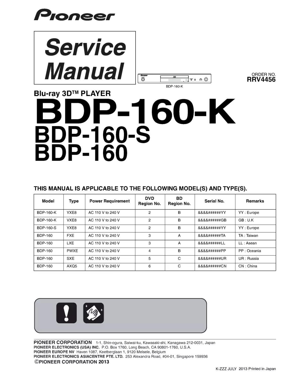
ORDER NO.
PIONEER CORPORATION 1-1, Shin-ogura, Saiwai-ku, Kawasaki-shi, Kanagawa 212-0031, Japan
PIONEER ELECTRONICS (USA) INC. P.O . Box 1760, Long Beach, CA 90801-1760, U.S.A.
PIONEER EUROPE NV Haven 1087, Keetberglaan 1, 9120 Melsele, Belgium
PIONEER ELECTRONICS ASIACENTRE PTE. LTD. 253 Alexandra Road, #04-01, Singapore 159936
PIONEER CORPORATION 2013
2013 Printed in Japan
BDP-160-K
RRV4456
Blu-ray 3DTM PLAYER
BDP-160-K
BDP-160-S
BDP-160
THIS MANUAL IS APPLICABLE TO THE FOLLOWING MODEL(S) AND TYPE(S).
Model
Type
Power Requirement
DVD
Region No.
BD
Region No.
Serial No.
Remarks
BDP-160-K
YXE8
AC110Vto240V
2
B
&&&&######YY
YY : Europe
BDP-160-K
VXE8
AC110Vto240V
2
B
&&&&######GB
GB:U.K
BDP-160-S
YXE8
AC110Vto240V
2
B
&&&&######YY
YY : Europe
BDP-160
FXE
AC110Vto240V
3
A
&&&&######TA
TA : Taiwan
BDP-160
LXE
AC110Vto240V
3
A
&&&&######LL
LL : Asean
BDP-160
PWXE
AC110Vto240V
4
B
&&&&######PP
PP : Oceania
BDP-160
SXE
AC110Vto240V
5
C
&&&&######UR
UR : Russia
BDP-160
AXQ5
AC110Vto240V
6
C
&&&&######CN
CN : China
K-ZZZ JULY
2
BDP-160-K
1
2
3
4
A
B
C
D
E
F
1
2
3
4
SAFETY INFORMATION
This service manual is intended for qualified service technicians; it is not meant for the casual do-it-
yourselfer. Qualified technicians have the necessary test equipment and tools, and have been trained
to properly and safely repair complex products such as those covered by this manual.
Improperly performed repairs can adversely affect the safety and reliability of the product and may
void the warranty. If you are not qualified to perform the repair of this product properly and safely, you
should not risk trying to do so and refer the repair to a qualified service technician.
LABEL CHECK
The following caution appears on your unit.
Location: inside of the unit
BDP-160/AXQ5
(Printed on the Rear Panel)
BDP-160/YXE8, /VXE8,
/SXE, /PWXE, /LXE
Laser Pickup specifications and Laser characteristics
BD
Wave length : 405 nm
Operating output : 1.16 mW CW, Class 1
Maximum output : Class 2 (under fault condition)
DVD
Wave length : 658 nm
Operating output : 178 W CW, Class 1
Maximum output : Class 1 (under fault condition)
CD
Wave length : 790 nm
Operating output : 174 W CW, Class 1
Maximum output : Class 1 (under fault condition)
The following caution label appears on
your unit.
Location: inside of the unit
3
BDP-160-K
5
6
7
8
5
6
7
8
A
B
C
D
E
F
CONTENTS
SAFETY INFORMATION ......................................................................................................................................................... 2
1. SERVICE PRECAUTIONS.................................................................................................................................................... 4
1.1 NOTES ON SOLDERING............................................................................................................................................... 4
2. SPECIFICATIONS................................................................................................................................................................. 5
2.1 ACCESSORIES.............................................................................................................................................................. 5
2.2 SPECIFICATIONS .......................................................................................................................................................... 5
3. BASIC ITEMS FOR SERVICE .............................................................................................................................................. 6
3.1 CHECK POINTS AFTER SERVICING ........................................................................................................................... 6
3.2 PCB LOCATIONS ........................................................................................................................................................... 7
3.3 JIGS LIST ....................................................................................................................................................................... 7
4. BLOCK DIAGRAM ................................................................................................................................................................ 8
4.1 OVERALL CONNECTION DIAGRAM ............................................................................................................................ 8
4.2 BLOCK DIAGRAM........................................................................................................................................................ 10
4.3 POWER BLOCK DIAGRAM ......................................................................................................................................... 12
5. DIAGNOSIS ........................................................................................................................................................................ 14
5.1 DIAGNOSIS FLOWCHART .......................................................................................................................................... 14
5.2 CONFIMATION OF THE Wi-Fi MODULE ..................................................................................................................... 19
6. SERVICE MODE ................................................................................................................................................................. 20
6.1 HOW TO ENTER TO SERVICE MODE ....................................................................................................................... 20
6.2 DESCRIPTION OF EACH ITEM................................................................................................................................... 20
6.3 DETAILED DESCRIPTION OF ITEMS USED IN SERVICE......................................................................................... 21
7. DISASSEMBLY ................................................................................................................................................................... 24
8. EACH SETTING AND ADJUSTMENT ................................................................................................................................ 32
8.1 NECESSARY ADJUSTMENT POINTS ........................................................................................................................ 32
8.2 FIRMWARE UPDATE ................................................................................................................................................... 33
8.3 METHOD OF READING OUT BARCODE DATA BY SERVICE MODE ....................................................................... 33
8.4 METHOD OF WRITING BARCODE DATA BY USING REMOTE CONTROL UNIT .................................................... 34
8.5 METHOD OF READING OUT AND WRITING BARCODE DATA BY USING PC AND SERVICE JIG ........................ 36
9. EXPLODED VIEWS AND PARTS LIST .............................................................................................................................. 40
9.1 PACKING SECTION ..................................................................................................................................................... 40
9.2 EXTERIOR SECTION .................................................................................................................................................. 42
10. SCHEMATIC DIAGRAM.................................................................................................................................................... 43
11. PCB CONNECTION DIAGRAM ........................................................................................................................................ 44
11.1 MAIN BOARD ASSY................................................................................................................................................... 44
11.2 FRONT BOARD and SWITCH BOARD ASSYS ......................................................................................................... 48
11.3 POWER BOARD ASSY .............................................................................................................................................. 50
12. PCB PARTS LIST.............................................................................................................................................................. 52
4
BDP-160-K
1
2
3
4
A
B
C
D
E
F
1
2
3
4
1. SERVICE PRECAUTIONS
1.1 NOTES ON SOLDERING
• For environmental protection, lead-free solder is used on the printed circuit boards mounted in this unit.
Be sure to use lead-free solder and a soldering iron that can meet specifications for use with lead-free solders for repairs
accompanied by reworking of soldering.
• Compared with conventional eutectic solders, lead-free solders have higher melting points, by approximately 40 oC.
Therefore, for lead-free soldering, the tip temperature of a soldering iron must be set to around 373 oC in general, although
the temperature depends on the heat capacity of the PC board on which reworking is required and the weight of the tip of
the soldering iron.
Do NOT use a soldering iron whose tip temperature cannot be controlled.
Compared with eutectic solders, lead-free solders have higher bond strengths but slower wetting times and higher melting
temperatures (hard to melt/easy to harden).
The following lead-free solders are available as service parts:
• Parts numbers of lead-free solder:
GYP1006 1.0 in dia.
GYP1007 0.6 in dia.
GYP1008 0.3 in dia.
5
BDP-160-K
5
6
7
8
5
6
7
8
A
B
C
D
E
F
2. SPECIFICATIONS
2.1 ACCESSORIES
2.2 SPECIFICATIONS
• Remote control x 1 (YXE8, VXE8, FXE, LXE, PWXE, SXE : 06-T2446E-A005) (RC-2426)
(AXQ5 : 06-T2446E-A006) (RC-2428)
• AAA/R03 dry cell batteries x 2
• Power cord
(YXE8, LXE, SXE : 51-DC0120-0CRA3)
(VXE8 : 51-DC0120-0CRD4)
(FXE : 51-NC0150-0LNA9)
(PWXE : 51-JC0120-0PNC7)
(AXQ5 : 51-GC0120-0CRA5)
• Warranty card (European models only)
• Software license notice (YXE8, VXE8, FXE, LXE, PWXE, SXE : ARC8260)
(AXQ5 : ARC8261)
• Operating instructions (YXE8 : 72-BDP160-EURB1)
(YXE8, VXE8, LXE, PWXE : 72-BDP160-GBRB1)
(FXE : 72-BDP160-TWNB1)
(LXE : 72-BDP160-TWNB1)
(SXE : 72-BDP160-RUSB1)
(AXQ5 : 72-BDP160-CHNB1)
Note
• The specifications and design of this product are subject to change without notice.
• This item incorporates copy protection technology that is protected by U.S . patents and other intellectual property
rights of Rovi Corporation. Reverse engineering and disassembly are prohibited.
Do not connect the unit through a VCR. Video signals fed through VCRs may be affected by copyright protection
systems and the picture will be distorted on the television.
• Corporation and product names mentioned herein are trademarks or registered trademarks of the respective
corporations.
Type
Blu-ray 3DTM PLAYER
Rated voltage
AC110Vto240V
Rated frequency
50 Hz/60 Hz
Power consumption
17W
Power consumption (standby)
0.3 W
Power consumption (quick start)
7W
Weight
2.0 kg
External dimensions (including projecting parts)
435mm(W)x58mm(H)x250mm(D)
Tolerable operating temperature
+5°Cto+35°C
Tolerable operating humidity
5 % to 85 % (no condensation)
Outputterminals
HDMI
1 set, 19-pin: 5 V, 250 mA
Audio outputs
2-channel (left/right)
1 set, RCA jacks
Audio output level
200 mVrms (1 kHz, –20 dB)
Frequency response
4 Hz to 88 kHz (192 kHz sampling)
Digital audio outputs Coaxial
1 set, RCA jacks
LAN
1 set, Ethernet jack (10BASE-T/100BASE-TX)
Wireless LAN (internal antenna)
Integrated IEEE 802.11n (2.4 GHz band) wireless
networking access, compatible with 802.11b/g Wi-Fi
networks
USB
2 set, Type A
Model
BDP-160
BDP-160-K
BDP-160-S
6
BDP-160-K
1
2
3
4
A
B
C
D
E
F
1
2
3
4
3. BASIC ITEMS FOR SERVICE
3.1 CHECK POINTS AFTER SERVICING
Item to be checked regarding video
Item to be checked regarding audio
Block noise
Distortion
Horizontal noise
Noise
Dot noise
Volume too low
Disturbed image (video jumpiness)
Volume too high
Too dark
Volume fluctuating
Too bright
Sound interrupted
Color disappearance
Mottled color
No.
Procedures
Check points
1
2
3
4
5
6
Confirm the firmware version on Test Mode.
The version of the firmware must be latest.
Update firmware to the latest one, if it is not the latest.
Confirm whether the customer complain has been solved.
If the customer complain occurs with the specific disc, use it for
the operation check.
The customer complain must not be reappeared.
Video, audio and operations must be normal.
Play back a CD.
(track search)
Audio and operations must be normal.
Play back a DVD.
(Menu operation, Title/chapter search)
Video, audio and operations must be normal.
Play back a BD.
(Menu operation, Title/chapter search)
Video, audio and operations must be normal.
Check the appearance of the product.
No scratches or dirt on its appearance after receiving it for
service.
To keep the product quality after servicing, confirm recommended check points shown below.
See the table below for the items to be checked regarding video and audio.
Cleaning
Be sure to clean the following positions by using the prescribed cleaning tools shown below as occasion demands.
Refer to “7. DISASSEMBLY”.
Name
Position to be cleaned
Part No.
Remarks
Cleaning liquid
Pickup leneses
GEM1004
Cleaning paper
GED-008
7
BDP-160-K
5
6
7
8
5
6
7
8
A
B
C
D
E
F
3.2 PCB LOCATIONS
3.3 JIGS LIST
POWER BOARD ASSY
FRONT CONTROL BOARD ASSY
SWITCH BOARD ASSY
MAIN BOARD ASSY
A
D
B
WIFI MODULE ASSY
Loader ASSY
C
NOTES: - Parts marked by “NSP” are generally unavailable because they are not in our Master Spare Parts List.
- The > mark found on some component parts indicates the importance of the safety factor of the part.
Therefore, when replacing, be sure to use parts of identical designation.
Mark No. Description
Part No.
LIST OF ASSEMBLIES
1..MAIN BOARD ASSY
08-BDP160-MA0/Y
(YXE8, VXE8, PWXE, SXE)
1..MAIN BOARD ASSY(FXE)
08-BDP160-MA2/F
1..MAIN BOARD ASSY(LXE)
08-BDP160-MA2/L
1..MAIN BOARD ASSY(AXQ5)
08-BDP160-MA1/A
1..FRONT BOARD ASSY
08-BDP160-FV0
1..SWITCH BOARD ASSY
08-BDP160-SB0
> 1..POWER BOARD ASSY
08-P015BE-PW0
Mark No. Description
Part No.
DVD Test Disc (DVD-Video)
BD-ROM Test Disc
Name
Jig No.
Remarks
Check of DVD-Video
Check of BD-ROM
GGV1025
GGV1350
BD-ROM Test Disc (One layer type)
For Adjustment
GGV1368
Service Jig
Refer to “ 8.6 METHOD OF READING OUT AND
WRITING BARCODE DATA BY USING PC AND
SERVICE JIG ”
GGF1676
(Including a USB cable)
8
BDP-160-K
1
2
3
4
A
B
C
D
E
F
1
2
3
4
4. BLOCK DIAGRAM
4.1 OVERALL CONNECTION DIAGRAM
MT8560
XP1
3PIN*2.0
3
1
10
XS135 10
2
1
XS136
2PIN*2.0
45PIN*0.5XP7
256M
N FLAS
XP19PIN*1.01914514
XP17 (USB_1)
4PIN*2.0
14
P2 (USB_2)
10
XP18
P1 (Ethernet )
P5 (HDMI)
USB_1
USB_2
G55
DC
SWIT
TI2050
GND
POWER_K-
TRAYIN#
GND
LOAD+
LOAD-
10PIN
U
COMMON
V
W
GND
B+
B-
A-
A+
POWER+12V_DVCCGNDIRWAKE_UPREBEOOT
WiFi MODULE ASSY
(07-WN713N-M1B)
XP4
4PIN*2.0
XP2
4PIN*2.0
14
3.3VGNDUSBP0USBM0
LOADER ASSY
(08-LTCBS9-222160)
SWITCH BOARD ASSY
(08-BDP160-SB0)
C
A MAIN BOARD ASSY
(YXE8, VXE8, PWXE, SXE :08-BDP160-MA0/Y)
(FXE :08-BDP160-MA2/F)
(LXE :08-BDP160-MA2/L)
(AXQ5 :08-BDP160-MA1/A)
9
BDP-160-K
5
6
7
8
5
6
7
8
A
B
C
D
E
F
4PIN*2.5
CN503
1
4
0
AMP&LPF DRV632
POWER AC IN
1
10
XS135 10PIN*2.0
256M
N FLASH
1Gbit DDR3 x 1
XS221
1
10
XP18
XP1
4PIN*2.5
1
4
VIDEO
LPF
DMI)
4PIN*2.0
USB 1
R
L
COAXIAL
SPDIF
P3 (RCA port)
5V
USB_1
USB_2
G556B
DC
SWITCH
12V
12V
GND
GND
2Gbit DDR3 x 1
CVBS
CVBS
1
4
10PIN*2.0
POWER+12V_DVCCGNDVDVCLKVSTBIRWAKE_UPREBEOOT
DC-DC
DC-DC
5V
G5175
9.5V
12V
12V
AS1117
EUP3484S
1.2V
1.5V
3.3V
3.3V_STBY
9.5V REG.
FRONT BOARD ASSY
(08-BDP160-FV0)
B
POWER BOARD ASSY
(08-P015BE-PW0)
D
Therefore, when replacing, be sure to use parts of identical designation.
When ordering service parts, be sure to refer to "EXPLODED VIEWS and PARTS LIST" or "PCB PARTS LIST".
The > mark found on some component parts indicates the importance of the safety factor of the part.
10
BDP-160-K
1
2
3
4
A
B
C
D
E
F
1
2
3
4
4.2 BLOCK DIAGRAM
8
OPU
TRAY
IN/OUT
MOTOR
BCHD
45PIN FFC
9PIN FFC
4PIN
A CH DDR3
MOTOR
DRIVER
RESET
OSCILLATOR
(27MHz30ppm)
TRANSFO
RMER
RF SIGNAL
SPINDLE&SL
ED
MOTOR
TRAYTRAVERSE
MAIN BOARD
Front BOARD
BD
LOADER
LAN
USB
Data
Power
Others
Control
PSU BOARD
AC IN
100,110~22
0Vac
POWER
manageme
nt IC
12V
IR
TBL3000+
SANYO480
4PINS
WIFI port
BDP-160 Block Diagram:
LOADER ASSY
(08-LTCBS9-222160)
POWER BOARD ASSY
D
Therefore, when replacing, be sure to use parts of identical designation.
When ordering service parts, be sure to refer to "EXPLODED VIEWS and PARTS LIST" or "PCB PARTS LIST".
The > mark found on some component parts indicates the importance of the safety factor of the part.
11
BDP-160-K
5
6
7
8
5
6
7
8
A
B
C
D
E
F
MTK
8560
10 PINS
DC-DC
LDO
Coaxial/L/R
B CH DDR3
DC-
DC
10PINS
5V
SPI
IR
MOS
NAND
FLASH
HDMI
TRANSFO
RMER
JTAG
12V
12V
5V
12V_
5V_D
USB_VCC
9V
1.5V
3.3V
3.3V_STBY
5V
5V
D
t BOARD
HDMI
LAN
COAXIAL/L/R
USB port
VFD
LED
KEYS
KEYS
Amplifier
1.2V
Power
switch
12V
USB
12V
USB
USB
12V
FRONT BOARD ASSY
B
A MAIN BOARD ASSY
12
BDP-160-K
1
2
3
4
A
B
C
D
E
F
1
2
3
4
4.3 POWER BLOCK DIAGRAM
BDP-160U4OPWRSB12V1.2VU1MT85601.5VOPWRSBU101/21.2VA1.2V1.2VR36R37DDR_VREF3.3V_STBYCECCircuitU13AS9632APU8256MBNANDFlashR23FB20D3.3VU409TPIC2050G4FTSDriverVCC_DFB19FB32MVCC_TAVCC+12V_D1.2VFB18M12V_TU9ASS1117VCC_BD_LDRESETCircuitXP71234U102/2XP15D552CN503PWBoardL5503.3uL12.2uL42.2uDDRIC_VREFDCDCConv.U5FB112V5VDCDCConv.U4OPWRSBL5L22.2u3.3V3.3VU2DDR3-13331GbDDR3U3DDR3-13332GbDDR391234POWERBOARDASSYC
13
BDP-160-K
5
6
7
8
5
6
7
8
A
B
C
D
E
F
Se+12V_D1.2V16XP1FB18M12V_TU9ASS1117VCC_BD_LD+12V_DJ1HDMITerminalF1HDMI_VCCHigh-SideSW1XP17USB_VCC115VCCtoFrontUSBtoFrontXP73010VCC_PDICVCC_HFMtoPickupU102/2U135PT6312FLDriverFL_ACCircuitIR1IRMVFD135FLDisplay69R154R1551k+5VZD136R1671004U11G556B1USB_VCC0P2USBTerminalP221USBTerminalXS135ZD135XS221MainBoardFVBoard-24V_D+12V_DVCCVCC_USB93.3VWIFIBoardR973FB21BoostVCCFRONTBOARDASSYBAMAINBOARDASSY
14
BDP-160-K
1
2
3
4
A
B
C
D
E
F
1
2
3
4
5. DIAGNOSIS
5.1 DIAGNOSIS FLOWCHART
No
Yes
Yes
No
No
Yes
No
Yes
Yes
No
SW1OFF:5V
SW1ON :0V
(GND)
Check whether either the
remote controller or the Main Unit
power button can not turn
on the power supply.
Only the
remote controller
Go to the flowchart for
“Remote control does
not work”
Both or only the Main
Unit power button
Check whether the
voltage of XP1(pin 1 and
pin 2) on the MAIN BOARD ASSY
are12V
Check whether there is no problem in the
connector contact between the POWER
BOARD ASSY and the MAIN BOARD
ASSY.
If there is no problem, please replace
the POWER BOARD ASSY.
Check whether there is no problem in the
connector contact between the MAIN
BOARD ASSY and the FRONT BOARD
ASSY.
If there is no problem, please replace
the MAIN BOARD ASSY.
Check whether the
voltage of XS135(pin 6) on the
FRONT BOARD ASSY is 5 V and
X135(pin 9) is 12 V
When the remote controller and the Main
Unit power button cannot turn on the power
Check whether the
voltage of XP18(pin 10) on the
MAIN BOARD ASSY
is 0V
Replace K138 on the
FRONT BOARD ASSY
When there is no change
When there is no change
Replace the FRONT BOARD
ASSY
Replace the MAIN BOARD ASSY
* Because a failure in the hardware reset circuit
may be the cause of the inactive power supply,
please replace the MAIN BOARD ASSY.
About hardware reset sircuit.
(A circuit for providing a function to reset the
product by inserting a bar in the small hole
on the front panel)
When only the Main Unit power
button is not active to turn on the power
Check whether the
voltage of XP1(pin 1) on the
SWITCH BOARD
ASSY is 5V
Check whether there is no
problem in the connector
contact between the FRONT
BOARD ASSY and the
SWITCH BOARD ASSY.
If there is no problem, please
replace the FRONT BOARD
ASSY.
Check whether SW1
on the SWITCH BOARD ASSY
operation is
normal
Replace SW1
How to check the SW1
1. Check the conduction with
a tester after turning off the
power.
2. Check the waveform of the
XP18 (pin 7:POWER) on
the MAIN BOARD ASSY.
Replace the SWITCH
BOARD ASSY
Power does not turn on
Waveform (POWER)
1) Power does not turn on
15
BDP-160-K
5
6
7
8
5
6
7
8
A
B
C
D
E
F
No
No
Yes
Yes
No display on VFD, and
buttons do not work
Check every supply voltage on the
MAIN BOARD ASSY is normal
Check the connect line is OK
Correct connection
Replace K135, K136, K137 and K138.
If still same situation, replace the FRONT BOARD ASSY.
Yes
No
No
Check the FRONT BOARD
ASSY signals VCLK, VSTB, VD
(XS135 : pin 1,2,3)
1.Check whether the bad solder exists
U135 and pins of VFD on the FRONT
BOARD ASSY
2.Check whether the circuit
connected to K135, K136, K137, and
K138 are broken.
Check if U10 are
soldering normally on the
MAIN BOARD ASSY
Resolder Q150 and U25.
If still same situation, replace the MAIN BOARD ASSY
Yes
2) No display on VFD, and buttons do not work
16
BDP-160-K
1
2
3
4
A
B
C
D
E
F
1
2
3
4
No
Remote control
does not work
Replace the battery for remote controller
Check whether the remote
controller’s battery is
exhausted or not.
Check the IR1(ET3050)
power supply is OK,
IR1(pin 3) is about 3V
Check the VCC line(net) on the FRONT
BOARD ASSY
Replace the FRONT BOARD ASSY
Yes
Yes
No
Yes
Check the U13 power supply
(U12:pin9=3.3V)
Check whether the audio
signal is right from the
U13 (pin 3 and pin 12) on the
MAIN BOARD ASSY
Check If R76 and R108 are
soldering normally on the MAIN
BOARD ASSY
Resolder R310 and R311.
If still same situation, replace the
MAIN BOARD ASSY
Yes
No analog audio output
Replace MAIN BOARD ASSY
Yes
No
No
NO
3) No analog audio output (video output is normal)
4) Remote control does not work
17
BDP-160-K
5
6
7
8
5
6
7
8
A
B
C
D
E
F
Yes
Check the connection 4 pin cable from the
MAIN BOARD ASSY
Can’t read disc or can’t
open the disc door
Check 45 pin and 8 pin
cable from the MAIN BOARD ASSY
connection to the loader is
normal
Replace loader
No
Check whether the
loader running is normal
Fix the connection 45 pin cable or
8 pin cable.
No
Yes
Check if U9 (pin 2) voltage
is normal (about 9V)
Resolder R1376.
If still same situation,
replace the MAIN BOARD ASSY
Replace the MAIN BOARD ASSY
No
Yes
Yes
Yes
No
No
Check if R31 is soldering
normally on the MAIN BOARD ASSY
or check U9 (pin 3) voltage is
OK (about 12V)
5) Can’t read disc or can’t open the disc door
Check the U409 power supply
(pin3=12V,pin18=3.3V,
pin31andpin56=5V,
pin42andpin46=12V)
18
BDP-160-K
1
2
3
4
A
B
C
D
E
F
1
2
3
4
Check if L6 is
soldering normally on the
MAIN BOARD ASSY
No
No video display
Replace the MAIN BOARD ASSY
Yes
Check if R614 is
soldering normally on the
MAIN BOARD ASSY
No
Yes
Yes
Resolder L452.
If still same situation,
replace the MAIN BOARD ASSY
Resolder R616.
If still same situation,
replace the MAIN BOARD ASSY
Check if P1 is soldering
normally on the MAIN
BOARD ASSY
No
No
Can not connect to
network
Yes
Check if R557, R558, R559, R560 and
R583 are soldering normally on the
MAIN BOARD ASSY
Check if U12 is soldering
normally on the MAIN BOARD
ASSY
No
Yes
Yes
Resolder U14.
If still same situation,
replace the MAIN BOARD ASSY
Resolder all resistors.
If still same situation,
replace the MAIN BOARD ASSY
Resolder P2.
If still same situation,
replace the MAIN BOARD ASSY
6) No video display
7) Can not connect to wired network
19
BDP-160-K
5
6
7
8
5
6
7
8
A
B
C
D
E
F
5.2 CONFIMATION OF THE Wi-Fi MODULE
How to Check on a Smartphone (Example: iPod Touch)
1 At the top screen of an iPod Touch, select Settings.
DIRECT-zlBD
3 Check that the above-mentioned SSID ("DIRECT-xxBD")
is displayed in the "Choose a Network" box.
2 Select Wi-Fi.
Procedures:
Check if the set SSID of this unit is displayed on a device such as a PC, following the procedures shown below.
The Wi-Fi module is judged to be normal if the SSID is displayed.
If the SSID is not displayed, check the cable between the Wi-Fi Module and the MAIN BOARD Assy.
1 Check that neither the AC adapter nor the LAN cable is
connected to this unit.
2 Connect the AC adapter then press the STANDBY/ON
button on the remote control unit.
Wait 30–40 seconds.
Playback may automatically start if a disc is loaded in the
tray.
If playback starts, stop it then remove the disc.
3 After startup is finished, press the (Up) button on the
remote control unit.
Some seconds later, Wi-Fi Direct mode will start and the
SSID "DIRECT-xxBD" for distinction of the unit will be
displayed. The indication "xx" denotes arbitrary numeric
values.
4 After Wi-Fi Direct mode is established, display the list of
Wi-Fi networks for your PC, iPhone, tablet PC, or other
wireless device. If the SSID confirmed on the TV screen
is displayed, the Wi-Fi module is judged to be normal.
1 Left-click on the wireless network icon on the system tray.
2 Check that the above-mentioned SSID ("DIRECT-xxBD")
is displayed on the list that appears.
How to Check on a PC Equipped with a Wireless LAN
Device
[Windows 7]
20
BDP-160-K
1
2
3
4
A
B
C
D
E
F
1
2
3
4
6. SERVICE MODE
6.1 HOW TO ENTER TO SERVICE MODE
6.2 DESCRIPTION OF EACH ITEM
In Service Mode, there is a mixture of Design and Development, Production Line Menu and Service Menu.
Here, menu items that are usable in Service and instructions are listed.
Only use the menu explained in this document. Others are for Design and Product lines.
1. Press [Home Menu] on the remote controller and select
"Initial Setup" from the home menu.
2. Pressing the number keys on the remote control in the following
order [5] [1] [7] [7] will display the Menu screen.
(If it does not appear, slowly press the number keys with a
1 second interval.)
[1] Enter FA mode
Implemented when exchanging the Loader and MAIN BOARD ASSY. Refer to "8.1 NECESSARY ADJUSTMENT
POINTS" for details.
[2] Save FE log to USB
For Design and Development purposes and cannot be used for Service.
[3] Save FA result to USB
For Design and Development purposes and cannot be used for Service.
[4] Laser Check
Verifies laser diode. Refer to "Laser Check" for details.
[5] Enter Barcode by 2D scanner
For Production line purposes and cannot be used for Service.
[6] Repair Service
For the former model and will not be used to exchange this Loader.
[7] Enter SP Mode
Mainly for Production Line, but some items can be used in Service. Please see "SP Mode" for details.
[8] PDXY Check
Verifies misalignment of optical axis. Refer to "PDXY Check" for details.
21
BDP-160-K
5
6
7
8
5
6
7
8
A
B
C
D
E
F
6.3 DETAILED DESCRIPTION OF ITEMS USED IN SERVICE
1. [4] Laser Check
Example BD
Target:
0x01b
Meas:
0x01b
OK
0x01b X 3= 0x051
Meas is 0x051 or more : NG
0x01B X 1/3 =0x009
Meas is 0x009 or less : NG
2. [7] Enter SP Mode
Verifies the output value of each laser diode inside the pick-up area. Implement according to the following procedures.
2 After a few seconds, measurement and judgment results will be displayed as follows.
If all measurement (Meas) values are 1/3 or greater or less than triple the target values (hex), [Pass] will be displayed.
If any of the measurement values is out of this range, [NG] will be displayed.
1 Select "[4] Laser Check" with the key from the Service Mode screen and press the "ENTER" key.
(perform without disc in tray)
("0x" is simply to express the hex,
so it is not necessary in the calculation)
There are 16 items in the SP Mode, the main items being for Production line and Design/Development.
The following is to explain items usable in Service. Other items require time for completion,
or are not suited for Service purposes. If you select them by mistake,
press the [Stop] key to end that item you accidentally selected.
(none of the items will affect the main unit)
22
BDP-160-K
1
2
3
4
A
B
C
D
E
F
1
2
3
4
2-1. Start Up
2-2. Jitter Measure / BLER Measure
[ Content of test ]
Implements initial movement of the disc servo continuously.
Implement the following process 20,000 cycles.
.
TrayClose .FoucusON . TOCRead .TrayOpen
(1 cycle 15 seconds x 20000=completed in approx. 83 hours 20 minutes)
Can be implemented on all of CD, DVD, and BD. Cannot change disc during process.
[ Instructions ]
1 Select "[7] Enter SP Mode" with the key from the Service Mode screen, and press the [ENTER] key.
2 The SP Mode window menu will be displayed, so select "Start Up" and press the [ENTER] key.
3 The tray will automatically open and the dedicated screen will appear. Place the disc you wish to use
on the tray, and push it in manually. ([Close] key will not function)
4 Start Up mode will be initiated, and count will start. Implement 20,000 times (4E20 in hex),
and if no errors occur, "Pass" will appear.
If errors do occur, they will be counted. Therefore, errors can be identified without finishing the process.
[ Effective indications ]
.
Tray sometimes does not open, discs sometimes are not recognized, discs sometime do not playback,
(When indications are related to discs, implment on the type of disc which has been pointed out.
If it is the disc on which the indications occurred, possibility of reoccurrence is higher.)
[ Content of test ]
Measures the Jitter or the Block Error Rate (BLER) of the disc inserted.
Only Pass or NG will be displayed, not Measurement values.
All of CD, DVD, and BD can be judged.
[ Instructions ]
1 Select "[7] Enter SP Mode" with the key from the Service Mode screen, and press the [ENTER] key.
2 The SP Mode window menu will be displayed, so select either "Jitter Measure"
"BLER Measure," and press the [ENTER] key.
3 The tray will automatically open and the dedicated screen will appear. Place the disc you wish to use
on the tray, and push it in manually. ([Close] key will not function)
4 The tray will reopen automatically. Measurement will start when you push the tray in manually.
5 When test is completed, "Pass" or "NG" is displayed.
[ Effective indications ]
Defect related to playback (blocked noise, sound jumping, image jumping, disc is paused, freeze of screen etc.)
However, even if Pass is displayed after this test, it is difficult to determine that the Driver is normal
with these Pass judgments only.
If an NG is generated in a specific disc only, the defect is likely to be caused by the disc. If an NG is
generated in other discs too, the defect is likely to be caused by the drive part.
23
BDP-160-K
5
6
7
8
5
6
7
8
A
B
C
D
E
F
3. [8] PDXY Check
For PDXY Check, the misalignment of pick-up optical axis can be checked.
The optical axis misalignments of X-axis and Y-axis are displayed [PDX] and [PDY] with %,
respectively.
All of CD, DVD, and BD can be measured.
The method for calculating PDX and PDY is shown below.
[ Instructions ]
1 Insert a disc (BD, DVD, CD) in a nomal mode. If the playback starts, pause it.
Display the home menu and enter into the Service Mode.
In this mode, the measurement can be carried out at an arbitrary place. After a disc is inserted, play and
stop the point you want to measure, and then enter into the Service Mode.
(The pick-up position does not return even in this status. The measurement at the place is available.)
2 Select "[8] PDXY Check" with the key from the Service Mode screen, and press the [ENTER] key.
3 After the measurement is started and completed, the measurement value is displayed. If the value is
within the reference value, "Pass" is displayed.
[Effective indications]
Defect related to playback (block noise, sound jumping, image jumping, disc is paused, freeze of screen etc.)
If an NG is generated in a specific disc only, the defect is likely to be caused by the disc. If an NG is
generated in other discs too, the defect is likely to be caused by the pick-up part. If the measurement value
is very close to 40% even if an NG is not generated, the NG is likely to be caused by the disc.
PDX = ((A+B)-(C+D)) / (A+B+C+D)
PDY = ((A+D)-(B+C)) / (A+B+C+D)
24
BDP-160-K
1
2
3
4
A
B
C
D
E
F
1
2
3
4
7. DISASSEMBLY
Note 1 : Do NOT look directly into the pickup lens. The laser beam may cause eye injury.
Note 2 : Even if the unit shown in the photos and illustrations in this manual may differ from your product, the procedures
described here are common.
Top Cover
CD Door ASSY
1
1
1
1
2
5
4
11
1
2
3
[1] Exterior Section
[1-1] To p Cover
(1) Remove the six screws.
(Except BDP-160-S/YXE8 :
)
63-B30060-3H3
BDP-160-S/YXE8 only :
63-B30060-3H4-TL
(2) Remove the Top Cover while lifting the rear
side of Top Cover.
[1-2] CD Door ASSY
(1) Press the STANDBY/ON button to turn on
the power.
(2) Press the OPEN/CLOSE button to open
the Tray.
(3) Remove upward the CD Door ASSY.
(4) Press the OPEN/CLOSE button to close
the Tray.
(5) Press the STANDBY/ON button to turn off
the power.
25
BDP-160-K
5
6
7
8
5
6
7
8
A
B
C
D
E
F
Loader ASSY
Loader ASSY
• Bottom view
XP18
XP17
XP18
XP17
XP2
MAIN BOARD ASSY
MAIN BOARD ASSY
Cable 10pin 160mm
Cable 4pin 180mm
Front
Loading Rack
Emergency Disc Ejection Rod
Front Panel ASSY
• How to open the Tray when the power
cannot be turned on
When the Tray cannot be opened because the
power cannot be turned on, it can be opened
using the Emergency Disc Ejection Rod
(GGF1529). (A long, thin rod about 1 mm in
diameter can be used in place of the rod.)
Emergency Disc Ejection Rod is inserted
from Notch of the Stand of Loader ASSY, and
slide the Loading Rack in the direction of
blue arrow, as indicated in the photo.
If the Tray pops out a little, fully pull it out by
hand.
Note: The Emergency Disc Ejection Rod will
not reach the Loading Rack unless it is
inserted in slant upward direction.
[2] Front Panel Section
Remove the Top Cover and the CD Door ASSY.
(Refer to the “ [1] Exterior Section”.)
-----------------------------------------------------------------
(1) Remove the Tape
(2) Disconnect the three connectors.
Note: Two cables (Cable 4pin 180mm, Cable
10pin 160mm) connected to XP17 and
XP18 are bundled with the Tape.
You should disconnect or connect it with
care.
(3) Unhook the four hooks of the Front Panel
ASSY and remove the Front Panel Section.
Note: See note on the next page before removing
the Front Panel Section.
1
2
3x4
Stand of Loader ASSY
Emergency Disc Ejection Rod
Notch
Notch
Tape
Tape
26
BDP-160-K
1
2
3
4
A
B
C
D
E
F
1
2
3
4
Rear Panel
4
5
3
2
6
SWITCH BOARD ASSY
Bottom Plate
Ground Plate
FRONT CONTROL BOARD ASSY
XP18
XP1
XP4
XP7
XP2
XP17
XP15
MAIN BOARD ASSY
MAIN BOARD ASSY
1
1
1
∗1
XP18
XP17
MAIN BOARD ASSY
Cable 10pin 160mm
Cable 4pin 180mm
Front Panel ASSY
Ground Tape
Ground Tape
Tape
Rear Panel
Note: SWITCH BOARD ASSY and Bottom Plate
are connected with the Ground Tape.
You should remove or attach the Front
Panel Section with care.
Note on assembling
∗1: Check whether the Ground Plate has a good
contact with the Bottom Plate.
[3] MAIN BOARD ASSY
Remove the Top Cover.
(Refer to the “ [1-1] To p Cover”.)
-----------------------------------------------------------------
(1) Disconnect the seven connectors.
(2) Remove the screw (64-B30060-303 -TL)
on the rear side.
(3) Remove the screw (63-B30080-BF3-TL)
on the rear side.
(4) Remove the screw (63-B30060-3H4-TL)
of the MAIN BOARD ASSY.
(5) Remove the screw (64-W30060-304)
of the MAIN BOARD ASSY.
(6) Remove the MAIN BOARD ASSY.
Note: Two cables (Cable 4pin 180mm, Cable
10pin 160mm) connected to XP17 and
XP18 are bundled with the Tape.
You should disconnect or connect it with
care.
Note: MAIN BOARD ASSY and Rear Panel are
connected with the Ground Tape.
You should remove or attach the MAIN
BOARD ASSY with care.
27
BDP-160-K
5
6
7
8
5
6
7
8
A
B
C
D
E
F
CN503
POWER BOARD ASSY
3
3
4
2
2
3
1
Front
MAIN BOARD ASSY
Loader ASSY
2
2
1
2
2
3
XP1
XP4
XP7
[4] POWER BOARD ASSY
Remove the Top Cover.
(Refer to the “ [1-1] To p Cover”.)
-----------------------------------------------------------------
(1) Disconnect the connector.
(2) Remove the two screws (63-B30080-BF3-TL)
on the rear side.
(3) Remove the three screws (63-B30060-3H4-TL)
of the POWER BOARD ASSY.
(4) Remove the POWER BOARD ASSY.
[5] Loader ASSY and
LOADER SW BOARD ASSY
Remove the Top Cover and CD Door ASSY.
(Refer to the “ [1] Exterior Section”.)
-----------------------------------------------------------------
(1) Disconnect the three connectors.
(2) Remove the four screws. (63-B30070-3H4)
(3) Remove the Loader ASSY.
28
BDP-160-K
1
2
3
4
A
B
C
D
E
F
1
2
3
4
∗2
∗2
Loader ASSY
• Bottom side
4
1
5
LOADER SW BOARD ASSY
Loader ASSY
Front Panel ASSY
board stopper
tray stopper
Tray
tray stopper
Notes on assembling
∗2: Insert two projections on the Loader ASSY
front side in the projections of the Front
Panel ASSY.
(4) Remove the two cables by soldering iron.
(5) Pull the board stopper toward the direction of
an blue arrow and remove the LOADER SW
BOARD ASSY.
[6] Tray Belt in Loader ASSY
Remove the Top Cover.
(Refer to the “ [1-1] To p Cover”.)
-----------------------------------------------------------------
(1) Push the tray stoppers toward outside of
Loader ASSY and remove the Tray.
29
BDP-160-K
5
6
7
8
5
6
7
8
A
B
C
D
E
F
Front
2
Loading Rack
Belt
Tray
Note on assembling
∗3: When inserting the Tray, slide the Loading
Rack toward the direction of the blue arrow
and then insert the Tray.
(2) Remove the Belt.
∗3
30
BDP-160-K
1
2
3
4
A
B
C
D
E
F
1
2
3
4
FFC Cable 1.0mm
45pin FFC Cable
• Bottom view
Loader ASSY
Double Side Tape
Ground Tape
Ground Tape
claw
Styling of cables between units
When you attach each unit, make a styling and connection of cables as shown in the photo.
Caution :
Nothing should be connected to
the connector part surrounded by
red line. Be careful not to connect
by mistake.
31
BDP-160-K
5
6
7
8
5
6
7
8
A
B
C
D
E
F
Front
1
Clean the pickup lens when it is stained, using
following cleaning materials:
Cleaning liquid : GEM1004
Cleaning paper : GED-008
hooks
hooks
Pickup Lens
[1] Top Cover
(1) Unhook each two places of the hooks of right
and left and then remove the Top Cover.
Caution:
The pickup for Blu-ray is a high-precision
component; therefore, clean the lens with
enough care so as not to cause a misalignment
in the optical axis.
Top Cover
Cleaning the Pickup Lens
32
BDP-160-K
1
2
3
4
A
B
C
D
E
F
1
2
3
4
8. EACH SETTING AND ADJUSTMENT
8.1 NECESSARY ADJUSTMENT POINTS
Mechanical
point
Mechanical
point
[1] When replace the LOADER ASSY
Note : Be sure to update the firmware before starting adjustments or settings.
[2] When replace the MAIN BOARD ASSY
This time
Adjustment Points
This time
Adjustment Points
When replace the LOADER ASSY
When replace the MAIN BOARD
ASSY
Write barcode data for pickup adjustment
Electric
point
Electric
point
Note : Be sure to check the version of firmware after MAIN BOARD ASSY is replaced.
If it is not the latest firmware, update it.
Please confirm that the USB memory is recognized after inserting the USB
memory to the USB terminal. (Due to protect wrong connection)
Read out barcode data for pickup
adjustment
(Before removing MAIN BOARD ASSY)
Write barcode data for pickup adjustment
(After replacing MAIN BOARD ASSY)
[About barcode data for pickup adjustment]
[About barcode data for pickup adjustment]
A new Loader ASSY is installed in this model and it has 64 bit barcode data for pickup adjustment.
Therefore when replacing a new Loader ASSY, it is necessary to write barcode data of the new Loader Assy.
The barcode data is stored in a MAIN BOARD ASSY. Therefore when replacing the MAIN BOARD ASSY, it
is necessary to read out the original barcode data before removing it and write the data to a new MAIN
BOARD ASSY after installing it.
[How to read and write the barcode data to the unit]
[How to read and write the barcode data to the unit]
There are two methods below to read and write the barcode data to the unit.
Please perform either method when replacing MAIN BOARD ASSY or Loader ASSY.
[Attention point when replacing MAIN BOARD ASSY]
[Attention point when replacing MAIN BOARD ASSY]
When the unit is no power condition due to defective of a MAIN BOARD ASSY, original barcode data
is not able to read out from it. In case of this, please replace both of the MAIN BOARD ASSY and Loader ASSY.
Necessary tools
Good Point
Bad Point
1 Remote Control Unit
It is not necessary to prepare
other tools such as Service Jig
and PC
Need to enter 64 letters barcode
data by using a Remote Control
Unit.
2
Service Jig (GGF1676), PC,
Driver and Read/Write
Program
It is very easy to read and
write the barcode data
It is necessary to prepare other
tools such as Service Jig and PC
(But Service Jig is very cheap)
33
BDP-160-K
5
6
7
8
5
6
7
8
A
B
C
D
E
F
8.2 FIRMWARE UPDATE
8.3 METHOD OF READING OUT BARCODE DATA BY SERVICE MODE
Because of customer's demand, for the path of firmware update, the file name, and the specification of
update are constantly changing.
The following are the steps of update:
1. Before upgrade, please check the current version of firmtware installed in this machine.
You can press HomeMenu button to enter the menu, after that, press button to display
“Home Menu”“Initial Setup”“Options”“System Information“Next Screen”, then you can see the information
of current firmware version by pressing the enter button.
2. Save the updating file [DLdiscidentifier.txt],[DVD.bin] and [BDP-160_Vxx.xx .bin] to the USB memory route path.
3. After step 2, please insert the USB memory into machine. While the screen shows the information
that a USB memory has been inserted, please press HomeMenu button to enter the menu, then find
“USB devices” through “Home Menu”“Initial Setup”“Options”“Update”“USB Storage”.
After press the enter button, the system will search the upgrade file itself to upgrade.
4. After reset, the machine is available for test.
1. Enter Service Mode
2. Select "[6] Repair Service" and press "ENTER"
3. Select "Show 480 2D barcode" and press "ENTER"
4. 64 letters barcode data is displayed. Make a note of the data.
( Refer to [6.1] HOW TO ENTER TO SERVICE MODE)
Note:
The import/export methods using Service mode are not available with a unit whose firmware version is V01.02 (start
of production lot), because exported data will be erroneous. To use such methods, it is necessary to update the
firmware of the unit to a version later than V01.02.
Note that when the methods using a PC and a special tool for servicing are to be used (see "8.5 METHOD OF
READING OUT AND WRITING BARCODE DATA BY USING PC AND SERVICE JIG"), import/export can be properly
performed with a unit whose firmware version is V01.02.
34
BDP-160-K
1
2
3
4
A
B
C
D
E
F
1
2
3
4
8.4 METHOD OF WRITING BARCODE DATA BY USING REMOTE CONTROL UNIT
1. Enter Service Mode
2. Select "[6] Repair Service" and press "ENTER"
3. Select "Enter 2D barcode by remote controller" and press "ENTER"
4. Entry screen is displayed
In case of replacing Loader ASSY, check new barcode data located at
back of the Loader Assy.
If removing a screw at the back of Loader ASSY and lift it up, you can see the label
with power on state.
5. Select one of 0~9 or A~F and press "ENTER" to input barcode data one by one
Note: If accidentally a wrong value is input, it can be corrected by using "<" and ">" key to move cursor.
35
BDP-160-K
5
6
7
8
5
6
7
8
A
B
C
D
E
F
7. Then, press "ENTER" to write the bar-code data to flash
8. "Pass" is displayed when input of bar-code date is completely finished. (Press "STOP" to exit this function)
9. Refer to ["8.3 METHOD OF READING OUT BARCODE DATA BY SERVICE MODE", "8.5 METHOD OF READING OUT
AND WRITING BARCODE DATA BY USING PC AND SERVICE JIG"], display the input data by selecting
"Show 480 2D barcode".
10. Make sure whether the displayed barcode data is completely same as the barcode data of a new
Loader ASSY or original MAIN BOARD ASSY.
[NOTE ]
If the repair unit was stored by incorrect barcode data, the pickup ( Loader ASSY) might
get a damage when playing a disc.
6. Input all of 64 digit data, and then press "return"
36
BDP-160-K
1
2
3
4
A
B
C
D
E
F
1
2
3
4
8.5 METHOD OF READING OUT AND WRITING BARCODE DATA BY USING
PC AND SERVICE JIG
Download the following necessary program file and driver from service website.
1. "PL2303_Prolific_DriverInstaller_v1.5 .0 .zip " ( Driver for USB <=> RS-232C jig)
2. "Rpower_2 .9.70(KEM480).zip"
( Reading / Writing tool for BDP)
Connect a service jig to a connector located of the following picture of the MAIN BOARD ASSY with
power off condition.
1. Unzip "PL2303_Prolific_DriverInstaller_v1.5 .0 .zip".
2. Refer to "um_pl2303_DriverInstallerManual_v1.5.0",install PL2303 Driver to PC.
3. Connect a service jig (GGF1674) to PC by USB cable and check the driver and jig are installed successfuly.
4. After installation, check which ComPort is selected to the service jig by Device Manager screen of PC.
( The following example is set COM4 for this jig. )
1. Unzip "Rpower_2.9 .70(KEM480).zip"
2. Click Rpower.exe
3. If Com port error pop up, click [OK] to continue the tool.
4. Select Comport number from ComPort window to the same ComPort of PC which is checked by 3-4 .
Service jig [GGF1676]
Connecter location
4. Start up reading and writing tool of barcode data for pickup adjustment
3. Installation of driver and connection for service jig
2. Connection of the service jig (GGF1676) and a unit
1. Preparation
(GGF1676 is included a USB cable.)
5-1 . Read barcode data
4-4. Select ComPort
4-6 . Click Tray Out
37
BDP-160-K
5
6
7
8
5
6
7
8
A
B
C
D
E
F
5. Turn on the unit and wait until "ready" is shown on display.
6. Click "Tray Out "window in order to check communication between PC and the unit.
If tray is not opened, please check connecter location of the jig and ComPort number.
1. Click "Read" window.
2. The barcode data in MAIN BOARD ASSY is displayed on window of "Bar Code" and then
Status of "Pass" is changed green color.
3. Turn off the unit and remove cable of the service jig from MAIN BOARD ASSY.
4. After installing a new MAIN BOARD ASSY, connect the jig cable to the MAIN BOARD ASSY and
perform the above steps 4.5 and 4.6 .
( In case of replacing MAIN BOARD ASSY, skip below steps 1 and 2 and start from step 3. )
1. If replacing Loader ASSY, check a new barcode data located at back side of the Loader
ASSY. (Service parts of Loader ASSY has a label in order to show the barcode data.)
If removing a screw at the back of Loader ASSY and lift it up, you can see the label with power on state.
2. Type all the barcode data (64 letters) to "Bar Code" window.
[NOTE]
When replacing MAIN BOARD ASSY,
perform this step before removing MAIN
BOARD ASSY and don't close the
Rpower.exe.
5. Read out barcode data for pickup adjustment
6. Write the barcode data to MAIN BOARD ASSY
38
BDP-160-K
1
2
3
4
A
B
C
D
E
F
1
2
3
4
1. Click "Read" window and Make sure whether the displayed barcode data is completely
same as the written barcode data at the above step 6.2 .
7. Check of the written barcode data at MAIN BOARD ASSY
3. Click Write window. When the barcode data is successfully written to the MAIN
BOARD ASSY, "PASS" is shown on the states window.
39
BDP-160-K
5
6
7
8
5
6
7
8
A
B
C
D
E
F
40
BDP-160-K
1
2
3
4
A
B
C
D
E
F
1
2
3
4
9. EXPLODED VIEWS AND PARTS LIST
9.1 PACKING SECTION
NOTES: - Parts marked by “NSP” are generally unavailable because they are not in our Master Spare Parts List.
- The > mark found on some component parts indicates the importance of the safety factor of the part.
Therefore, when replacing, be sure to use parts of identical designation.
- Screws adjacent to b mark on product are used for disassembly.
- For the applying amount of lubricants or glue, follow the instructions in this manual.
(In the case of no amount instructions, apply as you think it appropriate.)
41
BDP-160-K
5
6
7
8
5
6
7
8
A
B
C
D
E
F
(1) PACKING SECTION PARTS LIST
(2) CONTRAST TABLE
BDP-160-K/YXE8, BDP-160-K/VXE8, BDP-160-S/YXE8, BDP-160/SXE, BDP-160/PWXE, BDP-160/LXE, BDP-160/FXE and
BDP-160/AXQ5 are constructed the same except for the following:
Mark No.
Description
Part No.
NSP 1 Software License Notice
See Contrast table (2)
2 Remote Control Unit
See Contrast table (2)
> 3 AC Power Cord
See Contrast table (2)
4 Operating Instructions
See Contrast table (2)
5 Operating Instructions
See Contrast table (2)
6 Polyethylene Bag
74-053035-50GB1-TL
7 Gift Box
See Contrast table (2)
8 Right Card
76-104530-0AP-TL
9 Left Card
76-104540-0AP-TL
10 Pad
76-984950-0AP
NSP 11 AAA/R03 Dry Cell Battery
49-382380-BAT
NSP 12 Waranty Card
See Contrast table (2)
Mark No.
Symbol and
Description
BDP-160-K/
YXE8
BDP-160-K/
VXE8
BDP-160-S/
YXE8
BDP-160/
SXE
BDP-160/
PWXE
BDP-160/
LXE
BDP-160/
FXE
BDP-160/
AXQ5
NSP 1 Software
License Notice
ARC8260 ARC8260 ARC8260 ARC8260 ARC8260 ARC8260 ARC8260 ARC8261
2 Remote
Control Unit
06-T2446E-
A005
06-T2446E-
A005
06-T2446E-
A005
06-T2446E-
A005
06-T2446E-
A005
06-T2446E-
A005
06-T2446E-
A005
06-T2446E-
A006
> 3 ACPower
Cord
51-DC0120-
0CRA3
51-DC0120-
0CRD4
51-DC0120-
0CRA3
51-DC0120-
0CRA3
51-JC0120-
0PNC7
51-DC0120-
0CRA3
51-NC0150-
0LNA9
51-GC0120-
0CRA5
4 Operating
Instructions
72-BDP160-
EURB1
Not used
72-BDP160-
EURB1
Not used
Not used
Not used
Not used
Not used
5 Operating
Instructions
72-BDP160-
GBRB1
72-BDP160-
GBRB1
72-BDP160-
GBRB1
72-BDP160-
RUSB1
72-BDP160-
GBRB1
72-BDP160-
TWNB1
72-BDP160-
TWNB1
72-BDP160-
CHNB1
7 Gift Box
76-104520-
0ATE3
76-104520-
0ATE6
76-104520-
0ATE4
76-104520-
0ATE8
76-104520-
0ATE7
76-104520-
0ATE9
76-104520-
0ATE5
76-104520-
0ATF1
NSP12WarantyCard •••••
•••••
•••••
•••••
Not used
Not used
Not used
•••••
42
BDP-160-K
1
2
3
4
A
B
C
D
E
F
1
2
3
4
9.2 EXTERIOR SECTION
B
A
C
A
C
B
E
D
A
A
B
A
1/2
2/2
C
Double Side
Tape
Tape
Tape
CONTACTSIDENON-CONTACTSIDE
43
BDP-160-K
5
6
7
8
5
6
7
8
A
B
C
D
E
F
(1) EXTERIOR SECTION PARTS LIST
(2) CONTRAST TABLE
BDP-160-K/YXE8, BDP-160-K/VXE8, BDP-160-S/YXE8, BDP-160/SXE, BDP-160/PWXE, BDP-160/LXE, BDP-160/FXE and
BDP-160/AXQ5 are constructed the same except for the following:
10. SCHEMATIC DIAGRAM
There is no information to be shown in this chapter.
Mark No.
Description
Part No.
1 WIFI MODULE ASSY
07-WN713N-M1B
2 FRONT CONTROL BOARD ASSY 08-BDP160-FV0
3 MAIN BOARD ASSY
See Contrast table (2)
4 SWITCH BOARD ASSY
08-BDP160-SB0
5 LOADER SW BOARD ASSY 08-BDP160-SW0
6 POWER BOARD ASSY
08-P015BE-PW0
7 Loader ASSY
08-LTCBS9-222160
8 Cable 2pin 140mm
46-FH014T-02P-TL
9 Cable 10pin 160mm
46-FH016T-10SA
10 Cable 4pin 180mm
46-FH018F-04MA-TL
11 Tact Switch
48-TAC020-XX0
12 Crystal Resonator 27
45-OSC27M-0YAGA
13 WiFi 4pin Cable
46-FF018F-04SA1
14 Cable 4pin 340mm
46-FF034T-04H
15 FFC Cable 1.0mm
46-HH024C-09BV-TL
16 45pin FFC Cable
46-KF022C-45BUG-TL
17 CD Door ASSY
08-BDP150-DA1
18 Front Panel ASSY
See Contrast table (2)
19 Belt
59-108150-000-TL
20 Sponge
54-136050-000
21 Rubber Pad
54-907220-000-TL
22 Ground Plate
67-BD14Q1-0B0
23 Top Cover
See Contrast table (2)
24 Rear Panel
See Contrast table (2)
25 Bottom Plate
67-BD15R1 -1E0
26 S/TScrewB2.6X6
63-B26060-BF4
27 Screw
63-B30060-3H3
28 ST Screw B3X6 Silver
63-B30060-3H4-TL
29 Screw
63-B30070-3H4
30 S/T Screw B 3X8 BF
63-B30080-BF3-TL
31 Triangle M/C Screw B3X4
64-B30040-3H4-TL
32 M/CScrew3X6B
64-B30060-303 -TL
33 Triangle M/C Screw W3X6 64-W30060-304
34 Screw
See Contrast table (2)
Mark No.
Description
Part No.
Mark No.
Symbol and
Description
BDP-160-K/
YXE8
BDP-160-K/
VXE8
BDP-160-S/
YXE8
BDP-160/
SXE
BDP-160/
PWXE
BDP-160/
LXE
BDP-160/
FXE
BDP-160/
AXQ5
3 MAIN BOARD
ASSY
08-BDP160-
MA0/Y
08-BDP160-
MA0/Y
08-BDP160-
MA0/Y
08-BDP160-
MA0/Y
08-BDP160-
MA0/Y
08-BDP160-
MA2/L
08-BDP160-
MA2/F
08-BDP160-
MA1/A
18 FRONT
PANEL ASSY
08-BDP160-
FA0
08-BDP160-
FA0
08-BDP160-
FA1
08-BDP160-
FA0
08-BDP160-
FA0
08-BDP160-
FA0
08-BDP160-
FA0
08-BDP160-
FA0
23 Top Cover
67-BD14T1-
0E0B1-TL
67-BD14T1-
0E0B1-TL
67-BD14T1-
0E0B2
67-BD14T1 -
0E0B1-TL
67-BD14T1 -
0E0B1-TL
67-BD14T1-
0E0B1-TL
67-BD14T1-
0E0B1-TL
67-BD14T1-
0E0B1-TL
24 Rear Panel 67-BD15B1-
1E0C1
67-BD15B1-
1E0C1
67-BD15B1-
1E0C2
67-BD15B1 -
1E0C5
67-BD15B1-
1E0C4
67-BD15B1-
1E0C6
67-BD15B1-
1E0C3
67-BD15B1-
1E0C7
34 Screw
63-B30060-
3H3
63-B30060-
3H3
63-B30060-
3H4-TL
63-B30060-
3H3
63-B30060-
3H3
63-B30060-
3H3
63-B30060-
3H3
63-B30060-
3H3
44
BDP-160-K
1
2
3
4
A
B
C
D
E
F
1
2
3
4
11. PCB CONNECTION DIAGRAM
11.1 MAIN BOARD ASSY
A
XP7LOARDERASSYXP4XP1
XS135
XP18
B
XS221
XP17
B
D
SIDE A
MAIN BOARD ASSY
A
NOTE FOR PCB DIAGRAMS :
1. View point of PCB diagrams.
Capacitor
Connector
P.C.Board Chip Part
SIDE A
SIDE B
45
BDP-160-K
5
6
7
8
5
6
7
8
A
B
C
D
E
F
A
XS221
XP17
B
CN503
XP16
D
SIDE A
46
BDP-160-K
1
2
3
4
A
B
C
D
E
F
1
2
3
4
A
XP17
XP16
SIDE B
MAIN BOARD ASSY
A
47
BDP-160-K
5
6
7
8
5
6
7
8
A
B
C
D
E
F
A
XP4XP1
XP18
XP17
SIDE B
48
BDP-160-K
1
2
3
4
A
B
C
D
E
F
1
2
3
4
11.2 FRONT BOARD and SWITCH BOARD ASSYS
BC
XP1XP1XS136XS136
SIDE B
FRONT BOARD ASSY
B
C SWITCH BOARD ASSY
SIDE A
FRONT BOARD ASSY
B
C SWITCH BOARD ASSY
49
BDP-160-K
5
6
7
8
5
6
7
8
A
B
C
D
E
F
C
B
XP17
XS135
A
XP16
XS221
A
SIDE B
SIDE A
50
BDP-160-K
1
2
3
4
A
B
C
D
E
F
1
2
3
4
11.3 POWER BOARD ASSY
D
D
ACINCN501CN503AXP16
SIDE A
SIDE A
D POWER BOARD ASSY
51
BDP-160-K
5
6
7
8
5
6
7
8
A
B
C
D
E
F
D
D
CN501
CN503
SIDE B
SIDE B
D POWER BOARD ASSY
52
BDP-160-K
1
2
3
4
A
B
C
D
E
F
1
2
3
4
12. PCB PARTS LIST
- Meaning of the figures and others in the parentheses in the parts list.
Example) IC 301 is on the point (face A, 91 of x-axis, and 111 of y-axis) of the corresponding PC board.
IC 301 (A, 91, 111) IC NJM2068V
5621
1R0
R50
561
473
NOTES: - Parts marked by “NSP” are generally unavailable because they are not in our Master Spare Parts List.
- The > mark found on some component parts indicates the importance of the safety factor of the part.
Therefore, when replacing, be sure to use parts of identical designation.
- When ordering resistors, first convert resistance values into code form as shown in the following examples.
Ex.1 When there are 2 effective digits (any digit apart from 0), such as 560 ohm and 47 k ohm (tolerance is shown by J = 5%,
and K = 10%).
560Ω → 56×101 →
561 ................................................................... RD1/4PU
J
47 kΩ → 47 × 103 → 473 ................................................................... RD1/4PU
J
0.5 Ω
→ R50 ................................................................................................. RN2H
K
1Ω
→ 1R0 ................................................................................................. RS1P
K
Ex.2 When there are 3 effective digits (such as in high precision metal film resistors).
5.62kΩ → 562×101 →
5621 ................................................................. RN1/4PC
F
Mark No. Description
Part No.
LIST OF ASSEMBLIES
1..MAIN BOARD ASSY
08-BDP160-MA0/Y
(YXE8, VXE8, PWXE, SXE)
1..MAIN BOARD ASSY(FXE)
08-BDP160-MA2/F
1..MAIN BOARD ASSY(LXE)
08-BDP160-MA2/L
1..MAIN BOARD ASSY(AXQ5)
08-BDP160-MA1/A
1..FRONT BOARD ASSY
08-BDP160-FV0
1..SWITCH BOARD ASSY
08-BDP160-SB0
> 1..POWER BOARD ASSY
08-P015BE-PW0
Mark No. Description
Part No.
A MAIN BOARD ASSY
MISCELLANEOUS
CRYSTAL RESONATOR 27
45-OSC27M-0YAGA
B FRONT BOARD ASSY
MISCELLANEOUS
CABLE 4PIN 180MM
46-FH018F-04MA-TL
CABLE 2PIN 140MM
46-FH014T-02P-TL
CABLE 10PIN 160MM
46-FH016T-10SA
SWITCH TACT
48-TAC020-XX0
C SWITCH BOARD ASSY
SWITCH BOARD ASSY has no service parts.
D POWER BOARD ASSY
POWER BOARD ASSY has no service parts.