/
Теги: weapons military affairs patent
Год: 1904
Текст
No. 753,414.
PATENTED MAR. 1, 1904..
G. LUGER.
RECOIL LOADING SMALL ARMS.
APPLIOATIOH PILED MAE. 17, 1900.
KO MODEL.
10 SHEETS—SHEET 1.
No. 753,414-
PATENTED MAR. 1, 1904.
G. LUGER.
RECOIL LOADING SMALL ARMS.
APPLICATION PILED MAS. 17, 1900.
KO MODEL.
10 SHEETS-SHEET 2.
No. 753,414.
PATENTED MAR. 1, 1904.
G. LUGER.
RECOIL LOADING SMALL ARMS.
APPLIOATION TILED MAE. 17, 1900.
HO MODEL.
10 SHEETS-SHEET 3.
No. 753,414.
PATENTED MAR. 1, 1904.
G. LUGER.
RECOIL LOADING SMALL ARMS.
APPLICATION FILED MAB. 17, 1900.
No. 753,414.
PATENTED MAR. 1, 1904.
G. LUGER.
RECOIL LOADING SMALL ARMS.
APPLIOATIOH FILED MAK. 17, 1800.
BO MODEL.
IO SHEETS—SHEET 5.
N.>. 753,414.
PATENTED MAR. 1, 1904.
G. LUGER.
RECOIL LOADING SMALL ARMS.
APPLIOATIOH PILED MAB. 17. 1900.
SO MODEL.
10 SHEETS—SHEET 0.
Ku. 753,414.
PATENTED MAR. 1, 1904.
G. LUGER.
RECOIL LOADING SMALL ARMS.
APPLICATION FILED MAK. 17, 1900.
EO MODEL. 10 SHEETS—SHEET 7.
No. 753,414.
PATENTED MAR. 1, 1904.
G. LUGER.
RECOIL LOADING SMALL ARMS.
APPLICATION FILED MAB. 17, 1900.
NO MODEL. 10 SHEETS—SHEET 8
No. 753,414.
PATENTED MAR. 1, 1904.
BO MODEL.
G. LUGER.
RECOIL LOADING SMALL ARMS.
APPLIOATIOH PILED MAE. 17, 1900.
10 SHEETS-SHEET 9.
No. 753,414.
PATENTED MAE. 1, 1904.
G. LUGER.
RECOIL LOADING SMALL ARMS.
APPLIOATIOH TILED MAE. 17, 1900.
HO MODEL. 10 SHEETS—SHEET 10-
No. 753,414.
Patented March 1,1904.
United States Patent Office.
GEORG LUGER, OF CHARLOTTENBURG, GERMANY.
RECOIL-LOADING SMALL-ARM.
SPECIFICATION forming part of Letters Patent No. 753,414, dated March 1,1904.
Application filed March 17,1900* Serial No* 9,083* (No model.)
To all whom it тгшу concern:
Be it known that I, Georg Luger, engineer,
a subject of the Emperor of Austria-Hungary,
residing at Weimarerstrasse 34, Charlotten-
5 burg, JKingdomuofPrussia, German Empire,
have invented certmnnewancluseful Improve-
ments in or Connected with Recoil-Loading
Small-Arms; and I do hereby declare the fol-
lowing to be a full, clear, and exact description
io of the invention, such as will enable others
skiliedin the art to which it appertains to make
and use the same.
This invention relates to improvements in
recoil-firearms provided with movable barrels
15 and toggle-actuated or knee-jointed breech-
blocks, its object being, while simplifying the
construction of breech-loading recoil-firearms
of this class, to perfect their operation in such
a manner as to enable them fully to meet all
20 reasonable requirements.
The invention has reference not only to ar-
rangements calculated to improve the mode
of operation of the most important parts of
the weapon, and more especially of the breech
25 mechanism, and to simplify their structural
features, but also to devices by the aid of
which, while the weapon is being carried from
place to place, the parts are prevented from
coming accidentally into operation when they
30 are required to remain out of action and
which in firing render it impossible for the
breech to open prematurely under the pres-
sure of the gases, so that the safety of the
marksman is under all circumstances guaran-
35 teed, and yet the readiness for firing of the
weapon is in no way impaired.
As regards first of all the breech mechan-
ism there is provided a highly important new
arrangement which enables the toggle or knee
4° joint at the barrel end, which serves to effect
a positive closing, to be extended or closed or
cranked, folded, or opened, as the case may be,
by manipulating it directly at the central
hinge or pivot-point, whereas it is a well-
45 known fact that formerly special lever mech-
anism was required to transmit motion there-
to for this purpose. The knee-joint dr toggle
is in existing arrangements secured in the
“closed” position and enabled to withstand
the pressure of the gases by a construction 50
owing to which when the links of such knee-
joint are extended its central hinge comes to
be situated a little below the end points of the
joint. This slight depression, adopted on the
1 ‘ knee-press ” principle, is intended to protect 5 5
the joint while at rest and during the rearward
traverse of the barrel from breaking open.
Now in order to make this arrangement en-
tirely secure the contrivance here adopted con-
sists in providing the rearward joint of the 60
toggle-lever with shoulders which are some-
what inclined in upward and rearward direc-
tions and which lie in close contact with con-
veniently-situated abutments and in conjunc-
tion with the pivot of the knee-joint take up on 65
behalf of the rearward lever the gas-pressure
transmitted rearward by the breech-block.
The result is that the gas-pressure in all cases
is first exerted upon the above-mentioned bev-
eled shoulders or upon the abutments sup- 70
porting them, so that only part of its weight
is brought to bear upon the pivot of the rear
lever of the joint, and which pivot is fitted
loosely in its socket, whereas in the existing
constructions this pivot had to sustain the 75
full gas-pressure and was accordingly liable
to injury or destruction by bending or break-
ing. Owing to the provision of the free space
afyove alluded to for the pivot of the rear le-
ver to work in—small as that space is—and, 80
further, of the beveled shoulders, the links of
the toggle-lever or knee-joint when extended
have, as will be more fully explained later on,
a tendency to move in such a manner that in
firing—that is, under the influence of the pres- 85
sure of the gases—before the bullet has left
the barrel, and consequently before the barrel
has receded, the premature folding or crank-
ing of the jointed links—or, in other words,
the premature opening of the breech—cannot 00
take place.
With reference to the closing-spring, which
serves to close the breech—or, in other words,
to restore the knee-joint or toggle after it has
been opened or cranked to its closed or ex- 95
' tended position—the improvement which this
invention provides is that a flat spring is used
for the purpose, which is extended to its full
a
753,414
length, or approximately so, within the neck
of the butt, the operative* or free upper end
of such spring being connected to a swinging
arm suspended from the rearward link or le-
5 ver of the knee-joint or toggle, owing to the
intermediate agency of which arm the said
spring, though having but a comparatively
narrow space to work in, is enabled to control
the movements of the knee-joint or toggle
о within given and relatively wide limits.
In oraer to facilitate and simplify as far as
practicable the operations of taking the fire-
arm to pieces and afterward refitting the
same, the device here adopted consists in con-
5 necting the portion of the weapon which com-
Erises the receiver and the barrel with the
utt or handle-piece, which receives that por-
tion, by means of a sliding and revoluble bolt
fitted in the butt so as to be laterally remov-
to able and constituting what it is proposed to
describe as the “breech-holder,” a projecting
part or stop of which is adapted to rest di-
rectly or indirectly against an extension or
projection on the lower side of the barrel.
>5 While the barrel is at rest—that is, in the for-
ward position—the barrel-tube or its exten-
sion is, under the influence of the closing
spring, which maintains the linked levers or
toggle in the extended condition and the bar-
30 rel in its forward position, firmly pressed
against the bolt, or rather the stop of the bolt,
so that consequently the said closing-spring
itself serves to secure the connection of the
barrel or barrel-tube and the receiver with the
35 butt
The invention further comprises a novel au-
tomatic arresting arrangement for keeping
thebreech open after the contents of the maga-
zine have been exhausted. It consists of a
ao special arresting-lever located within the fire-
arm on one side of the magazine, close to the
opening through which the cartridges pass
into the breech, such lever being adapted
when in consequence of the magazine being
45 empty the cartridge-feeder is raised after the
last cartridge has been fired to be moved into
the operative position by a stop, stud, or the
like, connected with the said cartridge-feeder
in such a manner that one end of it rests against
50 a shoulder of the breech-block, thereby pre-
venting its moving into the closed position.
Now even should the empty magazine be re-
moved the arresting-lever being engaged with
the breech-bolt still owing to the action of the
55 breech-closing spring, compels the breech to
remain open, so that for the purpose of in-
serting a freshly-filled magazine and loading
the barrel the necessity of first reopening the
breech is avoided. The button or stud with
60 which the cartridge-feeder is provided to en-
able it to operate the arresting-lever will at
pie same time render signal service in depress-
ing the feeder-spring while the magazine is
being filled.
Certain improvements, to be more fully de- 65
scribed hereinafter, have also been made in
the trigger and in the means for securing the
same.
In the accompanying drawings, in which a
recoil-firearm in the form of a pistol con- 70
structed in accordance with the present inven-
tion is represented, by way of example, and
in which like parts are indicated by similar
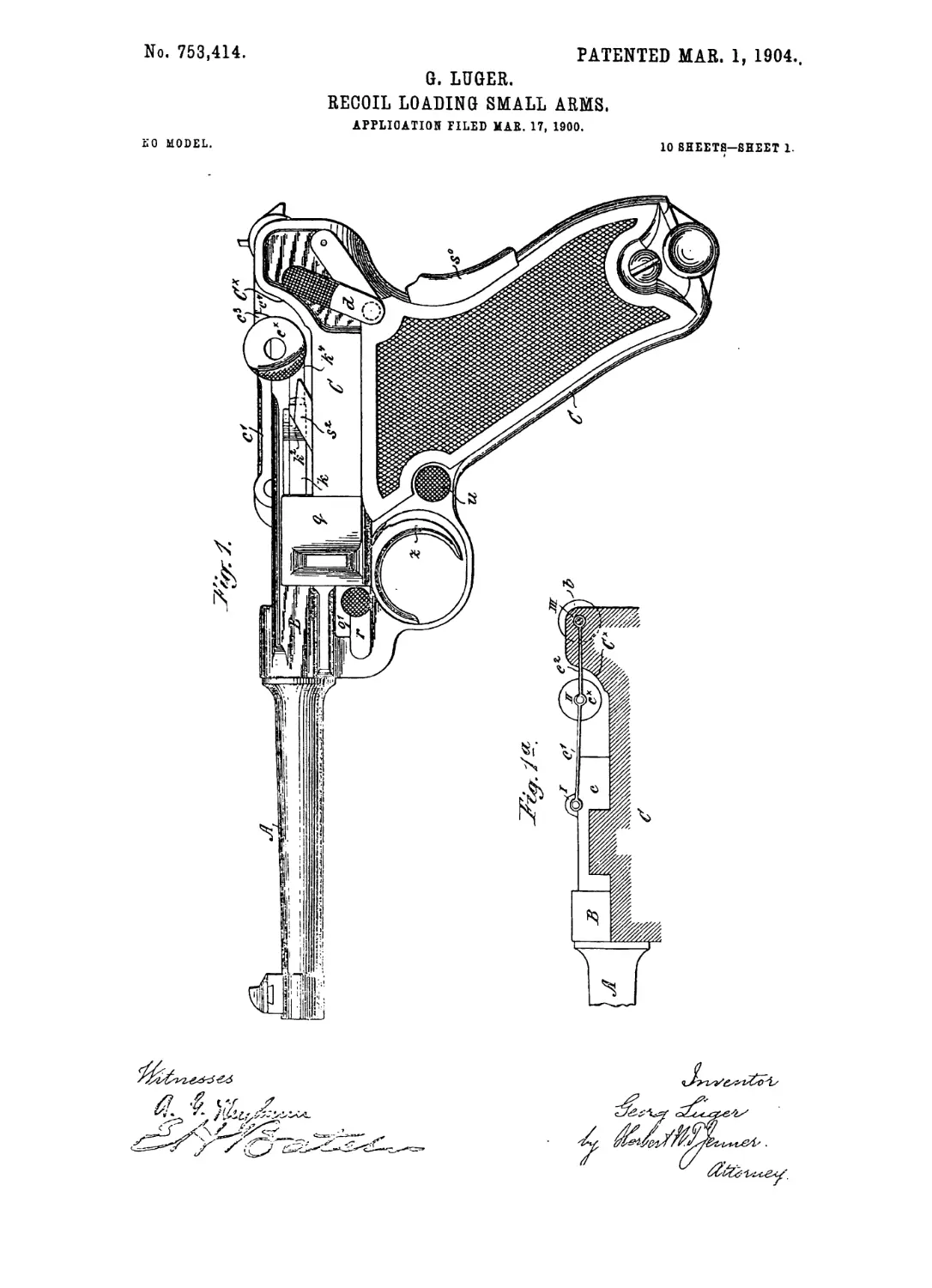
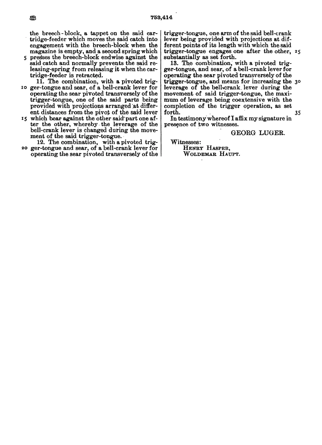
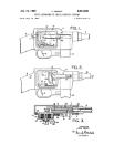
letters of reference, Figure 1 is a left-hand
side elevation of the pistol with all the opera- 75
tive parts secured against accidental move-
ment Fig. la is a corresponding diagram
illustrating the position of the breech mech-
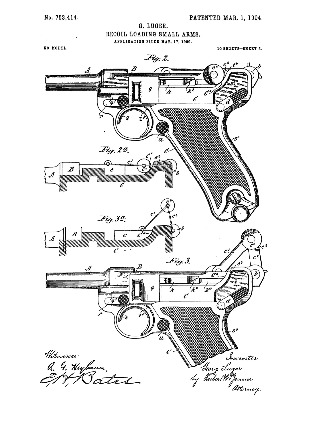
anism or knee-joint Fig. 2 is a similar view
to Fig. 1, but showing the pistol after firing 80
in the first stage of the rearward motion of
the barrel—that is, before the breech knee-
joint or toggle has been retracted or opened.
Fig. 2* is a corresponding diagram of parts.
Fig. 3 is a similar view to Fig. 2," but show- 85
ing the pistol with the breech open and the
knee-joint or toggle retracted and the barrel
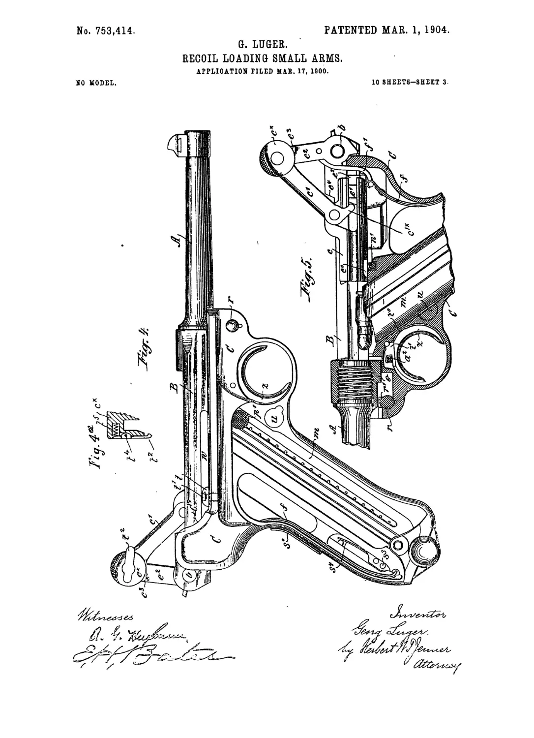
in its rearmost position. Fig. 3a is a corre-
sponding diagram of parts. Fig. 4 is a view
taken from the right-hand side, representing 90
the parts of the pistol in the same position
as in Fig. 3, but with the wooden butt casing
or shell removed. Fig. 4* is a detail side
view of the spring-actuated catch member Л
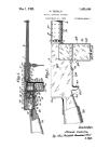
Fig. 5 is a side elevation, partly in section, 95
corresponding to Fig. 3, including an eleva-
tion of the retracted knee-joint or toggle.
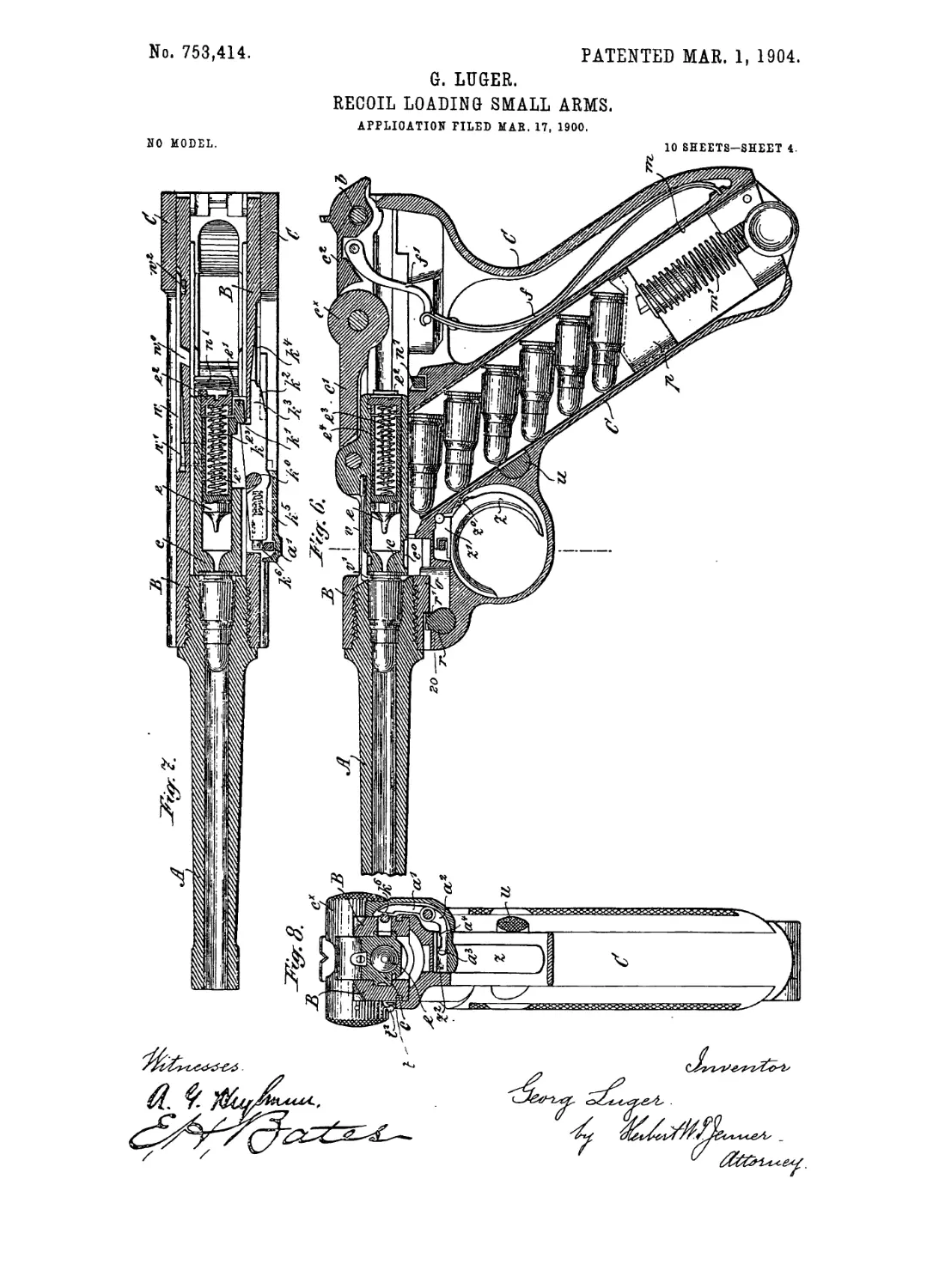
Fig. 6 is a vertical longitudinal section rep-
resenting the pistol immediately before firing.
Fig. 7 is a corresponding horizontal section 100
taken on the axial line of the barrel. Fig. 8
is a vertical transverse section taken on the
line x x, Fig. 6, and viewed from the front.
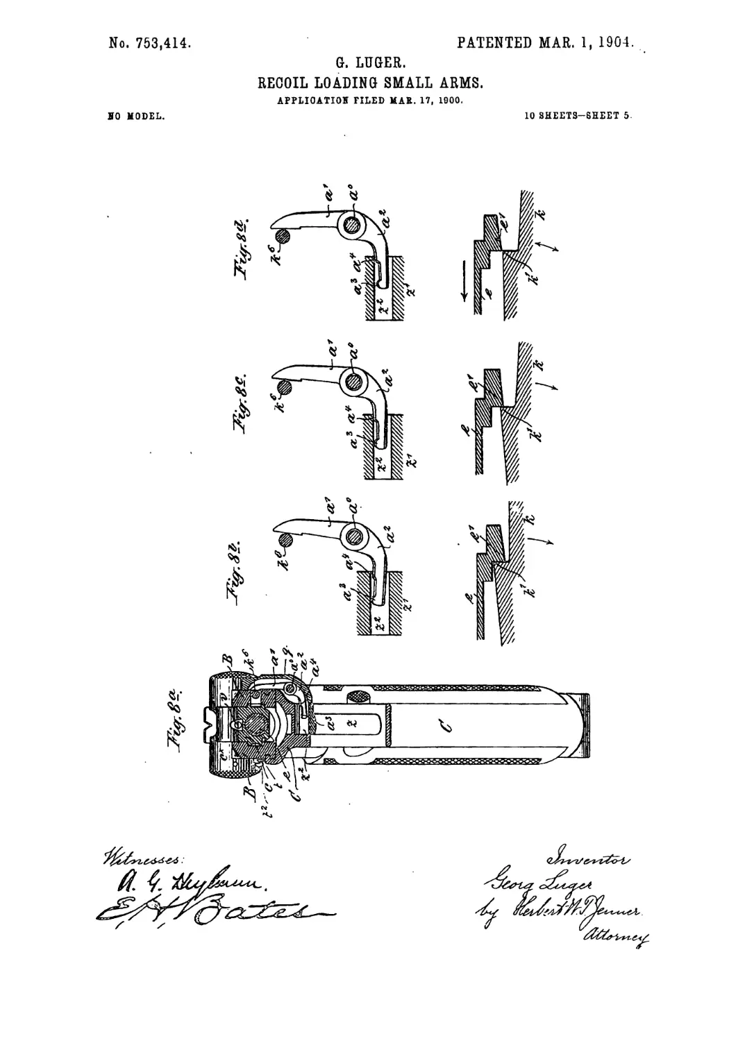
Figs. 8a to 8d illustrate the arrangement and
operation of the trigger mechanism in its 105
several positions. Figs. 8Ь, 8е, and 8* being
diagrams showing the particular position oc-
cupied at the time by the trigger-lever and
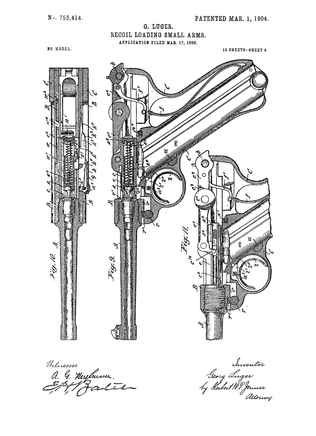
trigger-rod in each case. Fig. 9 is a similar
view to Fig. 6, but representing the pistol no
immediately after firing and showing the
magazine in elevation. Fig. 10 is a horizon-
tal section corresponding with Fig. 9. Fig.
11 is a longitudinal section, but with the
breech mechanism in elevation, showing the 115
parts in the same positions as are represented
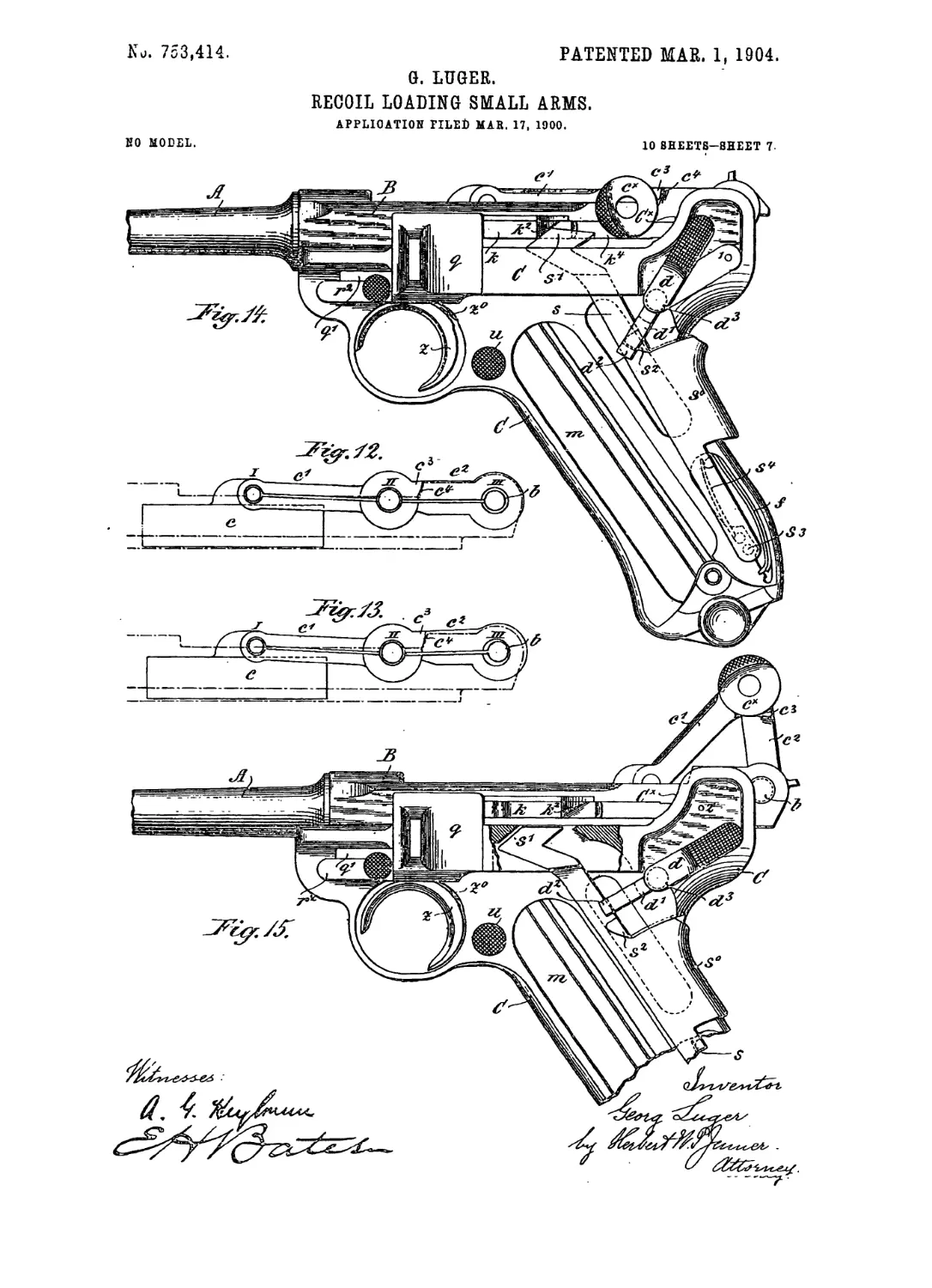
in Fig. 9. Figs. 12 and 13 are diagrams show-
ing how, before and during the firing opera-
tion, the shoulders of the rear link of the toggle-
levers cooperate with their respective abut- 120
ments and the rear pivot of the levers and also
illustrate the disposition of the toggle or knee-
joint and its constituent parts when subjected
to the pressure of the gases, but prior to the
backward stroke of the barrel. Fig. 14 is a 125
similar view to Fig. 1, illustrating the man-
ner in which the barrel and trigger are locked
against movement by means of an arresting de-
768,414
з
vice, the corresponding half of the butt-shell
Ijeing removed for the sake of greater clear-
ness. Fig. 15 is a similar view representing
the arresting device out of action, the barrel
5 and trigger being consequently unsecured and
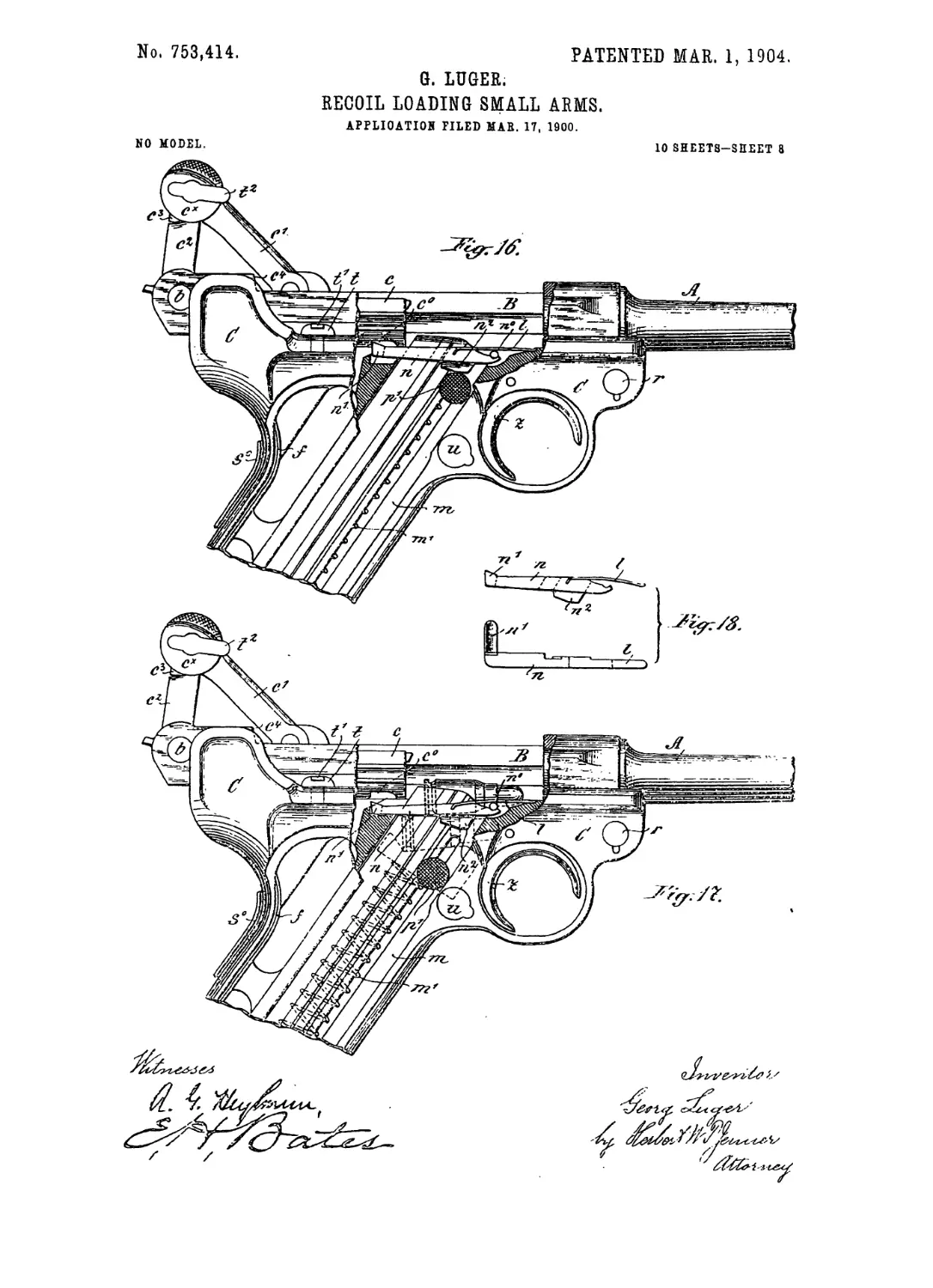
free to move. Figs. 16 and 17 are sectional
side views illustrating the arrangement and
operation of the breech-bolt-intercepting de-
vice, whereby after the magazine has been
io emptied—that is, the last cartridge fired—the
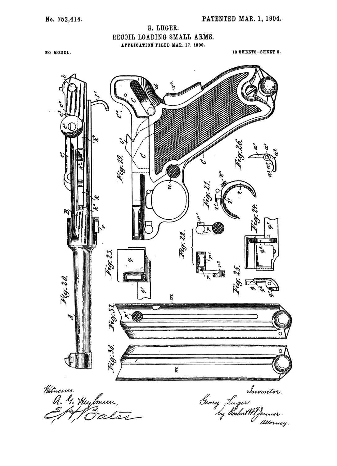
breech is held open. Fig. 18 comprises a side
elevation and a top view or plan of the breech-
bolt-intercepting lever. Fig. 19 is an eleva-
tion of the handle-piece or butt separately.
15 Fig. 20 is a separate view of the barrel with
the fork-shaped extension and the breech knee-
joint or toggle. Fig. 21 is a separate elevation
of the trigger tongue and spring. Fig. 22 is a
front and side elevation of the barrel-holding
20 bolt. Figs. 23, 25, and 24 are respectively a
side elevation, viewed from left to right, a
front elevation, and an opposite side view of
the trigger cover-plate separately. Fig. 26 is a
front elevation of the trigger-leverseparately.
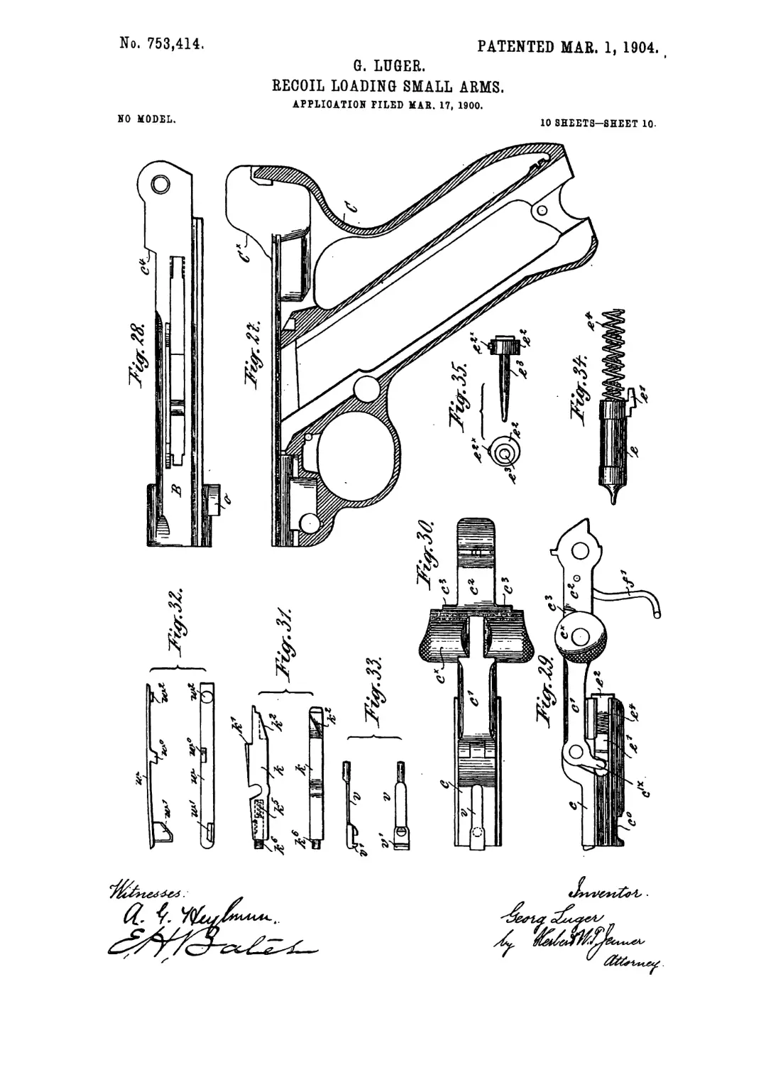
25 Fig. 27 is a vertical longitudinal section of
the butt separately. Fig. 28 is a side eleva-
tion of the fork-shaped barrel extension sepa-
rately, the breech knee-joint or. toggle and
trigger-rod being omitted. Fig. 29 is a side
30 elevation of the knee-joint or toggle and
breech-bolt separately. Fig. 30 is a top view
or plan thereof. Fig. 31 is a top view and sidq
elevation of the sear separately. Fig. 32 is
a top view and side elevation of the cartridge-
35 ejector separately. Fig. 33 is a top view and
side elevation of the cartridge-extractor sepa-
rately. Fig. 34 is a separate view of the fir-
ing-pin, together with its actuating-spring.
Fig. 35 is a front elevation and a side, eleva-
te tion of the end piece of the breech-bolt, and
Figs. 36 and 37 are opposite side elevations
of tiie magazine separately.
As is usual in recoil-firearms of the category
of arms to which the pistol represented in the
15 drawings belongs, said pistol comprises three
parts—namely, the barrel A, with the fork-
shaped extension В integral with or rigidly
attached to it, the breech-block c, and the case
C, whereby the barrel and fork-shaped ex-
.0 tension are guided and which in pistols or the
like is best formed, as shown, with its lower ex-
tension constituting the handle of the weapon.
The case C will therefore hereinafter be re-
ferred to throughout as the “handle-piece.”
5 As stated in the introductory part of this
specification, this firearm is one of the class
wherein the closing of the breech is effected
by means of a knee-joint or toggle, and it
engages one of the levers—namely, the front
о comprises a breech-block c, movable in the
fork-shaped barrel extension B, with which
one,c', while the other or rear lever, is hinged
to the said fork-shaped extension by means of
the pivot b. Now in accordance with the pres-
5 ent invention the knee-joint or toggle is
cranked, folded, or oi>ened while the barrel
performs its rearward movement. To this end
the lever-eye knuckle or boss with which the
knee-joint or toggle is provided, and which in
the example shown forms part of the rear le- 70
ver c2, though, if desired, it might be formed
on the forward lever, is extended laterally in
one or, preferably, in both directions beyond
the arms of the fork-shaped barrel extension
B, thus forming studs, projections, or shoul- 75
ders, which in the drawings are marked c*.
In the path of these studs or projections c* in
the present example suitably-curved guide-
surfaces Cx are provided on both sides of the
handle-piece, which when the barrel recedes 3o
are impinged upon by the above-mentioned
studs or projections c* » which by reason of thei r
shape are termed “ knee-eyes ” or u link-eyes,”
so that when a shot is fired they are by the
effect of the recoil moved upward, and thus З5
become the means of cranking or “opening”
the linked levers. During the first stage of
this operation the closing-spring f is strained
somewhat, so as to modify the violence of the
impact of the studs or shoulders c* upon the 9°
curved guide-surfaces Cx, and thereby, as far
as practicable, protect the parts involved from
wear or destruction. This phase is illustrated
in the drawings by Figs. 1 and 2 and the cor-
responding diagrams l‘and 2\ Figs. 1 and 95
showing the position of the breech-closing
mechanism when the linked toggle-levers are
extended, while Figs. 2 and 2‘ illustrate the
moment at which the studs or shoulders c*
impinge upon the guide-surfaces Cx. The 100
position of the parts while the joi ted levers
are cranked or folded, or, in ota?r words,
while the breech-closing mechanism is open, is
illustrated in Figs. 3 and 3\ In the second
phase of the process of recession of the barrel, 105
during which the studs or shoulders cx rise to
their highest position by sliding along the
guide-surfaces Cx, the closing-spring is neces-
sarily subjected to its highest strain, so thatthe
next succeeding first stage of the advance or no
closing movement of the breech-block, during
which the cartridge.is made to pass from the
magazine into the barrel, is accomplished by
the aid of the maximum power which the spring •
is capable of displaying as it is relieved from 115
pressure. As the linked arrangement is about
to be cranked or opened the fullest possible
benefit is derived from the relative position of
the levers, inasmuch as it will be seen that the
power of the recoil becomes operative at the 120
joint connection of such linked arrangement,
in the present example the front ‘end of the
rearward linked lever, so that the full length
of the linked levers comes into play as the re-
sultant' motive force attains the maximum. 125
The link connection Is partly carried out in
the manner already known. Thus when the
linked parts are extended it happens that of
the three points 1, II, and III of the toggle-
joint the axis of the central one, II— namely, >3°
753,414
the “ knee” proper—occupies a position a
little below a fine drawn through the axes I
and HI of the ends of the jointed parts, as
clearly shown in Figs. 1B and 2B. It is, how-
5 ever, essential that this depression of the
central part of the joint should be very slight
indeed if it be desired that while the car-
tridge is firmly fixed in its firing position
the opening of the breech should be feasi-
10 ble without difficulty. Now to effect this re-
sult the arrangement is supplemented by the
following improved device: The rearward
linked lever <? is provided with inclined shoul-
ders c\ which when the linked levers are
15 extended come into close contact with dor-
respondingly-inclined offsets d of the fork-
shaped barrel extension B, so that while the
breech is closed or the link mechanism ex-
tended these offsets or abutments are capa-
20 ble, in conjunction with the pivot J, of taking
up the pressure of the gases evolved in firing,
thereby affording said pivot partial relief from
pressure. This object is attained in a perfect
manner by inserting the said pivot or pin Ъ
25 into its socket loosely, whereby the result is
secured that under all circumstances the pres-
sure of the gases will invariably exercise its
effect first upon the shoulders cs and their
abutments and will in consequence of the
30 obliquity of the contact - surfaces raise the
rear end of the linked lever <? and at the same
time cause the said pivot to rest in contact
with its bearings and so that the extended
links will exhibit a tendency rather to become
35 a little more depressed at the center, though
this tendency is of course limited by the
amount of play given to the pin or pivot 5,
but is at all events no more than sufficient to
prevent a premature folding or cranking of
40 the links in firing in a more effective manner
than is feasible in existing constructions. The
tendency of the linked parts just referred to,
which is caused partly by the fact already
mentioned that the axis of the knee proper
45 in any event comes to be situated a little be-
low the axes °of the ends of the linked parts
and partly by the loose condition of the pin
or pivot J, is illustrated in Figs. 12 and 13,
the former figure showing the normal or in-
50 operative position thereof, in which the linked
or breech-closing parts are not subject to any
strain, while the latter figure indicates that
position which the parts will occupy when the
links are under the action of the pressure of
55 the gases before the barrel has receded—that
is, up to the moment when the studs or projec-
tions <?x impinge upon the curved guide-sur-
faces Cx. The freedom or play allowed to the
pivot Ъ is here shown on a somewhat exagger-
60 ated scale, so that the operation of the parts at
this juncture may be fully understood. The
pivot 5, as will be seen, has here been raised, and
so the shoulders c3 have for a short distance
been moved upward,without, however, having
65 come out of contact with their supports <?.
The closing-springy, which controls the linked
mechanism and restores it to the closed or ex-
tended position after the breech has been
opened, is a plate-spring lying in the neck of
the butt C, extended to its full length, or 70
nearly so, parallel tQ the magazine and having,
preferably, an S shape. Its lower end is
laterally inserted into a notched or recessed
projection of its guiding-wall, while its op-
erative upper end is suitably connected with 75
a swinging arm /', also preferably of an S
shape, which is pivotally connected with the
rearward linked lever c. The lower end of
the arm f' carries laterally-projecting studs,
over which the end of the spring is passed and 80
with which it engages by means of a half-
open hinge-eye suitably constructed in the
shape of a claw or hook, This method of
connection insures perfect mobility and en-
ables the parts to be readily detached when it 85
is desired to take the weapon to pieces.
The object of the combination of the spring
f with the arm f\ in view of the compara-
tively limited play afforded to the spring by
its confined location, is to enable the move- 90
ments of the linked mechanism within the
given relatively wide limits to be controlled.
The great advantage of this arrangement of
the spring is, in fact, that while it occupies
very little space it is yet capable of exerting 95
very great power. The closing-spring also
holds the barrel against the stop or bolt which
connects it with the handle-piece and prevents
it from sliding out of same. This connection
is effected by means of a revoluble bolt?*, re- tq
movably fitted within such handle-piece and
herein termed the “breech-holder,” which is
provided with a stud, projection, or stop /.
When the parts are connected, the position of
the bolt r (shown in Figs. 6 and 9) is such 10
that its stud r' is situated in front of a shoul-
der 0, projecting from the lower side of the
barrel. The said shoulder or projection о
thus serves to limit the forward movement of
the barrel, and the barrel or the said projec- 11
tion or shoulder о is normally held in contact
with the stud r' by the spring /, the closing-
spring /being under slight tension even while
the firearm is operative, so as to obviate any
accidental movement of the parts. In Figs. 11
14 and 15 a handle?*2 is shown projecting from
the end of the bolt r for the purpose of oper-
ating it. When the bolt is in the position
shown in Fig. 6, the projection r' rests against
a stop 20 on the handle-piece, so that the bar- 1:
rel cannot be pushed forward until the pro-
jection r* is turned downward out of the path
of the shoulder o.
In order that the breech may remain open
when the magazine is empty, an arresting-le- 1
ver n, Figs. 16,17, and 18, is arranged in the
side wall of the handle-piece at what is termed
the “break,” next to the magazine-orifice, such
lever being controlled by a spring I and pro-
vided with an arresting finger or tappet n' at 1
763,414
S
its rear end. Somewhere near the center of
its length, or rather nearer to its front end,
the said lever has a flange or projecting shield,
n2, lying in the path of a device connected with
5 the cartridge-feeder, thereby enabling such
device while the cartridge-feeder is raised as
a result of the magazine being empty to turn
the arresting-lever around its pivot n°, and
thereby bring it into its operative position,
io In the instance here given the device in ques-
tion is a button or knob p', secured to the car-
tridge-feeder p and adapted to move on the
outer wall of the magazine and to cooperate
with the shield or flange n2. The‘under side
15 of (he breech-block c at its forward end has a
slot or recess in which after the last car-
tridge has been fired the arresting-lever, which
has been brought into the operative position,
as stated, engages by means of its finger or pro-
20 jection n'. While in this position the said ar-
resting-finger or projection engages the rear
shoulder of the recess c°, so that notwithstand-
ing the action of the closing-spring the link
mechanism cannot move into its extended po-
25 sition. When the empty magazine is removed,
the breech still continues open, as the more
powerful closing-spring f presses the breech-
block or its shoulder c° against the arresting-
finger n' and retains the same in position
30 against the action of its spring Z. , The arrest-
ing-lever n may, however, spring back to its
inoperative position the moment it has in its
turn been released by a slight retraction of
the link mechanism effected by hand at the
35 knee-point <?x from contact with the shoulder
e° of the breech-block, whereby at the same
time a clear way will be left for the breech to
spring back into its forward position under
the action of the closing-spring. It is this ar-
40 rangement that secures the advantages re-
ferred to in the introductory part of this speci-
fication.
Lastly, in connection with the “lock” and
trigger devices the following improvements
45 have been made: The breech-block c, sliding
in the side grooves of the arms of the fork-
shaped barrel extension and being engaged
with by the front link c' of the knee-jointed
mechanism, receives in its interior the hollow
5° firing-pin e, a nib; e of which laterally pro-
truding through a groove or slot provided in
the wall of the block is so controlled by a nose
c'x, term mating the lever <?', that as the breech-
block retires the firing-pin is “cocked.” In
55 the wall of the' left-hand arm of the fork-
shaped barrel extension the sear к (shown
more particularly at Figs. 7,10, and 31) is ar-
ranged to oscillate upon its pivot A;0, the shoul-
der k' of such sear intercepting the nib e as
60 the breech-block advances and retaining the
firing-pin thereby in its cocked position until
the trigger is pressed—that is, until the sear
has been so acted upon by the triggey-tongue
that the shoulder lc has retired and by so do-
65 ing has released the firing-pin 6. Now in ac-
cordance with this invention the arrangement
has been so modified that the first movement
or operation of the trigger may take place
with comparative ease, but so that it becomes
more difficult just before the release of the 7°
parts which serve to effect percussion—that
is, the freeing .of the nib e—so that what may
be described as a “pressure-point” is pro-
vided, whereby the marksman is enabled to
manipulate the trigger in an absolutely reli- 7<
able manner, or, in other words, precisely to
determine the moment at which percussion
should take place. To, this end there is sus-
pended in contact with the trigger-tongue
2—that is, over it laterally—a special pres- 80
sure-lever in the form of a double-armed or
bell-crank lever a! a\ one arm of which—
namely, the upper one, a'—extends upward
and with its free end rests against the forward
end of the sear which latter terminates 85
in a spring-controlled pin or stud The
lower arm a2, which is nearly horizontal, en-
gages in the recess £ of a piece У, project-
ing from the tongue 0, which, as usual, is re-
tained in its initial or inoperative position by 90
a spring s°. In the position of rest of the
trigger mechanism with the firing-pin cocked,
but before firing, the extreirie outer end of
the lever-arm a2 lies in contact with the upper
wall of the recess £ in question, their point 95
of contact at this stage being marked a3 in the
drawings. Figs. 6, 7, and 8 and also the di-
agram 8b illustrate this position of the parts,
and the last-mentioned figure in particular is
an enlarged representation of the manner in 1 зо
which at this juncture the shoulder/*/ acts as an
abutment or support for the nib e and also of
the relative positions of a' to A® and of a3 to г2.
Now the moment the pressure upon the trig-
ger commences and its tongue 2 is forced back- 105
ward the wall of the recess will act upon the
lever-arm a8 or its extreme outer point of pres-
sure a3 and will thereby swing round the le-
ver a' a2 upon its pivot when the effective
lengths of the lever-arms a! a2 being approxi- no
mately equal motion will be transmitted at
the ratio of one to one. These conditions
will prevail until eventually as the arm a8 is
drawn farther downward the wall of the recess
meets an inner pressure-point a4 of the arm a2, 115
at which moment the pressure-point position
above referred to is reached. This interme-
diate situation of the parts is delineated . in
the enlarged diagram Fig. 8C, by referring to
which it will be seen that by this time the wall 120
of the recess has taken up its position upon
both pressure-points a3 and a* and that the
sear k, overcoming the resistance of the spring
/?, acting upon the rear arm № of the rod, has
been pressed, with its point X;®, inward for a 125
sufficient distance to cause the shoulder kf to
be withdrawn, so that it only slightly overlaps
the outer angle of the nib e. As after this
the operation of the trigger is continued, the
inner point of the pressure a4 will alone be ef- 13°
753,414
fective, so that for the slight movement which
emains to be performed to complete the trig-
ger operation, and which it will scarcely take a
moment to accomplish, a far shorter length of
5 lever a2 will come into operation, the ratio of
transmission being now one to two. Thus the
last brief trigger movement immediately pre-
ceding percussion requires a comparatively
greater expenditure of power than the initial
io longer movement, which may be accomplished
with practically no appreciable effort. The
position of the parts of the trigger mechanism
immediately after percussion—that is, after
the pressure - point has been overcome—is
15 illustrated by the enlarged diagram 8d, by in-
specting which it will be seen that the outer
pressure-point a3 is now relieved from contact
with the wall of the recess / in the projection
z‘ of the tongue s, contact with the inner pres-
2o sure-point being alone maintained. By this
time the shoulder k' of the sear has just re-
leased the nib e of the firing-pin 6, so that the
nib e may now move past the sear к and the
firing-pin e travel forward under the impulse
25 of its spring /. The position of the parts
after the firing-pin e has thus sprung forward—
that is, after firing—is illustrated in Figs. 8a,
9,10, and 11, it being assumed, however, that
the bullet has just left the barrel and that con-
30 sequently the barrel is only just starting on
its backward movement.
The arrangement adopted for securing the
trigger against accidental movement and in
conjunction therewith the locking or arresting
35 of the barrel and other movable parts is best
exemplified by Figs. 14 and 15. Here within
the handle C at the rear part and mounted
upon the pin / there is provided an arm 5, one
end of which is formed with a beveled head or
40 plate s', shaped to engagewith the sear, while
a projection / from the arm 5 protrudes rear-
wardly from the handle C. By reason of the
beveled head s' taking up a position in the
rearward path of the shoulder Z*2 of the sear A,
45 and thereby preventing the movement of the
latter, such sear becomes locked, so that neither
by the operation of the trigger-tongue z nor
through any accident can the firing-pin be-
come released for firing. At the same time
50 that the sear к is thus secured in position the
barrel and all its accessory parts are arrested,
the head remaining in the path of the de-
vices movable concurrently with the barrel.
The head s' does not relinquish this locked po-
55 sition until after the butt C has been firmly
grasped, and consequently the projection /
pressed forwardly against the resistance of its
spring; but the moment this has been done all
the movable parts recover their freedom of
60 operation. The trigger and other movable
parts are in this manner locked as long as the
projection s° is not pressed toward the butt;
but in order that it may even be held in the
hand with safety, no matter how carried, the
65 automatic locking devices have further been
supplemented here by arrangements which
enable the marksman himself by a grip of his
hand so to secure the said devices that he can-
not, except consciously, release them. This
purpose is effected by the double-armed lever 70
6?, pivoted on the handle-piece or butt by the
pivot d\ the inner arm d' of which lever is
provided with a laterally-projecting stud
which, according to its position for the time
being, comes into engagement with a lateral 75
projection в* from the retaining-arm s and so
secures such arm that no matter how firmly
the projection / is depressed the arresting
effect is maintained and all the parts continue
secure, as shown at Fig. 14, until by turning 80
the outer lever downward the extension
rises, disengaging the projection s2, and there-
by restoring the freedom of motion of the arm
5, as shown at Figi 15. To enable the locking-
lever d to be secured in either of the two po- 85
sitions assigned to it, its upper arm is made as
or controllable by a spring and fitted with ац
inwardly-projecting stud, which engages in
7he notches 1 and 2, provided in the sides of
the handle-piece or butt. 90
The trigger cover-plate q (shown in detail
in Figs. 23, 24, and 25) is provided with ex-
tensions and q\ the latter being for the han-
dle r2 of the locking-bolt r to work against.
The cartridge-ejector w (shown in detail in 95
Fig. 32) is arranged on one side of the bar-
rel extension B, as shown in Fig. 7, and is
provided with projections w', and w°, op-
erating in the usual approved manner.
The . artridge-extractor v (shown in detail 100
in Fig. 33) is secured to the front upper part
of the breech-block c, as shown in Fig. 9, and
is provided with a projection v' for engaging
with the flange of the cartridge.
The end piece / of the breech-block (shown 105
in detail in Fig. 35) is secured to the breech-
block, as shown in Fig. 6, and is provided
• with a catch /x for locking it in position and
a pin / for guiding the springs /, which op-
erate the firing-pin. no
The projection at the joint of the toggle-
levers is provided with a hooked catch mem-
ber /, (see Fig. 4, 4% and 8,) which engages
with the projection t* of a catch member t on
the receiver C when the breech is closed. 115
The catch member / (shown in detail in Fig.
4B) is preferably a spring-actuated catch mem-
ber, being pivoted to the projection cx by a
pin / and provided with a spring These
catch members hold the toggle-levers in their 120
closed position and prevent them from rising
until the hooked end of the catch member ?
has been slid rearwardly from under the pro-
jection
A catch и of approved construction is pro- 125
vided for holding the magazine in place.
What I claim is—
1. In a recoil-operated firearm, the combina-
tion, with a rearward-moving barrel and its
extension, of a non-recoiling receiver or cas- 130
758,414
ing having a depending hollow handle-piece
which is open to the said receiver, a breech-
block, linked levers pivoted to the said breech-
block and extension and having a laterally-
5 extended projection at a point intermediate
of their end pivots, and a spring secured in
-the said handle-piece under the said linked
levers and operatively connected with one of
them, said non-recoiling casing having at its
io side a guide-surface with which the said pro-
jection engages during the recoil.
2. The combination, with a non-recoiling
receiver or casing having a depending hollow
handle-piece which is open to the said receiver,
15 of a rearward-moving barrel and its extension
slidable in the said receiver, a breech-block,
linked levers pivoted to the said breech-block
and extension and having a laterally-extended
rounded stud or projection arranged at their
20 bending or knee point circumjacent to the
pivot-pin connecting such levers, and a spring
secured in the said handle-piece under the said
linked levers and operatively connected with
one of them, said non-recoiling casing having
25 at its side a guide-surface with which the said
stud or projection engages during the recoil
of the barrel.
3. In a recoil-operated firearm, the combina-
tion, with a non-recoiling receiver, and a barrel
30 and a barrel extension slidable therein; of a
breech-block, toggle-levers connecting the said
extension and breech-block, a catch member
on the said receiver, and a catch member car-
ried by the said toggle-levers, said catch mem-
35 bers operating to lock the toggle-levers until
one catch member has been slid rearwardly
out of engagement with the other during the
first} part of the recoil.
4. In a recoil-operated firearm, the combina-
4° tion, with a non-recoiling receiver having a
guide-surface on one side, and a barrel and a
barrel extension slidable in the said receiver;
of a breech-block, toggle-levers connecting
the said extension and breech-block and hav-
45 ing a lateral projection at their knee-point
which engages with the said guide - surface
during the recoil, a catch member on the said
receiver, and a catch member carried by the
said projection, said catch members operating
5° to lock the toggle-levers during the first part
of the recoil and to release them automatically
before the said projection strikes the said
guide-surface.
5. Ina recoil-operated firearm, the combina-
55 tion, with a non-recoiling receiver,and abarrel
and a barrel extension slidable therein; of a
breech-block, toggle - levers connecting the
said extension and breech-block, a catch mem-
ber on the said receiver, and a spring-actu-
60 ated catch member carried by the said toggle-
levers, said spring-actuated catch member be-
ing adapted to engage automatically with the
aforesaid catch member when pressed down-
ward on it at the closing of the breech and
$5 operating to lock the said toggle-levers until
it has been slid rearwardly out of engagement
with it.
6. In a firearm, the combination, with a re-
ceiver, a removable trigger cover-plate ar-
ranged at one side of the said receiver, and a 7°
barrel slidable in the said receiver and pro-
vided with a projecting shoulder; of a bolt
journaled in the front end portion of the said
receiver and provided with a projection at its
middle part which engages with the said 75
shoulder on the barrel and also with the side
wall of the said receiver, the barrel being
thereby normally prevented from sliding for-
wardly and the bolt prevented from sliding
longitudinally, and an operating-handle at one 80
end of the said bolt which normally engages
with the said cover-plate and prevents it from
being removed from the receiver.
7. In a firearm, the combination, with a re-
ceiver provided with a handle, and a barrel and 85
firing mechanism slidable in the receiver; of a
catch pivoted at one end in the lower part of
the handle and having a head at its free end
which prevents the firing mechanism from be-
ing moved rearwardly, said catch having also 90
a projection at its middle part, and a pin piv-
oted in the said receiver above and behind the
said catch and having an inner arm provided
with a stud which engages with the said pro-
jection and locks the said catch, said pin hav- 95
ing also an outer arm or operating-lever.
8. In a recoil-operated firearm, the combina-
tion, with a non-recoiling receiver, a barrel ex-
tension slidable therein, and a magazine pro-
vided with a spring-pressed cartridge-feeder; 100
of a breech-block slidable in the said exten-
sion, and a catch for engaging the said breech-
block when the magazine is empty, said catch
being pivoted to the said receiver on one side
of the discharge-opening of the magazine and 105
being moved into engagement with the said
breech-block by the said cartridge-feeder.
9. In a recoil-operated firearm, the combina-
tion, with a non-recoiling receiver, a barrel ex-
tension slidable therein, a magazine under the no
said extension, and a cartridge-feeder slidable
in the magazine; of a breech-block slidable
in the said extension, a catch pivoted to the
said receiver and arranged to one side of the
discharge-opening of the magazine and pro- 115
vided with a lateral projection for engaging .
with the breech-block, and a tappet on the said
cartridge-feeder which moves the said catch
into engagement with the breech-block when
the magazine is empty. 120
10. In a recoil-operated firearm, the combi-
nation, with a non-recoiling receiver, a barrel.
extension slidable therein, a magazine under
the said extension, and a spring-pressed car-
tridge-feeder slidable in the magazine; of a 125
breech-block slidable in the said extension, a
catch pivoted to the said receiver and arranged
to one side of the discharge-opening of the
magazine, a releasing-spring which normally
holds the said catch out of engagement with 130
753,414
the breech - block, a tappet on the said car-
tridge-feeder which moves the said catch into
engagement with the breech-block when the
magazine is empty, and a second spring which
5 presses the breech-block endwise against the
said catch and normally prevents the said re-
leasing-spring from releasing it when the car-
tridge-feeder is retracted.
11. The combination, with a pivoted trig-
io ger-tongue and sear, of a bell-crank lever for
operating the sear pivoted transversely of the
trigger-tongue, one of the said parts being
provided with projections arranged .at differ-
ent distances from the pivot of the said lever
15 which bear against the other said'part one af-
ter the other, whereby the leverage of the
bell-crank lever is changed during the move-
ment of the said trigger-tongue.
12. The combination, with a pivoted trig-
20 ger-tongue and sear, of a bell-crank lever for
operating the sear pivoted transversely of the
trigger-tongue, one arm of the said bell-crank
lever being provided with projections at dif-
ferent points of its length with which the said
trigger-tongue engages one after the other, 25
substantially as set forth.
13. The combination, with a pivoted trig-
ger-tongue, and sear, of a bell-crank lever for
operating the sear pivoted transversely of the
trigger-tongue, and means for increasing the 3°
leverage of the belLcrank. lever during the
movement of said trigger-tongue, the maxi-
mum of leverage being coextensive with the
completion of the trigger operation, as set
forth. 35
In testimony whereof I affix my signature in
presence of two witnesses.
GEORG LUGER.
Witnesses:
Henry Hasper,
Woldemar Haupt.