/


Автор: Forsberg D. Horn G. Moeller W.-D. Niemi V.
Теги: electronics internet wireless networks
ISBN: 978-1-118-35558-9
Год: 2013


Текст
LTE SECURITY
LTE SECURITY
Second Edition
Dan Forsberg
Poplatek Oy, Finland
Günther Horn
Nokia Siemens Networks, Germany
Wolf-Dietrich Moeller
Nokia Siemens Networks, Germany
Valtteri Niemi
University of Turku and Nokia Corporation, Finland
A John Wiley & Sons, Ltd., Publication
This edition first published 2013
© 2013 John Wiley and Sons Ltd
Registered office
John Wiley & Sons Ltd, The Atrium, Southern Gate, Chichester, West Sussex, PO19 8SQ, United Kingdom
For details of our global editorial offices, for customer services and for information about how to apply for
permission to reuse the copyright material in this book please see our website at www.wiley.com.
The right of the author to be identified as the author of this work has been asserted in accordance with the
Copyright, Designs and Patents Act 1988.
All rights reserved. No part of this publication may be reproduced, stored in a retrieval system, or transmitted, in
any form or by any means, electronic, mechanical, photocopying, recording or otherwise, except as permitted by
the UK Copyright, Designs and Patents Act 1988, without the prior permission of the publisher.
Wiley also publishes its books in a variety of electronic formats. Some content that appears in print may not be
available in electronic books.
Designations used by companies to distinguish their products are often claimed as trademarks. All brand names
and product names used in this book are trade names, service marks, trademarks or registered trademarks of their
respective owners. The publisher is not associated with any product or vendor mentioned in this book. This
publication is designed to provide accurate and authoritative information in regard to the subject matter covered.
It is sold on the understanding that the publisher is not engaged in rendering professional services. If professional
advice or other expert assistance is required, the services of a competent professional should be sought.
Library of Congress Cataloging-in-Publication Data
LTE security / Gunther Horn . . . [et al.]. – 2nd ed.
p. cm.
Includes bibliographical references and index.
ISBN 978-1-118-35558-9 (cloth)
1. Long-Term Evolution (Telecommunications) 2. Global system for mobile communications.
I. Horn, Gunther.
TK5103.48325.L74 2013
621.3845 6–dc23
2012025771
A catalogue record for this book is available from the British Library.
ISBN: 9781118355589
Set in 10/12pt Times by Laserwords Private Limited, Chennai, India
Contents
Preface
xiii
Foreword to the First Edition
xv
Acknowledgements
Copyright Acknowledgements
xix
xix
1
Overview of the Book
2
2.1
Background
Evolution of Cellular Systems
2.1.1
Third-Generation Network Architecture
2.1.2
Important Elements of the 3G Architecture
2.1.3
Functions and Protocols in the 3GPP System
2.1.4
The EPS System
Basic Security Concepts
2.2.1
Information Security
2.2.2
Design Principles
2.2.3
Communication Security Features
Basic Cryptographic Concepts
2.3.1
Cryptographic Functions
2.3.2
Securing Systems with Cryptographic Methods
2.3.3
Symmetric Encryption Methods
2.3.4
Hash Functions
2.3.5
Public-Key Cryptography and PKI
2.3.6
Cryptanalysis
Introduction to LTE Standardization
2.4.1
Working Procedures in 3GPP
Notes on Terminology and Specification Language
2.5.1
Terminology
2.5.2
Specification Language
5
5
6
7
8
9
10
10
11
12
13
14
16
17
18
19
20
21
22
26
26
27
GSM Security
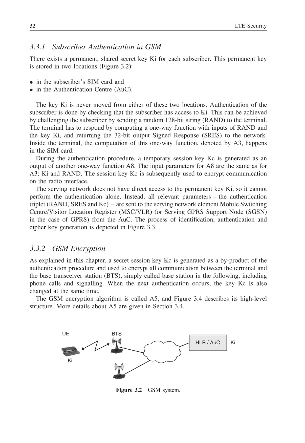
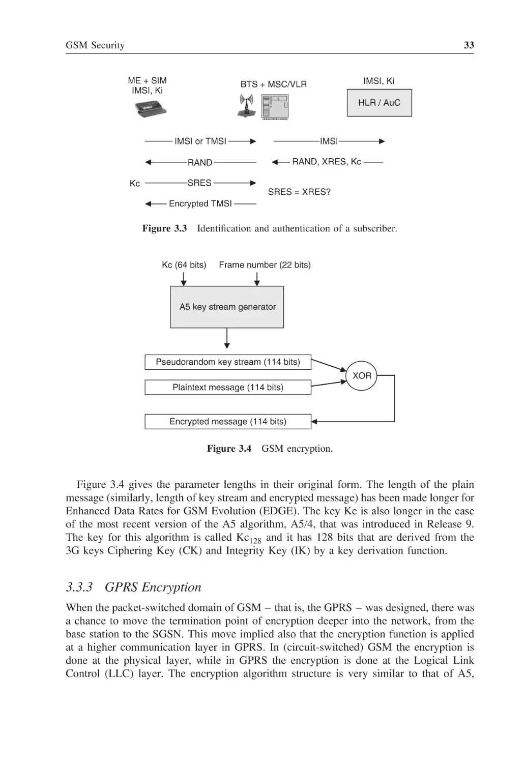
Principles of GSM Security
The Role of the SIM
29
29
30
2.2
2.3
2.4
2.5
3
3.1
3.2
1
vi
3.3
3.4
4
4.1
4.2
4.3
4.4
4.5
4.6
5
5.1
5.2
5.3
Contents
Mechanisms of GSM Security
3.3.1
Subscriber Authentication in GSM
3.3.2
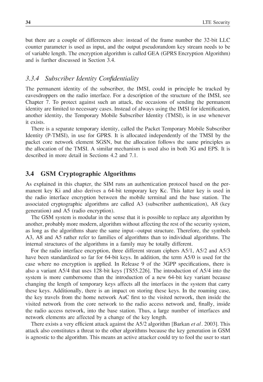
GSM Encryption
3.3.3
GPRS Encryption
3.3.4
Subscriber Identity Confidentiality
GSM Cryptographic Algorithms
31
32
32
33
34
34
Third-Generation Security (UMTS)
Principles of Third-Generation (3G) Security
4.1.1
Elements of GSM Security Carried over to 3G
4.1.2
Weaknesses in GSM Security
4.1.3
Higher Level Objectives
Third-Generation Security Mechanisms
4.2.1
Authentication and Key Agreement
4.2.2
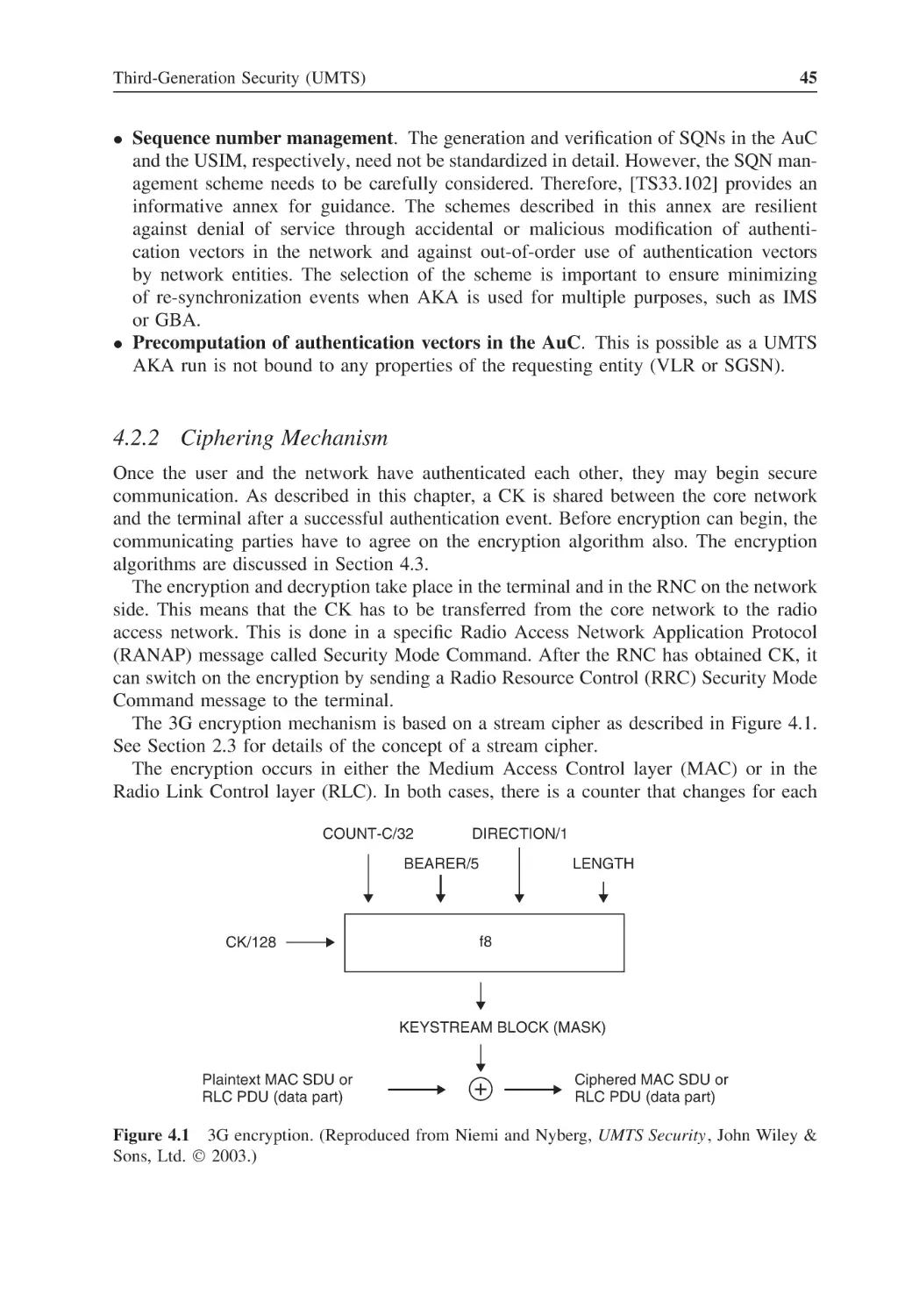
Ciphering Mechanism
4.2.3
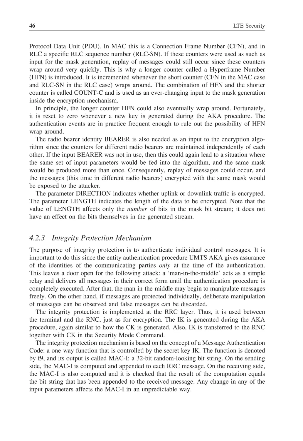
Integrity Protection Mechanism
4.2.4
Identity Confidentiality Mechanism
Third-Generation Cryptographic Algorithms
4.3.1
KASUMI
4.3.2
UEA1 and UIA1
4.3.3
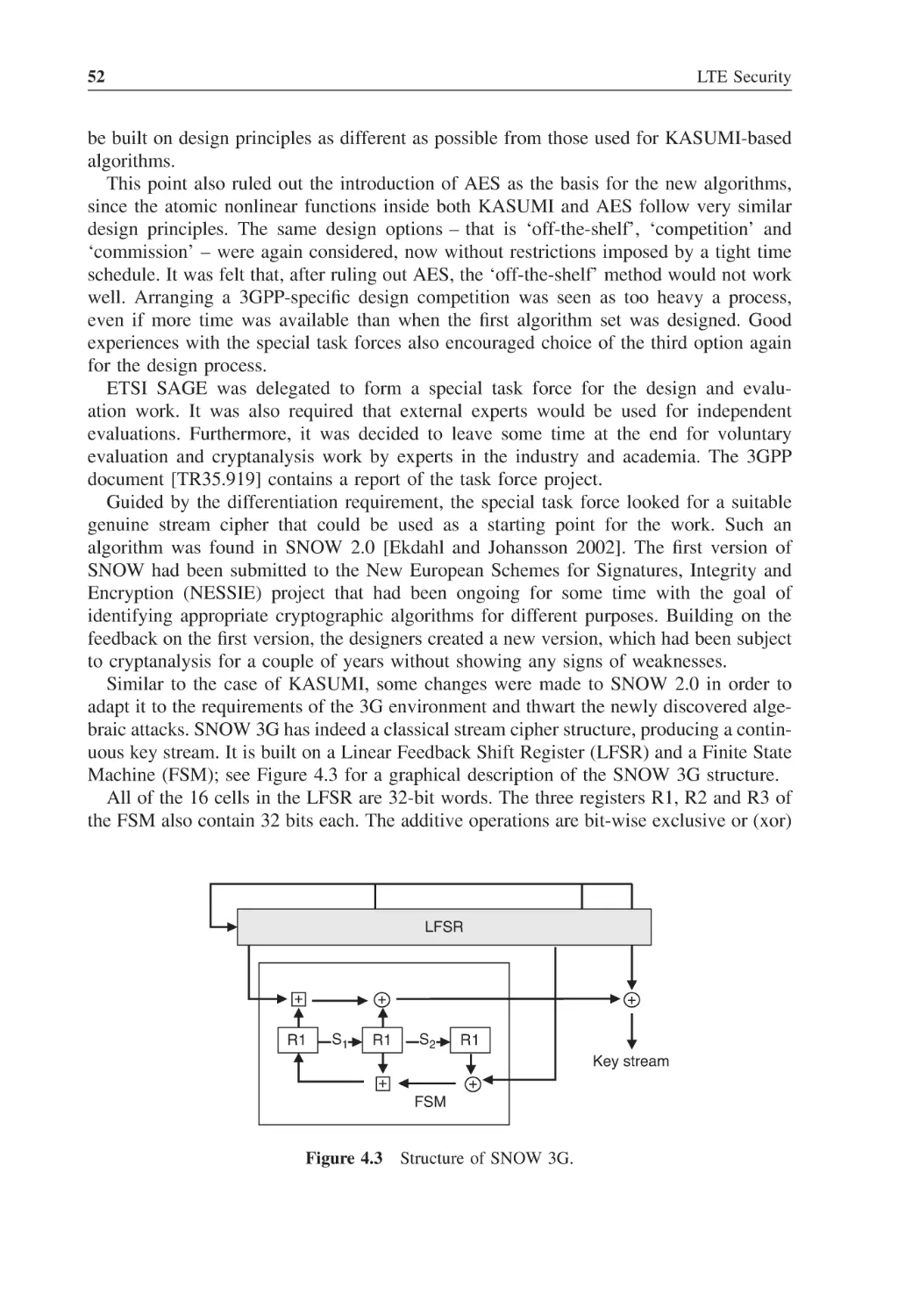
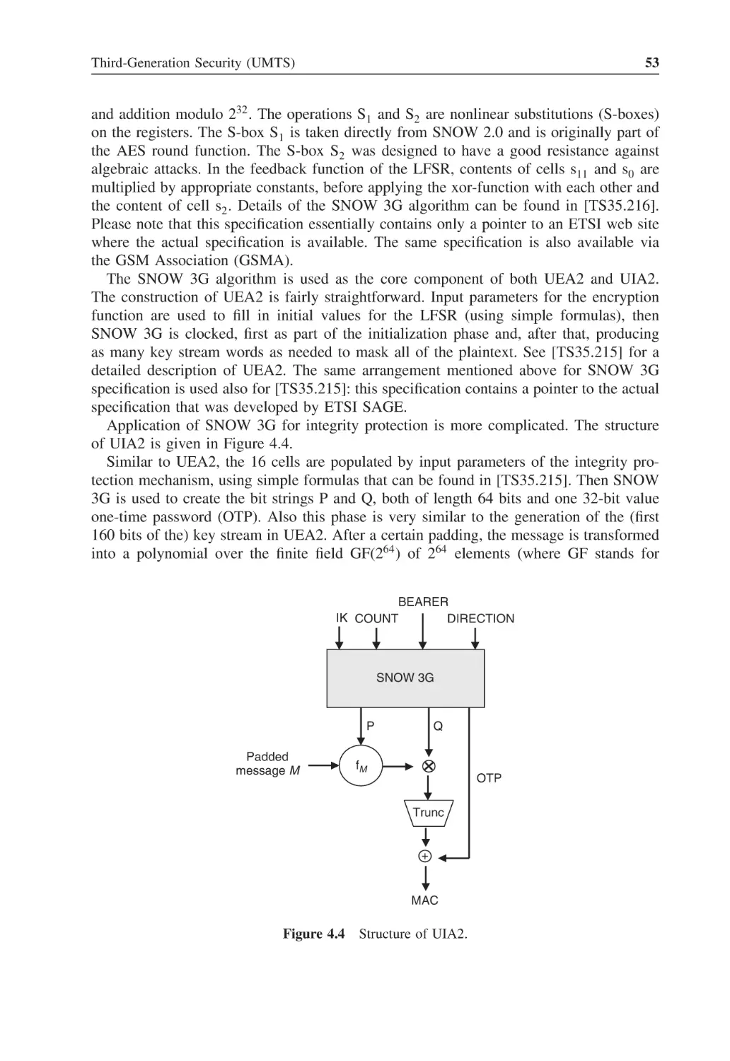
SNOW3G, UEA2 and UIA2
4.3.4
MILENAGE
4.3.5
Hash Functions
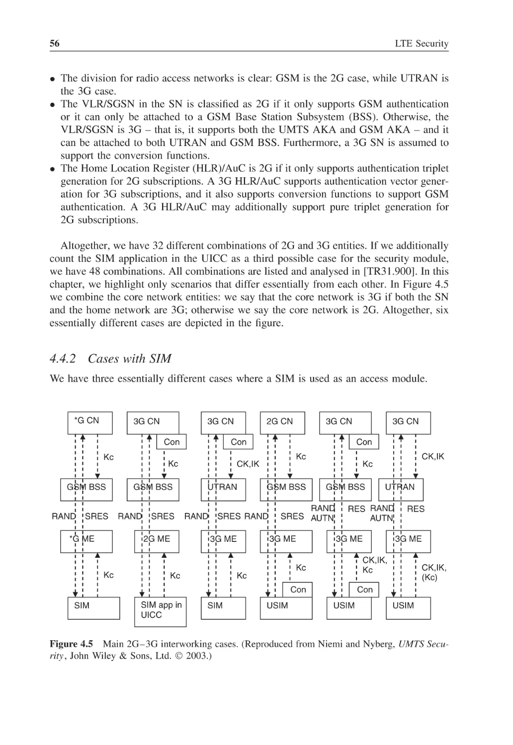
Interworking between GSM and 3G Security
4.4.1
Interworking Scenarios
4.4.2
Cases with SIM
4.4.3
Cases with USIM
4.4.4
Handovers between GSM and 3G
Network Domain Security
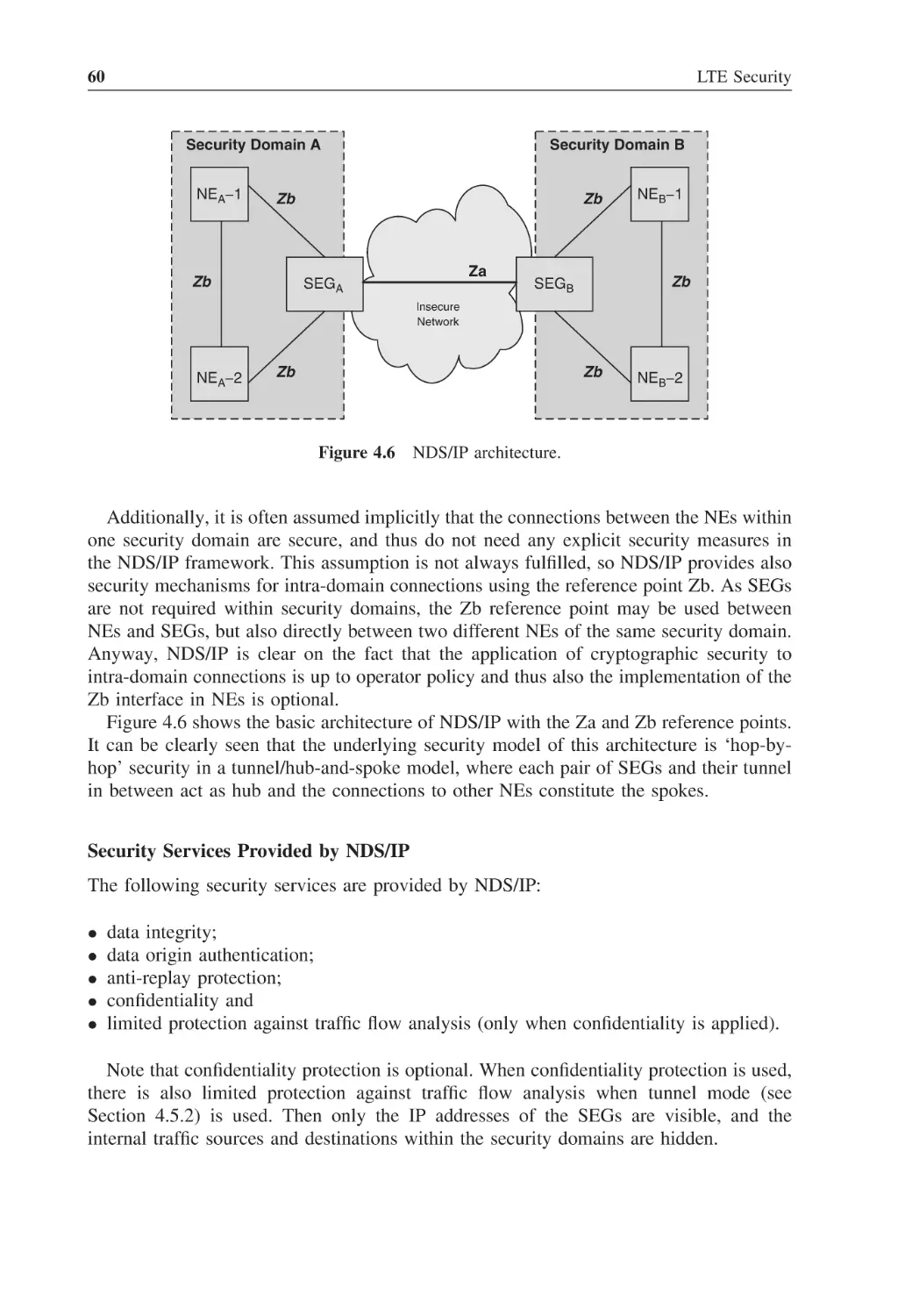
4.5.1
Generic Security Domain Framework
4.5.2
Security Mechanisms for NDS
4.5.3
Application of NDS
Architectures with RNCs in Exposed Locations
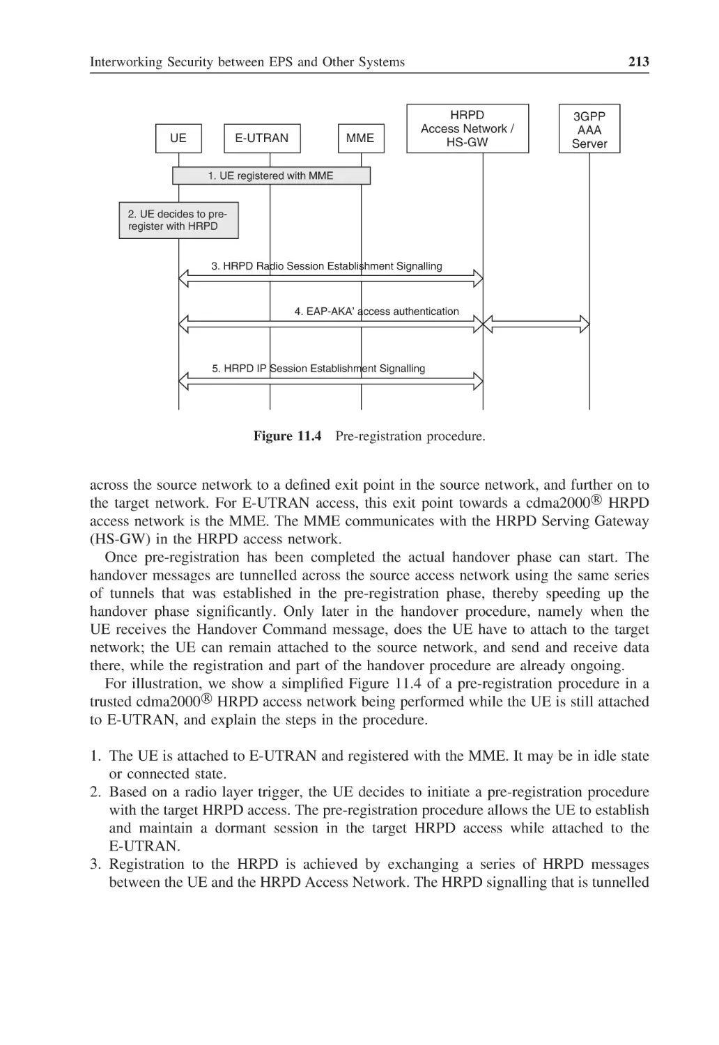
37
37
37
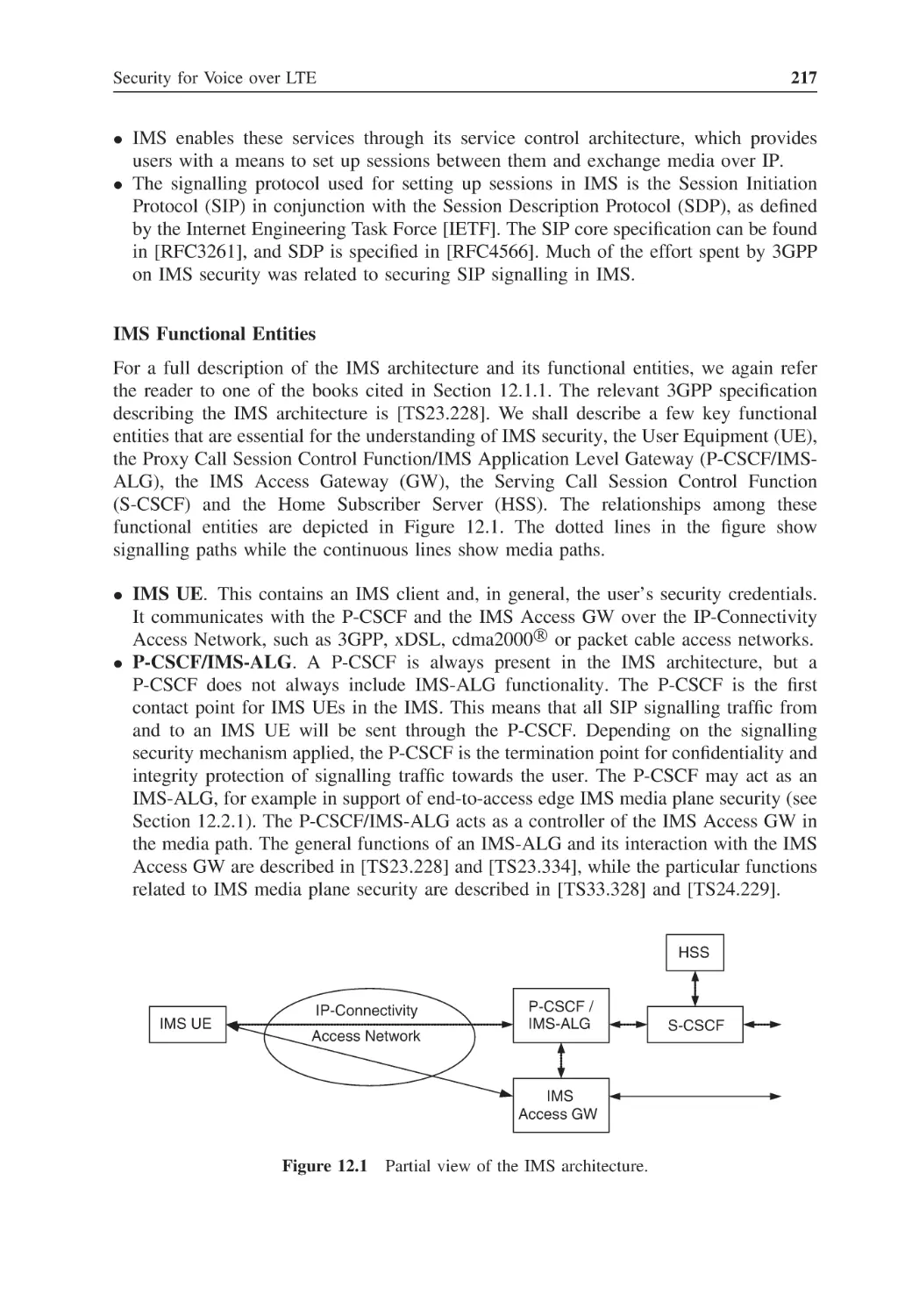
38
39
40
40
45
46
48
49
50
51
51
54
54
55
55
56
57
58
59
59
62
64
65
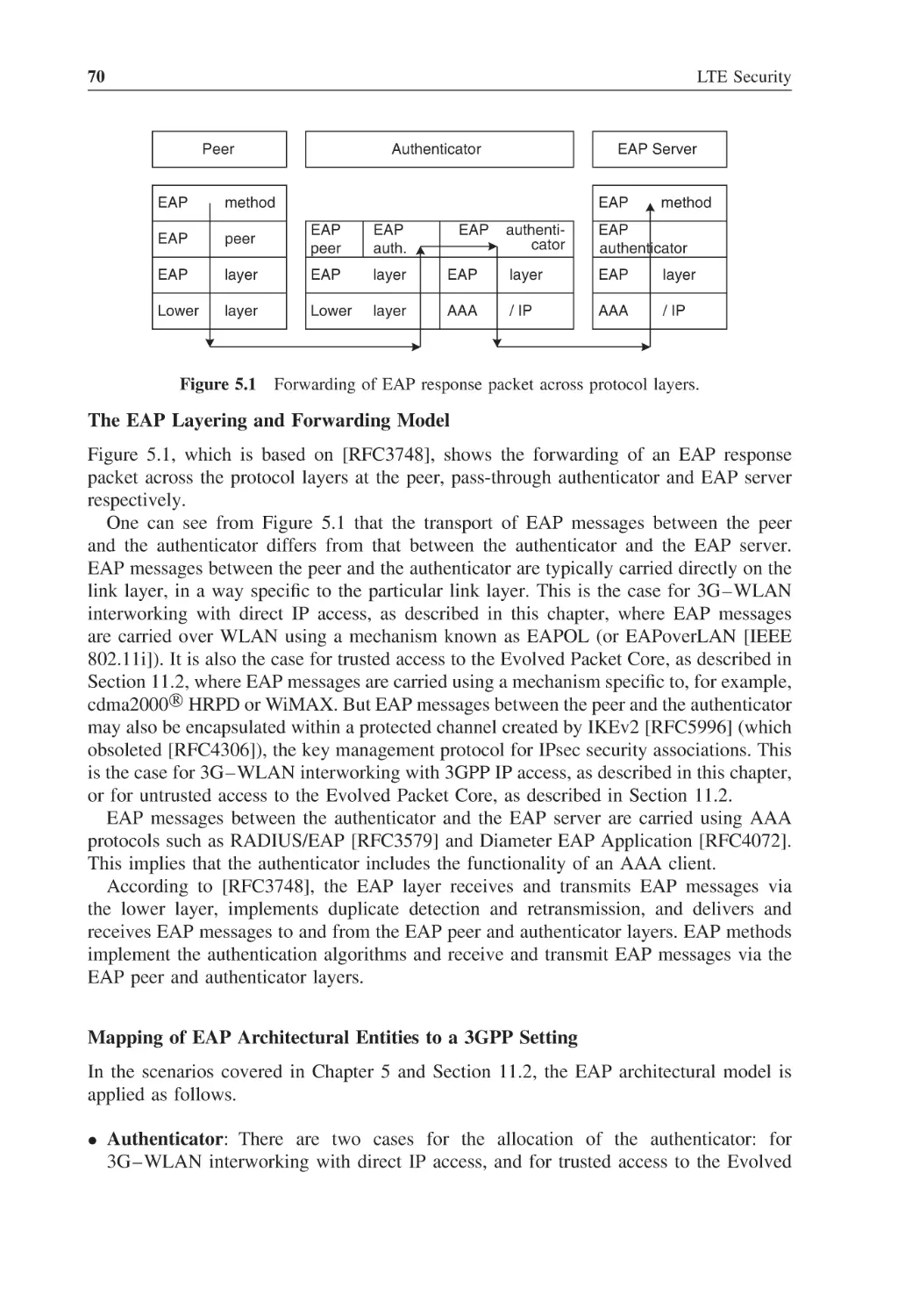
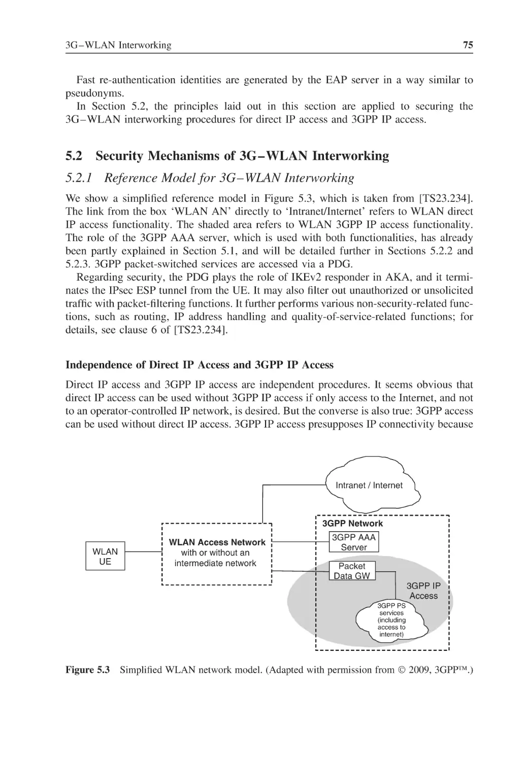
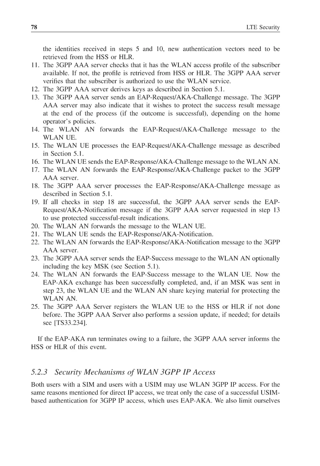
3G–WLAN Interworking
Principles of 3G–WLAN Interworking
5.1.1
The General Idea
5.1.2
The EAP Framework
5.1.3
Overview of EAP-AKA
Security Mechanisms of 3G–WLAN Interworking
5.2.1
Reference Model for 3G–WLAN Interworking
5.2.2
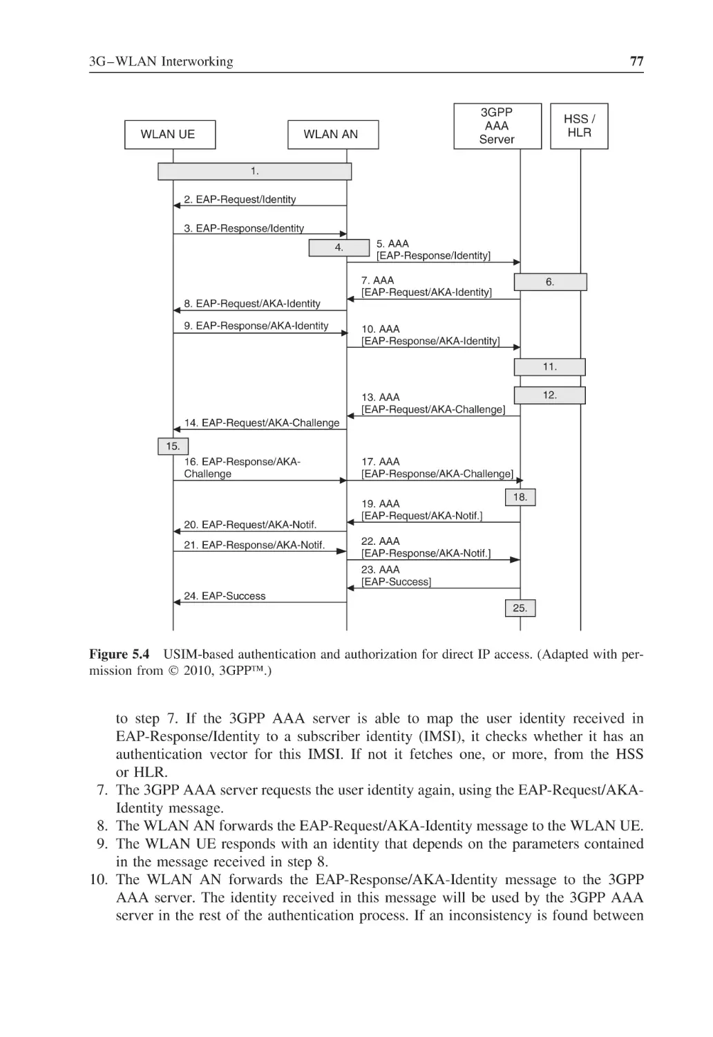
Security Mechanisms of WLAN Direct
IP Access
5.2.3
Security Mechanisms of WLAN 3GPP IP Access
Cryptographic Algorithms for 3G–WLAN
Interworking
67
67
67
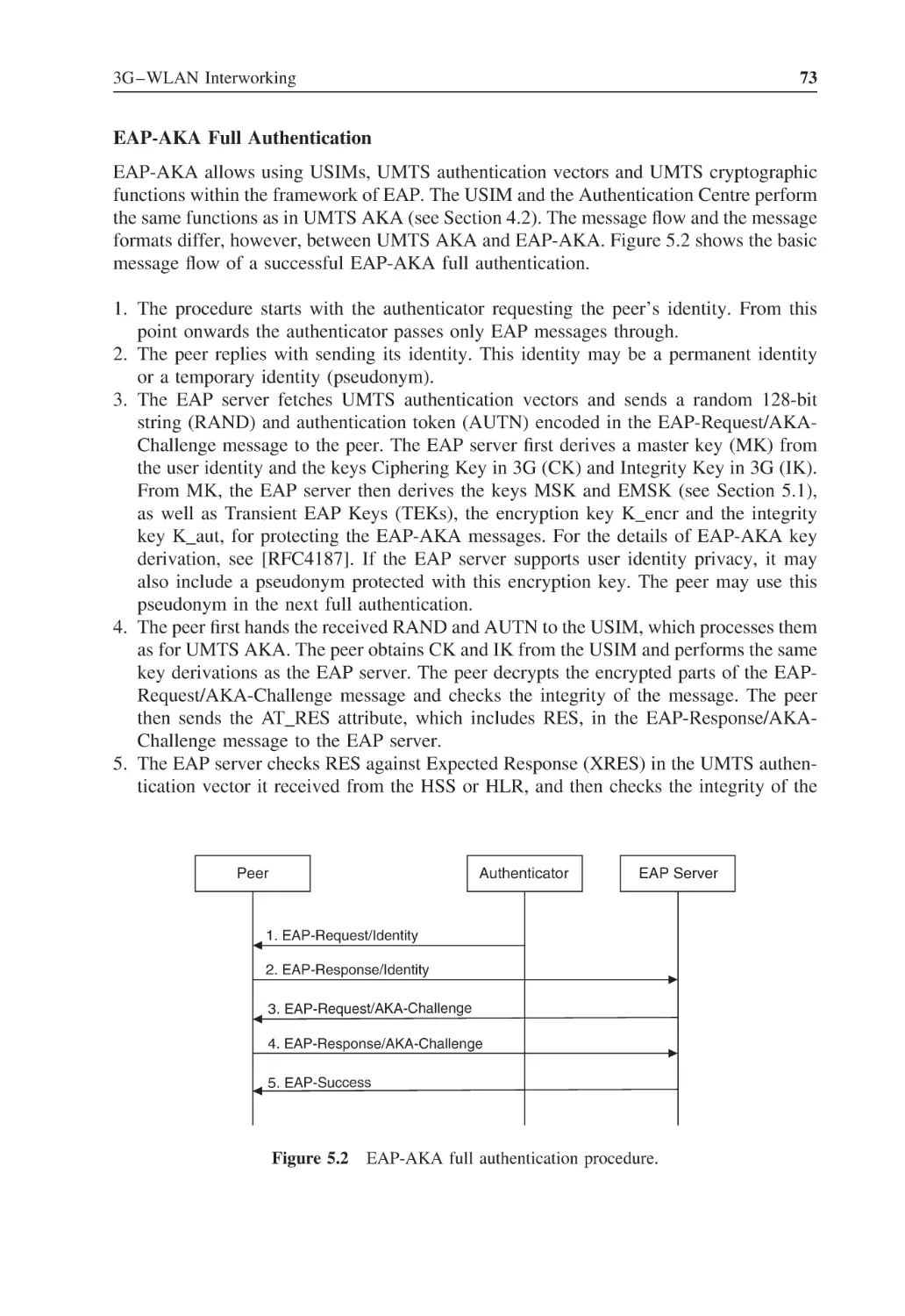
69
72
75
75
76
78
81
Contents
6
6.1
6.2
6.3
6.4
7
7.1
7.2
7.3
7.4
8
8.1
vii
EPS Security Architecture
Overview and Relevant Specifications
6.1.1
Need for Security Standardization
6.1.2
Relevant Nonsecurity Specifications
6.1.3
Security Specifications for EPS
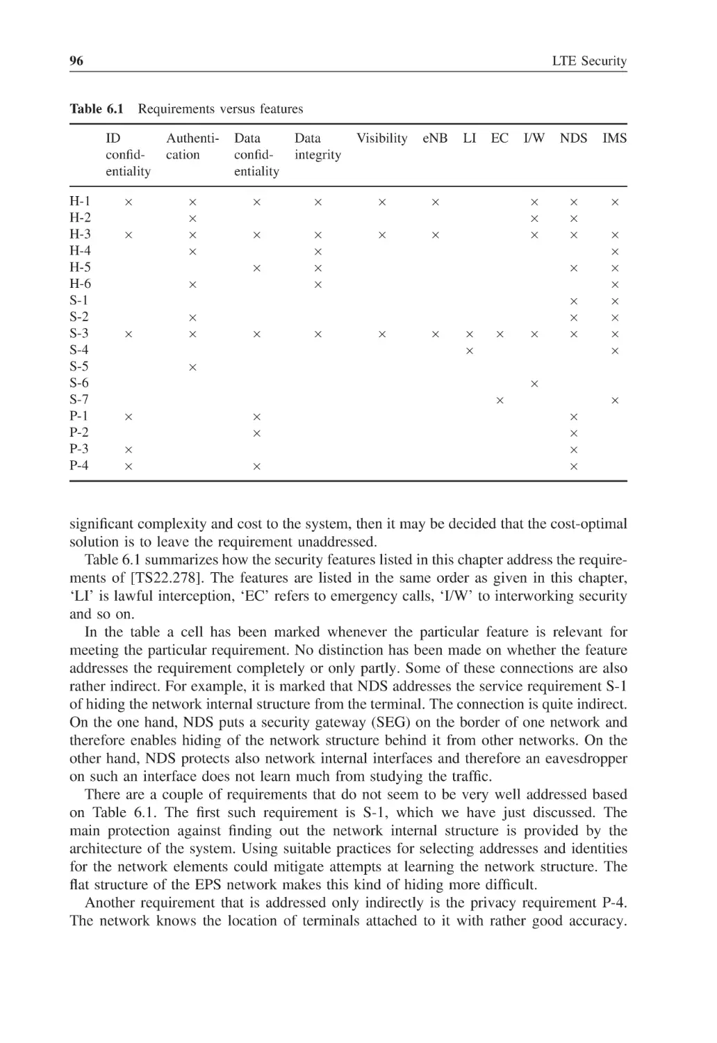
Requirements and Features of EPS Security
6.2.1
Threats against EPS
6.2.2
EPS Security Features
6.2.3
How the Features Meet the Requirements
Design Decisions for EPS Security
Platform Security for Base Stations
6.4.1
General Security Considerations
6.4.2
Specification of Platform Security
6.4.3
Exposed Position and Threats
6.4.4
Security Requirements
83
83
85
87
88
89
90
91
95
97
103
103
103
103
104
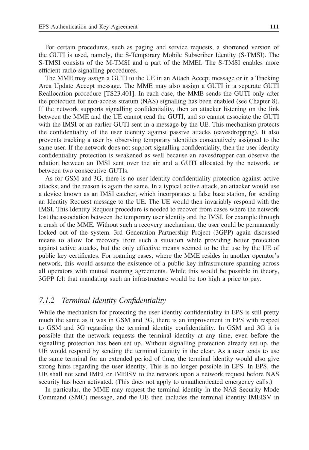
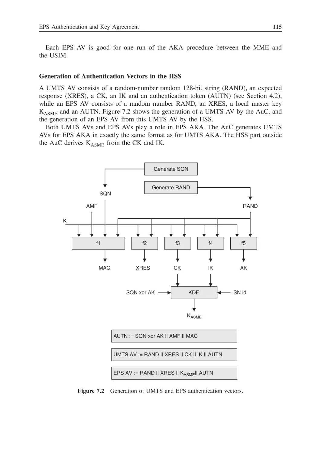
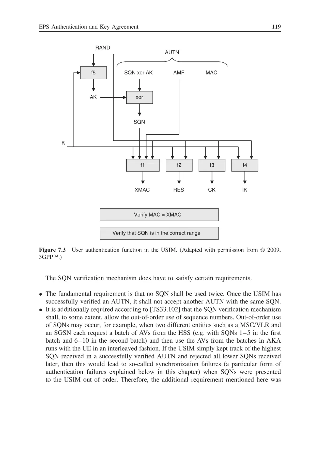
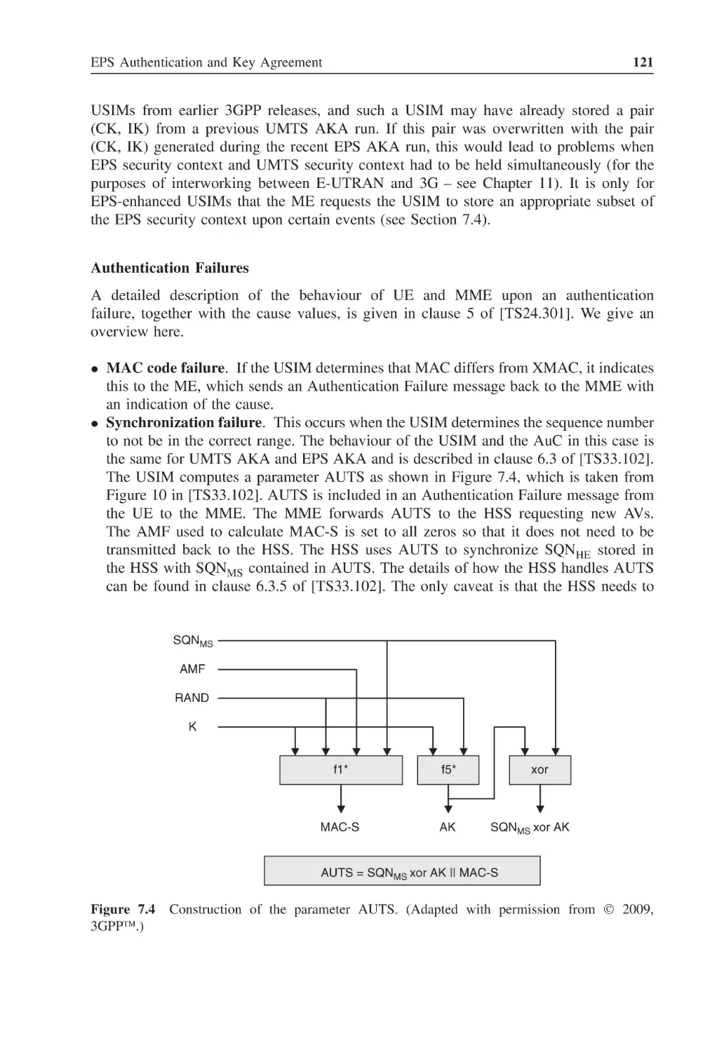
EPS Authentication and Key Agreement
Identification
7.1.1
User Identity Confidentiality
7.1.2
Terminal Identity Confidentiality
The EPS Authentication and Key Agreement Procedure
7.2.1
Goals and Prerequisites of EPS AKA
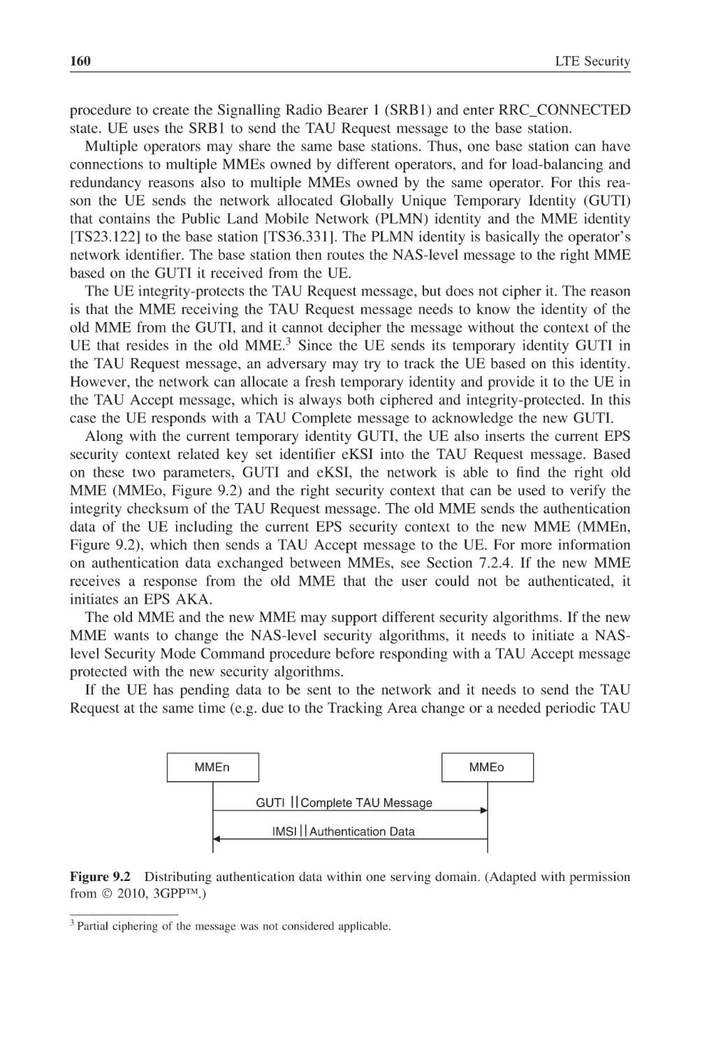
7.2.2
Distribution of EPS Authentication Vectors from HSS to MME
7.2.3
Mutual Authentication and Establishment of a Shared Key between
the Serving Network and the UE
7.2.4
Distribution of Authentication Data inside and between Serving
Networks
Key Hierarchy
7.3.1
Key Derivations
7.3.2
Purpose of the Keys in the Hierarchy
7.3.3
Cryptographic Key Separation
7.3.4
Key Renewal
Security Contexts
7.4.1
EPS Security Context
7.4.2
EPS NAS Security Context
7.4.3
UE Security Capabilities
7.4.4
EPS AS Security Context
7.4.5
Native versus Mapped Contexts
7.4.6
Current versus Non-current Contexts
7.4.7
Key Identification
7.4.8
EPS Security Context Storage
7.4.9
EPS Security Context Transfer
109
109
110
111
112
112
114
122
123
124
125
127
128
129
129
130
130
130
130
131
131
131
132
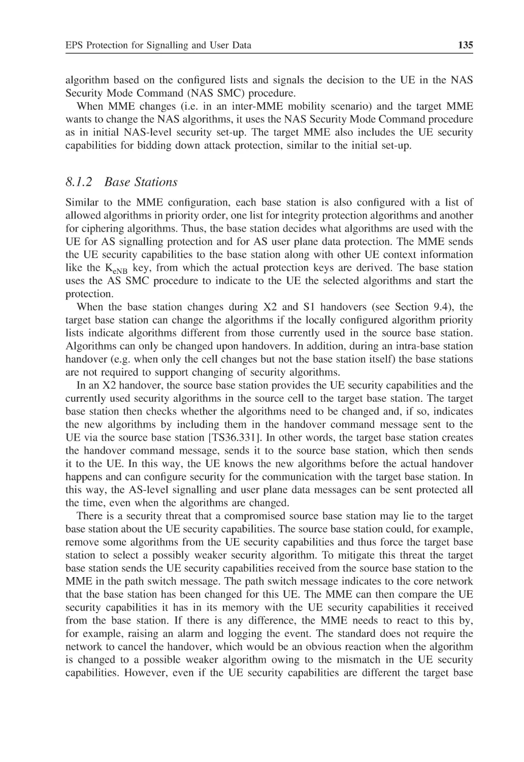
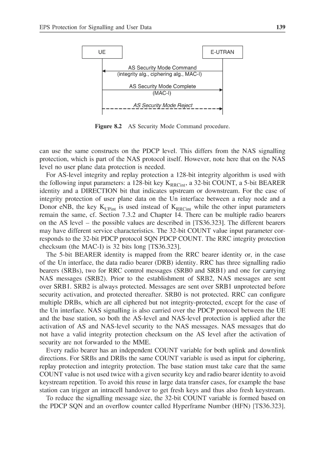
EPS Protection for Signalling and User Data
Security Algorithms Negotiation
8.1.1
Mobility Management Entities
133
133
134
118
viii
Contents
8.1.2
Base Stations
NAS Signalling Protection
8.2.1
NAS Security Mode Command Procedure
8.2.2
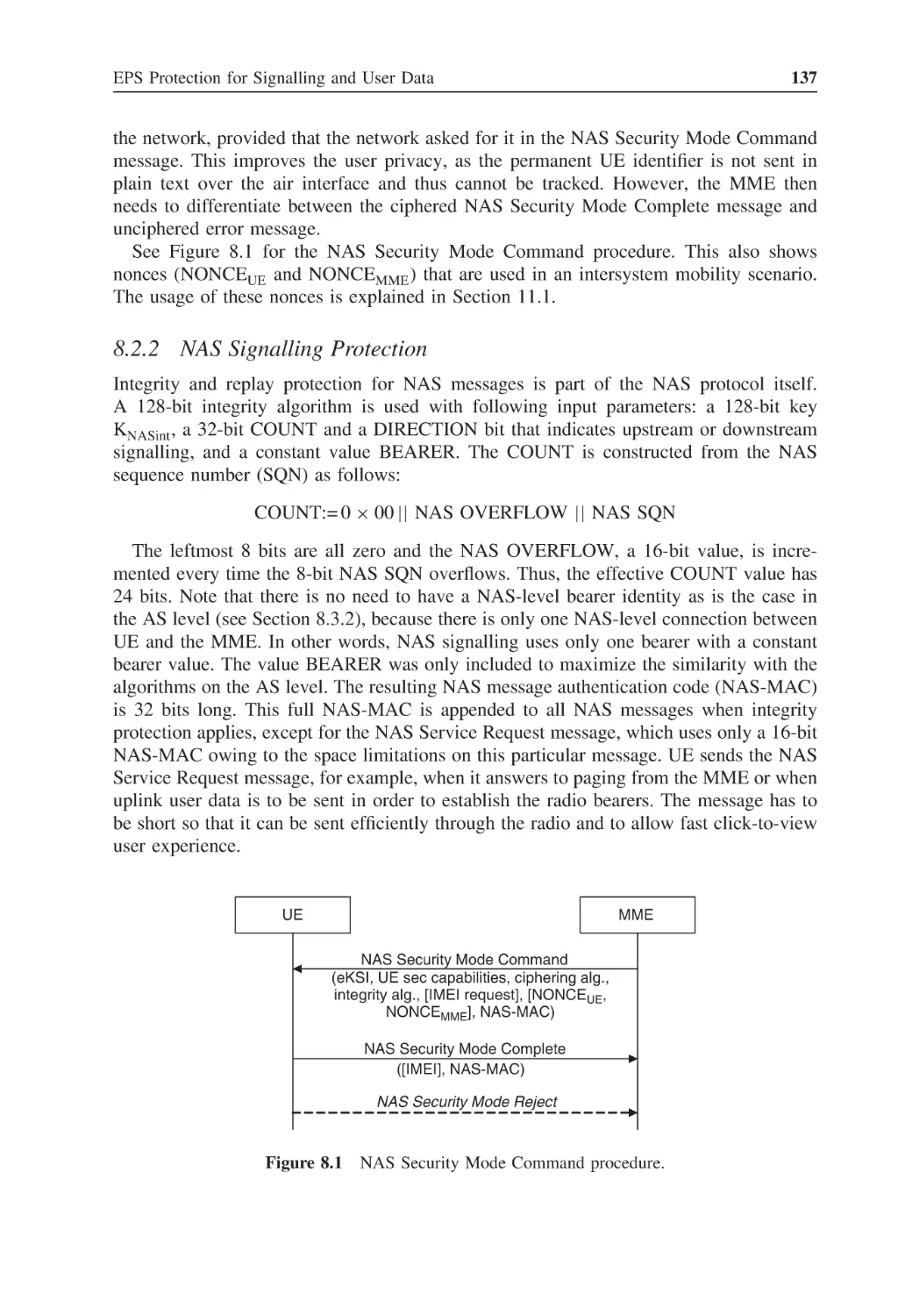
NAS Signalling Protection
AS Signalling and User Data Protection
8.3.1
AS Security Mode Command Procedure
8.3.2
RRC Signalling and User Plane Protection
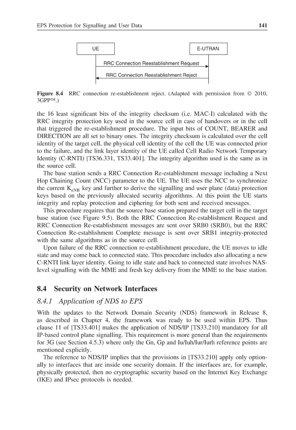
8.3.3
RRC Connection Re-establishment
Security on Network Interfaces
8.4.1
Application of NDS to EPS
8.4.2
Security for Network Interfaces of Base Stations
Certificate Enrolment for Base Stations
8.5.1
Enrolment Scenario
8.5.2
Enrolment Principles
8.5.3
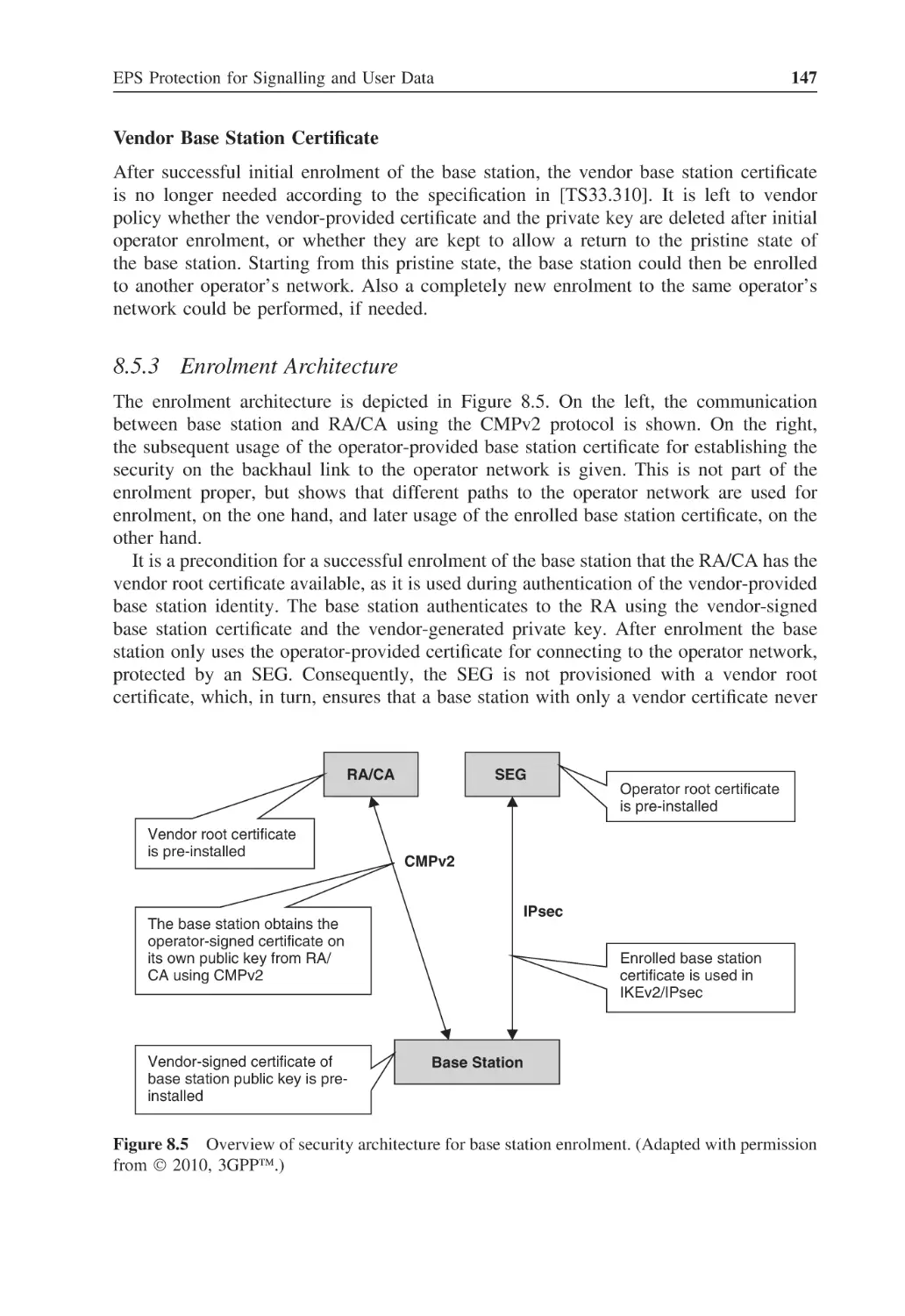
Enrolment Architecture
8.5.4
CMPv2 Protocol and Certificate Profiles
8.5.5
CMPv2 Transport
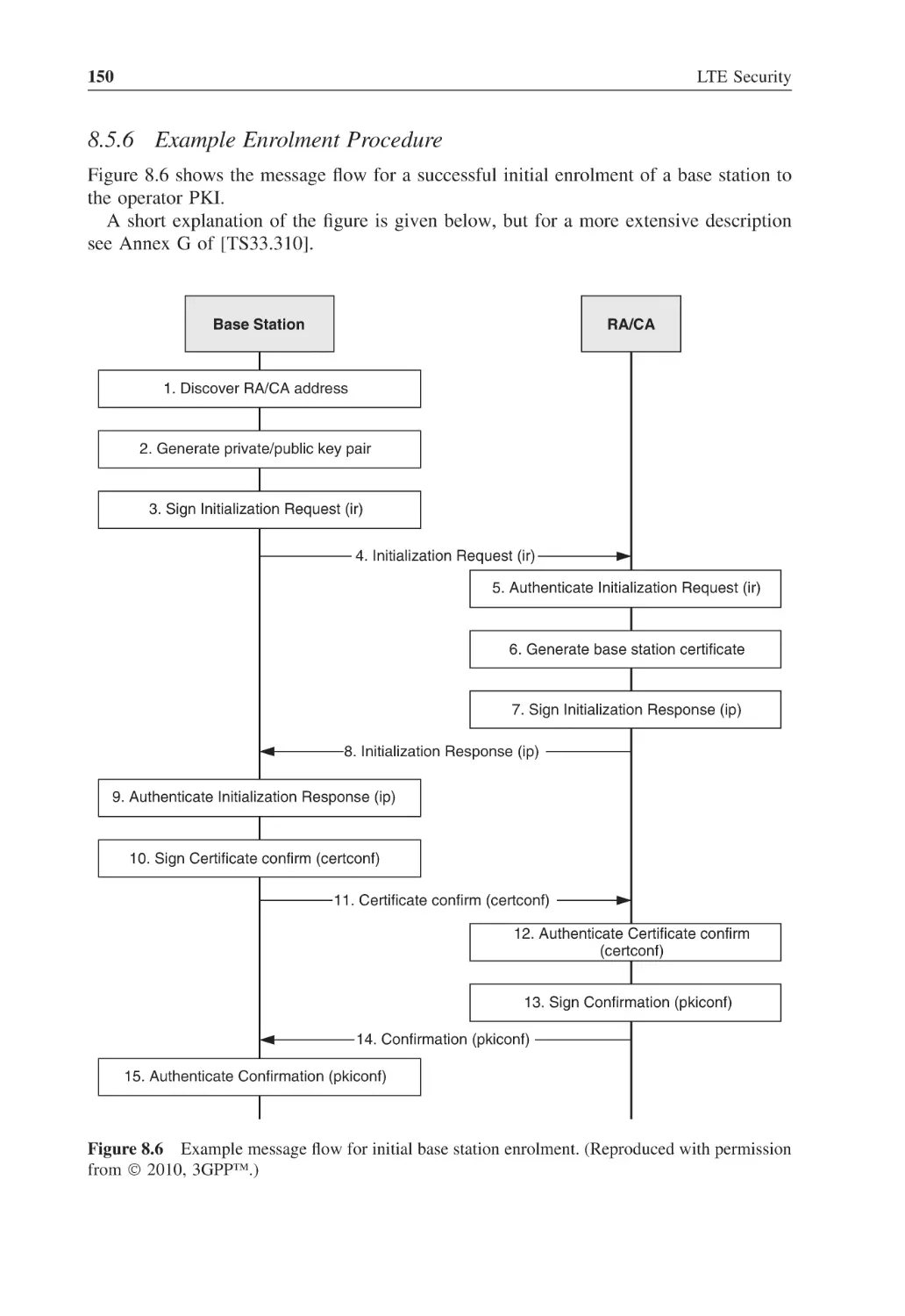
8.5.6
Example Enrolment Procedure
Emergency Call Handling
8.6.1
Emergency Calls with NAS and AS Security Contexts in Place
8.6.2
Emergency Calls without NAS and AS Security Contexts
8.6.3
Continuation of the Emergency Call When Authentication Fails
135
136
136
137
138
138
138
140
141
141
142
143
143
144
147
148
149
150
151
153
153
154
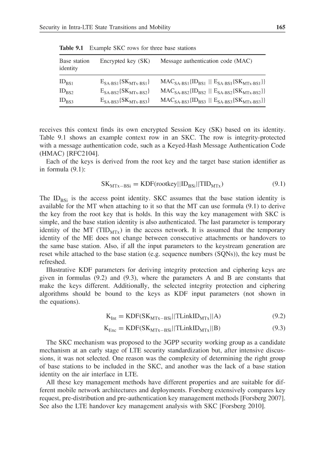
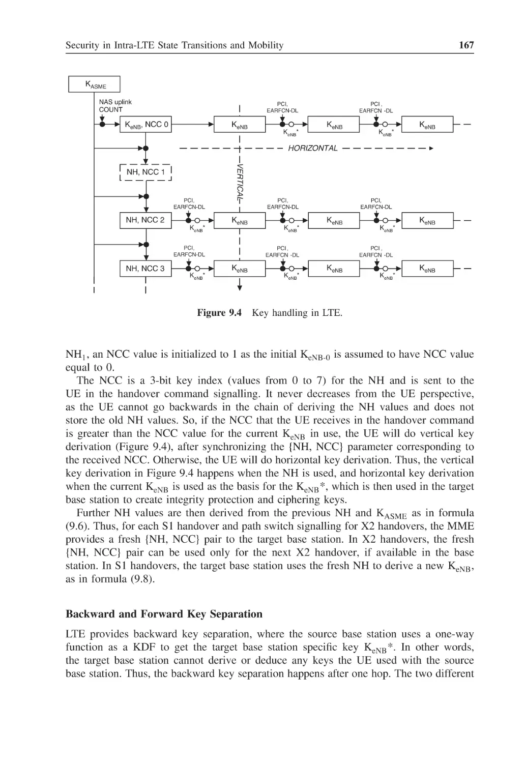
9.6
9.7
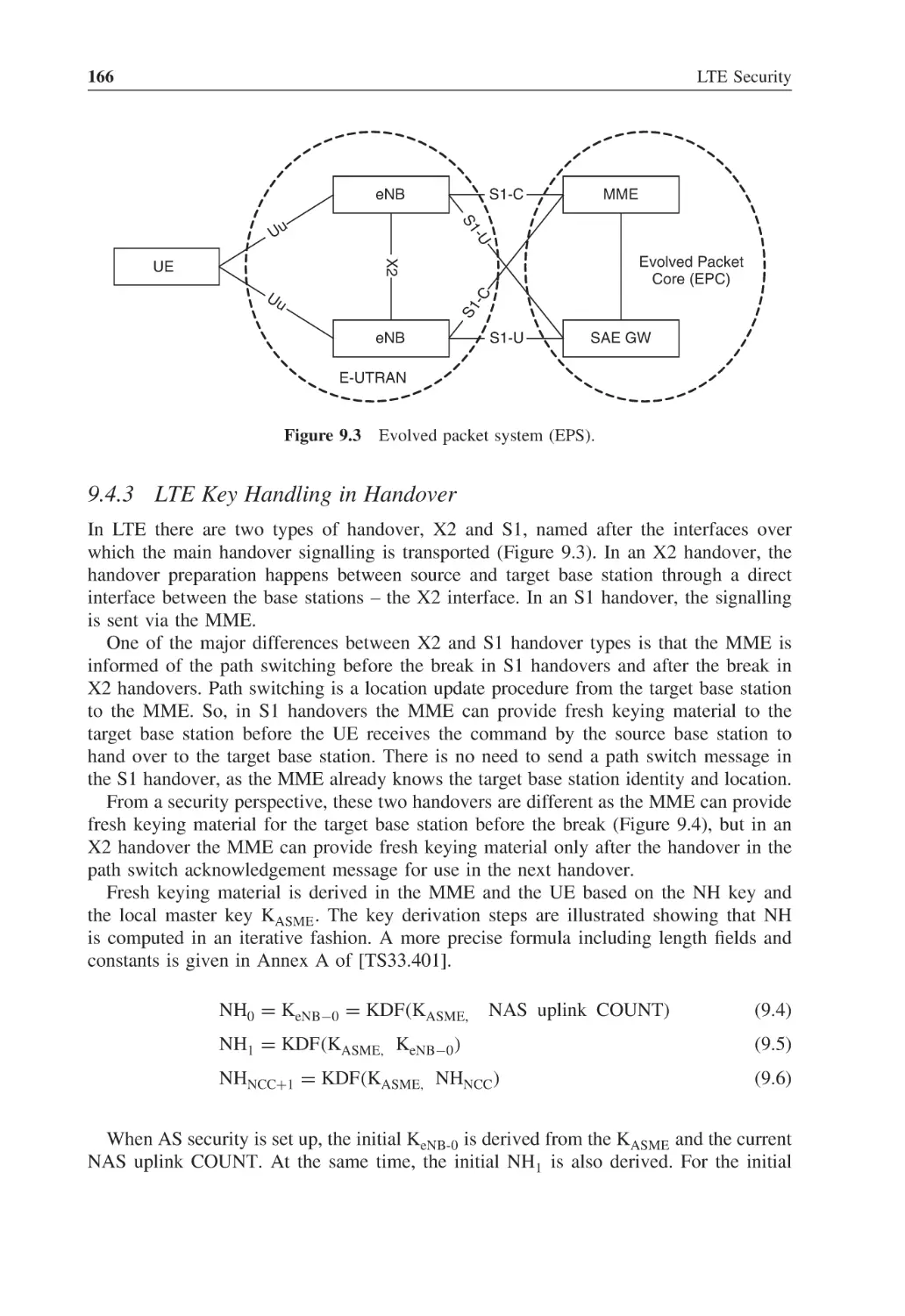
Security in Intra-LTE State Transitions and Mobility
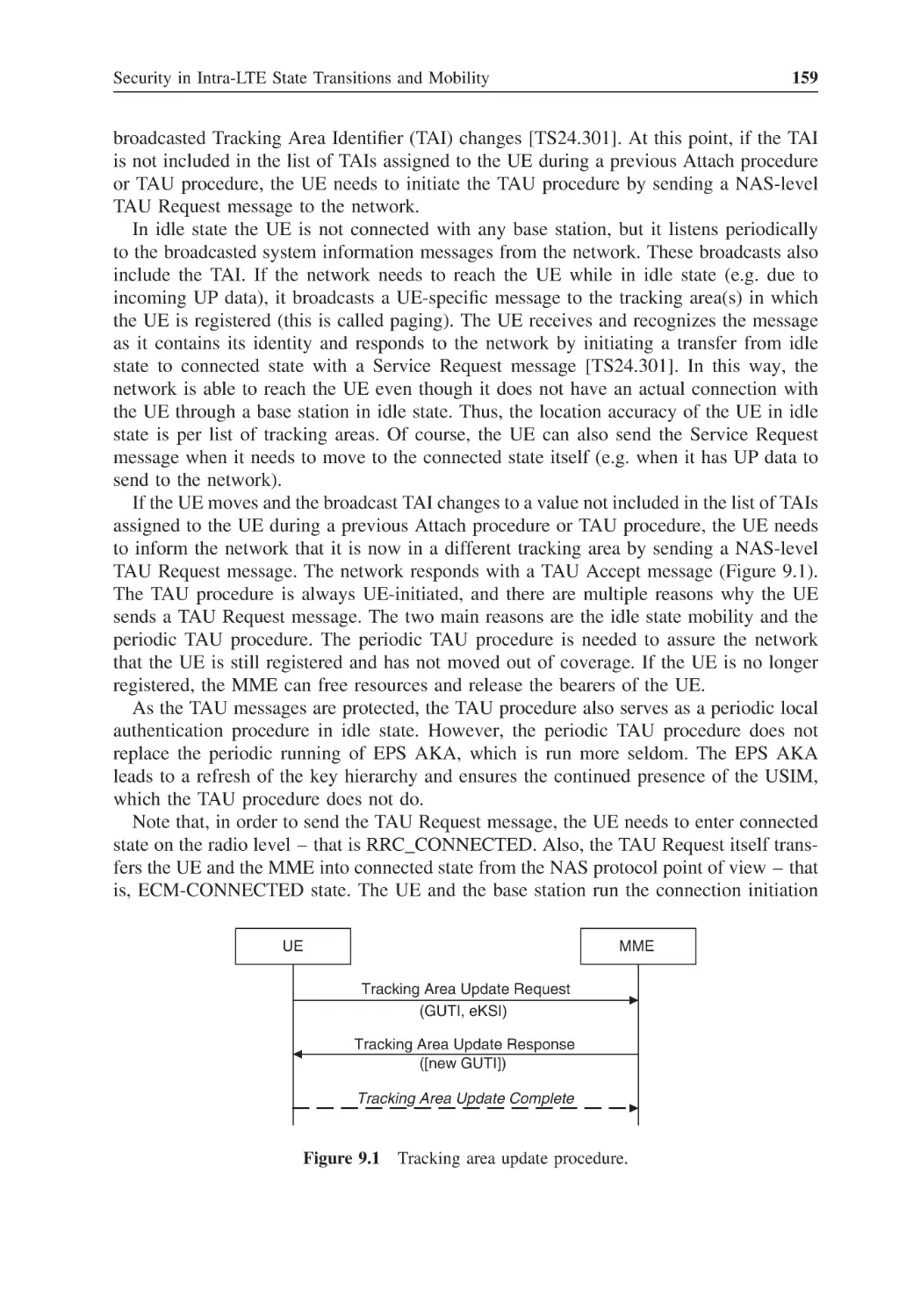
Transitions to and from Registered State
9.1.1
Registration
9.1.2
Deregistration
Transitions between Idle and Connected States
9.2.1
Connection Initiation
9.2.2
Back to Idle State
Idle State Mobility
Handover
9.4.1
Handover Key Management Requirements Background
9.4.2
Handover Keying Mechanisms Background
9.4.3
LTE Key Handling in Handover
9.4.4
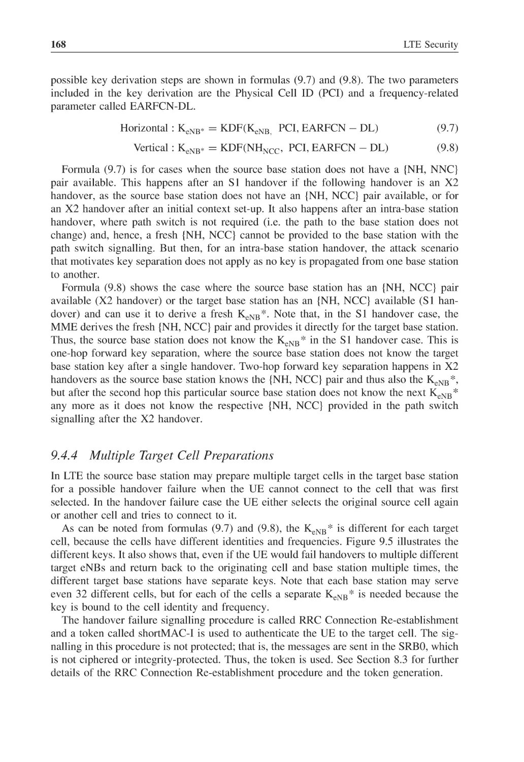
Multiple Target Cell Preparations
Key Change on the Fly
9.5.1
KeNB Rekeying
9.5.2
KeNB Refresh
9.5.3
NAS Key Rekeying
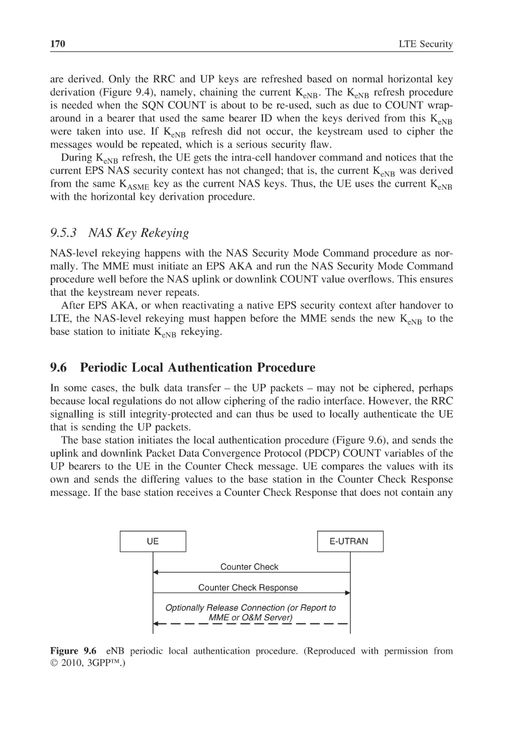
Periodic Local Authentication Procedure
Concurrent Run of Security Procedures
155
156
156
156
157
158
158
158
161
161
162
166
168
169
169
169
170
170
171
10
10.1
10.2
EPS Cryptographic Algorithms
Null Algorithms
Ciphering Algorithms
175
176
177
8.2
8.3
8.4
8.5
8.6
9
9.1
9.2
9.3
9.4
9.5
Contents
ix
10.3
10.4
Integrity Algorithms
Key Derivation Algorithms
180
180
11
11.1
Interworking Security between EPS and Other Systems
Interworking with GSM and 3G Networks
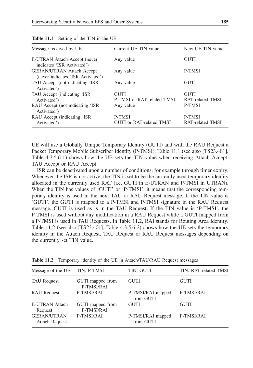
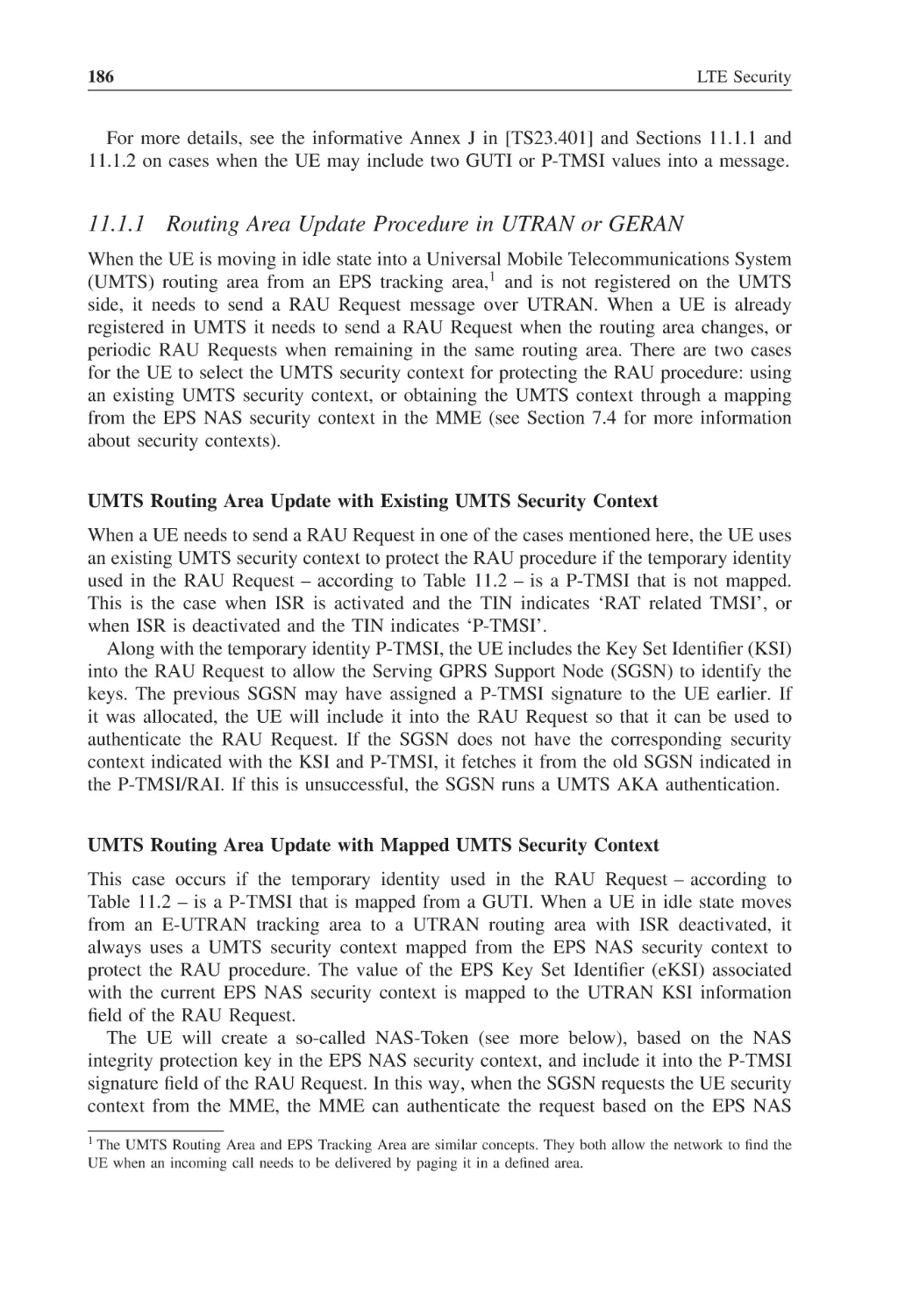
11.1.1 Routing Area Update Procedure in UTRAN or GERAN
11.1.2 Tracking Area Update Procedure in EPS
11.1.3 Handover from EPS to 3G or GSM
11.1.4 Handover from 3G or GSM to EPS
Interworking with Non-3GPP Networks
11.2.1 Principles of Interworking with Non-3GPP Networks
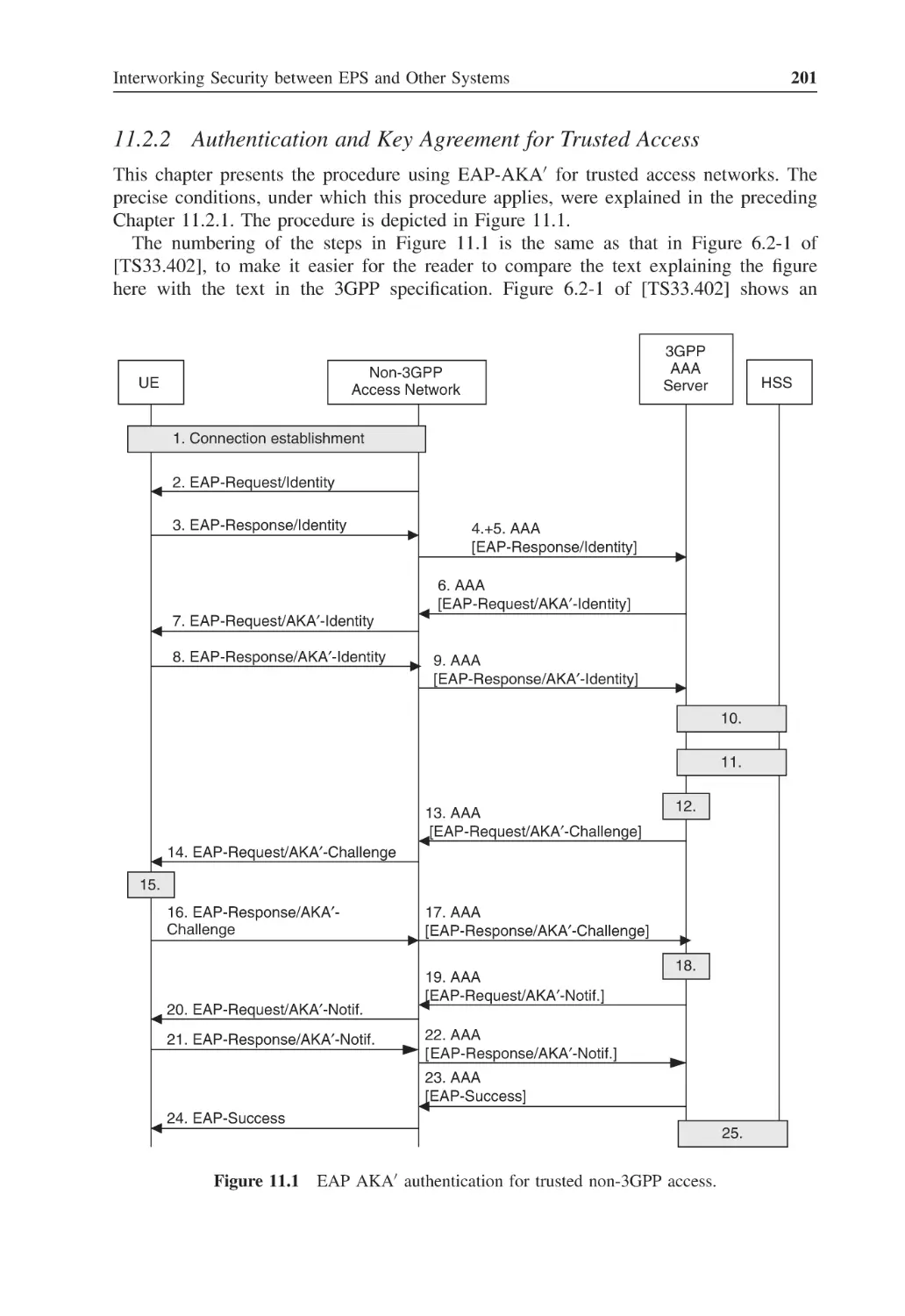
11.2.2 Authentication and Key Agreement for Trusted Access
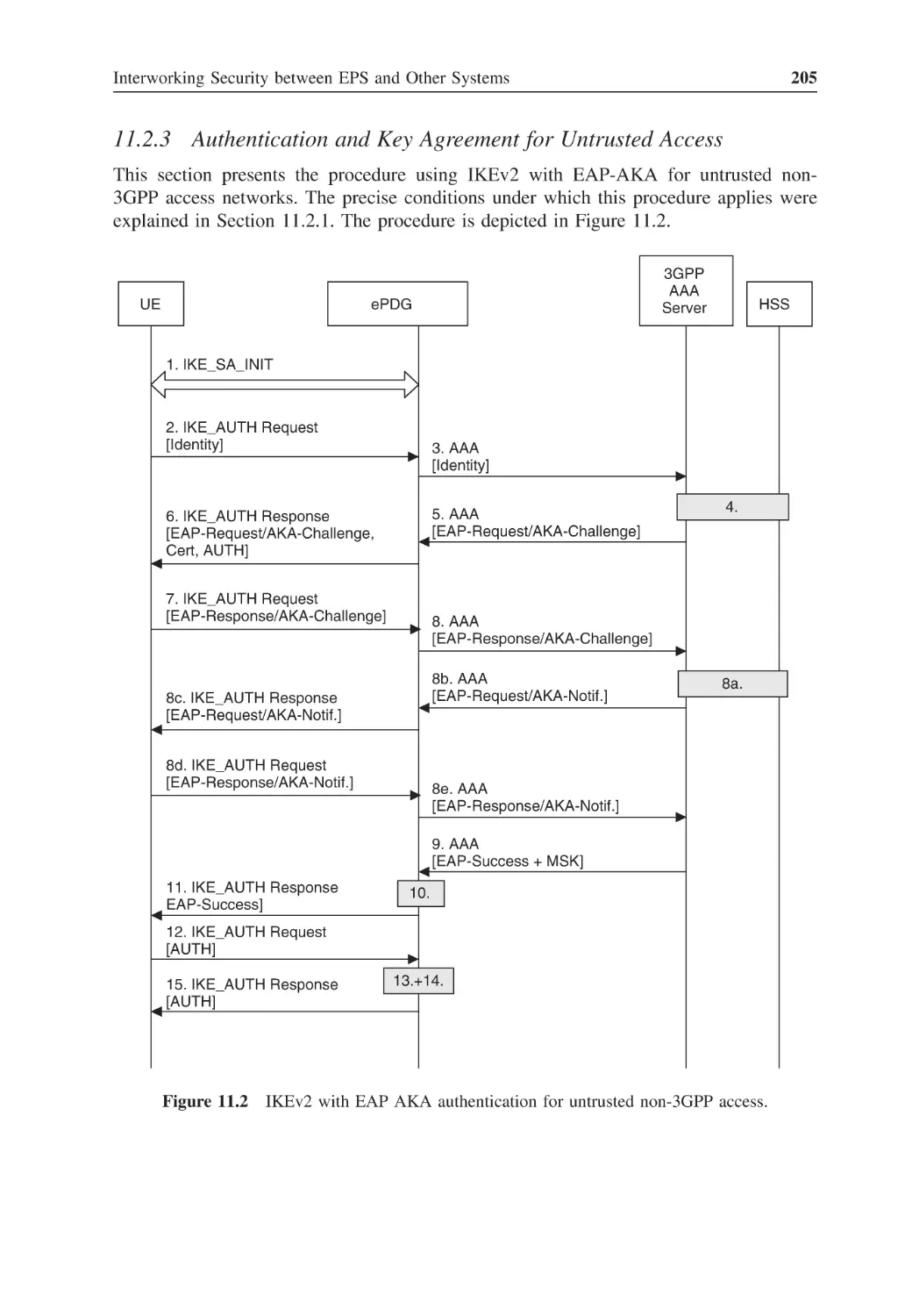
11.2.3 Authentication and Key Agreement for Untrusted Access
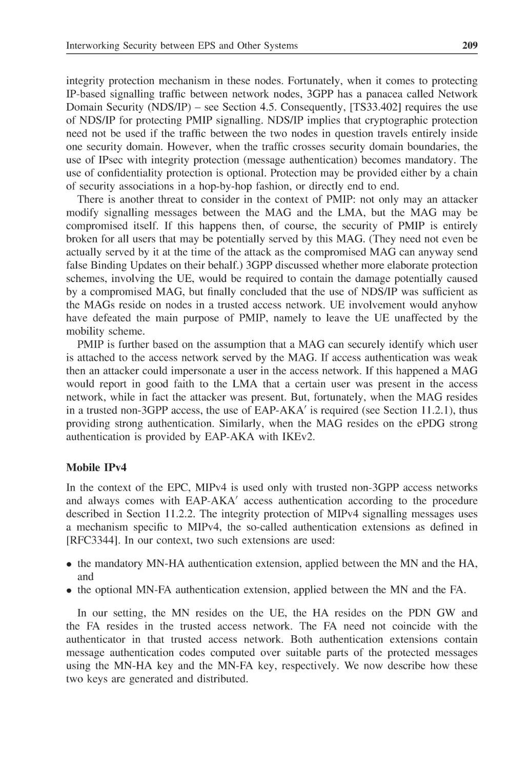
11.2.4 Security for Mobile IP Signalling
11.2.5 Mobility between 3GPP and Non-3GPP Access Networks
183
183
186
187
190
191
193
193
201
205
208
211
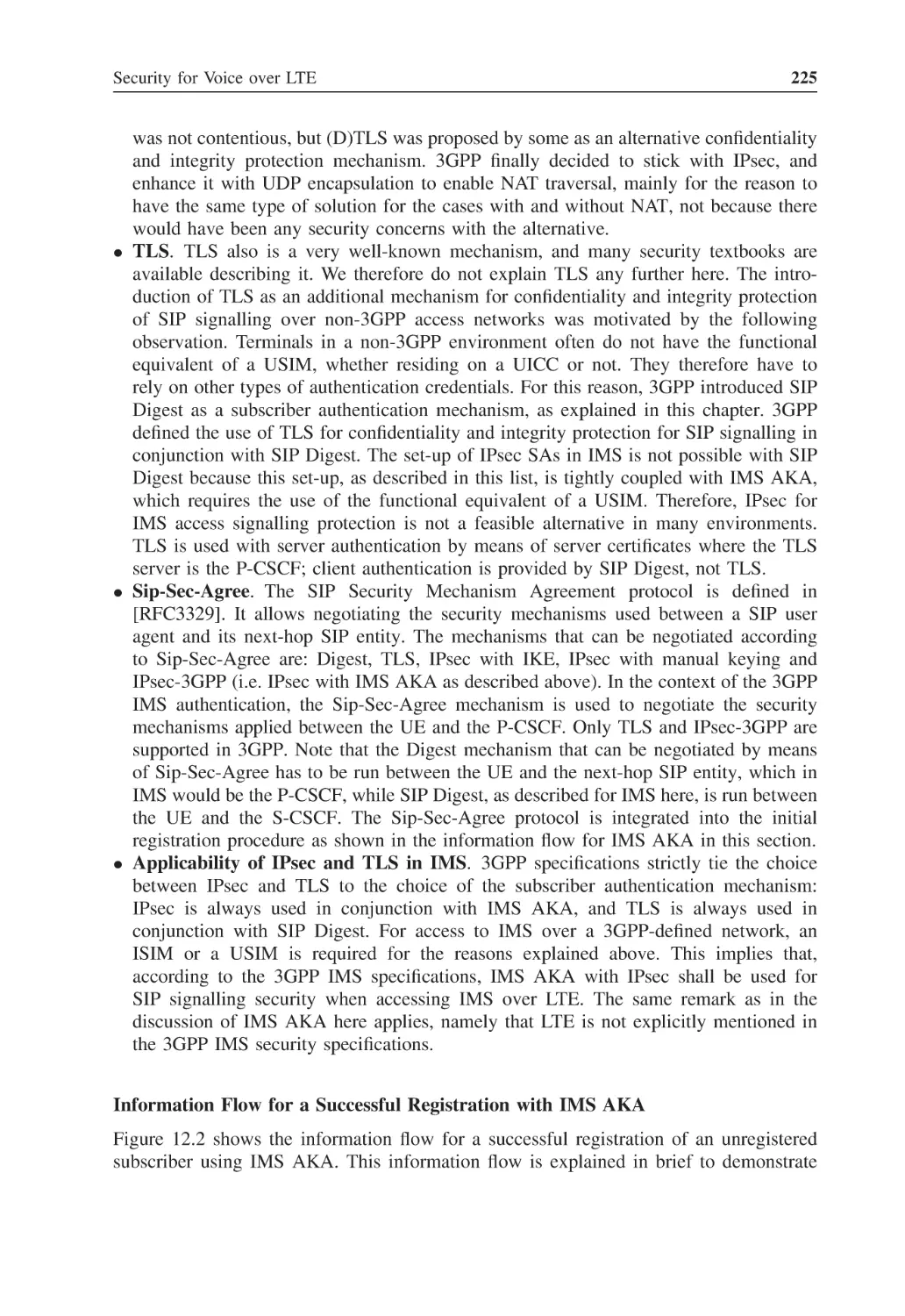
Security for Voice over LTE
Methods for Providing Voice over LTE
12.1.1 IMS over LTE
12.1.2 Circuit Switched Fallback (CSFB)
12.1.3 Single Radio Voice Call Continuity (SRVCC)
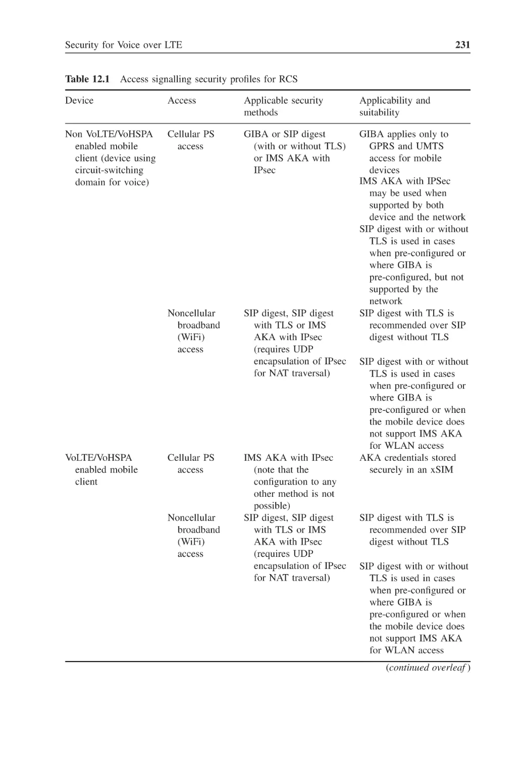
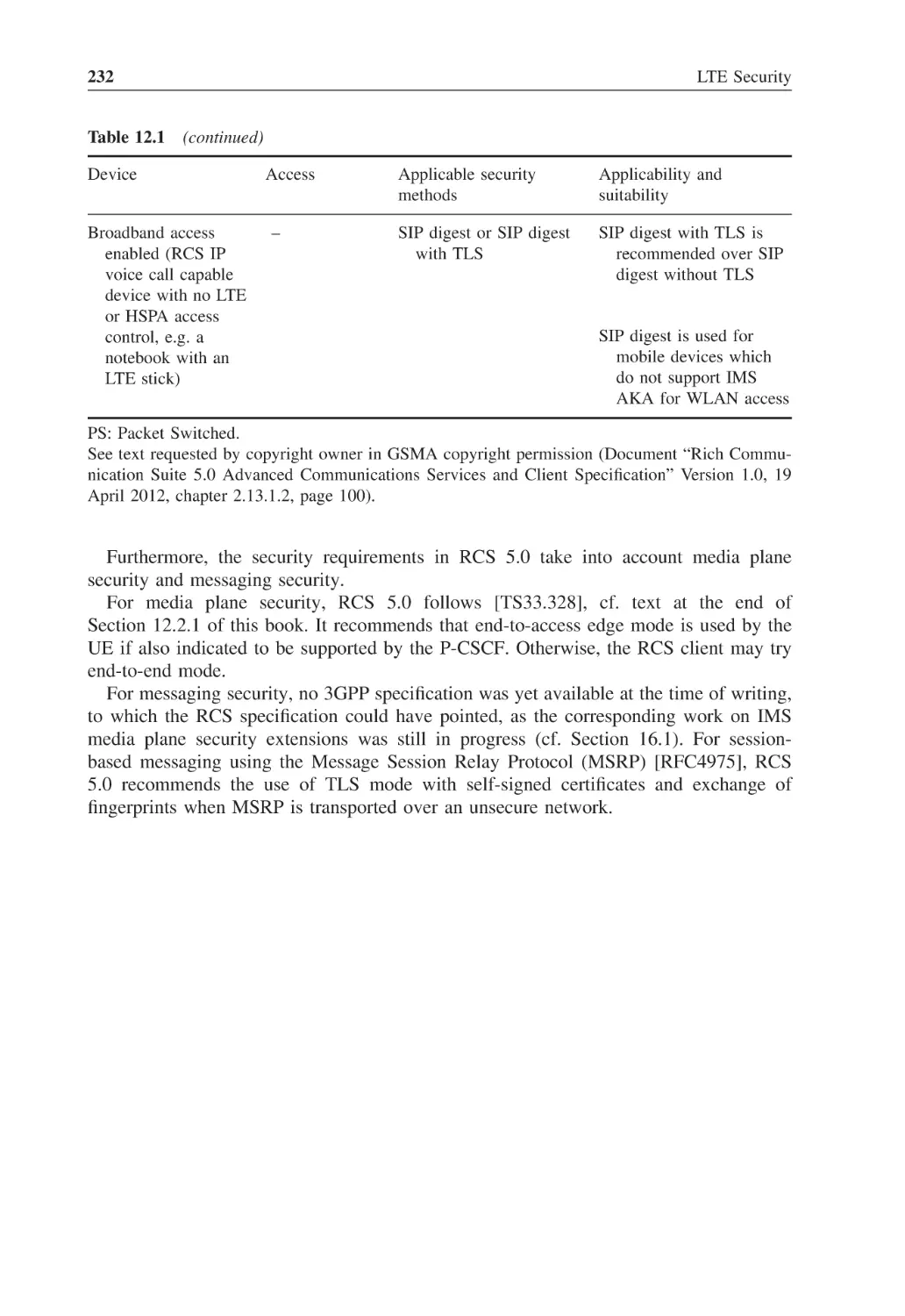
Security Mechanisms for Voice over LTE
12.2.1 Security for IMS over LTE
12.2.2 Security for Circuit Switched Fallback
12.2.3 Security for Single Radio Voice Call Continuity
Rich Communication Suite and Voice over LTE
215
215
216
218
218
220
220
228
228
230
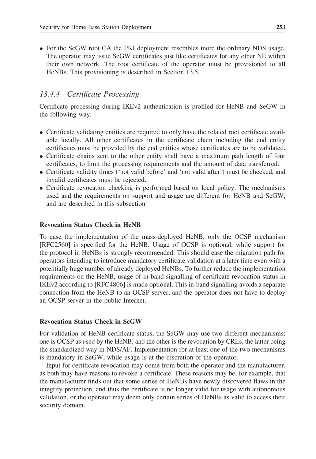
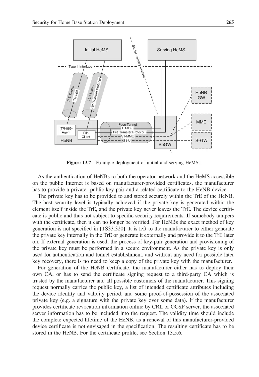
Security for Home Base Station Deployment
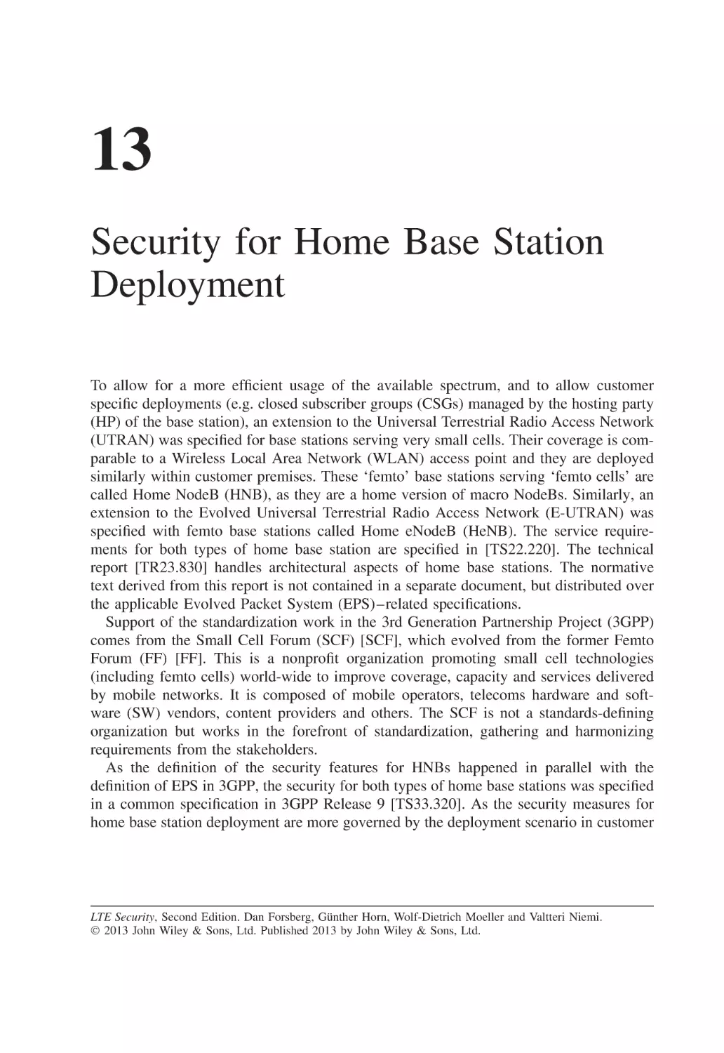
Security Architecture, Threats and Requirements
13.1.1 Scenario
13.1.2 Threats and Risks
13.1.3 Requirements
13.1.4 Security Architecture
Security Features
13.2.1 Authentication
13.2.2 Local Security
13.2.3 Communications Security
13.2.4 Location Verification and Time Synchronization
Security Procedures Internal to the Home Base Station
13.3.1 Secure Boot and Device Integrity Check
13.3.2 Removal of Hosting Party Module
13.3.3 Loss of Backhaul Link
13.3.4 Secure Time Base
13.3.5 Handling of Internal Transient Data
Security Procedures between Home Base Station and Security Gateway
13.4.1 Device Integrity Validation
233
234
234
237
239
240
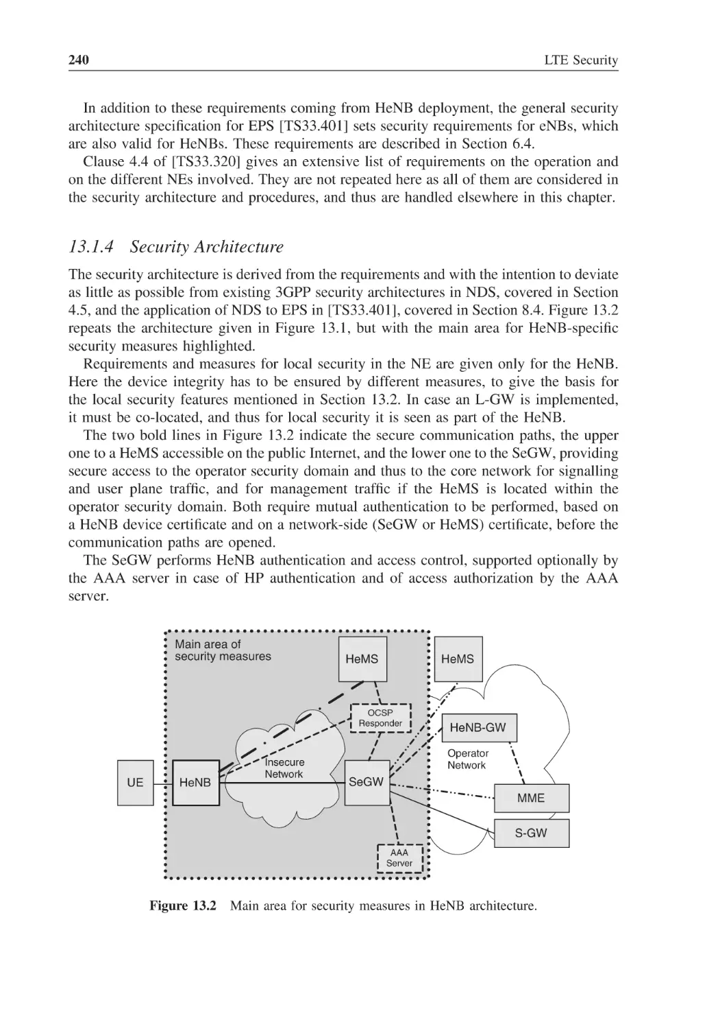
241
241
243
244
244
244
245
245
245
246
246
247
247
11.2
12
12.1
12.2
12.3
13
13.1
13.2
13.3
13.4
x
13.5
13.6
13.7
14
14.1
14.2
15
15.1
15.2
Contents
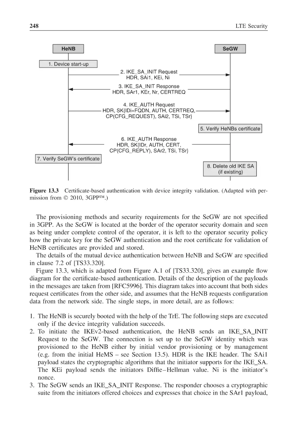
13.4.2 Device Authentication
13.4.3 IKEv2 and Certificate Profiling
13.4.4 Certificate Processing
13.4.5 Combined Device-Hosting Party Authentication
13.4.6 Authorization and Access Control
13.4.7 IPsec Tunnel Establishment
13.4.8 Verification of HeNB Identity and CSG Access
13.4.9 Time Synchronization
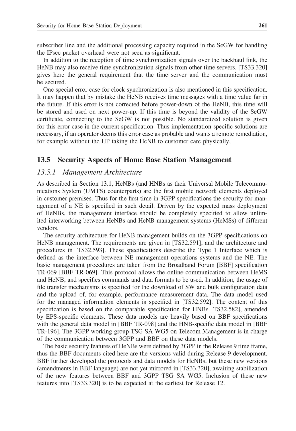
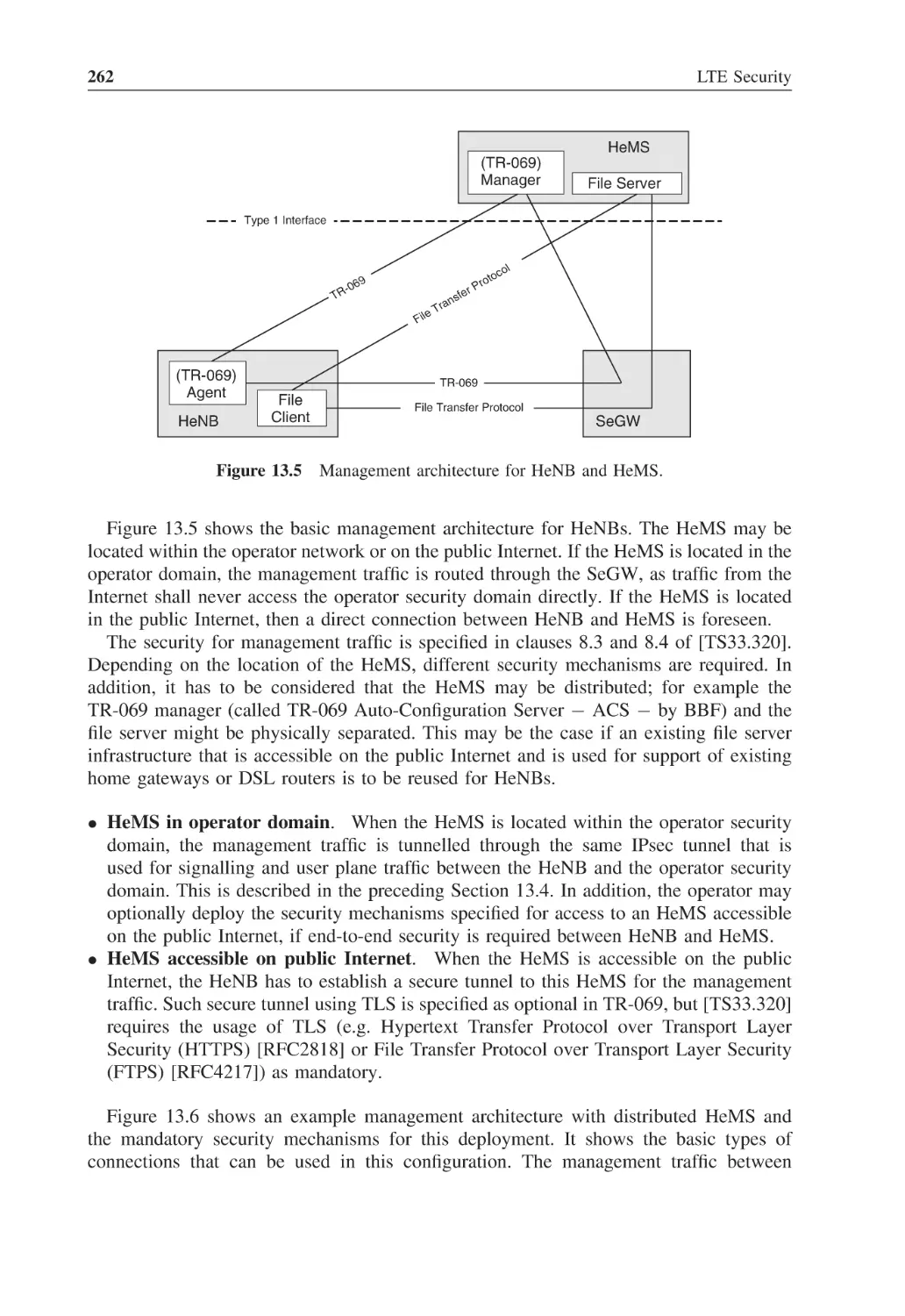
Security Aspects of Home Base Station Management
13.5.1 Management Architecture
13.5.2 Management and Provisioning during Manufacturing
13.5.3 Preparation for Operator-Specific Deployment
13.5.4 Relationships between HeNB Manufacturer and Operator
13.5.5 Security Management in Operator Network
13.5.6 Protection of Management Traffic
13.5.7 Software Download
13.5.8 Location Verification
Closed Subscriber Groups and Emergency Call Handling
13.6.1 UE Access Control to HeNBs
13.6.2 Emergency Calls
Support for Subscriber Mobility
13.7.1 Mobility Scenarios
13.7.2 Direct Interfaces between HeNBs
247
250
253
255
256
258
258
260
261
261
264
266
267
267
268
270
272
275
275
276
277
277
278
Relay Node Security
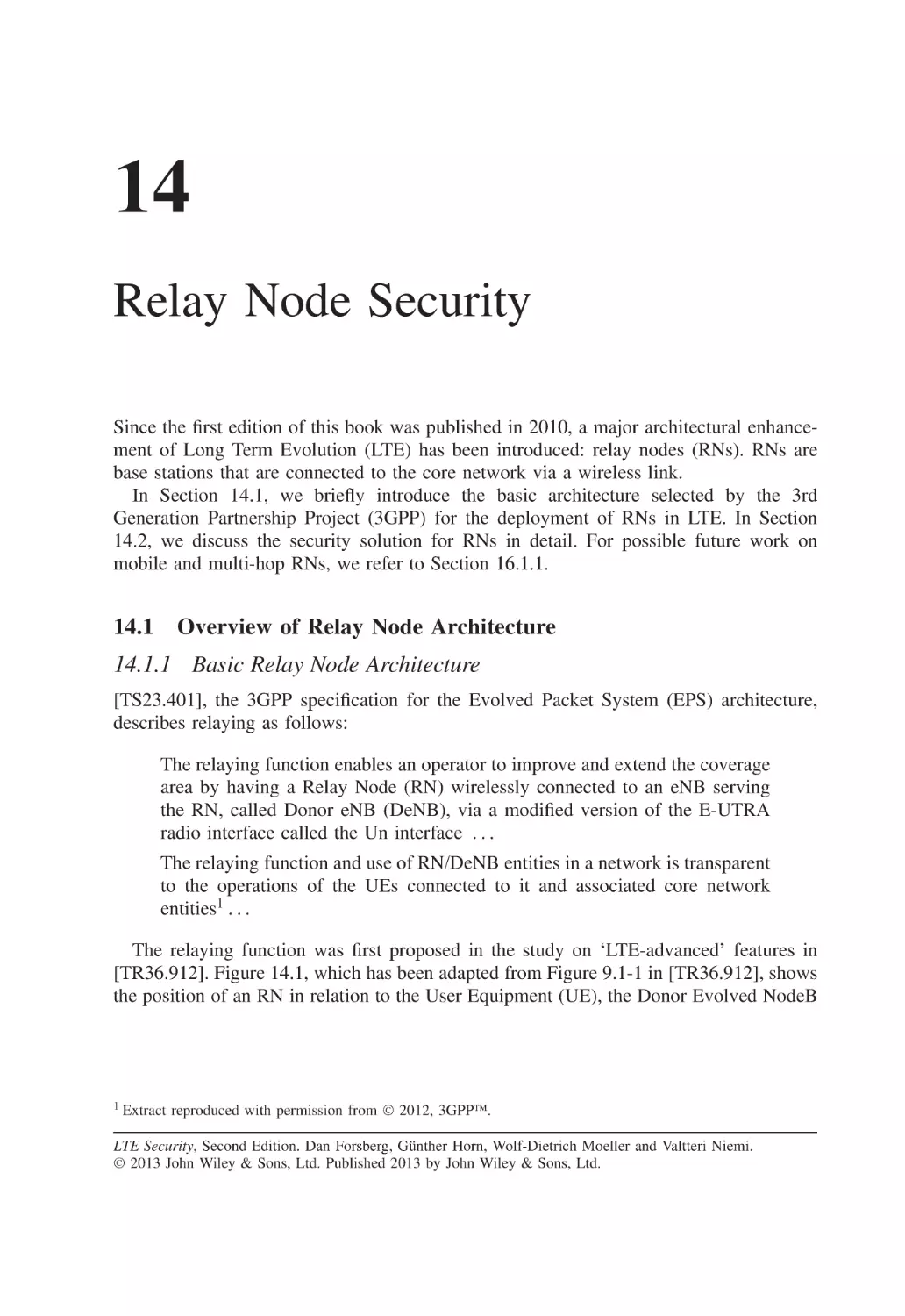
Overview of Relay Node Architecture
14.1.1 Basic Relay Node Architecture
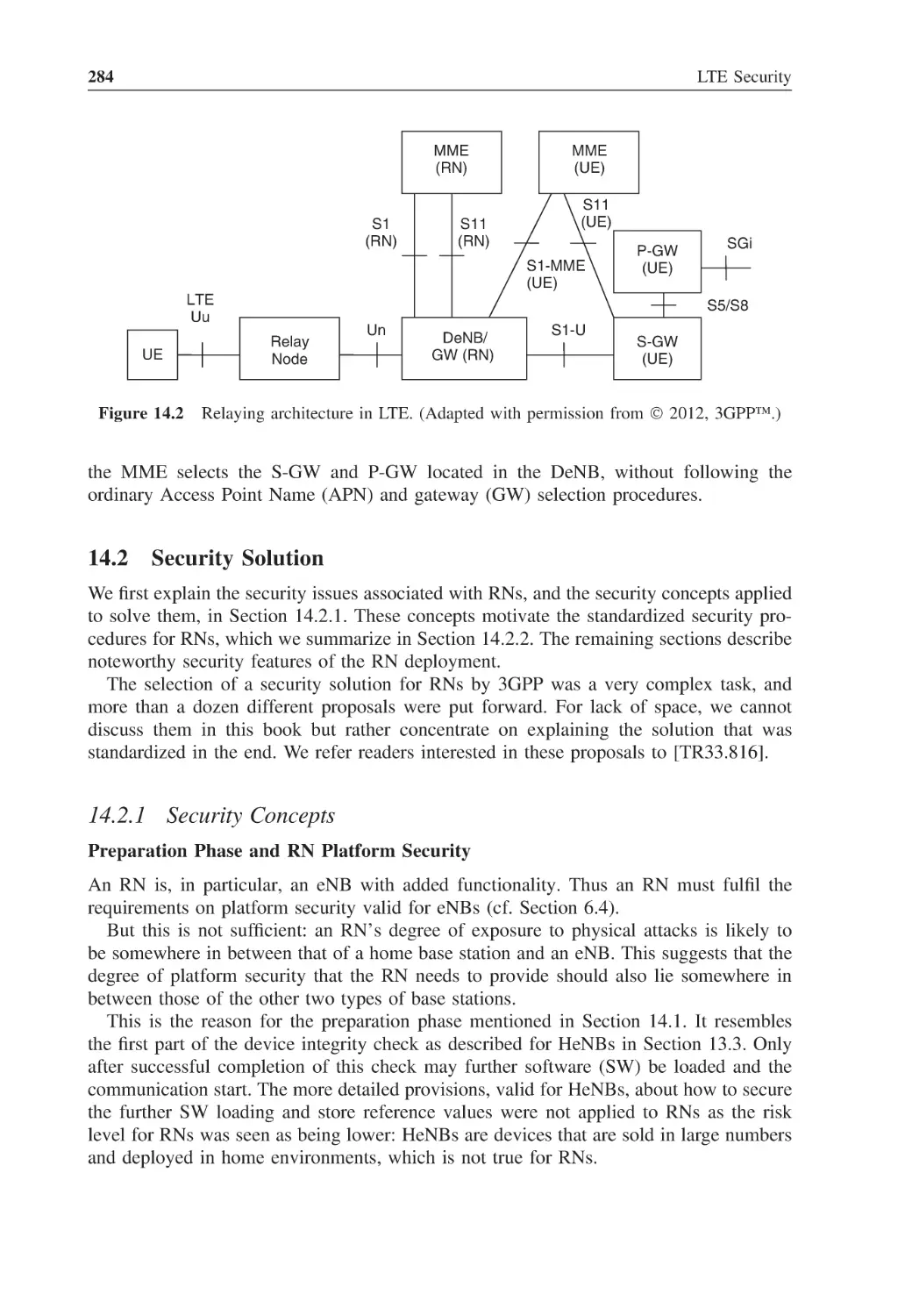
14.1.2 Phases for Start-Up of Relay Nodes
Security Solution
14.2.1 Security Concepts
14.2.2 Security Procedures
14.2.3 Security on the Un Interface
14.2.4 USIM and Secure Channel Aspects
14.2.5 Enrolment Procedures
14.2.6 Handling of Subscription and Certificates
281
281
281
283
284
284
288
290
290
291
291
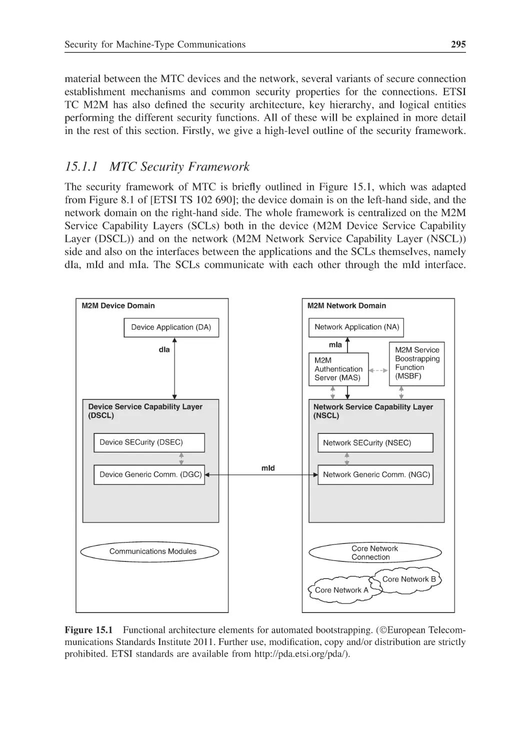
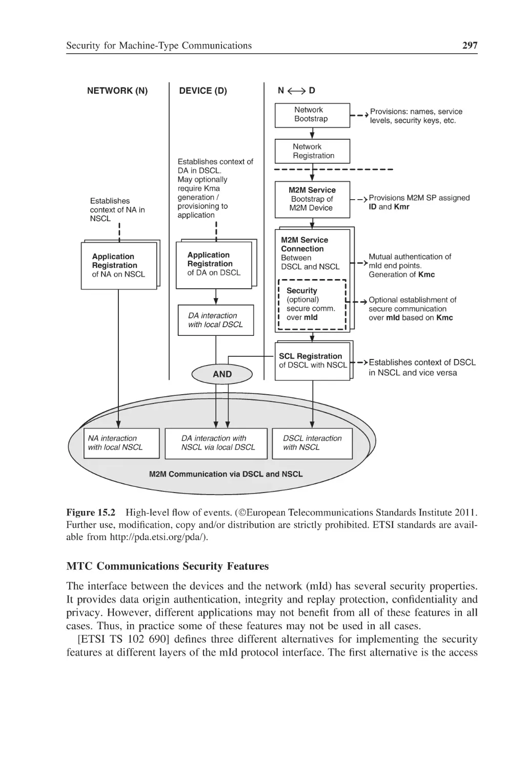
Security for Machine-Type Communications
Security for MTC at the Application Level
15.1.1 MTC Security Framework
15.1.2 Security (Kmr) Bootstrapping Options
15.1.3 Connection (Kmc) and Application-Level Security Association
(Kma) Establishment Procedures
Security for MTC at the 3GPP Network Level
15.2.1 3GPP System Improvements for MTC
15.2.2 Security Related to 3GPP System Improvements for MTC
293
294
295
298
301
301
301
303
Contents
xi
15.3
Security for MTC at the Credential Management Level
15.3.1 Trusted Platform in the Device
15.3.2 Embedded UICC
15.3.3 Remote Management of Credentials
306
307
307
308
16
16.1
Future Challenges
Near-Term Outlook
16.1.1 Security for Relay Node Architectures
16.1.2 Security for Interworking of 3GPP Networks and Fixed Broadband
Networks
16.1.3 Security for Voice over LTE
16.1.4 Security for Machine-Type Communication
16.1.5 Security for Home Base Stations
16.1.6 New Cryptographic Algorithms
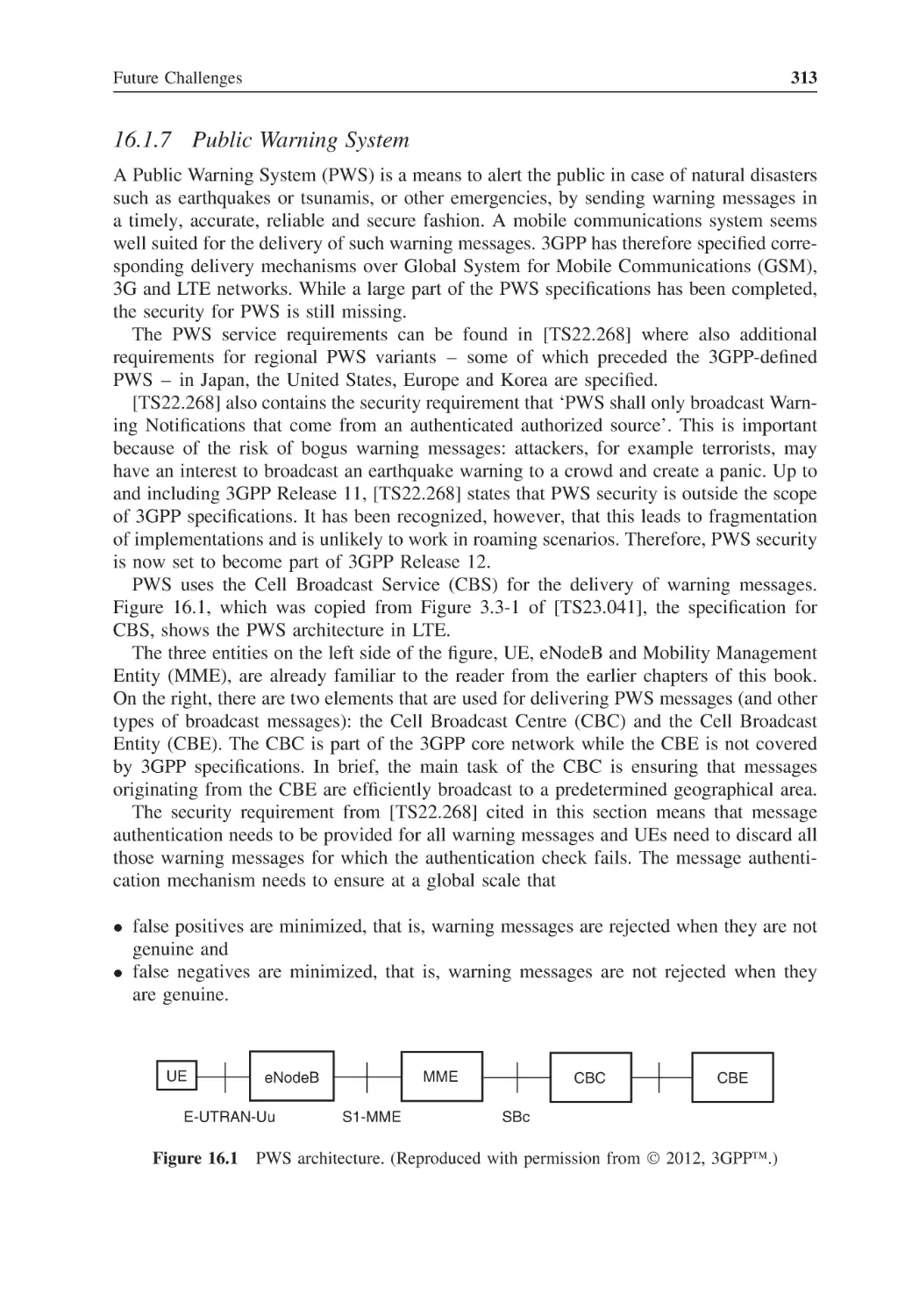
16.1.7 Public Warning System
16.1.8 Proximity Services
Far-Term Outlook
309
309
309
16.2
310
310
311
311
312
313
314
314
Abbreviations
319
References
327
Index
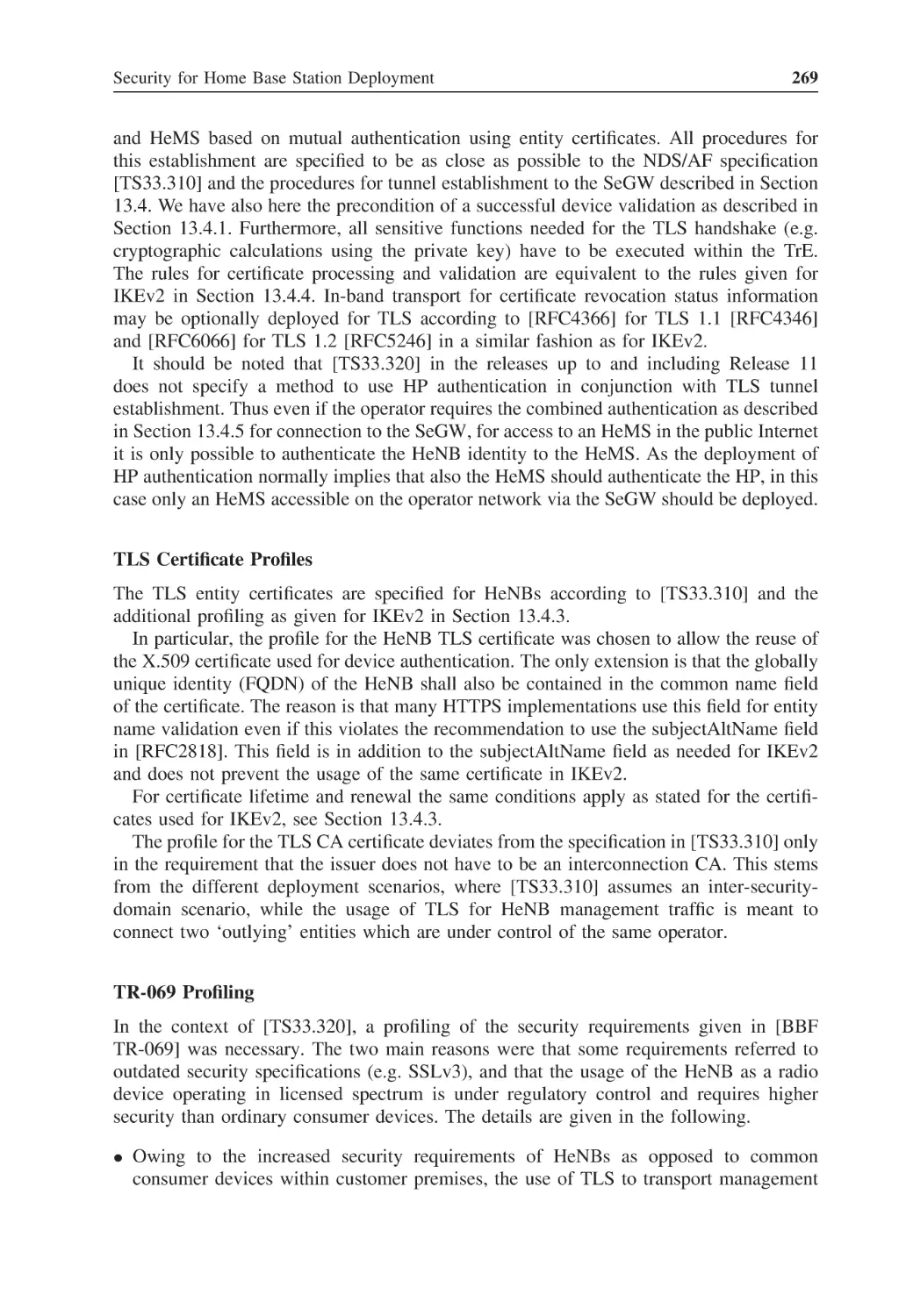
337
Preface
This is the second edition of the book LTE Security whose first edition appeared in the
autumn of 2010.
Since 2010, LTE has established itself as the unrivalled mobile broadband technology
of the fourth generation (4G), with significant commercial deployments around the world
and a fast-growing market. The subject of this book is hence even more relevant than it
was at the time of the first edition.
The basic specifications for LTE in general, and LTE security in particular, have proven
remarkably stable since their first versions were published in 2008 as part of 3GPP Release
8. Nevertheless, as is quite common in the standardization process, a number of corrections
to the LTE security specifications have been agreed since to fix shortcomings that had
become apparent during the development and deployment processes.
More importantly, new features have been added to LTE to enhance support for new
types of deployment scenarios and applications. From a security point of view, the most
important of these additions are the support for relay nodes and for machine-type communications. We therefore devote two new chapters to them.
A number of other new features have been added to LTE security since 2010, one
example being the addition of a third family of cryptographic algorithms for LTE. These
new features have been added to the chapters that had existed already in the first edition
of the book.
This book focuses on LTE security, but also gives a thorough introduction to its predecessors, GSM security and 3G security. The second edition updates the reader on recent
developments in these areas. While things were quite calm on the 3G security front, confidence in the strength of some cryptographic algorithms used with GSM has been further
eroded by live hacking demonstrations at a number of public events. These developments
suggest that it is now time to take those stronger GSM algorithms into use that have
already been standardized and are available in products.
Some of the topics mentioned in the last chapter of the first edition that provided an
outlook have matured in the meantime and been included in the other chapters of the
book. The outlook has been updated accordingly.
Summing up, this second edition includes the following updates with respect to the
first edition:
• Two new chapters, on relay nodes and machine-type communications, have been added.
xiv
Preface
• All enhancements to LTE security specified for 3GPP Releases 10 and 11 have been
included.
• All corrections to the specifications up to and including Release 11 and approved by
3GPP by June 2012 have been taken into account as far as they affect the text in
the book.
• Major developments since 2010 affecting GSM security and 3G security are explained.
• The last chapter of the book providing an outlook to future developments has been
updated.
Foreword to the First Edition
The early to mid-1980s saw the commercial opening across Europe of public-access
mobile communications systems. These cellular systems all used analogue technology,
but outside of the Nordic countries no attempt was made to standardize the systems – so
the technology adopted differed from country to country. Unfortunately, one thing they
did have in common was a total absence of adequate security features, which made
them open to abuse by criminals, journalists and all manner of opportunists. Users’ calls
could be eavesdropped on the air using readily available and comparatively inexpensive
interception devices, and there were celebrated cases of journalistic invasion of privacy.
A well-known example was the ‘squidgy’ tapes, where mobile telephone calls between
members of the British royal family were recorded. Mobile telephone operators and their
customers became very concerned.
The operators also had another problem with serious financial consequences. When a
mobile phone attempted to connect to a network, the only check made on authenticity
was to see that the telephone number and the phone’s identity correctly corresponded.
These numbers could be intercepted on the air and programmed to new phones creating
clones of the original. Clones were used by criminals to run up huge charges for calls
which had nothing to do with the legitimate owner. Cloning became very widespread,
with criminals placing their ‘cloning’ equipment in cars parked at airports to capture the
numbers from business people announcing their arrival back home to their families. It
represented a serious financial problem for operators who ended up covering the charges
themselves. The problems caused by lack of security in European analogue systems were
a significant factor in accelerating the creation and adoption of GSM.
GSM is a standard for digital mobile communications, designed originally for Europe
but now adopted all over the world. Being an international standard it brings economy
of scale and competition, and it enables users to roam across borders from one network
to another. Being digital it brings transmission efficiency and flexibility, and enables the
use of advanced cryptographic security. The security problems of the original analogue
systems are addressed in GSM by encryption on the air interface of user traffic, in particular voice calls, and authentication by network operators of their customers on an
individual basis whenever they attempt to connect to a network, irrespective of where
that network may be. From both a technical and a regulatory perspective, the use of
cryptography in GSM was groundbreaking. Initially manufacturers and operators feared
it would add too much complexity to the system, and security agencies were concerned
xvi
Foreword to the First Edition
that it may be abused by criminals and terror organizations. The legitimate fears and
concerns constrained what was possible, especially with the encryption algorithm, which
was designed against a philosophy of ‘minimum strength to provide adequate security’.
Despite this, and the continuing efforts of organized hackers, eavesdropping on the air of
GSM calls protected using the original cipher has still to be demonstrated in a real deployment, and with a stronger cipher already available in the wings, any future success will
be largely pointless. This doesn’t mean that GSM is free from security weaknesses – the
ability to attack it using false base stations is very real.
GSM is the first in an evolving family of technologies for mobile communications. The
second member of the family is 3G (or UMTS, as it is often referred to in Europe) and
the third, and most recent, is LTE EPS to give it its proper title which is used throughout
the main body of this book). With each technology evolution the security features have
been enhanced to address learning from its predecessor, as well as to accommodate any
changes in system architecture or services. The underlying GSM security architecture has
proved to be extremely robust, and consequently has remained largely unchanged with
the evolving technology family. It has also been adapted for use in other communications
systems, including WLAN, IMS and HTTP. It is characterized by authentication data and
encryption key generation being confined to a user’s home network authentication centre
and personal SIM, the two elements where all user-specific static security data is held.
Only dynamic and user session-specific security data goes outside these domains.
3G sees the addition to the GSM security features of user authentication of the access
network – to complement user authentication by the network, integrity protection of signalling and the prevention of authentication replay. Start and termination of ciphering are
moved from the base station further into the network. Of course, the false base station
attack is countered. A new suite of cryptographic algorithms based on algorithms open to
public scrutiny and analysis is introduced, and changes of regulation governing the export
of equipment with cryptographic functionality make their adoption easier for most parts
of the world.
LTE heralds the first technology in the family that is entirely packet-switched – so
voice security has to be addressed in an entirely different way from GSM and 3G. LTE
is a much flatter architecture, with fewer network elements, and is entirely IP-based.
Functionality, including security functionality, is migrated to the edge of the network,
including encryption functionality which is moved to the edge of the radio network, having
been moved from the base station to the radio network controller in the evolution from
GSM to 3G. While maintaining compatibility with the security architecture developed
for GSM and evolved for 3G, the security functionality has been significantly adapted,
enhanced and extended to accommodate the changes that LTE represents, as well as
security enhancements motivated by practical experience with 3G. Much of this plays
back into 3G itself as new security challenges arise with the advent of femto cells – lowcost end nodes in exposed environments that are not necessarily under the control of the
operator of the network to which they are attached.
Foreword to the First Edition
xvii
The book takes the reader through the evolution of security across three generations
of mobile, focussing with clarity and rigour on the security of LTE. It is co-authored by
a team who continue to be at the heart of the working group in 3GPP responsible for
defining the LTE security standards. Their knowledge, expertise and enthusiasm for the
subject shine through.
Professor Michael Walker
Chairman of the ETSI Board
Acknowledgements
This book presents the results of research and specification work by many people over
an extended period. Our thanks therefore go to all those who helped make Long Term
Evolution (LTE) possible through their hard work. In particular, we thank the people
working in 3GPP, the standardization body that publishes the LTE specifications, and,
especially, the delegates to the 3GPP security working group, SA3, with whom we were
working to produce the LTE security specifications over the past years.
We would also like to express our gratitude to our colleagues at Nokia and Nokia
Siemens Networks for our longstanding fruitful collaboration. We are particularly
indebted to N. Asokan, Wolfgang Bücker, Devaki Chandramouli, Jan-Erik Ekberg,
Christian Günther, Silke Holtmanns, Jan Kåll, Raimund Kausl, Rainer Liebhart, Christian
Markwart, Kaisa Nyberg, Martin Öttl, Jukka Ranta, Manfred Schäfer, Peter Schneider,
Hanns-Jürgen Schwarzbauer, José Manuel Tapia Pérez, Janne Tervonen, Robert Zaus
and Dajiang Zhang who helped us improve the book through their invaluable comments.
Finally, we would like to thank the editing team at Wiley whose great work turned our
manuscript into a coherent book.
The authors welcome any comments or suggestions for improvements.
Copyright Acknowledgements
The authors would like to include additional thanks and full copyright acknowledgement
as requested by the following copyright holders in this book.
• © 2009, 3GPP™. TSs and TRs are the property of ARIB, ATIS CCSA, ETSI, TTA and
TTC who jointly own the copyright in them. They are subject to further modifications
and are therefore provided here ‘as is’ for information purposes only. Further use is
strictly prohibited.
• © 2010, 3GPP™. TSs and TRs are the property of ARIB, ATIS CCSA, ETSI, TTA and
TTC who jointly own the copyright in them. They are subject to further modifications
and are therefore provided here ‘as is’ for information purposes only. Further use is
strictly prohibited.
• © 2010, Nokia Corporation. For permission to reproduce the Nokia Corporation UE
icon within Figures 2.1, 3.1, 3.2, 3.3, 6.1, 6.2, 6.3, 7.1 and 14.1.
• © 2011, European Telecommunications Standards Institute. Further use, modification, copy and/or distribution are strictly prohibited. ETSI standards are available from
http://pda.etsi.org/pda/.
xx
Acknowledgements
• © 2012, 3GPP™. TSs and TRs are the property of ARIB, ATIS CCSA, ETSI, TTA and
TTC who jointly own the copyright in them. They are subject to further modifications
and are therefore provided here ‘as is’ for information purposes only. Further use is
strictly prohibited.
• © 2012, GSM Association GSM™ and its licensors. All Rights Reserved.
Please see the individual figure and table captions and the footnotes to extracts from
3GPP specifications for copyright notices throughout the book.
1
Overview of the Book
Mobile telecommunications systems have evolved in a stepwise manner. A new cellular
radio technology has been designed once per decade. Analogue radio technology was dominant in the 1980s and paved the way for the phenomenal success of cellular systems. The
dominant second-generation system Global System for Mobile Communications (GSM,
or 2G) was introduced in the early 1990s, while the most successful third-generation
system, 3G – also known as the Universal Mobile Telecommunications System (UMTS),
especially in Europe – was brought into use in the first years of the first decade of the
new millennium.
At the time of writing, the fourth generation of mobile telecommunications systems is
being commercially deployed. Its new radio technology is best known under the acronym
LTE (Long Term Evolution). The complete system is named SAE/LTE, where SAE (System Architecture Evolution) stands for the entire system, which allows combining access
using the new, high-bandwidth LTE technology with access using the legacy technologies such as GSM, 3G and High Rate Packet Data (HRPD). The technical term for the
SAE/LTE system is Evolved Packet System (EPS), and we shall be using this term consistently in the book. The brand name of the new system has been chosen to be LTE, and
that is the reason why the title of the book is LTE Security.
With the pervasiveness of telecommunications in our everyday lives, telecommunications security has also moved more and more to the forefront of attention. Security is
needed to ensure that the system is properly functioning and to prevent misuse. Security
includes measures such as encryption and authentication, which are required to guarantee
the user’s privacy as well as ensuring revenue for the mobile network operator.
The book will address the security architecture for EPS. This is based on elements
of the security architectures for GSM and 3G, but it needed a major redesign effort owing
to the significantly increased complexity, and new architectural and business requirements.
The book will present the requirements and their motivation and then explain in detail
the security mechanisms employed to meet these requirements.
To achieve global relevance, a communication system requires world-wide interoperability that is easiest to achieve by means of standardization. The standardized part of
the system guarantees that the entities in the system are able to communicate with each
other even if they are controlled by different mobile network operators or manufactured
LTE Security, Second Edition. Dan Forsberg, Günther Horn, Wolf-Dietrich Moeller and Valtteri Niemi.
© 2013 John Wiley & Sons, Ltd. Published 2013 by John Wiley & Sons, Ltd.
2
LTE Security
by different vendors. There are also many parts in the system where interoperability does
not play a role, such as the internal structure of the network entities. It is better not
to standardize wherever it is not necessary because then new technologies can be introduced more rapidly and differentiation is possible among operators as well as among
manufacturers, thus encouraging healthy competition.
As an example in the area of security, communication between the mobile device
and the radio network is protected by encrypting the messages. It is important that we
standardize how the encryption is done and which encryption keys are used, otherwise
the receiving end could not do the reverse operation and recover the original content of
the message. On the other hand, both communicating parties have to store the encryption
keys in such a way that no outsider can get access to them. From the security point of
view, it is important that this be done properly but we do not have to standardize how
it is done, thus leaving room for the introduction of better protection techniques without
the burden of standardizing them first. The emphasis of our book is on the standardized
parts of EPS security, but we include some of the other aspects as well.
The authors feel that there will be interest in industry and academia in the technical
details of SAE/LTE security for quite some time to come. The specifications generated
by standardization bodies only describe how to implement the system (and this only
to the extent required for interoperability), but almost never inform readers about why
things are done the way they are. Furthermore, specifications tend to be readable by
only a small group of experts and lack the context of the broader picture. This book is
meant to fill this gap by providing first-hand information from insiders who participated in
decisively shaping SAE/LTE security in the relevant standardization body, 3rd Generation
Partnership Project (3GPP), and can therefore explain the rationale for the design decisions
in this area.
The book is based on versions of 3GPP specifications from March 2012 but corrections
approved by June 2012 were still taken into account. New features will surely be added
to these specifications in later versions and there will most probably also be further
corrections to the existing security functionality. For the obvious reason of timing, these
additions cannot be addressed in this book.
The book is intended for telecommunications engineers in research, development and
technical sales and their managers as well as engineering students who are familiar with
architectures of mobile telecommunications systems and interested in the security aspects
of these systems. The book will also be of interest to security experts who are looking
for examples of the use of security mechanisms in practical systems. Both readers from
industry and from academia should be able to benefit from the book. The book is probably
most beneficial to advanced readers, with subchapters providing sufficient detail so that
the book can also be useful as a handbook for specialists. It can also be used as textbook
material for an advanced course, and especially the introductory parts of each chapter,
when combined, give a nice overall introduction to the subject.
The book is organized as follows. Chapter 2 gives the necessary background information on cellular systems, relevant security concepts, standardization matters and so on. As
explained earlier, LTE security relies heavily on security concepts introduced for the predecessor systems. Therefore, and also to make the book more self-contained, Chapters 3–5
are devoted to security in legacy systems, including GSM and 3G, and security aspects
of cellular–WLAN (Wireless Local Area Network) interworking.
Overview of the Book
3
Chapter 6 provides an overall picture of the EPS security architecture. The next four
chapters provide detailed information about the core functionalities in the security architecture. Chapter 7 is devoted to authentication and key agreement which constitute the
cornerstones for the whole security architecture. Chapter 8 shows how user data and signalling data are protected in the system, including protecting confidentiality and integrity
of the data. A very characteristic feature in cellular communication is the possibility
of handing over the communication from one base station to another. Security for handovers and other mobility issues is handled in Chapter 9. Another cornerstone of the
security architecture is the set of cryptographic algorithms that are used in the protection
mechanisms. The algorithms used in EPS security are introduced in Chapter 10.
In the design of EPS, it has been taken into account already from the beginning how
interworking with access technologies that are not defined by 3GPP is arranged. Also,
interworking with legacy 3GPP systems has been designed into the EPS system. These
two areas are discussed in detail in Chapter 11.
The EPS system is exclusively packet based; there are no circuit-switched elements in
it. This implies, in particular, that voice services have to be provided on top of Internet
Protocol (IP) packets. The security for such a solution is explained in Chapter 12.
Partially independently of the introduction of EPS, 3GPP has specified solutions that
enable the deployment of base stations covering very small areas, such as in private
homes. This type of base station may serve restricted sets of customers (e.g. people living
in a house), but open usage in hotspots or remote areas is also envisaged. These home
base stations are also planned for 3G access, not only for LTE access. Such a new type
of base station may be placed in a potentially vulnerable environment not controlled by
the network operator and therefore many new security measures are needed, compared to
conventional base stations. These are presented in detail in Chapter 13.
Chapter 14 introduces the security for relay nodes, a new feature introduced in Release
10 of 3GPP specifications. Relay nodes enable extensions for network coverage.
Chapter 15 addresses machine-type communication (MTC), also called machine-tomachine communication. The chapter provides an introduction to MTC security at the
network level, the application level and the level of managing security credentials. First
enhancements for the benefit of MTC appeared in 3GPP Release 10, after which further
enhancements were done in Release 11 and still more are in the pipeline for Release 12.
These all are discussed in the chapter.
Finally, Chapter 16 contains a discussion of both near-term and far-term future challenges in the area of securing mobile communications.
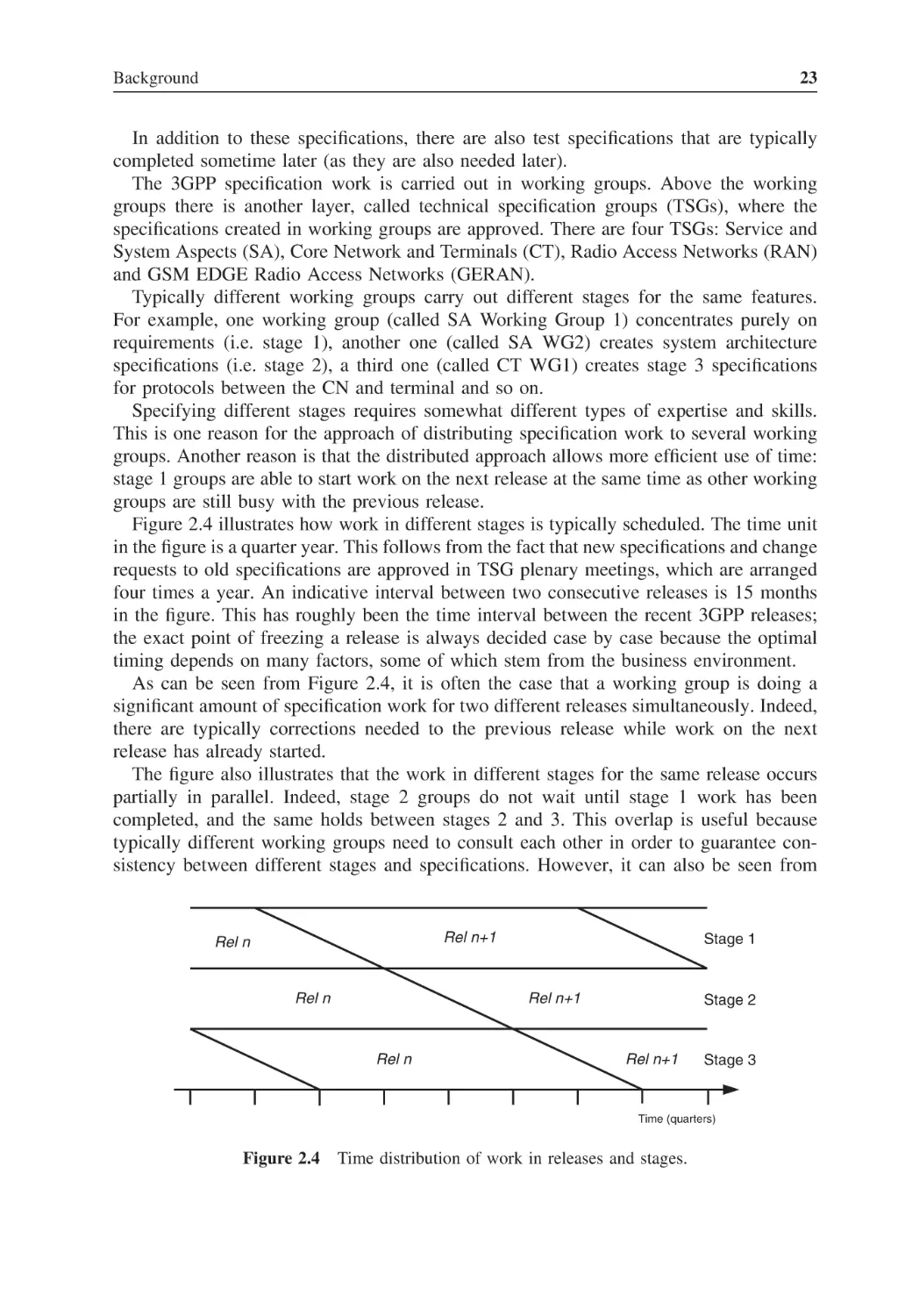
Many of the chapters depend on earlier ones, as can be seen from the descriptions
given here. However, it is possible to read some chapters without reading first all of the
preceding ones. Also, if the reader has prior knowledge of GSM and 3G systems and
their security features, the first four chapters can be skipped. This kind of knowledge
could have been obtained, for example, by reading the book UMTS Security [Niemi and
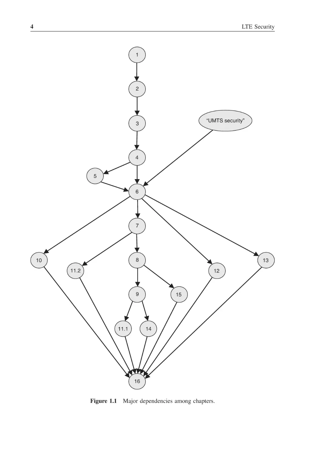
Nyberg 2003]. The major dependencies among the chapters of the book are illustrated in
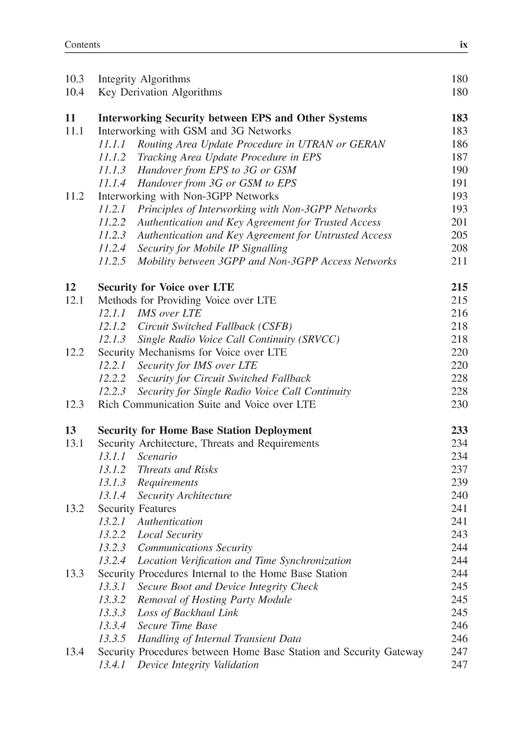
Figure 1.1.
4
LTE Security
1
2
“UMTS security”
3
4
5
6
7
8
10
13
11.2
12
9
11.1
15
14
16
Figure 1.1
Major dependencies among chapters.
2
Background
2.1
Evolution of Cellular Systems
Mobile communications were originally introduced for military applications. The concept
of a cellular network was taken into commercial use much later, near the beginning
of the 1980s, in the form of the Advanced Mobile Phone System (AMPS) in the United
States and in the form of the Nordic Mobile Telephone system (NMT) in northern Europe.
These first-generation cellular systems were based on analogue technologies. Simultaneous
access by many users in the same cell was provided by the Frequency Division Multiple
Access (FDMA) technique. Handovers between different cells were already possible in
these systems, and a typical use case was a phone call from a car.
The second generation of mobile systems (2G) was introduced roughly a decade later,
at the beginning of the 1990s. The dominant 2G technology has been the Global System
for Mobile (GSM) communications, with more than 3.5 billion users worldwide at the
time of writing. The second generation introduced digital information transmission on the
radio interface between the mobile phone and the base station (BS). The multiple access
technology is Time Division Multiple Access (TDMA).
The second generation provided an increased capacity of the network (owing to more
efficient use of radio resources), better speech quality (from digital coding techniques)
and a natural possibility for communicating data. Furthermore, it was possible to use new
types of security feature, compared to analogue systems.
Again roughly one decade later, at the beginning of the twenty-first century, the
third-generation (3G) technologies were introduced. Although GSM had become a
phenomenal success story already at that point, there were also other successful 2G
systems, both in Asia and in North America. One of the leading ideas for 3G was to
ensure fully global roaming: to make it possible for the user to use the mobile system
services anywhere in the world. A collaborative effort of standards bodies from Europe,
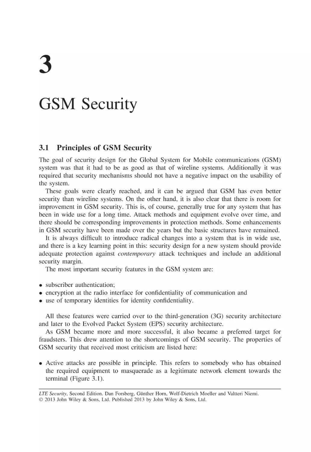
Asia and North America developed the first truly global cellular technologies in the 3rd
Generation Partnership Project (3GPP). At the time of writing, there are almost half a
billion 3G subscriptions in the world.
LTE Security, Second Edition. Dan Forsberg, Günther Horn, Wolf-Dietrich Moeller and Valtteri Niemi.
© 2013 John Wiley & Sons, Ltd. Published 2013 by John Wiley & Sons, Ltd.
6
LTE Security
The third generation provided a big increase in data rates, up to 2 Mbps in the first
version of the system that was specified in Release 99 of 3GPP. The multiple-access
technology is Wideband Code Division Multiple Access (WCDMA).
Both GSM and 3G systems were divided into two different domains, based on the
underlying switching technology. The circuit-switched (CS) domain is mainly intended
for carrying voice and short messages, while the packet-switched (PS) domain is mainly
used for carrying data traffic.
One more decade passed, and the time was ripe for taking another major step forward.
In 3GPP the development work was done under the names of Long Term Evolution (LTE)
of radio technologies and System Architecture Evolution (SAE). Both names emphasized
the evolutionary nature of this step, but the end result is in many respects a brand new
system, both from the radio perspective and from the system perspective. The new system
is called Evolved Packet System (EPS) and its most important component, the new radio
network, is called Evolved Universal Terrestrial Radio Access Network (E-UTRAN).
The EPS contains only a PS domain. It offers a big increase in data rates, up to more than
100 Mbps. The multiple-access technology is again based on FDMA, namely, Orthogonal
Frequency Division Multiple Access (OFDMA) for the downlink traffic (from the network
to the terminal) and Single Carrier Frequency Division Multiple Access (SC-FDMA) for
the uplink traffic (from the terminal to the network).
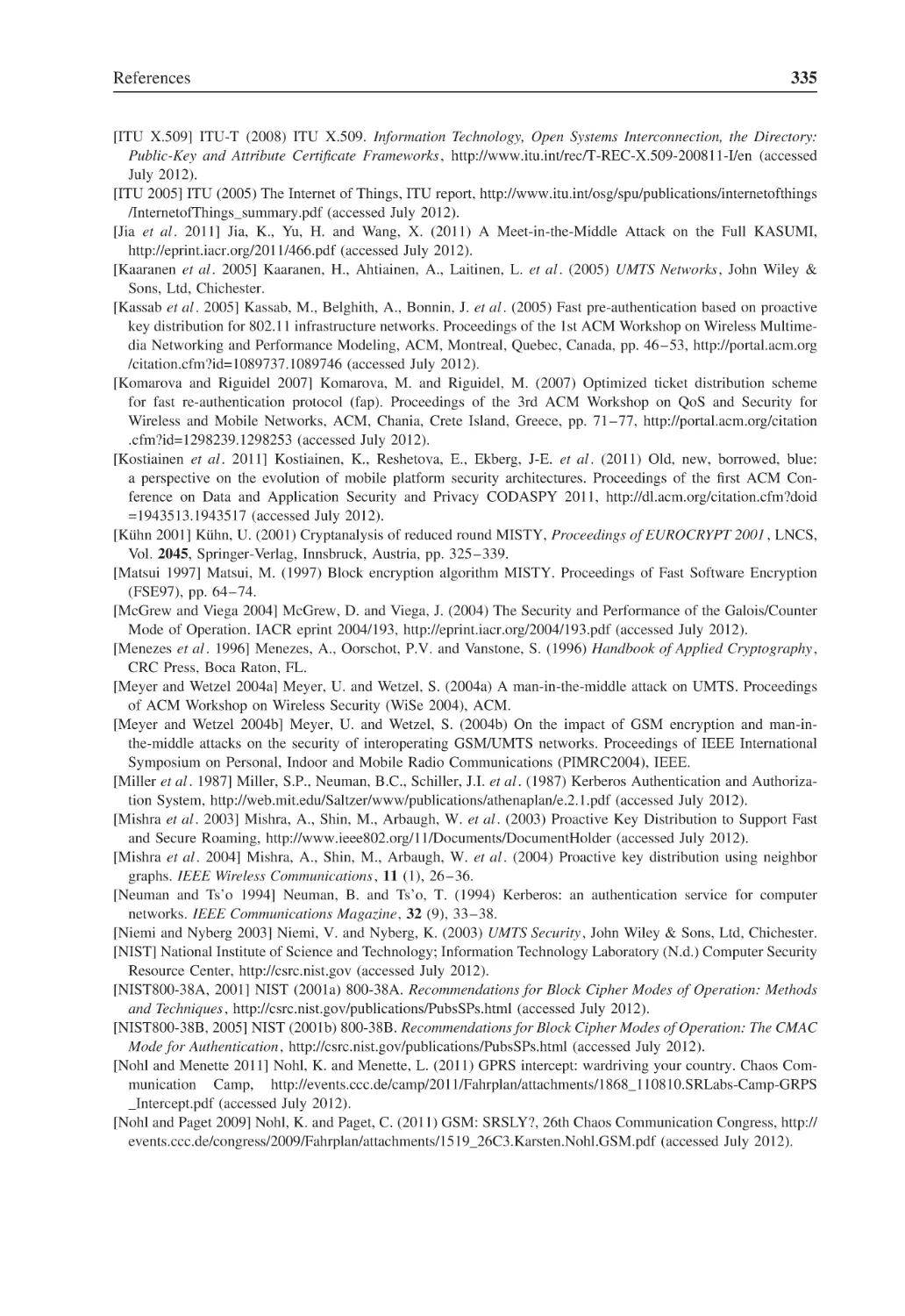
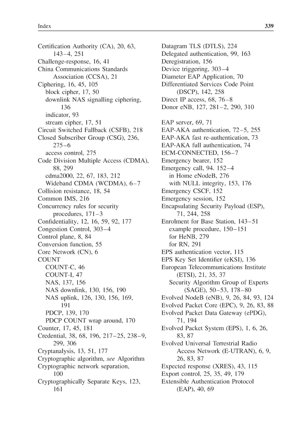
2.1.1 Third-Generation Network Architecture
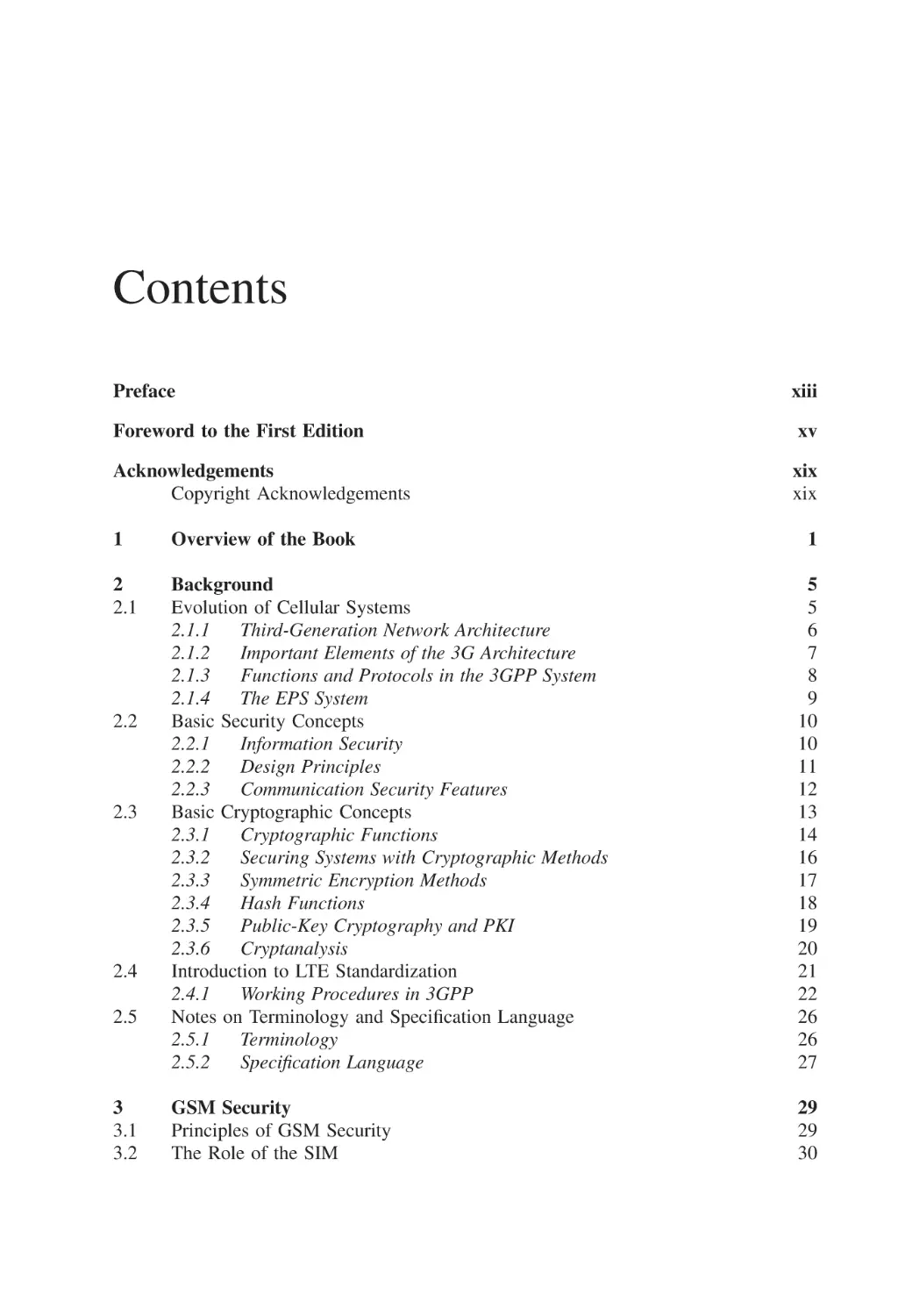
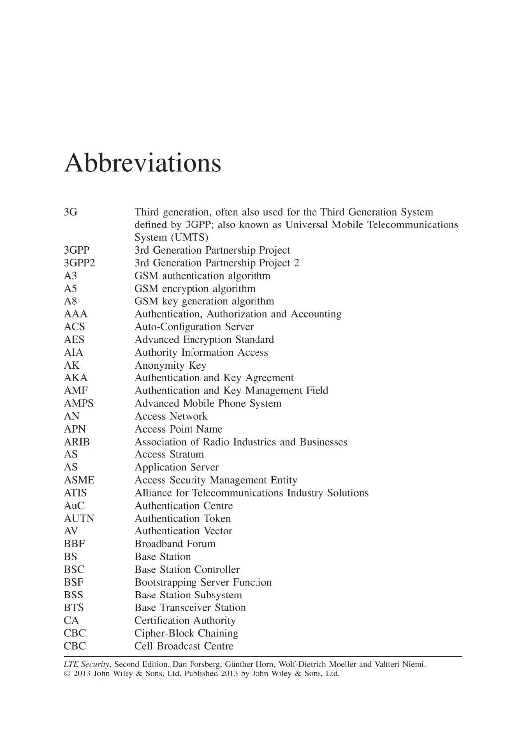
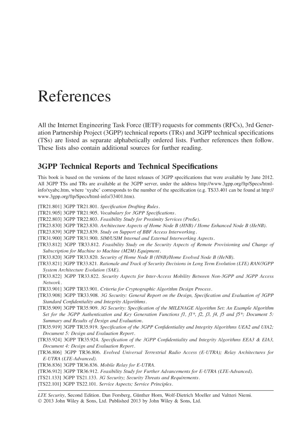
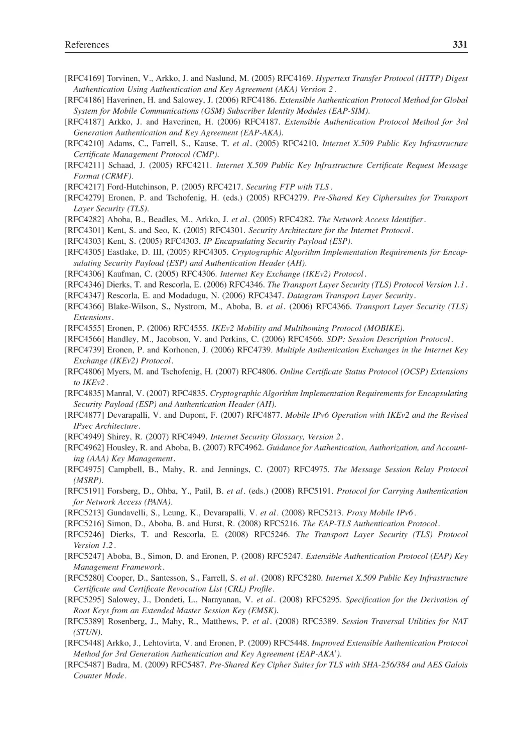
In this section, we give a brief overview of the 3GPP network architecture. A more
thorough description of the 3G architecture can be found elsewhere [Kaaranen et al . 2005].
A simplified picture of the 3GPP Release 99 system is given in Figure 2.1.
The network model consists of three main parts, all of which are visible in Figure 2.1.
The part closest to the user is the terminal, which is also called the User Equipment (UE).
The UE has a radio connection to the Radio Access Network (RAN), which itself is connected to the Core Network (CN). The CN takes care of coordination of the whole system.
UE
RNC
MSC/
VLR
GMSC
RNC
HLR
UTRAN
BSC
SGSN
GERAN
Figure 2.1
The 3G system.
GGSN
Background
7
The CN contains the PS domain and the CS domain. The former is an evolution of the
General Packet Radio Service (GPRS) domain of the GSM system, and its most important
network elements are the Serving GPRS Support Node (SGSN) and the Gateway GPRS
Support Node (GGSN). The CS domain is an evolution from the original CS GSM network
with the Mobile Switching Centre (MSC) as its most important component.
In addition to the various network elements, the architecture also defines interfaces or,
more correctly, reference points between these elements. Furthermore, protocols define
how different elements are able to communicate over the interfaces. Protocols involving
the UE are grouped into two main strata: the Access Stratum (AS) contains protocols that
are run between the UE and the access network, while the Non-Access Stratum (NAS)
contains protocols between the UE and the CN. In addition to these two, there are many
protocols that are run between different network elements.
The CN is further divided into the home network and the serving network. The home
network contains all the static information about the subscribers, including the static
security information. The serving network handles the communication to the UE (via
the access network). If the user is roaming, then the home and the serving network are
controlled by different mobile network operators.
2.1.2 Important Elements of the 3G Architecture
The UE consists of two parts: the Mobile Equipment (ME) and the Universal Subscriber
Identity Module (USIM). The ME is typically a mobile device that contains the radio
functionality and all the protocols that are needed for communications with the network.
It also contains the user interface, including a display and a keypad. The USIM is an
application that is run inside a smart card called Universal Integrated Circuit Card (UICC)
[TS31.101]. The USIM contains all the operator-dependent data about the subscriber,
including the permanent security information.
There are two types of RAN in the 3G system. The UTRAN is based on WCDMA
technology and the GSM/EDGE Radio Access Network (GERAN) is an evolution of
GSM technology.
The RAN contains two types of element. The BS is the termination point of the radio
interface on the network side, and it is called Node B in the case of UTRAN and Base
Transceiver Station (BTS) in GERAN. The BS is connected to the controlling unit of
the RAN, which is the Radio Network Controller (RNC) in UTRAN or the Base Station
Controller (BSC) of GERAN.
In the CN, the most important element in the CS domain is the switching element MSC
that is typically integrated with a Visitor Location Register (VLR) that contains a database
of the users currently in the location area controlled by the MSC. The Gateway Mobile
Switching Centre (GMSC) takes care of connections to external networks, an example
being the Public Switched Telephone Network (PSTN). In the PS domain, the role of
MSC/VLR is taken by the SGSN, while the GGSN takes care of connecting to Internet
Protocol (IP) services within the operator network and to the outside world, such as the
Internet.
The static subscriber information is maintained in the Home Location Register (HLR). It
is typically integrated with the Authentication Centre (AuC) that maintains the permanent
security information related to subscribers. The AuC also creates temporary authentication
8
LTE Security
and security data that can be used for security features in the serving network, such as
authentication of the subscriber and encryption of the user traffic.
In addition to the elements mentioned here and illustrated in Figure 2.1, there are many
other components in the 3G architecture, an example being the Short Message Service
Centre (SMSC) that supports storing and forwarding of short messages.
2.1.3 Functions and Protocols in the 3GPP System
The main functionalities in the 3GPP system are:
• Communication Management (CM) for user connections, such as call handling and
session management,
• Mobility Management (MM) covering procedures related to user mobility, as well as
important security features and
• Radio Resource Management (RRM) covering, for example, power control for radio
connections, control of handovers and system load.
The CM functions are located in the NAS, while RRM functions are located in the AS.
The MM functions are taken care of by both the CN and the RAN.
The division into user plane and control plane (also called signalling plane) defines an
important partition among the protocols. User plane protocols deal, as the name indicates,
with the transport of user data and other directly user-related information, such as speech.
Control plane protocols are needed to ensure correct system functionality by transferring
necessary control information between elements in the system.
In a telecommunication system, in addition to the user and control planes, there is also
a management plane that, for example, keeps all elements of the system in operation.
Usually, there is less need for standardization in the management plane than there is for
the user plane and the control plane.
The most important protocols for the Internet are IP, User Datagram Protocol (UDP)
and Transmission Control Protocol (TCP). In the wireless environment there is a natural
reason to favour UDP over TCP: fading and temporary loss of coverage make it difficult
to maintain reliable transmission of packets on a continuous basis. There is also a 3GPP
specific protocol that is run on top of UDP/IP. This is the GPRS Tunnelling Protocol
(GTP). It has been optimized for data transfer in the backbone of the PS domain.
The interworking of the different types of protocol can be illustrated by a typical use
case: a user receiving a phone call. First the network pages for the user. Paging is an
MM procedure; the network has to know in which geographical area the user could be
found. After the user has successfully received the paging message, the radio connection
is established by RRM procedures. When the radio connection exists, an authentication
procedure may follow, and this belongs again to the MM. Next the actual call set-up
(CM procedure) occurs during which the user may be informed about who is calling.
During the call there may be many further signalling procedures, such as for handovers.
At the end of the call, the call is first released by a CM procedure and after that the radio
connection is released by the RRM.
Background
9
2.1.4 The EPS System
The goals of the EPS are [TS22.278]:
•
•
•
•
•
•
•
higher data rates;
lower latency;
high level of security;
enhanced quality of service (QoS);
support for different access systems with mobility and service continuity between them;
support for access system selection and
capabilities for interworking with legacy systems.
The main means to achieve these goals are:
• the new radio interface and the new RAN based on it (E-UTRAN) and
• a flat IP-based architecture that has only two network elements on the user plane
(evolved NodeB (eNB) and Serving Gateway (S-GW)).
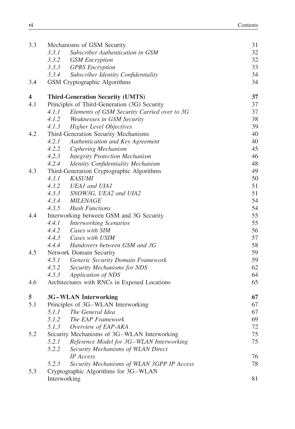
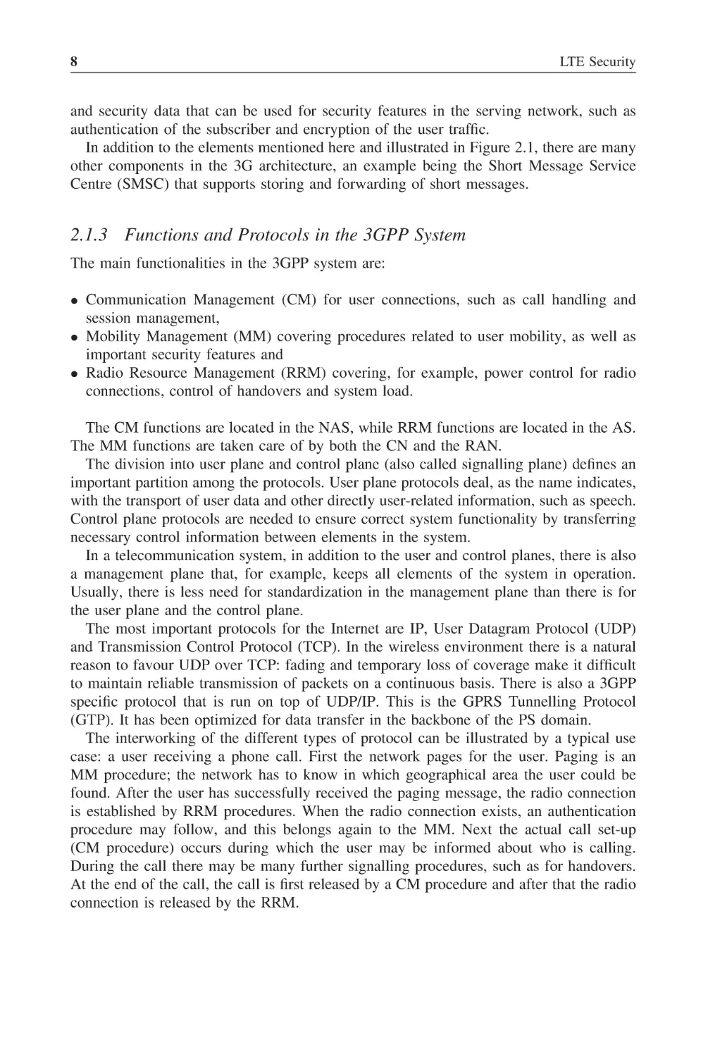
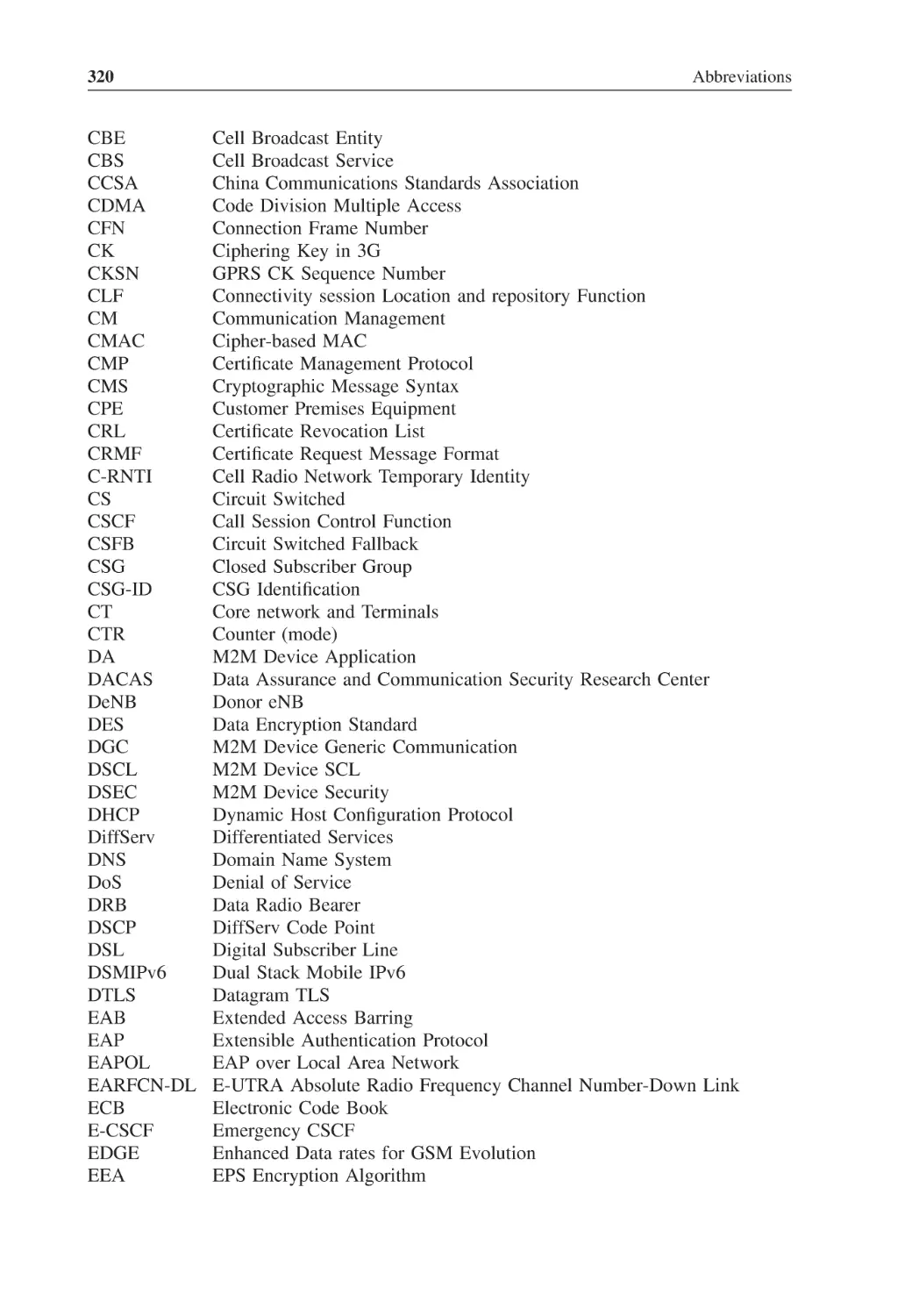
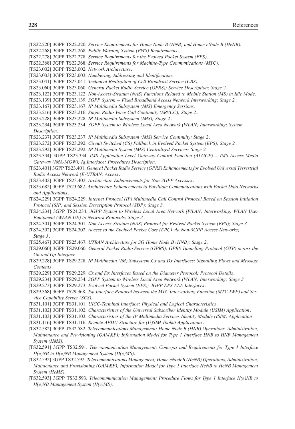
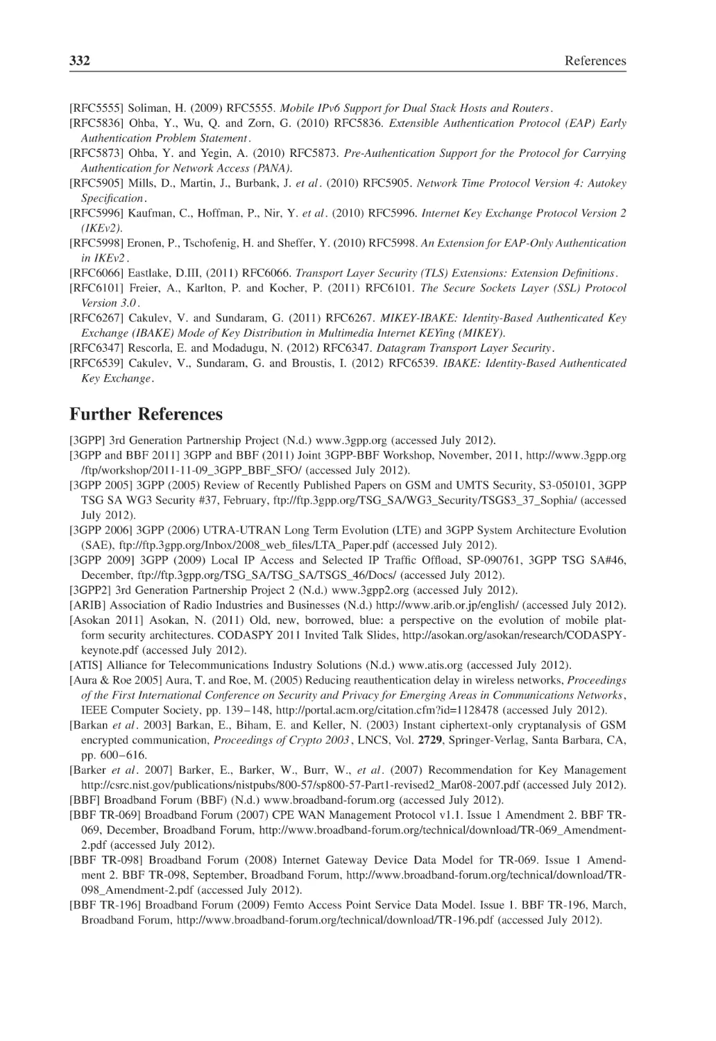
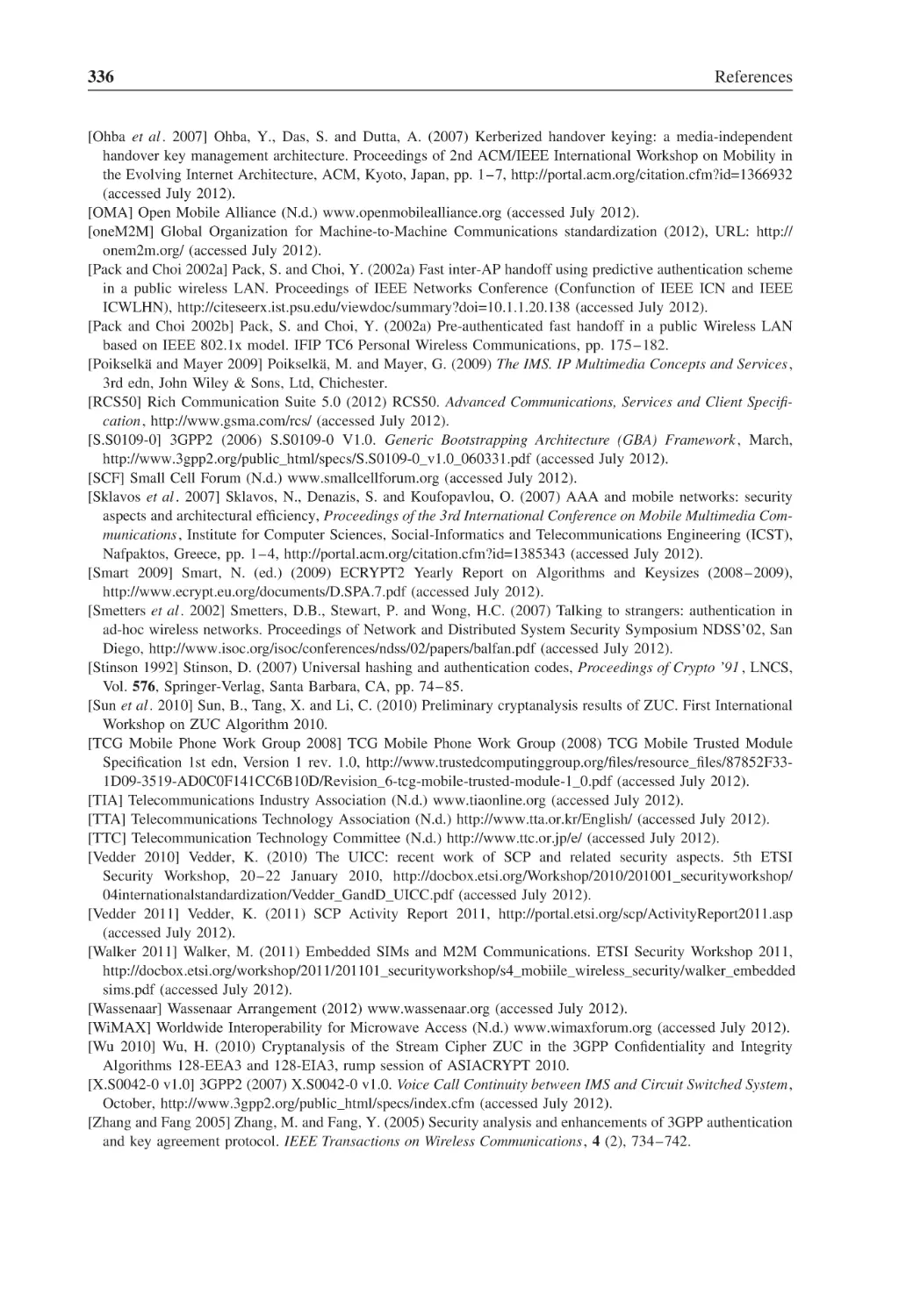
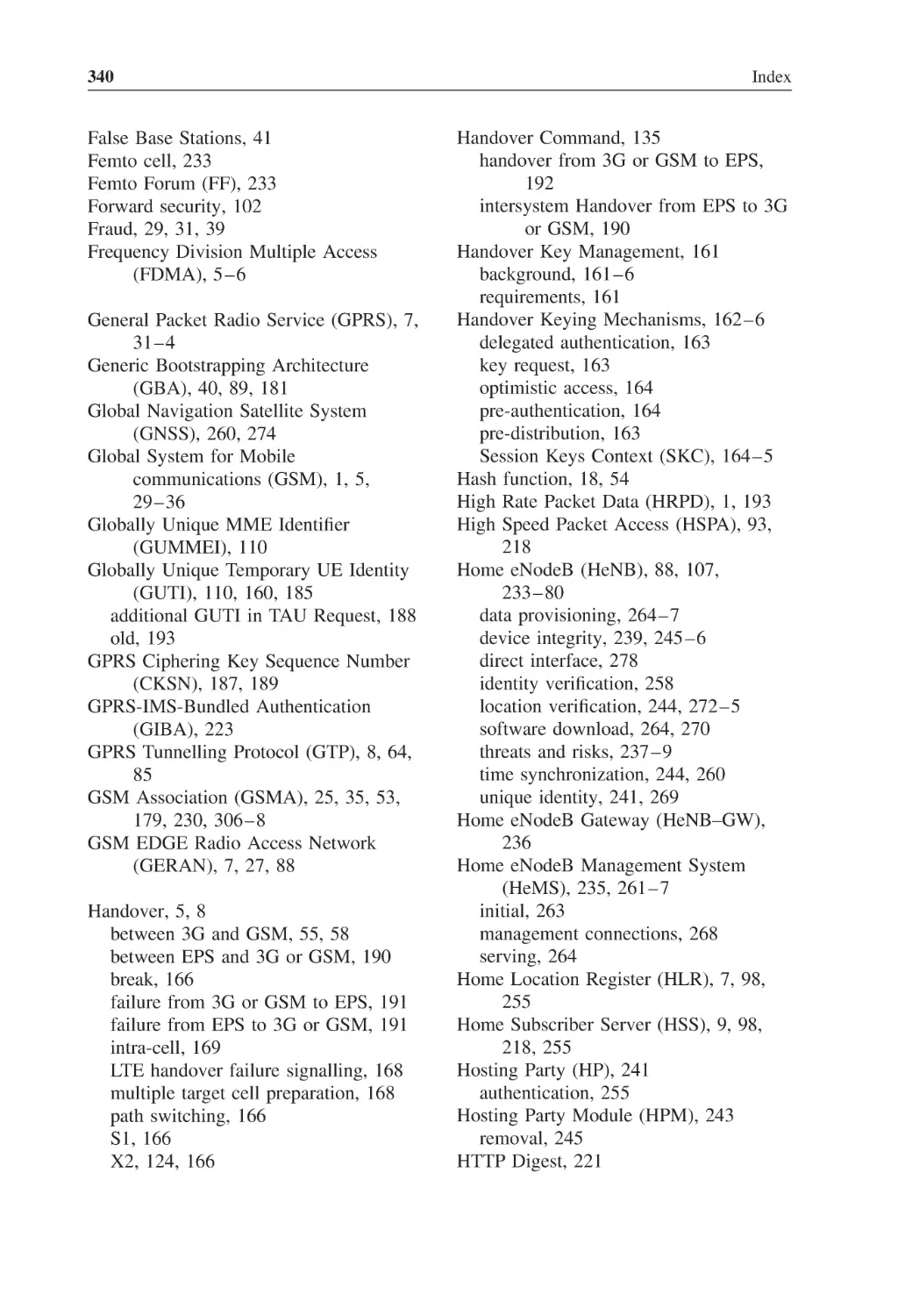
Figure 2.2 (adapted from [TS23.401]) illustrates the EPS network architecture in a case
where the UE is not roaming into a different network than where it has its subscription.
Note that the legacy RANs UTRAN and GERAN are included in the system together
with the legacy CN element SGSN.
The new CN element is called Mobility Management Entity (MME). The HLR of the
original GSM and 3G architecture is extended to the Home Subscriber Server (HSS). The
CN element for user plane handling is called Serving Gateway. The Packet Data Network
Gateway (PDN GW) handles the traffic towards PDNs. It is also possible that S-GW
and PDN GW are co-located. The CN of the EPS is called Evolved Packet Core (EPC).
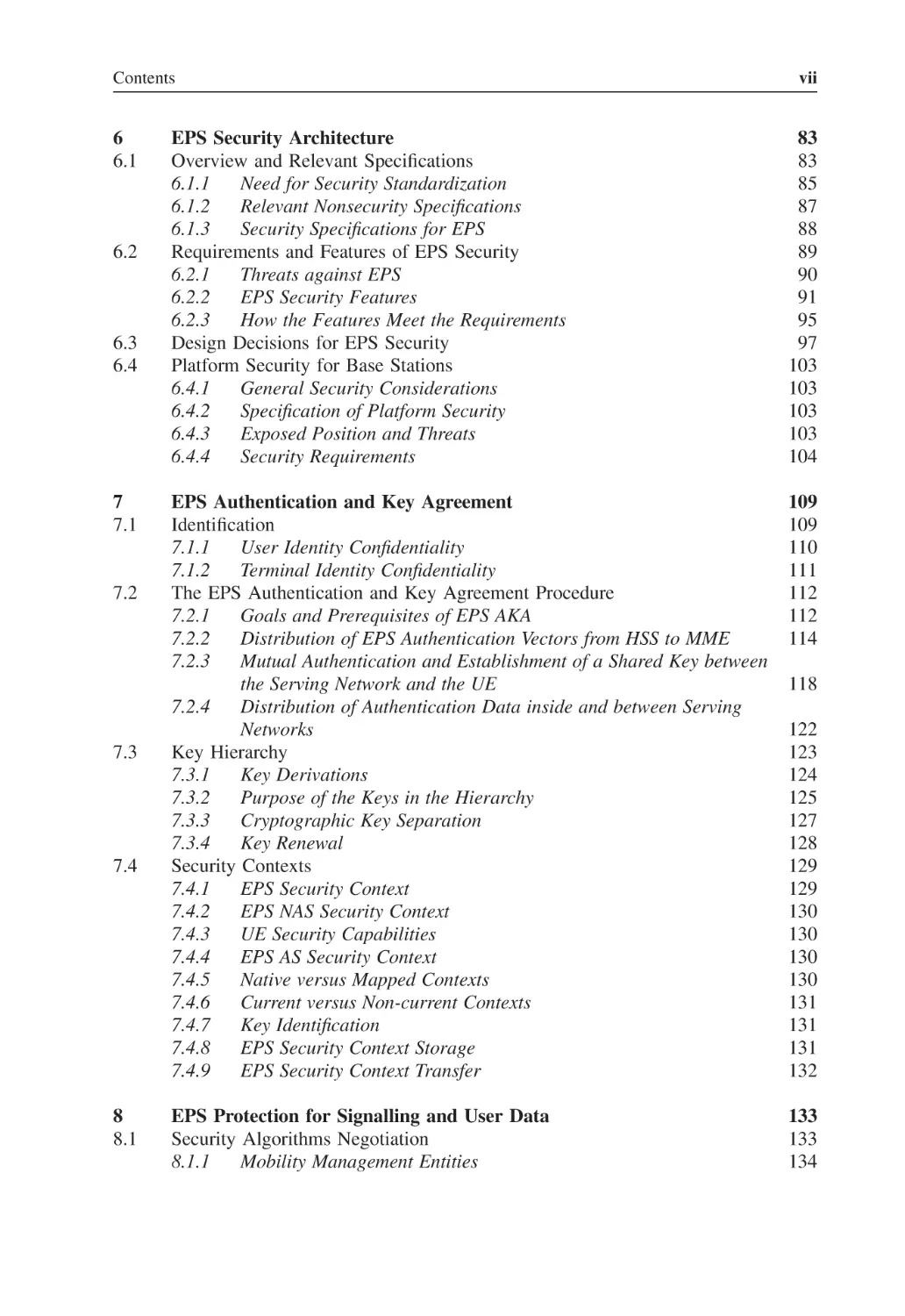
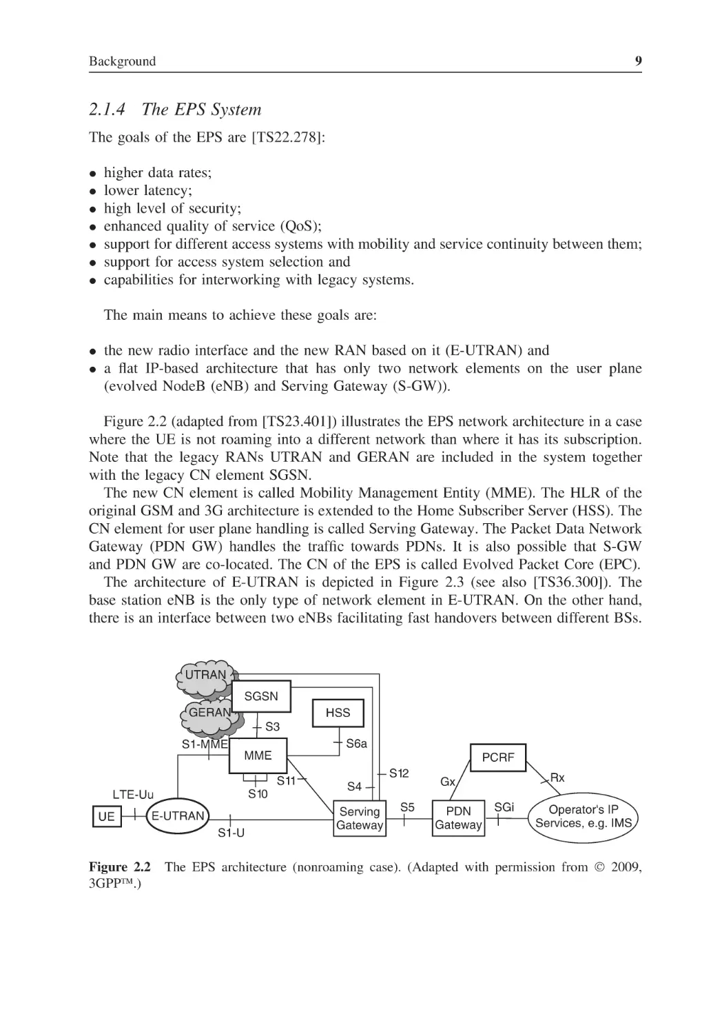
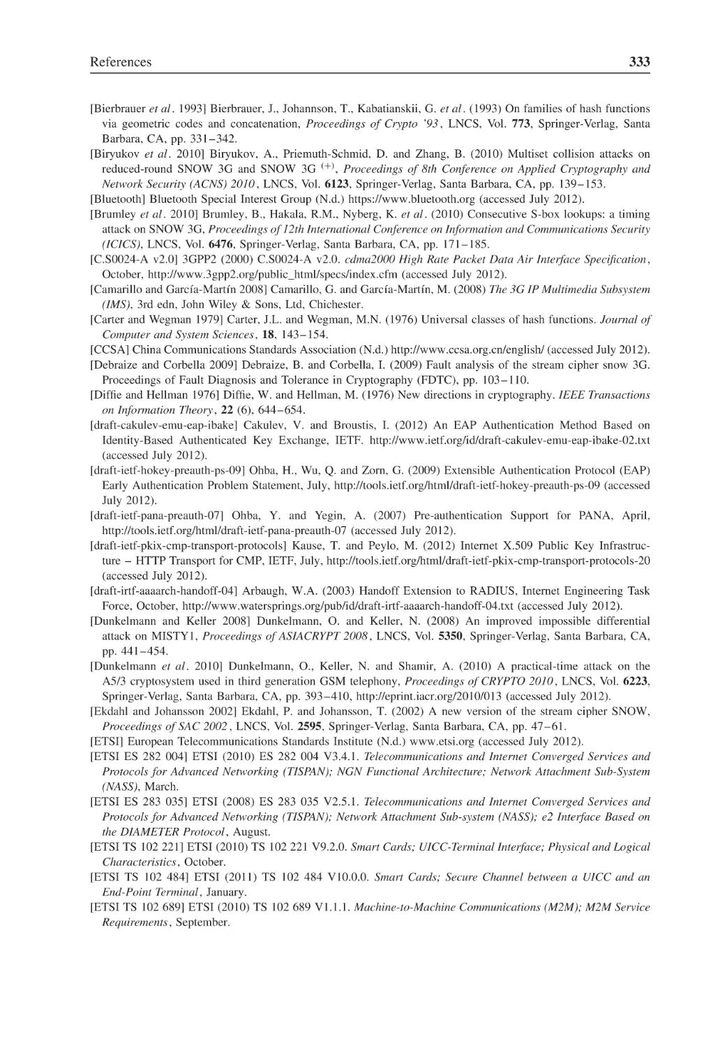
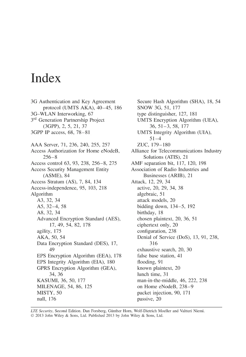
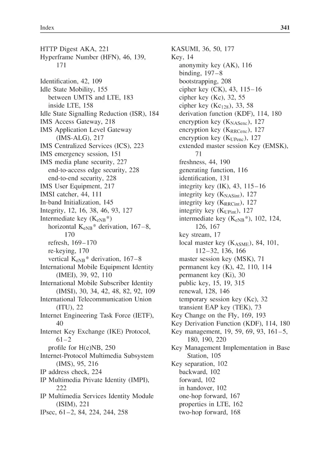
The architecture of E-UTRAN is depicted in Figure 2.3 (see also [TS36.300]). The
base station eNB is the only type of network element in E-UTRAN. On the other hand,
there is an interface between two eNBs facilitating fast handovers between different BSs.
UTRAN
SGSN
GERAN
HSS
S3
S6a
S1-MME
MME
PCRF
S11
S10
LTE-Uu
UE
E-UTRAN
S1-U
Figure 2.2
3GPP™.)
S12
S4
Serving
Gateway
S5
Rx
Gx
PDN
Gateway
SGi
Operator's IP
Services, e.g. IMS
The EPS architecture (nonroaming case). (Adapted with permission from © 2009,
10
LTE Security
MME / S-GW
MME / S-GW
X2
eNB
Figure 2.3
2.2
eNB
X2
X2
S1
S1
S1
S1
eNB
E-UTRAN
The E-UTRAN architecture.
Basic Security Concepts
It is not easy to define ‘security’ even though people tend to understand quite well what
is meant by it. Protection methods against malicious actions lie at the core of security.
There is also a clear distinction between security, on one hand, and fault tolerance and
robustness, on the other.
Many aspects of security are relevant for a communication system. There are physical
security aspects and information security aspects. The former include issues such as locked
rooms, safes and guards: all these are needed when operating a large-scale network.
Another property that belongs to the area of physical security is tamper resistance. Smart
cards play a major role in the system we describe in this book, and tamper resistance is
a key property of smart cards. Sometimes guaranteed tampering evidence is a sufficient
protection method against physical intrusion: if tampering can be detected quickly enough,
corrupted elements can be cut out of the network before too much damage is caused.
Biometric protection mechanisms are examples of methods between physical security
and information security. For example, checking of fingerprints assumes both sophisticated
measurement instruments and a sophisticated information system to support the use of
these instruments as access control devices.
In this book we concentrate mainly on aspects belonging to the broad category of
information security. In particular, we put focus on communication security. But physical
security is also important for EPS security and will be covered to some extent.
2.2.1 Information Security
In the context of information security, the following areas can be studied fairly independently of each other:
• System security. An example is trying to ensure that the system does not contain any
weak parts. Attackers typically try to find a point weak enough to be broken.
Background
11
• Application security. Banking over the Internet, for example, typically uses security
mechanisms that are tailored to meet application-specific requirements.
• Protocol security. Communicating parties are, for example, able to achieve security
goals by executing well-defined communication steps in a certain well-defined order.
• Platform security. The network elements and mobile terminals depend on the correct
functionality of the operating system that controls them. Physical security, too, has an
important role in platform security.
• Security primitives. These are the basic building blocks on top of which all protection
mechanisms are built. Typical examples are cryptographic algorithms, and items like
a protected memory can be seen as a security primitive (thus also bringing physical
security into the picture).
In this book we put the main emphasis on system security, protocol security and security
primitives. Platform security is covered only briefly, and application security is seen as
more or less orthogonal to the purposes of this book.
In the design of a practical security system there are always tight constraints. The
cost of implementing protection mechanisms must be balanced with the amount of risk
mitigated by these mechanisms. The usability of the system must not suffer because of
security. These trade-offs depend also on the intended use of the system: in a military
system, for example, trade-offs between security, cost and usability are done on a different
basis from in a public or a general-purpose communication system.
2.2.2 Design Principles
The design process of a security system typically contains the following phases:
• Threat analysis. The intention is to list all possible threats against the system, regardless of the difficulty and cost of carrying out an attack to materialize a particular threat.
• Risk analysis. The weight of each threat is measured quantitatively or, at least, in relation to other threats. Estimates are needed for both the probability of various attacks and
the potential gain for the attacker and/or damage to the attacked side caused by them.
• Requirements capture. Based on the earlier phases, it is now decided what kind of
protection is required for the system.
• Design phase. The actual protection mechanisms are designed in order to meet the
requirements. Existing building blocks such as security protocols or primitives are
identified, possibly new mechanisms are created and a security architecture is built.
Here the constraints have to be taken into account, and it is possible that not all
requirements can be met. This may cause a need to re-visit earlier phases, especially
the risk analysis.
• Security analysis. An evaluation of the results is carried out independently of the
previous phase. Usually, automatic verification tools can be used only for parts of a
security analysis. There are often holes in the security system that can be revealed only
by using creative methods.
• Reaction phase. While planning of the system management and operation can be seen
as part of the mechanism design phase, reaction to all unexpected security breaches
cannot be planned beforehand. In the reaction phase it is vital that the original design
12
LTE Security
of the system is flexible enough and allows enhancements; it is useful to have a certain
amount of safety margin in the mechanisms. These margins tend to be useful in cases
where new attack methodologies appear faster than expected.
We have listed here only the phases that can be considered part of the design process.
In addition, implementation and testing are also important in building a secure system.
One factor that affects several phases is the fact that often the security system is part
of a much larger system that is under design at the same time. This has been the case for
EPS specification work also. An iterative approach is needed because the general system
architecture and requirements are changing in parallel to the security design. Although
these iterations seem to slow down the process, it is important that the security for the
system be designed at the same time as the system itself is designed. Trying to add security
to an existing completed system typically leads to impractical and inefficient solutions.
2.2.3 Communication Security Features
Although security as an abstract concept is hard to define, its ingredients or features are
typically easier to grasp in definitions. In the following, we list the most important features
in communication security:
• Authenticity. In a classical scenario where parties A and B are communicating over
some channel, both typically want to begin with identifying each other. Authentication
is the process of verifying the identities.
• Confidentiality. In the same classical scenario, parties A and B may want to limit
the intelligibility of the communication to just the two parties themselves, to keep the
communication confidential.
• Integrity. If all messages sent by party A are identical to the ones received by party
B , and vice versa, then integrity of the communication has been preserved. Sometimes
the property that the message is indeed sent by A is called proof-of-origin, while the
term integrity is restricted to the property that the message is not altered on the way.
• Nonrepudiation. It is often useful for receiving party B to store a message received
from sending party A. Now nonrepudiation of the message means that A cannot later
deny having sent it.
• Availability. This is an underlying assumption for the classical scenario of A and B
communicating with each other. The communication channel must be available for
parties A and B .
Typical attacks and attackers against these features are as follows:
• Authentication. An imposter tries to masquerade as one of the communicating parties.
• Confidentiality. An eavesdropper tries to get information about at least some parts of
the communication.
• Integrity. A third party tries to modify, insert or delete messages in the communication
channel.
• Nonrepudiation. It may sometimes benefit the sender of a certain message if he or she
can later deny sending it. For example, the message may relate to a financial transaction,
or a commitment to buy or sell something.
Background
13
• Availability. A Denial of Service (DoS) attack tries to prevent access to the
communication channel, at least for some of the communicating parties.
The main emphasis in this book is on the first three features: authenticity, confidentiality
and integrity. The whole point of introducing LTE and EPS is to improve the availability
of the cellular access channel. The nonrepudiation feature is still of less importance in
EPS networks; it is much more relevant for the application layer.
2.3
Basic Cryptographic Concepts
Cryptology is sometimes defined as the art and science of secret writing. The possibility
to apply cryptology for protecting the confidentiality of communications is obvious. Additionally, it has been found that similar techniques can be successfully applied to provide
many other security features, such as for authentication.
Cryptology consists of two parts:
• cryptography – designing systems based on secret writing techniques and
• cryptanalysis – analysing cryptographic systems and trying to find weaknesses
in them.
The twofold nature of cryptology reflects a more general characteristic in security.
As explained in this chapter, it is very difficult to find testing methods that can be
applied to reliably assess whether a designed system is secure. The reason for this is
that the true test for a system begins when it is deployed in real life. Then attackers
may appear who use whatever ways they can find to break the system. What makes
the situation even more difficult is that these real-life attackers typically try to hide their
actions and methods as far as possible. Cryptanalysis (and security analysis more widely)
tries to anticipate what attackers might do and is constantly searching for novel ways
of attacking systems. In this manner, cryptanalysis (and security analysis) contributes
indirectly to achieving a better security level.
The role of cryptanalysis in modelling attackers is a complex issue. It is perfectly fine to
find weaknesses in systems that are still under design and not deployed in practice. This is
because then it is still easy and relatively cheap to take corrective action. However, when
the system is already in wide use the role of cryptanalysis may become controversial. A
clever attack found by a researcher may be reproduced by a real-life attacker who would
not have invented it otherwise. In this case, the attack found by the researcher seems to
cause a decrease in the level of security rather than an increase.
One obvious solution to this dilemma is to keep the cryptanalytic result confidential until
corrective action has been done to remove any real-life vulnerabilities. After these vulnerabilities have been removed, publishing the results helps to avoid similar vulnerabilities in
future implementations. Note that there are similar debates on how to handle vulnerabilities discovered in, for example, operating systems and browsers. There seems to be no general agreement on the appropriate handling of vulnerabilities in the security community.
Another solution to the problem is to be secretive even in the design phase. If real-life
attackers do not know what kind of cryptographic algorithms are in use in the real-life
systems, it is difficult for them to apply any cryptanalytic results in their attacks. In fact,
14
LTE Security
this approach was widely used until the 1970s. Before that time, academic published
results in cryptology were scarce, and their potential relation to real-life systems was
not known in public. The big disadvantage of the secretive approach, sometimes called
security by obscurity, is that feedback from practical experience to academic research is
completely missing, which slows down progress on the academic side.
As long as cryptography is used in closed and tightly controlled environments, such as
for military communications or protecting databases of financial institutions, there is no
need to open up the used systems to academic cryptanalysis. But the situation changes
when cryptographic applications are used in commercial systems involving consumers.
Firstly, there could be potential attackers among the users of the system and, therefore,
the design of the system could leak out to the public through various reverse-engineering
efforts. Secondly, it is harder to build trust in the system among bona fide users if no
information is given about how the system has been secured. This trend towards usage of
cryptology in more open environments is one reason for the boom in public cryptologic
research since the 1970s.
Another, perhaps bigger, reason was the introduction of novel, mathematically
intriguing cryptologic concepts, most notably the public key cryptography [Diffie and
Hellman 1976].
2.3.1 Cryptographic Functions
Let us next present formal definitions of some central cryptographic notions.
• Plaintext space P is a subset of the set of all bit strings (denoted by {0,1}*); we assume
here, for simplicity, that everything is coded in binary.
• Cryptotext (or Ciphertext) space C is also a subset of {0,1}*.
• Key space K is also a subset of {0,1}*. Often K = {0,1}k where k is a fixed security
parameter.
• Encryption function is E : P × K → C .
• Decryption function is D: C × K → P .
• Cryptosystem consists of all of the above: (P ; C ; K ; E ; D).
• Symmetric encryption is defined by D(E (p, k ), k ) = p.
• Asymmetric encryption is defined by D(E(p, k1 ), k2 ) = p, where keys k1 and k2 are not
identical, and moreover k2 cannot be derived easily from k 1 .
Modern cryptography is based on mathematical functions that are nontrivial from the
point of view of computational complexity. This means that either the function as such
is complex to compute or the function can be computed only once a certain piece of
information – a key – is available. Randomness is another fundamental notion in modern
cryptography. A pseudorandom generator is an algorithm that takes a truly random bit
string as an input (called a seed ) and expands it into a (much) longer bit string that is
infeasible to distinguish from a truly random bit string of the same length.
One important function type is a one-way function. Roughly speaking, a function has
the one-way property if
Background
15
• it is easy to compute f (x ), if x is given but
• for a given y, it is infeasible to find any x with f (x ) = y.
A more accurate definition could be given using terminology from complexity theory
[Menezes et al . 1996], but we do not need it for the purposes of this book.
Another important function type is a trapdoor function. It is similar to the one-way
function with one important difference: if a certain piece of information (a secret key)
is known, then it becomes easy to find x with f (x ) = y, given y. Trapdoor functions are
used in public key cryptography, for example for digital signatures.
One of the simplest examples of a function used in practice as a one-way function is
the multiplication of natural numbers. Given two integers n and m, it is easy to compute
their product nm but no efficient algorithm is known to compute the inverse operation,
determining factors of an integer when the integer becomes large enough. This is the case,
in particular, if the integer to be factored is a product of two large prime numbers.
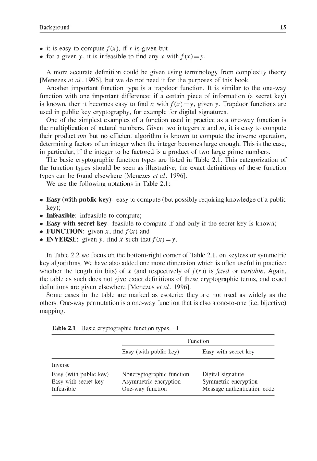
The basic cryptographic function types are listed in Table 2.1. This categorization of
the function types should be seen as illustrative; the exact definitions of these function
types can be found elsewhere [Menezes et al . 1996].
We use the following notations in Table 2.1:
• Easy (with public key): easy to compute (but possibly requiring knowledge of a public
key);
• Infeasible: infeasible to compute;
• Easy with secret key: feasible to compute if and only if the secret key is known;
• FUNCTION: given x , find f (x ) and
• INVERSE: given y, find x such that f (x ) = y.
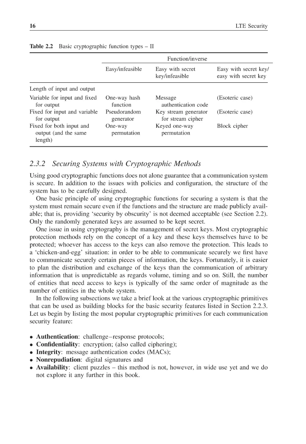
In Table 2.2 we focus on the bottom-right corner of Table 2.1, on keyless or symmetric
key algorithms. We have also added one more dimension which is often useful in practice:
whether the length (in bits) of x (and respectively of f (x )) is fixed or variable. Again,
the table as such does not give exact definitions of these cryptographic terms, and exact
definitions are given elsewhere [Menezes et al . 1996].
Some cases in the table are marked as esoteric: they are not used as widely as the
others. One-way permutation is a one-way function that is also a one-to-one (i.e. bijective)
mapping.
Table 2.1
Basic cryptographic function types – I
Function
Easy (with public key)
Easy with secret key
Noncryptographic function
Asymmetric encryption
One-way function
Digital signature
Symmetric encryption
Message authentication code
Inverse
Easy (with public key)
Easy with secret key
Infeasible
16
LTE Security
Table 2.2
Basic cryptographic function types – II
Function/inverse
Easy/infeasible
Easy with secret
key/infeasible
Easy with secret key/
easy with secret key
One-way hash
function
Pseudorandom
generator
One-way
permutation
Message
authentication code
Key stream generator
for stream cipher
Keyed one-way
permutation
(Esoteric case)
Length of input and output
Variable for input and fixed
for output
Fixed for input and variable
for output
Fixed for both input and
output (and the same
length)
(Esoteric case)
Block cipher
2.3.2 Securing Systems with Cryptographic Methods
Using good cryptographic functions does not alone guarantee that a communication system
is secure. In addition to the issues with policies and configuration, the structure of the
system has to be carefully designed.
One basic principle of using cryptographic functions for securing a system is that the
system must remain secure even if the functions and the structure are made publicly available; that is, providing ‘security by obscurity’ is not deemed acceptable (see Section 2.2).
Only the randomly generated keys are assumed to be kept secret.
One issue in using cryptography is the management of secret keys. Most cryptographic
protection methods rely on the concept of a key and these keys themselves have to be
protected; whoever has access to the keys can also remove the protection. This leads to
a ‘chicken-and-egg’ situation: in order to be able to communicate securely we first have
to communicate securely certain pieces of information, the keys. Fortunately, it is easier
to plan the distribution and exchange of the keys than the communication of arbitrary
information that is unpredictable as regards volume, timing and so on. Still, the number
of entities that need access to keys is typically of the same order of magnitude as the
number of entities in the whole system.
In the following subsections we take a brief look at the various cryptographic primitives
that can be used as building blocks for the basic security features listed in Section 2.2.3.
Let us begin by listing the most popular cryptographic primitives for each communication
security feature:
•
•
•
•
•
Authentication: challenge–response protocols;
Confidentiality: encryption; (also called ciphering);
Integrity: message authentication codes (MACs);
Nonrepudiation: digital signatures and
Availability: client puzzles – this method is not, however, in wide use yet and we do
not explore it any further in this book.
Background
17
2.3.3 Symmetric Encryption Methods
Symmetric encryption methods are divided into two main classes: block ciphers and
stream ciphers. In a block cipher, a fixed-length plaintext block is transformed into a
cryptotext block of the same length using a key (usually also of fixed length). Thus, for
any fixed key the block cipher is a bijection:
c = E(p, k); p = D(c, k) = D(E(p, k), k).
The dominant block cipher in the past was Data Encryption Standard (DES); its block
length is 64 bits and the key length is 56 bits. A newer general-purpose cipher, Advanced
Encryption Standard (AES), has a block length of 128 bits and a (minimum) key length
of 128 bits.
Usually a block cipher becomes stronger if it is iterated several times. In the design
of block ciphers, iteration is used also inside the block cipher. These iterations are called
rounds. There is a trade-off here, since adding more rounds increases both security and
processing time.
There are a few other classical design principles. For example, each plaintext bit and
each key bit should affect each ciphertext bit (diffusion); and the relation between plaintext
bits and ciphertext bits should be as complex as possible (confusion).
As block ciphers operate with fixed-size words, we encounter a practical problem:
how to encrypt messages longer than one block? A straightforward solution is called
Electronic Code Book (ECB) mode: a message is divided into blocks and each block
is encrypted independently. This mode has a major weakness: identical plaintext blocks
result in identical ciphertext blocks!
Several different modes exist that avoid this weakness by introducing additional changing input, such as by using earlier created ciphertext or a counter. Special modes can also
be created for using a block cipher for purposes other than encryption, for example as a
one-way function or a pseudorandom generator.
Next we discuss stream ciphers. The idea of a stream cipher is based on a simple but
absolutely secure cipher called the one-time pad . Assume the key k is as long as the
plaintext p. Then we define c = p xor k .
The one-time pad cannot be broken. Indeed, any ciphertext may be decrypted to any
plaintext (with some valid key). On the other hand, the one-time pad has one major
weakness: secure transport or storage of the key becomes as demanding a task as secure
transport or storage of the plaintext itself. But still it is advantageous that the transport
or storage of the key can be done in convenient time prior to the need of using the key.
In a stream cipher, the long random key of the one-time pad is replaced by a pseudorandom sequence. In other words, we start with a fixed-size key (a seed) and generate a
mask bit stream m (sometimes called a key stream) that is as long as the plaintext. Then
c = p xor m.
Usually there is an additional input (e.g. a counter-value), which is used together
with the key as a seed. Then the same key can be used for encrypting several messages independently of each other. This holds assuming that the additional input changes
for every instance, as when the counter-value is increased for every new message. One
18
LTE Security
main advantage of a stream cipher is the fact that the mask bit stream can be generated
in advance, even before the plaintext is known. This helps in avoiding delays in the
communication.
Another advantage is that the number of erroneous bits in the ciphered message introduced by a noisy channel equals the number of erroneous bits in the recovered plaintext;
whereas, for a block cipher, one bit error in a ciphered block typically renders the entire
block of recovered plaintext unintelligible. This is a reason why stream ciphers are often
used for channels with relatively high bit error rates, such as radio channels.
2.3.4 Hash Functions
Now we take a closer look at a type of cryptographic function that does not require any
key, namely, a hash function. A one-way hash function h has the properties:
• compression: h(x ) has a fixed length (e.g. 160 bits) while x may be of any length and
• h(x ) is easy to compute.
For some purposes it is important that the hash function fulfils further conditions:
• Second pre-image resistance. For a given x , it is infeasible to find any other x 0
different from x such that h(x ) = h(x 0 ) and
• Collision resistance. It is infeasible to find any two distinct x and x 0 such that
h(x ) = h(x 0 ).
It is possible to build a specific mode that converts a block cipher into a hash function,
but usually tailor-made hash functions require less computation than block ciphers, and
they can be implemented more efficiently. Two hash functions of this type are MessageDigest algorithm 5 (MD5) (128-bit hash) and Secure Hash Algorithm (SHA-1) (160-bit
hash), but many collisions have been found for the former and there is evidence that
collisions can be generated for the latter as well. At the time of writing, the most popular
hash function is SHA-256 (256-bit hash) but there is also an ongoing competition, run
by the National Institute of Standards and Technology (NIST) and scheduled to finish in
2012, for finding a new standard hash function, called SHA-3 [NIST].
Hash functions are used in many ways in applications. One important use case is as a
message digest: a variable-length message can have a unique fixed-length representation.
Of course, the representation cannot be truly unique, but collision resistance implies that
it is infeasible to find two messages (of any length) with the same message digest.
It is also possible to design the computation of a hash function around a secret key. Then
we speak of message authentication codes. These keyed hash functions have typically a
somewhat shorter output than (keyless) hash functions. The reason for this is the following
generic attack against keyless hash functions. Anybody can compute a large table of
inputs and corresponding hash output values (also called message digests). If the length
of the output is n, then it follows from the birthday paradox [Menezes et al . 1996] that
approximately 2n/2 hash outputs need to be computed before a collision is found.
A similar approach does not work for keyed hash functions as the key is known only
to authorized parties and the table of hash values is different for each possible secret key.
Background
19
There are three different strategies in the design of a MAC: either direct design, or
use of a block cipher or keyless hash functions as building blocks. The Hash Message
Authentication Code (HMAC) construction is an example of the third strategy. If k is the
key and x is the input, then the MAC value is obtained by double hashing:
HMAC(x, k) = h((k xor opad)|h((k xor ipad)|x)),
where vertical bars are used to denote concatenation, and opad and ipad are just constant
values used for padding purposes. The result is often truncated to create a shorter MAC
value (e.g. by extracting the first 96 bits from a total of 160 bits).
The basic use case of MACs in information security is to ensure the integrity of a
message: we append a MAC to each message transferred over an insecure channel. If the
receiving party knows the secret key, then it can compute the MAC as well in order to
check that the message sent and the message received are indeed identical. Note that the
requirement of collision resistance is not crucial for the use of a keyed hash function as
a MAC.
2.3.5 Public-Key Cryptography and PKI
We now look at the basic notions of public-key (asymmetric) cryptography; a deeper
treatment of the subject can be found elsewhere [Menezes et al . 1996]. The idea of
public-key encryption is simple: we use different keys for encryption and decryption, and
it is infeasible to derive the decryption key from the encryption key.
If such encryption and decryption functions are available, then the encryption key can
be made public, so it is possible for one party to communicate with many other parties
(who do not need to mutually trust each other) using the same key. It is important to note
that it is not sufficient that the encryption key be made publicly available; in addition,
authenticity of the public key has to be guaranteed.
The setting is reversed for a digital signature. It is infeasible to derive the signing key
(used to compute the signature function) from the verifying key (used to compute the
inverse of the signature function). The verifying key can be public, so many people can
independently verify the same signature. Usually it is actually the message digest that
gets digitally signed. As long as the used hash function is collision resistant, signing the
message digest is equivalent to signing the message itself.
Some main benefits of public-key cryptography are:
• easier key management for very large systems, especially those with many-to-many
relationships,
• the possibility to use digital signatures and, as a consequence, the possibility for nonrepudiation and
• the possibility for any entity to authenticate another entity without online connection
to any central trusted third party (but typically an offline connection to a trusted third
party is needed to enable entities to verify the public keys of other entities).
The dominant technique for guaranteeing authenticity of the public key is to use a
public key infrastructure (PKI). The central concept of a PKI is a certificate: user identity
20
LTE Security
and public key are signed by the certification authority (CA). It is assumed that it can
be verified by other means that the public key of the CA itself is authentic; for example,
it could be installed in a computing device at the time of manufacture, or it could be
downloaded in a physically secured trusted environment.
The registration authority (RA) verifies the user identity, often physically, and delivers
the certificate to the correct user. Sometimes a user’s private key gets compromised (e.g.
stolen), and then the certificate must be revoked. This is often done by including revoked
certificates into a certificate revocation list (CRL) that is signed by the CA.
In principle, anybody with a certificate is able to create more certificates by signing
identities and public keys of others. Typically CAs are arranged in a hierarchical fashion,
and each layer in the hierarchy has a certificate signed by the immediate upper-layer CA
except for the root CA on the top of the hierarchy, which either has only a self-signed
certificate or does not have any certificate at all. Verifying a certificate of a leaf entity
involves verifying all certificates of the nodes between the leaf node and the root node.
We speak then of ‘certificate chains’.
2.3.6 Cryptanalysis
Here we present the basic concepts of cryptanalysis. A classification of attackers can be
done, for instance, as follows.
• A passive attacker only monitors the communication and tries to break confidentiality.
• An active attacker also adds, deletes and modifies messages. He or she also tries to
break other security features in addition to confidentiality.
The following attack models (against encryption) can be identified.
• Ciphertext only. The attacker sees only ciphertext and tries to find the key or at least
the corresponding plaintext.
• Known plaintext. The attacker also knows the plaintext and tries to find the decryption key.
• Chosen plaintext. The attacker can choose the plaintext and also gets the corresponding ciphertext (and again tries to find the decryption key).
• Adaptive chosen plaintext. The plaintexts to be chosen may depend on previously
observed ciphertexts.
• Chosen ciphertext. The attacker chooses the ciphertext and gets the plaintext.
• Adaptive chosen ciphertext. The ciphertexts to be chosen may depend on previously
observed plaintexts.
Only the first two models are available for a passive attacker. Various chosen plaintext
and ciphertext scenarios can also be practical attack models. An example is the case where
the user has full access to a tamper-resistant cryptographic module and tries to discover
the key inside the module.
A similar classification of attack models applies for attacks against authentication and
integrity protection. The simplest attack type that applies even in the ciphertext-only
model is exhaustive search of all keys. If we have a reasonable amount of ciphertext
Background
21
available, there is typically only one key that decrypts the ciphertext into a meaningful
plaintext.
The differential cryptanalysis method is an example of a modern method in the chosen
plaintext scenario. It is carried out by choosing a big number of pairs of plaintexts with a
pre-determined difference. Analysis is done by studying the corresponding differences in
the ciphertexts. Another method, requiring only the known plaintext scenario, that has been
applied successfully for many block ciphers and stream ciphers is the linear cryptanalysis
method. It is based on analysis of the correlation between plaintext and ciphertext bits.
Recently another attack model has gained a lot of popularity:
• Related key attack. The attacker is able to ask that the key be changed, and does so
in such a way that the relation between the old key and the new key is pre-determined
and chosen by the attacker.
This attack scenario is very optimistic from the attacker’s point of view, because only
under special circumstances is there a real chance for the attacker to try to change keys
somehow. The related key scenario is often viewed as a theoretical tool that can be used
in the analysis of ciphers and their structures.
The following attack model takes a wider approach and it is often relevant in practical
settings:
• Side channel attack. The attacker is able to utilize information about the physical
implementation of the cryptosystem.
For instance, the attacker could measure time and power consumption related to execution of the cryptographic algorithm and deduce useful information about the key, possibly
by using statistical methods. The attacker may also be able to induce controlled faults in
the execution of the algorithm, such as by heat treatment or electric shocks.
2.4
Introduction to LTE Standardization
By the end of the 20th century, it had become evident in Japan that the regional secondgeneration system known as Personal Digital Cellular (PDC) was no longer going to
provide good enough service for the huge market. Therefore, two Japanese standards organizations, the Association of Radio Industries and Businesses (ARIB) and the Telecommunication Technology Committee (TTC), were already in quite an advanced state in
creating detailed specifications for a 3G technology, especially for the radio network part.
In parallel with the Japanese activities there were ongoing efforts in the European Telecommunications Standards Institute (ETSI) to prepare the way for a 3G cellular technology,
called the Universal Mobile Telecommunications System (UMTS).
In 1998, five standards development organizations (SDOs) decided to combine their efforts to accelerate the work and guarantee global interoperability. The
organizations – ETSI from Europe, ARIB and TTC from Japan, the Alliance for Telecommunications Industry Solutions (ATIS) from North America and the Telecommunications
Technology Association (TTA) from South Korea – formed the 3GPP. A little bit later,
a sixth partner, the China Communications Standards Association (CCSA), joined the
22
LTE Security
project. The six SDOs are the organizational partners of 3GPP. Each organizational
partner has its own individual members, including terminal and infrastructure
manufacturers, mobile network operators and telecommunications regulators.
The dream of getting all of the 3G development work under one project did not,
however, become true. In the United States a lot of work had been done for a system called
cdma2000® that had evolved from one of the North American second-generation cellular
systems. Driven by the Telecommunications Industry Association (TIA), another project
was started, called the 3GPP2. At the same time, the International Telecommunication
Union (ITU), a sub-organization of the United Nations, changed its original target of
creating one single International Mobile Telecommunications-2000 (IMT-2000) standard
to creating a family of 3G standards instead.
The co-operation between the 3GPP partners quickly began to work very well, and
a large number of specifications were in a stable state at the end of 1999. In March
2000, the first release, Release 1999 of the 3GPP specification set, was declared ‘frozen’.
Nonetheless, after that date many corrections were needed in most specifications, a process
that is unavoidable in a project of this scale. After Release 99, 3GPP continued by creating
more releases: Release 4 was frozen in 2001, Release 5 in 2002, Release 6 in 2005 and
Release 7 in 2007.
The first release that covers LTE and EPS is Release 8. It was frozen in 2008, Release 9
was frozen at the end of 2009, Release 10 was frozen in the first half of 2011 and the
most recent release whose results are covered in this book is Release 11 that is scheduled
to be frozen in the fall of 2012. In addition, we point out some developments already
discernible for Release 12 in Chapter 16, which gives an outlook to future challenges.
As early as the first 3GPP release, it was understood that the cycle of one year might
sometimes be too short to add significant features to each new release, so 3GPP stopped
the practice of naming releases after calendar years.
2.4.1 Working Procedures in 3GPP
The 3GPP formally is just a co-operation project between the partners, the regional
SDOs. Therefore, 3GPP produces specifications and they become standards only after
each regional partner has approved them. The idea is that each partner organization would
essentially ‘rubber-stamp’ the 3GPP specification and just convert it to the format of an
official standard. On the other hand, sometimes regional standards would complement
3GPP specifications. This could happen because of several reasons. For example, 3GPP
may explicitly decide to leave some aspects out of its agenda and perhaps rely on implementers’ ability to find optimal solutions while the regional SDO feels that standards
could be beneficial even for these aspects. Another reason could be deviations between
regional regulations, for example for lawful interception or public safety.
The specification work in 3GPP follows a three-stage model.
• Requirements for new services are defined in stage 1 specifications.
• Stage 2 specifications contain functional architectures that meet the requirements,
including descriptions of functional entities and information flows between them.
• In stage 3 specifications, the functional entities are mapped to physical entities and
bit-level descriptions of protocols between the entities are defined.
Background
23
In addition to these specifications, there are also test specifications that are typically
completed sometime later (as they are also needed later).
The 3GPP specification work is carried out in working groups. Above the working
groups there is another layer, called technical specification groups (TSGs), where the
specifications created in working groups are approved. There are four TSGs: Service and
System Aspects (SA), Core Network and Terminals (CT), Radio Access Networks (RAN)
and GSM EDGE Radio Access Networks (GERAN).
Typically different working groups carry out different stages for the same features.
For example, one working group (called SA Working Group 1) concentrates purely on
requirements (i.e. stage 1), another one (called SA WG2) creates system architecture
specifications (i.e. stage 2), a third one (called CT WG1) creates stage 3 specifications
for protocols between the CN and terminal and so on.
Specifying different stages requires somewhat different types of expertise and skills.
This is one reason for the approach of distributing specification work to several working
groups. Another reason is that the distributed approach allows more efficient use of time:
stage 1 groups are able to start work on the next release at the same time as other working
groups are still busy with the previous release.
Figure 2.4 illustrates how work in different stages is typically scheduled. The time unit
in the figure is a quarter year. This follows from the fact that new specifications and change
requests to old specifications are approved in TSG plenary meetings, which are arranged
four times a year. An indicative interval between two consecutive releases is 15 months
in the figure. This has roughly been the time interval between the recent 3GPP releases;
the exact point of freezing a release is always decided case by case because the optimal
timing depends on many factors, some of which stem from the business environment.
As can be seen from Figure 2.4, it is often the case that a working group is doing a
significant amount of specification work for two different releases simultaneously. Indeed,
there are typically corrections needed to the previous release while work on the next
release has already started.
The figure also illustrates that the work in different stages for the same release occurs
partially in parallel. Indeed, stage 2 groups do not wait until stage 1 work has been
completed, and the same holds between stages 2 and 3. This overlap is useful because
typically different working groups need to consult each other in order to guarantee consistency between different stages and specifications. However, it can also be seen from
Rel n+1
Rel n
Rel n
Stage 1
Rel n+1
Rel n
Stage 2
Rel n+1
Stage 3
Time (quarters)
Figure 2.4
Time distribution of work in releases and stages.
24
LTE Security
the same figure that there never is a point in time where all stages would work full time
for the same release.
The work in 3GPP is contribution driven; individual members send delegates to the
working group meetings in order to progress the specification work. Looking at it from
another angle, if no member has an interest in progressing work on a particular specification, that specification is never completed. The higher layer body, the TSG, has to approve
starting a new work item in a working group. Later the TSG approves the specification
resulting from the work item and the change requests to it.
The change request procedure is a formal tool for handling corrections to approved specifications. The correction process is handled by approving each individual change request
separately. Each change is also documented explicitly and the documentation includes, in
addition to the change itself, a reason for the change and a brief summary of the change.
In addition to technical specifications (TSs), working groups create also technical reports
(TRs). These are informative documents without normative status. Implementers could
completely ignore these documents and still build equipment fully compliant with the
3GPP specifications, and the resulting standards. Typically, TRs are used for (at least)
two essentially different purposes:
• for carrying out feasibility studies of features and mechanisms that could later be
specified in normative documents (in case the results of the feasibility study are encouraging) and
• for analysing features and adding guidelines and background information that are useful
for implementation, deployment and/or operation purposes.
TRs of the first type are typically done before corresponding TSs are created. Reports
of the second type are rather written after the corresponding specification, or at least a
draft version, is available.
For security, both types of reports are useful. Often several different approaches could
be taken in securing a certain feature. A feasibility study is useful in making each of
these approaches explicit and describing them to a similar level of detail. This helps in
comparing these approaches with each other and assessing whether they really reach the
security goals that are claimed. Of course, similar reasons explain why feasibility studies
are also useful for nonsecurity features.
There are specific reasons why reports of the second type are useful for security
purposes.
Analyses of how security features meet the requirements and how the chosen countermeasures address threats cannot be made obsolete by, for example, carrying out field
trials and pilots. For security features (e.g. a security protocol), the fact that it can be
run efficiently in practice is only a necessary condition for its adoption. It is not a sufficient condition because an even more important condition is that the feature cannot be
circumvented.
Guidelines, instructions and clarifications are of special importance in security because
specifications often leave some details to be decided during implementation, deployment
or operation. It is important that these decisions be made with the understanding of
Background
25
the purpose and characteristic of the security mechanism in question. It is possible to
completely undermine a security feature by poor choices of how and when it is in use.
TRs intended for internal use by 3GPP have a number of the form ‘xx.8xx’, while TRs
intended for wider distribution have a number of the form ‘xx.9xx’.
The TSs contain normative text using special wording with reserved words (see
Section 2.5.2). The normative text may still contain different optional elements:
functionalities that may be supported optionally. Sometimes there are also features that
are mandatory to support but still optional to use.
As mentioned in this chapter, the work in different groups on the same topic requires
a fair amount of coordination and communication between working groups. A typical
instrument for such purposes is a liaison statement that is sent from one working group
to another. Similar liaisons exist also between 3GPP and other organizations, such as the
Open Mobile Alliance (OMA) and the GSM Association (GSMA).
In Table 2.3 we show the division of 3GPP specifications into different series. From
the point of view of our book, the two security series 33 and 35, the 23 series, the 24
series and the 36 series are the most important ones. All 3GPP TSs and TRs are publicly
available [3GPP]. Some specifications of cryptographic algorithms in the 35 series need
to pass export control first, which introduces a delay in their publication. Note that there
are also 3GPP specifications that are relevant for GSM only. These are in series numbered
from 41 to 52, following the same order as in Table 2.3; that is, requirements are in the
41 series, (stage 1) service aspects are in the 42 series, and so on. In addition, the 55
series contains specifications for GSM security algorithms. Note also that there is no 53
series, that is, the security aspects are spread across the other series.
Table 2.3
Specification numbering in 3GPP series
Number of series
Subject of series
21
22
23
24
25
26
27
28
29
30
31
32
33
34
35
36
37
Requirements
Service aspects (stage 1)
Technical realization (i.e. architectural aspects) (stage 2)
Signalling protocols (stage 3) (UE – network)
Radio aspects
Codecs
Data
Signalling protocols (radio network – core network)
Signalling protocols (intra-fixed network)
Programme management
USIM and IC cards
O&M and charging
Security aspects
UE and USIM test specifications
Security algorithms
LTE and LTE-advanced radio technology
Multiple radio access technology aspects
26
2.5
LTE Security
Notes on Terminology and Specification Language
2.5.1 Terminology
The reader may have noticed that key terms occurring in this book are sometimes used with
different meanings in specifications, technical journal papers, marketing announcements or
the media at large. Conversely, different terms are sometimes used for the same concept.
This section is intended to introduce the key terms as used in this book and clarify
how these terms may be used in other forms of publications. The list of terms below is
ordered such that it makes sense to read it from start to end. We provide a complete list
of abbreviations in alphabetical order at the end of this book. All 3GPP abbreviations are
gathered in [TS21.905]. An arrow followed by an acronym (e.g. → E-UTRAN) indicates
that an explanation appears further down the list.
• LTE. This book is entitled LTE Security. We chose this title as ‘LTE’ has become a
widely known brand name for the 3GPP-defined successor technology of 3G mobile
systems. LTE stands for Long Term Evolution and originally denoted a work item in
3GPP aimed at developing a successor to the 3G radio technology. Gradually it came
to denote first the new radio technology itself, then also encompassed the RAN (→
E-UTRAN) and is now also used for the entire system succeeding 3G mobile systems
(→ SAE, → EPS) including also the evolved CN (→ EPC), as a quick search for the
term LTE on the 3GPP home page [3GPP] will reveal. Only a few 3GPP specifications
actually use the term LTE, apart from on their cover page, and if they do the term refers
to the radio part but never the entire system. Security specifications do not use this term
at all. We therefore use the term LTE in the overview parts of the book, but not in the
detailed technical parts, so as to make it easier for the reader to use the specifications
together with our book without terminological confusion. ETSI has registered ‘LTE’ as
a trademark for the benefit of the 3GPP Partners.
• E-UTRAN. E-UTRAN is the Evolved Universal Terrestrial Radio Access Network
using the LTE radio technology. The E-UTRAN consists of the network of LTE base
stations (eNB). The term E-UTRAN is widely used in the specifications and in the
detailed technical parts of this book.
• SAE. The term has made a similar, though not quite as successful, career as the
term LTE. Like LTE, it originally denoted a work item in 3GPP on Radio Access
Technologies (→ RAT). The aim was to develop a ‘framework for an evolution or
migration of the third generation mobile system to a higher-data-rate, lower-latency,
packet-optimized system that supports multiple RATs’ [3GPP 2006]. Combined with
LTE it became SAE/LTE, and now often denotes the entire system, encompassing
terminals, RANs and CNs. It is not commonly used in 3GPP specifications where
rather the term → EPS is preferred. It has not become a trademark either. We therefore
do not use it in this book any further.
• EPS. EPS has the same meaning as SAE/LTE. The term EPS is widely used in 3GPP
specifications and in this book.
• EPC. EPC is the CN part of the EPS. The term EPC is widely used in 3GPP specifications and in this book.
• RAT. When a terminal moves from a network using one RAT to another network using
a different RAT, one often speaks of inter-RAT mobility.
Background
27
• RAN. RAN encompasses the BSs (i.e. eNBs in E-UTRAN, NBs in →UTRAN and
BTSs in →GERAN) and the BS controllers (i.e. RNCs in UTRAN and BSCs in
GERAN). There are no BS controllers in E-UTRAN.
• UTRAN. The 3G RAN encompassing UMTS radio technology.
• GERAN. The 2G RAN encompassing GSM radio technology and its enhancement,
Enhanced Data Rates for GSM Evolution (EDGE).
• UE. There is a fine distinction between UE and →ME, which is, however, important
for security. The UE is the combination of the ME and the →UICC.
• ME. The ME is the terminal device without the UICC.
• UICC. The UICC is a smart card platform, on which applications such as the → USIM
reside.
• USIM. This application on the UICC holds the security parameters and functions that
are used in authentication and key agreement in 3G and EPS.
• Subscriber Identity Module SIM. In newer implementations it means a SIM application on the UICC. In older implementations it means the SIM functionality together
with the smart card platform.
2.5.2 Specification Language
Clear rules for the use of verbal forms in specifications are essential so that the reader
can distinguish mandatory requirements from other provisions where there is a certain
freedom of choice. 3GPP therefore defined the use of a few key words. The most important
key words are: ‘shall’ (meaning ‘is to’ or ‘is required to’), ‘should’ (meaning ‘it is
recommended that’ or ‘ought to’) and ‘may’ (meaning ‘is permitted’ or ‘is allowed’) – for
more details, see [TR21.801]. We use this specification language in the detailed parts of
this book.
3
GSM Security
3.1
Principles of GSM Security
The goal of security design for the Global System for Mobile communications (GSM)
system was that it had to be as good as that of wireline systems. Additionally it was
required that security mechanisms should not have a negative impact on the usability of
the system.
These goals were clearly reached, and it can be argued that GSM has even better
security than wireline systems. On the other hand, it is also clear that there is room for
improvement in GSM security. This is, of course, generally true for any system that has
been in wide use for a long time. Attack methods and equipment evolve over time, and
there should be corresponding improvements in protection methods. Some enhancements
in GSM security have been made over the years but the basic structures have remained.
It is always difficult to introduce radical changes into a system that is in wide use,
and there is a key learning point in this: security design for a new system should provide
adequate protection against contemporary attack techniques and include an additional
security margin.
The most important security features in the GSM system are:
• subscriber authentication;
• encryption at the radio interface for confidentiality of communication and
• use of temporary identities for identity confidentiality.
All these features were carried over to the third-generation (3G) security architecture
and later to the Evolved Packet System (EPS) security architecture.
As GSM became more and more successful, it also became a preferred target for
fraudsters. This drew attention to the shortcomings of GSM security. The properties of
GSM security that received most criticism are listed here:
• Active attacks are possible in principle. This refers to somebody who has obtained
the required equipment to masquerade as a legitimate network element towards the
terminal (Figure 3.1).
LTE Security, Second Edition. Dan Forsberg, Günther Horn, Wolf-Dietrich Moeller and Valtteri Niemi.
© 2013 John Wiley & Sons, Ltd. Published 2013 by John Wiley & Sons, Ltd.
30
LTE Security
False BS
UE
BS
Figure 3.1 Active attack.
• Sensitive control data such as keys to be used for radio interface encryption may be
sent between different networks without protection.
• Some essential parts of the security architecture were kept confidential (e.g. the cryptographic algorithms), which does not create trust in them in the long run.
• Keys used for the radio interface are short enough to eventually become vulnerable
to an exhaustive search attack where the attacker tries all the possible keys until one
makes a match.
All these limitations were known at the time when GSM security was designed. However, they were left in because it was estimated that the severity of the threats did not
justify the added cost of addressing the limitations. At the time of designing the 3G security architecture around a decade later, a similar comparison between cost and security
led to the conclusion that these limitations should be removed for 3G mobile networks.
In the following sections we take a brief look at the most important GSM security
features.
3.2
The Role of the SIM
The GSM technology is still the dominant global cellular standard. GSM also contains
the world’s largest security system: at the time of writing, there are more than 5 billion
actively used security elements in this one single coherent system. The cornerstone of
GSM security is the Subscriber Identity Module (SIM) that contains the International
Mobile Subscriber Identity (IMSI) and an associated 128-bit permanent key (Ki). As
will be explained shortly, GSM subscriber authentication is done by a cryptographic
challenge–response protocol based on the permanent key. There is also a key generation
mechanism integrated with the authentication protocol. Both of these cryptography-based
mechanisms are implemented inside the SIM on a smart card.
In the original GSM specifications and until Release 4 of 3rd Generation Partnership
Project (3GPP) specifications, the physical smart card itself was also called SIM, so the
specifications use the term SIM card. In the more recent releases, the setting is such that
the smart card itself is called a Universal IC Card (UICC) and SIM is an application
running in the UICC. This setting allows for other applications that may be run on the
same platform.
The SIM is by far the most successful smart card ever. In 2009, volumes of delivered
SIM cards exceeded three billion, contributing to approximately 75% of the total smart
card market [EUROSMART]. Altogether, the total weight of SIM cards shipped until
2010 equals the weight of more than 400 blue whales [Vedder, 2010]!
GSM Security
31
All smart cards share two fundamental properties that are the reason for the huge
success of these tiny devices. From a security point of view, the most important property
is tamper resistance. It requires very sophisticated equipment to tamper with a smart card
physically in such a manner that it is possible to find out what is inside. Of course, the
device can be disassembled, but it is difficult to gather useful information during the
process. Smart cards typically implement various physical protection mechanisms against
less intrusive attacks, such as shielding against viewing with an electron microscope.
The other main property of smart cards is portability. In the case of a SIM, this property
makes it possible for the GSM subscriber to move a SIM from one terminal device
to another, either temporarily or permanently. It also makes it possible to do so-called
plastic roaming – to travel to another country with only a SIM card in the wallet, and
rent or borrow a mobile phone from the target country. The popularity of this option
has nowadays decreased because terminal devices are so small themselves and they often
support many frequency bands. Another portability use case related to this travel scenario
is that subscribers replace their normal SIM with a local prepaid SIM in order to reduce
roaming costs.
Although a SIM card is tamper-resistant, it is still possible to break into an individual
card if sophisticated enough machinery is used in a high-tech laboratory. However, the
GSM security architecture is built in such a way that it is easy to lock the broken card out
of the system as soon as it is observed that tampering may have happened. As a general
rule, it is important that systems utilizing small and cheap security elements like smart
cards never include global secrets in these devices. If such devices contain only secrets
that are applicable to one single device and a single subscriber, then the gain of breaking
into the device is dramatically reduced.
One of the main motivations for breaking into a SIM card is a type of fraud called SIM
cloning. If the permanent key Ki of a subscriber leaks out it is possible to create ‘clones’ of
the broken SIM card. Using these clones it is possible to make many calls simultaneously
while using the same subscription. Fortunately, this kind of attack is easily detectable
from the network side (one single subscriber is suddenly in many different locations at
the same time), and the broken SIM and its clones can be shut out of the network.
In an attack like SIM cloning, the attacker typically is the owner of the SIM card. In
principle, it is also possible for an outsider to perform, for instance, a so-called lunch-time
attack against an innocent victim: if an attacker gets hold of the victim’s SIM card for a
long enough time, he or she can create a copy of the SIM. If the original SIM is destroyed
in the tampering, this does not bother the attacker, who can simply replace the original
SIM by a copy. If the only objective of the attacker is eavesdropping on calls made by
the victim, then the attack is difficult to detect. On the other hand, if the attacker begins
to make calls on behalf of the victim, the network has much better chances to notice that
something irregular is going on. Note here that assuming the attacker has a chance to
make a lunch-time attack, there are many other, easier ways to obtain the potential for
eavesdropping, such as by using traditional ‘bugs’.
3.3
Mechanisms of GSM Security
We shall now discuss briefly the most important security features in GSM and General
Packet Radio Service (GPRS).
32
LTE Security
3.3.1 Subscriber Authentication in GSM
There exists a permanent, shared secret key Ki for each subscriber. This permanent key
is stored in two locations (Figure 3.2):
• in the subscriber’s SIM card and
• in the Authentication Centre (AuC).
The key Ki is never moved from either of these two locations. Authentication of the
subscriber is done by checking that the subscriber has access to Ki. This can be achieved
by challenging the subscriber by sending a random 128-bit string (RAND) to the terminal.
The terminal has to respond by computing a one-way function with inputs of RAND and
the key Ki, and returning the 32-bit output Signed Response (SRES) to the network.
Inside the terminal, the computation of this one-way function, denoted by A3, happens
in the SIM card.
During the authentication procedure, a temporary session key Kc is generated as an
output of another one-way function A8. The input parameters for A8 are the same as for
A3: Ki and RAND. The session key Kc is subsequently used to encrypt communication
on the radio interface.
The serving network does not have direct access to the permanent key Ki, so it cannot
perform the authentication alone. Instead, all relevant parameters – the authentication
triplet (RAND, SRES and Kc) – are sent to the serving network element Mobile Switching
Centre/Visitor Location Register (MSC/VLR) (or Serving GPRS Support Node (SGSN)
in the case of GPRS) from the AuC. The process of identification, authentication and
cipher key generation is depicted in Figure 3.3.
3.3.2 GSM Encryption
As explained in this chapter, a secret session key Kc is generated as a by-product of the
authentication procedure and used to encrypt all communication between the terminal and
the base transceiver station (BTS), simply called base station in the following, including
phone calls and signalling. When the next authentication occurs, the key Kc is also
changed at the same time.
The GSM encryption algorithm is called A5, and Figure 3.4 describes its high-level
structure. More details about A5 are given in Section 3.4.
UE
BTS
HLR / AuC
Ki
Figure 3.2
GSM system.
Ki
GSM Security
33
ME + SIM
IMSI, Ki
IMSI, Ki
BTS + MSC/VLR
HLR / AuC
Kc
IMSI or TMSI
IMSI
RAND
RAND, XRES, Kc
SRES
SRES = XRES?
Encrypted TMSI
Figure 3.3 Identification and authentication of a subscriber.
Kc (64 bits)
Frame number (22 bits)
A5 key stream generator
Pseudorandom key stream (114 bits)
XOR
Plaintext message (114 bits)
Encrypted message (114 bits)
Figure 3.4 GSM encryption.
Figure 3.4 gives the parameter lengths in their original form. The length of the plain
message (similarly, length of key stream and encrypted message) has been made longer for
Enhanced Data Rates for GSM Evolution (EDGE). The key Kc is also longer in the case
of the most recent version of the A5 algorithm, A5/4, that was introduced in Release 9.
The key for this algorithm is called Kc128 and it has 128 bits that are derived from the
3G keys Ciphering Key (CK) and Integrity Key (IK) by a key derivation function.
3.3.3 GPRS Encryption
When the packet-switched domain of GSM – that is, the GPRS – was designed, there was
a chance to move the termination point of encryption deeper into the network, from the
base station to the SGSN. This move implied also that the encryption function is applied
at a higher communication layer in GPRS. In (circuit-switched) GSM the encryption is
done at the physical layer, while in GPRS the encryption is done at the Logical Link
Control (LLC) layer. The encryption algorithm structure is very similar to that of A5,
34
LTE Security
but there are a couple of differences also: instead of the frame number the 32-bit LLC
counter parameter is used as input, and the output pseudorandom key stream needs to be
of variable length. The encryption algorithm is called GEA (GPRS Encryption Algorithm)
and is further discussed in Section 3.4.
3.3.4 Subscriber Identity Confidentiality
The permanent identity of the subscriber, the IMSI, could in principle be tracked by
eavesdroppers on the radio interface. For a description of the structure of the IMSI, see
Chapter 7. To protect against such an attack, the occasions of sending the permanent
identity are limited to necessary cases. Instead of always using the IMSI for identification,
another identity, the Temporary Mobile Subscriber Identity (TMSI), is in use whenever
it exists.
There is a separate temporary identity, called the Packet Temporary Mobile Subscriber
Identity (P-TMSI), in use for GPRS. It is allocated independently of the TMSI by the
packet core network element SGSN, but the allocation follows the same principles as
the allocation of the TMSI. A similar mechanism is used also in both 3G and EPS. It is
described in more detail in Sections 4.2 and 7.1.
3.4
GSM Cryptographic Algorithms
As explained in this chapter, the SIM runs an authentication protocol based on the permanent key Ki and also derives a 64-bit temporary key Kc. This latter key is used in
the radio interface encryption between the mobile terminal and the base station. The
associated cryptographic algorithms are called A3 (subscriber authentication), A8 (key
generation) and A5 (radio encryption).
The GSM system is modular in the sense that it is possible to replace any algorithm by
another, probably more modern, algorithm without affecting the rest of the security system,
as long as the algorithms share the same input–output structure. Therefore, the symbols
A3, A8 and A5 rather refer to families of algorithms than to individual algorithms. The
internal structures of the algorithms in a family may be totally different.
For the radio interface encryption, three different stream ciphers A5/1, A5/2 and A5/3
have been standardized so far for 64-bit keys. In addition, the term A5/0 is used for the
case where no encryption is applied. In Release 9 of the 3GPP specifications, there is
also a variant A5/4 that uses 128-bit keys [TS55.226]. The introduction of A5/4 into the
system is more cumbersome than the introduction of a new 64-bit key variant because
changing the length of temporary keys affects all the interfaces in the system that carry
these keys. Additionally, there is an impact on storing these keys. In the roaming case,
the key travels from the home network AuC first to the visited network, then inside the
visited network from the core network to the radio access network and, finally, inside
the radio access network, into the base station. Thus, a large number of interfaces and
network elements are affected by a change of the key length.
There exists a very efficient attack against the A5/2 algorithm [Barkan et al . 2003]. This
attack also constitutes a threat to the other algorithms because the key generation in GSM
is agnostic to the algorithm. This means an active attacker could try to fool the user to start
GSM Security
35
A5/2 ciphering with the same key that is valid with another A5 algorithm from the point
of view of the genuine network. As a countermeasure, 3GPP and the GSM Association
(GSMA) launched a process that removed A5/2 completely from mobile terminals.
The situation is even more fragmented for the algorithms A3 and A8. This is a
consequence of the fact that these algorithms need not be standardized. The algorithms
A3 and A8 are executed in two places, in the SIM card on the user side, and in the AuC
on the network side. Because the same operator controls both the SIM and the AuC, it
is possible for mobile network operators to use their own proprietary algorithms. On the
other hand, 3GPP has created, as an example, public algorithm specifications for A3 and
A8 [TS55.205].
The history behind the A5 algorithms reflects general developments of mass-market
use of cryptography. At the time when GSM was created, there were strict controls on
the export of any products that contained cryptography. These types of restriction were in
use for most countries, including the European countries that were heavily involved in the
specification work of GSM inside the European Telecommunications Standards Institute
(ETSI). Cryptography was included in the list of dual-use goods and was basically comparable to items like guns. Similar to many other technologies, cryptographic protocols
can also be useful for somebody with malicious intentions.
When the algorithm A5/1 was designed, one obvious requirement was that it had to
comply with the export restrictions to the countries in the target market. At that time the
target market was mainly seen as Europe, at least in the early phases of the technology.
As the success of GSM soon became obvious, it turned out that another weaker algorithm was needed in order to get global export licences for GSM terminals and network
equipment. The algorithm A5/2 was designed for that purpose. At the end of the 1990s,
export restrictions were harmonized between many countries and a multilateral export
control regime was created under the name of ‘Wassenaar arrangement’ [Wassenaar]. At
the end of 2011, 41 countries had endorsed the arrangement, including Australia, Russia, Korea, Japan, the United States and many European countries. In many ways, the
creation of the Wassenaar arrangement also meant less strict controls. For example, massmarket products like mobile phones were essentially exempted from obtaining export
licences.
The Universal Mobile Telecommunications System (UMTS) cryptographic algorithms
were designed after liberalization of export control restrictions. Therefore, it was possible to introduce the 128-bit key encryption algorithm UEA1 based on the block cipher
KASUMI [TS35.202]. The algorithm A5/3 was created as a 64-bit key adaptation of
UEA1 [TS55.216]. Please note that the 3GPP Release 11 version of this specification
essentially contains only a pointer to an ETSI web site where the full specification is
available under the same specification number but a different version number. This kind
of arrangement is quite common for cryptographic algorithms in the cellular domain and
not only restricted to GSM. Some algorithms are available at a GSMA site, whereas 3GPP
provides just a pointer. These indirect arrangements are needed because export control
restrictions apply also to specifications, and it may take time to get the export licence.
The specifications of A5/1 and A5/2 are kept confidential and are provided only to
parties who need to know them for implementation or deployment purposes. However,
both algorithms need to be implemented in all GSM terminals (although not anymore for
A5/2) and therefore reverse engineering of the algorithms was naturally feasible. There
36
LTE Security
are many cryptanalytic results also against A5/1, and certain time–memory trade-offs are
possible. A successful campaign has been run to collect the vast amount of data that is
needed for breaking A5/1; see [Nohl and Paget 2011] for the principles of the attack.
When the auxiliary data is in use, it is possible to run the full break of A5/1 in a standalone PC. This is a known plaintext attack and, as is often the case, the signalling provides
the best source for known plaintext.
While the longer-term strategy of 3GPP is to move from A5/1 to A5/3 and A5/4, also
a shorter-term protection against acquiring known plaintext has been introduced. This is
done by randomizing bits in signalling messages in such places where the randomization
does not significantly complicate handling of these messages.
The KASUMI algorithm and UEA1 have been publicly available from the beginning of
3G and there are also cryptanalytic results against them. An efficient attack on stand-alone
KASUMI has been found in a ‘related key’ and ‘chosen plaintext’ setting [Dunkelmann
et al . 2010] (see Section 2.3.6 for a discussion of cryptanalytic attack scenarios). This
theoretical attack gives valuable cryptanalytic information about KASUMI, but the related
key scenario does not apply to A5/3 as used in the GSM.
As explained in Section 3.3.3, the most notable difference between GPRS security and
the original GSM security is the following: the A5 encryption algorithm that resides in the
physical layer is replaced by the GEA and encryption is moved to the LLC layer of the
radio network. So far, three different stream ciphers, GEA1, GEA2 and GEA3, have been
standardized for 64-bit keys, the last one being the only one with specifications publicly
available [TS55.216]. The GEA3 algorithm uses the same KASUMI-based key stream
generator as UEA1, and is therefore very similar to A5/3. Similarly to A5/4, starting
from Release 9 there is also the GEA4 algorithm that uses 128-bit keys [TS55.226].
Reverse engineering efforts have occurred for GEA1 and GEA2 algorithms, similarly
as for A5 algorithms. Based on these efforts, cryptanalysis has been possible and progress
has been made, as reported in [Nohl and Menette 2011]. This has led 3GPP to consider
removing GEA1 completely from the system, in a manner similar to what was done for
A5/2. The longer-term strategy of 3GPP is to move towards GEA3 and GEA4.
4
Third-Generation Security
(UMTS)
4.1
Principles of Third-Generation (3G) Security
The design work for 3G security was based on the practical experiences with Global
System for Mobile Communications (GSM) security and, to a lesser extent, experiences
with the security of other second-generation (2G) cellular systems. Before 3rd Generation
Partnership Project (3GPP) was created in 1998, there was a subgroup of the European
Telecommunications Standards Institute (ETSI) SMG 10 working group (WG) that did
preliminary work for Universal Mobile Telecommunications System (UMTS) security,
but the actual design work was done in the 3GPP security WG (SA3). Principles of
3G security, together with design objectives for security work, have been documented
[TS33.120].
The major principles for 3G security are:
• It builds on those elements of 2G security that have proven to be both robust and
needed.
• It addresses and corrects real and perceived weaknesses in 2G security.
• It adds new security features to address security needs of all new 3G services.
The first two principles were given priority in the beginning of the design work, whereas
the third principle became the most important for later releases of 3GPP where more and
more features have been added to the 3GPP system.
4.1.1 Elements of GSM Security Carried over to 3G
Here we list the security features and design principles that were identified as worth
retaining in 3G systems. In most areas, further development was done for 3G security.
The elements of 2G security that were considerably strengthened in 3G are as follows.
LTE Security, Second Edition. Dan Forsberg, Günther Horn, Wolf-Dietrich Moeller and Valtteri Niemi.
© 2013 John Wiley & Sons, Ltd. Published 2013 by John Wiley & Sons, Ltd.
38
LTE Security
• Subscriber authentication. This was extended to become mutual authentication
between subscribers and the system. Protocols and algorithms were also enhanced.
Note that 3G security uses the term user authentication rather than subscriber
authentication.
• Radio interface encryption. Encryption was extended to cover more than just the radio
interface between the terminal and the base station. The strength of the encryption was
greatly enhanced by a much longer key size and a publicly verifiable algorithm design.
• Subscriber Identity Module (SIM) as a removable and tamper-resistant security
module. The SIM card was (gradually) replaced by the Universal IC card (UICC)
but its role as a cornerstone of the security architecture remained. Functionality was
greatly enhanced for the UICC and the Universal Subscriber Identity Module (USIM)
application inside it, compared to the SIM. Related to this, the SIM application toolkit
security features were enhanced for the USIM application toolkit.
The elements of GSM security that were eventually seen as adequate also for the 3G
environment more or less as they existed already in GSM were as follows.
• Subscriber identity confidentiality on the radio interface. The mechanism based on
temporary identities provides protection only against passive attackers. Lots of effort
was spent on designing a protection also against active attackers, but in the end it turned
out that a full protection would require too costly an investment. Note that 3G security
uses the term user identity confidentiality rather than subscriber identity confidentiality.
• Transparency for the user. For the most important security features, like the ones
listed here, the user does not have to do anything to get them into operation. The global
and pervasive presence of 3G systems emphasizes the importance of this principle.
4.1.2 Weaknesses in GSM Security
Following from the second main principle expressed in this chapter, it was important to
explicitly list the weaknesses that were considered to be real at the time when design
work for 3G security was started. Of course, in parallel with the 3G security design work,
much effort was devoted to mitigating these weaknesses also in the GSM environment.
At the time of writing, more than a decade after the work was started, it is interesting to
compare how well the 3G security systems address the listed weaknesses. Partly for that
reason, we include all items from the original list (see [TS33.120] for full formulations
of these items) in the following.
• Active attacks by ‘false networks’ are possible. The feature of mutual authentication, in combination with the mandatory integrity protection for signalling, addresses
this weakness.
• Encryption keys and credentials for authentication are transmitted in cleartext between
and within networks. In order to address this weakness, network domain security (NDS)
features were added to 3G systems but only in later releases of the 3GPP specifications.
• Encryption does not extend far enough towards the network. In 3G the encryption is
run between the user equipment (UE) and the Radio Network Controller (RNC) entity,
which resides in the network behind the base station and is in a physically secure place.
Third-Generation Security (UMTS)
39
• Encryption is not used in some networks. From the technical and specification points
of view, it would be easy to remove this weakness: just drop all unencrypted calls and
sessions. However, this is a regulatory rather than a technical matter, and at the time
of writing there still exist big networks that do not regularly use encryption.
• Data integrity is not provided. Protection for signalling data integrity was added from
the first release of 3GPP specifications.
• The International Mobile Equipment Identity (IMEI) is an unsecured identity and should
be treated as such. Adding an independent authentication system for mobile equipments
(MEs), in addition to the subscriber authentication system, would have been too costly.
Therefore, the IMEI was kept as an unsecured identity from the network point of view.
However, measures to prevent tampering with the IMEI implementation on the ME
itself have been improved.
• Fraud and lawful interception were not considered in the design phase of GSM security.
This was changed for 3GPP work, as lawful interception specifications have been
developed in parallel with other specifications. Similarly, a fraud information-gathering
system and support for immediate service termination were provided already in early
releases of 3GPP.
• The home network does not know (or control) whether and how the serving network
(SN) authenticates roaming subscribers. Mandatory integrity protection addresses the
‘whether’ part, since integrity protection cannot be started without keys, and obtaining
keys requires authentication. Some effort was spent on trying to also address the ‘how’
part, but in the end it was decided that the ‘minimal trust’ principle does not justify
introduction of a new mechanism for this type of home control.
• There is no flexibility to upgrade security functionality over time. Certain elements
to support flexibility and future proofing have been included in the 3G systems. For
instance, there is a secure negotiation mechanism for encryption algorithms, which
enables effective introduction of new algorithms and removal of deprecated ones. On
the other hand, the authentication and key agreement (AKA) protocol is more or less
hard-wired to the system; only cryptographic algorithms used inside it may be upgraded.
Overall, it appears that the 2G weaknesses have been addressed well in 3G systems,
but there is room for improvement in some items. These lessons from the past have also
been helping in the design of the Long Term Evolution (LTE) and Evolved Packet System
(EPS) security functions.
4.1.3 Higher Level Objectives
Apart from the fairly concrete design principles stemming from experiences with 2G
systems, there was also a list of principles and objectives that helped in meeting the third
main principle: securing all new 3G services. For instance, the 3G security was designed
to ensure the following.
• All information related to a user is adequately protected.
• Resources and services in the networks are adequately protected.
• Standardized security features are available world-wide, and in particular there is at
least one encryption algorithm that can be exported world-wide.
40
LTE Security
• Security features are adequately standardized to support world-wide interoperability
and roaming.
• Protection for 3G subscribers is better than that provided by fixed and mobile (including
GSM) systems (of that time).
• 3GPP security mechanisms can be extended as required by new threats and services.
4.2
Third-Generation Security Mechanisms
4.2.1 Authentication and Key Agreement
The 3G AKA protocol, UMTS AKA, was originally designed for use in the circuitswitched (CS) and packet-switched (PS) domains of 3G. Variations of it have since been
used in a range of other settings. In this chapter we describe UMTS AKA and refer the
reader to the cited literature for other uses of AKA. These include:
• The Internet Engineering Task Force (IETF) specified Hypertext Transfer Protocol
(HTTP) Digest AKA in two versions [RFC3310, RFC4169]. HTTP Digest AKA
uses the UMTS AKA functions to dynamically generate passwords for HTTP Digest
[RFC2617].
• 3GPP specified IP Multimedia Subsystem (IMS) AKA, which uses HTTP Digest AKA,
embedded in Session Initiation Protocol (SIP) messages, to set up IPsec associations between an IMS UE and a SIP proxy, the Proxy Call Session Control Function
(P-CSCF) [TS33.203] – see Chapter 12.
• 3GPP also uses HTTP Digest AKA in its Generic Bootstrapping Architecture (GBA)
for authentication between the UE and a key distribution server, the Bootstrapping
Server Function (BSF) [TS33.220].
• 3GPP enhanced UMTS AKA to EPS AKA for authentication across LTE – see
Chapter 7. The main enhancement consists in providing a binding of the agreed keys
to the name of the SN.
• IETF specified Extensible Authentication Protocol (EAP) method called EAP-AKA
[RFC4187], which embeds the UMTS AKA functions in the EAP framework
[RFC3748]; in this way it makes UMTS AKA functions usable over a range of link
layer technologies, including Wireless Local Area Network (WLAN). EAP-AKA
[RFC5448] extends EAP-AKA by providing a binding of the agreed keys to the name
of the access network.
3GPP uses EAP-AKA to provide authentication for subscribers connected across
WLAN, and similar access networks, to the Internet and 3GPP core networks – see
Section 11.2.
3GPP uses EAP-AKA to provide authentication for subscribers connected across
trusted non-3GPP access networks to the Evolved Packet Core of EPS – see Chapter 11.
As we give a detailed description of the EPS AKA protocol in Section 7.2, and the
elements of UMTS AKA adopted in EPS AKA are clearly distinguished there from the
elements, which are new to EPS AKA, we do not present UMTS AKA in this section
in full detail. We rather give an overview and discuss the significant enhancements that
UMTS AKA provides over the GSM AKA protocol.
Third-Generation Security (UMTS)
41
The 3GPP Security Working Group WG SA3, which designed the UMTS AKA protocol, based its design on a threat and risk analysis of the GSM AKA protocol described
in Chapter 3. Some weaknesses of GSM AKA have already been discussed in Chapter
3. The threat and risk analysis showed that, while GSM security is still adequate today
to prevent widespread technical fraud, a determined attacker with significant resources
could attack GSM security using so-called false base stations, which are not under the
control of a licenced operator. False base stations were not considered a possibility for an
attacker when GSM was designed. We quote from a chapter written by Professor Michael
Walker [Hillebrand 2001], who was heavily involved in the design of GSM security:
One of the key assumptions when GSM security was designed was that the
system would not be subject to ‘active’ attacks, where the attacker could
interfere with the operation of the system or impersonate one or more entities
in the system. This assumption was made because it was believed such attacks,
which would require the attacker to effectively have their own base station,
would be too expensive compared to other methods of attacking GSM as a
whole (e.g. wiretapping the fixed links or even just bugging the target).
This view was clearly no longer tenable at the time that 3G security was designed; so,
protection measures against attacks using false base stations had to be included as part of
the 3G security architecture.
3G security includes two such protection measures: integrity protection of signalling and
prevention of replay of authentication messages. The combination of these two measures
can effectively mitigate false base station attacks.
Integrity protection is described in Section 4.2.3. Replay of authentication messages is
prevented in UMTS AKA by including a sequence number (SQN) controlled by the USIM
in the challenge sent to the mobile station and protecting the challenge, together with the
SQN, with a message authentication code. Adding this feature is the main enhancement
of UMTS AKA over GSM AKA.
Overview of UMTS AKA
In order to make this book self-contained, we include a high-level description of UMTS
AKA here, which is similar to a description given elsewhere [Kaaranen 2005]. The detailed
specification of the protocol can be found in clause 6.3 of [TS33.102].
There are three entities involved in the authentication mechanism of the UMTS system:
• the home network, sometimes called the home environment (HE),
• the SN and
• the terminal, more specifically the USIM (in a smart card, the UICC).
The basic idea is that the SN checks the subscriber’s identity (as in GSM) by a
challenge–response technique, while the terminal checks that the SN has been authorized by the home network to do so. The latter part is a new feature in UMTS (compared
to GSM), and it enables the terminal to check that it is connected to a legitimate network.
42
LTE Security
The mutual authentication protocol itself does not prevent the scenario where an attacker
puts up a false base station, but it guarantees (in combination with the other security
mechanisms) that the active attacker cannot get any real benefit out of the situation. The
only possible gain for the attacker is to be able to disturb the connection, but clearly no
protocol methods exist that can circumvent this type of attack completely. For instance,
an attacker can implement a malicious action of this kind by radio jamming.
The cornerstone of the authentication mechanism is a permanent key K that is shared
between the USIM of the user and the home network database. This is a permanent secret
with a length of 128 bits. The key K is never transferred out from the two locations. For
instance, users have no knowledge of their permanent key.
Together with mutual authentication, keys for encryption and integrity are derived.
These are temporary keys with the same length of 128 bits as the permanent key K.
New keys are derived from K during every authentication event. It is a basic principle
in cryptography to limit the use of a permanent key to a minimum and instead derive
temporary keys from it for protection of bulk data.
We describe now the AKA mechanism at a general level. The authentication procedure
can be started after the user has been identified in the SN. The identification occurs
when the identity of the user (i.e. permanent identity International Mobile Subscriber
Identity (IMSI) or Temporary Mobile Subscriber Identity (TMSI)) has been transmitted
to the Visitor Location Register (VLR) or the Serving GPRS Support Node (SGSN).
Then the VLR or the SGSN sends an authentication data request to the Authentication
Centre (AuC) in the home network.
The AuC contains the permanent keys of the users and, based on the knowledge of
the IMSI, the AuC is able to generate authentication vectors for the user. The generation
process consists of executions of several cryptographic algorithms, which are described
in more detail in this chapter. The generated vectors are sent back to the VLR/SGSN
in the authentication data response. These control messages are carried by the Mobile
Application Part (MAP) protocol.
In the SN, one authentication vector is needed for each authentication instance, that
is, for each run of the authentication procedure. This means that the (potentially longdistance) signalling between the SN and the AuC is not needed for every authentication
event, and it can in principle be done independently of the user actions after the initial
registration. Indeed, the VLR/SGSN may fetch new authentication vectors from the AuC
well before the number of stored vectors runs out.
The SN (the VLR or the SGSN) sends a user authentication request to the terminal. This
message contains two parameters from the authentication vector, called the random 128bit string (RAND) and authentication token (AUTN). These parameters are transferred to
the USIM that exists inside a tamper-resistant environment, the UICC. The USIM contains
the permanent key K, and using it with the parameters RAND and AUTN as inputs, the
USIM carries out a computation that resembles the generation of authentication vectors
in the AuC. This process also consists of executions of several algorithms, as is the case
in the corresponding AuC computation.
As a result of the computation, the USIM is able to verify whether the parameter AUTN
was indeed generated in the AuC, and, in the positive case, the computed parameter RES
is sent back to the VLR/SGSN in the user authentication response. Now the VLR/SGSN is
Third-Generation Security (UMTS)
43
able to compare the user response RES with the expected response (XRES) which is part
of the authentication vector. When they match, the authentication has been successful.
The keys for radio access network encryption and integrity protection, Ciphering Key
(CK) and Integrity Key (IK), are created as a by-product in the authentication process.
These temporary keys are included in the authentication vector and, thus, are transferred
from the AuC to the VLR/SGSN. These keys are later transferred further to the RNC
in the radio access network when the encryption and integrity protection are started. On
the other side, the USIM is able to compute CK and IK as well after it has obtained
RAND (and verified it through AUTN). These temporary keys are subsequently transferred from the USIM to the ME where the encryption and integrity protection algorithms
are implemented.
Discussion of UMTS AKA
We discuss here briefly some of the properties and prerequisites of UMTS AKA. This
discussion is similar to one presented elsewhere [Horn and Howard 2000]. UMTS AKA
relies on the following prerequisites.
• Trust prerequisites. Users have to trust their home network in all respects concerning
this protocol. The SN trusts the home network to send correct authentication vectors, and not disclose them to unauthorized entities. As the home network delegates
authentication checking to the SN, the former must place corresponding trust in the SN.
• Prerequisites on interface security. It is assumed that the core network interfaces
carrying authentication data between the SN and the home network, and between two
adjacent SNs, are adequately secure. UMTS AKA can, however, be run securely without additional assumptions on the security of the interface between the UE and the
SN entities.
• Prerequisites on cryptographic functions. UMTS AKA makes use of symmetric
key-based cryptographic functions f1 to f5, f1* and f5*. All seven functions1 are
implemented in the USIM and the AuC, respectively. Furthermore, there needs to be
a random number generator in the AuC. None of these cryptographic functions need
to be standardized; they are all up to agreements between operators and their AuC and
UICC vendors. One such realization of these functions is the set of algorithms provided
by the specification of MILENAGE [TS35.205].
UMTS AKA achieves the following protocol goals.
• Entity authentication. As for GSM AKA, the SN obtains assurance that the user with
the claimed identity was involved in the current protocol run. On the other hand, the
user obtains the somewhat lesser assurance that the authentication challenge RAND,
AUTN, and consequently the keys CK and IK derived from RAND were generated
by the user’s HE and not used in a previous successful UMTS AKA run. SN authentication is not achieved by UMTS AKA. The user only obtains assurance ‘that he is
connected to a serving network that is authorized by the user’s HE to provide him
1
The same seven functions are used in an identical way with EPS AKA. Their use with EPS AKA is described
in detail in Chapter 7.
44
•
•
•
•
•
•
2
LTE Security
services; this includes the guarantee that this authorisation is recent’ (cf. [TS33.102]).2
SN authentication was not deemed necessary when 3G security was designed as there
was an assumption of mutual trust among all UMTS operators. This assumption was,
however, considered no longer valid for the entire lifetime of EPS; see the discussion
on design decisions for EPS in Section 6.3. Consequently, for EPS, UMTS AKA was
enhanced to also provide SN authentication – see Section 7.2. A proposal to introduce
SN authentication already for 3G can be found in the publication [Zhang and Fang
2005].
Session key agreement. As a result of UMTS AKA, the CK and the IK are agreed
between UE and VLR or SGSN. These keys are mutually implicitly authenticated in
the sense that the keys can only be held by the legitimate entities, under the assumption
that the entities and interfaces in the core network are secure and the authentication
algorithms are secure.
Session key freshness. This property is obtained by the fact that the session keys are
derived using RAND, and RAND is guaranteed to be fresh by the use of the sequence
number in the message authentication code protecting RAND. Both the UE and the
VLR or SGSN have to trust the HE for generating a new RAND for every protocol run.
Due to key freshness, a compromise of the session keys agreed in a previous UMTS
AKA run does not affect the session keys from the new UMTS AKA run.
User identity confidentiality. The confidentiality of the user identity-related information on the interface between the user and the server is provided in the same way as in
GSM, by using a temporary identity TMSI. This implies that an eavesdropper on the
interface between the user and the SN cannot gain information on the user identity from
reading UMTS AKA messages. However, active attacks using so-called IMSI catchers
are still possible. Prevention of active attacks was discussed at length in 3GPP, and it
was concluded that symmetric key techniques bore the risk of shutting out legitimate
users during a crash on the network side, and the cost of introducing a public key
mechanism for this purpose would be too high.
Mitigation of pre-play attacks. A number of RAND, AUTN pairs may be obtained
from the network by an attacker at one point in time and used towards the user at some
time later. However, such an attacker cannot know the agreed keys. The mandatory
use of the IK rules out threats arising from this attack.
Mitigation of compromise of authentication vectors. If authentication vectors stored
in, or sent to, the VLR or SGSN became known to attackers, they could impersonate
the user towards the compromised network, or they could impersonate any 3G network towards the user, using the IK in local authentications. Furthermore, attackers
could eavesdrop on sessions. But as soon as a new run of UMTS AKA has been
performed successfully, attackers can no longer benefit from the compromised authentication vectors.
Re-synchronization procedure. UMTS AKA provides a mechanism to re-synchronize
the SQNs used between USIM and AuC. While, in most cases, a rejection of an
authentication request by a USIM due to a SQN being out of range will be due to
the VLR or SGSN using an outdated authentication vector it still has in storage, the
re-synchronization procedure of UMTS AKA even allows securely resetting any SQNs
held in the AuC to bring it into line with the SQN held in the USIM.
Some text reproduced with permission from © 2010, 3GPP™
Third-Generation Security (UMTS)
45
• Sequence number management. The generation and verification of SQNs in the AuC
and the USIM, respectively, need not be standardized in detail. However, the SQN management scheme needs to be carefully considered. Therefore, [TS33.102] provides an
informative annex for guidance. The schemes described in this annex are resilient
against denial of service through accidental or malicious modification of authentication vectors in the network and against out-of-order use of authentication vectors
by network entities. The selection of the scheme is important to ensure minimizing
of re-synchronization events when AKA is used for multiple purposes, such as IMS
or GBA.
• Precomputation of authentication vectors in the AuC. This is possible as a UMTS
AKA run is not bound to any properties of the requesting entity (VLR or SGSN).
4.2.2 Ciphering Mechanism
Once the user and the network have authenticated each other, they may begin secure
communication. As described in this chapter, a CK is shared between the core network
and the terminal after a successful authentication event. Before encryption can begin, the
communicating parties have to agree on the encryption algorithm also. The encryption
algorithms are discussed in Section 4.3.
The encryption and decryption take place in the terminal and in the RNC on the network
side. This means that the CK has to be transferred from the core network to the radio
access network. This is done in a specific Radio Access Network Application Protocol
(RANAP) message called Security Mode Command. After the RNC has obtained CK, it
can switch on the encryption by sending a Radio Resource Control (RRC) Security Mode
Command message to the terminal.
The 3G encryption mechanism is based on a stream cipher as described in Figure 4.1.
See Section 2.3 for details of the concept of a stream cipher.
The encryption occurs in either the Medium Access Control layer (MAC) or in the
Radio Link Control layer (RLC). In both cases, there is a counter that changes for each
COUNT-C/32
DIRECTION/1
BEARER/5
CK/128
LENGTH
f8
KEYSTREAM BLOCK (MASK)
Plaintext MAC SDU or
RLC PDU (data part)
+
Ciphered MAC SDU or
RLC PDU (data part)
Figure 4.1 3G encryption. (Reproduced from Niemi and Nyberg, UMTS Security, John Wiley &
Sons, Ltd. © 2003.)
46
LTE Security
Protocol Data Unit (PDU). In MAC this is a Connection Frame Number (CFN), and in
RLC a specific RLC sequence number (RLC-SN). If these counters were used as such as
input for the mask generation, replay of messages could still occur since these counters
wrap around very quickly. This is why a longer counter called a Hyperframe Number
(HFN) is introduced. It is incremented whenever the short counter (CFN in the MAC case
and RLC-SN in the RLC case) wraps around. The combination of HFN and the shorter
counter is called COUNT-C and is used as an ever-changing input to the mask generation
inside the encryption mechanism.
In principle, the longer counter HFN could also eventually wrap around. Fortunately,
it is reset to zero whenever a new key is generated during the AKA procedure. The
authentication events are in practice frequent enough to rule out the possibility of HFN
wrap-around.
The radio bearer identity BEARER is also needed as an input to the encryption algorithm since the counters for different radio bearers are maintained independently of each
other. If the input BEARER was not in use, then this could again lead to a situation where
the same set of input parameters would be fed into the algorithm, and the same mask
would be produced more than once. Consequently, replay of messages could occur, and
the messages (this time in different radio bearers) encrypted with the same mask would
be exposed to the attacker.
The parameter DIRECTION indicates whether uplink or downlink traffic is encrypted.
The parameter LENGTH indicates the length of the data to be encrypted. Note that the
value of LENGTH affects only the number of bits in the mask bit stream; it does not
have an effect on the bits themselves in the generated stream.
4.2.3 Integrity Protection Mechanism
The purpose of integrity protection is to authenticate individual control messages. It is
important to do this since the entity authentication procedure UMTS AKA gives assurance
of the identities of the communicating parties only at the time of the authentication.
This leaves a door open for the following attack: a ‘man-in-the-middle’ acts as a simple
relay and delivers all messages in their correct form until the authentication procedure is
completely executed. After that, the man-in-the-middle may begin to manipulate messages
freely. On the other hand, if messages are protected individually, deliberate manipulation
of messages can be observed and false messages can be discarded.
The integrity protection is implemented at the RRC layer. Thus, it is used between
the terminal and the RNC, just as for encryption. The IK is generated during the AKA
procedure, again similar to how the CK is generated. Also, IK is transferred to the RNC
together with CK in the Security Mode Command.
The integrity protection mechanism is based on the concept of a Message Authentication
Code: a one-way function that is controlled by the secret key IK. The function is denoted
by f9, and its output is called MAC-I: a 32-bit random-looking bit string. On the sending
side, the MAC-I is computed and appended to each RRC message. On the receiving side,
the MAC-I is also computed and it is checked that the result of the computation equals
the bit string that has been appended to the received message. Any change in any of the
input parameters affects the MAC-I in an unpredictable way.
Third-Generation Security (UMTS)
47
DIRECTION/1 IK/128 COUNT-I/32 FRESH/32
one-way function f9
RRC message
MAC-I
(32)
Figure 4.2 3G integrity protection. (Reproduced from Niemi and Nyberg, UMTS Security, John
Wiley & Sons, Ltd. © 2003.)
The function f9 is depicted in Figure 4.2. Its inputs are IK, the RRC message itself,
a counter COUNT-I, direction bit (uplink/downlink) and a random number FRESH. The
parameter COUNT-I resembles the corresponding counter for encryption. Its most significant part is a HFN that consists of 28 bits in this case where the four least significant bits
contain the RRC sequence number. COUNT-I protects against replay of earlier control
messages: it guarantees that the set of values for input parameters is different for each
execution of the integrity protection function f9.
The algorithms for 3G integrity protection are discussed in Section 4.3.
The parameter FRESH is chosen by the RNC and transmitted to the UE. It is needed
to protect the network against a maliciously chosen start value for COUNT-I. Indeed, the
most significant part of HFN is stored in the USIM between connections. An attacker
could masquerade as the USIM and send a false value to the network forcing the start
value of HFN to be too small. If the authentication procedure is not run, then the old IK
is taken into use. This would create a chance for the attacker to replay RRC signalling
messages from earlier connections with recorded MAC-I values if the parameter FRESH
was not involved. By choosing FRESH randomly, the RNC is protected against this kind
of replay attacks, which are based on recording earlier connections. As already explained,
it is the ever-increasing counter COUNT-I that protects against replay attacks based on
recording during the same connection as FRESH stays constant over a single connection.
From the terminal point of view, it is still essential that the value COUNT-I never repeats
itself even between different connections because a false network could send an old
FRESH value to the UE in order to try a replay attack in the downlink direction.
Note that the radio bearer identity is not used as an input parameter to the integrity
algorithm, although it is an input parameter to the encryption algorithm. Because there
are several parallel radio bearers for the control plane also, this seems to leave room for a
possible replay of control messages that were recorded within the same RRC connection
but on a different radio bearer. There is a historical reason for this state of affairs: at the
time of freezing the requirements for the integrity protection algorithm design work, the
specification for Universal Terrestrial Radio Access Network (UTRAN) contained only
one signalling radio bearer.
Instead of changing the algorithm structure retrospectively, the following trick was
introduced into the integrity protection mechanism in order to remove the security
48
LTE Security
hole. The radio bearer identity is always appended to the message when the message
authentication code is calculated, although it is not transmitted with the message.
Therefore, the radio bearer identity has an effect to the MAC-I value, and we have
protection also against replay attacks based on recordings on different radio bearers.
Clearly, there are a few RRC control messages whose integrity cannot be protected by
the mechanism. Indeed, messages sent before the IK is in place cannot be protected. A
typical example is the RRC Connection Request message sent from the UE. There is a
list in [TS33.102] about messages that are not integrity protected.
4.2.4 Identity Confidentiality Mechanism
The permanent identity of the user in UMTS is the IMSI (as is the case also in GSM).
However, the identification of the user in UTRAN is in almost all cases done by temporary identities: the TMSI in the CS domain or the Packet Temporary Mobile Subscriber
Identity (P-TMSI) in the PS domain. This implies that confidentiality of the user identity is protected almost always against passive eavesdroppers. Initial registration is an
exceptional case where a temporary identity cannot be used since the network does not
yet know the permanent identity of the user. After that, it is in principle possible to use
temporary identities.
The mechanism works as follows. Assume the user has been identified in the SN by
the IMSI already. Then the SN (VLR or SGSN) allocates a temporary identity (TMSI or
P-TMSI) for the user and maintains the association between the permanent identity and the
temporary identity. The latter is only significant locally, and each VLR/SGSN simply takes
care that it does not allocate the same TMSI/P-TMSI to two different users simultaneously.
The allocated temporary identity is transferred to the user once the encryption is turned on.
This identity is then used in both uplink and downlink signalling until the network allocates
a new TMSI (or P-TMSI). Paging, location update, attach and detach are examples of
signalling procedures that use (P-)TMSIs.
The allocation of a new temporary identity is acknowledged by the terminal, and, after
that, the old temporary identity is removed from the VLR (or SGSN). If the allocation
acknowledgement is not received by the VLR/SGSN, it will keep both the old and new
TMSIs and accept either of them in uplink signalling. In downlink signalling, the IMSI
must be used because the network does not know which temporary identity is currently
stored in the terminal. In this case, the VLR/SGSN tells the terminal to delete any stored
TMSI/P-TMSI and a new re-allocation follows.
Still one problem remains: how does the SN obtain the IMSI in the first place? Since
the temporary identity has a meaning only locally, the identity of the local area has to be
appended to it in order to obtain an unambiguous identity for the user. This means that
the Location Area Identity (LAI) is appended to the TMSI and the Routing Area Identity
(RAI) is appended to the P-TMSI.
If the UE arrives in a new area, then the association between IMSI and (P-)TMSI can
be fetched from the old location area or routing area if the new area knows the address
of the old area (based on LAI or RAI). At the same time, unused authentication vectors
may also be transferred from the old VLR/SGSN to the new VLR/SGSN (if there are
any). If the address of the old area is not known, or a connection to the old area cannot
be established, then the IMSI must be requested from the UE.
Third-Generation Security (UMTS)
49
There are some specific places, such as airports, where lots of IMSIs may be transmitted
over the radio interface as people are switching on their mobile phones after the flight.
This means also that the identity of the people arriving can in principle be found when
an eavesdropper knows their IMSIs. On the other hand, tracking people is usually also
otherwise easier in this kind of special place.
Altogether, the user identity confidentiality mechanism in UMTS does not give 100 per
cent protection but it offers a relatively good protection level. Note that the protection
against an active attacker is not very good since the attacker may pretend to be a new SN
to which users must reveal their permanent identity. The mutual authentication mechanism
does not help here since users must be identified before they can be authenticated.
The details of handling of temporary identities can be found from [TS43.020] and
[TS23.060].
4.3
Third-Generation Cryptographic Algorithms
The time when 3G security was designed coincided with an important watershed time for
commercial cryptography. As explained in Chapter 3, export control restrictions had been
greatly harmonized and also liberalized just a few years earlier. This gave the opportunity
to opt for strong cryptographic algorithms with a state-of-the-art key length.
The 3GPP document [TR33.901] lists the design criteria for 3G cryptographic algorithms. Two important decisions had to be made in the beginning. Firstly, it had to be
decided whether to aim for publicly available algorithms or secret algorithms (as was the
case in GSM). Secondly, it had to be decided for each algorithm whether it is obtained by
• selecting an already existing off-the-shelf algorithm (with adaptations to fit into the 3G
security architecture),
• inviting submissions from cryptography experts and/or the security community at large
for a new algorithm or
• commissioning a specific group of experts to carry out the design work in a task force
project.
The first decision was easier to take: many aspects seemed to favour public algorithms
over secret ones. Maybe the most important fact was that trust in algorithms is much
higher if they are available for analysis by the whole cryptographic community. Another
important point that made the decision quite easy was the fact that, in cases where the
algorithm needs to be implemented in all 3G terminals, details of the algorithm would
eventually be reverse-engineered by some people and leaked to the public anyhow.
The second decision was made somewhat more difficult by another important concurrent
process in cryptography. The National Institute of Standards and Technology (NIST) had a
big competition ongoing for finding a new standard general-purpose encryption algorithm
that would, for example, replace the Data Encryption Standard (DES) algorithm in US
governmental use. The difficulty lay in the fact that, although the NIST competition for
finding a new Advanced Encryption Standard (AES) algorithm was in many ways very
good for industrial purposes, it was scheduled to be closed significantly later than when
specifications for the first 3G cryptographic algorithm were needed for implementations.
Here it should be noted that, after the political agreement was reached to establish 3GPP
50
LTE Security
and aim for a truly global system, extremely ambitious schedules were set for when the
first release of the specifications had to be available.
This issue with tight schedules had two effects. The most obvious candidate (i.e. AES)
for the ‘off-the-shelf selection’ option would not have been available in time. On the other
hand, it was evident that there was not enough time for any kind of 3GPP cryptography
competition that would run in parallel with the (at that time) ongoing NIST competition.
Hence, the second option of inviting submissions was not seen as viable at all. Also, the
timing for going with the ‘off-the-shelf’ option was not good. Of course, possibilities like
choosing one of the AES candidate algorithms or existing standard algorithms (e.g. from
ETSI or the Federal Information Processing Standard (FIPS)) were considered but no
satisfactory solution was found. For these reasons, 3GPP chose the third option and delegated the ETSI body Security Algorithms Group of Experts (SAGE) (see [ETSI]) to create
a task force for the design and evaluation work for the first 3G cryptographic algorithms.
As explained in this chapter, cryptographic algorithms for AKA were left out of scope
of standardization. Therefore, the first two algorithms were needed for encryption and
integrity protection between UE and RNC. There were tight performance requirements
for both algorithms, and it was required that the chosen algorithms would perform well
in both hardware and software implementations.
4.3.1 KASUMI
The time schedule was tight also for the commissioned task force organized by ETSI
SAGE. Therefore, the task force did not start their design work from scratch but instead
looked for a suitable existing algorithm that could serve as a starting point for their work.
Suggestions were also welcome from experts in the industry. In this way, the design
process actually contained some elements of all three basic options.
The task force then chose the algorithm MISTY [Matsui 1997], designed in Japan,
as starting point for the design work. The main designer of MISTY, Mitsuru Matsui,
also joined the task force. Several changes were made to MISTY (or, more specifically,
MISTY1), mainly for the purpose of making the hardware implementations simpler or
faster. The resulting algorithm was given the name KASUMI, which is the Japanese word
for ‘mist’.
The task force had its own evaluation and testing teams but, in addition, three different
academic expert groups were invited to carry out the evaluation of KASUMI. The report
of the task force project can be found in [TR33.908].
The KASUMI algorithm is a block cipher that uses a block size of 64 bits and a key
size of 128 bits. Details of the algorithm can be found in [TS35.202]. KASUMI has a
Feistel structure, and it contains eight rounds with very similar structures. The atomic
nonlinear functions are called S-boxes (S7 and S9 ), and they can be implemented by a
small amount of combinational logic. In the S-box S7 (resp. S9 ), the output of 7 bits (resp.
9 bits) is calculated by bit operations on 7 (resp. 9) input bits.
KASUMI was not designed to be used as a stand-alone block cipher but only as a
building block for the UMTS encryption and integrity algorithms.
Third-Generation Security (UMTS)
51
4.3.2 UEA1 and UIA1
The first 3G encryption algorithm UEA1 and the first 3G integrity protection algorithm
UIA1 were designed by the task force of ETSI SAGE as special modes of operation of
KASUMI. For UEA1, a mode was needed that made a block cipher usable as a stream
cipher. Two popular modes for that purpose are ‘Counter Mode’ and ‘Output Feedback
Mode’, and the task force ended up with a new mode that is a combination of both
of these modes. For UIA1, a mode was needed that uses a block cipher for creating a
message authentication code. Details of the specifications of UEA1 and UIA1 can be found
in [TS35.201]. Test data is available in [TS35.203] and [TS35.204] for implementation
and conformance testing purposes. Niemi and Nyberg have discussed KASUMI-based
algorithms and the work of the task force [Niemi and Nyberg 2003].
Because the algorithms UEA1 and UIA1, together with their core building block
KASUMI, were made publicly available, there have been cryptanalytic efforts on them.
Several papers have also been published on the subject, targeting typically either KASUMI
or MISTY1, but many results on MISTY1 are also applicable to KASUMI. A typical
approach on doing cryptanalysis against algorithms with an iterative structure is reducing
the number of rounds and trying to attack the resulting weakened version of the algorithm.
At the time of writing, there exist attacks that are faster than an exhaustive search for a
six-round version of KASUMI [Kühn 2001, Dunkelmann and Keller 2008] and also one
attack slightly faster than the exhaustive search against the full eight-round KASUMI [Jia
et al . 2011]. Very strong attacks have been found in the scenario of related key attacks
with chosen plaintexts [Dunkelmann et al . 2010]. See Section 2.3.6 for more information
about these attack models. Fortunately, related key attack scenarios do not apply to the
3G security architecture and chosen plaintext attacks are hard to realize for KASUMI in
the UEA1 mode of operation.
4.3.3 SNOW3G, UEA2 and UIA2
Back in 2004, 3GPP decided that it was time to start specification work for another
algorithm set, in addition to the KASUMI-based algorithms UEA1 and UIA1. New attacks
had been introduced, called algebraic attacks, which were not taken into consideration
when KASUMI was designed. Still, there were no signs that algorithms in the KASUMI
family would be broken soon. Nevertheless, it was seen that the dependence on one
single algorithm creates a kind of ‘single point of failure’. Furthermore, sometimes it
has happened that the time interval has been relatively short between first theoretical
cryptanalytic results showing weaknesses in an algorithm and practical attacks exploitable
against the algorithm.
The design and specification work takes time, and implementation work followed by
wide-scale deployment adds to the delay. Especially when algorithms are implemented in
hardware, their introduction to products is a slow process. This fact further emphasized
the need for a proactive approach in introducing another algorithm set.
Sometimes breakthroughs in cryptanalysis lead to successfully breaking many algorithms almost simultaneously. To minimize the chances that both 3G algorithm sets would
be broken in a relatively short time, it was required that the new algorithm set should
52
LTE Security
be built on design principles as different as possible from those used for KASUMI-based
algorithms.
This point also ruled out the introduction of AES as the basis for the new algorithms,
since the atomic nonlinear functions inside both KASUMI and AES follow very similar
design principles. The same design options – that is ‘off-the-shelf’, ‘competition’ and
‘commission’ – were again considered, now without restrictions imposed by a tight time
schedule. It was felt that, after ruling out AES, the ‘off-the-shelf’ method would not work
well. Arranging a 3GPP-specific design competition was seen as too heavy a process,
even if more time was available than when the first algorithm set was designed. Good
experiences with the special task forces also encouraged choice of the third option again
for the design process.
ETSI SAGE was delegated to form a special task force for the design and evaluation work. It was also required that external experts would be used for independent
evaluations. Furthermore, it was decided to leave some time at the end for voluntary
evaluation and cryptanalysis work by experts in the industry and academia. The 3GPP
document [TR35.919] contains a report of the task force project.
Guided by the differentiation requirement, the special task force looked for a suitable
genuine stream cipher that could be used as a starting point for the work. Such an
algorithm was found in SNOW 2.0 [Ekdahl and Johansson 2002]. The first version of
SNOW had been submitted to the New European Schemes for Signatures, Integrity and
Encryption (NESSIE) project that had been ongoing for some time with the goal of
identifying appropriate cryptographic algorithms for different purposes. Building on the
feedback on the first version, the designers created a new version, which had been subject
to cryptanalysis for a couple of years without showing any signs of weaknesses.
Similar to the case of KASUMI, some changes were made to SNOW 2.0 in order to
adapt it to the requirements of the 3G environment and thwart the newly discovered algebraic attacks. SNOW 3G has indeed a classical stream cipher structure, producing a continuous key stream. It is built on a Linear Feedback Shift Register (LFSR) and a Finite State
Machine (FSM); see Figure 4.3 for a graphical description of the SNOW 3G structure.
All of the 16 cells in the LFSR are 32-bit words. The three registers R1, R2 and R3 of
the FSM also contain 32 bits each. The additive operations are bit-wise exclusive or (xor)
LFSR
+
+
R1
S1
R1
+
S2
R1
Key stream
+
+
FSM
Figure 4.3 Structure of SNOW 3G.
Third-Generation Security (UMTS)
53
and addition modulo 232 . The operations S1 and S2 are nonlinear substitutions (S-boxes)
on the registers. The S-box S1 is taken directly from SNOW 2.0 and is originally part of
the AES round function. The S-box S2 was designed to have a good resistance against
algebraic attacks. In the feedback function of the LFSR, contents of cells s11 and s0 are
multiplied by appropriate constants, before applying the xor-function with each other and
the content of cell s2 . Details of the SNOW 3G algorithm can be found in [TS35.216].
Please note that this specification essentially contains only a pointer to an ETSI web site
where the actual specification is available. The same specification is also available via
the GSM Association (GSMA).
The SNOW 3G algorithm is used as the core component of both UEA2 and UIA2.
The construction of UEA2 is fairly straightforward. Input parameters for the encryption
function are used to fill in initial values for the LFSR (using simple formulas), then
SNOW 3G is clocked, first as part of the initialization phase and, after that, producing
as many key stream words as needed to mask all of the plaintext. See [TS35.215] for a
detailed description of UEA2. The same arrangement mentioned above for SNOW 3G
specification is used also for [TS35.215]: this specification contains a pointer to the actual
specification that was developed by ETSI SAGE.
Application of SNOW 3G for integrity protection is more complicated. The structure
of UIA2 is given in Figure 4.4.
Similar to UEA2, the 16 cells are populated by input parameters of the integrity protection mechanism, using simple formulas that can be found in [TS35.215]. Then SNOW
3G is used to create the bit strings P and Q, both of length 64 bits and one 32-bit value
one-time password (OTP). Also this phase is very similar to the generation of the (first
160 bits of the) key stream in UEA2. After a certain padding, the message is transformed
into a polynomial over the finite field GF(264 ) of 264 elements (where GF stands for
BEARER
IK COUNT
DIRECTION
SNOW 3G
P
Padded
message M
Q
fM
OTP
Trunc
+
MAC
Figure 4.4
Structure of UIA2.
54
LTE Security
‘Galois field’, another term for a finite field). The polynomial is evaluated in the secret
point P, and the result is multiplied by the other secret 64-bit value Q. Then truncation
is applied to obtain 32 bits, which are finally xor-ed with the third secret value OTP.
The design of UIA2 is based on the principle of universal hashing [Carter and Wegman
1976, Stinson 2007, Bierbrauer 1993], and is similar to the Galois MAC construction
[McGrew and Viega 2004] with the important difference that fresh P and Q are generated
for each message. Further details of UIA2 and its design principles can be found in
[TS35.215] and [TR35.919].
At the time of writing, some attacks exist against a reduced-round version of SNOW
3G in certain attack scenarios, for example [Biryukov et al . 2010], and also attacks in
certain implementation scenarios, for example timing attacks [Brumley et al . 2010] and
fault injection attacks [Debraize and Corbella 2009]. However, in case no assumptions
are made about the implementation, no attacks faster than an exhaustive search are known
for full SNOW 3G.
4.3.4 MILENAGE
Although the 3G security architecture does not require standardization of the cryptographic algorithms needed for AKA protocol, a special task force very similar to the one
described in previous subsections was formed to create an informative example algorithm
set for that purpose. This set is called MILENAGE, and its specifications can be found in
[TS35.205], [TS35.206], [TS35.207] and [TS35.208]. The report of the task force project
is in [TR35.909].
The MILENAGE algorithms use a core function of a block cipher, in which both block
size and key size are 128 bits. For instance, the (basic form of) the AES algorithm can be
used as the core function. Niemi and Nyberg have discussed MILENAGE and its design
process [Niemi and Nyberg 2003].
4.3.5 Hash Functions
The hash functions are also needed for 3G security purposes. The NDS features, discussed
in Section 4.5, use hash functions for creating digital signatures, especially in certificates.
Another use of hash functions is in creating a message authentication code, in particular
for NDS features. For the purposes of WLAN-3G interworking, discussed in Chapter 5,
a hash function is also used for key derivation.
A popular choice of algorithm for all of the above purposes is the Secure Hash Algorithm (SHA-1). As explained in Section 2.3, SHA-1 cannot now be assumed to be
collision-resistant. This implies other choices of hash functions, such as SHA-256, should
be considered for those use cases of the hash function that depend on the property of
collision resistance. Use for a digital signature certainly depends on collision resistance
of the hash function, but, on the other hand, collision resistance is not crucial for use
cases of message authentication code and key derivation. Therefore, SHA-1 can still be
considered adequate for the latter purposes.
Third-Generation Security (UMTS)
4.4
55
Interworking between GSM and 3G Security
The radio interfaces of GSM and 3G are completely different, but still most terminals
that support 3G also support GSM. On the other hand, the 3G core network is a straight
evolution from that of GSM. This makes it easier to roam from one system to another,
and furthermore, even handovers between the two systems are possible. Since the security
features of the two systems differ from each other, it is tricky to define how security is
managed in the interoperation cases.
When 3G was introduced, it was seen that a smooth transition was needed from a
pure GSM network into a mixed network with both wide coverage provided by GSM
and hotspots provided by 3G. In order to ensure that the transition is indeed smooth, it
was decided that access to UTRAN is possible with SIM cards and the use of a USIM
is not mandatory. Then a user may switch to a 3G terminal without a need to change his
or her smart card.
The disadvantage of enabling smooth transition was of course the fact that the new security enhancements provided by USIM could not be assumed for every terminal accessing
a 3G network. When the SIM card is used to access UTRAN, there is no authentication
of the network and, furthermore, a SIM provides only 64 bits of key material (in the form
of Kc) per authentication. But for the integrity protection and encryption on the UTRAN
side, two 128-bit keys are needed. To solve this mismatch, the 64-bit key Kc is expanded
into two 128-bit keys by using specific conversion functions. However, it should be noted
that the resulting security level is comparable to that of GSM because the conversion
functions make keys longer only nominally.
Another interworking case is when a 3G subscriber with a proper USIM moves out
of 3G coverage. Then there is the opposite need to compress the longer 3G keys CK
and IK into 64 bits in order to be able to use GSM encryption. Also in this process the
security benefit of longer keys vanishes and the user obtains the GSM security level, at
least as regards encryption.
4.4.1 Interworking Scenarios
All possible interworking scenarios in a mixed GSM/3G environment are systematically
studied in [TR31.900]. There are five basic entities involved in these scenarios: the security
module, the terminal, the radio network, the serving core network and the home network.
Each of these entities could be classified into either 2G or 3G. Some of these entities may
actually be mixed cases, but from the security point of view it is simpler to try to define
a clear-cut division between 2G and 3G for each entity.
• The security module can be either a SIM card (= 2G case) or a UICC (= 3G case). It
is important to note that a UICC may contain a SIM application in addition to a USIM
application; when a SIM application is in use, we have a 2G case from a security point
of view.
• The ME is classified as 2G if it only supports the GSM radio access network. Otherwise
the ME is 3G, it supports either UTRAN only or both GSM radio access and UMTS
radio access.
56
LTE Security
• The division for radio access networks is clear: GSM is the 2G case, while UTRAN is
the 3G case.
• The VLR/SGSN in the SN is classified as 2G if it only supports GSM authentication
or it can only be attached to a GSM Base Station Subsystem (BSS). Otherwise, the
VLR/SGSN is 3G – that is, it supports both the UMTS AKA and GSM AKA – and it
can be attached to both UTRAN and GSM BSS. Furthermore, a 3G SN is assumed to
support the conversion functions.
• The Home Location Register (HLR)/AuC is 2G if it only supports authentication triplet
generation for 2G subscriptions. A 3G HLR/AuC supports authentication vector generation for 3G subscriptions, and it also supports conversion functions to support GSM
authentication. A 3G HLR/AuC may additionally support pure triplet generation for
2G subscriptions.
Altogether, we have 32 different combinations of 2G and 3G entities. If we additionally
count the SIM application in the UICC as a third possible case for the security module,
we have 48 combinations. All combinations are listed and analysed in [TR31.900]. In this
chapter, we highlight only scenarios that differ essentially from each other. In Figure 4.5
we combine the core network entities: we say that the core network is 3G if both the SN
and the home network are 3G; otherwise we say the core network is 2G. Altogether, six
essentially different cases are depicted in the figure.
4.4.2 Cases with SIM
We have three essentially different cases where a SIM is used as an access module.
*G CN
3G CN
3G CN
Con
Kc
GSM BSS
RAND
SRES
*G ME
RAND
SRES
2G ME
Kc
3G CN
Con
Kc
GSM BSS
2G CN
Con
Kc
CK,IK
UTRAN
RAND
GSM BSS
SRES RAND
3G ME
GSM BSS
RAND
SRES AUTN
3G ME
SIM app in
UICC
3G ME
USIM
RES
3G ME
CK,IK,
Kc
Kc
SIM
UTRAN
RES RAND
AUTN
Con
SIM
CK,IK
Kc
Kc
Kc
3G CN
CK,IK,
(Kc)
Con
USIM
USIM
Figure 4.5 Main 2G–3G interworking cases. (Reproduced from Niemi and Nyberg, UMTS Security, John Wiley & Sons, Ltd. © 2003.)
Third-Generation Security (UMTS)
57
SIM and GSM BSS
If a SIM is used for accessing a GSM BSS, then we have a pure GSM case from the
security point of view. The security features are 2G authentication and 2G encryption.
SIM Application and GSM BSS
A slight variant of the previous case is when a UICC is used in a 2G ME. The use of
a 2G ME implies that the radio access network must be a GSM BSS. We have exactly
the same security features executed as in the previous case: 2G authentication and 2G
encryption. On the other hand, a SIM application is used in the UICC, which implies that
conversion functions must be available in the core network in order to be able to produce
authentication triplets.
SIM and UTRAN
In this case, both the core network and the ME must be 3G, as they both support UTRAN.
The GSM encryption key Kc is expanded to CK and IK by the conversion functions, both
in the core network and in the ME. The special case of a SIM application in the UICC
is similar here. We have 2G authentication while encryption and integrity protection are
provided by 3G mechanisms but used with a 2G key, thus resulting in 2G-level security
for encryption.
4.4.3 Cases with USIM
There are, again, three essentially different cases when a USIM is used as the security
module. In all cases, both the ME and the home network must be 3G, since they must
support a USIM.
USIM and GSM BSS, with 2G Serving Network
In this case the home network must produce authentication triplets with the help of
conversion functions, because the SN only supports triplets. On the terminal side, the
USIM itself applies a conversion function to derive a GSM encryption key Kc. We have
2G authentication and 2G encryption. In order to address certain vulnerabilities [Meyer
and Wetzel 2004a and Wetzel 2004b], 3G authentication should be performed as soon as
the terminal with the USIM attaches to a 3G SN. An analysis of the two aforementioned
papers can be found in [3GPP 2005].
USIM and GSM BSS, with 3G Serving Network
In this case the authentication vectors can be used. Even if the radio access network is
only 2G, it is possible to run the UMTS AKA, as this protocol is transparent to the radio
network. On the other hand, keys CK and IK cannot be used. Thus, a conversion function
has to be applied both in the USIM and in the core network to generate a GSM encryption
key Kc or Kc128 , depending on the selected GSM encryption algorithm. Note that CK and
58
LTE Security
IK are, however, transferred to the ME in order to support potential future handovers to
UTRAN. We have now 3G authentication but 2G encryption (in case of Kc128 encryption
key length is the same as for 3G encryption).
Pure 3G Case
In this case all elements are 3G, and the full set of UMTS security features is in use. Note
additionally that the converted GSM key Kc may be derived in order to support potential
future handovers to GSM BSS.
There are no technical restrictions that would prevent running GSM authentication also
in this case. Indeed, a USIM does not know whether the ME is connected to a UTRAN
or to a GSM BSS. Therefore, in order to guarantee full 3G security, the ME has to abort
GSM authentication attempts when it is connected to UTRAN and contains a USIM.
Only in this case do we have all 3G security features: 3G authentication, 3G encryption
and 3G integrity protection (with 128-bit keys).
4.4.4 Handovers between GSM and 3G
The procedures for handovers are somewhat different, depending on whether they are done
in the CS or the PS domain. It is in principle easier to start sending packets via a new cell;
for a CS bit stream the transition from one cell to another has to be planned more carefully. This difference is visible also in the case of inter-RAT (Radio Access Technology)
handovers. For both cases, all Mobile Switching Centres (MSCs) or SGSNs that support
handover from GSM to UMTS should support and use 3G authentication [3GPP 2005].
CS Handovers from UTRAN to GSM BSS
The encryption algorithm must be changed during a handover from UTRAN to GSM BSS.
The 3G algorithm UEA is replaced by a GSM A5 algorithm. Also, the UTRAN key CK is
replaced by the converted Kc. The information about supported and allowed GSM algorithms together with the key is transferred inside the system infrastructure before the handover can take place. Naturally, integrity protection is stopped at handover to GSM BSS.
CS Handovers from GSM BSS to UTRAN
If the handover is done from GSM BSS to UTRAN, then the encryption algorithm is
changed from A5 to UEA. Before the actual handover may happen, the GSM BSS requests
the UE to send information about its UTRAN security capabilities and security parameters,
such as information about CK and IK. This information is transferred inside the system
infrastructure to the target RNC before encryption and integrity protection can be started
on the UTRAN side.
Intersystem Change for PS Services
There are a couple of notable differences between intersystem handovers for CS services
and corresponding intersystem changes for PS services. First, the General Packet Radio
Third-Generation Security (UMTS)
59
Service (GPRS) encryption terminates in the core network, so transfer of keys is somewhat
simpler. Second, there is a difference in the case where also the core network changes in
addition to change of the radio network. If the UE moves to the area of a new MSC/VLR,
the old MSC/VLR still remains as the anchor point for the call. On the other hand, if the
UE moves to the area of a new SGSN, then this new SGSN becomes also the anchor
point for the connection.
4.5
Network Domain Security
4.5.1 Generic Security Domain Framework
With 3GPP Release 5, the need for confidentiality, integrity, authentication and anti-replay
protection for control plane traffic on core network interfaces was identified. Therefore, a
general framework for security of Internet Protocol (IP)-based protocols used in 3GPP and
fixed broadband networks was introduced. This framework is specified in [TS33.210], and
is known under the acronym NDS/IP as abbreviation of ‘Network Domain Security for
IP-based protocols’. Besides describing the network architecture and security mechanisms
to be used for protection of IP traffic between different security domains and between
single network entities within one security domain, it also contains a basic framework
for cryptographic key management that mandates support for pre-shared keys only. Later
in Release 6 this specification was augmented with a separate specification on Public
Key Infrastructure (PKI) support in [TS33.310]. This specification is often referred to as
NDS/AF for ‘Network Domain Security/Authentication Framework’.
In order to be compliant with the NDS/IP framework, a network needs to apply it for
control plane traffic only, while user plane traffic is not covered by NDS/IP in general.
Still the framework may also be applied to user plane traffic, either based on decision of
the operator, or even mandatorily if required by other 3GPP specifications. One example
is the security of user plane data for the evolved NodeB (eNB) backhaul link as required
by [TS33.401] – see Chapter 8.
NDS Architecture
A basic concept for NDS is the notion of a security domain, which is defined as being a
part of or a complete network administrated by a single authority, and typically providing
the same level of security and the same type of security services to all elements and
connections contained within this domain. A security domain is normally confined to a
single operator, while any operator is free to subdivide their network into separate security
domains. Different security domains are connected by secure channels, which terminate in
Security Gateways (SEGs) at the borders of these security domains. The reference point
for these secure channels between security domains is called Za.
The above requirement implicitly disallows any direct connection between network elements (NEs) located in different security domains. But the specification does not prevent
an NE and the related SEG to be co-located. The only restriction here is that such a
co-located SEG should only act on behalf of this one NE, and not as a general SEG at
the border of a security domain.
60
LTE Security
Security Domain A
NEA−1
Security Domain B
Zb
Zb
Zb
Za
SEGA
NEB−1
Zb
SEGB
Insecure
Network
NEA−2
Zb
Zb
Figure 4.6
NEB−2
NDS/IP architecture.
Additionally, it is often assumed implicitly that the connections between the NEs within
one security domain are secure, and thus do not need any explicit security measures in
the NDS/IP framework. This assumption is not always fulfilled, so NDS/IP provides also
security mechanisms for intra-domain connections using the reference point Zb. As SEGs
are not required within security domains, the Zb reference point may be used between
NEs and SEGs, but also directly between two different NEs of the same security domain.
Anyway, NDS/IP is clear on the fact that the application of cryptographic security to
intra-domain connections is up to operator policy and thus also the implementation of the
Zb interface in NEs is optional.
Figure 4.6 shows the basic architecture of NDS/IP with the Za and Zb reference points.
It can be clearly seen that the underlying security model of this architecture is ‘hop-byhop’ security in a tunnel/hub-and-spoke model, where each pair of SEGs and their tunnel
in between act as hub and the connections to other NEs constitute the spokes.
Security Services Provided by NDS/IP
The following security services are provided by NDS/IP:
•
•
•
•
•
data integrity;
data origin authentication;
anti-replay protection;
confidentiality and
limited protection against traffic flow analysis (only when confidentiality is applied).
Note that confidentiality protection is optional. When confidentiality protection is used,
there is also limited protection against traffic flow analysis when tunnel mode (see
Section 4.5.2) is used. Then only the IP addresses of the SEGs are visible, and the
internal traffic sources and destinations within the security domains are hidden.
Third-Generation Security (UMTS)
61
Security Gateways (SEGs)
The SEGs have a twofold task, as they terminate the secure connections over the Za
reference point, and act as policy enforcement point for the security policies bound to the
security domain. The mechanisms for the secure connection are detailed in the NDS/IP
and NDS/AF specifications and described further in this chapter, while the policies are
out of scope of standardization. Such policies depend a lot on the type of Za interface,
be it intra-operator or inter-operator, and, in the latter case, on the agreements between
different operators. Mechanisms deployed for the enforcement of such policies may be
simple packet filters or more complex firewall rules, but also sophisticated content-related
inspections, relating to network signalling or even application-level content.
IKE and IPsec Profiles
As the Internet Key Exchange (IKE) and the IP Security Protocol (IPsec) are used throughout different 3GPP security specifications, and in order to avoid specifying all profiling
details separately in each specification, the NDS specifications were seen as best place
to specify common IKE and IPsec profiles, used within and outside NDS. Other 3GPP
specifications, for example in scope of this book [TS33.234], [TS33.401] and [TS33.402],
reference these common profiles. Thus in case the IETF protocols are updated, or the algorithm profiles are adjusted to new security requirements, then only the NDS specifications
have to be corrected.
[TS33.210] gives the profile for IPsec and the basic profile for IKE. [TS33.310] adds
profiling for IKEv2 used in conjunction with certificates.
Certificate Profiles
If a PKI infrastructure is used for authentication, the format and content of the certificates
has to be standardized. In the realm of NDS/AF, only X.509 certificates [ITU X.509]
are used with the particular profiling in [RFC5280]. Clause 6 of NDS/AF [TS33.310]
further profiles these certificates for usage in 3GPP NDS/AF. This profiling reduces the
variants to be implemented and thus helps to keep 3GPP-conformant implementations
simple, while still fully functional, for 3GPP network purposes.
In addition to providing the certificate profiles for all NDS use cases, [TS33.310] is also
used for specifying common certificate profiles referenced by other 3GPP specifications.
TLS Protocol and Certificate Profiles
While NDS/IP only specifies the usage of IKE and IPsec (see Section 4.5.2), the
specification on NDS/AF [TS33.310] extends the definition of certificate profiles and
interconnection/cross-signing infrastructure to entities using Transport Layer Security
(TLS). Connections secured by TLS are not handled in NDS/IP [TS33.210], therefore
no SEGs are defined for TLS usage either. As there is no restriction on TLS client and
server location, the roles of client and server are only defined by the fact of who initiates
the TLS handshake. Thus this TLS certificate usage applies to both connections between
entities within the same security domain and in different security domains.
62
LTE Security
Even if TLS is not specified to be used in basic NDS, Annex E of [TS33.310] gives
a TLS profile which is a blueprint for all TLS usage within 3GPP. This annex contains
provisions about the mandatory to support TLS versions and cipher suites, and some other
3GPP specific profiling of TLS.
TLS is not specifically used in EPS procedures; but, for example the security specification for IMS [TS33.203] allows the usage of TLS between IMS CSCF (Call Session
Control Function) elements and other SIP proxies. For details on IMS the reader is
referred to Chapter 12. Other nonstandardized deployments of TLS are commonly found
for securing O&M connections.
4.5.2 Security Mechanisms for NDS
The first releases of NDS/IP and NDS/AF were built on the set of IETF RFCs (Request
for Comments) on the Security Architecture for IP (IPsec) ([RFC2401] and following
RFCs) from November 1998. The first release of NDS/IP mandated only support for
authentication and key agreement based on pre-shared keys. For a detailed description of
the key management used with IKEv1 and the features related to the update to the new
RFCs mentioned below the reader is pointed to the NDS/IP specification [TS33.210]. As
a new feature in Release 6, a PKI-based certificate infrastructure was added with creation
of the NDS/AF specification [TS33.310]. This was mainly done to allow a flexible, yet
simple, architecture for connection of two different security domains.
In December 2005, the IETF published a whole new series of RFCs ([RFC4301] and
following RFCs) on IPsec, which superseded the old set of RFCs. Accordingly, 3GPP
now references the new RFCs from Release 8 onwards, and implementations according to
the new RFCs are recommended. This also included introducing the new authentication
and key agreement protocol IKEv2 [RFC4306] into [TS33.210] and [TS33.310]. In the
meantime, IETF updated the IKEv2 RFC, containing mainly clarifications. Thus the
current 3GPP specifications, starting from Release 11, reference the updated [RFC5996]
for IKEv2.
Usage of IPsec
In particular, references to [RFC2406] were updated to [RFC4303]. This new RFC
enhanced the Encapsulating Security Payload (ESP) packet format, and put the algorithm selection to a separate RFC [RFC4305], which was updated later to [RFC4835].
The [RFC4305] takes account of updated security requirements on algorithms, such as
deprecating the single DES algorithm, no longer requiring MD5 as algorithm mandatory
to support, and introducing and recommending AES-based algorithms. With the introduction of the reference to [RFC4835] in [TS33.210], the usage of algorithms for ESP
transforms within 3GPP is aligned with the IETF provisions.
In addition, Annex E of NDS/IP [TS33.210] gives an overview of influences on the
ESP packet format induced by the switch from [RFC2406] to [RFC4303].
Usage of IKE
The NDS/IP specification requires SEGs to implement both versions of the IKE protocol,
to allow interworking with SEGs and NEs from older releases supporting only IKEv1. But
Third-Generation Security (UMTS)
63
it encourages the usage of IKEv2 as it has certain security and performance advantages
over IKEv1, and mandates the usage of IKEv2 on both Za and Zb interfaces, if both peers
support this version. For all other NEs implementing the Zb interface the support of IKEv2
is mandatory, while support of IKEv1 is optional, and a note in the specification warns
that IKEv1 may be phased out completely from 3GPP usage in some future release.
In addition, NDS/IP allows that other 3GPP specifications may impose more stringent
requirements on IKE usage. This was done, for example in [TS33.401], where implementation of IKEv2 with usage of certificates is mandated (see Section 8.4.2). For a detailed
description of the message flows of IKEv2 including the information elements transferred,
see [RFC5996].
Mechanisms on the Za Reference Point
The secure connection between two SEGs is implemented as two unidirectional IPsec
Security Associations (SAs). The specification does not require multiple SAs per direction as a single SA per direction is sufficient to protect all traffic between SEGs.3 As
traffic over Za is not originated and terminated in the SEGs, but only forwarded by
the SEGs, the usage of ESP in tunnel mode is mandatory. Application of a non-NULL
ESP authentication transform is mandatory, while for the ESP encryption transform also
ESP_NULL is allowed. For details on mandatory and optional algorithms the reader is
referred directly to the NDS/IP specification [TS33.210] as this specification is updated
from time to time in line with the progress of cryptanalytical work, which may render
certain algorithms insecure in the future.
The establishment of a secure connection between SEGs is performed in two phases:
• The authenticity of the peers is mutually assured.
• The establishment of a secure transport channel is based on session key(s) established
during the authentication phase.
It should be noted that authorization to access the operator network based on the abovementioned authentication only provides a very simple access control method, meaning that
every element authenticated is also provided service. A more fine-grained access control
is not in scope of the NDS/IP specification. Thus the additional application of packet
filters or firewall functionality is to be considered if explicit authorization for access to
the network or single NEs is to be enforced.
Depending on the usage of the Za reference point – that is, if it is used between different
operators and authentication is based on PKI – a SEG has to validate the certificate of
another SEG signed by a root Certification Authority (CA) of another operator. The
NDS/AF specification [TS33.310] provides guidance on the establishment of a crosssigning infrastructure including certificate issuing, renewal and revocation.
3
It should be noted that NDS/IP is specified for IP-based control plane traffic. Thus one SA per direction is seen
as sufficient here. But if the same mechanisms are referenced for other kinds of traffic, multiple SAs per direction
may be appropriate, for example allowing different quality of service (QoS) levels. This applies to [TS33.401],
for instance, which refers to NDS/IP for user and management plane traffic also – see Section 8.4.2.
64
LTE Security
Mechanisms on the Zb Reference Point
Basically the same mechanisms as for the Za reference point are deployed. Differences
stem from the optional character of the reference point:
• The implementation of Zb in NEs is optional so as not to burden the implementation
of all NEs with additional functionality.
• The implementation and usage of ESP in transport mode (in addition to tunnel mode)
are allowed.
• Cross-signing of certificates is not necessary as, by definition, all NEs and SEGs belong
to the same security domain.
4.5.3 Application of NDS
During the first phase of introduction of NDS to 3GPP specifications, particular use cases
and scenarios were added to the NDS/IP specification [TS33.210] in normative annexes.
The following subsections give the application to GSM, UMTS and IMS security.
For future standardization work, it is preferred to add such normative text to the 3GPP
specification where the use case for NDS is specified, as done, for example, for EPS
in [TS33.401] – see Chapter 8. The definition of the mentioned reference points can be
found in [TS23.002].
Control Plane Traffic in the GPRS and 3G Core Networks
For all control plane traffic carried over the Gn and Gp reference points (so-called GTP-C
messages, see [TS29.060]), Annex B of [TS33.210] gives the rules how NDS/IP has to
be applied. All GTP-C messages carried over Gp between different networks or over Gn
between different security domains of the same network have to be protected using the
mechanisms specified for the Za reference point. As GTP-C messages may contain sensitive data, in addition to integrity protection also confidentiality protection is mandatory
on Za interface.
User plane traffic carried in GTP-U messages is not subject to mandatory protection
by NDS/IP. Still the security policy of an operator may decide that NDS/IP is to be
applied also to GTP-U traffic. Easy discrimination between GTP-C and GTP-U traffic
is possible from 3GPP Release 4 onwards, as GTP-C uses a dedicated User Datagram
Protocol (UDP) port. Anyway, it is completely optional to apply NDS/IP to a system that
is compliant only to 3GPP Release 99 (but not to later releases).
Control Plane Traffic between Core Network and Access Network
Annex D of [TS33.210] mandates the usage of the NDS/IP Za reference point mechanisms
for all control plane traffic from an RNC towards other RNCs or towards the core network
whenever it uses IP transport and traverses borders of security domains. In contrast to
general NDS/IP deployment, for this traffic confidentiality protection is mandatory on Za,
thus disallowing the ESP encryption transform NULL. The reason is that these interfaces
may carry subscriber specific security keys, which are vital for end-user security.
Third-Generation Security (UMTS)
65
Control Plane Traffic in IMS
Annex C of [TS33.210] defines for IMS that confidentiality and integrity protection for
SIP-signalling has to be provided in a hop-by-hop fashion. In the realm of NDS/IP this
applies to all signalling between IMS core NEs, both within the same security domain
(Zb interface) and between different security domains and IMS operator domains (Za
interface). When sensitive information is carried over Za interfaces (e.g. IMS session
keys), both encryption and integrity protection must be used. For more information on
IMS, see Chapter 12.
4.6
Architectures with RNCs in Exposed Locations
This section is of different nature than the previous sections on 3G security: the mechanisms described below were first developed for LTE and then introduced in Release 11
also to 3G networks.
There are deployment scenarios where the RNC is co-located with the Node B. As
Node Bs may be deployed outside the security domain of the operator, then also the RNC
may be located in an exposed location.
As the RNC terminates the radio link security, this deployment resembles the situation
for base stations (called eNBs) in LTE, where a similar flat architecture is deployed. Wider
deployment of this functionality came only at the same time as LTE was brought into
operation. This led to the situation, mentioned in the beginning of this section, that security
requirements for NEs in exposed locations were first stated for the LTE architecture, where
the flat architecture existed from the beginning.
Based on this knowledge for LTE, new requirements were set afterwards for RNCs
co-located with Node Bs in Annex I of [TS33.102]. These have been modelled after
the security requirements for eNBs in [TS33.401], including requirements for platform
security as well as security requirements and mechanisms for the network interfaces
carrying signalling and O&M traffic. For details see the descriptions for eNBs in Section
6.4 on platform security and in Section 8.4.2 for the interfaces.
Implementation of the security procedures is not mandated for all RNCs, as opposed
to the case of eNBs, but the specification recommends that RNCs in exposed locations
should adhere to these security requirements.
5
3G–WLAN Interworking
This chapter has a close relationship with Section 11.2 on interworking with non-3GPP
networks. It is also helpful when reading the authentication procedures for home base
stations in Section 13.4, but is not required for an understanding of other parts of the book.
Therefore, readers not interested in the topics dealt with in Chapter 5 and Sections 11.2
and 13.4 may safely skip this chapter.
This chapter is about security procedures for the case of a user accessing a 3GPP
core network via a Wireless Local Area Network (WLAN) radio access network (AN).
While the two preceding chapters on the security of second- and third-generation (2G
and 3G) mobile systems were meant to lay the foundations for understanding the security
mechanisms applied when a user accesses the Evolved Packet Core via an Long Term
Evolution (LTE) AN, this chapter is intended to provide the foundations for the case when
a user accesses the Evolved Packet Core via an AN not defined in 3GPP specifications,
for example via a WLAN [IEEE 802.11] or a Worldwide Interoperability for Microwave
Access (WiMAX) network [WiMAX], or a cdma2000® High Rate Packet Data (HRPD)
network defined in 3GPP2 specifications [3GPP2].
5.1
Principles of 3G–WLAN Interworking
5.1.1 The General Idea
3GPP performed its work on interworking between WLANs and 3GPP networks
(3G–WLAN interworking) as part of its Release 6, around the year 2004. LTE was not
even on the horizon at that time, but it turned out that the same framework that is used
for 3G–WLAN interworking could also be applied to the interworking of other types of
ANs with a 3GPP-defined core network, either a 3G core or an Evolved Packet Core.
Around 2004, WLANs had already found widespread adoption, in particular on laptop
computers, but also on mobile phones. Internet Protocol (IP) traffic from the laptop or
the mobile phone could be carried over the WLAN air interface to the WLAN access
LTE Security, Second Edition. Dan Forsberg, Günther Horn, Wolf-Dietrich Moeller and Valtteri Niemi.
© 2013 John Wiley & Sons, Ltd. Published 2013 by John Wiley & Sons, Ltd.
68
LTE Security
point, and from there over fixed lines (e.g. Digital Subscriber Line (DSL) lines) further
on into the Internet, or into external IP networks, such as IP networks provided by 3G
operators. Users could, in this way, use packet-based services such as the IP Multimedia
Subsystem (IMS) (see Chapter 12) without using cellular radio technology. This seemed
attractive to users as the available bandwidth was much higher than for 2G or 3G cellular
radio interfaces. The support for seamless mobility, an advantage of cellular networks
over WLAN, was not always needed by users.
3G–WLAN interworking defines two mechanisms:
• direct IP access, which provides access to the WLAN and a locally connected IP
network (e.g. the Internet) and
• 3GPP IP access, which allows users to establish, via access to the WLAN, connectivity
with external IP networks, such as 3G operator networks, corporate intranets or the
Internet via the 3GPP system.
The reader may wonder what the role of 3GPP, largely responsible for cellular access
and the corresponding core networks, would be in this set-up as WLANs and IP networks
are available independently of 3GPP technology. It turned out that there was a missing
link in this set-up, which 3GPP technology could fill: operators offering services always
need to know who their users are so that they can appropriately restrict service access
to authorized users only and charge them for the use of the service. In other words, an
Authentication, Authorization and Accounting (AAA) infrastructure was required. While
the protocols for AAA were available from IEEE specifications [IEEE 802.1X] and IETF
specifications (IETF references given in Section 5.1.2), and corresponding products were
in the market, the infrastructure for distributing credentials for user authentication and
user profiles for user authorization was not available on a global scale. But Subscriber
Identity Modules (SIMs) were already ubiquitous in mobile phones and Universal
Subscriber Identity Modules (USIMs) were also gaining traction fast. So, a technology
was needed such that SIMs and USIMs, and the user profiles available in GSM and 3G
cellular networks, could fill the gap. This technology is 3G–WLAN interworking.
The fact that an attractive use case appeared to be the use of laptops was accommodated
in two ways:
• by designing dedicated WLAN cards for laptops with integrated SIMs or USIMs and
• by defining so-called split user equipments.
While the former seems rather straightforward, the latter needs a bit of explanation. The
idea is that a user has both a laptop and a mobile phone. The laptop would terminate the
WLAN radio interface and run the applications over IP, while the mobile phone would
hold the SIM or USIM. A local radio connection between the laptop and the mobile phone,
possibly by means of Bluetooth [Bluetooth], would allow a software module on the laptop
to access the SIM or USIM on the mobile phone. In doing so, the laptop would use a
protocol originally designed for the communication between a phone without (U)SIM
3G–WLAN Interworking
69
built into a car and a mobile phone, with a (U)SIM, for example in the driver’s pocket.
The technical details of split user equipments (UEs) are not essential for the main purpose
of this chapter. We therefore refer the reader interested in these details to [TS33.234].
3G–WLAN interworking builds on a key technology called Extensible Authentication
Protocol (EAP), which we therefore describe next.
5.1.2 The EAP Framework
The EAP allows bringing together security mechanisms from three different areas:
• credential infrastructures and domain-specific authentication protocols, such as
(U)SIMs, Authentication Centres and Authentication and Key Agreement (AKA)
protocols defined by 3GPP,
• AAA protocols defined by the IETF and
• link layer-specific security protocols, such as those defined for WLAN by the IEEE in
[IEEE 802.11i].
EAP is an authentication framework that supports multiple authentication methods,
called EAP methods. We present only the very basics of EAP required for our purposes
here. EAP is specified in [RFC3748], while the EAP key management framework is
specified in [RFC5247]. EAP methods are defined in separate RFCs. The EAP methods
relevant in the context of this book are:
• EAP-SIM as specified in [RFC4186] – this method allows using SIMs and GSM
authentication vectors and cryptographic functions within the framework of EAP,
• EAP-AKA as specified in [RFC4187] – this method allows using USIMs and UMTS
authentication vectors and cryptographic functions within the framework of EAP and
• EAP-AKA as specified in [RFC5448] – this method also allows using USIMs and
UMTS authentication vectors and cryptographic functions within the framework of
EAP; in addition, EAP-AKA provides a binding of derived keys to the AN identity.
For more details, see Section 11.2.
The EAP Architectural Model
The basic entities are, according to [RFC3748]:
• Authenticator: the end of the link initiating EAP authentication,
• Peer: the end of the link that responds to the authenticator and
• EAP server: the entity that terminates the EAP authentication method with the peer.
In all scenarios relevant in the context of this book, the authenticator operates in the
so-called pass-through mode and, hence, does not perform any EAP method-specific
operations.
70
LTE Security
Peer
EAP
Authenticator
EAP Server
method
EAP
EAP
peer
EAP
layer
EAP
layer
EAP
layer
EAP
layer
Lower
layer
Lower
layer
AAA
/ IP
AAA
/ IP
Figure 5.1
EAP
auth.
EAP
method
EAP
peer
authenticator
EAP
authenticator
Forwarding of EAP response packet across protocol layers.
The EAP Layering and Forwarding Model
Figure 5.1, which is based on [RFC3748], shows the forwarding of an EAP response
packet across the protocol layers at the peer, pass-through authenticator and EAP server
respectively.
One can see from Figure 5.1 that the transport of EAP messages between the peer
and the authenticator differs from that between the authenticator and the EAP server.
EAP messages between the peer and the authenticator are typically carried directly on the
link layer, in a way specific to the particular link layer. This is the case for 3G–WLAN
interworking with direct IP access, as described in this chapter, where EAP messages
are carried over WLAN using a mechanism known as EAPOL (or EAPoverLAN [IEEE
802.11i]). It is also the case for trusted access to the Evolved Packet Core, as described in
Section 11.2, where EAP messages are carried using a mechanism specific to, for example,
cdma2000® HRPD or WiMAX. But EAP messages between the peer and the authenticator
may also be encapsulated within a protected channel created by IKEv2 [RFC5996] (which
obsoleted [RFC4306]), the key management protocol for IPsec security associations. This
is the case for 3G–WLAN interworking with 3GPP IP access, as described in this chapter,
or for untrusted access to the Evolved Packet Core, as described in Section 11.2.
EAP messages between the authenticator and the EAP server are carried using AAA
protocols such as RADIUS/EAP [RFC3579] and Diameter EAP Application [RFC4072].
This implies that the authenticator includes the functionality of an AAA client.
According to [RFC3748], the EAP layer receives and transmits EAP messages via
the lower layer, implements duplicate detection and retransmission, and delivers and
receives EAP messages to and from the EAP peer and authenticator layers. EAP methods
implement the authentication algorithms and receive and transmit EAP messages via the
EAP peer and authenticator layers.
Mapping of EAP Architectural Entities to a 3GPP Setting
In the scenarios covered in Chapter 5 and Section 11.2, the EAP architectural model is
applied as follows.
• Authenticator: There are two cases for the allocation of the authenticator: for
3G–WLAN interworking with direct IP access, and for trusted access to the Evolved
3G–WLAN Interworking
71
Packet Core, the authenticator resides in the non-3GPP AN. In a WLAN, the
authenticator often coincides with the WLAN Access Point terminating the WLAN
radio interface. For 3G–WLAN interworking with 3GPP IP access, and for untrusted
access to the Evolved Packet Core, the authenticator resides on the Packet Data
Gateway (PDG) and the evolved Packet Data Gateway (ePDG), respectively, which
act as the responders in IKEv2.
• Peer: The peer resides on the UE. It requires the use of SIM functionality for the
purposes of EAP-SIM and USIM functionality for the purposes of EAP-AKA and
EAP-AKA .
• EAP server: In all cases described in this book, the EAP server resides on the 3GPP
AAA server [TS23.234, TS23.402]. The 3GPP AAA server communicates with the
Home Subscriber Server (HSS) or Home Location Register (HLR) as part of the EAP
method execution to retrieve authentication vectors.
The Role of Link Layer Security
In general, authentication is not sufficient for ensuring secure communication. When the
access link is prone to eavesdropping or tampering, encryption and/or integrity protection
is required. The encryption and integrity keys need to be generated as part of the AKA
protocol. All three EAP methods relevant in our context, EAP-SIM, EAP-AKA and EAPAKA , provide mutual authentication and key agreement. The agreed keys are called
the Master Session Key (MSK) and Extended Master Session Key (EMSK) in EAP
terminology [RFC5247]. Both the peer and the EAP server derive both the MSK and the
EMSK. On the network side, while the EMSK remains in the EAP server, and is used in,
for example, [TS33.402] to derive mobile-IP-specific keys (see Section 11.2), the MSK is
sent by the EAP server to the authenticator. For direct WLAN access, the WLAN-specific
keys defined in [IEEE 802.11i] are derived from MSK in the peer and the authenticator;
[RFC5247] explains the relationship of these keys with MSK.
When EAP is used in conjunction with IKEv2, the key MSK is used to compute the
parameter AUTH, which is part of the IKEv2 exchange (of which more in Section 5.2.3),
but MSK plays no role in the derivation of the keys used to protect IP packets in the
IPsec tunnel set up by IKEv2 [RFC5996].
Use of EAP with IKEv2
IKE [RFC2409] and IKEv2 [RFC5996] are key exchange protocols for generating security associations to be used, for example, with IPsec ESP (IP Encapsulating Security
Payload [RFC4303]). The IKE mutual authentication is based either on shared keys or
on certificates on both sides. There are deployments, however, where neither of these
two possibilities is well suited: the use of shared keys does not scale, and the distribution of certificates to a large number of users of a public service may also be difficult
from an administrative point of view. Therefore, version 2 of IKE offers another possibility for authentication, namely the use of an EAP method for authenticating the client
(the ‘initiator’ in IKEv2 terminology). This possibility adds more flexibility by allowing the re-use of existing authentication infrastructures. It further allows the separation of
72
LTE Security
the IKEv2 termination point on the network side (the responder in IKEv2 terminology,
for example a Virtual Private Network (VPN) gateway) from the backend authentication
server. But IKEv2 still requires certificates for the authentication of the responder.
While the distribution of certificates to the responders in a network may be considered
practically feasible, as they are not very numerous, the requirement to have a public key
infrastructure may still be a burden in some usage scenarios. One may therefore wonder
whether responder authentication by certificates is required at all when the EAP method
provides mutual AKA, as many EAP methods do. And, indeed, a relatively recent RFC
allows removing the requirement of responder authentication by certificates under certain
conditions – see [RFC5998].
When doing so one of the problems to be taken into account is the ‘lying authenticator’
problem: even if the EAP method provides mutual authentication and key agreement, and
the MSK is used to establish a secure link between the EAP peer and the authenticator,
the EAP peer will, in general, know after a successful EAP protocol run only that the
authenticator is some entity entrusted by the EAP server to receive the key MSK. The
peer does not know, in general, from the EAP protocol run to which authenticator it is
connected. Consequently, the authenticator could lie about its identity. There are scenarios
where this may matter. For example, a user in a 3G–WLAN interworking scenario may
want to know whether he is connected to a WLAN access point meant to provide direct
IP access to the Internet, or an operator-controlled PDG meant to provide 3GPP IP access
to the operator’s network.
When EAP is used with IKEv2, and the responder, assuming the role of the authenticator, is authenticated by a certificate binding the public key to the authenticator’s identity,
the authenticator cannot lie about its identity. So while, in principle, responder authentication by certificates could be replaced by EAP mutual authentication, this would be
admissible only in scenarios where
• the lying authenticator problem did not matter,
• the EAP server coincided with the authenticator-responder or
• the EAP method also provided authentication of the authenticator (or a group of authenticators) to the peer.
The third condition is fulfilled by EAP-AKA [RFC5448] in the sense that it authenticates the group of authenticators identified by having the same ‘AN identifier’ to the
peer, but this condition is not fulfilled by EAP-AKA without further enhancements. Such
enhancements would be possible, but the corresponding references in [RFC5998] only
point to Internet drafts that were expired at the time this book was written.
5.1.3 Overview of EAP-AKA
The most important example of an EAP method in the context of this book is EAP-AKA
[RFC4187], which is based on the use of the USIM. We therefore give an overview
of EAP-AKA here. As the focus of this book is LTE security, and SIMs are no longer
allowed for accessing LTE and the Evolved Packet Core, we only briefly address the case
of EAP-SIM in this chapter.
3G–WLAN Interworking
73
EAP-AKA Full Authentication
EAP-AKA allows using USIMs, UMTS authentication vectors and UMTS cryptographic
functions within the framework of EAP. The USIM and the Authentication Centre perform
the same functions as in UMTS AKA (see Section 4.2). The message flow and the message
formats differ, however, between UMTS AKA and EAP-AKA. Figure 5.2 shows the basic
message flow of a successful EAP-AKA full authentication.
1. The procedure starts with the authenticator requesting the peer’s identity. From this
point onwards the authenticator passes only EAP messages through.
2. The peer replies with sending its identity. This identity may be a permanent identity
or a temporary identity (pseudonym).
3. The EAP server fetches UMTS authentication vectors and sends a random 128-bit
string (RAND) and authentication token (AUTN) encoded in the EAP-Request/AKAChallenge message to the peer. The EAP server first derives a master key (MK) from
the user identity and the keys Ciphering Key in 3G (CK) and Integrity Key in 3G (IK).
From MK, the EAP server then derives the keys MSK and EMSK (see Section 5.1),
as well as Transient EAP Keys (TEKs), the encryption key K_encr and the integrity
key K_aut, for protecting the EAP-AKA messages. For the details of EAP-AKA key
derivation, see [RFC4187]. If the EAP server supports user identity privacy, it may
also include a pseudonym protected with this encryption key. The peer may use this
pseudonym in the next full authentication.
4. The peer first hands the received RAND and AUTN to the USIM, which processes them
as for UMTS AKA. The peer obtains CK and IK from the USIM and performs the same
key derivations as the EAP server. The peer decrypts the encrypted parts of the EAPRequest/AKA-Challenge message and checks the integrity of the message. The peer
then sends the AT_RES attribute, which includes RES, in the EAP-Response/AKAChallenge message to the EAP server.
5. The EAP server checks RES against Expected Response (XRES) in the UMTS authentication vector it received from the HSS or HLR, and then checks the integrity of the
Peer
Authenticator
EAP Server
1. EAP-Request/Identity
2. EAP-Response/Identity
3. EAP-Request/AKA-Challenge
4. EAP-Response/AKA-Challenge
5. EAP-Success
Figure 5.2
EAP-AKA full authentication procedure.
74
LTE Security
message. If the checks are successful the EAP server sends an EAP-Success message to
the peer. The AAA message, in which the EAP-Success message is carried between the
EAP server and the authenticator, may also carry the key MSK. MSK is not forwarded
by the authenticator to the peer as the peer-derived MSK in step 3.
The EAP-AKA full authentication procedure ends with step 5. It may be followed by
a procedure, such as a four-way handshake according to [IEEE 802.11i], to establish link
layer security using the key MSK shared between the peer and the authenticator.
EAP-AKA Fast Re-authentication
The fast re-authentication procedure differs from a full authentication procedure in that
it does not consume a new UMTS authentication vector, nor does it involve the USIM.
Authentication and key derivation are based on the keys derived during the preceding full
authentication procedure. The same TEKs are used while fresh keys MSK and EMSK
are derived from MK. Fast re-authentication identities, different from the permanent user
identity, are used with this procedure. The EAP-AKA fast re-authentication procedure has
no equivalent in UMTS AKA; but one could argue that EPS AKA (see Chapter 7) has a
somewhat similar feature in that EPS AKA produces the local master key KASME , from
which new session keys can be generated without involving the USIM or consuming new
authentication vectors.
EAP-AKA Identities
The identities of the peer have the form of a Network Access Identifier (NAI), as defined in
[RFC4282]. A NAI is composed of a username and, optionally, a realm, and has the form
‘username@realm’. The username uniquely identifies a user within a realm (when there
is a realm). [TS23.234] specifies that the NAI representing the permanent user identity
in EAP-AKA for 3G–WLAN interworking shall be derived from the user’s International
Mobile Subscriber Identity (IMSI) as defined in [TS23.003]. A permanent user identity
then takes the form
‘0<IMSI>@wlan.mnc<MNC>.mcc<MCC>.3gppnetwork.org’
Permanent user identities are used only in EAP-AKA full authentications. Temporary
identities, also called pseudonyms, are used for the purpose of user identity privacy. They
are used only in EAP-AKA full authentications. Pseudonyms may be generated by the
EAP server in an implementation-dependent manner, as only the EAP server needs to be
able to map the pseudonym username to the permanent identity. 3GPP, however, specified
a particular way of generating pseudonyms from permanent user identities in [TS33.234]
in order to allow for the case where a user may be served by different servers within
an operator’s network at different points in time (e.g. for load-balancing purposes). The
3GPP-defined mechanism, which is described in Section 5.3, then allows all these servers
to understand the pseudonyms. Pseudonyms are sent by the EAP server to the peer in
an encrypted part of an EAP message. If they were not encrypted, user identity privacy
would be endangered.
3G–WLAN Interworking
75
Fast re-authentication identities are generated by the EAP server in a way similar to
pseudonyms.
In Section 5.2, the principles laid out in this section are applied to securing the
3G–WLAN interworking procedures for direct IP access and 3GPP IP access.
5.2
Security Mechanisms of 3G–WLAN Interworking
5.2.1 Reference Model for 3G–WLAN Interworking
We show a simplified reference model in Figure 5.3, which is taken from [TS23.234].
The link from the box ‘WLAN AN’ directly to ‘Intranet/Internet’ refers to WLAN direct
IP access functionality. The shaded area refers to WLAN 3GPP IP access functionality.
The role of the 3GPP AAA server, which is used with both functionalities, has already
been partly explained in Section 5.1, and will be detailed further in Sections 5.2.2 and
5.2.3. 3GPP packet-switched services are accessed via a PDG.
Regarding security, the PDG plays the role of IKEv2 responder in AKA, and it terminates the IPsec ESP tunnel from the UE. It may also filter out unauthorized or unsolicited
traffic with packet-filtering functions. It further performs various non-security-related functions, such as routing, IP address handling and quality-of-service-related functions; for
details, see clause 6 of [TS23.234].
Independence of Direct IP Access and 3GPP IP Access
Direct IP access and 3GPP IP access are independent procedures. It seems obvious that
direct IP access can be used without 3GPP IP access if only access to the Internet, and not
to an operator-controlled IP network, is desired. But the converse is also true: 3GPP access
can be used without direct IP access. 3GPP IP access presupposes IP connectivity because
Intranet / Internet
3GPP Network
WLAN
UE
WLAN Access Network
with or without an
intermediate network
3GPP AAA
Server
Packet
Data GW
3GPP IP
Access
3GPP PS
services
(including
access to
internet)
Figure 5.3
Simplified WLAN network model. (Adapted with permission from © 2009, 3GPP™.)
76
LTE Security
IKEv2, which is used with 3GPP IP access, is an IP-based protocol. But any method to
establish IP connectivity over the particular AN may be used; it is not necessary that
direct IP access, as defined in [TS33.234], be used in conjunction with 3GPP IP access.
5.2.2 Security Mechanisms of WLAN Direct IP Access
Both users with a SIM and users with a USIM may use direct IP access. We treat only
the case of successful USIM-based access authentication, which uses EAP-AKA, as it
helps the reader to understand LTE security, the focus of this book. Indeed, SIM-based
authentication is not allowed for LTE access. For WLAN direct IP access using EAPSIM, we refer the reader to [TS33.234]. We also limit ourselves to presenting the full
authentication procedure as the fast re-authentication procedure is very similar.
USIM-Based Access Authentication
The AKA procedure using an EAP-AKA full authentication can be seen in Figure 5.4.
The role of the EAP server/backend authentication server from the general EAP model
is assumed here by the 3GPP AAA server in conjunction with the HLR or HSS. The
authenticator resides in the WLAN AN. As mentioned, the authenticator is often realized
as part of the WLAN access point. The peer is realized in the WLAN UE.
The numbering of the steps in Figure 5.4 is the same as that in Figure 4 of [TS33.234]
so as to make it easier for the reader to compare the text explaining the figure here with
the somewhat more detailed text in the 3GPP specification. We do this even if it makes the
figure a little more complicated than necessary as, in many cases, the WLAN AN simply
passes the EAP messages through transparently without any further action on the EAP
messages themselves. The textual description in this book is shortened compared to in
[TS33.234] as not all details presented there are essential for understanding the principles
of 3G–WLAN interworking.
1. A connection is established between the WLAN UE and the WLAN AN, using a
WLAN technology-specific procedure (out of scope for 3GPP).
2. The authenticator in the WLAN AN sends an EAP-Request/Identity message to the
WLAN UE.
3. The WLAN UE sends an EAP-Response/Identity message containing an identity in
NAI format, either the permanent identity or a pseudonym.
4. The message is routed towards the proper 3GPP AAA server based on the realm part
of the NAI.
5. The 3GPP AAA server receives the EAP-Response/Identity message, encapsulated in
an AAA message.
6. The 3GPP AAA server determines the IMSI from the identity received in step 5 and
the EAP method to be used. According to [TS24.234], if the 3GPP AAA server is
not able to map the user identity received in EAP-Response/Identity to a subscriber
identity (e.g. because of an obsolete pseudonym), but it recognizes the EAP method,
the 3GPP AAA server requests a new identity using the EAP method indicated by
the WLAN UE. If this EAP method is EAP-AKA, the 3GPP AAA server proceeds
3G–WLAN Interworking
77
WLAN UE
3GPP
AAA
Server
WLAN AN
HSS /
HLR
1.
2. EAP-Request/Identity
3. EAP-Response/Identity
4.
5. AAA
[EAP-Response/Identity]
7. AAA
[EAP-Request/AKA-Identity]
6.
8. EAP-Request/AKA-Identity
9. EAP-Response/AKA-Identity
10. AAA
[EAP-Response/AKA-Identity]
11.
12.
13. AAA
[EAP-Request/AKA-Challenge]
14. EAP-Request/AKA-Challenge
15.
16. EAP-Response/AKAChallenge
20. EAP-Request/AKA-Notif.
21. EAP-Response/AKA-Notif.
17. AAA
[EAP-Response/AKA-Challenge]
19. AAA
[EAP-Request/AKA-Notif.]
18.
22. AAA
[EAP-Response/AKA-Notif.]
23. AAA
[EAP-Success]
24. EAP-Success
25.
Figure 5.4 USIM-based authentication and authorization for direct IP access. (Adapted with permission from © 2010, 3GPP™.)
7.
8.
9.
10.
to step 7. If the 3GPP AAA server is able to map the user identity received in
EAP-Response/Identity to a subscriber identity (IMSI), it checks whether it has an
authentication vector for this IMSI. If not it fetches one, or more, from the HSS
or HLR.
The 3GPP AAA server requests the user identity again, using the EAP-Request/AKAIdentity message.
The WLAN AN forwards the EAP-Request/AKA-Identity message to the WLAN UE.
The WLAN UE responds with an identity that depends on the parameters contained
in the message received in step 8.
The WLAN AN forwards the EAP-Response/AKA-Identity message to the 3GPP
AAA server. The identity received in this message will be used by the 3GPP AAA
server in the rest of the authentication process. If an inconsistency is found between
78
11.
12.
13.
14.
15.
16.
17.
18.
19.
20.
21.
22.
23.
24.
25.
LTE Security
the identities received in steps 5 and 10, new authentication vectors need to be
retrieved from the HSS or HLR.
The 3GPP AAA server checks that it has the WLAN access profile of the subscriber
available. If not, the profile is retrieved from HSS or HLR. The 3GPP AAA server
verifies that the subscriber is authorized to use the WLAN service.
The 3GPP AAA server derives keys as described in Section 5.1.
The 3GPP AAA server sends an EAP-Request/AKA-Challenge message. The 3GPP
AAA server may also indicate that it wishes to protect the success result message
at the end of the process (if the outcome is successful), depending on the home
operator’s policies.
The WLAN AN forwards the EAP-Request/AKA-Challenge message to the
WLAN UE.
The WLAN UE processes the EAP-Request/AKA-Challenge message as described
in Section 5.1.
The WLAN UE sends the EAP-Response/AKA-Challenge message to the WLAN AN.
The WLAN AN forwards the EAP-Response/AKA-Challenge packet to the 3GPP
AAA server.
The 3GPP AAA server processes the EAP-Response/AKA-Challenge message as
described in Section 5.1.
If all checks in step 18 are successful, the 3GPP AAA server sends the EAPRequest/AKA-Notification message if the 3GPP AAA server requested in step 13
to use protected successful-result indications.
The WLAN AN forwards the message to the WLAN UE.
The WLAN UE sends the EAP-Response/AKA-Notification.
The WLAN AN forwards the EAP-Response/AKA-Notification message to the 3GPP
AAA server.
The 3GPP AAA server sends the EAP-Success message to the WLAN AN optionally
including the key MSK (see Section 5.1).
The WLAN AN forwards the EAP-Success message to the WLAN UE. Now the
EAP-AKA exchange has been successfully completed, and, if an MSK was sent in
step 23, the WLAN UE and the WLAN AN share keying material for protecting the
WLAN AN.
The 3GPP AAA Server registers the WLAN UE to the HSS or HLR if not done
before. The 3GPP AAA Server also performs a session update, if needed; for details
see [TS33.234].
If the EAP-AKA run terminates owing to a failure, the 3GPP AAA server informs the
HSS or HLR of this event.
5.2.3 Security Mechanisms of WLAN 3GPP IP Access
Both users with a SIM and users with a USIM may use WLAN 3GPP IP access. For the
same reasons mentioned for direct IP access, we treat only the case of a successful USIMbased authentication for 3GPP IP access, which uses EAP-AKA. We also limit ourselves
3G–WLAN Interworking
79
to presenting the full authentication procedure as the fast re-authentication procedure is
very similar.
USIM-Based Authentication for WLAN 3GPP IP Access
For WLAN 3GPP IP access, an IPsec tunnel is established between the UE and the
PDG, spanning across the WLAN AN. Once established, the tunnel protects from any
vulnerabilities in the AN, so that the strengths and weaknesses of WLAN security
become irrelevant for WLAN 3GPP IP access. For protecting IP packets between
the UE and the PDG, IPsec ESP [RFC4303] in tunnel mode is used. For setting up
the corresponding security association, IKEv2 combined with EAP-AKA is used. The
combined IKEv2 with EAP-AKA procedure using an EAP-AKA full authentication for
3GPP IP access can be seen in Figure 5.5.
WLAN UE
PDG
3GPP
AAA
Server
HSS /
HLR
1. IKE_SA_INIT
2. IKE_AUTH Request
[Identity]
3. AAA
[Identity]
5. AAA
[EAP-Request/AKA-Challenge]
6. IKE_AUTH Response
[EAP-Request/AKA-Challenge,
Cert, AUTH]
7. IKE_AUTH Request
EAP-Response/AKA-Challenge]
4.
8. AAA
[EAP-Response/AKA-Challenge]
9. AAA
[EAP-Success + MSK]
9a. AAA
[Authorization Request]
9c. AAA
[Authorization Answer]
11. IKE_AUTH Response
[EAP-Success]
9b.
10.
12. IKE_AUTH Request
[AUTH]
13. IKE_AUTH Response
[AUTH]
Figure 5.5
USIM-based tunnel set-up, authentication and authorization for 3GPP IP access.
80
LTE Security
The role of the EAP server/backend authentication server is assumed by the 3GPP
AAA server in conjunction with the HLR or HSS. The authenticator resides on the PDG.
The peer is again realized in the WLAN UE.
The numbering of the steps in Figure 5.5 is the same as that in Figure 7A of [TS33.234]
so as to make it easier for the reader to compare the text explaining the figure here with
the somewhat more detailed text in [TS33.234].
1. The WLAN UE and the PDG exchange the first pair of messages, known as
IKE_SA_INIT, in which the PDG and the WLAN UE negotiate cryptographic
algorithms, exchange nonces and perform a Diffie–Hellman exchange.
2. The WLAN UE sends the user identity in the form required for EAP-AKA in this first
message of an IKE_AUTH exchange. In accordance with [RFC5996], the WLAN UE
omits the AUTH parameter in order to indicate to the PDG that it wants to use EAP
over IKEv2.
3. The PDG sends an appropriate AAA message to the 3GPP AAA server, containing
the user identity. The PDG includes a parameter indicating that the authentication is
being performed for tunnel establishment. This will help the 3GPP AAA server to
distinguish between authentications for direct IP access and authentications for 3GPP
IP access. When Diameter is used, the messages between the PDG and the 3GPP
AAA server are specified in [TS29.234], which in turn relies on the Diameter EAP
application specified in [RFC4072].
4. The 3GPP AAA server fetches the user profile and authentication vectors from the
HSS or HLR (if these parameters are not yet available in the 3GPP AAA server) and
determines the EAP method (EAP-SIM or EAP-AKA) to be used.
5. The 3GPP AAA server initiates the authentication challenge by sending an EAPRequest/AKA-Challenge message, encapsulated in an AAA message, towards the
PDG. The user identity is not requested again as the user identity received in step 3
could not have been modified or replaced by any intermediate node.
6. The PDG sends its identity, a certificate and an AUTH parameter to the WLAN
UE. The PDG generates this AUTH parameter by computing a digital signature over
parameters in the first message it sent to the WLAN UE (in step 1). The PDG also
includes the EAP-Request/AKA-Challenge message received in step 5.
7. The WLAN UE verifies AUTH using the public key in the certificate received in
step 6 and sends the EAP-Response/AKA-Challenge message towards the PDG.
8. The PDG forwards the EAP-Response/AKA-Challenge message to the 3GPP AAA
server, encapsulated in an AAA message.
9. When all checks are successful, the 3GPP AAA server sends the EAP-Success, encapsulated in an AAA message, which also contains the key MSK.
9a. The PDG sends an authorization request to the 3GPP AAA server.
9b. The 3GPP AAA server checks, based on the user’s subscription, if the user is authorized to establish the tunnel.
9c. The 3GPP AAA server sends the authorization answer to the PDG. The 3GPP AAA
server includes the IMSI if it received only a pseudonym in step 9a. This provides
the PDG with the means to identify the user by a permanent identity across all runs
of this procedure with varying pseudonyms.
3G–WLAN Interworking
81
10. The PDG generates another two AUTH parameters by computing message
authentication codes over parameters in the two messages exchanged in step 1 using
the shared key MSK. Note that the PDG could defer the generation of these two
AUTH parameters until receiving the message in step 12.
11. The PDG forwards an EAP-Success message to the WLAN UE over IKEv2.
12. The WLAN UE generates two AUTH parameters, using the locally derived MSK,
in the same way as the PDG in step 10, and then sends the AUTH parameter protecting
the first message from the UE to the PDG (sent in step 1).
13. The PDG verifies the AUTH parameter received in step 12 by comparing it with
the corresponding value computed in step 10. The PDG then sends the other AUTH
parameter computed in step 10 to the WLAN UE. The WLAN UE verifies the received
AUTH parameter by comparing it with the corresponding value computed in step 12.
5.3
Cryptographic Algorithms for 3G–WLAN Interworking
As explained in this chapter, several security mechanisms in 3G–WLAN interworking
are based on cryptographic algorithms.
Authentication of the subscriber is based on either USIM or SIM, and in each case the
corresponding algorithms, described in Sections 4.3 and 3.4 respectively, apply also for
3G–WLAN interworking. Additionally, both EAP-AKA and EAP-SIM bring extensions
to the mechanisms provided by USIM and SIM, and some of these extensions contain
cryptographic components; see [RFC4187] and [RFC4186] for details.
Protection of the user data and signalling data between the UE and the WLAN access
point also involves cryptographic algorithms. These protection mechanisms are out of
scope of 3GPP specifications but, for the sake of understanding the whole system, they
have been reviewed in an informative Annex A of [TS33.234].
For 3GPP IP access, the security mechanisms between the UE and the PDG are also
based on cryptography. The security tunnel between the UE and the PDG is based on
IPsec ESP and IKEv2, and the cryptographic algorithms that are available for these
security protocols are defined in the relevant IETF RFCs; see Section 5.2 for references. In
addition, 3GPP has narrowed down the number of options by selecting specific profiles that
must be supported in 3GPP–WLAN interworking; see clauses 6.5 and 6.6 of [TS33.234].
In the GSM and 3G systems (and similarly in EPS), the generation of the Temporary
Mobile Subscriber Identity (TMSI), or Packet Temporary Mobile Subscriber Identity (PTMSI), has been left out of the 3GPP specifications. The reason for this is that there
are no interoperability issues around the generation of a TMSI. It is generated inside a
single network entity, and once it has been generated there is no need for any entity to
know how the generation actually happened. The only basic requirement is that temporary
identities should be unpredictable, and therefore chosen essentially at random or using a
pseudorandom generator.
Temporary identities are also in use for 3G–WLAN interworking, but there the issue
of generating these identities is slightly more complicated. In this context, it is possible
that the temporary identity (e.g. pseudonym) is processed by a network entity that does
not know the relationship of the temporary identity to any permanent identity. For this
reason, generation of temporary identities is standardized, and it is also possible to reverse
82
LTE Security
the process; that is, to find the permanent identity IMSI based on the temporary identity
and some auxiliary information that is provided only to authorized network entities.
A simple encryption mechanism is specified in clause 6.4 of [TS33.234] for this purpose.
To create the temporary identity, the IMSI is first coded as a bit string, and then padded to
obtain a 128-bit value. Then one single run of the Advanced Encryption Standard (AES)
algorithm [FIPS 197] is applied to this value, using a specific key that is shared between
WLAN AAA servers in the same operator network. The encrypted 128-bit bit string is
used as the temporary identity.
6
EPS Security Architecture
6.1
Overview and Relevant Specifications
The Evolved Packet System (EPS) brings two new major ingredients into the 3rd
Generation Partnership Project (3GPP) environment: the radio network Evolved
Universal Terrestrial Radio Access Network (E-UTRAN) with a new radio interface, and
the Internet Protocol (IP)-based core network Evolved Packet Core (EPC). The security
functions and mechanisms that are part of Global System for Mobile communications
(GSM) and 3G security architectures are mostly based on designs and principles that
are generic enough and usable in many other environments. But still both GSM and
3G security architectures have a tight coupling with other functions and mechanisms in
these systems; security functions have been embedded into the overall architecture in an
optimal and efficient manner.
The design of the EPS security architecture follows the same principle of maximizing,
from a system point of view, the synergies between security functions and other functions.
In particular, this implies that:
• GSM and 3G security mechanisms offer a good basis for the EPS security architecture, but
• to a certain extent, each GSM or 3G mechanism, if reused, needs to be adapted from
the original context and embedded to the EPS architecture.
The EPS must also be able to interwork with legacy systems, so these adaptations have
to be done in a backward-compatible manner. In addition to adaptations from security
functionalities already existing in legacy systems, many new extensions and enhancements
have been introduced in the EPS security architecture.
In the following, we show how major security features (further discussed in Section 6.2)
fit into the EPS architecture. This is illustrated by Figure 6.1.
After the User Equipment (UE) has been identified, the Mobility Management Entity
(MME – described in Chapter 2) in the serving network fetches authentication data from
the home network. Next the MME triggers the authentication and key agreement (AKA)
protocol with the UE. After this protocol has been successfully completed, the MME and
LTE Security, Second Edition. Dan Forsberg, Günther Horn, Wolf-Dietrich Moeller and Valtteri Niemi.
© 2013 John Wiley & Sons, Ltd. Published 2013 by John Wiley & Sons, Ltd.
84
LTE Security
Mutual authentication and
key agreement
Authentication data
transfer
IPs
ec
UICC
ME
S-GW
c
se
IP
IPsec
MME
HSS
NAS protection
AS protection
Home Network
UP encryption
Serving Network
Figure 6.1 EPS security architecture.
the UE share a secret key, KASME , where the acronym ASME refers to Access Security
Management Entity. In the EPS, it is the MME that takes the role of the ASME.
Now the MME and the UE are able to derive further keys from the KASME . Two derived
keys are used for confidentiality and integrity protection of the signalling data between
the MME and the UE. This is represented in the figure by the arrow with ‘Non-Access
Stratum (NAS) protection’.
Another derived key is transported to the base station (evolved NodeB, eNB). Three
more keys are subsequently derived both in the base station and in the UE. Two of these
keys are used for confidentiality and integrity protection of the signalling data between
the eNB and the UE – see the arrow with ‘AS protection’ (Access Stratum). The third
key is used for confidentiality protection of the user plane (UP) data between the eNB
and the UE – see the arrow with ‘UP encryption’. More details on the key hierarchy can
be found in Section 7.3.
In addition to the protection of signalling and UP data originated or terminated by
the UE, there is also confidentiality and integrity protection for the signalling and user
data carried over the interface between the base station and the core network (EPC). The
signalling data is transferred between the UE and the MME over the S1-MME interface
while the user data is transferred between the UE and the Serving Gateway (S-GW)
over the S1-U interface. If cryptographic protection is applied to the S1-interfaces, the
protection mechanism used is IPsec. (More on the conditions for applying IPsec can be
found in Section 8.4.) The needed keys are not specific to the UE.
The X2-interface between two base stations is similarly protected by IPsec with keys
that are not specific to the UE in case cryptographic protection is applied.
Let us next take a look at how confidentiality and integrity protection mechanisms
are embedded in the protocol stack of EPS. In Figure 6.2, the relevant signalling plane
protocols are depicted.
The integrity protection and ciphering for NAS signalling is further explained in
Section 8.2. The integrity protection and ciphering for AS signalling protects the messages
of the Radio Resource Control protocol (RRC) (see Section 8.3). The IPsec protection
EPS Security Architecture
85
UE
MME
eNB
NAS
RRC
PDCP
NAS
Integrity & encryption
RRC
Int. & encr.
S1-AP
S1-AP
PDCP
IP
IPsec
IP
Figure 6.2 EPS signalling plane protection.
UE
S-GW
eNB
app
PDCP
Encr.
PDCP
GTP-U
IP
GTP-U
IPsec
IP
Figure 6.3 EPS user plane protection.
on the interface S1 (and similarly for the interface X2) is profiled as defined in 3GPP
specifications for Network Domain Security/IP layer (NDS/IP) (see Section 8.4).
Figure 6.3 provides an illustration of how UP protection is provided.
For both signalling and user data, the (optional) confidentiality protection between the
UE and the base station is embedded into the Packet Data Convergence Protocol (PDCP).
Integrity protection is not applied on user data between the UE and the base station. For
X2 and S1 interfaces, cryptographic protection for user data is provided in a way similar
to that for the corresponding control plane interfaces, by means of the IPsec protocol.
6.1.1 Need for Security Standardization
The main purpose of this book is to explain how the standardized part of EPS security works. To some extent we also discuss ingredients of the security that do not need
to be standardized. The fact that something need not be standardized does not make it
less important from a security point of view. For example, internal protection mechanisms inside network elements or terminals are of utmost importance for guaranteeing the
integrity of functions in these elements, and therefore also in guaranteeing the correct and
secure functioning of the overall system. But, from the system interoperability point of
view, it does not matter whether elements in the system use similar or different internal
protection mechanisms. What matters is that the protection is there and each element
should be protected in a way that is optimal for that particular element.
86
LTE Security
For mechanisms that involve several elements, for example the terminal and the
base station, interoperability is a key issue. The mechanism does not work unless both
communicating parties are able to figure out what the other party is up to. For this
purpose, standardizing the behaviour of the parties is indispensable. That said, there are
also caveats regarding the need for standardization in communications, which apply also
more widely than only to security protocols and mechanisms. If both communicating
parties are always controlled by the same administrative domain, it is enough that the
standardization happens inside that domain.
As an example, the communication between a client application and an application
server need not to be standardized when both client and server program are exclusively
developed by one single company. As another example, details of the communication
between the Universal Integrated Circuit Card (UICC) and the operator backend do not
need to be standardized because both communicating parties are owned by the same
operator. In particular, for security, those operations in the AKA protocol that are carried
out exclusively at either end of the chain (i.e. in the UICC or in the home operator
backend) do not need to be standardized. This applies to the choice of cryptographic
algorithms and also to the management of sequence numbers.
Sometimes it is good to provide standards also for situations where interoperability
does not strictly necessitate standardized behaviour. The example of AKA also applies
here: 3GPP has provided a standard choice for the cryptographic algorithms in the form
of the MILENAGE algorithms (see Chapter 4), and appropriate mechanisms for sequence
number management are provided in an informative annex of [TS33.102]. But in these
cases, the standard solution is provided only as a guideline or as a recommendation. The
purpose of this type of standard is to help companies in developing and deploying secure
solutions in a cost-efficient manner.
It is a useful general principle to leave room for introducing better solutions without
the delay caused by standardizing these better solutions first. For security, having some
heterogeneity in security mechanisms has two effects. On the positive side, when only part
of the system is protected by a particular mechanism, the value for an attacker of breaking
or circumventing this mechanism becomes smaller. On the negative side, there are many
more targets for an attacker to work with and, inevitably, there are going to be some weak
ones among the many mechanisms, especially because some organizations may not have
the skills or the resources to develop and evaluate appropriately secure mechanisms.
There is another point worth mentioning in the context of how and when to standardize
a communication protocol. Sometimes it is enough that the behaviour of one side of the
communication is standardized. Especially in the case where there is some asymmetry
between the positions of the communicating parties, one of the parties could adjust its
own actions based on the predictability of actions from the side whose behaviour follows
a standardized pattern. An example could be, again, the communication between the
terminal and the network: because the network is in control of the proper operation of
the whole system, it is enough that the network knows:
• how the terminal would react to requests, inquiries and other messages from the network and
• which circumstances would trigger the terminal to initiate the communication from
its side.
EPS Security Architecture
87
Indeed, some specifications of radio layer protocols in 3GPP follow these principles.
Only the UE actions are specified in detail while much more freedom is left on the
network side regarding when to invoke procedures and how to react on messages
received from the UE side.
From a security point of view, this kind of situation is problematic. A security protocol
is effective only when used in the right manner. It is not sufficient that the protocol
is sound and provides the required security goal once it is run; this is not much of
help if the protocol is not run at all. Leaving too much freedom to one side of the
communication does not help in guaranteeing to the other side that all security measures
are applied in situations where they need to be applied. More specifically, the network side
must not take certain actions, such as initiating certain procedures, unless certain security
procedures, such as start of signalling integrity protection, have been successfully run
first. Thus, sometimes security requires that the behaviour of communicating parties is
standardized to a greater extent than would be needed for enabling the communication
as such.
6.1.2 Relevant Nonsecurity Specifications
When considering security for a hugely complex system such as the EPS, it is difficult to state that some specifications would not be relevant from a security point of
view. Indeed, any functionality in the system could potentially be misused, so any functionality is also a potential subject for security considerations. However, the three-stage
model of 3GPP specifications (see Section 2.4) helps with this issue. Addressing security
in an inclusive manner in specifications for stages 1 and 2 is a much more attainable goal than adding security considerations into every single stage 3 specification.
Because the stage 3 specifications are built on stage 2, addressing security exhaustively on the latter level ensures that security is also adequately covered in stage 3
specifications.
The service requirements for EPS are captured in [TS22.278]. Clause 9 contains highlevel requirements for security and privacy. The service principles applied to the whole
3GPP environment are covered in [TS22.101].
The system architecture of EPS is defined in [TS23.401]. This is a stage 2 level document that gives the overall picture of the whole EPS: what entities are there, their
functions, what types of interface exist between different entities, what types of procedure
are run over these interfaces and so on. Because security functions and security procedures
are important special cases, there are many references to security in [TS23.401].
The most important component of the EPS architecture is the Long Term Evolution (LTE) radio network, E-UTRAN. The stage 2 description of E-UTRAN is given in
[TS36.300]. This specification also describes how home base stations fit into the overall
architecture. Clause 14 of [TS36.300] is devoted to security.
There are a big number (almost 100) of stage 3 specifications for EPS, and for
E-UTRAN in particular. Perhaps the most relevant of these are [TS24.301], which defines
the NAS procedures, and [TS36.323] and [TS36.331], which define the most relevant AS
protocols. The PDCP is specified in [TS36.323] while the RRC protocol is specified
in [TS36.331]. Refer back to Figures 6.1 and 6.2 for the role of these procedures and
protocols in the EPS security architecture.
88
LTE Security
In order to get some feeling about the complexity of these specifications, it may be
interesting to note that, at the time of writing, the most recent versions of these specifications had the following numbers of pages:
•
•
•
•
•
•
stage
stage
stage
stage
stage
stage
1
2
2
3
3
3
EPS requirements [TS22.278]: 33 pages
EPS architecture [TS23.401]: 285 pages
E-UTRAN architecture [TS36.300]: 201 pages
NAS procedures [TS24.301]: 335 pages
PDCP procedures [TS36.323]: 26 pages
RRC procedures [TS36.331]: 302 pages.
In addition to E-UTRAN, there are many other access technologies that may be used by
the EPS. Some of these have their specifications maintained in 3GPP, like the GSM and
3G radio technologies. But it is also possible to attach non-3GPP access technologies to
the EPS. The stage 2 architecture description of non-3GPP interworking aspects is given
in [TS23.402].
6.1.3 Security Specifications for EPS
The main specification for EPS security is [TS33.401]. It contains the stage 2 description
of the EPS security architecture, including all EPS security features. It is also the most
important single reference for this book. Care has been taken to ensure that the security
architecture of [TS33.401] is fully aligned with the system architecture of [TS23.401].
The document [TS33.401] contains also many security requirements. Similarly, care has
been taken to ensure that these requirements are aligned with service-related requirements
of [TS22.278]. At the time of writing, the most recent version of [TS33.401] contains
121 pages.
The specification [TS33.401] describes the security functions for access to the EPC via
E-UTRAN, and it also covers the security architecture for the cases where other 3GPP
access technologies – GSM/EDGE Radio Access Network (GERAN) and Universal Terrestrial Radio Access Network (UTRAN) – have been attached to the EPC. The security
aspects of the cases where a non-3GPP access technology (e.g. CDMA) is attached to
the EPC are described in another stage 2 security specification, namely, [TS33.402].
Again, care has been taken to ensure that [TS33.402] is aligned with the corresponding
system-level description [TS23.402].
The security architecture for home base stations is specified in [TS33.320]. This specification addresses two cases, access via UTRAN (Home NodeB) and E-UTRAN (Home
eNodeB, HeNB). The security architecture of [TS33.320] is aligned with the overall
architecture for home base stations. The latter is described in [TS25.467] for the case of
UTRAN and in [TS36.300] for the case of E-UTRAN.
The EPS security architecture obtains many important ingredients from earlier 3GPP
security specifications. The 3G AKA protocol UMTS AKA (Universal Mobile Telecommunications System), which is the central building block in EPS AKA, is described in
the 3G security architecture [TS33.102]. Similarly, the EPS user or subscriber identity
confidentiality mechanism is the same as the one described for 3G in [TS33.102]. The
Universal Subscriber Identity Module (USIM) application from 3G is usable as such for
EPS Security Architecture
89
the EPS. It is described in [TS31.102]. There are also specifications for cryptographic
algorithms, originally created for 3G but applicable also for EPS; these are covered in
Chapter 10. Security functions for interfaces between two EPS network elements are also
very similar to corresponding functions in the case of 3G network elements. Therefore,
specifications for NDS – [TS33.210] and [TS33.310] – are applicable to EPS as well. The
key derivation function for EPS purposes is based on the one defined originally for the
Generic Bootstrapping Architecture in [TS33.220]. This brief list of earlier specifications
that have been, at least to some extent, reused for the specifications of EPS security is not
exhaustive; other references are handled in specific sections in the remainder of this book.
In the design process of EPS security, feasibility study reports were started for both
the LTE-based security architecture and for non-3GPP interworking aspects. The first
one, [TR33.821], paved the way for [TS33.401], while [TR33.822] paved the way for
[TS33.402]. Sometime later, aiming for Release 9, a similar approach was taken for
home base station security: [TR33.820] paved the way for [TS33.320].
In an optimal situation, a separate set of reports would have been created for analysis
purposes. However, creating the specifications themselves had an obvious priority and
it was decided that the technical report [TR33.821] would also serve the purposes of
analysis and guideline for EPS and E-UTRAN, documenting why each chosen mechanism
addresses certain threats and why some other mechanisms under consideration have been
left out of the specifications. A word of warning is needed here: because of the time
pressure in finalizing Release 8, and the relatively short time that was allowed for creating
Release 9 specifications, it was impossible to bring the technical reports fully in line with
the contents of the corresponding technical specifications. This kind of caveat was also
included explicitly in both [TR33.821] and [TR33.822].
6.2
Requirements and Features of EPS Security
As explained in Section 6.1, there are two sources of requirements for EPS security:
[TS22.278] and [TS33.401]. The former provides high-level and service-related requirements, including security requirements, while the latter provides implementation and
security requirements derived from analysing the threats.
The high-level security requirements of [TS22.278] can be summarized as follows.
•
•
•
•
(H-1) EPS shall provide a high level of security.
(H-2) Any security lapse in one access technology must not compromise other accesses.
(H-3) EPS should provide protection against threats and attacks.
(H-4) EPS shall support authenticity of information between the terminal and the
network.
• (H-5) Appropriate traffic protection measures should be provided.
• (H-6) EPS shall ensure that unauthorized users cannot establish communications
through the system.
The more service-related security requirements of [TS22.278] can be summarized as
follows.
• (S-1) EPS shall allow a network to hide its internal structure from the terminal.
90
LTE Security
• (S-2) Security policies shall be under home operator control.
• (S-3) Security solutions should not interfere with service delivery or handovers in a
way noticeable by end users.
• (S-4) EPS shall provide support for lawful interception.
• (S-5) Rel-99 (or newer) USIM is required for authentication of the user towards EPS.
• (S-6) USIM shall not be required for re-authentication in handovers (or other changes)
between EPS and other 3GPP systems, unless requested by the operator.
• (S-7) EPS shall support IP Multimedia Subsystem (IMS) emergency calls (ECs).
The privacy-related requirements can be summarized as follows.
• (P-1) EPS shall provide several appropriate levels of user privacy for communication,
location and identity.
• (P-2) Communication contents, origin and destination shall be protected against disclosure to unauthorized parties.
• (P-3) EPS shall be able to hide user identities from unauthorized parties.
• (P-4) EPS shall be able to hide user location from unauthorized parties, including
another party with which the user is communicating.
Throughout the rest of Section 6.2, we go through all standardized security features
that are included in the EPS security architecture in order to meet these requirements. For
each feature, there are also more detailed requirements associated with it.
6.2.1 Threats against EPS
There are many security threats associated with communication in general. Most of these
are also of concern for EPS. In addition, there are EPS-specific threats that stem from the
particularities of the EPS architecture, trust model, characteristics of radio interface and
so on. Security threats for EPS are included in [TR33.821]. We do not go through all of
these threats in this book. Instead, we just list here the broader categories of threats seen
as relevant to EPS, and give examples of threats in each category.
• Threats against user identity. These are already explicitly addressed by requirements
P-1 and P-3.
• Other threats against privacy. These are explicitly addressed by the privacy requirements discussed in this chapter.
• Threats of UE tracking. Examples are tracking a user based on an IP address that
could potentially be linked to an International Mobile Subscriber Identity (IMSI) or
another identity, or tracking a user based on handover signalling messages.
• Threats related to handovers. An example is forcing a handover to a compromised
base station by a powerful signal.
• Threats related to base stations and last-mile transport links. Examples are the
threat of injecting packets directly into the last-mile transport link, or the threat of
physical compromise of base stations in vulnerable locations.
EPS Security Architecture
91
• Threats related to multicast or broadcast signalling. An example is broadcasting
false system information that would prevent proper functioning of the network.
• Threats related to denial of service (DoS). Examples are radio jamming or launching
a distributed attack from many UEs towards certain parts of the network or DoS attacks
against other UEs.
• Threats of misusing network services. Examples are flooding the network from inside
the network by compromised elements, or from the outside from the Internet.
• Threats against the radio protocols. An example is faking or modifying the first
radio connection establishment messages from the UE side.
• Threats related to mobility management. An example is the threat of disclosure of
sensitive data about users’ locations.
• Threats against manipulation of control plane data. These are addressed by requirements H-4, H-5 and H-6.
• Threats of unauthorized access to the network. These threats are already explicitly
addressed by requirement H-6.
As can be seen from the list, several of the threats are already addressed by the highlevel requirements or privacy requirements listed. Most of the other threats are addressed
by more specific requirements. However, there is one type of threat that is difficult to
address completely. This is the DoS type of threat against the network. Indeed, it is
extremely difficult to find logical countermeasures against radio jamming, for example.
Of course, it is difficult to launch a radio jamming attack without exposing oneself to
the risk of getting caught; the source of disturbing radio traffic can usually be located
by physical means. These types of physical means are out of scope of the EPS security
architecture, but the idea of a radio jamming attack is useful in determining what type of
logical DoS attacks are worth protecting against.
The line of thinking is roughly as follows. If there is a logical DoS attack whose
impact is smaller than that of a radio jamming attack, then there is no point in adding
specific countermeasures against such an attack, even when the cost of such countermeasures would be relatively small. An example of this type of attack could be flooding the
radio waves by fake requests for radio connection establishment. What is common in
this attack and the radio jamming attack is that the network recovers the normal functionality as soon as the attacker either stops jamming or stops flooding the network with
fake requests.
The guiding principle in finding protection against DoS attacks in the EPS context
(and more widely in other 3GPP contexts) has been to focus on DoS attacks that have
a persistent nature: there is a longer standing negative impact on the network functions
even after the attacker has gone away after making malicious actions.
6.2.2 EPS Security Features
This subsection lists the security features provided by the EPS security architecture.
Some of the crucial security features came along with the security design for the LTE
architecture. These design decisions are explained in more detail in Section 6.3. For most
92
LTE Security
of these features, a more detailed description of the feature is given in the remaining
chapters of the book.
Confidentiality of the User and Device Identities
This feature addresses privacy requirements P-1 and P-3. The purpose of the feature is
to prevent eavesdroppers from getting information to identify the communicating parties. There are two different identities involved. The subscriber identity IMSI is stored
in the UICC. The device identity, which comes in two variants – International Mobile
Equipment Identity (IMEI) and the International Mobile Equipment Identity and Software Version number (IMEISV) – is stored in the Mobile Equipment (ME), as explained
in Chapter 7. There are no straightforward ways of generally linking any of these identities to the identity of the actual person. On the other hand, as a phone and a UICC are
used for a long time, a person may be identified by any of these identities during this
time once the link to the person has been established.
This feature is copied from 3G and GSM security. The details of the mechanism are
defined in [TS33.102]. It is also discussed in Sections 3.3 and 4.2 of this book. For the
device confidentiality there are some enhancements created for EPS: the device identity is
not sent to the network before security measures for traffic protection have been activated.
Authentication between the UE and the Network
This feature addresses the high-level requirements H-2, H-4 and H-6. The purpose of
the feature is to verify the identities of the communicating parties. This is a cornerstone
of the correct functioning of the whole system because, without authentication, it would
be impossible to securely connect users to each other. The feature provides also the
possibility for the UE to verify the identity of the network that it is connected to.
This feature is also mainly copied from the 3G security architecture – see [TS33.102]
and Section 4.2. The authentication of subscribers is already present for GSM – see
[TS43.020] and Section 3.3. There is an enhancement property in EPS authentication that
provides means for the UE to directly verify the serving network identity. 3G authentication only provides assurance that the serving network is authorized by the home network
to serve the user. This enhancement partially addresses the requirement H-2.
There is another important security function tightly integrated with authentication: in
addition to verifying identities of each other the terminal and the network also agree
shared secret keys that can be subsequently used for the features of confidentiality and
integrity protection of data. Chapter 7 is devoted to the feature of EPS AKA.
Confidentiality of User and Signalling Data
This feature addresses the high-level requirement H-5 and privacy requirements P-1 and
P-2. The purpose of the feature is to encrypt (another word is cipher) the digital communication in order to make it incomprehensible to eavesdroppers, especially on the radio
interface. A similar feature exists in the 3G security architecture. However, the different
system architecture of EPS, compared to that of 3G, imposes differences also for this
EPS Security Architecture
93
feature. Most notably, the endpoint of the encryption on the network side (for user data
and radio network signalling data) is in the base station for EPS, while it is the radio
network controller (RNC) in 3G. The reason for this change is explained in Section 6.3.
Another big change is that an additional confidentiality protection mechanism is introduced for signalling between the UE and the core network. Similar to the situation with
GSM and 3G, providing data confidentiality is optional for the network operator. This
feature is described in detail in Chapters 8 and 10.
Integrity of Signalling Data
This feature addresses the high-level requirements H-4, H-5 and H-6. The purpose of
this feature is to verify the authenticity of each signalling message separately; that is,
to ensure that the signalling message is not modified in transit but instead received in
exactly the same form in which it has been sent. As in 3G, no integrity protection is
provided for user data, for the same reasons. (This is no longer true for an architecture
with relay nodes; cf. Chapters 7 and 14.) In both cases, 3G and EPS, it was felt that
the risk of successfully exploiting any modification of encrypted user data sent over the
air was relatively small, and the overhead added by integrity protection would have been
significant, especially for services with short packet sizes, such as voice. Furthermore, the
security gain provided by the ‘proof-of-origin’ part of integrity protection (see Chapter 2)
would have been relatively small unless integrity protection was provided in true endto-end fashion between the endpoints of the user data communication (e.g. between two
terminals). Supporting this would have required major extensions in the key management.
Similar to the confidentiality feature, certain changes have been necessary when compared to the corresponding feature in 3G. This feature is also covered in Chapters 8
and 10.
Visibility and Configurability of Security
This feature is present already in both 3G and GSM. The purpose is to give the user some
options to benefit from information about the security features. For the visibility purpose,
there is a ciphering indicator in the UE that shows whether the feature of data confidentiality is applied by the network or not. For the configurability purpose, the user has the option
of applying Personal Identification Number (PIN)–based access control to the UICC.
Platform Security of the eNodeB
The importance of platform security for base stations (i.e. eNBs) is emphasized in EPS
for two reasons:
• eNodeB is a termination point for major EPS security mechanisms.
• eNodeBs are expected to be installed in more vulnerable locations than 3G base stations
when EPS is deployed.
Similar trends are also present in the most recent evolution of 3G technology. The
High Speed Packet Access (HSPA) architecture contains an option where RNC and node B
94
LTE Security
functionalities are in the same node. For this option, platform security requirements similar
to those for eNBs (cf. Section 6.4.4) were added to [TS33.102] in Release 11.
Also, the concept of home base station applies to both UTRAN and E-UTRAN base
stations. It is clear that base stations in people’s homes (for example) are in a more
vulnerable location than macro cell base stations controlled by the operator. In order to
address these issues, requirements on the secure implementation of eNodeBs are included
in [TS33.401]. They are described in more detail in Section 6.4. For the case of home
base stations, there is a complete security specification in [TS33.320]. Home base station
specific security features are described in detail in Chapter 13.
Lawful Interception
This feature addresses the service requirement S-4. The purpose of the feature is to provide
access for law enforcement to the content of communications and related information,
such as identities of the communicating parties and times of the communications. Lawful
interception (LI) has a special role among the security features because it constrains the
choice of the other security mechanisms in the system. There is a certain contradiction
between the service requirement S-4 of providing lawful interception and the privacy
requirements. In this sense, the interception goes against the other security features and
should rather be seen as a controlled exception to the other security features.
The conditions under which the lawful interception can be activated by the law enforcement side are out of scope of the 3GPP specifications. They are a matter of the legislation
of the country where the interception is to be done. A typical way is to require a court
order before the lawful interception can be started.
Lawful interception is one of the EPS security features that are present also for 3G
and GSM. The 3GPP specifications for lawful interception have been arranged in such
a manner that, for every new feature, the existing lawful interception specifications are
extended to cover the arrangements needed for providing lawful interception aspects for
the new feature. This is a handy practice from a referencing point of view. The stage 1
specification [TS33.106] contains lawful interception requirements for all 3GPP features,
the stage 2 specification [TS33.107] contains the lawful interception architecture and the
stage 3 specification [TS33.108] contains the bit-level description of the interface by
which the needed information could be handed over to the law enforcement side.
The LTE radio technology as such does not bring many new issues from the lawful
interception point of view. The information that falls into the LI scope is still roughly the
same as for GSM and 3G.
Emergency Calls
This is another feature that, in a certain sense, interferes with other security features. In
some countries, the legislation requires that ECs should be possible even in cases where
security measures mandatory for normal calls are not present. An example case is when
there is no UICC inserted in the terminal. The feature addresses the service requirement
S-7. Special arrangements done for ECs, and emergency sessions in general, are described
in Sections 8.6 and 13.6.
EPS Security Architecture
95
Interworking Security
This feature is rather an enabler for the other security features but that does not make it
less important than the other features. The purpose is to ensure that security holes do not
appear in situations where there is a change from one system to another, such as when
moving from EPS to 3G or vice versa. Equally important are situations inside EPS where
coordination between several network entities is needed, possibly being under different
administrative domains, such as handovers between two different operator networks. The
features of data confidentiality and data integrity are based on the existence of shared
secret keys. In the interworking situations a big part of this feature is in key management,
ensuring that the correct keys are in the correct places at the correct time. Security for
transitions and mobility inside EPS is described in Chapter 9. The interworking security with other systems, including both other 3GPP systems and non-3GPP systems, is
described in Chapter 11.
Network Domain Security (NDS)
This feature is inherited from 3G. Its purpose is to protect the traffic between network
elements. Mutual authentication between the communicating parties, data confidentiality
and integrity are all ingredients of this feature. The details of the feature are described in
[TS33.210] and [TS33.310]; see also Sections 4.5, 8.4 and 8.5 of this book.
IMS Security for Voice over LTE
The EPS is an IP packet-based system. This implies that the voice calls have to be
provided by some means other than what has been customary for GSM and 3G; that is,
other than by a circuit-switched solution. There is a ready-made solution for this issue
already in Release 5 of 3GPP, namely, the IMS which is based on the Session Initiation
Protocol (SIP) protocol [RFC3261]. The IMS is an overlay system that works for any
access technology, including LTE.
The fact that IMS is independent of the access technology has implications for security:
there have to be security features that guarantee correct functioning of IMS regardless of
the security functions that the access technology (potentially) provides. The 3GPP security
specification for IMS is [TS33.203]. Chapter 12 addresses the IMS-based security features
for voice over LTE.
6.2.3 How the Features Meet the Requirements
An important part of the design of any system is the comparison of the included features
against the requirements that guide the design. This is especially true for the design
of security architecture because leaving any requirement unaddressed may potentially
undermine the whole purpose of the design, which is providing a secure system. It is also
possible to leave some requirements unaddressed but this should, of course, rather be a
conscious decision than an oversight. In the case of a security requirement, it may be that
the requirement has been added because of a remote threat that has minor consequences
from the system point of view. If only countermeasures can be found that would add
96
LTE Security
Table 6.1
H-1
H-2
H-3
H-4
H-5
H-6
S-1
S-2
S-3
S-4
S-5
S-6
S-7
P-1
P-2
P-3
P-4
Requirements versus features
ID
confidentiality
Authentication
Data
confidentiality
Data
integrity
Visibility
eNB
×
×
×
×
×
×
×
×
×
×
×
×
×
×
×
×
×
×
×
×
×
×
×
×
×
×
×
×
×
×
×
×
LI
EC
I/W
NDS
IMS
×
×
×
×
×
×
×
×
×
×
×
×
×
×
×
×
×
×
×
×
×
×
×
×
×
×
×
×
×
×
×
significant complexity and cost to the system, then it may be decided that the cost-optimal
solution is to leave the requirement unaddressed.
Table 6.1 summarizes how the security features listed in this chapter address the requirements of [TS22.278]. The features are listed in the same order as given in this chapter,
‘LI’ is lawful interception, ‘EC’ refers to emergency calls, ‘I/W’ to interworking security
and so on.
In the table a cell has been marked whenever the particular feature is relevant for
meeting the particular requirement. No distinction has been made on whether the feature
addresses the requirement completely or only partly. Some of these connections are also
rather indirect. For example, it is marked that NDS addresses the service requirement S-1
of hiding the network internal structure from the terminal. The connection is quite indirect.
On the one hand, NDS puts a security gateway (SEG) on the border of one network and
therefore enables hiding of the network structure behind it from other networks. On the
other hand, NDS protects also network internal interfaces and therefore an eavesdropper
on such an interface does not learn much from studying the traffic.
There are a couple of requirements that do not seem to be very well addressed based
on Table 6.1. The first such requirement is S-1, which we have just discussed. The
main protection against finding out the network internal structure is provided by the
architecture of the system. Using suitable practices for selecting addresses and identities
for the network elements could mitigate attempts at learning the network structure. The
flat structure of the EPS network makes this kind of hiding more difficult.
Another requirement that is addressed only indirectly is the privacy requirement P-4.
The network knows the location of terminals attached to it with rather good accuracy.
EPS Security Architecture
97
Therefore, there is an obvious danger of leaking this information somehow out to other
users of the system or to outsiders. Also in this case, the main protection comes from
an appropriate design of protocols and procedures in such way that information about
one user’s whereabouts does not affect content or context of procedures relating to other
users, even in cases where two users are communicating with each other. In addition,
specific care is taken on protecting the location-related information on its way from the
base station further back to the network.
It is important to note here that there are a number of location-based services that are
based on the idea of providing the location of one user to another. Examples are finding
friends in the locality, monitoring children and fleet management. But these services are
provided on the application layer and are, presumably, dependent on the consent of the
users involved.
6.3
Design Decisions for EPS Security
Section 6.2 presented the requirements placed on EPS security and their reasons. This
section highlights a few of the major design decisions that 3GPP took when deciding
how to satisfy the requirements. These decisions led to the EPS security architecture
being quite different from the 3G security architecture.
The allocation of security functions to functional entities and protocol layers is a fundamental task to be performed when designing a security architecture. Let us briefly
recapitulate the major elements of the 3G security architecture, as described in Chapter 4,
and then explain why the EPS security architecture had to be extended compared to the
3G security architecture. As stated earlier, in view of the success of the 3G security
architecture, 3GPP endeavoured to deviate from it only where it was made necessary by
differences in the overall EPS architecture compared with the overall 3G architecture,
and by differences in the security requirements (due to, for example, changing business
requirements or deployment scenarios).
Permanent Security Association
The 3G security architecture is anchored in a permanent security association between a
USIM application on a UICC in the UE and the Authentication Centre (AuC) in the Home
Location Register (HLR). The corresponding permanent key is never visible outside the
security module and the AuC. This permanent key is used in the AKA protocol. This
principle of a permanent security association is kept in EPS.
Interfaces in UE and HSS/HLR
The interface between the ME on the one side and the UICC and the USIM on the
other is fully standardized to allow interoperability between MEs, produced by handset
vendors, and UICCs with USIMs, produced by smart card vendors. The standardization
of this interface also ensures that the lifetimes of handsets and smart cards are completely
decoupled, which is an important business consideration. The picture is different on the
HLR side: here it was not felt necessary to standardize the interface between AuC and
98
LTE Security
the (rest of) the HLR, rather the AuC is considered part of the HLR. These principles
are kept in EPS, with the obvious modification that an Home Subscriber Server (HSS) is
used instead of an HLR.
Reuse of 3G USIMs
As we will see in this chapter, the AKA protocol in EPS, called EPS AKA, has evolved
from UMTS AKA, which is used in 3G. Although the differences are not very big, they
exist and raise the valid question, discussed in 3GPP, whether special support from an
evolved USIM is needed, or desirable, for EPS AKA. The decision in 3GPP was that EPS
AKA must be designed in such a way that the reuse of USIMs as used in 3G handsets
(i.e. USIMs according to Release 99 specifications) is possible. There is an overwhelming
business case that can be made to support this decision: a very large number of 3G USIMs
have already been shipped to subscribers, and it would incur significant cost to operators
if they had to exchange all these 3G USIMs for EPS-enabled ones before subscribers
could enjoy EPS services. Furthermore, when a 3G USIM can be reused for EPS then all
a subscriber needs to do for being able to use EPS is buy a new handset and insert his
old 3G USIM (provided the conditions of his subscription are compatible with it).
Nevertheless, security advantages of allocating certain security functions and keys to
an EPS-enabled USIM, and not the ME, were cited in the discussion in 3GPP; and indeed
such advantages exist. The main advantage is that certain cryptographic keys are not
available in the ME, but only in the more secure environment of the UICC, when the UE
is in the deregistered state. However, while in registered state, these keys must be available
in the ME anyway, so the advantage of storing them on the USIM is quite limited.
So, 3GPP had to trade off a clear business advantage against a moderate gain in
security. The 3GPP decision was that, while the reuse of 3G USIMs had to be possible,
EPS-enabled USIMs were also specified. In this way, operators are given the possibility
to perform the trade-off between business requirements and security according to their
particular requirements. We also mention here that there are enhancements to the USIM
for EPS that are not related to security.
This approach is quite similar to the one taken in the introduction of 3G security.
Although the differences between GSM authentication and UMTS AKA are much more
substantial than the ones between UMTS AKA and EPS AKA, at the time of 3G standardization it was decided to allow access to 3G radio access networks using 2G security
modules (SIMs).
No Reuse of 2G SIMs in EPS
We have seen now that both 3G and EPS allow the reuse of the security modules of the
respective previous system generation. However, 3GPP decided that it was not allowed
for EPS to go back even two generations, so 3GPP forbade the reuse of SIMs for access
to LTE radio networks.
Obviously, with SIMs, only the GSM AKA protocol is possible; and the security
disadvantages of GSM AKA over EPS AKA are quite significant. On the other hand, the
EPS Security Architecture
99
business case for reusing SIMs for LTE radio access networks is much weaker now than
the business case for reusing SIMs for 3G was 10 years ago (when 3G was introduced),
because now significant numbers of USIMs are in the field.
Delegated Authentication
In both GSM and 3G, it is the Visitor Location Register (VLR) (for the circuit-switched
domain) and the Serving GPRS Support Node (SGSN) (for the packet-switched domain),
respectively, not the HLR, that runs the actual authentication procedure with the UE.
The VLR or the SGSN fetches authentication vectors from the HLR, and, at some later
time chosen at the discretion of the VLR or the SGSN, the VLR or the SGSN sends an
authentication request to the UE and checks the correctness of the response. The VLR or
the SGSN is also responsible for the distribution of the session keys to the endpoints of
protection. In this sense, the HLR delegates the control of authentication checking and
session key distribution to the VLR or the SGSN. This implies that, in the roaming case,
the home network delegates these tasks even to the visited network.
3GPP decided to keep this principle also for EPS. This means that the MME requests
authentication vectors from the HSS, checks the authentication response and distributes
session keys to the endpoints of cryptographic protection. An advantage of this decision
is that the same model of interaction with the HSS as in 3G can be maintained and that
the HSS need not keep state during the run of an authentication protocol with the user. It
also implies that the Extensible Authentication Protocol (EAP) authentication framework
(see Section 5.1) does not apply.
This delegation of an important security task from the home network to the visited
network also implies a certain amount of trust of the home network in the visited network.
Any risks arising from the (unlikely) case that there should be a breach of this trust are
mitigated in EPS by a new feature enhancing the AKA protocol, namely, cryptographic
network separation (discussed in Section 6.3.1.7).
Reuse of the Fundamental Elements of UMTS AKA
3GPP decided to build on UMTS AKA, which has served 3G security well and has stood
up to analysis for 10 years now, and enhance it with additional functions only as far
as needed. It turned out that only one enhancement was considered necessary, namely,
cryptographic network separation.
Cryptographic Network Separation and Serving Network Authentication
This feature limits the effects of any security breach in a network to that network and
prevents a spill-over of the effects of the breach to other networks. It therefore addresses
requirement H-2 from Section 6.2. This is achieved by binding any EPS-related cryptographic keys, which leave the HSS, to the identity of the serving network, to which the
keys are delivered. It also enables the UE to authenticate the serving network. In 3G, a
UE cannot authenticate the serving network but only ascertain that it communicates with
a serving network authorized to do so by the UE’s home network (see Chapter 4).
100
LTE Security
It should be mentioned that the principle of cryptographic network separation is strictly
adhered to only in authentication procedures. 3GPP decided that keys obtained by one
serving network may be forwarded to another serving network in mobility events (handover or idle state mobility) and used there until the next authentication, which then
requires new keys bound to the new serving network. This decision is again a trade-off
between security and efficiency, in this case the efficiency that results from minimizing the
impact on the AuC and reducing delays in mobility events. A more detailed description
of this feature can be found in Section 7.2.
Termination Point for Encryption and Integrity Protection
Extending from the UE
It is clear for every radio system that the air interface, as the most vulnerable part of the
system, needs to be protected by providing confidentiality and, depending on the type of
data, also integrity protection. So, as the UE is one endpoint of the air interface, it is clear
that the range of this protection extends from the UE. It is less obvious what the network
endpoint of this protection should be. This question was answered differently even for the
different 3GPP-defined mobile systems, and it turned out to be one of the most crucial
security decisions that 3GPP had to take.
In the circuit-switched service of GSM, encryption terminates right at the network
termination of the air interface, at the Base Transceiver Station (BTS). The designers of
3G security saw this as one of the weak points of GSM security because the BTS is
often placed at an exposed location, and the link to the BSC, the next node further up in
the network, is an often unprotected microwave link. Therefore, 3GPP decided in 1999
that encryption (and integrity protection, which is not provided in GSM) should extend
further back into the network and terminate at the RNC, which was considered to be at
a physically secure location and connected to the core network via a secure link.
In General Packet Radio Service (GPRS), the 2G packet-switched service, encryption
extends even further into the network, namely up to the SGSN. However, this was not done
for security reasons, but rather for reasons that had to do with particular characteristics
of GPRS [Hillebrand 2001].
The difficulty the designers of EPS security were now facing stemmed from the fact that
one of the major overall design goals of EPS was to achieve a flat network hierarchy and
dispense with intermediate nodes like an RNC. This means that the RRC protocol, which
terminates in the RNC in 3G systems, now terminates in the eNB in EPS; that is again
right at the edge of the air interface and at an exposed location. But then the protection
of RRC messages also has to terminate at the eNB. This is in seeming contradiction
to the decision by 3G security designers that such a termination point would constitute
a security weakness. The seeming contradiction was resolved in EPS by accepting the
priority of having a flat overall architecture, but at the same time acknowledging the
particular vulnerability of the eNB and putting (for the first time for a 3GPP-defined
network node) stringent platform security requirements on the eNB. These requirements
are described in more detail in Section 6.4. Once it was established that the eNB would
be physically secured, there was no fundamental objection any more to terminate also UP
security at the eNB. This decision made protocol design significantly simpler.
EPS Security Architecture
101
On the other hand, NAS signalling extends between the UE and the MME, a controller
in the core network. While it would have been possible to provide protection for NAS
signalling in a hop-by-hop fashion, with one hop extending between the UE and the
eNB, and a second hop extending between the eNB and the MME, it was decided to
provide protection for NAS signalling end-to-end between the UE and the MME. As NAS
signalling is required whenever a user registers to a network, or periodically re-registers,
this decision also helps to mitigate any potential remaining security risks of terminating
protection for RRC and UP in the eNB. Furthermore, the NAS security context remains
stored in the UE and the MME while the UE is in idle state. This allows NAS signalling
to be secured even before the AS security extending between the UE and the eNB is
set up after the transition from idle state to connected state. However, the decision also
comes at a cost: as opposed to GSM and 3G, in EPS we now have different endpoints
for protection extending from the UE in the network, namely, the eNB and the MME.
This is one of the reasons for the more elaborate key hierarchy in EPS compared to 3G.
New Key Hierarchy in EPS
In GSM and 3G, the key hierarchy is quite simple: there is a permanent key shared
between (U)SIM and AuC, and there are the ciphering key Kc (or Kc128) in GSM and
the Ciphering Key CK and Integrity Key IK in 3G, which are directly used with the
encryption and integrity algorithms. As we will see in Section 7.3 in more detail, the key
hierarchy in EPS is considerably more elaborate, which can be easily seen already from
a mere glance at the key hierarchy diagram in Section 7.3. We mention only the main
reasons for this new key hierarchy here.
There is a local master key KASME at the core network level, which is distributed
from the HSS to the MME, and between MMEs, and is also generated in the ME. The
introduction of this key became necessary through the decision to reuse 3G USIMs, and
hence obtain the pair (CK, IK) from the USIM, and the new requirement of cryptographic
network separation, which implies a binding of keys to the serving network identity, a
property that is not fulfilled by (CK, IK). The introduction of this local master key
KASME has another very desirable effect, namely, that it reduces the frequency with which
authentication vectors need to be fetched from the HSS. KASME is not directly used in
encryption and integrity algorithms, so it does not need to be renewed as often as (CK,
IK) in 3G. KASME is less exposed also because it is never transferred to the radio access
network – it remains in the core network.
There is another intermediate key at the radio access network level, called KeNB , which
is distributed to the serving eNB from the MME. Its introduction was primarily motivated
by the fact that keys used for RRC control plane and UP protection in the eNB are bound to
certain parameters specific to an individual eNB and that handovers between eNBs should
not necessarily involve the MME before the completion of the handover procedure (the
so-called X2 handover described in Chapter 9). Therefore, a new level of key hierarchy
was required for an intermediate key, which was for use at the eNB level, but was not
yet bound to the parameters specific to an individual eNB and hence could be used in
handovers without MME involvement. The details of how this is exactly done are tricky.
A part of the complication arises from another security requirement introduced to limit
102
LTE Security
the consequences of a security breach in an eNB, namely, key separation in handovers,
discussed in this section below.
At the bottom of the key hierarchy are the keys directly used with the encryption or
integrity protection algorithms to protect the NAS, RRC or UP protocols.
Key Separation in Handovers
For efficiency reasons, there are handover preparations that do not involve the core
network. For these X2 handovers, the source eNB provides a key of type KeNB to the
target eNB for use after the handover. If the KeNB was handed over unchanged then the
target eNB would know which KeNB was used by the source eNB. In order to prevent
this, not the KeNB used at the source eNB itself, but rather the image of a one-way
function applied to KeNB , is forwarded to the next eNB. This ensures so-called backward
key separation in handover.
But backward key separation solves only one part of the problem: for a fast-moving
user, there may be a whole chain of handovers, and, if the image of a one-way function
applied to KeNB was forwarded to the next eNB in this chain of handovers, then all
eNBs in that chain would know the KeNB used further downstream in that chain, and one
compromised eNB in that chain would put all other downstream eNBs in the chain at risk
(although, by the property of backward key separation, not the eNBs upstream from it
in the chain, the eNBs the UE visited before the compromised eNB). In order to prevent
this, the requirement of forward key separation in handovers (also called forward security
in [TS33.401]) was introduced to ensure that the MME provides a fresh key for the next
hop immediately after handover if it was not possible during the handover. Details can
be found in Chapter 9.
It should be noted here that the terms forward key separation, backward key separation
and forward security used in this book and in 3GPP specifications are somewhat at odds
with similar terms used in other parts of the security literature. In particular, the term
perfect forward secrecy [Menezes et al . 1996] elsewhere can denote a property more akin
to backward key separation as defined here.
Homogeneous Security Concept for Heterogeneous Access Networks
EPS provides a framework for connecting heterogeneous access networks to a single core
network, the EPC. These include not only access networks defined by 3GPP (i.e. GERAN,
UTRAN and LTE) but also access networks defined by other standardization bodies,
such as cdma2000®HRPD defined by [3GPP2] and WiMAX defined by [WiMAX], and
possibly many more to be defined in the future. Also, there is no requirement to restrict
access to the EPC only to wireless access networks.
As it would be technically difficult and inefficient to design different procedures for all
these different access networks, a framework had to be found that could accommodate
the various access technologies. For authentication, this framework is provided by EAP
[RFC3748]. EAP allows carrying authentication messages over a variety of transports and,
EPS Security Architecture
103
thus, makes authentication independent of the particular nature of the access networks.
For access networks that are deemed untrusted by the EPC, EAP is combined with the
use of IKEv2 [RFC5996] and IPsec ESP [RFC4303] to provide protection against any
potential weaknesses in the access network security. Details can be found in Chapter 11.
6.4
Platform Security for Base Stations
6.4.1 General Security Considerations
[TS33.401] does not consider common security principles for all network element platforms, but only handles features specific to the eNBs. But it should be mentioned here that
common ‘good engineering practices’ for security design are necessary for all network
elements. This includes hardening of the elements (e.g. disabling of unused services
and network ports) and secure software (SW) design to avoid as much as possible
vulnerabilities caused by design or implementation flaws. If third-party SW is used, such
as open-source SW and/or libraries provided with compilers, such SW must comply with
the standards of secure SW design.
6.4.2 Specification of Platform Security
As described in the preceding subsection, it was a design decision for EPS that the
RRC control and UP security should terminate in the base station. Additionally, the
EPS architecture allows locating the eNB outside the security domain(s) of the mobile
network operator, in physically insecure locations. These two facts together create the
situation, as opposed to former solutions, that sensitive communication and configuration
data is available at locations outside conventional security domains. Thus, for the first
time in 3GPP standardization, specific requirements for platform security are addressed
in a related specification. Still, these new requirements will not eliminate the need for, or
detract from the importance of, the good engineering practices mentioned in this chapter.
As in EPS only the base stations can be placed in an exposed location, the remainder of
this section only handles platform security issues applicable to eNBs. All other network
elements used in EPS are still located within the security domain of the operator, and
thus are not subject to standardized platform security requirements.
6.4.3 Exposed Position and Threats
Attacks against base stations may happen locally or remotely. By performing a local attack
an attacker may, for example, get physical access to the base station and interfere with
the internal elements or use a direct connection to the base station antenna and network
interfaces to intercept or inject data. Remotely an attacker may manipulate a possibly
insecure backhaul link connection between a base station and the SEG of the operator
network or the direct connections between different base stations. Attacks from inside the
104
LTE Security
operator network via the backhaul link are not considered a threat for platform security, as
for EPS the assumption still holds that, from a standardization point of view, the security
inside the security domain of the operator is left to operator policies.
There may also be attacks on the physical implementation, such as by direct wiretapping of internal lines used for eavesdropping on data or for injection of malicious SW
or configuration parameters. Such physical attacks require the physical presence of the
intruder, at least during the preparation of the attack.
An entirely different category of attacks relies on pure SW methods to alter the functionality of the platform itself, either by causing the base station to malfunction resulting
in DoS, or by targeting the attacks so that the attacker gains partial or full control of the
base station. These attacks may be performed locally or remotely. Mostly such attacks are
targeted to vulnerabilities within the platform SW (e.g. within the operating system), the
communication protocol stacks or the application layer SW. They may comprise addition
or modification of SW, or modification of operational parameters.
A third attack category focuses on the intentions of the attacker. In some cases the
attacker may want to get information without further interfering with the platform operations. Such ‘passive attacks’ may be hard to detect, as the platform functionality is not
altered. Attacks of this kind may be targeted at eavesdropping on long-term keys (e.g.
keys used in authenticating the base station), on medium-term user-specific keys (e.g.
the intermediate key KeNB and the Next Hop parameter (NH)) or on short-term session
keys used for protecting the backhaul and air interfaces. Also, the UP traffic is available
in cleartext within the base station and thus the confidentiality may be at stake. On the
other hand, if the attacker wants to change the behaviour of the platform (by, for example
pushing it to transmit with higher power than configured by the management system), or
to deny services to certain users, then such attacks may also be detected based on the
functional behaviour of the base station.
6.4.4 Security Requirements
The threats mentioned in Section 6.4.3 led to security requirements for the base station
platforms as specified in clause 5.3 of [TS33.401]. This clause states requirements on the
platform and communications security of the base stations. While communications-related
security requirements are handled in Section 8.4, here we deal with the platform-related
security requirements. They are categorized as follows.
Base Station Setup and Configuration
These requirements deal with the SW and the configuration data used within the base
station. All SW loaded into the base station, either locally in the factory or on-site, or
remotely via an Operations and Management (O&M) system, must be authorized for use in
the base station. The text in the specification does not explicitly state who the responsible
authority is, but both the manufacturer of the base station and the mobile network operator
should be considered here. Only the manufacturer can ensure the correct operation of the
base station in terms of its SW, and, on the other hand, only the operator can determine
EPS Security Architecture
105
the settings of many operational configuration parameters like transmission frequencies
and power levels. A prerequisite for authorized SW installation is the integrity-protected
transfer of the SW to the base station, as otherwise any authorization does not make
sense. Also confidentiality of the SW transfer has to be ensured, so as to not disclose the
SW to unauthorized third parties having access to the network used for the backhaul link
between the base station and the operator network. To ensure that only authorized SW is
loaded and executed in the base station, a secure environment within the base station is
required for enforcement. This is described later in this Section.
Key Management inside the Base Station
All keys used for providing confidentiality and integrity protection within the base station
shall be secured. Most keys are used only inside the base station; they shall never leave
the secure environment within the platform. This applies to long-term keys, such as
the secrets used for authenticating the base station to the operator network. Also, the
session keys used for securing subscriber-specific sessions must remain within the secure
environment. This applies to keys used for RRC signalling security and for the encryption
and decryption of the UP data. Only when the specified operation of EPS requires the
transfer of keys, such as the KeNB * transferred in X2-handovers, are such keys allowed
to leave the secure environment. For securing such keys during transfer into and out of
the secure environment, see below in this Section.
Handling of User and Control Plane Data
All ciphering, deciphering and integrity and replay protection handling of user and control
plane data shall take place inside the secure environment of the base station where also
the related keys are stored. NAS signalling is not affected by this requirement, as the
base station forwards only protected NAS messages, without any interpretation of them.
The transfer of unencrypted UP data within the base station between the Uu and S1/X2
reference points is not explicitly mentioned in the specification, but it is obvious that
also this transport has to take place within the secure environment or has to be secured
by other (e.g. cryptographical) means, otherwise the protection of UP traffic would be
incomplete.
Secure Environment
The text in clause 5.3 of [TS33.401] mentions the term secure environment and describes
some of its features. Nevertheless it does not give a detailed description of a secure
environment and does not enforce certain mechanisms related to it, like secure boot.
Instead it relies on a state-of-the-art interpretation of the term and leaves the details to the
implementer. Only some properties are explicitly mentioned – the support of the secure
environment given to the boot process of the base station, the storage of sensitive data
and the functionality required for cryptographic security functions.
106
LTE Security
Based on these properties, it is obvious that the secure environment must contain a
root of trust, which is either unalterable, or can only be changed by applying mechanisms
with a high security level. This root of trust is then used for SW integrity checking
during SW download and/or boot processes. The specification does not require that all of
the base station SW must be running within the secure environment. Using mechanisms
as described by [TCG Mobile Phone Work Group, 2008] as an example, the secure
environment may be used to measure all SW loaded during the boot process, and enforce
that only authorized SW be executed.
An additional difficulty with specifying a secure environment in a generic way is that an
attacker always looks for the weakest point in the implementation. As the specification did
not want to require a certain implementation of the base station platform, any manufacturer
is free to, for instance, do a partitioning of the functionality according to their own design,
and to use any SW as long as this SW fulfils the security requirements. Thus a general
risk analysis for the base station platform is not possible, so each manufacturer has to
provide its own security analysis of their respective security design.
Physically securing the base station is not explicitly mentioned in the specification.
But the requirements clearly do not only apply to SW-based attacks on the base station,
but also to any physical attack. This means that physical tampering with the base station platform has to be prevented, be it for probing of circuits within the platform for
eavesdropping, or for unauthorized modification of SW and data. On the other hand, it
is commercially not viable to raise the physical security of the base stations above a
certain level, as otherwise both the capital expenditure for manufacturing as well as the
operational expenditure for maintenance would exceed acceptable levels for a network
element deployed in huge numbers. This leaves the manufacturer of the base station with
the task to define suitable platform security architectures and to assure their customers,
the operators, of the security level of their implementations and of conformance to the
specifications. Requiring evaluation of such architecture according to existing standards
(e.g. Security Requirements for Cryptographic Modules [ISO/IEC 19790], the internationalized version of Federal Information Processing Standard (FIPS) Publication 140-2
[FIPS 140-2]) was discussed during standardization but was dismissed. Such standards
are mainly intended for specialized security subsystems, including crypto co-processors
or modules, but not for complete functional systems like base stations that comprise a
secure environment as a subsystem only. In addition, each new hardware or SW version would require a new evaluation, which would also increase recurring costs and time
delays beyond acceptable ranges. Nevertheless, the pros and cons of having some form
of standardized security evaluation assurance may be weighed differently in the future.
Extensions for Special Types of Base Station
Clause 5.3 of [TS33.401] states that the security requirements in that clause are valid
for all types of base stations. Specifications for particular types of base stations may not
weaken these requirements, but only have more stringent requirements. Currently there
are two such types of eNBs.
The first type of such a specific base station is the HeNB. The security aspects of
HeNBs are described in [TS33.320]. Within this book, HeNBs are handled in Chapter 13.
EPS Security Architecture
107
With Release 10, another particular type of base station was added: the relay node.
This is an eNB connected to the EPC not via a fixed line for IP connectivity, but over
an air interface similar to the Uu interface used by ordinary UEs. Relay node security is
specified in Annex D of [TS33.401], with some features also added to the main part of
that specification. Relay nodes are handled in Chapter 14 of this book.
7
EPS Authentication and Key
Agreement
This chapter describes how users are identified and authenticated for network access in
EPS. Section 7.1 introduces the means to identify subscribers and terminals, and the mechanisms to protect the related identities. Section 7.2 then provides a detailed presentation of
EPS Authentication and Key Agreement (AKA), the protocol used in EPS to authenticate
subscribers and agree a local master key. Further keys are then derived from this local
master key to protect signalling and user traffic over various interfaces between the user
equipment (UE) and the network. The complete EPS key hierarchy resulting from this
derivation process is described in Section 7.3. In addition to keys, other security-related
parameters need to be shared between two entities running a security protocol between
them. These parameters, together with the keys, form a security context, and the various
security contexts used in EPS are described in Section 7.4.
7.1
Identification
We first describe the means to identify subscribers and terminals in EPS and explain the
uses of the corresponding identities. We then proceed to describe the identity confidentiality features, which help to protect the user’s privacy. These identities are specified in
[TS23.003].
• User identification. Global System for Mobile communications (GSM), 3G and EPS
all use the same type of permanent subscriber identity, the International Mobile Subscriber Identity (IMSI), to uniquely identify a subscriber. The IMSI is composed of
three parts:
– The Mobile Country Code (MCC) identifies the country of domicile of the mobile
subscriber.
LTE Security, Second Edition. Dan Forsberg, Günther Horn, Wolf-Dietrich Moeller and Valtteri Niemi.
© 2013 John Wiley & Sons, Ltd. Published 2013 by John Wiley & Sons, Ltd.
110
LTE Security
– The Mobile Network Code (MNC) identifies the home network of the mobile subscriber in that country.
– The Mobile Subscriber Identification Number (MSIN) identifies the mobile subscriber within a home network.
The IMSI is crucial for EPS security, as it is for GSM and 3G security, because
the permanent authentication key K used in EPS AKA, the AKA protocol used in
EPS, is identified by the IMSI. The permanent authentication key K is stored in the
Authentication Centre (AuC) and in the Universal Subscriber Identity Module (USIM),
but nowhere else.
There are a number of temporary identities associated with an IMSI in EPS, notably
the Globally Unique Temporary UE Identity (GUTI) and the Cell Radio Network Temporary Identity (C-RNTI). The GUTI is allocated for the purposes of user identity
confidentiality. The C-RNTI [TS36.331] is used to identify a UE having a Radio
Resource Control (RRC) connection within a cell. The only use of the C-RNTI in
security procedures is with handover preparation (see Section 9.4.4).
• Terminal identification. GSM, 3G and EPS all use the same type of permanent terminal identity, the International Mobile Equipment Identity (IMEI). In all systems, IMEI
is sometimes accompanied by a Software Version Number (SV) in which case the identity is called International Mobile Equipment Identity and Software Version Number
(IMEISV). Because of possible software upgrades in the terminal, the SV may change
during its lifetime, while IMEI remains the same.
7.1.1 User Identity Confidentiality
The EPS protects the confidentiality of the user identity against passive attacks in pretty
much the same way as do GSM and 3G. In each of these systems, the network assigns
the user a temporary identity sent in a message protected from eavesdropping. It is the
purpose of this temporary identity to provide an unambiguous identification of the UE
that does not reveal the user’s permanent identity – the IMSI. The temporary identity can
be used by the network and the UE during signalling between them, and can be translated
by them to the permanent user identity.
The temporary user identity used in EPS is called the Globally Unique Temporary UE
Identity. It is a bit different in structure from the Temporary Mobile Subscriber Identity
(TMSI) used as a temporary user identity in the circuit-switching (CS) domain of GSM and
3G, and the Packet Temporary Mobile Subscriber Identity (P-TMSI) used as a temporary
user identity in the packet-switching (PS) domain of GSM and 3G.
The GUTI has two main components:
• the Globally Unique Mobility Management Entity Identifier (GUMMEI), which globally uniquely identifies the Mobility Management Entity (MME) that allocated the
GUTI and
• the MME-TMSI (M-TMSI), which uniquely identifies the UE within the MME that
allocated the GUTI.
The GUMMEI is constructed from the MCC, the MNC and the Mobility Management
Entity Identifier (MMEI).
EPS Authentication and Key Agreement
111
For certain procedures, such as paging and service requests, a shortened version of
the GUTI is used, namely, the S-Temporary Mobile Subscriber Identity (S-TMSI). The
S-TMSI consists of the M-TMSI and a part of the MMEI. The S-TMSI enables more
efficient radio-signalling procedures.
The MME may assign a GUTI to the UE in an Attach Accept message or in a Tracking
Area Update Accept message. The MME may also assign a GUTI in a separate GUTI
Reallocation procedure [TS23.401]. In each case, the MME sends the GUTI only after
the protection for non-access stratum (NAS) signalling has been enabled (see Chapter 8).
If the network supports signalling confidentiality, then an attacker listening on the link
between the MME and the UE cannot read the GUTI, and so cannot associate the GUTI
with the IMSI or an earlier GUTI sent in a message by the UE. This mechanism protects
the confidentiality of the user identity against passive attacks (eavesdropping). It also
prevents tracking a user by observing temporary identities consecutively assigned to the
same user. If the network does not support signalling confidentiality, then the user identity
confidentiality protection is weakened as well because an eavesdropper can observe the
relation between an IMSI sent over the air and a GUTI allocated by the network, or
between two consecutive GUTIs.
As for GSM and 3G, there is no user identity confidentiality protection against active
attacks; and the reason is again the same. In a typical active attack, an attacker would use
a device known as an IMSI catcher, which incorporates a false base station, for sending
an Identity Request message to the UE. The UE would then invariably respond with the
IMSI. This Identity Request procedure is needed to recover from cases where the network
lost the association between the temporary user identity and the IMSI, for example through
a crash of the MME. Without such a recovery mechanism, the user could be permanently
locked out of the system. 3rd Generation Partnership Project (3GPP) again discussed
means to allow for recovery from such a situation while providing better protection
against active attacks, but the only effective means seemed to be the use by the UE of
public key certificates. For roaming cases, where the MME resides in another operator’s
network, this would assume the existence of a public key infrastructure spanning across
all operators with mutual roaming agreements. While this would be possible in theory,
3GPP felt that mandating such an infrastructure would be too high a price to pay.
7.1.2 Terminal Identity Confidentiality
While the mechanism for protecting the user identity confidentiality in EPS is still pretty
much the same as it was in GSM and 3G, there is an improvement in EPS with respect
to GSM and 3G regarding the terminal identity confidentiality. In GSM and 3G it is
possible that the network requests the terminal identity at any time, even before the
signalling protection has been set up. Without signalling protection already set up, the
UE would respond by sending the terminal identity in the clear. As a user tends to use
the same terminal for an extended period of time, the terminal identity would also give
strong hints regarding the user identity. This is no longer possible in EPS. In EPS, the
UE shall not send IMEI or IMEISV to the network upon a network request before NAS
security has been activated. (This does not apply to unauthenticated emergency calls.)
In particular, the MME may request the terminal identity in the NAS Security Mode
Command (SMC) message, and the UE then includes the terminal identity IMEISV in
112
LTE Security
the NAS Security Mode Complete message, which is already ciphered (if the network
supports confidentiality) – see Chapter 8.
7.2
The EPS Authentication and Key Agreement Procedure
The EPS AKA procedure is a combination of the following procedures:
• a procedure to generate EPS authentication vectors (AVs) in the Home Subscriber
Server (HSS) upon request from the MME, and to distribute them to the MME,1
• a procedure to mutually authenticate and establish a new shared key between the serving
network (SN) and the UE and
• a procedure to distribute authentication data inside and between SNs.
These procedures are described in the following, where also the terms EPS authentication vector and authentication data are explained. An overview of the EPS AKA procedure
is shown in Figure 7.1.
There is no self-contained description of the EPS AKA procedure in the main reference for EPS security [TS33.401]. Rather, only the differences to UMTS AKA (Universal
Mobile Telecommunications System) are provided there. We describe the EPS AKA procedure here in full, adapting and explaining relevant text from [TS33.401] and [TS33.102].
An EPS AKA procedure needs to be run (apart from the case of emergency calls – see
Section 8.6) whenever the UE and the network want to communicate and do not share a
security context. Security contexts are described in Section 7.4. EPS AKA may be run,
according to the network operator’s policy, to renew a security context.
For understanding the differences between EPS AKA and UMTS AKA, it is useful
to compare the roles played by the involved entities. The MME plays a role in EPS
AKA comparable to that of the Visitor Location Register (VLR) in UMTS AKA for CS
3G services and the Serving GPRS Support Node (SGSN) in UMTS AKA for PS 3G
services. The MME performs, however, additional functions in EPS AKA, which have
no equivalent in UMTS AKA. The Mobile Equipment (ME) and the HSS play similar,
but not identical, roles in both protocols. The USIM from UMTS AKA may be reused
for EPS AKA in an identical way, but optional EPS AKA–specific enhancements of the
USIM have also been defined.
7.2.1 Goals and Prerequisites of EPS AKA
The design criteria for EPS AKA are presented in Section 6.3 of this book. The prerequisites for EPS AKA, and the protocol goals achieved by EPS AKA, are quite similar to
those for UMTS AKA listed in Section 4.2. The one, seemingly small, enhancement of
EPS AKA compared to UMTS AKA is that EPS AKA provides implicit SN authentication, which UMTS AKA does not. Implicit SN authentication is achieved by binding an
appropriate key, KASME , to the serving network identity (SN id) and successfully using
the key with the messages following the authentication exchange. This seems straightforward, and indeed it does not require any changes to the USIM. In the ME and in the HSS,
1
Before the MME can request AVs from the HSS, it needs to identify the UE – see Section 7.1.
EPS Authentication and Key Agreement
USIM
ME
113
MME
HSS
Auth Info Req
(IMSI, SN id)
Generate EPS AV
incl. SN id
Auth Info Answer
(RAND, XRES,
KASME, AUTN)
Distribution of
EPS
authentication
vectors from
HSS to MME
Authentication Req
(RAND || AUTN)
Verify AUTN
Compute RES
Compute
CK and IK
Authentication Resp
(RES)
Authentication
and key
establishment
Compare
RES and XRES
Compute KASME
incl. SN id
Figure 7.1 EPS authentication and key agreement (AKA).
however, a few changes are required. As we will see in this chapter, one of these changes
is due to the requirement that it must be possible to use UMTS AKA and EPS AKA
simultaneously in a single operator’s network, and even in a single HSS/Home Location
Register (HLR) and with the same AuC. This simultaneous operation of UMTS AKA and
EPS AKA is enabled by marking an AV as ‘for EPS use’ or ‘for legacy uses’. This marking is achieved by setting a specific bit in the Authentication Management Field (AMF),
which is part of every AV. More information on the AMF can be found in this chapter.
There is an additional trust prerequisite on EPS AKA compared to UMTS AKA that
relates to the enhancement described in the previous paragraph, namely, that the UE and
the SN trust the home network to verify the identity of a SN requesting AVs and ensure
that the SN id, to which the key KASME in an AV is bound, matches the verified identity
of the SN, to which the AV is sent. If this prerequisite was not fulfilled, a SN could obtain
114
LTE Security
AVs with keys bound to the identity of another SN, which would render SN authentication
by means of EPS AKA impossible.
On the other hand, the HSS need not trust the SN in providing its correct identity as
the HSS can and does verify this identity; if the verification fails, the request for AVs
is denied.
There is also one additional cryptographic prerequisite: EPS AKA requires a key derivation function (KDF), residing in the ME and the HSS, outside the USIM and the AuC
respectively, for deriving the local master key KASME . As the key derivation resides in
the ME, it needs to be standardized; see Section 7.3 for further details on KASME and the
derivation of the key hierarchy in general.
Both EPS AKA and UMTS AKA are based on the use of the same permanent secret
key K which is shared between the USIM and the AuC in the user’s HSS. The key K
never leaves the USIM and the AuC. In addition, for both protocols, the USIM and the
HSS keep track of sequence numbers SQNMS and SQNHE respectively, to support network
authentication (the subscript MS stands for Mobile Station, while the subscript HE stands
for Home Environment).2 The sequence number SQNHE is an individual counter for each
user, which is used in the AuC for the generation of AVs; the sequence number SQNMS
denotes the highest sequence number the USIM has accepted.
7.2.2 Distribution of EPS Authentication Vectors from HSS to MME
The MME invokes the procedure by requesting EPS AVs from the HSS. The Authentication Information Request shall include the IMSI, the SN id of the requesting MME,
and an indication that the authentication information is requested for EPS. The SN id is
required for the computation of KASME in the HSS.
Upon the receipt of the Authentication Information Request from the MME, the HSS
may have pre-computed AVs available and retrieve them from the HSS database, or it
may compute them on demand. The HSS sends an Authentication Information Answer
back to the MME that contains an ordered array of n EPS AVs (1 . . . n). If n > 1, the
EPS AVs are ordered based on sequence number.
[TS33.401] recommends n = 1, so that only one AV is sent at a time, because the need
for frequently contacting the HSS for fresh AVs has been reduced in EPS through the
availability of the local master key KASME , which is not exposed in a way similar to
Ciphering Key in 3G (CK) and Integrity Key in 3G (IK) in UMTS and, hence, does not
need to be renewed very often. Based on the local master key, and keys derived from it, an
MME can offer secure services even when links to the HE are unavailable. Furthermore,
pre-computed AVs are no longer usable when the user moves to a different SN owing to
the binding of the local master key KASME to the SN id. However, pre-computation may
still be useful when the next request for AVs is likely to be issued by an MME in the
same SN, which may be the case, for example, for a user in his home network.
2
It should be noted that the term Mobile Station is no longer used in EPS. Nevertheless, we keep this notation
here so as to make it easier for the reader to compare the presentation in this book with the description of sequence
number handling in [TS33.102], which also applies to EPS AKA.
EPS Authentication and Key Agreement
115
Each EPS AV is good for one run of the AKA procedure between the MME and
the USIM.
Generation of Authentication Vectors in the HSS
A UMTS AV consists of a random-number random 128-bit string (RAND), an expected
response (XRES), a CK, an IK and an authentication token (AUTN) (see Section 4.2),
while an EPS AV consists of a random number RAND, an XRES, a local master key
KASME and an AUTN. Figure 7.2 shows the generation of a UMTS AV by the AuC, and
the generation of an EPS AV from this UMTS AV by the HSS.
Both UMTS AVs and EPS AVs play a role in EPS AKA. The AuC generates UMTS
AVs for EPS AKA in exactly the same format as for UMTS AKA. The HSS part outside
the AuC derives KASME from the CK and IK.
Generate SQN
Generate RAND
SQN
AMF
RAND
K
f1
MAC
f2
XRES
SQN xor AK
f3
f4
f5
CK
IK
AK
KDF
SN id
KASME
AUTN := SQN xor AK || AMF || MAC
UMTS AV := RAND || XRES || CK || IK || AUTN
EPS AV := RAND || XRES || KASME|| AUTN
Figure 7.2 Generation of UMTS and EPS authentication vectors.
116
LTE Security
The AuC starts with generating a fresh sequence number SQN and an unpredictable
challenge RAND. For each user the HSS keeps track of the counter SQNHE .
The HSS has some flexibility in generating sequence numbers, but some requirements need to be fulfilled by the mechanism used. According to [TS33.102], these
requirements are:3
• The generation mechanism shall allow the re-synchronization procedure in the HE (i.e.
in the HSS) described in clause 6.3.5 .
• When the SQN exposes the identity and location of the user, the AK may be used as
an anonymity key to conceal it. This needs some explanation. When the SQN of a
particular user was predictable, and sufficiently different from the SQNs of other users
in the area, it could be used to identify the user when eavesdropping on authentication
messages. Whether there is a risk for the SQN to hint at a user’s identity depends on
the SQN generation scheme and needs to be decided by the operator. As it is always
possible to use AK (there is a detailed description below), this second requirement is
actually not a requirement on the SQN generation process itself, but a caveat on the
use of SQNs in AVs.
• The generation mechanism shall allow protection against wrap-around [of] the counter
in the USIM .
It depends on the method of generating sequence numbers how exactly SQNHE is
used. Example methods for generating fresh sequence numbers are given in informative
Annex C.1 of [TS33.102]. One method is based on using SQNHE as a counter that
is increased step by step, while another method is time-based. Combinations of these
two methods are also possible. Furthermore, the SQN generation method can be chosen
such that separate SQN spaces are used for different domains in which AKA AVs are
used – EPS, 3G CS, 3G PS or IP Multimedia Subsystem (IMS). The use of this latter
feature is one way of minimizing synchronization failures; the handling of such failures is
explained in this chapter. A full description of the SQN generation methods here would,
unfortunately, require an amount of space and detail beyond the scope of this book. The
interested reader is therefore referred to the referenced part of the specification.
An AMF is included in the AUTN of each AV. The role of the AMF is discussed a bit
further below in this chapter.
Upon request from the HSS, the AuC computes the following values, as described in
[TS33.102]:
• a message authentication code MAC = f1K (SQN || RAND || AMF), where f1 is a message authentication function,
• an expected response XRES = f2K (RAND), where f2 is a (possibly truncated) message
authentication function,
• a cipher key CK = f3K (RAND), where f3 is a key generating function,
• an integrity key IK = f4K (RAND), where f4 is a key generating function and
• an anonymity key AK = f5K (RAND), where f5 is a key generating function or f5 ≡ 0.
3
Some text reproduced with permission from © 2010, 3GPP™.
EPS Authentication and Key Agreement
117
Finally the authentication token AUTN = (SQN xor AK) || AMF || MAC is constructed.
If the operator decides that no concealment of SQN is needed, then they set f5 ≡ 0
(AK = 0).
The following step is new for EPS compared to 3G. When the HSS receives the
UMTS AV from the AuC, the HSS applies the KDF to CK, IK, SN id and, for technical
cryptographic reasons, (SQN xor AK). The result of the application of KDF is the key
KASME . CK and IK can then be deleted in the HSS. The keys CK and IK used for
computing EPS AVs must never leave the HSS.
AMF Usage for EPS AKA Authentication Vector Identification
In earlier releases of the UMTS AKA specification, the use of the AMF was completely
proprietary. Annex F of [TS33.102] lists example uses of the AMF. They are:
• indicating the algorithm and key used to generate a particular AV when multiple algorithms and permanent keys are used,
• change of parameters relating to SQN verification in the USIM and
• setting threshold values for key lifetimes.
However, not much use was made of the AMF in practice; and it turned out, on the other
hand, that the AMF was well suited to distinguish between AVs for EPS use and those for
legacy uses. 3GPP decided to use the most significant bit of the AMF for this distinction
and call it the ‘AMF separation bit’, and to reserve the seven next most significant bits
of the AMF for future standardization use, while leaving the remaining eight bits for
proprietary use. Annex H of [TS33.102] defines this usage of the bits in the AMF. Annex
H was introduced in Release 8, the 3GPP release where EPS was first specified.
The AuC shall set the AMF separation bit to ‘1’ in AVs for EPS use, and to ‘0’
otherwise.
Readers may ask why the SQNs could not be used, instead of the AMF, to distinguish
AVs for EPS use from those for legacy uses. After all, as explained in this chapter, SQNs
can be generated such that separate SQN spaces are used for different usage domains of
AVs. The answer is twofold:
• Firstly and foremost, as we will see in Section 7.2.3, it is the ME that must check
whether the type of radio access network it is connected to (Evolved Universal Terrestrial Radio Access Network = E-UTRAN) corresponds to the type of AV (‘for EPS
use’) received from the network. But the ME cannot read the SQN if it is concealed
by AK. The USIM cannot perform this check as it has no idea about the network
connection. Furthermore, the USIM may be according to the Release 99 specifications
and have no EPS-specific functionality.
• Secondly, the SQN management scheme is proprietary, and 3GPP prefers to keep it
this way.
Only the AuC can set bits in the AMF. Therefore, in order for the AuC to be able to
correctly set the AMF separation bit, the HSS must tell the AuC that the request for AVs
is for EPS use. The example uses of the AMF listed here can still be realized using the
proprietary part of the AMF.
118
LTE Security
Lengths of Authentication Parameters
The lengths of authentication parameters are the same for EPS AKA as the ones specified
for UMTS AKA in clause 6.3.7 of [TS33.102]. In particular, the permanent key K, RAND,
CK and IK are all 128 bits long. It is true that KASME is 256 bits long, but it also has a
key entropy of only 128 bits as it is derived from K. It should be noted, however, that
EPS is specified in such a way that all keys can be extended to 256 bits of length if a
need is seen in the future.
7.2.3 Mutual Authentication and Establishment of a Shared Key
between the Serving Network and the UE
The purpose of this procedure is the authentication of the user and the establishment of a
new local master key KASME between the MME and the UE, and, furthermore, the verification of the freshness of the AV and authentication of its origin (the user’s home network)
by the USIM. KASME is used in subsequent procedures for deriving further keys for the
protection of the user plane (UP), RRC signalling and NAS signalling (see Section 7.3).
Authentication Requests
The MME invokes the procedure by selecting the next unused EPS AV from the ordered
array of EPS AVs in the MME database (if there is more than one). If the MME has
no EPS AV, it requests one from the HSS. The MME then sends the random challenge
RAND and the authentication token for network authentication AUTN from the selected
EPS AV to the ME, which forwards it to the USIM. The MME also generates a key set
identifier in EPS (eKSI) and includes it in the Authentication Request (see Section 7.4).
Verification in the USIM
Upon receipt of RAND and AUTN, the USIM proceeds as shown in Figure 7.3, which
is taken from Figure 9 in [TS33.102].
According to [TS33.102], the USIM first computes the AK = f5K (RAND) and retrieves
the sequence number SQN = (SQN xor AK) xor AK, where K is, as explained, the
permanent secret key shared between USIM and AuC. Remember that if no concealment
is needed, then f5K ≡ 0 (AK = 0).
Next the USIM computes XMAC = f1K (SQN || RAND || AMF) and verifies that it
equals the MAC included in AUTN.
Then the USIM verifies that the received sequence number SQN is in the correct range.
The mechanism for the SQN verification in the USIM has not been standardized, for the
same reason that the SQN generation in the HSS has not been standardized: both the
USIM and the HSS are under the control of the same stakeholder, the operator. But, for
those who do not want to specify their own mechanism, the informative Annex C.2 of
[TS33.102] provides an example mechanism.
EPS Authentication and Key Agreement
119
RAND
AUTN
AMF
MAC
f1
f2
f3
f4
XMAC
RES
CK
IK
f5
SQN xor AK
AK
xor
SQN
K
Verify MAC = XMAC
Verify that SQN is in the correct range
Figure 7.3
3GPP™.)
User authentication function in the USIM. (Adapted with permission from © 2009,
The SQN verification mechanism does have to satisfy certain requirements.
• The fundamental requirement is that no SQN shall be used twice. Once the USIM has
successfully verified an AUTN, it shall not accept another AUTN with the same SQN.
• It is additionally required according to [TS33.102] that the SQN verification mechanism
shall, to some extent, allow the out-of-order use of sequence numbers. Out-of-order use
of SQNs may occur, for example, when two different entities such as a MSC/VLR and
an SGSN each request a batch of AVs from the HSS (e.g. with SQNs 1–5 in the first
batch and 6–10 in the second batch) and then use the AVs from the batches in AKA
runs with the UE in an interleaved fashion. If the USIM simply kept track of the highest
SQN received in a successfully verified AUTN and rejected all lower SQNs received
later, then this would lead to so-called synchronization failures (a particular form of
authentication failures explained below in this chapter) when SQNs were presented
to the USIM out of order. Therefore, the additional requirement mentioned here was
120
LTE Security
introduced to ensure that the authentication failure rate due to synchronization failures
remained sufficiently low. For this purpose, the USIM must be able to store information relating to sequence numbers received in past successful authentication events.
3GPP even specified a threshold value for the out-of-order use of sequence numbers:
if the received SQN is among the last 32 sequence numbers generated, then it shall
be accepted if it was not used in a previous successful authentication. This could be
achieved, for example, by using a suitable window mechanism, but more sophisticated
methods are available – see Annex C.2 of [TS33.102].
• However, a USIM may reject a time-based sequence number if it was generated too
long ago. This check, if applied, takes precedence over the requirement in the previous
paragraph.
• The SQN verification mechanism may additionally check that an SQN is not accepted
if the jump from the last successfully received SQN is too big.
These various conditions on the SQN verification mechanism explain the formulation
that the USIM checks whether the SQN is ‘in the correct range’.
Authentication Responses
If the sequence number is considered to be in the correct range, the USIM computes
RES = f2K (RAND) and sends it to the ME, which includes RES in an Authentication Response message to the MME. The USIM also computes the cipher key
CK = f3K (RAND) and the integrity key IK = f4K (RAND). The USIM sends CK and
IK to the ME. A USIM may also support a key conversion function that converts the
pair (CK, IK) into a GSM cipher key Kc. If the USIM does support this function, it also
sends the so-derived Kc to the ME. If the ME supports 128-bit GSM encryption, the ME
also computes the GSM key Kc128 from CK and IK. For the use of these keys Kc and
Kc128 , see Section 4.4.
Upon receipt of the Authentication Response message, the MME checks whether the
received RES matches the XRES from the selected AV. If it does, then the authentication
of the user has been successful.
Up to this point, there are no functional differences between UMTS AKA and EPS AKA
in the handling of authentication requests, verification in the USIM and authentication
responses.
EPS AKA additionally requires, however, that an ME accessing E-UTRAN shall check
during authentication that the AMF separation bit is set to ‘1’. The ME ensures by
performing this check that the AV used in the current authentication run was marked
by the AuC as ‘for EPS use’ indeed. This check is in turn a prerequisite for successful
implicit SN authentication. When the ME receives (CK, IK) from the USIM, the ME
computes KASME using the same KDF and the same input parameters as the HSS. After
this, CK and IK can be deleted in the ME.
Key Storage on the USIM
In contrast to UMTS AKA, the ME does not request the USIM to store CK and IK
resulting from an EPS AKA run. The reason for this is that EPS AKA shall work with
EPS Authentication and Key Agreement
121
USIMs from earlier 3GPP releases, and such a USIM may have already stored a pair
(CK, IK) from a previous UMTS AKA run. If this pair was overwritten with the pair
(CK, IK) generated during the recent EPS AKA run, this would lead to problems when
EPS security context and UMTS security context had to be held simultaneously (for the
purposes of interworking between E-UTRAN and 3G – see Chapter 11). It is only for
EPS-enhanced USIMs that the ME requests the USIM to store an appropriate subset of
the EPS security context upon certain events (see Section 7.4).
Authentication Failures
A detailed description of the behaviour of UE and MME upon an authentication
failure, together with the cause values, is given in clause 5 of [TS24.301]. We give an
overview here.
• MAC code failure. If the USIM determines that MAC differs from XMAC, it indicates
this to the ME, which sends an Authentication Failure message back to the MME with
an indication of the cause.
• Synchronization failure. This occurs when the USIM determines the sequence number
to not be in the correct range. The behaviour of the USIM and the AuC in this case is
the same for UMTS AKA and EPS AKA and is described in clause 6.3 of [TS33.102].
The USIM computes a parameter AUTS as shown in Figure 7.4, which is taken from
Figure 10 in [TS33.102]. AUTS is included in an Authentication Failure message from
the UE to the MME. The MME forwards AUTS to the HSS requesting new AVs.
The AMF used to calculate MAC-S is set to all zeros so that it does not need to be
transmitted back to the HSS. The HSS uses AUTS to synchronize SQNHE stored in
the HSS with SQNMS contained in AUTS. The details of how the HSS handles AUTS
can be found in clause 6.3.5 of [TS33.102]. The only caveat is that the HSS needs to
SQNMS
AMF
RAND
K
f1*
f5*
MAC-S
AK
xor
SQNMS xor AK
AUTS = SQNMS xor AK || MAC-S
Figure 7.4 Construction of the parameter AUTS. (Adapted with permission from © 2009,
3GPP™.)
122
•
•
•
•
LTE Security
tell the AuC again that the request is related to EPS. The AuC cannot see this from
the AMF as the AMF in AUTS is set to all zeros. After a possible synchronization of
SQNHE , the HSS generates new AVs and sends them to the MME.
Incorrect type of AV. If the check of the AMF separation bit in the ME fails, then
the ME sends an Authentication Failure message back to the MME with an indication
of the cause.
Invalid authentication response. If the MME determines that XRES differs from
RES, then, depending on the type of identity used, the MME may decide to initiate
a new identification and authentication procedure towards the UE, or it may send an
Authentication Reject message to the UE and abandon the procedure.
Authentication failure reporting. For UMTS AKA, the VLR/SGSN shall report failed
authentications to the HLR – see clause 6.3.6 of [TS33.102]. This is no longer required
for EPS AKA as the usefulness of this reporting proved quite limited.
Reuse and retransmission of (RAND, AUTN). The verification of the SQN by the
USIM will cause the USIM to reject an attempt by the MME to re-use an AV for
establishing a particular key KASME more than once. In general, the MME is therefore
allowed to use an AV only once. There is one exception, however – see clause 5.4.2.3
of [TS24.301]. In the event that the MME has sent out an Authentication Request using
a particular AV and does not receive a response message (Authentication Response or
Authentication Failure) from the UE, it may re-transmit the Authentication Request
using the same AV. However, as soon as a response message arrives no further retransmissions are allowed.
7.2.4 Distribution of Authentication Data inside and between Serving
Networks
When a user moves around, the MME serving the UE may change. When the UE then
sends an Attach Request, or a Tracking Area Update Request [TS23.401], the UE will,
in general, use its temporary identity, the GUTI, in order to protect the confidentiality
of its permanent identity, the IMSI – see Section 7.1. But the new MME is not able to
make sense of the GUTI, so it has only two choices: request the permanent identity from
the UE and break identity confidentiality in this way, or ask the old MME, which issued
the GUTI, to translate the GUTI to the user’s IMSI. The old MME will also send back
authentication data to the new MME. Exactly what kind of authentication data is allowed
to be exchanged between old and new MME depends on whether the two MMEs reside
in the same or in different SNs.
When the two MMEs reside in the same SN, then any EPS security context the old
MME may have (at most two – see Section 7.4), and any unused EPS AVs, may be
transferred. The new MME may use these transferred EPS AVs as they are bound to the
correct SN id, so SN authentication in a new EPS AKA run using these AVs will work fine.
When the two MMEs reside in different SNs, then unused EPS AVs must not be
transferred for the very reason that SN authentication would not succeed in a new EPS
AKA run initiated by the new MME. But the transfer of the current EPS security context,
and hence its use between the UE and the new MME, is allowed, depending on the security
policy of the SNs. From a procedural point of view, this will not create any protocol
EPS Authentication and Key Agreement
123
failures with SN authentication. However, readers may wonder why this is allowed as
the EPS security context was generated from EPS AVs bound to a particular SN id and
is now used in a SN with a different identity. This decision by 3GPP is a result of the
trade-off between complexity and risk, which has been performed also in many other
instances during the design of EPS security. The reduction in complexity stems from the
fact that the HSS need not be contacted, and no new round of EPS AKA is needed. This
is important especially in situations where, due to the network topology, user movements
may result in frequent changes between MMEs. The risk, on the other hand, is mitigated
by the following facts.
• An EPS security context is forwarded only to a new MME trusted for this purpose by
the old MME.
• As soon as EPS AKA is run another time, the SN will be authenticated.
• EPS security would not be affected by any breach of security in a non-EPS network
because EPS security context is not transferred to non-EPS nodes, such as an SGSN.
A SN operator who deems the remaining risk still too high may adopt a policy of not
forwarding EPS security context.
7.3
Key Hierarchy
As already explained in Section 7.2, EPS AKA is an enhancement of UMTS AKA. This
means that the key agreement is similar in EPS and in UMTS. But this is only part of
the picture: in Section 6.3 we discussed the reasons why the key agreement part of EPS
AKA produces only a single intermediate key KASME instead of a set of keys that would
be subsequently used in security mechanisms. The latter is the case for UMTS: CK and
IK are generated during execution of the UMTS AKA procedure.
All cryptographic keys that are needed for various security mechanisms are derived from
the intermediate key KASME which can be viewed as a ‘local master key’ for the subscriber,
in contrast to the permanent master key K (for this subscriber). On the network side, the
intermediate local master key KASME is stored in the MME while the permanent master
key K is stored in the AuC. The advantages of using an intermediate key are twofold.
• It enables cryptographic key separation, which implies that each key is usable in one
specific situation (or context) only. Furthermore, knowing a key that is used in one
context does not help in trying to find out, or guess, what kind of key could possibly
be usable in another context.
• It also improves the system in terms of providing key freshness. That is, it is possible
to more often renew the keys used in security mechanisms, for example in ciphering.
As already explained in Section 6.3, we do not have to run EPS AKA each time we
want to renew keys used for protecting the radio interface, so we do not have to involve
the home network to have fresh keys in place.
The obvious disadvantage of using intermediate keys is the added complexity: there
are more types of keys in the system, all of which need to be computed, stored, protected,
kept in sync and so on. Altogether, we have a typical security versus complexity trade-off
124
LTE Security
situation. For EPS, the security benefits of using an intermediate key outweigh the added
complexity, whereas at the design phase of 3G security, there was not enough justification
for intermediate keys.
After the idea of using the intermediate key KASME was introduced in the design of EPS
security, it was quite natural to take a further step: another intermediate key KeNB was
added that is stored in the base station evolved NodeB (eNB). Addition of KeNB makes it
possible to renew keys for protection of radio access without involving the MME. Furthermore, an appropriately modified KeNB can be handed over between base stations in a socalled X2 handover (see Section 9.4) without involving the MME. The keys used directly
for protecting the RRC signalling and the user data on the radio interface would not be
suited for this purpose as they are bound to particular cryptographic algorithms, which is
not the case for KeNB , and base stations may apply different cryptographic algorithms.
Figure 7.5 shows the whole key hierarchy of EPS. The UMTS key hierarchy is a small
subset of this and consists of the two topmost layers only.
7.3.1 Key Derivations
In Figure 7.5, an arrow between two keys means that one key (the one to which the arrow
points) is derived from the other. In all cases, there are also additional input parameters
that are needed in the derivation. None of the additional parameters is assumed to be
secret information. In practice, a potential attacker may not know the correct values for
these additional parameters, but, to be on the safe side, it has to be assumed that the
attacker is in a good position to make educated guesses about these values.
There is one special arrow in the figure, namely, the loop arrow pointing from the
box representing keys KeNB /Next Hop parameter in E-UTRAN (NH) to itself; the next
subsection has an explanation of these keys. For all other cases, each key is always derived
K
USIM / AuC
CK, IK
UE / HSS
KASME
UE / MME
KNASenc
KNASint
KeNB / NH
UE / eNB
KUPint
Figure 7.5
KUPenc
KRRCint
KRRCenc
EPS key hierarchy. (Adapted with permission from © 2010, 3GPP™.)
EPS Authentication and Key Agreement
125
from another key at a higher layer in the hierarchy. The special case refers to a situation
where an intermediate key KeNB for one base station has to be derived based on a key
KeNB or NH from another base station, without having access to keys higher up in the
hierarchy. This restriction occurs in certain handover situations between eNodeBs where
the MME is not involved. For details on the key handling in this situation, see Section 9.4.
The most important property of the key derivation is that it meets the requirement of
being one-way as described in Section 2.3: starting from keys in lower layers of the key
hierarchy, it is impossible in practice to compute keys in the higher layers.
The topmost key derivation from K to CK and IK is different from the rest in the
sense that details of it are not standardized. It is also the only key derivation that is also
present in the 3G system. This first key derivation step happens, on the user side, inside
the USIM and, on the network side, inside the AuC. Both USIM and AuC are controlled
by the same operator and this is the reason why it is not necessary to standardize this step.
However, 3GPP specified a set of algorithms called MILENAGE that may be used by
operators – see Section 4.3. For the rest of the derivations the situation is different: on the
user side, key derivations happen in the ME, while on the network side, key derivations
happen in the MME or the eNB, so it is necessary to standardize these functions.
From an implementation point of view, it makes a lot of sense that all the key derivations
carried out in the UE share the same core cryptographic function. In fact, 3GPP has taken
the approach that all specified KDFs make use of the generic KDF that is specified in
[TS33.220]. In this generic KDF the core cryptographic primitive is the HMAC-SHA256 algorithm (Keyed-Hash Message Authentication Code-Secure Hash Algorithm) – see
Sections 2.3 and 4.3.
Figure 7.6 shows how key derivations are done on the network nodes. Respective
derivations need to be done also on the user side where all of them are carried out in
the ME.
In the figure, ‘KDF’ denotes the generic KDF based on HMAC-SHA-256 and ‘Trunc’
denotes a simple truncation function that uses only the 128 least significant bits of a
256-bit value and throws away the most significant half. Note here that there is an inbuilt
possibility in the EPS key hierarchy to take into use 256-bit keys for various security
functions, such as ciphering. However, at least for Releases 8 through 11 of EPS, security
provided by 128-bit keys is seen as adequate and the truncation is in use.
7.3.2 Purpose of the Keys in the Hierarchy
As explained, the key hierarchy contains one root key (K), several intermediate keys (CK,
IK, KASME , KeNB and NH) and several leaf keys (KNASenc , KNASint , KRRCenc , KRRCint ,
KUPenc and KUPint ). Here we explain the purpose of all these keys and also briefly explain
the input parameters that are needed in the derivation of each key.
• K is the subscriber-specific master key, stored in the USIM and the AuC. It is not
derived from any other key, but instead is a random 128-bit string.
• CK and IK are 128-bit keys derived from K, using additional input parameters, as
described in the previous section.
• KASME is derived from CK and IK using two additional inputs. First, the SN id, consisting of the MCC and the MNC, is used to tie the key to the network where it is
126
LTE Security
CK,IK
256
SN id, SQN ⊕ AK
MME
KeNB*
KeNB
256
NH
KDF
KDF
HSS
KeNB
eNB
256
KDF
NH
eNB
Physical cell ID, EARFCN-DL
256
256
KDF
256
KASME
NAS UPLINK COUNT
NAS-enc-alg,
Alg-ID
NAS-int-alg,
Alg-ID
256
RRC-enc-alg, Alg-ID
KDF
UP-enc-alg, Alg-ID
UP-int-alg, Alg-ID
KDF
KNASint
256
256
Trunc
Trunc
128
KNASenc
KDF
KDF
KDF
256
256
KNASenc
256
RRC-int-alg, Alg-ID
256
KDF
KeNB
128
KNASint
KUPint
256
Trunc
128
KUPint
256
256
256
KUPenc
KRRCint
KRRCenc
256
256
256
Trunc
Trunc
Trunc
128
128
128
KUPenc
KRRCint
KRRCenc
Figure 7.6 EPS key derivations on network side. (Adapted with permission from © 2010,
3GPP™.)
supposed to be stored and used. Second, the bit-wise sum of two additional parameters,
SQN and AK from the EPS AKA procedure, is used in order to more thoroughly use
the variation of information available. Note that, although AK is another key derived
during the EPS AKA, the value (SQN xor AK) is part of the parameter AUTN that is
sent in cleartext during EPS AKA, so it has to be assumed to be known by a potential
attacker. The purpose of KASME is to be a local master key in the MME.
• KeNB is derived from KASME and the additional input NAS uplink COUNT that is a
counter parameter. This additional parameter is needed to ensure that each new KeNB
derived from KASME differs from the ones derived earlier. The purpose of this key is
to be a local master key in an eNB.
• NH is another intermediate key that is needed in handover situations (see Section 9.4).
NH is derived from KASME , using either the newly derived KeNB as an additional input
for the initial NH derivation or a previous NH as an additional input in case such an
NH already exists.
• There is still another intermediate key needed in the process of deriving one KeNB from
another. This is called KeNB *, and it is derived from either KeNB or a freshly generated
NH if such a parameter exists. Additional parameters of physical cell id and downlink
frequency are used to tie the key to the local context. In handovers, KeNB * becomes
EPS Authentication and Key Agreement
•
•
•
•
•
•
127
the new KeNB in the target base station. The reason for introducing a separate key
KeNB * is to bring clarity for the presentation of the key hierarchy in the specifications.
An alternative would have been to refer to ‘future KeNB ’, ‘potential new KeNB ’, ‘KeNB
for target base station’ and so on, but all these formulations would have easily led to
confusions.
KNASenc is a key that is used to encrypt NAS signalling traffic. It is derived from KASME
and two additional parameters. The first one is called algorithm type distinguisher and,
in the case of KNASenc , it has a value indicating that this key is used for NAS encryption.
The second one is the identifier of the encryption algorithm.
Similarly as above, KNASint is a key that is used to protect the integrity of NAS signalling
traffic. It is derived from KASME and two additional parameters: the first one (algorithm
type distinguisher) indicates that the key is used for NAS integrity and the second one
is the integrity algorithm identifier.
KRRCenc is a key that is used to encrypt RRC signalling traffic. It is derived from KeNB
and two additional parameters: the first one (algorithm type distinguisher) indicates
that this key is used for RRC encryption and the second one is the identifier of the
encryption algorithm.
Similarly, KRRCint is used to protect the integrity of RRC signalling traffic. It is derived
from KeNB and two additional parameters: the first one indicates that this key is used
for RRC integrity and the second one is the integrity algorithm identifier.
KUPenc is used to encrypt UP traffic. This key is derived from KeNB and two additional
parameters: the first one indicates that this key is used for UP encryption and the second
one is the encryption algorithm identifier.
KUPint is used to protect the integrity of a certain type of UP traffic. It is used only
on the Un interface between a relay node and a Donor eNB (cf. Chapter 14) and not
on the Uu interface between a UE and a base station. This is why it is depicted in a
box with dotted lines. This key is derived from KeNB and two additional parameters:
the first one indicates that this key is used for UP integrity and the second one is the
integrity algorithm identifier.
There are even more keys used in EPS for the purpose of interworking with other
systems, such as with 3G systems. For example, CK is a key derived from KASME and it
is needed after handover from EPS to 3G for encryption. These mapped keys are discussed
in detail in Chapter 11.
7.3.3 Cryptographic Key Separation
One purpose of the complex key hierarchy is to provide key separation. It means that all
keys are used in a single unique context for cryptographic protection of either user traffic
or signalling traffic. Moreover, because all keys used for such protection are leafs in the
hierarchy, it is infeasible to derive a key used in one protection context from another key
(or set of keys) used in other contexts.
The intention is that attackers cannot find out any keys used in one context from keys
used in any other context. But if it happens anyway that some protection keys are leaked
in whatsoever manner to unauthorized parties, key separation prevents the leakage from
expanding. Of course, cryptographic key separation does not help if there is a leakage of
128
LTE Security
higher layer keys, perhaps because somebody has been able to get access to keys stored in
MME. But, looking from another point of view, if some unauthorized party has been able
to get access to the very core information stored in MME, then, for example, protection
of NAS signalling is less relevant for that kind of attacker: all NAS signalling terminate
in MME and it is therefore visible in cleartext.
There are also purely cryptographic reasons why key separation is a useful goal in any
circumstances; see Section 2.3 for ‘related key attack’.
Tying of a key to a particular context requires that this particular context is somehow
affecting key derivation. Therefore, each of the additional parameters used in derivation
of the keys in the hierarchy is motivated from this angle. Let us look, for example, at
the keys KNASint and KRRCint . It is natural that the derivation of these two keys is similar
because they are used for similar purposes. Both keys have two additional parameters,
one of which is the same in both cases: the integrity algorithm. The other input parameter
fixes explicitly that KNASint is used for NAS integrity protection while KRRCint is used for
RRC integrity protection; hence there is a difference in this second additional parameter.
For these two keys there is of course another difference: KNASint is derived from KASME ,
while KRRCint is derived from KeNB . This difference would already guarantee that these
two derived keys are different in normal operations, but it is difficult to claim that no
active attack scenario would exist where there would be a possibility to get either UE or
network elements to derive KNASint and KRRCint from the same key. On the other hand,
there is no particular need to minimize the number of input parameters to the ones that
are absolutely necessary. Using the purpose of the key as an explicit parameter in key
derivation is therefore a handy countermeasure in preventing the same key being used for
two different purposes, either by accident or design flaw or as a result of an active attack.
7.3.4 Key Renewal
As mentioned, another benefit of the complex key hierarchy is that keys can be renewed
without affecting all other keys. When one key is changed, only the keys that are dependent
on it have to be changed; the others may remain the same. For example, KeNB can be
re-derived without changing KASME in the process. As a consequence of changing KeNB ,
all keys derived from KeNB (e.g. KRRCenc and KRRCint ) are changed as well.
There are several reasons why renewing keys is seen useful although, at a first glance, it
seems to add unnecessary complexity: one key is replaced by another one that is used for
exactly the same duties as the old one was. One reason is a cryptographic one: when a key
is changed, the task of the attacker to find or guess the key is ‘returned back to square one’.
Another reason follows from a generic security principle: we should minimize the need to
distribute the same secret to many elements. In the case of KeNB , it is renewed whenever
it is derived for a new eNB, thus preventing two base stations from using the same key.
However, not all keys that are leafs in the key hierarchy can typically be renewed
without renewing the whole key hierarchy. Indeed, the security architecture is built in
such way that the keys KNASint and KNASenc can only be renewed without change in
KASME if the used algorithm is changed (which should probably be a very rare event).
There are two reasons for this:
EPS Authentication and Key Agreement
129
• The keys KNASint and KNASenc and (their mother key) KASME are all held by the same
entities anyway: on the network side by the MME and on user side by the ME.
• The amount of NAS signalling is not so huge that there would be a real need for
renewing keys (without running AKA) from a purely cryptographic point of view
either.
7.4
Security Contexts
When two parties engage in security-related communication, for example when running an
authentication protocol or exchanging encrypted data, they need an agreed set of security
parameters, such as cryptographic keys and algorithm identifiers, for the communication
to be successful. Such a set of security parameters is called a security context. There are
different types of security context depending on the type of communication, and the state
the communicating parties are in.
Note that entities may store security context data locally even when not engaged in
communication. The distinction between locally stored security context data and security
context shared between two communicating parties for the purpose of running a security
protocol is useful in principle, but it is a bit academic and not much adhered to in practice.
As the potential for confusion is low, we follow the common practice and speak only of
security contexts.
Several different types of security context have been defined for EPS so as to have
shorthand notations available for the various sets of security parameters used in particular
situations. Their definitions are a bit tricky, and 3GPP took a while to get them right,
but they are useful, and the reader will encounter them throughout the book, so we will
dwell on them a little here to have a central place for security context definitions and
explanations for reference. But it is true that quite a few of the parameters mentioned in
this section are explained only later, notably in Chapters 8, 9 and 11.
As can be seen from the preceding Section 7.3, where the EPS key hierarchy was
presented, EPS security is rooted in a permanent key K. The USIM and the AuC share
this key K and a set of AKA algorithms, such as MILENAGE as described in Section
4.3. The key K and the set of AKA algorithms are used for UMTS AKA runs over
GSM/EDGE Radio Access Network (GERAN) or Universal Terrestrial Radio Access
Network (UTRAN), and EPS AKA runs over Long Term Evolution (LTE). The notion
of EPS security context, as defined by 3GPP, does not include the key K or identifiers
of the AKA algorithms, but only keys and related parameters particular to EPS – from
KASME downwards in the EPS key hierarchy.
The following definitions draw heavily on clause 3 of [TS33.401].
7.4.1 EPS Security Context
This context consists of the EPS NAS security context and, when it exists, the EPS AS
(Access Stratum) security context. The EPS NAS security context is used for protecting
the NAS of EPS between the UE and the MME, and it may even exist when the UE is
in de-registered state (see Chapter 9). The EPS AS security context is used for protecting
130
LTE Security
the AS of EPS between the UE and the eNB, and it only exists when cryptographically
protected radio bearers are established and is otherwise void. For an EPS AS security
context to exist, the UE needs to be in connected state.
7.4.2 EPS NAS Security Context
This context consists of KASME with the associated key set identifier eKSI, the UE security
capabilities (this and eKSI are discussed further in this chapter) and the NAS uplink and
downlink COUNT values. These counters are relevant also for security as they are used as
input parameters to key derivations in certain state and mobility transitions (see Chapters
9 and 11) and, in conjunction with integrity protection, for preventing message replay.
Separate pairs of NAS COUNT values are used for each EPS NAS security context.
The EPS NAS security context is called full if it additionally contains the keys KNASint
and KNASenc (‘NAS keys’ for short) and the identifiers of the selected NAS integrity and
encryption algorithms, otherwise it is called partial. An EPS security context containing a
full or partial EPS NAS security context is also called full or partial, respectively. Note,
however, that both KNASint and KNASenc can be derived from the KASME when the NAS
integrity and encryption algorithms are known. Thus, they need not necessarily be stored
in the memory.
7.4.3 UE Security Capabilities
They are the set of identifiers corresponding to the ciphering and integrity algorithms
implemented in the UE. This includes capabilities for E-UTRAN, UTRAN and GERAN
if these access types are supported by the UE. A network node learns the UE security
capabilities from the UE, or from a neighbouring node (more on this in later chapters).
The UE EPS security capabilities are a subset of the supported UE security capabilities
relating to algorithms used in EPS.
7.4.4 EPS AS Security Context
This context consists of the cryptographic keys at AS level (i.e. between the UE and the
eNB) with their identifiers, the NH, the Next Hop Chaining Counter parameter (NCC)
used for NH access key derivation (see Section 9.4), the identifiers of the selected AS
level cryptographic algorithms for integrity protection of RRC and (in the context of relay
nodes) UP, and ciphering of RRC and UP, and the counters used for replay protection.
7.4.5 Native versus Mapped Contexts
There are different types of EPS security context, namely ‘native’ and ‘mapped’. These
types point to the origin of the context: a native EPS security context is a context whose
KASME was created during a run of EPS AKA, while a mapped EPS security context
is converted from a UMTS security context when the UE moves to LTE from UTRAN
or GERAN (see Chapter 11). A mapped EPS security context is always ‘full’, while a
EPS Authentication and Key Agreement
131
native EPS security context may be full or partial. A partial native EPS security context is
created by an EPS AKA run, for which no corresponding successful NAS SMC procedure
has been run; in other words, a partial native EPS security context is always in state ‘noncurrent’, as explained in Section 7.4.6. After having been put into use by running a NAS
SMC procedure, a partial native EPS security context becomes full as the NAS security
algorithms and the NAS keys have been agreed between the UE and the MME.
7.4.6 Current versus Non-current Contexts
There are other states in which EPS security contexts can be: ‘current’ and ‘non-current’.
The current security context is the one that has been activated most recently. A noncurrent security context is sitting on the side and waiting to replace the current one. As
mentioned in Section 7.4.5, a partial native EPS security context is non-current, but also
a full native EPS security context can be non-current, namely when it has been pushed
aside by a mapped EPS security context in a handover from UTRAN or GERAN to
EPS. A mapped EPS security context never becomes non-current. The different handling
of native and mapped in this respect is explained by the fact that a native context is
considered of higher value as it originates from within the EPS itself. It may therefore be
used later (again), while a mapped context may be discarded when no longer used as a
current context. The type of a context does not change during its lifetime. The state of a
context can change, but it can be only in one state at a time.
7.4.7 Key Identification
In E-UTRAN, the NAS Key Set Identifier eKSI identifies the key KASME . It is the purpose
of the eKSI to signal which KASME was used to derive the NAS keys, such as when the
UE sends a NAS message in moving from idle to connected state. The use of the eKSI
ensures key synchronization between the UE and the MME. The NAS Key Set Identifier
information element consists of a value of three bits and a type bit. The type indicates
whether an EPS security context is a native EPS security context or a mapped EPS security
context (‘0’ denotes native, and ‘1’ mapped). The eKSI is the EPS equivalent of the KSI
in 3G. The KSI also takes 3-bit values, but has no different types. The KSI points to the
set of two keys, CK and IK. In mobility between E-UTRAN and UTRAN, the value of
eKSI is mapped to KSI, and vice versa (see Section 11.1). The eKSI is allocated by the
MME, and the eKSI is therefore accompanied by the identity GUTI (see Section 7.1). The
GUTI tells the receiving MME at which MME the security context of the UE currently
resides. The UE can also signal that no key is available by setting the eKSI value to ‘111’.
7.4.8 EPS Security Context Storage
When the USIM is enhanced for EPS, a part of the EPS native security context is stored
on the USIM under certain conditions. When the USIM is not enhanced for EPS, the nonvolatile part of the ME memory takes on an equivalent role and stores that part of the
EPS native security context. The idea is that, in both cases, an EPS native security context
shall be kept even when the UE de-registers or is switched off. When the UE registers
132
LTE Security
again and goes to connected state, the EPS native security context can be retrieved from
storage and used to protect the initial NAS message. By re-using the stored context, a
new run of EPS AKA can be avoided. A mapped context is never stored on the USIM.
A mapped EPS security context is kept in a transition to idle state, and, if available, is
used to protect the initial NAS message when the UE transitions back to connected state.
A mapped EPS security context is deleted when the UE de-registers (see the definition
of current and non-current security context in Section 7.4.6).
7.4.9 EPS Security Context Transfer
Parts of the EPS security context may be pushed down from the MME to a base station, or
may be transferred between equivalent EPS nodes (e.g. from one MME to another MME,
or from one base station to another one). (Of course, base stations get to see only EPS AS
security context data.) This is possible even when these nodes lie in different networks,
providing the operators’ security policies allow this – see Section 7.2.4. EPS security
context shall not, however, be transferred to an entity outside the EPS. In particular, the
KASME shall never be transferred from the Evolved Packet Core (EPC) to an entity outside
the EPC. In this way, KASME is not revealed to network entities handling technologies
other than E-UTRAN.
8
EPS Protection for Signalling
and User Data
Protecting communication over the air and inside the network is important so that confidentiality of information can be assured and attacks on the communication channels can
be more easily mitigated. Evolved Packet System (EPS) has two layers of security for
signalling: the first layer is between User Equipment (UE) and the base stations, and the
second layer is between UE and the core network (see Chapter 6). The user plane data
packets are protected between UE and base stations and further in the network in hopby-hop manner. In this chapter, we describe in detail how the communication between
UE and network and inside the network is protected.
Long Term Evolution (LTE) has separate signalling and user planes. The signalling
plane is further divided into signalling between UE and base stations (i.e. Access Stratum, AS) and between UE and core network (i.e. Non-Access Stratum, NAS). Signalling
protection consists of ciphering and integrity protection with replay protection; for the
user plane (data) on the air interface only ciphering is provided, as explained in Sections
8.1–8.3, with the exception of the Un air interface between a relay node and a Donor
evolved NodeB (eNB), as explained in Section 7.3.2 and Chapter 14. We describe also how
core network interface protection mechanisms are used within EPS (in Section 8.4), how
certificate enrolment to the base stations is handled (in Section 8.5) and how emergency
calls are handled (in Section 8.6).
8.1
Security Algorithms Negotiation
Before the communication can be protected, both the UE and the network need to agree
on what security algorithms to use. EPS supports multiple algorithms and includes two
mandatory sets of security algorithms [TS33.401] – 128-EEA1 and 128-EIA1 based on
SNOW 3G [TS35.216], and 128-EEA2 and 128-EIA2 based on Advanced Encryption
LTE Security, Second Edition. Dan Forsberg, Günther Horn, Wolf-Dietrich Moeller and Valtteri Niemi.
© 2013 John Wiley & Sons, Ltd. Published 2013 by John Wiley & Sons, Ltd.
134
LTE Security
Standard (AES) [FIPS 197] – that all implementations of UEs, eNBs and MMEs need
to support. Furthermore, a third set of security algorithms, which is optional for implementation (i.e. 128-EEA3 and 128-EIA3 based on ZUC [TS35.221]), was introduced in
Release 11. EPS can be extended to support more algorithms in the future. See Chapter
10 for more information about AES, SNOW-3G and ZUC, and their usage in EPS.
Algorithms are negotiated separately between UE and base stations (AS level) and
between UE and the core network (i.e. MME, NAS level). The network selects the algorithms based on the UE security capabilities and the configured list of allowed security
algorithms for the network entities (e.g. base stations and MMEs). The UE provides its
security capabilities to the network during the attachment procedure and when sending
Tracking Area Update (TAU) Request messages after intersystem handovers to Evolved
Universal Terrestrial Radio Access Network (E-UTRAN) – see Section 11.1.4. The security capabilities for AS-level signalling, NAS-level signalling and user plane data are the
same, except that the user plane terminating at a UE does not require support of integrity
protection. However, it is possible to have different algorithms for AS and NAS active
at the same time. The configured list of allowed security algorithms in the network can
be used, for example, when an algorithm needs to be phased out. This list also provides
the operator with a means to express a preference of certain algorithms over others.
Messages cannot be protected before algorithms have been agreed and signalling protection has been set up. The security capabilities that the UE has provided to the network
are repeated in an integrity-protected response message from the network in order to protect against bidding down attacks, where the attacker modifies the message carrying the
UE security capabilities from the UE to the network. If UE detects a mismatch between
the security capabilities it sent to the network and the ones it received from the network,
the UE cancels the attach procedure. It could be argued that it would be even better if the
bidding down attack protection happened in both directions. The UE would then repeat
the UE security capabilities again to the network once the integrity protection has been
set up so that the network could detect bidding down attacks in case the UE failed to
do so. However, EPS relies on and requires UEs to do the checking, mainly because the
added security achieved by doing the check also on the network side does not justify the
added complexity.
Two Security Mode Command procedures are used to indicate the selected algorithms
and to start ciphering and integrity protection with replay protection. One Security Mode
Command procedure exists for the AS and another one for the NAS level. The MME is
responsible for selecting the NAS-level algorithms, and the base station is responsible for
selecting the AS-level algorithms, including the user plane algorithm. It is not possible to
change the AS-level algorithms using the AS Security Mode Command procedure. The
NAS-level algorithms can be changed with the NAS Security Mode Command procedure,
for example when the MME changes and the target MME supports different algorithms
from the source MME.
8.1.1 Mobility Management Entities
The operator configures MMEs with a list of allowed algorithms for NAS signalling in
priority order; one list for the integrity algorithms and one for the ciphering algorithms.
During the security setup the MME chooses one NAS ciphering and one NAS integrity
EPS Protection for Signalling and User Data
135
algorithm based on the configured lists and signals the decision to the UE in the NAS
Security Mode Command (NAS SMC) procedure.
When MME changes (i.e. in an inter-MME mobility scenario) and the target MME
wants to change the NAS algorithms, it uses the NAS Security Mode Command procedure
as in initial NAS-level security set-up. The target MME also includes the UE security
capabilities for bidding down attack protection, similar to the initial set-up.
8.1.2 Base Stations
Similar to the MME configuration, each base station is also configured with a list of
allowed algorithms in priority order, one list for integrity protection algorithms and another
for ciphering algorithms. Thus, the base station decides what algorithms are used with the
UE for AS signalling protection and for AS user plane data protection. The MME sends
the UE security capabilities to the base station along with other UE context information
like the KeNB key, from which the actual protection keys are derived. The base station
uses the AS SMC procedure to indicate to the UE the selected algorithms and start the
protection.
When the base station changes during X2 and S1 handovers (see Section 9.4), the
target base station can change the algorithms if the locally configured algorithm priority
lists indicate algorithms different from those currently used in the source base station.
Algorithms can only be changed upon handovers. In addition, during an intra-base station
handover (e.g. when only the cell changes but not the base station itself) the base stations
are not required to support changing of security algorithms.
In an X2 handover, the source base station provides the UE security capabilities and the
currently used security algorithms in the source cell to the target base station. The target
base station then checks whether the algorithms need to be changed and, if so, indicates
the new algorithms by including them in the handover command message sent to the
UE via the source base station [TS36.331]. In other words, the target base station creates
the handover command message, sends it to the source base station, which then sends
it to the UE. In this way, the UE knows the new algorithms before the actual handover
happens and can configure security for the communication with the target base station. In
this way, the AS-level signalling and user plane data messages can be sent protected all
the time, even when the algorithms are changed.
There is a security threat that a compromised source base station may lie to the target
base station about the UE security capabilities. The source base station could, for example,
remove some algorithms from the UE security capabilities and thus force the target base
station to select a possibly weaker security algorithm. To mitigate this threat the target
base station sends the UE security capabilities received from the source base station to the
MME in the path switch message. The path switch message indicates to the core network
that the base station has been changed for this UE. The MME can then compare the UE
security capabilities it has in its memory with the UE security capabilities it received
from the base station. If there is any difference, the MME needs to react to this by,
for example, raising an alarm and logging the event. The standard does not require the
network to cancel the handover, which would be an obvious reaction when the algorithm
is changed to a possible weaker algorithm owing to the mismatch in the UE security
capabilities. However, even if the UE security capabilities are different the target base
136
LTE Security
station may not have to change the used algorithms when the current algorithms are listed
in the UE security capabilities and also in the supported algorithms priority ordered list
of the base station. Thus, it is left for operator policy to decide what happens when the
source base station reports differing UE security capabilities compared to the UE security
capabilities stored in the MME.
In an S1 handover, the signalling between source and target base station goes through
the MME core network element. At this point also the MME may change, and in this case
the source MME sends the UE security capabilities to the target MME along with other
UE context information. The target MME then sends the UE security capabilities to the
target base station. So, the source base station does not provide the security algorithms,
but the target MME does. Thus, there is no need for the target base station to send the
UE security capabilities back to the MME as it does in the X2 handover case.
8.2
NAS Signalling Protection
8.2.1 NAS Security Mode Command Procedure
In the NAS Security Mode Command procedure the MME sends the NAS Security Mode
Command message to the UE, and the UE responds with a NAS Security Mode Complete
(or NAS Security Mode Reject) message. The NAS Security Mode Command message
contains the security capabilities of the UE (reflected back to UE) and the selected algorithms for NAS signalling protection. The message contains also a evolved Key Set
Identifier (eKSI) that identifies the correct key hierarchy (i.e. the root key KASME ) to be
used for key derivations in the UE. Thus, it also identifies the key used to integrity-protect
the message. The NAS Security Mode Command message is integrity-protected so that
the UE can verify its integrity, but not ciphered, as the UE does not yet know what algorithm and key to use for deciphering. Since the network already knows which algorithms
and keys have been selected, it can receive ciphered messages, and thus the UE sends the
NAS Security Mode Complete message both integrity-protected and ciphered. The MME
starts downlink NAS signalling ciphering after successfully verifying the Security Mode
Complete message. The MME starts uplink NAS signalling deciphering after it has sent
the NAS security mode command message.
For error cases the network needs to be prepared to receive unciphered messages after
the NAS Security Mode Command message has been sent. If the Mobile Equipment (ME)
is not able to verify the integrity of the NAS Security Mode Command message, it will
reply with a NAS Security Mode Reject message protected with the keys used before
the NAS Security Mode Command message, if any. However, during initial attachment
there is no previous NAS Security Mode Command and thus the reject message cannot
be protected, as there is no active security context.
There is a difference between the uplink ciphering activation stage between AS-level
and NAS-level Security Mode Command procedures (see Section 8.2.1). On the AS
level, the uplink ciphering starts only after the base station has received the Security
Mode Complete message and at the UE side when the UE has sent the Security Mode
Complete message. But on the MME level, the NAS Security Mode Complete message
is ciphered. In this way the UE can send its equipment identifier, International Mobile
Equipment Identity and Software Version number (IMEISV), confidentiality-protected to
EPS Protection for Signalling and User Data
137
the network, provided that the network asked for it in the NAS Security Mode Command
message. This improves the user privacy, as the permanent UE identifier is not sent in
plain text over the air interface and thus cannot be tracked. However, the MME then
needs to differentiate between the ciphered NAS Security Mode Complete message and
unciphered error message.
See Figure 8.1 for the NAS Security Mode Command procedure. This also shows
nonces (NONCEUE and NONCEMME ) that are used in an intersystem mobility scenario.
The usage of these nonces is explained in Section 11.1.
8.2.2 NAS Signalling Protection
Integrity and replay protection for NAS messages is part of the NAS protocol itself.
A 128-bit integrity algorithm is used with following input parameters: a 128-bit key
KNASint , a 32-bit COUNT and a DIRECTION bit that indicates upstream or downstream
signalling, and a constant value BEARER. The COUNT is constructed from the NAS
sequence number (SQN) as follows:
COUNT:= 0 × 00 || NAS OVERFLOW || NAS SQN
The leftmost 8 bits are all zero and the NAS OVERFLOW, a 16-bit value, is incremented every time the 8-bit NAS SQN overflows. Thus, the effective COUNT value has
24 bits. Note that there is no need to have a NAS-level bearer identity as is the case in
the AS level (see Section 8.3.2), because there is only one NAS-level connection between
UE and the MME. In other words, NAS signalling uses only one bearer with a constant
bearer value. The value BEARER was only included to maximize the similarity with the
algorithms on the AS level. The resulting NAS message authentication code (NAS-MAC)
is 32 bits long. This full NAS-MAC is appended to all NAS messages when integrity
protection applies, except for the NAS Service Request message, which uses only a 16-bit
NAS-MAC owing to the space limitations on this particular message. UE sends the NAS
Service Request message, for example, when it answers to paging from the MME or when
uplink user data is to be sent in order to establish the radio bearers. The message has to
be short so that it can be sent efficiently through the radio and to allow fast click-to-view
user experience.
UE
MME
NAS Security Mode Command
(eKSI, UE sec capabilities, ciphering alg.,
integrity alg., [IMEI request], [NONCEUE,
NONCEMME], NAS-MAC)
NAS Security Mode Complete
([IMEI], NAS-MAC)
NAS Security Mode Reject
Figure 8.1 NAS Security Mode Command procedure.
138
LTE Security
As a general rule, once the NAS-level integrity and replay protection has been activated
with the NAS-level Security Mode Command procedure, messages that are not integrityprotected are discarded in the UE and the MME. Also, when the verification of integrity
protection fails, the receiver will discard the message. Additionally, only certain messages can be accepted before integrity protection is activated. There are, however, some
exceptions to this rule; some exceptional messages are not discarded even if they are not
integrity-protected or if the integrity protection fails. All these exception cases are specified in [TS24.301]. Replay protection ensures that the receiver accepts a message with a
particular incoming NAS COUNT value only once using the same NAS security context.
NAS-level integrity and replay protection is active as long as the corresponding EPS
security context is available in the UE and the MME. For example, the Attach Request and
the Service Request messages are always integrity-protected if the EPS security context
is available.
Ciphering of NAS messages is also part of the NAS protocol. The NAS ciphering
algorithm uses the same input parameters as integrity protection, except for the key, which
is KNASenc for ciphering, and the additional parameter LENGTH. LENGTH indicates the
length of the keystream that needs to be generated. This parameter does not affect the
generated keystream bitstream.
8.3
AS Signalling and User Data Protection
8.3.1 AS Security Mode Command Procedure
The base station indicates the selected algorithms and start of security in the AS Security
Mode Command procedure. The base station sends the integrity-protected AS Security
Command Message to the UE, which then verifies the MAC. Then, if the code is correct,
the UE starts control plane signalling integrity and replay protection and prepares to
receive ciphered downlink control and user plane messages. The UE does not start uplink
ciphering before it has sent the AS Security Mode Complete message to the base station.
This is different from the NAS Security Mode Complete, which is ciphered to allow the
UE to send the device identifier, IMEISV, to the network confidentiality-protected. There
is no need to provide confidential data to the network in the AS Security Mode Command
message. Also, error handling is easier if the base station can activate uplink ciphering
after receiving the AS Security Mode Complete message, as then the AS Security Mode
Command procedure is successful. If there have been any errors in the procedure on the
UE side, it sends a failure message instead (see [TS36.331] for more details). The AS
security mode set-up procedure is described in Figure 8.2.
8.3.2 RRC Signalling and User Plane Protection
The AS-level signalling protocol is called Radio Resource Control (RRC) protocol
[TS36.331]. Both the user plane data and the RRC signalling are carried over the
Packet Data Convergence Protocol (PDCP) [TS36.323]. Furthermore, the security is
implemented on the PDCP layer and not on the RRC layer itself nor on the user plane
above PDCP. In this way both the signalling protection and user plane data protection
EPS Protection for Signalling and User Data
UE
139
E-UTRAN
AS Security Mode Command
(integrity alg., ciphering alg., MAC-I)
AS Security Mode Complete
(MAC-I)
AS Security Mode Reject
Figure 8.2
AS Security Mode Command procedure.
can use the same constructs on the PDCP level. This differs from the NAS signalling
protection, which is part of the NAS protocol itself. However, note here that on the NAS
level no user plane data protection is needed.
For AS-level integrity and replay protection a 128-bit integrity algorithm is used with
the following input parameters: a 128-bit key KRRCint , a 32-bit COUNT, a 5-bit BEARER
identity and a DIRECTION bit that indicates upstream or downstream. For the case of
integrity protection of user plane data on the Un interface between a relay node and a
Donor eNB, the key KUPint is used instead of KRRCint while the other input parameters
remain the same, cf. Section 7.3.2 and Chapter 14. There can be multiple radio bearers
on the AS level – the possible values are described in [TS36.323]. The different bearers
may have different service characteristics. The 32-bit COUNT value input parameter corresponds to the 32-bit PDCP protocol SQN PDCP COUNT. The RRC integrity protection
checksum (the MAC-I) is 32 bits long [TS36.323].
The 5-bit BEARER identity is mapped from the RRC bearer identity or, in the case
of the Un interface, the data radio bearer (DRB) identity. RRC has three signalling radio
bearers (SRBs), two for RRC control messages (SRB0 and SRB1) and one for carrying
NAS messages (SRB2). Prior to the establishment of SRB2, NAS messages are sent
over SRB1. SRB2 is always protected. Messages are sent over SRB1 unprotected before
security activation, and protected thereafter. SRB0 is not protected. RRC can configure
multiple DRBs, which are all ciphered but not integrity-protected, except for the case of
the Un interface. NAS signalling is also carried over the PDCP protocol between the UE
and the base station, so both the AS-level and NAS-level protection is applied after the
activation of AS and NAS-level security to the NAS messages. NAS messages that do
not have a valid integrity protection checksum on the AS level after the activation of
security are not forwarded to the MME.
Every radio bearer has an independent COUNT variable for both uplink and downlink
directions. For SRBs and DRBs the same COUNT variable is used as input for ciphering,
replay protection and integrity protection. The base station must take care that the same
COUNT value is not used twice with a given security key and radio bearer identity to avoid
keystream repetition. To avoid this reuse in large data transfer cases, for example the base
station can trigger an intracell handover to get fresh keys and thus also fresh keystream.
To reduce the signalling message size, the 32-bit COUNT variable is formed based on
the PDCP SQN and an overflow counter called Hyperframe Number (HFN) [TS36.323].
140
LTE Security
Only the SQN is sent in the messages and the HFN is increased every time the SQN
overflows. The length of the SQN can be configured and the length of the HFN is 32 bits
minus the length of the SQN (i.e. 5 bits for SRBs and 7 bits with short PDCP SQN or
12 bits with long PDCP SQN for DRBs).
AS-level integrity and replay protection is verified both in the UE and in the base
station. If the verification fails, the message is discarded. However, on the UE side a
specific recovery procedure is triggered (discussed in this chapter; see also [TS36.331]) to
allow coping with context mismatches between the UE and the base station that cause the
integrity protection to fail. The procedure used for the recovery is called RRC connection
re-establishment. This opens a Denial of Service (DoS) attack possibility for the attacker,
as it can send messages to the UE that contain false integrity checksums in order to trigger
the (in this case unnecessary) recovery procedure. However, this attack is nonpersistent,
and no worse than jamming (refer to the discussion in Section 6.2.1 on when a potential
DoS attack requires specific countermeasure). Thus 3GPP gave higher priority to the
possibility to recover from this context mismatch deadlock situation.
Similar to NAS signalling, certain RRC messages have to be accepted before the AS
security has been activated. But, for example, setting up bearers carrying user plane data
never happens before security is activated. Moreover, the UE accepts handover messages
only after security has been activated. Replay protection ensures that the receiver accepts
messages with a particular incoming PDCP COUNT value only once using the same AS
security context.
AS-level ciphering algorithms use the same input parameters as AS-level integrity algorithms, except that the ciphering keys KRRCenc and KUPenc are used instead of the integrity
protection key and the keystream LENGTH input parameter is required. LENGTH indicates how many keystream blocks need to be generated.
8.3.3 RRC Connection Re-establishment
The RRC connection re-establishment (Figures 8.3 and 8.4) is initiated by the UE when
there are multiple physical layer problems, handover failures or possibly integrity checksum errors. The purpose of this procedure is to resume the SRB1 operation and to
reactivate the security but without changing security algorithms.
The RRC Connection Re-establishment Request message from UE to the base station includes a security token parameter called shortMAC-I. This is generated by taking
UE
E-UTRAN
RRC Connection Reestablishment Request
RRC Connection Reestablishment
RRC Connection Reestablishment Complete
Figure 8.3
3GPP™.)
RRC connection re-establishment success. (Adapted with permission from © 2010,
EPS Protection for Signalling and User Data
UE
141
E-UTRAN
RRC Connection Reestablishment Request
RRC Connection Reestablishment Reject
Figure 8.4
3GPP™.)
RRC connection re-establishment reject. (Adapted with permission from © 2010,
the 16 least significant bits of the integrity checksum (i.e. MAC-I) calculated with the
RRC integrity protection key used in the source cell in case of handovers or in the cell
that triggered the re-establishment procedure. The input bits of COUNT, BEARER and
DIRECTION are all set to binary ones. The integrity checksum is calculated over the cell
identity of the target cell, the physical cell identity of the cell the UE was connected prior
to the failure, and the link layer identity of the UE called Cell Radio Network Temporary
Identity (C-RNTI) [TS36.331, TS33.401]. The integrity algorithm used is the same as in
the source cell.
The base station sends a RRC Connection Re-establishment message including a Next
Hop Chaining Count (NCC) parameter to the UE. The UE uses the NCC to synchronize
the current KeNB key and further to derive the signalling and user plane (data) protection
keys based on the previously allocated security algorithms. At this point the UE starts
integrity and replay protection and ciphering for both sent and received messages.
This procedure requires that the source base station prepared the target cell in the target
base station (see Figure 9.5). Both the RRC Connection Re-establishment Request and
RRC Connection Re-establishment messages are sent over SRB0 (SRB0), but the RRC
Connection Re-establishment Complete message is sent over SRB1 integrity-protected
with the same algorithms as in the source cell.
Upon failure of the RRC connection re-establishment procedure, the UE moves to idle
state and may come back to connected state. This procedure includes also allocating a new
C-RNTI link layer identity. Going to idle state and back to connected state involves NASlevel signalling with the MME and fresh key delivery from the MME to the base station.
8.4
Security on Network Interfaces
8.4.1 Application of NDS to EPS
With the updates to the Network Domain Security (NDS) framework in Release 8,
as described in Chapter 4, the framework was ready to be used within EPS. Thus
clause 11 of [TS33.401] makes the application of NDS/IP [TS33.210] mandatory for all
IP-based control plane signalling. This requirement is more general than the requirements
for 3G (see Section 4.5.3) where only the Gn, Gp and Iu/Iuh/Iur/Iurh reference points are
mentioned explicitly.
The reference to NDS/IP implies that the provisions in [TS33.210] apply only optionally to interfaces that are inside one security domain. If the interfaces are, for example,
physically protected, then no cryptographic security based on the Internet Key Exchange
(IKE) and IPsec protocols is needed.
142
LTE Security
8.4.2 Security for Network Interfaces of Base Stations
In addition to the general reference to NDS/IP for all interfaces between network elements,
the specifications contain provisions for base stations owing to their potentially exposed
location. A description of this special environment is given in Section 6.4 on platform
security for base stations. In many cases the base station location is such that the base
station is not inside a (normally physically secured) security domain of the operator. On the
other hand, a separate Security Gateway (SEG) for each base station is not a good solution
either, as SEGs are defined for concentrated traffic between security domains, and not
for the huge numbers of base stations deployed with a more mesh-like interconnection
caused by the coexistence of S1 and X2 interfaces. Thus the requirements on these
connections resemble the Za reference point, but without requiring a full SEG functionality
at the endpoints.
The base station has connections to the Evolved Packet Core (EPC) using the S1
reference point and to adjacent base stations via the X2 reference point. Clause 5.3 of
[TS33.401] states general security requirements for these links. In particular, integrity,
confidentiality and replay protection from unauthorized parties have to be provided. If
these links are not considered adequately secured by other means (e.g. physical), then
cryptographic means are necessary for the protection of the interface traffic. Details are
given in clause 11 of [TS33.401] for control plane data and in clause 12 for user plane
data. Clause 13 adds similar requirements for connections to the management system.
What is common to the security of the different planes is the reference to mandatory implementation of NDS/IP [TS33.210] with IPsec in tunnel mode and the reference to the updated IP Encapsulating Security Payload (ESP) Request For Comment
(RFC) [RFC4303]. Also implementation of IKEv2-based authentication with certificates
as specified and profiled in [TS33.310] is mandatory for all planes.
As the interface to the network may carry a mixture of traffic types (user, control and
management), Quality of Service (QoS) handling in the access and core network may be
important. As any marking of IP packets for QoS, for example by using Differentiated
Services Code Points (DSCPs), see [RFC3260], will be hidden by the tunnel mode IPsec,
the specification hints to using DSCPs on the encapsulating IP header of the backhaul
traffic also. These DSCPs may either be copied from the inner IP headers, or be set
according to some policy of the IPsec endpoints. If DSCPs are set on the encapsulating
header, different CHILD_SAs (Security Associations) may be necessary for the different
QoS classes to avoid discarding packets because of out-of-order arrival; see [RFC4301].
Some requirements on the termination points of these secured connections are discussed
in Section 6.4 on platform security for base stations. The discussion is mainly about the
location inside the base station where the handling of integrity protection and ciphering
for S1 and X2 purposes has to take place.
In contrast to the general NDS/IP requirements for the Za reference point, for all
network interfaces of the base station the termination point of the secured tunnel in the
core network may be in a SEG, but also other network elements are allowed for this task.
For S1 and X2 control and user plane connections transport mode IPsec is optionally
allowed to be implemented and used. This is in addition to the tunnel mode which is
mandatory to be implemented anyway.
EPS Protection for Signalling and User Data
8.5
143
Certificate Enrolment for Base Stations
Section 8.4 explained how the backhaul link of base stations is secured by mechanisms
according to NDS. Authentication for the establishment of these backhaul links is based
on a Public Key Infrastructure (PKI), as specified in clauses 11, 12 and 13 of [TS33.401],
which require IKEv2 certificates-based authentication according to [TS33.310].
As the LTE base stations are network elements expected to be deployed in large numbers, and as their authentication is based on operator-signed certificates, mechanisms for
the automated mass enrolment of base stations to the operator PKI were specified in
clause 9 of [TS33.310].
8.5.1 Enrolment Scenario
The enrolment of the base stations to the operator PKI is necessary, as NDS security
mechanisms require the authentication of network elements based on an operator-based
PKI (and not a vendor-based PKI). The following scenario is given as an example for the
delivery of base stations.
1. The operator orders a base station from the manufacturer and receives a confirmation
including the identity of the base station.
2. The manufacturer’s personnel installs the base station at the intended site and connects
the base station to the intended network, for example an operator virtual Local Area
Network (LAN).
3. The base station discovers its IP address via Dynamic Host Configuration Protocol
(DHCP) [RFC2131], and receives in the response additional information about a contact address for enrolment.
4. The base station authenticates its vendor-provided identity to the Certification Authority
(CA) of the operator, and requests an operator-signed certificate. The CA generates the
certificate and sends it to the base station, possibly together with an operator-defined
identity.
5. The base station installs this certificate and then uses this operator-signed certificate
to authenticate its identity to the SEG of the operator for operational connection to the
core network.
Note that the above scenario is not usually found in the deployment of HeNBs. Thus
for HeNBs enrolment to an operator PKI is only specified for special cases; else a
vendor-provided device certificate is used instead for authentication. This is described
in Chapter 13.
The above-mentioned CA normally consists of two logical parts: the Registration
Authority (RA) and the CA proper. These are logical elements, and the exact functional
split between both is not standardized, and may depend on the actual deployment scenario.
This separation also allows operating only one CA in a highly secure environment, while
there may be multiple RAs in front of the CA, depending on location, organizational unit,
specific task and so on. The basic functions of these elements are as follows:
• Registration authority. The RA is the front end and performs all communication with
the base station. It authenticates the base station, and formally checks the certificate
144
LTE Security
request. In addition, it may perform the authorization check if the base station is allowed
to enrol to the operator PKI, and it may assign an operator-defined identity to the base
station. Also the check of the proof-of-possession of the private key may be performed
in the RA, while some deployments may assign this task to be performed in the CA.
After all checks are performed successfully, the RA forwards the certificate request to
the CA, and in the end sends the generated certificate received from the CA to the
base station.
• Certification authority. The CA performs the actual generation of the certificate, based
on the certificate request sent from the base station and checked and possibly augmented
or modified by the RA. This is done using the private key of the CA, and thus the CA
requires an environment which guarantees the long-term security of this private key.
Therefore quite often a CA is operated as one central entity, serving many possible
RAs for different purposes.
8.5.2 Enrolment Principles
Requirements for Enrolment Procedure
The main guideline for the specification of a base station enrolment procedure was to
allow a plug-and-play deployment of base stations with:
•
•
•
•
•
usage of an existing standardized protocol for certificate enrolment,
minimization of manual interaction,
no need for pre-provisioning of operator-specific data in factory,
no need for security-relevant provisioning on installation site,
authentication of a base station to the RA of the operator based on a vendor-signed
base station certificate,
• secure provisioning of a base station certificate signed by the operator PKI and
• secure provisioning of an operator root certificate.
An extensive threat and risk analysis for the different possible solutions was carried out.
As part of this analysis, the following topics were discussed and resolved. Two solution
variants for the provisioning of operator root certificates (see later in this Section) were
accepted in order to allow for different trade-offs between risk and complexity depending
on the deployment scenarios.
Selection of Enrolment Protocol
Clause 7.2 of [TS33.310] requires the support of the Certificate Management Protocol version 2 (CMPv2) [RFC4210] for the lifecycle management of network element certificates.
Therefore the selection of CMPv2 also for base station enrolment was a natural choice.
Communication Channel between the Base Station and RA
The enrolment is done end-to-end between the base station and the RA of the operator.
The CMPv2 protocol provides means for proof of origin and integrity protection of the
EPS Protection for Signalling and User Data
145
messages, so no additional security tunnel for the communication is needed. As only
public data is transferred in a CMP protocol exchange, confidentiality protection is not
necessary for the communication either.
Authentication of Base Station by the Operator Network
The enrolment of the base station to the operator PKI is based on a vendor-provided base
station identity. The base station authenticates itself to the operator network during the
enrolment procedure using a vendor-provided public–private key pair installed in the base
station before enrolment, and a certificate on the base station identity and the public key
signed by a vendor CA. In the terminology of the CMPv2 specification, this enrolment is
an in-band initialization using an external identity certificate according to Appendix E.7
of [RFC4210]. The authenticating entity in the operator network (e.g. the RA) must be
provided with the root certificate of the vendor PKI to be able to authenticate the vendorprovided base station identity. This provisioning of the vendor root certificate must occur
before the enrolment procedure in a trustworthy manner.
Proof of Possession of the Private Key
The base station must provide the RA/CA with a proof of possession for the private key
which belongs to the public key to be certified. This is accomplished by usage of the Proofof-Possession information elements within the CMPv2 messages. This private–public key
pair may differ from the one used in authenticating the base station to the operator network.
Authorization of Base Station Enrolment
Authorization of the enrolment for each base station is not in the scope of the specification [TS33.310]. Nevertheless the RA has to be informed via management means of the
vendor-provided base station identities expected to be enrolled. This management data
may include the identity of the base station meant to be used in the operator infrastructure
(which may differ from the identity put into the base station in the factory) so that it can
be provided to the base station as part of the CMP protocol run. This identity may also
be provided to the base station after its installation, but before certificate enrolment – for
example in a DHCP response sent when the base station first attaches to the network.
Provisioning of the Operator Root Certificate
The authentication of the operator network by the base station during enrolment
would require a pre-provisioned operator root certificate in the base station. This, in turn,
would require provisioning of the operator root certificate in the factory (contradicting
the third requirement from the bulleted list above), the installation of the operator
root certificate on-site at installation time (which would have some unwanted security
implications), or some complex cross-signing relations between vendors and operators
(where the base station would be provided with a vendor root certificate in the factory,
and the operator root certificate would be cross-signed by this vendor root certificate).
146
LTE Security
Solutions with cross-signing were ruled out, as they would not allow the authentication
of single operators (as any cross-signed operator root certificate would be accepted by
the base station), and their added benefit would not outweigh the incurred complexity
of handling of the many trust relations necessary between a vendor and their many
customers. Thus only provisioning of the operator root certificate before or during the
CMPv2 protocol run is specified. If there is no operator root certificate provisioned at
all, the base station shall assume the enrolment procedure to have failed.
Provisioning of Operator Root Certificate during CMP Run
This is the plug-and-play solution without any operator-specific pre-provisioning and
security-relevant interaction on installation site. The base station extracts the operator
root certificate from the CMP response message from the RA/CA. As there may be
multiple certificates in the CMP response, the selection of the operator root certificate is
done based on the following two criteria: (i) the certificate is a self-signed certificate (only
root certificates are self-signed) and (ii) the newly generated base station certificate can
be validated by this root certificate, possibly via a chain of intermediate certificates also
contained in the CMP response. The risk of not performing an authentication of the
operator network at this time was seen as tolerable, as it is still enforced that only allowed
base stations may enrol with the operator network. As a base station needs the cooperation
of core network elements to be able to establish a connection with the UE, and only a
base station with a certificate of the intended operator may connect to their network, a
base station with a wrong certificate may never impersonate the intended operator network
towards the UE. In addition, architectural provisions below the IP layer may reduce such
risks, such as the deployment of virtual LANs.
Provisioning of Operator Root Certificate before CMP Run
This means that the operator root certificate is provisioned to the base station either in
the factory or by service personnel on installation site. Both variants violate one of the
requirements given here; that is, the operator-independent delivery of base stations from
the factory, or by having the need to perform security-relevant actions at installation site.
On the other hand, this allows the authentication of the operator network during enrolment
if the operator is willing to accept the higher complexity of the delivery process or the
additional trust into the manual installation procedure. If the base station is provisioned
with the operator root certificate before the start of the enrolment procedure, it must use
this root certificate for authenticating the RA/CA during enrolment.
Renewal of Base Station Key Pair or Operator Certificate
During the lifetime of a base station, the operator may choose to renew the private–public
key pair of the base station, or he may issue certificates with a lifetime shorter than the
expected device lifetime. In both cases, the key update message exchange specified in the
CMPv2 protocol suite is used. The main difference to the initial enrolment of the base
station is that, in this case, the base station authenticates itself to the RA/CA based on
the (old) operator certificate, and not the vendor certificate. This implies that all authentications performed during the renewal process are based on the operator root certificate.
EPS Protection for Signalling and User Data
147
Vendor Base Station Certificate
After successful initial enrolment of the base station, the vendor base station certificate
is no longer needed according to the specification in [TS33.310]. It is left to vendor
policy whether the vendor-provided certificate and the private key are deleted after initial
operator enrolment, or whether they are kept to allow a return to the pristine state of
the base station. Starting from this pristine state, the base station could then be enrolled
to another operator’s network. Also a completely new enrolment to the same operator’s
network could be performed, if needed.
8.5.3 Enrolment Architecture
The enrolment architecture is depicted in Figure 8.5. On the left, the communication
between base station and RA/CA using the CMPv2 protocol is shown. On the right,
the subsequent usage of the operator-provided base station certificate for establishing the
security on the backhaul link to the operator network is given. This is not part of the
enrolment proper, but shows that different paths to the operator network are used for
enrolment, on the one hand, and later usage of the enrolled base station certificate, on the
other hand.
It is a precondition for a successful enrolment of the base station that the RA/CA has the
vendor root certificate available, as it is used during authentication of the vendor-provided
base station identity. The base station authenticates to the RA using the vendor-signed
base station certificate and the vendor-generated private key. After enrolment the base
station only uses the operator-provided certificate for connecting to the operator network,
protected by an SEG. Consequently, the SEG is not provisioned with a vendor root
certificate, which, in turn, ensures that a base station with only a vendor certificate never
RA/CA
SEG
Operator root certificate
is pre-installed
Vendor root certificate
is pre-installed
CMPv2
IPsec
The base station obtains the
operator-signed certificate on
its own public key from RA/
CA using CMPv2
Vendor-signed certificate of
base station public key is preinstalled
Enrolled base station
certificate is used in
IKEv2/IPsec
Base Station
Figure 8.5 Overview of security architecture for base station enrolment. (Adapted with permission
from © 2010, 3GPP™.)
148
LTE Security
can gain access to the core network of the operator that lies behind the SEG. The same
considerations apply to X2 connections to other eNBs.
Figure 8.5 does not show the necessary security safeguards against attacks on the
RA/CA from the outside. This is left to operator decision as it has no influence on the endto-end CMPv2 interface between base station and RA/CA. Similarly, the exact separation
of functionality between RA and CA is not covered in the CMPv2 specification and in
[TS33.310] either. There is no need to standardize such a function split as, again, there is
no impact on the CMPv2 interface. Instead the operator may choose this split according
to their PKI infrastructure, and their particular security policies. An example architecture
could be that the RA is located in a demilitarized zone, and then communicates with the
CA located within the operator core network. A further function split of the RA is also
possible where the demilitarized zone only contains an RA front end and the authorization
task of the RA is performed within the operator core network.
8.5.4 CMPv2 Protocol and Certificate Profiles
The complete profile of CMPv2 [RFC4210] for usage in base station enrolment and
key update is specified in clause 9.5 of [TS33.310]. It contains all requirements and
preconditions, the exact definitions, which message fields are mandatory to use for each
message, which entity has to sign certain messages, and how the proof-of-possession fields
are to be handled. The profile also refers to the RFC on Certificate Request Message
Format (CRMF) [RFC4211], which defines the content of certificate request messages
used in CMP, and to the RFC on Internet usage of X.509 certificates [RFC5280].
The following gives an overview of the required message types, and some operational
issues to be considered.
Supported CMPv2 Messages
Based on the enrolment principles given in Section 8.5.2, the CMPv2 profile only
includes certificate initialization request and key update functions. Revocation processing,
requests for additional certificates, PKCS#10 requests and Certificate Revocation List
(CRL) fetches are not part of the CMPv2 profile. Thus only the following CMPv2 PKI
message bodies are required.
• Initialization request (ir). This request allows the initialization of a base station with
a certificate from the operator PKI based on a certificate from an external (i.e. vendor)
PKI.
• Initialization response (ip). This response to the base station contains the generated
base station certificate, the operator root certificate (if provided during CMP run), the
RA/CA certificate(s) and any intermediate certificates.
• Key update request (kur). This request is similar to ir, with the main difference that
the request is signed with a private key whose related public key is certified by the
same PKI as the new certificate will be, that is by the operator PKI.
• Key update response (kup). This response is similar to ip. It is a response to a kur
message.
EPS Protection for Signalling and User Data
149
• Certificate confirm (certconf). With this message the base station signals to the
RA/CA that it accepts the newly generated certificate.
• Confirmation (pkiconf). This response is the final (empty) response in the CMP message exchange.
Certificate and Key Usage in RA/CA
The RA/CA uses digital signatures for two different purposes:
• signing of base station certificates and
• signing of CMPv2 PKI messages.
The same private key could be used to sign certificates and messages, but this would
require setting key usage extensions for both use cases for the same certificate. This
may open up possibilities for misuse, as the part of the RA/CA responsible for signing
messages may be tricked into signing a certificate instead. Such signing would not undergo
the complete process of certificate generation. Thus, according to good PKI practices, it
is recommended that separate private keys and certificates be used for signing certificates
and CMPv2 messages.
Certificate Profiles
The profiles of the different certificates used in the CMP messages and for verification
of signatures are specified in clause 9.4 of [TS33.310]. They are specified based on the
existing certificate profiles in clause 6 of [TS33.310].
To allow easy handling of the enrolment of eNBs from different vendors at the same
RA/CA, the subject name format for the vendor-provided base station identity is clearly
specified. In addition, the inclusion of a distribution point for certificate revocation information (CRL distribution point) is not mandatory in vendor-provided certificates, as the
interface for distribution of such information is not in scope of the specification. Still
the base station vendor is obliged to provide the operator with certificate revocation
information, even if no particular format, for example CRL, is mandated.
8.5.5 CMPv2 Transport
Transport of CMPv2 messages between the base station and RA/CA is done using
Hypertext Transfer Protocol (HTTP), in accordance with [draft-ietf-pkix-cmp-transportprotocols]. Implementation of Hypertext Transfer Protocol over TLS (HTTPS) was mandatory in Release 9, but this requirement was removed in Release 10, as CMP messages are
self-secured for integrity and replay protection. Considering the need to pre-provision a
root certificate for validation of the Transport Layer Security (TLS) server certificate, and
the limited gain in adding confidentiality protection, HTTPS was not deemed necessary.
As the CMPv2 profile given in Section 8.5.4 contains only message exchanges originating from the base station, support for RA/CA-initiated HTTP requests (i.e. announcements) is not required.
150
LTE Security
8.5.6 Example Enrolment Procedure
Figure 8.6 shows the message flow for a successful initial enrolment of a base station to
the operator PKI.
A short explanation of the figure is given below, but for a more extensive description
see Annex G of [TS33.310].
Base Station
RA/CA
1. Discover RA/CA address
2. Generate private/public key pair
3. Sign Initialization Request (ir)
4. Initialization Request (ir)
5. Authenticate Initialization Request (ir)
6. Generate base station certificate
7. Sign Initialization Response (ip)
8. Initialization Response (ip)
9. Authenticate Initialization Response (ip)
10. Sign Certificate confirm (certconf)
11. Certificate confirm (certconf)
12. Authenticate Certificate confirm
(certconf)
13. Sign Confirmation (pkiconf)
14. Confirmation (pkiconf)
15. Authenticate Confirmation (pkiconf)
Figure 8.6 Example message flow for initial base station enrolment. (Reproduced with permission
from © 2010, 3GPP™.)
EPS Protection for Signalling and User Data
151
• Step 1. The base station discovers the RA/CA address.
• Steps 2–4. The base station generates the new private–public key pair if the latter is
not pre-provisioned. The ir is generated containing the new public key, the suggested
base station identity, if known, and the proof-of-possession field generated by applying
a digital signature with the new private key. The ir message is signed using the vendorprovided private key. Its own vendor-signed certificate and any intermediate certificates
are included in the extraCerts field of the PKIMessage carrying the ir. The signed
PKIMessage is sent to the RA/CA.
• Steps 5–8. The RA/CA verifies the digital signature on the ir message and the proof of
possession of the private key. The RA/CA generates the certificate for the base station
with an identity according to operator policy and signs it with the RA/CA private key
for certificate signing. The certificate is included into an ip. The ip message is signed
with the RA/CA private key for signing CMP messages. The RA/CA certificate(s) and
the operator root certificate and any certificates necessary in the trust chain are included
in the PKIMessage. The signed ir message is sent to the base station.
• Step 9. If the operator root certificate is not pre-provisioned to the base station, the
base station extracts the operator root certificate from the PKIMessage. The base station
authenticates the PKIMessage using the RA/CA certificate and installs the base station
certificate on success.
• Steps 10–12. The base station creates and signs the Certificate Confirm (certconf)
message and sends it to the RA/CA. The RA/CA authenticates the certconf message.
• Steps 13–15. The RA/CA creates and signs a Confirmation message (pkiconf) and
sends it to the base station. The base station authenticates the pkiconf message.
8.6
Emergency Call Handling
Although protection is typically independent of the protected content, so that all data is
protected in similar manner, there is one notable exception: emergency calls and, more
generally, IP Multimedia Subsystem (IMS) emergency sessions. Regulations on emergency calls vary between different countries, such as whether unauthenticated emergency
calls are permitted or not. Regulations of some countries require that it is possible to
always make an emergency call with UE, even when there is no valid Subscriber Identity
Module (SIM) or Universal Subscriber Identity Module (USIM) inserted.
If there is no USIM in the UE then there is no way to authenticate the user in LTE.
Furthermore, there is no key agreement and, consequently, neither confidentiality nor
integrity protection is possible. All this implies that emergency calls become an attractive
target for attackers. It is vital that the system guarantees that it is not possible to use a
call for anything else but emergency purposes when the UE is unauthenticated.
A specific state, called limited service state, is used to describe situations in which a UE
cannot obtain normal service [TS23.122]. An idle UE without a valid USIM enters limited
service state. There are also situations where a UE that contains a valid USIM would
enter limited service state, such as when there are no cells available from the selected
Public Land Mobile Network (PLMN). In the latter case, the UE tries automatically to reselect a PLMN but this could fail for normal service, for example in roaming situations.
No other services than emergency services are provided for a UE that is in limited
service state.
152
LTE Security
Specific functions for emergency call handling have been added to EPS in Release 9,
whereas in Release 8 only normal procedures are available for emergency purposes. A
voice solution for EPS is provided by IMS (see Chapter 12). In IMS, IMS emergency
sessions are used for emergency calls [TS23.167]. On the bearer level, there are specific
emergency bearers that support IMS emergency sessions. These bearers are available for
normally attached UEs, and in addition to UEs in limited service state when the local
regulation requires support for unauthenticated emergency calls. Altogether, there are four
different ways in which a network may provide support for emergency bearers [TS23.401].
• Support is available only for normally attached UEs, with valid subscription and authenticated by the network. There is no support for UEs in limited service state.
• Support is provided only for authenticated UEs, with valid International Mobile Subscriber Identity (IMSI) and subscription, but the UE may be in limited service state
owing to being in a location where it is restricted from service.
• Support is provided only for UEs that have a valid IMSI but authentication may be
skipped or it can fail.
• Support is provided to all UEs, even UEs without a USIM or without an IMSI. If there
is no IMSI the IMEI (International Mobile Equipment Identity) may be used to identify
the UE for emergency call purposes.
For all emergency bearer services, the MME uses a specific emergency Access Point
Name (APN) to derive the correct Packet Data Network Gateway (PDN GW) for emergency purposes. Note that this GW is always in the visited network in case of roaming
UEs. The motivation for this arrangement is clear: it is also the local Public Safety
Answering Point (PSAP) that is typically in a better position to handle the emergency
situation than a faraway PSAP.
The PDN connection that is associated with the emergency APN is totally dedicated to
IMS emergency sessions and no other services are allowed. In particular, the PDN GW
blocks all traffic associated with this APN that is not to or from an IMS network entity
providing emergency services.
On the IMS system, there is a specific Call Session Control Function (CSCF) devoted
to emergency sessions, called Emergency Call Session Control Function (E-CSCF)
[TS23.167]. One of its duties is to handle the communication towards a PSAP. The Proxy
Call Session Control Function (P-CSCF) has also a key role in handling emergency
sessions. Among other duties, the P-CSCF ensures that only registrations for emergency
purposes are accepted from emergency PDN connections. Moreover, the P-CSCF blocks
all non-emergency session requests that are related to an emergency registration.
All of the special arrangements discussed here guarantee, when taken together, that it is
not possible to misuse emergency support to make normal but still unauthenticated calls:
• UE in limited service state can only use emergency bearers.
• Emergency bearers are limited to an emergency APN and a specific emergency-aware
PDN GW.
• This specific PDN GW allows only traffic to and from IMS entities that handle emergency services.
EPS Protection for Signalling and User Data
153
• The P-CSCF on the IMS side checks that all IMS traffic to and from the specific PDN
GW is indeed for emergency purposes, and selects a suitable E-CSCF for the further
handling of the requests, including finding an appropriate PSAP for the session.
Emergency calls are also supported in handovers between IMS calls over E-UTRAN
and IMS calls over other 3GPP systems. Emergency calls are, however, not supported in
Single Radio Voice Call Continuity (SRVCC) handovers (cf. Chapter 12). Special handling
is needed in cases of unauthenticated calls.
For the case of non-3GPP access to the EPC, specifications starting from Release 9
support handover of an emergency session from E-UTRAN to High Rate Packet Data
(HRPD) (see Section 11.2). The reverse direction is not supported, though, because network coverage for HRPD is assumed to be better than that of E-UTRAN still for quite
some time in the future. The E-UTRAN also provides an indication to the HRPD side
about whether the UE has been authenticated in E-UTRAN [TS23.402]. The local regulations affect the handling of unauthenticated emergency sessions for the HRPD, similarly
as for E-UTRAN.
8.6.1 Emergency Calls with NAS and AS Security Contexts in Place
Here we consider the case where the UE and the MME share a NAS security context that
can be used to protect an emergency bearer.
In the most typical case, the UE making an emergency call can indeed be successfully
authenticated in EPS during the establishment of the emergency call, and the NAS Security
Mode Command procedure can be run, or a previously established NAS security context
already exists when the emergency call is set up. In both cases, keys are available for
ciphering and integrity protection purposes and can be applied normally, on both AS and
NAS levels. If an integrity check fails afterwards then the handling of this situation is
the same as in the case of non-emergency calls: signalling messages with a wrong MAC
will be discarded and eventually the call can terminate.
But, even when a NAS security context already exists, the MME may decide, according to its authentication policy, to initiate an EPS Authentication and Key Agreement
(AKA) run at any time. As explained above, depending on its policy, the network may
allow an emergency call to go forward when authentication fails. This case is handled in
Section 8.6.3.
8.6.2 Emergency Calls without NAS and AS Security Contexts
We next look at the case where UE cannot be authenticated in EPS during the emergency
call set-up, and there is no previously established NAS security context. A similar situation
occurs when an unauthenticated emergency call is handed over to E-UTRAN.
In both cases, there are no established keys available, so there cannot be any ciphering
or integrity protection on either the AS level or the NAS level. However, as, for normal
service, integrity protection of AS and NAS signalling is mandatory; it turned out to
be procedurally easier to define a ‘dummy’ integrity protection function for emergency
services rather than define an exceptional case of not sending a NAS security mode
154
LTE Security
command at all. This ‘dummy’ function is called NULL Integrity Algorithm and denoted
by EIA0. It simply adds a constant MAC of 32 zeros to every message. This null integrity
protection function is only allowed for UEs that are in limited service state and not
successfully authenticated in EPS. Similarly, a NULL Encryption Algorithm EEA0 has
been defined for emergency calls in limited service state.
8.6.3 Continuation of the Emergency Call When Authentication Fails
As already mentioned above, there is a possibility that an emergency call is allowed to
proceed even when AKA was run but it ended in failure, either during the set-up of an
emergency call or while the emergency call already is in progress. Now we have two
different scenarios: either
• UE and MME already share a security context from a previous (successful) AKA
run or
• there is no such shared security context.
In the first case, both UE and the MME may continue using the existing EPS security
context after the failed AKA. For this case, it is worth noting the contrast to a failed
integrity check. Both AKA and integrity check perform authentication: the AKA for
entity authentication and integrity check for message authentication (see Section 2.3).
However, the emergency call proceeds even when the authentication (by means of EPS
AKA) fails while the call can terminate if an integrity check fails.
When there is no shared security context, the MME sends a NAS SMC message with
null ciphering algorithm EEA0 and null integrity algorithm EIA0 chosen.
Note that all non-emergency bearers would be released after authentication fails.
9
Security in Intra-LTE State
Transitions and Mobility
This chapter describes security for state transitions and mobility inside Long Term Evolution (LTE). These include registering to the network, moving to ECM–CONNECTED
state (EPS Connection Management), intra-LTE handovers, moving to idle state, idle state
mobility and de-registering from the network.
The two layers of LTE security and the key management requirements are reflected in
the security of state transitions and mobility scenarios. The first layer security between
the user equipment (UE) and the base stations, called the Access Stratum (AS) security
layer, is set up only when user plane (UP) data needs to be exchanged, but the second
layer of security between UE and the core network, called the Non-Access Stratum (NAS)
security layer, is set up all the time when the UE is registered to the network. An Evolved
Packet System (EPS) NAS security context of type native (see Section 7.4) remains stored
in the UE and the Mobility Management Entity (MME) while the UE is not registered to
the network and is used when the UE re-registers to the network.
The second layer (NAS) is used to bootstrap the first layer (AS) security when the UE
needs to send or receive data. The first layer security is refreshed with the help of the
second layer security between the UE and the core network. Running EPS Authentication
and Key Agreement (AKA) and a Security Mode Command procedure refreshes the
second layer security itself that is the EPS NAS security context.
Before the security has been set up between the base station and the UE, there cannot
be any handovers or UP data transfers. When the UE is in ECM-IDLE state and needs to
send a NAS message to the network, a Radio Resource Control (RRC) connection between
the UE and the base station is established and both enter RRC_CONNECTED state. The
base station needs to transfer the received NAS message to the MME and thus establishes
an S1 connection with it. As a result, when the MME receives the NAS message, both
LTE Security, Second Edition. Dan Forsberg, Günther Horn, Wolf-Dietrich Moeller and Valtteri Niemi.
© 2013 John Wiley & Sons, Ltd. Published 2013 by John Wiley & Sons, Ltd.
156
LTE Security
the UE and the MME enter ECM-CONNECTED state. For faster transfer to the ECMCONNECTED state, the connection initiation signalling on the RRC protocol stack will
piggyback the UE-initiated NAS signalling messages (i.e. Service Request, Tracking Area
Update (TAU) Request, Attach Request or Detach Request).
9.1
Transitions to and from Registered State
9.1.1 Registration
When the UE initially registers to the network, the EPS AKA protocol is run, as described
in Chapter 7. As a result, both the UE and the MME share an intermediate key called
KASME . This key is the root for the Evolved Universal Terrestrial Radio Access Network
(E-UTRAN) key hierarchy (Section 7.3). The MME runs the NAS-level Security Mode
Command procedure (Section 8.2) to activate the NAS keys and security algorithms. The
NAS protocol-specific uplink and downlink message counters belonging to the NAS-level
security context, called NAS uplink COUNT and NAS downlink COUNT, are set to zero.
The NAS-level security context exists all the time while the UE is in registered state.
When an AS security context is established, the NAS uplink COUNT value is used as
a parameter to derive the KeNB key delivered to the serving base station. This ensures
that the KeNB is always fresh as there is always NAS-level signalling and thus also NAS
uplink COUNT increments.1
When the UE registers to the network and already has a native EPS security context in
the Non-volatile memory of the Mobile Equipment (ME) or in the Universal Subscriber
Identity Module (USIM) (discussed in this chapter), it will use this context to integrityprotect the NAS-level Attach Request message. The MME receiving the Attach Request
may have this EPS security context of the UE already in the memory. If not, it needs
to fetch it from the old MME or run EPS AKA. If the old and the new MME support
different security algorithms, the NAS-level keys need to be re-derived. Thus, the new
MME sends a NAS Security Mode Command (SMC) with the new security algorithm
identifiers and protects the message with the re-derived NAS keys.
If there is no NAS SMC procedure before the AS SMC procedure, the KeNB is derived
based on the NAS uplink COUNT in the Attach Request. Otherwise, the MME and the
UE will use the start value of NAS uplink COUNT from the latest NAS Security Mode
Complete message to derive the KeNB as it is the latest NAS uplink message from the
UE. This means that the MME cannot send the security context to the serving evolved
NodeB (eNB) before it knows which NAS uplink COUNT to use for deriving the KeNB .
See Section 7.3 for more information about key hierarchies and key derivations and
Section 9.7 for more about concurrent security procedures.
9.1.2 Deregistration
There are different cases in which the UE enters deregistered state. The UE can itself
deregister from the network, for example if it is switched off. The network can also initiate
1
However, there is an anomalous use of NAS uplink COUNT when KeNB is derived in UTRAN-to-E-UTRAN
handover – see Section 11.1.
Security in Intra-LTE State Transitions and Mobility
157
deregistration, perhaps because some procedure failed. For more information about the
reasons when the network initiates deregistration, see [TS24.301].
The EPS security context handling varies depending on whether the UE goes power-off
or not and whether the EPS security context is full and native or not – see Section 7.4.
The mapped or partial EPS security contexts are not stored in the UE or network when
UE goes to deregistered state, but the full native EPS security context generally is. There
are exceptions to this, such as when the network rejects the attachment request of the UE.
In this case, all security context data are removed from the UE and the MME.
The UE stores the full native EPS security context (except for KNASenc and KNASint ) to
the USIM if the USIM supports storage of EPS security context; otherwise the UE stores
it into Non-volatile memory on the ME. The latter case allows using existing USIMs used
in 3G networks (i.e. Release 99 USIMs), but does not prohibit updating the USIMs to
newer versions that support EPS-specific security context parameter storage.
In June 2011, 3GPP approved the following correction to the LTE security specification, which was applied back to the first 3GPP release including LTE, Release 8: The
specification now states that the only circumstances, under which the ME stores EPS
NAS security context parameters on the USIM or Non-volatile ME memory, are the transitioning to EMM-DEREGISTERED state or when an attempt to transition away from
EMM-DEREGISTERED state fails, cf. clause 6.4 of [TS33.401]. The emphasis in the preceding sentence is on ‘only’ as the earlier versions of the EPS security specification, which
were described in the first edition of this book, had called for storing EPS NAS security
context parameters on the USIM or Non-volatile ME memory also when transitioning to
ECM-idle state. The latter rule had the advantage of saving an EPS authentication run
when the UE crashed in idle mode as a valid security context could then be retrieved
from the USIM or Non-volatile ME memory. However, this optimization was abandoned
because one network operator discovered that, under certain circumstances, the transitions to idle mode, and, hence, the frequency of writing security context parameters back
to the USIM or Non-volatile ME memory, had become so high that there was a risk
of getting close to the maximum of the physically possible write cycle for smart cards
or Non-volatile ME memories. The maximum possible write cycle for smart cards was
estimated to be in the order of 100 000.
There is a potential risk of a similar problem occurring in 3G as well. Therefore, 3GPP
agreed a similar change in the conditions for writing 3G security context back to the
USIM. But because no indication of this risk actually materializing had been observed in
live networks it was agreed to apply this change only from 3GPP Release 11 onwards
for future-proofing purposes. We did not include corresponding text in Chapter 4 on 3G
security as Chapter 4 does not go to the same level of detail as Chapter 9.
9.2
Transitions between Idle and Connected States
In this section, we describe security context management on transitions to and from
ECM-CONNECTED and RRC_CONNECTED state. UE moves to RRC_CONNECTED
and ECM-CONNECTED state when it needs to send or receive data to or from the
network. When there is no need to send any data, UE is moved to idle state. In idle state,
the UE does not share any security context with the base station, only with the MME.
158
LTE Security
9.2.1 Connection Initiation
Service Requests and TAU Requests with the active flag2 set initiate the establishment
of an AS security context between the UE and the base station based on the existing
security context the UE shares with the MME. The NAS security is used to bootstrap
the AS security. The KeNB key is used to further derive RRC and UP protection keys
in the base station and the UE. The KeNB itself is derived based on the KASME and the
NAS uplink COUNT value of the message that caused the MME to send the security
context to the base station. So, the MME derives the KeNB and sends it along with the UE
security capabilities to the serving base station. The base station selects the AS security
algorithms (see Section 8.1) and sends the AS-level Security Mode Command to the UE.
The UE replies with the AS Security Mode Complete message (see Section 8.3).
The MME will also derive an initial Next Hop (NH) key parameter, but does not send
it to the base station in the initial security context setup because the KeNB is already in
the message and only one key and related Next hop Chaining Counter (NCC) value is
sent each time. The NH is like another KeNB and has an associated NCC value. The NH
key is created in an iterative fashion from KASME and the previous NH value, and the
NCC indicates the number of iterations. The KeNB is used as the initial NH value. An
NH is never sent to the base station without NCC and thus they are denoted as an {NH,
NCC} pair. These pairs are used in the handover key management for creating fresh keys
in the base stations (see Section 9.4).
Note that, from the security perspective, it is not useful to send also a freshly generated
{NH, NCC} pair in the initial security context setup as one key only is required and there
is no preceding base station that could have gained knowledge of the KeNB in a horizontal
X2-handover (see Section 9.4).
9.2.2 Back to Idle State
The UE enters the idle state when its signalling connection to the MME has been released
or broken. The release or failure is explicitly indicated by the base station to the UE or
detected by the UE itself. At this point, the base station discards all AS-level security
context parameters related to the UE. The MME also discards the AS security context
related {NH, NCC} pair when the UE enters the idle state. The UE discards the AS-level
security context and the {NH, NCC} pair.
The EPS NAS security context parameters are not updated on the USIM or the Nonvolatile memory in the transition to idle mode, in contrast to earlier versions of the EPS
security specification (cf. text at the end of Section 9.1).
9.3
Idle State Mobility
In this section we describe idle state mobility inside LTE. For intersystem idle state
mobility (e.g. between Universal Mobile Telecommunications System (UMTS) and LTE),
refer to Chapter 11. Idle state mobility happens when the UE moves and the network
2
If the MME has pending downlink user data or pending downlink signalling the AS security context establishment
can be initiated, even without the active flag set.
Security in Intra-LTE State Transitions and Mobility
159
broadcasted Tracking Area Identifier (TAI) changes [TS24.301]. At this point, if the TAI
is not included in the list of TAIs assigned to the UE during a previous Attach procedure
or TAU procedure, the UE needs to initiate the TAU procedure by sending a NAS-level
TAU Request message to the network.
In idle state the UE is not connected with any base station, but it listens periodically
to the broadcasted system information messages from the network. These broadcasts also
include the TAI. If the network needs to reach the UE while in idle state (e.g. due to
incoming UP data), it broadcasts a UE-specific message to the tracking area(s) in which
the UE is registered (this is called paging). The UE receives and recognizes the message
as it contains its identity and responds to the network by initiating a transfer from idle
state to connected state with a Service Request message [TS24.301]. In this way, the
network is able to reach the UE even though it does not have an actual connection with
the UE through a base station in idle state. Thus, the location accuracy of the UE in idle
state is per list of tracking areas. Of course, the UE can also send the Service Request
message when it needs to move to the connected state itself (e.g. when it has UP data to
send to the network).
If the UE moves and the broadcast TAI changes to a value not included in the list of TAIs
assigned to the UE during a previous Attach procedure or TAU procedure, the UE needs
to inform the network that it is now in a different tracking area by sending a NAS-level
TAU Request message. The network responds with a TAU Accept message (Figure 9.1).
The TAU procedure is always UE-initiated, and there are multiple reasons why the UE
sends a TAU Request message. The two main reasons are the idle state mobility and the
periodic TAU procedure. The periodic TAU procedure is needed to assure the network
that the UE is still registered and has not moved out of coverage. If the UE is no longer
registered, the MME can free resources and release the bearers of the UE.
As the TAU messages are protected, the TAU procedure also serves as a periodic local
authentication procedure in idle state. However, the periodic TAU procedure does not
replace the periodic running of EPS AKA, which is run more seldom. The EPS AKA
leads to a refresh of the key hierarchy and ensures the continued presence of the USIM,
which the TAU procedure does not do.
Note that, in order to send the TAU Request message, the UE needs to enter connected
state on the radio level – that is RRC_CONNECTED. Also, the TAU Request itself transfers the UE and the MME into connected state from the NAS protocol point of view – that
is, ECM-CONNECTED state. The UE and the base station run the connection initiation
UE
MME
Tracking Area Update Request
(GUTI, eKSI)
Tracking Area Update Response
([new GUTI])
Tracking Area Update Complete
Figure 9.1 Tracking area update procedure.
160
LTE Security
procedure to create the Signalling Radio Bearer 1 (SRB1) and enter RRC_CONNECTED
state. UE uses the SRB1 to send the TAU Request message to the base station.
Multiple operators may share the same base stations. Thus, one base station can have
connections to multiple MMEs owned by different operators, and for load-balancing and
redundancy reasons also to multiple MMEs owned by the same operator. For this reason the UE sends the network allocated Globally Unique Temporary Identity (GUTI)
that contains the Public Land Mobile Network (PLMN) identity and the MME identity
[TS23.122] to the base station [TS36.331]. The PLMN identity is basically the operator’s
network identifier. The base station then routes the NAS-level message to the right MME
based on the GUTI it received from the UE.
The UE integrity-protects the TAU Request message, but does not cipher it. The reason
is that the MME receiving the TAU Request message needs to know the identity of the
old MME from the GUTI, and it cannot decipher the message without the context of the
UE that resides in the old MME.3 Since the UE sends its temporary identity GUTI in
the TAU Request message, an adversary may try to track the UE based on this identity.
However, the network can allocate a fresh temporary identity and provide it to the UE in
the TAU Accept message, which is always both ciphered and integrity-protected. In this
case the UE responds with a TAU Complete message to acknowledge the new GUTI.
Along with the current temporary identity GUTI, the UE also inserts the current EPS
security context related key set identifier eKSI into the TAU Request message. Based
on these two parameters, GUTI and eKSI, the network is able to find the right old
MME (MMEo, Figure 9.2) and the right security context that can be used to verify the
integrity checksum of the TAU Request message. The old MME sends the authentication
data of the UE including the current EPS security context to the new MME (MMEn,
Figure 9.2), which then sends a TAU Accept message to the UE. For more information
on authentication data exchanged between MMEs, see Section 7.2.4. If the new MME
receives a response from the old MME that the user could not be authenticated, it
initiates an EPS AKA.
The old MME and the new MME may support different security algorithms. If the new
MME wants to change the NAS-level security algorithms, it needs to initiate a NASlevel Security Mode Command procedure before responding with a TAU Accept message
protected with the new security algorithms.
If the UE has pending data to be sent to the network and it needs to send the TAU
Request at the same time (e.g. due to the Tracking Area change or a needed periodic TAU
MMEn
MMEo
GUTI ⎥⎥ Complete TAU Message
IMSI⎥⎥ Authentication Data
Figure 9.2 Distributing authentication data within one serving domain. (Adapted with permission
from © 2010, 3GPP™.)
3
Partial ciphering of the message was not considered applicable.
Security in Intra-LTE State Transitions and Mobility
161
procedure), it can set an active flag in the TAU Request as true. In this way, the UE does
not need to send a separate Service Request message in addition to the TAU Request
message. As a result, the MME will send AS security context data to the base station,
and the base station will establish the AS security with the UE and set up the UP.4
9.4
Handover
In this section we first take a look at the handover key management requirements and
mechanisms background. Then we identify the mechanisms that are used in LTE key
management. Readers who want to read only about the LTE handover key management
mechanisms may skip the first two subsections and jump directly to Section 9.4.3.
9.4.1 Handover Key Management Requirements Background
There are multiple definitions for key management. The Internet RFC 4949 (Request
For Comment) defines it as follows: ‘The process of handling keying material during
its life cycle in a cryptographic system; and the supervision and control of that process’
[RFC4949]. National Institute of Standards and Technology (NIST) defines it as: ‘The
activities involving the handling of cryptographic keys and other related security parameters (e.g., IVs [i.e. Initialization Vectors], counters) during the entire life cycle of the keys,
including their generation, storage, distribution, entry and use, deletion or destruction, and
archiving’ [FIPS 140-2]. The Open System Interconnection/Reference Model (OSI/RM)
describes it in the following way: ‘The generation, storage, distribution, deletion, archiving and application of keys in accordance with a security policy’ [ISO 7498-2]. Here we
use the term key management to mean the mechanisms and rules for creating, distributing,
deriving and using cryptographical keys resulting from an authentication procedure, and
we limit it to the scope of mobile networks.
There are multiple documents listing requirements for key management for mobile
networks in general. For example, the Internet Engineering Task Force (IETF) has created a best current practice document [RFC4962] that describes requirements or guidance
for authentication, authorization and accounting (AAA) [Sklavos et al . 2007] key management [RFC2903]. IETF also has criteria for evaluating AAA protocols for network
access [RFC2989]. Also, both Wireless Local Area Network (WLAN) [IEEE 802.11] and
WiMAX [IEEE 802.16, WiMAX], follow similar guidelines in their specifications. The
3rd Generation Partnership Project (3GPP) has defined general security requirements and
architectures for the cellular networks like GSM (Global System for Mobile communications), UMTS and LTE [TS21.133, TS33.102, TR33.821, TS33.401, TS33.402]. The
different standardization bodies have separate requirements documents and settings, but, at
a high level, the key management security requirements are similar for mobile networks.
The common requirement is to have cryptographically separate keys (see Section 9.4.4).
The main threat for handover key management is key compromise, such as when an
attacker attacks a base station to retrieve the keys. To mitigate this threat, key separation is
required at many levels. Keys A and B are separate if key B cannot be derived from key A,
4
If MME has pending user plane or signalling data for the UE, it can send the AS security context to the base
station, even if the UE did not set the active flag.
162
LTE Security
and key A cannot be derived from key B. For the key derivation, a Key Derivation Function (KDF) is used, which must be a one-way function (e.g. a hash function like SHA256).
Partial key separation is achieved if the requirement holds only in one direction, but
not in the other – when backward or forward key separation applies, but not both. For
the definitions, see Section 6.3.
The following security properties of the handover key management are fulfilled by the
LTE key management:
•
•
•
•
•
•
•
•
key separation between access network technologies;
key separation between base stations;
key separation between UEs;
key separation between algorithms;
key separation between control and UPs (i.e. signalling messages and user data);
key separation between integrity protection and ciphering;
keystream separation between bearers and stream directions and
keystream (when using a stream cipher) always fresh, that is, the same key stream must
not be used twice to cipher the data.
In addition to these, implementation-specific security requirements are included, such as
for base station security-hardening purposes. LTE is the first 3GPP radio access technology
that puts implementation requirements on base stations. At a high level, the requirements
mean that the key derivations, integrity protection, deciphering and ciphering must happen
inside a secure environment. However, the requirements do not enforce any specific
mechanisms.
GSM does not follow forward or backward key separation principles as the same key
is transferred between the base stations. UMTS bypasses this requirement by introducing
a middle network element above the base stations called the Radio Network Controller
(RNC) that terminates the signalling and data protection. The RNC is typically in a
physically secure place, which makes it more resistant to physical attacks. As in GSM,
the RNCs transfer the same keys to the target RNC. LTE does not have an RNC, and
signalling and data protection termination happens in the base stations. However, LTE
supports both backward and, with a well-defined limitation, forward key separation.
9.4.2 Handover Keying Mechanisms Background
User authentication is needed when the mobile terminal (MT) attaches to the network.5
Then, as a result of the authentication and successful authorization for network access,
the MT and the network share a key that is used to protect the communication with the
network. When the MT is in a state that corresponds to what is called connected state in
LTE, also the MT and the base station share a key. When the MT changes the base station
in the network as a result of mobility, the new base station also needs to share a key with
the MT. There are multiple ways to deliver the base station specific keys efficiently to the
5
In this section we use the terms MT and base station in a broader and network technology independent sense to
mean a wireless terminal and a wireless receiver that communicates with the MT via a wireless link and with the
network via wireless or wired link.
Security in Intra-LTE State Transitions and Mobility
163
new base station before or during handover. Public key-based methods are traditionally not
considered because asymmetric cryptographical operations (like decrypting and signing
with a secret key of the public key pair) are considered computationally too heavy for
mobile devices and radios, in which handovers are very time critical.
Delegated Authentication
Delegated authentication means that the Authentication Server, like Home Subscriber
Server (HSS) in EPS, delegates the authentication authority to a local authentication
agent, which may be a local AAA server or signalling gateway close to the MT like the
MME in E-UTRAN. Typically this happens deriving a key from the root key that can
be distributed to the access network Key Distributor (KD). This is a common approach
in many mobile network key management frameworks as the mobility happens mostly
inside the access network or between the access networks, and there is no need to go
back to the authentication server.
Key Request
Key request is the simplest form of key delivery to the base station. The base station
sends a key request to the KD when the MT hands over to it. The KD creates a fresh
base station specific key and delivers it to the new base station. A modified mechanism
can be used for cases where the handover signalling goes through a centralized element
providing the KD functionality (e.g. a WLAN switch or the MME in EPS). In this case,
the source base station sends a key request to the KD along with other mobility signalling,
but the KD then sends a fresh key to the target base station, instead of to the source base
station. LTE uses this modified key request scheme in S1 handovers and a normal key
request mechanism in X2 handovers, except that in X2 handovers the fresh key is used
in the next handover and not in the current handover (see Section 9.4.3).
Pre-distribution
In a pre-distribution (or pre-emptive keying) scenario [draft-irtf-aaaarch-handoff-04,
Mishra et al . 2003, 2004, Kassab et al . 2005] the KD derives base station specific session
keys and distributes them to a number of base stations when the MT has successfully
attached to the access network. The specific base stations, and the number of them
included in the pre-distribution scheme, can vary [Mishra et al . 2004]. This scenario
makes the handover faster as the key is already in the target base station, provided that
it was in the distribution group of the pre-distribution algorithm. The main disadvantage
of a pre-distribution scheme is that it increases signalling between the KD and multiple
base stations. Also, the KD needs to pre-distribute the keys to multiple neighbouring
base stations, but the MT may never visit the neighbouring base stations the keys were
pre-distributed to. A modified pre-distribution scheme is where the base station sends
keys to the neighbouring base stations for preparing them for a possible handover. LTE
does not apply pre-distribution as such, because the source base station does not prepare
multiple target base stations. However, the X2 handover prepares the target base station
by sending the key to it before the actual radio break. In this way the key distribution
164
LTE Security
part happens before the time-critical handover break and thus makes the LTE handovers
very efficient as in pre-distribution in general.
Optimistic Access
Aura and Roe describe a method they call optimistic access [Aura and Roe 2005], in
which the network delivers a ticket to the MT. The MT then uses the ticket as a temporary
authentication key to get access before the normal authentication procedure is finished
with the target base station. This resembles ticket-based methods like the Kerberos [Miller
et al . 1987, Neuman and Ts’o 1994] protocol. Ohba and Dutta describe a kerberized
handover keying method, in which they also send a ticket to the target base station [Ohba
et al . 2007]. Komarova and Riguidel [2007] continue with the same mechanism and use
the tickets for fast intersystem roaming and also let the home network provide multiple
tickets to multiple visited networks at the same time for the MT. This mechanism increases
over-the-air signalling and is not well suited for LTE and thus not applied.
Pre-Authentication
Pack and Choi introduced a pre-authentication mechanism where the MT authenticates
to multiple base stations through a single base station [Pack and Choi 2002a, 2002b,
draft-ietf-pana-preauth-07, draft-ietf-hokey-preauth-ps-09, Smetters et al . 2007]. In this
way the MT can pre-establish shared keys with multiple neighbouring base stations. This
makes the next handover fast as the keys are already established. However, the MT may
have to run pre-authentication with multiple base stations as it is not certain to which
base station the MT is handed over next. It increases signalling over-the-air (battery life)
and between base stations. Pre-authentication sits well with intersystem handovers, as the
source and target systems may not support the same key management or authentication
mechanisms. In EPS, a form of this mechanism is applied to handovers between LTE
and cdma2000 HRPD access. These two access types are sufficiently different so that the
more efficient key mapping techniques applied to handovers between LTE and GSM or
3G systems cannot be used.
Session Keys Context
Session Keys Context (SKC) [Forsberg 2007] is a way to distribute keys to the base
stations. SKC contains multiple session keys separately encrypted for each and every
base station. The SKC is created in the KD, for a number of base stations and sent to
the base station that the MT is currently attached to. When the MT moves, the SKC is
transferred between the base stations. Transferring the SKC between base stations may use,
for example the context transfer protocol [RFC4067] or inter-access point protocol [IEEE
802.11F]. Each base station gets the session key from the SKC and creates encryption
and integrity protection keys from it.
The session keys are encrypted and accompanied by base station identity information. The encrypted session key and base station identity information are signed using a
Security Association (SA) between the KD and the base station. Each base station that
Security in Intra-LTE State Transitions and Mobility
Table 9.1
165
Example SKC rows for three base stations
Base station
identity
Encrypted key (SK)
Message authentication code (MAC)
IDBS1
ESA-BS1 {SKMTx-BS1 }
MACSA-BS1 {IDBS1 || ESA-BS1 {SKMTx-BS1 }}
IDBS2
ESA-BS2 {SKMTx-BS2 }
MACSA-BS2 {IDBS2 || ESA-BS2 {SKMTx-BS2 }}
IDBS3
ESA-BS3 {SKMTx-BS3 }
MACSA-BS3 {IDBS3 || ESA-BS3 {SKMTx-BS3 }}
receives this context finds its own encrypted Session Key (SK) based on its identity.
Table 9.1 shows an example context row in an SKC. The row is integrity-protected
with a message authentication code, such as a Keyed-Hash Message Authentication Code
(HMAC) [RFC2104].
Each of the keys is derived from the root key and the target base station identifier as
in formula (9.1):
SKMTx−BSi = KDF(rootkey||IDBSi ||TIDMTx )
(9.1)
The IDBSi is the access point identity. SKC assumes that the base station identity is
available for the MT when attaching to it so that the MT can use formula (9.1) to derive
the key from the root key that is holds. In this way the key management with SKC is
simple, and the base station identity is also authenticated. The last parameter is temporary
identity of the MT (TIDMTx ) in the access network. It is assumed that the temporary
identity of the ME does not change between consecutive attachments or handovers to
the same base station. Also, if all the input parameters to the keystream generation are
reset while attached to the base station (e.g. sequence numbers (SQNs)), the key must be
refreshed.
Illustrative KDF parameters for deriving integrity protection and ciphering keys are
given in formulas (9.2) and (9.3), where the parameters A and B are constants that
make the keys different. Additionally, the selected integrity protection and ciphering
algorithms should be bound to the keys as KDF input parameters (not shown in
the equations).
KInt = KDF(SKMTx−BSi ||TLinkIDMTx ||A)
(9.2)
KEnc = KDF(SKMTx−BSi ||TLinkIDMTx ||B)
(9.3)
The SKC mechanism was proposed to the 3GPP security working group as a candidate
mechanism at an early stage of LTE security standardization but, after intensive discussions, it was not selected. One reason was the complexity of determining the right group
of base stations to be included in the SKC, and another was the lack of a base station
identity on the air interface in LTE.
All these key management methods have different properties and are suitable for different mobile network architectures and deployments. Forsberg extensively compares key
request, pre-distribution and pre-authentication key management methods [Forsberg 2007].
See also the LTE handover key management analysis with SKC [Forsberg 2010].
166
LTE Security
eNB
S1-C
MME
S1
-U
Uu
Evolved Packet
Core (EPC)
X2
UE
S1
-C
Uu
eNB
S1-U
SAE GW
E-UTRAN
Figure 9.3
Evolved packet system (EPS).
9.4.3 LTE Key Handling in Handover
In LTE there are two types of handover, X2 and S1, named after the interfaces over
which the main handover signalling is transported (Figure 9.3). In an X2 handover, the
handover preparation happens between source and target base station through a direct
interface between the base stations – the X2 interface. In an S1 handover, the signalling
is sent via the MME.
One of the major differences between X2 and S1 handover types is that the MME is
informed of the path switching before the break in S1 handovers and after the break in
X2 handovers. Path switching is a location update procedure from the target base station
to the MME. So, in S1 handovers the MME can provide fresh keying material to the
target base station before the UE receives the command by the source base station to
hand over to the target base station. There is no need to send a path switch message in
the S1 handover, as the MME already knows the target base station identity and location.
From a security perspective, these two handovers are different as the MME can provide
fresh keying material for the target base station before the break (Figure 9.4), but in an
X2 handover the MME can provide fresh keying material only after the handover in the
path switch acknowledgement message for use in the next handover.
Fresh keying material is derived in the MME and the UE based on the NH key and
the local master key KASME . The key derivation steps are illustrated showing that NH
is computed in an iterative fashion. A more precise formula including length fields and
constants is given in Annex A of [TS33.401].
NH0 = KeNB−0 = KDF(KASME,
NAS uplink COUNT)
(9.4)
NH1 = KDF(KASME, KeNB−0 )
(9.5)
NHNCC+1 = KDF(KASME, NHNCC )
(9.6)
When AS security is set up, the initial KeNB-0 is derived from the KASME and the current
NAS uplink COUNT. At the same time, the initial NH1 is also derived. For the initial
Security in Intra-LTE State Transitions and Mobility
167
KASME
NAS uplink
COUNT
PCI,
EARFCN-DL
KeNB, NCC 0
KeNB
KeNB*
PCI ,
EARFCN -DL
KeNB
KeNB*
KeNB
HORIZONTAL
PCI,
EARFCN-DL
NH, NCC 2
KeNB*
VERTICAL
NH, NCC 1
PCI,
EARFCN-DL
KeNB
KeNB*
PCI,
EARFCN-DL
NH, NCC 3
KeNB*
PCI,
EARFCN-DL
KeNB
PCI ,
EARFCN -DL
KeNB
Figure 9.4
KeNB*
KeNB*
KeNB
PCI ,
EARFCN -DL
KeNB
KeNB*
KeNB
Key handling in LTE.
NH1 , an NCC value is initialized to 1 as the initial KeNB-0 is assumed to have NCC value
equal to 0.
The NCC is a 3-bit key index (values from 0 to 7) for the NH and is sent to the
UE in the handover command signalling. It never decreases from the UE perspective,
as the UE cannot go backwards in the chain of deriving the NH values and does not
store the old NH values. So, if the NCC that the UE receives in the handover command
is greater than the NCC value for the current KeNB in use, the UE will do vertical key
derivation (Figure 9.4), after synchronizing the {NH, NCC} parameter corresponding to
the received NCC. Otherwise, the UE will do horizontal key derivation. Thus, the vertical
key derivation in Figure 9.4 happens when the NH is used, and horizontal key derivation
when the current KeNB is used as the basis for the KeNB *, which is then used in the target
base station to create integrity protection and ciphering keys.
Further NH values are then derived from the previous NH and KASME as in formula
(9.6). Thus, for each S1 handover and path switch signalling for X2 handovers, the MME
provides a fresh {NH, NCC} pair to the target base station. In X2 handovers, the fresh
{NH, NCC} pair can be used only for the next X2 handover, if available in the base
station. In S1 handovers, the target base station uses the fresh NH to derive a new KeNB ,
as in formula (9.8).
Backward and Forward Key Separation
LTE provides backward key separation, where the source base station uses a one-way
function as a KDF to get the target base station specific key KeNB *. In other words,
the target base station cannot derive or deduce any keys the UE used with the source
base station. Thus, the backward key separation happens after one hop. The two different
168
LTE Security
possible key derivation steps are shown in formulas (9.7) and (9.8). The two parameters
included in the key derivation are the Physical Cell ID (PCI) and a frequency-related
parameter called EARFCN-DL.
Horizontal : KeNB∗ = KDF(KeNB, PCI, EARFCN − DL)
Vertical : KeNB∗ = KDF(NHNCC , PCI, EARFCN − DL)
(9.7)
(9.8)
Formula (9.7) is for cases when the source base station does not have a {NH, NNC}
pair available. This happens after an S1 handover if the following handover is an X2
handover, as the source base station does not have an {NH, NCC} pair available, or for
an X2 handover after an initial context set-up. It also happens after an intra-base station
handover, where path switch is not required (i.e. the path to the base station does not
change) and, hence, a fresh {NH, NCC} cannot be provided to the base station with the
path switch signalling. But then, for an intra-base station handover, the attack scenario
that motivates key separation does not apply as no key is propagated from one base station
to another.
Formula (9.8) shows the case where the source base station has an {NH, NCC} pair
available (X2 handover) or the target base station has an {NH, NCC} available (S1 handover) and can use it to derive a fresh KeNB *. Note that, in the S1 handover case, the
MME derives the fresh {NH, NCC} pair and provides it directly for the target base station.
Thus, the source base station does not know the KeNB * in the S1 handover case. This is
one-hop forward key separation, where the source base station does not know the target
base station key after a single handover. Two-hop forward key separation happens in X2
handovers as the source base station knows the {NH, NCC} pair and thus also the KeNB *,
but after the second hop this particular source base station does not know the next KeNB *
any more as it does not know the respective {NH, NCC} provided in the path switch
signalling after the X2 handover.
9.4.4 Multiple Target Cell Preparations
In LTE the source base station may prepare multiple target cells in the target base station
for a possible handover failure when the UE cannot connect to the cell that was first
selected. In the handover failure case the UE either selects the original source cell again
or another cell and tries to connect to it.
As can be noted from formulas (9.7) and (9.8), the KeNB * is different for each target
cell, because the cells have different identities and frequencies. Figure 9.5 illustrates the
different keys. It also shows that, even if the UE would fail handovers to multiple different
target eNBs and return back to the originating cell and base station multiple times, the
different target base stations have separate keys. Note that each base station may serve
even 32 different cells, but for each of the cells a separate KeNB * is needed because the
key is bound to the cell identity and frequency.
The handover failure signalling procedure is called RRC Connection Re-establishment
and a token called shortMAC-I is used to authenticate the UE to the target cell. The signalling in this procedure is not protected; that is, the messages are sent in the SRB0, which
is not ciphered or integrity-protected. Thus, the token is used. See Section 8.3 for further
details of the RRC Connection Re-establishment procedure and the token generation.
Security in Intra-LTE State Transitions and Mobility
eNB
cell: A
eNB
cells: B, C
KeNB*A
eNB
eNB
cells: E, F, G
Figure 9.5
9.5
KeNB*E
KeNB*F
KeNB*G
169
KeNB*B
KeNB*C
KeNB*D
eNB
cell: D
Separate keys for different target cells.
Key Change on the Fly
Key change on the fly is needed to get new keys into use when AS security has already
been activated. Thus, the new keys are taken into use on the fly, while sending and
receiving data. There are two cases for running the key change on-the-fly procedure,
namely, KeNB rekeying and KeNB refresh. In both cases, the RRC and UP protection keys
are refreshed. Also NAS-level keys can be changed, but this happens with the NAS-level
Security Mode Command procedure and is thus different from the AS-level (i.e. RRC
and UP keys) key change on-the-fly procedure.
9.5.1 KeNB Rekeying
KeNB rekeying happens when the whole key hierarchy has been renewed in the MME,
either by activating the (partial) EPS security context generated in an EPS AKA run or by
reactivating a native EPS security context after handover from UTRAN or GSM/EDGE
Radio Access Network (GERAN) to LTE (see Chapter 11). The MME creates a new KeNB
in a way similar to the procedure when AS security is set up (see Section 9.2), using the
key KASME and the NAS uplink COUNT from the NAS Security Mode Complete message
from the UE to the MME. In other words, the MME has to run a NAS-level Security
Mode Command procedure to change the NAS keys before sending the new AS security
context with a fresh KeNB to the serving base station. In this way, the new KASME and
NAS keys become the current EPS NAS security context before the key change on-the-fly
procedure is triggered in the base station.
When the base station receives the UE Context Modification request from the MME,
it initiates the key change on-the-fly procedure with the UE. This procedure is based
on intra-cell handover, and the same key derivation steps apply here as in the normal
handover case. The intra-cell handover command includes an indication of key change
on-the-fly procedure, and thus the UE knows that it needs to re-derive the KeNB based on
the new current KASME key.
9.5.2 KeNB Refresh
The KeNB refresh procedure happens locally in the base station and the UE. It is based
on intra-cell handover signalling. The same KASME is still in use, and no new NAS keys
170
LTE Security
are derived. Only the RRC and UP keys are refreshed based on normal horizontal key
derivation (Figure 9.4), namely, chaining the current KeNB . The KeNB refresh procedure
is needed when the SQN COUNT is about to be re-used, such as due to COUNT wraparound in a bearer that used the same bearer ID when the keys derived from this KeNB
were taken into use. If KeNB refresh did not occur, the keystream used to cipher the
messages would be repeated, which is a serious security flaw.
During KeNB refresh, the UE gets the intra-cell handover command and notices that the
current EPS NAS security context has not changed; that is, the current KeNB was derived
from the same KASME key as the current NAS keys. Thus, the UE uses the current KeNB
with the horizontal key derivation procedure.
9.5.3 NAS Key Rekeying
NAS-level rekeying happens with the NAS Security Mode Command procedure as normally. The MME must initiate an EPS AKA and run the NAS Security Mode Command
procedure well before the NAS uplink or downlink COUNT value overflows. This ensures
that the keystream never repeats.
After EPS AKA, or when reactivating a native EPS security context after handover to
LTE, the NAS-level rekeying must happen before the MME sends the new KeNB to the
base station to initiate KeNB rekeying.
9.6
Periodic Local Authentication Procedure
In some cases, the bulk data transfer – the UP packets – may not be ciphered, perhaps
because local regulations do not allow ciphering of the radio interface. However, the RRC
signalling is still integrity-protected and can thus be used to locally authenticate the UE
that is sending the UP packets.
The base station initiates the local authentication procedure (Figure 9.6), and sends the
uplink and downlink Packet Data Convergence Protocol (PDCP) COUNT variables of the
UP bearers to the UE in the Counter Check message. UE compares the values with its
own and sends the differing values to the base station in the Counter Check Response
message. If the base station receives a Counter Check Response that does not contain any
UE
E-UTRAN
Counter Check
Counter Check Response
Optionally Release Connection (or Report to
MME or O&M Server)
Figure 9.6 eNB periodic local authentication procedure. (Reproduced with permission from
© 2010, 3GPP™.)
Security in Intra-LTE State Transitions and Mobility
171
COUNT values, the procedure ends and the base station knows that there has not been
any packet injection or deletion attacks on the link with the link layer identity of the UE
and radio configuration.
The PDCP COUNT consists of a Hyperframe Number (HFN) and SQN. The SQN is
visible in every data packet on the link and is increasing. The HFN is increased when the
SQN overflows (i.e. the SQN value reaches its maximum and starts from zero again). So,
an attacker, if able to inject packets on the unciphered link, may send UP packets so that
the HFN overflows and the SQN value becomes (roughly) the same as it was before the
attack. In this way the base station and UE would not notice problems in the SQN but
still have differing HFN values in the memory. Since the UP is not protected, the HFN
is not used as an input parameter for deciphering. So, if the UE includes PDCP COUNT
values, it means that the UE has different PDCP COUNT values – or, more precisely,
different HFN values – in memory from the base station.
The base station may release the connection with the UE if this local authentication
procedure reveals differing PDCP COUNT values from the UE. The base station may
also report to the MME or an Operations and Management (O&M) server for further data
analysis and logging.
Normally, the UP packets are ciphered and meaningful packet injection is much harder
as the attacker does not know the ciphering keys, and thus deciphering on the base station
or UE results in random data and not protocol-specific headers. However, if base station
and UE do not do any validity checks on the packet contents, it may cause some harm or
problems on the implementations. Only integrity protection preserves the packet integrity.
Even though in LTE the UP ciphering is bound to the packet SQNs (i.e. the 32-bit PDCP
COUNT), there is no guarantee that the receiver, when deciphering the packet, is assured
that the packet contents have not been changed. However, binding the ciphering to the
SQNs makes it much harder to replay packets, and thus packet injection with correct
SQN and some valid content after deciphering is considered hard, as it would require
information about the ciphering key.
9.7
Concurrent Run of Security Procedures
There are many security and mobility-related procedures that both the base station and
the MME can initiate, and this may happen concurrently. Whether this is a design or
implementation problem does not matter if concurrency rules for the procedures help to
avoid errors and reduce complexity in implementations. For example, we know that after
EPS AKA there is a new key KASME in the MME, but the NAS keys are still based on
the old key KASME . Thus, the MME needs to initiate a NAS Security Mode Command
procedure. However, when this occurs during a service request procedure and at the same
time the MME sends the KeNB to the base station, there is a race condition between the AS
and NAS-level signalling procedures as the UE may derive the KeNB based on the old or
the new key KASME , dependent on whether the UE receives the AS-level Security Mode
Command before or after the NAS-level Security Mode Command. Next, we describe the
10 concurrency rules listed in [TS33.401].
1. The first rule states that the MME must not initiate any procedure that includes
sending a new KeNB to the base station during an ongoing NAS-level security mode
172
2.
3.
4.
5.
6.
7.
8.
LTE Security
command procedure. The reason is that, otherwise, the UE and MME may derive the
new KeNB from the different root keys. Note that the new KeNB will be taken into use
with either the AS-level security mode command procedure or with the key change
on-the-fly procedure, but not with intercell handovers.
Similarly, the second rule states that, if there is a procedure ongoing that includes
sending a new KeNB to the base station, the MME must not initiate a NAS security
mode command procedure. This rule is similar to the first one, and is required to
make sure that the UE and MME derive the KeNB from the same root key.
The third rule is also about deriving the KeNB from the right {NH, NCC} pair or KeNB
key during handovers. If the MME has an ongoing NAS security mode command
procedure, the {NH, NCC} pair sent to the target base station during handovers must
still be based on the old KASME root key. The reason is that, at the AS level, the
KeNB based on the old root key KASME is still used. Only after the MME has sent
the new KeNB to the base station, and the base station has successfully taken it into
use, the MME can send fresh {NH, NCC} pairs based on the new KASME root key.
This is the counterpart rule to the third rule and is for the UE. The UE must continue
to use the AS-level parameters based on the old root key KASME , even if the UE has
received the NAS security mode command message. Only after the base station has
successfully run the RRC Connection Re-configuration procedure for taking the new
KeNB from the new KASME root key into use, the UE must use the fresh AS-level
parameters for handovers and discard the old AS parameters.
The fifth rule says that while there is an ongoing interbase station handover procedure,
the base station shall reject any S1 UE Context Modification procedures from the
MME (i.e. the procedure that delivers a new KeNB based on a new KASME ). This is
simply to avoid key synchronization problems. Also, the base station must not initiate
any new handover procedures before the current RRC Connection Re-configuration
procedure is finished.
The sixth rule is similar to rule 5, but is for the MME. It says that the MME must
not proceed with an inter-MME handover or inter-RAT (Radio Access Technology)
handover signalling while there is an ongoing NAS security mode command procedure. The reason is that the NAS-level security context changes as a result of the
NAS security mode command procedure. In the inter-MME handover procedure, the
source MME sends the NAS-level security context to the target MME. Thus, during
the NAS security mode command procedure the NAS-level security context is not
well defined. Similar problems would occur in an inter-RAT handover.
Similarly to rule 6, the MME must not continue with inter-MME handover signalling
before it has finished an ongoing S1 UE Context Modification procedure. The reason
is the AS-level parameter synchronization among the base station, the UE and the
MME. If during this synchronization the source MME sent new or old NAS-level
security context, including the {NH, NCC} pair, to the target MME, the target MME
might send different KASME root key based parameters to the target base station from
what UE and the base station are currently using.
Rule 8 describes the case when the MME has taken new NAS keys into use based
on the new KASME root key but has not yet initiated the S1 UE Context Modification
procedure to synchronize the new KeNB with the base station and the UE. If at this
point there is an inter-MME handover, the source MME must send both the old
Security in Intra-LTE State Transitions and Mobility
173
and the new KASME root key security contexts with corresponding Key Set Identifier
(eKSI) to the target MME.
9. As a response to rule 8, the target MME needs to know what to do with the two
KASME during inter-MME handover. Rule 9 says that the target MME must use the
new KASME root key based NAS-level security context for NAS protection, but the old
KASME root key based parameters for the AS-level operations. Then the target MME
must at some point initiate the S1 UE Context Modification procedure to synchronize
the new KeNB based on the new KASME root key with the base station and the UE.
10. During inter-MME mobility, the source MME must not send any NAS messages to
the UE after it has sent the UE context to the target MME. Only if the handover is
cancelled or fails, the source MME can start sending NAS messages to the UE.
These rules are self-evident after the right situations or concurrency cases have been
identified. However, it is not easy to come up with a complete list of possible error cases
and concurrent run of procedures. These 10 rules help to understand the possible race
conditions and error cases better, but also provide guidance on how to implement the
system to better avoid them.
10
EPS Cryptographic Algorithms
In this chapter we discuss in detail the cryptographic algorithms that are used in the
Evolved Packet System (EPS). One principle that has been used in the design of EPS
security is that of algorithm agility: the system should be flexible in the sense that new
algorithms can be introduced and outdated ones can be removed, both without major
hassle. Therefore, it is expected that in the future new algorithms would appear in EPS,
but they are potentially not even invented at the time of writing and hence naturally not
yet discussed in this chapter. The need for better algorithm agility has stemmed from
experiences with 2G and 3G systems where new algorithms have been introduced and
one algorithm (A5/2) has also been removed from the 3rd Generation Partnership Project
(3GPP) system.
On the other hand, we are here discussing standardized algorithms. A general principle
for any standardized mechanisms (including non-security-related ones) is that options
should only be introduced if they serve a clear benefit for the system as a whole. If the
difference between one option and another is more like a matter of taste, or if the benefit
of each option over the others materializes only in a small minority of all circumstances,
options should not be introduced because they complicate the system, add development
cost and put the interoperability at risk. Hence, the number of different algorithms should
be kept small and introduction or removal of algorithms should be done only after it is
clear that such action adds value to the system as a whole.
As explained in Chapter 2, cryptographic algorithms – at least the ones that are usable
for mass-market products – share the same (from a deployment point of view, negative)
characteristic that they can be broken. Sometimes it can even be the case that theoretical
breaks are followed fairly rapidly by practical exploitations. This is the reason why we
need to have options in the choice of algorithms: in case one algorithm breaks, we still
have others standing. Another consequence of this kind of reasoning is that the design of
the algorithms in use should differ from each other as much as possible. Then it is less
likely that even a major breakthrough in cryptanalysis would affect many of them.
LTE Security, Second Edition. Dan Forsberg, Günther Horn, Wolf-Dietrich Moeller and Valtteri Niemi.
© 2013 John Wiley & Sons, Ltd. Published 2013 by John Wiley & Sons, Ltd.
176
LTE Security
Cryptographic algorithms are needed for both Access Stratum (AS) and Non-Access
Stratum (NAS) level protection, and the same algorithms may be used for both purposes. In
principle, completely different algorithm sets could have been specified for these two purposes. One advantage of such an approach would have been, once again, greater diversity
of the algorithms and, consequently, a smaller effect of a single broken algorithm. However, the big disadvantage would have been that, especially on the User Equipment (UE)
side, independent implementations would have been needed, one set for AS protection
and another set for NAS protection, consuming double the implementation effort.
Note that the message authentication code is denoted by Message Authentication
Code for Integrity (MAC-I) for AS level integrity protection in both [TS33.401] and
[TS24.301], while message authentication code for NAS level protection is denoted
by NAS-MAC in [TS33.401] and simply by Message Authentication Code (MAC) in
[TS24.301]. Throughout this chapter we use the abbreviation MAC for both AS-level
and NAS-level integrity protection.
10.1
Null Algorithms
Although protection of communications is needed, in some circumstances it is not possible
to provide cryptographic protection. One such situation is an unauthenticated emergency
call, as discussed in Section 8.6. It is always tricky to take care of exceptional situations
where protection is lifted: there have to be guarantees that the exception of no protection
does not, by accident or intentionally, spill over to cases where protection could have
been provided. For this reason, it is typically better to design systems so that the case of
no protection is explicitly triggered by actions of some of the communicating parties. In
other words, the protection needs to be explicitly turned ‘off’ instead of just not turning it
‘on’. Of course, this kind of explicit triggering of no protection does not alone guarantee
that the triggering is done only in appropriate situations, other measures are needed also.
It is now easier to understand why a concept of ‘Null algorithm’ makes sense. Because
the start of no-protection has to be done explicitly, it is simplest from the system point of
view to use procedures for starting no-protection similar to those that are used for starting
protection. Bear in mind here that the start of protection needs to be done explicitly as
well, mainly for synchronization reasons. Thus, instead of choosing a proper algorithm
to be put in place in order to start protection, we choose a Null algorithm to be put in
place to start no-protection.
The flip side of the coin is that the concept of ‘Null algorithm’ may be confusing to
some people who are not familiar with security issues. Indeed, a Null algorithm is not a
cryptographic algorithm; in fact it is not really an algorithm at all. Whereas the question
of whether a Null algorithm should be called an algorithm or something else may be
interesting from a semantic point of view, the important fact is that the use of the Null
algorithm provides no protection.
There are a couple of different ways in which a Null algorithm may be realized. One
obvious choice is that the Null algorithm does not do anything. This is the option that
has been chosen for the Null ciphering algorithm in EPS; mathematically speaking it is
an identity function: ciphertext is identical to plaintext. It is also called EPS encryption
algorithm number 0 (EEA0). In Annex B of [TS33.401] the Null algorithm is described
slightly differently: instead of doing nothing, it uses a keystream of all zeros. Because
EPS Cryptographic Algorithms
177
the ciphertext is obtained by a bitwise xor operation from the plaintext and the keystream
(see Section 2.3.3), this also results in the ciphertext being equal to the plaintext.
Another way of realizing a Null algorithm is to do some very simple operation, just
in order to make it explicit that a Null algorithm has indeed been in use. This is the
option that has been chosen for the Null integrity algorithm in EPS: regardless of the
message content or key or any other parameter, a 32-bit string of all zeros is appended to
the message as the result of applying the Null integrity algorithm. The reasoning behind
choosing this option for integrity rather than the other option of doing nothing is similar
to the reasoning described earlier in for Null algorithms in general: (i) it becomes explicit
that no integrity protection is intended to be provided and (ii) from a procedural point of
view, the protected case and the nonprotected case become as similar as possible.
A couple of remarks are needed here. Regarding (i), note that a MAC of all zeros may
occur also in the case of a proper integrity algorithm but only for one message out of 232
(on average). Regarding (ii), all processing of integrity check values (MAC or expected
MAC) is quite similar when using the Null algorithm or proper algorithms. On the sending
side, a MAC of all zeros is appended to a message in the same way in which a (proper)
MAC is appended to a message when using a proper integrity algorithm. On the receiving
side, as an example, if a message that requires a MAC to be included is received without
any MAC, then it is simply discarded even when a Null integrity algorithm is in use.
10.2
Ciphering Algorithms
The encryption mechanisms used in EPS are very similar to those used in 3G. There
are many differences between EPS and 3G in how keys are generated and managed but,
once the correct key is in place, the usage of the key is very similar in these systems.
This is fortunate in the sense that it allows terminals to use some internal components
for both Long Term Evolution (LTE) and 3G. Bear in mind that it would be quite natural
to support both 3G and LTE in the same terminal, similar to the way in which most 3G
terminals support also Global System for Mobile communications (GSM).
In EPS there are independent instances of confidentiality protection mechanisms, one on
the AS level and another on the NAS level. However, both mechanisms are very similar
to each other; and, with regard to the encryption algorithm itself, there is no difference:
an algorithm suitable for the AS level is also suitable for the NAS level, and vice versa.
It was clear from the start of EPS security design that a sufficient amount of cryptographic diversity would be useful. Therefore, it was decided that two ciphering algorithms
would be supported from the start of EPS. In addition, these two algorithms should be as
different from each other as possible, in order to minimize the chance that both would be
broken by the same breakthrough in cryptanalysis.
From what has been written so far in this section, it would be easy to draw the conclusion that the same set of algorithms that is in use for 3G would also be a good choice
for EPS. However, starting a completely new system always presents the possibility of
seeking new approaches and even better solutions than those that would be most natural
from a legacy system point of view.
The history of the selection process for the 3G ciphering algorithms is explained in
Chapter 4. The two 3G algorithms are, at the time of writing, UEA1 (UMTS Encryption
Algorithm) based on KASUMI and UEA2 based on SNOW 3G. It is notable that the
178
LTE Security
leading general-purpose algorithm Advanced Encryption Standard (AES) [FIPS 197] is
not among the two. The reasons for this were explained in Section 4.3. In short, AES was
not ready yet when KASUMI-based UEA1 was chosen, while SNOW 3G-based UEA2
was the preferred choice as the base algorithm, over AES, because its design was more
different from that of KASUMI.
It was expected that LTE terminals would probably need to support AES anyway, for
various application layer protection purposes. Therefore, choosing AES as a ciphering
algorithm for EPS would probably also offer some re-usability benefits, although of a
type different from those offered by choosing 3G algorithms also for LTE.
Altogether, designers of the EPS security architecture faced a kind of positive problem:
there were three good choices available for the algorithms while only two were needed
in the beginning. Referring back to the different design strategies that were discussed in
Section 4.3, it was seen that the strategy of choosing an off-the-shelf algorithm was a
better choice for EPS than the other two more complicated strategies: inviting submissions
and commissioning a design task force.
Although there were also many other potential off-the-shelf algorithms than the three
mentioned above, the selection was restricted soon to these three, mainly because of
the re-usability aspect. Taking into account the requirement of cryptographic diversity, it
seemed natural to include SNOW 3G into the final two. Between the other two, a decision
was finally made to choose AES over KASUMI as the base for the other algorithm that
would be supported from the beginning. Because of the general principle of avoiding
unnecessary options in the standardized system, the number of mandatory algorithms was
limited to two.
For the case of SNOW 3G, the specification work needed to adapt it to EPS security
architecture was minimal, and was carried out by references to the existing 3G specifications. The algorithm is called 128-EEA1, to explicitly denote that the algorithm uses a
128-bit key and to distinguish it from a possible future 256-bit version of this algorithm.
Note that 3GPP has decided that, if at some point in the future 128-bit keys are no longer
seen as long enough, it is better to double the key size instead of introducing, for example
192-bit keys.
For AES, the situation was slightly more complicated. Several modes of operations
for AES had already been defined in National Institute of Standards and Technology
(NIST) specifications but, for obvious reasons, none of them had been produced for this
particular purpose. However, it was soon found that there were already existing modes of
operation that could be adapted to the EPS environment. The tasks of choosing the most
appropriate existing mode of operation and creating the necessary specifications was, once
again, delegated to the ETSI SAGE (European Telecommunications Standards Institute
Special Algorithm Group of Experts) group. Since the needed effort was much smaller
than in the earlier design projects, no special task force was established. Also, instead of
creating stand-alone specifications, the needed definitions were appended to [TS33.401]:
Annex B contains extensions needed to existing NIST standards and Annex C contains
the necessary new test data.
The Counter mode [NIST800-38A 2001] was chosen for the EPS purposes. The needed
adaptation was simple. The initial 128-bit counter value was defined to contain the
ciphering algorithm input parameters COUNT, BEARER and DIRECTION in the most
significant part while the least significant part was defined to be all zeros. Then the counter
EPS Cryptographic Algorithms
179
would be incremented by the normal integer addition as long as new keystream blocks
of 128 bits would be needed.
The EPS algorithm based on AES in Counter mode is called 128-EEA2.
As explained in Chapter 3 cryptography is a subject for several trade restrictions. The
Wassenaar arrangement [Wassenaar] is an example of international export control policy.
There are also import restrictions, especially in China. These have hindered usage of
cryptography in mobile communications in China, and therefore Chinese authorities and
industry made in 2009 an initiative for including a third ciphering algorithm into EPS.
From the import control point of view the most important requirement is that the
algorithm should be of Chinese origin. Then it could be implemented as a part of a
product that may be imported to China. The need for the third algorithm stemmed from
a regional requirement and therefore it was decided in an early phase that support for the
new algorithm would be optional in 3GPP specifications.
Once again, an ETSI SAGE task force was created for the purpose of developing
algorithm specifications which then would be subsequently approved in 3GPP. The starting
point for the task force work was a stream cipher design by cryptography experts at the
Data Assurance and Communication Security Research Center (DACAS) of the Chinese
Academy of Sciences. This input algorithm carried the name ZUC already at this point
in time.
A process very similar to the creation of SNOW 3G was followed. In the first stage,
the ETSI SAGE task force performed an internal evaluation of the input algorithm ZUC.
As is the case also for SNOW 3G, it is a straightforward task to design the actual EEA3
algorithm based on ZUC, due to the fact that ZUC is a stream cipher.
The second stage was an evaluation of two independent, specifically funded teams of
academic experts. The task force took into account results of these second-stage evaluations and made the algorithm design public, both via 3GPP and also through other
channels.
For the third stage, a public evaluation was invited on the algorithms. The first halfyear of the public evaluation culminated in a public 2-day workshop in Beijing, China in
December 2010. Based on the results presented in the workshop (in particular [Sun et al .
2010]) and an interesting result presented in another cryptographic venue [Wu 2010], the
ETSI SAGE task force made two changes in the ZUC design. Starting with the modified
versions of the algorithms, a second half-year of public evaluation followed, leading to a
second 2-day public workshop, again in Beijing, in June 2011. No further changes were
made in the design of ZUC; see [TS35.222] for details of the ZUC algorithm. Similarly as
for some GSM and 3G algorithms, including SNOW 3G, in Release 11 this specification
essentially contains only a pointer to a place where the actual specification can be found.
The detailed specifications of ZUC and ZUC-based algorithms are found in the GSM
Association (GSMA) website.
The ZUC algorithm is based on linear feedback shift registers (LFSRs), bit reorganization and a nonlinear function. Therefore, there are some similarities between the
structure of SNOW 3G and that of ZUC. However, the ETSI SAGE task force concluded
that there are also so many differences that ZUC and SNOW 3G by no means ‘stand or
fall together’ [TR35.924].
The algorithm 128-EEA3 is included as an option in release 11 of 3GPP specifications
[TS35.221]. The prefix ‘128’ refers to the version of the algorithm that uses 128-bit keys.
180
10.3
LTE Security
Integrity Algorithms
Many of the facts explained for the background of EPS ciphering algorithms also apply to
integrity algorithms. The integrity protection mechanisms are similar in both 3G and LTE,
although there are big differences in key management. Each integrity algorithm applies as
such to both AS-level and NAS-level protection. In order to have a good security margin
against progress in cryptanalysis, two different algorithms are in place from the beginning
of EPS. From an implementation point of view, especially for terminals, it would be good
to have algorithms that are usable also for some other purposes.
There is a typical practice of using the same core cryptographic functions for both
ciphering and integrity purposes. This practice is also mainly due to re-usability benefits,
and there are no cryptographic reasons behind it. However, no heavy arguments were
found that would have spoken against such a practice, so it was decided that the two
integrity algorithms that are supported from the start are based on AES and SNOW 3G.
As was the case for ciphering, UIA2 could be adapted in a straightforward manner from
3G specifications but there is a small difference in one input parameter. The algorithm
is called 128-EIA1. Again, the numerical value of 128 refers to the possibility that a
256-bit version is needed in later releases. Because of the small difference in one input
parameter, the UIA2 test vectors of [TS35.217] are not necessarily sufficient for verifying
implementation of 128-EIA1. Therefore test data sets for 128-EIA1 were added in Release
11 (cf. Annex C of [TS33.401]).
For AES, similar to the case of ciphering, some more adaptation work was needed,
and it was carried out by ETSI SAGE. The Cipher-Based Message Authentication Code
(CMAC) mode was chosen [NIST800-38B 2005]. The additional definitions can be found
in Annex B of [TS33.401] and the necessary new test data is in Annex C of the same
specification. Similar to ciphering, the input parameters needed for EPS integrity protection are mapped to the CMAC initialization parameters, using all zeros for filling in the
rest of the parameters.
The EPS algorithm based on AES in CMAC mode is called 128-EIA2.
For Release 11, a new ciphering algorithm based on Chinese ZUC cipher is added,
as discussed in the previous subsection. Although import restrictions are not as strict for
integrity algorithms as they are for confidentiality algorithms, it made sense to introduce
a new algorithm EIA3 together with the new EEA3. This is because the ZUC core
algorithm would be implemented anyway for the purpose of EEA3 and increased diversity
in algorithms is a desirable goal, as discussed in this chapter.
The EIA3 construction requires only a small amount of hardware resources on top of
those needed for ZUC. The construction is based on the principle of using universal hash
functions, similarly as is the case for EIA2, but the actual construction differs from that
of EIA2. The integrity algorithm design was evaluated in three stages, together with the
ciphering algorithms.
The 128-EIA3 algorithm is added as an option in release 11 specifications; see
[TS35.221] for the details of the algorithm.
10.4
Key Derivation Algorithms
As explained in this book, the EPS key hierarchy is significantly more complex than that
of 3G or GSM. One consequence is that there has to be a standardized way to derive
EPS Cryptographic Algorithms
181
keys from each other. From the security point of view, it is crucial that the derivation
is one-way: it should not be possible to use physically less protected keys on the lower
layers of the hierarchy to get information about the physically more protected keys that
are higher up in the hierarchy. In addition, two keys derived from the same key should
be independent. Note here that the difference in the physical protection refers rather to
the network side; on the UE side there are fewer differences.
Although 3G access security did not require defining a standardized Key Derivation Function (KDF), it has been needed for other 3GPP features. Most notably, the
Generic Bootstrapping Architecture (GBA) [TS33.220, Holtmanns et al . 2008] includes
the derivation of new keys as one of its core features. EPS key derivation re-uses the
standard KDF of GBA. The core of the KDF is the cryptographic hash function SHA-256
[FIPS 180-2]. It is used in the keyed HMAC (Keyed-Hash Message Authentication Code)
mode [RFC2104], where the key for HMAC is the ‘mother’ key from which the lower
layer key is derived. The other input parameter for HMAC is called the message, a name
motivated by the primary use of HMAC for message integrity purposes. In the case of
3GPP key derivation, the message is a bit string S with a clearly defined structure:
S = FC||P0||L0||P1||L1||P2||L2|| . . . ||Pn||Ln
Here || denotes the concatenation operation. The parameter FC is a single octet that
is used to differentiate between various purposes that the KDF is used for in the 3GPP
system. The parameters P0, P1, P2, . . . Pn are the additional input parameters that are
needed in the key derivation. The parameter Li is a two-octet encoding of the length of
the parameter Pi (counted in octets). Using length values explicitly as part of the input
guarantees that the string S can be unambiguously parsed.
Annex A of [TS33.401] contains descriptions of all the instances of the KDF that are
needed for EPS purposes. For instance, it is explained in Section 7.3 that, for the case
of deriving KeNB from KASME , the only additional input parameter is the NAS uplink
COUNT value. For this key derivation purpose FC = 0 × 11 and P0 = NAS uplink
COUNT value. The length of NAS uplink COUNT is four octets, so L0 = 0 × 00 0 × 04.
As a slightly more complex example, let us take a look at the derivation of the Radio
Resource Control (RRC) encryption algorithm key KRRCenc from KeNB . It would appear
that the only additional input parameter required was the algorithm identifier, as explained
in Section 7.3. It was decided, however, to use the same FC for all key derivations leading
to a leaf key in the key hierarchy. Therefore, a further additional input parameter is needed
to separate these leaf keys from each other. Now FC = 0 × 05 for all these key derivations
while, for example P0 = 0 × 03 as coding for ‘algorithm-type distinguisher’ in the case of
RRC encryption key. P1 is the parameter for algorithm identity. Both the algorithm type
distinguisher and the algorithm identity are single octets long, so L0 = L1 = 0 × 01. The
algorithm identifiers have been defined in clause 5 of [TS33.401]. For example, using AES
as the encryption algorithm corresponds to value P1 = 0 × 02 (in clause 5 of [TS33.401],
the binary representation 0010 is given).
11
Interworking Security between
EPS and Other Systems
In this chapter, we describe how the Evolved Packet Core (EPC) can interwork with the
other 3rd Generation Partnership Project (3GPP) access technologies GSM/EDGE Radio
Access Network (GERAN) and Universal Terrestrial Radio Access Network (UTRAN),
and also how the EPC supports interworking with non-3GPP access technologies like
cdma2000® High Rate Packet Data (HRPD), Worldwide Interoperability for Microwave
Access (WiMAX) and Wireless Local Area Network (WLAN). Interworking is important
as Long Term Evolution (LTE) allows different deployment options for the operators.
Clients supporting multiple-access technologies, including LTE, need to have continuous
access to the network for good user experience. For example, a client using the thirdgeneration (3G) packet service may enter an LTE hotspot and thus be handed over to it
for a higher data throughput.
We start by describing the interworking with Global System for Mobile communications
(GSM) and 3G in Section 11.1 and move then to the non-3GPP interworking part in
Section 11.2.
11.1
Interworking with GSM and 3G Networks
Here we describe intersystem idle state mobility and handovers between 3G or GSM and
Evolved Packet System (EPS). This is particularly interesting as there are multiple cases
for handling the security context depending on the originating system and mobility mode
(handover or idle state mobility). Refer to Section 7.4 for detailed definitions relating
to security contexts. A process called ‘mapping of security contexts’ from 3G or GSM
to EPS, and vice versa, is applied in intersystem mobility. This mapping means that a
3G or GSM originated security context is used to derive an EPS non-access stratum
(NAS) security context, and vice versa. In handovers, the mapping of security contexts
LTE Security, Second Edition. Dan Forsberg, Günther Horn, Wolf-Dietrich Moeller and Valtteri Niemi.
© 2013 John Wiley & Sons, Ltd. Published 2013 by John Wiley & Sons, Ltd.
184
LTE Security
is always applied for efficiency reasons even if a native security context (one created by
an authentication in the respective system) is available in the target system. In idle state
procedures, an existing security context in the target system is used if available.
Security context mapping satisfies the security requirement of backward key separation
during EPS to 3G or GSM mobility. Backward key separation means that the target system
cannot derive the keys used in the source system. This requirement is realized by deriving
new keys required for 3G or GSM from the existing KASME during EPS to 3G or GSM
mobility. In the other direction, from 3G or GSM to EPS, it is the Mobility Management
Entity (MME), which does the mapping and thus the backward key separation does not
hold. Also, the security context mapping does not provide forward key separation; that
is, the source system knows the mapped keys used in the target system.
When an intersystem mobility event results in the use of mapped keys it is therefore
advisable to establish native security context soon after the event in order to minimize the
trust required of the target system in the source system. But even if there is unconditional
trust between the systems, as when they are part of the same trust domain of an operator,
when moving from 3G or GSM to EPS it is recommended in the specifications to establish
a native EPS NAS security context as soon as possible because native EPS security
is considered stronger for the reasons explained in Chapter 7. In practice this is, of
course, up to the operator’s security policy resulting from his or her risk analysis. After
a handover from 3G or GSM to EPS, an EPS AKA (Authentication and Key Agreement)
authentication can be run, and all keys in the key hierarchy can be renewed, even while the
User Equipment (UE) is in connected state, by using the key change on-the-fly procedure
as described in Chapter 9.
Idle State Signalling Reduction
EPS specifies Idle State Signalling Reduction (ISR) [TS23.401], which implies that the
UE can be registered simultaneously with multiple systems using different Radio Access
Technologies (RATs). With ISR the UE can be registered in Evolved Universal Terrestrial
Radio Access Network (E-UTRAN) and UTRAN or GERAN at the same time while in
idle state and listen to paging messages from the RAT where it is currently camping.
While re-selecting cells between these RATs, the UE does not need to send any location
update signalling messages provided that the respective routing or tracking areas do not
change. As a result, the idle state signalling is reduced if the UE switches back and
forth between E-UTRAN and UTRAN or GERAN. On the other hand, the network pages
the UE on both technologies when the UE receives incoming data, as the network does
not know which RAT the UE is actually listening to (see Figure J.4-1 Downlink data
transfer with ISR active in [TS23.401]). When ISR is switched on, the UE can also go
to connected state in one of the systems while remaining registered in the other system.
The ISR is activated when the network responds to a Tracking Area Update (TAU)
Request or Routing Area Update (RAU) Request with a TAU Accept or RAU Accept
message that indicates ISR activation. When the ISR is activated and the UE has multiple
temporary identities available, it sets a Temporary Identity Used in Next Update (TIN)
parameter value to ‘RAT-related TMSI’ (Temporary Mobile Subscriber Identity). This
means that the UE will use the RAT-specific temporary identity when it sends a RAU
Request or TAU Request message to the network. For example, with a TAU Request the
Interworking Security between EPS and Other Systems
Table 11.1
185
Setting of the TIN in the UE
Message received by UE
Current UE TIN value
New UE TIN value
E-UTRAN Attach Accept (never
indicates ‘ISR Activated’)
GERAN/UTRAN Attach Accept
(never indicates ‘ISR Activated’)
TAU Accept (not indicating ‘ISR
Activated’)
TAU Accept (indicating ‘ISR
Activated’)
RAU Accept (not indicating ‘ISR
Activated’)
RAU Accept (indicating ‘ISR
Activated’)
Any value
GUTI
Any value
P-TMSI
Any value
GUTI
GUTI
P-TMSI or RAT-related TMSI
Any value
GUTI
RAT-related TMSI
P-TMSI
P-TMSI
GUTI or RAT-related TMSI
P-TMSI
RAT-related TMSI
UE will use a Globally Unique Temporary Identity (GUTI) and with the RAU Request a
Packet Temporary Mobile Subscriber Identity (P-TMSI). Table 11.1 (see also [TS23.401],
Table 4.3.5.6-1) shows how the UE sets the TIN value when receiving Attach Accept,
TAU Accept or RAU Accept.
ISR can be deactivated upon a number of conditions, for example through timer expiry.
Whenever the ISR is not active, the TIN is set to be the currently used temporary identity
allocated in the currently used RAT (i.e. GUTI in E-UTRAN and P-TMSI in UTRAN).
When the TIN has values of ‘GUTI’ or ‘P-TMSI’, it means that the corresponding temporary identity is used in the next TAU or RAU Request message. If the TIN value is
‘GUTI’, the GUTI is mapped to a P-TMSI and P-TMSI signature in the RAU Request
message. GUTI is used as is in the TAU Request. If the TIN value is ‘P-TMSI’, the
P-TMSI is used without any modification in a RAU Request while a GUTI mapped from
a P-TMSI is used in TAU Requests. In Table 11.2, RAI stands for Routing Area Identity.
Table 11.2 (see also [TS23.401], Table 4.3.5.6-2) shows how the UE sets the temporary
identity in the Attach Request, TAU Request or RAU Request messages depending on
the currently set TIN value.
Table 11.2
Temporary identity of the UE in Attach/TAU/RAU Request messages
Message of the UE
TIN: P-TMSI
TIN: GUTI
TIN: RAT-related TMSI
TAU Request
GUTI mapped from
P-TMSI/RAI
P-TMSI/RAI
GUTI
GUTI
P-TMSI/RAI mapped
from GUTI
GUTI
P-TMSI/RAI
P-TMSI/RAI mapped
from GUTI
P-TMSI/RAI
RAU Request
E-UTRAN Attach
Request
GERAN/UTRAN
Attach Request
GUTI mapped from
P-TMSI/RAI
P-TMSI/RAI
GUTI
186
LTE Security
For more details, see the informative Annex J in [TS23.401] and Sections 11.1.1 and
11.1.2 on cases when the UE may include two GUTI or P-TMSI values into a message.
11.1.1 Routing Area Update Procedure in UTRAN or GERAN
When the UE is moving in idle state into a Universal Mobile Telecommunications System
(UMTS) routing area from an EPS tracking area,1 and is not registered on the UMTS
side, it needs to send a RAU Request message over UTRAN. When a UE is already
registered in UMTS it needs to send a RAU Request when the routing area changes, or
periodic RAU Requests when remaining in the same routing area. There are two cases
for the UE to select the UMTS security context for protecting the RAU procedure: using
an existing UMTS security context, or obtaining the UMTS context through a mapping
from the EPS NAS security context in the MME (see Section 7.4 for more information
about security contexts).
UMTS Routing Area Update with Existing UMTS Security Context
When a UE needs to send a RAU Request in one of the cases mentioned here, the UE uses
an existing UMTS security context to protect the RAU procedure if the temporary identity
used in the RAU Request – according to Table 11.2 – is a P-TMSI that is not mapped.
This is the case when ISR is activated and the TIN indicates ‘RAT related TMSI’, or
when ISR is deactivated and the TIN indicates ‘P-TMSI’.
Along with the temporary identity P-TMSI, the UE includes the Key Set Identifier (KSI)
into the RAU Request to allow the Serving GPRS Support Node (SGSN) to identify the
keys. The previous SGSN may have assigned a P-TMSI signature to the UE earlier. If
it was allocated, the UE will include it into the RAU Request so that it can be used to
authenticate the RAU Request. If the SGSN does not have the corresponding security
context indicated with the KSI and P-TMSI, it fetches it from the old SGSN indicated in
the P-TMSI/RAI. If this is unsuccessful, the SGSN runs a UMTS AKA authentication.
UMTS Routing Area Update with Mapped UMTS Security Context
This case occurs if the temporary identity used in the RAU Request – according to
Table 11.2 – is a P-TMSI that is mapped from a GUTI. When a UE in idle state moves
from an E-UTRAN tracking area to a UTRAN routing area with ISR deactivated, it
always uses a UMTS security context mapped from the EPS NAS security context to
protect the RAU procedure. The value of the EPS Key Set Identifier (eKSI) associated
with the current EPS NAS security context is mapped to the UTRAN KSI information
field of the RAU Request.
The UE will create a so-called NAS-Token (see more below), based on the NAS
integrity protection key in the EPS NAS security context, and include it into the P-TMSI
signature field of the RAU Request. In this way, when the SGSN requests the UE security
context from the MME, the MME can authenticate the request based on the EPS NAS
1
The UMTS Routing Area and EPS Tracking Area are similar concepts. They both allow the network to find the
UE when an incoming call needs to be delivered by paging it in a defined area.
Interworking Security between EPS and Other Systems
187
security context of the UE. If the MME can verify the NAS-Token it creates a mapped
UMTS security context by mapping it from the EPS NAS security context and transfers
it to the new SGSN. This mapped UMTS security context includes the UE security
capabilities and ciphering key and integrity key CK and IK derived from KASME , and
the KSI mapped from the eKSI corresponding to KASME . The MME has the UTRAN
and GERAN security capabilities as the UE provided them along with the EPS security
capabilities for the MME while registering in EPS (discussed further here).
The NAS-Token is created based on the NAS integrity protection key and the NAS
uplink COUNT. CK and IK are derived from the KASME using the same NAS uplink
COUNT value. For the exact formulas, see Annex A of [TS33.401]. The current NAS
uplink COUNT value in the UE and in the MME may be different owing to lost or pending
uplink NAS messages. For this reason, the MME will calculate the NAS-Token with a
range of NAS uplink COUNT values and compare the bits with the received P-TMSI
signature.2 If they match, the NAS-Token is verified and the MME identifies the NAS
uplink COUNT value that was used to calculate the NAS-Token and marks it as used.
Based on this NAS uplink COUNT value, the MME will also derive the CK and IK .
Thus, the same NAS-Token cannot be used twice in the MME, unless the NAS-Token is
retransmitted (perhaps because of a lost message during the same mobility event).
The UE stores the CK , IK and KSI on the Universal Subscriber Identity Module
(USIM) as the new UMTS security context. This is a mapped UMTS security context as
it was derived from the EPS NAS security context in the MME. The UE also computes
a Kc from CK and IK using the conversion function c3 specified in [TS33.102] and
updates the Kc value in the Mobile Equipment (ME) and the USIM. This is necessary as
any previously stored Kc was calculated from a previous UMTS security context CK and
IK and thus is not synchronized with CK and IK . The General Packet Radio Service
(GPRS) Ciphering Key Sequence Number (CKSN) is set to the KSI. Operators wanting
to create fresh keys and a native UMTS security context can always run UMTS AKA on
the UTRAN side, perhaps next time when the UE changes from idle to connected mode.
The RAU procedure in GERAN using a GSM security context mapped from the EPS
NAS security context in the UE and the MME is similar to the RAU procedure in
UTRAN using a UMTS security context mapped from the EPS NAS security context
in the UE and the MME, except that the UE and the SGSN will derive the cipher key
Kc or Kc128 [TS33.102] from CK and IK transferred from the MME to the SGSN,
and use the GERAN specific security algorithms. An SGSN that supports interworking
between E-UTRAN and GERAN must be able to handle UMTS security contexts. Thus,
the MME provides the same security context to the new SGSN as it provides for the
SGSN supporting interworking between E-UTRAN and UTRAN described above.
11.1.2 Tracking Area Update Procedure in EPS
When the UE is moving in idle state into a new EPS tracking area from a UTRAN
routing area, and is not registered on the EPS side to that tracking area, it needs to send a
Tracking Area Update (TAU) Request message to the MME. (To be precise: for sending
2
The NAS-token is actually truncated to at least 16 bits and included into the P-TMSI signature field. The P-TMSI
signature field is longer than 16 bits, but a part of the remaining bits is used for other purposes [TS24.301].
188
LTE Security
the TAU Request, the UE has to move to connected state. The UE may fall back to idle
state after the completion of the TAU procedure.) There are two cases for the UE to
choose the security context for protecting the TAU Request message: the UE can use a
current EPS NAS security context (either native or previously mapped EPS NAS security
context) if it is available in the UE, or map the current UMTS security context to an EPS
NAS security context.
Moving in idle state into an EPS tracking area from an UTRAN routing area is not the
only case when a UE sends a TAU Request. When a UE is already registered in EPS, it
needs to send a TAU Request when the tracking area changes, or periodic TAU Requests
when remaining in a tracking area.
EPS specifies a flag in the TAU Request called active flag. When this flag is set, the
MME will create an Access Stratum (AS) security context for the UE, including KeNB ,
and send it to the serving base station. As a result, the UE and the base station establish
AS-level security with the AS-level Security Mode Command (see Section 8.3), and can
start sending and receiving user plane data.
EPS Tracking Area Update with Current EPS NAS Security Context
The UE uses a current EPS NAS security context to protect the TAU procedure if the
temporary identity used in the TAU Request – according to Table 11.2 – is a GUTI that
is not mapped. This is the normal case for TAU procedures inside E-UTRAN. It is also
used when ISR is activated, and the tracking area changes compared to the currently
registered tracking area with the UE (meaning that the UE needs to send a TAU Request,
even if the ISR is activated). This case has already been described in Section 9.3 on idle
state mobility.
UE includes its GUTI and eKSI into the TAU Request message. The UE will only
integrity-protect the TAU Request message, so that if the MME changes, the new MME
is able to find out what the old MME identity is based on the GUTI as it cannot decipher
the message without the security context. If the old MME does not have the security
context of the UE and keys indexed with the eKSI, or the integrity protection validation
fails, the new MME will run EPS AKA.
Since the EPS supports multiple algorithms, it may be that the new MME supports
different algorithms from the old MME, and thus the NAS-level security algorithms need
to be changed. To do this, the MME will run the NAS Security Mode Command procedure
as described in Section 8.2 before sending the TAU Accept message to the UE protected
with the new NAS keys and NAS algorithms.
EPS Tracking Area Update with Mapped EPS NAS Security Context
If the TIN value in the UE is set to ‘P-TMSI’ – according to Table 11.2 – the UE includes
a GUTI mapped from a P-TMSI and the old RAI in the TAU Request along with the KSI
that identifies the keys in the UMTS security context. If the SGSN allocated a P-TMSI
signature, it is also included into the message.
If the UE has a current EPS NAS security context, it will additionally include the
eKSI and, if it exists, the GUTI that is associated with this context as an additional
Interworking Security between EPS and Other Systems
189
GUTI information element. This GUTI is then different from the GUTI mapped from
the P-TMSI. The UE then also integrity-protects the TAU Request with the keys and
algorithms in the current EPS NAS security context, but does not cipher it. The new
MME can then fetch the current EPS NAS security context from its own memory if the
EPS NAS security context indicated by the additional GUTI and the eKSI is still available.
If the UE does not have a current EPS NAS security context, it will not integrity-protect
or cipher the TAU Request message.
If the new MME does not have the current EPS NAS security context indicated by
the received eKSI, or the TAU Request was received without integrity protection, the
new MME will request the UMTS security context from the old SGSN and convert the
security context to a mapped EPS NAS security context. The MME finds the old SGSN
on the basis of the GUTI mapped from a P-TMSI, and the old SGSN identifies the UMTS
security context using the GPRS CKSN that was sent along by the UE together with the
mapped GUTI. This mapped EPS NAS security context then becomes the current EPS
NAS security context. The next paragraph explains how the mapped EPS NAS security
context is created.
The UE always includes a 32-bit NONCEUE into the TAU Request message. The nonce
is used only when a mapped EPS NAS security context needs to be created. But as the
UE cannot know when it sends the TAU Request whether this will be the case, it always
includes the NONCEUE . A nonce is, by definition, a number used only once. In this case,
NONCEUE even has to be a random number. (For more information about the randomness
requirements on NONCEUE , see Annex A in [TS33.401].)
When creating the mapped EPS NAS security context from the CK || IK received from
the SGSN, the MME will also create a nonce, called NONCEMME (which has to satisfy
similar randomness requirements as for NONCEUE ), and use both nonces to derive a fresh
mapped K ASME . The reason for using the nonces for creating the K ASME is that the same
CK || IK may be delivered to the new MME in idle state mobility procedures repeatedly,
for example when the UE moves back and forth between UTRAN and E-UTRAN several
times, and no new keys CK and IK are created on the UMTS side during this period. If
now the mapped K ASME was created only from CK and IK, without further fresh input the
same mapped K ASME would be created each time, and consequently also the same NAS
encryption and IKs (see Chapter 8). This would violate the security requirement that the
same keys with the same sequence numbers (COUNT values) must not be used twice as
they are used as input values for integrity protection and ciphering. But when the mapped
EPS NAS security context is created, the respective NAS uplink and downlink COUNT
values are set to start values. For this reason, the K ASME must be always fresh and thus
the use of the nonces is required. The new MME will take the new current EPS NAS
security context into use with the NAS Security Mode Command procedure (see Section
8.2), and include both of the nonces into the NAS Security Mode Command message.
The MME includes the NONCEUE so that the UE can verify that its own NONCEUE
was not modified while sent to the MME. Then the UE is also able to derive the fresh
K ASME by using the nonces as input values to the key derivation function. Annex A in
[TS33.401] shows the exact key derivation parameters and formulas. As normally, the
MME may also change the algorithms at the same time (e.g. if the new MME supports
different algorithms from the old MME).
190
LTE Security
This description applies also to idle state mobility from GERAN to E-UTRAN as the
requirement is that the source SGSN shares a UMTS security context with the UE.
11.1.3 Handover from EPS to 3G or GSM
Here we describe the key management during handovers from EPS to 3G or GSM. Note
that, before the handover can happen, both the NAS and AS security must be set up on the
EPS side. In other words, the base station cannot send handover commands without AS
security being active. This protects against attacks where the attacker sends unprotected
commands to hand over to other less secure RATs before the UE and base station have
set up AS-level security.
When the EPS network decides to do a handover to UTRAN or GERAN, it will create
UMTS keys and send them to the target SGSN along with UE security capabilities and the
KSI. The target system will then create handover command parameters, including security
algorithms for use in the target system, that are delivered to the MME and finally to the
serving base station in E-UTRAN that commands the UE to do handover to UTRAN.
We now first explain the handover to UTRAN. We then explain the (small) differences
in the case of handover to GERAN.
As already mentioned, in handovers always mapped keys are used in the target system
for efficiency reasons, irrespective of the availability of security contexts in the target
system. Both the UE and the MME need to create fresh UMTS keys CK and IK from
the current KASME . The KSI identifying CK and IK equals the value of eKSI identifying
the current KASME . To ensure key freshness, the UE and the MME use the current NAS
downlink COUNT value as input parameter to the CK and IK derivation and then
increase its value. In this way, the same NAS downlink COUNT value is never used
twice to derive CK and IK with the same KASME . To ensure that both the MME and the
UE use the same NAS downlink COUNT value, the MME includes four least significant
bits of the current 32-bit NAS downlink COUNT value into the message delivered to
the evolved NodeB (eNB) that commands the UE to do handover to UTRAN. The eNB
forwards these bits to the UE. The UE will then synchronize its NAS downlink COUNT
value with the one used by the MME, perhaps by increasing the NAS downlink COUNT
value until the four least significant bits match. The UE also checks that the same NAS
downlink COUNT value is not used twice to derive the CK and IK with the same KASME .
Note that the NAS downlink and uplink COUNT values must never decrease in the UE
or MME.
Along with the CK and IK , the MME provides also UE security capabilities to the
target SGSN. The target system then decides what algorithms to use.
The new mapped UMTS security context replaces all the stored values in the USIM,
in the ME, and in the target SGSN. In this way, the mapped context remains available to
both UE and SGSN after the UE has gone to idle state. Note further that the KSI mapped
from eKSI may be identical to a previously established KSI. It is therefore important that
previously stored key and KSI values be overwritten in all places where they may have
been stored so as to avoid future key synchronization problems between UE and SGSN.
As in the idle state mobility case described in Section 11.1.1, the UE also derives Kc
from the CK and IK and stores it on the USIM, together with the CKSN set to KSI.
Interworking Security between EPS and Other Systems
191
If the handover fails, the new mapped UMTS security context is deleted. If the target
SGSN had a security context with the same KSI as the new mapped security context, the
SGSN will delete it. This is needed to avoid possible security context synchronization
problems.
This description applies also for handovers from E-UTRAN to GERAN as the requirement is that the target SGSN shares a UMTS security context with the UE. However, the
UE and SGSN will derive Kc from the CK and IK , and Kc128 when the new encryption
algorithm requires a longer key. Also, the target SGSN and UE assign the eKSI value
associated with the CK and IK to the GPRS CKSN associated with the GPRS Kc or
Kc128 . The UE updates also Kc on the USIM.
11.1.4 Handover from 3G or GSM to EPS
In handover from UTRAN or GERAN to EPS, the mapped EPS NAS security context is
always used in the target system after handover. Only after the handover can the EPS take
an available native EPS NAS security context into use if it decides to do so by running a
Security Mode Command procedure or run EPS AKA to create a fresh native EPS NAS
security context.
The source system SGSN delivers the CK, IK and KSI to the target MME. If the user
has only a GSM subscription, and hence the security context in the SGSN was derived
from a Subscriber Identity Module (SIM) instead of a USIM, the SGSN delivers a Kc
to the target MME, which then aborts the procedure. Remember that the user is allowed
to access UMTS, but not EPS, when using a GSM subscription. To make the system
more efficient, the source Radio Network Controller (RNC) may check whether the UE
was authenticated with UMTS AKA (see more details in [TS33.401]). If the UE was not
authenticated with UMTS AKA, the source RNC may decide not to perform a handover
to E-UTRAN. (Actually, it does not make much sense for the RNC to go ahead with the
handover to E-UTRAN at this point as the MME will block it anyway.) Additionally, the
source RNC may choose another target system for the UE for the handover.
The target MME uses the CK and IK along with a NONCEMME to create a fresh mapped
K ASME . The MME creates the NONCEMME to make sure that the K ASME is fresh as the
same CK and IK may be delivered to the MME repeatedly, such as during handover
procedures when the UE is moving back and forth between UTRAN and E-UTRAN.
NONCEMME will satisfy the same randomness requirements as the nonces used in idle
state mobility procedures.
The KeNB is derived from the K ASME and sent to the target base station (i.e. eNB). As
usual, the KeNB derivation parameters include the NAS uplink COUNT value. However,
in the case of handover from UTRAN to E-UTRAN the specifications state that the NAS
uplink COUNT value used in the KeNB derivation has to be 232 –1, while the NAS uplink
COUNT value used in the NAS protocol as a message counter is set to 0 after handover
as it should be with a fresh key K ASME and, hence, fresh NAS encryption and IKs. The
rationale is that 3GPP discovered a particular scenario where the same KeNB would be
derived twice, leading to a keystream repetition and potential security vulnerability. 3GPP
decided to address this vulnerability even if it seemed quite difficult to exploit it.
The scenario is as follows. Assume that a UE is handed over to E-UTRAN, and a KeNB
is derived from the K ASME using a NAS uplink COUNT value of 0. Assume further
192
LTE Security
that no TAU Request is sent after the handover, due to ISR being on, and no other NAS
message is sent on the uplink, so the NAS uplink COUNT remains at 0. Then the UE goes
to idle state. When the UE comes back to connected state and sends a Service Request,
then this request uses the current NAS uplink COUNT value, which is 0. But according
to the general rule for deriving KeNB , described in Section 7.3, the current NAS uplink
COUNT value has to be used in the KeNB derivation. As the KASME has not changed,
this results in the derivation of the same KeNB as the one created after the handover. The
next Service Request will increase the NAS uplink COUNT, so the problem cannot occur
again, and the use of the value 232 –1 in the KeNB derivation right after handover solves
the problem as in the NAS signalling the NAS uplink and downlink COUNT values are
used as 24-bit values and the most significant 8 bits are always set to 0 [TS24.301]. Thus,
the NAS uplink or downlink COUNT value never reaches 32-bit maximum value (232 –1).
Note that the KSI is marked as KSISGSN when stored in the eKSI information element
in EPS. In this way, the EPS can distinguish between KSIs allocated by an MME and
KSIs coming from the SGSN as both network entities may have assigned the same value
(KSI is only 3 bits, but eKSI uses a fourth bit to distinguish between KSISGSN and
KSIASME – see Section 7.4). This works as the newly mapped EPS NAS security context
overwrites any existing current mapped EPS NAS security context. Note that, in the other
handover direction, the mapped UMTS security context overwrites the current UMTS
security context to, for example avoid the KSI overlap.
The target MME selects the NAS security algorithms and indicates them to the target
base station (eNB), together with KSISGSN , UE security capabilities and the NONCEMME .
The target base station then selects the AS-level security algorithms and includes all
these parameters into the handover command message. The handover command message
is then delivered to the source system, which sends it to the UE. When the UE receives
the handover command it will activate the AS-level and NAS-level security for the EPS
side. Similarly, when the target eNB receives the handover complete message from the
UE, it activates the AS-level security. The target MME activates the NAS-level security
when it receives the Handover Notify message from the target eNB.
The source system SGSN sends the UE security capabilities to the target MME. The
UE security capabilities, including the UE EPS security capabilities, were sent by the UE
to the SGSN via the UE Network Capability information element, which includes also
UE EPS security capabilities, in Attach Request and RAU Request. It is possible that
an SGSN of a previous release does not forward the UE EPS security capabilities to the
MME. When the MME does not receive UE EPS security capabilities from the SGSN,
the MME will assume that the default set of EPS security algorithms, which is the set of
algorithms defined for 3GPP Release 8 (cf. Chapter 10) is supported by the UE (and will
set the UE EPS security capabilities in the mapped EPS NAS security context, according
to this default set).
To protect against bidding down attacks from the source system, the UE includes its
security capabilities in the following TAU Request message after the handover so that the
MME can check them and change the NAS and AS security algorithms if needed. It is
possible that UE does not send the TAU Request within a certain period, perhaps because
the tracking area does not change and ISR is on, but this can only happen when the UE
previously registered with the MME, and the MME should then still have the UE EPS
Interworking Security between EPS and Other Systems
193
security capabilities from that previous registration. If the MME has already deleted that
context, then at most bidding down to the default set of capabilities is possible.
If the handover fails, the target MME deletes the new mapped EPS NAS security
context to avoid possible security context synchronization problems.
If the tracking area changes, the UE sends a TAU Request (also in the case the UE
was not at all registered in the EPS before) protected with the mapped EPS NAS security
context. If the UE has a native EPS NAS security context, it will include a GUTI into
the message, either in the Old GUTI information element or in the Additional GUTI
information element. The UE will include also an eKSI that is a KSIASME (i.e. KSI for
a native EPS NAS security context). In this way the MME is able to search the native
EPS NAS security context from its memory and activate it, if available, on the NAS level
after completion of the handover procedure. The MME sends the new KeNB derived from
the native EPS NAS security context to the target eNB. The target eNB uses the key
change on-the-fly procedure to activate the new keys on the AS level, as described in
Section 9.5. In this way, the EPS does not have to run EPS AKA for getting forward key
separation from the source system keys. However, if the UE does not have a native EPS
NAS security context, it is strongly recommended to run an EPS AKA and perform a key
change on-the-fly of the entire key hierarchy as soon as possible after the handover. The
reason is that the security target is to always have separate keys in the EPS.
This description applies also for handovers from GERAN to E-UTRAN as the requirement is that the source SGSN shares a UMTS security context with the UE.
11.2
Interworking with Non-3GPP Networks
This section has a close relationship with Chapter 5 on 3G–WLAN interworking. The
reader interested in this section is advised to first have a look at the principles of
3G–WLAN interworking laid out in Section 5.1 as they will be re-used here. The procedures here are also quite similar to the security mechanisms described in Section 5.2,
but they will be described in detail as there are some significant differences that would
be difficult to explain with only a wholesale reference to Section 5.2.
11.2.1 Principles of Interworking with Non-3GPP Networks
Scope
While Chapter 5 dealt with the security for accessing a third-generation core network
via a non-3GPP access network, using the example of WLAN, this chapter deals with
the security for accessing the EPC via a non-3GPP access network. A non-3GPP access
technology is a technology not defined by 3GPP; that is any access technology other than
E-UTRAN (LTE), UTRAN (3G) or GERAN (2G). The security procedures for non-3GPP
access to the EPC specified in [TS33.402] are not specific for any particular non-3GPP
access technology, but, for one particular access technology, namely cdma2000® HRPD
[TS33.402] provides a mapping of the procedures to the network entities. This reflects the
fact that access to the EPC via a cdma2000® HRPD access network represents probably
the most important use case at the time of writing this book. It permits operators using
194
LTE Security
the cdma2000® technology in their second-generation (2G) or 3G networks to smoothly
migrate to LTE. The cdma2000® access technology as such is specified in [C.S0024-A
v2.0] and is widely used in the Americas and parts of Asia. Other access technologies
explicitly mentioned in the 3GPP specifications [TS23.402] and [TS24.302] are WiMAX
(Worldwide Interoperability for Microwave Access) [WiMAX], WLAN and Ethernet.
The present treatment differs somewhat in scope from the preceding Section 11.1 on
interworking with GSM and 3G networks, because the latter dealt only with the security
aspects of movements between different types of network while this section deals also
with situations where the user remains stationary. Furthermore, user movements in non3GPP access to the EPC, considered in the context of the present section, are supported
in such a way that the EPC network remains the same; in contrast, in the context of
Section 11.1, the type of core network would, in general, also change for a moving user.
Trusted versus Untrusted Access Networks
A crucial concept in the context of non-3GPP access to the EPC is the distinction between
trusted and untrusted access networks. The intuitive meaning of ‘trusted access network’
is that both the security measures anyway present in the access network and the security
of the links between the access network and the EPC are good enough from the EPC
operator’s point of view. Consequently, for trusted access networks, no additional security
measures need to be defined to protect the communication between the terminal and the
EPC, while for untrusted access networks such additional measures are needed. Therefore,
the procedures vary substantially depending on the trust status of the access network.
The 3GPP specifications do not give precise criteria when an access network should be
considered trusted or not. The reason for this is that specifications are meant to capture the
technical behaviour of a system, while the question whether somebody trusts in something
goes beyond technology, and has to do also with organizational, commercial and legal
considerations. Consequently [TS23.402] states:3
Whether a Non-3GPP IP access network is Trusted or Untrusted is not a
characteristic of the access network.
It is therefore up to operators and users whether they consider an access network as
trusted or not. In most practical cases, a user’s home operator will take the decision for
the user, and the user’s terminal will learn of the trust status of the access network by
configuration or by an explicit indication in a protected signalling message sent during
3GPP-based access authentication – see clause 6.2.3 of [TS24.302]. The explicit indication takes precedence over the data configured in the terminal in case of conflict as it
is likely to be more up to date. The home operator may be assisted in this decision by
information received from a visited operator in roaming situations.
When an access network is untrusted, an IPsec tunnel must be established between the
UE and a node in the EPC, called the evolved Packet Data Gateway (ePDG). All traffic,
apart from the initial signalling for setting up the tunnel, must then travel across the access
3
Some text reproduced with permission from © 2010, 3GPP™.
Interworking Security between EPS and Other Systems
195
network inside this secure tunnel. In this way, the security level of the communication
between the UE and the EPC becomes independent of the security properties of the access
network, and the overall security level is high even if the access network provides no
security at all. When the access network is trusted, there is no need to use an ePDG and a
secured tunnel between the UE and the ePDG. As we will see, however, even for trusted
access networks, IPsec protection is required between the UE and the Home Agent (HA)
in certain cases for protecting Mobile IPv6 signalling.
In the view of the authors, in practical deployments cdma2000® HRPD access networks
would often be considered as trusted, while WLAN access may be considered trusted or
untrusted, depending, e.g. on the quality of the air interface protection.
Mobility Concepts for Non-3GPP Access to the EPC
When users are attached via a 3GPP-defined access network – E-UTRAN, UTRAN
or GERAN – their mobility is supported using mobility mechanisms specific to these
access networks. Examples are the mechanisms for handover in E-UTRAN described in
Chapter 9. For non-3GPP access to the EPC, these mechanisms are not available, and
mobility mechanisms specific to these non-3GPP access networks (not specified as part
of the EPS) and Internet Protocol (IP) mobility mechanisms are used instead. There are
three such IP mobility mechanisms relevant here:
• Proxy Mobile Internet Protocol (PMIP) [RFC5213],
• Mobile Internet Protocol version 4 (MIPv4) in Foreign Agent (FA) mode [RFC3344]
and
• Dual Stack Mobile IPv6 (DSMIPv6) [RFC5555].
It is specified in [TS23.402] how these mechanisms are used in the context of non3GPP access to the EPC. As this book focuses on security, and many other sources are
available to find more information on these IP mobility mechanisms, we do not attempt
to describe here how they work in any detail.
The use of these IP mobility mechanisms depends on the trust status of the non-3GPP
access network as follows (for details, see [TS23.402]).
• PMIP. The salient property of PMIP is that the UE is unaware of any IP mobility
handling and therefore assumes itself to be connected to its home network all the
time. The handling of mobility is performed on behalf of the UE by a so-called Mobile
Access Gateway (MAG). Its counterpart on the core network side is the Local Mobility
Anchor (LMA). When PMIP is used with a trusted access network, the MAG resides in
the non-3GPP access network; when PMIP is used with an untrusted access network,
the MAG resides on the ePDG. In both cases, the LMA resides on a gateway (GW)
in the EPC. ([TS23.402] also treats a case where a MAG resides in a Serving GW,
but this case is not further described in this chapter as it is not particular to non-3GPP
access to the EPC.)
• MIPv4. This is used only with trusted access networks. The Mobile Node (MN) resides
on the UE, the FA resides in the non-3GPP access network and the HA resides on a
GW in the EPC.
196
LTE Security
• DSMIPv6. This can be used with both trusted and untrusted access networks. The MN
resides on the UE and the HA resides on a GW in the EPC. There is no FA.
The security procedures relating to these mobility mechanisms are described in
Section 11.2.4.
The EAP Framework
The Extensible Authentication Protocol (EAP) framework was described in Chapter 5.
3GPP decided to apply the EAP framework for authentication and key agreement for
non-3GPP access to the EPC for the same reasons it had already decided to use the EAP
framework for 3G–WLAN interworking. These reasons are that the EAP framework
provides a means for using the same authentication and key agreement method across
different types of access networks and generating and distributing keys in a uniform
manner. An important reason is also that possibly existing credential infrastructures can
be re-used. The only aspect that is specific to the type of access network is the way in
which the transport of EAP messages is supported.
The peer resides on the UE and the EAP server resides on the 3GPP Authentication,
Authorization and Accounting (AAA) server. The allocation of the authenticator varies
with the scenarios, as we will see in this chapter.
EAP Methods Used with Non-3GPP Access to the EPC
The following two EAP methods are allowed to be used for non-3GPP access to the EPC:
• EAP-AKA as specified in [RFC4187] and
• EAP-AKA as specified in [RFC5448].
Both the UE and the 3GPP AAA server must implement both EAP-AKA and EAPAKA . The same USIM may be used for both EAP-AKA and EAP-AKA . The use of a
USIM is required only if the terminal supports also 3GPP access capabilities. Note that
the USIM always resides, by definition, on a smart card, the Universal Integrated Circuit
Card (UICC). If the terminal does not support 3GPP access capabilities, 3GPP does not
require that a UICC be present and 3GPP does not specify where the credentials used
with EAP-AKA and EAP-AKA reside. But the mobile terminal must support equivalent
functionality as provided by a USIM also in the latter case for the two aforementioned
EAP methods to work. This rule was introduced so as to ease the re-use of terminal types
in legacy environments where UICCs have not been used.
In contrast to 3G–WLAN interworking, EAP-SIM is no longer allowed. This is in line
with the general decision to deny access to the EPS based on a SIM (see also Chapter 6).
Overview of EAP-AKA
An overview of EAP-AKA has already been given in Chapter 5. Here we explain the
additional features of EAP-AKA not present in EAP-AKA.
Both EAP-AKA and EAP-AKA allow using USIMs (or equivalent functionality)
and UMTS authentication vectors and UMTS cryptographic functions, as described in
Interworking Security between EPS and Other Systems
197
Sections 4.2 and 7.2, within the framework of EAP. In addition, EAP-AKA provides a
binding of derived keys to the access network identity. The relationship between EAPAKA and EAP-AKA is therefore quite similar to that between UMTS AKA (Chapter 4)
and EPS AKA (Chapter 7).
The differences between EAP-AKA and EAP-AKA are as follows.
• For each EAP-AKA full authentication, UMTS authentication vectors, including the
keys CK and IK, are generated. However, the keys CK and IK are not directly used in
EAP-AKA . Rather, a further key pair (CK , IK ) is derived from (CK, IK) by including
the access network identity in the derivation. This provides the desired binding of the
keys to the access network identity.
• Any further EAP keys are then derived from (CK , IK ) rather than from (CK, IK).
• The way in which the Master Session Keys (MSKs), the Extended Master Session Keys
(EMSKs) and the Transient EAP Key (TEK) keys K_aut and K_encr are computed is
also substantially different compared to EAP-AKA.
• The key derivation function is based on the hash function Secure Hash Algorithm
(SHA)-256 rather than the weaker SHA-1 (see Section 2.3).
• In order to allow both sides to unequivocally derive the same keys, the access network
identity (called access network name in [RFC5448]) is sent from the EAP server to
the EAP peer in an appropriate attribute carried in the EAP-Request/AKA -Challenge
message. The access network identity must be constructed as defined, for each access
network type separately, in [TS24.302].
• The EAP peer and the EAP server can find out about their mutual support for EAPAKA by using the normal EAP method negotiation procedures, based on the different
EAP type codes associated with each EAP method. As we will see in this chapter, 3GPP
specifies under which conditions EAP-AKA and EAP-AKA are to be applied. The
3GPP AAA server enforces the use of the correct EAP method on the core network side.
• EAP-AKA provides a means for preventing bidding down to EAP-AKA. This is necessary as the security properties of EAP-AKA are stronger, and hence a bidding down
to EAP-AKA would unnecessarily weaken security in situations where both sides, peer
and server, would be able to support the stronger method, but would allow falling back
to the weaker method if otherwise communication was not possible.
EAP-AKA may be used for full authentications or fast re-authentications, just like
EAP-AKA. EAP-AKA also uses pseudonyms and re-authentication identities in the
same way as EAP-AKA.
We now discuss the advantages of being able to bind the key MSK to the access network
identity. Assuming the link between the peer and the authenticator to be protected by keys
derived from MSK, the key binding can eliminate some forms of the ‘lying authenticator’
problem, which has been mentioned in Section 5.1. The AAA procedures between the
authenticator and the EAP server may be assumed to provide strong authentication so
that the authenticator cannot lie about its identity to the EAP server. This enables the
EAP server to ensure that a key MSK bound to a particular access network identity
is delivered only to an authenticator associated with this access network identity. The
EAP server then informs the EAP peer about this access network identity in the EAP
message EAP-Request/AKA -Challenge, which is integrity-protected with the key K_aut.
198
LTE Security
Therefore, the authenticator can no longer lie to the peer about the access network identity,
with which it is associated. This prevents in particular an attack mentioned in [RFC5448]:
A roaming partner, R, might claim that it is the home network H in an effort
to lure peers to connect to itself. Such an attack would be beneficial for the
roaming partner if it can attract more users, and damaging for the users if
their access costs in R are higher than those in other alternative networks,
such as H.
Note that for EAP-AKA such an attack would be, in principle, possible. Whether this
attack constitutes a risk depends on the circumstances.
The benefits obtained from the key binding to the access network identity depend on the
granularity, with which ‘access network identity’ is defined. The access network identity
could identify an individual authenticator in an access network, or all authenticators in an
access network (as the name suggests), or even refer only to the access technology. The latter approach was chosen by 3GPP2 and WiMAX for the cdma2000® HRPD and WiMAX
access technologies. 3GPP also specified general access network identities for Ethernet
and WLAN in [TS24.302] for potential future use. This approach prevents breaches in
one access technology to spill over to another access technology, while breaches inside
each technology may still occur. More fine-grained definitions would be possible in the
future if desired.
The precautions to be taken with the authentication vectors are the same as for the case
of EPS AKA. Anybody getting hold of the keys CK and IK can also compute all the
keys derived from them and, consequently, perform the key binding to the access network
identity and impersonate any authenticator. It is therefore crucial for the security of EAPAKA that the keys CK and IK never leave the 3GPP Home Subscriber Server (HSS).
Authentication vectors for use with EAP-AKA must therefore have the Authentication
and Key Management Field (AMF) separation bit set to ‘1’, and the terminal side must
check this, just as for authentication vectors used with EPS AKA (see Chapter 7).
The development of EAP-AKA is a nice example of a smooth cooperation between
two standardization organizations, 3GPP and the Internet Engineering Task Force (IETF).
While 3GPP first discovered the need for an extension of EAP-AKA providing a binding
of keys to the access network identity, people at the IETF then took up this requirement
and produced [RFC5448] in time for 3GPP Release 8, in constant discussion with the
relevant Working Groups (WGs) in 3GPP, WG SA3 (where SA stands for service and
system aspects) and WG CT1.
Conditions for Applying EAP-AKA and EAP-AKA , Respectively
The conditions are slightly complicated and relate to the trust status of the access network
and the IP mobility scheme used.
• Trusted access networks. As a general rule, EAP-AKA must be used with trusted
access networks. The procedure described in Section 11.2.2 always applies when PMIP
(with the MAG in the non-3GPP access network) or MIPv4 are used as mobility
schemes. The authenticator then resides in the non-3GPP access network, and there
Interworking Security between EPS and Other Systems
199
is no protected tunnel to the EPC; it therefore is a good idea to benefit from the
EAP-AKA property of binding keys to the access network identity. There is, however,
an exception from the general rule when DSMIPv6 is used as described further in
this chapter.
• Untrusted access networks. For untrusted access networks, the establishment of an
IPsec tunnel between the UE and the ePDG is required, as described in Section 11.2.3.
This IPsec tunnel is established via IKEv2, in a manner quite similar to 3GPP IP access
in 3G–WLAN interworking (see Section 5.2). The UE, which is the IKEv2 initiator,
is authenticated using EAP-AKA inside IKEv2. One may wonder why EAP-AKA
is not used here. Indeed, the use of EAP-AKA would be perfectly possible for this
purpose. But EAP-AKA would provide no security advantage over EAP-AKA in this
case because IKEv2 mandates the use of certificates for responder authentication (i.e.
authentication of the ePDG to the UE); and this certificate-based authentication also
guarantees a binding of the IPsec security association used to protect the message in
the tunnel to the identity in the certificate. 3GPP opted for maximum commonality with
the case of 3GPP IP access and therefore decided in favour of using EAP-AKA here.
But, as reported in Chapter 5, the recent [RFC5998] would have allowed removing the
requirement of certificate-based authentication from IKEv2 when used with EAP-AKA .
Prior to tunnel establishment, access authentication may be required to gain IP connectivity over the untrusted access network. This access authentication may, or may not,
involve the 3GPP AAA server and is independent of the EAP-AKA run inside IKEv2.
We quote from [TS33.402]:4
This additional access authentication and key agreement is not required for
the security of the Evolved Packet Core. However, it may be required for the
security of the untrusted non-3GPP access network. Any authentication and
key agreement procedure deemed appropriate by the access network provider,
including EAP-AKA , may be used.
In particular, the access authentication need not even be an EAP method.
As mentioned in this chapter, DSMIPv6 can be used with both trusted and untrusted
access networks. The use of DSMIPv6 requires the establishment of an IPsec tunnel
between the UE and the Packet Data Network (PDN) GW, which acts as the HA, to
protect the Mobile Internet Protocol (MIP) signalling. Again, IKEv2, with EAP-AKA
for authenticating the UE to the network and certificate-based network authentication, is
used for this purpose. Note that the PDN GW and the ePDG are two different functional
entities, and, when using DSMIPv6 over untrusted access, there are two IPsec tunnels
whereby the tunnel between the UE and the PDN GW runs inside the tunnel between the
UE and the ePDG. When DSMIPv6 is used over trusted access, there is only one tunnel,
the one between the UE and the PDN GW. However, the secure user plane link between
UE and the PDN GW may be implemented with child security associations [RFC4877]
of the IPSec tunnel between them. Either the UE or the PDN GW may start negotiating
the child security associations, or initiate deletion of them.
4
Some text reproduced with permission from © 2010, 3GPP™.
200
LTE Security
Similar to the case of untrusted access, access authentication may be additionally
required to gain IP connectivity over the trusted access network. As only the MIP signalling, and not all traffic, is protected by the IPsec tunnel in this case, 3GPP recommends
using EAP-AKA for access authentication, as described in Section 11.2.2. But it is also
possible to use some other strong authentication method, documented in a standard covering the non-3GPP access network, if the following conditions are fulfilled [TS33.402].
1. The trusted access network authenticates the UE and provides a secure link for the
data to be transferred from the UE to the trusted access network.
2. The trusted access network protects against source IP address spoofing.
3. The trusted access network and the PDN GW have a secure link between them to
transfer the user data.
4. The trusted access network and the EPC need to co-ordinate when the UE detaches
from the trusted access network in order to ensure that the IP address that was assigned
to the UE is not used by another UE without the EPC being aware of the change. If
such an IP address change happened the PDN GW would have to remove the CoA
address binding for the old UE.
This sounds a bit complicated, and needs more explanation. The idea underlying these
four conditions is that origin authentication of IP packets from the UE can be achieved
using a form of IP address binding to the International Mobile Subscriber Identity (IMSI)
as follows. Condition 2 ensures that a user cannot illegally use somebody else’s IP address,
and conditions 1 and 3 ensure that no attacker can alter the IP address while the IP packet
is in transit from the UE to the PDN GW. So, these three conditions together ensure that
packets with the same source IP address always originate from the same user, at least as
long as this user is assigned that IP address.
But how can the operator of the EPC know which user is behind that IP address?
The required binding of the source IP address to an IMSI is provided by IKEv2 with
EAP-AKA authentication between the UE and the PDN GW because the authenticated
user identity is a Network Access Identifier (NAI) based on the IMSI. Condition 4 takes
care of the additional problem that an IP address may be reassigned by the access network
without the EPC noticing. If this happened the EPC would wrongly belief that the new
user, to which the IP address was reassigned, had the IMSI that in fact belongs to the old
user previously authenticated by means of EAP-AKA.
Condition 4 may not be easy to fulfil in practice as it asks for a coordination of IP
address assignment in the access network with functions in the core network. Examples
of how condition 4 may be achieved are mentioned in [TS33.402]. One example is a
coordination of timers for IP address reallocation in the access network with timers for
MIP binding expiry or Internet Key Exchange (IKE) Dead Peer Detection in the PDN
GW. Another example is the use of a GW control session defined in the context of the
policy and charging control (PCC) mechanism; for details, see [TS33.402].
All in all, the conditions listed above ensure that the EPC can verify that a certain IP
packet originates from an authenticated user with a particular IMSI. But as it is easy to
get things wrong with this kind of coordination, the specification [TS33.402] cautions that
EAP-AKA should be used if there is any doubt about the four conditions being fulfilled
in practice.
Interworking Security between EPS and Other Systems
201
11.2.2 Authentication and Key Agreement for Trusted Access
This chapter presents the procedure using EAP-AKA for trusted access networks. The
precise conditions, under which this procedure applies, were explained in the preceding
Chapter 11.2.1. The procedure is depicted in Figure 11.1.
The numbering of the steps in Figure 11.1 is the same as that in Figure 6.2-1 of
[TS33.402], to make it easier for the reader to compare the text explaining the figure
here with the text in the 3GPP specification. Figure 6.2-1 of [TS33.402] shows an
3GPP
AAA
Server
Non-3GPP
Access Network
UE
HSS
1. Connection establishment
2. EAP-Request/Identity
3. EAP-Response/Identity
4.+5. AAA
[EAP-Response/Identity]
6. AAA
[EAP-Request/AKA′-Identity]
7. EAP-Request/AKA′-Identity
8. EAP-Response/AKA′-Identity
9. AAA
[EAP-Response/AKA′-Identity]
10.
11.
13. AAA
[EAP-Request/AKA′-Challenge]
12.
14. EAP-Request/AKA′-Challenge
15.
16. EAP-Response/AKA′Challenge
20. EAP-Request/AKA′-Notif.
21. EAP-Response/AKA′-Notif.
17. AAA
[EAP-Response/AKA′-Challenge]
19. AAA
[EAP-Request/AKA′-Notif.]
18.
22. AAA
[EAP-Response/AKA′-Notif.]
23. AAA
[EAP-Success]
24. EAP-Success
25.
Figure 11.1 EAP AKA authentication for trusted non-3GPP access.
202
LTE Security
additional network element, an AAA proxy, but as such a proxy takes no active role
in the procedure and simply passes all messages through we have omitted the proxy in
Figure 11.1. The textual description in this book is shortened in some places compared
to [TS33.402] as not all details presented there are essential for the understanding of
authentication for trusted access networks. It is expanded in other places so as to explain
the rationale for certain steps.
We limit ourselves to presenting the full authentication procedure as the fast reauthentication procedure is very similar. (See Section 5.2 for a high-level explanation
of how the fast re-authentication differs from the full authentication.)
1. A link layer connection is established between the UE and the authenticator in the
non-3GPP access network. This establishment procedure is specific to the access
technology, such as cdma2000® HRPD.
2. The authenticator in the non-3GPP access network starts the EAP procedure by sending the EAP-Request/Identity message to the UE. According to the EAP framework,
this message is not specific to EAP-AKA .
3. The UE sends the EAP-Response/Identity message, which is not specific to EAPAKA either. The identity included by the UE is either a pseudonym received in a
previous protocol run, or it is derived from the IMSI. In either case, the identity
includes a leading digit hinting that the UE supports EAP-AKA [TS23.003].
4. The authenticator encapsulates the EAP Response/Identity message in a suitable AAA
message, using the DIAMETER protocol, and forwards it towards the 3GPP AAA
server. The AAA message also includes the access network identity. For a discussion
of the access network identity, see Section 11.2.1.
5. The 3GPP AAA server receives the AAA message. When it includes a pseudonym
the server derives the IMSI from it. If this fails, the server goes to step 6. For the
security of EAP-AKA it is important that the 3GPP AAA server can authenticate
the origin of this message at least to the extent that it can verify whether the sender
of the message – the authenticator – is indeed authorized to use the included access
network identity. If the authenticator could lie about the access network identity,
the binding of keys to this identity would be no longer meaningful. As mentioned in
Section 11.2.1, for the most important access technologies the access network identity
just refers to the access network type; for example it equals the string ‘HRPD’ or
‘WIMAX’. This means that the 3GPP AAA server must at least be able to verify (for
the purposes of EAP-AKA ) whether the authenticator resides in an access network
of type ‘HRPD’ or ‘WIMAX’.
6. Steps 6–9 are optional. They contain a message exchange for the 3GPP AAA server
obtaining the user identity in messages specific to EAP-AKA . [RFC5448] on EAPAKA strongly recommends using these steps in a general setting. They serve two
purposes. First, intermediate nodes between the authenticator and the 3GPP AAA
server may, in general, modify the identity sent as part of the EAP-Response/Identity
message in step 4, while they never do that for EAP method-specific messages.
However, when the intermediate nodes are all under operator control it can be ensured
by configuration that this does not happen. Second, the 3GPP AAA server may have
been unable to recognize a pseudonym sent by the UE in steps 3 and 4, in which
Interworking Security between EPS and Other Systems
7.
8.
9.
10.
11.
12.
13.
203
case the server would request the UE to send the permanent identity. But when a
pseudonym is constructed by encrypting the IMSI with a long-term key, as described
in Section 5.1, it is unlikely to happen that the server cannot recognize it. So, if it
can be ruled out with sufficient probability that the 3GPP AAA server can correctly
process the identity received in step 5, then the server can be configured to skip
steps 6–9.
Step 6 consists in the 3GPP AAA server sending the EAP-Request/AKA -Identity
message encapsulated in an AAA message.
The authenticator retrieves the EAP-Request/AKA -Identity message from the AAA
message and forwards it to the UE.
The UE responds with the type of identity requested in the EAP-Request/AKA Identity message.
The authenticator encapsulates the EAP-Response/AKA -Identity message in an AAA
message and forwards it to the 3GPP AAA server. The AAA message again includes
the access network identity in the same way as in step 4. The 3GPP AAA server then
performs the same checks on the access network identity as in step 5. The server
uses the received user identity in the remaining protocol steps.
The 3GPP AAA server knows from the origin of the AAA message, and the information elements contained in the AAA message (cf. [TS29.273]) that the current protocol
run is for trusted access, and hence EAP-AKA must be used. As stated earlier, all
UEs accessing the EPC must support EAP-AKA . So, if the user identity received in
steps 5 or 9 does not contain the hint that the UE supports EAP-AKA there must be
an error case, and the server abandons the procedure. Otherwise, the server sends a
request for an authentication vector to the HSS, together with the user’s IMSI and the
access network identity. The HSS sees from the inclusion of the latter that this is a
request for EAP-AKA and performs the transformation of the keys CK and IK to the
keys CK and IK , as described in Section 11.2.1. Note that the specification allows
the 3GPP AAA server to fetch an entire batch of authentication vectors in one go, and
then the server could have a suitable authentication vector already locally available
at the beginning of step 10, and would not need to contact the HSS. But the gain in
performance and reliability of doing so is limited as the 3GPP AAA server and the
HSS both reside in the home network and can be assumed to have a fast and reliable
link between them. Furthermore, when the 3GPP AAA server always requests only
one new authentication vector and then consumes it immediately, the likelihood for
synchronization errors in the USIM (see Chapter 4) is minimized irrespective of the
sequence number management scheme.
The 3GPP AAA server fetches the user profile from the HSS if not yet available.
The user profile tells the server that the user is authorized to access the EPC.
The 3GPP AAA server derives the keys MSK and EMSK and the TEK keys – see
[RFC5448] and Sections 5.1 and 11.2.1. In the context of the procedures described in
this book, EMSK is used only to derive a root key (RK) for the purposes of Mobile
IPv4 (see Section 11.2.4).
The 3GPP AAA server encapsulates the EAP-Request/AKA -Challenge message,
which includes the access network identity and, optionally, an attribute indicating the
trust status of the access network, in an AAA message and sends it to the authenticator.
204
LTE Security
14. The authenticator retrieves the EAP-Request/AKA -Challenge message from the AAA
message and forwards it to the UE.
15. The UE processes the received message according to the rules for EAP-AKA . In
particular, the UE must check whether the authentication vector is allowed to be used
with EAP-AKA – whether the AMF separation bit (Chapter 7 and Section 11.2.1) is
set to ‘1’. Furthermore, the UE compares the access network identity in the received
message with the locally observed one in all cases where [TS24.302] specifies how to
construct an access network identity from local observations, such as on a link layer
broadcast channel. [RFC5448] contains detailed rules how to perform the comparison.
These rules are made such that defining more fine-grained access network identities in
the future would be backwards compatible, so legacy UEs not understanding the more
fine-grained access network identities would still be able to perform the comparison
successfully. The UE – or the human user – may use the network name as a basis
for an authorization decision. For example, the UE may compare the network name
against a list of preferred or barred network names. If any of these checks does not
succeed the UE abandons the procedure. The UE also derives the keys MSK and
EMSK and the TEK keys at this point.
16. The UE sends the EAP-Response/AKA -Challenge message to the authenticator.
17. The authenticator encapsulates the EAP-Response/AKA -Challenge message in an
AAA message and forwards it to the 3GPP AAA server.
18. The 3GPP AAA server performs the checks on the response required by EAP-AKA ;
that is it uses the key K_aut to check the message integrity, and compares the RES
received from the UE with the Expected Response (XRES) received from the HSS.
19. Steps 19–22 are conditional. They are only performed if the 3GPP AAA Server
and the UE have indicated in steps 13 and 16, respectively, that they want to
use protected result indications. Otherwise the procedure continues from step 23
onwards.
Step 19 consists in the 3GPP AAA server sending the EAP-Request/AKA Notification message encapsulated in an AAA message.
20. The authenticator retrieves the EAP-Request/AKA -Notification message from the
AAA message and forwards it to the UE.
21. The UE sends the EAP-Response/AKA -Notification message.
22. The authenticator encapsulates the EAP-Response/AKA -Notification message in an
AAA message and forwards it to the 3GPP AAA server.
23. The 3GPP AAA server sends the EAP-Success message encapsulated in an AAA
message. The latter also contains the key MSK.
24. The authenticator retrieves the EAP-Success message from the AAA message and
forwards it to the UE. The authenticator stores the MSK and does not forward it to
the UE; but, as the UE has already derived the MSK in step 15, UE and authenticator
now share the MSK. The authenticator and the UE use the MSK according to the
security procedures specific to the non-3GPP access technology. For example, they
use MSK to derive further keys, which are then used to protect the radio access link.
25. The 3GPP AAA server registers the user with the HSS and maintains session state.
Interworking Security between EPS and Other Systems
205
11.2.3 Authentication and Key Agreement for Untrusted Access
This section presents the procedure using IKEv2 with EAP-AKA for untrusted non3GPP access networks. The precise conditions under which this procedure applies were
explained in Section 11.2.1. The procedure is depicted in Figure 11.2.
UE
3GPP
AAA
Server
ePDG
HSS
1. IKE_SA_INIT
2. IKE_AUTH Request
[Identity]
3. AAA
[Identity]
5. AAA
[EAP-Request/AKA-Challenge]
6. IKE_AUTH Response
[EAP-Request/AKA-Challenge,
Cert, AUTH]
7. IKE_AUTH Request
[EAP-Response/AKA-Challenge]
4.
8. AAA
[EAP-Response/AKA-Challenge]
8b. AAA
[EAP-Request/AKA-Notif.]
8c. IKE_AUTH Response
[EAP-Request/AKA-Notif.]
8d. IKE_AUTH Request
[EAP-Response/AKA-Notif.]
8a.
8e. AAA
[EAP-Response/AKA-Notif.]
9. AAA
[EAP-Success + MSK]
11. IKE_AUTH Response
EAP-Success]
10.
12. IKE_AUTH Request
[AUTH]
15. IKE_AUTH Response
[AUTH]
Figure 11.2
13.+14.
IKEv2 with EAP AKA authentication for untrusted non-3GPP access.
206
LTE Security
The numbering of the steps in Figure 11.2 is the same as that in Figure 8.2.2-1 of
[TS33.402], to make it easier for the reader to compare the text explaining Figure 11.2
with the text in the 3GPP specification. The numbering seems a little odd in places as,
apparently, some steps were added to the figure later. The textual description in this book
is shortened in some places compared to [TS33.402] as not all details presented there
are essential for the understanding of authentication for trusted access networks. It is
expanded in other places so as to explain the rationale for certain steps. We limit ourselves
to presenting the full authentication procedure as the fast re-authentication procedure is
very similar.
The procedural steps are almost identical to those for 3GPP IP access in 3G–WLAN
interworking, as described in Section 5.2.
1. The UE and the ePDG exchange the first pair of messages, known as IKE_SA_INIT,
in which the ePDG and the UE negotiate cryptographic algorithms, exchange nonces
and perform a Diffie–Hellman exchange.
2. The UE sends the user identity in the form required for EAP-AKA in this first message
of an IKE_AUTH exchange. In accordance with [RFC5996], the UE omits the AUTH
parameter in order to indicate to the ePDG that it wants to use EAP over IKEv2.
3. The ePDG sends an appropriate AAA message to the 3GPP AAA Server, containing
the user identity.
4. The 3GPP AAA Server sees from the information elements contained in the AAA
message (cf. [TS29.273]) that this is a request for authentication and authorization in
the context of untrusted access to the EPC, and not trusted access to the EPC, nor
3G–WLAN interworking. As the 3GPP AAA Server trusts the sender (the ePDG)
to include the correct information elements, the server knows that EAP-AKA must
be applied. The 3GPP AAA Server then deduces the IMSI from the received user
identity and fetches a fresh authentication vector and the user profile from the HSS
(unless already available). The authentication vector has the AMF separation bit set
to ‘0’ as it must be for EAP-AKA. The user profile tells the server that the user is
authorized to access the EPC.
5. The 3GPP AAA server encapsulates the EAP-Request/AKA-Challenge message in an
AAA message and sends it to the ePDG. The user identity is not requested again by
using the EAP-AKA-specific identity request/response messages as the user identity
received in step 3 could not have been modified or replaced by any intermediate node.
6. The ePDG sends its identity, a certificate and an AUTH parameter to the UE. The
ePDG generates this AUTH parameter by computing a digital signature over parameters in the first message it sent to the UE (in step 1). The ePDG also includes the
EAP-Request/AKA-Challenge message received in step 5.
7. The UE verifies AUTH using the public key in the certificate received in step 6 and
sends the EAP-Response/AKA-Challenge message towards the ePDG.
8. The ePDG forwards the EAP-Response/AKA-Challenge message to the 3GPP AAA
Server, encapsulated in an AAA message.
8a. The 3GPP AAA server performs the checks on the response required by EAP-AKA
(i.e. it uses the key K_aut to check the message integrity), and compares the RES
received from the UE with the XRES received from the HSS. At this point the UE
is authenticated from an EAP point of view.
Interworking Security between EPS and Other Systems
207
Note that steps 8b to 8e are conditional. They are used only if dynamic Internet
Protocol mobility selection (IPMS) is applied embedded in the EAP-AKA run. IPMS
consists essentially in selecting one of the IP mobility schemes – PMIP, MIPv4 or
DSMIPv6 – that may be used with non-3GPP access to the EPC as described in Section
11.2.1. For details on the IPMS, see [TS24.302]. Step 8b consists in the 3GPP AAA
server sending the EAP-Request/AKA-Notification message including the selected
mobility mode, encapsulated in an AAA message. Steps 8c, 8d and 8e consist in the
forwarding of this message by the ePDG to the UE, and the corresponding response
from the UE, forwarded by the ePDG to the 3GPP AAA server.
9. The 3GPP AAA server sends the EAP-Success message to the ePDG, encapsulated
in an AAA message. The latter also contains the key MSK.
10. The ePDG generates two additional AUTH parameters by computing message authentication codes over parameters in the two messages exchanged in step 1 using the
shared key MSK. Note that the ePDG could defer the generation of these two AUTH
parameters until steps 13 and 14 respectively.
11. The ePDG forwards the EAP-Success message to the UE over IKEv2.
12. The UE generates two AUTH parameters in the same way as the ePDG in step 10
and then sends the AUTH parameter protecting the first message from the UE to the
ePDG (sent in step 1).
13. The ePDG verifies the AUTH parameter received in step 12 by comparing it with
the corresponding value computed in step 10 or in this step. At this point the UE is
authenticated also from an IKEv2 point of view.
14. The ePDG computes the AUTH parameter which authenticates the second
IKE_SA_INIT message if not already done in step 10.
15. The ePDG then sends the AUTH parameter it computed in step 10 or step 14 to
the UE. The UE verifies the received AUTH parameter by comparing it with the
corresponding value computed in step 12.
Handling of IPsec Tunnels in Case of UE Mobility
IPsec was originally designed without mobility in mind. In order to allow for terminal
mobility while keeping the IPsec tunnel alive, the IETF developed MOBIKE [RFC4555].
With MOBIKE, the terminal (the initiator in IKE terms) may change its IP address
while maintaining the IPsec tunnel and inform the responder of the new IP address. But
MOBIKE still has to assume that the same, stationary, responder is used.
The procedures for untrusted non-3GPP access to the EPC take advantage of MOBIKE
using the following rules:
• When the UE moves from a source access where the UE is connected to an ePDG to
a target access that involves the same ePDG, the UE uses MOBIKE.
• When the UE moves from a source access where the UE is connected to an ePDG to
a target access that involves a different ePDG, the UE establishes a new IPsec tunnel
with the new ePDG using the procedures described in this subsection.
• When the UE is connected to the EPS without being connected to an ePDG and then
moves to a target access which involves the UE and an ePDG, the UE establishes
208
LTE Security
a new IPsec tunnel with the new ePDG again using the procedures described in this
subsection.
11.2.4 Security for Mobile IP Signalling
This subsection has three parts, corresponding to the three variants of MIP used with
non-3GPP access to the EPC: PMIP, Mobile IPv4 and Dual Stack Mobile IPv6.
Each of these MIP variants has its own way of securing the mobility signalling. In
each case, the main threat is that Binding Updates may be tampered with by an attacker.
A Binding Update is sent by the MIP client (MN or MAG) to the HA to inform the latter
about the client’s new IP address (the so-called care-of-address), under which the client
can be reached. The HA then knows to where it must forward incoming IP packets, destined to the client’s home address. If such tampering with Binding Updates was possible
an attacker could register a wrong care-of-address with the HA, and the client would
be unreachable until the next Binding Update. Binding Updates therefore need to be at
least integrity-protected. Confidentiality protection is not possible with all MIP variants. It
may be desirable, however, for protecting the client’s privacy. As always, cryptographic
integrity protection requires two elements:
• the availability of cryptographic keys and
• an integrity protection mechanism using the keys.
It is advantageous to derive the cryptographic RKs required for the purposes of MIP
from other keys present in the system anyway, such as an authentication key available in
the MN. The process of deriving RKs for one use case of cryptography from other security
parameters already present for other purposes is often referred to as bootstrapping the security of that use case. Here we describe how this bootstrapping is performed in our setting.
The integrity protection mechanisms used by the three MIP variants in the context of
non-3GPP access to the EPC are quite different: PMIP and DSMIPv6 rely on IPsec while
MIPv4 uses a mechanism specific to MIPv4. IPsec used with PMIP and DSMIPv6 can
provide confidentiality, if desired, while the MIPv4-specific mechanism cannot provide
confidentiality.
We now look at the three MIP variants one by one.
Proxy Mobile IP
The MAG is a network node, and not a user terminal. This makes life easy as far as key
distribution is concerned because the number of network nodes is quite small compared to
the number of terminals and users. While network operators have so far shied away from
distributing public key certificates to potentially hundreds of millions of their customers’
terminals, they do not see a major problem with supplying certificates to network nodes.
The PMIP signalling messages are exchanged between the MAG, either the authenticator in a trusted access network or an ePDG in the case of an untrusted access network,
and the PMIP HA (LMA) – either the Serving GW or the PDN GW (see Section 11.2.1).
So, the task to be solved is the distribution of keys to these nodes, and to implement an
Interworking Security between EPS and Other Systems
209
integrity protection mechanism in these nodes. Fortunately, when it comes to protecting
IP-based signalling traffic between network nodes, 3GPP has a panacea called Network
Domain Security (NDS/IP) – see Section 4.5. Consequently, [TS33.402] requires the use
of NDS/IP for protecting PMIP signalling. NDS/IP implies that cryptographic protection
need not be used if the traffic between the two nodes in question travels entirely inside
one security domain. However, when the traffic crosses security domain boundaries, the
use of IPsec with integrity protection (message authentication) becomes mandatory. The
use of confidentiality protection is optional. Protection may be provided either by a chain
of security associations in a hop-by-hop fashion, or directly end to end.
There is another threat to consider in the context of PMIP: not only may an attacker
modify signalling messages between the MAG and the LMA, but the MAG may be
compromised itself. If this happens then, of course, the security of PMIP is entirely
broken for all users that may be potentially served by this MAG. (They need not even be
actually served by it at the time of the attack as the compromised MAG can anyway send
false Binding Updates on their behalf.) 3GPP discussed whether more elaborate protection
schemes, involving the UE, would be required to contain the damage potentially caused
by a compromised MAG, but finally concluded that the use of NDS/IP was sufficient as
the MAGs reside on nodes in a trusted access network. UE involvement would anyhow
have defeated the main purpose of PMIP, namely to leave the UE unaffected by the
mobility scheme.
PMIP is further based on the assumption that a MAG can securely identify which user
is attached to the access network served by the MAG. If access authentication was weak
then an attacker could impersonate a user in the access network. If this happened a MAG
would report in good faith to the LMA that a certain user was present in the access
network, while in fact the attacker was present. But, fortunately, when the MAG resides
in a trusted non-3GPP access, the use of EAP-AKA is required (see Section 11.2.1), thus
providing strong authentication. Similarly, when the MAG resides on the ePDG strong
authentication is provided by EAP-AKA with IKEv2.
Mobile IPv4
In the context of the EPC, MIPv4 is used only with trusted non-3GPP access networks
and always comes with EAP-AKA access authentication according to the procedure
described in Section 11.2.2. The integrity protection of MIPv4 signalling messages uses
a mechanism specific to MIPv4, the so-called authentication extensions as defined in
[RFC3344]. In our context, two such extensions are used:
• the mandatory MN-HA authentication extension, applied between the MN and the HA,
and
• the optional MN-FA authentication extension, applied between the MN and the FA.
In our setting, the MN resides on the UE, the HA resides on the PDN GW and
the FA resides in the trusted access network. The FA need not coincide with the
authenticator in that trusted access network. Both authentication extensions contain
message authentication codes computed over suitable parts of the protected messages
using the MN-HA key and the MN-FA key, respectively. We now describe how these
two keys are generated and distributed.
210
LTE Security
MIPv4 Key Generation
We only explain the principles and refer to [TS33.402] for the key generation formulas
and the handling of special cases, such as dynamic HA assignment and EAP-AKA reauthentication. The key generation proceeds in the following steps.
• As a result of EAP-AKA access authentication, the UE and the 3GPP AAA server
share the key EMSK.
• The UE and the 3GPP AAA server derive a MIP-RK from the EMSK according to
[RFC5295]. The MIP-RK never leaves the 3GPP AAA server.
• The UE and the 3GPP AAA server derive a FA-RK from the MIP-RK. The 3GPP AAA
server sends the FA-RK to the authenticator.
• The UE and the 3GPP AAA server derive the MN-HA key from the MIP-RK. The
3GPP AAA server sends the MN-HA key to the PDN GW.
• The UE and the authenticator derive the MN-FA key from the FA-RK. The authenticator
sends the MN-FA key to the FA.
• No keys are sent to the UE as they are derived in the UE locally. No keys derived in
the UE leave the UE.
MIPv4 Message Protection
The MIPv4 message protection is described with the help of Figure 11.3. It proceeds in
the following steps.
1. During EAP-AKA access authentication (see Section 11.2.2) the key EMSK is generated in the UE and the 3GPP AAA server. The UE and the 3GPP AAA server then
derive the keys MIP-RK and FA-RK as described above. The 3GPP AAA server sends
FA-RK to the authenticator.
2. The UE sends a Registration Request (RRQ) message to the FA [TS23.402]. The UE
includes the MN-HA authentication extension and optionally the MN-FA authentication
extension.
3. The FA processes the RRQ message according to [RFC3344] and, in particular, validates the MN-FA authentication extension if present, using the MN-FA key it obtained
from the authenticator. The FA then forwards the RRQ message to the PDN GW. The
RRQ message is protected between the FA and the PDN GW using NDS/IP; that is,
3GPP does not make use of the Foreign–Home Authentication Extension defined in
[RFC3344].
4. The PDN GW contacts the 3GPP AAA server to learn whether the UE has been
authenticated and authorized and obtain the MN-HA key.
5. The PDN GW validates the MN-HA authentication extension. If the check is successful
the PDN GW sends a Registration Reply (RRP) to the UE through the FA. As in step 3,
the RRP message is protected between the PDN GW and the FA using NDS/IP.
6. The FA processes the RRP message according to [RFC3344] and then forwards it to
the UE. The FA includes an MN-FA authentication extension if the FA received an
MN-FA authentication extension in the RRQ message.
7. The UE validates the MN-FA authentication extension, if present, and the MN-HA
authentication extension.
Interworking Security between EPS and Other Systems
Trusted non3GPP Access
UE
1. Access Authentication
2. MIPv4 Registration Request
[MN-HA ext + MN-FA ext]
6. MIPv4 Registration Reply
[MN-HA ext + MN-FA ext]
211
PDN
GW
3GPP
AAA
Server
1. Access Authentication
3. MIPv4 Registration Request
[MN-HA ext]
5. MIPv4 Registration Reply
[MN-HA ext]
4. AAA
Interaction
7.
Figure 11.3 Message protection for mobile IPv4 with foreign agent.
Dual Stack Mobile IPv6
In our setting, the MN resides on the UE and the HA resides on the PDN GW. There is
no FA in DSMIPv6. An IPsec tunnel is set up between the UE and the PDN GW (acting
as a HA) using IKEv2 with EAP-AKA for the purpose of protecting the MIP signalling
between these entities. As required by IKEv2, the PDN GW is authenticated using a
public key certificate. While the purpose of this tunnel set-up is different from tunnel setup for untrusted access shown in Section 11.2.3, the information flow is almost identical.
As in the case of tunnel set-up for untrusted access, an EAP-AKA full authentication
procedure and an EAP-AKA fast re-authentication procedure may be used. Corresponding
information flows and their textual descriptions can be found in [TS33.402]. Once the
IPsec tunnel is established, the UE and the PDN GW can securely exchange DSMIPv6
signalling messages sent through this tunnel.
There is one additional security consideration to be taken into account. It needs to
be ensured that the UE can only send Binding Updates for its own Home Address and
not for Home Addresses of other MNs through this tunnel. This is achieved by binding
the Home Address to the IPsec security association as follows: the PDN GW allocates
a Home Network Prefix during the IKEv2 run and sends it to the UE. The UE then
auto-configures a Home Address from the IPv6 prefix received from the HA. This Home
Address is then bound to the IPsec security association.
11.2.5 Mobility between 3GPP and Non-3GPP Access Networks
The preceding Sections 11.2.1–11.2.4 dealt with the security procedures applied when
accessing the EPC via a non-3GPP access network. These procedures would also apply
while the UE was stationary. Here we deal with the additional procedures that apply
when the UE moves between E-UTRAN and a non-3GPP access network in idle state or
connected state.
212
LTE Security
For a UE moving between E-UTRAN and a non-3GPP access network while in
connected state (i.e. a UE performing handover), 3GPP defines two types of procedure:
• handover without optimizations between E-UTRAN and a general non-3GPP access
and
• handover with optimizations between E-UTRAN and a cdma2000® HRPD access.
The description of the information flows for these two types of procedure takes more
than 40 pages in clauses 8 and 9 of [TS23.402] and considers the many different combinations of interfaces that may occur. To provide a level of detail similar to this description
would be far beyond the reach of this book, and would give little insight on the security
aspects. We therefore limit ourselves to describing the new security concept used in these
procedures.
For the sake of completeness, we mention that [TS23.402] also contains a brief clause
on general principles for optimized network-controlled dual radio handover between
E-UTRAN and Mobile WiMAX. That clause does not, however, contain any description
of detailed procedures.
The security procedures are embedded in the descriptions of the overall handover
procedures in [TS23.402]. For the case of handover without optimizations, there is nothing
new in terms of security. When the UE moves to the target access network the UE first
attaches to that access network and then performs the security procedures defined for that
access network. So, when the UE moves, for example from a non-3GPP access network to
E-UTRAN the UE attaches to E-UTRAN, performs EPS AKA as described in Chapter 7,
and establishes confidentiality and integrity protection as described in Chapter 8.
In Chapter 9 on mobility between two E-UTRAN access networks, the central concept
is security context transfer between the source and the target network. In Section 11.1 on
mobility between an E-UTRAN access network and a GSM or 3G access network, the
central concept is security context mapping from the source to the target network. The
use of either concept obviates the need for another round of AKA in the target network
and therefore enhances performance. Neither security context transfer nor security context
mapping are, however, applicable to mobility between a 3GPP access and a non-3GPP
access network because the security architectures of the involved network are too different.
In the general case, nothing much can be done to improve performance from a security
point of view. For the case of handover with optimizations between E-UTRAN and
a cdma2000® HRPD access, however, the concept of pre-registration can be used to
improve handover performance. Pre-registration includes pre-authentication. The concept
is particularly useful for single-radio terminals that can attach only to one RAT at a time.
We explain the idea of pre-registration in the following.
Pre-registration
The basic idea of pre-registration is that a UE can register in the target network, using
procedures specific to the target network, while still being attached to the source network.
The UE communicates with the target network through a series of tunnels spanning
Interworking Security between EPS and Other Systems
UE
E-UTRAN
MME
213
HRPD
Access Network /
HS-GW
3GPP
AAA
Server
1. UE registered with MME
2. UE decides to preregister with HRPD
3. HRPD Radio Session Establishment Signalling
4. EAP-AKA’ access authentication
5. HRPD IP Session Establishment Signalling
Figure 11.4
Pre-registration procedure.
across the source network to a defined exit point in the source network, and further on to
the target network. For E-UTRAN access, this exit point towards a cdma2000® HRPD
access network is the MME. The MME communicates with the HRPD Serving Gateway
(HS-GW) in the HRPD access network.
Once pre-registration has been completed the actual handover phase can start. The
handover messages are tunnelled across the source access network using the same series
of tunnels that was established in the pre-registration phase, thereby speeding up the
handover phase significantly. Only later in the handover procedure, namely when the
UE receives the Handover Command message, does the UE have to attach to the target
network; the UE can remain attached to the source network, and send and receive data
there, while the registration and part of the handover procedure are already ongoing.
For illustration, we show a simplified Figure 11.4 of a pre-registration procedure in a
trusted cdma2000® HRPD access network being performed while the UE is still attached
to E-UTRAN, and explain the steps in the procedure.
1. The UE is attached to E-UTRAN and registered with the MME. It may be in idle state
or connected state.
2. Based on a radio layer trigger, the UE decides to initiate a pre-registration procedure
with the target HRPD access. The pre-registration procedure allows the UE to establish
and maintain a dormant session in the target HRPD access while attached to the
E-UTRAN.
3. Registration to the HRPD is achieved by exchanging a series of HRPD messages
between the UE and the HRPD Access Network. The HRPD signalling that is tunnelled
214
LTE Security
transparently over the E-UTRAN and EPC creates an HRPD session context between
the UE and the HRPD Access Network.
4. The UE, HS-GW and 3GPP AAA server exchange EAP-AKA signalling to authenticate the UE on the HRPD system, in accordance with the procedure described in
Section 11.2.2 on trusted access.
5. The UE and HS-GW exchange signalling to establish context to support the bearer
traffic environment in use over the E-UTRAN.
12
Security for Voice over LTE
Voice has historically been the first application of mobile communication networks, and
the success of Global System for Mobile communications (GSM) has been primarily based
on voice. While it is true that data applications have considerably gained in importance
over the years, voice is still a major source of revenue for mobile operators. It is expected
that voice will remain an important application even in the era of Long Term Evolution
(LTE), so there has been a lot of discussion about the best way to provide voice in
an LTE environment. Owing to this importance, we include this chapter on security of
Voice over Long Term Evolution (VoLTE) in this book although, as we will show in
this chapter, the corresponding security mechanisms are largely orthogonal to the LTE
security mechanisms discussed in the rest of the book.
The nature of this chapter is therefore somewhat different from the rest of the book
in that it describes all the relevant mechanisms, but does not go to a similar level of
detail. It includes the necessary references for readers who want to delve into this subject
more deeply.
In Section 12.1 we briefly introduce the methods standardized by 3GPP for providing
VoLTE. Then in Section 12.2 we discuss the security mechanisms used with these methods.
Finally, we show in Section 12.3 how these security mechanisms have been taken up by
the specifications for VoLTE and the Rich Communications Suite.
12.1
Methods for Providing Voice over LTE
There are two standardized methods for providing VoLTE:
• IMS (IP Multimedia Subsystem) over LTE. IMS is a largely access-independent
service control architecture that enables various types of multimedia services using
Internet Protocol (IP) connectivity.
• Circuit Switched Fallback (CSFB). This provides voice service by fallback from
LTE to the circuit-switched infrastructure offered in Universal Terrestrial Radio Access
LTE Security, Second Edition. Dan Forsberg, Günther Horn, Wolf-Dietrich Moeller and Valtteri Niemi.
© 2013 John Wiley & Sons, Ltd. Published 2013 by John Wiley & Sons, Ltd.
216
LTE Security
Network (UTRAN), GSM/EDGE Radio Access Network (GERAN) or a 3rd Generation
Partnership Project 2 (3GPP2)–defined network.
These two methods are complemented by the following feature:
• Single Radio Voice Call Continuity (SRVCC). This provides a means to hand over
a call between IMS over LTE or 3G High Speed Packet Access (HSPA) and the
circuit-switched domains of UTRAN, GERAN or a 3GPP2-defined network.
12.1.1 IMS over LTE
What is IMS?
IMS stands for Internet-Protocol Multimedia Subsystem. It is a subsystem or a domain
within a mobile communications system. IMS may be used for providing voice services
over different network technologies offering IP connectivity. In particular, it can be used
for providing voice services over LTE.
IMS is a huge knowledge area in itself and it is far beyond the scope of this book
to attempt giving an overview. Therefore, this section introduces the key IMS concepts
(in case the reader does not know them already). A detailed insight into IMS is given
in other books [Poikselkä and Mayer 2009, Gonzalo Camarillo and Garcı́a-Martı́n 2008].
The former provides the following definition of IMS:
IMS is a global, access-independent and standard-based IP connectivity and
service control architecture that enables various types of multimedia services
to end-users using common Internet-based protocols.
We discuss here some of the key words in this definition:
• The access independence of IMS means that, in principle, IMS services and procedures
may be provided and executed over different access technologies in the same way. So,
in principle, there should be nothing particular to IMS over LTE compared to IMS over
other access network types, such as over Digital Subscriber Line (DSL) type. And, to
a large extent, this is indeed true. There are, however, some dependencies of IMS on
the access technology. These dependencies are partly due to the inevitable influence of
the nature of the bearers available from the access technology on the service that can
be provided over those bearers. But they are also partly due to the fact that IMS has
grown out of the originally disjoint efforts of several standardization organizations, each
with their own legacy environments. These efforts were then unified in the so-called
Common IMS defined from 3GPP Release 7 onwards. The second reason applies, in
particular, to security, as we will see in Section 12.2.1.
• IMS is based on standards in contrast to proprietary Voice-over-IP solutions present in
the market today. IMS can be deployed globally based on the Common IMS specifications, which provide a global standard.
• The IMS multimedia services suite enables voice, together with supplementary services
known from traditional telephony services such as communication barring or call forwarding, as well as video, presence, group management, conferencing, messaging and
other services (cf. also Section 12.3).
Security for Voice over LTE
217
• IMS enables these services through its service control architecture, which provides
users with a means to set up sessions between them and exchange media over IP.
• The signalling protocol used for setting up sessions in IMS is the Session Initiation
Protocol (SIP) in conjunction with the Session Description Protocol (SDP), as defined
by the Internet Engineering Task Force [IETF]. The SIP core specification can be found
in [RFC3261], and SDP is specified in [RFC4566]. Much of the effort spent by 3GPP
on IMS security was related to securing SIP signalling in IMS.
IMS Functional Entities
For a full description of the IMS architecture and its functional entities, we again refer
the reader to one of the books cited in Section 12.1.1. The relevant 3GPP specification
describing the IMS architecture is [TS23.228]. We shall describe a few key functional
entities that are essential for the understanding of IMS security, the User Equipment (UE),
the Proxy Call Session Control Function/IMS Application Level Gateway (P-CSCF/IMSALG), the IMS Access Gateway (GW), the Serving Call Session Control Function
(S-CSCF) and the Home Subscriber Server (HSS). The relationships among these
functional entities are depicted in Figure 12.1. The dotted lines in the figure show
signalling paths while the continuous lines show media paths.
• IMS UE. This contains an IMS client and, in general, the user’s security credentials.
It communicates with the P-CSCF and the IMS Access GW over the IP-Connectivity
Access Network, such as 3GPP, xDSL, cdma2000® or packet cable access networks.
• P-CSCF/IMS-ALG. A P-CSCF is always present in the IMS architecture, but a
P-CSCF does not always include IMS-ALG functionality. The P-CSCF is the first
contact point for IMS UEs in the IMS. This means that all SIP signalling traffic from
and to an IMS UE will be sent through the P-CSCF. Depending on the signalling
security mechanism applied, the P-CSCF is the termination point for confidentiality and
integrity protection of signalling traffic towards the user. The P-CSCF may act as an
IMS-ALG, for example in support of end-to-access edge IMS media plane security (see
Section 12.2.1). The P-CSCF/IMS-ALG acts as a controller of the IMS Access GW in
the media path. The general functions of an IMS-ALG and its interaction with the IMS
Access GW are described in [TS23.228] and [TS23.334], while the particular functions
related to IMS media plane security are described in [TS33.328] and [TS24.229].
HSS
IMS UE
IP-Connectivity
Access Network
P-CSCF /
IMS-ALG
IMS
Access GW
Figure 12.1
Partial view of the IMS architecture.
S-CSCF
218
LTE Security
• IMS Access GW. This need not be present in the media path. When it is present it
may support end-to-access edge IMS media plane security (see Section 12.2.1). The
same references as for the IMS-ALG apply.
• S-CSCF. This handles the registrations of subscribers to the IMS, makes routing
decisions, maintains session states and stores user profiles. A user is able to initiate
and receive services only after a successful registration with the S-CSCF. The
S-CSCF forwards and receives SIP signalling messages to and from entities in
other networks (rightmost arrow in Figure 12.1). It is responsible for handling
subscriber authentication during registrations and, for certain security mechanisms,
the distribution of session keys for signalling security. For this purpose, it fetches
authentication information and service profiles from the HSS.
• HSS. The HSS is a database storing all data relevant to subscription and service use.
In particular, the HSS stores the security credentials tied to the private user identities
and computes authentication information from the credentials upon request from the
S-CSCF. For IMS over LTE, this HSS may coincide with the one used for Evolved
Packet System (EPS) as described in this book.
12.1.2 Circuit Switched Fallback (CSFB)
According to the 3GPP specification [TS23.272], Circuit Switched (CS) fallback in EPS
enables the provisioning of voice and other CS-domain services by re-using the circuitswitched infrastructure when the UE is served by Evolved Universal Terrestrial Radio
Access Network (E-UTRAN). A CS fallback-enabled terminal connected to E-UTRAN
may use GERAN, or UTRAN or a 3GPP2-defined 1xRTT network, to connect to the
CS domain for originating and terminating voice services. This function is available only
when E-UTRAN coverage is overlapped by GERAN or by UTRAN or 1xRTT coverage.
In other words, voice service is not provided via LTE, only via 2G or 3G networks.
For CSFB to work, it needs to be supported by signalling in EPS. In particular, the
UE needs to be registered in the CS domain once it attaches to LTE. This is achieved
through an interaction between the Mobility Management Entity (MME) and the Mobile
Switching Centre/Visitor Location Register (MSC/VLR) in the CS domain. When the UE
originates a call, it first switches over to the CS domain; when there is an incoming call
for the UE, the CS domain tells the MME to initiate paging for the UE over LTE. Upon
receiving the paging message, the UE then switches over to the CS domain and attaches
to it to receive the call.
For GERAN and UTRAN, the reader is referred to Chapters 3 and 4. References for
3GPP2-defined networks can be found in [TS23.272], and, more generally, under [3GPP2].
12.1.3 Single Radio Voice Call Continuity (SRVCC)
SRVCC is designed to ensure that a call started using IMS over LTE or IMS over the
3G HSPA can continue even when the radio conditions become inadequate for the call
to proceed with IMS over LTE or HSPA. This may be the case, for example when
the user moves out of LTE or HSPA coverage, or the quality of service has become
inadequate. When this happens, and the user is within coverage of another radio network
Security for Voice over LTE
219
offering circuit-switched services, the SRVCC makes it possible for the call to continue
in the circuit-switched domain of that other radio network. The call remains anchored in
an IMS application server, the Service Centralization and Continuity Application Server
(SCC AS), while the user is being served by the circuit-switched domain. Similarly,
SRVCC ensures that a call started in the circuit-switching domain can continue using
IMS over LTE or IMS over the 3G HSPA.
SRVCC supports, from 3GPP Release 9 onwards, the following types of handover for
voice calls from IMS over a packet domain to a circuit-switched domain:
•
•
•
•
•
from
from
from
from
from
LTE to UTRAN;
LTE to GERAN;
LTE to 3GPP2 1xCS;
HSPA to UTRAN and
HSPA to GERAN.
SRVCC supports, from 3GPP Release 11 onwards, the following types of handover for
voice calls in the converse direction, that is, from a circuit-switched domain to IMS over
a packet domain:
•
•
•
•
from
from
from
from
UTRAN
GERAN
UTRAN
GERAN
to
to
to
to
LTE;
LTE;
HSPA and
HSPA.
We will treat only the SRVCC handovers from LTE to UTRAN or GERAN in this
book. SRVCC handovers from HSPA to UTRAN or GERAN or SRVCC handovers in the
converse direction are treated quite similarly, from a security point of view.
For SRVCC handovers from LTE to UTRAN or GERAN, a MSC server enhanced
for SRVCC is required in the target circuit-switched domain. The enhanced MSC server
communicates with the MME and the SCC AS.
The term SRVCC refers to single radio because typical terminals cannot connect to
more than one of the radio networks in the list at a time. This makes the task of ensuring
the continuity of a voice call more difficult as the handover has to be performed in a very
short time so that the user experience is not negatively impacted. In order to improve the
efficiency of such handovers, procedures for mapping security contexts from the MME to
the enhanced MSC server have been defined for SRVCC. These procedures are presented
in Section 12.2.3.
SRVCC may also involve the handover of packet-switched nonvoice services to the
packet-switched domain of the target network. For this type of handover between LTE
and UTRAN or GERAN, the security procedures described in Section 11.1 apply.
SRVCC is defined in [TS23.216]. The IMS service continuity aspects and the SCC
AS are defined in [TS23.237] and [TS23.292]. The 3GPP2-specific aspects are defined in
[X.S0042-0 v1.0].
For the sake of completeness, we mention that there is also a dual radio Voice Call
Continuity (VCC), which applies when a terminal can connect to source and target radio
network simultaneously. This is often the case when one of the radio technologies is
220
LTE Security
UTRAN or GERAN (over which circuit-switched services would be provided) or LTE
(over which IMS-based services would be provided), and the other is Wireless Local Area
Network (WLAN) (over which IMS-based services would be provided).
12.2
Security Mechanisms for Voice over LTE
In this section we address the security aspects of the three methods for providing VoLTE
briefly described in Section 12.1.
12.2.1 Security for IMS over LTE
We first give a brief overview of IMS security and then explain which of the mechanisms
defined by 3GPP for IMS security apply to IMS over LTE.
One book [Poikselkä and Mayer 2009] describes the IMS signalling security procedures in some detail, but there presently is no book describing IMS media plane security
mechanisms, so the reader is referred to [TS33.328].
IMS Signalling Security
For many years, IMS security, as defined by 3GPP, was solely concerned with securing
SIP signalling in IMS. IMS signalling security provides subscriber authentication as well
as integrity and confidentiality of signalling messages in registration and session set-up
procedures. In particular, IMS signalling security ensures that only authorized subscribers
have access to IMS resources and can set up and receive IMS multimedia sessions, and
that charges are attributed to the right subscribers.
IMS signalling security is provided in a hop-by-hop fashion. The difficult part is securing the first hop from the IMS UE to the P-CSCF because of the key management
involving a large number of subscribers. The 3GPP specification that defines the IMS
access signalling security mechanisms is [TS33.203] whose first version was approved in
2002. IMS signalling sent between IMS core network nodes is secured using Network
Domain Security as described in Section 4.5 of this book.
Subscriber Authentication in IMS Registrations
In order to cater for the different needs of the various IMS deployment scenarios, and the
legacy of the terminals and networks that use IMS, the IMS signalling security specification [TS33.203] offers a variety of subscriber authentication mechanisms. We distinguish
three types of IMS subscriber authentication mechanisms in [TS33.203]:
• SIP-layer authentication;
• access-network bundled authentication and
• trusted-node authentication.
Security for Voice over LTE
221
SIP Layer Authentication
[TS33.203] specifies two SIP-layer authentication mechanisms:
• IMS Authentication and Key Agreement (AKA) and
• SIP Digest.
SIP Digest is based on HTTP Digest (where ‘HTTP’ stands for ‘Hypertext Transfer
Protocol’), while IMS AKA is based on an extension of HTTP Digest called HTTP Digest
AKA. We therefore first briefly describe HTTP Digest and its extension.
• HTTP Digest. The ‘Digest Access Authentication Scheme’ for HTTP defined in
[RFC2617] is often simply referred to as HTTP Digest. HTTP Digest uses the username
and a password shared between the user and the server as authentication credentials.
The password has to be distributed by administrative means before authentication can
start. HTTP Digest is based on a simple challenge–response paradigm. The server
sends a challenge in the form of a nonce value. (A nonce is a number used only once.)
A valid response by the user contains a checksum of the username, the password,
the given nonce value, a client-defined nonce, the HTTP method and the requested
Uniform Resource Identifier (URI). In this way, the password is never sent in
the clear.
• HTTP Digest AKA. For 3G networks, subscriber credentials are contained in the
Universal Subscriber Identity Module (USIM), which, by definition, resides on a smart
card, the Universal Integrated Circuit Card (UICC). The USIM is used in the UMTS
AKA protocol to authenticate the subscriber (see Chapter 4). This form of credential
is stronger than a mere username–password combination. This observation motivated
work extending HTTP Digest by combining it in a particular way with UMTS AKA.
This work resulted in HTTP Digest AKA [RFC3310]. The main advantage of HTTP
Digest AKA over plain HTTP Digest is that the former provides a one-time password
for HTTP Digest. This is achieved as follows. As we know from Chapter 4, in UMTS
AKA the VLR or Serving GPRS Support Node (SGSN) retrieves an authentication vector from the Authentication Centre in the Home Location Register (HLR) and then sends
a challenge RAND and an Authentication Token (AUTN) to the UE. The USIM generates a response (RES) and session keys Ciphering Key (CK) and Integrity Key (IK), and
sends them to the Mobile Equipment (ME). The ME stores the session keys and sends
the response RES back to the VLR or SGSN. In HTTP Digest AKA, it is the server
that fetches authentication vectors and sends the challenges. The appropriately encoded
parameters RAND, AUTN are used in HTTP Digest AKA as the nonce required by
the HTTP Digest scheme. HTTP Digest AKA uses the parameter RES as the password
required by the HTTP Digest scheme. Because every authentication run generates a
different RAND and, hence, a different parameter RES, HTTP Digest AKA indeed
produces a one-time password for HTTP Digest. Note also that [RFC3310] consistently
refers to the IP multimedia Services Identity Module (ISIM), and does not mention the
USIM; the relationship between the two terms is discussed further in this section.
222
LTE Security
HTTP Digest AKA was later enhanced to HTTP Digest AKAv2 (see [RFC4169]) in
order to counter certain man-in-the-middle attacks in tunnelled authentication scenarios.
HTTP Digest AKA and HTTP Digest AKAv2 differ in the way the HTTP Digest response
is created: HTTP Digest AKAv2 computes the password from RES, CK and IK using a
pseudorandom function.
• SIP Digest. [RFC3261] describes the modifications and clarifications required to apply
the HTTP Digest authentication scheme to SIP. The SIP scheme usage is almost
completely identical to that for HTTP described in [RFC2617]. We refer the reader
interested in the differences to [RFC3261]. Starting from [RFC3261], 3GPP specified
in [TS33.203] how to apply the HTTP Digest authentication scheme to the usage of
SIP in IMS. 3GPP called the resulting scheme SIP Digest. Like HTTP Digest, SIP
Digest uses username and password as authentication credentials. In SIP Digest, the
S-CSCF takes the role of the server challenging the user. The S-CSCF retrieves a hash
of the password from the HSS when a subscriber registers to the S-CSCF. The IMPI
(IP Multimedia Private Identity), which can be seen as the equivalent in IMS of the
International Mobile Subscriber Identity (IMSI) in GSM, 3G or EPS, is used as the
username. An IMSI can be converted into an IMPI in a canonical way [TS23.003].
The challenge and response are carried in specific headers of the messages in the IMS
registration procedure.
• IMS AKA. The IMS Authentication and Key Agreement scheme IMS AKA is specified in [TS33.203]. The subscriber authentication part of IMS AKA is an application of
HTTP Digest AKA to the usage of SIP in IMS. HTTP Digest AKAv2 is not required
for the purpose of IMS as the attack scenarios motivating the creation of HTTP Digest
AKAv2 do not apply. The IMS AKA authentication credentials are the functional equivalent of a USIM. They may be taken from a USIM, or may be a separate replica of
USIM functions and/or data. When IMS is accessed over a 3GPP-defined network,
the IMS AKA authentication credentials must reside on a UICC. When they reside
on a UICC they are, according to [TS33.203], called ISIM (IP Multimedia Services
Identity Module). For a more precise definition of ISIM and a warning about a slightly
inconsistent use of the term ISIM across 3GPP specifications, we refer the reader to
clause 8 of [TS33.203], as well as to the definition of an ISIM application on a UICC
in [TS31.103]. When IMS is accessed over a non-3GPP-defined network the IMS AKA
authentication credentials need not reside on a smart card. In IMS AKA, the S-CSCF
takes the role of the server challenging the user. The S-CSCF retrieves authentication
vectors from the HSS when a subscriber registers to the S-CSCF. The IMPI, which is
included in the ISIM, or converted from an IMSI on a USIM, is used as the username.
The challenge and response are carried in specific headers of the messages in the IMS
registration procedure. IMS AKA also has a key agreement part which is used for creating IPsec security associations (SAs) (see further in this chapter). An information flow
for a successful registration of an unregistered subscriber using IMS AKA is shown
later in this chapter.
• Applicability of IMS AKA and SIP Digest. 3GPP allows the use of SIP Digest only
when IMS is accessed over access networks that are not defined in 3GPP specifications [TS33.203]. Correspondingly, 3GPP decided that UICC-based credentials are
required for subscriber authentication when accessing IMS over 3GPP-defined access
Security for Voice over LTE
223
networks. The reason for this decision was that 3GPP wanted to ensure that the credentials for access-level authentication and IMS-level authentication had the same strength.
Only two of the IMS subscriber authentication mechanisms presented in this chapter
offer UICC-based credentials: GPRS-IMS-Bundled Authentication (GIBA) (see further
below in this section) and IMS AKA. GIBA allows the use of a Subscriber Identity
Module (SIM) or USIM, but is defined only for IMS access over GERAN or UTRAN.
Therefore, the only subscriber authentication mechanism defined by 3GPP that is applicable to IMS access over LTE is IMS AKA. We can note, though, that the specification
of IMS AKA in [TS33.203] does not mention LTE or EPS explicitly; but then it does
not really have to do this as IMS is access independent. We further point to the fact that
the S-CSCF needs to retrieve UMTS authentication vectors, not EPS authentication vectors, from the HSS even when IMS is accessed over LTE. Therefore, when receiving a
request from an S-CSCF, an HSS used also for EPS needs to instruct the Authentication
Centre to generate authentication vectors with the Authentication and key Management
Field (AMF) separation bit set to ‘0’ (see Section 7.2). An Authentication Centre in
the HSS used for EPS is always capable of generating UMTS authentication vectors.
Access-Network Bundled Authentication
In access-network bundled authentication, IMS subscriber authentication is coupled to the
authentication in the access network over which IMS is carried. 3GPP has defined two
such bundled authentication mechanisms: GIBA and NASS-IMS-Bundled Authentication
(NBA). Both schemes are specific to the access network technologies that gave them
their names: GIBA applies only when IMS is accessed over General Packet Radio Service
(GPRS) (Chapter 3) or the 3G packet domain (Chapter 4). NBA applies only when IMS is
accessed over a Network Access Subsystem (NASS) defined in [ETSI ES 282 004] by the
European Telecommunications Standards Institute’s Committee for Telecommunications
and Internet Converged Services and Protocols for Advanced Networking (ETSI TISPAN),
which is an xDSL-based access network.
For both GIBA and NBA, the idea is to bind the IP address to the private IMS user
identity, the IMPI. The idea exploits the fact that, in access authentication, the dynamically
allocated IP address is bound to the identifier used at the access level – the IMSI in the
case of GPRS and the Line Identifier in the case of NBA. Furthermore, the accesslevel identifier is assumed to have a long-term binding to the IMPI in the HSS. No
access-network bundled authentication mechanism has been standardized for LTE in detail.
Therefore these mechanisms are not considered any further in this book.
Trusted-Node Authentication
Trusted-node authentication allows a subscriber to gain access to IMS based on successful
access-level authentication being provided by a trusted node in the network which provides
an interworking function towards the IMS. In practice this is achieved by having this
trusted node take on the role of both the UE and the P-CSCF from an IMS perspective.
One example of such a scenario is the MSC Server enhanced for IMS Centralized Services
(ICS) as described in [TS23.292]. Trusted-node authentication is not relevant for IMS over
LTE; we therefore do not consider it any further in this book.
224
LTE Security
Confidentiality and Integrity Protection for SIP Signalling in IMS
3GPP defines two mechanisms in [TS33.203] for providing confidentiality and integrity
protection for SIP signalling between the UE and the P-CSCF, namely IPsec Encapsulating
Security Payload (ESP) and Transport Layer Security (TLS). We briefly describe their use
in IMS here.
For the sake of completeness, we mention that [TS33.203] defines two further mechanisms providing a limited form of SIP message origin authentication for non-registration
messages, namely an IP address check mechanism performed in the P-CSCF, and SIP
Digest proxy authentication performed in the S-CSCF. While these methods have their
merits in particular environments, neither of them provides confidentiality or full integrity
protection. As 3GPP ruled out the use of these methods with 3GPP-defined access networks, in particular with LTE, we do not dwell on them any further in this book. The reader
interested in the strengths and boundary conditions for the use of these two mechanisms
compared to IPsec and TLS is referred to the discussion in Annex Q of [TS33.203].
• IPsec. IPsec is a very well-known mechanism, and many security textbooks are
available describing it. We therefore do not explain IPsec any further here. The
usual means for setting up an IPsec SA is the Internet Key Exchange protocol (IKE)
[RFC2409], nowadays called IKEv1, or its successor, IKEv2 [RFC5996] (which
replaced [RFC4306]). However, the use of IKEv1 or IKEv2 is not mandated; rather,
it is allowed to use other means for setting up IPsec SAs. This is what 3GPP does: it
uses the keys (CK, IK) agreed by means of IMS AKA as the ciphering and integrity
keys required for IPsec ESP, possibly after a suitable key expansion (depending on
the cryptographic algorithm). Note that [TS33.203] refers to the version of IPsec
ESP defined in [RFC2406], not the updated version of IPsec ESP in [RFC4303].
The other parameters required for setting up IPsec SAs, including Security Parameter
Index (SPI), cryptographic algorithms, IP addresses and ports, are either established
by means of the SIP Security Mechanism Agreement protocol, also known as
Sip-Sec-Agree protocol (discussed in this list), or set to pre-determined values. For
the details of the establishment of IPsec SAs by means of IMS AKA, the reader is
referred to the specification [TS33.203] or the book [Poikselkä and Mayer 2009].
3GPP took the decision to use IMS AKA in conjunction with IPsec ESP in 2002.
TLS was not considered a viable alternative at the time as TLS requires Transmission
Control Protocol (TCP) as the transport protocol; so SIP over User Datagram Protocol
(UDP), whose support was considered essential by 3GPP, could not be protected by
TLS. Note that [RFC4347], on Datagram Transport Layer Security (DTLS), which
provides TLS over UDP, was completed by the IETF only in 2006. ([RFC4347] has now
been obsoleted by [RFC6347].) An extension to SIP Digest providing better integrity
protection than SIP Digest was also considered at the time, but discarded largely because
it was unable to provide confidentiality, which was already known at the time to
become a requirement in 3GPP Release 6. In the context of the work on Common
IMS in Release 7, 3GPP discussed (starting in the year 2005) an extension to the
confidentiality and integrity protection mechanism for SIP signalling to accommodate
scenarios with Network Address Translation (NAT), which do not usually occur with
cellular access networks, but are common with fixed access networks. During these
discussions, the continued use of IMS AKA as a subscriber authentication mechanism
Security for Voice over LTE
225
was not contentious, but (D)TLS was proposed by some as an alternative confidentiality
and integrity protection mechanism. 3GPP finally decided to stick with IPsec, and
enhance it with UDP encapsulation to enable NAT traversal, mainly for the reason to
have the same type of solution for the cases with and without NAT, not because there
would have been any security concerns with the alternative.
• TLS. TLS also is a very well-known mechanism, and many security textbooks are
available describing it. We therefore do not explain TLS any further here. The introduction of TLS as an additional mechanism for confidentiality and integrity protection
of SIP signalling over non-3GPP access networks was motivated by the following
observation. Terminals in a non-3GPP environment often do not have the functional
equivalent of a USIM, whether residing on a UICC or not. They therefore have to
rely on other types of authentication credentials. For this reason, 3GPP introduced SIP
Digest as a subscriber authentication mechanism, as explained in this chapter. 3GPP
defined the use of TLS for confidentiality and integrity protection for SIP signalling in
conjunction with SIP Digest. The set-up of IPsec SAs in IMS is not possible with SIP
Digest because this set-up, as described in this list, is tightly coupled with IMS AKA,
which requires the use of the functional equivalent of a USIM. Therefore, IPsec for
IMS access signalling protection is not a feasible alternative in many environments.
TLS is used with server authentication by means of server certificates where the TLS
server is the P-CSCF; client authentication is provided by SIP Digest, not TLS.
• Sip-Sec-Agree. The SIP Security Mechanism Agreement protocol is defined in
[RFC3329]. It allows negotiating the security mechanisms used between a SIP user
agent and its next-hop SIP entity. The mechanisms that can be negotiated according
to Sip-Sec-Agree are: Digest, TLS, IPsec with IKE, IPsec with manual keying and
IPsec-3GPP (i.e. IPsec with IMS AKA as described above). In the context of the 3GPP
IMS authentication, the Sip-Sec-Agree mechanism is used to negotiate the security
mechanisms applied between the UE and the P-CSCF. Only TLS and IPsec-3GPP are
supported in 3GPP. Note that the Digest mechanism that can be negotiated by means
of Sip-Sec-Agree has to be run between the UE and the next-hop SIP entity, which in
IMS would be the P-CSCF, while SIP Digest, as described for IMS here, is run between
the UE and the S-CSCF. The Sip-Sec-Agree protocol is integrated into the initial
registration procedure as shown in the information flow for IMS AKA in this section.
• Applicability of IPsec and TLS in IMS. 3GPP specifications strictly tie the choice
between IPsec and TLS to the choice of the subscriber authentication mechanism:
IPsec is always used in conjunction with IMS AKA, and TLS is always used in
conjunction with SIP Digest. For access to IMS over a 3GPP-defined network, an
ISIM or a USIM is required for the reasons explained above. This implies that,
according to the 3GPP IMS specifications, IMS AKA with IPsec shall be used for
SIP signalling security when accessing IMS over LTE. The same remark as in the
discussion of IMS AKA here applies, namely that LTE is not explicitly mentioned in
the 3GPP IMS security specifications.
Information Flow for a Successful Registration with IMS AKA
Figure 12.2 shows the information flow for a successful registration of an unregistered
subscriber using IMS AKA. This information flow is explained in brief to demonstrate
226
LTE Security
UE
P-CSCF
1. REGISTER
(Unprotected)
S-CSCF
2. REGISTER
(protected by NDS/IP)
HSS
3. Cx-AuthDataReq
(protected by NDS/IP)
5. 401 Auth_Challenge:
RAND, AUTN, CK, IK
(protected by NDS/IP)
4. Cx-AuthDataResp
(protected by NDS/IP)
6.
Create IPsec SAs
7. 401 Auth_Challenge:
RAND, AUTN
(unprotected)
8.
Create IPsec SAs
9. REGISTER:
Digest-Resp(RES; RAND)
(protected by an IPsec SA
created in 6. and 8.)
10. REGISTER
Digest-Resp(RES; RAND)
(protected by NDS/IP)
11.
Auth check
12. Cx-Put + Cx-Pull
(protected by NDS/IP)
15. 200 OK
(protected by an IPsec SA
created in 6. and 8.)
14. 200 OK
(protected by NDS/IP)
13. Cx-Put Resp + Cx-Pull Resp
(protected by NDS/IP)
Figure 12.2 Successful registration of an unregistered subscriber using IMS AKA.
the similarities and differences between UMTS AKA, EPS AKA and IMS AKA. The
stage 2 specification can be found in [TS33.203]; the stage 3 specifications can be found
in [TS24.229] for the messages between the UE and the S-CSCF, and in [TS29.228] and
[TS29.229] for the messages between the S-CSCF and the HSS.
1. The UE sends a REGISTER request including the IMPI and the appropriate
Sip-Sec-Agree header.
2. The P-CSCF processes the Sip-Sec-Agree header according to [RFC3329], strips
it off and forwards the message to the S-CSCF. (To be more precise: the message
is sent via an intermediate node called I-CSCF, which first contacts the HSS to
find a suitable S-CSCF. A description of the I-CSCF is omitted in this chapter as it
does not play an important role in the security procedures. The interested reader is
referred to [TS23.228].)
3. The S-CSCF requests authentication vectors from the HSS.
Security for Voice over LTE
227
4. The HSS returns authentication vectors of the form (RAND, XRES, CK, IK and
AUTN) known from UMTS AKA – see Section 4.2 and Figure 7.2.
5. The S-CSCF sends a so-called 401 Unauthorized message [RFC3261] to the
P-CSCF containing the Authentication Challenge (RAND, AUTN) and also the keys
(CK, IK).
6. The P-CSCF creates IPsec SAs from CK, IK, the SPI and parameters received in
message 1 and to be sent in message 7 (IP addresses and ports, and cryptographic
algorithms).
7. The P-CSCF forwards the 401 Unauthorized message with (RAND, AUTN), but
it does not forward the keys (CK, IK). The P-CSCF also includes the appropriate
Sip-Sec-Agree header.
8. The UE sends RAND and AUTN to the USIM or ISIM and gets RES, CK and IK
back. The UE creates IPsec SAs in the same way as the P-CSCF did in step 6. The
UE computes the Digest-Response over RAND and further parameters using RES
as the password as described for HTTP Digest AKA in this chapter.
9. The UE sends another REGISTER request to the P-CSCF. This request includes
the Digest-Response and the appropriate Sip-Sec-Agree headers. The request is
protected by an IPsec SA created in step 8.
10. The P-CSCF strips off the Sip-Sec-Agree headers and forwards the message to the
S-CSCF. Note that the message is discarded if it cannot be successfully processed
by IPsec at the P-CSCF using the appropriate IPsec SA created in step 6.
11. The S-CSCF computes the Digest-Response in the same way as the UE did in step 8
using XRES as the password and checks whether it matches the Digest-Response
received in message 10. If it does the UE is successfully authenticated.
12. The S-CSCF registers the subscriber with the HSS.
13. The HSS returns the subscriber profile to the S-CSCF.
14. The S-CSCF checks the subscriber’s authorization using the received profile. If this
check is successful the S-CSCF sends a so-called 200 OK message [RFC3261] to
the P-CSCF indicating the success of the registration.
15. The P-CSCF forwards the 200 OK message to the UE.
IMS Media Plane Security
The primary motivation for IMS media plane security was protecting the confidentiality
of the IMS media in transit, for example in order to prevent eavesdropping on voice
calls. In addition, IMS media integrity protection is supported. At the time of writing this
book, 3GPP has specified IMS media plane security only for real-time services in IMS
that use the Real-Time Transport protocol (RTP) [RFC3550]. These real-time services
include voice. The specification defining the IMS media plane security mechanisms is
[TS33.328], which was approved by 3GPP in late 2009.
For confidentiality protection, 3GPP originally relied on the security of the underlying
bearer networks, provided either by cryptographic means, such as link layer protection in
cellular access networks, or by assumed inherent physical properties of, for example xDSL
access links. But with the more widespread adoption of the Common IMS applicable to
228
LTE Security
all sorts of access network types (e.g. unencrypted public WLAN hotspots), a uniform
protection method for media realized above the transport layer seemed desirable. This led
to the definition of the end-to-access edge security mechanism where IMS media plane
traffic is secured between the IMS UE and the IMS Access GW at the edge of the access
network. Furthermore, uninterrupted end-to-end security between terminals gained in
importance. This led to the definition of IMS media plane end-to-end security mechanisms.
End-to-end media plane security comes in two variants, which differ in the key establishment protocols and cater to different use cases. All the mechanisms defined by 3GPP
for IMS media plane security so far can be implemented when accessing IMS over LTE.
As opposed to the case of IMS signalling security, there are no restrictions on the use
of any of these IMS media plane security mechanisms in the context of IMS access over
LTE in 3GPP specifications. But the need for end-to-access edge security when accessing
IMS over LTE may be considered not all too pressing, given that LTE provides strong
access security at the link layer, both between the UE and the base station (see Section
8.3) and between the base station and the edge of the core network (see Section 8.4). Still,
if a uniform handling of all traffic, irrespective of the access network type, is desired then
end-to-access edge media plane security may be applied also to IMS access over LTE.
12.2.2 Security for Circuit Switched Fallback
When CSFB is used, voice services are not provided over LTE but over the circuitswitched domains of GERAN, UTRAN or 3GPP2 1xRTT. Therefore, voice services using
CSFB are of no concern to LTE security; and the security mechanisms applied to voice
services are those generally applied to GERAN (Chapter 3), UTRAN (Chapter 4) or
3GPP2 1xRTT. The signalling in the EPS required to support CSFB is protected by the
LTE security mechanisms that are the main subject of this book.
12.2.3 Security for Single Radio Voice Call Continuity
Here we describe the security mechanisms for SRVCC handover from LTE to UTRAN or
GERAN. The corresponding security mechanisms for SRVCC handover in the converse
direction are quite similar and are hence omitted here. Both are specified in [TS33.401].
The corresponding security mechanisms for SRVCC handover between HSPA and
UTRAN or GERAN are not handled as they are not in the scope of this book. The
interested reader can find them in [TS33.102].
For SRVCC handover from LTE to UTRAN or GERAN, a security context mapping
from the MME to an MSC server enhanced for SRVCC is provided in order to improve
the efficiency of the handover. The main task is the mapping of the keys in use before
and after the handover. Before the handover, the UE and the MME share the current EPS
security context containing the key KASME (see Chapter 7). The idea is therefore to use
the key KASME and further parameters, to derive the keys required in the target network.
The derived keys are then transferred from the MME to the MSC server enhanced for
SRVCC as part of the SRVCC handover procedure.
Security for Voice over LTE
229
As the keys used in UTRAN and GERAN are different, we treat the two cases separately.
SRVCC Handover from LTE to UTRAN
The UTRAN target network requires a cipher key CK and an integrity key IK, as
described in Chapter 4. In order to distinguish the keys derived in the SRVCC procedure
from other keys (CK, IK) possibly already present in the UE and the VLR from a previous
visit to UTRAN, the keys derived for SRVCC carry the subscript ‘SRVCC’ for the
purposes of the description. The keys CKSRVCC and IKSRVCC are obtained by applying a
specific key derivation function KDF to the key KASME in the current EPS security context
and a freshness parameter. The freshness parameter was chosen to be the current value
of the Non-Access Stratum (NAS) downlink COUNT (see Chapter 8). It is to ensure that
two different SRVCC handovers do not result in the same keys CKSRVCC and IKSRVCC in
the target network. The key derivation for SRVCC is specified in Annex A of [TS33.401].
It uses a framework for key derivation common to various 3GPP features (see Section
10.4). This framework also ensures that the derived keys are usable only for SRVCC
purposes.
After key derivation, the MME increases the value of the NAS downlink COUNT by
1 in order to ensure continued freshness of this parameter.
The MME also sends the four least significant bits of the NAS downlink COUNT to
the evolved NodeB (eNB), which forwards them to the UE in the Handover Command.
This is done so as to allow for synchronization of the NAS downlink COUNT values
used by the MME and the UE. The NAS downlink COUNT values could be out of
synch, perhaps due to a NAS message sent by the MME down to the UE, which caused
the MME to increase the NAS downlink COUNT value, but got lost and was never
received by the UE, so that the UE did not increase the NAS downlink COUNT value
correspondingly. The algorithm for synchronizing the NAS downlink COUNT values in
the UE is implementation specific. Once this task has been performed successfully in the
UE, the UE updates the NAS downlink COUNT value accordingly.
SRVCC Handover from LTE to GERAN
The GERAN target network requires a cipher key of type Kc (64 bits) or Kc128 (128
bits) used with algorithms A5/1, A5/3 or A5/4, respectively (see Section 3.4). It depends
on the ciphering algorithm selected by the Base Station Subsystem (BSS) in the target
network which of the two types of keys is required. The keys Kc and Kc128 are derived
in a two-step procedure. The first step consists in deriving CKSRVCC and IKSRVCC from
KASME in the UE and the MME in exactly the same way as described above for LTE
to UTRAN SRVCC handover, and transferring them from the MME to the enhanced
MSC server. In the second step, the key conversion function c3, known from UTRAN to
GERAN interworking (see Section 4.4), is applied to the keys CKSRVCC and IKSRVCC in
the UE and the enhanced MSC server to obtain Kc; and the key derivation function KDF
230
LTE Security
defined in Annex B.5 of [TS33.102] is applied to the keys CKSRVCC and IKSRVCC in the
UE and the enhanced MSC server to obtain Kc128 .
12.3
Rich Communication Suite and Voice over LTE
The Rich Communication Suite (RCS) is a specification that has been developed by
the Global System for Mobile Communications Association (GSMA), the association of
mobile operators, in a series of releases since 2008. RCS is meant to improve the user
experience with a number of services for everyday mobile communications. These services
include extensions to traditional voice and messaging services (IP voice and video calls,
one-to-one chat and group chat), content sharing (video, images, location and file transfer)
and social profile information (e.g. availability, time zone and portrait).
At the time of writing, the latest RCS specification was RCS 5.0 (Services and Client
Specification) [RCS50]. In the words of this document, RCS 5.0 ‘provides a framework
for discoverable and interoperable advanced communication services and detailed specifications for a basic set of advanced communication services’. RCS aims at the mass
market, with widespread support by a large range of handsets and services being offered
by mobile operators around the world. Implementations of earlier RCS versions were
available in the market already in 2012, and implementations compliant to RCS 5.0 are
expected for 2013.
For RCS-compliant devices that are enabled for VoLTE, RCS 5.0 heavily draws on
another document published by the GSMA, the ‘IMS Profile for Voice and SMS’ [GSMA
2012]. This document defines a profile that identifies a minimum mandatory set of features
defined in 3GPP specifications that a wireless device, that is the UE, and network are
required to implement in order to guarantee an interoperable, high-quality IMS-based
telephony service over LTE radio access.
Due to the expected commercial relevance of RCS, it is particularly interesting to see
in the context of this book, how security is addressed in [RCS50] and [GSMA 2012].
Security Profiles for RCS and VoLTE
[RCS50] and [GSMA 2012] address security by referencing and profiling security specifications developed by other standardization organizations.
The security requirements in [GSMA 2012] are fully in line with what has been stated
in Section 12.2.1 of this book, namely that ‘according to the 3GPP IMS specifications,
IMS AKA with IPsec shall be used for SIP signalling security when accessing IMS over
LTE’. [GSMA 2012] does not contain any requirements on media security.
The security requirements in [RCS50] are more comprehensive: The access signalling
security requirements take into account VoLTE-enabled mobile clients and LTE access
networks as well as other types of clients and access networks. They are summarized
in Table 12.1, which has been adapted from Table 36 of [RCS50]. The table should
be self-explanatory as all the security mechanisms in it have already been explained in
Section 12.2.1. It should be noted, however, that the 3GPP specification [TS33.203] that
defines IMS access security does not allow the use of SIP Digest over access networks
defined in 3GPP specifications, that is, access over GSM, GPRS, UMTS or LTE.
Security for Voice over LTE
Table 12.1
231
Access signalling security profiles for RCS
Device
Access
Applicable security
methods
Applicability and
suitability
Non VoLTE/VoHSPA
enabled mobile
client (device using
circuit-switching
domain for voice)
Cellular PS
access
GIBA or SIP digest
(with or without TLS)
or IMS AKA with
IPsec
Noncellular
broadband
(WiFi)
access
SIP digest, SIP digest
with TLS or IMS
AKA with IPsec
(requires UDP
encapsulation of IPsec
for NAT traversal)
GIBA applies only to
GPRS and UMTS
access for mobile
devices
IMS AKA with IPSec
may be used when
supported by both
device and the network
SIP digest with or without
TLS is used in cases
when pre-configured or
where GIBA is
pre-configured, but not
supported by the
network
SIP digest with TLS is
recommended over SIP
digest without TLS
VoLTE/VoHSPA
enabled mobile
client
Cellular PS
access
Noncellular
broadband
(WiFi)
access
IMS AKA with IPsec
(note that the
configuration to any
other method is not
possible)
SIP digest, SIP digest
with TLS or IMS
AKA with IPsec
(requires UDP
encapsulation of IPsec
for NAT traversal)
SIP digest with or without
TLS is used in cases
when pre-configured or
where GIBA is
pre-configured or when
the mobile device does
not support IMS AKA
for WLAN access
AKA credentials stored
securely in an xSIM
SIP digest with TLS is
recommended over SIP
digest without TLS
SIP digest with or without
TLS is used in cases
when pre-configured or
where GIBA is
pre-configured or when
the mobile device does
not support IMS AKA
for WLAN access
(continued overleaf )
232
Table 12.1
LTE Security
(continued)
Device
Broadband access
enabled (RCS IP
voice call capable
device with no LTE
or HSPA access
control, e.g. a
notebook with an
LTE stick)
Access
–
Applicable security
methods
Applicability and
suitability
SIP digest or SIP digest
with TLS
SIP digest with TLS is
recommended over SIP
digest without TLS
SIP digest is used for
mobile devices which
do not support IMS
AKA for WLAN access
PS: Packet Switched.
See text requested by copyright owner in GSMA copyright permission (Document “Rich Communication Suite 5.0 Advanced Communications Services and Client Specification” Version 1.0, 19
April 2012, chapter 2.13.1.2, page 100).
Furthermore, the security requirements in RCS 5.0 take into account media plane
security and messaging security.
For media plane security, RCS 5.0 follows [TS33.328], cf. text at the end of
Section 12.2.1 of this book. It recommends that end-to-access edge mode is used by the
UE if also indicated to be supported by the P-CSCF. Otherwise, the RCS client may try
end-to-end mode.
For messaging security, no 3GPP specification was yet available at the time of writing,
to which the RCS specification could have pointed, as the corresponding work on IMS
media plane security extensions was still in progress (cf. Section 16.1). For sessionbased messaging using the Message Session Relay Protocol (MSRP) [RFC4975], RCS
5.0 recommends the use of TLS mode with self-signed certificates and exchange of
fingerprints when MSRP is transported over an unsecure network.
13
Security for Home Base Station
Deployment
To allow for a more efficient usage of the available spectrum, and to allow customer
specific deployments (e.g. closed subscriber groups (CSGs) managed by the hosting party
(HP) of the base station), an extension to the Universal Terrestrial Radio Access Network
(UTRAN) was specified for base stations serving very small cells. Their coverage is comparable to a Wireless Local Area Network (WLAN) access point and they are deployed
similarly within customer premises. These ‘femto’ base stations serving ‘femto cells’ are
called Home NodeB (HNB), as they are a home version of macro NodeBs. Similarly, an
extension to the Evolved Universal Terrestrial Radio Access Network (E-UTRAN) was
specified with femto base stations called Home eNodeB (HeNB). The service requirements for both types of home base station are specified in [TS22.220]. The technical
report [TR23.830] handles architectural aspects of home base stations. The normative
text derived from this report is not contained in a separate document, but distributed over
the applicable Evolved Packet System (EPS)–related specifications.
Support of the standardization work in the 3rd Generation Partnership Project (3GPP)
comes from the Small Cell Forum (SCF) [SCF], which evolved from the former Femto
Forum (FF) [FF]. This is a nonprofit organization promoting small cell technologies
(including femto cells) world-wide to improve coverage, capacity and services delivered
by mobile networks. It is composed of mobile operators, telecoms hardware and software (SW) vendors, content providers and others. The SCF is not a standards-defining
organization but works in the forefront of standardization, gathering and harmonizing
requirements from the stakeholders.
As the definition of the security features for HNBs happened in parallel with the
definition of EPS in 3GPP, the security for both types of home base stations was specified
in a common specification in 3GPP Release 9 [TS33.320]. As the security measures for
home base station deployment are more governed by the deployment scenario in customer
LTE Security, Second Edition. Dan Forsberg, Günther Horn, Wolf-Dietrich Moeller and Valtteri Niemi.
© 2013 John Wiley & Sons, Ltd. Published 2013 by John Wiley & Sons, Ltd.
234
LTE Security
HeMS
OCSP
Responder
L-GW
UE
HeNB
Insecure
Network
SeGW
HeMS
HeNB-GW
Operator
Security
Domain
MME
S-GW
optional
alternatively
Figure 13.1
AAA
Server
Deployment scenario and architecture for HeNBs.
premises, and less so by the actual radio and core network technology, there are only a
few differences between the security for 3G HNBs and for EPS HeNBs.
This chapter always refers to the deployment of home base stations in EPS – that is
the HeNB – but the differences to HNBs are mentioned where applicable.
13.1
Security Architecture, Threats and Requirements
13.1.1 Scenario
The concept of HeNBs was introduced to provide small-area or indoor coverage for mobile
communications based on the radio technology that is also used in the macro range. This
allows using the same user equipment (UE) for global and local access. The HeNB is
located within the customer premises and connected to the operator core network via
the existing broadband access line, such as Digital Subscriber Line (DSL) or broadband
cable. Figure 13.1 gives an overview of the deployment architecture.
The following paragraphs give short descriptions of the elements shown in Figure 13.1,
and their roles in HeNB deployment.
• Home eNodeB. The HeNB is a base station located on the customer premises and
transmitting in licensed spectrum. As the licensed spectrum is owned by the operator,
and the regulator holds the operator responsible for the usage of this spectrum, the
HeNB is subject to the same regulatory requirements as any other base station. As a
consequence of this responsibility, the deployment of a HeNB by a customer is based
on a contract with the mobile operator. In addition, specific security requirements exist
that do not allow the customer to have full control over the HeNB. Consequently,
certain configuration settings may be managed by the operator only. In the context
of HeNBs the customer is called Hosting Party to differentiate this customer from an
ordinary subscriber of mobile networks.
Security for Home Base Station Deployment
235
• Local gateway (L-GW). The L-GW has been an optional element since Release
10, and is, if implemented, co-located with the HeNB. It provides the Local Internet
Protocol Access (LIPA) function enabling an Internet Protocol (IP)–capable UE connected via a HeNB to access other IP-capable entities in the same residential or
enterprise IP network. Here the user plane traffic is not sent via a backhaul link to
the operator’s core network, but is diverted directly into the local network owned by
the HP of the HeNB, for example a home or office Local Area Network (LAN). The
L-GW is connected also to the core network by an S5 interface to the Serving Gateway
(S-GW) for certain control purposes on which we do not elaborate further, as they
are not security relevant. As the L-GW is in need of internal data of the HeNB, both
must be tightly coupled and the data exchanged between both must not be intelligible from the outside. In the rest of this chapter, the L-GW is mentioned explicitly
only if specific features of the L-GW are addressed. Being a co-located element, it is
seen otherwise as part of the HeNB, for example with respect to communication links
and management.
• UE. The UE is an ordinary UE as used for macro cells in EPS. All EPS-capable UEs
are also aware of the special HeNB functionality of CSGs, which is described further
below and in Section 13.6. This is different from 3G networks, where CSG-unaware
UEs have to be served as well, so the HNB architecture is required to have a separate
treatment for such legacy UEs.
• Backhaul link. The backhaul link is the link between the HeNB and the security
gateway (SeGW) (see below). It carries the S1 traffic, and also the management traffic
when routed via the SeGW. The backhaul link, and possibly also the link to the management system, extends across the public Internet in the general case. It is assumed
that the HP has an existing broadband connection to the Internet, such as via DSL or
broadband cable. As this connection is routed through the public domain, it is seen
as insecure, and many of the HeNB security features address the threats related to a
connection over an insecure network.
• Security Gateway. The SeGW is the door to the operator core network for all traffic
originating and terminating in the HeNB and therefore located at the edge of the operator
security domain. When a HeNB gateway (HeNB-GW, discussed further in this list) is
deployed, then the SeGW is located between HeNB and HeNB-GW, and thus within
the radio access network. When there is a direct connection of a HeNB to an Mobility
Management Entity (MME) the SeGW is at the edge of the core network. The SeGW is
the only additional mandatory network element (NE) introduced owing to the security
requirements. The acronym SeGW was intentionally chosen to be different from the
Security Gateway (SEG) as used in NDS/IP (Network Domain Security) [TS33.210].
While the SEG sits on the interface between two different security domains, the SeGW
connects an ‘outlying’ element belonging logically to the same security domain as the
core network of the operator it is connected to. The specific functionality of the SEG
used for macro base stations (evolved NodeBs, eNBs) is outlined in Section 8.4, while
the SeGW used for HeNBs is described in Section 13.4.
• HeNB Management System (HeMS). The HeMS is responsible for the management
of the HeNB. As a HeMS must be able to manage HeNBs of different manufacturers, the
so-called Type 1 interface between management system and HeNB has been specified
in [TS32.591] and [TS32.593] to allow for vendor interoperability. This specification
236
•
•
•
•
•
LTE Security
builds heavily on the management protocol for Customer Premises Equipment (CPE)
specified by the Broadband Forum (BBF) [BBF] in [BBF TR-069]. Depending on the
operator’s decision, the HeMS may be located within the operator security domain or
accessible directly on the public Internet. The latter scenario was included to allow the
usage of an existing management infrastructure for home equipment (e.g. for residential
gateways and/or DSL routers) to be used also for HeNBs. To cater for the special
enrolment and registration needs of a HeNB, which may be bought and connected by
the HP and not by the operator, the HeMS was logically split into an initial and a
serving HeMS. This allows provisioning the HeNB with a factory default configuration
containing the address of the initial HeMS only, which is not necessarily an operatorspecific address. In addition, the initial HeMS may check and modify the SW and
configuration of the HeNB before it connects to the serving network. Thus a location
of the initial HeMS in the public Internet may be advantageous, even if the serving
HeMS is located in the operator security domain. Details are described in Section 13.5.
MME and S-GW. The MME and the S-GW are the same NEs as specified for EPS
in the preceding chapters of this book. Also the interfaces between a HeNB and these
NEs are the same S1-MME and S1-U interfaces as defined for macro base stations.
HeNB-GW. The HeNB gateway is specified in [TS36.300] and is an optional element
in the EPS architecture. This is a deviation from 3G networks, where the HNB Gateway
is a mandatory element, which hides the specific features of HNBs and the Iuh interface
[TS25.467] from other core NEs. It is the task of the HeNB-GW to relieve the MME
from keeping track of huge numbers of HeNBs, as the MME was more designed to
cater to a limited number of eNBs only. As the HeNB-GW is optional, and has the
same S1 interface on both sides, both HeNB and MME are unaware if a HeNB-GW
is deployed. This means that a HeNB sees the HeNB-GW as MME, and the MME
sees all HeNBs connected to a HeNB-GW as one big eNB. For the realm of security
features in general there is no difference if the HeNB is connected via the S1 interface
to a HeNB-GW or an MME, as the secure backhaul link is terminated at the border
of the operator security domain in the SeGW. For the only deviation from this general
rule see Section 13.4.8 on ‘Verification of HeNB Identity and CSG Access’.
AAA Server. The Authentication, Authorization and Accounting (AAA) server is
optional to support. It is used for two optional mechanisms, first for communicating with
the Home Location Register/Home Subscriber Server (HLR/HSS) if HP authentication
is deployed, and second for access authorization for HeNBs if controlled by a AAA
server.
OCSP Responder. The Online Certificate Status Protocol (OCSP) server is optionally
deployed if the operator uses a certificate revocation infrastructure for SeGW certificates. It may either communicate with the SeGW and the HeMS, if in-band signalling
of certificate validity status is used, or directly with the HeNB. In the latter case no
communications security is needed despite the fact that this communication goes via
the insecure link, as OCSP response messages are protected by a signature. OCSP is
specified in [RFC2560].
Closed Subscriber Group (CSG). The HeNB is intended as a wireless access point
operated by a customer, so the possibility to restrict the general access to the HeNB
was specified. Three access modes for HeNBs are defined (cf. [TS22.220]), namely,
Security for Home Base Station Deployment
237
the closed mode (giving access to a CSG only), the open mode (giving access to
all subscribers of an operator and their roaming partners) and the hybrid mode as
mixture of the other two (see Section 13.6 for more explanations). The HP of the
HeNB can manage the membership of the CSG of his HeNB within certain limits set
by the operator. Section 13.6 gives an overview of the security-related features of CSG
management.
• X2 interface. This interface is intentionally missing from Figure 13.1, as it is a logical interface with different physical implementation variants. The X2 messages may
be routed through the SeGW via the operator security domain, or via direct interfaces between the HeNBs. The Release 9 specifications do not foresee an X2 interface
between HeNBs. Starting with Release 10, the X2 interface is introduced for HeNBs
belonging to the same CSG and for handovers to open access mode HeNBs. As the
routing of X2 messages via the SeGW does not have a security impact, and the support
of direct interfaces is optional for HeNBs, the main part of the following text describes
the basic HeNB architecture without direct interfaces, while Section 13.7 presents the
additional features specified for direct interfaces between HeNBs.
• S5 interface. This interface connects the L-GW with the S-GW within core network.
It is only used in case LIPA is activated for the HeNB. The S5 messages are carried
within the same backhaul tunnel to and from SeGW as the S1 traffic (discussed in
this list).
13.1.2 Threats and Risks
This subsection discusses the reasons for HeNB-specific security measures and gives
an overview of the threats and risks discussed during the development of the security
specification for HeNBs.
The threat and risk analysis is contained in a technical report [TR33.820] which was
started before the normative standardization work began. The normative specification
[TS33.320] contains only the requirements deduced from the threat and risk analysis.
These are handled in Section 13.1.3.
The list below summarizes the reasons why HeNB-specific security is seen as necessary.
The HeNB is a NE under the responsibility of an operator, but is not located in the security
domain of the operator as opposed to other NEs. Thus the following new issues arise:
• The link to the core network (e.g. DSL and the Internet) is not secured by operator
administrative means.
• The HeNB provides termination of the air-link encryption, thus user and Radio Resource
Control (RRC) signalling data are available in cleartext in the NE on the customer
premises.
• The NE located on the customer premises has direct access to the core network through
the secure tunnel, once it has been authenticated.
• Experience with, for example, set-top boxes implementing digital rights management
shows that the HeNB may be prone to intense offline examination by attackers.
• Once vulnerabilities are discovered, exploits may be easily available from the Internet
to a fraudulent HP, and may be applied, for example to the Ethernet port of the HeNB
within the residential Ethernet of the HP.
238
LTE Security
As the HeNB is a consumer-like device, the following features make it more prone to
attacks:
• The deployment numbers and thus the distribution are much larger and more widespread
than for any other NE.
• The price tag must be much lower than for current commercial operator NEs deployed
in smaller numbers, thus not allowing expensive security features.
On the other hand, the mobile operator has the following interests and obligations:
• The HeNB operates in licensed spectrum, contrary to WLAN for instance, so the
operator is liable for any violation of regulations (geo-location, transmit power, frequency, etc.).
• The operator must prohibit disturbances to their and other networks.
• The operator must ensure integrity, privacy and lawful interception also for UEs connected over HeNBs.
Keeping the above issues in mind, [TR33.820] puts the threats and risks into six main
groups:
1. Compromise of HeNB credentials
(a) Credentials may be disclosed by local physical or remote algorithmic attacks,
allowing cloning of the credentials for a multitude of devices, or for misuse of
the credentials for other purposes.
2. Physical attacks on a HeNB
(a) The device may be tampered with to compromise its integrity, such as to get
access to cleartext data transferred between air link and backhaul link.
(b) Faked or cloned credentials may be inserted in the device, leading to otherwise
unauthorized devices being admitted to the core network.
(c) Fraudulent SW and/or false configuration data may be inserted by, for example,
physical access to non-volatile memory.
3. Configuration attacks on a HeNB
(a) Unsuitable or outdated SW versions may be loaded.
(b) The radio management may be misconfigured.
(c) Access control lists may be altered, if enforced within the HeNB.
4. Protocol attacks on a HeNB
(a) A man-in-the-middle attack may be carried out on the backhaul link by manipulating, inserting or dropping messages to the HeNB.
(b) Denial-of-service (DoS) attacks on the HeNB may be carried out by sending faked
messages to the HeNB.
(c) If vulnerabilities of the protocols used on the backhaul link are discovered, these
may be exploited for attacks.
(d) External time messages and O&M traffic may be disturbed.
5. Attacks on the core network, including HeNB location-based attacks
(a) A faked HeNB may attach to the core network and attack it subsequently, perhaps
by trying DoS attacks or exploits on core NEs.
Security for Home Base Station Deployment
239
(b) Traffic from other sites may be tunnelled into the core network.
(c) A false location may be reported to the core network, giving rise to the network
configuring the HeNB with wrong parameters.
6. User data and identity privacy attacks
(a) As RRC signalling, S1 signalling terminating in the HeNB, and user plane traffic
are available in cleartext in the HeNB, eavesdropping on user data and revealing
user identities are possible.
(b) A faked or manipulated HeNB may masquerade as a valid HeNB to attract other
users, such as members of other CSGs normally not using this HeNB.
13.1.3 Requirements
The technical report [TR33.820] gives a list of 32 single security requirements on the
HeNB, derived from the particular threats against HeNBs described in Section 13.1.2.
For better readability the following list combines them under their related main topics:
• Authentication. Mutual authentication for backhaul link and O&M, strong enough
cryptographic mechanisms, unique identities for authentication, protected storage for
authentication credentials,
• Backhaul link and management traffic. Integrity protection mandatory, confidentiality protection mandatory for management and optional for backhaul link, authorization
needed for connection to core network,
• SW integrity, data confidentiality and integrity for the HeNB. Secure boot, authorized SW only, hardening of the device, validation of device integrity, secure data
storage and secured operations on sensitive data,
• User privacy. International Mobile Subscriber Identity (IMSI) hiding in device and
over the air, confidentiality of signalling and user plane data,
• Operation and management security. Addressed separately for operator and user
data with related access control, ultimate operator control for many data,
• DoS protection of network. Restriction of the number of connections per HeNB to
the network, only allow validated HeNBs into the core network,
• Closed subscriber group management and enforcement. Done by HP under control
by operator, access control enforced in core network and
• Location and time. Locking of HeNB to geo-location possible, reliable location information shall be gathered and transferred by the HeNB, time information for the HeNB
must be reliable.
Not all of these requirements could be fulfilled during the development of the normative
specification [TS33.320] on HNB and HeNB security. To give some examples:
• As there is no single reliable location information available in all possible locations,
the specification only recommends using the most adequate combination of methods
for each deployment.
• IMSI transfer over the air may not be avoidable, as the resolution of temporary identities
of many users passing by the HeNB location and trying to connect may put too high
a burden on the core network.
240
LTE Security
In addition to these requirements coming from HeNB deployment, the general security
architecture specification for EPS [TS33.401] sets security requirements for eNBs, which
are also valid for HeNBs. These requirements are described in Section 6.4.
Clause 4.4 of [TS33.320] gives an extensive list of requirements on the operation and
on the different NEs involved. They are not repeated here as all of them are considered in
the security architecture and procedures, and thus are handled elsewhere in this chapter.
13.1.4 Security Architecture
The security architecture is derived from the requirements and with the intention to deviate
as little as possible from existing 3GPP security architectures in NDS, covered in Section
4.5, and the application of NDS to EPS in [TS33.401], covered in Section 8.4. Figure 13.2
repeats the architecture given in Figure 13.1, but with the main area for HeNB-specific
security measures highlighted.
Requirements and measures for local security in the NE are given only for the HeNB.
Here the device integrity has to be ensured by different measures, to give the basis for
the local security features mentioned in Section 13.2. In case an L-GW is implemented,
it must be co-located, and thus for local security it is seen as part of the HeNB.
The two bold lines in Figure 13.2 indicate the secure communication paths, the upper
one to a HeMS accessible on the public Internet, and the lower one to the SeGW, providing
secure access to the operator security domain and thus to the core network for signalling
and user plane traffic, and for management traffic if the HeMS is located within the
operator security domain. Both require mutual authentication to be performed, based on
a HeNB device certificate and on a network-side (SeGW or HeMS) certificate, before the
communication paths are opened.
The SeGW performs HeNB authentication and access control, supported optionally by
the AAA server in case of HP authentication and of access authorization by the AAA
server.
Main area of
security measures
HeMS
HeMS
OCSP
Responder
UE
HeNB
Insecure
Network
HeNB-GW
Operator
Network
SeGW
MME
S-GW
AAA
Server
Figure 13.2
Main area for security measures in HeNB architecture.
Security for Home Base Station Deployment
241
The OCSP responder optionally provides the HeNB with certificate validity information
if the operator configures the HeNB to use such service. Usage of this feature is recommended, and, according to a note in the specification, this validity check may become
mandatory in future releases.
Figure 13.2 does not show the HP, as it is a role only and not a NE. To distinguish the
party having the physical control over the HeNB and managing some features (e.g. the
membership of subscribers in the CSG of the HeNB) from other customers or subscribers
of the operator, the term hosting party was coined. The HP will also have a contract with
the operator about the deployment of the HeNB, except in cases where no separate HP
is involved and the operator has direct control over the HeNB.
13.2
Security Features
This section describes the various security features used for securing the HeNB ecosystem.
The following sections then describe the procedures to implement these features. Detailed
references and technical descriptions of the features are also left to the sections describing
the procedures.
13.2.1 Authentication
HeNB Identity
The device identity of the HeNB is seen as the primary identity that is authenticated by the
operator network. Thus this identity necessarily is a globally unique identity. This HeNB
unique identity is specified in [TS23.003] on ‘Addressing, Numbering and Identification’
to allow a general usage of this identity within EPS. The format of this identity is a
Fully Qualified Domain Name (FQDN) which facilitates the use of the name in X.509
certificates according to NDS/AF [TS33.310].
Authentication Concepts
3GPP selected one general authentication concept to be mandatory to support in the HeNB
system, based on a Public Key Infrastructure (PKI). As the protocols for authentication,
IKEv2 was selected for the backhaul link, and a Transport Layer Security (TLS) handshake
for the link to an HeMS accessible on the public Internet. Mutual authentication is to be
based on certificates of the peers.
Optionally an alternative authentication mechanism may be implemented for the backhaul link in addition to IKEv2, and used instead. The exact protocol used in this case
is not specified by 3GPP, but the protocol chosen must also provide mutual authentication between HeNB and SeGW. In addition, all other general security requirements, for
example the integrity validation of the HeNB, have to be fulfilled. Note that in [TS33.320]
this alternative is called Non-IPsec usage option, as it implies also the usage of a layer 2
communications security mechanism which is bound to the aforementioned authentication,
and is different from IPsec.
As no details of this alternative authentication solution are specified, and as the general
security requirements apply for any solution, the text in the remainder of this chapter on
242
LTE Security
HeNB security discusses only the solution, which is mandatory to implement, namely the
one based on IKEv2.
Authentication Using IKEv2
As a PKI was chosen as the basis for device authentication, each HeNB device has to be
provided with a private–public key pair and a certificate binding the identity and other
properties to the public key. The device certificate will be issued by the operator, manufacturer or vendor of the HeNB, or by another party trusted by the operator. The issuing
of the device certificate must in all cases be authorized by the manufacturer or vendor,
as the certificate is used to assure the device integrity of the HeNB – see the descriptions
of device integrity in Section 13.3.1 and of autonomous validation in Section 13.4.1. The
advantage of using device certificates provided by the vendor, and not the operator, is that
the operator does not have to deploy a huge PKI for the expected mass rollout of HeNBs.
Similarly, the SeGW has to be provided with a certificate. This certificate is, however, issued by the operator. This can be done within the existing NDS/IP and NDS/AF
infrastructure available to many operators.
The device authentication comes in two forms: mutual authentication between the HeNB
and the SeGW, or between the HeNB and the HeMS. It is explained later under which
circumstances which form of device authentication is applied.
Both sides of the authentication procedure may use certificate validity information to
check the revocation status of the identity certificates and the certificates in the chain up
to and including the root certificate.
Two authentication mechanisms are specified for the device authentication: IKEv2 for
establishing an IPsec tunnel to the SeGW, and the TLS handshake for establishing a TLS
tunnel to the HeMS.
Certain deployment scenarios require the separate authentication of the HP. This authentication is optional and is always preceded by a (successful) device authentication. This
sequence of authentications is called combined (device and HP) authentication.
The HP authentication uses the Authentication and Key Agreement (AKA) mechanism
and is, hence, based on a permanent shared secret stored in the Universal Subscriber Identity Module (USIM) and the HLR/HSS. For carrying this authentication within the same
protocol as the device authentication, Extensible Authentication Protocol-Authentication
and Key Agreement (EAP-AKA) together with the feature of multiple authentications in
IKEv2 is used.
EAP-AKA provides mutual authentication between the operator network and the Hosting Party Module (HPM) containing the HP identity and secret. There were two main
reasons why the device authentication is mandatory, even when HP authentication is used.
• Firstly, the requirements for device integrity are bound tightly to the Trusted Environment (TrE) (see later), which also holds the secret (private key) used for certificate-based
device authentication. The definition of autonomous validation explicitly uses this fact,
so the device authentication is necessary to ascertain the successful device integrity
validation to the network.
• Secondly, the HPM is a removable token and thus not physically bound to the HeNB.
On the contrary, the specification explicitly allows transferring HPMs to other HeNB
devices, to allow an HP to swap devices for the same HP.
Security for Home Base Station Deployment
243
13.2.2 Local Security
The local security comprises secure storage of data and secure execution of SW. According
to [TS33.320], these features of the HeNB must be concentrated in a TrE within the HeNB
device. An optional co-located L-GW must also rely on this TrE.
If optional HP authentication (as part of combined authentication) is used, a second
TrE in the form of the HPM is introduced, realized as Universal Integrated Circuit Card
(UICC). These secure environments are independent of each other.
Trusted Environment and Secure Execution
The TrE is the logical entity within the HeNB that is responsible for securing a root of trust
used for the secure boot of the HeNB. The term logical entity implies that its implementation need not be physically separated from the rest of the HeNB, but still the implementations of all functions in this logical entity must be physically bound to the HeNB device.
The TrE will first perform a self-check based on a root of trust, and then verify further SW
modules. Once all SW modules necessary for the trusted operation of the HeNB have been
successfully started, the HeNB has successfully passed the local device integrity check
and is enabled for further operation. See Section 13.3.1 for a more detailed description.
A second task of the TrE is the secure storage of sensitive parameters used during
operation of the HeNB. In addition, all sensitive functions used for the device
authentication described in the previous subsection must be executed within the TrE.
This refers mainly to all operations involving the private key of the HeNB, as this secret
will never leave the TrE.
The network, represented by SeGW or HeMS, will be assured that the above-mentioned
secure boot has happened, and that in consequence the HeNB has passed the local
device integrity check. This verification result can be communicated to the network either
explicitly or implicitly. The combination of the above-mentioned properties of the TrE,
namely performing the integrity check and providing the sensitive functions for the device
authentication, leads to an elegant implicit form of communicating the successful device
verification. The TrE is in control of the private key used for authentication, so it can
also enforce that authentication may happen only under certain conditions. Therefore it is
specified that the TrE will perform the functions necessary for authentication and involving the private key only after a successful device integrity check. Then the network is
assured after successful authentication that only an integrity-checked device could have
performed this authentication successfully. This feature is called autonomous validation,
as all action for the validation is performed autonomously within the HeNB, and the network can implicitly validate the integrity status of the HeNB. For this reason, no explicit
communication about the verification result was specified.
Hosting Party Module
The HPM is specified to be a UICC [ETSI TS 102 221]. It thus provides secure storage
for the shared secret and a secure environment for the execution of the sensitive functions
using the shared secret for EAP-AKA authentication.
The HPM is bound to the HP by organizational measures of the operator.
244
LTE Security
Physical Security
Physical security is required to avoid easy local access to stored secrets, sensitive configuration parameters and SW. In particular, the root of trust within the TrE must be
physically secured as otherwise the whole local security of the HeNB device cannot be
guaranteed. For the HeNB device the design and implementation of physical security
features is left to the manufacturer. It is up to the manufacturer to assure the operator of a
secure design of the HeNB. Evaluation according to some externally specified standards
was not seen as adequate. The same arguments as given in Section 6.4 for macro base
stations apply, with the additional restriction that the HeNB is a consumer device with a
much lower price tag than the commercial macro base station.
For the HPM, the physical security is given by the fact that it is a UICC.
13.2.3 Communications Security
For communications security the requirements on backhaul link and connection to the
management system are that integrity, confidentiality and replay protection of the transmitted data shall be provided.
To fulfil these requirements, two mechanisms are specified in [TS33.320]:
• IPsec with Encapsulating Security Payload (ESP) in tunnel mode for the backhaul link
to the SeGW. This is mandatory to implement for the backhaul link.
• TLS for the management traffic to an HeMS accessible on the public Internet.
13.2.4 Location Verification and Time Synchronization
The geo-location of the HeNB is checked by the HeMS before the HeNB is allowed to
start radiating energy. This avoids operation of a HeNB in an area where the operator
is not allowed to operate base stations, or where the operator does not allow the HP to
operate the HeNB. See Section 13.5.8 for details of geo-location checking.
The availability of the correct time in the HeNB is important for checking certificate
expiry time. For this purpose, time synchronization messages are sent from a time server.
The transfer of these messages has to be protected. Furthermore, the time server must
provide a reliable time signal. Support for protecting time synchronization messages by
sending them via the secure backhaul link is mandatory, but optionally also other communication paths may be used provided that time server and transmission are secured.
To allow the HeNB the validation of certificate expiry also with missing or faulty local
clock, the HeNB must save the time when it is powered down in non-volatile secured
memory, and use this time at power-up, if no continuous time is available.
13.3
Security Procedures Internal to the Home Base Station
This section deals with the security related procedures that are executed locally within
the HeNB. Security procedures involving the NEs SeGW and HeMS are described in the
subsequent sections of this chapter.
Security for Home Base Station Deployment
245
13.3.1 Secure Boot and Device Integrity Check
As described in Section 13.2, the HeNB contains a TrE with a built-in root of trust.
On power-up of the HeNB, first the TrE itself is checked for integrity using the root of
trust. This secure boot process for the TrE itself ensures that only successfully verified
SW components are loaded or started. Once the TrE has been started successfully, it
proceeds to verify other SW components of the HeNB (e.g. the operating system and
further programs) that are necessary for the trusted operation of the HeNB. If the optional
L-GW is implemented, also all SW components necessary for the trusted operation of the
L-GW have to be verified.
The verification process that we have discussed consists of the comparison of measurement values (e.g. hash values) over the SW component to be loaded with the associated
trusted reference values stored in secured memory. If the values match, then the verification was successful. Normally these reference values will be hashes over the SW components to be loaded, but also hashes over data (e.g. configuration parameters) included in
the downloaded SW package are possible.
The device integrity check has been performed successfully once all SW components
necessary for the trusted operation of the HeNB have been verified and started.
To be able to perform the verification of the SW components, the downloaded SW
package must contain the associated trusted reference values. These have to be stored
in secured memory after the downloaded SW package was verified according to the
procedures described in Section 13.5.7 on SW download. This secured memory must be
protected against unauthorized modifications as the validity of the device integrity check
completely depends on the trustworthiness of the reference values.
13.3.2 Removal of Hosting Party Module
The HPM provides secure storage of the credentials used for HP authentication. Critical
security functions for support of the EAP-AKA authentication are performed in the HPM.
Thus it is ensured that the HPM is available to the HeNB at the time of a combined
device-HP authentication (see Section 13.4.5).
To avoid misuse of the HP credentials to be used during a second authentication within
some other device while the current HeNB is still operating, the HeNB must monitor the
availability of the HPM during subsequent operation. If the HeNB discovers the removal
of the HPM, the HeNB must shut down its air interface and disconnect from the operator’s
core network according to clause 4.4.2 of [TS33.320].
To bring the HeNB back into operation, the HeNB must establish a new connection
to the SeGW. If HP authentication has to be performed, this requires the insertion of the
same or another HPM into the HeNB.
13.3.3 Loss of Backhaul Link
To prevent uncontrolled transmission of the HeNB in case of loss of the connection to
the core network, the HeNB must implement a mechanism to shut down the air interface
within a certain time period after being disconnected. The usage of this mechanism and
the configuration of the time period are up to operator policy.
246
LTE Security
13.3.4 Secure Time Base
On establishment of the secure backhaul link to the SeGW, the HeNB has to validate the
certificate of the SeGW. This includes the check of the expiry time of the SeGW certificate,
which must be based on the current time. Thus a time source must be available. Similarly,
when a TLS tunnel to the HeMS is established the validity of the HeMS certificate has
to be checked.
The only mandatorily supported communication with the time server goes via the
backhaul link (see Section 13.4.9). Therefore a secure external time may not yet be
available to the HeNB when the secure backhaul link is being established. Thus the
HeNB needs an internal time source at start-up. Even if it can be expected that many
HeNBs will be equipped with a continuously running local clock, the specification does
not mandate such a clock. The reason is that, for low-cost devices, such a clock could be
left out, and that even with a continuous clock some clock fault (e.g. a flat battery) should
not prevent the HeNB from connecting to the operator network. Thus the specification
provides a solution requiring only a secure non-volatile storage within the HeNB. It is
required for every HeNB to save the current time in the TrE when it is powered down.
On subsequent power-up, the HeNB may use this last saved time directly, if it has no
continuous clock.1
If there is a continuous clock available then the HeNB will compare the last saved time
and the continuous time, and may continue counting with the time of the continuous clock
if it is later than the last saved time. This comparison was introduced because, after a
fault, local clocks often start on power-up at some fixed point in time, such as the UNIX
epoch at 1970-01-01 as specified in Section 4.15 of [IEEE Std 1003.1], and a time so
far in the past will probably exceed the validity period of all certificates and prevent a
successful connection to the operator network.
After establishment of the backhaul connection, a re-synchronization of the local clock
is mandatory. This is necessary not only for the HeNBs without continuous clocks, but
also caters for a possible drift in time for continuous clocks. The procedure for time
synchronization is described in Section 13.4.9.
13.3.5 Handling of Internal Transient Data
The HeNB terminates the air-link security and the backhaul-link security to the operator
security domain. As only Non-Access Stratum (NAS) messages are end-to-end protected
between UE and MME, all radio level signalling and all user plane traffic is available in
cleartext during transfer inside the HeNB. According to a requirement on the HeNB in
clause 4.4.2 of [TS33.320], this traffic has to be protected against unauthorized access.
This means that the modules handling the security of both air and backhaul link must
be located in a protected area of the HeNB and that the transfer of data between these
endpoints has to be performed securely. This may be achieved either by putting both
endpoints into the same secure area, or by deploying a protected (e.g. encrypted) link
between both endpoints even when both are inside the HeNB device.
1
This feature may require the operator to also take care of the start time (‘not valid before’) of the validity period
of the network side certificate. This must allow HeNBs to connect to the network even if they have, for example,
a ‘last saved time’ from manufacturing only, and were not connected for quite some time.
Security for Home Base Station Deployment
247
The same requirement applies to the data exchange between the HeNB and the
co-located L-GW, as this internal interface also carries sensitive data.
13.4
Security Procedures between Home Base Station
and Security Gateway
13.4.1 Device Integrity Validation
A prerequisite for any connection establishment between HeNB and operator network is
the successful device integrity validation of the HeNB by the network. This validation
is based on the secure boot of the HeNB and a device integrity check, which are both
described in Section 13.3. The validation itself is done implicitly by the network, as
successful authentication can be performed only if secure boot and device integrity check
succeeded. As no active collaboration of the network is needed, this validation is termed
autonomous validation. In case an optional L-GW is implemented, the device integrity
validation has to include this co-located L-GW.
The dependency of authentication on device validation is enforced by the TrE of the
HeNB. The access to the private key used for device authentication is only given based
on a positive device integrity result. As device authentication is also part of the combined authentication described later in Section 13.4.5, this arrangement ensures the correct
behaviour of the HeNB for both device authentication and combined authentication. In
addition, there is the same dependency between authentication and device validation for
any separate secure connection to the management system described in Section 13.5, as the
client authentication in TLS also needs to make use of the private key secured by the TrE.
13.4.2 Device Authentication
The mutual authentication of the HeNB device and the SeGW is mandatory according to
clause 4.4 of [TS33.320]. The use of digital signature-based authentication with certificates
for this purpose is specified in clause 7.2 of [TS33.320].
The HeNB will authenticate itself to the SeGW with its permanent and unique identity
that is described in Section 13.2 (for an exception using operator-provided identities see
Section 13.7.2). The identity of the SeGW is not specified by 3GPP, but is under control
of the operator. The identity needs to be contained in the subjectAltName field of the
SeGW certificate, which is signed by a Certificate Authority (CA) trusted by the operator.
The format of the SeGW identity is a FQDN [RFC1912] if Domain Name System (DNS)
is available, otherwise it is simply an IP address.
The authentication procedure is based on a private key and a certificate, in both HeNB
and SeGW. As the private keys have to be kept confidential, they must be securely
provided to and stored in both elements. In addition, both sides must have access to a
root certificate against which the element certificate of the other side is to be validated.
These root certificates are public and thus not subject to any confidentiality requirements;
but as they constitute the trust anchors for certificate validation, unauthorized exchange
has to be prevented.
The provisioning of the HeNB with the required data is described in Section 13.5.
248
LTE Security
HeNB
SeGW
1. Device start-up
2. IKE_SA_INIT Request
HDR, SAi1, KEi, Ni
3. IKE_SA_INIT Response
HDR, SAr1, KEr, Nr, CERTREQ
4. IKE_AUTH Request
HDR, SK{IDi=FQDN, AUTH, CERTREQ,
CP(CFG_REQUEST), SAi2, TSi, TSr}
5. Verify HeNBs certificate
6. IKE_AUTH Response
HDR, SK{IDr, AUTH, CERT,
CP(CFG_REPLY), SAr2, TSi, TSr}
7. Verify SeGW’s certificate
8. Delete old IKE SA
(if existing)
Figure 13.3 Certificate-based authentication with device integrity validation. (Adapted with permission from © 2010, 3GPP™.)
The provisioning methods and security requirements for the SeGW are not specified
in 3GPP. As the SeGW is located at the border of the operator security domain and seen
as being under complete control of the operator, it is left to the operator security policy
how the private key for the SeGW authentication and the root certificate for validation of
HeNB certificates are provided and stored.
The details of the mutual device authentication between HeNB and SeGW are specified
in clause 7.2 of [TS33.320].
Figure 13.3, which is adapted from Figure A.1 of [TS33.320], gives an example flow
diagram for the certificate-based authentication. Details of the description of the payloads
in the messages are taken from [RFC5996]. This diagram takes into account that both sides
request certificates from the other side, and assumes that the HeNB requests configuration
data from the network side. The single steps, in more detail, are as follows:
1. The HeNB is securely booted with the help of the TrE. The following steps are executed
only if the device integrity validation succeeds.
2. To initiate the IKEv2-based authentication, the HeNB sends an IKE_SA_INIT
Request to the SeGW. The connection is set up to the SeGW identity which was
provisioned to the HeNB either by initial vendor provisioning or by management
(e.g. from the initial HeMS – see Section 13.5). HDR is the IKE header. The SAi1
payload states the cryptographic algorithms that the initiator supports for the IKE_SA.
The KEi payload sends the initiators Diffie–Hellman value. Ni is the initiator’s
nonce.
3. The SeGW sends an IKE_SA_INIT Response. The responder chooses a cryptographic
suite from the initiators offered choices and expresses that choice in the SAr1 payload,
Security for Home Base Station Deployment
4.
5.
6.
7.
8.
249
completes the Diffie–Hellman exchange with the KEr payload and sends its nonce in
the Nr payload. In addition, it requests a certificate from the HeNB.
The HeNB sends its identity in the IDi payload in this first message of the IKE_AUTH
phase. This identity is identical to the one provided in the HeNB certificate. The HeNB
sends the AUTH payload and its own certificate, and also requests a certificate from the
SeGW. As all sensitive functions used for device authentication are to be performed
within the TrE (as specified in clauses 5.1.2 and 7.2.2 of [TS33.320]), the computation
of the AUTH parameter authenticating the first IKE_SA_INIT message is performed
within the HeNBs TrE. If the HeNB is configured to check the validity of the SeGW
certificate (see Section 13.4.4), it may add an OCSP request to the IKE message.
Alternatively, the HeNB may retrieve the SeGW certificate status information from
the OCSP responder later (in step 7). A configuration payload CP(CFG_REQUEST) is
carried in this message if the HeNBs remote IP address should be configured dynamically. The Security Association (SA) Payload SAi2 is used to negotiate attributes
of the SA established by the messages in steps 4 and 6 – for the tricky details, see
[RFC5996]. The TSi and TSr payloads contain the proposed traffic selectors. The
notation SK { . . . } indicates that these payloads are encrypted and integrity-protected.
On receipt of this message the SeGW may optionally select a user profile based on
the HeNBs identity presented in the IDi payload. The SeGW checks the correctness
of the AUTH received from the HeNB and calculates the AUTH parameter which
authenticates the second IKE_SA_INIT message. The SeGW verifies the certificate
received from the HeNB against the vendor root certificate stored within SeGW. The
SeGW may check the validity of the certificates using Certificate Revocation Lists
(CRL) or OCSP if configured to do so.
The SeGW sends its identity in the IDr payload, the AUTH parameter and its certificate
to the HeNB together with the rest of the IKEv2 parameters, and the IKEv2 negotiation
terminates. If the request received in step 4 contained an OCSP request, or if the SeGW
is configured to provide its certificate revocation status to the HeNB in an IKEv2
message, the SeGW retrieves SeGW certificate status information from the OCSP
server, or uses a valid cached response if one is available. The Remote IP address
of the HeNB is assigned in the configuration payload (CFG_REPLY), if the HeNB
requested it by sending CFG_REQUEST in step 4. The traffic selectors for traffic to
be sent on that SA are specified in the TSi and TSr payloads, which may be a subset
of what the initiator proposed in the message in step 4. The payload SAr2 contains
the offer accepted by the responder.
The HeNB verifies the SeGW certificate using its stored operator root certificate. This
root certificate must be secured against unauthorized exchange, so it has to be stored
within the TrE of the HeNB. Also the signature verification process has to be performed
within the TrE. The HeNB checks that the SeGW identity as contained in the SeGW
certificate equals the SeGW identity as used for connection establishment in step 2.
The HeNB checks the validity of the SeGW certificates using the OCSP response
if configured to do so. The HeNB checks the correctness of the AUTH parameter
received from the SeGW.
If the SeGW detects that an old IKE SA for that HeNB already exists, it will delete
the IKE SA and start with the HeNB an INFORMATIONAL exchange with a Delete
payload in order to delete the old IKE SA in the HeNB (not shown in Figure 13.3).
250
LTE Security
After successful completion of this procedure, the IKE SA (IKE_SA) and a first
CHILD_SA are established, and further CHILD_SAs for IPsec tunnels may be created.
This is described in Section 13.4.7.
In case any of the steps given here failed, a working backhaul link between HeNB and
operator network cannot be initiated. The current specification does not give any standardized remediation for this case. Thus it is implementation and configuration dependent, for
example if a separate connection (not through the SeGW) to the HeMS is established to
try remediation of the device by management means, or if a visible indication is given to
the customer on the HeNB device to prompt him to contact customer care.
If a co-located L-GW is deployed with the HeNB, then this L-GW may require an
IP address different from the IP address of the HeNB itself. Transfer of this second IP
address may be within the IKEv2 protocol run together with the first IP address (request
in step 4, and response in step 6), or later through the established IPsec tunnel. Neither
[RFC5996] nor [TS33.320] specify any indication for an IP address to be used for the
HeNB or for the L-GW, thus such an indication is left to implementation, if for example
needed because of separate IP address range assignment.
13.4.3 IKEv2 and Certificate Profiling
The profiles for IKEv2 and the related certificates follow as closely as possible the 3GPP
specifications on NDS. For this purpose [TS33.320] does not directly reference the Internet
Engineering Task Force Request For Comments (IETF RFCs) on IKEv2, but gives a normative reference to the specification on NDS/AF (Authentication Framework) [TS33.310],
which in turn points to NDS/IP [TS33.210] for the basic IKEv2 profile. Both NDS specifications are handled in more detail in Sections 4.5 and 8.4. Additional profiling is,
however, necessary to adapt the profiles to the particular environment of HeNBs. One big
difference is that IKEv1 is not allowed for HeNB connections, so only the IKEv2-related
parts of the NDS specifications are valid. The reason for this difference is that HeNB and
SeGW were defined for 3GPP Release 9 and, hence, no legacy systems supporting only
IKEv1 had to be taken into account.
The basic IKEv2 profile is given in clause 5.4.2 of [TS33.210]. It states the mandatory
algorithms to be supported for IKE_SA_INIT exchange and IKE_AUTH exchange. In
addition [TS33.320] explicitly excludes the usage of pre-shared keys for the IKE_AUTH
exchange. For the certificate-based authentication, the following additional rules are given.
• RSA signatures for authentication shall be supported.
• The HeNB shall include its identity into the IDi payload of the IKE_AUTH Request, to
allow the SeGW policy checks based on HeNB identity before any certificate handling
is done in SeGW. Usage of this unauthenticated identity does not constitute a security
risk, as [RFC5996] anyway requires the cross-check of IDi with the identity carried in
the certificate after certificate validation.
• Certificate requests and certificates (including any certificate chains up to the root
certificate) must be sent by both sides within the IKEv2 exchange. These certificates
shall all be of type ‘X.509 Certificate – Signature’ (type 4 as specified in [RFC5996]).
For certificate profiles of the X.509 certificates, the HeNB security specification references the relevant clauses of [TS33.310]. For all certificates that are not root certificates
Security for Home Base Station Deployment
251
(i.e. HeNB and SeGW certificates), and for all certificates up in the chain to the root
certificate, clause 6.1.3 of this specification about SEG certificates is referenced. This
clause in turn references clause 6.1.1, which is valid for all certificates used in [TS33.310].
For the HeNB certificates, the following additional rules are given.
• The certificate must be signed by a CA that is authorized by the operator, such as a CA
of the manufacturer or the vendor. This is a deviation from the rules in [TS33.310],
where all certificates are signed directly by the operator CA. This deviation is necessary
as the HeNB device certificate is installed in the HeNB by the manufacturer, and the
specification should not impose any need to exchange this certificate during the whole
lifetime of the HeNB. In addition, the operator is not the only party taking responsibility
for the HeNB, as the manufacturer stands for the device integrity of the HeNB when
signing and providing the certificate. Thus in many cases the manufacturer will sign
the HeNB certificates using their own CA, but also a (e.g. commercial) third-party CA
can be involved here if it is trusted by both the manufacturer and the operator.
• The HeNB certificate must carry an identity in FQDN format in the subjectAltName
field of the X.509 certificate [ITU X.509]. This clarification is necessary as TR-069
[BBF TR-069] allows other formats for the HeNB identity.
• The HeNB certificate may carry information about the location of a revocation information server of the manufacturer or vendor of the device. When the revocation
information is provided in the form of a CRL, the CRL distribution point as specified in [TS33.310] shall be given in the certificate. If an OCSP server is deployed for
online retrieval of certificate status information, the OCSP server information (Authority Info Access (AIA) extension) as specified in [RFC5280] and [RFC2560] shall be
given.
• A note in [TS33.320] points to a requirement on the HeNB certificate specific to the
HeNB usage scenario. As there is no certificate renewal procedure specified, normally
the certificate must be valid for the complete expected lifetime of the HeNB and the
expiration time (‘not valid after’) has to be set accordingly. If the manufacturer provides
a proprietary method for renewal of the HeNB certificate, an authorization mechanism
must be included, as only authorized parties shall be able to perform this renewal. If
the HeNB implements direct interfaces for mobility support between base stations (see
Section 13.7), then the HeNB must support certificate enrolment to an operator PKI
according to clause 9 of [TS33.310]. Thus for these HeNBs the certificate renewal
procedure specified there may be applied.
For the SeGW certificate, only one rule is given in the specification in addition to the
provisions of clause 6.1.3 of [TS33.310]:
• The operator may populate the certificate with an OCSP server information as specified
in [RFC2560]. If configured to do so, the HeNB may use this information to request
certificate validity status information from the OCSP server.
For the CA certificates used for validation of the HeNB and SeGW certificates, the
requirements in clause 6.1.4b of [TS33.310] for CAs issuing certificates for NEs are referenced, and not the requirements for SEG CAs where SEG is defined as for NDS/IP – see
252
LTE Security
Section 4.5. This was done as connections between different security domains and thus
interconnection CAs are not required.
The validity periods of the root certificates are not specified and are a matter of policies
of the bodies operating the CAs. For the CAs used in the certificate chain of SeGW
certificates, most probably any existing PKI policies of the operator will be deployed.
Replacement of certificates in NEs is common practice in operator networks. A secure
replacement procedure for the operator root certificate in the HeNB is not specified in
[TS33.320], but may be implemented by management procedures. For the certificate
chain used for validating HeNB certificates, the situation is different because the HeNB
device certificates are lifetime certificates, except for HeNBs supporting enrolment to an
operator PKI. No example policies for the PKI infrastructure on the manufacturer side are
mentioned in the specifications, but two different approaches are given in the following.
• If the CAs have a conservative approach, meaning that they are not allowed to sign
certificates with a later expiry time than that contained in their own current certificate,
then also the root certificate and all intermediate certificates must have an expiry time
which exceeds or at least equals the expected lifetime of the HeNBs.
• A more open approach is possible, if the CA signing the HeNB certificates is allowed
to issue certificates with longer lifetime than contained in its own certificate or, if it is
not the root CA, in any of the certificates in the chain to the root certificate. In this case
there is no strong requirement on the expiry time of these certificates. Given normal
validation policies, the earliest expiry time in the chain of certificates will anyway limit
the HeNB certificate lifetime. But if at a later point in time new certificates are issued
with longer lifetime, then also the actual validity of the HeNB certificate is extended at
most up to the expiry time of the HeNB certificate itself. This procedure implies two
hard conditions, namely that any new root certificate must be provided to the entity
checking the HeNB certificate, and that any new certificate for the CA having signed
the HeNB certificate must certify the same subject name and private–public key pair
as with the old certificate.
Based on the described certificate profiles, it is clear that the CA infrastructure for
NDS and the one for HeNB backhaul link differ from each other. While NDS assumes a
common CA for both sides of the authentication, or at least specific interconnection CAs
when bridging two security domains, for HeNB purposes the approach of two entirely
separated PKIs was chosen (except for HeNBs supporting enrolment to an operator PKI).
Reasons for this decision are given in Section 13.1. Thus the following CA infrastructure
is envisaged.
• For the HeNBs, the root CA logically lies with the manufacturer of the device. It is a
decision of the manufacturer either to deploy their own root CA, and to sign all HeNB
certificates locally, or to rely on the service of a trusted third party. The latter approach
may use a third-party CA either as root CA only while the manufacturer deploys their
own signing CA, or for signing for all single HeNB certificates. The root CA (and all
intermediate CAs that may be there) must be trusted by all operators who allow HeNBs
of this manufacturer to have access to their security domains. This also implies that the
HeNB manufacturer must provide any operator deploying their HeNBs with the trust
anchor used for signing the HeNB certificates.
Security for Home Base Station Deployment
253
• For the SeGW root CA the PKI deployment resembles more the ordinary NDS usage.
The operator may issue SeGW certificates just like certificates for any other NE within
their own network. The root certificate of the operator must be provisioned to all
HeNBs. This provisioning is described in Section 13.5.
13.4.4 Certificate Processing
Certificate processing during IKEv2 authentication is profiled for HeNB and SeGW in
the following way.
• Certificate validating entities are required to only have the related root certificate available locally. All other certificates in the certificate chain including the end entity
certificates must be provided by the end entities whose certificates are to be validated.
• Certificate chains sent to the other entity shall have a maximum path length of four
certificates, to limit the processing requirements and the amount of data transferred.
• Certificate validity times (‘not valid before’ and ‘not valid after’) must be checked, and
invalid certificates must be rejected.
• Certificate revocation checking is performed based on local policy. The mechanisms
used and the requirements on support and usage are different for HeNB and SeGW,
and are described in this subsection.
Revocation Status Check in HeNB
To ease the implementation of the mass-deployed HeNB, only the OCSP mechanism
[RFC2560] is specified for the HeNB. Usage of OCSP is optional, while support for
the protocol in HeNBs is strongly recommended. This should ease the migration path for
operators intending to introduce mandatory certificate validation at a later time even with a
potentially huge number of already deployed HeNBs. To further reduce the implementation
requirements on the HeNB, usage of in-band signalling of certificate revocation status in
IKEv2 according to [RFC4806] is made optional. This in-band signalling avoids a separate
connection from the HeNB to an OCSP server, and the operator does not have to deploy
an OCSP server in the public Internet.
Revocation Status Check in SeGW
For validation of HeNB certificate status, the SeGW may use two different mechanisms:
one is OCSP as used by the HeNB, and the other is the revocation by CRLs, the latter being
the standardized way in NDS/AF. Implementation for at least one of the two mechanisms
is mandatory in SeGW, while usage is at the discretion of the operator.
Input for certificate revocation may come from both the operator and the manufacturer,
as both may have reasons to revoke a certificate. These reasons may be, for example, that
the manufacturer finds out that some series of HeNBs have newly discovered flaws in the
integrity protection, and thus the certificate is no longer valid for usage with autonomous
validation, or the operator may deem only certain series of HeNBs as valid to access their
security domain.
254
LTE Security
HeNB
SeGW
AAAServer
HSS
1. Device start-up
2. IKE_SA_INIT Request
HDR, SAi1, KEi, Ni
3. IKE_SA_INIT Response
HDR, SAr1, KEr, Nr, CERTREQ,
N(MULTIPLE_AUTH_SUPPORTED)
4. IKE_AUTH Request
HDR, SK{IDi=FQDN, AUTH,
CERTREQ, CERT, SAi2, TSi, TSr,
N(MULTIPLE_AUTH_SUPPORTED),
N(ANOTHER_AUTH_FOLLOWS)}
5. Verify HeNBs certificate
6. IKE_AUTH Response
HDR, SK{IDr, AUTH, CERT}
7. Verify SeGW’s certificate
8. IKE_AUTH Request
HDR, SK{IDi=NAI)}
12. IKE_AUTH Response
HDR, SK{EAP-Request/
AKA-Challenge (RAND, AUTN)}
9. Access-Request
(Identity(NAI))
11. Access-Challenge
[EAP-Request/AKAChallenge] (RAND, AUTN)
10. AV retrieval
if needed
13. Verify AKA parameters
14. IKE_AUTH Request
HDR, SK{EAP-Response/
AKA-Challenge (RES)}
17. IKE_AUTH Response
HDR, SK{EAP-Success}
15. Access-Request
[EAP-Response/AKAChallenge] (RES)
16. Access-Accept
(MSK, [TiA,] EAP-Success]
18. Calculate AUTH
parameters using local MSK
19. IKE_AUTH Request
HDR, SK{AUTH}
20. Calculate AUTH
parameters using MSK
21. IKE_AUTH Response
HDR, SK{AUTH, SAr2, TSi, TSr}
22. Delete old IKE_SA
Figure 13.4 Device and hosting party identity-based authentication. (Adapted with permission
from © 2010, 3GPP™.)
Security for Home Base Station Deployment
255
Based on this dual input for revocation, either both parties operate their own revocation
server, which are both queried by the SeGW, or the manufacturer provides their revocation
lists to the operator, who combines them with their own revocation lists. [TS33.320]
explicitly states that the manufacturer is obliged to provide such revocation data if the
operator uses certificate status checking at all.
13.4.5 Combined Device-Hosting Party Authentication
The mutual authentication of the HeNB device and the SeGW is mandatory according
to clause 4.4 of [TS33.320]. The same clause gives the option to also authenticate a
HP to the network. This HP authentication is performed in addition to and following
the mutual device authentication between HeNB and SeGW, described in Section
13.4.2. It uses the feature of IKEv2 to provide authentication of the initiator by means
of an EAP method. The EAP method used for this purpose is EAP-AKA, which is
described in Chapter 5. Section 5.2.3 describes for the case of 3G-WLAN interworking
how EAP-AKA is used in the context of IKEv2. Both authentications, EAP-AKA and
certificate-based authentication, are embedded into the multiple authentication procedure
specified for IKEv2 in [RFC4739]. EAP-AKA would provide no security advantage
over EAP-AKA for this purpose because IKEv2 mandates the use of certificates for
responder (SeGW) authentication – see the similar case for untrusted access network
discussed in Section 11.2.1.
The reasons why HP authentication is not used as a stand-alone solution, but always
combined with device authentication, are given in Section 13.2.
The AKA functions used to support the EAP-AKA authentication must be provided
by the HPM, which is described in Section 13.3. The storage of the secrets used for
this authentication, and the calculation of the authentication parameters, must take place
within the HPM.
As can be seen from Figure 13.4, the HP authentication requires an AAA server as
an additional NE as compared to device authentication according to Section 13.4.2, and
the involvement of the HLR/HSS. The setting is similar to the architecture needed for
3GPP IP access in 3G-WLAN interworking specified in [TS33.234] and described in
Section 5.2.3, and, if already deployed, could be reused. A difference to the case of
3G–WLAN interworking is that the HP identity is not an ordinary subscriber identity
used, for example, in a UE, but an identity used for an NE. On the other hand, if
the HLR/HSS infrastructure is to be reused, the HP must have an entry there like any
other subscriber. But to avoid misuse of the HP identity, this entry should be clearly
differentiated in the subscriber profile from ordinary UE subscriptions.
Figure 13.4, adapted from Figure A.2 in [TS33.320], gives a message flow diagram for
the combined (device and HP) mutual authentication between HeNB and SeGW, which
is explained in more detail here. As with Figure 13.3, the diagram takes into account that
both sides request certificates from the other side.
1. This and steps 2–7 resemble the execution of the mutual device authentication
between HeNB and SeGW as described in Section 13.4.2 and Figure 13.3. In steps
3 and 4, both sides have to state their support for multiple authentications and the
HeNB indicates in step 4 that a second authentication will follow after the device
256
8.
11.
16.
17.
18.
20.
22.
LTE Security
authentication. The indication of ‘multiple authentications supported’ in step 3 could
be interpreted by the HeNB that HP authentication is wanted by the SeGW. But such
interpretations are not specified in any way, and depend solely on the policies given
to SeGW and HeNB. The exchange of some SA-related parameters sent in step 6 of
Section 13.4.2 is postponed to step 21.
In this and steps 9 and 10, the HeNB starts the second authentication by sending its
HP identity to the SeGW in the IDi payload. The SeGW forwards this identity to the
AAA Server in an Access Request message. The AAA Server fetches authentication
vectors for this identity from HSS/HLR together with subscription data if needed.
In this and steps 12 to 15, the AAA Server performs the EAP-AKA authentication
with the HeNB via the SeGW. The SeGW acting as IKEv2 responder inserts the
EAP messages into the IKEv2 messages. Within the HeNB the AKA functions are
performed within the HPM holding the shared secret key. An ordinary UICC with
USIM similar to a subscriber UICC can be used as HPM.
When all checks are successful, the AAA Server sends the Authentication Answer
including an EAP Success message and the Master Session Key (MSK) generated
from EAP-AKA procedure to the SeGW.
The EAP Success message is forwarded to the HeNB over IKEv2.
In this and step 19, the HeNB calculates the AUTH parameters for authentication
of the IKE_SA_INIT phase messages using the locally generated MSK. The AUTH
parameter sent by SeGW in step 17 is checked.
In this and step 21, the SeGW calculates the AUTH parameters for authentication of
the IKE_SA_INIT phase messages using the MSK received in step 16. The SeGW
checks the correctness of the AUTH parameter received from the HeNB in step 19.
The message sent to HeNB terminates the IKEv2 negotiation and contains all remaining parameters from step 6 of the device mutual authentication, which were not sent
in step 6 of the current procedure.
If the SeGW detects that an old IKE SA for that HeNB already exists, it deletes the
IKE SA and starts with the HeNB an INFORMATIONAL exchange with a Delete
payload in order to delete the old IKE SA in the HeNB (not shown in the figure).
13.4.6 Authorization and Access Control
The simplest deployment model of HeNBs does not need any explicit authorization and
access control for access to the operator security domain and thus to the core network. To
allow successful execution of the certificate-based device authentication, the operator has
to provide all SeGWs with the root CA certificate(s) of the HeNBs. This provisioning of
the root certificate(s) by the operator is the prerequisite of implicit access control. This
form of access control admits all devices to the operator network that successfully pass
device authentication; and only HeNBs with certificates rooted in the provisioned root
certificate(s) can do that. Implicit access control ascertains that each HeNB having access
to the network comes from a manufacturer accredited by the operator and that the HeNB
conforms to the integrity rules set up by the manufacturer and operator.
The authorization scheme described above requires that the root CAs only sign HeNB
device certificates. If also other certificates besides HeNB device certificates may be
Security for Home Base Station Deployment
257
issued under the same root CA, then the mere validation against the root certificate is
not sufficient. One solution for this problem is to restrict access to HeNB identities that
are verified by certificates signed by an intermediate CA exclusively used for device
certificates. Other solutions that also take information elements of the certificates (e.g.
subject names) into account are described here.
If there is no certificate revocation handling, this access control scheme is static. This
means that the access rights last until the expiry of the HeNB certificate or until any
of the certificates in the chain to the root certificate expires, whichever happens first.
To allow also the barring of single devices or complete series of HeNBs, perhaps if
some devices were found vulnerable or compromised, a revocation infrastructure may be
deployed. Alternatively, blacklists or whitelists may be used (discussed further in this
section). Details of an envisaged architecture of an optional revocation infrastructure are
given in Section 13.4.4.
A more fine-grained access control may be desirable for the following reasons.
1. The operator does not want to admit all products of a certain manufacturer to their
network, but wants to restrict the access to accredited types or series only. The criteria
used may be, for example, the feature set of the HeNB or the management capabilities
in their network.
2. Some manufacturers may share a common third-party root CA for HeNB device certificates, but the operator may want to allow access for HeNBs of certain manufacturers
only. The differentiating criterion here may be the manufacturer Identity (ID) that is
part of the device identity.
3. The operator may have commercial or business reasons to admit only certain HeNBs to
their network. For example, only HeNB devices explicitly registered with or provided
by the operator are admitted. In addition, a HeNB device may be bound to a specific
HeNB subscription, and only devices with such subscriptions are allowed. This access
control may be extended if the operator provides separate HP subscriptions, and wants
to bind single HeNB device identities to specific HP identities.
4. The operator wants a separate control over allowed devices, based for example on data
gathered by the management system about possible irregularities, or for commercial
reasons, such as to block certain HP identities out temporarily or indefinitely.
Such fine-grained access control is mentioned in clause 7.5 of [TS33.320], but no
specific method (e.g. blacklisting or whitelisting) is specified. Also the location of the
involved logical entities is not given. Naturally the SeGW is the access enforcement point,
but the location of the access decision point may be within the SeGW, in a separate AAA
server, or in the management system.
There may be concerns about the usage of an external AAA server, as the interfaces
between SeGWs and such servers are not well specified, and vary considerably. Clause 7.5
of [TS33.320] mentions the possibility to use the standardized OCSP protocol [RFC2560]
for this purpose. As in OCSP a separate request is sent to the OCSP server for each
certificate to be validated, the OCSP server may be enhanced with AAA functionality to
additionally look up a blacklist or a whitelist. In cases of denied access the OCSP server
may respond with a ‘certificate invalid’ message. This is not the intended purpose of the
258
LTE Security
OCSP protocol, which should only report the revocation status of certificates. Therefore,
this solution may only be deployed in a proprietary manner. Also, OCSP servers with
this extended functionality may not be available.
13.4.7 IPsec Tunnel Establishment
As a result of the authentication by means of IKEv2 as described in Sections 13.4.2 and
13.4.5, an IPsec tunnel is established between HeNB and SeGW. [TS33.320] does not
preclude the establishment of additional child SAs if, for example, needed for quality of
service (QoS) reasons as described in Section 8.4.2. The combined set of the IKE SA and
the child SAs is often referred to as the secure backhaul link of the HeNB.
The profiling of IPsec is done in accordance with clause 5.3 of the NDS/IP specification
[TS33.210]. The mandated security protocol is the ESP [RFC4303] in tunnel mode.
All traffic between HeNB (including the optional L-GW) and SeGW is carried through
this secure backhaul link – signalling, user plane and management plane traffic. For
management traffic a second option for a secure tunnel exists, which is described in
Section 13.5.
The NDS/IP specification is referenced also for the list of supported ESP authentication transforms and ESP encryption transforms. This means, according to clauses 5.3.3
and 5.3.4 of NDS/IP, that the algorithms according to [RFC4835] must be supported.
These are for encryption NULL [RFC2410], TripleDES-CBC [RFC2451] and AES-CBC
with 128-bit keys [RFC3602] mandatorily, and AES-CTR [RFC3686] recommended. For
integrity protection, these are HMAC-SHA1-96 [RFC2404] mandatorily, AES-XCBCMAC-96 [RFC3566] recommended, and HMAC-MD5-96 [RFC2403] optionally. Usage
of NULL integrity is not allowed, as 3GPP requires IPsec integrity protection for all use
cases.
The HeNB is normally located in the home (e.g. residential) network of the HP, with
access to the Internet via a broadband connection. Thus most probably there will be Network Address Translators/Network Address Port Translators (NATs/NAPTs) and firewalls
in the home network and the access network. Support for such environments is mandated
in clause 7.2.4 of [TS33.320] by requiring the support of the IKEv2 mechanisms for
detection of NAT [RFC3947], User Datagram Protocol (UDP) encapsulation for NAT
Traversal and HeNB-initiated NAT keep-alive [RFC3948], and Dead Peer Detection.
Support for QoS features on the backhaul link is not mentioned in [TS33.320], but has
been required since Release 11 according to [TS23.139]. In addition, the general clauses
on backhaul security for eNBs in [TS33.401] mention the usage of DiffServ Code Points
(DSCPs) to distinguish different QoS classes, which are also to be applied to HeNBs. For
a description of DSCP usage and the possible need to establish separate child SAs for
this purpose, see Section 8.4.2.
13.4.8 Verification of HeNB Identity and CSG Access
Based on the requirements on HeNB device integrity validation (see Section 13.4.1), in
general the HeNB is assumed to be a trusted device from an operator’s point of view. On
Security for Home Base Station Deployment
259
the other hand, the HeNB being a consumer device with low price tag, there were second
thoughts in 3GPP on the robustness of the local security of a HeNB, even if constructed
with a TrE according to the rules given in this chapter. A compromised HeNB would be
able to intercept and modify user plane traffic and fake S1 signalling messages, except the
NAS messages secured end-to-end between UE and MME (see the threat and risk analysis
in Section 13.1.2). One particular attack was discussed that a compromised HeNB could
broadcast the Closed Subscriber Group identity (CSG-ID) of a CSG not assigned to this
HeNB, and therefore attracting and eavesdropping on UEs being members of that CSG.
Naturally such an attack is only relevant for HeNBs operating in closed access mode, as a
HeNB operating in hybrid or open access mode is anyhow allowed to serve all subscribers
of an operator and their roaming partners.
Thus a second line of defence was introduced in Release 11, namely to verify the
access mode the HeNB is to be operated in, and also that the HeNB only sends UEassociated messages for subscribers belonging to the CSG assigned to that HeNB. This
verification is mandatory to implement from Release 11 on, and its usage by the operator
is recommended in [TS33.320]. The requirements are subdivided into four different tasks,
three of them assigned to SeGW and HeNB-GW or MME. The fourth task is assigned to
the network, without specifying which particular elements are to be involved. The tasks
are listed in the following:
1. When the HeNB sends UE-associated messages towards the network the first NE
handling them is the HeNB-GW, if present, or the MME otherwise. This NE needs
to know the origin of these messages. However, it cannot verify their origin directly
as it shares no security association with the HeNB. But the SeGW can authenticate
the origin of these messages based on the authentication of the HeNB identity during
the IKEv2 protocol run and the subsequent transfer of the messages over the secure
backhaul link established by the IKEv2 run. The SeGW is thus able to enforce a
binding between the HeNB identity and some information element in the messages
received over the secure backhaul link. This information element is to be chosen such
that it can also be interpreted by the HeNB-GW or the MME. In addition, the binding
between this information element and the authenticated HeNB identity is exported by
the SeGW to the network.
2. The HeNB-GW or the MME has to ensure that a compromised HeNB cannot pretend
to be operating in open or hybrid access mode making it exempt from the CSG-ID
check while in fact it was allowed to only operate in closed access mode requiring
the check. The information on the allowed operating mode has to be provided by the
network.
3. For all UE-associated messages received from a HeNB in closed access mode, the
HeNB-GW or the MME has to verify that the message can be mapped to a CSG-ID,
and that this CSG-ID is allowed for the HeNB from which the message originated.
For this verification task the network has to provide binding information between the
information element described in task 1 and the allowed CSG-ID.
4. The network is responsible to accept the binding information as provided by the SeGW,
and to provide the HeNB-GW or MME with the transformed information needed for
their tasks. This includes mapping between the information element used for binding
in the SeGW, the CSG-ID, the HeNB identity and the allowed access mode of the
260
LTE Security
HeNB. The mapping among the CSG-ID, the HeNB identity and the allowed access
mode of the HeNB is done based on static information available in the network.
Note that this verification does not include the actual CSG membership verification for
each UE, which is to control the access of UEs to the HeNB. This mandatory check is
already existent in the pre–Release 11 version of [TS36.300], and is performed in the
MME. The above verification only ensures that the MME can rely on the CSG indication
received in the S1 messages from HeNB or HeNB-GW. As the CSG-ID is inserted into the
S1 messages by the HeNB, the tasks listed in this subsection are essential in preventing
a compromised HeNB from lying about its CSG identity and allowed access mode.
A second issue is addressed by a note in [TS33.320]: to prevent a compromised HeNB
pretending to an MME to be a macro eNB, and thus circumventing any UE access
control for CSGs, the network must ensure that the above verification is performed for
all messages originating from HeNBs, and not only for messages containing a HeNB
identity.
13.4.9 Time Synchronization
In the context of HeNB security, reliable time information is required for the checking
of certificate validity times. Every certificate has a ‘not valid before’ and ‘not valid after’
entry, which have to be checked on every usage of the certificate. Therefore the HeNB
requires a secure time base, which is described in Section 13.3.4.
This local clock must be synchronized with a reliable external clock periodically. The
specification requires a maximum time interval of 48 hours between synchronizations,
when the HeNB is connected to the network. Local reception of time signals, such as
from a Global Navigation Satellite System (GNSS), was not seen as sufficient for standardization purposes as there may be locations for HeNBs where such reception is not
possible. Also such signals may be disturbed or faked quite easily, given that GNSS test
kits are commercially available at reasonable prices.
Based on these considerations, 3GPP decided that the provisioning of the HeNB with
time synchronization messages over the secure backhaul link is mandatory to implement. The Network Time Protocol (NTP) [RFC5905] would be a candidate, but the exact
protocol is not specified in the HeNB security specification.
The selected approach has a twofold advantage:
• Regardless of which time protocol is used, the operator has full control over the time
messages. This applies to both cases either when the operator deploys a time server, or
when they have access to a reliable time source from elsewhere, and feed the messages
into the backhaul links to the HeNBs under their control.
• There is no need to specify the usage of specific security mechanisms for the time
protocol itself.
Disadvantages of the approach were not seen, as the latency of the time synchronization
messages was not seen to be increased significantly by the handling within the IPsec
stack, as compared to the latencies introduced by transmission over the subscriber access
line, even if QoS mechanisms are used. Also the increase in required bandwidth on the
Security for Home Base Station Deployment
261
subscriber line and the additional processing capacity required in the SeGW for handling
the IPsec packet overhead were not seen as significant.
In addition to the reception of time synchronization signals over the backhaul link, the
HeNB may also receive time synchronization signals from other time servers. [TS33.320]
gives here the general requirement that the time server and the communication must
be secured.
One special error case for clock synchronization is also mentioned in this specification.
It may happen that by mistake the HeNB receives time messages with a time value far in
the future. If this error is not corrected before power-down of the HeNB, this time will
be stored and used on next power-up. If this time is beyond the validity of the SeGW
certificate, connecting to the SeGW is not possible. No standardized solution is given
for this error case in the current specification. Thus implementation-specific solutions are
necessary, if an operator deems this error case as probable and wants a remote remediation,
for example without the HP taking the HeNB to customer care physically.
13.5
Security Aspects of Home Base Station Management
13.5.1 Management Architecture
As described in Section 13.1, HeNBs (and HNBs as their Universal Mobile Telecommunications System (UMTS) counterparts) are the first mobile network elements deployed
in customer premises. Thus for the first time in 3GPP specifications the security for management of a NE is specified in such detail. Driven by the expected mass deployment
of HeNBs, the management interface should be completely specified to allow unlimited interworking between HeNBs and HeNB management systems (HeMSs) of different
vendors.
The security architecture for HeNB management builds on the 3GPP specifications on
HeNB management. The requirements are given in [TS32.591], and the architecture and
procedures in [TS32.593]. These specifications describe the Type 1 Interface which is
defined as the interface between NE management operations systems and the NE. The
basic management procedures are taken from the Broadband Forum [BBF] specification
TR-069 [BBF TR-069]. This protocol allows the online communication between HeMS
and HeNB, and specifies commands and data formats to be used. In addition, the usage of
file transfer mechanisms is specified for the download of SW and bulk configuration data
and the upload of, for example, performance measurement data. The data model used
for the managed information elements is specified in [TS32.592]. The content of this
specification is based on the comparable specification for HNBs [TS32.582], amended
by EPS-specific elements. These data models are heavily based on BBF specifications
with the general data model in [BBF TR-098] and the HNB-specific data model in [BBF
TR-196]. The 3GPP working group TSG SA WG5 on Telecom Management is in charge
of the communication between 3GPP and BBF on these data models.
The basic security features of HeNBs were defined by 3GPP in the Release 9 time frame,
thus the BBF documents cited here are the versions valid during Release 9 development.
BBF further developed the protocols and data models for HeNBs, but these new versions
(amendments in BBF language) are not yet mirrored in [TS33.320], awaiting stabilization
of the new features between BBF and 3GPP TSG SA WG5. Inclusion of these new
features into [TS33.320] is to be expected at the earliest for Release 12.
262
LTE Security
HeMS
(TR-069)
Manager
File Server
Type 1 Interface
P
fer
ol
oc
rot
9
06
TR
s
ran
eT
Fil
(TR-069)
Agent
HeNB
TR-069
File
Client
Figure 13.5
File Transfer Protocol
SeGW
Management architecture for HeNB and HeMS.
Figure 13.5 shows the basic management architecture for HeNBs. The HeMS may be
located within the operator network or on the public Internet. If the HeMS is located in the
operator domain, the management traffic is routed through the SeGW, as traffic from the
Internet shall never access the operator security domain directly. If the HeMS is located
in the public Internet, then a direct connection between HeNB and HeMS is foreseen.
The security for management traffic is specified in clauses 8.3 and 8.4 of [TS33.320].
Depending on the location of the HeMS, different security mechanisms are required. In
addition, it has to be considered that the HeMS may be distributed; for example the
TR-069 manager (called TR-069 Auto-Configuration Server − ACS − by BBF) and the
file server might be physically separated. This may be the case if an existing file server
infrastructure that is accessible on the public Internet and is used for support of existing
home gateways or DSL routers is to be reused for HeNBs.
• HeMS in operator domain. When the HeMS is located within the operator security
domain, the management traffic is tunnelled through the same IPsec tunnel that is
used for signalling and user plane traffic between the HeNB and the operator security
domain. This is described in the preceding Section 13.4. In addition, the operator may
optionally deploy the security mechanisms specified for access to an HeMS accessible
on the public Internet, if end-to-end security is required between HeNB and HeMS.
• HeMS accessible on public Internet. When the HeMS is accessible on the public
Internet, the HeNB has to establish a secure tunnel to this HeMS for the management
traffic. Such secure tunnel using TLS is specified as optional in TR-069, but [TS33.320]
requires the usage of TLS (e.g. Hypertext Transfer Protocol over Transport Layer
Security (HTTPS) [RFC2818] or File Transfer Protocol over Transport Layer Security
(FTPS) [RFC4217]) as mandatory.
Figure 13.6 shows an example management architecture with distributed HeMS and
the mandatory security mechanisms for this deployment. It shows the basic types of
connections that can be used in this configuration. The management traffic between
Security for Home Base Station Deployment
HeMS
er
Op
er a
File Server
rd
Bo
HeMS
263
(TR-069)
Manager
to r
cu
Se
Do
S
Pa igne
d
c
Fo kag
rm e
at
rity
in
ma
TL
ST
SW
u
Do nnel
wn
loa
d
Fil
e
TL
ST
u
Tra nne
l
ns
fer
Pr
oto
co
l
Type 1 Interface
IPsec Tunnel
File Client
HeNB
Figure 13.6
(TR-069)
Agent
TR-069
SeGW
Security mechanisms used depending on location of HeMS.
TR-069 agent in HeNB and TR-069 manager in HeMS is secured by the IPsec tunnel
between HeNB and SeGW. According to operator policies, the interface between SeGW
and HeMS and other network internal interfaces may be secured using the Zb interface for
elements in the same security domain, and using a sequence of Zb and Za interfaces for
elements in different security domains (see Section 4.5). But this is not required for HeNB
security. For SW Download or any other file transfer, the HeNB has to establish a TLS
tunnel with the file manager in HeMS before any data may be downloaded or uploaded.
The management architecture for HeNBs defined by 3GPP comprises two different
kinds of management systems. They are described in detail in the following.
• Initial HeMS. The initial HeMS is specified as the first management contact point for
the HeNB after first power-up, or after a reset of the HeNB to factory default values.
The access Uniform Resource Locator (URL) of this initial HeMS may be hard-coded
into the HeNB, or provisioned at the factory. The 3GPP specifications do not specify
if the initial HeMS is owned or operated by the operator, by the HeNB manufacturer
or vendor, or by a third party. This is to allow for a flexible enrolment procedure of
HeNBs to operator networks, without necessitating the provisioning of operator-specific
parameters into the HeNB for all HeNBs at time of production or delivery from factory.
Because of this it is also expected that an initial HeMS is more likely to be accessible
on the public Internet, as otherwise also a SeGW address must be pre-provided in
the HeNB.
The initial HeMS provides the HeNB with operational addresses and parameters
for later operation in a specific operator network. The selection of the addresses and
264
LTE Security
parameters may be based on the geo-location as reported by the HeNB or on the
globally unique identity of the HeNB. Also a first SW download may be done if the
initial HeMS detects an outdated or inappropriate version on the HeNB. With respect
to security mechanisms, the general security requirements for HeMSs apply also to the
initial HeMS. If the initial HeMS is located in the operator security domain behind
a SeGW, this SeGW is called initial SeGW, and the address of this SeGW must
also be pre-provisioned to the HeNB. The term initial SeGW is a logical name used in
management, and does not require a SeGW that is physically separated from the SeGW
used for (for example) S1 interface data or for the connections to the serving HeMS.
• Serving HeMS. The serving HeMS is the management system that takes care of
the everyday management of the HeNB. It is more likely to be located within the
operator network than the initial HeMS, as the management tasks are closely related
to the actual operation of the mobile network. This is in contrast to the tasks of the
initial HeMS, which is restricted to the task of initially provisioning the HeNB for
one operator network. Based on the HeNB management specification [TS32.593], the
HeNB has to register with the serving HeMS when first connecting to the network. Later
on, the serving HeMS performs configuration management and SW updates and is the
receiver of performance measurement data collected by the HeNB. If the serving HeMS
is located in the operator security domain, then the SeGW used for the management
traffic is called serving SeGW. This requires neither a physically separated SeGW nor
a separate IPsec tunnel for management traffic.
The distinction of initial and serving HeMS is primarily logical, thus there is no need to
deploy two HeMSs if the particular deployment scenario of an operator does not require
separate entities.
Figure 13.7 gives a possible architecture for HeNB deployment with the initial HeMS
accessible on the public Internet and the serving HeMS on the operator network. On first
power-up the HeNB connects to the initial HeMS and is configured with the FQDN of
the operator SeGW and the (inner) FQDN of the serving HeMS. The FQDNs may be
replaced by IP addresses, if no DNS is available for resolving domain names. All this
happens via a TLS tunnel. Then the HeNB disconnects from the initial HeMS, establishes
the secure backhaul tunnel as described in Section 13.4, and then connects to the serving
HeMS in the operator network.
The paths for the S1 interface are also given in Figure 13.7, to show that the management data is not handled differently from user and signalling data when seen from the
point of view of the backhaul link. Naturally a separation according to the type of traffic
may be done on the backhaul link, if for example QoS mechanisms are applied there. If
separate SAs are deployed for traffic separation, then all these SAs are derived as child
SAs from the same IKE SA.
13.5.2 Management and Provisioning during Manufacturing
For the whole concept of HeNB security to work the manufacturer has to pre-provision
some data into the HeNB. The data described here are independent from the target operator
network, where the HeNB will later be connected to.
Security for Home Base Station Deployment
urit
Sec
der
Bor
Initial HeMS
265
Serving HeMS
yD
Type 1 Interface
TLS
Tunn
File T
el
rans
fer P
rotoc
ol
TLS
Tunn
el
TR-0
69
in
oma
(TR-069)
Agent
File
Client
HeNB
HeNB
GW
MME
IPsec Tunnel
TR-069
File Transfer Protocol
S1-MME
S1-U
S-GW
SeGW
Figure 13.7
Example deployment of initial and serving HeMS.
As the authentication of HeNBs to both the operator network and the HeMS accessible
on the public Internet is based on manufacturer-provided certificates, the manufacturer
has to provide a private–public key pair and a related certificate to the HeNB device.
The private key has to be provided to and stored securely within the TrE of the HeNB.
The best security level is typically achieved if the private key is generated within the
element itself inside the TrE, and the private key never leaves the TrE. The device certificate is public and thus not subject to specific security requirements. If somebody tampers
with the certificate, then it can no longer be verified. For HeNBs the exact method of key
generation is not specified in [TS33.320]. It is left to the manufacturer to either generate
the private key internally in the TrE or generate it externally and provide it to the TrE later
on. If external generation is used, the process of key-pair generation and provisioning of
the private key must be performed in a secure environment. As the private key is only
used for authentication and tunnel establishment, and without any need for possible later
key recovery, there is no need to keep a copy of the private key with the manufacturer.
For generation of the HeNB certificate, the manufacturer either has to deploy their
own CA, or has to send the certificate signing request to a third-party CA which is
trusted by the manufacturer and all possible customers of the manufacturer. This signing
request normally carries the public key, a list of intended certificate attributes including
the device identity and validity period, and some proof-of-possession of the associated
private key (e.g. a signature with the private key over some data). If the manufacturer
provides certificate revocation information online by CRL or OCSP server, the associated
server information has to be included into the request. The validity time should include
the complete expected lifetime of the HeNB, as a renewal of this manufacturer-provided
device certificate is not envisaged in the specification. The resulting certificate has to be
stored in the HeNB. For the certificate profile, see Section 13.5.6.
266
LTE Security
For authentication to the initial HeMS, a root certificate for validation of the certificate
used by the network side has to be provided. This is either the root certificate for the TLS
server certificate if an initial HeMS accessible on the public Internet is contacted via a
mutually authenticated TLS tunnel, or a root certificate for the validation of the SeGW
certificate in front of the initial HeMS. This root certificate is not confidential, but it must
be secured against unauthorized replacement as it is the root of trust for authentication of
the network side.
Section 13.5.7 describes the secure SW download specified for SW updates of the
HeNB. To allow the validation of such SW downloads within the HeNB, a root certificate
for the validation of the signed data object must be provisioned to the HeNB. If the root
of trust for the SW download lies with the manufacturer of the HeNB, a certificate of a
CA acting as a root for SW signing must be provisioned to the HeNB. This certificate
must be stored securely, as any modification can only be possible by authorized access
to the HeNB.
13.5.3 Preparation for Operator-Specific Deployment
The following data have to be provided to the HeNB before registration at the serving
HeMS and ordinary operation in the operator network. The provisioning of the data
requires authorized access to the HeNB, as the root certificates provided are the root
of trust for authentication of the operator network, and thus must be secured against
unauthorized modification.
The minimum set of operator-specific data needed for registration with the operator
network depends on the architecture used by the operator.
• When the serving HeMS is accessible on the public Internet, only the FQDN of the
HeMS and the root certificate for validation of the HeMS certificate are necessary.
• For the deployment scenario where all communication of the HeNB with the operator
network is routed through the SeGW, the FQDN of the serving SeGW and the root
certificate for validation of the SeGW certificate are necessary. In addition, the operator
network internal FQDN for connecting to the HeMS must be available. A root certificate
for validating the HeMS certificate is only necessary if the operator uses the optional
end-to-end TLS tunnel within the IPsec tunnel.
The operator may decide to base the secure SW download on an operator-provided
signature in the signed data object as part of the SW download package (see Section
13.5.7). In this case the HeNB must be provisioned with the root certificate of the operator
which is to be used to validate the signed data object.
When a HeNB is branded for a specific operator, all data mentioned in this subsection
may be provided at the operator premises before delivery to the HP or by the manufacturer
together with the data described in the previous subsection. With an unbranded HeNB,
the most viable method is the use of an operator-independent initial HeMS. The FQDN
of this HeMS may be pre-provisioned according to Section 13.5.2, and the operatorspecific data is configured by the initial HeMS, based for example on the globally unique
identity of the HeNB authenticated by the HeMS and/or based on the geo-location of
the HeNB.
Security for Home Base Station Deployment
267
Provisioning at customer care points of the operator is also possible if a local
management interface is supported by the HeNB. Furthermore, a distribution of
these data by removable storage media is possible, such as by a UICC used for HP
authentication. Such local management is not part of the 3GPP specifications and the
security measures for such vendor-proprietary procedures are not handled by 3GPP. In
particular, the provisioning of these data by removable media would require additional
security measures as root certificates are required to be inserted into the HeNB by
authorized access only and must be securely stored within the TrE of the HeNB.
13.5.4 Relationships between HeNB Manufacturer and Operator
To enable authentication of the HeNB to the operator network, some interactions between
the HeNB manufacturer and the mobile operator are necessary. The decision to base the
HeNB device authentication on a manufacturer-provided certificate has the consequence
that the manufacturer has a responsibility for the HeNB for its complete deployment time.
This relates to the integrity and validity of the HeNB certificate, but also to the integrity
protection and validation of the HeNB device itself, as the device integrity validation is
closely bound to authentication in the concept of autonomous validation as described in
Section 13.3.
The first relationship between the manufacturer and the operator is of organizational
nature, and refers to the trust of the latter in the former. If any CA involved in the signing
of the HeNB certificate is not operated by the manufacturer, the operator must also trust
the CA which signed the HeNB device certificate and the CA chain up to the root CA.
With respect to the root certificate used for the validation of the HeNB device certificates, it is required that the currently valid root certificate has to be handed to each operator
who allows HeNBs of this particular manufacturer to authenticate to their network.
The expiry time of the root certificate must be sufficiently far in the future to allow
the validation of all certificates issued during the expected deployment time of the HeNB
device. However, if the root certificate is about to expire, a renewed certificate is to be
distributed. Such renewal must be done in such a manner that the public key and the
subject name of the CA issuing the device certificate stays the same, as otherwise older
device certificates could no longer be validated.
With respect to the certificates of individual devices, the manufacturer is obliged to
provide the operator with revocation information, in case the operator wants to establish
revocation lists. Such manufacturer-generated revocation information may be necessary,
for example if some HeNB devices or types are prone to be compromised or even already
found to be compromised. This compromise refers to both disclosure of the private key,
which would allow cloning of the HeNB identity, and to weaknesses in device integrity
protection, which would lead to failures of the autonomous validation mechanism.
13.5.5 Security Management in Operator Network
For the deployment of the security mechanisms described in this chapter, some management operations in the operator network are necessary.
As the network must authenticate the identity of the HeNBs, the NEs performing this
authentication must be provided with the root certificate(s) for validation of the HeNB
268
LTE Security
certificates. This applies to the SeGW, and also to the HeMS in case the HeMS uses
TLS. These root certificate(s) are received from the HeNB manufacturer(s), as described
in Section 13.5.4.
If the operator deploys a certificate revocation infrastructure for SeGW certificates, they
have to operate an OCSP server. This OCSP server must be provided with a certificate
signed by the operator root CA. This should be the same root CA as used for validating the
SeGW certificates, as otherwise the HeNB would have to be provided with two different
root certificates of the same operator.
If the operator uses authorization and access control (see Section 13.4.6), then the
related access control lists (e.g. blacklists or whitelists) have to be managed. Procedures
for the management of such lists are out of scope of [TS33.320].
13.5.6 Protection of Management Traffic
The security for all connections carrying management traffic between HeNB and HeMS
is specified in clause 8.3 of [TS33.320], based on the requirements given in clause 4.4.6.
This clause reads that the HeMS link shall provide integrity, confidentiality and replay
protection of the transmitted data. The required security mechanisms are not different
between initial and serving HeMS and initial and serving SeGWs, so all the text in this
subsection applies to all scenarios. The requirements also equally apply to the transfer of
the TR-069 management protocol data and any file transfers.
It is a general requirement for the communication between HeNB and HeMS that
both entities must be mutually authenticated and that a secure connection be established
between them. For management traffic through the SeGW (see further in this section),
the SeGW is the authentication partner on networks side instead of the HeMS.
Management Traffic Scenarios
Clause 8.3 of [TS33.320] gives the security requirements for the two different connection
scenarios, namely for the HeMS accessible on the operator network and on the public
Internet. The main features for both scenarios are as follows.
Management Traffic via SeGW
If the HeMS is located within the operator network, all management traffic will be sent
through the backhaul tunnel that terminates in the SeGW at the border of the operator
security domain. The most common deployment will be that this tunnel is the same tunnel
that also carries S1 signalling and user plane traffic (see the example in Figure 13.7). But
a tunnel to a separate SeGW for management is also allowed by the specification. In
all cases, the description of this tunnel and its establishment using mutual authentication
follow the generic procedures given in Section 13.4 for the secure connection to SeGW.
This deployment scenario is described in Section 13.5.1 on management architecture.
Management Traffic between HeNB and HeMS Accessible on Public Internet
If the HeMS is accessible on the public Internet, then the IPsec tunnel to the SeGW
cannot be used to secure the management traffic. Instead security mechanisms as given
by [BBF TR-069] are used. It is required to establish a TLS connection between HeNB
Security for Home Base Station Deployment
269
and HeMS based on mutual authentication using entity certificates. All procedures for
this establishment are specified to be as close as possible to the NDS/AF specification
[TS33.310] and the procedures for tunnel establishment to the SeGW described in Section
13.4. We have also here the precondition of a successful device validation as described in
Section 13.4.1. Furthermore, all sensitive functions needed for the TLS handshake (e.g.
cryptographic calculations using the private key) have to be executed within the TrE.
The rules for certificate processing and validation are equivalent to the rules given for
IKEv2 in Section 13.4.4. In-band transport for certificate revocation status information
may be optionally deployed for TLS according to [RFC4366] for TLS 1.1 [RFC4346]
and [RFC6066] for TLS 1.2 [RFC5246] in a similar fashion as for IKEv2.
It should be noted that [TS33.320] in the releases up to and including Release 11
does not specify a method to use HP authentication in conjunction with TLS tunnel
establishment. Thus even if the operator requires the combined authentication as described
in Section 13.4.5 for connection to the SeGW, for access to an HeMS in the public Internet
it is only possible to authenticate the HeNB identity to the HeMS. As the deployment of
HP authentication normally implies that also the HeMS should authenticate the HP, in this
case only an HeMS accessible on the operator network via the SeGW should be deployed.
TLS Certificate Profiles
The TLS entity certificates are specified for HeNBs according to [TS33.310] and the
additional profiling as given for IKEv2 in Section 13.4.3.
In particular, the profile for the HeNB TLS certificate was chosen to allow the reuse of
the X.509 certificate used for device authentication. The only extension is that the globally
unique identity (FQDN) of the HeNB shall also be contained in the common name field
of the certificate. The reason is that many HTTPS implementations use this field for entity
name validation even if this violates the recommendation to use the subjectAltName field
in [RFC2818]. This field is in addition to the subjectAltName field as needed for IKEv2
and does not prevent the usage of the same certificate in IKEv2.
For certificate lifetime and renewal the same conditions apply as stated for the certificates used for IKEv2, see Section 13.4.3.
The profile for the TLS CA certificate deviates from the specification in [TS33.310] only
in the requirement that the issuer does not have to be an interconnection CA. This stems
from the different deployment scenarios, where [TS33.310] assumes an inter-securitydomain scenario, while the usage of TLS for HeNB management traffic is meant to
connect two ‘outlying’ entities which are under control of the same operator.
TR-069 Profiling
In the context of [TS33.320], a profiling of the security requirements given in [BBF
TR-069] was necessary. The two main reasons were that some requirements referred to
outdated security specifications (e.g. SSLv3), and that the usage of the HeNB as a radio
device operating in licensed spectrum is under regulatory control and requires higher
security than ordinary consumer devices. The details are given in the following.
• Owing to the increased security requirements of HeNBs as opposed to common
consumer devices within customer premises, the use of TLS to transport management
270
•
•
•
•
LTE Security
traffic is mandatory when the HeMS is accessible on the public Internet. This is more
stringent than the optional usage of TLS in TR-069.
The above requirement also rules out the ACS connection request carried over Hypertext
Transfer Protocol (HTTP) as specified in Section 3.2.2 of TR-069 and the connection
request via NAT gateway as specified in annex G of TR-069, when the HeMS would
like to send this from the public Internet, as TR-069 forbids HTTPS for this request.
This is not a severe restriction compared to TR-069, as the support of this feature in
the HeMS is not mandated. In addition, if the ACS connection request is needed for
a particular deployment, the network configuration with the HeMS accessible on the
operator network can be deployed.
For the TLS protocol profile, the general 3GPP TLS profile in Annex E of [TS33.310]
is referenced. This profile states that SSL 3.0 [RFC6101] and TLS 1.0 [RFC2246]
must not be used as they are outdated. At least TLS 1.1 [RFC4346] must be supported
and TLS 1.2 [RFC5246] should be supported. Ideally only TLS 1.2 would have been
specified, as it contains the most up-to-date list of algorithms, but TLS 1.1 was allowed
also, as implementations of TLS 1.2 are still not generally deployed. If possible by
any means, TLS 1.2 should be implemented, and if both endpoints support TLS 1.2,
then this version must be used. Taking into account deployment of both TLS versions
1.1 and 1.2, the list of allowed and mandated cipher suites is taken from TLS 1.2,
and in addition the mandatory cipher suite of TLS 1.1 is also mandated. Thus TLS_
RSA_WITH_3DES_EDE_CBC_SHA and TLS_RSA_WITH_AES_128_CBC_SHA
are mandatory and TLS_RSA_WITH_AES_128_CBC_SHA256 is recommended to
be supported, and the support of RSA_WITH_RC4_128_SHA is not mandatory. The
usage of RC4-based cipher suites is discouraged.
As the design decision in 3GPP was to use PKI-based authentication for HeNB
devices, and not to mandate any shared key infrastructure, shared-secret-based
authentication between HeNB and HeMS is disallowed. Only certificate-based
authentication is allowed. This is intentionally specified contrary to the current version
of TR-069 Issue 1 Amendment 2 [BBF TR-069]. This profiling also means that the
digest authentication for the ACS connection request carried over HTTP as specified
in TR-069 and the password-based signature verification of the connection request
via NAT gateway as specified in annex G of TR-069 is not used in the context of
[TS33.320]. As mutual authentication is required, the above decision includes that TLS
must support client-side authentication with certificates in addition to the server-side
authentication commonly used with TLS.
The HeNB may not have accurate absolute time when being powered up, as it may use
the ‘last-saved time’ stored at the point in time of the last power-down (see Section
13.4.9). On the other hand, the current time is needed for the validation of certificates
during TLS tunnel establishment. The specification requires the use of such ‘inaccurate
local time’ for certificate validation, which is (intentionally) contrary to Section 3.3 of
the current version of [BBF TR-069].
13.5.7 Software Download
The general security requirements for eNBs given in clause 5.3.2 of [TS33.401] require
that the SW download be integrity- and confidentiality-protected, and that the SW be
Header
Security for Home Base Station Deployment
Command List
Signatures
PKCS#7
Signed Data
Object
271
SW Modules
Figure 13.8 Signed package format.
authorized. Similar requirements specifically for HeNBs are given in clause 4.4.2 of
[TS33.320]. In addition, the requirements on communication security given in clause
4.4.6 of [TS33.320] apply, which were described in Section 13.5.6.
The communications security with integrity and confidentiality protection is provided by
the secure connection for file transfer described in Section 13.5.6. In addition, clause 8.4
of [TS33.320] gives measures for integrity protection and authorization of the downloaded
SW package itself.
For integrity protection and authorization control, the downloaded SW must be signed.
The HeNB must verify the signature after download and install the downloaded SW on
success only.
Annex E of [BBF TR-069] specifies a signed package format, which combines SW modules to be loaded and the related installation commands into one package, and adds one
or more signatures to the package for proof of origin and integrity protection. Figure 13.8
shows the outline of this signed package.
The signature part contains one PKCS#7 signed data object according to the Cryptographic Message Syntax (CMS) specified in [RFC2315]. The only hash algorithm specified
is SHA-1 [RFC3174]. The signature algorithm is specified to be RSA.
The PKCS#7 signed data object contains external signatures, which means that the
signed data object does not contain the signed data itself. The signature is taken over the
header and command list, while the SW modules are not included. To still get an integrity
protection of the complete package, certain commands acting on the SW modules, such
as extract and add commands, contain the hash value of the SW module they act upon.
This indirectly protects all SW modules that are handled by commands in the command
list, and requires that on execution of a particular command the hash of the related SW
module has to be verified.
The standard allows multiple signatures so that the data can be signed by different
parties. It is specified that one valid signature is sufficient to validate the package, even
if multiple signatures are contained in the signed data object. This allows basing different
signatures on different root certificates, for example one root certificate of the manufacturer
and one of the operator. One operator may decide to leave the manufacturer root certificate
in the HeNB, and distribute the new SW versions as signed by the manufacturer. Another
operator may prefer to validate the SW against their own root certificate. Then such an
operator first checks the manufacturer signature and then signs the package a second time
with their own signing authority based on their own root certificate. This would even
allow the operator to change the SW and any parameters loaded with the SW specifically
for their own usage.
For usage of the signed package format in the context of HeNB deployment, the following requirements in addition to TR-069 are given in clause 8.4 of [TS33.320].
272
LTE Security
• Root for signatures. At least one of the signatures in the signature part of the signed
package must be from a signing authority with a certificate issued by an operator-trusted
CA. This trust is automatically given if an operator root certificate is used. With, for
example, a manufacturer root certificate the operator must trust the manufacturer and
their root CA. But such a trust relation would not really extend the trust relation of the
operator to the manufacturer, as the operator has to trust the manufacturer’s root CA
anyway for device authentication of the HeNB or for enrolment to operator PKI, if used.
• Validation in the TrE. The TrE of the HeNB must perform the signature and certificate
validation based on an operator-trusted root certificate, which shall be securely stored
within the TrE.
• SW reference values in signed package. The reference values used by the TrE to
secure the boot procedure will also be contained in the signed package. The usage of
these values is described in Section 13.3 on security procedures internal to the home
base station.
13.5.8 Location Verification
A prerequisite for the operation of a HeNB is the provisioning of the HeNB with correct
operational parameters, such as frequency range and allowed transmit power levels. Some
of these parameters are necessary to ensure correct operation (e.g. to avoid interference
with macro-cells or other HeNBs), while others may depend on regulatory requirements
(e.g. restriction of an operator coverage to certain areas or countries). As these parameters
depend on the geo-location of the HeNB and the macro-cell coverage, the operators require
assurance of the HeNB location.
As the customer may move the HeNB and may connect it to the Internet (and thus
to the SeGW or HeMS) at any location he wants to, the operator cannot rely solely on
administrative data for location determination, such as the intended location as given in a
HeNB HP contract. Thus an online location verification has to take place, both to supply
the HeNB with the correct intended configuration parameters, and to allow the radio
transmission to be turned on.
Clause 8.1 of [TS33.320] requires that the location verification be performed within
the network, and introduces the term verifying node for this function. The S1 signalling
protocol does not contain any location information data elements, and only the TR-069
management protocol is able to transfer location-related data. Thus only the HeMS is able
to verify the geo-location of the HeNB. Therefore the following text refers to the HeMS
as the verifying node.
[TS33.320] specifies four methods for determining the HeNB location, which are
described in the following. All of them rely on messages from the HeNB itself, and
not on measurements taken by other elements.
Public IP Address
This method uses the public (Internet) IP address of the HeNB to determine the location
of the HeNB based on the geographical assignment of IP addresses. The HeNB will
determine its IP address and send it as location information to the verifying node. This
is no problem if the HeNB is directly connected to the Internet, but normally the HeNB
Security for Home Base Station Deployment
273
may have one or even more NAT devices within the connection to the Internet, and thus
only knows the private address assigned to it. The specification [TS33.320] mentions
the public IP address of the broadband access device, which may be the IP address of the
HeNB itself if the HeNB is integrated with the broadband access device. But even the
IP address of the broadband access device may not be the public IP address, if there is
another NAT device at the border of the broadband access provider network.
Based on the above considerations, this method has the following restrictions.
• It has the precondition that the HeNB can determine its public IP address if located
behind a NAT, for example by using a STUN (Session Traversal Utilities for NAT)
[RFC5389] reporting the public IP address back to the HeNB.
• The public IP address may allow only a very rough estimate of the actual location. For
example, the public IP address may be assigned to an Internet service provider with
country-wide coverage.
• The HP may actively try to simulate a location by, for instance, proxying the connection
from a remotely connected HeNB via his or her own home-based network (i.e. the
network at the customer premises) to the operator network.
IP Address or Location Identifier Provided by Broadband
Access Provider
In some access networks, the broadband access provider may provide the location of
a certain subscriber to other entities. Annex B of [TS33.320] gives the example of an
access network according to the Telecommunications and Internet converged Services and
Protocols for Advanced Networking (TISPAN) Network Attachment Sub-System (NASS)
specifications [ETSI ES 282 004]. For this network architecture, a Connectivity Session
Location and Repository Function (CLF) is defined, which can be queried using the e2
interface [ETSI ES 283 035] for access line identifier and geo-location of a subscriber
based on the IP address used within the NASS. The verifying node may then verify the
data in the e2 response against the contracted data, for example the line identifier and/or
the geo-location of the HP.
This method has the following prerequisites and limitations.
• The HeNB can determine its IP address within the access network. If the HeNB is
connected via a NAT device to the access network, the HeNB may need similar mechanisms for the determination of the IP address as for the method with public IP address
described here.
• The access network must be able to provide location information to other entities.
• The mobile operator has a contract with the broadband access provider if the access
network is not under control of the mobile operator themselves.
• The mobile operator must have online access to some repository in the access network,
such as to the CLF via e2 interface in case of NASS.
• If the HP provides the HeNB with a faked IP address, perhaps by spoofing STUN
responses, the HeNB may report this faked address.
• The proxying attack described for the method with a public IP address may be applied
also in this case.
274
LTE Security
Measurement of Surrounding Macro-Cells
The HeNB measures the coverage of surrounding macro-cells and sends this information
to the verifying node. Based on the knowledge of the macro-cell locations, the verifying
node determines the location of the HeNB.
This method has quite a high probability to yield correct location information, as it may
be hard for an attacker to simulate an environment of certain macro-cells as expected at
the contracted location. The main disadvantage of this method is that many HeNBs will be
deployed in places where no macro-cell coverage is given, for example within buildings
or in remote areas.
Geo-Coordinates from a GNSS
Global Navigation Satellite Systems (GNSS) may be used to determine the geocoordinates of the HeNB location. By, for example, using an embedded Global Positioning System (GPS) receiver, the HeNB is able to measure its geographical longitude and
latitude. This is sent to the verifying node for comparison with the contracted location.
Theoretically this method yields exact location data with an accuracy much better than
needed by the verifying node. But still this method has limitations.
• Reception of GNSS signals is often disturbed or impossible within buildings or in
underground locations.
• Commercially available GNSS test kits which are available at reasonable prices may
simulate any geo-location by overriding the signal received from the satellites.
• Even if GNSS reception is possible, it may take many minutes until the GNSS receiver
is synchronized to the satellites and provides a result. This may be too long a waiting
time for the customer after power-up.
Location Measurement without Cooperation of the HeNB
The following two external methods were discussed, where the HeNB is not actively
involved in the measurement.
• Measurement of the location of the HeNB by adjacent base stations would work only
if the HeNB is near enough to a macro-cell base station to be receivable. In addition,
such measurement would be possible only after the HeNB starts radiating energy, while
the specification requires that the location may be determined before the HeNB may
start radiating.
• The public IP address of the HeNB is determined from the source IP address of the
management connection by an operator NE, such as the SeGW or the HeMS. This
method fails for any connection via the SeGW, as the SeGW has no interface to the
HeMS to report on identity and source IP address of the HeNB, and the HeMS only
knows the inner IP address, by which the HeNB communicates with the HeMS through
the IPsec tunnel. In addition, this method has the same pitfalls as the method with public
IP address reported by the HeNB described above as first method.
From these reasons, neither method was seen as suitable to be included into the specification.
Security for Home Base Station Deployment
275
Requirements on Location Verification
Different deployment scenarios and HeNB configurations will influence the availability,
accuracy and reliability of these types of location information. Thus no single method was
specified as mandatory, but at least one of the methods must be deployed. The selection of
the method is left to operator policy. In addition, the following requirements on location
verification are given in clause 8.1.6 of [TS33.320]. Many of them stem from the fact
that none of the methods is really reliable, and that the selection and combination of
the methods will depend a lot on actual location and use case of the HeNB and on the
contract with the HP.
• The verifying node must be able to request one or more of the four types of location information listed above from the HeNB. This allows the operator to selectively
define the method for the particular HeNB. In addition, the HeNB may provide such
information automatically.
• The verifying node must be configurable with policies for location verification, including type and frequency of the requests.
• The verifying node must be able to use ancillary information such as geo-coordinates
of surrounding macro-cells, postal address of HeNB as claimed by the HP, IP address
location information and so on.
• Location verification by the verifying node must be possible both before and after
switching on the HeNB radio.
• Possible actions of the verifying node shall be to raise an alarm, to permit the HeNB
to radiate energy or to prevent the HeNB from radiating.
• A HeNB must be configurable for how it reacts when ordered to cease transmitting.
Either it stops transmitting immediately, or it waits until any calls in progress have
been completed. In no circumstances are new calls allowed to be established after such
an order.
13.6
Closed Subscriber Groups and Emergency Call Handling
HeNBs may operate in one of the three access modes: closed, hybrid or open (see Section
13.1.1). A HeNB operating in the closed or hybrid access mode broadcasts on the radio
interface a specific CSG-ID assigned to the HP. Only members of this specific CSG may
camp on a HeNB operating in closed mode. In hybrid mode, UEs who are not members of
the broadcasted CSG are allowed to camp on the HeNB, but the members of the particular
CSG may have privileges regarding QoS, the number of allowed connections, and so on.
This section gives an overview of the security-related features of CSG handling and
then covers the complications for emergency call handling caused by HeNBs operating
in closed mode.
13.6.1 UE Access Control to HeNBs
Many HeNBs may broadcast the same CSG-ID, but for each HeNB only one CSGID is possible. [TS22.220] specifies the general service requirements applicable to UE
access control by means of CSGs. The detailed requirements on CSGs are given in clause
276
LTE Security
4.3.1 of [TR23.830], while the related normative consequences are included in the EPS
specifications where applicable. The membership of a specific CSG is managed by the
HP of the HeNB together with the mobile network operator. This happens under ultimate
control of the operator, as the membership status needs to be reflected in various core
network nodes and also updated on the UICC of the subscriber.
Any EPS-capable UE is aware of the feature of CSGs. This means that any UE compliant to Release 8 and higher at least understands the indication of the HeNB that it
is operated in closed mode. If the UE is capable of CSG handling it will interpret the
CSG-ID and may try to camp on this HeNB if allowed to. A UE not capable of CSG
handling will not at all try to camp on a HeNB allowing access to CSG members only,
except for emergency calls (see Section 13.6.2).
The lists of CSG-IDs allowed for a certain subscriber are held within UE and HLR/HSS
as part of the subscription profile. The Mobile Equipment (ME) or the USIM within the
UE holds a list of CSG-IDs and human-readable CSG names where the UE may camp
on. If the UE receives one of the allowed CSG-IDs, the UE may try to camp on the
related HeNB. The enforcement of access control to a HeNB is performed in the MME,
cf. clause 4.6.2 of [TS36.300]. This access control applies when the UE attaches to the
network via the HeNB, and when the UE moves to the HeNB from other eNBs or HeNBs.
Outbound mobility of a UE to other eNBs or HeNBs does not require any CSG-specific
access control.
To ensure that the MME always holds an up-to-date CSG membership list of the
subscribers, the HSS must push the latest list for each attached UE to the MME. This list
shall include the memberships of the subscriber for the currently used network. The list
kept locally in the MME is then updated accordingly.
This handling of CSGs for HeNBs differs from the handling for HNBs as 3G nonCSG aware UEs may also camp on a HNB. Therefore, the 3G case requires additional
procedures which are not necessary in EPS.
With respect to CSG access control, the H(e)NB security specification [TS33.320]
only quotes the other specifications that the MME shall perform the CSG access control
and in addition references the stage 2 specification [TS36.300] which gives the overall
description of E-UTRAN.
13.6.2 Emergency Calls
For home base stations in general, the same requirements and procedures exist for emergency access to the EPS as for macro base stations given in [TS33.401]. These are
described in Section 8.6.
Contrary to macro-cells, HeNBs may operate in closed mode, so allowing only members
of a CSG to camp on this HeNB. Still UEs not belonging to the particular CSG of
the HeNB must be able to make emergency calls or IP Multimedia Subsystem (IMS)
emergency sessions. Any ‘normal’ call of such a UE will be blocked by the network. The
same requirement is also valid for the verification of HeNB identity and CSG access as
described in in Section 13.4.8. UE-associated messages for UEs placing an emergency
call cannot be mapped to a CSG identity, and thus must be exempt from the check in
task 3 in Section 13.4.8.
Security for Home Base Station Deployment
13.7
277
Support for Subscriber Mobility
13.7.1 Mobility Scenarios
Before Release 10, there was no X2 interface support specified for HeNBs. This meant
that any handover to and from HeNBs had to be done using S1 handover involving the
MME. This had the advantage that handovers could be started regardless of the operating
mode (closed, hybrid or open access mode) of the target HeNB as the MME is responsible
for the access control based on CSG membership verification.
Starting with Release 10, X2-based handover between HeNBs is allowed if no access
control at the MME is needed. Thus the usage of X2 is restricted to the intra-PLMN (Public Land Mobile Network) handover between closed and/or hybrid access mode HeNBs
having the same CSG ID. In addition, handover to open access mode HeNBs is allowed.
X2 handover to or from macro base stations is under discussion, but foreseen for Release
12 at the earliest.
From a security point of view, one can separate two different ways of deploying the
X2 interface between HeNBs:
• The X2 messages may be sent uplink via the existing backhaul tunnel to the SeGW,
and then downlink through the backhaul tunnel of the other HeNB. This may include
a third hop inside the operator security domain if the two HeNBs are not connected to
the same SeGW.
• The source HeNB may have a ‘direct interface’ with the target HeNB, which means
that a secure connection is established between the two HeNBs.
The former variant has no security implications as the complete path of the messages is
secured by means already specified in Release 9. On the other hand, the transfer over two
or even more hops, including twice the backhaul leg, may not be wanted due to latency
or capacity reasons. Note that the X2 interface carries both signalling and user traffic.
These deficiencies may in particular apply to enterprise deployments of HeNBs with high
numbers of handovers, where many HeNBs are located close together at the enterprise
site, while the SeGW may be located far away within some operator premises.
The latter variant with direct interfaces avoids the drawbacks of the former variant,
albeit with the additional introduction of secure tunnels between HeNBs, requiring also
new security specification work.
Basically for HeNBs the same security requirements are valid as for macro base stations
(see Section 6). Thus X2 interfaces have to provide confidentiality, integrity and replay
protection. For the backhaul link of HeNBs the usage of the specified security mechanisms
(IKE, IPsec, TLS) is made mandatory, as the deployment is expected to be mainly in the
residential environment. On the other hand, X2 interfaces are expected to be more used
in enterprise deployments, or in restricted environments such as shopping malls. Thus
the usage of the security mechanisms specified is optional and left to the discretion
of the operator, and the mechanisms may be switched off if the operator trusts, for
example, the enterprise network to provide sufficient security. Still the implementation of
the mechanisms is mandatory so as not to have different variants of HeNBs with support
for direct interfaces, and to allow switching on security at any time if the need arises,
without having to replace the existing installation.
278
LTE Security
In addition to authentication, authorization for the access to the peer HeNB is required.
It should be noted that this authorization does not cover the decision, if the HeNB really
is allowed to start handovers to the other peer. This is handled by the existing radio
procedures, as the HeNB could initiate such handovers also as S1 handover via MME,
or with X2 messages sent via backhaul tunnel and SeGW. The authorization and access
control discussed here only handles the operator trust in the other peer device, namely
if from security point of view a direct communication path to the other peer may be
established. This approach is the same as the one already specified for X2 between eNBs.
If the specified cryptographic mechanisms are not used, then still the authorization of the
peer HeNB is required. In this case, the exact mechanism is out-of-scope of the 3GPP
specification. A possible solution could include a separate (virtual) network for HeNBs
within an enterprise network.
Even after introduction of the direct interfaces between HeNBs it is assumed that the
majority of HeNB deployments will be in the residential area without the need for X2
handovers. Thus the support of direct interfaces is optional for HeNBs. But once this
function is supported, all security features described in Section 13.7.2 are mandatory to
implement.
Section 13.7.2 describes the variant for the X2 interface with direct interfaces between
HeNBs.
13.7.2 Direct Interfaces between HeNBs
Design Considerations
Security for direct X2 interfaces has to provide confidentiality, integrity and replay protection. The same cryptographic mechanisms as for the HeNB backhaul to the SeGW
were selected, i.e. authentication with IKEv2, a secure tunnel using IPsec (see Section
13.4), and authorization and access control based on certificate chain validation up to the
root certificate.
With respect to the certificates there is one big difference between HeNBs and eNBs:
the eNBs are specified to enrol to an operator PKI, and thus the possession of an operator
certificate is sufficient for authentication and access control. In addition the eNB can
just use the same operator root certificate for X2 as for the backhaul to the Evolved
Packet Core (EPC). HeNBs are provided with a vendor device certificate, and thus for
authentication both sides would need the vendor root certificate for the other side. This
would require providing all HeNBs with vendor root certificates, and even with multiple
ones in case HeNBs from different vendors are involved. Without these direct interfaces
such root certificate provisioning is only necessary in the SeGW. Additionally, the mere
validation of vendor device certificates against the vendor root certificates does not allow a
selective device access control by the operator, as then all devices of all involved vendors
would be authorized, and not only the subset of devices that are explicitly trusted by that
operator. Note that the situation is different for eNBs, as an explicit selection will be done
during the enrolment of eNBs. In addition, using vendor certificates for HeNBs would
require keeping, for example, white lists in every HeNB, while for the HeNB backhaul
only the SeGW is in need of such lists.
Security for Home Base Station Deployment
279
The alternative to the usage of certificates for authentication would have been using IKE
with pre-shared keys, distributed via the backhaul link. But this variant for authentication
and access control was dismissed, as one common key for all deployments was evaluated
as being too insecure, and the distribution of separate pre-shared keys for each possible
X2 interface was seen as a nightmare for management. To circumvent these issues 3GPP
mandated the enrolment to the operator PKI for HeNBs supporting direct interfaces for X2.
This decision has the additional advantage that the same mechanisms can be used for
X2 connections from HeNBs to macro base stations if they may be specified in the future.
No adaptations in existing eNBs would be necessary as from security point of view the
solution for direct interfaces is the same for HeNBs and eNBs.
Enrolment to Operator PKI
The enrolment to operator PKI is configurable via HeMS. If the default configuration
is set in the factory, it shall be set to ‘no enrolment’, to allow the usage of the HeNB
in environments not aware of such enrolment. As the operator root certificate has to be
provisioned prior to the enrolment procedure anyhow, the configuration parameter may
be toggled at the same time.
The enrolment procedure of a HeNB to the operator PKI is the same as for eNBs. It is
specified in clause 9 of [TS33.310], using the Certificate Management Protocol (CMP),
cf. Section 8.5. Only a few alterations were necessary.
• The root certificate of the operator shall be pre-provisioned to the HeNB prior to the
CMP run. This may be done, for example, via the secure connection to initial HeMS,
as foreseen for ordinary HeNBs.
• To ease the task for HeNB manufacturers, the vendor certificate used to authenticate
the HeNB device during enrolment may follow the provisions for the vendor device
certificate of ordinary HeNBs (see Section 13.4.3), and is not obliged to follow the
profile for vendor base station certificates given in clause 9 of [TS33.310].
• The certificate issued by the operator PKI may directly follow the profile for certificates
of NEs given in [TS33.310], without following the additions and exceptions given in
[TS33.320] for vendor device certificates. This allows an operator to issue certificates
along the same profile to their base stations, regardless of being for a HeNB or an eNB.
It should be noted that the operator registration and certification authority (RA/CA)
may be accessed on the public Internet without additional security procedures, as the
CMP messages are self-secured for integrity and replay protection. If confidentiality is
required, or if the RA/CA is located within the operator network, then a backhaul tunnel
to, for example, an initial SeGW can be used, through which both initial HeMS and
RA/CA can be contacted. In the latter case the vendor device certificate is needed for the
authentication to the SeGW, even if the HeNB may use the operator device certificate
later during operation (discussed further in this section).
Enrolment to the operator PKI has three side effects which may make this enrolment also
attractive without usage of the direct interfaces. First, the operator may select their own
identities for the HeNBs instead of being obliged to use the standardized vendor-provided
280
LTE Security
names. Second, the enrolment as specified in [TS33.310] includes a certificate renewal
procedure that can be used to extend the lifetime of the certificate. Based on the old
operator device certificate, a new operator certificate can be issued before expiry of the
old certificate, either for the same public–private key pair, or for a newly generated pair.
This eliminates any problems that may be associated with the long-term certificates needed
for HeNBs without certificate renewal features as long as the first operator certificate is
issued before expiry of the vendor device certificate. And last but not least, the operator
may avoid the HeNB authorization by the SeGW (see Section 13.4.6), as the enrolment
process to the operator PKI may already include such authorization control.
Usage of IKE/IPsec and Operator Device Certificates
The establishment of secure tunnels for the direct interfaces to other HeNBs follows the
procedure given for the backhaul tunnel to the SeGW. The difference is that each HeNB
may play the roles of both IKE initiator and IKE responder. Thus the handling of the
certificate of the other peer resembles the handling of the HeNB device certificate in the
SeGW. Authentication and access control of the peer is accomplished by validation of
the peer’s device certificate against the operator root certificate.
Usage of transport mode for the IPsec connection is problematic as this could give
unwanted interrelations between the IP addresses used in the operator security domain,
and in the (e.g. enterprise) network carrying the direct interface connections. Thus only
IPsec in tunnel mode is allowed.
As opposed to the backhaul link, in-band signalling of OCSP for certificate revocation status is not useful for the direct interface, as both sides would have to gather the
revocation information anyhow from the network via the backhaul link. Instead it is recommended that HeNBs supporting direct interfaces also support CRLs, as this is the
established method for certificate revocation within operator networks. IP address allocation during or after the IKE protocol run is not applicable, as the IP addresses assigned
over the backhaul link will be used for the direct interfaces also.
If a HeNB is enrolled to the operator PKI then the operator device certificate may also
be used for authentication during the establishment of the backhaul link to the SeGW and
possibly for the TLS connection to the HeMS. This allows using the same private key
and certificate for establishment of the backhaul link and the direct interface links, once
the HeNB is enrolled to the operator PKI.
The access to the private key associated with the operator device certificate must follow
the same rules as for the vendor-provided key, as on usage of the operator-related key also
the autonomous validation (see Sections 13.3.1 and 13.4.1) is signalled to the network
and to the other peers. Thus also this private key must be stored in the TrE, and access
to this key shall only be granted after successful device integrity check. The operator has
to consider this fact, as during enrolment he accepts such ‘transitive trust’ relation from
the HeNB device vendor to himself.
Keeping the direct interface tunnels established makes only sense as long as the HeNB
is connected to the EPC. Thus it is required that any existing tunnel for direct interfaces
must be torn down in case the backhaul link of the HeNB is lost. This also prevents other
HeNBs initializing a handover to this HeNB, as it would be inoperable anyhow.
14
Relay Node Security
Since the first edition of this book was published in 2010, a major architectural enhancement of Long Term Evolution (LTE) has been introduced: relay nodes (RNs). RNs are
base stations that are connected to the core network via a wireless link.
In Section 14.1, we briefly introduce the basic architecture selected by the 3rd
Generation Partnership Project (3GPP) for the deployment of RNs in LTE. In Section
14.2, we discuss the security solution for RNs in detail. For possible future work on
mobile and multi-hop RNs, we refer to Section 16.1.1.
14.1
Overview of Relay Node Architecture
14.1.1 Basic Relay Node Architecture
[TS23.401], the 3GPP specification for the Evolved Packet System (EPS) architecture,
describes relaying as follows:
The relaying function enables an operator to improve and extend the coverage
area by having a Relay Node (RN) wirelessly connected to an eNB serving
the RN, called Donor eNB (DeNB), via a modified version of the E-UTRA
radio interface called the Un interface . . .
The relaying function and use of RN/DeNB entities in a network is transparent
to the operations of the UEs connected to it and associated core network
entities1 . . .
The relaying function was first proposed in the study on ‘LTE-advanced’ features in
[TR36.912]. Figure 14.1, which has been adapted from Figure 9.1-1 in [TR36.912], shows
the position of an RN in relation to the User Equipment (UE), the Donor Evolved NodeB
1
Extract reproduced with permission from © 2012, 3GPP™.
LTE Security, Second Edition. Dan Forsberg, Günther Horn, Wolf-Dietrich Moeller and Valtteri Niemi.
© 2013 John Wiley & Sons, Ltd. Published 2013 by John Wiley & Sons, Ltd.
282
LTE Security
Un
Uu
UE
Figure 14.1
RN
EPC
Donor eNB
Relay nodes in LTE. (Adapted with permission from © 2010, 3GPP™.)
(DeNB) and the Evolved Packet Core (EPC). UE, evolved NodeB (eNB) and EPC have
already been extensively dealt with elsewhere in this book. The DeNB is connected to
the EPC via fixed communication lines, like ordinary eNBs.
In the process of selecting an architecture for RNs in LTE, an important goal was
maximizing the commonality between the Uu interface and the Un interface. The RN
aspects relating to the radio access network are specified in [TS36.300].
The following properties of RNs, which exhibit the dual role they play, are worth noting
here as they are security-relevant.
Relay Node in the Role of a User Equipment
When the RN is started up, it establishes a connection to an eNB in the same way as
a UE over the Uu interface, as described elsewhere in this book. The fact that the RN
acts here in the role of a user equipment also implies that the RN contains a Universal
Subscriber Identity Module (USIM). In the RN start-up procedure, the S1 signalling traffic
is exchanged between the eNB, to which the RN attaches and which need not be a Donor
eNB, and the Mobility Management Entity (MME) serving the RN, which means it is
carried over a fixed backhaul link.
Relay Node in the Role of a Base Station
An RN appears to a UE as an eNB as defined in 3GPP Release 8. The UE does not
experience any differences between an architecture with RNs and one without RNs. When
the UE attaches to the network, the UE communicates with an MME serving the UE; the
S1 signalling traffic between the RN and the MME serving the UE is carried first over the
fixed line from the MME to the Donor eNB, and then on to the RN over the Un interface.
It is worth noting that the S1 signalling traffic is carried over Un in a Data Radio Bearer
(DRB) as, from a radio interface point of view, it is user data. Similar considerations apply
to X2 signalling traffic (cf. Section 9.4), when the UE is handed over from or to an RN.
Role of the Donor eNB
The eNB acting as Donor eNB has to provide some additional functionality for the support
of RNs. In particular, the DeNB acts as proxy for UE-related signalling of UEs attached to
an RN. This means that, for such UE-related signalling, the DeNB appears to the RN
as an MME (for S1) and as an eNB (for X2). As the signalling for the UEs connected
to an RN is transported in the user plane of the Un interface, the DeNB also provides
Serving Gateway/PDN Gateway (S-GW/P-GW) functionality for RN operations. Note that
a DeNB also acts as an ordinary eNB serving UEs directly over the Uu interface.
Relay Node Security
283
14.1.2 Phases for Start-Up of Relay Nodes
According to the roles of the RN described in Section 14.1.1, the start-up of the RN is
divided into three phases, the preparation phase (entirely related to security), the attach
procedure for RN pre-configuration and the attach procedure for RN operation.
Phase 0: Preparation Phase
In this phase, the RN prepares for the subsequent phases. As platform security is required
for the RN (cf. Section 14.2.1), the specification requires an integrity check of the RN
platform during the boot process, which is performed locally and before connecting to
any other device. This phase is described only in the security specification [TS33.401].
Phase I: Attach for RN Pre-configuration
In this phase, the RN behaves like a normal UE during power-up. It does not indicate that
it is an RN. Authentication of the RN and selection of S-GW and P-GW are performed
like for normal UEs. After the completion of the attach procedure, the RN has a normal
Uu interface to the network and establishes Internet Protocol (IP) connectivity with all
network elements necessary for configuration purposes. One such network element would
be an operations and maintenance (O&M) server from which the RN receives radio
configuration data and a list of possible DeNBs. When an RN attaches to an operator
network for the first time, for example after delivery from the manufacturer, it may also
connect to the certification authority of the operator, to enrol to the operator Public Key
Infrastructure (PKI) and receive an operator certificate, if necessary (see Section 8.5).
Execution of phase I after power-up is not mandatory. If the RN already possesses
enough information to attach for RN operation, including an operator certificate, valid
revocation information, a list of allowed DeNBs and other configuration data, then the
RN may skip phase I and directly proceed from the preparation phase to phase II. Note
that the RN has connectivity to the O&M server also during phase II, thus additional
management data may be obtained also in phase II.
Phase II: Attach for RN Operation
For operation as an RN, the RN is located within the LTE architecture as shown in
Figure 14.2, which was adapted from Figure 4.3.20.1-1 in [TS23.401]. For establishing
a link over the Un interface, the RN indicates during attachment to an RN-aware eNB
(DeNB) that the attachment is for an RN. The DeNB is aware of MMEs who support
RN functionality, and selects an MME(RN) accordingly. Note that the MME(RN) is a
logically distinct network element from the MME(UE), which is used later for the UEs
connected over the RN. Naturally these two logical MMEs may be realized by a single
physical network element.
When the MME(RN) receives an indication that the attachment is for an RN, it crosschecks that the subscription record received from the Home Subscriber Server (HSS)
contains information that the attaching RN is allowed to do so. If the check is successful,
284
LTE Security
MME
(RN)
S1
(RN)
S11
(RN)
MME
(UE)
S11
(UE)
S1-MME
(UE)
LTE
Uu
UE
Figure 14.2
P-GW
(UE)
SGi
S5/S8
Relay
Node
Un
DeNB/
GW (RN)
S1-U
S-GW
(UE)
Relaying architecture in LTE. (Adapted with permission from © 2012, 3GPP™.)
the MME selects the S-GW and P-GW located in the DeNB, without following the
ordinary Access Point Name (APN) and gateway (GW) selection procedures.
14.2
Security Solution
We first explain the security issues associated with RNs, and the security concepts applied
to solve them, in Section 14.2.1. These concepts motivate the standardized security procedures for RNs, which we summarize in Section 14.2.2. The remaining sections describe
noteworthy security features of the RN deployment.
The selection of a security solution for RNs by 3GPP was a very complex task, and
more than a dozen different proposals were put forward. For lack of space, we cannot
discuss them in this book but rather concentrate on explaining the solution that was
standardized in the end. We refer readers interested in these proposals to [TR33.816].
14.2.1 Security Concepts
Preparation Phase and RN Platform Security
An RN is, in particular, an eNB with added functionality. Thus an RN must fulfil the
requirements on platform security valid for eNBs (cf. Section 6.4).
But this is not sufficient: an RN’s degree of exposure to physical attacks is likely to
be somewhere in between that of a home base station and an eNB. This suggests that the
degree of platform security that the RN needs to provide should also lie somewhere in
between those of the other two types of base stations.
This is the reason for the preparation phase mentioned in Section 14.1. It resembles
the first part of the device integrity check as described for HeNBs in Section 13.3. Only
after successful completion of this check may further software (SW) be loaded and the
communication start. The more detailed provisions, valid for HeNBs, about how to secure
the further SW loading and store reference values were not applied to RNs as the risk
level for RNs was seen as being lower: HeNBs are devices that are sold in large numbers
and deployed in home environments, which is not true for RNs.
Relay Node Security
285
Furthermore, as one can see throughout this chapter, a so-called secure channel between
USIM and RN is required. The secure environment on the RN platform must also comprise
all the data and operations required for setting up and operating this secure channel.
Attach for RN Pre-configuration
When the RN is attached for pre-configuration, that is, when the RN assumes the role of
an ordinary UE, the protection mechanisms afforded by the Uu interface are adequate.
However, the role of the USIM requires additional considerations as a USIM in an RN
is more easily accessible by unauthorized persons than a USIM in a UE controlled by a
human user. It could, hence, possibly be removed by an attacker and inserted into another
RN, or even a UE. Therefore, appropriate restrictions were placed on the use of the USIM
in the start-up phase (discussed further in this chapter).
Attach for RN Operation
Integrity Protection for S1 and X2 Messages on Un
When the RN operates as an RN, the S1 and X2 signalling traffic for the UEs attached
to the RN is carried over the user plane of the Un air interface. This S1 and X2 traffic is
quite security-sensitive as it includes, for example, the cryptographic keys used to protect
the Uu air interface between UE and RN and the identities of the attached users. Hence,
it is clear that S1 and X2 signalling traffic needs to be confidentiality-protected as well
as integrity-protected as explained in Section 8.4. This raised the following issue: the
Un interface was modelled after the Uu interface, and, for the Uu interface, according to
3GPP Release 8, user data is only confidentiality-protected, not integrity-protected.
3GPP discussed two options for providing integrity protection for S1 and X2 traffic over
Un. One option was providing integrity at the Packet Data Convergence Protocol (PDCP)
layer in a way quite similar to how it is provided for Radio Resource Control (RRC)
signalling traffic (cf. Section 8.3). Another option was providing integrity protection at
the IP layer, by means of IPsec. This option also appeared kind of natural as IPsec is
already used to protect S1 and X2 signalling traffic on the fixed backhaul link from an
eNB to the EPC in the Release 8 architecture.
3GPP decided in favour of the first option to avoid the signalling overhead that comes
with setting up IPsec security associations, and the higher packet overhead that comes
with IPsec Encapsulating Security Payload (ESP) compared to integrity provided at the
PDCP layer. The overhead is further minimized by having the DeNB selectively turn on
integrity protection only for those DRBs that carry S1 and X2 signalling traffic.
Binding of Cryptographic Keys to the RN Platform
When an RN attaches for RN operation, then an EPS Authentication and Key Agreement
(AKA) procedure is run (cf. Section 14.2.2). The resulting keys Ciphering Key (CK)
and Integrity Key (IK) are generated by the USIM inserted in the RN and transferred
by the USIM to the RN, where further keys are derived for use with the PDCP layer
of the Un interface (cf. Section 14.2.3). As an RN is unattended, and an attacker may
easily gain access to the interface between the USIM and the RN, this interface must be
286
LTE Security
secured. In addition, mechanisms must be in place ensuring that the USIM hands these
keys only to RNs that are authorized to receive them, and that the RN accepts such keys
only from authorized USIMs. The solution selected by 3GPP for this problem was using
the concept of a secure channel between the USIM and the secure environment of the
RN. The secure channel provides a protected interface and a logical binding between the
two secure environments, the USIM on the Universal Integrated Circuit Card (UICC)
and the RN platform. Its advantage over a physical binding (i.e. a physical integration
of the USIM with the RN platform in a secure way) is its flexibility: while the physical
binding must happen during the manufacturing stage, the logical binding can occur during
deployment; see Section 14.2.4 for more details.
Assurance to Network of RN Platform Integrity
We stated in this chapter that the integrity of the RN platform is locally checked during
the preparation phase. But this is not sufficient: additionally, the network needs assurance
that this check was indeed performed successfully. Otherwise, the network must not allow
the RN to connect. This assurance is obtained through the following sequence of steps,
in which the secure channel plays an important role:
1. The RN starts setting up a secure channel with the USIM only after a successful local
platform integrity check.
2. The USIM gains assurance through the secure channel set-up that it is communicating
with an authentic RN and continues only when the set-up has been successful.
3. The network gains assurance that it is communicating with an authentic USIM through
a successful run of the EPS AKA. The network further learns from a check of the
subscription record that this USIM is reserved for exclusive use with RNs. As the
network trusts the secure implementation of authentic USIMs and RNs, it also trusts
the correct execution of steps 1 and 2 and, hence, implicitly gains the desired assurance
of the integrity of the RN platform.
Secure Channel
Secure channels between a UICC and a device are specified in [ETSI TS 102 484].
To ensure mutual authentication and binding between the USIM and RN, either preshared keys or certificates on both sides can be used. Both methods differ with respect to
management, but not in the level of security.
Certificate-Based Binding
In case of certificate-based binding, for the RN device the same enrolment procedures
to an operator PKI as for eNBs can be used (see Section 8.5). This implies that the
operator has complete control over which devices they allow to enrol to their PKI and
that the device identity can be assigned by the operator by a remote procedure during
the enrolment. This also implies that, in particular, no binding to an operator needs to be
known at the time of manufacturing the RN. This fact and the automation of enrolment
are the main advantages of the certificate-based approach.
Relay Node Security
287
The UICC containing the USIM has to be provisioned with a certificate that can be
validated by the RN device. Thus normally this should also be a certificate issued within
the same operator PKI. In addition, the UICC has to be provisioned with the root certificate
of the operator so that it can validate the RN certificate. Furthermore, the identity of an
RN is provisioned to the USIM, which allows a one-to-one binding between a particular
pair of USIM and RN (see the discussion in this chapter on the RN certificate revocation
check). These provisioning steps are part of the normal UICC provisioning process.
These procedures imply that the RN may enrol to the operator PKI over the air. At that
point in time it already needs connectivity, but does not yet possess an operator certificate
which can be validated by the USIM (because it is the very purpose of the enrolment
procedure to obtain such a certificate). Hence, no secure channel can be set up between
the USIM and RN at this point in time. This problem was solved by observing that the
secure channel is needed for phase II (attach for RN operation), but not for phase I (attach
for pre-configuration), and by mandating a second, separate USIM for the attachment in
phase I, which can be activated by the RN without establishing a secure channel with this
USIM. This USIM is called the USIM-INI, while the USIM used in phase II is called
the USIM-RN. The USIM-INI is not different from an ordinary USIM used with 3G or
LTE terminals, while the USIM-RN has to satisfy special requirements. Both types of
USIMs are specified in [TS31.102]. As the USIM-INI could be misused, for example
by anybody stealing the UICC from an exposed RN device, the subscription for this
USIM shall contain only minimal access rights, for example a restriction of access to a
certification authority and an O&M server of the operator. This limits the gain for any
attacker stealing a USIM-INI, as the USIM-INI cannot be used to, for example, establish
ordinary calls or connections to the Internet.
An integral part of any certificate validation is the check of its revocation status. This
is normally done by retrieving revocation information either via Certificate Revocation
Lists (CRLs) or by contacting an Online Certificate Status Protocol (OCSP) responder.
If a one-to-one binding between an RN device and USIM-RN is introduced, revocation
of the RN certificate can be replaced by barring the subscription related to the USIMRN and managing the data on the UICC. An alternative solution was under discussion
(cf. clause 10.11.7.1.1 of [TR33.816]) where the USIM would accept to set up a secure
channel with just any entity that could prove to be an authentic RN through the use of
a corresponding certificate. However, for ensuring that a compromised RN could be put
out of service, the USIM-RN would have had to perform a revocation check of the RN
certificate during the secure channel set-up. This proved difficult from a protocol point
of view, thus the one-to-one binding mentioned here was selected as the solution for RN
certificate validation. For details, see Section 14.2.6.
Binding Based on Pre-shared Keys
When using pre-shared keys (psk) for binding, the actual binding between the RN device
and the USIM has to be fixed during provisioning of both the RN device and the USIM.
Also any change of this binding requires management steps on both sides. In particular
for the RN device, this means that data cannot be provisioned over the air on first
start-up with a standardized and automated procedure, but must be securely provisioned
to the RN in a proprietary way.
288
LTE Security
On the other hand, the psk variant also has advantages. As the RN can establish the
secure channel from the beginning, it also uses the USIM-RN for phase I, and no USIMINI is required. As no certificates are required, operators not having a PKI in place are
not obliged to introduce a PKI just because of the deployment of RNs.
Assurance to the Network of RN Identity
Depending on operator policy, operators may either allow a certain class of RNs to
connect to their network, or they may want to authenticate the identity of each individual
RN device, as it is possible for ordinary eNBs to authenticate to the network using their
certificate during an IKEv2 protocol run. The assurance of RN platform integrity as
described in this chapter does not, on its own, provide the network with an authenticated
identity of the RN. But this goal is achieved implicitly through the one-to-one binding of
a USIM-RN to an RN as described here. In the psk case, the provisioning of the psk to a
USIM-RN and RN inherently provides such one-to-one binding. In the certificate-based
case, this is achieved by provisioning the UICC with the identity of the RN it shall connect
to. By this transitive trust, the network is assured that the RN was authenticated by the
USIM-RN. The actual RN identity can then be determined from the mapping between
the identities of the USIM-RN and the RN stored in the network.
14.2.2 Security Procedures
As stated in Section 14.1, the start-up of an RN consists of three phases. For all steps
during these phases, it is required that, in case any step fails, no subsequent step is
executed, with the possible exception that a failure message may be sent.
The preparation phase has been sufficiently described in Section 14.2.1. The following
gives a description of the security procedures for phases I and II, which include communication with the network. Some details of the procedures relating to USIM, secure channel
establishment and certificate enrolment and handling are given in subsequent sections.
Phase I: Attach for RN Pre-configuration
This phase differs for the certificate- and psk-based bindings. It includes all steps to be
performed before the RN can attach for RN operation.
A said above, if all necessary data to perform phase II is already available at the RN,
then phase I may be skipped by the RN, and the RN may directly proceed from the preparation phase to phase II. This includes that the establishment of the secure channel between
the RN and the USIM-RN has to be performed at the beginning of phase II. If phase I is
not skipped, the secure channel established in phase I can be used further on in phase II.
Certificate-Based Binding
• Step 1. Attachment to the network: The RN attaches to the network as an ordinary UE
using the USIM-INI.
Relay Node Security
289
• Step 2. Configuration: The RN contacts the PKI infrastructure of the operator and
enrols to the operator PKI if it does not possess a valid operator certificate. In addition,
certificate revocation information is retrieved, if this feature is used by the operator and
no valid data is locally available. If the RN contacts the O&M server for configuration
data, then security association(s) shall be applied that extend between the RN and an
entity in the EPC or in an O&M domain trusted by the operator. The means to establish
these security association(s) have not been mandated, but example mechanisms are
provided in [TS33.401].
• Step 3. Detach from network: The RN has all data necessary for RN operation and
detaches from the network as an ordinary UE.
• Step 4. Establishment of the secure channel with certificate-based mutual authentication:
The secure environment of the RN establishes a secure channel with the USIM-RN.
The RN side acts as the Transport Layer Security (TLS) client, and authenticates the
UICC based on the UICC certificate validated with the root certificate it has previously received from the operator. The RN is not preconfigured with a particular UICC
identity. The RN should check the validity of the UICC certificates by means of a
CRL. If no CRL is used, then subscription barring relating to the USIM-RN applies
(cf. Section 14.2.6).
The UICC acting as a TLS server authenticates the RN based on the RN certificate
that was enrolled or pre-configured to the RN, and verifies that the identity of the
RN in the RN certificate is the same as the identity pre-provisioned within the USIMRN. The UICC has no need to check the revocation status of the RN certificate as
subscription barring relating to the USIM-RN applies (cf. Section 14.2.6). After establishment of the secure channel, all communication with the USIM-RN is protected
by the secure channel and no communication with the USIM-RN outside the secure
channel is allowed.
Psk-Based Binding
• Step 1. Attachment to the network: The RN attaches to the network as an ordinary UE
using the USIM-RN. As the USIM-RN is allowed to communicate only via the secure
channel (except when taking the steps necessary to establish this channel), this requires
the establishment of the secure channel even if, in this phase, the RN does not attach
to the network in its role as an RN. Also in this case, the secure environment of the
RN sets up the secure channel, but the mutual authentication is performed implicitly
by using the pre-provisioned pre-shared keys in the secure environment of the RN and
in the USIM-RN.
• Step 2. Configuration: This works in the same way as for the certificate-based case.
Certificate-related steps are not performed, except if operator certificates are needed for
other purposes, for example securing an O&M connection by means of TLS.
• Step 3. Detach from network: This works in the same way as for the certificatebased case.
Phase II: Attach for RN Operation
For this phase, there is no difference between the certificate- and psk-based binding cases.
290
LTE Security
If the RN skipped phase I, then the secure channel to the USIM-RN according to the
appropriate steps in phase I has to be established now.
The RN activates the USIM-RN (if it is not already active) and attaches to the network
selecting a DeNB according to the configuration data that was either preconfigured or
received in phase I. It indicates that the connection is for an RN. Based on this indication,
the DeNB selects an RN-aware MME as MME(RN). The selected MME(RN) receives
the RN indication from the DeNB and runs EPS AKA with the RN and the USIM-RN. It
then checks the subscription record of the USIM-RN to see if this USIM-RN is for use
with RNs and accepts the attachment only if this check is successful.
RN Operation
After the completion of phase II, the attachment as an RN is complete, and the RN may
accept UEs to attach to it. Any IP traffic originating in the RN is carried over the Un
interface to the DeNB as data traffic, and thus routed to the co-located S-GW in DeNB.
Thus the network configuration has to ensure that the O&M server and possibly the PKI
infrastructure (e.g. for certificate renewal) are also reachable from the co-located P-GW
within the DeNB.
14.2.3 Security on the Un Interface
As explained in Section 14.2.2, the attachment procedure for RN operation requires running an EPS AKA. The keys resulting from this EPS AKA run are used to protect the
Un interface between the RN and the DeNB in the same way as explained for the Uu
interface between a UE and an eNB in Sections 7.3 and 8.3, with one addition: as now
a part of the user plane, namely the DRBs carrying S1 and X2 user signalling traffic,
also enjoys integrity protection, an additional key for user plane integrity is derived in a
straightforward manner.
As the UICC checks, as part of the secure channel set-up, that the RN was indeed
entitled to receive these keys, and the network trusts the secure implementation and
operation of the UICC and the RN, the network can also be assured that any traffic
arriving at the DeNB and protected with these keys was sent by an authorized RN.
As the DeNB acts as a proxy for S1 and X2 traffic, the DeNB can distinguish this
type of traffic from the rest and apply integrity selectively to the corresponding DRBs on
the Un interface. In contrast, confidentiality is applied unselectively, in keeping with the
procedures on the Uu interface. As 3GPP mandates the use of confidentiality for S1 and X2
traffic, this means that all traffic on the Un interface needs to be confidentiality-protected.
14.2.4 USIM and Secure Channel Aspects
This section explains in more detail the USIM-RN binding aspects and the secure channel
between the secure environment of the RN and the USIM-RN located within the UICC.
As described in this chapter, the security concept for RNs depends on a one-to-one
binding of RN and USIM-RN.
Relay Node Security
291
In the psk case, this is accomplished by giving each unique psk to only one RN and
one USIM-RN. This fact alone enables mutual authentication and the one-to-one property
of the binding. Both the USIM-RN and RN devices may be re-used for another binding
by re-configuring the pre-shared keys.
In the certificate-based case, the enforcement of the one-to-one binding lies with the
USIM-RN in the UICC. While the RN only authenticates the UICC as a ‘valid UICC to
connect to’, the USIM-RN verifies that the identity of the RN as contained in the subject
name of the TLS client certificate coincides with the pre-configured name. Also here the
preconditions apply that RN identities shall be unique, and that a certain RN identity shall
be provisioned to only one single USIM-RN. If the operator has configured the UICC to
accept over-the-air updates (see the secure Over the Air (OTA) mechanisms as specified
in [TS31.116]), then remote re-configuration of the USIM-RN is possible.
The secure channel between a UICC and a device is specified in [ETSI TS 102 484].
The variants allowed according to this specification were profiled by 3GPP for the RN
use case; for details, see clause D.3 of [TS33.401].
14.2.5 Enrolment Procedures
Certificates may be used for different purposes within the RN architecture. Within operator
networks, it is common to use one PKI under operator control for all purposes. Thus any
element using certificates has to be enrolled to the operator PKI.
In the case of certificate-based binding, the RN is in need of a certificate which can
be validated by the UICC containing the USIM-RN. In the general case, the O&M connection of the RN may use TLS with mutual certificate-based authentication. Thus in
many cases RNs need to enrol to an operator PKI. If such enrolment is done offline, the
exact procedure is not specified by 3GPP. For online enrolment, RNs shall use the same
procedure as specified for base stations in [TS33.310] (see Section 8.5). A precondition
for online enrolment is IP connectivity to the front end of the operator PKI, mostly a
registration authority (RA). Furthermore, it must be ensured that the RN is allowed to
reach the RA.
In case of enrolment during phase I and for RNs using the certificate-based binding,
the IP connectivity is established using the USIM-INI, and the subscription related to
the USIM-INI must allow that the RA can be reached. For certificate renewal, or when
a certificate is required for protecting O&M communication in the case of psk-based
binding, the enrolment may be done using the USIM-RN. Then it must be ensured that
the RA is reachable via the co-located P-GW in DeNB.
As the enrolment messages are self-protected, no additional security measures are necessary for the IP connection.
14.2.6 Handling of Subscription and Certificates
Due to the one-to-one binding of the USIM-RN to the RN, some management that is
otherwise necessary for the RN can be performed on the USIM-RN. Any RN can be
blocked from connecting to the network in its role as an RN by just barring the subscription
292
LTE Security
related to the USIM-RN bound to this RN. For cases with a psk-based secure channel,
barring the USIM-RN is also sufficient if a compromise of the psk in either USIM-RN
or RN is suspected. Naturally this requires the operator to maintain a ‘mapping table’ to
avoid the violation of this one-to-one binding requirement.
For the case of certificate-based binding, even some certificate management is replaced
by subscription handling. If the RN certificate shall be suspended or revoked, it is sufficient
to bar the subscription related to the USIM-RN, as no other USIM will contain the same
RN identity. On the other hand, barring the subscription relating to the USIM-RN only
partially achieves the same purpose as revocation of the UICC certificate (cf. NOTE 0 in
clause D.2.6 of [TS33.401]). Thus it is up to the operator’s risk assessment if they want to
deploy a certification revocation infrastructure for this purpose or not. If the RN certificate
is also used for purposes other than establishing the secure channel (e.g. establishing an
O&M connection), then other reasons may exist regarding why a revocation infrastructure
is to be deployed anyhow.
One particular issue in conjunction with certificate validation arises from the fact that
the UICC does not contain a clock to provide the actual time. Unlike the RN, which
is assumed to contain a continuous clock, and thus is able to perform an expiry check
on the UICC certificate, the UICC can validate only the certificate chain up to the preprovisioned root certificate. But this does not constitute a security risk, as the operator
has knowledge of the expiry time of the RN certificate, and [TS33.401] explicitly requires
limiting the lifetime of the subscription of the USIM-RN to the expiry time of the RN
certificate bound to this subscription. If the operator suspects any breach of the security of
the RN (including compromise of its private key), the related subscription can be barred.
15
Security for Machine-Type
Communications
Machine-type communications (MTC)1 are characterized by the fact that terminals are
not attended by humans. MTC have attracted tremendous interest due to the significant
potential for growth inherent in envisaged applications for them, while the growth potential
for human-to-human communication seems more limited, at least in developed countries.
MTC applications include:
• Security. This does not refer to communications security, which is the topic of this book,
but to issues such as surveillance systems, access control to buildings or car safety.
• Tracking and tracing. Examples are fleet management, tracking of valuable assets, traffic
information and road tolling.
• Payment. Examples of this are electronic payment at a point of sale in a shop, and
vending or gaming machines.
• Health. This includes supporting the aged or handicapped as well as telemedicine.
• Remote maintenance and control. Examples are sensors and vehicle diagnostics.
• Metering. Metering can involve power, gas, water and/or heating, as well as smart grid
applications.
• Consumer devices. Examples include digital cameras and eBooks.
The subjects in this list, and most of the examples following them, were taken from
Annex B of the 3rd Generation Partnership Project (3GPP) requirements specification
[TS22.368]. A similar list can be found in [ETSI TS 102 689], where also references to
more detailed descriptions of individual use cases are given.
1
Often the term machine-to-machine communication (M2M) is used for this kind of communication. We use MTC
here as the focus of this book is on LTE and, in the LTE context, the term MTC is more widely used.
LTE Security, Second Edition. Dan Forsberg, Günther Horn, Wolf-Dietrich Moeller and Valtteri Niemi.
© 2013 John Wiley & Sons, Ltd. Published 2013 by John Wiley & Sons, Ltd.
294
LTE Security
These applications will, in most cases, involve communication between an MTC device
(e.g. one providing sensor data) and an MTC server (e.g. one aggregating and evaluating
this sensor data). In some cases, MTC devices may also communicate directly among
each other to provide the application.
The communication may use different kinds of communication networks. For example,
the devices and the server may be connected over the Internet. If they are, they will then
form what is often referred to as the Internet of things. They may also be connected
over cellular networks, as many MTC applications will greatly benefit from using cellular
communication rather than, for example, fixed-line communication. This is obvious for
MTC applications that, by definition, require mobility such as fleet management or vehicle
diagnostics; but it is also true for many applications with stationary MTC devices where
providing fixed communication lines to the MTC device location may prove less costeffective, such as traffic information systems at bus stations or sensors in rural areas.
It makes sense in this situation to take a layered approach and decouple the description
of the generic functionality required by MTC applications from the particularities of the
communication network. This layered approach is also reflected in the standardization
work pertaining to MTC:
• ETSI’s Technical Committee M2M (cf. [ETSI]) has taken on the task of specifying the
generic functionality required by MTC applications.
• 3GPP has taken the responsibility for optimizing 3GPP-defined cellular networks (i.e.
the Global System for Mobile Communications (GSM), 3G and Long Term Evolution
(LTE)) for the benefit of MTC traffic.
We describe the security work performed by ETSI TC M2M in Section 15.1 and that
by various 3GPP working groups in Section 15.2. We will see that the two areas of work
are interdependent as some of the security procedures specified by ETSI TC M2M take
advantage of the security present at the network level.
There is one more aspect of MTC that we consider in this chapter: an important
component of security in 3GPP-defined networks from GSM onwards has been the smart
card containing the user credentials, that is, the Subscriber Identity Module (SIM) card
or the Universal Integrated Circuit Card (UICC) (cf. Sections 3.2, 4.1.1 and 6.3). But
when working on 3GPP network optimizations for the benefit of MTC, it was recognized
that the SIM card and the UICC in their current forms may prove suboptimal for MTC
support. New concepts are therefore under development that would ease deployment of
MTC devices. These concepts are presented in Section 15.3.
15.1
Security for MTC at the Application Level
This section covers some generic security features supporting MTC applications run
between an MTC device and the MTC server on which the MTC applications reside.
Such security features are being standardized by ETSI TC M2M, and are expected to
be, in the future, standardized by a new body called oneM2M [oneM2M].
ETSI TC M2M has agreed, in its Release 1, on the following security features and
mechanisms: several variants of bootstrapping mechanisms for establishing shared keying
Security for Machine-Type Communications
295
material between the MTC devices and the network, several variants of secure connection
establishment mechanisms and common security properties for the connections. ETSI
TC M2M has also defined the security architecture, key hierarchy, and logical entities
performing the different security functions. All of these will be explained in more detail
in the rest of this section. Firstly, we give a high-level outline of the security framework.
15.1.1 MTC Security Framework
The security framework of MTC is briefly outlined in Figure 15.1, which was adapted
from Figure 8.1 of [ETSI TS 102 690]; the device domain is on the left-hand side, and the
network domain on the right-hand side. The whole framework is centralized on the M2M
Service Capability Layers (SCLs) both in the device (M2M Device Service Capability
Layer (DSCL)) and on the network (M2M Network Service Capability Layer (NSCL))
side and also on the interfaces between the applications and the SCLs themselves, namely
dIa, mId and mIa. The SCLs communicate with each other through the mId interface.
M2M Device Domain
M2M Network Domain
Network Application (NA)
Device Application (DA)
mIa
dIa
M2M
Authentication
Server (MAS)
Device Service Capability Layer
(DSCL)
Network Service Capability Layer
(NSCL)
Device SECurity (DSEC)
Device Generic Comm. (DGC)
Communications Modules
M2M Service
Boostrapping
Function
(MSBF)
Network SECurity (NSEC)
mId
Network Generic Comm. (NGC)
Core Network
Connection
Core Network B
Core Network A
Figure 15.1 Functional architecture elements for automated bootstrapping. (©European Telecommunications Standards Institute 2011. Further use, modification, copy and/or distribution are strictly
prohibited. ETSI standards are available from http://pda.etsi.org/pda/).
296
LTE Security
The Device Generic Communication (DGC) and Network Generic Communication (NGC)
capabilities take care of the mId interface protocol termination. Both the device and
the NCSLs have security functionality (M2M Device Security (DSEC) and M2M Network Security (NSEC)) and other functionalities that are not listed here for reasons of
brevity. On the network side, the NSEC communicates with the M2M Authentication
Server (MAS) when devices connect to the network and want to establish M2M connections. On top of this security framework, there are the Device Applications (DAs) and
Network Applications (NAs) that communicate together and implement the wanted use
cases. In this subsection, we concentrate on this security framework and its properties for
the applications.
In addition to the entities shown in Figure 15.1, there can also be M2M gateway devices
that act like M2M devices towards the network, but provide M2M-type communication
interface for a group of M2M devices behind the gateway. The M2M gateway runs M2M
application(s) using M2M service capabilities. The gateway acts as a proxy between the
devices and the network. In this fashion, the gateway may provide services for other
devices connected to it that are otherwise disconnected and hidden from the network.
Such devices may include, for example, different kinds of sensors.
Security Framework Utilization
The security framework requires interaction between the applications, network and
device(s). Figure 15.2, which was adapted from Figure 5.2 of [ETSI TS 102 690], shows
at a high level the flow of (bootstrapping) events that are required to happen before the
M2M services can be used. On the left side from top to bottom there is the network (N)
event flow, in the middle the device (D) event flow, and on the right side the event flow
between the device and the network.
Firstly, both on the network and on the device side, the M2M applications (DA and
NA) locally register themselves to the DSCL and NSCL, respectively.
When the device connects to the network, it goes through the network bootstrapping
and network registration phases. Then the M2M Service Bootstrap phase is executed. At
this stage, the device gets an identity (ID) and a root key called an M2M Root Key (Kmr).
We will explain the different M2M Service Bootstrapping options in Section 15.1.2. The
Kmr is then the root of all other keys used in the M2M security framework. Generally,
the M2M Service Bootstrapping, including the Kmr generation, happens once during the
lifetime of an association between the device and the service provider. In contrast, the
next step, the M2M Service Connection, can occur multiple times and for each new
connection there is a fresh key Kmc, which is used to derive application-level keys. For
each application, there is a separate key called the M2M Application Key (Kma). A Kma
is used by the applications to further derive, for example, traffic protection keys like
integrity and ciphering keys. These traffic protection keys are then used over the mId
interface to provide the security features that are needed.
Finally, in the SCL Registration step, the DSCL registers with the NSCL. Both the
DSCL and the NSCL know about the applications in the device and on the network side,
and they have the security context that enables them to communicate securely.
Security for Machine-Type Communications
NETWORK (N)
DEVICE (D)
297
N
D
Network
Bootstrap
Establishes
context of NA in
NSCL
Establishes context of
DA in DSCL.
May optionally
require Kma
generation /
provisioning to
application
Application
Registration
of NA on NSCL
Application
Registration
of DA on DSCL
DA interaction
with local DSCL
Network
Registration
M2M Service
Bootstrap of
M2M Device
M2M Service
Connection
Between
DSCL and NSCL
Security
(optional)
secure comm.
over mId
SCL Registration
of DSCL with NSCL
AND
NA interaction
with local NSCL
DA interaction with
NSCL via local DSCL
Provisions: names, service
levels, security keys, etc.
Provisions M2M SP assigned
ID and Kmr
Mutual authentication of
mId end points.
Generation of Kmc
Optional establishment of
secure communication
over mId based on Kmc
Establishes context of DSCL
in NSCL and vice versa
DSCL interaction
with NSCL
M2M Communication via DSCL and NSCL
Figure 15.2 High-level flow of events. (©European Telecommunications Standards Institute 2011.
Further use, modification, copy and/or distribution are strictly prohibited. ETSI standards are available from http://pda.etsi.org/pda/).
MTC Communications Security Features
The interface between the devices and the network (mId) has several security properties.
It provides data origin authentication, integrity and replay protection, confidentiality and
privacy. However, different applications may not benefit from all of these features in all
cases. Thus, in practice some of these features may not be used in all cases.
[ETSI TS 102 690] defines three different alternatives for implementing the security
features at different layers of the mId protocol interface. The first alternative is the access
298
LTE Security
network (or link layer), in which case the security framework relies on the access network
security and there is thus no need to negotiate transport- or application-level security, at
least not with the same features. The second alternative is on the transport layer, or
channel security layer, which can be implemented, for example with IPsec or Transport
Layer Security (TLS). It is true that IPsec is on the Internet Protocol (IP) level and TLS on
the transport layer, but both of these provide end-to-end security between the end points on
top of the access network or link layer(s). The third layer that the M2M security framework
considers is the application-level security, provided, for example, by XML Security.
The M2M framework supports multiple access networks with different security properties, and the many different applications benefit from different security implementation
alternatives. For example, simple and stupid sensors would not need to start negotiation
of application-level security associations but rely on, for example, the LTE access
network security.
Application-Level Security Features
For the applications, the M2M security framework provides access control for writing
and reading data from the device and the network (see Section 15.1.1). Note also that the
security functions on the devices should be executed in a so-called secure environment
[ETSI TS 102 689], which provides additional security features for M2M applications.
This requires physical security features from the M2M devices, but at the same time
provides support for software integrity validation, secure storage, security status reporting
and so on. All these features allow M2M applications to implement, for example, monetary
transactions, micro-compensations and secure smart metering that are accountable and
billable. From this perspective, the security features from the M2M security framework
provide a good base from which to build a variety of applications.
15.1.2 Security (Kmr) Bootstrapping Options
The security for the M2M framework is based on shared secrets between the devices and
the network. This shared secret is the M2M Root Key, noted as Kmr. This key is used
as a basis for mutual authentication between the devices and the network, but also as the
root for connection and application-level keys. There are multiple options to initialize the
key Kmr in the devices and the network:2
• Manufacturing or deployment time. ‘The M2M Device/Gateway may be provided
with Kmr inside a Secured Environment Domain during manufacture or deployment.
In these cases, the M2M Service Provider is responsible for ensuring that M2M
Device/Gateways are provided with necessary Kmr’ (quoted from [ETSI TS 102 690]).
• Access network assisted. ‘The M2M Device/Gateway may leverage key material that
is derived from Access Network Credentials, and use that key material to provision the
Kmr in a Secured Environment Domain on the M2M Device/Gateway’ (quoted from
[ETSI TS 102 690]).
Some text reproduced with permission from © European Telecommunications Standards Institute 2011. Further
use, modification, copy and/or distribution are strictly prohibited. ETSI standards are available from http://pda
.etsi.org/pda/
2
Security for Machine-Type Communications
299
• Access network independent. ‘The Kmr may be provisioned in a Secured Environment on the M2M Device/Gateway in an access-network independent procedure.
This scenario is applicable when the Access Network Operator and the M2M Service
Provider do not share a business relationship and/or do not wish to use Access Network
Credentials for bootstrapping of M2M service layer credentials’ (quoted from [ETSI
TS 102 690]).
The access network assisted and independent methods will be briefly described next.
Access Network Assisted Bootstrapping Options
There are three different access network assisted bootstrapping options that bind the Kmr
derivation to the access network credentials. In other words, the access network authentication is used to also bootstrap the Kmr for M2M communications. These scenarios
require that the access network provider and the M2M service provider share a business
relationship. The options are:
• Generic Bootstrapping Architecture (GBA)–based M2M service bootstrap procedure. This is executed for GBA-capable M2M gateways and M2M devices equipped
with a SIM: a Universal Subscriber Identity Module, (USIM), IP Multimedia Services
Identity Module (ISIM), cdma SIM (CSIM) or (R-)UIM (User Identity Module). The
network operator that issued the SIM supports GBA as specified in [TS33.220]; see
[ETSI TS 187 003] and [S.S0109-0].
• Extensible Authentication Protocol (EAP-based) bootstrap procedure using SIMand Authentication and Key Agreement (AKA)–based credentials. Deployments
that want to utilize SIM- or AKA-based credentials with the EAP-based M2M Service Bootstrap procedure shall use EAP-SIM [RFC4186] or EAP-AKA [RFC4187,
RFC5448] with EAP/PANA (Protocol for Carrying Authentication for Network Access)
[RFC5191]. Note that the EAP/PANA-based M2M Service Bootstrap procedure is
agnostic to the authentication credentials and methods, and thus is similar to the access
network independent methods using EAP/PANA.
• Bootstrap procedure utilizing EAP-based network access authentication. ‘In
this approach the M2M bootstrapping procedure is a by-product of the network
access authentication procedure.2 More specifically, the network access authentication
procedure is utilized for the generation of Kmr. Instead of authenticating the
M2M Device/Gateway twice (once for the network access, and once for the M2M
bootstrapping), it is authenticated once for the network access, and the resultant keys
are used for generating the Kmr’ (quoted from [ETSI TS 102 690]).
Access Network Independent Bootstrapping Options
The automated M2M Service Bootstrap mechanism, which is performed independently
of any access network security operations, has M2M architecture-specific properties,
which include:
• It is aligned with the M2M architecture, where each device establishes a secure service
session with the M2M service capabilities, and not with other device nodes.
300
LTE Security
• It does not require manual provisioning of keys into servers during M2M device
deployment.
• It ensures that the M2M device and the M2M Service Bootstrap server mutually authenticate each other during the bootstrap procedure. This prevents any intermediate server
(or other entity) that enables bootstrapping between the M2M device and M2M Service
Bootstrap server to obtain access to the Kmr.
• In cases where the M2M device switches to a new M2M service provider, it prevents
the new operator from obtaining the old Kmr and enables the new operator to bootstrap
a new Kmr.
There are three alternatives for access network independent bootstrapping options:
• EAP-IBAKE (Identity Based Authenticated Key Exchange) over PANA. This
mechanism establishes Kmr between the M2M device and network. The bootstrap
protocol is based on IBAKE [RFC6267, draft-cakulev-emu-eap-ibake, RFC6539]. The
M2M Service Bootstrap procedure assumes that the M2M device shall be bootstrapped
using direct communication with the network through the mId reference point.
The bootstrap procedure utilizes Identity-Based Encryption (IBE)[RFC6267].
Specifically, a publicly known ID for every device (e.g. a Medium Access Control
(MAC) Address) is used to derive its IBE public key. The private key may be
provisioned to the M2M device by the network (i.e. through the mId Reference Point,
in a secure manner), or may be pre-provisioned by the manufacturer. When IBAKE is
used for M2M Service Bootstrap, the M2M device and M2M Service Bootstrapping
Function (MSBF) (cf. Figure 15.1) shall use their IBE private–public keys as
per the IBAKE protocol [draft-cakulev-emu-eap-ibake] in order to securely derive
the Kmr.
• EAP-TLS over PANA. The M2M device and the network perform a mutually authenticated EAP-TLS handshake [RFC5216] using device and server certificates. EAP-TLS
runs on top of EAP [RFC3748] using PANA [RFC5191] as the transport protocol and
EAP-TLS as the EAP method. The Kmr is generated based on the negotiated EAP-TLS
Extended Master Session Key (EMSK). A trusted third party provides the device and
server certificates. However, this trusted third party is out of the scope of the M2M
framework and so will not be further discussed here.
• TLS over Transmission Control Protocol (TCP) with device certificate. This method
uses TLS with device and server certificates for mutual authentication of the M2M
device and network, but carries the TLS protocol over TCP instead of EAP/PANA as
in the previous method. Once a mutually authenticated secure connection is established,
the network remotely provisions M2M-Node-ID and Kmr to a secured environment on
the M2M device.
Note that when certificates are used, a trusted third party that provides the root for the
certificate hierarchy must exist. This applies especially when the certificates are provided
during the manufacturing time and when the M2M service provider is independent of the
manufacturer.
Security for Machine-Type Communications
301
15.1.3 Connection (Kmc) and Application-Level Security Association
(Kma) Establishment Procedures
When the M2M device and network have a common shared secret, the root key Kmr,
they can use it to perform mutual authentication and then negotiate the connection key,
that is, the key Kmc. This key is used to derive credentials for traffic or object protection
when needed. Alternatively the Kmc is used to derive application-specific keys (i.e. Kma
keys), which in turn are used to protect the traffic or objects between application end
points. During the connection procedure, the M2M device may also report the integrity
validation results to the network.
The M2M service-level connection procedure can again be established based on different protocols:
• M2M service connection procedure based on GBA. In scenarios where the Mobile
Network Operator (MNO) and the M2M Service Provider are the same, the long-term
key stored in SIM can be used in GBA procedures (cf. [TS33.220] or [S.S0109-0] for
performing mutual AKA.
• M2M service connection procedure based on EAP/PANA. In this scenario, the
device and the network mutually authenticate each other with an EAP method over
the PANA protocol based on the root key Kmr that has already been provisioned with
a bootstrapping method. At the end of successful EAP-based mutual authentication and
delivery of the Master Session Key (MSK) (cf. Chapter 5) to the network end point
from the network authentication server, Kmc shall be generated from the MSK by the
NSCL and the DSCL.
• M2M service connection procedure based on TLS-psk (pre-shared key). This procedure uses TLS-PSK [RFC4279, RFC4346, RFC5246, RFC5487] for establishing Kmc
between a M2M device and network with the assistance of a MAS with whom the M2M
device has already established Kmr during the bootstrapping procedure.
15.2
Security for MTC at the 3GPP Network Level
The tremendous success of GSM and its successor systems has been mostly based on
mobile communication between humans. It is therefore understandable that the current
cellular networks are optimized for human-to-human communication and less so for MTC.
Consequently, 3GPP is conducting work on network improvements for MTC in order to
prepare the ground for realizing MTC’s full growth potential over 3GPP networks. This
work covers all 3GPP-defined networks, namely GSM, 3G and LTE.
15.2.1 3GPP System Improvements for MTC
3GPP approached the task of improving the communication networks under its control by
first refining the problem definition in several consecutive steps and deriving requirements
from them:
302
LTE Security
• 3GPP started from typical MTC applications as presented in the introduction to this
chapter.
• 3GPP then discussed ‘use cases’, which tried to capture network-related characteristics
common to several of the MTC applications (cf. Annex A of [TS22.368]).
• 3GPP then proceeded to distil service requirements from the MTC applications and
use cases capturing in some detail the issues that need to be tackled to improve the
performance of 3GPP networks for the benefit of MTC applications. These service
requirements were classified into two main groups (cf. clause 7 of [TS22.368]):
– Common service requirements. They include addressing and identification, charging, security, remote management and triggering.
– Specific service requirements. These requirements apply to particular (classes of)
MTC applications, including the following:
• applications with low (or no) mobility; for them, mobility management procedures
can be reduced,
• time-controlled applications that need to transmit data only during certain time
intervals, thus reducing the need for signalling outside these time intervals,
• time-tolerant applications (e.g. consumer devices uploading pictures) that can send
data at a later time when the network is congested,
• applications sending or receiving only small amounts of data (e.g. sensors), for
which the overhead in setting up a connection should be minimized,
• applications that only send data but need to be reached by the network infrequently
or not at all, or quite generally send data only infrequently; for them, mobility
management procedures and connection handling can be reduced,
• applications that are given favourable treatment (e.g. with respect to charging) in
exchange for a limited use of network resources; these need monitoring of their
behaviour and may trigger a priority alarm when anomalies are detected,
• applications that need a secure connection between the MTC device and the MTC
server (cf. also Section 15.1),
• applications that are triggered in a particular way to become active, based on
predetermined knowledge about their location and
• applications shared among large groups of devices under single control; these may
be handled in a group-specific way, for example relating to addressing or charging
in order to save resources.
• In a next step, these service requirements were translated into new functions added to
the overall 3GPP architecture for the benefit of MTC applications. 3GPP is conducting
an extensive study on such functional improvements. At the time of writing, this study
has produced 62 different proposals, with more expected to be added. So, there is a
wealth of ideas on what can be done.
• However, due to the complexity of the task, only a few of these improvements have been
translated into normative specifications at the time of writing (i.e. after the completion
of 3GPP Releases 10 and 11), namely:
– Congestion and overload control;
– Architectural enhancements for MTC and
Security for Machine-Type Communications
303
– Short Message Service (SMS)–based device triggering, including MTC devices that
have only a packet service subscription and no Mobile Subscriber Integrated Services
Digital Network Number (MSISDN), or calling number.
More improvements are expected to be standardized in the near future.
Congestion and Overload Control
This is a serious concern with MTC devices as large numbers of them may be programmed
to start activities simultaneously at a certain time or event. The new feature provides the
possibility to delay or bar the access of certain MTC devices that signalled time or delay
tolerance to the network, or are configured to be part of a certain class of devices, at
times of radio or core network congestion (cf. [TS23.401]).
Architecture Enhancements for MTC
An MTC Interworking Function (IWF) has been introduced that can be used as an entry
point to the 3GPP network by MTC application servers or MTC Services Capability
Servers. The IWF has interfaces with all relevant elements in the 3GPP network. For
details, see [TS23.682].
SMS−Based Device Triggering
If the MTC application server wants the MTC device to connect to the network, the server
may send a trigger to the device so that it attaches to the network. This trigger takes the
form of a specially formed SMS. There are several ways of doing this. The way that
has been standardized in 3GPP Release 11 is SMS delivery through an existing Short
Message Service Centre (SMS-C). More optimized methods that may be standardized
in the future include sending the trigger SMS directly from the IWF to the Mobility
Management Entity (MME), Serving GPRS Support Node (SGSN) or Mobile Switching
Centre (MSC), thereby bypassing the SMS-C. For details, see [TS23.682].
15.2.2 Security Related to 3GPP System Improvements for MTC
This book focuses on LTE, but the security measures proposed for MTC improvements
are identical or similar for the different generations of 3GPP networks. We mention the
differences where necessary.
The first and foremost goal is ensuring that any addition of a measure to the 3GPP
system for the benefit of MTC is adequately secured. Many such measures do not require
security beyond what is already provided by the general security mechanisms described
in this book, but some do. We discuss security for the MTC improvements already standardized in 3GPP Releases 10 and 11 that are mentioned in Section 15.2.1, and then
proceed to give an overview of security features under discussion at the time of writing
that are expected to be finalized in the near future.
304
LTE Security
Security for MTC Improvements Standardized
in 3GPP Releases 10 and 11
Security for Congestion and Overload Control
This control works in several ways, depending on the particular nature of the congestion.
One example is that, when an MME, SGSN or Access Point Name (APN) is congested,
the network can reject a request by an MTC device and include a back-off timer in the
reject message so that the device will not come back while that timer is running. Attackers
could cause denial of service if they could manage to send bogus back-off timers with
very high values to MTC devices. 3G and LTE offer better protection against this attack
than GSM: in 3G and LTE, the device honours such timers only when the signalling
messages are integrity-protected with the mechanisms described in this book. Otherwise,
when the message cannot be protected (e.g. as would be the case in an Attach reject
message with no previous security context established), the device will use a randomly
selected timer within a limited default interval. In GSM, there is no integrity protection,
but, if ciphering is enabled, a certain protection is provided by the fact, that the message
needs to be correctly ciphered.
Another example is that, when the radio network is congested, the base station can
broadcast an Extended Access Barring (EAB) signal that will be honoured by all devices
configured for EAB. Broadcast signals cannot be cryptographically protected, but the
effect of the attack will eventually stop when the broadcast signal barring the device is no
longer repeated. Bogus broadcast signals would be more easily detected than individual
signalling messages. In both cases, the attacker would have to mount a false base station
attack.
Security for MTC Architecture Enhancements
The introduction of the new element IWF also creates new interfaces. For the new 3GPPinternal interfaces, the security solution is obvious: Network Domain Security (cf. Sections
4.5 and 8.4) is the solution. For the external interface between an IWF and an MTC application server or Services Capability Server, which is called the Tsp interface and may
reside outside the operator’s domain, the protection mechanism is based on DIAMETER security as defined in [RFC3588]. Further details can be found in [TS23.682] and
[TS29.368]).
Security for SMS−Based Device Triggering
The sending of a large number of false trigger SMSs to many MTC devices could cause
them to contact the network all at the same time. Furthermore, as not all of them may
be configured to be delay-tolerant or support EAB, the congestion and overload control
measures explained in this chapter may not necessarily apply. Another threat that may
be caused by false trigger SMSs is battery exhaustion in the User Equipment (UE). The
countermeasures include home routing of SMSs and applying content-based filtering
to all SMSs from untrusted sources in the home network, so that trigger SMSs can be
identified and only trigger SMSs from trusted sources are forwarded to the MTC device
(cf. [TS23.682]).
Security for Machine-Type Communications
305
Security for MTC Measures under Discussion for 3GPP Release 12
Binding of (U)SIM and device: The need for such binding is explained in Annex A of
[TS22.368] as follows:3
In some configurations, it may be necessary to restrict the access of a UICC
that is dedicated to be used only with machine type modules associated with
a specific billing plan. It should be possible to associate a list of UICCs to a
list of terminal identities . . . so that if the UICC is used in another terminal
type, the access will be refused.
In other words, the functionality of an ‘inverse’ SIMlock is required. (The normal
SIMlock ensures, in contrast, that a certain terminal – typically a subsidized one – is
used only with certain SIMs.) At the time of writing, the solutions under consideration
included UE-based pairing and network-based pairing. In UE-based pairing, the UICC
is preconfigured with certain information – a (list of) International Mobile Equipment
Identities (IMEIs) or Personal Identification Numbers (PINs), or a secret to set up a
secure channel – and the terminal demonstrates knowledge of this information to the
UICC. In network-based pairing, the Home Subscriber Server (HSS) stores the allowed
pairs of International Mobile Subscriber Identities (IMSIs) and IMEIs and compares them
when the MTC device attaches to the network. In its simplest form, network-based pairing
relies on the IMEI reported by the device to the network. In an enhanced form, networkbased pairing modifies the AKA authentication procedure (cf. Chapters 3, 4 and 7) to also
perform authentication of the device platform. The choice between the proposed solutions
has to strike the right balance between security, complexity, backward compatibility, cost
(especially of the terminal, e.g. for providing secure environments) and manageability.
MTC−Specific Privacy Issues
MTC devices can often be associated with persons, and the data they transmit to the
application servers across the network may reveal a lot of private details of the person in
question, even more so when the data from several such MTC devices associated with the
same person is combined. As some predict that MTC devices will permeate every aspect
of our lives, the user must take care to remain in control of the data that his or her devices
collect and ensure that unwanted behavioural profiles are avoided. For example, a smart
meter may monitor the use of resources such as electricity or water in a house, which
may allow drawing a detailed picture of the person’s activities over the day. Other MTC
applications may reveal the precise location of a person over time. Collection of such data
by an MTC server may be the very purpose of the MTC application as in tracking and fleet
monitoring, or in certain health applications, but it may also be an unwelcome side effect.
Furthermore, unauthorized access to such data has to be prevented in all cases. Most of
these privacy concerns will relate to the application layer, and will have to be addressed
there. But some privacy concerns may have relevance at the network layer and should
be addressed there, for example cell-based location information associated with mobile
user identities. It has been proposed that a possible way of addressing privacy concerns
3
Some text reproduced with permission from © 2012, 3GPP™.
306
LTE Security
at the network level is letting MTC devices be in detached state (for applications that
allow this) when the MTC devices have no need to communicate. At the time of writing,
no agreed privacy concepts or solutions for MTC were available in 3GPP.
15.3
Security for MTC at the Credential Management Level
It has been recognized that the traditional SIM card or UICC is not ideally suited for
mass market deployments of MTC devices. There are several reasons for this:
• A traditional SIM card is designed to be easily inserted and removed from the device by
the holder of the device. In MTC, there typically are no such holders. On the contrary,
the MTC device may be placed in such a location that it is not at all easily accessible.
• Even if the MTC device itself was accessible to human users, the nature of the device
may require it to be sealed, for example for protection of sensitive instruments inside
the device or for protection against theft of the SIM/UICC. The MTC device could
also be located in such a hostile environment, for example outdoors in rough weather
conditions, that the protection of the SIM card and especially the interface between the
card and the device could suffer from human intervention.
• In some set-ups, MTC could consist of a huge number of devices, each of which
individually has only a limited functionality, for example a network of fairly simple
sensor devices. Then the addition of a SIM card reader in each device would increase
the cost of the whole system significantly. Also, even if each individual device could
be relatively easily accessible by a human user, the large number of them would make
human intervention in all of them cumbersome.
Therefore, some have endeavoured to think about alternative ways of handling user
credentials that are needed for secure network-level communications (see Section 15.2)
in the MTC device. These include the following:
• Trusted platform in the device and
• Embedded Universal Integrated Circuit Cards (eUICCs).
The first approach would utilize a trusted platform that is used in parallel with other
security purposes in the device, while the second approach would include the UICC
functionality in the device itself. The eUICC could in principle also be applicable for new
purposes in the device, hence the borderline between these two cases is somewhat blurred.
An important feature needed for both approaches is automated registration and automated network operator change without the need for a field engineer having to go out
and physically manage each deployed MTC device.
The following organizations are working on related issues:
• 3GPP made a feasibility study [TR33.812] in Release 9.
• The “GSM Association”. GSMA created a special task force for identifying use cases
and requirements for eUICC in the MTC context [GSMA 2011].
Security for Machine-Type Communications
307
• The ETSI Smart Card Platform Technical Committee (ETSI SCP) has begun to specify
both eUICCs and related management procedures. [Walker 2011] is a presentation about
both GSMA and ETSI SCP activities.
15.3.1 Trusted Platform in the Device
There has been a need for certain trusted computing features in mobile devices for quite
a long time. One example is the requirement of tamper resistance for IMEI in [TS42.009]
that was introduced in GSM specifications even before 3GPP was founded. Another
example is the SIMlock mentioned in the Section 15.2. The need for trusted computing
has been further emphasized by the shift towards open platforms in mobile devices: today
it is possible to download many kinds of applications into the mobile device. The related
issues bear many similarities with the ones discussed in Section 6.4 and Chapter 13 for
platform security in base stations.
Example architecture for trusted computing in the Mobile Equipment (ME) is
described here. The device contains a Trusted Computing Base (TCB) which is secured
with hardware solutions such as read-only memory (ROM) codes and secure memory
registers. Certain cryptographic functions and start of the device boot sequence would
be implemented inside the TCB together with a register value, called a root of trust, on
top of which it is possible to secure further software, including software updates, that
resides outside the TCB.
One solution is to have a device manufacturer public key and the necessary cryptographic certificate verification functions inside the TCB. Then it is possible to verify the
integrity of software that resides outside the TCB. Specifications from Trusted Computing Group may be utilized in implementing platform security for mobile devices [TCG
Mobile Phone Working Group 2008]. Global Platform (GP) is another industry forum
in the area of trusted computing. It creates specifications for embedded applications on
secure chip technology. An overview of both hardware and software platform security
features in mobile devices can be found in [Asokan 2011] and [Kostiainen et al . 2011].
This kind of platform security architecture could also include, as part of the TCB, a
Trusted Execution Environment (TEE) that operates in isolation from the main operating
system of the device. Such an environment could be utilized for storing and managing
MTC network-level credentials and also the algorithms that use those credentials. The
application-level credentials used for the security functions discussed in Section 15.1
could in principle also reside inside the TEE.
15.3.2 Embedded UICC
The issues listed with a traditional SIM card or a UICC are caused by the property of
removability and the fact that it is bound to a particular operator in a provisioning process
before it is deployed. Removability is one of the defining ideas for smart cards, but, in
contrast, a UICC that cannot be removed from the device could still make a lot of sense
for many purposes, especially in MTC contexts.
Therefore, ETSI SCP started work to specify an eUICC that would not be replaceable
or easily accessible. During 2010, ETSI SCP defined a new form factor called Machineto-Machine Form Factor 2 (MFF2) that could be soldered into the mother board of the
308
LTE Security
mobile device [Vedder 2011]. It follows that the UICC chip naturally needs to be available
already during the device-manufacturing phase. This implies that the difference between
the two concepts of UICC and USIM would become more significant than in the traditional
setting where typically a one-to-one mapping exists between UICC and USIM, and this
mapping lasts for the whole lifetime of the UICC. In the new set-up, the eUICC could
exist without any USIM usable for regular services in the beginning of its lifetime, and
there could be several USIMs in one eUICC during the lifetime of the eUICC.
15.3.3 Remote Management of Credentials
As mentioned in this chapter, the crucial problems of initialization and change of networklevel credentials are very similar regardless of whether a solution by a trusted environment
in the device or an eUICC is chosen. For both cases, there has to be a way to remotely
provision, manage and delete credentials during the whole lifetime of the MTC device.
The 3GPP feasibility study [TR33.812] and the GSMA task force [GSMA 2011] have
both concluded with a similar architecture. There is a need for a new type of network
entity in the 3GPP architecture: an entity that
• is independent of MNOs but, in a certain sense,
• takes the role of an MNO during the initialization and change of credentials.
In [TR33.812] such an entity is called a Registration Operator (RO), while in [GSMA
2011] and [Walker 2011] it is called a Subscription Manager (SM). This entity is necessary
for the functioning of the architecture, but the business requirements for the entity are
nontrivial.
In other words, it is not clear what the business case is for such an RO or an SM. One
possibility is to have it co-owned and managed by all MNOs together; another possibility
is to have MNOs as customers of trusted ROs or SMs.
There have to be built-in credentials in the MTC device, either in the trusted platform
or in the eUICC. They are needed for authentication and secure communications channel
establishment between the MTC device and the RO/SM and, potentially, for establishing
initial communication with a visited network operator (VNO). Once the secure communications channel is in place, it is possible to download MNO credentials and logic for
using those credentials for MTC purposes. Also, there would be a possibility to delete
the credentials, for example in case the subscription with the MNO is terminated.
Before any security between the device and the RO/SM may be established, these two
entities must be able to communicate with each other. This could be done either with
an ‘out-of-band’ channel, for example by attaching a wire to the device, or over the
cellular connection. In the latter case, the device would camp to whichever VNO would
be available, and provide a provisional profile (e.g. an IMSI-like ID), which would enable
the VNO to route the communication to the RO/SM instead of any home MNO.
ETSI SCP has taken the task of specifying the management procedures for handling
eUICCs, starting with requirements. At the time of writing, the specification work was
in progress.
16
Future Challenges
So far in this book we have described Long Term Evolution (LTE) security as it has
been defined by 3GPP up to March 2012, for 3GPP Releases 8–11. In this chapter we
present our views on likely future developments in LTE security and beyond. Section 16.1
describes activities already under discussion in 3GPP standardization that may bear fruit
in the near term, that is, in 3GPP Release 12 that is expected to be frozen by the second
half of 2014. Section 16.2 covers studies and research activities that may have an impact
on the security of LTE and potential successor systems in the longer run.
16.1
Near-Term Outlook
Since the first edition of this book was published in the autumn of 2010, many of the
topics presented in the corresponding section of the first edition have matured and are
now dealt with in the preceding chapters of this book, while progress on some other
topics mentioned there has been slower. And, of course, entirely new topics have arisen.
We will address all the topics that we expect to mature in the near term in this section.
We would like to caution, though, that all this is work in progress and subject to change.
16.1.1 Security for Relay Node Architectures
The major part of the work on relay node (RN) architectures and their security has been
completed since the first edition of this book appeared. We therefore added the new
Chapter 14 to this edition of the book. We see only two areas where future work with
security impact may be needed.
Mobile Relay Nodes
A mobile RN is characterized by the fact that the Donor eNB, to which it is connected,
changes over time. Certain adaptations to security are likely to be required due to this
characteristic. At the time of writing the study on mobile RNs [TR36.836] concentrates
on the high-speed train scenario, where the RN moves along a known trajectory.
LTE Security, Second Edition. Dan Forsberg, Günther Horn, Wolf-Dietrich Moeller and Valtteri Niemi.
© 2013 John Wiley & Sons, Ltd. Published 2013 by John Wiley & Sons, Ltd.
310
LTE Security
Normative results for this scenario may come within Release 12 time frame, while usage
of mobile RNs in the general case is expected to be handled even later.
Multi-Hop Relay Node Architectures
A multi-hop RN architecture is one where traffic between a User Equipment (UE) and a
Donor eNB is forwarded across several RNs in a multi-hop fashion. Such architectures
seem not high on 3GPP’s priority list, but they would certainly pose challenging security
problems, notably in the area of key management.
16.1.2 Security for Interworking of 3GPP Networks and Fixed
Broadband Networks
There is ongoing work on how the interworking between mobile networks, defined by
3GPP, and fixed broadband networks, defined by the Broadband Forum (BBF), can
be improved. 3GPP and the BBF agreed to work in their respective organizations to
address various aspects including basic connectivity, host-based mobility and networkbased mobility for untrusted accesses, network discovery and selection functions, IP
address allocation, authentication, policy and quality of service (QoS). The work encompasses access using Wireless Local Area Network (WLAN) or Home eNodeBs (H(e)NBs),
and it considers traffic routed via the 3GPP Evolved Packet Core (EPC) as well as
traffic that is offloaded by the Fixed Broadband Access network and does not traverse
the EPC.
The work is assumed to be performed on top of the Release 10 baseline architecture
that is specified in [TS23.402]. The corresponding security architecture is specified in
[TS33.402] and is described in Section 11.2. The security architecture for H(e)NBs is
specified in [TS33.320] and is described in Chapter 13.
The results of the ongoing study can be found in [TR23.839], while the normative results
already agreed for 3GPP Release 11 are contained in [TS23.139]. Interesting contributions
on the topic can also be found in the report from a workshop that was jointly organized
by 3GPP and the Broadband Forum [3GPP and BBF 2011].
Security aspects are also covered in [TS23.139]. Only minor additions to [TS33.402]
and [TS33.320] were required, mainly in support of QoS procedures. No open issues with
respect to security were noted in [3GPP and BBF 2011]. It remains to be seen whether
the future work on 3GPP–BBF interworking will raise further security aspects.
16.1.3 Security for Voice over LTE
Chapter 12 describes three methods for providing voice services over LTE: IP Multimedia Subsystem (IMS), Circuit Switched Fallback (CSFB) and Single Radio Voice Call
Continuity (SRVCC). The state of affairs in these three areas is as follows:
• IMS over LTE
For Session Initiation Protocol (SIP) signalling security in IMS, no developments affecting IMS over LTE are discernible. For IMS media security, it seems likely that support
Future Challenges
311
for non-real-time media (e.g. messaging), conferencing and call diversion will be added
to the specifications in 3GPP Release 12. A corresponding study was reaching completion in 3GPP at the time of writing.
• Circuit switched fallback
From a security perspective, CSFB seems stable now.
• Single radio voice call continuity
From a security perspective, SRVCC seems stable now as the security for reverse
SRVCC has been added in 3GPP Release 11 (cf. Section 12.1.3).
16.1.4 Security for Machine-Type Communication
Work on Machine-Type Communications (MTC) and its security has made significant
progress since the first edition of this book appeared. We therefore added the new Chapter
15 to this edition. Much remains to be done in all three areas covered in Chapter 15,
the MTC network level, the MTC application level and the level of MTC credential
management, as explained in that chapter.
16.1.5 Security for Home Base Stations
With the finalization of Release 9 work on HeNBs, also all security features for the
deployment of a small ‘femto’ base station in the home environment were provided.
This solution technically allows any EPS-capable UE to camp on a HeNB, and then to
communicate with the ‘rest of the world’ via the operator network.
During the Release 10 and 11 time frame, the HeNB architecture was extended to
enhance the benefits for the user operating a HeNB within his or her home, and to widen
the usage scenarios for HeNBs into areas outside the deployment of single HeNBs for
private homes or small enterprises. This comprises Local IP Access (LIPA) for the home
network, and support of subscriber mobility between HeNBs, as described in Chapter 13.
Initially two more features were planned for Release 11: support of local mobility for
LIPA also, and selective traffic offload for the H(e)NB subsystem at the local network.
These were postponed to Release 12 (see next section).
Mobility support between HeNBs and eNBs is another issue studied currently on the
architectural level, but without a detailed architecture agreed. Also X2 handovers between
HeNBs belonging to separate closed subscriber groups (CSGs) are not yet covered by the
functional architecture, and thus it is open if they will ever be introduced. In addition,
extensions planned for macro eNBs may also be applicable to HeNBs, but with the need
for adaptation to this particular environment.
Many of these future features are discussed in the Small Cell Forum (SCF), a nonprofit
organization of stakeholders in the ‘femto cell’ area – see the introduction to Chapter 13.
There have been no final decisions on any of the possible extensions to the HeNB
architecture described here and in the following paragraphs up to now, and the necessary
new security features or security enhancements have not yet been discussed in standardization either. Consequently, the mentioned possible influences on security may change
during future standardization work.
312
LTE Security
Mobility for Enterprise Femto
Deployment of HeNBs in all but the smallest enterprises will imply the usage of more than
one HeNB for the same CSG. While X2 handover between HeNBs is already specified,
mobility for subscribers between HeNBs within such a network for LIPA is still missing.
The Release 10 solution for LIPA includes a local gateway (L-GW) for user plane data
co-located with the related HeNB. For mobility support this solution is not suited, but
a centralized stand-alone L-GW is planned. Regardless of the particular solution to be
chosen in Release 12, this will require local connections between the HeNBs and the standalone L-GW, and also a backhaul connection between the L-GW and the operator network.
Related security specification will be discussed once the basic architecture is finalized.
Further security aspects will relate, for example to the access of UEs camping on the
enterprise HeNBs to the enterprise network. Preliminary assessments showed that a future
solution should encompass both (i) allowing access to the enterprise network based on
CSG membership only and (ii) enforcing a separate access control by the enterprise. The
integration of Private Branch Exchange (PBX) and public telephony functions may raise
security issues as well, depending on the solution(s) specified in future releases.
Selective IP Traffic Offload (SIPTO) at the Local Network
The Work Item Description in [3GPP 2009] states on Selective Internet Protocol Traffic
Offload (SIPTO):
Due to the fact that 3GPP radio access technologies enable data transfer
at higher data rates, the 3GPP operator community shows strong interest to
offload selected IP traffic not only for the Home (e)NodeB Subsystem but also
for the macro layer network, i.e. offload selected IP traffic from the cellular
infrastructure and save transmission costs.
Up to Release 11, such traffic offload is only specified to happen in the core network.
This does not relieve the backhaul link to Security Gateway (SeGW) and the Serving
Gateway/PDN Gateway (S-GW/P-GW) in the core network from the user plane traffic
load. Thus local traffic offload near to the HeNB is envisaged. Besides the fact that some
infrastructure for LIPA may be re-used for SIPTO in the local network, a security issue
may arise from the fact that traffic from a UE to the Internet is carried through the homebased network in cleartext, so the hosting party of a HeNB operating in open or hybrid
mode can eavesdrop on user data of any UE camping on this HeNB.
It is too early to say at the time of writing what the impact on security standardization
would be.
16.1.6 New Cryptographic Algorithms
The work on a third pair of cryptographic algorithms for EPS, UEA3 and UIA3, which
was mentioned in the Section 16.1 of the first edition, has now been completed. The results
are reported in Chapter 10. No new cryptographic algorithms for EPS are on the horizon,
but the next section, Section 16.2, contains some general considerations on the lifecycle
of cryptographic algorithms.
Future Challenges
313
16.1.7 Public Warning System
A Public Warning System (PWS) is a means to alert the public in case of natural disasters
such as earthquakes or tsunamis, or other emergencies, by sending warning messages in
a timely, accurate, reliable and secure fashion. A mobile communications system seems
well suited for the delivery of such warning messages. 3GPP has therefore specified corresponding delivery mechanisms over Global System for Mobile Communications (GSM),
3G and LTE networks. While a large part of the PWS specifications has been completed,
the security for PWS is still missing.
The PWS service requirements can be found in [TS22.268] where also additional
requirements for regional PWS variants – some of which preceded the 3GPP-defined
PWS – in Japan, the United States, Europe and Korea are specified.
[TS22.268] also contains the security requirement that ‘PWS shall only broadcast Warning Notifications that come from an authenticated authorized source’. This is important
because of the risk of bogus warning messages: attackers, for example terrorists, may
have an interest to broadcast an earthquake warning to a crowd and create a panic. Up to
and including 3GPP Release 11, [TS22.268] states that PWS security is outside the scope
of 3GPP specifications. It has been recognized, however, that this leads to fragmentation
of implementations and is unlikely to work in roaming scenarios. Therefore, PWS security
is now set to become part of 3GPP Release 12.
PWS uses the Cell Broadcast Service (CBS) for the delivery of warning messages.
Figure 16.1, which was copied from Figure 3.3-1 of [TS23.041], the specification for
CBS, shows the PWS architecture in LTE.
The three entities on the left side of the figure, UE, eNodeB and Mobility Management
Entity (MME), are already familiar to the reader from the earlier chapters of this book.
On the right, there are two elements that are used for delivering PWS messages (and other
types of broadcast messages): the Cell Broadcast Centre (CBC) and the Cell Broadcast
Entity (CBE). The CBC is part of the 3GPP core network while the CBE is not covered
by 3GPP specifications. In brief, the main task of the CBC is ensuring that messages
originating from the CBE are efficiently broadcast to a predetermined geographical area.
The security requirement from [TS22.268] cited in this section means that message
authentication needs to be provided for all warning messages and UEs need to discard all
those warning messages for which the authentication check fails. The message authentication mechanism needs to ensure at a global scale that
• false positives are minimized, that is, warning messages are rejected when they are not
genuine and
• false negatives are minimized, that is, warning messages are not rejected when they
are genuine.
UE
E-UTRAN-Uu
Figure 16.1
MME
eNodeB
S1-MME
CBC
CBE
SBc
PWS architecture. (Reproduced with permission from © 2012, 3GPP™.)
314
LTE Security
This message authentication mechanism is envisaged to be realized in two steps:
1. a public verification key is delivered to the UE in a secure manner and
2. when PWS security is enabled, all warning messages carry a digital signature that
needs to be verified by the UE using the public verification key before the message
can be displayed to the user.
Step (2) seems generally accepted at the time of writing. However, step (1) has raised
extensive discussions. Two approaches were under consideration:
• Traditional Public Key Infrastructure (PKI): Here, a UE would contain one or
several root certificates, and a certificate on the public verification key could be verified
by a chain leading up to the root certificate. This approach suffers from the difficulties
of establishing a global PKI and configuring UEs appropriately.
• Public key delivery via Non-Access Stratum (NAS) signalling: Here, the public
verification key would be delivered to the UE during the attach procedure as part
of NAS signalling. It would hence be protected by the normal NAS integrity protection (cf. Section 8.2). This approach seems favoured at the time of writing, but it
should be mentioned that it also has drawbacks: the core network nodes, MME, Serving
GPRS Support Node (SGSN) and Mobile Switching Centre/Visitor Location Register
(MSC/VLR), need updating for the benefit of PWS, and, more importantly, the approach
does not work well in GSM due to the lack of signalling message authentication there.
16.1.8 Proximity Services
If two devices are near to each other, it would in principle be possible to utilize direct
radio communications between the two, even with EPS frequencies. 3GPP is doing a
feasibility study on proximity-based services that could be enabled in this manner (cf.
[TR22.803]). The idea is to complement infrastructure-based communications with direct
device-to-device communications for purposes such as public safety, network offloading
and various social services (e.g. finding a nearby restaurant or social networking with
friends who happen to be in physical proximity).
For all services, usage of the direct link would still be controlled by the network.
On the other hand, at least for the public safety services, it would be important to be
able to establish such direct communications also when the two devices are out of the
network coverage. This situation is of particular interest from a security point of view,
for example as regards arranging authentication and authorization. But even when the
network coverage is available, establishing a secure link between the two devices is a
nontrivial specification task.
16.2
Far-Term Outlook
In the very beginning of this book it was explained that a new kind of cellular system and
associated radio interface have been created approximately once every 10 years. Based
on this pattern it would be tempting to predict that another major redesign would happen
around the year 2020. If we assume that 3GPP creates a new release of specifications every
Future Challenges
315
18 months, then that would imply that Release 16 might, once again, contain specifications
for a completely new system. In the previous section we listed many enhancements of
LTE and EPS that are expected to happen in Release 12 and beyond. Some of these
enhancements may well be still under specification even after Release 13; but even if that
is the case there is still a gap of at least a couple of releases before the new revolutionary
release would appear.
Since this book is about security, it is not worthwhile speculating which exact extension
features are going to appear after Release 13. What is certain is that most of them will
need security of some sort. The 3GPP security features are usually specified in such a
manner that they are future-proof at least to some extent, so there is a good chance they
could be applied somewhat more widely than just to those particular features they are
originally intended for. On the other hand, new features in mobile systems are typically
intended to enable some new use cases. Then it tends to be that, together with new use
cases, new ways to misuse the system appear as well. Therefore, it is a safe bet to predict
that each new release will also involve extensions to security specifications.
Key lengths of cryptographic algorithms are an area where speculative predictions and
educated guesses are common. As explained in earlier chapters, EPS has been prepared
for introducing 256-bit keys in all security mechanisms. According to some estimates
[Smart 2009, Barker et al . 2007], the generic cryptographic strength provided by 128-bit
keys will be adequate until around the year 2030. If we assume that LTE is going to be
in use as long as GSM (i.e. definitely more than 20 years), this extension capability will
be needed at some point but probably not very soon.
Cryptographic algorithms themselves constitute another area where advances may be
needed. Algorithms sometimes get broken and it is relatively easy to introduce new
algorithms into the EPS system. Hence, it is likely that, during the lifetime of LTE,
new algorithms will be introduced even before the longer keys are needed. One constant
source of speculation around cryptography is the potential effect of quantum computing.
For secret key cryptography the effect of quantum computing would not be as drastic as
for some of the most popular public key algorithms. It has been estimated [Smart 2009]
that 256-bit keys would provide protection also against attacks by quantum computing
into the ‘foreseeable future’.
Privacy has been a rising trend for several years, emphasized by huge amounts of
data that is cumulatively collected in the Internet. Much of this data is about ordinary
people; a big part is even contributed by the people themselves via social networks and
user-generated content. Mobile systems necessarily need lots of data about their users;
the systems cannot operate unless whereabouts of the terminals are known. A certain
amount of user-related data is also logged because of lawful interception. Mobile systems
constitute a good platform for location-based services and other context-aware services.
For these reasons, it is probable that some mechanisms to enhance protection of user data
and other personally identifiable information would be introduced into mobile systems,
and these may have an effect also on LTE and EPS.
One area of privacy that has been discussed several times in this book is the feature of
identity confidentiality. As explained earlier, the current protection mechanism by temporary identities is vulnerable to active attacks. Protection against these would probably
require introduction of public key technology into the area of access security. The cost of
such mechanisms has so far prohibited their introduction but it is conceivable that during
316
LTE Security
the lifetime of LTE the situation may change, partly due to new privacy requirements and
partly due to increased processing power that makes it faster to carry out complex public
key operations. Another factor on location and identity privacy is the fact that modern
terminals support many different radio technologies, most of which are not defined by
3GPP. This implies that protection mechanisms that are applied to only a subset of these
technologies have only a limited effect on identity privacy; users may still be tracked based
on those technologies that do not have a good protection. Issues like this underscore the
need for further work on interworking with non-3GPP networks.
Let us now take another look at the prediction that a new major system redesign will
appear at some point in the future. It could be argued that the creation of a new radio
interface does not necessarily imply that the whole system needs to be changed. The
support of many different access technologies is already a core feature of EPS. Therefore,
it may happen that a new radio interface is created, in either 3GPP or somewhere else,
and EPC is simply adapted to support that technology as well.
Another line of study is cognitive radio. The leading idea in it is to optimize the
use of radio frequencies and technologies dynamically and locally. The terminal could
sense its radio surroundings and use the radio technology that is most suitable for both the
environment and the current communication task. From a security point of view this raises
some new challenges. Although all possible radio technologies have their own protection
mechanisms, combining them in a dynamic manner is not a trivial task.
The convergence of Internet technologies and mobile communication technologies is
driving technology in a direction where a full-blown redesign of the cellular system is
no longer needed, at least not independently of the Internet. The future Internet would
certainly contain mobility built in as a core property. One consequence could be that
differences between the roles of mobile network operators and Internet service providers
become more blurred. There are also potential efficiency gains around cloud computing;
many tasks on the network side could be carried out wherever it is optimal to do so.
Therefore, the functional split inside the network would become much more dynamic than
is the case today. This kind of evolution provides also challenges to security, since more
and more legacy security features have to be supported in a single system simultaneously.
We have also a more heterogeneous set of terminals in the system, provisioned with many
different kinds of credentials.
Some of the large-scale security issues with the Internet, such as distributed Denial of
Service (DoS) attacks, botnets and spam, stem from the fact that sending data is easy
and cheap while it is more costly to process the data on the receiving end. One possible
architectural solution to the problem of unwanted traffic that plagues the Internet is to align
more to the ‘publish-and-subscribe’ paradigm instead of the ‘send-and-receive’ paradigm.
It is probably not an overstatement to claim that security and privacy issues will have a
major impact on the shape of the future Internet.
We will certainly have an extremely heterogeneous terminal base when the vision
of practically everything being connected to everything via the Internet comes about
[ITU 2005]. This kind of system obviously provides lots of possibilities for attacks also.
One avenue of protection could be provided by more extensive testing and certification
activities. These could be beneficial also on the infrastructure side where platform security
enhancements and various hardening methods are increasingly needed. It is not clear,
though, what is the best way to utilize standardization in this area.
Future Challenges
317
We have listed several different avenues that the evolution of EPS networks could take.
What is common to all these directions is that the concepts of security, trust and privacy
have major roles to play. To be able to continue the success stories of mobile networks and
communications, continuous evolution of the security concepts is a necessary requirement.
Properties like flexibility, agility and usability provide key ingredients on the way towards
this goal.
Abbreviations
3G
3GPP
3GPP2
A3
A5
A8
AAA
ACS
AES
AIA
AK
AKA
AMF
AMPS
AN
APN
ARIB
AS
AS
ASME
ATIS
AuC
AUTN
AV
BBF
BS
BSC
BSF
BSS
BTS
CA
CBC
CBC
Third generation, often also used for the Third Generation System
defined by 3GPP; also known as Universal Mobile Telecommunications
System (UMTS)
3rd Generation Partnership Project
3rd Generation Partnership Project 2
GSM authentication algorithm
GSM encryption algorithm
GSM key generation algorithm
Authentication, Authorization and Accounting
Auto-Configuration Server
Advanced Encryption Standard
Authority Information Access
Anonymity Key
Authentication and Key Agreement
Authentication and Key Management Field
Advanced Mobile Phone System
Access Network
Access Point Name
Association of Radio Industries and Businesses
Access Stratum
Application Server
Access Security Management Entity
Alliance for Telecommunications Industry Solutions
Authentication Centre
Authentication Token
Authentication Vector
Broadband Forum
Base Station
Base Station Controller
Bootstrapping Server Function
Base Station Subsystem
Base Transceiver Station
Certification Authority
Cipher-Block Chaining
Cell Broadcast Centre
LTE Security, Second Edition. Dan Forsberg, Günther Horn, Wolf-Dietrich Moeller and Valtteri Niemi.
© 2013 John Wiley & Sons, Ltd. Published 2013 by John Wiley & Sons, Ltd.
320
CBE
CBS
CCSA
CDMA
CFN
CK
CKSN
CLF
CM
CMAC
CMP
CMS
CPE
CRL
CRMF
C-RNTI
CS
CSCF
CSFB
CSG
CSG-ID
CT
CTR
DA
DACAS
DeNB
DES
DGC
DSCL
DSEC
DHCP
DiffServ
DNS
DoS
DRB
DSCP
DSL
DSMIPv6
DTLS
EAB
EAP
EAPOL
EARFCN-DL
ECB
E-CSCF
EDGE
EEA
Abbreviations
Cell Broadcast Entity
Cell Broadcast Service
China Communications Standards Association
Code Division Multiple Access
Connection Frame Number
Ciphering Key in 3G
GPRS CK Sequence Number
Connectivity session Location and repository Function
Communication Management
Cipher-based MAC
Certificate Management Protocol
Cryptographic Message Syntax
Customer Premises Equipment
Certificate Revocation List
Certificate Request Message Format
Cell Radio Network Temporary Identity
Circuit Switched
Call Session Control Function
Circuit Switched Fallback
Closed Subscriber Group
CSG Identification
Core network and Terminals
Counter (mode)
M2M Device Application
Data Assurance and Communication Security Research Center
Donor eNB
Data Encryption Standard
M2M Device Generic Communication
M2M Device SCL
M2M Device Security
Dynamic Host Configuration Protocol
Differentiated Services
Domain Name System
Denial of Service
Data Radio Bearer
DiffServ Code Point
Digital Subscriber Line
Dual Stack Mobile IPv6
Datagram TLS
Extended Access Barring
Extensible Authentication Protocol
EAP over Local Area Network
E-UTRA Absolute Radio Frequency Channel Number-Down Link
Electronic Code Book
Emergency CSCF
Enhanced Data rates for GSM Evolution
EPS Encryption Algorithm
Abbreviations
EIA
eKSI
EMSK
eNB
EPC
ePDG
EPS
ESP
ETSI
eUICC
E-UTRA
E-UTRAN
FA
FDMA
FIPS
FQDN
FSM
FTP
FTPS
GBA
GEA
GERAN
GGSN
GIBA
GMSC
GNSS
GPRS
GPS
GSM
GSMA
GTP
GUMMEI
GUTI
GW
H(e)NB
HA
HE
HeMS
HeNB
HeNB-GW
HFN
HLR
HMAC
HNB
HP
HPM
321
EPS Integrity Algorithm
Key Set Identifier in EPS
Extended Master Session Key
evolved NodeB
Evolved Packet Core
evolved Packet Data Gateway
Evolved Packet System
Encapsulating Security Payload
European Telecommunications Standards Institute
embedded UICC
Evolved UTRA
Evolved UTRAN
Foreign Agent
Frequency Division Multiple Access
Federal Information Processing Standard
Fully Qualified Domain Name
Finite State Machine
File Transfer Protocol
FTP over TLS
Generic Bootstrapping Architecture
GPRS Encryption Algorithm
GSM/EDGE Radio Access Network
Gateway GPRS Support Node
GPRS-IMS-Bundled Authentication
Gateway MSC
Global Navigation Satellite System
General Packet Radio Service
Global Positioning System
Global System for Mobile Communications
GSM Association
GPRS Tunnelling Protocol
Globally Unique MMEI
Globally Unique Temporary UE Identity
Gateway
HNB and/or HeNB
Home Agent
Home Environment
HeNB Management System
Home eNodeB
HeNB Gateway
Hyperframe Number
Home Location Register
Keyed-Hashing for Message Authentication (also Keyed-Hash Message
Authentication Code)
Home NodeB
Hosting Party
HP Module
322
HRPD
HS-GW
HSPA
HSS
HTTP
HTTPS
ICS
ID
IDi
IDr
IE
IEC
IEEE
IETF
IK
IKE
IMEI
IMEISV
IMPI
IMS
IMS-ALG
IMSI
IMT
IP
IPsec
ISIM
ISO
ISR
ITU
IWF
KASME
Kc
Kc128
KD
KDF
KeNB
Kma
Kmc
Kmr
KSI
LAI
LAN
LFSR
L-GW
LI
LIPA
Abbreviations
High Rate Packet Data
HRPD Serving Gateway
High Speed Packet Access
Home Subscriber Server
Hypertext Transfer Protocol
HTTP over TLS
IMS Centralized Services
Identity
Identification – Initiator
Identification – Responder
Information Element
International Electrotechnical Commission
Institute of Electrical and Electronics Engineers
Internet Engineering Task Force
Integrity Key in 3G
Internet Key Exchange
International Mobile Equipment Identity
IMEI and Software Version number
IP Multimedia Private Identity
IP Multimedia Subsystem
IMS Application Level Gateway
International Mobile Subscriber Identity
International Mobile Telecommunications
Internet Protocol
IP Security Protocol
IP Multimedia Services Identity Module
International Organization for Standardization
Idle state Signalling Reduction
International Telecommunication Union
Interworking Function
Local Master Key in EPS
Ciphering Key in GSM (64 bits)
Ciphering Key in GSM (128 bits)
Key Distributor
Key Derivation Function
Intermediate Key at eNB level
M2M Application Key
M2M Connection Key
M2M Root Key
Key Set Identifier used in 3G
Location Area Identity
Local Area Network
Linear Feedback Shift Register
Local Gateway
Lawful Interception
Local IP Access
Abbreviations
LLC
LMA
LTE
LTE-A
M2M
MAC
MAC
MAC-I
MAG
MAP
MAS
MCC
MD5
ME
MFF2
MIPv4
MM
MME
MMEI
MN
MNC
MNO
MS
MSBF
MSC
MSIN
MSK
MSRP
MT
MTC
NA
NAI
NAPT
NAS
NAS-MAC
NASS
NAT
NBA
NCC
NDS
NDS/AF
NDS/IP
NE
NGC
NH
NIST
323
Logical Link Control
Local Mobility Anchor
Long Term Evolution
LTE – Advanced
Machine-to-Machine communication
Medium Access Control
Message Authentication Code
Message Authentication Code for Integrity
Mobile Access Gateway
Mobile Application Part
M2M Authentication Server
Mobile Country Code
Message-Digest algorithm 5
Mobile Equipment
Machine-to-machine Form Factor 2
Mobile IPv4
Mobility Management
MM Entity
MME Identifier
Mobile Node
Mobile Network Code
Mobile Network Operator
Mobile Station
M2M Service Bootstrapping Function
Mobile Switching Centre
Mobile Subscriber Identification Number
Master Session Key
Message Session Relay Protocol
Mobile Terminal
Machine-Type Communications
M2M Network Application
Network Access Identifier
Network Address Port Translation
Non-Access Stratum
MAC for NAS for integrity
Network Attachment Sub-System
Network Address Translation
NASS-IMS-Bundled Authentication
Next hop Chaining Counter
Network Domain Security
Network Domain Security/Authentication Framework
Network Domain Security/IP network layer security
Network Element
M2M Network Generic Communication
Next Hop parameter in E-UTRAN
National Institute of Standards and Technology
324
NMT
NSCL
NSEC
NTP
O&M
OCSP
OFDMA
OMA
OTA
PBX
PC
PCI
PCRF
P-CSCF
PDC
PDCP
PDG
PDN
PDN GW
PDU
P-GW
PIN
PKCS
PKI
PLMN
PMIP
PS
PSAP
psk
PSTN
P-TMSI
PWS
QoS
RA
RAI
RANAP
RAND
RAT
RAU
RCS
RFC
RK
RLC
RLC-SN
RN
RNC
RO
Abbreviations
Nordic Mobile Telephone
M2M Network SCL
M2M Network Security
Network Time Protocol
Operations and Management
Online Certificate Status Protocol
Orthogonal Frequency Division Multiple Access
Open Mobile Alliance
Over The Air
Private Branch Exchange
Personal Computer
Physical Cell ID
Policy and Charging Rules Function
Proxy CSCF
Personal Digital Cellular
Packet Data Convergence Protocol
Packet Data Gateway
Packet Data Network
PDN Gateway
Protocol Data Unit
PDN Gateway
Personal Identification Number
Public Key Cryptography Standards
Public Key Infrastructure
Public Land Mobile Network
Proxy Mobile IP
Packet Switched
Public Safety Answering Point
pre-shared key
Public Switched Telephone Network
Packet TMSI
Public Warning System
Quality of Service
Registration Authority
Routing Area Identity
Radio Access Network Application Protocol
Random 128-bit string
Radio Access Technology
Routing Area Update
Rich Communication Suite
Request For Comments
Root Key
Radio Link Control
RLC Sequence Number
Relay Node
Radio Network Controller
Registration Operator
Abbreviations
ROM
RRC
RRM
RTP
SA
SA
SAGE
SCC
SCF
SC-FDMA
SCL
SCP
S-CSCF
SDO
SDP
SEG
SeGW
SGSN
S-GW
SHA
shortMAC-I
SIM
SIP
SIPTO
SK
SKC
SM
SMC
SMG
SMS
SMSC
SN id
SN
SPI
SQN
SRB
SRES
SRVCC
SSL
S-TMSI
STUN
SW
TAI
TAU
TCB
TCG
TCP
325
Read-Only Memory
Radio Resource Control
Radio Resource Management
Real-time Transport Protocol
Service and System Aspects
Security Association
Special Algorithm Group of Experts
Service Centralization and Continuity
Small Cell Forum
Single Carrier FDMA
M2M Service Capability Layer
Smart Card Platform
Serving CSCF
Standards Development Organization
Session Description Protocol
Security Gateway (in NDS)
Security Gateway (for HeNBs)
Serving GPRS Support Node
Serving Gateway
Secure Hash Algorithm
authentication token based on truncated MAC-I
Subscriber Identity Module
Session Initiation Protocol
Selective IP Traffic Offload
Session Key
Session Keys Context
Subscription Manager
Security Mode Command
Special Mobile Group
Short Message Service
Short Message Service Centre
Serving Network identity
Serving Network
Security Parameter Index
Sequence Number used in AKA
Signalling Radio Bearer
Signed Response
Single Radio Voice Call Continuity
Secure Sockets Layer
S-Temporary Mobile Subscriber Identity
Session Traversal Utilities for NAT
Software
Tracking Area Identifier
Tracking Area Update
Trusted Computing Base
Trusted Computing Group
Transmission Control Protocol
326
TDMA
TEE
TEK
TIA
TID
TIN
TISPAN
TLinkID
TLS
TMSI
TR
TrE
TS
TSG
TTA
TTC
UDP
UE
UEA
UIA
UICC
UMTS
UP
URI
URL
USIM
UTRA
UTRAN
VCC
VLR
VNO
VoHSPA
VoLTE
VPN
WCDMA
WG
WiMAX
WLAN
XCBC
XMAC-I
XOR
XRES
xSIM
ZUC
Abbreviations
Time Division Multiple Access
Trusted Execution Environment
Transient EAP Key
Telecommunications Industry Association
Temporary ID
Temporary Identity used in Next update
Telecommunications and Internet converged Services and Protocols for
Advanced Networking
Temporary Link ID
Transport Layer Security
Temporary Mobile Subscriber Identity
Technical Report
Trusted Environment
Technical Specification
Technical Specification Groups
Telecommunications Technology Association
Telecommunication Technology Committee
User Datagram Protocol
User Equipment
UMTS Encryption Algorithm
UMTS Integrity Algorithm
Universal Integrated Circuit Card
Universal Mobile Telecommunications System
User Plane
Uniform Resource Identifier
Uniform Resource Locator
Universal Subscriber Identity Module
Universal Terrestrial Radio Access
Universal Terrestrial Radio Access Network
Voice Call Continuity
Visitor Location Register
Visited Network Operator
Voice over HSPA
Voice over LTE
Virtual Private Network
Wideband Code Division Multiple Access
Working Group
Worldwide Interoperability for Microwave Access
Wireless LAN
CBC with extensions
Expected MAC-I
Exclusive or (operation)
Expected Response
Generic reference to different types of SIMs (e.g. USIM and ISIM)
Cryptographic algorithm with name ZUC
References
All the Internet Engineering Task Force (IETF) requests for comments (RFCs), 3rd Generation Partnership Project (3GPP) technical reports (TRs) and 3GPP technical specifications
(TSs) are listed as separate alphabetically ordered lists. Further references then follow.
These lists also contain additional sources for further reading.
3GPP Technical Reports and Technical Specifications
This book is based on the versions of the latest releases of 3GPP specifications that were available by June 2012.
All 3GPP TSs and TRs are available at the 3GPP server, under the address http://www.3gpp.org/ftp/Specs/htmlinfo/xyabc.htm, where ‘xyabc’ corresponds to the number of the specification (e.g. TS33.401 can be found at http://
www.3gpp.org/ftp/Specs/html-info/33401.htm).
[TR21.801] 3GPP TR21.801. Specification Drafting Rules.
[TR21.905] 3GPP TR21.905. Vocabulary for 3GPP Specifications.
[TR22.803] 3GPP TR22.803. Feasibility Study for Proximity Services (ProSe).
[TR23.830] 3GPP TR23.830. Architecture Aspects of Home Node B (HNB) / Home Enhanced Node B (HeNB).
[TR23.839] 3GPP TR23.839. Study on Support of BBF Access Interworking.
[TR31.900] 3GPP TR31.900. SIM/USIM Internal and External Interworking Aspects.
[TR33.812] 3GPP TR33.812. Feasibility Study on the Security Aspects of Remote Provisioning and Change of
Subscription for Machine to Machine (M2M) Equipment.
[TR33.820] 3GPP TR33.820. Security of Home Node B (HNB)/Home Evolved Node B (HeNB).
[TR33.821] 3GPP TR33.821. Rationale and Track of Security Decisions in Long Term Evolution (LTE) RAN/3GPP
System Architecture Evolution (SAE).
[TR33.822] 3GPP TR33.822. Security Aspects for Inter-Access Mobility Between Non-3GPP and 3GPP Access
Network .
[TR33.901] 3GPP TR33.901. Criteria for Cryptographic Algorithm Design Process.
[TR33.908] 3GPP TR33.908. 3G Security: General Report on the Design, Specification and Evaluation of 3GPP
Standard Confidentiality and Integrity Algorithms.
[TR35.909] 3GPP TR35.909. 3G Security: Specification of the MILENAGE Algorithm Set: An Example Algorithm
Set for the 3GPP Authentication and Key Generation Functions f1, f1*, f2, f3, f4, f5 and f5*; Document 5:
Summary and Results of Design and Evaluation.
[TR35.919] 3GPP TR35.919. Specification of the 3GPP Confidentiality and Integrity Algorithms UEA2 and UIA2;
Document 5: Design and Evaluation Report.
[TR35.924] 3GPP TR35.924. Specification of the 3GPP Confidentiality and Integrity Algorithms EEA3 & EIA3,
Document 4: Design and Evaluation Report.
[TR36.806] 3GPP TR36.806. Evolved Universal Terrestrial Radio Access (E-UTRA); Relay Architectures for
E-UTRA (LTE-Advanced).
[TR36.836] 3GPP TR36.836. Mobile Relay for E-UTRA.
[TR36.912] 3GPP TR36.912. Feasibility Study for Further Advancements for E-UTRA (LTE-Advanced).
[TS21.133] 3GPP TS21.133. 3G Security; Security Threats and Requirements.
[TS22.101] 3GPP TS22.101. Service Aspects; Service Principles.
LTE Security, Second Edition. Dan Forsberg, Günther Horn, Wolf-Dietrich Moeller and Valtteri Niemi.
© 2013 John Wiley & Sons, Ltd. Published 2013 by John Wiley & Sons, Ltd.
328
References
[TS22.220] 3GPP TS22.220. Service Requirements for Home Node B (HNB) and Home eNode B (HeNB).
[TS22.268] 3GPP TS22.268. Public Warning System (PWS) Requirements.
[TS22.278] 3GPP TS22.278. Service Requirements for the Evolved Packet System (EPS).
[TS22.368] 3GPP TS22.368. Service Requirements for Machine-Type Communications (MTC).
[TS23.002] 3GPP TS23.002. Network Architecture.
[TS23.003] 3GPP TS23.003. Numbering, Addressing and Identification.
[TS23.041] 3GPP TS23.041. Technical Realization of Cell Broadcast Service (CBS).
[TS23.060] 3GPP TS23.060. General Packet Radio Service (GPRS); Service Description; Stage 2 .
[TS23.122] 3GPP TS23.122. Non-Access-Stratum (NAS) Functions Related to Mobile Station (MS) in Idle Mode.
[TS23.139] 3GPP TS23.139. 3GPP System – Fixed Broadband Access Network Interworking; Stage 2 .
[TS23.167] 3GPP TS23.167. IP Multimedia Subsystem (IMS) Emergency Sessions.
[TS23.216] 3GPP TS23.216. Single Radio Voice Call Continuity (SRVCC); Stage 2 .
[TS23.228] 3GPP TS23.228. IP Multimedia Subsystem (IMS); Stage 2 .
[TS23.234] 3GPP TS23.234. 3GPP System to Wireless Local Area Network (WLAN) Interworking; System
Description.
[TS23.237] 3GPP TS23.237. IP Multimedia Subsystem (IMS) Service Continuity; Stage 2 .
[TS23.272] 3GPP TS23.292. Circuit Switched (CS) Fallback in Evolved Packet System (EPS); Stage 2 .
[TS23.292] 3GPP TS23.292. IP Multimedia System (IMS) Centralized Services; Stage 2 .
[TS23.334] 3GPP TS23.334. IMS Application Level Gateway Control Function (ALGCF) – IMS Access Media
Gateway (IMA-MGW); Iq Interface; Procedures Description.
[TS23.401] 3GPP TS23.401. General Packet Radio Service (GPRS) Enhancements for Evolved Universal Terrestrial
Radio Access Network (E-UTRAN) Access.
[TS23.402] 3GPP TS23.402. Architecture Enhancements for Non-3GPP Accesses.
[TS23.682] 3GPP TS23.682. Architecture Enhancements to Facilitate Communications with Packet Data Networks
and Applications.
[TS24.229] 3GPP TS24.229. Internet Protocol (IP) Multimedia Call Control Protocol Based on Session Initiation
Protocol (SIP) and Session Description Protocol (SDP); Stage 3 .
[TS24.234] 3GPP TS24.234. 3GPP System to Wireless Local Area Network (WLAN) Interworking; WLAN User
Equipment (WLAN UE) to Network Protocols; Stage 3 .
[TS24.301] 3GPP TS24.301. Non-Access-Stratum (NAS) Protocol for Evolved Packet System (EPS); Stage 3 .
[TS24.302] 3GPP TS24.302. Access to the Evolved Packet Core (EPC) via Non-3GPP Access Networks;
Stage 3 .
[TS25.467] 3GPP TS25.467. UTRAN Architecture for 3G Home Node B (HNB); Stage 2 .
[TS29.060] 3GPP TS29.060. General Packet Radio Service (GPRS); GPRS Tunnelling Protocol (GTP) across the
Gn and Gp Interface.
[TS29.228] 3GPP TS29.228. IP Multimedia (IM) Subsystem Cx and Dx Interfaces; Signalling Flows and Message
Contents.
[TS29.229] 3GPP TS29.229. Cx and Dx Interfaces Based on the Diameter Protocol; Protocol Details.
[TS29.234] 3GPP TS29.234. 3GPP System to Wireless Local Area Network (WLAN) Interworking; Stage 3 .
[TS29.273] 3GPP TS29.273. Evolved Packet System (EPS); 3GPP EPS AAA Interfaces.
[TS29.368] 3GPP TS29.368. Tsp Interface Protocol between the MTC Interworking Function (MTC-IWF) and Service Capability Server (SCS).
[TS31.101] 3GPP TS31.101. UICC-Terminal Interface; Physical and Logical Characteristics.
[TS31.102] 3GPP TS31.102. Characteristics of the Universal Subscriber Identity Module (USIM) Application.
[TS31.103] 3GPP TS31.103. Characteristics of the IP Multimedia Services Identity Module (ISIM) Application.
[TS31.116] 3GPP TS31.116. Remote APDU Structure for (U)SIM Toolkit Applications.
[TS32.582] 3GPP TS32.582. Telecommunications Management; Home Node B (HNB) Operations, Administration,
Maintenance and Provisioning (OAM&P); Information Model for Type 1 Interface HNB to HNB Management
System (HMS).
[TS32.591] 3GPP TS32.591. Telecommunication Management; Concepts and Requirements for Type 1 Interface
H(e)NB to H(e)NB Management System (H(e)MS).
[TS32.592] 3GPP TS32.592. Telecommunications Management; Home eNodeB (HeNB) Operations, Administration,
Maintenance and Provisioning (OAM&P); Information Model for Type 1 Interface HeNB to HeNB Management
System (HeMS).
[TS32.593] 3GPP TS32.593. Telecommunication Management; Procedure Flows for Type 1 Interface H(e)NB to
H(e)NB Management System (H(e)MS).
References
329
[TS33.102] 3GPP TS33.102. 3G Security: Security Architecture.
[TS33.106] 3GPP TS33.106. Lawful Interception Requirements.
[TS33.107] 3GPP TS33.107. 3G Security: Lawful Interception Architecture and Functions.
[TS33.108] 3GPP TS33.108. 3G Security: Handover Interface for Lawful Interception (LI).
[TS33.120] 3GPP TS33.120. Security Objectives and Principles.
[TS33.203] 3GPP TS33.203. 3G Security; Access Security for IP-Based Services.
[TS33.210] 3GPP TS33.210. 3G Security; Network Domain Security (NDS); IP Network Layer Security.
[TS33.220] 3GPP TS33.220. Generic Authentication Architecture (GAA); Generic Bootstrapping Architecture.
[TS33.234] 3GPP TS33.234. 3G Security; Wireless Local Area Network (WLAN) Interworking Security.
[TS33.310] 3GPP TS33.310. Network Domain Security (NDS); Authentication Framework (AF).
[TS33.320] 3GPP TS33.320. Security of Home Node B (HNB)/Home Evolved Node B (HeNB).
[TS33.328] 3GPP TS33.328. Solutions for IMS Media Plane Security.
[TS33.401] 3GPP TS33.401. 3GPP System Architecture Evolution (SAE); Security Architecture.
[TS33.402] 3GPP TS33.402. 3GPP System Architecture Evolution (SAE); Security Aspects of Non-3GPP Accesses.
[TS35.201] 3GPP TS35.201. Specification of the 3GPP Confidentiality and Integrity Algorithms; Document 1: f8
and f9 Specification.
[TS35.202] 3GPP TS35.202. Specification of the 3GPP Confidentiality and Integrity Algorithms; Document 2:
Kasumi Specification.
[TS35.203] 3GPP TS35.203. Specification of the 3GPP Confidentiality and Integrity Algorithms; Document 3:
Implementers’ Test Data.
[TS35.204] 3GPP TS35.204. Specification of the 3GPP Confidentiality and Integrity Algorithms; Document 4:
Design Conformance Test Data.
[TS35.205] 3GPP TS35.205. 3G Security; Specification of the MILENAGE Algorithm Set: An Example Algorithm
Set for the 3GPP Authentication and Key Generation Functions f1, f1*, f2, f3, f4, f5 and f5*; Document 1:
General .
[TS35.206] 3GPP TS35.206. 3G Security; Specification of the MILENAGE Algorithm Set: An Example Algorithm
Set for the 3GPP Authentication and Key Generation Functions f1, f1*, f2, f3, f4, f5 and f5*; Document 2:
Algorithm Specification.
[TS35.207] 3GPP TS35.207. 3G Security: Specification of the MILENAGE Algorithm Set: An Example Algorithm
Set for the 3GPP Authentication and Key Generation Functions f1, f1*, f2, f3, f4, f5 and f5*; Document 3:
Implementers’ Test Data.
[TS35.208] 3GPP TS35.208. 3G Security; Specification of the MILENAGE Algorithm Set: An Example Algorithm
Set for the 3GPP Authentication and Key Generation Functions f1, f1*, f2, f3, f4, f5 and f5*; Document 4: Design
Conformance Test Data.
[TS35.215] 3GPP TS35.215. Specification of the 3GPP Confidentiality and Integrity Algorithms UEA2 and UIA2;
Document 1: UEA2 and UIA2 Specifications.
[TS35.216] 3GPP TS35.216. Specification of the 3GPP Confidentiality and Integrity Algorithms UEA2 and UIA2;
Document 2: SNOW 3G Specification.
[TS35.221] 3GPP TS35.221. Specification of the 3GPP Confidentiality and Integrity Algorithms EEA3 and EIA3;
Document 1: EEA3 and EIA3 Specifications.
[TS35.222] 3GPP TS35.222. Specification of the 3GPP Confidentiality and Integrity Algorithms EEA3 and EIA3;
Document 2: ZUC Specification.
[TS36.300] 3GPP TS36.300. Evolved Universal Terrestrial Radio Access (E-UTRA) and Evolved Universal Terrestrial Radio Access Network (E-UTRAN); Overall Description; Stage 2 .
[TS36.323] 3GPP TS36.323. Evolved Universal Terrestrial Radio Access (E-UTRA); Packet Data Convergence
Protocol (PDCP) Specification.
[TS36.331] 3GPP TS36.331. Evolved Universal Terrestrial Radio Access (E-UTRA); Radio Resource Control (RRC);
Protocol Specification.
[TS42.009] 3GPP TS42.009. Security Aspects.
[TS43.020] 3GPP TS43.020. Security-Related Network Functions.
[TS55.205] 3GPP TS55.205. Specification of the GSM-MILENAGE Algorithms: An Example Algorithm Set for the
GSM Authentication and Key Generation Functions A3 and A8 .
[TS55.216] 3GPP TS55.216. Specification of the A5/3 Encryption Algorithms for GSM and ECSD, and the GEA3
Encryption Algorithm for GPRS; Document 1: A5/3 and GEA3 Specification.
[TS55.226] 3GPP TS55.226. 3G Security; Specification of the A5/4 Encryption Algorithms for GSM and ECSD,
and the GEA4 Encryption Algorithm for GPRS .
330
References
IETF Requests for Comments
All sources listed here reflect versions that were available by June 2012. All IETF RFCs are available under
the address http://www.ietf.org/rfc/rfcxyzv.txt, where ‘xyzv’ corresponds to the RFC number (e.g. RFC2131 in
/rfc/rfc2131.txt).
[RFC1912] Barr, D. (1996) RFC1912. Common DNS Operational and Configuration Errors.
[RFC2104] Krawczyk, H., Bellare, M. and Canetti, R. (1997) RFC2104. HMAC: Keyed-Hashing for Message
Authentication.
[RFC2131] Droms, R. (1997) RFC2131. Dynamic Host Configuration Protocol .
[RFC2246] Dierks, T. and Allen, C. (1999) RFC2246. The TLS Protocol Version 1.0 .
[RFC2315] Kaliski, B. (1998) RFC2315. PKCS #7: Cryptographic Message Syntax Version 1.5 .
[RFC2401] Kent, S. and Atkinson, R. (1998) RFC2401. Security Architecture for the Internet Protocol .
[RFC2403] Madson, C. and Glenn, R. (1998) RFC2403. The Use of HMAC-MD5-96 within ESP and AH .
[RFC2404] Madson, C. and Glenn, R. (1998) RFC2404. The Use of HMAC-SHA-1-96 within ESP and AH .
[RFC2406] Kent, S. and Atkinson, R. (1998) RFC2406. IP Encapsulating Security Payload (ESP).
[RFC2409] Harkins, D. and Carrel, D. (1998) RFC2409. The Internet Key Exchange (IKE).
[RFC2410] Glenn, R. (1998) RFC2410. The NULL Encryption Algorithm and Its Use with IPsec.
[RFC2451] Pereira, R. and Adams, R. (1998) RFC2451. The ESP CBC-Mode Cipher Algorithms.
[RFC2560] Myers, M. (1998) RFC2560. X.509 Internet Public Key Infrastructure Online Certificate Status Protocol
– OCSP .
[RFC2617] Franks, J., Hallam-Baker, P., Hostetler, J. et al . (1999) RFC2617. HTTP Authentication: Basic and
Digest Access Authentication.
[RFC2663] Srisuresh, P. and Holdrege, M. (1999) RFC2663. IP Network Address Translator (NAT) Terminology
and Considerations.
[RFC2818] Rescorla, E. (2000) RFC2818. HTTP over TLS .
[RFC2903] Laat, C.D., Gross, G., Gommans, L. et al . (2000) RFC2903. Generic AAA Architecture.
[RFC2989] Aboba, B., Calhoun, P., Glass, S. et al . (2000) RFC2989. Criteria for Evaluating AAA Protocols for
Network Access.
[RFC3174] Eastlake, D. and Jones, P. (2001) RFC3174. US Secure Hash Algorithm 1 (SHA1).
[RFC3260] Grossman, D. (2002) RFC3260. New Terminology and Clarifications for Diffserv .
[RFC3261] Rosenberg, J., Schulzrinne, H., Camarillo, G. et al . (2002) RFC3261. SIP: Session Initiation Protocol .
[RFC3310] Niemi, A., Arkko, J. and Torvinen, V. (2002) RFC3310. Hypertext Transfer Protocol (HTTP) Digest
Authentication Using Authentication and Key Agreement (AKA).
[RFC3329] Arkko, J., Torvinen, V., Camarillo, G. et al . (2002) RFC3329. Security Mechanism Agreement for the
Session Initiation Protocol (SIP).
[RFC3344] Perkins, C. (2002) RFC3344. IP Mobility Support for IPv4 .
[RFC3550] Schulzrinne, H., Casner, S., Frederick, R. et al . (2003) RFC3550. RTP: A Transport Protocol for
Real-Time Applications.
[RFC3566] Frankel, S. and Herbert, H. (2003) RFC3566. The AES-XCBC-MAC-96 Algorithm and Its Use with
IPsec.
[RFC3579] Aboba, B. and Calhoun, P. (2003) RFC3579. RADIUS (Remote Authentication Dial In User Service)
Support for Extensible Authentication Protocol (EAP).
[RFC3588] Calhoun, P., Loughney, J., Guttman, E., Zorn, G., and Arkko, J. (2003) RFC3588. Diameter Base
Protocol .
[RFC3602] Frankel, S., Glenn, R. and Kelly, S. (2003) RFC3602. The AES-CBC Cipher Algorithm and Its Use
with IPsec.
[RFC3686] Housley, R. (2004) RFC3686. Using Advanced Encryption Standard (AES) Counter Mode with IPsec
Encapsulating Security Payload (ESP).
[RFC3748] Aboba, B., Blunk, L., Vollbrecht, J. et al . (2004) RFC3748. Extensible Authentication Protocol (EAP).
[RFC3947] Kivinen, T., Swander, B., Huttunen, A. et al . (2004) RFC3947. Negotiation of NAT-Traversal in the
IKE .
[RFC3948] Huttunen, A., Swander, B., Volpe, V. et al . (2005) RFC3948. UDP Encapsulation of IPsec ESP Packets.
[RFC4067] Loughney, J., Nakhjiri, M., Perkins, C. et al . (2005) RFC4067. Context Transfer Protocol (CXTP).
[RFC4072] Eronen, P., Hiller, T. and Zorn, G. (2005) RFC4072. Diameter Extensible Authentication Protocol
(EAP) Application.
References
331
[RFC4169] Torvinen, V., Arkko, J. and Naslund, M. (2005) RFC4169. Hypertext Transfer Protocol (HTTP) Digest
Authentication Using Authentication and Key Agreement (AKA) Version 2 .
[RFC4186] Haverinen, H. and Salowey, J. (2006) RFC4186. Extensible Authentication Protocol Method for Global
System for Mobile Communications (GSM) Subscriber Identity Modules (EAP-SIM).
[RFC4187] Arkko, J. and Haverinen, H. (2006) RFC4187. Extensible Authentication Protocol Method for 3rd
Generation Authentication and Key Agreement (EAP-AKA).
[RFC4210] Adams, C., Farrell, S., Kause, T. et al . (2005) RFC4210. Internet X.509 Public Key Infrastructure
Certificate Management Protocol (CMP).
[RFC4211] Schaad, J. (2005) RFC4211. Internet X.509 Public Key Infrastructure Certificate Request Message
Format (CRMF).
[RFC4217] Ford-Hutchinson, P. (2005) RFC4217. Securing FTP with TLS .
[RFC4279] Eronen, P. and Tschofenig, H. (eds.) (2005) RFC4279. Pre-Shared Key Ciphersuites for Transport
Layer Security (TLS).
[RFC4282] Aboba, B., Beadles, M., Arkko, J. et al . (2005) RFC4282. The Network Access Identifier.
[RFC4301] Kent, S. and Seo, K. (2005) RFC4301. Security Architecture for the Internet Protocol .
[RFC4303] Kent, S. (2005) RFC4303. IP Encapsulating Security Payload (ESP).
[RFC4305] Eastlake, D. III, (2005) RFC4305. Cryptographic Algorithm Implementation Requirements for Encapsulating Security Payload (ESP) and Authentication Header (AH).
[RFC4306] Kaufman, C. (2005) RFC4306. Internet Key Exchange (IKEv2) Protocol .
[RFC4346] Dierks, T. and Rescorla, E. (2006) RFC4346. The Transport Layer Security (TLS) Protocol Version 1.1 .
[RFC4347] Rescorla, E. and Modadugu, N. (2006) RFC4347. Datagram Transport Layer Security.
[RFC4366] Blake-Wilson, S., Nystrom, M., Aboba, B. et al . (2006) RFC4366. Transport Layer Security (TLS)
Extensions.
[RFC4555] Eronen, P. (2006) RFC4555. IKEv2 Mobility and Multihoming Protocol (MOBIKE).
[RFC4566] Handley, M., Jacobson, V. and Perkins, C. (2006) RFC4566. SDP: Session Description Protocol .
[RFC4739] Eronen, P. and Korhonen, J. (2006) RFC4739. Multiple Authentication Exchanges in the Internet Key
Exchange (IKEv2) Protocol .
[RFC4806] Myers, M. and Tschofenig, H. (2007) RFC4806. Online Certificate Status Protocol (OCSP) Extensions
to IKEv2 .
[RFC4835] Manral, V. (2007) RFC4835. Cryptographic Algorithm Implementation Requirements for Encapsulating
Security Payload (ESP) and Authentication Header (AH).
[RFC4877] Devarapalli, V. and Dupont, F. (2007) RFC4877. Mobile IPv6 Operation with IKEv2 and the Revised
IPsec Architecture.
[RFC4949] Shirey, R. (2007) RFC4949. Internet Security Glossary, Version 2 .
[RFC4962] Housley, R. and Aboba, B. (2007) RFC4962. Guidance for Authentication, Authorization, and Accounting (AAA) Key Management.
[RFC4975] Campbell, B., Mahy, R. and Jennings, C. (2007) RFC4975. The Message Session Relay Protocol
(MSRP).
[RFC5191] Forsberg, D., Ohba, Y., Patil, B. et al . (eds.) (2008) RFC5191. Protocol for Carrying Authentication
for Network Access (PANA).
[RFC5213] Gundavelli, S., Leung, K., Devarapalli, V. et al . (2008) RFC5213. Proxy Mobile IPv6 .
[RFC5216] Simon, D., Aboba, B. and Hurst, R. (2008) RFC5216. The EAP-TLS Authentication Protocol .
[RFC5246] Dierks, T. and Rescorla, E. (2008) RFC5246. The Transport Layer Security (TLS) Protocol
Version 1.2 .
[RFC5247] Aboba, B., Simon, D. and Eronen, P. (2008) RFC5247. Extensible Authentication Protocol (EAP) Key
Management Framework .
[RFC5280] Cooper, D., Santesson, S., Farrell, S. et al . (2008) RFC5280. Internet X.509 Public Key Infrastructure
Certificate and Certificate Revocation List (CRL) Profile.
[RFC5295] Salowey, J., Dondeti, L., Narayanan, V. et al . (2008) RFC5295. Specification for the Derivation of
Root Keys from an Extended Master Session Key (EMSK).
[RFC5389] Rosenberg, J., Mahy, R., Matthews, P. et al . (2008) RFC5389. Session Traversal Utilities for NAT
(STUN).
[RFC5448] Arkko, J., Lehtovirta, V. and Eronen, P. (2009) RFC5448. Improved Extensible Authentication Protocol
Method for 3rd Generation Authentication and Key Agreement (EAP-AKA ).
[RFC5487] Badra, M. (2009) RFC5487. Pre-Shared Key Cipher Suites for TLS with SHA-256/384 and AES Galois
Counter Mode.
332
References
[RFC5555] Soliman, H. (2009) RFC5555. Mobile IPv6 Support for Dual Stack Hosts and Routers.
[RFC5836] Ohba, Y., Wu, Q. and Zorn, G. (2010) RFC5836. Extensible Authentication Protocol (EAP) Early
Authentication Problem Statement.
[RFC5873] Ohba, Y. and Yegin, A. (2010) RFC5873. Pre-Authentication Support for the Protocol for Carrying
Authentication for Network Access (PANA).
[RFC5905] Mills, D., Martin, J., Burbank, J. et al . (2010) RFC5905. Network Time Protocol Version 4: Autokey
Specification.
[RFC5996] Kaufman, C., Hoffman, P., Nir, Y. et al . (2010) RFC5996. Internet Key Exchange Protocol Version 2
(IKEv2).
[RFC5998] Eronen, P., Tschofenig, H. and Sheffer, Y. (2010) RFC5998. An Extension for EAP-Only Authentication
in IKEv2 .
[RFC6066] Eastlake, D.III, (2011) RFC6066. Transport Layer Security (TLS) Extensions: Extension Definitions.
[RFC6101] Freier, A., Karlton, P. and Kocher, P. (2011) RFC6101. The Secure Sockets Layer (SSL) Protocol
Version 3.0 .
[RFC6267] Cakulev, V. and Sundaram, G. (2011) RFC6267. MIKEY-IBAKE: Identity-Based Authenticated Key
Exchange (IBAKE) Mode of Key Distribution in Multimedia Internet KEYing (MIKEY).
[RFC6347] Rescorla, E. and Modadugu, N. (2012) RFC6347. Datagram Transport Layer Security.
[RFC6539] Cakulev, V., Sundaram, G. and Broustis, I. (2012) RFC6539. IBAKE: Identity-Based Authenticated
Key Exchange.
Further References
[3GPP] 3rd Generation Partnership Project (N.d.) www.3gpp.org (accessed July 2012).
[3GPP and BBF 2011] 3GPP and BBF (2011) Joint 3GPP-BBF Workshop, November, 2011, http://www.3gpp.org
/ftp/workshop/2011-11-09_3GPP_BBF_SFO/ (accessed July 2012).
[3GPP 2005] 3GPP (2005) Review of Recently Published Papers on GSM and UMTS Security, S3-050101, 3GPP
TSG SA WG3 Security #37, February, ftp://ftp.3gpp.org/TSG_SA/WG3_Security/TSGS3_37_Sophia/ (accessed
July 2012).
[3GPP 2006] 3GPP (2006) UTRA-UTRAN Long Term Evolution (LTE) and 3GPP System Architecture Evolution
(SAE), ftp://ftp.3gpp.org/Inbox/2008_web_files/LTA_Paper.pdf (accessed July 2012).
[3GPP 2009] 3GPP (2009) Local IP Access and Selected IP Traffic Offload, SP-090761, 3GPP TSG SA#46,
December, ftp://ftp.3gpp.org/TSG_SA/TSG_SA/TSGS_46/Docs/ (accessed July 2012).
[3GPP2] 3rd Generation Partnership Project 2 (N.d.) www.3gpp2.org (accessed July 2012).
[ARIB] Association of Radio Industries and Businesses (N.d.) http://www.arib.or.jp/english/ (accessed July 2012).
[Asokan 2011] Asokan, N. (2011) Old, new, borrowed, blue: a perspective on the evolution of mobile platform security architectures. CODASPY 2011 Invited Talk Slides, http://asokan.org/asokan/research/CODASPYkeynote.pdf (accessed July 2012).
[ATIS] Alliance for Telecommunications Industry Solutions (N.d.) www.atis.org (accessed July 2012).
[Aura & Roe 2005] Aura, T. and Roe, M. (2005) Reducing reauthentication delay in wireless networks, Proceedings
of the First International Conference on Security and Privacy for Emerging Areas in Communications Networks,
IEEE Computer Society, pp. 139–148, http://portal.acm.org/citation.cfm?id=1128478 (accessed July 2012).
[Barkan et al . 2003] Barkan, E., Biham, E. and Keller, N. (2003) Instant ciphertext-only cryptanalysis of GSM
encrypted communication, Proceedings of Crypto 2003 , LNCS, Vol. 2729, Springer-Verlag, Santa Barbara, CA,
pp. 600–616.
[Barker et al . 2007] Barker, E., Barker, W., Burr, W., et al . (2007) Recommendation for Key Management
http://csrc.nist.gov/publications/nistpubs/800-57/sp800-57-Part1-revised2_Mar08-2007.pdf (accessed July 2012).
[BBF] Broadband Forum (BBF) (N.d.) www.broadband-forum.org (accessed July 2012).
[BBF TR-069] Broadband Forum (2007) CPE WAN Management Protocol v1.1. Issue 1 Amendment 2. BBF TR069, December, Broadband Forum, http://www.broadband-forum.org/technical/download/TR-069_Amendment2.pdf (accessed July 2012).
[BBF TR-098] Broadband Forum (2008) Internet Gateway Device Data Model for TR-069. Issue 1 Amendment 2. BBF TR-098, September, Broadband Forum, http://www.broadband-forum.org/technical/download/TR098_Amendment-2.pdf (accessed July 2012).
[BBF TR-196] Broadband Forum (2009) Femto Access Point Service Data Model. Issue 1. BBF TR-196, March,
Broadband Forum, http://www.broadband-forum.org/technical/download/TR-196.pdf (accessed July 2012).
References
333
[Bierbrauer et al . 1993] Bierbrauer, J., Johannson, T., Kabatianskii, G. et al . (1993) On families of hash functions
via geometric codes and concatenation, Proceedings of Crypto ’93 , LNCS, Vol. 773, Springer-Verlag, Santa
Barbara, CA, pp. 331–342.
[Biryukov et al . 2010] Biryukov, A., Priemuth-Schmid, D. and Zhang, B. (2010) Multiset collision attacks on
reduced-round SNOW 3G and SNOW 3G (+) , Proceedings of 8th Conference on Applied Cryptography and
Network Security (ACNS) 2010 , LNCS, Vol. 6123, Springer-Verlag, Santa Barbara, CA, pp. 139–153.
[Bluetooth] Bluetooth Special Interest Group (N.d.) https://www.bluetooth.org (accessed July 2012).
[Brumley et al . 2010] Brumley, B., Hakala, R.M., Nyberg, K. et al . (2010) Consecutive S-box lookups: a timing
attack on SNOW 3G, Proceedings of 12th International Conference on Information and Communications Security
(ICICS), LNCS, Vol. 6476, Springer-Verlag, Santa Barbara, CA, pp. 171–185.
[C.S0024-A v2.0] 3GPP2 (2000) C.S0024-A v2.0. cdma2000 High Rate Packet Data Air Interface Specification,
October, http://www.3gpp2.org/public_html/specs/index.cfm (accessed July 2012).
[Camarillo and Garcı́a-Martı́n 2008] Camarillo, G. and Garcı́a-Martı́n, M. (2008) The 3G IP Multimedia Subsystem
(IMS), 3rd edn, John Wiley & Sons, Ltd, Chichester.
[Carter and Wegman 1979] Carter, J.L. and Wegman, M.N. (1976) Universal classes of hash functions. Journal of
Computer and System Sciences, 18, 143–154.
[CCSA] China Communications Standards Association (N.d.) http://www.ccsa.org.cn/english/ (accessed July 2012).
[Debraize and Corbella 2009] Debraize, B. and Corbella, I. (2009) Fault analysis of the stream cipher snow 3G.
Proceedings of Fault Diagnosis and Tolerance in Cryptography (FDTC), pp. 103–110.
[Diffie and Hellman 1976] Diffie, W. and Hellman, M. (1976) New directions in cryptography. IEEE Transactions
on Information Theory, 22 (6), 644–654.
[draft-cakulev-emu-eap-ibake] Cakulev, V. and Broustis, I. (2012) An EAP Authentication Method Based on
Identity-Based Authenticated Key Exchange, IETF. http://www.ietf.org/id/draft-cakulev-emu-eap-ibake-02.txt
(accessed July 2012).
[draft-ietf-hokey-preauth-ps-09] Ohba, H., Wu, Q. and Zorn, G. (2009) Extensible Authentication Protocol (EAP)
Early Authentication Problem Statement, July, http://tools.ietf.org/html/draft-ietf-hokey-preauth-ps-09 (accessed
July 2012).
[draft-ietf-pana-preauth-07] Ohba, Y. and Yegin, A. (2007) Pre-authentication Support for PANA, April,
http://tools.ietf.org/html/draft-ietf-pana-preauth-07 (accessed July 2012).
[draft-ietf-pkix-cmp-transport-protocols] Kause, T. and Peylo, M. (2012) Internet X.509 Public Key Infrastructure – HTTP Transport for CMP, IETF, July, http://tools.ietf.org/html/draft-ietf-pkix-cmp-transport-protocols-20
(accessed July 2012).
[draft-irtf-aaaarch-handoff-04] Arbaugh, W.A. (2003) Handoff Extension to RADIUS, Internet Engineering Task
Force, October, http://www.watersprings.org/pub/id/draft-irtf-aaaarch-handoff-04.txt (accessed July 2012).
[Dunkelmann and Keller 2008] Dunkelmann, O. and Keller, N. (2008) An improved impossible differential
attack on MISTY1, Proceedings of ASIACRYPT 2008 , LNCS, Vol. 5350, Springer-Verlag, Santa Barbara, CA,
pp. 441–454.
[Dunkelmann et al . 2010] Dunkelmann, O., Keller, N. and Shamir, A. (2010) A practical-time attack on the
A5/3 cryptosystem used in third generation GSM telephony, Proceedings of CRYPTO 2010 , LNCS, Vol. 6223,
Springer-Verlag, Santa Barbara, CA, pp. 393–410, http://eprint.iacr.org/2010/013 (accessed July 2012).
[Ekdahl and Johansson 2002] Ekdahl, P. and Johansson, T. (2002) A new version of the stream cipher SNOW,
Proceedings of SAC 2002 , LNCS, Vol. 2595, Springer-Verlag, Santa Barbara, CA, pp. 47–61.
[ETSI] European Telecommunications Standards Institute (N.d.) www.etsi.org (accessed July 2012).
[ETSI ES 282 004] ETSI (2010) ES 282 004 V3.4.1. Telecommunications and Internet Converged Services and
Protocols for Advanced Networking (TISPAN); NGN Functional Architecture; Network Attachment Sub-System
(NASS), March.
[ETSI ES 283 035] ETSI (2008) ES 283 035 V2.5.1. Telecommunications and Internet Converged Services and
Protocols for Advanced Networking (TISPAN); Network Attachment Sub-system (NASS); e2 Interface Based on
the DIAMETER Protocol , August.
[ETSI TS 102 221] ETSI (2010) TS 102 221 V9.2.0. Smart Cards; UICC-Terminal Interface; Physical and Logical
Characteristics, October.
[ETSI TS 102 484] ETSI (2011) TS 102 484 V10.0.0. Smart Cards; Secure Channel between a UICC and an
End-Point Terminal , January.
[ETSI TS 102 689] ETSI (2010) TS 102 689 V1.1.1. Machine-to-Machine Communications (M2M); M2M Service
Requirements, September.
334
References
[ETSI TS 102 690] ETSI (2012) TS 102 690 V2.0.2. Machine-to-Machine Communications (M2M); M2M Functional Architecture, February.
[ETSI TS 187 003] ETSI (2010) TS 187 003 V3.4.0. Telecommunications and Internet Converged Services and
Protocols for Advanced Networking (TISPAN); NGN Security; Security Architecture, December.
[EUROSMART] EUROSMART (N.d.) The Association Representing the Smart Security Industry,
www.eurosmart.com (accessed July 2012).
[FF] Femto Forum (FF) (N.d.) www.femtoforum.org (accessed July 2012) (see also [SCF]).
[FIPS 140-2] NIST (2001a) FIPS 140-2. Security Requirements for Cryptographic Modules, May, http://csrc
.nist.gov/publications/fips/fips140-2/fips1402.pdf (accessed July 2012).
[FIPS 180-2] NIST (2002) FIPS 180-2. Secure Hash Standard , August, http://csrc.nist.gov/publications/fips/fips1802/fips180-2.pdf (accessed July 2012).
[FIPS 197] NIST (2001b) FIPS 197. Advanced Encryption Standard (AES), November, http://csrc.nist.gov/public
ations/fips/fips197/fips-197.pdf (accessed July 2012).
[Forsberg 2007] Forsberg, D. (2007) Protected session keys context for distributed session key management.
Wireless Personal Communications, 43 (2), 665–676.
[Forsberg 2010] Forsberg, D. (2010) LTE key management analysis with session keys context. Computer Communications, doi: 10.1016/j.comcom.2010.07.002, http://dx.doi.org/10.1016/j.comcom.2010.07.002 (accessed July
2012).
[GP] GlobalPlatform (N.d.) www.globalplatform.org (accessed July 2012).
[GSMA] GSM Association (N.d.) http://www.gsma.com/home (accessed July 2012).
[GSMA 2011] GSMA (2011) Embedded SIM Task Force Requirements and Use Cases 1.0, GSMA whitepaper, 21
February, attachment to the 3GPP temporary document, http://www.3gpp.org/ftp/tsg_sa/tsg_sa/tsgs_53/docs/SP110438.zip (accessed July 2012).
[GSMA 2012] GSM Association (GSMA) (2012) IR.92. IMS Profile for Voice and SMS , http://www.gsma.com/rcs
/wp-content/uploads/2012/03/rcsrel4endgsmair92v12.pdf (accessed July 2012).
[Hillebrand 2001] Hillebrand, F. (ed.) (2001) GSM and UMTS. The Creation of Global Mobile Communication,
John Wiley & Sons, Ltd, Chichester.
[Holtmanns et al . 2008] Holtmanns, S., Niemi, V., Ginzboorg, P. et al . (2008) Cellular Authentication for Mobile
and Internet Services – Overview and Application of the Generic Bootstrapping Architecture, John Wiley &
Sons, Ltd, Chichester.
[Horn and Howard 2000] Horn, G. and Howard, P. (2000) Review of third generation mobile system security
architecture. Information Security Solutions Europe (ISSE2000), Barcelona, September 2000.
[IEEE 802.11] IEEE (2007) 802.11. IEEE Standard for Information Technology: Telecommunications and Information Exchange between Systems, Local and Metropolitan Area Networks, Specific Requirements. Part 11: Wireless
LAN Medium Access Control (MAC) and Physical Layer (PHY) Specifications, March.
[IEEE 802.11F] IEEE (2003) 802.11F. IEEE Trial-Use Recommended Practice for Multi-Vendor Access Point Interoperability via an Inter-Access Point Protocol across Distribution Systems Supporting IEEE 802.11TM Operation,
July.
[IEEE 802.11i] IEEE (2004) 802.11i. IEEE Standard for Information Technology: Telecommunications and Information Exchange between Systems, Local and Metropolitan Area Networks, Specific Requirements. Part 11:
Wireless LAN Medium Access Control (MAC) and Physical Layer (PHY) Specifications Amendment 6: Medium
Access Control (MAC) Security Enhancements, July.
[IEEE 802.16] IEEE (2004) 802.16. IEEE Standard for Local and Metropolitan Area Networks. Part 16: Air
Interface for Fixed Broadband Wireless Access Systems, June.
[IEEE 802.1X] IEEE (2004) 802.1X. IEEE Standard for Local and Metropolitan Area Networks: Port-Based Network Access Control .
[IEEE Std 1003.1] IEEE/The Open Group (2008) Std 1003.1. Portable Operating System Interface (POSIX) Base
Specifications, Issue 7 , http://www.opengroup.org/onlinepubs/9699919799/toc.htm (accessed July 2012).
[IETF] Internet Engineering Task Force (N.d.) www.ietf.org (accessed July 2012).
[ISO 7498-2] International Organization for Standardization (ISO) (1989) ISO 7498-2. Information Processing
Systems, Open Systems Interconnection, Basic Reference Model. Part 2: Security Architecture, January.
[ISO/IEC 19790] International Organization for Standardization (ISO) (2006) ISO/IEC 19790. Information
Technology, Security Techniques, Security Requirements for Cryptographic Modules, http://www.iso.org/iso/iso
_catalogue/ catalogue_tc/catalogue_detail.htm?csnumber=33928 (accessed July 2012).
[ITU] International Telecommunication Union (N.d.) www.itu.int (accessed July 2012).
References
335
[ITU X.509] ITU-T (2008) ITU X.509. Information Technology, Open Systems Interconnection, the Directory:
Public-Key and Attribute Certificate Frameworks, http://www.itu.int/rec/T-REC-X.509-200811-I/en (accessed
July 2012).
[ITU 2005] ITU (2005) The Internet of Things, ITU report, http://www.itu.int/osg/spu/publications/internetofthings
/InternetofThings_summary.pdf (accessed July 2012).
[Jia et al . 2011] Jia, K., Yu, H. and Wang, X. (2011) A Meet-in-the-Middle Attack on the Full KASUMI,
http://eprint.iacr.org/2011/466.pdf (accessed July 2012).
[Kaaranen et al . 2005] Kaaranen, H., Ahtiainen, A., Laitinen, L. et al . (2005) UMTS Networks, John Wiley &
Sons, Ltd, Chichester.
[Kassab et al . 2005] Kassab, M., Belghith, A., Bonnin, J. et al . (2005) Fast pre-authentication based on proactive
key distribution for 802.11 infrastructure networks. Proceedings of the 1st ACM Workshop on Wireless Multimedia Networking and Performance Modeling, ACM, Montreal, Quebec, Canada, pp. 46–53, http://portal.acm.org
/citation.cfm?id=1089737.1089746 (accessed July 2012).
[Komarova and Riguidel 2007] Komarova, M. and Riguidel, M. (2007) Optimized ticket distribution scheme
for fast re-authentication protocol (fap). Proceedings of the 3rd ACM Workshop on QoS and Security for
Wireless and Mobile Networks, ACM, Chania, Crete Island, Greece, pp. 71–77, http://portal.acm.org/citation
.cfm?id=1298239.1298253 (accessed July 2012).
[Kostiainen et al . 2011] Kostiainen, K., Reshetova, E., Ekberg, J-E. et al . (2011) Old, new, borrowed, blue:
a perspective on the evolution of mobile platform security architectures. Proceedings of the first ACM Conference on Data and Application Security and Privacy CODASPY 2011, http://dl.acm.org/citation.cfm?doid
=1943513.1943517 (accessed July 2012).
[Kühn 2001] Kühn, U. (2001) Cryptanalysis of reduced round MISTY, Proceedings of EUROCRYPT 2001 , LNCS,
Vol. 2045, Springer-Verlag, Innsbruck, Austria, pp. 325–339.
[Matsui 1997] Matsui, M. (1997) Block encryption algorithm MISTY. Proceedings of Fast Software Encryption
(FSE97), pp. 64–74.
[McGrew and Viega 2004] McGrew, D. and Viega, J. (2004) The Security and Performance of the Galois/Counter
Mode of Operation. IACR eprint 2004/193, http://eprint.iacr.org/2004/193.pdf (accessed July 2012).
[Menezes et al . 1996] Menezes, A., Oorschot, P.V. and Vanstone, S. (1996) Handbook of Applied Cryptography,
CRC Press, Boca Raton, FL.
[Meyer and Wetzel 2004a] Meyer, U. and Wetzel, S. (2004a) A man-in-the-middle attack on UMTS. Proceedings
of ACM Workshop on Wireless Security (WiSe 2004), ACM.
[Meyer and Wetzel 2004b] Meyer, U. and Wetzel, S. (2004b) On the impact of GSM encryption and man-inthe-middle attacks on the security of interoperating GSM/UMTS networks. Proceedings of IEEE International
Symposium on Personal, Indoor and Mobile Radio Communications (PIMRC2004), IEEE.
[Miller et al . 1987] Miller, S.P., Neuman, B.C., Schiller, J.I. et al . (1987) Kerberos Authentication and Authorization System, http://web.mit.edu/Saltzer/www/publications/athenaplan/e.2.1.pdf (accessed July 2012).
[Mishra et al . 2003] Mishra, A., Shin, M., Arbaugh, W. et al . (2003) Proactive Key Distribution to Support Fast
and Secure Roaming, http://www.ieee802.org/11/Documents/DocumentHolder (accessed July 2012).
[Mishra et al . 2004] Mishra, A., Shin, M., Arbaugh, W. et al . (2004) Proactive key distribution using neighbor
graphs. IEEE Wireless Communications, 11 (1), 26–36.
[Neuman and Ts’o 1994] Neuman, B. and Ts’o, T. (1994) Kerberos: an authentication service for computer
networks. IEEE Communications Magazine, 32 (9), 33–38.
[Niemi and Nyberg 2003] Niemi, V. and Nyberg, K. (2003) UMTS Security, John Wiley & Sons, Ltd, Chichester.
[NIST] National Institute of Science and Technology; Information Technology Laboratory (N.d.) Computer Security
Resource Center, http://csrc.nist.gov (accessed July 2012).
[NIST800-38A, 2001] NIST (2001a) 800-38A. Recommendations for Block Cipher Modes of Operation: Methods
and Techniques, http://csrc.nist.gov/publications/PubsSPs.html (accessed July 2012).
[NIST800-38B, 2005] NIST (2001b) 800-38B. Recommendations for Block Cipher Modes of Operation: The CMAC
Mode for Authentication, http://csrc.nist.gov/publications/PubsSPs.html (accessed July 2012).
[Nohl and Menette 2011] Nohl, K. and Menette, L. (2011) GPRS intercept: wardriving your country. Chaos Communication Camp, http://events.ccc.de/camp/2011/Fahrplan/attachments/1868_110810.SRLabs-Camp-GRPS
_Intercept.pdf (accessed July 2012).
[Nohl and Paget 2009] Nohl, K. and Paget, C. (2011) GSM: SRSLY?, 26th Chaos Communication Congress, http://
events.ccc.de/congress/2009/Fahrplan/attachments/1519_26C3.Karsten.Nohl.GSM.pdf (accessed July 2012).
336
References
[Ohba et al . 2007] Ohba, Y., Das, S. and Dutta, A. (2007) Kerberized handover keying: a media-independent
handover key management architecture. Proceedings of 2nd ACM/IEEE International Workshop on Mobility in
the Evolving Internet Architecture, ACM, Kyoto, Japan, pp. 1–7, http://portal.acm.org/citation.cfm?id=1366932
(accessed July 2012).
[OMA] Open Mobile Alliance (N.d.) www.openmobilealliance.org (accessed July 2012).
[oneM2M] Global Organization for Machine-to-Machine Communications standardization (2012), URL: http://
onem2m.org/ (accessed July 2012).
[Pack and Choi 2002a] Pack, S. and Choi, Y. (2002a) Fast inter-AP handoff using predictive authentication scheme
in a public wireless LAN. Proceedings of IEEE Networks Conference (Confunction of IEEE ICN and IEEE
ICWLHN), http://citeseerx.ist.psu.edu/viewdoc/summary?doi=10.1.1.20.138 (accessed July 2012).
[Pack and Choi 2002b] Pack, S. and Choi, Y. (2002a) Pre-authenticated fast handoff in a public Wireless LAN
based on IEEE 802.1x model. IFIP TC6 Personal Wireless Communications, pp. 175–182.
[Poikselkä and Mayer 2009] Poikselkä, M. and Mayer, G. (2009) The IMS. IP Multimedia Concepts and Services,
3rd edn, John Wiley & Sons, Ltd, Chichester.
[RCS50] Rich Communication Suite 5.0 (2012) RCS50. Advanced Communications, Services and Client Specification, http://www.gsma.com/rcs/ (accessed July 2012).
[S.S0109-0] 3GPP2 (2006) S.S0109-0 V1.0. Generic Bootstrapping Architecture (GBA) Framework , March,
http://www.3gpp2.org/public_html/specs/S.S0109-0_v1.0_060331.pdf (accessed July 2012).
[SCF] Small Cell Forum (N.d.) www.smallcellforum.org (accessed July 2012).
[Sklavos et al . 2007] Sklavos, N., Denazis, S. and Koufopavlou, O. (2007) AAA and mobile networks: security
aspects and architectural efficiency, Proceedings of the 3rd International Conference on Mobile Multimedia Communications, Institute for Computer Sciences, Social-Informatics and Telecommunications Engineering (ICST),
Nafpaktos, Greece, pp. 1–4, http://portal.acm.org/citation.cfm?id=1385343 (accessed July 2012).
[Smart 2009] Smart, N. (ed.) (2009) ECRYPT2 Yearly Report on Algorithms and Keysizes (2008–2009),
http://www.ecrypt.eu.org/documents/D.SPA.7.pdf (accessed July 2012).
[Smetters et al . 2002] Smetters, D.B., Stewart, P. and Wong, H.C. (2007) Talking to strangers: authentication in
ad-hoc wireless networks. Proceedings of Network and Distributed System Security Symposium NDSS’02, San
Diego, http://www.isoc.org/isoc/conferences/ndss/02/papers/balfan.pdf (accessed July 2012).
[Stinson 1992] Stinson, D. (2007) Universal hashing and authentication codes, Proceedings of Crypto ’91 , LNCS,
Vol. 576, Springer-Verlag, Santa Barbara, CA, pp. 74–85.
[Sun et al . 2010] Sun, B., Tang, X. and Li, C. (2010) Preliminary cryptanalysis results of ZUC. First International
Workshop on ZUC Algorithm 2010.
[TCG Mobile Phone Work Group 2008] TCG Mobile Phone Work Group (2008) TCG Mobile Trusted Module
Specification 1st edn, Version 1 rev. 1.0, http://www.trustedcomputinggroup.org/files/resource_files/87852F331D09-3519-AD0C0F141CC6B10D/Revision_6-tcg-mobile-trusted-module-1_0.pdf (accessed July 2012).
[TIA] Telecommunications Industry Association (N.d.) www.tiaonline.org (accessed July 2012).
[TTA] Telecommunications Technology Association (N.d.) http://www.tta.or.kr/English/ (accessed July 2012).
[TTC] Telecommunication Technology Committee (N.d.) http://www.ttc.or.jp/e/ (accessed July 2012).
[Vedder 2010] Vedder, K. (2010) The UICC: recent work of SCP and related security aspects. 5th ETSI
Security Workshop, 20–22 January 2010, http://docbox.etsi.org/Workshop/2010/201001_securityworkshop/
04internationalstandardization/Vedder_GandD_UICC.pdf (accessed July 2012).
[Vedder 2011] Vedder, K. (2011) SCP Activity Report 2011, http://portal.etsi.org/scp/ActivityReport2011.asp
(accessed July 2012).
[Walker 2011] Walker, M. (2011) Embedded SIMs and M2M Communications. ETSI Security Workshop 2011,
http://docbox.etsi.org/workshop/2011/201101_securityworkshop/s4_mobiile_wireless_security/walker_embedded
sims.pdf (accessed July 2012).
[Wassenaar] Wassenaar Arrangement (2012) www.wassenaar.org (accessed July 2012).
[WiMAX] Worldwide Interoperability for Microwave Access (N.d.) www.wimaxforum.org (accessed July 2012).
[Wu 2010] Wu, H. (2010) Cryptanalysis of the Stream Cipher ZUC in the 3GPP Confidentiality and Integrity
Algorithms 128-EEA3 and 128-EIA3, rump session of ASIACRYPT 2010.
[X.S0042-0 v1.0] 3GPP2 (2007) X.S0042-0 v1.0. Voice Call Continuity between IMS and Circuit Switched System,
October, http://www.3gpp2.org/public_html/specs/index.cfm (accessed July 2012).
[Zhang and Fang 2005] Zhang, M. and Fang, Y. (2005) Security analysis and enhancements of 3GPP authentication
and key agreement protocol. IEEE Transactions on Wireless Communications, 4 (2), 734–742.
Index
3G Authentication and Key Agreement
protocol (UMTS AKA), 40–45, 186
3G–WLAN Interworking, 67
3rd Generation Partnership Project
(3GPP), 2, 5, 21, 37
3GPP IP access, 68, 78–81
AAA Server, 71, 236, 240, 255, 257
Access Authorization for Home eNodeB,
256–8
Access control 63, 93, 238, 256–8, 275
Access Security Management Entity
(ASME), 84
Access Stratum (AS), 7, 84, 134
Access-independence, 95, 103, 218
Algorithm
A3, 32, 34
A5, 32–4, 58
A8, 32, 34
Advanced Encryption Standard (AES),
17, 49, 54, 82, 178
agility, 175
AKA, 50, 54
Data Encryption Standard (DES), 17,
49
EPS Encryption Algorithm (EEA), 178
EPS Integrity Algorithm (EIA), 180
GPRS Encryption Algorithm (GEA),
34, 36
KASUMI, 36, 50, 177
MILENAGE, 54, 86, 125
MISTY, 50
null, 176
Secure Hash Algorithm (SHA), 18, 54
SNOW 3G, 51, 177
type distinguisher, 127, 181
UMTS Encryption Algorithm (UEA),
36, 51–3, 58, 177
UMTS Integrity Algorithm (UIA),
51–4
ZUC, 179–180
Alliance for Telecommunications Industry
Solutions (ATIS), 21
AMF separation bit, 117, 120, 198
Association of Radio Industries and
Businesses (ARIB), 21
Attack, 12, 29, 34
active, 20, 29, 34, 38
algebraic, 51
attack models, 20
bidding down, 134–5, 192
birthday, 18
chosen plaintext, 20, 36, 51
ciphertext only, 20
configuration, 238
Denial of Service (DoS), 13, 91, 238,
316
exhaustive search, 20, 30
false base station, 41
flooding, 91
known plaintext, 20
lunch time, 31
man-in-the-middle, 46, 222, 238
on Home eNodeB, 238–9
packet injection, 90, 171
passive, 20
LTE Security, Second Edition. Dan Forsberg, Günther Horn, Wolf-Dietrich Moeller and Valtteri Niemi.
© 2013 John Wiley & Sons, Ltd. Published 2013 by John Wiley & Sons, Ltd.
338
Attack (continued)
physical, 90, 104, 106, 238
pre-play, 44
proxying, 273
radio jamming, 42, 91
related key, 21, 36, 51
replay, 46
side channel, 21
SIM cloning, 31
tracking, 34, 49, 90
Authentication, 12, 16, 90
access-network bundled, 223
data, 83, 122
failure, 121–2
failure reporting, 122
for base station enrolment, 145
of Home eNodeB, 239, 241–2, 247,
255, 268–9
request, 118
response, 120
SIP layer, 221
token (AUTN), 115, 117
trusted-node, 223
Authentication, Authorization and
Accounting (AAA), 68
Authentication Centre (AuC), 7, 32, 34,
42, 98, 123
Authentication Framework (AF), 59
Authentication Information Answer, 114
Authentication Information Request, 114
Authentication and Key Agreement
(AKA), 40–45, 112–23, 156,
201–8
EAP–AKA, 40, 69
GSM AKA, 40
HTTP Digest AKA, 40, 221
IMS AKA, 40, 221
UMTS AKA, 40–45, 186
Authentication Management Field (AMF),
117
Authentication Vector (AV), 42, 114
generation, 114
pre-computation, 114
Authenticator, 69–70
Authorization for Base Station enrolment,
145
Index
Authorized SW, 105, 271
Autonomous Validation, 247
Backhaul Link, 104, 142–3
for HeNB, 235
for RN, 282, 290
for RNC, 65
loss of, 245
Base Station, 7, 32–4, 135–6
Base Station Subsystem (BSS), 56–7
evolved Node B (eNB), 9, 26, 84, 93,
124
home, 84, 233–80
Node B, 7
Relay Node (RN), 281–92
security hardening, 106, 162
target Base Station, 191
Base Station Controller (BSC), 7, 100
Base Transceiver Station (BTS), 7, 32,
100
Bidding down attack, 134–5, 192
compromised Base Station, 135
Path Switch message, 135
Binding of (U)SIM and device, 305
Binding update, 208
Broadband Access, 234, 273
Broadband Forum (BBF), 236, 261
cdma2000 HRPD, 22, 88, 193
Certificate, 19, 61
cross-signing, 63
device certificate, 240, 242
expiry, 244, 251
for RN, 291
for TLS, 61, 269
processing, 253
profile, 61, 149, 250
renewal, 146, 251, 265, 280
revocation, 149, 236, 242, 251, 253
Certificate Management Protocol (CMP),
144, 148
messages, 148
profile, 148–9
transport, 149
Certificate Request Message Format
(CRMF), 148
Index
Certification Authority (CA), 20, 63,
143–4, 251
Challenge-response, 16, 41
China Communications Standards
Association (CCSA), 21
Ciphering, 16, 45, 105
block cipher, 17, 50
downlink NAS signalling ciphering,
136
indicator, 93
stream cipher, 17, 51
Circuit Switched Fallback (CSFB), 218
Closed Subscriber Group (CSG), 236,
275–6
access control, 275
Code Division Multiple Access (CDMA),
88, 299
cdma2000, 22, 67, 183, 212
Wideband CDMA (WCDMA), 6–7
Collision resistance, 18, 54
Common IMS, 216
Concurrency rules for security
procedures, 171–3
Confidentiality, 12, 16, 59, 92, 177
Congestion Control, 303–4
Control plane, 8, 84
Conversion function, 55
Core Network (CN), 6
COUNT
COUNT-C, 46
COUNT-I, 47
NAS, 137, 156
NAS downlink, 130, 156, 190
NAS uplink, 126, 130, 156, 169,
191
PDCP, 139, 170
PDCP COUNT wrap around, 170
Counter, 17, 45, 181
Credential, 38, 68, 196, 217–25, 238–9,
299, 306
Cryptanalysis, 13, 51, 177
Cryptographic algorithm, see Algorithm
Cryptographic network separation,
100
Cryptographically Separate Keys, 123,
161
339
Datagram TLS (DTLS), 224
Delegated authentication, 99, 163
Deregistration, 156
Device triggering, 303–4
Diameter EAP Application, 70
Differentiated Services Code Point
(DSCP), 142, 258
Direct IP access, 68, 76–8
Donor eNB, 127, 281–2, 290, 310
EAP server, 69, 71
EAP-AKA authentication, 72–5, 255
EAP-AKA fast re-authentication, 73
EAP-AKA full authentication, 74
ECM-CONNECTED, 156–7
Emergency bearer, 152
Emergency call, 94. 152–4
in Home eNodeB, 276
with NULL integrity, 153, 176
Emergency CSCF, 152
Emergency session, 152
Encapsulating Security Payload (ESP),
71, 244, 258
Enrolment for Base Station, 143–51
example procedure, 150–151
for HeNB, 279
for RN, 291
EPS authentication vector, 115
EPS Key Set Identifier (eKSI), 136
European Telecommunications Institute
(ETSI), 21, 35, 37
Security Algorithm Group of Experts
(SAGE), 50–53, 178–80
Evolved NodeB (eNB), 9, 26, 84, 93, 124
Evolved Packet Core (EPC), 9, 26, 83, 88
Evolved Packet Data Gateway (ePDG),
71, 194
Evolved Packet System (EPS), 1, 6, 26,
83, 87
Evolved Universal Terrestrial Radio
Access Network (E-UTRAN), 6, 9,
26, 83, 87
Expected response (XRES), 43, 115
Export control, 25, 35, 49, 179
Extensible Authentication Protocol
(EAP), 40, 69
340
False Base Stations, 41
Femto cell, 233
Femto Forum (FF), 233
Forward security, 102
Fraud, 29, 31, 39
Frequency Division Multiple Access
(FDMA), 5–6
General Packet Radio Service (GPRS), 7,
31–4
Generic Bootstrapping Architecture
(GBA), 40, 89, 181
Global Navigation Satellite System
(GNSS), 260, 274
Global System for Mobile
communications (GSM), 1, 5,
29–36
Globally Unique MME Identifier
(GUMMEI), 110
Globally Unique Temporary UE Identity
(GUTI), 110, 160, 185
additional GUTI in TAU Request, 188
old, 193
GPRS Ciphering Key Sequence Number
(CKSN), 187, 189
GPRS-IMS-Bundled Authentication
(GIBA), 223
GPRS Tunnelling Protocol (GTP), 8, 64,
85
GSM Association (GSMA), 25, 35, 53,
179, 230, 306–8
GSM EDGE Radio Access Network
(GERAN), 7, 27, 88
Handover, 5, 8
between 3G and GSM, 55, 58
between EPS and 3G or GSM, 190
break, 166
failure from 3G or GSM to EPS, 191
failure from EPS to 3G or GSM, 191
intra-cell, 169
LTE handover failure signalling, 168
multiple target cell preparation, 168
path switching, 166
S1, 166
X2, 124, 166
Index
Handover Command, 135
handover from 3G or GSM to EPS,
192
intersystem Handover from EPS to 3G
or GSM, 190
Handover Key Management, 161
background, 161–6
requirements, 161
Handover Keying Mechanisms, 162–6
delegated authentication, 163
key request, 163
optimistic access, 164
pre-authentication, 164
pre-distribution, 163
Session Keys Context (SKC), 164–5
Hash function, 18, 54
High Rate Packet Data (HRPD), 1, 193
High Speed Packet Access (HSPA), 93,
218
Home eNodeB (HeNB), 88, 107,
233–80
data provisioning, 264–7
device integrity, 239, 245–6
direct interface, 278
identity verification, 258
location verification, 244, 272–5
software download, 264, 270
threats and risks, 237–9
time synchronization, 244, 260
unique identity, 241, 269
Home eNodeB Gateway (HeNB–GW),
236
Home eNodeB Management System
(HeMS), 235, 261–7
initial, 263
management connections, 268
serving, 264
Home Location Register (HLR), 7, 98,
255
Home Subscriber Server (HSS), 9, 98,
218, 255
Hosting Party (HP), 241
authentication, 255
Hosting Party Module (HPM), 243
removal, 245
HTTP Digest, 221
Index
HTTP Digest AKA, 221
Hyperframe Number (HFN), 46, 139,
171
Identification, 42, 109
Idle State Mobility, 155
between UMTS and LTE, 183
inside LTE, 158
Idle State Signalling Reduction (ISR), 184
IMS Access Gateway, 218
IMS Application Level Gateway
(IMS-ALG), 217
IMS Centralized Services (ICS), 223
IMS emergency session, 151
IMS media plane security, 227
end-to-access edge security, 228
end-to-end security, 228
IMS User Equipment, 217
IMSI catcher, 44, 111
In-band Initialization, 145
Integrity, 12, 16, 38, 46, 93, 127
Intermediate key (KeNB *)
horizontal KeNB * derivation, 167–8,
170
refresh, 169–170
re-keying, 170
vertical KeNB * derivation, 167–8
International Mobile Equipment Identity
(IMEI), 39, 92, 110
International Mobile Subscriber Identity
(IMSI), 30, 34, 42, 48, 82, 92, 109
International Telecommunication Union
(ITU), 22
Internet Engineering Task Force (IETF),
40
Internet Key Exchange (IKE) Protocol,
61–2
profile for H(e)NB, 250
Internet-Protocol Multimedia Subsystem
(IMS), 95, 216
IP address check, 224
IP Multimedia Private Identity (IMPI),
222
IP Multimedia Services Identity Module
(ISIM), 221
IPsec, 61–2, 84, 224, 244, 258
341
KASUMI, 36, 50, 177
Key, 14
anonymity key (AK), 116
binding, 197–8
bootstrapping, 208
cipher key (CK), 43, 115–16
cipher key (Kc), 32, 55
cipher key (Kc128 ), 33, 58
derivation function (KDF), 114, 180
encryption key (KNASenc ), 127
encryption key (KRRCenc ), 127
encryption key (KUPenc ), 127
extended master session Key (EMSK),
71
freshness, 44, 190
generating function, 116
identification, 131
integrity key (IK), 43, 115–16
integrity key (KNASint ), 127
integrity key (KRRCint ), 127
integrity key (KUPint ), 127
intermediate key (KeNB *), 102, 124,
126, 167
key stream, 17
local master key (KASME ), 84, 101,
112–32, 136, 166
master session key (MSK), 71
permanent key (K), 42, 110, 114
permanent key (Ki), 30
public key, 15, 19, 315
renewal, 128, 146
temporary session key (Kc), 32
transient EAP key (TEK), 73
Key Change on the Fly, 169, 193
Key Derivation Function (KDF), 114, 180
Key management, 19, 59, 69, 93, 161–5,
180, 190, 220
Key Management Implementation in Base
Station, 105
Key separation, 102
backward, 102
forward, 102
in handover, 102
one-hop forward, 167
properties in LTE, 162
two-hop forward, 168
342
Key Set Identifier (KSI), 186
EPS Key Set Identifier (eKSI), 131,
136, 186
KSIASME , 192
KSISGSN , 192
Lawful Interception, 39, 94, 315
Limited service state, 151
List of allowed security algorithms, 58,
131
Local Gateway (L-GW), 227
Local master key (KASME ), 84, 101,
112–32, 136, 166
mapped (K’ASME ), 189
Local Mobility Anchor (LMA), 195
Location-based services, 96, 315
Logical Link Control (LLC), 34
Long Term Evolution (LTE), 1, 6, 26
Lying authenticator, 72, 197
MAC code failure, 121
M2M, Machine-to-machine
communication, 293
Device SECurity (DSEC), 295
M2M Authentication Server (MAS),
296
Network SECurity (NSEC), 295, 301
Service Capability Layers (SCL), 295
Machine-Type Communications (MTC),
293–308
Management plane, 8
Mapped UMTS Security Context, 186
Message authentication code (MAC),
16–19, 46, 54, 116
Cipher-based MAC (CMAC), 180
Galois MAC, 54
HMAC, 19, 181
HMAC-SHA-256, 125, 181
MAC-I, 46
MAC-S, 121
NAS-MAC, 137, 176
XMAC, 118
Messaging security, 232
MILENAGE, 54, 86, 125
MME Identifier (MMEI), 110
Mobile Access Gateway (MAG), 195
Index
Mobile Country Code (MCC), 109, 125
Mobile Equipment (ME), 7, 27
Mobile IP, 195
authentication extension, 209
binding update, 208
Dual Stack Mobile IPv6 (DSMIPv6),
196
Foreign Agent (FA), 195, 209–10
Home Agent (HA), 195, 199, 208, 210
Mobile IPv4 (MIPv4), 195
Proxy Mobile IP (PMIP), 195
Mobile Network Code (MNC), 110, 125
Mobile Subscriber Identification Number
(MSIN), 110
Mobile Switching Centre (MSC), 7, 32,
210
Mobility Management Entity (MME), 9,
83, 128
identity, 160
new, 160
old, 160
MSC server, 210
NAS downlink COUNT, 130
NAS Key Rekeying, 170
NAS Message Authentication Code
(NAS-MAC), 137, 176
NAS Service Request, 137
NAS-Token, 186
NAS-Token verification, 187
NAS uplink COUNT, 130
NASS-IMS-Bundled Authentication
(NBA), 223
Network Access Identifier (NAI), 74, 200
Network Access Subsystem (NASS), 223
Network Address Translation (NAT), 258
Network Domain Security (NDS), 59, 85,
141
Authentication Framework (NDS/AF),
59
for IP based protocols (NDS/IP), 59
Next Hop (NH) key parameter, 124, 126,
130, 158, 166
Next Hop Chaining Count (NCC), 130,
158, 167
{NH, NCC} pair, 158
Index
Node B, 7
Non-3GPP access network, 88, 193
identity, 197–8
trusted, 194, 198
untrusted, 194, 199
Non-Access Stratum (NAS), 7, 84, 101,
134, 136
Non-volatile Memory, 131, 157, 246
Nonce, 137, 189
NULL integrity, 154, 177
OneM2M, 294
One-way function, 14, 32, 125
Online Certificate Status Protocol
(OCSP), 236, 241, 253, 287
Operations and Management (O&M)
Server, 171
Operator Root Certificate, 145, 279
Overload Control, 303–4
Packet Data Convergence Protocol
(PDCP), 85, 87, 138, 285
Packet Data Gateway (PDG), 71
evolved (ePDG), 71, 194
Packet Data Network Gateway (PDN
GW), 9, 152, 199, 208–11, 282,
312
Packet injection attack, 171
Packet TMSI (P-TMSI), 34, 48
signature, 185–7
Paging, 8, 111, 137, 159, 184
Password, 40
Peer, 69, 71
Periodic Local Authentication, 159, 170
counter check procedure, 170
Periodic TAU procedure, 159
Physical Attack, 106
Physical Cell Id (PCI), 168
Platform Security, 11, 65, 93, 103–7,
245, 284, 307, 316
Pre-authentication, 164, 212
Pre-registration, 212
Privacy, 73–4, 90, 92, 109, 137, 208,
239, 305, 315
Proof-of-origin, 12, 93
Proof of Possession, 145
343
Protocol stack, 84
Proxy Call Session Control Function
(P-CSCF), 152, 217
Pseudonym, 73–4
Pseudorandom generator, 14, 81
Public Key Infrastructure (PKI), 19, 59,
143, 241, 252, 287
Public Land Mobile Network (PLMN)
identity, 151, 160
Public Safety Answering Point (PSAP),
152
Quality of Service (QoS), 9, 142, 258
Radio Access Network (RAN), 6, 27
Radio Access Technology (RAT), 26, 184
Radio bearer,
Data Radio Bearer (DRB), 139, 282
identity, 46
Signalling Radio Bearer (SRB), 139
Radio Network Controller (RNC), 7, 38,
101, 191
in exposed location, 65
Radio Resource Control (RRC) protocol,
45, 87, 101, 138, 155
RADIUS/EAP, 70
Random number (RAND), 43, 115
Randomness, 14
Re-synchronization, 44
Registration Authority (RA), 144
Relay node (RN), 107, 281–92
Secure Channel, 286, 290
Replay protection
AS, 139
NAS, 137
Rich Communications Suite, 215
Risk analysis, 11, 184, 237, 259
Roaming, 5, 7, 39, 55, 151
plastic, 31
Root of Trust, 106, 243
Routing Area Update (RAU) Request,
184
RRC Connection Re-establishment, 140,
168
C-RNTI, 141
NCC, 141
344
RRC Connection Re-establishment,
(continued )
shortMAC-I, 140, 168
RRC_CONNECTED, 155, 157, 159
S1 connection, 155
S1 Reference Point, 9–10, 84, 142, 235
Secure Boot, 243, 245
Secure Channel, 286, 290
Secure Environment, 105–6, 243, 285
Secure Time Base, 244
Security Algorithms Negotiation, 39, 133
Security Architecture for IP, see IPsec
Security Association (SA), 63
Security context, 129–32
current, 131, 188
data, 129
EPS, 129
EPS AS, 130, 158
EPS NAS, 130, 155
full, 130
mapped, 130, 183, 188, 190
native, 130, 156, 184
non-current, 131
partial, 130
storage, 131
transfer, 132
UMTS, 186
Security Domain, 59
Security Gateway (SEG), 59–60, 104
for HeNB (SeGW), 235, 247, 262
Security Management, 267
Security Mode Command
AS, 138
NAS, 136, 160, 188
NAS level rekeying, 170
UMTS, 45
Security Mode Reject
NAS, 136
Security Module, 38, 55, 57
Sequence number (SQN), 45, 114
generation, 115–16
Service Centralization and Continuity
Application Server (SCC AS), 219
Service Request
active flag, 158
Index
Serving Call Session Control Function
(S-CSCF), 218
Serving Gateway (S-GW), 9, 84
Serving GPRS Support Node (SGSN), 7,
33, 42, 56, 186
old, 186, 189
Serving network authentication, 100, 112
Serving network identity (SN id), 113
Session Description Protocol (SDP), 217
Session Initiation Protocol (SIP), 95, 217
Signalling plane, 8, 84
Single Radio Voice Call Continuity
(SRVCC), 216, 228
SIP Digest, 222
SIP Digest proxy-authentication, 224
SIP Security Mechanism Agreement, 225
Small Cell Forum, 233
Smart card, 10, 27, 30, 55, 98, 157, 294,
307
SNOW 3G, 51, 177
Software Integrity, 106, 239
Split user equipments, 68
Stage (1, 2, 3), 22–5, 87–8
Subscriber Identity, 30, 38, 109
confidentiality, 34, 38, 110
permanent (IMSI), 30, 34, 42, 48, 82,
109
temporary (GUTI), 110
temporary (TMSI), 34, 42, 48
Subscriber Identity Module (SIM), 27, 30,
34, 38, 55, 191
Supplementary services, 216
Synchronization failure, 121
System Architecture Evolution (SAE), 1,
6, 26
System Information message, 159
Tamper resistance, 10, 31, 38, 106, 307
Technical report (TR), 24
Technical specification (TS), 24
Telecommunication Technology
Committee (TTC), 21
Telecommunications Industry Association
(TIA), 22
Telecommunications Technology
Association (TTA), 21
Index
345
Temporary Identity, 29, 315
used in Next update (TIN), 184
used in WLAN-3G interworking, 81
Temporary Mobile Subscriber Identity
(TMSI), 34, 42–4, 48
Terminal identity (IMEI), 110
confidentiality, 92, 111
IMEI Software Version (IMEISV),
110, 136
Threat analysis, 11, 237, 259
Time Division Multiple Access (TDMA),
5
TR-069, 236, 261–3, 269–72
Tracking Area Identifier (TAI), 158
Tracking Area Update (TAU) procedure,
187
active flag, 158, 160, 188
fresh GUTI allocation, 160
integrity verification, 160
TAU Request, 184
Transmission Control Protocol (TCP), 8,
224, 300
Transport Layer Security (TLS), 61, 225,
244, 262, 269–270, 289
Triggering, 303–4
Trusted Environment (TrE), 242–3, 265
Tunnel Mode, 63, 142, 258
Two-layer Security, 133, 155
UE power-off, 157
UE security capabilities, 130, 134, 187,
190, 192
UMTS AKA, 40–45, 186
UMTS authentication vector, 115
UMTS Security Context
mapping from EPS security context,
186
Universal Integrated Circuit Card (UICC),
7, 27, 30, 55, 243, 286
embedded (eUICC), 307
Universal Mobile Telecommunications
System (UMTS), 1, 21
Universal Subscriber Identity Module
(USIM), 7, 27, 41, 55
release, 99, 157
Universal Terrestrial Radio Access
Network (UTRAN), 7, 27, 88
User Equipment (UE), 27
User plane, 8, 84
User Datagram Protocol (UDP), 8, 64,
224, 273
UDP Encapsulation, 225, 267
UE Context Modification request, 169
UE Network Capability information
element (IE), 192
X.509, 61, 148, 250
X2 Reference Point, 84, 142, 237, 277
Visitor Location Register (VLR), 7, 32,
42, 56
Vulnerability, 13, 57, 103, 237–9
WiMAX, 194
Wireless LAN (WLAN), 2, 67–82
Working group (WG), 23–5, 37, 41
Za Reference Point, 60, 63, 263
Zb Reference Point, 60, 64, 263
ZUC, 179–180