/



Текст
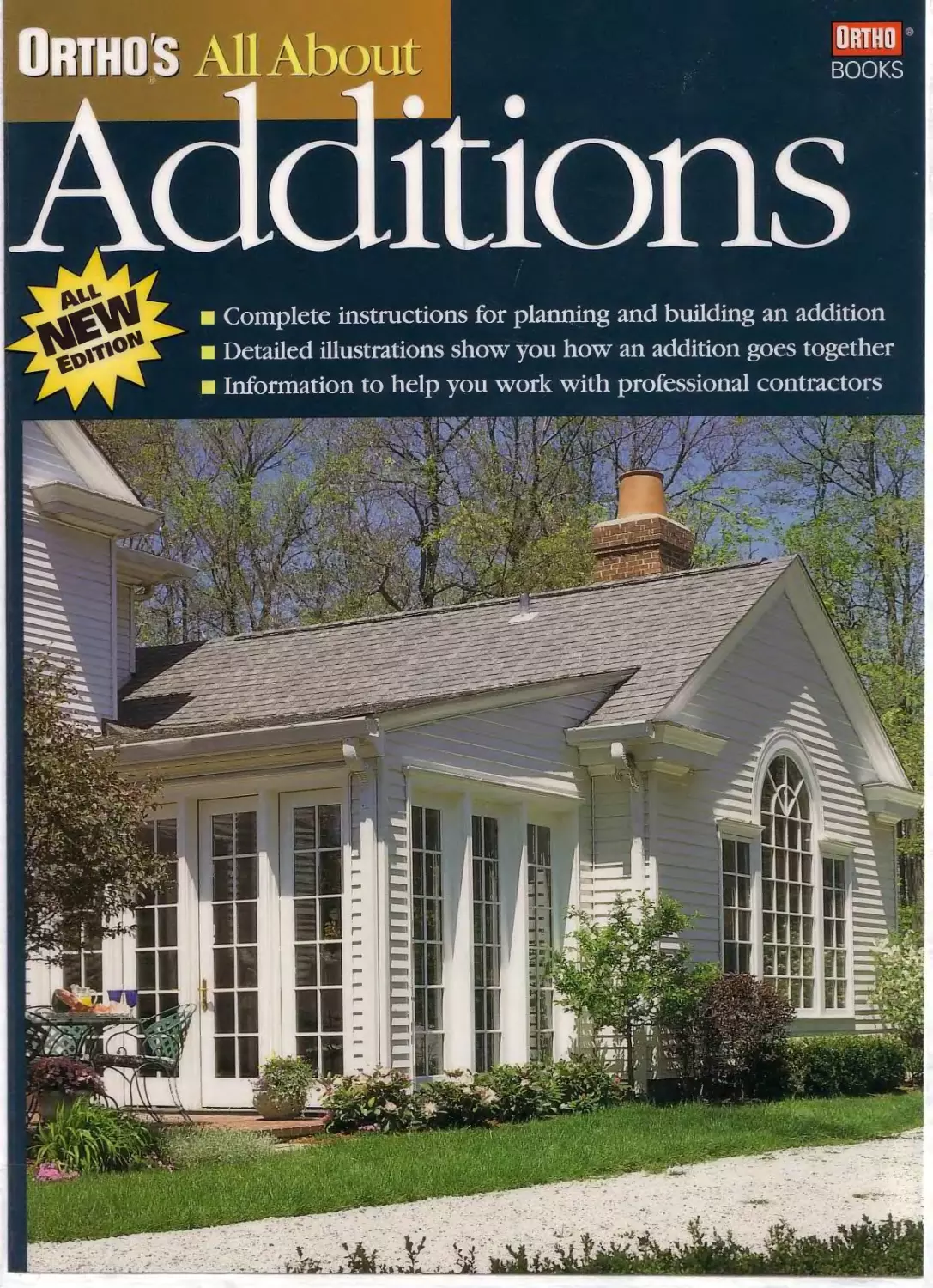
Ortho

Orthos au Abo

BOOKS

iiions

Complete instructions for planning and building an addition
Detailed illustrations show you how an addition goes together
Information to help you work with professional contractors
aria

Family rooms (above), master suites (far right), and kitchens
(below) are popular home additions. The best additions look like
an original part of the house, as with the family room (below
right) and master suite (right).


Getting
Started

In This Section

Project Management 6

The Foundation 8

Concrete Forms 10

Working with

Concrete 18

Peeing a Slab 20

Laying Concrete

Blocks 21

Insulating Foundation

Walk 22

When your growing family, more affluent
lifestyle, or at-home business no longer fits
comfortably into your home, you have to take
action. Your choices are to reorganise wasted
space in yoio home, buy or build a larger
home, or add on to your existing home.
Fhis book is about adding on

Adding on is worth considering if you like
your existing home and neighborhood, you have
a mature landscape, or you don’t want to give
up cherished memories.

Saving money is not a primary reason to add
on Building an addition will cost as much per
square foot as building а пеги home. It may
also require some remodehng of your existing
home to alh nv the new and old spaces to work
harmoniously. To keep an addition from
looking clumsy or tacked-on, it should blend
with the style of your existing home, so you
might need to hire an architect or desi,gner.
And additional electrical, heating, and cooling
loads might require upgrading of those systems.

Whether you build the addition yourself,
manage the job while others do the work, or
leave it all to a general contractor, you can
make better decisions if you understand what
goes into a project of such scope. This book
describes the steps in budding an addition, from
laying out the foundation to installing interior
moldings—everything you need to know to
succeed in adding on to your house.
Project Management

plans

The most important element in a successful
building project is a set of construction
drawings—the plans. Good plans help you
picture the project before you begin and serve
as a valuable reference throughout the
project. Complete and well-thought-out plans
will help you estimate material and labor
costs accurately. The plans will also show
subcontractors exactly what you want so they
can submit accurate bids. You’ll need good
plans, too, to secure project financing and
obtain necessary permits.

You can draw plans yourself or hire an
architect, usually for about 15 percent of the
project cost. Many lumberyards or home
centers will help, too. Expecting that you will
buy most of your building materials there, the
supplier will translate your rough sketches
into a minimal, but acceptable, set of plans.

If you draw your own plans, have them
checked by experienced building professionals
to ensure that the project meets building
codes, its structural elements are properly
sized, and you haven't overlooked any crucial
elements. Local building code authorities will
review your plans, too.

TYPICAL COST BREAKDOWN
(500-SQ.-FT. ADDITION)

Permit fees	$200

Site preparation and	storage	800

Foundation	3,200

Floor framing and subfloor	2,400

Wall framing and sheathing	3,000

Roof framing and sheathing	2,200

Roofing and gutters	1,800

Siding and exterior trim	2,400

Windows and doors	2,000

Exterior painting	2,200

Demolition	1,000

Rough wiring	2,800

Insulation	1,400

Finish walls and ceilings	3,600

Finish electrical	1,400

Heating	3,600

Trim and moldings	1,600

Interior painting	1,800

Floor covering	3,000

Debris removal	1,000

Contingencies	1,200

Subtotal	42,600

Overhead, profit (15	percent) 6,400

TOTAL	$49,000

what role will you Play?

Some confident and ambitious homeowners
tackle the entire project on their own, while
others prefer to hand the plans to a general
contractor, who then does the job. Between
these extremes, you can do some of the work
yourself and contract the rest or act as your
own general contractor, hiring and managing
subcontractors to do the complete job.

DOING IT YOURSELF: There are two
reasons for building an addition yourself—
to have the pleasure and pride of building
your own home or to save money. How much
money you can save depends on your skills
and how many special tools you will have to
rent or buy.

Here are some ways to cut costs by doing
work yourself:

	Do the work of the highest paid building
professionals—usually skilled workers, such
as plumbers and electricians.

	Do the tasks that have high labor cost
relative to material cost, such as insulating,
shingling, roofing, and painting.

	Do the small jobs that would take a
professional less than half a day, such as tiling
a countertop or installing vinyl flooring.

	Take charge of selecting and buying
materials and having them delivered on time.

ACTING AS THE CONTRACTOR:
Managing a construction project is like
running a small business—you have to plan
and schedule work, make decisions about
every detail, negotiate with a number of
people, understand each task and how it
relates to others, manage the finances, and
pay the bills.

This will always require much more tune
than you expect. You’ll spend a lot of time
negotiating with subcontractors and suppliers.
If you already have a full schedule, you will
have to eliminate some things to manage your
additional project.

To succeed as a project manager, you must
be organized, clear about the details of your
project, and prepared to spend long hours on
the telephone. You’ll need to set a budget and
adhere to it and make payments to suppliers
and subcontractors on time. It helps if you
have a lot of patience and good humor.
HIRING A CONTRACTOR: If you decide to
have a general contractor oversee the project,
you will first have to find a reputable
contractor who will work with you and stick
to his estimate (unless you approve changes).
You must be responsive when dealing with
the contractor, and make decisions quickly
and firmly when requested by your contractor.
Estimating the Costs

An important step in construction, before
the first nail is driven, is estimating the cost.
If you hire a general contractor or
subcontractors, their bids will be your
estimates. If you do the job yourself, you will
have to make your own cost estimate.

There are two kinds of costs to consider
m your estimate: predictable and hidden.

To estimate predictable costs, break the
project into smaller parts, such as foundation
work, framing, and roofing, then estimate the
material and labor costs for each part.

A construction cost estimating book,
available at bookstores, will help you make
a preliminary estimate of predictable costs.
These books show customary time and
material requirements for every step in the
construction process, including per-square-
toot costs for typical floors, walls, ceilings,
and other basic items. They also give regional
adjustment factors for material and labor
costs. Since they are based on costs submitted
b\ builders, they are accurate for normal
construction. The cost breakdown for a
5C0-square-foot, single-story addition of
average quality on the opposite page was
developed from a cost estimating book.

Hidden costs are harder to estimate; they
arise from rhe surprises that inevitably occur
during a project. Take time to imagine what
'.tuations could lead to changes in your plans,
dien include best-guess costs for them.
Hidden costs often include:

	liability insurance

 repairs or changes to the existing house
 debris removal and dump fees
 power cords or temporary power
 tool purchases, rentals, and replacements
 blade sharpening and replacement
 electric-service upgrades

 underground utility changes
 matching old or obsolete materials
 inability to recycle materials as expected
 landscape repairs or replacement

When you have your final plans, itemize
the materials and get firm price quotations
from suppliers. Be sure to include easily
overlooked items such as nails, hardware,
plumbing fixtures, and finishing materials.
These costs, along with bids from
subcontractors, will give you a more complete
cost estimate.

PREPARING YOURSELF

A building and remodeling project is noisy,
hectic, and wearing. Be prepared for setbacks,
disruptions, conflicts, and constant mess.
You’ll tolerate it best when you enjoy the
building process and rhe job’s progress. And
always try to remain cool when the inevitable
snags occur.

Minimize clutter on the job by clearing out
your garage, yard, or patio and devoting the
space to material storage and preparation.
Combat stress by setting aside part of your
budget—in money and time—for occasional
dinners out or weekend getaways.

SCHEDULING THE WORK

Here are the major tasks in building an addition, in the order in which they usually occur:

PLANNING AND PREPARATION

Finalize plans.

Estimate costs.

Arrange financing.

Obtain permits.

Order materials with long delivery
lead times.

Line up subcontractors.

FOUNDATION

Lav out building lines.

Excavate site.

Build forms; have them inspected.

Complete foundation.

Shell (Exterior)

Frame floor system.

Install underfloor utilities.

Have utilities inspected.

In?tall subflooring.

Frame walls and roof.

Modify common wall.

Install sheathing.

Install mechanical ducts.

Install plumbing and gas lines.

Install rough wiring, including
recessed fixtures.

Have utility installations and
framing inspected.

Apply roofing.

Install windows and doors.

Install siding.

INTERIOR

Frame intenor walls.

Install insulation and have
it inspected.

Apply wallboard and have
it inspected.

Finish wall surface.

Install trim.

Hang doors.

Paint interior and exterior.

Install floor underlayment.

Install cabinets, shelves,
and countertops.

Install plumbing fixtures.

Install built-in appliances.

Install electrical fixtures.

Install finish flooring.

Install freestanding appliances
(refrigerator, range).

Complete trim and decorative details.

COMPLETION

Get final inspections.

Convert construction loan.
The Foundation

Functions of the foundation

A foundation’s main functions include:
 supporting the building and anchoring
it against wind

	preventing vertical frost heave

	isolating the building from the ground

Some other common functions include:

	protecting against termites

	protecting from heat loss and storing
the building's heat in winter

	absorbing excess heat in summer

	providing space for storage, mechanical
systems, and additional living areas

types of Foundations

FULL BASEMENT In deep'frost areas,
excavate for a full basement, when possible.
(To avoid undermining the existing v
foundation, dig a full basement for an
/addition only when the house already has a
basement or deep footings.) A full basement
purs the footings below the frost line and
helps protect rhe plumbing from freezing.
The floor slab and wall footings are poured
concrete; the walls may be concrete or blocks.

Types of foundations

PERIMETER WALL: A full basement might
not be practical where the water table is high.
A shorter perimeter wall, constructed the
same way, is economical and provides the
same benefits, except head room.

SLAB ON GRADE: This economical
foundation allows you to finish the
foundation and floor in one operation.
It also keeps the floor close to the ground—
an advantage if height is a problem or if rhe
floor must match an existing slab.

PIER AND GRADE-BEAM: Reinforced
concrete beams supported by concrete piers
set deep into rhe ground are used for
structures on steep hillsides or unstable soil.
They usually require professional engineering.
Forms for the beams are built on grade, over
the piers, and follow the contour of the slope.
All-weather wood foundation:
Full'basement and perimeter'wall foundations
of pressure'treated lumber and plywood have
been used in Canada for 50 years. These
foundations require proper materials,
assembly, and backfilling techniques, so
seek advice from an architect or foundation
contractor who specializes in them.

A Do-It-Yourself job?

Unless you have experience in foundation
work, hire a subcontractor. Building a
foundation is heavy, backbreaking work that
comes at the beginning of your project, when
you might not be in shape nor have full
confidence in your building skills. The
foundation establishes the dimensions and
levelness of the building that sits on top of it,
so it must be constructed with dimensions
accurate to lA inch. You can make
adjustments in any other part of the building
as you work, but concrete is permanent.

You may be able to save some money on
the foundation even if you don’t do the whole
job. A contractor might lower his price if you
can correctly do some simple but time'
consuming tasks such as laying out the
foundation perimeter lines and building the
batter boards, scheduling the excavator,
placing the perimeter drains, waterproofing
the walls, placing exterior insulation (if any),
or backfilling around the foundation.

Anticipating requirements

Projects are always easier when you anticipate
special needs and problems before they occur.
Run through the Excavation and Special
Tools checklists on the opposite page to make
sure you are ready to start your foundation,
whether you use a subcontractor or not.
EXCAVATION: Hire an excavation
contractor to dig the foundation and footing
trenches (with the possible exception of a
small slab on grade) and the hole for a full
“asement Ask your foundation contractor
which excavator he would prefer to do the
digging. If it is someone he works with often,
ask him to coordinate the digging and the
placing of forms.

Here are some problems you might have
: » soh e before digging begins:

 Are there any obstructions, such as trees,
utility lines, septic tanks, or old footings that
will make excavation difficult? You might
have to remove one or more trees (the
excavator will remove the stumps). Call the

-Ricy company to move service wires.

 .Are there any nuisance plants, such as
ooison oak or berry bushes, that you should
remove before laying out the lines?

 Can a backhoe, concrete mixer, or other
ge equipment get to rhe site? If not, can
xi remo * e a section of fence or get
permission to pass through a neighbor’s yard?
 Is there room to store lumber, steel
reinforcing, gravel, crushed stone, sand,
c .Crete blocks, and other bulky material?

There will it be delivered? How will it get
t your site?

 Where will the excavated dirt go? Even a
—. Jest trench yields an astonishing pile of

soil. If you don’t have room in your own yard,
ask your neighbors and friends if they would
like some free fill, or look into public
landfills. Your excavator will probably know
someone who will take the fill.

 Will a deep excavation or pier holes create
a safety hazard for children? Be ready to put
up a temporary railing around the excavation
or cover deep bores with plywood.

SPECIAL TOOLS: Foundation work requires
some special tools:

 A water level, builder’s level, or transit for
leveling widely separated points. (For small
additions, you can use a level and a long,
straight board.)

 Two good wheelbarrows or a rented
conveyor for hand digging.

 A long-handle, square-nose shovel for
trimming trench bottoms.

 A rebar cutrer/bender. For a small job, you
can cut rebar with a hacksaw or reciprocating
saw and bend no. 3 or no. 4 rebar by hand
against a firm object.

 A hammer drill for drilling holes into the
existing foundation.

 Concrete finishing tools for slab work
(wood or magnesium floats, a tamper, a bull
float, a fresno, a seamer, and a steel trowel).

 Tools for block work (a trowel, a 4Toot
level, and a joint finisher).

CODE REQUIREMENTS

Grading

The backfill around a foundation must be graded to slope
. av at a minimum of 6 inches in 10 feet on all sides.

Footings

-ootings must be level on the top surface with a
m omum slope of 10 percent on the bottom surface;

<ep the footings where the slope exceeds 10 percent.

CONCRETE FLOORS ON GROUND

Remove all vegetation, topsoil, and foreign material.

Maximum depth of clean and compacted fill:

	earth—8 inches

	sand or gravel—24 inches

Selow-zrade base courses, except on w ell-drained soil or
_ sand-gravel mixture, must be clean sand, gravel,
zrnshed stone, or slag 4 inches thick.

A vapor barrier is required under slabs except for:

 -ctached, unheated structures

 when excepted by code official

Protection Against Decay

Use pressure-treated wood for these parts:

 joists up to 18 inches above grade within a foundation
 girders up to 12 inches above grade w'ithin foundation
 sills or plates on concrete up to 8 inches above grade
 siding or sheathing up to 6 inches above grade
 basement wall furring strips without a vapor barrier
 sills and sleepers on a slab w ithout a vapor barrier
 posts and columns in direct contact with the ground
or embedded in concrete and exposed to the weather
ANCHOR BOLTS

Embed ’/z-inch anchor bolts 15 inches into masonry or
7 inches into concrete; space them 6 feet on-center and
no more than 12 inches from corners.

Crawlspace Vent Openings

 net vent area without vapor barrier: ’/iso floor area
 net vent area with vapor barrier: ’/1,500 floor area
 vent opening within 3 feet of each corner
 corrosion-resistant ’/s-inch mesh screens
Concrete forms

LAYING OUT A SIMPLE FOUNDATION

Siding and sheathing removed to expose
foundation and structural members

Plumb line at edge
of new addition

Batter
boards

Existing siding

Corner stakes
beneath string
crossings

Ex.sting
foundation

Equal
d-agonals

Obstruction

A complex
foundation
requires more
batter boards and
layout lines than a

Equaf measurement
indicates string is .
parallel to side of house

simple three-sided addition;

the general layout technique is the same. t

5

To lay out a right angle corner, mark points 3 feet
from ihe corner on one side and four feet from the

\	corner on the adjacent side. Adjust the angle until

\	the distance between the points is 5 feet. s

\ You can use multiples of 3, 4, and 5 for '

\ greater accuracy.	s'

\	4 s'

\3	s'

Laying
Out the
foundation

'	Set up string lilies to establish

the outside edges of the foundation
wall. Run them between die house and
temporary batter boards, which can be taken
down and put back up as needed until the
foundation is completed. Before you set up
the lines, make sure your addition conforms
to the setback limits for your property. Your
local building inspection department ma}
require a certified survey.

The following procedure describes laying
out a simple rectangular addition, but the
same technique can be expanded to lay out
more complex additions, also.

1-	Mark where the outside edges of the new’
foundation w'ill meet the house foundation.

Using a level, extend vertical
lines onto the house siding.

Draw a secon 1 line outside each of the
foundation lines, separated from it by a
distance equal to the thickness of the siding
that will be on the addition.

2.	Remove some house siding and sheathing
between the marks to expose the floor joists
and subfloor. Use a circular saw w’ith the
blade set deep enough to cut through the
siding and sheathing but not into the framing.
3- Measure down from the top of the existing
subfloor at both marks to loc ate the top of the
new’ foundation. Since the dimensions of new
and old joists, the mudsill, subflooring, and
other members might be different, the tops of
the foundations might be at different levels.

4.	Drive a nail into the house framing or a
cleat attached to the house at each point.
Attach a nylon mason’s line to each nail.
Check the lines with a level; if they are not
level, lower the string at the higher corner.
You can adjust for the difference later when
you frame the floor.

5.	Build batter boards at one outer corner
6 feet beyond the corner of the addi tion so
diey will not interfere vith the excavation.

T build them, drive two pairs of pointed

_ into the ground about 4 feet apart, as

 wn above. Center them on the corner.
Screw a level crosspiece to the back of the
2x4s facing the house. Place the crosspiece so
\ -r the string line attached to the house runs
c rel across the top.

6.	Stretch the string line taut across the top
of die batter board. Slide it right or left until
ir is square to the house, then drive a nail
г i the batter board at that point. Use a
—-5 triangle (two legs of 3 and 4 feet, and a
hypotenuse of 5 feet) to square the line to the
use, as shown on the opposite page. For
e en greater accuracy, use multiples of 3'4'5,
such as 9'12'15 feet or 12'16-20 feet.

7.	Build batter boards for the second corner

' d attach the string. Pull the second string
to its batter board and move it right or
~ until the two lines are an equal distance
Apart at both ends.

8.	Stretch a third string line between the
'ide sets of batter boards, intersecting
ti" e first pair of lines at the comers of the
foundation.

9.	To make sure the string lines arc square,
measure diagonals and adjust lines until
diagonal measurements are within inch
of each other. If your house walls are out of
square at a corner where you will attach your
addition, the extended wall might look
crooked if you lay out the string lines
perfectly square. If the wall is not prominent,
lay out the lines as described, and conceal the
bend in the wall with tall plants.

It’s better to align a more prominent
addition wall with the existing house wall,
even if one wall of the addition will be out of
square with the end of the house. To do this,
follow the layout procedures described before,
but align the first string line with the side of
the house. To make sure it is perfectly aligned
with the house wall, stretch a new string line
along the entire length of that wall, from
batter board to the front of house. Move it
out far enough to clear any obstructions along
the house wall, making sure it is an equal
distance from the house foundation at all
points. Adjust the line from the foundation
so it is parallel to the longer line.

350. rue Saint-Joseoh tst, C
G1K 382 www.icqbJ.
Anchor boits no more than

Concrete forms

continued

6' apart and no more than
12" from end of any mudsill

Mudsill

Slab at least 41
thick and 8"
above grade

No mudsill in
doorways

Slab
FOUNDATION

6" wire mesh held
above plastic with
dobies

Mudsill

Existing
house

Rebar dowels
in holes drilled
into foundation

Existing
foundation

3" to 4
layer of
sand or
gravel

Footing 12й
to 15" wide
and deep
enough to
reach belo
frost line

Hooked rebar
ties slab to
footing

Anchor

bo’t

Rebar
reinforcing
in footing

6-mil
polyethylene
over gravel

Splice rebar by overlapping
and tying with wire

Excavation

The excavation contractor w ill probably paint
the layout lines on the ground w tth a spray
can, reiftOve rhe strings, and start digging.
The plans will show rhe distance from the top
of the foundation to the bottom of the slab
and footings.

The bottom of the trench for the footings
should be level and the sides straight Do not
throw dirt back into the trench; its bottom
and sides must be undisturbed soil.

For a full basement foundation, the
excavator usually digs to the bottom of the
floor slab first, making sure it’s level. The
footing trenches are then dug. After digging,
reset the string lines to build forms.

BUILDING FORMS

SLAB FOUNDATION: The slab and footings
are usually formed and poured together,
following these steps:

1.	Build forms for the slab with 2x lumber
held by stakes every 2 feet. Al ign the forms
with string lines, and level the top at least
8 inches above final grade. The trench walls
sen e as rhe forms for the footings.

2.	Dig trenches for pipes that will run under
the slab. Lay the pipes, then backfill.

3-	Spread 3 to 4 inches of sand or crushed
stone inside the slab perimeter, and cover it
with 6'mtl polyethylene sheeting as a vapor
barrier. Put 2 inches of sand over the sheet.
C, Lay horizontal rebar in the trenches,
resting the bottom bars on dobies (small
concrete blocks) and suspending rhe top bars
with tie wire hooked onto the top of the
form. Tie vertical rebar onto horizontal bars.

5. Lay 6'inch wire mesh over the sand on
2-inch dobies spaced 4 feet apart. Tie the
mesh to the rebar in the trench. (You may be
able to use fiberglass reinforcement; ask your
local code officials and concrete supplier.)
6. Pour the concrete. Fill the footing
nenches, then pour the slab. (See page 20 for
details about pouring and finishing a slab.)
Insert anchor bolts around the peri meter.

Where deeper footings are required, the
slab and footings are poured separately. It the
slab will rest on the footings, the trenches are
adequate for footing forms. Lay rebar in the
trenches and pour the concrete. Stand lengths
of rebar with hooks formed on one end in the
fresh concrete to tie the footing and th e slab
together. Then build a slab form,
о
PERIMETER
WALL

Joist
hangers

Floor
joist

Soleplate—
nailed to
subfloor
with stud
walls

Rim
joist

Existing
foundation

\ New
foundation

Anchor
bolt

Muds'll

Rebar dowels
cemented into
holes drilled into
existing foundation

'V/ ' Rebar in footing and
foundation wall

PERIMETER FOUNDATION:

•-г merer foundation:

- undation wall (which will be narrower than
т - footings and centered on them) will align

na? for the footings.

2. Rent plywood forms or construct forms
* 2 1 amber. (You can reuse rhe lumber for
-><r joists.) Drive tall stakes into the bottom
c trench every 3 feet, set so the inside
ot the forms will be 8 inches apart.

e forms. Level the tops of form boards
i die string lines, and place the bottoms

Crawl space

a

Polyethylene
barrier

tall to center over the footing holes. Pour

a post anchor into the wet concrete.

To hold each end of the girder, form
pockets in the walls or pour pilasters
(columns adjacent to a wall) See Beam
Pockets and Pilasters, page 15, for derails.

PERIMETER
WALL FORM

Anchor
bolt

e rebar in place. Rest the
rebar on dobies and fasten

sen meral form ties (available

- - г een the form sides to prevent

2 _ ncrete from forcing them

- - The ties allow you to free
?. ies after the concrete sets.

5.	jT locations for ’/rxlO-inch

- z ‘ - bolts on forms.

6.	-n intermediate girder is usually
- -1 for joist spans over 16 feet.

here vou’ll need posts and dig

- _-_sг 18xl8xl2-inch piers at
г r.ts. Build simple box forms

*	- inches square and 8 inches

Wedge

Steel
form tie
Scrap lumber

Pull out stakes the
same day as the
pour, as soon as
concrete sets

Place the inside form in the same way as the
outside form. Tie the inside and outside forms
together with spacers and form ties
Concrete forms

continued

FULL-BASEMENT FOOTING

Canted sides of excavation
or approved shoring

FULL-BASEMENT FOUNDATION

String to batter
boards marks top
of foundation

and pour concrete for a full-basement
foundation. But, you can build block

Here are rhe steps.

Multiple of
concrete block
height

Existing
basement
wall

allow enough depth for a 4-inch slab

2.	Dig footings wide enough to
support the slab after tl te wall is
finished (see below).

3.	Build forms along the lip of trench

Thckness

—I of gravel

LxX T beneath :

Ч' Footing trench

Footing form

Existing
footing

slab

footing by measuring a distance div isible

1'
m-n

Rebar held 3" above
bottom with dobies

and secure them with 1x2 stakes every 2 feet.
Nail 1x2 lies across the top of the forms.

4. Place horizontal rebar in rhe forms,
holding it off the ground with 3-inch dobies.
5. Mark locations on the form boards lor
pieces of vertical rebar. Lay out rhe marks so
the bars will extend into the holes in the

FULL-BASEMENT
BLOCK WALL

New floor joists

e plate

Existing floor joists Joist hanger Doub

New concrete or
concrete block wall

drainpipe
Getting Started 15

blocks. You can buy the
bars precut, usually with
a hook formed at the
bottom. Embed the bars
in the concrete when it is
poured; do not drive them
into the ground.

BEAM POCKETS AND
PILASTERS: Girders are
large beams that bridge
from one foundation wall
to another, di\ iding the
building into manageable
isr spans. The maximum
tit span is usually 16 feet;

2	feet will result in a
wronger floor.

To support the ends of
, rder, either form beam
r ckets into the
• undation walls or pour
ptlasters—p i liars adj ace n t
* the wall—as part of the
Hxmdation.

To form a beam pocket,
two scraps of 2x

Beam Pocket/pocket for girder

Aluminum flashing or
roofing felt keeps the beam
from contact with concrete

—- ming material to the inside of rhe
11-form boards. A single thickness—
inches— is not sufficient because building

12-inch

Second course
and all even-
numbered tiers
tie into wall

Rebar set
in footing
strengthens
pilaster

Pilasters in
Block Wall

г concrete

Set the

S - 7 ?rt the
,-r 'etween the

Footing extension

First course pilaster
block and odd-
numbered tiers lie
parallel to the wall

тег with
slab.

3	dies on concrete.

7o form a pilaster in a poured-concrete

'.I. interrupt the line of form boards with
- pening 12 inches wide extending from
— - top ot rhe footing to the point on the top

— board where the bottom of the girder
nil rest. Allow an extra I1/? inches for the

» ... rest. Build a box form around the
 - -7. • -.j, extending out from rhe wall at least
' inches.

To form a pilaster in a concrete block
o_ncition, interlock the pilaster blocks with

. cores. The center ol the girder
_ not fall exactly in

 e middle of a standard

-rich block, so build

" e г _ ner two


Concrete forms

continued

Grade-beam foundation: a grade-
beam foundation requires less excavation and
uses less concrete than a perimeter wall, yet
it looks and functions like one. It is, in fact,
a shallow perimeter wall supported by piers
which reach below the frost line or through
unstable soil. It serves well where frost
penetrates to a great depth or where the
ground slopes. Here is how to construct
a grade beam:

1.	Locate the centers for the supporting piers
uniformly around the foundation, no more
than 8 feet on-center. Place piers adjacent to
the existing foundation and at each corner.
Mark the centers on the layout strings with
pieces of tape or yarn.

2.	Excavate for the footings that will support
the piers. The bottoms of the footings must
extend below the maximum frost depth and
below any unstable soil. The footings should
be 18 inches square (or equivalent area) and
at least 8 inches thick. Dig the holes by hand
or hire an excavator with a power auger.

3.	Drive two reinforcing rods into the soil
where they will stand at least 3 inches inside
the edges of the piers to be formed on top of
the footings. The rebar should be long enough
to project at least 24 inches above grade.

4.	Pour the footings.

5.	Place 8-inch-diameter form tubes
(cylindrical paper forms) atop the footings,
enclosing rhe rebar. The tops of the tubes
should be at grade level.

6.	Carefully backfill around the form tubes
without moving them. Don’t let any soil fall
into the rubes.

7.	Build forms for the beams across the tops
of the form tubes. They will be like forms for
a perimeter wall, except the earth at grade
becomes the bottom of the form. The beam
must be at least 2 feet high at all points. On
a slope, keep the bottoms of the forms level
by stepping them in 1-foor increments.

8.	Lay horizontal rebar in the forms as shown
for perimeter walls (see page 13). Bend the
vertical bars from rhe piers at right angles,
and tie them to rhe bottom bars in the beam,
overlapping by at least 20 inches.

9.	Mark locations for PzxlO-inch anchor
bolts on forms.

10.	Mark the height of the concrete on the
inside of the form wall so that you can bring
it to the right level as you pour.

11.	Pour the concrete. Consolidate it with
a shovel or vibrator, then screed the top
surface level.

12.	When the concrete begins to set, place
the anchor bolts, standing them straight.

’	О	О

Grade Beam

Joist hangers

Floor joist

Subfloor

Soleplate—nai e :
to subfloor with
stud walls

Rim joist

----Mudsill

New
foundatio'-

Anchor
bolt

Existing
foundation

Rebar dowels cemented
into holes drilled into
existing foundation

Rebar in
pier and
foundation
wall

Polyethylene Crawl
barrier	space
All-Weather Wood Foundation

Existing floor joists Joist hanger Double plate New floor joists

Existing
basement
floor

Old
basement

Grade

Existing
footing and
basement wall

New doorway
cut in existing
basement wall

New
basement

2x8 pressure-
treated footing

2x6 т6"ос
pressure-
treated stud

------У2" treated
plywuod

6 mil poly
membrane

Gravel bed

New slab flooi

ALL-WEATHER WOOD FOUNDATION:

Wood-framed walls withstand ground
movement better than concrete walls because
they will flex slightly rather than crack.

This—plus the ease of finishing the interior—
makes wood-framed walls ideal for a full-
basement foundation.

Many people shy away from a wood
foundation, knowing that wood will rot in
contact with the earth. But pressure-treated
wood won’t rot when in ground contact.
Treated wood has been used for foundations
for more than 50 years. Ask a professional
familiar with wood foundations for design
advice. Here is the general construction
procedure, which also applies to building
a wood perimeter wall:

*1. Excavate a level basement hole 7 inches
deeper than the final slab or floor surface.

2.	Excavate for a sump pit and drainage pipe.
Or, dig just the pi and install a sump pump.

3.	Install a 24'inch-diameter precast concrete
tile with removable cover for the sump. Place
the cover flush with the finish slab surface.

4.	Pour 4 inches of pea gravel over the floor
area and around the tile. Level the gravel.

5.	Lay a 6-mil polyethylene membrane over
the gravel, overlapping seams by 24 inches.

6.	Lay pressure-treated 2x8s around the
perimeter as a footing for the wood wall.

7.	Frame the wood walls with pressure-
treated 2x6 studs, 16 inches on-center
8. Sheath the outside of the walls with
pressure-tieated */2-inch plywood. The face
grain should be vertical. Make sure all joints
are on studs.

9.	Install the floor system above to stabilise
the tops of the walls.

10-	Pour a 3-inch floor slab flush with the
t< -ps of the wall bottom plates. Reinforce the
slab with either 6x6 weided-wire mesh or
fiberglass strands added to the concrete.

11-	Staple a continuous sheet of 6-mil
polyethylene to the wall top plate so that it
hangs down over the outside ol the plywood
to the bottom of the wall.

12.	Apply a protective finish (painted
exteuor plywood or fiberglass-reinforced and
latex-modified mortar) to the portion of wall
which will remain above grade.

13.	Backfill against the wall. Grade the soil
to slope away from the foundation at a
minimum of 6 inches in 10 feet.
working with Concrete

Ordering Concrete

Unless you need such a small amount of
concrete that you can nnx it by hand, order
a ready-mixed concrete delivery. If the ready-
mix truck can’t drive to your addition site,
you will also need to hire a concrete-pumping
service or enlist several strong helpers with
wheelbarrows. Of course, if you have hired

a contractor to pour your foundation, the
contractor will order rhe concrete and
provide the labor for placement.

When ordering concrete, you must estimate
the amount and specify the kind of concrete

mix you want. Here are some pointers on
ordering concrete:

Estimating Concrete for
Footings and walls
(CUBIC YARD PER LINEAR FOOT OF FORMS)

Height, inches	6	8	Width, inches			20	24
			10	12	16
8	.012	.017	.020	.025	.033	.041	.049
12	.019	.025	.031	.037	049	.062	.074
24	.037	.049	.062	.074	.099	.123	.148
36	.056	.074	.093	.111	.148	.185	.222
48	.074	.098	.124	.148	.198	.246	.296
60	.093	.123	.155	.185	.247	.308	.370
72	.111	.148	.185	.222	.296	.370	444
84	.130	173	.216	.259	.345	432	.518
96	.148	.198	.247	.296	.395	494	.593


Figuring how much to order:

Concrete is sold by the cubic yard, usually just

called a yard. A cubic yard is the volume of a
cube that measures 3x3x3 Feet, or 27 cubic
feet. Figure the amount of concrete needed
for footings, walls, slabs, and walks from the
tables below left. Add 10 percent to your
estimate to allow for spreading of the forms
and waste.

Most ready-mix concrete companies set
the delivery minimum at 1 cubic yard. Many
add an additional charge for orders less than

5 or 6 yards You won’t have to take the
whole minimum yard when it’s delivered, but
you will have to pay for it. If you don’t need
the whole yard, consider having forms ready
so you can pour a sidewalk, footings for a

deck, or even concrete pavers with the excess.
AGGREGATE SIZE: Use fi-inch' aggregate

for most projects, unless building
codes require a different size. If you
will have the concrete pumped,
check with the pumping company
to make sure its equipment will
handle the size of aggregate you
are using.

Cement content: You must
specify the number of bags of
cement per yard of concrete. A five-
bag mix is normally requested when
the aggregate is Уч inch. A six-bag
mix is recommended for 3/s-inch
aggregate or when higher-strength
concrete is needed.

Other factors: You may also
need to specify' water-to-cement
ratio (1 to 2 by weight is standard
for residential foundations), slump
(4 inches for most jobs; 6 inches for
filling concrete block),
and air entrainment

estimating Concrete for Slabs and Walks

(CUBIC YARDS)

Area,	Thickness, inches

square feet

	2	3	4	5	6	8	10
10	.06	.09	.12	.14	.19	.25	.29
20	.12	.19	.25	.29	.37	.50	.58
50	.31	.47	.62	.72	.93	1.24	1.44
100	.62	.94	1.24	1.44	1.86	2.48	2.88
200	1.2	1.9	2.5	2.9	3.7	5.0	5.8
500	3.1	4.7	62	7.2	9.3	12.4	14-4
1,000	6.2	9.4	12.4	14-4	18.6	24-8	28.8

(a treatment for cold
weather which helps
prevent frost damage,
usually specified as
6 percent).

You might also have to
pay a standby charge for
time the concrete truck
remains at your job site,
after an allowance for
unloading time (usually
about 5 minutes per yard).
A concrete-pumping
service usually charges an
hourly fee plus a rate for
each yard pumped.

Make sure you are
prepared when the ready-
mix truck arrives so you
won’t have to pay the
standby charge and to
avoid having to add water to the concrete
if it begins to set in the truck

Installing rebar

Plans for most residential foundations call for
no. 4 rebar, which is Vi inch in diameter. This
size can be bent and cut fairly easily.

Use a special cutting tool for rebar—which
also bends rebar—or cut it with a metal cutoff
blade in a circular saw or a metal-cutting
blade in a reciprocating saw.

Splice rebar w ith tie wire. Codes specify
that two pieces overlap by at least 40
diameters (20 inches for no. 4 rebar)

Codes also specify concrete cover—
the minimum thickness of concrete
surrounding rebar. Where concrete is below

from the ground on all sides. Above grade,
the cover must be at least 1 ’/z inches.

Attach rebar for a new foundation to
shorter lengths of rebar embedded into the
existing foundation. First drill 7s-inch holes
at least 4 inches into rhe old foundation and
blow the dust out. Cut 24 inch lengths of
rebar, and cement one into each hole with
special epoxy mortar or other compound
before you build the forms.

POURING
A FORM

Drill ho’e in form,
tie wire to nai

Wire support
for rebar

Placing Concrete

Tamp concrete
to consol date it

Don’t handle concrete too much—just
enough to get it into place. Then use a rod,

Strike hammer
on stake to
spread impact
and effect

On rhe day of the pour, have plenty of help
lined up. As you pump or place concrete,
start at the lowest point in the forms. For
deep forms, fill the footing area before filling

it. Hu the sides of the forms with a hammer
to release air pockets.

TYING-lN
Rebar

Existing
foundation

30" pieces of rebar cemented .nto
holes in ex.sting foundation and
w red to rebar in the new foundation

dragging a screed (a piece of 2x4) across the
top of the forms. Use a sawing motion to push
excess cc mcrete in front of the screed and f ill
in low spots behind it. Allow the concrete to
stiffen slightly before setting anchor bolts or
lengths of vertical rebar in place.


Pouring a Slab

Level the surface with a
magnesium bull float. Push the
float with the leading edge
raised slightly so it won't dig in.

Setting anchor
bolts or rebar

After the concrete stiffens
slightly, insert anchor bolts or
vertical rebar where indicated
on the forms.

Steel troweling gives the
concrete a smooth surface.
Wait until the surface water
disappears before troweling.

Covered slab

Prevent the concrete from
drying too quickly while it
cures. Plastic sheeting will trap
the moisture to control drying.

As you pump or pour concrete into
forms for a slab, start at the farthest
point- When pouring the slab and
footings together, fill the footing area and
let it stiffen slightly before pouring the slab.

Handle concrete only enough to get it into
place. Then use a shovel or \ ibrating machine
to consolidate it.

After the concrete settles, level it by
dragging a screed (a piece of 2x4) across rhe
tops of the forms. Use a sawing motion to
push excess concrete along in front of the
screed and fill in low spots behind it. Let the
concrete stiffen slightly before setting anchor
bolts or lengths of vertical rebar.

Fimshcng the Concrete

After screed i ng, tamp the concrete with a
special tamper so the aggregate settles slightly
and a creamy mixture rises to rhe surface.
Then float the slab, using a bull float with
a long handle to reach the center. If rhe slab
is larger than 10x16 feet, use a jointer trowel
to groove it across the middle to limit cracks.
Use a long 2x4 for a straightedge.

After the concrete has stiffened slightly
and surface bleed water has evaporated, finish
the surface with a steel trowel and set the
anchor bolts. If you want a smooth, flat
surface, hire a professional finisher.

Cover the slab with polyethylene sheeting
for 10 to 14 days to cure. If there is danger of
freezing, which can prevent the concrete from
setting up properly, cover the plastic with
insulating material to hold in heat.

1
laying Concrete blocks

Lay blocks beside the footing excavation,
and drive rebars into the middle of the
trench every 4 feet, as shown in the
illustration at right.

After the footing has cured, place the two
comer blocks of the first course. (Always
place blocks with the wider webs on top.) Set
each block into a layer of mortar and press it
down to within A inch of the footing. Stretch
a line between the corner blocks to guide the
rest of the first course.

Lay mortar on the footing and apply mortar
to one end of each block as you set it in place
(called buttering) Raise the buttered end
slightly and lower it to fit snugly against the
preceding block in one smooth motion. Tap
the block level with the trowel handle, then
scrape away excess mortar with the blade.
Check your work often with a level, both
horizontally and vertically.

Fill the cores with concrete after the wall

Laying
Concrete
Block

Rebar driven into bottom of trench in
line with the first hole in every fourth
block—every 4" wi!:h 16" blocks «

Dry run of blocks laid beside
the footing trench to set the
position of rebar

Rebar in footing trench

raised at least 2" on stones

or pieces of brick

Lay out blocks in a dry run to determine placement of vertical
rebar. Place the bars so they will fall in the center of the first core
of every fourth block, about 4 feet apart.

has dried overnight. Even if your plans do not
require concrete in every space, you will have
to fill cores every 4 to 6 feet for setting

Rebar set
in footing

Line up first
course on
mason s twine

Footing

First course

First course
corner block

Mason's
line block

Shallow keyway
provides additional
support

concrete filling, pour insulating material,
such as vermiculite, into rhe cores.

Set the corner blocks for the first
course, and stretch a mason's line
between them. As you lay the
remaining blocks in the course,
align them with the line. Don't let
them touch the string, however;
that could distort the line.

corner

block

Add lengths of rebar after a few courses. Slide the new
bars into the block cores next to the original rods. Tamp
concrete into the cores to hold the new bars securely.

For each new course, stretch a mason's line between the
corner blocks to indicate the top of the blocks. As you
set each block, align its top edge with the line to ensure
a straight, true wall. Check the wall often with a level.
Insulating Foundation walls

Slab

Concrete conducts heat. To prevent heat loss
from the floor to the outside, you have to
insulate a slab around its perimeter Closed-
cell, extruded polystyrene is the best material
to use because it is impervious to moisture.
The insulation should extend to the
maximum depth of frost.

To prevent freeze-thaw cycles rrom lifting
the insulation, place the foam inside the
footing and slab form before pouring the
concrete. The sill plate will extend over the
loam and hold it in place, as shown below.
After the wall is framed, extend the sheathing
slightly over the sill and foam.

Research has shown that insulating to
1 foot below grade and horizontally for a total
distance equal to rhe depth of frost is as
effective as insulating straight down. This

Rim joist

Foam
insulation

Mudsill

sheeting

allows you to construct a slab with
a shallow footing even in cold
northern areas.

Sunlight attacks polystyrene,
so you must cover any exposed
insulation. Since the bottom of rhe
sheathing and siding must be a
minimum of 6 inches above grade,
you will have a 6-inch strip to
cover. T1 e material that looks most
natural (like concrete) is a
fiberglass-reinforced, modified latex
coating, described on the next page.

perimeter Wall

A perimeter wall can be insulated
on the outside with foam (explained
in rhe full-basement section that follows) or

on the inside with faced fiberglass blanket or
batt insulation. To insulate with fiberglass:
1. Lay a polyethylene sheet over the ground
inside the wall. Overlap any seams by 1 foot
and weight the seams to seal the joints.

2.	Cut insulation batts long enough to
extend from the sill and at least 1 foot out
onto the plastic sheeting, as shown ar
bottom left.

3.	Staple the top of rhe facing to the edge of
the sill, then staple the flanges along the sides
of the batts together, forming a continuous
layer of insulation over the wall.

4.	Weight the bottoms of the batts with scrap
pieces of 2x4-

5> Cut blocks of extruded polystyrene or
other closed-cell foam board to fir tightly in
rhe spaces between the joists. Press the blocks

firmly against the rim
joist to eliminate any
air space. If the blocks
are too loose to stay in
place, nail them to the
rim joist. Local fire
codes may require
covering the foam
with */2-inch dry wall.

You could fill the
spaces instead with
fiberglass batt. Either
trim the fiberglass
back 1 inch all around
to give you stapling
flanges, or install
unfaced fiberglass and
staple polyethylene
sheets to the subfloor,
joists, and sill to seal
rhe fiberglass against
moisture.
Full Basement

A concrete or masonry full-basement wall
can be insulated either on the inside or the
outside, but exterior insulation gives the
greatest benefit. Here’s why:
 Enclosing the thermal mass (heat storage
capacity) of the concrete within the building’s
insulation envelope lessens the temperature
change of the basement caused by outside
temperature changes.

	Isolating the wall from the cool earth
in summer allows it to reach the same
temperature as basement air, eliminating
condensation and mold.

	Exterior insulation minimizes the freezing-
and-thawing cycle of water in voids and
cracks, which damages concrete and concrete-
block walls.

Here’s how to insulate the outside of a
basement wall:

1.	Set the concrete forms 2 inches inside the
building lines, allowing 2 inches for exterior
foam insulation.

2.	Before backfilling the basement wall,
coat the wall from footing to sill with a
nonpetiolcum-based moisture barrier
(petroleum attacks plastic foams).

3.	Apply P/z-inch-thick, tongue-and-groove,
extruded polystyrene panels vertically,
snugging the panels up under the sill and the
lip of the sheathing. Attach the panels with
one hardened concrete screw and a plaster
button (a large perforated
washer for repairing
plaster) for each

2-foot-w'ide panel.

4-	Backfill to w'ithin

9.	After the first coat dries,
apply a coat to the entire surface,
extending down from the
sheathing to 6 inches below'
final grade.

10-	After the Floor joist

mortar cures,	------

finish

backfilling. =~- - -~J~ ====£~
Grade the soil

to slope aw'ay	/

from rhe foundation at Mudsill
6 inches per 10 feet.

11-	Fill the gap between
the foam and the
sheathing, which could be
up to Vi inch w'ide. An
easy way to caulk the gap
is with foam backer rod,
available in l/s-, l/4-, and
*/2-inch diameters at
lumberyards and home
centers. Stuff the rod into
the gap w'ith a putty knife.

Moisture
barrier

Sheathing

Rim
joist

Foam
insulation

Foundation
wall

6 inches of final grade.

5.	Brush the exposed
foam with a steel w'ire
brush to give the foam
tooth for the coating
to be applied.

6.	Cover all screw heads,
foam joints, and corners
w'ith strips of self-
adhesive, fiberglass-mesh
drywall tape.

7-	Mix fiberglass-
reinforced, latex-modified
mortar (available at
masonry supply outlets)
in a 5-gallon pail with a
power paint mixer.

8.	Brush or trow'el the
first coat of mortar over
the taped areas.

mortar over foam extends	modified mortar tape over nailheads and joints

6 inches below grade	over taped areas
BUILDING
THE SHELI

In This Section

The Floor 24

Framing the Floor 26

Stairs and

Subflooring 28

Walls 30

Building Walls 32

Raising a Wall 34

Tying a Wall to the

___________Old Roof 35

The Roof 36

Rafter Span Tables 38

Installing Rafters 40

Trusses 43

Sheathing 44

Roofing 46

the Floor

In most additions, except those built
on concrete slabs, the floor consists of
subflooring nailed or screwed to joists. The
joists rest directly on the mudsill or on a short
knee wall built on top of it. Joist spans longer
than 16 feet should be divided into shorter
spans by a girder running down rhe middle.

Figure the size and lumber species for floor
joists with the floor joist span tables on the
opposite page and the instructions on this
page. Verify the joist specifications with local
code officials before installation. If you build
with joists that don’t meet code requirements,
you might have to replace them before a
building inspector will approve your addition.

Make sure the level of the new finished
floor will match that of the existing floor,
unless your plans call for different levels.
If the existing floor is not level, decide which

Code Requirements

Bearing Walls

A load-bearing wall must be
supported on doubled joists,
a solid beam, or separated
double joists with blocking
4 feet on-center.

End Support

Ends of joists, beams, and
girders must extend 1 l/z inches
onto wood or metal or
3 inches onto masonry.

Lateral Restraint
at Supports

Joists must be laterally
restrained at their supports.
Use one of these methods:
install full-depth
solid blocking
 nail joists to a header,
band, or rim joist

nail joists to adjacent stud

Bridging

Joists larger than 2x12 require
bridging at least 10 feet on-
center. Use one of these:
I I full-depth solid blocking
 diagonal wood or
metal bridging
 a 1x3 across the
bottoms of the joists
Drilling and Notching
Notches and holes must not
occur in the middle one-third
of a joist span.

 Notches for ledgers at the
ends cannot be deeper than lA
of joist depth; other notches
cannot exceed */б of joist depth.
 Holes cannot be within 2
inches of the joist top or
bottom; hole diameter cannot
be larger than !/з of joist depth.

point to use as a reference for leveling the
new floor. If the two floors will be connected
only at a doorway, use the center of the
doorway for the leveling point. If the two
floors will be connected by two separate doors
or by a wide opening, adjust the addition floor
framing along its entire length to match the
two floors.

Preparations for floor construction include
arranging for the delivery of lumber and
plywood. Have a bundle of shim shingles
handy when you begi n work on the floor.

Before you start work, be sure to address
these two concerns:

 If the foundation creates a crawl space
with minimum access, and you plan to
insulate either inside the walls or under the
floor, install the insulation before you lay the
subfloor. If there will be access to the new
crawl space, plan your framing accordingly.
Most additions provide access to the
foundation area through a scuttle in a closet
floor, an existing basement, or the foundation
wall. If your access will be through the
addition fluor, frame the opening now.

 If you have a large girder, such as a 4x12
or steel beam, arrange for enough help to lift
it. A girder over a full basement might require
one or more steel columns or Lally columns
(steel pipe filled with concrete) for support.
Ask your lumberyard what types are available
and how long it will take to get one. If the
post is not adjustable, be certain of your
dimensions when you order it. You can
substitute a pressure-treated 4x4.

determining Joist Size
with Span tables

The clear span of a joist (shown top right on
the opposite page) is rhe horizontal distance
between its supports. The allowable clear span
depends on the dead load (weight of rhe floor
itself), live load (weight of occupants and
furnishings), joist size, plus the lumber species
group and grade.

The tables on rhe opposite page make it
easy to find the size joist you will need for
your addition floor. If the addition is for a
bedroom, use the table at the top; if it is for
anv other use, refer to the table at
the bottom. Here are two examples:
EXAMPLE 1: You are adding a
bedroom. The addition width is
16 feet, so the clear jspan between
sills is 15 feet. Your local lumberyard
has hem-fir (mixed species hemlock
and fir) No.l framing lumber. If the

joist spacing will be 16 mches on-center,
what size joists should you buy?

To find the joist she, go to the Bedrooms
table and find hem-fir, rhe second species

group down on the left. Follow the 16-inch
spacing row across to the right until you find
a '«pan greater than 15-0 (15 feet 0 inches)
under No. 1 That is 17-8, under 2x10. The

chart shows that you could use No. 2 2x1 Os
for spans up to 16-10.

EXAMPLE 2: You are adding a family room.

The room is 20 feet wide, and a girder divides
the span. The sills arc 2x6 and rhe girder
6x12. With a joist spacing of 16 inches on-

The joist span
tables below are

center, what is rhe required size of a No. 2
Southern yellow pine joist?

Since a family room is a habitable room
other than a bedroom, use the table at the

adapted from The

U.S. Span Book for

Major Lumber

Species, published

bottom The clear span for your room is
one-half of 18 feet 6 inches (20 feet minus
18 inches for the sills and girder), or 9 feet

3 inches. Follow the row for Southern pine,

by the Canadian
Wood Council. The
tables conform to
most U.S. building

16 inches on-center, to the right to find the
smallest No. 2 joist that spans 9-3. The
answer is a 2x6.

codes and Federal
Housing Authority
(FHA) requirements.

BEDROOMS (IO PSF DEAD LOAD, 30 PSF LIVE LOAD)

Allowable Clear Span of Joists, ft.-in.

Species Spacing Sei.		2x6  No.2	Sei.  No.3 Str.		2x8  No.1 No.2 No.3	Sei.  Str. No.1	2x10  No.2	Sei.  No.3 Str. No.1	2x12
Group in. o.c.	Str. No.1								No.2	No.3
Doug. Fir- 12	12-6 12-0	11-10	9-8	16-6	15-1015-7 12-4	21-0 20-3	19-10	15-0 25-7 24-8	23-0	17-5
Larch	16	IM 10-1110-9		8-5	15-0	14-5 14-1 10-8	19-1 18-5	17-2	13-0 23-3 2M	19-11	15-1
24	9-11 9-7	9-1	6-10	13-1	12-4 11-6 8-8	16-8 15-0	14-1	10-7 20-3 17-5	16-3	12—4
i lem-Fir 12	11-10 11-7	11-0	9-8	15-7	15-3 14-6 12-4	19-1019-5	18-6	15-0 24-2 23-7	22-6	17-5
1£_	10-9 10-6	10-0	8-5	14-2	13-1013-2 10-8	18-0 17-8	16-10	13-0 21-1 1 20-9	19-8	15-1
24	M 9-2	8-9	6-10	12—4	12-0 11-4 3-8	15-9 14-8	13-10	10_7 19-2 17-0	16-1	12-4
Southern 12	12-3 12-0	11-10	10-5	16-2	15-1015-7 13-3	20-8 20-3	19-[0	15-8 25-1 24-8	24-2	18-8
Fine	16	[1-2 10-1110-6		9-0	14-8	14-5 14-2 11-6	18-9 18-5	18-0	13-7 22-1022-5	21-1	16-2
24	9-9 9-7	9-4	у. -4	12-10	12-7 12-4 9-5	16-5 16-1	14-8	П-1 19-1 [ 19-6	17-2	13-2

Habitable rooms except bedrooms (io psf dead load, 40 psf live load)

Allowable Clear Span of Joists, ft.-in.

Species  Group	Spacing in. o.c.	2x6				No.1	2x8		2x0					2x12
		Sei.  Str. No.1	No.2 No.3		Sei.  Str.				Sei.  Str.	No.1	No.2 No.3		Sei.  Str.
							No.2	No.3						No.1 No.2	No.3
Doug Fir-	-	12	IM 10-1110-9		8-8	15-0	14-3	14-2	11-0	19-1	18-5	17-9	13-5	23-3	22-0 20-7	15-7
Larch	16	104 9-11	9-9	7-6	13-7	13-1	12-7	9-6	17-4	16-5	15-5	11-8	21-1	19-1 17-Ю13-6
	24	9-0 8-8	8-1	6-2	11-11	11-0	10-3	7-9	15-2	13-5	12-7	9-b	18-5	15-7 14-7	11-0
Hem-Fir	12	10-9 10-6	10-0	8-8	14-2	13-1013-2		11-0	18-0	17-8	16-1013-5		21-11	21-6 20-4	15-7
	16	9-9 9-6	9-1	7-6	12-10	12-7	12-0	9-6	16-5	16-0	15-2	11-8	19-11	18-7 17-7	13-6
	24	8-6 8-4	7-11	6-2	11-3	10-9	10-2	7-9	14-4	13-1	12-5	9-6	17-5	15-2 14-4	11-0
Southern	12	11-2 10-11 10-9 “944			14-8	14-5	14-2	11-11	18-9	18-5	18-0	14-0	22-1022-5 21-9		16-8
Pine	16	10-2 9-11	9-9	8-1	IM	13-1	[2-1010-3		17-0	16-9	16-1	12-2	20--9	20-4 18-1014-6
	24	8-10 8-8	8-6	6-7	11-8	11-5	11-0	8-5	14-11	14-7	13-1	9-11	18-1	17-5 15-5	11-10
Framing the Floor

Anatomy of a

the Mudsill

Mudsill

Anchor
bolt

Sills

The sills, or mudsills—
rhe bottommost pieces
of wood in a building—
arc secured to the
foundation by U-inch
anchor bolts. The floor
framing is nailed to the
sills, which are usually
2x6 or 2x8 pressure-
treated pine

To attach the sill, first
check the plans to see whether

it should lie flush with the outside

edge of rhe foundation wall or should
overhang the edge to allow for exterior foam
foundation insulation. Next, mark the
locations of the anchor bolts by laying the sill
next to the bolts. Drill %-inch-diameter holes
ar the marks.

If the flatness of the top of the foundation
varies by more than lA inch, mix a small
batch of mortar and fill the low spots before
laying the sill.

For basements or heated crawl spaces,
install a layer of sill seal, a compressible,

closed-cell plastic foam insulation, under
rhe sill to stop air infiltration.

In some areas, a metal termite shield
must also be installed under the sill. Roll
10-inch-wide aluminum flashing our over the
foundation so it laps 2 inches over the outside
edge; push it down over the bolts as you draw
it tight. Cut bolt holes with a utility knife.
Cover the aluminum with roofing cement—
especially around the bolt holes and at any
splices— just before installing the sill.

Then set the sill in place. Using a taut
chalk line as a guide, keep the sill straight
as you tighten the bolts.

Girders

A girder can be a solid beam or it can be
built from 2x lumber. Building codes usually
require at least 3 inches of bearing surface
under each end of a girder. If the girder is not
pressure-treated, line the foundation pockets
with aluminum flashing or asphalt roofing to
prevent direct contact with the concrete.
Shim or notch the girder to bring its edge
flush with the sill.

If the girder rests on a steel column, loosely
bolt it to the flange, then level it before
tightening the bolts. Shim as needed.
If wood posts support
the girder, connect the
girder to the posts with
metal post caps, using
16d joist hanger nails.

JOISTS

Joists are normally
spaced 16 inches on-
center, but they can

24 inches on-center,
depending on rhe
subfloor.

Joist hangers

Blocking

Vent hole

New
access
hole

Pressure-
treated
mudsill

EXISTING JOISTS
Perpendicular
To New Joists

Ledger bolted
to existing rim
joist

Pilaster

Floor joist

Girder

ost

Pier

New rim
joist

cooting

joists for the three ou tside
rim joists and nail the ends
together. Th is is your last chance
to make the floor square, so measure
the two diagonals and adjust the
joists until the diagonals are equal.
Toenail the rim joists to the sills with

Existing Joists Parallel Existing joists
To New Joists

Exist.ng rim
jpist removed

Rigid foam insulation
for heated crawl space

New 'O'Sts

ocking

If the new joists run perpendicular
to rhe existing foundation wall and
the existing joists, bolt a new 2x
ledger to the rim joist and attach
the joists to it with joist hangers.

If, instead, the new joists run
perpendicular to the common
foundation wall and parallel to
the existing joists, remove the old
rim joist. Overlap the new joists
beside the old, slum rhe new joists

so the tops are flush, and nail them

16 inches. Install blocking between them
along rhe top of the original sill.

Drk the locations of the
tT-t joists on the rim
 > and girder, starting
~ . the same end. Face-
т 1 each joist to the rim
' witE three or four 16d
I mated common nails
j toenail it to the sill below with three
• 3 nails. Install all joists with their crowns,
j - convex-curved edges, up. Install blocking
- een the joists over the girder and at the
ncdpoint of anv span longer than 8 feet. If
e )isrs are attached to the girder with joist
egersJ nail the hangers to the joist ends
---- then to the girder, to ensure that the
. be flush. Double up joists that fall
- : _• interior walls.

Floor Stepped
Over Girder
Stairs and Subflooring

framing and Building Stairs

You’ll need stairs to provide access to a
basement or second floor directly from your
addition. Rough-in the stairs as early as
possible to make construction easier.

Calculating stair dimensions:

Measure the vertical distance from finish

actual measurement by that number to find
the height of each riser. To determine tread
width, subtract the riser height from
17/2 inches.

Riser example:

108 inches / 7.5 inches = 14-4 steps (15)

108 inches /15 steps = 7/16 inches per step

TREAD EXAMPLE:

floor to finish floor (108 inches, for our
example). Divide this distance by 7.5 inches,
the standard riser height. Round the answer
up to the next whole number, and div ide the

17/2 inches—7/16 inches = 10Vi6 inches
FRAMING THE STAIRWELL: Frame the
rough opening for the stairs with headers

and trimmer joists as
shown below left.

Installing the stairs:

Tread

Riser

Select three straight 2x12s. Set
a framing square so the short leg
intersects the top edge of the
first 2x12 at the riser dimension
and the long leg at the tread
dimension. Scribe the outline
on the stringer.

New header

Rough

opening

for stairway

New header

Framing for
Staircase
PARALLEL
TO JOISTS

New trimmer
joist

Bearing
wall

New trimmer
joist

Bearing
wall

Slide the square along the
2x12 until it meets the first riser,
and scribe. Mark all steps this way.

bottom step the same height as the
others, trim the bottom of the
stringer by the thickness of a tread.

Then cut a notch for the 2x4 cleat.

Check the stringer for fit in the
О

Stair Code Requirements

Minimum Width

Above handrail: 36 inches

With one handrail: 32 inches

Cleat

Between two handrails: 28 inches

Headroom

At least 80 inches at all points

Risers and Treads

Maximum riser height: 7/4 inches

Maximum riser variation: 3/s inch

Minimum tread, nose to nose: 10 inches

Handrails

Required with three or more risers

Height above tread nosing: 30-38 inches

Minimum distance from wall: I/2 inches

Guardrails

Required more than 30 inches above floor

Minimum rail height: 36 inches

Must block 4'inch'diameter sphere
THE SUBFLOOR

Start with a full panel laid
perpendicular to joists

APA RECOMMENDED SUBFLOOR

Soleplate

Finish

Lay end of panel on
center of joist for joint

course with a half
panel; third course
will begin with a
full panel

stringer as a
pattern to mark
and cut the others.

Install the stringers,

stairwell.

U ae the first

Rim-
joist

attaching each to a ledger

or joi>t hangers at the top
and a cleat at the bottom. For

a stringer against a wall, nail a

2 - spacer between the studs and the stringer
to allow for wallboard and finish trim.

Cut risers from lx lumber. Cut the treads
from special tread stock with a rounded nose.
Rip it to a w idlh equal to rhe tread dimension
7 lus the tread thickness (usually 1Ц inches).
If die stairs are to be carpeted, you can use
4- and 1-inch plywood for risers and treads.

Attach risers and treads with construction

even though /ф-inch plywood is allowed
by most codes.

Smooth plywood and OSB panels labeled
APA Rated Sturdifloor are more expensive
but arc suitable for any kind of finish floor
except tile. Tile should have an additional
layer of ’/z-inch grade C-C plugged tongue-
and-groove plywood glued over rhe subfloor
to prevent flexing.

Installing subflooring: Install

adhesive and ringshank nails. Face-nail both
into the stringers, and drive nails from the
- icks of the risers into the treads.

The handrail can be attached to the wall
supported by balusters and newel posts for
en stairways'- Allow at least P/z inches
tween the handrail and a wall.

the subfloor

Subfloors are usually Уз- or Ут-inch plywood
structural oriented-strand board (OSB).

thing-grade plywood is acceptable if the
rmish floor will be wood or heavy carpet;
res lient sheet flooring or other thin material
W111 require a sol id-core underlayment, such
as 5:-inch lauan plywood.

Unless you are matching existing Уз-inch
г ood in the original house, install i-inch
ood for a stronger floor in your addition,

plywood panels with the long dimension
perpendicular to the joists. Start by snapping
a chalk line 4 feet from rhe outside edge of
the rim joist. Install a full panel first.

To prevent the floor from squeaking, apply
construction adhesive to the top edges of the
joists with a caulking gun just before laying
each pane. Nail the panels with 6d ringshank
nails every 6 inches around the edges and
every 12 inches on the interior.

Leave space between the panels at rhe
joints to prevent buckling if the floor gets
wet. The manufacturer might specify a gap
amount; othervv ise, carpenters sometimes use
a nickel as a spacer. Under sheet vinyl,
underlayment should have a gap of Узй inch.

After finishing the first row of panels, cut a
full panel in half, and stagger rhe panel joints
4 feet on the remaining rows. All joints must
be on joists.
walls

Verify your Plans

wall Height

Framing addition walls is the same as framing
any other wall, except that you may have to
match the height of nonstandard existing
house walls. For the ceilings in the main
house to flow continuously into rhe addition,
you must figure the framing height and finish
ceiling thicknesses closely. If there are framed
doorways between the old and new areas, a
ceiling height
difference of a
few inches will
code Requirements not be apparent.

TOP PLATES

Top plates must be doubled with overlapping
corners. Joints must overlap by at least
48 inches.

Joist and Rafter Support

Joists and rafters must be within 5 inches
of a bearing stud if the joists or rafters are
spaced more than 16 inches on-center and
the bearing studs are spaced 24 inches
on-center, except in the following cases:
 top plates are double 2x6s or 3x4s
 top plates are tripled
 solid blocking reinforces the top plate

Nonbearing partitions

Interior nonbearing partitions may be built
with a single top plate. Minimum stud
requirements are either of the following:
 2x3 studs spaced 24 inches on-center
 2x4 flat studs spaced 16 inches on-center

Notching

Notches in load-bearing studs must not
exceed 25 percent of stud width; in
nonbearing studs, 40 percent of width.

HOLES

The diameter of a hole must not exceed z
40 percent of stud width (60 percent for
double studs), if the hole is 7s inch or more
from edge.When drilling or notching a top
plate more than 50 percent of its width,
reinforce it with 24-gauge steel angle.

Firestopping

Required Firestopping locations:
 tops and bottoms of walls
 intersections of walls and ceilings
 tops and bottoms of stair stringers
 openings in floors and ceilings

Wall
Thickness

Exterior w alls
are usually
framed with
either 2x4 studs
16 inches on-
center, or 2x6
studs 24 inches
on-center.

The cost of
either framing
is about the
same. Factors
to consider
include:
 I bicker
insulation in the
2x6 wall reduces
heat loss
through the
wall by about
one-third.

 Most people
like the deeper-
set windows of
the thicker wall.
 The thicker
wall requires
extension jambs
for windows, at
additional cost.

Before you
decide, check
with local code
officials. Your
locality may
have an energy
code which
requires the
higher R-value
of the 2x6 wall.

You can’t plan too much before you actually
start framing. As soon as the subfloor is
finished, snap chalk lines on it to show rhe
locations of all walls and windows. Spend
some time walking around on it and try to
imagine bow the finished space will feel, how
the windows will look, what scenes will be
framed by the windows when you sit and
when you stand, and bow the doorways will
work. Don’t hesitate to change the sizes and
locations of walls, doorways, and windows
before placing your final order for materials.

Moving a doorway or window a few inches
at this point is much easier than moving it
after it has been framed. You can usually
move walls, doors, and windows a few inches
without concern. But major plan changes,
such as enlarging the glazed area or raising the
ceiling height, should be approved by local
code officials.

Double-Check
Rough Openings

The most common framing errors are due to
having the wrong rough-opening dimensions
for windows and doors. The rough opening is
the width and height of the opening in the
wall framing members—usually it is about ’/z
inch larger than the jamb size. Make sure you
have the correct rough-opening sizes for your
windows and doors, taken from the current
manufacturer’s catalog. It’s better to have your
windows and doors on site so you can measure
them before starting to frame the walls.

Preparing the Common Wall

If you will be removing the common wall
between the house and the addition or
creating a large opening in it, determine
whether it should be done now or it it can
he postponed until you finish the shell. Do it
now if the opening is wider than 6 feet and
the wall supports the house roof or second
floor. To see how, turn to Creating a Large
Opening on page 54.

Starr by preparing the house wall where the
addition walls will attach. Remove siding and
trim that would interfere with a direct
connection between existing and new
framing. If rhe new wall intersects rhe house
between two studs, install horizontal blocking
between the studs every 2 feet, or add studs to
the house wall to create a three-stud corner ar
the intersection.

Construct each new wall flat on the
subfloor and raise it into place, starting with
the walls that connect to the house. The
Typical
Stud Wall

Cripple studs

Double-
top plate

Soleplate in door
opening is cut
out when door
frame 'S installed

The rough opening-
of a door is 2У2"
wider and 3" higher
than the door

When you are facing front, there
should be a stud every 16", measured
from the left side of the building

Remainder
less than 16

C

Studs

King stud

Soleplate Blocks or

Cripple
studs

Trimmer
stud

Centerline of
partition wall. Put a
stud 1У2" on each
side of centerline

vDouble-
stud
corner
post

Header

heck

manufacturer's
s Decs for size

cf window

Dugh opening

insulation

remaining exterior wall comes next, followed
bv interior partition walls.

Arrange for people to help you raise long
walls. Ha\ e at least one person for even
10 teet of single-story wall or one person
7( r every 4 feet of two-story wall.

Haxe ar least one safe, sturdy stepladder or
_ dder tall enough for nailing the cap plates.

COMPONENTS

P tATES: The soleplate and top plate tie the
'all together and provide nailing or top and
"om of sheathing and dry wall.

STUDS: These vertical mem'bers support the

L ad of the roof, the ceiling, or the
- r above. They carry sheathing,
s: ding, and dry wall. They are spaced
either 16 inches (2x4 wall) or 24
itches *2x6 wall) on-center so that
they fall directly under ceiling joists

: rafters, as well as at the edges of
thing and dryw'all panels.

FfcDERS: These horizontal beams
sr n door and window openings and
on the trimmer studs.

TRIMMER STUDS: These short
< . > set the height of openings.

4G STUDS: These are the tall
outside wall openings. The
n n 'nets fasten to them.

Cripple studs: These short
sr is typically support w indowsills.
CORNER POST: This arrangement
‘ provides nading for dryw'all
inside comers.

header Spans

The headers support the ceiling and roof
loads above windows and doors. Use the table
below' to find the proper headers.

EXAMPLE: Your addition is 20 feet wade and
the code specifies a snow' load of 40 pounds
per square foot (psf). What are your options
for headers over a window' with a rough
opening of 6 feet 3 inches?

To find the answer, look under the 40 psf
snow load column for rhe building width of
20 feen The column (third from right) show's
the smallest headers to span at least 6—3 are
two 2x10s or three 2x8s.

Exterior Wall Headers
Supporting roof and Ceiling

Snow Load  Header	20 psf Building Width,			30 psf ft. Building Width,			40 psf ft. Building Width, ft.
	20	28	36	20	28	36	20	28	36
2-2x4	3-6	3-2	2-10	3-3	2-10	2-7	3-0	2-7	2-4
2-2x6	5-5	4-8	4-2	4-10	4-2	3-9	4-5	3-10	3-5
2-2x8	6-10	5-11	5—4	6-2	5—4	4-9	5-7	4-10	4—4
2-2x10	8-5	7-3	6-6	7-6	6-6	5-10	6-10	5-11	5—4
2-2x12	9-9	8-5	7-6	8-8	7-6	6-9	7-11	6-10	6-2
3-2x8	8—4	7-5	6-8	7-8	6-8	5-11	7-0	6-1	5-5
3-2x10	10-6	9-1	8-2	9-5	8-2	7-3	8-7	7-5	b-8
.3-2x12	12-2	10-7	9-5	10-119-5		8-5	9-11	8-7	7-8
4-2x8	9-2	84	7-8	8-6	7-8	6-11	8-0	7-0	6-3
4-2x10	11-8	10-6	9-5	10-109-5		8-5	9-11	8-7	7-8
4-2x12	14-1	12-2	10-1	1 12-7	10-119-9		11-6	9-11	8-11
Building Walls

Existing—
top plates

3-stud-
corner
post

INSTALLING
A VERTICAL
3-STUD

Existing
soleplate

Existing
house

New
subfloor

egin wall construction by cutting the
soleplate and one of the top plates to
length. Use the actual subfloor
dimension if it’s different from the
dimension in the plan. (It should be within
inch.) It the house framing at the point
of intersection is not perfectly plumb,

other corner of the wall.

Next, mark the stud locations on rhe
plates. To ensure that the layout starts from
the same end, lay the plates beside each
other and mark both at the same time.
Because the measurements start at the
corner of the wall instead of the center of a
stud, the mark for the first stud will be 15 A

studs fall 16 (or 24) inches on-center. A good
way to make this measurement less contusing
is to tack a %-inch-thick scrap of wood onto
the end of the plates and hook the tape
measure over it. This automatically places the
center of the first stud the correct distance
from the end.

Determine the locations of doors and
windows. Mark the rough-opening
width on the plates for the trimmer
studs, then mark rhe king studs
next to them.

You should also note where interior
walls will intersect the exterior wall, and

lay out stud locations for the intersections.
Verify whether the measurements you take
from the plan refer to the center or to an
edge of these intersections.

Next, build up corner posts from two studs

MARKING
THE PLATES

Soleplate

Top
plate

Tape
rule

Use actual subfloor
size to cut plates,
then mark stud
locations on them
as shown

together with 16-penny (I 6d) nails, 16 inches
on-center. You will not need full corner posts
where a wall is nailed into another wall.

Frame each opening with a header,
trimmer studs, king studs, and a sill,
if needed. The nailing sequence is:

rough sill between two trimmer studs
with two 16d nails at each end. For
a double sill, nail rhe sill 1/6 inches
lower than the rough opening to
allow for the top sill.

2.	Cut the header to length (rough-

and position it at the top of the
trimmer studs.

3.	Lay the king studs in place next
to the trimmer studs, and face-nail
them to the header with at least
4« Face-nail both
pairs of king and
trimmer studs
together with 16d
nails, 24 inches
on-center.

Next, face-nail
the completed
comer and all
opening assemblies
to the soleplate and
top plate with two
16d nails at both
ends of each stud.
Face-nail all
remaining studs to
rhe plates with
pairs of 16d nails.

The last step is
to cut and install
any cripple studs,
face-nailing into the

rough windowsill with 16d
nails and toenailing into the
header with four 8d nails.

You’re now ready to raise the wall
to make room to construct the next wall.

Building a Wall

Studs

Soleplate

Corner post

Top plate

Framing a Window

Framing a Door

Cripple stud

King stud

Bottom plate in
doorway is sawed
out after stud wall
is up and secured

Trimmer
studs

Header
Raising a wall  /*"X nap a chalk line 3*/2 inches inside the edge of the subfloor (5}/z inches for 2x6 walls) to mark the edge of the wall.  As a safety precaution, nail vertical blocks to the outside of the rim joist to keep the base of the wall from sliding off as you lift it. Then lift the wall into place.  Nail through the soleplate and subfloor into the joists with 16d nails. Using a 4'foot level, plumb the wall and nail it to rhe house framing. Next, plumb the wall at the corner, and brace it temporarily as shown in the illustration below.  When all of the walls are in place, install rhe cap plates, overlapping at all corners.  Chalk line ЗУг" inside edge of subfloor  ALIGNING AND	J  BRACING THE WALL	J'CTr-'^Г  \ ** \\	1	1  I =»	\ w  >	-'A r	If you built a long wall in two sections, make sure the cap plate extends at least 4 feet beyond the joint in both directions.  You can install permanent bracing now or after the roof is on. Covering the wall with plywood, oriented-strand board, or any other structural sheathing satisfies the code requirement for bracing.  Use a long level to align the new stud wall	~~~  vertically and nail it to	-  the existing house	.  i	’ 1  1 J	[I  LJi-- | lS^_i':~A	^**'****2/*^***^  	 —is^—- —	—Brace holds walls until  .s'	cap plates  are installed
Tying a Wall to
The Old roof

Before framing a second-story wall to butt
against an existing roof, cut the existing
roofing, roof sheathing, and any
overhanging structure back so that it aligns
with the edge oi the new floor training. Then,
if the gable-end wall isn’t required to support
the end rafter (most aren’t), remove it, too.

Frame and raise the new second-floor wall
against the old roof. At the same time, frame
in a doorway (it doesn’t have to be full-
height) for access to the attic.

Cut a pair of 2x4 or 2x6 rafters and,
holding them up against the existing roof
sheathing inside the attic, nail them to the
new stud wall from the attic side. Nail the

sheathing to the new rafters, either from
above or with angle-framing clips from below.

Cut and install angled 2x blocking between
rhe studs to follow the roofline, just above
the plane of the roofing. Install plywood
sheathing on the exterior wall, butting the
bottom against the roof sheathing.

Reshingle over the strip of bare roof
sheathing before installing the final siding.
Slip step flashing against the wall sheathing
at each course of roofing shingles (see Step
Flashing on page 47).

When you install the siding, leave 1 inch
of clearance between the bottom of the siding
and the roofing.

TYING NEW WALLS
To Old Roof

Blocking

Blocking

Existing
roof

New stud
wall

Rafter

Gutter

Rafter

Plywood
attic floor

Header for
opening
to attic

New
subfloor
Cutting Rafters

the Roof

The basic structure of a gable roof is a
triangle made up of a ceiling joist and
two rafters. Framing the roof of an
addition is complicated only by the possible
need to tie the new roof into the existing
roof. Use the span tables on pages 38-39 to
select rafters of the proper size, then
follow the directions below to frame

the gable roof.

Position of square for a 4 in 12 roof

roof that rises 4 inches in

with a

LAYING OUT THE RAFTERS

Plumb
cut

Rafter length

tongue

Leve

Tail
cut

Bird's
mouth

Line for
plumb cut

meet the bottom edge of
the board at 4 inches and

Shortening cut—half the
thickness of the ridge board
measured on a level lire

The plans will indicate
rhe slope of the roof—the
number of i nches of rise
in 12 inches of horizontal
run. Slope is expressed as

square. For

blade (long

Code Requirements

Roof Framing;

	Rafters parallel to joists
must be tied to them.

	Rafters not parallel to
joists must have rafter ties.
 Place rafter ties as close
as possible to the top plate.

	Space rafter ties no
more than 4 feet apart.

	Make the ridge board at
least 3/4 inch thick and as
wide as the rafter ends.

	Tie or gusset rafter tops
to the ridge board.

	Make valley and hip
rafters at least 1 16 inches
thick, as wide as the ends.

Ceiling Joists

Lap ceiling joists at least
3 inches or tie them
together to resist the
thrust of the rafters.

END BEARING

Rafter and ceiling joists
must bear on their
supports by at least 1 16
inches on wood or metal or
3 inches on masonry.

Cutting/Notching

Notches in rafters and
ceiling joists must not
exceed these limits:

	16 depth at ends

 16 depth in top or
bottom, not in the middle
16 of the member
 16 depth in top when
the notch is placed less
than the member’s depth
horizontally from support

Holes

Holes bored in rafters and
ceiling joists must not be
within 2 inches of the top
or bottom edge. The hole’s
diameter cannot be more
than 16 the depth of the
joist or rafter.

BRIDGING

Rafters with a depth-to-
thickness ratio greater than
6-1 (larger than 2x12, for
example) require bridging
at least every 10 feet on-
center. Use any of these:
 full-depth solid blocking
 diagonal wood or metal
 1x3 strip at bottom

Wind

Roofs subject to wind
uplift of 20 psf or more
must have truss or rafter
ties effectively connected
to the foundation.
To determine the length of the rafter, refer

to the numbers stamped on the longer blade
of the square. The 12.65 under rhe
4-inch mark means that for every foot

12.65 inches. If the run were 8 feet (half
of a total span of 16 feet), the rafter
length for a 4-in-12 roof would be

101.2 inches (8x12.65), or 8 feet

top edge of the board. Set the square
at 4 in 12 again, and scribe a plumb
line there.

Then slide rhe square, still in its 4-in-
12 position, back toward the original plumb

cut until it creates a line for the seat of the
bird’s mouth exactly the width of the 2x4 cap

Set first joist the
thickness of a
rafter from the end

Set all joists
Г/г" so all
rafters
center on
studs

Use metal	Joist sized for dead

connector in	p|us live load

special situations

Next, mark the tail cut by sliding the

of the overhang. Finally, go back to your first

bird’s mouth by half the thickness of the ridge
board (\s inch for a И-inch ridge board).

INSTALLATION: Mark the locations of the
rafter seats on the cap plates. The outside of

Cut the first pair of rafters. Test their fit by
placing the pair in position with a scrap of
ridge board between them at the peak. Adjust
as necessary. Once they have been adjusted to
fit well, use the adjusted rafter as a pattern for
the remaining rafters. After you have cut all
of the rafters, set them aside until you have
installed the ceiling joists.

Ceiling Joists

the first rafter should be flush with the
outside of the gable wall. Set the first ceiling
joist in from the wall to make room for the
gable-end studs and to provide a nailing
surface for the finish ceiling.

Toenail the ceiling joists to the cap plates
next to the rafter locations. The ceiling joists
will be nailed to the rafters over the cap
plates in order to complete the roof triangle
and prevent the walls from spreading under
the roof load. Trim rhe top corners of the

SELECTION: If the space under rhe rafters
will be occupied, the ceiling joists will also be
door joists, so use the floor-joist span tables
on page 25 to select ceiling joists.

Otherwise, use the table below.

joists fl Lish with the rafter slope. Where
earthquakes or high winds are a factor, attach
the joists with metal framing clips. This
framework can be a convenient scaffold
during installation of the rafters.

Ceiling joists with Limited Attic Storage

(10 PSF DEAD LOAD, 20 PSF LIVE LOAD)

Allowable Clear Span of Joists, ft-in.

2x4	2x6	2x8

Species Spacing Sei.			Nod	No.2 No.3		Sei.  Str.	No.1 No.2 No.3			Sei.  Str.	No.1 No.2 No.3
Group	in. o.c.	Str.
IXxjglas	12	10-5	10-0	9-10	7-8	16-4	15-9	14-10	11-2	21-7	20-1	18-9	14-2
Lif—	16	9-6	9-1	8-9	6-8	14-11	13-9	12-10 9-8		19-7	17-5	16-3	124
	24	8-3	7-8	7-2	5-5	13-0	11-2	10-6	7-11	17-1	14-2	13-3	10-0
Hem-Fir	12	9-10	9-8	9-2	7-8	15-6	15-2	14-5	11-2	20-5	19-7	18-6	14-2
	16	8-11	8-9	8-4	6-8	14-1	13-5	12-8	9-8	18-6	16-11	16-0	124
	24	7-10	7-6	7-1	5-5	12-3	10-11	104	7-11	16-2	13-10	13-1	10-0
S udiem	12	10-3	10-0	9-10	8-2	16-1	15-9	15-6	12-0	21-2	20-10 20-1		154
Fine	16	94	9-1	8-11	7-1	14-7	14-4	13-6	10-5	19-3	18-11	17-5	13-3
	24	8-1	8-0	7-8	5-9	12-9	12-6	11-0	8-6	16-10	15-10 14-2		10-10
38 Building the Shell

Rafter Span Tables

The span table below can be used to
specify rafters for roofs that will be
covered with heavy roofing, such as tile

with an assumed total weight of 10 psf.

Before using the tables, note the
definition of rafter clear

Ridge
board

HEAVY ROOFING, NO CEILING (20 PSF DEAD LOAD)

Allowable Clear Span of Rafters, ft.-in.
2x4	2x6	2x8	2x10

Species Spacing Sei.	Sei.	Sei.	Sei.

Group	in. o.c.	Str.	No.1	No.2	No.3	Str.	No.1	No 2	No.3	Str	No 1	No.2	No.3	Str.	No.1	No.2	No.3
20 PSF Snow Load
Douglas	12	11-6	10-1	9-5	7-1	17-9	14-9	13-9	10-5	22-5	18—8	17-5	13-2	27-5	22-9	214	16-1
Fir-	16	10-5	8-9	8-2	6-2	154	12-9	11-11	9-0	19-5	142	15-1	11-5	23-9	19-9	18-5	13-11
Larch	24	8-7	7-1	6-8	5-0	12-6	10-5	9-9	74	15-10	13-2	124	94	19-5	16-1	15-1	11-5
Hem—Fir	12	10-10	9-10	9-3	7-1	17-0	144	13-7	10-5	22-1	18-2	17-2	13-2	2411	22-2	2140	141
	16	9-10	8-6	8-0	6-2	15-1	12-5	11-9	9-0	19-1	15-9	14-11	11-5	234	19-3	142	13-11
	24	8-5	6-11	6-7	5-0	124	10-2	9-7	74	15-7	12-10	12-2	94	19-1	15-8	14-10	11-5
Southern	12	11-3	11-1	10-1	7-7	17-8	16-7	14-5	11-2	234	20-10	18-8	14-3	29-9	24-9	22-3	16-10
Pine	16	10-3	9-8	8-9	6-7	16-1	144	12-6	9-8	21-2	18-1	142	124	26-11	21-5	19-3	14-7
	24	8-11	7-11	7-1	54	14-1	11-9	10-2	7-11	18-3	14-9	13-2	10-1	22-0	17-6	15-9	11-11
30 PSF Snow load
Douglas	12		10-0	9-0	8-5	6—4	15-9	13-2	124	94	20-1	16-8	15-7	11-9	24-6	204	19-1	14-5
Fir-	16	9-1	7-10	7-3	5-6	13-9	11-5	10-8	8-1	17-5	14-5	13-6	10-3	21-3	17-8	16-6	12-6
Larch	24	7-8	6-4	4-11	4-6	11-3	94	49	6-7	14-2	11-9	11-0	84	174	14-5	13-6	10-2
Hem-Fir	12	9-6	8-9	8—4	64	14-10	12-10	12-2	9-4	19-7	16-3	15-4	11-9	24-1	19-10	18-9	14-5
	16	8-7	7-7	7-2	5-6	13-6	11-1	10-6	8-1	17-1	14-1	134	10-3	20-10	17-2	143	12-6
	24	7-6	6-2	5-10	4-6	11-0	9-1	8-7	6-7	13-11	11-6	10-10 44		17-1	14-0	13-3	10-2
Southern	12	9-10	9-8	9-0	6-9	15-6	14-10	12-11	10-0	20-5	18-8	16-8	12-9	26-0	22-2	19-11	15-1
Pine	16	8-11	8-8	7-10	5-10	14-1	12-10	11-2	48	146	142	14-5	11-0	23-8	19-2	17-3	13-0
	24	7-10	7-1	64	4-9	12-3	10-6	9-2	7-1	142	13-2	11-9	9-0	19-8	15-8	14-1	10-8


the illustration, it is the horizontal distance
between Supports, not the length of the rafter.
EXAMPLE: A 20-foor-wide building has 2x6
w alls, is roofed with asphalt sh-.ngles, and is
in an area where a 30 psf snow load can be
expected. The gable rafters are No. 1 Douglas

fir-larch, placed 24 inches on-center.

What size rafter meets the specifications?

Refer to the ch art for light roofing. The
rafter clear span is 9 feet o*/s inches (10 feet-
5|Z2 inches — % inch). Under 30 psf snow load,
read across the line for Douglas fir-larch,
24-inch sp icing, to find a 10-5 span, a 2x6.

Light roofing, no Ceiling (io psf dead load)
Allowable Clear Span of Rafters, ft.-in 2x4  Species Spacing	Sei.  Group in. o.c.	Str.	No.1 No.2					No.3	Sei.  Str.	2x6  No.1 No.2		No.3	Sei.  Str.	2x8  No.1 No.2		No.3	Sei.  Str.	No.1	2x10  No.2	No 3
20 PSF SNOW LOAD
Douglas  Fir-	12  16	11-6  L0-5	11-1  10-0	10-10 8-3  9-5 7-1		18-0  16-4	17-0  14-9	15-11  13-9	12-0  10-5	23-9  21-7	21-6  18-8	20-2  17-5	15-3  13-2	30-4  27-5	26-4  22-9	24-7	18-7  16-1
Larch	24	9-1	8-3	7-8	5-10	b-4	12-0	11-3	8-6	18-4	15-3	14-3	10-9	22-5	18-7	17-5	13-2
Hem- Fir	12	10-10 10-7		10-1	8-3	17-0	16-7	15-8	12-0	22-5	21-0	19-10 15-3		28-7	25-8	24- 3	18-7
	16	9-10	9-8	9-2	7-1	15-6	14-4	13-7	10-5	20-5	18-2	17-2	13-2	26-0	22-2	21-0	16-1
	24	8-7	8-0	7-7	5-10	13-6	11-9	11-1	8-6	17-10 14-10 14-0			10-9	22-0	18-1	17-2	13-2
southern	12	11-3	11-1	10-10 8-9		17-8	17-4	16-8	12-11	23-4	22-11	21-6	16-5	29-9	28-7	25-8	19-5
f me	16	10-3	10-0	9-10	7-7	16-1	15-9	14-5	11-2	21-2	20-10 18-8		14-3	27-1	24-9	22-3	16-10
	24	8-11	8-«	8-3	6-2	14-1	13-6	11-9	9-2	18-6	17-0	15-3	11-8	23-8	20-3	18-2	13-9
30 PSF Snow load
Douglas	12	10-0	9-8	9-5	7-1	15-9	14-9	13-9	10-5	20-9	18-8	17-5	13-2	26-6	22-9	21-4	16-1
Fir-  Larch	16  24	9-1  7-11	8-9  7-1	8-2  6-8	6-2  5-0	14-4  12-6	12-9  10-5	11-11  9-9	9-0  7-4	18-10  15-10	16-2  13-2	15-1  12-4	11-5  9-4	23-9  19-5	19-9  16-1	18-5  15-1	13-H  11-5
Hem-Fir	12	9-6	9-3	8-10	7-1	14-10	14-4	13-7	10-5	19-7	L8-2	17-2	13-2	25-0	22-2	21-0	16-1
	16	8-7	8-5	8-0	6-2	13-6	12-5	11-9	9-0	17-10	15-9	14-11	11-5	22-9	19-3	18-2	13-11
	24	7-6	6-11	6-7	5-0	11-10	10-2	9-7	7-4	15-7	12-10	12-2	94	19-1	15-8	14-10	11-5
scuthem	12	9-10	9-8	9-6	7-7	15-6	15-2	14-5	11-2	20-5	20-0	18-8	14-3	26-0	24'9	22-3	16-10
г UiC	16	8-11	8-9	8-7	6-7	14-1	13-9	12-6	9-8	18-6	1.8-1	16-2	12-4	23-8	21-5	19-3	14-7
	24	7-10	7-8	7-1	5-4	12-3	11-9	10-2	7-11	16-2	14-9	13-2	10-1	20-8	17-6	15-9	11-11
-? PSF SNOW LOAD
Dr-uglas	12	13-0	12-6	12-3	9-1	17-2	16-6	15-7	11-9	21-10 20-4		19-1	14-5	26-7	23-7	22-1	16-8
	16	11-10 11-5		10-8	8-1	15-7	14-5	13-6	10-3	19-10 17-8		16-6	12-6	24-2	20-5	19-2	14-6
Larch	24	10-4	9-4	8-9	6-7	13-7	11-9	11-0	8-4	17-4	14-5	13-6	10-2	20-1	16-8	15-7	11-10
Hem-Fir	12	12-3	12-0	11-5	94	16-2	15-10 15-1		11-9	20-8	19-10 18-9		14-5	25-1	23-0	21-9	16-8
	16	11-2	10-11	10-5	8-1	14-8	14-1	13-4	10-3	18-9	17-2	16-3	12-6	22-10 19-11		18-10 14-6
	24	9-9	9-1	8-7	6-7	12-10	11-6	10-10 8-4		16-5	14-0	13.-3	10-2	19-9	16-3	15-5	11-10
S jtr'hem	12	12-9	12-6	12-3	10-0	16-10 16-6		16-2	12-9	21-6	21-1	19-11	15-1	26-1	25-7	23-4	17-11
Z ~ D	16	11-7	11-5	11-2	8-8	15-3	15-0	14-5	11-0	19-6	19-2	17-3	13-0	23-9	22-10 20-2		15-6
	24	10-2	9-11	9-2	7-1	13-4	13-1	11-9	9-0	17-0	15-8	14-1	10-8	20-9	18-8	16-6	12-8
Installing Rafters

The procedure for attaching a gable roof
to the existing house roof depends on
whether the new ridge runs in the same
direction as the old one (parallel) or

1- Start by cutting two pairs of rafters (see
Laying Out the Rafters, page 36). Place one
pair at the gable end of the addition, the
outside faces of the rafters flush with the end

intersects it (perpendicular).

New ridge
Perpendicular to Old

Installing a set of rafters with the new ridge
board perpendicular to the old one is more
complicated than installing a parallel ridge.
Ask some people to help you: It will take at
least three sets of hands.

Installing Rafters Mark existing roof pitch
WITH New Ridge BOARD on ridge board by laying
Perpendicular to old a piece of scrap against it

ridge board

wall. Put a scrap of ridge board material
between rhe top ends of the rafters. Nail the
rafters to rhe cap plates only. Follow the same
steps with rhe other pair of rafters at the
opposite end of the addition wall, except nail
their bases to the ends of the ceiling joists,
as well as the cap plate.

2.	Remove the temporary ridge scraps and
slide the ridge board up between rhe pairs of
rafters so one end rests on the existing roof
and its top is flush with the tops of the rafters.
Mark the roof where the bottom of the ridge
board touches it.

3.	Scribe a line at the end of the ridge board
parallel to the slope of the roof. Remove rhe
ridge board and cut it along the scribed
line, saving the scrap piece for use later.

4- Snap a chalk line between the
ridge-board mark and rhe two points
where the new add ition walls
intersect the house. Snap a second
pair of lines parallel to and 1 foot
above the first ones. Remove all
of the shingles in the triangular
area between the upper set of
lines and the eaves.

5. Cut and place two 2x4
plates on the roof sheathing,
aligning their top edges on the lines
that run between the ridge-board mark and
the corners where the addition walls meet the
house. To check alignment before nailing,
stretch a chalk line across the two sets of

common rafters at several points and extend

Strip away roofing
and nail 2x4 plates
to sheathinq

2x4
block

Ridge board notched
and installed

Wall
plates

it to the plates. The chalk line should barely
touch the top edges of the plates. Adjust the
plates and nail them to the roof sheathing.

6> Slide the ridge board back into place
and nail it securely to the two plates at
the peak. Nail it to the two pairs of
common rafters. Slide a 2x4
block under the unsupported
end of the ridge board, then
nail it in place.

7.	Mark the rafter layout (16
inches or 24 inches on-center)
on both sides of the ridge board
and on each wall cap plate,
starting at the outer end.

8.	Install the rest of the
common (full-length) rafters.

9-	To mark the spacing for the
valley jack rafters along the 2x4
plates on the roof, hook a tape
measure on the last common

installed
rafter and extend it to the plate, parallel
with the ridge hoard Mark the point where
the rafter-spacing measurement (16 or 24
inches) intersects the top edge of the plate.
Slide the tape up the rafter and mark the
next rafter location. Mark all rafter locations
this way, always keeping the tape measure
parallel with the ridge board.

10» Plumb-cut the upper ends of rhe valley
jack rafters at the same angle as the
common rafters (see page 36). From the long
point of the. plumb cut, measure and mark
on the rafter the distance between the ridge
board and die top edge of the plate at the
first layout mark. Scribe the angle to match
the seat-cut angle of the bird’s mouth cut
(90 degrees to the plumb cut, as shown in
the illustration at right).

Tilt the blade on your circular saw to
match the angle of the ridge-board tail you
saved. Cut along the line so that the bottom
of the blade angles away from the line,
as shown at right.

To minimize waste, cut only one valley
rafter from each board, then use the
remainder for an opposing rafter. (For
example, use rhe remainder from rhe longest
rafter for the shortest rafter on the opposite
side of the roof.) Nail the valley jack rafters
in the same way as the common rafters.
11. If you want a gable-end overhang,
extend the ridge board, then let in 2x4
lookouts to support an outboard rafter,
5 shown in the illustration below.

MEASURING FOR, CUTTING, AND
Jnstalling Valley jack rafters

Mark positions of valley
jack rafters on ridge

board and roof plate

are multiples of 16

Bird's mouth to fit

Line up and install valley jack rafters with

over roof p^ate
Installing Rafters

continued

ends to the cap

8J nails and to

Mark ridge board to match
rafter positions on plates

Set first
joist the
width of a
rafter from
the end

3. Install the new
rafters in pairs.

INSTALLING RAFTERS
WITH NEW RIDGE
BOARD PARALLEL
To Old

Joist Center ridge board on addition
hanger	anc] |jre Up wjth Upper

edge of existing
end rafter

Temporary
braces

Use metal connector
in special situations

New Ridge Parallel to Old

Installing rafters with the ridge parallel to
the old one is not as difficult as installing
a perpendicular one. Here’s how to do it:
1  If the existing roof has an overhang, cut
it back to the last rafter that is flush with rhe
framing of the existing end wall.

2. Butt the ridge board to the edge of the last
house rafter, holding it in place with a joist
hanger. Brace the other end temporarily.

top ends into
the ridge
board, face-
nailing the rafter on one
side and toenailing the other.

4. If you live in an area prone to earthquakes
or hazardous winds, ask local code officials
about additional requirements for securing
rafters. You may only need to add wood collar
ties at the tops of the rafters, or building
codes might require metal framing clips and
hurricane ties to secure the rafters to the walls

extend the fascia hoards and the ridge board

Rake rafters

the rake rafters. Nail blocks between the rake
and end ratters every 16 inches. If there will
be no fascia boards, support the rake rafters
with 2x4 lookouts let into the last pair of

the blocking to allow
for ventilation.

Rafters

Joists

4ail blocking between rhe rafters
above the cap plates. Where the
ceiling or roof will be insulated,
Trusses

Contractors and developers usually build
roofs with trusses, prefabricated
assemblies of ceiling joists and rafters.

Trusses span long distances using small
dimensional lumber to save material.
Contractors also rely on trusses because they
speed roof construction and cut labor costs in
half compared to traditional framing methods.

Trusses also el iminate the need for exact
measuring and cutting of rafters. A drawback
is rhe 1< >ss of usable space under the roof.
Common rafters, without the diagonal
bracing of trusses, provide open space
between the rafters and ceiling joists that
can be used for storage or, with enough pitch,
h\ ing space.

INSTALLATION

You can order trusses through most
lumberyards. Take your plans and exact
building dimensions with you when you order
trusses so the dealer can make sure you get
the right onus. Have the trusses delivered the
day you plan to install them. Arrange to have
the delivery crew place rhe trusses on top of
the walls.

Have at least three persons on hand to
install trusses; two to slide the truss ends into
place on the cap plates and a third to raise
the peak, using a long pole from the ground.

Follow the manufacturer’s installation
instructions exactly, especially regarding
temporary bracing. If the bracing fails, the
trusses can fall like dominos, not only
damaging them but possibly injuring you
or your helpers.

Tilting Up
trusses

Temporary board holds
trusses in alignment
44 Building the Shell

Sheathing

Cut window
opening afte
installing
sheathing

^Joints fall

1 enframing
members or
blocking


Install filler strips
to allow use of
full panels

WALL

Sheathing

Sheathing is sheet
material, such as plywood

or OSB, which braces the
wall and provides a nailing
surface for most types of siding.

Diagonal metal straps or let-in 1x4 boards
are sometimes used to brace rhe walls when
siding can be applied directly to the studs. But
in high-quality construction, walls are usually
sheathed with solid material. Some materials,
such as textured plywood siding, function as
both sheathing and siding, saving money
and labor.

Plywood sheathing must be ar least 3/s inch
thick; at least l/z inch thick if you will nail
shingles or stucco lath to the sheathing.
Panels may be installed either horizontally or
vertically, but all seams must fall over framing
members or blocking. If the height of the
framing from mudsill to cap plate is more
than 96 inches, install a filler strip of
sheathing from just below the mudsill to
the midline of the soleplate. Above the filler
strip, install full sheets. Always use large
sheets as much as possible. Don’t patch
several scraps together.

every 6 inches around the
edges and every 12 inches in
the center with 6d common or

box nails. Install blocking behind any
seams that do not fall on framing. Check
your plans for additional nailing or blocking
that might be required in areas where
earthquakes or high winds are likely or for
construction on a steep hillside.

Cut the sheathing flush with the inside
edges of rough openings for windows and
doors. You can take careful measurements, lay
out the openings on the panel, and cur them
before installing the panels. Most builders,
however, install full panels, then cut out the
openings later with a reciprocating saw.

If you are installing textured plywood
siding without additional sheathing and the
addition has no soffits, notch the tops of
the panels to fit around the rafters. Butt the
edge of the siding against the underside of the
roof sheathing.

When siding will be installed over studs
without sheathing, install permanent diagonal
corner bracing on the outside of the studs.
Metal straps are stronger and easier to install
than 1x4 let-in bracing. The bracing must
Solid Deck of Plywood

Уе" between ends of i op sheets ripped to

plywood sheets

meet at center of ridge

Fu sheet

Half sheet

Sheets join
over i afters

y8‘'space between sides
of plywood sheets

With a plywood dock, a soffit
should be added for a more
finished appearance

cross each wall at 30 to 4^ degrees, must
connect the top plate and soleplate (or
mudsill, if possible), and must be nailed
ar each stud with a 16d common nail.

roof Sheathing

Install roof sheathing and roofing berore the
iding in order to weatherproof the addition
as ьооп as possible. Be sure the walls are well
-'raced and rhe ratters are tied to the walls
efore sheathing the roof because a strong

•7 -nd can exert tremendous lift on rhe
sheathed roof.

Sheathing for most roofing materials is
or %-inch plywood or OSB. Some roofing
.aterials, such as wood shingles, require

<7 ced sheathing of 1x4 boards.

\ХЪеп planning the roof sheathing,
termine if the underside of the

’...•athing will be visible at the
eaves and rake edges or if soffits

be visible, use an
^tractive material for rhe

rbrwood siding or V-rustic
.ood siding, and sheath
the rest of the roof w ith

- expense e panels.

PANEL SHEATHING: Install plywood

ers. staggering rhe end joints by 4 feet.

iher between rafters. These clips

el deflection w hen the root is walked on.
<ail the panels with 8d nails every 6 inches

at the ends and
every 12 inches
in the center.

SPACED SHEATHING:

Wood shingles and shakes

need air circulation beneath
them to prevent rot. Sheath rhe
roof with 1x4 or 1x6 boards nailed
over the rafters, spaced the sa me as the

exposure of the shingles.

For instance, if wood shingles are applied
with a 5-inch exposure (rhe amount of the
shingle exposed to the weather), the
sheathing boards must be spaced 5 inches on-
cenier so the shingle nails can be driven into
them. The first 18 inches just above the eaves
and 18 inches just below the ridge on each
side are usually covered with sobd boards for
a better nailing surface.

TONGUE-AND-GROOVE SHEATHING:

If the sheathing will be exposed inside the
house, as with cathedral ceilings, use tongue-
and-groove pine or cedar roofers. Install the
first board along the eaves with its tongue
edge toward the ridge. Use scraps of tongue -
and-groove hoards as hammering blocks when
you knock successive boards into place.
Stagger rhe butt joints, and gap the jo-nrs
’/16 inch for expansion when wet.

V4 or 1x6
boards
spaced for

shingles or
shakes

Solid covering at ridge for adjusting
shingle or shake exposure

Spaced Deck with
Starter Board Over
Rakes and Eaves

1x6 or 1x8
starter boa'-d
over rakes
and eaves
Roofing

Laying
The roof

Underlayment
(roofing felt)

Final strip of
felt folds
over ridge

Composition
shingles

I

Overlap 2" to 6"
depending on
slope of roof

sheathing

Cut off tabs of
regular shingle
for starter row

Starter strip

Metal diip edge

Using shingles
instead of starter strip

Composition shingles
are the most common

INSTALLATION

and are probably easiest
to install of the many

roofing materials. They come in a variety of
colors, weights, tab sizes, textures, and edge
configurations. The most durable have a

fiberglass core, which also gives them a better
fire rating than shingles with a felt core.

The shingles for an addition are applied the
same as for any new construction. The only
difference is in joining the new shingles to
the old. Here is how to install them-
1. Nail aluminum or galvanized-steel drip
edge along the eaves. The drip edge prevents
rain runoff from running back under the
shingles and protects the edge of the
sheathing from weathering.

2.	Starting at the bottom, cover the roof with

15-pound felt underlayment lapped

4 inches (19 inches for roof slopes of less than
3 in 12). Keep the printed lines on the felt
parallel to the eaves; they will be reference
lines for shingling. Staple the felt to the
sheathing, but not excessively.

3.	Nail additional drip edge over the felt at
rhe rake edges to protect the sheathing edges.
(Some areas require ice and water shield

along the starter row and in the valleys.)

4.	Apply a starter strip or a row of shingles
that you have removed the tabs from.

5.	Install the first row of shingles

with the full shingles offset horizontally
by half a tab (6 inches).

6-	As you work up the roof slope, maintain
a consistent pattern in lining up grooves
between individual tabs. The easiest

installation is to split the gaps—offset each
course by 6 inches. This pattern shows
deviations and mistakes more clearly,
however. A 4-inch pattern gives a strong
diagonal look, wears better than a 6-inch
pattern, and is recommended for slopes of less
than 4 in 12. Professionals sometimes use a
5'inch pattern, which looks more random.
7- If the new roof extends from the gable
end of the old roof, start each course at the
intersection and maintain the same pattern as
rhe old root. For a more durable scam, weave

new shingles into old by removing partial
shingles from the end of each old course
and continuing writh a new full shingle.

8.	If the new roof is perpendicular to the old
one, the intersection will form two valleys.
There are two methc>ds of roofing a valley:
open (shingles don t run across it) and closed
(shingles are laced across it). For an open
valley, install metal valley flashing or
90-pound roll r< Kiting in the valley. Start roll
roofing with a half-width (18 inches) face
down, followed by a full width (36 inches)
face up. As you lay each course of shingles,
flare rhe valley slightly outward for better
water flow.

9.	To form a closed valley, flash the valley
with metal or a full sheet (36 inches) of roll
roofing laid upside down to minimize
cracking. Interweave the shingles of
alternating courses over the valley and at
least 1 foot up the opposite side. Trim the
bottom of rhe final shingle of each course
about 2 inches to keep water from collect:ng
against it.

10-	At the top, cut the tabs from shingles
and lay rhe tabs along the ridge, overlapping
them by 6 inches. If winds usually blow from

one direction, lap the shingles in the
direction that will minimize water
penetration. Split the last shingle where it
butts up against the house roof, an .1 tuck the
two flaps up under the row of house shingles.

For mt >re information about roofing, see
Ortho's All About Roofing and Siding Basics.

Step Flashing

Where a roof butts against a house wall,
install flashing this way to prevent rain from
running down the wall and under the rooting:
1- Strip the siding from the wall above the
unction with the roof.

2.	Run roofing felt 4 inches up rhe wall,
or install an L-shape strip of 1 О-inch flashing
over the felt.

3.	Ob cop of each course of composition
ingles, nail a step flashing with its base

5 inches above the bottom of the tab. Nail

Metal step

Installing a Full-Lace
Closed Valley

onto the other roof

the flashing only at its top so the nails will
be covered by the next shingle course.

4- After the whole roof has been shingled
and Fashed, reinstall the siding, trimmed so
its bottom edge clears the roofing by 1 inch.

Vent Flashing

Flashing prevents rainwater from entering the
attic where vent pipes go through the roof.
Neoprene flashing boots are easy to install.

Pinch ise a boor for the p.pe size, then
install the flashing like a shingle.

Install the roofing as far as
then slip rhe boot over the
and nail -ts upper corners. ]
the next course of shingles
over the top edge of the
flashing, as shown in the
bottom illustration.

Roof Underlayment

Base layer of
THE FINAI

Details

Installing Windows

Selecting Windows

In This Suction

Installing Windows 48

Installing Skylights 50

Installing Doors 51

Siding 52

Access Dom
the House 54

Wiring 56

Running Cable 60

Extending Circuits 61

Switch-Controlled

W-ndows in the addition should complement
the existing house windows. But there’s more
to selecting windows than appearance. Energy
efficiency and maintenance requirements are
important factors to consider. Keep in mind
all the functions of a window.

FUNCTIONS: Windows keep out weather,
noise, insects, burglars, and other unwanted
intrusions. At the same time, windows admit
summer breezes, winter sunshine, year-round
daylight, and, often, a view of the outside.
Thermal performance: The most
energy-efficient windows are glazed w th low-
E glass, which has a microscopically thin
coating of metal oxides that moderates heat
transmission. The coating allows most solar
radiation—visible light and heat—to pass
through the glass while blocking long-wave
radiation—the heat that radiates from

surfaces. Л double-glazed window of low-E
glass can lower energy costs у ear round.

Look for a National Fenestration Raring
Council (NFRC) label, which lists a window’s
U-factor and other efficiency ratings. The
American Architectural Manufacturers
Association (AAMA) and Window and Door
Manufacturers Association (WDMA) rate
windows for air infiltration, water resistance,
and other qualities. Window dealers can
provide rating information for their lines.
MATERIALS: High-quality windows are
available in four materials:
 solid wood
 solid vinyl
 vinyl-clad wood
 aluminum-clad wood

Solid-wood windows, traditional favorites,
require the most maintenance. Solid-vinyl
windows are maintenance-free, but don't have
the look or feel of wood. Vinyl- and
aluminum-clad windows need no exterior
maintenance and have the warm feel of wood
on the interior.

Circuits 62

Insulation 64

Wallboard 66

Flooring 70

Interior Trim 76

SAFETY GLAZING

Safety glaring, such as plastic
or tempered glass, is required
in certain locations, such as:
 entry doors, except jalousies
 patio doors
 swinging doors
 storm doors
 unframed swinging doors
 doors and enclosures for
tubs, showers, hot tubs,
saunas, steam rooms, and
whirlpools, where the bottom
of the glazing is less than
60 inches above the drain
 where a single pane larger
than 9 square feet is within
36 inches horizontally of a

Code Requirements

walking surface, its bottom is
less than 1S inches above the
floor, and its top is more than
36 inches above the floor
 all glazings in railings

Exceptions

Safety glass is not required
in these situations:
 door openings less than
3 inches in diameter
 leaded glass panels
 faceted and decorative glass
 glazing in a panel where
there is a permanent barrier
between a door and the panel
 glazing in a panel where
there is a protective bar 34 to

38 inches above the floor that
can withstand a horizontal
pressure of 50 pounds per
linear foot

	exterior panes of multipane
window units when the
bottom of the pane is at least
25 feet above grade, roof,
or walking surface
И louvered windows and
jalousies with glass louvers
at least 3/i6 inch thick and no
more than 48 inches long
with smooth edges

mirrors mounted on flush
or panel doors

	mirrors mounted or hung
on w'alls
Window Dimensions

When framing rough openings for
windows and doors, it’s best to have
the windows and doors on hand. If
the windows arc not on site, double'
check the manufacturer’s specified
rough-opening sizes with your
supplier. The rough opening is
usually l/2 inch wider and taller than
the window dimensions.

Before installation, measure both
diagonals of the rough opening to
make sure it is square. If the
opening is out of square by more
than lA inch, adjust the framing.
The rough sill must be level; shims
can compensate for a slight slope.

Most windows include exterior
casing, simplifying the exterior trim
and siding installation. The siding
simply butts against the edge of the
casing. Many vinyl- and aluminum-
clad windows offer the choice of
casing or no casing. With no casing,
the siding butts against the thin
nailing flange.

Window Styles

Single-hung or
double-hung

Casement

Window Dimensions

installation

Staple 6-inch-wide flashing paper across rhe
bottom of the rough opening and along both
sides, so the side pieces overlap rhe bottom
piece and all inside edges are flush with the
opening. Place flashing paper across the top
after the window is in position.

Caulk the backs of the window casings or
die nailing flanges of metal or vinyl windows.
Then, with ar least two people, one inside
nd one outside, set the window into the
opening. The inside person levels the window
тате with shims, while the outside person
steadies the window and nails it in place.

From the inside, place shims between the
- de jambs and the studs. If specified in the
manufacturer’s instructions, drive casing nails
through the jambs and shims into the studs,
* enailing from the edges of the jambs rather
man face-nailing. Stuff fiberglass insulation
sely between rhe jambs and studs.

Drill holes through rhe casing or the
railing flange, if nor predrilled. Nail wood
casings with 12d hot-dip galvanized casing
n >. Nail metal or vinyl nailing flanges with
_ Ivanized roofing nails.

the window has wood casings, install a
~ ет J Z-flashing above rhe head casing; then
the final piece of flashing paper to
overlap the Z-flashing and the side paper
". ' mg-* or flange. The window is now ready
 ' me installation of wall siding.

Installing Window with Nailing flange

Flashing
paper

Top strip
of flashing
stapled
over
flange
Installing Skylights

A skylight, or a roof window, is one of
the most effective and dramatic design
features you can incorporate into your
addition. Daylight from overhead is usually
stronger than horizontal light, and rhe
skylight introduces it into the interior of a
room, so a skylight is about four times more
effective than a window for lighting a room.
Follow the detailed installation instructions
provided by the skylight manufacturer. Here
are typical installation steps.

Framing

Most skylights require more than one rafter
space for the opening. Cut the rafters
involved back 6 inches farther than the
rough-opening height of the skylight to allow
for double headers at top and bottom Double
rhe full-length rafters on each [side, and
support the ends of the cut rafters with the
double headers, as shown below.

the skylight doesn’t have an integral curb,
build a simple rectangle of 2x6s. The outside
dimensions of the frame should be % inch
shorter than the inside dimensions of the
skylight frame. Remove rhe shingles around
the opening. Lay the curb over the opening
and check that it’s square by measuring both
diagonals. Toenail it into the roof sheathing
with 8d nails.

flashing

Apply roofing up to the bottom of the curb
and lay the bottom flashing collar over the
roofing. Nail it to the sides of the curb. As
you continue shingling up th e roof beside the
curb, finish each row of shingles with a piece
of step flashing. Cover the flashing with the
next row of shingles. (See Step Flashing on
page 47.) Finish the top of the curb with
another metal collar and сащ the next row
of shingles over its top flange.

Skylight

Curb

Some skylights mount on a curb that raises
the glazing above the surface of the roof. If

To install the skylight, lay a bead of silicone
caulk along the top edge of the curb and place
the skylight down over it. Drive aluminum
nails with neoprene washers through the sides
of the skylight into the curb.

Framing Options

Installing a Skylight

Caulk
Installing Doors

prehung doors

Unless yon are an experienced carpenter,
purchase prehung doors. These units come
with rhe door, jambs, hinges, stop, and casings
all preassembled. The door is also usually
predrilled for a lockset.

Several versions are available at
lumberyards and home centers. For a
conventional, 4/^-inch-thick interior wall
(31/2-inch studs plus two layers of l/»-inch
drywall), get the standard unit with
4 %6-inch-wide jambs. For a wall ot different
thickness, get a split'jamb prehung door.
These have two-part telescoping jambs that
can accommodate wall thicknesses of:
 4'/8 to 4ll/io inches (drywall)
 414 to 5lA inches (plaster w'all)
 6?/i6 to 61,/16 inches (wide wall)

Installing the Door

1.	Remove the packing and the casing
if it is already installed on the unit.

2.	Knock out rhe hinge pins to separate
the door from the jamb. Trim off the excess
at the tops of the side jambs so they fit into
the rough opening with clearance of at least
2 inch.

3.	Center the jamb in the rough opening.
Place pairs of shim shingles between the
hinge-side jamb and the studs at each hinge
location. Drive a 12d finish nail through the
•amb and shims ar rhe top hinge. Drive it all
the w ay except for the last [A inch.

4.	Check the hinge jamb for plumb with a
--foot level, adjusting the shims in or our
antil the entire jamb is straight and plumb.
Drive 12d finish nails through rhe center of
the jamb at each hinge location. Then shim
nd nail it at the top and bottom.

5.	Level the head jamb by holding a
carpenter’s square against the hinge
nmb and head jamb. Adjust the
shims, then nail the head jamb to
 _.e header through the shims.

6« Measure the width between
\ side jambs at the top of rhe
Зэог, making sure the door closes
-ssily. Shim the latch-side jamb
- the top, bottom, middle, and
~v> intermediate points to
maintain this wddth. Nail it
: - rough the shims.

7.	dang the door and close it
m m time to time as you finish
z the latch jamb. Score the
"  mid mg ends of the shims with

1	ity knife and snap them off.

8.	Replace the casing you removed in the
first step. Nail it to the jamb and into the
wall studs wdth 6d finish nails. Nail the casing
on the other side to the wall studs.

Door Lockset

Door locksets offer three degrees of security:

	passage set—no lock

	privacy set—lockable from the inside only;
good for bedrooms and bathrooms

	security set—lockable from inside and
outside; suitable for an entry door or an
interior door into the garage, for example

Install the lockset following the
manufacturer’s instructions.

Knob and Latch

Escutcheon

Knob
Siding

Choosing Siding

к is usually best to match the siding on the
addition to rhe siding already on rhe house.
Sidings on older homes may be hard to
match, however. Begin your search early so
if you need to, you can make changes before
it’s time to install the siding.

A lumberyard or mill which does custom
milling may be able to match an obsolete or
unusual pattern. Architectural salvage firms
might have what you need, too. If you can’t
match your house siding, be careful when you
choose a different material for the addition.
The pattern should be close enough for the
addition to look like it’s part of the house.

If the sidings aren’t identical, you can
minimize the differences by painting the new
siding to match the house. Then use the trim,
roofing, and window styles to maintain
continuity. Or you can hide the junction of
the two siding styles—where the discrepancy
is most obvious—behind shrubbery, a trellis,

or a screen fence.

Hardboard
Siding

Wood shingle
Siding

Starter
course

Outside
corner

Inside
corner

If the house siding is weathered and worn,
consider siding both the house and addition
with the same material. If the proportions of
the new addition allow, you could install a
siding different from what’s on the house for
a contrast. Mixed materials can be attractive,
but it’s often best to ger professional design
advice beforehand.

Here are some siding materials to consider:
HARDBOARD: Hardboard lap siding comes
in a variety of widths and textures. It is
available plain, primed (ready for the paint of
your choice), or prepainted. Paint unprimed
siding within 30 days; primed within 60 days.

Install rhe siding with 8d stainless-steel or
galvanized siding nails, driven only into studs.
Adjacent lengths can butt together; nail the
siding at both гор and bottom at the joints.
Leave a /8-inch gap around doors and
windows and at corner boards. Caulk the gap
before painring with paintablc caulk or caulk
it after painting.

WOOD SHINGLE: Cedar shingles are a

traditional siding material. Many grades are
available in red or white cedar.

Use only No. 1 red cedar or
Extra grade white cedar shingles
for siding.

Exposure for the common
16-inch single should not exceed
7’/2 inches. Fasten the shingles
with two 3d shingle nails, 1 inch
from the edges and just high
enough to he covered by the
following course.

Shingles are usually treated
with a clear preservative or left
unfinished. They can be stained
or painted, too.

HORIZONTAL WOOD: Most
horizontal wood sidings are
redwood or red cedar. White
pine is popular in the Northeast.

The most common problem
with horizontal sidings is curling
and nail-popping, caused by
moisture and weather. Edge-grain
or radial-sawn siding boards
resist curling, but the best
prevention is to prime both
the front and back of the siding
before installation.

Fasten horizontal wood sidings
with stainless-steel siding nails
long enough to penetrate into
the studs 1Vi inches.
VINYL AND ALUMINUM:

These nonwood sidings are the
most practical of all of the siding
products. They are inexpensive,
dimensionally uniform, modular,
predrilled, lightweight, and
maintenance-free. Installation is
simple, as long as you follow the
manufacturer’s instructions. They
have their drawbacks, however.
Some people think nonwood
siding is so uniform it doesn’t
look natural. Also, metal or vinyl
siding sometimes cracks or dents
when struck.

The color is incorporated

in vinyl siding. Aluminum
siding comes prepainted from
the factory.

VERTICAL WOOD: Vertical
sidings are generally chosen for
their rustic look. Rough-sawn
lumber not only is more rustic
looking, but it’s less expensive and
holds stain and paint better than
surfaced (planed) lumber. For
uniform thickness, vertical sidings
are often surfaced on one side.

The best source for rough-sawn
siding is a small sawmill. Small mills
often don’t advertise, so ask local
contractors for referrals.

Fasten vertical wood sidings with
stainless-steel siding nails long
enough to penetrate the sheathing
and the studs by 1И? inches.

Nailing Patterns for

Horizontal Wood Siding (Side View)

Bevel	Rabbeted

siding	bevel

siding

Tongue-and- V-groove
groove siding siding

Corner
Construction

Outside corner

Inside corner

batten

siding

Outside

Installing Siding

Vinyl and

Siding strip

corner post

•nd never reaches the

shingles of a roof—each
-.ver overlaps the one

Aluminum
Siding

Starter strip

_nderlayment (building felt)
usually backs up the siding.
Many builders now
substitute house wrap
* т underlayment.

 all breathe while reducing
I infiltration. For detailed
sanctions about installing siding, see

s AH About Roojing and Siding Basics.
Access from the house

It an existing exterior doorway opens from
the house into the addition, you can simply
swap the exterior door for an interior door
in the same iamb and replace the threshold.
Since interior doors are thinner than exterior
doors (l3/s inches thick for interior, 13ч inches
for exterior doors), you may want to replace
the jambs. If the existing exterior door is in
good condition and fits the style of the room,
you could just leave it in place.

If your design calls for moving or enlarging
the door, you will have to cut a new doorway.
For an addition that enlarges an existing
room, you will have to remove part of—
and perhaps all of—the common wall.

preparation

Whether you are using the existing door,
creating a new doorway, or removing the
entire wall, strip the exterior siding from the
house wall. If you arc creating a new doorway
or creating a large opening, reroute any
affected wiring and plumbing before altering
rhe framing.

Creating a new doorway

DOOR

Framing

When installing a new door, verify its exact
size before framing rhe rough opening. The
rough opening for a door is usually 2 inches
wider than the door to allow for

King
stud

Cut away
soleplate after
framing the
opening

Header

Trimmer-

Creating a Large Opening

3/4 inch thick, plus */2-inch clearance. The
rough-opening height is usually 6 feet 10
inches above the subfloor to make room for
a 6-foot-8-inch door, plus

2 inches for the head jamb, finish flooring,
and clearance. Allow another H inch for
thick tile or carpet.

If you arc installing a prehung door, make
the rough opening Vj inch wider and ’/2 inch
taller than the assembled unit.

Here’s how to frame the opening:

1.	Place the hinge side of the door against an
existing plumb stud when possible. Otherwise,
cut and toenail a new king stud. Set it
1¥2 inches past the edge of the proposed
rough opening to allow for a trimmer stud.

2.	Cut and face-nail the trimmer stud
(usually 82 inches long) in place with a pair
of 12d common nails every 16 inches.

3.	Install the second king stud. Mark its
location on the top and bottom plates by
measuring from the first trimmer stud a
distance equal to the rough-opening width
plus 1 !/2 inches.

4.	Cut the second 2x4 trimmer. Its top
should be level with the top of the first
trimmer. Do not install the trimmer yet.

5.	Mark each king stud 5’/2 inches above its
trimmer. Then snap a chalk line between the
marks across the intermediate studs. Cut the
intermediate studs at that chalk mark.

6.	Measure the distance between the king
studs to find the length of the header.

Assemble the header from two lengths of 2x6,
with l/z-inch plywood between them. Snug
the assembled header up against rhe cut
intermediate studs by setting one end on the
already-installed trimmer and forcing up the
other header end with the new trimmer.

7-	Using 8d common nails, toenail the
header to the king studs and to the tops of the
trimmer studs, then install cripple studs above
both header ends. Toenail the remaining
cripple studs, and remove the section of
soleplate between the trimmers with a
handsaw or reciprocating saw.

Before you remove a wall, make sure you
know if it is a nonbearing wall or a bearing
wall that supports the roof or upstairs floors.
Often, if the joists above the wall run
perpendicular to the top plate, it is a bearing
wall. Consult a contractor if you aren’t sure.
You can remove a nonbearing wall with no
further preparation. If you are removing a
bearing wall, follow this procedure.

*1. First size the beam that will replace the
wall. If it is to support just the ceiling and
the roof, use the table, Exterior Wall Headers
Supporting Roof and Ceiling, on page 31.
Bearing
wall to be
removed

Temporary
Shoring

Towels to
protect ceiling

Stud under
every other joist

INSTALLING

Check below floor
for proper support

Temporary
wall 2' from
existing wall

REMOVING
EXISTING
Wall

Temporary stud
wall supports
ends of rafters
within addition

Remove studs.

soleplate, and top
ate—leave cap plate

Temporary stud
wall supports

Wall and
ceiling
covering
removed
as
necessary'

SUPPORT BEAM

Beam fits under

plate

Third peison
or a brace
holds up other
end of beam

Set 4x4
post in
place

temporary
stud walls
and patch
the walls,
floor, and
ceiling

—New post
h dden within
the wall

4x4 post from

Load

suhf.oor to

mudsill

Lf necessary, support the
load on a post and pier
set on a poured footing

or on a concrete floor

if it supports a second floor in addition, have
n engineer determine the beam size.

2.	Set temporary shoring on the house side
i the wall to support the wall’s load. Set
similar shoring under the rafter ends (if any)
n the addition side to support the roof load.

3.	Remove the covering from the wall. Mark
die dimensions of the new rough opening on
 e top plate and the soleplate

4-	Remove the studs, then cut and remove
th soleplate and the top plate at the marks,
saving the cap plate undisturbed.

5,	<ext, install a 4x4 post to support one
en f t the beam. Measure and cut it carefully,
especially it the joint between the beam and

the 4x4 joint will be visible. Cut the post lor
rhe other end, but do not install it yer. Make
sure the new posts are supported al 1 the way
to the foundation.

6.	Get some help to lift the beam into place,
resting one end on top of the first 4x4. Snug
the other end up by tapping the second 4x4
into position under it with a sledgehammer
Use a scrap piece of wood to protect the 4x4
from t he hammer.

7-	Nail down through the cap plate into the
beam at each ceiling joist. After the beam has
been secured, remove the temporary shoring
and finish the beam and stub walls.
WlBING

Wiring an addition is less complicated
than wiring a house First, the most
difficult installation—the service
entrance—is already done. Second, the

existing circuits serve as examples of how to
run new circuits. As a homeowner, you arc
allowed to do wiring in your own home

(as long as you comply with the code). This

A Simple Circuit diagram

Entrance box

section will help you
understand how the.
electrical system of
your home works.

What Is a Circuit?

An electrical circuit is a loop of wires,
originating at a circuit breaker or fuse in the

service entrance box and serving one or more
electrical devices.

Electrical current—a stream of electrons—

flows through a wire (the hot wire) from a

voltage source, passes through one or more
electrical devices, such as a lamp, a radio,
or a circular saw, and returns to the source
through another wire (the neutral wire).
Receptacles provide a convenient way to

Hot wire

CODE REQUIREMENTS: CIRCUITS

Convenience Outlets

Convenience receptacles are required
in every habitable room and must be
spaced so that no point along a wall
that’s more than 2 feet wide is more
than 6 feet from an outlet.

GFCI

Ground-Fault Circuit Interrupter
protection is required for all
receptacles in these locations:
 bathrooms

 within 6 feet of a kitchen sink
 unfinished basements, except
outlets dedicated to appliances and
sump pumps

	garages, except outlets dedicated
to appliances

	crawl spaces

 outdoors when accessible from
ground level; such receptacles are
required at the front and rear of
a dwelling

Kitchen Outlets

The kitchen, pantry, and dining
room must have at least two 20-amp
small appliance circuits. Refrigerators
and freezers can use these circuits.
Outlets must be provided for any
countertop 12 inches wide or wider,
and no point along a countertop
can be more than 24 inches from
an outlet.

Bathroom Outlets

Bathrooms must have at least one
outlet next to each lavatory, but a

single outlet between two lavatories
is permitted. All bathroom outlets
must be GFCI-protected.

Switched Lighting Outlets

There must be at least one outlet
controlled by a wall switch in every
habitable room, bathroom, hallway,
stairway, and wired garage.

Miscellaneous Outlets

A convenience outlet is required in
these locations:

	laundry room

	basement

	attached garage

	detached garage with power

	hallways 10 feet long or longer
The final details 57

A Typical Wiring Plan

Circuits

Lights: Kitchen, porch, and family
room, 15 amp or 20 amp

Small appliance, 20 amp

Small appliance, 20 amp

Range and oven:
20 amp to 50 amp

D.shwasher, 20amp

Garbage disposer, 20 amp

Symbols

Switch

Outlet

Circuits

connect appliances to the circuit. Some

wired into the circuit. A switch installed in
the hot wire can interrupt rhe current flow.

and current flows. When the switch is off,
the circuit is broken and no current flows.

the Wiring plan

Without thinking of how the wires will

light fixture, switch, and fixed appliance

together into circuits, as shown at the

which have their own dedicated
circuits, you should be able to wire an
entire small addition on one general-
purpose circuit, which usually has
10 to 13 fixtures on it If the house is
wired so that lights and outlets are all on
-.parate circuits, extend one of the light
circuits for the addition lights and add a
new circuit for the outlets.

Plan where you will run the wires back

Neutral wire from meter

Power

bus В

Service
entrance
stab or
prong

Power-
bus A

Connecting
flange

THE SERVICE
Entrance Box

For clarity, only one
circuit is shown

Knockouts
for other
circuits

Neutral bus bar

Connecting flange

I

»

Ground bus bar

Power wires
from meter

Knockouts
for other
circuits

Cable to
house
circuit


Main disconnect

Ground wire to
/ cold-water pipe
or ground rod

the attic.

the Service entrance

The sendee entrance is the gray steel box that
c tains circuit breakers for the house. The
nice entrance cable from the power line—
□are ^neutral) wire and two black (hot)

.	—usually enters at the top. Both hot

wires go to the main disconnect switch. The
output of the main disconnect is connected to
two power buses, running down the middle of
the box. The bare wire of the entrance cable
connects to the neutral bus bar in the box. At
the other side, or at rhe bottom of the box, is
the ground bus bar, which may or may not be
directly connected to the neutral bus bar.
Wiring

continued

To add a circuit to the entrance box, first
turn off the main disconnect. Connect a
circuit breaker of the type specified for the
box to one of the buses. Remove one of the
circular knockouts, install a connector clamp,
and thread the cable through it. Strip the
cable sheathing back and connect the black
wire to the breaker, the white wire to the
neutral bus bar, and the bare wire to the
ground bus bar. Turn on the main disconnect
and the new breaker to energize the circuit.

how big a box you will need. When using the
table, calculate the number of conductors Ц
using the following rules:

	Each hot or neutral wire (black, white,
or red) counts as a conductor.

	All grounding wires together count
as one conductor.

	Each device or fixture counts as
one conductor.

	All internal wire clamps and fixture studs
together count as one conductor.

BOXES

Electrical connections and devices such as
switches and outlets must be contained in a
box. The first step in wiring a circuit is to
install the boxes; you can use metal or plastic
ones. Plastic boxes are less expensive and do
not require grounding. Metal boxes provide
a wider margin for error in cutting out
drywall but are more expensive and must
be grounded.

BOX SHAPE: The shape of t he box depends
on its use. Boxes for switches and receptacles
are rectangular. Metal switch boxes can be
ganged—joined together. Plastic boxes are
available in multiple-device sizes. Junction
boxes are usually square. Round and
octagonal boxes are used for lamp fixtures,
sometimes for junction boxes. Utility or
handy boxes are intended for surface
mounting. Some devices, such as wall heaters
and recessed lights, have their own electrical
boxes built into the housing.

BOX SIZE: The National Electric Code
specifies how many wires and fittings can
safely fit into a box The table at right shows

Capacity of Boxes

Number of Conductors
That a Box Can Contain

Box  Shape	Dim. in inches	AWG Wire Size
		8	10	12	14
Square	4x114	6	7	8	9
	4x1 /2	7	8	9	10
	4x2/s	10	12	13	15
	411/16X1/4	8	10	11	12
	4i i/iexl /2	9	11	13	14
Round	4x1/4	4	5	5	6
	4x1/2	5	6	6	7
Octagon	4x2/8	7	8	9	10
Rectangle	3x2x1 /2	2	3	3	3
	3x2x2	3	4	4	5
	3x2x2/4	3	4	4	5
	3x2x2/2	4	5	5	6
	3x2x2/4	4	5	6	7
	3x2x3 /2	6	7	8	9

Typical boxes and Accessories
HEIGHT ABOVE THE FLOOR: The code
does not specify the height of the center
of a box above the floor The following
dimensions are commonly used:
SWITCH: 44 to 48 inches
RECEPTACLE: 12 inches
BASEBOARD HEATER: 6 inches
CEILING LIGHT: center of ceiling
JUNCTION BOX: wherever accessible;
box cannot be concealed inside walls

Wire and Cable

BLACK: hot wire; connects to the brass
(or darkest) screw terminal on a device
RED: rhe second hot wire (the other one
is the black one) in a three-wire, 220-volt
circuit; also used sometimes in
three-way sw'tch circuits
WHITE: neutral wire: connects
to rhe silver sere л terminal
BARE: grounding wire; connects
to the green screw terminal
GREEN: ixture grounding wire;
connects to green screw'

RECEPTACLES

120 volt

15 amp

Circuits are run with cable, which consists
of two or more conductors in a sheath. The
cable is labeled with the type of sheathing,
the size and number of conductors, and
whether it contains a bare ground w re.

In NM 12/2 w/G, for instance, NM means
nonmetallic (plastic) sheathing, 12/2 means
two 12-gauge conductors, and \\/G indicates
a separate grou nd conductor in the cable.
AMPACITY (AMP CAPACITY): All wire,
even copper wire, resists the flow of
electricity. This resistance results in heat and
a drop in voltage. The heat is proportional to
the current (in amps) squared; voltage drop is
proportional to the current and the length of
rhe cable. Heat from excessive current flow
could melt the plastic insulation around the
wires, allowing the wires to touch—a short
circuit. To prevent this, the load on the
circuit and the circuit breaker (or fuse)
protecting the circuit are limited by the
ampacity of the wire (see table below).

WIRE COLOR CODE: So that you can
readily identify wires in a cable to make
connections, the insulation is color-coded:

Receptacles

Plug and receptacle prongs are
arranged differently foi each
combination of current and vol tage
to prevent plugging an appliance
into a circuit with the wrong
current or voltage supply. Ahvays
install the receptacle that
corresponds to the capacity of
the circuit which serves it.

Switches

ampacity of Cables

Wire Size	Max. Amps/  Voltage Drop per 100 feet
	Types T&TW	Type SE
14	15A/3.7V	—
12	2CA/3.1V	—
IC	30A I 2.9V	—
s	4CA I 2.5V	—
6	55A/2.1V	—
	70A /1.7V	IOOA/2.4V
-4	95А/ 1.4V	125A / l.oV
1	—	150A / 1.8V
2 C	—	20СА/ 1.6V

Yqy w41l find four types of w^all
switches in the wiring section of
your hardware store or home center.
 Single-Pole. tw?o terminals on the
same side; controls a single circuit
тот a single location, toggle
labeled ON/OFF.

 Double-Pole: two terminals on
each side; can control a 220-volt
circuit or tw’o 110-volt circuits;
toggle labeled ON/OFF.

 Three-Way: three terminals;
controls a single circuit from
two locations; toggle not labeled.
 Four-Way: four terminals;
controls a single circuit from three
locations; toggle not labeled.

Single-pole

120 volt

20 amp

120/240 volt

30 amp

240 volt

20 amp

240 volt

30 amp

120/240 volt

50 amp

Three-way

Four-way
Running Cable

Wire the addition with Type NM
cable (nonmetallic plastic
sheathing), unless codes require
a different type.

Staple the cable to framing with approved
staples at least every 41/? feet. Cable must also
be stapled within 12 inches of metal boxes

Don’t run cable across the tops of joists in
an attic, unless you nail lx boards on each
side as guard strips. You don’t have to put
guard strips in an attic that has no permanent
stairs or ladder, except within 6 feet of the
access opening.

Connect cable to metal boxes with

and within 8 inches of plastic boxes.

When the cable changes direction, bend
it no tighter than a radius of five times the
cable diameter. Avoid kinks and keep the
cable flat, without spirals or twists.

To run cable through framing, drill holes in
the centers of the studs or plates so the cable
will be at least 1 A inches from both edges.
If it is closer, you must protect the cable from
nails and screws with metal plates (available
at hardware stores and home centers).

Your local code will specify what kind
of cable to run under the floor if it will be
exposed. In
most areas, NM
cable is allowed
in crawl spaces,
but BX armored
cable or UF
(Underground
Feeder) might
be required.
Run the cable
along the sides
of joists and top
plates in a
basement, or
drill holes
through the
centers of joists.

New Cable

approved metal or plastic connectors. Plastic
boxes do not require connectors, but you
must staple the cable to the framing within
8 inches of the box. Strip the cable sheathing
before stapling, leaving about 1 inch of
sheathing and 12 inches of wire in the box.
Fold the wires back into the box before
drywalling to avoid trapping them between
the drywall and framing.

Wiring for 3-way and 4-way switches
requires cable with three conductors and a
ground wire. Cable for these, as well as for
ceiling fans, can be 14 gauge (14'3 w/G).
The two small appliance circuits for the
kitchen can be run with 12-3 w/G cable.

After running cable between all of the
boxes and back to the service box (do nor
connect circuit breaker yet), strip 3A inch of
insulation from the ends of the conductors
protruding from the boxes. When white wires
act as black wires in switch loops, wrap black
electrical tape around them for identification.
Do not install the fixtures yet, but make
whatever other connections can be made
at this time.

Check wiring runs with a continuity tester
before having the work inspected and
covering it with drywall.

New Cable
Through a Stud

A box must extend the
—thickness of the wall
covering beyond the
edge of the stud

If the hole is not in the center
of the stud, the cable must be
protected with a metal plate

Running Cable

Switch loop from switch to
ceiling box for light fixture

Existing
receptacle
in family
room—
power
source for
extended
circuits

New
outlet

Continuing
circuit

Switch box for
ceiling light and

X1 x junction of cable

New outlet to new out,ets
Extending Circuits

You can add fixtures to an existing
circuit that is not used to capacity if it
is properly wired (grounded, protected
by a circuit breaker, and of rhe correct wire
size). Complete the wiring for the circuit
extension and turn off the existing circuit
beiore connecting the new wiring to the old.

The easiest place to tap into an existing
circuit is al a junction box, usually in the
basement, crawl space, or attic. Connect all of
the black wires together and all of the white
wires together in rhe box. Connect all of the
bare wires together. If rhe box is metal,
connect the bare ground wires to a short
pigtail of bare or green wire and connect that
wire to a screw or grounding clip in the box.
The box must have a metal cover.

Tapping into a Junction box

End-of-Run Receptacle

Run the new cable into the box and

connect black wires, white
w ires to their respective
pigrails; add another
grounding pigtail for a
metal box.

Wiring a Middle-
Of-run Switch

wires, and ground

Wiring to an End-of-Run

RECEPTACLE

An end-of-run receptacle is a convenient
place to add a circuit, as long as rhe outlet is
not controlled by a switch. Run the new cable
into rhe box. Then connect the two black

If power comes directly to
a switch, the box will
have two cables entering
it, and you can connect a
new cable. You cannot tie
a new circuit into a switch
loop, indicated by a single
cable entering the box

Before turning the
power off, turn rhe switch
off and use a voltage tester
to find our which black

wire is the hut source.

wires to a black pigtail, the two white wires to
a white pigtail, and rhe two bare wares to a

bare pigtail. Attach the
receptacle to the three
pigtails. Include a second
bare or green pigtail if
grounding a metal box.

Wiring to a
MIDDLE-OF-RUN
RECEPTACLE

A middle-of-run box
already contains two
cables and a receptacle, so
ou may need a bigger one
see the table, Capacity of

Boxes, page 58).

Middle-of-Run Switch

Power source comes
to switch, not fixture

Shut off the power and disconnect that ware
from the switch. Connect to it the black wire

Middle-of-Run Receptacle

from rhe new
cable and a
short black
pigtail. Attach
rhe pigtail back
to the switch.
Connect all bare
wires with a
pigtail and all
white wires
without one.
Attach the bare
pigtail to the
switch’s green
groundii ig screw'.
Switch-Controlled Circuits

Switch-Controlled
Receptacle

The black wire feeds through the
receptacle box to the switch by way
of a white wire marked to designate
it as black. The output of the switch
feeds back to the receptacle through
the black wire.

Split-Circuit
Receptacle

This is the same circuit as above,
except that the hot jumper tab
between the receptacles is removed,
so one outlet is switched while the
other is always on.

Light at the end
Of a circuit

The white wire feeds through the
switch box to the light fixture.
The black wire (and the power
to the light) is controlled by the
single-pole switch.

Switch at the End
Of a Circuit

Here the positions of light and
switch are reversed. The white wire
terminates at the light, while a
black/white pair continue to the
switch. Because the white wire is
being used as a black wire, its ends
must be painted or taped black.

Light in the Middle
Of a Circuit

This is the same circuit as above,
except that a third, unswitched
cable continues on to a farther box.
The black and white wires for this
cable are connected to the
incoming black and white wires
with wire nuts.
3-Way Switches
beyond a light

The black wire continues through
the fixture as a black-painted white
wire to the common terminal of the
first 3-way switch. A red and white
pair serves as the traveller
(connecting) wires between the two
switches. The black wire from the
common terminal of the last switch
feeds the light. Note that the white
traveller wire is marked with black
because it is sometimes hot.

Light Between
3-Way Switches

The black wire from the source
connects to the common terminal
of the first switch. The black wire
from rhe common terminal of the
second switch feeds the light The
traveller wires connect the
matching terminals of the two
switches through the fixture box.
The red traveller is red all the way;
the other traveller is a white wire
painted black.

LIGHT BEYOND

3-Way Switches

Again, the black wire from the
source connects to rhe common
terminal of the first switch The
black wire from the common
terminal of the second switch feeds
the light. The black and red pair
between the switches are the
travellers.

3- and 4-Way Switches

The black wire feeds through the
fixture box to the common terminal
t the first 3-way switch. A black
wire feeds from the common
terminal of the second 3-way switch
to the light, using one section of
white wire designated black. Both
sets of red and white travellers from
tr.e 3-way switches connect to the
.-quivalent terminals of the 4-way
switch in the middle.
insulation

Insulate after the frame and the rough
wiring have been inspected. (You may have
already insulated under the subfloor.) The
plans may specify the required R-values and
type of insulation, usually blankets or batts.
Besides R-value, there are two other factors
that affect insulation performance:

	Careful installation is important because
gaps in the insulation allow hear and air to
pass through. A lot of heat can escape
through a small opening.

	The warm side of rhe insulation must
be less permeable to moisture than the cold.
It might seem dry in winter, but there is more
moisture inside a house than outdoors. If this
moisture migrates through the insulation to
rhe cold side, it will condense on the
sheathing and eventually rot it and the
adjacent framing. You should always use
insulation with an integral vapor barrier, or
install a separate polyethylene plastic vapor
barrier over the insulation on the warm side.

Install insulation according to
manufacturer’s recommendations. Wear a
dust mask, goggles, and gloves for protection
against irritating fibers. Cut insulation with
a utility knife, changing the blade often.
Compress thick insulation with a board or
carpenter’s square to make cutting easier.

attic floors

Since your construction is new, the ceiling
joist spacing will be either 16 or 24 inches on-
center. Fiberglass blanket (long rolls) and batt
(8-foot lengths) are made to fit these joist
spacings perfectly. Make sure the vapor barrier
faces the warm side (down). Many energy
codes call for R-38 or R-49 attic insulation.
This is equivalent to L or 15 inches of
insulation. If you lay two thicknesses of
fiberglass, the second layer should be unfaced.

Outside Walls

It’s convenient to staple kraft- or foil-faced
fiberglass between studs, but the facing
prevents you from seeing any heat-robbing
gaps. It is better to install thick friction-fit
batts between the studs, then cover the inside
of rhe wall with 4-mil polyethylene sheeting.
When you come to wiring, split the batt, and
stuff half behind the cable and half in front of
it. Slit an X in the sheeting across switch and
electrical boxes, and tape the sheeting to the
box before installing dry wall.

Cut window openings in the sheeting after
the drywall is in place so that the sheeting is
trapped between the window rough-opening
frame and the drywall.

Installing Insulation
In an Attic

Installing insulation
in A WALL
Insulation

Insulate after the frame and the rough
wiring have been inspected. (You maj have
already insulated under the subfloor.) The
plans may specify rhe required R-values and
type of insulation, usually blankets or batts.
Besides R-value, there are two other factors
that affect insulation performance:

	Careful installation is important because
gaps in the insulation allow heat and air to
pass through. A lot of hear can escape
through a small opening.

	The warm side of the insulation must
be less permeable to moisture than the cold.
It might seem dry in winter, but there is more
moisture inside a house than outdoors. If this
moisture migrates through the insulation to
rhe cold side, ir will condense on rhe
sheathing and eventually rot it and the
adjacent framing. You should always use
insulation with an integral vapor barrier, or
install a separate polyethylene plastic vapor
barrier over the insulation on the warm side.

Install insulation according to
manufacturer’s recommendations. Wear a
dust mask, goggles, and gloves for protection
against irritating fibers. Cut insulation with
a utility knife, changing the blade often.
Compress thick insulation with a board or
carpenter’s square to make cutting easier.

Attic Floors

Since your construction is new, the ceiling
joist spacing will be either 16 or 24 inches on-
center. Fiberglass blanket (long rolls) and batt
(8-foot lengths) are made to lit these joist
spacings perfectly. Make sure the vapor barrier
faces the warm side (down). Many energy
codes call for R-38 or R-49 attic insulation.
This is equivalent to 12 or 15 inches of
insulation. If you lay two thicknesses of
fiberglass, the second layer should be unfaced.

Outside Walls

It’s convenient to staple kraft- or foil-faced
fiberglass between studs, but the facing
prevents you from seeing any heat-robbing
gaps. It is better to install thick friction-fit
batts between the studs, then cover the inside
of the wall with 4-mil polyethylene sheeting.
When you come to wiring, split the batt, and
stuff half behind the cable and half in front of
ir. Slit an X in the sheeting across switch and
electrical boxes, and tape the sheeting to the
box before installing drywall.

Cut window openings in rhe sheeting after
the drywall is in place so that the sheeting is
trapped between the window rough-opening
frame and the drywall.

INSTALLING INSULATION
in an Attic

Installing insulation
IN A WALL
Cathedral Ceilings

Insulating a cathedral ceiling is
similar to insulating an exterior wall
except lor one consideration: ice
dams. To prevent meltwater from
running down the roof and freezing
when it gets to rhe cold eaves, the
roof temperature must be constant
from the eaves to the ridge.
Channeling cold outside air
between the insulation and the
roof sheathing solves this problem.

Staple molded-foam ventilating
channels to the underside of the
roof sheathing before installing rhe
insulation. Vents in the soffit or
fascia and a continuous ridge vent
serve as air inlets and outlets.

After the vent strips are in place,
stuff friction-fit batts between the

Molded ventilating channels

rafters and cover them with a continuous
polyethylene vapor barrier, as shown on the
facing page for walls. Or, you can staple rhe
flanges of faced fiberglass bans ro the rafter
edges, as shown in the illustration at right.
This technique works better in roofs than in
walls because there is no wiring to cause gaps.

Your energy code may require a higher roof
R-value than you can achieve with just
fiberglass. If so, install 4x8-foot sheets of rigid
foam to the rafter edges or to 1x3 strapping
running the other way. The foam provides
an additional vapor barrier, but it must be
covered with drywall at least '/? inch thick
as a fire barrier.

under floors

Many people believe that the earth warms
a basement. Although a basement might be
warmer than rhe outdoors on a cold and
windy winter day, it is
usually not as warm as the
rest of the house.

Insulating under the floor
can reduce heat loss from
the upstairs to the
basement or crawl space.

Insulating under a floor
s the same as insulating a
wall or attic: A vapor
carrier must be placed on
the warm side—this time

the top—and ventilation must
be provided on the other side.

It vour floor sheathing is either plywood or
riented-strand board, and you have glued the
 ngue-and-groove panel edges, the

waterproof glue in the panels serves as
an adequate vapor barrier.

The question is how to hold up the
insulation against the relentless force of
gravity. The illustration at right shows one
possibility. Cut rigid panels of molded
polystyrene to fit between the joists, then
support them with battens screwed to the
bottoms of the joists. Molded polystyrene
does not act as a vapor barrier because the
panels are porous.

You couId hold insulation with panels of
lauan plywood drilled with occasional 1-inch
vent holes. Chicken wire would work, or you
could staple a zigzag of monofilament fishing
line or nylon cord to the joist bottoms.

Panels work best when there are animals
or a lot of air flow under the building; the
wire and string arc best where the basement
or crawl space is closed off.

Insulation batt Joist
Wallboard

Wallboard—also called drywall—
isn’t difficult to install, but
installing it can be messy, dusty,
heavy work, especially on a ceiling. An
experienced drywaller can measure, cut,
and install wallboard at least four times as fast
as a novice, so many do-it-yourselfers hire a
professional to hang and finish wallboard.
If you want the satisfaction of doing it
yourself, however, here is how to do it.

preparing to
Install Wallboard

Plan your layout in advance so you can
estimate accurately. Consider using long
panels, such as 10-, 12-, or even 14-foot sizes
(they’re all 4 feet wide), to reduce the number
of seams. Drywall panels should run
perpendicular to wall studs and ceiling joists.
Use full sheets around the tops of windows
and doors to eliminate joints that line up
with corners—joints there might crack.

Unless your framing lumber is very dry,
it may shrink after the wallboard is installed,
causing dry wall nails to pop out of the surface.
Using kiln-dried lumber for framing helps
minimize nail popping; so does closing the
doors and windows and keeping the room at
about 72 degrees F for a week or two before
nailing up wallboard. When framing lumber
has a high moisture content, install the
drywall over dry 1x3 strapping nailed to the
studs 16 inches on-center.

If you will install the dry wall immediately,
stack the sheets upright against the last wall
you plan to cover, giving you maximum floor
space to work in. If there will be a delay in
installation, stack the sheets flat on the floor
or they may sag eventually.

Make sure the wall and ceiling framing are
straight. Plane down high spots on bowed or
twisted studs. Double straight stock next to
studs that bow inward. Install blocking where
needed to support the panel edges.

Make sure all electrical boxes are mounted
so faces will be flush with the finish wall.
Wiring that runs through the framing should
be at least 116 inches from the face of a stud
or joist. If not, install an 18-gauge metal
protector on the stud or joist edge.

estimating Wallboard
Suppues

To estimate the number of wallboard sheets
you'll need, refer to the illustration on the
opposite page and follow these steps (the
estimate assumes an 8-foot-tall wall, using
4x8 sheets):

1.	Measure the room perimeter in feet.

2.	Divide the measurement by 4; round
up to the nearest whole number.

3.	Deduct the following amounts:

for each door—16 sheet

for each window—16 sheet

for a bay window or patio door—M sheet
for a bookcase or fireplace—16 sheet

4.	Round the result up to a whole sheer.

5-To estimate the number of sheers for the
ceiling, divide the width of rhe room by
4 and divide the length of the room by 8;
round both answers up, then multiply them
together to find the number of sheers.

After figuring the total number of sheets,
determine the right amount of ready-mix
joint compound, joint rape, and fasteners
by following the line across from the number
of whole sheets on the chart below.

Drywall is also available in lengths of 10,
12, and 14 feet. If you arc using sheets larger
than 4x8, increase the amounts of the
supplies proportional to the increased area.

Estimating Wallboard Supplies

Drywall, 4x8 Sheets	Compound, gallons	Joint Tape, feet	Screws, pounds		or	Nails, pounds
			1У4"	5/8"		1У4"	1%"
8	2	95	0.8	1.0		1.0	1.4
10	2	118	1.0	1.3		1.3	1.7
12	3	142	1.2	1.6		1.5	2.0
16	4	190	1.6	2.1		2.0	2.7
20	4	237	2.0	2.6		2.6	3.4
24	5	285	2.5	3.1		3.1	4.1
INSTALLING CEILING

Panels

Mark the centers of all ceiling joists
on the wall plates so you will know
where to nail after the panels are
up. Then, starring along one wall,
lift the first panel into place and
attach it to the joists with iki-inch
rngshank wallboard nails or
wallboard screws. Begin fastening
at the center of the panel and work
outward. Space nails 7 inches apart,
screws 12 inches apart. Nails and
screws should be at least 3/s inch
from the panel edge. Drive them
in until they sink slightly into the
paper covering (dimpling it without
ripping it) so the joint compound
can easily cover the heads.

Measure, cur to fit, and install

the remaining panels. Stagger all
end joints at least one joist
spacing—don’t line up end joints all across
the room. If you cut the edge or end off any
panels, place the fresh cut against the wall,
leaving a slight gap. Join the factory-beveled
edge of the panel against the beveled edges of
other panels. This makes joint taping easier.

If there are any electrical fixtures, flues, or
other obstructions in the ceiling, measure
and mark the hole locations carefully and cut
them out with a wallboard saw (see page 68).
Gaps around ceiling boxes and other
obstructions should be no larger than ]A inch.

apart. Snap chalk lines on the wallboard
between the marks on the ceiling and floor
to show where the centers of the studs are
for nailing.

Taping and finishing

Before covering rhe fasteners or joints, check
with the building inspector—you might have
to have an inspection. After that, tape and
finish the drywall as shown on page 69.

do not have to be finished

screws or nails which
penetrate the framing
at east -i inch. Cut the
panels with enough
clearance so you don't
have to force them into

w hich is recommended—

you can snug it up against

a baseboard.)

installing Wall Panels

bottom panel up against
the top panel, and fill any
gaps under it with narrow

Mark the centers of all
studs on both ceiling and

Installing
Panels

Chalk marks
at studs

Panels hung
horizontally

Metal corner
bead

an, screws 12 inches

Chalk
marks
at studs

Joint located
away from
corners
WKLLBORRD

coniinned

MARKING AND CUTTING

After
marking a
straight cut,
cut through
the paper face
of the good
side, using a
utility knife and
a straightedge.

smaller segment up,
and cut through the
crease with the knife.

To mark an
irregular cut,
set a child's
drawing
compass to
about
1 inch and trace
the shape while
holding the
compass legs
horizontal.

One way to cut a rectangular hole,
such as one for a receptacle box, is
with a wallboard saw. First mark the
outline of the hole.

Го cut a notch, make the long cut
with the utility knife and the short
cut with a wallboard saw. Then fold
the board back along the long cut,
and cut the back side with the knife.

Then push the sharp tip of the saw
through the wallboard at one corner
and saw along the line.

Punch and saw through
remaining sides. [7

Another way to make holes
is to cut through the paper
on all four sides, then
diagonally with an X.

Turn the board over, raise the tabs,

Strike the center of the X with a
Taping and Finishing Seams

2. Lay tape into wet
compound and smooth
with a 3" or 4" putty
knife. Wetting the tape
keeps it from binding

OUTSIDE CORNERS

5. Let compound dry thoroughly,
then sand. Or, moisten the
compound with a wet sponge and
smooth it with a 4" knife

/	6. Apply a second coat.

Smooth and feather with a 6"
knife. Sand when dry. Apply a third
coat and sand lightly when dry

1. Nail on a metal
corner strip, making

2. Apply
compound
with a
putty knife
or a corner
trowel
Make several passes with a
utility knife and straightedge
to get the exact fit. Make the
first one within 1/г inch, the
next within 1/s inch. Leave a
1/8-inch gap for expansion.

Cut along the
center of the
overlap, using a
straightedge as
a guide. Press
hard enough
to cut cleanly
through both
layers. Remove
any scrap or dirt
from under the
seam.

Flooring

Sheet Vinyl

Pull the edges
back and spread
adhesive in a
band under the
seam. Press the
seam into the
adhesive and
wipe up any
that squeezes
out. Clean the
surface
immediately.

After several
hours, apply
seam sealer to
the edges with
the applicator
tip. The sealer
fuses the vinyl
together to
make a
waterproof
joint

Install а /Иб-inch underlayment of lauan
plywood or hardboard over the subfloor. Nail
with 2d ringshank nails, 4 inches on center.
Leave а */i6- to ks-inch gap between the
panels for expansion. Fill all gaps, holes,
cracks, and nail depressions with a durable,
fast-drying compound.

Sheet vinyl must be cut accurately, whether
it’s laid loose as a full sheet or adhered at the
scams. The easiest way to fit the sheet is to
make a preliminary paper pattern.Tape large
pieces of kraft paper together, and trim the
pattern to fit the floor. Work carefully to
make a precise pattern.

The resilient sheet, which comes in
6- and 12-foot widths, should be unrolled
and allowed to relax at room temperature for
several hours before cutting. If you have to
seam two pieces of vinyl, tape them together
with a 2-inch overlap at the scam. Then lay
the paper pattern over the vinyl, tape it
down, and cut, allowing an extra inch at
all margins.

Lay the vinyl in place, making sure that
the margins curl up against the wall, and
follow the illustrations at left.

PREFINISHED FLOORS

FLOATING FLOOR: Prefinished flooring
consists of strips of medium-density fiberboard
(MDF) finished on both sides with plastic
laminate. The strips are precisely machined
with tongue-and-groove edges. The floating
installation is easy to do:

1.	Cover the floor with ’/s-inch foam pad.

2.	Dry-lay a row of planks across the room.

If the last plank will be narrower than

2 inches, rip the first plank to adjust it.

3.	Lay the planks, leaving a Vs-inch gap
along each wall. Insert spacers between
the flooring and the wall.

4-	As you lay each plank, run a bead of
carpenter’s glue inside its groove. Tap the
plank into place, using a piece of scrap
flooring as shown below.

5-	Wipe off excess glue immediately.
Before gluing any strips down, lay the flooring in a test pattern to see how the pieces
fall at doors and corners. Adjust the layout so you have no strip narrower than 2 inches.

You can test-fit quickly and easily on a computer with drawing software. Measure
the room exactly and draw it to scale on the computer. Assemble several strips of
flooring and measure the net width exactly. Create strips to the same scale
snap them together and try different arrangements on the computer screen
until you get the best fit.

Cut strips
to length with
a power miter saw
or a backsaw and a
miter box. Make other cuts
with a jigsaw or table saw,
as appropriate. When using a
jigsaw, clamp the strip firmly with
cardboard under the clamp to
protect the finish.

FASTENED-DOWN FLOOR: Gluing the
strips to the subfloor takes more work, but
results in a more solid-feeling floor When
deciding whether to glue, consider the
expected lifetime of the floor. Prefinished
MDF flooring cannot be sanded the way a
floor of solid-hardwood strips can. Glued-
down prefinished flooring is not a good
choice for high-traffic areas because replacing
strips that have worn or damaged finish would
be difficult. If you decide to glue the floor
down, here is how t<) do it:

1.	Carefully remove and save all of the
baseboards; they will cover the edges of the
new flooring.

2.	Remove any existing flooring, such as
vinyl tile, sheet vinyl, or carpeting, down
to the subfloor.

3.	Repair any damage to the subfloor. Make
sure rhe subfloor is sound, smooth, and level.

4.	Measure the th'ckness of the new flooring,
and cut the bottoms of door casings so the
planks will slip under.

5-	Break the flooring bundles, and spread the
planks around in the room for several days so
that they reach moisture equilibrium.

6-	Follow the step; illustrated below to install

Make paper templates for complex cuts, such as in doorways
and around pipes. Trim the template carefully, then transfer its
outline onto the flooring. Cut along the outline with a jigsaw.

Test-fit a strip that has a complex cut and adjust the fit
as necessary. Then place the strip and mark its edge on
the subfloor as a guideline for the adhesive. Apply the
adhesive to the subfloor.

Place the strip; keep sliding to a minimum (too much
sliding might push the adhesive ahead and out of the
joint} Tap the piece into place and press it into the
subfloor evenly.
Flooring

continued

TONGUE-AND-GROOVE

Hardwood Strip Flooring

Traditional Ri-inch, tongue-and-groove,
hardwood strip flooring takes the most work
to install but results in a solid, durable floor.
Nails don’t show because the tongue is
covered by the groove of the next board,
and rhe material is thick enough to sand and
refinish many times. Oak and maple arc the
most popular hardwood floors.

Unless there is good
reason not to, lay strip
flooring perpendicular
to the joists. Nails in the
subfloor will help you
locate the joist centers.
Line up a string over the
nails, and mark the joist
centers on the walls. If the
floor is not over a heated
space, cover it with
15-pound felt.

Lay the strips
parallel to the
joists, overlapped \

Preparations

The flooring is usually dry when shipped.
Acclimatize rhe strips by opening the bundles
and spreading rhe strips around the space you
will be flooring. Let them sit for at least five
days at about 70 degrees E The flooring might
add moisture to rhe air, so have rhe drywall
taping and painting complete.

Remove the baseboards carefully so you
can reuse them, and cut the bottoms of door
casings so the flooring will just slip under
them. As you remove rhe baseboards, write
on the back of each piece where it came from.

If flooring a kitchen, decide whether to
install flooring under a built-in
dishwasher or to place the machine
directly on the subfloor. Measure
the washer and countertop heights
carefully to make sure rhe appliance
will fit before you install flooring
under it. Don’t trap equipment
under a counter by flooring up to
the front of it, either.

The Starter Strip

Snap a chalk line 3/4 inch out from the
wall. Lay the first strip down with its
grooved edge along the chalk line

a pair of 8d finish nails. If the flooring
is oak or maple, predrill the holes to
avoid splitting the strip. Finish the
row Vz inch from the left end, and

4 inches and stapled
to the subfloor. Using
the marks on the walls,
snap chalk lines over the
joist centers.

and its end 1/z inch from the right-end

use the remainder to start

NAILING

Toenail the next few courses by
hand until there is enough room to
use a floor nailing machine. Drive

8d finish nails at 45 degrees just
above the tongue, and set the
heads with a nail set, being careful
not to mar the finish. Both by hand

and with the nailing machine,
drive nails at every joist (on the
chalk line), halfway between, and 2
inches from the end of every piece.
PLAN RUNG

It the floor is a simple rectangle, start
7a inch from one of the long walls and lay
parallel strips until you reach rhe opposite
wall. Place the first strip with rhe groove
toward rhe wall so that the tongue is always
exposed for nailing.

If the flooring will extend into other rooms,

plan ahead to keep rhe tongue edge exposed
as you work. You might have to reverse the
direction of the tongue by inserting a spline
into a groove, converting the groove into a
tongue. Most flooring suppliers stock
matching splines for this purpose.

nailing Machine

A nailing machine drives finish nails
or staples at the correct angle and
location on the tongue for blind
nailing. The heavy mallet ensures
that a single blow will set the nail
all the way.

Air-powered flooring nailers are
lighter. Because compressed air
does the driving, they are easier
to use. Most drive flooring staples
instead of nails.

Random Pattern

For both strength and appearance,
joints should be staggered. For a
random pattern, mix long and short
pieces, and always start a course
with the cutoff piece from the
previous course. As you go, check
each piece to make sure its end will
fall at least 6 inches from a joint in
the previous course. Stack random-
length flooring according to length
so you can keep track of what's left.

There won't be room for the
nailing machine on the last rows.
When you can no longer use the
machine, fasten the remaining strips
by hand. The last strip will probably
have to be ripped to width; be sure
to cut off the tongue side. Use a
piece of scrap wood to protect the
wall as you pry the last strip into
place Predrill the strip to prevent
splitting, then face-nail it.

BOARD FEET OF HARDWOOD STRIP FLOORING
(ASSUMES 5 PERCENT WASTE)

Floor Area, square feet	3/4Xl1/2	3/4X21/4	3/4ХЗУ4	Size, inches  УгхТУг	Угх2	3/вх1Уг	3/ex2
5	8	7	6	•7 l	7	7	7
10	16	14	13	14	13	14	13
20	31	28	26	28	26	28	26
	47	42	39	42	39	42	39
40	62	55	52	55	52	55	52
эС	78	69	65	69	65	69	65
60	9.3	83	77	83	78	83	78
/0	109	97	90	97	91	97	91
л	124	111	103	11!	104	111	104
90	140	125	116	125	117	125	117
100	155	138	129	138	130	138	130
Flooring

continued

Carpet

Installing carpet over a pad doesn’t require
much preparation. Remove the old carpet,
rhe old pad, and the tackless strip around rhe
edge of rhe room. Go over the floor carefully
and remove any nails or staples.

The instructions below are for installing
carpet over a wood subfloor. If the floor is a
concrete slab, you will have to nail rhe
rack less strip around rhe edge with concrete
nails. Before doing that, make sure the slab
does not contain any radiant-heat pipes that
you might puncture when nailing.

If there are radiant-heat pipes, wet the
floor, then turn up the heat. The areas that
dry first will reveal locations of the pipes.
Mark them with a felt marker or chalk.

After you install the rackless strip, install
rhe carpet pad, following rhe instructions
accompanying the illustration below. Then,
rough-fit the carpet. Seam it and fit it to the
room, as shown in the illustrations on rhe
opposite page.

Installing Carpet Pad

First, naif the tackless strip (available
from carpet dealers} around the
perimeter of the room, leaving a
space of two-thirds the carpet
thickness between the strip and the
wall. The teeth should point toward
the wall. Substitute gripper edge
(see illustration on the facing page}
for tackless strip at doorways or
other open areas.

Cut and fit sections of carpet pad
to fit inside the tackless strip. Staple
down the edge of the pad every
6 inches, leaving a 1/2-inch gap
between the pad and the tackless
strip. Cover the seams between the
sections of pad with duct tape.

Rough-Fitting the Carpet

Make a sketch of the sizes of the
carpet pieces you need, then cut
each piece from the roll, allowing
an extra 4 inches in length and
width for trimming. Make sure
when cutting and placing the pieces
that the pile goes the same way.

Except for loop-pile, always cut
carpet from the back side so that
the yarns are not cut Use a utility
knife with a fresh blade.

After the pieces are cut, place
them so they curl up the walls and
overlap by at least 1 inch at the
seams. Slit the folded-up corners
so the carpet will lie flat.
Cutting the Seam

Measure equal distances from
where folded pieces meet and snap
chalk lines on both sides. Cut along
the chalk lines with a sharp utility
knife, using a straightedge and a
backing board.

Seaming Tape

After adjusting the pieces so that
they butt perfectly, cut a piece of
hot-melt seaming tape to length and
center it under the seam with the
adhesive side facing up.

Heating the Seam

Starting at one end, slide a seaming
iron (you can rent one from the
carpet dealer} slowly along the
seam and pinch the seam together
Have someone walk on the seam to
press it down as you heat it.

The Knee Kicker

Following the sequence shown in
the diagrams at right, stretch and
kick the carpet into place. To work
the kicker, press its head into the

carpet about 1 inch from the wall.
Then, while still pressing down, give
the knee pad a swift kick with your
knee. The teeth of the tackless strip
should hook the carpet.

For large rooms, rent a power
stretcher to use where indicated by
the long arrows. Ask for instructions
when you rent the stretcher.

Trimming

Adjust the wall trimmer for the
carpet thickness. Press the trimmer
against both the wall and floor, and
slice off the excess carpet. Trim the
areas the trimmer can't reach with
a utility knife.

Tucking the Edges

Force the edge of the carpet into the
gap between the wall and the
tackless strip. If you have removed
the baseboard and plan to replace t,
this tucking step is not necessary.

Door Openings

At doorways and other wall
openings, trim and press the carpet
edge into the gripper strip. Using a
wood scrap to protect the strip,
pound it down over the carpet to
clamp it.
Interior Trim

Interior trim includes baseboards and
casings for the windows and doors.
There may also be other trim to install,
such as crown molding ar the ceiling, but
the techniques are similar.

Door
jamb

Follow this
procedure to
measure and
mark mitered
door casings.

MITER CUT

Start miter cut where

Fresh square cut

Head casing
nailed in place

To install trim, you’ll need a 16'Ounce
finish hammer, nail set, fine-toothed backsaw,
miter box, bevel gauge, and try square. You
can also use a power miter saw or a sliding
compound miter saw to make the cuts.

It’s usually best to finish painting or
wallpapering the walls before you install the
trim. It also saves a lot of time and mess if
you prepaint rhe trim itself before cutting
and installing it.

Door Casings

Casings should not be flush with the inside
edge of jambs bur should be set back about
lA inch to reveal some of the jamb. This
setback distance is called the reveal. Mark
it on the edges of the jambs.

To install the casing, square one end of
a piece of casing. Stand it on rhe floor and
align its inside edge along the left reveal.
Mark it at rhe top where rhe reveal lines
intersect, as shown below left.

At this mark, cut rhe casing at 45 degrees
and nail it in place with 4d finish nails ar rhe
jamb edge and 6d finish nails into rhe studs.

Cur rhe left end of the head (top) casing at
a 45-degree angle, and hold ir in place. Mark
its bottom edge where rhe reveal lines
intersect on the right jamb and make a 45-
degree cut outward from the mark. Tack rhe
head casing in place.

Square an end of a third piece of casing
and stand it in place. Mark both inside and
outside edges where they cross the mitered
head casing Scribe rhe casing between the
marks, make rhe miter cut, and nail rhe
casing to the jamb and wall.

Start miter
cut at
intersection
of head
casing

Fresh square cut
window casings

Measure and cut the stool—the interior
windowsill. The stool fits against the bottom

are cut to make horns that extend
lZi inch beyond each side casing. Install
mitered side and head casings as described on
the facing page for doors. Complete the
window trim with an apron under the stool.
The apron ends align with the outside edges
of rhe casings.

The illustration ar far right shows mitered-
corner trim and three other corner styles.
The two butted joints at the top are the most
common. Rosette blocks, as shown in the

Muntins

Stile

Inside
casing

Meeting
rails

PARTS
OF A
Window

Rail —
Stool-
Apron

Cord pulley

Sash cord

Upper sash

Inside stop

Lower sash

cut along the contour

BASEBOARDS

Baseboards can be made
up of one, two, or three
pieces of standard

for the floor covering it it
is not

already in place. If you are
installing a base shoe
against the bottom of rhe
baseboard, install it after
the finish flooring.

Use miter cuts to join

corners. At inside corners,
use a butt joint for square-

holding the coping saw

hoard. Fir the second

drywall into the studs.
It you need to probe to
find the studs, do so at
the bottom of the wa

the first piece and nail
it in place.

Moldings should he
nailed with 8d finish

=—f

...then, holding a coping
saw perpendicular to the
back surface, cut the
profile created by the
miter cut to fit the end
against Ihe first piece

Cut second piece with
a 45° miter cut...

2-PlECE
Baseboard

baseboard

joint for moldings.

3-PlECE
Baseboard

Base
cap

Baseboard

Base shoe

INSTALLING
Baseboards

square the end of the

and install it. Cut the
second piece ar a 45-

Square-cut end
of first piece
and butt the
end against
wall
78

Kitchens
And Baths

Cabinet Styles

Range base

SINK FRONT

Corner base

ISLAND BASE

End view

corner

Top view

Range base

Corner angle

Top view

Corner wall Corner Angle

Over range

End v.ew

Over refrigerator

In ms Section

Accessible Kitchens 80

Kitchen Framing 81

Drainpipes and Vent

_____________Pipes 82

Range Hoods 84

Installing Wall and
Base Cabinets 85

Baths 86

Bathroom Plans 88

Bathroom Framing 90

Bathroom Plumbing 92

Heating 93

Cabinets

Preassembled kitchen cabinets and bathroom
vanities are available in standard sizes and in
a range of quality. Manufactured cabinets arc
nor inexpensive, but they usually cost less
than custom cabinets of the same quality.

Although cabinet sizes are fairly standard,
not every manufacturer offers all of rhe
possible cabinet configurations. So, before
deciding on a detailed kitchen design with
exact cabinet sizes, choose a cabinet brand
and style. Lumberyards and home centers


Over island

End view

usually have cabinet samples and many
offer free design services.

After choosing a cabinet line, sir down
with the kitchen designer and develop a
detailed kitchen plan.

Delivery of rhe cabinets may rake anywhere
from a few hours to a few months. Check
delivery times with the dealer to make sure a
lack of cabinets doesn’t delay completion of
your project.

Some common cabinets styles are shown
above. Base and wall cabinets come in a
number of lengths to simplify layouts.
Computer-aided
Design

Take advantage of free design
services at a lumberyard or
home center. Here’s why:
 Two heads arc better than
one, especially when one is
a professional in the area
 The designer can suggest
solutions and produce rhe
final design, but you
still have final say.

 If you give the designer
accurate room dimensions,
you have some recourse with
the dealer if something doesn’t
fit at installation.

Kitchen Plan Showing Cabinets

Kitchen Plan

Here are the usual steps in
\\\irking up a kitchen design:
 Determine the dimensions
of your kitchen. Don’t take
these dimensions from your
plans. Measure the finished
walls, trim, and rough-in
plumbing to the nearest
*•'< inch. The designer will
need to know:
 wall lengths
 locations of the
outside edges of door
and window casings
 locations of plumbing
supply and drain pipes
 ceiling and
w indowsill heights
 appliance dimensions
 Transfer these dimensions
to a piece of graph paper, as
shown above right. Draw the
lavout on graph paper with a
grid that has one square equal
to 3, 6, or 12 inches. Don’t
worn about rhe accuracy of
vour sketch; the designer
will rely on your
written dimensions.

	Visit home centers and lumberyards
to chose a cabinet line and style.

	Go over your sketch with the home
center's designer, who will key your
dimensions into the computer. Then,

as you select cabinets, rhe computer will pur
t hem into place on rhe plan. You can look at
the design in three dimension» from any point
in the room. Once the design is final, the
computer will print the list of cabinets and
prices, then place the order.
ACCESSIBLE KITCHENS

Since enactment of the Americans with
Disabilities Act, much research has gone
into ways to make public facilities

accessible for people in wheelchairs. Use the
kitchen guidelines here and rhe bathroom
guidelines on page 87 to make your home
more accessible to a

Doorways 54- min.

48" required if
door has both a
latch and a closer

24" min.

1

42" min.

O_ZZZ_Z

48" required if
door has both a
latch and a closer

fa mily member or guest
who uses a wheelchair.
You might eventually
need a more accessible
home yourself if you plan
to stay in the home for
a long time.

For further details,
see the Code of Federal
Regulations, 28 CFR, Parr
36, Appendix A. It can be
found on the Internet or
in any large library.

48" min.

54" required
if door has
a closer

Staggered burners to

Seating under counter

At Tables


Kitchen Framing

BLOCKING

To make wall cabinet installation easier, nail
blocking (2x10 or 2x12) between studs where

wing walls and knee walls

A short wall can hide a refrigerator, define
an alcove, or terminate a countertop. If it
is full height, attach its top plates to ceiling
joists or into blocking between the joists.

A shorter wall can create a feeling of
more space and admit more natural light
into an alcove. The wall must be stiffened
because it has no support along the top
and one edge. You can brace the wall
with a corner cabinet, shelving, or a
counter installed against the wing wall
and the adjacent wall.

treestanding wall with screws instead
of nails, and cover it with either

floor and attach it to a joist
underneath, as shown at rig

Pass-Throughs

Full height stud wa'I

Spacer
blocks in
partition
channel

Stabilizing a
Free-Standing
Wing Wall

Partition
corner studs

Subfloor

Soleplate

Floor joists

Double
top plate

Wing wall

End stud

Soleplate

Frame a pass-through like a window,
with a double rough sill across the

bottom and a header at the top.
If the pass-through will be in an
existing bearing wall, shore up the
ceiling joists on each side of the
proposed opennag before cutting any
studs- Rather than removing studs
from the copening, cur them off at
the height of rhe pass-through,
allow ing for the double rough sill
and the finish shelf or trim.

Soffits

Soffits fill the space between rhe
ceiling and wall cabinets. Soffits are
usually framed after covering the
walls and ceiling with wallboard. To
allow for crooked walls or discrepancies in
cabinets, rhe finished soffit is usually made
1 inch deeper than the cabinets that will

hang below it. This creates a narrow overhang
just above cabinets, so cover the wallnoard
with a corner bead along this edge.

Frame rhe soffit with 2x2s to make it easier

to drive nails or screws in both directions.
Choose lumber for straightness; warps or bows
will show. You can frame the soffit with 2x3s

or 2x4s, which increases rigidity hut requires
toenailing for assembly.

Build the L-shaped ladder frame on rhe
floor, then raise ir into place and secure it by
nailing or screwing one rail into the ceiling
joists and rhe other into the wall studs. Cover

the soffit framing with wallboard.
Drainpipes and vent Pipes

Drain

Drains are the most difficult aspect of
plumbing because they must slope
between l/s inch and ]A inch per foot.

So, if you extend a drain to a new sink
location, there might not be enough
clearance to slope it to the new fixture if the
existing drain is strapped close to the bottom
of rhe floor joists. A kitchen sink with a
dishwasher requires a 2-inch drainpipe. You
might be able to run the new pipe parallel to
the joists and suspend it between them. It
might also be possible to bore through 2x10
or 2x12 joists for a 2-inch pipe (the holes
must be at least 2 inches from rhe joist edges).
Otherwise, the drainpipe will have to connect
to the main drain farther downstream.

All plumbing fixtures must be vented.
Venting allows air to circulate in the drainage
system without siphoning water out of traps
or applying backpressure to them, which
would break the seal. If you install a sink near
the old location, you can use the same vent,
provided you don’t exceed the trap arm
distance—the maximum distance between
the outlet of the sink trap and the vent pipe.
(Distances are normally 3’/2 feet for ll/’-inch
drainpipe and 6 feet for 2-inch pipe.)

Venting a Sink
Under a Window

Kitchen sinks usually have windows over
them so you don’t face a wall while working
at the sink. The window also makes it
impossible to run a vent pipe directly to the
roof next to the sink. Codes prohibit
changing a vent pipe direction from vertical
to horizontal lower than 42 inches above the
floor, which is higher than most windowsills.
But you can offset the vent pipe to clear the
window with two 45-degree firrings, avoiding
a 90-degree change in direction below the

42-inch limit. Or, you can place a vertical
vent pipe alongside the window and run
a horizontal trap arm from the sink to rhe
vent, as long as it does not exceed the
maximum trap arm distance, as shown
at left center.

Venting an island Sink

Venting an island sink without
installing a vent pipe through the
middle of the room is a problem
similar to venting a sink with a
window over it. Most codes
accept the venting arrangement
shown in the illustration at left.
Water Supply Pipes

Run the supply pipes after the drain
and vent pipes. A dishwasher
requires a Уз-inch supply, usually
flexible copper tubing, connected
to an angle stop under the sink or
dishwasher. A refrigerator with an
icemaker requires its own cold water
supply—typically Уз-inch tubing
with a separate angle stop behind
or next to t he refrigerator.

Rough-In Dimensions

Kitchen sink rough-in dimensions
are usually 15 inches above the
floor for the drain stub and 19
inches tor supply stubs. If the
sink is against an outside wall
in a northern climate, however,
you should run the supply pipes
up through the floor to
prevent freezing.

Dishwasher Shutoff Valves

New shutoff valve
for dishwasher

Existing hot water
shutoff valve for sink

nearby cabinet

compression fitting

Alternate. New
shutoff valve in
basement

FREEZE
PROTECTION

Prevent frozen pipes in
cold climates with these
precautions:

 Run hot and cold water
lines within insulated
areas.

 Tuck blanket insulation
under drainpipes.

	Wrap heat tape around
and insulate water supply
pipes that can’t be run in
an insulated area.

	Allow for expansion
(assume 6 inches for every
50 feet of pipe) if you use
plastic pipe.

	Install a freeze-proof
outside hose bibcock. Or,
you can install a drain-
and-waste valve inside the
house in the line to the
bibcock to shut it off and
drain it for the winter.

Sink and
Refrigerator
Shutoffs

-...or on cold water
in basement or
crawl space...

...or on cold water
pipe in nearby bath
or utility room

New shutoff valve and
compression coupling
for copper tubing under
nearby sink...

Gas Lines

Homeowners are not permitted to install gas
lines. If you are relocating or installing a gas
range, cooktop, clothes dryer, or water heater
that requires moving or installing gas lines,
hire a gas-certified plumber. The installer will

secure the necessary permit and
pressure-test the lines.

Extending a line to move an appliance
might require a larger pipe if the run is very
long. Adding a gas range or cooktop might
require a larger main gas supply pipe for the
house to meet the increased demand.
Range hoods

Mechanical ventilation removes
cooking odors and excess water
vapor from the kitchen.

A range vent system should he rated to
move 200 to 400 cubic feet of air per minute
(CFM) for average kitchens, more for large
kitchens. The hood must be at least 30 inches
above the cooking surface.

Plan the duct for the shortest possible run
and the fewest turns. The maximum allowable

length is usually 25 feet, with turns totaling
no more than 180 degrees. The duct must
terminate outside the house with an approved
roof or wall cap, not in an attic, crawl space,
or basement. A backdraft damper is required
to prevent outside air from flowing back in.

Both round and rectangular duct sections
are available at home centers and large
hardware stores. Route round duct through
free space, such as attics and crawl spaces;
run rectangular ductwork inside walls. The
installation instructions for the hood will

specify the minimum duct size (usually 7 or

8 inches in diameter for round
ducts, З’АхЮ inches for rectangular
ducts). Transition sections connect
the duct to the fan unit or join
round duct to rectangular duct.
If you can’t find what you need,
a sheet metal shop can fabricate it.

Install the duct before insulating
the walls. Extend the duct far
enough through the wall or ceiling
so the remaining pieces can be
connected when the cabinets and
hood are installed. Secure each
joint with a sheet metal screw and
seal it with duct tape.

The illustrations at left show a
variety of range venting options.
Although building codes provide
range hood specifications, the codes
don’t require one. So a popular
option, nor shown, is the ductless
range hood, which recirculates air
through a filter that traps smoke
and grease.

Range Hood Code

Clearance

30 inches of clear space is
required above the range top
 vent outlet must be at least

3 feet from a building opening
or the property line

DUCT

	must be made of 26-gauge
metal or heavier

	must have a smooth interior
 must be fitted with a backdraft
damper to prevent cold outside air
from entering the building
Installing Wall and Base Cabinets

Temporary cleat
attached to wall

Cabinet bottom
rests on cleat

holes and screw
cabinets together

Installing Wall Cabinets

Installing the Base Cabinets

Have someone help when you install kitchen
wall cabinets. They are moderately heavy and
you will need both of your hands free to drive
in the fasteners. Here’s how to Jo it:

1.	Remove the cabinet doors.

2.	Find the studs, either from the plan or
from the line of dry wall screws. Snap chalk
lines to indicate the stud centers.

3.	Mark the wall 54 inches above the floor
at both ends of the planned cabinets—
the standard height for wall cabinets. Snap
a horizontal chalk line between the marks.

4.	Using long drywall screws or double-
headed nails, attach a temporary 1x3 clear ti-
the wall, with its upper edge along the line.

5-	With your helper holding rhe first (usually
the corner) cabinet in place on rhe 1x3, drill
pilot holes and drive 2l/?-inch-long roundhead
screws through the cabinet's top hanging strip
into the studs. If you installed blocking before
the dry wall (see page 81), you don’t have to
hit the studs.

6.	Hang the rest of the wall cabinets the
same way, butting the cabinet faces together.

7.	Clamp the face frames of adjacent cabinets
together, keeping the faces flush. Drill
through the first frame into the second one
at the top, bottom, and middle Fasten the
frames together with 21/z-inch drywall screws.
Countersink the screws.

8-	Drill pilot holes and drive 2D-inch
roundhead screws through the cabinet’s
bottom hanging strip into the wall studs.

9.	Remove the 1x3 cleat, then rehang the
cabinet doors.

Although kitchen base cabinets are heavy,
you can install them without help. Here is
the general procedure:

1.	Remove the cabinet doors and drawers.

2.	If you haven’t done so already, find and
mark the centers of the studs, then snap
vertical chalk lines.

3.	Using a long level, determine if rhe floor
has a high spot where rhe cabinets will sit.
If there is, mark the spot. Mark the wall
34 И inches above the mark.

4.	Using a long level, mark a level line
through the mark on rhe wall. This indicates
the tops of the base cabinets.

5.	Set the first cabinet in place, and shim ir,
it necessary, to bring it to the level line. You
may have to shim the front and back to level
the cabinet both ways.

6.	Drill pilot holes and drive dry wall screws
through the back frame of rhe cabinet into
the wall studs.

7.	After each cabinet is fastened at the back,
saw or chisel the shims flush with the cabinet.
8. Shim and attach the remaining base
cabinets the same w ay. As you go, make sure
the edges of the front faces butt perfectly.

If necessary, place shims between rhe cabinets
at the rear to make the fronts butt tightly.

9.	One at a time, clamp rhe face frames of
adjacent cabinets together. Drill through the
first frame into the next one at the top,
bottom, and middle. Fasten the frames
together with 2,/>inch drywall screw's.
Countersink the screws.

10.	Rehang the cabinet doors.

edge of cabinet
Baths

Planning

Although a bathroom is smaller than a
kitchen, planning one can take just as much
time. One reason is the number and size of
waste pipes. The smaller waste pipes (1У1- and
2'inch) run through the centers of studs and
joists and 3'inch pipes can run between wall
studs. But 3'inch pipes with fittings and 4-
inch pipes won’t fit in a 2x4 wall You might
have to construct a 2x6 wall—a plumbing
wall—to conceal the largest pipes.

Further complicating bathroom design is
the need to slope drain lines l/s to У4 inch per
foot, which can pose problems with ceiling
heights on the floor below.

Before you get any permits or begin
construction, study your plans carefully and
verify all details and specifications with a
plumber and building officials.

The Code

Study the code requirements below, and make
sure your design conforms to them. If it is
impossible to do so, ask your code official if
there is a way to solve the problem without
changing the locations of your fixtures. Many
plumbing inspectors are former plumbers and
are used to solving such problems.

Existing Plumbing

Determine how the new plumbing will tie in
with the existing system. You need to know
how and where the 3' or 4'inch drain and
waste line will pass through the foundation
wall and at what height it will have to run in

order to maintain the l/s- to ^'inch-per-foot
slope to its connection with the existing line.

Water Heater

Check the size and location of your water
heater. If it is too small to support an
additional bathroom, you can install a larger
heater or place a second unit closer to the
new bathroom.

FIXTURES

Verify the sizes and locations of plumbing
fixtures, and check the manufacturers rough'
in dimensions. This is critical for bathtubs
and prefabricated shower units. Be sure the
drain location is specified for bathtubs (either
right-hand or left-hand), and make sure the
drain falls between two joists, not on a joist.
If it does fall on a joist, cut out part of the
joist and frame around the drain with headers
before you install the fixture.

Framing Details

Double-check the bathroom framing details.
You might need to add blocking for tubs,
built-in shower stalls, wall-hung toilets and
lavatories, and grab rails. Also, decide
whether accessories such as towel racks,
toilet tissue holders, medicine cabinets, and
soap dishes require blocking, wall recesses,
or other framing modifications.

Plan the locations for plumbing access
panels for tubs, showers, and spas. The panels
can affect the finish decor.

Code Requirements

Water Closets
(Toilets)

Water closets cannot use
more than 1.6 gallons per
flush. Clear space around a
toilet must extend at least
 15 inches from center
to a wall
 12 inches from center
to a tub
 21 inches in front

Showers

A showerhead can flow
2.5 gallons per minute
(gpm) or less at 80 pounds
per square inch (psi).

Water temperature cannot
exceed 120 degrees E The
shower control valve must
be of the thermostatic or
pressure balance type. The
floor of a shower must
have an area of at least
900 square inches that
contains a circle at least
30 inches in diameter.

Traps

A clothes washer or
laundry tub cannot
discharge into a trap
serving the kitchen sink.
Every fixture must have its

own trap, except these:
 one with an integral
trap (such as a toilet)
 multibowl sinks and
up to three individual
lavatories with outlets no
more than 30 inches apart

Cleanouts

Provide drain cleanouts
 when direction changes
more than 45 degrees
 every 40 feet regardless
of the number of turns
Cleanouts must have front
access of at least

12 inches for pipes up
to 3 inches in diameter or
18 inches for pipes over
3 inches in diameter.

Vent terminals

Vents must not terminate
 under windows or doors
 within 5 horizontal feet
of doors or windows 2 feet
or less above the opening
Roof vents must terminate
 at least 6 inches above
the high side of the roof
where it passes through
 at least 1 foot from
a vertical surface
BACKING REQUIREMENTS Д ACCESS CONSIDERATIONS

If your plans don’t specify special backing
board instead of ordinary dry wall for tiled
areas and other water-resistant surfaces,
consult a tile setter about requirements.

delivery of Large Items

Make sure your bathroom doorway is wide
enough for delivery of a prefabricated shower
or bathtub. If not, either leave part of a wall
unfinished until after the items have been
delivered or move the unit into the bathroom
before framing the room.

Most falls involving elderly persons take
place in bathrooms. For additional safety,
incorporate grab rails into your design. The
dimensions and features below arc taken from
the Americans with Disabilities Act, 28 CFR,
Part 36, Appendix A, for wheelchair access.
They work well for general safety protection,
too. Build as many of these features into your
bathroom design as you can.
BATHROOM PLANS

SIZE

Location

Many people, skimp on space in bathroom
planning. No other room in the house will
benefit more from a couple of extra feet in
both directions. Make your bath spacious,
not cramped.

The floor plans on these pages show some
possible arrangements of standard fixtures in
rooms ot different sires. Deluxe features such
as spas require additional space.

A bathroom’s location should be determined
by who uses it and how frequently:

I guests—locate bathroom near social spaces
(living and dining rooms)

	homeowner—make bathroom accessible
only from master bedroom

	other family members—place bathroom
close to bedrooms
Typical Half-Bath Layouts

typical multiuser-bath layouts
Bathroom Framing

Bathtubs and Toilets

Showerhead

Plumbing Wall

Box

Stack

light

Vent

Rough
opening
for
medicine
cabinet

Toilet supply

Lavatory supplies,
hot and cold

Lavatory
drain

Drain

Pipe
protector

Tub and
shower
valve

Tub and
shower
supplies

Rough Framing

Bathtubs, particularly large luxury
tubs or cast iron rubs, can be very
heavy. The tub should be located
over or near a foundation wall,
girder, or bearing wall. If it is nor,
the joists will probably be strong
enough to support a tub placed
perpendicular to them if they are
properly sized, are not weakened by
notches or holes, and are supported
solidly at the ends on the
foundation or girders.

If the tub lies parallel to the floor
joists or is perpendicular to them
but centered over a long span,
double rhe joists under the tub.

A toilet may require special floor
framing to provide enough room for
the large closet bend. I1 a joist is in
the way, cur the joist and support it
with a header. Double the header
and joists that support it if you have
to cut more than one joist.

Frame the bathroom floor, walls, and ceiling
with basic rough carpentry techniques: studs
16 inches on-center, double top plates, and
headers over doors and windows. Some
framing details are unique to bathrooms,
however. Most differences involve plumbing,
so consult a plumber early in the framing
work to learn about special needs. Details
to consider include the following:

FRAMING FOR BATHROOM FIXTURES

Headers and
framing for
medicine
cabinet

Header for tub

Support
for wall-
hung
lavatory

Shower support

Pipe access hole

Double joist
under edge
of tub

Cleats to hold	Shelf at foot of

tub flange	wb shortens

alcove to fit tub

Plumbing Walls

Large 3- and 4-incb-diameter drain and vent
pipes are usually concealed inside a wall that’s
called a plumbing wall. It is convenient to
group all or most of the fixtures along a single
plumbing wall, as shown in the illustration at
left, so a single drain can serve all of them.

Some pipes—such as a 4'inch soil stack,
a 3-inch stack with fittings, or even a large
shower valve—will not fit inside a 2x4 wall.
You could probably fir out the wall where
necessary by nailing 2x2s to the studs, but it
is simpler and better to frame the entire wall
with 2x6 or 2x8 plates and studs.

wing Walls

Short walls that enclose the end of a tub,
shower, or similar area should he framed like
ordinary partition walls if they extend to rhe
ceiling. Such walls often end just below
ceiling height to create an open feeling,
however, so they have no support along rhe
top and one edge. These walls—wing walls,
as shown on page 79—must be stabilized.

One way to make a short wing wall sturdy
is to butt it against and attach it to a rigid
construction, such as a vanity, a built-in tub,
or built-in linen shelves. Another way is to
sheath the wall on both sides with plywood,
fastened with dry wall screws, before applying
the final finish of backerboard or drywall.
Installing prefabricated
Tub or Shower Unit

Nailing
flange

Length of cnc'osure
specified by manufacturer

Studs
spaced for
faucet
assembly

PREFABRICATED
UNITS

A prefabricated bathtub or shower unit is
usually supported by framing around three
sides. Build the walls using standard stud
framing techniques. Adjust the stud spacings
where the tub and shower controls will be
installed so that a stud will not be in the way.

The length of rhe enclosure for the unit
must be accurate, so check the manufacturer’s
instructions for dimensions, or measure the
unit itself at its base.

If the enclosure walls stop short of the
ceiling, they are wing walls. Construct them
as explained on the prev ious page.

The drain in a shower base is
difficult to tighten after the shower
unit is installed, which makes it prone
to leakage. Make sure you follow the
base manufacturer's instructions
exactly, and install and tighten the
drain before setting the unit in place.

Frame in an access panel on the
back of the wall where the shower
valve or tub faucet will be. This will
allow7 you to get to rhe plumbing for
maintenance and repair.

Sunken Tubs

A sunken tub requires support from
below. This support could be a concrete
slab on the ground for a bathroom over a
crawl space. Or, it could be dropped floor
joists supported by walls for bathrooms
over a basement or a first floor.

Place a fiberglass tub on a Hi-inch layer
of mortar or quick-setting plaster to provide
maximum support. Foam is often used to
support fiberglass tubs to prevent cracking.
After setting the tub into rhe bedding, don’t
step into the tub until rhe material has set;
deflection of the tub bottom into it will make
a permanent gap between the tub and the
support.

Place fiberglass insulation around the tub
before closing in rhe walls to retain heat.

Sunken Tub Over Shallow Crawl Space

and framing
Bathroom Plumbing

Waste,

vent

Because of rhe toilet, a bathroom always
requires a 3'inch drain. Plumbing restraints
complicate the job of running a pipe from rhe
new bathroom to the main drain. That’s
because the drainpipe must have a consistent
slope of *Zs to Ц inch per foot and there may
be a limited number of places where a new
pipe can connect to the old. Codes restrict
which fittings can be used to join branch and
main drain; usually a Y, a combination, or a
similar long-sweep fitting is required to ensure
proper flow. A tee and cleanout are usually
installed where the old and new systems meet.

Even when all of these conditions are
satisfied, obstacles such as hearing ducts or
structural members might have to be moved.
You might even have to change rhe proposed
pipe routing.

All fixtures must be vented ro the roof.
If clustered near each other, they can share
a common vent, which must be a minimum
of 2 inches in diameter. Distance between

fixtures is limited by the code-specified trap-
arm distance—the maximum distance
between the outlet of a trap and its vent pipe.
The distance depends on rhe size of the drain
pipe; it is commonly 31/? feet for ibz-inch
pipe, and 6 feet tor 2-inch pipe.

When connecting a horizontal vent ro the
roof vent, change direction in the attic rather
than below the wall plates to avoid boring
holes through too many wall studs.

Changes in vent pipe direction from
vertical to horizontal must be made at least
6 inches above the flood line of the fixture
(approximately 24 inches above rhe floor for
a bathtub, 40 inches for a sink).

Inspection of completed rough plumbing
includes a test for leaks. For this rest, all stub-
outs are sealed with temporary plugs. To keep
water in rhe new pipes from flowing into the
existing plumbing system, plumbers usually
insert an inflatable test plug into the cleanout
tee where the systems meet to hold water
back. To make the test, the pipes, including
vent pipes, are filled with water to a specified
height above the drain (usually 10 feet).

Supply Pipes

TYPICAL FIXTURE ROUGH-lN DIMENSIONS

Because they are smaller and not
restricted in slope or length, the
water supply pipes arc always
installed after the drain and vent
pipes. If you connect new copper
pipes to existing galvanized pipes,
use a special dielectric union or
intermediate brass fitting to
minimize corrosion caused by
joining different metals that
are constantly exposed to water.

Supply pipes are normally tested
by capping all stub-outs and
pumping air into the pipes to a
specified pressure. If you connect
new pipes to existing pipes, water
pressure from the house system will
be sufficient for a leak test.

Rough-In Dimensions

Every fixture has recommended
rough-in dimensions for drain and
water supply stubs. They are fairly
standard for most fixtures, bur check
the manufacturer’s specifications for
special items such as luxury
bathtubs, elongated toilets, or
pedestal sinks. Also, be sure to
verify whether the dimensions arc
from the finish floor or subfloor.
heating

A bathroom addition can be heated by
extending the existing forced-air or
hot-water heating system, adding an
electric baseboard or wall heater, or by
installing a direct-vent gas heater.

Bathrooms have limited wall space, so it
might be difficult to find a good location for
a forced-air register. You can usually put one
under the toe-kick of the vanity cabinet by
bringing a duct up through the floor. Use a
transition elbow to connect the register to a
У4-inch H 1 О-inch rectangular duct that fits
horizontally under the cabinet. Cut a hole
into the toe-kick for the duct, set the vanity
in place, and install the register grill.

A bathroom usually requires no more than
4 feet of hydronic baseboard hearing. Ir you
need more, install a compact, fan-forced
convection unit under the vanity.

Electric wall heaters can be wired to a
120- or 240-volt circuit. The 240-volt circuit
requires three-wire cable and a double circuit
breaker. The heating unit might have an
integral thermostat or might require a
separate thermostat on the bathroom wall.

A direct-vent gas wall heater puts out a lot
of heat and is inexpensive to install because
it requires no chimney.

VENTILATION

A bathroom without a window that can be
opened must have an exhaust fan. It’s a good
idea to install one in any bathroom to force
moisture and odors to the outside.

A bathroom fan should be ducted to rhe
outside through the roof or a wall. To install
a bathroom fan, set its housing between a pair
of ceiling joists. Cut a 4 2-inch-diameter hole
through the roof or wall, and install a
termination cap. Run 4-inch flexible duct
from the fan housing to the cap.

Run a two-wire, 12-gauge feeder cable from
the circuit breaker panel to the Ian junction
box Then run cable from the fan to a switch
box on the wall, using cwo-w.re, three-wire,
or a pair of two-wire cables, depending on rhe
number of fan features that need sv itches. All
wires in this switch loop will be hot, so mark
any white wires with black tape or paint.

Walls and Ceiling

After the plumbing, wiring, duct work, and
framing are inspected, install insulation and
cover the walls and ceilings.

Install insulation, then install polyethylene
sheeting over the insulation and framing as
a vapor barrier, stapling it to studs and joists.
Cut it out around electrical boxes and
plumbing stub-outs.

You can apply two coats of latex vapor-
barrier paint instead of plastic sheeting. You
wall probably have to special-order the paint
from a wholesaler, though, because retail
paint stores rarely stock it. (Glidden Insul-
Aid is one brand.) Apply a wall or ceiling
finish oxer the vapor-barrier paint as you
would any latex primer.

Windowsills above a tub or shower are
likely to get wet from a showerhead, so wrap
the rough sill with plastic to prevent the
water from reaching and rotting the framing.

To minimize sound transmission from the
bathroom, install insulation in the interior
as well as the exterior walls. For maximum
sound deadening, frame rhe interior walls
with double studs or apply a double layer of
wallboard. Some builders install solid-core
doors to deaden sound.

Use water-resistant wallboard or special
tile backerboard in wet areas, such as shower
walls or around the bathtub. Use fiberglass
mesh tape and moisture-resistant joint
compound to seal the joints. You also can use
Type I tile mastic to seal the joints of the
cement backerboard.

Paint the walls and ceiling with alkyd
(od-lase) rather than latex paints—except
the vapor-barrier paint. Although special
vinyl paints are often recommended for
sealing fresh wallboard, use a durable alkyd
primer to create sufficient tooth for oil-base
finish paint. To save rime and effort, paint the
walls and ceiling before you install the
cabinets and fixtures.

flooring

Installation of the floor covering must be
coordinated with installation of bathtub,
toilet, vanity, and any other fixtures w hich
sit on the floor. Flooring can be cut and fitted
around fixtures, but it is easier and better to
install ir (except carpeting) before setting
fixtures. Putting down the finish floor fir$t
helps keep water from getting between the
floor and subfloor. It also eliminates the gaps
in the flooring and the necessity to caulk
around the fixtures.

If the finish floonng requires underlayment
(as do resilient materials or tile), install
underlayment-grade hardboard or plywood
instead of particleboard. Particleboard
expands and deteriorates more rapidly than
other materials if moisture seeps through to it.

Install ceramic floor tile over a mortar bed
or stable plywood (’/2-inch CC-plugged is
recommended over the subfloor). Use epoxy-
base adhesive to lav the tile.