/


Автор: McCarthy R.
Теги: practical guide shipbuilding water transport wooden structures ship modeling
ISBN: 0-85177-629-9
Год: 1994



Текст
                    /

Ron McCarthy

"BBECTAL st

The Author

The late Ron McCarthy had been a
professional modelmaker since leaving
school at the age of 14.
His first job during the Second World War
was building 100ft to the inch Admiralty
recognition vessels. He was also a member
of the team which built the model of the
Mulberry Harbour.
After the war he worked for a number of
years building shipbuilders’ models. He
built many sailing ship models and was a
regular contributor to the journal Model
Shipwright.

Front cover and back photograph
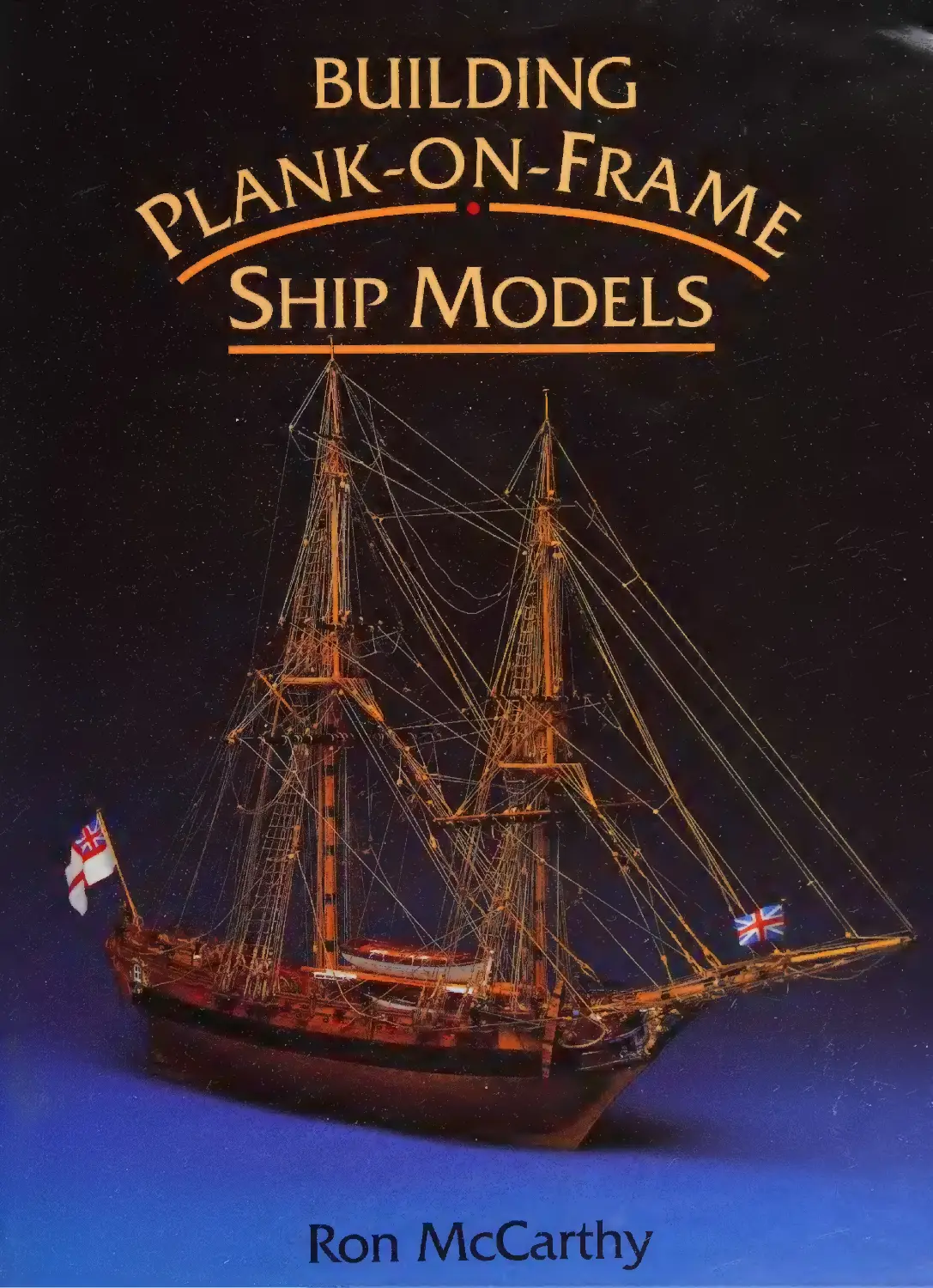
The author’ model of HMS Cruiser,
specially commissioned
for this book.
(Photographs: Michael Bassett)

£22.00 RRP

wi

$5.9

A

N 8782 AST 4 5.98 ASSTO2

BUILDING PLANK-ON-FRAME SHIP MODELS

Frontispiece: The Royal Navy snow rigged sloop
Cruiser of 1752, built to “2 scale by the
author.

BUILDING
QLANICKO-NON-F

FRA,
SHIP MODELS
Ron

McCarth

y

CONW

AY
-ii'

SY

This book is dedicated
of my wife, Eileen
whose ardent support
remained constant

to the memory
Margaret,
in this work
to the last.

© Ron McCarthy, 1994
First published in Great Britain in 1994 by
Conway Maritime Press,
a division of Chrysalis Books Ple
9 Blenheim Court
Brewery Road
London N7 9NY

www.conwaymaritime,com

A member of the Chaealis Group ple
Reprinted 2001

British Library Cataloguing in Publication Data

A CIP catalogue record for this book is available from the
British Library.
All rights reserved. No part of this publication may be
reproduced, stored in a retrieval system or transmitted in
any form or by any means: electronic, electrostatic, magnetic tape, mechanical, photocopying, recording or other-

wise without permission in writing from the publishers.
ISBN 85177 629 9

Printed in Great Britain by
the Bath Press Ltd

Contents

Chapter
Chapter
Chapter
Chapter
Chapter
Chapter
Chapter
Chapter
Chapter
Chapter

1|
2
3
4
5
6
7
8
9
10

Acknowledgements
Foreword
First Considerations
Making the Draughts
Frame Structure
External Planking
Internal Structure
Detail — Above and Below
Masts and Spars
The Standing Rigging
The Running Rigging
Some Basics on Sails
Recommended Reading

Acknowledgements

] SHOULD LIKE TO PLACE on record my grateful thanks to all those who
readily gave oftheir time, patience and erudition in helping this work into
the light of day. To my late wife, to whom this book is dedicated, for her
consistent sharing of the load to the end, and especially to John L Bowen
CEng MRINA, who not only launched me into orbit by suggesting my
name to the publisher, but remained a steadfast rock of support with his
friendly, expert advice through all aspects of the compilation. To Mr Asa
Arno of the Sjohistoriska Museet, Stockholm, for the loan of the negative
and diagram of the Chapman Cruiser masting and rigging plan. To Dr CP
van Romburgh of the Scheepvaart Museum, Amsterdam, Mr Leo M
Akveld of the Prins Hendrik Maritime Museum Rotterdam, Mr Henrik

Stissing Jensen of the Rigsarkivet, Copenhagen, the library and draught
room staff of the National Maritime Museum, Greenwich, the Admiralty
Archives Office, London, the Portsmouth Naval Base Museum, and all

those who carried out the in-depth research into the history of the sloop
HMS Cruiser of 1752.
RON MCCARTHY

Foreword

HosBiEs, I SUPPOSE, START as an ambition to make real an interest, to

transform a conception into a tangible form which can be seen, held and
felt, and be appraised by others. They are an intimate declaration of self,
and come as varied as all our diverse personalities. For my part, I found my
expression in the art of model building, and from an early age. And the
best of it has been building model ships. With the hobby, and later professional involvement, has come a host of extras to enrich my time: the study
of the social and political needs which laid the keels of the ships and sent
them on their voyages to the far reaches ofthe earth; the lore of the sea and
all the tales and fables, myths and mysteries the sea has inspired; and not
least the friendships made in the world of model making. This book is part
of that experience; it is the story of amodel ship. To take an idea, conceive
it as a three-dimensional image, and recreate in a tangible form its history
and historical context, is the core of this book. From a plank of rough
hewn lime, we can watch it take shape as a unique structure until it stands
complete, an embodiment ofthe search for perfection.
The model featured in this book is that of the Royal Navy snow rigged
sloop Cruiser of 1752, and was chosen because it is a simple example of a
single decked ship but incorporates all the structural and rigging practices
of awooden vessel which can be applied to any ship of this era.
While every endeavour has been made to include all the essential
elements of building an eighteenth-century model ship, this book itself
is only the key to a door, a door that leads to the far greater expanse of
the modelling world. It is a world in which many notable people have
contributed their knowledge and experience to the growth of model shipwrightry, and in which the products of their art grace both homes and
museums. I hope you will find there a share of all the pleasures I have
enjoyed over the many years since I laid my first keel.

FIGURE 8. Sail and rigging draught of
Cruiser, 1752, by FH Chapman. By
permission of the Sjohistoriska Museet,
Stockholm.

7

I
First

Considerations
THE Royat NAVAL snow rigged
sloop Cruiser of 1752 was built in a
year that looked both back to previous building practice, and forward
to the new. She was not a famous
ship, and did not distinguish herself
in any particular way except by hard
work and a constant call to duty. She
was like so many sloops and frigates
throughout the ages: the work horse
of a protecting navy. For most of her
career she was stationed in home
waters.

First commissioned

in 1753,

she patrolled off the North Foreland
and the North Sea, and in 1756-57,

the Downs. In June 1760 she was
recommissioned for cruising and convoy duties and remained on these duties until the conclusion of the Seven
Years War in 1763, when she was
paid ‘off in April of that year.
However,

she was

again recommis-

sioned in May and took up Channel
duties,

on

which

station

she

res

mained until 1770 when she went
again to a station off the North
Foreland/North Sea. On 10 September 1772 she sailed for North America. This brief history of her career,

together with the names of her captains,

is shown

duced

here

the

in Table

by kind

National

1, repro-

permission

Maritime

of

Museum,

Greenwich.
Her log shows that throughout her

time in home waters on patrol work
and convoy work, there was, to quote
from the many daily entries, ‘No
remarkable event to report’. It is a
story of patient duty in all weathers,
chasing off insurgent French fishing
craft and keeping a watch for smugglers, and at one time acting as escort
and baggage carrier to the Royal
Yachts. She was an integral and vital
part of the renowned wooden walls
behind which the folk of Britain
could sleep in peace and ease of mind.
In this respect she is a worthy example for a typical Royal Navy sloop
model.
On 2 October

1776, just after the

fermenting North American colonies
had erupted in their War of Independence, and some four years after tak-

ing up station off the coast of South
Carolina,

where

she had confounded

the contraband runners of that coast,
Cruiser met her end. No longer fit for
service after her prolonged years at
sea, she was ordered ‘to be destroyed

by fire’ by the Naval Commander
Chief, Lord Howe.

in

She was burnt off

Cape Fear, just south of Wilmington,
South Carolina. It was perhaps an ignoble end to a noble little ship, which
had served King and Country so well
for nearly a quarter of a century.
Cruiser’s specifications are shown in
Table 2. Five other sloops of the class,

10

TABLE

PLAN

K-ON-FRAME-MODELS

|: Station Record — HMS Cruiser

Commissioned

Captain

Station

Action or Event

WWIZ=—DD

Hyde Parker

Off Foreland

1753 Commissioned

and North Sea

1756

W Norton

Downs

1757
1760-61

B Hartwell

Downs

1762

C Leslie

P Forbes

1763

1763-65

J Macbride

1766

C Roche

1767-69
1770

J Brisbane

W772

J Cumming

1773-74

1775-77

Channel

Commissioned June ’60
Cruising and Convoy
Cruising and Convoy
April Paid Off
May ’63
Commissioned

R Keeler

North Foreland

and Dungeness

10 Sept °72 Sailed for
North America

Tyringham Howe

N Carolina

F Parry

Disposal

Burnt off South
Carolina 1777

By courtesy of the National Maritime Museum, Greenwich.

TABLE 2: Specifications — HMS Cruiser
Class:
Gun deck:
Length of
keel:

Snow Rigged Sloop

Beam,

20ft 7in

75ft Gin
62ft 3in

overall:
Beam,

20ft Oin

moulded:

Depth:

Oft 4in

Tonnage:

141 tons

Armament:

8 X 3pdr carriage guns

Complement:

80 men

10 swivels

TABLE 3: Sloops Laid Down 1752-54
Ketch Rigged
Speedwell

Built
Chatham

21 October

Fly

Portsmouth

Happy

Woolwich

9 April 1752
22 July 1754

Ranger

Woolwich

7 October 1752

Snow Rigged
Wolf

Built

Launched

Chatham

24 May 1754

Launched
1752

FIRST

laid down for the 1752-54 Establish-

as a ship, would be similar to that shown here.

Drawing reproduced from The Royal Yacht
Caroline 1749 by Sergio Bellabarba and
Giorgio Osculati, by courtesy of the
publishers, Conway Maritime Press.

FIGURE

1. HMS

Cruiser, as converted to a

Hl

vl

|

\

||

\\
li}

AN

However,

brig-of-war later in the century, the

trade and commerce. For this reason
the Admiralty felt the need for fast,
shallow draught ships that could
carry out a policing role around the
most vulnerable stretches of the
coast, notably the Channel and Foreland Stations, and this was the priority given to the shipyards in these
middle years of the eighteenth century. There was also a desire on the
Admiralty’s part to seek the best design of hull and rig for that duty,
resulting in much experimentation.
In this search for improved hull and
rig forms, Fly was based on the
proven design of the captured French
74 gun vessel Monarch and ketch
rigged, while Crawiser was based on
the proven qualities of the Royal
Yacht Caroline, built at Deptford in
1749, and was snow rigged. But not
for long. With the Admiralty experi-

++

WN

|

)

=

|

continuing,

Cruiser was

|
|

|

=

me

\||

\|

:

i

if

—

=

alt

=

\

:

}

Ll

later,

in December 1753, given a mizzen
on her short quarter deck and was
ship rigged. This proved so successful
that ketch rigged sloops fell completely out of favour, and the snow
rig to a lesser extent, in a marked

(| |

i|

WR
\ \

preference for the ship rigged sloop.

These ships have an interesting
historical background. They were
born of the prevailing political situation, namely the French and Austrian Wars.
The
prevention
of
smuggling and the discouragement

ments

ship rigged sloop, 8 December 1753.

il

ment, are shown in Table 3.

of French privateers were paramount
in protecting the realm’s legitimate

FIGURE 2. Royal Yacht Caroline. The run of
the rigging on Cruiser, especially when rigged

CONSIDERATIONS

E

ce |

with

the

advent

of the

snow once again came into its own. A
profile of Cruiser stepped with a

mizzen is shown in Fig 1. Caroline
was, of course, ship rigged, as shown
in Fig 2.

While Cruiser as a named and specifically classed vessel may be an ideal
subject for the shipyard plank-onframe construction outlined in this
book, it may not be everyone’s idea of
the type or period of ship with which
to begin. Before proceeding with the
construction of the model, it is as well

to consider
chosen.

why

Cruiser

has

been

Motivation and Objectives
Many beginning modellers will already have a preference for a particular class of ship and period. It is
worthwhile to consider the pros and
cons of various types of vessel. One
might initially be drawn to a famous
named ship, such as Santa Maria
1492, or Golden Hind of 1578,

of
or

Endeavour of 1768.
Or perhaps the choice will be inspired by a particular rig, such as a
schooner, brig, ketch or ship; or by a
particular type, galleon, galley, herring bus or carrack. Whatever the option, the pages that follow will help
you to reach your final goal.
The term ‘prototype’ in modern
usage is used for the full sized ship on
which a model is based. To my mind
there ts much misuse of this word today. The Thorndike Dictionary defines
it as the absolute original, and gives as
an example ‘The prototype of a present day ship is a hollowed out log’.
This I can go along with as it fits my
conception of the word. However, to
save confusing both myself and my
readers,

J will use

it in its modern

idiom. That said, I prefer to use the
terms which I consider more definiSeale in feet

a
ll

tive, and have talked here of either a

12

PLANK-ON-FRAME-MODELS

‘representative model’ of a given class,
or a model of a ‘named ship’. It is
clear that there are two roads down
which the modeller can go, and it is a
choice that must be taken early in the
proceedings to avoid disappointment
later. There are advantages and disadvantages to both, and we will examine
their respective merits, starting with

the named ship.

The Named Ship
To give some consideration to a
named ship, I once decided to make
six or so plank-on former models of
Santa Maria as a commercial project. I
maintained that as little or nothing
was known of this ship so named the
models need only be based on the
popular conception. In this respect I
thought I was on safe ground. At the
time there were many kit forms of
various quality available to the public,
all claiming the name Santa Maria on
their boxes, boldly and without hesitation. Mostly, they followed the
1892 reconstruction of the ship as a

twentieth-century
research __ the
model was rerigged and apologies
made by the museum in their catalogue for the erroneous hull construction. A later replica, built after
research by Guillen in 1927, took the
form of a caravel, not a nao; a further

replica was made in 1963 after
research by Martinez Hidalgo, and
reverted to the original conception
of the ship as a nao. This nao differed considerably from the 1892
version, not only in its rig and sail
arrangement but also noticeably
in its hull construction. Other ideas
of Santa Maria’s form of rig and
build can be seen in paintings, such
as the one by the Dutch marine artist Cornelis de Vries. These differences of construction can be seen
in Fig 3.
As well as Santa Maria as a named
ship, with little or no authentic data

to support the claim of a name, many
other ships fall into this category,
though some have far more claim
than others, such

as the famed

and

nao as conceived by Fernandez Duro,

celebrated Mayflower replica sailed to

with some adaptations peculiar to the

Plymouth,

kit designers. One, I observed, had a

mander Alan Villiers in 1957. The
difficulties of research raised in building this replica are fully outlined in
the book The Voyage of Mayflower II by

wheel on the poop, which was also out
of scale, if ithad a scale that could be

trusted. But then this was a fun aspect
of the business. After much delving
into researched material on Santa
Maria and especially following the excellent work by Xavier Pastor in his
book The Ships of Christopher Columbus
(Conway Maritime Press), which was
published at this time, I decided I
could not continue

with the model,

and relegated it to a ‘typical late 15th
century Nao of Western origin’. This

was about as far as I could go and
retain any claim to be _ honestly
authentic.
A model of the 1892 Duro replica
of Santa Maria, presented to the
Science Museum by the Spanish government, was put on display to the
public. However, in the light of

Warwick

Massachussetts,

Charlton

by Com-

(Cassell),

and

demonstrate yet again how difficult a
claim to a name can be.
On the bright side, many named
ships are well documented and have
been extensively researched and, naturally, the closer we come to our own
period the easier the task becomes, as
far more documentation survives together with authentic draughts drawn
up by naval architects and kept in the
archives of the world’s great maritime
museums.

Here,

too,

can

be found

surviving contemporary models together. with their researched history,
an authority that can confidently be
relied on. Trouble may arise, however,
when these draughts are taken up by

FIGURE

3. Santa Maria. These three versions

of the Santa Maria illustrate one of the

problems encountered when dealing with
famous but poorly-documented ships, and
could arise with other ships for which no plans
exist, such as Golden Hind and Mayflower. 1. As
conceived by Fernandez Duro as a nao, 1892.

2. As a caravel, by Guillen, 1927. 3. The
replica as researched by Martinez-Hidalgo,
1964. Drawings reproduced from The Ships of
Christopher Columbus by Xavier Pastor, by
courtesy of the publishers, Conway Maritime
Press.

ee

private firms in the business of supplying model plans, who use copies of
them as a basis for their own marketing sales. Here the model builder’s
own evaluation of their authenticity
must prevail, either by carefully studying the published catalogues, or by
gaining confidence in the draughtsmen they sponsor. There are publications which offer these recommendations and comments, but in the final
analysis it is wiser to arrive at your

own assessment.
There is yet another pitfall for the
named ship, which is that while the
plans for the ships may be fuily authenticated, drawn up by the most reliable of marine draughtsmen, they
may only depict the ship as she was at
a given period. It is as well to establish
this period. Normally, the plans are
taken from builder's draughts and
show the ship as launched. However,
it must be remembered that in the life
of a ship many alterations can, and
often do, take place. Also, in seventeenth and eighteenth-century sailing

ships, including Royal Navy ships, the
rig of the vessel was at the discretion
of the captain. This was especially so
with such sails as drivers, trysails and
flying kites rigged once the vessel was
at sea. Many arrangements of the gear
and tackles were unique to the captain. This was still very much in
vogue up to the last days of the sailing
era. To take Columbus as an example,
he changed the rig of Pinta from a
lateen rig to a square rig just before he
set sail to cross the Atlantic. On the
whole, the named ship model needs to
be researched far more thoroughly
than the representative model, and all
data obtained authenticated to ensure
that the plans used are absolutely true
and genuinely accurate, and that
where alterations have cccurred they
are annotated. Even then, the plans
should only be used in conjunction
with the findings carried out in recent
research, for many plans on _ the

FIRST

CONSIDERATIONS
ee

13

market today were drawn up decades
ago, and modern maritime archaeological finds are altering our ideas on
rigs and constructional practices considerably, especially since the raising
of Wasa and Mary Rose.

The Representative Model
With the representative model there
is not so much concern with the detail
of the particular ship under construction as with that detail’s historical accuracy. This is just as important
for the hull construction as for the
sails and rigging, and for such incidentals as the binnacle. In this respect
a far deeper knowledge is required of
maritime history and shipyard practices than for making a named ship
model. In the latter, much of the con-

structional work and detail of deck fittings would have been carried out by
the naval draughtsmen whose drawings are being used. But a representative set of draughts may have a
tendency towards ‘poetic licence’,
which can result in additions or rigs
being incorporated which are completely out of period. Models built
from such sources lack the discipline
of the named ship, where only that
which is known to have existed is
built in.
It is true that minor embellishments
of detail can be set on the model of a
named ship, but these are strictly lim-

ited. Even so, care must be taken that

they are in period. For example, fire
buckets,

fore channel

heads,

boxes and oil lamps, amongst
other items, can be added

lifebelt

many

to named

ships, none of which may appear on
the draught, but all would have been
expected

there,

and

all

strictly

to

period. The point is that without the
strict discipline of the named ship there
is a danger of ‘gilding the lily’ or,
worse, a runaway pandering to particular whims and fancies.
To cite an example of this, I once
built a representative model of a Queen

14

PLANK-ON-FRAME-MODELS

1. Model of the Egyptian Queen
Hatshepsut’s ship, c.1500 BC.

Hatshepsut ship, an ancient Egyptian

ern parallel Manfred von Richtofen’s

vessel of 1500 BC (see Photograph

all-scarlet

1). The only authority for this vessel

flew for a time in the Great War of
1914-18, the pilots of his squadron
all chose their own brazen colour
schemes; so one can easily imagine
ancient Egyptian captains with their
flamboyant love of colour being

was from the ships depicted on a
relief in the temple of Queen Hatshepsut at Deir-el-Bahri, at best a flat
profile view. An exhaustive study of
these ancient ships by Bjérn Landstrom published in his book Ships of
the Pharoahs, unfortunately now out
of print. But as there was such a
paucity of information for the final
appearance of the ships, it left a wide
scope for speculation and interpretation. In view of this, great care had to
be taken not to run amok. I have
seen some three or four models of
this ship, no two of which are in any
way the same. Different interpretations have been made not only on the
final colour schemes and decoration,

but also on the shape ofsteering oars,
the fore stage and stern stage rails,
and the angle, sweep and height of
the stern, and in particular the variation in the Lotus Flower trumpet
shape over the stern. In actual fact it
is not particularly important that any
of the models is entirely correct or
incorrect, as these Egyptian vessels
would have varied just as much
in real practice. If we take as a mod-

much

Albatros

of the same

DIII,

mind,

which

while

he

the

shipwrights themselves would have
added their own touches. The important point is not to overdo it but
to keep it in context, be consistent
and in tune with the period. None of
the models of these ancient Egyptian
craft I have seen looked incorrect, or

out of place with their final finish.
All seemed to portray exactly what
they were meant to be, though, as I
say, no two

were

the same,

and all

had arrived from the same single
basic profile relief.
So there is a need, with the representative model subject, for a sensitive
understanding of the period, and a
good acquaintance with the historical
background in both social and political spheres, all of which can influence
the final finish of the model. There is
a strong feeling amongst some model
builders that there is nothing as uninspiring as a faultlessly crafted but

FIRST

characterless model ship; one that
says nothing at all about the person
who made it. For example, who can
ever fail to recognise the stamp of a
Norman Ough warship? With the
representative model there is a wonderful opportunity to impart to it
much of yourself, but at the same
time ensuring that it is tempered with
some modesty and much moderation.

Structure
Here there are fundamentals that cannot be baulked. Before attempting to
build a model ship in any way, the
basic elements of the ship’s construction should be studied. In our
case, as we are talking about wooden
vessels of the mid-eighteenth century,
it would be a distinct asset for the
model builder to have a working
knowledge of the building practices of
that period. Only then can corners be
cut and a move made towards an individual concept of design structure,
whether moving from the confines of
a precut and prescribed kit assembly
to scratch building, or, as my path
took me, from the carved hull to the

framed one. For me it was a rude
awakening into the many rules and
regulations that govern the structuring of a ship, be it a barge or a deepwater carrier. In the case of a navy
ship, many of these rules have long
been laid down by Admiralty Board
Specifications. In the case of merchant
ships, by Lloyds from at least the middle of the eighteenth century, and
more lately, of course, by the Board of
Trade,

and

it is as well

to become

acquainted with them as they may apply to the ship being considered.

Scale
Having decided on the vessel to be
made, be it a named ship or a representative model of a class or period, the
matter of scale must be considered.
Miniature

models

are

a fascination,

and are a study in constructional tech-

CONSIDERATIONS

15

niques in themselves. No such complete fine work is intended for these
pages; there are books devoted to this
art written by the experts in it, and
currently

available.

However,

that

said, there is much work about a large
scale model which entails fine work
practice. For instance, a model anchor
winch can consist of several dozen
parts of finely executed work. Where
occasion merits, such miniature modelling is often desirable for good
effect.
The scales to be considered are
what are termed the workable ones:
anything from Yicin to the foot to %in
to the foot will produce something
that can be accommodated in the
home and be easy to handle.
Taking this loose formula as a
guideline means that a scale is largely
determined by the overall size of the
vessel on which the model is based. A
model of a small cutter could comfortably be made to a much larger scale
than, say, a model of a 72 gun ship.
As far as Cruiser is concerned,

with a

gun deck of 75ft Gin, a working scale
of 6ft to lin, or 1/72 scale, is ideal as
this produces a model of about 14in
for overall length of hull; not a large
model to contend with, and one that
should sit neatly in any home. At the
same time, the detail is large enough
to

work

without

trouble;

for

such

items as the ribs and trucks of parrels,
the truck would be something like a
millimetre across with a No 75 hole
drilled through the centre. Also sheet
blocks and buntline blocks can hold
their distinction in this scale quite
easily. Anything larger, and these
items would need to be very carefully
executed, while anything less than
1/96 scale would prove troublesome
to represent with conviction. All these
points should be borne in mind when
deciding on a scale.

Presentation
When constructing a plank-on-frame

16
PLANK-ON-FRAME-MODELS
eee
ee

2. Model of the Swedish warship Wasa (1628)
in the Science Museum, South Kensington,
London.

model as built by shipyard practice,
much of the fine work involved will
not be seen in the finished model.
This is a continuing dilemma for
model shipwrights. One answer is the
Navy Board model, which leaves the
frames below the wale without the
strakes, and much of the deck planking not placed, to expose the structure
of beams, carlings and lodging knees.
Although Navy Board models, with
their unique framing and their purpose, are a set apart from our concern

here, a lesson can be taken from them

inasmuch as the model constructed in
accordance with shipyard practice can
be left bare of strakes and planking in
the same way for presentation, and if
desired left unmasted

and, of course,

unrigged. Models made to hull only
stage, and cased, can be a great
attraction.
Another method is to use the partly
exposed
commercial
exhibition

approach. Today, this is much exalted
by travel agencies, and formerly by
tourist shipping lines, to display to the
public the commodious and comfortable accommodation on board their
vessels, be they Rhine river craft or
Baltic ferries. There was also an
Endeavour model of this nature in the
National Maritime Museum. With it
the model maker can enjoy the best of
both worlds, but is regrettably left
with an incomplete ship’s model, one
half of the model not only being bereft of strakes and wales but the
frames as weil, leaving an uninterrupted view of all decks and their details. A fine example of this is Harold
M Hahn’s model of the schooner
Halifax, which can be seen in his book
The Colonial Schooners.
Another idea used to display hidden work is the use of removable sections, either horizontally by removing
the whole upper part of the hull from

SS
re

just below the chain plates, or a vertical slab of the hull taken from between the fore and main channels. In
either case this can expose the model
to much damage and eventual wear
and tear at best, and leaves little satis-

faction for the cost of time and effort
in that the first device only exposes
one more deck, while the second exposes only parts of others, at the same

time running the risk of a seriously
injured eye from a yardarm while venturing to peer into a dim interior. A
more ingenious solution can be seen
in the Science Museum’s excellent

3. The spy hole lens viewing system outside
the case of the Wasa through which the viewer
may see the internal structure of the model.

model of Wasa. Here they have provided the public with a spyhole telescope arrangement on the outside of
the case, so that a lower gun deck can
be viewed in its entirety, complete
with cannon and crew (see Photographs 2 and 3).
The most successful and convincing
method of exposing some internal
work which would otherwise be concealed has been accomplished by
showing a model in a dockyard scene,
where it is either near completion or
in dock for some repair to the lower
hull requiring the removal of several
strakes. One of the best of these is
Harold M Hahn's Schooner on the
Stocks, from his diorama now in the
Mariners’ Museum, in which he shows

several schooners in various stages of
construction. Perhaps there is room
for compromise here just to show one
ship very near completion. There are
many convincing examples of the ship
in for repair, with the ship on the
stocks, and the removed

strakes laid

out in the yard.
Another way of showing detail is by
a photographic record of work carried
out, compiling an album of photographs showing the progress of work
from keel to completed model, with
some caption comment to each picture,
and logging a date. There is a danger
that if a roll of film does not develop
successfully, by the time the end of the

FIRST
eeCONSIDERATIONS
Le
ed

17

roll has been reached much of the work
photographed will have been concealed
by the progress of construction, or lost
in the maze of rigging. Where rigging
is concerned a photographic record of
work can be greatly enjoyed, as a carefully made euphroe or gammon rack
block can be shown as a set piece before it becomes merged with the
whole, as can the internal arrangement
and detail of ship’s boats if covers are
eventually fitted, or one boat nested
inside another.
When I built my Endeavour (Photograph 4), I fitted all decks and
bulkheads to the cabin accommodation. All are concealed, but I have the

smug satisfaction of knowing they are
there. Like possessing a secret. But
with this perversion comes a guilt
complex. Knowingly to ignore a mistake deep within the hull, though
never seen, would haunt me for ever.

It would have to be corrected before
being sealed away. Also, it must be
remembered that with modern medical technology, flexible searching rods
complete with lights and miniature
television cameras can not only photograph kidney stones 7” sztw but search
into the innermost parts of a model
ship and discover the wood shavings,
sawdust and lost belaying pins which
may be lodged there, thought by the
modeller never again to be seen.
With

the Endeavour model,

I have

left all the hatches open so that something of the lower decks can be seen.
It imparts a sense of depth, and a feel-

ing that something is going on there;
that the hatches are leading somewhere below. The forecastle reflects
light from behind the open gun ports,
and from behind the glazed ports and
windows,

while

the model

itself re-

tains a completeness.
In the end it is a highly individualistic choice, with a strong case for

personal preference, and what may be
a desired effect with one model may
not be so with the next. The Cruiser

18
PLANK-ON-FRAME-MODELS
18
PLANK-ON-FRAME-MODELS

model will be completely planked,
though some hatches may be left open
to show there is a below deck.

Work Place
One of the main attractions of building a plank-on-frame model is that
only a small space in which to work is
needed, such as a desk or side table in

a convenient position, preferably near
a window for natural light and where
work can be left without fear of it
being disturbed. If we consider the
fairly large scale chosen for Cruzser,
and that the hull at this scale will not
be much over a foot long, the frames
are going to fit into the palm of a
hand. As each frame is made up of
several parts, each component is
going to be very small, easily worked
on a work surface top of some 4ft x
2ft. An ideal item for this is a pedestal
desk, which

has several

drawers

on

each side of the leg space to house all
the tools likely to be needed for such a
model.
The tools required for the built-up
model are few, and for the most part
inexpensive, though some items may
be costly, such as power driven tools.
An

electric

fretsaw,

a Dremmel,

is

shown in Photograph 5, but there are
others on the market. More convenient and less noisy are the small piercing saw or the deep throated fretsaw
(Photograph 6). The 3in Petite circular saw seen in Photograph 7 is a definite asset.

However,

Ysin sheet lime

can be stripped down just as successfully with a craft knife and an
18in or 24in straight edge. Neither of
these electric power tools is strictly
essential; indeed their hand operated
equivalents may be preferred if you do
not care for noise. Or a low powered
(12-14

volt) DC

lathe arrangement

can be used (Fig 4). This tool may not
be called into service much in the
early stages but will come in useful
later for such fittings as tillers and
helms, balustrades and capstans. Most

have an extension for finishing off
masts and spars.
Needle files (see Photograph 8)
are essential for shaping, especially
when blockmaking.
Apart from
their various shapes, they come in
several cuts, from rough to fine, and

in a range of lengths from 3in to
Gin. Their quality depends on their
price, and in their quality their accuracy. Obviously, good quality
files, costing up to six times the
price of a cheap one, should not be
used for cleaning up a soft solder

4. 1/72 scale model of the bark Endeavour
(1768) built from Admiralty plans. The rigging
was based on information contained in the book
Masting & Rigging of English Ships of War
1625-1860 by James Lees (Conway Maritime
Press, London 1984). The hull was built of pine,
on the bread-and-butter system of waterline
sections, and carved to frame thickness inside
and outside. It was planked in spruce. All decks
were fitted, and the accommodation bulkheads
are complete with their doors. Little of this can
be seen except through the hatches. The blocks
and parrals were of boxwood. The model, which
was completed in 1989, was spray finished in
eggshell varnish.

FIRST

5. Electric fretsaw with an adjustable table,
the desirable feature of a long throat, and a
power take-off socket to which a flexible drive
to take sanding, drilling and grinding
assessories can be attached.

7. Miniature electric (12-volt) circular saw with,

toothed tenon saw. Top: deep throat fretsaw
and inside a junior hacksaw. Centre: brass-

/eft, a transformer fitted with an overload cut-

backed jewel saw. Bottom: piercing saw.

for cutting wood, metal and plastic and can cut
wood up to about “icin (4.5mm) thick.

out device. It can take various blades suitable

FIGURE 4. 18 volt, 3 amp DC Mini Lathe.
stock

3. Chuck with
various-sized

collets
5. Cable to
transformer

7. Clamps

2. Stainless rods 16
inch extensions

4. 18 volt, 3 amp DC

Oo
WD
WO
F&F
HGH
OO
On
:

ae,o

motor
6. Cast metal head
stock

19

6. Useful saws. Left: short, brass-backed, fine

i

1. Cast metal tail

CONSIDERATIONS

12

,

eee

8. Swiss needle files. From the top: triangular,
knife, round-edge joint, crossing, barrette,
hand, half-round, pippin, slitting, round,
square, and warding.

joint as the file becomes clogged
rapidly, while for shaping a 1/72 scale
buntline block only the very best will
suffice.

Sources of Tools
Tools and accessories can be gathered
from many sources, most of them remote from model building. In the display of tweezers (Photograph 9), for
example, the 10in forceps are from a
supplier of entomological equipment.

A catalogue from a specialist supplier
will prove very useful for finding
other items that can be used in model
work. The flat spade ended forceps
are designed for plucking eyebrows,
and can be bought from a chemist.
Photograph 10 includes a Spencer
Wells artery clamp, a scissor-like instrument with locking handles, which
can be obtained from a supplier of
surgical instruments. Amongst the
pliers are those used by professions
such as dental mechanics and instrument makers. The very useful probes
can be obtained from those discarded
by a dentist. A selection of essential
pliers and cutters can be seen in
Photograph 11. Amongst the pin
chucks (Photograph 12) are three
slender examples, as used by dentists,
which are useful for drilling a hole in
an awkward recess in a ship’s model.
For removing dust from a model —
and they do get dusty whilst under
construction — a ladies’ face powder
brush is ideal. The point is to develop
a keen eye for such items either when
window
shopping,
or
browsing
through the advertisements in the
large range of magazines now published, including those for the model
builder. Other useful sources are
newspaper small advertisements, car
boot and garage sales, jumble sales
and flea markets.

20

PLANK-ON-FRAME-MODELS

9. Tweezers. A. 10in (250mm) crocodile.
B. Nipping, with curved point. C. Pointed,
available with various end grips from wide to
narrow. D. Flat spade. E. Curved pointed.
F. Curved spade.

10. Miscellaneous tools. A. Curved and
straight tinsnips. B. Surgical artery clamp.
C. Dental probes. D. Vernier scale sliding
calipers. E. Entomological head sprung
tweezers. F. Miniature G clamps.

Finally, there is the home produced
preduct. The first of these is the sandpaper stick. It is simply a trued up
strip of durable wood of any length
from Gin to 10in, of about lin x “iin.
Both flat surfaces of the strip are faced
with sandpaper, either middle 2 or a
grade of your choice. It is essential
that the sandpaper is glued under
pressure to ensure a perfectly flat and
even surface. The edges must be kept
absolutely square and the sandpaper
trimmed sharp and clean. With this
tool the smallest work can be shaped
up with great precision. Another
home produced item can be a dowel
or draw plate. These items are extremely expensive to buy and, for the
purpose of making trennals, quite disproportionate to the need. A suitable
plate can be made from a piece of

and a two-litre ice cream container is
ideal for holding rigging material.
Similarly, a filter case, discarded from
a computer processing unit, is ideal
for housing needle files as it is made of
many corrugated and padded layers
into which the file handles can be inserted (Photograph 13).

sheet steel or an old steel rule, which

is drilled through with a series of holes
from '/2in to “in, countersinking all
holes on one side to give a sharp edge.
By clamping this plate in a vice and
drawing a split cane through the holes
in a diminishing progress, a few feet
of trennals stuff can be produced in a
few minutes. When the holes become
blunted it is a simple case of drilling a
new set. Other home produced items
are clamps and jigs, which can be made
from clothes pegs. Salvaged plastic
containers can be used for storage,

11. Pliers (all about 4in or 100mm long).
A. Round nose. B. side and end cutters.
C. Nipping head and pincer head. D. Long
nose, angled. E. Flat spade nose. F. Pointed
nose.

Timbers
For the best model work, wood with-

out any apparent grain or figuration
should be used. The best woods for
this are the traditional ones of the
fruit variety, and of course, lime and
box. This is to keep the appearance of

the timber work in scale. Many models, perfect in every respect, are spoilt
by the use of timber such as black
bean, which is dark brown with black

figuring streaks and curly mottles.
Such figuring may look fine on a piece
of furniture but rather begs credibility
on a model. Naturally, timbers with
an open or rough grain should be
avoided.
The timber used in the shipyards at
the time Cruiser was building was also
traditional, being mainly oak for all
the framing and outer skin of strakes
and wales. The keel would have been
elm, which although highly susceptible to the Lyctus beetle is very durable under water, and was also used,
hollowed out, for the bilge pumps. As

12. Pin chucks, etc. Top: Miniature lin
(25mm) vice with, immediately below, a brass

pin chuck with reversible head. Middle: Three
standard type pin chucks. Bottom: Three dental
pattern pin chucks.

FIRST

CONSIDERATIONS

21

it does not splinter finely, it was also
used at times for the gun decks. For
lining the gun decks, pitch pine would
have been used, and also, sometimes
with fir, for the bulkheads. Like the

other

woods,

pitch

pine

is heavy,

being around 41]b per cubic foot, and

13. Method of storing needle files. The holder
in which the files are placed is a filter from a
computer main unit, comprising a plastic box

fitted with corrugated aluminium interspaced
with felt.

being heavy, dense and tough with a
high resin content, making it resistant
to moisture. None of these woods is
suitable for model work.
Returning to the built-up model,
boxwood
is the most frequently
chosen material. This is a hard, light
yellow wood, with a uniform grain
without any distinction of rings, swirls
or figuration, and is ideal for the built
up ship model, equal for framing,
planking detail, and masting. The
best quality being up to 70lb per cubic foot, it is difficult

to work

and

needs the hands of the experienced for
its best effect. Cherry is another favourite, with the same qualities as box
and the advantage that after immersing in water it takes on a brownish red
colour which can be very pleasing in a
model. Apple is more plentiful than
pear, but both have the same advantages of a fine grain without mottling
or figuration. The model of Wasa in
the Science Museum is made from
pear, and shows this wood to good
effect when handled by an expert.
An ideal wood for the Cruiser model
would be English lime. This is a
tinted, pale brownish to white wood,
and lighter in weight than those mentioned above, being on average about
351b to the cubic foot when seasoned.
It is straight grained, without figuration and easy to work, and is
especially suitable for carving as it
cuts clean, deep and sharp without
splintering, in any direction. Care
must be taken as it sands rapidly, but
it leaves a smooth, silk-like finish. The

one snag with lime is that it is highly
susceptible to woodworm, but if this
penalty is recognised at the outset and
preventative
taken
by
measures

14. The half cubic foot of English lime wood.

applying a good soaking of a preServative during construction, the problem
should not arise. A cu ft lime plank
was purchased from which to cut the
material for Craiser (Photograph 14).
Not everyone will have access to a
circular saw bench with which to cut
such a plank into suitable sizes, not
just for one ship, but also for a good
reserve of stock. The material for

BD

PLANK-ON-FRAME-MODELS

A useful little information sheet on
rope making is given to visitors at the
ropery at Chatham Historic Naval
Dockyard. A ropery has stood on the

grey or brown for rigging. Rope
making can be done at home on a
suitable self-made rope walk, but a
description of this practice would require a chapter in itself; a drawing of a
typical rope making machine is shown
in Fig 5.
Another item for which to keep an
eye open is sail making materials.
Sails can be made from both paper
and cloth, but once again scale should
be the main consideration. So many
models, otherwise perfect, have been
made ridiculous by sails made up not
only with out of scale stitching but
out of scale material. If scaled up,
these sails would have a thickness of
several inches and stitches of over a
foot in length.
Finally, we come to consider glues
and varnishes. Today there are glues
on the market for every conceivable
purpose, from wood through to glass
and die cast metal. All are useful
somewhere around the model during

site since 1618, and one is still in use

construction,

and there is no better

today. Flax, jute, hemp, sisal and cotton have been the mainstay of this
trade. Their natural fibres are very

advice

to become

Cruiser will not amount to much more
than Yscu ft. These planks are not sold
in much less than Y2cu ft pieces but it
is by far the cheapest way to buy timber. For those without these facilities,

cut sizes of most of these woods can
be obtained from model supply shops,
which also often advertise their products in model maker magazines. A
typical extract from a recently obtained list of cut sizes of lime sheets
suitable for the built up model is 4in x

36in, ranging in thickness from Y2in
to Yin. Prices, of course, will vary
from vendor to vendor, and it is worth

checking which ‘lime’ it is: it can often
be American Bass, which has neither

the quality nor
English lime.

the workability

of

Other materials

strong when wet, have little stretch,

and can tolerate extremes of temperatures. Today, nylon, polyethylene and
polyester are counted amongst rigging materials used. All these fibres,
natural and man-made,

can be used

by the model shipwright, though sisal
and cotton should be strictly avoided.
Most rigging bought from a supplier
is hemp, and comes in a good range of
sizes from 0.10mm to 4mm or 5mm.
It is best to buy it wound onto a reel,
as winding from the hanks can become a frustration of tangles; many
modellers, however, like to hang the
hanks with weights for a few months

to stretch them. Man-made fibre
threads can be obtained from departmental stores and fishing tackle
shops, and white nylon can be dyed

with

than
them

all.

acquainted

However,

White

Woodwork adhesive is ideal for most
gluing as it acts as a filler for loose
packed joints and does not need to be
set under pressure. Properly applied,
it is stronger than the wood it joins.
Similarly, there are now a number of
polyurethane varnishes on the market, which come both in clear and in
various wood effects, matt, satin or

gloss finish. They are intermixable, so
the scope for variety is enormous. Apart from finish, they act as a sealer and
preservative, and for this reason
should be applied inside the hull and
on the underside of decks. Applied in
several thin coats these varnishes
spread well, leaving no drag, and provided each application is rubbed down
lightly with fine sandpaper and each
coat is allowed to dry hard. For a
spray finish they are ideal.

FIGURE 5. An example of amodel Rop
. Sprung tensioned
. Fixed hook thread
. 4- to 6-foot base
for Rope Walk

4. Traveller riding

iS)ret)

Making
the Draughts
DRAUGHTSMANSHIP

IS AN_

integral

part of the model shipwright’s makeup but he or she does not need to be
an accomplished draughtsman. Absolute accuracy of the measurement is
the order of the day, coupled with hair
thin lines. Add to that a competent
understanding of scales, and the conversion of scales, and the battle has
been won. Presentation is not important: even drawn on wallpaper or a
page torn from a scrapbook, a drawing is an asset to assist in the construction of a ship. When that use has
passed, so will any reason for keeping
it (although, of course, it is wise to
keep if there is a chance it will be
needed on another occasion). To help
with this, a scale card can be very useful. This is a table of scales worked up

for a particular model, and can have
infinite use on, for example, ships
built to a consistent 1/72 scale. The
table acts as a ready reckoner of full

chemist) are very useful. A few
touches of the pencil point to one of
these soon restores that essential
point. Alternatively, any small pad of
fine sandpapers will do the job.
In the course of building Cruzser’s
carcase, everything will depend on the
accuracy of the draughting of frames
for cutting, as well as on the fretting
of the frames themselves and their
precise placement from a construction
draught. It is not wise to accept without question a set of drawings from
which to build a particular model.
These draughts should be used purely
as a starting base, and even the very
best should be checked thoroughly for
TABLE 4: 1/72 Scale

Full Size

Scale Size

6ft

lin

3ft

Yoin

2ft

Yi 2in

size to scale size, from 6ft down to a
fraction of an inch, and consulting it

lft Gin

Y21n

lft

Y2in

saves much reworking of the scale
when dealing with any part of the

Yin

Yrain

Gin

Yin

construction; Table 4.

4

Yisin

When working to the fine lines required for a draught, a sharp pencil,
honed to a needle point, is a prime

3in

Yrain

Lin

VYisin

Yin

Ynoin

tool. For this, cosmetic emery

Ysin

Yig2in

boards

(cardboard nail files obtained from a

tOXx

PLANK-ON-FRAME-MODELS

contradictions or for errors of rig
which have emerged in the course of
modern research carried out since the
draughts were made. An example of
this is the sail and rigging plan of
Endeavour, obtained from one of the
most reliable sources in the model
maritime world. The drawing was
made many decades before, and its
author long passed on, but in the light
of modern knowledge the draught is
at great odds with what is now considered correct. In the past two decades so much has been achieved by
marine archaeologists and_ historical
maritime researchers that much opinion and concept has been changed,
even in the last decade, and the conse-

quent publications are wide-ranging
and numerous.

Remember,

however,

that the model builders of the past
were not so fortunate, either from the
volume of work or its easy access by
price. Many early modellers trod a
lonely path, and although many still
work alone, they now have the privilege of a tremendous back-up from an
international band of model shipwrights, all freely exchanging their
ideas and expertise through such jour-

nals as Model Shipwright, not to mention the help given by all the
maritime museums around the world.
Such is the scene today for all who
wish to avail themselves of it.
What, then, if a set of draughts can
be obtained to cover all likely needs?
A search through two or three of the
many catalogues and lists of plans to

though very expensive if all five or six
sheets are purchased. However, in
seeking a full set, one is severely restricted in choice; not only on the era
and class of ship but, more importantly, on the choice of scale. Much
better by far to acquire a little skill in
draughting up one’s own requirements from any given lines draught:
then the whole panorama of maritime
history, with its ships of any age, is
there for the choosing, and the task
becomes infinitely more interesting
and rewarding.
The National Maritime Museum
has a million such draughts, which
have always been available to the public on request, and in addition they
can supply complete sets of draughts
ofspecially selected ships at very reasonable prices. However, the fact remains that the vast majority of those
of the wooden ship era are lines and
profiles only due to the fact that sail
and rigging plans and those of spar
details were rarely made and very few
survive. The Museum provided a copy
of the Admiralty Draught lines and
profile of Cruiser of 1752, reproduced

in Fig 6.

I was fortunate in the choice of ship
as the subject for this book as the
mid-eighteenth century was a time of
change and experiment, not only in
England but with all the then great
naval powers of the western world.
The avant-garde naval architect of the
day, Fredrik Henrik af Chapman,
came from Sweden. That he designed

hand, whose sources are listed in the

Wasa,

current

discredit to him but to the powers of
his time insisting on an extra lower
gun deck against his advice. Chapman
(he had an English surname because
his father was an émigré Yorkshireman) came to England in the 1750s to
study English shipbuilding methods,
which was very fortunate from the
naval historian’s point of view and for
many a latter day model shipwright,
for he drew up numerous draughts of

maritime

modelling periodi-

cals, will reveal a number of full set
attractions. A few amongst the many
draughts offered are sets that consist

of a lines drawing, a profile or
arrangement, a sail and rigging plan,
a sheet of detail and spars, and a construction draught with perhaps some
station sections. One such set is
Harold A Underhill’s brigantine Leon.
These draughts are still obtainable,

which

sank

on

launch,

is no

MAKING

THE

DRAUGHTS

2S

fications were very loose by Admiralty
standards,

Scale in feet

Ca=eeeees

FIGURE 6. Lines plan of Craiser as in 1752.
Taken from an original Admiralty draughe.
Length overall
87ft Yin
Length on gun deck
75ft Gin
Breadth overall
20ft 7in
Breadth moulded
20ft Oin
Depth of hold
Oft 4in
Burden
141 tons
All measurements to inside planking (except
breadth overall).

$
the ships he visited in an era which is
lamentably devoid of such historically
vital maritime material. His work is
enshrined in his famous Architectura
Navalis Mercatoria, the original of
which, together with his other material, is held in the Sjohistoriska Museet,
Stockholm.
During his tour of the English
shipyards he paid a visit to Deptford
and there made draughts of Cruzer,
both lines and profile and, more

much

of the construction

being left to the shipyard. However,
they were specific in that the vessel
was of shallow draught, speedy, and
able to come about easily, and for this
purpose
should
follow
the
construction and lines of The Royal Caroline. The lines of this yacht can be see
in Fig 9, and are an interesting comparison with those of Crazser.
Caroline had proved a very successful ship with all the requisite qualities
and a speed in a fair wind of 10 knots,
with which the Admiralty Board
seemed well satisfied. As was King
George I], who was a much travelled
monarch, indulging in frequent trips
to the Continent. His influence on the
affair must have been considerable. It

im-

portantly, a satl and rigging plan.
These are reproduced in Figs 7 and 8.
My thanks are due to Mr A Arno of
the Sjohistoriska Museet for lending
me the negative and dao of the sail
plan. I obtained the Chapman lines
draught from sources at home, although this had been available from
Stockholm had I needed it. These
draughts provided a good base from
which to proceed, but further research
led to even further encouragement.
This was the book by Sergio Bellabarba and Giorgio Osculati on the
Royal Yacht Caroline of 1749 (Conway Maritime Press).
Caroline was also built at Deptford
and launched some two years before
Cruiser’s keel was laid. Cruiser’s speci-

is interesting that in future years
Cruiser paid escort to Caroline on at
least one occasion of these many trips.
The development of the design of
Caroline is from the design by Lord
Danby for the yacht Royal Transport, a
present from William II] to Czar Peter the Great in 1698. That story ts
interesting and well worth reading
up, but suffice it to say that the Caroline design formed the basis of all
British Naval Frigates, and even
larger ship construction, for more
than half a century after her launch.
Even more importantly, as her construction

is well documented,

it can

be safely followed for that of Cruiser
inasmuch as that to be a fast ship she
had to be lightly timbered. This follows with both the Admiralty draught
and the Chapman draught of her
lines, and agrees that she was double
framed throughout with a double siding of some 1G6in to 17in with room of
about 8in, giving a room

and space

dimension of 25in. With this information a construction draught can be
made.
The first step towards this is to
make from the “in to 1ft Admiralty
lines draught a reduced 1/72 scale

26
PLANK-ON-FRAME-MODELS
Se
eee
ee
ee

profile, body plan and half breadth
outline drawing. This will fit comfortably on a sheet of A2 cartridge paper.
The scale of inches should be drawn
on this sheet, so that when some half

dozen photocopies are run off they
can be instantly checked for any distortion. This will complete an outline
arrangement as shown in Fig 10.
With

these copies, there is now

the

basis to draw up, without undue repetition, all the draughts that may be
required. The outline draught is made
in the following way. A copy of an
original Admiralty draught would
have been made from an original that
may be all of 240 years old. Apart
from being very unfamiliar by modern standards,

much

of it may

have

faded. Therefore it is advisable to pencil in new waterlines and buttock lines
at 2ft intervals for ease of working.
Taking the draught as being at “is
scale, this gives a division of '/2in spacings. Starting at the base line of the
body plan, mark a series of horizontal
lines at these Yin intervals across the
body plan. From the centre line of the
body plan mark off a series of vertical
lines right and left of the centre at 2ft
or Yin intervals. The horizontal lines
of the grid so formed are the newly
formed waterlines. The vertical lines
are the newly formed buttock lines.
All these lines are then numbered accordingly. The next step is to mark in
the 2ft spaced waterlines only, on the
sheer plan, retaining the original station lines. These lines run from bow
to stern crossing the station lines, and
are started again at base.
On the half breadth plan, mark out
the buttock lines at 2ft intervals from
stem to stern. These lines also cross
the existing station lines. All these
lines should be numbered to conform
with those of the body plan, and of
course beginning from the centre line.
The draught is now ready to lift off all
dimensions for the new 1/72 reduced
outline draught.

FIGURE 7. The original F H Chapman
draught of Cruzser, 1752.

Outline Draught

By permission of the Sjéhistoriska Museet,

The first step towards this is to transfer all the new grid lines made on the
Yin original draught to a fresh sheet
of A2 paper, reducing the 1/48 scale
lines to those of 1/72. This will give
each line a grid width on the proposed
body plan of Ain or, by use of a conventional steel engineering rule with
Yoain divisions, Yizin. The waterlines
are drawn to this scale on the proposed sheer draught, and the buttocks
lines on the half breadth plan. The
original station lines are then set into
these lines to form the grid, starting,

Stockholm.

of course,

from dead flat frame.

On

the new sheet there should now be
three separate grids, one below the
other and in order of body plan, sheer
plan and half breadth plan. The task
now is to infill these with the outlines
of the vessel.
This can be done in either of two
ways: with a precisely set pair of proportional dividers (Fig 11); or by reading each measurement off as full size
on the 1/48 scale drawing and converting that measurement to 1/72

Enlarged scale
|

{

\

{

\
\\

/|

Left side

Right side
\

Graduated
For circles

—\ \

\

Graduated
dH

\ rt

|

For lines

VO)
HN
ty

| \ {\\
L/Y

[eee ee et
Reduced scale

FIGURE
20cm).

11. Proportional Dividers (length

MAKING

Winthoen
WAS

Weis

Le

ey

oe
_

aaeennd Leet

|

ed

; OES Ts Ne

SyNSum fer

fA

AD

bara Tea eos
A Ae

SBA

\\

a

—

ua
Etat

DRAUGHTS

27

scale for the other. If the proportional dividers are even a fraction
out, this could result in a creeping
distortion which would confound the
whole exercise. Reading off each
measurement
may
take a little
longer, but is a sure method to arrive
at a true reduction or enlargement
draught. Another good reason for
using a scale read measurement is
that it familiarises the model builder
with all the various sizes of scantlings
and

dimensions,

proportional

\\

THE

whereas

dividers

with

the

they are read

off blindly. Also as a safeguard, it ts

best to draw in on the new draught
an overall measurement

first, so that

the new lines can be contained
within these boundaries.
Cruiser’s moulded breadth is 20ft
Oin at the dead flat (widest) frame, te

to outside of frame or inside of planking. This means that the moulded or
greatest width of the dead flat frame
of the 1/72 scale body plan should be

FIGURE 9. Lines of the Royal Yacht Royal
Caroline, built at Deptford in 1749. The
similarity between the lines of Caroline and
those of Cruiser are easily identifiable. The
lines of Caroline formed the basis for British
naval ship design as far forward as the next

marked in at 3/2in, that is, at 1%2in

on each side of the vertical centre line.
Continuing with the body plan, it
is NOW just a matter of starting with

century.

the first waterline above the base, and
FIGURE

10. Cruiser. Basic outline draught,

L752.

$

measuring out along it from the vertical centre line to the point at which
the outermost frame crosses it. This
should read off at 7ft 9in, or 1//2in at

Body plan

|

Sheer plan

Half breadth plan

Scale in feet

ees

1/72 scale. A dot should be placed at
this point on this waterline on the
new body plan each side of the centre
line. This process is continued on each
side of the waterlines and buttock
lines where they intersect with this
frame, the measurements on the buttock lines being taken from the base
line upwards.
It is important in this exercise to
take all the measurements from one
side only of the original body plan,
repeating the same measurement on
each side of the new body plan, since
one side can differ from the other on
an original drawing. When al! the
dots have been completed, they are

28

PLANK-ON-FRAME-MODELS

joined up, using

a French

curve

to

form the outline of the widest frame
of the body plan.
For the sheer plan outline the station lines on the original draught can
be used, measuring up from the base
line to that of the sheer line. A start
can be made at dead flat, working
outwards from this, measuring each
station line on the original, converting the measurement to 1/72 scale,
and marking each measurement off
on each appropriate station line on
the new draught. Extra grid lines
may be required around the stem and
stern areas to gain a greater accuracy
for these outlines. When all lines

screw adjusted spring dividers, as in
Fig 14, may be preferred to the usual
drawing instrument, since these will
not alter when transferring a meaone
draught
to
surement
from

eg
fl) ||==

another.

Lines Preparation Draught
Compare Fig 12 with the completed
lines plan, Fig 13. The object is to
transfer the waterlines and buttock
lines appearing as curved lines on the
Admiralty sheer and half breadth plan
to the new drawing.
If we imagine that the sheer plan
a
shape Was
completely
carved
wooden

hull,

and

this

was.

ieee)
Ot.

Bt,

GR

FIGURE
plan.

ae

2

=

Ba.

ai.

24.

rN aye
6L

B84

through horizontally along the length

be joined with a weighted, flexible
curve and French curves to form the
sheer outline. The half breadth plan
can be done in he same way, using
the station lines on the original and
converting to the new draught, all
measurements being taken from the
centre line of the keel to the outermost line of the original half breadth
plan at dead flat, following this
through where it may tuck under the
prow or stern. A further description
of this conversion appears later in the
book. The work can be seen in Fig
12. With the outline of the vessel
drawn on this grid draught, all the
grid waterlines and buttock lines
should be removed to leave the basic
profile, body
and plan outline
draught.
The next step is to prepare a working lines plan, as in Fig 13. The most
important feature is the body plan,
which is drawn by putting in all the
frames, using the method adopted
above for taking off and drawing the

of each waterline, it would result in a

number of slices of wood with the
curved outline of their respective waterlines. Similarly, if the hull were cut
vertically lengthwise along the buttock lines, these pieces would show
the outline shape of each of the buttock lines. Once these basic concepts
are understood, the whole purpose of
a lines draught will be clear.
The buttock lines of the sheer plan

FIGURE 12. Lines plan. A grid
pattern has been marked on the
three basic views.

Body plan

widest (dead flat) frame on the outline

Half breadth plan

vor
44,

13. The completed lines

sliced

have been so marked, the dots should

draught. The accuracy of the buttock
lines and waterlines to be put on this
will depend on the accuracy with
which this body plan is drawn. To
save much time and effort here, a pair
of dividers can be used. Engineer’s

At,

MAKING

THE

DRAUGHTS

29

ee

and the waterlines of the half breadth
plan are formed by taking their measurements from the newly drawn in
body plan. Dealing with the sheer
plan first, the vertical station lines
marked A to 30% refer to the frame
numbers on the new body plan. On a
body plan it is customary for the
frames or station lines aft of the dead
flat (or in some cases the midship
frame or station) to be placed to the
left of the vertical centre line, and for

the frames forward of the dead flat to
be placed to the right of the vertical
centre line. Dead flat is usually
marked thus ® and is in reality a starting point of the greatest breadth.
Starting with the 2ft buttock line,
the

leaked,
FIGURE

14. Engineer's dividers.

nearest

to

the

keel,

with

the

spring dividers measure the distance
from the base line up to the point at
which it is crossed by frame 307%, and
transfer this to the new sheer plan,
putting a dot at the point indicated on
the vertical station line 30%. This exercise is repeated for frame 30'2 on
the body plan 2ft buttock line, and so
on until all frames have been taken up
on that buttock line. When each station line on the sheer plan has been so
marked, the dots are joined together
with a long curved sweep to form the

first, or 2ft buttock line, on the sheer

plan. On large scale draughts this
sweeping curve is inserted with the
aid of a flexible spline or batten, held

in place by a number of weights.
These splines are made of lancewood,
spruce, or nowadays of clear acrylic.
They can be obtained in a variety of
lengths and cross-sections to suit the
application. For a small draught, such
as this one, a 24in weighted,

flexible

curve serves just as well.
To return to the lines draught,
having dealt with all the frames of
the body plan crossing the 2ft buttock line, we can move out to the 4ft

buttock line and repeat the process
for this one and for each of the other
buttock lines in turn. The result will
be four buttock lines on the sheer
plan. The terminal points of these
buttock lines are taken from the
sheer line of the body plan. Sometimes only these lines aft of dead flat
are termed buttock lines, while those

forward of the dead flat are termed
bow lines.
The curved waterlines for the half
breadth plan are set on the new
draught in much the same way as the
buttock lines for the sheer plan except, of course, all measurements are

30

PLANK-ON-FRAME-MODELS

taken from the vertical centre line of
the body plan to where a frame line
cuts a waterline, starting with the 2ft
waterline. Beginning at the prow, you
will see that this first waterline commences at frame 30, and that frames

30% and 30% are too high up the
body plan centre line to be affected.
When all the station lines on the halfbreadth plan have been so marked out
and all the dots joined for form the
respective
waterlines,
the — lines
draught, as such, is complete. Free of
the draughting aspect of the work for
a while, we can consider the type of
framing to be used, and the room and
space required.

of Cruiser is given as 20ft Oin, this
would read:
20ft Oin x 'A2in = 10.625in
or, rounded up, a depth of keel of
lin. This would not include the false
keel. This measurement reads as | lin
on the Admiralty builder’s draught,
and so conforms to the formula.
Armed with this confirmed measurement, the next set of formulae for the
frames can be considered (Table 5).
In considering the disposition of
the frames for the construction
draught, the only concern at the moment is with the sided sizes of the
frames to determine the room and
space required. The figures with
which to work have been established,

Room and Space
The original Admiralty
builder’s
draught shows stations at 6ft 3in intervals marking every third frame, indicating two frames set between each
station. This arrangement conforms
with that of Caroline, on which Cruiser
is based, and in common with the
lighter framing of that ship, allows for

a far larger room than has hitherto
been the practice. At this point let me
explain what we mean by Room and
Space (Fig 15).
A frame has two principal dimensions (a sided size and moulded size —
Fig 16) and three principal components (the floor, the futtocks and the

top timbers). These are joined by
scarphs, anchor pieces and chocks (see
the inset in Fig 18, below). Their di-

mensions are determined by building
formulae based on other given dimensions, all as specified by Admiralty requirements. These tables of formulae
are set Out in many surviving Admiralty documents. Those concerning
the typical construction of the 141 ton
burden sloop Cruiser are as follows. To
arrive at the depth of keel, on which
dimension the frame sizes are to be
based:
The moulded breadth x !//2in
As the specified moulded breadth

together with a knowledge of the
practice of the period based on the
Royal Yacht Caroline. Caroline had
been built with double framing
throughout,
including
the
cant
frames, of which more later.

Double frames consist of a single
frame made up of a floor, second futtock and top timber, which was fayed
and bolted to another frame made up
of a first futtock, third futtock and top
timber (Fig 17). This gave a sided size
for a double frame of 8Y%in for floor
and 7 Yin for first futtock to a total of
16%in. Taking the dimension from
the builder's draught of 6ft 3in from
the aft side of one station frame to the
aft side of the next, leaving an infill of
two frames, the total space required
for the three double frames would be
49’in. This, subtracted from G6ft 3in
or 75in, would leave a total room of

25'/in. If you divide this by three it
gives a room of 8'/in. A rough guide
for a sloop at this time is that the
room is equal to a single frame sided
space. So once again, by rule of thumb
or by formula, we are on course.

Gun Port Dispositions
The next consideration before proceeding with the disposition of the
frames is the gun ports. It must be

FIGURE 15. Examples of room and space
framing. The three diagrams illustrate how the
disposition of frames in their room and space
altered both with the period and purpose of

the vessel.
1. Typical room and space of a naval frigate of
1790. The small space and great room was
to permit enough ventilation while giving
maximum timber to resist shot. A. Room
and space. B. Double frame. C. Filling
frame. D. Keel.
2. Room and space on Royal Yacht Caroline,
1749. This was the arrangement used for
the Cruiser, 1752. A. Room and space.
B. Double frames. C. Keel.
3. Room and space for a merchant brig, 1870.
With single frame disposition the space
would remain equal to the room. A. Room
and space. B. Double or square frame.
C. Space equal to frame. D. Keel.

BC

Cre

MAKING

_
SSS
LL
LL

THE

DRAUGHTS

EEE

ee

3]

TABLE 5: Frame Scantling Sizes

FIGURE

16. Frame dimensions.

Moulded at Head
Floor
First futtock
Second futtock
Top timber

Depth
Llin X
1lin X
1 lin X
Llin X

of Keel
0.59in
0.536in
0.29in
0.29in

Rounded up
6Yain
6in
3Viin
3\/in

Sided Sizes
Floor

1 lin X 0.786in

8/in

First fuctock
Second futtock
Top timber

lin X 0.714in
1 lin X 0.679in
1lin X 0.643in

7Ain
7'Ain
7in

TABLE 6: Gun Port Dimensions
Minimum distance between centres of gun
ports:
Length of gun port fore and aft:
Height of gun port:
Top of sill from deck:

(3.053in X 24)

= Oft 4’2in

(3.053in X 6%)
(3.053in X 6)
(3.053in x 3%)

= 19%iin
= 18'/in
= 10!/in

Straddle chain plates used on builder's draught.
All port sills to follow deck sheer.
The gun port to sit between two main frames.

FIGURE
frame.

17. Method of assembly of a double

remembered that Cruiser, as any other
warship of this period, was designed
as such, and built to carry guns. Unlike on a merchant vessel, the guns
were not placed on board as an
afterthought.
Here again is an involvement with
formula.
Cruiser carried eight 3
pounder carriage guns, as well as ten
swivels, and it is the carriage guns
which are of immediate concern.
While the ship carried only eight cannon, the Chapman draught shows
that she was pierced for twelve carriage guns, six gun ports to each side.
Little notice should be taken of the
position of these ports as shown, for
this is purely indicative. Their size and
true position is governed by the formula, and the design of the ship by

their placement. But more importantly, she was pierced for twelve cannon,

and because

she carried

twelve

cannon, they would not have been 3
pounders but 4 pounders. In view of
this the ports’ position and size would
have been based on 4 pounder shot. It
is as well to bear these points in mind
when viewing the construction.
he diameter of a4 pounder shot was
3.053in. The formula states that gun
ports are spaced apart, centre to centre, twenty-four times the diameter of
the shot. The gun port length fore and
aft should be 6% times the diameter of
the shot. The height of the gun port
should be 6 times the diameter of the
shot. The sill or lower edge should be 3
Y> times the diameter of the shot above
t{hemadecke sine dimension of §gun

PLANK-ON-FRAME-MODELS

ports for Cruiser would be as shown in
Table 6, as built for 4 pounder carriage guns. This formula is based on a
table of shot sizes as used by the Royal
Navy at this time, which can be seen
in Table 7.
consideration
is
the
Another
room required to work the guns.
By Admiralty directive the distance between the guns for 3 or 4
pounders was to a minimum of 6ft
Yin. This fits in favourably with the
formula for distance between gun
ports, though in the final work out
Cruiser’s gun ports were considerably
greater than this minimum = requirement.
There are two further aspects of
the framing which must be borne in
mind. One is the disposition of the
sweep ports, in the case of Cruiser,

and the other the space and position
of the quarter light. The sweep ports
were placed between the frames in
much the same way as the gun ports.
There were eleven ports per side
placed one each side of each gun
port, except in the case of the aftermost one, which had just one sweep
port on its fore part. They were given
sills and top pieces in the same way
as the gun ports; these sweep ports
were about 9in wide and 7in deep.
This size would be governed, of
course, by the diameter of the sweep.
The port covers will be discussed
later.
The squared spacing for the quarter

light was taken from the quarter
badge as shown on the original
draught.
Armed with these vital dimensions
it is possible to construct a disposition of frames draught. At this time
the angle of the cant frames together
with their required number can also
be determined. More of this aspect
will be dealt with under the discussion of cant frames in Chapter 3. A
disposition of frames draught is
shown in Fig 18.

FIGURE

18. Cruiser — Disposition of frames.

Timbers of the double frame:

Keel and Keel Assembly
Having completed the main draughts,
we can now move on to the more exciting work of construction. The fundamental part of any ship, of course,
is the keel and its components, and it
is here that a start should be made.
No model should be attempted
without an intimate knowledge of its
structure and composition — which ts
often the modeller’s reason for disdaining kits. With a kit, one is wise
after the event; with scratch building
one has to be wise before the event, or

disaster will follow. It is one thing to
assemble numbered parts, with no
idea of their purpose or cause, following the instructions of an exploded
diagram, and quite another to be in
the place of the original pattern
maker, researching, draughting and
making up the components oneself.
With the latter there is an intimate
acquaintance with all the reasons why
and how something is being done,
giving purpose and meaning to the
task and thereby producing great satisfaction with the end product — even
if it is not as perfect as the kit.
With this in mind, a sketch of the

keel and its assembly should be made
(Fig 19) as a working draught. The
example shown is a simplified arrangement of what in reality would
have been built in the shipyard, but
its essential elements are all there. For
the purpose of this model of Cruzser, to
be more ambitious is unnecessary.
The usual building practice for this
keel assembly is detailed in Fig 20 for

Ie Keel

Hog
Floor timber
Rebate for keelson
ow
MW Second
YN

futtock

False keel
. Rabbet
First futtock
Cross chock

. Anchor piece
. Third futtock
. Top timber.

MAKING

Scale in feet

a

THE

DRAUGHTS

33

en as en en a)

the stern timber, and Fig 21
stem and prow. This greater
can be undertaken by a model
if warranted as in the case of

for the
detail
builder
a large

scale model, or if the hull under the

wale is to be left completely exposed.
But the simplified form of the assembly can only be undertaken with confidence. f there
is a complete
understanding of all the components
that fashion it.
It can be seen from Fig 19 that the
sections of deadwood, or rising wood,

TABLE 7: Royal Navy Shot
mid Eighteenth Century
1lb shot

1.923in diameter

2lb shot

2.423in diameter

3lb shot
Alb shot

2.793in diameter
3.053in diameter

6lb shot

3. 494in diameter

Olb shot
12lb shot

4.000in diameter
4.403in diameter

18lb shot
24|b shot

5.040in diameter
5.546in diameter

32\b shot
36lb shot
42\b shot

6.106in diameter
6.350in diameter
6.684in diameter

Sizes,

have been made from one piece: one
fore, and one aft. In normal practice
the deadwood would have been made
up from much of the spare timber
around the yard, being scarphed and
jointed to suit the overall requirement, and in this way have taken on
any form ofstructuring. With the fore
piece the hog has been included with
the boxing.
The purpose of the deadwood is to
form a seating for those half frames,
mostly cant frames, that due to their
high rise with the sweep of the ship
fore and aft, cannot be accommodated

as one piece athwart the keel, as can

be seen when all the frames are
placed. A simplification of this is for
the deadwood to rise up with the
same siding as the keel. In building
practice note would have been taken
of the bearding line. This line is usually indicated on the old draughts as a
sweep from centre to stern and as a
sweep from centre to the stem. More
noticeably, it is to be found in the

stern, as the rise of floors here is fare

greater than those on the fore part of
the ship at this time. The bearding
line affords a narrow shelf on which
the heels of the cant frames can rest.
This was achieved by making the
scantling of the deadwood below the
bearding line slightly greater than the
deadwood

above

it, and

was

later

faired off to the frames. In most instances this curved shelving would
not have been any greater than lin or
2in at the most. In view of this, and
the small dimension of the model, the

bearding line can be ignored. Other
simplifications can be to the head timbers and stem,

which

can

be cut as

one, as also the keel and false keel.
The reason for keeping the apron as

34

PLANK-ON-FRAME-MODELS

FIGURE

19. Assembly of keel, stem and

sternpost.

piece
Combined stem and head

Bottom drawing
The assembled structure.
All pieces glued and fastened with cane
dowels. The rabbet line cut in before

Apron

assembly.

Top drawing

. Keel and false keel combined in a single

Combined rising wood, hog and boxing
piece
. Hog piece

. Rising wood
. Inner post

. Sternpost

FIGURE 20. Stern timbers
ey hatiarel
2. Stern counter timber

3. Fashion piece projection and cant
4. Quarter deck transom
5.
6.
7.
8.

Counter rail
Sternpost
Wing transom
Platform deck transom

9.
10.
11.
Ian
13.

Transom pieces

14.
15.
16.
17.
18.

Sternson knee
Crutch
Keelson
Scarph
Deadwood

19.
20.
1.
2.

Scarph of hog
Rabbet of keel
Line of quarter deck
Line of platform deck

Line of rabbet
Inner post
eel
False keel

MAKING

THE

DRAUGHTS

a}

noS)

FIGURE 21. Proposed arrangement of stem
area.
Figure piece

Gammoning knee
Hole for mainstay collar
. Gammoning piece
. Slot for gammon lashing
. Chock
. Lacing (main piece)

. Bobstay piece
. Hole for bobstay lashing
. Gripe

. Forefoot
. False keel
. Boxing
ericel
. Rabbet
16. Stem
. Scarph
. Apron
1 Stemson
20. Keelson

ZA
DP,
BBS.
24 .
Dy.
26.
DH

Hog
Deadwood
Breast hook
Deck hook
Mast step

Line of foremast
Forecastle deck

28. Fore platform deck

15 14°

13

12

a separate piece from the stem, as the
deadwood

from the keel, is to facilit-

ate the cutting or chamfering of the
rabbet, the recess which is required at

these points for fitting the strakes,
especially for the garboard or first
strake along the keel, when planking
up the hull. The rabbet should therefore be as wide as the thickness of
planking intended to be used.
If all these pieces are made to run
through with the same moulded
width as the keel, including the hog,
it is possible to cut them all from one
sheet of lime. Finished components of
the keel assembly can be seen in
Photograph 15 and as joined up in
Photograph 16. When joining these
pieces, white PVC wood adhesive is
ideal, and all joints should be pinned
with cane dowel. It is vital that the
stem and stern post run true to each
other and the keel, at 90 degrees to
the jig baseboard to ensure the stem
and stern post are square to centre.
They should be placed flat down on a
glass top while gluing through. Felt

covered lead blocks can be set on the
keel’s flat surface to ensure no part of
it will lift out of true. When the glue
has set firm the joints can be drilled
and fastened with cane dowels.

Building Jig
If the frames have been draughted
and cut to their exact dimensions
there should be little or no tolerance
in their make-up. At the scale to
which Cruzer is being built, this lack
of tolerance is even more acute. There
is a moulded size of the floors and first
futtocks of only “ioin, reducing to a
top timber size of a mere Yin. A saw
cut under or over on these dimensions
could have serious consequences.
Equally, the tracing taken, and the
draught made, cannot afford to be
even the thickness of an ink line out.
Yet however accurately this work is
done, it is of no avail if the frames are

not faired up absolutely true on the
keel, or the keel, stem and stern post

are not set up absolutely dead square
to a base. This last can only be assured

30
36

PLANK-ON-FRAME-MODELS
PLANK-ON-FRAME-MODEVS

15. The component parts of the basic keel and
deadwood assembly.

16. The keel assembled.

Line deep scored dead centre and
lines scored to width of keel
Bracket height to top of wing transom

_— Stops to height of keel rabbet

_ Deep score at every third frame
~

Bracket height to top of stem head

FIGURE 22. Building board jig.

and carried out with confidence by
using a frame building jig, an example
of which is shown in Fig 22. If the

—

VA

SIEM

Ir

ta ve

frames do not run true, it will show

up. as a hollow or a bump when
attempting the planking, however
slightly the frames may be out.
There have been many types of jig
advocated in various journals over the
years, but the example shown here
seems to be the most useful as it not
only maintains the stem and stern
post true at 90 degrees to base at all
times, but also allows the frame to be
removed for work to be done, and re-

placed to a trued up position without
having to reinstate securing pieces,
which would have to be trued up each

time they were renewed. Yet the
whole jig can be simply made.
You need a piece of perfectly flat
machine milled board. This should extend about 4in beyond each end of the
keel, and be about 2in wider each side

of the widest frame. For Crwzser a piece
24in x 7in from a sheet of /sin blockboard would be adequate. Blockboard, like plywood and chipboard, is
a machine manufactured product. It is
preferable because it consists of several pieces of machine planed obechi
faced top and bottom, with a 3.32in

Base of “in blockboard. Brackets of “Zin trued
pine.

MAKING

mahogany ply, so it is not given to
warp or shift in any way, is true in
every direction, perfectly flat, and
ideal for the purpose.
Finding the exact centre on the flat
top of the board, score a line at right
angles across the width and another
down the exact centre of the length.
With the board now quartered, two
further lines are scored each side of
the centre line lengthwise, to represent the width of the keel. All the station lines are then pencilled in at right
angles across the width of the board,
with the first scored line made acting
as the dead flat, the station lines ex-

tending fore and aft of this. These
lines should be double checked for
their accuracy, then scored in. The
reason for scoring, and not leaving
them as pencil or ink lines, is that in
time a pencil line can wear off,
whereas the scored line is permanent.
The next job is to consider the
brackets to hold the stem and stern
posts. metal brackets can be used,
both the flat strip angled type or the
pressed steel types used for shelving.
But while these may prove suitable,
given that they are trued up at a 90
degree angle, some compromise must
be made in the jig to allow for their
fixed manufactured height up from
base. You will find that all such
bought in items require a compromise. With a jig, there should be no
such compromise. It needs to be exact
in every respect, so it is strongly advised that the brackets be tailor made.
That said, machine planed timber
pieces or sections can be an asset if
bought from a reliable source. For ex-

ample, a 6ft length of lin x lin pine
measurement
may
be
true
to
throughout its length. A few inches of
this wood can be used for the
brackets.
First, cut two lengths to the height
of the stem, and two to the height of
the stern post to the point at which it
is crossed by the wing transom. The

THE

DRAUGHTS

Si)

next four pieces to cut are to buttress

these uprights, the buttress pieces
being laid lengthwise to form four
right angled brackets. The ends of all
these pieces must
be accurately
squared up, either on a disc sander or
with a new sharp broad sandpaper
stick carefully applied while the block
is held firmly on a flat top. The four
uprights are glued to their buttress
pieces on a flat glass top and checked
with an engineer’s square and left to
set.
Next, make eight lin x lin pieces
of “in ply to be spaced along each
side of the lines of the keel on the
baseboard. These pieces should not
extend up beyond the bottom line of
the rabbet for obvious reasons. Their
purpose is to maintain the keel in a
true position on the baseboard so that
the keel slots neatly between them.
With

these glued in position,

atten-

tion can be given to the keel. Lightly
mark in with a pencil all the station
lines, on both sides, with an engineer’s square; squares come in a range

ofsizes from 3in up.
PVC glued joints can generally be
handled after an hour or so, but with

the imperative 90 degree angle required on the brackets, they should
really be left overnight in a warm
room to set firmly. The next day they
can be checked again on the glass top
to make sure they have remained
true. the marked up keel can now be
placed in its slot, and the brackets in

their lateral positions to support the
stem and stern posts. With everything trued up the brackets can now
be glued to the baseboard in such a

way that the keel assembly can slot in
and out of them without pressure, yet
once there remain quite secure, withany
movement.
the
out
When
brackets have set firm they should be
checked again, to ensure that the
stem

and

stern

posts

are

a true

90

degrees to the base. Stops should then
be placed between
the pairs of

38

PLANK-ON-FRAME-MODELS

brackets to prevent any fore and aft
movement of the keel.
You can appreciate that the construction of even a simple jig is not to
be hurried. It is worth taking the time
as the whole future truing up of the
ship will depend on its accuracy. This
stage of the jig can be seen in Photograph 17 with and in Photograph 18
without the keel assembly. You will
see that the station frame lines on the
baseboard have been numbered from
1 to 30 with printed gum stickers,
obtained from a stationer, which are a

help when placing in the frames.
Now

we can return to the frames,

and again to the drawing board.

Lifting the Frames
The number of frames to be set on the
keel is 36, including the cant frames.

Each frame needs to be drawn up separately, and to do this the precise
shape of each frame needs to be ascertained. The only way to do this is to
lift them from the lines draught (see
Fig 29), using both the buttock lines
and the waterlines. This can be done
by adapting much the same technique
as used in draughting the new lines
drawing from the original 1752 Admiralty builder’s lines.
The first stage is to rule in with
single lines one face of all the frames
on the lines draught. In doing this, all
existing station lines should be ignored, unless they happen to coincide
with the lines of the frames you have
decided on.
As with the Cruiser draught, the
lines of the frames should begin at
dead flat, working outwards from this
17. Building jig, with stem- and sternframe
brackets and keel chocks in position on the
baseboard.

18. Jig with the keel, stem and sternpost in
place.

MAKING

THE

DRAUGHTS

3)

Se
™,

-

1

[

"
4

:

FIGURE 23. Lines plan arranged for the frame
outlines to be transferred to the framing grids.
Frames to be lifted numbered | to 36 on
the half breadth plan. All station numbers and
lines shown on the sheer profile to be ignored.
Waterlines taken from the half breadth
plan. Buttock and bow lines taken from the
sheer profile.
All frames forward of the dead flat (frame
21) are lined abaft the frame. All frames aft of
the dead flat (frame 20) lined on the forward
face of the frame, thus allowing for the bevel.

z

CTT

a

A

a:

S

al

i

é

|

+]

|

= a

24

Ing 0 tl

Fy

6

9

12

E

@

be<r
soe 7 ©

24

27

36

peat

|

sey

21

8

10

44

1s
|

|| |

12°49

04

13

|

a

|

2

we
16

17

Ve

¥e

202)

22

23

24

28

26

27

28

28 30 3)

32393
34 98 30

Scale in feet CEs

point fore and aft, all the lines being
carried through from the sheer plan
across the half breadth plan. The distance between these frame lines was
predetermined by the exercise of room
and space carried out earlier, and was
governed in turn by the frame disposition draught (see Fig 18). To allow for
the future bevel, all frame lines should

be drawn in on the lines draught at the
point of their greatest
moulded
breadth. This means that all lines
drawn aft of dead flat should be taken
from the fore part of the frame, while
all lines drawn forward of the dead flat
would have their lines drawn from the
aft face of frame; this arrangement can
be studied in Fig 23.
The next stage is to draw up a
series of body plan grids. Thirty-six of
these grids are required, and at 1/72
scale twelve frames can be drawn on a
single sheet of A3 size draughting paper. Set up on a board with a T-square
and set square, this is a simple procedure. The sheet can then be
photocopied. Alternatively, only one
graph can be drawn on a sheet of A4
and photocopied as necessary.

These grids will of course be consistent with those of the body plan on
the lines drawing, conforming with
the buttock lines ruled by division
across the half breadth plan and the
waterlines ruled across by the same
division on the sheer plan. Whatever
lines exist on these three aspects must
agree in every respect with the lines of
grids for frame lifting. For the Crazser
lines, these are at 2ft spacing (see
again Fig 29). It is important to ap-

preciate that the greater the number
of these divisions placed across the
body plan, and reflected as curved
buttock lines on the sheer plan and as
curved waterlines on the half breadth
plan, the greater will be the accuracy
of the lifted frame.
For this reason an extra division can
be added between the lft 3in waterline and the 3ft 3in waterline on the
body plan and sheer plan, giving an
extra essential 2ft 3in waterline,
which again is reflected on the half
breadth plan. In the same way, an
extra 9ft buttock line can be added on

the body plan and half breadth plan,
and

shown

as a curved

line on

the

40

PLANK-ON-FRAME-MODELS

i
15

13
11

=z

9
)

3
2

ea
Base line

FIGURE 24. Grid for layout oflifted frame.

sheer plan, omitting its straight line
on the half breadth plan. The design
of the finished grid for lifting the
frames can be seen in Fig 24, and that
with the outline of number 7 frame
marked on in Fig 25.
To lift the frames in this way, you
can start on the dead flat point of the
half breadth plan, that is frame num-

ber 20, or at any other point. With a
pair of dividers, measure up from the
keel centre to a point where the 2ft

3in waterline crosses

of the four waterlines

ee

a

ogy

H

COCCI

238

ft

Et
ees
sr
HPN
2
ee
anpneatel

.
Base line

it,

Lo ¢td

ee
OTST
SRea
el elke lt

ie

Se

that cross

including the 9ft 3in waterline of
greatest breadth. There should now

¢
Ue

it, and transfer

this measurement to the grid by placing one point of the dividers on the
centre line and marking a pencil dot
where the other point of the dividers
touches the 2ft 3in waterline of the
grid, both sides of the centre line
being taken up. This exercise is then
repeated for frame 20 with every one

\

1

EE

MWe

a.

Buttock lines

ag

4G

FIGURE 25. Frame grid with typical frame
outline marked in.

MAKING

THE

DRAUGHTS

Cut to internal
dotted line for
inside of frame

i
15

Cut to full
external line
for outside of
frame

is}

11

S

|
FIGURE 26. Grid showing a frame with both
faces marked in to indicate amount of bevel.

4]

7

:
2

4

Base line

a

HE

NI Z
BR
Se Sek

Bul oS ie ee A
|

ines

HR

a |

s

Buttock lines

be a series of ten pencil dots marking
out the shape of the frame on all the
waterlines.
Lastly, the top width of the frame is
marked in from the line of the rail
which is seen to run for the most part
inside the 9ft 3in waterline. Now proceed to add those of the buttock lines
of the sheer plan. Still on frame 20 on
the sheer plan, place a point of the

especially with a vessel such as Cruiser,
which has a marked tumble home. To
have added these as higher waterlines
on the half breadth plan would have
created

a confusion

of lines, as all

these lines would have fallen inside
the 9ft 3in waterlines of the greatest
breadth. As it is, the line of rail needs

careful study to trace its true route.
This, of course, is required as stated to

dividers on the base line, the bottom
line of the keel, and take a measure-

mark off the top width of the frame.
At this stage the line of the wale could

ment up to the 2ft buttock line. This
is transferred to the grid by placing
one point of the dividers again on the

be marked

base, and the other point on the 2ft

buttock line of the grid, once again on
both sides. This exercise is repeated
until all the buttock lines that cross
frame 20 have been taken up.
To determine the height of the
frame a measurement is taken from
the base to where it meets the sheer
line. The whole series of dots is then
joined up with a French curve. When
attempting this it is as well to consult
the curves of the station framing on
the body plan of the lines draught,

on,

as well

as the deck

lines, although this can also be done
later on.
Having dealt with frame 20, proceed steadily aft, then forward of the
dead flat until all the frames have
been graphed up. All the moulded
sizes to form the full moulded shape
of the frame can now be added.
Consideration should be given to
the bevel of the frames. You will see
that an incidence of bevel is incurred
as the frames sweep fore and aft from
dead flat, to follow the mould of the

ship, and that the bevel of any one
frame is not consistent throughout its

PLANK-ON-FRAME-MODELS

FIGURE

27.

Layout of
frames

athe esto

1 to 12

MAKING

THE

°

FIGURE

28.

<
N

o

=

fae

Layout of
frames 13 to

24

DRAUGHTS

2

e

ss

.

©

2.

vt

vv

N

N

6
1098

86
42109

8910
46

2

89110
462°

2
4

6

1098

8910
246

24

we
a

OF 5-

Ah

ML Odo

”

10$8
6

CGC

a)

EE=
fr

ty
he
=

a

eke tha

4:

PLANK-ON-FRAME-MODELS

FIGURE 29.
Layout of
frames 26 to

36

MAKING

curve. To achieve this there is a calculated method,
sometimes
termed

ghosting, which consists of laying on
the frame grid the ghosted outline of
the incidence of bevel as a kind of
dotted second outline.

With a modern age wooden merchant vessel, where the frames may
not be so frequent, this second frame

THE

DRAUGHTS

4S

sure and accurate way of obtaining
the bevel.
The complete range of thirty-six
frames so lifted can be seen in Figs 27
to 29, and as laid out are worth care-

ful study for they are indicative of the
lines of the ship and give a good impression of what is hoped will eventually be achieved.

line, which is the aft face of the frame
aft of dead flat, and the fore face of
the frame forward of dead flat, can be
laid in at the same time as the lines for

This can be carried out as one operation when lifting frames for a latter
day wooden cargo vessel or a medieval

lifting the frame were placed. All you

widely spaced, or when a much larger
scale has been used for an eighteenthcentury warship.

need is the dimension of the sided size
of the frame. If the double frame is to
be made in one piece, as is usually the
case in model work, the sided size of

both frames is required. In the case of
Cruiser at 1/72 scale, this was 'Msin.
This side of the frame can then be laid

on the grid either as a dotted line or a
coloured line at the same time as the
original operation described. The two
frames so laid on the grid (Fig 26) will
then allow for the angle of bevel to be
shaped to give a true run for laying on
the planking externally, and for the
bilge stringers and deck shelving internally. The full line should be cut
for the outside of the frame, while the

dotted is cut for the inside. This incidence of bevel is usually very slight as
it creeps along from frame to frame,

but the method

described

here is a

nao,

where

the

frames

are

more

On Cruiser, where the frames are
set much closer, confusion will arise

at such a small scale if the second
frame is logged in the first instance
on the draught, since mistakes could
be made very easily in taking off the
wrong
frame measurements.
To
avoid this the second frame line
should be taken off as a separate exercise, marking off each line in a colour as work proceeds, so that the last
line marked on the draught will always be the one being lifted.
Once the square frames have been
dealt with, thought needs to be given
to the cant frames (see Chapter 3),
although these do not differ much
from those that sit on the keel and
should not present any problems.

Frame
Structure

WHEN

FORMING

THE

frames,

the

straight grain of the timber should
follow the curve of the frame as far
as possible. This is accomplished
through its varied components of
floor, futtocks and top timber, and in

the shipyard by the use of compass
oak. For Cruiser, the double

frames

could be made as one, to give a single
sided size of just under Yin for the
two frames. In this way it would
simplify the double frame construction to just one floor timber,
with one futtock and one top timber
per side. The cant frames could be
arranged in a similar way.
Use can now be made of the frame
draughts, which should be marked off
with floors, futtocks and top timbers.
The joints of these pieces should be
made consistent, so that they will
come in way of the thick stuff later.
The strakes known as the thick stuff
are the longitudinal boards of the internal strengthening of the hull covering the frame joints.
The next stage is to trace off, on
tracing paper, the full outlines of each
frame, ensuring that the score to fit
over the hog is at absolute centre. The
material

for the various

floors,

fut-

tocks and top timbers is then cut from
a prepared Yin thick strip of lime,
and the pieces glued to the tracings
across their indicated joints. These

should be placed on a plate glass surface, weighted and left to dry. Each of
these frames should be numbered and
a bevel line indicated. A few frames so
prepared can be seen in Photographs
19 and 20. When the joints of the
frames have thoroughly set, they can
be drilled through and cane dowelled.
After this, they are fretted out around
their tracing, the outer line for the full
moulding of the frame, and the dotted inner line to allow for the bevel.
Each frame can then be sanded to
size, at the same time taking off both
internal and external bevels. At this
stage it is wise to leave the moulding
of the top timber at rail level somewhat

fuller than

its finished

19. Frame construction:

Floors, futtocks and

top timbers assembled and glued to grid
sheets on which frame outlines have been
marked.

size, to

allow for any discrepancy in the fairing up of the frames at this rather fine
point. A few of these frames may be
seen in Photograph 21, stacked to
show the flow of the bevelling. Photograph 22 shows some frames scored
for hog and keelson.
It is now time to deal with the cant
frames. On Cruiser these run from No
30 to No 36 on the fore part and from
No 1 to No 6 on the aft part. Cant
frames are those which come where
the line of the ship narrows, both towards

the bow

and

the stern,

and

where the bevel of a square frame
would become too excessive. Generally, the cant frames are set at an

20. Cant frames similarly arranged for cutting.

oy,

2

a

wW Y

a ~ = V B = ~ ea)

e

RONG ENG

PNSINTE

Le

~<2

S

SY

WARIS

SW,

Be

Oe

SR

48

PLANK-ON-FRAME-MODELS

angle never greater than 45 degrees.
The outer face of the frame should
run in a fair line with the planking of
the ship, and no bevel should be more
than 25 per cent of the moulded size.
In construction they are formed up in
the same way as the square frames,
and retain the same sided and
moulded size as those frames. Their
room and space is also equal to the
square frames, though the first cant
frame is usually fitted close in to the
last square frame at the point of the
hog., gathering its correct room and
space as it reaches the full breadth
mark of the ship at this point. In this
way the cant frames need to be
planned very carefully, but by drawing up their plan view, their correct
angle can easily be found. The cant
frames do not normally stretch across
the keel but are seated on the rising
wood or deadwood fore and aft. If the
rising wood is too shallow to afford
them a good housing, a floor needs to
be incorporated. On Cruiser, all the
cant frames should have a sufficient
housing on the deadwood so as not to
need a floor. If these frames are to be
tenoned into the deadwood the tenons
should be cut in at the same times as
the rabbet. You must remember to
increase the size of the frame to allow
for its seating in the mortice. Two
cant frames can be seen in Photograph 23.
Setting up the frames in the jig is the
most vital part of any ship modelling
construction. The jig has been formed
to retain the true alignment of the stem
and stern post to the keel. It is imperative that all the frames be set on the hog
not only at their exact centre but also in
their predetermined frame numbered
position. So it is a good idea to mark
onto the hog, while in a flat position,

the exact placings of each individual
frame and, to avoid confusion, the spac-

ings need to be numbered. This can be
done by placing the keel assembly directly onto the frame disposition draw-

ing. At this point the tenons for the cant
frames can be added.
Having found the exact centre of
each square frame to fit over the hog,
it remains to set the frame to the exact height of the sheer line port and
starboard. This is simplified if the
frame has been cut to this height during construction.
There are two ways in which to
find the true positions. The first is by
using

a centred

spline,

as shown

in

Photograph 24. The spline is made
from a trued piece of squared mahogany, morticed and tenoned with a
right angle piece at one end, to slot
firmly between the brackets of the jig
at the stern portion, and with an accurately centred slot at the other end to
fit over the stem head. A line is then
scored along the centre for the length
of the spline as a ready fixing for a
compass point. This arrangement
gives a firm fixed centre along the entire length of the ship at the sheerline
level, which can be easily removed
and replaced as necessary.
When setting up the first frame at

21. Square frames cut and shaped. Note the
recess for the hog, to be added for increased
stability.

dead flat, it should be set in a vertical

position with a set square, and its
correct alignment centre to keel
established by placing one point of a
pair of dividers on the spline groove,
and the other to mark an equal distance on the port and starboard sides
of the frame. Having done this, the
score of the frame is then lightly
glued and again trued up while the
glue sets. With this arrangement of
jig, it can be easily checked for its true
alignment from now on. All the
square frames are now dealt with in
this way and, as progress is made, the
preset bevels, both internal and external, can

be checked

to ensure

that

their flow runs to a smooth through
course. This is best done by removing
the ship from the jig and viewing he
whole with a keen eye.
For the cant

frames,

a card tem-

plate of their plan position should be

23. A pair of completed cant frames.

FRAME

STRUCTURE

49

22. Finished square frames, complete with
bevels.

made from the disposition drawing
and the lines drawing, showing the
angle of cant at the line of the sheer
rail. The cant frames are then set into
their tenons on the deadwood at these
angles. When the frames have set
firmly, they can be drilled through

24. Setting up the frames in the jig. Note the
use of dividers to ensure uniform positioning.

and cane dowelled to the hog and
deadwood.
As an alternative to the spline arrangement, a full plan template can
be used for all the frames. This involves taking a plan of the vessel at
the point of the sheerline rail, and

50
PLANK-ON-FRAME-MODELS
Do
ee
eee
eee

marking in the disposition of all the
frames. A similar spline to the one
used in the first method would need
to

be

made,

but

with

the

sheer

spokeshaved on. The card or millimetre ply template could then by fastened at the exact centre of the spline,
giving the true position of all the
frames both for their placing on the
keel and for their sheerline alignment.
Whichever method is used it is imperative that the frames finish with a fair
flow of the lines. This is best achieved
by taking the ship from the jig, as
already described, and viewing it with
a careful eye along all its aspects,
especially along the line of the sheer
and of the bilge. Any detraction from
the flow of the lines should then be
checked

and corrected, as it will be-

come virtually impossible to correct
any errors afterwards.
At this stage the hull has little
structural strength. In the shipyard all
the frames,

as assembled,

would

be

bolstered and shored up ready to received the further timbering. On the
model the frames can be strengthened
by fitting the keelson in place over the
floors. This may or may not be need
to be scored over the floor tops for a
seating, but for a stronger construction, it is wise to give it this advantage. Once the keelson has been
fastened

home,

the

stemson

sternson knees can be fitted.
The next task is to fair the
bevel ready to receive the
timbering. As the bevels were
very little work is needed
should be possible to place in

and

internal
internal
preset,
and it
the first

internal timbers, which are the limber

strakes.

The

limber strakes

are the

lowest internal strakes, set each side
of the keelson at a distance of Yin,

reducing to fay into the keelson at
their ends. Usually these consisted of
two strakes set side by side, Crwzser’s
dimensions being 10'in x 3in for the
first strake and Yin x 2%in for the
second strake. In practice the strakes

were made up with 25ft lengths,
which were joined with flat scarphs.
These timbers ran approximately
from the fish room to the forecastle
break. All this internal work can be
seen in Photograph 28.
If the inside of the model is going
to be fully lined, relying on some of
the main structure to give it the
necessary strength, the longitudinal
timbering can be fitted as one single
strake. Although it was the practice at
the time to use at least three strakes of
thick stuff on frigates and sloops, the
structuring of Caroline shows only one
strake. As this is sufficient, this is all
that need be fitted.

It was usual with frigates and
sloops built with three strakes to lay
the centre one directly over the floor
head or futtock joint, with the two
lesser ones placed one above and one
below this centre strake. The dimensions for the centre strake in respect of
a sloop would be for the width, as the
depth of keel, and the depth, about
35 per cent of this. This thick stuff is
also known as the longitudinals and in
later construction the stringers.
The next consideration to
strengthen the framing its the deck
clamps or beam shelves. The dimensions of these scantlings are once
again based on the keel. In the case of
a sloop of the period the deck clamps
consisted of two thick bands of planking which run fore and aft with the
sheer of the ship for an appropriate
deck, on which the beams of that deck

would rest.
The first strake has a width !%/o of
the depth of keel with a thickness of a
third of this. The second strake is 2in
less in both dimensions. To determine
the position of the beam shelves on
the framing of the model, you first
need to locate all the required decks
on the disposition draught, as transposed from the Admiralty arrangement draught.
Thought needs to be given here to

ee

FRAME

FIGURE 30. Cruiser. Arrangement of
accommodation.

1.

STRUCTURE

ail

i.

Rudder post trunking
Captain’s cabin
Magazine

4.

Ward room

5.
6.

Capstan
Main jeer bitts

7.

Main topsail sheet bitts

8.

Gallows

9.

Anchor bitts

0.

Fore jeer bitts

l

6.
7.
8.
19.

Fore topsail jeer bitts
Bowsprit heel stop
Manger
s
Manger scupper
Bread room
Brake pump elm tube
Main hold
Stove
Surgeon’s cabin

20.
21.

Officer marine’s cabin
Powder room

the amount of detailing to be included, for while a single deck vessel

for Cruiser would have been Gin. This
conforms to the Admiralty draught.

22.

Scuttle to filling room

such as Cruiser had a large hold under

The deck thickness for those decks

2.
3

4.
5.

21 ||22| [25| 26
Q-

ze Scuttle to bread room
ce
25. Scuttle to spirit room
BGs on
cp ct ee
a eee
Dom Wiedkenant secabin
30.
31.
32.
33.
34.

Captain’s bed space
Boatswain’s cabin
Sail room
Boatswain's store room
Forepeak store

35.
36.

Steward’s room
Carpenter's store room
(Larder) pantry
Carpenter's cabin
Galley

37.
38.
39.

C442:

=

ee

(2a)

es

41=

=o

27

sea
28

=

¢
Scale in feet

ESSPaEE OE

the gun deck, there would have been
not bearing the weight of armament
several platform decks both at the fore
would have been 2'4in with deck
.
.
.
part and the aft quarter of the ship.
beams 1/50 of their length thick. So
These can be seen in the accommodathe top of the beam shelving is On its
tion drawing, Fig 30. If it is intended
deckline, minus the thickness of the
to show a fully modelled oven, at least
deck and its beam. This was marked
one platform deck on the fore part of — on the disposition draught.
the ship would need to be constructed
To transfer these lines from the dison which it could rest. This would be _ position draught to the model a gauge
viewed through an open companionshould be made from a strip of milliway to the galley area. At this stage
metre ply some 4in long and lin
similar arrangements can be under
wide, taking care to ensure that all
consideration for other decks, such as
edges are square. The bottom narrow
the officers’ quarters aft.
edge of the strip is lined up with the
Decks that have
to be fitted, of baseine of the sheer draught of the dis:
course, are the main deck, the forecasposition drawing at frame No 6,

ihe

Sencdete taal hale

MES

camenerccommodation

tle deck, the quarter deck and that for

where the main deck beam shelf com-

42.

Senior seamen’s accommodation

the main cabin. These have already
been drawn in on the disposition
drawing.
To find the true position of the
beam shelving you must find out the
thickness of both the decking and the
beams which support it. For a sloop of
war the gun deck or main deck would
have been oak or elm. If oak was used
it would have been 3in thick. The
beams for the gun deck would have
been Ys5 of their length thick, which

mences, and is marked off at that
point. With the model once again sitting square in the jig, the ply strip is
presented to frame No 6, ensuring
that the ply template is square to the
base of the jig. The frame is then
marked off port and starboard. This
exercise is then repeated to all the
frames so affected. It is important that
there is no lateral movement with the
model in the jig at this stage, or that
the template employed does not flex

DZ

PLANK-ON-FRAME-MODELS

25. Spring-type wooden clothes pegs make
useful clamps when glueing up. They can be
adapted for many jobs.

in use. For this reason ply is preferred
here to card. It is obvious that any
such movement would confuse the
measurements taken.
The beam shelf can be cold bent to
sit flat along all frames at the points
that have been marked. This is easily
done when using lime as it will bend
and retain a position readily. It is never
wise to force any such component part
into a model, especially where the
frames depend on such a scantling, and
can easily be thrown out of true. Once
the beam shelf has been so construed,

it can be glued in position. The frames
are then checked again for their true
alignment before the beam shelf is
clamped to the frames. This can be
simply done with a series of household
clothes pegs (Photograph 25). These
pegs can be used in a variety of ways,
some being cut for specialised use.
More will be seen of them as progress
is made. When the glue has set, the
beam shelves can be cane dowelled. All
other beam shelving is dealt with in
this way.

Hawse Pieces
When the glue and dowelling of the
beam shelving has set, the now
formed up sloop can be removed from
the jig. Look along its lines to ensure
that all runs true. It is now a rigid
structure,

which

with

care

can

be

worked. It is also time to consider the
way ahead. The degree and amount of
lining will need to be decided. Apart
from

such items as the deck hooks,

there is very little more internal work
to be done before the framing will
need to be fully lined, if this is the
intention. Strengthening pieces such
as the riders, breast hooks, steps and

crutches are all set on over the lining
or ceiling. But first there is the matter
of the hawse pieces.
Hawse pieces are the framing timbers at the prow of a ship where cant
frames can no longer proceed. Their
siding and moulding dimensions are
to that of a single frame. They sit on a
line with the stem, curving back to fit
with a tenon joint into the first cant
frame, being set about 2in apart. In
the way of the hawse holes, from
which items they derive their name,
their scantling is increased so that
they can be fayed together. To ensure
a greater strength only half a hawse
hole is cut in each timber. With
Cruiser just four of these timbers
would be required per side, not counting the knighthead (Photograph 26).
The knighthead was originally a
hawse piece which sat next to the
stem, and became extended up as a
housing for the bowsprit, and as such
also served as an item for belaying and
for setting up tackle. For this reason,

26. Bow view showing knightheads, hawse
pieces and cant frames.

FRAME
$e
FRAME

STRUCTURE
STRUCTURE

0Dres)

27. Interior of the hull, looking forward,
showing breasthooks, deck hooks, crutch in

the stern, and mast steps astride the
footwaling.

they were also known as the bollard
timbers.

As

in the

case

of Cruiser,

where the diameter of the bowsprit is
slightly greater than the moulded size
of the stem at the point where it
passes through the knightheads, a
stem piece is fitted. This is a slimmed
down hawse piece to sit between the
knighthead and the stem apron, and
extended up only to the height of the
stem at that junction. Other arrangements of this have the inside faces of
the knightheads cupped to accommodate the bowsprit. All the hawse
pieces, including the knightheads and
stem piece, are fashioned from single

pieces of timber. They are held in place
in their upper parts by the breast hooks
and deck hooks. This arrangement can
be seen in Photograph 27.

Deck Hooks
The next item to be fitted is the deck
hook for the forecastle decking. This
in practice was normally made from
compass oak in one piece. For a mid
eighteenth-century sloop it had a
length of 16in for each 3ft of beam,
with its thickness 12 the depth of the
keel. the width at centre was approximately 2in for every inch of siding,
with the ends, where they squared

54
PLANK-ON-FRAME-MODELS
ee
ec
ee
eee

with a beam, being one-third of this.
However, with the shortage of compass oak, there were alternative constructions to this by using ekeing
pieces to supplement the reach or
depth of the deck hook. These were
simply fayed-in lengthening pieces.
The hook was fayed directly onto
the cant frames and the hawse pieces,
with its top surface level with the deck
beams, so that the decking could be
run through to lay flat on it. For this
reason it was given the same sheer
and camber as the deck. A deck hook
would be so fitted for all deck arrangements at the prow. A typical
deck hook can be seen in Photograph
27. It follows shipyard practice by
being scored around the knightheads
and the stem apron. Other aspects of
the internal structuring can be seen in
this photograph.

Breast Hooks
The breast hooks were made from one
piece of compass oak to obtain the
maximum strength. They were fayed
and bolted to the lining of the ship
athwart the cant frames and hawse
pieces on the fore part of the ship.
Where they came in the way of the
keelson and limber strakes, they were
rebated to fit over these members and
sit square again upon the lining. Two,
and sometimes three, were fitted to a

sloop at this time, the upper one
being longer than the others, with a
maximum length of 13ft Gin. For all
rates the siding was three-quarters
that of the keel depth. The depth of
the hook at centre was about three
times greater than its siding, with the
arms narrowing off from this as they
followed the flare of the ship. The
ends of the arms were rounded down.
For the model all hooks could be
made from lime sheet, two being incorporated with a mast step, which
was a common practice at this time. A
third breast hook should be set to reinforce the fore cant

frames (see Fig

eee

ee

21 for positions of breast hooks and
deck hooks).

Mast Steps
The mast step, as its name implies, is
a block set on the keel to house the
foot of a mast. In the case of Cruzser,
as she was snow rigged, two would be
required, one for the foremast, which
passed through the forecastle, and one
for the main mast, which passed
through the main deck just abaft of
the dead flat. An auxiliary mast is set
immediately abaft the main mast of a
snow, on which the gaff of the driver
is set, and to which

the luff of the

driver is laced. This auxiliary mast has
its heel set on the main deck. When
Cruiser became ship rigged, the heel of
the mizzen was housed in a block set
on the deck of the main cabin (see Fig
1). Before the two mast steps can be
set on the keel, the exact position and
rake of the masts must be determined. Once this has been done the
positions must be accurately marked
on the top of the keelson with a small
pencil cross. The centre of this cross
will mark the exact position where the
mortice of the mast will rest. As this is
a vital measurement it should be
double checked to ensure it is absolutely true. The reason for this will
become apparent in a moment.
The blocks were normally made
from a selection of solid oak timber. A
vertical tenon was veered into the top
of the block proportional to the mast’s
diameter. This was half the diameter
of the mast in the fore and aft direction, and two-thirds the diameter of

the mast in the thwartship direction.
The depth of the tenon was about half
the diameter of the mast. The mortice
piece cut on the heel of the mast
would be a snug fit for this.
These pieces can be made from
lime, and when cutting in the tenon,
pass it through the complete depth of
the piece so that the top of the keelson
with the pencil cross where the mast

28. Interior of the hull, looking aft. The stern
timbering includes the fashion piece
connecting to the transom. The crutch and
mainmast step can be seen.

FRAME

FIGURE 31. Hull cross section showing
Gunwale
Quickwork

21). That for the fore mast of Cruiser

should be set between
hooks for a combined
mast steps should
dowelled through the

Spirketting
Waterway

Lodging knee
Deck beam

Hanging knee
Deck clamp

the two breast
strength. Both
be glued and
keelson.

Crutches

Lining
Thickstuff
=e
iS
OID)
AES
ICN
NOOO
ES
Futtock rider

These are of a similar construction to

the breast hooks,
that they are used
frames to impart
to these members,
angle of the arms

Ceiling

Floor rider
Limber strake
eo
Limber board
Ww
BR
WA
16. Keelson
Limber hole
Hog
Sgo Keel
False keel

step will set is visible. When the block
is fully fashioned, and the tenon hole
fitted over

the cross,

the masts

will

have their exact positions.
The fore and aft siding of the block
was approximately twice the width of
the keelson, with its
thwartship
dimension approximately four times
the width of the keelson. The height
was that of the keelson plus that of a
good timber hold for the mast mortice. The block was given a broad

Garboard strake

Foot waling
Bottom planking
Diminishing strakes
Wales

Black strake

Top

yp)

limber strakes and bolted through the
lining (Photograph 28, and see Fig

construction.

raytNI

STRUCTURE

strakes

NON
KN
DN
NNN
NY

bevel on

scored
Ss

Se ae

its top fore and aft edges,

over

the

keelson

and

the

and differ only in
athwart the aft cant
additional strength
and in that way the
is more acute. Only

one needs to be fitted to Cruiser (see

Photograph 28 and Fig 20). Had she
been ketch rigged, as four of her sister
ships were rigged, a further crutch
could have been fitted in the way of
the mizzen mast step.
There are some other internal
strengthening pieces which should be
mentioned here, though not essential
to the model. These are the floor
riders, futtock riders and breast riders,

which are short internal frames bolted
over the lining and fitted relevant to
their named parts. They make an extremely interesting feature when
viewed through an unplanked model.
These can

be seen

in Fig 31, as can

the limber board which is omitted on
the model.

Stern Timbers

FIGURE

The final timbers to be fashioned and
placed to complete the framing are
those of the stern (Fig 32 and Photograph 29). As with the fore cant

32. Counter timbers.

Taffarel

frames, those of the stern should not

Quarter deck transom

be fitted at a greater angle than 45
degrees. This leaves a whole area to be
infilled with timbering between the
last cant frame, which is generally
known as the fashion piece, and the
rabbet of the sternpost. This is mostly
done with transom pieces below the
wing transom, and counter timbers
above it.

Counter timbers

Fashion piece
Counter rail
Tie beam

Wing transom
Platform deck transom

Transom pieces

Sternpost
Keel
False keel

12

Ui

However,

the

timbering

can

56

PLANK-ON-FRAME-MODELS

30. The completed carcase of the model.

commence by fitting the platform
deck transom, as it rests immediately
beneath the importantly placed wing
transom. The platform deck transom
serves the same purpose in the stern
as the deck hook serves in the fore
part of the ship. It should be scored
around the inner sternpost on its aft
part, and fayed by its ends to the fashion piece on its fore part. It should
have the same sheer and camber as
the deck it will support, with its top
surface on a line with those of the
deck beams.
The wing transom which, as already stated, is the most important
timber to set since the entire structure
of the upper works will rest on this
member, is the next item to place.
This should be set in its exact position
fore and aft, with its wings at the exact height from base, and equidistant

from the centre line. It is set by a
tenon to the top of the inner stern
post on its aft side, and fayed by its
ends to the fashion piece on the fore
side. It follows the line of the sheer
and has the same camber as the deck.
This can be seen in Figs 32 and 20.
The four counter timbers can now be
cut to shape and fine finished. Before
being tenoned into the wing transom,
all further rebating to be required on
these pieces should be completed, as
they are very fine and can easily
damage.
The remaining timbers for the
stern structure can now be made up
before assembly. These are the tafferal, quarter deck transom, and the
rails. Once fitted, they are anchored
in position by the quarter deck beam
shelving. When the final transom
pieces have been fitted, the carcase of
the model will be complete and ready
for planking (Photograph 30).

29. Stern timbering.

External

Planking
CARVEL PLANKING, that is planking
fitted to the frames of a ship edge to
edge and caulked, came into common
practice in the western hemisphere
from the Mediterranean during the
fourteenth

century.

Prior to this, ex-

tensive use of clinker boarding was
used for such ships as the Whitby cog
and those found on the Rhine. The
use of short broad boards for the
planking was transferred from the
clinker method to that of the carvel
built ship. It is therefore safe to say
that the earlier the shipbuilding practice, the shorter and wider would

be

the strake. By the mid eighteenth
century the planking had assumed
rational dimension, both
a more
through the design of the ships and
the advance of technology. At this
time the external planking of a sloop
would have had a strake of an average
length of some 25ft, with a width of
between 10in and 12in, and a thickness of 3in to 4in, these dimensions

being continuous from the garboard
strake up to the turn of the bilge, and
to the first strake of the diminishing
timber.
Once again these dimensions were
based on those of the moulded depth
of keel. Starting with the garboard
strake, the first strake placed against
the keel and fitted into the rabbet, the
general formula for its width was

approximately
two-thirds
of the
moulded depth of keel, which would
agree the Admiralty draught for
Cruiser showing a width of the garboard strake as some Yin. The thickness of the strake at the keel edge was
three-quarters of its width, which
would be an acceptable 7in for this
dimension,

with

a thickness

on

the

outer edge of half this, giving it a dimension of 3'/2in. This would agree
with the original appraisement when
dealing with the body plan, showing a
maximum beam inside the planking
of 20ft. A thickness of planking at 3%
in each side of the beam would agree
the specification maximum beam of
20ft 7in.

The keel edge of the garboard
strake was bearded on its top and bottom planes to form a snug fit into the
rabbet. A section through this strake
was not therefore rectangular, but
more in the form of a trapezium. The
length of the timbers forming the
strake would be 25ft and gained from
straight grained oak.
The first strake set against the garboard strake would have the same
thickness as that strake’s outer edge,
being 3'in, and would be continued

in this way up to the first strake of the
diminishing timber. This was known
as the bottom planking.
The diminishing strakes were some

58
DOr

3PLANK-ON-FRAME-MODELS
RUIN SNA
a ee

four planks set between the top of the
bottom planking and the underside of
the wale. These were graduated in
their thickness to taper from the
greater thickness of the wale to the
lesser thickness of the bottom planking. Other than this the diminishing
strakes would be of the same width
and cut in the same lengths as the
bottom planking.
Cruiser had just one wale which was
set below the deck line, and as was the

practice followed the sheer of the ship.
This was the main external longitudinal timber to strengthen the frame of
the ship, and prevent hogging; a
problem which had plagued ship
builders

from

ancient

times, since a

ship lifted by a heavy sea on its midship section would be left without
support at either end, causing the
ends to sag. Methods of strengthening
the construction of the wale at this
time, other than parallel planking as
used

on

Cruiser,

will be mentioned

later.
The thickness of the timber used
for the wale was half the moulded
depth of the keel, which for Crwzser
was about Gin. During this period the
greater width of the wale to the bottom planking would have registered
this difference of 2'in. Earlier in the
century it would have been twice this
size. The lengths of timber were similar to those of the bottom timber at
25ft, with the shift of butt in line with

these. The wale was composed of two
parallel strakes each approximately
1lin wide. These two heavy timbers
of the wale were the first pieces of
external planking to be fitted.
Immediately above the wale was a
single inverted diminishing strake, of
the same dimensions as the bottom
planking, but with its bottom thickness the same as the top of the wale,
and the width of the strake tapered off
to agree the thickness of the top timber. When the wale was the only part
of the hull to be painted black, this

ee

single diminishing strake immediately
above

the

wale

was

included,

and

came to be known as the black strake.
It was during this period that British shipbuilders considered
other
forms of construction than parallel
planking for the wale, and eventually
for other parts of the ship, such as the
diminishing strakes. This took the
form of top and butt planking, anchor
stock planking and hook and butt
planking, all of which are shown in
Fig 33. This form of planking did not
come into use in English shipbuilding
until the third quarter of the eighteenth century, and was only adopted
then by a few of the European yards.
To remain in context with the period
Cruiser
parallel — planked
was
throughout. Above the black strake
the timbering was much finer. While
the width of the plank remained a

2

=

——

es

———|

oe

=

=

—_——=

FIGURE 33. Planking of wales and
diminishing strakes.
The arrangements shown are designed to give

greater strength to these parts.
1. Top and butt planking
. Hook and butt planking
. Anchor stock planking

consistent 10in to 12in, the thickness

of the top planking for a sloop was
only one-ninth of the moulded depth
of the keel, which gave those for
Cruiser a thickness of some 1'/2in. This
dimension remained constant for the
whole of the topside planking at this
time.
In considering the topside planking, a word here about the rails. The
first rail up from the waterline was the
waist rail, which was fitted a specific
distance below the top timberline. On
Cruiser this was

lft 3in, and being a

single decked ship, it was not continuous, being interrupted by the gun
ports and channels. It had was 3in
wide. The sheer rail ran fore and aft
along the top of the timber line, the
width of this rail being approximately
Yin greater than the waist rail.
The rail that ran above the sheer
rail was known as the drift rail. When
this rail ran to the sheer of the forecastle and the quarter deck, terminating
at the breaks of these decks, they were
known as the fore drift rail and main
drift rail. The fore drift rail ran parallel to and at a prescribed height above

FIGURE 35. Rules for hull planking.
1. There must be a minimum of 5ft between

butts on adjoining strakes.
2. There must be a minimum of 4ft between

butts with one complete intervening strake.
3. There must be a minimum of three

complete strakes between butts landing on the
same frame.

EXTERNAL

adjoining

nating in a scroll. On Cruiser the
height of this rail was Gin, was open,

strake between, when the distance be-

tenoned

over

though on some
planked.

the

timberheads,

sister ships it was

Cruiser’s main drift rail, in common

}

jee
\
\

B

)

se

with other ships, also ran parallel to
the sheer rail but was infilled to accommodate the raised quarter deck.
This infill was known as the drift
planking. Starting with a scroll just
before the quarter deck break, its after
end was fayed into the tafferal. A typical moulded section of these rails is
shown in Fig 34, though their sections
can be seen on arrangement draughts
as they turn into the stem.
You will appreciate that in planking the model with various thicknesses of strakes, the external shape of
the huil will be changed from that of
its frame structure. In this way it is as
well to revert to those first considerations given to the draught, and how
it was essential to make sure that the
draughts being used were drawn to
either the internal or external lines of
the planking. All the external planking described can be seen in Fig 31.

Shift and Butt

FIGURE 34. Cross sections of mouldings as
used on Cruiser.
A. Drift rail. B. Sheer rail. C. Waist rail.
At 1/72 scale it was not possible to produce
these mouldings satisfactorily, so they were
simulated by bevels and chamfers on strips of
wood.

Rules and procedure for laying the
planks onto the frames have always
existed, having emerged from the
long experience of ship construction.
Most of these rules were defined in
Admiralty specifications, and were incorporated during the latter part of
the eighteenth century into the requirements stipulated by Lloyds Underwriters of London. Subsequently,
many of these rules were adopted as
conditions for insurance purposes by
other

maritime

bodies,

such

as the

American Bureau of Shipping.
The basic rules that concern us for
laying the strakes are those governing
the fastenings and the shift of butt.
With

the butts, there should

not be

less than Sft between the butts of any

unless

D2

the sheer rail, with its after end termi-

and

planks,

PLANKING

there

is a

tween butts must not be less than 4ft.
No butt should come on the same
timber (frame) unless there are at
least three strakes in between them.
This is shown in Fig 35. The shift of
butt allowed on Cruiser, where 25ft
strakes were used, was for the second

plank down a move ofbutt by 6ft, for
the third strake down a move of butt
by 12ft from the first butt, and for the
fourth strake down a move of butt by
18ft from the first butt. This is
termed a three plank shift. All butts
should land on the centre of a frame
to ensure a good fastening. When arriving at these divisions consideration
should be given to the one that would
occur in practice; that above all there

would be a conservation of timber. It
therefore follows that a line of strakes
from stem to stern would be so divided as to be the most economical in
the use of timber, and be of equal
proportion, yet retain the butts within
the rules.
The best way to arrive at an arrangement for the butt joint positions
is to draw up a rough plan of the
frames, showing these with single vertical lines, and cross them with the
number of planks (strakes) required,
placing a pencil cross where the butts
would occur. The pencil crosses can
then be erased and shifted around until a suitable layout is found. This is
known as a shift and butt plan.

Fastenings
The width of a plank defined the
scheme of fastenings, as eventually
approved by Lloyds. Generally speaking, planks

narrower

than

Gin were

fastened by a single trennal alternating down a frame from right to left
corners, while those from 6in to 1 lin

wide were fastened by alternating two
trennals and a single trennal per
plank, the first double trennal running down diagonally on the frame

60

Se

PLANK-ON-FRAME-MODELS
eee

from left to right, followed by a single
trennal in the second strake, with the

double trennals of the third strake
running diagonally down the frame
from right to left. For all planks 1 lin
wide or over, double trennals were
used on all strakes, the trennals slop-

ing down the frame from left to right.
Where a butt occurred a trennal
would

be

fastened

in each

corner,

giving a four trennal fastening over
the butt. For the wale strakes, these

butts can be flat scarphed over the
frame and fastened in the same way as
a straight butt.
For the most part the fastenings
were composed of trennals, though
many other forms of fastening were
used about the ship such as forelocks,
spikes, dumps and clench bolts. None
of these except the trennals concern
us here, for fastenings such as spikes
and dumps used on decking were
countersunk and infilled with wooden
filling pieces, which were then planed
smooth. Trennals were the most common form of fastening at this time,
the name being derived from the two
words ‘tree nail’. These were oak
dowels up to 3ft long and Yin to 2in
in diameter. The wood for these was
obtained from the newest growth at
the top of the tree as this was the
most supple of the timber. The
strength of a 2in diameter trennal was
about 4000Ib per square inch, but
they were inclined to rot. Greater
strength and durability was given to
the oak trennal by splitting its end
after insertion, and hammering home
a pitch pine wedge which, as far as
Cruiser

1s concerned,

is mentioned

purely as a matter of interest.
The trennals most prone
were

those

below

to rot

the waterline,

so

clench bolts were sometimes used.
These were copper rods fitted with a
head, the rod being up to 2¥%in in
diameter. They were used also for
such timbers as the heavy wales where
the plank and frame were bored

—

eee

eee

through and countersunk. The rod
was then rammed home to leave
about Zin of the rod proud of the
internal timber. A washer or rove was
fitted over this, and the end of the rod

ball-peened over the rove like a rivet.
With the bolt so secured, the counter-

sunk hole was then caulked and
planed off. In this way it is obvious
from a modeller’s point of view that
the same effect would appear on the
surface of the planking if either a
trennal or a clench bolt had been
intended.
Another point to consider about the
trennals is their use in securing the
planking of the model. You must remember that in a model at Crwzser’s
scale, building practice
is being
adapted to suit the model’s constructional needs. So a little licence can
be given. For a 10in or 1lin plank,
correctly speaking two trennals would
be required for each alternate plank,
but as a further stipulation at this time
required that the combined diameters
of two trennals should not exceed one
quarter the width of the plank, the diameter of a trennal could not be
greater than “sin at 1/72 scale. This
cane dowelling fastening, if fitted to
the

model,

would

prove

ineffective,

being so flimsy. Something in the region of ‘in diameter cane dowelling
would be required for a satisfactory fastening. In view of this, and for the sake
of the appearance of the model, one
trennal per strake on each frame would
not only be acceptable but desirable,
and may be carried out as for single
trennal planking. When connecting
the butt on the frame a trennal could
be placed at the top of one butt and at
the bottom of the other.
One further point about trennals
concerns
those
that secure
the
planking to the deadwood. Here the
guideline for neat rows of trennals afforded by the frames no longer exists.
To avoid the trennals wandering off in
all directions,

a strong

pencil

line

EXTERNAL eee
PLANKING
EE
NS

a

should be drawn from the centre of a

cant frame, as a pencilled continuation of the frame, across the deadwood to the keel. If the trennals are

drilled and fixed along these lines,
their neat
should
be
appearance
maintained.

Stealers and Drop Planks
When planking a ship, the strakes
should follow the form of the frames
in a natural sweep from stem to stern.
The strakes will, as a matter of course,

broaden and narrow as they follow the
sweep around the hull, but as they
approach the stem and the stern,
problems will arise in maintaining
maximum widths for the strakes bent
around

these acute

curves,

and also

parity of their hoods into their respective rabbets. The hood of a strake is
that part of its end which fits into the
rabbet.
In the after end of the ship,
especially under the counter or beneath

the

transom,

an

increase

in

width greater than that which can be
covered by the maximum width ofthe
plank runs will occur. Due to the
double curvature of the ship in this
region, it would not be practical nor
desirable to broaden even a 3//in
thick plank to twice its width to deal
with the problem.
In the same way, at the fore end,
and especially with a bluff bowed
ship, there may be a reduction of area
to be covered by the full width plank.
To maintain the flow and sweep of the
planking, it may be necessary to re-

duce the width of one or two planks
towards their ends to such an extent
that their hoods would be too narrow
to secure a successful fastening. To
overcome
both
these — problems,
stealers and drop planks are introduced into the planking runs at these
points.
A drop strake

is an extra short
plank of the same width and thickness
as the planking being used, which was

61

fitted some two or three frames back
from where the continuous strake required a greater width than its maximum designated. At this point the
drop strake was set into the continuous strake by half its depth, to rise at
an angle which followed the flow of
the curve, and land on the rabbet with
a hood equal to that of the strake into
which it had been set. The top edge of
the drop strake was then curved back
to align with the top edge of the continuous strake at the joint of the inset.
The next continuous strake was set
above this to follow through with the
line of the curve. In this way, at the
start of the drop strake, there will be
two strakes on the run, whereas at the

end of it there will be three.
The
stealer
is an
alternative
method of expanding the planking. It
is similar to the drop strake except
that it is quarter fitted into the last
laid continuous strake, and the one
above it, and runs out in the same

way to give a landing of three equal
hoods on the rabbet.
Should more than one stealer or
drop strake be required, than at least
one full continuous strake should sit
between them. Both stealers and drop
strakes should follow the flow of the
planking, and in no way appear
obtrusive. They should be fitted low
down on the bottom planking, their
position
being determined
when
marking out the planking runs.
Where the planking area narrows,
as it might about the bow, a reducing

stealer would be used. Here two continuous runs of planking may be stopped short of the stem where their
combined width would be equal to
one strake at midships. A single short
stealer plank is inserted at this point,
and run into the stem rabbet to give a
hood equal to those of the strakes below. The same rule applied to the reducing stealers as the expansion
stealers in that should more than one
reducing stealer be required, a full

62

PLANK-ON-FRAME-MODELS

continuous strake should sit between
them. Their position, too, should be

low down on the bottom planking,
and be determined on the planking
run. A safe guideline is that a stealer
will be required if the area to be covered at the stem or stern rabbets is
halfaplank wider, or halfa plank less,
than the width of the plank being
used. Both stealers and drop strakes
are shown in Fig 36.

External Planking
The first of the external planking to
be fitted should be the wale. This is
made up from two strips of lime each
to a scale size of llin x 6in. While
these slender strips may bend around
the frames without too much trouble,

their curvature is best done by the hot
can method (Photograph 31) so that
they can sit flat on the frames. This is
an efficient and simple method of
bending timber. As can be seen, a tin
can stripped of its label and washed
clean is secured in a vice, and a small

means of heating inserted just under
the lower rim. This can be either a
stub of candle or a methylated spirit
burner of some kind. The heat generated is quite considerable, and is effective in bending the work around the
curve of the can in a very rapid and
precise way. Care should be taken
when carrying out this work to avoid
blistered fingers. A strip of wood used

to apply any pressure prevents this.
The same procedure as used for the
main deck clamp should be used to
find the position of the wale. With the
model in the jig, mark off each frame
measurement, both top and bottom of
the wale, as they are lifted from the
lines drawing. The wale is bent round
to these marks,

glued and dowelled

home.
When fitting the external planking
care should be taken to make sure the
flow and sweep of the strakes run in
natural curves from stem to stern. To
do this the hull can be divided into

planking sections. With the model
out of the jig, two pairs of '/42in square
spruce battens are sprung round the
frames of the model, dividing it into

three sections to determine the best
flow of the strakes. With a small
model such as Cruiser, only two battens need be run round per side, but
with a larger model or hull more battens and divisions would be required.
In this way the area from the keel up
to the underside of the wale can be
divided into three “in planking sections. Having determined a good flow
with

the

battens,

especially

around

the bilge and up under the counter,
the battens can be fixed to the frames
with lill pins. This can be seen in
Photographs 32 and 33.
However, before finally fixing the
battens, it is advisable to measure
round the centre frame at dead flat,

which is the widest frame to be
planked, from the keel to the underside of the wale. This can be done
using a strip of paper placed round
the frame from the keel and marked
off under the wale. For Cruiser this
should give a measurement of 2%in.
Accepting that at 1/72 scale a 10in
plank would be about “ain, dividing
this into 2'4in gives approximately
fifteen planks, which would divide
conveniently into five planks between
battens. This is inclusive of the space
of %2in occupied by each batten.
Each frame can now be divided into
five equal parts between the battens,
allowing for a width of batten to be
included in one part. This will give
the required width size of each strake
round the hull. Where the division
increases around the stern region to a
greater width than Asin, it should be

compensated by a stealer in such a
way as not to disrupt the even run of
the planking. In the same way allowance should be made in the region
of the bottom planking of the stem
for reducing stealers.
One way to determine the width of

FIGURE 36. Stealers.
The shaded areas show three methods of
fitting stealers in planking.
1. Drop plank
2. Expanding stealer
3. Diminishing stealer

31. The ‘hot can’ equipment for bending
strakes and wales.

EXTERNAL

PLANKING

63

arith

Ti
32. The hull with the wale and the planking
division battens in place.

a strake on any given frame is by
using a pair of proportional dividers,
set to give a proportion of a planking
division. For example, they can be set
at 5 to 1, if a five plank division is
required. Each frame is then read off
along its battened division to give an
accurate reading of five-fifths of the
width of the division on that frame.
Each of the five planks is then fitted
to its pencil mark accordingly (Photographs 34 and 35).
Another way is to set the dividers
on a reducing ratio, commencing with
the 5 to 1. Each such frame division is
then transferred to the strake to be
fitted until all frames have been taken
up. The strake can then be shaped to
size and fitted, until the run is completed. The proportional dividers are
then reduced to a ratio of 4 to 1| for
the next run of strakes to be laid and
33. Another view of the hull showing the
sheer, or run, of the wale and the planking
battens.

completed. Then 3 to | and so on
until the space is filled. However, this
can be a rather tedious exercise on a
small model, especially where needle
sharp pencilled divisions along the
frames serves the purpose equally
well.
With

Cruiser,

the space

above

the

wale was found to equal those division
below the wale inasmuch as five
planks would be required to cover the
area. However, here the gun ports
and sweep ports would need to be
considered and the whole treated in a
special way. Also, there was

the fur-

ther matter of the rails. For this
reason it may be as well to leave most
of this planking until the deck planking has been completed. This would
ensure that the gun port sills are set at
the correct height of 10'in above the
deck.

64

PLANK-ON-FRAME-MODELS

34. With a pair of proportional dividers set at
a ratio of 1:5, five equal divisions can be
marked at any position in the span.

Planking should begin with the
garboard strake, as this has a distinctive shape and needs to be fitted carefully into the keel rabbet. Using a
shift and butt planking sketch as
guideline, the four corner method of
planking should be used as the best
way to proceed. This is done by fitting
the first plank of the strake into the
rabbet of the stem foot and its run
along the keel, first on the port side
and then on the starboard. Taking the
first planks of the garboard strake as
being 4in long (equal to 24ft in scale),
they should be fitted into the stem
foot rabbet, port and starboard. Similar pieces are then fitted aft into the
rabbet of the stern post and the run of
the keel, port and starboard. Lengths
of planking can then be run between
them on both sides, to complete the

garboard strakes. Both strakes should
be cane dowelled into the rabbets.
The idea of the four corner method
is to avoid any undue stress on or distortion of the frame structure by exerting an equal pressure all round.
Secondly, and just as important, it allows for a neat, accurate and firm fix-

ing of the hoods into the
which otherwise might prove
The next plank up from
board strakes should be set
from the first butt of the
strake,

and

its hood

fitted

rabbets,
difficult.
the gar6ft back
garboard
into the

stem rabbet. The procedure for the
four corner planking is continued in
this way until the whole of this section
of bottom planking is complete.
Where drop strakes and stealers are
required, they should be fitted in this
section. Single dowel fasteners can be
35. Using the opposite end of the proportional
dividers (still set at the 1:5 ratio), the width of

a strake at a particular frame can be obtained.
By setting the dividers to the distance between
the planking guide battens at each frame, the
widths of the individual strakes at each frame
can be determined.

EXTERNAL

PLANKING

65

36. Bottom strakes and diminishing strakes in
position.

used throughout. In the course of this
planking the first batten up should, of
course, have been removed, to accom-

modate the fitting of the last strake in
the section.
The next section to be completed is
from the wale down to the second
batten. This band of strakes includes
all the diminishing strakes. These can
be set in square, the rake being taken
off with a flat gouge on completion.
Pre-empting their angle can be done
with a small drawing marking off the
depth of each strake as it declines, but
this may be rather an unnecessary exercise in a small vessel with such a
short reach of strakes. The rake of
these diminishing strakes is, of course,

determined by the depth of the wale
at their top and the last of the bottom
strake’s depth at their bottom. With
37. Once the planking battens have served
their purpose they have to be removed, as
here. The planking of the remaining centre
section is not as difficult.

Cruiser there is an incline from 3in to
Gin over five 10in strakes.
Care should be taken to ensure that
the pattern of shift and butt of these
top strakes matches those of the first
section of planking fitted. This is a
simple matter as only five strakes of
the centre

section

are involved,

and

the shift of butts can be easily calculated; it shows, too, the need for the

guideline sketch. After the final
strakes in this section have been fitted, the second

batten

is removed.

The planked model at this stage is
shown in Photographs 36 and 37.
The centre section should be completed from the bottom to the top, the
last plank to be fitted being at midships.
This is the simplest plank to fit, as it has
little shape, is easily accessible, and can
be bedded down to a flat surface.
x

66

PLANK-ON-FRAME-MODELS

>.

:

y

cy

7S ‘

pew

:

if

Cc

i

EXTERNAL

<q

38. The stern, showing the rise of the

planking. The ‘hot can’ method was used to
shape the planks before fitting, Some stealers
had to be fitted.

The black strake can be fitted at
this stage. This is the strake above the
wale, which aligns with the top of the
deck clamp. The section of this strake
is trapezoid, and it diminishes in
depth from that of the wale on which
it sits to that of the first bulwark
strake,

which

rests

above

it. The

reason for fitting this strake is to allow
the protruding trennals to be cut off
with the rest, before fitting the deck
beams. This is done when the glue of
the planking and the trennals are dry,
after which both the inside and outside of the planking can be sanded,
and the hull given a liberal coating of
Rentokil as a long lasting preservative. This is especially important when
using lime.

<@ 39. The fore end, showing the symmetry of
the bow strakes and how they fit into the stem
rabbet. Stealers have had to be fitted.

40. Hull planking completed up to deck level.

PLANKING

67

Where no interior lining or footwaling has been carried out, some
model shipwrights advocate lining the
inside hull at this point with a shellac
coated gauze, such as a lin wide fin-

ger bandage. This can be laid in strips
along the stringers. The inside planking is first coated with a shellac or
varnish, the gauze strips pressed into
this while wet, and when dry given a
second top coat of varnish. The idea of
this is to preclude any movement of
the timbers through dampness or hostile atmosphere.
Views
showing
the completed
planking up to the deck level can be
seen in Photographs 38 to 40.

68

>
Internal
Structure

Ir Is AN ADVANTAGE to use the jig
throughout
the making of your
model. It will need to be modified in
way of the fore uprights to accommodate the head timbers. The first
alteration will be to move the fore uprights from their vertical position to
that of a horizontal one so that they
will just grip the foot of the stem. The
jig is no longer needed to maintain
the hull in a square state, as the hull is
now rigid by virtue of the structure so
far completed. But there remains the
need for a safe berth for the ship as
the rest of the work

is carried

out,

including, and especially for, all the
masting and rigging. A simple modification to the fore brackets will
answer this requirement for the
moment.
The work so far may have taken
several months, which raises the point
of sustaining progress on a model.
The amount of work involved is not
always appreciated by new modellers,
or for that matter by the overenthusiastic old hand. It is easy to
over-simplify and underestimate the
time a task will take, so that interest

may flag or the work becomes irksome. If this happens it is best to put
the model away for a few weeks, or
even months, and return to it with a
fresh mind. To work on a model con-

sistently for a year or more does not
suit everyone.

Interior Structures
In considering the next stage of con-

struction, thought should be given to
how much of the interior should be
exposed. There may be an urge to
make the oven and have a glimpse of
this as a point of future interest. It
would need to rest on the half deck
just aft of the forecastle break. It
should be fitted by putting in the
beam
shelving, followed by the
beams, and lastly by planking over
them.

Deck Beams
The dimensions of the beam shelving
for this half deck will be about threequarters the depth of keel for their
width, and the thickness one-third
that width, which makes their section
Jin x 3in. The beams to rest on these
would be rather heavy at 9in x Gin, as
they have to support the weight ofthe
oven. Those beams used for the fore-

castle and quarter deck, and the other
non weight bearing half decks, would
be something less than this. It is difficult to formulate deck beam dimensions, but the thickness

of the non

weight bearing beams would have to
be about %o of their length. For

INTERNAL STRUCTURE

69

weight bearing beams, such as those
— used on the main gun deck, the thickness should be about %5 of their
length. A beam was always about one
half again wider in its width than its
depth.
Taking the average length of a
beam at midships at the gun deck level
on Cruiser as 18ft, or 21G6in, this divided by 35 would give a depth of
a

Cul

i

FIGURE 37. General arrangement of Cruiser
when rigged as a snow.

k—_——_———_ft lin —_—____,
FIGURE 38. Iron stove. The stove shown here
was the basic type in use on board a Royal
Navy sloop ¢1750.
. Chimney
. Boiler
Oven
. Oven door
. Fire grate door
. Cocks
KRWN
NY

at
Zine
pa

beam of Gin. Adding half this dimension again to the depth would give a
width of beam of 9in. This conformed
to the size of beam indicated on the
Admiralty draught. As stated, those
beams for the non weight bearing
decks would be slightly less than this
_ based on the formula of %o part of
their length. Their disposition is shown
in the arrangement drawing, Fig 37.
Four beams should be fitted to the
galley area for the decking. This is a
very tight area, as you can see. As the
hatch giving access to the galley is a
largish one, affording a view into
much of the interior, it should not
only be decked, but also fully lined,
and given a bulkhead across the aft
part leading into the main hold (see
Bulkheads in Chapter Six for details).

Matters dealing with the decking will
be dealt with in detail below, when

the main deck planking is discussed.

Iron Stoves
—4
6in
1ft
k—

ft
I
______—>
————32in
412in
3ft

The iron stove can be a little model in
itself. That for Cruiser can be seen in
Fig 38. iron stoves were an innovation
of the mid eighteenth century. Before
this time the ovens as such were just
copper cauldrons in a brick surround
with a brick hearth and fire box. The
dishes which came from this arrangement were consequently of the boiled
kind, and records show that there was
not much variety. The iron stove was
a great improvement and was quickly
adopted, many designs and improvements being conceived by the rapidly
developing industry.
2in
6ft
<——_—_______—_
The stove chosen for Cruiser has

70

PLANK-ON-FRAME-MODELS

two boilers, a large one and a small
one. At the side of the stove is a door
for the coal fire together with
another door for baking or roasting
requirements. Two brass taps are
situated on the fore part for the

needs of hot water. By today’s standards it is a basic arrangement for
feeding eighty officers and men but
one which must have made their
meals that much more acceptable.
There are other arrangements of
these iron stoves for the larger ships,
which come equipped with a spit and
grill, a still, two fire boxes and two

roasting ovens, the exhaust from
which led into a common chimney.
Because of the great weight of the
stoves, they were usually placed on
the centre line of the ship, and as low
down as possible. Cruiser’s oven
should be placed immediately abaft
the forecastle break, at the centre of

ship and just abaft the anchor bitt
pins which pass through there. The
chimney for the exhaust fumes of the
stove should pass up through the
main deck at this point. A selection
of chimney designs can be seen in Fig
39. They were made in two parts,
one integral with the stove, and one
fitted above the deck line. The latter
was made from either metal or wood,

and if wood was usually lead lined.
Most were made with cowls which
could be turned to face the lee. The
one on Cruiser’s stove was square,
with a square cowl. The stove has to
be fitted before the main deck beams
are fitted.

Master Cabin
The next item to consider is the hung
deck for the master cabin. This is set
immediately aft of the main deck and
some lft 6in below it, starting directly
beneath the quarter deck break, and
terminating against the counter timbers. This deck should be laid in the
same way as that for the galley. Depending on the amount of detail you

require,

the individual

this deck can be omitted.

planking

of

Instead, it

could be made from one piece of ply,
as it was the practice at this time to
cover the decking of the captain’s
cabin with canvas, this often having a
chequered pattern of black and white
squares. However, so as not to deviate
too far from shipyard practice, this
may not be desirable and it should be
individually planked.
The master cabin should be fully
lined as much of it will be visible
through the stern windows, light
being admitted by these and those
across the quarter deck bulkhead. For
this reason the small ladder leading
down from the door on the main deck

ial

\hy

UI

Other Below Deck Areas
The final area which could warrant a
sense of ‘something going on below’ is
that immediately forward of the master cabin, the half deck occupied by
the ship’s officers. Here the companionway to this accommodation is
rather small. Once a ladder has been
placed there little more will be seen,
so this area can be completed with the
deck only, without any attempt at
lining.

Disposition of the Deck Beams
The dimensions of the main deck
beams have already been established.
Their disposition is shown on the half
breadth plan of the arrangement
drawing (see Fig 37). There are four-

teen main deck beams shown on the

i

i

a

if

eel

|

|

|

|

_——ee

|

|

L

—

|

—

|

|

|

of ar

els

|

/

—

\

L

=

eee
|

\

\

|

=

—

\——=1

| |

|__Il|

——4

should be fitted at this time, and also

the rudder post trunking, which runs
up through the deck to rise above the
quarter deck to a height sufficient to
house the rudder head and tiller. Allowance should be made to this height
for the thickness of the quarter deck
planking. This is also the time to varnish the hung deck, should you want
to, and to fit any furnishings such as a
table and chairs or cot into this very
open cabin space.

en

4

FIGURE

39. Wooden chimneys of Cruzser’s

period. They would have been lead lined. At
the top is the type fitted to Cruiser.
The base was lft 10in square and the height
3ft Oin.

ee

1

ee
A

oe

pe

ee

S

-.

3

eee

ke

So

4

ae
=

eG

a

eeSe ee
oo
>

Z

;

r

eK

FIGURE 40. Arrangement of mast partners.
1. Deck beam
2. After partner chock
3. Master partners

4. Filling chocks
5. Fore partner chock
The flat surfaces of the angled filling chocks
were curved to suit the circumference of the
mast when bedded home, after which wood

wedges were fitted and covered with canvas.

Admiralty draught, placed either beneath a gun port or immediately to
one side of it. These beams also form
the fore and aft boundaries of the four
hatches. Each of the beams should be
given a 6'4in camber overall by cold
bending the piece of lime to conform
to the shape of the camber template
made from Imm ply. As with all templates, and of course try squares, the
work should be lined up against them,
and shaped until all light ceases to
pass through any point of contact.
This is an essential point in forming
the camber, and just as important as
ensuring the strict conformity of the
thickness of the beams. Without this
precaution, trouble could ensue when
laying the decking. Of equal importance is the care that must be taken
when sanding down the decking.
Sandpaper, even the finest grade, can
cause dips and furrows which might
prove difficult to eradicate once they
have been set in, and may require relaying that section of the deck. No
attempt should be made to sand
around hatch coamings or other fixed
deck fittings with unsupported sandpaper. For this purpose small specially
designed sandpaper sticks are advised.
Those which are very useful for this
work are about 2in x in x iin with
ends angled to 30 or 45 degrees.
These prove most effective in keeping
the work square when sanding into
awkward corners and against vertical
right angled structures.

Beam Arms
There
beam
beam
reach

arose the need to place in the
disposition draught one set of
arms. Where a beam cannot
across from the port beam shelf

INTERNAL

STRUCTURE

FeAl

main mast partners, jeer bitts, fore
topsail bitts and pumps all come in
the way of a straight run for a beam,
so the beam arms have to be used.
This is also a convenient place to
change the run of the lodging knees,
as the beam arms rest about the dead
flat. Aft of the dead flat the arm of a
lodging knee is fayed to the fore side
of the

beam,

while

forward

of the

dead flat it is fayed to the aft side of
the beam. At the point of dead flat
where the two opposing toes of the
lodging knees meet, they are usually
crossed and fayed together. However,
in this instance, the heads of the beam
arms come between them, so the two

opposing toes can be fayed into it, one
on each side, as shown

on the beam

disposition draught (see Fig 37). Fig
40 shows constructional details of the
mast partners. Once fitted, all the
beams should be cane dowelled
through their ends into the beam
shelving.

Bulkheads
Before proceeding

with the quarter

deck and forecastle deck beams, it is
necessary to fit their bulkheads. That

for the quarter deck can be seen in Fig
41. This is made up with a framework
of panels, four windows

and a door.
Further reference to bulkheads will be

made in the following chapter.
The cowl hood over the door entry
port should now be made. This can be
fashioned from a block of lime, shaped
on the outer surfaces and then carved
on the inner surface to Y24in thickness
with a Yin flat gouge. Once these two
bulkheads have been fitted, the beams
for these areas can be fitted.

to the starboard beam shelf because of Jeer and Topsail Bitts
some

obstruction,

curved

beams

are

used called beam arms. These begin
on their respective beam shelves each
side of the obstruction, and curve
back aft to be fayed in with the side of
their adjacent beams. With Cruiser the

Before proceeding with setting in the
carlings and lodging knees, all those
items which, while they sit on the top
decks, begin their life either on the
keelson, or that pat of a frame adjacent to it must be fitted. The first of

HY

PLANK-ON-FRAME-MODELS

these are the main jeer bitts and main

fore topsail bitts, together with the
fore jeer bitts and the fore topsail
bitts. The bitts consist of a pair of
short posts called pins with a cross bar
between them. They are used for
belaying their named lines. The jeer
bitts are always placed just aft of the
centre line of the mast, while the topsail bitts are always on the fore side of
the mast. The dimensions of the main
jeer bitts for a sloop can be seen in Fig
42: these are the same

for the main

topsail bitts.
The fore jeer bitts and the fore topsail bitts are Yin less than those of the
main in the square section of the pin,
and for the cross piece. The pins for
the fore bitts being 7//2in square in
section as opposed to 8in for the main.
However, the height of the cross piece
above the deck taken from its underside, remains the same for both for the

fore and the main bitts at lft 10in.
This height remains fairly constant for
most classes of ship at this time, irrespective of the sizes of the pin. The
pins of these bitts continue down
from the deck level to rest beside the
keelson. The pin remains square
where it is scored into its immediate
deck beam and bolted through. Beneath this it tapers on its aft side to
about two-thirds of its width at its
foot, where it is bolted through to be
fayed onto the floor of a suitable
frame.
When
fitting these items, allowance must be made in their height
for the subsequent decking which will
surround them. Their finished height
should not, of course, be taken from
the beam to which they are fayed. It is
an easy mistake to make when placing
them for height. Just as importantly,
extreme care should be taken when
fixing their position to ensure that
they are exactly where they should be.
There is not a great deal of comfort in
having to cut them away after the
deck has been laid because they are

found to be out of true. Short of pulling up the deck and starting again,
there is little that can be done to save
the marring of an otherwise perfect
job. To obviate this catastrophe an exact centre pencil line should be maintained on the beams at all times. The
use of this will prove invaluable as
work proceeds up to and including
the planking.
One final point about the bitts. It
seems there is no set pattern for fitting the cross pieces facing fore or aft.
Some contemporary
models have
them facing aft, and others to the
fore, while there are some models on

which the jeer bitts are facing to the
fore and the topsail bitts facing aft.
Many drawings show this great variation, and it could be just a matter of
convenience from a belaying point of
view that they are set with these differences. It depends how close the
bitts are to the mast. With regard to
the fore topsail bitts on the forecastle
deck of Cruiser, the bowsprit step
should be set between the bitt pins of
this (Fig 43). The step should be fitted
before planking, as its lower part is
fayed to the deck beam there. Care
should also be taken to line up the
tenon for the bowsprit mortice to fit

FIGURE 41. Quarter deck bulkhead. The
timberheads are of square section. At the base
of the two inboard ones can be seen the
fairleads carrying the lines running between
the helm and the tiller. Above the door is the
plan view of the canopy.

INTERNAL

STRUCTURE

US

side of the fore jeer and topsail bitts.
As with the jeer bitts, the riding bitt
pins pass through the deck to run
down to the keelson area where they
are bolted through an appropriate
frame floor member. They are also
tapered off on their aft side by onethird of their width at the heel. The
dimensions are given for these bitts
in Fig 44, but the bites of the cross
piece must be aligned with the hawse

1ft 10in

holes, so that the hawse can have a

clear run.

Gallows
FIGURE 42. Main jeer and topsail bitrs. The
fore jeer and topsail bitts were Yin smaller
than those for the main, shown here. The

height of the cross piece above the deck was
the same for each set.

home at the correct angle for the spar.
A spare spar or dowel of the same
dimensions could be used for this
exercise.

Riding Bitts
The next items to be fitted on the
forecastle are the riding bitts, or as
they are also termed, the anchor bitts.
These consist of two staunch posts
with a heavy cross piece set between
them.

2
—

(7A

V7,

AN

A

|

FIGURE 43. Fore topsail bitts, showing the
method of fitting the block to take the heel of

the bowsprit.

Their use, as their name

im-

plies, is to secure the mooring hawse
whilst the ship is riding at anchor. For
this they need not only to be of a
sturdy construction but also well fitted to the most robust parts of the
ship. Usually just one set was fitted to
a small craft such as Cruiser.
The more common arrangement
for a frigate or larger ship was to use
at least two sets of riding bitts, one
positioned some 12ft behind the
other along the centre line of the gun
deck, but so constructed

as to form

an integral whole. Those on Crwzser
should be set midships at the break
of the forecastle, the pins being
seated on the gun deck whilst the
standards run forward on the forecastle top. The standards are the curved
down cheeks of the bitts bolted to
the front of the pins, giving them
support against the pull of the
hawse. On Cruiser they sit on each

The gallows fitted to a sloop for housing the boat and the spare spars come
next. They consist of a pair of upright
timbers with a sided dimension of 8in
and a depth of 10in, with a top beam
of the same scantlings, standing at a
height of 6ft above the deck. Two
pairs of these should be fitted, spaced
16ft apart on the centre line of the
ship. The first pair fay into the beam
by the fore hatch, and the second pair
fay into the hatch beam before the
main mast. The upright timbers of
the gallows reach down through the
deck with their feet fayed to the floors
of a frame. Photograph 41, showing
the upper strakes of hull planking removed on the port side, demonstrates
the height of the gallows.

Ship’s Boats
The Admiralty order of the time required that sloops on Channel duties
should carry a six-oared 24ft to 26ft
cutter and a 16ft to 18ft longboat;
constructional details of these are
given in the next chapter. As Cruiser
spent most of her time on Channel
duties, these are the boats which will

be fitted. Both boats have provision
for masts and consequently fixed centre thwarts, which prevent their being
nested. In view of this the cutter is
housed on the top of the gallows,
while the longboat is stowed on
crutches beneath the gallows.

74

PLANK-ON-FRAME-MODELS

Capstan and Pumps
The

final

items

to consider,

10in>
f
oT

where

part of them rests on the keelson region below, will be fully described in
the next chapter. That said, it will be
as well to become acquainted with
their construction before commencing
any part of them. The first of these
are the elm tree pumps, the main
parts of which naturally run down
from the gun deck to a place beside
the keelson, with the working part of
the pump visible above the deck situated just forward of the main mast.
Two pumps should be fitted in the
positions shown in the general ar-

it

ae

5ft 2in

1ft 6in

rangement drawing (see Fig 37).

The second of these items is the
capstan, the tapered spindle of which
rests on a block set across the keelson.
The capstan is placed just abaft the
main mast, and its construction is de-

tailed in Chapter Six.

Carlings, Ledges and Knees
Having made provision for all of these
below

deck items, the decks can

be

completed. The first item to go in are
the carlings. These are timbers similar
to, and with the same function as, the

deck beams, the difference being in
their size and that they run fore and
aft of the ship, being scored into the
deck beams. Their runs fore and aft
are known as tiers, being the side
tiers, the middle tiers and the midship
tiers. Each tier has to be a given distance away from the next, the distance depending on the deck and the
ship. The number of tiers used depends on the deck and the ship. Two
principal tiers of carlings should be set
on Cruiser, the side tier and the middle
tier. As with the deck beams, the

depth of a carling is always less than
the breadth. Those for Cruiser should
have a dimension of 8in x Sin. Where
they come in the way of a hatch, they
form its fore and aft sides.
Once the carlings have been set attention can by given to the knees, the

FIGURE

flat curved brackets which support the
deck beams. These fall into two categories: the lodging knees and the
hanging knees. These were usually
made from compass oak in the yard.
On the model a satisfactory arrangement can be found by cutting them at
a 45 degree angle across the grain of

44. Dimensions of the anchor or

riding bitt.

the lime, so there should be little or

no complication from splitting. Their
arrangement

is to act

as a pair of

brackets to support and hold in a deck
beam on the beam shelf. In practice
the hanging knee was bolted in a vertical position to the side of the beam,
with its top flush with the top of the

41. Top strakes removed to show che height of
the gallows.

———————
ee

INTERNAL
eeSTRUCTURE

a>

beam. Those forward of dead flat are

Hatches

fitted to the fore side of the beam, those

Embodied in the structuring of the
beam and carling work is the provision for the hatches. There are four on
Cruiser, as shown in the general arrangement drawing (see Figure 37).
For the most part the beams form the
thwartship boundary of the hatches
whilst the carlings form their fore and
aft boundaries. Where these scantlings fall short, filling pieces of the
same scantling should be fitted.
When laying the decking, allowance
must be made for the hatch coamings
to sit directly on the beams and the
carlings, as would be the normal practice. The thwartship coaming of the
hatch should be given a slightly
greater camber than the deck, and the
fore and aft part of the coaming made
some 9in high, being somewhat more
than the coamings of the earlier part
of the century. This was part of an
Admiralty directive. The coamings
should be joined at their corners with
a half depth overlap, seen in Fig 45.
In practice the overlap section of the
coaming was bolted through the
beam, making the whole structure a
watertight fit. The edges of the planking where it met the coaming should
be caulked. A 3in batten should be
affixed to the inside face of the fore
and aft coaming to support the gratings. Hatches of the period were generally longer than they were wide,
with the exception of those which
served as companionways, or where
deck space did not allow the practice,
such as might be found on a cutter.
Photographs 42 and 44 show the
deck before planking commences, complete with all hatches, bitts and gallows.

aft of dead flat to the aft side of the
beam. They sat over the lining, and
were bolted through this and the beam
shelving (see Figs 31 and 37 for details).
As already explained, the lodging
knees take up an opposing stance,
being set on a horizontal plane, with
their flat top flush with the top of the
beam
they are supporting,
and
through which their arm is bolted. For
those lodging knees aft of the dead fla,
the arm is bolted to the aft side of
beam. In this way each toe ofa lodging
knee is fayed into the side of a hanging
knee. The scantlings of the knees varied according to their position. Generally they are the same thickness as the
carlings. On the lodging knees, the
arm usually reaches to within a short
distance of the side carling. As the toe
of this knee is fayed in with the opposing hanging knee, the hanging knee is
proportional to this, the top of the
knee running along the beam being on
a parity with the opposite arm of the
lodging knee. The throats of the knees
are in the form of an arc to afford maximum strength with the minimum of
weight. This arc should be the same on
all the knees fitted.
The ledges are the lightest timbers
of the underdeck

structure,

and run

athwartships in line with the beams to
rest between the carlings, to which
they are fayed with a lin score. Where
they meet a lodging knee or filling
piece, they are fayed in with a lin score
in the same way as the carling. The
number set between each pair of
beams was usually three, but thus depended on the space available. With
close set beams two, or even one, ledge

would be fitted. The scantling of a
ledge varied according to its position or
requirement, but on a model it would
be best to make them consistent with
the formula for a sloop, ie 2 the
FIGURE 45. Hatch coaming corner, showing
the method of forming the angled joint.

width of the carling, with a thickness
of some
Yin less than this.

Deck Planking
The planking of a ship is a feature
which can make or mar a model. An
expanse of deck planking, laid bare to
the eye as if to invite inspection, 1s
perhaps more open to criticism than
anything else about the ship. Care in

La[

y

ee

STRUCTURE
EE INTERNAL
EEE Ee
ee

42. The completed underdeck structure of
beams, carlings and ledges before the
commencement of planking the main deck.

its laying is always worthwhile, and
the choice of material and method of

can be run off on a mini 3in circular

laying play an important part in
achieving a satisfactory result. Then
again, there are the technical aspects
of king boards and joggled planks,
margin planks and edging boards.
Add to all this the uniformity of board
widths and the neatness of the

giving an even finished cut. Thus a
flying start can be made with planks
which are all ofan even thickness and
all of equal width. Should a mini cir-

@ 43. The unplanked deck seen from forward.
Note that the bitts, gallows and hatch
coamings are all in place before planking
begins.

§ 44. The unplanked deck seen from aft. The
hanging deck for the master cabin has been
fully planked and fitted with a ladder before
the quarter deck beams are added.

caulking lines and you have a good
idea of what is involved.
It is not always possible to lay a
deck once and be satisfied with it. It
may seem to be out of character with
the model, or the absolute symmetry
of port and starboard sides may have
been lost. Whatever the cause, a new

start has to be made. Two or three
boards a fraction wider on one side,

and a like amount a fraction under on
the other can cause havoc in this way.
The lesson from this is careful planning and marking out across the
beams, and the accurate cutting of the
boards. As far as character and atmosphere are concerned, boards can
look

newly

laid

or

weathered,

holystoned or aged in aspect. This will
depend on the nature of the ship. To
put the same type of deck on a trading ketch from a West Country port,
a Thames barge in the clay trade, a
Cape Horner, or a Navy ship would
be a mistake.
Lime is a clean white wood and
very suitable for decking a Navy
sloop, providing it is free of its blea,
which can be a very dark pink. Bearing in mind what sticklers sailors
were, and are, for everything to be
spick and span, the decks would need
to appear well holystoned. Thus lime
for the decks in this instance would be
ideal, especially if it is clear varnished
on completion.
The best material for planking is
sheet lime, apple or pear, obtainable
in lengths a metre long by 3in wide,
which does not run under on any
edge; the thickness of the sheet depending on the scale used. The planks

Ti

saw fitted with a fine toothed blade,

cular saw not be to hand, lime sheet at

least can be cut into accurate plank
widths using a craft knife and a steel
straight edge.
There are various ways to represent
the caulking. For the model of a
period sailing ship there are two principal methods which can be used. The
first is to cut a batch of suitable planking lengths and glue these edge-on to
a strip of black paper of a type which
will not peel off in layers when cut.
Tests should be made beforehand as
paper which peels away from its adhering layer will alter the thickness of
the planks’ caulking and be noticeable
when they are laid. When the glue
has dried, the planks can be separated
by running a craft knife down between them. This should be done by
holding the batch firmly against a
thick magazine pad, with the black
papered edges on the underside. One
plank edge so treated should be sufficient. The top edge of the paper must
be clean and sharp with no ragged
tearing, so only a good sharp knife
should be used.
The second method is to use a
black marker pen, preferably water
based, and most importantly, one
with a chisel end to the felt tip. This
can be run down a length of planking
at one go. With this method both
sides of the plank should be treated to
produce a marked caulking line on the
finished deck. The advantage of using
the pen is that the butt jointing can
also be given a caulked effect, providing the ends of the planks are first
treated with white PVC wood glue
and allowed to dry, to prevent the ink
bleeding into the end grain of the
wood,

which

would

otherwise

in an unattractive staining.

result

78

PLANK-ON-FRAME-MODELS

Waterways
The first members of the decking to
go on are the waterways (see Fig 31).
These are strakes of timber a third or
so greater in width than the deck
planking, and a little over twice their
thickness. They were flat and rectangular on their bottom reach, and
concave in their section at this time.
Their function was to seal the edge
where the beam ends met the frames
and filling pieces against the penetration of sea water. The inboard margin
run of the waterway was the same
height as the planking thickness and
the margin plank, which was fayed
into it. The upper part of the waterway rose up in the concave section to
the same width as the first strake of
the spirketting, into which it was also
fayed. The waterway was caulked
where it met the margin plank and
the spirketting (see Fig 31). It underwent many changes in its history and
is strongly indicative of a ship’s
period.

Margin Planks and Nibbing
Strakes
In practice,

the

margin

plank

was

fayed into the waterway, and followed
it with a parallel curve for the full
length of the gun deck. This plank
was half as great again in width as the
deck planking, and of the same thickness. Generally it was made up in 25ft
lengths, each join being set with a
long scarf. It acted as a transition
plank between the curve of the deck
on its outboard side and the straight
laid planking on its inboard side. To
facilitate this a practice termed joggling was used. Where the straight
deck plank met the margin plank, to
maintain the straight run of the deck
planking, any overlap was cut into it
by the overlap being tapered off to a
fine angle and fitted into the margin
plank. This taper was not joggled into
the margin unless its length was more
than twice the width of plank, in

which case it was cut back to equal
half the plank width at the butt end.
This part of the plank was termed the
nib, and the plank so fitted was
termed the nibbing strake (see Fig
46). This joggling is not always carried out on models, but a neatly laid
joggled deck will always impart a professionalism to any model ship, whatever the period. The simplest way to
accomplish the joggling is to leave the
margin plank free, but firmly fitted.
The nibbed strake can then be laid
over the margin strake, and with a
fine pointed pencil the area of the
margin plank to be removed marked
out. The margin plank can then be
lifted and the marked area cut away.
Each nibbed plank should be fitted
before proceeding to the next.
When dealing with the margin
planks, the port side can be fitted
first. The finished plank can then be
turned over and presented to the starboard side, where it should be a comfortable fit, and then used as a

template tor the starboard one. When
completed, both should be left loosely
fitted so they can be lifted as required
to cut the nibbing strakes into them.

Shift and Butt
For a large expanse of decking, a shift
and

butt

plan will

be required,

in

much the same manner as that used
for the hull planking, since the decking planking was usually laid in three
or four shift butts, as shown in Fig 47.
With a small deck area there is little
need for this exercise, as the span of
uninterrupted decking is never extensive and a simple rule need only apply, namely that no two butts should
land on the same beam centre without
at least three continuous strakes between them.
The planking should be commenced on each side of a central pencil line marked up on each beam. One
complete run should be fitted at a
time. Provision should be made in the

=\
FIGURE 46. The method ofjoggling ends of
deck planks into the margin plank.

INTERNAL

a

{2

i“

[je
Ly

ae

i

ia)

cl
alta

r

SE ae ie
FIGURE 47. Deck planking: arrangement of
shift of butts.
Top: Three-plank shift
Bottom: Four-plank shift

bad

Ld

al

STRUCTURE

HS)

the bulwark internal timbering, and
to a combined height of about 12in.
Where they cross a gun port, the port
sill is cut into them, and the sweep
ports are cut into them in every case.
The lower spirketting timber should
be bearded to fit snugly over the waterway. The upper spirketting timber
sits square on the lower and is not
caulked as is the lower to the waterway. These timbers run in 25ft
lengths, the lengths being scarphed
together. Scarphing is never done in
the way of a gun port or sweep port.

Top Timbering

way of the hatch coamings to allow
these to be fitted to the beams and
carlings. All planking should be carefully cut round the bitt pins and the
gallows’ pins as they occur; the point
of entry for the main mast must be
maintained. It may be best if trennels
are not fitted on a model at a small
scale such as this as they may appear
rather oversized and ugly. The strakes
should be glued to the beams and carlings, and along their seams. When
the glue has dried, the deck should be
sanded and coated with Rentokil. Following this the cowling can be set
above the master cabin entry port, before the quarter and forecastle decks
are fitted in a similar way. There is a
difference with the quarter deck,
where a king board is always first-laid
along the centre of the deck. This
plank is a third wider than the rest.
Edging boards should be fitted at
both the quarter deck and forecastle
deck breaks to give a 3in overlap over
the main deck.

Next, the quick stuff can be run
round all bulwarks, the gun port and
sweep port positions being taken from
the frame disposition draught (see Fig
18). The quick stuff or bulwark
planking should be made 1%in thick
and 12in wide. For the external
planking on the bulwark, templates
should be made to check the height,
width and spacings of all gun ports
and sweep ports, to ensure strict conformity. The bulwark external planking can then be carried round to the
stem and back to the counter timbering, spacing being left for the
covering pieces from the tafferal to
the wales to be set there. These pieces
can then be fashioned and placed.

Channels
The channels should be fitted in conjunction with the external bulwark
timbering. These should be made
with dimensions commensurate with
the lower shrouds. A scantling formula exists for the channels, but this

longitudinal timbers that run between
the waterway and the quick stuff of
the bulwark, following the sheer of
the ship. They consist of two pieces

should not be taken too seriously if
the final appearance of the shrouds is
to look correct. The main concern is
to ensure that the shrouds and backstays are not bent over the drift rail or
bulwark top, nor set so far out as to
appear splayed. They should just clear
the top of the bulwarks in a comfort-

each side, of a thickness twice that of

able way

Spirketting
The
items

spirketting

strakes,

to be fitted,

are

the

next

the internal

to allow for stretch, or the

80

PLANK-ON-FRAME-MODELS

lateral pull of the masts. Commander
Alan Villiers’ account of his voyage
on Mayflower contains an excellent
description of the movement of the
hemp rigging and the masts on the
ship’s passage to the United States.
According to his account this was not
inconsiderable; at times he was most

alarmed, and he was a very experienced seaman. The point is to bear
this in mind when considering the
dimensions of these fundamental
parts of the rigging. The channels are
not fitted with brackets or knees. A
continuous batten is fitted on the underside of the channels, set at right
angles between their back edges and
the side of the ship. The shape of the
ends of the channels took on many
variations of design both at this time
and back to the last quarter of the
previous century. Those more common to the period of Cruiser can be
seen in Fig 48. The channels of
Cruiser should be set in line with the
waist rail, and about half way up and
against the edges of the gun port
openings. Their positions are shown
on the arrangement draught (see

Fig 37).

cat-tail. For a sloop the square section
of the cathead was 9in for its entire
length, inboard and outboard. On
Cruiser the projection over the side
should be 3ft 9in, with the projecting
arm set at 40 degrees to the centre
line of the ship on the horizontal
plane, and canted upwards by 15 degrees. The end of the cathead is
equipped with two vertical sheaves.
On the model these can be made by
drilling out with a No 70 twist drill a
pair of vertical slots, which are then
cleaned up square with a fine Swiss
file. Both slots should then be drilled
through laterally at their centres, and
copper wire eased home through these
lateral drill holes as a tight fit, cut off,
filed flat and spot super-glued. These
will act as firm sheaves on which to
rig the anchors later. It is as well to
anticipate these needs for future requirements, as a flimsy sheave arrangement which gives way when
rigged can be a headache. The support for the cathead forms part of the
head timbering, which will be described later. The cathead can be seen

FIGURE 48. Channel end designs. Shown
here are four of the many different designs for
the ends of channels found in the eighteenth
century. Few channel ends were square at this
time, and top left is the simple design more
commonly adopted. These four examples are
all shown with a batten across the slot for the
deadeye strop. Sometimes the edge of the
channel was moulded, though not always
carried right round.

inFig 49.

Hawse Holes
Catheads
The catheads,

next

to be fitted, are

the projecting arms of timber on the
forecastle and used in securing the anchor, or catting the anchor to use the
correct term — hence the cathead
name. This name was enhanced by
the carved head of a cat or a lion
placed over the end of the cathead as a
protection against sea water penetrating the end grain. Their right angled
shape was constructed in one piece
from compass oak, as they were required to sustain not only the weight
of the anchor as it came home but the
weight of the water sodden hawse attached to it. The inboard part of the
cathead that was secured by bolts to
the bulwark timbers was called the

The hawse holes were usually in pairs
at this time, one pair being set an
equal distance from the other each
side of the stem, with their openings
aligned to the bites of the anchor
bitts. The size of the opening was
relative to the size of the cable that
passed through it. The cable was a
manufactured item which came in
standard

sizes, so the formula

which

was used for the size of cable required
for any given vessel would need to be
rounded up or down to suit the size of
cable available. The formula to arrive
at the size of cable required was that
the circumference of the cable in
inches was half the full breadth of the
ship. For Cruiser this would give a dimension of 10“%in for the circum-

ee

ee
Ss

|

va
Yy
LE

|

fe

ah

/

af

ae
Ve

ae

oe
Ve

S

~

i.

ae

FIGURE 49. The arrangement of the shaped
cathead on Cruiser.

INTERNAL

ference of her cable. This divided by
3.14 (Pi) would give a dimension of
3’4in for the diameter of the cable.
The size of the hawse hole was % of
this, which would make the diameter

for the hawse hole 8in. This is the size
of hawse hole which should be fitted
on the model.
A 3in thick section of planking
should be fitted externally in the way
of the hawse

FIGURE 50. Hawse holes. The inner bulwark
and the bolster are eased and lipped down to
prevent damage to the cable. The inside of the
opening would be lined. This was a typical
arrangement for this period.

part (Fig 50).

Manger
A manger should be fitted just abaft
the catheads and be made up with
two double grooved stanchions set up
3ft apart on the midship line. A single
grooved stanchion is set to the port
bulwark just ahead of the centre
and another

to the star-

board bulwark. Nine inch boards are
then slotted in the grooves between
these

[a

FIGURE 51. Scuppers, showing how the
scuppers were cut through the waterway and
out through the ship's side. Crwiser had five
each side on the main deck.

$1

elsewhere in the ship. The manger derived its name from the custom of
keeping four legged livestock in this
place, as it proved ideal for the purpose. With a single decked vessel with
its hawse holes opening onto the forecastle top, this would not prove practical. On Cruiser it served in its
original capacity and also acted as an
early form of breakwater.

holes, together with a

3in square bolster along the bottom
edge, before the holes are drilled
through. In practice these holes
would have already been set when
fitting the hawse timbers. The hawse
holes are never left with acute right
angles at their opening, but are
sloped down with a lip on their lower

stanchions,

STRUCTURE

stanchions,

to

form

a

low

bulkhead. The after part of this
should be on a lateral line to the ship,
while the side members angle forward. A narrow waterway to act as a
form of seal can then be fitted. An
allowance should be made for the
bowsprit heel to pass over the centre
section.
On a two or three decked ship the
manger would have been on one of
the lower decks adjacent to the hawse
holes, and thus covered by an upper
deck. Its purpose was to contain the
sea water as it fell from the cable as it
was being hauled in. For this reason
large scuppers were fitted by the fore
part of the manger to drain this water
away quickly. These scuppers were
usually twice the size of those fitted

Scuppers
The scuppers for a sloop were 2'in in
diameter, and five in number on each

side of the main deck. Those for the
manger had a diameter of Sin. At this
time they were made by drilling a
hole at a downward angle of some 30
degrees through the waterway to the
outside of the ship. They were given
leather sleeves which were bent back
with a nailed collar, both to the entry
and the exit of the bore hole. The
external part of the scupper was fitted
with a square leather flap, nailed by
its top edge over the opening. This
flap acted as a valve, preventing the
re-entry of sea water.
With a diameter of 2'in, the scuppers on a model at 1/72 scale will not
register anything more than a pin
hole, and it would not be worthwhile
to fit them. However, those for the

manger, being of a greater diameter,
can be fitted. The leathering can be
represented with Humbrol saddle
paint. This scupper arrangement is
shown in Fig 51.

Rails
There are four rails on Cruiser. Two of
them are shown on the profile draught as thin beading lines running with
the sheer for the entire length of the
ship. One is set midway between the
gun ports, and is interrupted by them,
the other is at the top of the timber
line. Other lines shown are what are
called the capping rails and fife rails.
Great confusion can arise here as
various books of reference seem to use

82

PLANK-ON-FRAME-MODELS

their own

pet names

rails, and

there

for the same

is a vast

difference

amongst them as to what constitutes
what. The first rail up, which bisected
the gun ports, can be called the waist
rail. This is 3in deep and 3in wide at
the top, sloping back to Yin at the
bottom as a moulding. The second
rail up, which ran along the top timber line, can safely be called the sheer

rail. This 3Y2in deep and 3//in wide at
the top, sloping back to ! 21n as a
moulding. Immediately above this is
the drift rail or capping rail to the
bulwark. This is 12in wide and 3in
deep, with a moulding. This rail continues on the same line as the sheer
rail as it passes both the quarter deck
and forecastle breaks. There are two
enhanced or raised rails above this.
One begins with a scroll at the quarter deck break, and extends back to

fay in with the tafferal, and the other
starts with a turn down at the forecastle deck break and extends to just
short of the stem head. These could
be called the main drift rail for the
quarter deck, and the fore drift rail for
the forecastle

deck.

However,

while

that for the quarter deck is infilled
with planking known as drift planking, so is a true drift rail, the fore drift

rail is open, and tenoned over the timberheads. As such the fore drift rail
could be called a fife rail. Both these
rails are Gin high. Examples of moulding for all these rails are shown above
(see Fig 34), but their sections can be
found on large detail drawings, or discerned on small scales as they turn into
the stem. Details of the timberheads
used on the forecastle are shown in Fig
52. A further Gin high fife rail, with
four timberheads, is set on the quarter
deck above the bulkhead. These
timberheads are square, as can be seen
in Fig 53.

Head Timbers
The head timbers can be one of the

most

interesting

constructions

to

make on a late seventeenth-century to
late eighteenth-century ship. Interesting, because the structure is the most
demanding of a model shipwright’s
skills, inasmuch as there is no magic
calculation by which a modeller can
arrive at the design the ship in hand
demands. It is more a matter of aesthetic sense and a feeling for the personality of the ship, and what the
architect has tried to impart to her
design.
The most important thing to bear
in mind is that the head of such a
ship is a culmination of the flow and
grace of her lines, both of the sweep
of the sheer and the mould of the
framing.
The timbers that make up the head
are shown in Fig 54. In constructing
the head timbering of Crwzser, the first
members to go on should be the upper and lower cheeks which sit each
side of the knee of the head. These
should conclude the sheer line of the
wale, and while their position can be
ascertained from the draught, their
shape is best determined with card
templates. It is advisable to obtain an
exact fit with the internal part of the
cheek before the outside shape is
carved back to it.
The
head
timbers
are
those
straight, slightly curved pieces that sit
on the upper cheek, and branch out to
support the rails. They are also called
brackets. With Cruiser there are only
three of them, and as there is only one
rail, they are very short. Viewed head
on they should form a V shape. On
Dutch ships they form a U shape,
while on French ships they take the
form of a bracket. It is wise to make
these first in card, and also the rails,
and make them up as practice mock
assembly.
The single head rail on Cruiser
forms part of, and is a continuation of,
the cathead support, and is best made
in card first to achieve both the downward curve and the correct outward

FIGURE 52. Dimensions of the
>
timberheads on the forecastle. Note that they
were

rectangular,

not

square.

FIGURE 53. Dimensions of the
square timberheads on the quarter deck.

FIGURE

54. The head timbers.

>>

INTERNAL

STRUCTURE

Tin

Vv

——7)5in

Vv

k

Tin

A

,

1vin

*
1vin
x

7in
7in
1ft 9in

1ft 9in

||
2in

|
x

| 2in

3

3in

3in

le

{ 1in

g

Fife rail

| 1vain

Fife rail (

x

6in
6in

ey:

¥

:
4
Capping rail

¥

=

‘i

y

83

84

PLANK-ON-FRAME-MODELS

45. The bow of the planked hull, showing the
completed head timbers.

bow. Fortunately, a slender length of
lime or box can be coaxed easily in the
fingers to the shape required before
being attached to the curved cathead
support. Both port and_ starboard
members should be made as a handed
identical pair before assembly. A short
S shaped rail, known as the hair
bracket, and fashioned as a continua-

tion of the upper cheek line, is the
next item set, just forward of the
cathead support rail where they
should merge with the figure piece.
Trail boards 3in thick should be set
between the upper and lower cheeks
as filler pieces. Mostly these were
carved and coloured, but at this time

it was not a practice encouraged by
the Admiralty on small vessels such as
sloops. However, their decoration is a
discretion which might be considered.
The gammon lashing slot should be
cut through these to sit between two
of the head timbers. On larger two
decked vessels they would incorporate
the hawse holes.
The final pieces for the head assembly are the three beams set across the
tops of the head timbers or brackets.

A series of ledges should be set fore
and aft between

the beams.

At this

time on British ships gratings were
also laid between the beams and carwith Cruiser the space is

lings, but

rather

limited

for

this.

Provision

should be made for the heads, or seats

of ease. These are placed one each side
of the knee of the head. Box shutes
should be attached to clear the knee.
As this was a precarious place to sit, a
hand line, usually an iron bar, was
normally rigged between the stem
and the figure piece, supported in its
centre by a short iron stanchion. The

finished head can be seen in Photograph 45.
With this work on the hull completed, painting can then be considered. The bulkheads and_ other
deck fittings as placed could be given
a coat of light oak Cuprinol stain, applied with a No 1| brush. The internal
bulwarks should be painted a dull flat
red, as should the inside edges of the
gun ports. The external hull might be
spray finished or brushed with light
oak matt polyurethane, and given a
black wale.

Detail — Above
and Below
THIS CHAPTER

COVERS all the pieces

that are made off the model, the first

FIGURE 55. The figurehead. A grid layout
has been marked our on the side view of the
figurehead to allow its proportions to be
obtained.

of which is the figurehead. There is a
very useful, inexpensive little book
giving the history ofthese items in the
Shire
Album
publication — Ships’
Figureheads by M K Stammers.
The research carried out on Cruiser
did not reveal a particular figurehead.
The most probable candidate, if
there was to be one, would have been
that of a rampant lion, which most
navies of the time featured on their
ships, and not least the Royal Navy.
In any case, while the model is of a
named ship, it is also deemed to be
representative of her class, and for
that the lion figure was an_ ideal
subject.
The carving of figures is not a difficult task, nor is it simple, but it can be
-done satisfactorily by most. In essence
it is sculpturing in miniature, which is
no different from sculpturing in any
size. The basics are the same in that
the artist is dealing in proportion and
form. There are numerous inexpensive publications on anatomical drawing for beginners, available currently,
where all the basic principles are
graphically outline. A start can also be
made in studying the subject to be
carved, and for the rampant lion the
illustrations are extensive, and a synthesis of all the dominant features can

soon be reached. This should be set
into a proportional draught based on
a figurehead piece, so that the ‘Lion’

can be contained within these dimensions. The most important points are
that the crown has to be clear of the
bowsprit, and the back run in line
with the hair bracket. A graphed up

lion can be seen in Fig 55. The lion
can be fashioned from a small block
of lime or box with a craft knife and
needle files, the block first being outlined in the same way as the sketch.
For such a small item, it may be an
advantage to leave a 3in ‘handle’ of
extra material at the base until most
of the carving has been done.

Woodstock Anchors
Generally speaking, the design and
proportions of the naval anchors
changed little from the beginning of
the seventeenth century to the start of
the nineteenth. The proportions and
numbers of these anchors were laid
down by the Admiralty, and tables
can be found in Sutherland’s Shzpbuilding Unveiled, which he compiled
in the early part of the eighteenth
century.

The Chapman draught shows the
bower anchor as being 11ft from the
crown to the square of the stock. Fig
56 shows the principal parts of the
anchor,
and
a _ pair of typical

86

PLANK-ON-FRAME-MODELS

woodstock anchors can be seen in
Photograph 46.
At this time Cruiser would have carried about five anchors: a sheet anchor,

a best

bower

anchor,

and

a

second bower, all roughly the same
size, and a stream anchor and a kedge
anchor, this last used when moored in

a river or creek.
All the anchors were stowed in a
recognised order in that the best
bower was set on the fore part of the
starboard

fore

channel,

the

shank

being lashed, via a chain sling, to a
convenient timber head. The second
bower was stowed in a similar way on
the port fore channel. The sheet anchor was lodged just abaft the best
bower on the starboard fore channel
and chain slung again to a timber
head. The kedge and stream anchors
would have been stowed below deck,

or lashed to the sheet anchor. The
sizes of these were: the stream anchor
a quarter the size of the bower, and
the kedge an eighth the size of the
bower. Their design and proportions
would remain the same, except that
the kedge anchor may have been
given an iron bar stock.
The anchor lining was a series of
boards fitted on the hull where the
anchors were catted, one set to port,
the other to starboard. Usually they
were set at an angle between the wale
and the outer edge of the fore channel. They took the wear and tear of
catting the anchor, that is, as it swung

from the cathead to be fished up to
the channel. The pointed bills of the
anchor could cause great damage if
banged against the side of the ship in
a heavy swell.
The position of the lining is found
by taking an arc from the point of the
bill of the catted anchor to the point
of the sheer rail, which point would
then be centre of the lining. The lining of Cruiser by this measurement
came just forward of the fore channel,
as can be seen from the arrangement

draught (see Fig 37). There were many
variations in setting up this protective
planking, the thickness of which was
generally half that of the wale. Anchor
lining can be seen in Fig 57(c).
There is very little metal work
about an eighteenth-century — ship
compared,

for instance,

to

an

iron

sailing ship of the late nineteenth
century. However, the anchors do
provide some exercise in this art, and
brass is ideal for the purpose. One of
two methods can be used. The first is
to cut both shank, arms and blades as

one blank from a suitable sheet of
brass, leaving enough length on the
shank for the square and nuts. After
shaping, the palms are soldered on as
separate pieces. For smaller work,
such as those required for Cruiser, the
second method would have to be
used. In this the shank and arms plus
blades could be beaten to shape from
two pieces of annealed brass rod, the
shank then being soldered to the
crown of the arms with enough solder
retained to form the throat. With the
crown held in a vice, the palms can be
soldered in place. The stock, in both

46. Two wooden stock bower anchors. The
shank, crown, flukes and other parts were
made from brass. The stock is of wood, bound
with brass straps. (A metal anchor always
seems to hang better on a model than one
made wholly of wood or other materials.)

DETAIL

@ FIGURE 56. Anchor with wood stock.
1. Ring

Square
Iron hoop
4. Stock
5S. Nut

6. Shank
7. Palm
8. Crown

9. Bill
10. Blade
11. Arm

12. Throat

cases, is made from two pieces of
wood rebated around the square as
with the original, the pieces being secured with brass hoops.
The anchors can also be made in
plasticard. The range of plasticard,
tubing, rod and sections should not be
ignored for those who have a liking
for the ease

of such work,

for it ts

considerably less laborious and_ far
more rapid to construct from plastic
than brass.
Plasticard sheets, approximately
AA size, come in a range of useful
thicknesses
from
0.010in
up to
0.080in and in white, black and clear.

There is also a range of white butyrate
tube, rod and sections from square to
channel. It is easy to shape, file and
sand, and can, of course, by subjecting
to direct heat, be pressed and
moulded. The anchors for Cruiser
could be cut from this material but
given limewood stocks and_ brass
rings. Either of the brass construction
methods can be used for this.

Brake Pumps

FIGURE 57. Anchor gear.
A. Cathead
B. Anchor clinch
C. Anchor slings

This pump was also known as the
elm tree pump, being made out of an
elm log, bored through with a Sin
hole as a continuous pipe, reaching
from the limber hole to the gun deck
in the case of a sloop. It was used on
larger ships to draw sea water

=

—

ABOVE

AND

BELOW

87

directly from an intake outside the
hull in the region of the keel, for the

purpose of washing decks and for fire
fighting.
As the chain pump required a large
body of men for its operation, it was
not a practical proposition for small
vessels, and the elm tree pump was
adopted throughout the navy at the
time as an efficient appliance capable
of being worked by one or two men.
There were normally four such pumps
fitted, though on the smallest of vessels such as cutters and sloops of the
Cruiser class, only two were fitted. If
the log was not bored through, it was
split and hollowed, the two halves
then being close fitted and bound
with iron hoops shrunk on to make
the joins watertight. Each pump was
capable oflifting 25 gallons of water a
minute.
The action of the pump was by
simple suction, a moveable plunger
being operated by an ash lever known

as the brake, hence its name. The
moveable plunger was set above a
fixed one in the tube, both having
leather flaps on their tops to allow the
water to pass through them, but prevent the water from being pressured
back. The lower plunger (box) was
not exactly fixed, but tight wedged,
to that it could be extracted to renew
any worn

parts.

For this purpose

it

was fitted with a curved handle with
which it could be hooked up and removed from the pipe. This action is
shown in Fig 58. The pumps were
sited just forward of the main mast so
that they extended to the lowest part
of the ship.
On the model the pump head is the
only visible part of the pump sitting
above the main gun deck. The pump
head has an octagonal section body,
with a slightly radiused iron plate top
Yin thick; 2in down from this is a 2in

wide iron band 3/4in thick. The body
of the pump head stands 2ft high,
with an outside base dimension of

88

14in.

PLANK-ON-FRAME-MODELS

The

bracket

to support

the

brake lever rises some 20in about this,

giving an overall height to the pump
head of 3ft 8in. The brass handle is 3ft
7in long.
At 1/72 scale the body of the pump
head would be !%2in x /2in. The entire pump head could be fashioned
from brass, as octagonal rod at this
size can be obtained. Alternatively,
the body of the head can be made
from lime, with a turned off plastic
ring to fit tightly over this, which can
then be filed up to its octagonal faces.
A plasticard bracket can be welded to
this ring and a plasticard lever and
copper wire connecting rod set into
the bracket and head. The outlet
spout can be cut from a piece of plastic rod. Before the final placing of the
piece it is best to paint it black matt,
with the brake given a wooden colour.

k_—_——
4vin
2ft

Swivel Guns and Pedestals
Cruiser was rated for ten swivel guns
on the main deck, though there were
only eight pedestals shown on the
draught. This conforms with the usual
practice of the swivels of the gun deck
matching the number of carriage
guns. However, there are placements
on the draught for twenty pedestals,
the dimensions of which are shown in
Table 8. Presumably, with this arrangement, the ten swivels could be
disposed according to the need of the
moment, as they were easily carried
and quickly mounted.
All the pedestals were octagonal in
section with a 2in iron band reinforcement flush with their tops. On some

ships the octagonals are equal sided,
while on others they are shown flattened,

with

the broad

side running

fore and aft. All should be mounted
external of the bulwarks to which
they are bolted. For the model they
could be fashioned from lime and
given a brass support ring, being fitted after the final varnishing of the
bulwarks, glued and cane dowelled.

TABLE 8: Swivel Gun Pedestal Dimensions
Width

8in, octagonal section

Height at waist
Height at forecastle
Height at quarters

2ft 3in
3ft LYain
3ft 4Yrin

Four per side
Three per side
Three per side

The last quarter pedestal was angled at base to run with the counter.

FIGURE 58. Elm tree or brake pump.
. Elm tree log
. Spear, or connecting rod

. Leather flap valve, weighted.
. Moving box, or piston

Ph
WN
eS

. Fixed, or lower box
. Jin diameter bore hole
ti
KS)
fey
. Brake, with operating handle.

DETAIL

==

ott

ips

4sin

The swivels can be easily turned
from brass rod, the tiller arm forming
1 +) part of the turning. Where a tool rest

4
da

al

2vain

|
3ft 42in

is not used, needle files are ideal for
this shaping. Both a pedestal for the
quarter deck and the swivel dimensions

can be seen in Fig 59. The iron yoke to
hold the swivel trunnions should be
made from 40 thou (0.040in) brass
shim, drilled to take a short length of
Imm brass rod which is soldered at the
join (to act as a firm pintle). With this

+4

8in!

59. Dimensions ofthe swivel guns, and of the
pedestal for those fitted on the quarter deck.

arrangement, a modification can be
made to make the modelling easier by
drilling the gun through in the way of
the trunnion placement, as with the
shim yoke. With the gun barrel set in
the yoke, a short piece of 1mm brass
rod is passed through both yoke and
barrel, and touched with solder on the

outer side of the yoke, after which the
rod is cut and filed flush; this acts as a

secure pivot. The swivel was an antipersonnel weapon recently readopted
by the navy during the century. It was
operated by one or two men only, firing either ball or canister shot. The ball
would have been of lead with a 1 Yin
diameter, propelled with a 30z charge.
In the case of the pivot guns and the
main

cannon,

as

with

the

anchors,

ready made items can be obtained
from a supplier of good quality ship
model fittings. For the most part such
purchased items should not be a hit
and miss affair, compromising scales
and periods, but as in the case of the
items mentioned, be both the correct
size and period, with turned brass

items of a very high quality. A word of
caution may be appropriate here.
Many societies, where a model is submitted for awards, will not accept any
model unless every part has been made
by the modeller, and will reject out of
hand any model they suspect of having
purchased parts built into it.

Gun Carriages
As with most aspects of a ship, the
gun carriage design was improved

—

ABOVE

AND

BELOW

89

with use and the passage of time. By
the first quarter of the eighteenth
century it had undergone many
modifications since its initial inception on an English man-of-war.
Around this time the bed of the
carriage was no longer considered
necessary, as the underslung axles
were given a firmer integral fitting
and a transom run between the
cheeks. A platform was provided for
the elevation quoin.
However,

the essence

of the car-

riage remained the same. That the
gun could be run in and out of the
port quickly for reloading, that it allowed the maximum projection of
barrel beyond the carriage so that shot
could clear the rigging in the fore
part, and the minimum length of carriage on the aft part to lessen the deck
space required on the recoil. Weight
was also another factor that played a
part in its design. A typical English
carriage as fitted to Cruiser is shown in
Fig 60. A further point of interest ts
that a truck was made of two circles of
wood fayed and bolted together with
their grains running in opposite directions to give maximum strength.
Whether or not to show this refinement will depend on the scale. In
model work such considerations are a
constant problem.

Cannons
The 3 pounder cannon had varied in
length and weight over the previous
century, but by the mid eighteenth
century it had_ settled down to a
length of 4ft Gin with a weight of
7cewt Sqtrs. This length is based on
those indicated by the English gun
establishment of the time, namely,
that the length of a gun is 18 times
the calibre, hence 3in x 18

54in.

For the model at Craiser’s scale this
would mean a length of cannon of
Yin, which could be comfortably
turned from a %2in brass rod, fashioned with needle files against a

90

PLANK-ON-FRAME-MODELS

shaped template of brass shim to ensure all pieces were the same. The
trunnions can be set into a slot filed
on the underside of the barrel, with a

short length of %2in rod soldered in,
the solder filling the gaps. This will
save drilling through to fit them, as it
can be difficult to drill accurately on a
round surface. Should you wish to do
this, a flat should

be filed

on

the

round just slightly greater than the
drill size, and centre punched, when
the drill can be carried through without skidding off the surface and
breaking.

k————-. 2ft 72in.

Gun Tackle

————>

K 7in +

The 3 pounder gun was handled by a
crew of four men, which meant that

during an engagement more than
half the ship’s complement would be
engaged in working the armaments,
and the rest attending to the needs of
the ship. So it is understandable why
such a small ship required such a
large crew of eighty officers and men.
The guns were handled by their
crews with the help of the gun
tackles illustrated in Fig 61. They
consisted of three purchase tackles
and an arresting rope for the recoil,
known as the breeching rope. This
rope was the heaviest, with a circumference of 4in. For larger guns it
would,

of course,

have

a

greater

circumference.
The breeching rope was seized to a
ring bolt in the bulwark, passed
through another ring bolt on the gun
carriage, spliced over the cascabel of
the breech, forward again through a
ring bolt on the opposite side of the
carriage, and seized again on the ring
bolt in the bulwark on that side.
When the gun was run out, this rope
would be slack, as shown. As the gun
ran back on its trucks due to the recoil, the rope would be stretched taut,
halting any further backward movement of the carriage. The breeching
ring above the cascabel did not appear

until later in the eighteenth century.

To run the gun out, two purchasing tackles were rigged, one each side
of the carriage. A double purchasing
block was seized to the bulwark on
each side of the carriage, above that
for the breech rope ring, and a single
block seized to an eye bolt on each
side of the carriage adjacent to the
rear trucks. The standing part of
the purchasing lines were seized to the
lower strap of the carriage single
blocks, run up to the first sheave of
the

bulwark

double

blocks,

back

through the sheave of the single
blocks, and forward again to the second sheave of the bulwark double
blocks. The falls then led back to midship. An even haul on both these lines
would run the gun out with the front
of the carriage up against the port sill.
This arrangement was known as the

FIGURE 60. Mid eighteenth-century 3pdr
gun and carriage, showing dimensions of
component parts of the carriage.
Inset: the quoin (top) and cap-square.

DETAIL ee
— ABOVE
ee
ON

FIGURE 61. Arrangement of gun tackle.
1 . Training tackle

2 . Breeching rope
3 . Side or gun tackle

gun tackle, as opposed to the train
tackle which was used to haul the gun
carriage out for loading the shot. The
gun tackles were set up to an angle of
25 degrees from the centre line of the
gun, both on their plan and _ side
elevation.
The third purchase was rigged in
exactly the same way as the others
except that the double block was
seized to a centre point immediately
at the rear of the carriage. The single
block was placed in line with this and
seized to a ring bolt set in the deck at
a point just inboard of the greatest
extent of the breech rope, the fall of
the purchase again leading inboard.
This purchase was termed the train
tackle. The circumference of the rope
used on all three purchases was 2in.
It can be seen that by manipulating
all three of the purchase tackles the
gun could be trained on target, the
elevation being achieved with the
quoin, a wedge of wood with a handle
projecting from its rear part, which
was pushed in or pulled out from under the breech to change the elevation
of the gun barrel.
All three tackles were also used for
stowing the gun, when the muzzle
would be elevated inboard to rest
against the internal bulwark above
the port. Here a further hook was
provided to which the double block of
the train tackle was seized, the single

AND
ND

BELOW
DELON

91
ee

block with the standing part of the
purchase being seized to a strop
passed around the cascabel, known as
the breech strop. A muzzle strop was
also rigged in conjunction with the
double block on the bulwark hook.
The gun tackle purchase would retain
their position for the double block on
the bulwark, but the single standing
block would be moved back to be
seized to a ring bolt on the carriage by
the cascabel. The slack of breech rope
would be taken up by being passed
around the rear axle of the gun carriage before being frapped to the gun
tackle. Wooden wedges were inserted
fore and aft under all four trucks. The
falls were seized to their standing
parts.
There were naturally variations in
setting up all these rigs, the greatest
differences being the stowing of the
gun, which might be stowed run out
or sideways on to the bulwark, but
generally the principles remained the
same.

Capstan
The capstan used on a mid eighteenth-century sloop had a short, squat
shape, being 3ft high and a little over
3ft in diameter. The one placed on
Cruiser just abaft the main mast had
provision for twelve bars. This capstan
and the parts which went into its construction can be seen in Fig 62 and
Photograph 47.
All the component parts can be
made from lime apart from the pawl
ring which is made by bending a strip
of Imm ply around a lime disc. A
further smaller disc is then set inside
this to form the circular channel into
which the pawls could fall. This unit is
then glued to the base of the capstan
spindle.
The drumhead is made in two
parts, a lower and upper disc, into
which the capstan bar sockets are cut
before gluing the two parts together.
This is set on the spindle top. A

92 ____ PLANK-ON-FRAME-MODELS
2é
PLANK-ON-FRAME-MODELS

47. Component parts of the capstan, all made
from lime. The spindle was divided at deck
level, the capstan assembled, and fitted in
place after the deck had been laid.

chamfered

down

disc of lime

is set

above this as the cover. A suitable
brass pinhead can be set into this for
the central knob.
There are usually half as many
whelps as there are sockets to the capstan, sO six are set around the spindle,
complete with the cut in surge before
fitting. The top and bottom chocks
are then fitted and the four pawis
pinned to the lower chocks to rest
down inside the rim. The complete
capstan is shown in Photograph 48.
The whole unit is treated with a
brushed-on coat of Colron liquid wax.
This polish has the added advantage
of acting as a wood stain, and is sold
in three shades for light, medium and
dark woods. The medium shade gives
to the lime capstan a medium oak
finish. When the polish has dried, the
piece can be burnished with a handheld lambswool buff. This polish can
also be used to give a pleasing finish
to the blocks, and shows these items

to good effect with the completed
rigging.
The capstan is strongly indicative

of the period, changing its design
dramatically from era to era. When fitting this item care should be taken to
ensure it is not only the right period for
the model but also of the correct type
for the ship model being constructed.

Ladders
There

were

very

Cruiser, as can

few

be seen

ladders
from

on

the ar-

rangement draught, and those required were made individually by
trenching the stringers and gluing the
treads into the rebates. But bearing in
mind

that

with

another

model,

a

greater number may be _ required,
there is a method of making rapid
progress. This is shown in Fig 63, as
applied to the construction of wooden
ladders.
The ladder is made up of a pair of
stringers, either straight or curved,
and a number of treads each with a
Jin rise. Taking a flat wooden board
of the required thickness of the
stringer, the widths of the stringers
are ruled off with horizontal lines, allowing a spacing saw cut between

FIGURE 62. Capstan
1. Cover

Drumhead
Whelp
Surge
Paw! rim

Socket
Chocks
Pawl
Deck
Carlin
Spindle
Iron pin
Convex iron plate
HRW
NY
OAH
ND
OU
WNr
Step
— WnKeelson
=

FIGURE 63. Ladders and their method
>
of construction.
1. Batch of stringers laid on top of sheet
having lines marked on at an angle of 60°,
their spacing equal to the distance (height)
between treads.
2. Deep cuts made across the stringers along
the 60° lines, the width of the cuts being

equal to the thickness of the treads and
made to half the depth of the stringers.
3. Jig for cutting treads to uniform length.

DETAIL

each one. Lines at 60 degrees, or to
the set angle of the ladder, are ruled
across the face of these at the intervals
of the rise of tread. The spacing of
these lines must be absolutely accurate as they form the trenching lines
for the tread tenons. The trenching is
made with a fine toothed saw, cutting
a score into the angled lines. The
stringers are then parted with either a
knife cut or a saw. Two sets of
stringers will be required, one set
being cut at an opposing angle to
form a pair of corresponding trenching rebates. A pair of stringers, taking
one from each set, should form a cor-

responding V cut when placed side by
side.
The treads are formed from a strip
of wood cut to the depth and thickness of the tread. A simple jig is made
to cut the treads accurately to their
width, by forming a channel from
three strips of wood into which the
tread material can be slid as a firm fit.
A stop is placed at one end of the
channel, and a right angled cut made
across the channel sides at a distance
from the stop to the width of the

48. The assembled capstan.

tread,

inclusive

of the tenons

to fit

into the rebates of the stringers. This
is best done by setting the top and

i
SSE

SSSA

L
ASS

BS =

al

SAN]

— ABOVE

AND

BELOW

93

bottom treads in first, and allowing
the glue to dry, after which the remaining treads can be slotted home.
With curved or shaped stringers, a
wider saw cut margin is required between them to accommodate the extra material for the shape of the curve.
Batches of right 60 degree angles and
left 60 degree angles will be required,
of course, in the same way as those for
the straight ladders.
A further consideration are the ladder rails, which in most instances for

the period would be of made of wood.
The purpose of these was more than
decorative, concern for safety of life
and limb always being in the minds of
those who put to sea. Man-ropes were
rigged wherever possible for the safety
of the crew, and while rarely seen on
models, would be rigged on the ship
in the face of threatening or expected
foul weather. Those rigged for a quarter deck ladder are shown in Fig 64,
the man-ropes being run down from
iron stanchions to eye bolts in the
main deck.
Access to the ship was at this time
always a perilous business if boarding
from a small boat. The steps fitted to
the side of the hull seem to be an
innovation of the late seventeenth
century, rope ladders being used before this time. The ledge type steps
were narrow and had no finger-holds.
For this reason man-ropes were usually rigged, one each side of the steps,
to assist those climbing aboard.
Again, these are rarely shown on
models, as they would probably be
unshipped when not in use. However,
the ring bolts or short stanchions used
to set them up would remain, and
should be shown. An example of this
arrangement can be seen in Fig 65.

Bulkheads
60°

Generally

speaking,

the

bulkheads

below the waterline were of a heavier
construction than those above it. This
was because those deep in the ship

94

PLANK-ON-FRAME-MODELS

FIGURE 64. Man ropes at the quarter deck
ladder. The stanchions at the head of the
ladder were iron. The rope was secured to an
eye at the top of the stanchion, with the lower
end secured to a ringbolt in the deck.
FIGURE 65. Man ropes at the ship’s side.

were to partition off storerooms,
where security was a main consideration, while those in the upper part of
the ship were used to divide quarters
and cabin space. While the storeroom
bulkheads were boarded with pine or
fir nailed over a heavy frame and
rabeted to form a tight fit, with the
seams battened over, those for the

cabin

accommodation

been canvas

could

have

in some cases, stretched

over a light wood frame, and easily
removable. None of this framing was
supportive of the ship’s structure, all
the bulkhead work being supported,
in fact, by the structural timbers of
the ship, the stanchions for the
bulkheads being fitted into the deck
beams.
A typical construction of a bulkhead as fitted across the galley to the
main hold is shown in Fig 66. A

simpler form of construction to this is
to use a piece of 1mm ply being
shaped to the internal face of the
frames and reaching across the beam
of the gun deck and down to the keelson. If this method is adopted it
should be glued into place and the
galley side faced with planking. A
dummy door can be fitted leading to
the hold. This arrangement can be
seen in Photograph 49. The door
should be made of the same stuff as
used for the planking, but set in a
vertical rather than horizontal position. Alternatively, the ply could be
battened only and the door scored on
the ply face. These decisions depend
on the degree of detail desired.

Panelled Bulkheads and Doors
Many of the upper deck bulkheads
were fitted panels which could either

3in x 1%in

FIGURE G6. A section of main bulkhead
showing the half check lap joint of the planks
and the position of the horizontal stiffeners.

DETAIL — ABOVE

AND

BELOW

DD

Quarter Deck Bulkhead
The quarter deck bulkhead is shown
in Chapter Five (see Fig 42). There are
various ways to make this structure,
one being to interset the pillars with
the window frames and panels. Another is to make the whole bulkhead
from plastiglass and face it with the
pillars and panels. The windows
formed
from
plastiglass for the
bulkhead should be lined first with a
ruling pen before fitting. The paint
used should

be a thin cellulose, the

sizes of the windows first being scored
on to the plastiglass. The pieces
should be tacked to a drawing board
with a strip of reversed Scotch tape so
the work can be done accurately.
The windows
for the quarter
badges
49. Arrangement of the artificial bulkhead of
Imm plywood. This should be cladded and a
false door positioned before the deck beams
are fitted. In full size practice bulkheads relied
on the hull structure for their support, but
with plywood bulkheads the effect is reversed,
for they strengthen the structure.

be

removed

or

hinged

up.

These

panels, as with the doors, can be con-

structed in Bristol card or thin plasticard laid over a 1mm ply base as
shown in Fig 67.
The panelled frames should be
carefully drawn on the card, and the
top and bottom panels removed from
the sheet with a craft knife, before the

\

ea

[dex a
\\

a
So

ig:

|
,
FIGURE 67. Panelled doors.
1. Outer frame
2. Inner panels
3. Completed door
This method of construction can also be used

for panelled bulkheads.

outer panel frame is cut out. The
frames so formed can then be laid
over complete blank frames in laminations, to form the recessed panels.
Where the top panel of a door or
bulkhead is glazed, or fitted with inset
lattice work, the panel can be made
from clear plasticard, the lattice or
lead lights being put on the plastiglass
with a ruling pen loaded preferably
with a thin cellulose paint. If the ply
base behind these glazed or latticed
panels is left solid the area can first be
painted matt black and left to dry before fitting the frames. Door handles,
which can be conspicuous by their absence, can be represented by suitable
size pin heads. The colouring of the
panel should be done before the completed panel is stuck on to the ply
base.

(see Fig 68), and

the stern

windows (see Fig 69) can also be
treated in this way. Where windows
are free fitted, and not placed between
laminations, they should be given a 4%
2in edge frame, both inside and out-

side the glazing, to ensure a firm fix.
An alternative way to make the
window frame is to use card. Old
greeting cards are worth saving for this
purpose, as they can supply a variety of
thicknesses. Only those of good quality
should be used, the remainder being
ideal for templates and marking off
sunken measurements, such as may be
required when measuring into the
hold. For the windows the frame
should be accurately drawn up on a
board, and with a very keen craft knife
glazed areas removed, leaving just the
bare frame. Care should be taken not
to nip any part of the frame with the
knife, as this will always show and mar
the effect. Once the card frame is free
of the board, it can be either wood
stained on both sides or treated with

Colron liquid wax stain polish to give a
wood effect. When completely dry, the
frame can be fixed to the clear plasticard with Pritt or a similar adhesive
that will not squeeze out from under
the frame to mark the glass.

96

PLANK-ON-FRAME-MODELS

Chimneys
The galley chimney of Cruiser would
have been the usual truncated pyramid type found on most vessels at this
time, being made of wood and metal
lined, standing about 3ft high with an
18in square base. A selection of these
is shown in Chapter Five (see Fig 39).
That for Cruiser is the first of those
shown, being fitted with a cowl arrangement so that the whole structure
could be lifted and the vent turned to
the lee of the ship. It can be made
either from a small block of lime, the

vent opening being drilled out and
filed square, or formed from %2in
wood strips in the same way as a box,
the curved cowl being made from a
strip cold bent round a mandrel.

Decorative Work
The Admiralty took the first effective
steps towards limiting the excessive
amount of decoration on its ships by
an order of 1700, the maximum

cost

of decoration on a sloop not to exceed
£25. A more drastic order of 1703
dictated that the figurehead be restricted to that of a lion and stern
decoration to a trail board, and even-

tually that for a sloop the decoration
of the stern should be confined strictly
to the tafferal and quarter badge.
These restrictions were resented and
opposed by the rank and file of the
navy, and by the middle of the century the Admiralty had relented to
some extent with regard to the first
and second rates, and eventually even
frigates, but the orders were still enforced for sloops and small craft.
There is no direct reference in the
source material to the decorative work
of Cruiser, but based on the regulations
noted above, and the design of the
stern and quarter badges on the Admiralty draught, a safe assumption can be
made for the decoration as shown in
Figs 68 and 69, which is baroque in
style and in keeping with the period.
The monogram
(Fig 70) of the

reigning monarch, in this case George
II, was often placed as shown, and may
well have been repeated above the
quarter badge. The symbolism of the
simple decorative work shown around
the tafferal is in keeping with the time,
being bowers of oak depicting strength
and endurance,
interspersed
with
bowers of laurel, standing for nobility
and kingship. All this work in former
times would have been gilded, but due
to the restrictions on cost, by 1750 an
ochre paint or plain varnish had to suffice. It would have been set on a cobalt
background. The space beneath the
bowers arching over the three windows
would have been infilled with dark red.
The ribbons on the supports between
the windows would again have been
gilded.
All this work can be done on the
model by using highly malleable metals such as 1.5mm core solder and
copper wire down to 0.025mm, both
of which can be easily shaped up with
round nosed and flat pliers. Solder
cores are especially ideal for the leaf
work as they can be compressed flat,
curled and filed to shape giving a
good carved effect. The pieces are best
fixed in position with Uhu_ glue.
When the pieces have set, the whole
tafferal can be given a cobalt blue
wash and the detail of the decoration
picked out in a rather dull gilt,

FIGURE 68. Detail of quarter badge windows
and their surround.

FIGURE 70. Monogram of George II. This
was fitted at the centre of the taffrail.

FIGURE

69. The stern windows and stern

decoration.

DETAIL

FIGURE

— ABOVE

AND

BELOW

97

71. Helm dimensions.

ae

ae

4ft 8in

2ft

50. Stern and quarter decoration, and rudder

details. The fitting of a name plaque was not a

on

ee

Ee

bp

A

a

ey

aes

common practice in this period.

knocked down from Humbrol gold.
The complete stern and quarter decorations can be seen in Photograph 50.

Wheel
The helm

is made

with ten spokes

(Fig 71), as was usual at this time, and
measures 4ft in diameter, over the

handles.
Two brass rings are turned off from
Yin tube and ten notches files on one
side of each. The spokes are turned
from

|mm

brass rod, and the spindle

or axle formed from a short length of
1.5mm brass rod. This rod is set vertically into a wood block for soldering.
The hub of the wheel is formed by
sliding an 8BA and one 10BA washer
over this, onto which the heel of the

brass spokes rest, while their tops rest
on the notches of one brass ring. The
second ring is then placed over the
spokes and a second 8BA and 10BA
washer is slid on top of the spoke

heels. The spokes and rings are held
in place with bent steel pins. It is essential that no movement takes place
when soldering these parts as an intense heat is generated throughout all
the metals of the structure. When the
wheel has been cleaned and painted it
is assembled with the whole stand, the

98
PLANK-ON-FRAME-MODELS
e
eee ee
eee
eee
e
See

52. This view of the completed model shows
the wheel and binnacle just forward of the
quarter deck break.

51. The completed helm.

spindle running through from front to
back. The finished item can be seen in
Photograph 51. The lime wood parts
of the stand are finished with Colron
liquid wax polish. The helm is set on
the main gun deck aft of the main
mast and just forward of the quarter
deck break (Photograph 52).

Rudder
The design of a sloop rudder at the
time is shown in Fig 72. It comprises

a main oak piece which was fronted
with an elm board into which the rebates were cut to take the pintles; see
Fig 73 for pintle and gudgeon arrangement. The trailing part of the
rudder is furnished with a double
hance

made

from

fir, while the sole

plate at the foot of the rudder was of
elm. The head is usually bonded with
several iron bands, two running
around the head and two banded over
it. A socket is cut in the head to

ee
DETAIL —S AB
ABOVE
AND BELOW
ALL
OVETAND
BELOW

FIGURE 73. Rudder gudgeon and pintle. The
dimensions shown are for the bottom gudgeon

99
7?

6Vain

and pintle.

3in |

ke

1ft 9in

[2

2

©

K—>

©

1]
4

|]8v2in

Uwe

—

as

:

jain

:

©
Se

a

y

\

ee

a
en
+—
gin!

receive the tiller tenon. Cruiser’s
rudder can be seen in Photograph 53,
and the finished assembly in Photograph 50.

53. The rudder. Normally constructed of elm
and oak; these have been represented here by
mahogany and lime strips and footing. Five
pintles were usual, though there may have
been fewer.

<@ FIGURE 72. Rudder construction. This
arrangement is typical of that on an

eighteenth-century sloop.
1. Iron bands to head of stock
2. Mortice for tiller

3.
4,
5.
6.

Oak main
Elm front
Fir boards
Elm back

piece
piece
of hance
piece

7. 45° bearding to elm front piece
8. Elm sole plate

Tiller
Most small vessels of the eighteenth
century were slow to take advantage
of a wheel, being content with a tiller.
There is no evidence to support the
fact that Cruiser was equipped with a
wheel, but considering the high exposed position of the quarter deck, it
is most probable that one was fitted.
This is reinforced by the growing
practice by the mid eighteenth century of using this form of steering for
sloops, if not for the smaller cutters
and schooners. The arrangement of
placing a wheel in the protected space
on the main gun deck aft of the main
mast and just forward of the quarter
deck bulkhead and connected by messenger ropes to the tiller would afford
the helmsman protection not only
from enemy shot but also the worst of
the elements. This arrangement can
be seen rigged on many models of the
smaller class of vessel of the period,
one such being Endeavour in the
Plymouth Naval Base Museum. With
Endeavour the argument still rages as
to whether or not Captain Cook had
the tiller gear boarded over before he
set sail for his Pacific voyage.
The tiller on Cruiser would have

1ft 6in

<—

ae

ee
4ft 6in

—y

been about 8ft long and, if a wheel
had been carried, rigged as in Fig 74.
The roller fairleads are also shown in
the bulkhead draught in Chapter Five
(see Fig 42).
The messenger ropes were seized to
the neck of the tiller close to its junction with the casing, and set up with
lanyards before being led forward to
spectacle eye bolts on the tiller end.
From there they passed to single
sheave blocks at the sides of the quarter deck, set abaft and at the extreme

ends of the arc of the tiller. From
there they led forward to another pair
of single sheave blocks set at the sides
of the quarter deck just forward of the
tiller end, and from there to a pair of
blocks set midships in line with the
drum of the helm on the main gun
deck. The messenger ropes were led
to the drum over the roller fairleads,

down to two single blocks on the deck
at the quarter deck break, and thence
to the single blocks beneath the helm
drum, around which they were given
several turns before their ends were
nailed to the drum. The whole arrangement on the completed model
can be seen in Photograph 54.

Binnacle
A typical binnacle case is shown in Fig
75. This comprised a cabinet fitted
with three compartments,

the centre

one of which housed a lamp to light

100

PLANK-ON-FRAME-MODELS

FIGURE 74. Steering gear arrangement. Lead
of messenger (ropes) between helm and tiller.
1. Quarter deck
iS). Tiller
3. Messenger line tension lanyard
4. Single sheave blocks
5. Roller fairleads
6. Main deck
7. Helm

54. The quarter deck, showing the run of the
lines from the helm to the tiller. The curved
canopy over the entrance door in the quarter
deck bulkhead can be seen on the left. Note
the master cabin chimney passing through the

king plank, which is wider than the other
planks.

DETAIL

FIGURE 75. Mid eighteenth-century naval
binnacle.
1. Drawers for navigational aids
2. Glazed panels to compass chamber
3. Solid door to lamp chamber
4. Compass (shown by dotted outline)
5. Lamp (shown by dotted outline)
6. Lugs for lashing binnacle to deck

|

————e
i

sab

Be

4020
if

fo)

=

it

i Ca ee ce

0) |

2ft Gin ait

i ae

2

a

I |

ee

and motifs.

(eS

Tidy

a

AND

)

—)

a oeal

i
Job

©
=

(lium?

| |

30

ea
il

2

(ee

oeoen tide

=

hh

Lee

|

|

Ae

|

ee
ea

ae
coms

fg

i

fol

ea

Ci es

ee

the two compartments set either side
of it, which in turn housed a pair of
compasses exposed through glazed
doors. The lamp chamber was ventilated with holes in the solid door and
at the rear of the cabinet. Some variations of this show a cabinet with a top
flu or chimney. All iron fitments were
excluded from the construction of the

101

Sin

>
=

BELOW

Att

aL

re)

=

pee
el eo
SSS
SSS

)

FIGURE 76. An example of a basic
eighteenth-century compass card.
While the centre circle and points of the card
are shown plain here, they were usually
coloured in with allegorical or religious figures

————

| anne? Elneerapaen
'

— ABOVE

|

==)

Ey a

||

ing it to the deck would have been
bronze or brass. The one shown has
wooden lugs for this purpose. This arrangement of lamp and compasses is
peculiar to the navy. Merchant vessels
of the period had a similar cabinet,
but with a single compass housed in
the centre chamber with a lamp each

made of iron and bolted to the lid by
five through bolts, the one on the radius of the shoes serving to hold the
ring bolt on the inner side of the door.
The lids were made from a single
piece of timber to the same thickness
of the bulwark planking. The collars
of the hinges rested on a pair of pintles which were formed with a lateral
bolt passing through the bulwark,
and having their ends riveted over a
washer (Fig 77).
On Cruiser the oar ports were cut
through the thickness of the spirketting, the depth not allowing the inside
of the lid to be seen. In this case false
doors can be scored onto the external
bulwark
planking,
and
dummy

side of it, housed in the outer cham-

hinges,

bers. A typical compass card of the
time is shown in Fig 76. The cabinet
for Cruiser should be set before the
helm on the main deck. A second cabinet Compass was stored below as a
replacement should the operating one
be lost, while the captain would have
a personal portable compass in his
quarters.

made from 0.50mm brass wire, on
which flats have been filed on both

cabinet, so that the shackles for secur-

Oar Port Lids
The oar port lids are flush fitted to the
outside of the bulwark, and hinged
forward of the sweep with a continuous hinge radiused at its aft end in
the form of a horseshoe. The hinge is

“sin wide, fitted. These

sides, and

these are attached

are

to the

lids with Uhu glue. The pintles and
hinge pin lugs are also formed from
wire as one piece, the right angled pin
being fitted flat on the top surface,
and pushed home through a_ hole
drilled into the bulwark. The whole
hinge is painted black. A_ typical
sweep as carried by Cruiser can be seen

in Fig 78.

Gun Port Lids
Although Cruiser was not fitted with
gun port lids, it would be remiss not

102

PLANK-ON-FRAME-MODELS

FIGURE 77. Oar/sweep ports. Showing details
of construction of port lids and hinges.

f

1vin |
%ein

7¥in

Gren

nee
é

|
£

Qin

, @ +

N

FIGURE 78. Oars or sweeps. This is a typical
form of oar or sweep that could have been in
use on Cruiser.

FIGURE 79. Gun port lid.
A. Inboard view of lid showing the four 1//in
thick boards set vertically, and securing
ringbolt.
B. Side elevation showing pintle clench bolt
(top).

C. Outboard view of lid with three horizontal
planking boards and lifting ringbolt.

to

mention

them.

A

conventional

eighteenth-century lid, as shown in
Fig 75, the type usually fitted to
Royal Navy ships at this time, consists

solid structure when bolted through.
The four internal boards were about
1Y%in

thick,

the

two

inner

boards

being wider than the outer ones.
The three external planks were
usually of the same scantling to the

of seven boards, four vertical boards
on the inside and three horizontal
boards on the outside. These were set

external strakes, and would be so con-

at 90 degrees to each other to form a

structed to run in line with them. This

DETAIL

practice of external alignment was
carried out when a gun port lid
pierced a wale, so that the lower plank
of the lid could be of the wale thickness, and so give a contour to the lid
on the external face.
The lid shown would be that for a
small port, having only a single ring
for housing the lid, and a single internal ring for lashing it shut. Larger lids
would have a pair of such rings, usually placed at the ends of the hinges.
For hoisting

the lid, lines would

be

seized to the outside rings and led inboard through apertures above the
port, or on some small ships, simply
passed up and belayed to a rail. The
design of the hinges varies enormously, and each navy would have its
own distinctive pattern. All hinges
worked on the gudgeon and pintle arrangement, the bolt of the pintle
being set over with a rove once it had
been passed through the planking,
and the rove hammered over.
Earlier gun port lids had the inner
vertical boards set in from the edge of
the outer boards to from a_ recess
which fitted into a rebate in the gun
port rim. Later some gun port lids
were fitted with a vent hole to admit
some light and air to the gun deck in
foul weather. At times gun port
covers took the form of a pair of
doors, if the ports were in the way of

the rigging, the outward opening
doors acting against the scorching
flash of the shot, and so protecting the
rigging.

emma
a

:

ie a

>

2

:

—

ee

eee.

|
|

FIGURE

80. The method of construction of

gratings.
1. Framing

— ABOVE

AND

BELOW

103

For model work it is best to cut all
the ledges for a particular grating,
and clamping them together, file in
all the rebates for the battens. The
frame can be made up with or without
the rebates. With the frame made up
as a good fit to its hatch, the ledges
can be glued in, and when set the
battens glued into the rebates of the
ledges.
Suitable machine milled sections of
grating material can be obtained from
model suppliers, which can be built
up into large areas of grating. The
sizes range form Imm squares up to
7mm squares, but there is no distinction of ledges, frames or battens, as
one section crosses to intersect with
another, leaving the grating with an
overall thickness top and bottom.
This is of little consequence if the grating is glued into a hatch, but if employed on an exposed position, such as
the head timbers, it could look too

heavy and wrong.

Ships’ Boats
A well tried process for making
ships’ boats is the pressed mould
method. This is illustrated in Fig 81.
A solid wood plug is carved from a
close grained wood such as mahogany to the internal dimensions of
the boat, into which a dowel handle

is fitted. This forms the male former
of the moulding.
The female part of the former is
made from a suitable piece of 1/8in
ply, which should not be less than 2in
wide all round the plan size of the

Gratings

boat, when this is cut from the centre

Gratings are made up with three main
scantlings of the frame, ledges and
battens. The ledges are the same
depth as the frame. The battens are
half the depth of the frame. A section
of a grating can be seen in Fig 80
showing how the ends of both ledges
and battens are tenoned into the

of the ply.

2. Ledge

frame, and the battens

3. Batten

the ledges.

recessed

into

For the 24ft cutter, which at 1/72

scale measures 4in overall, a sheet of
20 thou plasticard should be pinned
by the four corners to the ply former,
this plasticard card being the approximate size of the ply board. This
should be gently heated before a radiant heat fire until the plasticard becomes floppy. Care must be taken so

104
104

PLANK-ON-FRAME-MODELS
PLANK-ON-FRAME-MODELS

that the plasticard does not blister or
buckle. While heating the card the
male boat should be left to warm, so

that it will not make a cold contact.
When the plasticard is sufficiently pliable, that is, when held flat it begins
to sag through the hull form of the
ply, the male former is pressed firmly
and squarely into the female former to
its full depth. The male mould should
be left in this position until the plasticard has again grown hard and cold,
when all excess plasticard can be cut
away and the male former removed
from the moulded boat shell. This
stage of the operation can be seen in
Photograph 55.
The shell can now be cut in half
down

the line of the stem

and keel,

and the transom part removed. The
two halves are then welded with liquid polystyrene to a precut plasticard
combined stem and keel piece, and a
fresh transom piece. These should be
left to dry and harden overnight, after
which the whole can be trimmed to a
true shape.
The majority of the navy boats
were carvel built, including the longboat (Fig 82). But one exception to
this was the cutter (Fig 83) which for
some reason was always clinker built.
With
the longboat,
fitting the
thwarts, knees, decking and ribs can
proceed with the shell as it is, but the
cutter will have to be planked both
externally and internally. This is done
in the same way as the planking on

55. Construction of a ship’s boat. At the top is
the wooden former for the boat, with its
handling stick, and below a plasticard shell
formed by pressing the mould into a sheet of
warmed plasticard.

DETAIL

—

ABOVE

AND

BELOW

@ FIGURE 81. Boat construction. The boat shell
is formed by pressing a mould of the shape of
the boat into a sheet of warmed plasticard
placed over a mould with an opening in it just
fractionally larger than the outline shape of

the boat.
1. Carved wooden plug, with handle.
2. Drawing pins for securing plasticard to

female mould.
4. Female mould, made of plywood.
5. Moulded or pressed boat hull, before
removal of surplus plasticard.

a
FIGURE 82. 16ft longboat. This boat was
stowed on chocks beneath the gallows.

FIGURE

83. 24ft cutter. The cutter was

stowed on the gallows, along with the spare
spars. The six-oared boat shown here would
have been used by Cruiser when on Channel
duties, in accordance with Admiralty

Directives of the 1750s.

“se tn

105

PLANK-ON-FRAME-MODELS
106
ee
ee

ee

eee

——

eee

56. Two finished plasticard boats. The one at
the top has been painted, while the other has
been varnished.

57. Boat stowage. The 24ft cutter is stowed
on the spare spars on top of the gallows, with
two sweeps in the foreground. Note that its
securing lashing passes through alternating
rowlocks to avoid slip. Below is the 16ft
longboat. The sweeps were made in the same
way as the oars.

the ship model, except that a good
quality typing paper is used in place
of wooden strips.
Starting again at the keel on the
outer surface of the shell with a garboard strake, the strips of paper are
overlaid with even spacing up to the
gunwale, where an extra strip is laid
for the gunwale plank. This spacing
can be determined with proportional
dividers, or as described for planking
the ship. When placing the clinker
planking on the inside of the shell, it
should start at the gunwale and work
down to the keel, as here the upper
edge of the clinker boarding will be
exposed. The same number of strakes
should be used on the inside as were

put on the outside. White PVC wood
glue is suitable for this as it allows
some movement of the paper strip to
adjust its position. When all this work
has been completed and the paper
dried out, the hull is given a generous
coating of knotting inside and out. All
the internal fittings can be installed in
the usual way. Two 1/72 scale clinker
built boats made in this way can be
seen in Photograph 56. The oars can
be made from Imm brass rod, the
ends of the rod being heated and softened, and squashed flat in a vice to
form the blades, which are filed to
shape with needle files. Photograph
57 is a detail of the finished model
amidships, showing boat stowage.

4

Masts

and Spars
THE MASTING OF A ship can usually
be completed for all the dimensions
from a rigging plan, coupled with a
sheet, drawn

to a larger scale, show-

ing the detail of tops, hounds, and
other arrangements for the masts, together with their full dimensions at
the partners, and up by quarters to
the cap. The caps can be shown as
separate items, for these varied considerably from period to period, and
during those periods, from country to
country. A good masting draught will
also show all the relevant yards, gaffs,
bowsprit and jibbooms, together with
all their arrangements.
However, there are many masting
and rigging tables available, and those
for the eighteenth century can be
found in the libraries of the Science
Museum and the National Maritime
Museum. Among these are David
Steel’s Elements of Mastmaking 1794
and James Love’s An Exact Table of
Proportions for the Thickness of Mast According to their Length 1735. There are
also some fundamental rules for the
time, one of which could be applied to
Cruiser as a small ship. This is the
ship’s greatest beam multiplied by a
figure of 2.28 for the height of the
lower main mast from partners to the
head tenon. The full beam of Crazser
being 20ft 7in x 2.28 would give a
lower main mast

height of 46ft 9in,

which agrees with the Chapman rigging draught, excluding the cap. All
other proportions of masts should be
taken from this figure and accordingly
all spars. There are also many other
basic rules which may be applicable
for the period. Where such figures apply, they will be used in the following
details of the masts and yards under
construction.
The timber used for mast making
in the yards at the time was pine. Before the American War of Independence, this came mostly from New
England. Masts were not built from a
single tree but made up for greater
strength in sections which were recessed and coaked together (Fig 84).
These sections, apart from being fitted with coaks, were also bound with

top wooldings, the number according
to the length of the mast. Wooldings
were rarely used on the mizzen or upper masts, though for Cruiser three
were given to her bowsprit. When
masting a ship, the bowsprit is the
obvious place to start.
The overall length of the bowsprit
was 33ft, with 23ft Gin of this extend-

ing beyond the knightheads. If the
tenon to fit in the heel block housing
is included, the model length would
be 5.11/1G6in, with a diameter of 42

in. This basic part of the bowsprit
should be turned, and sanded to a fine

108
i060

PLANK-ON-FRAME-MODELS
-PLANK-ON
FRAME

FIGURE 84. Built-up mast. Above ts a cross
section through the built-up mast, showing
the method of construcion with sections which
were rebated and coaked.

en ae

[
(is

J

=

sess

:

J

FIGURE 85. Bowsprit.

. Rope wooldings
. Gammon cleats
. Fairlead saddle
1

cor

2

3

21

finish. The tenon for bowsprit cap,
and that for the heel housing, should
then be cut and the piece laid between
the knightheads. From there the five
stops for the gammon lashing can be
marked on to line up with the slot in
the knee of the head. Other positions
can then be taken from the rigging
draught, such as the saddle for the
spritsail yard sling, which was lead
lined. This lead can be effected with
Humbrol paint after varnishing. The
saddle for the housing of the jibboom
heel can be fitted, and also the fairlead

saddle. The bees should be fitted close
up to the tenon as they butt onto the
cap. This arrangement for the bees

4

5

O43

6

and bees blocks is in keeping with the
period. Before 1745 they took on the
shape of a letter B and changed again
towards the end of the century. The
fore hole in the starboard bee is for
the fore top mast stay, and the aft
hole in the port bee for the fore top
mast preventer stay. The other two
holes are spare. The saddles should be
made from box or other suitable close
grained wood. All this bowsprit furniture can be seen in Fig 85. The wooldings should be fitted once the
finishing pine varnish has been applied. Copper wire can be used to
simulate the wooden hoops at the tops
and bottoms of the woolding bands.

.
5.
6.
7.

Spritsail yard sling saddle
Jibboom saddle
Bees and bees block
Detail of bees

me
WN
Fe

tal
'
’
’
i)
‘
‘
‘
‘
i}
.

' ’
Ad

Im
---y-

FIGURE 86. Bowsprit cap. The cap is set
perpendicular to the waterline, hence the
angled top and bottom faces and holes.

ee

MASTS

ANDeee
SPARS

109
ee

FIGURE 87. The jibboom.

The bowsprit cap (Fig 86) differed
from the mast head caps in that it sat
at 90 degrees to the waterline, while
its top and bottom surfaces were in
line with the steeve of the bowsprit.
The square hole on the lower part
should be a close fit over the bowsprit
tenon, but the round hole for the jibboom to pass through should be a
loose fit as space has to be left for the
inner surface of the hole to be leathered, this leathering being splayed
back and nailed to both the front and
rear of the hole rim. The top eye bolts
on each side, port and starboard, are

for the man-ropes, and the two lower
eye bolts are for the jibboom foot
ropes. The round hole should be one
and a half times the diameter of the
jibboom,

and

the

distance

between

that and the square hole should be
two-sevenths of the diameter of the
bowsprit. A groove was cut on
the rear starboard side of the cap for
the jack staff.
The jibboom was 23ft 3in long
with a diameter at the heel of 7'/in
(Fig 87). For the model it would be
3/4in x Yasin.

It should

be tapered,

with the diameter at the end being
two-thirds of the diameter at the heel.
The jibboom should be turned from a
close grained wood such as box or
lime. The octagonal section at the
heel is best done with paper strips at
this scale after fitting on. The length
of the octagonal portion should be
three and a half times the diameter of
FIGURE 88. Spritsail yard. All the other yards
on Cruiser follow this configuration.

the heel. A sheave should be cut into
this on the horizontal plane for the
heel rope, and a fid hole placed just
abaft of this midway between the
sheave and the heel for the heel lashing. A straight shoulder should be
formed at the outer end of the jibboom as a stop for the rigging collars.
The length of this is one and a half
times the diameter of the jibboom
end. When the piece has been pine
varnished the paper octagonals should
meld in with the wood.
The spritsail yard proportions
should be based on the rules applicable to all Royal Navy yards for the
period (Table 9). This should be used
in conjunction with Table 10, for the
mast and spar dimensions for Cruiser,
from which all the yards for the sloop
can be made. The spritsail yard can be
seen in Fig 88. It had an overall
length of 26ft with a diameter of 61n,
which for the model would read as 4%
in x ¥%2in. Paper strips should again
be used for the octagonal section in
this scale, and when varnished, should

meld in as the colouring of the pine
finish. The sling cleats should be
glued to the wood of the spar, and not
to the paper, the octagonal strips
being set each side of the sling cleat
pair. This spar should, of course,

be

turned, but as with all masts and
spars, they should be turned from
wood which has been split down the
natural grain and not from pieces
which have been sawn. All masts and

110
TABLE 9: Royal Navy Yard Proportions, mid Eighteenth Century
Diameter per 3ft length
Spritsail
Lower fore
Lower main

Fore topsail
Main topsail
Fore topgallant
Main topgallant
Stunsail boom
Stunsail boom

Yin
Yain
Yain
in
Yin
Ysin

¥sin

lin per (Sft length)

lin per (Sft length)

Proportions pertaining to all yards 1752
Taper to yard arm from second quarter:

Y diameter at slings

Length of yard arm:

Y24 length of yard

Yard arm cleats:
Length:
Width:
Depth:

Y2 diameter of yard
Y% length of cleat
7s of width of cleat

Number of cleats per yard arm:

2 lateral

Length of octagonal section:

Y of yard length

Cleats of sling:
Length:
Divisional spacing:
Breadth:
Width:

720 length of yard
Y> diameter of yard
Y% of cleat length
7s of cleat breadth

Cheek blocks were not fitted at this time.

TABLE 10: HMs Cruiser Mast and Spar Dimensions
Length

Greatest diameter
13Yin

Bowsprit

33ft

Jibboom
Spritsail yard

23ft 3in

7'in

26ft

6in

Lower fore mast

36ft
33ft 3in
18ft Gin

12¥%in
10in
34in

39ft
Date
18ft 9in

9¥in
5Yain
3¥%in

20ft

4in

Fore topmast

Fore topgallant mast
Fore lower yard
Fore topsail yard
Fore topgallant yard
Stunsail boom
Stunsail yard

10ft Gin

2Yein

Lower main mast
Main topmast

47ft 6in

15in

33ft Gin

10in

Main topgallant mast
Main lower yard
Main topsail yard
Main topgallant yard
Trysail mast
Trysail gaff

19ft

42ft

27ft
19ft 9in
43ft Gin
16ft 6in

3%oin

10Yain

5 Vin
4in
7 Vin
3 ¥sin

Lib

TABLE | 1: Royal Naval Lower Mast Proportions, mid Eighteenth Century
Length of main mast for a sloop is greatest beam X 2.28
Maximum diameter of sloop masts (at partners)
Main
Ain per yard of mast length
Fore
Mizzen

as main
Ysin per yard of mast length

Mast taper as a fraction of diameter at partners
Heel
%
Ist quarter
o%
2nd quarter
Ns
3rd quarter
%
Hounds
V4
Head
%
Cheeks
Length

to reach halfway between stop at hounds and partners
at gun deck

Front fish (or rubbing paunch) did not come into use until 1773
Hounds

Length
Width at top
Width at base

7, length of mast head
% of trestle tree width
Ys of trestle tree top width

Length
Breadth
Width

¥; length of hounds
7% length ofbib

Bibs

Y2 that oftrestle trees

Iron Hoops to head (usually five in number)
3in wide, evenly spaced between cap and hounds
Rope wooldings (number varied between six and nine)
Always one more to main mast than fore mast. Wooden hoops top and
bottom of rope woolding to keep position were 1’2in wide. Depth of woolding
was |2in. Mizzen woldings were two fewer than the number on fore mast
Mast head battens (usually eight per mast)
Length
¥s of length of head (bottom seated at the hounds)
Breadth
Ys diameter of head
Width
Y% of breadth
Main mast caps

Length of cap
4 times diameter of round hold
Breadth
2 times diameter of round hole
Depth
7% of breadth
Fore and aft ends were square
Trestletrees
Length
Mast head length
Fore
Main

Mizzen

to within 1%in of the edge of the platform top rim

4¥iin per yard of mast length
Sin per yard of mast length
3¥iin per yard of mast length

Note: In all other respects mizzen proportions were the same as fore and main masts

2

PLANK-ON-FRAME-MODELS

spars should be made from split timber in this way, as this will prevent
warp.

=a
aaa

Fore and Main Lower Masts
The lower masts should be made to
the dimensions as specified by the
masting detail draught if one is available. A table of mast proportions for
the period can be seen in Table 11.
This may not always accord strictly
with a rigging draught, but such a
table will provide a good guide to the
proportions most commonly in use at
the time.
A drawing of the fore lower mast
for the sloop can be seen in Fig 89,
and that for the main lower mast is
shown in Fig 90. You will note that
the lengths of both heads are the same
at 4ft 9in, as shown on the Chapman
draught. Note that the cheeks of the
masts extend down to half the length
of the mast and are carried up to the
cap. The hounds and bibs are set into
the cheeks to carry the trestletree and
bolster (Fig 91).

The cheeks are bound in with several rope wooldings below the top,
and several iron hoops above the top.
The iron hoops are spaced around
with eight wooden battens to protect
the sails from chafing. The number of
iron hoops was usually five, and the
number of wooldings varied from nine
to six for the main mast, according to
its length. The fore mast always carried one less woolding than the main.
Some careful carving will be involved in the construction of these
masts. The central spindle of the mast
can be turned, though this is not vital
if it is rounded in a systematic way.
This is done by starting with a perfectly square section, reducing the
corners first to give an octagonal section, then again to give a sixteen sided
section. This is finished to a consistent
round section. In this way a straight
length to the mast can be maintained
at all times.

euiae
| |
|

u

a

FIGURE 89. Arrangement of the lower

FIGURE 90. Arrangement of the main lower

foremast.

mast.

The dowel so obtained should then
be tapered back from a point at the
partner to the head, using a pair of
external callipers to ensure the correct
diameters are being kept for the relevant quarters. Following this, the taper
for the heads can be formed. The
tenons for the step and the cap should
not be cut at this time, as they need to
be lined up with the square of the
trestletrees and hounds.
While the cheeks in practice reach
up to the head, it is not strictly
necessary to do so on the model, as
the cheeks and the hounds can be
made in one piece. The lowest reach
of the cheeks should be marked as a
line circling the mast spindle, and the
points to the height of the hounds
marked at the top of the spindle. A
pencil centre line should be run down

MASTS

between these, both front and back of

AND

SPARS

ES

once the bibs have been glued in and
the glue set firm.
The trestletrees (Fig 92) should be
about an inch shorter in lengch than
the rim of the top, and those for the
main mast of sufficient length to accommodate the housing of the trysail
mast. The bottom of the fore and aft

6. Trestletrees
5

the spindle. A cut should be made
each side of these top markings to a
depth of one quarter of the mast diameter at that point, and the mast
spindle given a flat taper on these two
sides to the depth of the cut at the
top, running out to feather into the
full diameter of the bottom pencil circle. Two strips of wood to the full
thickness and width of the hounds
and the length of the cheeks should be
glued to these flat surfaces, and left to
set. These strips will form both the
cheeks and the hounds.
Once the glue has set hard, the
hounds can be marked on and the
strips carved back to form the cheeks.
The bottom parts of the cheeks should
sit just proud of the mast spindle,
while the bottoms of the hounds
should sit just proud of the cheeks.
The tops of the hounds are left with
enough wood to a depth of a fraction
under the width of the trestletrees
when fitted.
The bibs can now be placed. It is
best to make these up complete with
the scarfs, present them to the hounds
and pencil the scarf line onto the
hounds, which can then be cut away.
At this point the angle of the trestletrees should be confirmed from the
draught and the model, the latter by
setting the mast into the model, to be

shaped, at an angle, the length of the
forward shape being one and a half
times the depth of the trestletree, and
the after one being the depth of the
trestletree. In plan both ends are
rounded. The trestletrees were chamfered on their undersides. An iron
plate should be set into the top surface of the fore part as a bearing for
the topmast fid. With the trestletrees
squared, the top tenon for the mast
cap and bottom tenon for mast step
can be cut, ensuring that they are
square to the trestletrees.
A pair of bolsters are set above the
trestletrees to take the strain of the
shroud gang throats, the edge in the
way of these being bevelled to a quarter circle. Their length would be from
just abaft the fid hole to the aft edge
of the aft crosstree. Except for the
rounded edge it was a square section
with a width 1/%in greater than that
of the trestletree.
The proportion for all caps should
be: length four times the diameter of

8 . Bib

confident that the tops, when

the round hole, breadth twice the di-

ea
FIGURE

91. Detail of mainmast, as in the

Royal Navy ¢1752.
1. Cap
2. Head
3. Iron bands
4i. Wood battens
5 . Bolster

. Hounds

9. Cheek
10. Wood hoop
11. Rope woolding

fitted,

will lie parallel to the waterline. Any
adjustment to this angle can be made

ends of the trestletrees are cut off, or

ameter of the round hole and
depth two-fifths of this.

12. Section

FIGURE 92. Detail of lower trestletree.

After snape
After crosstree tenon
Rebate for mast
Fore crosstree tenon

Fore snape

WV
nN
hw

6. Iron plate for topmast fid

6 Y,

the

114

PLANK-ON-FRAME-MODELS

FIGURE 94. Stunsail boom outer iron. These
were the pattern in use in the Royal Navy in

Stunsail Booms and Yards
’
7
:
:
y
Cruiser is shown rigged with two/
lower stunsails on the foremast only. |
At this time they should be rigged \
with the lower boom held to the lower
fore yard by figure-of-eight irons, one
set on each end of the yard arms and
one other set on the yard one third of
the length of the stunsail boom in
from the iron at the yard arm. Both
inner and outer irons should sit at an
upward 45 degree angle to the fore
part of the yard. During the Crazser
period the yard part of the inner iron
was open ended. A typical example of
the inner iron of the period is shown
in Fig 93 and that for the outer iron in
Fig 94. These figure-of-eight irons
should be made from suitable brass
tube, either turned off or cut with a
tube cutter. The connecting pieces
can be brass square and flat section,
and preferably with the component
parts silver soldered together for
strength, as such delicate work can
easily be damaged.
The stunsail boom should be of a
round section throughout. The given
diameter runs parallel for the first
third of its length from the inboard
end, and from there tapers to twothirds of the full diameter at the outboard end. The inboard end should be
set with a ferrule and a hook. A rigging hole should be drilled in the
outer end in a fore and aft direction,
the hole being set in a distance of one
end diameter of the boom. Both the
hook and the hole are essential rigging requirements. The proportional
length of the boom should be fiveninths of the lower fore yard, while
the proportional diameter should be

lin for every Sft of the boom length.
If the stunsails are to be set, it would
be wise to turn these slender booms

from brass rod, as apart from avoiding
warp, the brass rod will give a firm
foundation on which to rig the sail.
Both the stunsail boom and yard are
shown in Fig 95.

Wa2:

Se

=

The stunsail yard length should be
four-sevenths of the boom’s length
and the yard should be of a round
section for its entire length. Its diameter is the same ratio as for the boom,

being lin for every Sft of its length.
This yard, too, should be made from
brass rod. In Cruiser’s time it was
slung from a point one-third of the
way out from the inboard end, the
sling cleats being set on the forward
face of the yard at this point. It should
be tapered in the same way as the
topsail yard, from the centre out to
the yard arms where the diameter
should be three-sevenths of its greatest diameter. The yard arm cleats
were also set as for the topsail yard.

Trysail Mast
The trysail mast should be a parallel
sided pole with a diameter not greater
than half that of the main mast. It is
positioned directly abaft the main
mast to which it should be attached at
the head by being housed between the
after part of the main trestletrees and
the after mast crosstree. A short form
of crosstree or chock to arrest its
movement should be set between the
trysail mast head and that of the main
mast. The mast should be further secured by a double fid arrangement,
one being placed immediately across
the top of the trestletrees, and another
beneath it. The gap between the two
masts must be large enough to permit
the free run of the trysail gaff parrel.
The heel, with a tenon, should be

Cr JG

Ey eS

FIGURE 93. The iron for the inner stunsail
boom.

MASTS

eS

AND
ee

SPARS
we>

FIGURE 95. Stunsail boom and yard.

Top. The stunsail boom: length 20ft, diameter
4 inches at inboard end.
Bottom. Stansail yard: length 10ft Gin,
diameter at centre 2'4in.

©

WK

set into a step fastened to the gun
deck just abaft the main mast partners. The mast can again be secured
either by a figure-of-eight iron, one
part encompassing the trysail mast
and the other part encompassing the
main mast, or a similar arrangement

made from wood. In some instances
the main mast part of the eight can be
cut short, so that it runs to only half
the circumference. These brackets are
set about 18in up from the deck.
The purpose of the trysail mast was
to afford an unimpeded run to the
trysail gaff and the trysail luff attachments, either lacing, cringles or
hoops. It was a feature of the rig
which designated the ship a snow, and
differentiated the rig from that of the
later brig. On some ships, a rope
horse took the place of the wooden
mast, but in all respects served the
same purpose. An example of the
wooden mast is shown in Fig 96.

should be cupped to a little over half
the diameter of the trysail mast, and
angled internally to 45 degrees to sit
square on the mast when hoisted. The
length of the jaws’ scarphing on the
gaff should not be less than twoninths of the gaff length. The scarphing should be reinforced with three
iron bands (Fig 97). The jaws should
be made as a separate piece and
scarphed to the pole of the gaff, being
glued and dowelled through.
You will note that the jaws are provided with two lateral holes for rigging a basic parrel. The parrel consists
of several wooden balls, called trucks,

strung like beads on a rope. This
forms a holding collar when passed
around the trysail mast with the ends
of the rope parrel seized through the
holes of the gaff jaws. Enough slack
should be left in this for the gaff to be
freely hoisted and lowered as required. The dimensions of Crwzser’s
gaff are given in Table 10.

Trysail Gaff

FIGURE 96. Arrangement of trysail mast.
1. Parallel trysail mast
2. Mainmast

3. Trestletree
4. Iron band
5. Fid

6.
7.
8.
9.
10.

Crosstree
Short crosstree lodging block
Figure-of-eight iron support
Trysail mast step
Plan view of gaff jaws

The greatest diameter of the gaff
should be at a ratio of “in for every
3ft of length, tapering to a width at
its outer end of half that.
The outer end of the gaff is fitted
with a metal ferrule, with an eyebolt
used for hoisting signals. Two cleats
should be placed laterally on the gaff
end as rigging stops in the same way
as those for the yardarms.
The inboard end of the gaff is fitted
with horseshoe shaped jaws, usually
leather covered on the inner surface to
ensure an easy passage when being
hoisted or lowered on the trysail mast.
The leathering can be simulated with
Humbrol saddle paint. The jaws

Tops
The history of tops is an interesting
one, perhaps in a way encapsulating
in their development the sobering influence imposed on the mariner by
both religion and law. From the high
mounted castle set on the top of a
single pole mast, from which all manner of death was hurled down, they
evolved into an essential work place
and a means of making safe the rising
heights of the masts until, in time,
their awful origins remained only as a
vestige of fighting tops dn a man-ofwat.
The tops began to forsake their
round form at the end of the seven-

116

PLANK-ON-FRAME-MODELS

FIGURE 97. Arrangement of trysail gaff.

teenth century, with a gradual movement to squared aft ends and elliptical
foreparts by the mid eighteenth century, on all masts. A typical main top
is shown in Fig 98, and the crosstrees
which help support it in Fig 99. For
this period the proportion of the top
should be: length fore and aft sevenninths of the width. The lapped
planks of the platform (Fig 100)
should be no greater than 2'%in thick,
those running athwartships being
lapped over those running fore and
aft. These joints were nailed through
and the nails clenched over a rove.
This construction will form the centre
square hole, or lubber hole. Bear in
mind when making this that the platform is not made to the overall dimensions of the top. Allowance
should be made for the broad board
which extends out over the platform
of the top by 4in all round.
The lubber hole should be a little
wider athwartships than fore and aft.
The proportion should be that the aft
edge of the lubber hole should reach
back to within one-fifth of the width
of the top, while the width of the hole

should be about two-fifths of the
width of the top.
The next part of the construction
should be the broad board. This runs
all the way round the outer part of the
top. It should be given a 4in overlap
to the platform edge. The board
should not be greater than 7in wide
and 4in deep.
Once the broad board is on, the bat-

tens can be placed. The arrangement
of the battens varied enormously

FIGURE 98. A typical main top of the period.
While four stanchions are shown here, on

smaller vessels such as Cruiser only three were
used.

MASTS

AND

SPARS

17

FIGURE 99. Detail of crosstree.

1. Quarter taper
2. Lubber wood
3. Tenon for trestletree

from ship to ship, but generally at this
time they can be accepted as shown,
being 4in high on the fore part, sloping back in this way on the plan elevation. They should be cut to fay in over
the broad board, and finish flush with

FIGURE 100. Planking of tops. Method of
forming rebates for the top planking.

its edge. Once the battens are placed,
filling pieces to the height of the batten and about lin wide can be fitted
between them to form a continuous
rim, except on the aft edge, which
remains open. This aft part is covered
with another broad plank termed the
gunwale plank.
The gunwale plank was about lft
wide and 3in thick. On the mizzen
top, if one were carried, it would be
somewhat less than this. Its purpose
was to carry the stanchions for the
rail. On large ships these would be
turned pillars set with a wooden rail.
On small ships they were often iron
stanchions set with an iron rail. For
Cruiser an iron rail can be made up
with brass rod and wire, the rod being
turned with an end ball, which is dril-

ae

A
i

ee

ee ee
o-J el

FIGURE

101. Arrangement of main top mast.

led and the wire passed through and
soldered.
There should
be four
stanchions for the fore and main tops,
and three on the mizzen. Both wood
and iron rails should be to a height of
3ft.
The futtock plates are iron strips
placed flat on the broad plank, in the
way of the top mast shroud deadeyes.
These can be represented with black
painted card or paper, painted and
then glued in place. Three holes
should be drilled through for the

deadeye strops. The fore one should
be set in line with the head of the
main mast. The aft one set about 6in
from the aft edge of the plate, and the
third set exactly in the centre of these
two.
The final holes to drill are for the
crowsfoot rigging. There are twelve of
these, evenly spaced along the fore
part of the top just inside the filling
pieces.

Topmasts
Cruiser’s fore topmast was 3in shorter
than the main topmast. Both are
of the same construction and proportions, and the detail to follow represents what is commonly accepted
for these masts as built in the Royal
Navy in the mid eighteenth century.
The main topmast is shown in Fig
101.

The diameter at the lower cap
should be “vin per 3ft of the mast
length. The main mast cap hole
through which it passes to sit on its
fid should be “in greater than this to
allow for the leathering. The taper to
the lower part of the head should be
to seven-tenths of the diameter at the
main mast cap hole, while the diameter at the top of the head should be
eleven-twentieths. At this time the
head was left square, often with
chamfered edges. The length of the
head should be one-tenth part of the
mast’s length. Top cheek blocks were
fitted athwartships each side of the
head to sit just beneath the topmast

PLANK-ON-FRAME-MODELS
118
eee

cap. Each block had two sheaves, one
beneath the other for hoisting the
staysail halliards and stays. Two eye
bolts were set beneath the cap, one
each side of the topgallant mast hole,
for rigging the topsail reefing tackle.
The hounds were octagonal, with a
length two-thirds of the topmast head
and a top width twice that of the top
mast head. These should be angled
down to fair in with the pole of the
mast. It is on these that the top mast
trestletrees and bolsters will rest.
The mast is round until it reaches
the heeling block, which should be
square at this time for a sloop. The
block should have chamfered edges
and be one-seventh part of the main
mast head long. The block is that part
of the mast which sits between the
main top trestletrees and the fore
crosstree. A fid hole is placed in the
block athwartships, about half way
up. The height should be one-third
the diameter of the mast and the
width one-quarter diameter of the
mast. The fid is passed through this to
sit on the main top trestletrees iron
plates, and holds the top mast in position. A filling chock is set behind it
and against the main masthead to
prevent movement. The block, together with the heel, should have the
same length as the top mast head,
that is, one-tenth part of the top mast
length. The heel at this time was octagonal and the diameter of the mast
at the main mast cap hole. A topping
sheave should be set in diagonally
from the fore part face to the aft starboard face. A second topping sheave
should be set 6in above the block running
in the
opposite
diagonal
direction.
A groove should be cut in the block
above the sheaves so that the topping
rope can run out free once the mast is
hoisted. These sheaves were not left
rigged.
The top mast trestletrees (Fig 102)

on Cruiser sat 4ft down from the top

of the masthead. The draught dimensions agree with their formula which
is that their length should be one-fifth
of the length of the topgallant mast,
and depth *%in for every foot of
length, the breadth three-quarters of
this.
There were three top mast crosstrees,
their
length
being
fourfifteenths that of the topgallant mast,
and depth half that of the trestletrees
with the same breadth as these.
While

these masts

can be turned,

they can just as easily be made from
the square reducing to octagonal
method. With this the piece should be
cut exact to size with the square section to the finished dimensions of the
block, and the length to the finished
height of the mast inclusive of the cap
tenon.
The piece should be divided for the
block placement and again for the
hounds, being marked around with a
try square and then lightly scored in
with a fine toothed jewel saw. A central pencil line should be marked on
all four faces

of these

areas,

which

should be strictly maintained as work
on the mast progresses. The round
part of the mast can then be reduced
from the square by forming the octagonals, the straight line of the mast
being maintained by the pencilled
centre lines, the taper and the roundness on all surfaces being checked as
work proceeds, with a pair of external
callipers.
The octagonal can be set into the
heel

with

a

hand

Swiss

file,

and

the head squared off with the same
tool. An iron band should be set on
the lowest part of the heel. A hand
file can be used to set in the octagonal tapers for the hounds. Following
this the topping sheaves can be set
in. As these are not rigged they can
remain as being suggested, in that
they need not be cut right through,
but just to a depth to indicate their
presence.

FIGURE 102. Top mast crosstrees and
trestletrees.

MASTS

The tenon for the cap can then be cut,
and the cheek blocks placed. There
are two ways of dealing with the
cheek blocks, depending on the scale.
For very small work solid pieces can
be glued in place and the double
sheaves drilled through and eased out
with a fine rat-tail to simulate the
sheaves, or each cheek can be formed
qo

Ho

Up

FIGURE 103. The position of the hounds on
fore and main topgallant masts.

in two parts. This is by gluing a flat
side to the masthead with the length
and width of the cheek, but only to
the thickness of one side of the sheave
hole. The second part of the cheek
should be ofsufficient thickness to incorporate the full width of the
sheaves. The sheave holes should be
filed out with a square Swiss file to
form an E profile. The sheave pulleys
can be set into this piece before gluing
to the side already set on the mast.
The assembled pieces should be drilled through both sheave pulleys and
pinned, the fine pin heads forming the
spindle heads of the pulleys. Finally,
the

trestletrees,

crosstrees,

bolsters

and caps can be set on to complete the
masts.

Topgallant Masts
There is a difference of Gin in height
between Cruiser’s fore topgallant mast
and the main topgallant mast. This
difference is shown on the Chapman
draught as being between the topmast cap and the topgallant hounds,
the main topgallant mast being the
greater. Apart from this both masts
have the same dimensions in all respects. The mast is shown in Fig 103.

AND

SPARS

119

The taper to the hounds is to tenthirteenths of the diameter of the
mast at the topmast cap. The greatest
diameter of the mast is to a ratio of
lin per 3ft of length.
The heeling should be square to a
proportional length of two and a half
times the diameter of the mast.
The hounds are octagonal, being
half the length of the top mast
hounds, and to a width at the top to
just clear the top mast cap hole. A
vertical sheave should be cut in the
centre of the hounds running fore and
aft for the topgallant halliard and tie.
Between the hounds and the heeling, the mast is round with a round
terminal beneath the heeling, and a
round head above the hounds. However, if the head ts set with trestletrees

and crosstrees for a royal mast or flag
pole, the head would be square. On
Cruiser this is not the case, the topgallants being terminated with a bun
set with a pair of fore and aft sheaves
for the flag halliards.
A single topping sheave should be
set running diagonally from the starboard forward face to the port after
face just above the heeling. The
length of the sheave is just over the
diameter of the mast at the lower
head. The fid hole is the same as that
for top mast, being set athwartships
half way up the heeling to a length of
one-third and a width of one-quarter
of the mast diameter.
The construction of these masts
should follow the same procedure as
that for the top masts.

120

S

The Standing
Rigging
ONLY

GOOD

QUALITY

hemp,

linen

thread, polyester or nylon should be
used for the rigging. Materials such as
domestic cotton thread will rot
quickly. Fishing line nylon should be
boiled to remove the protective wax
and then dyed, either steel or hemp.
Tables for comparative rigging

Tables giving some basic proportions for Cruzser’s rigging will be shown
as work proceeds, starting with that for
the bowsprit (Table 12). Along with
this is the recognised order of dressing
the masts (Table 12 shows the order
for the bowsprit). While this order may
not necessarily have been strictly ad-

sizes are available, like those for the

hered to, the variation from vessel to

masts and spars. Any modeller is
strongly advised to become well acquainted with them. Among them,
and
the
most
consulted
for
eighteenth-century Royal Navy ships,
are John Davis's The Seamen’s Speculum
of 1711,
Sutherland’s
The Ship

vessel was not extensive. All the standing rigging is shown in Fig 104.

Builder’s

Assistant,

and

his work

A

General Proportion for the Rigging of a
Three Mast Ship. For later in the century there is Steel’s Elements of Mastmaking, Sailmaking and Rigging of
1794. There are also general rules for
all rigs of the period, giving proportions of the rigging based on the main
mast, as the scantlings for the hull are
based on the dimensions of the keel.
When attempting to rig a model,
strict observance should be made of
all these relative proportions, not only
for the standing rigging but also the
running rigging, which is equally important. Otherwise the rigged model
may look hideously wrong, all the
work so carefully done on the hull
construction set at nought.

The Bowsprit
Gammon Lashing
The first item of rigging to fit should
be the gammon lashing. The diameter
of the stuff used for the lashing should
be one-fifth that of the bowsprit, with
a length of 1% times that of the
bowsprit. It is set up with a close
pulled hitch to the inner part of the
sprit above the aft end of the gammon
lashing hole in the head. From there it
should be led forward to pass through
the starboard side of the foremost part
of the gammon hole, so that the lashing is taken back to the port side of
the sprit and wound over hard against
the fore part of the first wind of the
hitched loop, before being taken forward again on the starboard side, to
be bent again through the gammon
hole tight against the aft part of the
first gammon hole wind. This exercise

THE

ji

as

Hy
anil

aul

Agu
FIGURE 104. Elevation showing arrangement
of standing rigging.

RIGGING

(Al

/

ye

= FS
CS]
eee".

STANDING

ii

————
7

=-aeeeE=

CCEA
J

a

aaaun
= ,r

He

fee!
is repeated until all nine winds have
been taken up, each of the winds on
the sprit top sitting immediately in
front of the last wind, and each of the

winds passing through the gammon
hole sitting immediately behind the
previous gammon hole wind.
It will be found that if the rig has
been carried out correctly, all the lines
will be crossed in their centre to form
a fan effect top and bottom of centre,
or a propeller twist aspect. An exploded view of this procedure is
shown in Fig 105.
The lashing should be completed
by frapping the end of the line around
the crossed over centre section with
the same number of turns as were
passed around the sprit, namely nine.
The final part ofthe line is then seized
to the top of its last turn. On a small
scale, this can be simply glued. These

are the turns as would be given to a
sloop. A larger vessel would have
more, a 90 gun ship having up to
fourteen or fifteen. The completed
lashing is shown in Fig 106. At this
stage it might be advisable to fit the
gammon lashing blocks as shown in
Fig 107. These provide essential fairlead holes for future runs of the rigging, which will be explained in due
course. The two blocks are seized
about the gammon lashing just abaft
the gammon lashing hole.
These should be made from boxwood, the insets top and bottom
being taken out with a three-sided
needle file. The number of fairlead
holes for Cruiser should be six per side.
The easiest way to rig this is to seize
the lower part first, hold it up under
the bowsprit, and seize the upper part
in position.

122

PLANK-ON-FRAME-MODELS

TABLE

12:

Royal

Navy

Propor-

tional
Diameters
of Bowsprit
Standing Rigging, mid Eighteenth
Century
Bowsprit
gammoning

Ys of bowsprit
diameter

Horse

Y% of gammoning

Woolding

% of gammoning

,
SN

Bobstays

’% of fore stay

VN

Bobstay collars

As bobstay

N

Shrouds

Ys of bowsprit
diameter

Ne,
—e
\
ey, Se,

Shroud collar

Ys of shroud

‘

“Yo of rigged stay

Lanyards

% of rigged stay
or collar

7

a

:

Worming

%,

FIGURE 105. Expanded view showing the
sequence of fitting the gammon lashing. The

Fore stay

Y% of fore mast

standing part is hitched to the starboard after

Fore preventer

To of fore stay

side of the sprit and taken forward to pass
through the gammon hole on the fore part.
.
erat
All the following windings are taken forward
to the previous one on the sprit and then aft
to the last one in the gammon hole. Winding

ae

i
arias,

:

WA dae oFE
pte

aap

stay
Fore preventer
stay collar
,

/2 of fore
preventer stay
:

Note: An alternative proportion for the
gammoning rope was Yio of the fore stay

in this way will produce a propeller effect.

:

.

Order of dressing the bowsprit
1. Fore stay collar

-

:

<7

.

J

y

f

()
4
r

0

\
n) ‘
U

-

SN

=
:

\

0
)

N\

x

. Inner bobstay collar

See

. Starboard and port shroud collars

FIGURE

(=)

cee

ox

107. Gammon lashing blocks.

. Outer bobstay collar
hd
WwW
BR
A . Fore preventer stay collar

Bobstays
The bobstays were those parts of the
bowsprit rigging which prevented its
upward movement by the pull of the
fore stays. In Cruiser’s time, two were
usually rigged, an inner and an outer,
and in accordance with the formula

would have been half the thickness of

a

0

6

the fore stay, with a length a third of
the bowsprit length. They were
formed

as a continuous ring of rope,
the ends being spliced together after

FIGURE 106. The appearance of the
completed gammon lashing.

FIGURE

108. Bobstay collar and deadeye.
Note the positions of the lanyard holes.

THE

FIGURE
collars.

109. Forestay and fore preventer stay

being passed through a hole in
the stem. In this way, each of the
two bobstays formed in itself a
double stay. The spliced part of the
rope should rest in the score of the
deadeye, which was fitted in the bight
of the doubled rope and eventually
rigged to the bobstay collar matching
deadeye with a lanyard. The stay
should be parcelled and served for its
entire length. The collar should be of
the same rope thickness as the stay.
The positions of the inner and outer
bobstay collars can be determined
from the rigging draught. The collar
is formed by seizing a wormed strop
around a deadeye, leaving two equal
legs with an eye spliced into each end.
The strop is passed completely around
the sprit, where the eyes should be
seized together tightly.
The collar is shown in Fig 108. A
safe proportion for deadeyes is just
slightly more and never less than half
the diameter of the mast or spar to
which they are rigged. It would be
incorrect to use hearts at this time, as

they did not come into general use for
this purpose until much later in the
century. The thickness of lanyard
should not be more than half that of
the stay, or the seizing more than half
that of the collar.
The forestay collars are set up with
hearts, and are formed with a contin-

uous double strop. That is, a length of
rope of adiameter half that of the fore
stays and long enough to pass twice
round the heart and twice round the
bowsprit at this point of rig is spliced
to form a continuous ring. This
should be parcelled and served all
through. The ring of rope is then
pulled straight with the splice bent
over one end. A heart is then seized
into a bight so that the splice rests in
the top of the heart groove. Two
grooves were scored around the heart.
The two looped tails so formed should
then be seized right around the sprit.

STANDING

RIGGING

235

Both the collar for the forestay and
that for the fore preventer stay are
dealt with in this way. The collar is
shown in Fig 109.

Shrouds
Shrouds had a thickness one-fifth of
the bowsprit diameter, and are shown
on the Chapman draught as being the
same length as the bowsprit.
The shrouds were rigged to the
bowsprit collar with deadeyes at this
time. Two shrouds were usually set
one each side of the sprit to harness
any lateral movement. They should
be set up on the bow with a hook
arrangement cast through an eye
bolt, one to port and one to starboard, the eye bolts being set about
3ft abaft of and in line with the lower
head cheek. The shrouds should be
parcelled and served for their entire
length, the bow hook being set in a
metal thimble.
The shroud collar Was formed
from a single strop, two deadeyes
being seized into it to sit one each
side of the sprit between the inner
and outer bobstay collars. The tails of
the strop should be fitted with
spliced eyes through which the lashing can be passed to secure the collar
as a snug fit around the sprit.
Wooden stops should be fitted to the
bowsprit at the rear of the first collar
from inboard to prevent any backward movement. The shroud collars
and shroud arrangement is shown in
fev, WMO).
Man-ropes
Mention has already been made of
man-ropes as rigged for ladders, and
with stanchion supports, around the
coamings of open hatches. They were
even more vital when working the
spars. The bowsprit should be rigged
with two of these ropes, one to port
and one to starboard. They should be
rigged between two pairs of ring

124

PLANK-ON-FRAME-MODELS

bolts,
one
pair fitted
to
the
knightheads and the other to the upper part of the bowsprit cap.

The Jibboom
Traveller
This was an iron ring set on the jibboom as a loose fit so that it might
ride the tension of the jib sheet stay. It
should be given at least “in clearance
and in practice was completely covered in leather to avoid friction and
wearing of the jibboom timbers. The
diameter of the rod ring metal for a
sloop was 1“%in. For the model it can
be made from brass wire turned
around a pair of round nosed pliers.
Before soldering the joint it should be
fitted with a free moving metal loop

\

>

}>

ZS

thickness one-quarter part of the fore
stay diameter. Photograph 59, a detail of the finished model, gives a
clear view of the footropes.

FIGURE 110. Detail of bowsprit shroud collar
and bowsprit shroud rigging.

i

)

isis

and hook (Fig 111).

The jib stay is bent to the loop
while the hook carries the eye of the
outhaul, which enables the jib sheet to
be kept taught. The rigging of the
traveller will be explained when describing the fore mast rigging.

=e

aaah

|
Topgallant Stay Collar
This should be the second item to fit
over the jibboom end stops, and
should rest snugly against the foot
rope eyesplice. The collar should be
made up as one continuous strop, into

Horses or Footropes
The horses were footropes for seamen
to stand on when working the jibboom, and were rigged as follows.
Two lengths were spliced with an eye
to fit snugly over the jibboom end
stop, being the first of its rigging to
be fitted, and

should

be laid hard

against the stop shoulder. The inboard ends were led back to loop below the jibboom by about 3ft, or
waist height, and belayed by being
spliced around the jibboom heel just
abaft the bowsprit cap, or in the case
of Cruiser, spliced into eye bolts each
side of the cap on its upper part. Before fitting, figure-of-eight knots
should be worked along its length at
2ft intervals to help maintain a
foothold (Fig 113). The rope had a

which three thimbles should be
seized, the centre one to sit on the top
of the stop. The thimbles are the fairleads through which the topgallant
stay and the topgallant sail bowlines
run, the centre thimble being for the
stay (Fig 112). The collar should be
fitted to the end stop by easing it over
the strop as a snug fit. The thickness
of the rope for the strop should be
equal to that of the stay, and parcelled
and served all round. The simplest
way to model the thimbles is from a
suitably sized length of boxwood

FIGURE

111. Iron traveller, as used for

rigging the fore topgallant stay jibsail.
a

OS ooe
» ~

5

|
C)

dowel, which should first be end dril-

led to the size of the inside diameter
to a depth beyond that required for
the thimble. The score can be set on
the dowel with a fine rat-tail file. The
thimble can then be separated from

FIGURE

112. Topgallant stay collar.

=i

ji
of

ee iesmnimenceme
THE

58. Seen in Portsmouth

Naval Base Museum

was this figure of a seaman reefing a topsail
with the aid of a Flemish horse.

STANDING

RIGGING

15

59. The fully rigged head. Note the iron traveller on the jibboom, with
outhaul and inhaul toggled together. The fore course port sheet block,
clew block and tack are made fast together and suspended by the clew
line. The jack does not carry the Cross ofSt Patrick at this time.

FIGURE

113. Jibboom rigging.

1. Arrangement of jibboom guys
i)

. Arrangement of footropes.
. Fitting for crupper rope

Ss)

126
FN

PLANK-ON-FRAME-MODELS
EN
aN
a

the dowel length with a jewel saw,
care being taken not to exert too
much pressure in case the thin wall of
the formed thimble should collapse.

Proportional rigging diameters for the
jibboom and the order of dressing are
shown in Table 13.

Lower Masts
For sixth rates, including sloops and
cutters, only two tackle pendants

Guys
The jibboom should be set with two
lateral guys only for this period. The
guys should be made up with pendants

and

falls, and

for the era of

Cruiser, rigged in the following way.
The pendants should be eye spliced
over, or hitched around the jibboom
end stop, to form an equal pair from
where each is run back to a point mid
way between the end of the jibboom
and the spritsail yard, port and starboard. Each pendant end should then
be spliced onto a single sheave block.
Two single sheave blocks should
then be set on the upper part of the
spritsail yard quarters to act as fairleads. At a later period these were
thimbles. The four blocks so set
should be no larger than four times
the diameter of the pendant rope.
The standing parts of the pendant
falls, or runners,

are spliced around

the spritsail yardarms, one to port, the
other to starboard, led up through
their pendant blocks, back through
the blocks set on the yard, and
belayed to cleats on the bowsprit heel,
or suitable timberheads. This rig is illustrated in Fig 113.

Crupper Rope
The crupper rope was the lashing to
make
fast the jibboom to the
bowsprit, and should have a cordage
diameter the same as that of the
shroud lanyards. Its standing part
should be seized through a lateral hole
in the jibboom about 2ft out from the
heel, and be given at least seven turns
to outboard about the bowsprit and
the jibboom, the end being seized to
the final turn (see Fig 113). Heel lashings were not practised at this time.

should be fitted, set one each side of

the mast. They should be the first
items fitted over the masthead and be
bedded over the bolsters. In practice,
the bolsters would first be padded out
with strips of canvas and tarred over.
On a model this could look messy but
can be suitably represented by painting the top surface of the bolsters a
matt black before fitting the rigging
over them.
The tackle pendants should descend no further than the line of the
futtock shrouds and upper catharpins
at this time, and if left unrigged, the
ends seized to each side of the mast, or
as was more usual, to the inner side of

the first shrouds. Their thickness
should be a little over half that of the
relevant lower stay, and the same diameter as the respective shrouds. See
Table 14 for proportional sizes of the
lower mast rigging.
Each of the four pendants for the
sloop should be made separately, and
each given an eyesplice to fit around
the mast. The throat of the eyesplice
should come no lower than the bottom line of the bolster, and the seizing
should be in line with the trestletree.
The pendant was parcelled and served
for its entire length (Fig 114 details
parcelling and serving). A single block
for the tackle runner should be seized
into the end of each pendant, whether
or not they are to be rigged. The two
mast pendants are bedded down in
the same

order

as the shrouds,

the

first being passed over the head to
starboard, and its partner to port.
There are various ways to simulate
the serving aspect of these items, depending on the scale being used. For a
small scale a white PVC wood glue

THE

wy

TABLE 14: Royal Navy Proportional Diameters of Lower Mast
Standing Rigging, mid Eighteenth
Century

Pendants

Pendants of the

Y% of bobstay

Guy falls

¥, of pendants

Horses

Ys, of fore stay
As topgallant stay

collar

Heel lashing

As bowsprit
shroud lanyard

Iron ring traveller

LYin

Order of dressing
1. Traveller
2. Footropes

. Worming

RIGGING

TABLE
13: Royal Navy Proportional
Diameters
of Jibboom
Standing Rigging, mid Eighteenth
Century

Topgallant stay

FIGURE 114. Parcelling and serving rope.
. Shroud laid rope (right down to left)
. Cable laid rope (left down to right)

STANDING

3. Guy pendants
4. Top gallant stay collar

‘Av of relevant stay

tackle
Runners of the

“Yo of pendant

tackle

Falls of the tackle

'Ao of runners

Shrouds

“Av of relevant stay

Shroud lanyards

Y% that of relevant

Stays

Y, diameter of

shroud

relevant mast
Main stay collar

Yio of main stay

Preventer stays

“iw of relevant stay

Preventer stay

“vo of relevant

collars

preventer stay

Stay lanyards

Vs of stay

. Parceling, using strips of tarred canvas
3
N
Rw
A . Serving

Upper catharpins

Y of shroud

6. Serving mallet

Lower catharpins

Y of shroud

(not rigged)

Ratlines

Vin

Crowsfeet

Yin

Euphroe tackle

Lin

Order ofdressing the lower masts

1. Pendants of tackle
2. Shroud gangs
(fore mast: Ist pair to starboard, 2nd
pair to port, 3rd pair to starboard, etc;
main mast: as above, but Ist swifter
to starboard, 2nd swifter to port)
3. Stays

(for Cruiser these should follow the
preventers)

Preventer stays

Upper catharpins
Lower catharpins
(not rigged at this time)

SA
ON
ABS

128

PLANK-ON-FRAME-MODELS

filling between the lays of the cordage
may be sufficient, and is done by passing the line of stuff through the
thumb and finger loaded with a token
amount of glue. When the glue has
dried, a single coat of thin black paint
can be applied which will finish the
job and give to the rigging the
appearance of being parcelled and
served. For larger scales the serving
can be a very fine thread wound on
over
the glue treated
cordage.
Similarly, the bight of the eyesplice
about the masthead should be leathered, which can be represented by
winding the gummed strip of a cigarette paper around the cordage, and
painting with Humbrol saddle paint.
The working part of the fore and
main tackles consists of a runner and
falls. The runner’s thickness should be
just over half that of the pendant. A
double block is spliced into one end,
and the other end is then rove
through the single block on the pendant and the end fitted with a hook,

which was usually belayed through an
eye bolt fitted on the fore part of the
adjacent channel. This was the hoisting part of the tackle.
The purchase and falls had a thickness slightly more than half that of
the runner.

For the model, the cor-

dage for all the tackle could be 1mm
for the pendant, 0.75mm for the runner, and 0.5mm for the purchase.
A single hook block should be seized
into one end of the falls and hooked
into the eye bolt used for belaying the
runner hook, or to an eye bolt close to
it. The other end of the fall then roves
through one sheave of the double block
of the runner, down through the single
sheave of its own block, and up
through the second sheave of the
double block. The end of the fall
should be triced up and belayed to an

found with all purchase tackle. It
should be rigged so that it is seen to
work: the double block of the runner
should not come up hard against the
single block of the fall before loads can
be safely swung inboard. A good indication of this is that the runner
should be two-thirds and the fall onethird of the shroud when the fall block
is belayed on the channel.
Shrouds
Cruiser had four shrouds per side on
the fore mast, and five per side on the
main mast. These should be put on in
pairs. The cordage length can be determined by taking it up from '/in
below the channel around the head of
the mast and down again to its starting point on the channel. This should
afford enough material to turn into its
deadeyes. The diameter of the shroud
material should be six-tenths that of
its relevant stay (see Table 14 for
proportions).
The shrouds were usually of shroud
laid rope, in which case the deadeyes
should be turned in so that the short
leg is on the left side viewed from
outboard, both port and starboard. If
the shroud is cable laid, the short leg

should
when

come

up on

viewed

from

the right side
outboard,

both

adjacent timberhead or cleat (Fig 115,

port and starboard. The throat of the
turn should be seized as close and as
tight about the deadeye as possible, to
avoid having a gap at this point when
rigged and stretched. It is best in the
final stages of the rigging to stitch the
crossed parts of the shroud with a fine
needle and thread, pulling them tight,
rather than leaving it as a tied seizing.
The short leg should reach up to three
times the diameter of the deadeye. It
is important to maintain all the
shroud short legs at a uniform height
throughout for neatness. Two further
seizings should be placed above the

and see Photograph 61). This is the
usual way of rigging the mast tackle,
though of course variations will be

just below the top. Fig 116 illustrates
the whole arrangement. It is also

throat seizing, one to centre, and one
FIGURE

115. Lower mast tackle.

60. The bowsprit and lower foremast in
position. The footropes running from bowsprit
cap to the knightheads have been fitted, and
the bowsprit collars for the forestay and fore
preventer stay set up with their hearts. Below
the bowsprit the lower and upper bobstays are
in place, and its starboard shroud has been set
to the wale just abaft the lower beak knee.
The foremast tackle pendants and falls, the
first items to go over the masthead, have been
fitted.

FIGURE 116. Setting up shrouds. Deadeyes
and lanyards viewed from inboard side.
1. Purchase of lanyard frapped to shroud
2. Knot at end of lanyard
3. Through channel section
4. Chain plate
61. The lower mainmast, with fully rigged
mast tackle, in place. Note the length of the
pendants in relation to the purchase. A triced
up end of the falls lies above the cleat on the
port bulwark. The eyebolt above the gunport
opening, used for lashing the gun muzzle
against the bulwark when the cannon was not
in use, has yet to be fitted.

Z

<

NZ

TG

Po
7
:

IS:

~

SS

Ss

MEd

THE

62. With the mast tackle fitted, the fore and
main shrouds are set up, followed by the lower

mast stays, though in this case the preventer
stays were first. On larger ships this order of
placing the stays would be reversed. The main
stay is led forward to be set up on the
starboard side by the knightheads. The
crowsfeet have been fitted to the fore and
main stays by means of a euphroe. The
ratlines are set 15 scale inches apart, and
completed at the head by a futtock stave.

<q 63. The lower foremast. The shrouds have
been bowsed in with catharpins. The guys for
the starboard bumkin have been fitted, as
have the gammon

block and fairlead saddle,

drilled ready to take the running rigging, on
either side of the gammon lashing. Just visible
is the hook and eyebolt arrangement for the
standing part of the bowsprit starboard
shroud.

<@ 64. The lower mainmast from aft. Note the

important to make sure that all the
rigged deadeyes of the shrouds are a
uniform height above the channels.
Any misalignment will look not only
very untidy but also unprofessional.
For this a card template marker
should be used when setting them up.
The shroud deadeyes for Cruiser
should be 9in in diameter. The deadeyes are best made from boxwood
dowel, in much the same way as described for hearts, the holes first being
end drilled, and the score set in, before parting the piece from the dowel
length with a fine jewel saw. The faces
should then be given a convex shape,
common at this period.
The pairs of shrouds should be
placed over the head to snug down on
the bolster in the practised procedure.
The first pair to starboard, the second
pair to port, the third pair to starboard
and the fourth pair to port. Each
should be served down from around
the head

to a distance

of 8ft, and

wormed for the rest. The first shroud
ofeach pair should be served for its entire length. The bights of the shrouds
should also be leathered in the way of
the head and bolster. The paired
shrouds should be seized into a bight 1
Y% time the diameter of the masthead.
When dealing with the single
shrouds on the last of the main mast

euphroe and tackle. The trysai! mast has been
stepped, with its fid through the head and box
housing the heel.

q
g

0

FIGURE 117. Sequence for reeving lanyards.
1-4. Sequence of threading lanyard through
deadeye holes
;
5. Threading completed, seen from outboard
side
6. Completed threading seen from inboard
side
7. Lead of lanyard purchase end for frapping
to shroud

®

1

0

0

0 |}0
6

2

3

STANDING

RIGGING

131

gang, they should be eyespliced separately to pass over the head, the first
to starboard and the second to port.
These single shrouds were known as
swifters. In all other respects there is
no distinction between them and the
paired shrouds.
Once all the shrouds have been
served and set with their bights over
the masthead, the deadeyes can be set
in, starting with the first shroud of the
starboard fore mast gang. In the first
instance it is best to tight hitch the
shroud around the deadeye to a height
clear of the channel deadeye by about
2ft, or twice the diameter of the dead-

eye. This exercise should then be carried out on the first of the shrouds on
the port side, using the card template
to ensure an exact spacing. It is essential throughout the rigging of the
shrouds that the mast maintains its
true position for rake and vertical
alignment. The shroud deadeye and
its channel deadeye can be loose
rigged with the lanyard, as shown in
ler, WILY
All the shrouds for the fore mast
should be rigged provisionally in this
way, tensions being taken up with the
deadeye shroud hitches and lanyards
until a satisfactory even tension, and a
straight uniform run for the deadeyes,
is achieved. The permanent seizing of

2

PLANK-ON-FRAME-MODELS

this rigging can then
ing while doing so
pulled out of true.
shows a detail of

proceed, ensurthat nothing is
Photograph 65
the completed

shrouds, deadeyes and ratlines.

Ratlines
The ratlines on a model only appear
correct when they are rigged in the
practised manner of being clovehitched to every shroud across the
gang, no matter what the scale. Any
other method of fixing them across
can only serve to diminish the final
result of the finished model. Care
should be taken when rigging the
ratlines never to bowse the shrouds in,

but to maintain uniform loops across
the gang without distorting the
straight run of the shrouds.

Technically, they were made from a
standard 1'/in line for all ratlines of
the rig, and spaced from 12in to 15in
apart. Each should start with an eyesplice seized to the first fore stay, be
clove-hitched across, and conclude
with an eyesplice seized to the last
stay. In small scale model work, no
one will mind much if the eyesplice is
omitted and the run of the ratline
starts and ends with a clove-hitch.
Apart from this, an eyespliced bank of
ratlines on a small scale can appear
very much an overstatement, even
when the eye is pulled straight with
the lashing, and disappears from view,
only to leave an irritating blob. It is
better to stick with

the clove-hitch,

and be without knobbly shrouds.
There are many knots to be used

65. Close up detail of rigging of deadeyes and
lanyards to shrouds.

THE STANDING

RIGGING

133

length. Each catharpin has an eyesplice at both ends by which they are
seized to a shroud. This arrangement
of the upper catharpins came into
vogue about 1735, and remained until the early part of the next century.
Before and after this, other arrangements prevailed. Those for Cruiser are
shown in Fig 119. The lower catharpins were not rigged after 1730.

Stays

FIGURE 118. Four steps in making a clove
hitch around a shroud.

on a ship’s model, and while it may
have been a help here to have thumb
sketches of them in the text, it would

be far wiser for the modeller to purchase a volume exclusively devoted to
knot making and rope work, where
each stage in forming a knot is graphically explained. In the long run it
makes the task much simpler, and far
more interesting. A clove-hitch is
shown in Fig 118.

Upper and Lower Catharpins
The catharpins are an arrangement of
short ropes which run athwartships,
to bowse in the lower shrouds. The
upper set are four in number, both on
the fore mast and the main mast, and

are rigged individually from the fore
shroud back, immediately between
the futtock staves. The diameter of
the rope is one-quarter that of the
shroud,
FIGURE
catharpins.

119. Rigging of the upper

and

is served

for its entire

On most rigs the preventer stay sits
above its main stay. However, on
small vessels this was sometimes in-

verted, and the preventer stay sat under its main stay. On the Chapman
rigging draught, Cruiser is shown as
being rigged in this way. For this
reason the preventer stays should go
over the masthead

first, both on the

fore mast and the main mast.
All four stays for Cruiser should be
rigged over their mastheads in the
same way, the differences being their
lead and setting up. on their lower
parts. All four stays in other respects
should be the same.
The stays were more usually cable
laid, the circumference

of the main

stays being half the diameter of the
respective mast (or their diameter approximately one sixth that of the
mast) while the
preventers were
seven-tenths the diameter of their respective stays. Their collars were
formed with an eyesplice and a

toa
134

PLANK-ON-FRAME-MODELS
PLANK-ON-FRAME-MODELS

mouse, the eye of the splice being just
large enough for the stay to pass
through. The mouse was raised on the
stay as a stop for the eye, so that with
the eye hard up against the mouse, it
formed a loop or bight. When set up
the eye and the mouse should be
about 6ft forward of the fore part of
the lubber hole. Or alternatively, the
length of the bight should be at least
one and three-quarters times the
length of the trestletree. The head
loop was served all through, and the
stay for some G6ft down from the
mouse. The remainder of the stay was
usually wormed. This arrangement

73
LZ
ZAMIR
Ill ZZ
ZA
WM

N

3Z

ET
GMT

can be seen in Fig 120. In times of
conflict, such as the Seven Years War

of 1756-63, the preventer stay and its
main stay may have been snaked together as shown in Fig 120(3).
The pear shaped mouse should
have a length and diameter three
times that of the stay. In practice, it
was made up with spun yarn, which
was parcelled and tarred over. It was
then pointed with “in rope. For small
model work it may be easier to form
the mouse from a piece of shaped boxwood, drilled through, and glued in
position. The boxwood mouse should

then be darned over with a fine black
thread, starting by passing a stitch
through the stay at the base of the
mouse, carrying the thread up and
over the mouse to pass it through the
stay at the top of the mouse. This
exercise should be continued until the
mouse is covered all round with
evenly spaced threads running from
top to bottom. The thread should
then be woven laterally into the longitudinal threads to form a netted
darn, the final stitch being passed
through the stay and tied off. The
whole can then be given a thin coat of
black paint.
Both the fore preventer stay and
the forestay were set up to the
bowsprit with hearts and lanyards, as
described with the bowsprit furniture,

the matching hearts being on the
stays as shown in Fig 120(2).
The main preventer stay is shown
on the Chapman draught to run to a
point about 2ft below the main stay as
it crosses the fore mast. This suggests
that the preventer head loop should
be passed over the masthead before
that of the main stay. A heart should
be bent into the end of the stay to
match that of the collar. The collar
consists of a strop into which a heart
has been seized, to leave two equal
legs, eye spliced at each end (Fig 121).
The legs should be long enough to
circle the fore mast, where the eyes
are seized together with a rose knot.
The height of the collar should be
about 9ft up from the forecastle deck.

FIGURE 120. Rigging details — forestay and
bowsprit.
1. Forestays: mouse and loop for rigging to
head

. Heart and lanyard arrangement for rigging
to bowsprit
3. Method of snaking preventer stay and
forestay in wartime

NO

THE STANDING

Le

FIGURE

121. Main preventer stay collar

arrangement.

The heart of the stay and that of the
collar should then be seized together
with a lanyard which should have
a diameter one-third that of the
stay.
The lower end of the main stay
should be bent onto a heart in the
same way as the preventer stay, the
heart to reach a point just abaft the
starboard knighthead, where it will
meet the heart of its collar.
The collar consists of a long strop
with a heart set into the bight at its
top, to leave a short leg and a long
leg, the short leg being one-sixth the
length of the long leg. An eyesplice
should be set in the short leg, which
should rest on the port side of the
bowsprit. The long leg is passed to the
starboard side of the bowsprit immediately
by the stem,
passed
through its hole in the cutwater and
gammoning knee, and up through the
eye of the short leg on the port side of
the bowsprit, and seized back on itself
to form the collar. This arrangement
can be seen in Fig 122. The collar and
main stay should then be seized together with a lanyard, the heart of the
collar resting immediately abaft the
starboard knighthead.

around

its

blocks.
The

crowsfoot

continuous

own

RIGGING

run

1S 5:

between

roping

line of 1Y%in

the

was

one

stuff,

the

standing part of which was seized to
the euphroe strop fore part, led up to
the top rim to pass through the central hole from the upper side to the
underside. From there it rove upwards through the next hole to starboard, down to the upper hole of the
euphroe block, and from there down

through the innermost hole on the
port side of the top rim, and so back
to the second hole of the euphroe.
This exercise of moving from port to
starboard continued until all the
holes on the euphroe and the top
were taken up. The crowsfoot should
be completed with the last hole on
the starboard side of the top, where
the end of the rope should be double
hitched around the last threaded loop
on the underside of the top (Fig 123).
There should be six holes provided
for the Cruzser euphroes, and thirteen
for the top.

Euphroe
The euphroe was a cod shaped block
scored all round its narrow rim with a
series of evenly spaced holes drilled
through its flat surface. The fore part
should be twice the width of the aft
part, both ends being rounded. On
the plan elevation the sides ran parallel, although the ends were again
rounded. The euphroe block was rigged to the stay just below the mouse
with a single purchase tackle, the upper block of which should be seized to
the aft part of the euphroe strop, the
lower block being seized to the stay.
The standing part of the purchase was
seized to the upper block, led down
FIGURE
prow.

122. Setting up the main stay to the

through the sheave of the lower block,

FIGURE

from where the end should be frapped

crowsfeet and euphroe.

123. Arrangement of rigging of the

PLANK-ON-FRAME-MODELS
136
Seen
eee
eee

The Topmasts
Burton Tackle
For hoisting sails, swivels and other
heavy items to the tops, a permanent
tackle was rigged. This was known as
the burton tackle, and was much the

same as the tackle of the lower masts.
The two burton pendants usually used
were made up by two lines eyespliced
together, the eye being passed over
the top mast head to be bedded down
on the bolsters as the first item to be
fitted. The pendants extended down
each side of the top mast to about
one-third of the way down the
shrouds. A single block was spliced
into their ends. The proportional diameters of the topmast rigging are
shown

in Table

15, as well as the

order of dressing the topmast. If the
pendants are not rigged, they should
be seized to the fore shrouds.
The topmast burton fall had _ its
standing part seized to the pendant
block strop, from where it passed
down to reeve through the sheave of a
single block hooked to an eye bolt in
the top up through the sheave of the
pendant block and so down to the
top. The fall should be belayed to a
cleat on the fore topmast shroud at
shoulder height, and the end of the
fall triced up to its own part. Photograph 66 shows the fore topmast burton tackle being set up.

Shrouds
The topmast shrouds were rigged over
the head of the topmast in the same
way as the lower shrouds. The lower
ends should be seized into proportionate
deadeyes and secured with lanyards to
the lower deadeyes. The ratline rope
was 1%in in diameter with 15in spacings. Cruiser had three shrouds per side
on both fore and main topmasts.

Futtock Shrouds
The lower deadeyes of the topmast
shrouds should be given wire strops

ee

terminating in eyes. The eyes should
be passed through holes in the top,
the deadeyes sitting on the iron plate,
the strops reaching below the top rim.
The futtock shrouds are of the same
number as the topmast shrouds, and
should appear a continuation of them.
The shroud should be about 6ft long
TABLE 15: Royal Navy
Proportional Diameters of
Topmast Standing Rigging, mid
Eighteenth Century
Burton pendants
Main
Fore
Mizzen

Y of topmast
shrouds
Ao of topmast
shrouds
Ao of topmast
shrouds

Burton tackle falls
Main and fore

75 of shrouds

Mizzen

"ho of pendant

Stays

Y% that of lower

stays
Collars
Main
Fore

Y% of topmast
stay
¥5 of topmast
stay

Shrouds

Yio of lower
shrouds

Futtock shrouds

As topmast

Standing backstay

As shrouds

shrouds

Lanyards

/2 of backstay

Shifting backstay
pendant

“vo of standing
backstay

Shifting backstay
falls

Y2 topmast
shrouds

Order of dressing the topmasts
. Burton pendants
. Shrouds

. Shifting backstay pendant
. Standing backstays
. Preventer stay

. Stays

eH
DN
W
KR
NWA

————————

ee

THE STANDING

RIGGING

1D7

and reach to a level with the lower
yards. A hook should be seized into
the upper end to connect with the eye
of the lower topmast deadeyes. The
lower part should be given an end
seizing.
The futtock stave can consist of a
short length of brass rod, which
should reach across all the lower
shrouds at a point where the futtock
shrouds end, and be seized internal of

all shrouds. The brass should be
painted black before fitting the
futtocks.
The lower ends of the futtocks are
then

bent around

the futtock

stave,

the ends being seized down their
lower shroud (Fig 124). The ratlines
of the futtock can then be rigged in
the usual way. The upper catharpins
should run laterally from the futtock
stave. The futtock shrouds are shown
clearly in Photograph 67, a view of
the completed main top area of the
model.

Shifting Backstays
Shifting backstays can be rigged.
Considering the height of the masts, it
is as well to fit these stays as shown.
Two should be set on the main topmast, and two on the fore topmast,
that is, one each to port and
starboard.
The diameter of the pendant should
be seven-tenths that of the standing
backstay.
The pendants of the two stays
should be joined with an eyesplice,
and seated over the shrouds on the
top mast masthead. They should
extend down half as much again as
the burton pendants. A thimble
should
66. Setting up the fore topmast burton tackle,
the first item to go over the masthead. The
burton fall, bent about a deadeye and hanging
below the top, will be triced up to the first
topmast shroud when these have been set up.
Note the futtock shrouds and crowsfoot
rigging. The main topmast burton tackles are
fitted in the same way.

be turned

in their ends,

to

which long tackle blocks should be
hooked.
The fall of a shifting backstay
should be fitted with a hooked single
block belayed to an eye bolt set in the
deck just abaft the standing backstay.
The fall should then lead up to the

138

FRAME-MODELS

FIGURE

124. Rigging of futtock shrouds and

Staves.

ie
“3

68. Showing the fore topmast shifting
backstay. Thimbles for the topsail yard
halliards’ strops are in place. The main
topmast rigging has been set up in the same
way, and its stay and preventer stay lead
blocks can be seen.

67. The main top and rig of the gaff. Note the
main topsail and topgallant yard braces led aft

to the gaff peak. On a merchant vessel these
would be led forward.

a

a

bottom

ae

sheave

of the tackle

block,

down through the single sheave
block, up to reeve through the upper
sheave of the long tackle block, and
the fall belay to a cleat near its run on
the inner bulwark. This is shown in
Fig 125. Normally, the falls were only
rigged when under sail, but for the
model it is as well to show them
rigged whether or not sails are set.
The diameter of the falls should be
half that of their relevant topmast
shrouds. Photograph 68 gives a clear
view of the fore topmast shifting
backstays.
The Chapman draught shows two
pairs of standing backstays to both
fore and main topmasts. However,
other sources show a single pair set
up from the aft channel for both fore
and main. As the latter conforms
with the Admiralty draught, this is
how the model was rigged. They
should be rigged as for the shrouds,
the lower ends being set up with
deadeyes and lanyards to the channels. The standing back stays should

FIGURE

125. Rigging of the shifting

backstay.

FIGURE
stay.

126. Rigging of the fore topmast

THE STANDING
ee

a

be the same
ant shrouds.

RIGGING
ee

139

diameter as their relev-

Fore Topmast Stay and Preventer Stay
Both the fore topmast stay and fore
topmast preventer stay were set over
the masthead as the lower stays. The
lower end of the fore topmast stay
passed through the fore starboard
sheave of the bees (Fig 126) after
which a heart should be turned into
its end. The stay should run back
along the starboard side of the
bowsprit to within Sft to 6ft of the
stem. A stropped eye bolt should be
set into the prow close to the
bowsprit, and a heart on a short strop
seized to the eye bolt, and laced with a
lanyard to the heart bent to the stay.
The preventer stay should be dealt
with in exactly the same way, except
that it should pass through the aft
hole of the bees on the port side, and
be set up with hearts and lanyards on
the port bow. Photograph 69 shows
the fore topmast standing rigging
completed.

140

PLANK-ON-FRAME-MODELS

Main Topmast Stay and Preventer Stay
Both these stays were set over the
mastheads in the same manner as the
lower stays. The lower ends of both
stays were set up on deck. The lead
block of the main top mast stay
should

be set to a collar, the collar

being set just above the fore stay on
the foremast head, by passing the
long leg of the collar around the head
from the starboard side, and through

the eye of the short leg on the part
side of the masthead. The end of the
long leg is then bent back to be seized
to its own part.
The preventer stay collar should be
fitted in a similar way, but on a line
with that of the bib. Single blocks
should then be seized to each of the
eyes of the stay collars.
The main topmast stay should be
rove through the top collar block, and
a long tackle block seized into its end.
A single hooked block should be
belayed to an eye bolt in the deck
immediately behind the starboard side
of the fore mast, to which the stand-

ing part of the main top mast stay
tackle falls has been seized. The fall
then runs up to reeve through the top
sheave of the long tackle block, down
through the sheave of the single
block, and up through the bottom
sheave of the long tackle block. The
end of the fall is frapped about its own
part, and seized off.
The preventer stay should be
rigged in exactly the same way
through the block of its collar by the
bibs of the foremast. The preventer
stay tackle falls should be set up on
the port side of, and just abaft, the

fore mast.

The Topgallant Masts
Fore Topgallant Stay
The first item placed over the fore
topgallant masthead should be the
forestay. This should be done with a
simple

eyesplice

fitted

over

the

head. The lower end of the stay
should be passed from fore to aft
through the centre thimble of the
three rigged over the jibboom stop,
passed back to the prow via the
bowsprit fairlead centre hole, and
belayed to a cleat on the starboard
side of the inboard part of the
bowsprit on the forecastle top.

THE

69. The rigged fore topmast. The fore ropmast
stay and preventer stay pass through the bees
and are set up with hearts and lanyards on the
prow. The burton tackle falls are triced up to
the topmast shrouds. The shifting backstay
has been fitted.

Main Topgallant Stay
The upper part of the stay was fitted
as for the fore topgallant stay. The
lower end passed through a block
seized to a strop fitted to the fore top
mast head above the fore top mast
stay collar. From this block it ran
abaft the mast to the collar of the
main topmast stay lead block, to
which it was belayed with a double
hitch.

Shrouds
Three shrouds per side were fitted to
the topgallant masts at this time. The
upper parts of the shrouds should be
rigged as those for the lower shrouds.
The lower parts of the shrouds passed
through their respective holes in the
extremes of the topgallant crosstrees
and were set up as futtock shrouds by
seizing to a futtock stave seized to the
inner part of the topmast shrouds
about
4ft down
topgallant
the
hounds. The seizing to the stave was
exactly the same as that described for
the lower futtock shrouds. Ratlines
were not always fitted at this time,
but if fitted they would be no more
than six per side up from the
crosstrees. The topgallant futtocks

STANDING

RIGGING

141

were given ratlines in the same way as
the lower futtocks.
The standing backstays were one
per side on both the fore topgallant
and main topgallant masts. They
should be eyespliced together and be
the last items placed over the head.
They should be set up to deadeyes
and lanyards as the shrouds. A table
of proportional sizes for the topgallant
standing rigging and the order of
dressing the masts is given in Table
16.

TABLE 16: Royal Navy
Proportional Diameters of
Topgallant Mast Standing Rigging,
mid Eighteenth Century
Stays

/2 of topmast stay

Shrouds

As topgallant stay

Shroud lanyards

% of shroud

Standing
backstays

As topgallant
shrouds

Order ofdressing the topgallant masts
1. Stays
2. Shrouds
3 . Standing backstays

122

PLANK-ON-FRAME-MODELS

BA~n,

8
BS
[| Ly) __
% \\

y

=i

a

a

5

=)

i=)

[os]

—

|

oO

—S

er
[os] ey [=]

a

STS
AX)
ees

FIGURE
rigging.

127. Draught of the running

The Running
Rigging
IT IS ADVISED that before attempting
any part of the running rigging, all its
runs should be carefully studied from
the following draughts and descriptions, to predetermine the required
fairleads, eyebolts for standing parts,
and cleats where falls are to be belayed.

The Lower Yards
The lower yards were held fast to
their masts by jeers and parrels at this
period. These items were in part a re-

sidual arrangement from the previous
century, when the lower yards were
lowered to the deck in order to furl
the courses. During the period the ties
were abandoned in favour of the jeers,
and the parrels retained as a means of
securing the yard to the mast in a
permanently hoisted position. Table
17 gives the proportional sizes of the
lower yards’ rigging relative to the appropriate mast stay. The table also
shows the order of dressing the yardarms. Figure 127 gives an overview of
the running rigging, while Photographs 70, 71 and 72 show details of
the rigging as completed.

Jeers
Dealing first with the jeers as arranged in the mid eighteenth century,
their principal purpose was to act as a
sling for the yard, and varied with the
size of the ship as to the number of
sheaves to a block, and to the number

TABLE 17: Royal Navy
Proportional Diameters of Lower
Yard Running Rigging, relative to
the Mast Stay
Jeer strops
Jeer falls
Parrel rope
Lifts
Lift cap span
Footropes
Footrope lanyards
Stirrups
Brace pendants
Brace
Yard tackle pendant
Yard tackle falls
Leech lines
Bunt lines

ho
Yi
“0
Vs
Vs
Ys
Yio
45
Ys
Ys
75
V4
Vs
Vs

Bowlines

V4

Bowline bridles
Reef pendants
Reef tackle
Reef lines
Clew garnets
Sheets
Tack maximum
Earings

Yi
Ys
Yo
Yo
Ys
f;
Y
Yr

Order ofdressing the lower yards
1. Footropes

2. Yard tackle
3. Brace pendants

4. Topsail sheet block
WN

Lift block

144

PLANK-ON-FRAME-MODELS

70. Starboard quarter,
showing the lower
yards and spritsail
yards rigging, together
with that for their sails.
Note the heavy lines of
the tacks passing
through the starboard
chesstree and bumkin
lead block from the
suspended clew blocks.

THE

71. Many of the items
of rigging described in
the text can be seen

here. Note the

extensive use of spans
seized about the stays,

such as that for the

fore topgallant
bowlines. The slacked

off stay and toggled
outhaul and downhaul

of the main topgallant
staysail allow the sail
to be stowed on the
fore top.

RUNNING

RIGGING

1 or N

146
a

PLANK-ON-FRAME-MODELS
coer
ap aero
ernten ns ee

ee

es

ee

a

ee

SS

ss

SSS

72. Rigging of the gaff
and trysail. The lead of
the main, topsail and
topgallant braces, and
the standing and
running parts of the
main course sheets are
visible. Extra
timberheads, two port
and two starboard,
have been placed on
the quarter deck rail to
accommodate the vang
falls and those of the
main topsail yard
braces. These are
additional to those
shown on the original
draught, and such
modifications have
always formed part of
shipyard practice when
dealing with practical
applications of gear,
tackle, etc.

THE

RUNNING

RIGGING

147

SSSSSSSSssss

SSSSSSSSSSSSSSSSSSS

FIGURE 128. Rigging of jeers to lower yard.
The topsail yard ties are rigged in a similar

SSS
SS
SSS
SSS
SSS
SYS

way.

of blocks used. For the largest vessels
two treble sheaved blocks were hung
by long strops from the masthead,
and two double sheaved blocks were
seized to the slings of the yard. The
standing part of the jeer rope was eyespliced to the yard just outboard of
the double block, taken up to the fore
of the outermost sheaves of the treble
block, and down to the double block,

until all sheaves were taken up with
the end set up on deck.
For a sloop the tackle was much
lighter and can be set up as follows
(Fig 128). Two single blocks were
hung by a long strop from the masthead to rest just below the trestletrees. A double block was stropped to
the centre of the yard slings. The
standing parts of the jeer ropes were

148

PLANK-ON-FRAME-MODEL S

FIGURE

129. The arrangement of the parrels

of the lower yard.
Upper yards would have two rows of trucks
and a reduced number of ribs.

ECOL OQ
V

isos
Byer
AKDT
Cho)

eyespliced around the masthead, the
starboard rope reeving through one
sheave of the yard double block and
up through the sheave of the port
mast block, and down to belay on the
bitt. The port jeer rope should be rove
through the second sheaves of the
double yard block from port to starboard, reeving through the sheave of
the

starboard

mast

block,

and

so

down to belay on the bitt. At a later
date the lower ends were set up with a
double purchase tackle.

Parrels
The parrel (Fig 129) was made up
with a series of trucks and ribs. The
trucks were round wooden balls of a
uniform size drilled through to take a
line. They should be about 2in in diameter, and can be made up from a
boxwood dowel, end drilled for the
thread, filed to a ball, and parted from

the dowel stick. In
be made uniformly
The ribs should
strip of boxwood,

this
and
be
the

way they can
rapidly.
made from a
concaves filed

out with a half round needle file, dril-

led through for the thread, and parted

=

from the strip, when the ends can be
rounded. There should be three convex parts to the rib, and a truck
should be strung against each one,
followed by another rib. The number
of ribs and trucks so assembled will
depend on the diameter of the mast.
The parrel should span the mast from
immediately abaft the yard on the
port side to immediately abaft the
mast on the starboard side, starting
and ending with a rib.
After the parrel has been assembled
and the ends of the parrel ropes tied
off, enough rope should be left on
both ends to rig the parrel to the yard
and mast. This can be done in a number of ways, the usual method being
to give the ends a turn around the
yard, back over the concave parts of
the ribs, taking one end from left to
right and the other from right to left,
until the whole line has been expanded. When reeving the line from
the yard to the parrel, the line should
be looped over a neighbouring line
before passing over the ribs to bowse
the whole into a tight fit. The ends
should be seized together on the fore

THE

RUNNING

RIGGING

149

FIGURE 130. Lower yard lifts.
A. Clove hitched span
B. Run of the lift
C. Topsail sheet block and lift block with
standing part of lift with eye spliced strop

part of the yard. Truss pendants and
falls took the place of the parrels on
the lower yards during the later part
of the century.

Lifts
The lower yard lifts were an arrangement of tackle to hold the yard in a
horizontal position to the mast (Fig
130). They were so designed to cant
the yard if necessary, as opposed to
the standing lifts in the next century,
which were fixed spans. While the

principle of the lifts remained constant, their rig suffered many changes
during the sailing ship era, as was
common with most rig arrangements.
By the mid eighteenth century the
lower lifts were rigged as follows as
shown.
A long strop, with an eye spliced
into

each

end,

should

be

turned

around the cap to provide two short
pendants, one to port and one to starboard. A long tackle or fiddle block is
then seized to each eye of the pendant

PLANK-ON-FRAME-MODELS
150
EE
ne

(Fig 130A). An alternative method is
to bend the long tackle block directly
to the strop, dispensing with the eye
lashings. A decade later, eye bolts
were fitted under the caps, to which
double blocks were seized.
A single block, set above a topsail
sheet block, with the common strop
being given a seizing between them,
is seized around the yard arm. A small
collar with a seized eye is then set
beside the blocks on the yardarm (Fig
130C).
The standing part of the lift is
seized to the eye of the collar, passed
up to rove through the bottom sheave
of the tackle block from the top, down
to the single block on the yardarm to
rove up through the sheave, up again
to pass through the upper sheave of
the tackle block, and so down to the
deck. The fall can be belayed and triced up to either the aft bitt or to a
cleat on the mast. The mast cleats
were the precursors of the spider
bands,

and should

be set about

4ft

above the deck.
Footropes
Two footropes or horses should be
fitted to all yards at this stage, the
rigging arrangement on their inner
ends being pertinent only to the mid
eighteenth century on Royal Navy
ships.
The footropes, as their name implies, were ropes rigged to fall 3ft below the yard for the seamen to stand
on while handling the sail (Fig 131).

They were introduced during the latter part of the previous century. The
outer ends were spliced around the
yardarm throughout the period, but
the inner ends suffered change. By the
time of Cruiser the inner ends were
spliced around
a _ deadeye, each
footrope extending from the yard arm
to the slings, one to port and one to
starboard. The two footrope deadeyes
were then seized together with a lanyard, which in turn was usually seized

ee

up to the centre of the yard (Fig
131A):
Each footrope should be supported
by at least two stirrups on the lower
yards, with one each for the topsail
yards. They should not be required for
the topgallant yards. The stirrups
were plaited ropes ending with an
eyesplice. In practice they were given
a couple of turns around the yarn at
the quarters, and nailed in position
(Fig 131B). The stirrup eye should
hang down about 3ft on the fore part
of the yard. The footrope is passed
through the eye in its rigging, the
stirrup serving to hold the footrope up
to a working height.
Flemish horses are short footropes
rigged to the yardarms to assist
seamen when reefing a sail. They
should only be rigged on a yardarm
when

its sail can

be reefed, and so

were mostly confined to the topsail
yard. The outboard part of the horse
should be seized to an eye bolt in the
yardarm end, the inner end set up
with deadeyes (Fig 131C). The fitting of this feature should be
guarded as they did not become
common until the 1760s, though
they were known to be used occasionally before this time.

Braces and Brace Pendants
The length of brace pendants for all
yards were about three-tenths of their
respective yards. All were rigged in
the same way by being eyespliced
over their yardarm at one end, and
fitted with a single common block on
the other.
The lead of the braces can be
found in the Chapman sail and rigging draught (see Fig 8), and in Fig
ye

Dealing with the lower fore yard
first, a short strop should be clovehitched around the main stay, threequarters of the way up, to hang 3ft
down each side of the stay. Eyesplices
should be turned in each end of this.

———————

ee
EE

FIGURE 131. Rigging footropes.
A. Method of rigging footropes to lower yards
B. Stirrup bent to yard
C. Flemish horse

A similar strop, but with a common
single sheave block spliced into each
end, should be clove-hitched to the
stay about 4ft back from the eyespliced strop. An eyesplice should be
made on the end of the standing part
of the brace,

which

should

then

be

seized to the eye of the lower strop.
The brace will then lead through the
block of the yard pendant, back to
rove through the block on the stay
strop, and so down to the deck, where

it should reeve through a single lead
block just aft of the main hatch. The
fall should be belayed on the main
copsail bitts.
When tricing up the falls on the
bitts, enough cordage should be given
to the coil so that it can be convincingly paid out, when the yard is close
hauled from a square position. This, of
course, will apply to all yards, and the
falls of all running rigging.
The standing part of the lower
main yard braces should be seized or
bent to an eye bolt on the aftermost
part of the quarter deck rail, port and
starboard. From there they should
rove through their respective blocks of
the yardarm pendants, and back

THE

RUNNING
UNNING

RIGGING
RIGGING

151
aL

through sheaves set in the bulwarks
just abaft the quarter badge. From
there they are taken inboard and
belayed on cleats set on the internal
quarter deck bulwark. The falls
should be coiled on deck. This can be
neatly done by flat winding a length
of the same cordage onto a pre-glued
piece of card. When the flat coil has
dried on firmly, the card is trimmed
away to leave the coiled rope exposed.
The coil is then glued over the short
tail of the fall.

Yard Tackle
The yard tackle was an arrangement
for lifting heavy loads inboard

conjunction

or, in

with other tackle, boats

in and out of the water. One was set
to each of the fore and main lower
yardarms. They came into use during
the latter part of the previous century,
and continued in the described form
well into the next.
The tackle should consist of a long
pendant a quarter of the yard’s
length. The standing part of the pendant should be spliced around the
yardarm, the other end being given a
long tackle block. The falls of the

PLANK-ON-FRAME-MODELS
152
Sd
a
da i

tackle should be long enough to lower
a boat into the water, and a hooked

single block should be bent to one end
of the falls for this purpose. As the
block would be used for lifting such
heavy weights as cannon it is highly
probable that it would be iron
stropped and not rope stropped, the
iron strop being between a in and
lin thick. The falls should be belayed
with the hook of the falls block being
seized to the futtock stave.
The run of the falls should have its
standing part seized to the hook block
strop, from where it should rove
through the lower sheave of the long
tackle

block,

down

through

the

sheave of the hook block, and up
through to the top sheave of the long
tackle block from where it should be
triced up to hang below the yard at
the third quarter.
Tricing lines were rigged to hoist
the tackle up for belaying. The lines
were unshipped when this had been
done, but the means of rigging them
should remain. These should consist
of a single common block seized to
the yard immediately above the
hoisted long tackle block, and a further single common block seized to
the yard at the slings. A small metal
cleat will be required, set on the fore
rim of the top. Fig 132 shows them
belayed, and the running rigging
draught Fig 127 shows them lowered
over the side.

Leechlines
Leechlines replaced the complicated
martinets around the middle of the
previous century. Their purpose was
to spill the air from the sail for
furling.
The leechlines are a good example
of how a modified rig was first introduced into small ships long before
being adopted by the larger vessels.
The run of the leechlines as described
below were rigged to sloops and cutters as early as the first quarter of the

eighteenth century, but were not
rigged like this throughout the navy
until the last quarter of the eighteenth
century.
For a sloop, one leechline should be
rigged per side to the courses, whereas
for a sixth rate two would have been
rigged. Dealing with the double
leechline first, the standing part
should be seized to the upper leechline
cringle on the sail, up through a single
block on the fore of the yard, set a
quarter of the way in from the arm,
up through the outer sheave of a
double block set under the fore part of
the top. It continues aft along to the
outer sheave of a double block set under the aft part of the top, down
through the upper block of two single
blocks stropped together bottoms up,
up again to the inner sheave of the aft
double block under the top, forward
to the inner sheave of the fore double
block under the top, down to a second
block seized to the yard, just inboard
of its partner, and the end is seized to
the lower leech cringle of the sail. The
lower block of the two single blocks
stropped together should be rigged as
a simple whip.
The single leechline should follow
the same run as the first lead of the
double leech line, its standing part
being seized to a single cringle on the
sail, and

the

inner

sheaves

of the

double blocks under the top being
taken up eventually with the outer
buntline. The double stropped single
blocks would not be required, one
single sheave block taking their place,
to which the single leechline should
be bent. The whip would then be rove
through this block. A variation of this
arrangement

is to

omit

the

whip,

when the leechline would run directly
to the deck. In each case, the fall of

the whip or that of the leechline
should be belayed to a cleat on the
mast,

or

to

the

bitts.

shown in Fig 133.
Should the model

This

run

is

be completed

THE RUNNING

RIGGING

Sys;

FIGURE 132. Lower yard arm tackle and
tricing lines.

FIGURE

WJ

133. Lower fore and main course

leech lines and leech line whips.

without sails, but with the sail rigging
not sent down, the standing part of
the leechline should be wall knot
stopped, or given a toggle, and pulled
into the block set upon the yard. The
remainder of the leech run and the
whip, if fitted, would remain the
same.
Buntlines — Fore Course

The rig and number of buntlines varied with the size of the course.

For a

sloop of the mid eighteenth century,
two per side of the course should be
carried (Fig 134). Their run was much
the same as that for the leechlines.
Eye bolts should be fitted to the top of
the yard at this time, to which the
buntline blocks should be seized. Two
bolts per side of the yard should be set
in the region of the second and third
quarters.
The standing part of the outer
buntline should be attached to the

154

PLANK-ON-FRAME-MODELS

hee SA

emerlial

buntline cringle at the foot of the sail,
about a third of the way in. The line
should lead up to the block seized at
the second quarter of the yard, up
through the inner sheave of the
leechline;

fore

double

block

on

the underside of the top, aft through
the inner sheave of the aft leechline
double block under the top, and so
down to the deck where it should be
belayed on the topsail bitts.
The standing part of the inner
buntline should be attached to the
cringle at the foot of the sail some
two-thirds of the way in. From there
it should lead up to rove through the
block set at the third quarter of the
yard, up through a single block set
on the fore part of the top on the
underside, aft through a single block
set on the aft side of the top on the
underside, and down to the deck. It

should be belayed on the topsail
bitts.
Should the courses not be bent to
the yard but the sail buntline rigging
blocks remain rigged, the standing
part of the buntline should be wall
knot stopped, or toggled and pulled

FIGURE 134. Arrangement of fore course
buntlines.

up to the yard block. The remainder
of the buntline should be rigged as
before.
As with the leechlines, the rigging
of the buntlines were transitional at
this time. Larger vessels may still have
been rigged with a shoe block and
buntline falls. For sloop and cutters,
the rig should be as described.
Buntlines — Main Lower Course
These should be rigged on the yard in
the same way as those for the fore
course.

However,

the lead differs in

that the bunt legs are led forward of
the course and are set up with a shoe
block and buntline falls. They should
be rigged as shown in Fig 135.
The outer buntline leads up from
the yard block to the inner sheave of
the double leech block on the fore
part of the underside of the top, down
through the upper sheave of a shoe
block on the fore of the sail, up
through a single block on the fore
part of the top, on its underside, and
down through the second bunt block
on the yard, and so down to the foot
cringle of the sail.

THE

RUNNING

RIGGING

SS)

y
FIGURE 135. Main lower course buntlines.
Arrangement of buntlines and buntline falls.
Right. Typical shoe block

4

The standing part of the fall should
be bent to an eye bolt in the forecastle
deck by a timberhead adjacent to the
stem, up through the lower sheave of
the shoe

block,

and

so back

to be

belayed on the timberhead by the
stem near its standing part. Both port
and starboard buntlines are dealt with
in this way.

fore stay collar, from where they
should lead back to the forecastle top
via a fairlead on the gammon lashing,
or a pair of holes on the bowsprit
saddle fairlead. The ends should be
belayed to cleats on the internal forecastle bulwark adjacent to the stem,
one to port and the other to
starboard.
When the sail is not fitted, the bri-

Bowlines and Bridles — Fore Course
Bowlines were used to support the
leech of the sail and hold it firm to the
wind. For this rig, bowline cringles
were fitted to the leech. In the case of
a sloop where only a single bridle
would be used, two cringles should be

dles should be timber hitched about
the yard just a foot or two inboard
from the cleats. The bowlines and bridles are otherwise rigged in the same
way.

fitted to each side of the sail, about

These were rigged in exactly the
same way as those for the fore course,
were
except
that the bowlines
belayed directly on the fore jeer bitts
at this time. Reef tackle and pendants to lower yards were not rigged
at this time. While the courses may
well have had reef bands, reefing
points and cringles, the sail was shortened by hauling it up by hand, the
reefing cringles acting as earing
cringles which were seized to the
yardarm.

half way along its length, to accommodate the two bridles and_ their
bowlines (Fig 136). One end of a
short strop forming a bridle should be
bent to the upper cringle, and passed
through a thimble seized into the end
of its bowline, when the free end of
the bridle should be bent to the lower

cringle.
Each of the two bowlines should
FIGURE

136. Arrangement of lower course

bowlines and bridle.

then

be led forward

to two

blocks

seized to the bowsprit, just abaft the

Bowlines and Bridles — Main Course

156

PLANK-ON-FRAME-MODELS

Clew Garnets

shoulder block as it was

There is no distinction between the
clew garnets of the courses and the
clews of the upper sails.
The standing part of the clew garnet
should be timber hitched about the
yard one-third of the yard’s length
from the centre. From there it should
lead to the shoulder clew block at the

known, should be used. This block is

sometimes

shown in Fig 138. It is distinctive in
having an anti-nipping break formed
in its lower part to give the sheet an
unimpeded run. It should be seized to
the clew of the sail. For the courses, a

be belayed on the top sail bitts (Fig

round sheet block should be used
without the beak, as the sheet will not
be impaired by a yard. Should the sail
not be bent to the yard, it should be
rigged by passing the strop over that
of the clew block, when the wall knot
head of the tack should be passed
through the strop of the clew block,
so joining all three parts of the sail

137). The clew block has a distinctive

clew arrangement together. The clew

shoulder built into it, and were rigged
as described at this time. The second
inner block on the yard always remained a common block. It can be
done, of course, by building the
shoulders as integral parts and then
drilling through for the strop. The clew
block should be seized to the clews as
shown in Fig 137 detail. The sizes of
wooden blocks in relation to the size of
rope for which they are being used are
shown in Table 18.

lines,

clew of the sail, back to a shoulder clew

block seized to the yard underside just
in from its standing part, along to a
common block seized to the yard on its
underside by the top sail sheet or quarter block, and so down to the deck to

Fore Course Sheets
For the topsails,

a sheet

block,

or

tack

and

sheets

can

then

be

rigged in the usual way, the combined
tackle being suspended about 9ft
below the quarter blocks of the yard
(Fig 139, and see Fig 127 for the
arrangement).

The run of the sheets was a simple
arrangement.
The
standing
part
should be bent to an eye bolt in the
side of the hull, in line with and about

10in below the sill of the third gun
port back from forward. A sheave
should be set in the bulwark aft of this
on a line with the centre of the gun
port and about 18in aft of it. The
FIGURE

137. Arrangement of clew garnets.

Right. Detail of clew garnet block.

Lae
TaBLe 18: Common
Rope

Vi

Ys

No

V2

Wooden Block Sizes, Relative to their Ropes

Block dimensions

Single sheave

Double sheave

Triple sheave

Height

3

3

3

Width
Breadth
Sheave

2”
1%
1%

2”
2%
1%

DY
2%
1%

Height

4

4

4

Width
Breadth
Sheave

34
2%
1%

BY,
2%
1%

3M
3u%
1%

Height
Width
Breadth
Sheave

SV
4Y,
3
2%

SV
4
3%
2”

SY
4,
4%
2”

Height

6%

6%

6”

Width

5 Yj

5 Vij

5)Y,

Breadth

au

SY

SH

Sheave

23 4

274

274

Ys

Height
Width
Breadth
Sheave

Ts
6”
AY,
au

7%
6”
5%
au

Ths
6”
7
3u%

Ys

Height

9%

OMY

WM”

Width
Breadth
Sheave

T%s
5)
4Y,

7%
6%
4Y,

Ths
8%
4Y,

1

vA

WA

2

2”

3

Height

il

162

iW

Width

10

10

10

Breadth
Sheave

6”
ye

8%
SY

1
5”

Height

15%

15%

15%

Width

12%

12%

12%

Breadth
Sheave

8%
ik

WY
7

146
7

Height

18Y%

18%

18%

Width

1SV

Vi

by)

Breadth
Sheave

10
8%

13%
8%

16%
8%

Height

24”

24

24/2

Width

20%

20%

20%

Breadth

13%

18

22%

Sheave

Wl Vi

11 Y%

Wil WY,

Height

20%

30%

20%

Width

25

25%

25

Breadth
Sheave

16%
13%

22%
13%

27%
13%

264

Height

264

36%

Width

30%

30%

20%

Breadth

206

26%

33%

Sheave

16%

16Yv

16%

All measurements are in inches.

Notes

The diameter of the strops in all cases is commensurate with that of the rope of the block

The width of the sheave slot can be taken as being io of the block height in all cases

158

PLANK-ON-FRAME-MODELS

FIGURE

138. Sheet or shoulder block.

FIGURE 139. Arrangement for linking
together the lower plain sheet block, clew
garnet block and tack wall knot when a sail is
not rigged.

sheave should be set into a horizontal
slot. From the standing part of the
sheet the line should run forward
through
the sheet
block,
back
through the sheave in the bulwark
from outboard, and be belayed on a
kevel or a cleat inside the bulwark.

The main course sheets standing
part should be bent to an eye bolt set
on the lower line of the quarter badge
window, rove up through the main
course sheet block, and back through
the sheave set in the quarter deck bulwark on a line just forward of centre

ee

above

the

quarter

badge,

where

it

should be belayed to a cleat or kevel
set inside the bulwark.

Tacks
With regard to the square sails, tacks
were only rigged on the courses. The
fore tack was set to a bumkin, which

was first introduced into small vessels
in the early part of the eighteenth
century, to become general practice in
all vessels by the middle of the century. By Crwzser’s time it had taken a
round form on the outboard end with
an octagonal form on the inboard end,
the change taking place in the centre.
The length for the sloop would be
about 7ft with a diameter of 7in. The
bumkin should have a downward
curve and a taper from the heel to the
end, the end being about a quarter
FIGURE

THE

RUNNING

RIGGING

159

diameter less than the heel. It should
be rigged with the curve pointing
downwards. A necking should be
scored on its outer end for the strop of
the tack block.
The inboard end should be set high
in the prow above and outboard of the
outer hawse hole, and line up on its
outer end with the clew of the fore
course when the sail is tacked hard
over. To support the bumkin against
the upward pull of the tack, a fore
shroud and an aft shroud should be
fitted. Both shrouds should be set on
the neck of the bumkin with eyesplices. The other end of the shrouds
should be set up with deadeyes and
lanyards to ring bolts on the knee of
the head. The fore shroud just above
the inner bobstay, and the aft shroud
about 3ft below the outer bobstay.
This ts illustrated in Fig 140.

140. The method of setting up the

bumkin for the fore tack.

eG

160

PLANK-ON-FRAME-MODELS

FIGURE

141. The method of rigging the tack

block and chesstree for the main course tack.

The tack should be given a large
wall knot to hold it in the clew, and

from 10 yards down taper to half the
diameter of the head. This can be
done by separating the lays of rope
and running a little white PVC wood
glue into the remaining lays. As the
tack is rather a heavy line, an absence
of tapering would be noticeable on
any scale.
From the wall knot in the clew, the

tack roves through a shoulder block
on the bumkin, and is taken back to

belay on the first timberhead on the
forecastle top by the stem. At this
period the tacks were not crossed as
previously, before the introduction of
the bumkin, the port going to port
and the starboard to starboard.
According
to
the
Chapman
draught and the Admiralty draught, a
tacking block for the main course tack
was placed just abaft the second gun
port from forward. The tacking block
was usually decorated. A skid or
fender set with a chesstree sheave
should be set immediately abaft this
(Fig 141). From

the clew of the sail,

the tack should reeve through the
sheave of the chesstree, through the
hole or port in the tacking block, and
belay on a cleat or kevel inside the
bulwark just aft of the tacking block
port.

Main Stay Tackle
By the mid eighteenth century
the garnet tackle had been replaced
by a pair of permanent main stay
tackles, one being rigged over the
main hatch and the other over the
fore hatch.
These consist of pendants and
falls. They were not rigged with runners. The main hatch pendant should
be about 9ft long, eyespliced at one
end, the eye being just large enough
for the pendant rope to pass through.
The pendant is secured to the stay by
being looped over it, the pendant
passing through the eye and being
pulled tight, forming a collar around
the stay. A fiddle or long tackle
block should be seized in its end (Fig
142).
The fall has its standing part seized
to the strop of a single hook block and
reeves up through the lower sheave of
the fiddle block, down through the
sheave of the hook block, and up
through the upper sheave of the fiddle
block, and so down

to the deck (Fig

143).
The tackle is belayed by the hook
of the lower block being seized to the
stay just abaft the fore mast with a bill
hitch, the fall being triced up the stay
with it.
The fore hatch tackle is rigged in

SS
WERT
SINISE
S
SSE
SDSS

SYS

FIGURE 142. Fiddle and hook blocks.
Left. Long tackle or fiddle block.
Right. Iron stropped hook block with ring.

FIGURE

ae

143. Arrangement of main stay

MNS
AS

SSS

Ee cn a

|

teen Sell

tackle.

exactly the same way, except that the
pendant is only half the length of the
main hatch pendant.

Reef Points and Robands
These were
usually

made
from
braided rope. The length of the points

PLANK-ON-FRAME-MODELS
Se
eee
ee

FIGURE

144. Arrangement of the topsail ties

and halliards, with details of the tie flat block
and thimble.

should be twice the circumference of
the yard, threaded through a hole in
the reefing band, and knotted on both
sides of the hole. There should be two
points to each cloth. Two-thirds of the
reef point should hang abaft the sail,
and one-third on the fore of the sail.
Each roband should be set to the
yard separately, each being served
through a hole on the head of the sail,
its length three times the circumference of the yard. It should be given
two complete turns around the yard

and through the hole of the sail, and
be finished with a reef knot on the top
of the yard.

Gaskets
By the mid eighteenth century, gaskets, or ropes for holding in the furled
sail to the yard, had taken the form of
a number of separate lines evenly
spaced along the yard, the number
depending on the size of the yard. For
a sloop, four gaskets per yard would
be about right for the lower yards.

SS
ee
en

The standing end was nailed to the
top of the yard. With the sail furled
the gaskets should wind around it and
the yard, starting from the nailed
standing end and winding out towards the arm. Special harbour gaskets for dressing the yard did not
appear until the next century.
When the sail is set, the gaskets
should be coiled, and hang down the
front of the sail.

The Topsail Yards
Ties
These should be rigged in a similar
way to the jeers of the lower yards.
The difference is that they were
rigged with a halliard. Two independent halliards should be rigged, one
for each tie, port and starboard.
The end of the tie should be bent to
a flat round halliard block (Fig 144
detail). Another such block should be

hooked to an eye bolt high up on the
outside bulwark on a line with the top
mast backstay. The standing part of
the halliard should be seized to the
strop of the upper halliard block, led
down through the lower block, up
again to the block on the tie, and
down to the deck. The fall is belayed
on a cleat set to the inside bulwark by
the lower block.
On the fore mast, the falls should

be rigged to haul aft, while on the
main mast they should be rigged to
haul forward.
To hold the halliards into the side,

a short strop of about Ift long should
be seized to the tie just above the
block. The end of the strop is seized
around a bullseye, free running along
the top mast backstay. It would be
ideal to fit the bullseye when rigging
the backstay. However, should this be
overlooked the bullseye can be halved,

and the two pieces glued around the
stay, Maintaining its free running as-

pect, and the joint reinforced with the
seizing of the strop. The tie and hal-

THE

RUNNING

RIGGING
ee

163

liard arrangement are shown in Fig
144. The proportional sizes of the
topsail rigging in relation to the maststay are shown in Table 19, while the
relevant sizes of belaying cleats for
their appropriate rope size are shown
in Table 20.

Parrels
These were fitted in the same way as
described for the lower yard parrels,
except that only two rows of trucks
were needed to form the parrel, with
only two holes required in the ribs for
the parrel ropes. As this yard was
lowered and hoisted in use, the parrel
should

be loose

fitted, with

enough

play in it for a full tack.

Lifts
It was the practice at this time to rig
the topgallant sheets integrally with
topsail lifts.
Two blocks should be seized to
long strops clove-hitched to the top
mast head. The blocks should hang
each side of the mast just below the
trestletrees. The standing part of the
lift is seized to the clew of the topgallant sail, through a single block eye
spliced to the topsail yardarm, up
through the sheaves of the stropped
block at the head, and so down
deck. The fall should be set
lower shroud pin rail, or to
seized to the second lower

to the
to the
a cleat
shroud
back. When the topgallant sail is not
bent, the lift is seized to a pair of donkey’s ears set to the foremast cap, and
then toggled in these ears or in
stropped eyes.

Footropes
These were fitted to both fore and
main topsail yards as described for the
lower yards, except that the deadeyes
were omitted on the inner ends. These
should be given eyesplices which are
rigged to the parrel seizing about the
yard. One stirrup only is fitted to each

164
See

PLANK-ON-FRAME-MODELS

TABLE 19: Royal Navy
Proportional Diameters of Topsail
Yard Running Rigging, relative to
the Topmast Stay
Ties

“Ao

Ties halliard

Ys of tie

Parrel rope

Yoo

Lifts

As topsail yard
halliards

Footropes

WA

Stirrups

Ys

Lanyards

Y4

Flemish horses

4

Brace pendants

Ya

Braces

Ys

Leech lines

Ys

Bunt lines

x

Staysail stay

Y

Staysail sheet
pendants

V2

Staysail sheets

VE

Staysail whips

Vs

Staysail halliards

Ys

Staysail tacks

0

Downhaul

Yi

Brails

Ys

Stunsail halliards

oo

Sheets and tacks

TABLE 20: Sizes of Rigging Cleats,
relative to the Belayed Ropes
Diameter
of rope

Length

Height

Width

Yi
%s
V>
Ys
1
Ys
l'/,
2

4/s
6%
8%
10%
We
14
SY
18%

1%
2%
3
3”
4Ve
4%
5
6%

LY
1%
24
2%
3%
3
3h
4%

2”

21

7

Vi

3

23%

THs

5%

Note: All measurements are in inches.

Fore Topsail Yard Braces
The standing part of the brace should
be seized to the main stay just below
the collar, led through the sheave of
the pendant block on a short strop
clove-hitched about the main stay,
immediately beneath the standing
part ofthe brace, down to a lead block
seized to a short strop about the main
stay just abaft the fore mast, and so
down to belay on the fore jeer bitts
(Fig 145). This rig varied at this time
in that the standing part of the brace
could be seized to the main stay
collar.

Main Topsail Yard Braces
footrope which should rest down to
3ft below the yard.
Flemish horses can be fitted as described when dealing with the lower
yards. It should be borne in mind that
these items were not common practice
until 1760.

Brace Pendants
These should be rigged as described
for the lower yards. The length re-

mains the same at three-tenths the
length of the yard.

With most merchant snows this rigging was led forward, but with naval
sloops the practice was to lead the
topsail braces aft. This is shown in the
Chapman draught (see Fig 128).
The standing part of the brace
should be set on the end of the gaff,
from where it is passed up to rove
through the block of the pendant, and
down through the inner sheave of one
of a pair of double blocks bent to a
short span clove-hitched to the peak
of the gaff. From this block the brace

—————

ee

THE RUNNING
RUNING

RIGGING
RIGGING

165
AOD.

ee

FIGURE 145. The run of the braces of the
fore and main topsail yards.

passes down to the quarter deck bulwark where it is belayed on a cleat.
The outer sheaves of the double
blocks on the gaff are for the topgallant braces which were more usually rigged
aft.
However,
the
Chapman draught shows the topgallant braces leading forward. If this
is adopted only single blocks would be
required on the gaff peak for the topsail braces.

Leechlines
The leechlines were rigged in conjunction with the buntlines (Fig 146).
Two leechlines should be rigged: one
to port and one to starboard on both
main and fore topsails. The standing
part should be seized to the upper
bowline cringle, let up through a
block a quarter of the way in from the
yardarm, up through the second lead
block seized to the head of the tie
block strop, up through the inner
sheave of a double block seized to an

eye bolt under the top mast trestle
trees, and so down to the deck via a

shroud thimble. The falls should be
belayed to a cleat on the lower
shrouds, or to the pin rail seized to the
shrouds,
just above
the
upper
deadeyes.

Buntlines
Two buntlines should be set, one each

side of the sail. The standing part
should be bent to the bunt cringle on
the foot of the sail, rove up through a
single common block seized to the
yard about two-thirds in from the
yardarm, and up through the outer
sheave of the double block set under
the top mast trestletrees, and from
there to the deck via shroud thimbles.
The falls should be belayed beside
that of the leechline.

Bowlines — Fore Topsail
The bridle should be rigged as for the
fore course. A single span with a block

166

PLANK-ON-FRAME-MODELS

FIGURE 146. Arrangement of the bunt lines
and leech lines of the fore and main topsails.

bent to each end should be clovehitched about the topstay on a level
with the fore top. Two further single
blocks should be rigged to the top eye
bolts on the side of the bowsprit cap.
The bowline should run from the
bridle, through the blocks on the fore
top mast stay, down to the blocks on
the bowsprit cap, back through the
top hole of the gammon_ lashing
block. From there it should be
belayed on a cleat nailed to the
bowsprit heel on the forecastle top.

Bowlines — Main Topsail
Two single lead blocks

should

be

seized to eye bolts on the aft end of
the fore top trestletrees. The bowlines
should reeve from the bridles to these
blocks, and down to the deck to be
belayed inside the pins on the riding
bitts cross piece.

Reefing Tackle
Two reefing bands were set on the
topsails at this time, the reefing tackle
cringle being about 3ft below the
lower band (Fig 147).

The reefing tackle pendant is a line
bent to the reefing cringle of the sail,
roves up through a vertical hole in the
yardarm, and should extend to a

THE

RUNNING

RIGGING

167

FIGURE 147. Arrangement ofthe reefing
tackle for the fore and main topsails.

length half way along the yard. A
single block should be spliced into the
end of this pendant.
To rig the reef tackle falls, an eye
bolt should be set into the underside
of the top mast cap on its fore part,
port and starboard. A short span set
with a single block in each end should
be clove-hitched around the top mast
head, the blocks to hang each side of
the mast below the trestletrees. The
standing part of the fall should be
bent to the eye bolt under the cap, led
down to rove through the block of the
pendant, and up through the block
under the trestletrees. From there it
should pass through the lubber hole,
through thimbles set on the catharpins, and belay on a mast cleat, the
cleat being set about 4ft up from the
deck, and aligned with other cleats set
around the mast at this point.

Clewlines
The mid eighteenth-century rig for
the topsail clewlines had returned to
its simplified form of the previous
century, and consisted of a clew block
set in the clew of the sail, and one

other clew block set two-thirds of the
way in from the yardarm on the yard.
The standing end of the clewline was
seized to the yard just outboard of this
second block, rove through the clew
block on the sail, back through the
sheave of the block on the yard, and
down to the deck via the lubber hole.
The fall was belayed to the topsail
sheet bitts.

Sheets
The rigging of these sheets was
more complicated than the rig of
clewlines. The standing end of
sheet should be given a wall knot,

no
the
the
by

168

PLANK-ON-FRAME-MODELS

ne Gal = acse fore

top hamper,
S howing the rig
of th € fore

top & allant mast
and yard.

THE
ne EEE

RUNNING
EOE RIGGING
SONGS

which it is held in the clew of the sail.
The sheet should then reeve through
the shoulder block set with the lift
block on the lower yardarm, pass
inboard along the lower yard to
the slings, through one of two sheet
blocks set beneath the lower yard
with the strops inside the sling cleats,
and belay on the topsail sheet bitts.

TABLE 21: Royal Navy
Proportional Diameters of
Topgallant Yard Running
Rigging, relative to the
Topgallant Mast Stay
Halliards

Y

Lifts

ho

Reef Points, Robands and Gaskets

Footropes

As lifts

All these items should be fitted as for
the courses.

Brace pendant

As lifts

Braces

Y

Bowlines

As braces

Clew lines

As braces

Sheets

As lifts

The Topgallant Yards

169

Ties
A single tie block was stropped to
the centre of the yard for a sloop at
this time. The tieline should have an
eye spliced into its standing end,
through which the tieline can pass to
form a collar, which should sit over
the topgallant masthead. The tieline
then leads down to reeve through the
sheave of the block on the yard from
starboard to port, up through the
fore and aft sheave set in the topgallant mast hounds from fore to aft,
and from there leads down to the
deck, to belay on the jeer bitts. The
tie can be seen clearly in Photograph
73, a detail of the completed fore top
area.
There is a variation to this arrangement in that the tie can be given a
simple whip. For this the tieline is
shortened to reach behind the mast to
a level about 6ft below the top mast
trestletrees when the topgallant yard
is lowered. A single block should then
be spliced into this shortened end.
The standing part of the halliard for
the whip should be bent to an eye bolt
in the aft rim of the lower top, lead up
to rove through the sheave of the
tieline block, and so down to the deck
to belay on the jeer bitts. There are
other variants of this rig for larger and
heavier topgallant yards. The relevant

sizes of the topgallant sail rigging are
shown in Table 21.

Parrels
These should be rigged as for the topsail yards.

Lifts
Two single blocks should be seized to
the ends of a short strop, which
should then be clove-hitched about
the topgallant masthead. A_ single
block should then be stropped to each
topgallant yardarm. The standing
part of the lift is eyespliced around the
topgallant masthead, leads down to
rove through the block on the yardarm, up to reeve through the block on
the masthead by its own standing
part, and down to the lower top. The
fall is belayed to a cleat seized to the
aft top mast shroud, and triced up.

PLANK-ON-FRAME-MODELS
170
a
eae
ee

Footropes
Footropes should be rigged as for the
topsail yard, but without stirrups.

Brace Pendants
These may or may not be rigged on
sloops. If rigged, they would follow
the same procedure as other yards. In

main top mast stay, down to one
sheave of the double block on the
lower fore top, and is belayed on the
cross piece of the riding bitts. When a
pendant is used, the standing part of
the brace begins on the main top mast
stay by the span for its lead block, is
taken through the pendant block, and
led as before.

the case of brace pendants not being
rigged, the standing part of the brace
would be eyespliced directly to the
yardarm. It would be a matter for the
master’s discretion.

Leechlines

Braces — Main Topgallant Yard

Buntlines

These can be led aft as for the topsail
braces, running through the outer
sheaves of the double blocks set on
the peak of the gaff. With pendants,
the standing part of the brace would
also be seized here. The falls would
belay on the taffrail. If led forward
without pendants, two single blocks
should be bent to a short strop which
is clove-hitched to the main topgallant stay, about one-third up from
the fore top mast trestletrees. The
standing part of the brace is eyespliced directly to the topgallant yardarm, reeves through the lead block on
the stay, through a thimble set on the
aft fore top mast shroud, and so down
to the deck. The fall is belayed to the
cross piece of the riding bitts.
When pendants are rigged, the
standing part of the brace would begin on the main topgallant stay next

These

to the lead blocks.

Braces — Fore Topgallant Yard
A short span with a single block bent
to each end should be clove-hitched to
the main top mast stay just below the
mouse. A double block is set to the
centre of the aft part of the fore lower
top. If the brace is eyespliced directly
to the topgallant yardarm, it leads
from there to the lead block on the

These were not rigged to the topgallant sails.

were

not rigged to the top-

gallant sails.

Bowline Bridles
The topgallant sails should be rigged
with bowlines. The bridles should be
fitted as for the lower sails.

Bowlines — Fore Topgallant Sail
A span with thimbles seized into both
ends should be clove-hitched a quarter of the way down the fore topgallant stay. The bowlines should lead
from the bridles to reeve through the
stay thimbles, and from there to the
outer thimbles of the three set in a
collar on the necking of the jibboom
end. The bowlines then lead back to
reeve through the second holes down
on the gammon blocks each side of
the sprit, and from there to the forecastle top to belay on cleats nailed to
the bowsprit heel on or by the topsail
bowline falls.

Bowlines — Main Topgallant Sail
The bowlines should run from the bridle to reeve through lead block seized
to eye bolts in the aft end of the fore
topgallant trestletrees. From there
they continue down to the fore lower

ae

THE RUNNING
EES

FIGURE

RIGGING
ENG
CINGr

_

171
it

148. Method of seizing sheets and

clewlines on topgallant sails.

top, and belay on cleats seized to the
centre top mast shroud, the ends of
the falls being triced up.

Clewlines
These lines should be eyespliced directly to the clew of the sail (Fig 148),
led up from there to a single block
stropped to the slings, and from there
led down to the lower top, where they
are belayed on a cleat seized to the
first top mast shroud.
Sheets
As explained, these were integral with
the topsail lifts at this time.
The robands and gaskets should be
rigged as on the lower sails.

The Sprit Sail Yard

own part. The other end is taken over
the sprit, around the yard on that
side, and seized back on its own part.
The remaining end is brought back
over the sprit and the two eyes seized
together (Fig 149, detail). Photograph
74 shows the completed rigging of the
entire fore part of the model.

Halliard
The standing part should be spliced to
the strop of a single block set under
the centre of the yard. From there it
roves through the lower sheave of a
long tackle block seized to an eye bolt
under the sprit cap, leads back
through the single block under the
yard, forward through the top sheaves
of the long tackle block, back through
a hole in the starboard gammon
block, and is made fast inside the fore-

castle bulwark.

Slings
The sprit sail yard parrel gave way to
slings in the mid seventeenth century.
The slings should be made up with a
long rope wormed and parcelled all
through, long enough to pass twice
around the bowsprit and once around
each side of the yard positioned under
the sprit. An eye should be spliced in
each end. One end should be taken
around the yard, and seized back to its

Standing Lifts
These relics of the spritsail top mast
era were not usually fitted after 1745.

Brace Pendants
These should be fitted as other yards.
Braces
The braces comprise one length of
rope, middled and clove-hitched half

2

PLANK-ON-FRAME-MODELS

n
ee
n
Ee

FIGURE
1.

149. Spritsail rigging arrangement.

Slings

2 . Halliard

3 . Brace pendants
4 . Braces
5 . Lifts
Sheets

ON.

. Clewlines
. Buntlines
. Footropes

TELE

RUNNING

RIGGING

oe Port bow,

showing
bowsprit
rig ging, catted
anchor, and

figurehe ad.
é

WTR

174

PLANK-ON-FRAME-MODELS

way down the forestay. Each leg is
then roved through its pendant block,
and leads from there up to one of a
pair of single blocks bent to a short
span clove-hitched to the forestay
two-thirds of the way up. From there
each brace is led to a single block
seized to eye bolts under the fore part
of the fore lower top, and led from
there to the deck. The falls should
belay on the fore topsail bitts.

Buntlines
One buntline per side should be
rigged to the sprit sail. The standing
part is seized to the bunt cringle at
the foot of the sail, passes up through
a thimble seized to the yard 3ft from
centre, and passes through a hole in
the gammon block, from where it
leads up to the forecastle. It is belayed
to a cleat inside the fore bulwark.

Reef Points
Running Lifts
The standing part should be eyespliced to the yardarm, and lead from
there to one of a pair of single blocks
seized to each end of a span, clovehitched to the bowsprit immediately
abaft the cap. From there they should
lead back to rove through the fourth
holes in the gammon block, and belay

to

cleats

on

the

forecastle

inside

bulwark.

Sheets
The standing part should be made
fast to a timberhead by the first lower
fore mast shroud. The sheet block on
the clew of the sail was always a specially shouldered block akin to a clew
block in that the strop passed through
a shoulder to prevent its wear on the
sail (Fig 150). The lead of the sheet,

after roving through this block, led
back to a sheave in the bulwark, just
forward

of the third gun

port back,

and belayed to a cleat or kevel inside
the bulwark, adjacent to the sheave.

Reef points were as on other sails.
One reef band was usual on the sprit
sail. Reefing tackle was not rigged,
the sail being shortened by hand.
Footropes
The footrope comprised one continuous span eyespliced to each yardarm,
and seized up in the centre of the yard
to the strop of the block. Stirrups
were not rigged.
Robands and gaskets are as on
other sails. Details of all these rigging
arrangements are shown in Fig 149.

Rigging to the Gaff
The gaff parrel is explained under
standing rigging, and under masts
and spars.

Topping Lift
A span should be roved through the
lower sheave of a leg and fall block,
which is similar to a long tackle block,
only with parallel sides. The span
should then be seized to the gaff, the
fore part one-third of the way along,

Clewlines
The standing part was seized to the
yard two-thirds in from the yardarm.
From there it rove through the clew of
the sail and back to a block seized to
the yard just inboard of the standing
part. From there the clewline led
through a block seized to the top head
rail just abaft the gammon lashing,
from where it leads to the forecastle.
It is belayed to a cleat inside the fore
bulwark.

the aft part two-thirds of the way, the
span bridging the middle third of the
gaff. A single block should be
stropped to the masthead just under
the cap. A second single block should
be stropped to the masthead just
above the trestletrees. The standing
part of the lift is then eyespliced over
the peak of the gaff, roves through the
upper block by the cap, through the
upper sheave of the long block,
through the sheave of the lower block

FIGURE

150. Spritsail sheet block.

THE

RUNNING

RIGGING

WS:

gaff. Their length is three-tenths that
of the gaff. A block should be spliced
into each end. A single hook block
should be fitted to an eye bolt in the
deck quarters on both sides.
The standing part of the fall should
be seized to the single block strop,
pass up through the pendant block,
down through the deck block, and
belay to a cleat on the taffrail.

Throat Halliard
A single hook block should be set by
the hook to the eye bolt in the upper
side of the gaff jaws. A second single
common block seized to a long strop
should be set to the masthead to hang
between
the trestletrees. The fall
should be seized to the strop of this
block, rove through the block on the
gaff jaws, through the block on the
masthead, forming a single purchase
tackle, and belayed on the starboard

side of the main jeer bitts.

Rigging to the Trysail

FIGURE

151. Arrangement
of the rigging of

the gaff and trysail, with detail of the trysail
sheet.

by the trestletrees, and so down to the
deck. The fall is belayed to a cleat on
the port side of the mast, or to the jeer
bitts. All details of gaff and trysail
rigging are given in Fig 151.

Vangs and Falls
The vang pendants should be made
up with one length of rope, middled,
and clove-hitched to the peak of the

This was a transitional period for the
trysail, which began life as the
mizzen lateen sail and evolved into
the spanker of the nineteenth century. The sail on a snow was free
footed, which distinguished the rig
from the later brig, whose sail was
fitted with a boom. Much of the rigging practised with the snow trysail
at this time was still that of the earlier lateen sail. The rigging given
here is its most simplified form.
The sail is bent by being seized to
the peak of the gaff by its peak earing
cringle, and to the throat of the gaff
by its throat earing cringle, and laced
by a continuous line to the gaff, and
another continuous line to the trysail
mast or horse. The horse was an alternative form of rig to the wooden
mast, and was more prevalent on
naval ships than merchantmen (see
Fig 152). The foot of the trysail was

twice as long as the head.
Three pairs of brail blocks should

176

PLANK-ON-FRAME-MODELS

be set on the gaff, each block of the
pair to sit each side of the sail, the first
pair one-third back from the gaff
peak, the second pair two-thirds back,
and the third pair seized to an eye bolt
under the gaff jaws. Three brail
cringles should be set on the leech of
the sail, the first a quarter.down from
the peak, the second half way down,

and the third three-quarters of the
way down.
The peak brails lead from the top
cringle on the leech to rove through
the first brail blocks. The falls are
belayed to cleats set on the bulwark of
each quarter.
The middle brails lead from the
second cringle down to rove through
the second pair of blocks on the gaff,
lead through thimbles seized half way
up the aft main lower shroud, and are
belayed to cleats seized to this shroud
just above the deadeyes.
The throat brails lead from the
third leech cringle, through the gaff
throat brail blocks and down to the
deck. The falls are belayed to cleats on
the main mast.

Sheets
The sheet consisted ofa long length of
rope with a thimble spliced in one
end. The rope should be bent to the
clew of the sail with a sheet-bend. The
thimble end should be one-third of
the rope length. A hook block should
be set to an eye bolt in the deck in the
quarter. One such bolt should be fitted to each quarter. The long part of
the sheet then roves through the
block, through the thimble on_ its
short end, and is belayed aft of the
deck block to a cleat in the bulwark.
See the detail in Fig 151.

Tack
The tack should be a long length of
rope seized to the tack cringle, and
leads forward to rove through a ring
bolt set in the deck abaft the trysail
mast. It is rove like this until three

turns have been taken up, the fall
being frapped about the centre of the
turns.

Fancy Line Tackle
This tackle should be rigged to hold
the lee brails free of the sail when set.
The rig consists of two blocks
stropped to the peak of the gaff. Two
fancy lines are set, one each side of the
sail, and comprise a long span with a
thimble bent in both ends. These
should be looped between the throat
and middle brails, the brails passing
through the thimbles. Before this, the
spans themselves should pass through
thimbles seized on the end of a pair of
lines, the falls of which reeve through
the two blocks on the gaff peak, and
belay to the taffrail.

Rigging to the Fore Top
Stunsatls
Cruiser carried stunsails on the fore
top mast

only (Fig 153). As few re-

cords survive of the rig of this sail,
alternatives
are
given
where
applicable.

Halliards
The stunsail yard should be rigged
with a halliard, the standing part of
which is seized to the yard one-third
of the way along the yard from inboard.
The
halliard then roves
through the block with a thimble
which is seized to an eye bolt in the
end of the topsail yard arm. From
there it leads through one of a pair of
single blocks bent to a strop clovehitched about the top mast cap, and
from there leads to the deck to belay
on the topsail bitts.

Sheets
The sheets are double, one leading
forward

to the forecastle

deck,

the

other leading aft to the deck at the
waist; both should be belayed on timberheads. Sheet blocks are not used,

FIGURE

152. Trysail. There were times on

active service or in times of war when the

trysail was set up on a horse. The horse was a
heavy rope spliced with an eye round the
masthead. It passed over a bolster on the
crosstrees and down the after side of the mast

to the deck, where it was set up with deadeyes
and lanyard to a ring bolt in the deck. When a
horse was set, the gaff jaws sat directly on the

mast.

THE

the sheets being bent directly to the
clew of the sail. Nor are there any lead
blocks rigged according to some
sources, though other authorities
show a lead block rigged to the first
quarter of the lower yard, with another seized to the yard in the region
of the slings. The aft sheet roves
through these blocks, and leads to the
deck to belay on the fore topsail bitts.
The fore sheet leads and belays as before. This may have been a matter for
the master’s

but

model

discretion

builders

at the time,

have

no

such

option.

Most small vessels manhandled the
boom in and out for setting or hauling
in

3. Tack
4. After sheet
. Fore sheet

various rigging arrangements for this.

boom tackle

By the 1750s staysails had evolved
from being set flying to being set on
stays. For the Crwuzser, all these stays
were additional stays to those supporting the masts, with the exception
of the main topmast staysail, which
was set on the preventer stay.
There were four principal staysails
on a sloop: the jib, the fore topmast
staysail, the main topmast staysail,
and the main topgallant staysail. In
addition to these, there may have
been a main staysail, though this was
rarely carried at this time.
Each of these staysails required a
halliard, downhaul, sheets and a tack.

2. Downhaul

. Stunsail
NAW

Rigging the Staysatls

Some of the sails had distinctions
which are outlined here.
For the fore topmast staysail, a net
was set up to contain the sail when it
was lowered. This comprised two battens strung athwartship between two
lines
run
from
the knightheads
through eyebolts, to those of the upper part of the bowsprit cap. A fore
and aft line was passed backwards and
forwards between the battens by some
ten stretches to form the netting.
The width of the battens would be
equal to the overall width of the
knightheads. See Photograph 74.
The jib stay for a sloop at this time
was set up to the thimble of the traveller, from where it rove through the
starboard upper sheave of the fore
topmast cheek block, then down to
belay on the aftermost starboard timberhead on the foc’sle top. The jib
outhaul should be seized to the
shackle of the traveller. This rove
through the sheave cut in the jibboom
end, ran back along the underside of
the jibboom, where it should be
spliced to a long tackle block. This
should be rigged as a purchase to a
single hooked block attached to an
eyebolt beneath the sprit cap. The
standing part of the purchase is seized
forward to rove through the lower
sheave of the long tackle block, back

Stunsail Boom Tackle
153. Rigging of the fore top stunsail.

Ly:

This line is eyespliced to the end of
the stunsail yard, led down to pass
through a thimble seized mid way on
the leech of the sail, roves through a

and so down to the deck to belay in
the region of the waist.

1. Halliard

RIGGING

Downhauler

block in the outboard clew of the sail,

FIGURE

RUNNING

the

sail.

However,

there

were

One is from the lower yard. Here a
double block is seized to the boom
iron, and another to the hole in the

inboard end of the boom. The standing part of the purchase is seized
through the boom hole, and leads forward to the block on the boom

iron,

and back through the block seized to
the boom hole until all sheaves are
taken up. The fall is hitched inboard
to the lower yard.
The second method is to have a
single block on the boom iron with
the standing part of the purchase rigged through the boom hole. The purchase runs forward to rove through
the block on the boom

iron, back to

another lead block seized to the third
quarter of the lower yard, and from
there down to the deck. The fall
belays on the fore topsail bitts.

178

ee en

PLANK-ON-FRAME-MODELS
ee
eee
Ee

SS

Se

75. Base of foremast, showing bitts, etc and
rope stowage.

through the sheave of the hooked
block, forward again the upper sheave
of the long tackle block, and belayed
in the foc’sle via a fairlead in the gammon lashing block. Another item
which requires special mention is the
main topgallant staysail stay.
The standing part of the stay was
spliced into the main topgallant stay
6ft down from the collar, from where

it rove through a lead block stropped
to
the
aftermost
fore
topmast
crosstree on the port side. From the
lead block the stay passed through the
fore top lubber hole, and was hitched
around the port trestletree, the fall
being triced up to the rail.
If a sail is rigged on the stay it
would need to be set up taught.
Without

the sail, or

furled, it
set it up
line with
was that

would be more accurate to
slack, the bight coming in
the top. The reason for this
when furling the sail, the

with

the

sail

stay needed to be slackened off, as the

sail was stowed on the fore top. This is

featured on the Cruiser model, where

not only the stay hangs down in a
bight, but the toggled together outhaul and downhaul, which follow the

same run.
For the most part the staysail stays,
having passed through their appropriate topmast cheek block sheaves,
would be set up with a simple purchase tackle or lanyard and thimble
arrangement to keep them taught. In
the case of a sloop, all downhauls and
outhauls would be bent directly to
their staysail head cringle, the outhaul
being given lead blocks, or passed
through the lower sheaves of the
cheek block. It would belay on a top
or the deck. The downhaul would
pass through a few hanks to support it
down to a lead block seized to the stay
collar or as appropriate. The fall
would belay on a top or the deck.
With the sail unbent, and the down-

haul and outhaul remaining rigged,
they should be toggled together to
form a continuous line.

Le

10
Some Basics
on Sails

THE SAIL PLAN OF Cruiser (Fig 154) is
based on that of Caroline, which took

to the water just a few years before
Cruiser, from the same yard. Sails are
always rigged in accordance with the
captain’s preference, but generally
speaking a suit of sails consists of the
following for a snow rigged sloop.
The square sails, those bent to a
yard, would be the spritsail, the fore
course, the fore topsail and the fore
topgallant. The main course, the main
topsail and the main topgallant. The
appropriate stunsails may have been
carried on these yards, though the
Chapman draught shows only the
topmast stunsails, with only that for
the fore drawn in.
The

courses

(Fig

155) should

be

given a single reef band, while the
topsails (Fig 156) should be given
three. The topgallants (Fig 157) were
not reefed, but taken in. The spritsail

(Fig 158) had a reefing arrangement
of its own, together with one other
feature: it had three circular holes set
in its foot, each the width of one cloth,

reinforced with narrow bolt ropes
around their circumference. One hole
was in the centre of the foot, the two

others set by each leech. They were
known as water holes and served to
drain sea water from the cupped sail.
Also for this reason the reefs were set
diagonally in the form of a flattened

X to drain off water when the sail was
reefed.
The fore and aft sails consisted of
two head sails, which were the jib and
fore top mast staysail (Fig 159).
Sometimes an extra fore staysail may
have been rigged but this was far
from the general practice. Behind
these came
the main topgallant
staysail, the top mast staysail and the
main staysail (Fig 160). The last sail
in the group is the trysail (shown in

Fig 151).

Sail Dimensions
Only general directions can be given
for the size of sails as they were all
traditionally made by the sailmakers
using their own ideas of form and design, much as tailors do. The sails
were in fact tailor made for the ship,
often by the ship’s own sailmaker,
whose workshop can be seen on such
vessels as Warrior and Victory at Portsmouth. That said, they were all designed with regard to strengthening
and wear about a top or mast, or in
the way of cringles and clews, where

extra reinforcing cloths were sewn on.
Successful model sails can be made
with a little careful thought.
The first job is to determine the
size of the sail relative to the ship.
Generally, the head of the course or
topsail would reach across the yard to

180

PLANK-ON-FRAME-MODELS

FIGURE

154. Craiser's sail plan as in 1752.

SOME

FIGURE

BASICS

ON

181

SAILS

155. The courses.

le Fore course.

2 . Main course. This has two more cloths at
the foot than at the head.
Pasaath pom fate ee
ov
h ceca
eS EE

182

PLANK-ON-FRAME-MODELS

FIGURE 156. Fore and main topsails.
Both sails were similar, but with the following
dimensions:
Fore topsail:

Head 22ft 6in
Leech 27ft Gin
Foot 34ft Oin
Main topsail: Head 23ft Oin
Leech 30ft 3in
Foot 37ft Oin

FIGURE 158. Spritsail. Note the crossed
reefing bands and the three water holes in
the foot of the sail.

SOME

them from other head sails.

183

ae

1. Jib. This sail, and also the flying jib, have a

SAILS

WUE TEE EIT

3. Main staysail

FIGURE 159. Head sails.

ON

SETI

FIGURE 160. Main staysails.
1. Topgallant staysail
2. Topmast staysail

BASICS

2. Fore topmast staysail.

SE
A VY EO
TED PE
ET
ESS
EES TEL EE

wan

a
my

NS

Le:

SER
SESS
SSS SESS

PLANK-ON-FRAME-MODELS
184
ee
ee
ee

within 18in of the ends, this being the
usual length of the yard arm. The topgallant would reach to within 6in of
the ends, the royal being a little less.
The width of the foot for the fore
course was the same as the head, and

that for the main course should be
two cloths wider. The topsails and
topgallants should be to the cleats of
the lower yard to which their sheet
blocks have been set. The depth of the
spritsail should be just over half its
width.
The depth of the sail at the leech
for the two courses should be within
Sft of their respective decks. These
were the only sails to be given a roach.
All other sails were square or straight

footed. The topsail depth should be
from the bottom of the top mast
hounds to the reach of the main yardarms, and the topgallant from beneath the mast stop to the reach of
the topsail yardarms.
The proportion of the fore and aft
sails can be counted as follows. The
leech of the jib was the same as for the
fore topsail, with the foot two-thirds
that of the leech. The leech of the fore
staysail was relative to that of the fore
course, the foot being two-thirds of
this. The main staysail leech was as
great as that for the main course, the
foot being two-thirds of this. The
leech of the main top mast staysail
should be 6ft greater than that for the
main topsail with a foot just half of
this. The topgallant staysail should
have a leech four-fifths that for the
topsail, with a foot just over half of
this. The head of the trysail reached to
within 2ft of the peak end, the foot
being twice that of the head.

Sail Construction
The sails were made up from bolts of
cloth at a constant width of 24in. The
seams ranged between 1%in and 2%
in, changing as the sail was moulded
to shape. All sails were given a tabling, that is a hem or fold on all

ee

ee

TABLE 22: Royal Navy Proportional Diameters of Bolt Ropes, mid
Eighteenth Century
Square sails
Foot and leech ropes
Courses

Ys of respective stay

Topsails

7; of respective stay

Topgallants

'/ that of respective topsail

Head ropes on all square sails

SS5 that of respective foot and leech ropes

Staysails
All ropes
Lower

75 topmast stay

Topmast

Ys topmast stay

Topgallant

Ys topmast stay

Royal

YS topmast stay

Flying staysails

As for hanked staysails, but with luff rope
twice the thickness

Square staysails post 1760

As for flying staysails

Trisails
Head rope

73 topmast stay

All others

Ys topmast stay

Note: These proportions are only acceptable for small scale work; large scales require more precise
measurements.

edges. For the course, the tabling was
4in to Gin for the head, and 3in to Sin
for the leech and foot. The spritsail
and topsails were 3in to 4in at the
head, with 3in for the leech and foot.

The topgallants had 3in for the head
and 2'in for the leech and foot. The
stunsails were much the same, though
the canvas was comparatively lighter
in weight. The tabling of the staysails
ranged between 2in and 3in for the
leech, with lin greater on the stay and
2in on the foot. All cloths of the fore
and aft sails ran parallel to the leech at
this time. All tabling and ropes were
set on the port side of the sail.
The mast cloth was an extra cloth
stitched on the aft side in the centre of
the courses and topsails. They extended set from the foot of the sail up
as far as the middle band. The middle
band was about a third of the way up

FIGURE

161. Detail of staysail hanks.

That shown was made of iron, but sometimes

they were made of wood. The eyes were seized
through eyelets in the edge of the sail.

SOME

76. The completed model. While a work log
was not kept, the construction took some two
thousand hours.

the

courses,

and

were

a full

cloth

across the sail from leech to leech. The
leech linings were an extra full cloth
sewn to each leech on the fore side on
the courses, tapering to half a cloth on
the topsails. Where sails carried reefs,

a reef lining was added on the fore
side, reaching from leech to leech,
one-third of a cloth wide. At this time
foot linings had not been introduced.
Bunt linings were used on the fore
side of the sails in the way of the buntlines up to the height of the middle
band. Stunsails were only afforded extra corner cloths, as were the staysails.
Bolt ropes were stitched to all edges to
take the strain of the wind and relieve
the canvas. Each bolt rope is named
after its position on the sail, for example the head rope. A table of bolt

BASICS

ON

SAILS

185

rope proportions is given in Table 22.
Cringles were about in smaller
than their bolt rope. An earing was
made by exteriding the leech rope and
splicing it back on itself to form the
loop, the ends of the head rope being
spliced into it.
The clews were made up from two
slightly thicker ropes than their bolt
ropes, one being spliced into the leech

rope and the other into the footrope.
The two ends were then spliced together to form the loop and wormed
and served all over.
The staysails were run on their
stays with hanks (Fig 161). The
downhauls

and

outhauls

were

seized

to the head earings.
I have found the best results are
obtained in modelling sails by assem-

PLANK-ON-FRAME-MODELS
186
eee
eee
ee ee ee

bling the component parts in the
order in which the original sail was
made. For a choice of material, I find
superior quality typing paper ideal,
though I have also had success with
very fine polyester cotton fabric.
Cruiser’s main yard measures Gin
between the cleats at 1/76 scale,
which gives the width of the main
course. A measurement from the yard
to about

5ft (scale) above

the deck

gives a depth to the leech of Sin. The
number of cloths can now be calculated, allowing a scale 2in seam for
each: 36ft width (scale) divided by
22in gives twenty cloths, plus two extra cloths for the angled leeches on
the course. Each cloth should be “in
by Sin, and these should be cut using
a craft knife and steel rule.
The glue used to join the strips
should

be

water

based,

and

slow-

drying. Work should begin at the
centre cloth of the sail, proceeding
outwards in equal measurements. As
work progresses, the belly of the sail
should be moulded

in, as should the

billowing back of the lower leeches
toward the clews; the head should re-

main straight. When the glue is dry,
the sail can be cut. Scissors are necessary to trim the head square to the
cloths and to cut in the curve of the
roach, to a height of about one twelfth
the depth of the sail. The two extra
cloths can now be added to form the
angled leeches.
The sail is completed by gluing the
tabling strips to the aft side and the
middle and reef bands to the fore side,

with leech linings and bunt linings
glued across these. The bolt ropes can
now beglued on, with bunt line cringles
and reefing cringles spliced in as appropriate, and the ends of the leech ropes
then spliced into the head and foot
ropes to form the earings and clews.
I have found Windsor-Newton solid
white water colour tablets ideal for
painting sails as it gives a suitable matt
effect and fine consistency. At least two

coats should be applied to each side of
the sail, avoiding the rope work. The
clews and earings should be painted
black to simulate serving. Finally, the
holes for the reef points and robands
should be drilled, after which the sail is

complete. All other sails can be made in
the same way.

Conclusion
Completion of the sails and their rigging marks the natural end of the
process of building an eighteenthcentury model ship, just as in effect
the bending of the sails was the final
operation carried out on board a real
ship before its active service began.
The sequence of modelling operations outlined in this book for Cruiser
are typical, and illustrate the most
logical and practical — as well as the
most authentic — way to approach
building a model of any sailing vessel
of reasonable size from the seventeenth to nineteenth centuries. Every
type of vessel, however, and indeed
every single model, inevitably presents particular problems of construction, and a book of this type
cannot hope to provide guidance on
all details. It is in the application of
the general principles outlined here
(and in all of the excellent and invalu-

able earlier guides to ship modelling
by many outstanding modellers of the
past) to the demands of a particular
project that the individual skill of the
modeller comes to the fore.
Such skill is acquired only with patience and persistence and with time,
but the satisfaction to be found in
each completed model is all the
greater for the sense of developing experience in the art of model shipwrightry, and every model — even the
first — is a worthy achievement. A
model sailing ship may grace home or
museum for many years, both the
proof of an individual modeller’s skill
and the product of a long tradition of
the highest craftsmanship.

187

Recommended

reading

Anderson, R C

The Rigging of Ships in the Days ofthe Spritsail Topmast
1600-1720

London 1927, reprinted London 1982
Bellabarba, Sergio
and
Osculati, Giorgio

The Royal Yacht Caroline 1749
London 1989

Bigon, Mario

Century Guide to Knots
London 1983

and

Regazzoni, Guido
Bowen, John (ed)

Model Shipwright
Quarterly journal published

by Conway

Maritime

Press, London

Charlton, Warwick

Mayflower Il
London 1967

Dodds, James
and
Moore, James

Building the Wooden Fighting Ship
London 1984

Franklin, John

Navy Board Ship Models 1650-1750
London 1989

Goodwin, Peter

The Construction and Fitting of the Sailing Man of War
1650-1850

London 1987
Hahn, Harold M

The Colonial Schooner 1763-1775
London

1981

Harris, Daniel G

F H Chapman
London 1989

Hogg, lan

Naval Gun

and
Batchelor, John

Poole 1978

188

PLANK-ON-FRAME-MODELS

Howard, Frank

Sailing Ships of War 1400-1860
London 1979

Lavery, Brian

The Arming and Fitting of English Ships of War 16251860
London 1987

Lavery, Brian (ed)

The Line of Battle
Conway’s History of the Ship series
London 1992

Lees, James

The Masting and Rigging of English Ships of War 1625—
1860
London 1979

Lind, Lew

Sea Jargon — Dictionary of Nautical Terms
Cambridge 1982

MacGregor, David

Merchant Sailing Ships 1775-1815
London 1985

Marquardt, Karl Heinz

18th Century Rigs and Rigging
London 1992

Whipple, A

Fighting Sail
The Seafarers Series
Amsterdam 1978

zu Mondfeld, Wolfram

Historic Ship Models
London 1985

189

Index

Page numbers in éta/ics refer to illustrations
accommodation draught 51, 5/

bolsters 81, 112—113, 773, 119, 126, 131
bolt ropes table 184, 185-186

anchor bitts see riding bitts
anchor pieces 30, 32

bottom planking 55, def 57-58, 62, 64,
65
bowlines 124, table 143, 145, 155, 155,

anchors 80, 85-87, 86, 173

anchor lining 86
anchor stock planking 58, 58

165-166, table 169, 170-171

aprons 33, 34, 35, 35, 53
backstays 79-80, table 136, 141, table 141,
163

bridles rable 143, 170
bows 61, 66, 84
bowsprit 52-53, 72-73, 85, 108, 155
cap 107-108,

shifting backstays table 136, 137,
138-139,

battens 62, 63, 65, 65, 75, 80, 94,
beams

IS,

MAME,

4.0555 50, O72)

heel 57, 81, 107-108,

file 74-7),

beam arms 71
positioning and measurements 51,
68-71, 69, 84

172

164-165,

165, table 169, 170, 171, 172, 174

bevel see under frames

brackets 68, 80, 88
see also head timbers, knees

173, 140

bilge 45, 50, 57
binnacle 13, 98, 99, 101, 101
dS Silly PIDs, 15hy HS THO, WO, AGS
154-155, 164, 169, 174, 178

sible

black strakes see wnder strakes
blocks 18-19, 90-91, 160
for running rigging 15, 143, 144, 147,

LAT We), Noy)

body plan 26-29, 27-28, 39, 41
bollard timbers see hawse pieces

channels

13, 58, 79-80, 80, 86, 131, 139

Chapman, Fredrick Henrik af 24-25
see also lines and profile draught, sail and
rigging draught
chesstree 144, 160, 160
chimneys 70, 70, 96, 100
chocks 30, 32, 35, 71, 114

clews and lines 144, 155, 156, 159-160,
167, 169, table 169, 171,

bridles 155, 155, 165-166
bulkheads 69-71, 72, 81, 84, 95, 99

177-178,

171, 172, 174,

185-186

blocks 156, 156, 158
clinker building 104, 106, 106

construction 21, 93-95, 94

bullseye 163

bobstays 35, 122, table 122, 122-123, table

caulking 57, 60, 75, 77-79

breech rope 90-91

bulwarks 67, 79-82, 88, 90-91,

boatswain's cabin and store room 5/

capstan 51, 74, 91-92, 92-93
carlings 74-75, 76

sizes table 164
clench bolts 60

breast hooks 35, 52-55, 53

169, 171, 174-178

140
see also euphroe
boats see cutter, ships’ boats

112, 1173,

163, 167, 176, 177

cleats 150-152, 155, 159-160, 163,
165-166, 169-171, 174, 176, 184

brail blocks and cringles 176-177
copsail yard table 164
brake pumps 5/7, 74, 87-88, 88

148, 149, 152-156, 156, table 157,
158, 158-160, 161-162, 163-166,

for standing rigging 121, 122, 126, 128,

107, 108, 109, table 111,

117-119,

ceiling 52, 55

134, 135, 139, 140

see also spritsail
boxing 34, 35
brace pendants table 143, 150-151, table
braces table 143, 146, 150-151,

bees 108, 108, 139

caps

cat-tail 80

164, 164, table 169, 170, 171,

Tie)

bearding line 33

bibs table 111, 112-113,

jibboom saddle 108
129-130,

beam shelving 45, 50-52, 54, 55, 56, 62,

48-50

see also fashion pieces
capping rail see drift rail

catharpins 126, table 127, 130, 133, 133
catheads 80, 80, 81, 82, 84

126

standing rigging 120-124, 122, 124,

76, 78, 84

construction and setting 46, 47, 48,

cascabel 90-91

107-108, table 110

Ia

48, 49, 52, 52, 54-55, 61

carvel planking def 57, 104

Leh

construction and dimensions 53,

139

eile NViVile IW,

108, 109, 124, 166, 174,

cant frames 30, 32—33, 38, 45, 46, 47, 48,

coaking 107, 108
101, 151,

155, 156, 158-159, 174, 176
planking 79

collars 35, 122—124,
127, 129, 133-135,

123-124,

127, table

135, table 136, 140,

150, 155, 164, 169

154-155, table 164, 165, 166, 170, 172,

compass 101, 101
counter 55, 55-56, 61, 70, 79
rail 34, 55

174

cringles 152, 154-155, 165, 174, 175, 176

bumkins

130, 144, 159, 159

buntlines 15, table 143, 153-155,

burton tackle 136, table 136, 137

buttock lines 26-29, 38-41, 39-41
butts see shift of butts

Grosstreesw
on lla Tm
118, 118-119, 178

Li Ge Ones

crowsfeet 117, table 127, 135, 135, 137

l 90
TU

PLANK-ON-FRAME-MODELS
PUAN
KOR
eS

history table 10, 9-11
crupper rope 125, 126

rigging table 143, 152, 153, 154,
153-159
forefoot 35
forelocks 60
fore lower mast 35, 54-55, 112-113,

crutches 34, 52, 53-54, 55, 73

cutter 73, 103-104, 105
cutwater

135

deaceves 117 71225 1235128 ™ iS is
131-132, 136-137, 139, 141, 150, 159

dead flat point 27, 29, 38-41, 54, 62, 71,
Ts)
deadwood

size formulae 30, table 31
see also cant frames
French curve 28, 41

hooks 53, 53-54
fore course 179, 181, 184

Cruiser, AMS

furnishings 70
futtock plates 117
futtock riders 55, 55
114,

construction and dimensions tables
110-111,
ISZIE135,

136-137, 137, 138) 141

772, 112-113

rigging 126-128, table 127, 128-130,
33, 34, 35, 48-49, 60-61

futtocks 30, 32, 35, 46, 47, 50

futtock shrouds and staves 126, table 136,

135, 170, 174, 178

135, 174

deck beams see beams
deck clamps see beam shelves

fore lower yard table 110

deck hooks 35, 53, 53-54, 56
decks 16, 51-54, 56, 58-61, 63, 72,
74-75, 76, 77-80, 94, 140, 176

143-163, 147, 148, 153
foremast see fore lower mast, fore topmast,

rigging and tackle 142, table 143,

gaff 54, 107
rigging 138, 146, 164-165, 170,
L74=177, U5
galley 51, 51, 69, 94

gallows 51, 73, 74, 76, 79, 105

hanging deck 70, 76

fore topgallant mast
fore preventer stay 123, table 136, 139

platform decks 34, 35, 51, 51, 55, 56
see also forecastle deck, gun deck, main

foresail see fore course

gammon lashing 35, 108, 1/08, 120-121,
122710 LS)
block 121), 12271307 166, 1705 Wale
174, 178
hole 84, 120-121

cabin deck, quarter deck
decoration 80, 96-97, 96
diminishing strakes 55, 57-58, 65, 65
doors 71, 94-95, 95, 101

forestay table 127, 129, 134, 134, 174
GOllace emule
sal)

knee 35, 135
garboard 35, 55, 57, 64

fore staysail 184

garnets table 143, 156, 156, 158, 160
gaskets 162-163, 169, 171, 174

downhauls

fore topgallant mast tab/e 110, 118, 119
rigging 140, table 141, 141, 146, 168,
169
fore topgallant sail 124, 145, 163,

145, table 164, 177-178,

185

draughts and plans 12-13, 23-45, 49-50
see also individual draughts and plans
drift rails 58-59, 59, 81-82

drop planks 61-62, 62, 64

collar 123, 129

fore tack 159, 159

170-171,

171, 179, table 184, 184

fore topgallant stays 124, 124, 126, table

dumps 60

WATE TAO)

fore topgallant staysail 183, 184
fore topgallant yard
rigging table 110, 150, 163, 165, 168,

earings table 143, 175, 185-186

elm tree pump see brake pump
Endeavour 16-17, 18, 24, 99
euphroe table 127, 130, 135, 135

table 169, 169-171, table 184

fore top hamper 168
fairleads 108, 108, 121, 126, 130, 140,

fore topmast 167

55
fancy line tackle 176

construction and measurements table

fashion pieces 34, 54, 55, 55-56

rigging 118, table 136-140, 136,

110, 117-119,

fastenings 59-61

137-140,

fenders 160
fiddle blocks 149-150,

fids 113, 173, 114, 125, 117-119,

fife rails 81-82
figurehead 85, 85, 96, 173

figure piece 35
flagpole 119
HOOKS

0) 5251955460) 405 50h DDD. >

Fly, ums table 10, 11

flying jib 183
flying kites 13
footropes 124, 125, table 127, table 143,
150, 151, 163-164, table 164, table 169,
170, 172, 174, table 184

‘Flemish horses’ 124, 125, def 150, 164,
table

164

footwales 53, 55, 67
forecastle 50, 58, 70-71, 73, 78, 80-82,
Soy AOS

onli

forecastle deck 35, 51, 53-54, 78, 82, 176
beams 54, 68, 71, 73

152, 163, 166, 170, 176

179, 183,

table 184
130

gripe 35
gudgeons 98, 99, 103

gun carriages 31-32, 89-91, 90

pun deck 215 Si, 695 7355/4 Ss.cu, O92
115
gunports 31-32, 58, 63, 71, 79, 80, 81,
101-103,

102, 129, 156, 174

spacing 30-32, 79
guns table 10, 31-32, table 88, 88-91,
89-91

gunwales 55, 117
guys 125, 126, table 127, 130

118

fore topmast staysail 177-178,
160, /61

‘ghosting’ 45
gratings 84, 103, 103

fore topsail 174, 179, 182, 184

rigging 72, 73, 73, 146, 149, 154, 156,
158, 163-169, 166, table 184
fore topsail yard rable 110
rigging 138, 162, 163-164, table 164,
165
frame disposition draught 32, 33, 39, 46,
48,51, 54
frame grid 30, 40, 40-44, 45

frames 28-30, 33, 48-49, 51, 59-60, 62,
64, 73, 78
attachment to keel 38-45, 39, 42-44,
51-52

bevelling 39, 41, 41, 45, 46, 48, 49, 50
construction 23, 30, 31, 35-36, 41, 45,

47-49

hair brackets 84, 85

half breadth plan 28, 29-30, 39, 39-41
half deck 68

Halifax 16
halliard blocks 162, 163
halliards 162, 163, table 164, table 169,
NCS

Nae

RS

Ths

Way. aT

hanks 184, 185

Happy, AMS table 10
hatch beams 73
hatches; 17—18;,'69! 7.1) 735 74. 7s 75705
160-161
hawse holes 52, 80-81, 81, 84, 159

hawse pieces 52, 52-53, 54, 73,
head timbers 68, 80, 82, 83-84,
hearts 123, 131, 134, 134-135,
helm 97-98, 97-99, 100
hinges 101, 103
hogging 58
hogs 32, 33, 34-35, 35, 46, 48,

80-81
84
139

48, 49, 5:

double frames 25, 30, 31, 46
frame grid 30, 40, 40-44, 45

hold plo

half frames 33

hook blocks 128, 152, 160, 161, 176

hook and butt planking 58, 58

INDEX

eee

hoop 113
horses see footropes

main course 179, 181, 184, 186

rigging table 143, 146, 152, 153,

horse (trysail) def 176, 176
hounds

154-156,

107, table 111, 112-113,

118-119,

113,

119, 169

main lower mast 54, 73-74, 78, 99,
ONS),

hull 16-17, 156

155, 158-160

external timbering 35, 57—67

WG, 116, 126, 131, 134

irons, figure-of-eight 1/4, 114-115

U3, U3)5)

179, 183, 184

jibboom 109, 177-178

main lower yard table 110, 151-152,

186
rigging and tackle 142, table 143,
143-163, 147-148, 153
main mast see main lower mast, main

construction and measurements
108-109, table 110
rigging 109, 124-126,

topmast, main topgallant mast

125, table 127,

140

mainsail see main course
main stay 35, 133-134,

135, 160, 161,

joggling 78, 78

164
main staysail 177-178, 179, 183

Keel 20534235), 35) 36; 54,55) 87

main topgallant mast
construction and measurements table

traveller 124, 124-125, table 127

assembly 32-35, 33-34
false keel 30, 32, 34-35, 55
and frames 30, 30, 40-41, 48, 55

rigging 140-1, table 141, 146, 169
main topgallant sail 124, 163, 170-171,
171, 179, table 184, 184

main topgallant stays 124, 124, 126, table

and hull timbering 57-58, 64
see also frames, rabbets

127, 170

keel plan 32, 34

main topgallant staysail 145, 177-178,

Keelson 32, 34, 35, 50; 54=55, 55, 71,
73-74
kevels 159, 160, 174

main topgallant yard table 110, 150, 165,

knees 50, 55, 71, 74-75, 80, 84, 159
107-108,

124,

table 169, 169-171, table 184

main topmast 117-119
construction and measurements table
117-119

rigging 118-119, table 136, 136-140,
lacing 35
ladders 76, 92-93, 93-94

137-139,

lanyards 122, 123, 126, table 127, 129,

130, 132, 134, 134, table 136, 139, 141,
table 141, 150, 159, table 164
lead blocks 164, 166, 170, 177, 178
leathering 81, 109, 115, 124

ledges 75, 76, 84
leeches 155, 184-185
leechlines table 143, 152-153, 153, 154,
table 164, 165, 166, 170, 179, table 184,

185-186

leg and fall block def 174
Leon 24
164, 169, 169-170,

163, table

171, 172, 174

lill pins 62
limber strakes see under strakes

lines and profile draught (Chapman)
24-26, 25, 28-30, 38-39, 41, 81, 160

lines working plan 28-29, 28-30,39

lining 52, 54-55, 55, 67, 70

152, 170

main topmast staysail 179, 183, 184, table
184
main topsail 5/7, 179, 182, 184
rigging 73, 146, 149, 154, 156, 158,

162, 163-169, 166, table 184
main topsail yard table 110
rigging 146-147, 162, 163-165, table
164, 165
manger 51, 81
man-ropes 93, 94, 109, 123-124
margin planks 78
Mary Rose 13
mast cloth 184
mast construction 54-55, 79-80, 107,
108, 109, tables 110-111, 112-119
mast partners 71, 7/

see also tops
masting detail draught 112
mast steps 35, 52, 53-54, 54-55, 72, 112,
LIL)

lubber holes 116, 167, 178

Mayflower I 12
messenger see under ropes
mizzen mast 11, 11, 54-55, 107, table 111,

main cabin deck 51, 54, 70

modelling

longitudinals see thickstuff

11

monogram 96, 96
mouldings 59
mouse

134, 134

name plaque 97
nibbing strakes 78
outhauls 125, 145, 178, 185

outline draught 26-28, 26-27
scales 26-27
ovens 51, 69, 69, 70

panelling 94-95, 95
parrels 15, 115, 143, table 143, 148,

148-149, 163, table 164, 169, 171
pendants 126, table 127, 129, table 136,
136-137, table 143, 149-152,

160, table

Pinta 13
pintles 98, 99, 101, 102, 103
planking 36, 45, 48, 57-67, 58, 64, 66

bending 62, 62
fastenings 39-61
‘four corner’ method 64
see also decks, shift of butts, top and butt

179, 183, 184

110, 116—118,

NADI WEIS\s ATG

lifts able 143, 149, 149-150,

15-18, 68

164

110, 118-119

calculations from 28, 30, 54, 57, 58

knightheads 52, 52-53,

presentation

scales 15, table 23, 23-26, 35
see also individual draughts and plans

rigging 126-135, table 127, 128-130,

jeers 51, 71-73, 73, 143, table 143, 147,
147-148, 155, 163-164, 169
jib 124, 177-178,

model construction draught 25—26, 35

Monarch, HMs

HHS. CS

construction and measurements 54, 107,
tables
WO
ASS
iso =i 35

191

117, table 136

11-22, 68, 185, 186

planking
planking arrangement draught 59, 69, 70

powder room 5/
preventer stay table 127, 133-134,
134-135, table 136, 140

profile draught see Admiralty lines and
profile draught
prototype def 11-12
prow 135, 140, 159
see also hawse pieces
pumps 20, 71, 74
quarter badge windows 32, 95—96, 96,
151, 158-159
quarter deck 11, 34, 56, 58, 68, 70, 71,
JN, They (2 (sia}, D's) Say

9). OL), MSkey

164-165
fitting 51
and rails 58-59, 82, 146
transom 34, 55, 56
quarter light 32
Queen Hatshepsut ship 13-14, 14

quick stuff 79
quickwork 55
rabbets 32, 34-35, 35, 48, 55, 57, 61-62,

64, 94
see also keel
rails 41, 46, 56, 58, 63, 81-82,

103, 117,

163

Ranger, HMS table 10
ratlines sable 127,

132-133,

136-137

92

PLANK-ON-FRAME-MODELS

eee
See

reef bands 155, 162, 166-167, 179, 182,
184-186

reefing tackle sable 143, 155, 161-162,

snapes 113
spars 18, 73, 107, 109, table 110, table 111,

Speedwell, ums table 10
spirketting 55, 78, 79
spritsail 179, 182, 184

rigging 108, 108, 126, 144, 171-174,

166

172-173

pins 70, 73

yard 109, 109, table 110,

rigging 11, 11, 80, 114-115, 120-178

171, 172

stanchions 81, 94, 123

see also rope and under individual sails,

table 136, 139, 139-141, table 141, 145,
table 164, 170

see also backstays, forestays, main stay
staysails 179, 183, 184, 184, 185

rigging table 164, 177-178, table 184
messenger ropes 99, 100

see also footropes, man-ropes
rudder 51, 97-99, 98-99
sail and rigging draught (Chapman) 8, 25,
107-108,

112, 119, 123, 133-134,

150, 160, 164-165,

139,

earings, leeches, leechlines, reef bands,

sternson knee 34, 50
stirrups 150, 163-164, table 164, 170
diameters table 143

black strakes 55, 58, 67

limber strakes 50, 54, 55, 55, 87
measurements 54, 57-58, 62-63
see also hull

scuppers 5/7, 81, 8/
scuttles 5/
sheer line 41, 48, 50, 54, 56, 58

stringers see thickstuff

sheer plan 26, 28-29, 39-40,
sheer rail 49, 58-59, 59, 82

stunsail boom 114, 114, 177, 177
construction and measurements fable

sheet blocks 15, 156, 158
sheets table 143, 156, 158-159, 163, table
164, 167, 169, table 169, 171, 171,

ye

172,

shift of butts 58, 59-60, 64-65, 72,
ships’ boats 17, 73, 103-106,

104-105,

rigging 177, 177
stunsails 114, 179, 184-185
stunsail yard
WOR

Ae

ETS)

sweep ports 32, 63, 79, 101, 102

he)

shoe blocks 154, 155, 155
shot 31—32, table 33, 89
shoulder blocks 156, 158, 160, 169
shrouds 79-80, table 122, 123, table 127,
IB 1E133)

182.136;

table 136, 139, 141, table 141, 159, 165
see also futtock shrouds
sizes see under frames
skids 160
slings 108, 108, table 110, 114,

HATE NSO) NG, HIP

sweeps

102, 106, 106

‘swifters’ 131

115-117,

116-117

trail board 84, 96

wing transom 34, 37, 55, 55-56
traveller see wnder jibboom
trennals 20, 59-61, 67
trestletrees table 111, 112-114,

113, 118,

118-119, 126, 134, 165, 169-170,
tricing 152, 153, 160

175

trucks 15, 148, 148, 163
trunnions 89, 90
trysail 13, 179, 184

rigging 115, 146, 175, 175-176, table
trysail gaff table 110, 114-115, 116
trysail mast 15, 114-116, 715, 117,
130

construction 114-115
dimensions table 110

vangs 146, 175
waist rail 58, 59, 80, 82

wales 55, 58, 58, 60,
82, 84, 86, 103
Wasa IS TOM pa
water holes 179, 182
waterline 25, 27—30,
109
waterways 55, 78-79,
wheel see helm

62, 63, 65, 67, 79,
a4

38-41, 39, 58, 60,

81

whips 152-153, table 164, 169
tabling 184, 186
tackle blocks 149-150,

windows 70, 72, 72, 95, 96
151-152,

159-160, 167
tacks 144, 159-160, 160, table 164, 176,
TT

143, 147,

tops 107,

65

construction and measurements fable

78-79, 79

128; 129-180,

LOMA

rigging 114, table 164, 177, 177

a O— ie

topping ropes 118

184

78, 106

107

topmasts see individual topmasts
topping lift 174-175

transoms 34, 54-55, 55, 61, 89

stern 34, 55, 55-56, 56, 61-62, 66, 97,
155

stoves 51, 69, 69-70
strakes 35, 46, 58, 59, 61-62, 64-65, 67,

tabling, and individual sails
Santa Maria 12, 12
scarphing 30, 34-35, 50, 60, 79
‘Schooner on the Stocks’ model 17
scrolls 59

timber line 81
top and butt planking 58, 58

stemson 35, 50

64

construction 22, 179-186
see also clews and clewlines, cringles,

169
tiller 99, 100
timberheads 59, 82, 83, 86, 146, 155,

topstay 166
top timbers 30, 32, 46, 58, 79

sternpost 34, 35-37, 38, 48, 55, 55-56,

sails 8

ties 143, 162, 162-163, table 164,

stealers 61-62, 62, 64, 66
stem 34, 35, 35, 37, 38, 48, 52-53,
61-62, 64, 79-80, 155

windows 70, 95, 96

179

sail plan 180

throat brails 176
throat halliard 175
‘tiers’ def74

174

‘standards’ 73

stays 124, table 127, 133-135, 134,

masts and spars
rigging plan 107
ring bolts 123-124, 159
rising wood see deadwood
robands 161-162, 169, 171, 174

thick stuff 46, 50, 55
thimbles 124, 126, 162, 165, 170,
176

145

166-167, 167, 169, 174, 179, 185
ribs 15, 148
RICets 2,555 >
riding bitts (anchor bitts) 57, 73, 74, 80,

ee

—

MIE

diameters table 143
taffrails 34, 55, 56, 79, 82, 96, 96,
170

Wolf, us table 10
wooldings

107, 108, table 111, 112, 113,

122
worming 134, 171, 185

yards see individual yards
yard tackle blocks 152

Conway Maritime Press publish a whole
range of books on maritime and naval history,
a number of which are listed below.
The Anatomy of the Ship Series:
THE 100-GUN SHIP VICTORY
Revised edition
John McKay
240 x 254, 120 pages, 29 photographs, 300
line drawings

ISBN 0 85177 444 X

£25.00

THE MASTING AND RIGGING OF
ENGLISH SHIPS OF WAR, 1625-1860
Second Edition
James Lees
295 x 248, 304 pages, 93 photographs, 540
line drawings
ISBN 0 85177 290 0
£35.00
EIGHTEENTH CENTURY RIGS
AND RIGGING
Karl Heinz Marquardt
295 x 240, 352 pages, over 1200 drawings
ISBN 0 85177 586 1
£35.00

WARSHIPS IN MINIATURE
A PRACTICAL GUIDE TO NAVAL
WATERLINE SHIP MODELLING IN
1/1200 SCALE
Michael Ainsworth
242 x 184, 224 pages 120 photographs,
plans and diagrams
ISBN: 0 85177 799
£25.00
MODEL SHIPWRIGHT
Editor: John Bowen C Eng, MRINA
240 x 185, 72 pages, 75 photographs & 40
plans/line drawings
£7.95 per issue
SHIPS IN MINIATURE
Lloyd McCaffrey
242 x 184, 144 pages, 85 photographs, 26
line drawings
ISBN 85177 485 7
£19.99
HORNBLOWER’S
MODELS

SHIPS AND THEIR

Martin Saville

242 x 184,128 pages, 100 colour & b/w
illustrations
ISBN 0 85177 783 X
If you would like a free copy of our
illustrated catalogue please write to:

Conway Maritime Press
9 Blenheim Court, Brewery Road,
London N7 9NY

Tel: 020 7700 7611
Fax: 020 7700 4552
www.conwaymaritime.com
Printed in Great Britain.

£20.00

a UTEDINGT
K-ON- F

LANKONA RAN
SHIP MODELS”

Building ‘plank- on-frame’ is the pre--eminent ship .
modelling technique which nearly all model ship_wrights aspire to: this practical manual is: intended as the foremost guide to.all its intricacies.
Taking as his example the two-masted sloop of
1752, the Cruiser, the author leads the reader
through every stage of building a model. of the _
vessel, from preliminary research and taking
lines to the actual construction of the Boe
and fittings, and. its masting and riggin
- Each clear, step- by-step stage is describ

_. inthe text andillustrated with explanator >=

4 line drawings and photographs.

/

<

_ Thoughasingle ship isemployedas
an

example, the techniques can’

) equally well be applied to any
wooden sailing ship, and for this.
reason the book is an essential tool
) for modelmakers -be sinners andthe
experienced alike.

ti

0-85177-629-9

mY

l