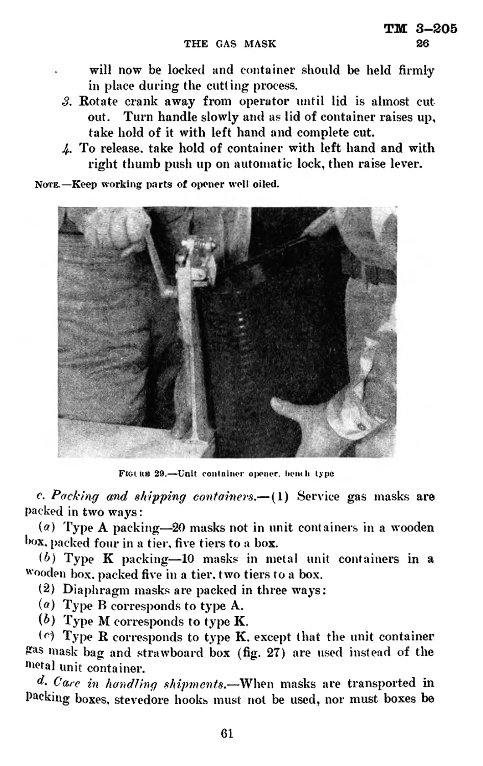
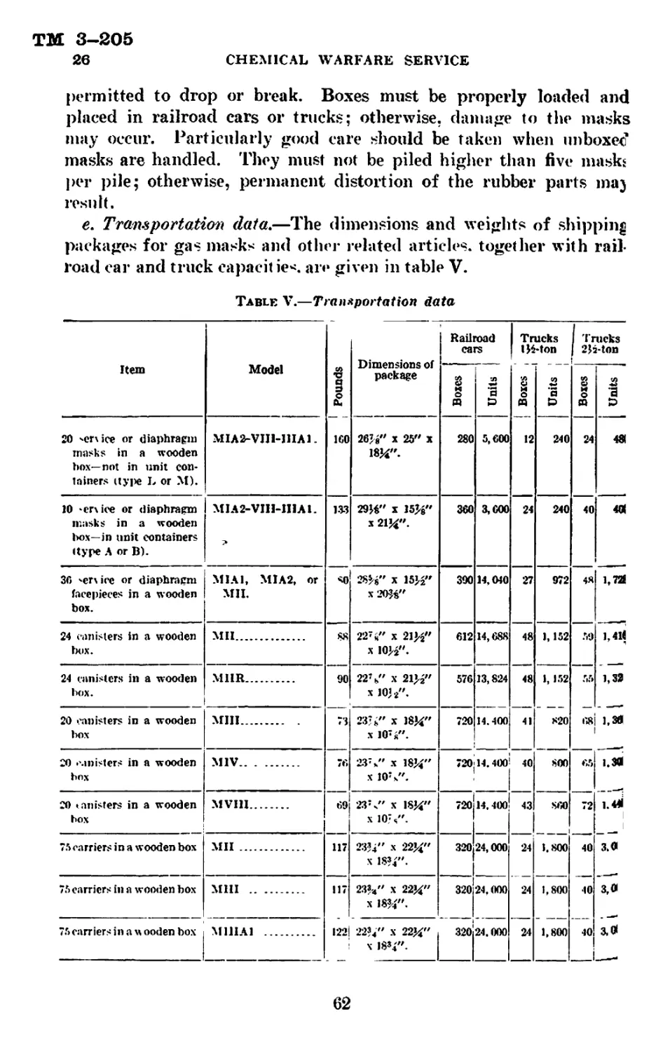
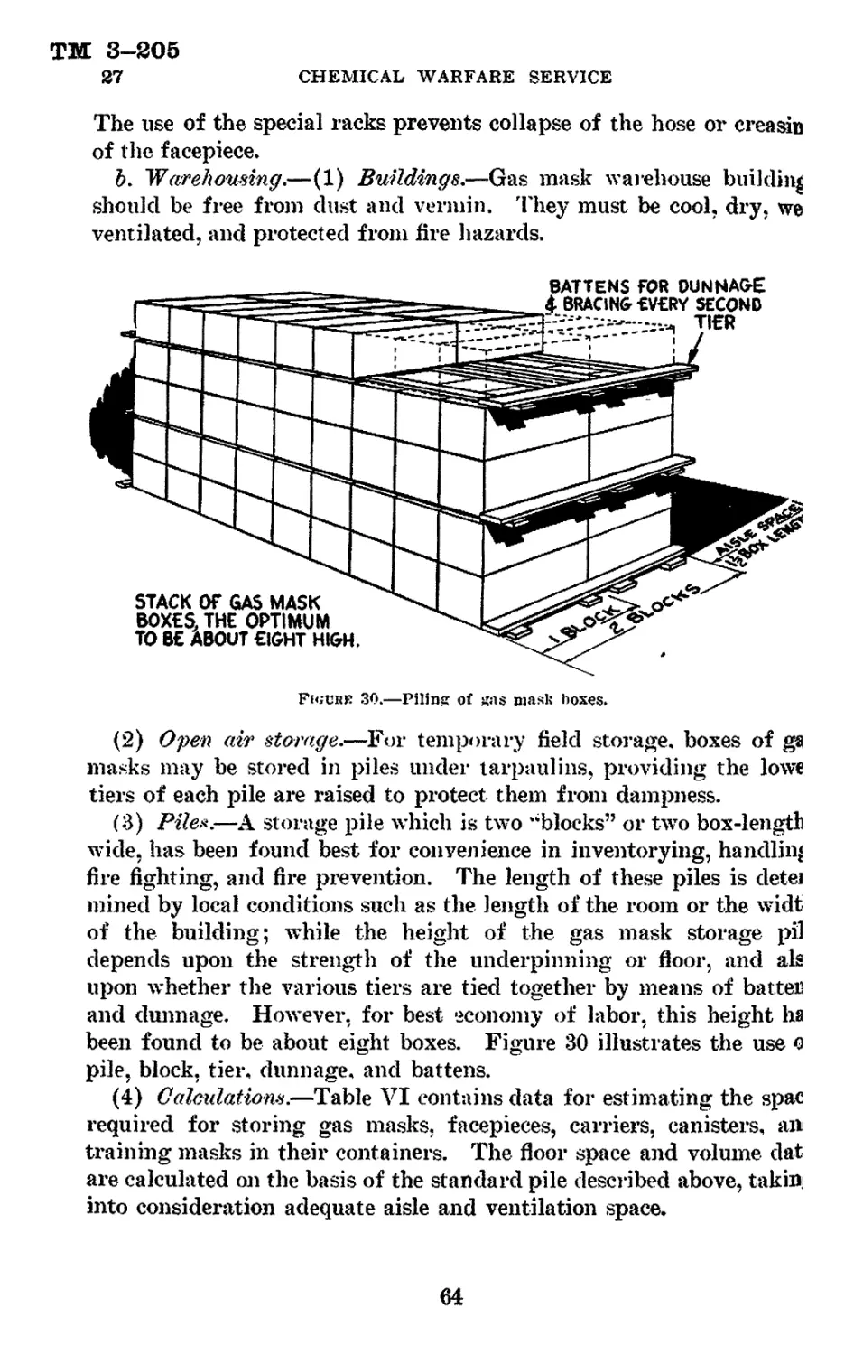
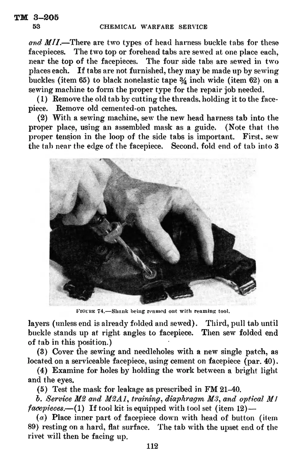
/


Теги: the gas mask means of protection
Год: 1941


Текст
ТМ 3-205
WAR DEPARTMENT
TECHNICAL MANUAL
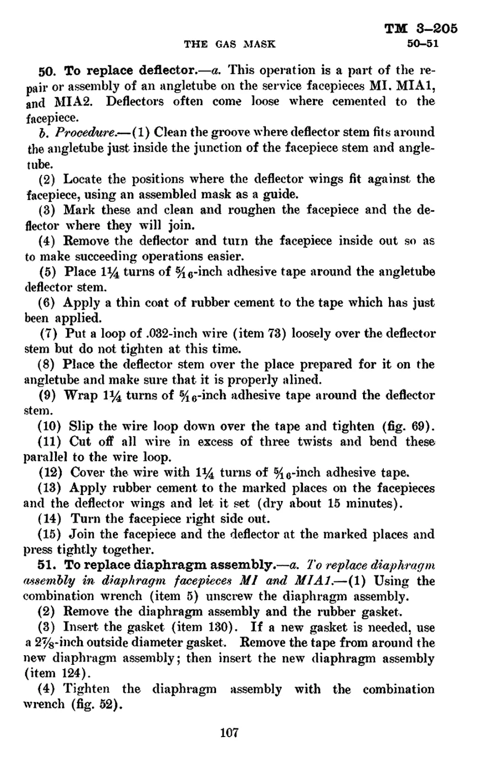
J
THE GAS MASK
October 9,1941
ТМ 3-205
1-2
TECHNICAL MANUAL
No. 3-205
WAR DEPARTMENT,
Washington, October 9, 1941.
THE GAS MASK
Prepared under direction of the
Chief of the Chemical Warfare Service
Paragraphs
Section I. General--------------------------------------------- 1-3
II. Service gas mask_________________________________ 4-9
III. Special respirators_____________________________10-16
IV. Special canisters--------------------------------17-23
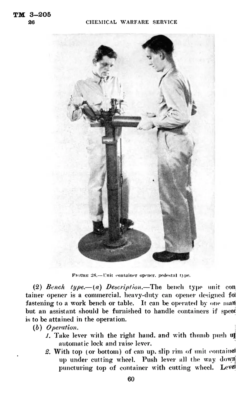
V. Care, handling, packing, and shipping____________24-27
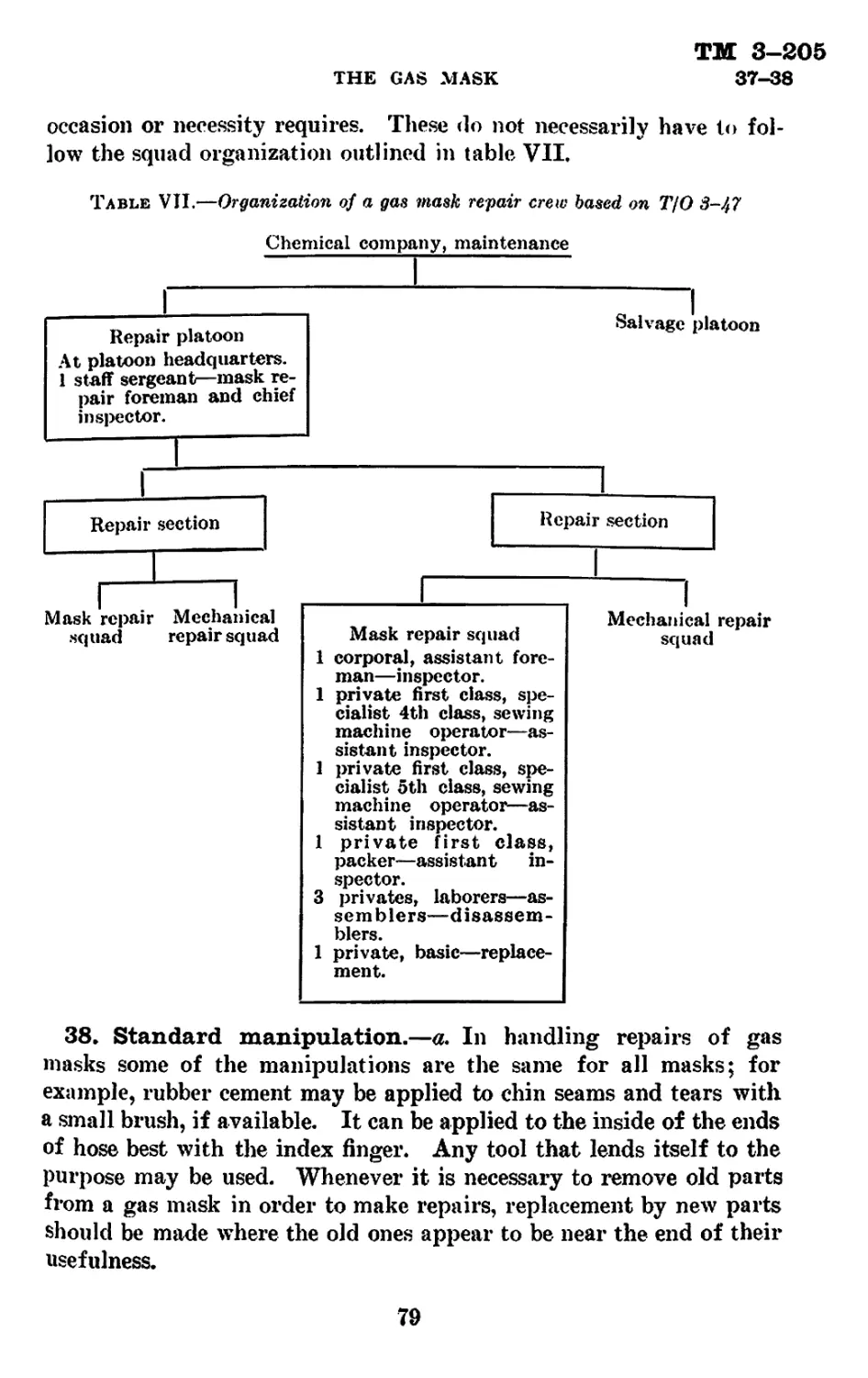
VI. Repair kits______________________________________28-34
VII. Repair procedure________________________________35-54
VIII. Testing and field inspection____________________55-60
Page
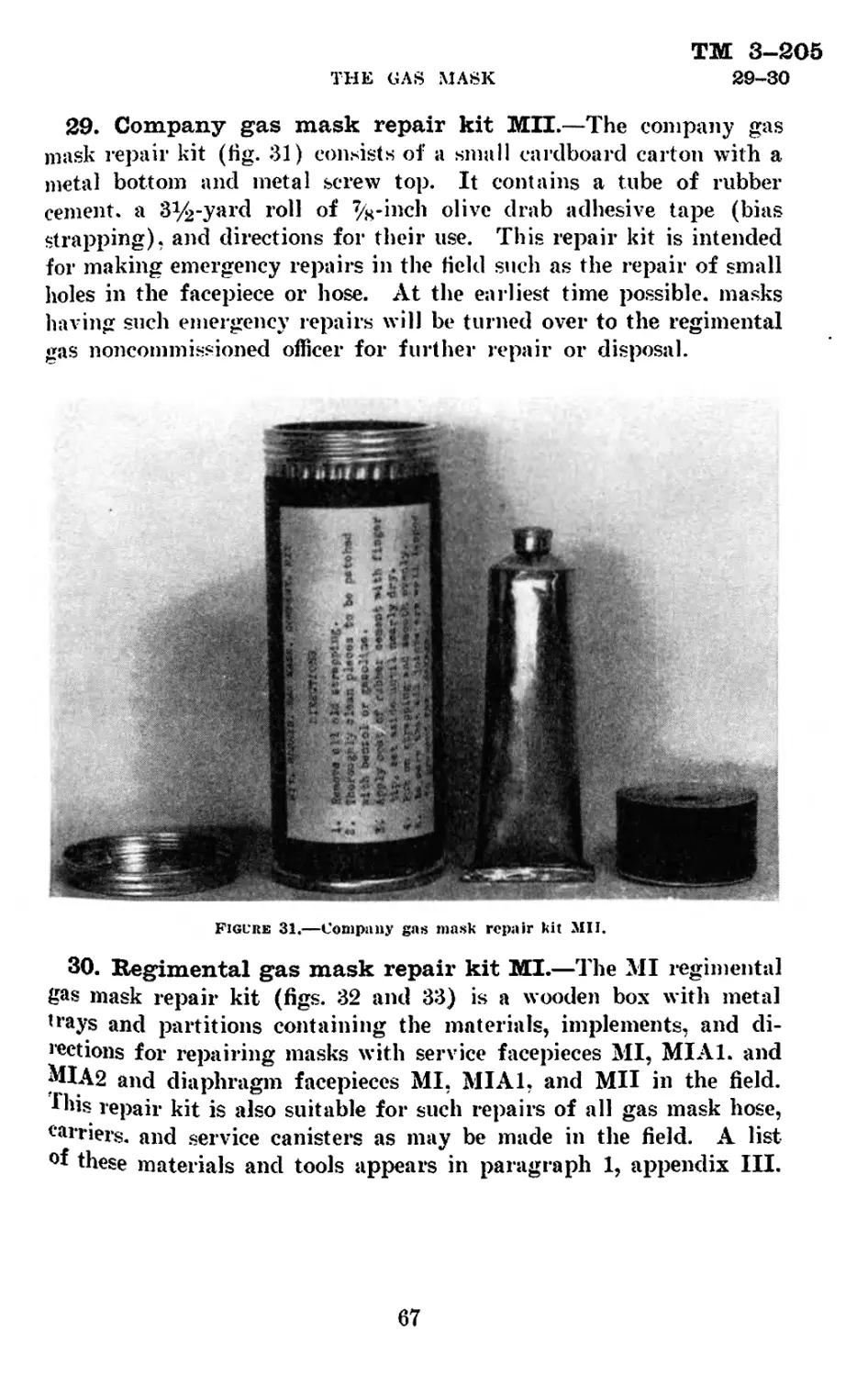
Appendix I. List of references--------------------------------- 127
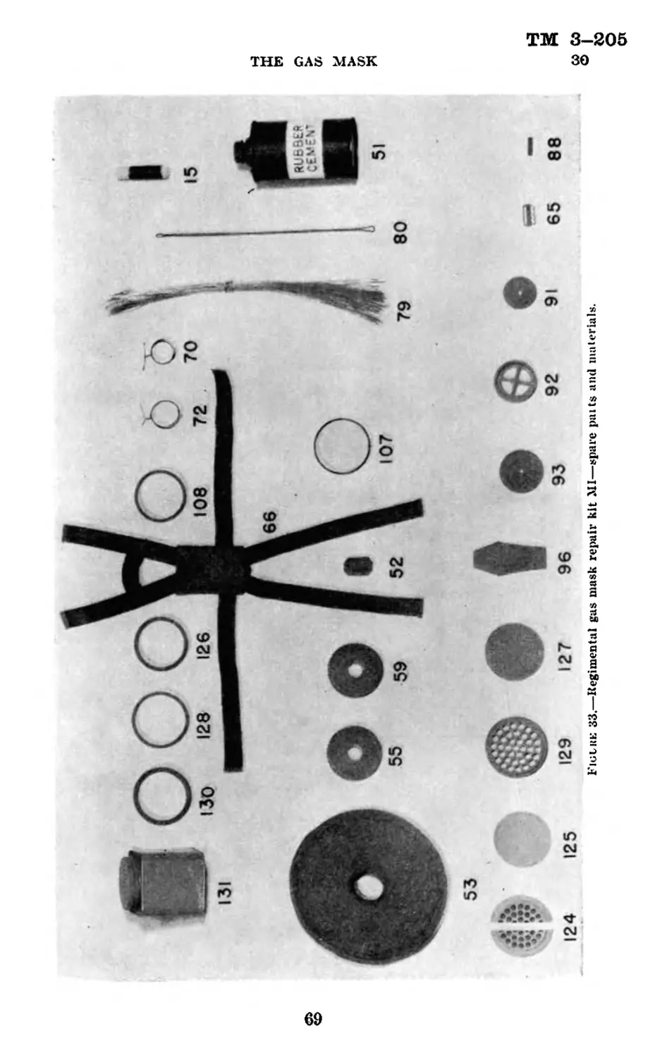
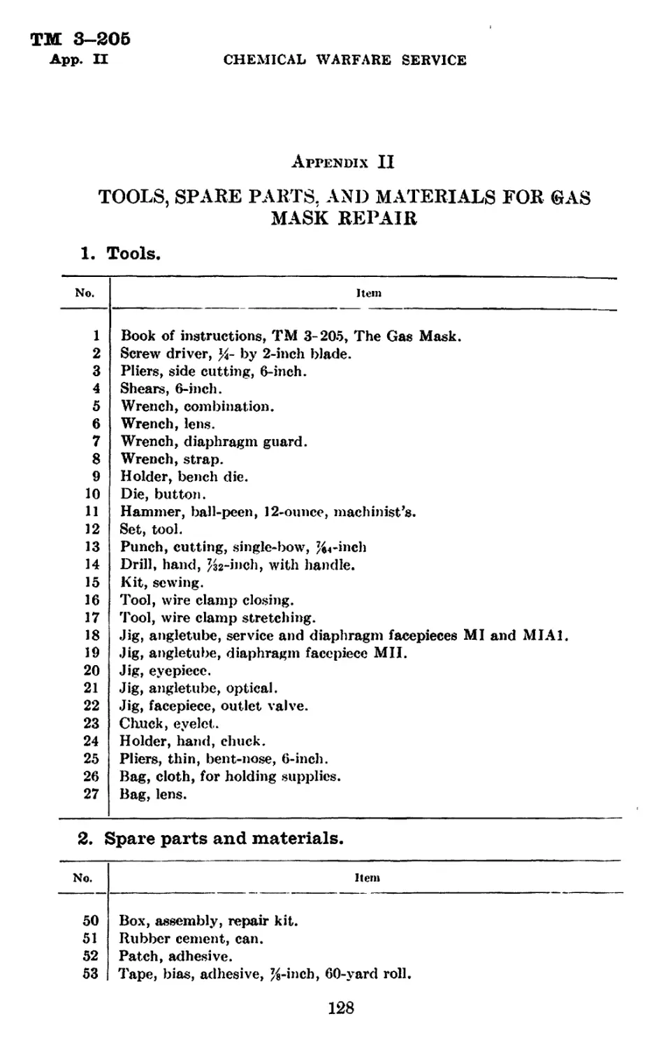
II. Tools, spare parts, and materials for gas mask
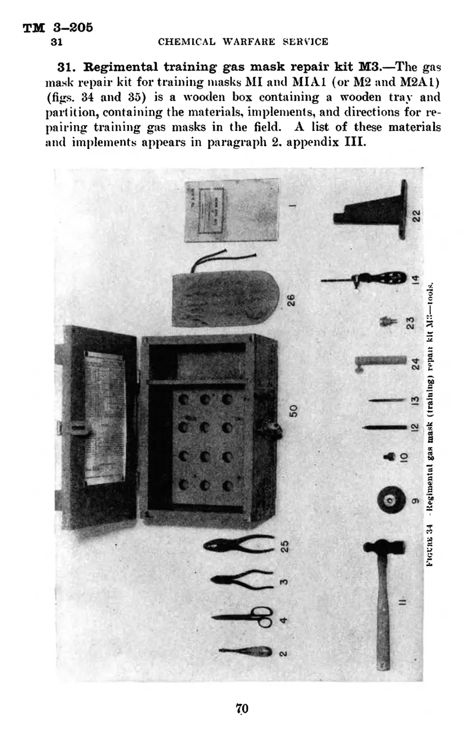
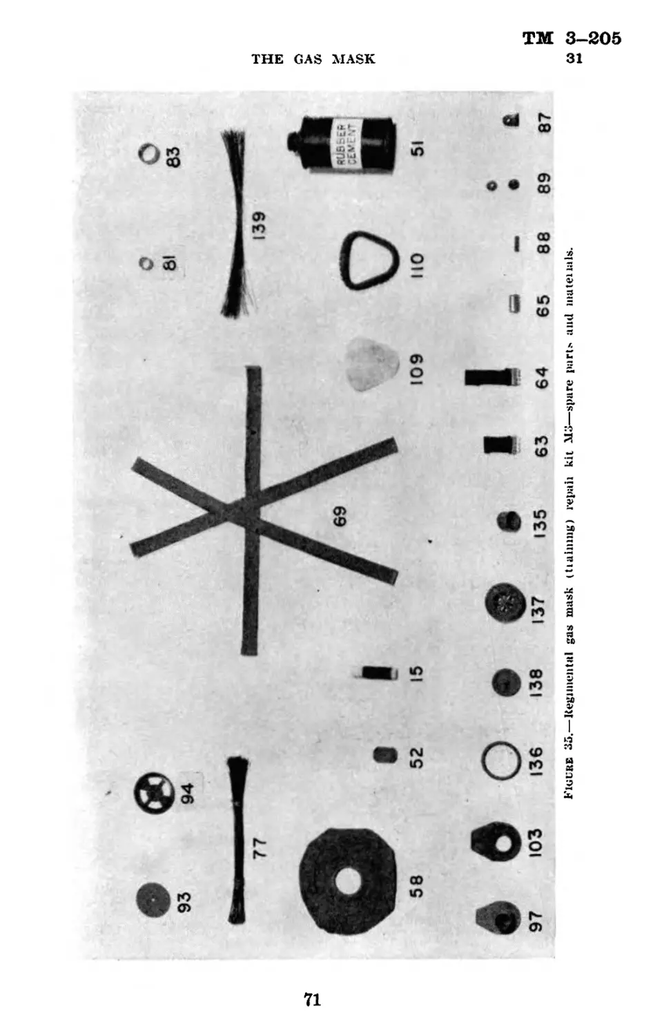
repair_________________________________________ 128
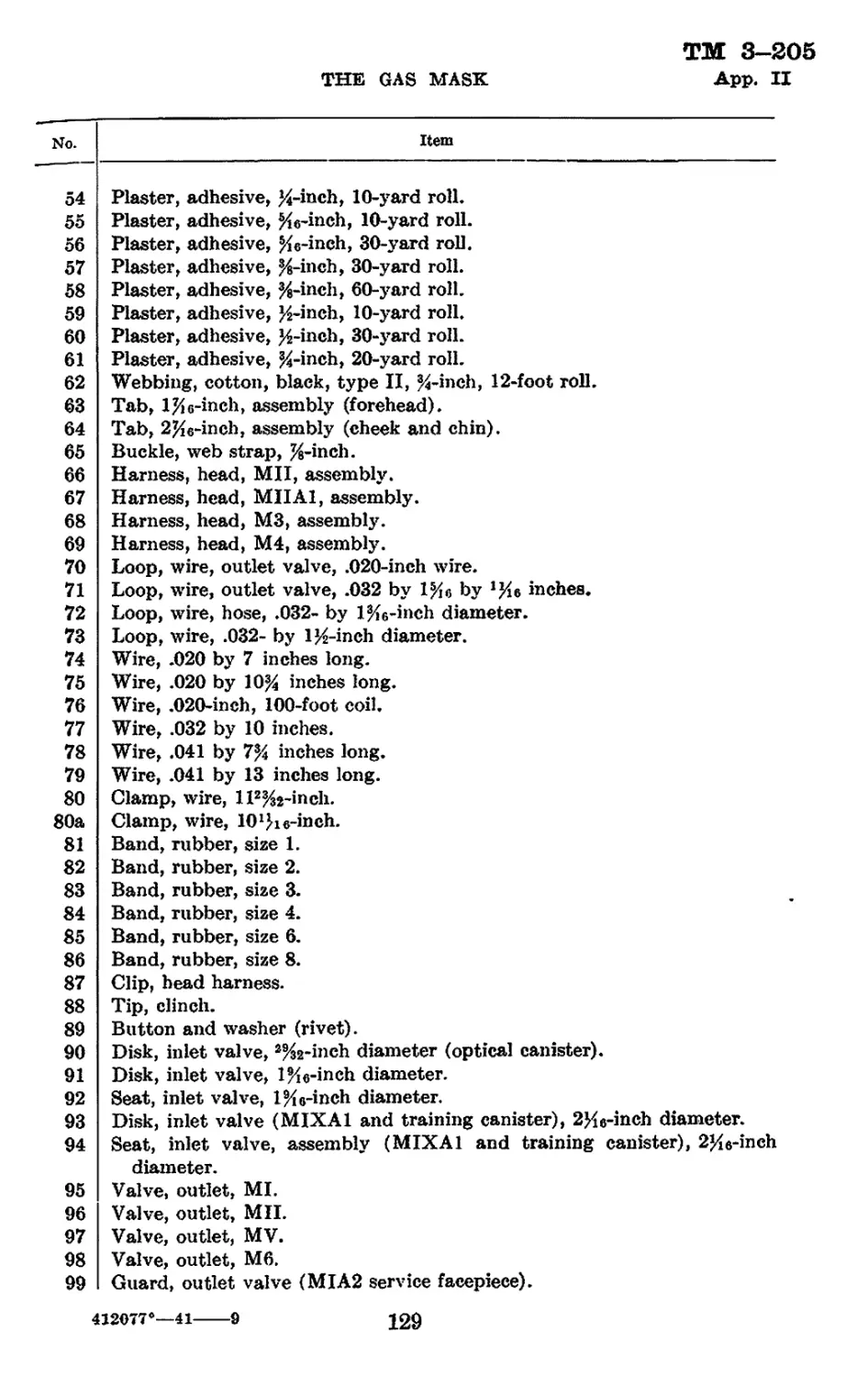
III. Regimental gas mask repair kits---------------- 131
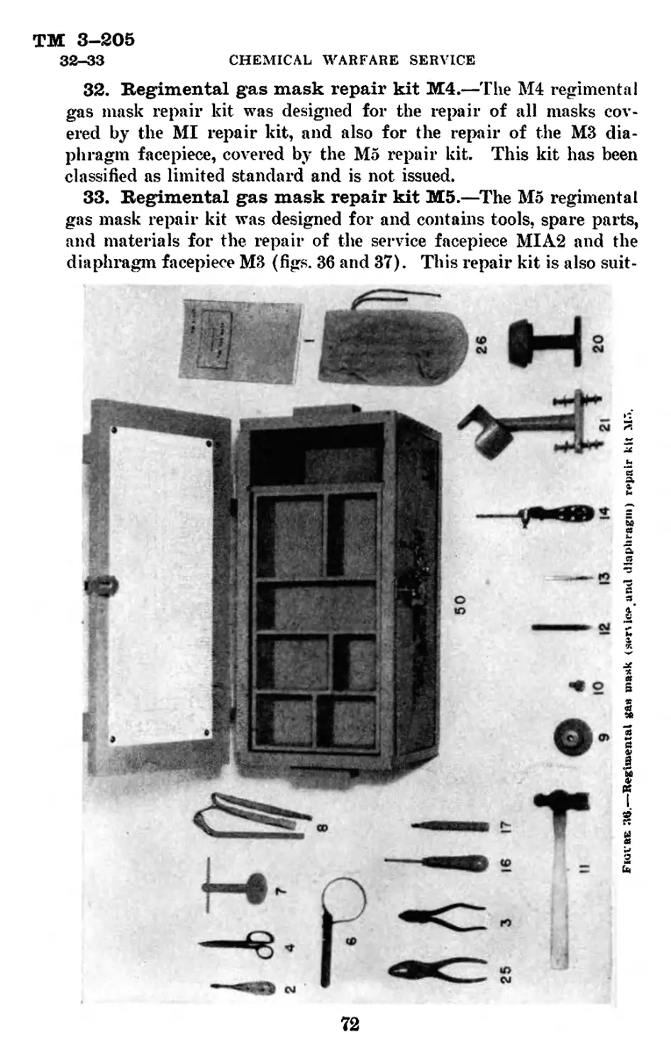
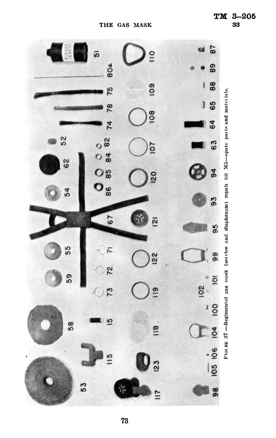
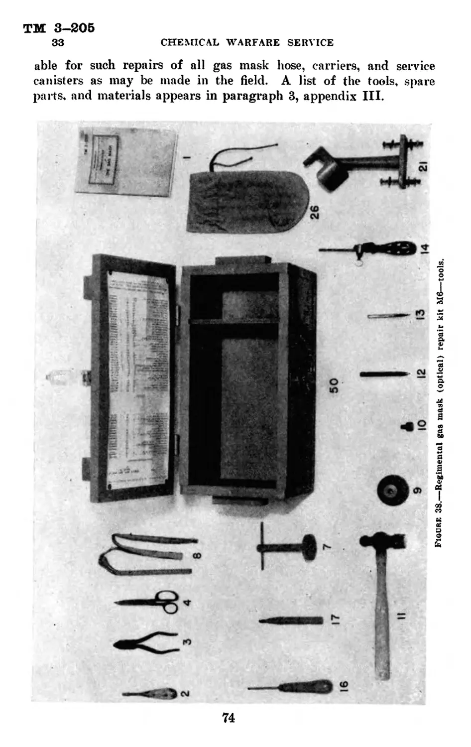
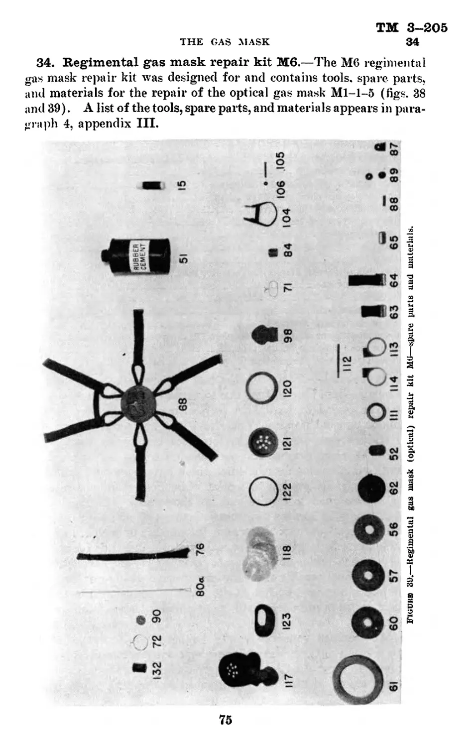
Section I
GENERAL
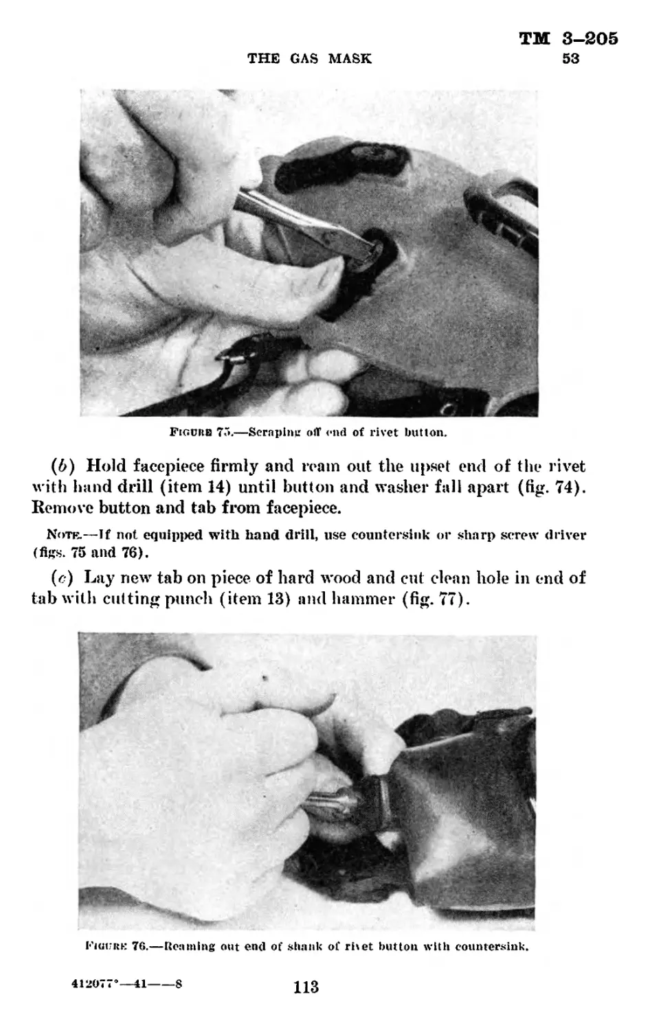
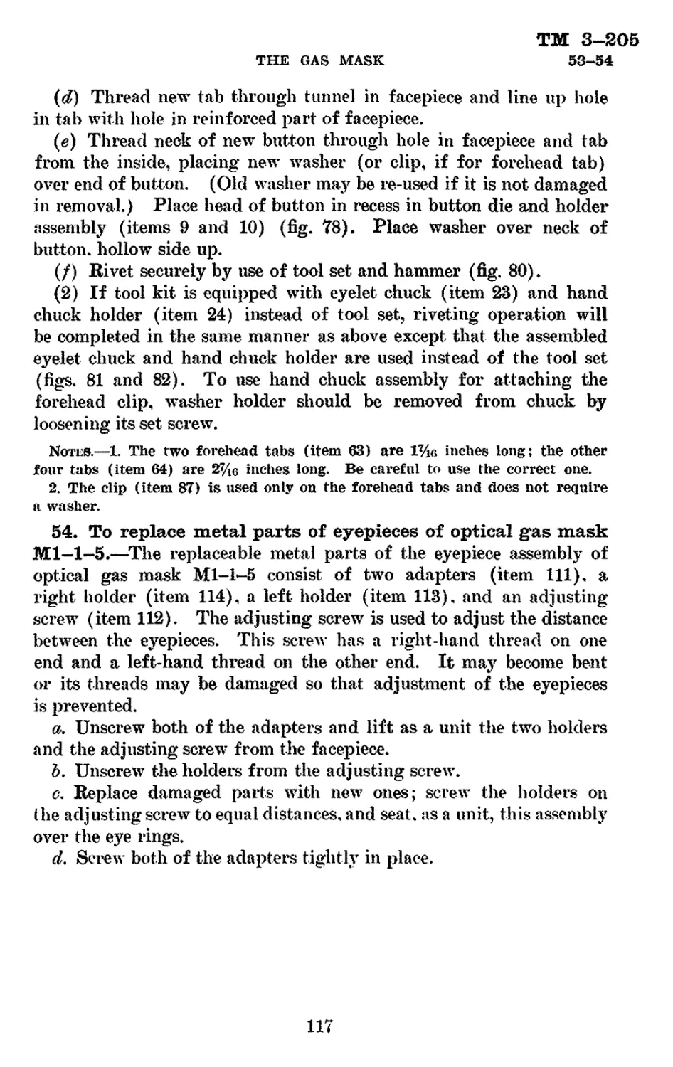
Paragraph
Purpose_____________________________________________________________ 1
Scope------------1-------------------------------------------------- 2
References__________________________________________________________ 3
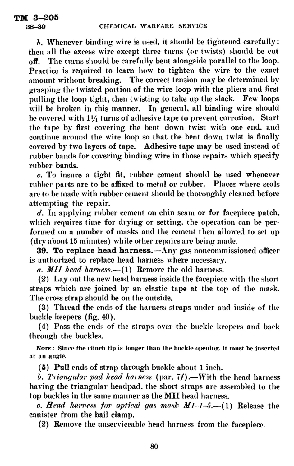
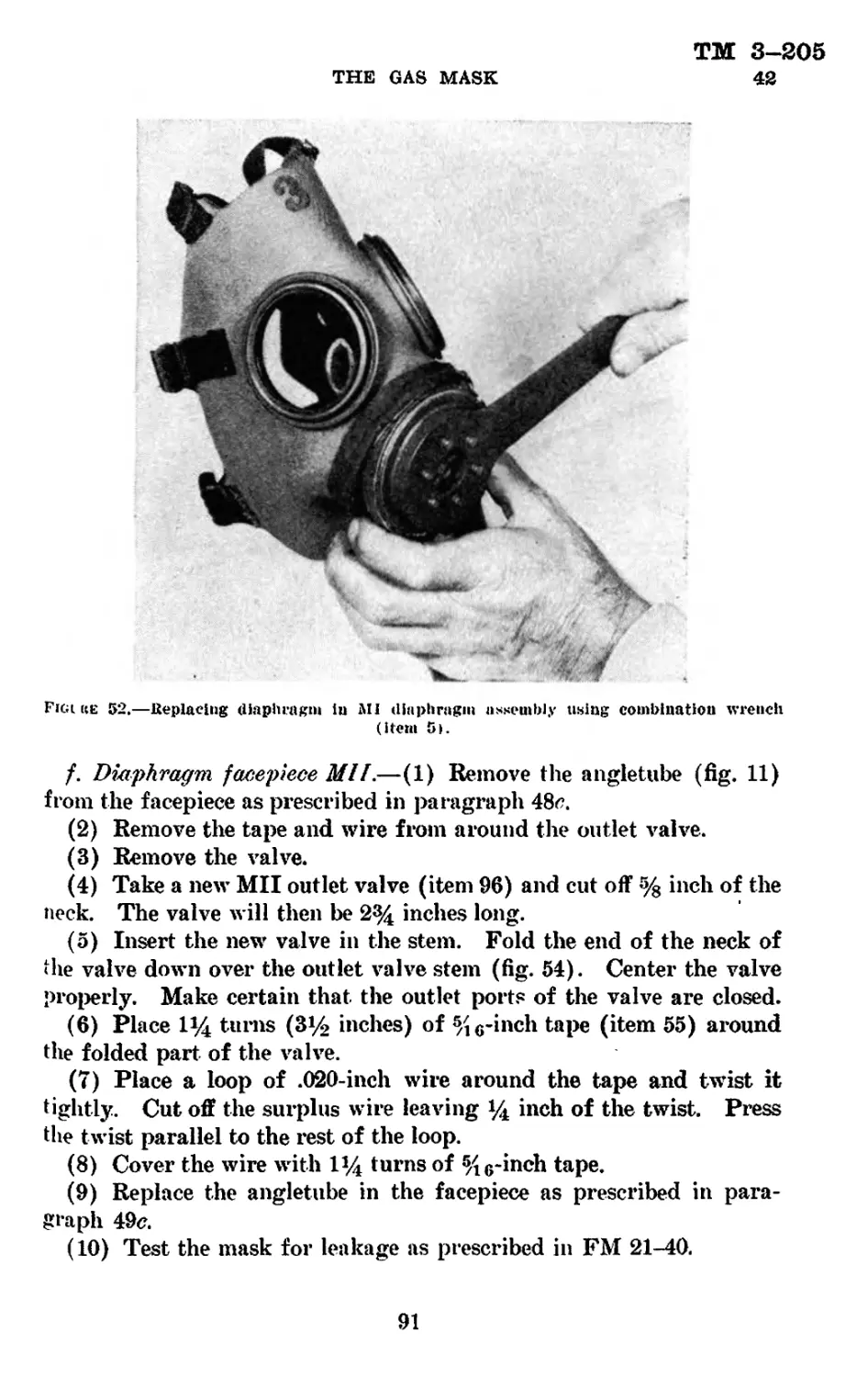
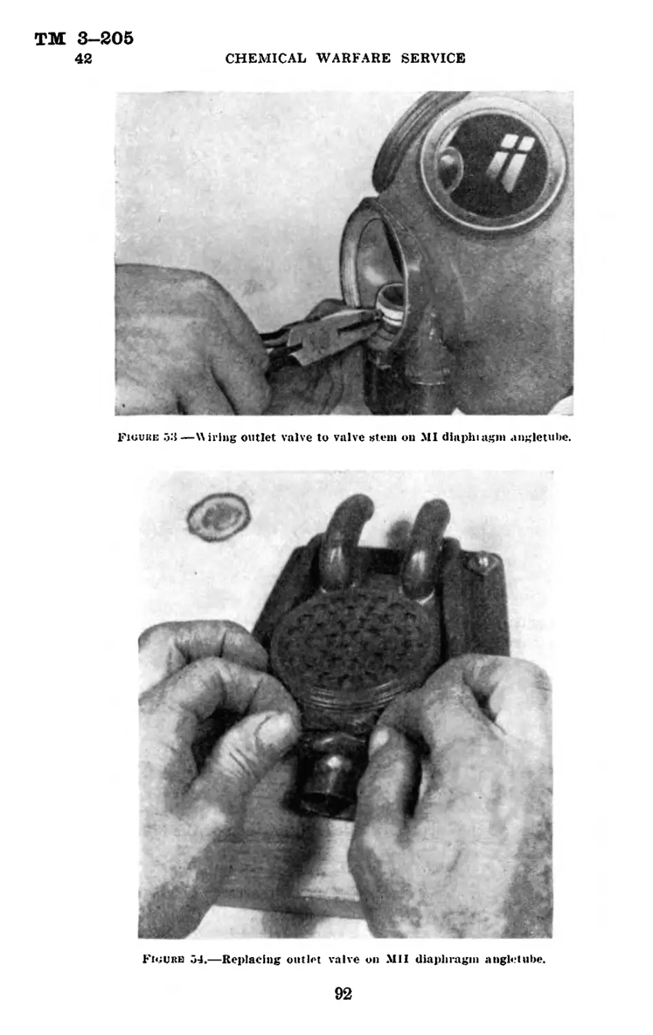
1. Purpose.—This manual is published for the information and
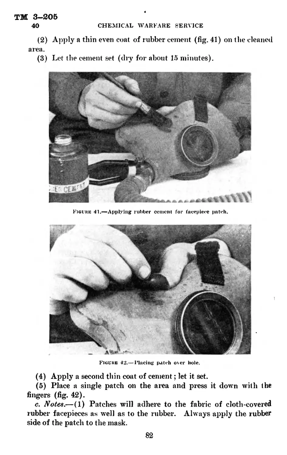
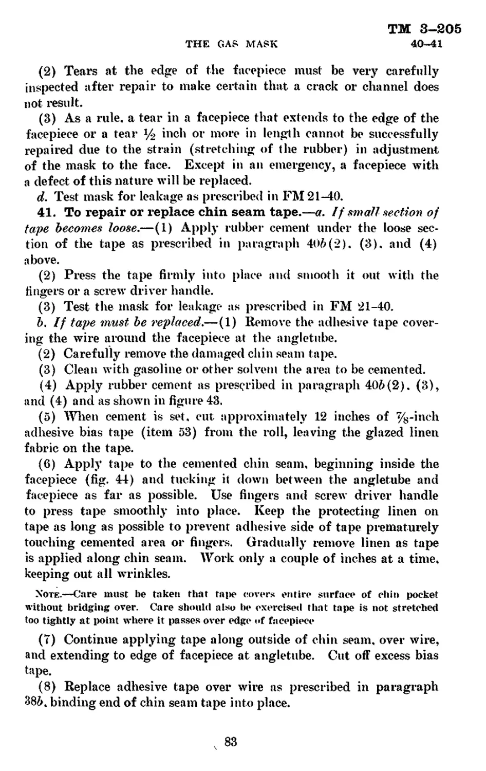
guidance of the using arms and services and all personnel charged
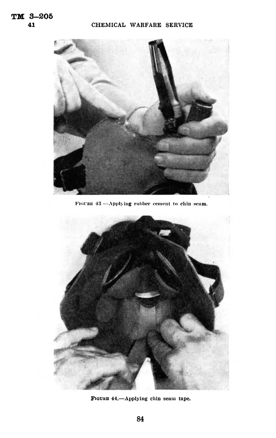
with the issue, alteration, repair, and testing of gas masks in the field.
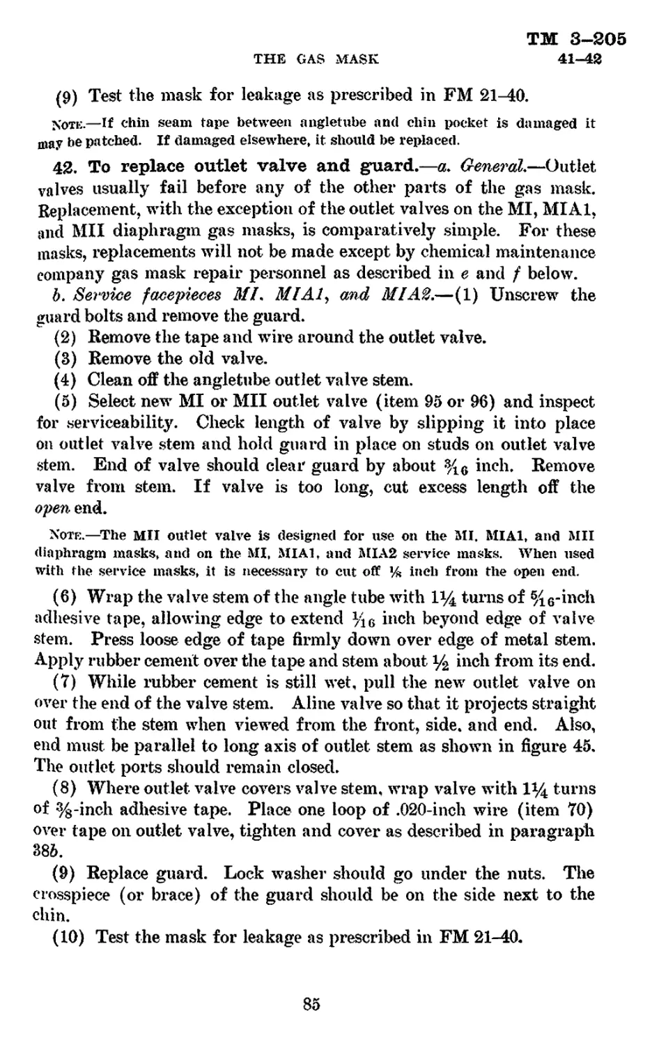
2. Scope.—This manual explains the designations or numbering
systems for the principal components of the gas mask. In order
that confusion in storage records and inspections may be avoided,
tables giving the main distinguishing characteristics of the various
components are furnished. The several special masks or respirators,
canisters, and like equipment are also described. Field repair and
**Thts pamphlet supersedes TR 1120-35. October 21, 1930.
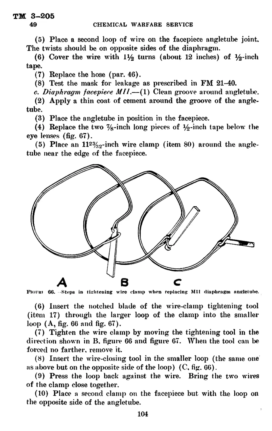
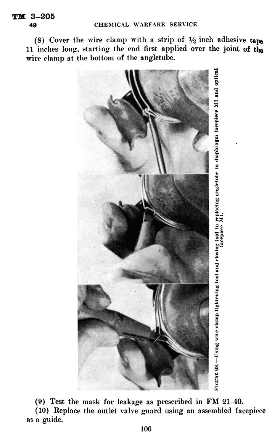
412077°- 41
1
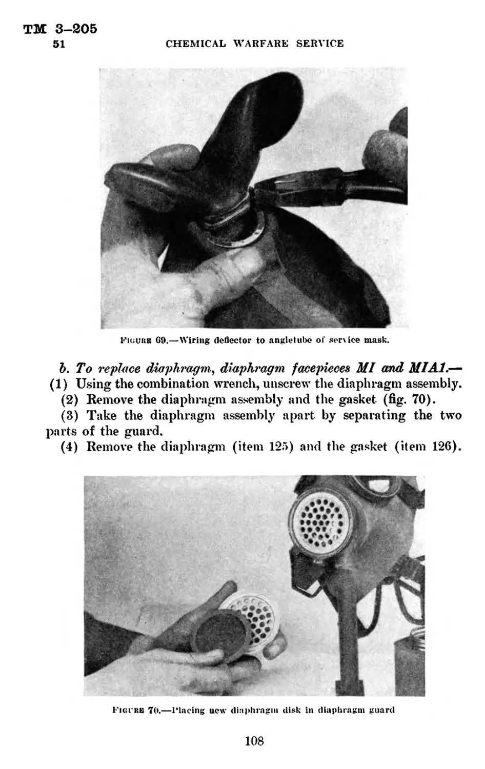
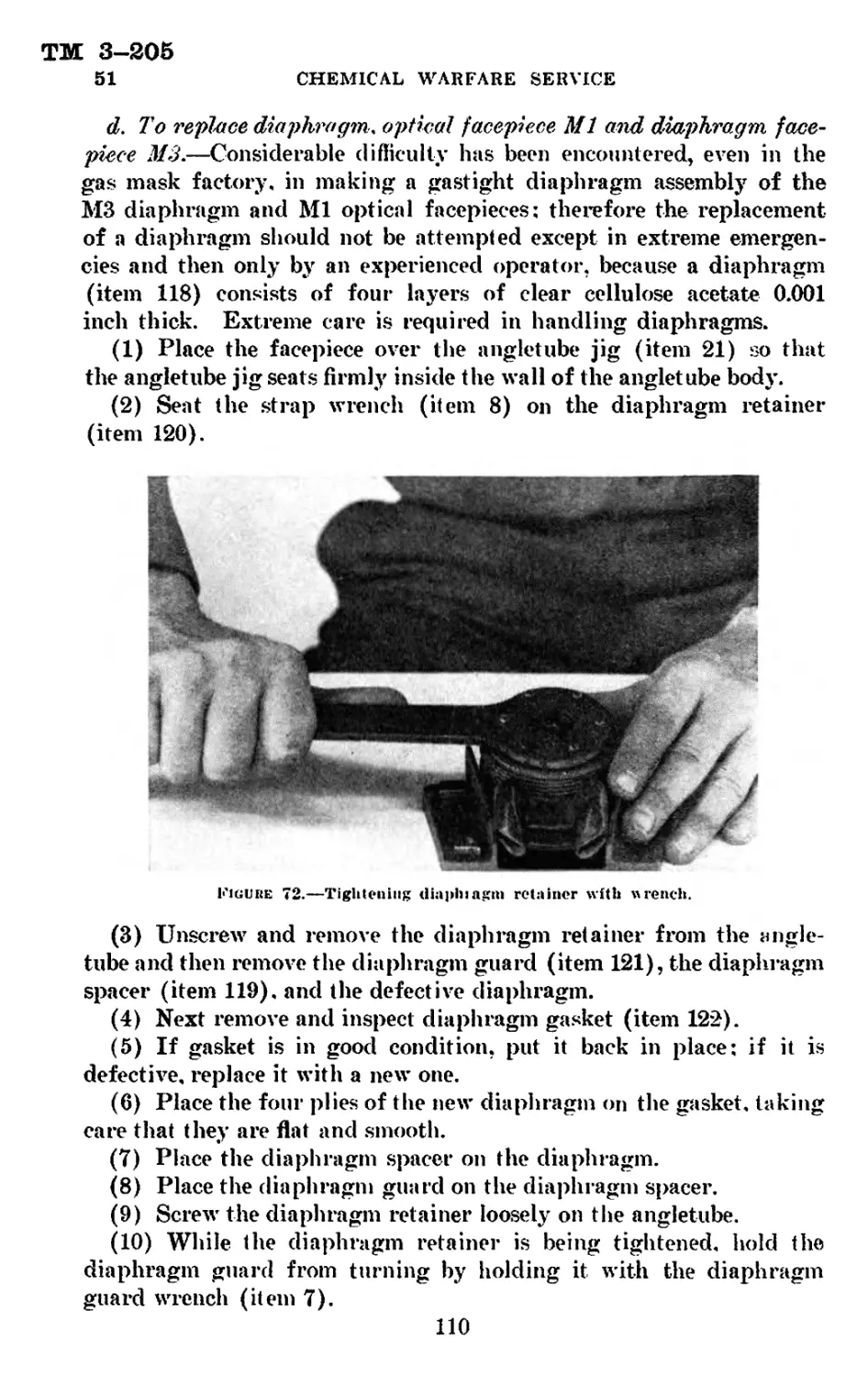
1
ТМ 3-205
2-4
CHEMICAL WARFARE SERVICE
testing equipment are listed, and directives for these repairs and
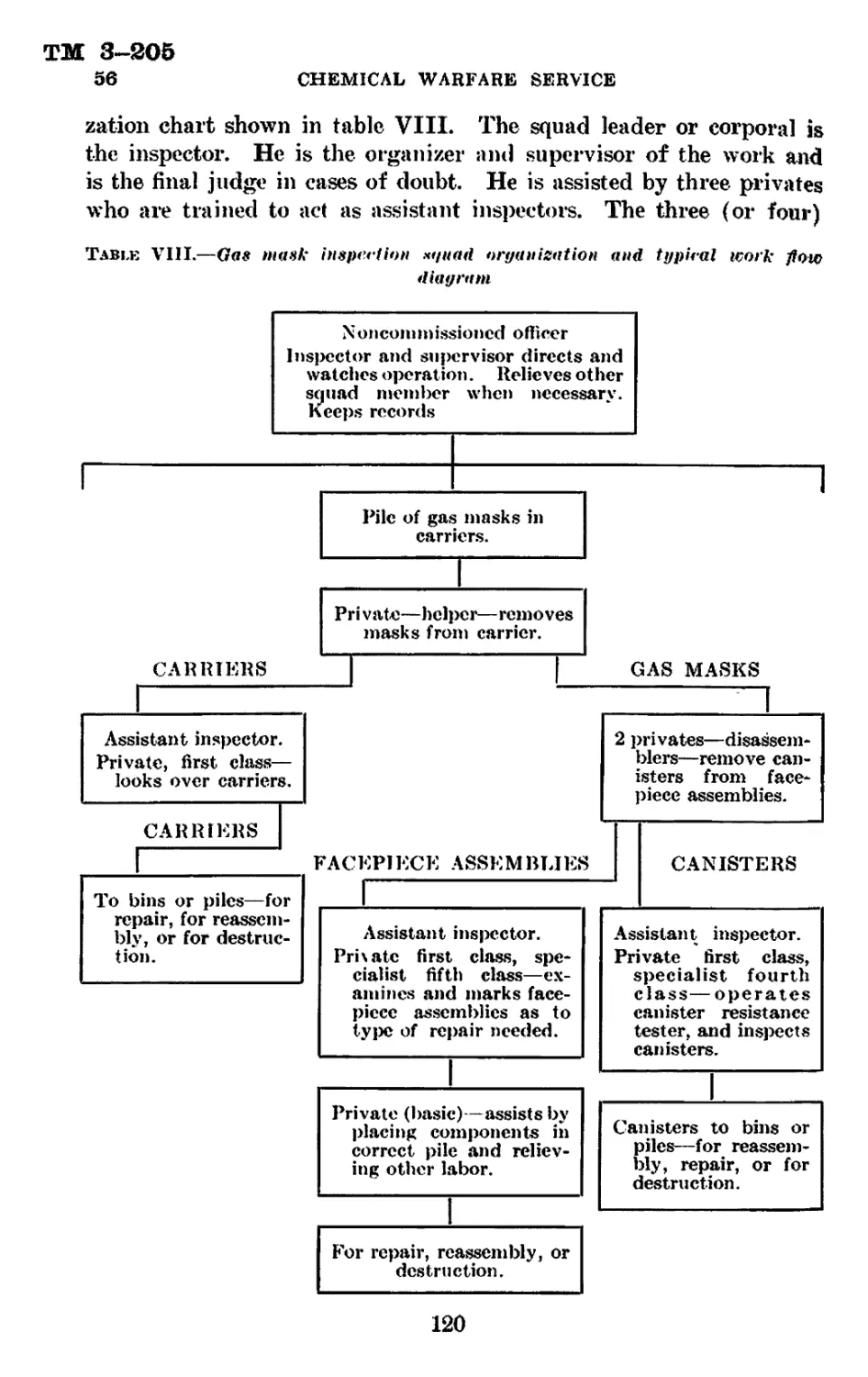
testing procedures are provided.
3. References.—See appendix I.
Section II
SERVICE GAS MASK
Paragraph
General_________________________________________________________________ 4
Numbering and identification systems____________________________________ 5
Distinguishing characteristics of various types of gas masks------------ 6
Description and nomenclature of service and diaphragm facepiece parts— 7
Description and nomenclature of canisters and canister parts------------ 8
Description and nomenclature of carrier_________________________________ 9
4. General.—a. Definition.—The military gas mask is an appa-
ratus designed to purify the air which the soldier breathes. It also
protects his eyes and face when he is in an atmosphere contaminated
with toxic or irritating gases, vapors, or smokes.
b. Components.—The complete gas mask consists of three principal
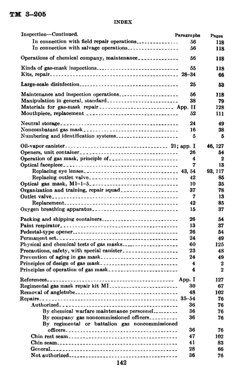
parts—the facepiece assembly, the canister, and the carrier (fig. 1).
(f) Facepiece assemblj & Cnnixtei
Fjgukb I.—.Main components of miliiary ga* masks
® Carrier.
(1) The facepiece assembly generally consists of the facepiece, con-
taining eyepieces, an outlet valve, a hose connection ог angletube,
and with a head harness attached. When a connecting hose forms
part of the gas mask, it is included in the facepiece assembly.
(2) The canister has a hose connection which may or may not
include an elbow nozzle, and also one or two inlet valves, depending
on the type of canister. These inlet valves are found in all models
except the model IX.
2
TM 3-205
4
THE GAS MASK
(3) The earner is made of a canvas pouch or sack with various
straps and buckles for slinging to body of wearer.
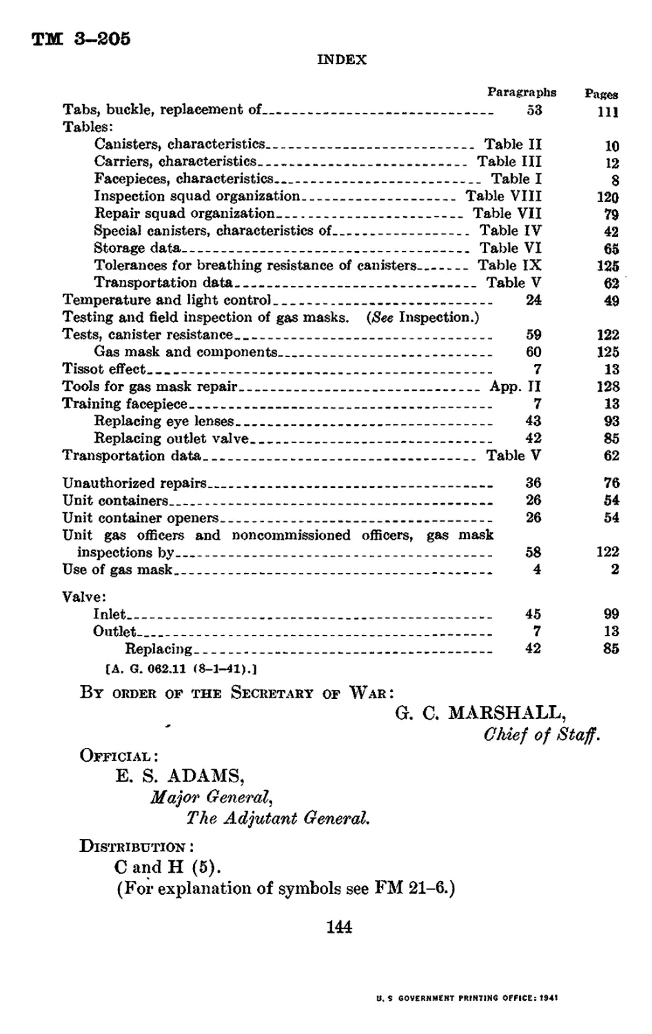
c. Principle of operation.—(1) The gas mask is an air filter. The
path of the air flow in the service gas mask is as shown in figure 2.
Air is drawn into the mask when the soldier inhales, and the mask
is so constructed that this air must first pass through a canister
containing a filtration system. This system comprises both mechan-
ical and chemical fillers, the former filtering out solid and liquid
FACE PIECE
DEFLECTOR
HOSE
AIR PASSAGE
CANISTER
AIR ENTERS HERE
CARRIER
CHARCOAL AND
SODA LIME
MECHANICAL
FILTER
AIR EXPELLED f I.
HERE |V
AIR DEFLECTED
AGAINST EYEPIECES
BEFORE INHALATION
ke 2.—Air flow system of gas mask
particles (smoke ami dust), and the latter absorbing and neutralizing
toxic and irritating gases and vapors. The air after being purified
by filtration is drawn to the soldier s face and after being inhaled and
exhaled is expelled from the mask through an outlet valve.
(2) The facepiece fits snugly to the face so as to be gastight and
is held in place by an elastic head harness. It is equipped with eye-
pieces of safety glass or other transparent material, and a deflector
which deflects incoming air against the eyepieces so as to prevent
3
тм 3—205
4 CHEMICAL WARFARE SERVICE
condensation of moisture on the lenses. In addition to this method
of reducing dimming of the eyepieces, a soaplike substance, known
as “antidim,” is furnished with each mask—except the training
mask—and which, when spread as a thin layer over the inner surfaces
of the eyepieces, tends further to keep down eyepiece fogging. The
facepiece is equipped with an outlet valve through which exhaled
air is expelled and a metal tube which is connected to the canister by
a corrugated rubber hose.
(3) The canister is a metal cylinder or oblong-shaped box contain-
ing a filter and chemicals comprising the filtration system. Ordi-
narily, it is equipped with an inlet valve which permits the entrance
of incoming ah’ and a nozzle for the exit of purified air. This inlet
valve prevents exhaled air from passing through the canister. The
nozzle of the canister usually is connected to the facepiece by the cor-
rugated rubbei* hose tube through which the purified air passes to
the wearer’s face. The facepiece, hose, and canister are contained in
a canvas carrier.
d. Limitations and use.—(1) The protection afforded by the gas
mask is due primarily to the canister, the other components of the
gas mask merely preventing air from entering the facepiece by any
other route. There is at the present time no known toxic gas, vapor,
or smoke against which adequate protection cannot be provided by
means of a suitable canister.
(2) Special canisters can be made up with filtration systems that
will eliminate any one or all of the known toxic gases or dusts from
the air breathed. No canister, however, affords protection indefi-
nitely. The life of the canister is dependent upon the total quantity
of gas which it is capable of filtering out of the air. Thus, for very
high concentrations, the life of the canister may be short, while in
low concentrations, it may be a matter of many weeks or months
before the canister becomes so saturated with gas that it fails to pro-
tect. Normal field gas conditions are such that a canister does not
break down suddenly. Except in case of mechanical damage, any
failure of the filters occurs very gradually and can be noticed by the
wearer as it happens.
(3) The filtration system of the Army canister provides excellent
protection against field concentrations of the chemical agents of
warfare. Generally, field concentrations are relatively low. There
are, however, toxic gases such as carbon monoxide and ammonia
against which the Army canister will not protect, although adequate
protection could be furnished if necessary. Neither will the Army
4
ТМ 3-205
THE GAS MASK 4-5
canister nor any canister type of gas mask protect in an atmosphere
containing an insufficient amount of oxygen to support life, nor, for a
certainty, in cases where concentrations of the toxics are extremely
high, such as might be encountered in inclosed spaces, in chemical
manufacturing plants, storage tanks, and the like. The service can-
ister will protect against high concentrations of gas for only a short
period of time. It is therefore assumed that protection for longer
periods is assured only if the concentration of gas does not exceed
one percent by volume. For such contingencies, which do not occur
in the open air, hose masks or self-contained oxygen breathing ap-
paratuses are required.
e. General principles of design.—Any complete description of the
military gas mask must take into consideration the principles of
design enumerated below. The mask must—
(1) Protect against all chemical warefare agents.
(2) Have a low breathing resistance.
(3) Be light in weight.
(4) Be comfortable.
(5) Be simple in design; easy to operate and repair.
(6) Not interfere greatly with vision.
(7) Be rugged enough to withstand field conditions.
(8) Be reasonably easy to manufacture in quantity.
(9) Not deteriorate in storage for at least several years.
(10) Have a service life in the field of at least several months.
(11) Be inexpensive.
(12) Be made of nonstrategic materials as far as possible.
Many of these requirements are opposed to each other. Thus, the
requirements of maximum protection and light weight are opposed to
each other since the amount of protection varies with the weight of
chemicals used and the capacity of the filter. The greater the
weight of chemicals and the size of the filter, the heavier the canister.
Low breathing resistance depends upon a large surface area for the
filter, but this increases the size and weight. A small, light canister
would have less weight of chemicals with resultant lower protection,
while a smaller filter area would cause greater breathing resistance.
Therefore, the military mask is a compromise among the above
twelve factors, of which the first three are the most important.
5. Numbering and identification systems.—a. General.—
Many different types and models of each of the three components of
the gas mask have been made in the past 20 years of development.
5
ТМ 3—205
5 CHEMICAL WARFARE SERVICE
Many of these models were eliminated in the experimental stage,
while others have been adopted, produced, and issued. Two different
identification systems have been used to help in distinguishing
these—one for experimental and development articles and another
for the adopted production types. Although chiefly concerned with
the latter, supply and using personnel in the field occasionally en-
counter experimental types under test, and it is for this reason that
both systems are described.
&. Experimental types.—When in the course of experimentation
and development the materials or design of a component are radically
changed, the experiment is designated by a number prefixed by the
letter E. When the model has been revised slightly without making
a major change in design or materials, the letter R followed by a
number representing the chronological revision is added. For
example, a fully-molded rubber facepiece assembly is made with a
rubber disk outlet valve and without hose and might be given the
identification number E41R1. If a new model with a very slight
change in the valve position is tried, the identification number would
become E41R2. Since the complete gas mask consists of three com-
ponents, it is customary to use the number of each experimental main
component that goes to make up the mask in the identification
number, so that in describing the mask as a whole, the facepiece as-
sembly is identified first, the canister second, and the carrier third.
The training mask in figure 8 had the numbers E41R40-E20R20 for
the facepiece assembly and canister, training mask MI; and E41R38-
E20R20 for the facepiece assembly and canister, training mask MIA1,
before either had been adopted as standard for production and issue.
It should be noted that the only differences are to be found in the
facepiece assembly (type of valve), and that the MI carrier, formerly
known as carrier E8R79, is the same for both masks.
c. Standard articles.—(1) When a mask component has been com-
pletely tested and is adopted as a standard for issue to the Army, it is
given a new identification number. Instead of using the letter E,
the letter M (signifying standardized model number) is used. Thus,
the first standard service facepiece assembly is known as the MI.
Revisions are designated by an A (signifying alteration) followed by
the chronological number of the alteration. Hence, there have been
two distinct alterations made or improvements added to the service
facepiece, MI, which have not materially changed the design or
materials. These two models are known as the MIA1 and MIA2.
(2) For complete designation of the adopted type of the entire gas
6
TM 3—205
5-6
THE GAS MASK
mask, it is necessary to identify all of the three main components:
the facepiece assembly, the canister, and the carrier (as explained
for the experimental types), bearing in mind that the letter M
indicates adopted model and the letter A indicates adopted minor
change. Thus, the present standard service gas mask, known as
the MIA2-IXA1-IVA1, is the latest model of this type.
(3) Where more than one of the components are included in
identifying the article, the letter M is not repeated. As an example,
the experimental training gas mask, formerly designated as E41R40-
E20R20-E8R79, later adopted as a standard article, is now designated
as training gas mask MI-I-I. On articles standardized prior to
September 1940, the M numbers are the Roman numerical system
while the A numbers are Arabic; in the future all M numbers will
also be Arabic. When in the Standard Nomenclature and Price
List the letter R is included in the identification number, recondition-
ing of the original article is indicated.
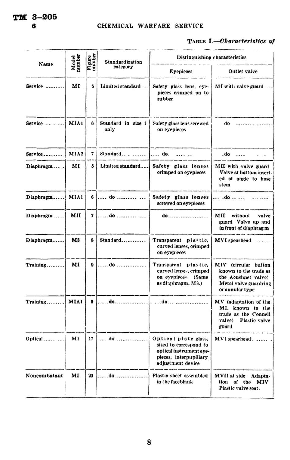
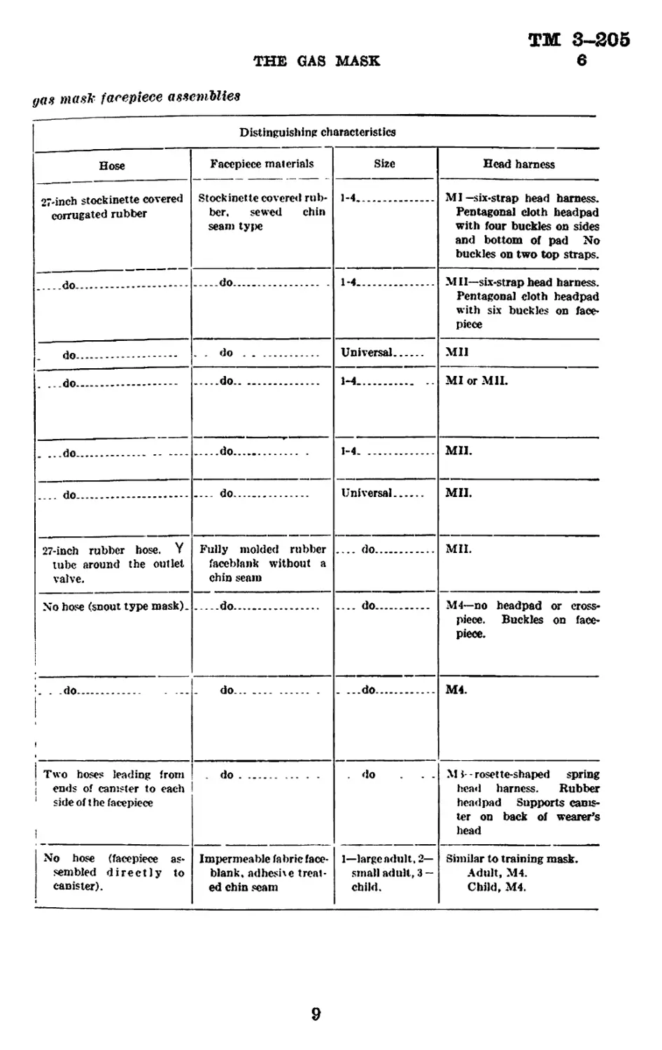
6. Distinguishing characteristics of various types of gas
masks.—Since the organization of the Chemical Warfare Service,
continuous research has been conducted on the task of providing the
best possible protection against chemical warfare agents. The
problem is a most difficult one as explained in paragraph 4e, but
much progress has been made in securing the maximum amount of
protection and comfort combined with the easiest method of
production. As a result there is a succession of models of facepieces,
canisters, and carriers, each of which is a logical development based
upon previous experiences. In some cases many of each of these
components have been made and issued to troops or stored for emer-
gency. Unless there is a way of identifying the parts of the gas
mask, much confusion of records may result. Maintenance personnel
must be able to recognize these various models since the repairs to be
made vary with each one. Tables I, II, and III give the charac-
teristics of the various types for these purposes. Figures 5 to 10,
inclusive, 15, 17, and 19 illustrate the descriptions in these tables.
ТМ 3-205
6
CHEMICAL WARFARE SERVICE
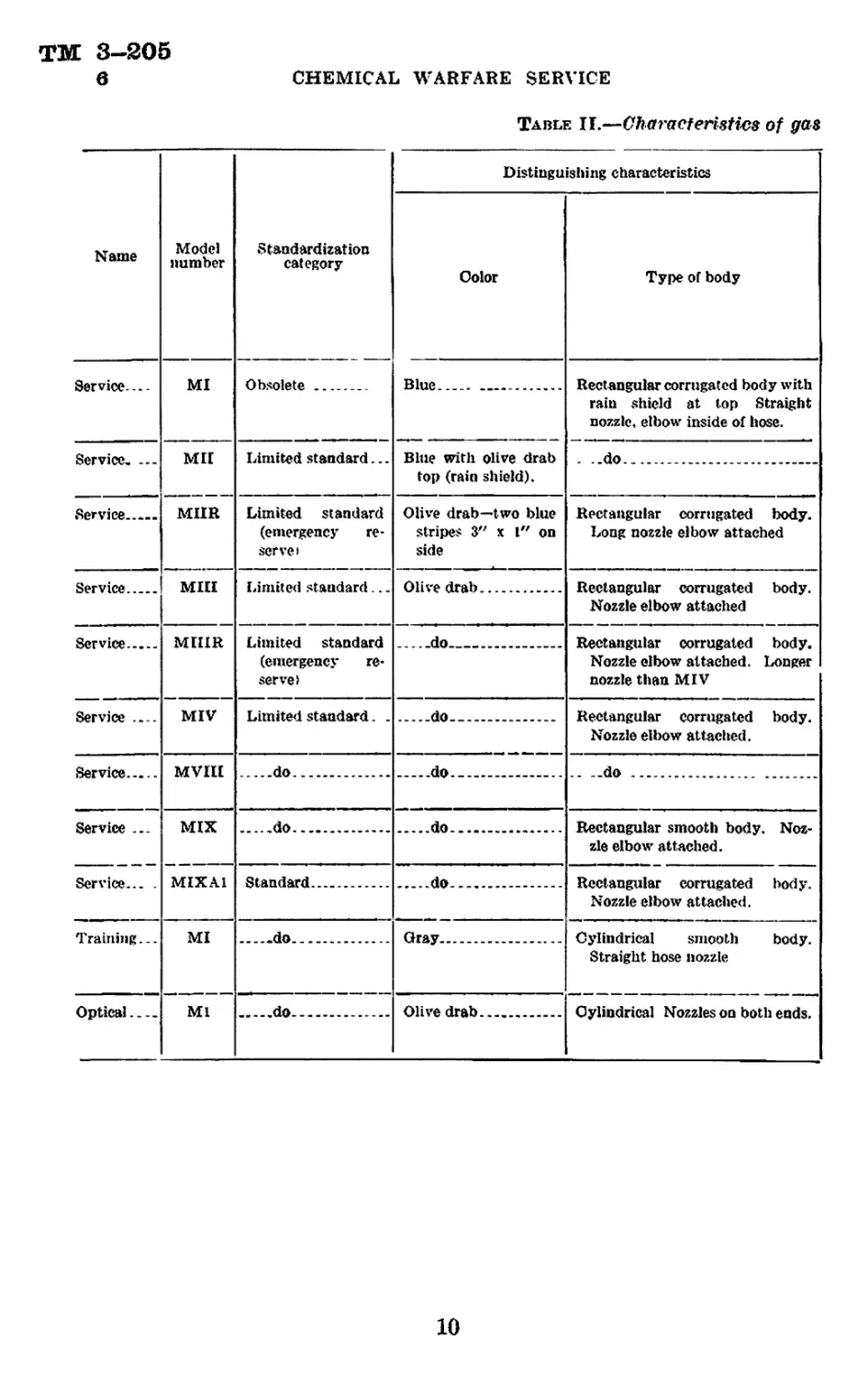
Table I.—Characteristics of
Name I Model । numtier 1 jure rnber Standardization Distinguishing characteristics
fc 5 category i Eyepieces Outlet valve
Service MI 5 Limited standard.. _. Safety glass lens, eye- pieces crimped on to rubber MI wit li valve guard....
Service .. . ... MIAl 6 Standard in size 1 only Safety glass len< screwed on eyepieces do
Service MIA2 7 Standard ....do .do
Diaphragm... . Diaphragm MI MI At & 6 Limited standard. _ - .... do ... Safety glass lenses crimped on eyepieces Safety glass lenses screwed on eyepieces Mil with valve guard Valve at bottom insert - ed at angle to hose stein ... .do .. ...
Diaphragm MU 7 do do. MU without valve guard Valve up and in front of diaphragm
Diaphragm М3 8 Standard. Transparent plastic, curved lenses, crimped on eyepieces M VI spearhead
Training Ml 9 do Transparent plastic, curved lenses, crimped on eyepieces (Same as diaphragm, М3.) MIV (circular button known to the trade as the Acushnet valve) Metal valve guardring or annular type
Training MIAl 9 do . ...do. MV (adaptation of the MI, known to the trade as the Connell valve) Plastic valve guard
Optical Ml 17 ... do Optica I plate glass, sized to correspond to optical instrument eye- pieces, interpupillary adjustment device MVl spearhead.
Noncombatant MI 20 do. Plastic sheet assembled in the faceblank MVII at side Adapta- tion of the MIV Plastic valve seat.
8
TM 3-205
6
THE GAS MASK
yas mask facepiece assemblies
Distinguishing characteristics
Hose Facepiece materials Stockinette covered rub- ber, sewed chin seam tyjie Size Head harness
27-inch stockinette covered corrugated rubber 1-4 MI—six-strap head harness. Pentagonal doth headpad with four buckles on sides and bottom of pad No buckles on two top straps.
do 1-4 MII—six-strap head harness. Pentagonal cloth headpad with six buckles on face- piece
do . . do . . Universal Mil
. ...do do 1-4- MI or MIL
. ...do. do 1-4. MIL
.... do. do Universal Mil.
27-inch rubber hose. Y tube around the outlet valve. Fully molded rubber faceblank without a chin seam .... do MIL
No hose (snout type mask). do .... do M4—no headpad or cross- piece. Buckles on face- piece.
L . .do . ... i do . ...do M4.
| Two hoses leading from | ends of canister to each । ' side of t he facepiece i . do 1 .do ... M i- - rosette-shaped spring head harness. Rubber head pad Supports canis- ter on back of wearer’s head
No hose (facepiece as* sembled directly to canister). Impermeable fabric face- blank, adhesive treat- ed chin seam 1—large adult, 2— small adult, 3 — child. Similar to training mask. Adult, M4. Child, M4.
9
TM 3-S05
6
CHEMICAL WARFARE SERVICE
Table II.—Characteristics of gas
Name Model number Standardization category Distinguishing characteristics
Color Type of body
Service— MI Obsolete Blue.... Rectangular corrugated body with rain shield at lop Straight nozzle, elbow inside of hose.
Service. ... Mil Limited standard... Blue with olive drab top (rain shield). . ..do
Service MUR Limited standard (emergency re- serve» Olive drab—two blue stripes 3" x l" on side Rectangular corrugated body. Long nozzle elbow attached
Service Mill Limited standard... Olive drab Rectangular corrugated body. Nozzle elbow attached
Service MUIR Limited standard (emergency re- serve) do Rectangular corrugated body. Nozzle elbow attached. Longer nozzle than MIV
Service — MIV Limited standard. . do Rectangular corrugated body. Nozzle elbow attached.
Service MVIII do do do
Service ... Service... . MIX do do Rectangular smooth body. Noz- zle elbow attached.
MIX Al Standard . do. - Rectangular corrugated body. Nozzle elbow attached.
Training... MI do.... Gray Cylindrical smooth body. Straight hose nozzle
Optical. Ml do.. Olive drab Cylindrical Nozzles on both ends.
10
TM 3-205
6
THE GAS MASK
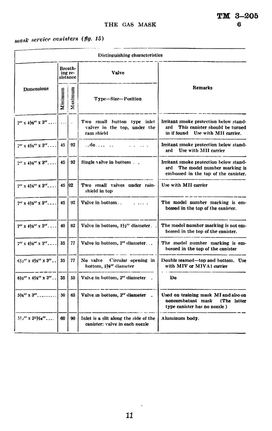
mask service canisters (fig. Л5)
Distinguishing characteristics
Dimensions Breath- ing re- sistance Valve Remarks
| Minimum ! | .Maximum | T ype—Size—Position
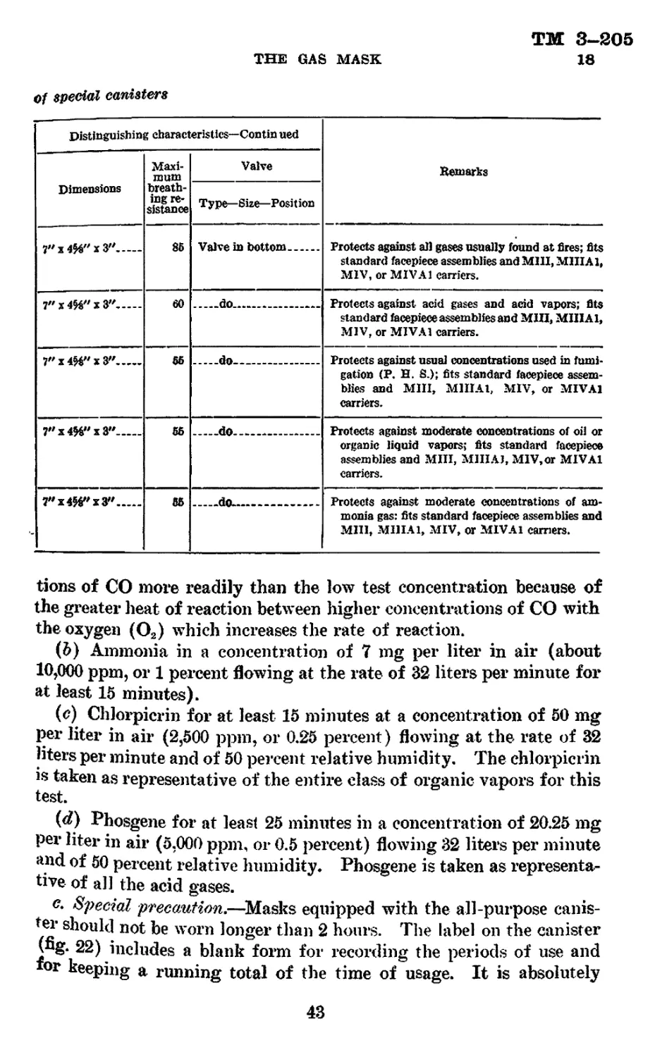
7"x4)8"x3".... Two small button type inlet valves in the top, under the ram shield Irritant smoke protection lielow stand- ard This canister should be turned in if found Use with Mil carrier.
7' x 4H" x 3". - - - 45 92 ..do.-.. .. Irritant smoke protection below stand- ard Use with МП carrier
Гх^Гх^.... 45 92 Single Aalve in bottom . . Irritant smoke protection below stand- ard The model number marking is embossed in the top of the canister.
7" x W x 3"... - 45 92 Two small valves under rain- shield in top Use with MH carrier
7" x-РД''хЗ"---. 45 92 Valve in bottom The model number marking is em- bossed in the top of the canister.
7" x 4%" x 3" 40 82 Valve in bottom, diameter. . The model number marking is not em- bossed in the top of the canister.
7"x4$$"x3"-_- 35 77 Valve in bottom, 2" diameter... The model number marking is em- bossed in the top of the canister
6h" x4$s"x3"._ 35 77 No valve Circular oiiening in bottom, 196" diameter Double seamed—top and bottom. Use with MIV or MIVA1 carrier
х4Ц"хЗ".. 35 55 Vahc in bottom, 2" diameter . Do
5^"x3" 50 65 Valve in bottom, 2?' diameter . Used on training mask MI and also on noncombatant mask (The latter type canister has no nozzle )
5h"x2W"- — €0 90 Inlet is a slit along the side of the canister: valve in each nozzle Aluminum body.
11
ТМ 3-205
6
CHEMICAL WARFARE SERVICE
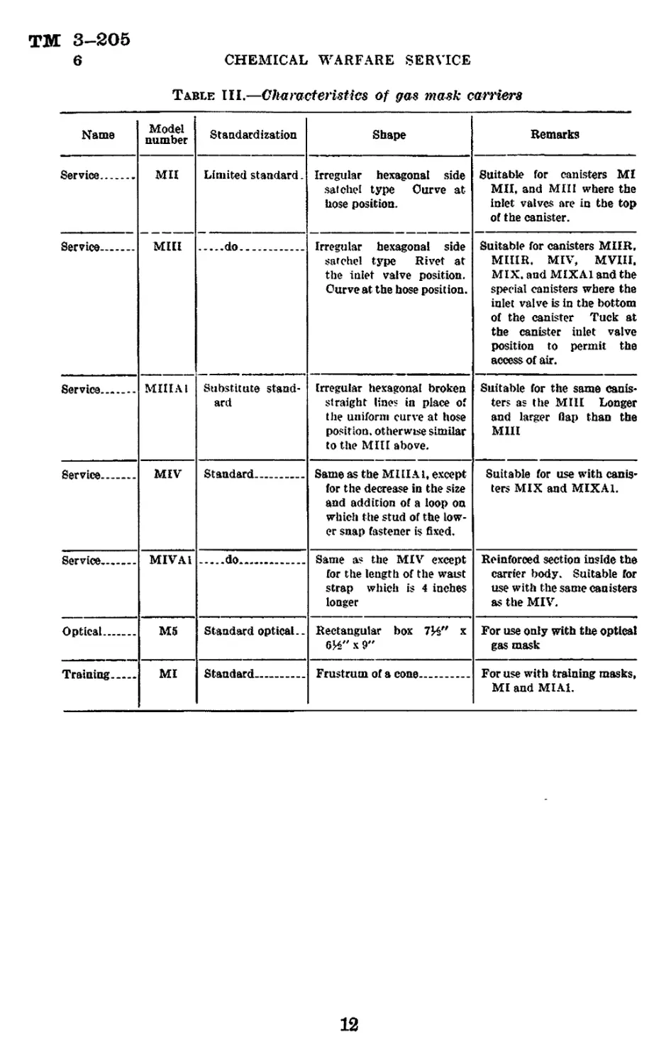
Table III.—Characteristics of gas mask carriers
Mama Model number Standardization Shape Remarks
Service МП Limited standard. Irregular hexagonal side satchel type Curve at Lose position. Suitable for canisters MI MH, and Mill where the inlet valves are in the top of the canister.
Service Mill do Irregular hexagonal side satchel type Rivet at the inlet valve position. Curve at the hose position. Suitable for canisters MIIR, MUIR. MIV, MVIII, MIX. and MIXA1 and the special canisters where the inlet valve is in the bottom of the canister Tuck at the canister inlet valve position to permit the access of air.
Service MIHAI Substitute stand- ard Irregular hexagonal broken straight lines in place of the uniform curve at hose position, otherwise similar to the МШ above. Suitable for the same canis- ters as the Mill Longer and larger flap than the М1П
Service MIV Standard Same as the Ml II Al, except for the decrease in the size and addition of a loop on which the stud of the low- er snap fastener is fixed. Suitable for use with canis- ters MIX and MIXA1.
Service MIVA1 do Same as the MIV except for the length of the waist strap which is 4 inches longer Reinforced section inside the carrier body. Suitable for use with the same canisters as the MIV.
Optical M5 Standard optical.. Rectangular box 7И" x 6И" x 9" For use only with the optica! gas mask
Training MI Standard Frustrum of a cone For use with training masks, MI and MIAl.
12
TM 3-206
6-7
THE GAS MASK
HEAD HARNESS
FACEPIECE
DEFLECTOR
CHIN SEAM
HEAD
HARNESS
BUCKLE
BUCKLE
TAB
OUTLET
VALVE GUARD
HOSE
EYEPIECE
BINDER
RING
'"’EYEPIECE
ANGLE CROSS
TUBE STRAP
ELASTIC
WEBBING
LENS
CLINCH
TIP
OUTLET VALVE
GUARD BOLT
OUTLET VALVE
PORT
HEAD PAD
PATCHES
OUTLET VALVE
Figure 3.—Service mask, MIA2.
EYEPIECE i*
BINDER
RING
OUTLET
VALVE
EYEPIECE
ANGLE
TUBE
HOSE
FACEPIECE
DIAPHRAGM
DEFLECTOR
TUBE
HEAD HARNESS
ELASTIC WEBBING
HEAD
PAD
CROSS STRAP
,ANGLE
TUBE
RETAINER
CHIN REST
HOSE STEM
Figure 4.—Diaphragm mask, MIL
7. Description and nomenclature of service and diaphragm
facepiece parts.—The parts and minor components of the MIA2
service facepiece assembly are illustrated in figure 3; the parts of the
Mil diaphragm facepiece assembly in figure 4. A discussion of the
more important parts of these and other facepieces follows:
13
ТМ 3—305
7
CHEMICAL WARFARE SERVICE
a. Facepiece.—(1) Most service and diaphragm facepieces are made
from a flat piece of stockinette-covered rubber known as the face-
blank. However, facepieces could be made from leather, synthetic
lubber, or impregnated cloth. This blank is of such a shape that
when it is folded double, a single seam (the chin seam) will produce the
proper shape to fit the face and leave a round hole in the lower front
portion in which the angletube may be inserted. The eyepiece holes
in the faceblank are elliptical in shape so that when the eyepieces are
inserted, the tension on the rubber will cause the mask to fit snugly
across the forehead and the eyepieces to bulge forward.
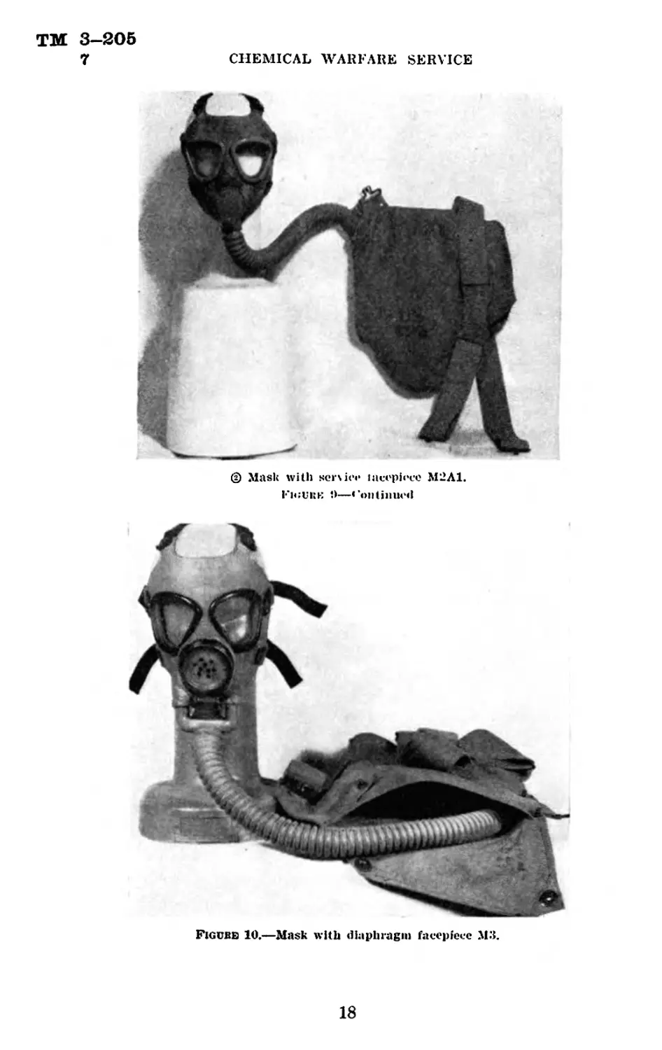
(2) There are five types of service facepieces: the MI (fig. 5);
MIAl (fig. 6); MIAS (fig. 7); М2 (fig. 9); and M2A1 (fig. 9); and
four types of diaphragm facepieces: the MI (fig. 5); MIAl (fig. 6);
MH (fig. 7); and М3 (fig. 10). The М2 and M2A1 service facepieces
are the same as the MI and MIAl training facepieces (figs. 8 and 9).
The diaphragm facepiece has a larger opening in it than the service
mask so as to accommodate the larger angletube occasioned by the
diaphragm. The diaphragm MI and MIAl models correspond to the
service MI and MIAl, and the diaphragm Mil to the service MIA2.
except in the angletube assembly. The М3 has a fully-molded rubber
facepiece and corresponds to the service M2A1. In addition to the
differences in the eyepieces and the diaphragm assembly explained
below, there is a difference in size.
(3) The MI and MIAl were made in four sizes, number one being
the smallest. The number was placed near the center of the upper
edge of the facepiece. The MIA2, the М2 and M2A1 service, and MH
diaphragm are made only in the universal size. The letters US and
U are placed on the forehead of these; the letter U signifying uni-
versal size.
(4) Experience has shown that the various sizes will fit the follow-
ing percentage of men:
Size: Percent
One______________________________________________ Five
Two______________________________________________ Fifty.
Three___________________________________________ Thirty-five.
Four_____________________________________________ Ten.
Where the universal size mask is used, a small number of small sizes
are found necessary. The size range is about as follows:
Size: Pocent
Small_______________________________________— Five,
Universal______________________________________Ninety-five.
14
TM 3-205
7
THE GAS MASK
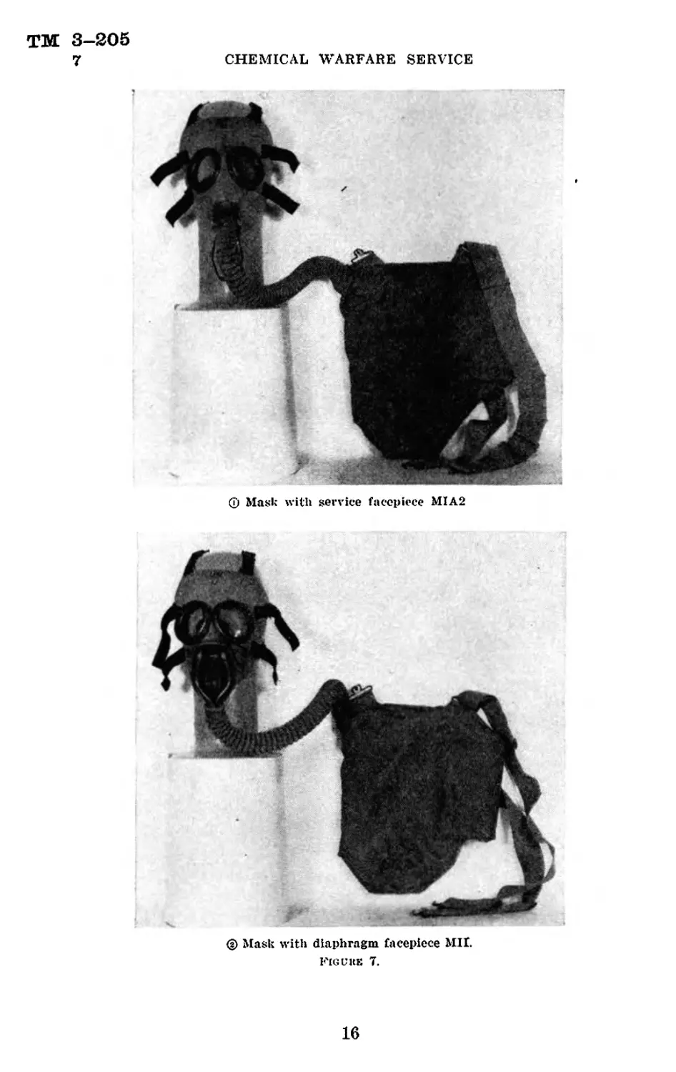
О Service.
© Diaphragm.
Figure 5.—Mask with facepiece Ml.
© Service.
© Diaplu.igm
Figi he 6.—Mask with facepiece MIAl.
15
ТМ 3—205
7
CHEMICAL WARFARE SERVICE
ф Mask with service facepiece MIA2
© Mask with diaphragm facepiece MIL
Fig и as 7.
16
TM 3-205
7
THE GAS MASK
(j) MI oi М2. (?) M(A1 or M2A1 (з) Carrier (all)
Figi he 8.—Training mask ami carrier
Ф Mask with ser\ ice facepiece М2
Figi re !»
412077°—41----2
17
ТМ 3—205
7
CHEMICAL WARFARE SERVICE
@ Mask with sen ice timepiece M2A1.
Ficuke 9—<’on tinned
Figube 10.—Mask with diaphragm facepiece М3.
18
ТМ 3-205
THE GAS MASK 7
(5) The training facepieces are made of fully molded rubber and
contain no chin seam. They are made only in a universal size and
bear the letters US and U on the forehead. There are two models,
the MI and MIAl. These are alike except for the outlet valves which
are shaped as illustrated in figure 8. In training facepieces to be
procured in the future, the MI and MIAl will be designated М2
and M2A1. respectively, since they will be the same as the service
М2 and M2A1. No change will be made in the nomenclature of
training masks in the hands of troops at present.
(6) The noncombatant facepiece (fig. 21) is made of laminated
impermeable fabric.
(7) The optical facepiece (fig. 19) is made of fully molded rubber
and contains no chin seam. It is made only in a universal size and
is so marked. It is called the optical gas mask Ml-1-5. This mask
has a diaphragm and two 11-inch lengths of hose connecting the
facepiece to the head canister.
(8) The diaphragm facepiece М3 (fig. 10) is made of fully molded
rubber and contains no chin seam. The eyepieces are similar to those
of the training mask. It is made only in the universal size.
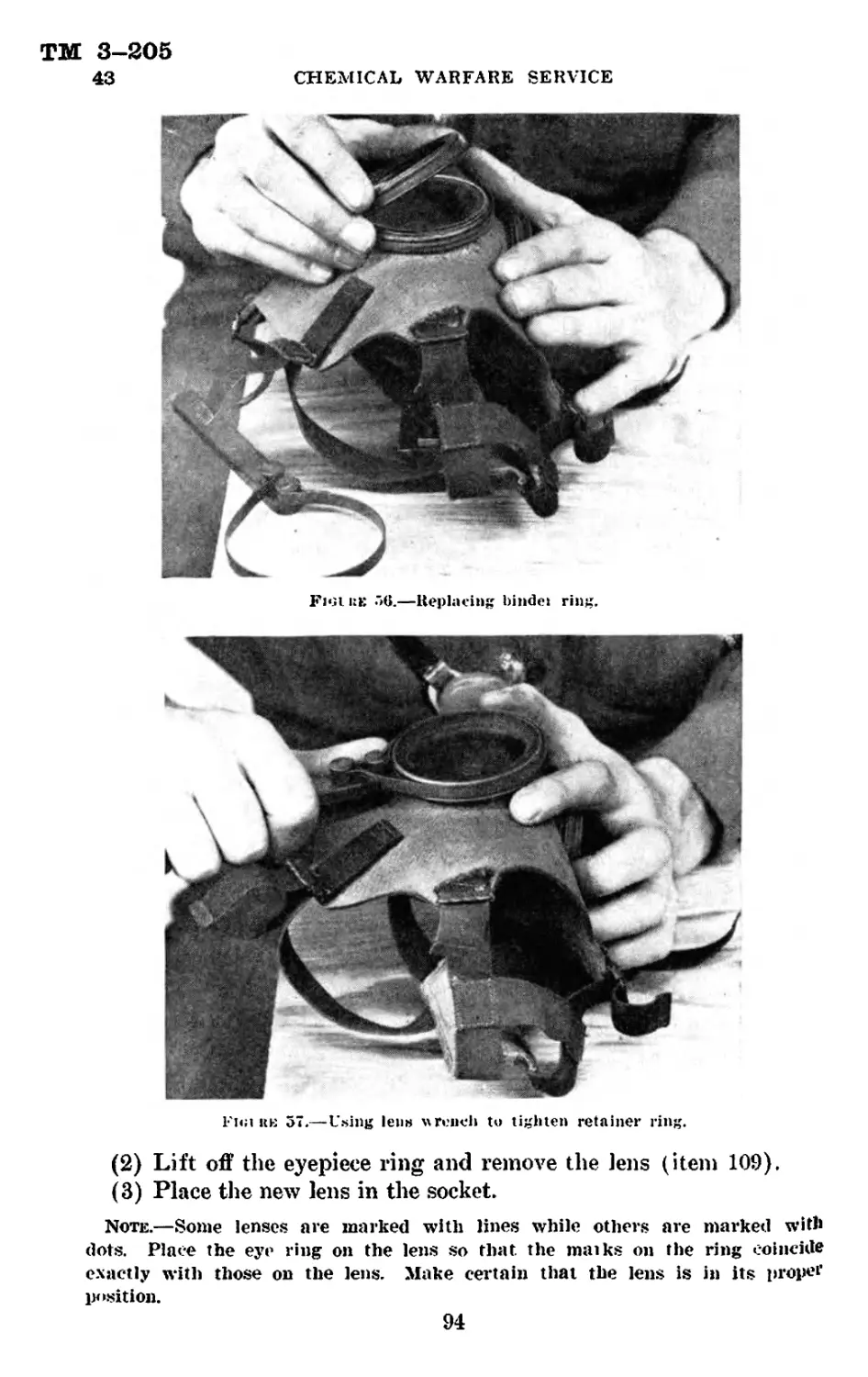
b. Eyepieces.—(1) The eyepieces of the service and diaphragm
masks having stockinette-covered facepieces, consist in part of metal
frames which are crimped on to the faceblank. Shatterproof lami-
nated glass lenses are held in place in these frames and are made gas-
tight by washers, and in the service MIAl and MIA2, and diaphragm
MIAl and Mil, are fastened on by a screw-type binder ring. Thus,
these lenses may be replaced in the field. The lenses of the service
MI and diaphragm MI facepieces are retained by a crimped-on frame
and therefore may not be changed in the field.
(2) In the training mask (fig. 8), the service М2 and M2A1 (fig. 9),
and diaphragm М3 (fig. 10), the eyepieces are made of a triangu-
larly shaped transparent plastic material, and are curved so as to
increase the field of vision and to permit a minimum of reflected
light. Left and right lenses are identical. The eyepiece holes
have molded recesses into which the lenses fit. The holes are smaller
than the lenses so that when they are in place, the resultant tension
insures an airtight fit. A metal eye ring is crimped on over the lens
to hold it in place.
(3) In the noncombatant mask (fig. 21) the eyepieces are made of a
transparent plastic and are sewn in place.
(4) The eyepieces of the optica] mask are of high grade plane
glass. They are small and are designed for use with binocular type
optical instruments. A thumbscrew device adjusts the distance be-
19
TIME 3—205
7
CHEMICAL WARFARE SERVICE
tween the lenses so as to vary the interpupillary distance to fit the
face and eyes of the individual wearer.
c. Angletube.—(1) The angletube of the service facepiece MI, MIA1.
and MIA2 connects the facepiece with the rubber hose which in turn is
connected to the canister. It is made of an aluminum alloy and con-
tains two separate tubes for air passages. Incoming air enters the
facepiece through one of these while the exhaled air leaves by the
other. The front passage is connected to the hose on the outside and
to the deflector on the inside of the facepiece. The other passage,
through which exhaled air is expelled^ is connected on the outside to
the outlet valve, while on the inside it is open to receive exhaled air.
These connections of the angletube to the facepiece, hose, deflector, and
the outlet valve are made by the use of rubber cement, steel binding
wire, and adhesive tape.
(2) The angletube assemblies for the MI and MIA1 diaphragm face-
pieces (figs. 5 and 6) are the same and are made of an aluminum alloy.
The inlet tube is connected to the side of the angletube near the outlet
valve, and branches on the inside to deliver the incoming air to each
eyepiece. *
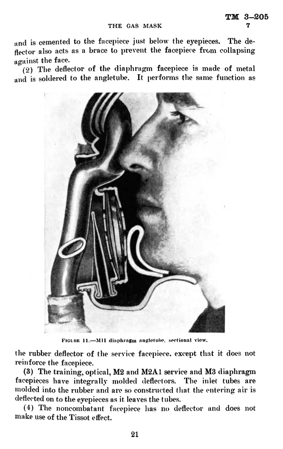
(3) The angletube assembly for the Mil diaphragm facepiece (fig. 7)
is illustrated by the sectional view in figure 11. The inlet tube splits <
near the bottom of the assembly to form two branches of a Y which
pass into the facepiece and’ thence to the lower edges of the eyepieces.
The outlet valve points upward and is protected from injury by the
branches of the inlet tube. The diaphragm is placed in rear of the ।
outlet valve. The assembly is made of copper.
(4) The angletube assembly for the М3 diaphragm facepiece con-
tains no air inlet tube (figs. 10 and 12). The corrugated hoses are
connected to the facepiece by means of a metal Y tube. The outlet
valve is placed below the diaphragm and is bent back between the chin
and the Y tube.
(5) The angletube assembly for the Ml optical facepiece also con-
tains no air inlet tube (fig. 19). The inlet tubes are molded into the
facepiece and are connected to the canister by corrugated hoses.
The outlet valve of this facepiece is also below the diaphragm and is
bent back. It has a metal valve guard.
d. Deflector.—(1) The deflector of the service facepiece MI, MI Al,
and MIA2 is a butterfly-shaped piece of rubber which causes air
entering the facepiece to pass up and across the inner surfaces of the
eyepieces, thus causing evaporation of moisture which tends to con-
dense on the lenses. (This is known as the “Tissot effect.”) It is
fastened to the angletube with rubber cement and a wire loop (fig. 69),
20
TM 3-205
7
THE GAS MASK
and is cemented to the facepiece just below the eyepieces. The de-
flector also acts as a brace to prevent the facepiece from collapsing
against the face.
(2) The deflector of the diaphragm facepiece is made of metal
and is soldered to the angletube. It performs the same function as
Figire 11.—Mil diaphragm anglehibc. sectional view.
the rubber deflector of the service facepiece, except that it does not
reinforce the facepiece.
(3) The training, optical, М2 and M2A1 service and М3 diaphragm
facepieces have integrally molded deflectors. The inlet tubes are
molded into the rubber and are so constructed that the entering air is
deflected on to the eyepieces as it leaves the tubes.
(4) The noncombatant facepiece has no deflector and does not
make use of the Tissot effect.
21
ТМ 3-205
7
CHEMICAL WARFARE SERVICE
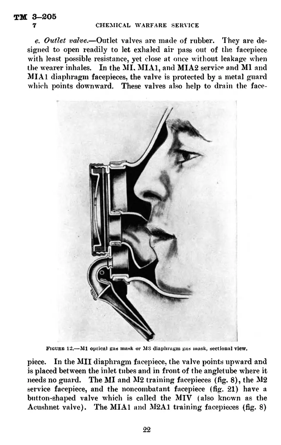
e. Outlet valve.—Outlet valves are made of rubber. They are de-
signed to open readily to let exhaled air pass out of the facepiece
with least possible resistance, yet close at once without leakage when
the wearer inhales. In the MI. MIAl, and MIA2 service and MI and
MIAl diaphragm facepieces, the valve is protected by a metal guard
which points downward. These valves also help to drain the face-
Figurb 12.—Ml optica) ga« mask or М3 diaphragm gas mask, sectional view.
piece. In the Mil diaphragm facepiece, the valve points upward and
is placed between the inlet tubes and in front of the angletube where it
needs no guard. The MI and М2 training facepieces (fig. 8), the М2
service facepiece, and the noncombatant facepiece (fig. 21) have a
button-shaped valve which is called the MIV (also known as the
Acushnet valve). The MIAl and M2A1 training facepieces (fig. 8)
22
ТМ 3-205
THE GAS MASK 7
and the M2A1 service facepiece have a valve which is a modification
of and functions similar to those on the older type service face-
pieces. It is called MV (also known as the Connell valve) and has a
plastic valve guard. The optical mask (fig. 19) and the diaphragm
facepiece М3 (fig. 10) have pear-shaped valves, and are otherwise
similar to the service masks, but are protected by metal guards bent
to slope under the chin and to the rear.
f. Head harness.—(1) In the service and diaphragm masks, the
head harness, which holds the facepiece firmly in place on the head,
consists of six elastic tapes each attached at one end to buckles which
in turn are attached to the edge of the facepiece. The other end is
«attached to a pentagonal piece of cloth-covered felt called the head-
pad. In some cases, this headpad may be a rectangularly shaped piece
of canvas. Since the buckles are attached to the facepiece, the entire
head harness may be readily replaced, if necessary, in the field.
(2) The training and noncombatant head harnesses are similar to
those of the service and diaphragm masks, but the elastic webbing
straps are sewed together in a triangle instead of being attached to
a piece of cloth or felt. Nevertheless, this triangle is also called a
headpad. The optical mask has a rosette-shaped head harness made
of six loops of coiled wire arranged so as to support the head canister,
and with web tapes attaching springs to buckles on the facepiece.
In this case, the headpad is circular. It is made of molded rubber
shaped to fit the contours of the head and also to receive the coiled
wire loops. It has a recess in the rear center for attaching a metal
clip. The clip in turn supports the canister.
Hase.—(1) The hose of the service and diaphragm masks is a
tube made of corrugated rubber and is 27 inches long. It connects
the canister to the facepiece. Early models were stockinette covered.
(2) The training mask has no hose. The canister is connected to
the facepiece by a short tube which is integrally molded into the face-
piece. The noncombatant mask has the canister connected directly
to the facepiece with no nozzle between. The optical mask has two
il-inch lengths of hose which connect to opposite ends of the head
canister. These are corrugated and have a molded rubber elbow
(90°) where the hose connects to each end of the head canister.
A. Diaphragm assembly.—(1) The diaphragm, which facilitates
voice transmission, consists of a thin disk made of plastic or resinous
material and is protected by a perforated metal guard. There are
three types of diaphragms; the first is used in the diaphragm face-
pieces Ml and MI Al (figs. 5 and G): the second in the Mil diaphragm
(fig. 7); and the third in the М3 diaphragm (fig. 10) and the Ml
optical facepiece (fig. 19).
23
ТМ 3-205
7
CHEMICAL WARFARE SERVICE
(2) In the diaphragm facepieces MI, MIA1, and Mil. the angle-
tube assembly is modified to permit the insertion of the diaphragm.
Otherwise, these facepieces are similar to the service facepieces MI9
MIA1, and MIA2, respectively (figs. 5, 6. and 7).
(3) The diaphragm assembly of the diaphragm facepiece Mil is
made to include the outlet valve. There is a fabric chin rest sewed
into the facepiece to prevent the wearer’s nose, chin, and mouth from
coming in contact with the diaphragm assembly.
(4) The diaphragm assemblies of the М3 diaphragm facepiece and
the Ml optical facepiece are similar and have no connection with
the air inlet tubes as is the case with all others The outlet valve and
guard assembly of these facepieces is an integral part of the diaphragm
assembly.
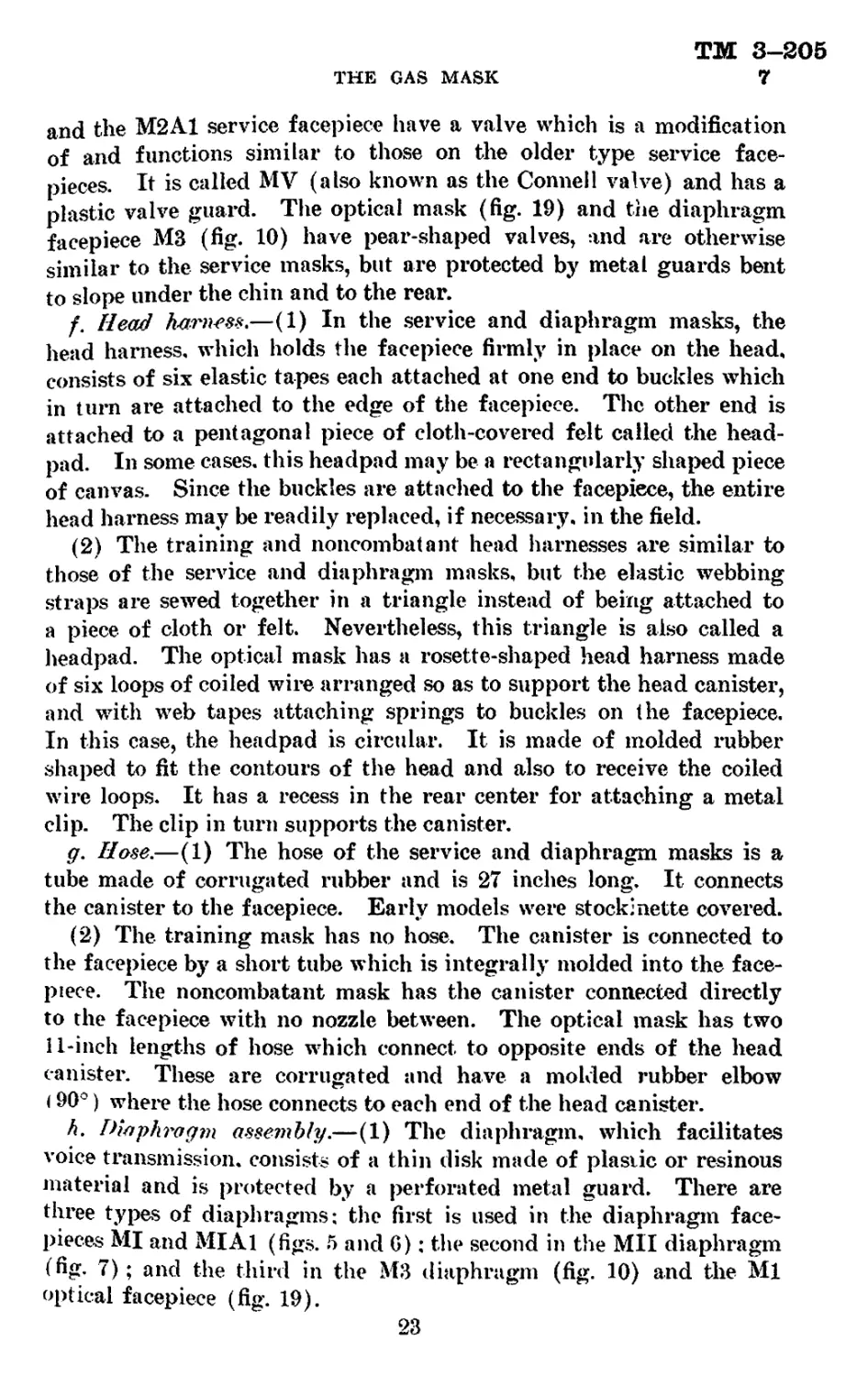
z. Antidim.—(1) A small can containing a piece of cloth wrapped
around a stick of soap-like compound called antidim (fig. 13) is
Ejguke 1:1 —Antidiin
furnished with each service and diaphragm mask. It is held in the
carrier by a loop of fabric sewed on the lower canister strap. If
used as directed, this antidim will greatly reduce fogging of the
eyepieces. Antidim should be used after each time the mask is
worn. To apply, clean the eyepieces, rub the stick gently on both
sides of the lenses, leaving a small amount of the antidim on the eye-
pieces. Spread it evenly over the surface with the fingers. Then
polish both sides of the eyepieces with the cloth until the antidim
is evenly distributed on the surface of the lenses. If properly ap-
24
ТМ 3-205
THE GAS MASK 7-8
plied so as to leave a coating, the eyepieces will have a uniformly
even surface upon which there will be little obscuring effect of the
exhaled breath.
(2) Antidim does not prevent the condensation of moisture upon
the lenses. The antifogging effect is obtained in quite a different way.
Water does not easily wet or spread over glass. The tiny droplets
of moisture condense upon the lenses and instead of spreading remain
as drops, each having a surface which reflects light. Light rays
which penetrate the water droplets are refracted unevenly and at
mam different angles. These reflected and refracted rays interfere
with one another, thus causing the fogging effect. Antidim reduces
the surface tension of the condensed droplets of water, causing them
to form a thin, even film through which light passes with less dis-
tortion and much less interference than when the moisture is in
multitudinous droplets. Thus, clearer vision is obtained.
(3) Antidim is not supplied with the training masks, but it can
be used on plastic lenses in the same manner as on glass eyepieces.
In lieu of antidim, a good grade white toilet soap may be used.
It should be spread with a soft cloth such as a handkerchief. Care
must be taken when antidim is applied to plastic lenses lest the
surface be scratched.
8. Description and nomenclature of canisters and canister
parts.—a. General.—The very earliest of military gas masks had no
canister: instead, the air was passed through layers of treated cloth.
These filters were improved by introducing a box of chemicals in
place of the cloth. The safety and protection furnished by the gas
mask was very greatly increased thereby because of the increase in
surface and the greater quantity of the chemicals. Modern develop-
ments of the canister have been along the lines of producing greater
effectiveness in particulate (or smoke) filtration, and in increasing
the efficiency of the absorbents by means of various added chemicals.
b. Part*.—The canister includes three main parts (fig. 14) : a con-
tainer made of metal and provided with an air inlet and outlet; a
filter which removes solid and liquid particles by mechanical filtra-
tion: and a chemical filling which removes gases by adsorption, neu-
tralization, or both. The canister must conform to the general
requirements for gas masks which are given in paragraph 4e. This
greatly limits the materials which may be used.
(1) Container.—The container is the box into which the mechanical
filter and chemicals are placed. It may be made of lithographed or
enameled sheet iron, galvanized iron, aluminum, tin plate, or some
other metal. Tin plate is most generally used. The MI to MVIII
25
ТМ 3—205
8
CHEMICAL WARFARE SERVICE
and the MIXA1 canisters are rectangular in shape with rounded
vertical edges and having corrugated sides; the ends are smooth. The
MIX canister is rectangular and has smooth sides and ends. The
training and noncombatant canisters are cylindrical and smooth.
The optical canister is cylindrical and corrugated.
800Y
INNER TUBE NOZZLE
BOTTOM
VALVE
SEAT
INNER TUBE
BAG
MECHANICAL
FILTER-----
ADHESIVE
TAPE
В
CHEMICAL
TOP
INNER TUBE
STUD
CHEMICAL
CONTAINER
BODY
CHEMICAL
filling
INLET VALVE DISC
Figure 14.—Gas mask canister, cross-sect Iona] view.
(2) Mechanical filter.— {a) The interstices of the mechanical filter
must be fine enough to stop the extremely small, .solid, and liquid
particles in which irritant gases and smokes occur. Most of these
particles cannot be seen under an ordinary high-power microscope
since they are of minute (colloidal) dimensions. Even under the
ultra-microscope, they are visible only as points of reflected light.
On the other hand, the filter must not be so dense as to cause a high
resistance to the flow of air through it and thus cause increased
breathing resistance. A filter which fulfills these requirements has
been developed.
(6) The materials used are fragile, and great care must be exer-
cised in handling and repairing gas mask canisters to the end that
these filters are not damaged. For this reason the canister will not;
be opened for repairs in the field except by special authorization as
described in paragraph 36d.
(3) Absorptive and neutralizing chemicals.—(a) General require-
ments.—The chemicals used for absorption must—
1. Be very minutely porous so as to provide a huge surface;
area for adsorption in as small a space as possible. 1
26
ТМ 3-205
THE GAS MASK 8
%* Not react with each other* nor corrode the container.
5. Not be greatly affected by humidity.
Remove the gases very rapidly since the air moves through
the canister at such a velocity as to be in contact with the
chemicals for only a fraction of a second.
5. Have a high capacity, since the canister should last several
months when in use.
6* . Be easily and cheaply manufactured from domestic raw
materials.
7. Not cause a high resistance to breathing.
б’. Resist crushing and abrasion.
(J) Activated charcoal.
1. Of all the materials tested for the requirements listed in (a)
above, the only one which approximately fulfills all the
requirements is activated charcoal made from a very dense
material and in the form of finely divided granules. Dur-
ing the World War, cocoanut shell was found to be the
best raw material, but various nut shells, fruit seeds, etc.,
were also used. Since then, methods of activation have
been greatly improved, and now domestic raw materials
can be used instead of cocoanut shell.
2. Charcoal is made from wood and wood-like materials which
consist of cellulose and other components. In charcoal
manufacture, the cellulose is heated and thus converted
to carbon, water is given off, and other constituents are
also evolved. The residue is called primary charcoal. If
the primary charcoal is then subjected to treatment with
heat and steam or to some superheated vapors or gases
in the absence or in limited amounts of air, more of the
constituents are driven off leaving purer carbon. This
activated charcoal is full of tiny spaces which were
formerly occupied by some other constituents of the origi-
nal material and now gives an extremely great surface to
a small amount of charcoal.
3. Charcoal may also be processed in part by chemical action,
as for example, by the peculiar charring action of zinc
chloride, concentrated sulphuric acid, or phosphoric acid.
lh When air containing a gas or gases used in warfare is
passed through activated charcoal, the molecules of the
gas are held physically on the surface of the pores of the
charcoal while the purified air flows through. This
process is called adsorption and may be considered com-
27
ТМ 3-205
8 CHEMICAL WARFARE SERVICE
parable to the action of a magnet in attracting and hold-
ing iron filings on its surface. The heavier the gas, the
more easily it is adsorbed.
5. One of the characteristics of chemical warfare agents is
that any such substance must be capable of producing the
desired effect in very small quantities or doses. Casualty-
producing chemical warfare agents are therefore chosen
for their high toxicity and relatively great effect in low
or minute concentrations.
6. The chemicals used in the gas mask canister, especially
the charcoal, must therefore be able to seize and securely
retain exceedingly small quantities of the chemical war-
fare agent. Also, these canister chemicals must be able
to retain relatively large quantities of the toxic substances.
Modern gas mask charcoal is chosen for these specific
qualities. However, the total weight of toxic substances
adsorbed and the tenacity with which they are held will
vary with the vapor density of the gas and the tempera-
ture. Thus, it is easier to adsorb and retain mustard gas
vapor which has a high vapor density than some other
lighter substance as, for example, hydrocyanic acid gas, or
even phosgene. At very high temperatures, these lighter
gases will be retained with difficulty, or if previously
adsorbed by the charcoal, may slowly be released again.
(б*) Neutralizing chemicals.
1. There are several chemical substances which will react with
and neutralize those gases or vapors not readily adsorbed
or not easily retained by the activated charcoal. These
may act on the gas in any or all of several ways as, for
example, by decomposition, oxidation, catalysis, or by direct
chemical combination. A number of these substances are
described under special canisters in section IV. The prin-
cipal neutralizing chemical in the service, optical, and
training canisters is soda lime, several different mixtures
of which have been developed so that the exact composition
may vary.
2. Those gases which are not easily or firmly held by the char-
coal or are given off by it come in contact with the soda
lime. This latter substance may combine directly with the
gas as in the case of phosgene, or may decompose the gas
to form harmless substances which in turn may combine
with the sodium and calcium hydroxides in the mixture.
28
TM 3-205
8
THE GAS MASK
The soda lime reacts more rapidly at higher temperatures.
Thus, there is an advantage in having a combination of
charcoal and soda lime, in that while a rise in temperature
decreases the adsorptive capacity of the charcoal, it in-
creases the chemical activity of the soda lime, and the two
effects tend to balance each other.
(d) Removal of specific chemical agents.—The following table
shows which components of the canister absorb or neutralize the vari-
ous known war gases:
Symbol Types of agents Neutralizing component
DM Adamsite Filter.
CA Brom benzylcyanide Charcoal.
CN C h loracet ophenone Charcoal and filter.
CNB Chloracetophenone solution Do.
CNS do_ _ Do.
Cl Chlorine Charcoal-soda lime.
PS Chlorpicnn-— Charcoal.
cc Cyanogen chloride Do.
DP Diphosgene Charcoal-soda lime.
DA Diphenylchlorarsine Filter.
ED E thy Idichlorarsine Charcoal-soda lime.
M-l Lewisite Do.
HS Mustard gas Charcoal.
CG Phosgene Charcoal-soda lime.
c. Limitations of service canister.—The service canister does not
protect against carbon monoxide or ammonia or does it supply oxygen.
(1) Carbon monoxide.—Carbon monoxide is odorless and colorless,
and a person subjected to a sufficient concentration of it will lose con-
sciousness without warning. It is lighter than air however, and
therefore high concentrations are likely to be found only in inclosed
spaces. Carbon monoxide may be present in burning buildings since
it is one of the products of combustion. Therefore, the Army canister
must not be used in fire fighting. There is an all-purpose canister
which is suitable for protection against carbon monoxide, as explained
in paragraph 18&. Carbon monoxide may also be encountered in
automobile exhaust gas, illuminating gas, blast furnace gas, mine-
explosion gas, and gases resulting from the burning of smokeless pow-
der propellants, such as might be found in pillboxes, casemates, and
inclosed turrets. Ventilation removes the carbon monoxide.
(2) Ammonia gas.—Ammonia gas may be encountered in accidents
or fires around refrigeration plants. The service canister must not be
used for protection when such an accident occurs.
29
IM 3-205
8
CHEMICAL WARFARE SERVICE
(3) Oxygen deficiency.— (a) Canisters will not supply or manufac-
ture oxygen and therefore must not be used where the air is deficient
in oxygen. In a mine after an explosion, in the hold of a ship, in an
oil or gasoline tank, etc., this deficiency may occur. In such cases, a
hose mask or a self-contained oxygen apparatus, such as described
in paragraphs 14 and 15, should be used.
(&) The service canister is designed to protect only against low con-
centrations of war gases not greater than approximately one percent
by volume. Higher concentrations are unlikely to occur in the field,
except when a shell bursts in an inclosed space or very close to the
victim. In such a case, a man, although he is wearing his mask, should
hold his breath if momentary penetration occurs. The extremely high
concentrations are transitory in the open as wind sweeps gases away.
Such high concentrations may also result when one is changing a valve
or repairing a leak on a chemical cylinder.
d. Types of canisters in use.— (1) Nine types of service canisters
have been issued since World War I: the MI, Mil. MUR. Mill,
MUIR, MIV. MV1II. MIX, and MIXA1 (fig. 15). (For description
Figure !•">.—<»as mask canisters.
30
ТМ 3-205
THE GAS MASK 8
see table II.) There are also special canisters, and canisters for the
optical mask, noncombatant mask, and the training masks. All the
service canisters are fundamentally the same; each has a mechanical
and chemical filter, but improvements have been made in every case.
All the canisters since and including the Mill give practically com-
plete protection against war gases at concentrations likely to be en-
countered in the field. The MI is obsolete as its protection against
smokes is considered too low, although it is substantially higher than
that of the better World War I canisters; the Mil and MIIR are better
but provide rather low protection. The training canister gives ade-
quate protection against war gases, but since it is smaller than the serv-
ice canisters it will not last as long under the same conditions of use.
(2) Assuming proper care and use, the life of any canister depends
upon these factors:
Concentration of gas=c
Rapidity of breathing=b
Time of contact = t
Thus, life or 1=еХ&ХЛ and a change in any one will result in a
corresponding change in the life because the canister is designed to
hold or neutralize a definite weight of absorbed chemical agent.
(3) The military canister if correctly cared for rarely breaks down
suddenly. It usually fails very gradually, and its user can detect
evidences of failure through minor physiological effects and warning
signs such as odor, slight headache, and lacrimation. These effects
generally can be noticed long before the mask completely fails.
(4) Table II gives the chief characteristics of the various canisters
for identification purposes, while their pictures are shown in figure
15. A cross section of a service canister is shown in figure 14.
(5) (a) The Army service canister consists of a corrugated sheet
metal can or outer container. 7 by 4% by 3 inches in the MI to
MVIII, and by 4% by 3 inches in the MIX and MIXA1. (The
MIX is not corrugated,) At the bottom of the outer container
(except in the case of the MI, Mil, Mill, and MIX) is an inlet
valve consisting of a rubber disk attached to a metal valve seat.
The MIX canister has no inlet valve. In the MI, Mil, and Mill
canisters there are two inlet valves in the top of the canister. These
are covered by a rain shield and may be used in the Mil carrier. In
the MIIR and MUIR models, the canister bodies have been changed
to the “valve in bottom” type. All canisters with the valve in the
bottom are used with Mill or MIV type of carriers (see table III).
The interior construction of the MIIR and MUIR is the same as
the original models.
31
ТМ 3-205
8—9 CHEMICAL WARFARE SERVICE
(b) The inlet valve (or valves) opens only when the wearer inhales
and thus prevents the exhaled breath from passing out through
the canister. If permitted to do so the carbon dioxide of the exhaled
breath will react with and cause deterioration of the soda lime.
(c?) At the top of the canister is an elbow nozzle (except on the
MI and Mil where the nozzle is straight) which connects to the hose
leading to the facepiece. A metal elbOw is furnished with the Mil
canister. It is about 1 inch long on one end and 1% inches long
on the other. In assembling the canister to the hose, the long end
of the elbow is inserted into the nozzle and the hose is forced over
the short end. The elbow prevents kinking of the hose.
(d) Inside the can is a filter which catches solid particles of smokes
and some liquid particles. Within the filter is a perforated metal
container which contains the chemicals, a mixture of activated char-
coal, and soda lime. These adsorb and neutralize the gases which
have passed through the filter. There is another smaller perforated
metal inner tube which is covered with a muslin inner tube bag to
prevent the chemicals from working through the perforations. The
inner tube opens directly on the outlet nozzle.
(6) The training canister is a cylindrically shaped smooth can
5% inches long and 3 inches in diameter. Its internal structure is
similar to that of the service canister. A canister similar to the
training canister but without a nozzle is used with the noncombatant^
mask. The optical canister is also a cylindrically shaped can
inches long and 3 inches in diameter, and with a long slit in the sid^
for an air inlet and two nozzles, one at each end. There is a valvd
in each nozzle which serves the same purpose as the inlet valve on
the service canister.
9. Description and nomenclature of carrier.—a. The service
carrier is an irregularly shaped satchel made of olive-drab canvas
provided with adjustable shoulder and waist straps made of 2-inch
cotton webbing (fig. 16). It is carried on the left side under the arm
so that one strap is over the right shoulder and the other around th«
waist. The carrier opens to the front when in the slung position,
and the opening is covered by a flap which is closed with two snap
fasteners. Inside the carrier are two straps to hold the canister ill
place. The upper one is sewed to the left side and fastened to the
right side of the carrier by means of a snap fastener. The lowej
one is sewed at both ends, and has sewed to it a loop which holds
the antidim can. Five service carriers, the Mil, Mill, MIIIA1
MIV, and MI VAI. have been made and are illustrated in figure IT
(For description see table III.) The rectangular shaped MI car
32
TM 3-205
9
THE GAS MASK
HOOK CLASP
SLIDE
SHOULDER STRAP
BODY
STRAP
STRAP
CARRIER
BODY
UPPER
CANISTER
STRAP
HOSE POCKET 1
EYE CLASP
SNAP FASTENER STUD
SNAP FASTENER
SOCKET
CHAPE
LOWER
CANISTER
STRAP
ANTI DIM
STRAP AND
ANTI DIM SET
Figuk& 16.—NompnelatuiP ot «as mask ranier MIVA1.
MH Mill MIHAI MIV MIVA1
Fxsi re 17—Service carriers.
rier is obsolete. All others are in use though the Mil is no longer
issued. They are fundamentally the same but each is an improve-
ment over the previous one.
6. As explained in table III, the Mil carrier, which has no tuck
in the bottom, is used with canisters MI, Mil, and Mill, since these
canisters have the inlet valves in the top. AH other service canisters
have the air inlet in the bottom; therefore, the other carriers all have
a tuck below the air inlet of the canister to permit unrestricted air
passage. The Mill has this tuck and a rivet at the inlet valve posi-
tion. In the Mill Al the uniform curve at the hose position is re-
placed by broken straight lines. The MIV carrier is smaller than
the Mill Al, the flap has been reshaped, and a loop is added on which
the post of lower snap fastener is fixed. The MIVA1 carrier is the
same as the MIV except that the waist strap is 4 inches longer.
412077° —41-----3
33
ТМ 3—305
9
CHEMICAL WARFARE SERVICE
<?. The optical gas mask carrier (fig. 18) is a rectangular shaped
canvas satchel. It has an adjustable shoulder strap but no waist
strap. The opening is at the top and is covered by three flaps, two
*FACEFO
FAC ЕР I EC
HOSE
SHOULDER AMD BODY
STRAPS TO BE NEATLY
FOLDED AND TUCKED
INSIDE OF CARRIER
.CANISTER
ANTI DIM SET
OUTLET VALVE GUARD
♦HOSE-GUARD
*NOTB - The faceform and boat-guard are
used la packing masks for storage,
Figi re 18 —Placement of gas mask in carrier.
CARRIER
being extensions of the sides which fasten together in the cental
and the third being an elongation of the back side which comes ove
the side flaps and fastens in two places on the front of the carrier.
d. The training gas mask carrier is shaped like an inverted frustur
of a cone. It has an adjustable shoulder strap made of %-incl
cotton webbing and a waist cord made of cotton shelter tent rope
The opening of this carrier is at the top and is covered with a flaj
which is an elongation of the inner side of the carrier. This flaj
is closed with one snap fastener. The facepiece and canister ai|
completely removed for adjustment to the face. The noncombatan
gas mask carrier is similar to the training mask carrier except that it i
shorter and has no waist cord.
34
TM 3-205
9-10
THE GAS MASK
Section III
SPECIAL RESPIRATORS
Paragraph
Optical gas mask Ml-1-5----------------------------------------------------- ю
Aviators’ gas mask---------------------------------------------------------- ц
Dust respirators----------------------------------------------------------- 12
Paint respirators---------------------------------------------------------- 13
Hose mask------------------------------------------------------------------ 14
Oxygen breathing apparatus------------------------------------------------- 15
Noncombatant gas mask------------------------------------------------------ 10
10. Optical gas mask Ml—1—5.—The optical gas mask (fig. 19)
is designed for use with optical instruments, such as range finders,
gun sights, field glasses, periscopes, etc., where the instruments must
be held close to the eyes. It has small eyepieces made of plane glass.
An adjustable bridge, called the eyepiece adjustment assembly, across
the nose connects the two eyepieces so that the space between may be
changed to correspond to the distance between the wearers eye pupils,
and thus permits him to focus and use binocular instruments requir-
ing both eyes to be adjusted to the instrument eyepieces. There is
a diaphragm in the mask to facilitate speech transmission. The
canister is fitted to a head harness and when in use rests on the lower
part of the back of the head so as to prevent interference by the hose
with the operation of optical instruments. It is made only in the
universal size. This mask is described in detail in appropriate
paragraphs on the service mask.
35
ТМ 3—305
11—12
CHEMICAL WARFARE SERVICE
11. Aviators’ gas mask.—The aviators’ gas mask, which is ii
the development stage and has not been standardized, has a full]
molded rubber facepiece with eyepieces similar to those in the train
ing mask. It contains a diaphragm to aid in speech transmission
It is so constructed that by means of a 3-way valve the wearer car
breathe oxygen from his oxygen tank, air that has been filterec
through a canister, or unfiltered air. Thus, he can choose his aij
supply at will. It is made only in the universal size.
12. Dust respirators.—a. Commercial type dust respirators
have been adopted for protection of certain classes of military per
soimel such as vehicle drivers. These respirators are light, com
fortable, half-masks with effective dust filters. In most models theri
is an inlet and outlet valve; in some models there is no inlet valve
They cover only the lower portion of the face, and if protection foi
the eyes is desired, goggles must be worn. Several of the modeh
in present use are shown in figure 20. Nomenclature and numberi
shown in figure 20 are assigned by the manufacturer and have n<
military significance.
ft. A respirator similar to the American Optical Company Вл-910!
has been standardized as the model 1. This respirator includes
both an inlet and an outlet valve. The filters for the respirator}
other than the R-9100 shown in figure 20 are replaceable and an
expendable.
Ф American Optical Company R-1000.
® Mine Safety Appliance Company Comfo.
(3> Wilson Company No. 5.
(?) American Optical Company R-9100
Figurh 20.—Dust respirators, commercial types.
36
ТМ 3-205
THE GAS MASK 12-15
Caution.—Troops wearing these respirators must always bear in
mind that they do not protect against gas.
13. Paint respirators.—a. Paints, particularly the newer types of
synthetics and lacquers, contain certain noxious constituents. Men
engaged in paint spraying are subjected to the fumes of the volatile
portions of these paints. Although spraying is usually done under a
hood connected to an exhaust fan. some of the fumes almost always
escape into the room. Since the human body can stand small amounts
of these substances, only partial protection is necessary. The paint
respirator covers the wearers nose and mouth. It contains several
layers of felt to stop pigment and liquid particles, and activated char-
coal to catch some of the fumes. The eyes are not protected.
b. Protection from paint fumes should be provided in military
establishments where spray painting of vehicles and other equipment
is required and no special ventilation is provided. Paint respirators
to be used by the United States Army are of commercial type approved
by the United States Bureau of Mines and are procured and issued
by the Quartermaster Corps.
14. Hose mask.—a. When the concentration of oxygen is below
the 16 to 17 percent required to sustain life, or the concentration of a
gas is too great for the special canisters provided for it, either a hose
mask or a self-contained oxygen breathing apparatus is required.
1'he former consists of a facepiece similar to the service, diaphragm,
or training types, attached to a length of hose. With it the wearer
may enter tanks, tank cars, ships’ holds, sewers, etc., in safety. About
25 feel or more of hose are attached to the mask and the inlet
is placed in an uncontaminated source of air. A hand or motor-driven
blower may be provided for longer lengths of connecting hose. The
hose mask is simple, rugged, and costs little to maintain. The hose
mask gives full protection to the lungs against all gases if the open
end of the hose is in an uncontaminated atmosphere. On the other
hand, it restricts the movements of the wearer and requires either a
pump tender or an assistant who watches from the outside of the
inclosure.
b. Hose masks are not made by the United States Army but may
be obtained commercially. However, hose masks may be improvised
by attaching a long length of hose to any military facepiece, if neces-
sary. Obviously, their military use is limited.
15. Oxygen breathing apparatus.—a. Whenever concentra-
tions of gas are so high as to render the standard gas mask or any of
the special canisters useless, or when there is a deficiency of oxygen
a ml the hose mask is not suitable for use, the self-contained oxygen
37
TWT 3—205
15-Х6
CHEMICAL WARFARE SERVICE
breathing apparatus is required. This mask supplies an artificial
oxygen atmosphere and gives full protection to the wearer’s lungs ini
any atmosphere containing any gas or a lack of oxygen. It consists of
a facepiece (or mouthpiece), one or more tanks of oxygen, a pressure
control apparatus, and a regenerator which removes the carbon dioxide
in the exhaled air before the air is rebreathed. The tanks are usually?
carried on the back. The disadvantages of the apparatus are that
fresh tanks of oxygen are needed from time to time and the apparatus
may get out of order.
b. This apparatus is used extensively in mine rescue work whetf
carbon monoxide and methane gases or oxygen deficient atmospheres
are encountered, and in fighting certain kinds of fires. The Navy
“escape” lung and the high altitude aviator’s masks are modifications
of the oxygen breathing apparatus.
<?. The self-contained oxygen breathing apparatus is not made by the
United States Army but may be obtained commercially. Obviously;
its military use is limited. ;
16. Noncombatant gas mask.—The noncombatant gas mask
(fig. 21) is an inexpensive but efficient mask for civilian employees and
others who are not required to engage in any great activity during
Figure 21.—Noncombatant gas mask MI-I-I.
38
TM 3-205
16-17
THE GAS MASK
gas attacks. The canister, which is attached directly onto the front
of the facepiece, is not replaceable. Except for the omission of
the canister nozzle, the noncombatant canister is the same as is used in
the training mask. The eyepieces are made of a transparent plastic
material and are sewed in place. The facepiece is made of rubberized
fabric and is sewed and glued together at a chin seam. There is no
deflector. A button or rubber disk type outlet valve which is the same
as the MIV outlet valve on the MI training mask is inserted in the left
side of the facepiece. These masks come in three sizes: large adult,
small adult, and child.
Section IV
SPECIAL CANISTERS
Paragraph
General--------------------------------------------------------------------- 17
All-purpose canister-------------------------------------------------------- 18
Acid vapor canister--------------------------------------------------------- 19
Hydrocyanic acid canister--------------------------------------------------- 20
Oil vapor canister---------------------------------------------------------- 21
Ammonia canister------------------------------------------------------------ 22
General safety precautions applicable when using special canisters-------- 23
17. General.—a. The following special canisters are used by the
Army:
Color painted
All-purpose________________________________Red
Acid vapor-------------------------------White
Hydrocyanic acid__________Yellow with white top
Oil vapor--------------------------------Black
Ammonia_________________________________Green
All the special canisters shown in figure 22 and described below (table
IV and pars. 18 to 22, inch), are designed for assembly with the stand-
ard service facepiece assemblies, MI, MIA1, MIA2, М2, or M2A1, or
the standard diaphragm facepiece assemblies, MI, MIA1, MH. It
is also possible to use these canisters with the standard training face-
piece MI or MI Al, providing the standard 27-inch hose is employed.
These canisters are to be used with carriers Mill and MIIIA1. The
outer containers of all special canisters are made of tin plate with
rounded corners and edges and are about 7 by 4% by 3 inches. Each
has an inlet valve in the bottom and each is connected to the hose by
means of a canister nozzle or nozzle elbow. In order to recognize them
readily, each type is painted a different color.
Ъ. The test conditions used to determine the protection afforded are
severe. Concentrations used in testing are rarely encountered more
39
ТМ 3—205
17-18
CHEMICAL WARFARE SERVICE
than momentarily in service in well-ventilated places. The flow of 32
liters of air per unit as is required by the test is equivalent to the breath-
ing of a man performing hard work or walking at a rate of 3^ miles
per hour. '
1. All-purpose—red
2. Hydrocyanic acid—yellow with white top.
3. Acid vapor—white.
4. Oil vapor—black.
5. Ammonia—green
Figurн 22.—Special canisters.
18. All-purpose canister.—a, Description.—(1) The all-pur'
pose canister (fig. 22) is painted red. On one side of the canister S
pasted a red label on which brief instructions for the use and storagj
of the mask are printed. Absorbent chemicals which have a higl
capacity for absorbing or restraining irrespirable gases and smoke
are placed in the canister in layers. The first layer, which consists o;
250 cc of activated charcoal, has a high capacity for organic vapors
such as acetone, alcohols, aniline, benzene, carbon bisulfide, carbol
tetrachloride, chloroform, ether, ethylene dichloride, formaldehyde
gasoline and other petroleum distillates, and toluene.
(2) Above the charcoal is a cotton pad which filters out smokes
dusts, and mists. This, together with another cotton pad at the tog
is sufficient to remove large particulate smokes, such as those arising
40
TM 3—205
18
THE GAS MASK
from burning materials like coak wood, and paper. These filters do
not. however, remove all military irritant smokes.
(3) Next above the filter is a layer of 175 cc of silica gel for the
purpose of restraining ammonia. However, the silica ge] has some
absorptive power for restraining organic vapors and supplements the
charcoal in this respect. Silica gel is a silicic acid preparation formed
by precipitation from solution, dehydration, and granulation. Above
the silica gel is a metal screen separator.
(4) Above the metal screen separator are placed 400 cc of caustic
pumice for restraining acid gases and water vapor. Caustic pumice
is a granular preparation of caustic soda and pumice. Among the
numerous acid gases which are restrained by the caustic pumice may
be mentioned—
Acetic acid.
Formic acid.
Hydrogen sulfide.
Hydrocyanic acid gas.
Sulfur dioxide.
Chlorine.
Hydrochloric acid gas.
Oxides of nitrogen.
Phosgene.
(5) The caustic pumice also absorbs water vapor which must be
restrained, because it inhibits the action of the material (hopcalite)
next above it. A wire screen separator is placed on top of the caustic
pumice.
(6) The hopcalite is a specially prepared mixture of manganese
dioxide and copper oxide in granular form; 175 cc are included.
Hopcalite acts as a catalyst to cause union of carbon monoxide with
the oxygen in the air, thus forming the relatively harmless carbon
dioxide. The hopcalite functions until moisture in the air finally
penetrates to the hopcalite. As it is impossible for the wearer of a
mask to tell when the carbon monoxide, which is tasteless and odorless,
finally penetrates, and as water vapor is always present in the air
drawn into the canister, a time limit of 2 hours’ total use is put upon
a canister.
(7) Above the hopcalite is a wire screen separator. Next are 150
cc of caustic pumice to prevent access of water vapor to the hopcalite
from above.
(8) Lastly, there is another cotton pad filter between wire screens
to serve as a smoke filter and also to prevent dusts from the absorbents
being drawn into the facepiece. The absorbents are held firmly in
place by means of a strong spring in the bottom which presses firmly
against the stiff upper screen.
41
TM 3—305
18
CHEMICAL WARFARE SERVICE
Table IV.—Characteristic
Name Model number Standard iza- tion category Distinguishing characteristics
Oolor Type of body
AU-purpose MI Standard Red Rectangular corrugated body 2
Acid vapor MI do White .. ..do
HON MI do Yellow with white top. do
Oil vapor MI • ”<10 Black do
Ammonia MI do.— Green.. do. :
&. Protection.—(1) The all-purpose canister will provide protec-
tion against concentrations of 1 percent by volume of any toxic ga!
or against a total concentration of 1 percent by volume of any com-
bination of gases that may be met. When the gases finally breal
through the canister, the wearer can, in all cases except carboji
monoxide, recognize their presence by their odor or taste. Because
of the carbon monoxide, the time limit of 2 hours’ total use is imposed
If carbon monoxide is absent, the mask may actually protect again®
other gases beyond the 2-hour limit. However, the canister must noi
be used for a total period of time to exceed 2 hours, whether carbol
monoxide has previously been encountered or not. 1
(2) Specifications for the canister require that it shall restrain-4
(a) Carbon monoxide (CO) in concentrations of 1 to 1.2 mg (milll
grams) per liter (about 1,000 ppm (parts per million), or 0.1 регсехн
by volume) in air flowing at the rate of 32 liters per minute and agl
proximately saturated with water vapor at 25° C. Penetrations 4
not more than 0.02 mg CO per liter are permitted during the first 1Q|
minutes, nor more than 0.1 mg per liter during the next 50 minutes!
both are harmless amounts. The canister restrains higher concentre
42
TM 3-205
18
THE GAS MASK
of special canisters
Distinguishing characteristics—Contin ued Remarks
Dimensions Maxi- mum breath- ing re- sistance Valve Type—Size—Position
86 Valve in bottom Protects against all gases usually found at fires; fits standard facepiece assemblies and Mill, МША1, MIV, or MIVAl carriers.
7"хШ"хЗ" 60 do Protects against acid gases and acid vapors; fits standard facepiece assemblies and МШ, MIHAI, MIV, or MIVA1 carriers.
7"x4%"x3" 66 do Protects against usual concentrations used in fumi- gation (P. H. 8.); fits standard facepiece assem- blies and Mill, MIHAI, MIV, or MIVA1 carriers.
7"x4%"x3" 56 do-- Protects against moderate concentrations of oil or organic liquid vapors; fits standard facepiece assemblies and Mill, Mill A J, MIV,or MIVAl carriers.
7"x4%"x3" 65 do- Protects against moderate concentrations of am- monia gas: fits standard facepiece assemblies and Mill, MIHAI, MIV, or MIVAi earners.
tions of CO more readily than the low test concentration because of
the greater heat of reaction between higher concentrations of CO with
the oxygen (O2) which increases the rate of reaction.
(&) Ammonia in a concentration of 7 mg per liter in air (about
10,000 ppm, or 1 percent flowing at the rate of 32 liters per minute for
at least 15 minutes).
(c) Chlorpicrin for at least 15 minutes at a concentration of 50 mg
per liter in air (2,500 ppm, or 0.25 percent) flowing at the rate of 32
liters per minute and of 50 percent relative humidity. The chlorpicrin
is taken as representative of the entire class of organic vapors for this
test.
(<0 Phosgene for at least 25 minutes in a concentration of 20.25 mg
per liter in air (5,000 ppm, or 0.5 percent) flowing 32 liters per minute
and of 50 percent relative humidity. Phosgene is taken as representa-
tive of all the acid gases.
c Special precaution.—Masks equipped with the all-purpose canis-
ter should not be worn longer than 2 hours. The label on the canister
(bg. 22) includes a blank form for recording the periods of use and
Or keeping a running total of the time of usage. It is absolutely
43
ТМ 3—205
18-19
CHEMICAL WARFARE SERVICE
necessary to record each period of use immediately to insure the
safety of subsequent users of the canister.
19. Acid vapor canister.—a. Description.—(1) The acid vapo
canister (fig. 22) is painted white. On the outside of the canister is
pasted a label on which brief instructions for the use and storage o:
the mask are printed. In the canister above the inlet valve is a per
forated metal dome which supports the granular soda lime absorbed
for the acid vapors and permits the passage of air into the filling whicl
•is 1Д50 cc of soda lime.
(2) Soda lime has a high capacity for the acid vapors. It restrains
all acid vapors, of which the following may be mentioned among th(
numerous volatile acid materials:
Acetic acid.
Chlorine.
Formic acid.
Hydrogen chloride.
Hydrogen cyanide.
Hydrogen sulfide.
Nitrogen peroxide.
Phosgene.
Sulfur dioxide.
(3) The granules of soda lime are held in place by means or a spring
which presses against a stiff screen and cotton pad on the upper sur
face of the soda lime. The cotton pad also prevents any leakage of thi
soda lime or its dust into the spring compartment, whence the dust, il
present, might be carried into the facepiece.
ft. Protection.—The acid vapor canister will provide protection foi
40 minutes against 0.5 percent by volume of phosgene in air of 50 pe£
cent relative humidity flowing at the rate of 32 liters per minute, or ij
will restrain for 80 minutes hydrocyanic acid gas in concentration oi
0.2 percent in air of the same relative humidity and same rate of flow
Phosgene and hydrocyanic acid gas are taken as representative of th
entire class of acid vapors. While the canister will restrain up to j
percent of acid vapor, its life is reduced accordingly. It is necessarj
for the wearer of the mask to know that the concentration of the aci(i
vapor does not exceed 1 percent, because higher concentrations maj
quickly penetrate the mask. j
c. Special precofutions.—(1) The life of the acid vapor canister
when worn in ventilated places, is generally very much longer thai;
indicated in b above because it is seldom that the wearer will be sub?
j'ected to concentrations continuously as great as stated. When thi
canister approaches saturation, a slow but gradually increasing leaK
age of vapors will take place. The odor of most of these vapors will
warn the wearer of the penetration and that he must have the canistel
replaced.
44
ТМ 3—205
THE GAS MASK 19-20
(2) If the feeling of irritation on the skin caused by some acid va-
pors (for example, sulfur dioxide) becomes acute, the concentration is
excessive and may penetrate the canister. Under such conditions the
wearer of the acid vapor mask should leave the contaminated atmos-
phere until the concentration is reduced by ventilation, water spray, or
other means. Continued exposure, even though the mask does restrain
the vapors, might result in blisters on the bkin. Not all acid vapors
are irritating to the skin, however; hydrogen cyanide may produce
a feeling of warmth, probably due to superficial congestion, but at a
concentration as high as 2 percent it does not irritate.
(3) The acid vapor canister affords no protection against organic
vapors such as ether, benzene, aniline, gasoline, etc.; against carbon
monoxide which may be encountered in fires in inclosed spaces or
around leaking gas mains; or against ammonia gas which may be
encountered in refrigeration plants.
(4) The special precautions relative to wearing this mask in con-
centrations of hydrocyanic acid gas as listed in paragraph 20e must be
observed.
20. Hydrocyanic acid canister.—Description.—The HCN
canister (fig. 22) is made to protect against concentrations of this
gas and is painted yellow with a white top. On the outside of the
canister is pasted a label upon which brief instructions for the use
and storage of the mask are printed. Absorbent chemicals which
have a high capacity for absorbing hydrocyanic acid and cyanogen
chloride are placed in the canister in three layers. The first layer
consists of 150 cc of charcoal impregnated with hexamethylenetetra-
mine and rests on a perforated metal dome. Above this is a layer of
400 cc of caustic pumice. On top of the pumice is another layer of
600 cc of charcoal impregnated with hexamethylenetetramine. These
absorbents are held in place by means of a spring which presses
against a stiff screen and a cotton pad on the upper surface of the
top layer of charcoal. This cotton pad prevents leakage of the
charcoal into the spring compartment.
ft. Protection.—(1) The HCN canister will provide protection for
a man performing hard work against a mixed concentration of one-
twentieth of 1 percent hydrocyanic acid and one-thirtieth of 1 per-
cent of cyanogen chloride, by volume, for 3 to 5 hours. (This is
approximately the concentration employed by the Public Health
Service for ordinary fumigation.) When the canister begins to
fail, the amount of gas penetrating during the succeeding half hour
will be extremely minute, and the canister is so constructed that the
cyanogen chloride, which is a tear gas, is the first to break through
45
ТМ 3—205
ЙО-21 CHEMICAL WARFARE SERVICE
and thus serves as a warning that the canister is failing. The life
of the canister will generally be much longer than stated above since
it is very seldom that the wearer will be subjected to the full con-
centration of gases employed during fumigation. Fumigated
compartments are usually ventilated before operators are required to
enter.
(2) The HCN canister will also provide considerable protection
against other acid gases such as chlorine, hydrochloric acid, and
sulfur dioxide, and against organic vapors such as benzol, gasoline,
and alcohol. The use of the HCN canister for protection against
these gases is recommended, however, only if more suitable canisters
are not available.
Special precautions.—(1) It should be remembered that the
canister will break down in a rather short time when used in very
high concentrations of hydrocyanic acid and cyanogen chloride.
Therefore, it should not be used in a concentration exceeding 1 per-
cent by volume. Concentrations as high as this ordinarily will not
be encountered in fumigation work.
(2) It should also be remembered that a man may be overcome;
by the absorption of hydrocyanic acid gas through the skin; a conr
centration of 2 percent hydrocyanic acid gas being sufficient to thus
overcome a man in about 10 minutes. Therefore, even if one wears,
a gas mask, exposure to concentrations of hydrocyanic acid gas;
of 1 percent by volume or greater should be made only in case o£
necessity and then for a period not longer than 1 minute at a time..
In general, places containing this gas should be well ventilated with
fresh air before the wearer of the mask enters, thus reducing the
concentration of hydrocyanic acid gas to low fractional percentages;;
(3) The HCN canister affords no protection against carbon mon-
oxide which may be encountered in fires in inclosed spaces or around
leaking gas mains, or against ammonia gas which may be
encountered in refrigeration plants.
21. Oil vapor canister.—a. Description,—The oil vapor canistei
(fig. 22) is painted black. On the outside of the canister is pasted
a label on which brief instructions for the use of the mask are
printed. In the canister above the inlet valve is a perforated meta]
dome which supports the granular, activated charcoal absorbent for
the oil vapors and permits the passage of air into the charcoal. The
1,150 cc of granulated charcoal are held in place by means of a spring
which presses against a stiff screen and cotton pad on the upper
surface of the charcoal. The cotton pad also prevents any leakage
46
ТМ 3-205
THE GAS MASK 21-22
of the charcoal or its dust into the spring compartment, whence the
dust, if present, might be carried into the facepiece.
Ъ. Protection.—(1) The oil vapor canister will provide protection
for at least 3 hours against 0.25 percent of chlorpicrin vapor in air
of 50 percent relative humidity, flowing at the rate of 32 liters per
minute. The canister will restrain up to 2 percent of oil vapor, but
the life is reduced accordingly.
(2) In addition to the protection afforded against oil vapors, the
oil vapor canister will provide similar protection against other
organic vapors such as alcohol, aniline, benzene, carbon bisulfide,
carbon tetrachloride, ether, and toluene. It also provides some pro-
tection against acid gases such as phosgene, hydrochloric acid gas,
chlorine, sulfur dioxide, hydrogen sulphide, and formic acid because
the activated charcoal also adsorbs these gases to some extent.
Better protection against some acid gases is provided by the acid
vapor gas mask.
c. Special precautions.—(1) Concentrations in excess of 2 percent
by volume may quickly penetrate the mask, hence the mask should
not be worn in such concentrations. Concentrations as high as 2 per-
cent will not be found in the open air or in well-ventilated rooms
where the vapors occur because of leaking containers or the spilling
of liquids. Concentrations greatly in excess of 2 percent may be
found in storage tanks or bunkers for petroleum, gasoline, and other
volatile organic liquids. Tanks and bunkers should be thoroughly
drained and aired to reduce the vapor concentration below 2 percent
before the individual may enter. If it becomes necessary to enter
a tank wherein the vapors have not been reduced to less than 2 per-
cent, a hose mask should be employed, or a self-contained oxygen
breathing apparatus as approved by the United States Bureau of
Mines should be worn.
(2) When the canister approaches saturation with any of the oil
vapors, a slow but gradually increasing leakage will take place. The
odor of the vapor will warn the wearer of the mask of the penetra-
tion. and when this occurs the canister must be replaced.
(3) The oil vapor canister affords no protection against carbon
monoxide which may be encountered in fires in inclosed spaces or
around leaking gas mains, or against ammonia gas which may be
encountered in refrigeration plants.
32. Ammonia canister.—a. Description.—The ammonia canister
(fig. 22) is painted green. On the outside of the canister is pasted
a label on which brief instructions for the use and storage of the mask
are printed. Absorbent chemicals which have a high capacity for
47
тм 3-205
22-23 CHEMICAL WARFARE SERVICE
absorbing ammonia are placed in the canister in two layers. The
first layer, which consists of 100 cc of silica gel, rests on a perforated
metal dome. Above this is a layer of 1,000 cc of “kupramite.” Silica
gel is a silicic acid preparation formed by precipitation from soltb
tion, dehydration, and granulation. The kupramite is a hydrated
copper sulfate impregnated into pumice stone granules. These
absorbents are held in place by means of a spring which presses
against a stiff screen and a cotton pad on the upper surface of the
kupramite. The cotton pad also prevents any leakage of the
chemicals into the spring compartment.
b. Protection.—The ammonia canister is designed to protect only
against ammonia gas in concentrations not exceeding 2 percent by
volume. It affords no protection against other gases or smokes.
Concentrations in excess of 2 percent will quickly penetrate the
canister. Such concentrations may quickly be reduced by spraying
the contaminated air with water since ammonia gas is very soluble
in water.
c. Special precautions.—(1) If the feeling of irritation on the
skin exposed to ammonia gas becomes acute, the concentration is
•excessive and the gas may penetrate the canister. Continued expo-
sure, even though the mask restrains the ammonia, may result in
blisters on the skin. Wearers of masks with the special ammonia
canister should leave the contaminated atmosphere when skin irrita*
tion becomes acute. Concentrations may be reduced by ventilation
or by water spray.
(2) When penetration of the canister starts it will increase slowly,
thus affording the wearer sufficient time to leave the contaminated
atmosphere before a dangerous concentration passes.
23. General safety precautions applicable when using spe-
cial canisters.—a. The extreme maximum concentrations of gas ii
which any of these canisters should be used is about 2 percent bj
volume. However, the mask should not be worn in concentration
above 1 percent, so that there is always an ample margin of safety
Concentrations as high as 1 percent are not ordinarily found in opei
air or in buildings where small spills or leaks occur. There is, how
ever, danger of concentrations above 1 or 2 percent in tanks, around
gas wells, or in rooms where breaks have occurred in the gas circu
lating systems, as for example, in refrigeration or manufacturing
plants.
b. In the event there is any question concerning the amount of th<
concentration likely to be encountered, or in case it is suspected thal
the oxygen content of the air is low, an air analysis should be made
48
TM 3-305
23-24
THE GAS MASK
There are two ways of making the analysis for oxygen content. The
first is by means of the miners flame safety lamp. If the lamp does
not burn, the oxygen concentration is too low to support life. The
flame safety lamp is necessary, because there is danger of explosion
in certain gas-air mixtures, especially around ammonia or organic
vapor accidents.
Note,—Flames will propagate even through a flame safety lamp in the pres-
ence of hydrogen or acetylene gas-air mixtures; for these gases, analytical tests
must be made. If. an absence of oxygen is indicated by either of the above
methods, ventilation of the tank, bunker, or room either by natural or forced
draft should be arranged before workmen are allowed to enter with a canister
type of gas mask.
c. For working in unventilated spaces, or where there is an oxygen
- deficiency, the hose mask or the oxygen breathing apparatus may be
used, providing the gas or vapor encountered is not absorbed through
the skin, such as in the case of hydrocyanic acid gas or some of the
intensely irritating vapors. Only specially trained men should be
permitted to wear the oxygen breathing apparatus.
d. Where work is to be done in a vapor-filled inclosed space, good
safety practice will require that there be at least one man stationed
at some point where he can watch and assist the workman who is to
enter the space or room. It may even be necessary to provide a safety
rope between the safety man and the workman. In any event, an
unimpeded way or method of escape should always be planned and
left open.
Section V
CARE, HANDLING, PACKING. AND SHIPPING
Paragraph
Care________________________________________________________________________ 24
Disinfection and cleaning___________________________________________________ 25
Packing and shipping______________________________________________________ 26
Storing_____________________________________________________________________ 27
24. Care.—a. General precautions.—(1) The gas mask is spe-
cially designed and constructed to withstand the wear and tear of
field service and, with reasonable care, will have long life. Rough
handling of a gas mask may cause serious mechanical damage such
as dents or breaks in the metal parts, tears in the rubber or fabric,
cracked or scratched and broken eye lenses, and torn valves. Any of
these may occur if other articles are carried in the carrier, or if the
entire mask is handled carelessly, sat upon, or used as a pillow.
(2) Care must be taken to prevent prolonged exposure to moisture,
since this tends to cause rotting of the stockinette fabric and the
412077°—11---1 4$
ТМ 3-205
84 CHEMICAL WARFARE SERVICE
deterioration of the protective tape around the wire bindings of
the deflector, outlet valve, angletube, and hose, thus exposing them
to rust and decomposition. Dampness also causes mildew of fabrics.
These will not happen if the mask receives reasonable care. The
mask can be worn for extended periods in the rain without any harm
resulting, if water is not permitted to collect in the carrier, and if
the mask and carrier are dried out soon after use.
Ъ. Deterioration factors.—(1) The gas mask is made of a number
of basic materials such as rubber, metal, canister chemicals, and Alter
materials, fabrics, and plastics. With the exception of the rubber,
these materials will last, indeflnitely if kept in a cool, dry place where
they will not be injured. Rubber, on the other hand, will rapidly
deteriorate unless special care is taken to prevent it. Deterioration of
rubbei’ is called “aging” and is a form of oxidation or burning which
starts slowly and, as it progresses, goes on at an increasing rate. Aging
results from the contact of the oxygen of the air with the rubber,
particularly in sunlight, and from the reactions of substances within
the rubber itself.
(2) The flrst signs of aging may be observed when the rubber begins
to lose its elasticity and begins to set in distorted shapes. This may
be followed by “tackiness,” at which time the rubber becomes sticky
and loses most of its elasticity. Later, the rubber becomes dry and
brittle. Once it becomes tacky, it is worthless and should be replaced1*
Aging is speeded up chiefly by light, heat, contact with certain mate
rials, and the action of organic solvents, such as gasoline and oil.
(3) It is a fundamental principle of chemistry that the rate of an;
reaction (and this includes the rate of deterioration of rubber) jus
about doubles for every increase of temperature of 10° C. or 18° E
Thus, at 96° F., the aging rate of rubber is approximately four time
the rate at 60° F. Therefore, storage of gas masks in high tempera
tures should be avoided.
(4) If rubber is creased, folded, stretched, or otherwise unnatural!;
distorted in one place for a long time, it tends to fail along the fol
or the stretched point. With gas masks this failure can be prevent®
to a large extent by placing face forms in the facepieces or by keepin;
them, when not in actual use, in approved storage racks as describe
in paragraph 27 and shown in figure 23.
c. Prevention of aging.-—There are several ways of slowing dowj
or preventing the aging of rubber:
(1) Componnding.—Certain materials called vulcanization accel
erators, antioxidants, and fillers are mixed with the crude rubber. Th
accelerators combat aging by permitting vulcanization at lower tew
50
TM 3-205
24
THE GAS MASK
Figure 23 —Storing gas masks in garrison.
peratures and by speeding up the process: this improved cure renders
the rubber compound less subject to deterioration. The antioxidants
are substances which may react with oxygen more readily than the
rubber molecule, or they may decelerate the oxidation of the rubber.
In either case the result is the same, because aging is chiefly oxidation,
the prevention of which extends the usefulness of the important flexi-
ble parts of the mask. The life of the mask has been greatly increased
in recent years by the use of these substances. Various manufacturers
use different compounding formulas.
(2) Neutral storage.—(a) An additional and very effective way of
delaying the aging process is to seal the rubber in a container in which
there is no air or oxygen, thereby permitting only the limited spon-
taneous aging of the rubber due to its components. In the case of the
gas mask, packing in vacuum is impractical because the mask is rel-
atively large, and any vacuum-sealed can or container would have to be
very strong, heavy, and expensive in order to withstand the pressure
involved. However, the same effect can be had by replacing the air
with an inert atmosphere which contains no oxygen. In this case,
pressures on the container are low.
51
ТМ 3-205
24 CHEMICAL WARFARE SERVICE
(&) As explained in paragraph 26, the air in a unit container is
removed and replaced by a nitrogen atmosphere from which the oxy.
gen has been removed. Containers with masks intended for wax' re-
serves are sealed and stored in this manner, and a number of theoreti-
cal tests have indicated that such canned gas masks do not age
appreciably in 20 years of undisturbed storage, providing the сощ
tainers do not leak. However, once the mask is removed from the
neutral atmosphere within the container, the aging of the rubber starts
and proceeds normally. *
d. Distortion prevention.—(1) Distortion or “permanent set” Ы
rubber mask parts happens most frequently near the chin of the face
piece and to the hose whenever the mask is improperly placed in th
carrier so that the hose bends over the outlet valve guard.
(2) A bad permanent set to the hose may also be caused by plaein
the canister in the carrier backward so that the canister nozzle point
to the rear. When the canister is placed in the carrier in such mannei
the hose is sharply kinked across the end of the nozzle and the flow c
ail' is cut off. If permitted to remain in this position for any lengt
of time, the damage will necessitate the replacement of the hose. Co]
rect procedure when returning canisters to carriers will prevent dis
tortion, especially if the position of the mask in the carrier is fn
quently checked by inspection.
(3) A hose guard (fig. 18) is used in packing to aid in preventin
kinking of the hose against the outlet valve guard. Permanent set c
the facepiece is prevented by using metal, paper, or papier mache face
forms when the mask is not issued to an individual wearer (figure 27)
The metal hose guard prevents kinking of the hose when the mask is i:
the carrier, while storage in organizational racks, as described in para
graph 27 and illustrated in figure 23. will prevent the hose from bein
distorted wThen not in the hands of an individual. The metal outle
valve guard protects the outlet valve from distortion. When the mas'
is packed for long storage or shipment, these may be augmented by tw
small pieces of cardboard inserted into the guard to prevent accidents
folding of the valve. When stored unboxed, loose masks must not b
piled more than five masks high.
e. Temperature and light control.—Temperature and light both ac
on rubber to speed up the aging process. Fox' this reason, all mask
not in unit containers should be kept at as low a temperature as i
possible with the facilities available. Individuals must be cautions
to avoid placing their masks near heated radiators, stoves, or fires. Ii
a warehouse where the circulation of air among the boxes is most im
52
TH 3-205
24-25
THE GAS MASK
portant, sufficient air space must be left between adjoining packages.
The storage space should be kept dark.
25. Disinfection and cleaning.—Gas masks are individual
equipment and whenever they are turned in or are to be used by
another person they should be disinfected.
a. Individual disinfection.—There are two ways in which the gas
mask disinfection process may be organized and carried out. The
first is by individuals as prescribed in FM 21-40. Each individual
cleans and dries his own mask before turning it in or exchanging it.
This process is supervised by a trained gas noncommissioned officer
or chemical warfare maintenance soldier, who inspects each mask
before the individual is relieved of responsibility for the mask.
ft. Large scale disinfection.—(1) There is sometimes a necessity
for disinfection of a great number of gas masks, especially where
individual soldiers are not available. Examples are in mask salvage
operations after a battle or when organizations are demobilized. In
this case, the work is performed by one or more of the salvage squads
in the chemical maintenance company.
(2) If the quantities of salvaged gas masks to be cleaned and disin-
fected are great enough, it may be advisable to improvise special
equipment such as special racks, as described below, spray guns for
applying the disinfectant, vacuum driers, and special carrier clean-
ing and washing machines. This process is a part of any large
repair project and will be earned out only after the masks have
been repaired and inspected for serviceability.
(3) The disinfection solution used is a 3 percent solution of
formaldehyde or a 2 percent solution of lysol or cresol such as is
prescribed in FM 21-40 as amended. However, instead of applying
the solution by hand, it would be feasible to use a paint spray
apparatus for the purpose. Gas masks must be worn by spray gun
operators and assistants because the formaldehyde solution gives off
irritating fumes. When large numbers of masks are disinfected,
the operators’ hands should be protected by rubber gloves. The face-
pieces should first be scrubbed with soap and water, then rinsed with
clear water. The facepiece to be disinfected must be held in an
upside down position while being sprayed. Also, the canisters should
be set above the facepieces so that the solutions will not run into the
hose. An improvised folding rack with a shelf for the canisters and
notches to hold the facepieces similar to that shown in figure 24 may
speed up the process. It is probable that a number of these racks
or similar holders might be needed for large disinfection jobs. After
the facepieces have been disinfected, the masks may be dried by
53
ТМ 3-205
25-26
CHEMICAL WARFARE SERVICE
means of an air jet. The masks should be aerated 24 hours after
the disinfecting to remove the formaldehyde.
Figure 24.—Folding rack or holder for gas masks.
c, Cleaning of carrier.—Mud, grease, and soil may be removed;
from carriers by brushing vigorously and dry-cleaning, or if that
is not practicable, by washing superficially with soap and water.
The carriers should not be laundered because laundering causes
shrinkage to such an extent that the mask may be difficult to replace
in the carrier. Laundering also has a tendency to remove the
waterproofing compound.
36. Packing and shipping.—a. Unit containers,—The problem
of keeping gas masks from contact with air, moisture, and sunlights
has been solved by storing the masks in individually sealed, nitrogen-!
filled metal containers. The complete gas mask with a faceform h
placed in a metal unit container. The air is removed by a vacuun:
pump and is replaced by nitrogen. The container is then sealed anci
is placed in a wooden box which holds ten unit containers. Thfe
box is then stored until the masks are to be issued to the individual
soldier.
(1) MI (fig. 25).—The MI unit container consists of a flat tin-
plate box 12% inches wide by 14% 6 inches long by 3%6 inches high
The corners are rounded and the box is made in two parts, which
are joined together by means of a tear strip soldered all around
54
TM 3—305
26
THE GAS MASK
© Before closing. © Sealed. © After opening
Figi rb 25—Unit container MI
the periphery. When the mask is packed, it is placed in the con-
tainer and the tear strip is soldered. A small hole, y$ inch in
diameter, is left in the top section for evacuation of the air and
refilling with nitrogen, after which the hole is covered by a small
disk of tin plate and soldered. Because of the tendency for leaks
to appear around the tear strip, the MI container has been replaced
by the Mil. The container is opened by grasping the small tab on
the tear strip with the pliers (item 3) and pulling.
(2) Mil (fig. 26).—The Mil unit container is a rectangular metal
box 4% inches by 14% inches by 12% inches, shaped like a flattened
cylinder. The sides are corrugated to increase strength and the top
and bottom are double seamed to the body of the container. The
bottom and body are assembled first and the inask placed therein.
О Bel ore closing. ® Sealed (5) Afrei opening
(With pedestal 1мм* opener )
Figure 26—Unit container MU
55
ТМ 3—305
26
CHEMICAL WARFARE SERVICE
The top, in which there is a small filling hole % inch in diameter,
is then placed onto the body. Air is withdrawn from the container
and it is then filled with nitrogen: a small metal disk is soldered
over the filling hole. To prevent damage to masks during opening,
containers are opened by means of a unit container opener.
(3) Gas mask bag (fig. 27).—In a type of package used in packing
the М3 diaphragm gas masks, the gas mask (in the carrier) is placed
in a large pliofilm or bag envelope, which is then sealed by heating
and crimping the open end. Cellophane may be substituted for the
pliofilm in some cases. A moisture and dustproof package is thus
formed. This type of container should not prevent aging to any
marked degree, however. The mask is further protected by packing
in individual .strawboard boxes or cartons. Ten of these units are
shipped in a wooden box.
Figure 27.—Unit container ga.s mask bag.
ft. Types of unit container openers.—There are two types of uni!
container openers (figs. 28 and 29):
(1) Pedestal, type Л.—(a) Description.—Unit container opener
pedestal, type A, consists of a cutting head mounted on a floor pedestal
equipped with a large floor flange so that the opener may stand firmlj
on any level surface. The opener is operated by hand. The cutting
head is equipped with a pair of cutting wheels, a handle for operating
the cutting wheels, and a guide plate to assist in manually guiding
the container in its passage between the cutting wheels. The uppei
cutting wheel is normally held in an elevated position by means of я
56
ТМ 3-205
THE GAS MASK 26
spring to provide space between the cutting wheels for insertion of
an edge scam of the unit container. A foot pedal, attached to the
pedestal, is arranged to depress the upper cutting wheel, thus causing
the upper wheel to grip and cut into a peripheral surface of the unit
container when the container is in position for opening.
(/?) Accessories.—A small box for tools is mounted on the pedestal.
It contains one pair of spare cutting wheels and a combination, double
open end. and spanner wrench. The wrench is for use as follows:
1. Standard nuts,—The large open end is for the 5%-inch
standard nuts on the pedal mechanism.
2. Set screws,—The small open end is for the 4%-inch set screws
on the head socket and on the handle adjustment.
3. Lock nuts.—T'he spanner pins are for the lock nuts on each
of the two cutting wheels.
(e) Adjustments.—Before operating the opener the following parts
in particular should be in accurate adjustment:
1. Guide plate.—The face of the guide plate should be flush
with the front annular surface of the shoulder of the lower
cutting wheel. After setting the guide plate, the two
knurled adjusting screws and the two knurled lock nuts
should be made hand! ight in order to fix the guide plate in
this posit ion. A tool should not be used to grip the knurled
screws or nuts; they should be operated by hand. Both
screws should be turned in unison to prevent straining the
adjusting mechanism.
2. Cutting wheels.—When the upper cutting wheel is lowered,
the rear face of its cutt ing edge should be exactly %4 inch
forward of the front face of the lower cutting wheel. The
pedal should not be operated if the wheels are out of adjust-
ment. lest the edges of the cutting wheels be damaged.
3. Foot pedal.—1'1 ве foot pedal should be adjusted by means
of the turnbuckle on the rod to the lever for lowering the
upper cutting wheel so that when the wheel is fully de-
pressed the lever clears the baseplate by about Vs inch.
Then tighten the lock nuts against the two ends of the turn-
buckle. This adjustment facilitates ease of operation.
(d) Operation.—Two men compose a crew for opening unit con-
tainers—a guider, who handles the unit container's and guides them
through the cutting wheels of the opener, and an operator, who
depresses the pedal and turns the handle.
/. Guider.—The guider may assist in steadying the opener, if
it is not fixed to a floor or base, by standing with one foot
57
ТМ 3—205
26 CHEMICAL WARFARE SERVICE
on the base of the opener. The guider manipulates a unit
container as follows:
(a) Body seam.—The guider picks up a unit container
and holds it with the longitudinal seam, on the
body of the container uppermost and horizontal.
(b) End seam.—A double seamed edge that joins either
end of the unit container to the body is next
placed between the cutting wheels with the body
seam adjacent to and to the left of the cutting
wheels as viewed by the guider.
(c) Guide plate.—As much as possible of the edge of
the end seam is held snugly against the guide
plate. The guider. with the container in posi-
tion ready far cutting, should exercise special
care in guiding the container so the end will be
parallel with the guide plate throughout the
cutting operation, and also held with a slight
pressure against the guide plate.
(d) Rotation.—As the operator turns the cutting wheels,
the guider carefully guides the container against
the guide plate while rotating the container in£
a counterclockwise direction as viewed by him,;
until the container nearly completes one revolu-
tion and the body seam is immediately to his
right of the cutting wheels. The body seam
should not be cut because it is too thick for the
machine to cut readily and it may put the
machine out of adjustment.
(e) Removal.—The operator now raises the upper cut-
ting wheel, and the guider removes the containei
from the opener.
(f) Command of operation,—The guider should be ill
charge of the immediate operation. He should
employ the commands: READY; CUT; STOBj
The operator should conform to these direction^
Such procedure eliminates confusion, reduces
fatigue, and increases output. ।
2. Operator.—The operator should assist in steadying th|
pedestal and himself as well by grasping with his
hand the top of the housing of the opener. He inay assist
58
TM 3-206
26
THE GAS MASK
in steadying himself by resting the ball of his left foot on
the pedal, and the heel of that foot on the floor. When the
container is in readiness to be opened, the operator operates
the opener as follows:
(a) Lower pedal.—The pedal is lowered by foot pres-
sure until the upper cutting wheel pierces the
edge of the body of the container near the body
seam, in the location described in above.
(b) Handle.—While maintaining only just sufficient
pressure on the pedal to cut the edge of the body
of the container properly, the handle is rotated
in a direction away from the operator until the
container nearly completes one revolution, and
the body seam is immediately to the right, as
viewed by the guider, of the cutting wheels. The
body seam should not be cut.
(c) Pedal pressure.—The work required to turn the
handle increases with the pressure applied on the
foot pedal. Sufficient pressure to prevent slip-
page of the unit container between the cutting
wheels is needed. An excess of pressure beyond
this increases the labor and may be avoided after
some experience in opening the unit containers.
(d) Raise pedal.—The pedal is raised by releasing the
operator’s foot pressure until the cutting wheels
are separated so that the guider may remove the
container from the opener,
(e) Care.
1. Greasing.—When the opener is not in use the cutting wheels
and the guide plate should be kept well covered with a
heavy lubricant to prevent rusting.
2. Sharpening.—When the cutting wheels become dulled they
should be replaced; two spare cutting wheels are included
for this purpose in the box on the pedestal. The dulled
wheels should be carefully ground by an expert machinist
to sharpen them. The sharp spare wheels should be kept
well greased in readiness for use. The wheels should be
handled with care at all times to avoid damage to them.
5. Oiling.—The bearings and working parts of the machine
should be oiled as needed to reduce friction and to prevent
wear of the parts.
59
ТМ 3-205
26
CHEMICAL WARFARE SERVICE
FKiUitE 28.— Unit ronlaiih'r opener, pedestal rjpe.
(2) Bench type.— (a) Description.—The bench type unit con
tainer opener is a commercial, heavy-duty can opener designed fol
fastening to a work bench or table. It can be operated by one mart
but an assistant should be furnished to handle containers if spce<
is to be attained in the operation.
(&) Operation. ;
1. Take lever with the right hand, and with thumb push u|
automatic lock and raise lever.
2. With top (or bottom) of can up. slip rim of unit containei
up under cutting wheel. Push lever all the way dowii
puncturing top of container with cutting wheel. Level
60
TM 3-205
26
THE GAS MASK
will now be locked and container should be held firmly
in place during the cutting process.
3. Rotate crank away from operator until lid is almost cut
out. Turn handle slowly and as lid of container raises up,
take hold of it with left hand and complete cut.
4. To release, take hold of container with left hand and with
right thumb push up on automatic lock, then raise lever.
Note.—Keep working parts of opener well oiled.
Figi us 29.—Unit container ofiener. bent It type
e. Packing and shipping containers,— (1) Service gas masks are
packed in two ways:
(«) Type A packing—20 masks not in unit containers in a wooden
box. packed four in a tier, five tiers to a box.
(6) Type К packing—10 masks in metal unit containers in a
wooden box. packed five in a tier, two tiers to a box.
(2) Diaphragm masks are packed in three ways:
(#) Type В corresponds to type A.
(&) Type M corresponds to type K.
Type R corresponds to type K. except that the unit container
mask bag and strawboard box (fig. 27) are used instead of the
metal unit container.
Care in handling shipments,—When masks are transported in
Packing boxes, stevedore hooks must not be used, nor must boxes be
61
ТМ 3-205
26
CHEMICAL WARFARE SERVICE
permitted to drop or break. Boxes must be properly loaded and
placed in railroad cars or trucks; otherwise, damage to the masks
may occur. Particularly good care should be taken when unboxed
masks are handled. They must not be piled higher than five masks
per pile; otherwise, permanent distortion of the rubber parts maj
result.
e. Transportation data.—The dimensions and weights of shipping
packages for gas masks and other related articles, together with rail-
road car and truck capacities are given in table V.
Table V.—Transportation data
Item Model Pounds Dimensions of package Railroad cars Trucks J I И-ton Trucks 2H*ton
Boxes 1 Units 1 n Units Boxes 1 Units
20 "crxice or diaphragm masks in a wooden box—not in unit con- tainers (type L or M). MIA2-VII1-J1IA1. 160 26Ц" X 25" X 18J£". 280 5,600 12 240 24 481
10 -enice or diaphragm masks in a wooden box—in unit containers (type A or B). MIA2-VIII-II1A1. 133 29Ц" x 15%” x 21^''. 360 3,600 24 240 40
36 чсгх ire or diaphragm facepieces in a wooden box. Ml Al, MIA2, or MIL SO x 15И" x ‘-W' 390 14,040 27 972 48 1,721
24 canisters in a wooden box. MH 88 227/' x 21J3" x 10И". 612 14,688 48 1,152 59 1,416
24 canisters in a wooden box. MIIR 90 22’/' x 21^/' x 10i2". 576 13,824 48 1, 152 55 1,33
20 canisters in a wooden box Mill 73 23’/' x 18^" x 10’/'. 720 14.400 41 820 68| 1 1,38
20 «'.misters in a wooden box MIV 76 234" x x 104". 720;14.4(X)! 40 800 65 1.34
20 canisters in a wooden box MVI1I 69 234" x 1S%" x 10;/'. 720 14.400 43 S6o| 72 1.441
75 carriers in a wooden box Mil 117 234" X 224" x 184". 320 24,000 24 1.800 40 3,4
75 carriers in a wooden box Mill 117 23?-<" X 22Ц" x 18£,"'. 320 24,000 24 1,800 40 3,4
75 carriers in a w ooden box । MIHAI I22| 224" X 224" j x 184"'. 320|24.000 24 1,800 40 3,4 ——«
62
TM 3-205
26-27
THE GAS MASK
Table V.—Transportation data—Continued
Dimensions of package Railroad ears 1 Trucks 1 И-ton 1 ruck' 24-ton
Item Model Pounds I Boxes 1 1 | Units Boxes I Units | i a. e l ~
80 carriers m a wooden box. MIVA1 125 29>з" x 15'$" x 21?i" 360 28.800 24 1.920 80 ’ 3.200
54 carton? or 1.296 sets of antidim in a wooden box MI 127 23" x 22%" x 17И". 320 414.720 22 28,512 39 50,544
200 company gas mask repair kits in a wooden box MU 92 25" x Vi'/j" x 12И" 448 89,600 32 6,400 54 10,800
1 regimental gas mask repair kit MI 39 23И" x 83X" x 10’Г- 1.408 1.408 76 76 128 128
20 training masks MI or MIAl 76 27*4" x 20^" x W'. 360 7,200 27 540 48 960
50 noncombatant masks in a wooden box MI 120 20" x 22" x 30". 288 14,400 18 90 32 160
20 optica! masks in wooden boxe* in card- board cartons M1-1-5 131 45" x 20K" x 19?4". 250 5.000 18 360 24 480
10 diaphragm masks in wooden box. sealed in cellophane bugs M3-IXA1-IVA1.... 100 29" x 15K" x 215£". 360 3.600 24 240 40 400
I ga« mask re|»nir kit for training masks—regi- mental. М3 27 16.4" x НИ" x 9И". 2,112 2,112 120 120 180 180
27. Storing,—a. In organizations.—As long as a gas mask is left
in its unit container its storage presents no particular problem. How-
ever, once the mask has been issued to an organization or individual,
its care becomes somewhat more difficult. Organizational masks
should be stored in racks as prescribed in FM 21-40. The dimen-
sions and general perspective views of satisfactory storage closets
suitable for a company in garrison are shown in figure 23. Less
elaborate racks may be made by placing the shelves and notched face-
piece holders along a wall, or on posts or uprights in the store room,
and covering the masks with curtains to protect them from dust and
light. Satisfactory curtains may be made from salvage shelter tents
or blankets. A room for these storage racks should be cool and dry.
63
ТМ 3—305
27
CHEMICAL WARFARE SERVICE
The use of the special racks prevents collapse of the hose or cr easin
of the facepiece.
ft. Warehousing.—(1) Buildings.—Gas mask warehouse building
should be free from dust and vermin. They must be cool. dry. we
ventilated, and protected from fire hazards.
(2) Open air storage.—For temporary field storage, boxes of g«
masks may be stored in piles under tarpaulins, providing the low«
tiers of each pile are raised to protect them from dampness.
(3) Pile*.—A storage pile which is two "blocks” or two box-lengtb
wide, has been found best for convenience in inventorying, handling
fire fighting, and fire prevention. The length of these piles is detei
mined by local conditions such as the length of the room or the w-idt
of the building; while the height of the gas mask storage pil
depends upon the strength of the underpinning or floor, and als
upon whether the various tiers are tied together by means of batter
and dunnage. How ever, for best economy of labor, this height ha
been found to be about eight boxes. Figure 30 illustrates the use о
pile, block, tier, dunnage, and battens.
(4) Calculations.—Table VI contains data for estimating the spac
required for storing gas masks, facepieces, carriers, canisters, an
training masks in their containers. The floor space and volume dat
are calculated on the basis of the standard pile described above, takin;
into consideration adequate aisle and ventilation space.
64
TM 3—305
27
THE GAS MASK
Table VI.—Stoiaye data
Item Model Suggested stor- age height Load in pounds per square foot Area per unit stored one pack- age high (sq ft.) Dis- place- ment per unit (cu ft.)
Pack- ages Feet
Gas mask, service or diaphragm — boxed, not in unit containers Masks with facepieces Ml, MIA I, M1A2, МП 8 12.2 274 0.357 0.542
Gas mask, service or diaphragm- boxed in unit containers. Masks with facepieces MI, MHI. MIA2, Mil 7 12.4 288 .492 .868
Facepiece—service boxed Ml, MIA 1, MJA2 7 11 9 182 .132 .224
Canister—boxed MIV .... . 13 11 8 325 232 210
Carrier—boxed Mill Al 7 10 9 244 .72 1.120
Training masks—boxed . Masks with facepiece* Ml, MI Al 10 12 2 194 293 344
Noncombatant masks—boxed. . . MI-I-I 6 H 0 173 . 125 153
20 optical masks in wooden boxes in cardboard eartons. Ml-l-5 .... 7 11.8 142 6. 35 10.45
10 diaphragm masks in wooden box, sealed in cellophane bags M3-IXAI IVA I 8 12 2 139 3.15 5 75
80 carriers in a wooden box . . Ml VAI 8 12 2 322 3. 15 5.79
1 gas mask repair kit, regimental, In wooden box Ml 10 7.3 221 1.76 1.29
1 gas mask repair kit, company, in wooden box Mil 12 7 144 .77 .60
1 gas mask repair kit for training masks, regimental 1 М3 1 11 7.9 225 1.32 1.02
Gas masks, service or diaphragm, in carriers, loose (unboxed). Temporary Store flat on shekes, not more than о masks high.
Semipermanent—In racks with hoses straight ami facepieces in forms
Gas masks, training in carriers, loose Temporary —Store flat on shelvi i?s, not more than 5 masks high.
(unboxed). Semipermanent.— Facepieces in slings from rods or hooks forms—Carriers hung free by their
Note —The above storage data allow for space between rows and aisles To find the area of floor space
necessary to store a given number of boxes, multiply the number of boxes by the ficure for the area per unit
stored one package high, and divide by the number of packages high that the articles are to be stored
412077°—41----5
65
ТМ 3-205
28 CHEMICAL WARFARE SERVICE
Section VI
REPAIR KITS
Paragraph
General_________________________ — - ----------------------- 28
Company gas mask repair kit MU---------- _ ------------------- 29
Regimental gas mask repair kit MI--------------------------------- 30
Regimental training gas mask repair kit М3__________________________ 31
Regimental gas mask repair kit M4--- ----------------------------- 32
Regimental gas mask repair kit M5___________________________________ 33
Regimental gas mask repair kit MG__________________________________ 34
28. General.—a. Even with the best of care, gas masks may get
out of order and require repairs. Some repairs are quite minor
and can be made easily in the field; some can be made only by specially
trained maintenance personnel, while others may be made only ati
an arsenal or depot.
b. No repairs other than the ones authorized should be attempted
by the various agencies, except in very grave emergencies. The lists
given in paragraph 36 show which repairs may be made in the field
by regimental gas mask repair personnel or by chemical warfart
maintenance personnel. Other repairs should not be attempted ex-
cept by special authorization from the Chief of the Chemical Warfare
Service.
c. For field repairs, there are six different repair kits available foi
use in the Army.
d. Descriptions of each of these follow in paragraphs 29 to 34
inclusive, The tools, spare parts, and materials are numbered «
such manner that an item has the same number regardless of whicl
repair kit it may be contained in. For example. 6-inch shears wil
always be item 4. In some repair kits certain items may not bj
included and in such cases the number assigned to that item will bi
vacant in that kit. In the directions for tKe repair of masks (se^
VII). the various items referred to are given numbers corresponding
to the numbers in the list of items shown in appendix II.
e. Maintenance companies will possess sufficient repair equipment
to make authorized repairs in the field and will improvise or add |
the standard tools as necessity and experience may require. *
66
TM 3-205
29—30
THE GAS MASK
29. Company gas mask repair kit MH.—The company gas
mask repair kit (fig. 31) consists of a small cardboard carton with a
metal bottom and metal screw top. It contains a tube of rubber
cement, a 3^-yard roll of %-inch olive drab adhesive tape (bias
strapping), and directions for their use. This repair kit is intended
for making emergency repairs in the field such as the repair of small
holes in the facepiece or hose. At the earliest time possible, masks
having such emergency repairs will be turned over to the regimental
gas noncommissioned officer for further repair or disposal.
Figure 31.—Company gas mask repair kit Mil.
30. Regimental gas mask repaii' kit MI.—The MI regimental
gas mask repair kit (figs. 32 and 33) is a wooden box with meta]
trays and partitions containing the materials, implements, and di-
rections for repairing masks with service facepieces MI, MIAl. and
^IA2 and diaphragm facepieces MI, MIAl, and MH in the field,
f his repair kit is also suitable for such repairs of all gas mask hose,
carriers. and service canisters as may be made in the field. A list
°f these materials and tools appears in paragraph 1, appendix 1П.
67
ТМ 3—205
30
CHEMICAL WARFARE SERVICE
Figure 32.—Regimental ga« uiask repair kit Ml.
68
о
со
Figvke 33.—Regimental gas mask repair kit MI—spare paits and materials.
80
65
I
51
88
a
&
£
Я
8
« 03
o ।
to
о
СЛ
ТМ 3-205
31
CHEMICAL WARFARE SERVICE
31. Regimental training gas mask repair kit М3.—The gas
mask repair kit for training masks MI and MIA1 (or М2 and M2A1)
(figs. 34 and 35) is a wooden box containing a wooden tray and
partition, containing the materials, implements, and directions for re-
pairing training gas masks in the field. A list of these materials
and implements appears in paragraph 2. appendix III.
70
TM 3-205
31
THE GAS MASK
71
ТМ 3-205
32-33
CHEMICAL WARFARE SERVICE
32. Regimental gas mask repair kit M4.—The M4 regimental
gas mask repair kit was designed for the repair of all masks cov-
ered by the MI repair kit, and also for the repair of the М3 dia-
phragm facepiece, covered by the M5 repair kit. This kit has been
classified as limited standard and is not issued.
33. Regimental gas mask repair kit M5.—The M5 regimental
gas mask repair kit was designed for and contains tools, spare parts,
and materials for the repair of the service facepiece MIA2 and the
diaphragm facepiece М3 (figs. 36 and 37). This repair kit is also suit-
72
98
105 106
Figure 37 —Regiment a! gas mask
0 t • ® । 1 - - : *
99 95 93 94 63 64 65 88 89 87
(sei vice and diaphragm) rcpaii kit Mu—spare pai Is and nialvi ials.
ТМ 3-205
33 CHEMICAL WARFARE SERVICE
able for such repairs of all gas mask hose, carriers, and service
canisters as may be made in the field. A list of the tools, spare
parts, and materials appears in paragraph 3, appendix III.
Figure 38.—Regimental gas mask, (optical) repair kit M6—tools.
74
TM 3—205
34
THE GAS MASK
34. Regimental gas mask repair kit M6.—The M6 regimental
gas mask repair kit was designed for and contains tools, spare parts,
and materials for the repair of the optical gas mask Ml-1-5 (figs. 38
and 39). A list of the tools, spare parts, and materials appears in para-
graph 4. appendix 1П.
75
ТМ 3-205
35-36 CHEMICAL WARFARE SERVICE
Section VII
REPAIR PROCEDURE
- Paragraph
Personnel 35
Authorized repairs-------------------------------------------------------- 36
Repair squad organization and training---------------------------------- 37
Standard manipulation----------------------------------------------------- 38
To replace head harness--------------------------------------------------- 39
To patch small holes or tears in facepiece or hose______________ 40
To repair or replace chin seam tape--------------------------------------- 41
To replace outlet valve and guard----------------------------------------- 42
To replace or repair eye lenses------------------------------------------- 43
To replace canister------------------------------------------------------- 44
To replace inlet valve disk----------------------------------------------- 45
To replace hose----------------------------------------------------------- 46
To repair chin rest seam, diaphragm facepiece Mil------------------------- 47
To remove angletube_______________________________________________________ 48
To replace angletube------------------------------------------------------ 49
To replace deflector------------------------------------------------------ 50
To replace diaphragm assembly--------------------------------------------- 51
To replace mouthpiece, diaphragm facepiece М3 or optical facepiece Ml___ 52
To replace head harness buckle tabs--------------------------------------- 53
To replace metal parts of eyepieces of optical gas mask M1-1-5____________ 54
35. Personnel.—Even with the best of care, gas masks may re-
quire repairs from time to time due to normal wear and tear. After
a battle or period of hard field service, many masks may require
difficult or unusual repairs. Therefore, it is necessary to have spe-
cially trained personnel to do maintenance and repair work. The
Chemical Warfare Service has maintenance companies and special
gas mask maintenance detachments, which have personnel skilled in
making nearly all repairs to masks. Chemical maintenance com-
panies are assigned to armies and are motorized. The special de-
tachments may be located at general depots and at corps area and
department headquarters. However, the number of such troops will
probably never be large enough to satisfy all the demands for repairs.
Therefore, each regiment or separate battalion should have specially
trained personnel capable of performing or supervising certain minor
repair jobs as required by FM 21-40. Such personnel will be trained
for their duties in gas noncommissioned officer schools established for
the purpose.
36. Authorized repairs.—a. By. company gas nonconwnissio'nsd
officers.—Temporary repairs of minor defects in the facepiece, hose, or
other parts of the gas mask may be made by the company gas noncom-
missioned officer with materials furnished in the MH company gas
76
ТМ 3-205
THE GAS MASK 36
mask repair kit. Any more serious repair must be made by other
agencies.
&. By regimental or battalion gas noncommissioned officer*.—When
the regiment or separate battalion is in garrison and is located so that
shipment of reparable gas masks to any chemical depot or a chemical
maintenance company is not economical or feasible, as decided by the
army commander, masks will be repaired within the organization con-
cerned. These repairs will be supervised by the unit gas officers of
the organization who will be assisted by the organizational gas non-
commissioned officers (sometimes called chemical noncommissioned
officers in Tables of Organization). The latter will organize and
train such personnel as may be detailed to make the repairs and will
act as inspectors and foremen of improvised mask repair crews.
These gas noncommissioned officers or improvised repair crews will not
undertake any repairs other than those specifically authorized herein.
Masks requiring repairs of a more difficult nature will be turned over
to special chemical maintenance company or detachment personnel
for reconditioning or disposal. The following repairs or replace-
ments may be made within the organization by experienced and trained
regimental or battalion gas noncommissioned officers:
(1) Change or replace the head harness of all masks (par. 39).
Replace buckle tabs on masks with fully molded facepieces.
(2) Patch small holes, cracks, or tears in the facepieces of all masks
(par. 40).
(3) Repair the chin seam of the service facepieces MI, MIAl, and
MIA2 and diaphragm facepieces MI and MIAl (par. 41).
(4) Replace the outlet valve, service facepieces MI, MIAl, MIA2,
М2, and M2A1; the training facepieces MI, MIAl, М2, and M2A1;
the diaphragm facepiece М3; and the optical facepiece Ml (par. 42
6, c, and d).
(5) Replace eyepieces on all masks except the MI service, MI
diaphragm, and the optical facepiece.
(6) Change or replace the canister on all gas masks (par. 44).
(7) Replace the inlet valve disks on all canisters except the MIX
(par. 45).
(8) Replace the hose, all masks (par. 46).
c. By chemical warfare maintenance personnel.—Chemical warfare
maintenance companies and detachments will have the necessary tools
and equipment together with trained personnel experienced for nearly
all kinds of repairs. These special gas mask repair sections may,
at the discretion of the field army commander, be required to make all
the repairs and replacements listed above. These special sections or
77
ТМ 3-205
36-37 CHEMICAL WARFARE SERVICE
crews will make all other necessary repairs and replacements except
the ones specifically mentioned in d below.
d. Repair» not authorized.—(1) The following repairs will not be
made in the field without special authorization from the Chief of the
Chemical Warfare Service:
(a) Any repair which involves disassembly of the canister, such as
would be necessary for the repair of the filter or the replacement
of the chemicals.
(&) The replacement of the lenses in the optical facepiece Ml,
the service facepiece MI. and the diaphragm facepiece MI.
(2) The above repairs may, however, be made at such especially
equipped depots, arsenals, or gas mask manufacturing establishments
as may be designated by the Chief of the Chemical Warfare Service.
37. Repair squad organization and training.—In general,
there are two types of gas mask repair personnel. They are indicated
in paragraph 36& and describing the repairs which may be performed
by each.
a. Unit да» noncommissioned officers.—Personnel to assist trained
gas noncommissioned officers is obtained from the organization con-
cerned and is trained and supervised by the noncommissioned officers
charged with the repairs. The organization of a temporary repair
team may follow that shown for the gas mask repair squad described
below. However, the circumstances will determine the number of
men needed and the type of work they will do.
b. Chemical Warfare Service repair squads.—Those repairs which
are too extensive, involved, or difficult to be made by the unit gas
noncommissioned officers in the field are performed by special gas
mask repair sections in the chemical maintenance companies, or
gas mask repair detachments at corps area and department head-
quarters and general depots.
(1) A gas mask repair section of the repair platoon of a chemical
maintenance company is shown in the organization diagram in table
VII. The squad organization is also suitable for large scale gas mask
inspection operations such as described in section VIII. The repair
section is equipped with repair tables and benches, all of the tools
listed in paragraph 4, appendix III, together with special jigs,
dies, racks, sewing machines, canister testing machines, spray paint -
ing and disinfecting apparatus. The section may also improvise
additional equipment necessary for such other repairs as may be
required in the field.
(2) The special gas mask repair detachments may be organized at
corps areas and department headquarters or general depots as the
78
TM 3-205
37-38
THE GAS MASK
occasion or necessity requires. These do not necessarily have to fol-
low the squad organization outlined in table VII.
Table VII.—Organization of a gas mask repair crew based on T/0 3-47
Chemical company, maintenance
38» Standard manipulation.—a. In handling repairs of gas
masks some of the manipulations are the same for all masks; for
example, rubber cement may be applied to chin seams and tears with
a small brush, if available. It can be applied to the inside of the ends
of hose best with the index finger. Any tool that lends itself to the
purpose may be used. Whenever it is necessary to remove old parts
from a gas mask in order to make repairs, replacement by new parts
should be made where the old ones appear to be near the end of their
usefulness.
79
ТМ 3-305
38-39 CHEMICAL WARFARE SERVICE
J. Whenever binding wire is used, it should be tightened carefully:
then all the excess wire except three turns (or twists) should be cut
off. The turns should be carefully bent alongside parallel to the loop.
Practice is required to learn how to tighten the wire to the exact
amount without breaking. The correct tension may be determined by
grasping the twisted portion of the wire loop with the pliers and first
pulling the loop tight, then twisting to take up the slack. Few loops
will be broken in this manner. In general, all binding wire should
be covered with 1*4 turns of adhesive tape to prevent corrosion. Start
the tape by first covering the bent down twist with one end. and
continue around the wire loop so that the bent down twist is finally
covered by two layers of tape. Adhesive tape may be used instead of
rubber bands for covering binding wire in those repairs which specify
rubber bands.
r. To insure a tight fit, rubber cement should be used whenever
rubber parts are to be affixed to metal or rubber. Places where seals
are to be made with rubber cement should be thoroughly cleaned before
attempting the repair.
rf. In applying rubber cement on chin seam or for facepiece patch,
which requires time for drying or setting, the operation can be per-
formed on a number of masks and the cement then allowed to set up
(dry about 15 minutes) while other repairs are being made.
39. To replace head harness.—Any gas noncommissioned officer
is authorized to replace head harness where necessary.
a. Mil head harness.—(1) Remove the old harness.
(2) Lay out the new head harness inside the facepiece with the short
straps which are joined by an elastic tape at the top of the mask.
The cross strap should be on the outside.
(3) Thread the ends of the harness straps under and inside of the
buckle keepers (fig. 40).
(4) Pass the ends of the straps over the buckle keepers and back
through the buckles.
Note: Since the clinch tip is longer than the buckle opening. it must be inserted
at an angle.
(5) Pull ends of strap through buckle about 1 inch.
ft. Triangular pad head harness (par. 7/).—With the head harness
having the triangular headpad, the short straps are assembled to the
top buckles in the same manner as the Mil head harness.
c. Head harness for optical gas mask M1-1-5.—(1) Release the
canister from the bail clamp.
(2) Remove the unserviceable head harness from the facepiece.
80
TM 3-205
39-40
THE GAS MASK
Figure 40.—Threading ends of harness straps under and around buckle keepers.
(3) Insert the straps of the new head harness into the respective
buckles as described in a above, using another fully assembled face-
piece as a guide.
Note.—The straps which are joined by the cross strap are assembled to the top
of t lie facepiece.
(4) Reattach the bail clamp to the head harness and the canister.
d. Inspect all head harness replacements by stretching the assembled
head harness at the headpad to see if all straps are of equal tension
and that none are weakened.
e. Except in the event of minor damage to a head harness, it is pref-
erable to replace the damaged head harness with a new one. Repairs
such as the application of clinch tips (item 88) or sewing to repair
minor damage may be made. (For items for gas mask repair see app.
II.)
40. To patch small holes or tears in facepiece or hose.—a.
General.—Damage to the facepiece rubber caused by a small cut, tear,
or puncture may be repaired and made gastight by applying patches
on the inner and outer surfaces of the facepiece over the cut, tear, or
puncture. Care should be exercised in placing patches adjacent to the
deflector or in patching adjacent holes that the patches used do not
extend over the deflector or do not overlap. Patches incorrectly placed
may cause channels through which air is directed to the hole or tear
being repaired.
6. Procedure.—(1) Use solvent (benzene, straight gasoline, or dry-
cleaning fluid) and a rag to clean the area around the hole to be cov-
ered. This area should be slightly larger than the patch.
412077°—41---6
81
ТМ 3—206
40
CHEMICAL WARFARE SERVICE
(2) Apply a thin even coat of rubber cement (fig. 41) on the cleaned
area.
(3) Let the cement set (dry for about 15 minutes).
Figure 41.—Applying rubber cement for facepiece patch.
Figure 42.— Placing patch oxer hole.
(4) Apply a second thin coat of cement; let it set.
(5) Place a single patch on the area and press it down with the
fingers (fig. 42).
c. Notes.—(1) Patches will adhere to the fabric of cloth-covered
rubber facepieces as well as to the rubber. Always apply the rubber
side of the patch to the mask.
82
TM 3—205
40—41
THE GAS MASK
(2) Tears at the edge of the facepiece must be very carefully
inspected after repair to make certain that a crack or channel does
not result.
(3) As a rule, a tear in a facepiece that extends to the edge of the
facepiece or a tear y2 inch or more in length cannot be successfully
repaired due to the strain (stretching of the rubber) in adjustment
of the mask to the face. Except in an emergency, a facepiece with
a defect of this nature will be replaced.
d. Test mask for leakage as prescribed in FM 21-40.
41. To repair or replace chin seam tape.—a. If small section of
tape becomes loose.—(1) Apply rubber cement under the loose sec-
tion of the tape as prescribed in paragraph 406(2). (3). and (4)
above.
(2) Press the tape firmly into place and smooth it out with the
fingers or a screw driver handle.
(3) Test the mask for leakage as prescribed in FM 21-40.
b. If tape must be replaced.—(1) Remove the adhesive tape cover-
ing the wire around the facepiece at the angletube.
(2) Carefully remove the damaged chin seam tape.
(3) Clean with gasoline or other solvein the area to be cemented.
(4) Apply rubber cement as prescribed in paragraph 406(2). (3),
and (4) and as shown in figure 43.
(5) When cement is set. cut approximately 12 inches of %-inch
adhesive bias tape (item 53) from the roll, leaving the glazed linen
fabric on the tape.
(6) Apply tape to the cemented chin seam, beginning inside the
facepiece (fig. 44) and tucking it down between the angletube and
facepiece as far as possible. Use fingers and screw driver handle
to press tape smoothly into place. Keep the protecting linen on
tape as long as possible to prevent adhesive side of tape prematurely
touching cemented area or fingers. Gradually remove linen as tape
is applied along chin seam. Work only a couple of inches at a time,
keeping out all wrinkles.
Note.—Care must be taken that tajie covers entire surface of chin pocket
without bridging over. Care should also he exercised that tape is not stretched
too tightly at point where it passes over edge of facepiece
(7) Continue applying tape along outside of chin seam, over wire,
and extending to edge of facepiece at angletube. Cut off excess bias
tape.
(8) Replace adhesive tape over wire as prescribed in paragraph
386. binding end of chin seam tape into place.
83
ТМ 3-205
41
CHEMICAL WARFARE SERVICE
Figi.’re 43—Applying rubber cement to chin seam.
Figure 44.—Applying chin seam tape.
84
ТМ 3—205
THE GAS MASK 41-42
(9) Test the mask for leakage as prescribed in FM 21-40.
Note.—If chin seam tape between angletube and chin pocket is damaged it
may be patched. If damaged elsewhere, it should be replaced.
42. To replace outlet valve and guard.—a. General.—Outlet
valves usually fail before any of the other parts of the gas mask.
Replacement, with the exception of the outlet valves on the MI, MLA1,
and Mil diaphragm gas masks, is comparatively simple. For these
masks, replacements will not be made except by chemical maintenance
company gas mask repair personnel as described in e and f below.
b. Service facepieces MI. MIAl, and MIA2.—(1) Unscrew the
guard bolts and remove the guard.
(2) Remove the tape and wire around the outlet valve.
(3) Remove the old valve.
(4) Clean off the angletube outlet valve stem.
(5) Select new MI or MU outlet valve (item 95 or 96) and inspect
for serviceability. Check length of valve by slipping it into place
on outlet valve stem and hold guard in place on studs on outlet valve
.stem. End of valve should clear guard by about inch. Remove
valve from stem. If valve is too long, cut excess length off the
open end.
Note.—The Mil outlet valve is designed for use on the MI. MI Al, and Mil
diaphragm masks, and on the MI, MIA1, and MIA2 service masks. When used
with the service masks, it is necessary to cut off % inch from the open end.
(6) Wrap the valve stem of the angle tube with 114 turns of %6-inch
adhesive tape, allowing edge to extend Vie inch beyond edge of valve
stem. Press loose edge of tape firmly down over edge of metal stem.
Apply rubber cement over the tape and stem about y2 inch from its end.
(7) While rubber cement is still wet, pull the new outlet valve on
over the end of the valve stem. Aline valve so that it projects straight
out from the stem when viewed from the front, side, and end. Also,
end must be parallel to long axis of outlet stem as shown in figure 45.
The outlet ports should remain closed.
(8) Where outlet valve covers valve stem, wrap valve with 1% turns
of %-inch adhesive tape. Place one loop of .020-inch wire (item 70)
over tape on outlet valve, tighten and cover as described in paragraph
386.
(9) Replace guard. Lock washer should go under the nuts. The
crosspiece (or brace) of the guard should be on the side next to the
chin.
(10) Test the mask for leakage as prescribed in FM 21-40.
85
ТМ 3—205
42
CHEMICAL WARFARE SERVICE
Figube 45.—Outlet \alve coirertly alined.
c. Training facepiece and service facepiece М2 and M2A1.—Replace-
ments of the MIV (item 138) or circular type outlet valve will be made
by using the MV valve and valve guard (items 97 and 103).
Note.—This will change the nomenclature of the facepiece to add Al after the
model number, i. e., М2 to М2Л1.
(1) Remove the rubber band, binding wire, and tape from the out-
let stem of the facepiece.
(2) Remove the outlet valve and valve guard from the facepiece.
(3) Remove the outlet valve from the guard.
(4) Insert the stem of a new outlet valve in the stem of the outlet
valve guard (fig. 46).
(5) Pull the stem of the valve back onto the stem of the guard
(fig. 47).
(6) Insert the valve and guard into the facepiece outlet stem (fig-
48). Be careful to aline vertically the valve unit and to set it all the
way into the stem.
(7) Place 5 inches of %-inch tape over the neck of the facepiece
outlet valve stem.
(8) Place a 10-inch piece of .032-inch wire (item 77) over the tape
and tighten it (fig. 49). Cut off the excess wire except for three twists
and bend these twists down alongside, parallel to the loop.
(9) Place a size 1 (the smaller size) rubber band (item 81) over the
wire by pulling it over the outlet valve guard (fig. 50).
(10) Test the mask for leakage as prescribed in FM 21-40.
86
TM 3—205
42
THE GAS MASK
Figurh 46.—Insei ting MV valve in \ahe guard.
Figure 47.—Folding stein of vahe over stem of guard.
87
ТМ 3-205
42
CHEMICAL WARFARE SERVICE
Figure 48.—Inserting assembled MV valve into facepiece outlet valve nozzle.
Figure 49.—Wiring valve to vahe stem.
88
TM 3-205
42
THE GAS MASK
Fegub» 50.—Placing size J rubber band over wire.
d. М3 diaphragm and Ml optical facepiece.—(1) Unscrew the outlet
valve guard bolt and take off the outlet valve guard.
(2) Remove the rubber band and binding wire from the old valve
and pull off the valve.
(3) Unwind the old adhesive tape from the angletube outlet stem.
Clean off this stem.
(4) Replace the tape just removed with 2^2 inches (1% turns) of
new %-inch adhesive tape (item 58) with Vie inch of the width of this
tape projecting beyond the end of the angletube outlet stem.
(5) Apply a thin coat of rubber cement to the tape.
(6) While rubber cement is still wet, pull the new outlet valve on
over the end of the valve stem. Aline valve so that it projects straight
out from the stem when viewed from the front, side, and end. Also,
end must be parallel to long axis of outlet stem as shown in figure 51.
The outlet ports should remain closed.
(7) Where outlet valve covers valve stem, wrap valve with turns
of %-inch adhesive tape. Place one loop of .020-inch wire (item 70)
over tape on outlet valve, tighten, and cover as described in paragraph
38&.
(8) Replace outlet valve guard.
(9) Test the mask for leakage as prescribed in FM 21-40.
89
ТМ 3-205
42
CHEMICAL WARFARE SERVICE
Figube 51.—Replacing outlet valve on Ml optical facepiece.
e. Diaphragm facepiece Ml and MI Al.—(1) Using the combina-
tion wrench (item 5), unscrew and remove the diaphragm assembly
(fig. 52).
(2) Remove the tape and wire from around the valve.
(3) Remove the valve.
(4) Remove adhesive tape from angletube outlet stem; clean the.
stem; replace with 114 turns of %6-inch tape (item 55) folding
inch of width of tape over end of stem.
(5) Insert a new rubber valve (item 96). Fold the end down over
the angletube outlet stem (fig. 53).
(6) Where the outlet valve covers valve stem, wrap valve with
1% turns of adhesive tape. Place one loop of .020-inch wire (item
70) over tape on outlet valve, tighten, and cover as described in para-
graph 385.
(7) Replace the diaphragm assembly as prescribed in paragraph
51л (fig. 52).
(8) Test the mask for leakage as prescribed in FM 21-40.
90
TM 3—205
42
THE GAS MASK
Figuie 52.—Replacing diaphragm In AU diaphragm assembly using combination wrench
(item 5».
/. Diaphragm facepiece MU.—(1) Remove the angletube (fig. 11)
from the facepiece as prescribed in paragraph 48r.
(2) Remove the tape and wire from around the outlet valve.
(3) Remove the valve.
(4) Take a new Mil outlet valve (item 96) and cut off % inch of the
heck. The valve will then be 2% inches long.
(5) Insert the new valve in the stem. Fold the end of the neck of
the valve down over the outlet valve stem (fig. 54). Center the valve
properly. Make certain that the outlet ports of the valve are closed.
(6) Place ПД turns (3*4 inches) of %G-inch tape (item 55) around
the folded part of the valve.
(7) Place a loop of .020-inch wire around the tape and twist it
tightly. Cut off the surplus wire leaving 14 inch of the twist. Press
the twist parallel to the rest of the loop.
(8) Cover the wire with 1*4 turns of %6-inch tape.
(9) Replace the angletube in the facepiece as prescribed in para-
graph 49e.
(10) Test the mask for leakage as prescribed in FM 21-40.
91
ТМ 3-205
42
CHEMICAL WARFARE SERVICE
Figure 53—Wiring outlet valve to valve stem on MI diaphiagm angletube.
Figure 54.—Replacing outlet valve on Mil diaphragm angletube.
92
TM 3-205
43
THE GAS MASK
43. To replace or repair eye lenses.—a. Types on which repair
ts impracticable.—The “crimped on” eyepieces of the MI service and
MI diaphragm facepieces and the small well-protected eyepieces of the
Ml optical facepiece do not lend themselves to practicable repair or
replacement, except by highly skilled mechanics equipped with special
tools.
b. Service facepieces MIAl and MIA2 and diaphragm facepieces
MIAl and MH.—(1) Hold the facepiece with a firm grip with one
hand. Unscrew the eyepiece retainer ring with the lens wrench (item
6).
(2) Remove the defective lens and gasket.
(3) Place a thin coat of rubber cement on a new 2%-inch outside
diameter gasket (item 108).
(4) Insert the gasket and the new lens (item 107). (See fig. 55.)
(5) Replace the retainer ring (fig. 56) and tighten it with the lens
wrench (fig. 57).
(6) Test the mask for leakage as prescribed in FM 21-40.
Figi* kb 55.—Inserting new gasket and lens
c. Training facepieces MI and MIAl; М2 and М2 Al; service face-
pieces М2 and М2 Al; and diaphragm facepiece М3.—(1) Insert the
handle of the 6-inch pliers under each of the 32 tabs of the eye ring
(item 110) in turn as shown in figure 58 and bend them back so that
they are at right angles to the front surface.
93
ТМ 3—305
43
CHEMICAL WARFARE SERVICE
Figi he ">G.—Replacing bindei ring.
Figi kb 57.—Using lens wrench to tighten retainer ring.
(2) Lift off the eyepiece ring and remove the Jens (item 109),
(3) Place the new lens in the socket.
Note.—Some lenses are marked with lines while others are marked with
dots. Place the eye ring on the lens so that, the maiks on the ring coincide
exactly with those on the lens. Make certain that the lens is in its proper
position.
94
TM 3-205
43-44
ТНК GAS MASK
(4) Using the handle of the pliers (or screw driver), bend one of
the tabs at the bottom of the eye ring over and behind the eyepiece
(fig. 59). Then bend over one on the top and each side of the eye-
piece. Continue this in turn until all the tabs have been bent into
place (fig. 60).
(5) Test the mask for leakage as prescribed in FM 21-40.
44. To replace canister.—a. Service and diaphragm masks.—
(1) Remove the tape and wire from the hose at the canister elbow
nozzle.
Fjgurk 58—Opening eye ring tabs—training mask.
(2) Remove the old canister.
(3) Place a thin coat of rubber cement on the inside of the hose
with the index finger.
(4) Place a loop of .032-inch wire (item 73) over the hose.
(5) Insert the nozzle of the new canister into the hose about
% inch.
(6) Tighten the wire loop around the hose (fig. 61).
(7) Cover the wire with 1% turns of %-inch tape (fig. 62).
(8) Test the mask for leakage as prescribed in FM 21-40.
Note.—In replacing the canister, obsene the same precaution as prescribed
hi "note/* paragraph 46a (fig. 65).
95
ТМ 3-205
44
CHEMICAL WARFARE SERVICE
F1GUKH 60.—Tightening tabs on eye ring—tiaining mask.
96
TH 3-205
44
THE GAS MASK
Figure 61.—Wiring hose to canister nozzle.
FiGt he 62—Placing tape around wire.
412077"—41----7 97
TM 3-205
44 CHEMICAL WARFARE SERVICE
b. Training mask.—(1) Remove the robber band, wire, and tape
from around the outside of the canister stem.
(2) Remove the canister.
(3) Place a thin coat of rubber cement around the inside of the
inlet stem of the facepiece.
(4) Place a size three rubber band (item 83) around the upper
part of the inlet stem.
(5) Force the nozzle of the canister up into the inlet stem of the
facepiece.
(6) Place a 5-inch strip of %-inch tape around the inlet stem of
the facepiece.
(7) Place 10 inches of 0.032-inch wire (item 77) around the tape,
make two loops, tighten the wire with the pliers, cut off all of the
extra wire except for three twists. Press these twists down alongside,
parallel to the loops.
(8) Pull the rubber band down over the wire.
(9) Test the mask for leakage as prescribed in FM 21-40.
c. Optical gas mask Mi-1—5.—(1) Remove the canister from the
headpad by lifting the end of the canister spring slightly and pull
the bail clamp from under the spring.
(2) Remove the tape and wire from around the hose and detach
the hose from the canister.
(3) Place the new canister on the bail clamp with the canister inlet
facing downward and to the rear.
(4) Place a 0.032-inch wire loop (item 72) around each hose elbow,
and slip them back on the hose until needed.
(5) Apply one coat of rubber cement to the inside surface of the
hose elbows, and while the cement is still wet force the hose elbows1
onto the canister nozzle and place the hose in proper position, using
an assembled mask as a guide.
(6) Apply a 5-inch strip of %6-inch adhesive tape around each
hose at the canister, allowing the ends of the tape to overlap.
(7) Place the wire loops previously placed on the hose around
each hose over the adhesive tape and y4 inch from the end of the hose,
so that the turns of the wire lie together and cross each other where
the wire is to be twisted.
(8) Tighten and cover the wire loop as directed in paragraph 38b.
(9) Test the mask for leakage as prescribed in FM 21-40.
98
ТМ 3-306
THE GAS MASK 45-46
45, To replace inlet valve disk»—a. Canisters MIIR, MUIR,
MIV) MV HI, MIXA1 training and special canisters.—(1) Force the
jnetal valve seat out with a screw driver.
Note.—In removing an inlet valve seat with screw driver do not exert pressure
in just one place. Insert the screw driver beneath the flange, pry gently, move to
another place, and repeat until the valve seat is loosened. To do otherwise is
liable to cause a set or bend in the valve seat flange, thus preventing an airtight fit.
(2) Remove the rubber disk and clean the valve seat.
(3) Place a new rubber disk (item 91 or 93) on the metal pin in
center of valve seat. (On the MVHL MIXA1 and training canisters
use the large-sized—2%e-inch—disks.
(4) Insert, the valve in the canister, seat it squarely, then press in
place with butt of hand, finally seating with a hard rap of the hand.
(5) To test, fit the assembled mask to the face, close the outlet valve,
and exhale. Leakage can be felt at the valve.
6. Optical gas mask canister ML—(1) Remove the canister from
the hose as prescribed in paragraph 44e.
(2) Lift the edge of the inlet valve disk with the end of a screw
driver until the valve disk can be grasped between the thumb and the
screw driver.
(3) Pull the old valve disk out and insert a new valve disk (item
90), pushing it gently over the head of the stud in the valve seat so
that the valve disk lies evenly against the valve seat.
(4) Replace the canister on the hose as prescribed in paragraph 44c.
(5) To test, fit the assembled mask to the face, close outlet valve, and
exhale. Leakage can be felt at the air intake.
Note.—Leakage of the inlet valve disks also may be indicated by abnormal
fogging of the lenses.
46. To replace hose.—a. AU masks except optical gas mask
M 1-1-5 and training gas masks.—(1) Remove the tape and wire from
around the hose at both ends.
(2) Remove the old hose from the nozzle elbow of the canister and
from the angletube hose stem.
(3) Place a loop of .032-inch wire (item 73) around one end of the
new hose.
(4) Apply a thin layer of rubber cement around the inside of the
ends of the new hose with the index finger.
(5) While cement is still wet, insert the hose stem of the angletube
into one end of hose.
(6) Tighten and cover the wire loop as directed in paragraph 38&
(figs. 63 and 64).
99
ТМ 3-205
46 •
CHEMICAL WARFARE SERVICE
Figurh 63.—Wiring hos<* to hose .stem of angletube.
(7) Proceed with the attachment of the canister to the other end
of the hose (figs. 61 and 62).
Note.—When inserting the canister nozzle into the hose, the canister and the
facepiece must be in the same plane. Hold the canister and allcnv the facepiece to
hang free. The broad side of the canister should be parallel to the chin seam
of the facepiece (fig. 65).
(8) Test the mask for leakage as prescribed in FM 21-40.
Figure 61.—Cohering wire with tape.
100
TM 3-205
46
THE GAS MASK
6. To replace elbow hose an optical gas mask M1-1-5.—(1) Detach
the defective hose from the canister nozzle and from the metal sleeve
in the end of the inlet tube of the facepiece. The defective hose is
detached from the metal sleeve in the same manner and with the same
tools as used in detaching the hose from the canister.
(2) Attach a new hose to the canister nozzle in the manner described
in paragraph 44c.
Figure 65.—Assembling complete gas mask—canister and facepiece must be in same
pia no.
(3) Place one loop of .032-inch wire (item 72) around the free end
of the elbow hose and slip it back on the hose.
(4) Apply one coat of rubber cement to the inside surface of the
free end of the hose and before the cement dries slip the end of the
hose over the meta] sleeve in the inlet tube until the end of the hose
and the inlet tube meet, and turn the hose to the proper position,
using an assembled mask as a mode].
101
ТМ 3—205
46-48 CHEMICAL WARFARE SERVICE
(5) Apply a 4-inch strip of %6-inch adhesive tape around the end of
the hose, allowing one end of the tape to overlap its other end. An
edge of the adhesive tape should be approximately % inch from the
end of the hose.
(6) Place the wire loop previously placed around the hose over
the center of the adhesive tape so that the turns of the wire lie to-
gether and cross each other at a point where the wire is to be twisted.
(7) Twist the ends of the wire loop, using pliers, until they bind
the hose tightly around the metal sleeve in the inlet tube.
(8) Cut off the surplus wire from the wire loop, leaving about three
twists, which then will be bent and pressed down (not hammered) to
the hose, leaving a reasonably smooth connection.
(9) Cover this wire loop and the adjacent wire loop which binds
the inlet tube to the metal sleeve (item 132) with 4 inches of %-inch
adhesive tape, allowing one end of the adhesive tape to overlap the
other end. covering the twist with the overlapped ends.
(10) Test the mask for leakage as prescribed in FM 21-40.
47. To repair chin rest seam, diaphragm facepiece MH.—a.
If a small portion of the tape covering the chin rest seam becomes loose,
cement it into place.
5. To replace chin rest seam tape—
(1) Remove the tape from around the angletube connection.
(2) Remove the tape covering the chin rest seam. Leave a small
section, % to У2 inch, at the binder wires on the angletube connection.
(3) Cement the remaining ends of the tape in place.
(4) Apply cement along seam and allow to set.
(5) Place 10 inches of %-inch bias tape (item 53) over the seam.
The ends of this tape should be at the angletube.
(6) Place 15 inches of V^-inch adhesive tape over the wire clamp.
(7) Test the mask for leakage as prescribed in FM 21-40.
48. To remove angletube.—Service facepieces ML MI AL
and MIA®.—(1) Remove the hose as described in paragraph 46».
(2) Insert the angletube jig (item 18) into the hose stem.
(3) Mark the facepiece and angletube to aid in replacing the
angletube.
(4) Remove the tape and wire on the facepiece just above the
angletube.
(5) Turn the facepiece inside out.
(6) Detach the butterfly-shaped deflector from the sides of the
facepiece.
(7) Remove the tape and wire from the base of the deflector.
(8) Remove the angletube.
102
IM 8—206
THE GAS MASK 48-49
Ъ. Diaphragm facepieces MI and MIAl.—(1) Remove the hose.
(2) Remove the tape and wire from the facepiece just behind the
diaphragm.
(3) Mark the facepiece and angletube to aid in replacing the angle-
tube in its proper position.
(4) Remove the angletube diaphragm assembly.
c. Diaphragm facepiece MH.—(1) Remove the hose.
(2) Mark the angletube and facepiece so as to help in replacing the
angletube.
(3) Remove the tape and wire clamp (item 80) from the angletube.
(4) Remove the angletube.
d. Diaphragm facepiece М3 and optical facepiece Ml.—(1) Remove
the tape and cut or unfasten the wire clamp (item 80a).
(2) Mark the position of the angletube in the facepiece.
(3) Remove the angletube.
49. To replace angletube.—a. Service facepieces MI, MIAl, and
MIA®.—(1) Clean the grooves around the angletube.
(2) Place 1% turns of i^-inch adhesive plaster in the groove around
the larger part of the angletube.
(3) Apply a thin coat of rubber cement on the adhesive plaster.
(4) Insert the angletube into the opening at the facepiece stem
and make sure that it is correctly alined and placed.
(5) Place a piece of .041-inch wire (item 79) around the facepiece
stem and tighten it.
(6) Cut off all excess wire except about three twists.
(7) Bend the three twists parallel to and against the loop.
(8) Place a second piece of wire on the facepiece-angletube joint.
The twists should be on the opposite side of the angletube.
(9) Place 1% turns of %6-inch adhesive tape over the wire and
around the outside of the facepiece stem.
(10) Replace the deflector as prescribed in paragraph 50.
(11) Attach the hose to the angletube as described in paragraph
46a.
(12) Test the mask for leakage as prescribed in FM 21-40.
&. Diaphragm facepieces Ml and MI Al.—(1) Clean grooves around
angletube.
(2) Apply a thin coat of cement in the grooves around the angle-
tube. Do not dry.
(3) Insert the diaphragm angletube assembly in the facepiece.
(4) Place a piece of .041-inch wire (item 79) around the rubber
facepiece and diaphragm. Tighten the wire, cut off the extra wire,
and press the twist alongside the loop.
103
TM 3-206
49
CHEMICAL WARFARE SERVICE
(5) Place a second loop of wire on the facepiece angletube joint.
The twists should be on opposite sides of the diaphragm.
(6) Cover the wire with iy2 turns (about 12 inches) of ^-inch
tape.
(7) Replace the hose (par. 46).
(8) Test the mask for leakage as prescribed in FM 21-40.
c. Diaphragm facepiece MIL—(1) Clean groove around angletube.
(2) Apply a thin coat of cement around the groove of the angle-
tube.
(3) Place the angletube in position in the facepiece.
(4) Replace the two %-inch long pieces of %-inch tape below the
eye lenses (fig. 67).
(5) Place an ll2%2-inch wire clamp (item 80) around the angle-
tube near the edge of the facepiece.
Figuiu 66. -Steps in tightening wire clamp when replacing МП diaphragm anglelube.
(6) Insert the notched blade of the wire-clamp tightening tool
(item 17) through the larger loop of the clamp into the smaller
loop (A, fig. 66 and fig. 67).
(7) Tighten the wire clamp by moving the tightening tool in the
direction shown in B. figure 66 and figure 67. When the tool can be
forced no farther, remove it.
(8) Insert the wire-closing tool in the smaller loop (the same one
as above but on the opposite side of the loop) (C. fig. 66).
(9) Press the loop back against the wire. Bring the two wires
of the clamp close together.
(10) Place a second clamp on the facepiece but with the loop on
the opposite side of the angletube.
104
TM 3-205
49
THE GAS MASK
(11) Tighten and close the second loop as before.
(12) Place 13 inches of %-inch tape over the clamps.
(13) Replace the hose (par. 46).
(14) Test the mask for leakage as prescribed in FM 21-40.
d. Diaphragm facepiece М3 and optical facepiece Ml.—(1) Remove
the outlet valve guard from the new angletube.
(2) Apply a piece of %-inch adhesive tape 11 inches long around
the groove of the new angletube, with the edge of the tape covering
the inner flange of the angletube.
(3) Apply a thin coat of cement in the groove around the angle-
tube. Do not dry.
Figure 67.—Tightening wire clamp—Mil diaphragm mask.
(4) Place the angletube on the angletube jig (item 21) and mount
the facepiece on the angletube so that it is in the proper position,
using an assembled facepiece as a guide.
(5) Apply a strip of %-inch adhesive tape 11 inches long around
the snout of the facepiece, which is over the groove in the angletube.
(6) Bind the facepiece onto the angletube with a 10x%6-inch
wire clamp (item 80a) by placing the wire clamp around the angle-
tube over the strip of %-inch tape on the facepiece with the joint of
the clamp near the bottom of the angletube as shown in figure 68.
(7) The clamp is then joined and tightened by means of a wire-
clamp tightening tool (item 17) and a wire-clamp closing tool (item
16). (See fig. 68.)
105
ТМ 3-205
49
CHEMICAL WARFARE SERVICE
(8) Cover the wire clamp with a strip of ^-inch adhesive tape
11 inches long, starting the end first applied over the joint of the
wire clamp at the bottom of the angletube.
(9) Test the mask for leakage as prescribed in FM 21^40.
(10) Replace the outlet valve guard using an assembled facepiece
as a guide.
106
TM 3-205
THE GAS MASK 50-51
50. To replace deflector.—a. This operation is a part of the re-
pair or assembly of an angletube on the service facepieces MI. MI Al,
and MIA2. Deflectors often come loose where cemented to the
facepiece.
Procedure.—(1) Clean the groove where deflector stem fits around
the angletube just inside the junction of the facepiece stem and angle-
tube.
(2) Locate the positions where the deflector wings fit against the
facepiece, using an assembled mask as a guide.
(3) Mark these and clean and roughen the facepiece and the de-
flector where they will join.
(4) Remove the deflector and turn the facepiece inside out so as
to make succeeding operations easier.
(5) Place 114 turns of %0-inch adhesive tape around the angletube
deflector stem.
(6) Apply a thin coat of rubber cement to the tape which has just
been applied.
(7) Put a loop of .032-inch wire (item 73) loosely over the deflector
stem but do not tighten at this time.
(8) Place the deflector stem over the place prepared for it on the
angletube and make sure that it is properly alined.
(9) Wrap turns of %6-inch adhesive tape around the deflector
stem.
(10) Slip the wire loop down over the tape and tighten (fig. 69).
(11) Cut off all wire in excess of three twists and bend these
parallel to the wire loop.
(12) Cover the wire with 1^ turns of %e-inch adhesive tape.
(13) Apply rubber cement to the marked places on the facepieces
and the deflector wings and let it set (dry about 15 minutes).
(14) Turn the facepiece right side out.
(15) Join the facepiece and the deflector at the marked places and
press tightly together.
51. To replace diaphragm assembly.—a. To replace diaphragm
assembly in diaphragm facepieces MI and MI Al.—(1) Using the
combination wrench (item 5) unscrew the diaphragm assembly.
(2) Remove the diaphragm assembly and the rubber gasket.
(3) Insert the gasket (item 130). If a new gasket is needed, use
a 2%-inch outside diameter gasket. Remove the tape from around the
new diaphragm assembly; then insert the new diaphragm assembly
(item 124).
(4) Tighten the diaphragm assembly with the combination
wrench (fig. 52).
107
TM 3-205
51
CHEMICAL WARFARE SERVICE
Figure 69.—Wiring deflector to angletube of sen ice mask.
b. To replace diaphragm, diaphragm facepieces MI and MI Al.—
(1) Using the combination wrench, unscrew the diaphragm assembly.
(2) Remove the diaphragm assembly and the gasket (fig. 70).
(3) Take the diaphragm assembly apart by separating the two
parts of the guard.
(4) Remove the diaphragm (item 125) and the gasket (item 126).
Figure 70.—Placing new diaphragm disk in diaphragm guard
108
TM 3—205
51
THE GAS MASK
(5) Place a new 21%6-inch diameter diaphragm disk in the metal
diaphragm guard.
(6) Place the gasket in the guard on top of the disk (fig. 70).
(7) Place the smaller metal guard in the larger guard on top of
the gasket.
(8) Place a thin layer of rubber cement on a 2%-inch outside
diameter gasket (item 130).
(9) When the cement is set, insert the gasket in the angletube.
(10) Insert the diaphragm assembly into the angletube assembly
and tighten it with the combination wrench (fig. 52).
Figure! 71.—Remoxing retainer and ippiacing diaphragm parts.
c. To replace diaphragm assembly. diaphragm facepiece Mil.—
(1) Remove the angletube from the facepiece as described in para-
graph 48.
(2) Place the angletube in the angletube jig (item 19).
(3) Unscrew and remove the diaphragm retainer (item 129) using
the combination wrench (fig. 71).
(4) Replace the defective parts.
(5) Seat the diaphragm on the gasket. If the gasket needs re-
placement, use a 21%6-inch outside diameter gasket (item 127).
(6) Replace the diaphragm retainer using the combination wrench
(fig. 72).
(7) Replace the angletube in the facepiece as described in
paragraph 47.
109
ТМ 3—205
51
CHEMICAL WARFARE SERVICE
d. To replace diaphragm. optical facepiece Ml and dia/phragm, face-
piece М3.—Considerable difficulty has been encountered, even in the
gas mask factory, in making a gastight diaphragm assembly of the
М3 diaphragm and Ml optical facepieces: therefore the replacement
of a diaphragm should not be attempted except in extreme emergen-
cies and then only by an experienced operator, because a diaphragm
(item 118) consists of four layers of clear cellulose acetate 0.001
inch thick. Extreme care is required in handling diaphragms.
(1) Place the facepiece over the angletube jig (item 21) so that
the angletube jig seats firmly inside the wall of the angletube body.
(2) Seat the strap wrench (item 8) on the diaphragm retainer
(item 120).
Figure 72.—Tightening diapinagm retainer with wrench.
(3) Unscrew and remove the diaphragm retainer from the angle-
tube and then remove the diaphragm guard (item 121), the diaphragm
spacer (item 119), and the defective diaphragm.
(4) Next remove and inspect diaphragm gasket (item 122).
(5) If gasket is in good condition, put it back in place: if it is
defective, replace it with a new one.
(6) Place the four plies of the new diaphragm on the gasket, taking
care that they are flat and smooth.
(7) Place the diaphragm spacer on the diaphragm.
(8) Place the diaphragm guard on the diaphragm spacer.
(9) Screw the diaphragm retainer loosely on the angletube.
(10) While the diaphragm retainer is being tightened, hold the
diaphragm guard from turning by holding it with the diaphragm
guard wrench (item 7).
110
TM 3—205
51-53
THE GAS MASK
(11) Use the strap wrench to tighten the diaphragm retainer until
it is securely seated to insure a good, even compression of the rubber
gasket under the diaphragm (fig. 73).
(12) Test the mask for leakage as prescribed in FM 21-40.
52. To replace mouthpiece, diaphragm facepiece М3 or op-
tical facepiece Ml.—a. Remove the defective mouthpiece from the
mouthpiece stem of the angletube with the aid of pliers and screw
driver as needed.
&. Slip the mouthpiece (item 123) over the mouthpiece stem and
orient properly, using an assembled facepiece as a guide.
c. Apply a strip of %6-inch adhesive tape 5%-inches long around
the neck of the mouthpiece.
Figure 73.—Using strap wrench in icpiacing tiiaphi agni in diapluagm facepiece М3 and
optical facepiece Ml.
d. Make one complete turn of 0.020-inch binding wire 7 inches long
(item 74) around the neck of the mouthpiece.
e. Twist the wire tightly and cut off the surplus wire, leaving about
three turns of the twisted portion which is then bent and pressed (not
hammered) down on the neck of the mouthpiece, leaving a smooth
connection and surface.
/. Cover the exposed wire around neck of the mouthpiece with
a strip of %6-inch adhesive tape 5% inches long and overlap the
ends of the tape on the twist.
53. To replace head harness buckle tabs.—a. Service fdee-
pieces MI, MI Al, arid MIAS md diaphragm facepieces Ml, Ml Al,
111
ТМ 3-205
53
CHEMICAL WARFARE SERVICE
and MIL—There are two types of head harness buckle tabs for these
facepieces. The two top or forehead tabs are sewed at one place each,
near the top of the facepieces. The four side tabs are sewed in two
places each. If tabs are not furnished, they may be made up by sewing
buckles (item 65) to black nonelastic tape % inch wide (item 62) on a
sewing machine to form the proper type for the repair job needed.
(1) Remove the old tab by cutting the threads, holding it to the face-
piece. Remove old cemented-on patches.
(2) With a sewing machine, sew the new head harness tab into the
proper place, using an assembled mask as a guide. (Note that the
proper tension in the loop of the side tabs is important. First, sew
the tab near the edge of the facepiece. Second, fold end of tab into 3
Figlke 74.—Shank being roamed out with reaming tool.
layers (unless end is already folded and sewed). Third, pull tab until
buckle stands up at right angles to facepiece. Then sew folded end
of tab in this position.)
(3) Cover the sewing and needleholes with a new single patch, as
located on a serviceable facepiece, using cement on facepiece (par. 40).
(4) Examine for holes by holding the work between a bright light
and the eyes.
(5) Test the mask for leakage as prescribed in FM 21-40.
&. Service М2 and M2AL training. diaphragm М3, and optical Ml
facepieces.—(1) If tool kit is equipped with tool set (item 12)—
(a) Place inner part of facepiece down with head of button (item
89) resting on a hard, flat surface. The tab with the upset end of the
rivet will then be facing up.
112
TM 3-205
53
THE GAS MASK
Figure 75.—Scraping oil end of rivet button.
(6) Hold facepiece firmly and ream out the upset end of the rivet
with hand drill (item 14) until button and washer fall apart (fig. 74).
Remove button and tab from facepiece.
Note.—If not equipped with hand drill, use countersink or sharp screw driver
(figs. 75 and 76).
(c) Lay new tab on piece of hard wood and cut clean hole in end of
tab with cutting punch (item 13) and hammer (fig. 77).
Figure 76.—Reaming out end of shank of rhet button with countersink.
412077°—41---8
113
ТМ 3-205
53
CHEMICAL WARFARE SERVICE
Figure 77.—Punching rivet hole in head harness tab.
Figure 78—Placing new rhet button on button die.
114
ТМ 3-20E
53
THE GAS MASK
Figure 79—Placing tab and washer on rhvt button.
Figure 80.—(’losing rivet with tool set.
115
TM 3-205
53
CHEMICAL WARFARE SERVICE
Figi re 81.—Placing washer in handchuck.
Figure S2.—Closing rivet, using ejelet chuck and hand holder.
lie
TH 3-205
THE GAS MASK 53-54
(</) Thread new tab through tunnel in facepiece and line up hole
in tab with hole in reinforced part of facepiece.
(e) Thread neck of new button through hole in facepiece and tab
from the inside, placing new washer (or clip, if for forehead tab)
over end of button. (Old washer may be re-used if it is not damaged
in removal.) Place head of button in recess in button die and holder
assembly (items 9 and 10) (fig. 78). Place washer over neck of
button, hollow side up.
(/) Rivet securely by use of tool set and hammer (fig. 80).
(2) If tool kit is equipped with eyelet chuck (item 23) and hand
chuck holder (item 24) instead of tool set, riveting operation will
be completed in the same manner as above except that the assembled
eyelet chuck and hand chuck holder are used instead of the tool set
(figs. 81 and 82). To use hand chuck assembly for attaching the
forehead clip, washer holder should be removed from chuck by
loosening its set screw.
Notes.—1. The two forehead tabs (item 63) are l7/k; inches long; the other
four tabs (item 64) are 2%e inches long. Be careful to use the correct one.
2. The clip (item 87) is used only on the forehead tabs and does not require
a washer.
54. To replace metal parts of eyepieces of optical gas mask
Ml—1-5.—The replaceable metal parts of the eyepiece assembly of
optical gas mask Ml-1-5 consist of two adapters (item 111), a
right holder (item 114), a left holder (item 113). and an adjusting
screw (item 112). The adjusting screw is used to adjust the distance
between the eyepieces. This screw has a right-hand thread on one
end and a left-hand thread on the other end. It may become bent
or its threads may be damaged so that adjustment of the eyepieces
is prevented.
a. Unscrew both of the adapters and lift as a unit the two holders
and the adjusting screw from the facepiece.
&. Unscrew the holders from the adjusting screw.
6'. Replace damaged parts with new ones; screw the holders on
the adjusting screw to equal distances, and seat, as a unit, this assembly
over the eye rings.
d. Screw both of the adapters tightly in place.
117
ТМ 3-205
55-56 CHEMICAL WARFARE SERVICE
Section VIII
TESTING AND FIELD INSPECTION
Paragraph
Kinds of gas mask inspections----------------------------------------- 55
Chemical maintenance company inspection operations____________________ 56
Inspections by army chemical depot personnel__________________________ 57
Inspections by unit gas officers and noncommissioned officers_________ 58
Canister resistance tests_________ ___________________________________ 59
Physical and chemical tests of gas masks and components_______________ 60
55. Kinds of gas mask inspections.—a. Every individual
whose duties require the wearing of a gas mask is taught to make
an habitual inspection of it daily. This inspection is prescribed in
FM 21-40 as a part of the required individual training. Likewise,
company or similar unit commanders are required to make periodical
inspections of masks and training. The inspection procedure for a
company is also explained in FM 21-40.
&. In addition to the typical inspections mentioned above, there
are special inspections in connection with salvaging, repairing, or
acceptance of gas masks. These special gas mask inspections are
made by trained personnel such as—
(1) Enlisted inspectors of the chemical maintenance companies.
(2) Enlisted inspectors of the army chemical depots.
(3) Unit gas officers or gas (chemical) noncommissioned officers.
(4) Military and civilian inspectors at gas mask factories and
arsenals.
The procedures to be followed, equipment to be used, organization
of assistants, and training of the first three of these are described
in the paragraphs below.
56. Chemical maintenance company inspection opera-
tions.—The chemical company, maintenance (T/O 3-47), has two
main functions. First, it must be prepared to identify, segregate,
and handle chemical warfare equipment and materials which may
be concentrated as a result of battlefield salvage operations. A sal-
vage platoon is included in the organization for this purpose. The
second function is that of repair. Thus, a repair platoon with a
special gas mask repair squad is also a part of these companies.
a. Inspection, in connection with salvage operations.—(1) Every
private, except those trained in other specialties, and every noncom-
missioned officer of the salvage platoon of the chemical maintenance
company will be schooled in the duties of a special gas mask inspector.
In action, or after a military engagement, these inspectors will prob-
ably work in very close cooperation with Quartermaster Corps salvage
118
TM 3—205
THE GAS MASK 56
personnel. It will be their duty to see that gas masks which are
picked up on the battlefield, or come in from hospitals and first-aid
stations, are properly segregated, listed, tagged, and protected from
weather or other damage. Under such regulations as may be pro-
vided by the commanding general of the field army to which the
maintenance company is assigned, these gas mask salvage inspectors
will discard and destroy any damaged or infected masks as are judged
unfit for further handling or repair.
(2) Probably one of the most difficult problems that the special
salvage gas mask inspector will have to solve will be that of recog-
nizing and handling those masks which have been contaminated with
persistent vesicants. The inspector will have to judge by visual or
other simple tests the extent of contamination and whether the mask
is worth reconditioning.
(3) At the time an inspector goes over any lot (or miscellaneous
quantity) of gas masks, he will obtain all the details possible of the
immediate previous history of the articles. Such information as
places where the lot was found, present location of the lot, whether it
has been subjected to persistent vesicants, whether the masks have
been used in gas, the number in the lot, whether, in general, most of
the masks have been exposed to excessive moisture or bad weather
for a long time, and any other information which will be of value
in the reconditioning plans or process will be recorded in triplicate
on a field inspection report of gas masks. The lot will be identified
by a salvage lot number and will be tagged accordingly. All copies
of this report will be turned into the company commander of the
maintenance company for disposal.
(4) All masks which are found free from contamination will be
sent either to the army chemical depot or to the repair platoon.
The trucks of the salvage platoon will be used for this purpose or,
if these are not available, by any other means of transportation at
hand. Those masks which are known to have been contaminated
are taken in special vehicles to a decontamination center where
facilities for mechanical cleansing and handling are available.
&. Inspections in connection with field repair operations.—(1) Gas
masks which have been received by an army chemical depot as a
result of salvage operations, or which have been turned in as unserv-
iceable, are passed through an inspection procedure designed to check
the worth of the equipment for further use and issue. This work is
done by the gas mask repair squads of the maintenance company
repair platoon. An inspection crew for field repair operations con-
sists of a complete gas mask repair squad as outlined in the organi-
119
ТМ 3-205
56 CHEMICAL WARFARE SERVICE
zation chart shown in table VIII. The squad leader or corporal is
the inspector. He is the organizer and supervisor of the work and
is the final judge in cases of doubt. He is assisted by three privates
who are trained to act as assistant inspectors. The three (or four)
Table VIII.—Gas mask inspection м/uad organization and typical work flow
diagram
120
ТМ 3-205
THE GAS MASK 56-57
privates who make up the rest of the squad help the assistant inspec-
tors by performing any or all of the routine tasks incidental to
preparing the masks for the tests.
(2) The masks are first removed from the carriers. These latter
are visually inspected for defects and worn places. The inspector
also looks for missing parts such as lost antidim sets. If the carrier
is dirty, it is set aside for cleaning before further handling (par.
25^). otherwise it is placed in a separate pile or bin and marked
according to the repair necessary.
(3) The canister is next removed from the hose. The inspector
examines the inlet valve and the outer body for defects. He then
subjects the canister to a breathing resistance test such as described
in paragraph 59. discarding all those which fail to meet tolerances
as announced by regulations set up by the commanding general of
the field army.
(4) The facepiece assembly is next examined by distending or
flexing the various component parts and visually noting whether
or not there are any defects, holes, or cracks in the mask, any marked
loss of resiliency in the rubber, or any permanent set which might
cause malfunctioning. Valves, valve guards, head harness, buckles,
straps, eyepieces, deflectors, diaphragms, chin seams, angletubes, and
hose are all carefully checked. The various faulty components and
places for repairs are marked or tagged, and the facepiece assemblies
put in separate piles or bins according to defect until such time as
they may be reconditioned.
(5) After each step in the repair and reassembly of the gas mask,
it will be thoroughly checked and inspected, either visually or by any
other means, available to the inspector. However, before it is placed
back into the carrier for storage or reissue, it will be thoroughly
cleaned and disinfected according to instructions contained in
paragraph 25.
(6) When a mask has been put back into the carrier, a final check
will be made to see that the hose and facepiece are correctly placed
therein so as to avoid a permanent set in case the facepiece or hose
is kinked in replacement.
(7) In addition to the above inspections, representative samples
of each lot of salvaged or unserviceable canisters and of contaminated
facepieces and carriers will be analyzed or tested in a laboratory as
described in paragraph 60.
57. Inspections by army chemical depot personnel.—In
each chemical depot company there are noncommissioned officers
who are rated as inspector’s and checkers. While there are many
121
TM 3—206
57-59 CHEMICAL WARFARE SERVICE
other items of storage to be examined in the course of receipt and
issue of all the chemical supplies for a field army, the gas mask will
undoubtedly be the most numerous single article. Used masks must
be checked for completeness and condition by these inspectors before
they are accepted for storage and issue. This inspection by the
depot company inspectors may be omitted if the maintenance com-
pany is repairing salvaged or unserviceable masks within the army
depot installation.
58. Inspections by unit gas officers and noncommissioned
officers.—a. There will be occasions when chemical warfare main-
tenance personnel will not be available for inspections and repair of
gas masks. At other times these maintenance troops will be far too
few to do all the work required. Under these and other circumstances,
gas mask inspections of all sorts, and such other repairs as they may
be authorized to do, are made by the trained gas officers and gas (or
chemical) noncommissioned officers required for each regiment and
battalion by FM 21-40.
&. In general, these inspectors will be graduates of a gas officers’
or gas noncommissioned officers’ school and will have been taught
the duties of the particular job as a part of the course of training.
These special inspectors, for example, the gas noncommissioned
officers, may not only be required to examine and repair unserviceable
masks within the regiment, but also to pass upon any lot of used
masks received for issue. These gas officers and noncommissioned
officers must be able to organize, train, and supervise the work of
any inspection team or labor assistants which may be furnished by
the regiment concerned.
59. Canister resistance tests.—a. Necessity for tests.—(1)
Canisters that have become wet or have been subjected to excessive
moisture are very apt to be unsafe. If water gets into the chemical
filter, some of the chemicals may be leached out of the mixture,
while in other cases the porosity of the chemical granules may be
destroyed. Chemicals may even adhere together causing a cake-like
formation. Water coming in contact with a mechanical filter may
destroy its efficacy. In any case, the efficiency of the canister may
be very greatly reduced.
(2) Sometimes wet canisters may be recognized from their out-
ward appearance by evidence of rust or corrosion. However, it may
not always be possible to determine definitely that the canister con-
tains this defect without making a mechanical test. The chemicals
which have become wet but have not dried are likely to have a higher
resistance to air flow because of caking. On the other hand, if the
122
ТМ 3—205
THE GAS MASK 59
canister has dried out, there is a possibility that cracks or channels
may have developed because of shrinkage in the previously caked
chemicals. In this case* the air flow resistance may be very much
under normal. Thus, the resistance to air flow is a means of judging
the worth of a canister.
(3) If the resistance as measured by an air flow meter varies
greatly from the standard tolerances as found in specifications for
the particular type under test, the canister should be considered as
unsafe. These resistance tests are not positive* however, and should
be confirmed by laboratory smoke and gas penetration tests on rep-
resentative samples. These tests are described in paragraph 60.
Regardless of tests, it is best to replace canisters having abnormal
resistance.
ft. 'When canister resistance tests are made.—Canister resistance
tests are made on all gas masks that have been collected as a result
of battlefield or other salvage operations and are to be reconditioned
for reissue. Also, all masks that have a history of having become
wet as a result of accidental flooding, or that are known to have been
worn in the field for protracted periods of rainy weather, will, when
turned in for reconditioning, be tested for air flow resistance.
Canister resistance indicators, working along the lines described
below, have been developed for this purpose.
c. Operation of typical apparatus.—(1) A number of machines
have been developed to test the breathing resistance of canisters.
Those in use at manufacturing arsenals are large and cumbersome
but sensitive and accurate; those which are intended for use by
maintenance companies in depots or in the field are of necessity
lighter in weight, more rugged in construction, and less sensitive.
However, the canister resistance indicator which is described below
is satisfactory for field testing of canisters. Several models have
been made, each of which is an improvement over the previous one.
All. however, work on the same principle.
(2) The apparatus consists essentially of air pressure measuring
devices. The air stream is supplied by a vacuum pump which is
driven by an electric motor, the pressure is maintained by one or
more reservoirs of water, and the height of water in the reservoir
is indicated by manometers. A flow of air exceeding in amount that
breathed by a man engaged at hard labor, which is about 32 liters
per minute, is maintained by the vacuum pump. When a resistance
is inserted in the air stream, the change in pressure is indicated by
the water column in the manometer. Thus, the resistance of the
123
TM 3-205
59
CHEMICAL WARFARE SERVICE
O/ayram of a J3reo/A/n^ /tes/sfoffce Jnch'ca/or.
Figure s.3. — Biunthing icsistanre indicate» diagram.
Figure 84.—Canister resistance indicator ESR4.
124
ТМ 3—205
THE GAS MASK 59-60
canister is obtained. A schematic drawing (fig. 83) indicates the
main parts of a typical machine.
<7. Types of machines.—There are two types of machines in use
in the field at the present time—the canister resistance indicator
MIA1 and the canister resistance indicator E8R4 (fig. 84). Both
are essentially the same and resemble one another very closely. A
book of instructions containing pictures and drawings accompanies
each testing machine for the purpose of teaching the operation and
care of each individual type.
c. Breathimg resistance specifications.—Tolerances for the breathing
resistance of canisters are given in table IX.
Table IX.—Tolerances for breathing resistance of canisters
Canister Mm head of water (with valve present) Mm head of water (without valve)
Minimum Maximum Minimum Maximum
MI
MH 45 92
MIIR 45 92 37 S4
Mill 45 92 37 84
MIHR 45 92 37 84
MIV 40 82 32 74
MVIII 35 77 32 74
MIX 35 77 (') 0)
MTXA1 35 77 32 74
Optical Ml 60 90 0) (9
Training MI 42 90 39 87
i No inlet Valve.
60. Physical and chemical tests of gas masks and compo-
nents.—a. In addition to the visual and breathing resistance exami-
nations described in the preceding paragraphs, some of the gas mask
parts or components undergoing inspection and reconditioning by
the maintenance company may be more thoroughly tested by various
chemical and physical tests. For each field army there is a chemical
laboratory company which is organized, equipped, and trained to
make all types of chemical tests and analyses in the field.
b. A part of the duties of such a laboratory company will be con-
cerned with making such tests on gas masks which have been recon-
ditioned from salvage, or have been decontaminated, as may be
necessary to confirm without question the visual or other inspection
methods utilized by the chemical maintenance company inspectors.
125
ТМ 3—205
60
CHEMICAL WARFARE SERVICE
c. In making these laboratory tests it is generally necessary to
destroy the article; hence, only a few representative samples in
each salvage lot are chosen. The instruction as to the quantities
of gas masks or components out of each salvage lot, the methods of
sampling, ways of handling and forwarding the samples, and inter-
pretation of results will be found in regulations published by the
commanding general of the field army concerned.
d. Tests and analysis which may be made as a matter of
routine are—
(1) Tests for contamination of gas masks and carriers.
(2) Canister tests such as—
(a) Smoke penetration.
(6) Penetration of various gases and vapors.
e. In addition to these, other special tests will be made, for
example, strength of fabrics, various leakage tests, and special analy-
sis as circumstances may require. The regulations regarding these
tests are to be found in instructions on the technical operations of
the chemical laboratory company.
126
TM 3-205
Арр. I
THE GAS MASK
Appendix I
LIST OF REFERENCES
FM 21-40, “Defense Against Chemical Attack.”
General and technical instructions prepared under the supervision
of the Chief of the Chemical Warfare Service and published by
the War Department on—
The Hydrocyanic Acid Gas Mask, February 1, 1932.
The Acid Vapor Gas Mask, September 1, 1932.
The Oil Vapor Gas Mask, July 15, 1932.
The Ammonia Gas Mask, June 15. 1932.
The All-purpose Gas Mask, July 15, 1932.
Section III, Circular No. 197, War Department, 1941.
Training Circular No. 13, War Department, 1941.
Film strips, 3-3,3-4, 3-5, and 3-6.
Training films 3-216, 3-217. 3-218, and 3-219.
127
ТМ 3—305
Арр. II
CHEMICAL WARFARE SERVICE
Appendix II
TOOLS, SPARE PARTS. AND MATERIALS FOR ©AS
MASK REPAIR
1. Tools.
No. Item
1 2 3 4 5 6 7 8 9 10 11 12 13 14 15 16 17 18 19 20 21 22 23 24 25 26 27 Book of instructions, TM 3-205, The Gas Mask. Screw driver, %- by 2-inch blade. Pliers, side cutting, 6-inch. Shears, 6-inch. Wrench, combination. Wrench, lens. Wrench, diaphragm guard. Wrench, strap. Holder, bench die. Die, button. Hammer, ball-peen, 12-ounce, machinist’s. Set, tool. Punch, cutting, single-bow, %4-inch Drill, hand, %2-inch, with handle. Kit, sewing. Tool, wire clamp closing. Tool, wire clamp stretching. Jig, angletube, service and diaphragm facepieces MI and MIA1. Jig, angletube, diaphragm facepiece МП. Jig, eyepiece. Jig, angletube, optical. Jig, facepiece, outlet valve. Chuck, eyelet. Holder, hand, chuck. Pliers, thin, bent-nose, 6-inch. Bag, cloth, for holding supplies. Bag, lens.
2. Spare parts and materials.
No. Item
50 51 52 53 Box, assembly, repair kit. Rubber cement, can. Patch, adhesive. Tape, bias, adhesive, %-inch, 60-yard roll.
128
TM 3-205 THE GAS MASK Арр. II
No. Item
54 55 56 57 58 59 60 61 62 63 64 65 66 67 68 69 70 71 72 73 74 75 76 77 78 79 80 80a 81 82 83 84 85 86 87 88 89 90 91 92 93 94 Plaster, adhesive, %-inch, 10-yard roll. Plaster, adhesive, % clinch, 10-yard roll. Plaster, adhesive, %e-inch, 30-yard roll. Plaster, adhesive, %-inch, 30-yard roll. Plaster, adhesive, %-inch, 60-yard roll. Plaster, adhesive, %-inch, 10-yard roll. Plaster, adhesive, %-inch, 30-yard roll. Plaster, adhesive, %-inch, 20-yard roll. Webbing, cotton, black, type II, %-inch, 12-foot roll. Tab, Щ 6-in ch, assembly (forehead). Tab, 2Jie-inch, assembly (cheek and chin). Buckle, web strap, %-inch. Harness, head, Mil, assembly. Harness, head, MH Al, assembly. Harness, head, М3, assembly. Harness, head, M4, assembly. Loop, wire, outlet valve, .020-inch wire. Loop, wire, outlet valve, .032 by 1%C by inches. Loop, wire, hose, .032- by l%e~inch diameter. Loop, wire, .032- by 1 %-inch diameter. Wire, .020 by 7 inches long. Wire, .020 by 10% inches long. Wire, .020-inch, 100-foot coil. Wire, .032 by 10 inches. Wire, .041 by 7% inches long. Wire, .041 by 13 inches long. Clamp, wire, ll2%2-inch. Clamp, wire, 10e-inch. Band, rubber, size 1. Band, rubber, size 2. Band, rubber, size 3. Band, rubber, size 4. Band, rubber, size 6. Band, rubber, size 8. Clip, head harness. Tip, clinch. Button and washer (rivet). Disk, inlet valve, *%2-inch diameter (optical canister). Disk, inlet valve, l%«-inch diameter. Seat, inlet valve, 1%6-inch diameter. Disk, inlet valve (MIXA1 and training canister), 2%6-inch diameter. Seat, inlet valve, assembly (MIXA1 and training canister), 2%e-inch diameter.
95 96 97 98 99 Valve, outlet, MI. Valve, outlet, MH. Valve, outlet, MV. Valve, outlet, M6. Guard, outlet valve (MIA2 service facepiece).
412077°—41---9 129
TM 3-205
Арр. II
CHEMICAL WARFARE SERVICE
No Г tern
100
101
102
103
104
105
106
107
108
109
110
111
112
113
114
115
116
117
118
119
120
121
122
123
124
125
126
127
128
129
130
131
132
133
134
135
136
137
138
139
Screw, machine, roundhead, #8, ^-inch.
Nut, machine screw, hexagonal, #8.
Washer, lock, #8, screw size.
Guard, outlet valve (MV valve).
Guard, outlet valve (M6 outlet valve).
Screw, machine, roundhead, #6, 1 J4-inch.
Nut, machine screw, hexagonal, #6.
Lens, glass, laminated, 2.74-inch diameter.
Gasket, lens, 2%-inch.
Lens, plastic.
Eye ring (plastic eyepiece).
Adapter, eyepiece, optical.
Screw, adjusting, eyepiece, optical.
Holder, left eyepiece.
Holder, right eyepiece.
Y-tube assembly.
Angletube assembly (М3 diaphragm facepiece).
Angle tube and guard assembly (М3 diaphragm facepiece).
Diaphragm, angletube, cellulose acetate, 2.55-inch diameter.
Spacer, diaphragm, М3.
Retainer, diaphragm, М3.
Guard, diaphragm, М3.
Gasket, diaphragm, 23%<-inch outside diameter.
Mouthpiece.
Diaphragm assemblies, diaphragm facepiece MI and MI Al.
Diaphragm, diaphragm facepiece MI and MIA1, 2%-inch.
Gasket, diaphragm, 21%6-inch.
Diaphragm, diaphragm facepiece МП, 2(%e-inch.
Gasket, angletube, 2%-inch.
Retainer, angletube, Mil diaphragm.
Gasket, diaphragm (disk), 2%-inch.
Can, gasket and valve.
Sleeve, seamless (optical facepiece).
Bolt, stove, roundhead, J4 inch by 3 inches.
Washer, iron, %-inch bolt size.
Ferrule, aluminum.
Guard, outlet valve (MIV outlet valve).
Seat, outlet valve (MIV outlet valve).
Valve, outlet, MIV.
Wire, .032 by 11 inches.
130
TM 3—206
Арр. IV
THE GAS MASK
Appendix III
REGIMENTAL GAS MASK REPAIR KITS
1. Repair kit MI.—a. Nonexpendable items.
No.
Item
I Quantity
1
18
19
20
3
2
4
16
17
5
6
50
Book, instruction, TM 3-205______________________________________
Jig, angletube, service and diaphragm facepiece, MI and MIA1__
Jig, angletube, diaphragm facepiece, Mil_________________________
Jig, eyepiece____________________________________________________
Pliers, side-cutting, 6-inch_____________________________________
Screw drivers, %- by 2-in ch blade_______________________________
Shears, 6-inch---------------------------------------------------
Tool, wire clamp closing_________________________________________
Tool, wire clamp stretching________________________________._____
Wrench, combi nation---------------------------------------------
Wrench, lens______ ______________________________________________
Box, assembly, repair kit________________________________________
1
1
1
1
2
2
1
1
1
1
1
1
b. Expendable items.
No. Item Quantity
133 Bolts, stove, %- by 3-inch 10
65 Buckles, web strap, %-inch 12
131 Can, containing 1
128 Gaskets, angletube, 21 %6-inch 10
126 Gaskets, diaphragm, 21Иб-1псЬ 5
130 Gaskets, diaphragm (disk), 2%-inch 5
108 Gaskets, lens, 2%-inch 20
91 Disk, inlet valve, 1 % б-in ch diameter 20
93 Disks, inlet valve, 2%«-inch diameter 3
51 Cement, rubber (pint size), cans 2
80 Clamps, wire, ll2%2~inch 30
124 125 Diaphragm assemblies, diaphragm facepiece, MI and MIA1 Diaphragm, diaphragm facepiece, MI and MIA1,2,}16-inch 3 12
127 Diaphragm, diaphragm facepiece, Mil, 21?46-inch 12
66 Harness, head, MH assembly... 12
15 Kit, sewing ._ 1
Needles . 5
Thread, feet 50
131
TM 3—205
Арр. Ill
CHEMICAL WARFARE SERVICE
No.
Item
Quantity
107
72
70
52
55
59
129
53
88
91
96
134
79
Lens, glass, laminated, 2.74-inch diameter______________________
Loops, binding, hose, .032-inch diameter wire___________________
Loops, binding, outlet valve, .020-inch diameter wire___________
Patches, facepiece (12 bundles)_________________________________
Plaster, adhesive, Яв-inch, 10-yard roll________________________
Plaster, adhesive, %-inch, 10-yard roll_________________________
Retainers, angletube, MU diaphragm______________________________
Tape, adhesive, %-inch (bias strapping o. d.), 60-yard roll_____
Tips, clinch____________________________________________________
Disk, valve, inlet, l%e-inch diameter___________________________
Valves, outlet, Mil (3 bundles)---------------------------------
Washers, iron, ^-inch, bolt size________________________________
Wires, binding, galvanized steel, .041-inch diameter, 13 inches long.
13
100
100
300
6
10
6
2
12
20
72
20
50
The can (131) contains four sizes of rubber gaskets as follows:
10
5
5
20
Quan-
tity
Item No. Name
128 Gasket, angletube 1
126 Gasket, diaphragm *
130 Gasket, diaphragm (disk) 2
108 Gasket, lens 4
Outside
diameter
(inch)
2*%e
2’M.
2%
2%
i Used in diaphragm mask MU.
1 Used between diaphragm and smaller metal disk of diaphragm assembly of diaphragm masks MI and
MIA1.
• Used between diaphragm assembly and angletube in diaphragm masks MI and MI AL
« Used between lens and facepiece in service masks MI Al and MIA2 and diaphragm masks MI A1 and MIL
The can also contains two sizes of diaphragms for the diaphragm
assembly:
Smaller size, inches outside diameter (item 125). used
in diaphragm masks MI and MIA1.
Larger size, 2x%e inches outside diameter (item 127). used in
diaphragm mask Mil.
2. Repair kit М3.—a. Nonexpendable items.
No. Item Quantity
26 Bag, cloth, for holding supplies 6
1 Book, instruction, TM 3-205 1
23 Chuck, eyelet1 1
10 Die, button 1
14 Drill, hand, %i-inch, with handle 1
11 Hammer, 12-ounce, ball-peen, machinist’s 1
See footnote at end of table;
132
TM 3-205
App. Ill
THE GAS MASK
No. Item Quantity
9 Holder, bench die 1
24 Holder, hand, chuck 1 1
22 Jig, facepiece outlet valve 1 1
3 Pliers, side cutting, 6-inch 2
25 Pliers, thin, bent-nose, 6-inch 1
13 Punch, cutting, single-bow, % 4-in ch 2 1
2 Screw driver, У- by 2-inch blade 2
12 Set, tool2 - 1
4 Shears, 6-inch 1
50 Box, assembly, repair kit 1
b. Expendable items.
No. Item Quantity
81 Band, size 1, black, synthetic rubber 20
83 Band, size 3, black, synthetic rubber 20
133 Bolts, stove, Ул by 3 inches for jig 1 2
65 Buckle, web strap, size %-inch 12
89 Button and washer 50
51 Cement, rubber, pint can 1
87 Clip, head harness 10
93 Disk, inlet valve, 2%e-inch 20
110 Eye ring 12
135 Ferrule, aluminum1 10
136 Guard, outlet valve (MIV)1 - 5
103 Guard, outlet valve (MV) 10
69 Harness, head, M4, assembly 12
15 Kit, sewing 1
Needles 5
Thread, feet 50
109 Lens 12
52 Patch, %- by 1 %-inch, adhesive (12 bundles) 300
58 Plaster, adhesive, %-inch, 60-yard roll 1
94 Seat, inlet valve, assembly, 2%e-inch 5
137 Seat, for outlet valve (MIV)1 10
63 Tab, l%e-inch, assembly (forehead) 24
64 Tab, 2%e-inch, assembly (check and chin) 24
88 Tip, clinch, %-inch 12
138 Valve, MIV, outlet1 10
97 Valve, MV, outlet 16
77 Wire, 0.032 inch diameter, galvanized, 10 inches, pieces 175
139 Wire, 0.032 inch diameter, galvanized, 11 inches, pieces1 50
134 Washer, iron, %-inch, for bolts 1 4
1 These items included in М3 repair kits issued before January 1,1941, only, and are no longer issued,
з These items included in М3 repair kits issued after January 1,1941, only.
133
TM 3-206
Арр. Ill
CHEMICAL WARFARE SERVICE
3. Repair kit M5.—a. Nonexpendable, items.
No.
Item
Quantity
26
27
1
50
10
14
11
9
21
20
3
25
13
2
12
4
16
17
7
6
8
Bag, cloth, for holding supplies________________________________
Bag, lens-------------------------------------------------------
Book of instruction, TM 3-205___________________________________
Box, assembly, repair kit_______________________________________
Die, button_____________________________________________________
Drill, hand, %2-inch, with handle_______________________________
Hammer, ball-peen, 12-inch, machinist’s-------------------------
Holder, bench die____________________________ __________________
Jig, angletube__________________________________________________
Jig, eyepiece---------------------------------------------------
Pliers, side cutting, 6-inch____________________________________
Pliers, thin, bent-nose, 6-inch_________________________________
Punch, cutting, single-bow, %4-inch_____________________________
Screw driver, /- by 2-inch blade________________________________
Set, tool_______________________________________________________
Shears, 6-inch__________________________________________________
Tool, wire clamp closing----------------------------------------
Tool, wire clamp stretching_____________________________________
Wrench, diaphragm guard_________________________________________
Wrench, lens____________________________________________________
Wrench, strap___________________________ _______________________
6
20
1
1
1
1
1
1
1
1
I
I
1
1
1
1
1
I
1
1
I
b. Expendable items.
No. ;
Item
Quantity
117
82
84
85
86
133
65
89
87
80a
118
93
Angletube and guard, assembly (М3 diaphragm facepiece)___________
Band, rubber, size 2_____________________________________________
Band, rubber, size 4_____________________________________________
Band, rubber, size 6_____________________________________________
Band, rubber, size 8_____________________________________________
Bolt, stove, round head, %- by 3-inch____________________________
Buckle, web strap, %-inch________________________________________
Button and washer (rivet)________________________________________
Clip, head harness__________________________________________-____
Clamp, wire, 10l%e-inch__________________________________________
Diaphragm, angletube, 2.55-inch diameter, cellulose acetate______
Disk, inlet valve (MIXA1 and training canister), 2%e-inch
diameter_______________________________________________________
2
24
24
24
24
4
48
100
24
10
10
10
134
TM 3-205
App. Ill
THE GAS MASK
No.
Item
Quantity
110
122
108
121
99
104
67
15
107
109
72
73
71
123
106
101
52
54
55
58
59
120
51
105
100
94
119
63
64
53
88
95
98
134
102
62
75
78
74
115
Eye ring (plastic eyepiece)___________________________________
Gasket, diaphragm, 23%4-inch outside diameter_________________
Gasket, lens, 2%-ineh_________________________________________
Guard, diaphragm, М3____________ _____________________________
Guard, outlet valve (MIA2 service facepiece) -________________
Guard, outlet valve (M6 outlet valve)_________________________
Harness, head, MIIA1__________________________________________
Kit, sewing___________________________________________________
Lens, glass, laminated, 2.74-inch diameter____________________
Lens, plastic_________________________________________________
Loop, wire, hose, .032- by 1%6-inch diameter__________________
Loop, wire, .032- by 1%-inch diameter_________________________
Loop, wire, outlet valve, .032- by l%e- by ^«-ineh____________
Mouthpiece____________________________________________________
Nut, machine screw, hexagonal #6______________________________
Nut, machine screw, hexagonal #8______________________________
Patch, adhesive_______________________________________________
Plaster, adhesive, %-inch, 10-yard roll_______________________
Plaster, adhesive, %6-inch, 10-yard roll______________________
Plaster, adhesive, %-inch, 60-yard roll_______________________
Plaster, adhesive, %-inch, 10-yard roll_______________________
Retainer, diaphragm, М3_______________________________________
Rubber cement, can____________________________________________
Screw, machine, roundhead, #6, 1%-inches______________________
Screw, machine, roundhead, #8, %-inch_____________________ __
Seat, inlet valve assembly (MIXA1 and training canister), 2%e-
inch diameter__________________________________'____________
Spacer, diaphragm, М3_________________________________________
Tab, V/i6 inches, assembly (forehead)_________________________
Tab, 2/i6 inches, assembly (cheek and chin)___________________
Tape, bias, adhesive, %-inch, 60-yard roll_____________________
Tip, clinch___________________________________________________
Valve, outlet, MI_____________________________________________
Valve, outlet, M6_____________________________________________
Washer, iron, %-inch bolt size________________________________
Washer, lock, #8 screw size___________________________________
Webbing, cotton, black, type II, %-inch, 12-foot roll_________
Wire, .020 inch by 10% inches_________________________________
Wire, .041 inch by 7% inches__________________________________
Wire, .020 inch by 7 inches___________________________________
Y-tube, assembly______________________________________________
4
5
1
5
40
16
25
5
12
20
50
50
75
5
12
12
300
3
6
1
6
5
1
12
12
10
5
24
48
1
24
72
50
8
12
1
100
25
20
5
135
ТМ 3-205
Арр. хи
CHEMICAL WARFARE SERVICE
4. Repair kit M6 (optical).—a. Nonetependable items.
No.
Item
Quantity
26
1
10
14
11
9
21
3
13
2
12
4
17
16
7
8
50
Bags, cloth, for holding supplies_______________________________
Book of instructions, TM 3-205__________________________________
Die, button_____________________________________________________
Drill, hand, %2-ineh, with handle_______________________________
Hammer, 12-ounce, ball-peen, machinist's________________________
Holder, bench die_______________________________________________
Jig, angletube, optical_________________________________________
Pliers, side cutting, 6-inch------------------------------------
Punch, cutting, single-bow, %4-inch_____________________________
Screw driver, %-inch by 2-inch blade____________________________
Set, tool_______________________________________________________
Shears, 6-inch__________________________________________________
Tool, wire clamp stretching_____________________________________
Tool, wire clamp closing________________________________________
Wrench, diaphragm guard-----------------------------------------
Wrench, strap___________________________________________________
Box, assembly, repair kit_______________________________________
3
1
1
1
1
1
1
2
1
2
1
1
1
1
1
1
1
b. Expendable items.
No. Item Quantity
Ill Adapter, eyepiece, optical 12
117 Angletube and guard assembly 2
84 Band, rubber, size’ 4 50
133 Bolts, stove, %- by 3-inch,for jig 2
65 Buckle, web strap, %-inch 12
89 Button (rivet) 48
51 Cement, rubber, pint can 1
80a Clamp, wire, 101 %6-inch 6
87 Clip, head harness 12
118 Diaphragm, angletube, 4-ply 10
90 Disk, inlet valve, 2%2-inch - 20
122 Gasket, diaphragm, 23%4 inch outside diameter 10
104 Guard, for outlet valve, M6 5
121 Guard, diaphragm 3
68 Harness, head, М3, assembly 10
113 114 Holder, left, eyepiece Holder, right, eyepiece 6 6
15 Kit, sewing 1
72 Loop, wire, hose, .032-by l%e-inch 100
71 Loop, wire, outlet valve, .032-by l^e-by ^e-inch 50
123 Mouthpiece 4
106 Nut, machine screw, hexagonal #6 5
52 Patch, adhesive 125
56 Plaster, adhesive, %e-inch, 30-yard roll 1
136
TM 3-205
App. Ill
THE GAS MASK
No
Itom
। Quantity
57
GO
61
120
112
105
132
63
64
88
98
89
134
62
76
Plaster, adhesive, %-inch, 30-yard roll-------------------------
Plaster, adhesive, %-inch. 30-yard roll_________________________
Plaster, adhesive, %-inch, 20-yard roll_________________________
Retainer, diaphragm______________________________________________
Screw, adjusting, eyepiece______________________________________
Screw, machine, roundhead, #6, l-% inch_________________________
Sleeve, seamless________________________________________________
Tab, l%o-inch, assembly (forehead)______________________________
Tab, 2%o-inch, assembly (cheek and chin)________________________
Tip, clinch_____________________________________________________
Valve, outlet, M6_______________________________________________
Washer, for button______________________________________________
Washer, iron, %-inch bolt size__________________________________
Webbing, cotton, black, type II, %-inch______________(feet).-
Wire, 0.020-inch______________________________________do_____
1
1
1
5
6
5
6
24
24
12
50
24
4
6
100
137
TM 3-205
INDEX
Paragraphs Pages
Absorption of specific chemical agents_________________________ 8 25
Accelerators for rubber compounding____________________________ 24 49
Acid vapor canister----------------------------------- 19; app. I 44.127
Activated charcoal-------------------------------------------- 8 25
Adapters, eyepiece ring, optical facepiece--------------------- 54 117
Aging, prevention---------------------------------------------- 24 49
All-purpose canister---------------------------------- 18; app. I 40.127
Ammonia canister----------------------------------------22; app. I 47, 127
Angletube_______________________________________________________ 7 13
Removal---------------------------------------------------- 48 102
Replacement________________________________________________ 49 103
Antidim____________________________________________________ 4, 7 2, 13
Antioxidants, action on rubber-------------------------------- 24 49
Army chemical depot personnel---------------------------------- 57 121
Authorized repairs------------------------------------------- 36 76
Aviators’gas mask---------------------------------------------- 11 36
Bench-type opener---------------------------------------------- 26 54
Breathing apparatus, oxygen----------------------------------- 15 37
Breathing resistance indicator--------------------------------- 59 122
Canister, characteristics-----------------------------4; table II 2,10
Chemicals-------------------------------------------------- 8 25
Container---------------------------------------------- 8 25
Description and nomenclature___________________________ 4, 8 2, 25
Filter----------------------------------------------------- 8 25
Life of---------------------------------------------------- 8 25
Limitations________________________________________________ 8 25
Parts______________________________________________________ 8 25
Replacement-------------------- -..................... 44 95
Resistance tests------------------------------------------ 59 122
Breathing resistance specifications__________59; table IX 122,125
Necessity____________________________________________ 59 122
Operation of typical apparatus----------------------- 59 122
Types of machines____________________________________ 59 122
When made____________________________________________ 59 122
Types in use_______________________________________________ 8 25
Canister resistance indicator--------------------------------- 59 122
Canisters, special____________________________________________ 17 39
Acid vapor________________________________________________ 19 44
All-purpose_______________________________________________ 18 40
Ammonia___________________________________________________ 22 47
Hydrocyanic acid___________________________________________20 45
Instructions, general and technical______________________ 8 25
Oil vapor_________________________________________________ 21 46
Safety precautions______________________________________ 23 48
Canister, service______________________________________________ 8 25
Care, handling, packing, and shipping______________________ 24-27 49
139
TM 3-205
INDEX
Paragraphs
Carrier, description and nomenclature_______________4; table III; 9
Cleaning_______________________________________________ 25
Characteristics of various types of gas masks______________ 6
Canisters and canister parts____________________Table II; 8
Various facepieces_________________________________Table I; 7
Charcoal, activated____________________________________________ 8
Chemical agents, removal by canister___________________________ 8
Chemical maintenance company inspection operations--------- 56
Chemical and physical tests of gas masks___________________ 60
Chin rest seam repairing______________________________________ 47
Chin seam repairing___________________________________________ 41
Company gas mask repair kit Mil____________________________ 29
Containers, packing and shipping______________________________ 26
Pages
2, 12, 32
53
7
10, 25
8, 13
25
25
118
125
102
83
67
54
Deflector______________________________________________________ 7 13
Replacement of____________________________________________ 50 107
Description and nomenclature of carrier------------------------ 9 32
Description and nomenclature of facepiece______________________ 7 , 13
Design of gas mask, principles of______________________________ 4 2
Deterioration factors in gas masks____________________________ 24 49
Diaphragm assembly___________________________________________ 7 13
Replacement_______________________________________________ 51 107
Diaphragm facepiece___________________________________________ 42 85
Replacing eye lenses______________________________________ 43 93
Replacing outlet valve____________________________________ 42 85
Disinfection of gas mask______________________________________ 25 53
Distinguishing characteristics of various types of gas masks-_ 6 7
Distortion prevention_________________________________________ 24 49
Dust respirator_______________________________________________ 12 36
Eye lenses, replacing_________________________________________ 43 93
Eyepiece_________ _____________________________________________ 7 13
Replacement of metal parts of optical_____________________ 54 117
Facepiece, description and nomenclature______________Table I; 4; 7
Patching small holes_______________________________________ 40
Repairing chin seam________________________________________ 41
Sizes_______________________________________________________ 7
Tield repair operations________________________________________ 56
Filter of canister______________________________________________ 8
8, 2, 13
81
83
13
118
25
Gaskets, types and use__________________________________ App. Ill 131
Gas mask___________________________________________________ 4-9 2
Aging, prevention_______________________________________ 24 49
Aviators’----------------------------------------------- 11 36
Care of_________________________________________________ 24 49
Characteristics of various types_________________________ 6 7
Components_______________________________________________ 4 2
Compounding_____________________________________________ 24 49
Design___________________________________________________ 4 2
Deterioration factors___________________________________ 24 49
Diaphragm assembly_____________________________________ 7 13
140
TM 3-205
INDEX
Gas masks—Continued. Paragraphs Pages
Disinfection---------------------------------------------- 25 53
Distinguishing characteristics of various types____________ 6 7
Distortion prevention------------------------------------- 24 49
Experimental types------ ---------------------------------- 5 5
General description---------------------------------------- 4 2
Hose______________________________________________________ 14 37
Identification and numbering systems ---------------------- 5 5
Inspections_______________________________________________ 55 118
Limitations------------------------------------------------ 4 2
Model numbers---------------------------------------------- 5 5
Neutral storage___________________________________________ 24 49
Noncombatant__________________________________________ 7. 16 13. 38
Numbering and identification systems----------------------- 5 5
Optical gas mask Ml-1-5__________________________________ 10 35
Packing and shipping-------------------------------------- 26 54
Physical and chemical tests_______________________________ 60 125
Principles of design_______________________________________ 4 2
Principles of operation____________________________________ 4 2
Regimental repair kit MI---------------------------------- 30 67
Regimental training repair kit M3_ _ _____________________ 31 70
Regimental repair kit M4__________________________________ 32 72
Regimental repair kit M5__________________________________ 33 72
Regimental repair kit M6__________________________________ 34 75
Repair kit, Mil, company__________________________________ 29 67
Replacing canister._____________________________________ 44 95
Service__________________________________________________ 4-9 2
Standard types_____________________________________________ 5 5
Storage--------------------------------------------------- 27 63
Temperature and light control_____________________________ 24 49
Testing and field inspection___________________________ 55-59 118
Training___________________________________________________ 7 13
Transportation data_____________________________________ 26 54
Use________________________________________________________ 4 2
Guards, outlet valve_________________________________________ 42 85
Head harness___________________________________________________ 7 13
Replacement_______________________________________________ 39 80
Tabs, replacement of buckle_______________________________ 53 111
Hose mask_____________________________________________________ 14 37
Hose___________________________________________________________ 7 13
Patching small holes or tears_____________________________ 40 81
Replacing_________________________________________________ 46 99
Hydrocyanic-acid canister______________________________ 20; app. I 45, 127
Identification and numbering systems -------------------------- 5 5
Indicator, canister resistance________________________________ 59 122
Individual disinfection_______________________________________ 25 53
Inlet valve disk______________________________________________ 45 99
Inspection______________________________________ 55-60; table VIII 118, 120
By army chemical depot personnel-------------------------- 57 121
By unit gas officers and noncommissioned officers_____ 58 122
141
ТМ 3-206
INDEX
Inspection—Continued. Paragraphs Pages
In connection with field repair operations________________ 56 118
In connection with salvage operations_____________________ 56 118
Operations of chemical company, maintenance___________________ 56 118
Kinds of gas-mask inspections_________________________________ 55 118
Kits, repair_______________________________________________ 28-34 66
Large-scale disinfection______________________________________ 25 53
Maintenance and inspection operations_________________________ 56 118
Manipulation in general, standard----------------------------- 38 79
Materials for gas-mask repair----------------------------Арр. II 128
Mouthpiece, replacement_______________________________________ 52 111
Neutral storage_______________________________________________ 24 49
Noncombatant gas mask_________________________________________ 16 38
Numbering and identification systems--------------------------- 5 5
Oil-vapor canister---------------------------------------21; app. I 46, 127
Openers, unit container_______________________________________ 26 54
Operation of gas mask, principle of---------------------------- 4 2
Optical facepiece______________________________________________ 7 13
Replacing eye lenses_________________________________ 43, 54 93, 117
Replacing outlet valve____________________________________ 42 85
Optical gas mask, M1-1-5______________________________________ 10 35
Organization and training, repair squad_______________________ 37 78
Outlet valve___________________________________________________ 7 13
Replacement_______________________________________________ 42 85
Oxygen breathing apparatus____________________________________ 15 37
Packing and shipping containers------------------------------- 26 54
Paint respirator______________________________________________ 13 37
Pedestal-type opener__________________________________________ 26 54
Permanent set------------------------------------------------- 24 49
Physical and chemical tests of gas masks---------------------- 60 125
Precautions, safety, with special canister-------------------- 23 48
Prevention of aging in gas mask------------------------------- 24 49
Principles of design of gas mask------------------------------- 4 2
Principles of operation of gas mask---------------------------- 4 2
References----------------------------------------------- Арр. I 127
Regimental gas mask repair kit MI_____________________________ 30 67
Removal of angletube__________________________________________ 48 102
Repairs---------------------------------------------------- 35-54 76
Authorized------------------------------------------------ 36 76
By chemical warfare maintenance personnel------------ 36 76
By company gas noncommissioned officers______________ 36 76
By regimental or battalion gas noncommissioned
officers--------------------------------------------- 36 76
Chin rest seam____________________________________________ 47 102
Chin seam_________________________________________________ 41 83
General___________________________________________________ 28 66
Not authorized-------------------------------------------- 36 76
142
TM 3—205
INDEX
Paragraphs
Repair kits-----------------------------------------------28-34
Component parts------------------------------------- App. HI
Regimental repair kit MI-------------------------------- 30
Regimental training repair kit М3------------------------ 31
Regimental repair kit M4--------------------------------- 32
Regimental repair kit M5--------------------------------- 33
Regimental repair kit M6--------------------------------- 34
Repair kit Mil, compaiw---------------------------------- 29
Repair personnel, general------------------------------------ 35
Repair procedure___________________________________________35-54
Repair squad organization and training-------------- 37; table VII
Chemical Warfare Service repair squads------------------- 37
Unit gas noncommissioned officers________________________ 37
Replacement of—
Angletube________________________________________________ 49
Canister----------------------------------------------- 44
Deflector________________________________________________ 50
Diaphragm assembly_______________________________________ 51
Elbow hose_______________________________________________ 46
Eye lenses________________________________________________43
Head harness--------------------------------------------- 39
Head harness buckle tabs--------------------------------- 53
Hose_____________________________________________________ 46
Inlet valve disk_________________________________________ 45
Metal parts of eyepieces--------------------------------- 54
Mouthpiece_______________________________________________ 52
Outlet valve and guard----------------------------------- 42
Resistant tests, canister____________________________________ 59
Respirator, special_______________________________________ 10-16
Dust_____________________________________________________ 12
Paint____________________________________________________ 13
Safety precautions for special canisters_____________________ 23
Salvage lot__________________________________________________ 56
Salvage operations___________________________________________ 56
Service facepiece_____________________________________________ 7
Repairing chin seam______________________________________ 41
Replacing eye lenses------------------------------------- 43
Replacing outlet valve---------------------------------- 42
Service gas mask__________________________________________ 4-9
Shipping and packing gas mask-------------------------------- 26
Sizes of facepiece____________________________________________ 7
Small holes in facepiece, patching of________________________ 40
Spare parts for gas mask repair___________________________ App. II
Special canisters, general_______________________ 17-23; table IV
Special respirators_______________________________________ 10-16
Standard manipulation, general------------------------------- 38
Storing______________________________________________27; table VI
Oranizations_____________________________________________ 27
Warehousing______________________________________________ 27
Pages
66
131
67
70
72
72
75
67
76
76
78, 79
78
78
103
95
107
107
99
93
80
111
99
99
117
111
85
122
35
36
37
У 48
118
118
13
83
93
- 85
2
54
13
81
128
39, 42
35
79
63, 65
63
63
143
ТМ 3—205
INDEX
Paragraphs Pages
Tabs, buckle, replacement of_________________________________ 53 1Ц
Tables:
Canisters, characteristics_____________________________ Table II 10
Carriers, characteristics______________________________ Table III 12
Facepieces, characteristics____________________________ Table I 8
Inspection squad organization-----------------------Table VIII 12Q
Repair squad organization___________________________Table VII 79
Special canisters, characteristics of__________________ Table IV 42
Storage data------------------------------------------- Table VI 65
Tolerances for breathing resistance of canisters_______Table IX 125
Transportation data____________________________________Table V 62
Temperature and light control____________________________________ 24 49
Testing and field inspection of gas masks. (See Inspection.)
Tests, canister resistance_______________________________________ 59 122
Gas mask and components______________________________________ 60 125
Tissot effect_____________________________________________________ 7 13
Tools for gas mask repair__________________________________Арр. II 128
Training facepiece_____________________________________________ 7 13
Replacing eye lenses ~ ....-____________________________ 43 93
Replacing outlet valve_______________________________________ 42 85
Transportation data________________________________________ Table V 62
Unauthorized repairs--------------------------------------- 36 76
Unit containers_______________________________________________ 26 54
Unit container openers________________________________________ 26 54
Unit gas officers and noncommissioned officers, gas mask
inspections by_________________________________________________ 58 122
Use of gas mask________________________________________________ 4 2
Valve:
Inlet__________________________________________________________ 45 99
Outlet_____________________________________________________ 7 13
Replacing____________________________________________ 42 85
[A. G. 062.11 (8-1-41).]
By order of the Secretary of War:
G. C. MARSHALL,
Chief of Staff.
Official :
E. S. ADAMS,
Major General^
The Adjutant General.
Distribution :
C and H (5).
(For explanation of symbols see FM 21-6.)
144
U. S GOVERNMENT PRINTING OFFICE: 1941