/


Теги: weapons military affairs tanks


Текст
DEPARTMENT OF THE ARMY
OPERATORS
MANUAL for
PRODUCED BY 203d MILITARY INTELLIGENCE BATTALION
CHAPTER I
INTRODUCTION
Section I. GENERAL
1-1 SCOPE
a. This manual is intended only
to provide clarification on the most
commonly used and encountered systems
of the Soviet Medium Tank T-62. Ques-
tions concerning malfunctions and de-
viations from normal operations that
occur in systems not explicitly ex-
plained in this manual will be di-
rprtod tn thp address listed below:
COMMANDER
2030 MI BN
ATTN: IAM-T-0
Aberdeen Proving Ground, MD 21005-5301
AUTOVON 298-2712/2833
leiepnuiie lliqutl lea van uc inauc w
AUTOVON 283-3969/5482. Queries should
include the system affected, the nature
of the malfunction and/or the symptoms.
Photographs of the system and the in-
operative area should also be included.
bi. This manual contains operator
instructions and limited organizational
maintenance responsibilities for the
Soviet Medium Tank T-62, i.e., lubrica-
tion, preventive maintenance checks, and
services required.
1-2 FORMS AND RECORDS
a^. DA Forms and records used for
equipment maintenance will be those pre-
scribed in TM 38-750 for its closest
US counterpart (M-60 Al).
b.. Records of errors, omissions and
recommendations for improving this pub-
lication by the individual user is en-
couraged. Reports should be submitted
to the address listed in paragraph 1-1
above.
Section II. DESCRIPTION AND DATA
h-3 DESCRIPTION
a. General. The T-62 series
Soviet Medium Tank is a full tracked
armored fighting vehicle (Illustrated
in figures 1-1 to 1-6). It is a heavily
armed combat vehicle designed to cur-
rently meet the bulk of Soviet armored
forces needs.
This section provides a brief de-
scription of and tabulated data for
the T-62 and T-62A tanks. The infor-
mation contained in this section is
arranged to cover descriptions of hull
and turret components, and tabulated
data beneficial to the crew. The tank
crew consists of a commander, gunner,
loader, and driver.
The primary differences between the
T-62 and T-62A tanks are the contour and
size of the turret, the removal of the
fixed loader's hatch from the T-62 with
the addition of a machine gun mount on a
rotating cupola in the loader's hatch
of the T-62A, and the thickness of the
armor on the top of the turret and en-
gine deck lid.
jj. Definition and Locational Terms.
The terms "right" , "left", "front", and
"rear" designate the general areas or
sides of the tank as viewed when facing
the tank at the engine end.
c. Hull. The hull of the tank is
divided into four sections (from front
to rear): Driver's compartment, turret
compartment, engine compartment and power
train compartment. The upper part of the
hull has openings for the driver's hatch,
and the turret, engine and power train
deck lids. An escape hatch is located
in the hull floor behind the driver's
seat.
1-1
FIG. 1-1 THE T-62A SOVIET MEDIUM TANK
© ® ©
1
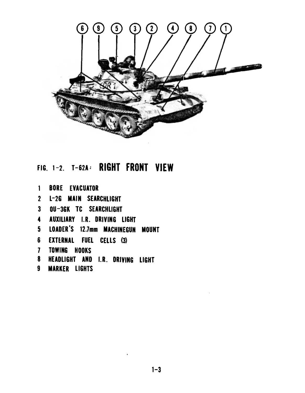
fig. i-2. Т-62А RIGHT FRONT VIEW
1 BORE EVACUATOR
2 L-2G MAIN SEARCHLIGHT
3 OIJ-3GK TC SEARCHLIGHT
4 AUXILIARY I.R. DRIVING LIGHT
5 LOADER'S 12.7mm MACHINEGUN MOUNT
6 EXTERNAL FUEL CELLS (3)
7 TOWING HOOKS
8 HEADLIGHT AND I.R. DRIVING LIGHT
9 MARKER LIGHTS
1-3
FIG. 1-3. T-62A= LEFT REAR VIEW
1 SPONSOR BOXES
2 SPARE OIL TANK
3 EXHAUST PORT
4 MACHINEGUN DISMOUNTED STOWAGE MOUNT
5 SELF-RETRIEVAL LOG
6 SPARE FUEL BARREL STRAPS
7 TOWING HOOKS
8 DRIVE SPROCKET
9 ANTENNA MOUNT
10 TC CUPOLA
11 LOADERS CUPOLA
1-4
fig. i-4. т-62*: RIGHT FLANK VIEW
1 SPONSON BOX
2 EXTERNAL FUEL TANKS
3 MACHINEGUN MOUNT
4 L-2G SEARCHLIGHT
5 ROAD WHEEL SPACING
@ ® ® ф
fig. i-5. T-62A: LEFT FLANK VIEW
1 GUNNERS PERISCOPE HOUSING
2 GUNNER S TELESCOPE PORT
3 IDLER WHEEL
4 SPARE TRACK BLOCKS
1-5
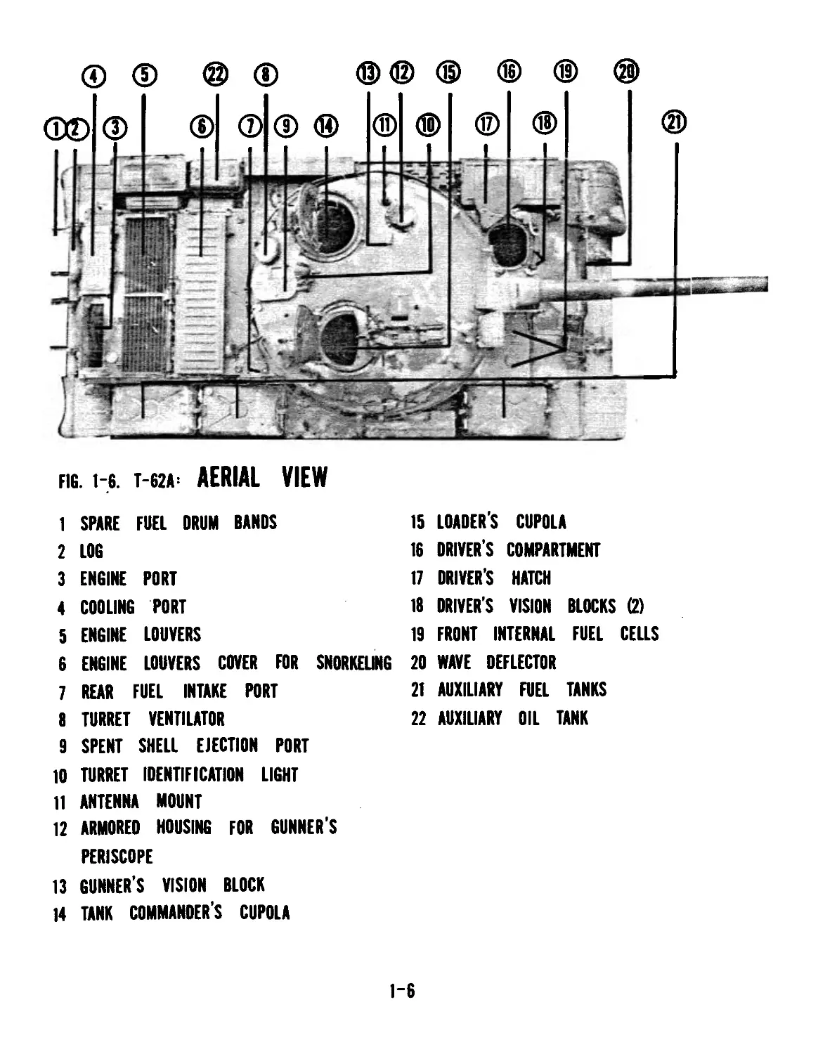
fig. 1-6. T-62A: AERIAL VIEW
1
2
3
4
5
6
7
8
9
SPARE
LOG
ENGINE
COOLING
ENGINE
ENGINE
REAR FUEL INTAKE PORT
TURRET
SPENT
FUEL DRUM BANDS
15
16
17
18
19
CUPOLA
COMPARTMENT
HATCH
VISION
PORT
PORT
LOUVERS
LOUVERS COVER FOR SNORKELING 20
21
22
VENTILATOR
SHELL EJECTION PORT
10 TURRET IDENTIFICATION LIGHT
11 ANTENNA MOUNT
12 ARMORED HOUSING FOR GUNNER'S
PERISCOPE
13 GUNNER’S VISION BLOCK
14 TANK COMMANDER’S CUPOLA
LOADERS
DRIVERS
DRIVER’S
DRIVER'S
FRONT INTERNAL
WAVE DEFLECTOR
AUXILIARY FUEL
AUXILIARY OIL TANK
BLOCKS (2)
FUEL CELLS
TANKS
1-6
Section II. DESCRIPTION AND DATA
1-3 DESCRIPTION (CONT.)
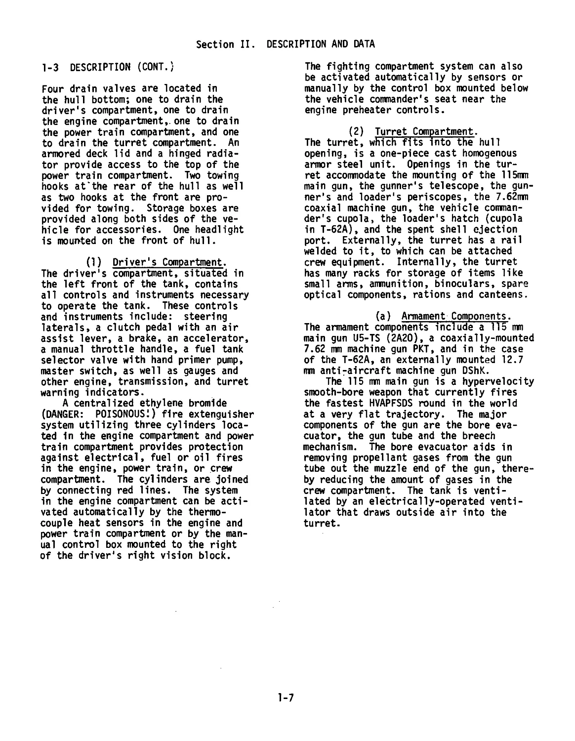
Four drain valves are located in
the hull bottom; one to drain the
driver's compartment, one to drain
the engine compartment,, one to drain
the power train compartment, and one
to drain the turret compartment. An
armored deck lid and a hinged radia-
tor provide access to the top of the
power train compartment. Two towing
hooks at‘the rear of the hull as well
as two hooks at the front are pro-
vided for towing. Storage boxes are
provided along both sides of the ve-
hicle for accessories. One headlight
is mounted on the front of hull.
(1) Driver's Compartment.
The driver's compartment, situated in
the left front of the tank, contains
all controls and instruments necessary
to operate the tank. These controls
and instruments include: steering
laterals, a clutch pedal with an air
assist lever, a brake, an accelerator,
a manual throttle handle, a fuel tank
selector valve with hand primer pump,
master switch, as well as gauges and
other engine, transmission, and turret
warning indicators.
A centralized ethylene bromide
(DANGER: POISONOUS!) fire extenguisher
system utilizing three cylinders loca-
ted in the engine compartment and power
train compartment provides protection
against electrical, fuel or oil fires
in the engine, power train, or crew
compartment. The cylinders are joined
by connecting red lines. The system
in the engine compartment can be acti-
vated automatically by the thermo-
couple heat sensors in the engine and
power train compartment or by the man-
ual control box mounted to the right
of the driver's right vision block.
The fighting compartment system can also
be activated automatically by sensors or
manually by the control box mounted below
the vehicle commander's seat near the
engine preheater controls.
(2) Turret Compartment.
The turret, which fits into the hull
opening, is a one-piece cast homogenous
armor steel unit. Openings in the tur-
ret accommodate the mounting of the 115mm
main gun, the gunner's telescope, the gun-
ner’s and loader's periscopes, the 7.62mm
coaxial machine gun, the vehicle comman-
der's cupola, the loader's hatch (cupola
in T-62A), and the spent shell ejection
port. Externally, the turret has a rail
welded to it, to which can be attached
crew equipment. Internally, the turret
has many racks for storage of items like
small arms, ammunition, binoculars, spare
optical components, rations and canteens.
(a) Armament Components.
The armament components include a 115 mm
main gun U5-TS (2A20), a coaxially-mounted
7.62 mm machine gun PKT, and in the case
of the T-62A, an externally mounted 12.7
ran anti-aircraft machine gun DShK.
The 115 ran main gun is a hypervelocity
smooth-bore weapon that currently fires
the fastest HVAPFSDS round in the world
at a very flat trajectory. The major
components of the gun are the bore eva-
cuator, the gun tube and the breech
mechanism. The bore evacuator aids in
removing propellant gases from the gun
tube out the muzzle end of the gun, there-
by reducing the amount of gases in the
crew compartment. The tank is venti-
lated by an electrically-operated venti-
lator that draws outside air into the
turret.
1-7
Section II. DESCRIPTION AND DATA
(b) Commander's Cupola.
The commander's cupola is a self-con-
tained unit mounted and secured in the
top of the turret. The cupola contains
the commander's periscope, TKN-3, and
searchlight, OU-3Gk, and the necessary
controls to lay the main gun in azimuth
(deflection). The cupola has four vi-
sion blocks to provide the tank comman-
der with external vision. The loader in
the T-62A also has a rotating cupola to
which is attached a mount for a 12.7 mm
DShK antiaircraft machine gune. This
machine gune can only be fired from out-
side the tank.
(c) Gun Elevating and
Turret Traversing System. The gun ele-
vating and turret traversing system con-
sists of mechanical, electrical and hy-
draulic components arranged so that only
the gunner can elevate or depress
(electric/hydraulic) the gun but either
the gunner or tank commander can traverse
(all electric) the turret 360 degrees in
either direction.
The power elevation mode is fully
stabilized, but either stabilized or. un-
stabilized power traverse can be used.
In case of power failure, the turret can
be traversed and the gun elevated manually,
but only by the gunner.
(d) Sighting and Fire Control
Components. Two types of sighting and
fire control components are available for
the T-62 or T-62A tank. These types are
conventional (daylight) and IR (infrared).
The gunner's primary sight is the TSh2B-41u
telescope. The telescope features a rota-
ting reticle for the superelevation re-
guired of the different types of ammunition.
It has dual magnification and a filter ca-
pability as well as an integral lens wiper.
It also has a stadiametric range finder.
The gunner's IR sight is the TPN1-Al-
li periscope. It is used in conjunction
with the main searchlight, L-2G.
The tank commander's sight is the TKN-3.
This binocular day/night sight features
a stadiametric range finder (day use only)
and is coaxially mounted with the tank
commander's searchlight, 0U-3GK.
The auxiliary sighting and fire con-
trol system includes the azimuth indicator
and the gunner's quadrant. The azimuth
indicator is based on 6000 mils in 360°
and has fine and gross needles. The gross
adjustment indicator is shaped like the
gun in the turret and tells the gunner the
precise location of the turret with res-
pect to the hull. The gunner's quadrant
is graduated from 2700 to 3800 mils and
has a fine adjustment screw for 0-100 mil
settings.
(3) Engine Compartment.
Power is supplied by a V-12 (580 HP) water-
cooled diesel engine with an injection
pump type fuel system. The engine is pres-
sure lubricated. The air cleaner is a
three stage canister type that can only be
fitted in one sequence.
(4) Power Train Compartment.
(a) Master Clutch.
The master clutch consists of ten driving,
nine driven steel discs and a release
mechanism.
(b) Transmission.
The transmission is a five speed manual
type with five forward gears and one re-
verse gear. Upshifting and downshitfing
is accomplished by using the double-clutch
procedure.
(c) Steering Clutch.
The steering clutch is a two stage plane-
tary type. The steering clutch transmits
torque to the final drives of the vehicles.
The steering clutches also serve as brakes
for the vehicle.
1-8
FIG. 1-7. ENGINE AND POWER TRAIN DECK LIDS
FIG. 1-8. ENGINE RADIATOR
1-9
FIG. 1-9. ENGINE. V~12 DIESEL
1-10
FIG. 1-10. TRANSMISSION AND FAN
1-11
FIG. 1-11. AIR FILTER COMPARTMENT
1-12
FIG. 1-12. AIR FILTER ELEMENTS
1-13
Section II. DESCRIPTION AND DATA
(d) Final Drive.
The final drives are intended for in-
creasing the torque on the drive sproc-
kets. Each final drive is a two-step,
step-down reduction gear.
cL Track and Suspension.
The tank is equipped with a torsion bar
Christie suspension with shock absorbers
on the first and last road wheels on each
side. The track is an all steel, dead-
type that is very strong and wear-resis-
tant. Each side of the suspension system
is comprised of 5 road wheels, a compen-
sating idler, and a drive sprocket. The
track pins are not secured at their outer
end and are free to travel towards the
hull. The pin hammer, a raised portion
of metal welded to the hull just forward
of the sprocket, drives the track pins
back into position-each time they pass
over the sprocket. The center guides of
the track ride between the road wheels
both above and below. This characteris-
tic makes the track very hard to throw.
1-4 TABULATED DATA
a. General Vehicle.
Combat weight Crew 40 tons 4
Basic dimensions
length with gun 9335 mm
forward length with gun
rearward . 9068 mm
hull length 6630 mm
width 3300 mm
height 2395 mm
clearance 430 mm
b. Travel Speeds- (rated at 1800
engine RPM):
1st gear 14.5 Km/h
2d gear 20 Km/h
3d gear 29 Km/h
4th gear 45.5 Km/h
5th gear 7 Km/h
Reverse Maximum on paved road 50 Km/h
c, . Operational Data.
(1) Fuel consumption per 100 km
travel;
on dirt roads 300-330 1.
on paved roads 190-210 1.
(2) Oil consumption per engine hour
1.5-3.0 1.
(3) Travel distance per tank of fuel;
on paved roads up to 450 Km
on dirt roads up to 320 Km
(4) Travel distance with two extra
barrels of fuel;
on paved roads up to 650 Km
on dirt roads up to 450 Km
d. Surmountable Obstacles.
Maximum grade angle 30°
Maximum lateral bank angle 30°
Ditch width 2.85 m
Wall height 0.8 m
Ford depth 1.4 m
Water obstacle (using snorkel)
river depth 5.5 m
river width 1000 m
e^. Armament
(1) Main Gun
Type U5-TS (2A20) Smooth
bore
Caliber 115 mm
1-14
FIG. 2-3. INSTRUMENT PANEL
1 BILGE PUMP TOGGLE
2 OIL PUMP-AIR START SWITCH
3 SMOKE SCREEN SWITCH
4 REAR MARKER SWITCH
5 I.R. HEADLIGHT SWITCH
6 SERVICE DRIVE LIGHT SWITCH
7 FRONT MARKER LIGHT SWITCH
8 HORN
9 ELECTRIC STARTER
10 ENGINE HOUR GAUGE
11 TACHOMETER
12 OIL PRESSURE GAUGE
13 OIL TEMPERATURE GAUGE
14 WATER TEMPERATURE GAUGE
15 VOLTMETER AMMETER
16 FUSE BOX
Section II. DESCRIPTION AND DATA
e. Armament (Cont./
(a) Maximum sighting range
using TSh2B-41U gunner's telescope:
APDS 4000 m
HEAT 3700 m
HE 18 4800 m
HE 11 3600 m
(b) Using TPN-1-41-11 gunner's
IR periscope: Sighting range is up to
800 m.
(c) Maximum rate of fire
aiming from a standstill is four
rounds per minute.
(d) Recoil
Normal recoil 350-415 mm
Counterrecoil
hydraulic fluid
capacity 4.25-4.45 1.
Recoil limit 430 mm
Counterrecoil brake
fluid capacity (approx) 7 1.
(2) Machine Gun
Type PKT
Caliber 7.62 mm
Max. effective range
using TSh2B-41U sight 2000 m
Max. rate of fire (effective, rds/min)
200-250 rds
No. of rds per belt 250 rds
(3) Ammunition Complement
U5-TS Main Gun 40 rds
PKT (SGMT) machine gun 2500 rds
Fixed-round weight
APDS 22.5 kg
HEAT 26.2 kg
HE 28.1 kg
f. Aiming and Viewing Instrument.
(a) TKN-3 Day Night
Power 5X 4.2X
Field of
view 10° 8°
Range of
view -- 400 m
(b) TSh2B-41U
Power 3.5x and 7x
Field of
view 18° and 9°
(c) TPN-1-41-11
Power 5.5
Field of
view 6°
Range 800 m with L-2G main
searchlight.
q. Driver's Viewing Instrument.
Night Viewing TVN-2 Power lx Field of view 30° Range of view 60 i m
h. Loader's Viewing Instrument.
Day viewing MK-4 Field of view, forward Field of view, rearward or MK-4S 25° 16°
1. Engine. Engine Model Cylinders Max, HP at 2000 RPM Max. torque @ RPM (Kgm) Cooling Fuel V-55 V-12 580 !<P 1200-1250 240 Kgm Water Diesel
j. Fuel Supply System.
Fuel used (US) Fuel tank capacities interior exterior Fuel filter Coarse Diesel #2 675 1. 285 1. and fine
k. Lubrication System.
(Til used (US) 0E-50
System capacity 77 1.
oil tank capacity 55 1.
exterior oil tank capacity 35 1.
1. Cooling & Preheating System.
Coolant capacity 77 1.
Preheater type injection with
electric (primary)
and manual
(emergency)
activation
1-15
FIG 2-4 FUEL TANK SELECTION LEVER
1 EXTERNAL AND REAR CELL
2 FRONT FUEL CELLS
3 ALL CELLS
4 OFF
5 PURGE PUMP AIR BLEEDER HANDLE
6 LEVER ARROW
7 GEAR SHIFT GATE RELEASE
2-5
Section II. DRIVER'S CONTROLS AND INSTRUMENTS
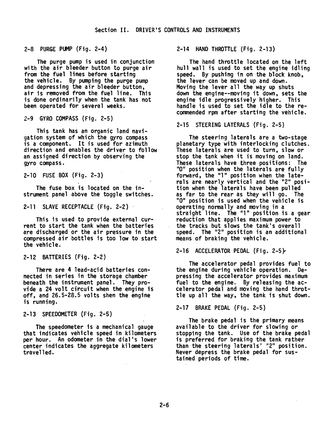
2-8 PURGE PUMP (Fig. 2-4)
The purge pump is used in conjunction
with the air bleeder button to purge air
from the fuel lines before starting
the vehicle. By pumping the purge pump
and depressing the air bleeder button,
air is removed from the fuel line. This
is done ordinarily when the tank has not
been operated for several weeks.
2-9 GYRO COMPASS (Fig. 2-5)
This tank has an organic land navi-
gation system of which the gyro compass
is a component. It is used for azimuth
direction and enables the driver to follow
an assigned direction by observing the
gyro compass.
2-10 FUSE BOX (Fig. 2-3)
The fuse box is located on the in-
strument panel above the toggle switches.
2-11 SLAVE RECEPTACLE (Fig. 2-2)
This is used to provide external cur-
rent to start the tank when the batteries
are discharged or the air pressure in the
compressed air bottles is too low to start
the vehicle.
2-12 BATTERIES (Fig. 2-2)
There are 4 lead-acid batteries con-
nected in series in the storage chamber
beneath the instrument panel. They pro-
vide a 24 volt circuit when the engine is
off, and 26.5-28.5 volts shen the engine
is running.
2-13 SPEEDOMETER (Fig. 2-5)
The speedometer is a mechanical gauge
that indicates vehicle speed in kilometers
per hour. An odometer in the dial's lower
center indicates the aggregate kilometers
travelled.
2-14 HAND THROTTLE (Fig. 2-13)
The hand throttle located on the left
hull wall is used to set the engine idling
speed. By pushing in on the block knob,
the lever can be moved up and down.
Moving the lever all the way up shuts
down the engine—moving it down, sets the
engine idle progressively higher. This
handle is used to set the idle to the re-
commended rpm after starting the vehicle.
2-15 STEERING LATERALS (Fig. 2-5)
The steering laterals are a two-stage
planetary type with interlocking clutches.
These laterals are used to turn, slow or
stop the tank when it is moving on land.
These laterals have three positions: The
"0" position when the laterals are fully
forward, the "1“ position when the late-
rals are nearly vertical and the "2" posi-
tion when the laterals have been pulled
as far to the rear as they will go. The
"0" position is used when the vehicle is
operating normally and moving in a
straight line. The “I" position is a gear
reduction that applies maximum power to
the tracks but slows the tank's overall
speed. The "2" position is an additional
means of braking the vehicle.
2-16 ACCELERATOR PEDAL (Fig. 2-5>
The accelerator pedal provides fuel to
the engine during vehicle operation. De-
pressing the accelerator provides maximum
fuel to the engine. By releasing the ac-
celerator pedal and moving the hand throt-
tle up all the way, the tank is shut down.
2-17 BRAKE PEDAL (Fig. 2-5)
The brake pedal is the primary means
available to the driver for slowing or
stopping the tank. Use of the brake pedal
is preferred for braking the tank rather
than the steering laterals' "2" position.
Never depress the brake pedal for sus-
tained periods of time.
2-6
Section II. DRIVER'S CONTROLS AND INSTRUMENTS
2-18 PARKING BRAKES (Fig. 2-5)
The parking brake rod is located be-
tween the brake and clutch pedals. By
depressing the brake pedal and pulling
back on the parking brake rod until it
engages the brake pedal, the tank can be
braked for parking. Push down on the brake
pedal to release the park brake rod.
2-19- CLUTCH PEDAL (Fig 2-5)
The clutch is a multiple-disc dry-
friction, steel-on-steel type and is one
of the most vulnerable parts of the Т-62/
T-62A. The air-assist lever is on the mid-
left arm of the clutch pedal (Figs. 2-6/
2-7). This lever is used to provide com-
pressed air-assisted clutch operations
when shifting to reduce clutch wear. The
air-assist can be engaged by pushing the
lever to the left. This clutch pedal en-
gages and disengages the master clutch when
released and depressed.
NOTE: NEVER START THE VEHICLE WITH THE
AIR-ASSIST LEVER TO THE LEFT. SEE PARA-
GRAPH 2-24 FOR USE OF THE AIR-ASSIST LEVER
WHEN SHIFTING.
2-20 GEAR SHIFT LEVER (Fig. 2-5)
The gear shift lever, located to the
driver's right side, can engage five-for-
ward speeds and one reverse speed. The
gear selection lever has a gate release
which permits engagement of 2d, 3d, 4th
and 5th gears. The gate release is not
applied when engaging 1st or reverse gear
(Fig. 2-4).
2-21 DRIVER'S AUXILIARY EQUIPMENT
a_. Communications (Fig. 2-2) A US
intercom junction box has been provided
for crew communication when operating the
tank.
b. Compressed Air Bottles (Fig. 2-8)
Two 5-liter compressed air bottles
are mounted on brackets on the left hull
wall behind the driver. They each have a
handle valve. Rotate the valve clockwise
to close the system and counter-clockwise
to open the system. The valves are always
left closed until preparing to start the
tank. The compressed air gauge (Fig 2-8)
displays the pressure in kg/cm2 (atmos-
pheres) that the system contains. A mini-
mum of 50 atmospheres is required to start
the vehicle with compressed air. The max-
imum permissible bottle capacity is 150
atmospheres.
c_. Driver's Hatch (Fig. 2-9) The
driver's hatch has three possible posi-
tions: Closed, open-and-up and open-and-
down. To lock the driver's hatch in the
closed position, pull out on the hatch
lever and rotate it to the right. Place
the lever in a perpendicular position to
the driver's hatch shaft and rotate the
lever and hatch back towards the compressed
air bottles. Push the handle down and to-
wards the hull wall until it locks (Fig.
2-12). This closed position is used when-
ever the turret is placed in power opera-
tion. The hatch has a microswitch that
will not complete the electric circuit of
the turret unless the hatch is closed (see
paragraph 3-11). To put the hatch in the
open-and-up position, pull out and rotate
the hatch handle, moving it on a horizontal
axis towards the front of the tank until
the pin catches in the hole (Fig. 2-11).
To put the hatch in the open-and-down posi-
tion, proceed as for the open-and-up posi-
tion. Upon reaching the position where the
pin would engage the hole, rotate the han-
dle along the left hull from the front of
the tank to the rear until it engages as 1г
did for the closed position (Fig. 2-10).
This position is recommended for maximum
safety whenever the tank is driven with the
hatch open.
2-7
FIG. 2-5. DRIVER’S COMPARTMENT
1 PURGE PUMP AIR BLEEDER BUTTON
2 GYRO COMPASS
3 SPEEDOMETER
4 STEERING LATERALS
5 ACCELERATOR PEDAL
6 BRAKE PEDAL
7 PARK BRAKE
8 CLUTCH PEDAL
9 GEAR SHIFT LEVER
2-8
FIG. 2-6. MECHANICAL CLUTCH
1. AIR CLUTCH ENGAGEMENT LEVER
2. HAND THROTTLE
FIG. 2-7. AIR CLUTCH
2-9
FIG. 2-8. AIR BOTTLES
1. GAUGE
2. VALVES
FIG. 2-9. DRIVER'S HATCH
FIG. 2-10. OPEN-ANO-DOWN FIG. 2-11. OPEN-ANO-UP
1. HANDLE
1. HANDLE
2-10
FIG. 2-12. HATCH HANDLE
fclG. 2-13 DRIVER'S COMPARTMENT
1 HAND THROTTLE
2 ENGINE COVER HANDLE
2-11
Section II. DRIVER'S CONTROLS AND INSTRUMENTS
Engine Coyer Handle (Fig. 2-13)
The engine cover handle, located to the
driver's left on the hull wall, is used
to close the engine covers when the tank
is snorkeling. These covers prevent water
from seeping into the engine compartment.
There are two positions; open, when the
handle is toward the tank bow; and closed,
when the handle is towards the tank rear.
The tank should always be operated with
the engine covers open.
e. Vision Blocks (Fig. 2-14) The
driver has 2 vision blocks to aid him when
driving with his hatch closed. There are
two defroster cables connected to the vi-
sion blocks (Fig. 2-15) that can defrost
the blocks when turned on (Fig. 2-21).
To remove the blocks, rotate the white
mounting rod (Fig. 2-14) and pull down on
the vision block handle. The vision blocks
can be cleaned with compressed air and
cleaning fluid from a reservoir (Fig. 2-16)
by depressing the push button on the right
lateral hand grip (Fig. 2-14).
£. TVN-2 Infrared Periscope (Fig. 2-17)
The driver has the TVN-2 IR periscope for
night driving. The left vision block is
removed and the TVN-2 mounted in its place.
The IR power cable from the BT-6-26 power
supply is connected to the TVN-2 and when
the switch on the BT-6-26 is placed in the
"ON" position, the TVN-2 will illuminate.
This periscope has an unaided range of 60
meters.
!• Dome Lights (Figs. 2-18/2-19)
There are several dome lights available to
the driver to illuminate his compartment.
The main dome light near the instrument
panel will generally illuminate the driver's
compartment even if the master is off.
There are two lights that illuminate the
driver's instrument panel and speedometer.
They work with a 3-position toggle switch
with the center position for all lights
off, right position for dim, and left posi-
tion for bright.
к* Fire Extinguisher Control Box
(Fig. 2-2(5] The fire extinguisher control
box on the hull ceiling near the instrument
panel operates the organic T-62 fire ex-
tinguisher system. It has two red check
lamps that will glow to indicate an opera-
tional system when the master switch is
on. There is a small check window on the
left panel front that reveals the number
of fire extinguisher bottles still full.
It should read "3". There are two metal
covers on the panel front. The left cover
conceals the resetting mechanism for the
number of extinguisher bottles. The right
cover (Fig. 2-20) conceals two push but-
tons and a toggle switch. The toggle
switch selects either automatic or manual
operation of the system. The push buttons
activate fire extinguisher bottles for the
turret or the engine compartment.
NOTE: The mixture used in the fire ex-
tinguisher bottles is extremely toxic.
All crew members must exit the tank when
this system is used.
i_. Escape Hatch The escape hatch is
behind the driver and below the gunner's
feet. The hatch is lifted up and into the
tank rather than dropped from the tank.
j. Turret Warning Lights (Figs. 2-18/
2-19) There are two warning lights in the
driver's compartment that illuminate to
warn the driver when the gun tube is over
or beyond either fender. The right warn-
ing light illuminates when the gun tube
extends beyond the right fender; the left
warning light illuminates when the gun tube
is beyond the left fender.
k_. KUV-3 Ventilator Control Box
(Fig. 2-2TJ The KUV-3 ventilator control
box under the driver's right vision block
has 2 push buttons that turn the turret
ventilator on or off. The button on the
left starts the ventilator and the right
button turns it off.
1_. KRP-1 CBR Relay Box (Fig. 2-22)
The KRP-1 CBR relay box under the driver's
left vision block performs a variety of
functions related to the PAZ CBR system on
the T-62. Since the PAZ system is not
present on the T-62 tanks available for
training, it is strongly recommended that
this relay box be disregarded. Otherwise,
activation of the system will automatically
seal certain parts of the tank.
2-12
FIG. 2-14. DRIVER'S AREA
FIG. 2-15. VISION BLOCK
DEFROSTER CABLE
1 PERISCOPE MOUNTING RODS
2 PERISCOPE AIR-WATER CLEANER
BUTTON
FIG. 2-16. VISION BLOCK
WASHER RESERVOIR
FIG. 2-17. TVN-2 I.R. PERISCOPE
2-13
1 INSTRUMENT LIGHTS
2 DOME LIGHT
3 TURRET WARNING LIGHT
4 PURGE PUMP
AIR BLEEDER BUTTON
1 INSTRUMENT LIGHT
2 WARNING LIGHT
FIG. 2-18. COMPARTMENT LIGHTS
FIG. 2-19. SPEEDOMETER LIGHT
2-14
FIG. 2-20. FIRE EXTINGUISHER
CONTROL BOX
FIG. 2-21. HULL VENTILATOR
CONTROL BOX
1 PERISCOPE DEFROSTER
2 VENTILATOR BOX
1 WINDOW 3 AUTO-MANUAL TOGGLE
2 RED LIGHTS 4 PUSH BUTTONS
FIG. 2-22. DRIVER COMPARTMENT
1 KRP-1 CBR RELAY BOX
2-15
Section III. OPERATION OF VEHICLE (AUTOMOTIVE)
2-22 GENERAL
This section contains the procedures
for operating the tank under normal and
unusual conditions. Read Section II,
Driver's Controls/Instrument, of this
chapter to become familiar with the loca-
tion and operation of driver's controls
and instruments before attempting to im-
plement the procdures outlined in this
section.
NOTE:The T-62 Medium Tank possesses sub-
stantially different operating procedures
than those normally encountered on US
equipment. For this reason, it is impera-
tive that personnel become intimately fami-
liar with the contents of this chapter be-
fore attempting vehicle operation.
2-23 PRE, DURING, POST OPERATION SERVICES
Prior to starting the engine a pre-
operational check must be made (Table 2-1).
The operator/crew will log all discrep-
ancies and/or malfunctions noted during
the pre-operational check on a DA Form
2404. Malfunctions and discrepancies
whose correction is beyond the user unit's
responsibility will be reported to the in-
stallation maintenance facility.
2-24 STARTING THE ENGINE
a. Check the driver's hatch to insure
it is locked.
b. Open the air bottles by rotating
the valve handles counter-clockwise (Fig.
2-8). Minimum air pressure to start is
50 kg/an2.
c. Adjust the driver's seat for a com-
fortable leg position.
d. Insure that the parking brake is en-
gage? (Fig. 2-5).
e. Insure that the gear shift lever is
in neutral.
f. Insure that the air assist lever is
in the 12 o'clock position; thus, the air
clutch is not engaged (Fig. 2-6).
NOTE: Never start the tank if the air
assist lever on the clutch pedal is to the
left. This means the air clutch is en-
gaged and the tank will partially elevate
when the clutch is released upon beginning
movement.
<[. Place the steering laterals in the
far forward "0" position.
h. Insure that engine cover handle is
in the "OPEN" position.
i_. Turn master switch on (Fig. 2-2).
Depress the voltmeter check button;
the voltage reading should be between 22-
26 volts (Fig. 2-3).
NOTE: Do not use the electric starter to
start the engine if the voltage is below 22
k. Check the fire extinguisher system
control box (Fig. 2-20) to see that the
lights are illuminated and that the number
"3" appears in the check window.'
1_. Place the fuel distribution lever
in a position that will select fuel from
the fuel cells (See para 2-6).
m. If the tank has not been started
for several weeks, depress the air bleeder
button and pump the purge pump several
times until fuel can be heard moving
through the lines (Figs. 2-3/2-4).
n_. Alert the crew that the engine is
about to be started.
a. Move and hold the air start-oil
pump switch at the 12 o'clock position to
activate the oil pump and watch the oil
pressure gauge until the oil pressure is
between 6-7 kg/cm2.
CAUTION: Do not activate the oil pump for
periods longer than 5 seconds. If the en-
gine oil pressure fails to reach the de-
sired level, release the switch, wait 30
seconds and try again.
2-16
Section III. OPERATION OF VEHICLE (AUTOMOTIVE)
Minimum oil pressure to start is 2 kg/cm2.
Without releasing the oil pump -
air start switch, depress the accelerator
pedal and move the air start-oil pump switch
to the air start position (3 o'clock).
CAUTION: Do not hold the air start switch
in the "start" position for periods longer
than 5 seconds. If engine fails to start,
wait 15 seconds and repeat steps 2-24o and
2-24p.
2- When the engine starts, release
the oil pump-air start switch and, while
depressing the accelerator, move the hand
throttle down (Fig. 2-13) until the engine
rpms are 700-800 on the tachometer. Check
the gauges on the instrument panel. If the
engine oil pressure is less than 2 kg/cm2,
stop the engine (see para 2-28) and deter-
mine cause. If all gauges are operating,
increase engine rpms to 1300-1600 to warm-
up the engine. The engine' is considered
warmed-up when the oil and water tempera-
ture are 50°C and the engine oil pressure
is between 6-9 kg/cm2.
£. If the engine fails to start using
the air start system, move the oil pump-
air start switch to the oil pump position,
depress accelerator and press the electric
starter button (Fig. 2-3). After engine
starts, follow the same procedure out-
lined in para 2-24q.
NOTE: Never depress electric starter
button for periods exceeding 5 seconds.
If engine fails to start within 5 seconds,
release the starter button, wait 15 se-
conds and try again.
2-25 PUTTING THE TANK IN MOTION
£. Ensure area around the tank is
clear and that personnel and equipment
are not in the vehicle travel path.
b. Use front and rear ground guides
when moving the tank around the motor
park or in congested area.
£. The vehicle should be placed in
motion using second gear under normal
driving conditions. When driving condi-
tions are poor, or when moving the vehicle
around the motor park, use first gear.
d. To move the tank, proceed as fol-
lows:
(1) After the engine has suffi-
ciently warmed up, set the engine rpms to
550-600 with the hand throttle.
(2) Place the steering laterals in
the middle "1" position.
(3) Release the park brake.
(4) Insure that the air clutch en-
gagement lever is not engaged, depress the
clutch pedal and hold it down for 2-3 secs.
Move the gear shift lever into second gear,
exerting rearward pressure until it en-
gages. Do not be alarmed if it takes an
inordinate amount of force to engage second
gear. If you fail to engage second gear,
place the gear shift lever in neutral, re-
lease the clutch pedal, depress the clutch
pedal and attempt to engage second gear
again.
NOTE: A unique feature of the T-62 is the
master clutch system. This system can be
operated either mechanically or hydro-
pneumatically, employing the compressed
air system. The mechanical clutch is used
whenever the tank is in first or reverse
gears and when the tank is being placed in
motion (second gear). The hydro-pneumatic
clutch is engaged after the tank has begun
movement in second gear by moving the air
clutch engagement lever on the clutch pedal
to the left. The hydro-pneumatic operation
of the clutch reduces clutch wear and
lengthens clutch life. Thus, the tank is
always driven with the hydro-pneumatic
clutch after it moves initially.
Remember: Never attempt to move the tank
with the air clutch engagement lever to the
left (Fig. 2-6). Always move the air clutch
engagement lever to the 9 o'clock position
(Fig. 2-7) after the tank has started to
move forward.
2-17
Section III. OPERATION OF VEHICLE (AUTOMOTIVE)
(5) Tell the TC you are ready to
move the tank.
(6) When the TC reports all clear,
release the clutch pedal quickly and smooth-
ly, simultaneously increasing the engine fuel
supply by depressing the accelerator pedal
gradually.
(7) As the tank begins to roll for-
ward, smoothly move the steering laterals to
the "0" position. This will increase tank
speed.
(8) After the vehicle has moved for-
ward 20-30 yards, move the air assist lever
to the left.
2-26 SHIFTING GEARS
a_. Up Shifting. To shift to a higher
gear"”(e.g. second to third gear) wait until
the engine speed is 1600-1900 rpms. Let up
on the accelerator pedal and depress the
clutch pedal. Move the gear shift lever to
neutral, release the clutch pedal, depress
the clutch pedal, move the gear shift lever
to third gear, release the clutch pedal
quickly while simultaneously accelerating.
This shifting procedure is often referred
to as "double-clutching" and is a requisite
procedure for T-62 drivers to lengthen clutch
life.
b. Down Shifting. To shift to a lower
gear from a higher one, let up on the accel-
erator pedal and depress the clutch pedal.
Move the gear shift lever to neutral, re-
lease the clutch pedal, depress clutch pedal
and simultaneously increase engine speed by
depressing the accelerator, move gear shift
lever to lower gear, release the clutch and
accelerate slowly. The engine acceleration
during shifting is necessary to make the en-
gine rpm the same as that of the transmission.
2-27 STEERING THE TANK
a. To maneuver the vehicle while in mo-
tion, forward or rearward, it is necessary
to pull the corresponding lateral to the "1"
position. For example, to turn to the right,
pull the right lateral to the "1" position
and keep the left lateral in the "0" posi-
tion. The reverse is applicable when
steering to the left.
f>. The tank can also be turned when
both laterals are in the "1" position
(gear reduction). Simply pull the right/
left lateral back to the "2" position to
turn right/left. The "2" position brakes
the respective tracks and is used for
shorter radius turns in conjunction with
the "1" position.
c. Never place one of the laterals in
the ir2" position when the tank is in 4th
or 5th gear. It is recommended to use the
laterals sparingly for turning, i.e. mini-
mize the number of small steering correc-
tions.
d. When making a turn, increase engine
speed" as the turn is made to prevent engine
stalling. When making a larger radius turn,
"pump" the respective lateral by alternate-
ly moving it back and forth from the "0" to
the "1" position.
e. Avoid turns on steep uphill or down-
hill slopes.
2-28 STOPPING THE TANK
a. To stop the tank gradually, let up
on the accelerator, depress the clutch pe-
dal, shift to neutral, release the clutch
pedal and pump the brake pedal until the
tank comes to a halt.
b. To stop the tank in emergencies,
depress the brake pedal quickly (or pull
both laterals to the "2" position), depress
the clutch pedal and release the accelera-
tor. Place the gear shift lever in neutral
and release the clutch.
c. To slow the vehicle when driving,
pull the laterals to the "1" position.
When ready to resume speed, return the
laterals to the "0" position.
2-18
Section III. OPERATION OF VEHICLE (AUTOMOTIVE)
2-29 SHUTTING DOWN THE ENGINE
a_. Turning off the engine after sus-
tained operation can cause the engine
coolant as well as the engine to overheat.
Thus, after braking the vehicle to stop
and engaging the park brake, idle the
engine at 1500-1600 rpms until the water
temperature is 70°C or less.
j). Move air assist lever to upright
(12 o'clock) position.
c. Reduce engine speed to 700-800
rpms and idle for 2 more minutes.
d. Move hand throttle all the way
up to shut down the engine (Fig. 2-13).
e. Turn off master switch (Fig. 2-2).
f. Close air bottles by rotating hand
valve clockwise.
2-30 SMOKE GENERATING SYSTEM
a_. The T-62 tank has its own smoke
generating capability. This system can
produce a dense, white smoke screen that
will persist for 2-4 minutes. The system
basically consists of spraying diesel fuel
into the exhaust manifold when the mani-
fold is sufficiently hot enough for fuel
combustion. This partial combustion
creates the thick white smoke that exits
from the tank's exhaust port.
b. To operate the system:
(1) The engine must be running and
warmed-up. The engine coolant temperature
should be at least 60°C.
(2) The tank should be moving in
2d or 3d gear.
(3) The driver turns on the smoke
screen switch on his instrument panel
(Fig. 2-3). After a 3-5 second delay, the
smoke cloud will appear from the exhaust
port.
(4) The driver must depress the
accelerator fully to prevent engine fuel
starvation. Minimum engine rpm is 1600.
Never attempt to use the smoke system in a
gear higher than third.
(5) To turn off the smoke screen,
turn off the smoke screen switch. Smoke
will continue for a 5-15 second period un-
til all the fuel is expelled from the ex-
haust manifold.
2-19
SECTION III
OPERATION OF VEHICLE (AUTOMOTIVE)
Table 2-1 Pre, During and Post Operation Checks
PRE DURING POST ITEM TO BE CHECKED PROCEDURE Visually inspect for evidence of lubricant and fuel leaks concur- rently with the daily checks and services.
1 Fire Extinguishing Check the fire extinguisher control
System (Fig. 2-20) box for broken seals, that there is a "3" in the check window and that the check lights are illumi- nated.
2 25 Fluid Levels Before starting engine, check that the engine, transmission, transfer case, final drives and the radiator have sufficient fluid for operation. Check for evidence of fuel, lubri- cant and coolant leaks in power plant and power train compartment. Check oil levels as follows: ENGINE OIL (Fig. 2-23) Raise power train armor deck lid. Raise the radiator and lock in place Remove oil filler plug with wrench.
2-20
FIG. 2-23. ENGINE OIL
FIG. 2-24. TRANSMISSION OIL
2-21
Table 2-1 Pre, During and Post Operation Checks
PRE DURING POST ITEM TO BE CHECKED
PROCEDURE
Remove oil screen from filler open-
ing. Use dipstick and measure the
oil level. The oil level should not
be above the top mark or more than
an inch below the mark. Add OE 50
oil if needed.
TRANSMISSION (Fig. 2-24)
Remove red bolt (Filler bolt) and
check oil level with lower dipstick
mark. Add OE 50 oil if needed.
ENGINE COOLANT (Fig. 2-25)
Lower the radiator (horizontal posi-
tion) and remove filler cap with
special tool, insuring that pressure
release detent has been replaced.
Check coolant level - coolant level
should be 30-40 mm below the filler
neck.
TRANSFER CASE (Fig. 2-26)
Weekly, remove red bolt and check oil
level with middle dipstick mark.
Add OE 50 oil if needed.
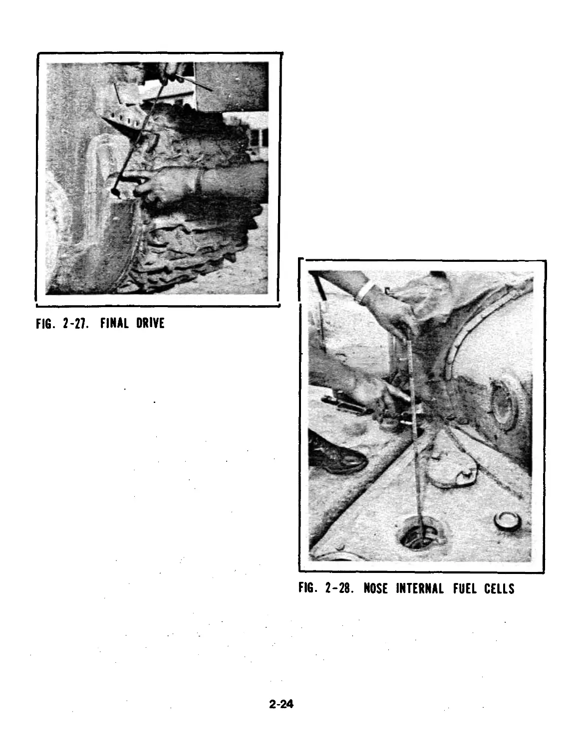
FINAL DRIVE (Fig. 2-27)
Weekly, remove the final drive fill
plug. Use special dipstick to check
level. Add GO 90, if needed, to
2-22
FIG. 2-25. ENGINE COOLANT
FIG. 2-26 TRANSFER CASE
2-23
FIG. 2-27. FINAL DRIVE
FIG. 2-28. NOSE INTERNAL FUEL CELLS
2-24
Table 2-1 Pre, During and Post Operation Checks
PRE DURING POST ITEM TO BE CHECKED PROCEDURE
3 26 Fuel System (Figs. 2-28 - bring level up to mark on dipstick. Do not over fill. Check fuel lines (yellow) for leaks.
4 27 2-31) Suspension System Fill nose, external and rear tanks leaving 4-6 in. below top of filler neck for expansion. Inspect tracks, road wheels, idler
5 17 28 (Figs. 2-32 - 2-34) Air Start Switch wheels, drive sprockets and shock absorbers for excessive wear or da- mage. Check shock absorbers for fluid leakage indicating damaged seals. Check torsion bars by lift- ing road wheel. The road wheel will lift easily if torsion bar is broken. Check tract tension. Tension is con- sidered normal when the track is 60- 80 mm above the 1st road wheel. Ensure air start switch is in the
6 29 (Fig. 2-3) Master Switch off position (arrow to the left). Push in master switch rod to engage
(Fig. 2-2) electric power. Check voltmeter to ensure storage batteries have between 22-26 volts. To turn off, push the catch release and the master switch rod will return to the upper position
2-25
FIG. 2-29. REAR INTERNAL FUEL CELL
FIG. 2-30. FRONT EXTERNAL FUEL CELL
2-26
FIG. 2-31. REAR EXTERNAL FUEL TANKS
FIG. 2-32. ROAD WHEELS
2-27
FIG. 2-33. DRIVE SPROCKET
FIG. 2-34. IDLER WHEEL
2-28
Table 2-1 Pre, During and Post Operation Checks
PRE DURING POST ITEM TO BE CHECKED
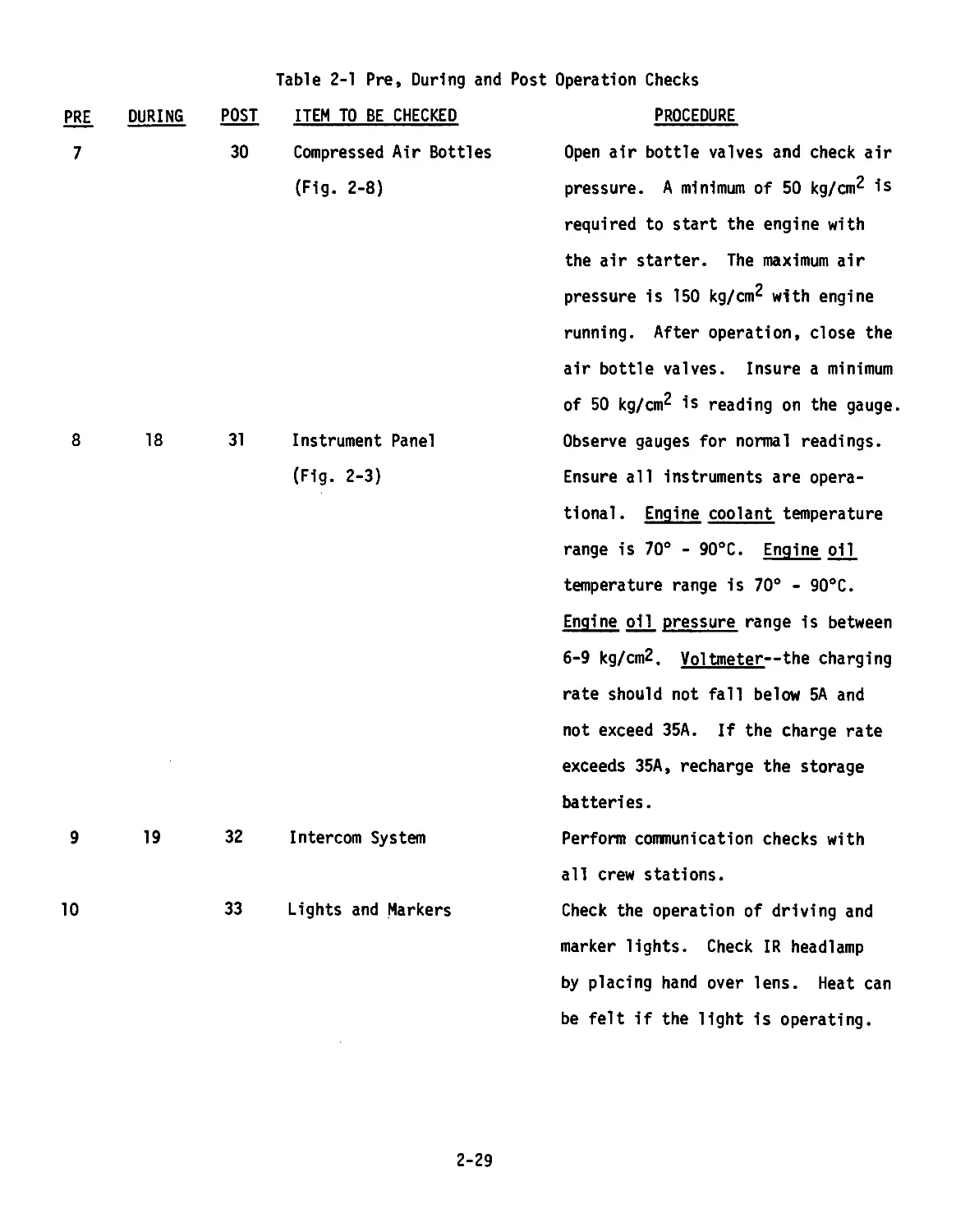
7 30 Compressed Air Bottles (Fig. 2-8)
8 18 31 Instrument Panel (Fig. 2-3)
9 19 32 Intercom System
10 33 Lights and Markers
PROCEDURE
Open air bottle valves and check air
pressure. A minimum of 50 kg/cm^ is
required to start the engine with
the air starter. The maximum air
pressure is 150 kg/cm^ with engine
running. After operation, close the
air bottle valves. Insure a minimum
of 50 kg/cm^ is reading on the gauge
Observe gauges for normal readings.
Ensure all instruments are opera-
tional. Engine coolant temperature
range is 70° - 90°C. Engine oil
temperature range is 70° - 90°C.
Engine oil pressure range is between
6-9 kg/cmZ. Voltmeter—the charging
rate should not fall below 5A and
not exceed 35A. If the charge rate
exceeds 35A, recharge the storage
batteries.
Perform communication checks with
all crew stations.
Check the operation of driving and
marker lights. Check IR headlamp
by placing hand over lens. Heat can
be felt if the light is operating.
2-29
Table 2-1 Pre, During and Post Operation Checks
PRE DURING POST ITEM TO BE CHECKED PROCEDURE
11 20 Throttle/accelerator (Fig. 2-7) Check hand throttle and accelerator controls for binding, grabbing or ex- cessive linkage play.
12 21 Steering and Braking Controls (Fig. 2-5) Check steering laterals for braking actions, binding, grabbing or "spon- gy" feel. Check brake pedal for ex- cessive play or binding.
22 34 Road Wheel, Idler Wheel, Final Drive and Shock Absorbers (Figs. 2-32, 2-34, 2-27) During halts and after vehicle opera- tion, feel these components cautious- ly for noticeable variation in temp- eratures between like components. An overheated hub indicates a malad- justed, inadequately lubricated or damaged bearing. Shock absorbers should feel wanner than hull.
23 35 Unusual Noises or Odors Bilge Pumps Be alert for unusual noises, odors, or visual indications of malfunction of power plant, power train or sus- pension components. Check operation of bilge pumps. Air should be felt at outlets.
13 36 37 Storage Batteries Air Breather (Fig. 2-35) Check electrolyte level, inspect terminals and cables for corrosion. Coat with thin film of grease. Clean air breather weekly or more often when operating in dusty/sandy
areas.
2-30
FIG. 2-35. AIR BREATHER
FIG. 2-36. AIR SYSTEM SEDIMENT DRAIN
2-31
Table 2-1 Pre, During and Post Operation Checks
PRE DURING POST ITEM TO BE CHECKED PROCEDURE
a. Wash in solvent. b. Blow inside and outside dry with compressed air.
14 Engine Covers Open and close engine covers to en- sure their satisfactory operation.
15 38 Hatch Covers Operate driver's hatch to ensure it operates freely.
16 24 39 Hull Hull Blower Check under hull for evidence of fuel or oil leaks. Ensure that access plates are secure. With engine running, turn on hull blower with KUV-3 control box in the driver's compartment.
40 Compressed Air System Sediment Drain (Fig. 2-36) Take the hose and lay it over the rear hull and rotate valve counter- clockwise to drain water and sediment from the system.
2-32
CHAPTER III
TURRET OPERATING INSTRUCTIONS
Section I. TURRET CONTROLS AND EQUIPMENT
3-1 GENERAL
This section contains information cover-
ing location and operation of the armament,
conventional and infrared sighting and fire
control equipment and auxiliary equipment in
the turret. The information in this chapter
is arranged to cover the commander's, gun-
ner's, and loader's equipment, location and
operation, and auxiliary turret controls and
equipment.
3-2 LOCATION AND OPERATION OF COMMANDER'S
CONTROLS AND EQUIPMENT
a_. Tank Commander's Hatch (Figs. 3-1,
3-4). The tank commander's hatch opens to
the vertical position and can be locked in
either the opened or closed position.
Locking the hatch from the outside requires
the use of a special hatch key. (Fig. 3-2)
Locking the hatch from the inside (combat
lock) is accomplished by rotating the locking
pin after the hatch is secured by the locking
handle (Fig. 3-3).
When the hatch is locked open, pulling
up on the hatch release handle permits low-
ering of the hatch.
The small round hatch in the Tank Com-
mander's hatch permits the vehicle commander
to fire his flare gun with a closed hatch.
b. Vision Blocks. The Tank Commander
has four (4) one-power vision blocks. Two
are mounted in the cupola and two are mounted
in the Tank Commander's hatch. These blocks,
in addition to the sight, give the Tank Com-
mander a greater than 180° field of view at
any one time.
c. Tank Commander's Periscope, TKN-3
(Figs. 3-3, 3-5). The Tank Com-
mander's periscope sight is the TKN-3.
It is a day/night binocular vision device
which employs an integral infrared capabi-
lity for night observation. It is mounted
in the Tank Commander's hatch by one quick-
release turn-screw and can be rotated along
its mounted axis to view above or below the
horizontal.
TKN-3
DAY NIGHT
Magnification 5x 4.2 x
Field of View 10° 8°
Range — 400m (with 0U-3GKSLT)
Reticle yes no
The screen and diaphragm switches are
used only in the night mode to reduce the
glare of the IR on the target. During day
operation, they must be left in the closed
(3AKP) position.
The day-night mode selection switch is
located on the right side of the periscope.
"A" is day and "H" is night.
Beneath the left side of the sight is
the infrared power source which, when turned
on after the sight is in the night mode
("H"), makes a ticking sound (Fig. 3-5).
The handles of the TKN-3 serve a multi-
tude of purposes. First, they are held to
protect the Tank Commander from the recoil
of the tank during service firing. Second,
they are used to rotate the Tank Commander's
cupola left or right. Third, on the end of
the right handle is a spring-loaded push
button that turns on the Tank Commander's
searchlight for brief periods of time.
(NOTE: Tank Commander's cupola electrical
power switch must be turned on first).
Fourth, the spring-loaded button on the left
handle provides the target designation capa-
bility that the Tank Commander has. This
allows him to override the gunner's controls
in the horizontal mode (azimuth) only.
3-1
FIG. 3-2. HATCH KEY
3-2
FIG. 3-3. OPEN HATCH! REAR VIEW
1 HATCH HANDLE
2 COMBAT LOCK
3 HATCH RELEASE HANDLE
4 FLARE HATCH
5 VISION BLOCKS (4)
6 TC SEARCHLIGHT SWITCH
7 TC PERISCOPE, TKN-3
8 TC CUPOLA RING LOCK
9 WIPER HANDLE
1 LIGHT 0U-3GK WITH COVER
2 WIPER
3 GUNNER’S VISION BLOCK
4 GUNNER’S PERISCOPE TPNHH1
FIG. 3-4. OPEN HATCH FRONT VIEW
3-3
FIG 3-5. TKN-3 PERISCOPE
1 SCREEN LEVER
5 EYE DISTANCE ADJUSTMENT
2 DIAPHRAGM LEVER
6 IR POWER SUPPLY SWITCH
3 DAY/NIGHT MODE SWITCH
7 TARGET DESIGNATE BUTTON
4 HEADREST
8 IR ON-OFF PUSH BUTTON
3-4
Section I. TURRET CONTROLS AND EQUIPMENT
The eyepieces can be adjusted for sepa-
ration and can be focused + four (4) diopters
(Fig. 3-5). The protective covering (Fig.
3-4) over the external lens of the sight is
kept dust-and-dirt-free by moving the white
handle above the TKN-3 sight. This activates
a rubber wiper that moves across the lens
cover.
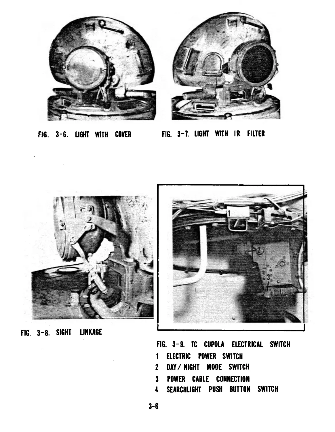
d. Tank Commander's Searchlight, OU-
36 К ?Figs. 3-6, 3-7). Mounted coaxially
with the Tank Commander's sight, TKN-3, is a
searchlight, 0U-3GK. This light has visible
and infrared capabilities by changing filters.
The filter of the searchlight is protected by
a metal cover whenever the searchlight is not
being used.
The searchlight is activated by one of
two means. After the cupola electrical
switch is on (see para e) (Figs. 3-9, 3-3),
either the button on the right handle of the
TKN-3 is pushed or a toggle switch on the
cupola ring is turned on. The toggle would
be used for prolonged illumination; the push-
button for intermittent illumination.
The searchlight can be bore-sighted to
the TKN-3 Tank Commander's periscope by ad-
justing its connecting linkage (Fig. 3-8).
e^. Tank Commander's Cupola Electrical
Power Switch (Pig. 3-9). Before the Tank
Commander can activate his searchlight or
target designator, he must first turn on the
cupola electrical power switch that is mount-
ed beneath the cupola ring to the Tank Com-
mander's right side.
f. Cupola Ring Lock (Fig. 3-3). The
Tank Commander's cupola can be locked either
to the front or the rear. The cupola ring
lock is located on the right side of the
cupola ring to the rear of the right vision
block.
To unlock the cupola, permitting free
manual movement of the cupola, the lock ring
is pulled out and rotated 90°(one quarter turn)
This step must be done before attempting to
perform the target designator function.
£. Rear Lights and Switch (Fig. 3-10)
There are two lights mounted between the
Tank Commander's hatch and loader's hatch
outside the turret. The large light is an'
identification light for night movements
and the light below it is a rear marker
light which is turned on when in a static
night defensive mode or in convoy under
blackout/IR conditions. With it on, an
approaching soldier will know the orienta-
tion of the main gun over the hull of the
vehicle which also has marker lights. In
the case of a night convoy, drivers will
be able to follow vehicles to their front by
observing the bright spots in their TVN-2
driver IR device.
The toggle switch for these lights is
located inside the turret on the rear wall
(Fig. 3-11). When facing the switch, move
the toggle to the right to turn on the rear
identification light, and to the left to
turn on the rear marker light. The center
position is "OFF".
h. Turret Ring Lock (Fig. 3-12).
The Tank Commander also has responsibility
for the turret ring lock located to his left
on the turret ring. The lock is operated by
extending the handle, rotating the white
lever (which unlocks the bolt), raising or
lowering the bolt into the receptacle on the
hull, locking it in place by rotating the
white locking lever, and moving the handle
out of the way. When unlocked, the bolt
must be secured in the up position (by ro-
tating the white lever) to preclude damage
to it as the turret rotates.
There are receptacles for the turret
ring lock bolt on both sides of the hull
(Figs. 3-12, 3-13) permitting locked turret
operation with the main gun pointing over
the front slopes or the rear deck.
i_. Gun Shield (Fig. 3-14). For the
protection of the Tank Commander from the
recoil of the main gun and the operation of
the spent-shell ejection mechanism, there
is a shield that is mounted on his seat
along his right side. THIS SHIELD SHOULD
ALWAYS BE MOUNTED WHEN THE VEHICLE IS MOVING
3-5
FIG. 3-7. LIGHT WITH IR FILTER
FIG. 3-6. LIGHT WITH COVER
FIG. 3-8. SIGHT LINKAGE
FIG. 3-9. TC CUPOLA ELECTRICAL SWITCH
1 ELECTRIC POWER SWITCH
2 DAY/NIGHT MODE SWITCH
3 POWER CABLE CONNECTION
4 SEARCHLIGHT PUSH BUTTON SWITCH
3-6
FIG. 3-10. REAR TURRET LIGHTS
1 MARKER LIGHT
2 IDENTIFICATION LIGHT
I LIGHT SWITCH
2 TC SEAT BACKREST
3 CUPOLA HANDGRIP
FIG. 3-11. TURRET LIGHTS SWITCH
3-7
FIG. 3-13. TURRET LOCK
RECEPTICLES ON LOADER'S SIDE
FIG. 3*12. TURRET RING LOCK
1 HANDLE
2 LOCKING HANDLE
3 RECEPTICLE
FIG. 3*14. TC BALLISTIC SHIELD
1 SHIELD
2 TC SHEET
< 3
FIG. 3*15. INTERCOM
1 TURRET RING LOCK
2 SOVIET RADIO MOUNT
3 TC INTERCOM BOX
4 GUNNER INTERCOM BOX
3-8
Section I. TURRET CONTROLS AND EQUIPMENT
j. Radio (Fig. 3-15). For the safety
of tne tank crew, a US intercom system has
been mounted throughout the tank. The AM
1780/VRC is located between the Tank Comman-
der and gunner, with intercom junction boxes
for all crewmen. NEVER OPERATE THE VEHICLE
WITHOUT CLEAR INTERCOM COMMUNICATIONS.
3-3 GUNNER'S CONTROLS AND EQUIPMENT
The following paragraphs cover location
of the gunner's controls and equipment in a
T-62 or T-62A tank equipped with conventional
sighting and fire control components. For
discussion purposes, the gunner's controls
and equipment have been divided into three
areas: Sighting and fire control, gun ele-
vating and turret traversing, and miscel-
laneous equipment.
a. Sighting and Fire Control Equipment
“ (Figs. 5-1577-17)------------ -------
(1) Gunner's Telescope, TSh2B-41U is
the gunner's primary means of target engage-
ment and the sole means for daylight use. It
is an excellent optical device that incor-
porates a rotating reticle to compensate for
superelevation, a selection of filters, a
choice of magnifications, and an adjustable
headrest for right or left eye use.
TSh2B-41U
Magnification
Field of View
NIGHT
18°
The front of the telescope is mounted on
a bracket that is bolted to the gun frame.
(Fig. 3-19) The rear of the sight is sus-
pended from the turret roof by a bracket.
The headrest can be positioned to accommodate
either right eye or left eye use (Figs. 3-20,
3-21).
A filter switch is positioned on the
left side of sight just forward of the rear
mounting bracket (Fig. 3-16). The filter is
used to reduce glare in the field of view.
Forward of the filter switch is the mag-
nification lever that is used to select be-
tween the 3.5 and 7 power operation.
On the right side of the scope is the
wiper lever that cleans dust from the front
lens of the telescope (Fig. 3-17).
Located on top of the telescope is a
wrench that is used to tighten the scope to
its front mount and to adjust the boresight
azimuth and elevation knobs (Fig. 3-17).
On the underside of the telescope is the
range knob which rotates the 5 reticles over
a fixed black line (Fig. 3-17). This knob
is rotated to index the range commanded by
the Tank Commander according to the ammuni-
tion he selected for target engagement.
This compensates for the superelevation re-
quired for the ammunition specified.
The reticles from left to right are
(Fig. 3-18):
HVAPDSFS - HEAT - HE 18 - HE 11 - COAX
At the bottom of the reticle is the
stadimetric range finder based on a vehicle
height of 2.7 meters.
(2) For night target engagement,
the gunner uses the TPN1-41-11 infrared
monocular periscope that is mounted to the
left of the telescope (Fig. 3-20). The
sight is fixed in position but a linkage
connects it to the main gun carriage.
CHARACTERISTICS
Magnification 5.5 x
Field of View 6°
Range 800 m (with use of main
searchlight)
3-9
FIG. 3-18. TSh2B-41u GUNNERS TELESCOPE, LEFT SIDE
1 WIPER
2 DEFROSTER CABLE CONNECTOR
3 ATTACHMENT SCREW
4 BORESIGHT KNOBS
5 MAGNIFICATION LEVER
6 RANGE KNOB
7 FILTER LEVER
EYEPIECE
FIG. 3-17. TSh2B-41u GUNNER’S TELESCOPE, RIGHT SIDE
1 WIPER ARM
2 ADJUSTMENT WRENCH
3-10
FIG. 3-18 TSh2B-41u Telescope Reticle?. a
1. Stadimetric Range Finder
Range Line
— 37
36—
34
32
48—
—46
44—
—42
40-
36
34
20
19
18
40=l_36
94=28
24=---20
^=12 и
Q ----4
БР
APDS
30 —38 36— —34 —30 17 16
28— 32 —30 28 15
26 24— 28— —26 24— 26 24 14 13
22 20 -=-22 20— —22 20 12
18 16-=- —18 16-= -=14 —18 16 11 TO
-=-14 12— ~ 14
8=” a—*> 8
8-=< .-=-6 8“ZLe 6
0 CM bliin * о 4=2 0 4"=-2 0— О A mm to
БК 0018 0011 ГТ
НЕП
HE18
HEAT
COAX
2 mils
I’!*,?2? 30
Range Finder
3-11
Section I. TURRET CONTROLS AND EQUIPMENT
The headrest can be positioned for left
eye or right eye use. The eyepiece is ad-
justable for +4 diopters (Figs. 3-20, 3-21).
Above and to the right of the eyepiece is
an adjustment wrench to adjust the boresight
knobs which are located at the bottom of the
scope (Fig. 3-21). The knob on the left ad-
justs azimuth while the right one changes
elevation.
To the left of the eyepiece is the power
connection for the infrared power supply,
model BT-6-26 and the intensity adjustment
knob (Fig. 3-21). The power supply has one
two-position "ON-OFF" toggle switch that
should be left "OFF" at all times when the
periscope is not in use. (Up is on; down
is off).
Above the headpiece is a chart that
shows the ranges for various types of ammuni-
tion at specific points on the reticle
(Fig. 3-20, 3-21).
CHART FROM TPN1-41-11 PERISCOPE
HEAT
APDS HE 11 HE 18 COAX
8 1111
14 3 1 2 2
19 5 A 4 3.5
30 9 | 7 6
In daytime, do not turn on without the
diaphragm being on. In bright light, do not
operate.
During the day, the gunner's periscope is
protected by an armored shield that bolts to
the front of the protective housing (Figs.
3-22, 3-23). This shield and the mounting
bolts should be carefully stored after re-
moval .
(3) Searchlight, Model L-2G (Fig.
3-24). The main searchlight of the T-62 tank
is the L-2G searchlight. It is mounted to
the right of the main gun on a platform that
is linked to the main gun housing.
It has both visible and infrared modes
which are available by changing filters.
In the infrared mode, the searchlight gives
the gunner an 800 meter range at which he
can successfully engage targets.
The searchlight is protected by a metal
cover that should be kept in place at all
times when the searchlight is not in use
(Figs. 3-24, 3-25).
The searchlight power switch is located
in the gunner's compartment above the tele-
scope bracket (Fig. 3-26). When it is
turned on (MASTER must be on), a dim red
light illuminates in the combat compartment
near the searchlight switch.
(4) Vision Block, Type TNP-165
(Figs. 3-22, 3-26). Above the gunner's
telescope, suspended from the turret ceil-
ing, is a 1 x power vision block that can be
used for general sight, main gun orientation
before acquiring a target in the relatively
narrow field of vision of the telescope.
(5) Main Gun/Coax Switches (Fig.
3-26). To the right of the telescope is
located the fuse box for the armament system
and a bank of toggle switches.
In the T-62A tank, there are only two
toggle switches. The right toggle is the
main gun switch; the left is the coax
switch. In the T-62 tank, there are four
toggle switches. The bottom two are the
same as in the T-62A; right is main gun,
left is coax. The two switches above are
from left to right: sight reticle illumina-
tion and sight defogger/defroster.
(6) Azimuth Indicator (Fig. 3-27).
The T-62 is equipped with an azimuth indi-
cator that is located to the left of the
gunner. The azimuth indicator shows the
gunner the orientation of the turret and,
more specifically, the gun tube over the
hull of the vehicle. It is also used for
range card target engagement.
3-12
FIG. 3-19. TELESCOPE IN TANK
1 RANGE KNOB
2 MAGNIFICATION LEVER
3 FILTER LEVER
4 GUNNER'S CONTROLS
FIG. 3-20. TELESCOPE ANO PERISCOPE
PREPARED FOR LEFT EYE USE
FIG. 3-21. TELESCOPE AND PERISCOPE
PREPARED FOR RIGHT EYE USE
1 GUNNERS VISION BLOCK I AZIMUTH ADJUSTMENT
2 IR POWER SUPPLY 2 ELEVATION ADJUSTMENT
3 MANUAL TRAVERSE HANDLE
4 GUNNER'S CONTROLS
5 TPN BORESIGHT WRENCH 3-13
FIG. 3-22. PERISCOPE WITH
PROTECTIVE COVER
FIG. 3-23. PERISCOPE READY FOR
NIGHT USE
1 GUNNER'S VISION BLOCK
FIG. 3-24. SEARCHLIGHT, L-2G,
WITH COVER
FIG. 3-25. SEARCHLIGHT, L-2G,
READY FOR NIGHT USE
1 LOADER'S PERISCOPE
1 AUXILIARY IR DRIVING LIGHT
2 COAX FIRING PORT
3-14
Section I. TURRET CONTROLS AND EQUIPMENT
The azimuth indicator is based on 6000
mils in 360° and has two hands; a 100 mil
minute-hand and the 6000 mil "hour-hand" that
show the orientation of the gun tube over the
hull.
Below the azimuth indicator is a toggle
switch which provides illumination for night
reading of the dial.
(7) Gunner's Quadrant (Fig. 3-28).
The gunner's quadrant is located to the right
of the gunner on the gun frame. It is used
to lay the gun in elevation on pre-planned
targets with the use of a range card.
Just forward of the gunner's quadrant, is
a toggle switch for night illumination of the
gun frame.
The gunner's quadrant is graduated from
2700-3200 mils and has a micrometer adjust-
ment knob graduated from 0-100 mils.
(8) Manual Cocking Handle (Fig. 3-29)
Along the top edge of the gun carriage to the
right of the gunner is the manual cocking
handle.
The gun is recocked (as in the case of a
misfire) by pul ling the cocking handle to the
rear. When the gun is cocked, there is an
audible click.
Forward of the cocking handle is the man-
ual breech closing handle (Fig. 3-29). This
handle is pulled out from the gun carriage
and pushed toward the front turret wall.
After the breech closes, the handle is re-
leased.
(9) Mechanical Trigger (Fig. 3-30).
Set into the gun carriage to the right of the
gunner, below the cocking handle, is the
mechanical trigger. If the electric system
fails, the mechanical trigger can be de-
pressed to fire the main gun.
b. Gunner's Elevation and Traverse
Controls.
(1) Manual Traverse Handcrank
(Fig. 3-31). To the left of the gunner is
the manual traverse handcrank. By rotating
it, the turret moves left or right. On the
end of the traverse handle is an auxiliary
electrical trigger for the coaxial machine
gun.
(2) Manual Elevation Handcrank
(Fig. 3-32). The manual elevation handcrank
is located below the gunner's electrical
controls. By rotating it, the main gun ele-
vates or depresses. At the base of the han-
dle is located an auxiliary electrical trig-
ger for the main gun.
(3) Manual Traverse Disengagement
Lever (Fig. 3-33). To the left of the man-
ual traverse handle is the manual disengage-
ment lever. When the turret is placed in
power operation, this handle must be rotated
toward the gunner to disengage the manual
traverse handcrank (Fig. 3-34). If the
sleeve does not immediately fall into its
disengaged position, make minor movements of
the traverse handle until it does.
(4) Manual Elevation Disengagement
Lever (Figs. 3-35, 3-36). The manual ele-
vation handcrank must be disengaged to per-
mit power elevation of the main gun.
Behind the gunner's controls is located
a round handle that must be pulled up and
rotated to the right till it locks in place.
If any difficulty is experienced, push down
on the assist handle located below and to
the left of the gunner's controls (Fig. 3-35)
WARNING! NEVER DISENGAGE MANUAL ELEVATION
HANDLE WITHOUT HAVING STARTED THE TANK EN-
GINE AND HAVING FOLLOWED THE PROCEDURE TO
SAFELY PUT THE TURRET INTO POWER OPERATION.
GUN TUBE WILL GO TO MAXIMUM DEPRESSION IF
DISENGAGEMENT LEVER IS MOVED TO THE RIGHT
WHILE TANK ENGINE IS OFF.
3-15
1 MAIN SEARCHLIGHT SWITCH
2 GUNNER'S DOME LIGHT SWITCH
3 GUNNER'S DOME LIGHT
4 MAIN GUN SWITCH
5 COAX SWITCH
6 TELESCOPE RETICLE ILLUMINATION SWITCH
7 TELESCOPE DEFROSTER
8 GUNNER'S VISION BLOCK
FIG. 3-26. SWITCHES
1 IR POWER SOURCE BT-6-26 FOR TPN 2-41-11
2 FINE NEEDLE INDICATOR
3 GROSS NEEDLE INDICATOR
4 MANUAL TRAVERSE CRANK
5 AZIMUTH INDICATOR ILLUMINATION SWITCH
I
FIG. 3-27. AZIMUTH INDICATOR
1 ILLUMINATION SWITCH
2 MICROMETER ADJUSTMENT
FIG. T-28. GUNNER'S QUADRANT
3-16
1 COCKING LEVER
2 BREECH CLOSING HANDLE
FIG. 3-29. COCKING AND BREECH
CLOSING HANDLE
FIG. 3-30. MANUAL TRIGGER
3-17
FIG. 3-31. MANUAL TRAVERSE
HANDCRANK
1 TRAVERSE HANDCRANK
2 GUNNERS PANIC GRIP
3 AUXILIARY COAX TRIGGER
4 ELEVATION HANDCRANK
5 AUXILIARY MAIN GUN TRIGGER
FIG. 3-32. MANUAL ELEVATION HANDCRANK
3-18
Section I. TURRET CONTROLS AND EQUIPMENT
To reengage the mechanical elevation hand-
crank, pull up the elevation disengagement
lever, and move it to the left. If any dif-
ficulty in experienced in locking it to the
left, wiggle the manual elevation handcrank
till gear teeth mesh.
(5) Gunner's Controls (Fig. 3-37).
Directly in front of the gunner’s seat are
the gunner's controls. With these controls
he can electrically traverse, elevate and
fire the main gun and coax machine gun. In
addition, there are three toggle switches
across the bottom of the control gauge that
turn on (from left to right) unstabilized
traverse (UNSTAB TRAV), stabilized elevation
(STAB ELEV) and stabilized traverse (STAB
TRAV).
There are two lights above the toggle
switches. The red one on the right illumi-
nates when the center toggle (STAB ELEV) is
turned on. The left one is green and illumi-
nates when the far left toggle (UNSTAB TRAV)
is turned on,
The handgrips on the gunner's control box
? e used to elevate the main gun and traverse
e turret. The grips are twisted up and
Fown or right and left to cause turret and
main gun movement.
At the top of each handgrip is a black
push-button. These buttons are the main
electrical triggers. The right handgrip but-
ton is the coax trigger. NOTE: On some
models of the T-62 tank, another push-button
is found by the right fore-finger on the
right handgrip. This button has no function.
c. Miscellaneous.
(1) Gunner's Seat and Footrest
(Figs. 3-38, 3-3$). The gunner's seat can be
lowered or raised by squeezing together the
grips along the top of the seat mount. The
lowering of the seat facilitates access to
the escape hatch and to electrical components
and gyros beneath the main gun.
The gunner's footrest likewise can be
lowered for operation to keep the gunner's
feet off the turret floor or can be raised
to provide better access to areas beneath
the gunner's controls and the main gun (Figs.
3-38, 3-39).
(2) Gunner's Backrest (Fig. 3-40).
The gunner has no rigid backrest as do the
other crewmen. Instead, there is a strap
that is fixed to the main gun carriage. The
free end of the strap is connected to one of
the holes in the radio mount.
(3) Gunner's Grip Handle (Panic
Grip)(Fig. 3-32, 3-37). When firing the
main gun or protecting himself from jolts
when the vehicle moves cross-country, the
gunner can hold a fixed handle mounted below
the manual traverse handle to the left of
the gunner's control gauge.
(4) Gunner's Dome Light (Fig. 3-26).
The gunner has a dome light located behind
the 1 x-power vision block above the main in-
frared searchlight switch.
(5) Intercom. The gunner's seat is
next to the AM 1780/VRC fitted to the Soviet
radio mount. The gunner has been provided
with his own junction box, mounted by his
left side.
3-4 LOADER'S CONTROLS AND EQUIPMENT
a^. General. This section contains in-
formation on the loader's controls and equip-
ment of the T-62 and T-62A equipped with con-
ventional armament and fire control systems.
b. Loader's Hatch (Figs. 3-41, 3-42,
3-43T- The loader in a T-62 has a fixed
hatch that can be secured in either the
locked open or locked closed positions. In
a T-62A, the loader's hatch is mounted on a
cupola to which is also attached a machine
gun mount for a 12.7 mm DShK anti-aircraft
machine gun. This cupola can be rotated
360°. The loader's hatch can be locked in
either the open or closed position and has a
combat lock identical to the type found on
the Tank Commander's hatch.
3-19
FIG. 3-33. MANUAL TRAVERSE ENGAGED
HANDLE ROTATED TOWARD TURRET
WALL
FIG. 3-34. MANUAL TRAVERSE DISENGAGED
HANDLE ROTATED TOWARD GUNNER
SLEEVE IS DOWN
FIG. 3-36. MANUAL ELEVATION DISENGAGED
FIG. 3-35. MANUAL ELEVATION ENGAGED
1 DISENGAGEMENT ASSIST HANDLE
2 DISENGAGEMENT KNOB
3-20
FIG. 3-37. GUNNER'S CONTROLS
1 COAX TRIGGER
2 MAIN GUN TRIGGER
3 TRAVERSE HANDCRANK
4 ELEVATION HANDCRANK
5 PANIC GRIP
6 MANUAL ELEVATION DISENGAGEMENT ASSIST LEVER
7 STABILIZED ELEVATION SWITCH
8 RED LIGHT
9 STABILIZED TRAVERSE SWITCH
10 UNSTABILIZED TRAVERSE SWITCH
11 GREEN LIGHT
12 POWER ELEVATION-TRAVERSE HANDGRIPS
13 AUXILIARY COAX TRIGGER
3-21
FIG.3-38. GUNNER'S SEAT AND
FOOTREST STOWED
FIG. 3-39. GUNNER'S SEAT AND
FOOTREST IN POSITION
1. HEAT SENSOR BUTTON
FIG. 3-40. GUNNER'S BACK REST
1 BACK REST
2 SOVIET TANK CREWMAN HELMET
3-22
Section I. TURRET CONTROLS AND EQUIPMENT
c. Loader's Seat (Fig. 3-44). The
loader's seat is springloaded in both the
T-62 and T-62A. In the T-62, there are two
mounts for the seat along the turret wall of
the loader's compartment. In the T-62, the
loader has only one mount for his seat.
ci. Loader's Safety (Fig. 3-45). The
loader's safety 1s located on the right side
of the gun carriage. This safety is a two-
position device. When the lever is pushed
in, the safety is in the "FIRE" position.
When the black button on the side of the
safety is pushed in, the lever spings to the
extended position and the safety is in the
"SAFE" position (Fig. 3-46).
The loader's safety is an absolute safety.
When the safety is in the "SAFE" position, no
trigger will fire, to include the main gun
mechanical trigger. In addition, a "SAFE"
safety will render the turret powerless. The
gunner will have no electrical traverse or
elevation control. The safety is returned to
the "SAFE" position each time the main gun
fi res.
£. Loader's Periscope, MK-4S (Figs.
3-47, 3«-46). The loader has a periscope
mounted in the turret ceiling that gives
him vision to the front and side of the
vehicle. The periscope swivels in its mount
and can be rotated about its horizontal mount-
ing axis.
The sight has a dual periscope vision
capability to the front and to the rear.
The sight is normally mounted to allow the
loader to look to his front. In this mode
the loader has a 25° field of vision. By
pulling down on the headrest, the loader can
configure the periscope to look to his rear.
In this mode, the loader has a 16° field of
view.
f. Loader's Handgrip (Panic Grip)
(Fig. 3-47). The loader has a handleto
the right of his periscope that is to be
used during firing of the main gun or during
vehicular movement across rough terrain.
£. Coax Mount (Fig. 3-49). The loader
is responsible for loading and servicing the
7.62 mm PKT coax machine gun. The mount for
the coax is located to the right of the main
gun on the gun frame. Beneath the mount
hangs a cloth bag that catches the shell
casings.
h_. Travel Lock (Fig. 3-50). The main
gun travel lock in the T-62 series tank is
located inside the turret. A bar is hung
from the turret roof and fixed by a pin at
the top of the breech. There are three
positions in which the T-62 main gun can be
locked.
When the gun is not in travel lock, the
bar is removed from the turret roof.and
stowed in a special mount behind the two
round ready rack along the right rear of the
turret wall (Fig. 3-51).
i_. Automatic Ejection System. Гпэ
T-62 series tank has an integral spen:
shell ejection mechanism which is activated
by the recoil of the main gun and ejects
shell casings from the turret. The ejector
mechanism consists of three main elements;
the tray, the ejector port (Figs. -3-53, 3-54,
3-55, 3-56), and the electrical control box
(Fig. 3-57).
(1) The Ejector Tray (Fig. 3-52).
The frame of the ejector tray is bolteo to
the gun carriage. Normally, the ejection
mechanism is functioned by the recoil of the
gun, but the mechanism can be tested elec-
trically.
WARNING! WHEN TESTING THE ELECTRICAL OPERA-
TTUN OF THE EJECTION MECHANISM, KEEP WELL
CLEAR OF THE EJECTOR TRAY.
3-23
FIG. 3-41. LOADER’S HATCH T-62
FIG. 3-42. LOADER'S HATCH. FRONT VIEW
1 HATCH LOCK
2 LOADER'S PERISCOPE. MK-4
FIG. 3-44. LOADER'S SEAT
FIG. 3-43. LOADER S HATCH. REAR VIEW
1 COMBAT LOCK
2 HANDLE
3 HANDLE RELEASE HANDLE
3-24
FIG 3-48 LOADER’S SAFETY-“SAFE"
FIG 3-45 LOADER'S SAFETY-“FIRE”
I SAFETY SELECTOR
2 SAFETY RELEASE BUTTON
FIG 3-47 LOADER’S PERISCOPE MK-4,
FOR VIEWING TO THE FRONT
FIG 3-48 LOADER’S PERISCOPE
FOR VIEWING TO THE REAR
1 LOADER'S DOME LIGHT
2 EJECTOR CONTROL BOX
3 LOADER’S HANDGRIP
1 AUXILIARY IR DRIVING LIGHT
2 PERISCOPE IN EXTENDED
POSITION AND ROTATED 180°
3-25
Section I. TURRET CONTROLS AND EQUIPMENT
When activated (by either recoil or
electrical means), the tray assembly sepa-
rates from the framework and rises to the
ejection port.
(2) The Ejector Port (Figs. 3-53,
3-54). There is an ejector port on the rear
side of the turret. It is through this port
that spent shells are ejected. The port is
opened and closed by a servomotor mounted to
its side. The door opens automatically when
the ejection system functions and can also
be opened electrically without the entire
system functioning (Figs. 3-55, 3-56). The
port can be opened manually (with difficulty)
by disengaging and pushing up the servomotor
which is joined to the port.
The door has a handle on it so it can be
locked shut. This handle must always be in
the open position before attempting to func-
tion the door separately or the ejection
system tray either electrically or by recoil.
(3) The Ejection System Control Box
(Fig. 3-57). Immediately below the loader's
panic grip on the turret wall is mounted the
electrical control box for the ejection
system. This box has one toggle switch and
two push buttons.
The toggle switch is used to select two
different electrical modes of opening the
ejector port. With the switch is the AUTO
position (toward the front turret wall),
the ejector mechanism (tray and door) can be
functioned by the recoil of the gun or by
tripping the micro switch at the rear of the
shell tray.
When the toggle is in the MAN position
(toward rear of turret), the loader can push
the "OPEN" button to function only the door.
Pushing the "CLOSE" button shuts the port.
j_. Breech Opening Handle (Fig. 3-58).
The breech opening handle is located on the
top edge of the gun. The springloaded handle
(Fig. 3-59) must be raised to clear its de-
tent from the locked travel position. The
handle is then swung towards the gunner's
seat (Fig. 3-60). This movement takes a
minimum of effort since the gear does not
engage until it's fully open. An audible
click signals that the handle is engaged
(Fig. 3-60).
The loader then pulls the handle back
towards his position until the extractors
in the breech-block audibly click into the
locked open position (Fig. 3-61). At this
point, the handle is still not locked in its
travel position. On top of the handle near
its shaft is the handle disengagement lever
that is spring-loaded (Figs. 3-62). By
squeezing the lever, tension is released on
the handle and it can be secured in its
travel position (Fig. 3-63).
k. Turret Ventilator (Fig. 3-56). The
turret ventilator is located in the Tank
Commander's area, but the "ON-OFF" control
box is located near the ejector port, within
reach of the loader. It should be turned
on to remove gases and smoke from the turret
compartment.
1_. Dome Light (Fig. 3-64). The loader
has an adjustable screen dome light with
which he can illuminate his working area.
The switch for the light is located on the
turret ceiling just left and forward of the
loader's periscope.
m. Driver's Auxiliary IR Light (Fig.
3-24T. The switch for the driver's auxi-
liary infrared light is mounted in the
loader's area just above the power connec-
tion for the loader's electrical control
box (Fig. 3-57). The infrared light itself
is located on the fixed platform of the main/
searchlight mount.
Even though the loader has no infrared
viewing capability, the height of this
auxiliary light is of great assistance to
the driver during IR conditions.
3-26
FIG. 3-49. COAX MOUNT
FIG. 3-50. TRAVEL LOCK MOUNTED
FIG. 3-51. TRAVEL LOCK BAR STOWED
FIG. 3-52. EJECTOR TRAY
3-27
FIG. 3-53. EJECTION PORT
1 EJECTION PORT
2 TURRET VENTILATOR
FIG. 3-54. EJECTION PORT AND SERVOMOTOR
1 SERVOMOTOR DISENGAGEMENT HANDLE
FIG. 3-56. EJECTION PORT OPEN
FROM TURRET
FIG. 3-55. EJECTION PORT OPEN
1 EJECTION PORT LOCKING HANDLE
1 VENTILATOR CONTROL BOX-
ON-OFF
2 VENTILATOR
3-28
FIG. 3-57. EJECTOR CONTROL BOX
1 CONTROL BOX
2 AUTO-MAN TOGGLE SWITCH
3 OPEN-CLOSE PUSH BUTTON
4 LOADER’S PANIC GRIP
5 DRIVER’S AUXILIARY IR LIGHT SWITCH
6 LOADER'S PERISCOPE
7 DOME LIGHT
8 MAIN GUN “ON" WARNING LIGHT
3-29
FIG. 3-58. BREECH HANDLE STOWED
1 HANDLE
2 TRAVEL LOCK PIN
FIG. 3-60. HANDLE ENGAGED
FIG. 3-59. HANDLE OUT OF DETENT
3-30
Section I. TURRET CONTROLS AND EQUIPMENT
ji. Replenisher (Fig. 3-64). The loader
has prime responsibility for monitoring the
level of hydraulic fluid in the gun recoil
system. He checks to confirm the presence
of hydraulic fluid in the window. This win-
dow is located to the right side of the main
gun above the coax mount.
o. Communications (Fig. 3-65). The
loader has access to his own intercommunica-
tion junction box (US) that is located to
his rear on a protective plate that covers
the turret ring.
3-5 AUXILIARY CONTROLS AND EQUIPMENT
a_. General. This section contains
operation information for auxiliary controls
and equipment in the turret. The informa-
tion in this section covers the hull blower,
engine-preheater, fire detector and ammuni-
tion racks.
b. Hull Ventilator (Fig. 3-67). The
hull ventilator is located below and to the
rear of the Tank Commander's seat. It pulls
air from the turret area into the engine
compartment. This ventilator must be used
to supply air to the engine when the tank
snorkels.
The control box for this ventilator is
located in the driver's compartment (see
Driver Controls and Equipment).
£. Pre-Heater(Figs. 3-66, 3-67). The
engine pre-heater apparatus is located be-
neath the Tank Commander's seat. The control
panel for the pre-heater is located immedia-
tely to the left and below the Tank Comman-
der's seat.
The pre-heater is used in winter opera-
tions to warm the engine coolant.
d. Ammunition Racks. There are five
separate ammunition racks in the T-62; a two
round turret ready rack (Fig. 3-70), a 16
round front hull rack (Fig. 3-72), and two
one-round racks (Figs. 3-73, 3-74), along the
floor beneath the gunner's footrest. Total
basic load is 40 rounds.
The rear hull 20-round rack is color
coded to facilitate its construction as
ammunition is placed into it.
£. Heat Sensor. By the base of the
front 16 round ammo rack (Fig. 3-68), and
by the fuel cell near the rear 20-round
rack (Fig. 3-69), are heat sensors that will
activate the fire extinguisher system auto-
matically. If the system does not activate
automatically, the vehicle commander can
activate the system by pushing a button
located below and to the left of the TC's
seat (Fig. 3-39).
WARNING! IF FIRE EXTINGUISHER EVER GOES
OFF, IMMEDIATELY VACATE THE VEHICLE.
SOVIET FIRE EXTINGUISHER GAS IS HIGHLY
POISONOUS.
3-31
FIG. 3-61. BREECH FULLY OPENED
FIG. 3-63. DETENT RAISED TO STOW
FIG. 3-62. HANDLE DISENGAGEMENT LEVER
3-32
FIG. 3-64. REPLENISHER
1 REPLENISHER
2 LOADER’S DOME LIGHT
1 TURRET
2 TURRET
VENTILATOR
RING
FIG. 3-65. LOADER’S INTERCOM BOX
3-33
FIG. 3-66. PREHEATER CONTROLS
1 GLOW PLUG SWITCH
2 MOTOR SWITCH
FIG. 3-67. PREHEATER
1 HULL VENTILATOR
FIG. 3-68. HEAT SENSOR BY FORWARD
HULL AMMO RACK
FIG. 3-69. HEAT SENSOR BY FUEL CELL
3-34
FIG. 3-70. TWO-ROUND READY RACK
—
FIG. 3-71. 20-ROUND HULL RACK
FIG. 3-72. 16-ROUND HULL RACK
FIG. 3-73. 1-ROUND RACK BY GUNNER’S FEET
FIG. 3-74. 1-ROUND RACK BY LOADER’S FEET
3-35
Section II. OPERATION AND USE OF TURRET ARMAMENT AND FIRE CONTROL EQUIPMENT
3-6 GENERAL
This section contains the procedures for
the operation and employment of the turret
armament and associated fire control and
sighting equipment in the T-62A Soviet Medium
tank.
3-7 AMMUNITION TYPES AND STORAGE
a_. Types of T-62 Ammunition. The T-62
has three types of ammunition for the 115 mm
U5-TS main gun. These are a hypervelocity,
armor piercing, finstabili'zed, discarding
sabot (HVAPFSDS) round, two types of high-
explosive fragmentation (НЕ-FRAG) round,
charges 11 and 18, and a high explosive anti-
tank (HEAT) round. These round are issued in
ammunition boxes. When these rounds are
loaded on the tank, grease or dirt should be
removed from the ammunition. Ensure that the
fuses have caps and that the V-429V fuse for
the НЕ-FRAG round is set at "0". Do not use
any rounds that have cracks at the base or
casing flange or have noticeable dents. Re-
member the rounds are electrically fired.
Use the same precautions you would use when
handling US tank ammunition.
b. Ammunition Storage. The T-62 has a
basic load of 40 rounds unless it is a com-
mand tank. In that case, it stows 37 rounds.
The storage configuration is shown in section
3-5d.
The basic load for the PKT machine gun is
2500 rounds in 10 250 round replenishable
belts. There are 120 rounds for the AK-rifle,
10 hand grenades and 12 flare pistol cart-
ri dges.
3-8 PREPARING AND INSPECTING ARMAMENT FOR
FIRING
a_. 115 mm Main Gun. The following will
be accomplished before firing the main gun:
(1) Boresight the TSh2B-41 tele-
scope, TPN 1-41-11 infrared periscope and the
TKN 3 Tank Commander's periscope (See section
3-12).
(2) Clean the gun tube and breech.
Examine the barrel for cracks or bulges.
(3) Remove and clean the breech-
block. Disassemble firing pin mechanism
and remove all dust, dirt or grease. Mea-
sure the firing pin head length. It must
be between 2 and 2.42mm long.
NOTE: Breech removal, disassembly and
assembly will be addressed in a change to
this manual should ammunition become avail-
able for service firing.
(4) Cock the firing pin with the
cocking handle, turn on the main gun switch
and depress the main gun trigger to check
operation of the firing pin. (NOTE: Do
not leave firing pin cocked. This will
weaken the spring).
(5) Rotate the manual elevation
handcrank. If it binds unnecessarily, clean
dirt from spur gear.
(6) Rotate manual traverse hand-
crank.
b. Automatic Ejection System. The fol-
lowing checks will be made before firing the
main gun:
(1) Check for completeness of
ejection assembly.
(2) Function the automatic ejection
system. To do this:
(a) Start the tank.
(b) Unlock the ejector port.
Levers should be in positions shown (Fig.
3-75).
(c) Disengage ejection frame-
work from travel lock and secure the travel
lock in "open" position (Figs. 3-76, 3-77).
(d) Turn on main gun switch. A
green warning light should illuminate next
to the ejection system control box (Fig.
3-78).
3-36
Section II. OPERATION AND USE OF TURRET ARMAMENT AND FIRE CONTROL EQUIPMENT
(e) Move mode selector switch
on ejection system control box to "automatic1'
(Fig. 3-78).
(f) Take a 3-foot board and
from the loader's position push the circuit
activating pin (Fig. 3-79).
(g) The tray will elevate in
line with the ejector port which will open.
The shell will be ejected, the framework will
return to its original position and the hatch
will close. Personnel should stand clear of
the framework and ejector port when it is in
operation.
c. Stabilizer System. The following
checks will be made before firing the main
gun or using the turret in the stabilized
mode:
(1) Check replenisher fluid level
in the check window. (Fig. 3-80). It should
be visible in the window.
(2) Check horizontal and vertical
performance of stabilizer system (See Sec-
tion 3-11 for instructions on placing the
stabilizer system in operation).
(3) Check operation of TC's TKN-3
override in both stabilized and unstabilized
modes (See Section 3-11 for instructions on
operation of TC's override) (Fig. 3-81).
(4) Check operation of main gun
hydraulic braking. This is done by placing
gun in power elevation. When the manual
elevation controls are disengaged the gun
should remain in place. If there is a system
malfunction, the gun will depress rapidly
(See Section 3-11 for instructions on placing
elevation system in power operation).
d. 7.62 mm PKT Coaxial MG.
(1) Preparation of the Machine Gun
for Firing. These items and procedures
should be checked and followed before firing
the weapon.
(a) Ammo. Examine the ammo
belts to be sure all the rounds are firmly
seated in their belts. Loose cartridges
will fall out if the belt is shaken.
(b) Spare Parts and Acces-
sories. Spare parts, accessories, ammo box
shell and belt bag, and MG mounting should
all be in good condition.
(c) Pre-Firing Weapon Check.
1" Remove cover from wea-
pon and the weapon from the mounting (See
Annex A).
2. Break the weapon down,
clean and check the parts, with careful
cleaning of gun bore.
3. Apply light oil to all
movable parts.
4. Reassemble weapon and
check the gas chamber indicator, usually
set at slot 2 (Fig. 3-82).
5. Check the assembled
weapon and attach it to the mounting (Fig.
3-82).
6. Attach PKT solenoid
cable to electrical socket located forward
of the loader's safety (Fig. 3-83).
7. Pull the trigger and
check the gun action.
(d) Sighting Weapon. Bore-
sight the PKT as outlinea in para 3-12b.
(2) Stages and Steps in Firing the
Machinegun. There are four basic stages in
operating this weapon; loading, sighting,
firing and unloading. The steps for each
stage follow:
(a) Loading.
1. Open receiver and place
belt into feed chamber, with first round in
the extractor catches. Pull belt backwards
until it stops (Figs. 3-84, 3-85).
3-37
FIG. 3-75. EJECTION PORT
1 DOOR LOCKING HANDLE
2 SERVOMOTOR ENGAGEMENT ARM
FIG. 3-76. EJECTOR TRAY LOCKED
FIG. 3-77. EJECTOR TRAY UNLOCKED
1 METAL LATCH
FIG. 3-78. EJECTOR CONTROL BOX
1 AUTO-MANUAL SWITCH
2 OPEN-CLOSE PUSH BUTTONS
3 WARNING LIGHT
3-38
FIG. 3-79. ACTIVATING PIN
FIG. 3-80. REPLENISHER
FIG. 3-81. TKN-3 PERISCOPE IN CUPOLA
3-39
Section II. OPERATION AND USE OF TURRET ARMAMENT AND FIRE CONTROL EQUIPMENT
2. Close receiver and pull
charging handle backwards, then push forward.
(Fig. 3-85).
(b) Sighting and Aiming.
1. Use the TSh2B-41U tele-
scope. Rotate range knob until the horizon-
tal line corresponds to the range for the PKT.
2. Then place the main aim-
ing point on the target by traversing the
turret and/or elevating/depressing the main
gun.
(c) Weapon Firing.
1. Weapon fires light-weight
steel rounds, tracer or armor-piercing. The
rate and intensity of fire are determined by
the kind of target and nature of combat.
2. The electric trigger is
operated by a push button on the left hand-
grip of the gunner's controls. Cease fire by
releasing the button (See Fig. 3-37).
3. Firing of the weapon is
automatic while the button is depressed un-
til, of course, all the rounds are expended.
Firing is usually in bursts of 2 to 4 rounds
at targets up to 600 meters, while tank is
moving. Targets at longer ranges, 600-1,000
meters are usually large targets such as
truck columns or infantry groups. Firing in
bursts over 10 rounds is effective in un-
usual circumstances only.
(d) Unloading Weapon.
1. Open receiver cover and
feed tray; remove cartridge from feedlock
opening.
2. Remove ammo belt and
close receiver.
3. Do not cock weapon.
Close receiver cover.
4. Open shell and belt bag
and pour expended rounds into bucket.
(3) Immediate Action.
(a) If a stoppage occurs, wait
five seconds. (The bolt must remain forward
for the first five seconds due to the possi-
bility of a hangfire).
(b) After the five second de-
lay, raise the cover and remove the ammuni-
tion belt and links from the feed tray.
(c) Pull the charging handle to
the rear, making sure that the sear engages
the sear notch in the operating rod; close
the cover immediately, then return the cock-
ing handle to its forward position.
(d) During the retraction of
the bolt, observe if the round is extracted
and ejected.
1. If the round is NOT ex-
tracted, pull the trigger, attempting to
fire the round. If the round does not fire
and the barrel is hot, wait at least five
minutes with the bolt in the forward posi-
tion to preclude damage or injury in the
event of a cook off. After the five minute
wait, remove the round by using a cleaning
rod inserted from the muzzle of the weapon.
2. If a round is extracted,
or when a round is removed from the chamber,
inspect the weapon and the ammunition to de-
termine the cause of the stoppage.
(e) After clearing the weapon,
reload, relay on the target, and attempt to
fire.
3-9 Preparing and Inspecting Sighting/Fire
Control Eguipment for Use.
a. TKN-3 Tank Commander's Periscope.
To cHeck the operation of the TKN-3:
3-40
FIG. 3-82. PKT GAS CHAMBER INDICATOR
FIG. 3-83. PKT MOUNTED
1 SOLENOID CABLE
3-41
FIG. 3-84. 1NSERBNG BELT
FIG. 3-85. ROUND IN PLACE
1 CHARGING HANDLE
3-42
Section II. OPERATION AND USE OF TURRET ARMAMENT AND FIRE CONTROL EQUIPMENT
(1) Place diaphragm and screen knobs
in the "closed" (ZAKP) position.
(2) Place mirror control in night
mode (H) (Fig. 3-86).
(3) Turn on TC's cupola power
switch.
(4) Turn on TKN-3 power switch
(Fig. 3-86).
(5) Move the diaphragm and screen
knobs gradually until a greenish hue appears
in the field of view along with an image of
the terrain. Maintain minimal brightness.
Do not continue operation in daylight for
periods longer than 30 seconds.
(6) Return screen and diaphragm
knobs to "CLOSED" (ZAKP) position and move
the mirror control lever to "DAY" (A) mode.
(7) To check the TKN-3 at night,
open screen and diaphragm knobs all the way
and turn on the 0U-3GK searchlight.
(8) To turn on the searchlight, the
gunner flips the main searchlight toggle
switch above the TSh2B-41U telescope. When
the IR filter is installed on the search-
light, it should radiate a discernible amount
of heat.
b. TPN 1-41-11 Infrared Periscope.
To Cfieck the operation of the TPN 1-41-11 IR
periscope:
(1) Wait until dark. Remove armor
protective plate for the head of the TPN-1-41-
11 on turret exterior.
(2) Attach IR power cable to the
power connection on the periscope (Fig. 3-87).
(3) Turn on toggle switch on BT-6-
26 power supply (Fig. 3-88).
(4) There should be a greenish hue
field of view. Adjust for brightness with
the intensity adjustment knob on the peri-
scope's left side (Fig. 3-87). Turn on the
L-2G searchlight and adjust periscope for
clarity of vision.
3-10 OTHER TURRET PRE-OPERATION CHECKS
a_. After the tank is started, turn on
the turret ventilator with the control box
on the turret ceiling or the one located in
the driver's compartment (Fig. 3-89).
b. Check all internal fuel line (yel-
low) for evidence of leakage.
c. Turn on the turret rear light and
vehicle identification light (Figs. 3-90,
3-91).
d. Check operation of intercom system.
e^. Check operation of dome lights,
quadrant elevation light and azimuth indi-
cator light.
3-11 OPERATION OF THE GUN ELEVATION AND
TURRET TRAVERSING MECHANISMS
a_. General. The T-62 turret can be
operated in both a stabilized and an un-
stabilized mode. The turret traverse
mechanism is electrically operated. The gun
elevation mechanism is electro-hydraulically
operated. The T-62 also uses the standard
mechanical manual elevation and traverse
controls. There are several features that
are unique to this system. The manual ele-
vation and power elevation controls cannot
be used simultaneously. This is cittribu-
table to the requirement the manuals con-
trols be mechanically disengaged when using
the power controls. The same applies for
the manual and power traverse controls. A
certain sequence is also necessary to place
the turret in and remove it from power ope-
ration. This sequence must be followed
exactly. The tank commander has a turret
traverse override but no means of overriding
or even operating the main gun elevation
mechanism.
b. Manual Operation. To use the manual
controls:
(1) Remove the main gun from tra-
vel lock (Fig. 3-92). Stow the travel lock
bar above the loader's turret wall ready
rack in the bracket provided (Fig. 3-93).
3-43
FIG. 3-86. TKN-3 PERISCOPE
1 SCREEN LEVER
2 DIAPHRAGM LEVER
3 DAY/NIGHT MDDE SWITCH
4 HEADREST
5 EYE DISTANCE ADJUSTMENT
6 IR POWER SUPPLY SWITCH
7 TARGET DESIGNATE BUTTON
8 IR ON-OFF PUSH BUTTON
3-44
Section II. OPERATION AND USE OF TURRET ARMAMENT AND FIRE CONTROL EQUIPMENT
(2) Unlock the turret. (Fig. 3-94).
(3) Confirm that the manual controls
are engaged. The manual traverse disengage-
ment lever should be pointing away from the
gunner (Fig. 3-95). The manual elevation
disengagement lever should be to the left
(Fig. 3-96).
(4) The gun can now be depressed/
elevated and the turret traversed by rotating
the respective handcranks.
£. Power Operation. There are three pos-
sible modes of power operation; unstabilized
traverse-manual elevation (UNSTAB TRAV-MAN
ELEV), unstabilized traverse-stabilized ele-
vation (UNSTAB TRAV-STAB ELEV) and stabi-
lized elevation-stabilized traverse (STAB
ELEV-STAB TRAV).
(1) Unstabilized Traverse Manual
Elevation. This mode is used in shop areas,
assembly areas and other places where power
traverse is desired. To place the turret in
this mode:
(a) Start the vehicle.
(b) Place loader's safety in
"SAFE" position (Fig. 3-97).
(c) Close and lock down driver's
hatch.
(d) Unlock turret and remove
gun from travel lock.
(e) Disengage manual traverse
mechanism by pulling manual disengagement
lever toward gunner's seat and down (Fig.
3-98). Rotate manual traverse handcrank to
ensure disengagement.
(f) Move UNSTAB TRAV toggle
switch to 12 o'clock position. A green
light will illuminate to indicate power opera-
tion (Fig. 3-99).
(g) Depress loader's safety to
"FIRE" position (Fig. 3-100).
(g) Depress loader's safety
to "FIRE" position (Fig. 3-100).
(h) By moving the gunner's
power control handgrips left or right, the
turret can be traversed. Use the manual
elevation handcrank for gun elevation.
(2) Unstabilized Traverse - Stabi-
lized Elevation! This mode is used for
tactical convoys where enemy contact is pro-
bable or imminent. To place the main gun in
this mode:
(a) Repeat steps (a) through
(d) for UNSTAB TRAV-MAN ELEV.
(b) Move stabilized elevation
toggle switch (Fig. 3-99) to 12 o'clock
position. A red light will illuminate on
the gunner's controls to indicate system
operation.
(c) Wait a minimum of 2 minutes
to permit the stabilizer system gyros to
warm up sufficiently.
NOTE: Never attempt to operate stabilizer
system without waiting 2 minutes for gyro
warm-up. Otherwise serious damage can re-
sult in the stabilization system.
(d) Disengage the manual ele-
vation mechanism by pulling up on the dis-
engagement lever knob (Fig. 3-101), and
moving it to the right as far as it will go.
Rotate the manual elevation handcrank to
confirm manual elevation disengagement.
WARNING! If the manual elevation mechanism
is disengaged prior to activating the STAB
ELEV toggle switch, the main gun will drop
rapidly, creating a danger to the personnel
inside the turret or standing near the gun
tube outside the tank. NEVER disengage
manual elevation mechanism prior to acti-
vating STAB ELEV toggle switch.
(e) Disengage manual traverse
mechanism with disengagement lever as pre-
viously described (Fig. 3-98).
3-45
FIG. 3-87. TPN 1-41-11 PERISCOPE
1 AZIMUTH ADJUSTMENT
2 ELEVATION ADJUSTMENT
3 ADJUSTMENT WRENCH
4 INTENSITY KNOB
FIG. 3-88. PERISCOPE AND TELESCOPE
IN TANK
1 IR POWER CONNECTION
2 IR POWER UNIT BT-6-26
FIG. 3-89. VENTILATOR AND CONTROL BOX
3-46
FIG. 3-90. TURRET LIGHTS
1 MARKER LIGHT
2 IDENTIFICATION LIGHT
FIG. 3-31. TURRET LIGHT SWITCH
1 MARKER LIGHT OH
2 ID LIGHT OH
3 OFF
3-47
FIG. 3-92. TRAVEL LOCK
FIG. 3-93. TRAVEL LOCK STOWED
3-48
1
2
3
FIG. 3-94. TURRET RING LOCK
HANDLE
SECURING HANDLE
RECEPTACLE
FIG. 3-96. GUNNER'S CONTROLS
FIG. 3-95. MANUAL TRAVERSE
DISENGAGEMENT LEVER
3-49
Section II. OPERATION AND USE OF TURRET ARMAMENT AND FIRE CONTROL EQUIPMENT
(f) Move UNSTAB TRAV toggle
switch to 12 o'clock position. Green light
will illuminate to indicate system operation.
(g) Depress loader's safety
switch to "FIRE" position (Fig. 3-100).
(h) The turret may now be power
operated for traverse and elevation. The gun
is only stabilized in the vertical plane.
(3) Stabilized Traverse-Stabilized
Elevation. Full stabilized operations are
used for combat engagements. In a movement
to contact, the crew might have the turret in
the UNSTAB TRAV-STAB ELEV mode and simply
flip the STAB TRAV Switch for full stabilized
operations. To have full main gun stabili-
zation:
(a) Repeat steps (a) through
(e) for the UNSTAB TRAV-STAB ELEV mode.
(b) Move STAB TRAV switch to
12 o'clock position.
WARNING! NEVER turn STAB TRAV switch on be-
fore STAB ELEV switch otherwise serious da-
mage to the stabilization system could re-
sult. The UNSTAB TRAV switch may be turned
on if desired.
(c) Depress loader's safety to
"FIRE" position. The main gun is now fully
stabilized in both axes.
(4) Tank Commander's Traverse Over-
ride. The TC has the capability to override
the gunner's turret traversing control. This
override is accomplished with the use of the
TC's TKN-3 target designate sight (Fig. 3-
102) mounted in his hatch. To use the over-
ri de:
(a) The turret must be in the
power traverse mode.
(b) Turn on the TC cupola power
switch (Fig. 3-103).
(c) Unlock the TC's cupola
(Fig. 3-102).
(d) Using the hand grips on
the TKN-3, move the sight and cupola until
the target has been identified in the sight
picture.
(e) Depress button on left
hand grip (Fig. 3-102). Turret will slew at
maximum speed to align with TC's sight pic-
ture. Release the button when the gun is
generally aligned with the TKN-3. Do not
continue to depress the button after the
turret is aligned with the TKN-3.
d. Ceasing Power Operation. There is
also a specific sequence for ceasing power
operation when it is no longer needed. To
return to manual operation:
(1) Place loader's safety on "SAFE"
position.
(2) Re-engage manual elevation
mechanism by lifting disengagement lever
knob and moving the lever to the left and
locking it down. Rotate manual elevation
handcrank back and forth to facilitate re-
engagement.
(3) Move STAB ELEV switch to 6
o' clock position. Red light will go out.
(4) Move UNSTAB TRAV and/or STAB
TRAV switch to 6 o' clock position.
(5) Re-engage manual traverse
mechanism by lifting disengagement lever and
pushing up and away from gunner's seat.
(6) The turret can now be manually
operated.
3-12 BORESIGHTING
a_. TSh2B-41U Telescope/115 mm Main Gun.
To boresight the gunner's telescope:
(1) Place the tank on level ground.
(2) Remove the external protective
glass cover for the telescope.
(3) Affix thin wire cross-hairs on
gun muzzle at prescribed marks.
3-50
FIG. 3-97. "SAFE"
FIG. 3-98. MANUAL TRAVERSE DISENGAGED
FIG. 3-99. GUNNER’S CONTROLS
1 STABILIZED ELEVATION
2 STABILIZED TRAVERSE
3 UNSTABILIZED TRAVERSE
3-51
FIG. 3-100 "FIRE"
FIG. 3-Ю1 MANUAL ELEVATION DISENGAGED
3-52
Section II. OPERATION AND USE OF TURRET ARMAMENT AND FIRE CONTROL EQUIPMENT
(4) With the gun breech closed, re-
move the firing pin mechanism with special
tool provided (Fig. 3-105). Place grooved
end into breech well, push in and rotate 90°.
Mechanism can now be removed.
(5) Select a well-defined object
approximately 1600 meters from the tank.
(6) Move the gun tube until the
muzzle's cross-hairs are on the upper left
corner of the target as seen through the
breech well opening.
(7) Looking through the sight, ro-
tate range knob (Fig. 3-106) underneath
telescope until the horizontal range line is
aligned with the range scale zeros on the
ammunition reticles (Fig. 3-108).
(8) If the main aiming point is off-
center, take the adjusting wrench and rotate
the azimuth adjusting screw first until the
main aiming point is aligned with the sight-
ing object (Fig. 3-107). Then, to adjust for
elevation, rotate the range knob to place the
main aiming point on the sighting object.
Rotate the elevating adjusting screw with
the adjusting wrench until the range line is
in alignment with the range scale zeros
(Fig. 3-107).
b. 7.62 mm PKT Coaxial Machine Gun.
The PKT (or SGMT for older tanks) machine gun
is boresighted with the same procedures out-
lined for the TSh2B-41U/l15 mm main gun.
There are two differences. The PKT barrel is
mounted without the receiver group and the
sighting object should be at an approximate
range of 400 meters rather than 1600 meters.
£. TPN 1-41-11 Infrared Periscope. The
gunner's IR periscope is boresighted only
after the TSh2B-41U telescope has been bore-
sighted. To boresight the TPN 1-41-11:
(1) Select an object 700 meters from
the tank. Place a flashlight at this loca-
tion.
(2) Rotate the TSh2B-41U telescope
range knob until range line is aligned with
range scale zeros.
(3) Place telescope main aiming
point on the selected object aiming point.
(4) Turn on TPN 1-41-11's IR power
supply BT-6-26 (Fig. 3-98) and adjust for
minimum brightness with the intensity knob
on the periscope's left side (Fig. 3-87).
(5) If the arrow in the periscope
reticle does not coincide with the object
aiming point, adjust for azimuth by turning
the azimuth boresight screw with the attach-
ed wrench (Fig. 3-87). Adjust for eleva-
tion by turning the elevation boresight
screw (Fig. 3-87). Make adjustments until
periscope aiming point (arrow) corresponds
to object aiming point.
d. TKN-3 Tank Coiwnander's Periscope.
The TkN-3 tank commander's sight is bore-
sighted after the TSh2B-41U and TPN 1-41-11
sights have been boresighted. To boresight
the TKN-3:
(1) Select a well-defined object
1000 meters from the tank.
(2) Lock the TC's hatch.
(3) Rotate range knob on TSh2B-41U
until range line is in alignment with the
range scale zeros. Place apex of main gun
aiming point on selected target object.
(4) If the TKN-3 is properly
mounted, the center cross-hairs will line up
with the selected target object. If off-
center, loosen the four mounting bolts that
secure the sight frame to the TC hatch (Fig.
3-109) and by moving the frame and TKN-3
simultaneously, position the cross-hair
center on the target object and retighten
the mounting bolts.
e. . TC 0U-3GK Searchlight. For proper
viewing with the TKN-3 under night condi-
tions, the TC's IR searchlight must be bore-
sighted with the TKN-3. This requires
3-53
FIG. 3-102. TKN IN HATCH
1 CUPOLA LOCK
2 OVERRIDE BUTTON
FIG. 3-103. CUPOLA POWER SWITCH
3-54
Section II. OPERATION AND USE OF TURRET ARMAMENT AND FIRE CONTROL EQUIPMENT
another person to make adjustments to the
searchlight as instructed by the observer.
To boresight the OU-3GK:
(1) Select an object 400 meters
from the tank and mark it with a flashlight.
(2) Turn on TC's turret power
switch (See Fig. 3-103).
(3) Place day/night mode switch on
"night" position—"H" as it appears on the
lever (See Fig. 3-109).
(4) Turn on the IR power switch on
left base of TKN-3 (See Fig. 3-86).
(5) Adjust illumination intensity
with diaphragm and screen levers (See Fig.
3-109).
(6) Aim TKN-3 center of view on
flashlight.
(7) If the searchlight beam does
not coincide vertically with the TKN-3,
loosen lock nuts of searchlight rod sleeve
until the beam is aligned with sighting di-
rection and tighten lock nuts.
(8) If the searchlight beam does
coincide horizontally with the TKN-3, loosen
the 4 searchlight pivot plate nuts (Fig. 3-
110), rotate the searchlight horizontally to
align the beam with TKN-3's field of view
and tighten pivot-plate nuts.
f. L-2G Searchlight (Main). To bore-
sight the L-£g IR searchlight with the gun-
ner's TPN-1-41-11 IR periscope:
(1) Select an object about 700
meters from the tank and position a flash-
light there.
(2) Turn on searchlight with SLT
power switch above telescope (See Fig. 3-26).
(3) Turn on TPN 1-41-11 IR periscope
after removal of metal protective cover.
(4) Place aiming point apex on ob-
ject target with turret manual controls.
(5) If the searchlight beam does
not coincide horizontally with the TPN 1-
41-11's field of view, loosen bracket mount-
ing bolts (Fig. 3-111) and turn horizontal
adjusting bolts until the brightest part of
searchlight beam is centered on target ob-
ject.
(6) If the searchlight beam does
not coincide vertically with the TPN-1-41-
11 's field of view, turn vertical adjust-
ment bolts on double-arm lever (Fig. 3-111)
of bracket slotted shaft to align search-
light beam with field of view.
(7) Tighten lock nuts on adjusting
bolts and bracket mounting bolts.
£. Gunner's Quadrant (Fig. 3-112). To
boresight the gunner's quadrant:
(1) Place an M-l quadrant on gun
breech parallel to axis of gun.
(2) Center M-l quadrant bubble by
rotating the manual elevation handcrank.
(3) Center gunner's quadrant bub-
ble by rotating quadrant knob (Fig. 3-112).
(4) If zero graduation on collar is
not opposite index, loosen set screw (Fig.
3-112) and rotate knob until zero is oppo-
site index, and tighten set screw.
3-13 DIRECT FIRE OPERATION
Crew functions and duties on the T-62
are similar to those on the US M60 with
some exceptions. These exceptions take into
account the differences in turret operation.
a_. Target Acquisition. Targets may be
acquired by any crew member. The tank com-
mander has the largest sector of responsi-
bility for target acquisition as shown in
Fig. 3-113).
3-55
Section II. OPERATION AND USE OF TURRET ARMAMENT AND FIRE CONTROL EQUIPMENT
Using his TKN-3 target designator sight, he
continually rotates his cupola looking for
possible targets. The loader, using his ro-
tational MK-4 periscope, performs the same
function on the opposite side of the turret.
The gunner and driver have the least visibi-
lity and focus primarily on the tank's im-
mediate front. Any crew member spotting a
target alerts the crew over the intercom and
gives a bearing so that the turret can be
traversed in that direction. This can be
done by either the gunner or the tank com-
mander. If the tank commander initially
identifies the target, he will announce
"Override, right/left" and press the over-
ride button on the TKN-3's left handgrip un-
til the turret is generally aligned with his
sight. The gunner announces, "Identified"
upon initial sighting of the target.
b. Ranging. Ranging is a tank commander
responsibility? He has two means of deter-
mining range. First, if the target height is
approximately 2.7 meters (approx 8.9 feet)
the TC can use the stadia range finder in the
TKN-3 to determine (Fig. 3-114) range. Se-
cond, if the target height is substantially
more/less than 2.7 meters, he can use the
azimuth scale on the TKN-3 in conjunction
with the formula to determine range. The
H
R я Д’ X 1000 where
R я range to target in meters
H я target height
A angle in mils at which target is
sighted.
scale gradutions are 4 mils, so that the
range to a target 3.2 meters high (M60A1
height) at an angle of 4 mils would be 800
meters. The gunner can also determine range
if the TC is unable to do so. He has a
stadia range finder in the lower right hand
corner of the TSh2B-41U telescope (Fig. 3-
115) and can use the lateral lead lines to
determine range with the above formula.
The interval between these lines is two
mils; the interval between the main aiming
point and vertical line below it is also 2
mils.
£. Aiming. The TC gives the fire com-
mand. This fire command consists of:
ELEMENTS OF FIRE COMMAND EXAMPLE
Warning Gunner
Ammunition Sabot/Heat/HE/
Coax
Target Tank
Range 1600
Direction 12 o' clock
Command Fire
NOTE: At this point, there should be a
round already in the tube and the loader's
safety depressed to the "FIRE" position.
Otherwise, the turret cannot be power-
operated.
The gunner responds "Identified" upon vi-
sual acquisition of the target. When the
TC reports the range to the target, the
gunner rotates the range knob (See Fig. 3-
106) on the telescope until the black hori-
zontal range line corresponds to the range
scale for the ammunition being fired. This
action imparts the superelevation necessary
to successfully engage the target. If the
main gun is not loaded, the loader loads
the round ordered and pushes the loader's
safety to the "FIRE" position. 'This per-
mits the gunner to use his power controls
to track the target. For a stationary tar-
get, the gunner will move his power controls
until the main aiming point is centered on
the target. For a moving target, he uti-
lizes his lead lines on the horizontal
scale.
d_. Firing. To fire the 115 mm main
gun, the gunner turns on the main gun
switch (See Fig. 3-26). This will provide
power to the automatic ejection system as
indicated when the green light near the
3-56
Fig. 3-106. Range Knob
Fiq. 3-107. TSh2B-4lu Telescope
1. Azimuth Adjustment 2. Elevation Adjustment
3-57
FIG. 3-Ю8. TARGET PICTURE WITH RANGE O’s
3-58
FIG. 3-109. TKN-3 MOUNTING BOLTS
1 DAY/NIGHT SWITCH
2 SCREEN SWITCH
3 DIAPHRARM SWITCH
FIG. 3-110. OU-3GK ADJUSTMENT LINKAGE
1 PIVOT PLATE NUTS
2 ROD SLEEVE COUPLING
3-59
FIG. 3-ТП. L-2G ADJUSTMENT LINKAGE
1 HORIZONTAL ADJUSTMENT
2 VERTICAL ADJUSTMENT
I______________________________
FIG. 3-112. GUNNER’S QUADRANT
1 QUADRANT KNOB
2 SET SCREW
3-60
FIG. 3-113. CREW TARGET ACQUISITION SECTOR
3-61
4 mils
| *? ’2 * I6 |Q 20 22 24 26 2830
l I i I I I l I i I il
2.7
RANGE FINDER
РЮ. 3-114. TKN-3 TANK COMMANDER’S SIGHT RETICLE
3-62
FIG. 3-115 TSh2B-41u TELESCOPE RETICLE
3-63
Section II. OPERATION AND USE OF TURRET ARMAMENT AND FIRE CONTROL EQUIPMENT
automatic ejection system control box illum-
inates (See Fig. 3-57). The loader places
the ejection selector switch on "automatic"
(See Fig. 3-57) and checks to see if the
ejection frame is out of travel lock. He in-
sures the loader's safety is on "FIRE" and
announces "UP" to the TC and gunner. When
the gunner has properly aligned the sight on
the target, he announces "READY" and the TC
gives the command to fire. The gunner press-
es the electrical trigger button on the right
handgrip of the gunner's controls (See Fig.
3-37). He can also fire the main gun with
the trigger on the manual elevation hand-
crank or the manual trigger in a well on the
main gun (See Fig. 3-30). The gun will fire
and, upon recoil, the breech will open,
thrusting the shell casing back into the
automatic ejection tray. When it strikes the
electrical contact at the rear of the tray,
the grippers seize the casing, the tray ele-
vates, the ejection port hatch opens and the
ejectors discard the casing by propelling it
through the open hatch. The framework re-
turns to its previous location and the port
hatch closes. The gun will now assume a
loading angle of 2°30‘ - 4°30' to facilitate
the loading of the next round.
The loader takes the next round and
guides it about halfway into the breech with
his left hand. Then, with a vigorous shove,
he slides it into the breech, moving his hand
to the right to avoid the closing breech. At
this point, the tank is the most vulnerable
since all power operation is cut off until
the loader has chambered the round and pushed
the safety to the "FIRE" position. After he
presses the safety to "FIRE", the gun, if in
the stabilized mode, will return to its pre-
vious firing location.
e,. Firing Malfunctions. If the gun
fails to fire when the electrical triggers are
depressed, depress the manual trigger. If it
still fails to fire, recock the trigger with
the cocking lever (see Fig. 3-29), and at-
tempt to fire again. If this fails also,
wait one minute, open the breech and remove
the round. If the auto ejection system is
out of operation, place selector switch on
"manual" and by using the "OPEN-CLOSE" buttons
on the ejection system control box, discard
the casings through the ejection port hatch.
f. Safety. There are several safety
rules to be observed when firing the main
gun. The TC should have his protective
shield mounted to protect him from the
ejection frame. The loader must remember to
stand clear of the breech and ejection frame
when the gun recoils. If the recoil ex-
ceeds 430 mm, cease firing and have main-
tenance personnel inspect the counter-re-
coil mechanism. Always wait one minute be-
fore attempting to unload a round that fail-
ed to fire. Place the automatic ejection
system selector switch on "Automatic" only
when preparing to fire. Load the gun only
after the ejection framework has lowered
completely. Never attempt to function
ejection mechanism by hand.
£. Night Firing. The TPN 1-41-11 IR
periscope is the gunner's primary sight for
night engagements. Used in conjunction with
the L-2G main IR searchlight, this periscope
enables the gunner to engage targets at 800
meters, the effective range of the search-
light. To place the TPN 1-41-11 into opera-
tion, see paragraph 3-9b. The TPN reticle
(Fig. 3-116) is used for ranging, employing
the formula.
H
R » A X 1000 meters. The distance between
the arrow's apex and the lateral scale lines
is 8 mils. The following table is used for
fi ri ng:
ARROW APEX TOP OF LOWER LINE
SABOT 700 m 2000 m
HE-FRAG 100 m 550 m
COAX-PKT 150 m 450 m
For example, for a target 700 meters away
and a SABOT round in the gun tube, use the
apex of the arrow as a main aiming point.
For soft targets at 450 meters, use the top
of the lower line for aiming the PKT mac-
hinegun. The 0U-3GK IR searchlight attached
to the commander's hatch can also provide
IR illumination for the TPN 1-41-11. Its
effective range is 400 meters, which re-
stricts the gunner's engagement range. The
TC also uses his searchlight to assist the
driver when driving under night IR condi-
tions.
3-64
MAIN GUN
AIMING POINT
COAX
AIMING POINT
FIG. 3-116. TPN 1-41-TI GUNNER’S PERISCOPE RETICLE
3-65
CHAPTER 4
ORGANIZATIONAL MAINTENANCE INSTRUCTIONS
Section I. PARTS AND TOOLS
4-1 REPAIR PARTS
Repair parts are not supplied with or
issued for replacement of parts that become
worn, broken or otherwise unserviceable.
Required parts for replacement within the
scope of operator/crew maintenance functions
will be requested through the installation
maintenance facility. When the installation
maintenance facility cannot provide the re-
quired part they will report this problem to
the organization addressed in paragraph 1-1.
4-2 SPECIAL TOOLS AND EQUIPMENT
Special tools and equipment designed
for operation, maintenance, repair and
general use are issued with the vehicle.
Special tools should not be used for pur-
poses other than prescribed and when not in
use, should be properly stowed. Issued
tools and equipment are listed with the
vehicle receipt document and are subject to
recall with the vehicle. Missing, broken,
or otherwise unserviceable tools or equip-
ment will be fabricated locally or reported
to the organization addressed in paragraph
1-1.
Section II. LUBRICATION
4-3 LUBRICATION INSTRUCTIONS
a.. General. Any special lubricating
instructions required for specific mechanisms
or parts are contained in the pertinent sec-
tion of this manual.
J). Service Intervals. Service inter-
vals specified in Table 4-1, are for normal
operation where moderate temperature, humi-
dity and atmospheric conditions prevail.
TABLE 4-1 SERVICE INTERVALS
KM HR
KEY INTERVAL INTERVAL REMARKS
D Daily - Required after operation.
W Weekly - Required regardless of accrued hours of kilometer operation.
Q Quarterly - Required every 90 days or at stated intervals whichever comes first.
S 2,000 100 Semi-annually - Required every 180 days or at stated intervals whichever comes first.
A 4,000 200 Annually - Required every 12 months or at stated intervals whichever comes first.
4-1
Section II. LUBRICATION
£. Lubrication Equipment. Each vehicle
is supplied with a hand grease gun adequate
for required vehicle lubrication. Clean
this gun both before and after use. Operate
lubricating gun carefully and in such a man-
ner as to insure a proper distribution of the
lubricant.
d_. Points of Application. Vehicle lub-
rieating fittings, oil filters, fuel filter,
level devices, filler openings and drain
plugs are shown in figures 4-1 thru 4-25 and
are referenced in Table 4-2, Vehicle Hull
Lubrication Points and Interval Key. Ve-
hicle hull top access plates are illustrated
in figures 4-1 thru 4-4. Vehicle hull bot-
tom access plates are illustrated in figure
4-5 thru 4-10. The lubrication points, in
most cases, are marked RED for easy identi-
fication.
TABLE 4-2 VEHICLE HULL LUBRICATION POINTS AND INTERVAL KEY
INTERVAL KEY FIGURE NUMBER LUBRICATION POINT TYPE LUBRICANT REMARKS
D S* 4-11 Engine Oil 0E-50 Use dipstick to check engine oil level. Do not fill above the top mark (55 1). Change oil every 180 days, 2,000 kms or 100 hours of operation whichever comes first. (♦In- stallation maintenance responsibility).
Q A* 4-12 Transfer Case 0E-50 Use dipstick to check transfer case oil level. The mid-mark measures between 142 and 144 mm. Never fill above the top of the mark. Change oil annually or when the unit is down for repair. (*Installation main- tenance responsibility).
Q S 4-13 Road Wheels GAA Check road wheels for leaks, tire damage and mounting bolts. Use grease gun to semi- annually feed lubricant into the filling hole until fresh grease appears in second hole.
Q S 4-14 Idler Wheels GAA Check idler wheel for leaks, tire damage and mounting bolts. Use grease gun to semi- annually feed lubricant into the filling hole until fresh grease appears in the se- cond hole.
W A* 4-15 Final Drive 0E-50 Check lubrication level and refill if neces- sary. Change the oil every 4,000 kms or annually (*Installation maintenance respon- sibility).
W 4-16 Drive Sprocket Check mounting bolts.
Q A* 4-17 Transmission 0E-50 Check lubrication level and refill if neces-
sary. Oil all shafts and linkages to the
4-2
FIG. 4-1. FRONT FUEL TANK ACCESS PLATES
1 FRONT HONEYCOMB TANK 2 NOSE TANK
3 EXTERNAL FUEL TANK
FIG. 4-2. REAR FUEL TANK ACCESS PLATES (HONEYCOMB) (1)
EXTERNAL FUEL TANK (2)
4-3
FIG. 4-3. REAR DECK ACCESS PLATES
1 POWER PLANT COMP.
2 POWER TRAIN COMP.
FIG. 4-4. POWER TRAIN ACCESS PLATE IN RAISED POSITION
4-4
FIG. 4-5. HULL BOTTOM LEFT REAR
1 ACCESS TO OIL TANK DRAIN ANO OIL
COOLER DRAIN _________
2 ACCESS TO LEFT STEERING CLUTCH
3 LEFT FINAL DRIVE DRAIN PLUG
FIG. 4-6 HULL BOTTOM RIGHT REAR
1 ACCESS TO RIGHT STEERING CLUTCH
2 RIGHT FINAL DRIVE DRAIN PLUG
FIG. 4-7. HULL BOTTOM MID LEFT
1 ACCESS TO ENGINE OIL SUMP DRAIN
4-5
TRANSMISSION
DRAIN PLUG
ACCESS PLATE
MASTER
ACCESS
CLUTCH
PLATE
TRANSFER
DRAIN PLUG
ACCESS PLATE
REAR HONEYCOMB
FUEL TANK
DRAIN PLUG
ACCESS PLATE
FIG. 4-8. HULL BOTTOM, RIGHT SIDE ACCESS PLATES
FIG. 4-10. HULL BOTTOM ACCESS PLATES FOR:
1 PRE-HEATER EXHAUST
2 CREW ESCAPE HATCH
FIG. 4-9. HULL BOTTOM ACCESS PLATES FOR:
1 NOSE FUEL DRAIN PLUG
2 HONEYCOMB FUEL DRAIN PLUG
4-6
FIG. 4-11. ENGINE OIL CHECK
FIG. 4-12. TRANSFER CASE OIL CHECK
FIG. 4-14. IDLER WHEEL
FIG. 4-13. ROAD WHEEL
RED BOLTS ARE LUBE POINTS
RED BOLT HEADS ARE LUBE POINTS
4-7
TABLE 4-2 VEHICLE HULL LUBRICATION POINTS AND INTERVAL KEY (CONT.)
INTERVAL FIGURE LUBRICATION TYPE
KEY NUMBER POINT LUBRICANT REMARKS
transmission. Change oil every 4,000 kms or
annually (*Installation maintenance respon-
sibility).
Q Bolts, secur- ing access plates, deck plates, and threaded parts of plugs 0E-30 Clean and coat with a thin layer of oil.
Q Battery Term- inals GAA Clean battery terminals and apply a light coat of grease.
Hatch covers, locking pins, tow hooks and engine louver shafts 0E-30 Use oil can to feed lubricant through hin- ges and pinshafts.
Q S Hydraulic shock absor- bers 50% Turbine oil and 50% trans- former oil Check tightness of shock absorber mounting bolts for seal leakage. Unscrew filler plug semi-annually. If lubricant falls to reach lower edge of filler hole, refill.
Q 4-18 Master Clutch and release mechanism GAA Use grease gun to feed 3 to 3.5 ounces of lubricant through the filling tube on the clutch housing.
Q 4-19,20 Steering Clutch Use grease gun to feed 3 to 3.5 ounces of lubricant through the filling tube on clutch drum.
Q All shafts, axles, levers and hinged joints. 0E-30 Use oil can to feed oil through the pivot points or filling holes.
w 4-21 Air Cleaner Remove the three cartridges, wash with sol- vent and blow dry with compressed air.
Q 4-22 Fan Hub Bearing GAA Remove armor plate and use grease gun to feed 3.5 to 4 oz. of lubricant into filler point.
D 4-23 Compressed Air System After each operation drain water and sedi- ment from the compressed air system.
4-8
FIG. 4-15. FINAL DRIVE OIL CHECK
FIG. 4-16. DRIVE SPROCKET
FIG. 4-17. TRANSMISSION OIL CHECK
FIG. 4-ia MASTER CLUTCH LUBE POINT
4-9
FIG. 4-19. ENGINE OIL COOLER AND LEFT STEERING
CLUTCH LUBE POINT (1)
FIG. 4-20. RIGHT STEERING CLUTCH LUBE POINT (1)
4-10
TABLE 4-2 VEHICLE HULL LUBRICATION POINTS AND INTERVAL KEY (CONT.)
INTERVAL KEY FIGURE NUMBER LUBRICATION POINT TYPE LUBRICANT REMARKS
Q* 4-24 Coarse Fuel Remove, wash with solvent and blow dry with compressed air (*Installation maintenance responsibility).
A* 4-24 Fine Fuel Filter Remove, wash with solvent and blow dry with compressed air (*Installation maintenance responsibility).
A* 4-8,9 Fuel Tanks Annually drain 4-5 liters from each tank to remove sediment (*Installation maintenance responsibility).
A* 4-25 Oil Filter Remove and clean annually. (*Installation maintenance responsibility).
e. Installation Maintenance. The installation maintenance personnel are re- sponsible for the lubrication points anno- Furthermore, the installation maintenance personnel are responsible for those areas beyond the unit's capabilities.
tated in Table 4-2.
Section III. PREVENTIVE MAINTENANCE SERVICE
4-4 GENERAL
Preventive maintenance (PM) is the
systematic care, inspection and servicing of
equipment to maintain it in a serviceable
condition, prevent breakdowns and assure
maximum operational readiness. Preventive
maintenance is accomplished by the equipment
operator. The operator's role in the perfor-
mance of PM services are:
a. Perform daily services each time the
equipment is operated.
t>. Assist installation personnel in the
performance of other scheduled periodic ser-
vices, lubrication and required repairs.
4-5 RESPONSIBILITY
Users of this tank are responsible to
their command to insure the tank is pro-
perly maintained in a serviceable condition
and that it is properly cared for when in use.
4-6 RECORDING REPAIRS
The equipment records system provides
for recording repairs required and accom-
plished on specific items of equipment.
This will include, but is not limited to,
adjusting, cleaning and replacing parts.
Deficiencies discovered before, during and
after operation that cannot be corrected by
the operator will be entered on DA Form
2404 Deficiencies immediately corrected
by the operator are not recorded, except
when such corrections are made by replacing
parts. Deficiencies which constitute re-
pairs for the installation maintenance faci-
lity will be recorded as installation main-
tenance.
4-7 PREVENTIVE MAINTENANCE BY OPERATOR AND
CREW
a.. Purpose. To assure maximum opera-
tional readiness, it is necessary that the
tank be systematically inspected at inter-
vals every day it is operated so that de-
fects may be discovered and corrected before
4-11
a. COMPLETE ASSEMBLY
b. COVER OFF
c. 1st ELEMENT REMOVED
d. 1st ANO 2d ELEMENT REMOVED
e. 1st, 2d AND 3d ELEMENT REMOVED
FIGURE 4-21 AIR CLEANER ASSEMBLY
4-12
FIG. 4-22. FAN HUB BEARING LUBE POINT
FIG. 4-24. FUEL FILTER
1 COARSE FILTER
2 FINE ALTER
FIG. 4-23. COMPRESSED AIR SYSTEM
SEDIMENT DRAIN
FIG. 4-25. OIL FILTER (1)
1-13
Section III. PREVENTIVE MAINTENANCE SERVICE
they result in serious damage or failure.
Certain scheduled maintenance services will
be performed at designated intervals. Any
deficiencies discovered that cannot be cor-
rected by the operator will be reported on
DA Form 2404 and DA Form 2407 to the instal-
lation maintenance facility through the unit's
maintenance facility.
b. Daily Preventive Maintenance (PM)
Service. The tank will be inspected each
day that it is operated. Definitions of
these services appear in (1) through (3) be-
low:
(1) Before-operation service. This
is a brief service to ascertain that the tank
is ready for operation. It is primarily a
check to ascertain if conditions affecting
vehicle readiness have changed since the last
after-operation service.
(2) During-operation service. This
service consists of detecting unsatisfactory
performance. While driving, the crew should
be alert for any unusual noises, odors, ab-
normal instrument readings, steering irre-
gularities, or any other indications of
tank malfunctions. Each time the brakes are
applied, the vehicle is turned, or the gears
are shifted should be considered a test and
any unusual or unsatisfactory performance
should be noted.
(3) After-operation service. This
service consists of correcting, insofar as
is possible, any operational deficiencies.
Thus, the tank is prepared to operate in a
minimum period of time.
Section IV. TROUBLESHOOTING
4-8 SCOPE
a. . This section contains troubleshooting
information for locating and correcting some
of the troubles which may develop in this
vehicle. Each symptom of trouble or mal-
function given for an individual component or
system is followed by a list of probable
causes of the trouble and corrective actions
necessary to remedy the malfunction.
b. This technical manual cannot cover
all possible troubles and deficiencies that
may occur under the many conditions of opera-
tion. If a specific cause of malfunction and
corrective action are not addressed, proceed
to isolate the system in which the trouble
occured and then notify your installation
maintenance facility.
£. Troubleshooting is the systematic
isolation of defective components by means
of an analysis of affected systems, testing
to determine the defective component and
applying the remedies.
In most cases the operator can only note
trouble symptoms by detecting strange or
unusual noises or conditions and reporting
these conditions to the installation main-
tenance facility through unit maintenance
personnel.
d_. Standard automotive theories and
principles of operation apply in trouble-
shooting this tank. The operator must pay
particular attention to any unusual noises
and report them to the unit maintenance per-
sonnel if the remedy is beyond the respon-
sibility of the operator or crew. The more
symptoms of trouble that can be evaluated,
the easier the isolation of the defect.
4-9 PROCEDURES
Table 4-3 lists possible malfunctions
that may be experienced during the operation
of this vehicle or its components. Each
malfunction is followed by a list of pro-
bable causes that may be considered in de-
termining the action necessary to correct
the malfunction. Probable causes are listed
in their order of probability and should be
considered accordingly during troubleshoot-
ing.
4-14
TABLE 4-3 TROUBLESHOOTING THE HULL
MALFUNCTION PROBABLE CAUSES CORRECTIVE ACTION
ENGINE
1. Engine fails to crank. a. Master switch not ON. a. Turn master switch on (para 2-4).
b. Air start system fail- ure. b. Check air pressure in the cylinder (50 kg/sq cm is the minimum required). If air pressure is below 50 kg/sq cm use auxiliary electric start procedures (2-24r) and check compressor system.
c. Electric starter fails to gain required speed. c. Check condition of bat- teries and charge if neces- sary.
2. Engine cranks but fails to start. a. Fuel shut-off valve closed. a. Open fuel shut-off valve (para 2-6).
b. Fuel tanks empty. b. Fill fuel tanks (para l-3e).
c. Air in fuel lines. c. Bleed air from fuel lines (para 2-24m).
d. Fuel line-clogged. d. Notify organizational/ installation maintenance per- sonnel .
3. Engine starts but operates erratically. a. Air in fuel system. a. Bleed air from fuel sys- tem (para 2-24m).
b. Clogged fuel filters. b. Notify organizational/ installation maintenance per- sonnel .
c. Air flow restricted through air cleaner. c. Check for plugged air cleaner. Clean filter ele- ments (Table 4-2).
4. Engine overheats as indicated by engine coolant temperature gauge. a. b. Low coolant level. Defective water pump. a. Add coolant as required to bring level up to 30-40mm below filler neck (Table 2-1) a. Check circulation of
cooling liquid. If none,
notify organizational/in-
stallation maintenance per-
sonnel .
4-15
TABLE 4-3 TROUBLESHOOTING THE HULL (CONT.)
MALFUNCTION
PROBABLE CAUSES
CORRECTIVE ACTION
c. Restricted air intake gri11. c. Clean air intake grill and insure engine cover han- dle is in the open position (para 2-21d).
d. CAUTION: Do not allow engine to operate for sustained periods if coolant tem- perature exceeds 105°C. Radiator core clogged or defective coolant gauge. d. Notify organizational/ installation maintenance personnel. CAUTION: Change to a lower gear. If temperature fails to drop, cool down the engine and de- termine the cause.
5. Engine overheats as a. indicated by engine oil temperature gauge. Low engine oil level. a. Add oil as required (Table 2-1).
b. Dirty oil cooler grill. b. Clean the grill surface.
c. Engine overloaded. c. Reduce load.
d. CAUTION: Do not allow engine to operate for sustained periods if oil tempera- ture exceeds 110°C. Oil temperature gauge or sending unit defec- tive. d. Notify organizational/ installation maintenance per- sonnel . CAUTION: Change to a lower gear. If temperature fails to drop, cool down the engine and de- termine the cause.
6. Engine does not de- a. velop full power. Restricted air cleaner. a. Service air cleaner (Table 2-1). If elements are clean, notify organizational/ installation maintenance per- sonnel .
b. Engine oil level too high. b. Refer to Table 2-1.
7. Engine oil consump- a. tion excessive. Engine oil level too high. a. Refer to Table 2-1.
b. Leaking oil lines or connections. b. Check engine for exter- nal oil leaks. If leaks
exist, notify organizational/
installation maintenance per-
sonnel .
4-16
TABLE 4-3 TROUBLESHOOTING THE HULL (CONT.)
MALFUNCTION:PROBABLE CAUSES CORRECTIVE ACTION
c. Defective engine lub-
rication system.
8. Engine misfires.
9. Engine fails to attain
required oil pressure.
10. Fuel consumption
excessive.
a. Defective fuel or air
intake system.
b. Defective engine.
a. Engine oil level low.
b. Air in oil system.
c. Clogged oil filter or
oil pressure gauge
defective.
FUEL SYSTEM
a. Leaking fuel line con-
nections or fuel tank.
c. Nofity organizational/
installation maintenance per-
sonnel .
a. Notify organizational/
installation maintenance per-
sonnel .
b. Notify organizational/
installation maintenance per-
sonnel .
a. Refer to Table 2-1.
b. Check for oil leaks in
front of the oil pump. Noti-
fy organizational/installa-
tion maintenance personnel.
c. Notify organizational/
installation maintenance per-
sonnel .
b. Defective fuel system.
a. Check fuel system for
evidence of leakage. If
leaks exist, notify organiza-
tional/installation mainten-
ance personnel.
b. Notify organizational/
installation maintenance per-
sonnel .
11. Clutch drags.
CLUTCH
Excessive pedal clearance.
Idle engine, depress clutch
pedal to fully release posi-
tion, allow time for the
clutch to stop. Shift trans-
mission into first or reverse
gear. If shift cannot be
made without severe clashing
of gears or, if after engage-
ment of gears, there is jump-
ing or creeping movement of
the vehicle with clutch fully
released, the clutch is drag-
ging. Notify organizational/
installation maintenance per-
sonnel .
4-17
TABLE 4-3 TROUBLESHOOTING THE HULL (CONT.)
MALFUNCTION PROBABLE CAUSES CORRECTIVE ACTION
12. Clutch slips. Insufficient pedal free travel or worn clutch discs. Notify organizational/instal- lation maintenance personnel.
13. Clutch clatters. Oil or grease on clutch discs. Notify organizational/instal- lation maintenance personnel.
14. Clutch does not dis- engage. a. Defective clutch assembly. b. Improper clutch con- trol linkage adjust- ment. a. and b. Notify organiza- tional /installation mainten- ance personnel.
15. Clutch air assist inoperable. Electropneumatic valve defective. TRANSMISSION Notify organizational/instal- lation maintenance personnel.
16. Gears clash when shifting. Improper clutch adjustment. b. Buildup of mud and dirt on one track. Notify organizational/instal- lation maintenance personnel. b. Clean track.
19. Final drive over- heated and/or noisy. a. Low oil level. a. Fill to required level (Table 2-1).
20. Water in final drive. Defective output seals or loose filler caps. TRACKS AND SUSPENSION Notify organizational/instal- lation maintenance personnel.
21. Tank pulls to one side. Unequal track tension. Check and adjust track ten- sion (para 4-11).
22. Tank sags to one side. Broken torsion bar. Notify organizational/instal- lation maintenance personnel.
23. Excessive noise in tracks or suspension. a. Worn or broken road wheel bearings. a. Check hubs for excessive heat immediately after tank
operation. If hub feels ex-
cessively hot, notify organi-
zational/installation main-
tenance personnel.
b. Worn track pins or b. Check for worn or da-
shoes. mage track pin or shoes and
replace if necessary.
4-18
TABLE 4-3 TROUBLESHOOTING THE HULL (CONT.)
MALFUNCTION PROBABLE CAUSES CORRECTION ACTION
24. Track does not main- tain proper tension. Defective track adjustor. , Notify organizational/instal- lation maintenance personnel.
25. Leaking road wheels, idler wheels, or shock absorbers. Damaged or defective hub seals or gaskets. Notify organizational/instal- lation maintenance personnel.
26. Tank rides exces- sively hard. One or more defective shock absorbers. Notify organizational/instal- lation maintenance personnel.
Section V. 4-10 GENERAL Maintenance performed by the operator and crew on the track consists of checking and adjusting track tension, removing and installing track shoes to maintain track ten sion, disconnecting and connecting the track to replace a thrown track and inspection of track shoes for pins and pin wear. 4-11 TRACK TENSION a,. Checking track tension (Fig. 4-26). (1) Track tension is considered normal if the upper run of each track is 60-80 mm above the 1st road wheel. (2) In cases where the track is elongated and a normal tensioning cannot be achieved, remove one track pad from each track. Maximum number of track pads is 96; minimum number of track pads is 90. TRACK MAINTENANCE b_. Adjusting Track Tension (Fig. 4-27). (1) Perform the track adjustment on level hard ground. (2) Ensure that the idler wheel axle is not above the horizontal axis of the idler crank. (3) Raise the front mud shield and lock in an upright position. (4) Loosen the lock nut (small nut) by turning it counter-clockwise. (5) Align special wrench over lock nut and adjusting nut (large nut) and turn clockwise to tighten the tract or counter- clockwise to loosen the track until proper tension is attained. (6) Remove special wrench and tighten lock nut (small nut).
4-19
NORMAL TRACK TENSION 60-80mm ABOVE 1st ROAD WHEEL
FIGURE 4-26 PROPER TRACK TENSION
FIGURE 4-27 TRACK TENSION ADJUSTING NUT
4-20
APPENDIX A
A-l Disassembly of the PKT (Fig. A-l)
a. Place the machine gun on a flat surface with the muzzle pointed away from you.
b. Ensure that the weapon is clear. Take the weapon by the electric trigger with the
left hand. Depress the latch with the right thumb and open the receiver cover (Figs. A-2
and A-3). Raise the feed tray base and place the safety on "FIRE" (Fig. A-4).
c. Pull the carrier block back to the rear with the retracting handle and ensure that
the weapon is clear. To prevent damage to the bolt, carrier or receiver, gently release
the carrier block with the retracting handle.
d. To remove the guide rod and the main spring, hold the weapon with the left hand and
push the guide rod with the right hand until its lug is disengaged from the hole on the
rear receiver wall. Lift the rear of the guide rod and remove it together with the re-
ceiver main spring (Fig. A-5). Detach the main spring from the guide rod.
e. To remove the carrier block and bolt, hold the weapon with the left hand and pull
the carrier block to the rear as far as it will go. Raise the carrier block, and remove it
and the bolt from the receiver (Figs. A-6 and A-7).
f. Next, grasp the carrier block in the left hand with the bolt facing up, shift the
bolt back and turn it to the right so that the guide lug disengages the shaped recess of the
carrier block. Then, push the bolt forward, turn it to the right and detach it from the
carrier block (Fig. A-8).
g. Take the bolt in the left hand with the bolt channel pointed down and move the
firing pin completely rearward. Then, move it forward by the lug with the right hand. Re-
move it from the bolt channel (Fig. A-9).
h. Depress the retainer with a drift pin and push the electric trigger up so that the
guide lugs disengage the receiver's vertical slots.
i. To remove the barrel, move the barrel latch to the left. (Fig. A-10). Rotate the
carrying handle forward and remove the barrel (Fig. A-l1). The weapon is now fully dis-
assembled (Fig. A-12).
A-l
FIG. A-1. PKT COAXIAL MACHINEGUN
A-2
FIG. A-2. RECEIVER COVER LATCH
FIG. A-3. RAISED COVER
A-3
FIG. A-4. RAISED FEED TRAY
FIG. A-5. RECEIVER MAIN SPRING
A-4
FIG. A-6. CARRIER BLOCK RAISED
FIG. A-7. CARRIER BLOCK AND BOLT REMOVED
A-5
FIG. A-8. BOLT REMOVED FROM CARRIER BLOCK
FIG. A-9. FIRING PIN REMOVED
A-6
A-2. Assembly of the PKT.
a. Open the receiver cover, lift the feed block base and move the barrel latch to the
left as far as it will go (Fig. A-13). Fit the barrel into the receiver (Fig. A-14), align
the chamber sleeve with the gas piston tube and pull the barrel rearward (Fig. A-15). Se-
cure the barrel by moving the barrel latch to the right and turning the carrying handle to
the left.
b. Align the electric trigger housing's guide lugs with the receiver's vertical slots.
Depress the lock and push the electric trigger down as far as it will go. The lock should
enter the receiver hold.
c. Hold the bolt with the left hand and insert the firing pin's front end in the bolt
channel and push it forward into the bolt (Fig. A-16).
d. Take the carrier block in the left hand and the bolt in the right hand. Insert the
cylindrical part of the bolt into the carrier block channel by directing the firing pin lug
into the ejection lug slot. Move the bolt rearward and rotate it to the left. Push the
bolt forward (Fig. A-17).
e. Take hold of the carrier block by the feeding extractor with the right hand so that
the right thumb holds the bolt forward. Hold the weapon with the left hand and push the
electric trigger. Insert the carrier block with the gas piston into the receiver (Fig. A-
18) and place the carrier block in the fully forward position (Fig. A-19).
f. With the right hand, take the guide rod and slip the main spring onto it so that the
first coil of the main spring enters the circular groove of the guide rod. While holding
the rear of the weapon with the left hand, insert the guide rod with the main spring into
the carrier block channel (Fig. A-20). Compress the main spring and push the guide rod
forward and down as far as it will go. Insert the guide rod lug into the hole in the re-
ceiver rear wall and close the cover.
A-7
FIG. A-Ю. BARREL LATCH MOVED TO THE LEFT
FIG. A-11. BARREL DISENGAGED
A-8
FIG. A-12 PKT DISASSEMBLED
FIG. A-13 BARREL LATCH
A-9
FIG. A-14. BARREL BEING FITTED INTO
RECEIVER GROUP
FIG. A-15. BARREL IN POSITION
A-1O
FIG. A-16. INSERTING FIRING PIN
INTO BOLT
FIG. A-17. INSERTING BOLT INTO CARRIER
BLOCK
A-11
FIG. A-18. INSERTING CARRIER BLOCK AND GAS
PISTON INTO RECEIVER
FIG. A-19. CARRIER BLOCK IN FOWARD POSITION
A-12
»
FIG. A-20 INSERTING MAIN SPRING
A-13