/


Теги: weapons military affairs
Год: 1950


Текст
CONFIDENTIAL - DISCREET
PROVISIONAL NOTES
FOR USERS OF
RIFLE, AUTOMATIC,-280-IN
E. M. I
(C. E. A. D.)
Ia/mP 23
D. OF A. (S. A.)
MINISTRY OF SUPPLY
LONDON
1950
CONFIDENTIAL - DISCREET
оактапз
Section Page
1. Introduction ........................................................ 1
2. ?asic data........................................................... 3
3. Characteristics and Features ........................................ 3
4. Handling -
Magazine filling ................................................. 5
Loading and Unloading (Hying position)............................ 5
Adjusting the gas regulator.......... 6
Pitting the bipod................................................. 6
Fixed sight with inverted pointer................................. 8
5. Holding, aiming and firing -
As a self-loading rifle.......................................... 12
As a sub machine gun ............................................ 15
As a light machine gun........................................... 15
6. Mechanism -
Backward action ...........................................• • 16
Forward action .................................................. 19
Trigger and firing action ....................................... 20
Holding open device ............................................. 21
7. Immediate action ................................................... 21
8. Elementary stripping.,.............................................. 22
To strip......................................................... 22
To assemble ..................................................... 24
9» Advanced stripping ................................................. 24
10. Cleaning and maintenance.......................................... 27
11. Use of sling ....................................................... 29
12. Crenade ‘firing -
.description of projector and sights ......................... 29
To fit projector to gun.......................................... 31
To fire a grenade................................................ 31
To aim ........................................................ 31
Points to note vdien firing a grenade ........................... 32
13. Use of bayonet...................................................... 32
I A/M.P 23
Frontispiece
-1 -
SECTION I Introduction
1. The general character is ties of the weapon are its versatility and its power of delivering
either rapid single round fire or a volume of fire with the employment of a single man.
The weapon can be fired as a self loading rifle, a sub machine gun or (with the addition of
a bipod) a light machine gun. Its effective range as a self loading rifle is 500-yards. When fired
from the bipod its effective range can be increased to 800-yards. With the addition of a grenade
launcher, it can project a li*lb. grenade to a maximim range of 250-yards. It can also be fitted
with a bayonet.
2. It is an air cooled weapon. To avoid over-heating, strain and excessive expenditure of
ammunition and at the same time to produce the necessary volume of fire as well as to maintain
accuracy, it is best, when employing automatic, to fire in bursts of two to three rounds.
The accuracy of the gun permits of only a small margin of error in aiming and range
estimation.
3. Taking into account the time required to change magazines a trained man should be able to
maintain, if required, an average rapid rate of 3C/4O aimed single shots a minute. Firing automatic
an average rapid rate of 60-rounds per minute can be obtained.
Bearing in mind the limited amount of ammunition available with the gun during movement a
man can fire 10 magazines at the automatic rapid rate. After this, in order to preserve the barrel
of the gun and to avoid excessive over-heating, it is advisable that the rate of fire should be
reduced if the battle situation permits.
4. To ensure that the section will fulfil its role in war the personnel must be trained so that
each individual is capable of performing the following duties concerned with the handling of the
gun:-
(a) To prepare gun for firing and maintain it in action.
(b) To carry the gun and get it quickly into action on ary type of ground.
(c) To fire accurately at various rates up to 60-rounds per minute according to the
requirements of various types of targets likely to be encountered in battle.
(d) To observe fire and correct his application accordingly.
(e) To assist forward movement by fire while at the same time ensuring that such fire does
not endanger his own troops.
(f) To fire with effect at low flying aircraft.
( ) To engage appropriate targets with effective rifle - grenade fire.
(h; To use the weapon effectively, with the bayonet in close quarter fighting.
I я/К P 2 5
Fig. I
- 5 -
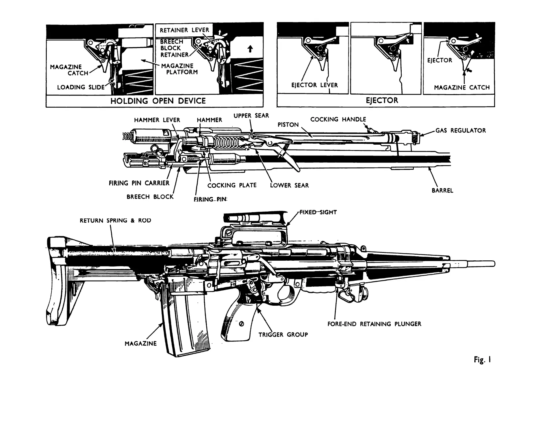
5. General Description of ЕЛ.1 Automatic Rifle .280 Lightened Pattern
Weight of gun Weight of gun (and bipod) Filled Magazine (20 rounds) Length of gun overall Length of barrel Type of sight Graduation 9-Jb. 7-ozs. 9-lb. L-oz. 9-lb. 15^-ozs. 9-lb. 9^-ozs. 1-lb. 7"ozs. 36-in. 24i-in. Unit telescopic eight (Unit magnification) 100-yds. to 900-yds.
SECTION 2 Basic Data Lightened Pattern
Shot travel Muzzle velocity Weight of projectile Weight of charge Maximum pressure Weight of barrel Estimated rate of fire Magazine capacity 23.5-in. 2415-ft./sec. 140 grains 30.5 grains 21.5 tons/sq.in. (true) 2-lb. 6-oz. 2*lb. 450 r.pun. 20 rounds
SECTION 3 Characteristics & Features
(fig.i)
Gas operated with gas regulation
Straight through shoulder re-action
Positively locked breech with forward looking
Mechanical and applied safety
Single and automatic firing with double trigger pressure
Firing pin energy divorced from return spring
Holding open device
Release for holding open device, incorporated in magazine catch
Optical sight
Initiation of fire with breech block in locked position
Charger loading device incorporated in the magazine
I A/M P 2J
-5 -
SECTION 4 Handling
Magazine Filling
The magazine can be filled by two separate and distinct methods. A charger loading device is
incoroorated in the magazine.
(a) Filling loose rounds by hand. (Fig.2) Hold the magazine in one hand, base of magazine,
resting on thigh and front of magazine facing body. Place round on magazine platfona and
press round down and back with thumb. Count the number of rounds.
(b) Filling from charger. (Fig.j) The charger loading device is located in the rear of the
magazine behind the magazine platform. To prepare magazine for filling, insert nose of
bullet into circular recess on left of magazine and press upwards to full extent of slot.
Hold magazine in left hand, pointing away from body; with thumb of left hand press the
loading device forward and down until the two stops on the device engage on the rear lips
of the magazine. Maintaining a firm forward pressure on the device with the thurib of the
left hand place charger into the guide. Place the thumb on the top round Just in front
of the charger; force the round into the magazine in one clean movement, pressing the top
round down until it is engaged by the lips of the magazine. Flick the charger out of the
way with the right hand and load with additional chargers.
Loading and unloading (Lying position) (Fig .4)
Ya) To load. Assume lying position. Hold weapon by pistol grip with the right hand, the gun
resting along the right fore-arm, fore-finger along the trigger guard, the butt against the body.
Full cocking handle to the rear in one strong crisp movement. The working portions will remain to the
rear, held up on the holding open device. Tilt magazine opening to the left, controlling movement by
the right hand and the pressure of the body against the butt.
Fide up magazine in left hand, place nose of magazine into the magazine opening, ensuring
that the front of the magazine is held up against the opening. Maintaining this position, swep rear
end of magazine into the opening, allowing the working portions to come forward, feeding the top round
into the chamber and allowing'the magazine catch to engage and retain the magazine. Make safe by
pushing the change lever (located on the left of the gun Just behind the trigger) upwards to its
highest position.
I АД P 23
— 6
(Ъ) То unload. Tilt magazine to the left. Remove magazine by pressing magazine catch forward
with, thumb of left hand, and with the same movement remove the magazine. Press change lever downwards
to "repetition" or "automatic” position. Cock gun. (This will eject the loaded round, and the
working portions will remain to the rear on the holding open device). Release holding open device
by pressing magazine catch to the rear with the fore-finger of the left hand. Assume firing position
and press the trigger. For additional safety it is advisable to re-cock the gun and carry out the
same sequence of operations. Die gun is then clear. Close ejection opening cover.
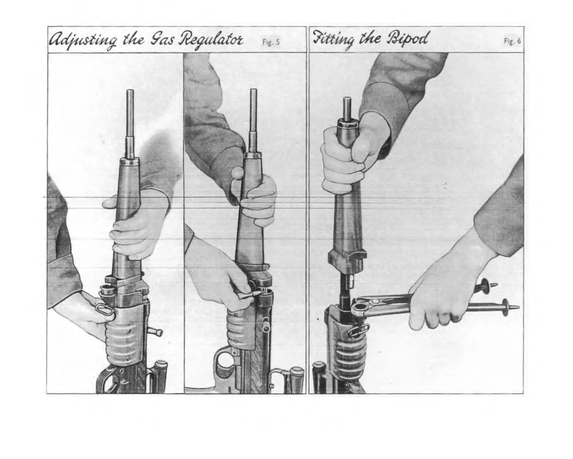
Adjusting the gas regulator (Fig.5)
The gas regulator has three positions. "Normal”, "more gas" and "less gas”.
The gas regulator will always be adjusted to Normal at the start of a shoot.
Hold gun brv fore-end, butt resting on ground. Press in fore-end retaining plunger with thumb
(or fore-finger; and draw fore-end upwards. Enough movement of the fore-end will be obtained to clear
the gas regulator before the fore-end is retained by its catch.
Using the nose of a bullet depress the positioning stud of the regulator out of engagement with
the positioning groove, and turn regulator to the required position, allowing the stud to reassert
itself, thus positioning and retaining the regulator in the new position.
The setting of the gas regulator can be seen by the size of the gas port which is shown directly
on top of the gas regulator.
Note that by pressing in the fore-end retaining plunger, the fore-end can be sufficiently
withdrawn to allow this operation - to remove the fore-end completely from the barrel, the retaining
plunger must be depressed, _and turned.
Fitting the bipod~(Fig.6)
Hold gun by fore-end, butt resting on ground; press the fore-end retaining plunger with thumb
(or fore-finger) and turn until positioning slot in plunger is vertical. V/hen plunger is in this
position it disengages from the fore-end and the fore-end can be drawn upwards, clear of the barrel.
Place the neck of the bipod over the bipod attachment on the gun, and swivel it into position.
Replace fore-end, pressing in retaining plunger and turn it until positioning slot is horizontal.
.1 A/M P .23
— 8 _
Using fixed sight with inverted pointer and range graduations
(a) Zeroing (Fig .7)
The pointer is intended to be zeroed to give a central at 100-yards. The lens tube
thereafter remains fixed in relation to the axis of the barrel, until such time as re-zeroing becomes
necessary.
Vertical error (elevation) is compensated by fitting a thicker or thinner washer (or
distance piece) on the elevation adjusting screw (1).
Lateral error (line) is compensated by fitting a thicker or thinner washer (or distance
piece) on the lateral adjusting screw (2).
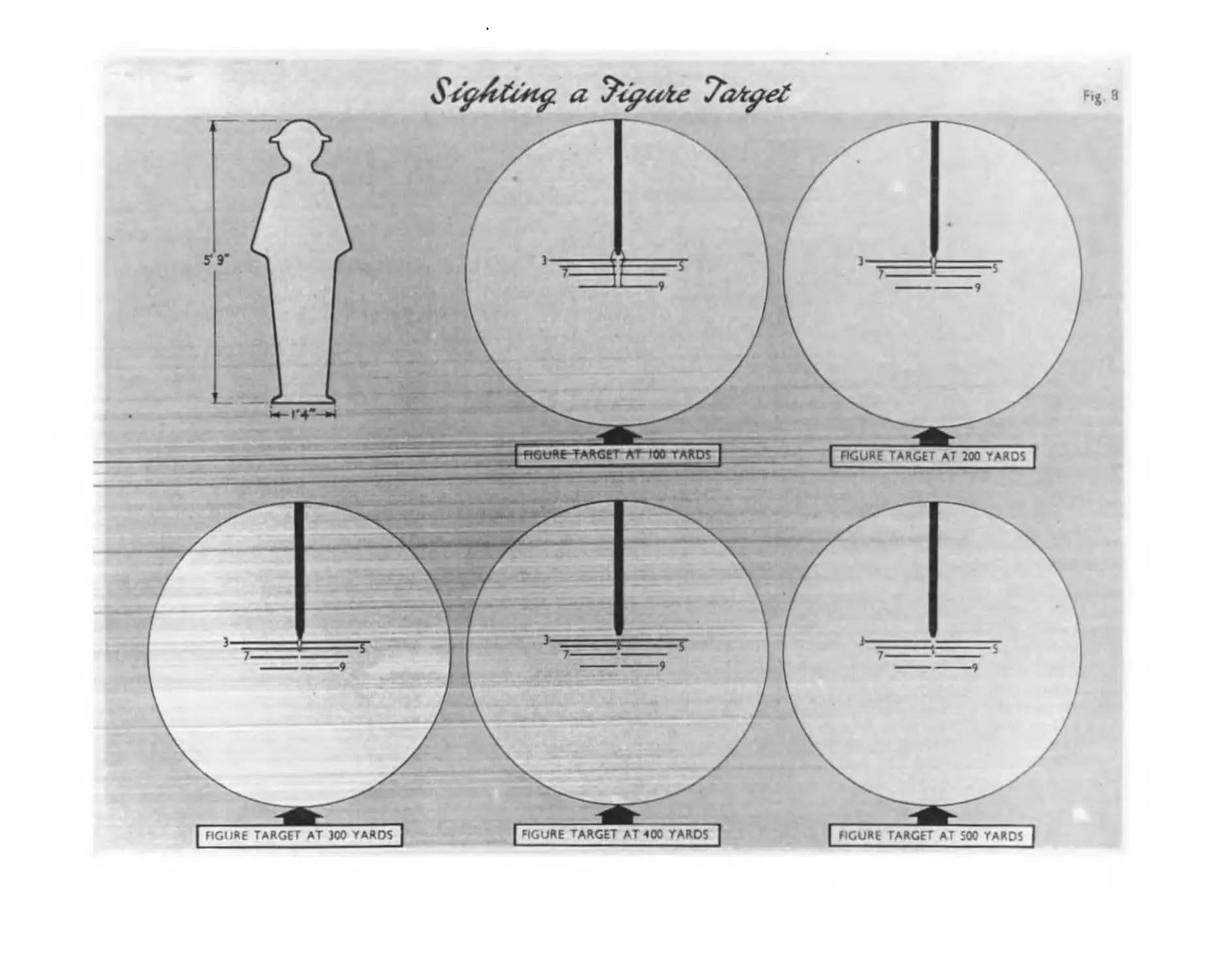
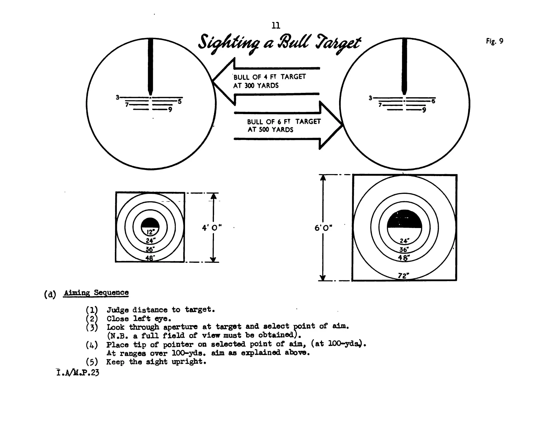
(b) Aiming (Figs.8 and 9)
The aim varies to allow for the drop of the bullet, under the influence of gravity, during
its time of flight over the range to the target.
For ranges up to ЮО-yds. the tip of the pointer is brought down to the centre of the target.
For succeeding ranges the pointer is raised above the centre of the target to a height which
represents the gravity drop of the bullet over that distance.
Owing to the restricted space on the lens, only alternate range graduations are marked (300,
500, 700 and 900 yds.) These graduation lines are broken in the centre (i.e. vertically beneath the
pointer) to allow the fir er to see the target clearly when it is centralised. Uiese lines are also
used for levelling.
( c) Judging Distance
The vertical gapb between the graduation lines may be used as a medium for quick Judgement
of distance.
(Example - Assuming that the target is a figure of average height - say 51 9” - then its
distance may be roughly gauged as follows: with the feet standing on the 700-yds. line, if the head
reaches the 300-yds. line, the range is 300-yds; if the top of the head comes half-way between the
300-yds. and 500-yds. lines, the range is 400-yds; if the head is blocked out by the 500-yds. line
the range is 500-yds. but if the head can be seen the range is 600-yds.)
When the range to the target has been Judged by this or ацу other means, as a general rule
the head of a target figure less than 300-yds. distant should be covered by the tip of the pointer,
but for all subsequent ranges the appropriate pointer on the scale vertically beneath the pointer is
brought to the centre of the target.
I A/hl P 2?
(a) Aiming Sequence
(1) Judge distance to target.
f2) Close left eye.
(3) Look through aperture at target and select noint of aim.
(N.B. a full field of view must be obtained).
(4) Place tip of pointer on selected point of aim, (at 100-yds).
At ranges over 100-yds. aim as explained above.
(5) Keep the sight upright.
I.A/1LP.23
—12-
SECTION 5 Holding, Aiming & Firing
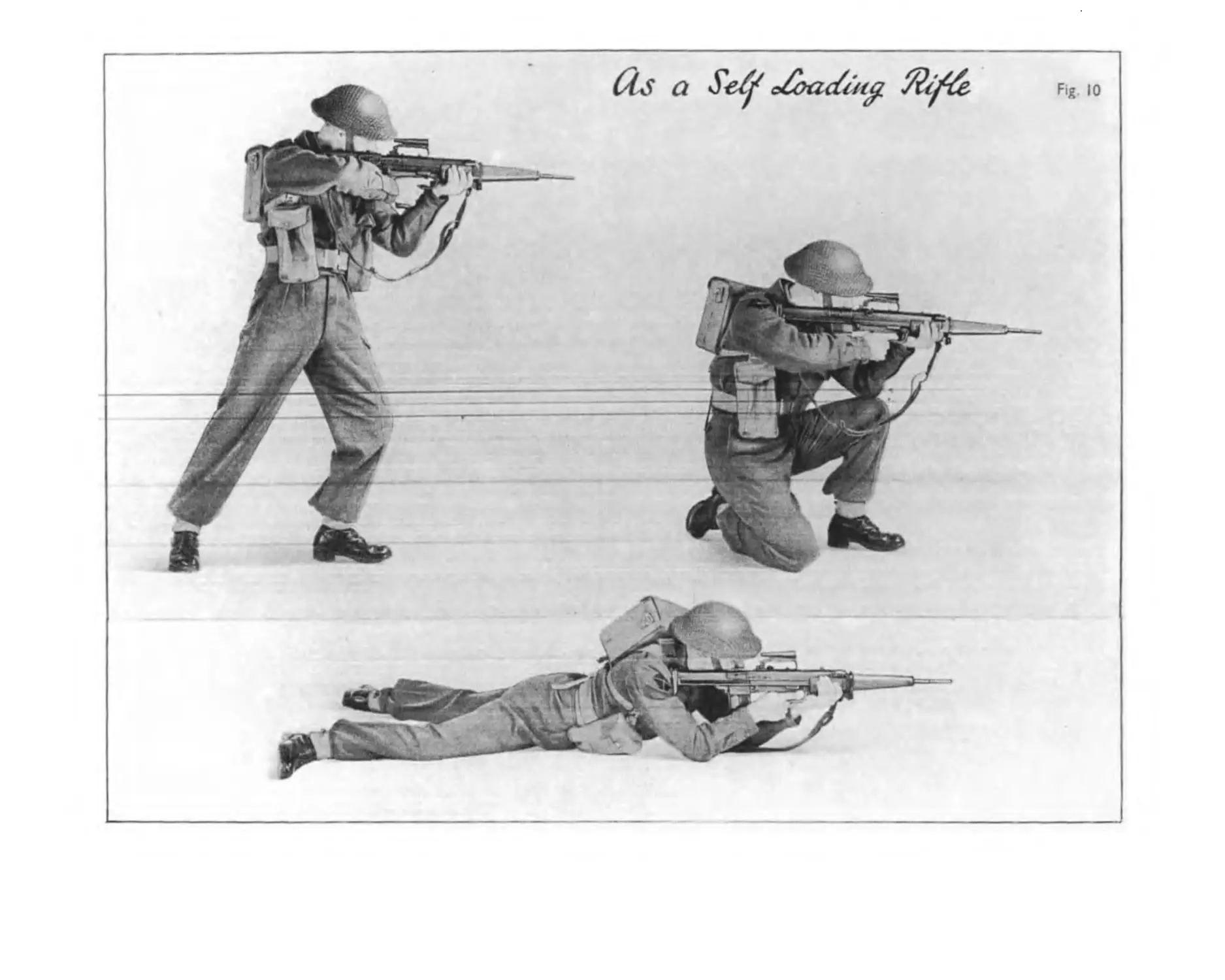
*1. AS A SZLF-IOADING RIFIE (Fig. 10)
Hold the weapon by the pistol grip with the right hand; the gun resting along the right fore-arm,
fore-finger of right hand along the trigger guard. Assume the lying position; use the left hand to
assist movement. Grasp the weapon firmly by the right hand, the magazine opening to the left, and the
weapon lying along the right fore-arm. The legs will be wide apart, body oblique to the line of fire.
Load weapon as taught. Place the change lever to safe. Grasp the hand grip with the left hand, and
look to the front. On a fire order being given, press change lever to the horizontal position and
assume the firing position.
Aiming - The right hand must be the master hand for every shot fired. The hold on the pistol grip
should be firm and controlled and a steady pressvere applied to the rear, bearing the weapon into the
shoulder and locking it there. Whenever the butt is brought into the shoulder the fore-finger must take
the first pressure on the trigger. The left hand should form a support for the forward end of the
weapon; the grip should be firm without causing strain.
No_attempt _ahouL3L- be made to pull the rifle into the shoulder with the left hand.
Owing to the straight through reaction of this weapon there is a tendency for the orthodox firer
when getting in the firing position, to use only the heel of the butt in contact with the shoulder. This
must be guarded against and a conscious effort made to bed as ouch of the butt into the shoulder as
possible.
The whole position is finally locked by the weight of the head pressing the chin downwards and to
the right against the stock. The eye relief between sight and firer’s eye should be in the region of
3-4” • The tripod for the rifle has now been formed by the chest .and arms and* the rifle has been locked
on that tripod. Adm as detailed in Section 4.
Firing - On coming into the aim the firer must take the first pressure. Whilst concentrating on
the target take an approximate aim.
Just before an accurate aim is taken breathing must be gently restrained.
The instance that the eye registers the correct aim the second pressure will be taken and the shot
fired.
The hold and aim must be maintained at least until the bullet has left the barrel. In fact it is
advisable that the firer follow through until the bullet has reached the target. Observe strike.
Release pressure on the trigger cleanly and completely. The weapon has now fed another round into the
chamber and the gun is cocked ready to fire this round. If it is required to fire another round the
sequence is as before. AHI - FIRE - OBSERVE - RE-AIM.
The slow rate of fire is 10 rounds per minute.
1.Д11 P.23
(As a S-eCjt o£oacfa(£
Fig 10
— is-
г. AS A SUB ЬАСНШВ GUN (Fi3.ll)
Holding is of the first importance especially -when firing in bursts. Correct holding can be
gained only by experience in firing ball ammunition.
There are two positions for holding the Infantry Personal Weapon as a sub machine gun:-
(a) Holding at the waist
The left foot is advanced with the knee slightly bent, and the right leg braced; the weight
of the body being balanced on the left foot. The right hand is on the pistol grip with the fore-
finger on the trigger; the left hand on the forward grip supporting the weapon. The butt of the
weapon is pressed tightly against the side by the right arm. The left elbow is pulled back into the
body and the complete weapon is thus clamped in its correct position so that when the body is turned
to face an enemy the gun is instinctively aligned on to the target. Care must be taken that the right
fore-arm is kept in its correct position in line with the pistol grip so as not to interfere with
ejection.
(b) Holding in the shoulder
The position of the body and hands is the same as for holding at the waist; the right elbow
is raised and the right shoulder pushed well forward into the butt with the left elbow almost under
the weapon.
Firing - Owing to the speed with which single rounds can be fired and also the fact that the
firer can correct on the strike much more easily, greater accuracy is obtained by firing single rounds,
and the need for economy of ammunition is met, so that single round firing will be employed wherever
possible. Bursts should be reserved for extreme emergency and when used should be of two to three
rounds only. In the role of machine carbine the weapon can be carried in any convenient position but
when expecting to meet the enemy it should be held at the waist. Although the weapon can be fired
whilst on the move greater accuracy is obtained by halting momentarily to do so. For targets at about
25-yards the weapon may be fired from the waist by sense of direction. For ranges above this and if
time permits aim will be taken using the sight.
3. AS A LIGHT blACHINE GUN (Fig. 12)
The gun when in the role of a light machine gun, will be fitted with a bipod. The weapon will be
placed gently on the ground with the bipod upright and the butt of the gun resting on its right side
bringing the magazine opening to the left.
1.101^.23
-16-
Poaition for Loading - The body straight behind gun, legs together, left hand holds forward grip;
right hand holds pistol grip; first finger along trigger guard when butt is on the ground; load as
taught.
Holding - Holding is most essential when the weapon is fired in this role as normally fire will
be in bursts and although the weapon has little shock of recoil the automatic action of the gun when
fired from the bipod sets up vibration which unless controlled, throws the gun off its alignment.
This control can only be effected by correct holding which is essential for accurate shooting.
Aiming position (Fig.12) - Place left elbow on ground and hold forward grip with the left hand.
Raise the butt and place the butt into the shoulder by moving body forward into the gun. Hold pistol
grip in right hand exerting a downward and backwards pressure. Lock the gun into position by
pressing the head against the stock with the eye in correct aiming position.
Firing - The normal rate of automatic fire is 20 rounds per minute fired in bursts of two to
three rounds. In rapid fire this is stepped up to 60 rounds per minute. Correct holding must be
maintained throughout each burst. After each burst observe the strike of the shoot with a minimum
movement of the head and correct if necessary. The firer will always make allowance for side winds
by applying the rules for aiming off.
unanging magazines On a magazine bfeing emptied the weapon will be swivelled on the bipod,
bringing the magazine to the left. The magazine will be removed as taught and the full magazine
inserted, which will release the holding open device and feed the first round into the chamber ready
for firing.
SECTION 6 Mechanism
Backward-action (Fig >13)
Some of the gases following the bullet pass from the barrel, through the gas regulator into the
gas cylinder. This forces the piston to the rear and compresses the return spring, until the piston
comes to the end of its stroke.
As the piston moves to the rear, a cam machined on the piston extension is brought out of
contact with the upper sear lever, leaving the upper sear, under the influence of its spring, ready
to engage the upper bent of the hammer. At the same time the firing pin carrier is withdrawn from
between the rollers, allowing them to move inwards and unlock the breech block. Also during this
primary movement a stud on the underside of the piston extension engages the cocking plate in the
barrel block, and cocks the hammer which is retained by the upper sear. After the breech block is
unlocked, it is carried to the rear, under the influence of the piston, canying with it the fired
cartridge case on the extractor, until the ejector clears it through the ejection opening in the
body-
bA/Mj>.23
UctiotL
Fig. 14
19
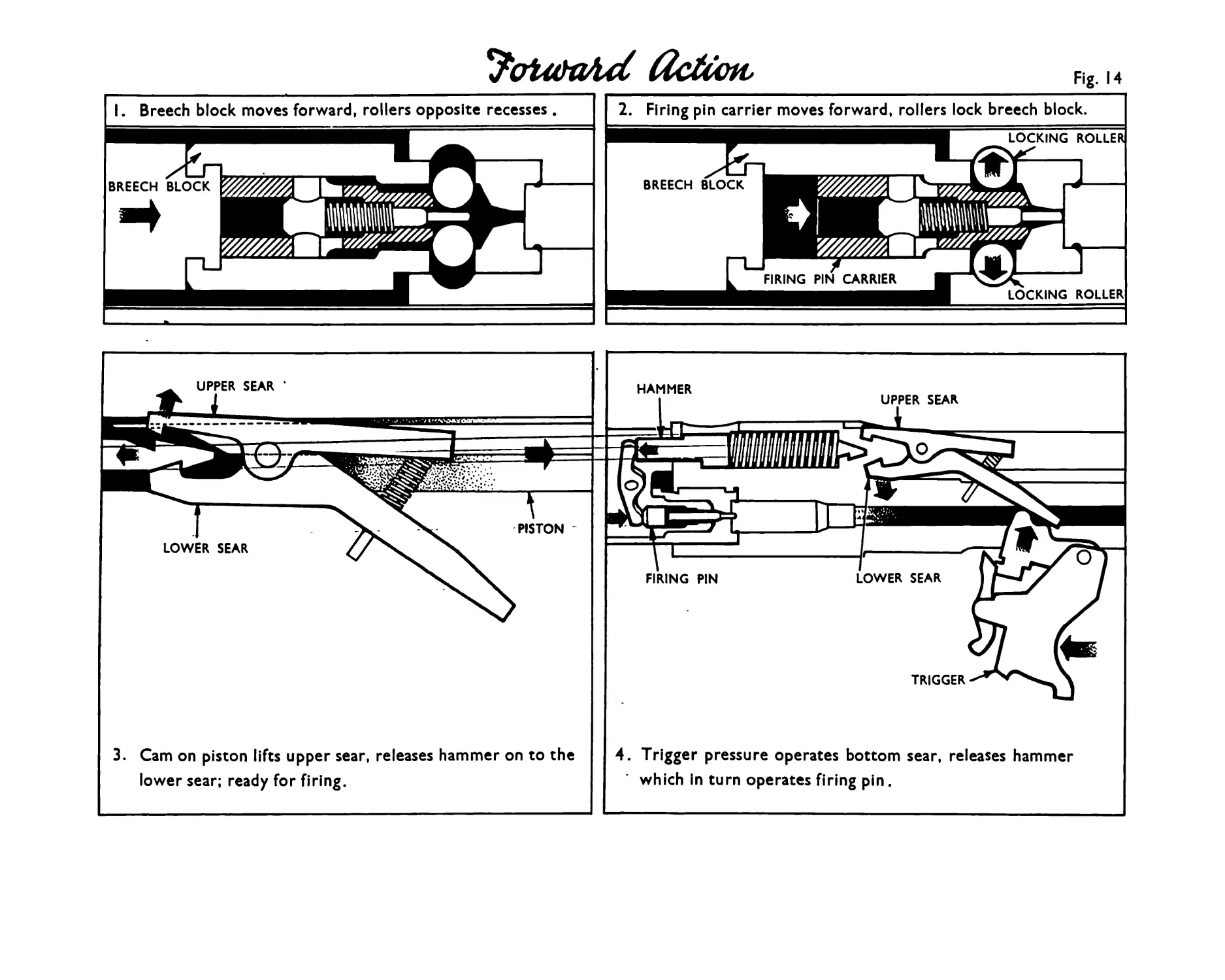
Forward action (Fig.lW
The piston, having reached the end of its stroke, is forced forward by the return spring,
carrying with it the breech block. The face of the breech block meets the base of the top round in
the magazine and forces it forward into the chamber, the extractor closing over the rim.
As the br.eech block is arrested at the chamber, the locking rollers are opposite their
recesses in the barrel block. Further movement of the piston cams these rollers into their locked
position, and they are retained there by the firing pin carrier, which is tapered to influence the
rollers. Shortly before the piston reaches its fully forward position the cam on its extension
lifts the upper sear and releases the hammer onto the lower sear.
Applied safety is provided Ту the change lever in the "safe” position (Fig.15). When the change
lever is in this position, the trigger is locked, and two safety levers in the trigger mechanism
positively lock the hammer and the piston.
Llechanical safety is provided ty positive locking of the breech block during firing. No protrusion
of the firing pin is possible until after the breech block is in the locked position as the position
of the locking rollers regulate the position of the firing pin carrier within the breech block.
20
Нагаек and ЗМ/иг fiction
With the change lever at automatic, pressure on the trigger actuates the lower sear lever which
in turn releases the hanner. The hammer, under the influence of its spring, strikes the upper part
of the hammer lever, pivoting the lower part of the hammer lever forward, and striking the firing pin
I.A4UP.23
as long as the trigger is pressed, the gun will continue to fire but if the trigger is released the
lower bent of the hammer will be free to engage on the lower sear, during this last forward action,
a round will be fed into the breech, and the action will lock, but the gun will not fire.
With the change lever at "single shot" the trigger must be released and pressed each time a shot
is to be fired, as the trigger pawl is tripped out of engagement with the upper part of the trigger,
which can then no longer actuate the lower sear lever.
Note that pressure on the trigger only actuates the lower sear. The function of the upper
sear is to retain the hammer until the action is locked.
With the change lever at "safe" the trigger is positively locked, and two safety levers
positively lock the hammer and the piston.
Holding Open Device
A holding open device (Fig.l) is incorporated (with the magazine catch) in the body of the gun,
behind the magazine opening. This device holds the working portions to the rear when an empty
magazine, or no magazine is in the gun. On a full magazine being placed in the gun, the holding
open device is pivoted out of engagement with the breech block, which is then driven forward, under
the action of the return spring, feeding the top round in the magazine, into the chamber, and
locking the action.
The gun is then ready to fire. If it is required to clear the gun, the magazine is removed and
the cocking handle pulled to the rear. This will eject the unfired round and the recoiling portions
will remain to the rear, held up on the holding open device. To re-lease the holding open device
from the breech block, press the magazine catch to the rear. This will allow-Hbhe working portions
to go forward, under the action of the return spring, and lode the action. Press the trigger to
release the firing pin. The gun is now clear.
SECTION 7 Immediate Action
If the gun is property cared for, stoppages other than an enpty magazine will rarely occur.
Immediate action is the action performed by the firer to remedy a stoppage. It must be carried
out quickly, and with practice, should become instinctive. Immediate action is not complete until
the gun has been re-aimed and fired.
If the gun fails to fire, or stops firing:-
Immediate action. Remove magazine; pull back cocking handle; release holding open device;
pull back cocking handle; replace magazine; ata gm and fire.
Note: If cocking handle stops to the rear, it indicates, NOT a stoppage, but an empty magazine.
Iisnediate action. Remove empty magazine; replace full magazine; ata gm and fire.
1Д/М P 23
22
SECTION 8 Elementary Stripping
(PIGS. I? AND 18)
Remove magazine; cock gun; release holding open device; press trigger; close ejection
opening cover; the gun is now clear.
To strip
(a) Remove sling; hold gun by fore-end, butt resting on ground. Press in fore-end retaining
plunger with thumb (or fore-finger), and turn until positioning slot in plunger is vertical.
When plunger is in this position, it disengages from the fore-end, and the fore-end can be drawn
upwards, clear of the barrel. (See Pig.5)«
(b) Hold gun forward of butt; press in head of return spring rod with thumb, and turn until
positioning slot in head is vertical. In this position the head of the rod is released from the
recesses in the butt, and the spring must be controlled by pressure of the thumb. Withdraw
return spring and rod. Withdraw cocking handle.
(c) To remove trigger group, push out the two fixing pins securing trigger group to body.
(d) Withdraw trigger group from body.
(e) Place butt on ground; rest foot lightly on butt; grip barrel with both hands, and withdraw
barrel group from body in one clear movement.
(f) The weapon is now stripped into its main groups, as shewn - the body and fore-end; the
barrel group; the trigger group.
(g) To remove gas regulator: Press positioning stud of the regulator out of engagement with the
gas cylinder, rotate the regulator until the positioning stud is opposite the large recess
inmediately above the barrel, and remove.
I А/Ы P 23
-24-
To assemble
Replace gas regulator; stand body of gun on butt, and slide the barrel group, in its
positioning grooves, back into the body, until the gas block is about to enter the body; then
press magazine catch to the rear; this withdraws the ejector from the pathway of the barrel
group; maintaining the ejector in this position force barrel group home; care must always be
taken that the ejector is kept clear of the pathway of the barrel group during this last stage
of assembly, otherwise the barrel group cannot be forced home, and damage to the ejector will
ensue.
Replace trigger group, ensuring the tw safety levers are properly inserted into their
recesses in the body, and secure with the two fixing pins. Replace* cocking handle in its slot,
cock gun, and action will remain to the rear, held up on the holding open device.
Feed return spring through butt, into the gun and idien resistance is felt, thread as much
of the spring as is possible on to the return spring rod, feed nose of rod into the recess in
the butt, and push rod into the gun. Maintaining pressure on rod, release the holding open
device, the working portions will go forward, and the head of the return spring rod may then
be inserted into its seating. When rod is fully home, turn the head until the positioning
slot is horizontal across the butt. The rod is now locked in position.
N.B. It is most important to hold the working portions to the rear as taught while inserting
the spring.
Replace fore-end, pressing in retaining plunger, and turning it, until positioning slot
is horizontal.
Cock gun, release holding open device, press trigger to clear gun and check functioning.
Close ejection opening cover.
SECTION 9 Advanced Stripping
(FIGS. 19 AND 20)
To strip barrel group - comprising piston and ezrtension, breech block and hammer unit. First ensure
that action is cocked (to release the locking rollers from their recesses in the breech); to do this,
replace cocking handle in recess of piston, place the tip of the cocking handle on an ammunition box,
etc. muzzle pointing away from the user, and press down on the cocking handle, which is withdrawn.
Proceed as follows:-
(a) withdraw piston and breech block slightly fi*om the barrel block, withdraw hammer unit
retaining pin, and withdraw hammer unit forward fran block, ensuring that the top and bottom sear
levers are NOT pressed together during the process.
I JP 2J
25
(b) Withdraw piston and breech block clear of barrel block - turn barrel block upside down, and
shake out the cocking plate.
(c) To remove breech block from piston extension, press retaining spring rings of breech block
extension inwards, into the positioning slots on the extension, and slide extension downwards,
out of engagement with the breech block. Slide piston to the rear, disengaging the hammer lever
from its reoess in the firing pin carrier.
(d) To remove firing pin - insert nose of bullet into rear of the firing pin carrier, and press
forward to relieve pressure of spring; press out the retaining pin; release pressure on rear of
firing pin and withdraw firing pin and spring from the rear.
I A/M P 23
26
fe) To strip breech block - insert nail of finger under the spring retaining rollers (situated on
top of the breech block) lift slightly, and the locking rollers will shale out. Insert nose of
bullet under nose of horse-shoe spring, press up, and slip spring from front portion of the breech
block; lift out the extractor.
(f) To strip hammer unit - hold hammer unit with fingers and thurib, so that pressure can be
exerted on the upper and lower sear levers. Place nose of hammer on ground, and press the two sear
levers together. This will release the hammer and spring from their housing.
To re-assemble reverse the above .operations, noting the following points:-
(a) The hammer; Ensure bent nearest nose of the hammer is positioned to engage with the upper
sear.
(b) The firing pin; Bress firing pin forward against action of spring, before trying to insert
the retaining pin.
(c) The firing pin into the breech block; Ensure the hammer lever is held almost parallel with
the breech block, until firing pin carrier is inserted, then ensure the hamper lever fits into
its recess in the firing pin carrier, slide on breech-block extension ana secure with spring.
(d) The breech block in the locked position in the breech; Withdraw firing pin carrier to rear
of the breech block, collapsing the locking rollers. Ease breech block forward into breech, and
when fully heme press piston extension forward, influencing the rollers into their locking
recesses, and disengaging the upper sear from its bent in the hammer. Press lower sear lever
upwards, firing the hammer, and positively locking the action.
I Д/М P 23
-27-
SECTION 10 Cleaning & Maintenance
Stores
Cleaning rod (at present P.H. ,22-inch rod); Pull through; Gauge; Cylinder cleaning rod;
Cylinder cleaning wire brush; Cylinder cleaning mop; Oil container; Flannelette.
Daily cleaning
Clean barrel, using the cleaning rod. A dry piece of flannelette, lr-in. by 1^-in. will
be put half way through the eye at the end of the cleaning rod. The action will be oocked, and
the rod will be inserted from the muzzle end.
When the barrel has been cleaned with dry flannelette, a slightly smaller piece of
flannelette, well oiled, will be similarly used to oil the barrel.
Before firing: Strip completely (with the exception of the bolt).
Clean and leave dry the gas affected parts i.e. barrel and breech; gas cylinder, using
the cleaning rod and mop; the gas regulator; head of the piston; face of the bolt.
Clean remainder of gun and slightly oil the working parts.
When assembling, set gas regulator at nonaal. Clean magazines, paying particular
attention to the magazine platform.
After firing
Strip completely. Clean barrel as for rifle, using boiling water if available, ana gauze
when necessary.
Clean gas cylinder with cylinder cleaning rod, wire brush and mop. Clean with oily rag
remaining parts; then dry, clean and slightly oil.
In the absence of a cleaning rod, a pull through may be used, the weight inserted through
the breech and dropped through the barrel.
The gas cylinder (which is detachable) may be cleaned in a similar way, after removal of
the gas regulator.
Note
A feature of this weapon is that under field conditions, the gas regulator and gas cylinder
can be cleaned with a minimum of stripping.
Remove fore-end and gas regulator as taught. The gas cylinder can then be cleaned, with
the cylinder cleaning rod, wire brush and mop, without ary further stripping.
1Д/Ы J> 23
Fig. 21
— 29—
SECTION II Use of Sling
(FIG. 21)
The sling may be used as a valuable aid to steadiness when firing single round or automatic
fire.
Method
(a) Hold the rifle in the right hhnd, by the pistol grip; pass the left hand through the
loop in the sling, from left to right.
(b) Then pass the left hand round the front part of the sling, in a clockwise direction,
and grasp the rifle at the forward grip.
(c) Draw the rifle slightly back and with the right hand hitch the loop of the sling well
up the left upper arm and assume the aiming position.
To adjust
It is important that the loop of the sling is adjusted to the correct length for the fir er.
If it is found to be too loose, tighten by sliding the metal clip on the loop towards the forward
swivel on the rifle, and pick up slack on rear D piece. It will be found that when the sling is
correctly adjusted for the firer, as an aid to steadiness, it will also be in adjushnent for grenade
firing.
SECTION 12 Grenade Firing
(FIGS.22 AND 2J
In order to fire a grenade from the rifle, a projector will be attached to the rifle, which
is then loaded with a grenade cartridge, and the grenade placed on the projector. On the grenade
cartridge being fired, the grenade is discharged.
Description of Projector and Sights
The projector consists of a ribbed cylindrical steel tube, with a grenade retaining clip -
fastened between two of the rear ribs. On one end there is a bayonet type socket which is fitted
with a spring catch, to retain the projector on the muzzle of the rifle.
NOTE: The grenade sight (fig.22) is superimposed on the projector, and consists of an arm slotted
and shaped to give three ranges - 50-yards, 75“yards and 100-yards. The complete sight can be
raised and lowered in the projector, and is held in position by a positioning stud.
I Д/bi P 23
Fig 22
erf &ieaade Scyfa
-31-
To fit projector to gun (Fig-22)
Hold weapon with one hand, and place projector on the rifle.* Turn projector until the cut
away portion in the projector coincides with the retaining lugs on the barrel. Press projector
down firmly until it reaches its full extent of engagement (compressing the spring retaining
catch) then turn projector until the spring catch re-asserts itself and snaps into position
locking the projector on to the rifle.
To remove, raise catch with fore-finger and thumb to full extent, swivel projector to
disengage it from retaining lugs, and withdraw.
To fire a grenade
fa) Remove magazine and clear gun.
(b) Attach projector to weapon as taught, and raise sights.
(q\ Cock gun, allowing the recoiling portion to be held up on the holding open device.
(d) Load grenade cartridge direct into the-breech by hand. (This is best done by tilting the
magazine opening to the left and inserting the grenade cartridge direct into the breech, through
the magazine opening.)
(e),’ Release holding open device and put change lever to safe.
SLoad grenade on to projector,. (Fig.22) holding grenade by tail.
Assume correct firing position by holding weapon with the right hand as pistol grip. Place left
arm under the rifle and above the sling. (Fig.22)
Pass the left hand round the front part of the sling in a clockwise direction and grasp the
rifle at the forward grip. Draw the rifle slightly back and with the right hand place the sling
across the upper part of the chest (Fig.22) and finally lock the rifle into position by placing butt
under right arm pit (Fig.22). If the correct position has been assumed the weapon should be rigidly
fixed, with the sling lying taut across the upper chest, and the butt^held in position by the tension
on the sling, and clamped into position, under the right arm pit by the right upper arm.
A firm grip should be maintained with the left hand.
To ,ahn
Lower head until eye looks along the approximate line of sight of the rifle (Fig.22).
Raise or lower the muzzle of the rifle until the silhouette of the grenade corresponds with the
appropriate range circle on the sight. The rifle is then at the correct elevation for that particular
range.
For ranges over one hundred yards, depending on the cover and the firing position, the grenade
may be fired as described above, estimating increased elevation to give the desired range, or the
heel of the butt may be placed on the ground, the estimated tangent elevation applied to the gun (in
relation to the ground), and the trigger pressed with the straight fore-finger (Pig.2j).
I A/U x 23
— 52—
Points to note when firing a grenade from this position
(a) Heel of the "butt on the ground.
(b) Left hand forward of the hand grip (to avoid interference with the cocking handle).
(c) Right hand clenched, with straight fore-finger. Pore-finger resting on trigger. Trigger
pressed by complete movement of hand.
(d) Heel of butt placed outside position of right knee.
An alternative method of holding has been evolved with the butt in the shoulder and the
shortened sling passing from the butt, across the chest, under the arm pit and over the upper arm
to the front swivel. This position would appear to give a better firing position and facilitate
sighting, but has the disadvantage that the considerable shock of recoil is taken mostly on the
shoulder.
SECTION 13 Use of the Bayonet
(fig.2^)
The No.7 bayonet (modified) is used with this automatic rifle. To attach the bayonet to the
rifle, rotate the socket from the normal ’’knife” position until the spring catch position is in line
with the ring of the cross piece. The socket and cross piece are then placed over the barrel and
turned until the cut away portion in the socket coincides with the retaining lugs on the barrel.
Press down firmly and turn until the spring catch on the socket reasserts itself and snaps into
position locking the bayonet on to the rifle.
To remove, raise catch with fore-finger and thumb to full extent, swivel bayonet to disengage
it from retaining lugs and withdraw.
In bayonet fighting with the automatic rifle, handling will be along normal orthodox lines,
and the "on guard” position will be assumed by taking a full pace forward with the left foot, and
at the same time bringing the rifle up to a natural fighting position. It is suggested that,during
close quarter fighting, vrihile a full magazine is on the gun, the ’’Bullet and bayonet” position should
be adopted. This enables the soldier to use the bullet, and, to a limited extent, the bayonet,together.
When the magazine is empty or when it is NOT desirous to fire the rifle (say, during a silent
night attack) the "bayonet" position should be adopted. This position would appear to give maximum
length during the "point" and a greater choice of handling position, in offence and defence,without
disturbing the grip of the hands.
P 23
ffiatfet and tfiaycnet
Fig 24
-54-
Points to note
"Bullet - Bayonet" Position
(a) Left hand on hand grip, right hand on pistol grip, fore-finger on trigger, but butt of the
weapon pressed firmly against the side, by the right arm. "Point" to be made by straightening left
arm and thrusting forward rifle with right arm.
"Bayonet" Position
(b) Left hand should have a, firm grip on the fore-end, the right hand just clear of the butt,
holding round the stock.
CONFIDENTIAL - DISCREET
I A/U P 23
THE MAMBA.
Plan. Fore-end moved forward for access to gas regulator.
the cobra' ’280'
F.N .280 RUTO. CRBBiNE
Short flodel
(.л ' 9<е ц.«?
I. 280 AUTO. CARBINE
Lon о Model.