/


Теги: weapons
Год: 1943
Похожие

Текст
PRELIMINARY ORDNANCE PAMPHLET No. 820
40MM
ANTIAIRCRAFT CUN
40MM MACHINE CUN MECHANISM
MARK! MARK 2 MARK 1. MOD. 1 MARK 2, MOD. 1
40MM CUN BARREL
MARK 1
40MM SIGHT
MARK 3 MARK 4
DESCRIPTION AND OPERATION
I
PRELIMINARY
ORDNANCE PAMPHLET No. 820
tf
40MM ANTIAIRCRAFT CUN
40MM Machine Gun Mechanism...............Mark 1
40MM Machine Gun Mechanism...............Mark 2
40MM Machine Gun Mechanism......Mark 1, Mod. 1
40MM Machine Gun Mechanism......Mark 2, Mod. 1
40MM Gun Barrel..........................Mark 1
40MM Sight...............................Mark 3
40MM Sight............................. Mark 4
DESCRIPTION AND OPERATION
OCTOBER 1943
NAVY DEPARTMENT
BUREAU OF ORDNANCE
WASHINGTON, D. C.
ORDNANCE PAMPHLET No. 820
40MM ANTIAIRCRAFT GUN
October 1943
1. Ordnance Pamphlet No. 820 provides a description of
the construction and operation of the 40MM Machine Gun Mecha-
nism, and descriptions of the gun barrel and sight. It also includes
operating instructions and instructions for the care and maintenance
of the gun.
2. Ordnance Pamphlet No. 820-A may be used where a
less detailed pamphlet is desired.
3. This pamphlet supersedes Ordnance Data No. 3781, pre-
liminary manual for the description and operation of the 40MM anti-
aircraft gun. Ordnance Data No. 3781 should be destroyed. Ballistic
Data for 40MM Guns are given in Ordnance Pamphlet No. 867.
4. Ordnance Pamphlet No. 820 is UNCLASSIFIED.
Rear Admiral, U. S. N. /
Chief of the Bureau of Ordnance
Page 2
О. P. 820
PREFACE
This Ordnance Pamphlet, No. 820, applies
to the following:
40MM MACHINE GUN MECHANISMS,
MARK 1 AND MARK 2,
MARK 1, MOD. 1 AND MARK 2, MOD. 1
40MM GUN BARREL, MARK 1
40MM SIGHTS, MARK 3 AND MARK 4
Standard Navy nomenclature is used
herein, and is considered preferable to that
used on drawings and in previous publica-
tions relating to these mechanisms.
York Safe and Lock Co.
York, Pennsylvania
О. P. 820
Page 3
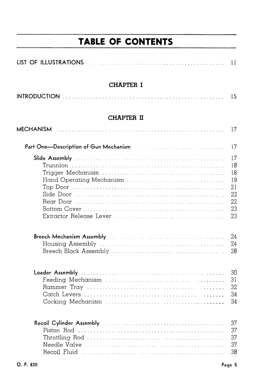
TABLE OF CONTENTS
LIST OF ILLUSTRATIONS ......................................... 11
CHAPTER I
INTRODUCTION................................................... 15
CHAPTER П
MECHANISM ..................................................... 17
Part One—Description of Gun Mechanism ...................... 17
Slide Assembly............................................ 17
Trunnion .............................................. 18
Trigger Mechanism ..................................... 18
Hand Operating Mechanism............................... 19
Top Door............................................... 21
Side Door ............................................. 22
Rear Door.............................................. 22
Bottom Cover........................................... 23
Extractor Release Lever ............................... 23
Breech Mechanism Assembly................................. 24
Housing Assembly....................................... 24
Breech Block Assembly.................................. 28
Loader Assembly .......................................... 30
Feeding Mechanism ..................................... 31
Rammer Tray ........................................... 32
Catch Levers........................................... 34
Cocking Mechanism ..................................... 34
Recoil Cylinder Assembly ................................. 37
Piston Rod ............................................ 37
Throttling Rod ........................................ 37
Needle Valve........................................... 37
Recoil Fluid .......................................... 38
О. P. 820
Page 5
TABLE OF CONTENTS
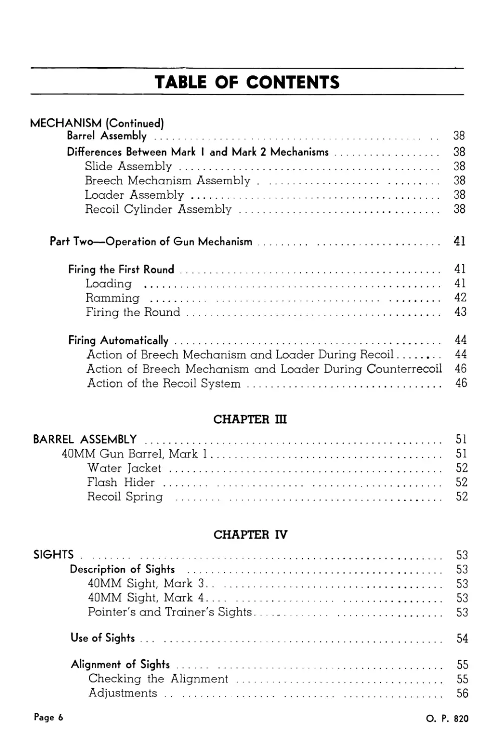
MECHANISM (Continued)
Barrel Assembly ..................................................... 38
Differences Between Mark I and Mark 2 Mechanisms............... 38
Slide Assembly.............................................. 38
Breech Mechanism Assembly................................... 38
Loader Assembly............................................. 38
Recoil Cylinder Assembly.................................... 38
Part Two—Operation of Gun Mechanism.............................. 41
Firing the First Round......................................... 41
Loading .................................................... 41
Ramming .................................................... 42
Firing the Round............................................ 43
Firing Automatically........................................... 44
Action of Breech Mechanism and Loader During Recoil......... . 44
Action of Breech Mechanism and Loader During Counterrecoil 46
Action of the Recoil System................................. 46
CHAPTER Ш
BARREL ASSEMBLY ..................................................... 51
40MM Gun Barrel, Mark 1......................................... 51
Water Jacket ............................................... 52
Flash Hider ................................................ 52
Recoil Spring .............................................. 52
CHAPTER IV
SIGHTS............................................................... 53
Description of Sights ......................................... 53
40MM Sight, Mark 3.......................................... 53
40MM Sight, Mark 4.......................................... 53
Pointer's and Trainer's Sights.............................. 53
Use of Sights.................................................. 54
Alignment of Sights............................................ 55
Checking the Alignment ..................................... 55
Adjustments ................................................ 56
Page 6
О. P. 820
TABLE OF CONTENTS
CHAPTER V
CYCLIC OPERATION OF THE GUN MECHANISM............................ 57
Feeding the Round........................................... 58
Cocking the Rammer.......................................... 58
Ramming the Round........................................... 61
Closing the Breech.......................................... 61
Firing the Round............................................ 62
Ejecting the Case........................................... 62
CHAPTER VI
LOADING AND UNLOADING............................................ 65
Instructions for Loading.................................... 65
Instructions for Unloading ................................. 65
CHAPTER VII
CASUALTIES ...................................................... 69
Casualties Which Can Be Corrected Quickly and Easily........ 69
Clip Placed in Loader Improperly......................... 69
Firing Pedal Not Fully Depressed......................... 69
Other Casualties ........................................... 69
Live Round Drops Out Into Case Chute..................... 69
Live Round In the Gun or On the Rammer Tray.............. 70
Live Round Still Above Star Wheels....................... 71
Star Wheels Locked ................................ 71
Long Recoil................................................. 72
Twisted Crankshaft.......................................... 72
CHAPTER VIII
FUNCTIONAL CHECK-OFF LIST.............................. 77
Daily Check ................................................ 77
О. P. 820
Page 7
TABLE OF CONTENTS
CHAPTER IX
ASSEMBLY AND DISASSEMBLY............................................. 78
Barrel Assembly .............................................. 80
Removal of the Barrel Assembly.............................. 80
Installation of the Barrel Assembly......................... 81
Disassembly of the Barrel Assembly.......................... 81
Assembly of the Stripped Barrel Assembly ................... 84
Recoil Cylinder Assembly ...................................... 87
Removal of the Recoil Cylinder Assembly..................... 87
Installation of the Recoil Cylinder Assembly ............... 87
Disassembly of the Recoil Cylinder Assembly................. 87
Assembly of the Stripped Recoil Cylinder Assembly........... 89
Loader Assembly ............................................... 92
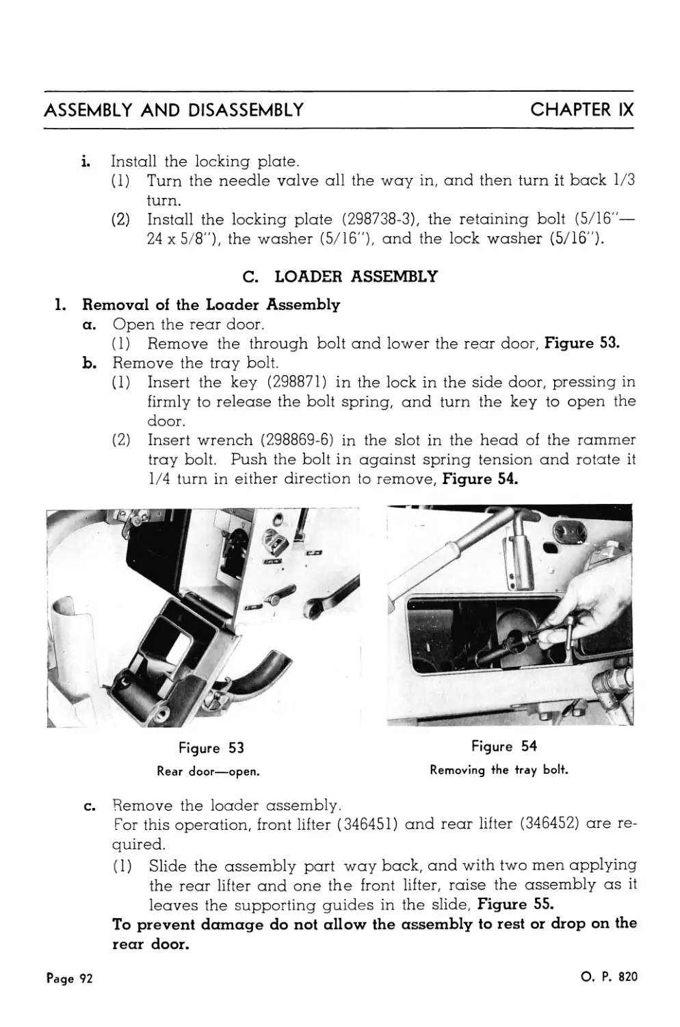
Removal of the Loader Assembly.............................. 92
Installation of the Loader Assembly......................... 94
Removal of the Rammer Tray.................................. 94
Installation of the Rammer Tray............................. 95
Disassembly of the Rammer Tray.............................. 95
Assembly of the Stripped Rammer Tray........................ 96
Disassembly of the Loader Assembly.......................... 97
Assembly of the Stripped Loader Assembly................... 104
Housing Assembly.............................................. 110
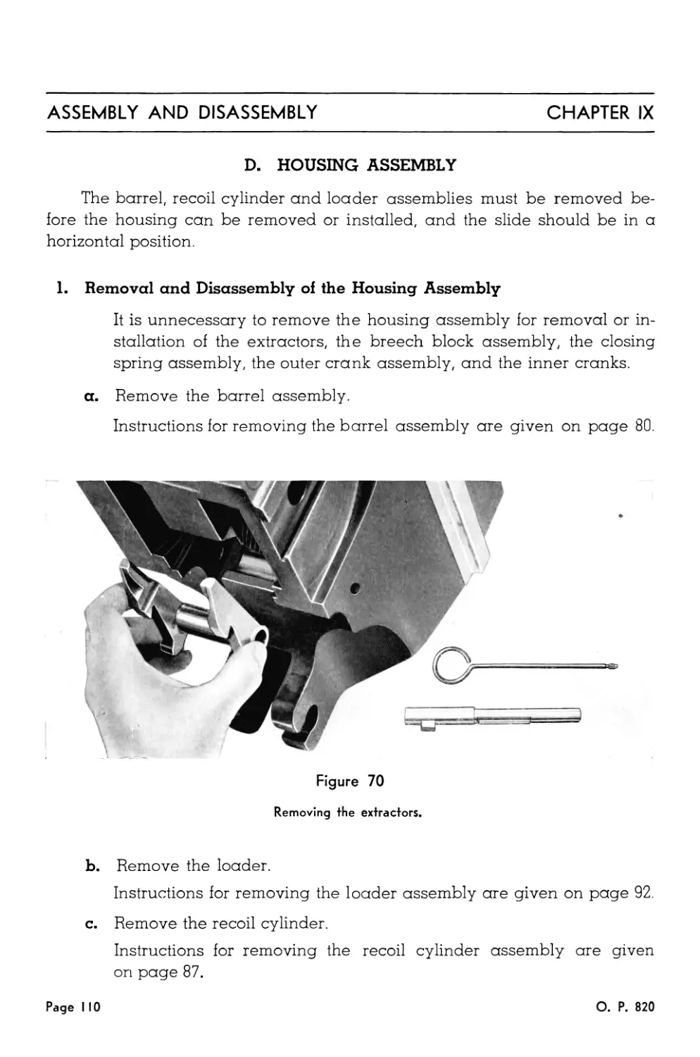
Removal and Disassembly of the Housing Assembly............ 110
Assembly and Installation of the Housing Assembly ......... 113
Breech Block Assembly ........................................ 115
Removal and Disassembly of the Breech Block Assembly ... . 115
Assembly and Installation of the Breech Block Assembly ... . 118
Slide Assembly................................................ 120
Removal and Disassembly of the Top Door.................... 120
Assembly and Installation of the Top Door.................. 121
Removal and Disassembly of the Side Door................... 122
Assembly and Installation of the Side Door................. 123
Removal and Disassembly of the Bottom Cover................ 123
Assembly and Installation of the Bottom Cover.............. 124
Removal and Disassembly of the Rear Door................... 124
Assembly and Installation of the Rear Door ................ 124
Page 8
О. P. 820
TABLE OF CONTENTS
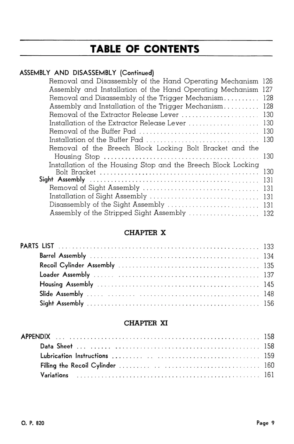
ASSEMBLY AND DISASSEMBLY (Continued)
Removal and Disassembly of the Hand Operating Mechanism 126
Assembly and Installation of the Hand Operating Mechanism 127
Removal and Disassembly of the Trigger Mechanism............ 128
Assembly and Installation of the Trigger Mechanism.......... 128
Removal of the Extractor Release Lever...................... 130
Installation of the Extractor Release Lever................. 130
Removal of the Buffer Pad................................... 130
Installation of the Buffer Pad.............................. 130
Removal of the Breech Block Locking Bolt Bracket and the
Housing Stop .............................................. 130
Installation of the Housing Stop and the Breech Block Locking
Bolt Bracket ............................................ 130
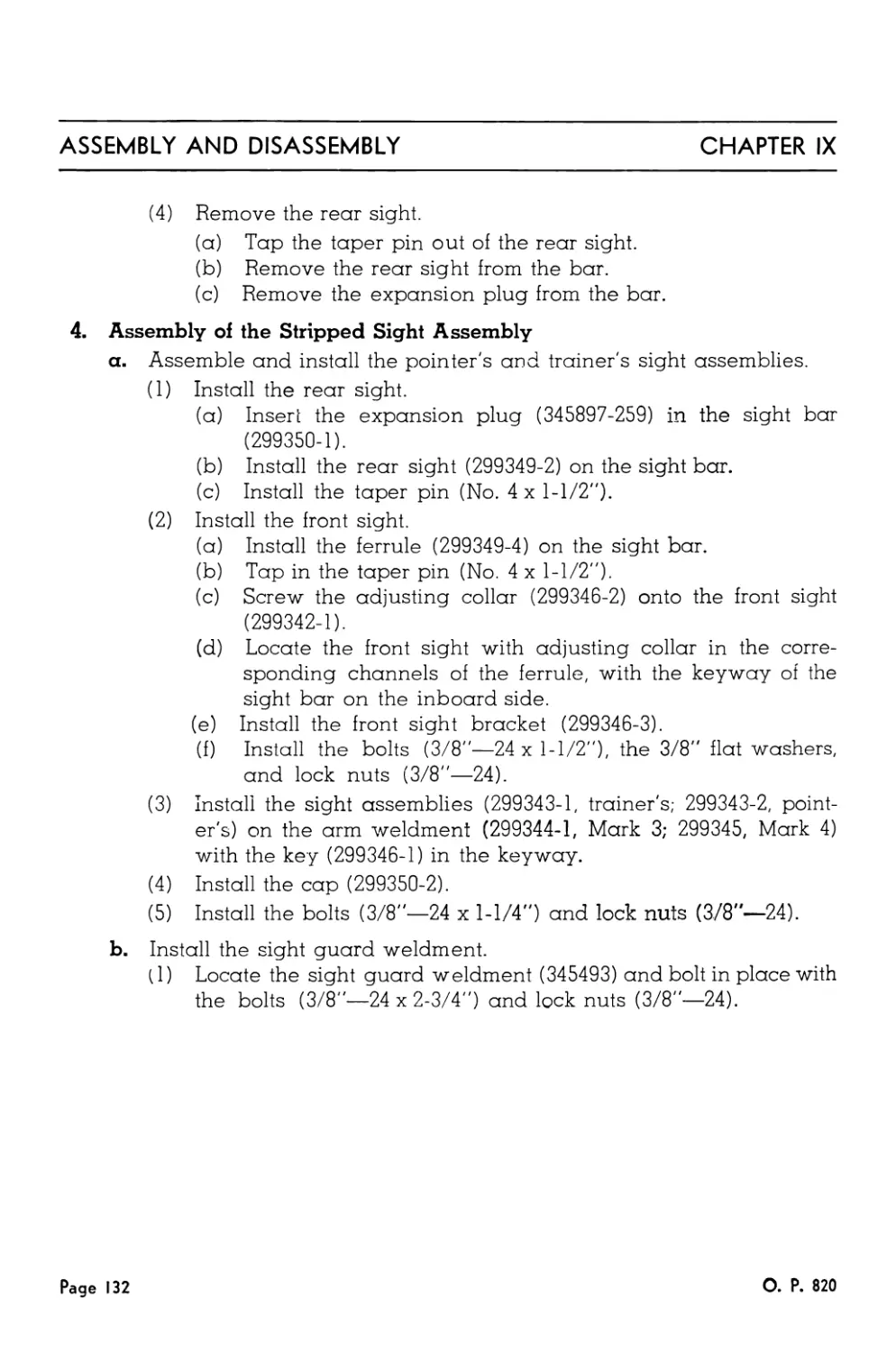
Sight Assembly ............................................... 131
Removal of Sight Assembly.................................. 131
Installation of Sight Assembly............................. 131
Disassembly of the Sight Assembly.......................... 131
Assembly of the Stripped Sight Assembly..................... 132
CHAPTER X
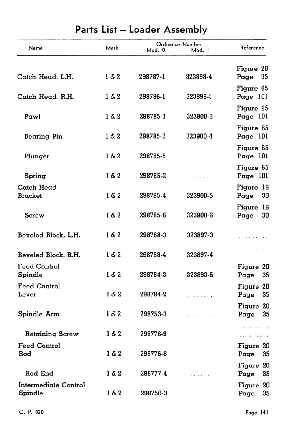
PARTS LIST .......................................................... 133
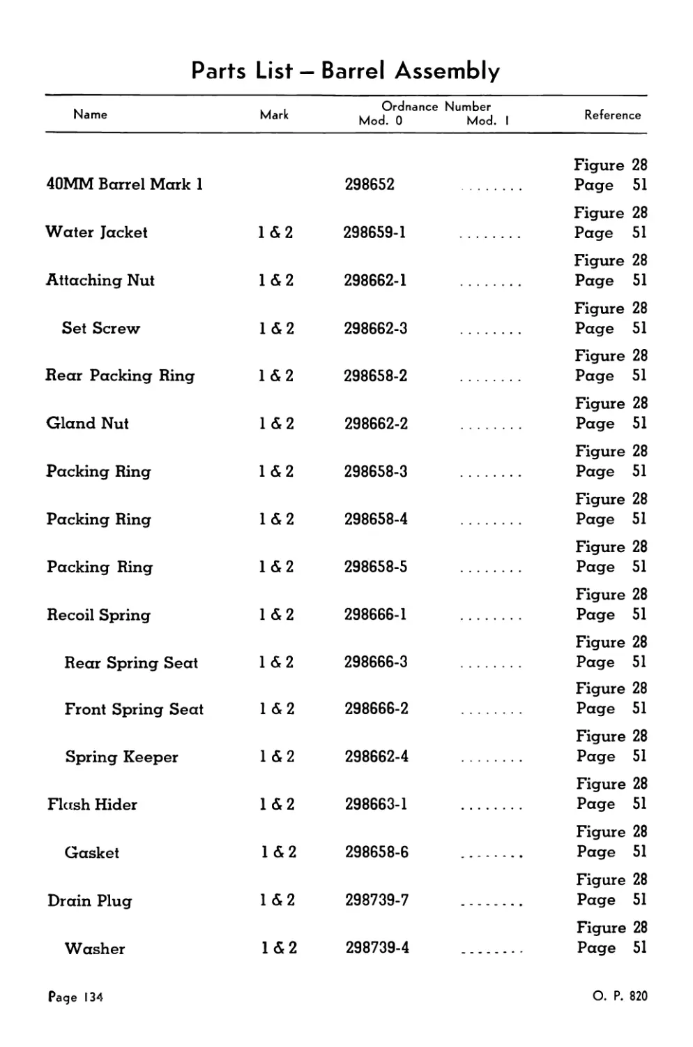
Barrel Assembly ............................................... 134
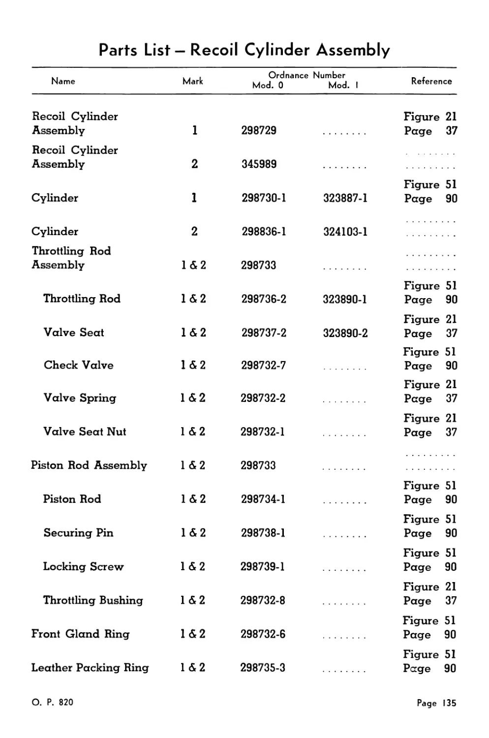
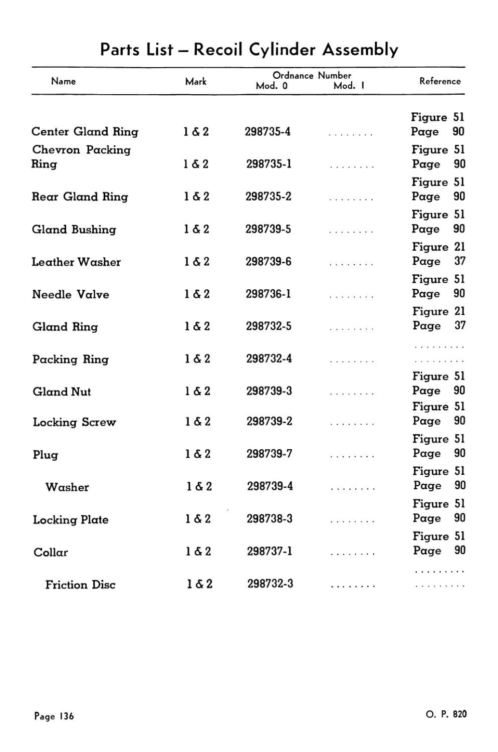
Recoil Cylinder Assembly....................................... 135
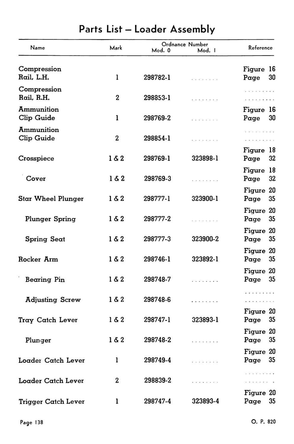
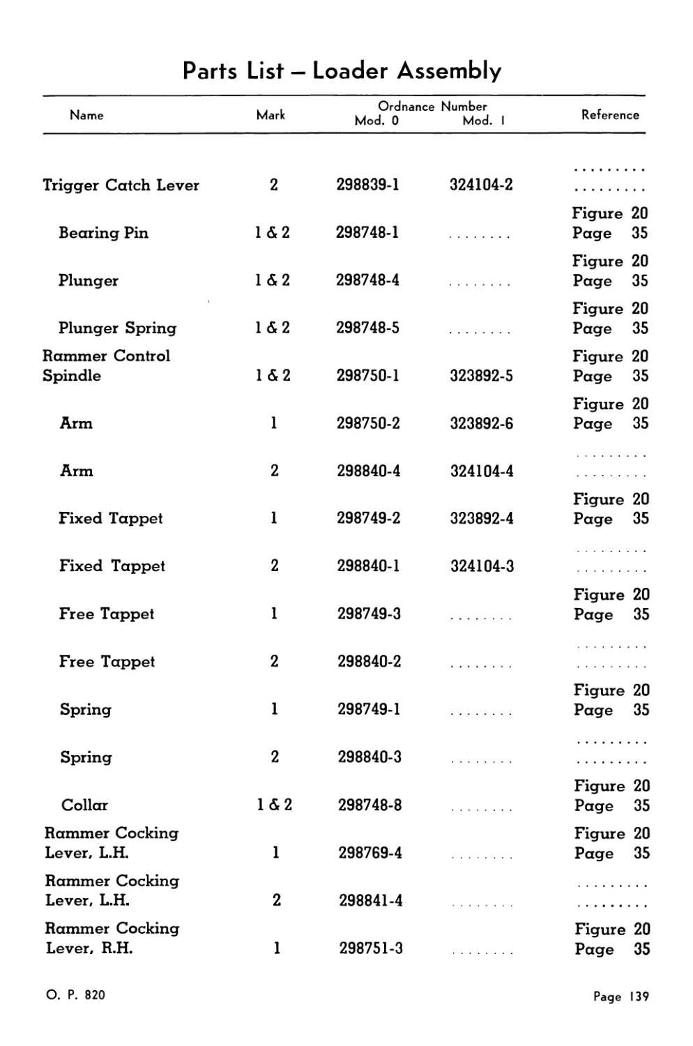
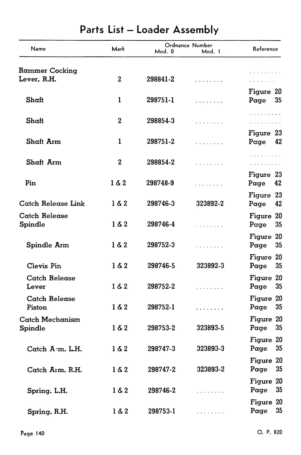
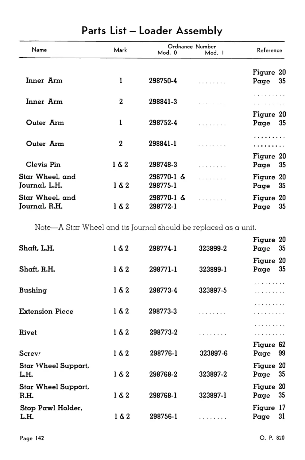
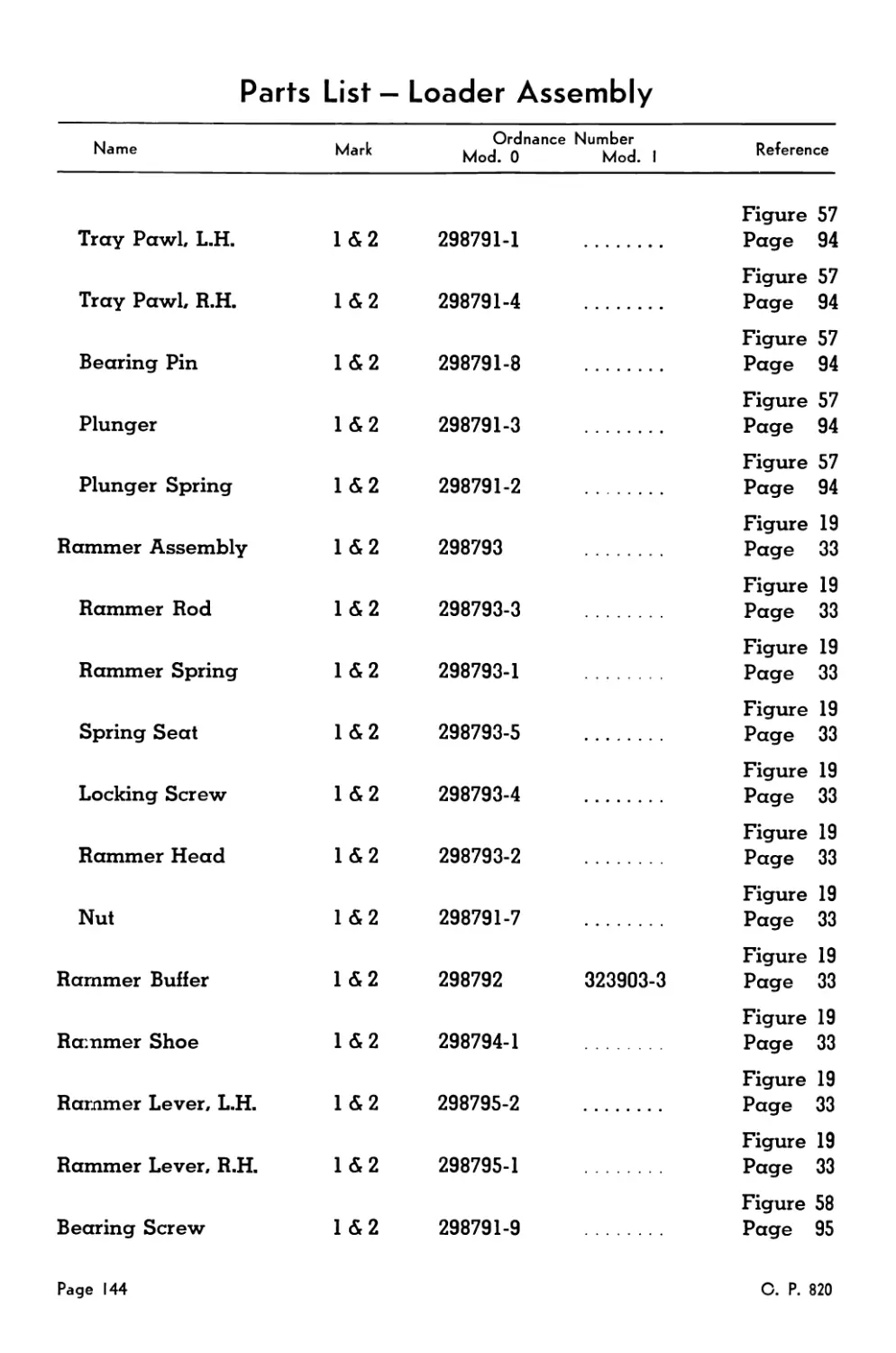
Loader Assembly ............................................... 137
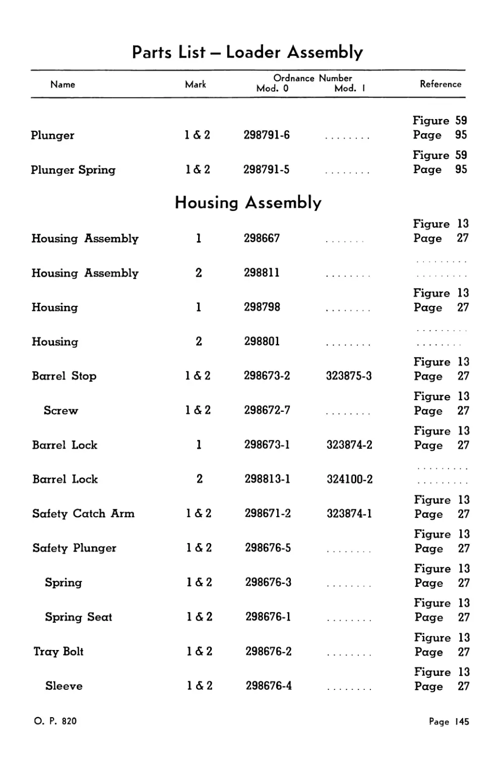
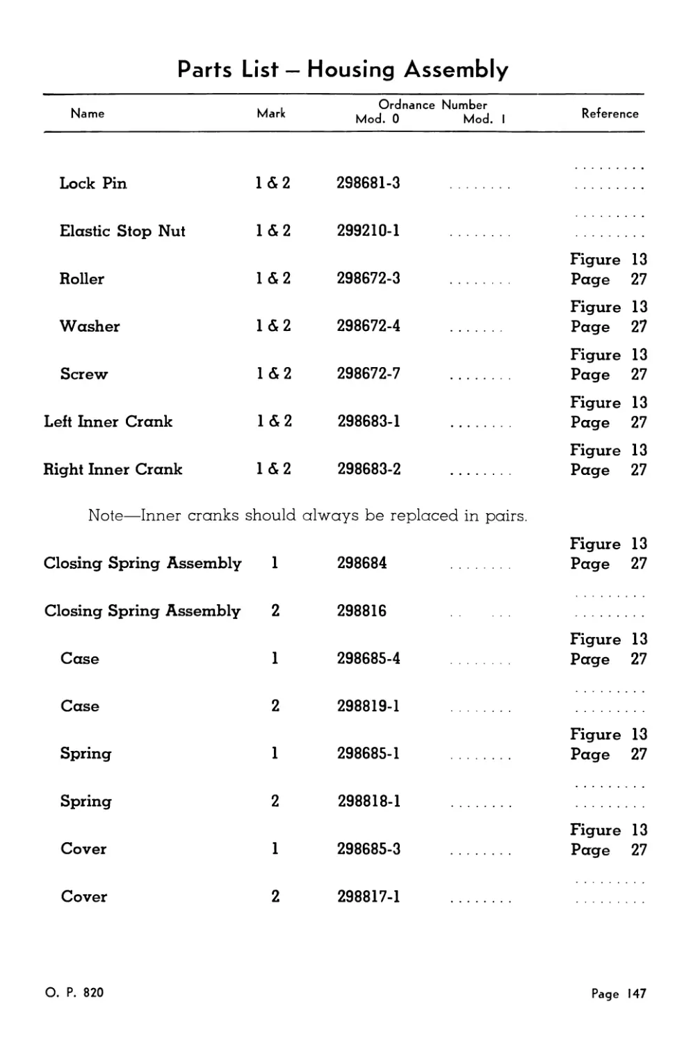
Housing Assembly .............................................. 145
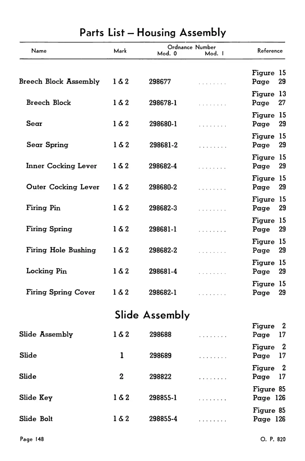
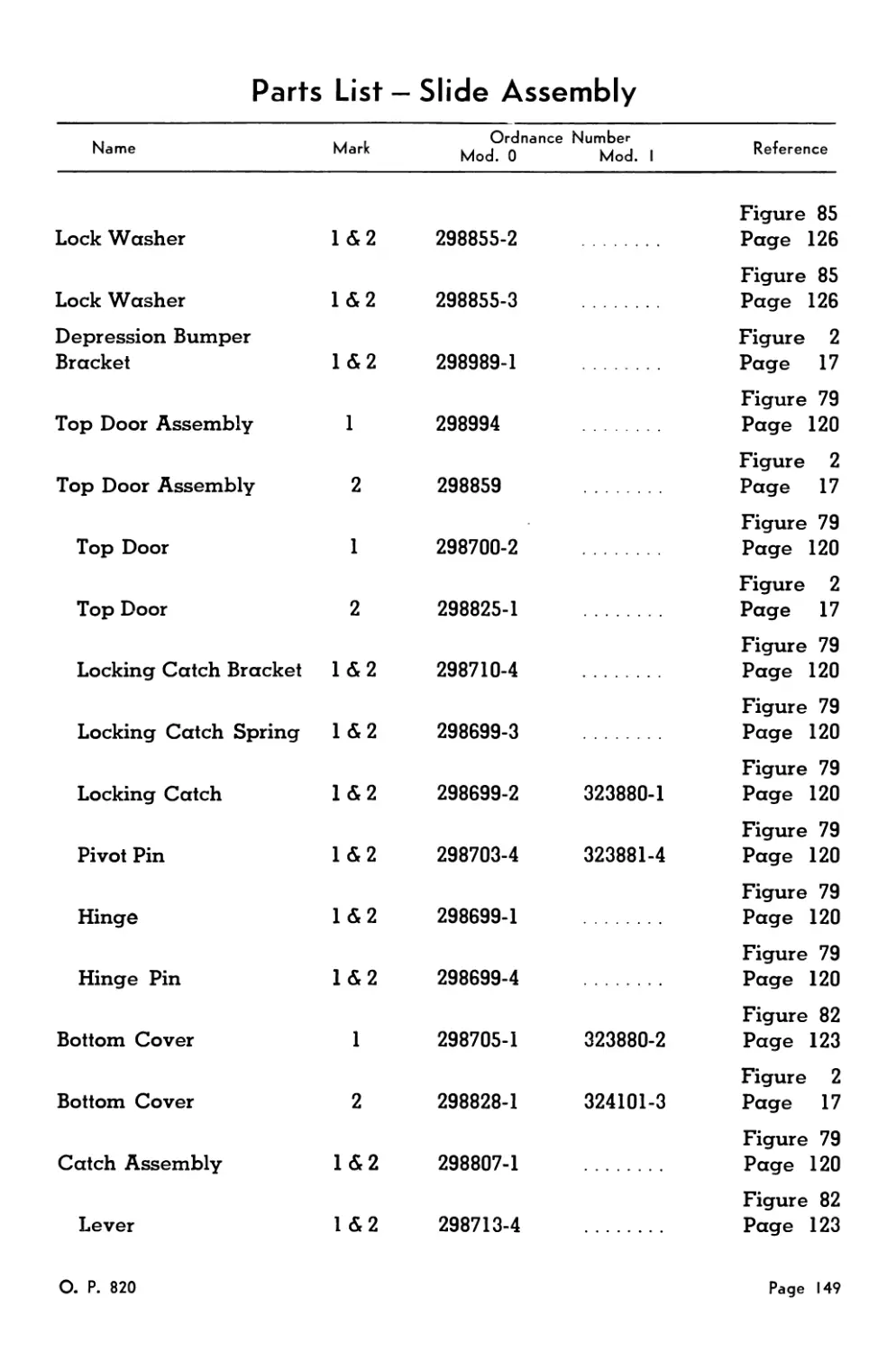
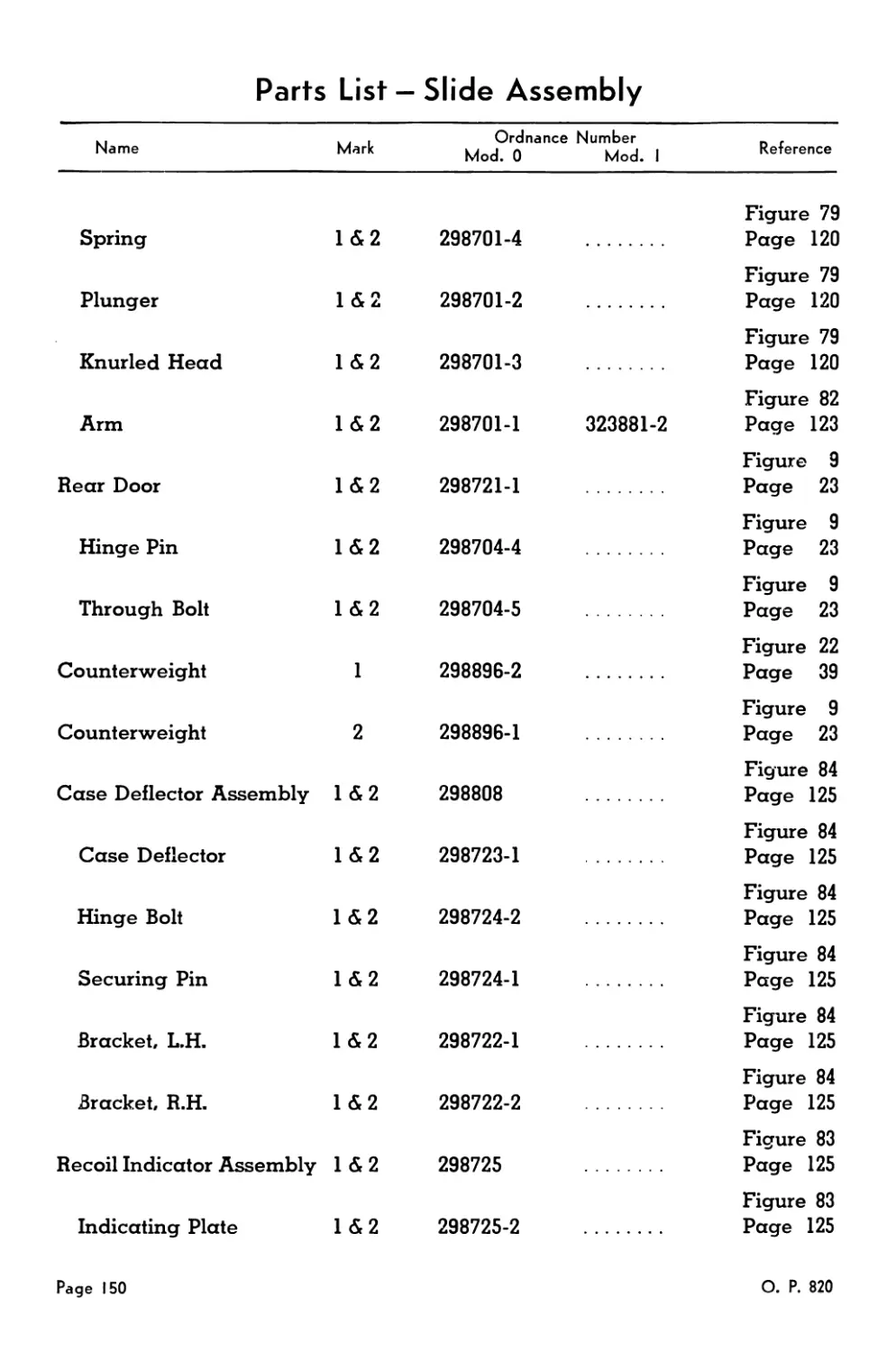
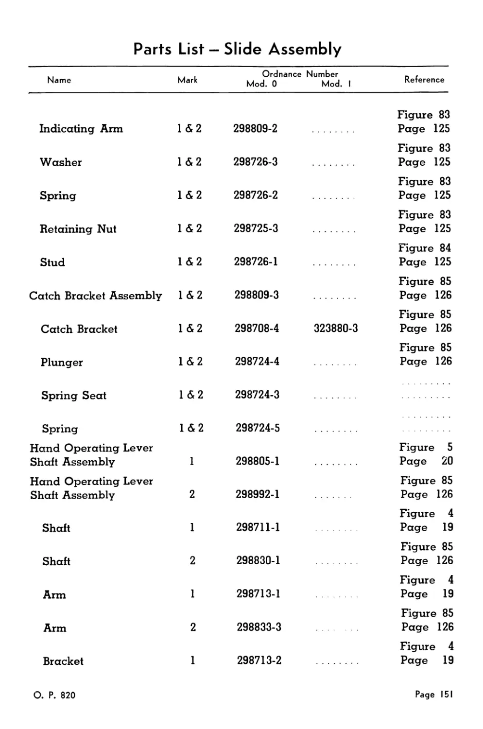
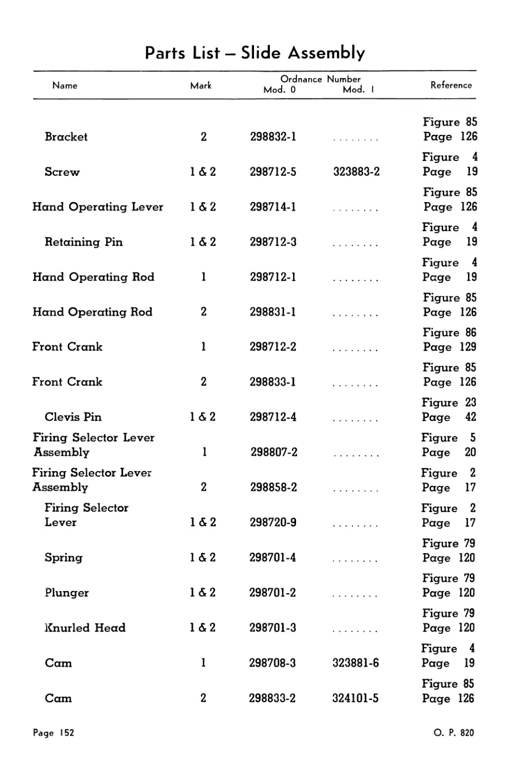
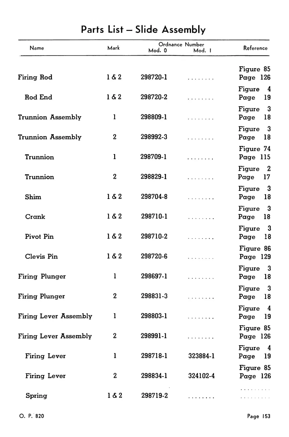
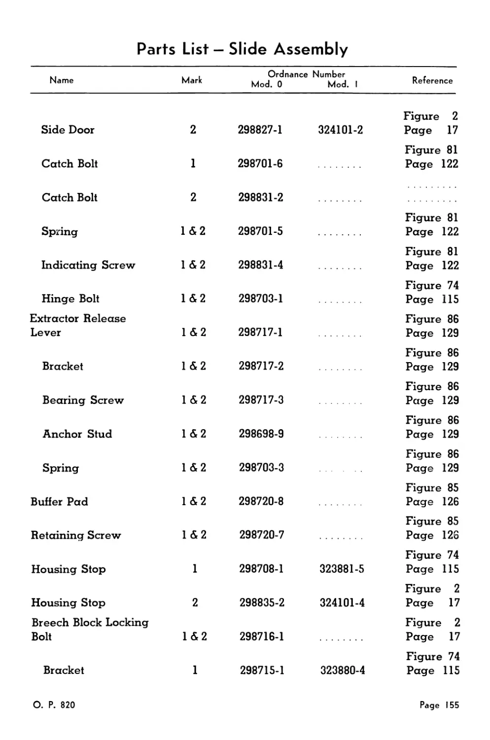
Slide Assembly................................................. 148
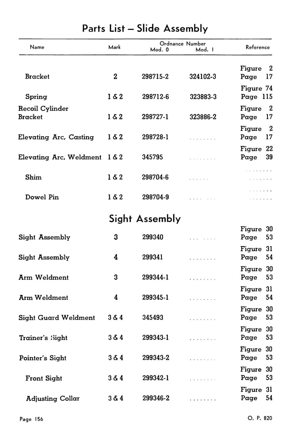
Sight Assembly................................................. 156
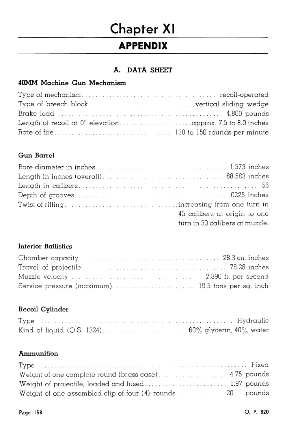
CHAPTER XI
APPENDIX ............................................................ 158
Data Sheet .................................................... 158
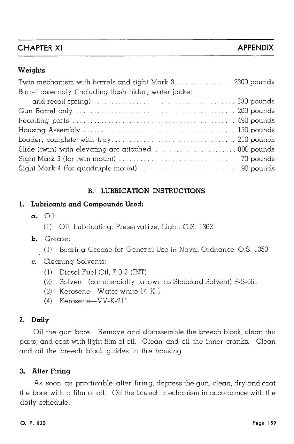
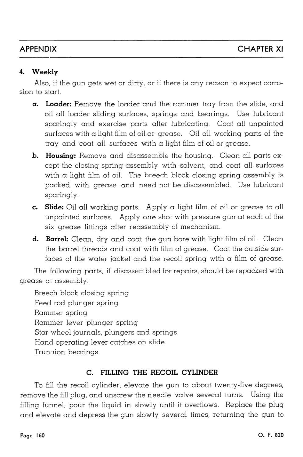
Lubrication Instructions....................................... 159
Filling the Recoil Cylinder.................................... 160
Variations .................................................... 161
О. P. 820
Page 9
LIST OF ILLUSTRATIONS
1. 40MM Antiaircraft Guns.................................... 14
2. Slide Assembly ........................................... 17
3. Trunnion Diagram.......................................... 18
4. Trigger Mechanism and Hand Operating Mechanism............ 19
5. Firing Selector Lever Positions........................... 20
6. Top Door ................................................. 21
7. Barrel Lock .............................................. 21
8. Side Door Cam Action...................................... 22
9. Rear Door ................................................ 23
10. Housing—Broken Open View ............................... 24
11. Housing—Front View........................................ 25
12. Housing—Side View ........................................ 26
13. Housing—Disassembled ..................................... 27
14. Safety Plunger ........................................... 28
15. Breech Block—Disassembled ................................ 29
16. Loader Assembly .......................................... 30
17. Feed Pawls and Stop Pawls................................. 31
18. Loader Assembly—Rear View................................. 32
19. Rammer Tray .............................................. 33
20. Loader Mechanism ......................................... 35
21. Sectional View of Recoil Cylinder......................... 37
22. Gun Mechanism Assembly.................................... 39
23. Cocking Mechanism......................................... 42
24. Breech Closed............................................. 43
25. Breech Block—Firing ...................................... 44
26. Breech Block—Cocking ..................................... 45
27. Operation of the Recoil Cylinder Assembly................. 49
28. Barrel Assembly .......................................... 51
29. Breech End of Barrel...................................... 52
30. Sight—Mark 3 ............................................. 53
31. Sight—Mark 4 ............................................. 54
О. P. 820
Page 11
LIST OF ILLUSTRATIONS
32. Mark 3 Sight Alignment Diagram.............................. 55
33. Mark 4 Sight Alignment Diagram.............................. 56
34. Feeding the Round........................................... 59
35. Cocking the Rammer.......................................... 59
36. Ramming the Round........................................... 60
37. Closing the Breech ......................................... 60
38. Firing the Round............................................ 63
39. Ejecting the Case .......................................... 63
40. Using the Round Releasing Tool.............................. 66
41. Using the Pusher Tool ...................................... 67
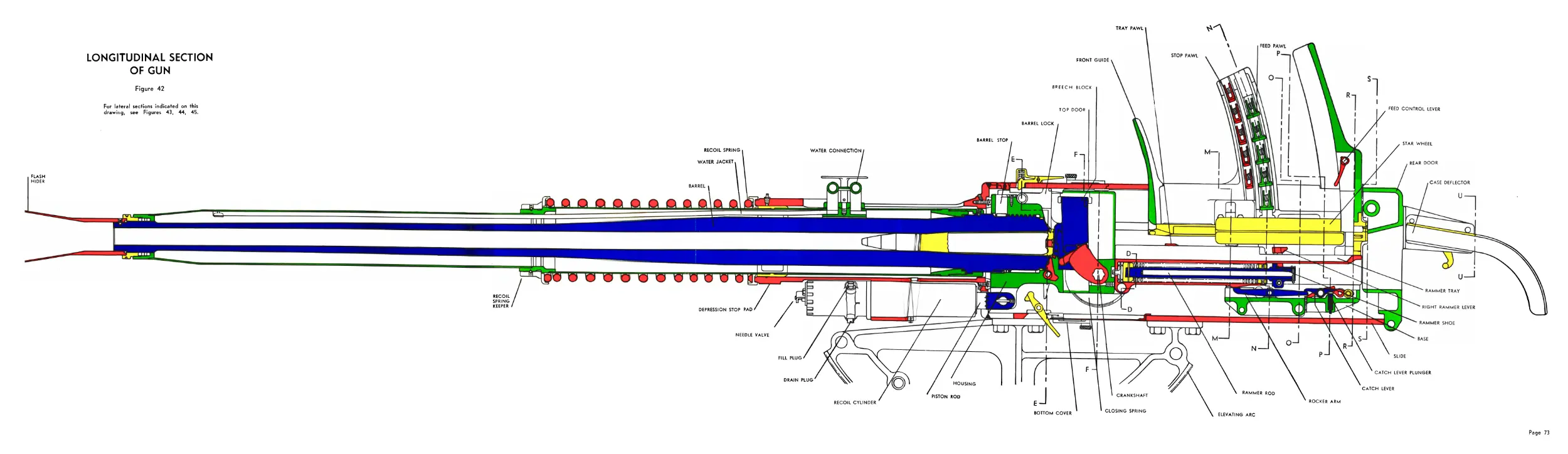
42. Longitudinal Section of Gun ................................ 73
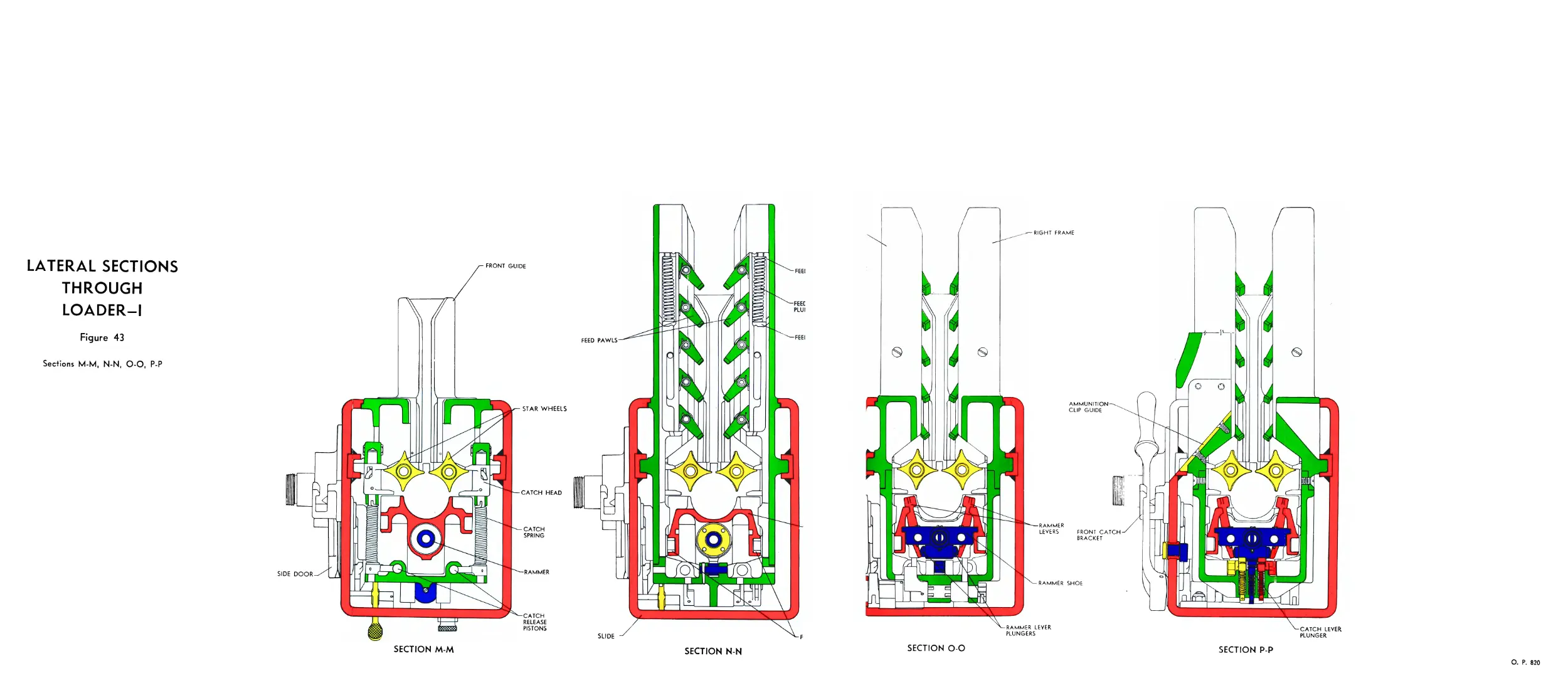
43. Lateral Sections Through Loader—I........................... 74
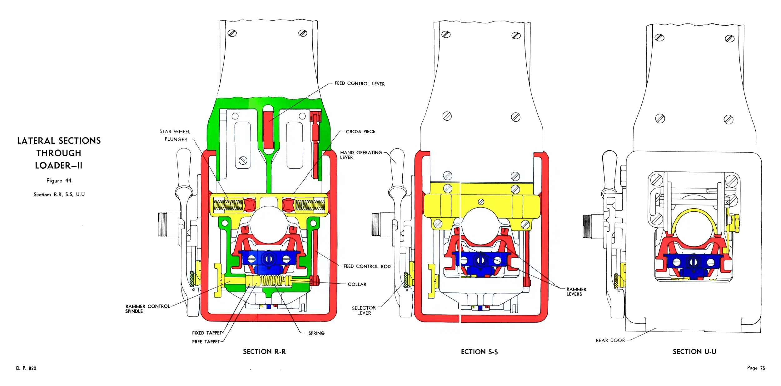
44. Lateral Sections Through Loader—II.......................... 75
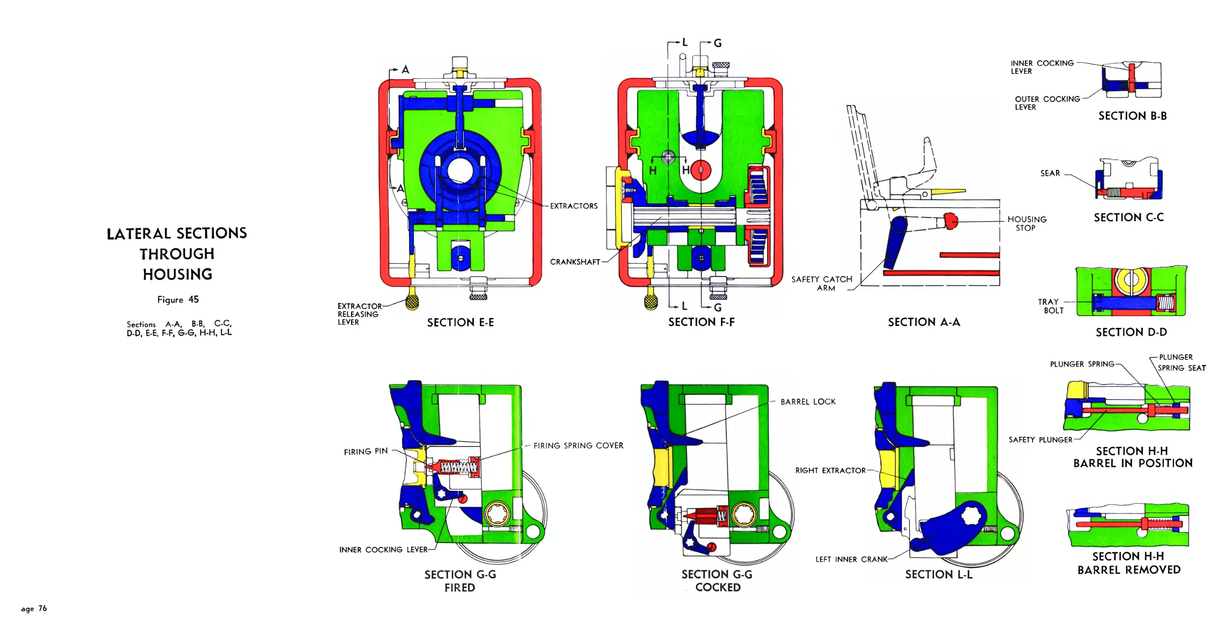
45. Lateral Sections Through Housing............................ 76
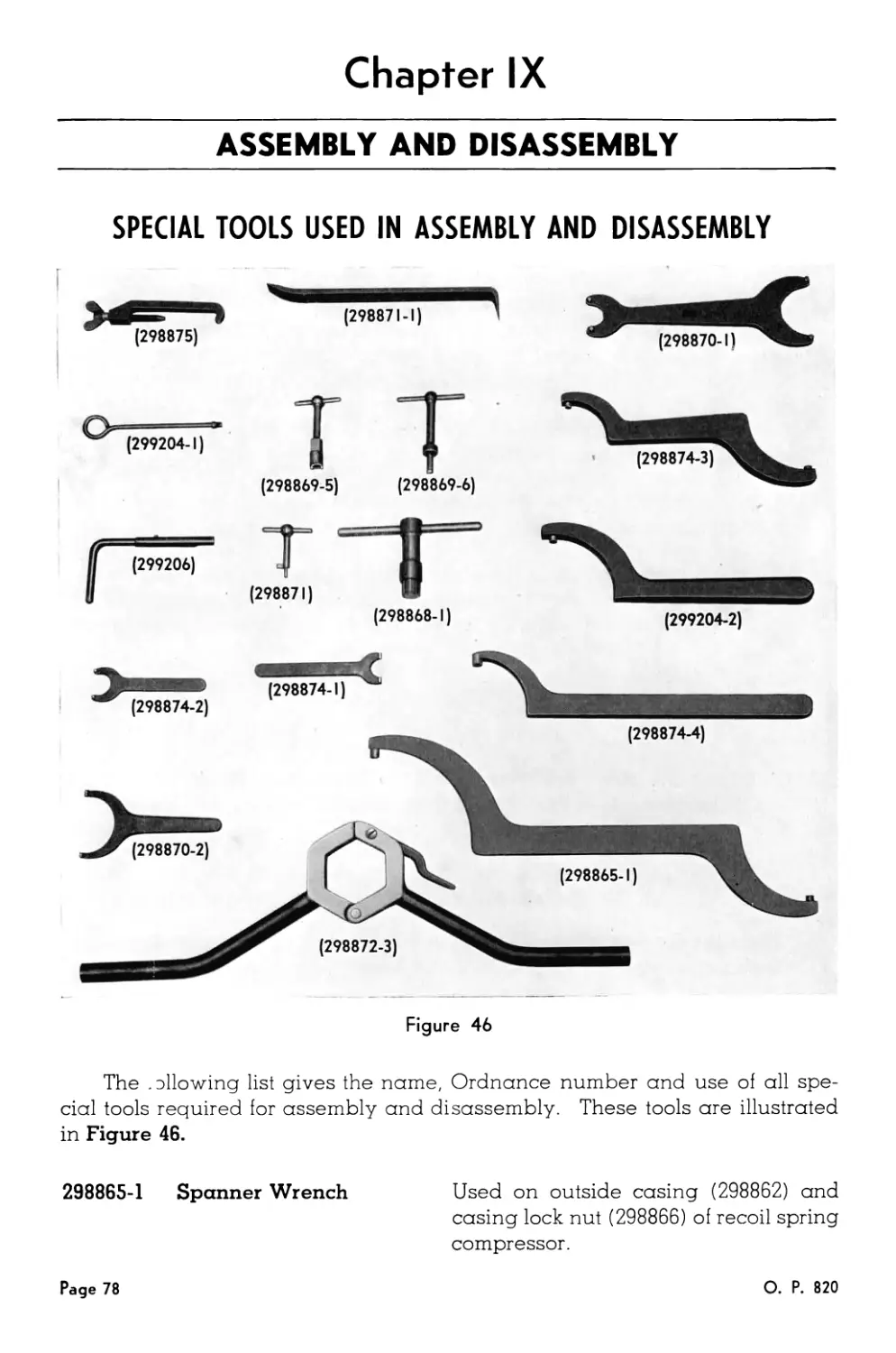
46. Special Tools Used in Assembly and Disassembly.............. 78
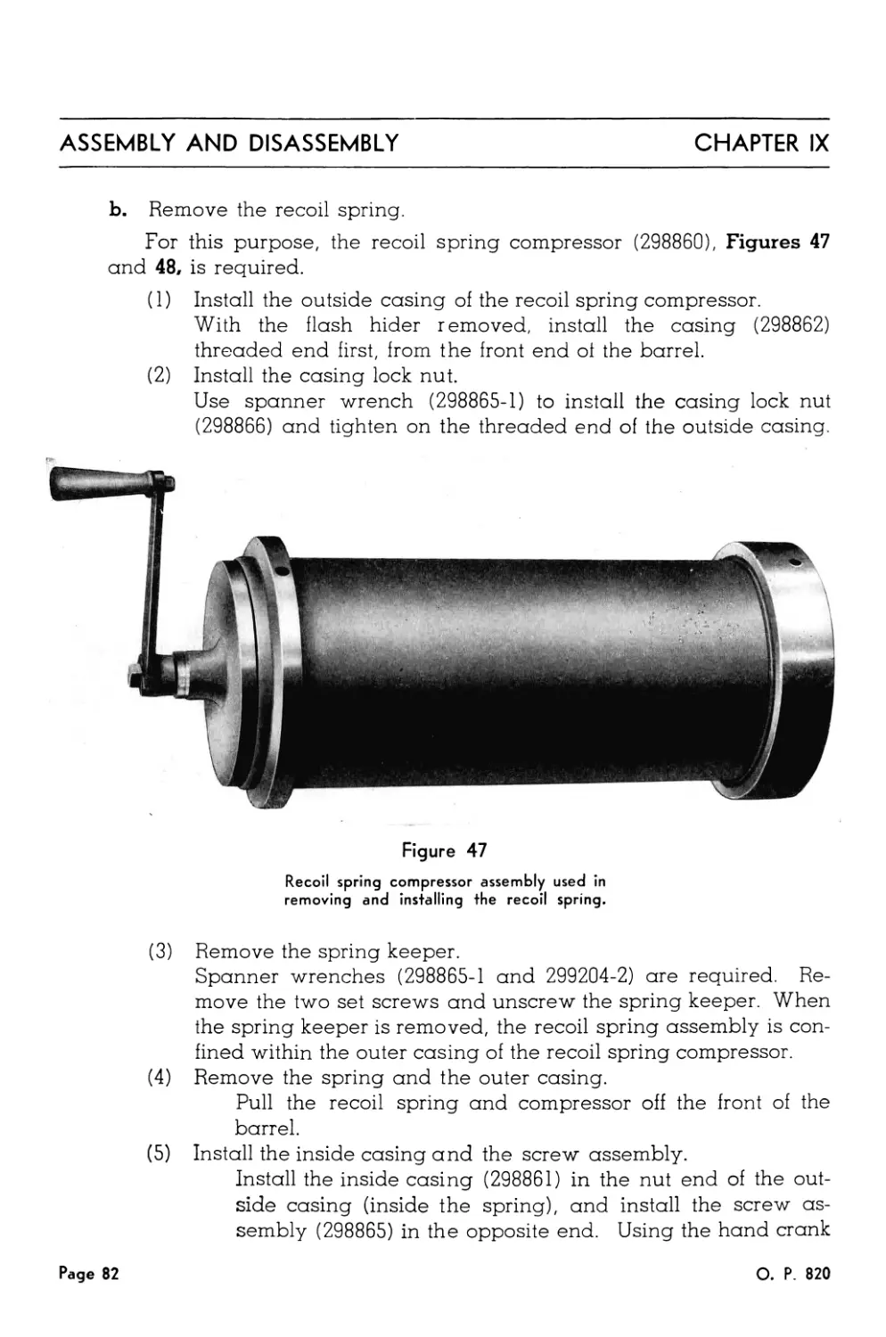
47. Recoil Spring Compressor Assembly........................... 82
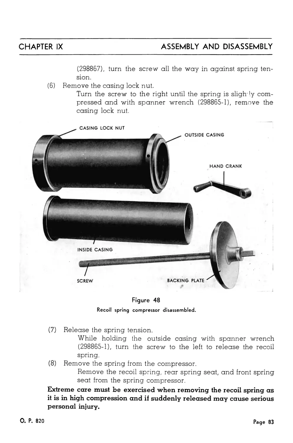
48. Recoil Spring Compressor Disassembled....................... 83
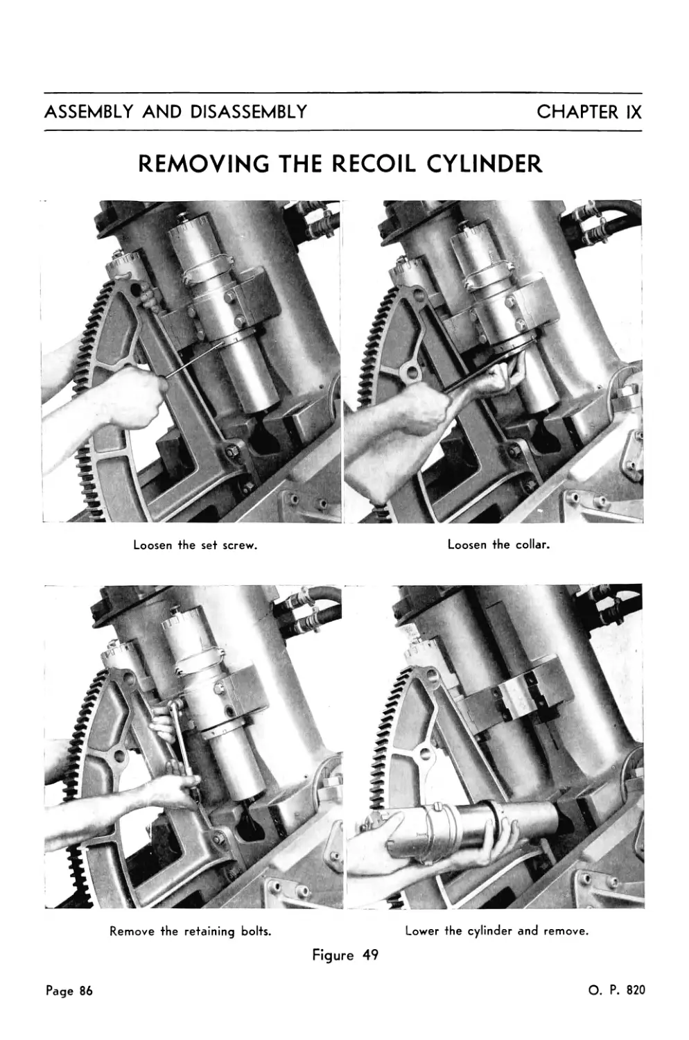
49. Removing the Recoil Cylinder................................ 86
50. Removing the Needle Valve................................... 88
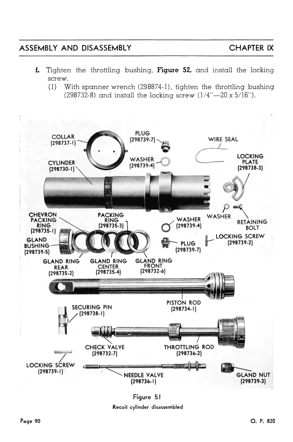
51. Recoil Cylinder Disassembled................................ 90
52. Tightening the Throttling Bushing........................... 91
53. Rear Door—Open ............................................. 92
54. Removing the Tray Bolt...................................... 92
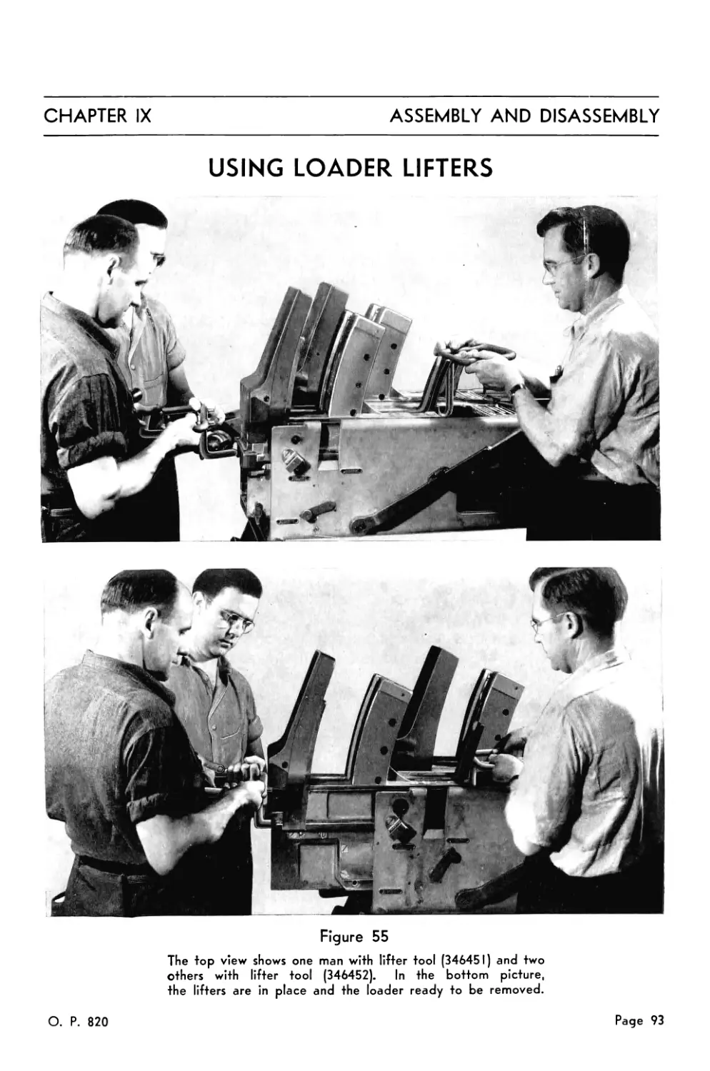
55. Using Loader Lifters........................................ 93
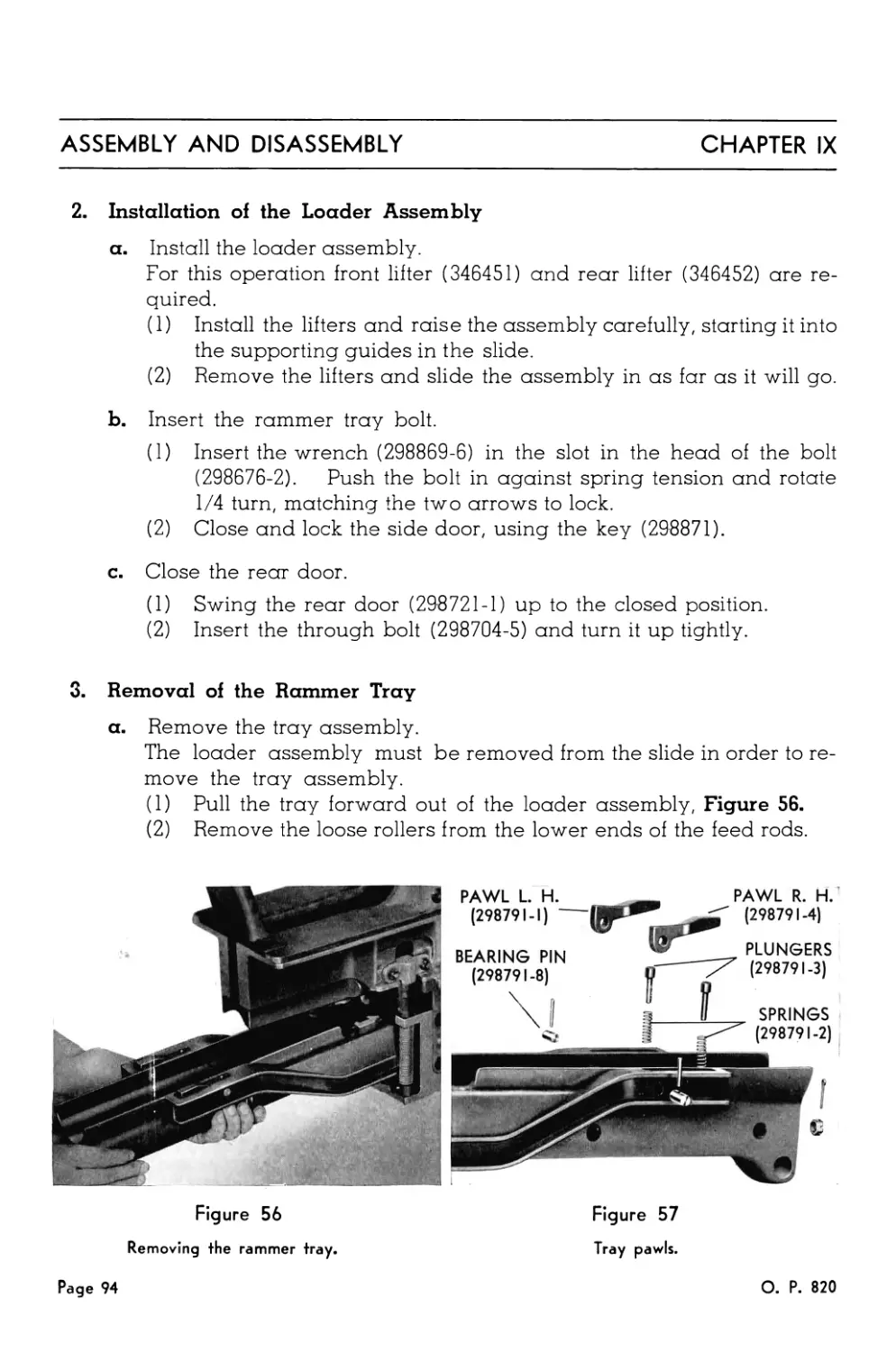
56. Removing the Rammer Tray.................................... 94
57. Tray Pawls ................................................. 94
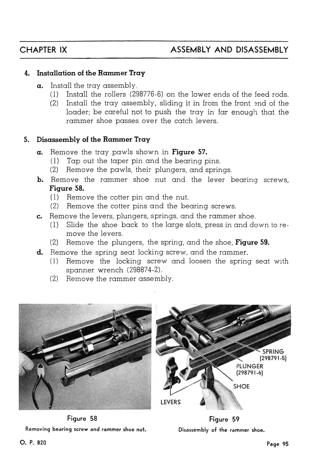
58. Removing Bearing Screw and Rammer Shoe Nut.................. 95
59. Disassembly of the Rammer Shoe.............................. 95
60. Feed Control Mechanism...................................... 97
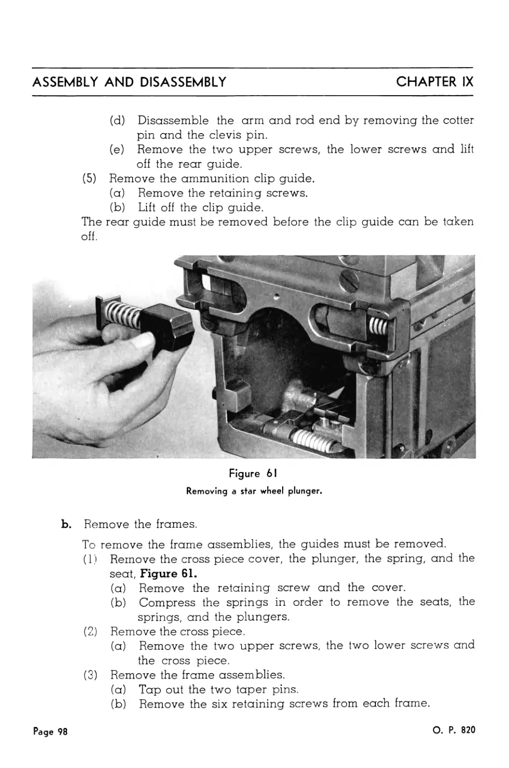
61. Removing a Star Wheel Plunger............................... 98
62. Removing a Star Wheel ...................................... 99
Page 12 О. P. 820
LIST OF ILLUSTRATIONS
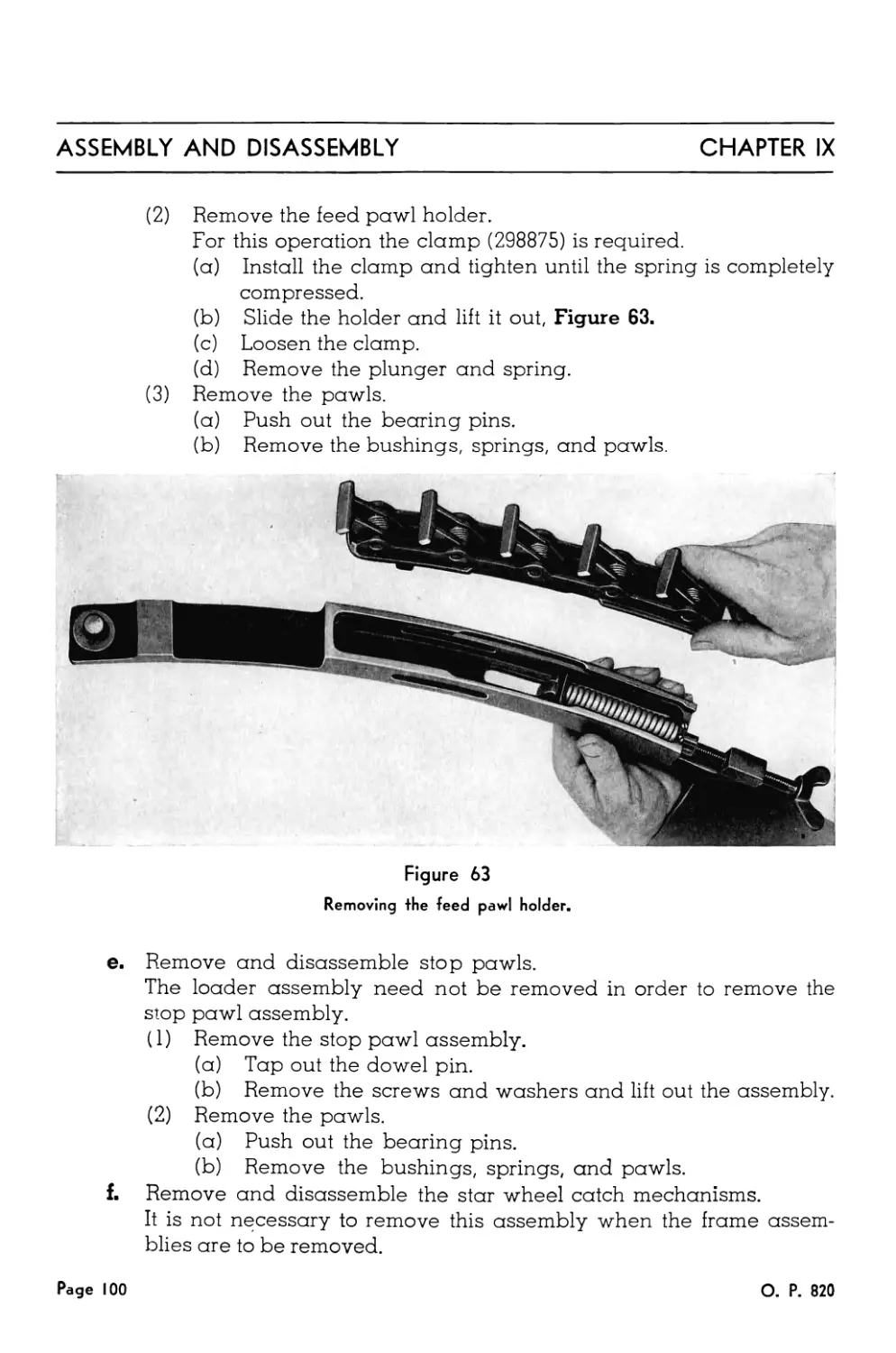
63. Removing the Feed Pawl Holder............................... 100
64. Removing the Catch Head...................................... 101
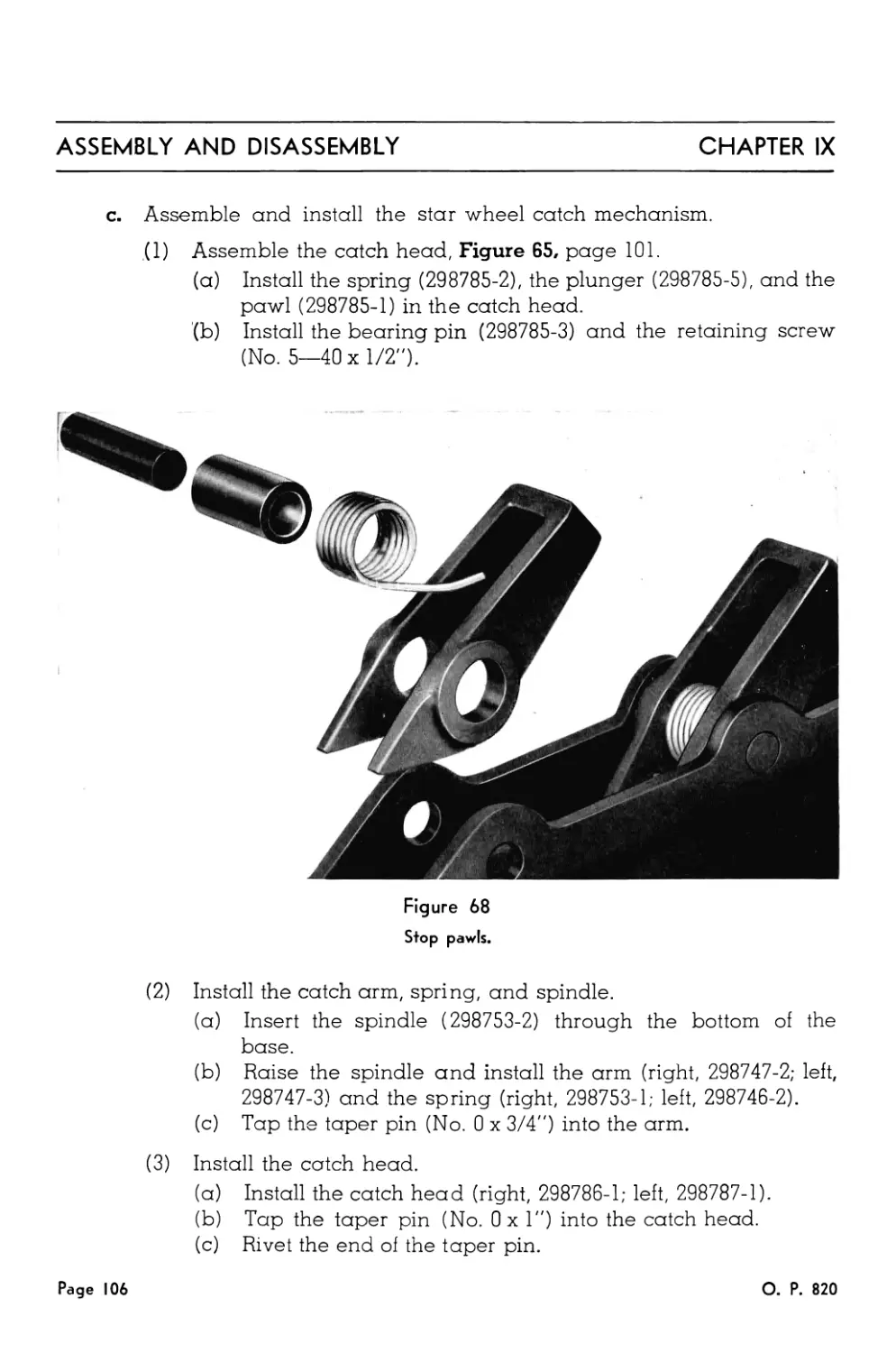
65. Catch Head................................................... 101
66. Removing the Outboard Rammer Cocking Lever.................. 102
67. Removing the Catch Levers and the Bearing Pin............... 103
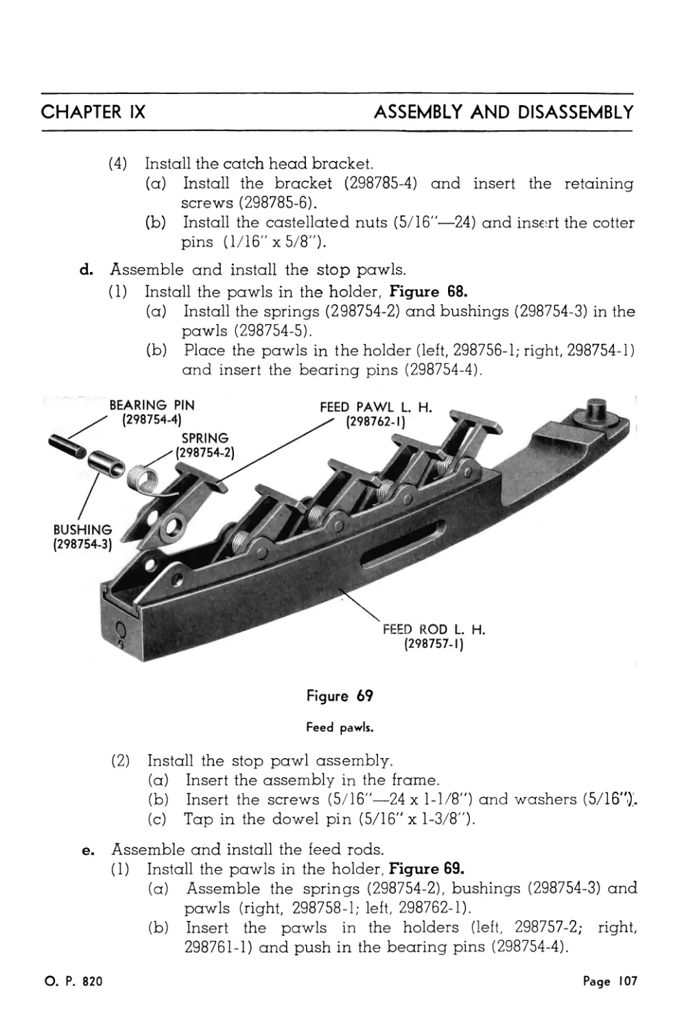
68. Stop Pawls.................................................. 106
69. Feed Pawls ................................................. 107
70. Removing the Extractors..................................... 110
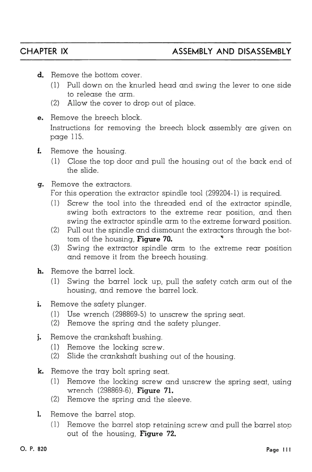
71. Removing the Tray Bolt Spring Seat.......................... 112
72. Removing the Barrel Stop ................................... 112
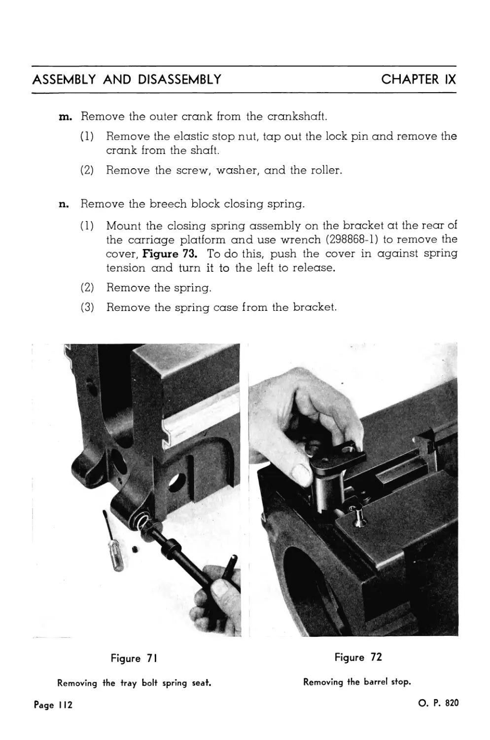
73. Disassembly of the Closing Spring........................... 113
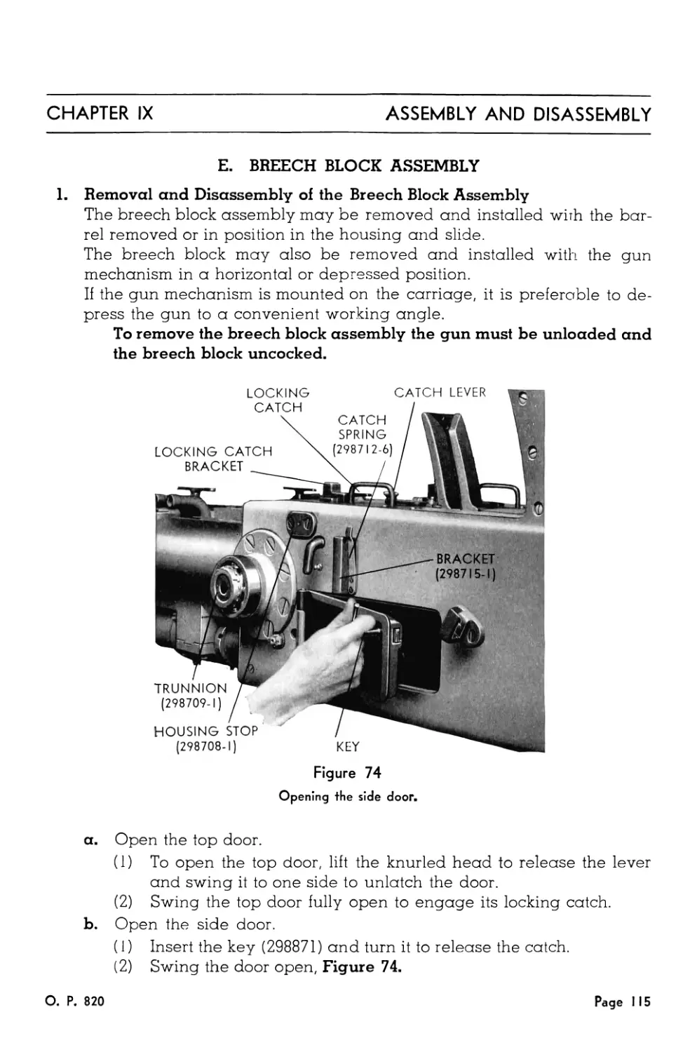
74. Opening the Side Door....................................... 115
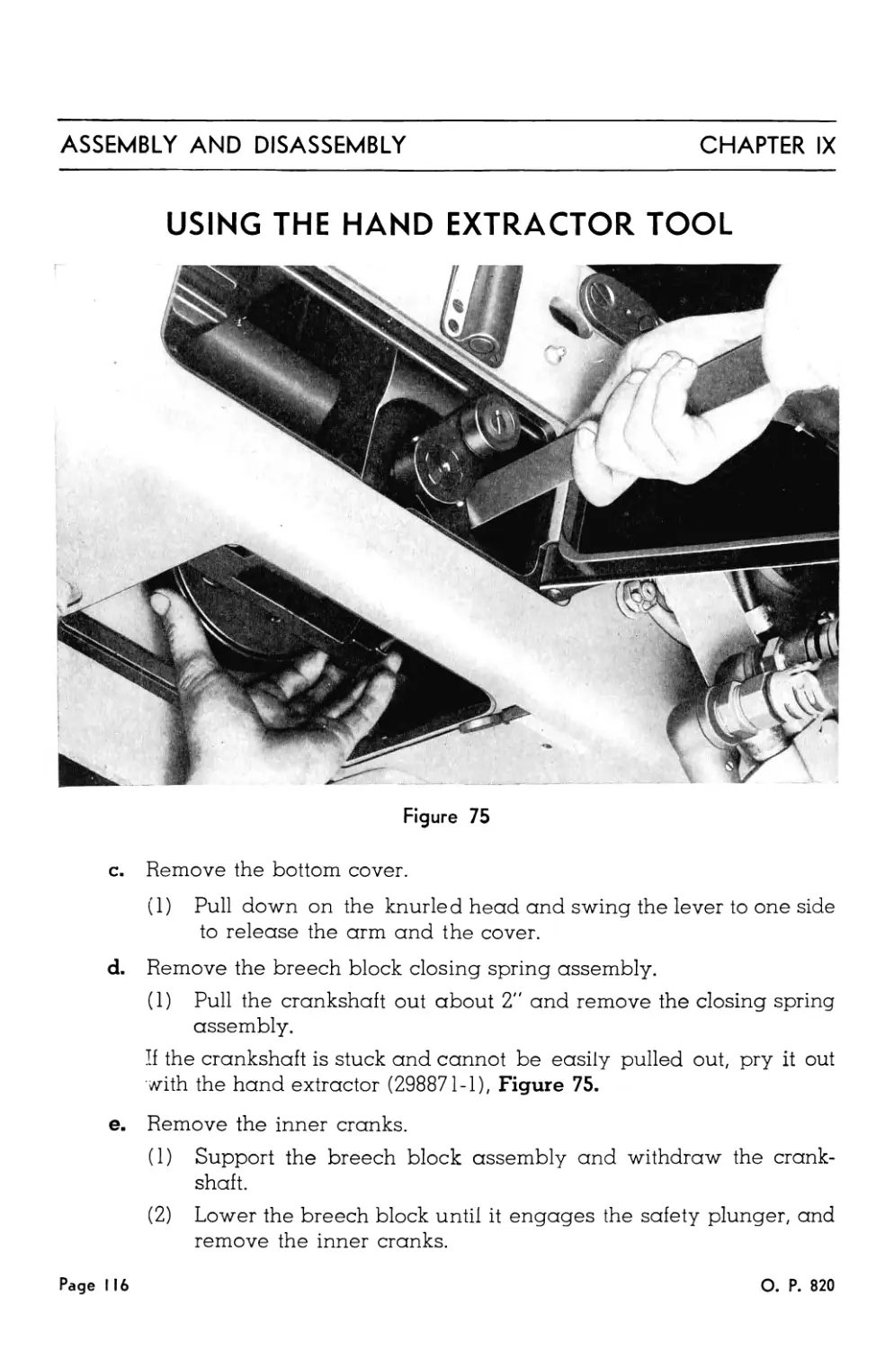
75. Using the Hand Extractor Tool............................... 116
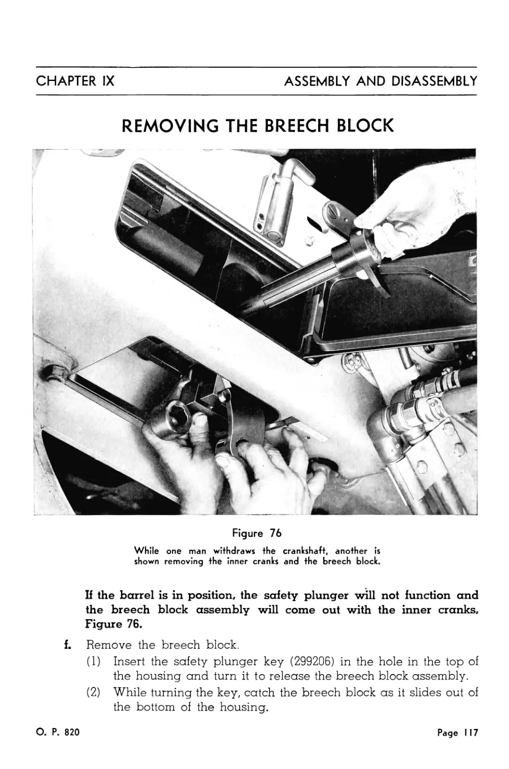
76. Removing the Breech Block................................... 117
77. Removing the Firing Spring Cover............................ 118
78. Removing the Outer Cocking Lever............................ 118
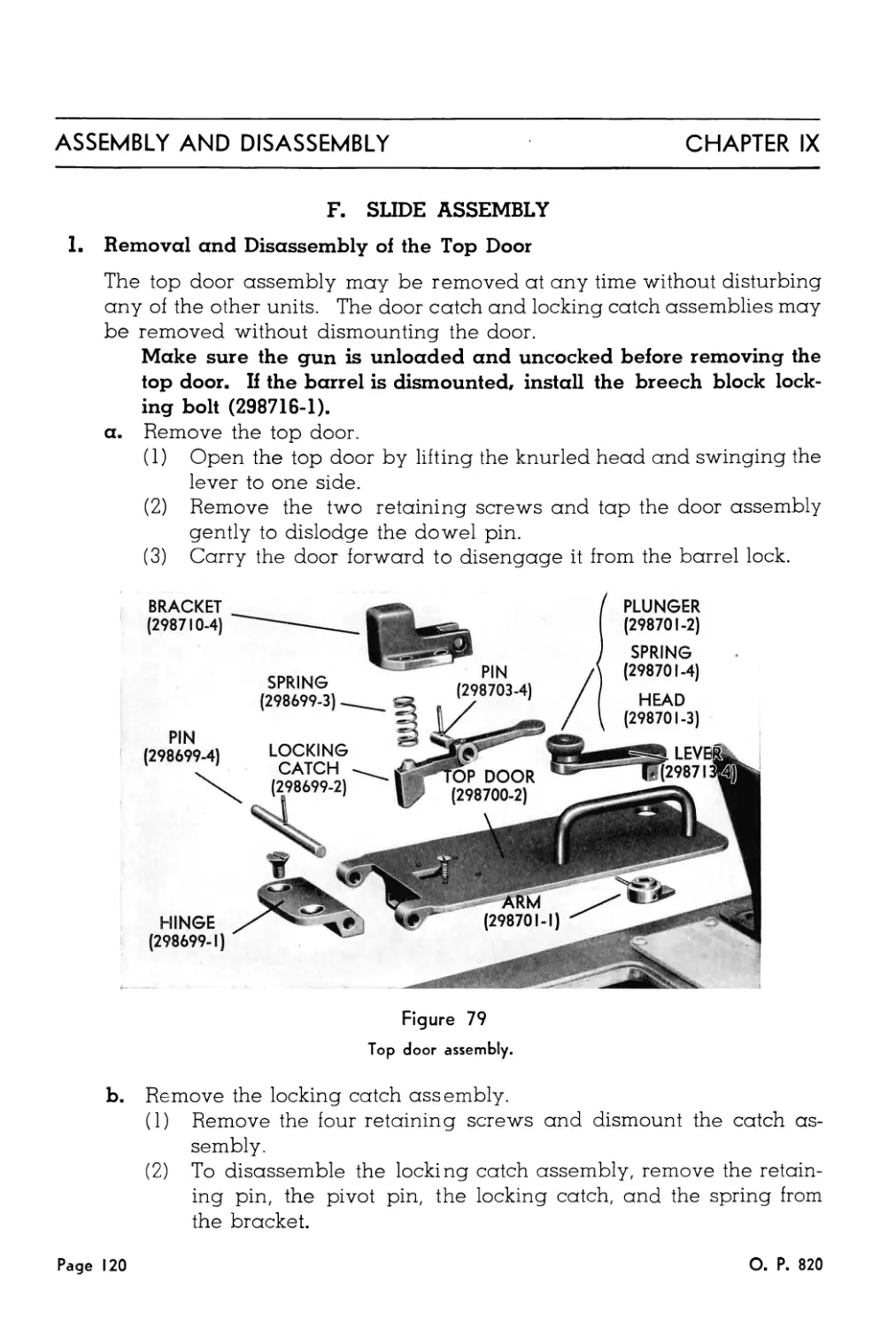
79. Top Door Assembly........................................... 120
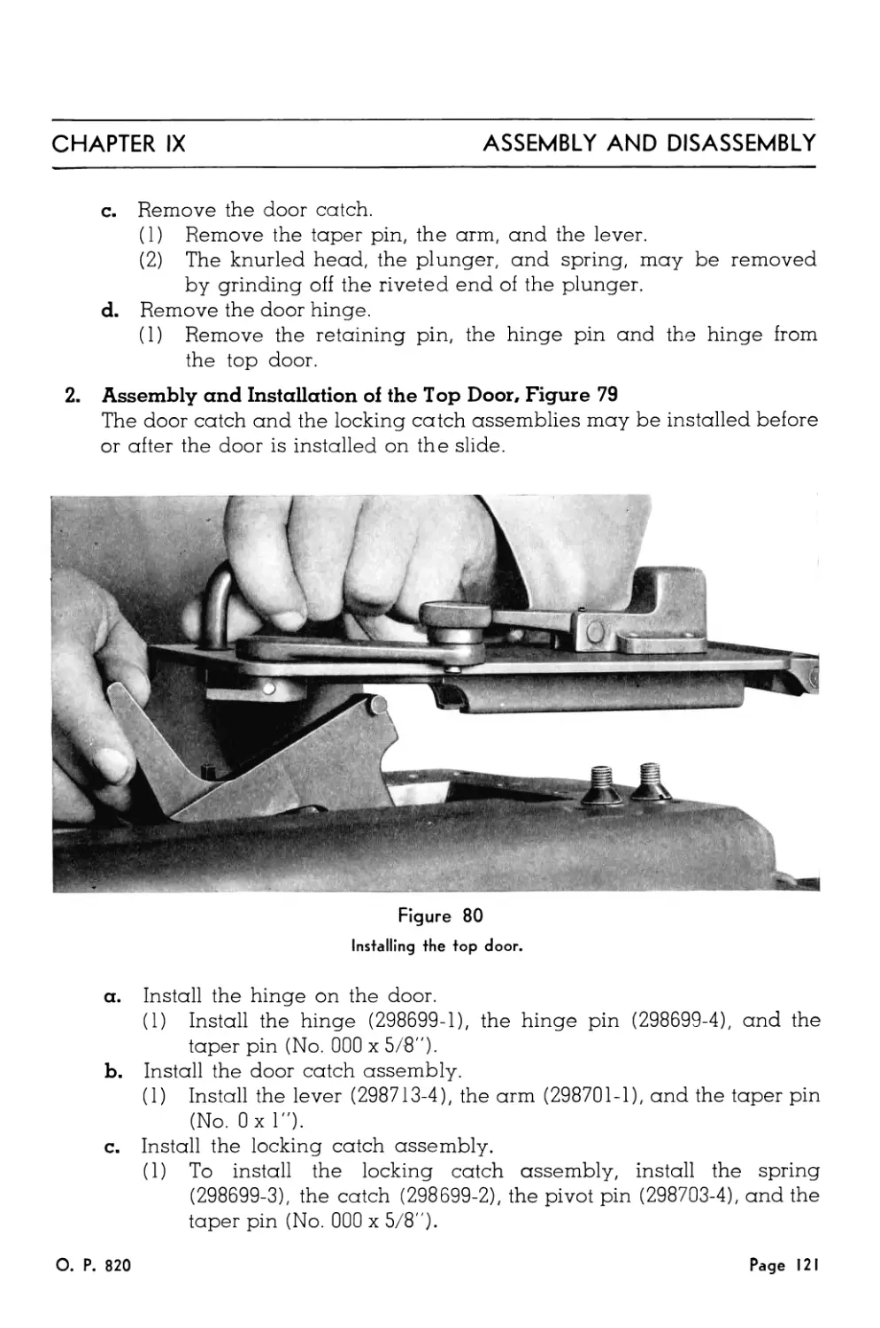
80. Installing the Top Door..................................... 121
81. Removing the Side Door Catch................................ 122
82. Bottom Cover ............................................... 123
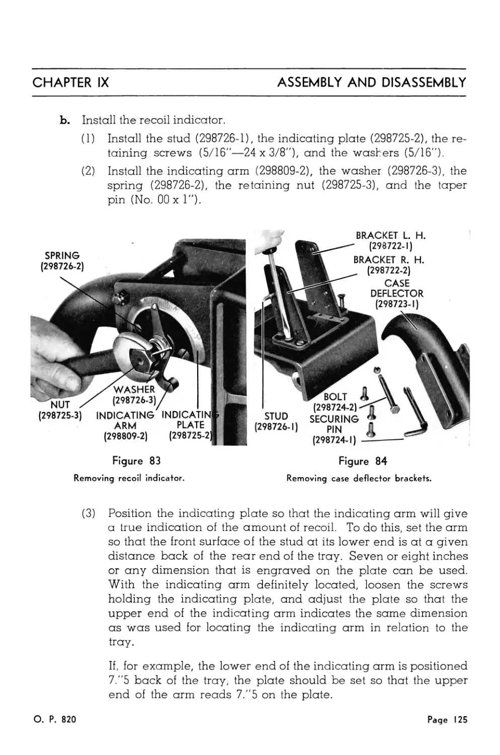
83. Removing the Recoil Indicator............................... 125
84. Removing the Case Deflector Brackets........................ 125
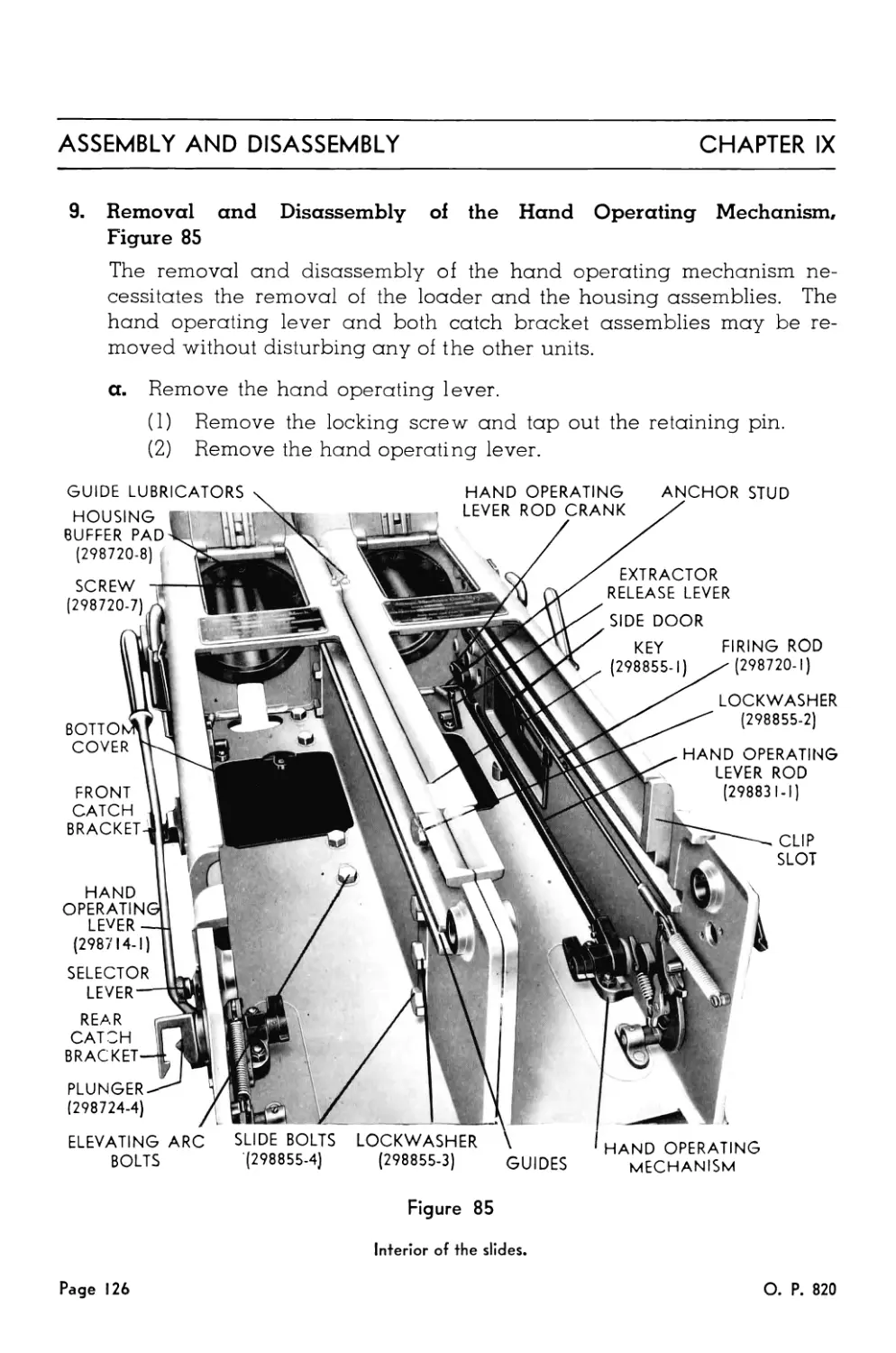
85. Interior of the Slides...................................... 126
86. Detail of the Interior of the Slide......................... 129
О. P. 820
Page 13
40ММ ANTIAIRCRAFT GUNS
Page 14
О. P. 820
Chapter I
INTRODUCTION
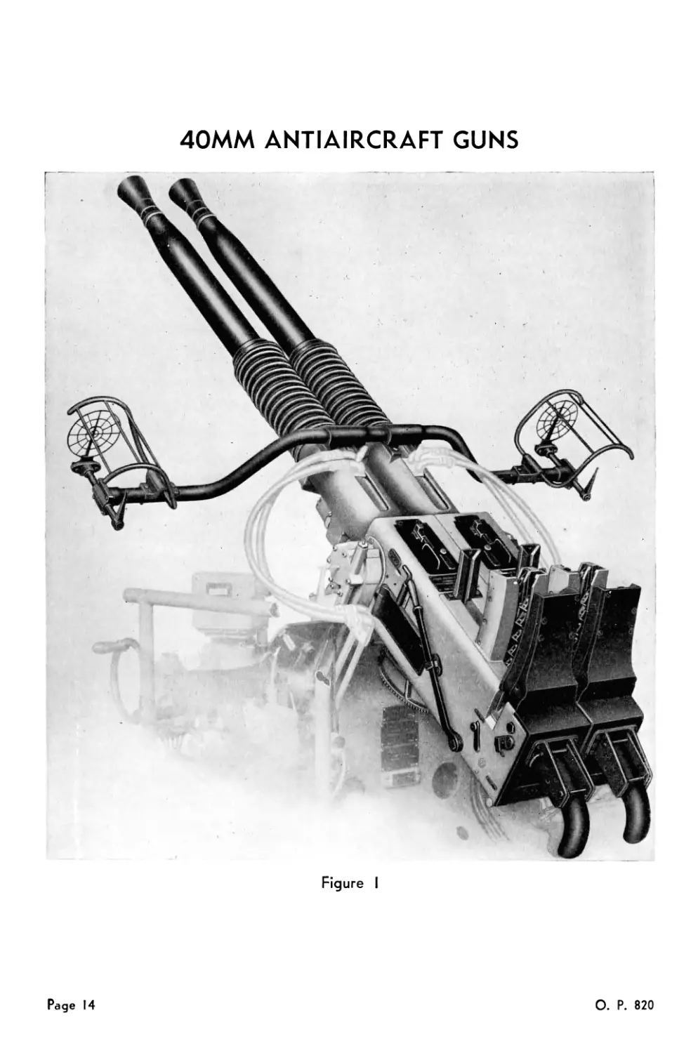
The 40MM Antiaircraft Gun, Figure 1, consists of the machine
gun mechanism, the gun barrel, and the sights. The 40MM
Machine Gun Mechanisms are assembled in pairs. The left
mechanism is designated Mark 1 or Mark 1, Mod. 1, and the right
mechanism is designated Mark 2 or Mark 2, Mod. 1. The only
differences between the two Marks of mechanisms are those re-
quired by the twin assembly. The only difference between the
Mod. 0 and Mod. 1 is that certain parts are not interchangeable
between the two. 40MM Gun Barrels, Mark 1, are used with all
mechanisms. The 40MM Sight, Mark 3, is used on the 40MM
Twin Mount; the 40MM Sight, Mark 4, is used on the 40MM Quad-
ruple Mount.
The design of these mechanisms and barrels is essentially
that of the Swedish Bofors 40MM Antiaircraft Gun. The design
provides for a rapid fire, recoil operated, automatic mechanism,
with a maximum cyclic rate of approximately 160 rounds per
minute.
О. P. 820
Page IS
Chapter II
DESCRIPTION
MECHANISM
OPERATION
Part One—Description of Gun Mechanism
The 40MM Machine Gun Mechanism consists of five principal compo-
nents. They are the Slide Assembly/ Breech Mechanism Assembly, Loader
Assembly, Recoil Cylinder Assembly, and Barrel Assembly (excluding
barrel).
A. SLIDE ASSEMBLY
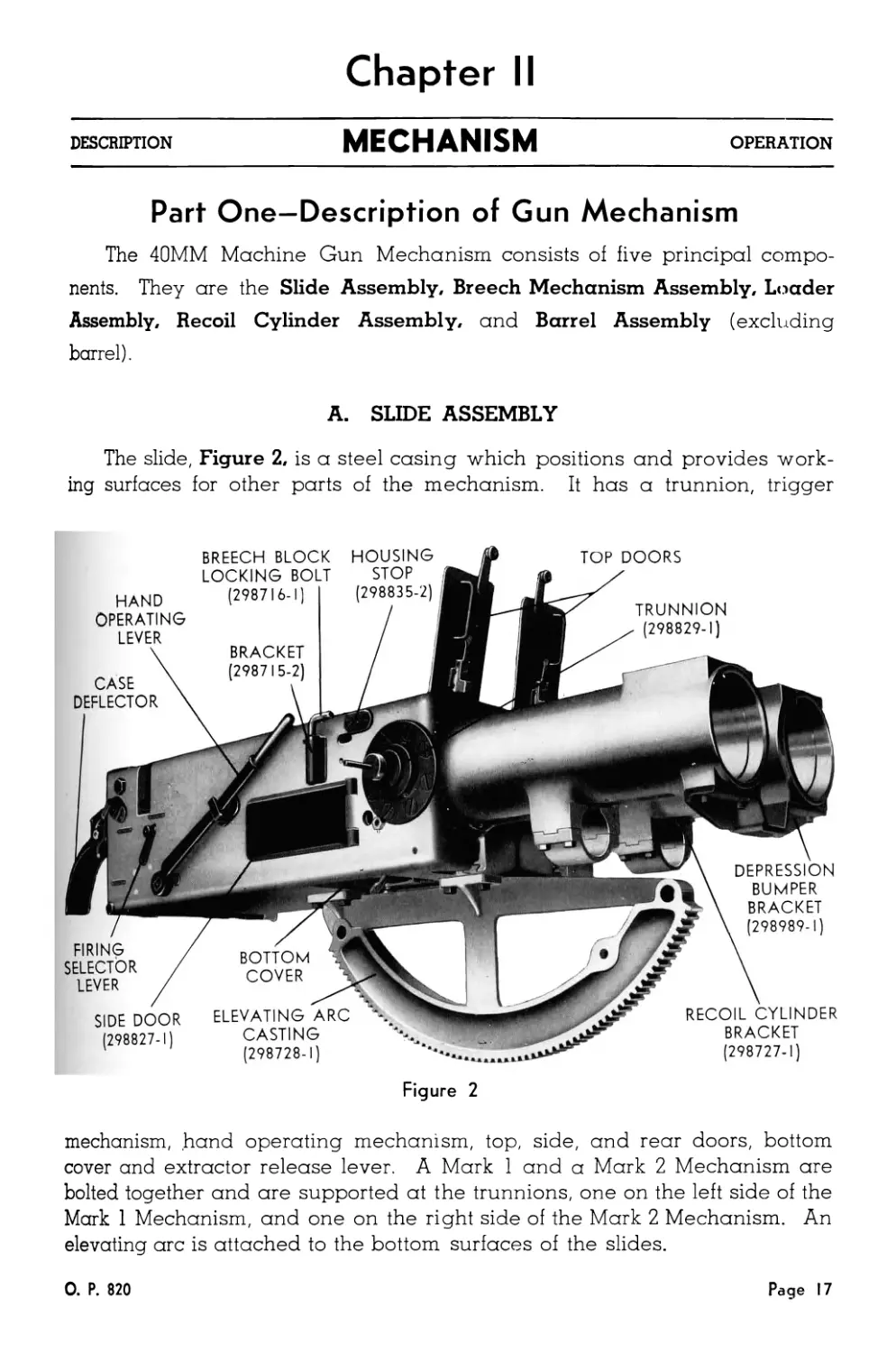
The slide, Figure 2, is a steel casing which positions and provides work-
ing surfaces for other parts of the mechanism. It has a trunnion, trigger
HOUSING
STOP
(298835-2)
CASE
DEFLECTOR
TOP DOORS
TRUNNION
(298829-1)
HAND
OPERATING
LEVER
BREECH BLOCK
LOCKING BOLT
(298716-1)
ELEVATING ARC
CASTING
(298728-1)
DEPRESSION
BUMPER
BRACKET
(298989-1)
RECOIL CYLINDER
BRACKET
(298727-1)
FIRING
SELECTOR
LEVER
SIDE DOOR
(298827-1)
Figure 2
mechanism, hand operating mechanism, top, side, and rear doors, bottom
cover and extractor release lever. A Mark 1 and a Mark 2 Mechanism are
bolted together and are supported at the trunnions, one on the left side of the
Mark 1 Mechanism, and one on the right side of the Mark 2 Mechanism. An
elevating arc is attached to the bottom surfaces of the slides.
0. P. 820
Page 17
MECHANISM
DESCRIPTION
CHAPTER II
TRUNNION DIAGRAM
BEARING
CARRIAGE
FIRING
PLUNGER
(298697-1)
ARC
RACK
TRUNNION
SHIM
LOCK WASHER
CARRIAGE
SLIDE
SLIDE
FIRING
PLUNGER
(298831-3)
TRUNNION
SHIM
BEARING
LOCK WASHER “X
LOCK NUT
PIN
(298710-2)
CRANK
(298710-1)
LOCK NUT
KEY
The trunnion on the left is part of the Mark I
the one on the right is part of the Mark 2
Mechanism,
Mechanism.
1. Trunnion
The trunnion, Figure 3, contains the firing plunger and crank of the trig-
ger mechanism. The trunnion of the Mark 1 Mechanism is provided with a
gear sector to transmit gun elevation to the firing cut-out mechanism of the
mount.
2. Trigger Mechanism
The trigger mechanism, Figure 4, is on the left side of the Mark 1 Mecha-
nism on t ie right side of the Mark 2 Mechanism. It is operated by the firing
plunger in the trunnion. The trigger is a vertical arm, pivoted near its center,
and is located inside and at the rear of the slide, where it contacts and con-
trols the movement of the rammer control spindle arm of the loader. The
trigger is operated by a pawl on the firing lever. Motion of the trigger and
firing mechanism is limited by the cam on the firing selector lever shaft,
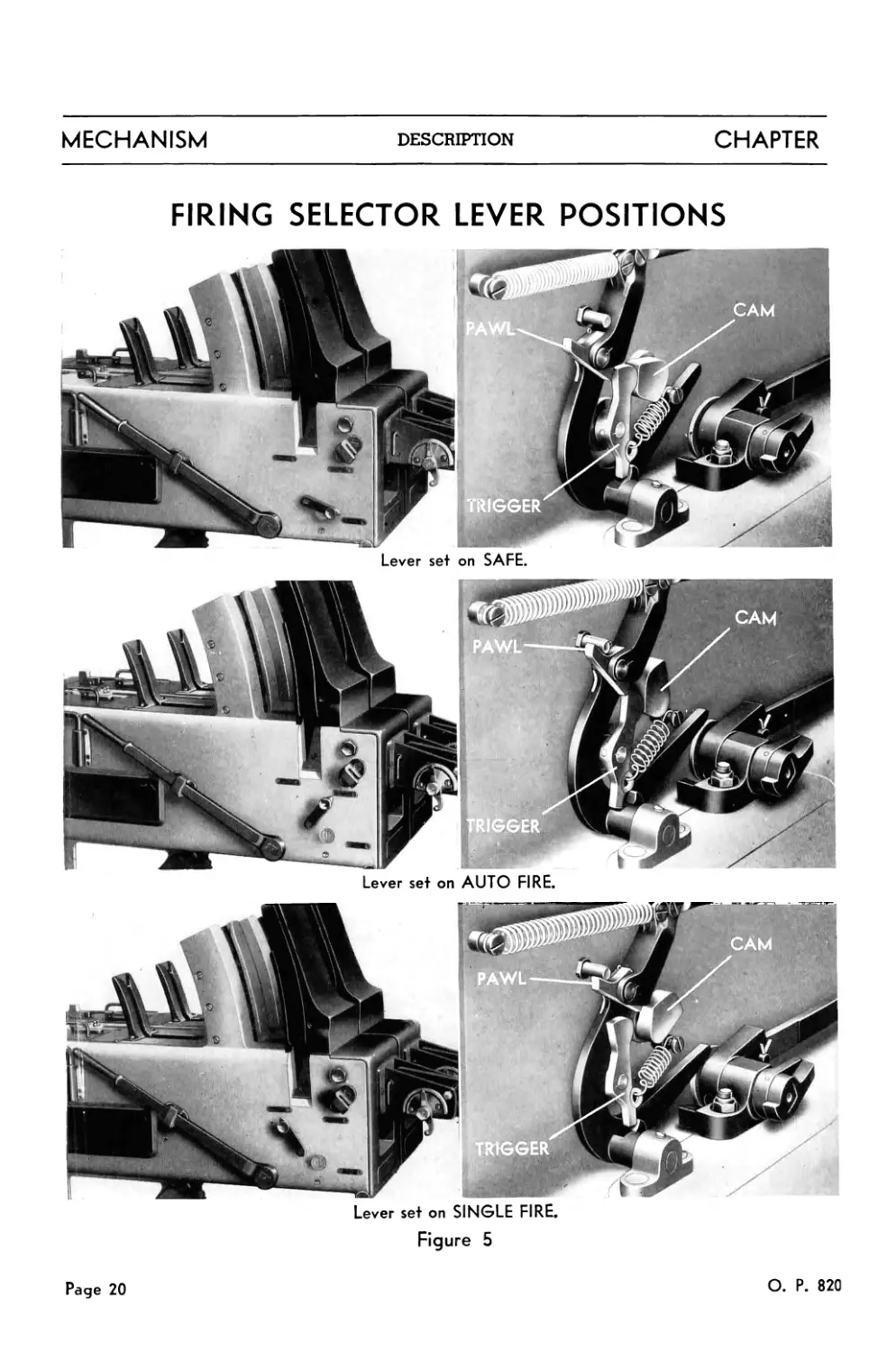
as shown in Figure 5. When the firing selector lever is at SAFE, motion of
the trigger mechanism is prevented by the firing selector cam. When the
selector lever is at AUTO FIRE, the trigger can be maintained in the firing
Page 18
О. P. 820
CHAPTER II
DESCRIPTION
MECHANISM
position by the trigger mechanism. When the selector lever is at SINGLE
FIRE, motion of the trigger mechanism can be sufficient to permit the pawl to
trip and thus release the trigger. The trigger returns to its non-firing position
after releasing the trigger catch lever in the loader. Thus in SINGLE FIRE
the firing mechanism must be restored to its non-firing position before the
trigger can again be operated.
FIRING LEVER
SPRING
(298720-5)
CONNECTING
ROD END
FIRING SELECTOR
CAM
(298708-3)
STUD
(298720-3)
HAND OPERATING
LEVER ROD
(298712-1)
STOP STUD
(298703-2)
FIRING
PAWL
(298717-4)
(298719-1)
HAND OPERATING
LEVER SHAFT ARM
(298713-1)
FIRING
LEVER
(298718-1)
BRACKET
(298713-2)
SCREW
(298712-5)
BEARING
PIN
(298699-5)
RAMMER CONTROL
SPINDLE ARM
BEARING PIN
(298704-3)
TRIGGER SPRING
(298727-3)
HAND OPERATING
LEVER SHAFT
(29871 l-l) ,
Figure 4
Phantom positions of the rammer control spindle arm show how it contacts the
trigger when the loader is placed in the slide. The position of the hand operat-
ing lever shaft is shown when the hand operating lever is in the rear catch bracket.
3. Hand Operating Mechanism
The hand operating mechanism, located on the same side of the slide as
the trigger mechanism, provides the means for performing manually the
operations required to prepare the gun for firing, operations which are
otherwise accomplished automatically during recoil and counterrecoil. It
О. P. 820
Page 19
MECHANISM
DESCRIPTION
CHAPTER
FIRING SELECTOR LEVER POSITIONS
Lever set on AUTO FIRE.
Lever set on SINGLE FIRE.
Figure 5
Page 20
О. P. 820
CHAPTER II
DESCRIPTION
MECHANISM
consists of the external hand operating lever and associated internal link-
age. The arm on the hand operating lever shaft, Figure 4, operates the cock-
ing mechanism of the loader. A projecting lever of the shaft is pinned to the
hand operating rod, which engages the toe of the breech mechanism outer
crank to cock the breech mechanism. The lever also provides an interlock
with the trigger mechanism to prevent firing when the hand operating ever is
in the rear catch bracket.
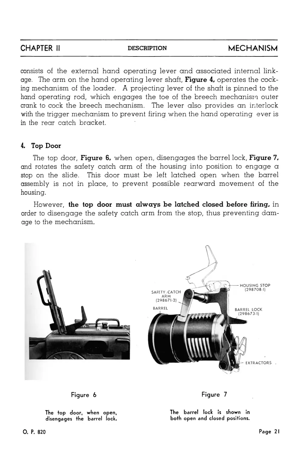
4. Top Door
The top door, Figure 6, when open, disengages the barrel lock, Figure 7,
and rotates the safety catch arm of the housing into position to engage a
stop on the slide. This door must be left latched open when the barrel
assembly is not in place, to prevent possible rearward movement of the
housing.
However, the top door must always be latched closed before firing, in
order to disengage the safety catch arm from the stop, thus preventing dam-
age to the mechanism.
Figure 6
The top door, when open,
disengages the barrel lock.
0. P. 820
Figure 7
The barrel lock is shown in
both open and closed positions.
Page 21
MECHANISM
DESCRIPTION
CHAPTER II
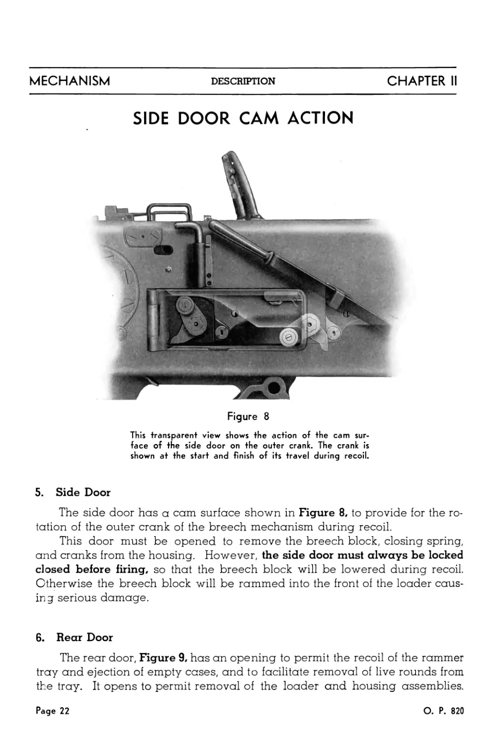
SIDE DOOR CAM ACTION
Figure 8
This transparent view shows the action of the cam sur-
face of the side door on the outer crank. The crank is
shown at the start and finish of its travel during recoil.
5. Side Door
The side door has a cam surface shown in Figure 8, to provide for the ro-
tation of the outer crank of the breech mechanism during recoil.
This door must be opened to remove the breech block, closing spring,
and cranks from the housing. However, the side door must always be locked
closed before firing, so that the breech block will be lowered during recoil.
Otherwise the breech block will be rammed into the front of the loader cous-
in g serious damage.
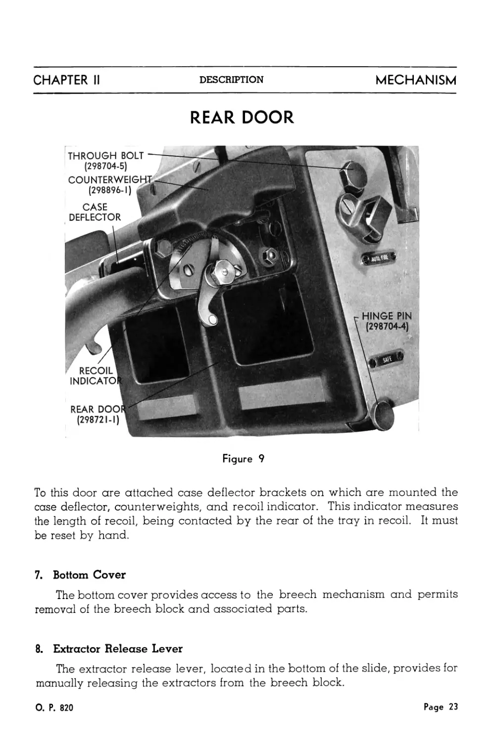
6. Rear Door
The rear door, Figure 9, has an opening to permit the recoil of the rammer
tray and ejection of empty cases, and to facilitate removal of live rounds from
the tray. It opens to permit removal of the loader and housing assemblies.
Page 22
О. P. 820
CHAPTER II
DESCRIPTION
MECHANISM
REAR DOOR
Figure 9
To this door are attached case deflector brackets on which are mounted the
case deflector, counterweights, and recoil indicator. This indicator measures
the length of recoil, being contacted by the rear of the tray in recoil. It must
be reset by hand.
7. Bottom Cover
The bottom cover provides access to the breech mechanism and permits
removal of the breech block and associated parts.
8. Extractor Release Lever
The extractor release lever, located in the bottom of the slide, provides for
manually releasing the extractors from the breech block.
0. P. 820
Page 23
MECHANISM
DESCRIPTION
CHAPTER II
B. BREECH MECHANISM ASSEMBLY
The breech mechanism assembly consists of a housing assembly, breech
block assembly and associated operating parts, and is a recoiling part of the
gun mechanism.
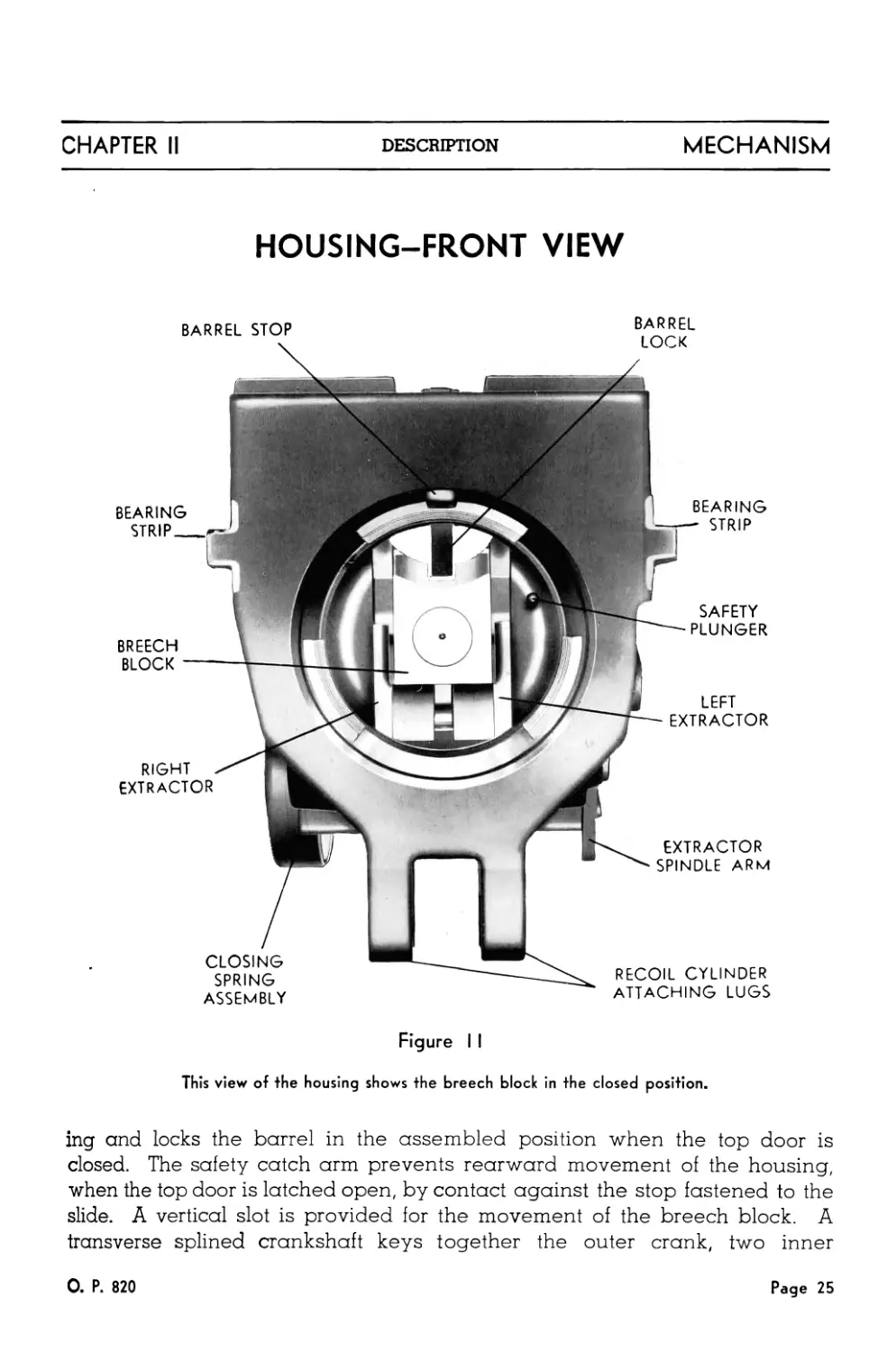
1. Housing Assembly
The housing, Figures 10, 11, and 12, is a rectangular steel block with pro-
jecting bronze-covered bearing strips which ride in corresponding guides in
the slide. The housing is provided with an interrupted thread for attaching
the breech end of the barrel. The barrel lock is pivoted in the top of the hous-
BARREL BARREL BARREL LOCK BREECH BLOCK
STOP
LEFT EXTRACTOR
SAFETY CATCH
ARM
RECESS FOR THE
SAFETY PLUNGER
RIGHT
INNER
CRANK
CLOSING
SPRING
ASSEMBLY
OUTER COCKING LEVER
LEFT INNER CRANK
LOCKING SCREW
OUTER CRANK
CRANKSHAFT
CRANKSHAFT
BUSHING
SAFETY PLUNGER
Figure 10
EXTRACTOR
SPINDLE
EXTRACTOR
SPINDLE
ARM
Broken open housing shows the relationship of the parts of this assembly.
Page 24
О. P. 820
CHAPTER II
DESCRIPTION
MECHANISM
HOUSING-FRONT VIEW
BEARING
STRIP
BARREL STOP
BREECH
BLOCK
RIGHT
EXTRACTOR
BARREL
LOCK
CLOSING
SPRING
ASSEMBLY
EXTRACTOR
SPINDLE ARM
BEARING
STRIP
SAFETY
PLUNGER
LEFT
EXTRACTOR
RECOIL CYLINDER
ATTACHING LUGS
Figure I I
This view of the housing shows the breech block in the closed position.
ing and locks the barrel in the assembled position when the top door is
closed. The safety catch arm prevents rearward movement of the housing,
when the top door is latched open, by contact against the stop fastened to the
slide. A vertical slot is provided for the movement of the breech block. A
transverse splined crankshaft keys together the outer crank, two inner
0. P. 820
Page 25
MECHANISM
DESCRIPTION
CHAPTER II
HOUSING-SIDE VIEW
Figure 12
This is the complete assembly for Mark I Mecha-
nism, as it appears from the rear outboard side.
cranks, and the cover of the breech block closing spring. These are shown
in Figure 13. Cams on the inner cranks operate in slots in the sides of the
breech block to open and to close and lock the block in the closed position.
Additional cams on the inner cranks operate the outer cocking lever and the
sear of the breech block. Extractors, operated by the downward stroke of the
Page 26
О. P. 820
CHAPTER II
DESCRIPTION
MECHANISM
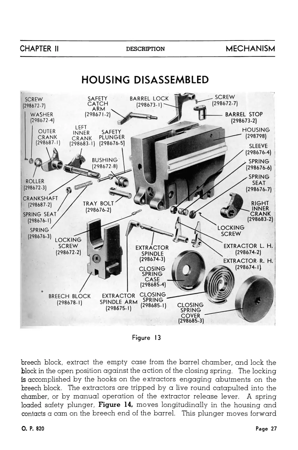
HOUSING DISASSEMBLED
LEFT
INNER
CRANK
OUTER
CRANK
(298687-1)
ROLLER
(298672-3)
BUSHING
(298672-8)
. SCREW
(298672-7)
LOCKING
SCREW
(298672-2)
CLOSING
SPRING
COVER
(298685-3)
BARREL LOCK
(298673-1)'—
TRAY BOLT
(298676-2)
SAFETY
CATCH
ARM
(298671-2)
BREECH BLOCK
(298678-1)
EXTRACTOR L. H.
(298674-2)
EXTRACTOR R. H
(298674-1)
BARREL STOP
(298673-2)
HOUSING
— (298798)
SLEEVE
/ (298676-4)
/ у SPRING
/ (298676-6)
X у SPRING
/ SEAT
X (298676-7)
CRANKSHAFT
(298687-2)
SPRING SEAT?
(298676-1)
SPRING '
(298676-3)
SAFETY
PLUNGER
(298683-1) (298676-5)
RIGHT
INNER
CRANK
(298683-2)
LOCKING
SCREW
(298672-7)
WASHER
(298672-4)
CLOSING
SPRING
w CASE
(298685-4)
EXTRACTOR CLOSING
SPINDLE ARM SPRING
(298675-1) (298685-1)
Figure 13
breech block, extract the empty case from the barrel chamber, and lock the
block in the open position against the action of the closing spring. The locking
is accomplished by the hooks on the extractors engaging abutments on the
breech block. The extractors are tripped by a live round catapulted into the
chamber, or by manual operation of the extractor release lever. A spring
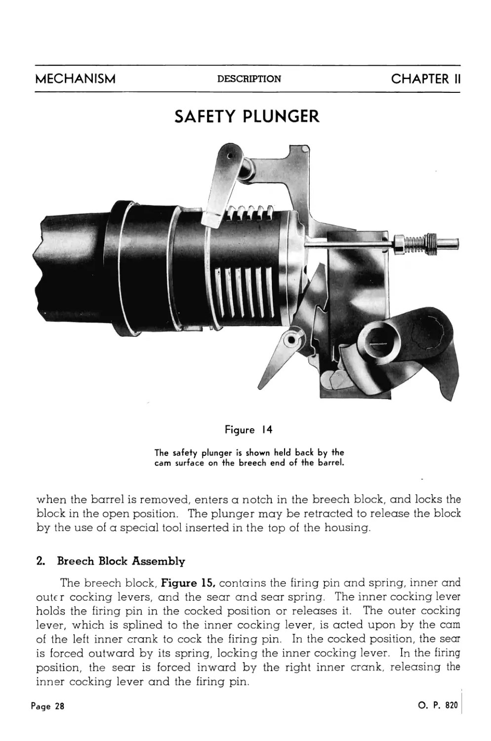
loaded safety plunger, Figure 14, moves longitudinally in the housing and
contacts a cam on the breech end of the barrel. This plunger moves forward
0. P. 820
Page 27
MECHANISM
DESCRIPTION
CHAPTER II
SAFETY PLUNGER
Figure 14
The safety plunger is shown held back by the
cam surface on the breech end of the barrel.
when the barrel is removed, enters a notch in the breech block, and locks the
block in the open position. The plunger may be retracted to release the block
by the use of a special tool inserted in the top of the housing.
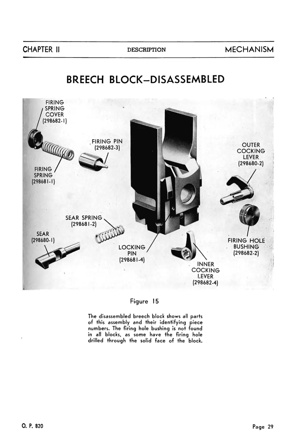
2. Breech Block Assembly
The breech block, Figure 15, contains the firing pin and spring, inner and
outer cocking levers, and the sear and sear spring. The inner cocking lever
holds the firing pin in the cocked position or releases it. The outer cocking
lever, which is splined to the inner cocking lever, is acted upon by the cam
of the left inner crank to cock the firing pin. In the cocked position, the sear
is forced outward by its spring, locking the inner cocking lever. In the firing
position, the sear is forced inward by the right inner crank, releasing the
inner cocking lever and the firing pin.
Page 28
О. P. 820
CHAPTER II
DESCRIPTION
MECHANISM
BREECH BLOCK-DISASSEMBLED
FIRING
LEVER
(298682-4)
Figure 15
The disassembled breech block shows all parts
of this assembly and their identifying piece
numbers. The firing hole bushing is not found
in all blocks, as some have the firing hole
drilled through the solid face of the block.
0. P. 820
Page 29
MECHANISM
DESCRIPTION
CHAPTER II
C. LOADER ASSEMBLY
The loader assembly, Figure 16, consists of feeding, ramming and cock-
ing mechanisms and their associated parts. It is located in the rear of the
slide, resting on guides for easy removal, and is locked in place by the rear
door.
CATCH
HEAD
FRONT
GUIDE
(298766-1)
LEFT FRAME
(298763-1)
RAIL L. H.
(298780-1)
RAIL R. H.
(298778-1)
REAR
GUIDE
(298767-1)
CLIP
GUIDE
(298769-2)
SPINDLE
ARM
FRAY
RAMMER COCKING
LEVER SHAFT
COMPRESSION
RAIL
(298782-1)
CATCH RELEASE RAMMER COCKING
LEVER LEVER L. H.
RIGHT FRAME
(298764-1)
Figure 16
Page 30
О. P. 820
CHAPTER II
DESCRIPTION
MECHANISM
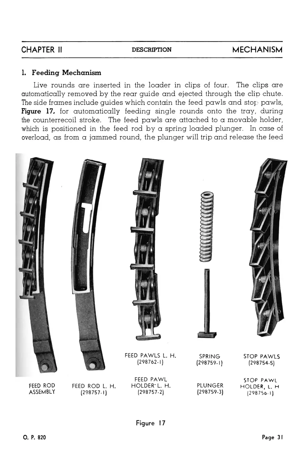
1. Feeding Mechanism
Live rounds are inserted in the loader in clips of four. The clips are
automatically removed by the rear guide and ejected through the clip chute.
The side frames include guides which contain the feed pawls and stop pawls,
Figure 17, for automatically feeding single rounds onto the tray, during
the counterrecoil stroke. The feed pawls are attached to a movable holder,
which is positioned in the feed rod by a spring loaded plunger. In case of
overload, as from a jammed round, the plunger will trip and release the feed
FEED PAWLS L. H.
(298762-1)
SPRING
(298759-1)
STOP PAWLS
(298754-5)
FEED ROD
ASSEMBLY
FEED ROD L. H.
(298757-1)
FEED PAWL
HOLDER'L. H.
(298757-2)
PLUNGER
(298759-3)
STOP PAWL
HOLDER, L. H
(298756-1)
Figure 17
0. P. 820
Page 3 I
MECHANISM
DESCRIPTION
CHAPTER II
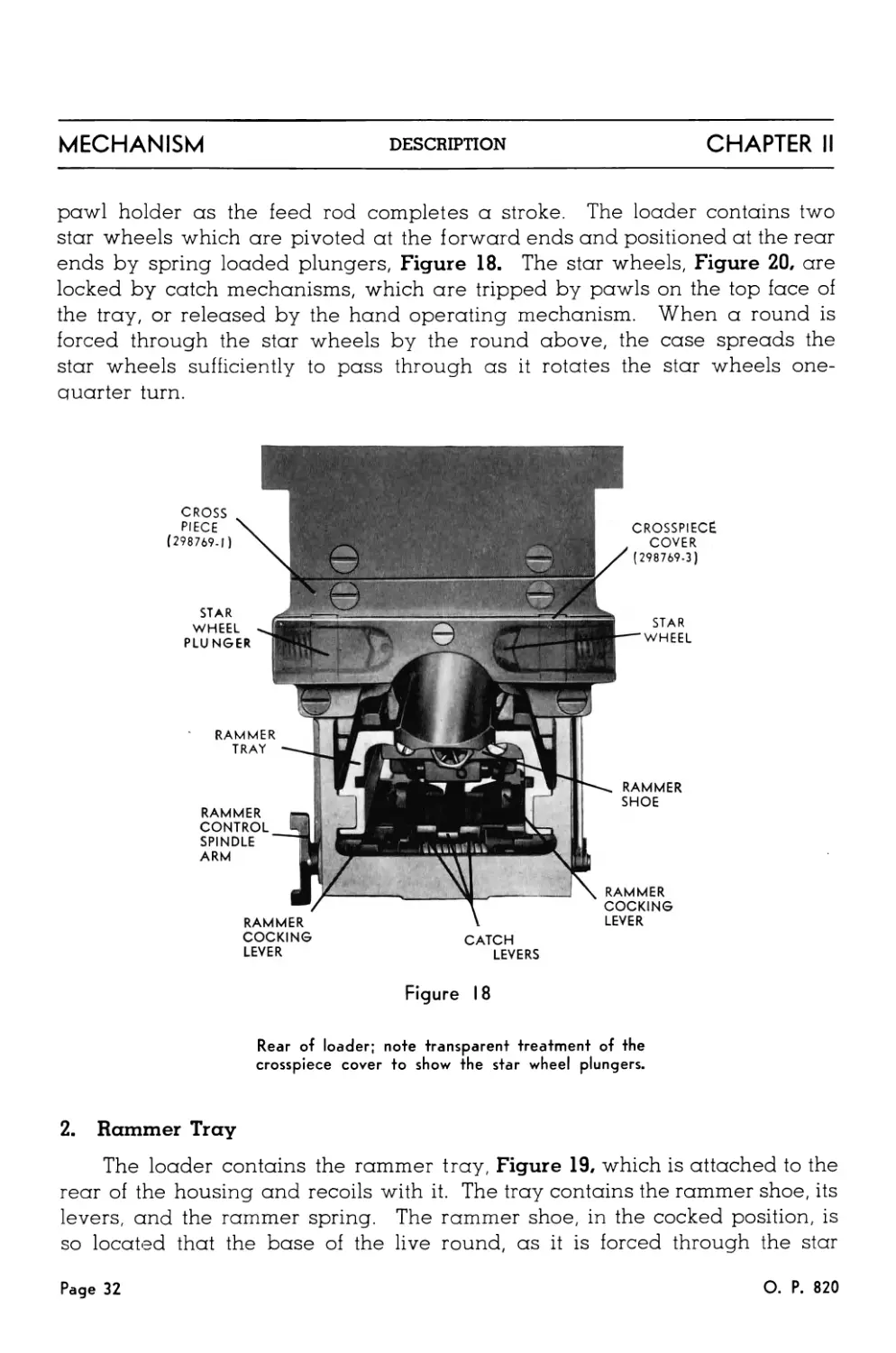
pawl holder as the feed rod completes a stroke. The loader contains two
star wheels which are pivoted at the forward ends and positioned at the rear
ends by spring loaded plungers, Figure 18. The star wheels, Figure 20, are
locked by catch mechanisms, which are tripped by pawls on the top face of
the tray, or released by the hand operating mechanism. When a round is
forced through the star wheels by the round above, the case spreads the
star wheels sufficiently to pass through as it rotates the star wheels one-
quarter turn.
CROSS
PIECE
(298769-1)
STAR
WHEEL
PLUNGER
RAMMER
CONTROL
SPINDLE
ARM
STAR
WHEEL
CROSSPIECE
COVER
(298769-3)
RAMMER
SHOE
RAMMER
RAMMER
COCKING
LEVER
RAMMER
TRAY
I
COCKING
LEVER
CATCH
LEVERS
Figure 18
Rear of loader; note transparent treatment of the
crosspiece cover to show the star wheel plungers.
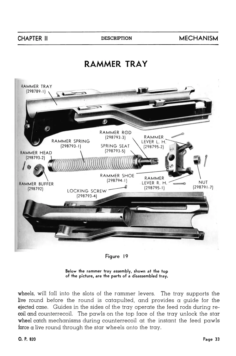
2. Rammer Tray
The loader contains the rammer tray, Figure 19, which is attached to the
rear of the housing and recoils with it. The tray contains the rammer shoe, its
levers, and the rammer spring. The rammer shoe, in the cocked position, is
so located that the base of the live round, as it is forced through the star
Page 32
О. P. 820
CHAPTER II
DESCRIPTION
MECHANISM
RAMMER TRAY
RAMMER TRAY
(298789-1)
SPRING SEAT
(298793-5)
(298793-1)
RAMMER HEAD \
(298793-2)
RAMMER BUFFER
(298792)
RAMMER ROD
(298793-3)
RAMMER
LEVER L. H.
(298795-2)
RAMMER SHOE D..,. .CD
(298794-11 RAMMER
,Z ° i) LEVER R H
(298795-1)
LOCKING SCREW
(298793-4)
NUT
(298791-7)
Figure 19
Below the rammer tray assembly, shown at the top
of the picture, are the parts of a disassembled tray.
wheels, will fall into the slots of the rammer levers. The tray supports the
live round before the round is catapulted, and provides a guide for the
ejected case. Guides in the sides of the tray operate the feed rods during re-
coil and counterrecoil. The pawls on the top face of the tray unlock the star
wheel catch mechanisms during counterrecoil at the instant the feed pawls
force a live round through the star wheels onto the tray.
0. P. 820
Page 33
MECHANISM
DESCRIPTION
CHAPTER II
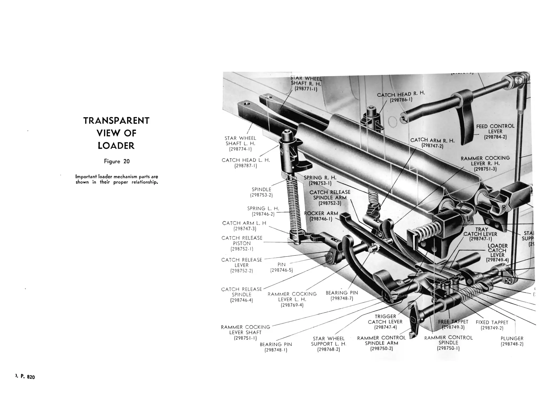
3. Catch Levers
The rammer shoe is latched in the cocked position by one of three
levers in the base of the loader. The three levers, Figure 20, are:
Center—Tray Catch Lever
Inboard—Loader Catch Lever
Outboard—Trigger Catch Lever
These levers are pivoted on a common shaft and are of varying length so
that they release the rammer shoe in the following order: Tray catch lever,
loader catch lever, trigger catch lever.
a. The tray catch lever is operated, through a rocker arm, by a cam on
the bottom of the tray, and is in the releasing position whenever the
tray is within about one inch of battery position.
b. The loader catch lever is maintained in the releasing position by a
linkage in the rear guide, whenever the loader contains more than
one round above the star wheels. Its purpose is to prevent the
gun from firing the round on the tray, when there are fewer than two
rounds above the star wheels to push another round onto the tray in
counterrecoil. This lever is provided to prevent loss of automatic
functioning of the mechanism, by latching the rammer shoe in the
cocked position, if the loader is supplied with ammunition at a rate
less than the rate of fire. This lever releases the rammer shoe auto-
matically upon the insertion of additional clips of ammunition.
c. The trigger catch lever is controlled by the rammer control spindle,
and the arm of the spindle is contacted and controlled by the trigger
of the slide assembly. The trigger catch lever is placed in the re-
leasing position whenever the trigger is in the firing position.
4. Cocking Mechanism
The loader contains the cocking mechanism which is operated by the
hand operating mechanism of the slide. The cocking mechanism forces the
rammer shoe to the rear and thus compresses the rammer spring. At the
same time, the cocking mechanism rotates the catch mechanisms so that a
round can be forced through the star wheels. Motion of the hand operat-
ing lever, beyond the position necessary to latch the rammer shoe, causes
the rammer levers to move to the rear end of the slots in the tray. When
the rammer levers are in this position, they are spread by the slots, so that a
round can be inserted in or removed from the tray through the opening
in the rear door.
Page 34
О. P. 820
oiAK WHEEL
SHAFT R. H.,
(298771-1)
CATCH HEAD R- H.
/ (298786-1)
TRANSPARENT
VIEW OF
LOADER
Figure 20
Important loader mechanism parts are
shown in their proper relationship.
STAR WHEEL
SHAFT L. H.
(298774-1)
CATCH HEAD L. H.
(298787-1)
SPINDLE
(298753-2)
SPRING L. H
(298746-2) '
SPRING R. H.
(298753-1)
CATCH RELEASE
SPINDLE ARM
(298752-3)
CATCH ARM L. H
(298747-3)
ROCKER ARM
(298746-1)
CATCH ARM R. H
(298747-2)
FEED CONTROL
LEVER
(298784-2)
RAMMER COCKING
LEVER R. H.
(298751-3)
CATCH RELEASE
PISTON
(298752-1)
CATCH RELEASE
LEVER
(298752-2)
PIN "
(298746-5)
F TRAY <
CATCH LEVER
' (298747-1)
LOADER
----—— CATCH
LEVER
(298749-4)
STAI
SUPP
CATCH RELEASE
SPINDLE
(298746-4)
RAMMER COCKING
LEVER L. H.
(298769-4)
BEARING PIN
(298748-7)
RAMMER COCKING""
LEVER SHAFT
(298751-1)
BEARING PIN
(298748-1)
STAR WHEEL
SUPPORT L. H-
(298768-2)
TRIGGER
CATCH LEVER
(298747-4)
FREE JtfPPE
^4?98749-3)
FIXED TAPPET
(298749-2)
RAMMER CONTROL
SPINDLE ARM
(298750-2)
RAMMER CONTROL
SPINDLE
(298750-1)
PLUNGER
(298748-2)
>• P. 820
CHAPTER II
DESCRIPTION
MECHANISM
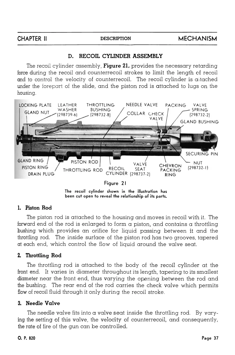
D. RECOIL CYLINDER ASSEMBLY
The recoil cylinder assembly, Figure 21, provides the necessary retarding
force during the recoil and counterrecoil strokes to limit the length of recoil
and to control the velocity of counterrecoil. The recoil cylinder is attached
under the forepart of the slide, and the piston rod is attached to lugs on the
housing.
LOCKING PLATE LEATHER
THROTTLING NEEDLE VALVE PACKING VALVE
Figure 2 I
The recoil cylinder shown in the illustration has
been cut open to reveal the relationship of its parts.
1. Piston Rod
The piston rod is attached to the housing and moves in recoil with it. The
forward end of the rod is enlarged to form a piston, and contains a throttling
bushing which provides an orifice for liquid passing between it and the
throttling rod. The inside surface of the piston rod has two grooves, tapered
at each end, which control the flow of liquid around the valve seat.
2. Throttling Rod
The throttling rod is attached to the body of the recoil cylinder at the
front end. It varies in diameter throughout its length, tapering to its smallest
diameter near the front end, thus varying the opening between the rod and
the bushing. The rear end of the rod carries the check valve which permits
flow of recoil fluid through it only during the recoil stroke.
3. Needle Valve
The needle valve fits into a valve seat inside the throttling rod. By vary-
ing the setting of this valve, the velocity of counterrecoil, and consequently,
the rate of fire of the gun can be controlled.
0. P. 820
Page 37
MECHANISM
DESCRIPTION
CHAPTER II
4. Recoil Fluid
The fluid used in the recoil cylinder is specified by O.S. 1324. This mix-
ture is approximately sixty percent glycerine and forty percent water, with a
small percentage of corrosion inhibiting compound added.
E. BARREL ASSEMBLY
For description of barrel assembly see Chapter III.
F. DIFFERENCES BETWEEN MARK 1 AND MARK 2 MECHANISMS
Since the two mechanisms are bolted together so that they elevate and
depress as a unit, certain differences between the Mark 1 and Mark 2 Mecha-
nisms are necessary.
1. Slide Assembly
To permit the gun to be loaded, cocked and fired, each mechanism has
its hand operating lever, firing selector lever, trigger mechanism, and firing
plunger on the outboard side of the slide. To allow access to the breech
mechanism assembly, the side doors are on the outboard side. The extractor
release levers are also placed near the outboard side of each slide. The
top doors differ in having their catches on the inboard side.
2. Breech Mechanism Assembly
The housings in the Mark 1 and Mark 2 Mechanisms differ in having their
breech closing spring assemblies mounted on the inboard side, while the
outer cranks, the extractor spindle arms, and safety catch arms are on the
outboard side. The breech closing springs differ in the direction of their spi-
rals; the closing spring in the Mark 1 Mechanism is wound so that it increases
in diameter in a counter-clockwise direction, when viewed from the convex
side of the spring; in the Mark 2 Mechanism, the spring is wound in the op-
posite direction.
Extractors and breech block assemblies are identical for the two Marks
of mechanisms, and are, therefore, interchangeable.
3. Loader Assembly
The differences between the loaders in the Mark 1 and Mark 2 Mecha-
nisms are those which are required to permit the cocking of the rammer and
release of the catch mechanisms by the hand operating lever, the operation
of the rammer control spindle arm by the trigger, and ejection of the ammuni-
tion clips through the outboard side of the slide.
4. Recoil Cylinder Assembly
The only difference between the recoil cylinders in the Mark 1 and Mark 2
Mechanisms is that the fill plug of each is positioned on the outboard side for
easy access in filling the recoil cylinders.
Page 38
О. P. 820
GUN MECHANISM
ASSEMBLY
Figure 22
The transparent side shows how the other principal com-
ponents of the mechanism fit together in the slide.
HOUSING
loader
COUI
{:
inner cam surface
OF SIDE DOOR
TRAY
SLIDE
CHAPTER II
OPERATION
MECHANISM
Part Two—Operation of Gun Mechanism
Before automatic operation of the gun mechanism can take place, the
gun mechanism must first be cocked and a round fed onto the tray manually.
When the trigger catch lever is depressed, the round is rammed into the
chamber and fired. The resulting recoil and counterrecoil will new cock the
gun mechanism and feed the rounds, thus providing automatic operation.
A. FIRING THE FIRST ROUND
1. Loading
To prepare the mechanism for firing, the hand operating lever is moved
to the rear as far as possible and then forward to the rear catch bracket. This
movement, Figure 23, performs three operations:
It rotates the rammer cocking levers which force the rammer shoe
to the cocked position where it is held by the loader catch lever.
It operates the star wheel catch mechanisms, through a linkage
and catch release pistons, to permit a quarter turn of the star
wheels.
It lowers the breech block, through the hand operating rod, to a
position which causes the extractors to lock the block down.
A clip of four rounds is now placed in the loader and pushed smartly
home, rotating the star wheels and placing the lowermost round on the
rammer tray with its base in the slots of the rammer levers. The clip is auto-
matically detached from the rounds, and ejected through the clip chute of the
loader.
These rounds press back the feed control lever, disengaging the loader
catch lever from the rammer shoe. The trigger catch lever now holds the
rammer shoe until released by the trigger mechanism. The hand operating
lever is returned to the forward catch bracket, and the firing selector lever
set on AUTO FIRE. The mechanism is now prepared to fire automatically
as long as at least two rounds are in the loader above the star wheels.
0. P. 820 Page 41
MECHANISM
OPERATION
CHAPTER II
COCKING MECHANISM
Figure 23
The illustration shows the position of the outer crank, the
catch mechanisms, and the rammer cocking levers when
the hand operating lever is moved fully to the rear.
2. Ramming
The inward motion of the firing plunger in the trunnion operates the
trigger mechanism of the slide and disengages the trigger catch lever from
the rammer shoe. The rammer shoe, with the rammer levers and the live
round, is forced rapidly forward by the rammer spring. At the end of the
rammer stroke, the rammer levers are spread by the slots in the tray, and the
live round is released at high velocity and catapulted into the barrel
chamber.
Page 42
О. P. 820
CHAPTER II
OPERATION
MECHANISM
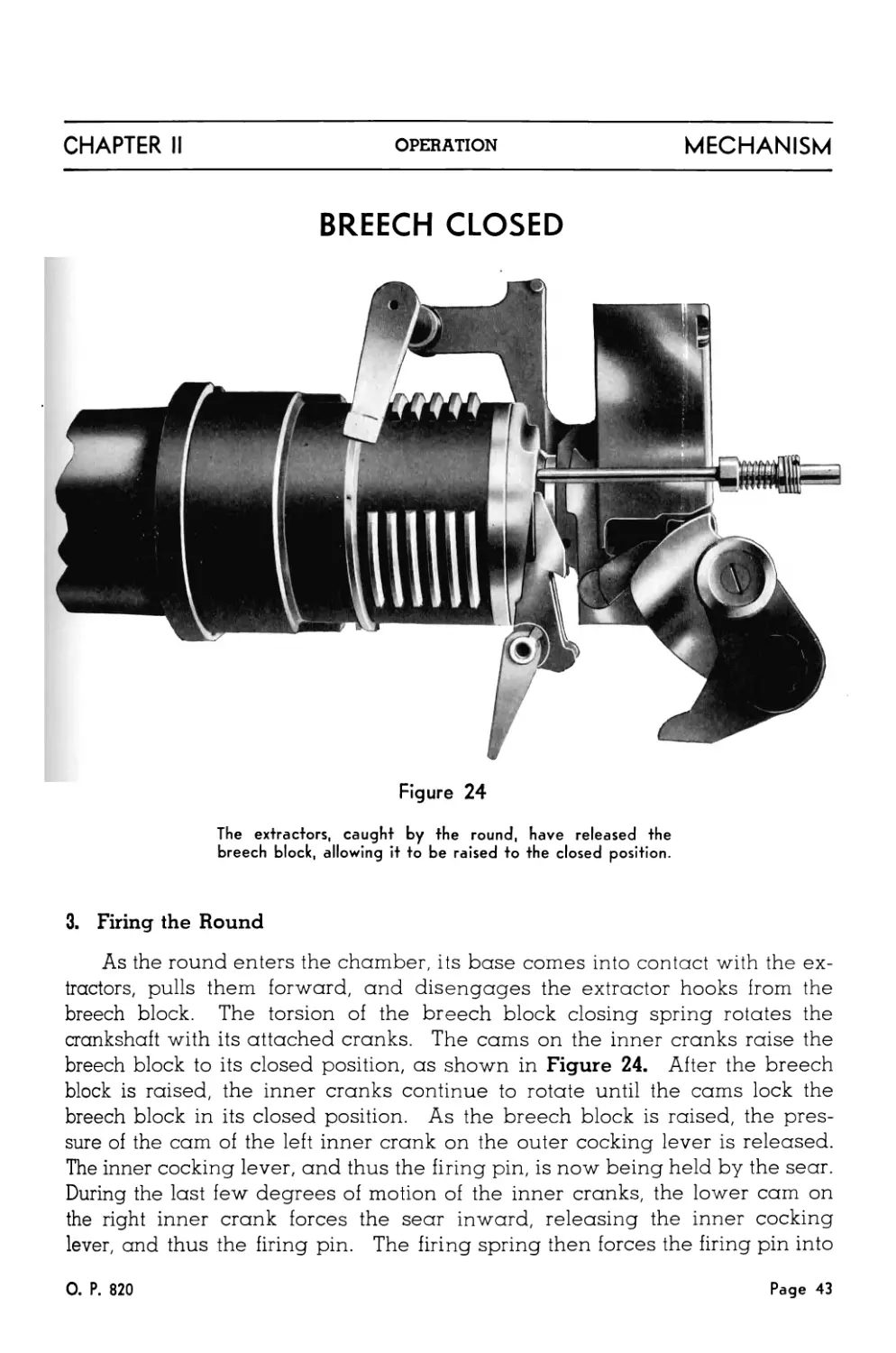
BREECH CLOSED
Figure 24
The extractors, caught by the round, have released the
breech block, allowing it to be raised to the closed position.
3. Firing the Round
As the round enters the chamber, its base comes into contact with the ex-
tractors, pulls them forward, and disengages the extractor hooks from the
breech block. The torsion of the breech block closing spring rotates the
crankshaft with its attached cranks. The cams on the inner cranks raise the
breech block to its closed position, as shown in Figure 24. After the breech
block is raised, the inner cranks continue to rotate until the cams lock the
breech block in its closed position. As the breech block is raised, the pres-
sure of the cam of the left inner crank on the outer cocking lever is released.
The inner cocking lever, and thus the firing pin, is now being held by the sear.
During the last few degrees of motion of the inner cranks, the lower cam on
the right inner crank forces the sear inward, releasing the inner cocking
lever, and thus the firing pin. The firing spring then forces the firing pin into
0. P. 820
Page 43
MECHANISM
OPERATION
CHAPTER II
BREECH BLOCK-FIRING
CRANK
BREECH
BLOCK
LEFT INNER
SEAR
SEAR
SPRING
INNER
COCKING
LEVER
CAM
RIGHT INNER
CRANK
FIRING
PIN
Figure 25
The breech block is shown in the closed position. Transparent treat-
ment of the block shows the relationship of the parts of the assembly.
the primer. This is illustrated in Figure 25. The firing pin rotates the freely
moving inner and outer cocking levers during its stroke.
B. FIRING AUTOMATICALLY
1. Action of Breech Mechanism and Loader During Recoil
During recoil, the cam on the side door acts on the outer crank to rotate
the crankshaft and the inner cranks. The first movement of the inner cranks
retracts the firing pin and unlocks the breech block, Figure 26. To do this, a
Page 44
О. P- 820
CHAPTER II
OPERATION
MECHANISM
BREECH BLOCK-COCKING
LEVER LEVER CRANK
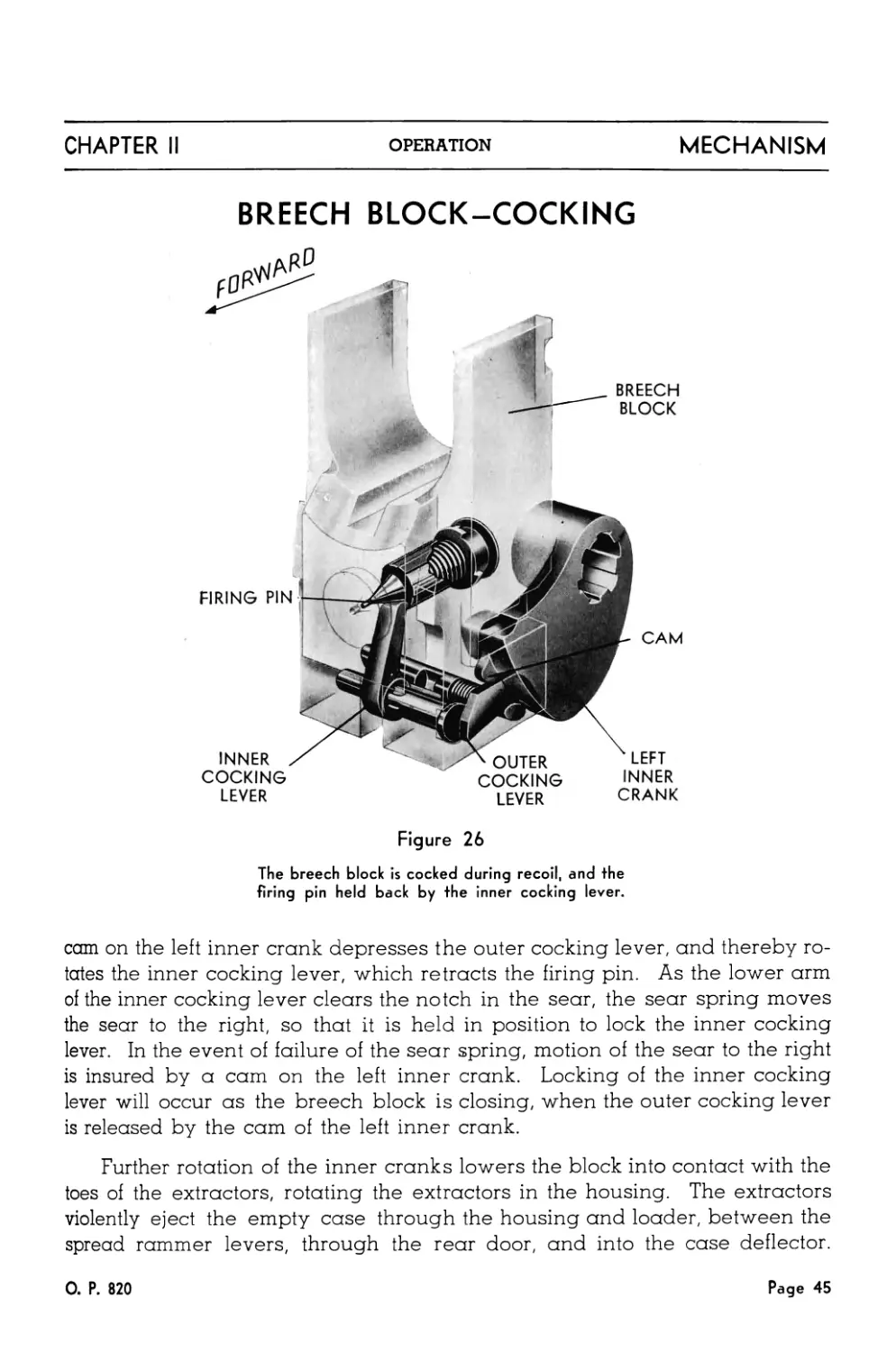
Figure 26
The breech block is cocked during recoil, and the
firing pin held back by the inner cocking lever.
cam on the left inner crank depresses the outer cocking lever, and thereby ro-
tates the inner cocking lever, which retracts the firing pin. As the lower arm
of the inner cocking lever clears the notch in the sear, the sear spring moves
the sear to the right, so that it is held in position to lock the inner cocking
lever. In the event of failure of the sear spring, motion of the sear to the right
is insured by a cam on the left inner crank. Locking of the inner cocking
lever will occur as the breech block is closing, when the outer cocking lever
is released by the cam of the left inner crank.
Further rotation of the inner cranks lowers the block into contact with the
toes of the extractors, rotating the extractors in the housing. The extractors
violently eject the empty case through the housing and loader, between the
spread rammer levers, through the rear door, and into the case deflector.
0. P. 820
Page 45
MECHANISM
OPERATION
CHAPTER II
They also lock the breech block in the open position, as shown in Figure 14,
page 28.
During the recoil movement of the rammer tray, the feed pawls of the
loader are raised above the next rounds, which are being held in position by
the stop pawls. This motion is produced by the roller on the lower end of the
feed rod being moved by the guides on the sides of the tray.
2. Action of Breech Mechanism and Loader During Counterrecoil
During counterrecoil, the breech block closing spring acts to move
the breech block to the closed position, but motion of the block is stopped as
the breech block is latched open by the hooks on the extractors. Conse-
quently the outer crank is carried clear of the side door cam.
As the tray moves forward during counterrecoil, the pawls on the top
surface rotate the catch heads, so that the star wheels can be rotated by the
round which is fed between the star wheels and then onto the tray. The
rounds in the loader are forced downward by the feed pawls, .which in turn
are operated by the guides of the tray. As the tray is moving forward, the
rammer shoe is latched to the rear by the tray catch lever, in such a position
that the base of the next live round above the star wheels will be caught by
the slots in the rammer levers as the round is dropped onto the tray. The
tray continues forward, and when it is about one inch from battery position,
the cam on the bottom of the tray trips the rocker arm, which in turn trips the
tray catch lever, releasing the rammer.
The cycle, beginning with the ramming of the live round, will be repeated
if the trigger is kept in the firing position, and if the loader contains sufficient
rounds, so that the loader catch lever is in the releasing position. If the trig-
ger is kept in the firing position, but the loader contains insufficient rounds
for operation of the loader catch lever, firing will cease, but will begin again
immediately upon the insertion of additional rounds into the loader.
3. Action of the Recoil System
The recoil system is comprised of the recoil spring and the recoil cylinder.
The recoil spring provides in counterrecoil the force necessary to return the
gun mechanism to the battery position, cock the rammer, and feed a new
round. The recoil cylinder controls the length of recoil and the velocity of
counterrecoil.
As the barrel, housing, and tray recoil, the housing carries with it the
recoil cylinder piston rod. As the piston rod is drawn to the rear of the recoil
Page 46
О. P. 820
CHAPTER II
OPERATION
MECHANISM
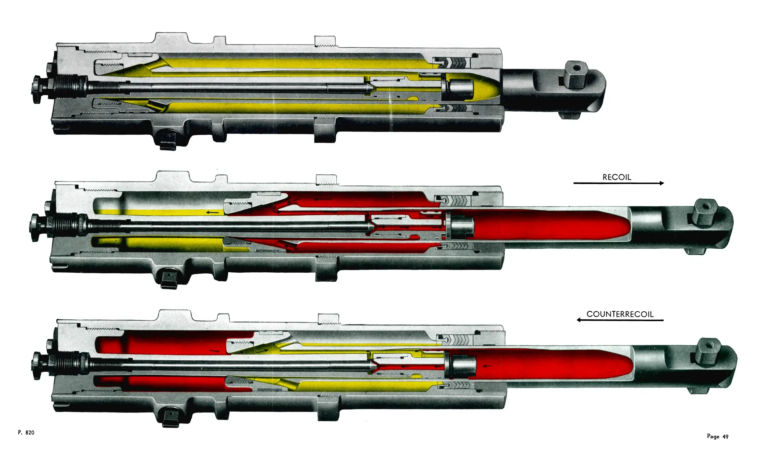
cylinder over the throttling rod, Figure 27, liquid is forced from the rear to
the front of the piston through the eight holes in the piston and through the
throttling bushing. Liquid pressure forces the check valve to the rear, thereby
opening the ports in the valve seat. Through these ports liquid now passes
to the rear of the valve. Liquid also passes to the rear of the valve around
the valve seat and through the tapered grooves inside the piston rod. through
the ports in the throttling rod, over the needle valve, and through the seat.
These effective flow areas set up a fluid resistance which retards recoil.
Meanwhile, the recoil spring has been placed under greater compression.
When recoil ceases, the recoil spring returns the recoiling parts to battery po-
sition, and the piston rod moves forward along with the housing.
During counterrecoil, the piston rod moves forward over the throttling
rod, and the check valve, under spring action and liquid pressure, masks the
ports in the valve seat. Liquid at the rear of the valve seat is forced to the
front of the valve seat through the grooves in the piston rod and through the
bore in the center of the valve seat. The tapered grooves gradually reduce
the flow space as the barrel approaches the battery position until finally no
liquid can pass over the valve seat. The flow of liquid from the rear to the
front of the seat is now restricted to the bore in the seat, over the needle
valve, and through the ports in the throttling rod. Liquid in front of the piston
is forced through the throttling bushing and the holes in the piston.
Finally, the front end of the piston enters the recess in the head of the
throttling rod. This action forces the liquid between the head and piston
through the space between the throttling bushing and the throttling rod. The
front taper of the rod reduces the flow space as the barrel approaches the bat-
tery position. This action and the tapered grooves inside the piston rod
further reduce the speed of counterrecoil.
At the end of counterrecoil, the buffer pad provides a positive stop at bat-
tery position for the recoiling parts of the gun mechanism.
The length of recoil is measured by the recoil indicator, attached to the
rear door. The indicator is operated by the rear surface of the rammer tray.
A length of recoil of approximately 7.2 inches is required to insure automatic
operation of the mechanism. Shorter recoil may be insufficient to permit the
tray pawls to operate the catch mechanisms of the star wheels, thus prevent-
ing feeding. Short recoil may also cause a jam on the tray by causing the
star wheels to start to rotate before the ejected case has had time to clear
them. The maximum operating length of recoil is about 8.3 inches and is lim-
о. P. 820
Page 47
MECHANISM
OPERATION
CHAPTER II
ited by the design of the throttling rod and bushing in the recoil cylinder.
Normal recoil should lie within the above mentioned limits, and will vary
somewhat with the elevation of the gun, and with the quantity, specific
gravity, and temperature of the recoil fluid.
The velocity in counterrecoil, and thus the rate of fire, is determined by
the setting of the needle valve of the recoil cylinder. The setting of this valve
has no appreciable effect on the length of recoil. The needle valve is ad-
justable at the forward end of the recoil cylinder.
OPERATION OF
THE RECOIL CYLINDER
ASSEMBLY
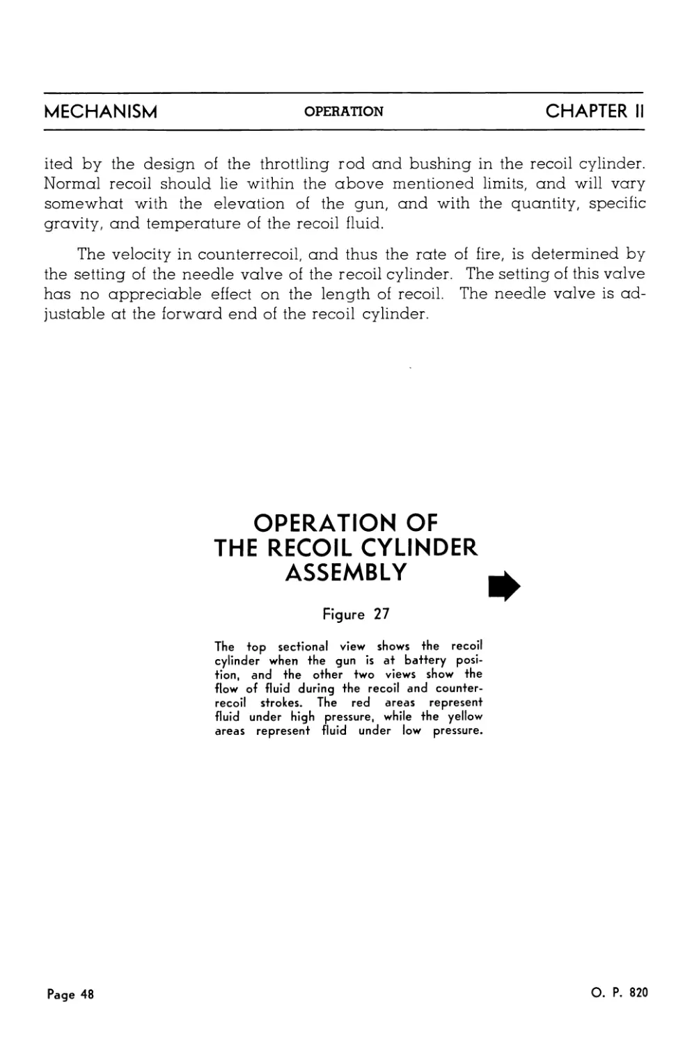
Figure 27
The top sectional view shows the recoil
cylinder when the gun is at battery posi-
tion, and the other two views show the
flow of fluid during the recoil and counter-
recoil strokes. The red areas represent
fluid under high pressure, while the yellow
areas represent fluid under low pressure.
Page 48
О. P. 820
Р. 820
Page 49
Chapter III
BARREL ASSEMBLY
BARREL
(298652)
ATTACHING NUT (298662-1)
PACKING RING
(298658-4)
WATER JACKET
(298659-1)
PACKING RINGS
(298658-3)
PACKING RING
(298658-5) (298739-4)
Figure 28
RECOIL SPRING
FRONT SPRING SEAT (298666-2)
REAR SPRING SEAT (298666-3)
FLASH HIDER
(298663-1)
GLAND NUT
(298662-2)
GASKET
(298658-6)
SPRING PACKING RING REAR (298658-2)
KEEPER _______________ '
(298662-4) gr—PLUG
‘ ' - (298739-7)
SET SCREWS
(298662-3)
A complete barrel assembly is shown at the top of the il-
lustration; below the assembly are shown its individual parts.
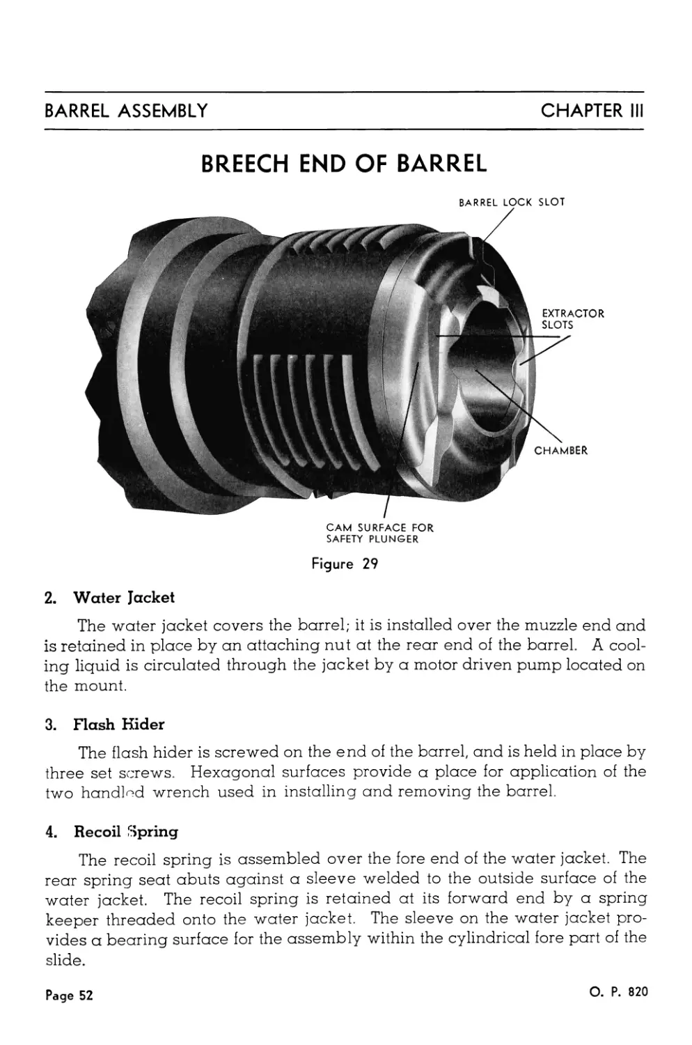
The Barrel Assembly, Figure 28, includes a 40MM Barrel, Mark 1, its
water jacket, a flash hider, and a recoil spring. The barrel assembly is in-
serted in the cylindrical fore part of the slide and engaged, by a half turn to
the right, with mating interrupted threads in the housing. This half turn
brings uppermost the barrel interlock slot in the breech end of the barrel,
where it receives the barrel lock upon closure of the top door.
1. 40MM Gun Barrel, Mark 1
The breech face of the barrel, Figure 29, is also provided with vertical
slots to accommodate the extractors, and a cam surface to actuate the breech
block safety plunger which is assembled in the housing. The bore is rifled
with sixteen grooves having a right hand twist. The rifling is of increasing
twist—one turn in 45 calibers at the origin to one turn in 30 calibers at the
muzzle.
О. P. 820
Page 51
BARREL ASSEMBLY
CHAPTER III
BREECH END OF BARREL
BARREL LOCK SLOT
CAM SURFACE FOR
SAFETY PLUNGER
Figure 29
2. Water Jacket
The water jacket covers the barrel; it is installed over the muzzle end and
is retained in place by an attaching nut at the rear end of the barrel. A cool-
ing liquid is circulated through the jacket by a motor driven pump located on
the mount.
3. Flash Hider
The flash hider is screwed on the end of the barrel, and is held in place by
three set screws. Hexagonal surfaces provide a place for application of the
two handled wrench used in installing and removing the barrel.
4. Recoil Spring
The recoil spring is assembled over the fore end of the water jacket. The
rear spring seat abuts against a sleeve welded to the outside surface of the
water jacket. The recoil spring is retained at its forward end by a spring
keeper threaded onto the water jacket. The sleeve on the water jacket pro-
vides a bearing surface for the assembly within the cylindrical fore part of the
slide.
Page 52
О. P. 820
Chapter IV
SIGHTS
A. DESCRIPTION OF SIGHTS
The sights provide a simple means of giving the necessary lead to allow
for target motion during the time of flight of the projectile, and also provide
for quick changing of the lead, as the position of the target changes. When
the gun is controlled by means of the director, these sights are not used.
SIGHT GUARD
WELDMENT
(345493)
CAP
(299350-2)
SIGHT
ARM WELDMENT FRONT SIGHT
(299344-1) (299342-1)
FRONT
BRACKET
(299346-3)
FERRULE
(299349-4)
SIGHT
(299349-2)
№.
TRAINER'S
SIGHT
(299343-1) |
- -
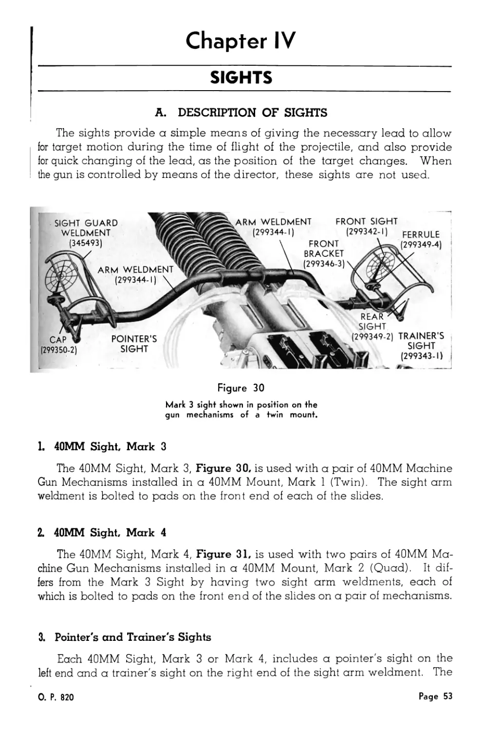
Figure 30
Mark 3 sight shown in position on the
gun mechanisms of a twin mount.
1. 40MM Sight, Mark 3
The 40MM Sight, Mark 3, Figure 30, is used with a pair of 40MM Machine
Gun Mechanisms installed in a 40MM Mount, Mark 1 (Twin). The sight arm
weldment is bolted to pads on the front end of each of the slides.
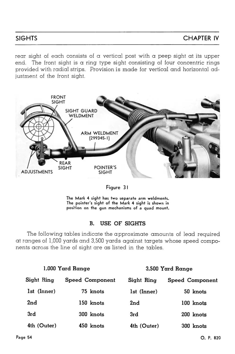
2. 40MM Sight, Mark 4
The 40MM Sight, Mark 4, Figure 31, is used with two pairs of 40MM Ma-
chine Gun Mechanisms installed in a 40MM Mount, Mark 2 (Quad). It dif-
fers from the Mark 3 Sight by having two sight arm weldments, each of
which is bolted to pads on the front end of the slides on a pair of mechanisms.
3. Pointer's and Trainer's Sights
Each 40MM Sight, Mark 3 or Mark 4, includes a pointer's sight on the
left end and a trainer's sight on the right end of the sight arm weldment. The
0. P. 820
Page 53
SIGHTS
CHAPTER IV
rear sight of each consists of a vertical post with a peep sight at its upper
end. The front sight is a ring type sight consisting of four concentric rings
provided with radial strips. Provision is made for vertical and horizontal ad-
justment of the front sight.
Figure 3 I
The Mark 4 sight has two separate arm weldments.
The pointer's sight of the Mark 4 sight is shown in
position on the gun mechanisms of a quad mount.
B. USE OF SIGHTS
The following tables indicate the approximate amounts of lead required
at ranges of 1,000 yards and 3,500 yards against targets whose speed compo-
nents across the line of sight are as listed in the tables.
1,000 Yard Range
Sight Ring Speed Component
1st (Inner) 75 knots
2nd 150 knots
3rd 300 knots
4th (Outer) 450 knots
3,500 Yard Range
Sight Ring Speed Component
1st (Inner) 50 knots
2nd 100 knots
3rd 200 knots
4th (Outer) 300 knots
Page 54
О. P. 820
CHAPTER IV
SIGHTS
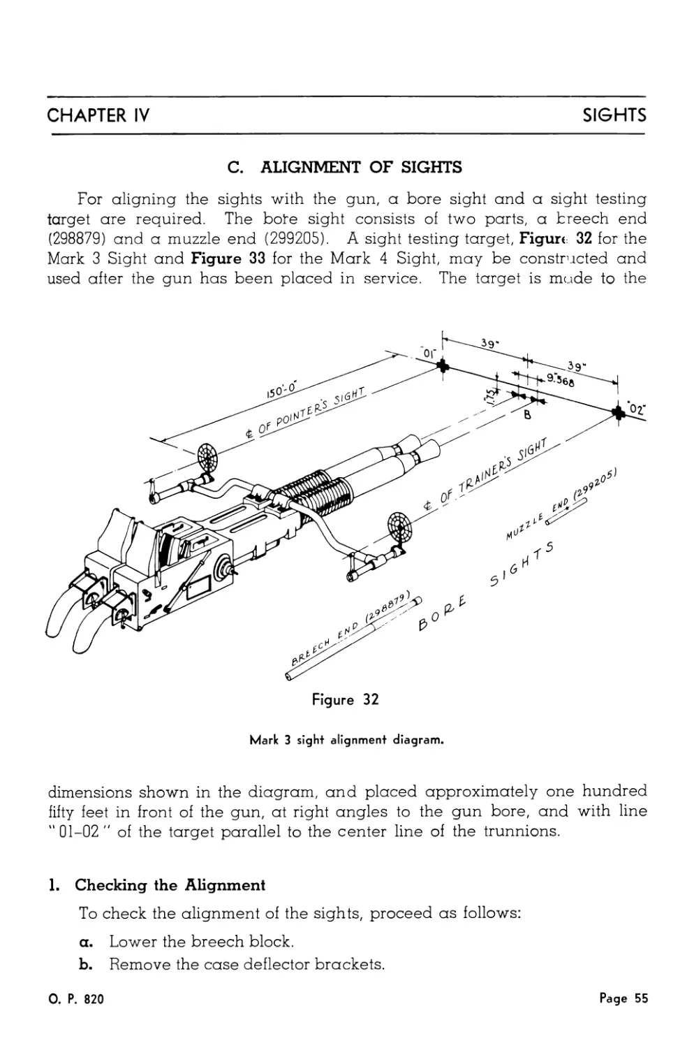
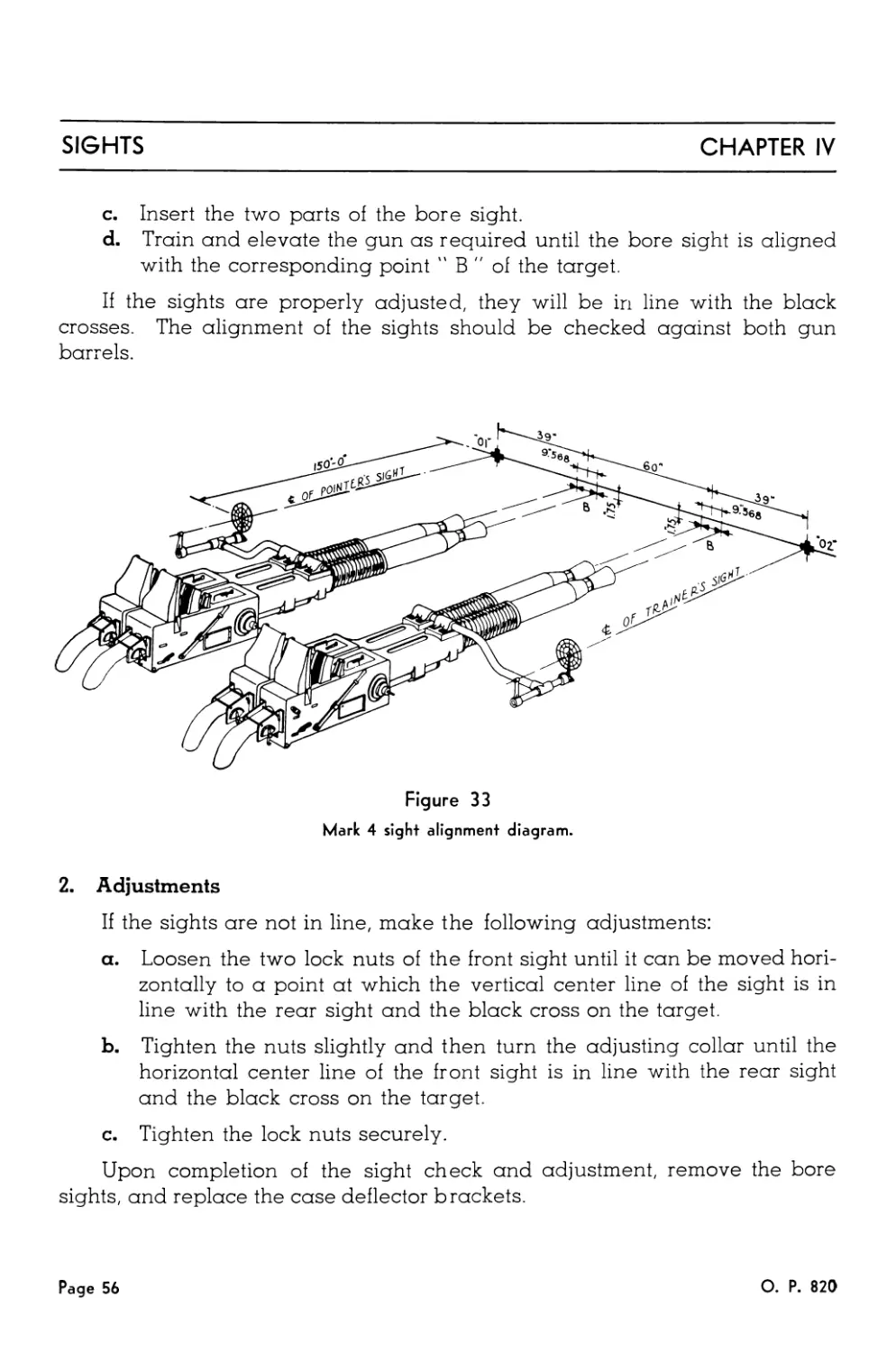
C. ALIGNMENT OF SIGHTS
For aligning the sights with the gun, a bore sight and a sight testing
target are required. The bote sight consists of two parts, a breech end
(298879) and a muzzle end (299205). A sight testing target, Figure: 32 for the
Mark 3 Sight and Figure 33 for the Mark 4 Sight, may be constructed and
used after the gun has been placed in service. The target is made to the
dimensions shown in the diagram, and placed approximately one hundred
fifty feet in front of the gun, at right angles to the gun bore, and with line
"01-02" of the target parallel to the center line of the trunnions.
1. Checking the Alignment
To check the alignment of the sights, proceed as follows:
a. Lower the breech block.
b. Remove the case deflector brackets.
О. P. 820
Page 55
SIGHTS
CHAPTER IV
c. Insert the two parts of the bore sight.
d. Train and elevate the gun as required until the bore sight is aligned
with the corresponding point " В " of the target.
If the sights are properly adjusted, they will be in line with the black
crosses. The alignment of the sights should be checked against both gun
barrels.
2. Adjustments
If the sights are not in line, make the following adjustments:
a. Loosen the two lock nuts of the front sight until it can be moved hori-
zontally to a point at which the vertical center line of the sight is in
line with the rear sight and the black cross on the target.
b. Tighten the nuts slightly and then turn the adjusting collar until the
horizontal center line of the front sight is in line with the rear sight
and the black cross on the target.
c. Tighten the lock nuts securely.
Upon completion of the sight check and adjustment, remove the bore
sights, and replace the case deflector brackets.
Page 56
О. P. 820
Chapter V
CYCLIC OPERATION
Cyclic Operation of
The Gun Mechanism
In automatic fire, one complete cycle of operation occurs ap-
proximately every half second. In each cycle the following basic
functions are performed:
A live round is fed onto the tray.
The rammer is cocked.
The round is rammed into the barrel chamber.
The breech is closed.
The round is fired.
The empty case is ejected.
These basic functions are shown step by step in the following
diagrams, following a round through the complete cycle from feed-
ing to ejection. In these diagrams, the cool colors (green and blue)
are used to indicate the parts of the gun mechanism that move in re-
coil, while the warm colors (red, orange, and yellow) are used to
indicate other moving parts.
0. P. 820
Page 57
CYCLIC OPERATION
CHAPTER V
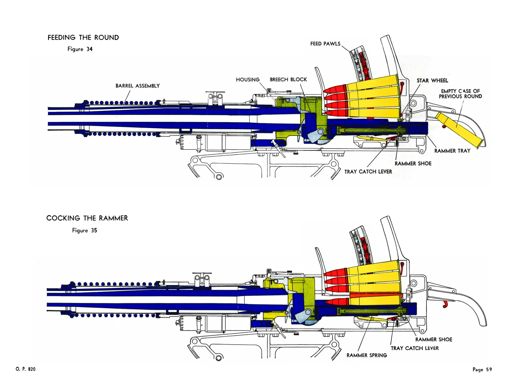
A. FEEDING THE ROUND
Figure 34
The barrel assembly, breech mechanism, and tray are moving forward
in counterrecoil. The breech block is held down by the extractors, and the
rammer shoe is held back by the tray catch lever. The star wheels are re-
leased, the catch heads of the catch mechanisms having been tripped by the
rammer tray pawls. The feed pawls, due to the action of the tray guides, are
pressing the rounds down. This forces the bottom round between the star
wheels and onto the tray.
B. COCKING THE RAMMER
Figure 35
The barrel assembly, breech mechanism, and tray are still moving for-
ward in counterrecoil and have almost reached battery position. The live
round is now on the tray with its base in the slots of the rammer levers. The
rammer shoe is being held back by the tray catch lever, and as the tray
moves forward, the rammer spring is compressed, cocking the rammer. The
trigger cctch lever is held down by the trigger mechanism, and the loader
catch lever is held down by the rounds in the loader. This leaves only the
tray catch lever holding the rammer shoe.
Page 58
О P. 820
FEEDING THE ROUND
Figure 34
FEED PAWLS
О. P. 820
Page 59
RAMMING THE ROUND
Figure 36
Page 60
О. P. 820
CHAPTER V
CYCLIC OPERATION
C. RAMMING THE ROUND
Figure 36
The parts that were moving forward in counterrecoil have now reached
battery position. The beveled cam on the under side of the tray has ridden
over the forward end of the rocker arm, tripping the tray catch lever, thus
allowing the rammer shoe and levers to be thrown forward by the action of
the rammer spring. As the rammer levers neared the forward limit of their
travel, they were spread apart by the cam slots of the tray through which they
extend. This allows the round to continue its travel and be thrown into the
barrel chamber.
D. CLOSING THE BREECH
Figure 37
The round is completely in the chamber and the closing spring is raising
the breech block to the closed position. The breech block is free to rise, be-
cause the extractors were unhooked from the block by the base of the round
as it was thrown into the chamber. As the block rises, pressure of the cam
on the left inner crank is removed from the outer cocking lever. The firing
pin is being held back only by the inner cocking lever which is prevented
from moving by the sear.
0. P. 820
Page 61
CYCLIC OPERATION
CHAPTER V
E. FIRING THE ROUND
Figure 38
The breech is completely closed and the round is fired. Firing occurs
after the breech is closed, by the action of the cam of the right inner crank
upon the sear. The cam forces the sear inward, releasing the inner cocking
lever and the firing pin. The firing pin strikes the primer, which explodes
the propellant charge of the round.
F. EJECTING THE CASE
Figure 39
The barrel assembly, breech mechanism, and tray are moving rearward
as a result of the momentum imparted by the powder pressure at the begin-
ning of recoil. The breech block is in the open position, the outer and
inner cranks having been rotated by action of the roller, riding against the
cam surface of the side door. The firing pin is cocked by action of the cam
of the left inner crank depressing the outer cocking lever. As the breech
block descended, it struck the toes of the extractors, ejecting the empty case.
The feed pawls, due to the action of the tray guides, are rising in order to
feed the next round onto the tray.
A complete cycle has now taken place, and the action repeats itself in
automatic fire as long as the loader is supplied with ammunition and the trig-
ger mechanism is held in the firing position.
Page 62
О. P. 820
EJECTING THE CASE
Figure 39
FEED PAWLS RISING
EMPTY CASE
EXTRACTOR
BREECH BLOCK
0. P. 820
Page 63
Chapter VI
LOADING AND UNLOADING
A. INSTRUCTIONS FOR LOADING
1. Put the firing selector lever on SAFE.
2. Move the hand operating lever all the way to the rear, then latch it in the
rear catch bracket.
3. Push a full clip into the loader, so that one round drops onto the ram-
mer tray. When the clip is pushed in far enough to accomplish this, the
empty clip will be ejected through the clip chute. Place another full clip
in the loader.
4. Move the hand operating lever forward and latch it in the forward
catch bracket.
5. See that the feed control thumb lever on the loader rear guide, if pro-
vided, is in the position indicated by the red arrow.
6. Place the firing selector lever on AUTO FIRE or SINGLE FIRE as desired.
7. a. Hold the firing pedal of the mount down for automatic fire,
b. Press the firing pedal smartly for each shot in single fire.
8. Keep the loader filled.
The loader catch lever will stop operation, with the rammer shoe
cocked, when only two rounds remain, one on the tray and one on
the star wheels. The gun mechanism is then in condition to resume
automatic fire when the loader is refilled, without further manipula-
tion of the hand operating lever.
B. INSTRUCTIONS FOR UNLOADING
1. Place the firing selector lever on SAFE.
2. Elevate the gun to about 30 degrees.
3. Move the hand operating lever all the way to the rear, making sure an
assistant catches the live round thus released from the rammer levers,
as the round slides through the opening in the rear door.
4. Place the hand operating lever in the rear catch bracket.
О. P. 820
Page 65
LOADING AND UNLOADING
CHAPTER VI
5. Install the round releasing tool (29-8899) in the side frames, Figure 40,
compressing the feed and stop pawls.
6. Lift out the rounds which have been released. Remove the round re-
leasing tool.
7. Using the pusher tool (298876), Figure 41, force the round on the star
wheels down on to the rammer tray. Remove the round.
8. Move the hand operating lever fully forward to release the star wheel
catch mechanisms, and then latch it in the rear catch bracket.
Figure 40
Using the round releasing tool.
Page 66
О. P. 820
CHAPTER VI
LOADING AND UNLOADING
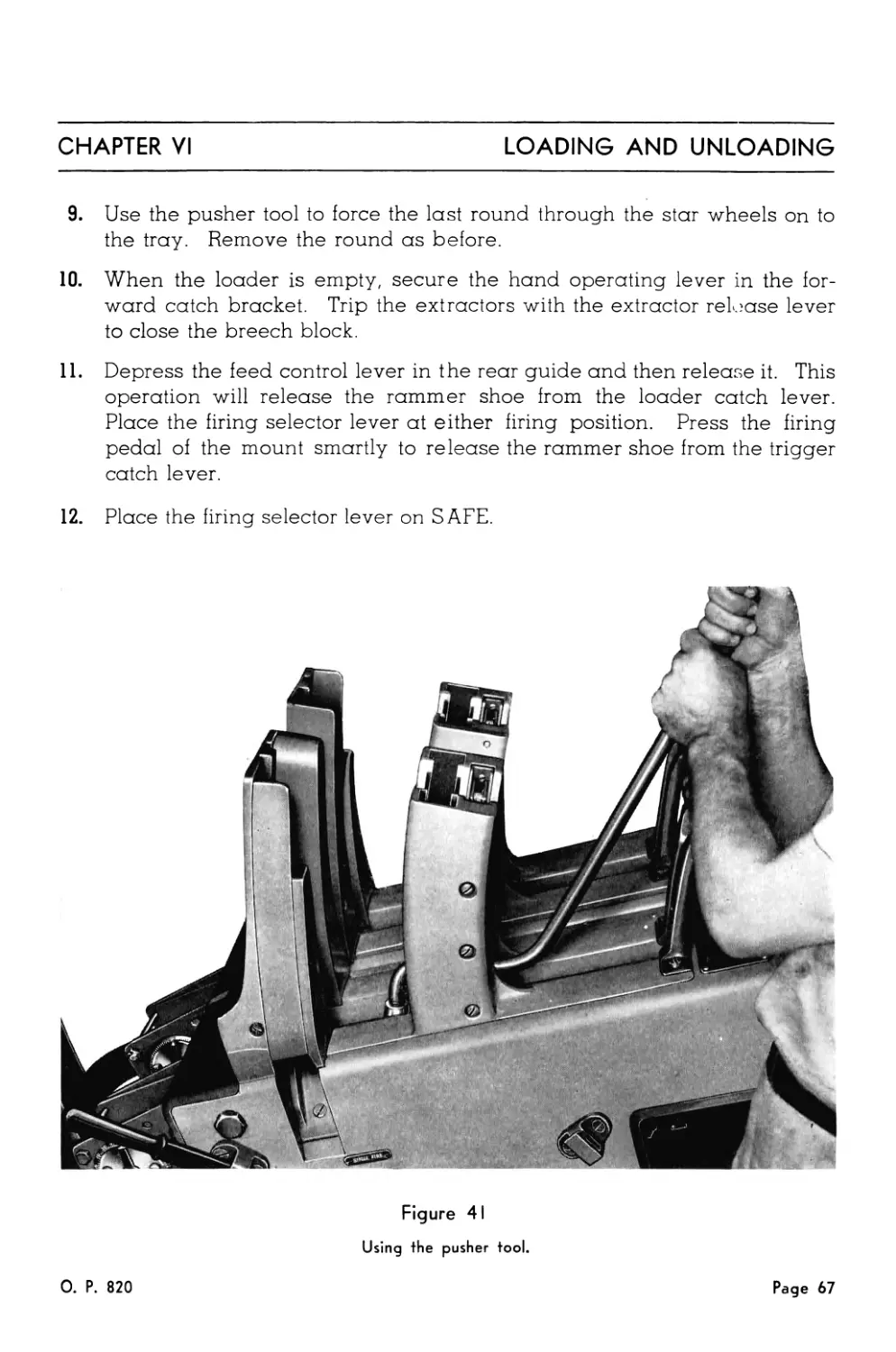
9. Use the pusher tool to force the last round through the star wheels on to
the tray. Remove the round as before.
10. When the loader is empty, secure the hand operating lever in the for-
ward catch bracket. Trip the extractors with the extractor release lever
to close the breech block.
11. Depress the feed control lever in the rear guide and then release it. This
operation will release the rammer shoe from the loader catch lever.
Place the firing selector lever at either firing position. Press the firing
pedal of the mount smartly to release the rammer shoe from the trigger
catch lever.
12. Place the firing selector lever on SAFE.
Figure 41
Using the pusher tool.
О. P. 820
Page 67
Chapter VII
CASUALTIES
In the event of a casualty, the greatest care should be exercised
to insure that no actions are taken which can result in injury to per-
sonnel or material. It is important to understand that a round in the
chamber can be fired unexpectedly even with the firing selector lever
on SAFE, if for any reason the breech block has failed to close.
A. CASUALTIES WHICH CAN BE CORRECTED QUICKLY AND EASILY
1. Clip Placed in Loader Improperly
The most common loader failure is caused by jammed rounds, resulting
from a clip not being passed into the loader properly. To free the rounds thus
jammed, insert the round releasing tool (298899) in the loader to hold back
the feed and stop pawls. Rounds in the upper part of the loader can then be
cleared by hand. Either end of the pusher tool (298876) may be carefully
used to pry the jammed rounds loose. Properly loaded rounds should be
free enough to be removed by hand. Firing will continue when a new clip is
placed in the loader.
2. Firing Pedal Not Fully Depressed
Depress the firing pedal fully. If the gun fires, no further examination is
required.
B. OTHER CASUALTIES
1. Live Round Drops Out Into Case Chute
Open the top door.
a. If the breech block is latched down by the extractors and the empty
case has been ejected, trip the extractor release lever. Closing of
the breech block indicates that the breech block closing spring is not
broken. Follow the normal loading procedure and continue firing.
Casualties of this nature have occurred with no parts damaged and
through no fault of the operator.
0. P. 820
Page 69
CASUALTIES
CHAPTER VII
b. If the breech block is in the closed position, and a round is in the
chamber, it is likely that it has failed to extract, but that recoil
and counterrecoil were completed, and the ejected live round was
rammed against the rear face of the closed breech block. Examina-
tion of the mechanism will probably show that the crankshaft in the
housing is twisted or that the extractors are broken.
2. Live Round In the Gun or On the Rammer Tray
Place the firing selector lever at SAFE. Remove the bottom cover of the
slide.
a. If the breech block is down, insert the breech block locking bolt, and
then open the top door. Never open the top door when it is possible
for the gun to fire. Remove the round through the rear door, and
examine the mechanism for damaged parts, such as, broken ex-
tractors, twisted crankshaft, broken breech block closing spring,
broken rammer rod or spring. Examine the round to determine, if
possible, the cause of the trouble. If the gun was at a low angle of
elevation when this stoppage occurred, it may have been the same
type of casualty as the one described in 1. a. above, when a live
round dropped out into the case chute.
b. If the breech block is closed, and if examination of the tray through
the opening in the rear door,—without removing the case deflector,—
discloses a live round on the tray, the case in the chamber is pre-
sumably empty, and the casualty should be treated as in para-
graph 1. b. above, after removal of the live round.
c. If the breech block is closed and a live round is not on the tray or
in the case chute, and examination through the bottom opening in
the slide shows the base of a case in the gun, a misfire has occurred
and the procedure will be governed by the applicable Naval Regula-
tions. If the breech block is not fully closed for any reason, the firing
pin will not be released at all. In such cases, the breech block may
slowly close itself and fire the gun after an apparent misfire, by
wedging action of the breech block finally seating a round in a dirty
chamber, by slow action of a gummy breech block, etc. A situation
of this kind can usually be determined by examination of the sear in
the bottom of the breech block.
(1) If the sear is to the left, that is, the head of the sear is fully in the
mating slot, the firing pin has been released and the casualty
is probably a misfire
Page 70
О. P. 820
CHAPTER VII
CASUALTIES
(2) If the sear is to the right that is, the head of the sear is not fully
in the mating slot and is adjacent to the right inner crank, the fir-
ing pin probably has not been released but the casualty should
be treated as a misfire until definite knowledge to the contrary
has been determined. After removal of the round in accordance
with Naval Regulations, the mechanism should be examined
and tested for free operation of all parts.
3. Live Round Still Above Star Wheels
a. If a round is not on the rammer tray, in the chamber or has not
dropped out into the case chute, feeding through the star wheels may
have been prevented by a jammed round in the loader. In such case
the feed pawl safety mechanism has operated. Remove the jammed
and other rounds, force or hammer the feed pawls down into their
normal positions, and follow the normal loading procedure. Failure
to feed may also result from short recoil or a twisted crankshaft in the
housing. Either condition may cause slow ejection of the empty case,
which will not clear the star wheels in time to permit feeding of the
next round.
b. If recoil is too short—less than about seven inches—feeding will be
definitely prevented because the catches will not be released. If short
recoil is the result of low temperature operation, firing of several
rounds may warm the fluid in the recoil cylinder sufficiently to per-
mit automatic operation. Certain of the mechanisms have throttling
rods which may prevent sufficient recoil to allow reliable cold
weather automatic operation. With such throttling rods, one or two
ounces of the fluid in the recoil cylinder should be removed, such that
recoil with service charge at approximately zero degrees elevation
produces a length of recoil between 7.4 and 7.5 inches. This fluid
should be replaced when warmer temperatures are encountered.
C. STAR WHEELS LOCKED
If it is not possible to push a round through the star wheels during the
normal loading routine, the star wheels are probably locked by the catch
mechanisms. Such a condition will result from a sheared taper pin in the
bottom of the loader, in which case motion of the hand operating lever will
not release the catch mechanisms. The remedy is to replace the taper pin.
However, the gun may be fired normally and safely, before the taper pin is
replaced, by loading the first round as follows:
О. P. 820
Page 71
CASUALTIES
CHAPTER VII
With the hand operating lever all the way to the rear so that the rammer
levers are moved to the rear and spread, carefully place a live round on the
tray through the rear door opening. Move the hand operating lever slowly
forward, at the same time maintaining the round in such a position that the
base of the case will be caught in the slots in the rammer levers. The mecha-
nism may then be operated normally.
D. LONG RECOIL
Long recoil will not cause stoppage but may cause excessive stresses in
the mechanism. Tests indicate that with the present design of throttling rod
and bushing a length of recoil in excess of about 8.3 inches is not practically
attainable. However, if this maximum length of recoil is obtained, it is prob-
able that excessive pressures are being developed in the recoil cylinder, and
therefore, excessive stresses are being developed elsewhere in the mecha-
nism. The recoil cylinder should be examined to determine if it has sufficient
fluid.
E. TWISTED CRANKSHAFT
An angular displacement of the housing outer crank of about five de-
grees, an amount readily detected, from the normal position when the
breech block is closed is sufficient to make satisfactory operation doubtful. A
twist of approximately eleven degrees will result in no motion of the ex-
tractors when the breech block is pulled down. In such case the crankshaft
should be replaced. If the extractors are broken, they should be replaced.
Even if only one extractor is broken, both should be replaced.
Twisting of the shaft may have developed gradually or may have oc-
curred suddenly during the firing of the last round. If the casualty resulted
from a single tight case, it could not have been foreseen. As a precau-
tionary measure, the crankshaft should be examined periodically for this
twisted condition. A slow speed of extraction of the empty cartridge case,
resulting in a jam on the tray between the ejected case and the next round,
is a danger signal that a twisted shaft may be developing. Recoil of less
than abo it 7.2 inches may give the same result.
Page 72
О. P. 820
TRAY PAWL
FEED PAWL
STOP PAWL
FRONT GUIDE
LONGITUDINAL SECTION
OF GUN
BREECH BLOCK
Figure 42
FEED CONTROL LEVER
TOP DOOR
BARREL LOCK
BARREL STOP
STAR WHEEL
WATER CONNECTION
RECOIL SPRING
REAR DOOR
WATER JACKET
CASE DEFLECTOR
BARREL
FLASH
HIDER
M—
RAMMER TRAY
RIGHT RAMMER LEVER
DEPRESSION STOP PAD
RAMMER SHOE
NEEDLE VALVE
BASE
SLIDE
FILL PLUG
PLUNGER
CATCH LEVER
DRAIN PLUG
HOUSING
CATCH LEVER
RAMMER ROD
CRANKSHAFT
PISTON ROD
ROCKER ARM
E
RECOIL CYLINDER
CLOSING SPRING
BOTTOM COVER
ELEVATING ARC
№i lili
RECOIL
SPRING
KEEPER
For lateral sections indicated on this
drawing, see Figures 43, 44, 45.
Page 73
LATERAL SECTIONS
THROUGH
LOADER-1
Figure 43
Sections M-M, N-N, O-O, P-P
SECTION M-M
SECTION N-N
FEEI
FEEC
PLUI
FEEI
F
RIGHT FRAME
PLUNGERS
SECTION 0-0
SECTION P-P
PLUNGER
О. P. 820
LATERAL SECTIONS
THROUGH
LOADER-II
Figure 44
Sections R-R, S-S, U-U
SECTION R-R
ECTION S-S
SECTION U-U
0. P. 820
Page 75
LATERAL SECTIONS
THROUGH
HOUSING
Figure 45
Sections A-A, В-В, C-C,
D-D, E-E, F-F, G-G, H-H, L-L
EXTRACTOR
RELEASING
LEVER
G
EXTRACTORS
CRANKSHAFT
HOUSING
STOP
OUTER COCKING
LEVER
INNER COCKING
LEVER
SECTION B-B
SECTION C-C
SECTION E-E
SECTION F-F
SECTION A-A
TRAY
BOLT
SECTION D-D
SECTION G-G
FIRED
COCKED
age 76
Chapter VIII
FUNCTIONAL CHECK-OFF LIST
A. DAILY CHECK
Breech Mechanism
1. Check operation of the breech block firing mechanism by pulling the
hand operating lever about 30 degrees to the rear to cock the firing pin.
An audible click should be heard. Let the lever go forward to release
the firing pin. This operation should produce another click.
2. Pull the hand operating lever all the way back, then return it to the front
catch bracket. Open the top door and inspect the extractors.
3. Trip the extractors with the extractor release lever. The breech block
closing spring should cause the breech block to slam up.
4. With the breech block in the closed position, see that the outer crank is
not displaced more than five degrees from the normal position. The toe
of the crank should normally be parallel to the lower edge of the side
door.
Loader
5. Pull the hand operating lever all the way back, then return it to the front
catch bracket. See that the rammer shoe is held by the loader catch
lever.
6. Place the hand operating lever in the rear catch bracket. Force a
round through the star wheels onto the tray. Remove the round.
7. Press the feed control lever. Listen for the click that indicates release of
the rammer shoe by the loader catch lever.
8. Put the firing selector lever on AUTO FIRE or SINGLE FIRE. Press the
firing pedal to check operation of the rammer.
О. P. 820
Page 77
Chapter IX
ASSEMBLY AND DISASSEMBLY
SPECIAL TOOLS USED IN ASSEMBLY AND DISASSEMBLY
(298868-1) (299204-2)
The . cllowing list gives the name, Ordnance number and use of all spe-
cial tools required for assembly and disassembly. These tools are illustrated
in Figure 46.
298865-1 Spanner Wrench
Used on outside casing (298862) and
casing lock nut (298866) of recoil spring
compressor.
Page 78
О. P. 820
CHAPTER IX
ASSEMBLY AND DISASSEMBLY
298868-1 Wrench Used on closing spring cover (298685-3).
298869-5 Wrench Used on safety plunger spring seat (298676-1).
298869-6 Wrench Used on tray bolt (298676-2), tray bolt spring seat (298676-7), firing hole bush- ing (298682-2), and firing spring cover (298682-1).
298870-1 Spanner Wrench Used on gland bushing (298739-5), throttling rod (298736-2), and collar (298737-1) of recoil cylinder.
298870-2 Spanner Wrench Used on recoil cylinder (298730-1).
298871 Side Door Key For side door lock.
298871-1 Hand Extractor To extract outer crank and crankshaft.
298872-3 Flash Hider Wrench Used on flash hider (298663) to remove barrel assembly.
298874-1 Spanner Wrench Used on throttling bushing (298732-8).
298874-2 Spanner Wrench Used on rammer spring seat (298793-5).
298874-3 Spanner Wrench Used on gland nut (298662-2) and at- taching nut (298662-1) of water jacket.
298874-4 Spanner Wrench Used on gun barrel (298652).
298875 Feed Rod Spring Clamp To compress plunger spring of feed rod holder.
299204-1 Extractor Spindle Tool To remove extractor spindle (298674-3).
299204-2 Spanner Wrench Used on recoil spring keeper (298662-4).
299206 Safety Plunger Key To retract safety plunger.
О. P. 820
Page 79
ASSEMBLY AND DISASSEMBLY
CHAPTER IX
All piece numbers given in this chapter are for the 40MM Gun Barrel,
Mark 1, the 40MM Gun Mechanism, Mark 1, and the 40MM Sights, Marks 3
and 4. Piece numbers for the corresponding parts of the 40MM Gun Mecha-
nism, Mark 2, Mark 1, Mod. 1, and Mark 2, Mod. 1, are listed in the Parts List
adjacent to the Mark 1 numbers. Ordnance numbers of individual pieces
are not given in the Disassembly sections, but may be found in the corre-
sponding Assembly sections. The piece numbers of all special tools required
for either assembly or disassembly are given in both sections.
A. BARREL ASSEMBLY
1. Removal of the Barrel Assembly
a. Remove the water connection at the water jacket.
(1) Turn the hand screw and lift the water connection and its gas-
kets from its seat on the water jacket.
(2) Depress the gun and drain the coolant through the drain on the
front end of the water jacket.
b. Place the gun in the horizontal position and lock the elevation secur-
ing device.
c. Lower the breech block.
(1.) Disengage the hand operating lever from the front catch bracket
and pull it all the way back to lower the breech block, and then
return the lever to the rear catch bracket for safety.
This prevents interference of the extractors when the barrel is
turned.
d. Open the top door.
(1) Lift the knurled head at the rear of the top door and swing the
lever to one side to unlatch the door. Then open the door to re-
lease the barrel lock, and latch it open.
e. Remove the barrel assembly.
(1) With two men applying the flash hider wrench (298872-3) to the
flash hider and several men to handle the weight of the breech
end, rotate the barrel one-half turn to the left to disengage the
retaining threads. Remove the barrel assembly by pulling it
forward away from the slide.
Page 80
О. P. 820
CHAPTER IX
ASSEMBLY AND DISASSEMBLY
f. Uncock the gun mechanism.
If the gun is to remain idle for any length of time with the barrel re-
moved, it should be uncocked.
(1) Place the hand operating lever in the front catch bracket, insert
the safety plunger key (299206) in the opening in the top of the
housing and turn so as to retract the safety plunger. At the
same time, trip the extractor release lever on the bottom of the
slide.
(2) Release the rammer by depressing the feed control lever and
• operating the firing mechanism.
The top door on the slide should never be closed while the barrel as-
sembly is removed from the gun.
2. Installation of the Barrel Assembly
a. Install the barrel assembly.
(1) With two men applying the flash hider wrench (298872-3) to the
flash hider and several men to handle the weight of the breech
end, insert the breech end of the barrel into the forward end of
the slide so that the opening for the water connection is on the
bottom of the barrel.
(2) Using care to prevent damage to the threads in the housing or
on the barrel, slide the barrel in as far as it will go, rotate the
barrel a half turn to the right to engage the threads.
Proper assembly of the barrel with the housing will be indicated
when the top door can be closed and latched without requiring
force.
(3) Remove the wrench.
b. Uncock the gun by closing the breech and releasing the rammer.
c. Fill the water jacket with coolant and replace the water connections.
3. Disassembly of the Barrel Assembly
a. Remove the flash hider.
(1) Remove the three set screws.
(2) Unscrew the flash hider from the end of the barrel and remove
the copper ring.
The flash hider may be removed without disturbing the recoil spring.
To remove the recoil spring, the flash hider must first be removed.
О. P. 820
Page 81
ASSEMBLY AND DISASSEMBLY
CHAPTER IX
b. Remove the recoil spring.
For this purpose, the recoil spring compressor (298860), Figures 47
and 48, is required.
(1) Install the outside casing of the recoil spring compressor.
With the flash hider removed, install the casing (298862)
threaded end first, from the front end of the barrel.
(2) Install the casing lock nut.
Use spanner wrench (298865-1) to install the casing lock nut
(298866) and tighten on the threaded end of the outside casing.
Figure 47
Recoil spring compressor assembly used in
removing and installing the recoil spring.
(3) Remove the spring keeper.
Spanner wrenches (298865-1 and 299204-2) are required. Re-
move the two set screws and unscrew the spring keeper. When
the spring keeper is removed, the recoil spring assembly is con-
fined within the outer casing of the recoil spring compressor.
(4) Remove the spring and the outer casing.
Pull the recoil spring and compressor off the front of the
barrel.
(5) Install the inside casing and the screw assembly.
Install the inside casing (298861) in the nut end of the out-
side casing (inside the spring), and install the screw as-
sembly (298865) in the opposite end. Using the hand crank
Page 82
О. P. 820
CHAPTER IX
ASSEMBLY AND DISASSEMBLY
(298867), turn the screw all the way in against spring ten-
sion.
(6) Remove the casing lock nut.
Turn the screw to the right until the spring is sligh'ly com-
pressed and with spanner wrench (298865-1), remove the
casing lock nut.
Figure 48
Recoil spring compressor disassembled.
(7) Release the spring tension.
While holding the outside casing with spanner wrench
(298865-1), turn the screw to the left to release the recoil
spring.
(8) Remove the spring from the compressor.
Remove the recoil spring, rear spring seat, and front spring
seat from the spring compressor.
Extreme care must be exercised when removing the recoil spring as
it is in high compression and if suddenly released may cause serious
personal injury.
0. P. 820
Page 83
ASSEMBLY AND DISASSEMBLY
CHAPTER IX
c. Remove the water jacket.
(1) Using spanner wrench (298874-3), unscrew the gland nut on the
front of the water jacket.
(2) Remove the two packing rings and the two steel rings.
(3) Release the set screw in the attaching nut at the rear end
of the water jacket. Turn off the nut, using spanner wrench
(298874-3), while holding the barrel with spanner wrench
(298874-4).
(4) Remove the water jacket and its gasket over the front end of the
barrel.
(5) Remove the drain plug and washer.
4. Assembly of the Stripped Barrel Assembly
a. Install the water jacket.
(1) Install the gasket (298658-2) and the water jacket (298659-1) over
the front end of the barrel.
(2) Put on the attaching nut (298662-1). This nut is placed over the
breech end of the barrel and screwed onto the water jacket
until the screw holes in the nut match the corresponding holes
in the water jacket. Use spanner wrench (298874-3) on the at-
taching nut and spanner wrench (298874-4) on the gun barrel.
Put in and tighten the set screw (298662-3).
(3) Insert the packing in the front end of the water jacket in the fol-
lowing order: (298658-3), (298658-5), (298658-3), (298658-4).
(4) Using spanner wrench (298874-3), screw the gland nut (298662-2)
into the front end of the water jacket against the above packing
rings.
(5) Install the drain plug (298739-7) and washer (298739-4).
b. Install the recoil spring.
For this operation the recoil spring compressor (298860) is re-
quired.
(1) Place the recoil spring on the inside casing.
(a) Stand the inside casing (298861) on end, and place on it
the rear spring seat (298666-3), then the recoil spring
(298666-1), and finally the front spring seat (298666-2).
Page 84
О. P. 820
CHAPTER IX
ASSEMBLY AND DISASSEMBLY
(2) Place the spring under tension.
(a) Place the outside casing (298862) over the recoil spring.
(b) Insert the screw assembly (298865).
(c) While holding the outside casing with spanner wrench
(298865-1), use the hand crank (298867) to turn the screw
into the inside casing until the spring is compressed far
enough to allow the casing lock nut to be attached.
(3) Remove the inside casing and the screw assembly.
(a) Using spanner wrench (298865-1), screw the casing lock nut
(298866) on the outside casing.
(b) Crank the screw assembly to the left until the recoil spring
is retained in the outside casing.
(c) Remove the screw assembly and the inside casing.
(4) Install the spring and casing on the water jacket.
Spanner wrenches (298865-1 and 299204-2) are required.
(a) Place the casing and spring, nut end first, over the water
jacket.
(b) Install the spring keeper (298662-4), and screw it on tightly
until the two set screw holes match the corresponding holes
in the water jacket.
(c) Insert the set screws and draw them up tightly.
(5) Remove the casing lock nut and the outside casing.
(a) With spanner wrench (298865-1), remove the casing lock
nut (298866), and take off the outside casing (298862).
c. Install the flash hider.
(1) Install the copper ring and the flash hider.
(a) Place the copper ring (298658-6) over the front end of the
barrel. Screw the flash hider (298663-1) tightly against the
copper ring, using the flash hider wrench (298872-3), until
the set screw holes in the flash hider match those in the
barrel.
(b) Insert the three set screws (298662-3) and draw them up
tightly.
О. P. 820
Page 85
ASSEMBLY AND DISASSEMBLY
CHAPTER IX
REMOVING THE RECOIL CYLINDER
Loosen the set screw.
Loosen the collar.
Remove the retaining bolts.
Lower the cylinder and remove.
Figure 49
Page 86
О. P. 820
CHAPTER IX
ASSEMBLY AND DISASSEMBLY
B. RECOIL CYLINDER ASSEMBLY
1. Removal of the Recoil Cylinder Assembly, Figure 49
a. Loosen the recoil cylinder.
(1) Elevate the gun to about 50 degrees.
(2) Loosen the set screw and turn the collar part way о J the cylin-
der, using spanner wrench (298870-1).
(3) Remove the four retaining bolts and take off the clamp.
b. Remove the assembly.
(1) Lower the recoil cylinder assembly until it is approximately at
right angles to the slide.
(2) Disengage the securing pin from the housing lugs.'
2. Installation of the Recoil Cylinder Assembly
a. Attach the assembly.
(1) Elevate the gun to about 50 degrees.
(2) Holding the recoil cylinder approximately at right angles to the
slide, insert the end of the piston rod in the bottom of the slide
so that the securing pin is engaged in the lugs on the bottom of
the housing.
b. Bolt the recoil cylinder to the gun.
(1) Bolt the clamp (298727-1) to the pad on the bottom of the slide
with the four bolts (1/2"—20x1-3/4").
(2) With spanner wrench (298870-1) turn the collar (298737-1) tight,
and insert and tighten the set screw (1/4"—20 x 1/4").
3. Disassembly of the Recoil Cylinder Assembly
a. Remove the wire seal and the drain and fill plugs.
(1) Cut the wire seal.
(2) Remove the plugs and washers. Allow the liquid to drain.
b. Remove the locking plate.
(1) Remove the retaining bolt, then take off the washers and the
locking plate.
О. P. 820
Page 87
ASSEMBLY AND DISASSEMBLY
CHAPTER IX
REMOVING NEEDLE VALVE
Figure 50
Removing the needle valve after the locking screw and the gland nut have been removed.
c. Remove the gland nut and the needle valve, Figure 50.
(1) Remove the locking screw.
(2) Remove the gland nut, the needle valve, and the gland rings.
d. Remove the throttling rod.
(1) Hold the recoil cylinder either in a vise or with spanner wrench
(298870-2), and unscrew the throttling rod, using spanner
wrench (298870-1).
(2) Remove the washer.
(3) Push in the piston rod and remove the throttling bushing lock
screw.
(4) Loosen the throttling bushing with spanner wrench (298874-1)
and remove the throttling rod assembly.
e. Remove the securing pin.
(1) Remove the securing pin locking screw, and tap out the pin.
f. Remove the piston rod.
(1) Pull the piston rod out of the cylinder.
Page 88
О. P. 820
CHAPTER IX
ASSEMBLY AND DISASSEMBLY
g. Remove the gland bushing, packings, and rings.
(1) Use spanner wrench (298870-1) to remove the gland bushing.
(2) Remove the rear gland ring, the four chevron packing rings, the
center gland ring, the leather packing ring, and t? e front gland
ring.
h. Remove the check valve.
(1) Tap out the taper pin.
(2) Remove the nut, then lift off the spring and the check valve.
i. Remove the valve seat and the throttling bushing.
(1) Tap out the taper pin.
(2) Unscrew the valve seat from the throttling rod, and remove the
throttling bushing.
4. Assembly of the Stripped Recoil Cylinder Assembly, Figure 51.
a. Assemble the valve seat on the throttling rod.
(1) Place the throttling bushing (298732-8) over the throttling rod
(298736-2), holding the end with the slots for the spanner wrench
forward.
(2) Screw the valve seat (298737-2) into the end of the throttling
rod, fasten with a taper pin (No. ООО x 1").
b. Assemble the nut, spring, and check valve.
(1) Install the check valve (298732-7), spring (298732-2), and nut
(298732-1).
(2) Fasten the nut with the taper pin (No. ООО x 1").
c. Install the piston rod and the packing rings.
(1) Install the piston rod (298734-1) in the cylinder (298730-1).
(2) Install the front gland ring (298732-6), the leather packing ring
(298735-3), the center gland ring (298735-4), the four chevron
packing rings (298735-1), the rear gland ring (298735-2), and the
gland bushing (298739-5). Tighten the gland bushing with span-
ner wrench (298870-1).
d. Install the securing pin.
(1) Tap in the securing pin (298738-1).
(2) Insert the locking screw (298739-1).
e. Install the throttling rod assembly.
(1) Push in the piston rod (298734-1).
(2) Install the leather washer (298739-6) and the throttling rod
assembly.
О. P. 820
Page 89
ASSEMBLY AND DISASSEMBLY
CHAPTER IX
f. Tighten the throttling bushing, Figure 52, and install the locking
screw.
(1) With spanner wrench (298874-1), tighten the throttling bushing
(298732-8) and install the locking screw (1/4"—20 x 5/16").
WIRE SEAL
COLLAR
(298737-1)
CYLINDER
(298730-1)
WASHER
(298739-4)
PLUG
(298739-7)
LOCKING
PLATE
(298738-3)
CHEVRON
PACKING \
RING
(298735-1) /М»
GLAND I______
BUSHING—Ищ
(298739-5) Ш
GLAND RING
REAR
(298735-2)
PACKING
RING
(298735-3)
<«
z WASHER
(298739-4)
r
GLAND RING
CENTER
(298735-4)
- PLUG
(298739-7)
WASHER
RETAINING
BOLT
LOCKING SCREW
If" (298739-2)
GLAND RING
FRONT
(298732-6)
CHECK VALVE
(298732-7)
LOCKING SCREW
(298739-1)
THROTTLING ROD
(298736-2)
SECURING PIN
PISTON ROD
(298734-1)
NEEDLE VALVE
(298736-1)
GLAND NUT
(298739-3)
Figure 51
Recoil cylinder disassembled
Page 90
О. P. 820
CHAPTER IX
ASSEMBLY AND DISASSEMBLY
TIGHTENING THROTTLING BUSHING
Figure 52
g. Tighten the throttling rod and install the needle valve.
(1) Holding the recoil cylinder either in a vise or with spanner
wrench (298870-2), tighten the throttling rod (298736-2), using
spanner wrench (298870-1).
(2) Assemble the packing ring (298732-4) and the steel gland ring
(298732-5) on the needle valve (298736-1).
(3) Screw in the needle valve and tighten the gland nut (298739-3).
(4) Install the locking screw (298739-2).
h. Fill the recoil cylinder.
(1) Unscrew the needle valve two turns.
(2) Install the drain plug (298739-7) and washer (298739-4), and
with the forward end of the cylinder raised to a 25 degree in-
cline, fill the cylinder to overflowing with liquid. Install the fill
plug (298739-7) and tilt the cylinder slowly several times. Again
fill the cylinder to overflowing while inclined at 25 degrees.
(3) Install the fill plug and washer (298739-4) and wire the plugs
together.
О. P. 820
Page 91
ASSEMBLY AND DISASSEMBLY
CHAPTER IX
i. Install the locking plate.
(1) Turn the needle valve all the way in, and then turn it back 1/3
turn.
(2) Install the locking plate (298738-3), the retaining bolt (5/16"—
24x5/8"), the washer (5/16"), and the lock washer (5/16").
C. LOADER ASSEMBLY
1. Removal of the Loader Assembly
a. Open the rear door.
(1) Remove the through bolt and lower the rear door, Figure 53.
b. Remove the tray bolt.
(1) Insert the key (298871) in the lock in the side door, pressing in
firmly to release the bolt spring, and turn the key to open the
door.
(2) Insert wrench (298869-6) in the slot in the head of the rammer
tray bolt. Push the bolt in against spring tension and rotate it
1/4 turn in either direction to remove, Figure 54.
Figure 53
Rear door—open.
Figure 54
Removing the tray bolt.
c. Remove the loader assembly.
For this operation, front lifter (346451) and rear lifter (346452) are re-
quired.
(1) Slide the assembly part way back, and with two men applying
the rear lifter and one the front lifter, raise the assembly as it
leaves the supporting guides in the slide, Figure 55.
To prevent damage do not allow the assembly to rest or drop on the
rear door.
Page 92
О. P. 820
CHAPTER IX
ASSEMBLY AND DISASSEMBLY
USING LOADER LIFTERS
Figure 55
The fop view shows one man with lifter tool (346451) and two
others with lifter tool (346452), In the bottom picture,
the lifters are in place and the loader ready to be removed.
О. P. 820
Page 93
ASSEMBLY AND DISASSEMBLY
CHAPTER IX
2. Installation of the Loader Assembly
a. Install the loader assembly.
For this operation front lifter (346451) and rear lifter (346452) are re-
quired.
(1) Install the lifters and raise the assembly carefully, starting it into
the supporting guides in the slide.
(2) Remove the lifters and slide the assembly in as far as it will go.
b. Insert the rammer tray bolt.
(1) Insert the wrench (298869-6) in the slot in the head of the bolt
(298676-2). Push the bolt in against spring tension and rotate
1/4 turn, matching the two arrows to lock.
(2) Close and lock the side door, using the key (298871).
c. Close the rear door.
(1) Swing the rear door (298721-1) up to the closed position.
(2) Insert the through bolt (298704-5) and turn it up tightly.
3. Removal of the Rammer Tray
a. Remove the tray assembly.
The loader assembly must be removed from the slide in order to re-
move the tray assembly.
(1) Pull the tray forward out of the loader assembly, Figure 56.
(2) Remove the loose rollers from the lower ends of the feed rods.
PAWL L. H.
(298791-1) ~
BEARING PIN
(298791-8)
Figure 56
Removing the rammer tray.
PAWL R. H.
(298791-4)
PLUNGERS
(298791-3)
SPRINGS
(298791-2)
Figure 57
Page 94
О. P, 820
CHAPTER IX
ASSEMBLY AND DISASSEMBLY
4. Installation of the Rammer Tray
a. Install the tray assembly.
(1) Install the rollers (298776-6) on the lower ends of the feed rods.
(2) Install the tray assembly, sliding it in from the front snd of the
loader; be careful not to push the tray in far enough that the
rammer shoe passes over the catch levers.
5. Disassembly of the Rammer Tray
a. Remove the tray pawls shown in Figure 57.
(1) Tap out the taper pin and the bearing pins.
(2) Remove the pawls, their plungers, and springs.
b. Remove the rammer shoe nut and the lever bearing screws,
Figure 58.
(1) Remove the cotter pin and the nut.
(2) Remove the cotter pins and the bearing screws.
c. Remove the levers, plungers, springs, and the rammer shoe.
(1) Slide the shoe back to the large slots, press in and down to re-
move the levers.
(2) Remove the plungers, the spring, and the shoe, Figure 59.
d. Remove the spring seat locking screw, and the rammer.
(1) Remove the locking screw and loosen the spring seat with
spanner wrench (298874-2).
(2) Remove the rammer assembly.
Figure 58
Removing bearing screw and rammer shoe nut.
Figure 59
Disassembly of the rammer shoe.
О. P. 820
Page 95
ASSEMBLY AND DISASSEMBLY
CHAPTER IX
e. Disassemble the rammer.
(1) Tap out the taper pin, compress the spring, and unscrew the
rammer head from the rod.
(2) Remove the spring and the seat.
Handle the spring carefully to avoid personal injury.
f. Remove the rammer buffer.
(1) Remove the cotter pin and the castellated nut.
(2) Using a rod (3/8" diameter x 15" long), tap out the buffer.
6. Assembly of the Stripped Rammer Tray
a. Install the rammer buffer.
(1) Insert the rammer buffer (298792), stud first, into the rammer
chamber.
(2) Install and tighten the castellated nut (3/8"—24), and install the
cotter pin (3/32" x 1").
b. Assemble the rammer.
(1) Place the rammer spring (298793-1) and spring seat (298793-5)
on the rammer rod (298793-3).
(2) Compress the spring, and screw the rammer head (298793-2) on
the rod.
c. Install the rammer and the locking screw.
(1) Install the rammer assembly in the tray.
(2) Screw the spring seat (298793-5) into the rammer chamber with
spanner wrench (298874-2) and install the locking screw
(298793-4).
d. Install the rammer shoe, plungers, plunger spring, and rammer
levers.
(1) Install the rammer shoe (298794-1), the plunger spring (298791-5)
and the plungers (298791-6).
(2) Slide the rammer shoe (298794-1) back to the large slot, press in
and up to install the levers (right, 298795-1; left, 298795-2).
e. Install the lever bearing screws and the rammer shoe nut.
(1) Install the bearing screws (298791-9) and their cotter pins
(1/8" x 1-1/4").
(2) Install the 1-1/16" rammer shoe nut (298791-7) and the cotter pin
(1/8" x 1-1/2").
f. Install the tray pawls, Figure 57.
(1) Install the springs (298791-2), the plungers (298791-3), and the
pawls (right, 298791-4; left, 298791-1).
(2) Insert the bearing pins (298791-8) and drive in the taper pins
(No. 00 x 1-1/8").
Page 96
О. P. 820
CHAPTER IX
ASSEMBLY AND DISASSEMBLY
7. Disassembly of the Loader Assembly
a. Remove the guides and the feed control mechanism.
(1) Remove the front guide.
(a) Remove the two top retaining screws and then the two
clamp screws.
(2) Remove the left rail of the rear guide.
(a) Remove the two retaining screws, the lower front screws,
the long through screws and the upper front screw.
(b) Remove the rails.
(3) Remove the right rail of the rear guide.
(a) Remove the two rear retaining screws and the long
through screw.
(b) Remove the rail.
(4) Remove the feed control mechanism, Figure 60, and the rear
guide.
(a) Remove the cotter pin and the clevis pin from the outer arm
of the intermediate control spindle, and unscrew the feed
control rod from the rod end.
(b) Remove the lever and arm retaining screws and tap out
the spindle.
(c) Remove the spindle arm and rod end, and the feed control
lever.
Figure 60
Feed control mechanism removed from the rear guide.
О. P. 820 Page 97
ASSEMBLY AND DISASSEMBLY
CHAPTER IX
(d) Disassemble the arm and rod end by removing the cotter
pin and the clevis pin.
(e) Remove the two upper screws, the lower screws and lift
off the rear guide.
(5) Remove the ammunition clip guide.
(a) Remove the retaining screws.
(b) Lift off the clip guide.
The rear guide must be removed before the clip guide can be taken
off.
Figure 61
Removing a star wheel plunger.
b. Remove the frames.
To remove the frame assemblies, the guides must be removed.
(1) Remove the cross piece cover, the plunger, the spring, and the
seat, Figure 61.
(a) Remove the retaining screw and the cover.
(b) Compress the springs in order to remove the seats, the
springs, and the plungers.
(2) Remove the cross piece.
(a) Remove the two upper screws, the two lower screws and
the cross piece.
(3) Remove the frame assemblies.
(a) Tap out the two taper pins.
(b) Remove the six retaining screws from each frame.
Page 98
О. P. 820
CHAPTER IX
ASSEMBLY AND DISASSEMBLY
c. Remove the star wheels.
The frame assemblies must be removed in order to remove the star
wheels.
(1) Tap out the taper pins.
(2) Remove the star wheel shaft retaining screws, the shafts, and
the star wheels, Figure 62.
Figure 62
Removing a star wheel after the retaining screw has
been removed. The star wheel shaft and extension
piece are being withdrawn from the star wheel.
d. Remove and disassemble the feed rods.
The tray assembly must be removed in order to remove the feed rod
assemblies. Instructions for removal are given on page 94. .It is not
necessary, however, to remove the frame assemblies in order to serv-
ice the feed rod assemblies. The following instructions apply to
either of the feed rods.
(1) Remove the feed rod asse mbly.
(a) Use an offset screw driver to remove the retaining screw.
(b) Rotate the star wheel and raise the assembly out of the
frame.
О. P. 820
Page 99
ASSEMBLY AND DISASSEMBLY
CHAPTER IX
(2) Remove the feed pawl holder.
For this operation the clamp (298875) is required.
(a) Install the clamp and tighten until the spring is completely
compressed.
(b) Slide the holder and lift it out, Figure 63.
(c) Loosen the clamp.
(d) Remove the plunger and spring.
(3) Remove the pawls.
(a) Push out the bearing pins.
(b) Remove the bushings, springs, and pawls.
Figure 63
Removing the feed pawl holder.
e.
Remove and disassemble stop pawls.
The loader assembly need not be removed in order to remove the
stop pawl assembly.
(1) Remove the stop pawl assembly.
(a) Tap out the dowel pin.
(b) Remove the screws and washers and lift out the assembly.
(2) Remove the pawls.
(a) Push out the bearing pins.
(b) Remove the bushings, springs, and pawls.
Remove and disassemble the star wheel catch mechanisms.
It is not necessary to remove this assembly when the frame assem-
blies are to be removed.
Page 100
О. P. 820
CHAPTER, IX
ASSEMBLY AND DISASSEMBLY
(1) Remove the catch head bracket.
(a) Remove the cotter pins and the castellated nuts.
(b) Tap out the retaining screws and remove the bracket.
(2) Remove the catch head.
(a) File off the riveted ends of the taper pin.
(b) Rotate the catch arm and insert a block between it and
the casting to place the catch head taper pin in position to
be driven out. Drive out the taper pin, Figure 64.
(c) Remove the catch head.
Figure 64
Removing the catch head.
BEARING
PIN
(298785-3)
PAWL
(298785-1)
PLUNGER
(298785-5)
Figure 65
Catch head.
SPRING
(298785-2)
(3) Remove the catch arm, spring and spindle.
(a) Tap the taper pin out of the catch arm.
(b) Raise the spindles and remove the catch arm and the
spring.
(c) Remove the spindle through the bottom.
(4) Disassemble the catch head, Figure 65.
(a) Remove the retaining screw and the bearing pin.
(b) Push out the pawl, the plunger and the spring.
О. P. 820
Page 101
ASSEMBLY AND DISASSEMBLY
CHAPTER IX
g. Remove and disassemble the star wheel catch release and the ram-
mer cocking levers.
(1) Remove the catch release spindle retaining pins.
(a) Tap out the three taper pins.
'(2) Remove the catch release spindle and the catch release levers.
(a) Tap out the spindle and pull out the catch release levers.
(3) Remove the catch release pistons.
(a) Rotate the catch heads and extract the pistons.
Figure 66
Removing the outboard rammer cocking lever.
(4) Remove the catch release link and the rammer cocking lever
shaft arm.
(a) Remove the lock screw and the shaft arm.
(b) Remove the pin from the shaft arm.
(c) Take out the cotter pin and remove the clevis pin from the
link.
(5) Remove the outboard rammer cocking lever, Figure 66.
(a) Tap out the taper pin.
(6) Remove the inboard rammer cocking lever and shaft.
(a) Tap out the taper pin.
(b) Remove the shaft and lever.
Page 102
О. P. 820
CHAPTER IX
ASSEMBLY AND DISASSEMBLY
h. Remove and disassemble the catch lever mechanisms.
(1) Remove the rammer control spindle.
(a) Tap out the taper pin from the fixed tappet.
(b) Remove the spindle.
(c) Remove the fixed tappet, the free tappet, the spring, and
the collar.
(d) Tap out the taper pin to remove the arm from the spindle.
(2) Remove the catch levers and their plungers.
(a) Depress the plungers and install cotter pins or wire in the
holes in the lower ends to hold them down.
Figure 67
Removing the catch levers and the bearing pin.
(b) Tap out the taper pin from the bearing pin.
(c) Tap out the bearing pin and remove the loader catch lever
(inboard), tray catch lever (center), and the trigger catch
lever (outboard), Figure 67.
(d) Depress the plungers and remove the holding pins or wire.
(e) Remove the plungers and the springs.
(3) Remove the intermediate control spindle and arms.
(a) Tap out the taper pin from the outer arm, and remove the
inner arm and spindle.
(b) Tap out the taper pin to remove the inner arm.
(4) Remove the rocker arm.
(a) Tap out the taper pin from the bottom of the base.
(b) Tap out the bearing pin and remove the lever.
О. P. 820
Page 103
ASSEMBLY AND DISASSEMBLY
CHAPTER IX
8. Assembly of the Stripped Loader Assembly
a. Assemble and install the catch lever mechanisms.
(1) Install the rocker arm.
(a) Insert the rocker arm (298746-1) and the bearing pin
(298748-7).
(b) Tap in the taper pin (No. 000x 1") from the top of the
base.
(2) Install the intermediate control spindle and arms.
(a) Install the inner arm (298750-4) on the spindle (298750-3)
and fasten with a taper pin (No. 000 x 3/4").
(b) Insert the spindle into the base from the inside and attach
the outer arm (298752-4) with a taper pin (No. 000 x 7/8").
(3) Install the catch levers and their plungers.
(a) Insert the two end plungers (298748-4), the center plunger
(298748-2), and the springs (298748-5) in the holes in the
bottom of the base.
(b) Depress the plungers and insert wires or cotter pins in the
holes in the lower ends to hold them down.
(c) Start the bearing pin (298748-1) into the base and thread
it through the holes in the following levers: The trigger
catch lever (298747-4) (outboard), the tray catch lever
(298747-1) (center), and the loader catch lever (298749-4)
(inboard). Push the bearing pin the rest of the way into
the base.
(d) Install the taper pin (No. 1 x 1-1/4").
(e) Depress the plungers and remove the holding pins or wire.
(4) Install the rammer control spindle.
(a) Install the arm (298750-2) on the spindle (298750-1) and
fasten with a taper pin (No. 000 x 7/8").
(b) Start the spindle (298750-1) into the base and thread it
through the following: the fixed tappet (298749-2, the free
tappet (298749-3), the spring (298749-1), and the collar
(298748-8). Push the spindle the rest of the way into the
base.
(5) Adjust the tray catch lever.
(a) Turn the adjusting screw (298748-6) in the bottom of the
base to bring the tray catch lever level with the two side
Page 104
О. P. 820
CHAPTER IX
ASSEMBLY AND DISASSEMBLY
levers. After the loader is assembled in the slide, cock the
gun and check the clearance between the rammer shoe
and the tray catch lever using a (".020—".050) thickness
gauge and a 3” straight edge. It should be between
".020-''.050. If it is found that the clearance exceeds ".050,
remove the rocker arm and grind off the tcp surface of the
front end. Grind as much material off the rocker arm as is
required to bring the clearance to ".050.
If the clearance is found to be less than ' .020, replace the
lever.
b. Assemble and install the star wheel catch release and the rammer
cocking levers.
(1) Install the inboard cocking lever and shaft.
(a) Install the shaft (298751-1) and the lever (298751-3) in the
base.
(b) Install the taper pin(l x 1-1/4").
(2) Install the outboard rammer cocking lever.
(a) Install the lever (298769-4) and fasten with a taper pin
(No. lx 1-1/4").
(3) Install the catch release link, the spindle arm, and the rammer
cocking lever shaft arm.
(a) Assemble the link (298746-3) and the spindle arm (298752-3)
with the clevis pin (298746-5) and the cotter pin
(1/16" x 1/2").
(b) Install the pin (298748-9) through the link and shaft arm
(298751-2).
(c) Install the shaft arm on the rammer cocking lever shaft,
and insert the lock screw (No. 8—32 x 3/8", dog point head-
less).
(4) Install the catch release pistons.
(a) Rotate the catch heads and install the pistons (298752-1).
(5) Install the catch release levers.
(a) Locate the catch release levers (298752-2) in the base and
insert the spindle (298746-4). Install the spindle arm on the
end of the spindle.
(6) Install the catch release spindle retaining pins.
(a) Install the three taper pins (No. 1 x7/8").
О. P. 820
Page 105
ASSEMBLY AND DISASSEMBLY
CHAPTER IX
c. Assemble and install the star wheel catch mechanism.
(1) Assemble the catch head, Figure 65, page 101.
(a) Install the spring (298785-2), the plunger (298785-5), and the
pawl (298785-1) in the catch head.
(b) Install the bearing pin (298785-3) and the retaining screw
(No. 5—40 x 1/2").
Figure 68
Stop pawls.
(2) Install the catch arm, spring, and spindle.
(a) Insert the spindle (298753-2) through the bottom of the
base.
(b) Raise the spindle and install the arm (right, 298747-2; left,
298747-3) and the spring (right, 298753-1; left, 298746-2).
(c) Tap the taper pin (No. 0 x 3/4") into the arm.
(3) Install the catch head.
(a) Install the catch head (right, 298786-1; left, 298787-1).
(b) Tap the taper pin (No. Ox 1") into the catch head.
(c) Rivet the end of the taper pin.
Page 106
О. P. 820
CHAPTER IX
ASSEMBLY AND DISASSEMBLY
(4) Install the catch head bracket.
(a) Install the bracket (298785-4) and insert the retaining
screws (298785-6).
(b) Install the castellated nuts (5/16"—24) and insert the cotter
pins (1/16" x 5/8").
d. Assemble and install the stop pawls.
(1) Install the pawls in the holder, Figure 68.
(a) Install the springs (298754-2) and bushings (298754-3) in the
pawls (298754-5).
(b) Place the pawls in the holder (left, 298756-1; right, 298754-1)
and insert the bearing pins (298754-4).
Figure 69
Feed pawls.
(2) Install the stop pawl assembly.
(a) Insert the assembly in the frame.
(b) Insert the screws (5/16"—24 x 1-1/8") and washers (5/16")'.
(c) Tap in the dowel pin (5/16" x 1-3/8").
e. Assemble and install the feed rods.
(1) Install the pawls in the holder, Figure 69.
(a) Assemble the springs (298754-2), bushings (298754-3) and
pawls (right, 298758-1; left, 298762-1).
(b) Insert the pawls in the holders (left, 298757-2; right,
298761-1) and push in the bearing pins (298754-4).
О. P. 820
Page 107
ASSEMBLY AND DISASSEMBLY
CHAPTER IX
(2) Install the feed pawl holder in the feed rod.
For this operation, clamp (298875) is required.
(a) Install the plunger spring (298759-1) and the plunger
(298759-3) in the feed rod.
(b) Install the clamp and tighten until the spring is completely
compressed.
(c) Insert the holder in the feed rod and slide it down.
(d) Loosen the clamp.
(3) Install the feed rod assembly in the frame.
(a) Insert the feed rod assembly in the slot in the frame, rotat-
ing the star wheel as the feed rod is pushed down to the
bottom of the groove.
(b) Using an offset screwdriver, install the retaining screw
(298759-2).
f. Install the star wheels.
(1) Assemble the star wheel on the shaft (left, 298774-1; right,
298771-1) and install it in the loader with the retaining screw
(298776-1).
(2) Tap in the taper pin (No. 000 x 7/8")-
g. Install the frames.
(1) Install the frame (right, 298764-1; left, 298763-1) and insert the six
retaining screws (3/8 "— 24 x 5/8 ") •
(2) Tap in the two taper pins (No. 7 x 2").
h. Install the star wheel plungers.
(1) Install the cross piece.
(a) Install the cross piece (298769-1), the two lower screws
(3/8"_24x7/8").
i,2) Install the star wheel plungers, springs, and seats, and the cross
piece cover.
(a) Install the plungers (298777-1), the springs (298777-2), and
the seats (298777-3).
(b) Install the cross piece cover (298769-3) and the retaining
screw (1/4"—28x1/2").
i. Install the guides and the feed control mechanism.
(1) Install the ammunition clip guide.
Page 108
О. P. 820
CHAPTER IX
ASSEMBLY AND DISASSEMBLY
(a) Install the guide (298769-2) and the retaining screws
(5/16"—24 x 1/2").
(2) Install the rear guide and feed control mechanism.
(a) Install the rear guide (298767-1), and insert the four re-
taining screws (3/8''—24x7/8").
(b) Assemble the rod end (298777-4) and the spindle arm
(298753-3) with the clevis pin (298748-3).
(c) Install the cotter pin (1/16" x 5/8").
(d) Insert the spindle (298784-3), and install the lever and arm
retaining screws (298776-9).
(e) Screw the rod (298776-8) into the rod end (298777-4).
(3) Install the right rail.
(a) Install the rail (298778-1) and insert the long through
screw (298776-2) and the two rear retaining screws
(5/16"—24x3/4").
(4) Install the left rail.
(a) Install the two rails (298782-1 and 298780-1).
(b) Install the upper front screw (5/16"—24x1"), the
long through screw (298776-2), the lower front screws
(5/16"—24x1/2"), and the two rear retaining screws
(5/16"—24x3/4").
(5) Install the front guide.
(a) Install the front guide (298766-1).
(b) Install the two clamp screws (298776-3) and the two top
retaining screws (3/8"—24x5/8").
(6) Adjust the feed control mechanism.
(a) Install a ".25 gauge block or thickness gauge under the
front end of the loader catch lever (inboard).
(b) Insert two dummy rounds in the loader to position the feed
control lever in the rear guide. Hold up in position the
outer arm on the intermediate control spindle, and adjust
the length of the feed control rod until all the up and down
motion is eliminated. When the clevis pin (298748-3) is in-
serted, install the cotter pin (1/16" x 5/8").
О. P. 820
Page 109
ASSEMBLY AND DISASSEMBLY
CHAPTER IX
D. HOUSING ASSEMBLY
The barrel, recoil cylinder and loader assemblies must be removed be-
fore the housing can be removed or installed, and the slide should be in a
horizontal position.
1. Removal and Disassembly of the Housing Assembly
It is unnecessary to remove the housing assembly for removal or in-
stallation of the extractors, the breech block assembly, the closing
spring assembly, the outer crank assembly, and the inner cranks.
a. Remove the barrel assembly.
Instructions for removing the barrel assembly are given on page 80.
Figure 70
Removing the extractors.
b. Remove the loader.
Instructions for removing the loader assembly are given on page 92.
c. Remove the recoil cylinder.
Instructions for removing the recoil cylinder assembly are given
on page 87.
Page I 10
О. P. 820
CHAPTER IX
ASSEMBLY AND DISASSEMBLY
d. Remove the bottom cover.
(1) Pull down on the knurled head and swing the lever to one side
to release the arm.
(2) Allow the cover to drop out of place.
e. Remove the breech block.
Instructions for removing the breech block assembly are given on
page 115.
f. Remove the housing.
(1) Close the top door and pull the housing out of the back end of
the slide.
g. Remove the extractors.
For this operation the extractor spindle tool (299204-1) is required.
(1) Screw the tool into the threaded end of the extractor spindle,
swing both extractors to the extreme rear position, and then
swing the extractor spindle arm to the extreme forward position.
(2) Pull out the spindle and dismount the extractors through the bot-
tom of the housing, Figure 70. *
(3) Swing the extractor spindle arm to the extreme rear position
and remove it from the breech housing.
h. Remove the barrel lock.
(1) Swing the barrel lock up, pull the safety catch arm out of the
housing, and remove the barrel lock.
i. Remove the safety plunger.
(1) Use wrench (298869-5) to unscrew the spring seat.
(2) Remove the spring and the safety plunger.
j. Remove the crankshaft bushing.
(1) Remove the locking screw.
(2) Slide the crankshaft bushing out of the housing.
k. Remove the tray bolt spring seat.
(1) Remove the locking screw and unscrew the spring seat, using
wrench (298869-6), Figure 71.
(2) Remove the spring and the sleeve.
1. Remove the barrel stop.
(1) Remove the barrel stop retaining screw and pull the barrel stop
out of the housing, Figure 72.
О. P. 820
Page I I I
ASSEMBLY AND DISASSEMBLY
CHAPTER IX
m. Remove the outer crank from the crankshaft.
(1) Remove the elastic stop nut, tap out the lock pin and remove the
crank from the shaft.
(2) Remove the screw, washer, and the roller.
n. Remove the breech block closing spring.
(1) Mount the closing spring assembly on the bracket at the rear of
the carriage platform and use wrench (298868-1) to remove the
cover, Figure 73. To do this, push the cover in against spring
tension and turn it to the left to release.
(2) Remove the spring.
(3) Remove the spring case from the bracket.
Figure 71
Removing the tray bolt spring seat.
Figure 72
Removing the barrel stop.
Page 112
О. P. 820
CHAPTER IX
ASSEMBLY AND DISASSEMBLY
DISASSEMBLY OF THE CLOSING SPRING
Figure 73
When being assembled or disassembled the closing spring assembly
is mounted in a bracket on the rear of the carriage platform.
2. Assembly and Installation of the Housing Assembly
a. Assemble the crankshaft.
(1) Install the roller (298672-3), washer (298672-4), and screw
(298672-7) on the crank.
(2) Mount the crank (298687-1) on the shaft (298687-2) and install the
lock pin (298681-3) and the elastic stop nut (299210-1).
b. Assemble the breech block closing spring.
(1) Install the spring case (298685-4) in the bracket on the rear of the
carriage platform and install the spring (298685-1), convex side
out, in the case.
(2) To install the cover (298685-3) it is necessary to press the cover
in against spring tension as it is being turned to the right by the
wrench (298868-1) to lock it to the case.
c. Install the barrel stop.
(1) Insert the barrel stop (298673-2) in the housing and install the re-
taining screw (298672-7). Tighten the screw firmly.
d. Install the tray bolt seat and spring.
(1) Insert the sleeve (298676-4), the spring (298676-6), and the seat
(298676-7) in the inboard lug on the housing and screw the seat
in tightly, using wrench (298869-6).
(2) Install the locking screw (1/4"—20 x 1/4").
О. P. 820
Page 113
ASSEMBLY AND DISASSEMBLY
CHAPTER IX
e. Install the crankshaft bushing.
(1) Slide the bushing (298672-8) into position in the housing and in-
sert the locking screw (298672-2).
f. Install the safety plunger.
(1) Install the safety plunger spring (298676-3) and the safety
plunger (298676-5) in the housing.
(2) Insert the spring seat (298676-1) and screw it in tightly, using
wrench (298869-5).
g. Install the barrel lock.
(1) Place the barrel lock (298673-1) in an upright position in the
housing and install the safety catch arm (298671-2).
h. Install the extractors.
For this operation, extractor spindle tool (299204-1) is reguired.
(1) Assemble the extractors (298674-1 and 298674-2) together and
place them in position in the housing with the hooked sides
down.
(2) Install the extractor spindle arm (298675-1) by swinging it rear-
ward and pushing it all the way into position.
(3) With the extractor assembly in the rear position and the extrac-
tor spindle arm swung forward, install the spindle (298674-3).
i. Install the housing.
(1) Install the housing in the rear end of the slide, and push the
housing all of the way forward. Open the top door to retain the
housing in position.
j. Install the breech block.
Instructions for installing the breech block are given on page 118.
k. Install the bottom cover.
(1) Install the cover (298705-1) in position, and lock it by lifting the
knurled head (298701-3) and swinging the lever (298713-4) to
one side until it latches in the rear notch in the cover.
1. install the recoil cylinder.
Instructions for installing the recoil cylinder are given on page 87.
m. Install the loader.
Instructions for installing the loader are given on page 94.
n. Install the barrel assembly.
Instructions for installing this assembly are given on page 81.
Page I 14
О. P. 820
CHAPTER IX
ASSEMBLY AND DISASSEMBLY
E. BREECH BLOCK ASSEMBLY
1. Removal and Disassembly of the Breech Block Assembly
The breech block assembly may be removed and installed wirh the bar-
rel removed or in position in the housing and slide.
The breech block may also be removed and installed with the gun
mechanism in a horizontal or depressed position.
If the gun mechanism is mounted on the carriage, it is preferable to de-
press the gun to a convenient working angle.
To remove the breech block assembly the gun must be unloaded and
the breech block uncocked.
Figure 74
Opening the side door.
a. Open the top door.
(1) To open the top door, lift the knurled head to release the lever
and swing it to one side to unlatch the door.
(2) Swing the top door fully open to engage its locking catch.
b. Open the side door.
(1) Insert the key (298871) and turn it to release the catch.
(2) Swing the door open, Figure 74.
О. P. 820
Page 115
ASSEMBLY AND DISASSEMBLY
CHAPTER IX
USING THE HAND EXTRACTOR TOOL
Figure 75
c. Remove the bottom cover.
(1) Pull down on the knurled head and swing the lever to one side
to release the arm and the cover.
d. Remove the breech block closing spring assembly.
(1) Pull the crankshaft out about 2" and remove the closing spring
assembly.
If the crankshaft is stuck and cannot be easily pulled out, pry it out
with the hand extractor (298871-1), Figure 75.
e. Remove the inner cranks.
(1) Support the breech block assembly and withdraw the crank-
shaft.
(2) Lower the breech block until it engages the safety plunger, and
remove the inner cranks.
Page 116
О. P. 820
CHAPTER IX
ASSEMBLY AND DISASSEMBLY
REMOVING THE BREECH BLOCK
Figure 76
While one man withdraws the crankshaft, another is
shown removing the inner cranks and the breech block.
If the barrel is in position, the safety plunger will not function and
the breech block assembly will come out with the inner cranks.
Figure 76.
f. Remove the breech block.
(1) Insert the safety plunger key (299206) in the hole in the top of
the housing and turn it to release the breech block assembly.
(2) While turning the key, catch the breech block as it slides out of
the bottom of the housing.
О. P. 820
Page 117
ASSEMBLY AND DISASSEMBLY
CHAPTER IX
g. Remove the firing pin.
(1) Insert the wrench (298869-6) in the slot in the firing spring cover,
Figure 77, push the cover in against spring tension, and give it a
quarter turn in either direction to remove.
(2) Remove the firing spring and the firing pin.
h. Remove the firing hole bushing.
(1) Tap against the smooth end, but do not try to force the pin all
the way out of the breech block.
(2) Insert the wrench (298869-6) from the rear of the breech block
and unscrew (clockwise) the firing hole bushing. Remove the
locking pin.
Figure 78
Removing the outer cocking lever.
Figure 77
Removing the firing spring
cover.
i. Remove the cocking levers and the sear.
(1) Push the sear in against spring tension, and remove the outer
cocking lever, Figure 78.
(2) Remove the inner cocking lever, the sear, and the sear spring.
2. Assembly and Installation of the Breech Block Assembly
a. Install the sear and cocking levers.
(1) Install the sear spring (298681-2), the sear (298680-1) and the
inner cocking lever (298682-4).
Page 118
О. P. 820
CHAPTER IX
ASSEMBLY AND DISASSEMBLY
(2) Push the sear in against spring tension and insert the outer cock-
ing lever (298680-2).
b. Install the firing hole bushing.
(1) Insert the locking pin (298681-4) with the curved slot to conform
with the shape of the hole for the bushing.
(2) Screw in the bushing (298682-2), tighten it with the wrench
(298869-6) and use a 1/8" drift in driving the locking pin tight,
driving against the slotted end.
c. Install the firing pin.
(1) Insert the firing pin (298682-3) and the firing spring (298681-1).
(2) Insert the wrench (298869-6) in the slot in the firing spring
cover, push the cover (298682-1) in against spring tension, and
give it a guar ter turn to match the arrows.
d. Install the breech block.
(1) Insert the safety plunger key (299206) in the hole in the top of
the housing and turn it to retract the safety plunger.
(2) Slide the breech block up from the bottom. Turn the key to re-
lease the safety plunger, and allow the breech block to slide
down until it is locked by the safety plunger.
If the barrel is in position, the safety plunger is not operative and
the block, the inner cranks, and the crankshaft must be installed at
the same time.
e. Install the inner cranks.
(1) Insert the inner cranks (left, 298683-1; right, 298683-2), and after
retracting the safety plunger with the key, slide the breech block
and cranks up in the housing as far as they will go, tripping the
extractor release lever so that the block will clear the extractor.
(2) Insert the crankshaft (298686), with the flat surface on the lower
arm of the outer crank parallel with the bottom of the side door,
pushing it in far enough to support the breech block and inner
cranks but not far enough to prevent the assembly of the clos-
ing spring.
f. Install the closing spring assembly.
(1) Slide the closing spring assembly up in the T slot in the side of
the housing and push the crankshaft all the way in.
g. Install the bottom cover, close and lock the side door and top doors.
О. P. 820
Page I 19
ASSEMBLY AND DISASSEMBLY
CHAPTER IX
F. SLIDE ASSEMBLY
1. Removal and Disassembly of the Top Door
The top door assembly may be removed at any time without disturbing
any of the other units. The door catch and locking catch assemblies may
be removed without dismounting the door.
Make sure the gun is unloaded and uncocked before removing the
top door. If the barrel is dismounted, install the breech block lock-
ing bolt (298716-1).
a. Remove the top door.
(1) Open the top door by lifting the knurled head and swinging the
lever to one side.
(2) Remove the two retaining screws and tap the door assembly
gently to dislodge the dowel pin.
(3) Carry the door forward to disengage it from the barrel lock.
BRACKET / PLUNGER
(298710-4)"—-——- (298701-2)
SPRING
(298699-3)
PIN
(298703-4)
SPRING
(298701-4)
PIN
(298699-4)
HEAD
(298701-3)
LOCKING
CATCH
(298699-2)
OP DOOR
(298700-2)
5. LEVEI
(298713
HINGE
(298699-1
ARM
(298701
Figure 79
Top door assembly.
b. Remove the locking catch assembly.
(1) Remove the four retaining screws and dismount the catch as-
sembly.
(2) To disassemble the locking catch assembly, remove the retain-
ing pin, the pivot pin, the locking catch, and the spring from
the bracket.
Page 120
О. P. 820
CHAPTER IX
ASSEMBLY AND DISASSEMBLY
c. Remove the door catch.
(1) Remove the taper pin, the arm, and the lever.
(2) The knurled head, the plunger, and spring, may be removed
by grinding off the riveted end of the plunger.
d. Remove the door hinge.
(1) Remove the retaining pin, the hinge pin and the hinge from
the top door.
2. Assembly and Installation of the Top Door, Figure 79
The door catch and the locking catch assemblies may be installed before
or after the door is installed on the slide.
Figure 80
Installing the top door.
a. Install the hinge on the door.
(1) Install the hinge (298699-1), the hinge pin (298699-4), and the
taper pin (No. 000 x 5/8").
b. Install the door catch assembly.
(1) Install the lever (298713-4), the arm (298701-1), and the taper pin
(No. Ox 1").
c. Install the locking catch assembly.
(1) To install the locking catch assembly, install the spring
(298699-3), the catch (298699-2), the pivot pin (298703-4), and the
taper pin (No. 000 x 5/8").
О. P. 820
Page 121
ASSEMBLY AND DISASSEMBLY
CHAPTER IX
(2) Mount the catch assembly in position on the door and install the
four retaining screws (10—32 x 1/2").
d. Install the top door.
(1) Insert the barrel lock in the top door guide, Figure 80, and then
slide the door rearward into position.
(2) Install the hinge retaining screws (5/16"—24 x 1/2") and the
dowel pin (No. 2x3/4").
(3) After the door is closed, lift the knurled head (298701-3) and
swing the lever (298713-4) forward to engage the arm
(298701-1).
3. Removal and Disassembly of the Side Door
The side door assembly may be removed at any time without disturbing
any of the other units. The catch may be removed without dismounting
the side door.
Make sure the gun is unloaded and uncocked.
a. Remove the side door.
(1) Open the side door with the key.
(2) Remove the door hinge bolt and take off the door assembly.
b. Remove the catch, Figure 81.
(1) Remove the spring retaining screw and slide the spring out
toward the door hinge.
Figure 81
Removing the side door catch.
Page 122
О. P. 820
CHAPTER IX
ASSEMBLY AND DISASSEMBLY
(2) Remove the indicating screw and slide the catch out of posi-
tion.
4. Assembly and Installation of the Side Door
a. Install the catch.
(1) Slide the catch bolt (298701-6) into position and install the indi-
cating screw (298831-4).
(2) Slide the spring (298701-5) into position and install the spring
retaining screw (1/4”—28 x 5/8”).
b. Hang the side door.
(1) Install the door hinge bolt (298703-1) after the door (298702) has
been placed in position.
(2) Close and lock the side door with the key (298871).
5. Removal and Disassembly of the Bottom Cover
The bottom cover assembly may be removed at any time without
disturbing any of the other units.
a. Remove the bottom cover.
(1) Pull down the knurled head and swing the lever to one side to
release the cover assembly.
b. Remove the cover catch.
(1) Remove the taper pin, the arm and the lever.
(2) The knurled head, the plunger, and the spring may be removed
by grinding off the riveted end of the plunger.
О. P. 820
Page 123
ASSEMBLY AND DISASSEMBLY
CHAPTER IX
6. Assembly and Installation of the Bottom Cover, Figure 82
a. Install the cover catch.
(1) Assemble the spring (298701-4), the plunger (298701-2), and the
knurled head (298701-3).
(2) Insert the lever (298713-4) in the cover (298705-1) and attach the
arm (298701-1) with a taper pin (No. Ox 1").
b. Install the cover.
(1) Insert the flanged edge of the cover into the rear part of the
cover opening, and swing the cover up into place.
(2) Swing the cover catch to lock the cover in place.
7. Removal and Disassembly of the Rear Door
The rear door assembly may be removed at any time without dis-
turbing any of the other units. The case deflector, the deflector
brackets and the recoil indicator assembly may be removed with-
out dismounting the rear door.
Make sure the gun is unloaded before removing the rear door.
a. Remove the rear door.
(1) Remove the through bolt.
(2) Remove the taper pin, hinge pin, and the door assembly.
The door must be partly closed in order to remove the taper pin.
b. Remove the recoil indicator, Figure 83.
(1) Remove the taper pin, nut, spring, washer and the indicating
arm.
(2) Remove the retaining screws, the washer and the indicating
plate, and the stud.
c. Remove the case deflector and brackets, Figure 84.
(1) Remove the cotter pin, castellated nut, hinge bolt, securing pin
and the deflector.
(2) Remove the bracket retaining screws and the brackets.
8. Assembly and Installation of the Rear Door
a. Install the case deflector brackets.
(1) Install the brackets (298722-1 and 298722-2) and insert the re-
taining screws (3/8"—24x7/8").
(2) Install the deflector (298723-1) and insert the hinge bolt
(298724-2), the castellated nut (3/8"—24) and the retaining cot-
ter pin (3/32" x 1").
(3) Install the securing pin (298724-1).
Page 124
О. P. 820
CHAPTER IX
ASSEMBLY AND DISASSEMBLY
b. Install the recoil indicator.
(1) Install the stud (298726-1), the indicating plate (298725-2), the re-
taining screws (5/16"—24x3/8"), and the washers (5/16").
(2) Install the indicating arm (298809-2), the washer (298726-3), the
spring (298726-2), the retaining nut (298725-3), and the taper
pin (No. 00 x 1").
Figure 83
Figure 84
Removing recoil indicator.
Removing case deflector brackets.
(3) Position the indicating plate so that the indicating arm will give
a true indication of the amount of recoil. To do this, set the arm
so that the front surface of the stud at its lower end is at a given
distance back of the rear end of the tray. Seven or eight inches
or any dimension that is engraved on the plate can be used.
With the indicating arm definitely located, loosen the screws
holding the indicating plate, and adjust the plate so that the
upper end of the indicating arm indicates the same dimension
as was used for locating the indicating arm in relation to the
tray.
If, for example, the lower end of the indicating arm is positioned
7."5 back of the tray, the plate should be set so that the upper
end of the arm reads 7."5 on the plate.
О. P. 820
Page 125
ASSEMBLY AND DISASSEMBLY
CHAPTER IX
9. Removal and Disassembly of the Hand Operating Mechanism,
Figure 85
The removal and disassembly of the hand operating mechanism ne-
cessitates the removal of the loader and the housing assemblies. The
hand operating lever and both catch bracket assemblies may be re-
moved without disturbing any of the other units.
a. Remove the hand operating lever.
(1) Remove the locking screw and tap out the retaining pin.
(2) Remove the hand operating lever.
ВОТТО
COVER
SELECTOR
LEVER
HAND
OPERATIN
LEVER
(298714-1)
REAR
CATCH
BRACKET
GUIDE LUBRICATORS
HAND OPERATING ANCHOR STUD
HOUSING
BUFFER PAD
(298720-8)
SCREW
(298720-7)
FRONT
CATCH
BRACKET
PLUNGER
(298724-4)
EXTRACTOR
RELEASE LEVER
SIDE DOOR
KEY
FIRING ROD
(298720-1)
k
HAND OPERATING
MECHANISM
LOCKWASHER
(298855-2)
HAND OPERATING
LEVER ROD
(298831-1)
CLIP
SLOT
ELEVATING ARC
BOLTS
SLIDE BOLTS
(298855-4)
LOCKWASHER
(298855-3) GUIDES
Figure 85
Interior of the slides.
Page 126
О. P. 820
CHAPTER IX
ASSEMBLY AND DISASSEMBLY
b. Remove the hand operating rod, crank, and shaft.
(1) Remove the elastic stop nuts and the screws from the rear
bracket.
(2) Remove the cotter pin, retaining nut, and the washer from the
front crank.
(3) Move the hand operating rod, crank, and shaft inward toward
the center of the slide and remove.
c. Disassemble the hand operating rod, crank, and shaft.
(1) Remove the cotter pins and the clevis pins and remove the
crank and the rod.
(2) Remove the taper pin and pull the arm and bracket off the hand
operating lever shaft.
d. Remove and disassemble the catch brackets.
(1) Remove the retaining screws and the catch bracket assemblies.
(2) To disassemble the catch brackets remove the seat, spring and
the plunger from the bracket.
10. Assembly and Installation of the Hand Operating Mechanism
a. Assemble and install the catch brackets.
(1) Install the plunger (298724-4) and the spring (298724-5) in the
bracket (298708-4), and the screw in the spring seat (298724-3).
(2) Install the catch bracket assemblies, and insert the retaining
screws (3/8"—24x5/8").
b. Assemble the hand operating rod, crank, and shaft.
(1) Assemble the bracket (298713-2) and the arm (298713-1) on the
hand operating lever shaft (298711-1) and secure the arm to the
shaft with the taper pin (No. 0 x 1").
(2) Assemble the hand operating rod (298712-1) on the front crank
(298712-2) and the hand operating lever shaft with the clevis
pins (298712-4) and the cotter pins (1/8" x 3/4").
c. Install the hand operating rod, crank, and shaft.
(1) Insert the assembly, the slide, and push the hand operating
lever shaft through its bushing in the side of the slide.
(2) Install the screws (298712-5) in the bracket, and put on the elas-
tic stop nuts (3/8"—24).
(3) Install the washer (1/2") and the retaining nut (1/2"—20) on the
front crank, and insert the cotter pin (1/8" x 1-1/4").
d. Install the hand operating lever.
(1) Install the hand operating lever (298714-1).
(2) Drive in the retaining pin (298712-3), and install the locking
screw (1/4"—20x3/8").
О. P. 820
Page 127
ASSEMBLY AND DISASSEMBLY
CHAPTER IX
11. Removal and Disassembly of the Trigger Mechanism
To remove and disassemble the trigger mechanism it is first necessary to
remove the loader.
a. Loosen the firing lever assembly.
(1) Remove the firing lever spring stud.
(2) Unhook the trigger spring from the trigger and its stud.
(3) Remove the connecting screws and the firing lever spring.
b. Remove and disassemble the firing lever.
(1) Remove the lock screw, and tap the bearing pin out of the
bracket.
(2) Remove the lever assembly from the slide.
(3) Remove the cotter pin, bearing pin, pawl, plunger, and the
spring from the firing lever.
c. Remove the firing plunger and crank assembly.
(1) Remove the pivot pin, and dismount the crank assembly.
(2) Remove the firing plunger from the inside of the slide.
d. Disassemble the crank assembly.
(1) Remove the cotter pin, the clevis pin and the crank.
(2) Loosen both lock nuts, and remove the rod ends and lock nuts
from the firing rod.
e. Remove the firing selector lever and the trigger.
(1) Remove the taper pin, the firing selector lever and the cam.
(2) The knurled head, the plunger, and the spring may be removed
from the lever by grinding off the riveted end of the plunger.
(3) Remove the taper pin, the bearing pin, and the trigger.
12. Assembly and Installation of the Trigger Mechanism
a. Install the firing selector lever and the trigger.
(1) Assemble the plunger (298701-2), the spring (298701-4), and the
knurled head (298701-3) with the lever (298720-9).
(2) Install the cam (298708-3) through the side of the slide, and at-
tach the firing selector lever with the taper pin (No. 00 x 1").
'(3) Install the bearing pin (298699-5), the trigger (298727-2) and
drive in the taper pin (No. 000x3/4").
b. Assemble the crank assembly.
(1) Assemble the rod ends (298720-2) on the rod (298720-1), locking
them with the lock nuts (1/4"—28).
(2) Attach the crank (298710-1) to the firing rod by means of the
clevis pin (298720-6), and fasten with the cotter pin
(1/16" x 1/2").
Page 128
О. P. 820
CHAPTER IX
ASSEMBLY AND DISASSEMBLY
c. Install the crank assembly and firing plunger in the trunnion.
(1) Insert the firing plunger (298697-1) from the inside of the slide.
(2) Install the crank assembly and the pivot pin (298710-2).
d. Assemble and install the firing lever.
(1) Assemble the spring (298719-2), the plunger (298704-2), the pawl
(298717-4), the bearing pin (298719-1), and the cotter pin
(1/16" x 1") in the firing lever (298718-1).
(2) Place the assembly in the slide, and install the bearing pin
(298704-3) in the bracket (298708-2). Install the lock screw
(1/4"—20 x 1/2").
e. Attach the trigger mechanism springs and the firing rod.
(1) Install the firing lever spring (298720-5) and attach the firing rod
with connecting screws (298693-5).
(2) Install the firing lever spring stud (298720-3) and the trigger
spring stud (298699-6) and attach the trigger spring (298727-3)
and the firing lever spring.
Figure 86
Detail of the interior of the slide.
О. P. 820
Page 129
ASSEMBLY AND DISASSEMBLY
CHAPTER IX
13. Removal of the Extractor Release Lever
To remove or install the extractor release lever it is necessary to have
the housing out of the slide.
a. Remove the extractor release lever, Figure 86.
(1) Unhook the spring from the lever and from the anchor stud.
(2) Remove the bracket retaining screws and remove the bracket,
lever, and stud from the slide.
(3) Remove the cotter pin; unscrew the bearing screw, and remove
the lever from the bracket.
14. Installation, of the Extractor Release Lever
a. Install the extractor release lever.
(1) Assemble the lever (298717-1) on the bracket (298717-2) with the
bearing screw (298717-3); lock with the cotter pin (1/8" x 1").
(2) Install the bracket and lever in the slide and insert the retaining
screws (5/16"—24x3/4").
(3) Install the anchor stud (298698-9) in the slide, and hook the
spring (298703-3) between the stud and the lever.
15. Removal of the Buffer Pad
To remove and install the buffer pad, the housing and recoil cylinder
must be removed from the gun.
a. Remove the buffer pad.
(1) Loosen or remove the six set screws on the outside of the slide.
(2) Remove the retaining screws and the buffer pad.
16. Installation of the Buffer Pad
a. Install the buffer pad (298720-8) and the retaining screws (298720-7).
b. Install and tighten the set screws (1/4"—20 x 1/2") on the outside of
the slide.
17. Removal of the Breech Block Locking Bolt Bracket and the Housing Stop
The breech block locking bolt bracket or the housing stop may be
removed at any time without disturbing any of the other units.
a. Remove the locking bolt bracket.
(1) Remove the retaining screws, the spring, and the bracket.
b. Remove the housing stop.
(1) Remove the retaining screws, and pull the stop out of the side
of the slide.
18. Installation of the Housing Stop and the Breech Block Locking Bolt
Bracket
a. Install the housing stop.
(1) Mount the stop (298708-1) in position in the slide and install the
retaining screws (3/8"—24x5/8").
Page 130
О. P. 820
CHAPTER IX
ASSEMBLY AND DISASSEMBLY
b. Install the breech block locking bolt bracket.
(1) Locate the bracket (298715-1) on the side of the slide.
(2) Install the spring (298712-6) and insert the five retaining screws
(No. 10—32x1/2").
G. SIGHT ASSEMBLY
The following instructions apply to either the Mark 3 or Mark 4 sight as-
sembly.
1. Removal of the Sight Assembly
a. Remove the bolts and lockwashers which attach the arm weldment
to the slides.
b. Remove the sight assembly.
c. Remove the dowel pins.
2. Installation of the Sight Assembly
a. Place the sight assembly in position and install the bolts
(1/2"—20 x 1") and the 1/2" external tooth lockwashers, turning the
bolts down lightly.
b. Install the dowel pins (299277-4).
c. Tighten the bolts.
d. Check the alignment of sights as described in Chapter IV.
3. Disassembly of the Sight Assembly
The following instructions apply to either the pointer's or trainer's sight
assembly.
a. Remove the sight guard weldment.
(1) Remove the lock nuts and bolts and lift off the sight guard weld-
ment.
b. Remove and disassemble the pointer's and trainer's sight assem-
blies.
(1) Remove the lock nuts and bolts and remove the cap.
(2) Remove the assembly and tap out the key.
(3) Remove the front sight.
(a) Remove the lock nuts and bolts and remove the front sight
bracket.
(b) Lift out the front sight.
(c) Screw off the adjusting collar.
(d) Tap the taper pin out of the ferrule.
(e) Remove the ferrule from the bar.
О. P. 820
Page 131
ASSEMBLY AND DISASSEMBLY
CHAPTER IX
(4) Remove the rear sight.
(a) Tap the taper pin out of the rear sight.
(b) Remove the rear sight from the bar.
(c) Remove the expansion plug from the bar.
4. Assembly of the Stripped Sight Assembly
a. Assemble and install the pointer's and trainer's sight assemblies.
(1) Install the rear sight.
(a) Insert the expansion plug (345897-259) in the sight bar
(299350-1).
(b) Install the rear sight (299349-2) on the sight bar.
(c) Install the taper pin (No. 4 x 1-1/2").
(2) Install the front sight.
(a) Install the ferrule (299349-4) on the sight bar.
(b) Tap in the taper pin (No. 4 x 1-1/2").
(c) Screw the adjusting collar (299346-2) onto the front sight
(299342-1).
(d) Locate the front sight with adjusting collar in the corre-
sponding channels of the ferrule, with the keyway of the
sight bar on the inboard side.
(e) Install the front sight bracket (299346-3).
(f) Install the bolts (3/8"—24 x 1-1/2"), the 3/8" flat washers,
and lock nuts (3/8"—24).
(3) Install the sight assemblies (299343-1, trainer's; 299343-2, point-
er's) on the arm weldment (299344-1, Mark 3; 299345, Mark 4)
with the key (299346-1) in the keyway.
(4) Install the cap (299350-2).
(5) Install the bolts (3/8"—24 x 1-1/4") and lock nuts (3/8"—24).
b. Install the sight guard weldment.
(1) Locate the sight guard weldment (345493) and bolt in place with
the bolts (3/8"—24 x 2-3/4") and lock nuts (3/8”—24).
Page 132
О. P. 820
Chapter X
PARTS LIST
This Parts List includes the names and Ordnance numbers of all pieces
and assemblies included in
40MM Gun Barrel, Mark 1
40MM Machine Gun Mechanisms, Mark 1 and Mark 2 and Mark 1,
Mod. 1 and Mark 2, Mod. 1
40MM Sights, Mark 3 and Mark 4.
Column 1 gives the name of the piece or assembly.
Column 2 indicates whether the piece or assembly is part of a Mark 1 or
Mark 2 Mechanism or a Mark 3 or Mark 4 Sight.
Column 3 gives the Ordnance number of the Mod. 0 piece or assembly.
Column 4 gives the Ordnance number of the Mod. 1 piece only when it
is not interchangeable with the Mod. 0 piece.
Column 5 lists references to illustrations throughout the pamphlet in which
the piece or assembly is shown. No reference is given in the case of certain
Mark 2 pieces which are similar in appearance to corresponding Mark 1
pieces, or in the case of a few small parts not shown in any illustration.
Order parts from Lists of Drawings only.
О. P. 820
Page 133
Parts List — Barrel Assembly
Name Mark Ordnance Number Mod. 0 Mod. 1 Reference
40MM Barrel Mark 1 298652 Figure 28 Page 51
Water Jacket 1 &2 298659-1 Figure 28 Page 51
Attaching Nut 1&2 298662-1 Figure 28 Page 51
Set Screw 1 &2 298662-3 Figure 28 Page 51
Rear Packing Ring 1&2 298658-2 Figure 28 Page 51
Gland Nut 1 &2 298662-2 Figure 28 Page 51
Packing Ring 1 &2 298658-3 Figure 28 Page 51
Packing Ring 1 &2 298658-4 Figure 28 Page 51
Packing Ring 1&2 298658-5 Figure 28 Page 51
Recoil Spring 1 &2 298666-1 Figure 28 Page 51
Rear Spring Seat 1 <& 2 298666-3 Figure 28 Page 51
Front Spring Seat 1 &2 298666-2 Figure 28 Page 51
Spring Keeper 1 &2 298662-4 Figure 28 Page 51
Flash Hider 1&2 298663-1 Figure 28 Page 51
Gasket 1 &2 298658-6 Figure 28 Page 51
Drain Plug 162 298739-7 Figure 28 Page 51
Washer 1&2 298739-4 Figure 28 Page 51
Page 134
О. P. 820
Parts List — Recoil Cylinder Assembly
Name Mark Ordnance Mod. 0 Number Mod. 1 Reference
Recoil Cylinder Assembly 1 298729 Figure 21 Page 37
Recoil Cylinder Assembly 2 345989
Cylinder 1 298730-1 323887-1 Figure 51 Page 90
Cylinder 2 298836-1 324103-1
Throttling Rod Assembly 1&2 298733
Throttling Rod 1&2 298736-2 323890-1 Figure 51 Page 90
Valve Seat 1&2 298737-2 323890-2 Figure 21 Page 37
Check Valve 1 &2 298732-7 Figure 51 Page 90
Valve Spring 1&2 298732-2 Figure 21 Page 37
Valve Seat Nut 1 &2 298732-1 Figure 21 Page 37
Piston Rod Assembly 1 &2 298733
Piston Rod 1 &2 298734-1 Figure 51 Page 90
Securing Pin 1 <& 2 298738-1 Figure 51 Page 90
Locking Screw 1&2 298739-1 Figure 51 Page 90
Throttling Bushing 1 &2 298732-8 Figure 21 Page 37
Front Gland Ring 1&2 298732-6 Figure 51 Page 90
Leather Packing Ring 1 &2 298735-3 Figure 51 Page 90
О. P. 820
Page 135
Parts List — Recoil Cylinder Assembly
Name Mark Ordnance Number Mod. 0 Mod. 1 Reference
Center Gland Ring 1 &2 298735-4 Figure 51 Page 90
Chevron Packing Ring 1 &2 298735-1 Figure 51 Page 90
Rear Gland Ring 1 &2 298735-2 Figure 51 Page 90
Gland Bushing 1&2 298739-5 Figure 51 Page 90
Leather Washer 1&2 298739-6 Figure 21 Page 37
Needle Valve 1&2 298736-1 Figure 51 Page 90
Gland Ring 1 <& 2 298732-5 Figure 21 Page 37
Packing Ring 1 &2 298732-4
Gland Nut 1 &2 298739-3 Figure 51 Page 90
Locking Screw 1&2 298739-2 Figure 51 Page 90
Plug 1 &2 298739-7 Figure 51 Page 90
Washer 1 &2 298739-4 Figure 51 Page 90
Locking Plate 1&2 298738-3 Figure 51 Page 90
Collar 1 &2 298737-1 Figure 51 Page 90
Friction Disc 1&2 298732-3
Page 136
О. P. 820
Parts List — Loader Assembly
Name Mark Ordnanc Mod. 0 :e Number Mod. 1 Reference
Figure 16
Loader Assembly 1 298742 Page 30
Loader Assembly 2 298847 Figure 16
Base 1 298741-1 323891-1 Page 30
Base 2 298838-1 324104-1 Figure 16
Left Frame 1 298763-1 323894-1 Page 30
Left Frame 2 298842-1 324104-6 Figure 16
Right Frame 1 298764-1 323895-1 Page 30
Right Frame 2 298843-1 324104-5 Figure 16
Front Guide 1&2 298766-1 Page 30
Screw 1 &2 298776-3 Figure 16
Rear Guide 1 298767-1 Page 30
Rear Guide 2 298844-1 Figure 16
Rail, R.H. 1 298778-1 Page 30
Rail, L.H. 2 298851-1 Figure 16
Rail, L.H. Rail, R.H. 1 2 298780-1 298852-1 Page 30
Screw 1 &2 298776-2
О. P. 820
Page 137
Parts List — Loader Assembly
Name Mark Ordnanc Mod. 0 :e Number Mod. 1 Reference
Compression Figure 16
Rail, L.H. Compression 1 298782-1 Page 30
Rail, R.H. Ammunition 2 298853-1 Figure 16
Clip Guide Ammunition 1 298769-2 Page 30
Clip Guide 2 298854-1 Figure 18
Crosspiece 1&2 298769-1 323898-1 Page 32 Figure 18
Cover 1 &2 298769-3 Page 32 Figure 20
Star Wheel Plunger 162 298777-1 323900-1 Page 35 Figure 20
Plunger Spring 1 &2 298777-2 Page 35 Figure 20
Spring Seat 1 &2 298777-3 323900-2 Page 35 Figure 20
Rocker Arm 1&2 298746-1 323892-1 Page 35 Figure 20
Bearing Pin 1 &2 298748-7 Page 35
Adjusting Screw 1 &2 298748-6 Figure 20
Tray Catch Lever 1 &2 298747-1 323893-1 Page 35 Figure 20
Plunger 1&2 298748-2 Page 35 Figure 20
Loader Catch Lever 1 298749-4 Page 35
Loader Catch Lever 2 298839-2 Figure 20
Trigger Catch Lever 1 298747-4 323893-4 Page 35
Page 138
О. P. 820
Parts List — Loader Assembly
Name Mark Ordnanc Mod. 0 :e Number Mod. 1 Reference
Trigger Catch Lever 2 298839-1 324104-2
Bearing Pin 1 &2 298748-1 Figure 20 Page 35
Plunger 1 &2 298748-4 Figure 20 Page 35
Plunger Spring 1&2 298748-5 Figure 20 Page 35
Rammer Control Spindle 1 &2 298750-1 323892-5 Figure 20 Page 35
Arm 1 298750-2 323892-6 Figure 20 Page 35
Arm 2 298840-4 324104-4
Fixed Tappet 1 298749-2 323892-4 Figure 20 Page 35
Fixed Tappet 2 298840-1 324104-3
Free Tappet 1 298749-3 Figure 20 Page 35
Free Tappet 2 298840-2
Spring 1 298749-1 Figure 20 Page 35
Spring 2 298840-3
Collar 1 <& 2 298748-8 Figure 20 Page 35
Rammer Cocking Lever, L.H. 1 298769-4 Figure 20 Page 35
Rammer Cocking Lever, L.H. 2 298841-4 .........
Rammer Cocking Lever, R.H. 1 298751-3 Figure 20 Page 35
О. P. 820
Page 139
Parts List — Loader Assembly
Name Mark Ordnanc Mod. 0 ;e Number Mod. 1 Reference
Rammer Cocking Lever, R.H. 2 298841-2
Shaft 1 298751-1 Figure 20 Page 35
Shaft 2 298854-3
Shaft Arm 1 298751-2 Figure 23 Page 42
Shaft Arm 2 298854-2
Pin 1&2 298748-9 Figure 23 Page 42
Catch Release Link 1&2 298746-3 323892-2 Figure 23 Page 42
Catch Release Spindle 1 &2 298746-4 Figure 20 Page 35
Spindle Arm 1&2 298752-3 Figure 20 Page 35
Clevis Pin 1 &2 298746-5 323892-3 Figure 20 Page 35
Catch Release Lever 1 &2 298752-2 Figure 20 Page 35
Catch Release Piston 1&2 298752-1 Figure 20 Page 35
Catch Mechanism Spindle 1 &2 298753-2 323893-5 Figure 20 Page 35
Catch Arm, L.H. 1&2 298747-3 323893-3 Figure 20 Page 35
Catch Arm, R.H. 1&2 298747-2 323893-2 Figure 20 Page 35
Spring, L.H. 1&2 298746-2 Figure 20 Page 35
Spring, R.H. 1 &2 298753-1 Figure 20 Page 35
Page 140
О. P. 820
Parts List — Loader Assembly
Name Mark Ordnanc Mod. 0 :e Number Mod. 1 Reference
Catch Head, L.H. 1&2 298787-1 323898-4 Figure 20 Page 35
Catch Head, R.H. 1 &2 298786-1 323898-G Figure 65 Page 101
Pawl 1&2 298785-1 323900-3 Figure 65 Page 101
Bearing Pin 1&2 298785-3 323900-4 Figure 65 Page 101
Plunger 1&2 298785-5 Figure 65 Page 101
Spring 1&2 298785-2 Figure 65 Page 101
Catch Head Bracket 1&2 298785-4 323900-5 Figure 16 Page 30
Screw 1 &2 298785-6 323900-6 Figure 16 Page 30
Beveled Block, L.H. 1&2 298768-3 323897-3
Beveled Block, R.H. 1 &2 298768-4 323897-4
Feed Control Spindle 1 &2 298784-3 323893-6 Figure 20 Page 35
Feed Control Lever 1 &2 298784-2 Figure 20 Page 35
Spindle Arm 1&2 298753-3 Figure 20 Page 35
Retaining Screw 1&2 298776-9
Feed Control Rod 1&2 298776-8 Figure 20 Page 35
Rod End 1 &2 298777-4 Figure 20 Page 35
Intermediate Control Spindle 1 &2 298750-3 Figure 20 Page 35
О. P. 820
Page 141
Parts List — Loader Assembly
Name Mark Ordnance Number Mod. 0 Mod. 1 Reference
Inner Arm 1 298750-4 Figure 20 Page 35
Inner Arm 2 298841-3
Outer Arm 1 298752-4 Figure 20 Page 35
Outer Arm 2 298841-1 > • >
Clevis Pin 1&2 298748-3 Figure 20 Page 35
Star Wheel, and 298770-1 & Figure 20
Journal. L.H. 1&2 298775-1 Page 35
Star Wheel, and 298770-1 & Figure 20
Journal. R.H. 1 &2 298772-1 Page 35
Note—A Star Wheel and its Journal should be replaced as a unit.
Shaft. L.H. 1&2 298774-1 323899-2 Figure 20 Page 35
Shaft. R.H. 1&2 298771-1 323899-1 Figure 20 Page 35
Bushing 1 &2 298773-4 323897-5
Extension Piece 1 &2 298773-3
Rivet 1 &2 298773-2
Screw 162 298776-1 323897-6 Figure 62 Page 99
Star Wheel Support, L.H. 1 &2 298768-2 323897-2 Figure 20 Page 35
Star Wheel Support, R.H. 1&2 298768-1 323897-1 Figure 20 Page 35
Stop Pawl Holder, L.H. 1 &2 298756-1 Figure 17 Page 31
Page 142
О. P. 820
Parts List — Loader Assembly
Name Mark Ordnance Number Mod. 0 Mod. 1 Reference
Stop Pawl Holder, R.H. 1 & 2 298754-1 Figure 17 Page 31
Stop Pawl 1&2 298754-5 Figure 17 Page 31
Feed Rod, L.H. 1&2 298757-1 Figure 17 Page 31
Feed Rod, R.H. 1 &2 298761-2
Feed Pawl Holder, L.H. 1 &2 298757-2 Figure 17 Page 31
Feed Pawl Holder, R.H. 1&2 298761-1
Feed Pawl, L.H. 1 &2 298762-1 Figure 69 Page 107
Feed Pawl, R.H. 1 &2 298758-1
Bearing Pin 1&2 298754-4 Figure 69 Page 107
Bushing 1&2 298754-3 Figure 69 Page 107
Pawl Spring 1 &2 298754-2 Figure 69 Page 107
Plunger 1&2 298759-3 Figure 17 Page 31
Plunger Spring 1 &2 298759-1 Figure 17 Page 31
Roller 162 298776-6
Retaining Screw 1&2 298759-2
Rammer Tray Assembly 1 &2 298788 Figure 19 Page 33
Rammer Tray 1&2 298789-1 Figure 19 Page 33
О. P. 820
Page 143
Parts List — Loader Assembly
Name Mark Ordnance Mod. 0 Number Mod. 1 Reference
Tray Pawl, L.H. 1 &2 298791-1 Figure 57 Page 94
Tray Pawl, R.H. 1 &2 298791-4 Figure 57 Page 94
Bearing Pin 1&2 298791-8 Figure 57 Page 94
Plunger 1 &2 298791-3 Figure 57 Page 94
Plunger Spring 1&2 298791-2 Figure 57 Page 94
Rammer Assembly 1&2 298793 Figure 19 Page 33
Rammer Rod 1&2 298793-3 Figure 19 Page 33
Rammer Spring 1&2 298793-1 Figure 19 Page 33
Spring Seat 1&2 298793-5 Figure 19 Page 33
Locking Screw 1 &2 298793-4 Figure 19 Page 33
Rammer Head 1&2 298793-2 Figure 19 Page 33
Nut 1 &2 298791-7 Figure 19 Page 33
Rammer Buffer 1&2 298792 323903-3 Figure 19 Page 33
Rammer Shoe 1 &2 298794-1 Figure 19 Page 33
Rammer Lever, L.H. 1 &2 298795-2 Figure 19 Page 33
Rammer Lever, R.H. 1 &2 298795-1 Figure 19 Page 33
Bearing Screw 1 &2 298791-9 Figure 58 Page 95
Page 144
О. P. 820
Parts List — Loader Assembly
Name Mark Ordnance b Mod. 0 lumber Mod. 1 Reference
Plunger 1&2 298791-6 Figure 59 Page 95
Plunger Spring 1&2 298791-5 Figure 59 Page 95
Housing Assembly Housing Assembly 1 298667 Figure 13 Page 27
Housing Assembly 2 298811
Housing 1 298798 Figure 13 Page 27
Housing 2 298801
Barrel Stop 1&2 298673-2 323875-3 Figure 13 Page 27
Screw 1&2 298672-7 Figure 13 Page 27
Barrel Lock 1 298673-1 323874-2 Figure 13 Page 27
Barrel Lock 2 298813-1 324100-2
Safety Catch Arm 1 &2 298671-2 323874-1 Figure 13 Page 27
Safety Plunger 1 &2 298676-5 Figure 13 Page 27
Spring 1&2 298676-3 Figure 13 Page 27
Spring Seat 1 &2 298676-1 Figure 13 Page 27
Tray Bolt 1&2 298676-2 Figure 13 Page 27
Sleeve 1 &2 298676-4 Figure 13 Page 27
О. P. 820
Page 145
Parts List — Housing Assembly
Name Mark Ordnance h Mod. 0 lumber Mod. 1 Reference
Spring 1 <& 2 298676-6 Figure 13 Page 27
Spring Seat 1 &2 298676-7 Figure 13 Page 27
Extractor, L.H. 1 &2 298674-2 323874-4 Figure 13 Page 27
Extractor, R.H. 1&2 298674-1 323874-3 Figure 13 Page 27
Note—Extractors Extractor Spindle should always be replaced 1 298674-3 in pairs. Figure 13 Page 27
Extractor Spindle 2 298815-2
Bushing 1&2 298674-4
Spindle Arm 1 298675-1 Figure 13 Page 27
Spindle Arm 2 298815-1
Crankshaft Bushing 1 &2 298672-8 Figure 13 Page 27
Locking Screw 1 &2 298672-2 Figure 13 Page 27
Crankshaft 1 298686
Crankshaft 2 298820
Shaft 1&2 298687-2 Figure 13 Page 27
Outer Crank 1 298687-1 Figure 13 Page 27
Outer Crank 2 298821-1
Page 146
О. P. 820
Parts List — Housing Assembly
Name Mark Ordnance Number Mod. 0 Mod. 1 Reference
Lock Pin 1&2 298681-3
Elastic Stop Nut 1&2 299210-1 Figure 13
Roller 1 &2 298672-3 Page 27 Figure 13
Washer 1&2 298672-4 Page 27 Figure 13
Screw 1&2 298672-7 Page 27 Figure 13
Left Inner Crank 1 &2 298683-1 Page 27 Figure 13
Right Inner Crank 1 &2 298683-2 Page 27
Note—Inner cranks should always be replaced in pairs.
Closing Spring Assembly 1 298684 Figure Page 13 27
Closing Spring Assembly 2 298816 Figure 13
Case 1 298685-4 Page 27
Case 2 298819-1 Figure 13
Spring 1 298685-1 ... Page 27
Spring 2 298818-1 Figure 13
Cover 1 298685-3 ... Page 27
Cover 2 298817-1
О. P. 820
Page 147
Parts List—Housing Assembly
Name Mark Ordnance Number Mod. 0 Mod. 1 Reference
Breech Block Assembly 1&2 298677 Figure 15 Page 29
Breech Block 1&2 298678-1 Figure 13 Page 27
Sear 1 &2 298680-1 Figure 15 Page 29
Sear Spring 1 &2 298681-2 Figure 15 Page 29
Inner Cocking Lever 1&2 298682-4 Figure 15 Page 29
Outer Cocking Lever 1&2 298680-2 Figure 15 Page 29
Firing Pin 1 &2 298682-3 Figure 15 Page 29
Firing Spring 1&2 298681-1 Figure 15 Page 29
Firing Hole Bushing 1 &2 298682-2 Figure 15 Page 29
Locking Pin 1&2 298681-4 Figure 15 Page 29
Firing Spring Cover 1 &2 298682-1 Figure 15 Page 29
Slide Assembly Slide 1&2 Assembly 298688 Figure 2 Page 17
Slide 1 298689 Figure 2 Page 17
Slide 2 298822 Figure 2 Page 17
Slide Key 1&2 298855-1 Figure 85 Page 126
Slide Bolt 1&2 298855-4 Figure 85 Page 126
Page 148
О. P. 820
Parts List — Slide Assembly
Name Mark Ordnance Mod. 0 Number Mod. 1 Reference
Lock Washer 162 298855-2 Figure 85 Page 126
Lock Washer 1&2 298855-3 Figure 85 Page 126
Depression Bumper Bracket 1&2 298989-1 Figure 2 Page 17
Top Door Assembly 1 298994 Figure 79 Page 120
Top Door Assembly 2 298859 Figure 2 Page 17
Top Door 1 298700-2 Figure 79 Page 120
Top Door 2 298825-1 Figure 2 Page 17
Locking Catch Bracket 1&2 298710-4 Figure 79 Page 120
Locking Catch Spring 1 &2 298699-3 Figure 79 Page 120
Locking Catch 1&2 298699-2 323880-1 Figure 79 Page 120
Pivot Pin 1&2 298703-4 323881-4 Figure 79 Page 120
Hinge 1&2 298699-1 Figure 79 Page 120
Hinge Pin 1&2 298699-4 Figure 79 Page 120
Bottom Cover 1 298705-1 323880-2 Figure 82 Page 123
Bottom Cover 2 298828-1 324101-3 Figure 2 Page 17
Catch Assembly 1&2 298807-1 Figure 79 Page 120
Lever 1 &2 298713-4 Figure 82 Page 123
О. P. 820
Page 149
Parts List — Slide Assembly
Name Mark Ordnanc Mod. 0 :e Number Mod. 1 Reference
Spring 1&2 298701-4 Figure 79 Page 120
Plunger 1&2 298701-2 Figure 79 Page 120
Knurled Head 162 298701-3 Figure 79 Page 120
Arm 1&2 298701-1 323881-2 Figure 82 Page 123
Rear Door 1&2 298721-1 Figure 9 Page 23
Hinge Pin 1&2 298704-4 Figure 9 Page 23
Through Bolt 1 &2 298704-5 Figure 9 Page 23
Counterweight 1 298896-2 Figure 22 Page 39
Counterweight 2 298896-1 Figure 9 Page 23
Case Deflector Assembly 1 &2 298808 Figure 84 Page 125
Case Deflector 1 &2 298723-1 Figure 84 Page 125
Hinge Bolt 1&2 298724-2 Figure 84 Page 125
Securing Pin 1&2 298724-1 Figure 84 Page 125
Bracket, L.H. 1 &2 298722-1 Figure 84 Page 125
Bracket, R.H. 1 &2 298722-2 Figure 84 Page 125
Recoil Indicator Assembly 1 &2 298725 Figure 83 Page 125
Indicating Plate 1 &2 298725-2 Figure 83 Page 125
Page 150
О. P. 820
Parts List — Slide Assembly
Name Mark Ordnance Mod. 0 Number Mod. 1 Reference
Indicating Arm 1 &2 298809-2 Figure 83 Page 125
Washer 1&2 298726-3 Figure 83 Page 125
Spring 1 <& 2 298726-2 Figure 83 Page 125
Retaining Nut 1 &2 298725-3 Figure 83 Page 125
Stud 1&2 298726-1 Figure 84 Page 125
Catch Bracket Assembly 1 &2 298809-3 Figure 85 Page 126
Catch Bracket 1 &2 298708-4 323880-3 Figure 85 Page 126
Plunger 162 298724-4 Figure 85 Page 126
Spring Seat 1&2 298724-3
Spring 1 &2 298724-5
Hand Operating Lever Shaft Assembly 1 298805-1 Figure 5 Page 20
Hand Operating Lever Shaft Assembly 2 298992-1 Figure 85 Page 126
Shaft 1 298711-1 Figure 4 Page 19
Shaft 2 298830-1 Figure 85 Page 126
Arm 1 298713-1 Figure 4 Page 19
Arm 2 298833-3 Figure 85 Page 126
Bracket 1 298713-2 Figure 4 Page 19
О. P. 820
Page 151
Parts List— Slide Assembly
Name Mark Ordnance Mod. 0 Number Mod. 1 Reference
Bracket 2 298832-1 Figure 85 Page 126
Screw 1 &2 298712-5 323883-2 Figure 4 Page 19
Hand Operating Lever 1 &2 298714-1 Figure 85 Page 126
Retaining Pin 1&2 298712-3 Figure 4 Page 19
Hand Operating Rod 1 298712-1 Figure 4 Page 19
Hand Operating Rod 2 298831-1 Figure 85 Page 126
Front Crank 1 298712-2 Figure 86 Page 129
Front Crank 2 298833-1 Figure 85 Page 126
Clevis Pin 1 &2 298712-4 Figure 23 Page 42
Firing Selector Lever Assembly 1 298807-2 Figure 5 Page 20
Firing Selector Lever Assembly 2 298858-2 Figure 2 Page 17
Firing Selector Lever 1 <& 2 298720-9 Figure 2 Page 17
Spring 1 &2 298701-4 Figure 79 Page 120
Plunger 1 &2 298701-2 Figure 79 Page 120
Knurled Head 1 &2 298701-3 Figure 79 Page 120
Cam 1 298708-3 323881-6 Figure 4 Page 19
Cam 2 298833-2 324101-5 Figure 85 Page 126
Page 152
О. P. 820
Parts List — Slide Assembly
Name Mark Ordnani Mod. 0 :e Number Mod. 1 Reference
Firing Rod 1 &2 298720-1 Figure 85 Page 126
Rod End 1 &2 298720-2 Figure 4 Page 19
Trunnion Assembly 1 298809-1 Figure 3 Page 18
Trunnion Assembly 2 298992-3 Figure 3 Page 18
Trunnion 1 298709-1 Figure 74 Page 115
Trunnion 2 298829-1 Figure 2 Page 17
Shim 1 &2 298704-8 Figure 3 Page 18
Crank 1 &2 298710-1 Figure 3 Page 18
Pivot Pin 1&2 298710-2 Figure 3 Page 18
Clevis Pin 1 &2 298720-6 Figure 86 Page 129
Firing Plunger 1 298697-1 Figure 3 Page 18
Firing Plunger 2 298831-3 Figure 3 Page 18
Firing Lever Assembly 1 298803-1 Figure 4 Page 19
Firing Lever Assembly 2 298991-1 Figure 85 Page 126
Firing Lever 1 298718-1 323884-1 Figure 4 Page 19
Firing Lever 2 298834-1 324102-4 Figure 85 Page 126
Spring 1&2 298719-2
О. P. 820
Page 153
Parts List —Slide Assembly
Name Mark Ordnanc Mod. 0 :e Number Mod. 1 Reference
Plunger 1 &2 298704-2
Pawl 1&2 298717-4 323883-6 Figure 4 Page 19
Bearing Pin 1 £2 298719-1 323885-1 Figure 4 Page 19
Connecting Screw 1 £2 298693-5 Figure 4 Page 19
Firing Lever Spring 1 £2 298720-5 Figure 4 Page 19
Firing Lever Pawl Stop Stud 1 £2 298703-2 Figure 4 Page 19
Bracket 1 £2 298708-2 Figure 4 Page 19
Bearing Pin 1 £2 298704-3 Figure 4 Page 19
Firing Lever Spring Stud 1 £2 298720-3 Figure 4 Page 19
Trigger Spring Stud 1 £2 298699-6 Figure 4 Page 19
Trigger Spring 1 £2 298727-3 Figure 4 Page 19
Trigger 1 298727-2 323886-2 Figure 4 Page 19
Trigger 2 298835-1 324102-5 Figure 85 Page 126
Bearing Pin 1£2 298699-5 323881-1 Figure 4 Page 19
Side Door Assembly 1 298988 Figure 81 Page 122
Side Door Assembly 2 298999 Figure 2 Page 17
Side Door 1 298702-1 323882-1 Figure 81 Page 122
Page 154
О. P. 820
Parts List — Slide Assembly
Name Mark Ordnanc Mod. 0 :e Number Mod. 1 Reference
Side Door 2 298827-1 324101-2 Figure 2 Page 17
Catch Bolt 1 298701-6 Figure 81 Page 122
Catch Bolt 2 298831-2
Spring 1&2 298701-5 Figure 81 Page 122
Indicating Screw 1 &2 298831-4 Figure 81 Page 122
Hinge Bolt 1&2 298703-1 Figure 74 Page 115
Extractor Release Lever 1 &2 298717-1 Figure 86 Page 129
Bracket 1 &2 298717-2 Figure 86 Page 129
Bearing Screw 1&2 298717-3 Figure 86 Page 129
Anchor Stud 1 &2 298698-9 Figure 86 Page 129
Spring 1 &2 298703-3 Figure 86 Page 129
Buffer Pad 1 &2 298720-8 Figure 85 Page 126
Retaining Screw 1&2 298720-7 Figure 85 Page 126
Housing Stop 1 298708-1 323881-5 Figure 74 Page 115
Housing Stop 2 298835-2 324101-4 Figure 2 Page 17
Breech Block Locking Bolt 1&2 298716-1 Figure 2 Page 17
Bracket 1 298715-1 323880-4 Figure 74 Page 115
О. P. 820
Page 155
Parts List — Slide Assembly
Name
Mark
Ordnance Number
Mod. 0 Mod. I
Reference
Figure 2
Bracket 2 298715-2 324102-3 Page Figure 17 74
Spring Recoil Cylinder 1&2 298712-6 323883-3 Page 1 Figure 115 2
Bracket 1&2 298727-1 323886-2 Page Figure 17 2
Elevating Arc, Casting 1&2 298728-1 Page Figure 17 22
Elevating Arc, Weldment 1 &2 345795 Page 39
Shim 1 &2 298704-6
Dowel Pin 1&2 Sight 298704-9 Assembly Figure 30
Sight Assembly 3 299340 Page Figure 53 31
Sight Assembly 4 299341 Page Figure 54 30
Arm Weldment 3 299344-1 Page Figure 53 31
Arm Weldment 4 299345-1 Page Figure 54 30
Sight Guard Weldment 3&4 345493 Page Figure 53 30
Trainer's Sight 3&4 299343-1 Page Figure 53 30
Pointer's Sight 364 299343-2 Page Figure 53 30
Front Sight 3&4 299342-1 Page Figure 53 31
Adjusting Collar 364 299346-2 Page 54
Page 156
О. P. 820
Parts List — Sight Assembly
Name Mark Ordnance Mod. 0 Number Mod. 1 Reference
Front Sight Bracket 3&4 299346-3 Figure 30 Page 53
Ferrule 3&4 299349-4 Figure 30 Page 53
Bar 3&4 299350-1 Figure 30 Page 53
Key 3&4 299346-1
Rear Sight 3&4 299349-2 Figure 30 Page 53
Expansion Plug 3&4 345897-259 Figure 31 Page 54
Cap 3&4 299350-2 Figure 30 Page 53
Dowel Pin 364 299277-4
О. P. 820
Page 157
Chapter XI
APPENDIX
A. DATA SHEET
40MM Machine Gun Mechanism
Type of mechanism........................................ recoil-operated
Type of breech block...............................vertical sliding wedge
Brake load .................................................. 4,800 pounds
Length of recoil at 0° elevation...................approx. 7.5 to 8.0 inches
Rate of fire................................. 130 to 150 rounds per minute
Gun Barrel
Bore diameter in inches...................................... 1.573 inches
Length in inches (overall).................................. 88.583 inches
Length in calibers.................................................... 56
Depth of grooves...............................................0225 inches
Twist of rifling...............................increasing from one turn in
45 calibers at origin to one
turn in 30 calibers at muzzle.
Interior Ballistics
Chamber capacity............................................ 28.3 cu. inches
Travel of projectile. . .................................... 78.28 inches
Muzzle velocity...................................... 2,890 ft. per second
Service pressure (maximum)........................... 19.5 tons per sq. inch
Recoil Cylinder
Type ............................................
Kind of liquid (O.S. 1324).......................
............. Hydraulic
60% glycerin, 40% water
Ammunition
Type ............................................................... Fixed
Weight of one complete round (brass case)....................4.75 pounds
Weight of projectile, loaded and fused....................... 1.97 pounds
Weight of one assembled clip of four (4) rounds .............20 pounds
Page 158
О. P. 820
CHAPTER XI
APPENDIX
Weights
Twin mechanism with barrels and sight Mark 3................2300 pounds
Barrel assembly (including flash hider, water jacket,
and recoil spring)...................................... 330 pounds
Gun Barrel only............................................. 200 pounds
Recoiling parts ............................................ 490 pounds
Housing Assembly.............................................130 pounds
Loader, complete with tray...................................210 pounds
Slide (twin) with elevating arc attached.................... 800 pounds
Sight Mark 3 (for twin mount)................................. 70 pounds
Sight Mark 4 (for quadruple mount)............................ 90 pounds
B. LUBRICATION INSTRUCTIONS
1. Lubricants and Compounds Used:
a. Oil:
(1) Oil, Lubricating, Preservative, Light, O.S. 1362.
b. Grease:
(1) Bearing Grease for General Use in Naval Ordnance, O.S. 1350.
c. Cleaning Solvents:
(1) Diesel Fuel Oil, 7-0-2 (INT)
(2) Solvent (commercially known as Stoddard Solvent) P-S-661
(3) Kerosene—Water white 14-K-l
(4) Kerosene—VV-K-211
2. Daily
Oil the gun bore. Remove and disassemble the breech block, clean the
parts, and coat with light film of oil. Clean and oil the inner cranks. Clean
and oil the breech block guides in the housing.
3. After Firing
As soon as practicable after firing, depress the gun, clean, dry and coat
the bore with a film of oil. Oil the breech mechanism in accordance with the
daily schedule.
О. P. 820
Page 159
APPENDIX
CHAPTER XI
4. Weekly
Also, if the gun gets wet or dirty, or if there is any reason to expect corro-
sion to start.
a. Loader: Remove the loader and the rammer tray from the slide, and
oil all loader sliding surfaces, springs and bearings. Use lubricant
sparingly and exercise parts after lubricating. Coat all unpainted
surfaces with a light film of oil or grease. Oil all working parts of the
tray and coat all surfaces with a light film of oil or grease.
b. Housing: Remove and disassemble the housing. Clean all parts ex-
cept the closing spring assembly with solvent, and coat all surfaces
with a light film of oil. The breech block closing spring assembly is
packed with grease and need not be disassembled. Use lubricant
sparingly.
c. Slide: Oil all working parts. Apply a light film of oil or grease to all
unpainted surfaces. Apply one shot with pressure gun at each of the
six grease fittings after reassembly of mechanism.
d. Barrel: Clean, dry and coat the gun bore with light film of oil. Clean
the barrel threads and coat with film of grease. Coat the outside sur-
faces of the water jacket and the recoil spring with a film of grease.
The following parts, if disassembled for repairs, should be repacked with
grease at assembly:
Breech block closing spring
Feed rod plunger spring
Rammer spring
Rammer lever plunger spring
Star wheel journals, plungers and springs
Hand operating lever catches on slide
Trunnion bearings
C. FILLING THE RECOIL CYLINDER
To fill the recoil cylinder, elevate the gun to about twenty-five degrees,
remove the fill plug, and unscrew the needle valve several turns. Using the
filling funnel, pour the liquid in slowly until it overflows. Replace the plug
and elevate and depress the gun slowly several times, returning the gun to
Page 160
О. P. 820
CHAPTER XI
APPENDIX
about twenty-five degrees elevation. Remove the fill plug, and using the
funnel, pour in liquid until it again overflows. Replace the fill plug and
reset the needle valve by closing it and then unscrewing it one-third of a
turn. Approximately 1.2 pints of liquid is required to fil' the recoil cylinder.
D. VARIATIONS
1. Elevating Arc
Elevating arcs have been manufactured by two different methods. Ele-
vating arc (298728-1) is a casting, while elevating arc (345795) is a weldment.
2. Breech Block
In breech blocks of earlier manufacture, the firing hole bushing
(298682-2) is threaded, and installed in the breech block by the use of the
wrench (298869-6), and locked in place by the use of the locking pin
(298681-2).
In later breech blocks, the firing hole bushing is an integral part of the
breech block.
3. Loader
In loaders of later manufacture, no feed control thumb lever (298784-1)
will be found. Consequently the instructions in Chapter VI to place this
lever on the red arrow position are to be disregarded in operating these
mechanisms.
О. P. 820
Page 161
DISTRIBUTION
Requests for copies of Ordnance Pamphlet No. 820 should be
addressed to the nearest BuOrd Publications Distribution Center:
Commandant and Superintendent
U. S. Naval Gun Factory, Navy Yard
Washington 25, D. C.
Commandant
Navy Yard
Mare Island, California
Officer in Charge
Ordnance Publications Subcenter
Naval Supply Depot
Pearl Harbor, T. H.
Commander Service Force, Seventh Fleet
Ordnance Publications Subcenter
c/o Fleet Post Office
San Francisco, California
DISTRIBUTION:
Standard Navy Distribution List No. 15
2 copies each unless otherwise noted.
1. (1 copy), a-h, j-n, q-t, x, z-ff, ii-11, nn, oo, qq, ss-zz; 2. (1 copy),
a, d-h, n-p, s, t, v, bb, dd, gg; 3. a*, e*, f*, i*, j*, к*, 1*, r*, t*, x*, bb*,
dd*, hh*, jj*, kk*, qq*, xx*, zz*, aaa,* ddd*, eee*; 4. a*, b*, e*, f*, g,
i*, )*, к*, 1*, r*, t*, x*, bb*, dd*, kk*, qq*, tt*, uu*, vv, xx, yy*; 6. (3
copies), a-p; 7. a-c, f-i, j, 1 (Des Bases only), o, x, y, aa; 8. h (NOL
and No. Beach only), i, j, n (SPECIAL LIST K, L, O, S, V, Z, AA),
q, r, u, gg; 8. (3 copies), x; 10. s, t; 11. a (Vice CNO, SecNav,
ComdtMarCorps); 12.; 14. a.
* .Applicable Ships.
Page 162
О. P. 820