/


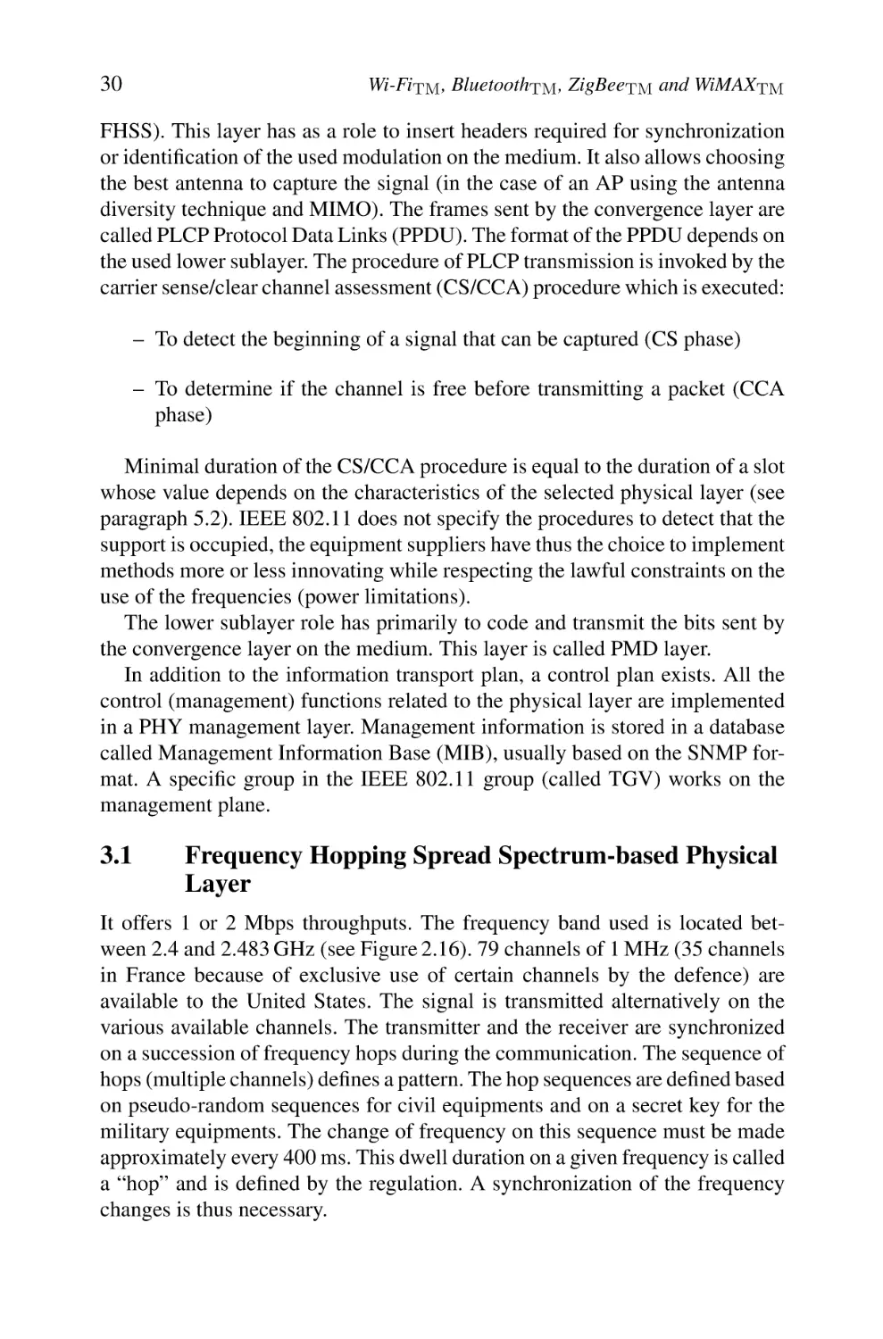


Автор: Labiod H. Afifi H. Santis C.
Теги: electronics internet mobile networks
ISBN: 978-1-4020-5396-2
Год: 2007


Текст
WI-FI TM , BLUETOOTH TM , ZIGBEE TM AND WIMAX TM
WI-FI TM , BLUETOOTH TM , ZIGBEE TM
AND WIMAXTM
by
H. LABIOD
ENST, Paris, France
H. AFIFI
INT, Evry, France
C. DE SANTIS
INT, Evry, France
A C.I.P. Catalogue record for this book is available from the Library of Congress.
ISBN 978-1-4020-5396-2 (HB)
ISBN 978-1-4020-5397-9 (e-book)
Published by Springer,
P.O. Box 17, 3300 AA Dordrecht, The Netherlands.
www.springer.com
Printed on acid-free paper
All Rights Reserved
© 2007 Springer
No part of this work may be reproduced, stored in a retrieval system, or transmitted
in any form or by any means, electronic, mechanical, photocopying, microfilming, recording
or otherwise, without written permission from the Publisher, with the exception
of any material supplied specifically for the purpose of being entered
and executed on a computer system, for exclusive use by the purchaser of the work.
I dedicate this book to my
husband, my parents and my
sister and brothers
Houda Laboid
Contents
Dedication
Preface
v
xiii
Foreword
xv
1
Introduction
1
2
Wi-FiTM : Architecture and Functions
1. WLAN Roadmap via IEEE 802.11 Family Evolution
1.1 Panorama of Standards
1.2 Features of the Different WLAN Generations
1.3 WLAN Markets
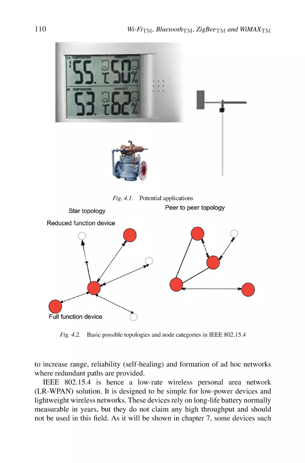
2. IEEE 802.11 Architecture
2.1 Three Basic Operational Modes
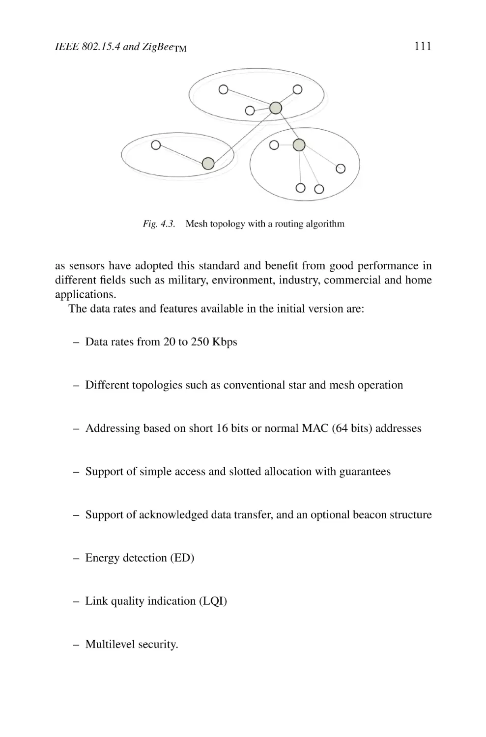
2.2 Possible Configurations
2.3 Basic Services
2.4 Description of Sublayers’ Structures
3. Different Physical Layers
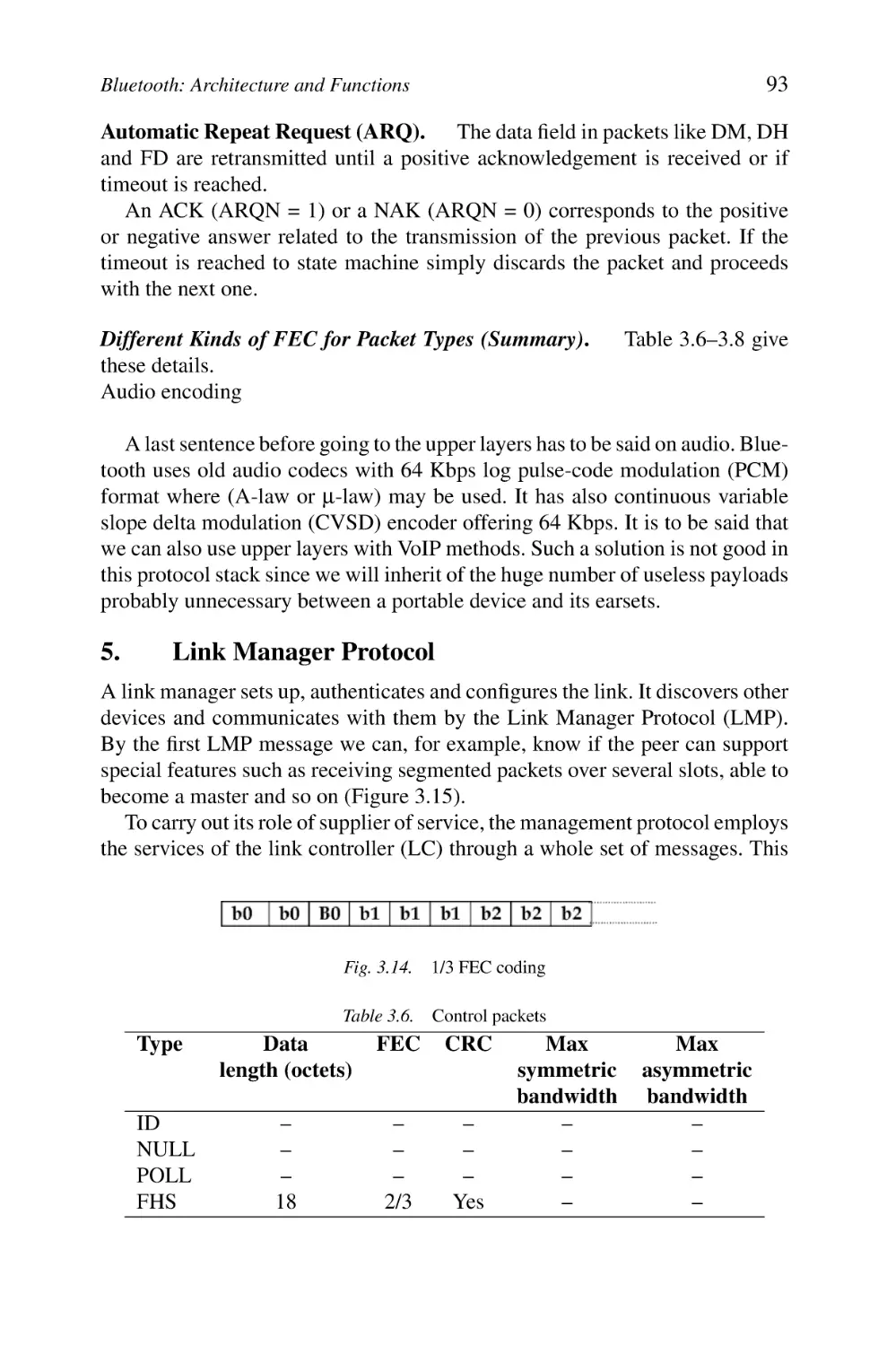
3.1 Frequency Hopping Spread Spectrum-based Physical Layer
3.2 Direct Sequence Spread Spectrum-based Physical Layer
3.3 Infrared Transmission
3.4 IEEE 802.11b Standard high Rate Direct Sequence
Spread Spectrum-based Physical Layer
3.5 The OFDM Technique of the IEEE 802.11a/g Standards
3.6 The IEEE 802.11n Physical Layer
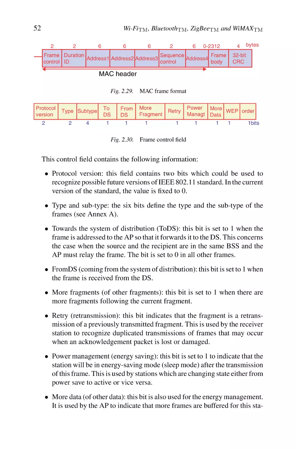
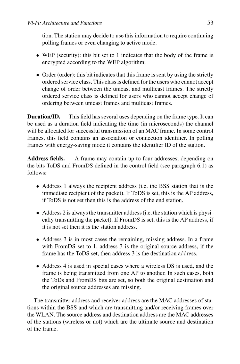
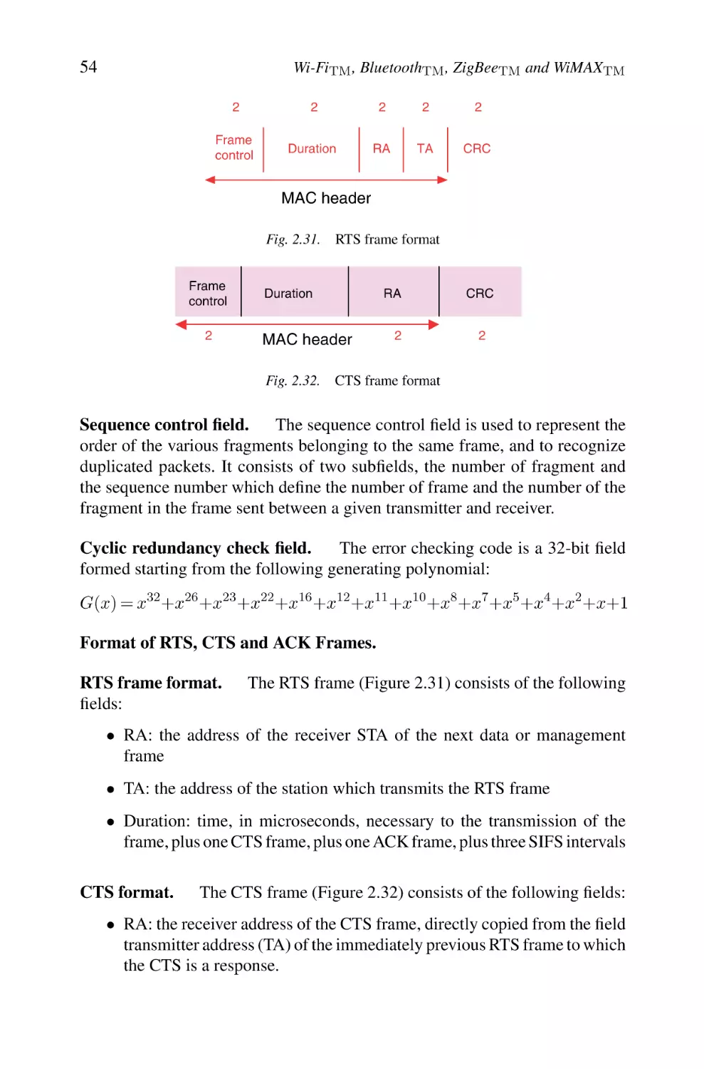
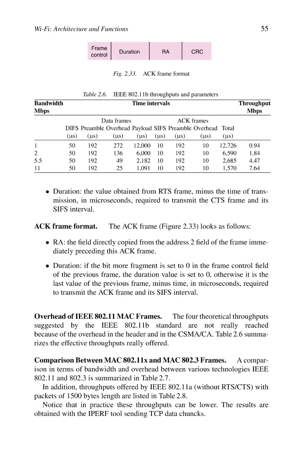
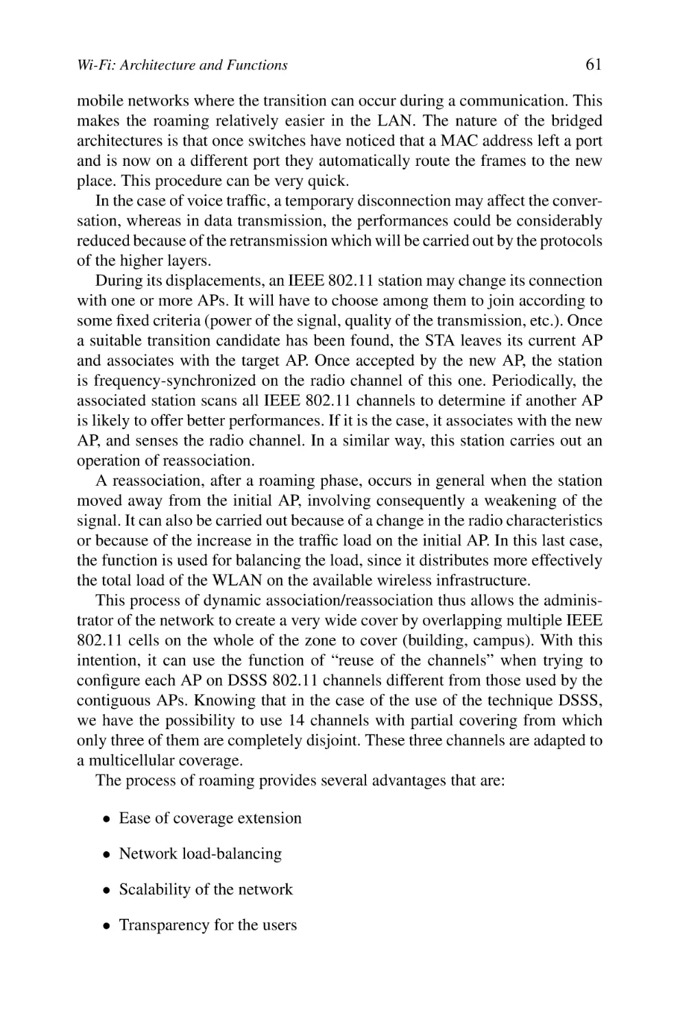
3.7 Frame Formats
4. Data Link Layer
5. Medium Access Control Layer
5.1 Medium Access Mechanisms
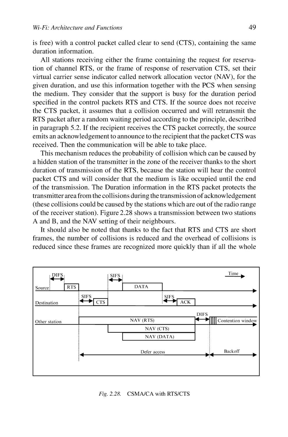
5.2 Basic Access Technique CSMA/CA
5.3 Virtual Carrier Sense CSMA/CA Mechanism
with Short Messages RTS and CTS
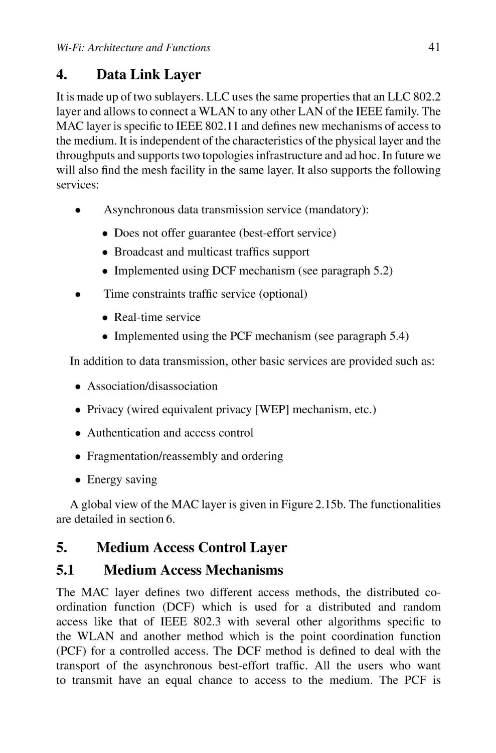
5.4 PCF and HCF
5.5 Frames Formats
6. Functions
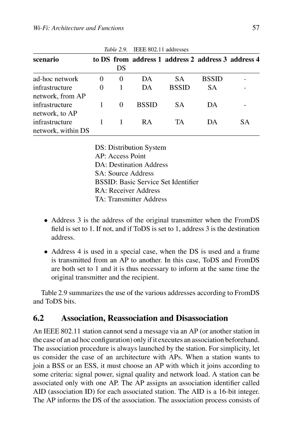
6.1 Addressing
6.2 Association, Reassociation and Disassociation
vii
5
5
6
10
12
15
15
19
27
27
29
30
32
35
36
36
38
40
41
41
41
42
48
50
51
56
56
57
viii
Contents
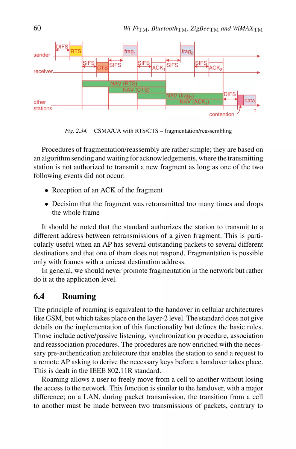
6.3 Fragmentation and Reassembling
6.4 Roaming
6.5 Synchronization
6.6 Energy Conserving
6.7 Management Frames Format
7. Mobility
8. Security
9. IEEE 802.11 Family and its Derivative Standards
9.1 IEEE 802.11g
9.2 IEEE 802.11e
9.3 IEEE 802.11d
9.4 IEEE 802.11F
9.5 IEEE 802.11h
9.6 IEEE 802.11i and IEEE 802.1X
9.7 IEEE 802.11k
9.8 IEEE 802.11j
9.9 IEEE 802.11p
9.10 IEEE 802.11u
9.11 IEEE 802.11v
9.12 IEEE 802.11r (Fast Roaming/Fast BSS Transition)
9.13 IEEE 802.11s
9.14 IEEE 802.11w
10. Wi-Fi and Other Technologies, Concurrency or Complementarity?
3
BluetoothTM : Architecture and Functions
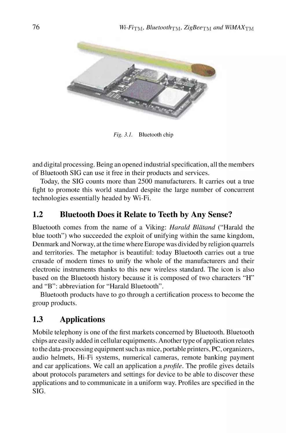
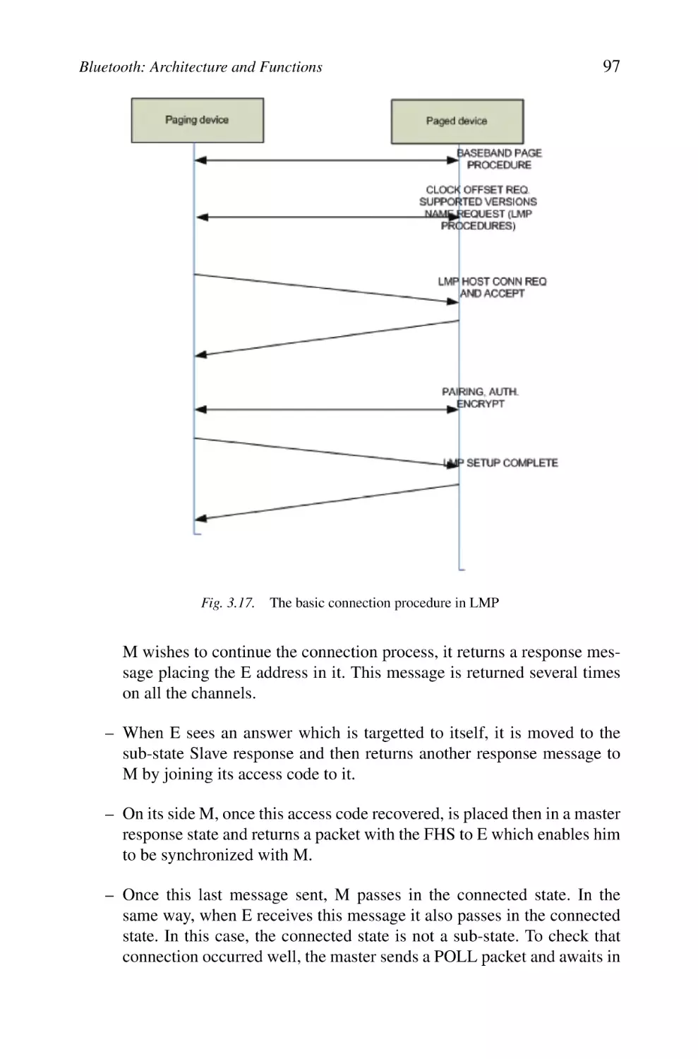
1. Introduction
1.1 SIG
1.2 Bluetooth Does it Relate to Teeth by Any Sense?
1.3 Applications
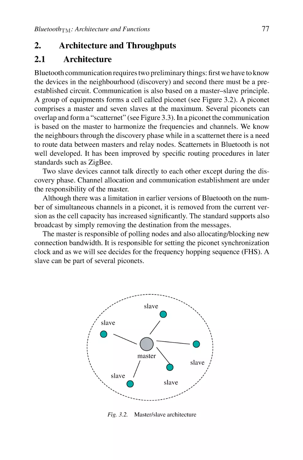
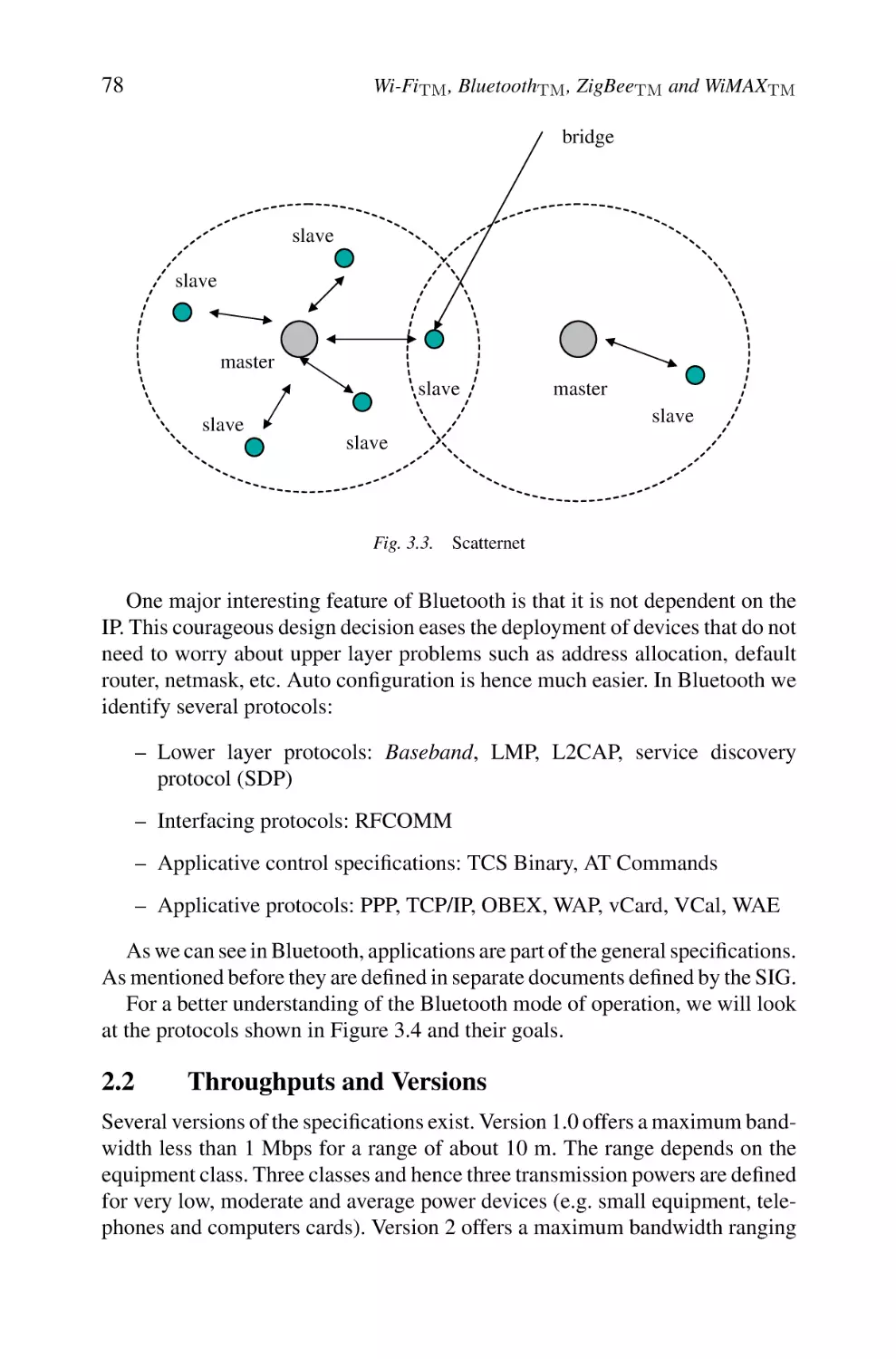
2. Architecture and Throughputs
2.1 Architecture
2.2 Throughputs and Versions
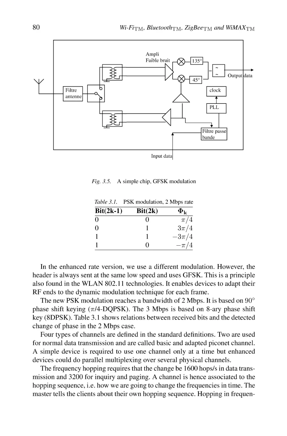
3. Physical Layer and Physical Channels
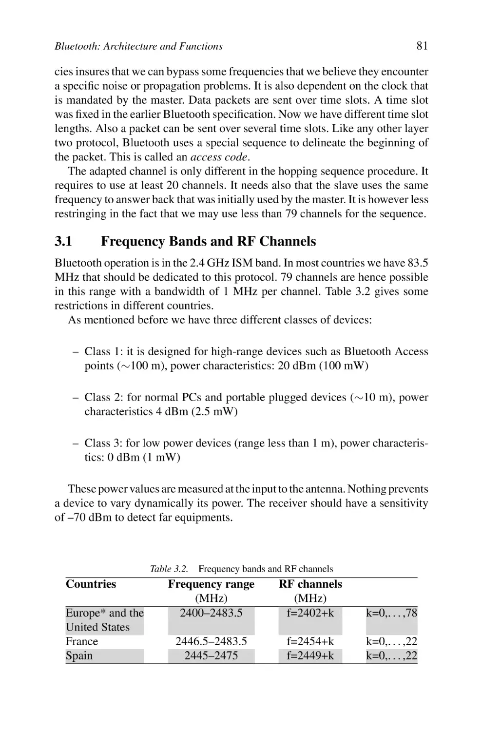
3.1 Frequency Bands and RF Channels
4. Baseband Layer
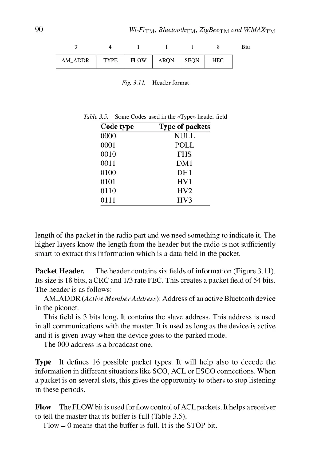
4.1 Physical Characteristics
4.2 Addressing
4.3 Bluetooth Packets
4.4 Error Control
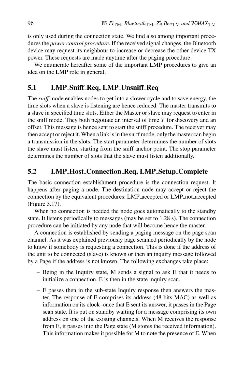
5. Link Manager Protocol
5.1 LMP Sniff Req, LMP Unsniff Req
5.2 LMP Host Connection Req, LMP Setup Complete
5.3 LMP AU RAND, LMP SRES
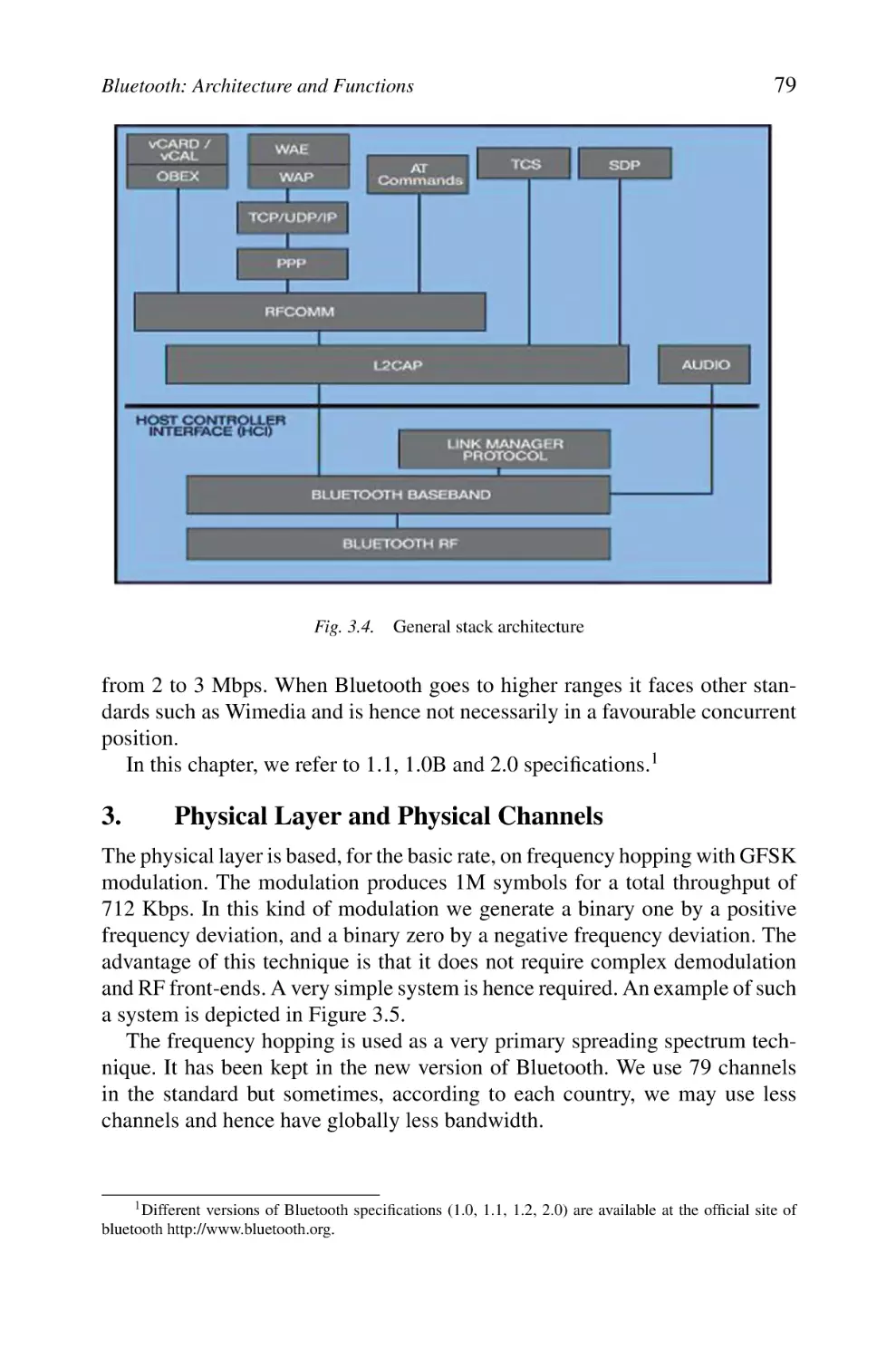
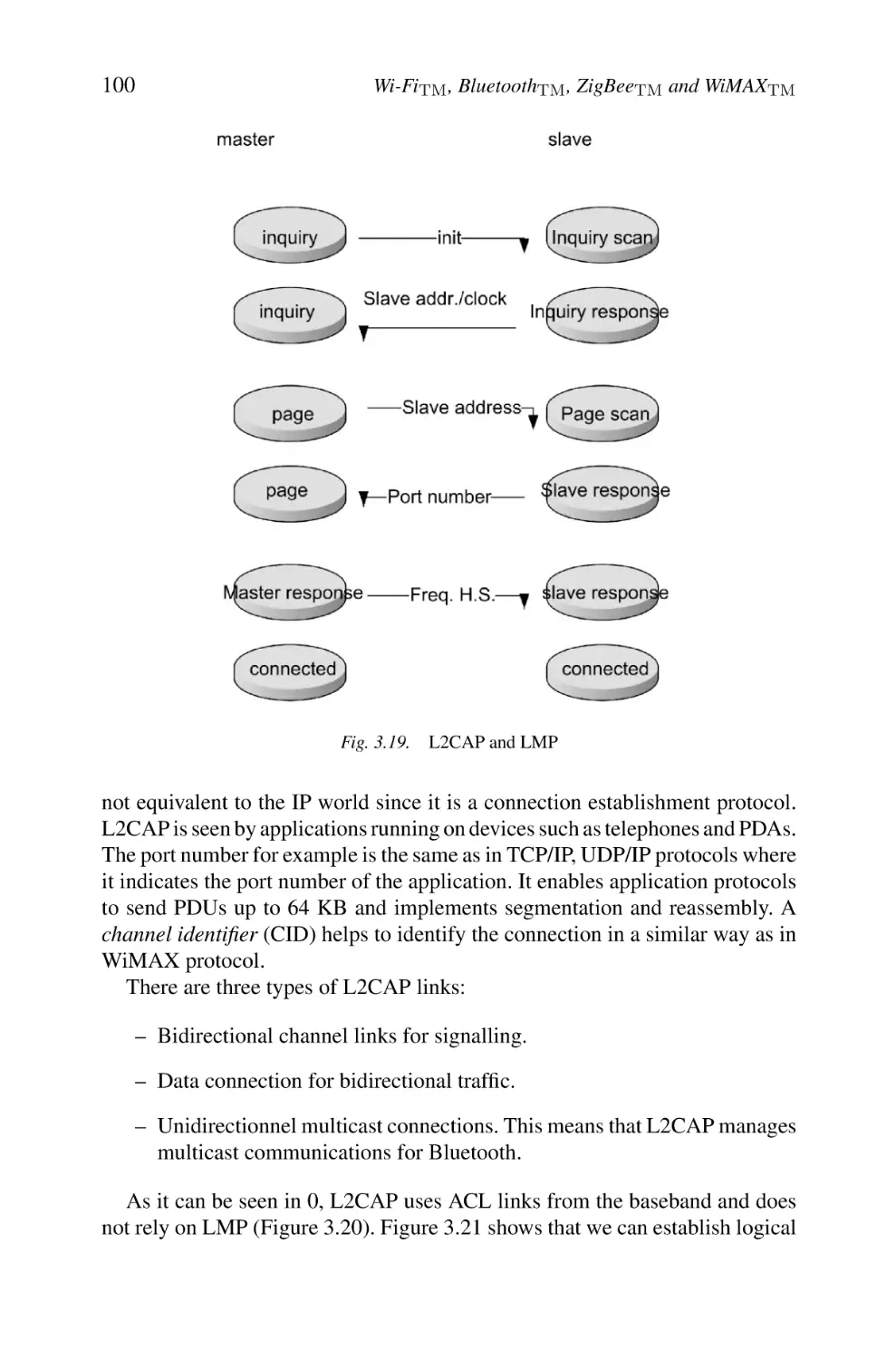
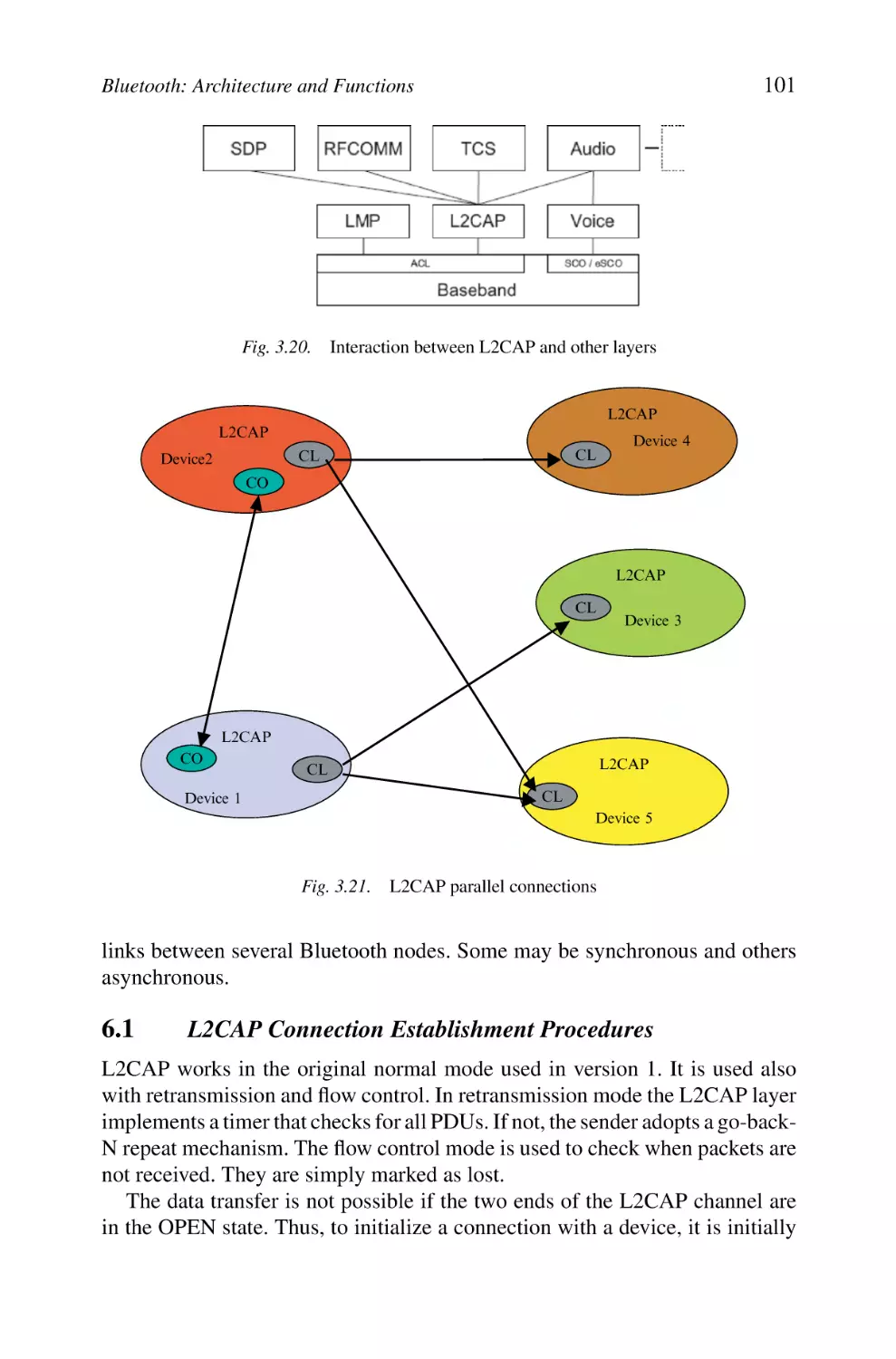
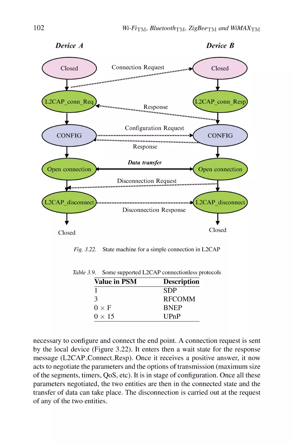
6. Logical Link Control and Adaptation Protocol
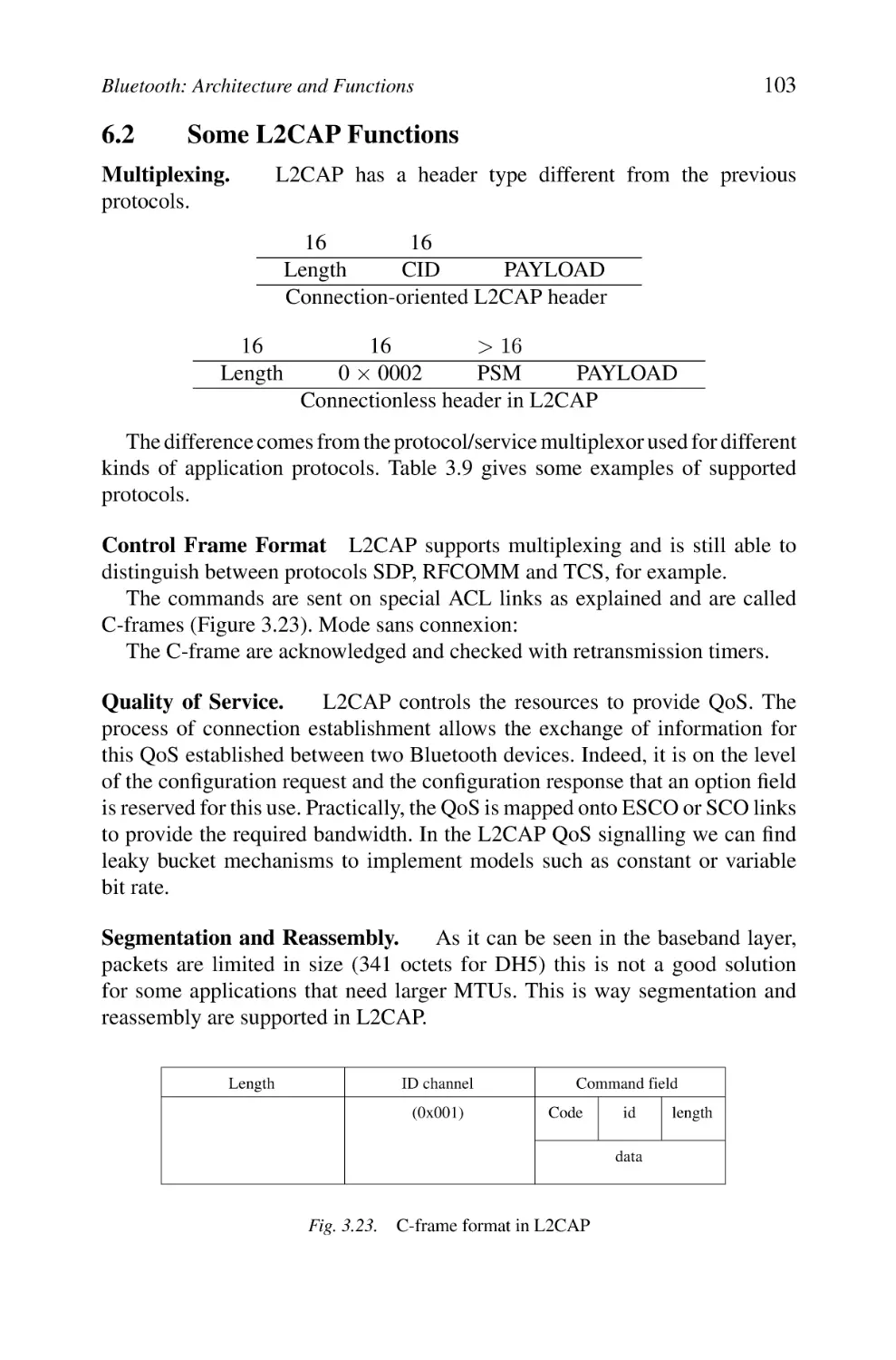
6.1 L2CAP Connection Establishment Procedures
6.2 Some L2CAP Functions
59
60
62
62
63
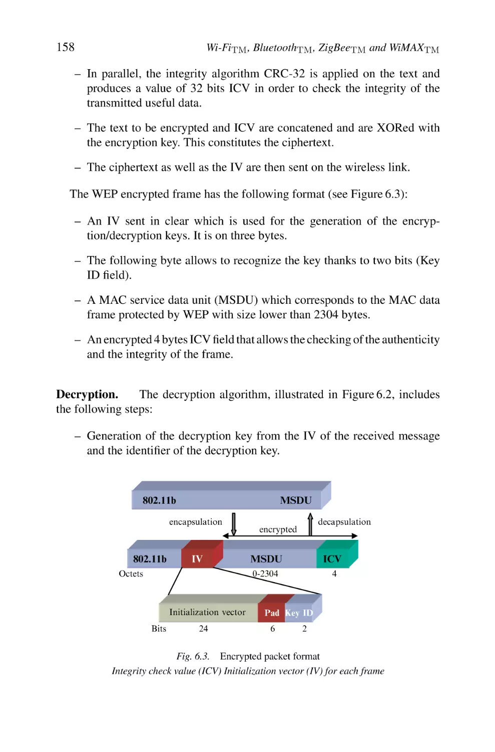
64
64
65
65
66
66
67
67
67
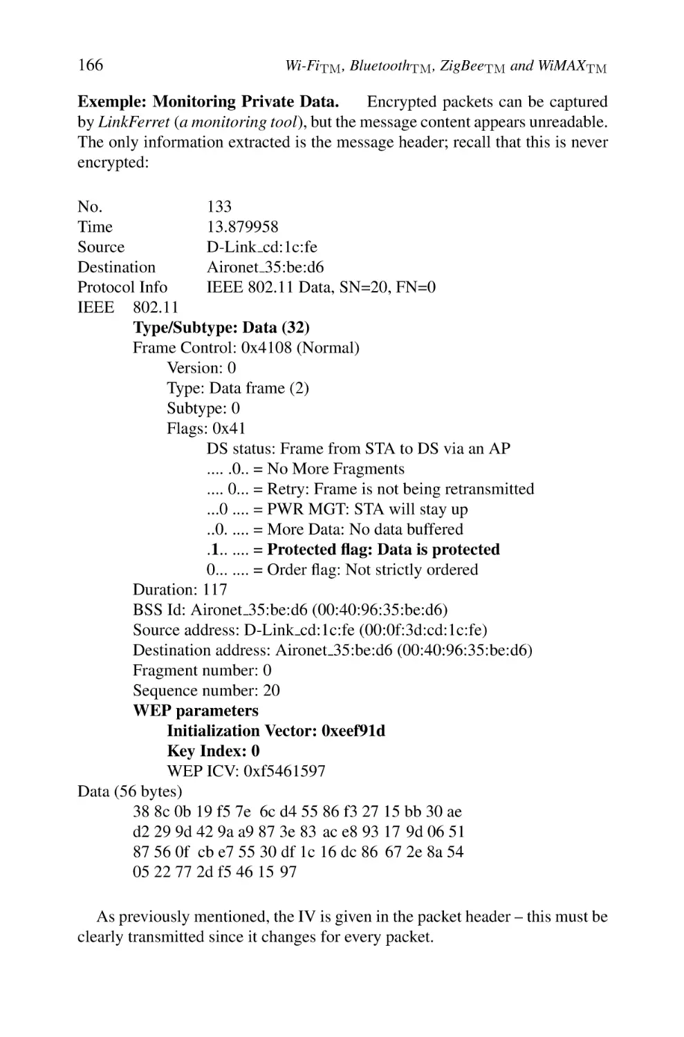
67
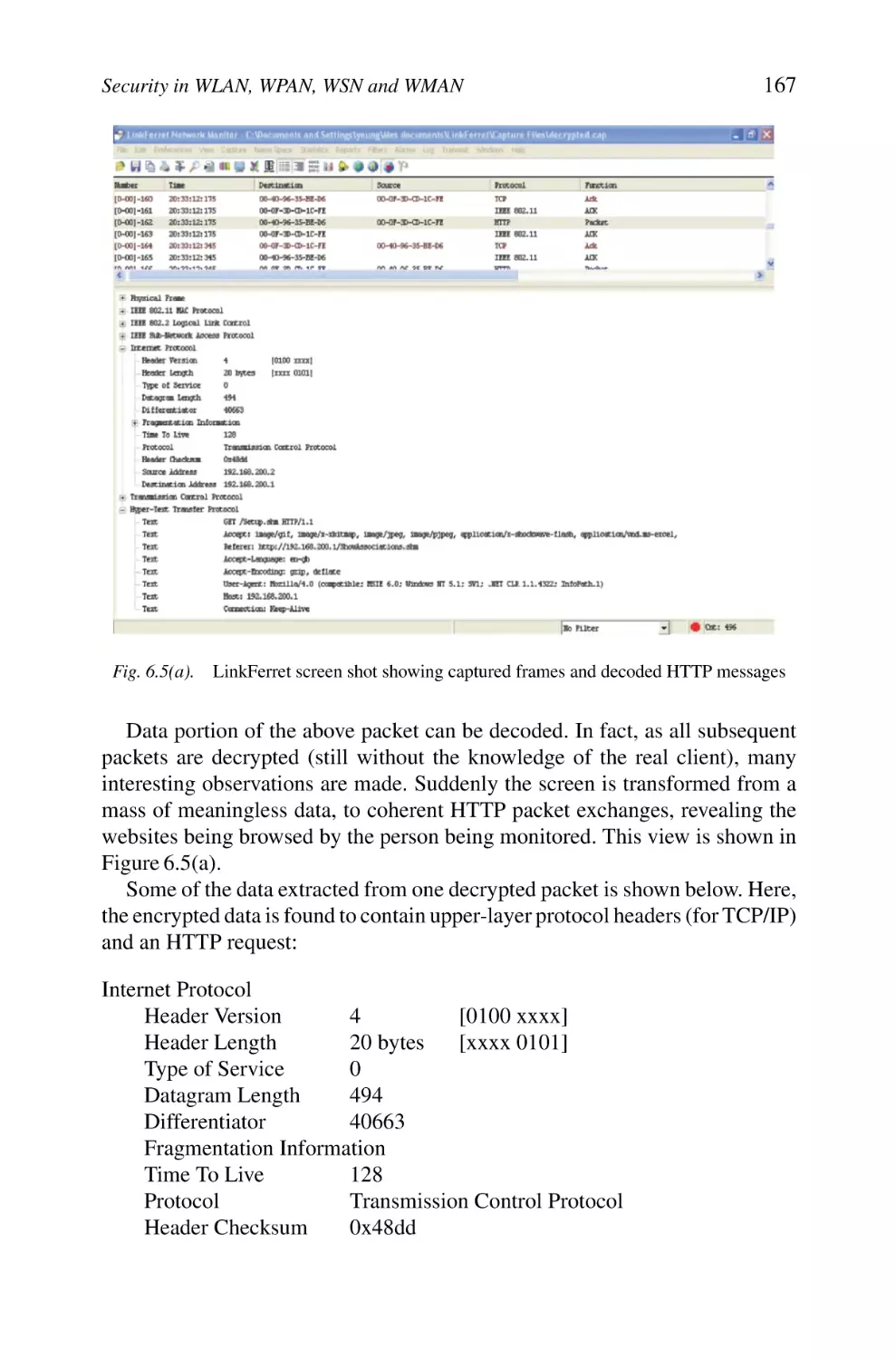
68
69
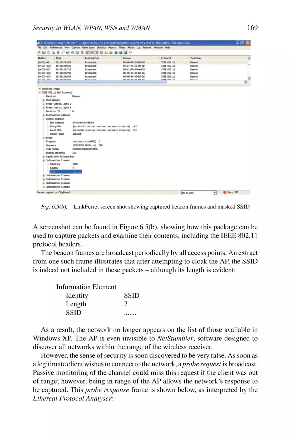
70
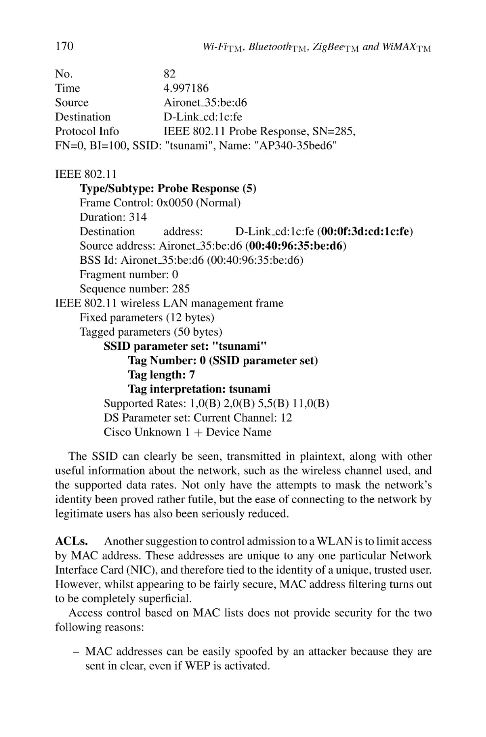
70
70
72
73
73
75
75
75
76
76
77
77
78
79
81
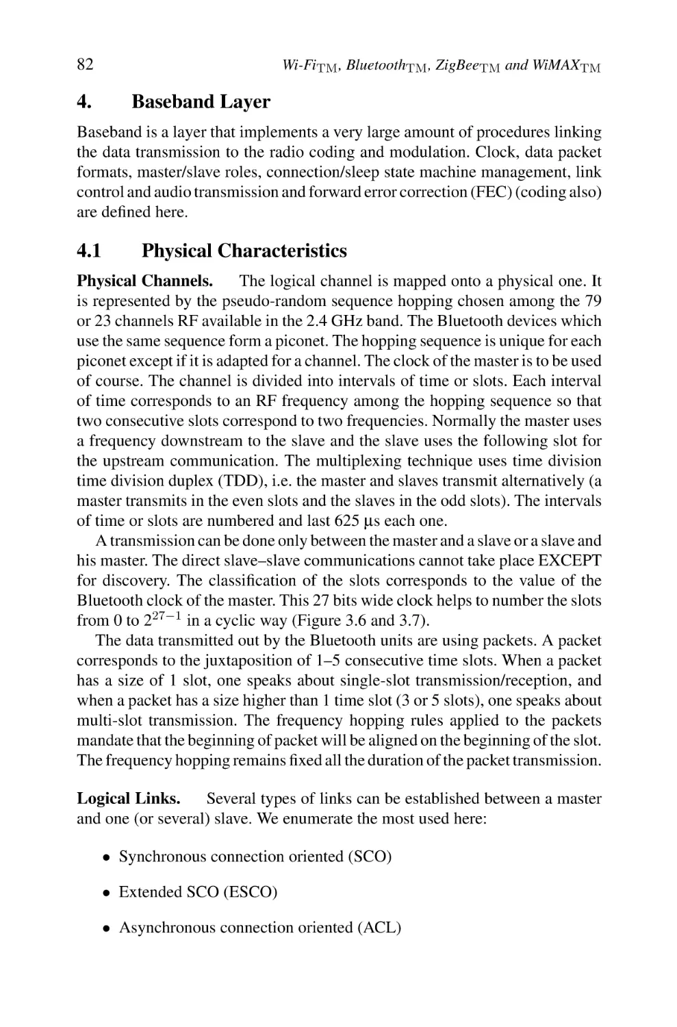
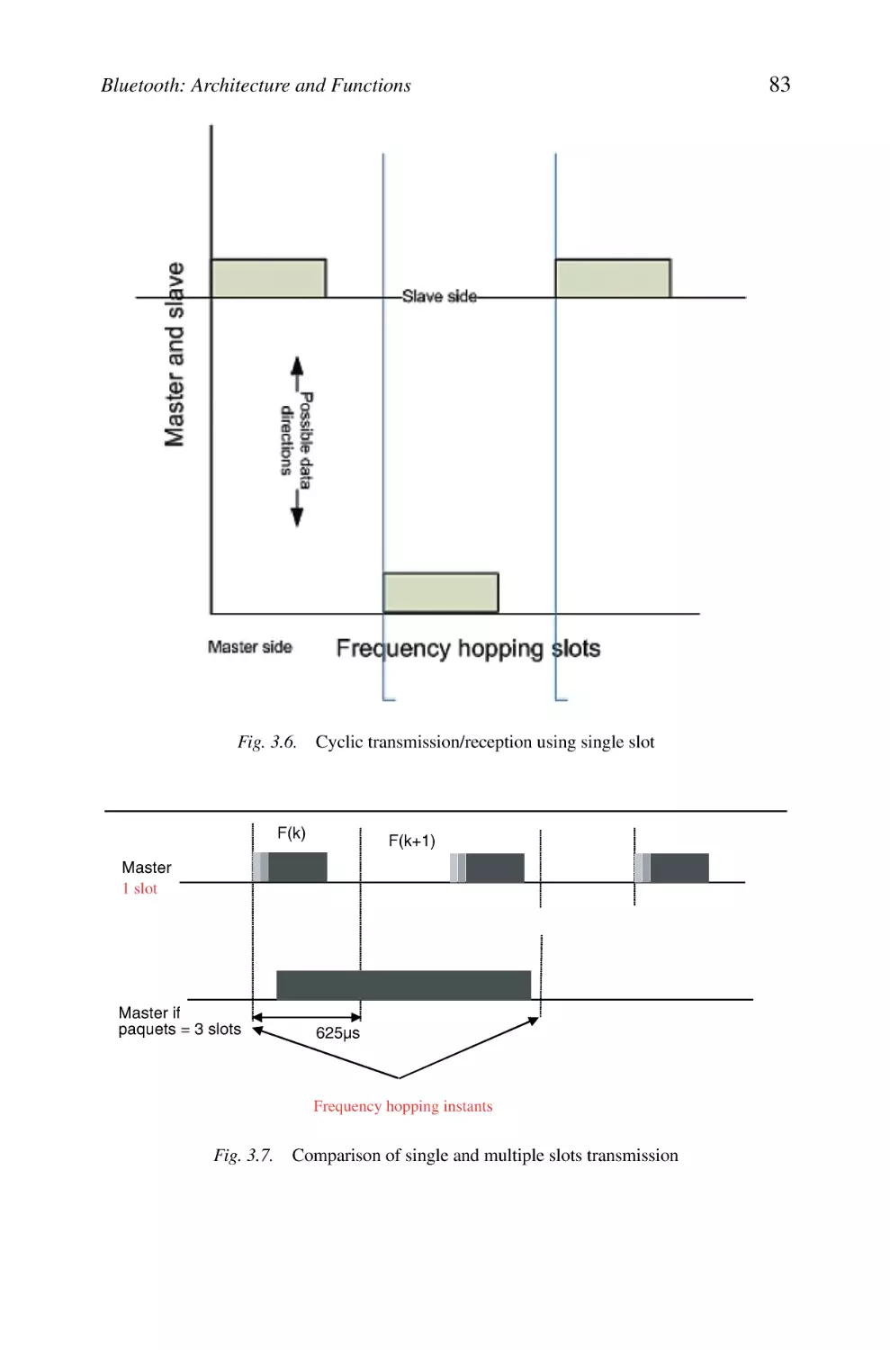
82
82
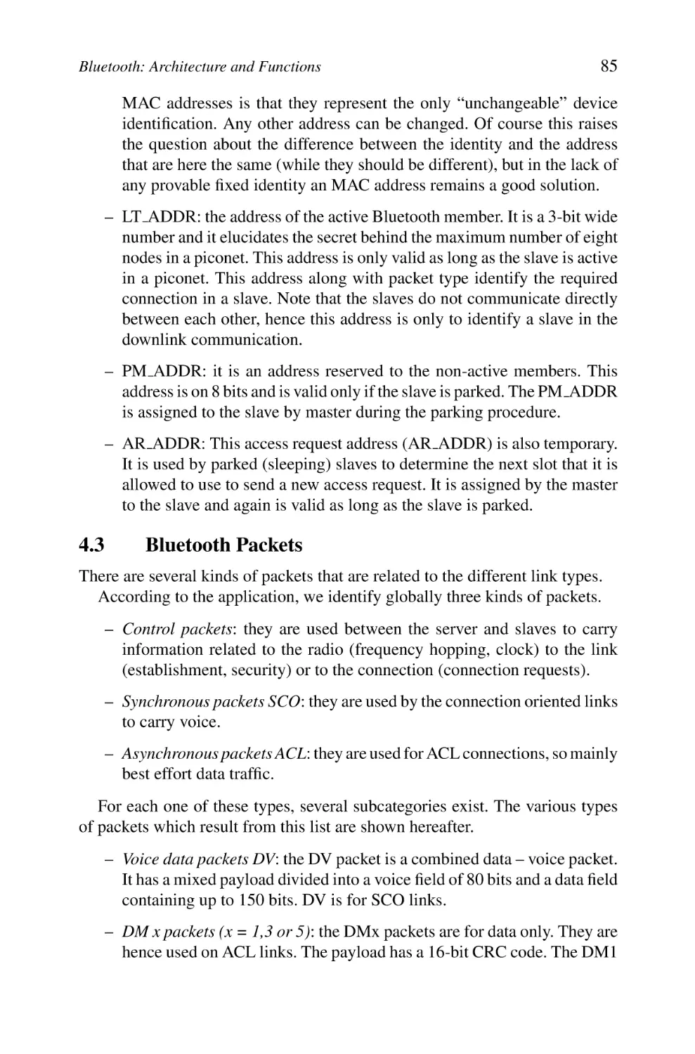
84
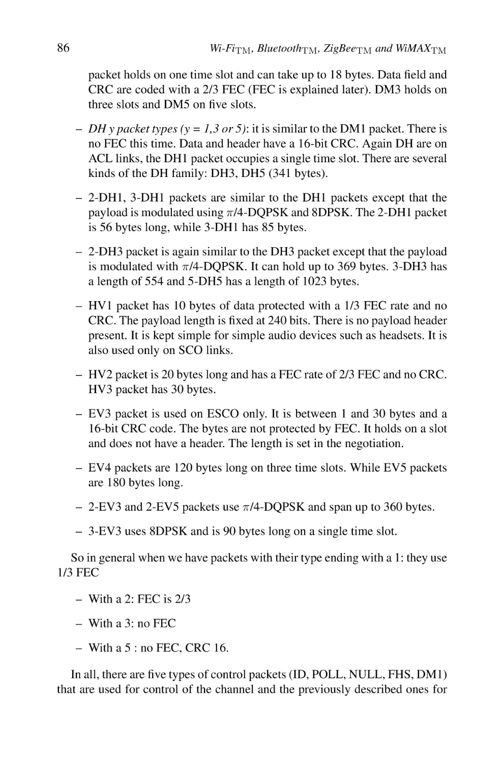
85
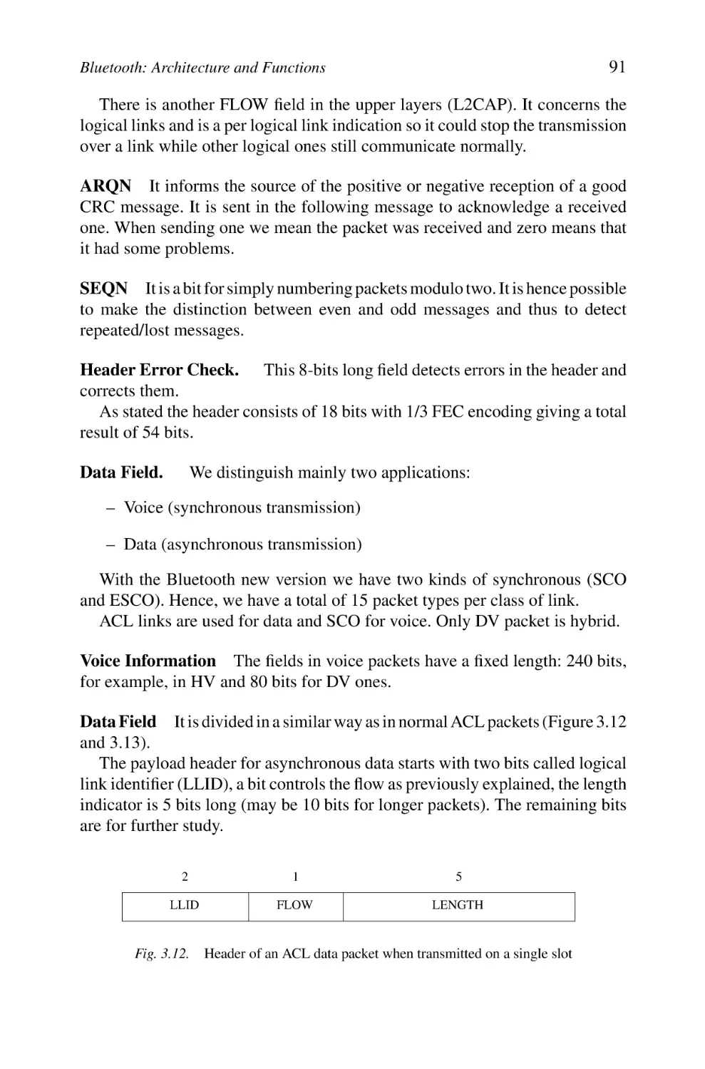
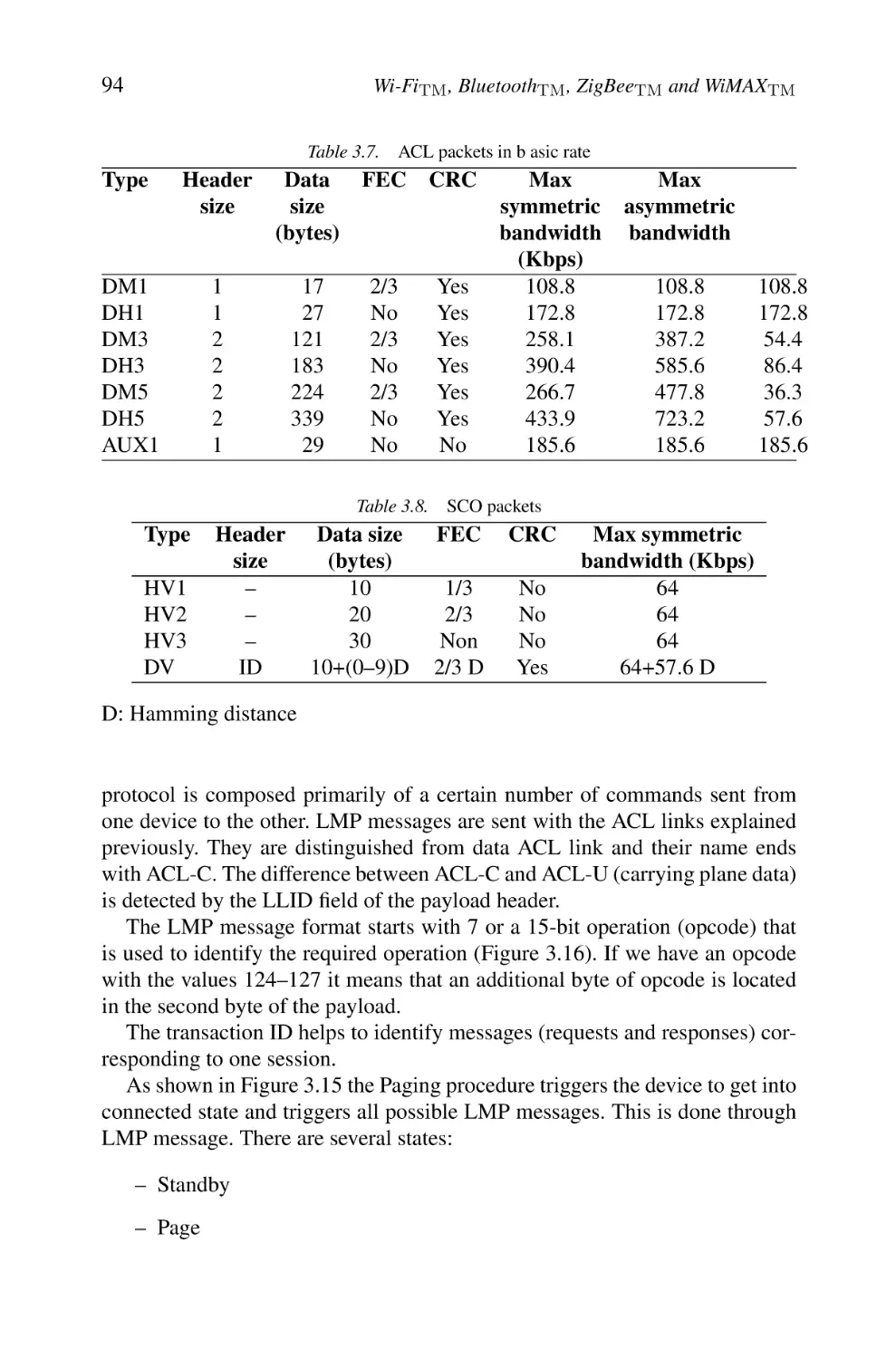
92
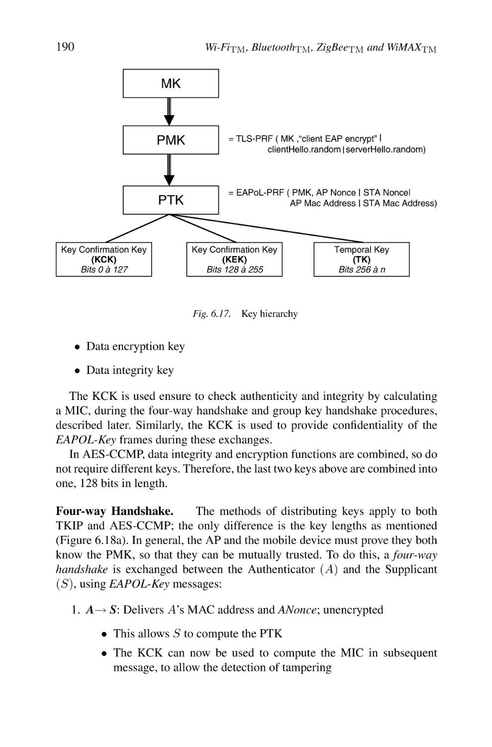
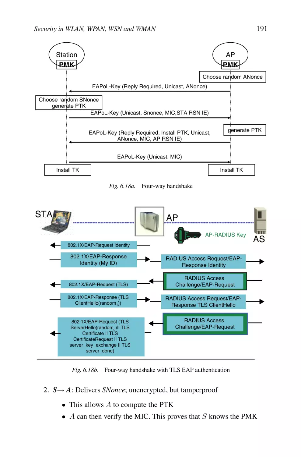
93
96
96
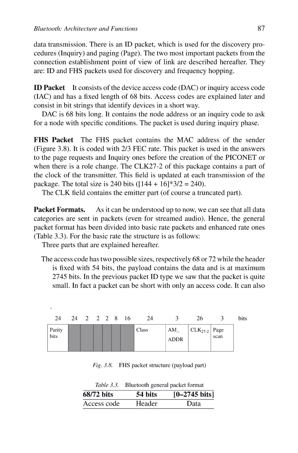
98
99
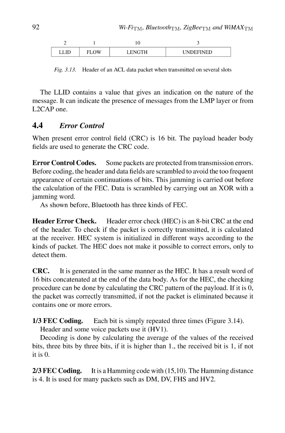
101
103
Contents
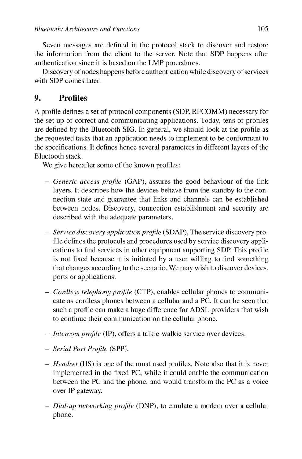
7. RFCOMM Protocol
8. Service Discovery Protocol
9. Profiles
10. Host Control Interface
11. Bluetooth Network Encapsulation Protocol
12. Conclusion
4
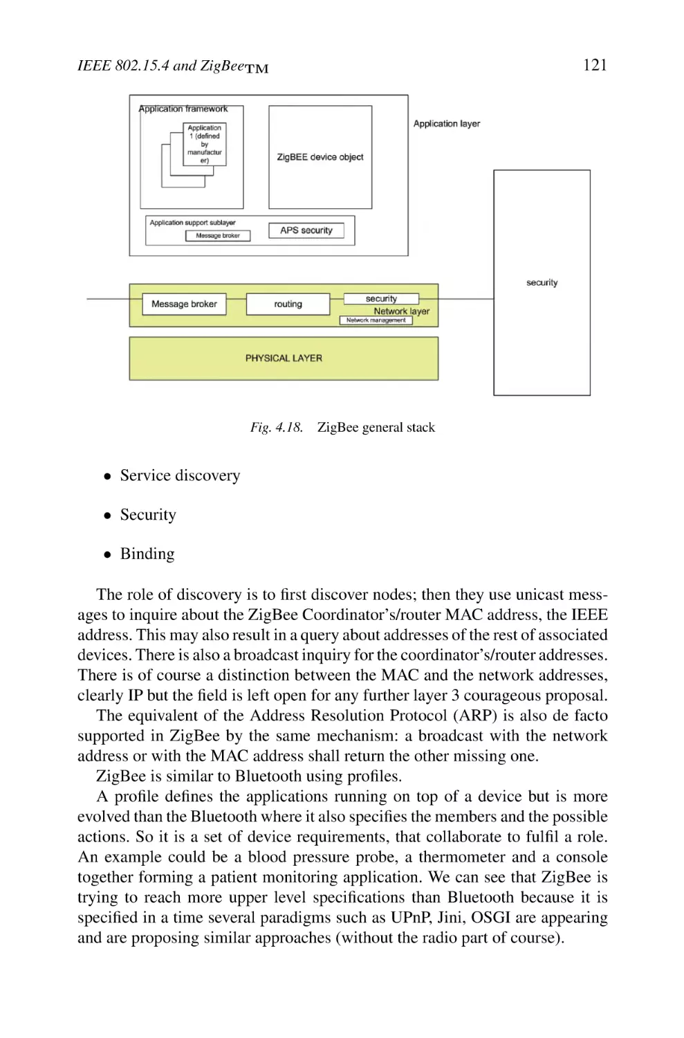
IEEE 802.15.4 and ZigBeeTM
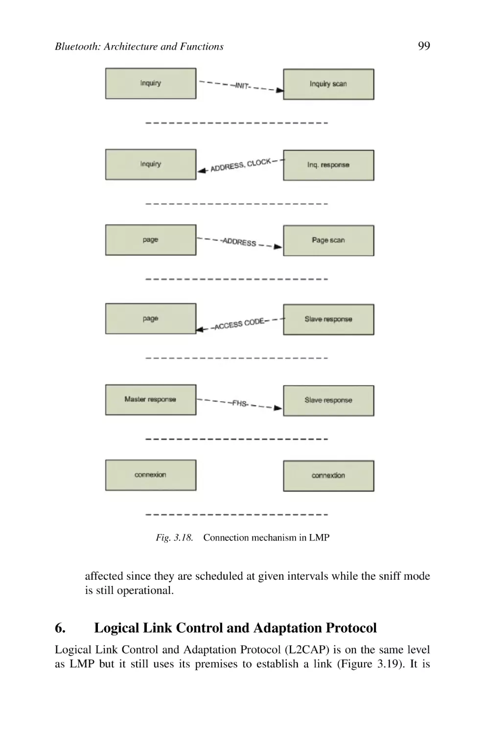
1. General Architecture
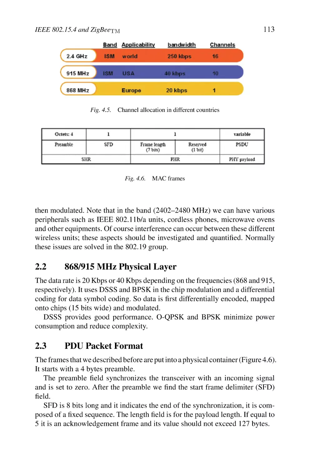
2. Physical Layer
2.1 2450 MHz Physical Layer
2.2 868/915 MHz Physical Layer
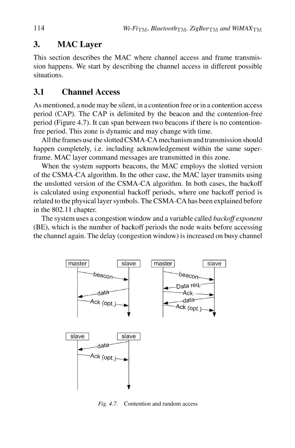
2.3 PDU Packet Format
3. MAC Layer
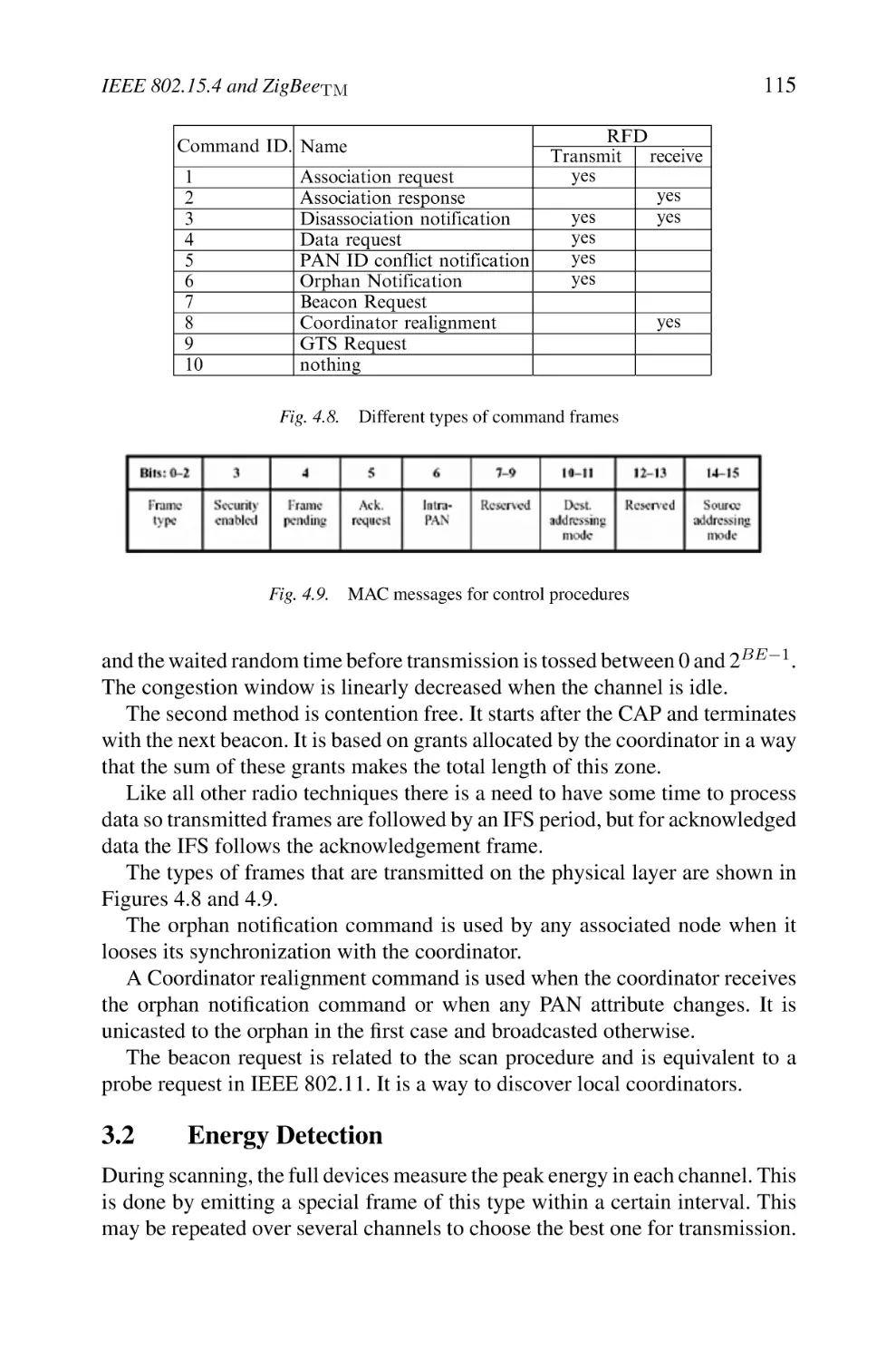
3.1 Channel Access
3.2 Energy Detection
3.3 Active and Passive Scan
3.4 Association Procedure
3.5 Guaranteed Time Slot
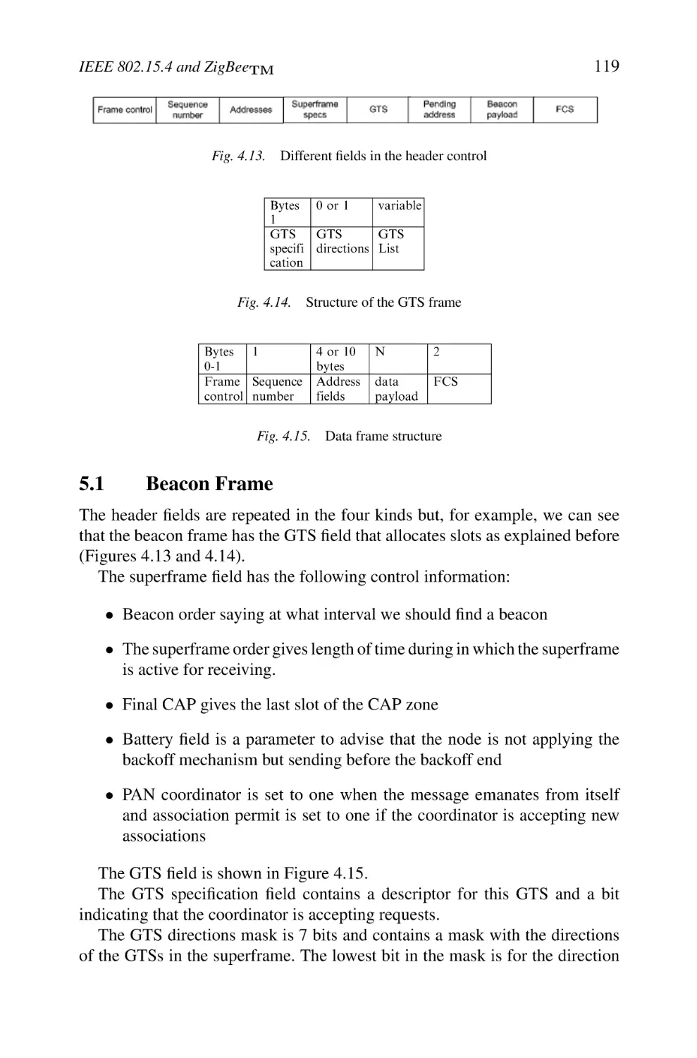
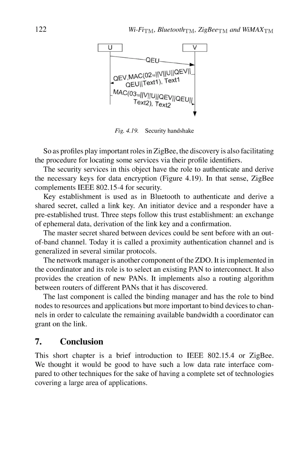
4. Security
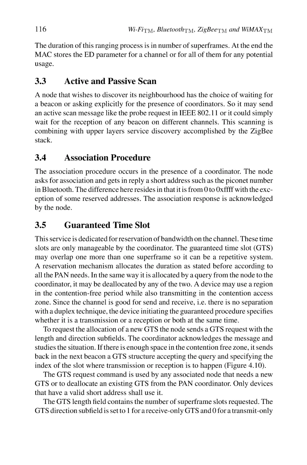
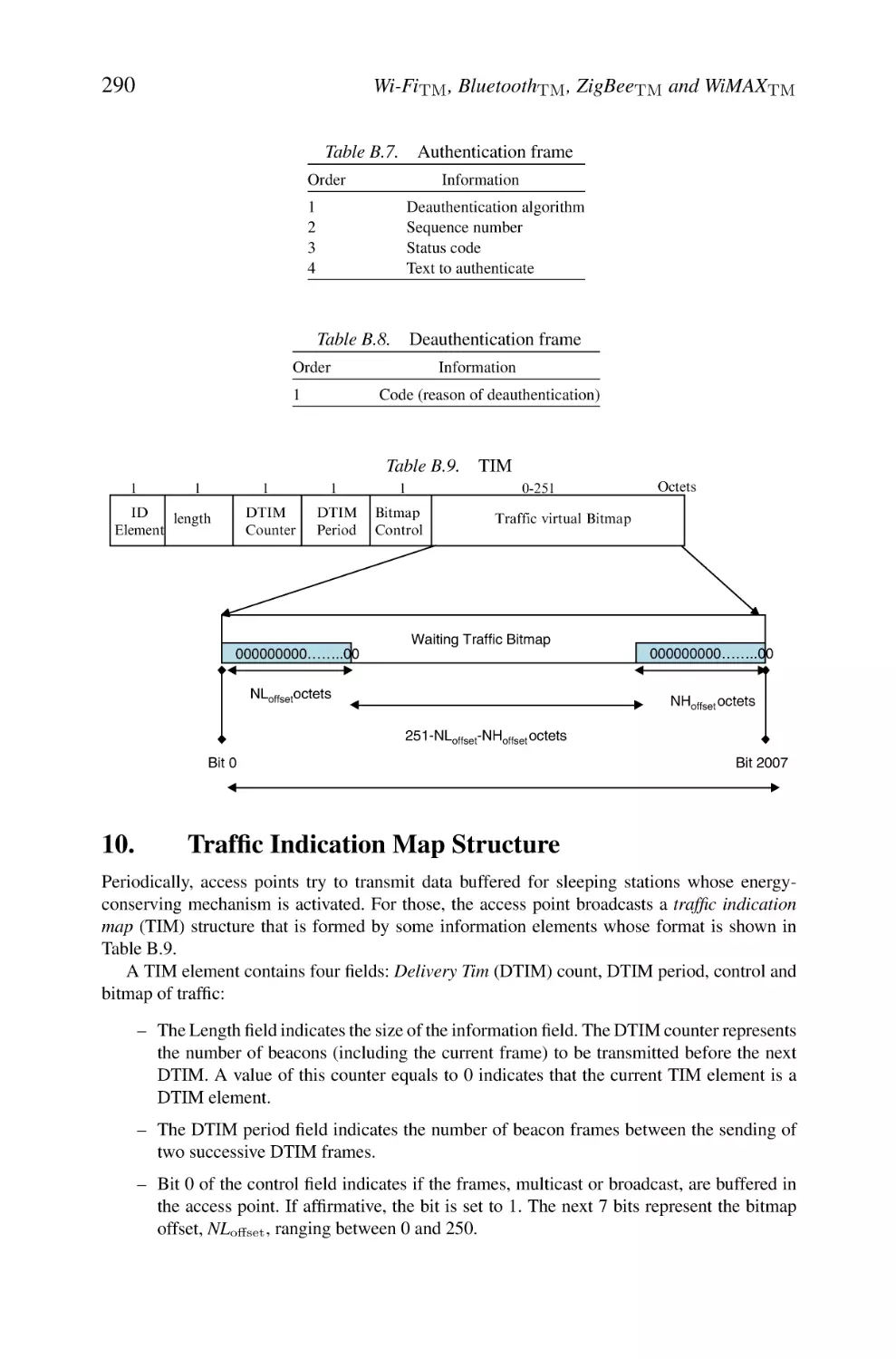
5. Frame Structures
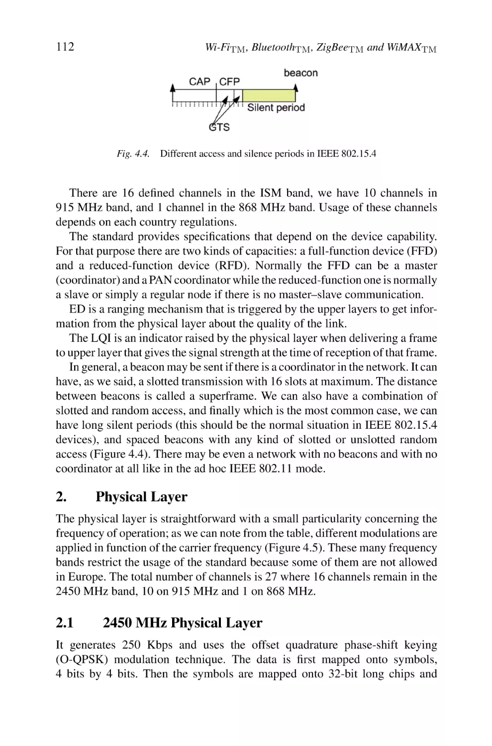
5.1 Beacon Frame
5.2 Data Frame
6. ZigBee
7. Conclusion
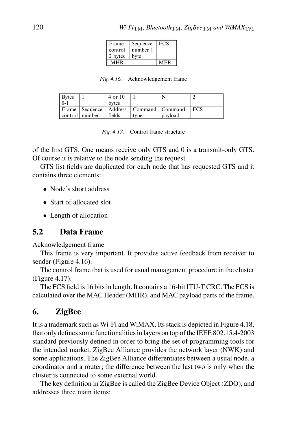
5
WiMAXTM and IEEE 802.16
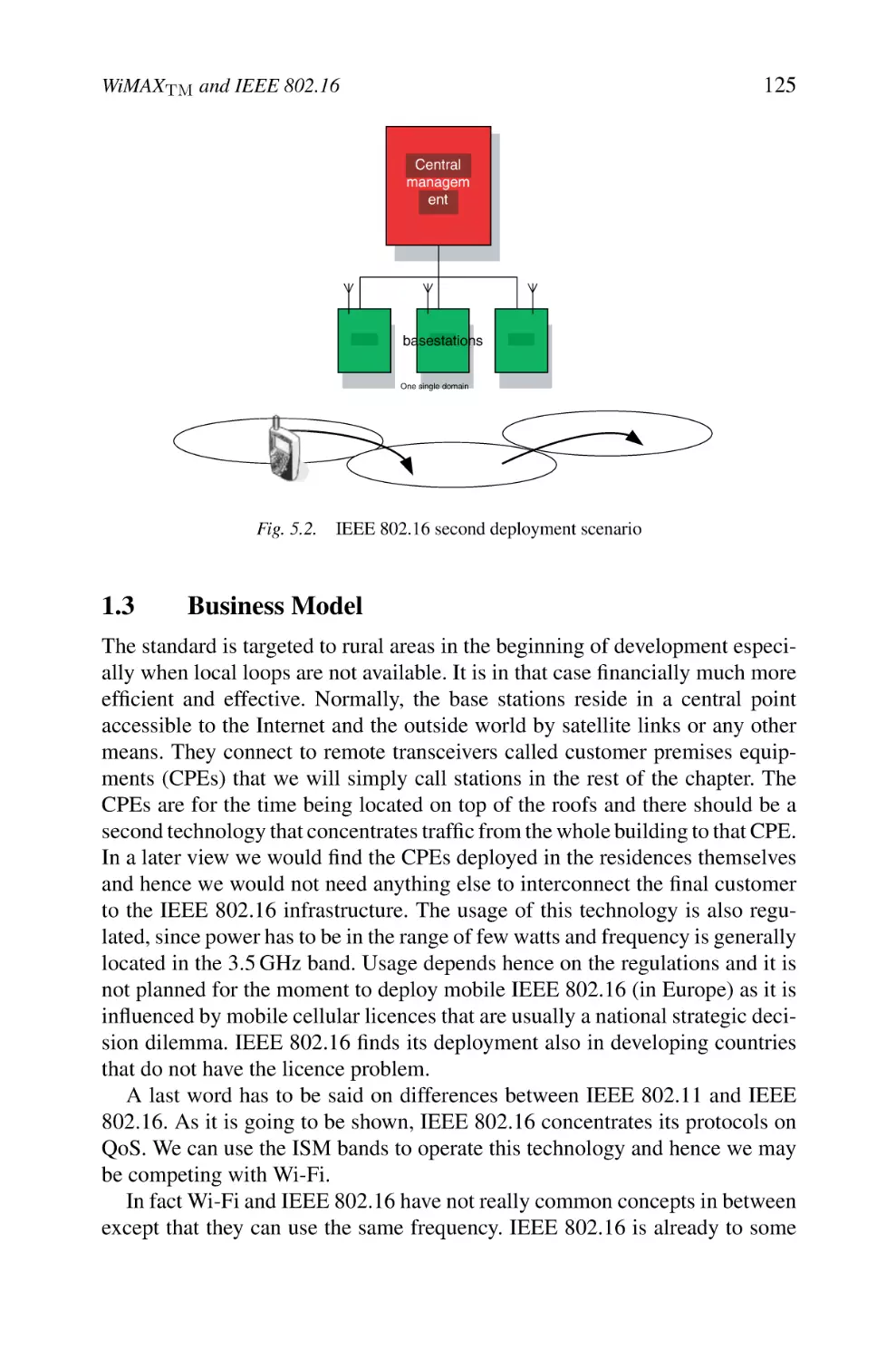
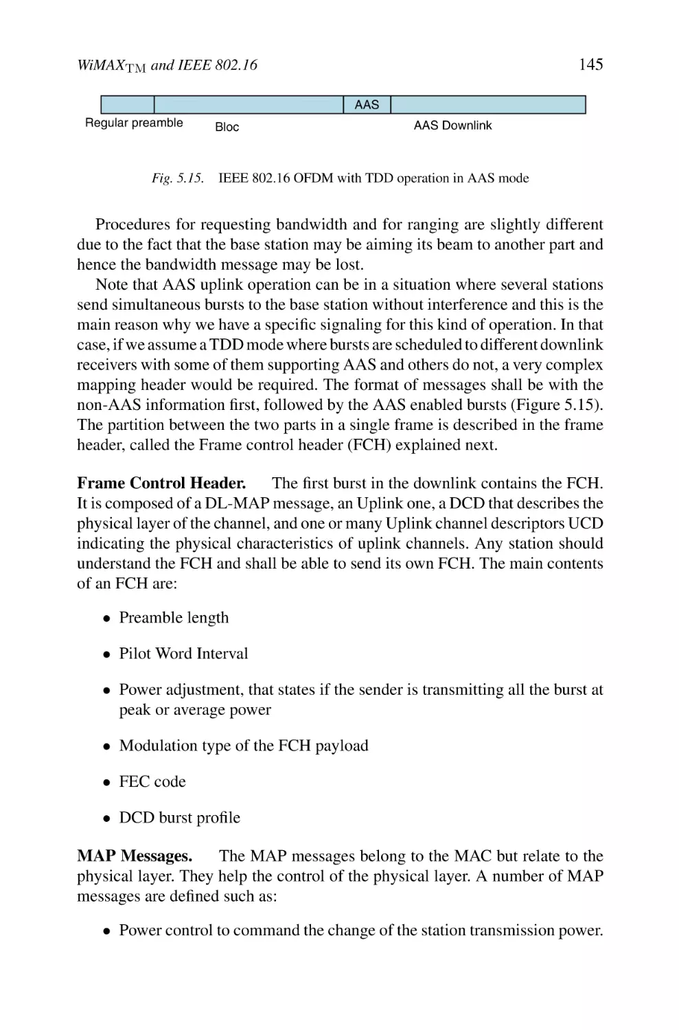
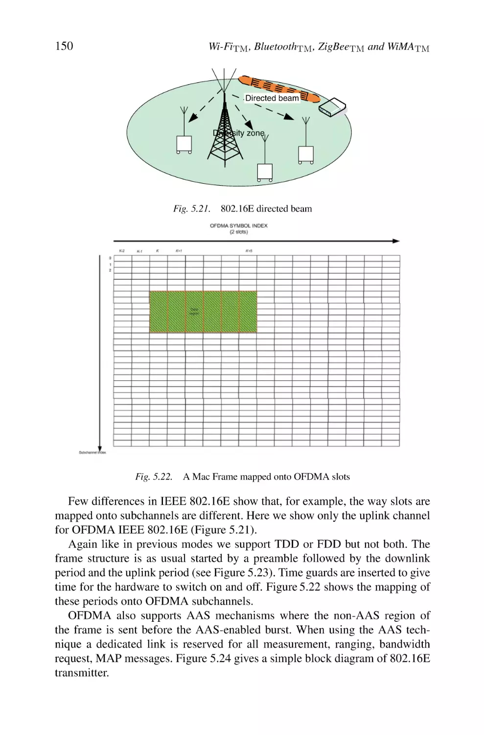
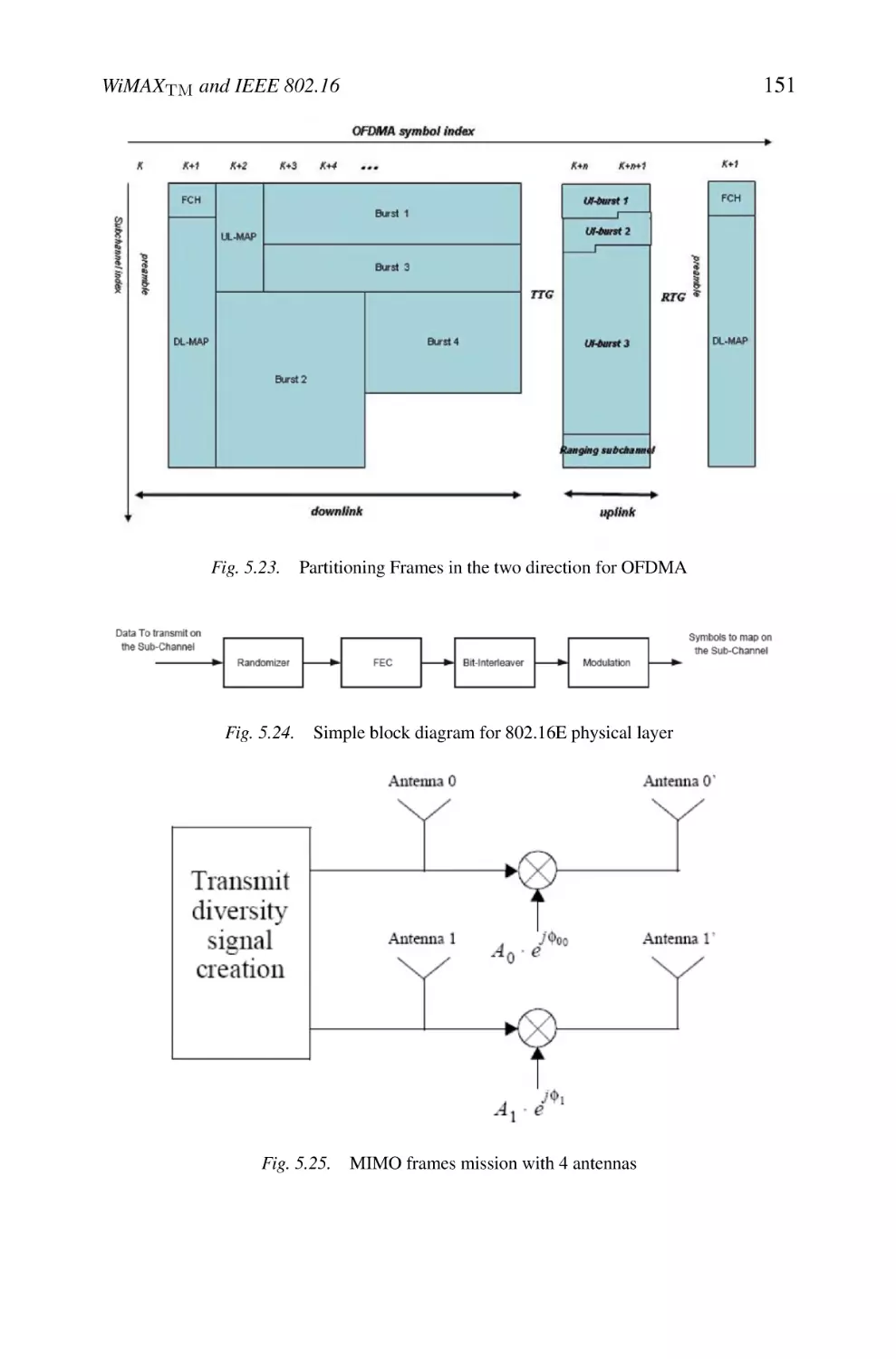
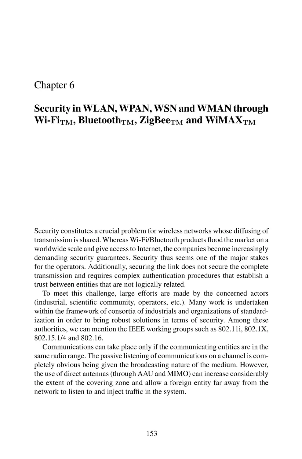
1. Introduction
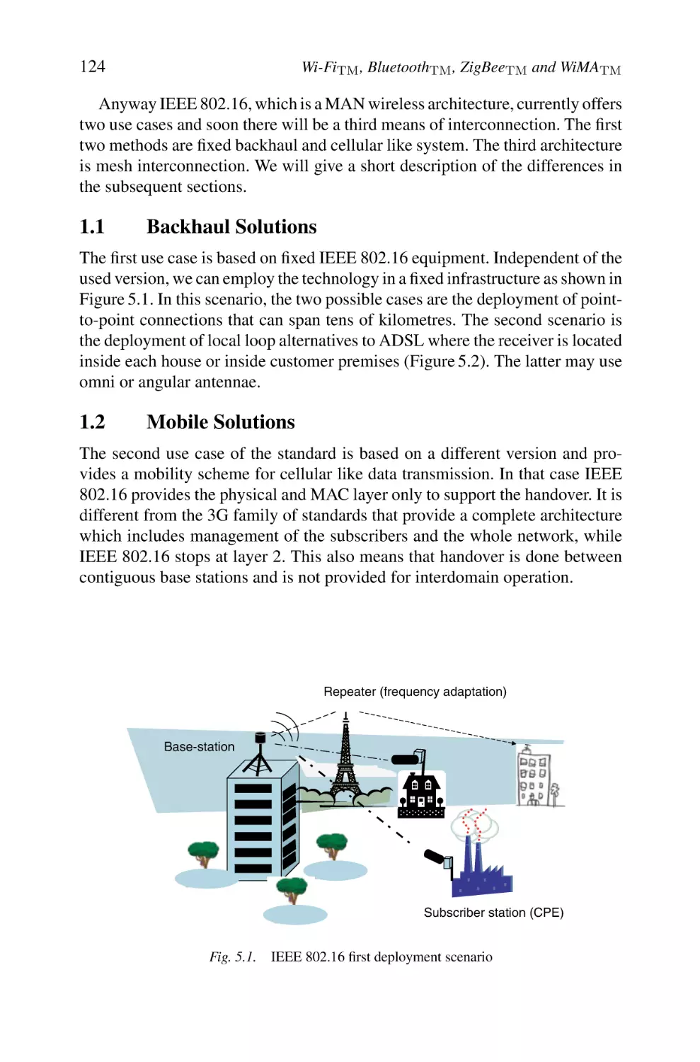
1.1 Backhaul Solutions
1.2 Mobile Solutions
1.3 Business Model
1.4 Evolution of the IEEE 802.16 Group Activities
1.5 Equipment Category and Frequency Bands
1.6 Layers and Architecture
2. MAC Layer
2.1 Automatic Repeat Request
2.2 Scheduling and QoS
2.3 Contention Resolution in IEEE 802.16
2.4 Adaptive Antenna System
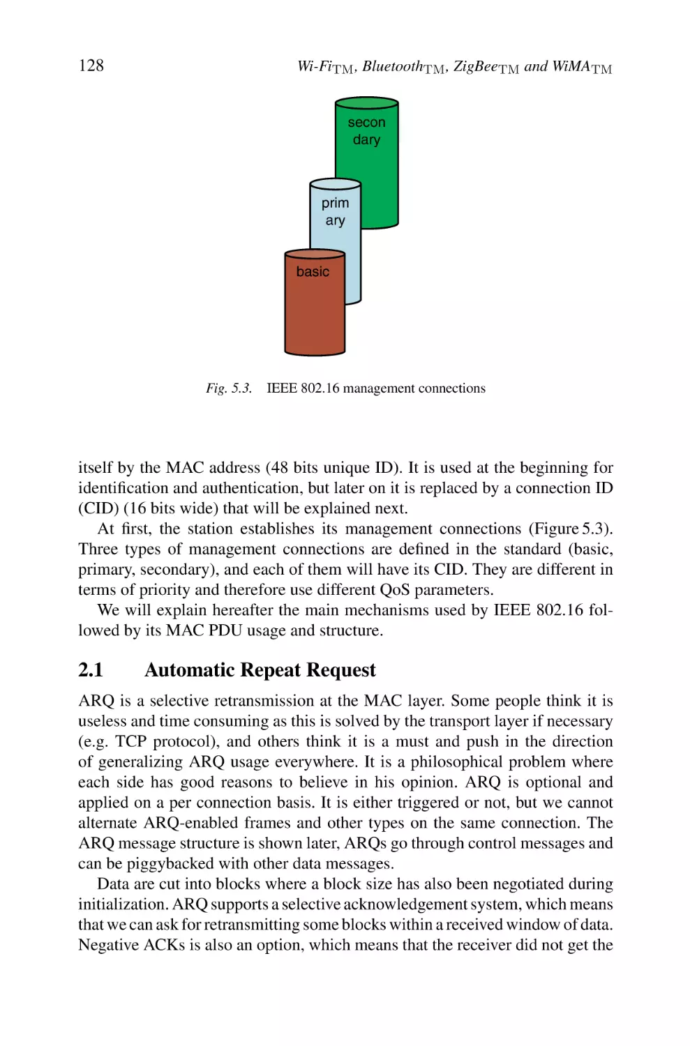
2.5 Joining an IEEE 802.16 Network and Initialization
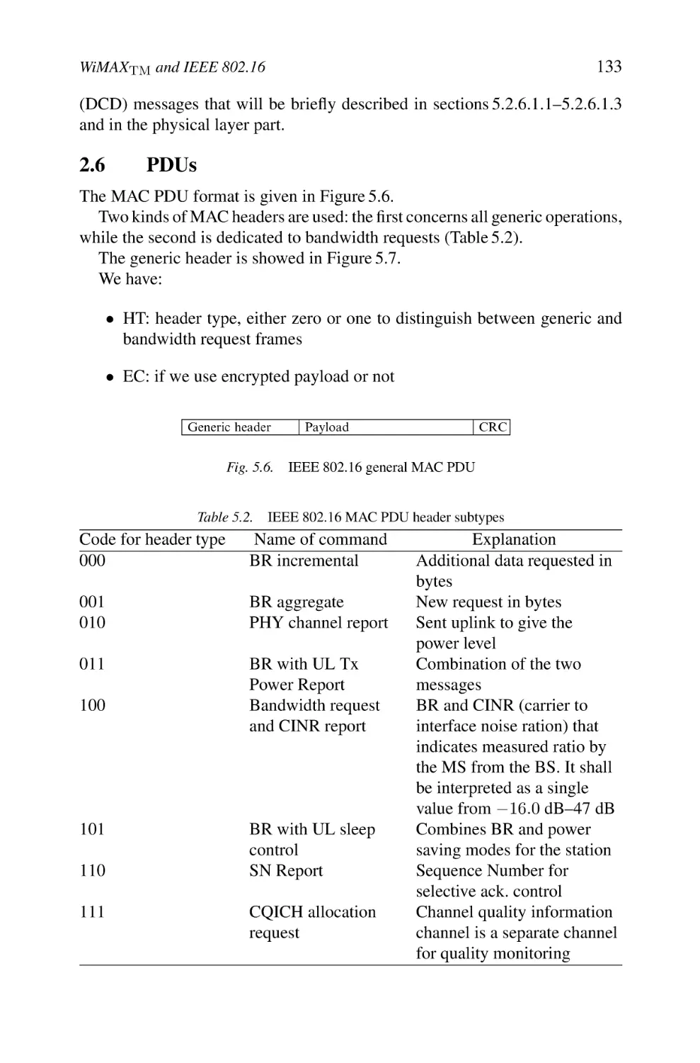
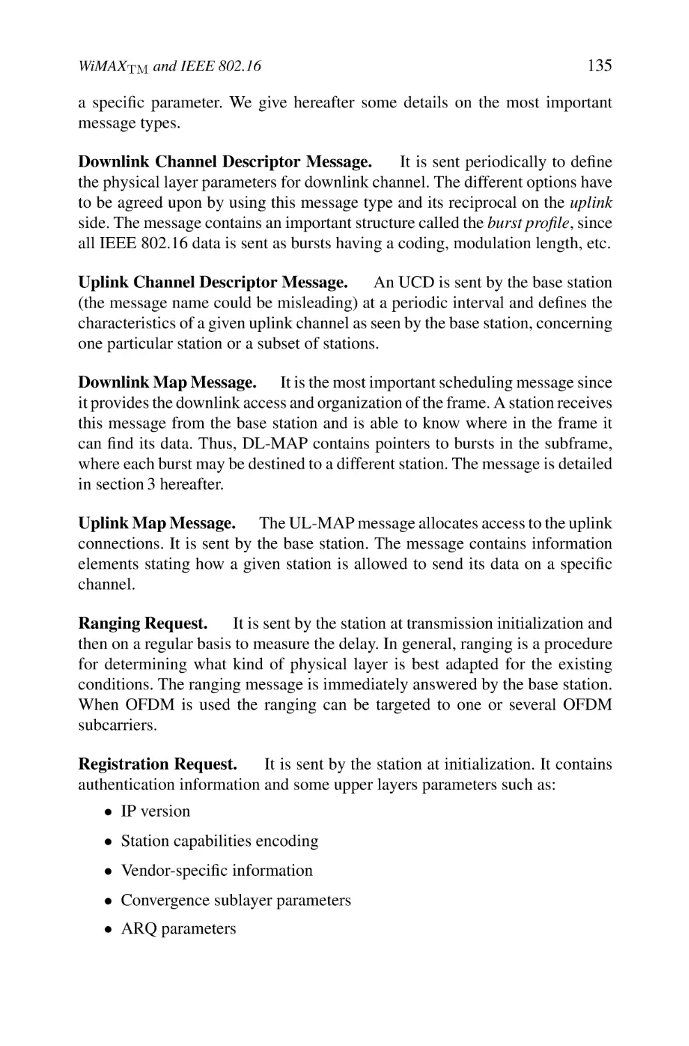
2.6 PDUs
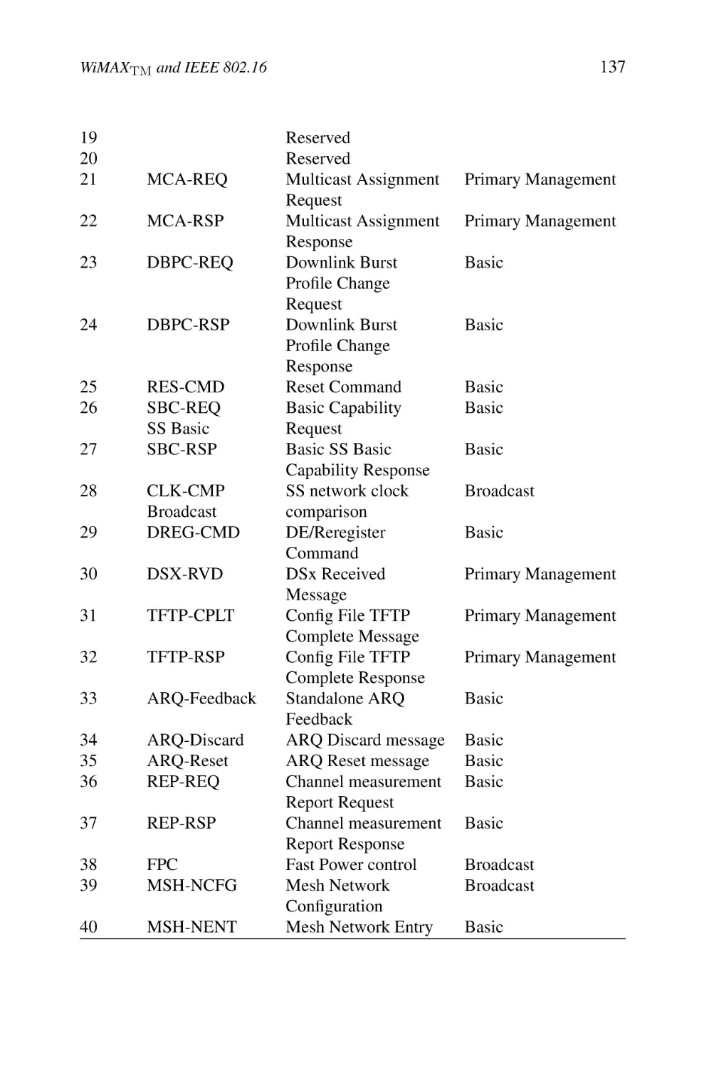
2.7 PDU Organization
3. Physical Layer
3.1 IEEE 802.16 SC (Single Carrier)
3.2 The Single Carrier in Lower Bands
3.3 OFDM Physical Layer
3.4 OFDMA Physical Layer
ix
104
104
105
106
107
108
109
109
112
112
113
113
114
114
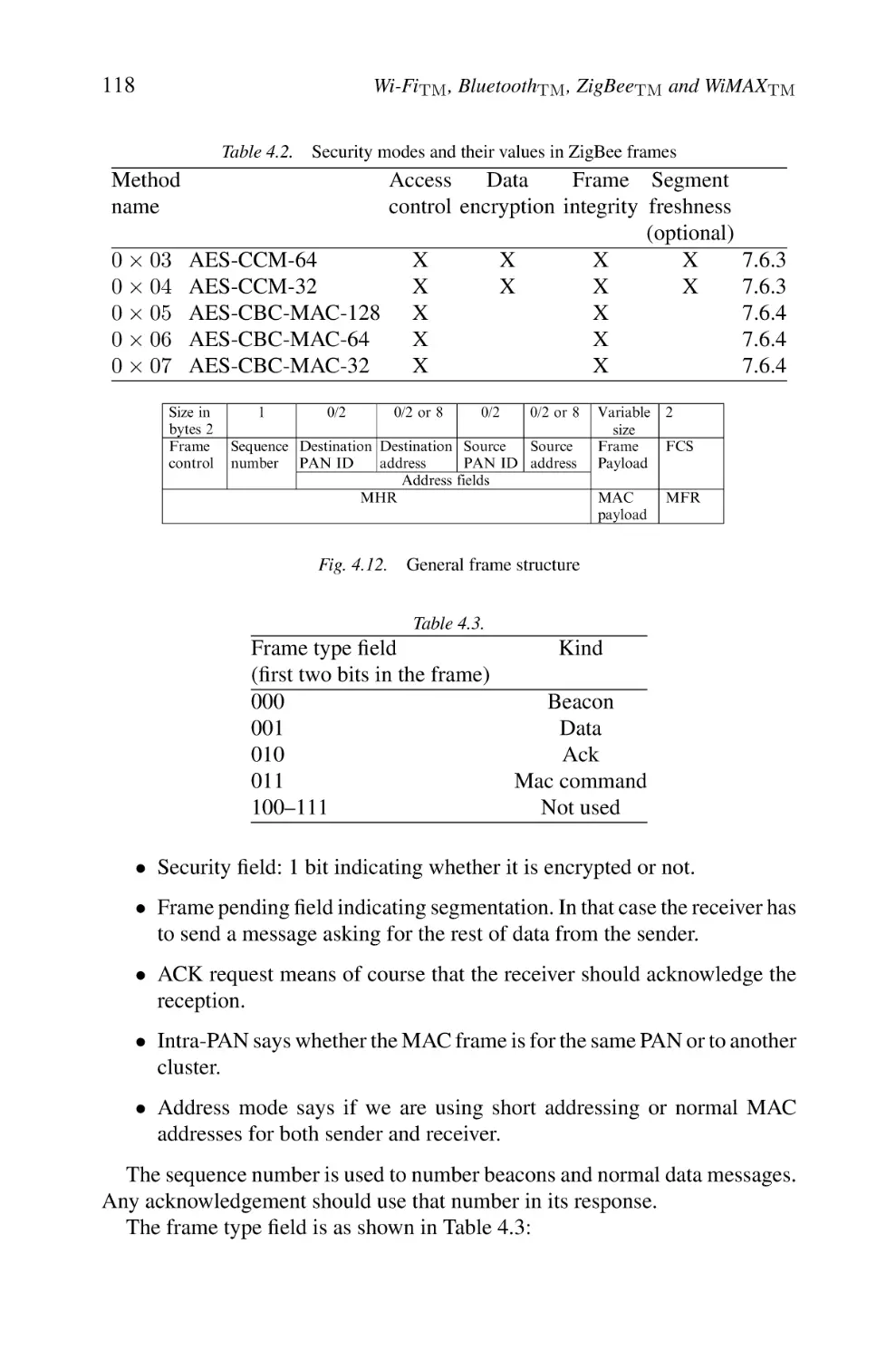
115
116
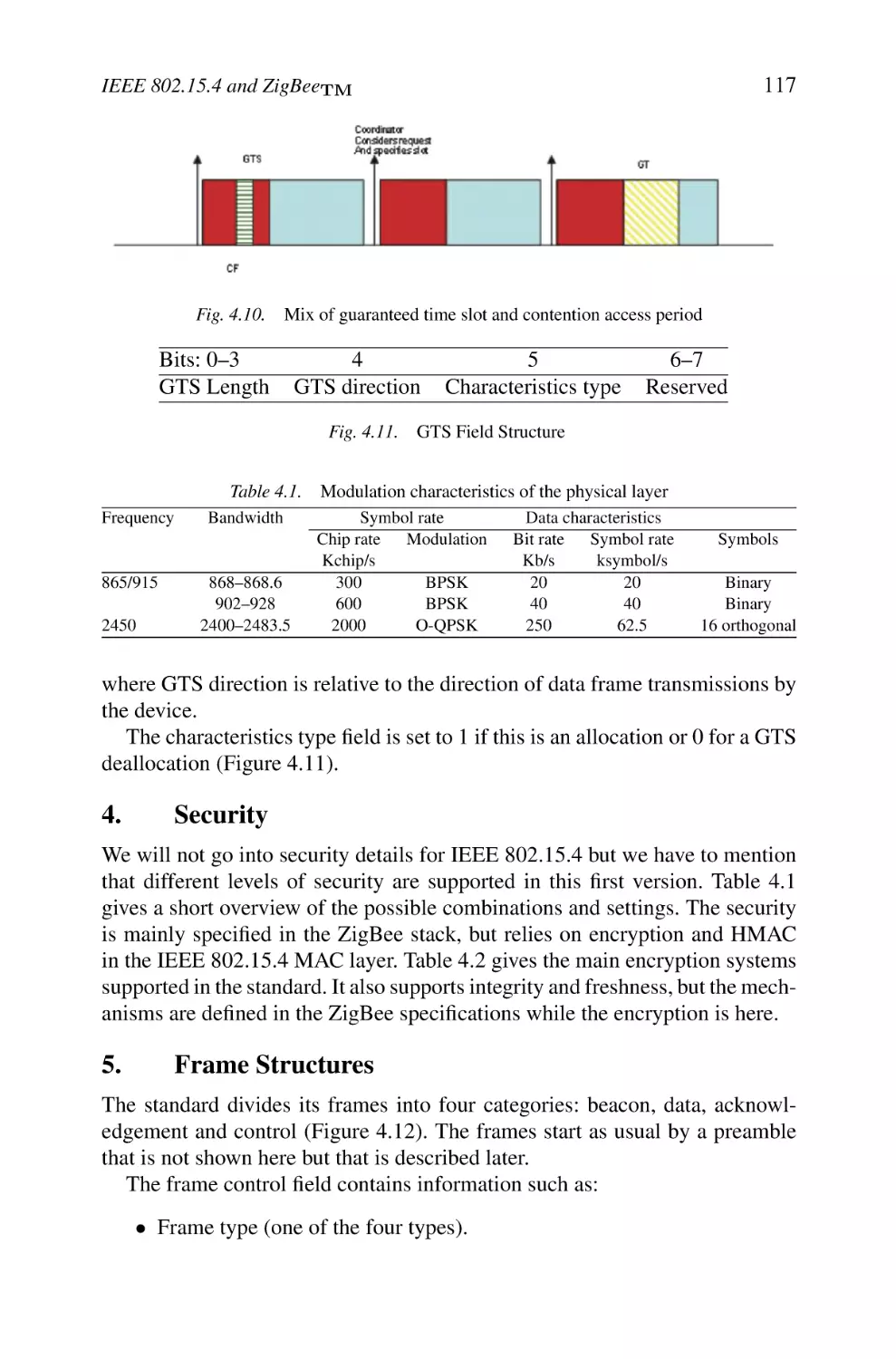
116
116
117
117
119
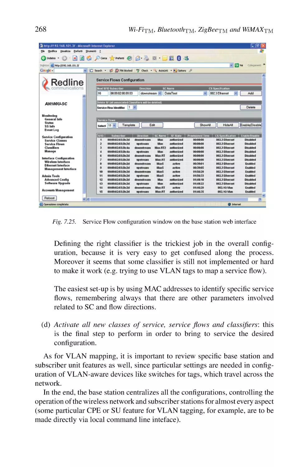
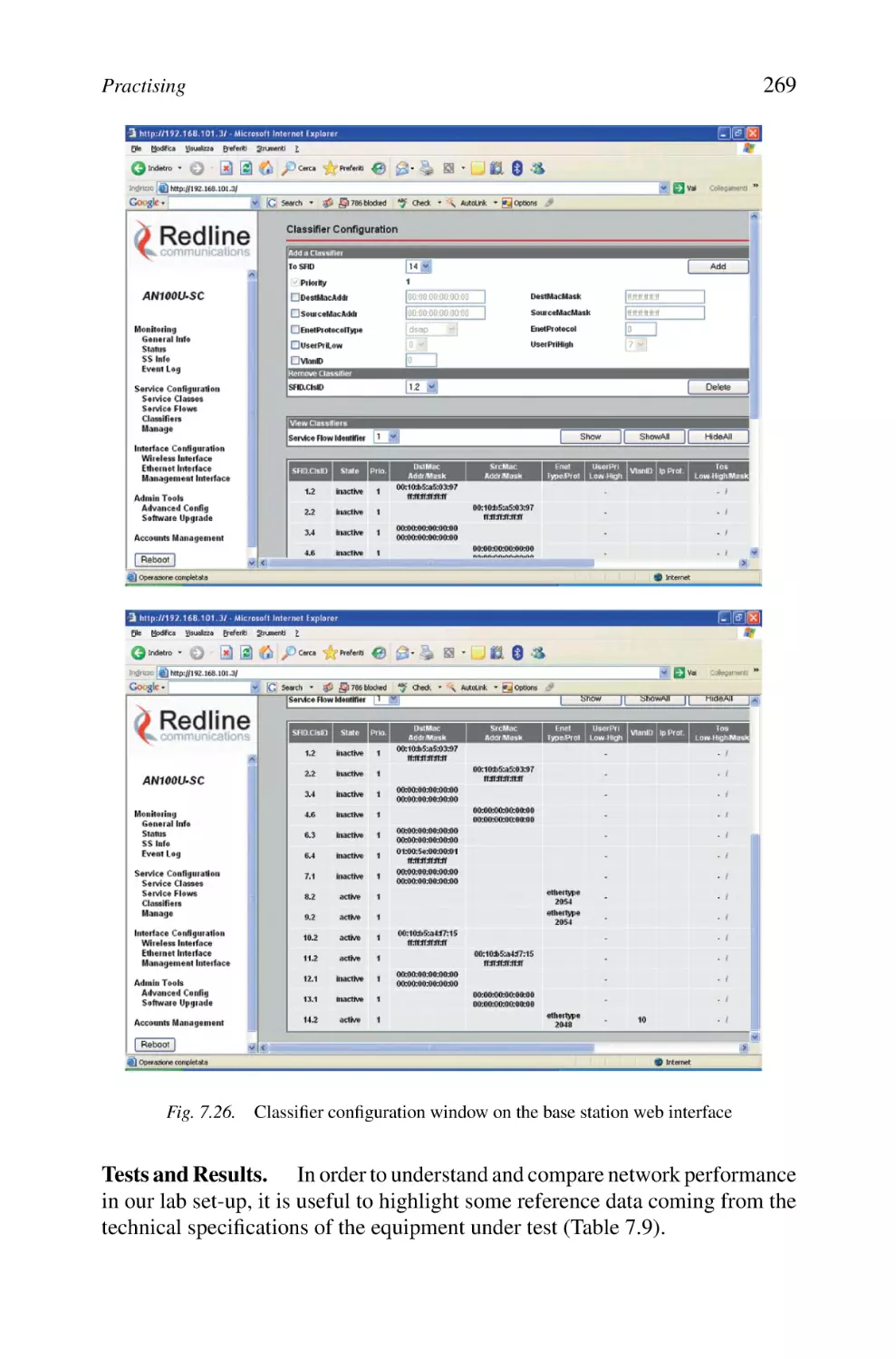
120
120
122
123
123
124
124
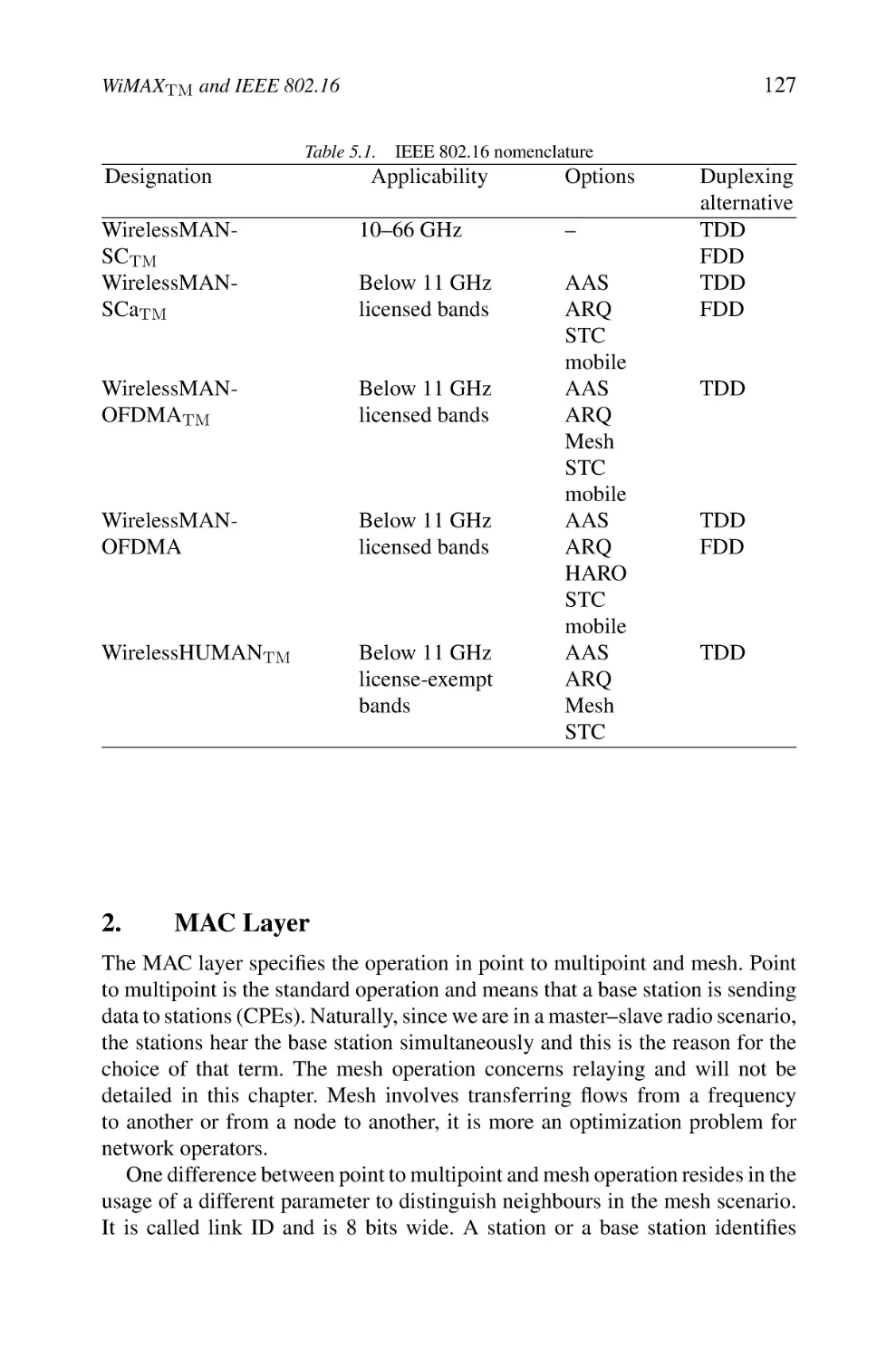
125
126
126
126
127
128
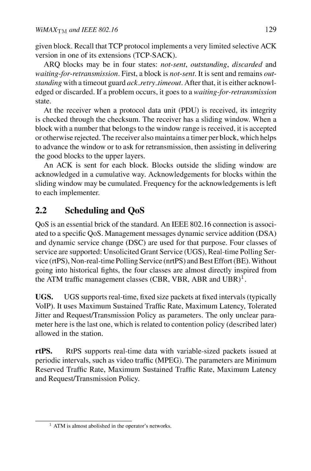
129
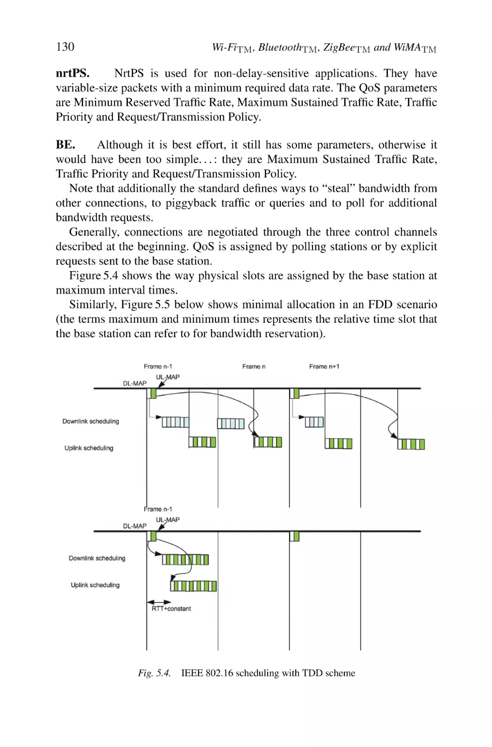
131
132
132
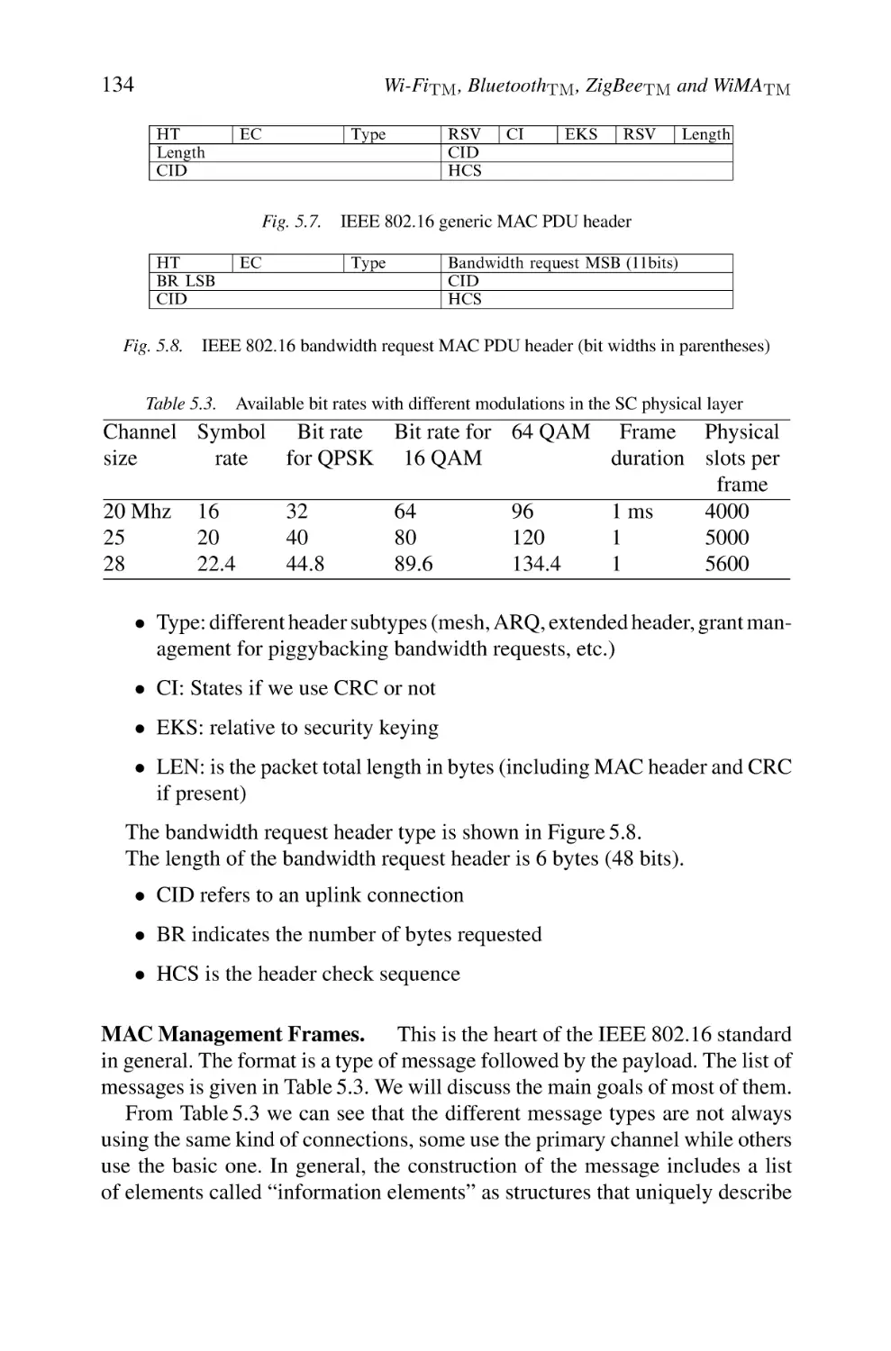
133
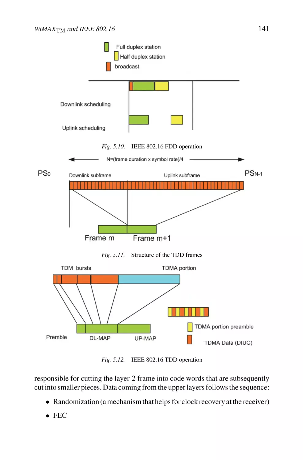
139
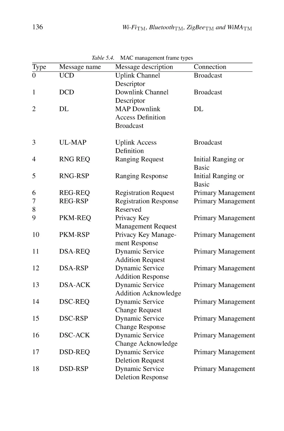
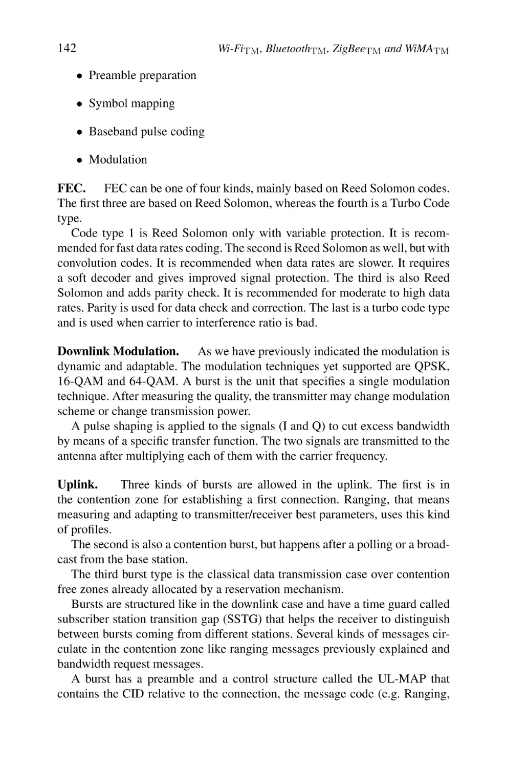
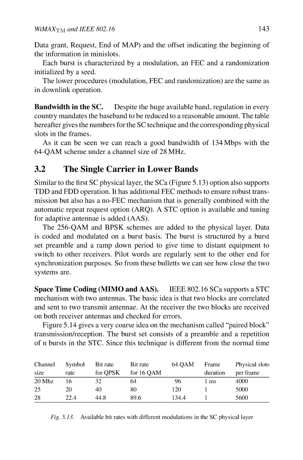
139
140
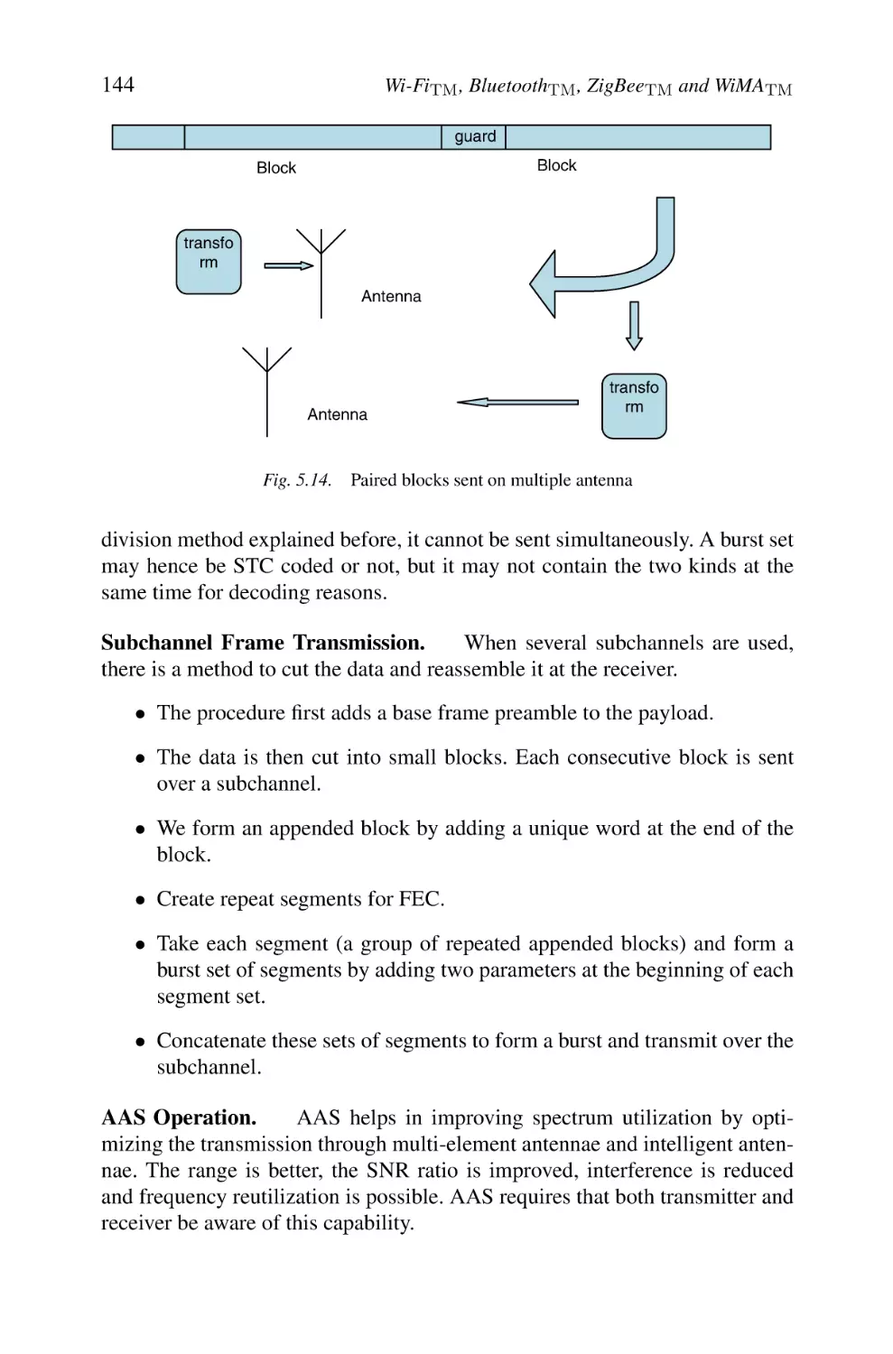
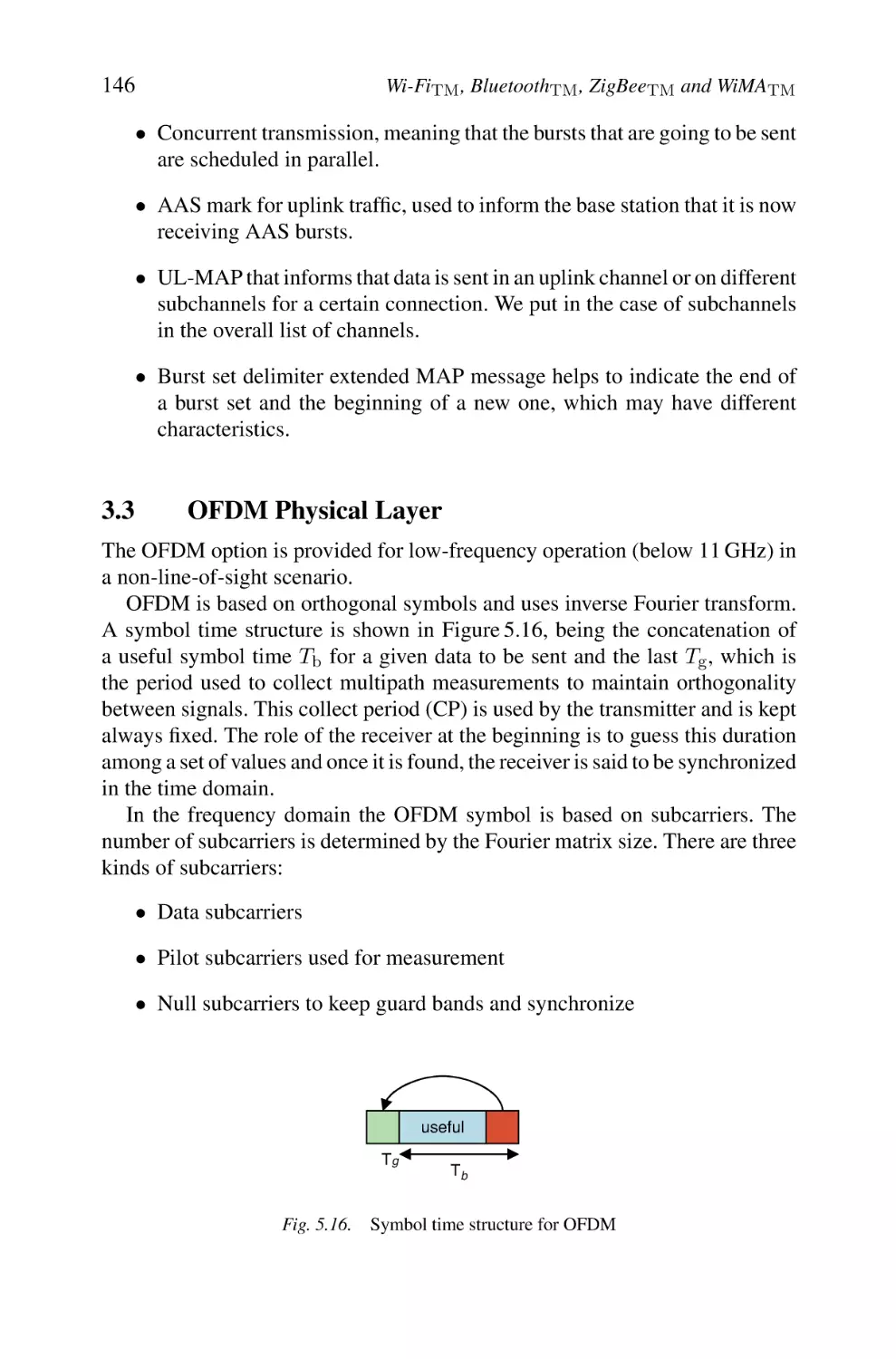
143
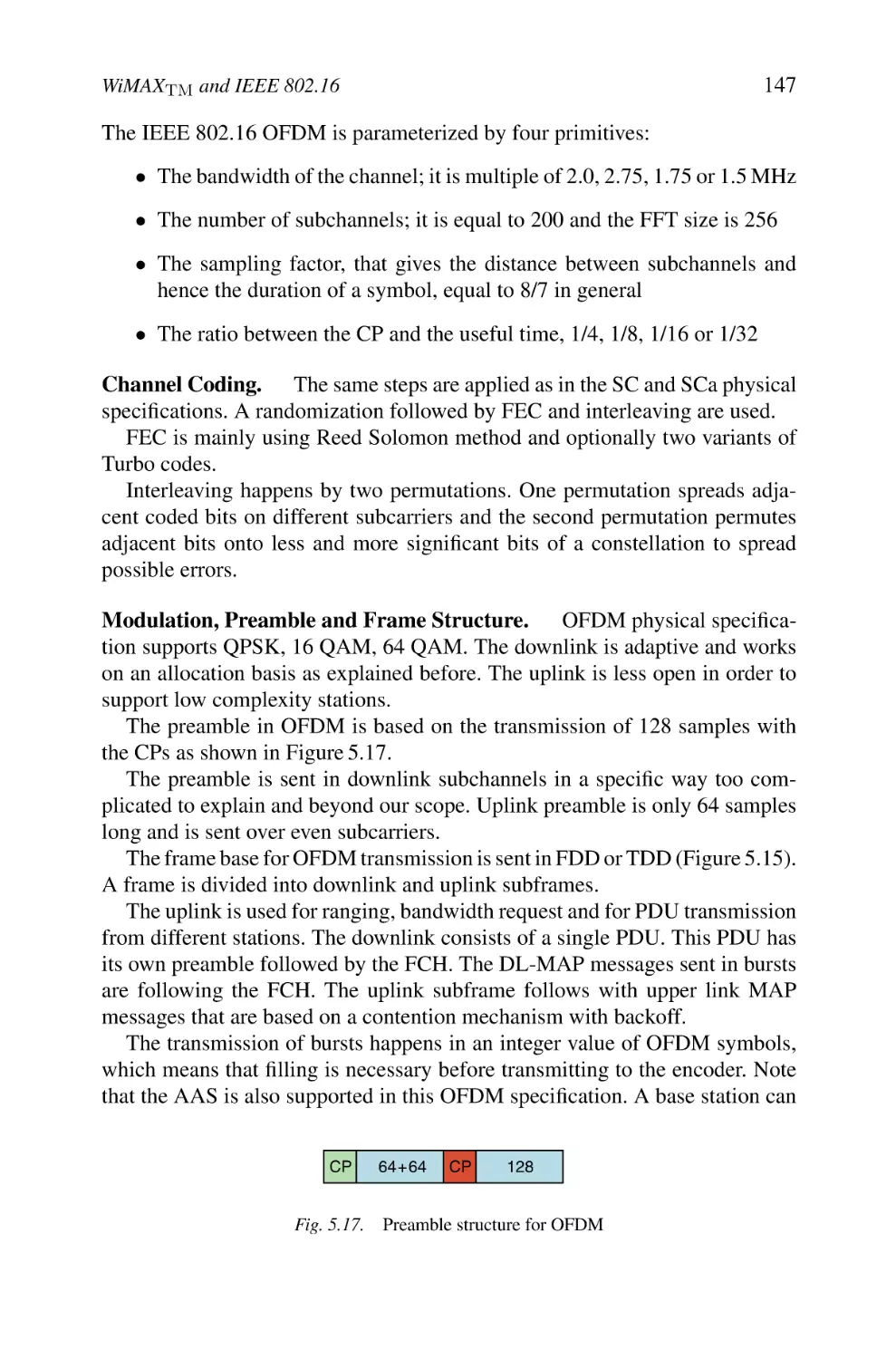
146
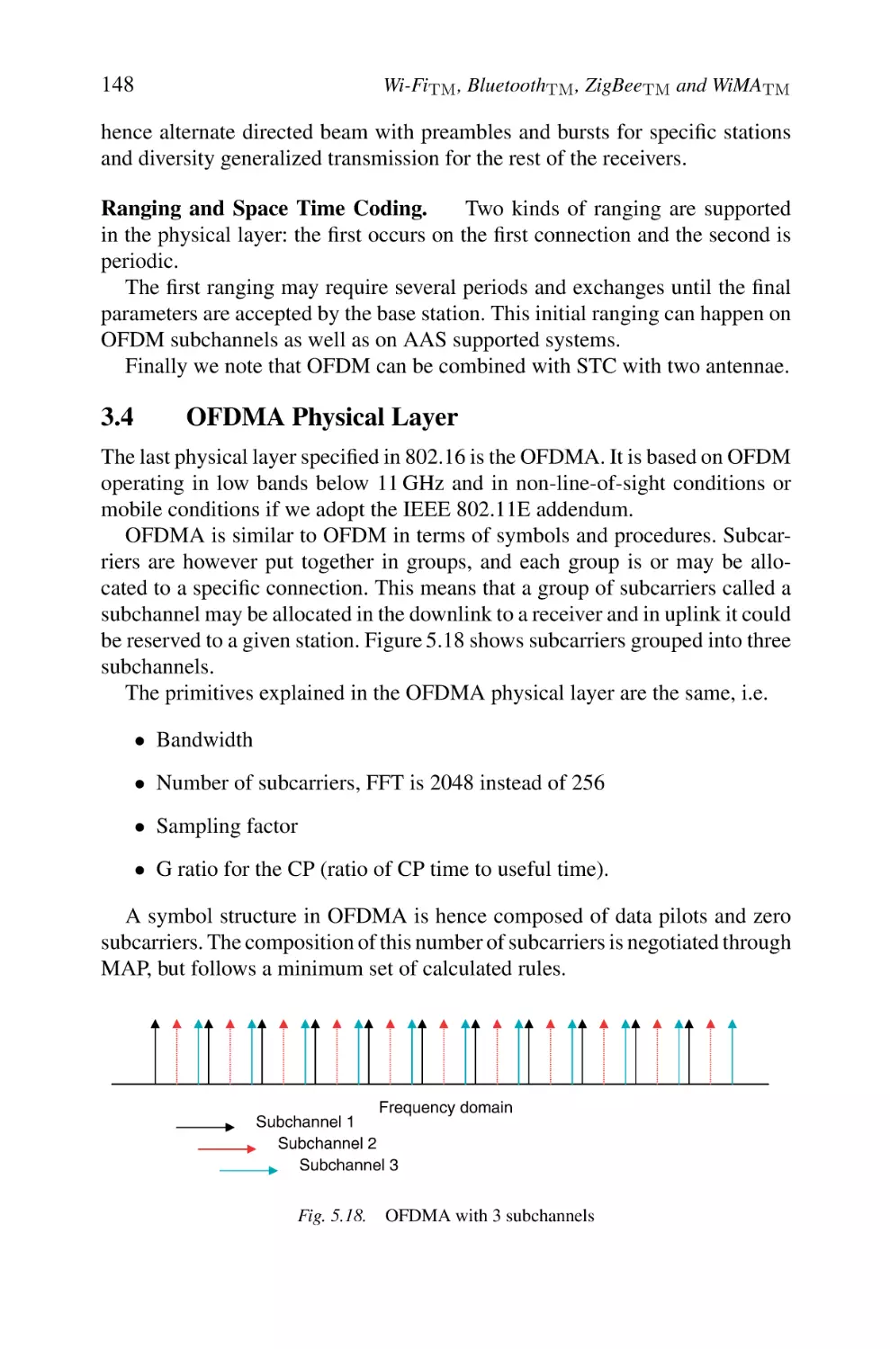
148
x
6
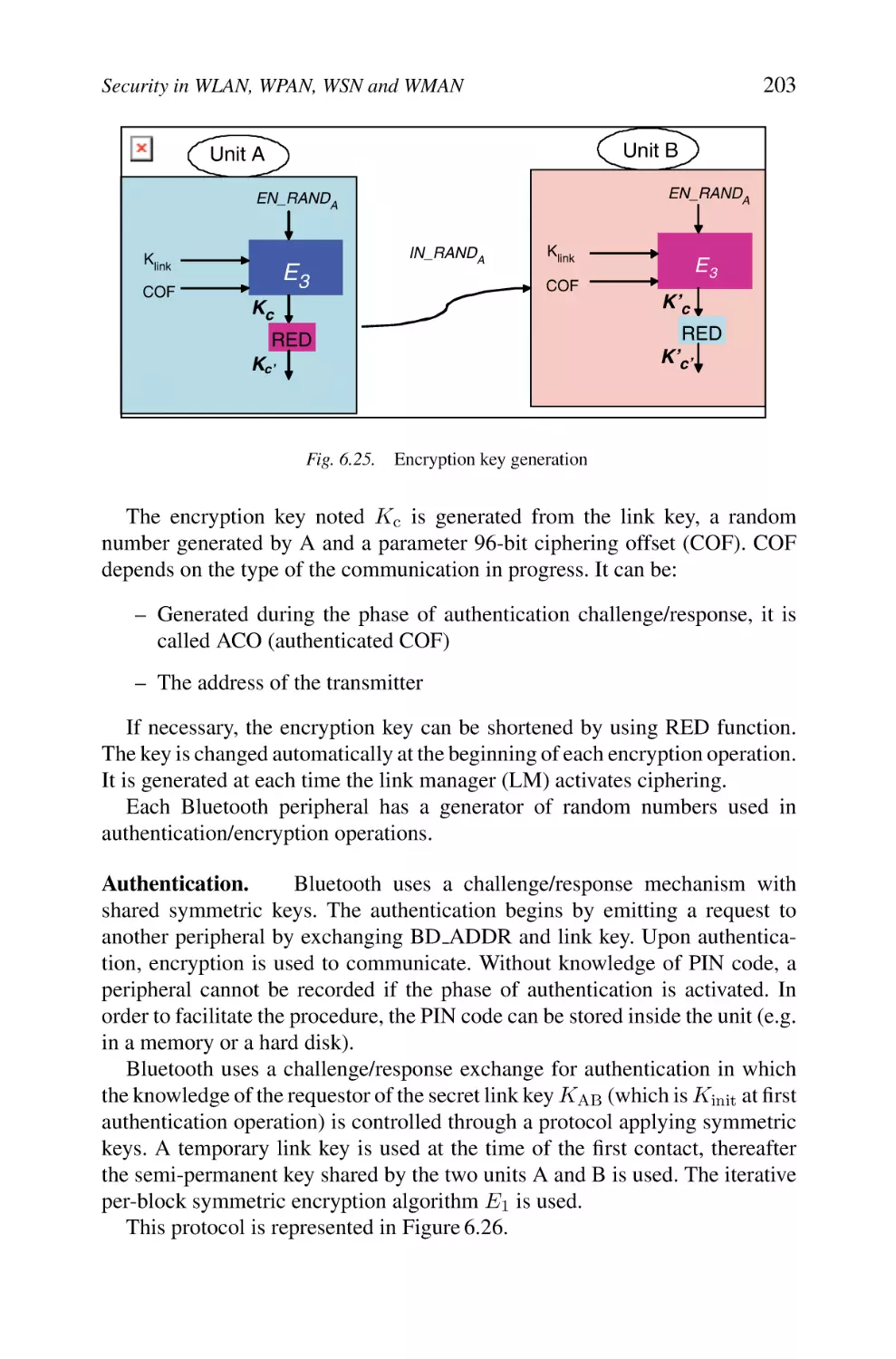
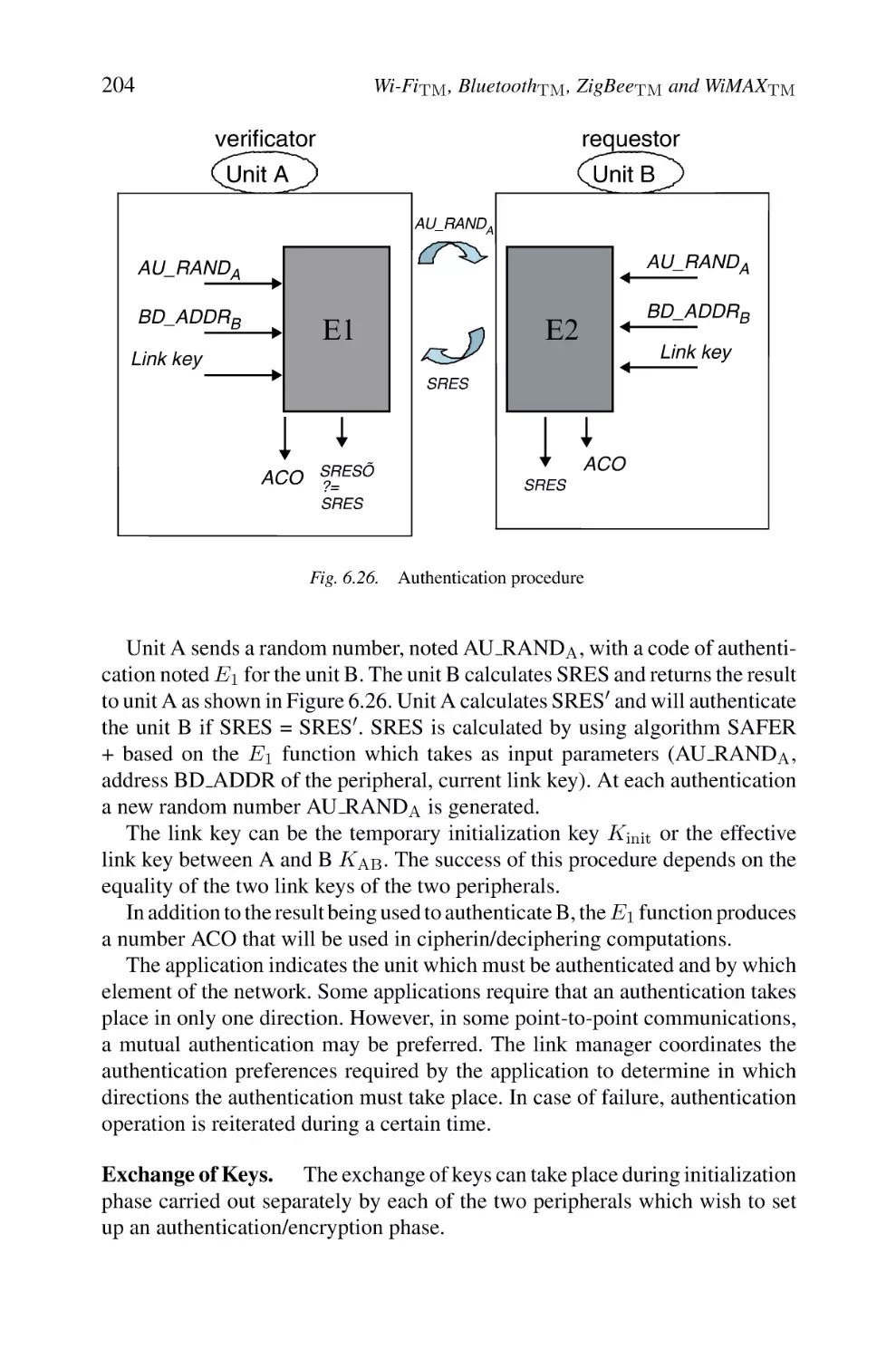
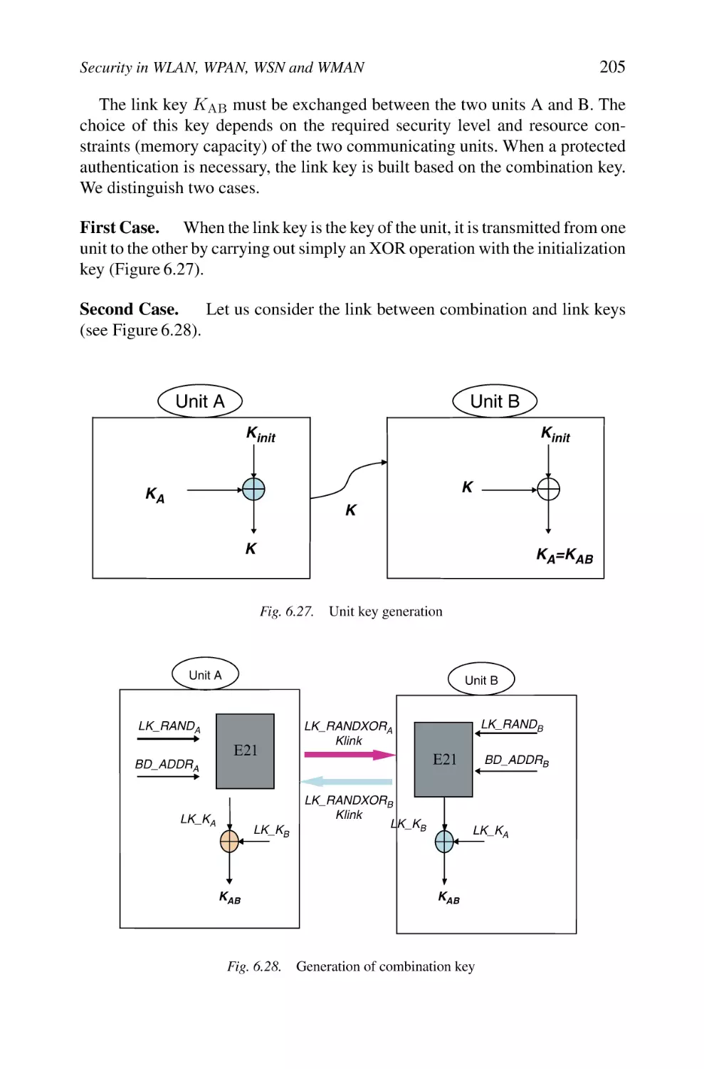
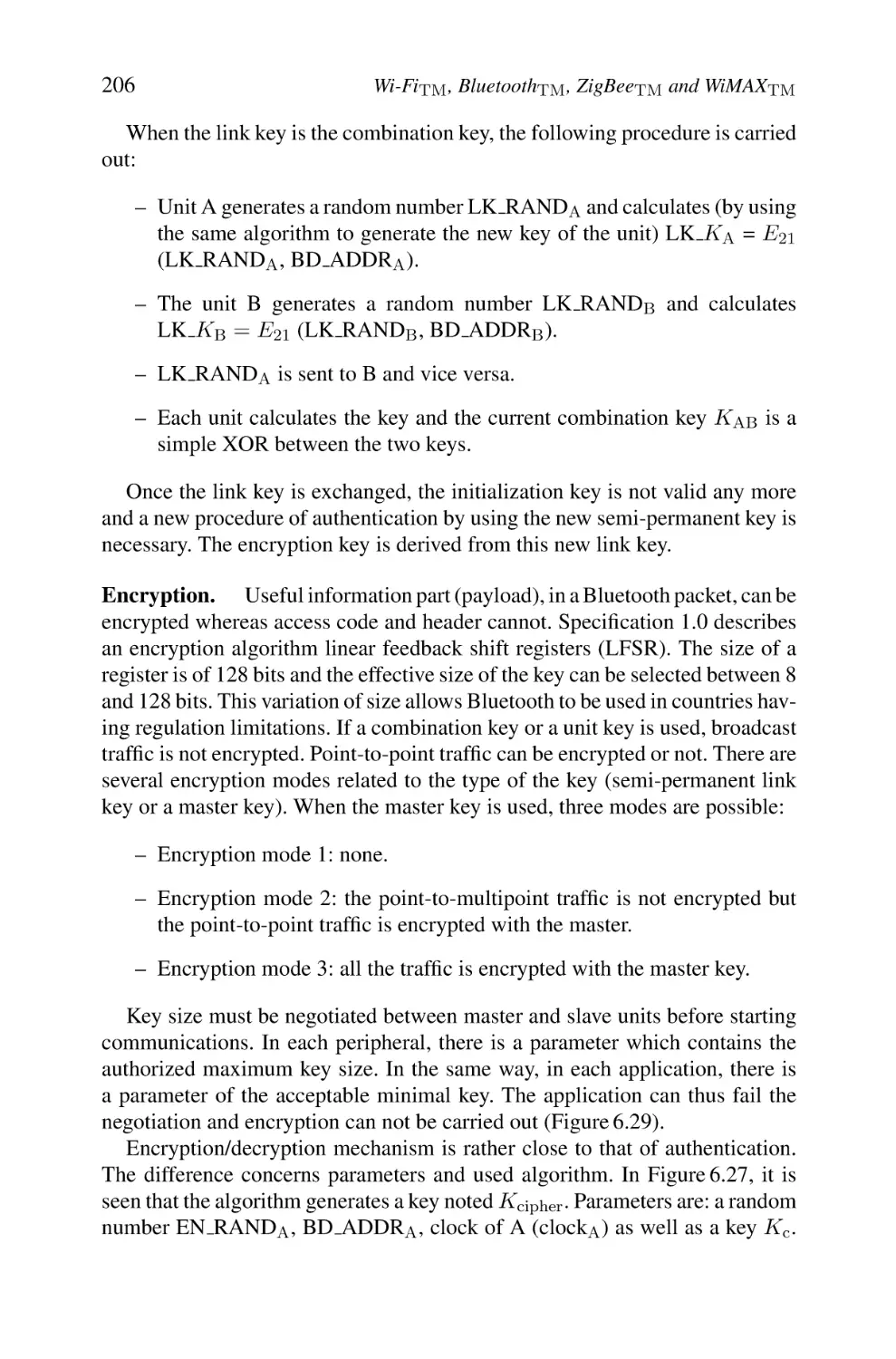
Security in WLAN, WPAN, WSN and WMAN through Wi-FiTM ,
BluetoothTM , ZigBeeTM and WiMAXTM
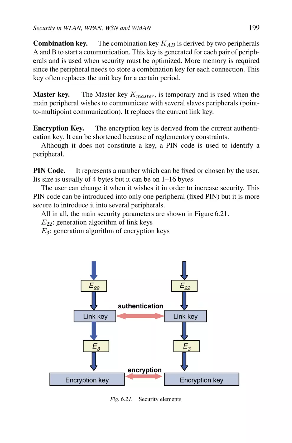
1. Security in Wi-Fi Systems
1.1 Security in Wi-Fi Networks
1.2 Security Flaws
1.3 Taxonomy of Attacks
1.4 Diverse Solutions
1.5 WPA/WPA2: IEEE 802.1X and TKIP/AES
1.6 Synthesis
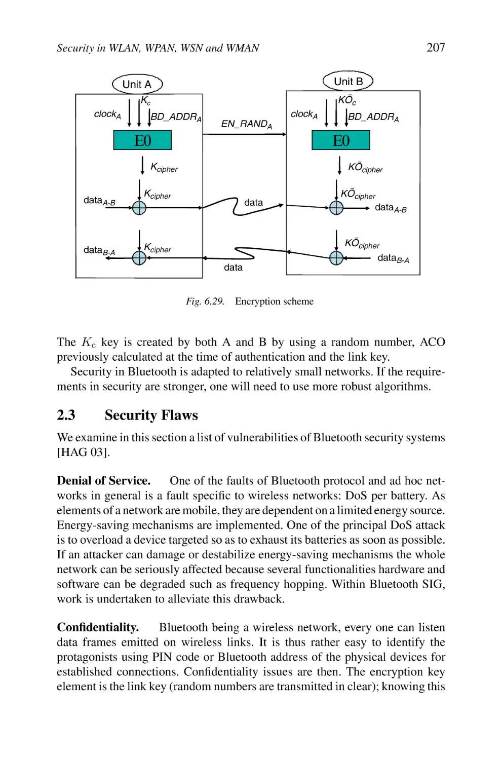
2. Security in Bluetooth Systems
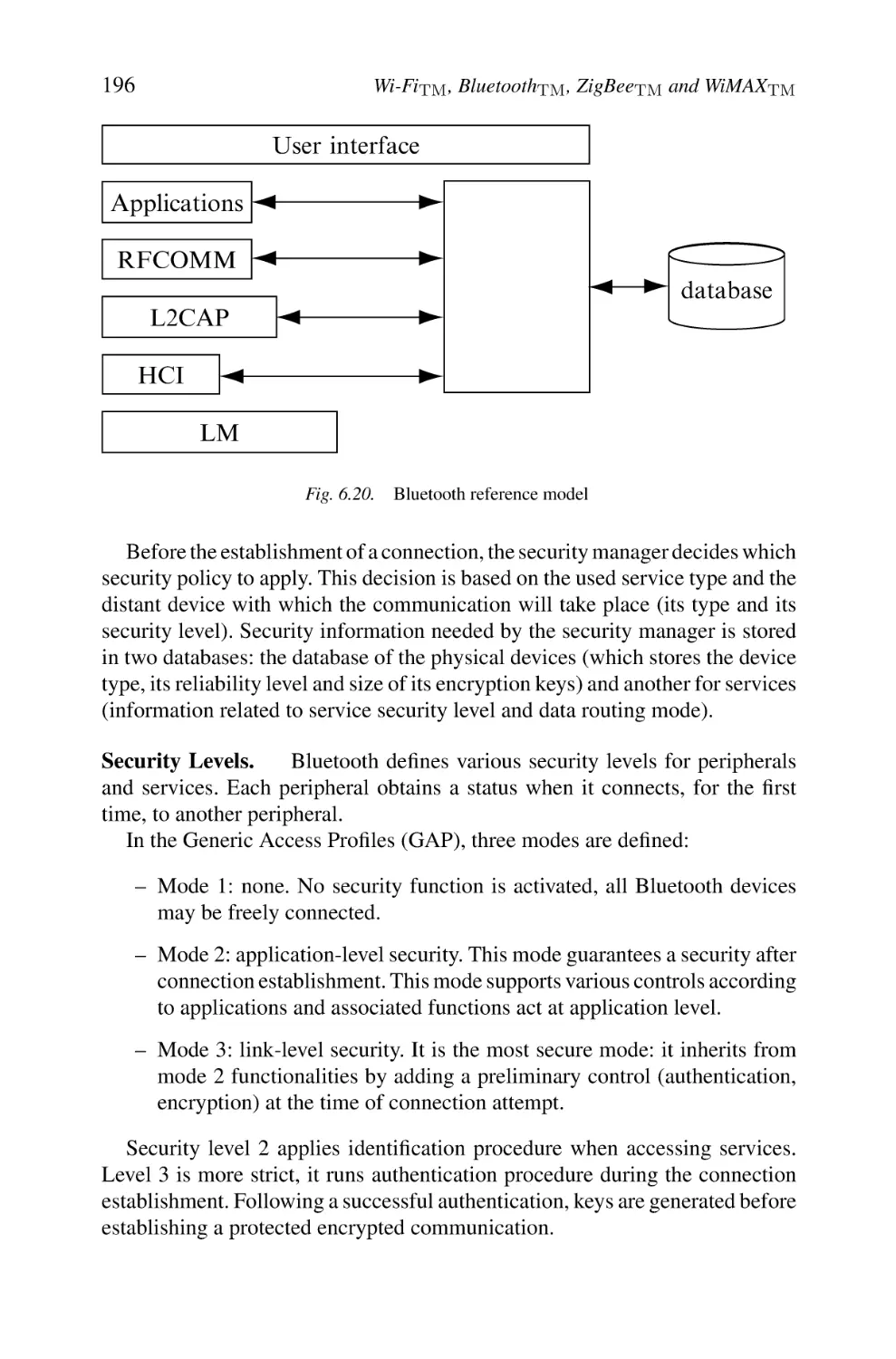
2.1 Security Architecture
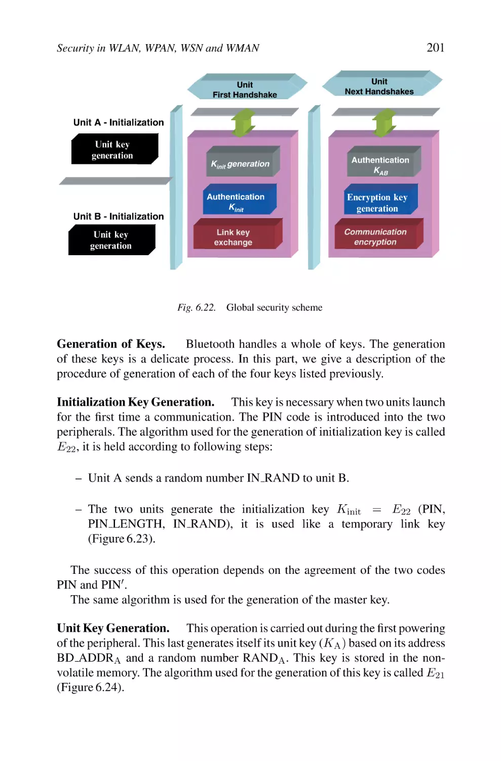
2.2 Main Procedures
2.3 Security Flaws
2.4 Synthesis
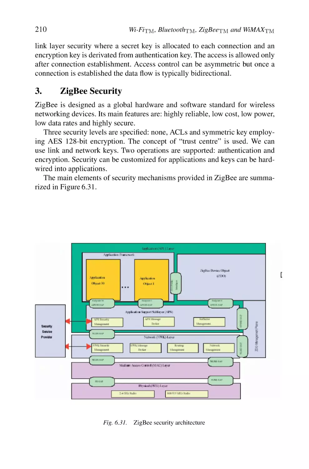
3. ZigBee Security
3.1 ZigBee Security Architecture
3.2 Mechanisms
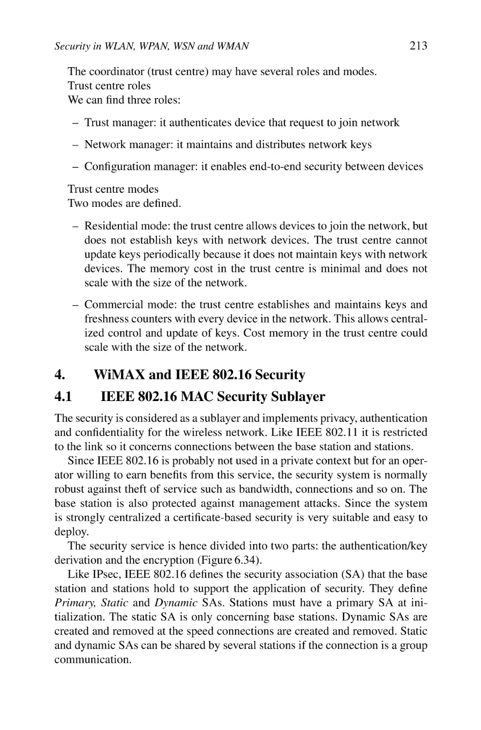
3.3 Trust Centre Concept
4. WiMAX and IEEE 802.16 Security
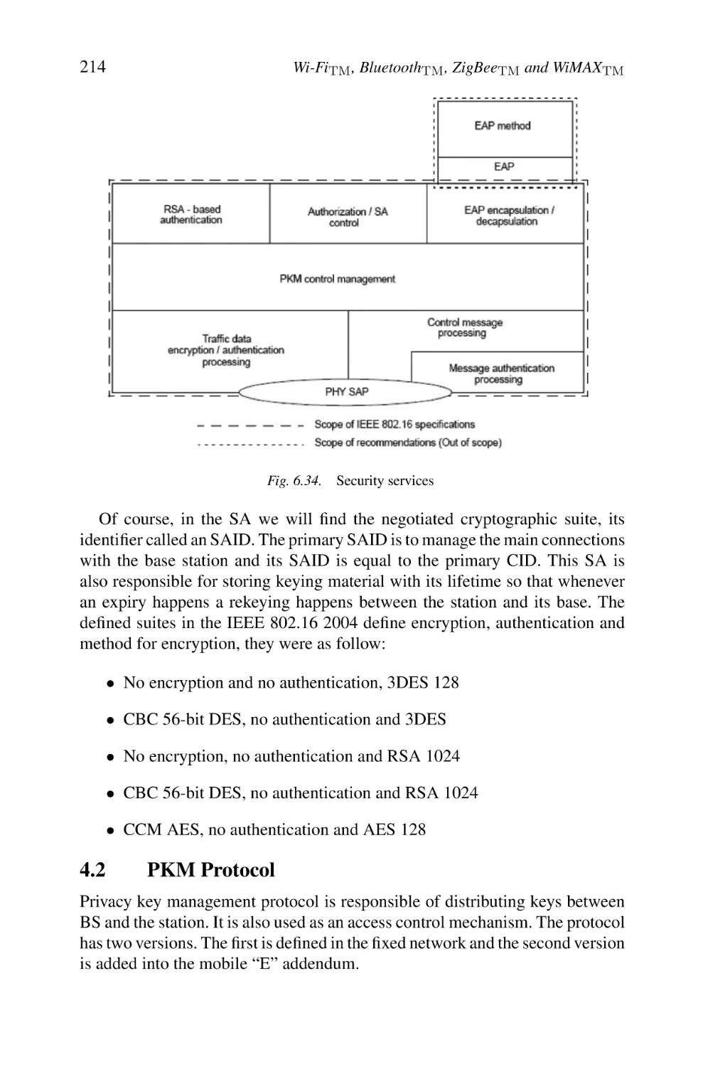
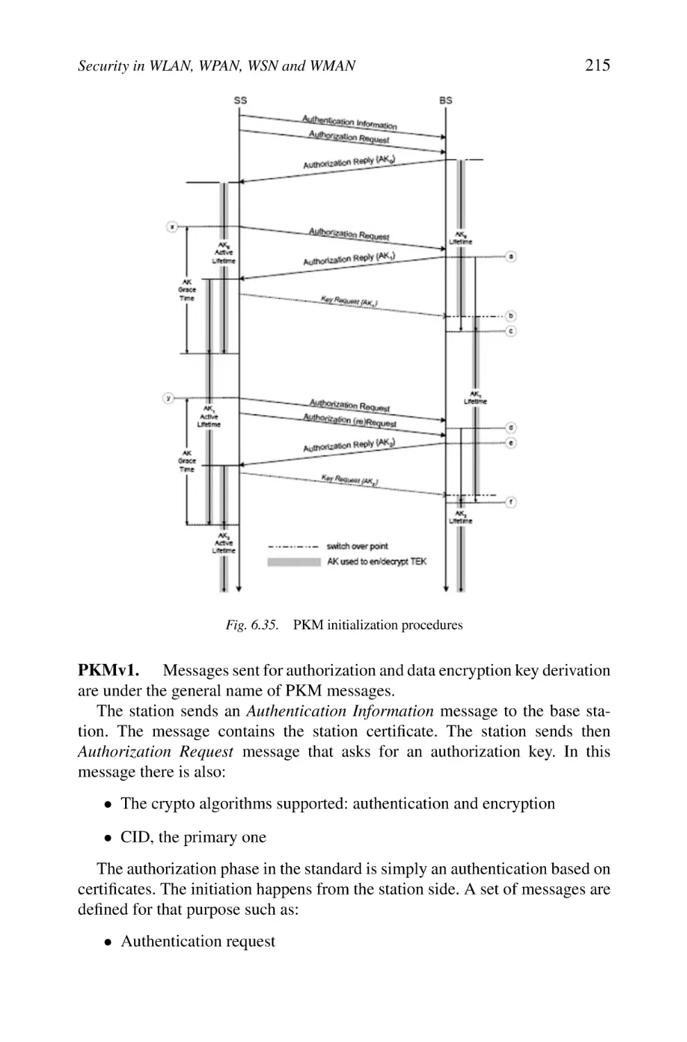
4.1 IEEE 802.16 MAC Security Sublayer
4.2 PKM Protocol
4.3 Traffic Encryption Key
4.4 Security Enhancement for Mobile Communications
5. Conclusion
7
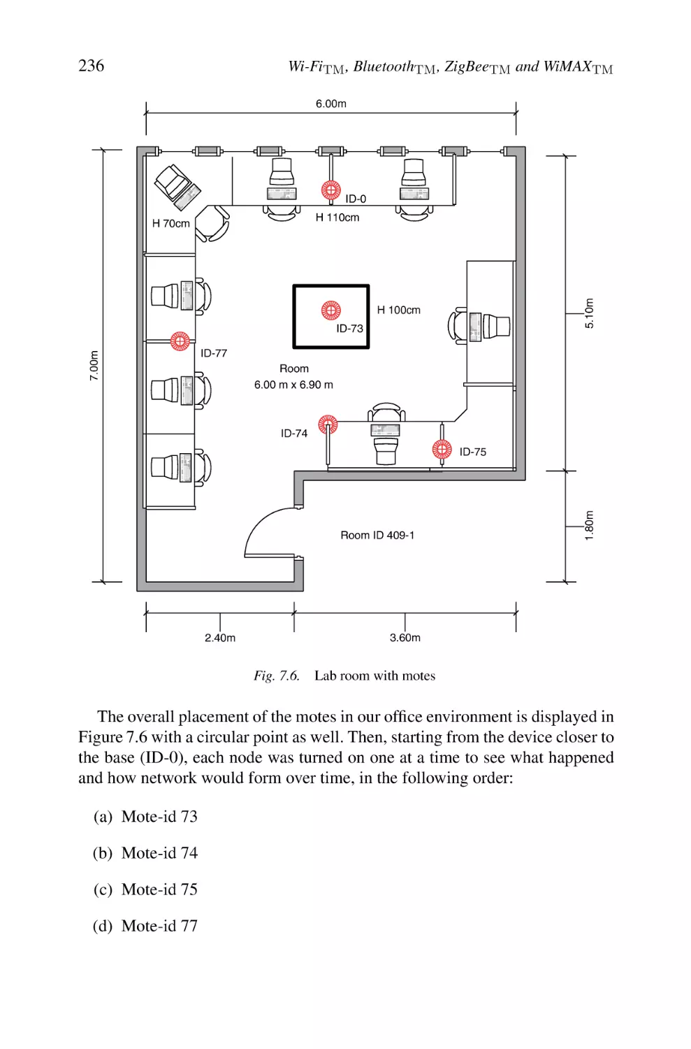
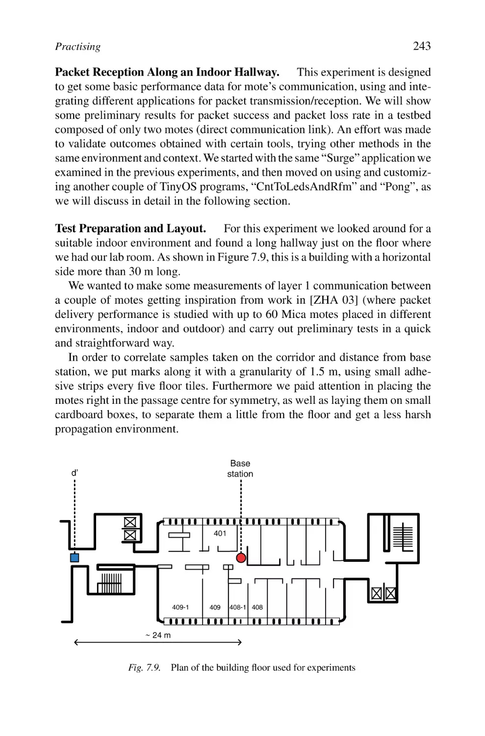
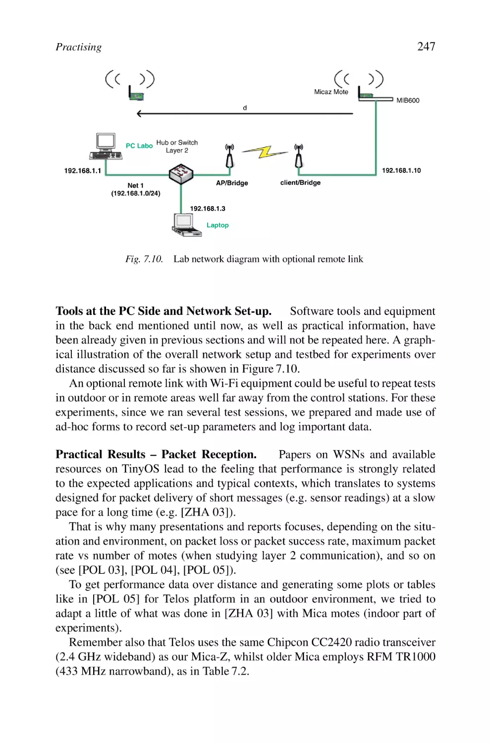
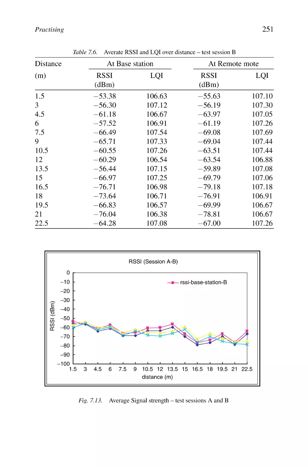
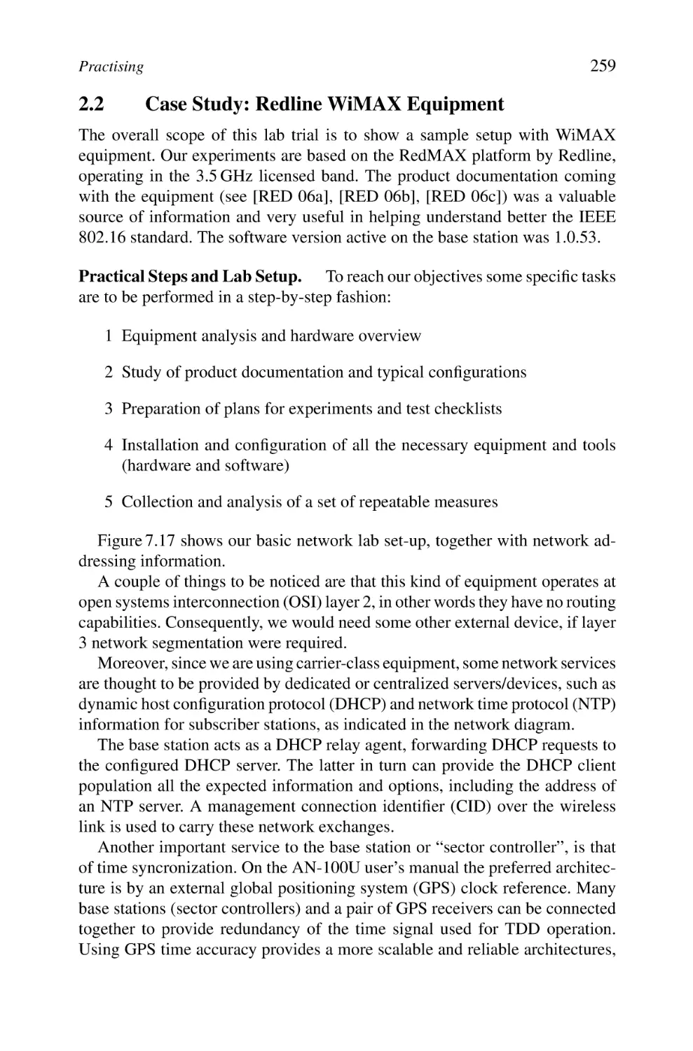
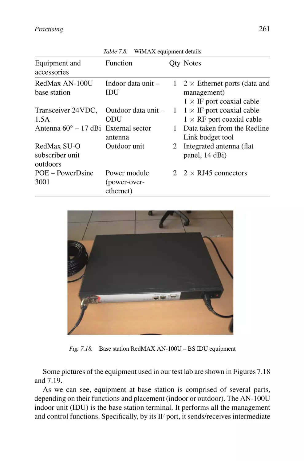
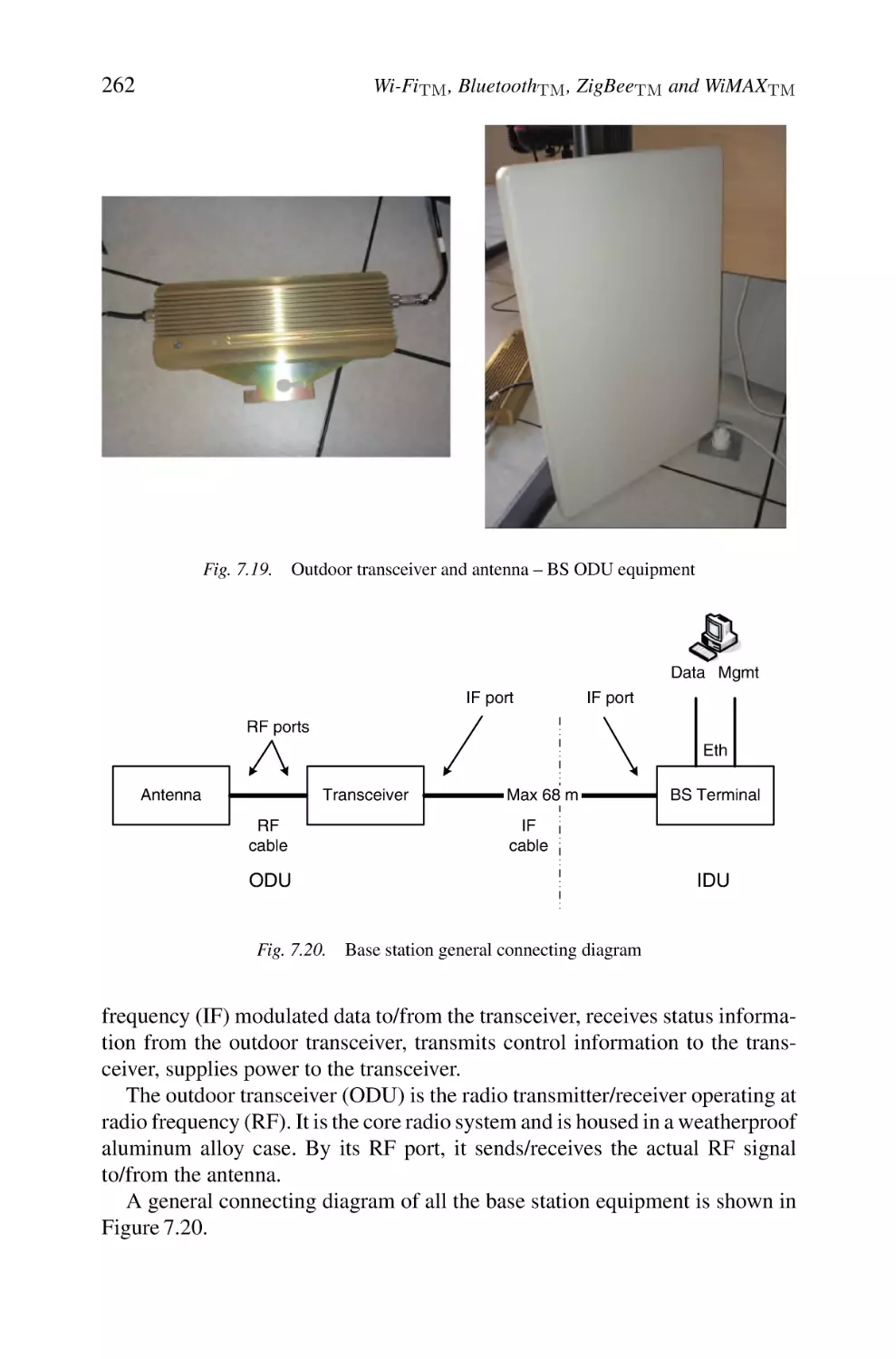
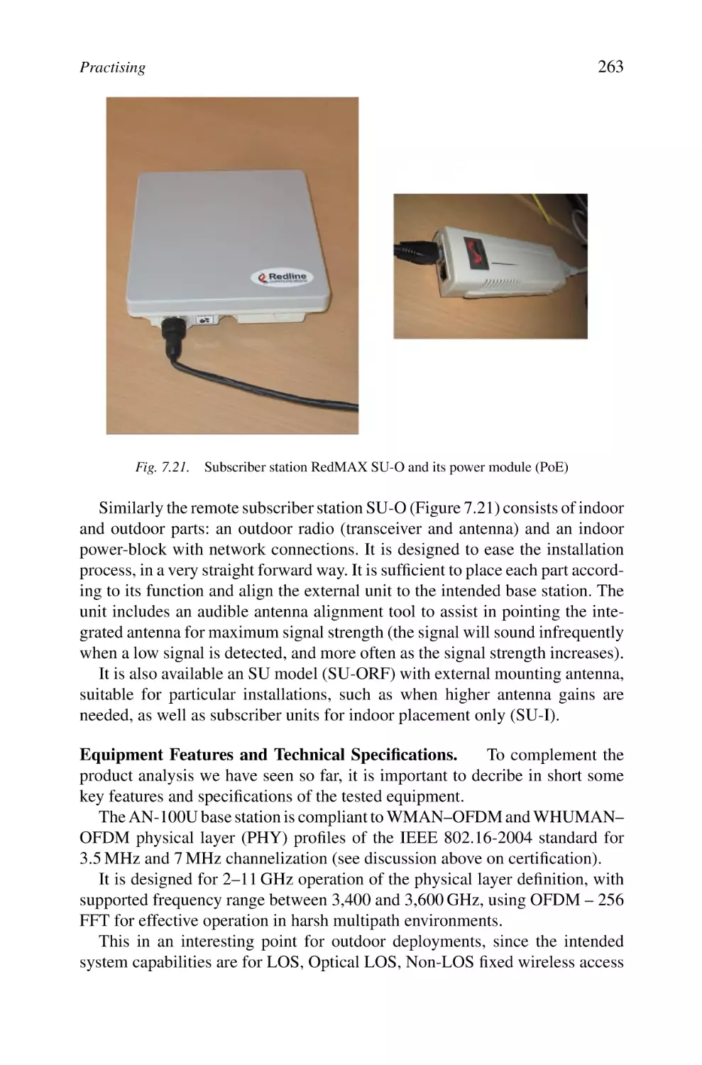
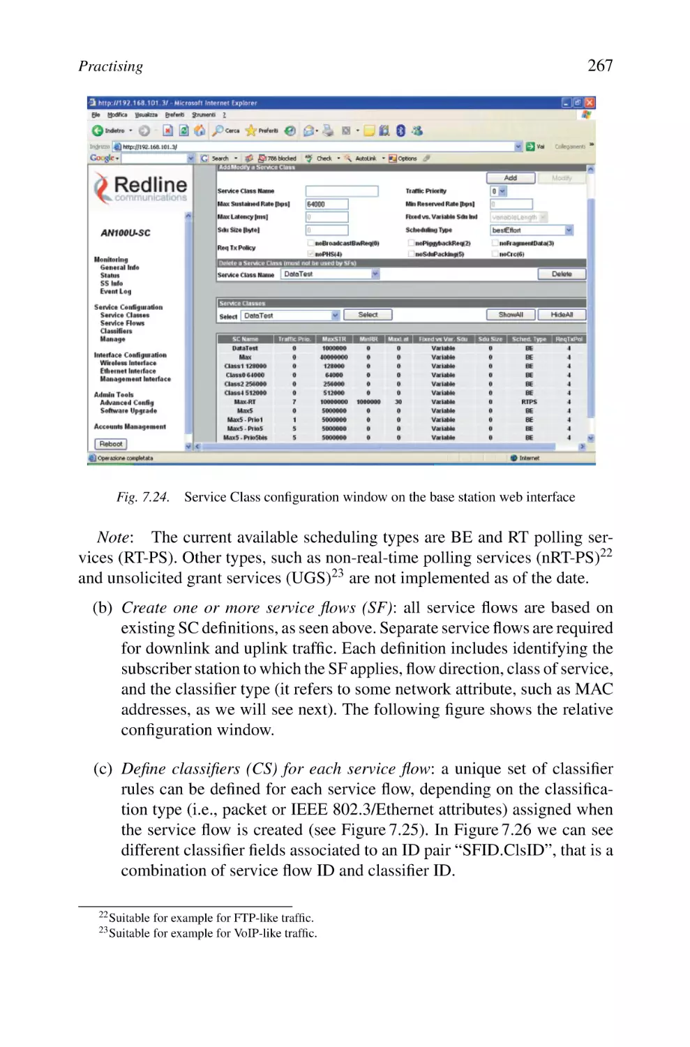
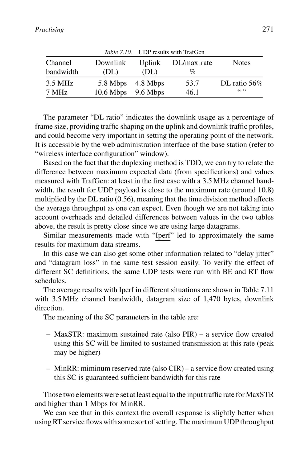
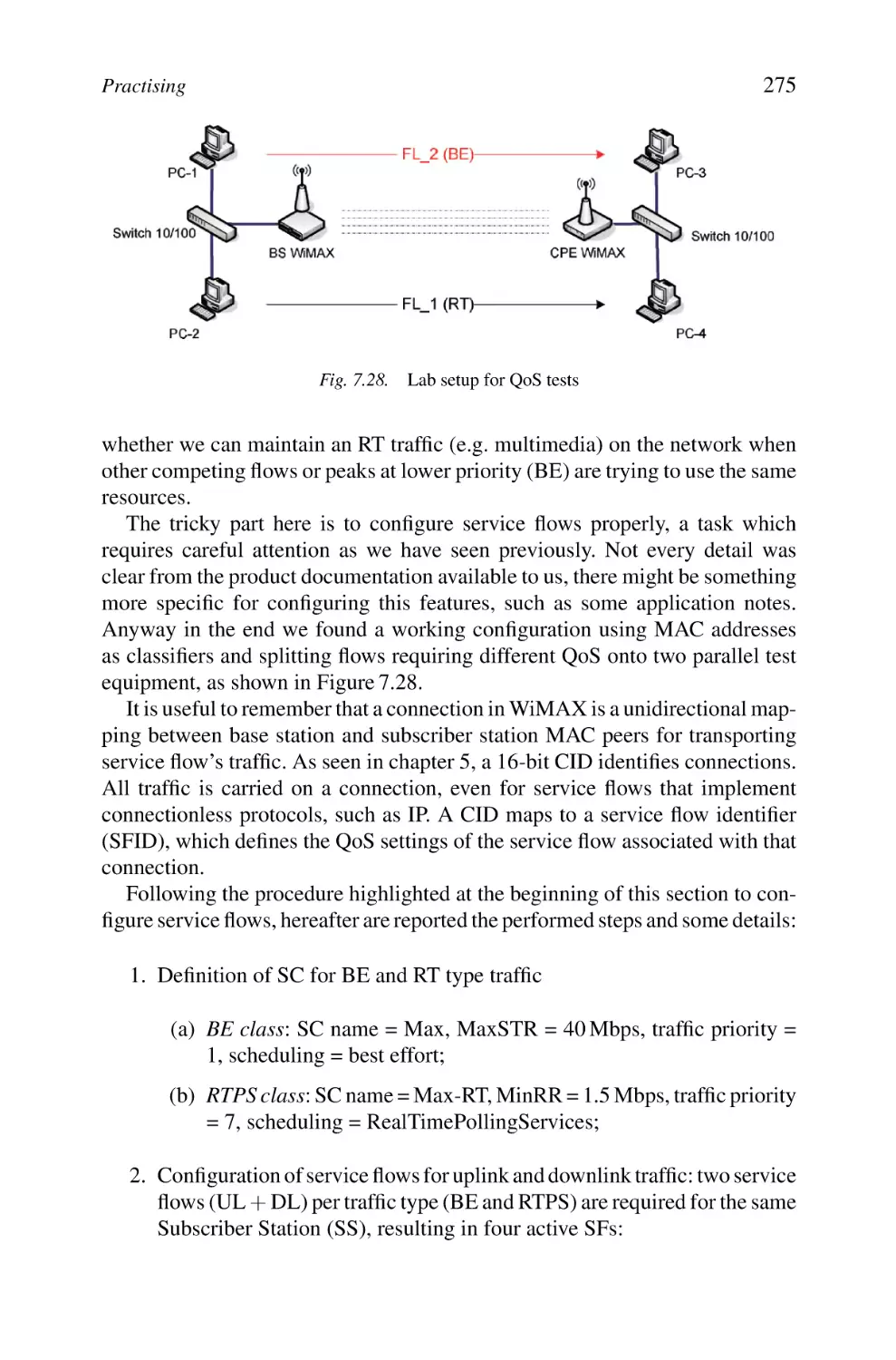
Practising
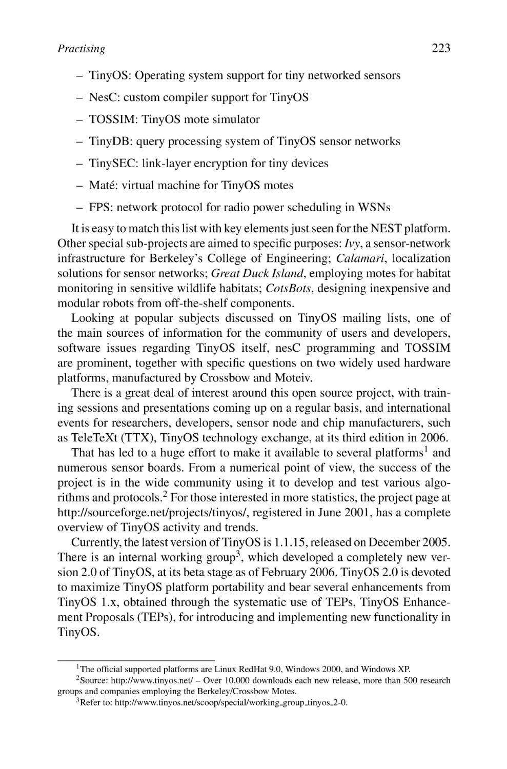
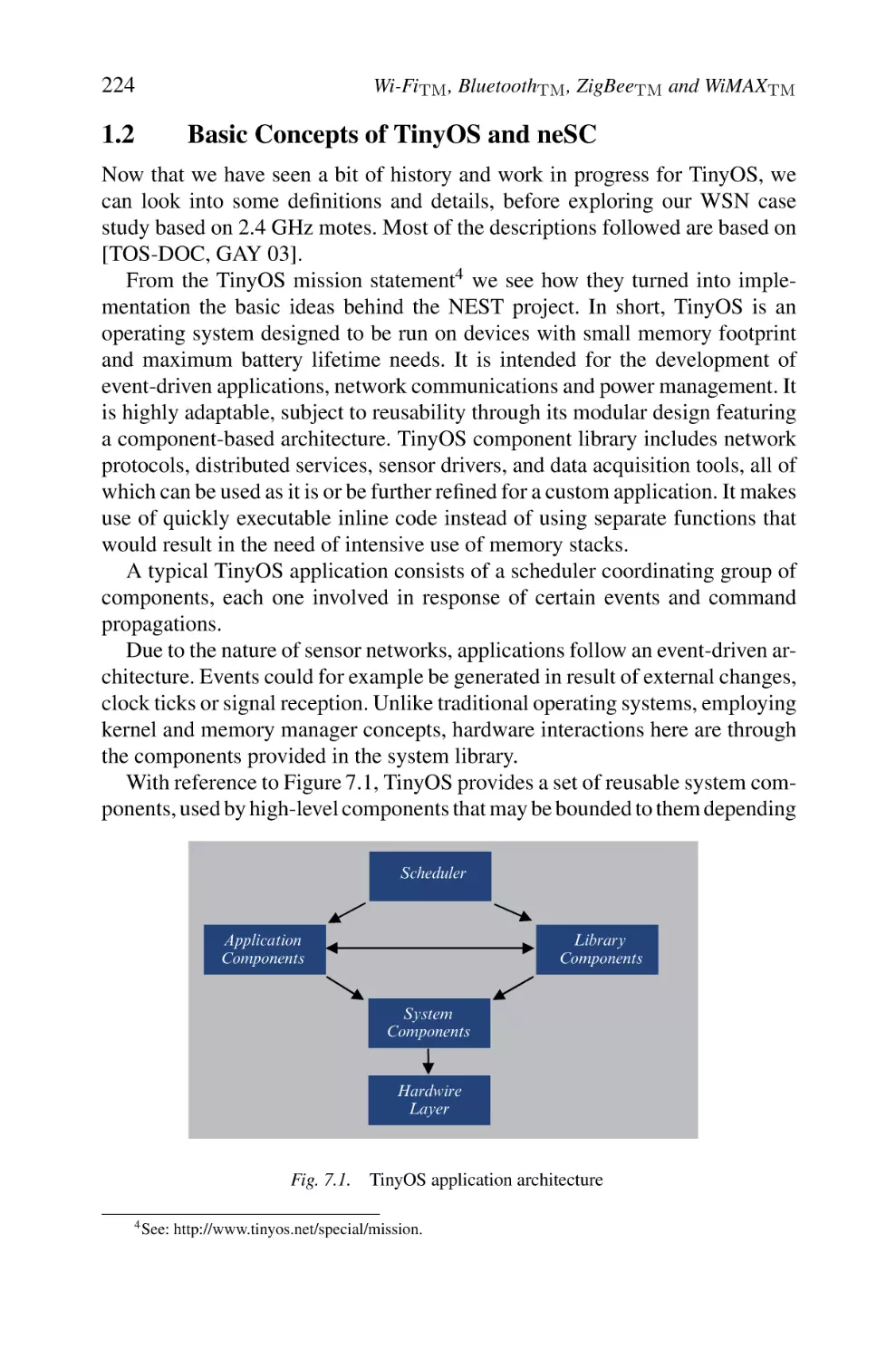
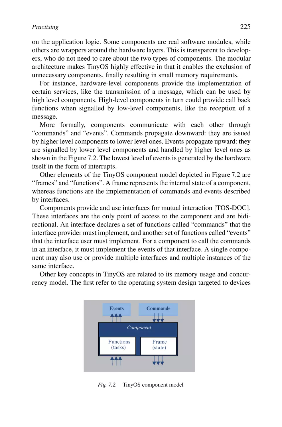
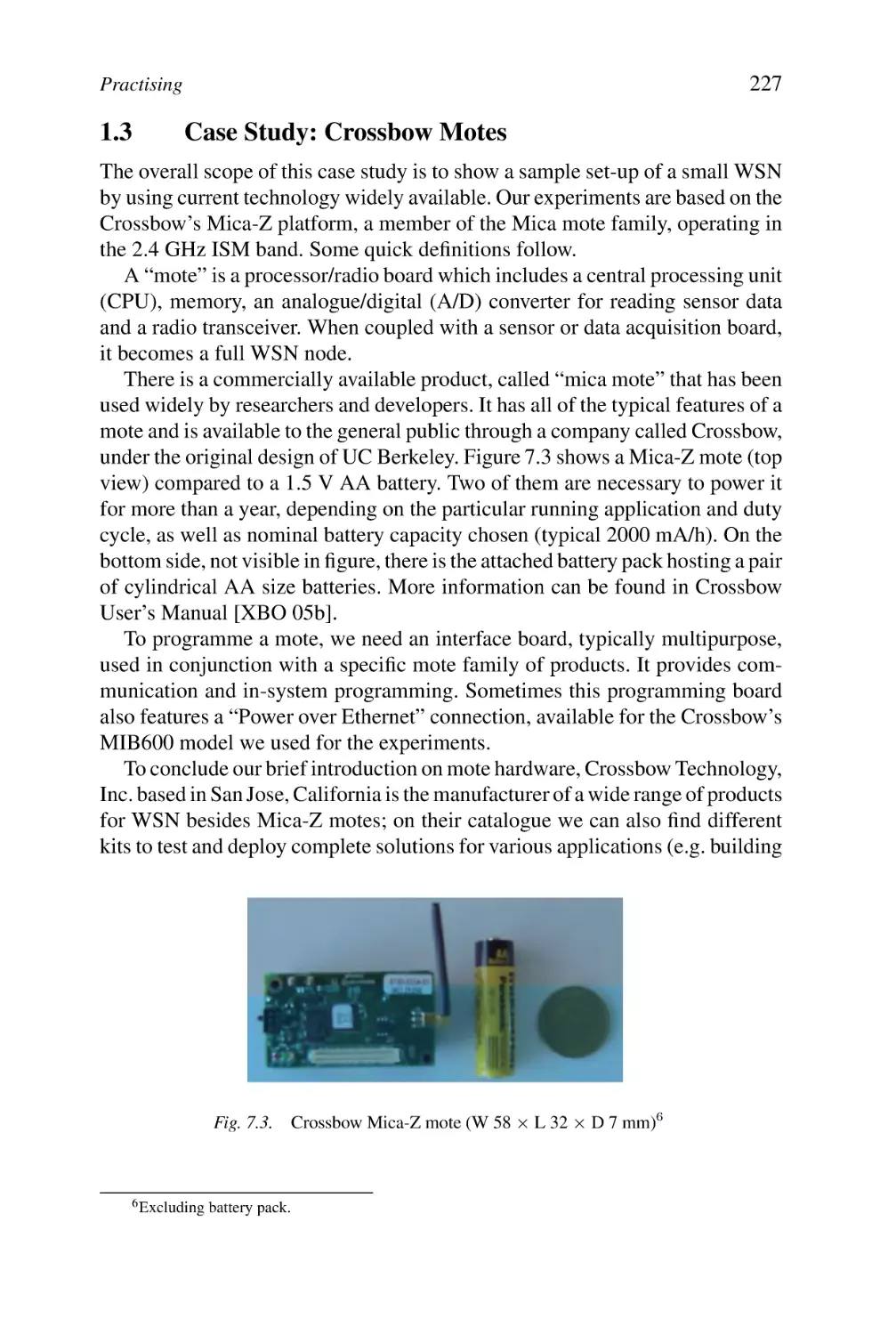
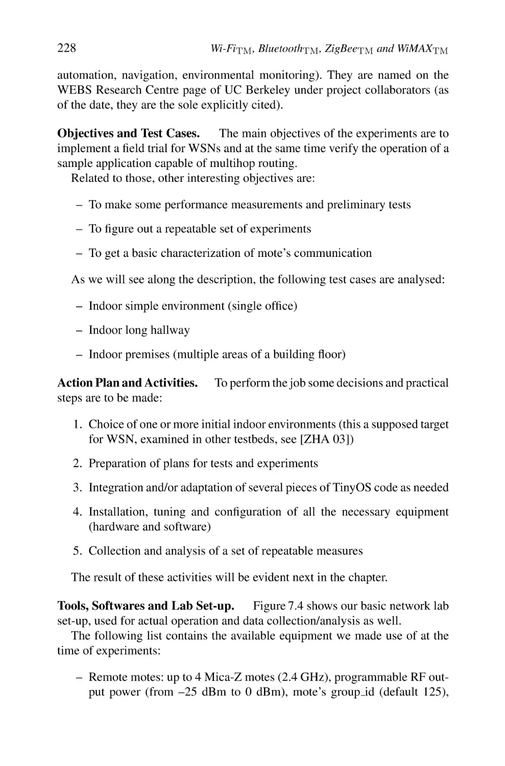
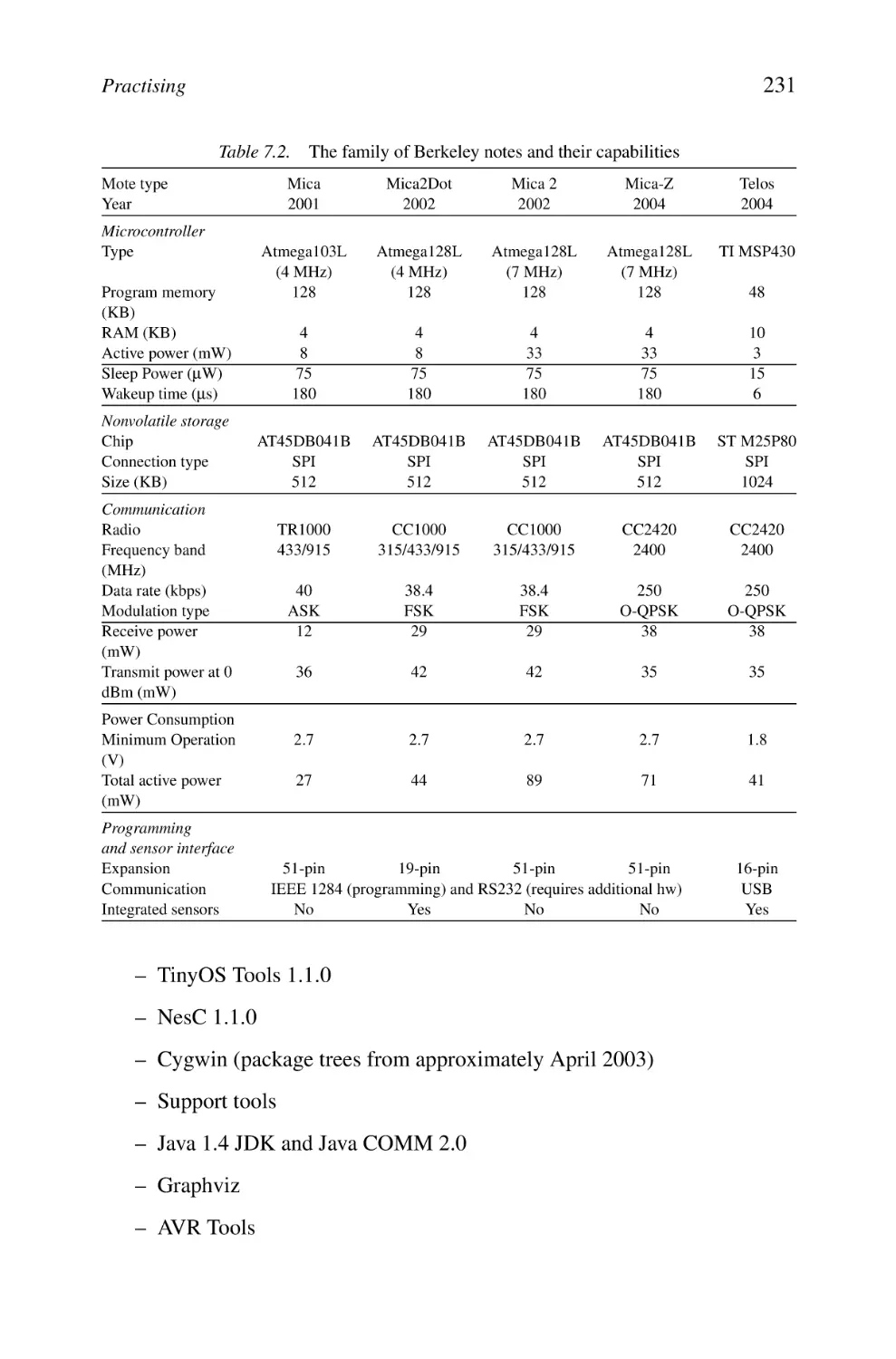
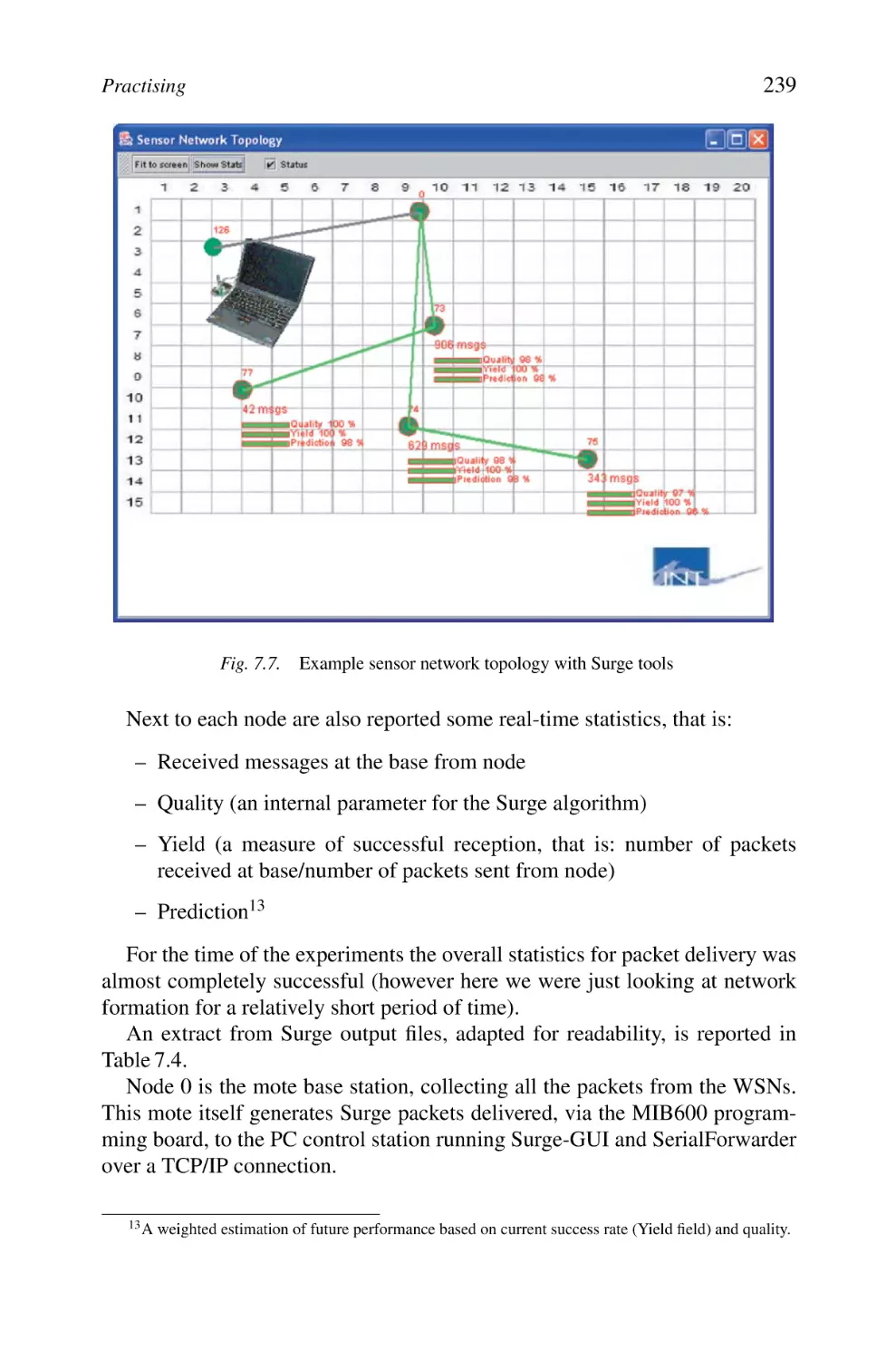
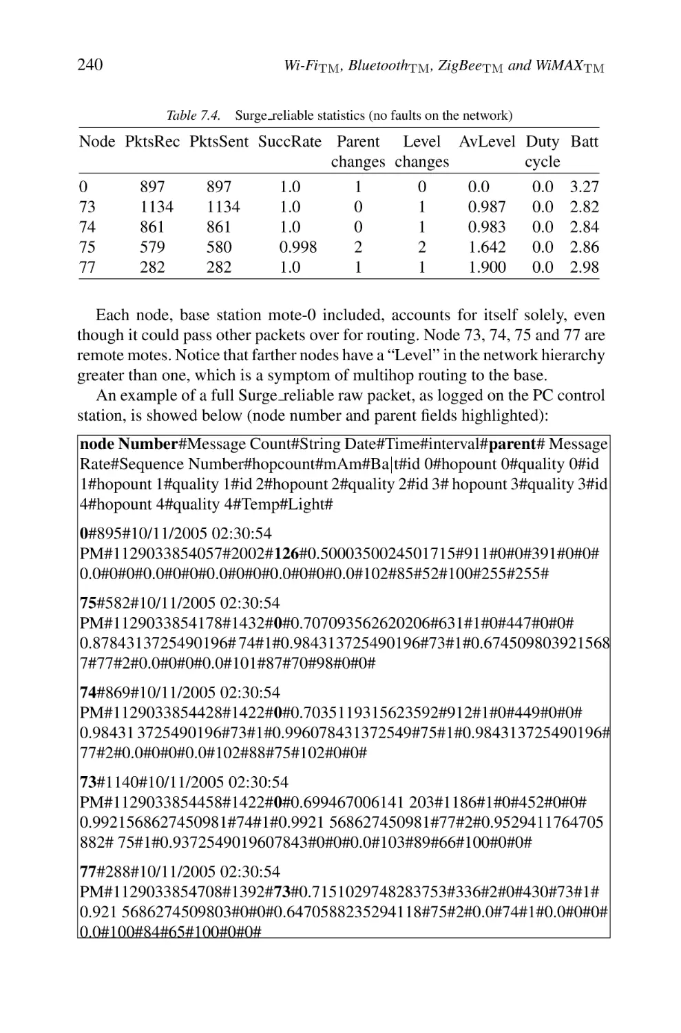
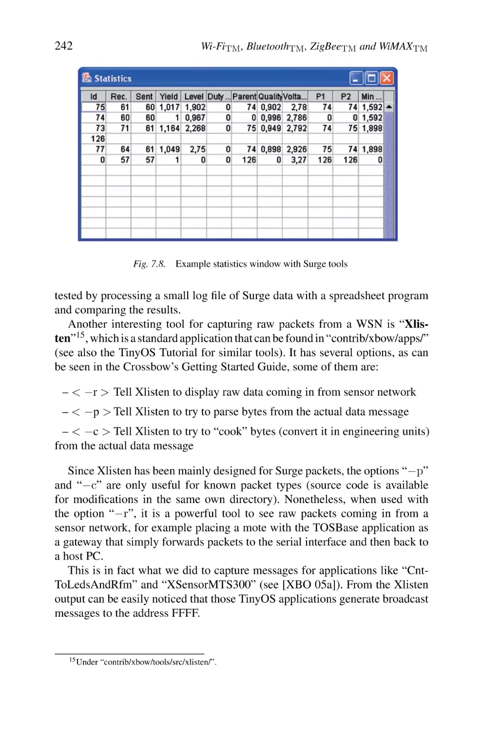
1. Mastering the TinyOS Platform
1.1 Brief Historical Notes and State-of-the-art in TinyOS
1.2 Basic Concepts of TinyOS and neSC
1.3 Case Study: Crossbow Motes
1.4 Experimentation and Measurements
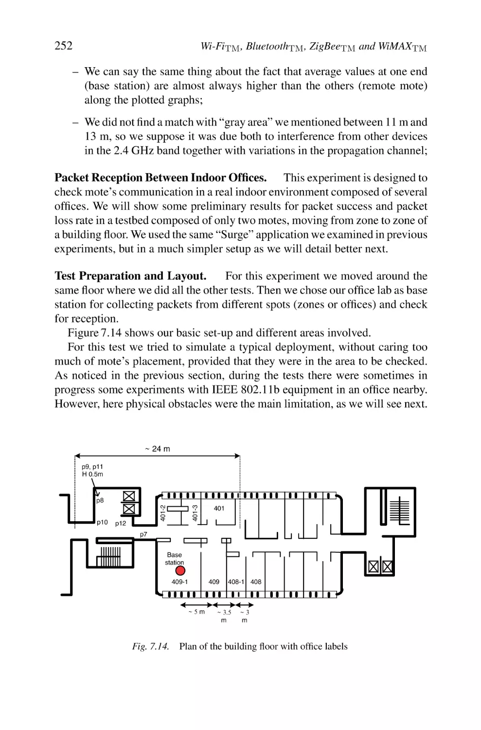
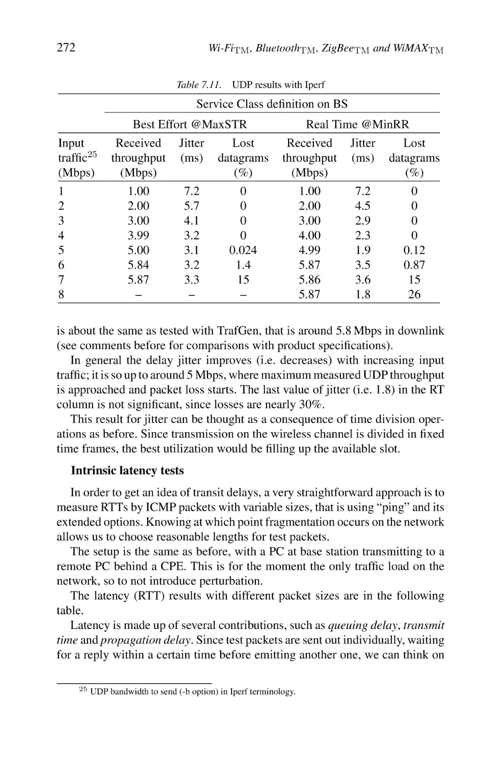
2. Practising WiMAX Equipment
2.1 General Objectives and Action Plan
2.2 Case Study: Redline WiMAX Equipment
2.3 Lab Experiments
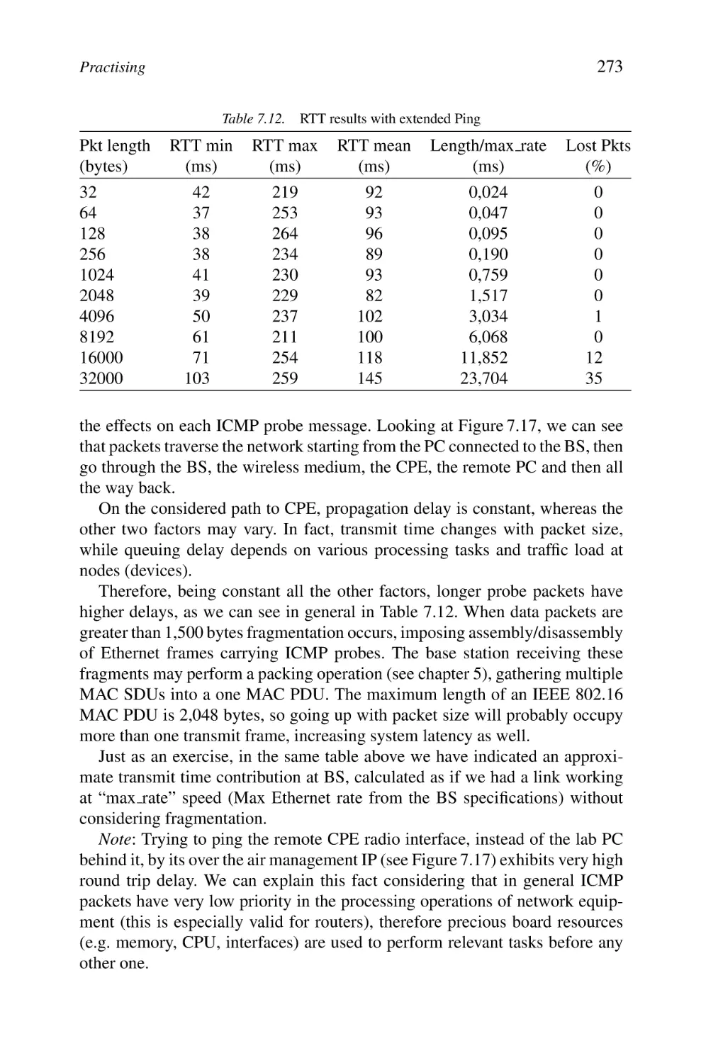
Appendix A: Structure of IEEE 802.11 Packets at Various
Physical Layers
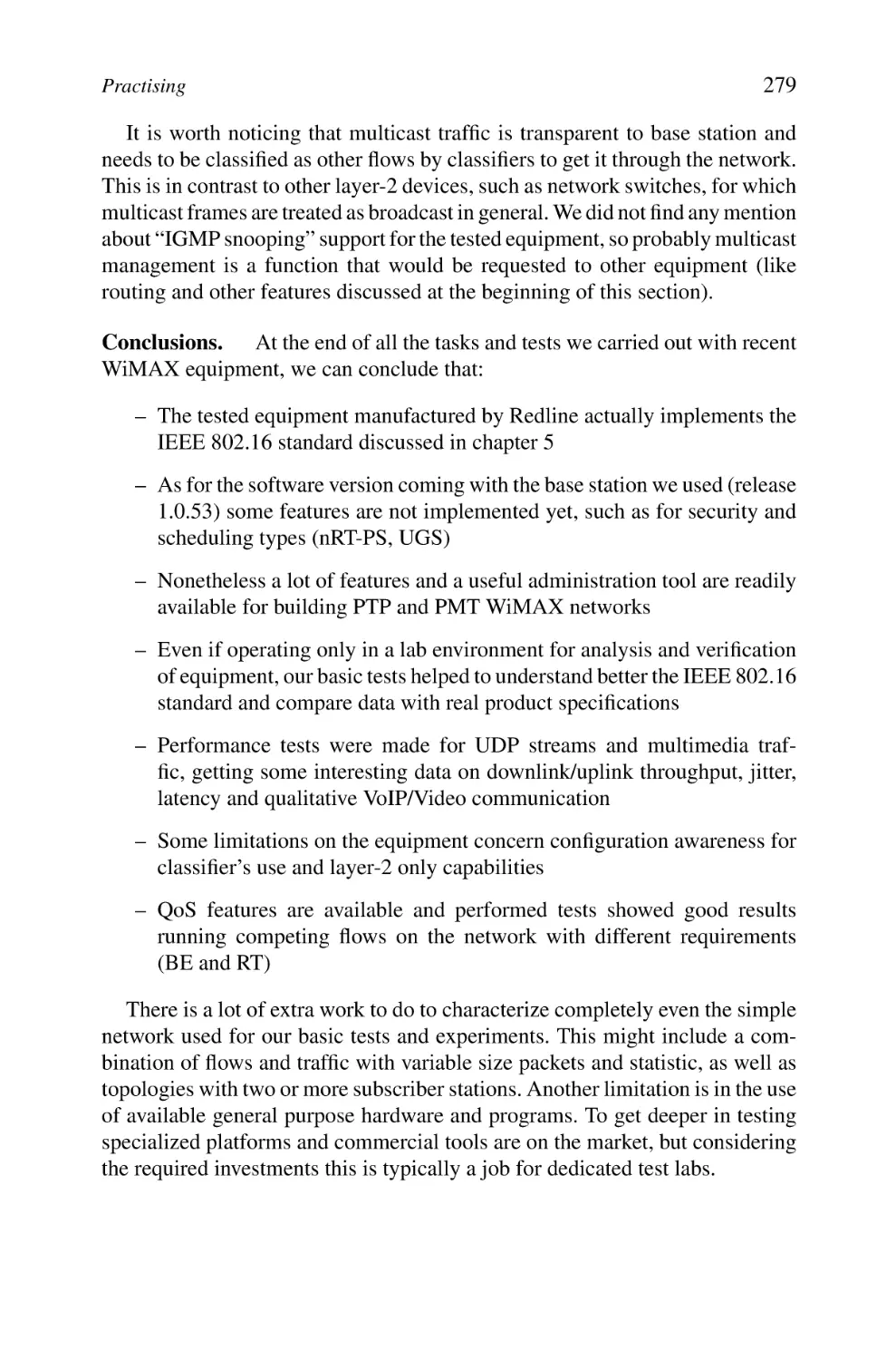
1. Packet Format of Frequency Hopping Spread-spectrum
Physical Layer (FHSS PHY)
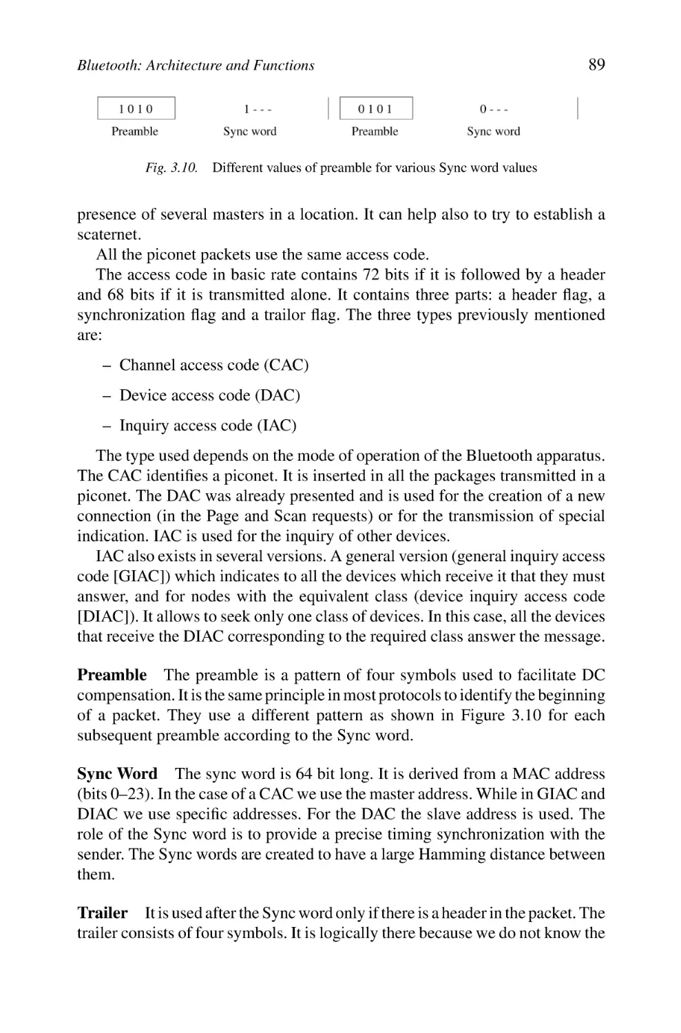
1.1 Preamble
1.2 Physical Layer Convergence Protocol Header
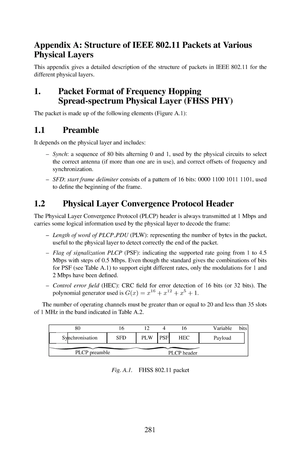
2. Packet Format of Direct-Sequence Spread Spectrum
Physical Layer (DSSS PHY)
2.1 Preamble
2.2 PLCP Header
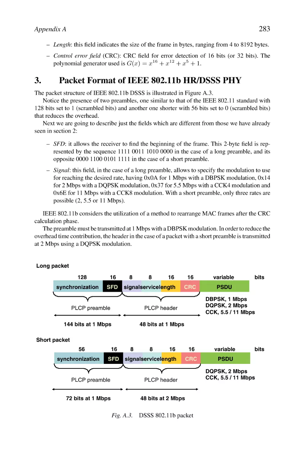
3. Packet Format of IEEE 802.11b HR/DSSS PHY
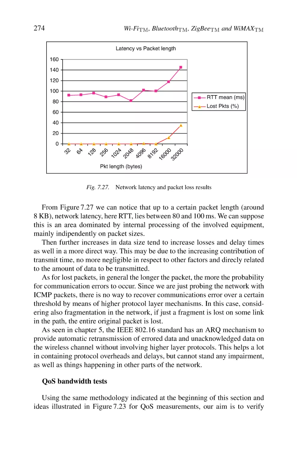
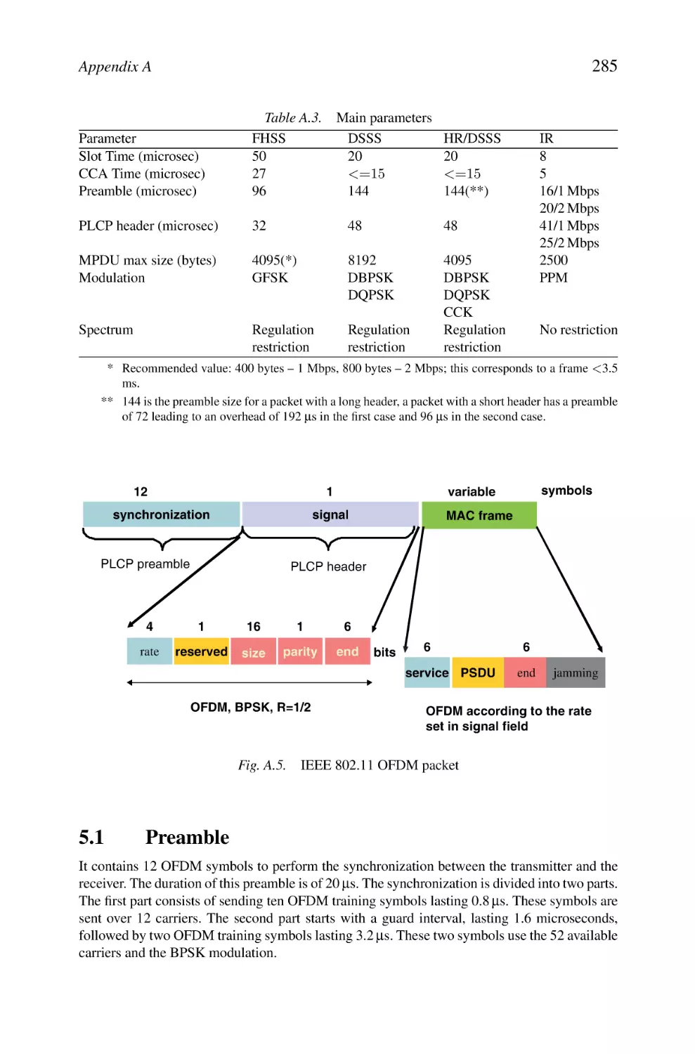
Contents
153
155
155
161
171
174
193
194
195
195
200
207
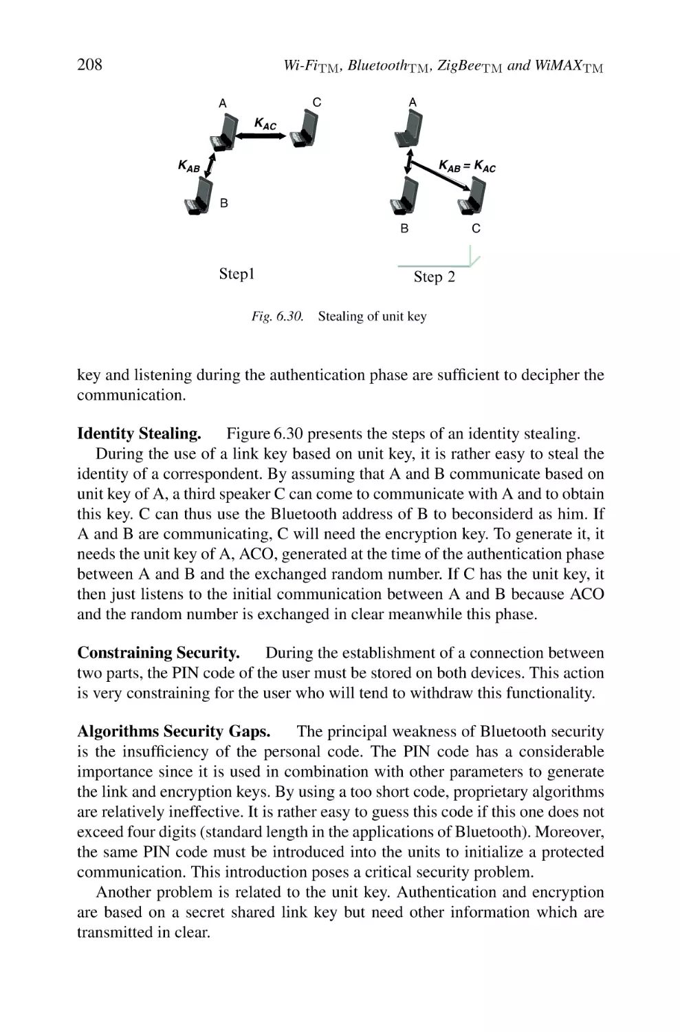
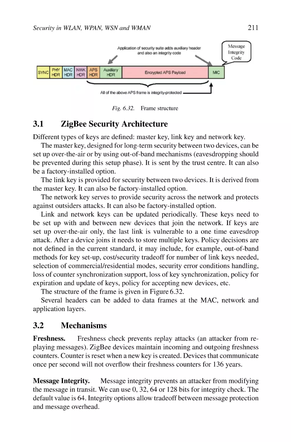
209
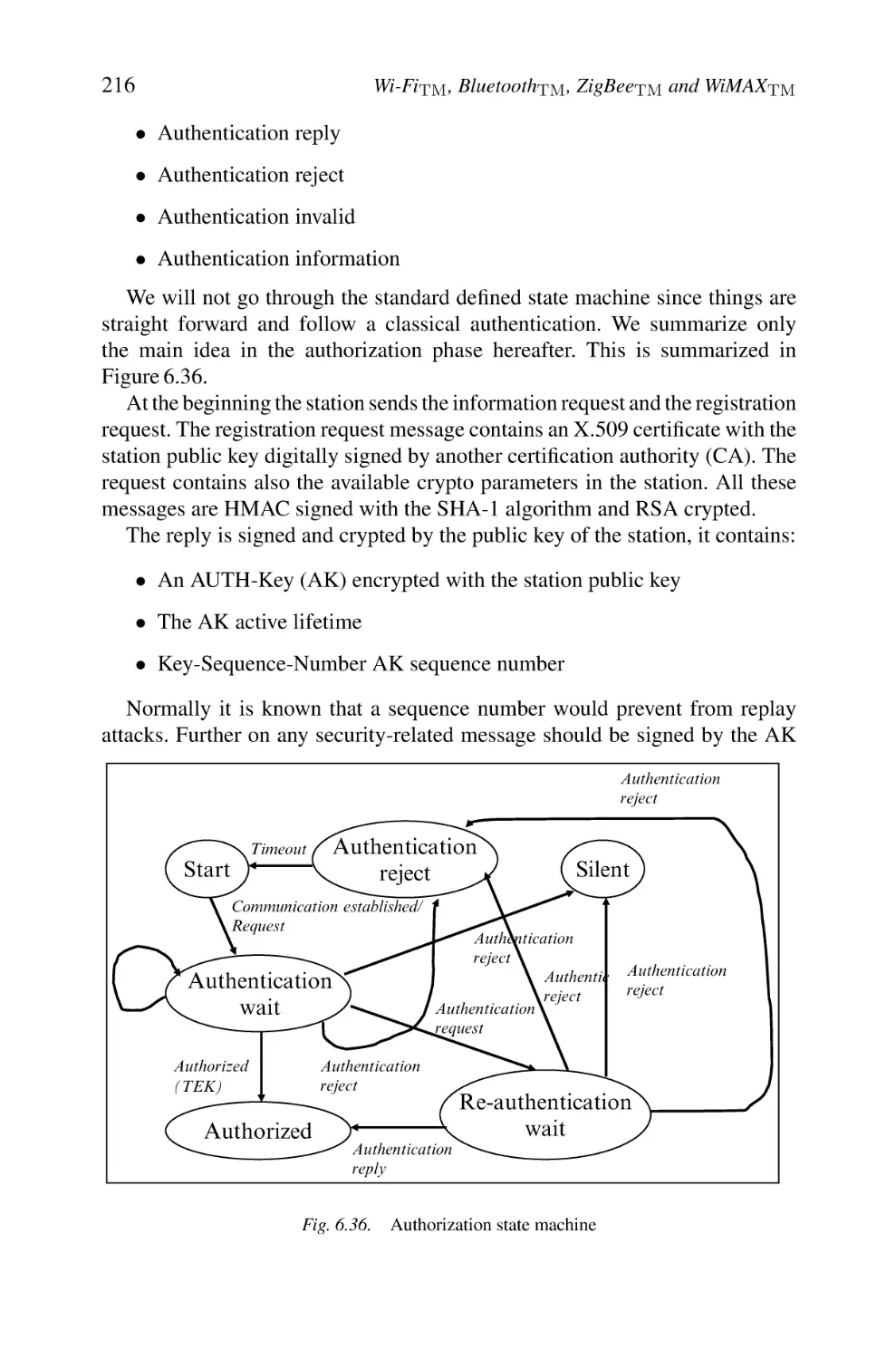
210
211
211
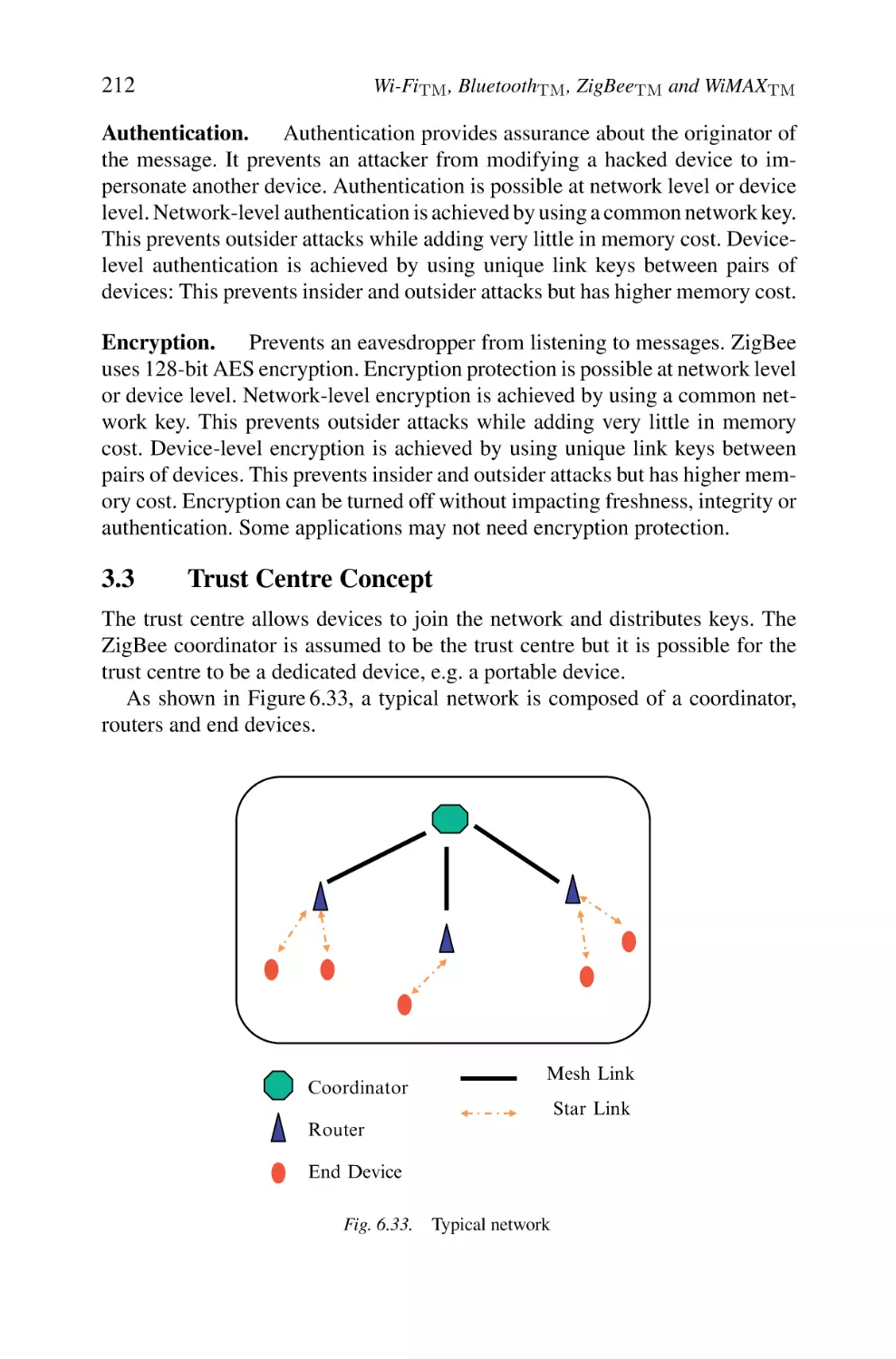
212
213
213
214
217
217
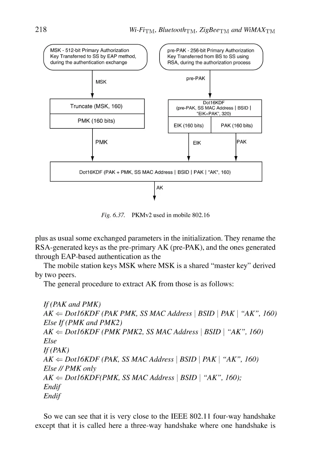
219
221
221
222
224
227
235
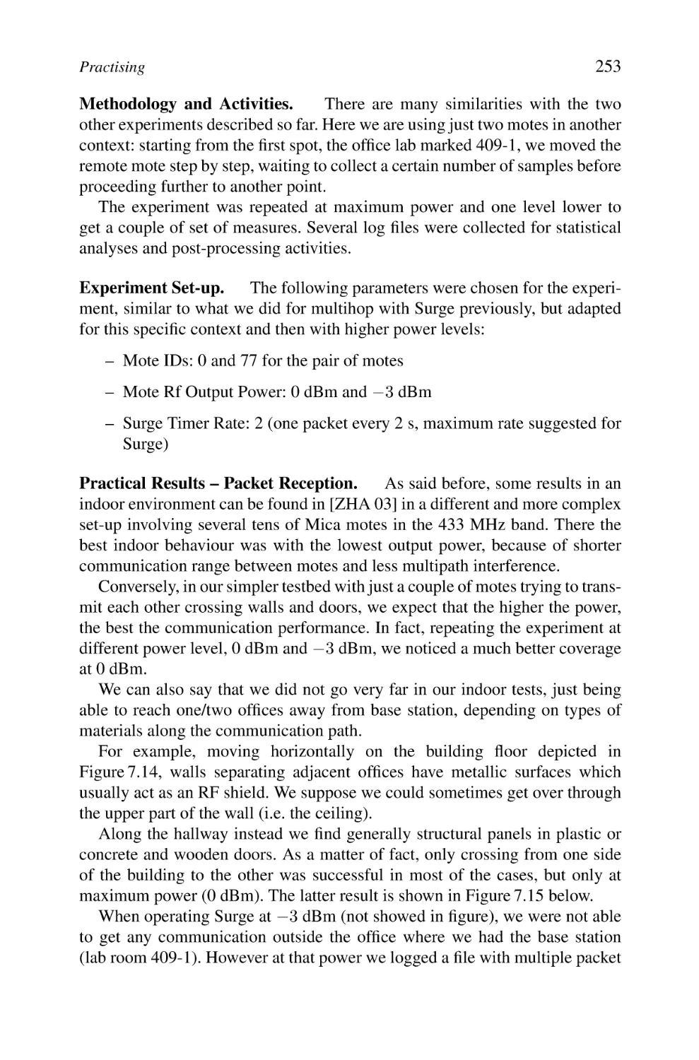
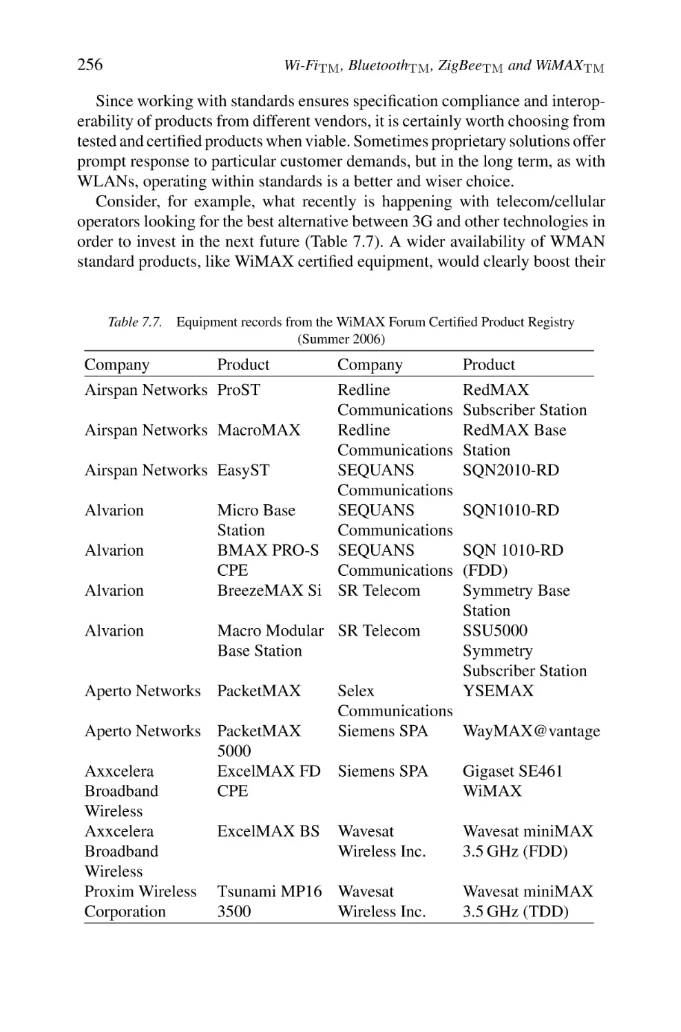
255
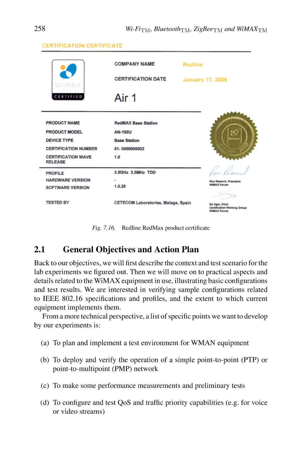
258
259
264
281
281
281
281
282
282
282
283
Contents
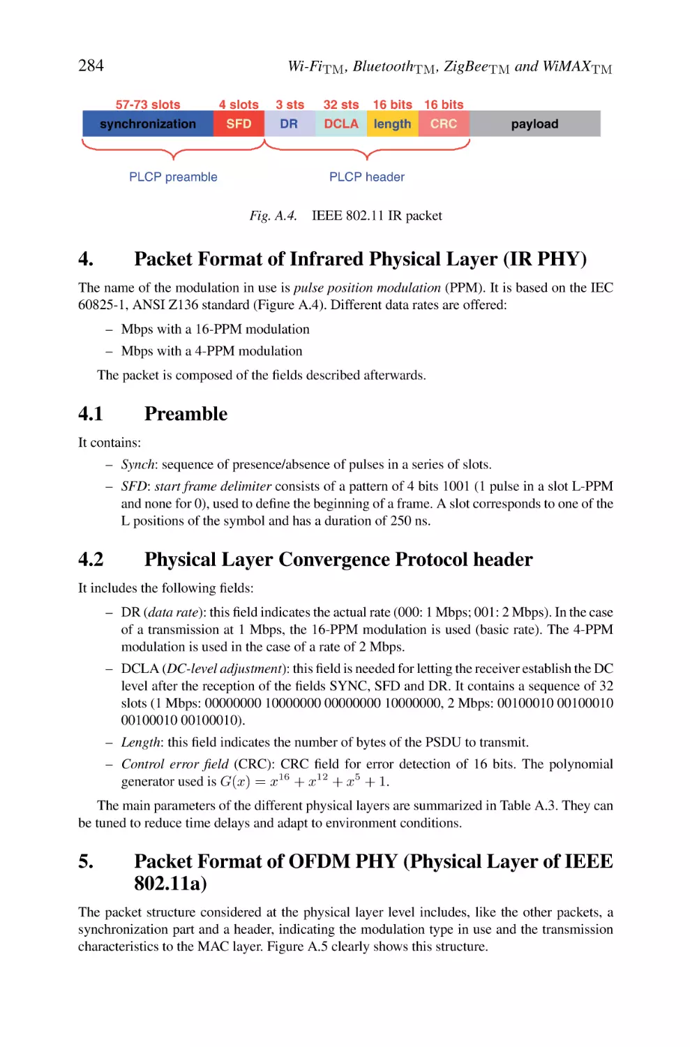
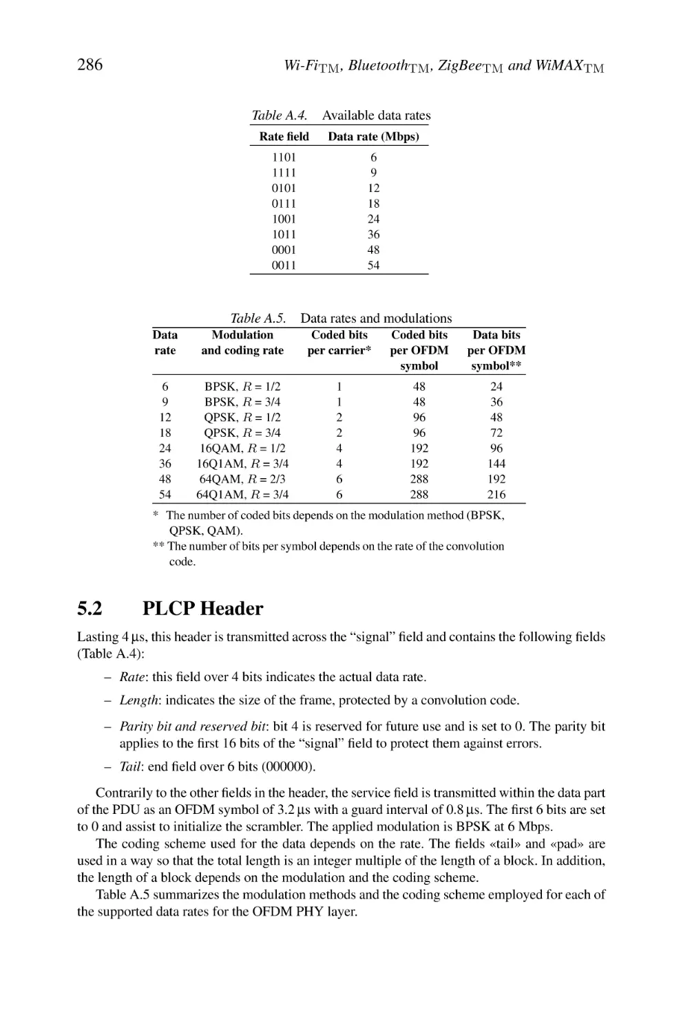
4. Packet Format of Infrared Physical Layer (IR PHY)
4.1 Preamble
4.2 Physical Layer Convergence Protocol header
5. Packet Format of OFDM PHY (Physical Layer of IEEE 802.11a)
5.1 Preamble
5.2 PLCP Header
xi
284
284
284
284
285
286
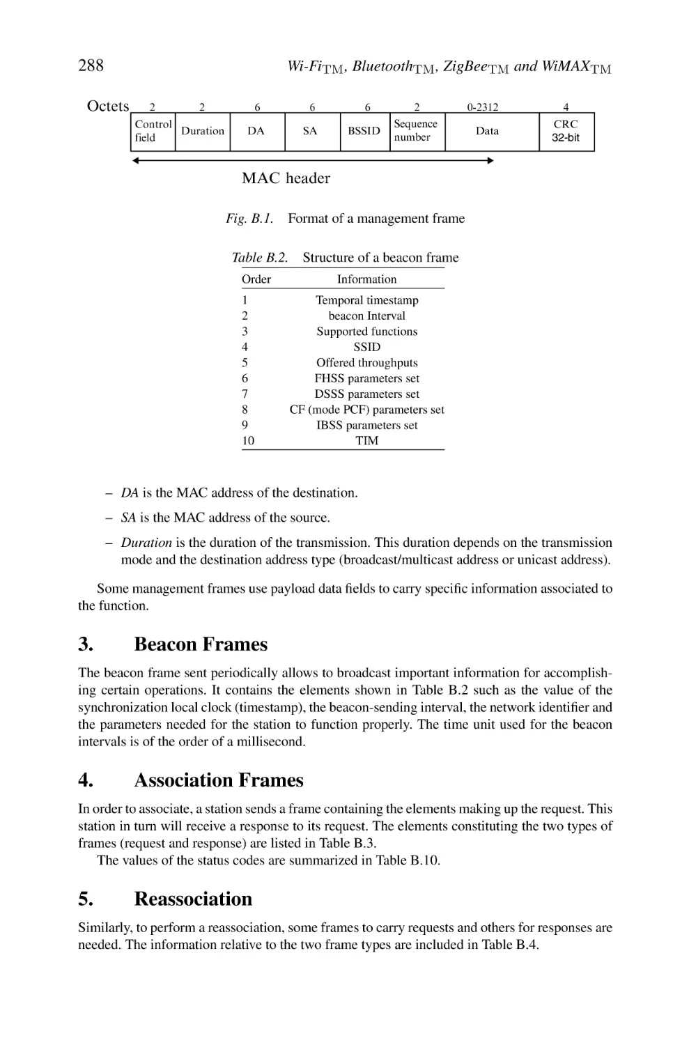
Appendix B: IEEE 802.11 MAC Frames Structure
1. Different Types of MAC Frames
2. Management Frames
3. Beacon Frames
4. Association Frames
5. Reassociation
6. Disassociation Frames
7. Probe Request Frames
8. Authentication Frames
9. Deauthentication Frames
10. Traffic Indication Map Structure
11. Status Codes
287
287
287
288
288
288
289
289
289
289
290
291
Glossary
293
References
311
Preface
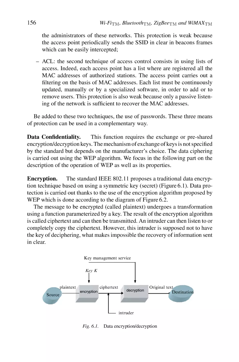
The advent of ubiquitous computing and the proliferation of portable computing devices have raised the importance of mobile and wireless networking.
Recently, there has been a tremendous interest in broadband wireless access
systems, including wireless local area networks (WLANs), broadband wireless
access, and wireless personal area networks (WPANs). This domain is a subject
of huge research and many standardization activities are undertaken throughout
the world.
Based on the most recent developments in the field of wireless technologies related to WLAN, WPAN, wireless sensor networks (WSN) and wireless
metropolitan area network (WMAN), this book gives a detailed description of
the widespread or recently used standards like Wi-Fi, Bluetooth, ZigBee, and
WiMAX. Our book aims at regrouping in a single volume up-to-date information related to these different technologies, which can be used separately
or combined to provide specific applications. The emergence of these very
promising systems is mainly due to great technological progress in the field
of wireless communication protocols; they will also make it possible to offer
a broad range of new applications in both civilian and military domains. The
inherent characteristics of these systems imply new challenges. Our book deals
with several relevant topics related to the evolution of these spontaneous, selforganized, or cellular-based networks. Through its seven chapters, we tackle
critical problems such as the design of medium access control (MAC) and routing protocols, the support of the quality of service, the security mechanisms,
the mobility/roaming aspects, etc. We preferred to follow an analysis-oriented
approach which aims at drawing up complete states of the art on both technology and standards. We also present some practical aspects and highlight some
trends as a stake for future standards. This book is intended for readers with
knowledge of networking and protocols. The audience includes network engineers, designers, implementers, undergraduate/graduate/postgraduate students,
and information systems managers.
The standards that we present are definitely based strongly on the knowledge of modulation and coding though we try, in this book, to pass over this
domain which is widely tackled in many specialized books. Hence, we try to
xiii
xiv
Preface
attract readers who are new to these technologies and make them aware of the
challenges in the different layers. As standards are made by those who have the
interest and patience to participate, discuss, and reach consensus, we also hope
to create a new interest in participation so as to open and improve the technical
levels of our future standards.
Wireless technology remains the most exciting area in telecommunications
and networking, thanks to its continuous and very fast evolution. The book thus
invites the reader for an exploring travel in order to understand the genesis of
the most important and interesting systems, which will certainly change the
landscape of future communications.
Houda Labiod
Hossam Afifi
Costantino De Santis
Foreword
It is a great honour for me to write the foreword for this book. The development of wireless communication applications and services has been incredibly
boosted to the point that the ubiquitous communication concept has found many
concrete expressions.
The Ethernet networks available in all offices since the 1980s allowed a comfortable computer resources usage thanks to their high bandwidth. But soon the
laptop became the principal office equipment, and the Ethernet suffered from the
necessity to connect physically, impeding employee mobility and the frequent
need to move from offices to meeting rooms. While on the move, employees
could not modify or consult data bases, email, etc. Ten years ago “Allways on”
(always online) was an essential request of Internet users. Mobile communication networks such as GPRS, CDMA, and UMTS offered insufficient bandwidth
for comfortable usage. The arrival of the wireless local area networks (WLANs)
has made “Allways on” a reality in companies, public places, streets, hotels,
supermarkets, and private residences.
Korea pioneered in the venture, and at the end of 2003, 16,000 WLANs were
available for public use. Korean customers could pay a fixed price for subscription to high-speed network access, which included access to their residence
by Ethernet or ADSL and connectivity through WLAN to the whole territory
when on the move. In Europe hotel chains, airports, museums, metros, etc.,
equipped themselves to offer this service to their customers. High bandwidth
access anywhere anytime is perceived today as a natural convenience associated
with many service benefits (e.g. housing, travel, lecture, tourism).
The development of PDAs, game consoles, smart phones, household
appliances, and cars with digital services additionally creates the need for
local communication between these objects in order to allow them to cooperate. A good example is ADSL home gateways that integrate wireless access
(Wi-Fi, Bluetooth, etc.) to provide easily installable triple-play services (telephony, Internet, and television) in the home. Furthermore, an accepted phone
call on your mobile can pause the program on the nearest television set, use its
loudspeakers, and perhaps use the television screen for a video call or a video
clip received in an MMS.
xv
xvi
Foreword
Most of these objects will have access to several interfaces of communications (GPRS, Wi-Fi, Bluetooth) in order to be able to combine the services
offered on every domain. The next step is the “always best connected” concept,
assuming that a single object could discover the most favourable network and
use it transparently for the service required at any time and in any location.
This is also becoming a commercially available service in Korea and France.
For instance, the telecom operator Orange has recently put on the market its
“Unik” facility, which allows mobile phone users Wi-Fi access without service
disruption whenever available, with associated low fares, instead of UMTS or
GSM used outdoors.
Future services that will be available are body area networks (BANs), in
which sensors and actuators need to communicate to send their information
and to adapt their behaviour to the physical environment. Context-specific applications, such as handicapped persons’ services, for instance, require new
LANs that use energy sparingly, and can efficiently discover and communicate with transient neighbours such as RFID, biosensors, and biochips. New,
currently designed services will need such properties. Billions of such sensors,
captors, and activators will surround us and our personal assistants should be
able to get the information across in time to provide us with useful enhanced
services. Many of those tiny objects will have at their disposal very low energy
capacity, and the choice for the optimal system design is still an open issue.
This book provides a comprehensive description of IEEE802.11, also called
Wi-Fi, Bluetooth, WiMAX, or ZigBee. In-depth descriptions of the protocols are
provided. The authors possess a solid practical experience of these networks that
appears clearly in the explanations and numerous outlines in the text. Security,
service discovery, and operating system integration are critical issues discussed
in this book.
The authors have developed the important points of wireless networks describing the profits and technical elements of each approach, and explaining the
integration of the WLAN in the context of the Internet.
Professors Hossam Afifi and Houda Labiod should be congratulated for their
synthetic and very complete work.
Pierre Rolin
Dean of Telecom INT
Evry, France
Chapter 1
Introduction
Today wireless is becoming the leader in communication choices among
users. It is not anymore a backup solution for nomadic travellers but really a
new mood naturally used everywhere even when the wired communications are
possible. Many technologies evolve then continuously, changing the telecommunication world. We talk about wireless local area networks (WLANs), wireless personal area networks (WPANs), wireless metropolitan area networks
(WMANs), wireless wide area networks (WWANs), mobile ad hoc networks
(MANETs), wireless sensor networks (WSNs) and mesh networks. Since we
can find today a multitude of wireless technologies we decided to group a
number of complementary technologies into one document to make it easier for
a reader to understand some of the technical details of each media. Our attention
has hence gone towards the most popular wireless techniques nowadays used at
different scales. The first scale is the new defined “human body” scale where we
envision to have many wireless devices not necessarily powered by anything,
but just with ambient noise or with human heat and radiating digital information
proper to ones very intimate life such as medical care.
A slightly larger scale of use cases, considered to be very important, addresses personal communications. Here, we talk about a personal “bubble” where
everything belongs to a user with constraints on bandwidth and security.
In these two situations we consider in this book the available standards that
fit to the usage, i.e. Bluetooth and ZigBee. Note that ZigBee is normally known
under the name of Institute of Electrical and Electronics Engineers (IEEE)
802.15.4, whereas ZigBee is more targeted to design a related architecture
1
2
Wi-FiTM , BluetoothTM , ZigBeeTM and WiMAXTM
for upper layers. In both standards a special care has been taken with power
consumption. Of course with time, one can conclude that still an effort can be
made over these solutions to save more energy, but every standard is related to
a period where research advances are not yet mature enough to propose them
as technical solutions. Even more, it may happen that a theoretical solution is
not feasible with today’s state-of-the-art integration and silicon technologies.
When we expand the “bubble” to larger scales with interpersonal collaborations, small office and home applications, we cannot neglect the wireless fidelity
(Wi-Fi) standard of course. The larger part of this book is dedicated to that huge
group of standards. Wi-Fi is going through the same growth as the Internet Protocol (IP), that makes it a great success and that takes it away from its original
purpose to what people want to do effectively with it. Wi-Fi or IEEE 802.11
for technical people is an always evolving standard. We see that engineers still
show an increasing interest in proposing new ideas that make better solutions.
The group that meets every two months all over the world in a pseudorandom
walk, is composed of a few hundreds of engineers and researchers, considered
as experts in wireless and mobile communications. Contrarily to other standard
bodies, that are more driven by business, there is still room in IEEE 802.11, for
research studies and the pseudo-democratic procedure that is used in this area
to select proposals still leaves the space for new ideas to come up. Of course,
contributing to that group is still not easy as one could imagine, as one must
physically follow all meetings and compete with large industrial well-known
groups that control the floor.
The Wi-Fi group as we show in the book consists of a few tens of working
groups each dedicated to a specific problem. The groups consider very diverse
problems such as increasing the bandwidth or range, securing connections, mesh
networking, vehicular communications, cooperative transmission and so on.
The last area that we consider in this book is about metropolitan radio transmission. We focus of course on IEEE 802.16 or what is commercially called
worldwide interoperability for microwave access (WiMAX) as it seems to be
the leading choice in this area.
IEEE 802.16 is also a very dynamic group that is competing with different
bodies such as the Third Generation Partnership Project (3GPP) and even with
Wi-Fi when it is deregulated in terms of transmission power.
We consider in this book two additional aspects: security and practical
deployment because we believe that they are necessary to have a better view of
how things are used and are put together in a real environment.
We do not consider, however, regulatory problems although it is in se a group
in the IEEE 802 since it is strictly a per country political issue too complex to
treat in a technical book. We need, however, to raise the reader’s attention to
the fact that regulatory wireless aspects do influence both the technique and the
future.
Introduction
3
A regulation can, for example, prevent a standard from being deployed in
whole continent such as North America or Europe by disabling some frequency
bands or by reducing the authorized power or channel width.
Note also that all these standards are dealt with in the IEEE 802 group that
means that they are compatible with the general two layers architecture defined
there. This also means that addressing, bridging and interface with upper layers
are somehow the same in all these technologies.
An additional effort is done to be able to switch from one technology to the
other in a seamless way. Although the group is not detailed in the book we
have to present it in the introduction as a global virtual layer that enables the
handover from a technology to the other without a service interruption. This
effort is jointly led in IEEE 802.21 (media independent handover [MIH]) and
in the Internet Engineering Task Force (IETF), where an orthogonal layer is
designed to be able to extract radio information from the physical layer and to
send it to an appropriate decision entity in the terminal, in the network or both
to decide whether it is appropriate to change the connection from one wireless
technology to the other. In the book we start with the IEEE 802.11 standard and
all of its variants.
We continue with IEEE 802.16 group of standards with its different physical
layers. The Bluetooth technology is described afterwards and we finish with
the ZigBee standard. As explained before, two additional chapters describe
the security issues in these different standards and some practical experiments
that we led to provide a practical and critical view of potential usage of these
technologies.
Organization. After the introduction (chapter 1), chapter 2 briefly gives a
general description of WLANs. It starts by describing the context of this new
type of networks within the framework of mobile networks. It then provides
a rather broad outline on the particular characteristics of fourth-generation
WLANs, their uses, the elements which constitute the architecture and the
supported applications by quoting various types of current market segments
covered by this technology. The second part of this chapter is dedicated to
IEEE 802.11/802.11b (Wi-Fi) standards, which describes in an exhaustive way
the mechanisms developed, with a special focus on access protocols. Standardization activities for the IEEE 802.11 family specifications are given in order
to show the rapid evolution of the technical enhancements related to this technology.
Following the same clear and descriptive approach, the specification of the
Bluetooth standard is detailed in chapter 3, while reviewing its major characteristics for lower and higher layers.
Chapter 4 covers IEEE 802.15.4 and ZigBee which are concerned with
wireless sensor networks. ZigBee technology enables the coordination of
4
Wi-FiTM , BluetoothTM , ZigBeeTM and WiMAXTM
communication among thousands of tiny sensors, which are very low cost, with
lower power consumption and low data rate.
In chapter 5, we provide an overview of the IEEE 802.16 architecture and
services and then look in more detail at the IEEE 802.16 specification.
Chapter 6 is devoted to security, which represents one of the major issues
when deploying a wireless network. It comprises four parts. The first part includes an exhaustive state of the art of security for Wi-Fi systems, with an
approach that consists in reviewing the developed mechanisms for authentification and encryption. Then we analyze thoroughly security flaws, showing an
up-to-date classification of attacks. A report on standardization efforts, as well as
short-term and medium-term solutions, is explicitly examined by highlighting
still unsolved problems. In a similar way, the second part comprises a security
study of Bluetooth systems. The third and fourth parts address, respectively,
the security mechanisms related to WiMAX and ZigBee systems. A general
conclusion ends this chapter by giving hot lines to set up short- and long-term
security solutions.
The goal of chapter 7 is to illustrate by practical examples and experiments
real WSN setups and WiMAX fresh equipment. The material is organized giving first a brief overview of TinyOS, an open source project devoted to network
embedded technology and devices. Then some experiments and results are presented in a step-by-step fashion, to provide suggestions and feeling with WSNs.
With reference to WMANs, the main focus is on configuration and testing of
a complete wireless system composed of a base station and a couple of subscriber units using certified WiMAX equipment. A lab set-up for basic network
performance measurements is showed, together with results attained by using
popular tools.
The reader will find at the end of the book two appendices, which will provide
him specific details concerning some important elements. Appendix A describes
the structure of packets transmitted, according to the selected IEEE 802.11
physical layer. Appendix B contains a detailed description of the structure of
IEEE 802.11 medium access control (MAC) frames.
Given the vast amount of information and the diversity of concepts, we preferred, in order to facilitate the reading of the book, to develop an extended
glossary, which expands acronyms and provide a concise explanation of technical terms. A great number of figures are also included to provide an easy
illustration of the various developed schemes as well as protocols and structures. A variety of useful documents and relevant websites are given to provide
information related to the topics of this book.
This book, through its synthesis-based approach, can thus constitute an
invaluable help for a broad range of readers who will benefit from an
understanding of wireless communications and the associated technologies.
This includes students, professionals, designers, implementers and managers.
Chapter 2
Wi-FiTM : Architecture and Functions
In just the past few years, WLANs have gained a tremendous place in the
local area network (LAN) market. Today, WLANs based on the IEEE 802.11
standard constitute a practical and interesting solution of network connection
offering mobility, flexibility, low cost of deployment and use. The purpose of
this chapter is to describe in a detailed way the concepts, principles of operation and rationales behind some of the features and/or components of the
standard which was originally started in 1997. We chose a clear and concise
style of writing to facilitate the understanding of the inherent concepts in this
technology, which sometimes require knowledge from several disciplines. Different aspects are covered throughout the chapter. Section 1 is devoted to a brief
description of the main characteristics of WLANs. Then a detailed analysis of
the IEEE 802.11 standard is given, including the physical transmission layer
(section 3), the access to the medium (section 5) and the management functions
such as addressing, association/disassociation, roaming and energy-conserving
(section 6). In this chapter we focus particularly on the IEEE 802.11 and 802.11b
(labelled Wi-Fi) standards, nonetheless an overview of several derivative standards and working groups is shown in section 9.
1.
WLAN Roadmap via IEEE 802.11 Family Evolution
Wi-Fi standard has gained some age and hence some maturity. It is still a very
active group of standardization and one can see that new working or study
groups are created to explore new directions. Note also that different national
5
6
Wi-FiTM , BluetoothTM , ZigBeeTM and WiMAXTM
regulatory boards strongly influence the standard. We can see, for example,
that in Europe, after the liberation of some frequencies in the 5 GHz band with
good output power (1 W) makes the Wi-Fi a challenger to other long-range
technologies such as WiMAX that is explained later in chapter 5.
1.1
Panorama of Standards
A WLAN is a data transmission system designed to ensure a connection that
does not depend on the location of peripherals using wireless links rather than
a cabled, fixed infrastructure. In companies, WLANs are generally deployed
as the final link between the existing wired network and a group of customers’
computers, offering a wireless access to the whole of the resources and services
of the corporate network, in one or more buildings (sites).
In these last years WLANs are also getting their way into university campuses
and public zones such as railway stations and airports, allowing any individual
equipped with a portable computer to reach public information services or to
connect itself to the Internet through the wireless infrastructure.
The widespread of WLANs depends closely on the developed standards.
Indeed, the standardization ensures the reliability and the compatibility of products from different equipment suppliers. The IEEE 802 Committee, acknowledged as the world authority for LANs, defined several LAN standards during
last 20 years, including the IEEE 802.3 Ethernet, the IEEE 802.5 Token Ring
and the IEEE 802.3u 100BASE-T Fast-Ethernet. In 1990, the IEEE 802 Committee formed a new working group, the IEEE 802.11, specifically devoted to
WLANs, with a charter to develop a physical medium specification and a MAC
protocol. The Institute of Electrical and Electronics Engineers (IEEE) ratified
the 802.11 specification in 1997. This standard, in its first version, featured
data rates of 1 and 2 Mbps and defines the fundamental rules for signalling
and wireless services. The major problem, which limited the initial industrial
development of WLANs, was then the limited throughput, too low to really
meet the various enterprises needs. Conscious of the need for increasing this
rate, the IEEE defined the 802.11HR specification (also named IEEE 802.11
high rate or 802.11b) with speeds of 5.5 and 11 Mbps. The IEEE also worked
out the specifications of the 802.11a version in the 5 GHz band.
The statutory organizations and suppliers’ alliances adopted this new high
data rate standard, and many market sectors appeared (Small Office Home
Office [SOHO], as well as public/governmental and private/corporate related).
Apart from the standard bodies, the main players of the wireless industry met
within the Wi-Fi Alliance, previously called Wireless Ethernet Compatibility
Alliance (WECA). The mission of the Wi-Fi alliance is to certify the interworking and the compatibility between IEEE 802.11HR network equipments
and also to promote this standard.
Wi-FiTM : Architecture and Functions
7
The Wi-Fi alliance regroups manufacturers of semiconductors for WLANs,
hardware suppliers and software providers. Among them we can find companies like 3Com, Cisco-Aironet, APPLE, Breezecom, Cabletron, Compaq, Dell,
Fujitsu, IBM, Intersil, Lucent Technologies, No Wires Needed, Nokia,
Samsung, Symbol Technologies, Wayport and Zoom.
Up to now, the IEEE 802.11 family of standards did not cease to continuously
come up with new proposals of standards. Right below we provide a list of
IEEE Standards and Task Groups (TGs) that exist within the IEEE 802.11
working group. The Official 802.11 WG Project Timelines can be found at
http://www.ieee802.org/11/802.11 Timelines.htm.
As it can be seen from the IEEE 802.11 home page, it is very easy to become
an active member in the group where a minimum of three physical meetings
are required for a person to become a voting member and hence influence the
decisions taken there.
The most prevalent WLAN protocols are those related to the IEEE 802.11,
IEEE 802.11b (Wi-Fi) and IEEE 802.11g standards. This family of standards
deals with the physical and data link layers as defined by the OSI basic reference
model (ISO/IEC 7498-1:1994). Today we see that the IEEE 802.11n is slowly
taking over them.
The term used for IEEE 802.11b-certified products is Wi-Fi. Wi-Fi certification is provided by Wi-Fi alliance; notice that at present it has been extended
to include IEEE 802.11g products as well. Wi-Fi alliance has also developed a
certification procedure for IEEE 802.11a products called Wi-Fi5.
The list of standards and those derived from Wi-Fi are quoted below:
– IEEE 802.11: the original 1 and 2 Mbps, in the 2.4 GHz industrial,
scientific and medical (ISM) band, and infrared (IR) standard (1999).
– IEEE 802.11b: enhancements to IEEE 802.11 to support 5.5 and 11 Mbps
(1999).
– IEEE 802.11a: the IEEE 802.11a standard operates in the 5 GHz band
and allows throughputs from 6 to 54 Mbps.
– IEEE 802.11g: allows to reach higher data rates (54 Mbps, identical to
IEEE 802.11a) in the 2.4 GHz band. The orthogonal frequency-division
multiplexing (OFDM) modulation is used. It provides backwards compatibility with 802.11b (2003).
– IEEE 802.11d: international (country-to-country) roaming extensions
(2001), access points (APs) communicate information on available radio
channels and acceptable power levels, according to countries’ lawful
restrictions.
– IEEE 802.11c: bridge operation procedures, included in the IEEE 802.1D
standard (2003).
8
Wi-FiTM , BluetoothTM , ZigBeeTM and WiMAXTM
– IEEE 802.11e: enhancements (2005), standard for the quality of service
(QoS), which defines the specifications of the QoS mechanisms to support
multimedia applications. Apply to IEEE 802.11b/a/g. It introduces the
hybrid coordination function (HCF). HCF uses both a contention-based
channel access method, called the enhanced distributed channel access
(EDCA) and a contention-free channel access method, called HCFcontrolled channel access (HCCA) which have been derived from their
earlier versions enhanced distributed channel function (EDCF) and HCF.
– IEEE 802.11F: deals with the standardization of protocols between APs
to allow the use of a multivendor infrastructure avoiding proprietary standards. The Inter-Access Point Protocol (IAPP) offers this interworking
feature.
– IEEE 802.11h: spectrum managed IEEE 802.91a (5 GHz) for European
compatibility (2004). Mechanisms of frequency dynamic selection and
transmit power control (TPC) are considered.
– IEEE 802.11i: enhanced security (2004). Apply to standards IEEE 802.11
b/a/g.
– IEEE 802.1X standard: provides security mechanisms for various media
including wireless links by the means of strong authentication procedures
with dynamic key distribution.
– IEEE 802.11j: convergence of the American (IEEE 802.11) and Japanese
standards (it is the adaptation of the former to the Japanese legislation).
– IEEE 802.11k: radio resource measurement (RRM) enhancements; it defines methods and measuring criteria needed by higher layer protocols to
fulfill management and maintenance functions.
– IEEE 802.11n: higher throughput improvements; it offers higher data
rates (108–600 Mbps) in the 2.4 and 5 GHz bands.
– IEEE 802.11p: wireless access for the vehicular environment (WAVE).
– IEEE 802.11r: fast roaming.
– IEEE 802.11s: mesh networking.
– IEEE 802.11T: wireless performance prediction (WPP) – test methods
and metrics.
– IEEE 802.11u: interworking with non-802 networks (e.g. cellular).
9
Wi-FiTM : Architecture and Functions
– IEEE 802.11v: wireless network management.
– IEEE 802.11w: protected management frames.
– IEEE 802.11y: 3650–3700 operation in the United States.
Note – there is no standard or task group named “802.11x”. Rather, this term
is used informally to denote any current or future IEEE 802.11 standard, in
cases where further precision is not necessary. (The IEEE 802.1X standard for
port-based network access control, is often mistakenly called “802.11x” when
used in the context of wireless networks.)
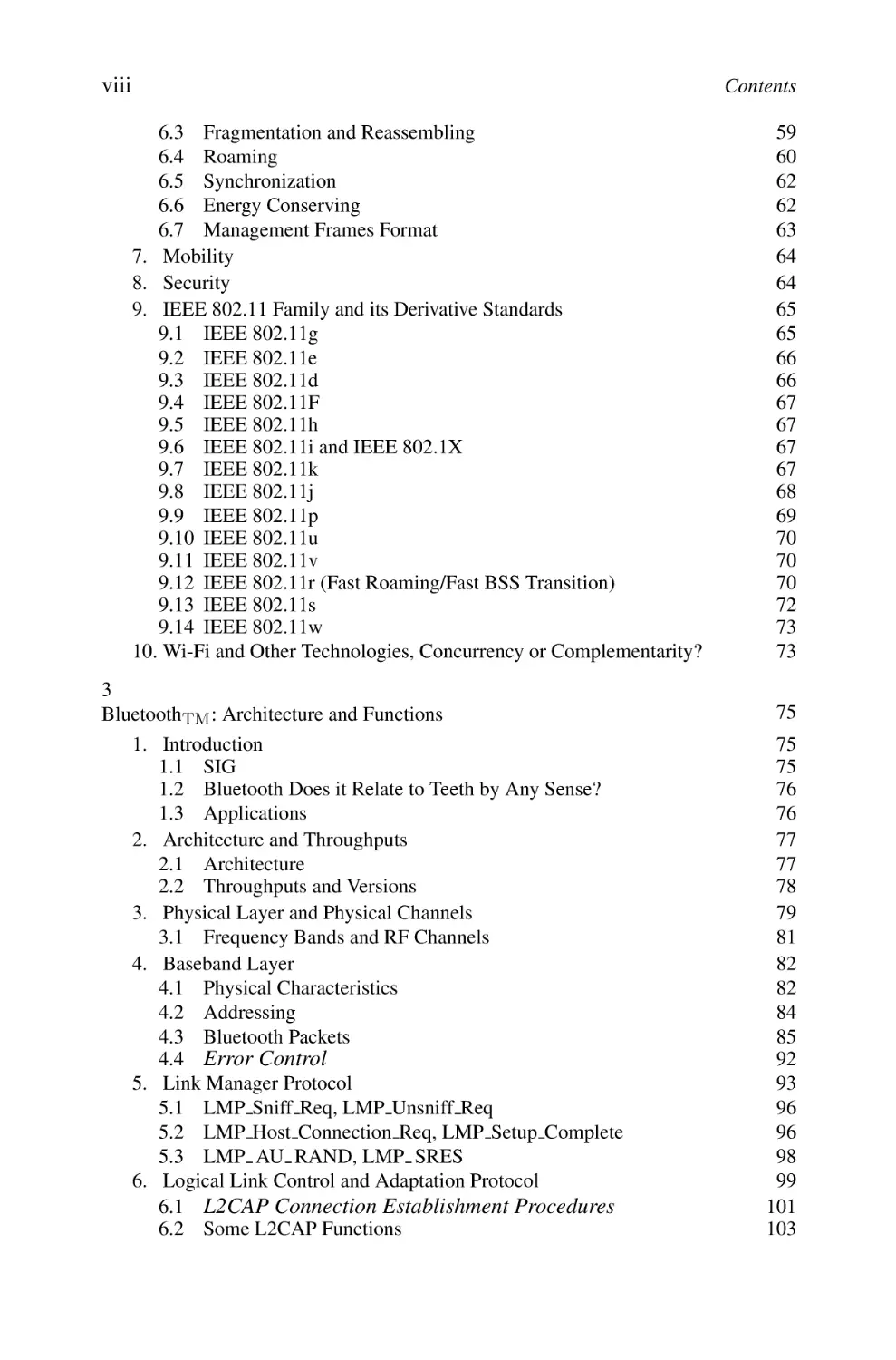
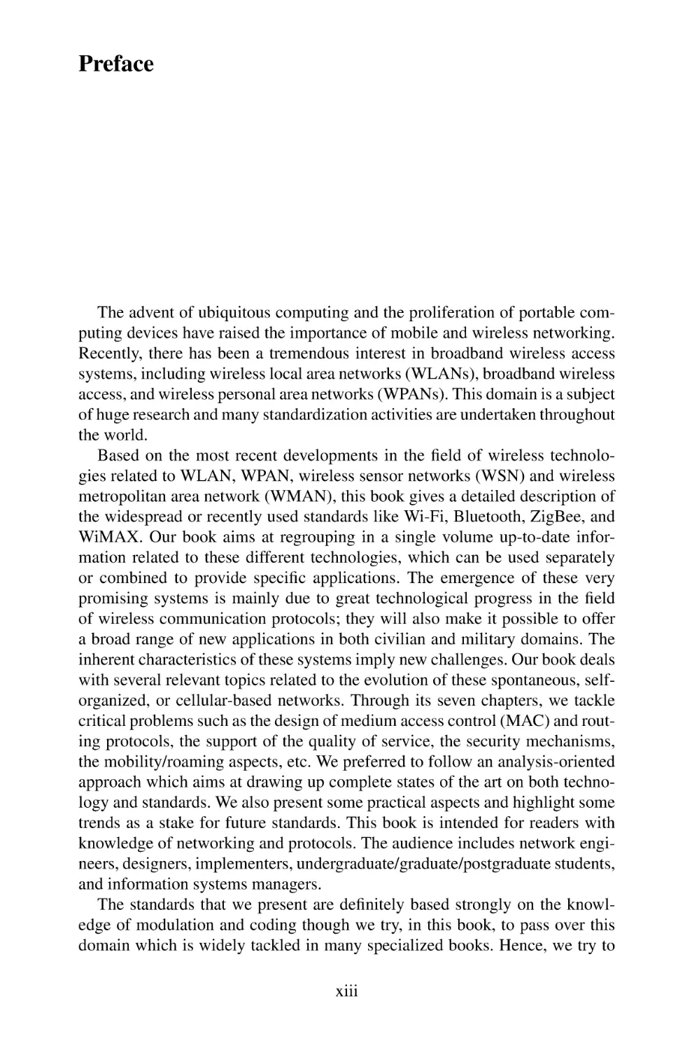
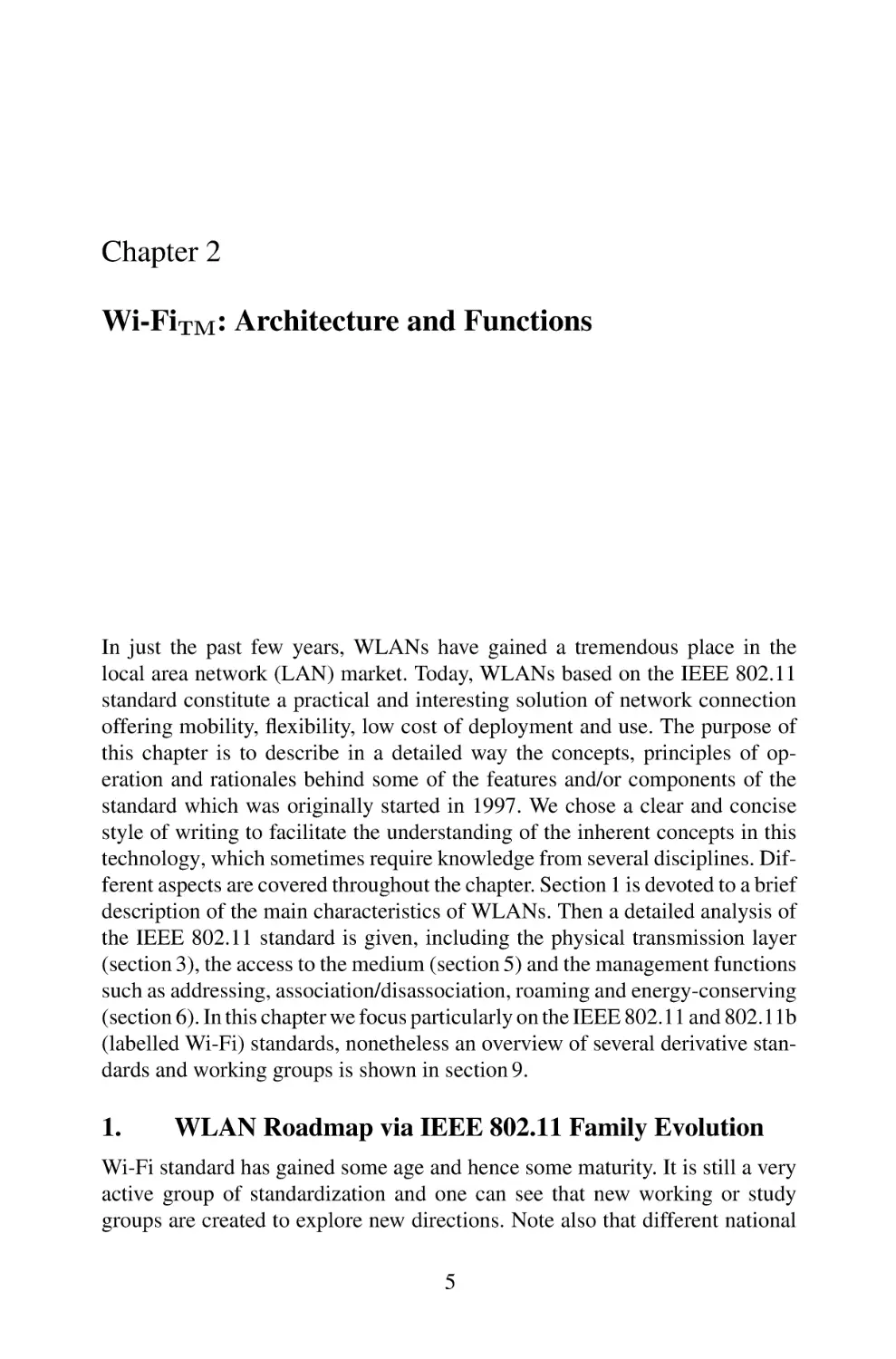
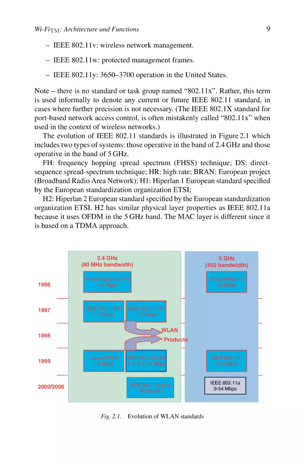
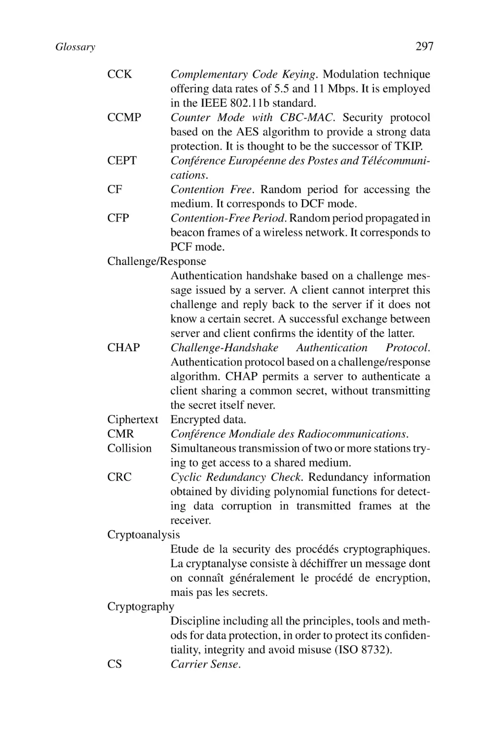
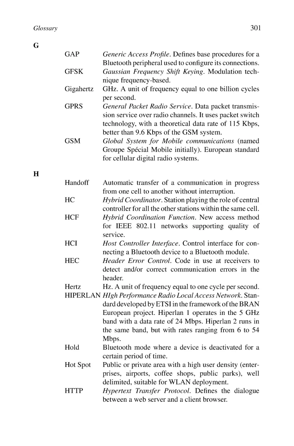
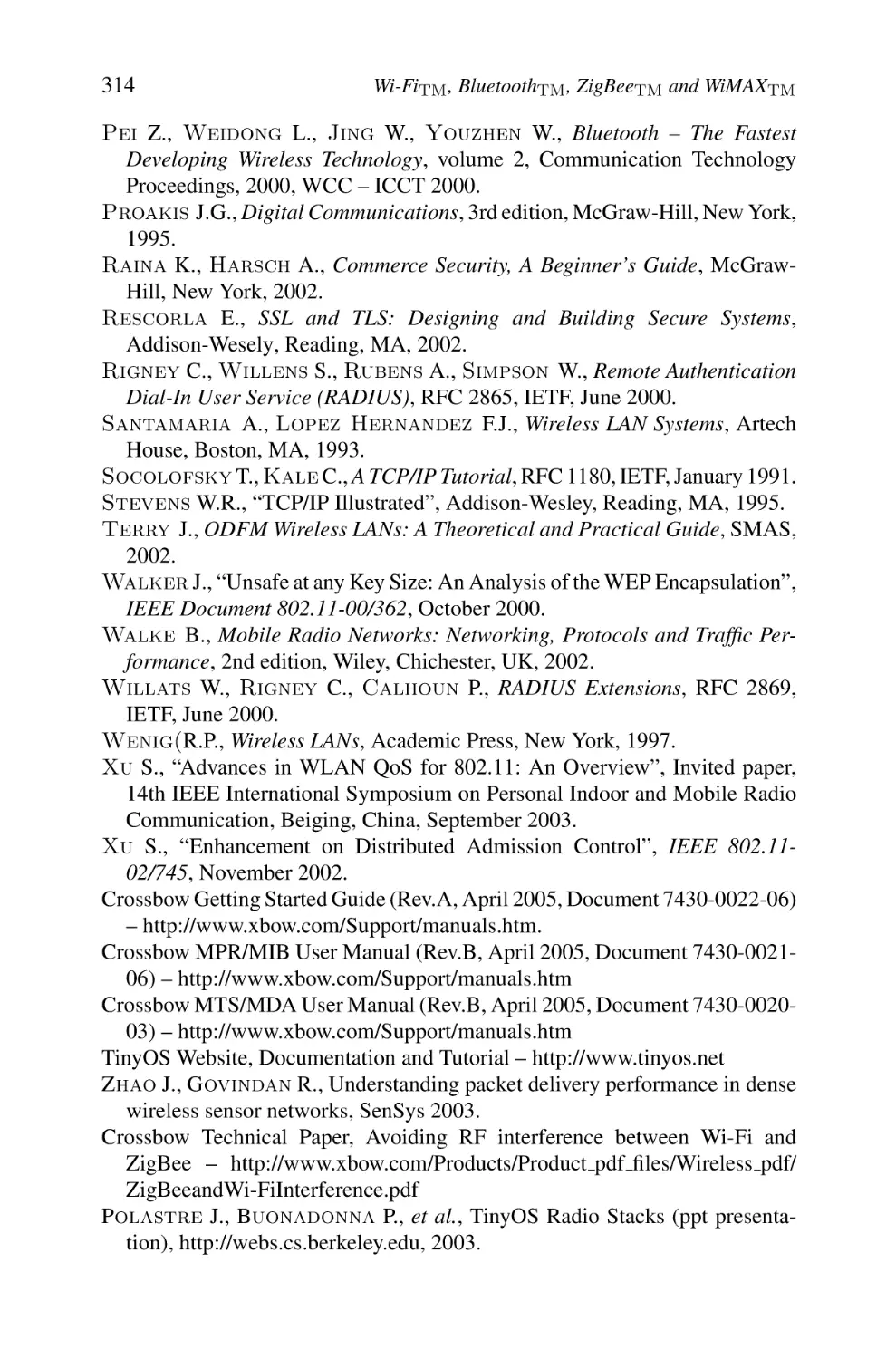
The evolution of IEEE 802.11 standards is illustrated in Figure 2.1 which
includes two types of systems: those operative in the band of 2.4 GHz and those
operative in the band of 5 GHz.
FH: frequency hopping spread spectrum (FHSS) technique; DS: directsequence spread-spectrum technique; HR: high rate; BRAN: European project
(Broadband Radio Area Network); H1: Hiperlan 1 European standard specified
by the European standardization organization ETSI;
H2: Hiperlan 2 European standard specified by the European standardization
organization ETSI. H2 has similar physical layer properties as IEEE 802.11a
because it uses OFDM in the 5 GHz band. The MAC layer is different since it
is based on a TDMA approach.
1996
1997
2.4 GHz
(80 MHz bandwidth)
5 GHz
(450 bandwidth)
Proxim Open Air FH
1.6 Mbps
ETSI BRAN H1
23 Mbps
IEEE 802.11 FH
1, 2 Mbps
IEEE 802.11 DS
1, 2 Mbps
WLAN
1998
1999
2000/2006
Products
Home RFFH
1.6 Mbps
IEEE 802.11b HR
1, 2, 5.5, 11 Mbps
IEEE 802.11b/g/i/e
Bluetooth
Fig. 2.1. Evolution of WLAN standards
IEEE 802.11a
9-54 Mbps
IEEE 802.11a
9-54 Mbps
10
1.2
Wi-FiTM , BluetoothTM , ZigBeeTM and WiMAXTM
Features of the Different WLAN Generations
A WLAN is an interesting technology because it offers a vast range of
applications, thanks to its several advantageous characteristics including high
capacity, short-distance coverage, full connectivity and broadcast capability.
The following are the main features of WLANs.
– Licence-free operation; connection to backbone LAN
– World availability according to standards
– Theoretical throughputs definitely higher than those offered by 3G standards as universal mobile telecommunications system (UMTS)
– Low-cost design with equipment prices in progressive reduction (APs
and wireless cards); very competitive costs compared to third-generation
mobile systems (license + equipment)
– Roaming/handoff support
– Ease of deployment
The characteristics of these systems thus knew an evolution which can be summarized as follows:
* First generation (IEEE 802.11) since 1997 (WLAN/1G):
– Connectivity of PC terminals (between them or to a fixed LAN).
– Bridge-based APs.
– Roaming.
– Coexistence with other networks (e.g. WLAN and Ethernet LAN) which
means bridging. Note that there is a small problem in the IEEE 802.11 in
general with respect to bridging where it does not fulfill completely the
bridging rules and is hence nonconformant to the 802 paradigms.
* Second generation (IEEE 802.11b) since 1998 (WLAN/2G):
– More effective management of WLAN
– Interworking and interoperability
– Migration starting from the first generation
– Conformity to the IEEE 802.11b standard
* Third generation (802.11a/g) since 2000 (WLAN/3G):
– High throughput (HT)
– Design of networks more open and integrated
11
Wi-FiTM : Architecture and Functions
– Conformity to the IEEE 802.11a/g standard
– Minimization of antenna sizes
– Improvement of receiver’s sensitivities
* Fourth generation (IEEE 802.11n) (WLAN/4G):
• Very high throughput (some hundreds of Mbps)
• Long distances at high data rates (equivalent to IEEE 802.11b at 500
Mbps)
• Use of robust technologies (e.g. multiple-input multiple-output [MIMO]
and space time coding).
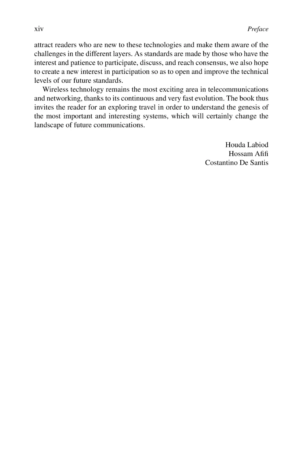
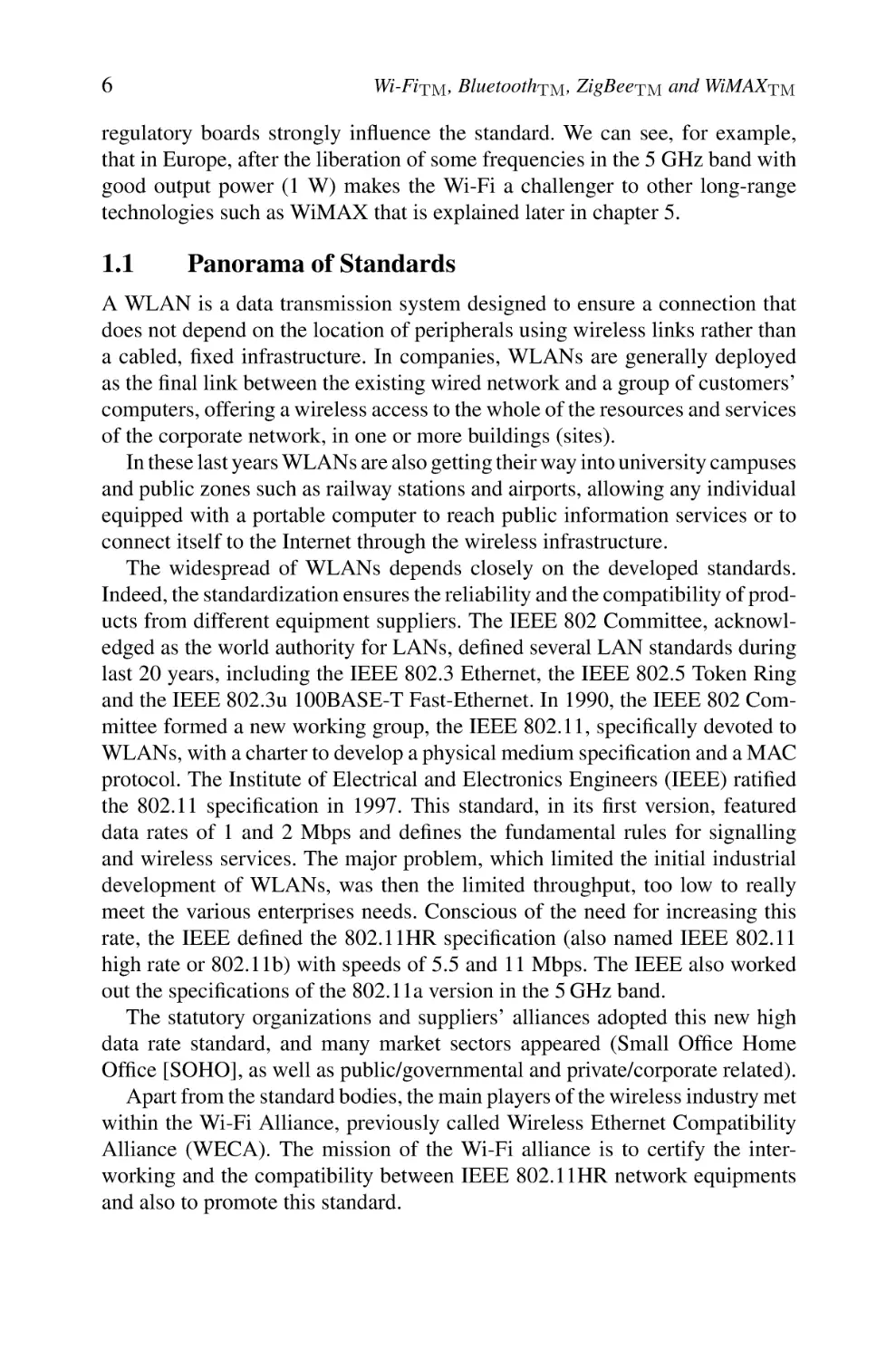
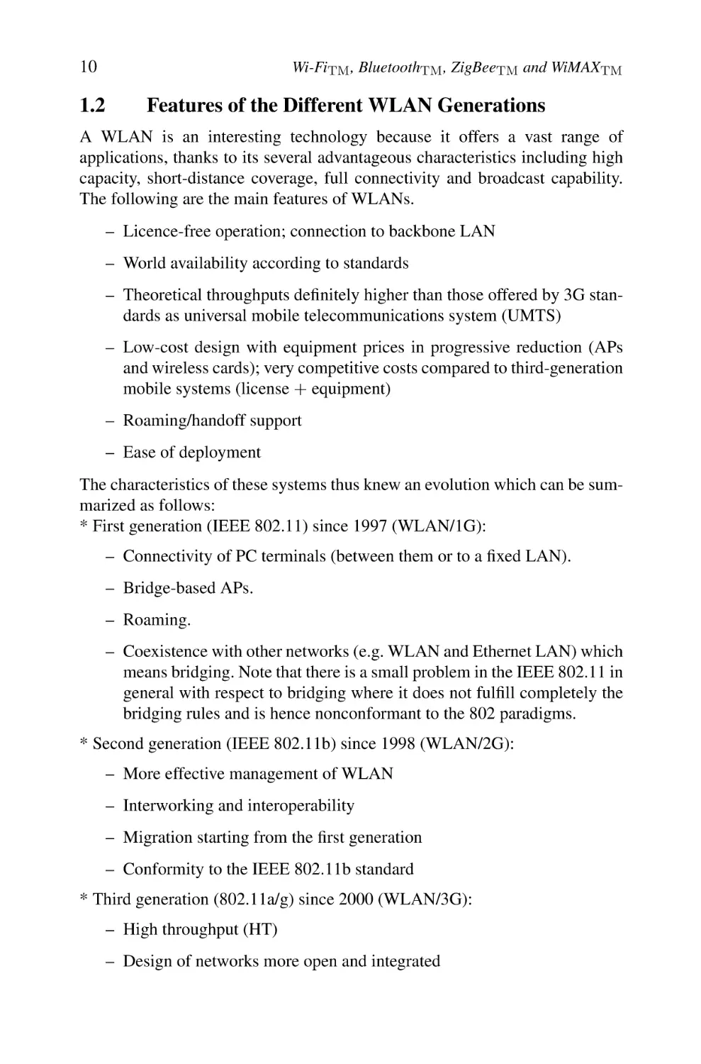
We compared the price of an IEEE 802.11b-based solution with that of an
equivalent cabled Ethernet-based solution. The IEEE 802.11b cards used are of
type Cisco-Aironet. We have three APs and 50 wireless cards (25 PCMCIA and
25 PCI cards). The total price of the equipment was almost the same. Although
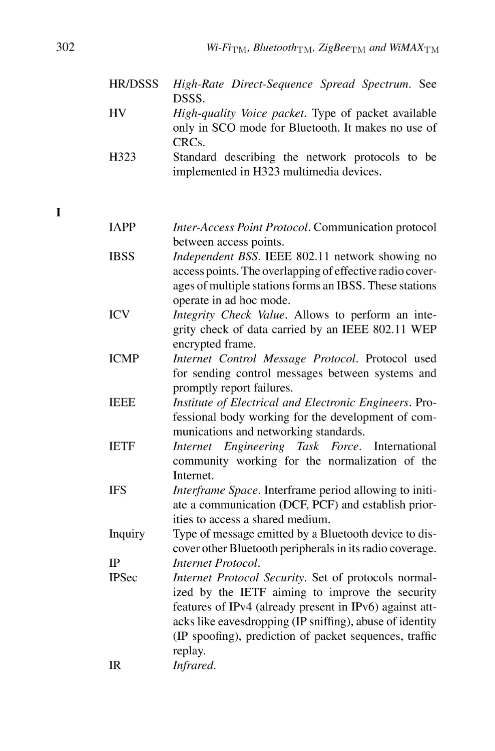
the initial investment is important as it is shown by the carried study, it is
important to point out the immediate beneficial return of the WLAN solution (Figure 2.2). Indeed, the prices are quite similar at the beginning of the
installation of the two networks, but during their lifespan, and considering
also the flexibility in connectivity and in configuration changes, an IEEE
802.11b WLAN-based solution will provide more advantages. It should also
be mentioned that the prices of wireless equipment is continuously decreasing
nowadays.
In addition, an IEEE 802.11b solution is more advantageous than a wide area
network (WAN) operator solution, because there are no specialized connections.
Physical limitations are also removed and the deployment is simple and fast.
WLAN hardware
WLAN Implementation Costs
1%
Monthly expenses
1%
16%
Management
expenses
50%
16%
16%
Application
Development
Outsourcing
Downtime
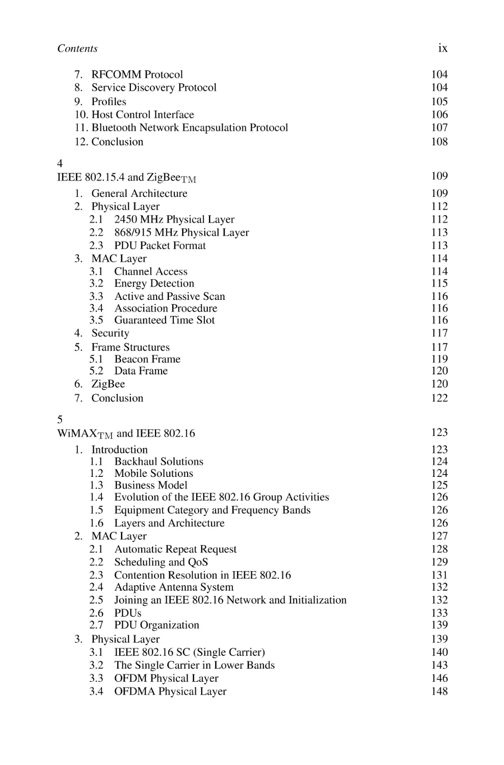
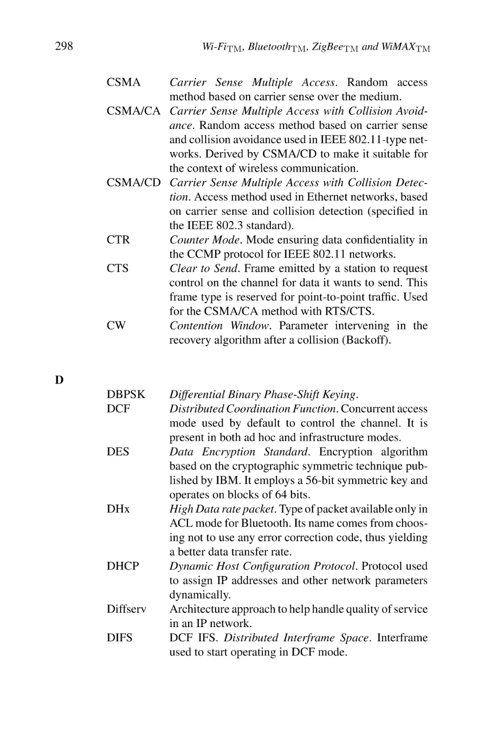
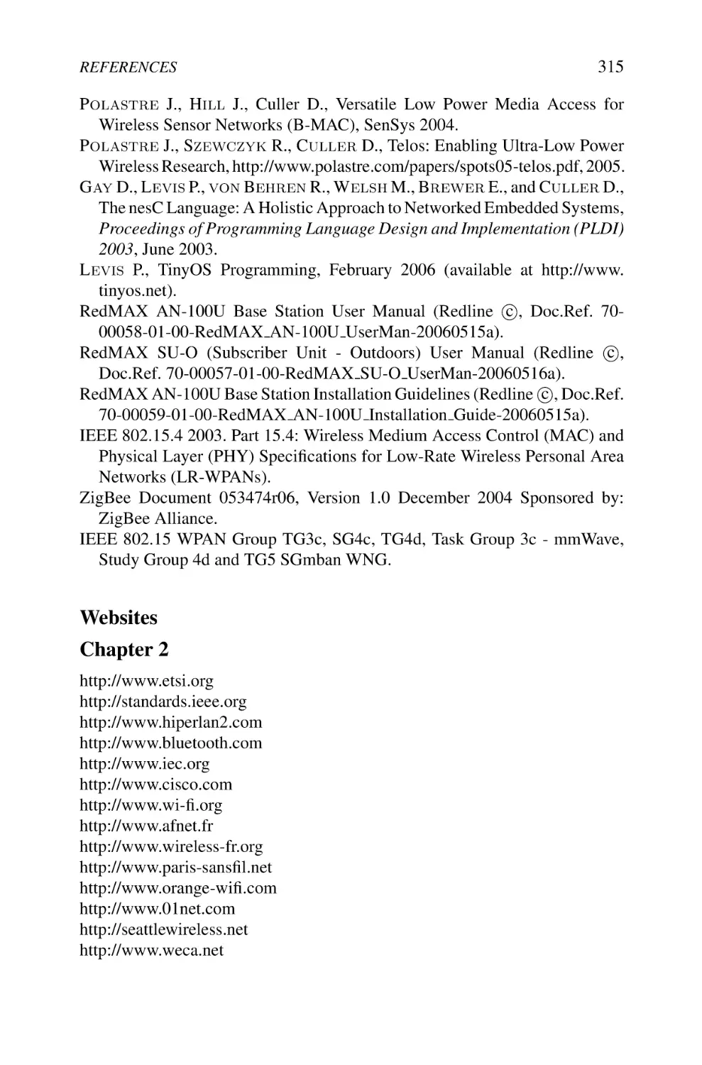
Fig. 2.2. Distribution of the costs of a WLAN solution (souce WLANA). This figure illustrates
clearly that a great part of the costs relates to the used physical material (1: downtime, 2: expenses,
3: management, 4: development of applications, 5: outsourcing, 6: material)
12
Wi-FiTM , BluetoothTM , ZigBeeTM and WiMAXTM
Limitations.
Independently of legal aspects, some limitations of this technology still remain such as:
– Lower data rates compared with those of high-speed fixed networks
– A limited range and influence of fixed obstacles especially metallic walls
– A shared bandwidth without a high degree of control
– Security attacks
– A quality of transmission depending on the environment (multipath
propagation, path loss)
– Interworking
– Deployment
– A lack of QoS control
In order to mitigate these disadvantages, works are undertaken within several
working IEEE groups. As these problems have been addressed, the popularity
of WLANs has grown rapidly.
1.3
WLAN Markets
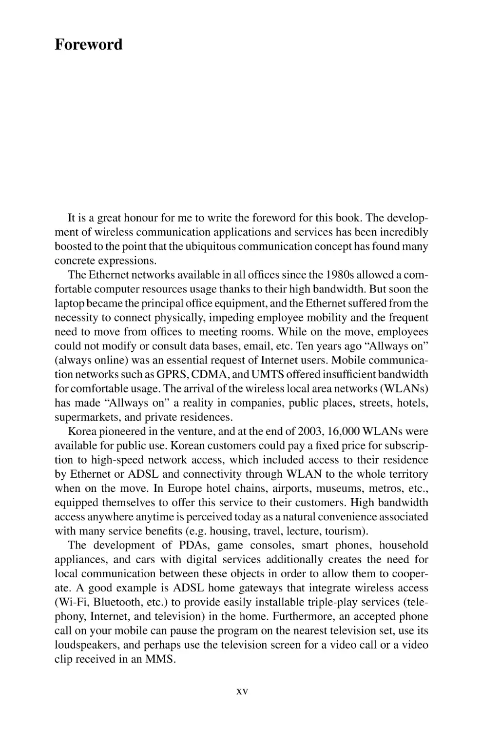
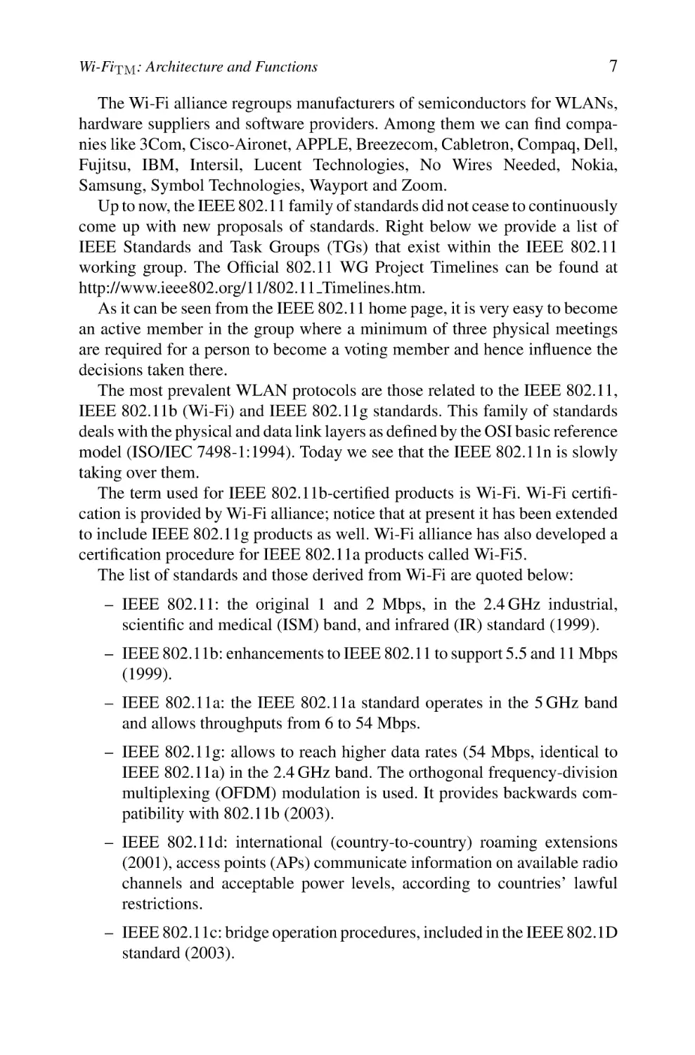
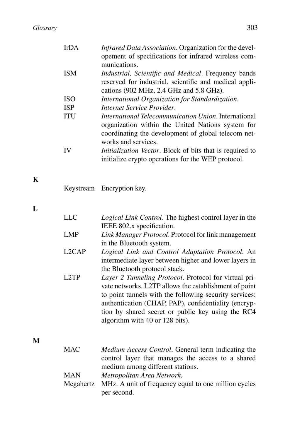
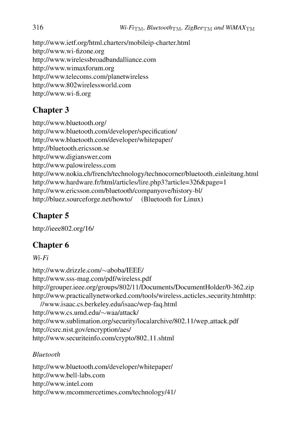
We distinguish several categories of systems where a WLAN can be used
(Figure 2.3):
– Wireless personal area networks
– Wireless area networks
– Wireless metropolitan area networks
WLAN services evolve into three main categories of market segments.
Private Segment.
We list three types of networks.
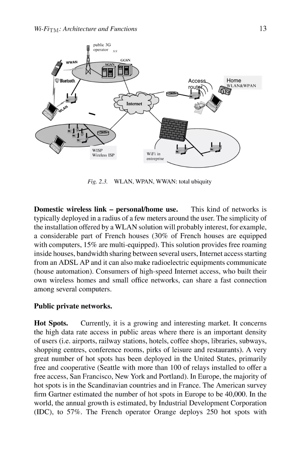
Enterprise networks – professional private use. WLAN solutions suitably
meet a strong need for nomadism intra- and intersite for users. It remains to address two requirements: the security of access and issues related to interferences
and interworking. It is a market segment which is typically filled by system
integrators (deployment of WLAN networks, integration of existing systems and
development of security solutions) and equipment suppliers. Many enterpriseclass organizations have deployed WLAN technologies also in an attempt to
increase their productivity.
13
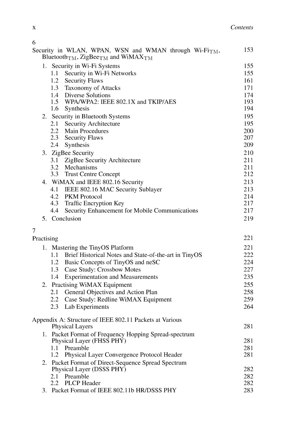
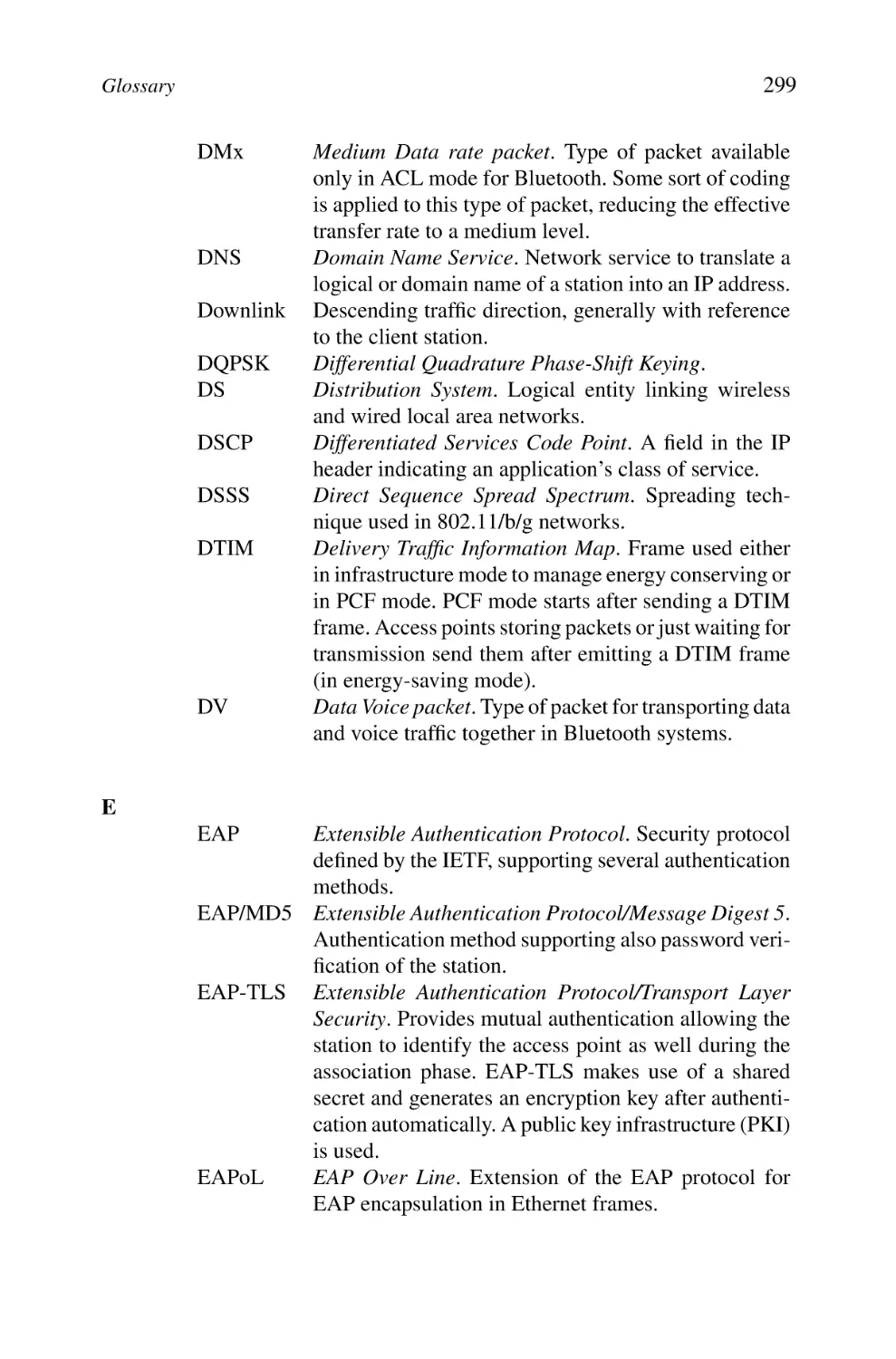
Wi-FiTM : Architecture and Functions
public 3G
operator xx
WWAN
GGSN
SGSN
Access
router
Home
WLAN&WPAN
Internet
N
LA
W
WISP
Wireless ISP
WiFi in
entreprise
Fig. 2.3. WLAN, WPAN, WWAN: total ubiquity
Domestic wireless link – personal/home use.
This kind of networks is
typically deployed in a radius of a few meters around the user. The simplicity of
the installation offered by a WLAN solution will probably interest, for example,
a considerable part of French houses (30% of French houses are equipped
with computers, 15% are multi-equipped). This solution provides free roaming
inside houses, bandwidth sharing between several users, Internet access starting
from an ADSL AP and it can also make radioelectric equipments communicate
(house automation). Consumers of high-speed Internet access, who built their
own wireless homes and small office networks, can share a fast connection
among several computers.
Public private networks.
Hot Spots.
Currently, it is a growing and interesting market. It concerns
the high data rate access in public areas where there is an important density
of users (i.e. airports, railway stations, hotels, coffee shops, libraries, subways,
shopping centres, conference rooms, pirks of leisure and restaurants). A very
great number of hot spots has been deployed in the United States, primarily
free and cooperative (Seattle with more than 100 of relays installed to offer a
free access, San Francisco, New York and Portland). In Europe, the majority of
hot spots is in the Scandinavian countries and in France. The American survey
firm Gartner estimated the number of hot spots in Europe to be 40,000. In the
world, the annual growth is estimated, by Industrial Development Corporation
(IDC), to 57%. The French operator Orange deploys 250 hot spots with
14
Wi-FiTM , BluetoothTM , ZigBeeTM and WiMAXTM
approximately 1500 APs and average 200 connections per day. The directory
of these hot spots is available at www.orange-wifi.com. In France, a clear
tendency to the democratization of the access to the Internet appears through
networks known as “libertarian” (Wi-Fi-France and Wi-Fi-Paris associations).
It is obvious that a worldwide deployment of thousands of new hot spots is
well in progress and one can obtain fresher information looking for example at
www.wi-fiplanet.com.
They are classified into two categories:
Free Networks.
– Entirely libertarian networks which cover urban zones, although totally
free, anti-terrorism laws mandate that a user still be identified for legal
interception and tracking.
– Networks deployed in non-covered/non-connected rural zones.
Applications.
We find several application areas for WLANs such as:
– LAN extension
– Cross-building interconnect
– Ad hoc networking
– Nomadic access
– Public hot spot access
– Data transmission within vertical markets such as:
• LANs (offices)
• Medical applications (real-time information transfers)
• Retail trade, warehouse
• Stores, shopping centres, railway stations
• Maintenance in airports and seaports
• Education, finance, industry
• SOHO
Several key factors enable to foresee a rise of the WLAN market, among
which we can quote:
– A progressive maturity of the standards (especially those derived from
the IEEE 802.11, 802.11b Wi-Fi and 802.11a/g)
– A deployment delay of third-generation mobile systems
Wi-Fi: Architecture and Functions
15
– A considerable investment and maturity of products (terminals, cards,
adaptors, APs, etc.)
– Integration of Wi-Fi chipsets into portable laptops and tablet PCs
– Proposals for solutions of security and roaming (with certain limitations)
– An increase in the deployment of the multi-equipment in residence
– An increased mobility of users
– High throughputs of wireless systems (2G/3G/4G)
– A consequent fall in costs (Wi-Fi chips, APs, the market of PCMCIA
cards disappearing)
– A frequency band usable without licence
– More widespread Wi-Fi availability
– More Wi-Fi competition
– Aggregated Wi-Fi hot spots networks (service providers wISPs, operators)
– Various markets are covered (enterprises, domestic market, telecommunication, education, health, SOHO, public sector, etc.)
We propose in section 2 a detailed technical study of the primary IEEE 802.11
standard, whose major basic mechanisms have been included in the most recent
standards and more particularly Wi-Fi.
Let us note that in the continuation, the terms IEEE 802.11b and Wi-Fi will
be used interchangeably.
2.
2.1
IEEE 802.11 Architecture
Three Basic Operational Modes
The IEEE 802.11 standard considers two types of components: a wireless client
station (in general a PC equipped with a wireless network interface card [NIC])
known as a station (STA) and an access point (AP) or sometimes called wireless relay, which functions as a bridge and a relay point between the fixed
network and the wireless network. This AP is usually composed of a radio
transceiver/receiver, a network card (e.g. Ethernet 802.3) and a software for
layer-2 bridging in conformity with the IEEE 802.1d standard. The AP behaves
like the basic station of the wireless network, aggregating the access of multiple wireless stations to the fixed network. The wireless stations include IEEE
802.11 network access cards or wireless adapters (or network interface controller). These adapters are available in many formats (PCI, PCMCIA, USB
and nowadays Wi-Fi chips).
16
Wi-FiTM , BluetoothTM , ZigBeeTM and WiMAXTM
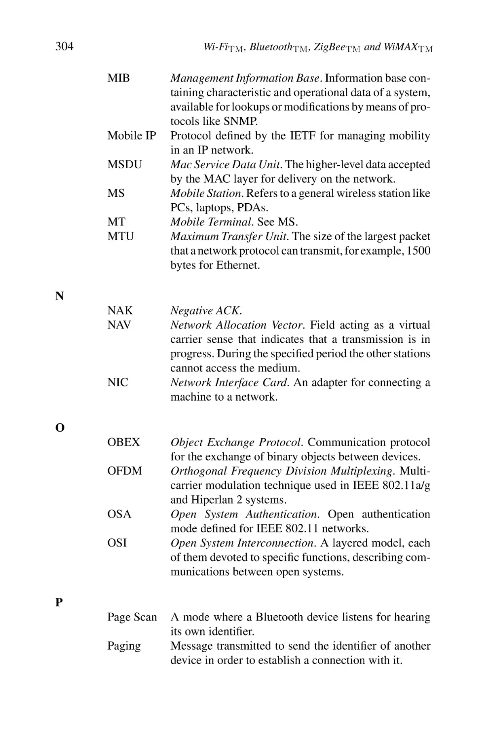
The IEEE 802.11 standard’s model defines three modes: an infrastructure
mode, an ad hoc mode and a mesh mode.
Infrastructure Mode. Within the infrastructure mode, the wireless network
consists of at least an AP connected to the fixed network infrastructure and a
set of wireless client stations. This configuration is based on a cellular architecture where the system is subdivided into cells. Each cell (called Basic Service
Set[BSS], in the IEEE 802.11 is controlled by a base station (called AP).
The stations within a BSS execute the same MAC protocol and compete for
access to the same shared wireless medium. We can refer to it in the following
sections as a cell. Although a WLAN may be formed by a single cell (with a single AP), the maximum distance between stations is limited by many factors like
RF output power and the propagation conditions of the indoor/outdoor environments. To provide for an extended coverage area, multiple BSSs are used where
the APs are connected through a backbone called a distribution system (DS).
The whole interconnected WLAN including at least two different BSSs (with
respect to their APs) and the DS, is seen as a single logical IEEE 802 network to
the logical link control (LLC) level and is called an Extended Service Set (ESS).
The majority of WLANs should be able to reach the fixed LAN services (file
servers, printers and Internet access). The DS is responsible of transporting the
packets between various cells within the ESS area. Data transfers occur between
stations within a BSS and the DS via an AP. DS handles address mapping
and interworking functions. BSSs may partially overlap. This is commonly
used to cover an extended area. BSSs could be physically disjointed or colocated. To provide flexibility to the WLAN architecture, IEEE 802.11 logically
separates the wireless medium from the DS medium. The DS can correspond to
an Ethernet network, Token Ring, FDDI or any other communication network
such as a wireless IEEE 802.11 point to point. A wide zone ESS can also provide
to the various client stations an access towards a fixed network, such as Internet.
Before any communication can be set within a BSS, the wireless client stations
must execute an association with the AP.
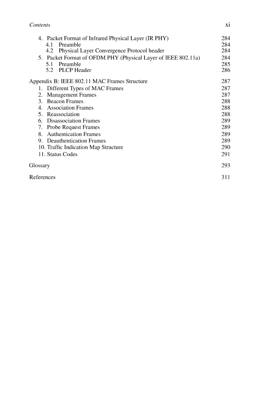
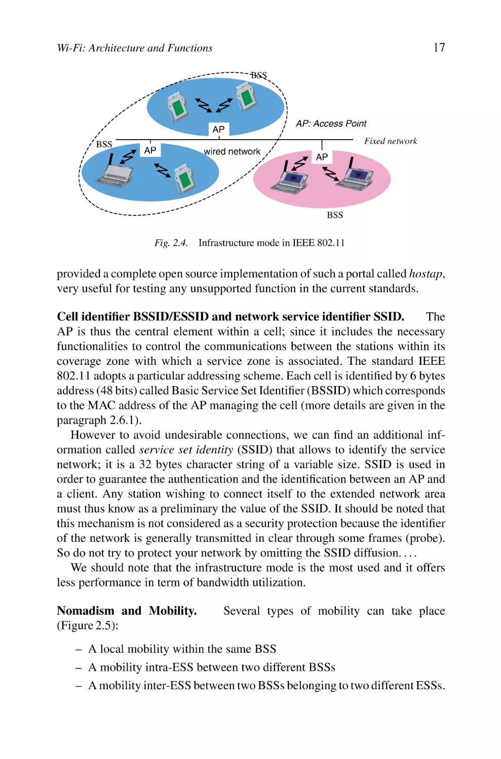
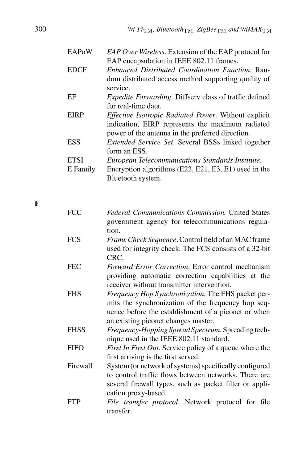
Figure 2.4 shows a typical IEEE 802.11 LAN including the components
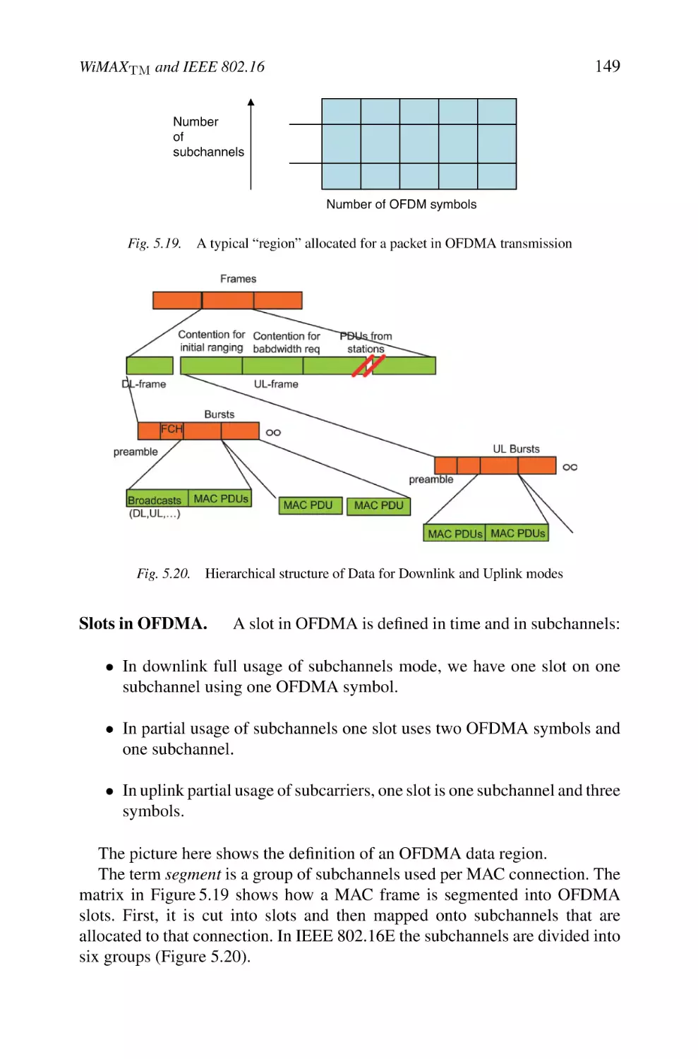
described above.
The standard defines the concept of “portal or gateway”, it is a device which
is used to interconnect an IEEE 802.11 architecture with a traditional wired
802.x LAN. This concept is an abstract description of a part of the functionalities
of a translation bridge. The portal’s function is to provide a logical integration between WLAN architectures and existing wired LANs. In most hardware implementations, all the APs behave as portals. The portal logic can be
implemented in a device, such as a bridge or a router or a switch, and it is a part
of the WLAN and is attached to DS. In Linux, some good implementers have
17
Wi-Fi: Architecture and Functions
BSS
AP
BSS
AP
AP: Access Point
Fixed network
wired network
AP
BSS
Fig. 2.4.
Infrastructure mode in IEEE 802.11
provided a complete open source implementation of such a portal called hostap,
very useful for testing any unsupported function in the current standards.
Cell identifier BSSID/ESSID and network service identifier SSID.
The
AP is thus the central element within a cell; since it includes the necessary
functionalities to control the communications between the stations within its
coverage zone with which a service zone is associated. The standard IEEE
802.11 adopts a particular addressing scheme. Each cell is identified by 6 bytes
address (48 bits) called Basic Service Set Identifier (BSSID) which corresponds
to the MAC address of the AP managing the cell (more details are given in the
paragraph 2.6.1).
However to avoid undesirable connections, we can find an additional information called service set identity (SSID) that allows to identify the service
network; it is a 32 bytes character string of a variable size. SSID is used in
order to guarantee the authentication and the identification between an AP and
a client. Any station wishing to connect itself to the extended network area
must thus know as a preliminary the value of the SSID. It should be noted that
this mechanism is not considered as a security protection because the identifier
of the network is generally transmitted in clear through some frames (probe).
So do not try to protect your network by omitting the SSID diffusion. . . .
We should note that the infrastructure mode is the most used and it offers
less performance in term of bandwidth utilization.
Nomadism and Mobility.
(Figure 2.5):
Several types of mobility can take place
– A local mobility within the same BSS
– A mobility intra-ESS between two different BSSs
– A mobility inter-ESS between two BSSs belonging to two different ESSs.
18
Wi-FiTM , BluetoothTM , ZigBeeTM and WiMAXTM
802.11 LAN
STA1
8
802.x
LAN
BSS1
Porta l
Access
Point
Point
Distribution System
Access
Point
ESS
BSS2
STA2
Fig. 2.5.
802.11 LAN
STA3
Extended service set (ESS), distribution system (DS) and cell BSS
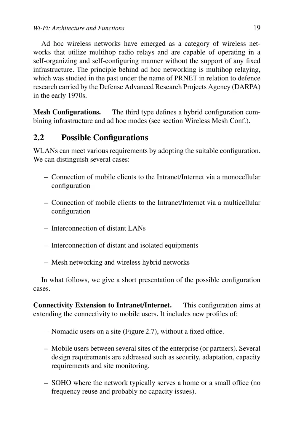
IBSS
Fig. 2.6.
Ad hoc mode
Ad hoc Mode.
The ad hoc mode (Figure 2.6) simply represents a group of
IEEE 802.11 wireless stations that communicate directly between them without
having a connection with an AP or a connection to a fixed network through the
DS. This configuration is sometimes referred as a peer-to-peer configuration.
Each station can establish a communication with any other station in the cell
which is called an independent cell Independent Basic Service Set (IBSS).
These networks have been studied at the beginning of the 1970s and were
named packet radio networks (PRNET). As in the infrastructure mode, an ad
hoc network is also identified by an SSID identifier.
This mode allows to create quickly and simply a wireless network where
there is not fixed infrastructure or where such an infrastructure is not necessary
for the required services (hotel room, conference centres or airport), or finally
when the access to the fixed network is prohibited or difficult.
Wi-Fi: Architecture and Functions
19
Ad hoc wireless networks have emerged as a category of wireless networks that utilize multihop radio relays and are capable of operating in a
self-organizing and self-configuring manner without the support of any fixed
infrastructure. The principle behind ad hoc networking is multihop relaying,
which was studied in the past under the name of PRNET in relation to defence
research carried by the Defense Advanced Research Projects Agency (DARPA)
in the early 1970s.
Mesh Configurations.
The third type defines a hybrid configuration combining infrastructure and ad hoc modes (see section Wireless Mesh Conf.).
2.2
Possible Configurations
WLANs can meet various requirements by adopting the suitable configuration.
We can distinguish several cases:
– Connection of mobile clients to the Intranet/Internet via a monocellular
configuration
– Connection of mobile clients to the Intranet/Internet via a multicellular
configuration
– Interconnection of distant LANs
– Interconnection of distant and isolated equipments
– Mesh networking and wireless hybrid networks
In what follows, we give a short presentation of the possible configuration
cases.
Connectivity Extension to Intranet/Internet.
This configuration aims at
extending the connectivity to mobile users. It includes new profiles of:
– Nomadic users on a site (Figure 2.7), without a fixed office.
– Mobile users between several sites of the enterprise (or partners). Several
design requirements are addressed such as security, adaptation, capacity
requirements and site monitoring.
– SOHO where the network typically serves a home or a small office (no
frequency reuse and probably no capacity issues).
20
Wi-FiTM , BluetoothTM , ZigBeeTM and WiMAXTM
Nomadic
peripherals
(PC, PDA…)
Local
Server
Access
Router
WAN
LAN
Access points
Distant
server
Fixed Stations
Site
Distant Site
Fig. 2.7.
Nomadic users – private site
LAN
Level 2 mobility
-roaming-
Access points
(APs)
WAN
Site A
Distant
Server
LAN
Distant site
Access Points
(APs)
Site B
Fig. 2.8.
Multicellular architecture: collaborative nomads roaming through various sites
Multicellular Configuration. This configuration uses several APs, defining
distinct cells that overlap partially. In a group of contiguous cells, each AP
operates on a different frequency (Figure 2.8).
Users roam in a transparent way through several sites (from a cell to another),
thanks to the roaming mechanism.
Distant Network Interconnection. This configuration is a solution to extend
access to structures (sites) and/or distant equipments such as:
Wi-Fi: Architecture and Functions
21
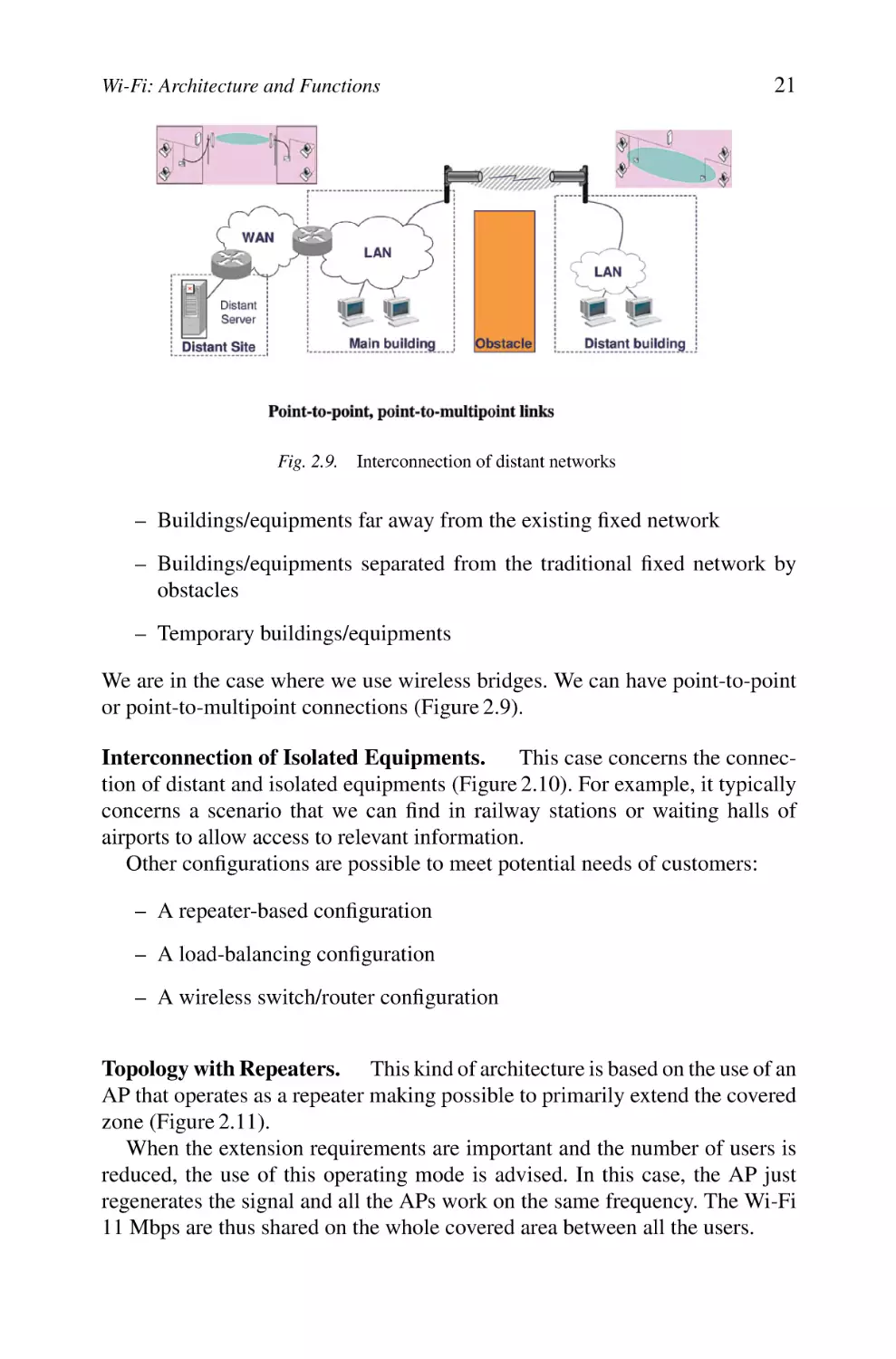
Fig. 2.9. Interconnection of distant networks
– Buildings/equipments far away from the existing fixed network
– Buildings/equipments separated from the traditional fixed network by
obstacles
– Temporary buildings/equipments
We are in the case where we use wireless bridges. We can have point-to-point
or point-to-multipoint connections (Figure 2.9).
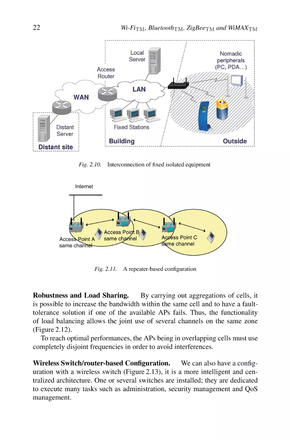
Interconnection of Isolated Equipments.
This case concerns the connection of distant and isolated equipments (Figure 2.10). For example, it typically
concerns a scenario that we can find in railway stations or waiting halls of
airports to allow access to relevant information.
Other configurations are possible to meet potential needs of customers:
– A repeater-based configuration
– A load-balancing configuration
– A wireless switch/router configuration
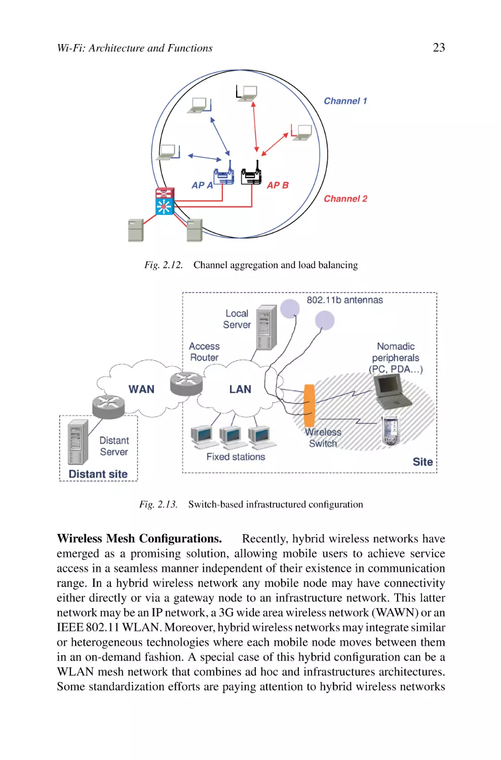
Topology with Repeaters. This kind of architecture is based on the use of an
AP that operates as a repeater making possible to primarily extend the covered
zone (Figure 2.11).
When the extension requirements are important and the number of users is
reduced, the use of this operating mode is advised. In this case, the AP just
regenerates the signal and all the APs work on the same frequency. The Wi-Fi
11 Mbps are thus shared on the whole covered area between all the users.
22
Wi-FiTM , BluetoothTM , ZigBeeTM and WiMAXTM
Fig. 2.10.
Interconnection of fixed isolated equipment
Internet
’
Access Point A
same channel
Access ’ Point B
same channel
Fig. 2.11.
’
Access Point C
same channel
A repeater-based configuration
Robustness and Load Sharing.
By carrying out aggregations of cells, it
is possible to increase the bandwidth within the same cell and to have a faulttolerance solution if one of the available APs fails. Thus, the functionality
of load balancing allows the joint use of several channels on the same zone
(Figure 2.12).
To reach optimal performances, the APs being in overlapping cells must use
completely disjoint frequencies in order to avoid interferences.
Wireless Switch/router-based Configuration. We can also have a configuration with a wireless switch (Figure 2.13), it is a more intelligent and centralized architecture. One or several switches are installed; they are dedicated
to execute many tasks such as administration, security management and QoS
management.
23
Wi-Fi: Architecture and Functions
Channel 1
AP A
AP B
Channel 2
Fig. 2.12.
Channel aggregation and load balancing
Fig. 2.13. Switch-based infrastructured configuration
Wireless Mesh Configurations.
Recently, hybrid wireless networks have
emerged as a promising solution, allowing mobile users to achieve service
access in a seamless manner independent of their existence in communication
range. In a hybrid wireless network any mobile node may have connectivity
either directly or via a gateway node to an infrastructure network. This latter
network may be an IP network, a 3G wide area wireless network (WAWN) or an
IEEE 802.11 WLAN. Moreover, hybrid wireless networks may integrate similar
or heterogeneous technologies where each mobile node moves between them
in an on-demand fashion. A special case of this hybrid configuration can be a
WLAN mesh network that combines ad hoc and infrastructures architectures.
Some standardization efforts are paying attention to hybrid wireless networks
24
Wi-FiTM , BluetoothTM , ZigBeeTM and WiMAXTM
technology. Standard organizations are actively calling for specifications for
mesh networking, e.g. IEEE 802.11, IEEE 802.15, IEEE 802.16 and IEEE
802.20. The IEEE 802.11s (targeted for June 2008) is concerned with WLAN
mesh networking.
In fact, in most WLAN deployments today, there is a clear distinction between the devices that comprise the network infrastructure and the devices that
are clients that simply use the infrastructure to gain access to network resources.
The most common WLAN infrastructure devices deployed today are standard
IEEE 802.11 APs that provide a number of services. APs are usually directly
connected to a wired network (e.g. IEEE 802.3), and simply provide wireless
connectivity to client devices rather than utilizing wireless connectivity themselves. Client devices, on the other hand, are typically implemented as simple
IEEE 802.11 STAs that must associate with an AP in order to gain access to
the network. These simple STAs are dependent on the AP with which they are
associated to communicate.
There is no reason, however, that many of the devices under consideration
for use in WLANs cannot support much more flexible wireless connectivity.
Dedicated infrastructure class devices such as APs should be able to establish
peer-to-peer wireless links with neighbouring APs to establish a mesh backhaul
infrastructure, without the need for a wired network connection to each AP.
Moreover, in many cases devices traditionally categorized as clients should
also be able to establish peer-to-peer wireless links with neighbouring clients
and APs in a mesh network. In some cases, these mesh-enabled client devices
could even provide the same services as APs to help legacy STAs gain access to
the network. In this way, the mesh network extensions proposed blur the lines
between infrastructure and client devices in some deployment scenarios.
Based on IEEE 802.11s definitions, a typical mesh architecture divides
wireless nodes into two major classes: mesh class nodes are nodes capable
of supporting mesh services, while the non-mesh class includes simple client
STAs. Mesh class nodes may optionally also support AP services and may be
managed or unmanaged. A WLAN mesh network topology may include mesh
points (MPs) with one or more radio interfaces and may utilize one or more
channels for communication between MPs.
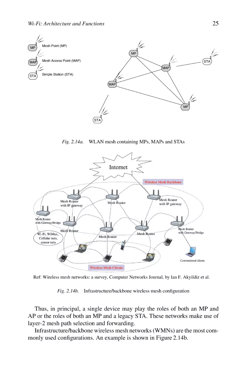
An example WLAN Mesh is illustrated in Figure 2.14a. Any devices that
support mesh services are MPs. Note that an MP may be either a dedicated
infrastructure device or a user device that is able to fully participate in the
formation and operation of the mesh network. A special type of MP is the mesh
access point (MAP), which provides AP services in addition to mesh services.
Simple STAs associate with mesh APs to gain access to the (mesh) network.
Simple STAs do not participate in WLAN mesh services such as path selection
and forwarding.
25
Wi-Fi: Architecture and Functions
MP
Mesh Point (MP)
MP
MAP
Mesh Access Point (MAP)
STA
MAP
STA
Simple Station (STA)
MAP
MP
STA
Fig. 2.14a.
WLAN mesh containing MPs, MAPs and STAs
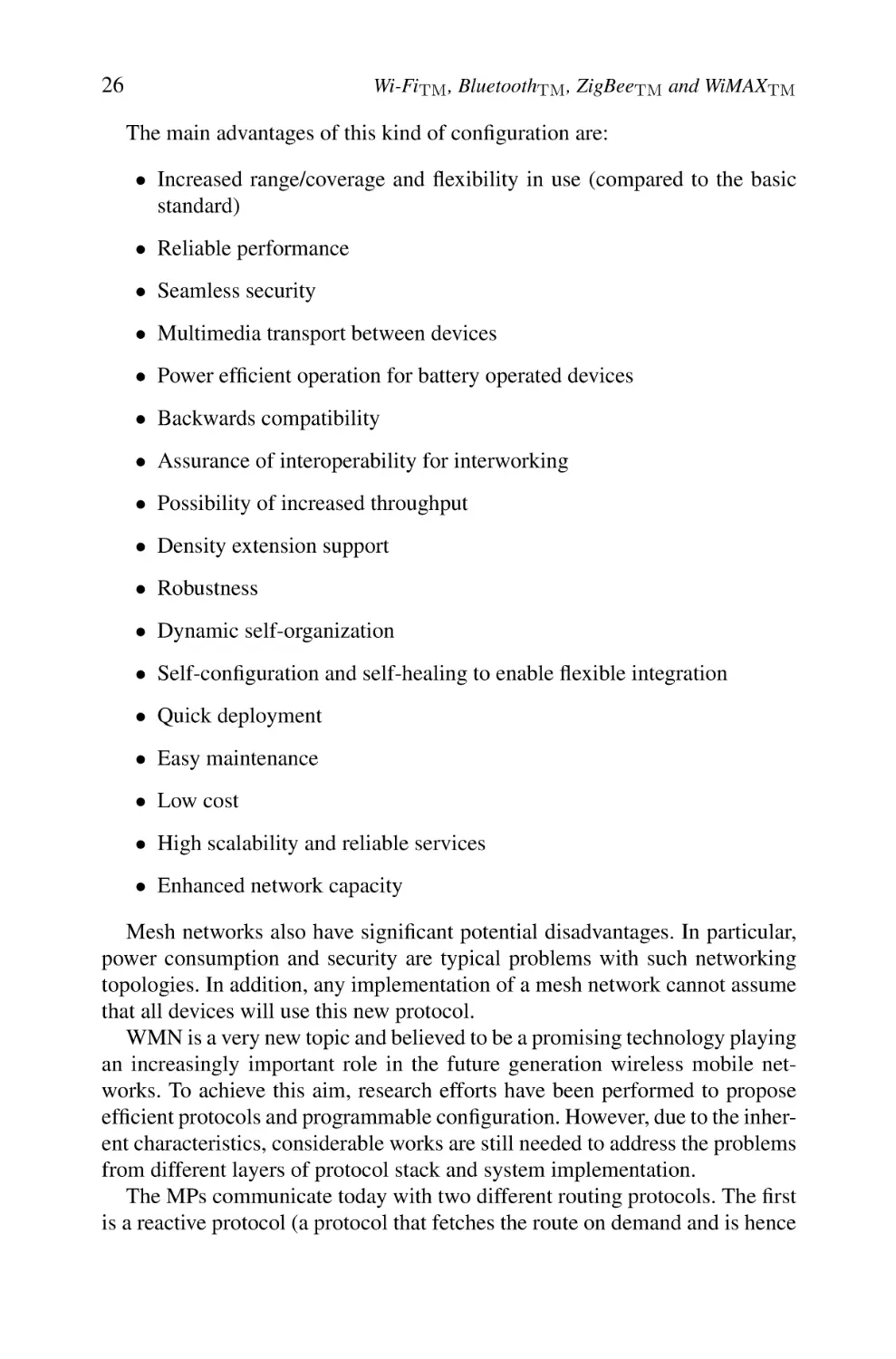
Ref: Wireless mesh networks: a survey, Computer Networks Journal, by Ian F. Akyildiz et al.
Fig. 2.14b.
Infrastructure/backbone wireless mesh configuration
Thus, in principal, a single device may play the roles of both an MP and
AP or the roles of both an MP and a legacy STA. These networks make use of
layer-2 mesh path selection and forwarding.
Infrastructure/backbone wireless mesh networks (WMNs) are the most commonly used configurations. An example is shown in Figure 2.14b.
26
Wi-FiTM , BluetoothTM , ZigBeeTM and WiMAXTM
The main advantages of this kind of configuration are:
• Increased range/coverage and flexibility in use (compared to the basic
standard)
• Reliable performance
• Seamless security
• Multimedia transport between devices
• Power efficient operation for battery operated devices
• Backwards compatibility
• Assurance of interoperability for interworking
• Possibility of increased throughput
• Density extension support
• Robustness
• Dynamic self-organization
• Self-configuration and self-healing to enable flexible integration
• Quick deployment
• Easy maintenance
• Low cost
• High scalability and reliable services
• Enhanced network capacity
Mesh networks also have significant potential disadvantages. In particular,
power consumption and security are typical problems with such networking
topologies. In addition, any implementation of a mesh network cannot assume
that all devices will use this new protocol.
WMN is a very new topic and believed to be a promising technology playing
an increasingly important role in the future generation wireless mobile networks. To achieve this aim, research efforts have been performed to propose
efficient protocols and programmable configuration. However, due to the inherent characteristics, considerable works are still needed to address the problems
from different layers of protocol stack and system implementation.
The MPs communicate today with two different routing protocols. The first
is a reactive protocol (a protocol that fetches the route on demand and is hence
Wi-Fi: Architecture and Functions
27
reactive, i.e. slower). The second is proactive (a protocol that periodically solves
all possible routes and is hence more power greedy).
2.3
Basic Services
The IEEE 802.11 architecture supports a series of basic services that are:
– Association/disassociation/reassociation
– Delivery of the MAC/MSDU frames
– Authentication/deauthentication
– Diffusion and broadcast
– Beacon and probing
– Privacy/confidentiality
– Higher-layer timer synchronization/QoS traffic scheduling
– Radio measurements
2.4
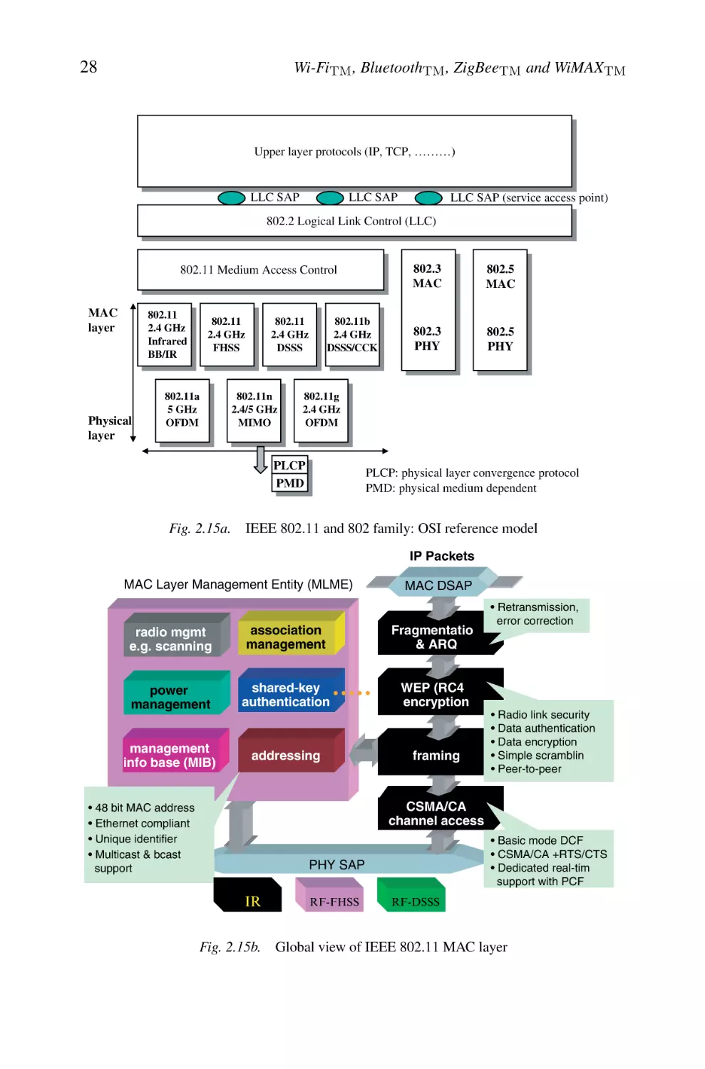
Description of Sublayers’ Structures
Similarly to other IEEE 802 standards, IEEE 802.11 focuses on the two lowest
sublayers of the ISO model (interconnection of the open systems), the physical
layer (PHY) and a data link layer containing the MAC sublayer and the LLC)
as shown in Figure 2.15.
The physical layer, which is in charge of the transmission of the MAC frames
on the wireless medium, uses several modulation techniques and binary coding.
The reader interested by the details of the techniques for modulation, RF design
and signal processing can consult the references quoted at the end of this chapter
[BRO 97, LEE 95, PRO 95, WAL 02].
The MAC layer is described thereafter by presenting its various functions
(association, fragmentation, access control, security, etc.) as well as the structures of MAC 802.11 frames. The IEEE 802 standard defines the same data link
high sublayer for all the LANs; it acts as a LLC 802.2 sublayer. IEEE 802.11
standard thus describes only the physical and MAC layers. We can thus lead to
a total stacking of the ISO layers like illustrated in Figure 2.15a.
Notice 2.1 – Architecture, functions and basic services of Wi-Fi (IEEE
802.11b) are defined by the original IEEE 802.11 standard. IEEE 802.11b
specification affects only the physical layer offering higher data rates and a
more robust connectivity.
28
Wi-FiTM , BluetoothTM , ZigBeeTM and WiMAXTM
Upper layer protocols (IP, TCP, ………)
LLC SAP
LLC SAP
LLC SAP (service access point)
802.2 Logical Link Control (LLC)
802.11 Medium Access Control
MAC
layer
802.11
2.4 GHz
Infrared
BB/IR
Physical
layer
802.11a
5 GHz
OFDM
802.11b
2.4 GHz
DSSS/CCK
802.11
2.4 GHz
DSSS
802.11
2.4 GHz
FHSS
802.11n
2.4/5 GHz
MIMO
802.5
MAC
802.3
PHY
802.5
PHY
802.11g
2.4 GHz
OFDM
PLCP
PMD
Fig. 2.15a.
802.3
MAC
PLCP: physical layer convergence protocol
PMD: physical medium dependent
IEEE 802.11 and 802 family: OSI reference model
IP Packets
MAC Layer Management Entity (MLME)
MAC DSAP
radio mgmt
e.g. scanning
association
management
Fragmentation
& ARQ
power
management
shared-key
authentication
WEP (RC4)
encryption
management
info base (MIB)
addressing
framing
• Retransmission,
error correction
• Radio link security
• Data authentication
• Data encryption
• Simple scrambling
• Peer-to-peer
CSMA/CA
channel access
• 48 bit MAC address
• Ethernet compliant
• Unique identifier
• Multicast & bcast
support
• Basic mode DCF
• CSMA/CA +RTS/CTS
• Dedicated real-time
support with PCF
PHY SAP
IR
Fig. 2.15b.
RF-FHSS
RF-DSSS
Global view of IEEE 802.11 MAC layer
Wi-Fi: Architecture and Functions
3.
29
Different Physical Layers
Several types of radio interfaces can be supported by the IEEE 802.11 reference
architecture. Three different physical layers are defined in the basic standard:
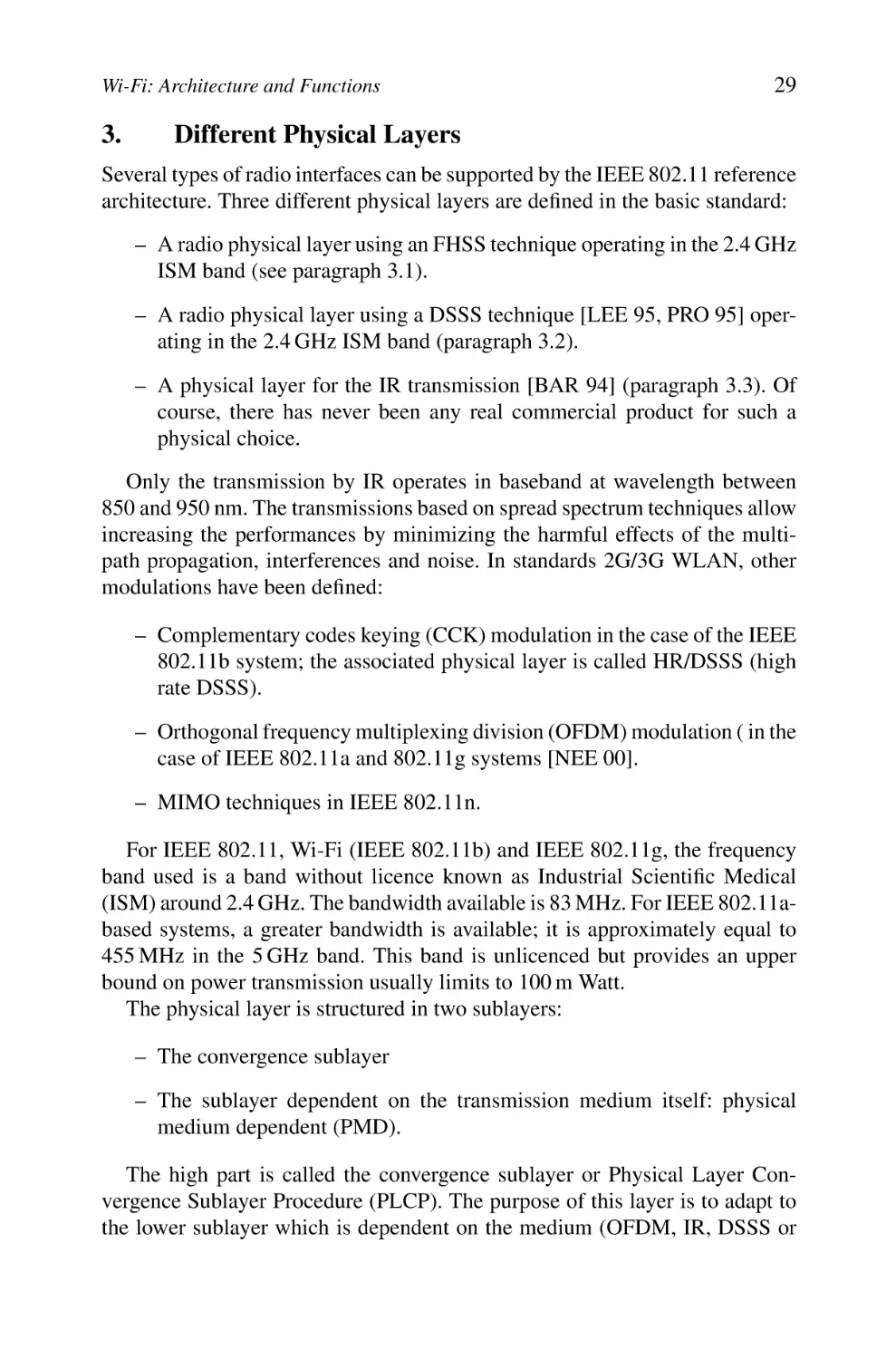
– A radio physical layer using an FHSS technique operating in the 2.4 GHz
ISM band (see paragraph 3.1).
– A radio physical layer using a DSSS technique [LEE 95, PRO 95] operating in the 2.4 GHz ISM band (paragraph 3.2).
– A physical layer for the IR transmission [BAR 94] (paragraph 3.3). Of
course, there has never been any real commercial product for such a
physical choice.
Only the transmission by IR operates in baseband at wavelength between
850 and 950 nm. The transmissions based on spread spectrum techniques allow
increasing the performances by minimizing the harmful effects of the multipath propagation, interferences and noise. In standards 2G/3G WLAN, other
modulations have been defined:
– Complementary codes keying (CCK) modulation in the case of the IEEE
802.11b system; the associated physical layer is called HR/DSSS (high
rate DSSS).
– Orthogonal frequency multiplexing division (OFDM) modulation ( in the
case of IEEE 802.11a and 802.11g systems [NEE 00].
– MIMO techniques in IEEE 802.11n.
For IEEE 802.11, Wi-Fi (IEEE 802.11b) and IEEE 802.11g, the frequency
band used is a band without licence known as Industrial Scientific Medical
(ISM) around 2.4 GHz. The bandwidth available is 83 MHz. For IEEE 802.11abased systems, a greater bandwidth is available; it is approximately equal to
455 MHz in the 5 GHz band. This band is unlicenced but provides an upper
bound on power transmission usually limits to 100 m Watt.
The physical layer is structured in two sublayers:
– The convergence sublayer
– The sublayer dependent on the transmission medium itself: physical
medium dependent (PMD).
The high part is called the convergence sublayer or Physical Layer Convergence Sublayer Procedure (PLCP). The purpose of this layer is to adapt to
the lower sublayer which is dependent on the medium (OFDM, IR, DSSS or
30
Wi-FiTM , BluetoothTM , ZigBeeTM and WiMAXTM
FHSS). This layer has as a role to insert headers required for synchronization
or identification of the used modulation on the medium. It also allows choosing
the best antenna to capture the signal (in the case of an AP using the antenna
diversity technique and MIMO). The frames sent by the convergence layer are
called PLCP Protocol Data Links (PPDU). The format of the PPDU depends on
the used lower sublayer. The procedure of PLCP transmission is invoked by the
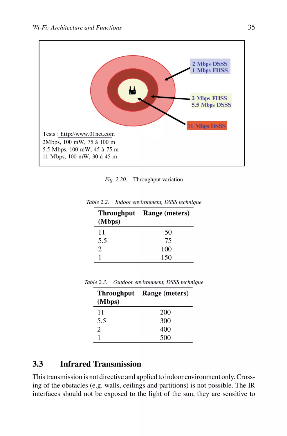
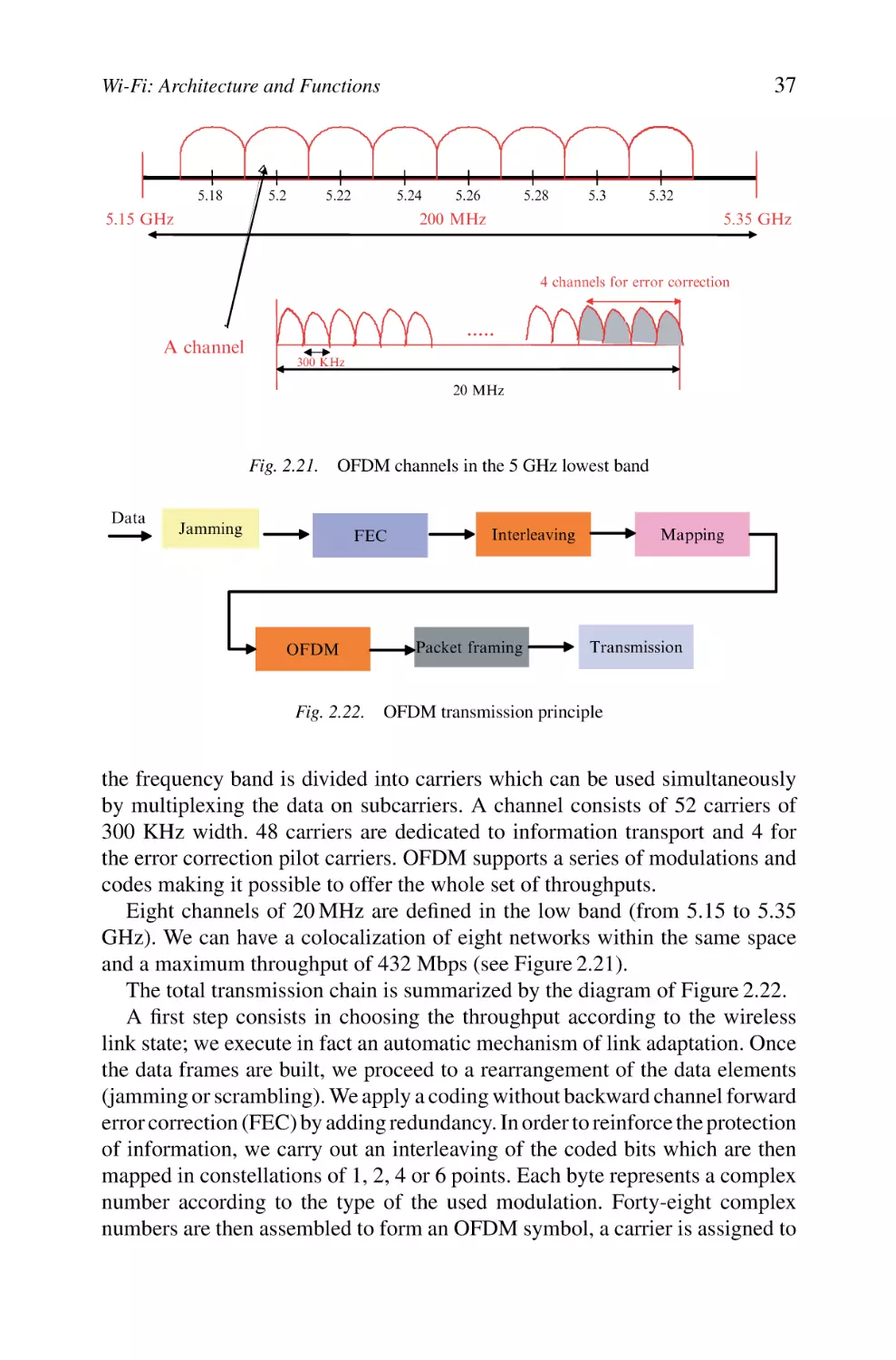
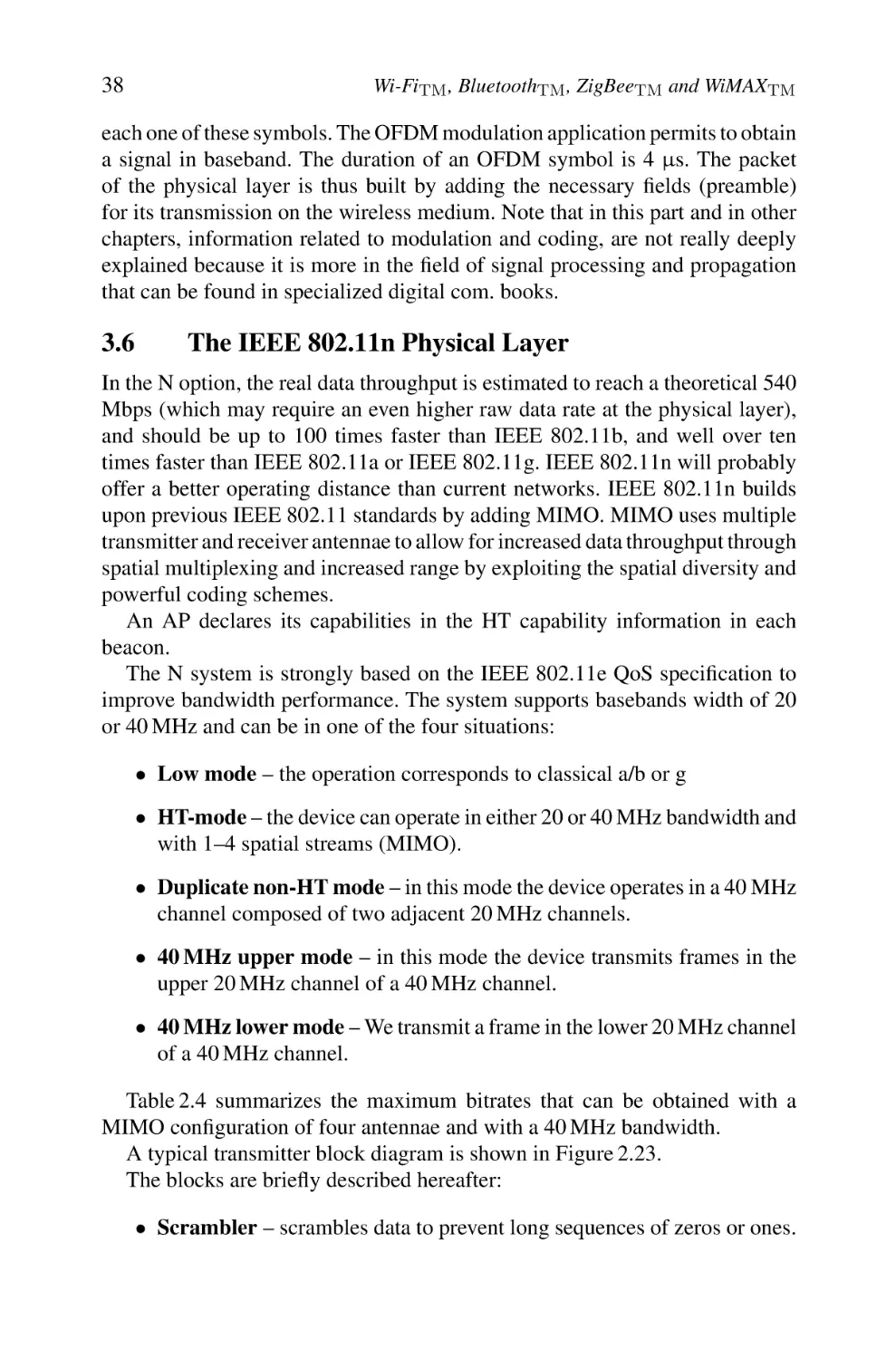
carrier sense/clear channel assessment (CS/CCA) procedure which is executed:
– To detect the beginning of a signal that can be captured (CS phase)
– To determine if the channel is free before transmitting a packet (CCA
phase)
Minimal duration of the CS/CCA procedure is equal to the duration of a slot
whose value depends on the characteristics of the selected physical layer (see
paragraph 5.2). IEEE 802.11 does not specify the procedures to detect that the
support is occupied, the equipment suppliers have thus the choice to implement
methods more or less innovating while respecting the lawful constraints on the
use of the frequencies (power limitations).
The lower sublayer role has primarily to code and transmit the bits sent by
the convergence layer on the medium. This layer is called PMD layer.
In addition to the information transport plan, a control plan exists. All the
control (management) functions related to the physical layer are implemented
in a PHY management layer. Management information is stored in a database
called Management Information Base (MIB), usually based on the SNMP format. A specific group in the IEEE 802.11 group (called TGV) works on the
management plane.
3.1
Frequency Hopping Spread Spectrum-based Physical
Layer
It offers 1 or 2 Mbps throughputs. The frequency band used is located between 2.4 and 2.483 GHz (see Figure 2.16). 79 channels of 1 MHz (35 channels
in France because of exclusive use of certain channels by the defence) are
available to the United States. The signal is transmitted alternatively on the
various available channels. The transmitter and the receiver are synchronized
on a succession of frequency hops during the communication. The sequence of
hops (multiple channels) defines a pattern. The hop sequences are defined based
on pseudo-random sequences for civil equipments and on a secret key for the
military equipments. The change of frequency on this sequence must be made
approximately every 400 ms. This dwell duration on a given frequency is called
a “hop” and is defined by the regulation. A synchronization of the frequency
changes is thus necessary.
31
Wi-Fi: Architecture and Functions
Time
9
8
7
6
5
4
3
2
1
2,400 GHz
2,4835 GHz Frequency
Fig. 2.16.
PLCP
scrambling
FHSS technique
temporal
Synch
Symbol
mapping
PLCP
Demodulation
GFSK
Chipping sequence
Gaussian
filter
Modulations
GFSK
Descrambling
FHSS receiver
FHSS transmitter
Fig. 2.17.
FHSS transmitter/receiver structure
The advantages of this technique are numerous. Indeed, it prevents a total
loss of the signal (only the coded signal on the scrambled carrier frequency is
lost and is retransmitted generally besides on the next hop). It provides a good
immunity against interferences, fading and background noise. This method thus
constitutes an effective solution in a multipath environment.
The transmission by FHSS offers two throughputs. The modulations used are:
– A frequency modulation Gaussian frequency shift keying (GFSK) with
two levels for 1 Mbps
– A frequency modulation GFSK with four levels for 2 Mbps
The preambles and frame headers in both cases are transmitted with a modulation of 1 Mbps.
Figure 2.17 shows the structure of an FHSS transmitter/receiver.
The existing equipment on the market supporting a physical layer with 2
Mbps can have the capacity to reduce their throughput to 1 Mbps if the quality
of the signal becomes bad. This may be seen as good or bad depending on the
usage. It is good because far station still can emit and receive data, while it is
also considered bad because a slower station monopolizes the channel more
time than a fast station slowing down the overall cell performance.
32
3.2
Wi-FiTM , BluetoothTM , ZigBeeTM and WiMAXTM
Direct Sequence Spread Spectrum-based Physical
Layer
This technique uses a single frequency band contrary to FHSS technique. The
used frequency band is 2.4–2.4835 GHz. 14 channels of 22 MHz separated
by 5 MHz are defined. Adjacent channels partially overlap as it is shown in
Figure 2.18.
In the original version of the standard, the DSSS transmission offers two
rates. The modulations used are:
• A phase modulation differential binary phase shift keying (DBPSK) for
1 Mbps
• A modulation in squaring of phase DQPSK for 2 Mbps
These two modulations are based on the principle of the differential phase
modulation. Thus, a new symbol to be transmitted results in a rotation of the
phase of the signal. This technique thus requires to know the reference of phase
only for the first emitted symbol. Then, a transmission of a symbol resulting
in a rotation of the phase of the signal compared to the phase of the preceding
symbol, it is not necessary any more to know the phase of reference.
In the binary frequency modulation DBPSK, only one information bit is
emitted by a symbol. Thus, the appearance of one “0” does not cause rotation
of phase whereas the appearance of one “1” causes an inversion of phase. In the
frequency modulation in squaring of phase DQPSK, one transmits two bits of
information by symbol. The rate of transmission is thus multiplied by two. The
rotation of phase is summarized in Table 2.1.
More important throughputs are offered in the standard IEEE 802.11b: 5.5
and 11 Mbps. The preamble and the header of a frame at the physical layer are
transmitted at 1 Mbps.
In order to avoid the problems of interferences and/or of noise, we can use a
technique of chipping which can spread the spectrum. Each bit of information is
Low channel
22 MHz
Mid channel
22 MHz
High channel
22 MHz
5 MHz
22 MHz
2,4835 GHz
2,4 GHz
Fig. 2.18. 2.4 GHz channels
33
Wi-Fi: Architecture and Functions
Table 2.1.
Different phase rotations
Symbol Rotation
00
0◦
01
90◦
11
180◦
10
270◦
coded in a succession of bits called chips. This sequence in general consists of 11
bits agreed upon between the transmitter and the receiver. A Barker code is used
with a sequence of chipping “+1, −1, +1, +1, −1, +1, +1, +1, −1, −1, −1”.
This redundant coding permits to recover a complete bit even when a great part
of the signal is lost. The transmission is carried out only on one fixed frequency
contrarily to the FHSS technique.
It should be noted that this method of chipping introduces a redundancy in
addition to a spread spectrum technique which makes the signal to be transmitted
more robust to the errors. Indeed, if the noise affects only one part of the band,
it will be possible to restore the signal and to recover the bits of information.
The sequence of chips has 6 chips set to 1 and 5 to −1. Thus, this distribution
makes it possible the receiving station to find its synchronization thanks to a
measurement of the autocorrelation of the signal received with the sequence
of chips of the receiver. It is necessary to notice that each time that a bit is
emitted, the receiver multiplies its sequence of 11 chips with the sequence of
the received signal: if there is a shift between the sequence of the receiver and
that of the emitted signal, it is difficult to decode the signal. The measurement
of the autocorrelation between these two sequences allows to determine if the
receiver is in shift compared to the sequences emitted by the source.
A mechanism of throughput variation according to the quality of the wireless
links is applied.
Figure 2.19 shows the structure of a DSSS transmitter/receiver which is more
complex than that of a FHSS transmitter/receiver.
A French characteristic concerning the regulation for the frequencies was that
until the end of 2001 only four frequencies were used because of the existence
of defencee radars in the band 2.4 GHz. Gradually, a total use of the band
becomes effective on the whole of the territory. Moreover it is now free to use
5 GHz transmitters with high-power throughput, a solution that we said can be
competitive with WiMAX solutions.
Given that the available channels in the 2.4 GHz frequency band overlap partially, interferences on adjacent channels can take place. However, it is possible
to choose three perfectly disjoint channels. For example, in Europe, we can find
34
Wi-FiTM , BluetoothTM , ZigBeeTM and WiMAXTM
PLCP
spreading
Synch
time
Filter
PLCP
correlator
Chipping sequence
Modulations
DBSK, DQPSK, CCK
Demod.
DSSS transmitter
Descrambling
DSSS receiver
Fig. 2.19. DSSS transmitter/receiver
the channels (1[2412 MHz], 7[2442 MHz], 13[2472 MHz]) and in the United
States (1[2412 MHz], 6[2437 MHz], 11[2462 MHz]). Consequently, three APs
defined to cover three cells make possible to aggregate throughput and to offer
a total throughput of 3 times the maximum bandwidth of the cell.
FHSS or DSSS?.
The decision should be based on the customer applications’ requirements. If the needs are directed towards a broad cover or
High throughputs, then the selected technique will be DSSS. In addition, in
the case of a highly multipath environment, it is preferable to use the FHSS
technique.
The majority of the currently existing products on the market mainly implement the IEEE 802.11b DSSS standard that offers four throughputs. The
selected throughput is defined dynamically according to the radio conditions.
Figure 2.20 illustrates this mechanism. We notice that more the equipment is
close to the AP, more the throughput used is high for both FHSS and DSSS.
The first zone around the AP makes it possible to reach throughputs of about 11
Mbps whereas when one move away, the throughput falls to 5.5, then 2 and 1
Mbps. Located at the same distance of the AP, the throughput offered by DSSS
is multiplied approximately by a factor of 2 compared to that offered by FHSS.
The extent of the covering zone in DSSS is generally related to the throughputs used with a distinction according to the type of the environment (indoor
or outdoor) (Tables 2.2 and 2.3).
The goal of this section is to give to the reader an idea on the orders of
magnitude of the ranges according to the throughputs. It should be noted that
these measurements were taken in a particular environment and are thus related
to the characteristics of materials of the buildings and the environments in
general.
In some configurations, a total degradation of the cell in term of throughput
may occur if a station is distant from the AP and chooses to transmit to a low
throughput.
35
Wi-Fi: Architecture and Functions
2 Mbps DSSS
1 Mbps FHSS
2 Mbps FHSS
5.5 Mbps DSSS
11 Mbps DSSS
Tests : http://www.01net.com
2Mbps, 100 mW, 75 à 100 m
5.5 Mbps, 100 mW, 45 à 75 m
11 Mbps, 100 mW, 30 à 45 m
Fig. 2.20. Throughput variation
Table 2.2.
Indoor environment, DSSS technique
Throughput
(Mbps)
11
5.5
2
1
Table 2.3.
50
75
100
150
Outdoor environment, DSSS technique
Throughput
(Mbps)
11
5.5
2
1
3.3
Range (meters)
Range (meters)
200
300
400
500
Infrared Transmission
This transmission is not directive and applied to indoor environment only. Crossing of the obstacles (e.g. walls, ceilings and partitions) is not possible. The IR
interfaces should not be exposed to the light of the sun, they are sensitive to
36
Wi-FiTM , BluetoothTM , ZigBeeTM and WiMAXTM
snow and fog. The transmission is done with a wavelength located between 850
and 950 nm with a power emitted of up to 2 W. The modulation used is position
modulation pulsates (PPM).
3.4
IEEE 802.11b Standard high Rate Direct Sequence
Spread Spectrum-based Physical Layer
In addition to the 1 and 2 Mbps transmissions supported by the basic standard,
transmissions with 5.5 and 11 Mbps are possible in IEEE 802.11b thanks to
the use of the complementary code keying (CCK) modulation. Information is
sent by using special and sophisticated complementary codes. The chipping
rate is of 11 Mchip/s with an 8-chip symbol duration. The 5.5 Mbps throughput
is obtained with a transmission of 4 bits per symbol instead of 8 to reach
a throughput of 11 Mbps. Also, the algorithmic of CCK makes it possible
the receivers to easily distinguish the various codes even in the presence of
interferences and fading due to multipath. The process of generation of CCK
symbols resembles in general to that used in DSSS with the difference that the
code words are partially derived starting from the data; on the other hand a static
code Barker is not used and the spreading of the signal is carried out using CCK
symbols.
The supported MAC layer is always the same. Although the modulation
used is different, the available channels are identical to those authorized for
DSSS PHY layer with lower throughput. One nice experiment that one can do
is to switch on two different APs with preconfigured different physical layers
(usually we can set up a 11b with a 11a). The two APs are interconnected via
Ethernet. When we switch off one of the APs the station handovers to the second
one but all communications remain and the data flow continue to arrive through
the new interface. It is called a seamless handover.
3.5
The OFDM Technique of the IEEE 802.11a/g
Standards
IEEE 802.11a and 802.11g systems use the OFDM modulation in the 5 GHz/
2.46 Hz ISM band. The total bandwidth available is approximately 455 MHz
of which 200 are allocated to indoor use and 255 to the outdoor use. This
modulation allows to reach throughputs between 6 and 54 Mbps and provides
good performances in presence of multipath. The MAC layer is identical to
that defined for the other physical layers (FHSS, DSSS, HR/DSSS, IR). The
physical layer supporting OFDM modulation is complex because it applies a
varied whole of techniques of digital transmission such as the phase modulation,
OFDM multicarrier transmission, convolutional coding and interleaving. Let
us recall that OFDM was proposed for the first time by the ETSI within the
European system Hiperlan 1. OFDM is based on a frequential division where
37
Wi-Fi: Architecture and Functions
5.18
5.2
5.22
5.24
5.15 GHz
5.26
5.28
5.3
5.32
200 MHz
5.35 GHz
4 channels for error correction
.....
A channel
300 KHz
20 MHz
Fig. 2.21. OFDM channels in the 5 GHz lowest band
Data
Jamming
FEC
OFDM
Fig. 2.22.
Interleaving
Packet framing
Mapping
Transmission
OFDM transmission principle
the frequency band is divided into carriers which can be used simultaneously
by multiplexing the data on subcarriers. A channel consists of 52 carriers of
300 KHz width. 48 carriers are dedicated to information transport and 4 for
the error correction pilot carriers. OFDM supports a series of modulations and
codes making it possible to offer the whole set of throughputs.
Eight channels of 20 MHz are defined in the low band (from 5.15 to 5.35
GHz). We can have a colocalization of eight networks within the same space
and a maximum throughput of 432 Mbps (see Figure 2.21).
The total transmission chain is summarized by the diagram of Figure 2.22.
A first step consists in choosing the throughput according to the wireless
link state; we execute in fact an automatic mechanism of link adaptation. Once
the data frames are built, we proceed to a rearrangement of the data elements
(jamming or scrambling). We apply a coding without backward channel forward
error correction (FEC) by adding redundancy. In order to reinforce the protection
of information, we carry out an interleaving of the coded bits which are then
mapped in constellations of 1, 2, 4 or 6 points. Each byte represents a complex
number according to the type of the used modulation. Forty-eight complex
numbers are then assembled to form an OFDM symbol, a carrier is assigned to
38
Wi-FiTM , BluetoothTM , ZigBeeTM and WiMAXTM
each one of these symbols. The OFDM modulation application permits to obtain
a signal in baseband. The duration of an OFDM symbol is 4 µs. The packet
of the physical layer is thus built by adding the necessary fields (preamble)
for its transmission on the wireless medium. Note that in this part and in other
chapters, information related to modulation and coding, are not really deeply
explained because it is more in the field of signal processing and propagation
that can be found in specialized digital com. books.
3.6
The IEEE 802.11n Physical Layer
In the N option, the real data throughput is estimated to reach a theoretical 540
Mbps (which may require an even higher raw data rate at the physical layer),
and should be up to 100 times faster than IEEE 802.11b, and well over ten
times faster than IEEE 802.11a or IEEE 802.11g. IEEE 802.11n will probably
offer a better operating distance than current networks. IEEE 802.11n builds
upon previous IEEE 802.11 standards by adding MIMO. MIMO uses multiple
transmitter and receiver antennae to allow for increased data throughput through
spatial multiplexing and increased range by exploiting the spatial diversity and
powerful coding schemes.
An AP declares its capabilities in the HT capability information in each
beacon.
The N system is strongly based on the IEEE 802.11e QoS specification to
improve bandwidth performance. The system supports basebands width of 20
or 40 MHz and can be in one of the four situations:
• Low mode – the operation corresponds to classical a/b or g
• HT-mode – the device can operate in either 20 or 40 MHz bandwidth and
with 1–4 spatial streams (MIMO).
• Duplicate non-HT mode – in this mode the device operates in a 40 MHz
channel composed of two adjacent 20 MHz channels.
• 40 MHz upper mode – in this mode the device transmits frames in the
upper 20 MHz channel of a 40 MHz channel.
• 40 MHz lower mode – We transmit a frame in the lower 20 MHz channel
of a 40 MHz channel.
Table 2.4 summarizes the maximum bitrates that can be obtained with a
MIMO configuration of four antennae and with a 40 MHz bandwidth.
A typical transmitter block diagram is shown in Figure 2.23.
The blocks are briefly described hereafter:
• Scrambler – scrambles data to prevent long sequences of zeros or ones.
39
Wi-Fi: Architecture and Functions
IEEE 802.11n bit rates
Modulation
BPSK
QPSK
QPSK
16-QAM
16-QAM
64-QAM
64-QAM
64-QAM
Interleaver
QAM
mapping
Interleaver
QAM
mapping
Intezleaver
QAM
mapping
CSD
Interleaver
QAM
mapping
CSD
IFFT
CSD
STBC
Stream Mapper
FEC encoder
FEC encoder
Encoder Parser
Scrambler
Mbps
60.0
120.0
180.0
240.0
360.0
480.0
540.0
600.0
NSS Spatial Streams
Fig. 2.23.
Spatial Mapping
Table 2.4.
Insert
GI and
Window
Analog
and RF
IFFT
CSD
Insert
GI and
Window
Analog
and RF
IFFT
CSD
Insert
GI and
Window
Analog
and RF
IFFT
CSD
Insert
GI and
Window
Analog
and RF
NSTS Space Time
Streams
NTX Transmit chains
IEEE 802.11n transmitter
• Encoder parser – de-multiplexes the scrambled bits among FEC encoders, in a round-robin manner.
• FEC encoders – encodes data to enable error correction – FEC encoders
may include binary convolutional encoders followed by puncturing
device, or LDPC encoder.
• Stream parser – divides the outputs of the encoders into blocks that will
be sent to interleavers and mapping devices. The sequences of the bits
sent to the interleavers are called spatial streams.
40
Wi-FiTM , BluetoothTM , ZigBeeTM and WiMAXTM
• Interleaver – interleaves the bits of each spatial stream (changes order
of bits) to prevent long sequences of adjacent noisy bits from entering
the FEC decoder.
• QAM mapping – maps the sequence of bits in each spatial stream to
constellation points (complex numbers).
• Space time block coding – constellation points from one spatial stream
are spread into two space time streams using a space time block code.
• Spatial mapping – maps space time streams to different transmit chains.
This may include one of the following:
• Direct mapping – constellation points from each space time stream
are sent to a different transmit chain.
• Spatial expansion – vectors of constellation points from all the
space time streams are multiplied by a matrix to produce the input
to the transmit chains.
• Beamforming – similar to spatial expansion: each vector of constellation points from all the space time streams is multiplied by
a matrix of steering vectors to produce the input to the transmit
chains.
• Inverse fast Fourier transform – converts a block of constellation points
to a time-domain block.
• Cyclic shift insertion – inserts the cyclic shift into the time-domain
block. In the case that spatial expansion is applied that increases the
number of transmit chains, the cyclic shift may be applied in the frequency
domain as part of spatial expansion.
• Guard interval (GI) insertion – inserts the guard interval.
The reader who wishes to look further into the quoted digital transmission
techniques finds at the end of this chapter, a very broad whole of references
on the subject [BRO 97, COLLAR 99c, COLLAR 00, EDO 97, NEE 00,
PRO 95].
3.7
Frame Formats
The reader will find in Appendix A the detailed structure of the various frames
associated with the various physical layers.
Wi-Fi: Architecture and Functions
4.
41
Data Link Layer
It is made up of two sublayers. LLC uses the same properties that an LLC 802.2
layer and allows to connect a WLAN to any other LAN of the IEEE family. The
MAC layer is specific to IEEE 802.11 and defines new mechanisms of access to
the medium. It is independent of the characteristics of the physical layer and the
throughputs and supports two topologies infrastructure and ad hoc. In future we
will also find the mesh facility in the same layer. It also supports the following
services:
•
Asynchronous data transmission service (mandatory):
• Does not offer guarantee (best-effort service)
• Broadcast and multicast traffics support
• Implemented using DCF mechanism (see paragraph 5.2)
•
Time constraints traffic service (optional)
• Real-time service
• Implemented using the PCF mechanism (see paragraph 5.4)
In addition to data transmission, other basic services are provided such as:
• Association/disassociation
• Privacy (wired equivalent privacy [WEP] mechanism, etc.)
• Authentication and access control
• Fragmentation/reassembly and ordering
• Energy saving
A global view of the MAC layer is given in Figure 2.15b. The functionalities
are detailed in section 6.
5.
Medium Access Control Layer
5.1
Medium Access Mechanisms
The MAC layer defines two different access methods, the distributed coordination function (DCF) which is used for a distributed and random
access like that of IEEE 802.3 with several other algorithms specific to
the WLAN and another method which is the point coordination function
(PCF) for a controlled access. The DCF method is defined to deal with the
transport of the asynchronous best-effort traffic. All the users who want
to transmit have an equal chance to access to the medium. The PCF is
42
Wi-FiTM , BluetoothTM , ZigBeeTM and WiMAXTM
CFP
beacon
PCF
Fig. 2.24.
CP
DCF
beacon
CFP
CP
PCF
DCF
Structure of superframe: CFP and CP periods
now replaced by the hybrid coordination function (HCF) and is based on
a polling approach plus a differentiated transmission by assigning different
waiting periods accord to nodes priorities. It requires the existence of an
entity for control. HCF is conceived for the data transmission with time constraints such as the real-time traffic (voice, video). DCF is thus the basic
access method with contention whereas HCF is an optional method without
contention. Contention free period (CFP) is the HCF period and contention
period (CP) is the duration of contention. Information relative to the two access
modes with and without contention is disseminated in the BSS through control
frames called beacon frames or beacons (equivalent to the BCCH channel in
GSM cellular networks). A superframe is defined by a CFP part followed by
the DCF mode part (Figure 2.24). The beginning of a superframe is delimited
by a beacon frame.
In what follows, we will detail the two types of access mechanisms.
5.2
Basic Access Technique CSMA/CA
The basic access mechanism, called DCF is typically the carrier sense multiple
access with collision avoidance (CSMA/CA) mechanism. CSMA protocols are
well known and Ethernet is the most famous one, which is a protocol based on
the CSMA/CD access mechanism (CD for collision detection). Contrarily to
CSMA/CD mechanism which is based on the collision detection, the CSMA/CA
allows an access to a shared medium by avoiding collisions.
Collision detection mechanisms are well suited to a fixed LAN, but they
cannot be used in a wireless environment, for two main reasons:
• Implementing a collision detection mechanism would require the implementation of a full duplex radio capable of transmitting and receiving
simultaneously; and we have not such terminals.
• In a wireless environment, we cannot be sure that all the stations hear each
other (which is the basic assumption of the collision detection principle).
Moreover, the fact that a station wanting to transmit checks if the medium
is free, does not necessarily mean that the medium is free around the
receiver area (multipath channels, fading).
• The carrier sense procedure takes a relatively long time in comparison
with the fixed networks (typically 30–50 µs in fixed networks).
43
Wi-Fi: Architecture and Functions
C
B
A
A is out of C’s radio range
Fig. 2.25.
Hidden stations
To understand the principle of CSMA/CA mechanism, we first of all examine the radio problems which brought to develop a new mechanism inspired of
the CSMA/CD but adapted to the context of the wireless transmission. Indeed,
the wireless transmission raises unknown new problems such as:
– The hidden stations problem
– The exposed stations problem
– The near-far effect related to radio signal attenuation according to the
covered distance
Hidden stations problem. The deployment of WLANs can face the hidden
nodes problem (Figure 2.25). This problem occurs when two stations cannot
hear each other owing to the fact that the distance which separates them is too
large or that an obstacle prevents them from communicating between each other.
But they have overlapped covering zones. If stations A and C make only the
detection of the carrier by listening the channel, not being capable of hearing
each other, they will be authorized to emit at the same time. Consequently,
if A and C wish to send packets at the same time to station B located in the
intersection of the covering zones, a collision occurs and thus B will not be able
to receive any of the two data communications. Stations A and C are said to be
hidden one from each other.
Exposed stations problem. Let us consider the case where station B transmits data to station A (as shown in Figure 2.26). If station C senses the radio
channel, it can hear a communication in progress. It concludes that it cannot
transmit packets to station D but if C transmits, collisions would be created only
in the area between B and C and not in the area where destinations D and A are.
In order to overcome these problems, the IEEE 802.11 standard uses the
collision avoidance mechanism with a positive acknowledgement scheme as
follows. A station wanting to transmit senses the medium. If the medium is
44
Wi-FiTM , BluetoothTM , ZigBeeTM and WiMAXTM
C
C
A
A
D
D
BBB
Fig. 2.26.
Exposed stations
busy, the transmission is differed. If the medium is free for a specific time
(called distributed interframe space [DIFS], in the case of the asynchronous data
transmission), then the station is authorized to transmit. The receiving station
(which can be also the AP playing its relay role) checks the cyclic redundancy
check (CRC) of the received packet and returns an acknowledgement (ACK) of
delivery. The reception of the ACK indicates to the transmitter that no collision
took place. If the transmitter does not receive the acknowledgement, then it
retransmits the frame after an ACK TIMEOUT until it obtains it or gives up
after a given number of retransmissions.
This kind of protocol, inspired from that defined in the Ethernet network, is
effective when the medium is not overloaded, since it authorizes the stations to
transmit with a minimum delay, but collisions can always take place. This is
due to the fact that the stations which sense the medium, can find it free, and
finally decide to transmit, sometimes at the same time as other stations carrying
out this same series of operations.
These collisions must be detected, so that the MAC layer can retransmit the
frame without having to pass again by the high layers, what would generate
significant delays. Indeed, a first difference between CSMA/CD and CSMA/CA
mechanisms is the possibility of collisions detection. In CSMA/CD, collision
is detected at transmission side because the stations are capable of sensing
the medium during data transmissions. But the collision can be detected only
at the receiver side in the case of the CSMA/CA mechanism. In the Ethernet
networks the collisions are detected by the transmitting stations which retransmit data frames using a recovery algorithm called binary exponential back-off
(BEB).
In order to supervise the network activity, the MAC sublayer works in
collaboration with the physical layer. The physical layer uses clear channel
assessment (CCA) algorithm to evaluate the availability of the channel. To
know if the channel is free, the physical layer measures the power received
by antenna called received signal strength indicator (RSSI). The physical layer
thus determines that the channel is free by comparing the RSSI value with a
Wi-Fi: Architecture and Functions
45
fixed threshold and transmits thereafter to the MAC layer an indicator of free
channel. In the contrary case, the transmission is differed according to rules’
quoted previously.
All in all, the CSMA/CA protocol is based on:
– Sensing the medium thanks to CS procedure (CS carrier sense)
– Using interframe space (IFS) timers
– Using positive acknowledgements and the collision avoidance approach
– Executing backoff algorithm
– Using multiple access
Interframe Spaces (Spaces Between Successive Frames).
IEEE 802.11
standard defines four types of IFS timers classified by ascending order, which
are used to define different priorities:
• Short interframe space (SIFS) is used to separate the transmissions belonging to the same dialogue (data frames and acknowledgements). It is
the smallest gap between two frames. There is always, at most, only one
station authorized to transmit at any given time, taking thus priority over
all other stations. This value is fixed by the physical layer and is calculated
in such way that the transmitting station will be able to switch back to
receive mode to be able to decode the incoming packet. A high priority
SIFS is then used to transmit frames like ACK, CTS and response to a
polling.
• Point coordination IFS (PIFS) is used by the AP (called coordinator in
this case) to gain the access (to the medium before any other station. It
reflects an average priority to transmit the time-bounded traffic.
• Distributed IFS (DIFS) is the IFS of weaker priority than the two previous;
it is used in the case of data asynchronous transmission.
• Extended IFS (EIFS) is the longest IFS. It is used by a station receiving a
packet which is corrupted by collisions to wait more time than the usual
DIFS in order to avoid future collisions.
These timers define degrees of priority. When several stations wish to transmit
simultaneously, the station wishing to emit the urgent frames as the acknowledgements will be able to send them in first. Then other priority frames will
be transmitted considered to be like those related to the administration tasks or
the traffic which has delay constraints. Lastly, the least important information
concerning the asynchronous traffic will be transmitted after a longer latency.
46
Wi-FiTM , BluetoothTM , ZigBeeTM and WiMAXTM
Table 2.5.
Parameter
Slot Time
SIFS Time
CWmin (slots)
CWmax (slots)
Main parameters
Physical layer
FHSS
DSSS, HR/DSSS
OFDM
IR
FHSS
DSSS, HR/DSSS
OFDM
IR
FHSS
DSSS, HR/DSSS
OFDM
IR
FHSS/DSSS/IR/OFDM
Value
50
20
9
8
28 microsec +/− 10%
10 microseconds
16 microseconds
10 microseconds
15
31
15
63
1023
PIFS and DIFS are calculated (formulae [2.1] and [2.2]) according to SIFS.
PIFS = SIFS + SlotTime
(2.1)
DIFS = SIFS + 2 × SlotTime
(2.2)
where:
SlotTime = minimal delay to determine the state of the channel + Rx − Tx
turnaround time + propagation time.
The value of SIFS is related to the characteristics of the physical layer (see
Table 2.5).
Note that in the IEEE 802.11e, we have an EDCF where these timers take
each two possible values: one low and one high. By this way, we make a natural
differentiation of traffic over the link.
Another Note concerns slow traffic; as we can see if we mix a station sending
on the DCF with a speed of 1 Mbps with another using MIMO at 190 Mbps the
slow station will monopolize the channel 190 times more than the rapid station.
The only way to avoid that is to configure APs where low speeds are disabled.
Exponential Backoff Algorithm.
This algorithm is a well-known method
used to resolve the problem of equity of competitor accesses of several stations
to a shared medium. This method requires that each station chooses a “withdrawal period” a random number N (called backoff time) ranging between 0
and the size of contention window. This number N is expressed in slots. Before
accessing to the medium, each station must check that another station did not
Wi-Fi: Architecture and Functions
47
access the medium before it. It waits for this number of slots before accessing
the medium.
The duration of a slot (SlotTime) is defined so that the station is always able
to determine if another station has accessed the medium at the beginning of
the preceding slot. The average value of the waiting delay grows exponentially
with the number of retransmissions.
The IEEE 802.11 standard defines the backoff algorithm to be executed in
the following cases:
• When a station wanting to transmit, senses the medium before the first
transmission of a frame and finds that the medium is occupied, it waits
during a random period before trying to transmit again
– After each retransmission
– After a successful transmission
The only case where this mechanism is not used is when the station decides to transmit a new frame and the medium has been free for more than
SIFS/PIFS/DIFS.
The waiting random duration (WRD) is calculated by using the following
formula:
(2.3)
WRD = CW∗ random()∗ SlotTime
where:
• CW is the size of the contention window, CW = [CWmin − CWmax ].
At each failure, the CW size is doubled until reaching a maximum value
CWmax . The values of CWmin and CWmax are given in Table 2.5.
• Random is a random number ranging between 0 and 1.
• SlotTime = minimal delay to determine the state of the channel +Rx −
Tx turnaround time + propagation time.
Reduction in the withdrawal period in the case of CSMA/CA mechanism is
different from that applied in the case of CSMA/CD procedure. Indeed, instead
of a reduction at each clock signal, the number of slots is fallen only when the
channel is free throughout this slot. If the channel becomes busy, in this case the
timer is frozen. It is an additional protection in order to decrease the probability
of collisions after the random waiting duration.
We assume that the stations have the same probability of accessing the
medium because each station must reuse the same algorithm after each retransmission. The disadvantage of this method is that it does not guarantee a maximum delay and consequently is not appropriate for real-time applications (such
as the voice and video).
48
Wi-FiTM , BluetoothTM , ZigBeeTM and WiMAXTM
Immediate access when DIFS
medium is free >= DIFS
PIFS Contention Window
SIFS
DIFS
Busy Medium
Source S
Listen carrier
Defer Access
Backoff Window
Next frame
time
Slot time
Select slot and decrement backoff as
long as medium is idle
SIFS
Destination D
ACK
Busy Medium
time
Fig. 2.27.
Medium Listening.
CSMA/CA access method
This function is fulfilled thanks to two procedures:
• A procedure for listening at the physical layer called physical carrier
sense (PCS). PCS detects the presence of other stations by analysing all
the frames on the wireless medium and by detecting the activity on the
medium thanks to the relative energy of its signal compared to the other
stations
• A procedure for listening at the MAC layer named virtual sense carrier
(VCS) in the case of a reservation of the medium.
The basic global mechanism is described in Figure 2.27 by considering the
case of the asynchronous data transmission between a source S and a destination
D. A similar operation is adopted in the case of transmissions of other frames;
we should only consider the adequate IFS.
5.3
Virtual Carrier Sense CSMA/CA Mechanism
with Short Messages RTS and CTS
Because of collisions, packet loss can occur despite of using BEB recovery
algorithm and acknowledgements of the frames. Consequently, in the case of
an environment where there are a lot of hidden stations or in the case of transmissions of very long frames, the standard defines a virtual carrier sense mechanism.
The principle of operation of the mechanism is described as follows.
A station wanting to send frames, begins by initially transmitting a short
control packet called request to send (RTS), which contains the source, the destination and duration of the transmission (i.e. total duration of the transmission
of the packet and its ACK). The destination station answers (if the medium
49
Wi-Fi: Architecture and Functions
is free) with a control packet called clear to send (CTS), containing the same
duration information.
All stations receiving either the frame containing the request for reservation of channel RTS, or the frame of response of reservation CTS, set their
virtual carrier sense indicator called network allocation vector (NAV), for the
given duration, and use this information together with the PCS when sensing
the medium. They consider that the support is busy for the duration period
specified in the control packets RTS and CTS. If the source does not receive
the CTS packet, it assumes that a collision occurred and will retransmit the
RTS packet after a random waiting period according to the principle, described
in paragraph 5.2. If the recipient receives the CTS packet correctly, the source
emits an acknowledgement to announce to the recipient that the packet CTS was
received. Then the communication will be able to take place.
This mechanism reduces the probability of collision which can be caused by
a hidden station of the transmitter in the zone of the receiver thanks to the short
duration of transmission of the RTS, because the station will hear the control
packet CTS and will consider that the medium is like occupied until the end
of the transmission. The Duration information in the RTS packet protects the
transmitter area from the collisions during the transmission of acknowledgement
(these collisions could be caused by the stations which are out of the radio range
of the receiver station). Figure 2.28 shows a transmission between two stations
A and B, and the NAV setting of their neighbours.
It should also be noted that thanks to the fact that RTS and CTS are short
frames, the number of collisions is reduced and the overhead of collisions is
reduced since these frames are recognized more quickly than if all the whole
DIFS
Source
Time
SIFS
DATA
RTS
SIFS
Destination
SIFS
ACK
CTS
DIFS
NAV (RTS)
Other station
Contention window
NAV (CTS)
NAV (DATA)
Defer access
Fig. 2.28.
CSMA/CA with RTS/CTS
Backoff
50
Wi-FiTM , BluetoothTM , ZigBeeTM and WiMAXTM
MAC frame is transmitted (this is true if the packet is significantly bigger than
the RTS, thus the standard authorizes the transmission of short packets without
the exchange of RTS/CTS).
The mechanism CSMA/CA with RTS/CTS is a mechanism which thus
allows the data transmission and the reception of the ACK without collision. Consequently, it is advised to also use it to send long frames for which a
retransmission would be too expensive in terms of bandwidth. This is controlled
per each station by a parameter called RTS Threshold.
How can we solve the problem of hidden stations thanks to this mechanism?
The hidden station problem is illustrated in Figure 2.25.
Station C is hidden station from station A. Let us consider the case where
station A transmits data to the station B. Station C does not detect the activity
of station A. In this case, station B can transmit freely without interfering with
station C transmission. If A and B exchange RTS/CTS messages, station C is
informed thanks to the sending of a frame CTS by station B indicating that the
medium is busy. C thus does not try to transmit during the transmission between
A and B.
If the virtual carrier sense is executed, the sending of control packet CTS
by the recipient B can solve the problem of the hidden nodes. Indeed, thanks
to its packet CTS, B will reach all the stations in its radio range and thus will
inform all the stations which would like potentially to emit. If B receives the
RTS packet of A in first, then B will receive the CTS packet emitted by B and
thus will understand that the medium is busy and thus stops transmitting.
The IEEE 802.11 standard specifies that the basic technique DCF is mandatory and other procedures CSMA/CA with RTS/CTS and HCF are optional.
Finally, if the IEEE 802.11 cell is not crowded, simply avoid using RTS/CTS
because you will loose a lot of time because of signalling.
5.4
PCF and HCF
Beyond the basic DCF, there was an optional PCF mechanism now replaced by
IEEE 802.11E. This mechanism makes use of the higher priority that the AP
may gain by the use of a smaller PIFS. PCF uses a centralized polling scheme,
which requires the AP as a point coordinator (PC) in a BSS. The AP sends
polling requests to stations for data transmission, hence controlling medium
access. If PCF is supported, both PCF and DCF coexist and the time is divided
into superframes. A superframe starts with a beacon frame. Each superframe
consists of a CP where DCF is used and a CFP where PCF is used.
During the CFP, the PC maintains a list of registered STAs and polls each
STA according to its list. Then, when an STA is polled, its gets the permission to
transmit data frame. Since every STA is permitted a maximum length of frame
to transmit, the maximum CFP duration for all the STAs can be known and
Wi-Fi: Architecture and Functions
51
decided by the PC, which is called CFP max duration. The time used by the
PC to generate beacon frames is called target beacon transmission time (TBTT).
In the beacon, the PC denotes the next TBTT and broadcast it to all the others in
the BSS. In order to ensure that no DCF STAs are able to interrupt the operation
of the PCF, a PC waits for a PIFS, which is shorter than DIFS, to start the PCF.
Then, all the others STAs set their NAVs to the values of CFP max duration
time, or the remaining duration of CFP in case of delayed beacon. During the
CP, the DCF scheme is used, and the beacon interval must allow at least one
DCF data frame to be transmitted. Normally, PCF uses a round-robin scheduler
to poll each STA sequentially in the order of polling list, but priority-based
polling mechanisms can also be used if different QoS levels are requested by
different STAs.
Performance analysis of this protocol showed that it is not adapted to the
transmissions of traffic with strong time constraints and thus there is no product
on the market that implements it. It is possible that if a station takes the channel,
it can monopolize it during a long time and the beacons frames can be delayed.
HCF mechanism (IEEE 802.11e) deals with these aspects.
5.5
Frames Formats
There are three main types of frames:
• Data frames which are used for data transmission
• Control frames which are used to control access to the medium (e.g. RTS,
CTS, ACK)
• Management frames which are frames transmitted to exchange management information but are not forwarded to upper layers (e.g. beacon
frames)
Each frame type is subdivided into different subtypes according to their specific
functions.
MAC Frame Format. The structure of the frame is traditional (close to that
of an Ethernet frame) (Figure 2.29). For each IEEE 802.11 frame an associated
MAC header is defined. The functionalities associated with these types of frames
are described in section 6.
The following figure shows the general format of the MAC frame, some
fields are only present in specific frames, as described later. The fields are as
follows.
Frame control field.
below (Figure 2.30):
The structure of the frame control field is described
52
Wi-FiTM , BluetoothTM , ZigBeeTM and WiMAXTM
2
2
6
6
6
2
6
0-2312
4
Sequence
Frame Duration
Frame
Address4
Address1 Address2 Address3
control
control ID
body
bytes
32-bit
CRC
MAC header
Fig. 2.29.
Protocol
version
2
Type Subtype
2
4
To
DS
1
From
DS
1
Fig. 2.30.
MAC frame format
More
Fragment
1
Retry
1
Power More
WEP order
Managt Data
1
1
1
1bits
Frame control field
This control field contains the following information:
• Protocol version: this field contains two bits which could be used to
recognize possible future versions of IEEE 802.11 standard. In the current
version of the standard, the value is fixed to 0.
• Type and sub-type: the six bits define the type and the sub-type of the
frames (see Annex A).
• Towards the system of distribution (ToDS): this bit is set to 1 when the
frame is addressed to the AP so that it forwards it to the DS. This concerns
the case when the source and the recipient are in the same BSS and the
AP must relay the frame. The bit is set to 0 in all other frames.
• FromDS (coming from the system of distribution): this bit is set to 1 when
the frame is received from the DS.
• More fragments (of other fragments): this bit is set to 1 when there are
more fragments following the current fragment.
• Retry (retransmission): this bit indicates that the fragment is a retransmission of a previously transmitted fragment. This is used by the receiver
station to recognize duplicated transmissions of frames that may occur
when an acknowledgement packet is lost or damaged.
• Power management (energy saving): this bit is set to 1 to indicate that the
station will be in energy-saving mode (sleep mode) after the transmission
of this frame. This is used by stations which are changing state either from
power save to active or vice versa.
• More data (of other data): this bit is also used for the energy management.
It is used by the AP to indicate that more frames are buffered for this sta-
Wi-Fi: Architecture and Functions
53
tion. The station may decide to use this information to require continuing
polling frames or even changing to active mode.
• WEP (security): this bit set to 1 indicates that the body of the frame is
encrypted according to the WEP algorithm.
• Order (order): this bit indicates that this frame is sent by using the strictly
ordered service class. This class is defined for the users who cannot accept
change of order between the unicast and multicast frames. The strictly
ordered service class is defined for users who cannot accept change of
ordering between unicast frames and multicast frames.
Duration/ID. This field has several uses depending on the frame type. It can
be used as a duration field indicating the time (in microseconds) the channel
will be allocated for successful transmission of an MAC frame. In some control
frames, this field contains an association or connection identifier. In polling
frames with energy-saving mode it contains the identifier ID of the station.
Address fields.
A frame may contain up to four addresses, depending on
the bits ToDS and FromDS defined in the control field (see paragraph 6.1) as
follows:
• Address 1 always the recipient address (i.e. the BSS station that is the
immediate recipient of the packet). If ToDS is set, this is the AP address,
if ToDS is not set then this is the address of the end station.
• Address 2 is always the transmitter address (i.e. the station which is physically transmitting the packet). If FromDS is set, this is the AP address, if
it is not set then it is the station address.
• Address 3 is in most cases the remaining, missing address. In a frame
with FromDS set to 1, address 3 is the original source address, if the
frame has the ToDS set, then address 3 is the destination address.
• Address 4 is used in special cases where a wireless DS is used, and the
frame is being transmitted from one AP to another. In such cases, both
the ToDs and FromDS bits are set, so both the original destination and
the original source addresses are missing.
The transmitter address and receiver address are the MAC addresses of stations within the BSS and which are transmitting and/or receiving frames over
the WLAN. The source address and destination address are the MAC addresses
of the stations (wireless or not) which are the ultimate source and destination
of the frame.
54
Wi-FiTM , BluetoothTM , ZigBeeTM and WiMAXTM
2
2
2
2
2
Frame
control
Duration
RA
TA
CRC
MAC header
Fig. 2.31.
Frame
control
2
RTS frame format
Duration
RA
MAC header
Fig. 2.32.
2
CRC
2
CTS frame format
Sequence control field.
The sequence control field is used to represent the
order of the various fragments belonging to the same frame, and to recognize
duplicated packets. It consists of two subfields, the number of fragment and
the sequence number which define the number of frame and the number of the
fragment in the frame sent between a given transmitter and receiver.
Cyclic redundancy check field.
The error checking code is a 32-bit field
formed starting from the following generating polynomial:
G(x) = x32 +x26 +x23 +x22 +x16 +x12 +x11 +x10 +x8 +x7 +x5 +x4 +x2 +x+1
Format of RTS, CTS and ACK Frames.
RTS frame format.
fields:
The RTS frame (Figure 2.31) consists of the following
• RA: the address of the receiver STA of the next data or management
frame
• TA: the address of the station which transmits the RTS frame
• Duration: time, in microseconds, necessary to the transmission of the
frame, plus one CTS frame, plus one ACK frame, plus three SIFS intervals
CTS format.
The CTS frame (Figure 2.32) consists of the following fields:
• RA: the receiver address of the CTS frame, directly copied from the field
transmitter address (TA) of the immediately previous RTS frame to which
the CTS is a response.
55
Wi-Fi: Architecture and Functions
Frame
control
Duration
Fig. 2.33.
Table 2.6.
Bandwidth
Mbps
RA
CRC
ACK frame format
IEEE 802.11b throughputs and parameters
Time intervals
Throughput
Mbps
Data frames
ACK frames
DIFS Preamble Overhead Payload SIFS Preamble Overhead Total
(µs)
(µs)
(µs)
(µs) (µs)
(µs)
(µs)
(µs)
1
2
5.5
11
50
50
50
50
192
192
192
192
272
136
49
25
12,000
6,000
2,182
1,091
10
10
10
10
192
192
192
192
10
10
10
10
12,726
6,590
2,685
1,570
0.94
1.84
4.47
7.64
• Duration: the value obtained from RTS frame, minus the time of transmission, in microseconds, required to transmit the CTS frame and its
SIFS interval.
ACK frame format.
The ACK frame (Figure 2.33) looks as follows:
• RA: the field directly copied from the address 2 field of the frame immediately preceding this ACK frame.
• Duration: if the bit more fragment is set to 0 in the frame control field
of the previous frame, the duration value is set to 0, otherwise it is the
last value of the previous frame, minus time, in microseconds, required
to transmit the ACK frame and its SIFS interval.
Overhead of IEEE 802.11 MAC Frames. The four theoretical throughputs
suggested by the IEEE 802.11b standard are not really reached
because of the overhead in the header and in the CSMA/CA. Table 2.6 summarizes the effective throughputs really offered.
Comparison Between MAC 802.11x and MAC 802.3 Frames. A comparison in terms of bandwidth and overhead between various technologies IEEE
802.11 and 802.3 is summarized in Table 2.7.
In addition, throughputs offered by IEEE 802.11a (without RTS/CTS) with
packets of 1500 bytes length are listed in Table 2.8.
Notice that in practice these throughputs can be lower. The results are
obtained with the IPERF tool sending TCP data chuncks.
56
Wi-FiTM , BluetoothTM , ZigBeeTM and WiMAXTM
Table 2.7.
IEEE standard
Bandwidth
Comparison table between IEEE 802.11 and 802.3 standards
802.11
802.11b
802.11a
802.3
1,2 Mbps
1, 2, 5.5,
6, 9, 12, 18, 24, 36, 48,
10, 100,
11 Mbps
54 Mbps
1,000 Mbps
DIFS
128 µs
50 µs
6 µs
IFS 6.9 µs, 0.96 µs
Slot time
50 µs
20 µs
6 µs
5.12 µs, 5.12 µs
DATA preamble
250 µs
192 µs
10, 7, 6, 5, 4, 3, 3, 3 µs 6.4 µs, 0.64 µs
MAC overhead
34 bytes
34 bytes
34 bytes
18 bytes
Payload
46–1,500 bytes 46–1,500 bytes
46–1,500 bytes
46–1,500
(0–2,312 w/o (0–2,312 w/o
(0–2,312 w/o
802.3)
802.3)
802.3)
SIFS
28 µs
10 µs
13 µs
–
ACK preamble
192 µs
192 µs
10, 7, 6, 5, 4, 3, 3, 3 µs
–
MAC
14 bytes
14 bytes
14 bytes
–
overhead/ACK
Table 2.8. IEEE 802.11a rates
Theoretical throughput
(Mbps)
6
24–27
36
54
6.
Effective throughput
(Mbps)
5.3
18
24
32
Functions
Several functions are supported by the IEEE 802.11 standard. This section aims
to describe in a brief way the characteristics of each of them.
6.1
Addressing
A compliant Ethernet addressing on 48 bits is adopted. The standard defined
four fields which are:
• Address 1 is always the address of the receiver (i.e. the station in the BSS
which is the receiver of the packet). If ToDS is set to 1, it is the address
of the AP, if not, it is the address of the station.
• Address 2 is always the address of the transmitter (i.e. the station that
physically transmits the packet). If FromDS is set to 1, it is the address
of the AP, if not, it is the address of the transmitting station.
57
Wi-Fi: Architecture and Functions
Table 2.9.
scenario
ad-hoc network
infrastructure
network, from AP
infrastructure
network, to AP
infrastructure
network, within DS
IEEE 802.11 addresses
to DS from address 1 address 2 address 3 address 4
DS
0
0
DA
SA
BSSID
0
1
DA
BSSID
SA
1
0
BSSID
SA
DA
-
1
1
RA
TA
DA
SA
DS: Distribution System
AP: Access Point
DA: Destination Address
SA: Source Address
BSSID: Basic Service Set Identifier
RA: Receiver Address
TA: Transmitter Address
• Address 3 is the address of the original transmitter when the FromDS
field is set to 1. If not, and if ToDS is set to 1, address 3 is the destination
address.
• Address 4 is used in a special case, when the DS is used and a frame
is transmitted from an AP to another. In this case, ToDS and FromDS
are both set to 1 and it is thus necessary to inform at the same time the
original transmitter and the recipient.
Table 2.9 summarizes the use of the various addresses according to FromDS
and ToDS bits.
6.2
Association, Reassociation and Disassociation
An IEEE 802.11 station cannot send a message via an AP (or another station in
the case of an ad hoc configuration) only if it executes an association beforehand.
The association procedure is always launched by the station. For simplicity, let
us consider the case of an architecture with APs. When a station wants to
join a BSS or an ESS, it must choose an AP with which it joins according to
some criteria: signal power, signal quality and network load. A station can be
associated only with one AP. The AP assigns an association identifier called
AID (association ID) for each associated station. The AID is a 16-bit integer.
The AP informs the DS of the association. The association process consists of
58
Wi-FiTM , BluetoothTM , ZigBeeTM and WiMAXTM
an exchange of information relative to the various stations, capacities of the
cell, etc. DS records station identifier, its AID and its current position. Any
station, being in the area managed by the BSS, can thus transmit or receive
data frames only after the end of the association which must finish successfully.
The association procedure is preceded or combined with an authentification
phase. This is shown in some APs that by “association pending” field until the
authentication takes place.
Disassociation can be carried out either at the request of the AP or the station
which launched the association operation. Before the association procedure, a
station needs to get synchronization information from the AP or from the other
stations in an ad hoc configuration. Disassociation is a well known attack when
security is disabled and targets in general identity usurpation of the station.
Concerning the reassociation operation, it takes place in several cases
which are:
• Roaming
• Change of the characteristics of the radio environment
• Traffic network too high on the AP
• Load-balancing activated
To be able to join a BSS/IBSS, an IEEE 802.11 station needs to ranging
or listening mechanisms. It has to detect the presence of an AP, respectively
another station in the case of an ad hoc configuration. The station can get the
needed information by one of two means: passive scanning and active scanning.
Passive and Active Scanning. Similarly to other wireless and mobiles systems, any IEEE 802.11 station, scans the environment, i.e. it senses the medium
to intercept the beacons signals (a beacon is the frame sent periodically (containing the synchronization information) by the AP, equivalent to the broadcast
control channel used in GSM networks). If one of the selection criteria of the
target AP is not respected (for example, power of transmission of the AP is
weak) the station continues its search to find a suitable AP. This search is done
in two manners: passive or active listening. These procedures are based on
performances or energy consumption criteria.
Passive scanning: in this case, the station just waits to receive a beacon frame
coming from the AP.
Active scanning: in this case, once the station found the appropriate channel,
it directly sends a request of association through a probe request frame and
waits until the AP answers with a probe response frame. Once the operation
is successfully completed, the station is synchronized on the frequency of the
AP. Periodically, the station scans all the channels to evaluate if another AP has
Wi-Fi: Architecture and Functions
59
better performances and in this case joins with it at the condition that the SSID
is allowed.
In this case, the station activates the active listening and sends registration
requests to the various APs which are in its radio zone. Upon receiving beacons
from the APs, it evaluates the received signals and chooses the more adapted
AP according to its selection criteria. An authentication phase thus takes place
to be able to register the station. Once registered in the BSS/ESS, the station
sends an association request. The station will not be able to start a transmission
phase unless the AP answers positively to the formulated association request.
The procedure of reassociation is described in paragraph 6.4.
6.3
Fragmentation and Reassembling
Typically, fragmentation is used in wireless communications to optimize the
reliability of transmission. Longer frames are thus divided into small fragments.
More particularly, in a WLAN environment, it is necessary to handle packets
of small size for the following reasons:
1. The error rate per bit is more important on a radio connection than on a
fixed physical medium. The probability of a packet of being corrupted
increases proportionally with the packet size.
2. The overhead generated by the successive retransmissions of corrupted
packets (because of collisions or even because of the noise): more the
sizes of the packets are small, while having a minimal size for which the
overhead remains negligible compared to the payload of the frame, less
this overhead is important.
3. On the other hand, more frames induce more timers and thus longer
delays. So it is always a matter of compromises between losses, delays
and throughput.
An IEEE 802.11 frame must be fragmented if its size exceeds a threshold
value called Fragmentation Threshold set by the network administrator. When
a frame is split up, all the fragments are transmitted in a sequential way. The
medium is not released until all the fragments are successfully transmitted.
If an ACK is not correctly received the station stops transmitting and tries to
reach the medium again and takes again the transmission starting from the
last not delivered fragment. If the stations use RTS/CTS mechanism, only the
first fragment sent uses RTS/CTS frames as it is illustrated in Figure 2.34;
the channel will thus be reserved for the total duration of the transmission of
fragments. The transmission of each fragment is framed by two SIFS and the
stations unconcerned by the exchange update gradually their NAVs respectively.
At the receiving side, a procedure of reassembly of fragments is needed.
60
Wi-FiTM , BluetoothTM , ZigBeeTM and WiMAXTM
DIFS
sender
RTS
frag1
SIFS
receiver
CTS SIFS
frag2
SIFS
ACK1 SIFS
SIFS
ACK2
NAV (RTS)
NAV (CTS)
NAV (frag1)
NAV (ACK1)
other
stations
DIFS
data
contention
Fig. 2.34.
t
CSMA/CA with RTS/CTS – fragmentation/reassembling
Procedures of fragmentation/reassembly are rather simple; they are based on
an algorithm sending and waiting for acknowledgements, where the transmitting
station is not authorized to transmit a new fragment as long as one of the two
following events did not occur:
• Reception of an ACK of the fragment
• Decision that the fragment was retransmitted too many times and drops
the whole frame
It should be noted that the standard authorizes the station to transmit to a
different address between retransmissions of a given fragment. This is particularly useful when an AP has several outstanding packets to several different
destinations and that one of them does not respond. Fragmentation is possible
only with frames with a unicast destination address.
In general, we should never promote fragmentation in the network but rather
do it at the application level.
6.4
Roaming
The principle of roaming is equivalent to the handover in cellular architectures
like GSM, but which takes place on the layer-2 level. The standard does not give
details on the implementation of this functionality but defines the basic rules.
Those include active/passive listening, synchronization procedure, association
and reassociation procedures. The procedures are now enriched with the necessary pre-authentication architecture that enables the station to send a request to
a remote AP asking to derive the necessary keys before a handover takes place.
This is dealt in the IEEE 802.11R standard.
Roaming allows a user to freely move from a cell to another without losing
the access to the network. This function is similar to the handover, with a major
difference; on a LAN, during packet transmission, the transition from a cell
to another must be made between two transmissions of packets, contrary to
Wi-Fi: Architecture and Functions
61
mobile networks where the transition can occur during a communication. This
makes the roaming relatively easier in the LAN. The nature of the bridged
architectures is that once switches have noticed that a MAC address left a port
and is now on a different port they automatically route the frames to the new
place. This procedure can be very quick.
In the case of voice traffic, a temporary disconnection may affect the conversation, whereas in data transmission, the performances could be considerably
reduced because of the retransmission which will be carried out by the protocols
of the higher layers.
During its displacements, an IEEE 802.11 station may change its connection
with one or more APs. It will have to choose among them to join according to
some fixed criteria (power of the signal, quality of the transmission, etc.). Once
a suitable transition candidate has been found, the STA leaves its current AP
and associates with the target AP. Once accepted by the new AP, the station
is frequency-synchronized on the radio channel of this one. Periodically, the
associated station scans all IEEE 802.11 channels to determine if another AP
is likely to offer better performances. If it is the case, it associates with the new
AP, and senses the radio channel. In a similar way, this station carries out an
operation of reassociation.
A reassociation, after a roaming phase, occurs in general when the station
moved away from the initial AP, involving consequently a weakening of the
signal. It can also be carried out because of a change in the radio characteristics
or because of the increase in the traffic load on the initial AP. In this last case,
the function is used for balancing the load, since it distributes more effectively
the total load of the WLAN on the available wireless infrastructure.
This process of dynamic association/reassociation thus allows the administrator of the network to create a very wide cover by overlapping multiple IEEE
802.11 cells on the whole of the zone to cover (building, campus). With this
intention, it can use the function of “reuse of the channels” when trying to
configure each AP on DSSS 802.11 channels different from those used by the
contiguous APs. Knowing that in the case of the use of the technique DSSS,
we have the possibility to use 14 channels with partial covering from which
only three of them are completely disjoint. These three channels are adapted to
a multicellular coverage.
The process of roaming provides several advantages that are:
• Ease of coverage extension
• Network load-balancing
• Scalability of the network
• Transparency for the users
62
Wi-FiTM , BluetoothTM , ZigBeeTM and WiMAXTM
Discovery.
The STA may develop a list of potential transition candidates
so that it can make a transition to a target AP as quickly as possible at the
appropriate time. Fast BSS transition services provide mechanisms for the STA
to communicate and retrieve information on candidate APs prior to making a
transition. The communications with the candidate AP can take place by direct
communication or through the STA’s existing association with its current AP.
An advanced procedure has been defined in 802.11 R for fast roaming. In this
case, authentication happens with new candidate APs through associate ones.
6.5
Synchronization
When users move, their terminals must remain synchronized to be able to communicate. Within a BSS, the stations synchronize their clocks with the clock
of the AP. To maintain a total synchronization within a cell, the AP periodically sends beacons frames which contain the value of the clock of the AP.
At reception of these frames, the stations update their clocks. The structure
which maintains the timers of all the stations of the same cell synchronized is
called timing synchronization function (TSF); it is periodically broadcasted in
the beacon frame.
The AP sends periodically beacons which contain a copy of TSF. These
beacons can be delayed because of the activity which can take place on the
medium. If the local timer TSF of a station is different from the stamp in
the received beacon, the station updates its timer at the value of the received
stamp. A similar procedure is carried out in the case of an ad hoc architecture.
A more complex mechanism of distributed synchronization is performed to
synchronize stations in the same IBSS. Each station in an IBSS adopts the
received synchronization of any beacon which has a value TSF more recent
than its own timer TSF. Moreover, each station calculates an additional random
period to send the beacon (with TSF included) on the medium. TSF is based on
an internal clock of 1 MHz with ticks in microseconds.
The structure TSF is given in Appendix B.
6.6
Energy Conserving
Because of limited-battery equipments, it was necessary to define an energysaving mechanism. Two operating modes are defined: the active mode where the
terminal constantly listens to the medium and the energy-saving mode where
the terminal can be in a sleeping state, it is known as power save polling mode.
In the case of architecture with APs, the principle is as follows (see
Figure 2.35). The AP maintains a database where it collects information
concerning the stations in energy-saving mode. It stores also all the data frames
which are addressed to them. A station prevents the AP before being in an idle
state. Thus, the AP gathers its frames arrived during its sleeping period. The
63
Wi-Fi: Architecture and Functions
DTIM interval
Time-axis
TIM
TIM
AP activity
Busy Medium
DTIM
TIM
Broadcast
DTIM
Broadcast
TIM
PS Station
PS-Poll
TX operation
Fig. 2.35. Energy conserving (infrastructure mode)
stations awake periodically to consult a called specific frame traffic indication
map (TIM) sent by the AP concerning the unicast traffic which it stores. If the
AP gathers data frames for a specific station, this latter sends a request to the
AP “Polling Request Frame” indicating that it will be able to receive its data.
Between the moments of reception of TIM frames, the terminals turn over in
the idle mode.
In order to distinguish between the broadcast/multicast traffic and the unicast
traffic, the AP sends a called specific frame delivery traffic indication map
(DTIM) and the same mechanism is applied. The period of the sendings of
DTIM frames is usually taken as a multiple of the period of TIM frames’
transmission. TIM and DTIM structures are given in Appendix B.
In Figure 2.35, the first axis shows the intervals of beacons. The second axis
shows the activity of the AP. The AP sends periodically beacons but these latter
can be delayed because of the activity on the wireless medium. The third axis
shows the stations which awake periodically to listen beacons and TIM frames.
If a station wants to receive data from the AP, it sends to it a request PS-poll
(power save polling request frame). The field “Duration” in the PS-poll frame
is replaced by the AID. If the bufferized data have an important size, then
fragmentation is applied.
A last word on energy saving is controversial. In fact, we have two problems:
AP buffers cannot be infinite and hence cannot store forever frames addressed
to sleeping stations and second it is very easy to build a DoS (Denial of Service)
attack on an AP by sending fake traffic to sleeping nodes (that can also be fake).
6.7
Management Frames Format
Functionalities of association/disassociation, authentication, synchronization
and energy focus on the use of management frames which transport various
structures which are summarized in Appendix B:
– Association, reassociation and disassociation
– Authentication, deauthentication
64
Wi-FiTM , BluetoothTM , ZigBeeTM and WiMAXTM
– Beacon frame
– Probe
– TIM and DTIM
7.
Mobility
Mobility is a critical issue to solve since the context of IEEE 802.11 systems
gives the possibility to the users to freely roam through several BSS, IBSS
and ESS. Obviously, the user wishes to keep connectivity in a transparent way
during his displacements. IEEE 802.11 offer a mechanism of roaming which
makes it possible to manage this mobility on the level of layer 2. It is clear that
the standardization of the protocol IAPP, by the working group IEEE 802.11F,
contributes to facilitate the interworking of different networks. In the case of
seamless roaming, several aspects must be taken into account:
– The attribution of IP addresses. The mobile user can belong to the same
sub-net or distinct IP networks. A DHCP server will be generally used;
some APs also support this functionality. One can also use private IP
addresses.
– The management of mobility at layer 3 to maintain network connections
when IP addresses change dynamically. A candidate protocol, currently
existing, is Mobile IP (RFC 2002), although this latter is not very adapted
to a wireless context and gives dramatic handover times.
– Authentication, access control to the network and access control to the services, in particular within the framework of an interconnection of heterogeneous networks operated by various operators including particularly
hot spots; this can be solved with an adequate IEEE 802.11r solution.
– Billing and QoS aspects (bandwidth sharing control).
8.
Security
The problems of security and privacy complicate the installation of a WLAN.
Even if certain security mechanisms are natively integrated, their security can
be easily violated if the relevant precautions are not taken into account. The
IEEE 802.11 Committee defines a solution to security by working out at the
beginning a protocol called WEP. Serious failures were quickly detected in
the proposed mechanisms and overcame lately. Mainly, short keys and the worse
key derivation algorithm that one can design were the reason for that failure.
The reader can find in chapter 6 an exhaustive presentation of the basic
security mechanisms of IEEE 802.11 standard, faults and works in progress.
Wi-Fi: Architecture and Functions
9.
65
IEEE 802.11 Family and its Derivative Standards
An evolution in terms of throughput led to the specification of four main standards IEEE 802.11b, 802.11g, 802.11a and recently 802.11n. Major drawbacks
of the basic WLAN technology have been addressed and largely resolved in
terms of regulation, security and roaming. A panoply of tracks outcome with
solutions within several working groups (IEEE 802.11e, 802.11F, 802.11g,
802.1h, 802.1i, 802.1X).
9.1
IEEE 802.11g
This standard operates in the 2.4 GHz band (like IEEE 802.11b) and offers
similar throughputs to those proposed by IEEE 802.11a. The modulations used
are: BPSK, QPSK, CCK and OFDM (12–54 Mbps). The IEEE 802.11g products
are compatible with Wi-Fi products. A broader availability of these products
is now effective. We can thus reach an aggregate throughput of 162 Mbps
divided between three networks using three completely disjoint channels. The
modulation scheme used in IEEE 802.11g is OFDM for the data rates of 6, 9,
12, 18, 24, 36, 48 and 54 Mbps, and reverts to (like the IEEE 802.11b standard)
CCK for 5.5 and 11 Mbps and DBPSK/DQPSK + DSSS for 1 and 2 Mbps. Even
though IEEE 802.11g operates in the same frequency band as IEEE 802.11b, it
can achieve higher data rates because of its similarities to IEEE 802.11a. The
maximum range of IEEE 802.11g devices is slightly greater then that of IEEE
802.11b devices, but the range in which a client can achieve full (54 Mbps) data
rate speed is much shorter then that of IEEE 802.11b.
Most of the dual-band IEEE 802.11a/b products became dual-band/tri-mode,
supporting a, b and g in a single mobile adaptor card or AP. Despite its major
acceptance, IEEE 802.11g suffers from the same interference as IEEE 802.11b
in the already crowded 2.4 GHz range. Devices operating in this range include
microwave ovens, Bluetooth devices and cordless telephones.
Chip maker Atheros sells a proprietary channel linking feature called Super
G for manufacturers of APs and client cards. This feature can boost network
speeds up to 108 Mbps by using channel linking. Also range is increased to
four times the range of IEEE 802.11g and 20 times the range of IEEE 802.11b.
This feature may interfere with other networks and may not support all b and g
client cards. In addition, packet bursting techniques are also available in some
chipsets and products which will also considerably increase speeds. This feature
may not be compatible with other equipments. Broadcom, another chipmaker,
developed a competing proprietary frame bursting feature called “125 High
Speed Mode” or Linksys “SpeedBooster”, in response to criticism of Super G’s
interference potential.
66
9.2
Wi-FiTM , BluetoothTM , ZigBeeTM and WiMAXTM
IEEE 802.11e
It makes revision to the MAC layer of the current IEEE 802.11 to expand support for LAN applications that have QoS requirements. DCF/PCF mechanisms
provided by IEEE 802.11 MAC to support best-effort services are replaced with
a new super set of features. IEEE 802.11e introduces the HCF. HCF comprises
two principal mechanisms:
• A new contention-based channel access method called EDCA; it is an
extension of the legacy DCF mechanism which integrates priorities and
defines four traffic classes.
• A contention-free channel access method called HCCA.
With the EDCA, QoS is supported by using four access categories, each
corresponding to an individual prioritized data flow. With the HCCA, a hybrid
coordinator (HC) allocates transmission opportunities (TXOPs) to wireless stations by polling, so as to allow them contention-free transfers of data, based on
QoS policies.
One main feature of HCF is to introduce four access category (AC) queues
and eight traffic stream (TS) queues at MAC layer. When a frame arrives at
MAC layer, it is tagged with a traffic priority identifier (TID) according to its
QoS requirements. The frames with TID values from 0 to 7 are mapped into four
AC queues using EDCA access rule. On the other hand, frames with TID values
from 8 to 15 are mapped into eight TS queues using HCCA rule. The reason
of separating TS queues from AC queues is to support strict parameterized
QoS at TS queues while prioritized QoS is supported at AC queues. Another
main feature of the HCF is the concept of TXOP, which is the time interval
permitted, for a particular station to transmit packets. During the TXOP, there
can be a series of frames transmitted by a station separated by SIFS. The TXOP
is called either EDCF-TXOP, when it is obtained by winning a successful EDCA
contention; or polled-TXOP, when it is obtained by receiving a QoS CF-poll
frame from the AP. The maximum value of TXOP is called TXOPLimit, which
is determined by AP.
Target applications include transport of voice (VoWLAN), audio, video,
video conferencing and streaming.
9.3
IEEE 802.11d
This working group studies the lawful aspects covering the totality of the continents. IEEE 802.11d is referred to as a regulatory domain update. It deals with
issues related to regulatory differences in various countries.
Wi-Fi: Architecture and Functions
9.4
67
IEEE 802.11F
The goal of this working group was to develop an IAPP that allows interoperability between APs of multiple vendors across a DS supporting IEEE 802.11
wireless links.
9.5
IEEE 802.11h
This standard deals with power and spectrum management issues. The goal
is to enhance the current IEEE 802.11 MAC and 802.11a PHY specifications
with network management and control extensions to provide spectrum and
TPC management in the unlicensed ISM 5 GHz band. Procedures of dynamic
frequency selection (DFS) and TPC are defined.
9.6
IEEE 802.11i and IEEE 802.1X
These two standards deal with security features applied to IEEE 802.11b/a/g/n.
Details on protocols and architectures are given in chapter 6.
9.7
IEEE 802.11k
RRM is a key enabler to the next generation of WLANs. It is an amendment for
RRM. WLAN radio measurements enable stations to observe and gather data
on radio link performance and on the radio environment. A station may choose
to make measurements locally, or may request a peer station within the BSS to
make one or more measurements and returns the results. It provides knowledge
about the radio environment to improve performance and reliability.
The existing IEEE 802.11 measurements and information about them are
inadequate to move ahead to the next generation of WLAN. The proposed 11k
approach is to add measurements that extend the capability, reliability and maintainability of WLANs through measurements and provide that information to
upper layers in the communications stack. In addition, there are new technologies needing more measurement and capability. These technologies include
voice over IP (VoIP), video over IP and location, as well as mitigation of harsh
radio environment places where WLANs are operated (multifamily dwellings,
airplanes, factories, municipalities, etc.).
The group has provided the mechanisms using request/response queries
and the MIB. The 11k specification adopted the TGh layer management
request/response model to gather the information. Also, by recognizing the
mobility requirements of the new technologies, such as VoIP and video streaming, the group specified measurements, the channel load report and the neighbour report as a means of developing pre-handoff information gathering that
drastically speeds up the ability to handoff between cells within the same
68
Wi-FiTM , BluetoothTM , ZigBeeTM and WiMAXTM
ESS. By accessing and using this information, the stations (either in the APs
or in the individual devices) can make decisions about the most effective
way to utilize the available spectrum, power and bandwidth for its desired
communications.
The RRM specification:
• Enables better diagnostics of problems
• Enables better frequency planning, optimized network performance, simplified and/or automated WLAN radio configuration
• Achieves better performance in dense BSS deployments
• Better utilize radio resources across client stations
• Enables new services
– Location-based services
– VoIP
– Video over IP
The specification makes lists of known stations (stations, both APs and
devices) visible to the requester; it includes link statistics including counts of
MSDU/MPDU and channel utilization in total microseconds. It includes data
rates, modulation and link margin as seen by other stations. It includes optional
events to notify management stations of authentication and association events
and can provide TRAPS on association and authentication failures. It also provides reports on all the pre-authentication and deauthentication events, as well
as normal association and disassociation events. We also find transmitter power
control (TPC) report, AP channel, power capability, neighbour report element
ID, TSF information, received channel power indicator, DS parameter set, channel number, regulatory class, measurement duration, BSSID, threshold/offset,
measurement modes (passive/active or beacon table), measurement duration,
PHY type, beacon interval, number of frames, transmitted fragment count,
multicast transmitted frame count, failed count, retry count, frame duplicate
count, ACK failure count, transmitted frame count, BSSID information, channel number, spectrum management capability, QoS capability, etc.
It is the first step in making WLAN smart and capable of making appropriate
decisions for fast handoff, for mesh connectivity, and for managing the radio
environment.
9.8
IEEE 802.11j
This standard studies the convergence of the American standards IEEE 802.11
and European Hiperlan 2 (both functioning in the band of 5 GHz). An adaptation
to the Japanese legislation is added with the use of 4.9 and 5 GHz bands.
Wi-Fi: Architecture and Functions
9.9
69
IEEE 802.11p
The standard IEEE 802.11p is also referred to as wireless access for the vehicular
environment (WAVE). It defines enhancements to IEEE 802.11 required to support intelligent transportation systems (ITS) applications. This includes data
exchange between high-speed vehicles and between these vehicles and the
roadside infrastructure in the licensed ITS band of 5.9 GHz. The communications provided by WAVE generally occur over distances up to 1000 m between
roadside stations and mostly high speed, but occasionally stopped and slow
moving, vehicles or between high-speed vehicles. WAVE includes a number of
new classes of applications that pertain to roadway safety (e.g. vehicle collision
avoidance) and emergency services (e.g. those provided by police, fire departments, ambulances and rescue vehicles). These applications impact WAVE in a
number of ways; most notably in the reliability of the data communications and
the extremely low latencies required. Some critical applications require that the
total time from first signal detection to completion of multiple frames of data
exchange must be completed within the order of 100 ms. WAVE adds capability
to simplify the operations and associated management in order to support fast
access.
WAVE operations utilize a control channel and multiple service channels.
Prioritized access in WAVE operations uses the EDCA mechanism.
The extension of the PHY for WAVE builds on the OFDM system. The
WAVE radio frequency system occupies a licensed ITS radio services band,
as regulated in the United States by the Code of Federal Regulations. Other
regions and countries may allocate other bands in the 5–6 GHz range. The
OFDM system provides WAVE with data payload communication capabilities
of 3, 4.5, 6, 9, 12, 18, 24, and 27 Mbps in 10 MHz channels. The support of
transmitting and receiving at data rates of 3, 6 and 12 Mbps is mandatory. WAVE
has the option to operate on 20 MHz channels. If using the optional 20 MHz
channel implementation, data payload capabilities of 6, 9, 12, 18, 24, 36, 48 and
54 Mbps can be supported. The support of transmitting and receiving at data
rates of 6, 12 and 24 Mbps is mandatory for the optional 20 MHz configuration.
In the context of this standard, “WAVE” refers to operation within the ITS band
and not to operation in other bands.
Stations operating in WAVE shall be capable of transferring messages between the roadside and vehicles travelling at speeds up to 140 km/h with a
packet error rate (PER) of less than 10% for PSDU lengths of 1000 bytes and
between the roadside and vehicles at speeds up to a minimum of 200 km/h with
a PER of less than 10% for PSDU lengths of 64 bytes. For vehicle-to-vehicle
communications stations shall be capable of transferring messages at closing
speeds of up to a minimum of 283 km/h with a PER of less than 10% for PSDU
lengths of 200 bytes. Multipath and the effects of motion are addressed.
70
9.10
Wi-FiTM , BluetoothTM , ZigBeeTM and WiMAXTM
IEEE 802.11u
IEEE 802.11u is an amendment to the IEEE 802.11 standard to add features that
improve interworking with external networks. IEEE 802.11 currently makes an
assumption that a user is pre-authorized to use the network. IEEE 802.11u
covers the cases where user is not pre-authorized. A network will be able to
allow access based on the user’s relationship with an external network (e.g.
hot spot roaming agreements), or indicate that online enrolment is possible, or
allow access to a strictly limited set of services such as emergency calls. From
a user perspective, the aim is to improve the experience of a travelling user who
turns on a laptop in a hotel many miles from home. Instead of being presented
with a long list of largely meaningless SSIDs the user could be presented with
a list of networks, the services they provide and the conditions under which the
user could access them. The IEEE 802.11u proposal requirements specification
contains requirements in the areas of enrolment, network selection, emergency
call support, user traffic segmentation and service advertisement. The IEEE
802.11u standard is in its proposal evaluation steps.
9.11
IEEE 802.11v
IEEE 802.11v is the wireless network management standard for the IEEE 802.11
family of standards. TGV is working on an amendment to the IEEE 802.11 standard to allow configuration of client devices while connected to IEEE 802.11
networks. The standard may include cellular-like management paradigms. The
IEEE 802.11v standard is still in its proposal stages.
9.12
IEEE 802.11r (Fast Roaming/Fast BSS Transition)
IEEE 802.11r is the unapproved IEEE 802.11 standard that specifies fast BSS
transitions. This will permit connectivity aboard vehicles in motion, with fast
handoffs from one AP to another managed in a seamless manner. Handoffs are
supported under the “a”, “b” and “g” implementations, but only for data (using
IEEE 802.11F or IAPP). The handover delay is too long to support applications
like voice and video.
The primary application currently envisioned for the IEEE 802.11r standard
is VoIP, or Internet-based telephony) via mobile phones designed to work with
wireless Internet networks, instead of (or in addition to) standard cellular networks. The delay that occurs during handoff cannot exceed about 50 ms (the
interval that is detectable by the human ear). However, current roaming delays
in IEEE 802.11 networks average in the hundreds of milliseconds. This can
lead to transmission “hiccups,” loss of connectivity and degradation of voice
quality. Faster handoffs are essential for IEEE 802.11-based voice to become
widely deployed.
Wi-Fi: Architecture and Functions
71
Another problem with current IEEE 802.11 is that a mobile device cannot
know if necessary QoS resources are available at a new AP until after a transition.
Thus, it is not possible to know whether a transition will lead to satisfactory
application performance.
IEEE 802.11r refines the transition process of a mobile client as it moves
between APs. The protocol allows a wireless client to establish a security and/or
QoS state at the target new AP which leads to minimal connectivity loss and
application disruption. The overall changes to the protocol do not introduce
any new security vulnerabilities. This preserves the behaviour of current legacy
stations and APs. Fast BSS transitions can only take place within a mobility
domain within an ESS.
Until that time, however, enterprises will need to use proprietary hardware
from vendors such as SpectraLink to get fast roaming for applications such
as VoIP. It should be noted that some wireless VoIP systems use the insecure
WEP encryption to keep authentication time under the 20-ms threshold mark.
More secure encryption types such as TKIP or AES-CCM (CCMP) involve
handshakes that happen after association, and they can typically take 30–40 ms,
potentially disrupting the call. IEEE 802.21 might have to use IEEE 802.11r
facilities for roaming between IEEE 802.11 domains.
The amendment addresses solutions to two classes of network infrastructures
from a QoS perspective: one where the transition-enabled AP is willing to
provision QoS resources at (re)association time; and another where the AP
needs to pre-reserve the network infrastructure resources before transitioning.
We can refer to IEEE 802.11e and IEEE 802.11k to get necessary information
on the neigbourhood to assist in optimizing delays.
The fast BSS transition services are defined to:
– Improve the efficiency of radio channel use by combining resource allocation with authentication during connection establishment
– Enable the client station to perform key computations prior to reassociation, thereby minimizing a potential critical path computation and
enabling an authenticated (re)association exchange
– Remove the four-way handshake race conditions described in chapter 6
– Enable allocation of resources at reassociation time
The fast BSS transition services include:
– A key management framework for security that allows the station and the
AP to pre-compute keys
– A mechanism for negotiating the allocation of resources prior to or at
(re)association
72
Wi-FiTM , BluetoothTM , ZigBeeTM and WiMAXTM
– A mechanism for exchanging the messages in the transition protocol
either directly to the target AP (“over-the-air”), or by being relayed
through the currently associated AP (“over-the-DS”)
9.13
IEEE 802.11s
IEEE 802.11s is the unapproved IEEE 802.11 standard for ESS mesh networking. It specifies an extension to the IEEE 802.11 MAC to solve the interoperability problem by defining an architecture and protocol that support both
broadcast/multicast and unicast delivery using radio-aware metrics over selfconfiguring multihop topologies.
The Standard is being defined by the IEEE Task Group (TGs), the aim of the
project is to provide a protocol for auto-configuring paths between APs over –
configuring multihop topologies in a wireless distribution system (WDS) to
support both broadcast/multicast and unicast traffic in an ESS mesh using the
four-address frame format or an extension.
Two main proposals Wi-Mesh and See-Mesh have merged to create the global
single joint proposal.
Wi-Mesh Proposal. The Wi-Mesh alliance (WiMA), which includes Accton
Technology, ComNets, InterDigital Communications, NextHop Technologies,
Nortel, Philips, MITRE, Naval Research Laboratory, Swisscom Innovations and
Thomson, has presented a proposal that enables seamless communications for
wireless users regardless of equipment vendor. Wi-Mesh proposal is designed
to work for all three major applications of mesh technology – consumer and
small business, metropolitan and military.
See-Mesh Proposal.
Another consortium, See-Mesh, is backed by Intel,
Nokia, Motorola, NTT DoCoMo and Texas Instruments. As part of their IEEE
802.11s proposal, Intel has introduced what they call mesh portals. Mesh portals
offer interoperability to mesh networks by allowing older (and newer) wireless
standard technology to be recognized and incorporated into the network.
IEEE 802.11s defines a complete framework that describes in detail the main
features of WLAN mesh architecture, it includes:
– Operational modes (lightweight mesh operation, power saving mode)
– A reference model for interworking
– Multichannel operation (single and multiple radio devices)
– Mesh topology discovery and formation (neighbour discovery, path
selection, peer link setup and channel selection)
Wi-Fi: Architecture and Functions
73
– Mesh path selection and forwarding
• As default protocol hybrid wireless mesh protocol (HWMP)
• Optional, radio aware OLSR
– Security framework
• Centralized/distributed/pre-shared key 802.1X authentication model
• Extension AKM
– Multichannel MAC
– Congestion control
– Configuration and management
– Beaconing and synchronization
– Power management
9.14
IEEE 802.11w
IEEE 802.11w is the protected management frames standard for the IEEE
802.11 family of standards. TGw is working on improving the IEEE 802.11
MAC layer to increase the security of management frames. WLANs send system management information in unprotected frames, which makes them vulnerable. IEEE 802.11u provides mechanisms that enable data integrity, data
origin authenticity, replay protection and data confidentiality for selected IEEE
802.11 management frames including but not limited to action management
frames, deauthentication and disassociation frames.
This standard will protect against network disruption caused by malicious
systems that forge disassociation requests that appear to be sent by valid equipment. It is expected that IEEE 802.11w would extend IEEE 802.11i to apply to
IEEE 802.11 management frames as well as data frames. These extensions will
have interactions with IEEE 802.11r and IEEE 802.11u. The IEEE 802.11w
standard is in its early proposal stages.
10.
Wi-Fi and Other Technologies, Concurrency
or Complementarity?
A very great interest in the use of WLAN technology, Wi-Fi and its successors has made evident along the chapter and should emerge clearly. Despite
regulatory restrictions that may be present in certain countries, the combined
efforts of manufacturers, standard bodies, user groups, system integrators, marketing pressure, etc. seem to have pushed the development of the WLAN market
well further. Similarly, issues regarding regulation, security and roaming (IEEE
74
Wi-FiTM , BluetoothTM , ZigBeeTM and WiMAXTM
802.11a/g/h/i/e, UWB) have been addressed by specific working/task groups,
so not to pose a business or technical risk for the near future. WLAN are fast
becoming the “last mile” of choice for the overall Internet infrastructure. Most
business offices, universities and airports, use WLANs as Internet access links.
Actually, WLANs demonstrate clearly that they hold the promise of providing
unprecedent mobility, flexibility and scalability than their wired counterparts.
It will certainly be necessary to clarify the positioning and strategy of mobile
and fixed operators, traditional and wireless internet service provider (ISP), to
figure out where the wireless sector is heading and next challenges.
From a user point of view, what it matters is always the answer to (at least)
the simple questions – how fast, how far, how much – in order to make up his
mind for new implementations, technologies and budget allocation.
Wi-Fi networks evolved in terms of rates, QoS and security; they can in some
cases compete with the cellular mobile networks and in other cases being complementary with other technologies wireless/wired/mobile. Among other technologies which are born, we can quote, for example, WiMAX (IEEE 802.16)
and WiBro (derivative of WiMAX). While Wi-Fi networks fulfil the need for
data services in local areas, IEEE 80.216 aims at serving the broadband wireless
access in metropolitan area networks. We find also IEEE 802.20 which proposes
similar functionalities; its objective is to integrate in future versions of the cellular networks a mobile solution based on the OFDM. On another side, the
distribution networks of television are seeing standards like DVB-T or DVB-H
(cellular phones) emerging and which will revolutionize the distribution of
images. At shorter distances, technologies like Bluetooth, UWB and ZigBee
should not be forgotten.
It is clear that the future will continue to be rich in evolutions of wireless
networks.
Chapter 3
BluetoothTM : Architecture and Functions
1.
Introduction
Bluetooth technology aims at allowing wireless short-range communications
between several devices. Developed originally by Ericsson, Bluetooth undergoes an evolution of its specifications maintained and developed by the Special
Lobby Special Interest Group (SIG) of Bluetooth and is accessorily standardized
by the IEEE under the reference IEEE 802.15.1. Today IEEE 802.15 subgroups
and other forums such as the Wimedia Alliance are competing for the same
field of operation.
The governing idea behind Bluetooth consisted in specifying a wide scale
integrated circuit to be deployed on a very large scale on various types of
equipments with a very reduced energy consumption and thus announcing very
low prices (Figure 3.1).
1.1
SIG
In 1994, Ericsson Mobile Communications launched a feasibility study of lowcost low-consumption radio interface to be used between mobile telephones and
their accessories. In February 1998, IBM, INTEL, Nokia and Toshiba joined
the Swedish company and in May they created the SIG. It was widened by
the arrival of 3Com, Agere (Lucent Technologies), Microsoft and Motorola
during 2000 and does not cease increasing thus gathering actors who cover
several fields of expertise such as cellular telephony, portable computers, cars
75
76
Wi-FiTM , BluetoothTM , ZigBeeTM and WiMAXTM
Fig. 3.1.
Bluetooth chip
and digital processing. Being an opened industrial specification, all the members
of Bluetooth SIG can use it free in their products and services.
Today, the SIG counts more than 2500 manufacturers. It carries out a true
fight to promote this world standard despite the large number of concurrent
technologies essentially headed by Wi-Fi.
1.2
Bluetooth Does it Relate to Teeth by Any Sense?
Bluetooth comes from the name of a Viking: Harald Blätand (“Harald the
blue tooth”) who succeeded the exploit of unifying within the same kingdom,
Denmark and Norway, at the time where Europe was divided by religion quarrels
and territories. The metaphor is beautiful: today Bluetooth carries out a true
crusade of modern times to unify the whole of the manufacturers and their
electronic instruments thanks to this new wireless standard. The icon is also
based on the Bluetooth history because it is composed of two characters “H”
and “B”: abbreviation for “Harald Bluetooth”.
Bluetooth products have to go through a certification process to become the
group products.
1.3
Applications
Mobile telephony is one of the first markets concerned by Bluetooth. Bluetooth
chips are easily added in cellular equipments. Another type of application relates
to the data-processing equipment such as mice, portable printers, PC, organizers,
audio helmets, Hi-Fi systems, numerical cameras, remote banking payment
and car applications. We call an application a profile. The profile gives details
about protocols parameters and settings for device to be able to discover these
applications and to communicate in a uniform way. Profiles are specified in the
SIG.
77
BluetoothTM : Architecture and Functions
2.
2.1
Architecture and Throughputs
Architecture
Bluetooth communication requires two preliminary things: first we have to know
the devices in the neighbourhood (discovery) and second there must be a preestablished circuit. Communication is also based on a master–slave principle.
A group of equipments forms a cell called piconet (see Figure 3.2). A piconet
comprises a master and seven slaves at the maximum. Several piconets can
overlap and form a “scatternet” (see Figure 3.3). In a piconet the communication
is based on the master to harmonize the frequencies and channels. We know
the neighbours through the discovery phase while in a scatternet there is a need
to route data between masters and relay nodes. Scatternets in Bluetooth is not
well developed. It has been improved by specific routing procedures in later
standards such as ZigBee.
Two slave devices cannot talk directly to each other except during the discovery phase. Channel allocation and communication establishment are under
the responsibility of the master.
Although there was a limitation in earlier versions of Bluetooth on the number of simultaneous channels in a piconet, it is removed from the current version as the cell capacity has increased significantly. The standard supports also
broadcast by simply removing the destination from the messages.
The master is responsible of polling nodes and also allocating/blocking new
connection bandwidth. It is responsible for setting the piconet synchronization
clock and as we will see decides for the frequency hopping sequence (FHS). A
slave can be part of several piconets.
slave
slave
master
slave
Fig. 3.2.
slave
slave
Master/slave architecture
78
Wi-FiTM , BluetoothTM , ZigBeeTM and WiMAXTM
bridge
slave
slave
master
slave
slave
master
slave
slave
Fig. 3.3. Scatternet
One major interesting feature of Bluetooth is that it is not dependent on the
IP. This courageous design decision eases the deployment of devices that do not
need to worry about upper layer problems such as address allocation, default
router, netmask, etc. Auto configuration is hence much easier. In Bluetooth we
identify several protocols:
– Lower layer protocols: Baseband, LMP, L2CAP, service discovery
protocol (SDP)
– Interfacing protocols: RFCOMM
– Applicative control specifications: TCS Binary, AT Commands
– Applicative protocols: PPP, TCP/IP, OBEX, WAP, vCard, VCal, WAE
As we can see in Bluetooth, applications are part of the general specifications.
As mentioned before they are defined in separate documents defined by the SIG.
For a better understanding of the Bluetooth mode of operation, we will look
at the protocols shown in Figure 3.4 and their goals.
2.2
Throughputs and Versions
Several versions of the specifications exist. Version 1.0 offers a maximum bandwidth less than 1 Mbps for a range of about 10 m. The range depends on the
equipment class. Three classes and hence three transmission powers are defined
for very low, moderate and average power devices (e.g. small equipment, telephones and computers cards). Version 2 offers a maximum bandwidth ranging
Bluetooth: Architecture and Functions
Fig. 3.4.
79
General stack architecture
from 2 to 3 Mbps. When Bluetooth goes to higher ranges it faces other standards such as Wimedia and is hence not necessarily in a favourable concurrent
position.
In this chapter, we refer to 1.1, 1.0B and 2.0 specifications.1
3.
Physical Layer and Physical Channels
The physical layer is based, for the basic rate, on frequency hopping with GFSK
modulation. The modulation produces 1M symbols for a total throughput of
712 Kbps. In this kind of modulation we generate a binary one by a positive
frequency deviation, and a binary zero by a negative frequency deviation. The
advantage of this technique is that it does not require complex demodulation
and RF front-ends. A very simple system is hence required. An example of such
a system is depicted in Figure 3.5.
The frequency hopping is used as a very primary spreading spectrum technique. It has been kept in the new version of Bluetooth. We use 79 channels
in the standard but sometimes, according to each country, we may use less
channels and hence have globally less bandwidth.
1 Different versions of Bluetooth specifications (1.0, 1.1, 1.2, 2.0) are available at the official site of
bluetooth http://www.bluetooth.org.
80
Wi-FiTM , BluetoothTM , ZigBeeTM and WiMAXTM
Ampli
Faible bruit
135°
45°
Filtre
antenne
~
~
Output data
clock
PLL
Filtre passe
bande
Input data
Fig. 3.5.
A simple chip, GFSK modulation
Table 3.1.
Bit(2k-1)
0
0
1
1
PSK modulation, 2 Mbps rate
Bit(2k)
0
1
1
0
Φk
π/4
3π/4
−3π/4
−π/4
In the enhanced rate version, we use a different modulation. However, the
header is always sent at the same low speed and uses GFSK. This is a principle
also found in the WLAN 802.11 technologies. It enables devices to adapt their
RF ends to the dynamic modulation technique for each frame.
The new PSK modulation reaches a bandwidth of 2 Mbps. It is based on 90◦
phase shift keying (π/4-DQPSK). The 3 Mbps is based on 8-ary phase shift
key (8DPSK). Table 3.1 shows relations between received bits and the detected
change of phase in the 2 Mbps case.
Four types of channels are defined in the standard definitions. Two are used
for normal data transmission and are called basic and adapted piconet channel.
A simple device is required to use one channel only at a time but enhanced
devices could do parallel multiplexing over several physical channels.
The frequency hopping requires that the change be 1600 hops/s in data transmission and 3200 for inquiry and paging. A channel is hence associated to the
hopping sequence, i.e. how we are going to change the frequencies in time. The
master tells the clients about their own hopping sequence. Hopping in frequen-
81
Bluetooth: Architecture and Functions
cies insures that we can bypass some frequencies that we believe they encounter
a specific noise or propagation problems. It is also dependent on the clock that
is mandated by the master. Data packets are sent over time slots. A time slot
was fixed in the earlier Bluetooth specification. Now we have different time slot
lengths. Also a packet can be sent over several time slots. Like any other layer
two protocol, Bluetooth uses a special sequence to delineate the beginning of
the packet. This is called an access code.
The adapted channel is only different in the hopping sequence procedure. It
requires to use at least 20 channels. It needs also that the slave uses the same
frequency to answer back that was initially used by the master. It is however less
restringing in the fact that we may use less than 79 channels for the sequence.
3.1
Frequency Bands and RF Channels
Bluetooth operation is in the 2.4 GHz ISM band. In most countries we have 83.5
MHz that should be dedicated to this protocol. 79 channels are hence possible
in this range with a bandwidth of 1 MHz per channel. Table 3.2 gives some
restrictions in different countries.
As mentioned before we have three different classes of devices:
– Class 1: it is designed for high-range devices such as Bluetooth Access
points (∼100 m), power characteristics: 20 dBm (100 mW)
– Class 2: for normal PCs and portable plugged devices (∼10 m), power
characteristics 4 dBm (2.5 mW)
– Class 3: for low power devices (range less than 1 m), power characteristics: 0 dBm (1 mW)
These power values are measured at the input to the antenna. Nothing prevents
a device to vary dynamically its power. The receiver should have a sensitivity
of –70 dBm to detect far equipments.
Table 3.2.
Countries
Europe* and the
United States
France
Spain
Frequency bands and RF channels
Frequency range
(MHz)
2400–2483.5
RF channels
(MHz)
f=2402+k
k=0,. . . ,78
2446.5–2483.5
2445–2475
f=2454+k
f=2449+k
k=0,. . . ,22
k=0,. . . ,22
82
4.
Wi-FiTM , BluetoothTM , ZigBeeTM and WiMAXTM
Baseband Layer
Baseband is a layer that implements a very large amount of procedures linking
the data transmission to the radio coding and modulation. Clock, data packet
formats, master/slave roles, connection/sleep state machine management, link
control and audio transmission and forward error correction (FEC) (coding also)
are defined here.
4.1
Physical Characteristics
Physical Channels.
The logical channel is mapped onto a physical one. It
is represented by the pseudo-random sequence hopping chosen among the 79
or 23 channels RF available in the 2.4 GHz band. The Bluetooth devices which
use the same sequence form a piconet. The hopping sequence is unique for each
piconet except if it is adapted for a channel. The clock of the master is to be used
of course. The channel is divided into intervals of time or slots. Each interval
of time corresponds to an RF frequency among the hopping sequence so that
two consecutive slots correspond to two frequencies. Normally the master uses
a frequency downstream to the slave and the slave uses the following slot for
the upstream communication. The multiplexing technique uses time division
time division duplex (TDD), i.e. the master and slaves transmit alternatively (a
master transmits in the even slots and the slaves in the odd slots). The intervals
of time or slots are numbered and last 625 µs each one.
A transmission can be done only between the master and a slave or a slave and
his master. The direct slave–slave communications cannot take place EXCEPT
for discovery. The classification of the slots corresponds to the value of the
Bluetooth clock of the master. This 27 bits wide clock helps to number the slots
from 0 to 227−1 in a cyclic way (Figure 3.6 and 3.7).
The data transmitted out by the Bluetooth units are using packets. A packet
corresponds to the juxtaposition of 1–5 consecutive time slots. When a packet
has a size of 1 slot, one speaks about single-slot transmission/reception, and
when a packet has a size higher than 1 time slot (3 or 5 slots), one speaks about
multi-slot transmission. The frequency hopping rules applied to the packets
mandate that the beginning of packet will be aligned on the beginning of the slot.
The frequency hopping remains fixed all the duration of the packet transmission.
Logical Links.
Several types of links can be established between a master
and one (or several) slave. We enumerate the most used here:
• Synchronous connection oriented (SCO)
• Extended SCO (ESCO)
• Asynchronous connection oriented (ACL)
Bluetooth: Architecture and Functions
Fig. 3.6.
Cyclic transmission/reception using single slot
F(k)
F(k+1)
Master
1 slot
Master if
paquets = 3 slots
625µs
Frequency hopping instants
Fig. 3.7.
Comparison of single and multiple slots transmission
83
84
Wi-FiTM , BluetoothTM , ZigBeeTM and WiMAXTM
SCO are used for:
– Voice communications in circuit mode
– Synchronous and symmetrical services
Reservation of slots at regular intervals gives 64 Kbps per slot. The SCO link
is symmetric, i.e. you have same slots upstream and downstream and they are
point to point.
ESCO are asymmetric links and they offer more packet types supported on
their communications.
ACL links are used for:
– Data communication
– Symmetrical and asymmetrical asynchronous services
– Discovery and paging
In general, all signalling uses ACL. Also by default any slave has an ACL to
communicate with the master. The maximum throughput a user can have on an
asynchronous link is 723.2 Kbps for Bluetooth phase I devices. In this case, a
upstream link of 57.6 Kbps can still be supported. Symmetrical flows ranging
between 108 and 433 Kbps are also possible. The synchronous link supports a
full-duplex connection (full-duplex) with flows that are multiple of 64 Kbps in
each direction.
Link Combinations. The node manager may choose any combination of link
types. The choice is left open to choose either SCO or an ESCO connections, if
the application parameters allow it, an ACL connection may be simultaneously
used (it is always there). There is however an important condition that states
that nothing can happen before the node gets connected and this cannot happen
before it establishes a primary ACL connection with the master as stated earlier.
The logic behind it is clearly to enable the node to receive commands from the
master at any time.
4.2
Addressing
Four types of addresses are used between Bluetooth devices: BD ADDR,
LT ADDR, PM ADDR and AR ADDR:
– BD ADDR: Bluetooth device fixed address. It is provided by the manufacturer. Each device must have a unique address. The length is 48 bits. It
corresponds to an MAC address. It is however as we will see only in signalling to start a communication but never after. The funny thing about
Bluetooth: Architecture and Functions
85
MAC addresses is that they represent the only “unchangeable” device
identification. Any other address can be changed. Of course this raises
the question about the difference between the identity and the address
that are here the same (while they should be different), but in the lack of
any provable fixed identity an MAC address remains a good solution.
– LT ADDR: the address of the active Bluetooth member. It is a 3-bit wide
number and it elucidates the secret behind the maximum number of eight
nodes in a piconet. This address is only valid as long as the slave is active
in a piconet. This address along with packet type identify the required
connection in a slave. Note that the slaves do not communicate directly
between each other, hence this address is only to identify a slave in the
downlink communication.
– PM ADDR: it is an address reserved to the non-active members. This
address is on 8 bits and is valid only if the slave is parked. The PM ADDR
is assigned to the slave by master during the parking procedure.
– AR ADDR: This access request address (AR ADDR) is also temporary.
It is used by parked (sleeping) slaves to determine the next slot that it is
allowed to use to send a new access request. It is assigned by the master
to the slave and again is valid as long as the slave is parked.
4.3
Bluetooth Packets
There are several kinds of packets that are related to the different link types.
According to the application, we identify globally three kinds of packets.
– Control packets: they are used between the server and slaves to carry
information related to the radio (frequency hopping, clock) to the link
(establishment, security) or to the connection (connection requests).
– Synchronous packets SCO: they are used by the connection oriented links
to carry voice.
– Asynchronous packets ACL: they are used for ACL connections, so mainly
best effort data traffic.
For each one of these types, several subcategories exist. The various types
of packets which result from this list are shown hereafter.
– Voice data packets DV: the DV packet is a combined data – voice packet.
It has a mixed payload divided into a voice field of 80 bits and a data field
containing up to 150 bits. DV is for SCO links.
– DM x packets (x = 1,3 or 5): the DMx packets are for data only. They are
hence used on ACL links. The payload has a 16-bit CRC code. The DM1
86
Wi-FiTM , BluetoothTM , ZigBeeTM and WiMAXTM
packet holds on one time slot and can take up to 18 bytes. Data field and
CRC are coded with a 2/3 FEC (FEC is explained later). DM3 holds on
three slots and DM5 on five slots.
– DH y packet types (y = 1,3 or 5): it is similar to the DM1 packet. There is
no FEC this time. Data and header have a 16-bit CRC. Again DH are on
ACL links, the DH1 packet occupies a single time slot. There are several
kinds of the DH family: DH3, DH5 (341 bytes).
– 2-DH1, 3-DH1 packets are similar to the DH1 packets except that the
payload is modulated using π/4-DQPSK and 8DPSK. The 2-DH1 packet
is 56 bytes long, while 3-DH1 has 85 bytes.
– 2-DH3 packet is again similar to the DH3 packet except that the payload
is modulated with π/4-DQPSK. It can hold up to 369 bytes. 3-DH3 has
a length of 554 and 5-DH5 has a length of 1023 bytes.
– HV1 packet has 10 bytes of data protected with a 1/3 FEC rate and no
CRC. The payload length is fixed at 240 bits. There is no payload header
present. It is kept simple for simple audio devices such as headsets. It is
also used only on SCO links.
– HV2 packet is 20 bytes long and has a FEC rate of 2/3 FEC and no CRC.
HV3 packet has 30 bytes.
– EV3 packet is used on ESCO only. It is between 1 and 30 bytes and a
16-bit CRC code. The bytes are not protected by FEC. It holds on a slot
and does not have a header. The length is set in the negotiation.
– EV4 packets are 120 bytes long on three time slots. While EV5 packets
are 180 bytes long.
– 2-EV3 and 2-EV5 packets use π/4-DQPSK and span up to 360 bytes.
– 3-EV3 uses 8DPSK and is 90 bytes long on a single time slot.
So in general when we have packets with their type ending with a 1: they use
1/3 FEC
– With a 2: FEC is 2/3
– With a 3: no FEC
– With a 5 : no FEC, CRC 16.
In all, there are five types of control packets (ID, POLL, NULL, FHS, DM1)
that are used for control of the channel and the previously described ones for
87
Bluetooth: Architecture and Functions
data transmission. There is an ID packet, which is used for the discovery procedures (Inquiry) and paging (Page). The two most important packets from the
connection establishment point of view of link are described hereafter. They
are: ID and FHS packets used for discovery and frequency hopping.
ID Packet It consists of the device access code (DAC) or inquiry access code
(IAC) and has a fixed length of 68 bits. Access codes are explained later and
consist in bit strings that identify devices in a short way.
DAC is 68 bits long. It contains the node address or an inquiry code to ask
for a node with specific conditions. The packet is used during inquiry phase.
FHS Packet The FHS packet contains the MAC address of the sender
(Figure 3.8). It is coded with 2/3 FEC rate. This packet is used in the answers
to the page requests and Inquiry ones before the creation of the PICONET or
when there is a role change. The CLK27-2 of this package contains a part of
the clock of the transmitter. This field is updated at each transmission of the
package. The total size is 240 bits ([144 + 16]*3/2 = 240).
The CLK field contains the emitter part (of course a truncated part).
Packet Formats. As it can be understood up to now, we can see that all data
categories are sent in packets (even for streamed audio). Hence, the general
packet format has been divided into basic rate packets and enhanced rate ones
(Table 3.3). For the basic rate the structure is as follows:
Three parts that are explained hereafter.
The access code has two possible sizes, respectively 68 or 72 while the header
is fixed with 54 bits, the payload contains the data and is at maximum
2745 bits. In the previous packet ID type we saw that the packet is quite
small. In fact a packet can be short with only an access code. It can also
.
24
24
2
2 2 8
16
Parity
bits
24
Class
3
AM_
ADDR
Fig. 3.8.
26
CLK27-2 Page
scan
FHS packet structure (payload part)
Table 3.3.
68/72 bits
Access code
Bluetooth general packet format
54 bits
Header
3
[0–2745 bits]
Data
bits
88
Wi-FiTM , BluetoothTM , ZigBeeTM and WiMAXTM
Table 3.4.
Bluetooth general packet format for enhanced rate
68/72 bits
Access code
54 bits
Header
Fig. 3.9.
Guard
sync
Data
Trailer
Access code format
be composed of the access code and the packet header or the access code,
the packet header and the payload which is the normal case.
In the enhanced rate the structure is shown in Table 3.4.
Enhanced data rate packets access code and packet header are identical in
format and modulation to the basic rate packets. The structure has an additional
guard time and synchronization sequence. The guard time is a period starting
at the end of the last GFSK symbol of the header and ending at the start of
the reference symbol of the synchronization sequence and shall be between
4.75 and 5.25 µs. The synchronization consists of a symbol that has a length of
11 µs. It is followed by ten DPSK symbols. The trailer is also a symbol equal to
zero (00 followed by 00 for the π/4-DQPSK and 000 followed by 000 for the
8DPSK.
The first 72 bits are used to synchronize different piconet equipment. The
role of the header is to:
– Number the packets and to detect a loss
– Give the local piconet number of the node
– To indicate the packet type
– To require an acknowledgement
– To check the content via a CRC
The rest of the packet contains the data itself. When the packet is segmented
on several slots, a specific indication is put in the type code.
Access Code. We have seen that data packets, ID and other control packets
start with an access code (Figure 3.9). It is generally used to identify the piconet
and to synchronize the reception. The packet is not accepted until the access
code corresponds to the master identity. This is a simple way to identify the
Bluetooth: Architecture and Functions
Fig. 3.10.
89
Different values of preamble for various Sync word values
presence of several masters in a location. It can help also to try to establish a
scaternet.
All the piconet packets use the same access code.
The access code in basic rate contains 72 bits if it is followed by a header
and 68 bits if it is transmitted alone. It contains three parts: a header flag, a
synchronization flag and a trailor flag. The three types previously mentioned
are:
– Channel access code (CAC)
– Device access code (DAC)
– Inquiry access code (IAC)
The type used depends on the mode of operation of the Bluetooth apparatus.
The CAC identifies a piconet. It is inserted in all the packages transmitted in a
piconet. The DAC was already presented and is used for the creation of a new
connection (in the Page and Scan requests) or for the transmission of special
indication. IAC is used for the inquiry of other devices.
IAC also exists in several versions. A general version (general inquiry access
code [GIAC]) which indicates to all the devices which receive it that they must
answer, and for nodes with the equivalent class (device inquiry access code
[DIAC]). It allows to seek only one class of devices. In this case, all the devices
that receive the DIAC corresponding to the required class answer the message.
Preamble The preamble is a pattern of four symbols used to facilitate DC
compensation. It is the same principle in most protocols to identify the beginning
of a packet. They use a different pattern as shown in Figure 3.10 for each
subsequent preamble according to the Sync word.
Sync Word The sync word is 64 bit long. It is derived from a MAC address
(bits 0–23). In the case of a CAC we use the master address. While in GIAC and
DIAC we use specific addresses. For the DAC the slave address is used. The
role of the Sync word is to provide a precise timing synchronization with the
sender. The Sync words are created to have a large Hamming distance between
them.
Trailer It is used after the Sync word only if there is a header in the packet. The
trailer consists of four symbols. It is logically there because we do not know the
90
Wi-FiTM , BluetoothTM , ZigBeeTM and WiMAXTM
3
4
1
1
1
8
AM_ADDR
TYPE
FLOW
ARQN
SEQN
HEC
Fig. 3.11.
Bits
Header format
Table 3.5. Some Codes used in the «Type» header field
Code type
0000
0001
0010
0011
0100
0101
0110
0111
Type of packets
NULL
POLL
FHS
DM1
DH1
HV1
HV2
HV3
length of the packet in the radio part and we need something to indicate it. The
higher layers know the length from the header but the radio is not sufficiently
smart to extract this information which is a data field in the packet.
Packet Header. The header contains six fields of information (Figure 3.11).
Its size is 18 bits, a CRC and 1/3 rate FEC. This creates a packet field of 54 bits.
The header is as follows:
AM ADDR (Active Member Address): Address of an active Bluetooth device
in the piconet.
This field is 3 bits long. It contains the slave address. This address is used
in all communications with the master. It is used as long as the device is active
and it is given away when the device goes to the parked mode.
The 000 address is a broadcast one.
Type It defines 16 possible packet types. It will help also to decode the
information in different situations like SCO, ACL or ESCO connections. When
a packet is on several slots, this gives the opportunity to others to stop listening
in these periods.
Flow The FLOW bit is used for flow control of ACL packets. It helps a receiver
to tell the master that its buffer is full (Table 3.5).
Flow = 0 means that the buffer is full. It is the STOP bit.
91
Bluetooth: Architecture and Functions
There is another FLOW field in the upper layers (L2CAP). It concerns the
logical links and is a per logical link indication so it could stop the transmission
over a link while other logical ones still communicate normally.
ARQN It informs the source of the positive or negative reception of a good
CRC message. It is sent in the following message to acknowledge a received
one. When sending one we mean the packet was received and zero means that
it had some problems.
SEQN It is a bit for simply numbering packets modulo two. It is hence possible
to make the distinction between even and odd messages and thus to detect
repeated/lost messages.
Header Error Check. This 8-bits long field detects errors in the header and
corrects them.
As stated the header consists of 18 bits with 1/3 FEC encoding giving a total
result of 54 bits.
We distinguish mainly two applications:
Data Field.
– Voice (synchronous transmission)
– Data (asynchronous transmission)
With the Bluetooth new version we have two kinds of synchronous (SCO
and ESCO). Hence, we have a total of 15 packet types per class of link.
ACL links are used for data and SCO for voice. Only DV packet is hybrid.
Voice Information The fields in voice packets have a fixed length: 240 bits,
for example, in HV and 80 bits for DV ones.
Data Field It is divided in a similar way as in normal ACL packets (Figure 3.12
and 3.13).
The payload header for asynchronous data starts with two bits called logical
link identifier (LLID), a bit controls the flow as previously explained, the length
indicator is 5 bits long (may be 10 bits for longer packets). The remaining bits
are for further study.
2
1
5
LLID
FLOW
LENGTH
Fig. 3.12.
Header of an ACL data packet when transmitted on a single slot
92
Wi-FiTM , BluetoothTM , ZigBeeTM and WiMAXTM
2
1
10
3
LLID
FLOW
LENGTH
UNDEFINED
Fig. 3.13. Header of an ACL data packet when transmitted on several slots
The LLID contains a value that gives an indication on the nature of the
message. It can indicate the presence of messages from the LMP layer or from
L2CAP one.
4.4
Error Control
When present error control field (CRC) is 16 bit. The payload header body
fields are used to generate the CRC code.
Error Control Codes. Some packets are protected from transmission errors.
Before coding, the header and data fields are scrambled to avoid the too frequent
appearance of certain continuations of bits. This jamming is carried out before
the calculation of the FEC. Data is scrambled by carrying out an XOR with a
jamming word.
As shown before, Bluetooth has three kinds of FEC.
Header Error Check. Header error check (HEC) is an 8-bit CRC at the end
of the header. To check if the packet is correctly transmitted, it is calculated
at the receiver. HEC system is initialized in different ways according to the
kinds of packet. The HEC does not make it possible to correct errors, only to
detect them.
CRC. It is generated in the same manner as the HEC. It has a result word of
16 bits concatenated at the end of the data body. As for the HEC, the checking
procedure can be done by calculating the CRC pattern of the payload. If it is 0,
the packet was correctly transmitted, if not the packet is eliminated because it
contains one or more errors.
1/3 FEC Coding. Each bit is simply repeated three times (Figure 3.14).
Header and some voice packets use it (HV1).
Decoding is done by calculating the average of the values of the received
bits, three bits by three bits, if it is higher than 1., the received bit is 1, if not
it is 0.
2/3 FEC Coding. It is a Hamming code with (15,10). The Hamming distance
is 4. It is used for many packets such as DM, DV, FHS and HV2.
93
Bluetooth: Architecture and Functions
Automatic Repeat Request (ARQ). The data field in packets like DM, DH
and FD are retransmitted until a positive acknowledgement is received or if
timeout is reached.
An ACK (ARQN = 1) or a NAK (ARQN = 0) corresponds to the positive
or negative answer related to the transmission of the previous packet. If the
timeout is reached to state machine simply discards the packet and proceeds
with the next one.
Different Kinds of FEC for Packet Types (Summary).
these details.
Audio encoding
Table 3.6–3.8 give
A last sentence before going to the upper layers has to be said on audio. Bluetooth uses old audio codecs with 64 Kbps log pulse-code modulation (PCM)
format where (A-law or µ-law) may be used. It has also continuous variable
slope delta modulation (CVSD) encoder offering 64 Kbps. It is to be said that
we can also use upper layers with VoIP methods. Such a solution is not good in
this protocol stack since we will inherit of the huge number of useless payloads
probably unnecessary between a portable device and its earsets.
5.
Link Manager Protocol
A link manager sets up, authenticates and configures the link. It discovers other
devices and communicates with them by the Link Manager Protocol (LMP).
By the first LMP message we can, for example, know if the peer can support
special features such as receiving segmented packets over several slots, able to
become a master and so on (Figure 3.15).
To carry out its role of supplier of service, the management protocol employs
the services of the link controller (LC) through a whole set of messages. This
Fig. 3.14. 1/3 FEC coding
Table 3.6.
Control packets
Type
Data
length (octets)
FEC
CRC
ID
NULL
POLL
FHS
–
–
–
18
–
–
–
2/3
–
–
–
Yes
Max
symmetric
bandwidth
–
–
–
–
Max
asymmetric
bandwidth
–
–
–
–
94
Wi-FiTM , BluetoothTM , ZigBeeTM and WiMAXTM
Table 3.7.
ACL packets in b asic rate
Type
Header
size
Data
size
(bytes)
FEC
CRC
DM1
DH1
DM3
DH3
DM5
DH5
AUX1
1
1
2
2
2
2
1
17
27
121
183
224
339
29
2/3
No
2/3
No
2/3
No
No
Yes
Yes
Yes
Yes
Yes
Yes
No
Max
symmetric
bandwidth
(Kbps)
108.8
172.8
258.1
390.4
266.7
433.9
185.6
Max
asymmetric
bandwidth
108.8
172.8
387.2
585.6
477.8
723.2
185.6
108.8
172.8
54.4
86.4
36.3
57.6
185.6
Table 3.8. SCO packets
Type
HV1
HV2
HV3
DV
Header
size
–
–
–
ID
Data size
(bytes)
10
20
30
10+(0–9)D
FEC
CRC
1/3
2/3
Non
2/3 D
No
No
No
Yes
Max symmetric
bandwidth (Kbps)
64
64
64
64+57.6 D
D: Hamming distance
protocol is composed primarily of a certain number of commands sent from
one device to the other. LMP messages are sent with the ACL links explained
previously. They are distinguished from data ACL link and their name ends
with ACL-C. The difference between ACL-C and ACL-U (carrying plane data)
is detected by the LLID field of the payload header.
The LMP message format starts with 7 or a 15-bit operation (opcode) that
is used to identify the required operation (Figure 3.16). If we have an opcode
with the values 124–127 it means that an additional byte of opcode is located
in the second byte of the payload.
The transaction ID helps to identify messages (requests and responses) corresponding to one session.
As shown in Figure 3.15 the Paging procedure triggers the device to get into
connected state and triggers all possible LMP messages. This is done through
LMP message. There are several states:
– Standby
– Page
95
Bluetooth: Architecture and Functions
Fig. 3.15.
Bluetooth state machine
7
Transaction ID
OPCODE
Fig. 3.16.
PAYLOAD
LMP message format
– Inquiry
– Connection
– Park
Note that the Inquiry is not a state managed by the LMP, i.e. it is not due to
LMP messages that we make an inquiry but a more higher layer protocol (host
control interface [HCI]).
Some LMP Procedures. The LMP procedures include the connection phase,
the detach phase, power control and adaptive frequency hopping (AFH). AFH
improves the performance of the physical link in the presence of radio interference. It can also reduce its own interference with other external devices and it
96
Wi-FiTM , BluetoothTM , ZigBeeTM and WiMAXTM
is only used during the connection state. We find also among important procedures the power control procedure. If the received signal changes, the Bluetooth
device may request its neighbour to increase or decrease the other device TX
power. These requests are made anytime after the paging procedure.
We enumerate hereafter some of the important LMP procedures to give an
idea on the LMP role in general.
5.1
LMP Sniff Req, LMP Unsniff Req
The sniff mode enables nodes to get into a slower cycle and to save energy, the
time slots when a slave is listening are hence reduced. The master transmits to
a slave in specified time slots. Either the Master or slave may request to enter in
the sniff mode. They both negotiate an interval of time T for discovery and an
offset. This message is hence sent to start the sniff procedure. The receiver may
then accept or reject it. When a link is in the sniff mode, only the master can begin
a transmission in the slots. The start parameter determines the number of slots
the slave must listen, starting from the sniff anchor point. The stop parameter
determines the number of slots that the slave must listen additionally.
5.2
LMP Host Connection Req, LMP Setup Complete
The basic connection establishment procedure is the connection request. It
happens after paging a node. The destination node may accept or reject the
connection by the equivalent procedures: LMP accepted or LMP not accepted
(Figure 3.17).
When no connection is needed the node goes automatically to the standby
state. It listens periodically to messages (may be set to 1.28 s). The connection
procedure can be initiated by any node that will become hence the master.
A connection is established by sending a paging message on the page scan
channel. As it was explained previously page scanned periodically by the node
to know if somebody is requesting a connection. This is done if the address of
the unit to be connected (slave) is known or then an inquiry message followed
by a Page if the address is not known. The following exchanges take place:
– Being in the Inquiry state, M sends a signal to ask E that it needs to
initialize a connection. E is then in the state inquiry scan.
– E passes then in the sub-state Inquiry response then answers the master. The response of E comprises its address (48 bits MAC) as well as
information on its clock–once that E sent its answer, it passes in the Page
scan state. It is put on standby waiting for a message comprising its own
address on one of the existing channels. When M receives the response
from E, it passes into the Page state (M stores the received information).
This information makes it possible for M to note the presence of E. When
Bluetooth: Architecture and Functions
Fig. 3.17.
97
The basic connection procedure in LMP
M wishes to continue the connection process, it returns a response message placing the E address in it. This message is returned several times
on all the channels.
– When E sees an answer which is targetted to itself, it is moved to the
sub-state Slave response and then returns another response message to
M by joining its access code to it.
– On its side M, once this access code recovered, is placed then in a master
response state and returns a packet with the FHS to E which enables him
to be synchronized with M.
– Once this last message sent, M passes in the connected state. In the
same way, when E receives this message it also passes in the connected
state. In this case, the connected state is not a sub-state. To check that
connection occurred well, the master sends a POLL packet and awaits in
98
Wi-FiTM , BluetoothTM , ZigBeeTM and WiMAXTM
return for any type of packets. If a connection occurred indeed, the slave
is synchronized with its master.
The connection time (time needed for the whole procedure) is typically 0.64 s
(this is only valid if the slave address is already known). Since less than 1 s is
required to connect a node, it is better to go into the standby mode and save
batteries.
5.3
LMP AU RAND, LMP SRES
Authentication is based on a challenge response mechanism where the user
enters a challenge friendly called the PIN. This procedure is called pairing
because it establishes a session key after a successful authentication between
two devices. This is why the node starting the communication sends a command
called LMP au rand that contains a random number (the challenge) to the
recipient. A specific algorithm is used to combine the address, the PIN, the
random number and to send back the response in the LMP SRES that looks
strangely like GSM algorithms. A detailed section on Bluetooth security is
found later in the book. This is only to explain that many important procedures
happen in the LMP layer.
Once the node is connected, it can be in different states as shown in
Figure 3.18.
– Active sub-state: is a state where the node is not parked. It is normally
connected or it is listening to the traffic.
– Hold mode: the physical link is only active during SCO and ESCO slots.
All asynchronous links remain inactive. The node is operated once for
each invocation and return to the previous mode. The node can sleep
when not programmed for the SCO slots because it is not expected to
receive anything else.
– Park mode: the device cannot communicate with master. It waits on a
channel called public service broadcasting (PSB) to listen to the master.
The slave communicates at certain periods only. It means again that out
of these PSB period the slave is sleeping. A slave in this state is inactive,
it does not receive and send any more messages. Its only activity consists
in awaking from time to time to synchronize with the master thanks to
“beacons” that are sent regularly. This passive state allows to release one
of the seven places available in a piconet. More than seven Bluetooth
peripherals can thus cohabit within the same piconet.
– Sniff mode: a slave can alternate N slots of sleep states (energy saving),
and K slots of active states. Normally the sniff mode affects ACL links.
They should not be used in the inactive slots. SCO and ESCO are not
Bluetooth: Architecture and Functions
Fig. 3.18.
99
Connection mechanism in LMP
affected since they are scheduled at given intervals while the sniff mode
is still operational.
6.
Logical Link Control and Adaptation Protocol
Logical Link Control and Adaptation Protocol (L2CAP) is on the same level
as LMP but it still uses its premises to establish a link (Figure 3.19). It is
100
Wi-FiTM , BluetoothTM , ZigBeeTM and WiMAXTM
Fig. 3.19.
L2CAP and LMP
not equivalent to the IP world since it is a connection establishment protocol.
L2CAP is seen by applications running on devices such as telephones and PDAs.
The port number for example is the same as in TCP/IP, UDP/IP protocols where
it indicates the port number of the application. It enables application protocols
to send PDUs up to 64 KB and implements segmentation and reassembly. A
channel identifier (CID) helps to identify the connection in a similar way as in
WiMAX protocol.
There are three types of L2CAP links:
– Bidirectional channel links for signalling.
– Data connection for bidirectional traffic.
– Unidirectionnel multicast connections. This means that L2CAP manages
multicast communications for Bluetooth.
As it can be seen in 0, L2CAP uses ACL links from the baseband and does
not rely on LMP (Figure 3.20). Figure 3.21 shows that we can establish logical
101
Bluetooth: Architecture and Functions
Fig. 3.20. Interaction between L2CAP and other layers
L2CAP
L2CAP
CL
CL
Device2
Device 4
CO
L2CAP
CL
Device 3
L2CAP
CO
L2CAP
CL
CL
Device 1
Device 5
Fig. 3.21.
L2CAP parallel connections
links between several Bluetooth nodes. Some may be synchronous and others
asynchronous.
6.1
L2CAP Connection Establishment Procedures
L2CAP works in the original normal mode used in version 1. It is used also
with retransmission and flow control. In retransmission mode the L2CAP layer
implements a timer that checks for all PDUs. If not, the sender adopts a go-backN repeat mechanism. The flow control mode is used to check when packets are
not received. They are simply marked as lost.
The data transfer is not possible if the two ends of the L2CAP channel are
in the OPEN state. Thus, to initialize a connection with a device, it is initially
102
Wi-FiTM , BluetoothTM , ZigBeeTM and WiMAXTM
Device A
Device B
Connection Request
Closed
L2CAP_conn_Req
Response
Closed
L2CAP_conn_Resp
Configuration Request
CONFIG
CONFIG
Response
Data transfer
Open connection
Open connection
Disconnection Request
L2CAP_disconnect
L2CAP_disconnect
Disconnection Response
Closed
Closed
Fig. 3.22.
State machine for a simple connection in L2CAP
Table 3.9.
Some supported L2CAP connectionless protocols
Value in PSM
1
3
0×F
0 × 15
Description
SDP
RFCOMM
BNEP
UPnP
necessary to configure and connect the end point. A connection request is sent
by the local device (Figure 3.22). It enters then a wait state for the response
message (L2CAP Connect Resp). Once it receives a positive answer, it now
acts to negotiate the parameters and the options of transmission (maximum size
of the segments, timers, QoS, etc). It is in stage of configuration. Once all these
parameters negotiated, the two entities are then in the connected state and the
transfer of data can take place. The disconnection is carried out at the request
of any of the two entities.
103
Bluetooth: Architecture and Functions
6.2
Some L2CAP Functions
Multiplexing.
protocols.
L2CAP has a header type different from the previous
16
16
Length
CID
PAYLOAD
Connection-oriented L2CAP header
16
Length
16
> 16
0 × 0002
PSM
PAYLOAD
Connectionless header in L2CAP
The difference comes from the protocol/service multiplexor used for different
kinds of application protocols. Table 3.9 gives some examples of supported
protocols.
Control Frame Format L2CAP supports multiplexing and is still able to
distinguish between protocols SDP, RFCOMM and TCS, for example.
The commands are sent on special ACL links as explained and are called
C-frames (Figure 3.23). Mode sans connexion:
The C-frame are acknowledged and checked with retransmission timers.
Quality of Service.
L2CAP controls the resources to provide QoS. The
process of connection establishment allows the exchange of information for
this QoS established between two Bluetooth devices. Indeed, it is on the level
of the configuration request and the configuration response that an option field
is reserved for this use. Practically, the QoS is mapped onto ESCO or SCO links
to provide the required bandwidth. In the L2CAP QoS signalling we can find
leaky bucket mechanisms to implement models such as constant or variable
bit rate.
Segmentation and Reassembly.
As it can be seen in the baseband layer,
packets are limited in size (341 octets for DH5) this is not a good solution
for some applications that need larger MTUs. This is way segmentation and
reassembly are supported in L2CAP.
Length
ID channel
(0x001)
Command field
Code
id
data
Fig. 3.23.
C-frame format in L2CAP
length
104
Wi-FiTM , BluetoothTM , ZigBeeTM and WiMAXTM
Fig. 3.24.
The data structure for a given service
Several packets from the baseband layer can hence be reassembled in a single
L2CAP MTU or vice versa.
7.
RFCOMM Protocol
The RFCOMM protocol emulates serial and USB ports over the L2CAP protocol. It uses an ETSI standard (TS 07.10) for this purpose. It supports all applications using the serial port communication. RFCOMM provides a reliable
data transfer, simultaneous connections and flow control.
RFCOMM supports up to 60 open ports. An identification data link connection identifier (DLCI) identifies the link between a client and the application
server.
The AT-Command application is used to communicate between devices supporting the modem application such as telephones, mobiles and FAX equipment.
AT-Layer is directly implemented on the RFCOMM.
8.
Service Discovery Protocol
This protocol is vital to Bluetooth. It is the first and only protocol that works
for discovery in wireless environment. Today there are new protocols on top of
TCP/IP such as JINI and UPnP, but they are really very heavy and complicated
while SDP remains simple. The protocol is based on the client server model.
Each node is a client and a server at the same time. Data is described in a specific
attribute-based structure (Figure 3.24). SDP supports:
• Search for services by service class
• Search for services by service attributes
• Service browsing, which means to extensively look at everything
supported on the device
Bluetooth: Architecture and Functions
105
Seven messages are defined in the protocol stack to discover and restore
the information from the client to the server. Note that SDP happens after
authentication since it is based on the LMP procedures.
Discovery of nodes happens before authentication while discovery of services
with SDP comes later.
9.
Profiles
A profile defines a set of protocol components (SDP, RFCOMM) necessary for
the set up of correct and communicating applications. Today, tens of profiles
are defined by the Bluetooth SIG. In general, we should look at the profile as
the requested tasks that an application needs to implement to be conformant to
the specifications. It defines hence several parameters in different layers of the
Bluetooth stack.
We give hereafter some of the known profiles:
– Generic access profile (GAP), assures the good behaviour of the link
layers. It describes how the devices behave from the standby to the connection state and guarantee that links and channels can be established
between nodes. Discovery, connection establishment and security are
described with the adequate parameters.
– Service discovery application profile (SDAP), The service discovery profile defines the protocols and procedures used by service discovery applications to find services in other equipment supporting SDP. This profile
is not fixed because it is initiated by a user willing to find something
that changes according to the scenario. We may wish to discover devices,
ports or applications.
– Cordless telephony profile (CTP), enables cellular phones to communicate as cordless phones between a cellular and a PC. It can be seen that
such a profile can make a huge difference for ADSL providers that wish
to continue their communication on the cellular phone.
– Intercom profile (IP), offers a talkie-walkie service over devices.
– Serial Port Profile (SPP).
– Headset (HS) is one of the most used profiles. Note also that it is never
implemented in the fixed PC, while it could enable the communication
between the PC and the phone, and would transform the PC as a voice
over IP gateway.
– Dial-up networking profile (DNP), to emulate a modem over a cellular
phone.
106
Wi-FiTM , BluetoothTM , ZigBeeTM and WiMAXTM
PPP
rfcommm
L2CAP
LMP
baseband
Fig. 3.25.
Object transfer through OBEX protocol
– Fax FP (Fax Profile).
– Local area network profile (LAP), implements a bridging facility for
Bluetooth devices to interconnect to a LAN. While very attractive, it will
be shown to be very inefficient. It is also completely concurrent to Wi-Fi
and is hence unused. The figure shows why it is unpractical. We will give
in the implementation chapter some more details about this usage.
– Generic object exchange profile (GOEP), very useful profile for exchanging objects between two phones (Figure 3.25). Objects are identified by
their extensions. Not all phones interpret these objects correctly. Objects
could be visit cards, photos, videos, email, etc.
– File transfer profile (FTP), that is not related to FTP over IP, but still has
the same functionalities.
– Synchronization profile (SP), very useful also to synchronize agendas,
mailers, addresses, etc.
10.
Host Control Interface
HCI provides an interface with methods for uniform access to baseband functions and independent from the upper interface. Today we have USB, PCMCIA,
PCI, RS232 and WAP interfaces already defined.
Figure 3.26 shows how the interconnection is made with this protocol configuration. HCI is a mandatory implementation in Bluetooth devices acting as
a master.
Bluetooth: Architecture and Functions
Fig. 3.26.
107
Functional HCI entities
TCPIP
BNEP
L2CAP
LMP
Fig. 3.27.
11.
BNEP protocol encapsulation
Bluetooth Network Encapsulation Protocol
A new protocol called Bluetooth Network Encapsulation Protocol (BNEP) has
been added to the specifications. It is important to note that, conscious of the
future of Bluetooth in the IP world, the consortium considers the improvement
of the broadcast performances in this environment. For these reasons, a protocol
for direct encapsulation was proposed under the name of BNEP. As shown in
Figure 3.27, it allows a direct integration of IP or Ethernet in L2CAP and LMP.
It supports broadcast for a better Address Resolution Protocol (ARP) that was
originally implemented in a point-to-point manner in the LAN profile.
108
Wi-FiTM , BluetoothTM , ZigBeeTM and WiMAXTM
Fig. 3.28. Typical Bluetooth equipments
12.
Conclusion
Bluetooth technology has certain assets: low power consumption, high level of
integration, profiles, native management of the voice and it includes mechanisms
for simple QoS and error control (Figure 3.28). The new version has improved
data rates and makes it more attractable for high-rate transfers related to video.
Chapter 4
IEEE 802.15.4 and ZigBeeTM
1.
General Architecture
When we talk about designing WPANs, we have three general trends that are
contradictory: low data rate, medium data rate and high data rate. It is not
always a desire in short-range situations to have low or high throughput because
different applications require different conditions of operation. So Bluetooth can
be considered as a medium data rate, while IEEE 802.15.4 is really the low data
rate candidate. Unfortunately, there is no high data rate available from the IEEE
but from other consortia such as WiMedia (a solution based on ultra-wideband
[UWB] physical layer). IEEE 802.15.4 is designed to supply radio and MAC
protocols allowing the designer to focus on the applications and customers’
needs.
ZigBee is the architecture developed on top of the IEEE 802.15.4 reference stack model and takes full advantage of its powerful physical radio
layer. IEEE 802.15.4 and ZigBee Alliance continue to work closely to ensure
an integrated and complete solution for the market especially for sensor
networking-based applications. ZigBee provides services such as security,
discovery, profiling and so on for the two layers specified by the IEEE group.
The target applications are summarized in Figure 4.1.
As shown in Figure 4.2 we have different topologies that can range from a
centralized star or a cluster-tree-based architecture to a complete mesh network.
In the last case there is a need to have an additional routing protocol. A possible
architecture for mesh network is shown in Figure 4.3. Mesh networking enables
109
110
Wi-FiTM , BluetoothTM , ZigBeeTM and WiMAXTM
Fig. 4.1.
Fig. 4.2.
Potential applications
Basic possible topologies and node categories in IEEE 802.15.4
to increase range, reliability (self-healing) and formation of ad hoc networks
where redundant paths are provided.
IEEE 802.15.4 is hence a low-rate wireless personal area network
(LR-WPAN) solution. It is designed to be simple for low-power devices and
lightweight wireless networks. These devices rely on long-life battery normally
measurable in years, but they do not claim any high throughput and should
not be used in this field. As it will be shown in chapter 7, some devices such
IEEE 802.15.4 and ZigBeeTM
111
Fig. 4.3. Mesh topology with a routing algorithm
as sensors have adopted this standard and benefit from good performance in
different fields such as military, environment, industry, commercial and home
applications.
The data rates and features available in the initial version are:
– Data rates from 20 to 250 Kbps
– Different topologies such as conventional star and mesh operation
– Addressing based on short 16 bits or normal MAC (64 bits) addresses
– Support of simple access and slotted allocation with guarantees
– Support of acknowledged data transfer, and an optional beacon structure
– Energy detection (ED)
– Link quality indication (LQI)
– Multilevel security.
112
Wi-FiTM , BluetoothTM , ZigBeeTM and WiMAXTM
Fig. 4.4. Different access and silence periods in IEEE 802.15.4
There are 16 defined channels in the ISM band, we have 10 channels in
915 MHz band, and 1 channel in the 868 MHz band. Usage of these channels
depends on each country regulations.
The standard provides specifications that depend on the device capability.
For that purpose there are two kinds of capacities: a full-function device (FFD)
and a reduced-function device (RFD). Normally the FFD can be a master
(coordinator) and a PAN coordinator while the reduced-function one is normally
a slave or simply a regular node if there is no master–slave communication.
ED is a ranging mechanism that is triggered by the upper layers to get information from the physical layer about the quality of the link.
The LQI is an indicator raised by the physical layer when delivering a frame
to upper layer that gives the signal strength at the time of reception of that frame.
In general, a beacon may be sent if there is a coordinator in the network. It can
have, as we said, a slotted transmission with 16 slots at maximum. The distance
between beacons is called a superframe. We can also have a combination of
slotted and random access, and finally which is the most common case, we can
have long silent periods (this should be the normal situation in IEEE 802.15.4
devices), and spaced beacons with any kind of slotted or unslotted random
access (Figure 4.4). There may be even a network with no beacons and with no
coordinator at all like in the ad hoc IEEE 802.11 mode.
2.
Physical Layer
The physical layer is straightforward with a small particularity concerning the
frequency of operation; as we can note from the table, different modulations are
applied in function of the carrier frequency (Figure 4.5). These many frequency
bands restrict the usage of the standard because some of them are not allowed
in Europe. The total number of channels is 27 where 16 channels remain in the
2450 MHz band, 10 on 915 MHz and 1 on 868 MHz.
2.1
2450 MHz Physical Layer
It generates 250 Kbps and uses the offset quadrature phase-shift keying
(O-QPSK) modulation technique. The data is first mapped onto symbols,
4 bits by 4 bits. Then the symbols are mapped onto 32-bit long chips and
113
IEEE 802.15.4 and ZigBeeTM
Fig. 4.5.
Channel allocation in different countries
Fig. 4.6.
MAC frames
then modulated. Note that in the band (2402–2480 MHz) we can have various
peripherals such as IEEE 802.11b/a units, cordless phones, microwave ovens
and other equipments. Of course interference can occur between these different
wireless units; these aspects should be investigated and quantified. Normally
these issues are solved in the 802.19 group.
2.2
868/915 MHz Physical Layer
The data rate is 20 Kbps or 40 Kbps depending on the frequencies (868 and 915,
respectively). It uses DSSS and BPSK in the chip modulation and a differential
coding for data symbol coding. So data is first differentially encoded, mapped
onto chips (15 bits wide) and modulated.
DSSS provides good performance. O-QPSK and BPSK minimize power
consumption and reduce complexity.
2.3
PDU Packet Format
The frames that we described before are put into a physical container (Figure 4.6).
It starts with a 4 bytes preamble.
The preamble field synchronizes the transceiver with an incoming signal
and is set to zero. After the preamble we find the start frame delimiter (SFD)
field.
SFD is 8 bits long and it indicates the end of the synchronization, it is composed of a fixed sequence. The length field is for the payload length. If equal to
5 it is an acknowledgement frame and its value should not exceed 127 bytes.
114
3.
Wi-FiTM , BluetoothTM , ZigBeeTM and WiMAXTM
MAC Layer
This section describes the MAC where channel access and frame transmission happens. We start by describing the channel access in different possible
situations.
3.1
Channel Access
As mentioned, a node may be silent, in a contention free or in a contention access
period (CAP). The CAP is delimited by the beacon and the contention-free
period (Figure 4.7). It can span between two beacons if there is no contentionfree period. This zone is dynamic and may change with time.
All the frames use the slotted CSMA-CA mechanism and transmission should
happen completely, i.e. including acknowledgement within the same superframe. MAC layer command messages are transmitted in this zone.
When the system supports beacons, the MAC employs the slotted version
of the CSMA-CA algorithm. In the other case, the MAC layer transmits using
the unslotted version of the CSMA-CA algorithm. In both cases, the backoff
is calculated using exponential backoff periods, where one backoff period is
related to the physical layer symbols. The CSMA-CA has been explained before
in the 802.11 chapter.
The system uses a congestion window and a variable called backoff exponent
(BE), which is the number of backoff periods the node waits before accessing
the channel again. The delay (congestion window) is increased on busy channel
Fig. 4.7. Contention and random access
115
IEEE 802.15.4 and ZigBeeTM
Command ID. Name
1
2
3
4
5
6
7
8
9
10
Association request
Association response
Disassociation notification
Data request
PAN ID conflict notification
Orphan Notification
Beacon Request
Coordinator realignment
GTS Request
nothing
Fig. 4.8.
Fig. 4.9.
RFD
Transmit
receive
yes
yes
yes
yes
yes
yes
yes
yes
Different types of command frames
MAC messages for control procedures
and the waited random time before transmission is tossed between 0 and 2BE−1 .
The congestion window is linearly decreased when the channel is idle.
The second method is contention free. It starts after the CAP and terminates
with the next beacon. It is based on grants allocated by the coordinator in a way
that the sum of these grants makes the total length of this zone.
Like all other radio techniques there is a need to have some time to process
data so transmitted frames are followed by an IFS period, but for acknowledged
data the IFS follows the acknowledgement frame.
The types of frames that are transmitted on the physical layer are shown in
Figures 4.8 and 4.9.
The orphan notification command is used by any associated node when it
looses its synchronization with the coordinator.
A Coordinator realignment command is used when the coordinator receives
the orphan notification command or when any PAN attribute changes. It is
unicasted to the orphan in the first case and broadcasted otherwise.
The beacon request is related to the scan procedure and is equivalent to a
probe request in IEEE 802.11. It is a way to discover local coordinators.
3.2
Energy Detection
During scanning, the full devices measure the peak energy in each channel. This
is done by emitting a special frame of this type within a certain interval. This
may be repeated over several channels to choose the best one for transmission.
116
Wi-FiTM , BluetoothTM , ZigBeeTM and WiMAXTM
The duration of this ranging process is in number of superframes. At the end the
MAC stores the ED parameter for a channel or for all of them for any potential
usage.
3.3
Active and Passive Scan
A node that wishes to discover its neighbourhood has the choice of waiting for
a beacon or asking explicitly for the presence of coordinators. So it may send
an active scan message like the probe request in IEEE 802.11 or it could simply
wait for the reception of any beacon on different channels. This scanning is
combining with upper layers service discovery accomplished by the ZigBee
stack.
3.4
Association Procedure
The association procedure occurs in the presence of a coordinator. The node
asks for association and gets in reply a short address such as the piconet number
in Bluetooth. The difference here resides in that it is from 0 to 0xffff with the exception of some reserved addresses. The association response is acknowledged
by the node.
3.5
Guaranteed Time Slot
This service is dedicated for reservation of bandwidth on the channel. These time
slots are only manageable by the coordinator. The guaranteed time slot (GTS)
may overlap one more than one superframe so it can be a repetitive system.
A reservation mechanism allocates the duration as stated before according to
all the PAN needs. In the same way it is allocated by a query from the node to the
coordinator, it may be deallocated by any of the two. A device may use a region
in the contention-free period while also transmitting in the contention access
zone. Since the channel is good for send and receive, i.e. there is no separation
with a duplex technique, the device initiating the guaranteed procedure specifies
whether it is a transmission or a reception or both at the same time.
To request the allocation of a new GTS the node sends a GTS request with the
length and direction subfields. The coordinator acknowledges the message and
studies the situation. If there is enough space in the contention free zone, it sends
back in the next beacon a GTS structure accepting the query and specifying the
index of the slot where transmission or reception is to happen (Figure 4.10).
The GTS request command is used by any associated node that needs a new
GTS or to deallocate an existing GTS from the PAN coordinator. Only devices
that have a valid short address shall use it.
The GTS length field contains the number of superframe slots requested. The
GTS direction subfield is set to 1 for a receive-only GTS and 0 for a transmit-only
117
IEEE 802.15.4 and ZigBeeTM
Fig. 4.10.
Mix of guaranteed time slot and contention access period
Bits: 0–3
GTS Length
4
GTS direction
Fig. 4.11.
Table 4.1.
Frequency
865/915
2450
Bandwidth
868–868.6
902–928
2400–2483.5
5
Characteristics type
6–7
Reserved
GTS Field Structure
Modulation characteristics of the physical layer
Symbol rate
Chip rate
Modulation
Kchip/s
300
BPSK
600
BPSK
2000
O-QPSK
Data characteristics
Bit rate Symbol rate
Kb/s
ksymbol/s
20
20
40
40
250
62.5
Symbols
Binary
Binary
16 orthogonal
where GTS direction is relative to the direction of data frame transmissions by
the device.
The characteristics type field is set to 1 if this is an allocation or 0 for a GTS
deallocation (Figure 4.11).
4.
Security
We will not go into security details for IEEE 802.15.4 but we have to mention
that different levels of security are supported in this first version. Table 4.1
gives a short overview of the possible combinations and settings. The security
is mainly specified in the ZigBee stack, but relies on encryption and HMAC
in the IEEE 802.15.4 MAC layer. Table 4.2 gives the main encryption systems
supported in the standard. It also supports integrity and freshness, but the mechanisms are defined in the ZigBee specifications while the encryption is here.
5.
Frame Structures
The standard divides its frames into four categories: beacon, data, acknowledgement and control (Figure 4.12). The frames start as usual by a preamble
that is not shown here but that is described later.
The frame control field contains information such as:
• Frame type (one of the four types).
118
Wi-FiTM , BluetoothTM , ZigBeeTM and WiMAXTM
Table 4.2.
Security modes and their values in ZigBee frames
Method
name
Access
Data
Frame Segment
control encryption integrity freshness
(optional)
0 × 03 AES-CCM-64
X
X
X
X
0 × 04 AES-CCM-32
X
X
X
X
0 × 05 AES-CBC-MAC-128 X
X
0 × 06 AES-CBC-MAC-64
X
X
0 × 07 AES-CBC-MAC-32
X
X
Size in
bytes 2
Frame
control
1
0/2
0/2 or 8
0/2
0/2 or 8
Sequence Destination Destination Source
Source
number PAN ID
address
PAN ID address
Address fields
MHR
Fig. 4.12.
Variable
size
Frame
Payload
2
MAC
payload
MFR
7.6.3
7.6.3
7.6.4
7.6.4
7.6.4
FCS
General frame structure
Table 4.3.
Frame type field
(first two bits in the frame)
000
001
010
011
100–111
Kind
Beacon
Data
Ack
Mac command
Not used
• Security field: 1 bit indicating whether it is encrypted or not.
• Frame pending field indicating segmentation. In that case the receiver has
to send a message asking for the rest of data from the sender.
• ACK request means of course that the receiver should acknowledge the
reception.
• Intra-PAN says whether the MAC frame is for the same PAN or to another
cluster.
• Address mode says if we are using short addressing or normal MAC
addresses for both sender and receiver.
The sequence number is used to number beacons and normal data messages.
Any acknowledgement should use that number in its response.
The frame type field is as shown in Table 4.3:
119
IEEE 802.15.4 and ZigBeeTM
Fig. 4.13.
Different fields in the header control
Bytes 0 or 1
variable
1
GTS
GTS
GTS
specifi directions List
cation
Fig. 4.14.
Bytes 1
0-1
Frame Sequence
control number
Structure of the GTS frame
4 or 10
bytes
Address
fields
N
2
data
payload
FCS
Fig. 4.15. Data frame structure
5.1
Beacon Frame
The header fields are repeated in the four kinds but, for example, we can see
that the beacon frame has the GTS field that allocates slots as explained before
(Figures 4.13 and 4.14).
The superframe field has the following control information:
• Beacon order saying at what interval we should find a beacon
• The superframe order gives length of time during in which the superframe
is active for receiving.
• Final CAP gives the last slot of the CAP zone
• Battery field is a parameter to advise that the node is not applying the
backoff mechanism but sending before the backoff end
• PAN coordinator is set to one when the message emanates from itself
and association permit is set to one if the coordinator is accepting new
associations
The GTS field is shown in Figure 4.15.
The GTS specification field contains a descriptor for this GTS and a bit
indicating that the coordinator is accepting requests.
The GTS directions mask is 7 bits and contains a mask with the directions
of the GTSs in the superframe. The lowest bit in the mask is for the direction
120
Wi-FiTM , BluetoothTM , ZigBeeTM and WiMAXTM
Frame
control
2 bytes
MHR
Fig. 4.16.
Bytes
1
0-1
Frame Sequence
control number
4 or 10
bytes
Address
fields
Fig. 4.17.
Sequence
number 1
byte
FCS
MFR
Acknowledgement frame
1
N
Command Command
type
payload
2
FCS
Control frame structure
of the first GTS. One means receive only GTS and 0 is a transmit-only GTS.
Of course it is relative to the node sending the request.
GTS list fields are duplicated for each node that has requested GTS and it
contains three elements:
• Node’s short address
• Start of allocated slot
• Length of allocation
5.2
Data Frame
Acknowledgement frame
This frame is very important. It provides active feedback from receiver to
sender (Figure 4.16).
The control frame that is used for usual management procedure in the cluster
(Figure 4.17).
The FCS field is 16 bits in length. It contains a 16-bit ITU-T CRC. The FCS is
calculated over the MAC Header (MHR), and MAC payload parts of the frame.
6.
ZigBee
It is a trademark such as Wi-Fi and WiMAX. Its stack is depicted in Figure 4.18,
that only defines some functionalities in layers on top of the IEEE 802.15.4-2003
standard previously defined in order to bring the set of programming tools for
the intended market. ZigBee Alliance provides the network layer (NWK) and
some applications. The ZigBee Alliance differentiates between a usual node, a
coordinator and a router; the difference between the last two is only when the
cluster is connected to some external world.
The key definition in ZigBee is called the ZigBee Device Object (ZDO), and
addresses three main items:
121
IEEE 802.15.4 and ZigBeeTM
Fig. 4.18.
ZigBee general stack
• Service discovery
• Security
• Binding
The role of discovery is to first discover nodes; then they use unicast messages to inquire about the ZigBee Coordinator’s/router MAC address, the IEEE
address. This may also result in a query about addresses of the rest of associated
devices. There is also a broadcast inquiry for the coordinator’s/router addresses.
There is of course a distinction between the MAC and the network addresses,
clearly IP but the field is left open for any further layer 3 courageous proposal.
The equivalent of the Address Resolution Protocol (ARP) is also de facto
supported in ZigBee by the same mechanism: a broadcast with the network
address or with the MAC address shall return the other missing one.
ZigBee is similar to Bluetooth using profiles.
A profile defines the applications running on top of a device but is more
evolved than the Bluetooth where it also specifies the members and the possible
actions. So it is a set of device requirements, that collaborate to fulfil a role.
An example could be a blood pressure probe, a thermometer and a console
together forming a patient monitoring application. We can see that ZigBee is
trying to reach more upper level specifications than Bluetooth because it is
specified in a time several paradigms such as UPnP, Jini, OSGI are appearing
and are proposing similar approaches (without the radio part of course).
122
Wi-FiTM , BluetoothTM , ZigBeeTM and WiMAXTM
Fig. 4.19.
Security handshake
So as profiles play important roles in ZigBee, the discovery is also facilitating
the procedure for locating some services via their profile identifiers.
The security services in this object have the role to authenticate and derive
the necessary keys for data encryption (Figure 4.19). In that sense, ZigBee
complements IEEE 802.15-4 for security.
Key establishment is used as in Bluetooth to authenticate and derive a
shared secret, called a link key. An initiator device and a responder have a
pre-established trust. Three steps follow this trust establishment: an exchange
of ephemeral data, derivation of the link key and a confirmation.
The master secret shared between devices could be sent before with an outof-band channel. Today it is called a proximity authentication channel and is
generalized in several similar protocols.
The network manager is another component of the ZDO. It is implemented in
the coordinator and its role is to select an existing PAN to interconnect. It also
provides the creation of new PANs. It implements also a routing algorithm
between routers of different PANs that it has discovered.
The last component is called the binding manager and has the role to bind
nodes to resources and applications but more important to bind devices to channels in order to calculate the remaining available bandwidth a coordinator can
grant on the link.
7.
Conclusion
This short chapter is a brief introduction to IEEE 802.15.4 or ZigBee.
We thought it would be good to have such a low data rate interface compared to other techniques for the sake of having a complete set of technologies
covering a large area of applications.
Chapter 5
WiMAXTM and IEEE 802.16
In this chapter we describe the main technical characteristics of the IEEE
802.16 standard. We go through the different layers and their architecture, but at
the beginning we explain the main objectives of the standard and some political
issues behind it. As it will be seen in the chapter we cannot simply skip physical
layer details even though they are not really in the target of this book, because
IEEE 802.16 has the very bad characteristic to work in a cross-layer design
manner where everything ends up controlling the physical layer.
1.
Introduction
The IEEE 802.16 group has started to produce recommendations for a relatively
long period. The evolution of the wireless physical layers is seen in the different
versions, the same way it can be noticed in IEEE 802.11 standard. That is why
we can see a first physical layer implementing plesiochronous digital hierarchy
(PDH) like data rates with a line of sight restrictive condition. Few years later,
with the familiarization to OFDM, a new version has come up with “line of
sight” restriction removed but with lower throughput. We did not see any IEEE
802.16 equipment in the first editions of the standard, not because the lack of
products, but because of the unclear legislation in that area together with the
wide deployment of fixed asymmetric digital subscriber line (ADSL) wired
lines.
123
124
Wi-FiTM , BluetoothTM , ZigBeeTM and WiMATM
Anyway IEEE 802.16, which is a MAN wireless architecture, currently offers
two use cases and soon there will be a third means of interconnection. The first
two methods are fixed backhaul and cellular like system. The third architecture
is mesh interconnection. We will give a short description of the differences in
the subsequent sections.
1.1
Backhaul Solutions
The first use case is based on fixed IEEE 802.16 equipment. Independent of the
used version, we can employ the technology in a fixed infrastructure as shown in
Figure 5.1. In this scenario, the two possible cases are the deployment of pointto-point connections that can span tens of kilometres. The second scenario is
the deployment of local loop alternatives to ADSL where the receiver is located
inside each house or inside customer premises (Figure 5.2). The latter may use
omni or angular antennae.
1.2
Mobile Solutions
The second use case of the standard is based on a different version and provides a mobility scheme for cellular like data transmission. In that case IEEE
802.16 provides the physical and MAC layer only to support the handover. It is
different from the 3G family of standards that provide a complete architecture
which includes management of the subscribers and the whole network, while
IEEE 802.16 stops at layer 2. This also means that handover is done between
contiguous base stations and is not provided for interdomain operation.
Repeater (frequency adaptation)
Base-station
Subscriber station (CPE)
Fig. 5.1. IEEE 802.16 first deployment scenario
125
WiMAXTM and IEEE 802.16
Central
managem
ent
basestations
One single domain
Fig. 5.2. IEEE 802.16 second deployment scenario
1.3
Business Model
The standard is targeted to rural areas in the beginning of development especially when local loops are not available. It is in that case financially much more
efficient and effective. Normally, the base stations reside in a central point
accessible to the Internet and the outside world by satellite links or any other
means. They connect to remote transceivers called customer premises equipments (CPEs) that we will simply call stations in the rest of the chapter. The
CPEs are for the time being located on top of the roofs and there should be a
second technology that concentrates traffic from the whole building to that CPE.
In a later view we would find the CPEs deployed in the residences themselves
and hence we would not need anything else to interconnect the final customer
to the IEEE 802.16 infrastructure. The usage of this technology is also regulated, since power has to be in the range of few watts and frequency is generally
located in the 3.5 GHz band. Usage depends hence on the regulations and it is
not planned for the moment to deploy mobile IEEE 802.16 (in Europe) as it is
influenced by mobile cellular licences that are usually a national strategic decision dilemma. IEEE 802.16 finds its deployment also in developing countries
that do not have the licence problem.
A last word has to be said on differences between IEEE 802.11 and IEEE
802.16. As it is going to be shown, IEEE 802.16 concentrates its protocols on
QoS. We can use the ISM bands to operate this technology and hence we may
be competing with Wi-Fi.
In fact Wi-Fi and IEEE 802.16 have not really common concepts in between
except that they can use the same frequency. IEEE 802.16 is already to some
126
Wi-FiTM , BluetoothTM , ZigBeeTM and WiMATM
extent an affordable technology, but it is more expensive than Wi-Fi. What we
can say is that IEEE 802.16 is a real competitor of IEEE 802.11e with QoS.
It is useless today to try to operate IEEE 802.11e on long-distance networks
(point to point) and it is much more ingenious to use the QoS of IEEE 802.16.
The latter was originally designed for that purpose and brings improvement and
advantages over Wi-Fi.
1.4
Evolution of the IEEE 802.16 Group Activities
The group started proposing new drafts a decade ago. It has since then updated
the different layers with new techniques. We have the IEEE 802.16 proposal
followed by the IEEE 802.16-2004, the IEEE 802.16e mobile amendment and
IEEE 802.16j for mesh networks.
1.5
Equipment Category and Frequency Bands
We have already explained the presence of the base station and CPE in the general scenario. There is a third element called “repeater” with the role of relaying
circuits and switching frequencies for optimization problems. Practically there
might be no difference among the three of them. However, for economic and
performance purposes we design a base station with much more processing
power, memory, etc. than the CPE or the repeater (Table 5.1).
1.6
Layers and Architecture
IEEE 802.16 is again part of the IEEE 802 group and hence should conform to
the bridging (or any layer-2 rules) concepts. The addressing is based on MAC
addresses and the base station is seen as a bridge. Nothing prevents it to be a
router, but it should implement all layer-2 functionalities also. Addressing, as
it is going to be explained, is used as an identification for nodes, but the use
of circuits with a circuit identifier replaces this address as long as the node is
recognized by the network.
The layers are divided into a MAC and a physical layer. In the MAC layer
several sublayers are defined. The first is called the service-specific and is the
adaptation of IEEE 802.16 to the available packet types: ATM, Ethernet and IP.
Of course, in practice it is only IP that is generalized in the available products.
The MAC sublayer is based on a connection-oriented principle. It is very
close to the ATM transport protocol. The connection is using a context that
describes the mapping between the incoming flows and the underlying QoS.
As we will see later, a station registers itself to the base station, negotiates the
physical layer characteristics and then can communicate bidirectionally. A service flow defines the negotiated QoS for all matching packets (service-specific
sublayer). The QoS can be changed dynamically and it supports extremely well
data bursts. Everything is negotiated for uplink and downlink separately.
127
WiMAXTM and IEEE 802.16
Table 5.1.
Designation
IEEE 802.16 nomenclature
Applicability
Options
WirelessMANSCTM
WirelessMANSCaTM
10–66 GHz
–
Below 11 GHz
licensed bands
WirelessMANOFDMATM
Below 11 GHz
licensed bands
WirelessMANOFDMA
Below 11 GHz
licensed bands
WirelessHUMANTM
Below 11 GHz
license-exempt
bands
AAS
ARQ
STC
mobile
AAS
ARQ
Mesh
STC
mobile
AAS
ARQ
HARO
STC
mobile
AAS
ARQ
Mesh
STC
2.
Duplexing
alternative
TDD
FDD
TDD
FDD
TDD
TDD
FDD
TDD
MAC Layer
The MAC layer specifies the operation in point to multipoint and mesh. Point
to multipoint is the standard operation and means that a base station is sending
data to stations (CPEs). Naturally, since we are in a master–slave radio scenario,
the stations hear the base station simultaneously and this is the reason for the
choice of that term. The mesh operation concerns relaying and will not be
detailed in this chapter. Mesh involves transferring flows from a frequency
to another or from a node to another, it is more an optimization problem for
network operators.
One difference between point to multipoint and mesh operation resides in the
usage of a different parameter to distinguish neighbours in the mesh scenario.
It is called link ID and is 8 bits wide. A station or a base station identifies
128
Wi-FiTM , BluetoothTM , ZigBeeTM and WiMATM
secon
dary
prim
ary
basic
Fig. 5.3.
IEEE 802.16 management connections
itself by the MAC address (48 bits unique ID). It is used at the beginning for
identification and authentication, but later on it is replaced by a connection ID
(CID) (16 bits wide) that will be explained next.
At first, the station establishes its management connections (Figure 5.3).
Three types of management connections are defined in the standard (basic,
primary, secondary), and each of them will have its CID. They are different in
terms of priority and therefore use different QoS parameters.
We will explain hereafter the main mechanisms used by IEEE 802.16 followed by its MAC PDU usage and structure.
2.1
Automatic Repeat Request
ARQ is a selective retransmission at the MAC layer. Some people think it is
useless and time consuming as this is solved by the transport layer if necessary
(e.g. TCP protocol), and others think it is a must and push in the direction
of generalizing ARQ usage everywhere. It is a philosophical problem where
each side has good reasons to believe in his opinion. ARQ is optional and
applied on a per connection basis. It is either triggered or not, but we cannot
alternate ARQ-enabled frames and other types on the same connection. The
ARQ message structure is shown later, ARQs go through control messages and
can be piggybacked with other data messages.
Data are cut into blocks where a block size has also been negotiated during
initialization. ARQ supports a selective acknowledgement system, which means
that we can ask for retransmitting some blocks within a received window of data.
Negative ACKs is also an option, which means that the receiver did not get the
WiMAXTM and IEEE 802.16
129
given block. Recall that TCP protocol implements a very limited selective ACK
version in one of its extensions (TCP-SACK).
ARQ blocks may be in four states: not-sent, outstanding, discarded and
waiting-for-retransmission. First, a block is not-sent. It is sent and remains outstanding with a timeout guard ack retry timeout. After that, it is either acknowledged or discarded. If a problem occurs, it goes to a waiting-for-retransmission
state.
At the receiver when a protocol data unit (PDU) is received, its integrity
is checked through the checksum. The receiver has a sliding window. When a
block with a number that belongs to the window range is received, it is accepted
or otherwise rejected. The receiver also maintains a timer per block, which helps
to advance the window or to ask for retransmission, then assisting in delivering
the good blocks to the upper layers.
An ACK is sent for each block. Blocks outside the sliding window are
acknowledged in a cumulative way. Acknowledgements for blocks within the
sliding window may be cumulated. Frequency for the acknowledgements is left
to each implementer.
2.2
Scheduling and QoS
QoS is an essential brick of the standard. An IEEE 802.16 connection is associated to a specific QoS. Management messages dynamic service addition (DSA)
and dynamic service change (DSC) are used for that purpose. Four classes of
service are supported: Unsolicited Grant Service (UGS), Real-time Polling Service (rtPS), Non-real-time Polling Service (nrtPS) and Best Effort (BE). Without
going into historical fights, the four classes are almost directly inspired from
the ATM traffic management classes (CBR, VBR, ABR and UBR)1 .
UGS. UGS supports real-time, fixed size packets at fixed intervals (typically
VoIP). It uses Maximum Sustained Traffic Rate, Maximum Latency, Tolerated
Jitter and Request/Transmission Policy as parameters. The only unclear parameter here is the last one, which is related to contention policy (described later)
allowed in the station.
rtPS.
RtPS supports real-time data with variable-sized packets issued at
periodic intervals, such as video traffic (MPEG). The parameters are Minimum
Reserved Traffic Rate, Maximum Sustained Traffic Rate, Maximum Latency
and Request/Transmission Policy.
1
ATM is almost abolished in the operator’s networks.
130
Wi-FiTM , BluetoothTM , ZigBeeTM and WiMATM
nrtPS.
NrtPS is used for non-delay-sensitive applications. They have
variable-size packets with a minimum required data rate. The QoS parameters
are Minimum Reserved Traffic Rate, Maximum Sustained Traffic Rate, Traffic
Priority and Request/Transmission Policy.
BE.
Although it is best effort, it still has some parameters, otherwise it
would have been too simple. . . : they are Maximum Sustained Traffic Rate,
Traffic Priority and Request/Transmission Policy.
Note that additionally the standard defines ways to “steal” bandwidth from
other connections, to piggyback traffic or queries and to poll for additional
bandwidth requests.
Generally, connections are negotiated through the three control channels
described at the beginning. QoS is assigned by polling stations or by explicit
requests sent to the base station.
Figure 5.4 shows the way physical slots are assigned by the base station at
maximum interval times.
Similarly, Figure 5.5 below shows minimal allocation in an FDD scenario
(the terms maximum and minimum times represents the relative time slot that
the base station can refer to for bandwidth reservation).
Fig. 5.4. IEEE 802.16 scheduling with TDD scheme
131
WiMAXTM and IEEE 802.16
Name
Frequency
range
Wireless MAC SC 10-66 Ghz
Wireless MAN SCa Below 11
Ghz, license
Wireless MAN
Below 11
OFDM
Ghz, license
Wireless MAN
Below 11
OFDMA
Ghz, license
Wireless Human
Fig. 5.5.
Below 11,
unlicensed
Features
Scheduling
TDD/FDD
AAS,ARQ,STC,Mobile TDD/FDD
AAS,ARQ,MESH,
STC,Mobile
AAS,ARQ,
HARQ,MESH,
STC,Mobile
AAS,ARQ,
HARQ,MESH,
STC,Mobile
TDD/FDD
TDD/FDD
TDD
IEEE 802.16 scheduling with FDD scheme
The allocated slots for the Uplink MAP (UL-MAP) messages, containing
information that defines the entire access for a scheduling interval, are those
after the round trip delay period.
2.3
Contention Resolution in IEEE 802.16
Normally, if we use allocated bandwidth, contention will not happen. However,
collisions may happen during “Initial Ranging” (ranging is the mechanism that
enables the station to decide which physical layer parameters to use for optimal
data transmission) and “Request” messages, since they occur on unallocated
bandwidth. Contention is a problem in uplink channels to the base station and not
on the downlink naturally. One mandatory contention resolution algorithm must
be implemented and is called the truncated binary exponential backoff window.
The window is controlled by the base station that broadcasts its parameters.
When a station wants to send data and even if there is no collision detected, it
sets its backoff window equal to the value found in the UL-MAP message. The
station selects a random number within the backoff window that will indicate
the number of contention transmission opportunities the station waits before
transmitting. The transmission opportunities in a contention zone are also set
by the base station in the UL-MAP messages.
After transmission, the station waits for the acknowledgement. In case it is
not received, the station increases its backoff window by a factor of 2 up to the
maximum backoff window. The station then uses a new random number within
its new backoff window and repeats the same procedure. After a maximum
retry number the station has to try ranging again to see what to do in the uplink
channel to avoid such problems.
Transmission Opportunities in IEEE 802.16.
The transmission opportunity is a period in minislots to allow stations to transmit their bandwidth requests.
The term has nothing to do with IEEE 802.11E. It is intended for a group of
132
Wi-FiTM , BluetoothTM , ZigBeeTM and WiMATM
stations to transmit their bandwidth requests or Initial Ranging exchanges in
those periods, which make up in fact the contention zone. The duration of these
opportunities depends on the parameter published by the base station and on
the physical layer characteristics.
2.4
Adaptive Antenna System
Adaptive antenna system (AAS) is a system using directive antennae or antenna
elements that adapt the antenna beam for a better reception. In general, the beam
is better focalized onto the receiver to increase the spatial density of receivers
without increasing the transmission rate or frequency. In IEEE 802.16 beams
are steered to multiple users simultaneously and realize frequency reuse within
the cell, a reuse that is proportional to the number of antenna elements.
Another possible physical improvement happens in the signal-to-noise ratio
(SNR) gain if the receiver combines multiple signals by adjusting the gain to a
particular emitter. Another general advantage of this technique is the reduction
of interference by steering null beams for co-channel interferers. AAS is used in
IEEE 802.16 and its negotiation requires a set of substantial messages between
the base station and the AAS-enabled stations.
2.5
Joining an IEEE 802.16 Network and Initialization
As it can be seen, IEEE 802.16 is very complex and a lot of parameters need to
be agreed upon before any lucky transmission. Network entry and initialization
is the term used in the standard to define the necessary procedures for entering
and registering a new station. It is defined for PMP and mesh, with special
additions for the mobile case.
The procedure is summarized as follows:
• Scanning for downlink channel and establishing synchronization with the
base station
• Obtaining base station parameters
• Performing ranging procedures
• Negotiating basic capabilities
• Authenticating and key derivation
• Registering the station
• IP initialization
• Setting up connections
These procedures are primarily implemented through downlink map (DLMAP), uplink channel descriptor (UCD) and downlink channel descriptor
133
WiMAXTM and IEEE 802.16
(DCD) messages that will be briefly described in sections 5.2.6.1.1–5.2.6.1.3
and in the physical layer part.
2.6
PDUs
The MAC PDU format is given in Figure 5.6.
Two kinds of MAC headers are used: the first concerns all generic operations,
while the second is dedicated to bandwidth requests (Table 5.2).
The generic header is showed in Figure 5.7.
We have:
• HT: header type, either zero or one to distinguish between generic and
bandwidth request frames
• EC: if we use encrypted payload or not
Generic header
Payload
CRC
Fig. 5.6. IEEE 802.16 general MAC PDU
Table 5.2. IEEE 802.16 MAC PDU header subtypes
Code for header type
000
Name of command
BR incremental
001
010
BR aggregate
PHY channel report
011
BR with UL Tx
Power Report
Bandwidth request
and CINR report
100
101
110
111
BR with UL sleep
control
SN Report
CQICH allocation
request
Explanation
Additional data requested in
bytes
New request in bytes
Sent uplink to give the
power level
Combination of the two
messages
BR and CINR (carrier to
interface noise ration) that
indicates measured ratio by
the MS from the BS. It shall
be interpreted as a single
value from −16.0 dB–47 dB
Combines BR and power
saving modes for the station
Sequence Number for
selective ack. control
Channel quality information
channel is a separate channel
for quality monitoring
134
Wi-FiTM , BluetoothTM , ZigBeeTM and WiMATM
HT
Length
CID
EC
Type
RSV
CID
HCS
CI
EKS
RSV
Length
Fig. 5.7. IEEE 802.16 generic MAC PDU header
HT
BR LSB
CID
EC
Type
Bandwidth request MSB (11bits)
CID
HCS
Fig. 5.8. IEEE 802.16 bandwidth request MAC PDU header (bit widths in parentheses)
Table 5.3. Available bit rates with different modulations in the SC physical layer
Channel Symbol Bit rate Bit rate for 64 QAM Frame Physical
size
rate
for QPSK 16 QAM
duration slots per
frame
20 Mhz 16
32
64
96
1 ms
4000
25
20
40
80
120
1
5000
28
22.4
44.8
89.6
134.4
1
5600
• Type: different header subtypes (mesh, ARQ, extended header, grant management for piggybacking bandwidth requests, etc.)
• CI: States if we use CRC or not
• EKS: relative to security keying
• LEN: is the packet total length in bytes (including MAC header and CRC
if present)
The bandwidth request header type is shown in Figure 5.8.
The length of the bandwidth request header is 6 bytes (48 bits).
• CID refers to an uplink connection
• BR indicates the number of bytes requested
• HCS is the header check sequence
MAC Management Frames. This is the heart of the IEEE 802.16 standard
in general. The format is a type of message followed by the payload. The list of
messages is given in Table 5.3. We will discuss the main goals of most of them.
From Table 5.3 we can see that the different message types are not always
using the same kind of connections, some use the primary channel while others
use the basic one. In general, the construction of the message includes a list
of elements called “information elements” as structures that uniquely describe
WiMAXTM and IEEE 802.16
135
a specific parameter. We give hereafter some details on the most important
message types.
Downlink Channel Descriptor Message.
It is sent periodically to define
the physical layer parameters for downlink channel. The different options have
to be agreed upon by using this message type and its reciprocal on the uplink
side. The message contains an important structure called the burst profile, since
all IEEE 802.16 data is sent as bursts having a coding, modulation length, etc.
Uplink Channel Descriptor Message. An UCD is sent by the base station
(the message name could be misleading) at a periodic interval and defines the
characteristics of a given uplink channel as seen by the base station, concerning
one particular station or a subset of stations.
Downlink Map Message. It is the most important scheduling message since
it provides the downlink access and organization of the frame. A station receives
this message from the base station and is able to know where in the frame it
can find its data. Thus, DL-MAP contains pointers to bursts in the subframe,
where each burst may be destined to a different station. The message is detailed
in section 3 hereafter.
Uplink Map Message. The UL-MAP message allocates access to the uplink
connections. It is sent by the base station. The message contains information
elements stating how a given station is allowed to send its data on a specific
channel.
Ranging Request. It is sent by the station at transmission initialization and
then on a regular basis to measure the delay. In general, ranging is a procedure
for determining what kind of physical layer is best adapted for the existing
conditions. The ranging message is immediately answered by the base station.
When OFDM is used the ranging can be targeted to one or several OFDM
subcarriers.
Registration Request.
It is sent by the station at initialization. It contains
authentication information and some upper layers parameters such as:
• IP version
• Station capabilities encoding
• Vendor-specific information
• Convergence sublayer parameters
• ARQ parameters
136
Wi-FiTM , BluetoothTM , ZigBeeTM and WiMATM
Table 5.4.
Type
0
Message name
UCD
1
DCD
2
DL
3
UL-MAP
4
MAC management frame types
Message description
Uplink Channel
Descriptor
Downlink Channel
Descriptor
MAP Downlink
Access Definition
Broadcast
Connection
Broadcast
Broadcast
RNG REQ
Uplink Access
Definition
Ranging Request
5
RNG-RSP
Ranging Response
6
7
8
9
REG-REQ
REG-RSP
10
PKM-RSP
11
DSA-REQ
12
DSA-RSP
13
DSA-ACK
14
DSC-REQ
15
DSC-RSP
16
DSC-ACK
17
DSD-REQ
18
DSD-RSP
Registration Request
Registration Response
Reserved
Privacy Key
Management Request
Privacy Key Management Response
Dynamic Service
Addition Request
Dynamic Service
Addition Response
Dynamic Service
Addition Acknowledge
Dynamic Service
Change Request
Dynamic Service
Change Response
Dynamic Service
Change Acknowledge
Dynamic Service
Deletion Request
Dynamic Service
Deletion Response
PKM-REQ
Broadcast
DL
Initial Ranging or
Basic
Initial Ranging or
Basic
Primary Management
Primary Management
Primary Management
Primary Management
Primary Management
Primary Management
Primary Management
Primary Management
Primary Management
Primary Management
Primary Management
Primary Management
137
WiMAXTM and IEEE 802.16
19
20
21
MCA-REQ
22
MCA-RSP
23
DBPC-REQ
24
DBPC-RSP
25
26
RES-CMD
SBC-REQ
SS Basic
SBC-RSP
27
28
29
CLK-CMP
Broadcast
DREG-CMD
30
DSX-RVD
31
TFTP-CPLT
32
TFTP-RSP
33
ARQ-Feedback
34
35
36
ARQ-Discard
ARQ-Reset
REP-REQ
37
REP-RSP
38
39
FPC
MSH-NCFG
40
MSH-NENT
Reserved
Reserved
Multicast Assignment
Request
Multicast Assignment
Response
Downlink Burst
Profile Change
Request
Downlink Burst
Profile Change
Response
Reset Command
Basic Capability
Request
Basic SS Basic
Capability Response
SS network clock
comparison
DE/Reregister
Command
DSx Received
Message
Config File TFTP
Complete Message
Config File TFTP
Complete Response
Standalone ARQ
Feedback
ARQ Discard message
ARQ Reset message
Channel measurement
Report Request
Channel measurement
Report Response
Fast Power control
Mesh Network
Configuration
Mesh Network Entry
Primary Management
Primary Management
Basic
Basic
Basic
Basic
Basic
Broadcast
Basic
Primary Management
Primary Management
Primary Management
Basic
Basic
Basic
Basic
Basic
Broadcast
Broadcast
Basic
138
Wi-FiTM , BluetoothTM , ZigBeeTM and WiMATM
Table 5.4.
Type
41
Message name
MSH-DSCH
42
MSH-CSCH
43
MSH-CSCF
44
AAS-FBCK-REQ
45
AAS-FBCK-REP
46
AAS Beam Select
47
AAS BEAM REQ
48
AAS BEAM RSP
49
DREG-REQ
Continued
Message description
Mesh Distributed
Schedule
Mesh Centralized
Schedule
Mesh Centralized
Schedule Configuration
Connection
Broadcast
AAS Feedback
Request
AAS Feedback
Response
AAS Beam Select
message
AAS Beam Request
message
AAS Beam Response
message
SS Deregistration
message
Basic
Broadcast
Broadcast
Basic
Basic
Basic
Basic
Basic
Privacy Key Management Messages.
Privacy key management (PKM)
messages is a series of requests and responses to authenticate the station to the
base station and to derive a session key. More details will be given in the chapter
dedicated to wireless security protocols.
Dynamic Service Addition Messages. The QoS parameters related to GS,
RT services and so on are negotiated through the DSA-Req/DSA-Response
messages.
ARQ, Mesh and AAS.
Other specific messages are used to negotiate the
automatic repeat request mechanism used for loss recovery. As explained before,
ARQ helps recovering lost bursts.
A set of messages is reserved to configure mesh communication between
stations, but we do not go deeper here on this topic.
AAS is the intelligent antenna system (AAS). These messages are exchanged
between AAS-enabled stations and their base station to agree upon specific
antenna beams they prefer to communicate upon. During ranging the station
detects base station available beams, then negotiating which one to use and its
physical parameters.
139
WiMAXTM and IEEE 802.16
Uplink burst
IP
IP
cid 0×32 cid 0×33
Band.
cid 0×399
Uplink burst
ranging
IP
cid 0×0E3 cid 0×33
.
Fig. 5.9. Typical bidirectional transmission with ranging
2.7
PDU Organization
The IEEE 802.16 standard is capable of doing concatenation, fragmentation
and packing (Figure 5.9).
• Concatenation means to send different data corresponding to different
CIDs between a station and the base station in a single burst or consecutive
ones.
• Fragmentation means that we cut an upper layer data unit (SDU) in
smaller pieces and send them numbered.
• Packing means gathering multiple MAC SDUs into a one MAC PDU.
• The appropriate connection attributes say if we have fixed or variable
length packets.
3.
Physical Layer
The physical layer is a heritage of several evolutions that are called SC, SCa,
OFDM, orthogonal frequency division multiple access (OFDMA) and Mobility
addendum (802.16E), as it can be seen in Table 5.1. Additional physical layers
are being worked out in the committees. It operates in a large band of 40 GHz,
which leads to many possibilities. The scheduling of connections can happen
in time, frequency and space domains. This means that we use time division
duplex (TDD) to share uplink and downlink, but also frequency division duplex
(FDD), OFDMA and directive antennae that restrict their beams to a specific
end point. The space domain is also managed through multiantenna techniques
(MIMO) that appeared in the late editions of the standard.
The physical layer is very complex because it can merely combine all the
above-mentioned mechanisms into one transmission event. It is also strongly
140
Wi-FiTM , BluetoothTM , ZigBeeTM and WiMATM
based on the MAC signalling layer, the MAP messages that were described
previously. The role of unimax forum is to agree on subset of these parameters
for a smooth transition.
3.1
IEEE 802.16 SC (Single Carrier)
The first physical layer is for upper frequencies greater than 11 GHz with
a single carrier. One big advance in IEEE 802.16 is that each frame is
coded and modulated dynamically according to channel quality. This is similar to IEEE 802.11. Framing is an important concept in IEEE 802.16 and
helps in synchronization. A frame is used to send and receive data at one
side. For example, the TDD mode mandates that a frame be divided into a
downlink subframe followed by an uplink one. In FDD of course they are
multiplexed on different frequencies and can hence be emitted at the same
time.
Frame duration can be of 0.5, 1 or 2 ms. We can send broadcast half-duplex
or full-duplex subframes. Some transitions may happen with no transmission
at all or transmission may be continuous.
In Time division mode there are two mandatory periods that are left empty
(no transmission from both sides) to have time to (de)activate the necessary
radio frequency equipment from transmission to reception and vice versa. The
smallest unit that can be specified is different in the uplink and downlink subframes. It is called a “physical slot” (PS) in downlink and “minislot” in uplink.
A minislot is equal to 2m PS, where m ranges from 0 to 7.
The Downlink subframe is the part of the frame going from the base station to
the station. It is composed of a preamble as usual (coded in QPSK) followed by
a data structure containing pointers to data bursts which follows in the subframe.
The data pointers point to data that may have different encodings.
The downlink units listen to this header and find the beginning of each burst
where they will find another header containing the destination MAC address.
If it matches, the downlink unit address is picked and decoded, otherwise it
is dropped.
The FDD downlink (Figure 5.10) is similar in principle but contains also a part
for half-duplex stations where the scheduling for subframe (n) is programmed
in subframe (n − 1) preceding it. The DL-MAP message is specific for each
burst. It contains several pieces of information such as CID, modulation, FEC
and most important the start position of the burst itself in the subframe. The
size of the burst in terms of PSs is also calculated here.
A burst is hence divided into a certain number of physical slots (Figure 5.11
and Figure 5.12). This number varies for a fixed size burst because the modulation is not always the same and varies according to the signal quality. Then
the FEC is applied on the PS and it generates a code word. The upper layer is
141
WiMAXTM and IEEE 802.16
Fig. 5.10. IEEE 802.16 FDD operation
Fig. 5.11. Structure of the TDD frames
Fig. 5.12.
IEEE 802.16 TDD operation
responsible for cutting the layer-2 frame into code words that are subsequently
cut into smaller pieces. Data coming from the upper layers follows the sequence:
• Randomization (a mechanism that helps for clock recovery at the receiver)
• FEC
142
Wi-FiTM , BluetoothTM , ZigBeeTM and WiMATM
• Preamble preparation
• Symbol mapping
• Baseband pulse coding
• Modulation
FEC. FEC can be one of four kinds, mainly based on Reed Solomon codes.
The first three are based on Reed Solomon, whereas the fourth is a Turbo Code
type.
Code type 1 is Reed Solomon only with variable protection. It is recommended for fast data rates coding. The second is Reed Solomon as well, but with
convolution codes. It is recommended when data rates are slower. It requires
a soft decoder and gives improved signal protection. The third is also Reed
Solomon and adds parity check. It is recommended for moderate to high data
rates. Parity is used for data check and correction. The last is a turbo code type
and is used when carrier to interference ratio is bad.
Downlink Modulation. As we have previously indicated the modulation is
dynamic and adaptable. The modulation techniques yet supported are QPSK,
16-QAM and 64-QAM. A burst is the unit that specifies a single modulation
technique. After measuring the quality, the transmitter may change modulation
scheme or change transmission power.
A pulse shaping is applied to the signals (I and Q) to cut excess bandwidth
by means of a specific transfer function. The two signals are transmitted to the
antenna after multiplying each of them with the carrier frequency.
Uplink.
Three kinds of bursts are allowed in the uplink. The first is in
the contention zone for establishing a first connection. Ranging, that means
measuring and adapting to transmitter/receiver best parameters, uses this kind
of profiles.
The second is also a contention burst, but happens after a polling or a broadcast from the base station.
The third burst type is the classical data transmission case over contention
free zones already allocated by a reservation mechanism.
Bursts are structured like in the downlink case and have a time guard called
subscriber station transition gap (SSTG) that helps the receiver to distinguish
between bursts coming from different stations. Several kinds of messages circulate in the contention zone like ranging messages previously explained and
bandwidth request messages.
A burst has a preamble and a control structure called the UL-MAP that
contains the CID relative to the connection, the message code (e.g. Ranging,
143
WiMAXTM and IEEE 802.16
Data grant, Request, End of MAP) and the offset indicating the beginning of
the information in minislots.
Each burst is characterized by a modulation, an FEC and a randomization
initialized by a seed.
The lower procedures (modulation, FEC and randomization) are the same as
in downlink operation.
Bandwidth in the SC. Despite the huge available band, regulation in every
country mandates the baseband to be reduced to a reasonable amount. The table
hereafter gives the numbers for the SC technique and the corresponding physical
slots in the frames.
As it can be seen we can reach a good bandwidth of 134 Mbps with the
64-QAM scheme under a channel size of 28 MHz.
3.2
The Single Carrier in Lower Bands
Similar to the first SC physical layer, the SCa (Figure 5.13) option also supports
TDD and FDD operation. It has additional FEC methods to ensure robust transmission but also has a no-FEC mechanism that is generally combined with the
automatic repeat request option (ARQ). A STC option is available and tuning
for adaptive antennae is added (AAS).
The 256-QAM and BPSK schemes are added to the physical layer. Data
is coded and modulated on a burst basis. The burst is structured by a burst
set preamble and a ramp down period to give time to distant equipment to
switch to other receivers. Pilot words are regularly sent to the other end for
synchronization purposes. So from these bulletts we can see how close the two
systems are.
Space Time Coding (MIMO and AAS). IEEE 802.16 SCa supports a STC
mechanism with two antennas. The basic idea is that two blocks are correlated
and sent to two transmit antennae. At the receiver the two blocks are received
on both receiver antennas and checked for errors.
Figure 5.14 gives a very coarse idea on the mechanism called “paired block”
transmission/reception. The burst set consists of a preamble and a repetition
of n bursts in the STC. Since this technique is different from the normal time
Channel
size
20 Mhz
25
28
Symbol
rate
16
20
22.4
Fig. 5.13.
Bit rate
for QPSK
32
40
44.8
Bit rate
for 16 QAM
64
80
89.6
64 QAM
96
120
134.4
Frame
duration
1 ms
1
1
Physical slots
per frame
4000
5000
5600
Available bit rates with different modulations in the SC physical layer
144
Wi-FiTM , BluetoothTM , ZigBeeTM and WiMATM
guard
Block
Block
transfo
rm
Antenna
Antenna
transfo
rm
Fig. 5.14. Paired blocks sent on multiple antenna
division method explained before, it cannot be sent simultaneously. A burst set
may hence be STC coded or not, but it may not contain the two kinds at the
same time for decoding reasons.
Subchannel Frame Transmission.
When several subchannels are used,
there is a method to cut the data and reassemble it at the receiver.
• The procedure first adds a base frame preamble to the payload.
• The data is then cut into small blocks. Each consecutive block is sent
over a subchannel.
• We form an appended block by adding a unique word at the end of the
block.
• Create repeat segments for FEC.
• Take each segment (a group of repeated appended blocks) and form a
burst set of segments by adding two parameters at the beginning of each
segment set.
• Concatenate these sets of segments to form a burst and transmit over the
subchannel.
AAS Operation.
AAS helps in improving spectrum utilization by optimizing the transmission through multi-element antennae and intelligent antennae. The range is better, the SNR ratio is improved, interference is reduced
and frequency reutilization is possible. AAS requires that both transmitter and
receiver be aware of this capability.
145
WiMAXTM and IEEE 802.16
AAS
Regular preamble
Fig. 5.15.
Bloc
AAS Downlink
IEEE 802.16 OFDM with TDD operation in AAS mode
Procedures for requesting bandwidth and for ranging are slightly different
due to the fact that the base station may be aiming its beam to another part and
hence the bandwidth message may be lost.
Note that AAS uplink operation can be in a situation where several stations
send simultaneous bursts to the base station without interference and this is the
main reason why we have a specific signaling for this kind of operation. In that
case, if we assume a TDD mode where bursts are scheduled to different downlink
receivers with some of them supporting AAS and others do not, a very complex
mapping header would be required. The format of messages shall be with the
non-AAS information first, followed by the AAS enabled bursts (Figure 5.15).
The partition between the two parts in a single frame is described in the frame
header, called the Frame control header (FCH) explained next.
Frame Control Header.
The first burst in the downlink contains the FCH.
It is composed of a DL-MAP message, an Uplink one, a DCD that describes the
physical layer of the channel, and one or many Uplink channel descriptors UCD
indicating the physical characteristics of uplink channels. Any station should
understand the FCH and shall be able to send its own FCH. The main contents
of an FCH are:
• Preamble length
• Pilot Word Interval
• Power adjustment, that states if the sender is transmitting all the burst at
peak or average power
• Modulation type of the FCH payload
• FEC code
• DCD burst profile
MAP Messages.
The MAP messages belong to the MAC but relate to the
physical layer. They help the control of the physical layer. A number of MAP
messages are defined such as:
• Power control to command the change of the station transmission power.
146
Wi-FiTM , BluetoothTM , ZigBeeTM and WiMATM
• Concurrent transmission, meaning that the bursts that are going to be sent
are scheduled in parallel.
• AAS mark for uplink traffic, used to inform the base station that it is now
receiving AAS bursts.
• UL-MAP that informs that data is sent in an uplink channel or on different
subchannels for a certain connection. We put in the case of subchannels
in the overall list of channels.
• Burst set delimiter extended MAP message helps to indicate the end of
a burst set and the beginning of a new one, which may have different
characteristics.
3.3
OFDM Physical Layer
The OFDM option is provided for low-frequency operation (below 11 GHz) in
a non-line-of-sight scenario.
OFDM is based on orthogonal symbols and uses inverse Fourier transform.
A symbol time structure is shown in Figure 5.16, being the concatenation of
a useful symbol time Tb for a given data to be sent and the last Tg , which is
the period used to collect multipath measurements to maintain orthogonality
between signals. This collect period (CP) is used by the transmitter and is kept
always fixed. The role of the receiver at the beginning is to guess this duration
among a set of values and once it is found, the receiver is said to be synchronized
in the time domain.
In the frequency domain the OFDM symbol is based on subcarriers. The
number of subcarriers is determined by the Fourier matrix size. There are three
kinds of subcarriers:
• Data subcarriers
• Pilot subcarriers used for measurement
• Null subcarriers to keep guard bands and synchronize
useful
Tg
Fig. 5.16.
Tb
Symbol time structure for OFDM
147
WiMAXTM and IEEE 802.16
The IEEE 802.16 OFDM is parameterized by four primitives:
• The bandwidth of the channel; it is multiple of 2.0, 2.75, 1.75 or 1.5 MHz
• The number of subchannels; it is equal to 200 and the FFT size is 256
• The sampling factor, that gives the distance between subchannels and
hence the duration of a symbol, equal to 8/7 in general
• The ratio between the CP and the useful time, 1/4, 1/8, 1/16 or 1/32
Channel Coding. The same steps are applied as in the SC and SCa physical
specifications. A randomization followed by FEC and interleaving are used.
FEC is mainly using Reed Solomon method and optionally two variants of
Turbo codes.
Interleaving happens by two permutations. One permutation spreads adjacent coded bits on different subcarriers and the second permutation permutes
adjacent bits onto less and more significant bits of a constellation to spread
possible errors.
Modulation, Preamble and Frame Structure. OFDM physical specification supports QPSK, 16 QAM, 64 QAM. The downlink is adaptive and works
on an allocation basis as explained before. The uplink is less open in order to
support low complexity stations.
The preamble in OFDM is based on the transmission of 128 samples with
the CPs as shown in Figure 5.17.
The preamble is sent in downlink subchannels in a specific way too complicated to explain and beyond our scope. Uplink preamble is only 64 samples
long and is sent over even subcarriers.
The frame base for OFDM transmission is sent in FDD or TDD (Figure 5.15).
A frame is divided into downlink and uplink subframes.
The uplink is used for ranging, bandwidth request and for PDU transmission
from different stations. The downlink consists of a single PDU. This PDU has
its own preamble followed by the FCH. The DL-MAP messages sent in bursts
are following the FCH. The uplink subframe follows with upper link MAP
messages that are based on a contention mechanism with backoff.
The transmission of bursts happens in an integer value of OFDM symbols,
which means that filling is necessary before transmitting to the encoder. Note
that the AAS is also supported in this OFDM specification. A base station can
CP
Fig. 5.17.
64+64
CP
128
Preamble structure for OFDM
148
Wi-FiTM , BluetoothTM , ZigBeeTM and WiMATM
hence alternate directed beam with preambles and bursts for specific stations
and diversity generalized transmission for the rest of the receivers.
Ranging and Space Time Coding.
Two kinds of ranging are supported
in the physical layer: the first occurs on the first connection and the second is
periodic.
The first ranging may require several periods and exchanges until the final
parameters are accepted by the base station. This initial ranging can happen on
OFDM subchannels as well as on AAS supported systems.
Finally we note that OFDM can be combined with STC with two antennae.
3.4
OFDMA Physical Layer
The last physical layer specified in 802.16 is the OFDMA. It is based on OFDM
operating in low bands below 11 GHz and in non-line-of-sight conditions or
mobile conditions if we adopt the IEEE 802.11E addendum.
OFDMA is similar to OFDM in terms of symbols and procedures. Subcarriers are however put together in groups, and each group is or may be allocated to a specific connection. This means that a group of subcarriers called a
subchannel may be allocated in the downlink to a receiver and in uplink it could
be reserved to a given station. Figure 5.18 shows subcarriers grouped into three
subchannels.
The primitives explained in the OFDMA physical layer are the same, i.e.
• Bandwidth
• Number of subcarriers, FFT is 2048 instead of 256
• Sampling factor
• G ratio for the CP (ratio of CP time to useful time).
A symbol structure in OFDMA is hence composed of data pilots and zero
subcarriers. The composition of this number of subcarriers is negotiated through
MAP, but follows a minimum set of calculated rules.
Frequency domain
Subchannel 1
Subchannel 2
Subchannel 3
Fig. 5.18.
OFDMA with 3 subchannels
149
WiMAXTM and IEEE 802.16
Number
of
subchannels
Number of OFDM symbols
Fig. 5.19.
A typical “region” allocated for a packet in OFDMA transmission
Fig. 5.20. Hierarchical structure of Data for Downlink and Uplink modes
Slots in OFDMA.
A slot in OFDMA is defined in time and in subchannels:
• In downlink full usage of subchannels mode, we have one slot on one
subchannel using one OFDMA symbol.
• In partial usage of subchannels one slot uses two OFDMA symbols and
one subchannel.
• In uplink partial usage of subcarriers, one slot is one subchannel and three
symbols.
The picture here shows the definition of an OFDMA data region.
The term segment is a group of subchannels used per MAC connection. The
matrix in Figure 5.19 shows how a MAC frame is segmented into OFDMA
slots. First, it is cut into slots and then mapped onto subchannels that are
allocated to that connection. In IEEE 802.16E the subchannels are divided into
six groups (Figure 5.20).
150
Wi-FiTM , BluetoothTM , ZigBeeTM and WiMATM
Directed beam
Diversity zone
Fig. 5.21.
Fig. 5.22.
802.16E directed beam
A Mac Frame mapped onto OFDMA slots
Few differences in IEEE 802.16E show that, for example, the way slots are
mapped onto subchannels are different. Here we show only the uplink channel
for OFDMA IEEE 802.16E (Figure 5.21).
Again like in previous modes we support TDD or FDD but not both. The
frame structure is as usual started by a preamble followed by the downlink
period and the uplink period (see Figure 5.23). Time guards are inserted to give
time for the hardware to switch on and off. Figure 5.22 shows the mapping of
these periods onto OFDMA subchannels.
OFDMA also supports AAS mechanisms where the non-AAS region of
the frame is sent before the AAS-enabled burst. When using the AAS technique a dedicated link is reserved for all measurement, ranging, bandwidth
request, MAP messages. Figure 5.24 gives a simple block diagram of 802.16E
transmitter.
151
WiMAXTM and IEEE 802.16
Fig. 5.23.
Fig. 5.24.
Partitioning Frames in the two direction for OFDMA
Simple block diagram for 802.16E physical layer
Fig. 5.25.
MIMO frames mission with 4 antennas
152
Wi-FiTM , BluetoothTM , ZigBeeTM and WiMATM
Frames are from 2 to 20 ms long in both TDD and FDD. The MAP messages
used in the physical layer context are for defining the burst size (number of
symbols, subchannels, etc.), the AAS parameters (such as number of antennae).
One new MAP message supported in this physical layer is the MIMO MAP that
specifies some basic MIMO parameters. The STC here support four antennae
instead of two in previous physical versions. Among the MAP messages for
physical layer configuration we have the messages that define how subcarriers
are shared among the used subchannels.
OFDMA uses convolutional coding and optional turbo coding. Figure 5.25
shows an example of transmission using four antennae.
Chapter 6
Security in WLAN, WPAN, WSN and WMAN through
Wi-FiTM , BluetoothTM , ZigBeeTM and WiMAXTM
Security constitutes a crucial problem for wireless networks whose diffusing of
transmission is shared. Whereas Wi-Fi/Bluetooth products flood the market on a
worldwide scale and give access to Internet, the companies become increasingly
demanding security guarantees. Security thus seems one of the major stakes
for the operators. Additionally, securing the link does not secure the complete
transmission and requires complex authentication procedures that establish a
trust between entities that are not logically related.
To meet this challenge, large efforts are made by the concerned actors
(industrial, scientific community, operators, etc.). Many work is undertaken
within the framework of consortia of industrials and organizations of standardization in order to bring robust solutions in terms of security. Among these
authorities, we can mention the IEEE working groups such as 802.11i, 802.1X,
802.15.1/4 and 802.16.
Communications can take place only if the communicating entities are in the
same radio range. The passive listening of communications on a channel is completely obvious being given the broadcasting nature of the medium. However,
the use of direct antennas (through AAU and MIMO) can increase considerably
the extent of the covering zone and allow a foreign entity far away from the
network to listen to and inject traffic in the system.
153
154
Wi-FiTM , BluetoothTM , ZigBeeTM and WiMAXTM
Among the main attacks listed in the context of wireless networks, we quote:
– Intrusion: the intrusion consists, for an external element, to connect itself
to the operator access point and then to be able to penetrate in the network (WLAN, WPAN, . . .). This attack can occur in two manners, either
coming from the interior of the network or remotely.
– Data capture: it is the most traditional attack. It is easy to recover the
contents of data which circulate on the wireless link. This can take place
thanks to spies entities which are in the zone or are remote with the help
of a direct antenna.
– “Man-in-the-Middle” attack: man-in-the-middle (MITM) attacks on a
LAN are the most frightening attacks. It acts, for a machine having bad
intentions, to make so that the communication between two target computers passes from the assailing machine and this in a transparent way.
This type of attack is extremely powerful, because the attacker can hear all
the communications and modify what he wants. This attack is particularly
easy to implement, it is enough to have an access point like Trojan horse.
– Intruding access point: this attack consists in connecting a false access
point to the network. After its installation, the attack can be done near
the access point, in its radio range or remotely by using a direct antenna.
As to make life easy for attackers, several tools are available on the free open
source domain that gather all the mechanisms ready to be used, one can mention
as an example the Auditor bundle.
As for fixed networks, security mechanisms (encryption, authentication)
must be implemented in a wireless network. Nevertheless, because of the context
of wireless communication, the wireless link is very vulnerable, it is important
to be vigilant with respect to the malicious attacks which benefit from the radio
wave propagation in open space. The radio channel is a broadcasting medium,
that propagates in all directions and thus is interceptable by whoever provided
with a suitable device.
This chapter aims to review the mechanisms proposed for WLAN, WPAN,
WMAN and WSN networks, residual faults, the progress of standardization,
as well as the implemented solutions. We restrict ourselves particularly to the
four systems, Wi-Fi, Bluetooth, WiMAX and ZigBee. This chapter is composed
thus of four main parts. The first part presents a state of the art of security in the
Wi-Fi systems. It includes a presentation of the basic mechanisms, an analysis
of the security faults and a classification of the listed possible attacks. This
part ends with a description of the solutions suggested, a progress report of the
activity of standardization and also a description of the problems which remain
open. The second part is devoted to the Bluetooth system, covering the same
Security in WLAN, WPAN, WSN and WMAN
155
aspects as in the case of the Wi-Fi system. The third and fourth parts address,
respectively the security mechanisms related to WiMAX and ZigBee systems.
A general conclusion ends this chapter by giving hot lines to set up shortand long-term security solutions.
1.
Security in Wi-Fi Systems
Security in wireless networks gained an increasingly important interest since
the publications of scientific articles which clearly describe the insufficiencies
of the used mechanisms; particularly those concerning the IEEE 802.11/Wi-Fi
systems. Confidentiality and authentication must be taken into account since
most wireless architectures are connected to a fixed infrastructure.
1.1
Security in Wi-Fi Networks
Wi-Fi products, present on the market, mainly support security mechanisms
proposed by IEEE 802.11 standards (802.11b/802.11i/WPA/WPA2) with some
owners improvements.
Basic Mechanisms.
The IEEE 802.11 standard defines basic mechanisms
to enhance security. These mechanisms are:
– Access control
– Authentication of stations which are connected to the network
– Confidentiality and integrity of data thanks to the WEP protocol.
These mechanisms are limited to make secure exchanges between two
stations.
Unfortunately, these techniques cause many faults generating major security
problems in IEEE 802.11 networks. The first articles which sounded alarm on
these large gaps were published in 1999 and were written by researchers of the
University of Berkeley.
In what follows, we will review each one of these mechanisms.
Access Control.
Access control is performed mainly using two techniques
based on the use of SSIDs and/or access control lists (ACLs).
– SSID: the SSID is an identifier of the network represented by an alphanumeric code common to all the access points and stations forming the same
network. Thus, if a user knows the SSID of the network, then it is able
to reach it if not, its request will be rejected. Default values exist in the
solutions suggested by the manufacturers and must be personalized by
156
Wi-FiTM , BluetoothTM , ZigBeeTM and WiMAXTM
the administrators of these networks. This protection is weak because
the access point periodically sends the SSID in clear in beacons frames
which can be easily intercepted;
– ACL: the second technique of access control consists in using lists of
access. Indeed, each access point has a list where are registered all the
MAC addresses of authorized stations. The access point carries out a
filtering on the basis of MAC addresses. Each list must be continuously
updated, manually or by a specialized software, in order to add or to
remove users. This protection is also weak because only a passive listening of the network is sufficient to recover the MAC addresses.
Be added to these two techniques, the use of passwords. These three means
of protection can be used in a complementary way.
Data Confidentiality.
This function requires the exchange or pre-shared
encryption/decryption keys. The mechanism of exchange of keys is not specified
by the standard but depends on the manufacturer’s choice. The data ciphering
is carried out using the WEP algorithm. We focus in the following part on the
description of the operation of WEP as well as its properties.
Encryption. The standard IEEE 802.11 proposes a traditional data encryption technique based on using a symmetric key (secret) (Figure 6.1). Data protection is carried out thanks to the use of the encryption algorithm proposed by
WEP which is done according to the diagram of Figure 6.2.
The message to be encrypted (called plaintext) undergoes a transformation
using a function parameterized by a key. The result of the encryption algorithm
is called ciphertext and can then be transmitted. An intruder can then listen to or
completely copy the ciphertext. However, this intruder is supposed not to have
the key of deciphering, what makes impossible the recovery of information sent
in clear.
Key management service
Key K
plaintext
Source
ciphertext
encryption
decryption
Original text
Destination
intruder
Fig. 6.1.
Data encryption/decryption
157
Security in WLAN, WPAN, WSN and WMAN
Shared
Secret Key
40 bits
+
64 bits
+
RC4
Original
text
24 bits
IV
Initialisation
Vector
IV used
IV
Initialisation
vector
IV used
IV
clear
IV
clear
CRC-32
encrypted
text
encrypted
text
24 bits
Shared
Secret Key
40 bits
+
Fig. 6.2.
64 bits
RC4
Original
Text
CRC
Data encryption/decryption using WEP
WEP is based on an algorithm with symmetrical secret key, the same keys
are thus used for the encryption and decryption. Encryption is applied on the
cleartext sequence and on a pseudo-random sequence. The opposite process is
applied during decryption. To enhance security, in addition to the static encryption key present in each station, an initialization vector which changes with
each sent frame is used. Key is called keystream which is in fact obtained by
applying the RC4 algorithm [FLU 01] to the secret key k and the initialization
vector (IV), noted RC4 (IV,k).
Data encryption by WEP, illustrated in Figure 6.2, is done through the following steps:
– The two entities share a secret 40 bits key k. This key is concatened with
an IV (24 bits), which is reset at each transmission. IV offers the property
of autosynchronization of the algorithm.
– The resulted 64 bits are used as an entry for the generator of pseudorandom sequences, which uses RC4 algorithm, to produce the encryption
key sequence.
158
Wi-FiTM , BluetoothTM , ZigBeeTM and WiMAXTM
– In parallel, the integrity algorithm CRC-32 is applied on the text and
produces a value of 32 bits ICV in order to check the integrity of the
transmitted useful data.
– The text to be encrypted and ICV are concatened and are XORed with
the encryption key. This constitutes the ciphertext.
– The ciphertext as well as the IV are then sent on the wireless link.
The WEP encrypted frame has the following format (see Figure 6.3):
– An IV sent in clear which is used for the generation of the encryption/decryption keys. It is on three bytes.
– The following byte allows to recognize the key thanks to two bits (Key
ID field).
– A MAC service data unit (MSDU) which corresponds to the MAC data
frame protected by WEP with size lower than 2304 bytes.
– An encrypted 4 bytes ICV field that allows the checking of the authenticity
and the integrity of the frame.
Decryption.
The decryption algorithm, illustrated in Figure 6.2, includes
the following steps:
– Generation of the decryption key from the IV of the received message
and the identifier of the decryption key.
802.11b
MSDU
encapsulation
802.11b
IV
Octets
Initialization vector
Bits
24
decapsulation
encrypted
MSDU
ICV
0-2304
4
Pad Key ID
6
2
Fig. 6.3. Encrypted packet format
Integrity check value (ICV) Initialization vector (IV) for each frame
Security in WLAN, WPAN, WSN and WMAN
159
– Decryption of the received message with the key to obtain the initial
message.
– Check of the integrity of the decrypted message by using ICV algorithm.
– Comparison between the obtained ICV and transmitted ICV with the
message; if an error is detected an indication of error is sent to the MAC
layer and then transmitted to the transmitting station.
Authentication Models.
systems:
IEEE 802.11 standard proposes two authentication
– The Open System Authentication (OSA). It is the first technique suggested by default. There is no explicit authentication; a station can join
any access point and listen to data in clear within a cell. This mode is used
if one chooses an easy use of the system without security management;
– The shared key authentication (SKA).
The second technique provides a better system for authentication based on
the use of a mechanism to share secret key between the station and the access
point. This authentication is possible only when the WEP encryption option is
activated. It allows to check that the station which wishes to be authenticated
has the shared key. This operation does not require to transmit in clear the key,
but is based on the encryption algorithm described previously.
The shared secret key is stored in the Management Information Base (MIB)
in writing mode only. The IEEE 802.11 standard does not give any detail on the
procedure of key distribution. 802.11b.corl corrects the problems involved in
the MIB and the management of the access points in the IEEE 802.11b version.
This mechanism comprises generally four steps:
– The station wanting to connect to an access point (infrastructure mode)
or another station (ad hoc mode), sends an authentication request.
– The access point answers by sending an authentication frame containing
a random challenge text of 40 or 128 bits (the manufacturers extended
the initial length to reinforce security), generated by WEP algorithm.
– Upon receiving the frame containing the text, the station encapsulates
it in an authentication frame and encrypts it with the shared secret key
before sending it to the access point.
– The access point decrypts the text using the same shared secret key and
compares it with the sent one. If the text is identical, the access point
confirms its authenticity otherwise it sends a negative response.
160
Wi-FiTM , BluetoothTM , ZigBeeTM and WiMAXTM
Terminal
Authentification
request
AP
challenge
challenge response
(challenge encrypted)
success
confirmation
Fig. 6.4. SKA model
We can note many weaknesses in the mechanisms listed below, among which:
– Data encryption protects only MAC data frames, and not the header of the
physical layer frame, other stations can then listen the encrypted frames.
– The same shared key is used for encryption/decryption and authentication.
– There is also a method where the stations and the access points may use
WEP alone without authentication. That is carried out in open system
mode.
Security mechanisms proposed in IEEE 802.11 are included in all the derived
standards including IEEE 802.11b (Wi-Fi).
Key Management. No mechanism of distribution of keys is mentioned in the
standard. Consequently, the equipment suppliers implement specific solutions
in their products. Unfortunately, in the majority of the cases, it is not possible to
verify the consistency of the implemented procedures; in spite of that security
faults are always detected.
WEP keys can be used in two manners:
– The first method provides a window with four keys (taking into account
the reservation of 2 bits for their description in Key ID of the IV (see
Figure 6.3). Stations and access points can decrypt frames using one of
these four keys. Classically, only one key is used, it is introduced manually
and is regarded as being the key by default.
– The second method is called key mapping table. In this method, each
MAC address can have a separate key. This table at least contains ten
entries and the maximum size is directly related to the chipset. Assign
Security in WLAN, WPAN, WSN and WMAN
161
a separated key to each user permits to better protect the frames. Since
keys can be only changed manually, the periodic validity of the life of the
key remains an important problem. This solution consumes memory, is
difficult to manage, and is error prone. For these reasons, it is often not
implemented by many vendors.
1.2
Security Flaws
In spite of the deployed security mechanisms in IEEE 802.11 networks, the
security of the latter is a critical problem. This is due to:
– Weaknesses detected in the access control mechanisms
– Problems of insecurity related to WEP
In what follows, we will describe in detail the main detected flaws at the
beginning. For more information on these last, the reader can read the articles
of Walker, Goldberg and Wagner of the University of Berkeley who were at the
origin of the demonstration of the vulnerability of IEEE 802.11 systems; what
besides involved a great polemic [BOR 01, WAL 00].
Several weaknesses have been discovered in this protocol compromising
security in WLANs. WEP is based on RC4 algorithm to generate the pseudorandom encryption keys from the IV and the shared secret keys. To obtain the
encrypted text, an operation XOR is carried out, between the encryption key and
the plaintext. At reception, the access point (or a station in an IBSS) applies an
operation XOR to the encryption key which it calculates and with the received
encrypted text in order to find the original text.
Encryption such as it is used is vulnerable to the following attacks:
– If the attacker changes a bit in the encrypted text, then the equivalent bit
in the plaintext will be faded.
– If an attacker intercepts two texts encrypted with the same key, then it
will be easy to find the plaintexts. Indeed, by applying the XOR operation
on the two encrypted texts, the effect of encryption disappears: the result
is then the XOR of two plaintexts. By using statistical attacks, the two
texts can then be found.
More explicitly, this can be expressed mathematically in the following way:
We assume:
– T1, T2 two plaintexts
– k encryption key
– C1, C2 two ciphertexts
162
Wi-FiTM , BluetoothTM , ZigBeeTM and WiMAXTM
We have C1 = T1 XOR k and C2 = T2 XOR k
From where
C1 XOR C2 = (T1 XOR k) XOR (T2 XOR k) = (T1 XOR T2) XOR (k XOR k)
= T1 XOR T2
However, WEP protocol supports some solutions against these attacks by the
means of:
– Data integrity check thanks to ICV field.
– Change of the IV so that different encryption keys are generated. With
each frame, a new IV is created. IV generation is not specified in IEEE
802.11 standard, but some implementations use incrementation by one,
or random IV with each frame.
But these two protection techniques are rather weak, were incorrectly used by
WEP, what led to serious security faults. These last are related to the components
of the global security system including IVs, CRC field, RC4 algorithm, SSIDs
and/or ACLs, key management and access points management.
The objective of this part is to explain in details the failure of the initial
listed mechanisms in order to better understand thereafter the new orientations
to improve them and the existing solutions.
Key Problems.
Beyond the WEP insecurity, insecurity of IEEE 802.11
networks is also due to the problems of management of the secret keys. IEEE
802.11 standard does not define any management mechanisms and distribution
of these keys. However, security of these networks is closely related to those
critical function. Some questions have to be asked:
– How are keys generated?
– How are they distributed?
– How much keys are deployed on the network?
– With which frequency are they changed?
These various points are not specified in the standard and are left to the choice
of the manufacturers. Consequently, we raise the following points:
– The majority of keys (40 or 104 bits length) are generated manually. They
are then not very different from a traditional password and are vulnerable
to dictionary attacks. There is another method for the generation of keys
which consists in making correspondence between a secret key and the
MAC address. But, this solution is not highly deployed.
Security in WLAN, WPAN, WSN and WMAN
163
– The standard specifies that a protected method must be employed for
the distribution of the keys. The method of distribution of keys affects
the frequency of change of these keys insofar as if the keys are changed
manually, it would be reasonable not to frequently change them.
The reuse of a single key increases obviously the probability of IV collisions
which grows proportionally according to the number of the users. Moreover,
PCMCIA cards reset IV to 0 each time they reset:
– There is another weakness which refers to management keys in WLANs.
Indeed, the constitution of the keys is based on the identity of the machine
(MAC addresses) and not on the identity of the user. This can be regarded
as a weakness insofar as an unauthorized user can be introduced into the
network using an authenticated machine.
– Size of the key, fixed at the beginning, to 40 bits was extended to 128 bits
(only 104 bits are actually used). Increase the size of the key does not
secure against the repeated accesses but makes nevertheless the attacks
more difficult to implement.
IV Problems.
Initially, the IV is coded into 24 bits and is transmitted in
the message in clear. WEP concatenates IV with the shared keys. As described
previously, for each transmission of a frame, a key of a family of 224 keys is
selected to encrypt data. This process involves the following weaknesses:
– WEP allows to share the same key between the stations of the same
BSS, a key which is not changed. With the help of a distribution of
adequate generation of frames one could manage to find the same key.
Consequently, it would be necessary to add an algorithm which makes it
possible to prevent that a station uses an IV used by another station.
– If one considers a loaded access point which continuously sends frames
of 1.500 bytes at 11 Mbps, the space of IV will be completely traversed
after 1.500*8/(11*106) *224 = ∼18,302 s or 5 hours 5 minutes (this value
can even be lower because the size of the frames is generally lower than
1.500 bytes). This permits an attacker to recover at the end of 5 hours
two encrypted texts.
– Moreover, some implementations authorize that the stations and the
access points of the same network use the same secret keys, what
increases, chances of collision of the encryption keys. It is recommended
to change IV per frame.
164
Wi-FiTM , BluetoothTM , ZigBeeTM and WiMAXTM
CRC Problems.
Integrity control field CRC-32, applied only to the useful
part of the data, involves primarily two faults:
– CRC-32 is linear, what implies that starting from two texts whose CRC
are known, it is possible to find the CRC of the sum of these two texts. This
characteristic was intelligently exploited by the attackers; it is possible
to change bits in the encrypted message, without changing the integrity
of the whole message. In addition, let us note that the CRC permits to
check that the integrity of data and not their authenticity. An example is
clarified below.
We assume:
– M the clear message, C the encrypted message, C’ the modified encrypted
message.
– b the changes which the attacker wants to apply to the encrypted text C.
– c is the encrypted ICV.
– c’ it is the value of ICV modified by the attacker.
Then b = C XOR C’
The text modified by the attacker has the format <C , c >. Let us search c’.
<C’, c’> = <M’, CRC(M’)> XOR RC4(v,k)
= <M XOR b, CRC(M XOR b)> XOR RC4(v,k)
= <M XOR b, CRC(M) XOR CRC(b)> XOR RC4(v,k)
= <M, CRC(M)> XOR RC4(v,k) XOR <b, CRC(b)>
= <C, c> XOR <b, CRC(b)>
= <C XOR b, c XOR CRC(b)>
The attacker has only to do c’ = c XOR CRC (b)
– CRC is a non-encrypted function. An attacker can thus create checksums
of frames where the plaintext is known. As soon as the attacker obtains
a pair (IV, key), he will be able to inject its own intruding packets in the
network.
– Access points can accept packets even if they reuse the same IV. An
attacker can benefit from the second weakness of the CRC field, quoted
above, and to send false packets which will not be rejected by the access
point.
Security in WLAN, WPAN, WSN and WMAN
165
RC4 Problems. RC4 algorithm constitutes the critical element of the WEP
protocol. RC4 was developed in 1987 by Ron Rivest for RSA Data Security
Inc. RC4 aims at generating a series of random numbers, an operation of XOR
is carried out between the generated bits and the message of origin. RC4, has
the following properties:
– Encryption is carried out bit by bit (flow encryption) without awaiting
the complete reception of data.
– The encryption keystream k is independent of the plaintext, the determination of the decryption key k according to k requires the factorization
of an integer N of big size.
– Encryption/decryption are fast, approximately ten times faster than with
a DES algorithm.
– The implementation is simple.
– Immunity with respect to a linear or differential cryptanalysis.
RC4 typically operates as follows: RC4 uses a clear field (e.g. IV) and a secret
value (e.g. key secret) to produce a pseudo-random sequence (e.g. encryption
key). On the other hand, if the same secret value is used with various clear
fields, then the analysis of the pseudo-random sequences can help to find the
secret field.
Because of the use of RC4 algorithm for the generation of the encryption keys,
WEP has a weakness which was at the base of the attack of Fluhrer, Mantin and
Shamir. This attack resulted in breaking easily and quickly WEP keys. Several
tools available on Internet allow a uer, not informed, to obtain certain RC4
keys (IV, k) known as weak keys. In order to counter this vulnerability, some
equipments remove these keys, however, a simple statistical analysis is enough
to discover them.
Management Problems.
Many access points support an SNMP agent to
carry out the management tasks. If the configuration of access points is badly
carried out, an intruder can read and potentially write significant information.
Moreover, it is possible to reach the configuration of certain access points by an
Internet interface (via HTTP or telnet). It is thus important to instal a password
to reach the configuration of the access points.
Some information on connections to the access point are stored on the terminals of the users. If the configuration of the user is not optimal, accessing
this information becomes very easy and weakens all the system. For example,
in the products 3Com, the non-encrypted WEP key is contained in a Windows
register.
166
Wi-FiTM , BluetoothTM , ZigBeeTM and WiMAXTM
Exemple: Monitoring Private Data.
Encrypted packets can be captured
by LinkFerret (a monitoring tool), but the message content appears unreadable.
The only information extracted is the message header; recall that this is never
encrypted:
No.
133
Time
13.879958
Source
D-Link cd:1c:fe
Destination
Aironet 35:be:d6
Protocol Info
IEEE 802.11 Data, SN=20, FN=0
IEEE 802.11
Type/Subtype: Data (32)
Frame Control: 0x4108 (Normal)
Version: 0
Type: Data frame (2)
Subtype: 0
Flags: 0x41
DS status: Frame from STA to DS via an AP
.... .0.. = No More Fragments
.... 0... = Retry: Frame is not being retransmitted
...0 .... = PWR MGT: STA will stay up
..0. .... = More Data: No data buffered
.1.. .... = Protected flag: Data is protected
0... .... = Order flag: Not strictly ordered
Duration: 117
BSS Id: Aironet 35:be:d6 (00:40:96:35:be:d6)
Source address: D-Link cd:1c:fe (00:0f:3d:cd:1c:fe)
Destination address: Aironet 35:be:d6 (00:40:96:35:be:d6)
Fragment number: 0
Sequence number: 20
WEP parameters
Initialization Vector: 0xeef91d
Key Index: 0
WEP ICV: 0xf5461597
Data (56 bytes)
38 8c 0b 19 f5 7e 6c d4 55 86 f3 27 15 bb 30 ae
d2 29 9d 42 9a a9 87 3e 83 ac e8 93 17 9d 06 51
87 56 0f cb e7 55 30 df 1c 16 dc 86 67 2e 8a 54
05 22 77 2d f5 46 15 97
As previously mentioned, the IV is given in the packet header – this must be
clearly transmitted since it changes for every packet.
Security in WLAN, WPAN, WSN and WMAN
167
Fig. 6.5(a). LinkFerret screen shot showing captured frames and decoded HTTP messages
Data portion of the above packet can be decoded. In fact, as all subsequent
packets are decrypted (still without the knowledge of the real client), many
interesting observations are made. Suddenly the screen is transformed from a
mass of meaningless data, to coherent HTTP packet exchanges, revealing the
websites being browsed by the person being monitored. This view is shown in
Figure 6.5(a).
Some of the data extracted from one decrypted packet is shown below. Here,
the encrypted data is found to contain upper-layer protocol headers (for TCP/IP)
and an HTTP request:
Internet Protocol
Header Version
4
[0100 xxxx]
Header Length
20 bytes
[xxxx 0101]
Type of Service
0
Datagram Length
494
Differentiator
40663
Fragmentation Information
Time To Live
128
Protocol
Transmission Control Protocol
Header Checksum
0x48dd
168
Wi-FiTM , BluetoothTM , ZigBeeTM and WiMAXTM
Source Address
192.168.200.2
Destination Address 192.168.200.1
Transmission Control Protocol
Source Port
3645
Destination Port
80 Hyper-Text Transfer Protocol
Sequence Number
1843802233
Ack Number
2253027150
Header Size
20
Flags
[xx01 1000]
Window Size
17520
Checksum
0xc110
Urgent Pointer
0
Hyper-Text Transfer Protocol
Text
GET /Setup.shm HTTP/1.1
Text
Accept: image/gif, image/x-xbitmap,
image/jpeg, image/pjpeg, application/x-shockwave-flash
Text
Accept-Language: en-gb
Text
Accept-Encoding: gzip, deflate
Text
User-Agent: Mozilla/4.0
Text
Host: 192.168.200.1
Text
Connection: Keep-Alive
Not only have the IP addresses of the client and the access point been
discovered, the HTTP GET message is also intercepted. The page/Setup.shm
is being requested from the host 192.168.200.1. Since this is the address of the
AP itself, it is clear that the client is accessing the set-up pages for the wireless
network.
Subsequent replies contain HTTP 200 OK messages. Since no upper-layer
encryption is in place, the content of the web page is clearly transmitted. Due
to the nature of the client’s activities, in this scenario the entire configuration
of the access point could be compromised.
Use of SSIDs.
As it was previously described in paragraph 6.1.1.1, the
concept of closed network is defined based on the fact that only users who know
the name of the network or SSID are authorized to join the network. However,
control frames containing SSID are sent in clear. Moreover, an access point
can advertise its SSID, then a user can intercept it and access to the BSS. Even
this advertisement option is disabled, used passwords are often simple and a
dictionary attack allows to discover a great number of them. So, it is necessary
to change the SSIDs.
Using the LinkFerret Network Monitor software it is possible to passively
observe the packets present in any particular channel of the wireless medium.
Security in WLAN, WPAN, WSN and WMAN
169
Fig. 6.5(b). LinkFerret screen shot showing captured beacon frames and masked SSID
A screenshot can be found in Figure 6.5(b), showing how this package can be
used to capture packets and examine their contents, including the IEEE 802.11
protocol headers.
The beacon frames are broadcast periodically by all access points. An extract
from one such frame illustrates that after attempting to cloak the AP, the SSID
is indeed not included in these packets – although its length is evident:
Information Element
Identity
Length
SSID
SSID
7
.......
As a result, the network no longer appears on the list of those available in
Windows XP. The AP is even invisible to NetStumbler, software designed to
discover all networks within the range of the wireless receiver.
However, the sense of security is soon discovered to be very false. As soon as
a legitimate client wishes to connect to the network, a probe request is broadcast.
Passive monitoring of the channel could miss this request if the client was out
of range; however, being in range of the AP allows the network’s response to
be captured. This probe response frame is shown below, as interpreted by the
Ethereal Protocol Analyser:
170
Wi-FiTM , BluetoothTM , ZigBeeTM and WiMAXTM
No.
82
Time
4.997186
Source
Aironet 35:be:d6
Destination
D-Link cd:1c:fe
Protocol Info
IEEE 802.11 Probe Response, SN=285,
FN=0, BI=100, SSID: "tsunami", Name: "AP340-35bed6"
IEEE 802.11
Type/Subtype: Probe Response (5)
Frame Control: 0x0050 (Normal)
Duration: 314
Destination
address:
D-Link cd:1c:fe (00:0f:3d:cd:1c:fe)
Source address: Aironet 35:be:d6 (00:40:96:35:be:d6)
BSS Id: Aironet 35:be:d6 (00:40:96:35:be:d6)
Fragment number: 0
Sequence number: 285
IEEE 802.11 wireless LAN management frame
Fixed parameters (12 bytes)
Tagged parameters (50 bytes)
SSID parameter set: "tsunami"
Tag Number: 0 (SSID parameter set)
Tag length: 7
Tag interpretation: tsunami
Supported Rates: 1,0(B) 2,0(B) 5,5(B) 11,0(B)
DS Parameter set: Current Channel: 12
Cisco Unknown 1 + Device Name
The SSID can clearly be seen, transmitted in plaintext, along with other
useful information about the network, such as the wireless channel used, and
the supported data rates. Not only have the attempts to mask the network’s
identity been proved rather futile, but the ease of connecting to the network by
legitimate users has also been seriously reduced.
ACLs. Another suggestion to control admission to a WLAN is to limit access
by MAC address. These addresses are unique to any one particular Network
Interface Card (NIC), and therefore tied to the identity of a unique, trusted user.
However, whilst appearing to be fairly secure, MAC address filtering turns out
to be completely superficial.
Access control based on MAC lists does not provide security for the two
following reasons:
– MAC addresses can be easily spoofed by an attacker because they are
sent in clear, even if WEP is activated.
171
Security in WLAN, WPAN, WSN and WMAN
– The majority of the IEEE 802.11 wireless cards allow the change of their
MAC addresses. Although engrained in the hardware of the device itself,
the MAC address can be easily overridden by the operating system. This
can be achieved using simple commands in Linux, by altering a registry
entry in Windows, or even by using automated tools.
Consequently, an attacker can easily determine a list of the authorized
addresses. It is thus necessary to maintain coherence in the presence of several
access points.
Non-authenticated Control Messages.
authenticated:
The following messages are not
– Reauthentication
– Deauthentication
– Association
– Disassociation
– Beacons and probes
Note that TGW (802.11W) is working on improving the IEEE 802.11 MAC
layer to increase the security of management frames.
1.3
Taxonomy of Attacks
Following the detected security faults, we establish a classification which gathers a large majority of the possible attacks.
Passive Attack by Traffic Spoofing.
This attack is a direct consequence
of the collision of the IVs. By exploiting the collision of two IVs, the result of
XOR operation can be used to deduce the contents from the messages. In order
to reduce the number of messages to intercept, the attacker can benefit from
the IP traffic characteristics, which is generally foreseeable and includes many
redundancies.
An extension of this attack would be to use a station connected to Internet and
to send a traffic towards an IEEE 802.11 station. Knowing the original message
and the encrypted message, the attacker will be able to recover the encryption
key. Below, the following steps:
– One knows the coded message ciphertext and the message in clear plaintext.
– It was seen previously that ciphertext = plaintext XOR RC4 (IV,k).
172
Wi-FiTM , BluetoothTM , ZigBeeTM and WiMAXTM
– One can do plaintext XOR ciphertext = plaintext XOR plaintext XOR
RC4 (IV,k).
– Like plaintext XOR plaintext = 0 (property of the XOR), we obtain RC4
(IV,k) = plaintext XOR ciphertext.
As long as the IV does not change, one is able then to decipher the messages by making ciphertext XOR RC4 (IV,k) = plaintext. It is then necessary to
separate the message part of the CRC32 (plaintext).
Active Attack by Traffic Injection. This attack allows intercepting packets
in transit, to modify them and to send them to the recipient without detecting that
they were modified. The attacker must initially make assumptions on headers
of the transmitted packets and not concerning the contents of these packets. If
it manages to guess the IP address of the recipient, the attacker can change this
address in order to direct the packet towards a machine which it controls on
Internet. If the packet is correctly received by the access point, then it will be
deciphered and directed, in clear, towards the desired machine. If, moreover, the
attacker can guess the TCP header, then he will be able to change the destination
port number of the packet (e.g. port 80) so that the traffic crosses the majority
of the firewalls.
A second attack due to the linearity of CRC-32 is possible. If it is supposed
that an attacker has a ciphertext and associated plaintext, it can then modify
the ciphertext, calculate the CRC-32 and correct the integrity field ICV so that
the packet is accepted. This attack is also possible even if the attacker does not
know the whole plaintext. It can then carry out a selective modification of the
data field and modify thereafter the CRC-32 value.
In this case, the attacker can:
– Obtain RC4 (IV,k) according to the preceding method
– Constitute its new message newtext
– Calculate the CRC32 (newtext)
– Concatenate two parts in newplaintext
– To send newciphertext = newplaintext XOR RC4 (IV,k)
It is important to note that the length of the secret key k has no impact on
these attacks.
Dictionary Attack.
The limited space of IV values as well as not very
frequent change of the secret key gives the possibility to an attacker to built a
table of keystream RC4 (IV,k) for each IV value. Once it learns the plaintext
Security in WLAN, WPAN, WSN and WMAN
173
part of a few packets, it can determine the key generated by RC4. This key can
be used to decipher all the packets using the same IV. This table requires up to
24 GB.
IP Redirection.
The attacker seeks to guess the contents of the headers
of packets in particular destination IP address. It can thus redirect the traffic,
intended for this user, towards a machine under its control and which belongs
to an Internet network. The packet will be successfully decrypted by the access
point and transmitted not encrypted through the gateways and the routers until
reaching the machine of the attacker.
Authentication without Keys. This attack is relatively simple. It is enough
to follow the sequence of the following actions:
– Save a couple challenge/response with a sniffer
– Use the challenge to decrypt the answer and to find the key
– To use the obtained key to cipher the challenges
The attacker starts by intercepting the second and the third message of control
during the exchange of message which takes place at the time of the authentication operation. The second message contains a random challenge sent in clear.
The third message contains the challenge encrypted with the shared authentication key. The attacker thus knows:
– The random challenge P
– The challenge encrypted C
– The IV
The pseudo-random keystream is obtained by using WEP with the shared
key k according to the following equation:
WEP (k,IV) = C + P
The size of the pseudo-random chain represents the size of the authentication
frame because all the elements constituting the frame are known: algorithm,
number of sequence, code, length and text of the challenge. Moreover, the text
of the challenge remains the same for all the authentication responses.
The attacker thus has the necessary elements to be authenticated with the
target network without having to know the shared secret key k. It is enough for
him to undertake the following actions:
– The attacker sends a authentication request to the wished access point
– The access point answers by sending a challenge in clear
174
Wi-FiTM , BluetoothTM , ZigBeeTM and WiMAXTM
– The attacker extracts the text from the challenge, pseudo-random stream
WEP(k,IV ) and forms the response text by carrying out an XOR operation
of the two values
– The attacker calculates a new ICV value
– The attacker answers with a response authentication message, associates
with the access point and joins the network
Denial of Service.
This attack is based on the fact that the reassociation/
disassociation messages are not authenticated. The mechanism of association
allows association of a station with a particular access point. This mechanism
is held after the authentication of the station. If this one wishes to change
access point (reassociation) or to finish its association with the access point
(disassociation), it is not obliged to authenticate itself. This point was exploited
by the attackers who send a huge number of such messages to saturate the access
and thus causing the denial of service (DoS).
Attacks Tools.
By exploiting the weaknesses of RC4, tools such as
WEPCrack, Airsnort and Sniffer Wireless were developed to crack WEP secret
keys. These tools are downloadable on Internet starting from the following
addresses:
– http://airsnort.sourcefourge.Net
– http://sourceforge.Netprojects/wepcrack
– http://www.sniffer.COMproducts/sniffer-wireless/
Obviously, there is a multitude of other means which make it possible to
establish attack scenarios (ethereal, THC RUT, Kismet, LinkFerret, Netstumbler, AiroPeek, Airmagnet, Sniffer Wireless, Grasshopper, Mobilemanager,
Airjack, etc.).
1.4
Diverse Solutions
All the completed work in the field of security in IEEE 802.11 networks highlighted a huge number of serious insecurity problems. This insecurity is due
partly to the bad techniques of access control, but it results primarily from the
WEP problems:
– Encryption with 40–128 bits keys
– Linearity of CRC-32
– Absence of the integrity control by message integrity check (MIC) with
key
Security in WLAN, WPAN, WSN and WMAN
175
– Limitation of IV’s space
– Absence of a protection against IV repetition
– Bad implementation of RC4 in WEP
– Bad management of keys
– Use of static keys (although manufacturers implement already the
dynamic keys) even a single key for all the network was used in the
beginning
Regarding the total failure of IEEE 802.11 security mechanisms, searching
for immediate solutions was necessary. To mitigate these insufficiencies, two
working groups were formed within the IEEE. Firstly, IEEE 802.11i designed
a new protocol for data encryption and management of keys, while the second
created the first grinding of the IEEE 802.1X, intended to ensure the security of
the access to the network. While waiting for the standards, the manufacturers
put on the market their first Wi-Fi products with some different implementations
versions.
A panoply of solutions has been proposed which rapidly reach maturity
giving the necessary methods to secure Wi-Fi/802.11x networks.
Following the same method adopted in paragraph 6.1.1, we will describe in
this part, in a brief way, the various solutions with making an accent on the IEEE
802.11i standard which is the most important security driver of these networks.
Evolution of WEP to WEP2.
at:
WEP2 was proposed by IEEE 802.11 aiming
– Alleviating the insecurity limitations caused by the various WEP vulnerabilities
– Ensuring a compatibility with WEPv1
Mechanisms.
WEP2 proposes the following functionalities:
– Increase the size of IVs to 128 bits (24 bits in WEPv1)
– Increase the size of the keys to 128 bits
– Periodic change of keys by using the IEEE 802.1X protocol
– Non-authentication of reassociate and disassociate messages
– Absence of protection against IV collision
– Use of RC4 algorithm
176
WEP2 Still has Flaws!.
following conclusions:
Wi-FiTM , BluetoothTM , ZigBeeTM and WiMAXTM
An analysis of WEP2 brings us to formulate the
– Since IV is broader in WEP2 (128 bits), the chances of IV collision
decrease, but this does not completely prevent against intentional reuse.
– Attacks of decrypting traffic based on total or partial knowledge of the
messages sent in clear, were not affected by the increase of IV size.
Indeed, in the absence of a targeted protection against the reuse of IVs,
it remains possible to recover data encrypted with the same key and to
apply the attacks quoted in the preceding section.
– Authentication attacks remain possible because they were not affected
by the IV size increase.
– Dictionary attacks are always possible.
– Attacks of decryption in real time become more difficult with WEP2
thanks to the increase of IV size, the memory necessary for the storage
of a IV table would be of 2128 *1500 bytes = 5.11032 GB, not supported
by the current systems.
– DoS attack remains possible since reassociate and disassociate messages
are still not authenticated.
It is clear that WEPv2 does not solve all the problems of security posed by
WEP and thus does not constitute an enough robust mechanism to constitute a
complete security solution for Wi-Fi networks. Robust Security Network (RSN)
the project supported by IEEE 802.11i aimed at enhancing such mechanisms.
This project is based on the IEEE 802.1X protocol to provide a powerful solution
to the problems of access control, authentication and key management.
Indeed, the IEEE 802.11i standard includes two classes of algorithms: preRSN security algorithms (WEP and authentication) and RSN algorithms.
MAC Ciphering Evolution and RSN Project under IEEE 802.11i standard.
The long-awaited IEEE 802.11i specification was fully ratified in 2004 and
defines a new type of network – the RSN. The standard includes the following
elements:
– Adoption of IEEE 802.1X authentication architecture (already present in
Windows XP).
– Use of protocols Remote Authentication Dial-In User Service (RADIUS)
or Kerberos for strong authentication and key management.
– Use of WEP, WEP2 with Temporal Key Integrity Protocol (TKIP),
Counter with Cipher Block Chaining Message Authentication Codes
Security in WLAN, WPAN, WSN and WMAN
177
Protocol (CCMP) based on the use of Advanced Encryption Standard
(AES).
– TKIP, short-term solution intended to improve the mechanism of authentication per packet and to replace ICV mechanism.
– AES, this new ciphering standard will replace, in the long term, completely the encryption algorithm to reach a very good level of security
and to carry out a more powerful integrity control.
– Use of Michael as a control integrity code MIC, on 64 bits, to ensure the
integrity of the messages.
– Definition of a hierarchy for the generation of keys.
– Use of a packet sequence number.
TKIP can be directly supported on the existing equipments by changing only
the software. Contrary to TKIP, AES is incompatible with the existing products.
Another aspect is devoted to fast mobility (fast handoff) secured mechanisms
where reauthentication is not needed, security profiles between various access
points during roaming are defined as it is defined in IAPP.
Temporal Key Integrity Protocol.
three new aspects:
Protocol TKIP, using WEP, integrates
– Use MIC instead of CRC.
– New ordering of IVs: a security flaw that MIC cannot detect is the replay
attack. The best way of circumventing this problem is to assign sequence
number to each packet. TKIP uses IV as a packet sequence number.
Transmitter and receiver initialize this number to zero at each generation
of new keys. The transmitter increments this number with each packet
sent. At reception, a packet is considered valid if its sequence number is
strictly higher than the number of a correctly received packet associated
to the same key.
– Cryptographic function allows to combine for each packet the temporal
session key, the sequence number and the IV. This mixing function thus
permits to obtain a 128-bit key per packet. This key per packet is necessary
to avoid the reuse of the keys which was a major problem in WEP. The
temporal session key is derived starting from the key (master key) which
is used in IEEE 802.1X architecture.
Procedures of encryption/decryption are described respectively in Figures 6.6
and 6.7.
178
Wi-FiTM , BluetoothTM , ZigBeeTM and WiMAXTM
Fig. 6.6.
Encryption/encapsulation with TKIP
Fig. 6.7. Decryption/decapsulation with TKIP
TKIP improves WEP by adding some functions, as shown in Figure 6.8:
– TKIP calculates MIC (called Michael) of a MSDU of 64 bits length,
including the following elements: source address, destination address,
priority and data field. It concatenates MIC with MSDU.
– TKIP splits up the MSDU in several MAC Protocol Data Units (MPDUs).
A sequence number TKIP sequence counter (TSC) is assigned to each
MPDU. It is the 48-bit extended IV. TSC allows to lengthen the lifespan
of the session key eliminating the need to recompute the key lasting a
security association (SA).
– For each generated MPDU, TKIP uses a mixing cryptographic function to
generate a key. This function, operating in two phases, uses parameters
179
Security in WLAN, WPAN, WSN and WMAN
TSC4 TSC5 Rsvd
IV
3
Ext.IV
1
TSC0 TSC1 TSC2 TSC3
Encrypted data
4
MIC
8
ICV
4
Reserved : 5 bits
Extended IV :1bit
key ID : 2 bits
Fig. 6.8.
Encrypted frame structure with TKIP
like TSC, the temporal key (shared key secret on 128 bits) and MAC
address of transmitter MT (transmitter address).
– WEP encryption of each MPDU is carried out by using RC4 key (104
bits) and IV (24 bits). A WEP key generated per packet is thus associated
to a temporal session key. This key and MIC key are derived during the
IEEE 802.1X exchanges.
TKIP can have the following countermeasures:
– Exhaustion of the sequence number TSC. If a new temporal session key
cannot be defined before the exhaustion of the space of the values of
sequence numbers (on 16 bits), then communications will have to stop.
– Failure of keys refresh. The implementation envisages to stop considering
the traffic until the process of keys regeneration finishes successfully or
a disassociation will take place.
– Failure with MIC. The station erases the keys and reassociates.
WEP decryption procedure is improved thanks to the execution of the
following operations:
– Before decapsulating a received MPDU, TKIP extracts the sequence number TSC and the key from IV. If the sequence number is valid, TKIP
uses the mixing function to derive the WEP key otherwise the packet is
rejected.
– TKIP sends (IV, RC4 key) and MPDU fragment to the decapsulation
module.
– If ICV value check by WEP proceeds successfully, MPDUs are thus
reassembled in a MSDU. A MIC integrity control will take place thereafter.
180
Wi-FiTM , BluetoothTM , ZigBeeTM and WiMAXTM
– If the integrity check of the whole MSDU (source address, destination
address, priority, data field) fails the packet is rejected. In the contrary
case, the received MSDU is delivered. Countermeasures, quoted above,
are called upon if the frame is erroneous and to alert if necessary the
network administrator.
Because of MIC weaknesses, TKIP takes the following actions. If the integrity control fails, the used keys for encryption and integrity will not be used
any more. The failure rate of MIC procedure should be minimal. Aiming at
decreasing the risk of false alarms, the integrity control is carried out after the
other types of controls (CRC, IV).
The structure of TKIP MPDU packet is illustrated by Figure 6.8. TKIP
extends the encrypted WEP frame of 12 bytes, 4 bytes for the extended field IV
and 8 bytes for the integrity code MIC.
Because of the increased size of MPDU frames (because of the TSC and
field MIC), MSDU (MAC source address + MAC destination address + data)
of maximum size of 2312 bytes can be fragmented in MPDU of 2346 bytes
maximum size. The maximum sizes actually depend on the adjustment of Fragment Threshold parameter, by default set to 2346 bytes.
TKIP is an intermediate Solution. It is not viewed as a long-term solution, like
AES, nevertheless it remains better than WEP. In Sections 6.1.4.4 and 6.1.4.5
we give a description of AES and CCMP.
AES.
AES was developed by National Standard and Technology Institutes
(NIST) in 1997. It is an iterative per-block ciphering algorithm which supports
various combinations [length of key] – [block length]: 128-128, 192-128 and
256-128 bits.
AES operates on blocks of 128 bits (plaintext) transformed into encrypted
blocks of 128 bits (ciphertext) while following a sequence of Nr operations or
“rounds”, starting from a key of 128, 192 or 256 bits. According to the size of
this latter, the iteration count differs; it can be 10, 12 or 14.
A brief description of encryption/decryption AES is available at
http://en.wikipedia.org/wiki/Advanced Encryption Standard.
Among the strong features of AES, we find simplicity/speed of calculation,
weak resources, implementation flexibility (software or hardware), resistance
to linear cryptanalysis attacks and robustness to dictionary attacks (Figure 6.9).
CCMP.
Counter-Mode CBC-MAC Protocol (CCMP) is based on AES in
mode Counter Mode with CBC-MAC (CCM). This last combines CTR mode
(Counter) ensuring confidentiality and authentication/integrity CBC-MAC
[HOU 03] (Cipher block Chaining Message Authentication Codes). Only one
key is used for the two procedures. Like TKIP, CCMP uses an extended 48-bit
181
Security in WLAN, WPAN, WSN and WMAN
Input
(128 bits)
Output (128 bits)
AES
Key (128 bits)
Fig. 6.9. An AES block (used by CCMP)
PN4
PN5 Rsvd
IV
Ext. IV
3
1
PN0
PN1
Données chiffrées
PN2
PN3
ICV
MIC
4
8
4
Reserved : 5 bits
Extended IV : 1bit
key ID : 2 bits
Fig. 6.10.
CCMP encrypted frame structure
MAC header
AAD
Construction
PlainText
CCM
A2, priority
Nonce
Construction
Encryption
Encrypted
Data, MIC
II
Encrypted
MPDU
Key
Packet number, PN
Key Identity
Increment
PN
CCMP header
Construction
Fig. 6.11. Encryption/encapsulation with CCMP
IV called Packet Number (PN), instead of TSC, whose position in the frame
remains unchanged.
ICV field is owed but the encrypted frame MPDU format remains identical
to the TKIP frame; it is shown by Figure 6.10.
The process of encapsulation is illustrated by Figure 6.11. CCM, packetoriented, is based on a block ciphering. Encrypted AES blocks defined as well
for MIC calculation as for data ciphering use the same temporal session key
(noted K). Similarly to TKIP, the temporal key is derived from one key (master
182
Wi-FiTM , BluetoothTM , ZigBeeTM and WiMAXTM
key) generated by IEEE 802.1X. Ciphering and MIC operations are launched
in parallel. Several elements contribute to calculate MIC (PN, extracted header
information, useful data). A first AES block receives as input PN, the key,
whose output is concatenated with some elements of the header (additional
authentication data [AAD]) and a nonce; which is transmitted like input data
to another AES block. The nonce is calculated from some information (packet
number, destination address, priority). This process continues until processing
all data of the frame (header included).
The encryption algorithm CTR (Counter) encrypts data and the obtained
MIC; it uses a sequence number determined from some elements (PN, a flag,
data extracted from header, counter set to 1). This sequence number is used (to
calculate the first AES block which output is XORed with a 128-bit block of a
non-encrypted frame.
The counter is incremented and the process is thus repeated for the following
stored block of 128 bits until treating the totality of the useful data. The final
counter is reset to 0 and injected as input to an AES block which its ouput
is XORed with the MIC calculated previously. Encrypted MIC field is then
concatenated with the encrypted frame to constitute the complete frame which
will be finally transmitted. This process is described by Figure 6.12.
Decryption/decapsulation procedure takes place in an opposite way to that
of encryption/encapsulation. A last step is added in order to compare MIC and
AAD values to those received before the decrypted frame has been delivered to
the MAC layer.
Table 6.1 summarizes the essential characteristics of the three suggested
protocols.
MAC header
AAD
Construction
ciphertext
MIC
A2, priority
Nonce
PN
data
Construction
CCM
decryption
Data
MIC
II
decrypted
key
Increments
PN
packet number, PN
Fig. 6.12.
Decryption/decapsulation with CCMP
MPDU
decrypted
183
Security in WLAN, WPAN, WSN and WMAN
Table 6.1.
Protocol
Encryption
Size of key (bits)
Comparative table between WEP, TKIP and CCMP
WEP
RC4
40 or 104
Key liveness
Key per packet
TKIP
RC4
128 encryption
64 authentication
IV 24 bits
IV 48 bits
concatenation Mixing function
IV 48 bits
Not necessary
Data integrity
Header integrity
Replay
Key management
CRC32
No
No
No
CCM
CCM
Use IV
IEEE 802.1X
Michael
Michael
Use IV
IEEE 802.1X
CCMP/AES
AES-CCMP
128
Also, IEEE 802.11i indicates three building blocks to carry out SA management. It concerns:
– The use of RSN negotiation to establish a security context. For example,
a BSS can support several encryption protocols the access point and the
user must pass by a negotiation phase to choose the highest level of
security being able to be supported by both.
– Authentication based on IEEE 802.1X and encryption (TKIP or AES).
– Key management by means of IEEE 802.1X providing the various keys.
802.1X.
IEEE 802.1X provides a framework for strong mutual authentication and key distribution. IEEE 802.11i defines the interactions between IEEE
802.1X and 802.11.
IEEE 802.1X authentication uses three entities:
– A customer (Supplicant) wishing to access to a service.
– An authenticator (which generally corresponds to the access point). It
relays authentication frames between the client and the waiter of authentication. From the point of view of the client, the authenticator carries out
the authentication.
– An authentication server: this server communicates using an Authentication Authorization Accounting (AAA) protocol with the authenticator.
RADIUS [RIG 00, WIL 00] servers are the most used.
Figure 6.13 shows the various entities implied in 802.1X.
184
Wi-FiTM , BluetoothTM , ZigBeeTM and WiMAXTM
Local user
Client
RADIUS server
unsecured network NAS
Encrypted data
RADIUS
client
User with
Wireless
interface
EAP Client
Proxy
RADIUS server
Access point
Authenticator
Station
Second RADIUS
server
Authentication server
AP
AAA
Network access server (NAS)
Fig. 6.13.
IEEE 802.1 IX architecture
IEEE 802.1X requires the cooperation of two protocols:
– An authentication method, negotiated on level 2, thanks to the Extensible Authentication Protocol (EAP) [BLU 98], between the client and
the authenticator. Several protocols are candidates such as EAP-Message
Digest 5 (MD5), EAP-Transport Layer Security (TLS) [ABO 99], lightweight EAP (LEAP) and tunnelled TLS (TTLS). EAP-TLS automatically
generates encryption keys which can be renewed periodically and makes
them thus appropriate to be used within IEEE 802.11.
– An application-level AAA protocol, used between the authenticator and
the authentication server, in order to allow the authentication of the user,
its authorization with the access to the services and the billing of its
services.
An IEEE 802.1X dialogue is performed according to the diagram of
Figure 6.14.
185
Security in WLAN, WPAN, WSN and WMAN
user domain
EAP over
RADIUS
RADIUS server
Visited Domain
user
NAS
802.11b,
EAPoW
Internet
RADIUS over IPSec
RADIUS server
Home Domain
Fig. 6.14.
IEEE 802.11 and IEEE 802.1X
The authenticator sends an EAP-Request/Identity packet to the client as soon
as it detects that the link is in activity, it asks him to be identified. Supplicant
sends an EAP-Response/Identity packet to the authenticator which transmits
it to the authentication server. The authentication server answers with a challenge sent to the authenticator. The authenticator encapsulates the EAP packet
in an IEEE 802 frame and sends it to the client. Various authentication methods
can be used. EAP supports two types of authentication: simple and mutual.
The mutual method is suitable in the case of wireless networks. In this case,
the client answers the challenge via the authenticator and passes the response to
the authentication server. If the client delivers the correct identity, the authentication server answers with an EAP-success message which is then sent towards
the client. The authenticator then allows the client to access to the network
according to the attributes set by the authentication server. If the authentication
fails, the authentication server informs the authenticator that breaks the link
with the client.
This dialogue requires the encapsulation of protocol EAP in IEEE 802
frames. We call EAP Over LAN (EAPOL) the protocol deployed in fixed LANs
and EAP Over Wireless (EAPOW) in IEEE 802.11. This encapsulation requires
some extensions of EAP in order to integrate IEEE 802 frames.
The authenticator can also transmit a message EAPOL-key or EAPOW-key
to the client, indicating information on a key to be used to protect the started
session.
The global architecture is shown in Figure 6.14.
A typical authentication using the protocol 802.1X in a network IEEE 802.11
is illustrated by Figure 6.15a.
186
Wi-FiTM , BluetoothTM , ZigBeeTM and WiMAXTM
Fig. 6.15a.
Authentication by IEEE 802.1X in an IEEE 802.11 network
Especially, choosing EAP-TLS within IEEE 802.1X framework permits to
considerably enhance Wi-Fi networks security (see Figure 6.15b). Indeed EAPTLS is an open standard supported by most of the existing wireless equipments.
Based on EAP, it uses the concept of public key infrastructure (PKI). A user
must have a certificate to be able to authenticate itself with network. The AAA
server must also have a certificate to validate its identity regarding its customers. A certification authority (CA) delivers certificates to both AAA servers
and users.
PKI with EAP-TLS is a solid solution since private and public keys are used.
The exchange of EAP-TLS messages offers a mutual authentication, a common
negotiation of encryption methods, and a secure keys exchange between client
and authentication authority. EAP-TLS offers for the moment the most secure
method for both authentication and keys exchange.
We notice that IEEE 802.1X authentication in IEEE 802.11 systems, occurs
after the phases of authentication and association. Moreover, the exchange
of WEP keys is possible only if IEEE 802.1X authentication is successfully
achieved.
Thanks to IEEE 802.1X, the following security mechanisms are provided:
– An authentication and an integrity of each packet exchanged between
the RADIUS server and the access point. Indeed, these two entities share
a secrecy. This secrecy is used to authenticate the messages exchanged
between RADIUS server and the authenticator (thanks to the attribute
Message-Authenticator) and between the authenticator and RADIUS
Security in WLAN, WPAN, WSN and WMAN
Fig. 6.15b.
187
Authentication with EAP-TLS
server (thanks to the EAP-Authenticator attribute). Consequently, a
mutual authentication between these two entities is carried out.
– Flexibility and scalability are provided. Indeed, by separating the authenticator from the authentication server (the authenticator does not have any
more the responsibility of authenticating itself the client it just have to
transfer authentication requests to the server), the number of access points
can be increased easily.
– Flexibility based on confidentiality support (attribute EAPOL key message).
– Access control: an authentication based on user identity constitutes a
rather effective access control. However, attacks such as session hijacking
are possible.
– A flexibility of key management thanks to the possibility of changing
frequently and dynamically keys by the access points or authentication
server.
Remote Authentication Dial-In User Service. RADIUS is specified by the
IETF and designed for use over TCP/IP networks. It defines a set of functionalities that should be common across authentication servers, and a protocol that
allows other devices to access these capabilities.
There are four core RADIUS message types: Access-Request, AccessChallenge, Access-Accept and Access-Reject. All EAP messages are encapsulated in the attribute field of RADIUS. If the AP does not know if the
RADIUS server supports EAP, it can send an EAP-Start message, within
188
Wi-FiTM , BluetoothTM , ZigBeeTM and WiMAXTM
Code
1 octet
Identifier
1 octet
Length
2 octets
Data
Fig. 6.16.
EAP packet format
an Access-Request. The response is either EAP-Request/Identity or a reject
message.
In a wireless environment, it is important to authenticate every message
within the authorization process. This prevents the identity of a valid user,
having been granted access to the network, from being stolen (known as session
hijacking). To avoid this, the server sends a master key to the AP to provide
per-packet authorization and integrity protection. This key is itself encrypted
and sent in a key delivery attribute.
Extensible authentication protocol. EAP is specified in RFC 2284 as part
of PPP. Originally it was designed as an alternative to CHAP/PAP protocols.
It is a very simple and extensible protocol. It transports various authentication
protocol messages between a user (client) and an authenticator server. A number
of EAP methods have been defined to address several requirements in WLAN
security. We can find EAP-MD5, EAP-TLS (widely used), EAP-TTLS, PEAP,
EAP-SIM, EAP-AKA and EAP-fast. These authentication methods comprise
certificate and password-based authentication but also permit the usage of GSM
SIM cards, SecureID tokens, etc. For example, EAP-MD5 is a weak authentication method since it only offers client-side authentication. In addition to
MD5 weaknesses (collision attacks), passwords are stored in clear on the AAA
server and some AAA traffic attacks are possible. EAP-TLS provides highest
security support using digital certificates at both the client and the AAA server.
LEAP, a Cisco solution offering an effective security solution using WEP-based
equipments. But it is vulnerable to dictionary attacks.
EAP thus covers a vast variety of the popular user equipment. Since its
introduction for IEEE 802, EAP has gained a tremendous popularity.
The structure of the EAP packet is given in Figure 6.16. It comprises five
fields: code, identifier, length, type and data.
WPA and RSN Key Hierarchy.
In this section we clarify the roles of the
many different keys involved in the involved security architecture. Keys fit into
one of two key hierarchies, known as the Pairwise Key Hierarchy and the Group
Key Hierarchy. At the top of each is the master key, which can take one of two
forms: preshared or server-based.
Security in WLAN, WPAN, WSN and WMAN
189
A preshared key (PSK) is manually
Preshared and Server-based Keys.
installed in the mobile device and the AP by some method outside of Wi-Fi
protected access (WPA) or RSN. Note that this bypasses upper layer authentication, and identity is assumed by possession of the key. This is particularly
suitable for deployments in the home or small office environments, where RADIUS implementations are not warranted or are deemed too expensive. This
system is commonly marketed as WPA-PSK or WPA-Personal.
In WPA systems, the PSK is 256 bits in length, or 64 hexadecimal characters. However, it is difficult for a user to enter such a key directly. Instead, a
pass-phrase can be used, composed of 8–63 ASCII characters. This phrase is
hashed together with the SSID to derive the 256-bit PSK. However, care must
be taken to choose an appropriately secure pass-phrase.
A more robust, expandable solution uses a server-based key. This employs an
upper-layer distribution process, thus omitting the human element and allowing
for the use of more secure keys. The key is generated by the mobile device and
the authentication server, which passes it to the AP through a secure connection. This system is suited to large WLAN deployments, and as such has been
marketed as WPA-Enterprise.
The two key hierarchies are almost identical for both TKIP and AES-CCMP
encryption schemes, used in WPA and RSN, respectively. However, slightly
fewer keys are required in the latter, for reasons that will become clear. In
total, TKIP requires 768 bits of storage for its transient keys, whereas AESCCMP reduces this to 512 bits. To ensure interoperability in an environment of
mixed equipment, TKIP should be used for multicast. If AES-CCMP is used
for multicast, TKIP cannot be used for pairwise security.
Pairwise Key Hierarchy.
These keys protect communication between a
single pair of devices, for example, a mobile device and an AP. The AP must
store a pairwise key for each and every mobile device.
At the top of the hierarchy is a 256-bit (32-byte) pairwise master key (PMK).
This can be either a PSK, or delivered from an upper-layer protocol. The PMK is
used to derive the temporal keys, which together make up the pairwise transient
key (PTK). These temporary keys are recomputed every time a device associates
with an AP.
The PTK is generated from the PMK, combined with a nonce and an MAC
address from both authenticator and supplicant. In this way the PTK is bound
to the identity of both devices (Figure 6.17).
The PTK under TKIP consists of four keys, each 128 bits in length:
• EAPOL-Key: key conformation key (KCK)
• EAPOL-Key: key encryption key (KEK)
190
Wi-FiTM , BluetoothTM , ZigBeeTM and WiMAXTM
MK
PMK
= TLS-PRF ( MK ,“client EAP encrypt”
clientHello.random serverHello.random)
PTK
= EAPoL-PRF ( PMK, AP Nonce STA Nonce|
AP Mac Address STA Mac Address)
Key Confirmation Key
(KCK)
Bits 0 à 127
Key Confirmation Key
(KEK)
Bits 128 à 255
Fig. 6.17.
Temporal Key
(TK)
Bits 256 à n
Key hierarchy
• Data encryption key
• Data integrity key
The KCK is used ensure to check authenticity and integrity by calculating
a MIC, during the four-way handshake and group key handshake procedures,
described later. Similarly, the KCK is used to provide confidentiality of the
EAPOL-Key frames during these exchanges.
In AES-CCMP, data integrity and encryption functions are combined, so do
not require different keys. Therefore, the last two keys above are combined into
one, 128 bits in length.
Four-way Handshake.
The methods of distributing keys apply to both
TKIP and AES-CCMP; the only difference is the key lengths as mentioned
(Figure 6.18a). In general, the AP and the mobile device must prove they both
know the PMK, so that they can be mutually trusted. To do this, a four-way
handshake is exchanged between the Authenticator (A) and the Supplicant
(S), using EAPOL-Key messages:
1. A→ S: Delivers A’s MAC address and ANonce; unencrypted
• This allows S to compute the PTK
• The KCK can now be used to compute the MIC in subsequent
message, to allow the detection of tampering
191
Security in WLAN, WPAN, WSN and WMAN
Station
PMK
AP
PMK
Choose random ANonce
EAPoL-Key (Reply Required, Unicast, ANonce)
Choose random SNonce
generate PTK
EAPoL-Key (Unicast, Snonce, MIC,STA RSN IE)
EAPoL-Key (Reply Required, Install PTK, Unicast,
ANonce, MIC, AP RSN IE)
generate PTK
EAPoL-Key (Unicast, MIC)
Install TK
Install TK
Fig. 6.18a.
STA
Four-way handshake
AP
AP-RADIUS Key
802.1X/EAP-Request ldentity
802.1X/EAP-Response
ldentity (My ID)
RADIUS Access Request/EAPResponse Identity
802.1X/EAP-Request (TLS)
RADIUS Access
Challenge/EAP-Request
802.1X/EAP-Response (TLS
ClientHello(random1))
RADIUS Access Request/EAPResponse TLS ClientHello
802.1X/EAP-Request (TLS
ServerHello(random2)|| TLS
Certificate || TLS
CertificateRequest || TLS
server_key_exchange || TLS
server_done)
Fig. 6.18b.
AS
RADIUS Access
Challenge/EAP-Request
Four-way handshake with TLS EAP authentication
2. S→ A: Delivers SNonce; unencrypted, but tamperproof
• This allows A to compute the PTK
• A can then verify the MIC. This proves that S knows the PMK
192
Wi-FiTM , BluetoothTM , ZigBeeTM and WiMAXTM
3. A→ S: Signals A is ready to begin using new keys for encryption
• Cannot be replayed, because MIC is computed from SNonce
• Unencrypted, and proves that A knows the PMK
4. S→ A: Unencrypted acknowledgement
• S installs keys after sending, A after receiving this message
Figure 6.18b shows the four-way handshake with EAP-TLS use. The disadvantage is that a four-way handshake can be slow, sometimes taking several
seconds. This could present problems in some circumstances, such as executing
a sufficiently fast handover between APs during VoIP calls.
Group key Hierarchy.
A group key is shared by all members of a trusted
group, and is used for multicast or broadcast messages (Figure 6.19. It must
be changed whenever a member leaves the network, to ensure that previously
networked devices can no longer receive broadcast messages.
The AP creates a 256-bit cryptographic-quality random number (i.e. it is not
at all predictable) known as the group master key (GMK). This does not need
to be bound to any identity, as authentication will not be required.
The AP then derives the group transient key (GTK). As was the case with the
PTK, only one of these keys is required under AES-CCMP, 128 bits in length;
in TKIP, both 128-bit keys are required:
• Group encyption key
• Group integrity key
Fig. 6.19.
Group key handshake
Security in WLAN, WPAN, WSN and WMAN
193
After establishing the pairwise secure connection, the AP can then send the
GTK to each device. This is achieved using the group key handshake, performed
through the following exchange of EAPOL-Key messgaes:
1. A→ S: Delivers the GTK
• The key data itself is encrypted using the KEK
• The KCK is used to calculate a MIC, protecting the entire message
from tampering
2. S→ A: Unencrypted acknowledgement
• The KCK is again used to calculate a MIC
Replay counters are also included in the messages to protect against replay
attacks. To avoid service disruptions when changing keys, the devices in fact
store two GTKs, one key currently being used, and one new key. The new one
is only used when all the nodes in a network have acknowledged its receipt.
VPN, Firewall and Application-level Security.
For wide area networks
with strong security requirements, the solution of virtual private networks
(VPN) is advised. Virtual tunnels are configured to ensure that only the
authorized users are able to reach the corporate network. Several approaches
are possible to implement VPNs where two aspects are important: authentication
and data encryption. It is necessary to consider operations of reauthentication
during roaming between VPNs. The most widespread protocols are Point-toPoint Tunneling Protocol (PPTP), Layer 2 Tunneling Protocol (L2TP) and IP
security (IPsec) [LOS 00].
Firewalls can filter the packets per address and/or by port. In the case of
wireless networks, a firewall is put behind each access point or in the equipment
itself.
Securing applications is also possible. Several protocols can be used such as
Secure Socket Layer (SSL), TLS, Secure Shell (HS) and Pretty Good Privacy
(PGP).
Another solution can be the installation of intrusion detection systems with
servers IIS, Real Secure IDS or Air IDS. At access points, it is necessary to
have SNMP traps and login-based mechanism.
1.5
WPA/WPA2: IEEE 802.1X and TKIP/AES
WPA is a label of Wi-Fi Alliance to certify the Wi-Fi equipments implementing
a subset of IEEE 802.11i mechanisms such as IEEE 802.1X or TKIP. WPA was
designed to work immediately with existing hardware. It was shipped with most
IEEE 802.11g devices, or available as a firmware upgrade for older equipment.
194
Wi-FiTM , BluetoothTM , ZigBeeTM and WiMAXTM
WPA defines two operating modes; “SOHO” mode and “Enterprise” mode.
The first requires little configuration and is adapted to small companies or
domestic use which requires only little security while the second is more robust
and implements more complex mechanisms. In response to the final ratification of the IEEE 802.11i specification, the Wi-Fi Alliance updated their WPA
standard to WPA2, a full implementation of the RSN that usually requires a full
hardware upgrade.
SOHO Mode.
This mode is based, like WEP, on a secret key shared by
all users or simply between the user and the access point. This key is used for
authentication, encryption via TKIP mechanism and MIC-based integrity.
“Enterprise” Mode. This second operating mode also uses TKIP and MIC.
But authentication is more complex by using an IEEE 802.1X architecture.
1.6
Synthesis
Richness and complexity of the topic of security in IEEE 802.11 WLANs,
illustrated throughout this part, lead at the end of the exhaustive state of the art
which we carried out, to enumerate a certain number of directives, some are
short, other long-term, to set up a secured system.
Because of the failures of the first basic mechanisms, some attitudes appeared
such as:
– Limit, as far as possible, the area radio range into a zone or into private
buildings which are under control of the owner of the network, so as to
avoid unauthorized access from a public zone.
– Configure each access point with a personalized SSID different from
that defined by default. The mode broadcast SSID must be enabled. It is
recommended to regularly change SSIDs.
– Filter MAC addresses.
– Activate WEP in spite of its failures, to use keys of 128 bits and change
regularly WEP keys. To derivate WEP keys from a main session key and
to use dynamic keys.
– Monitor the sequencing of long IVs.
Aiming at reinforcing security, according to needs, we need to:
– Set up the IEEE 802.1X authentication architecture
– Filter packets via a firewall
– Use application security protocols (IPsec)
Security in WLAN, WPAN, WSN and WMAN
195
Security in IEEE 802.11 networks is a field which has evolved and reaches
a maturation state. For medium-term, the standard IEEE 802.11i, with TKIP
and/or AES will be integrated in the equipment. It is obvious that VPNs with
IPsec tunnels represents a robust solution.
Since ad hoc networks and WMNs are more and more deployed, security
issues related to this kind of configurations have to be investigated. We have
to design accurate trust models and to establish appropriate trust management
mechanisms.
2.
Security in Bluetooth Systems
In addition to lower rates compared with those offered by Wi-Fi, Bluetooth suffers from another handicap which is security. Bluetooth security requirements
depend on three factors:
– Strategic character of exchanged data: in the case of a domestic PAN
connecting very close devices, data confidentiality is not essential. One
may always acquire necessary material to divert data, but is this really an
objective?
– Probability of attacks: data in a wireless network can be critical, since they
impact the correct operation of equipments, even the security of home
environment: fire protection alarms, alarms, water leakages detection,
etc.; domestic networks have to be correctly secured.
– Services: typically, security needs is more important for professional
uses than for personal uses. The Intranet of a company should be well
protected.
Coming from telephony world, Bluetooth security was inspired by that
existing in second-generation DECT digital phones. It is in fact a point-to-point
security by exchange of private keys.
Taking into account the fact that Bluetooth uses a radio connection, the broadcasted traffic can potentially be captured by the neighbouring receivers. Even if
Bluetooth uses fast FHSS, MAC authentication and authorization mechanisms
are used. Bluetooth supports a series of means to offer security at both lower
and higher layers.
We detail the specified procedures in the Specification 1.1, in order to analyse
their operation and to show their vulnerabilities.
2.1
Security Architecture
The reference model, illustrated by Figure 6.20, includes a security dedicated
entity called Security Manager [MUL 01].
196
Wi-FiTM , BluetoothTM , ZigBeeTM and WiMAXTM
User interface
Applications
RFCOMM
database
L2CAP
HCI
LM
Fig. 6.20.
Bluetooth reference model
Before the establishment of a connection, the security manager decides which
security policy to apply. This decision is based on the used service type and the
distant device with which the communication will take place (its type and its
security level). Security information needed by the security manager is stored
in two databases: the database of the physical devices (which stores the device
type, its reliability level and size of its encryption keys) and another for services
(information related to service security level and data routing mode).
Security Levels.
Bluetooth defines various security levels for peripherals
and services. Each peripheral obtains a status when it connects, for the first
time, to another peripheral.
In the Generic Access Profiles (GAP), three modes are defined:
– Mode 1: none. No security function is activated, all Bluetooth devices
may be freely connected.
– Mode 2: application-level security. This mode guarantees a security after
connection establishment. This mode supports various controls according
to applications and associated functions act at application level.
– Mode 3: link-level security. It is the most secure mode: it inherits from
mode 2 functionalities by adding a preliminary control (authentication,
encryption) at the time of connection attempt.
Security level 2 applies identification procedure when accessing services.
Level 3 is more strict, it runs authentication procedure during the connection
establishment. Following a successful authentication, keys are generated before
establishing a protected encrypted communication.
Security in WLAN, WPAN, WSN and WMAN
197
In addition to these three security modes, Bluetooth offers two security levels
for physical devices (reliable or not reliable). Trust levels are defined. Peripherals can have two trust values: trusted, untrusted. A trusted peripheral can
access all services without restriction. The peripheral must be authenticated.
The untrusted peripheral has only limited services. Every new peripheral is
considered as unknown and is untrusted.
Link Layer Security. In each Bluetooth peripheral, four elements are used
to maintain link-level security:
– The permanent Bluetooth peripheral address BD ADDR of 48 bits,
unique for each peripheral, it is assigned during its construction. These
addresses are controlled by the IEEE and can be regarded as Ethernet
MAC addresses.
– A four-digit personal identification number (PIN) code, it is a personal
code assigned to the user. It can be stored on 1 to 16 bytes.
– A private authentication key “link key” of 128 bits.
– A private encryption key with size varying from 8 to 128 bits.
– A random number generator RAND of 128 bits.
BD ADDR addresses of other peripherals are stored in peripheral database
for later use. All peripherals in a network are synchronized. Communication
between various peripherals uses a fast FHSS technique which, in addition to
its robustness to interferences, makes difficult to capture transmissions.
Security of Services. Needs for authorization, authentication and encryption
change. At the moment of connection establishment, the user can choose among
several security levels. The security level is defined by three attributes:
– Requested authorization: access is automatically granted to trusted
peripherals or to untrusted peripherals after an authorization procedure.
– Requested authentication: the peripheral must be authenticated before
connection to the application.
– Requested ciphering: the link must be in an encrypted mode before
accessing services.
At lower levels, services can be fixed as being accessible to all peripherals.
Usually, the restriction urges the user to be authenticated. When highest security levels are necessary, both authorization and authentication may be needed.
198
Wi-FiTM , BluetoothTM , ZigBeeTM and WiMAXTM
A reliable peripheral has access to services whereas an unreliable peripheral
needs an authorization.
Bluetooth offers three security levels:
– Authorized and authenticated
– Authenticated
– Free access
Key Management.
Several types of keys exist. The main key is the link
key used between two peripherals for authentication purpose. From this key,
the encryption key is derived to secure data. It is regenerated at each new
transmission.
Authentication Key link key. According to applications, there are four types
of keys of 128 bits length, temporary (used only during the current session) or
semi-permanent (used in several sessions):
– Initialization key Kinit
– Unit key KA
– Combination key KAB
– Master temporary key Kmaster (master key)
Each one of these keys is generated with an algorithm of E family. Except for
E0, all algorithms are based on Secure And Fast Encryption Routine (SAFER+)
[MUL 01]. It is a simple and robust algorithm to linear or differential cryptanalysis.
Link key is used during all security exchanges. As soon as a link key is
generated, its authenticity is checked.
A short description of each one of these keys and procedures of their generation are given in the following sections.
Initialization key.
The initialization key Kinit is used during initialization
phase. This key protects initialization parameters. It is used for only one session
and is created at each device initialization. It is used when there is no yet unit
key or combination key.
Unit key. The unit key KA is derived by the equipment during the installation
phase. KA storage requires a limited memory capacity. It is semi-permanent
and is stored in the volatile memory.
199
Security in WLAN, WPAN, WSN and WMAN
Combination key. The combination key KAB is derived by two peripherals
A and B to start a communication. This key is generated for each pair of peripherals and is used when security must be optimized. More memory is required
since the peripheral needs to store a combination key for each connection. This
key often replaces the unit key for a certain period.
Master key.
The Master key Kmaster , is temporary and is used when the
main peripheral wishes to communicate with several slaves peripherals (pointto-multipoint communication). It replaces the current link key.
Encryption Key.
The encryption key is derived from the current authentication key. It can be shortened because of reglementory constraints.
Although it does not constitute a key, a PIN code is used to identify a
peripheral.
PIN Code. It represents a number which can be fixed or chosen by the user.
Its size is usually of 4 bytes but it can be on 1–16 bytes.
The user can change it when it wishes it in order to increase security. This
PIN code can be introduced into only one peripheral (fixed PIN) but it is more
secure to introduce it into several peripherals.
All in all, the main security parameters are shown in Figure 6.21.
E22 : generation algorithm of link keys
E3 : generation algorithm of encryption keys
E
E22
22
E22
E
22
authentication
Link
clé
dekey
lien
Link key
E3
E3
encryption
Encryption key
Encryption key
Fig. 6.21.
Security elements
200
2.2
Wi-FiTM , BluetoothTM , ZigBeeTM and WiMAXTM
Main Procedures
The initialization phase represents an important phase. It includes four tasks
which are:
– Generation of the initialization key
– Authentication and generation of the authentication key
– Exchange of link key
– Generation of encryption key
Obviously, execution of these various tasks depends on the required service.
Security manager fixes the security level. If necessary, it can launch authentication operations and/or encryption and can send requests to user interface to
control authorization and PIN code.
Communications between various Bluetooth entities use a link key. This key
of 128 bits is generated in a different way according to the communication type:
– At initialization step (unit key)
– During the starting of a communication between two peripherals
(combination key)
– During a communication initiated by only one device (initialization key),
– During a communication between a master and several slaves (master
key)
A total diagram describing the various phases is given by Figure 6.22.
We assumed that only two peripherals A and B wish to communicate. The
following steps occur:
– A and B switch on (First Startup)
– A and B communicate in order to establish a shared secret key for next
communications (First Handshake);
– A and B use the non-volatile stored key to exchange data (Following
Handshakes)
The operation First Hansdshake is launched when two units wish to communicate for the first time. One of the two units (requestor unit B) tries to
communicate with the other unit (verficator unit A). B must show that it is
authorized to communicate. By definition, each requestor unit is authorized
with the condition it shares the same code PIN with the verificator.
201
Security in WLAN, WPAN, WSN and WMAN
Unit
First Handshake
Unit
Next Handshakes
Unit A - Initialization
Unit key
generation
Unit B - Initialization
Unit key
generation
Authentication
KAB
Kinit generation
Authentication
Kinit
Encryption key
generation
Link key
exchange
Communication
encryption
Fig. 6.22.
Global security scheme
Generation of Keys.
Bluetooth handles a whole of keys. The generation
of these keys is a delicate process. In this part, we give a description of the
procedure of generation of each of the four keys listed previously.
Initialization Key Generation. This key is necessary when two units launch
for the first time a communication. The PIN code is introduced into the two
peripherals. The algorithm used for the generation of initialization key is called
E22 , it is held according to following steps:
– Unit A sends a random number IN RAND to unit B.
– The two units generate the initialization key Kinit = E22 (PIN,
PIN LENGTH, IN RAND), it is used like a temporary link key
(Figure 6.23).
The success of this operation depends on the agreement of the two codes
PIN and PIN .
The same algorithm is used for the generation of the master key.
Unit Key Generation. This operation is carried out during the first powering
of the peripheral. This last generates itself its unit key (KA ) based on its address
BD ADDRA and a random number RANDA . This key is stored in the nonvolatile memory. The algorithm used for the generation of this key is called E21
(Figure 6.24).
202
Wi-FiTM , BluetoothTM , ZigBeeTM and WiMAXTM
Unité B
Unité A
IN_RAND
IN_RAND
PIN
L
E
E22
IN_RAND
PIN’
E
E22
L’
K’init
Kinit
L’: PIN’ size
L: PIN size
Fig. 6.23. Initialization key generation
Unit B
Unit A
BD_ADDRB
BD_ADDRA
RANDA
E
E21
21
RANDB
KB
KA
Fig. 6.24.
E21
Unit key generation
This key may be rejected or regenerated, consequently all the links which
this unit become unavailable and the First Handshake phase is reiterated with
each equipment with which it communicates.
This key is generated by the master by using the
Master Key Generation.
E22 algorithm with two 128-bit random numbers; the output is a 128-bit key.
A third random number is then sent to the slave station. With the algorithm
and the current link key, an overlay (OVL) is calculated by master and slave
units. The new link key which is the key master is thus sent to the unit XORed
with OVL. The slave unit can thus determine the key master. This procedure is
carried out with each slave.
Combination Key Generation (see section 2.2.2).
Encryption Key Generation.
The encryption key is generated using E3
algorithm. The procedure is described by Figure 6.25.
203
Security in WLAN, WPAN, WSN and WMAN
Unit B
Unit A
EN_RANDA
EN_RANDA
Klink
COF
E3
IN_RANDA
Klink
COF
Kc
K’c
RED
K’c’’
RED
Kc’
Fig. 6.25.
E3
Encryption key generation
The encryption key noted Kc is generated from the link key, a random
number generated by A and a parameter 96-bit ciphering offset (COF). COF
depends on the type of the communication in progress. It can be:
– Generated during the phase of authentication challenge/response, it is
called ACO (authenticated COF)
– The address of the transmitter
If necessary, the encryption key can be shortened by using RED function.
The key is changed automatically at the beginning of each encryption operation.
It is generated at each time the link manager (LM) activates ciphering.
Each Bluetooth peripheral has a generator of random numbers used in
authentication/encryption operations.
Authentication.
Bluetooth uses a challenge/response mechanism with
shared symmetric keys. The authentication begins by emitting a request to
another peripheral by exchanging BD ADDR and link key. Upon authentication, encryption is used to communicate. Without knowledge of PIN code, a
peripheral cannot be recorded if the phase of authentication is activated. In
order to facilitate the procedure, the PIN code can be stored inside the unit (e.g.
in a memory or a hard disk).
Bluetooth uses a challenge/response exchange for authentication in which
the knowledge of the requestor of the secret link key KAB (which is Kinit at first
authentication operation) is controlled through a protocol applying symmetric
keys. A temporary link key is used at the time of the first contact, thereafter
the semi-permanent key shared by the two units A and B is used. The iterative
per-block symmetric encryption algorithm E1 is used.
This protocol is represented in Figure 6.26.
204
Wi-FiTM , BluetoothTM , ZigBeeTM and WiMAXTM
verificator
requestor
Unit A
Unit B
AU_RANDA
AU_RANDA
AU_RANDA
BD_ADDRB
E1
BD_ADDRB
E2
Link key
Link key
SRES
ACO
SRESÕ
?=
SRES
Fig. 6.26.
ACO
SRES
Authentication procedure
Unit A sends a random number, noted AU RANDA , with a code of authentication noted E1 for the unit B. The unit B calculates SRES and returns the result
to unit A as shown in Figure 6.26. Unit A calculates SRES and will authenticate
the unit B if SRES = SRES . SRES is calculated by using algorithm SAFER
+ based on the E1 function which takes as input parameters (AU RANDA ,
address BD ADDR of the peripheral, current link key). At each authentication
a new random number AU RANDA is generated.
The link key can be the temporary initialization key Kinit or the effective
link key between A and B KAB . The success of this procedure depends on the
equality of the two link keys of the two peripherals.
In addition to the result being used to authenticate B, the E1 function produces
a number ACO that will be used in cipherin/deciphering computations.
The application indicates the unit which must be authenticated and by which
element of the network. Some applications require that an authentication takes
place in only one direction. However, in some point-to-point communications,
a mutual authentication may be preferred. The link manager coordinates the
authentication preferences required by the application to determine in which
directions the authentication must take place. In case of failure, authentication
operation is reiterated during a certain time.
Exchange of Keys. The exchange of keys can take place during initialization
phase carried out separately by each of the two peripherals which wish to set
up an authentication/encryption phase.
205
Security in WLAN, WPAN, WSN and WMAN
The link key KAB must be exchanged between the two units A and B. The
choice of this key depends on the required security level and resource constraints (memory capacity) of the two communicating units. When a protected
authentication is necessary, the link key is built based on the combination key.
We distinguish two cases.
First Case. When the link key is the key of the unit, it is transmitted from one
unit to the other by carrying out simply an XOR operation with the initialization
key (Figure 6.27).
Second Case.
Let us consider the link between combination and link keys
(see Figure 6.28).
Unit A
Unit B
Kinit
Kinit
K
KA
K
K
KA=KAB
Fig. 6.27.
Unit key generation
Unit A
Unit B
LK_RANDA
E21
BD_ADDRA
E 21
E21
E 21
LK_KA
LK_KB
KAB
Fig. 6.28.
LK_RANDB
LK_RANDXORA
Klink
LK_RANDXORB
Klink
LK_KB
BD_ADDRB
LK_KA
KAB
Generation of combination key
206
Wi-FiTM , BluetoothTM , ZigBeeTM and WiMAXTM
When the link key is the combination key, the following procedure is carried
out:
– Unit A generates a random number LK RANDA and calculates (by using
the same algorithm to generate the new key of the unit) LK KA = E21
(LK RANDA , BD ADDRA ).
– The unit B generates a random number LK RANDB and calculates
LK KB = E21 (LK RANDB , BD ADDRB ).
– LK RANDA is sent to B and vice versa.
– Each unit calculates the key and the current combination key KAB is a
simple XOR between the two keys.
Once the link key is exchanged, the initialization key is not valid any more
and a new procedure of authentication by using the new semi-permanent key is
necessary. The encryption key is derived from this new link key.
Encryption. Useful information part (payload), in a Bluetooth packet, can be
encrypted whereas access code and header cannot. Specification 1.0 describes
an encryption algorithm linear feedback shift registers (LFSR). The size of a
register is of 128 bits and the effective size of the key can be selected between 8
and 128 bits. This variation of size allows Bluetooth to be used in countries having regulation limitations. If a combination key or a unit key is used, broadcast
traffic is not encrypted. Point-to-point traffic can be encrypted or not. There are
several encryption modes related to the type of the key (semi-permanent link
key or a master key). When the master key is used, three modes are possible:
– Encryption mode 1: none.
– Encryption mode 2: the point-to-multipoint traffic is not encrypted but
the point-to-point traffic is encrypted with the master.
– Encryption mode 3: all the traffic is encrypted with the master key.
Key size must be negotiated between master and slave units before starting
communications. In each peripheral, there is a parameter which contains the
authorized maximum key size. In the same way, in each application, there is
a parameter of the acceptable minimal key. The application can thus fail the
negotiation and encryption can not be carried out (Figure 6.29).
Encryption/decryption mechanism is rather close to that of authentication.
The difference concerns parameters and used algorithm. In Figure 6.27, it is
seen that the algorithm generates a key noted Kcipher . Parameters are: a random
number EN RANDA , BD ADDRA , clock of A (clockA ) as well as a key Kc .
207
Security in WLAN, WPAN, WSN and WMAN
Unit B
Unit A
Kc
clockA
KÕc
BD_ADDRA
EN_RANDA
clockA
E0
E0
E0
E0
Kcipher
dataA-B
dataB-A
BD_ADDRA
KÕcipher
Kcipher
data
KÕcipher
dataA-B
KÕcipher
Kcipher
data
Fig. 6.29.
dataB-A
Encryption scheme
The Kc key is created by both A and B by using a random number, ACO
previously calculated at the time of authentication and the link key.
Security in Bluetooth is adapted to relatively small networks. If the requirements in security are stronger, one will need to use more robust algorithms.
2.3
Security Flaws
We examine in this section a list of vulnerabilities of Bluetooth security systems
[HAG 03].
Denial of Service.
One of the faults of Bluetooth protocol and ad hoc networks in general is a fault specific to wireless networks: DoS per battery. As
elements of a network are mobile, they are dependent on a limited energy source.
Energy-saving mechanisms are implemented. One of the principal DoS attack
is to overload a device targeted so as to exhaust its batteries as soon as possible.
If an attacker can damage or destabilize energy-saving mechanisms the whole
network can be seriously affected because several functionalities hardware and
software can be degraded such as frequency hopping. Within Bluetooth SIG,
work is undertaken to alleviate this drawback.
Confidentiality.
Bluetooth being a wireless network, every one can listen
data frames emitted on wireless links. It is thus rather easy to identify the
protagonists using PIN code or Bluetooth address of the physical devices for
established connections. Confidentiality issues are then. The encryption key
element is the link key (random numbers are transmitted in clear); knowing this
208
Wi-FiTM , BluetoothTM , ZigBeeTM and WiMAXTM
C
A
A
KAC
KAB
KAB = KAC
B
B
Step1
Fig. 6.30.
C
Step 2
Stealing of unit key
key and listening during the authentication phase are sufficient to decipher the
communication.
Identity Stealing. Figure 6.30 presents the steps of an identity stealing.
During the use of a link key based on unit key, it is rather easy to steal the
identity of a correspondent. By assuming that A and B communicate based on
unit key of A, a third speaker C can come to communicate with A and to obtain
this key. C can thus use the Bluetooth address of B to beconsiderd as him. If
A and B are communicating, C will need the encryption key. To generate it, it
needs the unit key of A, ACO, generated at the time of the authentication phase
between A and B and the exchanged random number. If C has the unit key, it
then just listens to the initial communication between A and B because ACO
and the random number is exchanged in clear meanwhile this phase.
Constraining Security.
During the establishment of a connection between
two parts, the PIN code of the user must be stored on both devices. This action
is very constraining for the user who will tend to withdraw this functionality.
Algorithms Security Gaps.
The principal weakness of Bluetooth security
is the insufficiency of the personal code. The PIN code has a considerable
importance since it is used in combination with other parameters to generate
the link and encryption keys. By using a too short code, proprietary algorithms
are relatively ineffective. It is rather easy to guess this code if this one does not
exceed four digits (standard length in the applications of Bluetooth). Moreover,
the same PIN code must be introduced into the units to initialize a protected
communication. This introduction poses a critical security problem.
Another problem is related to the unit key. Authentication and encryption
are based on a secret shared link key but need other information which are
transmitted in clear.
Security in WLAN, WPAN, WSN and WMAN
209
Frequency Hopping Sequence Attack. In a large majority of wireless systems, omnidirectional propagation is used. Bluetooth peripherals are considered
as relays points to extend the communication zone but this involves attacks. An
attacker can easily intercept the traffic which crosses (the windows, walls).
From there, it will be able after a certain period, to collect relevant information
on the operation of the network allowing him to discover the frequency hopping
algorithm as well as its parameters.
BD ADDR Spoofing.
The address of a peripheral is single. Nevertheless,
this unicity involves another problem. Once, this identification is associated to
user, peripherals can thus be tracked and spied.
2.4
Synthesis
Bluetooth security system is flexible thanks to its several security modes and a
series of functionalities which are:
– The exchange and the regeneration of keys
– Authentication driven by the application (authentication in only one
direction or mutual authentication):
– Encryption:
– With keys of 8 bits to 128 bits
– With modified algorithm SAFER+
– From station to station
– Two main key types:
– Authentication key (link key) which can be:
– An initialization key
– A temporary key (the master key)
– Unit key
– A combination key
– An encryption key.
Bluetooth devices use a combination of PIN code and a physical address. In
order to know the identity of the user, peripherals and their rights, concepts of
authorization and authentication are defined. From the authentication point of
view, the peripheral is only authenticated and not the user. This point is critical
for the applications requiring a strong security. Bluetooth technology uses a
210
Wi-FiTM , BluetoothTM , ZigBeeTM and WiMAXTM
link layer security where a secret key is allocated to each connection and an
encryption key is derivated from authentication key. The access is allowed only
after connection establishment. Access control can be asymmetric but once a
connection is established the data flow is typically bidirectional.
3.
ZigBee Security
ZigBee is designed as a global hardware and software standard for wireless
networking devices. Its main features are: highly reliable, low cost, low power,
low data rates and highly secure.
Three security levels are specified: none, ACLs and symmetric key employing AES 128-bit encryption. The concept of “trust centre” is used. We can
use link and network keys. Two operations are supported: authentication and
encryption. Security can be customized for applications and keys can be hardwired into applications.
The main elements of security mechanisms provided in ZigBee are summarized in Figure 6.31.
Fig. 6.31.
ZigBee security architecture
Security in WLAN, WPAN, WSN and WMAN
Fig. 6.32.
3.1
211
Frame structure
ZigBee Security Architecture
Different types of keys are defined: master key, link key and network key.
The master key, designed for long-term security between two devices, can be
set up over-the-air or by using out-of-band mechanisms (eavesdropping should
be prevented during this setup phase). It is sent by the trust centre. It can also
be a factory-installed option.
The link key is provided for security between two devices. It is derived from
the master key. It can also be factory-installed option.
The network key serves to provide security across the network and protects
against outsiders attacks. It can also be factory-installed option.
Link and network keys can be updated periodically. These keys need to
be set up with and between new devices that join the network. If keys are
set up over-the-air only, the last link is vulnerable to a one time eavesdrop
attack. After a device joins it needs to store multiple keys. Policy decisions are
not defined in the current standard, it may include, for example, out-of-band
methods for key set-up, cost/security tradeoff for number of link keys needed,
selection of commercial/residential modes, security error conditions handling,
loss of counter synchronization support, loss of key synchronization, policy for
expiration and update of keys, policy for accepting new devices, etc.
The structure of the frame is given in Figure 6.32.
Several headers can be added to data frames at the MAC, network and
application layers.
3.2
Mechanisms
Freshness.
Freshness check prevents replay attacks (an attacker from replaying messages). ZigBee devices maintain incoming and outgoing freshness
counters. Counter is reset when a new key is created. Devices that communicate
once per second will not overflow their freshness counters for 136 years.
Message Integrity. Message integrity prevents an attacker from modifying
the message in transit. We can use 0, 32, 64 or 128 bits for integrity check. The
default value is 64. Integrity options allow tradeoff between message protection
and message overhead.
212
Wi-FiTM , BluetoothTM , ZigBeeTM and WiMAXTM
Authentication.
Authentication provides assurance about the originator of
the message. It prevents an attacker from modifying a hacked device to impersonate another device. Authentication is possible at network level or device
level. Network-level authentication is achieved by using a common network key.
This prevents outsider attacks while adding very little in memory cost. Devicelevel authentication is achieved by using unique link keys between pairs of
devices: This prevents insider and outsider attacks but has higher memory cost.
Encryption.
Prevents an eavesdropper from listening to messages. ZigBee
uses 128-bit AES encryption. Encryption protection is possible at network level
or device level. Network-level encryption is achieved by using a common network key. This prevents outsider attacks while adding very little in memory
cost. Device-level encryption is achieved by using unique link keys between
pairs of devices. This prevents insider and outsider attacks but has higher memory cost. Encryption can be turned off without impacting freshness, integrity or
authentication. Some applications may not need encryption protection.
3.3
Trust Centre Concept
The trust centre allows devices to join the network and distributes keys. The
ZigBee coordinator is assumed to be the trust centre but it is possible for the
trust centre to be a dedicated device, e.g. a portable device.
As shown in Figure 6.33, a typical network is composed of a coordinator,
routers and end devices.
Coordinator
Mesh Link
Star Link
Router
End Device
Fig. 6.33.
Typical network
Security in WLAN, WPAN, WSN and WMAN
213
The coordinator (trust centre) may have several roles and modes.
Trust centre roles
We can find three roles:
– Trust manager: it authenticates device that request to join network
– Network manager: it maintains and distributes network keys
– Configuration manager: it enables end-to-end security between devices
Trust centre modes
Two modes are defined.
– Residential mode: the trust centre allows devices to join the network, but
does not establish keys with network devices. The trust centre cannot
update keys periodically because it does not maintain keys with network
devices. The memory cost in the trust centre is minimal and does not
scale with the size of the network.
– Commercial mode: the trust centre establishes and maintains keys and
freshness counters with every device in the network. This allows centralized control and update of keys. Cost memory in the trust centre could
scale with the size of the network.
4.
4.1
WiMAX and IEEE 802.16 Security
IEEE 802.16 MAC Security Sublayer
The security is considered as a sublayer and implements privacy, authentication
and confidentiality for the wireless network. Like IEEE 802.11 it is restricted
to the link so it concerns connections between the base station and stations.
Since IEEE 802.16 is probably not used in a private context but for an operator willing to earn benefits from this service, the security system is normally
robust against theft of service such as bandwidth, connections and so on. The
base station is also protected against management attacks. Since the system
is strongly centralized a certificate-based security is very suitable and easy to
deploy.
The security service is hence divided into two parts: the authentication/key
derivation and the encryption (Figure 6.34).
Like IPsec, IEEE 802.16 defines the security association (SA) that the base
station and stations hold to support the application of security. They define
Primary, Static and Dynamic SAs. Stations must have a primary SA at initialization. The static SA is only concerning base stations. Dynamic SAs are
created and removed at the speed connections are created and removed. Static
and dynamic SAs can be shared by several stations if the connection is a group
communication.
214
Wi-FiTM , BluetoothTM , ZigBeeTM and WiMAXTM
Fig. 6.34.
Security services
Of course, in the SA we will find the negotiated cryptographic suite, its
identifier called an SAID. The primary SAID is to manage the main connections
with the base station and its SAID is equal to the primary CID. This SA is
also responsible for storing keying material with its lifetime so that whenever
an expiry happens a rekeying happens between the station and its base. The
defined suites in the IEEE 802.16 2004 define encryption, authentication and
method for encryption, they were as follow:
• No encryption and no authentication, 3DES 128
• CBC 56-bit DES, no authentication and 3DES
• No encryption, no authentication and RSA 1024
• CBC 56-bit DES, no authentication and RSA 1024
• CCM AES, no authentication and AES 128
4.2
PKM Protocol
Privacy key management protocol is responsible of distributing keys between
BS and the station. It is also used as an access control mechanism. The protocol
has two versions. The first is defined in the fixed network and the second version
is added into the mobile “E” addendum.
Security in WLAN, WPAN, WSN and WMAN
Fig. 6.35.
215
PKM initialization procedures
PKMv1. Messages sent for authorization and data encryption key derivation
are under the general name of PKM messages.
The station sends an Authentication Information message to the base station. The message contains the station certificate. The station sends then
Authorization Request message that asks for an authorization key. In this
message there is also:
• The crypto algorithms supported: authentication and encryption
• CID, the primary one
The authorization phase in the standard is simply an authentication based on
certificates. The initiation happens from the station side. A set of messages are
defined for that purpose such as:
• Authentication request
216
Wi-FiTM , BluetoothTM , ZigBeeTM and WiMAXTM
• Authentication reply
• Authentication reject
• Authentication invalid
• Authentication information
We will not go through the standard defined state machine since things are
straight forward and follow a classical authentication. We summarize only
the main idea in the authorization phase hereafter. This is summarized in
Figure 6.36.
At the beginning the station sends the information request and the registration
request. The registration request message contains an X.509 certificate with the
station public key digitally signed by another certification authority (CA). The
request contains also the available crypto parameters in the station. All these
messages are HMAC signed with the SHA-1 algorithm and RSA crypted.
The reply is signed and crypted by the public key of the station, it contains:
• An AUTH-Key (AK) encrypted with the station public key
• The AK active lifetime
• Key-Sequence-Number AK sequence number
Normally it is known that a sequence number would prevent from replay
attacks. Further on any security-related message should be signed by the AK
Authentication
reject
Authentication
reject
Timeout
Start
Communication established/
Request
Authentication
wait
Authorized
(TEK)
Authentication
reject
Authentic
reject
Authentication
request
Authentication
reject
Authorized
Silent
Re-authentication
wait
Authentication
reply
Fig. 6.36.
Authentication
reject
Authorization state machine
Security in WLAN, WPAN, WSN and WMAN
217
and we note that there are two AKs for each direction of data flow. So in short
the AK serves as follows:
• To check the HMAC in key request going from the station to the base
station
• To calculate the HMAC in the key reply
• To encrypt the TEK in the key reply from base station to the station.
4.3
Traffic Encryption Key
After authorization a state machine for each SAID is started, mainly to derive
the data encryption key. The state machines have to periodically refresh the
encryption key so they use a special message: Key Request to the base station,
with a reference to the actual SAID.
The base station responds with a Key Reply message, containing the new key
for that particular SAID. TEK messages are encrypted using a derivation of the
AK called key encryption key (KEK). In the TEK reply the base station sends the
necessary initialization parameters relative to the encryption (e.g. CBC IVs).
4.4
Security Enhancement for Mobile Communications
The new features are mainly related to three things:
• EAP integration in the authentication phase
• A version two PKM algorithm
• Group key derivation
• Another integrity check method called Cypher-based MAC
• Mention of pre-authentication but no proposals yet
We know that EAP opens the door to an infinite number of authentication
methods including 3G like methods. So it is not anymore restricted to PKI
systems.
As for the pre-authentication, it simply means that a node should derive the
AK before it moves to another base station. How this is done and when is not
really explained and is left for any eventual next version of the standard.
We explain hereafter the PKMv2. It uses a slightly different key hierarchy
that defines what keys are necessary and how they are generated. It is different
due to the presence of two authentication systems, one based on RSA and the
other on EAP.
The first keys are used to protect management message integrity and transport
the traffic encryption keys (TEK). The TEK are derived through the first keys
218
Wi-FiTM , BluetoothTM , ZigBeeTM and WiMAXTM
MSK - 512-bit Primary Authorization
Key Transferred to SS by EAP method,
during the authentication exchange
pre-PAK - 256-bit Primary Authorization
Key Transferred from BS to SS using
RSA, during the authorization process
pre-PAK
MSK
Dot16KDF
(pre-PAK, SS MAC Address I BSID I
"EIK+PAK", 320)
Truncate (MSK, 160)
PMK (160 bits)
EIK (160 bits)
PMK
PAK (160 bits)
EIK
PAK
Dot16KDF (PAK + PMK, SS MAC Address I BSID I PAK I "AK", 160)
AK
Fig. 6.37. PKMv2 used in mobile 802.16
plus as usual some exchanged parameters in the initialization. They rename the
RSA-generated keys as the pre-primary AK (pre-PAK), and the ones generated
through EAP-based authentication as the
The mobile station keys MSK where MSK is a shared “master key” derived
by two peers.
The general procedure to extract AK from those is as follows:
If (PAK and PMK)
AK ⇐ Dot16KDF (PAK PMK, SS MAC Address | BSID | PAK | “AK”, 160)
Else If (PMK and PMK2)
AK ⇐ Dot16KDF (PMK PMK2, SS MAC Address | BSID | “AK”, 160)
Else
If (PAK)
AK ⇐ Dot16KDF (PAK, SS MAC Address | BSID | PAK | “AK”, 160)
Else // PMK only
AK ⇐ Dot16KDF(PMK, SS MAC Address | BSID | “AK”, 160);
Endif
Endif
So we can see that it is very close to the IEEE 802.11 four-way handshake
except that it is called here a three-way handshake where one handshake is
Security in WLAN, WPAN, WSN and WMAN
219
removed because everything is centralized to the base station and there is no
need to ask for nonces coming from the station.
5.
Conclusion
Security in wireless networks poses new problems not encountered in fixed
networks. Indeed, flexibility in displacements of users makes security control
very complex. In addition, because of wireless transmission characteristics, a
huge number of vulnerabilities appear. Up to date, no communication channel
is as variable or unverifiable as a wireless link. In order to reach a satisfactory
security on such networks, it is necessary to know their intrinsic faults:
– Broadcast of information make easy to execute remotely passive attacks
– Sensitivity to jamming involving a DoS and decreasing the availability
of the network
– Not secured configurations by default of new devices
– Lack key distribution mechanisms at link level, etc.
The strong polemic around IEEE 802.11 security issues, gave a great dash to
research on wireless security topic. Indeed, an intense activity was undertaken as
well in the field of cryptography as in the field of architectures of authentication.
Incidences of technological improvements through proposed solutions have and
will have a great impact on both wireless and wired networks.
For Wi-Fi technology, an important list of security faults was detected
because mainly of the weaknesses of protocol WEP and the absence of mechanism of key distribution. Hopefully, the standard IEEE 802.11i specified
powerful mechanisms to enhance security. However, some attacks are still
possible like dictionary and DoS attacks.
Security procedures in Bluetooth are more elaborate than in Wi-Fi, but there
are always weaknesses:
– A simple authentication where only peripherals are authenticated, no
authentication of users nor data
– Significant information exchanged in clear during security operations
– Security specifications which consider only simple problems
– A lack of dynamic keys
Authorization system must be reinforced. This is possible without changing
the protocol stack but by modifying the security manager and the initialization
procedure. Other improvements are possible:
– Exchange keys between peripherals by using key agreement-type
procedures
220
Wi-FiTM , BluetoothTM , ZigBeeTM and WiMAXTM
– Frequent change of the pseudonym address which masks the peripheral
physical address
– More robust methods of security must be implemented in high layers
– Reinforcement of the system of authorization with architectures of
distribution and management of keys
– Secure routing for broader networks must be investigated separately
ZigBee provides pretty good security mechanisms for low rate and short
range wireless systems. These mechanisms are settled in combination between
layer 2 and high layers. Revocation is not supported but next versions of the
standard will probably include it. WiMAX security applies a classical approach
based on using certificates. Also, the use of EAP makes WiMAX security similar
to the one adopted in Wi-Fi networks. Beyond the formation and sensitizing
of users, it is essential to configure its network in a protected way. This step
includes configuration of link and transport layers but also periodic audit and
permanent monitoring of its network.
Chapter 7
Practising
In this chapter we are going to get into some practical details of technologies
we have explored and compared along the book, with a special focus on wireless
sensor networks (WSN) experiments and WiMAX deployment.
Thus, our aim is to show by examples how to start and prepare try-outs for
WSNs and WMANs.
For our WSNs test cases, the material is organized giving a brief overview
of TinyOS, an open source project devoted to network embedded technology
and devices. Then some experiments and results are presented in a step-by-step
fashion, to provide the interested reader suggestions and feeling with WSNs.
As for WMANs, the main focus is on configuration and testing of a complete
wireless system composed of a base station and a couple of subscriber units
using fresh certified WiMAX equipment. A lab set-up for experimenting basic
network performance is showed, together with results attained, by using popular
tools.
1.
Mastering the TinyOS Platform
The main objective of this section is to introduce the WSN platform used for
our experiments. Then we will move on to practical aspects and details related
to Mica-Z devices (or motes) and test cases in three typical indoor deployment
scenarios. For each of these we describe context, methodology, tools and final
results. We are interested in sample topologies to test basic WSN operation and
functions. References to inspiring work and available papers on the Internet are
given along for further readings and information.
221
222
1.1
Wi-FiTM , BluetoothTM , ZigBeeTM and WiMAXTM
Brief Historical Notes and State-of-the-art in TinyOS
TinyOS is an open source operating system developed by the Wireless Embedded Systems (WEBS) Research Centre at Berkeley University. Following links
from its main site, that is http://webs.cs.berkeley.edu/, we end up to a group of
projects and sub-projects devoted to this field, the most articulated is NEST, an
acronym for Network Embedded Systems Technology.
The objective of the NEST project is to make available an open experimental software/hardware platform for NEST research, in order to accelerate
the development of algorithms, services, and their composition into modular
complex applications.
To better understand TinyOS origins, below are reported with comments key
elements of the composed platform pursued by NEST, which consist of:
– The hardware required for low-cost, large-scale experimentation of
Network Embedded Systems, to be based on small, resource-limited
devices (sensor nodes)
– The specialized operating system that supports applications, as well as
a set of features tailored to the context, such as communication, lowpower consumption for maximum battery lifetime, remote monitoring
and control
– A debugging and visualization environment, suited to operate with
numerous interacting nodes and to support a development model based
on events
– The infrastructure services for time synchronization, storage, computing
and simulations, the last being powerful enough to explore large networks and worst-case situations like those encountered in wireless
communication
– Mechanisms for composition of finite-state machines that enable modular
design and help in developing stable applications
– A macrocomputing language that simplifies programming groups or
collection of nodes, that is usually the case working in a typical distributed environment
The focal concept around which the NEST platform is developed seems to
be algorithms and algorithmic work, allowing researchers to move from theory
to practice, without each group developing extensive infrastructure for testbeds
and simulations.
A list of the main projects under the NEST umbrella started after its inception,
including the fundamental TinyOS, is reported for further reference and to show
different lines of development:
Practising
223
– TinyOS: Operating system support for tiny networked sensors
– NesC: custom compiler support for TinyOS
– TOSSIM: TinyOS mote simulator
– TinyDB: query processing system of TinyOS sensor networks
– TinySEC: link-layer encryption for tiny devices
– Maté: virtual machine for TinyOS motes
– FPS: network protocol for radio power scheduling in WSNs
It is easy to match this list with key elements just seen for the NEST platform.
Other special sub-projects are aimed to specific purposes: Ivy, a sensor-network
infrastructure for Berkeley’s College of Engineering; Calamari, localization
solutions for sensor networks; Great Duck Island, employing motes for habitat
monitoring in sensitive wildlife habitats; CotsBots, designing inexpensive and
modular robots from off-the-shelf components.
Looking at popular subjects discussed on TinyOS mailing lists, one of
the main sources of information for the community of users and developers,
software issues regarding TinyOS itself, nesC programming and TOSSIM
are prominent, together with specific questions on two widely used hardware
platforms, manufactured by Crossbow and Moteiv.
There is a great deal of interest around this open source project, with training sessions and presentations coming up on a regular basis, and international
events for researchers, developers, sensor node and chip manufacturers, such
as TeleTeXt (TTX), TinyOS technology exchange, at its third edition in 2006.
That has led to a huge effort to make it available to several platforms1 and
numerous sensor boards. From a numerical point of view, the success of the
project is in the wide community using it to develop and test various algorithms and protocols.2 For those interested in more statistics, the project page at
http://sourceforge.net/projects/tinyos/, registered in June 2001, has a complete
overview of TinyOS activity and trends.
Currently, the latest version of TinyOS is 1.1.15, released on December 2005.
There is an internal working group3 , which developed a completely new version 2.0 of TinyOS, at its beta stage as of February 2006. TinyOS 2.0 is devoted
to maximize TinyOS platform portability and bear several enhancements from
TinyOS 1.x, obtained through the systematic use of TEPs, TinyOS Enhancement Proposals (TEPs), for introducing and implementing new functionality in
TinyOS.
1 The
official supported platforms are Linux RedHat 9.0, Windows 2000, and Windows XP.
http://www.tinyos.net/ – Over 10,000 downloads each new release, more than 500 research
groups and companies employing the Berkeley/Crossbow Motes.
3 Refer to: http://www.tinyos.net/scoop/special/working group tinyos 2-0.
2 Source:
224
1.2
Wi-FiTM , BluetoothTM , ZigBeeTM and WiMAXTM
Basic Concepts of TinyOS and neSC
Now that we have seen a bit of history and work in progress for TinyOS, we
can look into some definitions and details, before exploring our WSN case
study based on 2.4 GHz motes. Most of the descriptions followed are based on
[TOS-DOC, GAY 03].
From the TinyOS mission statement4 we see how they turned into implementation the basic ideas behind the NEST project. In short, TinyOS is an
operating system designed to be run on devices with small memory footprint
and maximum battery lifetime needs. It is intended for the development of
event-driven applications, network communications and power management. It
is highly adaptable, subject to reusability through its modular design featuring
a component-based architecture. TinyOS component library includes network
protocols, distributed services, sensor drivers, and data acquisition tools, all of
which can be used as it is or be further refined for a custom application. It makes
use of quickly executable inline code instead of using separate functions that
would result in the need of intensive use of memory stacks.
A typical TinyOS application consists of a scheduler coordinating group of
components, each one involved in response of certain events and command
propagations.
Due to the nature of sensor networks, applications follow an event-driven architecture. Events could for example be generated in result of external changes,
clock ticks or signal reception. Unlike traditional operating systems, employing
kernel and memory manager concepts, hardware interactions here are through
the components provided in the system library.
With reference to Figure 7.1, TinyOS provides a set of reusable system components, used by high-level components that may be bounded to them depending
Scheduler
Application
Components
Library
Components
System
Components
Hardwire
Layer
Fig. 7.1. TinyOS application architecture
4 See:
http://www.tinyos.net/special/mission.
225
Practising
on the application logic. Some components are real software modules, while
others are wrappers around the hardware layers. This is transparent to developers, who do not need to care about the two types of components. The modular
architecture makes TinyOS highly effective in that it enables the exclusion of
unnecessary components, finally resulting in small memory requirements.
For instance, hardware-level components provide the implementation of
certain services, like the transmission of a message, which can be used by
high level components. High-level components in turn could provide call back
functions when signalled by low-level components, like the reception of a
message.
More formally, components communicate with each other through
“commands” and “events”. Commands propagate downward: they are issued
by higher level components to lower level ones. Events propagate upward: they
are signalled by lower level components and handled by higher level ones as
shown in the Figure 7.2. The lowest level of events is generated by the hardware
itself in the form of interrupts.
Other elements of the TinyOS component model depicted in Figure 7.2 are
“frames” and “functions”. A frame represents the internal state of a component,
whereas functions are the implementation of commands and events described
by interfaces.
Components provide and use interfaces for mutual interaction [TOS-DOC].
These interfaces are the only point of access to the component and are bidirectional. An interface declares a set of functions called “commands” that the
interface provider must implement, and another set of functions called “events”
that the interface user must implement. For a component to call the commands
in an interface, it must implement the events of that interface. A single component may also use or provide multiple interfaces and multiple instances of the
same interface.
Other key concepts in TinyOS are related to its memory usage and concurrency model. The first refer to the operating system design targeted to devices
Events
Commands
Component
Functions
(tasks)
Fig. 7.2.
Frame
(state)
TinyOS component model
226
Wi-FiTM , BluetoothTM , ZigBeeTM and WiMAXTM
with very limited memory. Components are loaded and linked together statically
with the program size determined at compile time. It does not provide the heap
for dynamic or runtime allocation of memory. It leaves the local variables on the
stack: whenever flow is changed from one function to another, it temporarily
saves the state to stack, using pointers to store variables.
As for the concurrency model, TinyOS executes only one program consisting of selected system components and custom components needed for a single
application (see Figure 7.1), using two threads of execution: “tasks” and “hardware event handlers”. Tasks are functions whose execution is deferred and that
run to completion once scheduled. A task cannot be pre-empted by another task,
it can rather be interrupted by a hardware event handler, which is executed and
run to completion as well in response to a hardware interrupt.
Moving further in this brief description of the main elements of the NEST
platform, we have not mentioned yet the programming language in which the
TinyOS system is written: nesC, an extension to C designed to define and apply
the structuring concepts and execution model of TinyOS.
The TinyOS Tutorial includes a quick overview of the nesC language concepts and syntax to get started with programming in this environment. In short,
the TinyOS system, libraries, and applications are written in nesC, consequently
there is a close relationship between the two. This language is primarily intended
for embedded systems, such as sensor networks. nesC has a C-like syntax, but
supports all the features required by TinyOS, such as the concurrency model
and mechanisms for structuring, naming, and linking together software components into reliable network-embedded systems. Its high modularity by design
allows developers to build components that can be easily composed into complete, concurrent systems. Moreover, it features extensive checking capabilities
at compile time, looking for data races5 and potential application deadlocks.
So, for readers who have some experience with C or C++ languages, writing
simple nesC programs should be not too difficult, but it could be much more
challenging developing complex applications that involve a large number of
devices. There needs to fully understand the models and paradigms behind
TinyOS and nesC, particularly configurations, which link together components.
One of the main difficulties with TinyOS and nesC is to have access to clear
and up-to-date information. The tutorial we already mentioned is a little outdated
(2003), but for the reader interested in a good comprehensive introduction to
TinyOS programming, there is a recent guide (February 2006) available on-line
[LEV 06].
We will see practical examples, operational procedures and sample TinyOS
applications in the upcoming sections.
5 nesC programs are susceptible to certain race conditions in accessing data, because “tasks” and “hardware event handlers” may be pre-empted by other asynchronous code.
227
Practising
1.3
Case Study: Crossbow Motes
The overall scope of this case study is to show a sample set-up of a small WSN
by using current technology widely available. Our experiments are based on the
Crossbow’s Mica-Z platform, a member of the Mica mote family, operating in
the 2.4 GHz ISM band. Some quick definitions follow.
A “mote” is a processor/radio board which includes a central processing unit
(CPU), memory, an analogue/digital (A/D) converter for reading sensor data
and a radio transceiver. When coupled with a sensor or data acquisition board,
it becomes a full WSN node.
There is a commercially available product, called “mica mote” that has been
used widely by researchers and developers. It has all of the typical features of a
mote and is available to the general public through a company called Crossbow,
under the original design of UC Berkeley. Figure 7.3 shows a Mica-Z mote (top
view) compared to a 1.5 V AA battery. Two of them are necessary to power it
for more than a year, depending on the particular running application and duty
cycle, as well as nominal battery capacity chosen (typical 2000 mA/h). On the
bottom side, not visible in figure, there is the attached battery pack hosting a pair
of cylindrical AA size batteries. More information can be found in Crossbow
User’s Manual [XBO 05b].
To programme a mote, we need an interface board, typically multipurpose,
used in conjunction with a specific mote family of products. It provides communication and in-system programming. Sometimes this programming board
also features a “Power over Ethernet” connection, available for the Crossbow’s
MIB600 model we used for the experiments.
To conclude our brief introduction on mote hardware, Crossbow Technology,
Inc. based in San Jose, California is the manufacturer of a wide range of products
for WSN besides Mica-Z motes; on their catalogue we can also find different
kits to test and deploy complete solutions for various applications (e.g. building
Fig. 7.3. Crossbow Mica-Z mote (W 58 × L 32 × D 7 mm)6
6 Excluding
battery pack.
228
Wi-FiTM , BluetoothTM , ZigBeeTM and WiMAXTM
automation, navigation, environmental monitoring). They are named on the
WEBS Research Centre page of UC Berkeley under project collaborators (as
of the date, they are the sole explicitly cited).
Objectives and Test Cases.
The main objectives of the experiments are to
implement a field trial for WSNs and at the same time verify the operation of a
sample application capable of multihop routing.
Related to those, other interesting objectives are:
– To make some performance measurements and preliminary tests
– To figure out a repeatable set of experiments
– To get a basic characterization of mote’s communication
As we will see along the description, the following test cases are analysed:
– Indoor simple environment (single office)
– Indoor long hallway
– Indoor premises (multiple areas of a building floor)
Action Plan and Activities.
steps are to be made:
To perform the job some decisions and practical
1. Choice of one or more initial indoor environments (this a supposed target
for WSN, examined in other testbeds, see [ZHA 03])
2. Preparation of plans for tests and experiments
3. Integration and/or adaptation of several pieces of TinyOS code as needed
4. Installation, tuning and configuration of all the necessary equipment
(hardware and software)
5. Collection and analysis of a set of repeatable measures
The result of these activities will be evident next in the chapter.
Tools, Softwares and Lab Set-up. Figure 7.4 shows our basic network lab
set-up, used for actual operation and data collection/analysis as well.
The following list contains the available equipment we made use of at the
time of experiments:
– Remote motes: up to 4 Mica-Z motes (2.4 GHz), programmable RF output power (from –25 dBm to 0 dBm), mote’s group id (default 125),
229
Practising
PC Labo
Hub or Switch
Layer 2
Micaz Mote
MIB600
192.168.1.1
192.168.1.10
Net 1
(192.168.1.0/24)
192.168.1.3
Laptop
Fig. 7.4. Lab basic network diagram
frequency channel (from chapter 11 to chapter 26 in the IEEE 802.15.4allocated band, 5 MHz spacing)
– Base station: MIB600 programming board (TCP/IP communication to
the programming and controlling environment), 1 mote programmed as
a base station
– PC side: Java tools and executables developed for collecting and analysing
TinyOS data (e.g. SerialForwarder, Surge-GUI and related logging and
statistical tools, Xlisten, etc.) mainly packetized by Crossbow;
Note: The internal transceiver of Mica-Z motes (Chipcon CC2420) is IEEE
802.15.4 compliant and could be used to build ZigBee networks. However, it
must be noticed that the current MAC-layer in TinyOS does not implement an
IEEE 802.15.4 medium access, that is under development at present.7
Other details of our set-up are in Table 7.1 below.
Table 7.2 summarizes Crossbow’s Mica mote product family and Moteiv’s
Telos platform, features and capabilities (adapted from [POL 05] and [XBO
05b]).
Notice that for our basic experiments we are mainly interested in layers
1 and 2 network behaviour, consequently we do not cover sensor reading (and
7 See
the (Tinyos-devel) list and the TinyOS FAQ, both available at: http://www.tinyos.net.
230
Wi-FiTM , BluetoothTM , ZigBeeTM and WiMAXTM
Table 7.1. Lab Set-up details
Equipment
Control and
programming
station
Programming
environment
Network
Description/details
Standard PC
Qty.
1
TinyOS 1.1.10 +
Cygwin
Ethernet hub 8-port
1
1
Wireless
network
(optional)
AP/bridge and/or
client-bridge
2
Java tools
Surge (GUI), Stats,
SerialForwarder,
HistoryViewer
Xlisten
Standard notebook
1
Other tools
Laptop PC
(optional
support)
Programming
board
Network nodes
Sensor boards
(optional)
Ethernet
programming board
Mica-Z motes
(2.4 GHz)
“Micasb” sensor
boards (temperature/light/audio)
1
1
1
5
2
Notes
WinXPpro SP2, Intel
Pentium II – 930 MHz,
256 MB RAM
Crossbow’s fully tested
to date
Suitable also for
network sniffing
To get optional remote
connection to the base
station (MIB600+
mote id-0)
Last version packetized
by Crossbow (SurgeView zip)
Ver.1.2
Pentium-M, WinXPpro
SP2, network tools
Crossbow part-number
MIB600CA
Crossbow part-number
MPR2400CA
external sensors –
Crossbow part-number
MTS300
applications) aspects in detail. Moreover sensor boards are energy consuming,
so it is advisable not to attach them if not necessary.
Preparing the Environment.
Installing the TinyOS environment on a PC
is “relatively” simple following directions on the project web site (http://www.
tinyos.net/tinyos-1.x/doc/install.html). Assuming a Windows box as in our lab
set-up and starting from scratch, it is advisable installing with the “InstallShield
wizard” rather than manually. This includes all the packages and tools needed
to get to a certain baseline version (i.e. 1.1.0).
The basic TinyOS 1.1.0 InstallShield set-up offers the following software
packages:
– TinyOS 1.1.0
231
Practising
Table 7.2.
Mote type
Year
Microcontroller
Type
Program memory
(KB)
RAM (KB)
Active power (mW)
Sleep Power (µW)
Wakeup time (µs)
Nonvolatile storage
Chip
Connection type
Size (KB)
Mica
2001
Mica2Dot
2002
Mica 2
2002
Mica-Z
2004
Telos
2004
Atmega103L
(4 MHz)
128
Atmega128L
(4 MHz)
128
Atmega128L
(7 MHz)
128
Atmega128L
(7 MHz)
128
TI MSP430
4
8
75
180
4
8
75
180
4
33
75
180
4
33
75
180
10
3
15
6
AT45DB041B
SPI
512
AT45DB041B
SPI
512
AT45DB041B
SPI
512
AT45DB041B
SPI
512
ST M25P80
SPI
1024
TR1000
433/915
CC1000
315/433/915
CC1000
315/433/915
CC2420
2400
CC2420
2400
40
ASK
12
38.4
FSK
29
38.4
FSK
29
250
O-QPSK
38
250
O-QPSK
38
36
42
42
35
35
2.7
2.7
2.7
2.7
1.8
27
44
89
71
41
Communication
Radio
Frequency band
(MHz)
Data rate (kbps)
Modulation type
Receive power
(mW)
Transmit power at 0
dBm (mW)
Power Consumption
Minimum Operation
(V)
Total active power
(mW)
Programming
and sensor interface
Expansion
Communication
Integrated sensors
The family of Berkeley notes and their capabilities
51-pin
19-pin
51-pin
51-pin
IEEE 1284 (programming) and RS232 (requires additional hw)
No
Yes
No
No
– TinyOS Tools 1.1.0
– NesC 1.1.0
– Cygwin (package trees from approximately April 2003)
– Support tools
– Java 1.4 JDK and Java COMM 2.0
– Graphviz
– AVR Tools
48
16-pin
USB
Yes
232
Wi-FiTM , BluetoothTM , ZigBeeTM and WiMAXTM
After that, the easiest way to upgrade is via RPMs, a Linux-style packet
manager, with available concurrent versions system (CVS)8 snapshots. RPMs
can be used on both Linux and Cygwin/Windows, the latter being a Linux-like
environment for Windows (a kind of emulation).
A CVS snapshot release is a convenient-to-install package, but it must be
noticed that it could be not fully tested by anyone other than the implementor.
For example, the TinyOS 1.1.10 snapshot is the preferred Crossbow’s version
as reported on [XBO 05a], a guide that we suggest to use as an alternative to
the link above if working with a Crossbow’s kit as we did.
Working with Crossbow’s applications (under/opt/tinyos-1.x/contrib/xbow/
apps), it is possible to set most of the parameters by editing the “MakeXbowlocal” file (/opt/tinyos-1.x/contrib/xbow/apps/MakeXbowlocal).
For setting the RF power level (“MICAZ RF Power Levels” section of the
file), uncomment the corresponding line, such as:
CFLAGS+ = −DCC2420 TXPOWER = TXPOWER M3DBM
Similarly, to select a frequency channel for Mica-Z motes, there is a section
named “ZigBee Channel Selection”, where it is possible to pick up the desired
operating frequency, for instance:
CFLAGS+ = −DCC2420 DEF CHANNEL = 26
All the things work together at compile time thanks to a particular “Makefile” that each application must have in its root directory (e.g. /opt/tinyos-1.x/
contrib/xbow/apps/Surge Reliable/ for the application Surge Reliable).
Notice that the application “Makefile” has to take into account the “MakeXbowLocal” file and the latest make system, adding these lines:
include ../MakeXbowlocal
include ${TOSROOT}/tools/make/Makerules
Then, if the software environment is correctly set, to compile a TinyOS
application it is necessary to issue a “make” command from a Cygwin shell in
the program directory, such as:
$ make micaz
This “make” compiles the application for the target platform, here micaz, and
creates a sub-directory tree as /build/<platform name> (i.e. “build/micaz/”),
containing the executable for the specified hardware type.
8 It is a widely used revision control system for software development, popular in the open-source world.
233
Practising
Finally, the program can be actually uploaded to a target mote as showed
below (refer to the lab set-up in Figure 7.4):
$ make micaz reinstall,75 eprb,192.168.1.10
This command uploads a previously compiled application with the parameters:
– <micaz>
platform type (e.g. mica, mica2, micaz)
– <reinstall>
upload an executable already compiled for a target9
– < 75 >
node-ID (mote’s local address to be set)
– <eprb>
the type of programmer in use (i.e. Ethernet
Programming Board
(eprb), MIB600)
– <192.168.1.10>
IP address configured on the programming board
The mote is now programmed and the same steps apply to preparing a group
of motes sharing an identical application.
In order to listen to the information coming from the WSN, it is necessary
to run a socket listener on a PC, like the Java-tool named SerialForwarder.
“SerialForwarder” is a Java application that acts as a bridge between different
connections. It provides TCP/IP communication at the back-end side for one or
more controlling or monitoring clients.
It is used to read packet data from a computer’s serial port or network link and
forward it over a server port connection, so that other programs can communicate with the sensor network via a sensor network gateway. “SerialForwarder”
does not display the packet data itself, but rather updates the packet counters
in the lower-right hand corner of its control window. Once running, the Serial
Forwarder listens for network client connections on a given TCP port (9001 is
the default), and simply forwards TinyOS messages from the communication
port (serial or network) to the network client connection, and vice versa. It is important to notice that multiple applications can connect to the Serial Forwarder
at once, and all of them will receive a copy of the messages from the sensor
network.
In Figure 7.5 we can see typical configuration parameters of SerialForwarder,
that is:
– <Server Port>
9001 (default)
– <Mote communications>
network@192.168.1.10:10002
9 This
improves operational speed when there are several motes to install.
234
Wi-FiTM , BluetoothTM , ZigBeeTM and WiMAXTM
Fig. 7.5.
SerialForwarder control window
The general syntax for mote communications, depending on how the host
PC is attaching to the base station, is:
serial@COM<#>:57600
where <#> = 1, 2, 3, etc., for serial port COM1, COM2, COM3, etc., if using
a serial interface board (e.g. Crossbow’s MIB510), or:
network@<IP Address of MIB600>:10002
which contains the IP address of the ethernet board MIB600 and the default
TCP port, the latter corresponding to the serial interface of the attached mote
(i.e. mote ID-0) through the virtual serial server of the board itself.
Our WSN is now connected to a classical IP network. Then, to write programs
capable to read data from the WSN, there is a very powerful tool: MIG.
MIG (message interface generator) is a tool that is used to automatically
generate Java classes that correspond to active message types used in mote
applications. MIG reads in the nesC struct definitions for message types in a
mote application and generates a Java class for each message type that takes
care of the tricky details of packing and unpacking fields in the message’s byte
format.
MIG is used in conjunction with the net.tinyos.message package, which
provides a number of routines for sending and receiving messages through the
235
Practising
MIG-generated message classes. For example, nesC constant generator (NGC)
is a tool to extract constants from nesC files for use with other applications and
is typically used with MIG.10
1.4
Experimentation and Measurements
Multihop in a Simple Enclosed Environment.
This experiment is designed to test and integrate different components already available in the TinyOS
world for multihop communication in a WSN, by an application called Surge.
In subsequent sections we will also see snapshots and outputs from some of
the softwares we used for data collection and analysis (Surge-View tools),
such as Surge-GUI, Stats, etc., freely downloadable at Crossbow’s support site
(http://www.xbow.com/support/).
Test Preparation and Layout.
For this first experiment we made use of
the same laboratory room employed for system check and validation of the
Crossbow kit. As showed in the figure below, this is a real office, ∼6 × 7 m,
fitted with chairs, tables, PCs monitors, etc.
We wanted to test basic multihop routing with Surge Reliable, an application provided by Crossbow for Mica-mote WSNs (see /tinyos-1.x/doc for details
about Surge). In order to simulate a kind of simple radio frequency (RF) environment for radio propagation between sensor nodes, we regulated the output
power of the Mica-Z motes at a very low level (−15 dBm or −25 dBm), so
that each closer pair would see a direct optimal path. This can be seen also as
a simulation of farther distances at higher power levels.
Furthermore we paid attention in placing the motes in an imaginary horizontal
plane, above the level of possibly interfering objects in the office (>1 m).
Similarly, the base station and the other motes were put farther the area where
the PC control station and the tester were operating.
Because of the functioning of the Surge reliable algorithm (two-way
communication), when adjusting power levels we also cared to keep things
symmetric, that is all the motes with the same RF output to not incur in odd
behaviours.
Methodology and Activities.
The area where we made our experiments
is generally a floor covered with linoleum tiles 30 × 30 cm, walls are either in concrete/bricks or pre-built plastic/metal structural panels, doors are
in wood or metal, ceilings have the typical structure for interior premises (suitable to accommodate lights, electrical cables, etc.). Hence we could get distance
measurements with a ruler, as well as counting the floor tiles.
10 Extract
from the TinyOS Tutorial.
236
Wi-FiTM , BluetoothTM , ZigBeeTM and WiMAXTM
6.00m
ID-0
H 70cm
5.10m
H 110cm
H 100cm
7.00m
ID-73
ID-77
Room
6.00 m x 6.90 m
ID-74
Room ID 409-1
2.40m
1.80m
ID-75
3.60m
Fig. 7.6. Lab room with motes
The overall placement of the motes in our office environment is displayed in
Figure 7.6 with a circular point as well. Then, starting from the device closer to
the base (ID-0), each node was turned on one at a time to see what happened
and how network would form over time, in the following order:
(a) Mote-id 73
(b) Mote-id 74
(c) Mote-id 75
(d) Mote-id 77
237
Practising
After complete set-up, a fault on a critical node was simulated (shutting it
down) and network reaction was observed. A log file during every step was
collected for statistical analyses and post-processing.
Experiment Set-up.
experiment.
Table 7.3 shows the specific parameters chosen for the
Tools at the PC Side.
After installing all the control programs packetized
by Crossbow under “C:/Program Files/Surge-View” of a Windows host PC, the
following steps are required:
(a) Run the socket listener for TinyOS packets (SerialForwarder.exe)
(b) Configure the SerialForwarder server to connect to a specific interface
board (i.e. MIB600)
(c) Start the Surge-GUI application provided (Surge.exe) with the correct
parameters
(d) (optionally) Redirect the standard output of “Surge.exe” to a log file for
post-processing
Table 7.3.
Set-up for the multihop experiment
Parameter
MOTE GROUP ID
MOTE NODE ID
(base station)
Value
0×7D
ID 0
MOTE NODE IDs
(others)
IDs 73, 74, 75, 77
MOTE
FREQUENCY
CHANNEL
MOTE RF OUTPUT
POWER
SURGE TIMER
RATE
IEEE 802.15.4,
chapter 26
(2480 MHz)
−15 dBm and
−25 dBm
8
Notes
Decimal 125, default
ID 0 (mandatory) for the
mote base station placed
on top of the programming
board MIB600;
ID equals to the last two
digit of the Crossbow
mote’s serial number for
the remote motes;
It is supposed not to
overlap with 802.11
channels
Adjusted via the
MakeXbowlocal file
One packet every 8 s,
suggested initial rate11
11 Parameter INITIAL TIMER RATE, file Surge.h under “/opt/tinyos1.x/contrib/xbow/apps/Surge
Reliable/”.
238
Wi-FiTM , BluetoothTM , ZigBeeTM and WiMAXTM
The Surge executable is capable to connect to SerialForwarder on port
9001, collect and display TinyOS Surge packets coming from the WSN
through the base station (mote ID-0 together with ethernet interface board
MIB600).
The box below shows a typical session at the PC side (commands in bold).
C:\Program Files\Surge-View>Surge 125> surge-1n-260905.log
C:\Program Files\Surge-View>Stats<surge-1n-260905.log
Node Number: Packets Received: Packets Sent: Success Rate: Parent Changes:
Level Changes: Average Level: Duty Cycle: Battery Voltage:
0: 35: 35: 1.0: 1: 0: 0.0: 0.0: 3.270460358056266
75: 38: 38: 1.0: 0: 1: 0.9210526315789473: 0.0:2.987733644859813
C:\Program Files\Surge-View>Surge 125
C:\Program Files\Surge-View>node Number#Message Count#String Date#
Time#interval#parent#Message Rate#Sequence Number#hopcount#mAm#
Batt#id 0#hopount 0#quality 0#id 1#hopount 1#quality 1#id 2#hopount 2#
quality 2#id 3#hopount 3#quality 3#id 4#hopount 4#quality 4#Temp#Light#
Other available tools are “Stats.exe” and “HistoryViewer.exe”, which give
an overview of the health of the Surge sensor network.
Practical Results – Multihop Behaviour.
At first, with motes at their full
default output power level (0 dBm), it was not possible to get a multihop behaviour. Then power was decreased until a suitable value for this environment was
reached between −15 and −25 dBm with an average mote’s distance of 2 m.
As for the Mica-Z datasheet , the maximum range is:
– 75 m to 100 m outdoor (line of sight), half-wave dipole antenna
– 20 m to 30 m indoor, half-wave dipole antenna
However, the antennas which normally come with Mica-Z motes are quarterwave whip types (monopole), which are less effective12 .
Snapshots of the network were taken with motes at −25 dBm output power,
showing how network was forming as the number of motes increased. Nodes in
the topology window were identified and placed in their actual relative position
(see Figures 7.6 and 7.7).
12 On the FAQ they say to expect about half that distance without a ground plane that is usually the case
for quick deployments.
239
Practising
Fig. 7.7.
Example sensor network topology with Surge tools
Next to each node are also reported some real-time statistics, that is:
– Received messages at the base from node
– Quality (an internal parameter for the Surge algorithm)
– Yield (a measure of successful reception, that is: number of packets
received at base/number of packets sent from node)
– Prediction13
For the time of the experiments the overall statistics for packet delivery was
almost completely successful (however here we were just looking at network
formation for a relatively short period of time).
An extract from Surge output files, adapted for readability, is reported in
Table 7.4.
Node 0 is the mote base station, collecting all the packets from the WSNs.
This mote itself generates Surge packets delivered, via the MIB600 programming board, to the PC control station running Surge-GUI and SerialForwarder
over a TCP/IP connection.
13 A
weighted estimation of future performance based on current success rate (Yield field) and quality.
240
Wi-FiTM , BluetoothTM , ZigBeeTM and WiMAXTM
Table 7.4.
Surge reliable statistics (no faults on the network)
Node PktsRec PktsSent SuccRate Parent Level AvLevel Duty Batt
changes changes
cycle
0
897
897
1.0
1
0
0.0
0.0 3.27
73
1134
1134
1.0
0
1
0.987
0.0 2.82
74
861
861
1.0
0
1
0.983
0.0 2.84
75
579
580
0.998
2
2
1.642
0.0 2.86
77
282
282
1.0
1
1
1.900
0.0 2.98
Each node, base station mote-0 included, accounts for itself solely, even
though it could pass other packets over for routing. Node 73, 74, 75 and 77 are
remote motes. Notice that farther nodes have a “Level” in the network hierarchy
greater than one, which is a symptom of multihop routing to the base.
An example of a full Surge reliable raw packet, as logged on the PC control
station, is showed below (node number and parent fields highlighted):
node Number#Message Count#String Date#Time#interval#parent# Message
Rate#Sequence Number#hopcount#mAm#Ba|t#id 0#hopount 0#quality 0#id
1#hopount 1#quality 1#id 2#hopount 2#quality 2#id 3# hopount 3#quality 3#id
4#hopount 4#quality 4#Temp#Light#
0#895#10/11/2005 02:30:54
PM#1129033854057#2002#126#0.5000350024501715#911#0#0#391#0#0#
0.0#0#0#0.0#0#0#0.0#0#0#0.0#0#0#0.0#102#85#52#100#255#255#
75#582#10/11/2005 02:30:54
PM#1129033854178#1432#0#0.707093562620206#631#1#0#447#0#0#
0.8784313725490196# 74#1#0.984313725490196#73#1#0.674509803921568
7#77#2#0.0#0#0#0.0#101#87#70#98#0#0#
74#869#10/11/2005 02:30:54
PM#1129033854428#1422#0#0.7035119315623592#912#1#0#449#0#0#
0.98431 3725490196#73#1#0.996078431372549#75#1#0.984313725490196#
77#2#0.0#0#0#0.0#102#88#75#102#0#0#
73#1140#10/11/2005 02:30:54
PM#1129033854458#1422#0#0.699467006141 203#1186#1#0#452#0#0#
0.9921568627450981#74#1#0.9921 568627450981#77#2#0.9529411764705
882# 75#1#0.9372549019607843#0#0#0.0#103#89#66#100#0#0#
77#288#10/11/2005 02:30:54
PM#1129033854708#1392#73#0.7151029748283753#336#2#0#430#73#1#
0.921 5686274509803#0#0#0.6470588235294118#75#2#0.0#74#1#0.0#0#0#
0.0#100#84#65#100#0#0#
241
Practising
It can be noticed the rather high number of parameters used to make the
multihop algorithm work, either for accountability or for operation.
The meaning of some of the fields of the log file above is as follows:
– Node number
Node identifier
– Message count
Number of messages received (at base)
– Sequence number Packet ID as sent from node
– Hopcount
Number of hops between base station and node
– Parent
Current routing parent (highlighted)
– Quality
Link quality to node-i (i.e. for neighbour 0, 1, 2, 3, 4)
– Voltage
Battery voltage14
Another part of the experiment was to simulate a fault condition, choosing
a critical node like mote ID-73 and turning it off. At the beginning (first initial
minutes) the counters on the impacted nodes stop (mote 73 and 77). After a
while the still active node (mote 77) tries to re-enter the network by node 74,
and then its internal algorithm chooses to connect directly to the base station.
Obviously the overall statistics for node 77 go down because many packets
were lost during the outage. If letting it run for a long time in good network
condition, the relative success rate value (Yield field) will recover to higher
values as usual. Node 73 appears alone on the topology window and after few
minutes goes away (not showed).
Experiments with other topologies and power levels were carried out to look
at different cases. An example of Surge statistics is given along, together with
some explanation.
In Figure 7.8 some interesting pieces of information can be noticed:
– Success rate values (Yield field in Surge terminology) greater than one are
symptoms of signal multipath, since in this basic test we are just collecting
packets at base without further processing; during data post-processing
it needs to be careful, filtering unwanted duplicates
– P1 and P2 indicate alternative paths to base station in the form of most
common parents; the Surge algorithm uses its best candidate, ready to
switch to another path if necessary
The “Stats” application we mentioned at the beginning among available PC
tools, deals with multiple reception of the same packets correctly. This was
14 In
ADC (Analog to Digital Converter) count, to be converted in engineering units.
242
Wi-FiTM , BluetoothTM , ZigBeeTM and WiMAXTM
Fig. 7.8.
Example statistics window with Surge tools
tested by processing a small log file of Surge data with a spreadsheet program
and comparing the results.
Another interesting tool for capturing raw packets from a WSN is “Xlisten”15 , which is a standard application that can be found in “contrib/xbow/apps/”
(see also the TinyOS Tutorial for similar tools). It has several options, as can
be seen in the Crossbow’s Getting Started Guide, some of them are:
– < −r > Tell Xlisten to display raw data coming in from sensor network
– < −p > Tell Xlisten to try to parse bytes from the actual data message
– < −c > Tell Xlisten to try to “cook” bytes (convert it in engineering units)
from the actual data message
Since Xlisten has been mainly designed for Surge packets, the options “−p”
and “−c” are only useful for known packet types (source code is available
for modifications in the same own directory). Nonetheless, when used with
the option “−r”, it is a powerful tool to see raw packets coming in from a
sensor network, for example placing a mote with the TOSBase application as
a gateway that simply forwards packets to the serial interface and then back to
a host PC.
This is in fact what we did to capture messages for applications like “CntToLedsAndRfm” and “XSensorMTS300” (see [XBO 05a]). From the Xlisten
output can be easily noticed that those TinyOS applications generate broadcast
messages to the address FFFF.
15 Under
“contrib/xbow/tools/src/xlisten/”.
243
Practising
Packet Reception Along an Indoor Hallway. This experiment is designed
to get some basic performance data for mote’s communication, using and integrating different applications for packet transmission/reception. We will show
some preliminary results for packet success and packet loss rate in a testbed
composed of only two motes (direct communication link). An effort was made
to validate outcomes obtained with certain tools, trying other methods in the
same environment and context. We started with the same “Surge” application we
examined in the previous experiments, and then moved on using and customizing another couple of TinyOS programs, “CntToLedsAndRfm” and “Pong”, as
we will discuss in detail in the following section.
Test Preparation and Layout. For this experiment we looked around for a
suitable indoor environment and found a long hallway just on the floor where
we had our lab room. As shown in Figure 7.9, this is a building with a horizontal
side more than 30 m long.
We wanted to make some measurements of layer 1 communication between
a couple of motes getting inspiration from work in [ZHA 03] (where packet
delivery performance is studied with up to 60 Mica motes placed in different
environments, indoor and outdoor) and carry out preliminary tests in a quick
and straightforward way.
In order to correlate samples taken on the corridor and distance from base
station, we put marks along it with a granularity of 1.5 m, using small adhesive strips every five floor tiles. Furthermore we paid attention in placing the
motes right in the passage centre for symmetry, as well as laying them on small
cardboard boxes, to separate them a little from the floor and get a less harsh
propagation environment.
Base
station
d’
401
409-1
409
408-1 408
~ 24 m
Fig. 7.9.
Plan of the building floor used for experiments
244
Wi-FiTM , BluetoothTM , ZigBeeTM and WiMAXTM
Note: During the tests there were sometimes in progress some experiments
with IEEE 802.11b equipment in an office nearby (access points on Linux),
working in the same 2.4 GHz band. When capturing traffic with an air-sniffer,
they occasionally caught errors on frame, supposing some form of interference
with motes. However, at the beginning our sensor network operating on ZigBee
channel 26 (2480 MHz) seemed not to suffer from IEEE 802.11b, as suggested
in Crossbow’s technical paper on avoiding interference between Wi-Fi and
ZigBee (see [XBO TR]).
Methodology and Activities.
As we already saw in the previous section,
the area where we made the experiments is a floor covered with linoleum tiles
30 × 30 cm, walls are either in concrete/bricks or pre-built plastic/metal structural panels, doors are in wood or metal, ceilings have the typical structure for
interior premises (suitable to accommodate lights, electrical cables, etc.).
Since we could not cover the whole distance with available motes, we used
just a couple of motes, one being the base station, the other the remote mote, to
gather measurements along the corridor. Then, starting from the first mark we
placed during test preparation (that is 1.5 m from base station), we moved on
step by step, waiting to collect a certain number of samples before proceeding
further to another point.
The experiment was repeated at different days/times and with more than one
tool/application to get a sufficient set of measures and double-check results.
Several log files were collected for statistical analyses and post-processing
activities.
Experiment Set-up for Surge. Since we were interested in packet reception
behaviour over distance, at first we tried to reuse the same tools as we did for
tests inside the lab, as everything was already available and configured to collect
sequenced packet transmitted from a remote mote to a base station.
The following parameters (Table 7.5) were chosen for the experiment, similarly to what we did for multihop with Surge previously, but adapted for this
specific context and then with higher power levels.
Experiment Set-up for Pong.
To sample received signal strength indicator (RSSI)16 and link quality indicator (LQI)17 values at mote’s receiver, it is
possible to use “Pong”, an application developed for Telos, a wireless sensor
device like Mica-Z manufactured by MoteIV (www.moteiv.com).
We then managed to modify a little the suite of software components to make
them work with our motes and environment (TinyOS-1.1.10). Compile and
16 Received
17 Link
Signal Strength Indicator.
Quality Indicator.
245
Practising
Table 7.5.
Set-up for the hallway experiment
Parameter
MOTE GROUP ID
MOTE NODE ID (base
station)
Value
0 ×7 D
ID 0
MOTE NODE IDs
(other)
IDs 74
MOTE FREQUENCY
CHANNEL
IEEE
802.15.4,
chapter 26
(2480 MHz)
–3 dBm and
MOTE RF OUTPUT
POWER
SURGE TIMER RATE
0 dBm
8
Notes
Decimal 125, default
ID 0 (mandatory) for the mote
base station placed on top of
the programming board
MIB600;
ID equals to the last two digit
of the Crossbow mote’s serial
number for the remote motes;
It is supposed not to overlap
with IEEE 802.11 channels
Adjusted via the
MakeXbowlocal file
One packet every two
seconds, maximum rate
suggested for Surge
install on two Mica-Z motes, one with ID 1 (mandatory) and another whatever
(ex. 77); then the one with ID 1 has to be placed on MIB600 as base station and
the other far away, both turned on (the first on the base gets energy from the
programmer itself, do not turn the power switch on for that).
The following specific parameters were used to compile the corresponding
“.nc” code:
– Mote Rf Output Power: −3 dBm
– Counter Timer Rate: 2000 or 200 (one packet every 2 s or one packet
every 200 ms)18
To just see raw packets, it is possible to use “xlisten-r” (see the previous
section) in order to get data coming from the mote attached to base station and
have a look at those by hand (to decode it, see also the TinyOS Tutorial lesson
6); when reaching the payload field, use “PongMsg.h” under the application
directory to interpret the data.
18 Timer
interface in “/opt/tinyos-1.x/apps/Pong/PongM.nc” file.
246
Wi-FiTM , BluetoothTM , ZigBeeTM and WiMAXTM
A smarter way to decode packets is using the java tools coming with Pong,
i.e. “PingPong.java”. To compile it, issue the following command in a Cygwin
shell:
$ javac PingPong.java
After that, just run “SerialForwarder” as seen before and launch:
$ java PingPong
to see RSSI values and LQI values in Pong messages, brought to us by
SerialForwarder talking to our MIB600.
Actual values embedded in Pong packets are easily seen with the related java
tools, as shown in the box below.
$ java PingPong
1,−13,−58,107,High,77,−13,−58,107,High
Let’s have a look at the line in PingPong output above. The meaning of the
fields is as follows:
(a) First half, values referred to mote ID-1 at base station:
Source-ID
Source RSSI (at transceiver)
Source RSSI (in dBm)
Source LQI
Source LQI (interpreted)
1
–13
–58
107
High
(b) Second half, values referred to remote mote ID-77:
Destination-ID
Destination RSSI (at transceiver)
Destination RSSI (in dBm)
Destination LQI
Destination LQI (interpreted)
77
–10
–55
107
High
RSSI in dBm is obtained by subtracting a fixed number (i.e. 45, corresponding
to the approximate RF front-end gain) from values detected at transceiver (see
Chipcon CC2420 datasheet).
Similarly, LQI and its range are interpreted from values reported in the same
datasheet as follows:
– LQI > = 104 is “high”
– LQI between 80 and 103 is “medium”
– LQI < 80 is “low”
247
Practising
Micaz Mote
MIB600
d
PC Labo Hub or Switch
Layer 2
192.168.1.10
192.168.1.1
Net 1
(192.168.1.0/24)
AP/Bridge
client/Bridge
192.168.1.3
Laptop
Fig. 7.10. Lab network diagram with optional remote link
Tools at the PC Side and Network Set-up. Software tools and equipment
in the back end mentioned until now, as well as practical information, have
been already given in previous sections and will not be repeated here. A graphical illustration of the overall network setup and testbed for experiments over
distance discussed so far is showen in Figure 7.10.
An optional remote link with Wi-Fi equipment could be useful to repeat tests
in outdoor or in remote areas well far away from the control stations. For these
experiments, since we ran several test sessions, we prepared and made use of
ad-hoc forms to record set-up parameters and log important data.
Practical Results – Packet Reception.
Papers on WSNs and available
resources on TinyOS lead to the feeling that performance is strongly related
to the expected applications and typical contexts, which translates to systems
designed for packet delivery of short messages (e.g. sensor readings) at a slow
pace for a long time (e.g. [ZHA 03]).
That is why many presentations and reports focuses, depending on the situation and environment, on packet loss or packet success rate, maximum packet
rate vs number of motes (when studying layer 2 communication), and so on
(see [POL 03], [POL 04], [POL 05]).
To get performance data over distance and generating some plots or tables
like in [POL 05] for Telos platform in an outdoor environment, we tried to
adapt a little of what was done in [ZHA 03] with Mica motes (indoor part of
experiments).
Remember also that Telos uses the same Chipcon CC2420 radio transceiver
(2.4 GHz wideband) as our Mica-Z, whilst older Mica employs RFM TR1000
(433 MHz narrowband), as in Table 7.2.
248
Wi-FiTM , BluetoothTM , ZigBeeTM and WiMAXTM
Packet yield (A)
1.2
1
0.8
Surge (0 dBm)
0.6
Surge (-3 dBm)
0.4
0.2
24
21
22.5
18
19.5
15
16.5
12
13.5
9
10.5
6
7.5
3
4.5
1.5
0
distance (m)
Fig. 7.11.
Packet reception over distance with Surge
Using the experiment set-up described earlier, we found in general a good
packet reception along the hallway, up to 34 m at 0 dBm (maximum output
power for Mica-Z) when having the opportunity to go farther to the next building
department.
Then power was decreased at −3 dBm to suit our environment better that
is working over distances (∼25 m max. from base station) comparable to the
expected range after the first test.
The results in both cases are showed in Figure 7.11, where left bars represent
Surge values at 0 dBm.
Notice that at 34 m and 0 dBm output power, we once closed the entrance
doors at the edges of the hallway, so that placing two obstacles between base
station and remote mote, causing packet success rate (Yield field) to fall to
∼0.75. However, when operating Surge at –3 dBm, we encountered an odd
behaviour between 11 m and 13 m, like “gray areas” cited in [ZHA 03]. In fact
we experienced a very bad packet reception, falling to zero in certain cases, in
that specific zone for samples taken in different test sessions.
In the following plot (Figure 7.12) there is a closer look at packet reception,
zooming on measures between 9 m and 15 m at a finer granularity than we did
before (x-axis labels not in scale).
We made the following hypotheses to explain these last results:
– Wireless communication uncertainty: we know that wireless channels are
not deterministic, so it is normal to experience high variations in packet
reception occasionally.
249
Practising
Packet yield (B)
1.2
1
0.8
0.6
Surge-zoom (-3 dBm)
0.4
0.2
15
13
12
11.7
11.4
11.3
11.2
11
11.1
9
10
10.5
0
distance (m)
Fig. 7.12.
Packet reception with Surge (zoom on “gray area”)
– Interference from other devices in the 2.4 GHz band: even though we
paid attention in setting up our testbed, following Crossbow’s directions
to avoid RF interference from Wi-Fi networks, we know that at least in
one case there were colleagues working with IEEE 802.11b access points
nearby.
– Surge behaviour: as we already said, this application is not the most
straighforward one for transmitting/receiving packets only, because it
runs multihop routing algorithms between motes and its complexity can
lead to possible instabilities or freezing (at least from a user perspective)
To try to understand better what was going on in our environment, we then
decided to use other applications/tools in order to confirm (or put even more
doubts) the latest results.
The first thing that came up to our minds was to operate using “CntToLedsAndRfm” and “TOSBase” to generate traffic from a remote mote to a base
station, and then back to a host PC. There is not much to say, in the sense
that we did not find any “out-of-range” indication and reception was always
good at the time of experiments, with packets sent from the remote mote well
received at base station along the entire hallway. We could anticipate this result,
because beyond the “gray area” packet reception with Surge was fine in many
test sessions. However this further experiment confirmed at least this fact.
After that we tried to correlate values obtained so far with RSSI measurements taken along the corridor, adapting the Pong application for Telos to work
with our Mica-Z software environment. A discussion on work done, together
with plots of RSSI values over distance, is given next.
250
Wi-FiTM , BluetoothTM , ZigBeeTM and WiMAXTM
Practical Results – RSSI Measurements. As introduced early on, this test
was designed to have an indication of signal coverage on our testbed, in order
to pinpoint problems and possibly match what we referred as “gray area” of
communication.
Some useful information on RSSI and LQI values are to be found in the
datasheet of Chipcon CC2420, the IEEE 802.15.4 radio which comes with
Mica-Z motes. Generally speaking, LQI is a measure of the “error” in the signal
(at the demodulator), not the strength of the signal. Consequently a “weak”
signal may still be very defined with no errors, and then deliver a good LQI
over distance, as we can see if there is no interference for example from other
2.4 GHz devices.
Back to our issue, we found good values for RSSI and LQI, also between
11 m and 13 m, in two distinct test sessions (A and B) performed in different days
and with two different pair of motes, to confirm and double-check measured
data.
The Pong application collects signal strength and LQI value for mote at base
station (always with ID = 1 for this application) and a remote mote, so it
actually gives two symmetric measurements.
We can say that what we obtained is comparable with data seen in [POL
05] for Telos, in [XBO 05b] (Crossbow’s MPR Manual) and typical values in
Chipcon CC2420 datasheet. Plotted values are averaged over several hundred
samples at each point of measurement (marks on the floor) with an RF output
power of −3 dBm on ZigBee channel 26.
Extra-work could involve a check at 0 dBm (or even at a lower output power,
e.g. −10 dBm), and a comparison with a “Path loss model”, as in [ZHA 03] for
Mica in the 900 MHz band. Moreover, we could not swap the position of base
station with remote mote to look for asymmetries in our testbed, but as we saw
Pong gives RSSI/LQI values in pair at least.
LQI is always high, around 106 and 107, as reported in Table 7.6 for session B.
As expected, RSSI decreases with distance, and received values at base
station and remote mote follow the same trend in their fluctuations. The results
for RSSI are showed in Figure 7.13.
The overall picture of RSSI values looks very similar in its trend. But more
important we found that at the time of experiments we got always very good
LQI data over distance that in the end is what interests more.
Besides what we have already said, the following other comments can be
made:
– Differences in values between base station and remote station, even if they
refer to symmetric points, can be explained with wireless communication
channel characterization, i.e. space-time variant;
251
Practising
Table 7.6.
Distance
Averate RSSI and LQI over distance – test session B
At Base station
(m)
RSSI
(dBm)
−53.38
−56.30
−61.18
−57.52
−66.49
−65.71
−60.55
−60.29
−56.44
−66.97
−76.71
−73.64
−66.83
−76.04
−64.28
1.5
3
4.5
6
7.5
9
10.5
12
13.5
15
16.5
18
19.5
21
22.5
LQI
106.63
107.12
106.67
106.91
107.54
107.33
107.26
106.54
107.15
107.25
106.98
106.71
106.57
106.38
107.08
At Remote mote
RSSI
(dBm)
−55.63
−56.19
−63.97
−61.19
−69.08
−69.04
−63.51
−63.54
−59.89
−69.79
−79.18
−76.91
−69.99
−78.81
−67.00
LQI
107.10
107.30
107.05
107.26
107.69
107.44
107.44
106.88
107.08
107.06
107.18
106.91
106.67
106.67
107.26
RSSI (Session A-B)
0
−10
rssi-base-station-B
RSSI (dBm)
−20
−30
−40
−50
−60
−70
−80
−90
−100
1.5
3
4.5
Fig. 7.13.
6
7.5
9 10.5 12 13.5 15 16.5 18 19.5 21 22.5
distance (m)
Average Signal strength – test sessions A and B
252
Wi-FiTM , BluetoothTM , ZigBeeTM and WiMAXTM
– We can say the same thing about the fact that average values at one end
(base station) are almost always higher than the others (remote mote)
along the plotted graphs;
– We did not find a match with “gray area” we mentioned between 11 m and
13 m, so we suppose it was due both to interference from other devices
in the 2.4 GHz band together with variations in the propagation channel;
Packet Reception Between Indoor Offices. This experiment is designed to
check mote’s communication in a real indoor environment composed of several
offices. We will show some preliminary results for packet success and packet
loss rate in a testbed composed of only two motes, moving from zone to zone of
a building floor. We used the same “Surge” application we examined in previous
experiments, but in a much simpler setup as we will detail better next.
Test Preparation and Layout.
For this experiment we moved around the
same floor where we did all the other tests. Then we chose our office lab as base
station for collecting packets from different spots (zones or offices) and check
for reception.
Figure 7.14 shows our basic set-up and different areas involved.
For this test we tried to simulate a typical deployment, without caring too
much of mote’s placement, provided that they were in the area to be checked.
As noticed in the previous section, during the tests there were sometimes in
progress some experiments with IEEE 802.11b equipment in an office nearby.
However, here physical obstacles were the main limitation, as we will see next.
~ 24 m
p9, p11
H 0.5m
p12
401-3
p10
401-2
p8
401
p7
Base
station
409-1
409
~5m
408-1 408
~ 3.5
m
~3
m
Fig. 7.14. Plan of the building floor with office labels
Practising
253
There are many similarities with the two
Methodology and Activities.
other experiments described so far. Here we are using just two motes in another
context: starting from the first spot, the office lab marked 409-1, we moved the
remote mote step by step, waiting to collect a certain number of samples before
proceeding further to another point.
The experiment was repeated at maximum power and one level lower to
get a couple of set of measures. Several log files were collected for statistical
analyses and post-processing activities.
Experiment Set-up. The following parameters were chosen for the experiment, similar to what we did for multihop with Surge previously, but adapted
for this specific context and then with higher power levels:
– Mote IDs: 0 and 77 for the pair of motes
– Mote Rf Output Power: 0 dBm and −3 dBm
– Surge Timer Rate: 2 (one packet every 2 s, maximum rate suggested for
Surge)
Practical Results – Packet Reception.
As said before, some results in an
indoor environment can be found in [ZHA 03] in a different and more complex
set-up involving several tens of Mica motes in the 433 MHz band. There the
best indoor behaviour was with the lowest output power, because of shorter
communication range between motes and less multipath interference.
Conversely, in our simpler testbed with just a couple of motes trying to transmit each other crossing walls and doors, we expect that the higher the power,
the best the communication performance. In fact, repeating the experiment at
different power level, 0 dBm and −3 dBm, we noticed a much better coverage
at 0 dBm.
We can also say that we did not go very far in our indoor tests, just being
able to reach one/two offices away from base station, depending on types of
materials along the communication path.
For example, moving horizontally on the building floor depicted in
Figure 7.14, walls separating adjacent offices have metallic surfaces which
usually act as an RF shield. We suppose we could sometimes get over through
the upper part of the wall (i.e. the ceiling).
Along the hallway instead we find generally structural panels in plastic or
concrete and wooden doors. As a matter of fact, only crossing from one side
of the building to the other was successful in most of the cases, but only at
maximum power (0 dBm). The latter result is shown in Figure 7.15 below.
When operating Surge at −3 dBm (not showed in figure), we were not able
to get any communication outside the office where we had the base station
(lab room 409-1). However at that power we logged a file with multiple packet
254
Wi-FiTM , BluetoothTM , ZigBeeTM and WiMAXTM
Packet loss
1.2
1
0.8
Surge (0 dBm)
0.6
0.4
0.2
40103
40102
Lndp7
Lndp8
Lndp9
Lndp10
Lndp11
Lndp12
401
409
4081
4091
0
Zone/office
Fig. 7.15.
Packet loss in indoor environment with Surge
reception, which we mentioned several times as due to multipath and signal
reflections.
An example of that kind of Surge reliable raw packets, as received on the PC
control station, is showed below (output format adapted for readability, sample
sets of multiple packets highlighted):
Node
77
77
77
77
77
77
77
77
77
77
77
77
77
77
77
77
77
77
77
77
77
77
Count
Seq
Hopcnt
15
16
17
18
19
20
21
22
23
24
25
26
27
28
29
30
31
32
33
34
35
36
210
211
212
213
213
213
213
214
214
214
214
214
215
215
215
215
215
215
216
217
218
219
1
1
1
1
1
1
1
1
1
1
1
1
1
1
1
1
1
1
1
1
1
1
Practising
255
At the end of the indoor test sessions we carried out (in an
Conclusions.
enclosed space, along a hallway, between offices), we can conclude that:
– Among all the experiments, the higher variability was found in the last
test between offices, mainly because of physical obstacles along the communication path
– We experienced the same behaviour inside a single office as well, just
moving a little bit one mote respect to the other
– In the latter case, it is mainly due to multipath, as seen in the log session
shown previously
– When working in a small enclosed space, it is important to use the right
amount of power, or to be general adjust it to the specific target environment
– Doing so permits to have a clearer communication channel for the
intended topology, avoiding direct or indirect interference
– In a multihop testbed involving several contiguos offices and motes, probably we could make an application like Surge work (for what we have
seen in our specific environment with also metallic panels, a high power
level, i.e. 0 dBm, would be required to get over obstacles)
2.
Practising WiMAX Equipment
In the previous chapters we have seen the concepts behind the new generation ofWMANs and their technical specifications as a result of standardization
bodies efforts led by the IEEE. In this section we are going to present some
lab experiments employing one of the few certified WiMAX platform on the
market.
The WiMAX product registry
The complete and updated list of all the manufacturers who went through the
certification process endorsed by the WiMAX forum is available at the WiMAX
Forum CertifiedTM Product Registry.19 That provides specific information on
Member’s WiMAX Forum certified products, giving direct access to posted
products and certifications by company or product category. As of the date,
a list extracted from the online registry with company names and products is
showed in the table right below just to provide a quick overview of the current
trend.
19 See:
http://www.wimaxforum.org/kshowcase/view.
256
Wi-FiTM , BluetoothTM , ZigBeeTM and WiMAXTM
Since working with standards ensures specification compliance and interoperability of products from different vendors, it is certainly worth choosing from
tested and certified products when viable. Sometimes proprietary solutions offer
prompt response to particular customer demands, but in the long term, as with
WLANs, operating within standards is a better and wiser choice.
Consider, for example, what recently is happening with telecom/cellular
operators looking for the best alternative between 3G and other technologies in
order to invest in the next future (Table 7.7). A wider availability of WMAN
standard products, like WiMAX certified equipment, would clearly boost their
Table 7.7. Equipment records from the WiMAX Forum Certified Product Registry
(Summer 2006)
Company
Product
Airspan Networks ProST
Company
Redline
Communications
Airspan Networks MacroMAX
Redline
Communications
Airspan Networks EasyST
SEQUANS
Communications
Alvarion
Micro Base
SEQUANS
Station
Communications
Alvarion
BMAX PRO-S SEQUANS
CPE
Communications
Alvarion
BreezeMAX Si SR Telecom
Alvarion
Macro Modular SR Telecom
Base Station
Aperto Networks PacketMAX
Aperto Networks PacketMAX
5000
Axxcelera
ExcelMAX FD
Broadband
CPE
Wireless
Axxcelera
ExcelMAX BS
Broadband
Wireless
Proxim Wireless Tsunami MP16
Corporation
3500
Product
RedMAX
Subscriber Station
RedMAX Base
Station
SQN2010-RD
SQN1010-RD
SQN 1010-RD
(FDD)
Symmetry Base
Station
SSU5000
Symmetry
Subscriber Station
YSEMAX
Selex
Communications
Siemens SPA
WayMAX@vantage
Siemens SPA
Gigaset SE461
WiMAX
Wavesat
Wireless Inc.
Wavesat miniMAX
3.5 GHz (FDD)
Wavesat
Wireless Inc.
Wavesat miniMAX
3.5 GHz (TDD)
Practising
257
interest and encourage the adoption of IEEE 802.16 networks even in urban
areas. Mobility is probably the last barrier to overcome, so the competition
would become more real by the time IEEE 802.16e products would hit the
market.
Equipment identification
The equipment we had the opportunity to try is produced by Redline
Communications (http://www.redlinecommunications.com). This is a Canadian
company founded in 1999 with headquarters in Markham, Ontario. As we can
see in the last table, it is listed in the WiMAX Forum Certified Product Registry. From their web site we understand that the core technologies of their
products, related to the data link layer (MAC), physical layer (PHY) and radio
communications (RF), are internally developed. The product portfolio includes
a wide range of radio equipment, operating in licensed and non-licensed spectrum mainly for fixed broadband wireless systems. Figures report over 20,000
installations in more than 80 countries, with a commercial network built around
some of a hundred distributors.
The base station and subscriber station models are the following:
(a) RedMax AN-100U Base Station
(b) RedMax SU-O Subscriber Unit Outdoors
From the information on the certificate for the base station we obtain:
– Product name, model and type: RedMax, AN-100U, base station
– Issue date and number: January 2006, certificate #2
– Profile: 3.5 GHz (center frequency), 3.5 MHz (channel width), TDD
(duplexing technique)
– Software version: 1.0.28
– Test laboratory: Cetecom, Spain
We can also notice that as of date we are at the very early stages of the overall
process of bringing to market several interoperable products. As a curiosity,
certificate #1 was issued to Aperto Networks base station the same day. Centro
de Tecnología de las Comunicaciones (CETECOM) is a WiMAX Forum
Designated Certification Laboratory (WFDCL) located in Spain, offering
testing and certification services in wireless technologies.
As for profiles, a certification (Figure 7.16) for one profile does not imply
that other profiles are not implemented on the equipment. For example a 7 MHz
channel width option is available on the tested equipment as well.
258
Wi-FiTM , BluetoothTM , ZigBeeTM and WiMAXTM
Fig. 7.16.
2.1
Redline RedMax product certificate
General Objectives and Action Plan
Back to our objectives, we will first describe the context and test scenario for the
lab experiments we figured out. Then we will move on to practical aspects and
details related to the WiMAX equipment in use, illustrating basic configurations
and test results. We are interested in verifying sample configurations related
to IEEE 802.16 specifications and profiles, and the extent to which current
equipment implements them.
From a more technical perspective, a list of specific points we want to develop
by our experiments is:
(a) To plan and implement a test environment for WMAN equipment
(b) To deploy and verify the operation of a simple point-to-point (PTP) or
point-to-multipoint (PMP) network
(c) To make some performance measurements and preliminary tests
(d) To configure and test QoS and traffic priority capabilities (e.g. for voice
or video streams)
259
Practising
2.2
Case Study: Redline WiMAX Equipment
The overall scope of this lab trial is to show a sample setup with WiMAX
equipment. Our experiments are based on the RedMAX platform by Redline,
operating in the 3.5 GHz licensed band. The product documentation coming
with the equipment (see [RED 06a], [RED 06b], [RED 06c]) was a valuable
source of information and very useful in helping understand better the IEEE
802.16 standard. The software version active on the base station was 1.0.53.
Practical Steps and Lab Setup. To reach our objectives some specific tasks
are to be performed in a step-by-step fashion:
1 Equipment analysis and hardware overview
2 Study of product documentation and typical configurations
3 Preparation of plans for experiments and test checklists
4 Installation and configuration of all the necessary equipment and tools
(hardware and software)
5 Collection and analysis of a set of repeatable measures
Figure 7.17 shows our basic network lab set-up, together with network addressing information.
A couple of things to be noticed are that this kind of equipment operates at
open systems interconnection (OSI) layer 2, in other words they have no routing
capabilities. Consequently, we would need some other external device, if layer
3 network segmentation were required.
Moreover, since we are using carrier-class equipment, some network services
are thought to be provided by dedicated or centralized servers/devices, such as
dynamic host configuration protocol (DHCP) and network time protocol (NTP)
information for subscriber stations, as indicated in the network diagram.
The base station acts as a DHCP relay agent, forwarding DHCP requests to
the configured DHCP server. The latter in turn can provide the DHCP client
population all the expected information and options, including the address of
an NTP server. A management connection identifier (CID) over the wireless
link is used to carry these network exchanges.
Another important service to the base station or “sector controller”, is that
of time syncronization. On the AN-100U user’s manual the preferred architecture is by an external global positioning system (GPS) clock reference. Many
base stations (sector controllers) and a pair of GPS receivers can be connected
together to provide redundancy of the time signal used for TDD operation.
Using GPS time accuracy provides a more scalable and reliable architectures,
260
Wi-FiTM , BluetoothTM , ZigBeeTM and WiMAXTM
PC Mgmt
DHCP + NTP server
.3
IDU
.100
PC Test
ODU
BS WiMAX
.202
.206 PC
PC
.220 (*)
.221 (*)
Switch 10/100
Switch 10/100
CPE WiMAX
.203
(*) over-the-air
mgmt IP (dhcp)
CPE WiMAX
.207
Net
192.168.101.0/24
PC
Fig. 7.17.
PC
Basic network diagram for WMAN equipment testing
when several base stations operate in close proximity using adjacent frequencies. Thus the use of the GPS clock minimizes inter-cell interference through
accurate coordination of transmit and receive periods.
Base Station and Subscriber Unit Overview.
The RedMAX AN-100U
base station and RedMAX SU-O (subscriber unit or CPE) are IEEE 802.162004 compliant wireless devices for deployment of PMP and PTP systems.
Table 7.8 contains the available equipment we made use of at the time of
experiments.
The base station as a whole consists of an indoor terminal (IDU) and outdoor
transceiver and antenna (ODU). A complete wireless system is comprised of
a base station and one or more subscriber stations. Each subscriber station (or
CPE) registers and establishes a bidirectional data link with an authorized base
station.
A base station functions as a central hub or concentrator, managing wireless
links for remote subscriber stations and connecting this network to the outside
world, typically by a WAN link.
In our tests, since we were operating in an indoor lab, it is important to
limit the output power, especially at the base station. The maximum power
from the system technical specifications is 23 dBm (region and regulatory
domain specific), so we operated at 0 dBm with an additional external attenuator
(20 dB loss).
261
Practising
Table 7.8.
Equipment and
accessories
RedMax AN-100U
base station
WiMAX equipment details
Function
Indoor data unit –
IDU
Transceiver 24VDC, Outdoor data unit –
1.5A
ODU
◦
Antenna 60 – 17 dBi External sector
antenna
RedMax SU-O
Outdoor unit
subscriber unit
outdoors
POE – PowerDsine
Power module
3001
(power-overethernet)
Fig. 7.18.
Qty Notes
1 2 × Ethernet ports (data and
management)
1 × IF port coaxial cable
1 1 × IF port coaxial cable
1 × RF port coaxial cable
1 Data taken from the Redline
Link budget tool
2 Integrated antenna (flat
panel, 14 dBi)
2 2 × RJ45 connectors
Base station RedMAX AN-100U – BS IDU equipment
Some pictures of the equipment used in our test lab are shown in Figures 7.18
and 7.19.
As we can see, equipment at base station is comprised of several parts,
depending on their functions and placement (indoor or outdoor). The AN-100U
indoor unit (IDU) is the base station terminal. It performs all the management
and control functions. Specifically, by its IF port, it sends/receives intermediate
262
Wi-FiTM , BluetoothTM , ZigBeeTM and WiMAXTM
Fig. 7.19.
Outdoor transceiver and antenna – BS ODU equipment
Data Mgmt
IF port
IF port
RF ports
Eth
Antenna
Transceiver
RF
cable
Max 68 m
ODU
Fig. 7.20.
BS Terminal
IF
cable
IDU
Base station general connecting diagram
frequency (IF) modulated data to/from the transceiver, receives status information from the outdoor transceiver, transmits control information to the transceiver, supplies power to the transceiver.
The outdoor transceiver (ODU) is the radio transmitter/receiver operating at
radio frequency (RF). It is the core radio system and is housed in a weatherproof
aluminum alloy case. By its RF port, it sends/receives the actual RF signal
to/from the antenna.
A general connecting diagram of all the base station equipment is shown in
Figure 7.20.
Practising
263
Fig. 7.21. Subscriber station RedMAX SU-O and its power module (PoE)
Similarly the remote subscriber station SU-O (Figure 7.21) consists of indoor
and outdoor parts: an outdoor radio (transceiver and antenna) and an indoor
power-block with network connections. It is designed to ease the installation
process, in a very straight forward way. It is sufficient to place each part according to its function and align the external unit to the intended base station. The
unit includes an audible antenna alignment tool to assist in pointing the integrated antenna for maximum signal strength (the signal will sound infrequently
when a low signal is detected, and more often as the signal strength increases).
It is also available an SU model (SU-ORF) with external mounting antenna,
suitable for particular installations, such as when higher antenna gains are
needed, as well as subscriber units for indoor placement only (SU-I).
Equipment Features and Technical Specifications.
To complement the
product analysis we have seen so far, it is important to decribe in short some
key features and specifications of the tested equipment.
The AN-100U base station is compliant to WMAN–OFDM and WHUMAN–
OFDM physical layer (PHY) profiles of the IEEE 802.16-2004 standard for
3.5 MHz and 7 MHz channelization (see discussion above on certification).
It is designed for 2–11 GHz operation of the physical layer definition, with
supported frequency range between 3,400 and 3,600 GHz, using OFDM – 256
FFT for effective operation in harsh multipath environments.
This in an interesting point for outdoor deployments, since the intended
system capabilities are for LOS, Optical LOS, Non-LOS fixed wireless access
264
Wi-FiTM , BluetoothTM , ZigBeeTM and WiMAXTM
in a cell-based PMP scenario. Furthermore the RedMAX product does not
support mesh communication (direct subscriber-to-subscriber).
As of date, the base station is reported hardware ready in order to provide
encryption for user traffic based on the IEEE 802.16 MAC features and header
fields, even tough the privacy sub-layer (e.g. for DES and AES) are not available
in the current software revision.
One of the main objective of WiMAX is to provide a certain quality of service.
The tested base station uses TDD to transmit and receive on the same RF channel. This is a non-contention based method for implementing an efficient and
predictable two-way communication within a cell. The scheduling algorithm is
managed by the WiMAX base station, that sends data traffic to subscriber stations, polls remote units for grant requests, and sends grant acknowledgements,
based on the total traffic level, to all subscriber stations (SU).
To overcome the typical difficulties of the wireless channel, data transmitted
over the wireless interface is protected using channel encoding techniques. The
AN-100U base station supports convolution coding rates of 1/2, 2/3 and 3/4.
Other techniques are combined to maximize overall system performance:
the ARQ mechanism, for automatic retransmission of errored and unacknowledged data without involving higher-layer protocols, and Reed Solomon error
correction codes, for correcting bursts of errors.
The resulting data stream then modulates the OFDM signal carriers within the
physical layer. The tested base station supports BPSK, QPSK and 16 quadrature
amplitude modulation (QAM), and 64 QAM.
2.3
Lab Experiments
As anticipated at the beginning, we are interested in testing basic network
performance and QoS capabilities (e.g. for voice or video streams) for a PMP
fixed wireless access scenario.
Therefore using the lab setup illustrated in Figure 7.17 we want to configure
and verify the operation of the WiMAX equipment described so far in the current
section. We will also see snapshots of the web administration tool (Figure 7.22)
available on the RedMAX base station, a very convenient way to control and
understand better all the accessible product features.
Tools and Methodology.
To test basic network performance we are going
to use some popular tools like “TrafGen,”20 a Java based UDP and TCP traffic generator, and “Iperf,”21 a client-server utility to measure TCP and UDP
throughput performance.
20 Refer
21 See:
to: http://www-lor.int-evry.fr/∼vincent/java/trafGen/trafGenEn.htm.
http://dast.nlanr.net/Projects/Iperf/.
265
Practising
Fig. 7.22.
Redline graphical web administration tool
We made use in particular of UDP traffic streams in order to inject a high
packet rate and verify the effect on our sample network.
Typical measurements include maximum throughput, datagram loss, delay
jitter depending, e.g. on packet size, data sending rate, traffic direction
(upload/download).
Care has to be taken in choosing a neat set-up, at least to get started, such
as to avoid fragmentation and have all the involved equipment and devices
behaving predictably (e.g. far from being a bottleneck themselves). This obviously includes the machines used as traffic sources and sinks, which ought to
be monitored for health/performance status during test sessions.
As for QoS measurements, the following general procedure was applied:
1 Set up of traffic sources with different priority requirements, such as “real
time” (RT) high priority and “best effort” (BE) low priority
2 Injection of RT traffic flows in the network, like that originated by a
multimedia source (see below), in order not to saturate link capacity
3 Addition of a traffic burst such to exceed wireless channel capacity (several Mbps), for example 20% higher, assuming that the bottleneck is there
4 Analysis of results at the sink, qualitative and quantitative, depending on
the used tools
266
Wi-FiTM , BluetoothTM , ZigBeeTM and WiMAXTM
FL_1 + FL_2
100
FL_2 (BE)
80
FL_1 (RT)
40
Time
Fig. 7.23.
Max rate
Traffic
Traffic
Max rate
100
(FL_1)out
???
40
Time
Effect of two competing flows on the network (focus on FL 1, RT)
Figure 7.23 illustrates the concepts above for assessing QoS characteristics
in a typical scenario with two flows having different requirements.
For multimedia traffic we made use of videoLAM client (VLC), a program
freely downloadable from “http://www.videolan.org/vlc/”. It can act, for example, as a motion picture experts group (MPEG) video source over IP located on
the BS side, with one or more remote VLC player at CPE sides.
Configuration Details and Service Flows.
One of the key aspects in configuring a WiMAX base station is related to service flow settings, a main feature
of the IEEE 802.16 standard. A service flow represents a unidirectional data
flow having separate QoS settings and priorities for uplink and downlink traffic,
providing the ability to set up different connections to each served subscriber
station.
The base station, controlling all uplink and downlink traffic scheduling,
allows QoS settings enforcement for each service flow. By considering the
requests of all subscriber stations, the base station schedules uplink and downlink traffic to conform to the required service level agreements.
To have a general idea of what is involved in creating service flows on the
tested base station, these are the steps to follow with some notes aside:
(a) Define one or more “Service Classes” (SC): this is a pre-requisite, since
each SC defines a set of standard QoS parameters that can be associated
with a service flow. By creating a set of standardized SCs, new service
flows, that conform to them, can be added. Each SC definition includes
traffic rates, latency settings, priority and transmission policy settings, as
showed in Figure 7.24 below:
267
Practising
Fig. 7.24. Service Class configuration window on the base station web interface
Note: The current available scheduling types are BE and RT polling services (RT-PS). Other types, such as non-real-time polling services (nRT-PS)22
and unsolicited grant services (UGS)23 are not implemented as of the date.
(b) Create one or more service flows (SF): all service flows are based on
existing SC definitions, as seen above. Separate service flows are required
for downlink and uplink traffic. Each definition includes identifying the
subscriber station to which the SF applies, flow direction, class of service,
and the classifier type (it refers to some network attribute, such as MAC
addresses, as we will see next). The following figure shows the relative
configuration window.
(c) Define classifiers (CS) for each service flow: a unique set of classifier
rules can be defined for each service flow, depending on the classification type (i.e., packet or IEEE 802.3/Ethernet attributes) assigned when
the service flow is created (see Figure 7.25). In Figure 7.26 we can see
different classifier fields associated to an ID pair “SFID.ClsID”, that is a
combination of service flow ID and classifier ID.
22 Suitable
23 Suitable
for example for FTP-like traffic.
for example for VoIP-like traffic.
268
Wi-FiTM , BluetoothTM , ZigBeeTM and WiMAXTM
Fig. 7.25.
Service Flow configuration window on the base station web interface
Defining the right classifier is the trickiest job in the overall configuration, because it is very easy to get confused along the process.
Moreover it seems that some classifier is still not implemented or hard
to make it work (e.g. trying to use VLAN tags to map a service flow).
The easiest set-up is by using MAC addresses to identify specific service
flows, remembering always that there are other parameters involved
related to SC and flow directions.
(d) Activate all new classes of service, service flows and classifiers: this
is the final step to perform in order to bring to service the desired
configuration.
As for VLAN mapping, it is important to review specific base station and
subscriber unit features as well, since particular settings are needed in configuration of VLAN-aware devices like switches for tags, which travel across the
network.
In the end, the base station centralizes all the configurations, controlling the
operation of the wireless network and subscriber stations for almost every aspect
(some particular CPE or SU feature for VLAN tagging, for example, are to be
made directly via local command line inteface).
269
Practising
Fig. 7.26.
Classifier configuration window on the base station web interface
Tests and Results. In order to understand and compare network performance
in our lab set-up, it is useful to highlight some reference data coming from the
technical specifications of the equipment under test (Table 7.9).
270
Wi-FiTM , BluetoothTM , ZigBeeTM and WiMAXTM
Table 7.9.
Channel
bandwidth
3.5 MHz
7 MHz
Extract from Redline base station technical specifications
Over the air bit
rate (wireless
PHY)
Up to 17.5
Mbps uncoded
rate24
Ethernet bit rate
(wired MAC)
Notes
Up to 10.8
Mbps max.
Ethernet rate
We assume this is for 64
QAM, minimum OFDM
guard time (1/32) and
code rate (3/4) on the
wireless side
Up to 35 Mbps
uncoded rate
Up to 23 Mbps
max. Ethernet
rate
Besides these best possible figures, on the same technical sheet it is correctly
noted that actual Ethernet data throughput (not rate) is dependent on channel
size, user protocols, packet size, burst rate, transmission latency and link distance. In other words, it depends on actual network usage type and traffic, as
well as real context deployment.
As for latency, we see values ranging from 6 to 18 ms, depending on channel
size and frame duration (see Figure 7.22 for examples of wireless interface
configuration). This should be the minimum latency looking just at the wireless
interface and its intrinsic transmission mechanisms.
UDP performance tests
Using the tools indicated before, we tried to reach and verify the maximum
rates from the specifications. To generate a continuous UDP stream we made
use of “TrafGen” with the following parameters and options:
1. Continuous emission with a relatively large datagram size (1024 bytes)
2. Downlink test (DL), running UDP send at BS side and UDP receive at
remote side (SU or CPE)
3. Uplink test (UL), running UDP send at SU/CPE side and UDP receive at
BS side
4. DL and UL test, running two parallel streams in opposite directions
The average received UDP results are in Table 7.10.
24
This may be a typo on the specs sheet, since it is probably the coded rate (over the air bits).
271
Practising
Table 7.10.
Channel
bandwidth
3.5 MHz
7 MHz
Downlink
(DL)
5.8 Mbps
10.6 Mbps
UDP results with TrafGen
Uplink
(DL)
4.8 Mbps
9.6 Mbps
DL/max rate
%
53.7
46.1
Notes
DL ratio 56%
“”
The parameter “DL ratio” indicates the downlink usage as a percentage of
frame size, providing traffic shaping on the uplink and downlink traffic profiles,
and could become very important in setting the operating point of the network.
It is accessible by the web administration interface of the base station (refer to
“wireless interface configuration” window).
Based on the fact that the duplexing method is TDD, we can try to relate the
difference between maximum expected data (from specifications) and values
measured with TrafGen: at least in the first case with a 3.5 MHz channel bandwidth, the result for UDP payload is close to the maximum rate (around 10.8)
multiplied by the DL ratio (0.56), meaning that the time division method affects
the average throughput as one can expect. Even though we are not taking into
account overheads and detailed differences between values in the two tables
above, the result is pretty close since we are using large datagrams.
Similar measurements made with “Iperf” led to approximately the same
results for maximum data streams.
In this case we can also get some other information related to “delay jitter”
and “datagram loss” in the same test session easily. To verify the effect of
different SC definitions, the same UDP tests were run with BE and RT flow
schedules.
The average results with Iperf in different situations are shown in Table 7.11
with 3.5 MHz channel bandwidth, datagram size of 1,470 bytes, downlink
direction.
The meaning of the SC parameters in the table are:
– MaxSTR: maximum sustained rate (also PIR) – a service flow created
using this SC will be limited to sustained transmission at this rate (peak
may be higher)
– MinRR: miminum reserved rate (also CIR) – a service flow created using
this SC is guaranteed sufficient bandwidth for this rate
Those two elements were set at least equal to the input traffic rate for MaxSTR
and higher than 1 Mbps for MinRR.
We can see that in this context the overall response is slightly better when
using RT service flows with some sort of setting. The maximum UDP throughput
272
Wi-FiTM , BluetoothTM , ZigBeeTM and WiMAXTM
Table 7.11.
UDP results with Iperf
Service Class definition on BS
Input
traffic25
(Mbps)
1
2
3
4
5
6
7
8
Best Effort @MaxSTR
Received Jitter
Lost
throughput (ms) datagrams
(Mbps)
(%)
1.00
7.2
0
2.00
5.7
0
3.00
4.1
0
3.99
3.2
0
5.00
3.1
0.024
5.84
3.2
1.4
5.87
3.3
15
–
–
–
Real Time @MinRR
Received Jitter
Lost
throughput (ms) datagrams
(Mbps)
(%)
1.00
7.2
0
2.00
4.5
0
3.00
2.9
0
4.00
2.3
0
4.99
1.9
0.12
5.87
3.5
0.87
5.86
3.6
15
5.87
1.8
26
is about the same as tested with TrafGen, that is around 5.8 Mbps in downlink
(see comments before for comparisons with product specifications).
In general the delay jitter improves (i.e. decreases) with increasing input
traffic; it is so up to around 5 Mbps, where maximum measured UDP throughput
is approached and packet loss starts. The last value of jitter (i.e. 1.8) in the RT
column is not significant, since losses are nearly 30%.
This result for jitter can be thought as a consequence of time division operations as before. Since transmission on the wireless channel is divided in fixed
time frames, the best utilization would be filling up the available slot.
Intrinsic latency tests
In order to get an idea of transit delays, a very straightforward approach is to
measure RTTs by ICMP packets with variable sizes, that is using “ping” and its
extended options. Knowing at which point fragmentation occurs on the network
allows us to choose reasonable lengths for test packets.
The setup is the same as before, with a PC at base station transmitting to a
remote PC behind a CPE. This is for the moment the only traffic load on the
network, so to not introduce perturbation.
The latency (RTT) results with different packet sizes are in the following
table.
Latency is made up of several contributions, such as queuing delay, transmit
time and propagation delay. Since test packets are sent out individually, waiting
for a reply within a certain time before emitting another one, we can think on
25
UDP bandwidth to send (-b option) in Iperf terminology.
273
Practising
Table 7.12.
Pkt length
(bytes)
32
64
128
256
1024
2048
4096
8192
16000
32000
RTT min
(ms)
42
37
38
38
41
39
50
61
71
103
RTT results with extended Ping
RTT max
(ms)
219
253
264
234
230
229
237
211
254
259
RTT mean
(ms)
92
93
96
89
93
82
102
100
118
145
Length/max rate
(ms)
0,024
0,047
0,095
0,190
0,759
1,517
3,034
6,068
11,852
23,704
Lost Pkts
(%)
0
0
0
0
0
0
1
0
12
35
the effects on each ICMP probe message. Looking at Figure 7.17, we can see
that packets traverse the network starting from the PC connected to the BS, then
go through the BS, the wireless medium, the CPE, the remote PC and then all
the way back.
On the considered path to CPE, propagation delay is constant, whereas the
other two factors may vary. In fact, transmit time changes with packet size,
while queuing delay depends on various processing tasks and traffic load at
nodes (devices).
Therefore, being constant all the other factors, longer probe packets have
higher delays, as we can see in general in Table 7.12. When data packets are
greater than 1,500 bytes fragmentation occurs, imposing assembly/disassembly
of Ethernet frames carrying ICMP probes. The base station receiving these
fragments may perform a packing operation (see chapter 5), gathering multiple
MAC SDUs into a one MAC PDU. The maximum length of an IEEE 802.16
MAC PDU is 2,048 bytes, so going up with packet size will probably occupy
more than one transmit frame, increasing system latency as well.
Just as an exercise, in the same table above we have indicated an approximate transmit time contribution at BS, calculated as if we had a link working
at “max rate” speed (Max Ethernet rate from the BS specifications) without
considering fragmentation.
Note: Trying to ping the remote CPE radio interface, instead of the lab PC
behind it, by its over the air management IP (see Figure 7.17) exhibits very high
round trip delay. We can explain this fact considering that in general ICMP
packets have very low priority in the processing operations of network equipment (this is especially valid for routers), therefore precious board resources
(e.g. memory, CPU, interfaces) are used to perform relevant tasks before any
other one.
274
Wi-FiTM , BluetoothTM , ZigBeeTM and WiMAXTM
Latency vs Packet length
160
140
120
100
RTT mean (ms)
80
Lost Pkts (%)
60
40
20
0
0
00
00
32
96
48
24
92
16
81
40
20
10
8
25
6
12
64
32
0
Pkt length (bytes)
Fig. 7.27.
Network latency and packet loss results
From Figure 7.27 we can notice that up to a certain packet length (around
8 KB), network latency, here RTT, lies between 80 and 100 ms. We can suppose
this is an area dominated by internal processing of the involved equipment,
mainly indipendently on packet sizes.
Then further increases in data size tend to increase losses and delay times
as well in a more direct way. This may be due to the increasing contribution of
transmit time, no more negligible in respect to other factors and direcly related
to the amount of data to be transmitted.
As for lost packets, in general the longer the packet, the more the probability
for communication errors to occur. Since we are just probing the network with
ICMP packets, there is no way to recover communications error over a certain
threshold by means of higher protocol layer mechanisms. In this case, considering also fragmentation in the network, if just a fragment is lost on some link
in the path, the entire original packet is lost.
As seen in chapter 5, the IEEE 802.16 standard has an ARQ mechanism to
provide automatic retransmission of errored data and unacknowledged data on
the wireless channel without involving higher layer protocols. This helps a lot
in containing protocol overheads and delays, but cannot stand any impairment,
as well as things happening in other parts of the network.
QoS bandwidth tests
Using the same methodology indicated at the beginning of this section and
ideas illustrated in Figure 7.23 for QoS measurements, our aim is to verify
275
Practising
Fig. 7.28.
Lab setup for QoS tests
whether we can maintain an RT traffic (e.g. multimedia) on the network when
other competing flows or peaks at lower priority (BE) are trying to use the same
resources.
The tricky part here is to configure service flows properly, a task which
requires careful attention as we have seen previously. Not every detail was
clear from the product documentation available to us, there might be something
more specific for configuring this features, such as some application notes.
Anyway in the end we found a working configuration using MAC addresses
as classifiers and splitting flows requiring different QoS onto two parallel test
equipment, as shown in Figure 7.28.
It is useful to remember that a connection in WiMAX is a unidirectional mapping between base station and subscriber station MAC peers for transporting
service flow’s traffic. As seen in chapter 5, a 16-bit CID identifies connections.
All traffic is carried on a connection, even for service flows that implement
connectionless protocols, such as IP. A CID maps to a service flow identifier
(SFID), which defines the QoS settings of the service flow associated with that
connection.
Following the procedure highlighted at the beginning of this section to configure service flows, hereafter are reported the performed steps and some details:
1. Definition of SC for BE and RT type traffic
(a) BE class: SC name = Max, MaxSTR = 40 Mbps, traffic priority =
1, scheduling = best effort;
(b) RTPS class: SC name = Max-RT, MinRR = 1.5 Mbps, traffic priority
= 7, scheduling = RealTimePollingServices;
2. Configuration of service flows for uplink and downlink traffic: two service
flows (UL + DL) per traffic type (BE and RTPS) are required for the same
Subscriber Station (SS), resulting in four active SFs:
276
Wi-FiTM , BluetoothTM , ZigBeeTM and WiMAXTM
(a) Service flow 1: SFID = 1, subscriber = <CPE MAC address>,
direction = downstream, SC name = Max, CS specification = IEEE
802.3 Ethernet
(b) Service flow 2: SFID = 2, subscriber = <CPE MAC address>,
direction = upstream, SC name = Max, CS specification = 802.3
Ethernet
(c) Service flow 3: SFID = 3, subscriber = <CPE MAC address>,
direction = downstream, SC name = Max-RT, CS specification =
IEEE 802.3 Ethernet
(d) Service flow 4: SFID = 4, subscriber = <CPE MAC address>,
direction = upstream, SC name = Max-RT, CS specification = IEEE
802.3 Ethernet
3. Definition of classifiers to map created service flows;
(a) Classifier 1: SFID.ClsID = 1.1, DestMAC = <MAC PC-3>, DestMAC Mask = ff:ff:ff:ff:ff:ff
(b) Classifier 2: SFID.ClsID = 2.1, SourceMAC = <MAC PC-3>,
SourceMAC Mask = ff:ff:ff:ff:ff:ff
(c) Classifier 3: SFID.ClsID = 3.1, DestMAC = <MAC PC-4>, DestMAC Mask = ff:ff:ff:ff:ff:ff
(d) Classifier 4: SFID.ClsID = 4.1, SourceMAC = <MAC PC-4>,
SourceMAC Mask = ff:ff:ff:ff:ff:ff
4. Generate traffic with real time requirements from PC-2 to PC-4 and with
best effort requirements from PC-1 to PC-3;
Note: The “traffic priority” parameter indicated above for SCs is not related
to priority settings defined in Ethernet 802.1p. It is the priority to be used for
service flows created using that particular service class. This priority is relative
only to other service flows on the same subscriber station, where a value of 7
represents the highest priority.
To get quantitative measurements, we made use of the same tools described
earlier, in particular “Iperf”, which allows generating tunable UDP traffic
streams easily.
The results with different flow combinations are in Table 7.13 (refer to
Figure 7.28).
From the results above and other tests carried out, we have noticed a general
good response for expected bandwidth on the QoS stream by defining two
completely different service flows, related to BE and RT service classes.
Outcomes were different trying to set different concurrent BE flows having a
combined MaxSTR lower than the maximum seen in previous tests (e.g. about
5.8 Mbps on downlink).
277
Practising
Table 7.13.
Test case
A
B
C
∗
QoS results with different flows
FL 1 (RT)
FL 2 (BE)
On
Off
On
Off
On
On∗
Received
stream (PC-3)
1.5
n.a.
∼1.5
Received
stream (PC-4)
NA
5.8 approx.
Less than the
remaining
capacity (3.6)
and pkt loss
Perturbing burst, up to 6 Mbps at the source.
For example, considering the same lab set-up as before we found weird
behaviours depending on priority settings and order of transmission:
– Case 1: two service flows (uplink + downlink) with BE class of service
to serve any PC behind the CPE (by entering DestMAC Mask =
00:00:00:00:00:00);
in this case PC-3 and PC-4 share the available bandwidth and none of
them gets more than the other
– Case 2: two service flows per direction and per PC with BE class of
service to match PC-3 and PC-4 MAC addresses;
in this case we have a total of four service flows as before for BE and
RT, but we noticed that one of them got always priority over the other;
for example, generating two flows of 3 Mbps to PC-3 and PC-4, one of
them receives 3 Mbps with 0% loss, the other gets just a couple of Mbps
with 30% loss; increasing the traffic to the more favoured PC up to the
maximum allowable on the link, causes the second one to stop receiving
and have 100% loss;
We suppose this behaviour is either due to an erroneous configuration (even
tough using just MAC addresses it should be quite straightforward) or to an
incoherent functioning on the base station. It could also come out from service
flows having the same “traffic priority” (see before), even if mapped to different
MAC addresses (classifiers).
QoS qualitative tests – VoIP streams
To verify VoIP communication using the same set-up we have just seen for
QoS bandwidth measurements, it is sufficient to configure FL 1 (RT) to support
VoIP traffic (MinRR > 64 Kbps) and FL2 2 (BE) as before.
278
Wi-FiTM , BluetoothTM , ZigBeeTM and WiMAXTM
Then looking at Figure 7.28, let PC-1 and PC-3 be two SIP phones (soft or
hard VoIP phones). Consequently to establish and test a voice communication,
it is just a matter of calling the VoIP peer and compare its perceived quality (e.g.
clearness, fluidity, etc.) while adding a second flow (BE) at increasing rates.
Following this simple procedure and the same tools as before, we have been
able to establish a satisfying VoIP communication using the QoS features and
service flows for RT and BE traffic. Without activating QoS mechanisms, increasing the parallel BE stream by means of “Iperf” leads rapidly to degraded
performance in voice communication.
In this test session we just experienced sound quality directly, but we did not
mention some important factors for real time traffic, such as jitter and network
delay. The latter, for example, has to be less than 150 ms round trip for a good
conversation quality.
However, when traffic flow generated for FL 2 (BE) exceeds 10 Mbps, despite of the fact we had some QoS settings on the network, we observed degradation on the first RT flow as well. It is probably so since we are approaching
the maximum Ethernet rate on the base station that is about 10.8 Mbps from its
specifications (see Table 7.9).
QoS qualitative tests – video streams
Following the same procedure we have just seen for VoIP traffic, it is possible
to test the reception of a video stream using VLC, a software for multimedia
traffic. For example we used it as an MPEG video source over IP located on
the BS side, with one or more remote VLC player installed on PCs behind
subscriber stations.
Then configuring the different service flows for RT and BE traffic as before,
with a MinRR of 1.5 Mbps for RTPS class of service, we were able to send a
multimedia stream across the wireless network meeting the required quality.
As with VoIP tests, the parallel perturbing flow has to be no more than
10 Mbps to not incur in severe degradation caused by congestion at base station.
In that case, even with QoS mechanisms in place, correct network operation is
disrupted.
Since it is possible to set VLC for multicast streaming, we tried to configure
the base station and its classifiers to manage this type of traffic cleverly. As
already seen, configuring classifiers can easily become a challenging task. Some
internals are not clearly documented, so at first we made use of MAC addresses
to map service flows. Then some checks were made in order to understand better
how to deliver multicast traffic properly, such as working with IPv4 or VLAN
(IEEE 802.1Q) type classifiers (these are defined when creating service flows,
see above). Since it did not perform as expected, we went back to Ethernet
802.3 style classifiers to make it work at least for basic tests.
Practising
279
It is worth noticing that multicast traffic is transparent to base station and
needs to be classified as other flows by classifiers to get it through the network.
This is in contrast to other layer-2 devices, such as network switches, for which
multicast frames are treated as broadcast in general. We did not find any mention
about “IGMP snooping” support for the tested equipment, so probably multicast
management is a function that would be requested to other equipment (like
routing and other features discussed at the beginning of this section).
Conclusions. At the end of all the tasks and tests we carried out with recent
WiMAX equipment, we can conclude that:
– The tested equipment manufactured by Redline actually implements the
IEEE 802.16 standard discussed in chapter 5
– As for the software version coming with the base station we used (release
1.0.53) some features are not implemented yet, such as for security and
scheduling types (nRT-PS, UGS)
– Nonetheless a lot of features and a useful administration tool are readily
available for building PTP and PMT WiMAX networks
– Even if operating only in a lab environment for analysis and verification
of equipment, our basic tests helped to understand better the IEEE 802.16
standard and compare data with real product specifications
– Performance tests were made for UDP streams and multimedia traffic, getting some interesting data on downlink/uplink throughput, jitter,
latency and qualitative VoIP/Video communication
– Some limitations on the equipment concern configuration awareness for
classifier’s use and layer-2 only capabilities
– QoS features are available and performed tests showed good results
running competing flows on the network with different requirements
(BE and RT)
There is a lot of extra work to do to characterize completely even the simple
network used for our basic tests and experiments. This might include a combination of flows and traffic with variable size packets and statistic, as well as
topologies with two or more subscriber stations. Another limitation is in the use
of available general purpose hardware and programs. To get deeper in testing
specialized platforms and commercial tools are on the market, but considering
the required investments this is typically a job for dedicated test labs.
Appendix A: Structure of IEEE 802.11 Packets at Various
Physical Layers
This appendix gives a detailed description of the structure of packets in IEEE 802.11 for the
different physical layers.
1.
Packet Format of Frequency Hopping
Spread-spectrum Physical Layer (FHSS PHY)
The packet is made up of the following elements (Figure A.1):
1.1
Preamble
It depends on the physical layer and includes:
– Synch: a sequence of 80 bits alterning 0 and 1, used by the physical circuits to select
the correct antenna (if more than one are in use), and correct offsets of frequency and
synchronization.
– SFD: start frame delimiter consists of a pattern of 16 bits: 0000 1100 1011 1101, used
to define the beginning of the frame.
1.2
Physical Layer Convergence Protocol Header
The Physical Layer Convergence Protocol (PLCP) header is always transmitted at 1 Mbps and
carries some logical information used by the physical layer to decode the frame:
– Length of word of PLCP PDU (PLW): representing the number of bytes in the packet,
useful to the physical layer to detect correctly the end of the packet.
– Flag of signalization PLCP (PSF): indicating the supported rate going from 1 to 4.5
Mbps with steps of 0.5 Mbps. Even though the standard gives the combinations of bits
for PSF (see Table A.1) to support eight different rates, only the modulations for 1 and
2 Mbps have been defined.
– Control error field (HEC): CRC field for error detection of 16 bits (or 32 bits). The
polynomial generator used is G(x) = x16 + x12 + x5 + 1.
The number of operating channels must be greater than or equal to 20 and less than 35 slots
of 1 MHz in the band indicated in Table A.2.
80
Synchronisation
16
12
4
16
Variable
SFD
PLW
PSF
HEC
Payload
PLCP preamble
PLCP header
Fig. A.1. FHSS 802.11 packet
281
bits
282
Wi-FiTM , BluetoothTM , ZigBeeTM and WiMAXTM
Table A.1. Supported rates
PSF bit 0
PSF bits 1-2-3
Rate (Mbps)
000
001
010
011
100
101
110
111
1.0
1.5
2.0
2.5
3.0
3.5
4.0
4.5
0
0
0
0
0
0
0
0
Table A.2. FHSS channels
Lower limit
Upper limit
Legal coverage
2.448 GHz
2.482 GHz
2.4465 − 2.4835 GHz
128
16
Synchronisation
SFD
8
8
Signal Service
PLCP preamble
16
16
Variable
Size
CRC
Payload
bits
PLCP header
Fig. A.2. DSSS 802.11 packet
2.
Packet Format of Direct-Sequence Spread Spectrum
Physical Layer (DSSS PHY)
The packet has the following structure (see Figure A.2).
2.1
Preamble
It is dependent on the physical layer and includes:
– Synch: it is composed of 128 bits set to «1» and cooperates to the synchronization of the
receiver.
– SFD: start frame delimiter consists of a pattern of 16 bits: 1111 0011 1010 0000, used
to define the beginning of the frame.
The preamble must be transmitted at 1 Mbps with a DBPSK modulation.
2.2
PLCP Header
The PLCP header is always transmitted at 1 Mbps. It contains several fields:
– Signal: this field allows to specify the modulation to use for reaching the desired rate,
having 0A for 1 Mbps with a DBPSK modulation and 14 for 2 Mbps with a DQPSK
modulation.
– Service: this field is reserved for future use and must be initialized to 0. A value of 00
signifies that the unit conforms to the IEEE 802.11 standard.
283
Appendix A
– Length: this field indicates the size of the frame in bytes, ranging from 4 to 8192 bytes.
– Control error field (CRC): CRC field for error detection of 16 bits (or 32 bits). The
polynomial generator used is G(x) = x16 + x12 + x5 + 1.
3.
Packet Format of IEEE 802.11b HR/DSSS PHY
The packet structure of IEEE 802.11b DSSS is illustrated in Figure A.3.
Notice the presence of two preambles, one similar to that of the IEEE 802.11 standard with
128 bits set to 1 (scrambled bits) and another one shorter with 56 bits set to 0 (scrambled bits)
that reduces the overhead.
Next we are going to describe just the fields which are different from those we have already
seen in section 2:
– SFD: it allows the receiver to find the beginning of the frame. This 2-byte field is represented by the sequence 1111 0011 1010 0000 in the case of a long preamble, and its
opposite 0000 1100 0101 1111 in the case of a short preamble.
– Signal: this field, in the case of a long preamble, allows to specify the modulation to use
for reaching the desired rate, having 0x0A for 1 Mbps with a DBPSK modulation, 0x14
for 2 Mbps with a DQPSK modulation, 0x37 for 5.5 Mbps with a CCK4 modulation and
0x6E for 11 Mbps with a CCK8 modulation. With a short preamble, only three rates are
possible (2, 5.5 or 11 Mbps).
IEEE 802.11b considers the utilization of a method to rearrange MAC frames after the CRC
calculation phase.
The preamble must be transmitted at 1 Mbps with a DBPSK modulation. In order to reduce the
overhead time contribution, the header in the case of a packet with a short preamble is transmitted
at 2 Mbps using a DQPSK modulation.
Long packet
128
synchronization
16
SFD
8
8
16
signalservicelength
PLCP preamble
16
variable
CRC
PSDU
DBPSK, 1 Mbps
DQPSK, 2 Mbps
CCK, 5.5 / 11 Mbps
PLCP header
144 bits at 1 Mbps
bits
48 bits at 1 Mbps
Short packet
56
synchronization
16
SFD
PLCP preamble
72 bits at 1 Mbps
8
8
16
signalservicelength
16
variable
CRC
PSDU
PLCP header
48 bits at 2 Mbps
Fig. A.3. DSSS 802.11b packet
bits
DQPSK, 2 Mbps
CCK, 5.5 / 11 Mbps
284
Wi-FiTM , BluetoothTM , ZigBeeTM and WiMAXTM
57-73 slots
4 slots
3 sts
32 sts
16 bits 16 bits
synchronization
SFD
DR
DCLA
length
PLCP preamble
CRC
payload
PLCP header
Fig. A.4. IEEE 802.11 IR packet
4.
Packet Format of Infrared Physical Layer (IR PHY)
The name of the modulation in use is pulse position modulation (PPM). It is based on the IEC
60825-1, ANSI Z136 standard (Figure A.4). Different data rates are offered:
– Mbps with a 16-PPM modulation
– Mbps with a 4-PPM modulation
The packet is composed of the fields described afterwards.
4.1
Preamble
It contains:
– Synch: sequence of presence/absence of pulses in a series of slots.
– SFD: start frame delimiter consists of a pattern of 4 bits 1001 (1 pulse in a slot L-PPM
and none for 0), used to define the beginning of a frame. A slot corresponds to one of the
L positions of the symbol and has a duration of 250 ns.
4.2
Physical Layer Convergence Protocol header
It includes the following fields:
– DR (data rate): this field indicates the actual rate (000: 1 Mbps; 001: 2 Mbps). In the case
of a transmission at 1 Mbps, the 16-PPM modulation is used (basic rate). The 4-PPM
modulation is used in the case of a rate of 2 Mbps.
– DCLA (DC-level adjustment): this field is needed for letting the receiver establish the DC
level after the reception of the fields SYNC, SFD and DR. It contains a sequence of 32
slots (1 Mbps: 00000000 10000000 00000000 10000000, 2 Mbps: 00100010 00100010
00100010 00100010).
– Length: this field indicates the number of bytes of the PSDU to transmit.
– Control error field (CRC): CRC field for error detection of 16 bits. The polynomial
generator used is G(x) = x16 + x12 + x5 + 1.
The main parameters of the different physical layers are summarized in Table A.3. They can
be tuned to reduce time delays and adapt to environment conditions.
5.
Packet Format of OFDM PHY (Physical Layer of IEEE
802.11a)
The packet structure considered at the physical layer level includes, like the other packets, a
synchronization part and a header, indicating the modulation type in use and the transmission
characteristics to the MAC layer. Figure A.5 clearly shows this structure.
285
Appendix A
Parameter
Slot Time (microsec)
CCA Time (microsec)
Preamble (microsec)
Table A.3.
FHSS
50
27
96
Main parameters
DSSS
20
<=15
144
PLCP header (microsec)
32
48
48
MPDU max size (bytes)
Modulation
4095(*)
GFSK
8192
DBPSK
DQPSK
Spectrum
Regulation
restriction
Regulation
restriction
4095
DBPSK
DQPSK
CCK
Regulation
restriction
HR/DSSS
20
<=15
144(**)
IR
8
5
16/1 Mbps
20/2 Mbps
41/1 Mbps
25/2 Mbps
2500
PPM
No restriction
* Recommended value: 400 bytes – 1 Mbps, 800 bytes – 2 Mbps; this corresponds to a frame <3.5
ms.
** 144 is the preamble size for a packet with a long header, a packet with a short header has a preamble
of 72 leading to an overhead of 192 µs in the first case and 96 µs in the second case.
12
1
synchronization
signal
PLCP preamble
symbols
variable
MAC frame
PLCP header
4
1
16
1
6
rate
reserved
size
parity
end
bits
6
service PSDU
OFDM, BPSK, R=1/2
6
end
jamming
OFDM according to the rate
set in signal field
Fig. A.5. IEEE 802.11 OFDM packet
5.1
Preamble
It contains 12 OFDM symbols to perform the synchronization between the transmitter and the
receiver. The duration of this preamble is of 20 µs. The synchronization is divided into two parts.
The first part consists of sending ten OFDM training symbols lasting 0.8 µs. These symbols are
sent over 12 carriers. The second part starts with a guard interval, lasting 1.6 microseconds,
followed by two OFDM training symbols lasting 3.2 µs. These two symbols use the 52 available
carriers and the BPSK modulation.
286
Wi-FiTM , BluetoothTM , ZigBeeTM and WiMAXTM
Table A.4. Available data rates
Rate field
Data rate (Mbps)
1101
1111
0101
0111
1001
1011
0001
0011
6
9
12
18
24
36
48
54
Table A.5. Data rates and modulations
Data
rate
Modulation
and coding rate
Coded bits
per carrier*
Coded bits
per OFDM
symbol
Data bits
per OFDM
symbol**
6
9
12
18
24
36
48
54
BPSK, R = 1/2
BPSK, R = 3/4
QPSK, R = 1/2
QPSK, R = 3/4
16QAM, R = 1/2
16Q1AM, R = 3/4
64QAM, R = 2/3
64Q1AM, R = 3/4
1
1
2
2
4
4
6
6
48
48
96
96
192
192
288
288
24
36
48
72
96
144
192
216
* The number of coded bits depends on the modulation method (BPSK,
QPSK, QAM).
** The number of bits per symbol depends on the rate of the convolution
code.
5.2
PLCP Header
Lasting 4 µs, this header is transmitted across the “signal” field and contains the following fields
(Table A.4):
– Rate: this field over 4 bits indicates the actual data rate.
– Length: indicates the size of the frame, protected by a convolution code.
– Parity bit and reserved bit: bit 4 is reserved for future use and is set to 0. The parity bit
applies to the first 16 bits of the “signal” field to protect them against errors.
– Tail: end field over 6 bits (000000).
Contrarily to the other fields in the header, the service field is transmitted within the data part
of the PDU as an OFDM symbol of 3.2 µs with a guard interval of 0.8 µs. The first 6 bits are set
to 0 and assist to initialize the scrambler. The applied modulation is BPSK at 6 Mbps.
The coding scheme used for the data depends on the rate. The fields «tail» and «pad» are
used in a way so that the total length is an integer multiple of the length of a block. In addition,
the length of a block depends on the modulation and the coding scheme.
Table A.5 summarizes the modulation methods and the coding scheme employed for each of
the supported data rates for the OFDM PHY layer.
Appendix B: IEEE 802.11 MAC Frames Structure
This appendix gives a detailed description of the structure of frames transmitted at the MAC
layer level.
1.
Different Types of MAC Frames
Table B.1 summarizes the type of frames found at the MAC layer.
Table B.1. MAC frames
Type Value
Type
Subtype Value
(b3b2)
Description (b7b6b5b4)
00
00
00
00
00
00
00
00
00
00
00
00
00
01
01
01
01
01
01
01
10
10
10
10
10
10
10
10
10
11
2.
Management
Management
Management
Management
Management
Management
Management
Management
Management
Management
Management
Management
Management
Control
Control
Control
Control
Control
Control
Control
Data
Data
Data
Data
Data
Data
Data
Data
Data
Reserved
0000
0001
0010
0011
0100
0101
0110-0111
1000
1001
1010
1011
1100
1101-1111
0000-1001
1010
1011
1100
1101
1110
1111
0000
0001
0010
0011
0100
0101
0110
0111
1000-1111
0000-1111
Subtype Description
Association request
Association response
Reassociation request
Reassociation response
Probe request
Probe response
Reserved
Beacon
ATIM
Disassociation
Authentication
Deauthentication
Reserved
Reserved
Power save-poll (PS-Poll)
RTS
CTS
ACK
CF-End
CF-End + CF-ACK
Data
Data + CF-ACK
Data + CF-Poll
Data + CF-ACK + CF-Poll
Null function (no data)
CF-ACK (no data)
CF-Poll (no data)
CF-ACK + CF-Poll (no data)
Reserved
Reserved
Management Frames
The MAC header is identical for all the management frames (Figure B.1):
– BSSID is the address of the access point in the case of a network of type infrastructure
or the identifier IBSS in an ad hoc network.
287
288
Wi-FiTM , BluetoothTM , ZigBeeTM and WiMAXTM
Octets
2
2
Control
Duration
field
6
DA
6
SA
6
BSSID
2
Sequence
number
0-2312
Data
4
CRC
32-bit
MAC header
Fig. B.1.
Format of a management frame
Table B.2. Structure of a beacon frame
Order
1
2
3
4
5
6
7
8
9
10
Information
Temporal timestamp
beacon Interval
Supported functions
SSID
Offered throughputs
FHSS parameters set
DSSS parameters set
CF (mode PCF) parameters set
IBSS parameters set
TIM
– DA is the MAC address of the destination.
– SA is the MAC address of the source.
– Duration is the duration of the transmission. This duration depends on the transmission
mode and the destination address type (broadcast/multicast address or unicast address).
Some management frames use payload data fields to carry specific information associated to
the function.
3.
Beacon Frames
The beacon frame sent periodically allows to broadcast important information for accomplishing certain operations. It contains the elements shown in Table B.2 such as the value of the
synchronization local clock (timestamp), the beacon-sending interval, the network identifier and
the parameters needed for the station to function properly. The time unit used for the beacon
intervals is of the order of a millisecond.
4.
Association Frames
In order to associate, a station sends a frame containing the elements making up the request. This
station in turn will receive a response to its request. The elements constituting the two types of
frames (request and response) are listed in Table B.3.
The values of the status codes are summarized in Table B.10.
5.
Reassociation
Similarly, to perform a reassociation, some frames to carry requests and others for responses are
needed. The information relative to the two frame types are included in Table B.4.
289
Appendix B
Table B.3.
Order
1
2
3
4
Association frame
Request
Response
Supported functions
Censing frequency
SSID
Offered throughputs
Supported functions
Status code
AID
Offered throughputs
Table B.4. Reassociation frame
Order
1
2
3
4
5
Request
Response
Supported functions
Listening frequency
BSSID
SSID
Offered rates
Supported functions
Status code
AID
Offered rates
Table B.5. Disassociation frame
Order
Information
1
Code (reason of disassociation)
Table B.6. Probe request
Order
1
2
6.
Information
SSID
Offered throughputs
Disassociation Frames
The format of this frame sent by a station wanting to terminate an existing association with a
BSS or an IBSS is shown in Table B.5.
7.
Probe Request Frames
A Probe request frame is sent by a station in order to collect the information needed to carry
out an operation of association. The response to this request contains some elements such as
the timestamp, the beacon-sending interval, the SSID, the parameters for the spread spectrum
process and the available rates in the network (Table B.6).
8.
Authentication Frames
The authentication frame contains the elements needed for the authentication such as the
algorithm and the text proposed to the user (Table B.7).
9.
Deauthentication Frames
This frame contains only the reason for the deauthentication (Table B.8).
290
Wi-FiTM , BluetoothTM , ZigBeeTM and WiMAXTM
Table B.7. Authentication frame
Order
Information
1
2
3
4
Deauthentication algorithm
Sequence number
Status code
Text to authenticate
Table B.8.
Deauthentication frame
Order
1
Information
Code (reason of deauthentication)
Table B.9. TIM
1
1
1
ID
length
Element
DTIM
Counter
1
1
DTIM
Period
Bitmap
Control
0-251
Octets
Traffic virtual Bitmap
Waiting Traffic Bitmap
000000000……..00
000000000……..00
NLoffsetoctets
NHoffset octets
251-NLoffset-NHoffset octets
Bit 0
10.
Bit 2007
Traffic Indication Map Structure
Periodically, access points try to transmit data buffered for sleeping stations whose energyconserving mechanism is activated. For those, the access point broadcasts a traffic indication
map (TIM) structure that is formed by some information elements whose format is shown in
Table B.9.
A TIM element contains four fields: Delivery Tim (DTIM) count, DTIM period, control and
bitmap of traffic:
– The Length field indicates the size of the information field. The DTIM counter represents
the number of beacons (including the current frame) to be transmitted before the next
DTIM. A value of this counter equals to 0 indicates that the current TIM element is a
DTIM element.
– The DTIM period field indicates the number of beacon frames between the sending of
two successive DTIM frames.
– Bit 0 of the control field indicates if the frames, multicast or broadcast, are buffered in
the access point. If affirmative, the bit is set to 1. The next 7 bits represent the bitmap
offset, NLoffset , ranging between 0 and 250.
291
Appendix B
– The traffic virtual bitmap includes 2008 bits organized in 251 bytes. The bit i is set to
1, this implies that the access point has at least a frame of a station waiting to transmit.
Bit i is equal to 0 in the case where there are no frames buffered for the station whose
association identifier is equal to i. NLoffset indicates the number of first bytes whose bits
are equal to 0 and NHoffset specifies the number of last bytes whose bits are equal to 0.
The virtual bitmap actually sent is reduced in order not to transmit useless 0.
11.
Status Codes
The different values for the status codes are summarized in Table B.10.
Table B.10. Status codes
Code
Explanation
Code
Explanation
0
Success
13
Authentication algorithm not supported
1
Failure
14
Erroneous sequence number in an authentication
frame
2–9
Reserved
15
Authentication failed due to an incorrect response
to the challenge
10
Cannot support the
requested functions
16
Authentication failed due to time out
11
Reassociation denied as it is not
possible to confirm
the association
17
Association failed as the AP cannot accept new
stations in
12
Association denied
(unspecified reason)
18
Association failed as the station does not support
all of the data rates required
19-65535 reserved
GLOSSARY
Symbols and numbers
2.5G
3G
802.3
802.11
802.11b
802.11a
802.11g
802.11e
802.11i
802.11F
802.11c
802.11h
Cellular communication system packet switchoriented. By this general term we refer to a system
with data rates lying between those of GSM and thirdgeneration systems. GPRS and i-mode are an example
of 2.5G systems.
Cellular communication system, high-speed capable
and packet switch-oriented, said of third generation.
IEEE standard that specifies a carrier sense access
method and a physical layer suitable for wired local
area networks. It is the specification used for Ethernet.
IEEE standard that includes specifications at physical
and access control layers to support wireless local area
networks of IEEE 802.11 type at 1 and 2 Mbps in the
2.4 GHz band.
Extension of the IEEE 802.11 standard to support data
rates up to 5.5 and 11 Mbps in the 2.4 GHz band.
IEEE standard employing the OFDM modulation in
the 5 GHz band at a maximum speed of 54 Mbps.
IEEE standard employing the OFDM modulation in
the 2.4 GHz band at a maximum speed of 54 Mbps.
IEEE standard that defines quality of service mechanisms for IEEE 802.11 equipment.
IEEE working group dealing with the enhancement of
the IEEE 802.11 security features.
IEEE working group carrying out effort to normalize
communication protocols between access points.
A specification of the IEEE 802.11 family not aimed at
the general public. It is just a modification of the IEEE
802.1d standard for bridging IEEE 802.11 frames (data
link layer).
Set of rules targeted to harmonize IEEE 802.11 specifications to the Hiperlan 2 standard, so that to conform
to the European regulation for allowable frequencies
and power levels.
293
294
Wi-FiTM , BluetoothTM , ZigBeeTM and WiMAXTM
802.11j
802.15.1
802.16
802.20
802.1X
802.11HR
Norm to comply to the Japanese regulation, as is IEEE
802.11h for Europe.
IEEE specification for the Bluetooth norm.
Deals with technologies for the wireless local loop.
There are three working groups: IEEE 802.16.1 (air
interface in the 10–66 GHz band), IEEE 802.16.2
(coexistence of fixed broadband wireless access systems) and IEEE 802.16.3 (air interface in the 2–11
GHz band).
Working group for the Mobile Broadband Wireless Access (MBWA), which specifies a standard
optimized for IP transport services over wireless
access interfaces in the 3.5 GHz band.
Standard which defines a port-based access control
architecture by means of several authentication procedures and mechanisms.
HR stands for High Rate (see IEEE 802.11b).
A
AAA
ACK
ACL
ACL
ACO
Ad hoc
ADSL
Authentication, Authorization, Accounting. Standard
devoted to procedures for network access control
and billing records for different telecommunication
systems.
Acknowledgement. A response message which is sent
to confirm a positive reception of a frame.
Access Control List. It can be constituted, for example,
by a set of MAC addresses, those of stations authorized
to accessing network resources.
Asynchronous Connectionless. A type of connection
defined for the Bluetooth system, used primarily to
transfer data.
Authenticated Ciphering Offset. Parameter used along
the process of crypto key generation for a Bluetooth
device.
or ad hoc network. A network made of mobile units
which communicate between them without an access
point acting as an intermediary.
Asymmetric Digital Subscriber Line. Data communication technique over typical telephone lines (128
Kbps–6 Mbps).
295
Glossary
AES
AF
AID
AIFS
AP
ARQ
ART
ATIM
Advanced Encryption Standard. Cryptographic system based on symmetric keys. Standard developed
by (National Institute of Standards and Technology
(NIST) to replace Data Encryption Standard (DES)
eventually.
Assured Forwarding. Diffserv class of traffic defined
for quality of service requirements.
Association Identifier. Identifies a successful association for a given user in infrastructure mode. The
duration field can include the AID. PS-Poll frames
carry this identifier instead of duration.
Arbitration Interframe Space. Interframe time specified in the IEEE 802.11e standard.
Access point. Network entity equipped with a wireless
interface, playing a central role in the architecture as
it leads traffic to the wired part of the network (An
AP is generally connected to a wired network, such
as Ethernet). In infrastructure mode, the access point
combines transmissions within its coverage area. Any
communication traverses the AP mandatorily.
Automatic Repeat Request. Correction error mechanism which retransmits corrupted frames on request
issued by receiving stations.
Telecommunications regulation authority in France.
Ad-hoc Traffic Information Map. In ad hoc mode stations having traffic destined to other stations that are
in energy-saving state, use ATIM frames to let them
know. Once these beacons are heard by the intended
station, the one storing the data is allowed to transmit
them.
B
Back off
Baseband
Random timer value selected by each station wanting
to access the medium. Once it is expired (decrement
is suspended during every transmission), the station is
authorized to use the DIFS interframe to access the
wireless channel.
In the Bluetooth specification, the baseband layer comprises the procedures to manage the radio frequency
layer.
296
Wi-FiTM , BluetoothTM , ZigBeeTM and WiMAXTM
Beacon
BER
Bluetooth
BPSK
BRAN
BS
BSS
BSSID
Management frame broadcasted at regular intervals
carrying information about the operational state of the
network (synchronization, frequencies, random access
periods, etc.).
Bit Error Rate. Ratio between the number of bits
received in error and the number of bits transmitted.
Standard defined by the Special Interest Group (SIG)
consortium for short-range systems with rates of
1 Mbps in the 2.4 GHz band. It is a wireless technology enabling voice and data communication between
different electronic equipment, such as PCs, mobile
phones or any peripheral in general, over short distances.
Binary Phase-Shift Keying. Two-state phase modulation (0 is encoded by a phase shift of 0◦ , whereas 1 is
represented by a phase shift of 180◦ ).
Broadband Radio Access Network. European project
now concluded which led to the specifications for
Hiperlan 1 and Hiperlan 2.
Base Station. A set of transmitters and receivers (transceiver system) serving a given area or cell. This general
term is widely used in mobile cellular networks.
Basic Service Set. A communication cell where wireless stations can transmit/receive data and get access to
available network resources. Stations within the coverage area of an access point are logically associated
and form a BSS.
BSS Identifier. Network identifier of a BSS cell. It corresponds to the MAC address of the concerned access
point.
C
CBR
CC
CCA
CCITT
Constant Bit Rate.
Central Controller. Central element that controls the
access to a shared communication medium.
Clear Channel Assessment. Function used to determine the activity on the medium in an IEEE 802.11
network.
International Telegraph and Telephone Consultative
Committee. An organization, which is part of ITU that
recommends telecommunications standards.
297
Glossary
CCK
Complementary Code Keying. Modulation technique
offering data rates of 5.5 and 11 Mbps. It is employed
in the IEEE 802.11b standard.
CCMP
Counter Mode with CBC-MAC. Security protocol
based on the AES algorithm to provide a strong data
protection. It is thought to be the successor of TKIP.
CEPT
Conférence Européenne des Postes and Télécommunications.
CF
Contention Free. Random period for accessing the
medium. It corresponds to DCF mode.
CFP
Contention-Free Period. Random period propagated in
beacon frames of a wireless network. It corresponds to
PCF mode.
Challenge/Response
Authentication handshake based on a challenge message issued by a server. A client cannot interpret this
challenge and reply back to the server if it does not
know a certain secret. A successful exchange between
server and client confirms the identity of the latter.
CHAP
Challenge-Handshake Authentication Protocol.
Authentication protocol based on a challenge/response
algorithm. CHAP permits a server to authenticate a
client sharing a common secret, without transmitting
the secret itself never.
Ciphertext Encrypted data.
CMR
Conférence Mondiale des Radiocommunications.
Collision
Simultaneous transmission of two or more stations trying to get access to a shared medium.
CRC
Cyclic Redundancy Check. Redundancy information
obtained by dividing polynomial functions for detecting data corruption in transmitted frames at the
receiver.
Cryptoanalysis
Etude de la security des procédés cryptographiques.
La cryptanalyse consiste à déchiffrer un message dont
on connaît généralement le procédé de encryption,
mais pas les secrets.
Cryptography
Discipline including all the principles, tools and methods for data protection, in order to protect its confidentiality, integrity and avoid misuse (ISO 8732).
CS
Carrier Sense.
298
Wi-FiTM , BluetoothTM , ZigBeeTM and WiMAXTM
CSMA
Carrier Sense Multiple Access. Random access
method based on carrier sense over the medium.
CSMA/CA Carrier Sense Multiple Access with Collision Avoidance. Random access method based on carrier sense
and collision avoidance used in IEEE 802.11-type networks. Derived by CSMA/CD to make it suitable for
the context of wireless communication.
CSMA/CD Carrier Sense Multiple Access with Collision Detection. Access method used in Ethernet networks, based
on carrier sense and collision detection (specified in
the IEEE 802.3 standard).
CTR
Counter Mode. Mode ensuring data confidentiality in
the CCMP protocol for IEEE 802.11 networks.
CTS
Clear to Send. Frame emitted by a station to request
control on the channel for data it wants to send. This
frame type is reserved for point-to-point traffic. Used
for the CSMA/CA method with RTS/CTS.
CW
Contention Window. Parameter intervening in the
recovery algorithm after a collision (Backoff).
D
DBPSK
DCF
DES
DHx
DHCP
Diffserv
DIFS
Differential Binary Phase-Shift Keying.
Distributed Coordination Function. Concurrent access
mode used by default to control the channel. It is
present in both ad hoc and infrastructure modes.
Data Encryption Standard. Encryption algorithm
based on the cryptographic symmetric technique published by IBM. It employs a 56-bit symmetric key and
operates on blocks of 64 bits.
High Data rate packet. Type of packet available only in
ACL mode for Bluetooth. Its name comes from choosing not to use any error correction code, thus yielding
a better data transfer rate.
Dynamic Host Configuration Protocol. Protocol used
to assign IP addresses and other network parameters
dynamically.
Architecture approach to help handle quality of service
in an IP network.
DCF IFS. Distributed Interframe Space. Interframe
used to start operating in DCF mode.
299
Glossary
DMx
DNS
Downlink
DQPSK
DS
DSCP
DSSS
DTIM
DV
Medium Data rate packet. Type of packet available
only in ACL mode for Bluetooth. Some sort of coding
is applied to this type of packet, reducing the effective
transfer rate to a medium level.
Domain Name Service. Network service to translate a
logical or domain name of a station into an IP address.
Descending traffic direction, generally with reference
to the client station.
Differential Quadrature Phase-Shift Keying.
Distribution System. Logical entity linking wireless
and wired local area networks.
Differentiated Services Code Point. A field in the IP
header indicating an application’s class of service.
Direct Sequence Spread Spectrum. Spreading technique used in 802.11/b/g networks.
Delivery Traffic Information Map. Frame used either
in infrastructure mode to manage energy conserving or
in PCF mode. PCF mode starts after sending a DTIM
frame. Access points storing packets or just waiting for
transmission send them after emitting a DTIM frame
(in energy-saving mode).
Data Voice packet. Type of packet for transporting data
and voice traffic together in Bluetooth systems.
E
EAP
Extensible Authentication Protocol. Security protocol
defined by the IETF, supporting several authentication
methods.
EAP/MD5 Extensible Authentication Protocol/Message Digest 5.
Authentication method supporting also password verification of the station.
EAP-TLS Extensible Authentication Protocol/Transport Layer
Security. Provides mutual authentication allowing the
station to identify the access point as well during the
association phase. EAP-TLS makes use of a shared
secret and generates an encryption key after authentication automatically. A public key infrastructure (PKI)
is used.
EAPoL
EAP Over Line. Extension of the EAP protocol for
EAP encapsulation in Ethernet frames.
300
Wi-FiTM , BluetoothTM , ZigBeeTM and WiMAXTM
EAPoW
EDCF
EF
EIRP
ESS
ETSI
E Family
EAP Over Wireless. Extension of the EAP protocol for
EAP encapsulation in IEEE 802.11 frames.
Enhanced Distributed Coordination Function. Random distributed access method supporting quality of
service.
Expedite Forwarding. Diffserv class of traffic defined
for real-time data.
Effective Isotropic Radiated Power. Without explicit
indication, EIRP represents the maximum radiated
power of the antenna in the preferred direction.
Extended Service Set. Several BSSs linked together
form an ESS.
European Telecommunications Standards Institute.
Encryption algorithms (E22, E21, E3, E1) used in the
Bluetooth system.
F
FCC
FCS
FEC
FHS
FHSS
FIFO
Firewall
FTP
Federal Communications Commission. United States
government agency for telecommunications regulation.
Frame Check Sequence. Control field of an MAC frame
used for integrity check. The FCS consists of a 32-bit
CRC.
Forward Error Correction. Error control mechanism
providing automatic correction capabilities at the
receiver without transmitter intervention.
Frequency Hop Synchronization. The FHS packet permits the synchronization of the frequency hop sequence before the establishment of a piconet or when
an existing piconet changes master.
Frequency-Hopping Spread Spectrum. Spreading technique used in the IEEE 802.11 standard.
First In First Out. Service policy of a queue where the
first arriving is the first served.
System (or network of systems) specifically configured
to control traffic flows between networks. There are
several firewall types, such as packet filter or application proxy-based.
File transfer protocol. Network protocol for file
transfer.
301
Glossary
G
GAP
GFSK
Gigahertz
GPRS
GSM
Generic Access Profile. Defines base procedures for a
Bluetooth peripheral used to configure its connections.
Gaussian Frequency Shift Keying. Modulation technique frequency-based.
GHz. A unit of frequency equal to one billion cycles
per second.
General Packet Radio Service. Data packet transmission service over radio channels. It uses packet switch
technology, with a theoretical data rate of 115 Kbps,
better than 9.6 Kbps of the GSM system.
Global System for Mobile communications (named
Groupe Spécial Mobile initially). European standard
for cellular digital radio systems.
H
Handoff
Automatic transfer of a communication in progress
from one cell to another without interruption.
HC
Hybrid Coordinator. Station playing the role of central
controller for all the other stations within the same cell.
HCF
Hybrid Coordination Function. New access method
for IEEE 802.11 networks supporting quality of
service.
HCI
Host Controller Interface. Control interface for connecting a Bluetooth device to a Bluetooth module.
HEC
Header Error Control. Code in use at receivers to
detect and/or correct communication errors in the
header.
Hertz
Hz. A unit of frequency equal to one cycle per second.
HIPERLAN HIgh Performance Radio Local Access Network. Standard developed by ETSI in the framework of the BRAN
European project. Hiperlan 1 operates in the 5 GHz
band with a data rate of 24 Mbps. Hiperlan 2 runs in
the same band, but with rates ranging from 6 to 54
Mbps.
Hold
Bluetooth mode where a device is deactivated for a
certain period of time.
Hot Spot
Public or private area with a high user density (enterprises, airports, coffee shops, public parks), well
delimited, suitable for WLAN deployment.
HTTP
Hypertext Transfer Protocol. Defines the dialogue
between a web server and a client browser.
302
Wi-FiTM , BluetoothTM , ZigBeeTM and WiMAXTM
HR/DSSS
HV
H323
High-Rate Direct-Sequence Spread Spectrum. See
DSSS.
High-quality Voice packet. Type of packet available
only in SCO mode for Bluetooth. It makes no use of
CRCs.
Standard describing the network protocols to be
implemented in H323 multimedia devices.
I
IAPP
IBSS
ICV
ICMP
IEEE
IETF
IFS
Inquiry
IP
IPSec
IR
Inter-Access Point Protocol. Communication protocol
between access points.
Independent BSS. IEEE 802.11 network showing no
access points. The overlapping of effective radio coverages of multiple stations forms an IBSS. These stations
operate in ad hoc mode.
Integrity Check Value. Allows to perform an integrity check of data carried by an IEEE 802.11 WEP
encrypted frame.
Internet Control Message Protocol. Protocol used
for sending control messages between systems and
promptly report failures.
Institute of Electrical and Electronic Engineers. Professional body working for the development of communications and networking standards.
Internet Engineering Task Force. International
community working for the normalization of the
Internet.
Interframe Space. Interframe period allowing to initiate a communication (DCF, PCF) and establish priorities to access a shared medium.
Type of message emitted by a Bluetooth device to discover other Bluetooth peripherals in its radio coverage.
Internet Protocol.
Internet Protocol Security. Set of protocols normalized by the IETF aiming to improve the security
features of IPv4 (already present in IPv6) against attacks like eavesdropping (IP sniffing), abuse of identity
(IP spoofing), prediction of packet sequences, traffic
replay.
Infrared.
303
Glossary
IrDA
ISM
ISO
ISP
ITU
IV
Infrared Data Association. Organization for the developement of specifications for infrared wireless communications.
Industrial, Scientific and Medical. Frequency bands
reserved for industrial, scientific and medical applications (902 MHz, 2.4 GHz and 5.8 GHz).
International Organization for Standardization.
Internet Service Provider.
International Telecommunication Union. International
organization within the United Nations system for
coordinating the development of global telecom networks and services.
Initialization Vector. Block of bits that is required to
initialize crypto operations for the WEP protocol.
K
Keystream Encryption key.
L
LLC
LMP
L2CAP
L2TP
Logical Link Control. The highest control layer in the
IEEE 802.x specification.
Link Manager Protocol. Protocol for link management
in the Bluetooth system.
Logical Link and Control Adaptation Protocol. An
intermediate layer between higher and lower layers in
the Bluetooth protocol stack.
Layer 2 Tunneling Protocol. Protocol for virtual private networks. L2TP allows the establishment of point
to point tunnels with the following security services:
authentication (CHAP, PAP), confidentiality (encryption by shared secret or public key using the RC4
algorithm with 40 or 128 bits).
M
MAC
Medium Access Control. General term indicating the
control layer that manages the access to a shared
medium among different stations.
MAN
Metropolitan Area Network.
Megahertz MHz. A unit of frequency equal to one million cycles
per second.
304
Wi-FiTM , BluetoothTM , ZigBeeTM and WiMAXTM
MIB
Mobile IP
MSDU
MS
MT
MTU
Management Information Base. Information base containing characteristic and operational data of a system,
available for lookups or modifications by means of protocols like SNMP.
Protocol defined by the IETF for managing mobility
in an IP network.
Mac Service Data Unit. The higher-level data accepted
by the MAC layer for delivery on the network.
Mobile Station. Refers to a general wireless station like
PCs, laptops, PDAs.
Mobile Terminal. See MS.
Maximum Transfer Unit. The size of the largest packet
that a network protocol can transmit, for example, 1500
bytes for Ethernet.
N
NAK
NAV
NIC
Negative ACK.
Network Allocation Vector. Field acting as a virtual
carrier sense that indicates that a transmission is in
progress. During the specified period the other stations
cannot access the medium.
Network Interface Card. An adapter for connecting a
machine to a network.
O
OBEX
OFDM
OSA
OSI
Object Exchange Protocol. Communication protocol
for the exchange of binary objects between devices.
Orthogonal Frequency Division Multiplexing. Multicarrier modulation technique used in IEEE 802.11a/g
and Hiperlan 2 systems.
Open System Authentication. Open authentication
mode defined for IEEE 802.11 networks.
Open System Interconnection. A layered model, each
of them devoted to specific functions, describing communications between open systems.
P
Page Scan
Paging
A mode where a Bluetooth device listens for hearing
its own identifier.
Message transmitted to send the identifier of another
device in order to establish a connection with it.
305
Glossary
Park
PC
PCF
PCI
PCMCIA
PCS
PDA
PDU
PER
PHB
PHY
Piconet
PIFS
PIN
PKI
Plaintext
PLCP
A mode where a Bluetooth device (slave) is active only
during short periodic time intervals.
Point Coordinator. Coordination point managing the
access to the medium by the PCF method.
Point Coordination Function. Optional transmission
mode in the IEEE 802.11 standard. In infrastructure
mode only, for controlling the reservation type. The
access point authorizes in succession the different stations in its polling list to transmit.
A network card for transferring data bidirectionally
between the PC and the network.
Personal Computer Memory Card International
Association. Communication interface for portable
computers.
Physical Carrier Sense.
Personal Digital Assistant. Pocket computer, typically
used to complement a more powerful office PC or laptop, integrating multiple functions, tools and utilities
worth having while on the move.
Protocol Data Unit.
PDU Error Ratio. Packet error rate. Ratio between the
number of packets received in error and the number of
packets transmitted.
Per Hop Behaviour.
Physical layer.
A Bluetooth network made up of eight devices communicating simultaneously during the time in which
they share the same frequency channels.
PCF IFS. Interframe used to initiate a contention-free
access period.
Personal Identification Number. Numerical code used
to enhance control access security to a user system.
Public Key Infrastructure. A trust architecture for key
management, providing strict procedures and services
for digital certificates. The comprehensive architecture includes the certificate authority, the registration
authority, systems for certificate publication/
distribution.
Unencrypted message.
Physical Layer Convergence Procedure Sublayer.
Sublayer defined in the IEEE 802.11 base standard.
Its purpose is to adapt to the lower sublayer that is
medium-dependent (infrared, DSSS or FHSS).
306
Wi-FiTM , BluetoothTM , ZigBeeTM and WiMAXTM
PMD
Poll
PPP
PPTP
PRNG
PS
PS-Poll
Physical Medium-Dependent. Defined in the IEEE
802.11 standard, has basically the role of encoding and
transmit the information bits coming from the convergence layer over a specific medium.
Interrogation request.
Point-to-point Protocol. Layer 2 protocol featuring
multiple services, such as authentication, retransmission, load sharing. It can carry different protocol PDUs
such as IP, IPX, Appletalk over serial lines (e.g. via
modem or telephone network).
Point-to-Point Tunneling Protocol. A popular protocol
for virtual private networks.
Pseudo Random Number Generator.
Power Save. Energy-saving mode.
Power Save Polling request frame. In energy saving
mode in an IEEE 802.11 network, when a station wants
to receive data from an access point, it sends a PS-Poll
request.
Q
QoS
QPSK
Quality of Service.
Quadrature Phase-Shift Keying. Modulation technique
using four phase shifts to encode 2 bits per symbol.
R
RADIUS
Remote Authentication Dial-In User Service. Protocol
for authentication, authorization and configuration between network access servers.
RC4
Ron’s Code or Rivest’s Cipher. A symmetric encryption algorithm.
RF
Radio Frequency.
RFCOMM Serial Cable Emulation Protocol. Protocol for serial
cable emulation in the Bluetooth system.
Roaming
Procedure allowing a mobile user to change access
point without losing connection.
RSA
Invented by Rivest, Shamir and Adleman (RSA) in
1977, and based on asymmetric cryptography, RSA is
the most popular security algorithm providing essential services such as authentication, confidentiality,
integrity and digital signature.
RSN
Robust Security Network.
307
Glossary
RTS
RTT
RX
Request to Send or Ready To Send. Frame resent by a
station to confirm a request of control of the channel. It
is emitted as a response to a CTS frame and is reserved
for point to point traffic.
Round Trip Time. Time to go back and forth in TCP.
Receive or receiver.
S
SAFER+
Scatternet
SCO
Scrambling
SDP
SIFS
SIG
SKA
Slot
Sniff
SNMP
SNR
SoHo
SSH
SSID
SSL
STA
Encryption algorithm used in the Bluetooth system.
Aggregation of multiple piconets.
Synchronous Connection-Oriented.
Technique to randomize a bit stream.
Service Discovery Protocol.
Short IFS. Interframe used to initiate an access period
for management frames.
Special Interest Group. The association for the definition of the Bluetooth norm, comprising more than
2000 companies.
Shared Key Authentication. Authentication method
based on a shared key or secret.
Basic time interval. Its duration is determined depending on the characteristic of the specific physical layer.
Energy-saving mode. A Bluetooth device is active only
during sniffing time periods, where it listens to the
channel.
Simple Network Management Protocol.
Signal-to-Noise Ratio.
Small office Home office. Market segment dedicated to
office and home applications.
Secure Shell. Communication protocol allowing secure
remote access to Unix machines (especially to run
commands like rlogin, rsh and rcp). SSH alleviates the
typical security weaknesses related to accessing distant
Unix systems.
Service Set Identifier. Identifier of a wireless network.
Secure Socket Layer. Secure communication protocol
providing security services based on symmetric (DES,
3-DES, RCx) and asymmetric (RSA) encryption methods.
Station.
308
Wi-FiTM , BluetoothTM , ZigBeeTM and WiMAXTM
T
TBTT
TC
TCP
TCP/IP
TDD
TKIP
TIM
TPC
TSF
TX
TXOP
Target Beacon Transmission Time.
Traffic Class. Class of traffic defined in IEEE 802.11e.
Transport Control Protocol. Connection-oriented protocol for reliable data exchanges between two systems
(OSI layer 4) connected by one or more IP networks.
Transmission Control Protocol/Internet Protocol.
Time Division Duplex. Duplexing technique based on
time frames.
Temporal Key Integrity Protocol. Protocol for strong
data encryption in IEEE 802.11 networks.
Traffic Information Map. Frame used in infrastructure
mode to manage energy-saving and for PCF mode.
Transmit Power Control. Procedure for controlling
transmission power.
Timing Synchronization Function. Data structure
broadcasted in beacon frames in IEEE 802.11 networks
to ensure synchronization of mobile stations.
Transmit or Transmitter.
Transmission Opportunity. Indicates the time interval
in which a station has the right to transmit. A starting time and a maximum duration of transmissions are
defined.
U
UDP
UMTS
Uplink
USB
User Datagram Protocol. Connectionless protocol that
can be used over IP networks.
Universal Mobile Telecommunication Service.
Ascending traffic direction, generally with reference
to the client station.
Universal Serial Bus. Serial bus standard to interface
up to 127 peripheral devices.
V
VBR
VCS
VPN
Variable Bit Rate.
Virtual Carrier Sense. A carrier sense method based
on using the NAV field of IEEE 802.11 frames.
Virtual Private Network.
309
Glossary
W
WAN
WAP
WECA
WEP
Whitening
Wi-Fi
Wi-Fi Alliance
WISP
WLAN
WLANA
WLL
WMAN
WPA
WPAN
WSN
Wide Area Network.
Wireless Application Protocol. A protocol developed to allow efficient access to Internet or web
content to mobile terminals like portable phones.
Wireless Ethernet Compatibility Alliance. Organization committed to certifying interoperability
of IEEE 802.11b equipment. Owner of the Wi-Fi
logo for IEEE 802.11b products.
Wired Equivalent Privacy. Data encryption protocol defined in the IEEE 802.11 standard.
Technique to equalize the spectrum of a signal,
making it similar to the white noise spectrum.
Wireless Fidelity. Label assigned by WECA (Wi-Fi
Alliance) to 802.11b-certified equipment. Name
generally used to denote the IEEE 802.11b norm.
The new name for WECA.
Wireless ISP.
Wireless Local Area Network. Technology for
connecting fixed or mobile stations in a limited
area wirelessly.
Wireless LAN Alliance.
Wireless Local Loop.
Wireless MAN.
Wi-Fi Protected Access. Label assigned to Wi-Fi
equipment by the Wi-Fi alliance, implementing
stronger security mechanisms than WEP, such as
TKIP.
Wireless Personal Area Network. Proximity network of small extension. Bluetooth is an example.
Wireless Sensor Network.
References
Aboba B., Simon D., “PPP EAP/TLS Authentication Protocol”, RFC 2716,
IETF, October 1999.
Aboba B., The Unofficial 802.11 Security Wej Page, http://www. drizzle.com/
∼aboba/IEEE
Arbaugh W.A., Shankar N., Wang J., “Your 802.11 Network has no
Clothes”, Proceedings of the First IEEE International Conference on Wireless LANs and Home Networks, http://www.cs.umd.edu/∼waa/wireless.pdf,
December 2001.
Barry J.R., Wireless Infrared Communications, Kluwer Academic, Boston,
MA, 1994.
Blake S.D., Black M., Carlson M., Davies E., Wang Z., Weiss W.,
“An Architecture for Differentiated Services”», RFC 2475, December 1998.
Blunk L., Vollbrecht J., PPP Extensible Authentication Protocol (EAP),
RFC 2284, IETF, March 1998.
Borisov N., Goldberg I., Wagner D., “Intercepting Mobile Communications: The Insecurity of 802.11”, Proceedings of the 7th ACM International
Conference on Mobile Computing and Networking, Rome, Italy, July 2001.
Bray J., Sturman C.F, Bluetooth, Connect Without Cables, Prentice-Hall,
Englewood Cliffs, NJ, 2001.
Calhoun P. et al., “Diameter Base Protocol”, RFC 3588, IETF, September
2003.
Casole M., «WLAN Security – Status, Problems and Perspective», Proceedings of the European Wireless 2002, Florence, Italy, February 2002.
Choi S., “Can EDCF Support QoS?” IEEE 802.11-01/413, 2001.
Choi S. et al., “Multiple Frame Exchanges during EDCF TXOP”, IEEE 802.1102/566, November 2002.
IEEE Standard 802.3, “CSMA/CD Access Method and Physical Layer Specifications”, IEEE Project 802, Local Area Network Standards, IEEE, 1983.
L.M.S.C of the IEEE Computer Society, “Wireless LAN Medium Access
Control (MAC) and Physical Layer (PHY) Specifications”, IEEE Standard
802.11, 1999 editions, 1999.
311
312
Wi-FiTM , BluetoothTM , ZigBeeTM and WiMAXTM
L.M.S.C of the IEEE Computer Society, “Wireless LAN Medium Access Control (MAC) and Physical Layer (PHY) Specifications: Higher-Speed Physical Layer Extension in the 2.4 GHz Band”, IEEE Standard 802.11b, 1999
editions, 1999.
IEEE standard 802.11a, High-Speed Physical Layer in the 5GHz Band, 1999
edition (supplement to 802.11-1999), 1999.
Specification of the Bluetooth System, volumes 1 and 2, version 1.0B, (spécification disponible sur le site web – http://www.bluetooth.org/
spec/), December 1999.
Hiperlan Type 2: Physical Layer, ETSI 101 475, February 2001.
Bluetooth SIG, Specification of the Bluetooth System, version 1.1 (février 2001),
version 1.2 (novembre 2003), (spécification disponible sur le site web –
http://www.bluetooth.org/spec/), 2001.
Advanced Encryption Standard (AES), Federal Information Processing Standard Publication 197, National Institute of Standards and Technology, 2001.
L.M.S.C of the IEEE Computer Society, “Port-Based Network Access Control”,
IEEE Standard 802.1X, June 2001.
Specification for Radio Resource Measurement, Draft Supplement to ISO/IEC
8802-11/1999(E) ANSI/IEEE Std 802.11, 1999 edition, IEEE Std 802.11k/D0,
November 2002.
Bluetooth Security White Paper, Bluetooth SIG, 2002.
“IEEE standard 802.11g-2003 Part II, Wireless LAN Medium Access Control
(MAC) and Physical Layer (PHY) Specifications”, Amendment 4: Futher
Higher Data Rate Extension in 2.4 GHz Band, 2003.
IEEE Standard P802.11F/D5, Recommended Practice for Multi-Vendor Access Point Interoperability via Inter-Access Point Protocol Across Distribution Systems Supporting IEEE 802.11 Operation, unapproved draft, January
2003.
IEEE 802.11 WG, draft Supplement to Standard for Telecommunications and
Information Exchange between Systems – LAN/MAC Specific Requirements – Part 11, Wireless Medium Access Control (MAC) and Physical
Layer (PHY) Specifications: Medium Access Control (MAC) Enhancements
for Quality of Service (QoS), IEEE 802.11e/D4.0, 2003.
IEEE draft Supplement to Standard for Telecommunications and Information
Exchange Between Systems – LAN/MAC Specific Requirements – Part 11:
Wireless Medium Access Control (MAC) and Physical Layer (PHY) Specifications, Specification for Enhanced Security, Standard 802.11i, D3.0, 2003.
Crow B.P., Widjaja I., Kim J.G., Sakai P.T., “IEEE 802.11 Wireless Local
Area Networks”, IEEE Communications Magazine, September 1997.
Dobbertin H., “The Status of MD5 After a Recent Attack”, RSA Laboratories’ CryptoBytes, volume 2, No. 2, 1999, ftp://ftp.rsasecurity.com/pub/
cryptobytes/crypto2n2.pdf
REFERENCES
313
Fluhrer S., Martin I., Shamir A., “Weaknesses in the Key Scheduling
Algorithm of RC4”, Proceedings of the 8th Annual Workshop on Selected
Areas in Cryptography, August 2001.
Geier J., Wireless LANs, Wiley, New York, 2000.
Geier J., Wireless LANs: Implementing High Performance IEEE 802.11 Networks, 2nd edition, SAMS, 2002.
Haarsten J.C., “The Bluetooth Radio System”, IEEE Personal Communications Magazine, volume 7, pp.28–36, February 2000.
Hager C.T., Midkiff S.F, “An Analysis of Bluetooth Security Vulnerabilities”, IEEE Wireless Communications and Networking, volume 3 , WCNC,
New Orleans, LA, pp. 16–20, 2003.
Hecker A., Labiod H., Serhrouchni A., Authentis: Through Incremental Authentication Models to Secure Interconnected Wi-Fi WLANS, IEEE
ASWN, Paris, 2002.
Housley R., Whiting D., Temporal Key Hash, 2001, http://grouper.ieee.org/
groups/802/11/Documents/DocumentHolder/1-550.zip, 2001.
Housley R., Whiting D., Ferguson N., Counter with CBC-MAC,
http://csrc.nist.gov/encryption/modes/proposedmodes/ccm/ccm.pdf, 2003.
Kaco M., Sécurité des Réseaux, Macmillan Technical Publishing, France,
1999.
Lagrange X., Godlewski P., Tabbane S., Réseaux GSM, cinquième édition revue et augmentée, Hermès, Paris, 2000.
Lee W.C., Mobile Cellular Telecommunications: Analog and Digital Systems,
2nd edition, 1995.
Loshin P., Big Book of IPsec RFCs: Internet Security Architecture, Academic
Press, New York, 2000.
Medahi A., Afifi H., Zeghlache D., “A New Model for Wireless VoIP
speech quality Evaluation”, PIMRC 2003, China, 2003.
Menmzes A.J., van OOrschot P.C., Vanstone S., Handbook of Applied
Cryptography, http://www.cacr.math.uwaterloo.ca/hac/, 1996.
Miller A., Bisdikian C., Bluetooth Revealed, Prentice-Hall, Englewood
Cliffs, NJ, 2001.
Mangold S. et al., “IEEE 802.11e Wireless LAN for Quality of Service”,
Proceedings of the European Wireless 2002, Italy, 2002.
Muller T., “Bluetooth Security Architecture version 1.0”, http://www. bluetooth.com/developer/whitepaper/whitepaper.asp, 2001.
Nee R.V., OFDM Wireless Multimedia Communications, Artech House,
Boston, MA, 2000.
O’Hara B., Petrick A., The IEEE 802.11 Handbook: A Designer’s Companion, IEEE Press, New York, 2001.
Parks G., “Unfairness in 802.11 DCF Networks”, IEEE 802.11-01/052, 2001.
314
Wi-FiTM , BluetoothTM , ZigBeeTM and WiMAXTM
Pei Z., Weidong L., Jing W., Youzhen W., Bluetooth – The Fastest
Developing Wireless Technology, volume 2, Communication Technology
Proceedings, 2000, WCC – ICCT 2000.
Proakis J.G., Digital Communications, 3rd edition, McGraw-Hill, New York,
1995.
Raina K., Harsch A., Commerce Security, A Beginner’s Guide, McGrawHill, New York, 2002.
Rescorla E., SSL and TLS: Designing and Building Secure Systems,
Addison-Wesely, Reading, MA, 2002.
Rigney C., Willens S., Rubens A., Simpson W., Remote Authentication
Dial-In User Service (RADIUS), RFC 2865, IETF, June 2000.
Santamaria A., Lopez Hernandez F.J., Wireless LAN Systems, Artech
House, Boston, MA, 1993.
Socolofsky T., Kale C., A TCP/IP Tutorial, RFC 1180, IETF, January 1991.
Stevens W.R., “TCP/IP Illustrated”, Addison-Wesley, Reading, MA, 1995.
Terry J., ODFM Wireless LANs: A Theoretical and Practical Guide, SMAS,
2002.
Walker J., “Unsafe at any Key Size: An Analysis of the WEP Encapsulation”,
IEEE Document 802.11-00/362, October 2000.
Walke B., Mobile Radio Networks: Networking, Protocols and Traffic Performance, 2nd edition, Wiley, Chichester, UK, 2002.
Willats W., Rigney C., Calhoun P., RADIUS Extensions, RFC 2869,
IETF, June 2000.
Wenig(R.P., Wireless LANs, Academic Press, New York, 1997.
Xu S., “Advances in WLAN QoS for 802.11: An Overview”, Invited paper,
14th IEEE International Symposium on Personal Indoor and Mobile Radio
Communication, Beiging, China, September 2003.
Xu S., “Enhancement on Distributed Admission Control”, IEEE 802.1102/745, November 2002.
Crossbow Getting Started Guide (Rev.A, April 2005, Document 7430-0022-06)
– http://www.xbow.com/Support/manuals.htm.
Crossbow MPR/MIB User Manual (Rev.B, April 2005, Document 7430-002106) – http://www.xbow.com/Support/manuals.htm
Crossbow MTS/MDA User Manual (Rev.B, April 2005, Document 7430-002003) – http://www.xbow.com/Support/manuals.htm
TinyOS Website, Documentation and Tutorial – http://www.tinyos.net
Zhao J., Govindan R., Understanding packet delivery performance in dense
wireless sensor networks, SenSys 2003.
Crossbow Technical Paper, Avoiding RF interference between Wi-Fi and
ZigBee – http://www.xbow.com/Products/Product pdf files/Wireless pdf/
ZigBeeandWi-FiInterference.pdf
Polastre J., Buonadonna P., et al., TinyOS Radio Stacks (ppt presentation), http://webs.cs.berkeley.edu, 2003.
REFERENCES
315
Polastre J., Hill J., Culler D., Versatile Low Power Media Access for
Wireless Sensor Networks (B-MAC), SenSys 2004.
Polastre J., Szewczyk R., Culler D., Telos: Enabling Ultra-Low Power
Wireless Research, http://www.polastre.com/papers/spots05-telos.pdf, 2005.
Gay D., Levis P., von Behren R., Welsh M., Brewer E., and Culler D.,
The nesC Language: A Holistic Approach to Networked Embedded Systems,
Proceedings of Programming Language Design and Implementation (PLDI)
2003, June 2003.
Levis P., TinyOS Programming, February 2006 (available at http://www.
tinyos.net).
c Doc.Ref. 70RedMAX AN-100U Base Station User Manual (Redline ,
00058-01-00-RedMAX AN-100U UserMan-20060515a).
c
RedMAX SU-O (Subscriber Unit - Outdoors) User Manual (Redline ,
Doc.Ref. 70-00057-01-00-RedMAX SU-O UserMan-20060516a).
c Doc.Ref.
RedMAX AN-100U Base Station Installation Guidelines (Redline ,
70-00059-01-00-RedMAX AN-100U Installation Guide-20060515a).
IEEE 802.15.4 2003. Part 15.4: Wireless Medium Access Control (MAC) and
Physical Layer (PHY) Specifications for Low-Rate Wireless Personal Area
Networks (LR-WPANs).
ZigBee Document 053474r06, Version 1.0 December 2004 Sponsored by:
ZigBee Alliance.
IEEE 802.15 WPAN Group TG3c, SG4c, TG4d, Task Group 3c - mmWave,
Study Group 4d and TG5 SGmban WNG.
Websites
Chapter 2
http://www.etsi.org
http://standards.ieee.org
http://www.hiperlan2.com
http://www.bluetooth.com
http://www.iec.org
http://www.cisco.com
http://www.wi-fi.org
http://www.afnet.fr
http://www.wireless-fr.org
http://www.paris-sansfil.net
http://www.orange-wifi.com
http://www.01net.com
http://seattlewireless.net
http://www.weca.net
316
Wi-FiTM , BluetoothTM , ZigBeeTM and WiMAXTM
http://www.ietf.org/html.charters/mobileip-charter.html
http://www.wi-fizone.org
http://www.wirelessbroadbandalliance.com
http://www.wimaxforum.org
http://www.telecoms.com/planetwireless
http://www.802wirelessworld.com
http://www.wi-fi.org
Chapter 3
http://www.bluetooth.org/
http://www.bluetooth.com/developer/specification/
http://www.bluetooth.com/developer/whitepaper/
http://bluetooth.ericsson.se
http://www.digianswer.com
http://www.palowireless.com
http://www.nokia.ch/french/technology/technocorner/bluetooth einleitung.html
http://www.hardware.fr/html/articles/lire.php3?article=326&page=1
http://www.ericsson.com/bluetooth/companyove/history-bl/
http://bluez.sourceforge.net/howto/ (Bluetooth for Linux)
Chapter 5
http://ieee802.org/16/
Chapter 6
Wi-Fi
http://www.drizzle.com/∼aboba/IEEE/
http://www.sss-mag.com/pdf/wireless.pdf
http://grouper.ieee.org/groups/802/11/Documents/DocumentHolder/0-362.zip
http://www.practicallynetworked.com/tools/wireless acticles security.htmhttp:
//www.isaac.cs.berkeley.edu/isaac/wep-faq.html
http://www.cs.umd.edu/∼waa/attack/
http://www.sublimation.org/security/localarchive/802.11/wep attack.pdf
http://csrc.nist.gov/encryption/aes/
http://www.securiteinfo.com/crypto/802 11.shtml
Bluetooth
http://www.bluetooth.com/developer/whitepaper/
http://www.bell-labs.com
http://www.intel.com
http://www.mcommercetimes.com/technology/41/