/


Теги: weapons military affairs machine gun
Год: 1945

Текст
BROWNING MACHINE GUNS,
CALIBER .30, M1917A1,
Ml 919A4, AND Ml 919A6
WAR DEPARTMENT
JULY 1945
V: 1. О С • • fm 23-ю
о I
FIELD MANUAL
BBOWNING MACHINE GUNS, САЫВЕВ .80, M1017A1,
M1010A4, AND M1O1OA0
Changes! WAR DEPARTMENT
No. 1. f Washington 25, D. C., 30 September 1946
FM 23-55, 30 July 1945, is changed as follows:
III. MARKSMANSHIP COURSES.
«***•*•
b. Count A (Superseded). Instruction practice consists of firing
tables I and II at least once. The instruction and record practice
prescribed in table I may be completed prior to commencing instruc-
tion and record practice in table II. With the M1919A6 machine
gun, table I is fired from the tripod, and table II from the bipod.
Table I1
Range (inches) Time (seconds) Total shots Target Type of fire
1,000 451 .. 48 1,000-inch heavy ma- chine-gun target. (Pasters 5 to 6 or 9 to 10.) 1,000-inch heavy ma- chine-gun target. (Pasters 7 to 8 or 8 to 7.) Combined, one exer- cise, 48 rounds. One burst each scoring space. Searching, one exer- cise, 30 rounds. One burst each scoring space.
1,000 35 » 30
> Prior to firing this table for Instruction and record practice. the flrer will be permitted one adjustment
burst of six rounds at one of the fixed scoring spaces. There will be no time limit for adjustment firing and
the burst will not be scored. In firing this table, the soldier must not know which type of exercise he will
fire until he takes his position at the gun. The officer in charge will inform the individual of the exercises
to be fired. The searching exercise will be fired in the lateral direction opposite to that in which the com-
bined traversing and searching exercise is fired.
• Fifty seconds for light machine guns.
• Forty seconds for light machine guns
TabU П
Range (yards) Time Total shots Target Type of fire
400 to 800.. 4 min 120 8 double “E” silhou- ette targets. Fixed. One exercise, 120 rounds.
c. Course В (Superseded). With all guns on the tripod mount,
instruction practice consists of firing tables III and IV once. Record
practice consists of firing table IV once. Following record practice
with the tripod, the M1919A6 machine gun is fired from the bipod
for familiarization.
AGO 703B—Dec. 716КЙ°-4в
1
TabU III
Range (inches) Time (seconds) Total shots Target Type of fire
1,000 No limit 12 1,000-inoh machine- gun target. 1,000-inch machine- gun target. 1,000-inch machine- gun target. 1,000-inch machine- gun target. 1,000-inch machine- gun target. Zeroing allowance per man during instruc- tion practice. FIXED (4 exercises,
1,000- No limit. 24
1,000 No limit 30 6 rounds each). SEARCHING (1 ex-
1,000 No limit- 96 ercise, 30 rounds). COMBINED (2 ex-
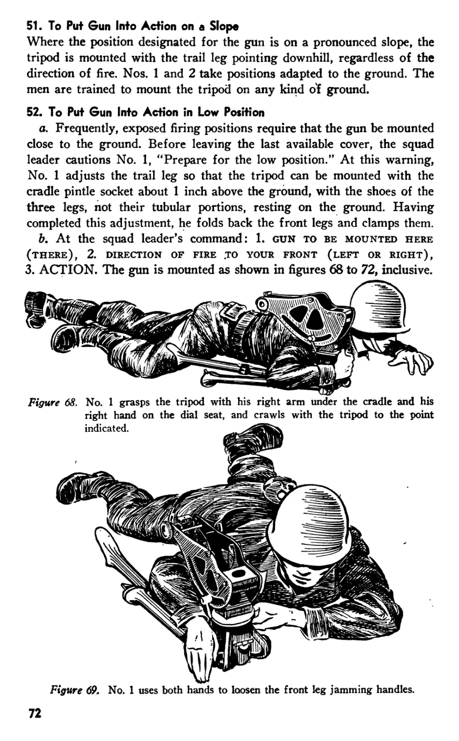
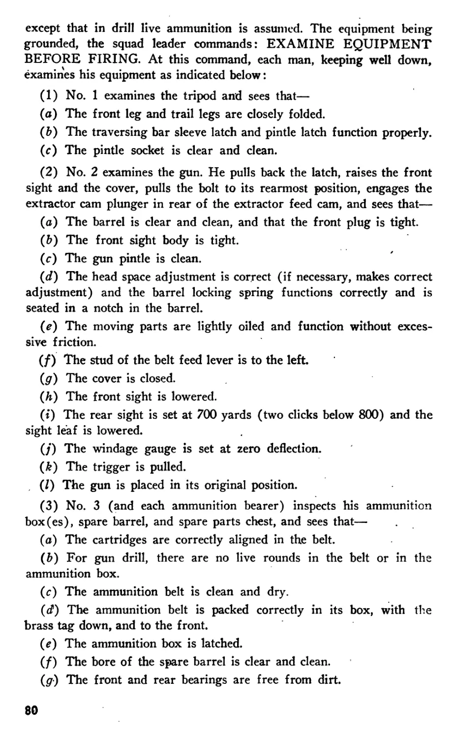
1,000 No limit.—. 150 ercises, 48 rounds each). FIXED, SEARCH- ING, and COM- BINED (7 separate exercises, 150 rounds).
TabU IV
Range (inches) Time (seconds) Total shots Target Type of fire
1,000 No limit- 12 1,000-inch machine- gun target. Zeroing allowance per man during record
1,000 12 (each exercise). 24 1,000-inch machine- gun target. (Pas- ters 1, 2, 3, and 4.) practice. FIXED, 4 separate exercises, 6 rounds each. One burst
1,000 35 i— 30 1,000-inoh machine- gun target. (Pas- ters 7 to 8.) each scoring space. SEARCHING, 1 exer- cise, 30 rounds. One burst each scor-
1,000 451 (each exercise). 96 1,000-inch machine- gun target. (Pas- ters 5 to 6 and 9 to 10.) ing space. COMBINED, 2 exer- cises, 48 rounds each. One burst each scor- ing space.
i Forty seconds for light machine guns.
1 Fifty seconds for light machine guns.
[AG 300.7 (19 Sep 46)]
Вт obdeb or thb Secretary or Wab:
Official:
EDWARD F. WITSELL
Major General
The Adjutant General
DWIGHT D. EISENHOWER
Chief of Staff
Distribution:
AAF (10); AGF (40); T (2); Def Comd (2); Arm & Sv Bd (1);
Tech Sv (2); HD (2); FC (1); Gen & Sp Sv Sch (50), except 7
(8500); USMA (50); ROTC (1); A (10); CHQ (10); D (3); В
(2); R 2, 5, 7, 17, 18 (2); Bn 2, 5, 7, 17, 18 (2); C 2, 5, 7, 17, 18
(5), 9 (2); T/O & E: 6-160-1 (5); 6-165 (2); 6-166 (5); 6-167
(5); 6-169 (5); 9-65 (2); 9-66 (5); 9-67 (5); 10-35 (2); 10-36
(5); 10-37 (5); 11-57 (5); 1W88 (5); 11-488S (5); 44-75 (2);
44-76 (5); 44-77 (5).
For explanation of distribution formula, see FM 21-6.
. АОО 7MB
S. eOVERNMEKT PRINTINO OFFICEi 1946
WAR DEPARTMENT FIELD MANUAL
F M 2 3-55
This manual supersedes FM 23-55, 20 June 1940, including С 1, 25 July 1941, C 2, 6 May 1942,
C 3, 24 July 1942, C 4, 1 May 1944; FM 23-45, 12 April 1943, including С 1, 22 April 1943,
C 2, 25 March 1944; FM 23-50, 12 August 1942, including С 1, 12 October 1942, C 2, 1 March
1943, C 3, 23 April 1943, C 4, 29 April 1944; TM 9-206, 1 September 1943, including С 1,
7 November 1943; section II, Training Circular No, 61, War Department 26 September 1944;
and Training Circular No, 6, War Department, 8 February 1945,
BROWNING MACHINE GUNS,
CALIBER .30, M1917A1,
M1919A4, and M1919A6
WAR DEPARTMENT • JULY 1945
United States Government Printing Office
Washington t 1943
For sale by the Superintendent of Documents, U, S, Government Printing Office
Washington 25, D. G - SO cents
WAR DEPARTMENT
Washington 25, D. C., 30 July 1945.
FM 23-55, Browning Machine Guns, Caliber .30, M1917A1, M1919A4,
and M1919A6, is published for the information and guidance of all
concerned.
[AG 300.7 (16 Apr 45)]
By order of the Secretary of War:
Official :
J. A. ULIO
Major General
The Adjutant General
G. C. MARSHALL
Chief of Staff
Distribution :
AAF (10) ; AGF (40) ; ASF (2) ; T of Opns (2) ; Arm & Sv Bd
(1) ; Def Comd (2) ; Tech Sv (2) ; SvC (10) ; HD (2) ; PC&S
(1); Gen & Sp Sv Sch (50) except Inf Sch (8,500); USMA
(50) ; ROTC (1) ; A (10) ; CHQ (10) ; D (3) ; В (2) ; R 2, 5,
7, 17, 18 (2); Bn 2, 5, 7, 17, 18 (2); C 2, 5, 7, 17, 18 (5); 9 (2).
T/O & E: 6-160-1 (5); 6-165 (2); 6-166 (5); 6-167 (5);
6-169 (5) ; 9-65 (2); 9-66 (5) ; 9-67 (5) ; 10-35 (2) ; 10-36
(5); 10-37 (5); 11-57 (5); 11-488 (5); 11-488S (5); 44-75
(2); 44-76 (5); 44-77 (5).
Refer to FM 21-6 for explanation of distribution formula.
ii
CONTENTS
Paragraphs Pape
1-5 1
6-19 7
20-30 29|
31-33 36
34-37 45
38-43 50
CHAPTER 1.
Section I.
II.
III.
IV.
V.
VI.
MECHANICAL TRAINING.
Descriptions ....................................
Disassembling, assembling and changing parts.....
Care and cleaning ...............................
Mechanical functioning...........................
Stoppages and immediate action...................
Mounts...........................................
CHAPTER 2. TRAINING FOR PLACING MACHINE GUNS IN
ACTION.
Section I. General .....................................
II. Gun drill with M1917Al machine gun..........
III. Gun drill with M1919A4 machine gun..........
IV. Gun drill with M1919A6 machine gun .........
V. Measuring and laying off angles.............
VI. Battery drill.................................
44-45 57
46-54 58
55-62 79
63-69 90
70-81 97
82-92 103
CHAPTER 3. MARKSMANSHIP.
Section I. General ........................................... 93-96 109
II. Preparatory exercises .............................. 97-109 110
III. Range practice..................................... 110-111 126
IV. Conduct of range practice ......................... 112-120 128
V. Safety precautions ................................ 121-122 142
CHAPTER 4. MARKSMANSHIP FOR MOVING GROUND TARGETS. 123-127 143
CHAPTER 5. MARKSMANSHIP FOR AERIAL TARGETS.
Section I. Antiaircraft gunnery............................ 128-131 147
II. Preliminary training ........................... 132-138 151
III. Advanced training: towed-target and radio-controlled
plane-target Bring .................................. 139-151 156
CHAPTER 6. TECHNIQUE PF FIRE: DIRECT LAYING.
Section I. General *............................................ 152-153 163
II. Characteristics of fire............................. 154-157 163
III. Classes of fire...................................... 158-161 167
IV. Range determination and windage ..................... 162-168 170
V. Elements of fire orders ............................ 169-170 171
VI. Target designation.................................. 171-172 172
VII. Fire distribution .................................. 173-178 174
VIII. Fire control ........................................ 179-181 181
IX. Auxiliary aiming point................................... 182 183
X. Fire orders.......................................... 183-184 185
XI. Overhead fire....................................... 185-186 191
XII. Final protective lines ............................ 187-193 196
XIII. Range cards............................................. 194 200
XIV. Direct laying on landscape targets at 1,000 inches... 195-201 202
in
CONTENTS
CHAPTER 7.
Section I.
II.
III.
CHAPTER 8.
Section I.
II.
III.
CHAPTER 9.
Section I.
II.
III.
IV.
APPENDIX I.
II.
111.
IV.
V.
VI.
TECHNIQUE OF FIRE: POSITION DEFILADE. Paragraph, Page
Firing positions ........ ;................. 202-203 204
Firing ........................................ 204-208 206
Fire orders and new targets.................... 209-210 213
TECHNIQUE OF FIRE: INDIRECT LAYING.
General ;................................ 211-212 214
Theory of indirect laying ......................... 213 217
Solving an indirect laying problem ............ 214-216 220
ARMORED APPLICATION (M1919A4 MACHINE GUN).
Mounts and mount adjustment ................... 217-219 237
Sights and sight adjustment ................... 220-221 238
Placing guns in action .......................... 222 238
Marksmanship training ....................... 223-227 238
ACCESSORIES ........................................... 248
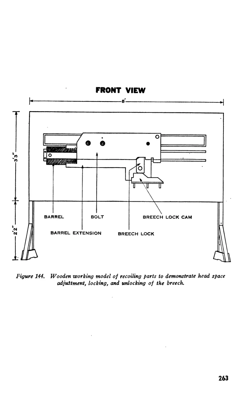
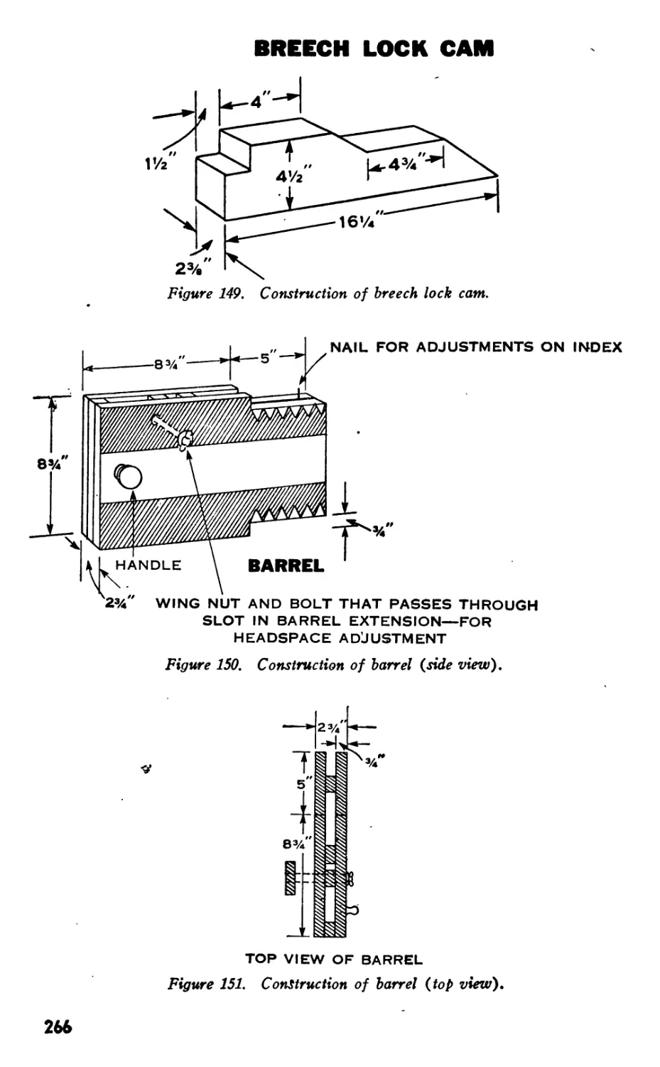
CONSTRUCTION OF WOODEN WORKING MODEL............... . 259
FIRING AT HELD TARGETS................................. 267
INFANTRY PLOTTING BOARD M10..........‘................. 270
COMPUTATION OF FIRING DATA............................. 276
DESTRUCTION OF ORDNANCE MATERIEL IN EVENT
OF IMMINENT CAPTURE.................................... 288
INDEX
291
This manual supersedes FM 23-55, 20 June 1940, including С I, 25 July 1941, C 2, 6 May 1942,
C 3, 24 July 1942, C 4, 1 May 1944; FM 23-45, 12 April 1943, including С 1, 22 April 1943,
C 2, 25 March 1944; FM 23-50, 12 August 1942, including С 1, 12 October 1942, C 2, 1 March
1943, C 3, 23 April 1943, C 4, 29 April 1944; TM 9-206, 1 September 1943, including С 1,
7 November 1943; section II, Training Circular No, 61, War Department 26 September 1944;
and Training Circular No, 6, War Department, 8 February 1945,
CHAPTER 1
MECHANICAL TRAINING
Section I. DESCRIPTIONS
1. Browning Machine Gun. Caliber .30. M1917A1
a. Principle of operation. The M1917A1 machine gun (fig. 1) is
recoil operated, belt fed, and water cooled. In recoil operation, the rear-
ward force of the expanding powder gas (kick) furnishes the operating
energy. •
b. General data.
Weight of gun and pintle, without water (pounds)... 32.60
Weight of gun and pintle, with water (pounds)....... 41.00
Length of barrel (inches)............................ 23.90
Sight graduation (yards) ........................... 2,600
Weight of tripod, M1917A1 (pounds).................... 53.20
Cyclic rate of fire (rounds per minute)............ 450-600
c. Cooling system. The barrel is surrounded by a water jacket which
holds about 7 pints of water. The water prevents the barrel from becom-
ing overheated. Since the heat of prolonged firing generates steam in the
water jacket, a steam tube assembly is provided to permit the steam to
escape. This assembly extends the length of the water jacket and is
located inside at the top. It consists of two tubes, one within the other;
For military terms not defined in this manual, see TM 20-205; for list of training
publications, see FM 21-6; for training films, film strips, and film bulletins, see
FM 21-7; and for training aids, see FM 21-8.
Unless otherwise stated, any statement contained in this manual is applicable to
all three guns. For convenience, the M1917A1 machine gun is frequently referred
to throughout the manual as the “heavy” machine gun; the M1919A4 and M1919A6
guns are similarly referred to as “light” machine guns. Material concerning the
M1919A4 machine gun applies also to the M1919A6 gun when the latter is mounted
on the M-2 tripod, unless otherwise stated. Therefore, when reference is made
to the M1919A4 and M1919A6 guns or “light” guns, it is to be understood that
both guns are mounted on the M-2 tripod for the operation under discussion.
When the M1919A6 gun is mounted on the bipod, the fact will be parenthetically*
stated.
1
BELT
FEED
the shorter, outer tube slides freely over the inner tube. On the top side
and at each end of the inner tube is a hole. Since the outer tube is
shorter than the distance between these two holes; it cannot cover both
holes at the same* time. Therefore, as the muzzle is elevated or depressed,
gravity causes the outer tube to slide down and cover the lower hole,
thus preventing water from flowing into the assembly. Correspondingly,
the upper hole is uncovered, allowing the steam to pass from the water
jacket through the inner tube. The steam then passes through a small
tube to the steam condensing device, the opposite end of which is im-
mersed in the water chest.
d. Front sight. The front sight consists of the front sight blade and
the front sight base. The blade is dovetailed into the base to permit lateral
adjustment and is held in place by the front sight bladescrew. The base
screws fasten the base to the end cap. They are screwed in place and
then filed flush with the base. The base is also sweated on with solder.
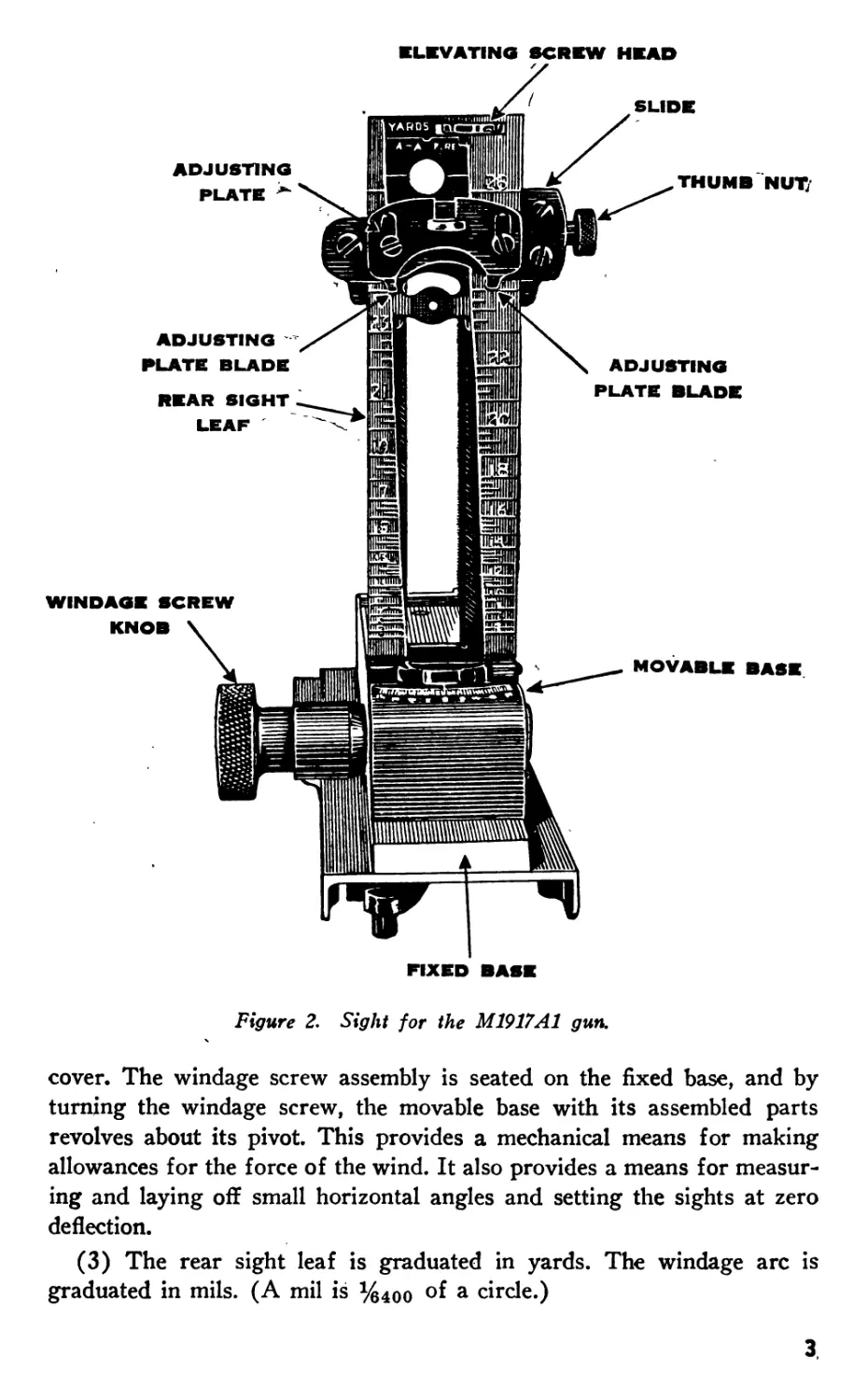
e. Rear sight. (1) The rear sight (fig. 2) is adjustable for windage
and deflection. Compensation for drift is set off automatically by the
construction of the rear sight leaf.
(2) The leaf and slide assembly is mounted on the movable base,
which, in turn, is pivoted on the fixed base, the latter being riveted to the
2
ELEVATING SCREW HEAD
FIXED BASE
Figure 2. Sight for the M1917A1 gun.
cover. The windage screw assembly is seated on the fixed base, and by
turning the windage screw, the movable base with its assembled parts
revolves about its pivot. This provides a mechanical means for making
allowances for the force of the wind. It also provides a means for measur-
ing and laying off small horizontal angles and setting the sights at zero
deflection.
(3) The rear sight leaf is graduated in yards. The windage arc is
graduated in mils. (A mil is %4Oo °f a circle.)
3
2. Browning Machine Gun, Caliber .30, M1919A4
a. Principle of. operation. The M1919A4 machine gun (fig. 3) is
recoil operated, belt fed, and air cooled. This gun is equipped with a
front barrel plug which, by trapping some of the gas near the muzzle,
insures the positive recoil of the barrel and barrel extension.
Figure 3. Browning machine gun, caliber 30, M1919A4.
b. General data.
Weight of gun (pounds)....................................... 3L00
Weight of barrel (pounds)................................ 7.35
Weight of pintle and combined elevating and traversing
mechanism (pounds) ................................... 4.75
Weight of tripod mount, М2 (pounds)..................... 14.00
Length of barrel (inches)............................ 24.00
Sight graduation (yards)............................. 2400.
Cyclic rate of fire (rounds per minute)............... 400-550
c. Cooling system. The M1919A4 machine gun is provided with a
heavy barrel. This barrel, which is slower to heat up than the lighter
barrel of the M1917A1 gun, presents a larger surface to the air. The air
circulating between the barrel and the barrel jacket carries off some of
the heat generated by firing.
d. Front sight. The front sight (fig. 4(i)) consists of a front sight
blade, a front sight post, bracket body, and a plunger mechanism. The
front sight post pivots on the front bearing screw when folded. The
plunger mechanism provides a locking device to keep the front sight post
in its upright position when the gun is being fired.
e. Rear sight. (1) The rear sight (fig. 4(5)) is assembled to the rear
sight base and is adjustable for windage. The rear sight base is secured
4
to the left side plate of the receiver by three rivets in the flange of the
base.
(2 ) The rear sight leaf is graduated for elevation in 100-yard divisions
up to 2,400 yards. Motion of the rear sight slide is accomplished by rota-
FRONT SIGHT
Figure 4. Sights of the M1919A4 and M1919A6 gun.
5
tion of the elevation screw knob. This elevating screw mechanism is
equipped with a mil click device which may be used in conjunction with
the mil scale engraved on the left side of the rear sight leaf to measure
or establish angles of elevation in mils. (See pars. 77 and 78.)
(3 ) The windage screw mechanism also incorporates a mil click device.
Adjustment of the rear sight leaf in windage is accomplished by rotation
of the windage screw knob. The windage gauge of the M1919A4 machine
gun is marked in 5-mil graduations for 10 mils right or left from zero.
3. Browning Machine Gun, Caliber .30, M1919A6
a. Principle of operation. The M1919A6 machine gun (fig. 5)
operates in the same manner as the M1919A4 gun. (See par. 2a.) A
booster cap is furnished with the M1919A6 gun to speed up the cyclic
rate. It is affixed to the front barrel bearing by means of a detachable
retaining clip. This booster cap traps some of the gas in the barrel which
acts to insure positive recoil action when the gun is fired at angles other
than the usual horizontal.
Figure 5. Browning machine gun, caliber .30, M1919A6.
b. General data. With the exception of the following, the data listed
in paragraph 2b, c, d, and e applies to the M1919A6 gun.
Weight of gun with bipod and shoulder stock (pounds).. 32.50
Weight of barrel (pounds).............................. 4.65
Weight of shoulder stock (pounds)...................... 1.75
4. Ammunition Belt
The ammunition belt is made of woven fabric with loops, and with a
metal strip at each end to facilitate loading. Some belts have a metal strip
at one end only.
5. Mountings
See section VI of this chapter for a detailed description of the various
mountings.
6
Section II. DISASSEMBLING. ASSEMBLING. AND CHANGING PARTS
6. General
a. Disassembling may be considered under two general headings: re-
moval of the groups to the extent required for ordinary cleaning and
minor repairs, and detailed disassembling, involving removal of all com-
ponent parts of each group.
b. A group is a number of parts, contained in a common housing,
which function as a unit.
c. The removal of the different groups from the gun and the complete
disassembling of the groups authorized to be disassembled by the using
services can be accomplished with the tools provided.
J. To prevent damage to the rear sight of the M1917A1 gun, the sight
leaf must be raised before raising the cover. The cover is raised by
gripping the rear sight base and not the sight leaf, windage screw knob,
or rear sight thumb nut.
e. To prevent damage to the front sight of the M1919A4 and M1919A6
guns, the front sight post, if it is in the lowered position, must be raised
before raising the cover.
7. Removal of Groups from Gun (fig. 6(T) and @)
a. Backplate. (1) Pull back on the latch and raise the cover. With
the left hand, pull back on the bolt handle and hold it in the rearmost
position.
(2) With the right hand, insert the rim of a cartridge or the screw
driver end of the combination tool, in the slit in the end of the driving
spring rod. With the slit horizontal, push in the driving spring rod as far
as it will go and turn it clockwise one-quarter turn until the slit is vertical.
In this position, the driving spring rod pin will engage in its recess in
the bolt and the driving spring is held compressed within the bolt.
(3) Push the bolt handle forward 1 inch to free the rear end of the
driving spring rod from the backplate. Push the latch forward and lift
out the backplate.
b. Bolt handle and bolt. Pull the bolt all the way back and remove
the bolt handle. Remove the bolt.
c. Lock frame. Insert the nosq of a cartridge through the hole in the
right side of the receiver and push in on the trigger pin. Grasp the trigger
and pull the lock frame, barrel extension, and barrel from the receiver.
If resistance is met, pull on spacer to avoid damage to trigger. Hold the
barrel in one hand and the lock frame in the other; trip the accelerator
and separate the lock frame from the barrel extension.
7
d. Barrel extension and barrel. Unscrew the barrel and barrel ex-
tension from each other.
e. Latch. Pull the latch to the rear until it separates from the top plate.
f. Cover. (1) Remove the cotter pin from the cover bolt. Place the
screw driver end of the combination tool in the slit in the cover bolt to
prevent the bolt from turning, then unscrew the nut.
Figure 6(T). Groups of the M1917Al machine gun.
8
Figure 6(2). Groups of the M1919A4 and M1919A6 machine guns. (For the lock
frame, bolt, and barrel extension groups see fig. &Q-)
i
(2) Remove the cover bolt, cover catch spring,, the fixed and movable
plates, and the cover.
(3) Lower the rear sight leaf of the M1917A1 gtni.
Note. To prevent undue wear, the cover and latch should not be removed except
when necessary for cleaning or replacement of parts.
9
g. Booster cap, bipod, and carrying handle of M1919A6 gun (fig.
7). Turn the booster cap one-quarter turn and remove it from the barrel
jacket. Pry off the lock ring, slide off the bipod leg assembly, and remove
the carrying handle.
Figure 7. Booster cap, bipod, and carrying handle of the M1919A6 gun.
h. Shoulder stock of the M1919A6 gun (fig. 8). Loosen the wing
nut on the clamp assembly and slide the stock assembly off the buffer tube.
WING NUT
Figure 8. Shoulder stock of the M1919A6 gun.
8. Replacing Groups in Guns
a. Shoulder stock of M1919A6 gun. Slide the shoulder stock assem-
bly onto the buffer tube and tighten the wing nut.
10
b. Carrying-handle, bipod, and booster cap of M1919A6 gun.
Slide the carrying handle onto the barrel jacket. Assemble bipod assembly
to the front barrel bearing, and replace the lock ring. Place the booster
cap on the front barrel bearing so that the retaining clip is up, making
sure that the slots in the booster cap mate with slots in the front barrel
bearing. Push the retaining clip assembly until it snaps into engagement
with the slots in the front barrel bearing.
c. Cover. Place cover catch spring on cover bolt and position the fixed
and movable plates. Insert the covet bolt in the cover hole. Place the
screw driver end of the combination tool in the slit in cover bolt to pre-
vent it from turning, and screw the nut on cover bolt until the desired
tension is obtained. Replace the cotter pin. On the M1917A1 gun, raise
the sight leaf before the cover is raised.
rf. Latch. Push the latch onto the top plate from the rear, keeping
spring up so that it does not catch on rear of the top plate.
e. Barrel extension and barrel. (1) Screw the barrel and barrel
extension together until the rear end of the barrel is flush with the inside
of the barrel extension.
(2) Insert the barrel and barrel extension into the receiver until the
lower rear lugs of the barrel extension are against the bottom plate
(M1917A1 gun), or until the forward end of the barrel extension is op-
posite the rear end of the receiver (M1919A4 and M1919A6 guns).
f. Lock frame (fig. 9). (1) Take the lock frame in both hands with
Figure 9. Assembling the lock frame of the M1917A1 gun to the barrel extension.
H
the index fingers beneath and supporting the accelerator (M1917A1 gun)
or hold the barrel extension with one hand, and grip the lock frame in
the other hand so. that the index finger is beneath and supporting the
accelerator (M1919A4 and M1919A6 guns).
(2) Place the claws of the accelerator in front of and against the T-lug.
(3) Insert the front projections of the lock frame in the slots of the
barrel extension and push forward until the accelerator turns backward,
locking the lock frame to the barrel extension.
(4) Push down the tips of the accelerator to insure positive locking.
(5) Force the trigger pin inward to clear it from the right side plate,
and push the parts into the gun. (See fig. 10.)
Figure 10. Replacing the lock frame, barrel extension, and barrel.
(6) Continue pushing forward until a click is heard as the trigger pin
springs out and into its seat in the right side plate. Check to make sure
the trigger pin head appears in its seat in the right side plate. (If the
barrel of the M1919A4 or M1919A6 gun is hung on the front barrel bear-
ing, reach forward under the jacket and align the barrel.)
g. Bolt and bolt handle (fig. 11). Push the cocking lever forward
and insert the bolt, pushing down on the rear end of the trigger to pre-
vent the front of the bolt from tripping the accelerator. Insert the bolt
handle through the large opening at the rear of the slot and push it for-
ward about 1 inch, being sure that the collar on the handle is inside of the
right side plate.
h. Backplate. Push forward on the latch and replace the backplate.
Hold the bolt handle fully back with the left hand, place the rim of a
Cartridge, or the screw driver end of the combination tool, in the slit in the
12
Figure 11. Replacing the bolt.
end of the driving spring rod, and turn the rod one-quarter turn counter-
clockwise until the slit is horizontal. This releases the driving spring.
Allow the bolt to go forward.
i. Head space adjustment. (1) Importance. The head space of a
military weapon, with the cartridge fully seated in the chamber, is the
distance between the base of the cartridge and the face of the bolt. In
Browning machine guns head space is adjusted by obtaining the proper
distance between the forward part of the bolt and the rear end of the
barrel. Proper adjustment is necessary in order to insure continued opera-
tion, to obtain the best uniformity of shot patterns, and to prevent damage
to the gun.
(2 ) Adjustment. The head space adjustment is correct when the breech
lock rides smoothly up the breech lock cam into its fully locked position
and is in positive contact with the forward wall of the breech lock recess,
and the forward end of the bolt is positioned against the rear end of the
barrel. The adjustment is made as follows:
(a) Pull the bolt to the rear about % inch.
(&) Screw the barrel into the barrel extension, using the nose of a
cartridge or the combination tool in the barrel notches, until the recoiling
parts will not go into battery under pressure of the driving spring when
the bolt handle is released. Then unscrew the barrel from the barrel ex-
tension one notch at a time (checking after each notch) until the barrel
and barrel extension will just go fully forward into battery without being
forced. (See fig. 12.) Then unscrew the barrel one additional notch. If
correctly adjusted the recoiling parts will go into battery without the least
bind, and with a solid metallic sound when eased forward from approxi-
mately 1 inch out of battery position. It is important to obtain this ad-
justment before backing off the barrel the additional notch.
Note. There are no head space or timing gauges issued for caliber .30 ground
machine guns.
Caution: Care must be exercised to avoid roughening the barrel surface
643150°—45--2 13
during the adjustment. Also, if the packing of the M1917A1 gun binds
the barrel, a false head space adjustment will result.
Figure 12. Making head space adjustment.
(3 ) Alternate method of making head space adjustment. Head space
adjustment can be made before the moving parts are assembled in the
receiver, as follows: Screw the barrel and barrel extension together until
the rear of the barrel is flush with the inside of the barrel extension.
Remove the extractor from the bolt. Place the bolt in the bolt guides in
the barrel extension. Push the bolt fully forward. Turn the assembly so
that the bolt is down. Lock the bolt to the barrel extension by pushing
the breech lock fully into its recess in the bolt. Hold it firmly in that posi-
tion with the thumb. Screw the barrel and barrel extension together until
the barrel is stopped by contact with the bolt. Be certain that the barrel
does not force the breech lock from its fully locked position/Turn the
assembly so that the bolt is up. Unscrew the barrel and barrel extension
just enough to cause the breech lock to fall from its recess. Remove the
bolt. Screw the barrel and barrel extension together one notch, or if the
nose of the barrel locking spring is between two notches, one and the
fraction notches. Assemble the gun.
(4 ) Making quick head space adjustment. After the correct head
•space has been determined by either of the above methods, the notch in
which the barrel locking spring is engaged may be marked with a center
punch. Thereafter, screw or unscrew the barrel and barrel extension until
the barrel locking spring is in the marked notch.
(5 ) Improper head space adjustment, (a) Insufficient or tight head
space. When the head space adjustment is insufficient (tight), poor func-
tioning will result, as the breech lock will not fully enter its recess in the
bolt. This condition may damage the barrel extension, bolt, or breech lock.
U
Extraction trouble may also occur because of improper timing of locking
and unlocking. Furthermore, with a tight head space adjustment, the gun
operates sluggishly because of the binding of the moving parts. If the
head space adjustment is very tight, the notches on the rear end of the
barrel can be seen protruding from beneath the feedway, the bolt handle
will not be fully forward, and the firing pin cannot be released by press-
ing the trigger.
(t ) Excessive or loose head space. When the head space adjustment
is excessive (loose), there will be play between the bolt and the barrel.
This may cause a rupture of the cartridge case when the bolt is violently
started to the rear independently of the barrel and barrel extension. If
there is a weakness in the cartridge case itself, such as a split case, the
possibility of a ruptured partridge is increased.
J. Cover. With the bolt fully forward, position the stud of the belt feed
lever to the left (fig. 13) and close the cover, being sure that the latch
engages. Pull the trigger.
Figure 13. Positioning the belt feed lever stud.
15
9. Detailed Disassembly of Bolt
a. Extractor. Raise the extractor and remove it
b. Driving spring rod (fig. 14). Great care should be exercised in re-
moving the driving spring rod from the bolt as the force of the driving
spring when released can easily cause the rod to jump from the hand end
possibly result in injury to personnel. To remove the driving spring rod,
place the protuding end of the rod on a table or a block of wood. Grasp
the bolt firmly in the right hand (palm of the hand over the face of the
bolt), press down and at the same time turn the bolt one-fourth turn to
the left, releasing the driving spring rod pin from its recess in the bolt.
Slowly release pressure on the bolt allowing it to rise under the action of
the driving spring until about 3 inches of the rod protrudes. Grasp the
protruding portion of the rod and spring and lift the bolt from the table,
holding the rod and spring in their same position relative to the bolt.
Separate the rod and spring from the bolt with a quick jerk. The quick,
separating jerk will prevent the spring from kinking. Remove the driving
spring rod from the driving spring.
Figure 14. Removing the driving spring and rod.
c. Cocking lever. Rotate the top of the cocking lever to the rear of
the bolt and withdraw the cocking lever pin from the bolt. Lift out the
cocking lever.
d. Sear (figs. 15 and 16)f Hold the bolt with the front end toward the
body and release the firing pin by pushing down on the sear. Place the
16
Figure 15. Seating the sear spring in the cut in the bolt.
nose of a cartridge near the end of the sear spring, away from the sear
spring pin, and push downward and to the right on the spring to seat it
in the cut in the bolt. This releases the sear, which is removed at the •bot-
tom of the bolt.
e. Sear spring and pin (fig. 17). Turn the sear spring back to its
normal position to clear the cut. Push the nose of a cartridge into the hole
in the bottom of the bolt to start the sear spring pin moving outward.
Place the top end of the cocking lever well under the sear spring and pry
the pin out of the bolt.
17
Figure 17. Removing the sear spring and pin.
f. Firing pin. Place the palm of the hand under the rear of the bolt,
tilt the rear end of the bolt down, and allow the firing pin to fall out and
into the palm of the hand.
10. 'Assembling Bolt (fig. 18)
a. Firing pin. Place the firing pin in the bolt, striker downward and
to the front; tilt the front of the bolt downward until the striker projects
through the small hole in front of the bolt.
b. Sear spring and pin. Replace the sear spring and pin by inserting
the pin in its recess and pushing with a cartridge on its top, avoiding
pressure on the leaves of the sear spring itself.
c. Sear. Hold the bolt'in the left hand, front end toward the body,
top up. With the point of a cartridge placed near the end of the sear
spring, away from the pin, push downward and to the right to seat its
edge in the cut in the bolt. With the notched projection of the sear to the
front, push the sear upward from the bottom, holding it with the first
finger of the left hand. Press downward and to the left on the sear spring
with a cartridge to engage the end of the spring in the sear.
d. Cocking lever. Replace the cocking lever, making certain that the
rounded nose on the lower end is to the rear and in its recess in the firing
pin. Insert the cocking lever pin from the left side of the bolt. The upper
end of the cocking lever should be to the rear of the bolt and the hole in
the cocking lever aligned with the hole in the bolt before inserting the pin.
To test the correctness of the assembly, cock by pressing forward on the
upper end of the cocking lever, then rotate it to the rear and press down
on the sear with a cartridge. This should release the firing pin.
18
Figure 18. Bolt group.
e. Driving spring rod. The same degree of care should be exercised
in assembling the driving spring rod to the bolt as in removing it. Place
the driving spring on the driving spring rod. With the back end of the
rod resting on a table or a block of wood, gather as much of the spring
on the rod as can be* held compressed by the thumb and fingers of the left
hand. With the bolt securely held in the right hand, front end of the bolt
in the palm of the hand, slip the bolt over the end of the spring. Push
downward to compress the spring and allow the driving spring rod pin
to enter the slot in the side of the bolt. Turn the bolt slowly 90° clockwise
until the slit in the rod is crosswise (vertical) to the slot in the side of
the bolt, with the pin firmly engaged.
f. Extractor. Insert the extractor stud in the rear hole of the two
large holes in the left side of the bolt, the extractor pointing up. Turn the
19
extractor downward toward the front to engage the collar on the extractor
under the collar cut in the bolt.
11. Detailed Disassembly of Lock Frame
a. Trigger. Grasp the head of the trigger pin between the thumb and
the first finger of the right hand and remove *it to the right. Lift out the
trigger. If the pin is too tight to permit its removal in this manner, it
must be drifted out. Do not remove the trigger pin spring except when
necessary.
b. Accelerator. Push out the accelerator pin and remove the accel-
erator.
c. Barrel plunger (fig. 19). Hold the lock frame with the left hand,
projections pointing upward, slot to the left, separator between the second
and third fingers, first and second fingers gripping barrel spring. Press
down and out on the barrel plunger with the thumb of the right hand to
disengage the plunger guide pin from its slot. Allow the spring, with
plunger, to rise slowly. Lift out the spring and remove it from the barrel
plunger.
Figure 19. Removing the barrel plunger and spring.
12. Assembling Lock frame (fig. 20)
a. Barrel plunger. Assemble the barrel plunger spring to the barrel
plunger. Holding the lock frame as shown in figure 19, seat the end of
the barrel plunger spring in the recess in the lock frame separator, barrel
plunger guide pin facing the slot in the lock frame. Using the first and
second fingers of the left hand to prevent the spring from buckling, press
down with the thumb of the right hand on the end of the barrel plunger
20
ASSEMBLED LOCK FRAME GROUP
until the barrel plunger guide pin can be seated in the slot. Care should
be taken that the action of the spring does not cause the plunger to slip
out of the hand.
b. Accelerator. Replace the accelerator with the tips up and the
rounded surface to the front. Insert the accelerator pin, taking ca^e that
both ends of the pin are flush with the sides of the lock frame.
c. Trigger. Push the front end of the trigger up under the spacer and
over the separator, placing the center in its square seating. If the trigger
pin spring has been removed, seat the spring on the trigger pin, placing
the small end of the spring toward the head of the pin. Replace the pin
from the right.
21
13. Defailed Disassembly of Barrel Extension (fig. 21)
a. Barrel locking spring. Insert the rim of a cartridge under the
hook of the barrel locking spring and pull it out.
b. Breech lock. Push out the breech lock pin and remove the breech
lock.
GROUP
BREECH LOCK
Figure 21. Barrel extension group.
14. Assembling Barrel Extension
a. Breech lock. Place the breech lock in its slot, taking care that the
double beveled edge is up and to the front. Insert the breech lock pin and
insure that both ends of the pin are flush with the sides of the barrel
extension.
b. Barrel locking spring. Insert the barrel locking spring in the seat-
ing in the left side of the barrel extension, hook inward, and force home
as far as it will go.
15. Detailed Disassembly of Cover (fig. 22)
a. Belt feed lever pivot. Take out the cap, plug, or screw from the
22
belt feed pivot bushing nut and remove the belt feed lever pivot and
washer.
6. Belt feed lever. Withdraw the belt feed lever from its recess in
the belt feed slide and remove lever.
c. Slide and pawl. Remove belt feed slide by sliding it from the cover.
Push out the belt feed pawl pin from the slide and remove the pawl and
spring.
d. Cover extractor spring. With the thumb, press down on the lock-
ing end of the cover extractor spring and guide it from its recess under
the cover extractor cam. This spring must be held down with the thumb
while being guided from its recess, as it is under strong tension.
Figure 22. Cover group.
16. Assembling Cover.
a. Cover extractor spring. Place the forked end of the cover ex-
tractor spring in its recess in the stud. Press down on the locking end of
the spring and when it is fully depressed push the projection of the spring
into the notch of the cover extractor cam.
b. Slide and pawl. Place the small end of the belt feed pawl spring
over its stud in the slide. Place the belt feed pawl over the slide so that
the large end of the belt feed pawl spring fits into its recess in the pawl.
Push down on the pawl and aligrt the holes of the pawl and slide. Insert
the belt feed pawl pin so that its ends are flush with the sides of the slide.
Replace the belt feed slide in its grooves in the cover, taking care that the
23
pawl is pointing to the right when the cover is assembled to the gun.
c. Belt feed lever. Insert the rounded end of the belt feed lever
through the slot in the cover and in its recess in the belt feed slide. Be
sure the lever stud is away from the. cover and to the rear. Position the
pivot hole in the lever over the pivot hole in the bushing nut.
d. Belt feed lever pivot. Insert the belt feed lever pivot in the top
of the belt feed lever pivot bushing nut so that the pivot extends through
the hole in the belt feed lever below. Drop in the shakeproof lock washer
and screw in the belt feed lever pivot screw until tight.
17. Disassembly and Assembly of Parts Dismounted for Repair Only
a. Shock-absorbing group (fig. 23). (1) Disassembly, (a) Unscrew
the adjusting screw and remove the adjusting screw plunger and spring.
(b ) Remove the buffer disks and buffer plate through the rear end of
the grip.
Figure 23. Shock-absorbing group.
(2) Assembly. Replace the parts in reverse order. In assembling the
shock-absorbing group, it must be kept in mind that part of the recoil
energy of the bolt is transmitted to the buffer pile (the assembled buffer
disks) in the form of metal-to-metal impact with great force. In order
that the buffer pile may absorb this force, the following precautions must
be observed:
(a) The buffer disk pile must always form a compact column com-
pressed between the buffer plate and the adjusting screw.
24
(£) The disks should be clean and free from rough edges and sur-
faces. Use sufficient disks so that when the adjusting screw is inserted
and tightened, its rear face will be flush with or protrude slightly from
the rear face of the grip. If the adjusting screw becomes below flush
with the rear face of the grip, remove the screw and add one or more
disks. Firing the gun with the adjusting screw below flush is prohibited.
(c) After assembly, adjust the buffer by tightening the adjusting
screw, making sure that the adjusting screw does not protrude more than
one thread.
(rf) Substitution of other material for these disks is prohibited.
b. Belt-holding pawl. (1) Hold down the belt-holding pawl and
withdraw the belt-holding pawl split pin to the rear.
(2) Lift off the belt-holding pawl.
(3) Lift the belt-holding pawl spring from its seating.
(4) Assemble in reverse order.
c. Steam tube for M1917A1 gun (fig. 24). (1) The steam tube
should never be removed unless it becomes so clogged that steam will not
pass off, or the outer tube becomes stuck so it will not slide back and
forth on the inner tube when the gun is held in the hands and tipped for-
ward and backward. Great care must be used to prevent damage to the
threads of the steam tube front plug. It should never be removed except
under the supervision of an officer, or by an experienced armorer or
ordnance personnel.
(2) Drain the water jacket. Stand the gun with the muzzle up and
25
the water jacket vertical. Remove the steam tube front plug screw. Un-
screw the steam tube front plug until the threads are disengaged and
the tube can be lifted out
(3) To assemble, stand the gun as prescribed in (2) above, and insert
the steam tube. Gently screw in the threads, stopping at once if there is
any undue resistance. The gun and tube must be exactly vertical to insure
that the conical end of the tube enters its seating in the trunnion block.
By removing the rear water plug on the jacket, and directing a flashlight
or sunlight inside the jacket, it can be determined when the conical end
of the tube is aligned with its seating in the trunnion -block. Forcing the
screw against resistance will damage the threads. If it does not screw in
easily, unscrew it a short distance, be sure the water jacket is vertical,
and try again until the threads screw in smoothly. Screw in tight without
excessive force, and then position the notch in the rim of the plug exactly
on the round countersunk recess for the front plug screw, unscrewing
part of a turn if necessary. Replace the screw and screw it firmly into its
countersunk seating. If the notch in the rim is not engaged by the screw
head, the steam tube will not be aligned to permit the escape of steam
through the end cap and the steam generated in firing will cause the water
jacket to burst.
18. Packing Barrel of M1917A1 Gun
Asbestos packing is applied at the muzzle and breech ends of the barrel
to prevent leakage from the water jacket. The amount of packing must
not be excessive, since the friction caused thereby will interfere with the
action of the mechanism. The packing should be well saturated with oil
before being applied.
a. Packing breech end. Disassemble the gun. Place the muzzle end
of the barrel in the trunnion block so that the barrel rests at an upward
angle on the top plate. Using a piece of packing, the length of which ap-
proximately equals the circumference of the water jacket, flatten one end
of the packing and place that end in the cannelure so that it will wind
clockwise. The exact length of the packing will be determined by trial and
experience. Wind the packing clockwise over the flattened end, binding
it in place. Press the packing toward the forward wall after each turn;
on the last turn, force the free end under the previous turn. Using the
flat side of the screw driver end of the combination tool, smooth out the
packing. Lift the barrel from its position on the receiver, reverse the
direction of the barrel, insert its breech end in the hole in the trunnion
block, and push it forward gently. Twist the barrel clockwise until the
packing is worked down to fit the hole. Then reassemble the gun and
make head space adjustment.
26
b, Packing'Muzzle end (fig. 25). To pack the muzzle end, one man
takes his position at the front end of the gun and removes the muzzle
gland. Taking a piece of packing about twice the circumference of the
water jacket in length, he flattens out one end of the packing and places
that end as close as possible to the end cap. (If the packing is thick, it
may be necessary to remove one strand.) He then winds one turn of
packing clockwise over the flattened end, binding it in place, and slips the
muzzle gland over the muzzle, forcing the first coil of packing back into
its seat under the end cap. He continues to wind the* packing, similarly
forcing each turn back into its seating by means of the muzzle gland.
The muzzle gland is then screwed into the end cap by the man who un-
screwed it and the packing is worked down at the same time by another
man pulling the bolt to the rear several times. If there is too much fric-
tion, remove one or two turns of packing. With the muzzle gland screwed
in securely, there should be about three muzzle gland threads exposed on
a newly , packed barrel.
Figure 25, Packing the muzzle end of the M1917A1 gun.
19. Methods of Changing Parts
a. General. If the time element is important, a broken minor part
should be replaced by substituting the complete spare group which con-
tains it. Thus, a broken firing pin would be remedied by changing bolts.
Damaged parts should be replaced as soon as opportunity permits and a
27
new replacement group assembled. Headspace adjustment should be
checked if a group has been changed.
b. Spare parts. Some of the spare parts for caliber .30 machine guns,
M1917A1, M1919A4, and M1919A6 are interchangeable. They should
be checked in pertinent Standard Nomenclature Lists A-5 and A—6.
Since a small percentage of parts may vary slightly from standard dimen-
sions, they should be tested in the gun in which they are to be used as
soon as received. Any spare parts which do not fit properly should be
replaced.
c. Changing parts of M1917A1 gun. When changing parts of the
M1917A1 gun requiring the removal of the barrel, it is often necessary
to save the water in the water jacket. This depends entirely upon pre-
vailing conditions; in battle, water may not be obtained readily, and time
also may be of the utmost importance. If it is necessary to save the water
in the water jacket when changing parts which require the removal of
the barrel, one of the following methods should be employed:
(1) First method, (a) Remove the bolt.
(&) Push in on the trigger pin and pull the lock frame to the rear
from % to % inch.
(c) Remove the elevating pin and depress the muzzle by raising the
rear end of the gun.
(J) Hold a plug, such as a steam plug cork wrapped in clean patches,
at the muzzle.
(e) Withdraw the lock frame, barrel extension, and barrel to the rear.
As the barrel is withdrawn, follow it with the plug or steam plug cork
and insert it in the hole in the end cap.
(/) Replace the necessary part.
(g) Place a plug or twisted patch in the muzzle of the barrel.
(h) Replace the groups in the gun. When the muzzle of the barrel
passes through the hole in the end cap, the plug or steam plug cork will
be forced out. After removing the plug or twisted patch from the muzzle,
run a patch through the barrel.
(i) In removing and replacing the barrel, care must be exercised not
to disarrange the packing. Frequently, in assembling, the barrel pushes
the front packing out of its seat in the end cap.
(/) Adjust the head space.
(2) Second method. Drain the water from the water jacket into the
water chest. This method requires more time than the method described
above, as the water jacket has to be refilled after the new barrel is seated.
d. Quick method of changing barrel on M1919A6 gun. (1) Re-
28
move the booster cap, unscrew the barrel (using the M6 combination
wrench), and slide it out of the barrel jacket. Use asbestos mittens if the
barrel is hot.
(2) Slide a new barrel into the barrel jacket, screw the barrel into the
barrel extension, and replace the booster cap. Adjust head space. (See
par. 8i2(&).)
Section III. CARE AND CLEANING
20. Importance
The care and cleaning of the machine guns, mounts, and accessories
are the duty of the* gun crew or other personnel using the gun. Experience
has shown that more machine guns have become unserviceable through
improper care and cleaning than from extensive use.
21. Lubricants, Cleaning Materials, and Rust Preventives
The use of unauthorized cleaning materials, such as abrasives, is for-
bidden. The only materials authorized and issued for use in the care and
cleaning of machine guns, mounts, and accessories, are—
a. Rifle bore cleaner. This cleaner is issued for cleaning the bore of
the machine gun after firing, and will provide temporary protection
against rust. If cleaner freezes, thaw out and shake well.
b, Soda ash. Soda ash is used to clean the bore of the barrel when rifle
bore cleaner is not available. To use, dissolve tablespoons of soda ash
in 1 pint of water (warm water if available).
c. Soap. A solution of soap and water should be used to clean the bore
if rifle bore cleaner or soda ash is not available. To use, dissolve % pound
of soap chips in 1 gallon of water (hot water if available).
d. Light preservative lubricating oil (PL). This oil is used for
the lubrication of all moving parts, and for preservation of metal surfaces
of machine guns in actual service at temperature in excess of 0° F.,
except in areas of extreme moisture or high humidity.
e. Medium preservative lubricating oil (PM). This oil provides
short-term protection against rust, and should be used on guns exposed
to salt water atmosphere and spray, high humidity, and extreme moisture.
It should be used for oiling parts of weapons prior to landing operations.
f. Special preservative lubricating oil (PS). This oil will be used
for oiling weapons at all temperatures. It provides the desired protection
against corrosion under all atmospheric conditions except those specifically
mentioned, in e above. It replaces light preservative lubricating oil when
stocks of the latter are exhausted.
643150°—45-
3
29
g. Light rust-preventive compound. This compound is used to pro-
tect metal parts for long storage periods and for preparing weapons for
shipment.
h. Dry-cleaning solvent. Dry-cleaning solvent is a noncorrosive,
petroleum solvent used to remove grease, oil, or rust-preventive com-
pound. It is highly inflammable; therefore, smoking and open fires must
be prohibited in the vicinity of its use.
Note. See TM 9-850 for detailed description of the above materials.
22. Care and Cleaning When Guns Have Not Been Fired
a. General. Care and cleaning, during intervals between firing, are
necessary to insure the proper condition of machine guns. Each gun must
be completely disassembled in order to inspect, clean, and lubricate it
properly. Machine guns in the hands of troops should be inspected daily.
b. Bore and chamber. (1) To clean the bore and chamber, attach a
cloth patch to the cleaning rod and insert the patch in the bore at the
breech end. Move it forward arid backward several times and replace with
a new patch. Make sure that the patch goes all the way through the bore
before the direction is reversed.
(2) Repeat until a patch comes out clean.
(3) After thorough cleaning, saturate a patch with light preservative
lubricating oil and run it through the chamber and bore. When no firing
is being done, the bore and chamber should be cleaned and reoiled at 5-day
intervals. This interval should be reduced under extreme atmospheric con-
ditions when it is evident that more frequent application is required.
(4) When issue patches are not available, patches should be cut ap-
proximately 2% inches square to permit their passage through the bore
without bending the cleaning rod.
Note. Never leave a patch or other obstacle in the chamber or bore of the gun.
c. Receiver. (1) Disassemble, clean, and oil all moving parts com-
pletely.
(2) Clean the screw heads and crevices with a small cleaning brush
or small stick.
(3) To clean the metal surfaces, rub with a dry cloth to remove mois-
ture and dirt. Then wipe with a cloth that has been dipped in special
preservative lubricating oil and wrung out. This protective film must
be maintained at all times. To maintain the protective film, perform this
service daily.
(4) Clean the dirt from the outer surfaces of the machine gun with a w
slightly oiled cloth, wipe with a soft dry one, and then oil. To remove
30
gummy deposits resulting from congealed oil, use rifle bore cleaner or
dry-cleaning solvent and wipe dry before reoiling.
d. Accessories. (1) Care and cleaning will not be confined to the gun
alone, but will include the mount, spare parts, and all accessories.
(2) Belts and ammunition must be kept clean and dry.
(3) Gun covers are provided to prevent dirt from entering the gun.
23. Preparatory to Firing z
a. Procedure. Before firing, take steps to insure efficient functioning
of the guns. (See par. 36b.)
b. Spare parts chest. The contents of the spare parts chest permit
immediate replacement of unserviceable parts. The chest should, there-
fore, be kept complete at all times with its contents clean, serviceable,
and lightly oiled.
24. During Firing
a. Oil frequently but sparingly the cam groove, the cocking lever, and
the M1917A1 muzzle gland packing.
b. Avoid pulling a partially empty belt through the feed opening, as
lint and dirt will interfere with the functioning and the feed mechanism.
The cover may be raised and the empty part of the belt lifted and placed
in or removed from the feedway. The cover is then closed.
c. Observe the functioning of the gun to anticipate failures.
d. Examine for water leakage on the M1917A1 gun.
25. After Firing
a. General. Machine guns must be thoroughly cleaned immediately
after firing. Since the bore sweats, and to insure complete removal of
powder residue and primer fouling, the bore cleaning procedure should
be repeated on 3 consecutive days thereafter, or until there is no further
evidence of sweating.
b. Cleaning barrel with rifle bore cleaner. (1) Saturate a clean
patch with rifle bore cleaner and swab the bore. Repeat this operation two
or three times, using clean saturated patches each time, and running them
completely forward and backward through the bore.
(2) If, after cleaning on the third day after firing, the weapon is not
likely to be fired within the next 24 hours, wipe dry and oil. Otherwise,
do not wipe dry, but leave the bore wet with rifle bore cleaner.
c. Cleaning barrel with soda ash or soap solution. (1) Place
barrel, muzzle down, in a vessel containing soda ash solution, soap solu-
tion, or water, and swab the bore for 1 minute.
31
(2) While bore is wet, run a brass or bronze brush forward and back
through the barrel three or four times.
(3) Using the cleaning rod and patch, pump clean water through the
bore.
(4) Dry and oil as in b above.
d. Cleaning parts other than barrel. (1) Thoroughly clean the
cover, bolt, barrel extension, lock frame, and backplate, using a small stick
covered with a flannel patch, if necessary. Remove dirt and oil from all
recesses and springs.
(2) Wipe all parts with a cloth, wet with oiL
e. Exterior surfaces. (1) Wipe off the exterior of the gun with a
dry cloth to remove moisture and dirt.
(2) Wipe all metal surfaces with a cloth, wet with oil.
f. Accessories. Clean the mount and oil unpainted surfaces with pre-
servative lubricating oil. Oil spare parts and all accessories with pre-
servative lubricating oil.
g. WLcxtst. (1) Clean and lightly oil all threads, the traversing dial,
and other moving parts.
(2) Clean and then remove all oil from the serrations of the M1917A1
tripod legs, otherwise dirt and sand may collect and interfere with positive
locking of the legs.
(3) Remove, clean, and lightly oil the M1917A1 tripod cradle pintle.
(4) Clean and dry the traversing dial seat. Do not place oil in the
seat, as this will cause dirt to collect and interfere with easy dial adjust-
ment.
(5) The gun pintle bushing should be cleaned and lightly oiled.
h. Booster cap and front barrel bearing, M1919A4 and M1919A6
guns. (1) Carbon is deposited in the booster cap and front barrel bear-
ing, M1919A4 and M1919A6 guns, during firing. If this deposit is not
removed periodically, it will eventually cause the barrel to bind.
(2 ) Unscrew the front plug with the combination tool and scrape out
the carbon.
26. Preparation for Storage
a. Medium preservative lubricating oil is most suitable for short-term
storage (less than 30 days).
b. Before storing, machine guns, mounts, and accessories should be
thoroughly cleaned and oiled. The bolts should be in the forward position
with firing pins released. Wooden supports of the packing boxes must
be painted with rust-preventive compound.
32
c. Under no circumstances will a gun be placed in storage while con-
tained in a cloth or other cover, or with a plug or patch in the bore.
27. Cleaning Weapons Received from Storage
a. Use corrosion preventive solvent to dissolve and remove all traces
of oil or rust-preventive compound.
b. Wipe thoroughly dry and follow the instructions in paragraph 22.
28. Care and Cleaning Under Unusual Conditions
a. Care and*cleaning in cold climates (FM 70-15). (1) It is
necessary that the moving parts of the weapons be kept absolutely free
from moisture. It has also been found that excess oil on the working
parts will solidify and cause sluggish operation or complete failure.
(2) Before firing in temperatures below 0° F., completely disassemble
and clean all parts of the gun thoroughly and oil by rubbing with a cloth
which has been dipped in oil and wrung out.
(3) Drain the water from the jacket of the M1917A1 gun and add
an antifreeze compound. (See par. 30.)
(4) Upon bringing the gun indoors, it should first be allowed to come
to room temperature; then be disassembled, wiped completely dry of
all moisture which may have condensed on the cold metal surfaces, and
thoroughly oiled with lubricating oil.
(5) If possible, condensation should be avoided by providing a cold
place in which to keep the gun when it is not in use. For example, a
separate cold room or, when in the field, platforms with proper cover
may be used.
(6) If the gun has been fired, the bore should be immediately swabbed
out with an oily patch and, when the weapon reaches room temperature,
thoroughly cleaned and oiled as described in paragraph 25.
Ъ. Сахе and cleaning in tropical climates (FM 72-20). In tropi-
cal climates where temperature and humidity are high, the weapon
should be thoroughly inspected daily by dismounting and, if necessary,
disassembling the groups to permit drying and oiling the parts. Care
should be exercised to see that all unexposed parts, as well as all
surfaces, are kept clean and oiled.
c. Care and cleaning in hot, dry climates. (1) In hot, dry
climates where sand and dust are apt to get into the mechanism and
bore, the weapons should be wiped clean at least once daily. Groups
should be disassembled to facilitate thorough cleaning.
(2) When the weapon is used under sandy conditions, all lubricant
should be wiped from exposed and noncritical operating surfaces. This
33
will prevent sand carried by the wind from sticking to the lubricant and
forming an abrasive compound which will damage the mechanism.
(3) Immediately upon leaving sandy terrain, the weapon should be
cleaned and lubricated with light preservative lubricating oil.
(4) Care must be taken in handling the gun,* as perspiration from
the hands contains acid which causes rusting. Wipe the gun frequently
with a dry cloth.
(5) During sand or dust storms, the gun should be kept covered, if
possible. Immediately after such storms, it should be cleaned.
29. Care During Gas Attack
a. General. (1) A complete suit of protective clothing and a service
gas mask should be worn during decontaminating operations.
(2) It is important to prevent the chemicals used in a gas attack
from getting in or on the gun and ammunition. When a gas attack is
anticipated, cover the gun, ammunition, mount, spare parts, and
accessories.
(3) If time permits, apply oil to the surfaces of all the parts of the
weapon, mount, accessories, and spare parts.
(4) If the gun is not being used, oil it and then cover it with a canvas
gun cover or place in a container so that it cannot come into contact
with any contaminating chemicals.
(5) After the attack, clean the material with dry-cleaning solvent, if
uncontaminated.
b. Decontamination. (1) Material contaminated with nonpersistent
chemicals must be cleaned as soon as possible with dry-cleaning solvent
or denatured alcohol, as these chemicals form corrosive acids when they
combine with moisture.*
(2) If the surface of the material is coated with grease or oil and
has been in a mustard or Lewisite attack, first remove the grease or oil
by wiping with rags wetted with dry-cleaning solvent. Decontaminate
unpainted •metal surfaces with a solution of noncorrosive decontaminating
agent, D.A.N.C. This agent acts within 15 minutes. A second applica-
tion is recommended.
(3) Decontaminate painted surfaces with a bleaching solution. Pre-
pare this by mixing three parts of the bleaching powder (chloride of
lime) with two parts of water by volume. The chloride of lime mixture
(slurry) should not be allowed to remain on the metal parts more than
*Material contaminated with Lewisite may he decontaminated with water.
34
1 hour; a second application should be made within a brief period after
the first application to insure complete covering.
(4) After decontamination, clean the material thoroughly and prepare
for use as described in paragraph 22. •
(5) Do not allow chemical agents to come into contact with the skin.
Burn or preferably bury all wiping materials used for decontamination.
Mark the place where they are buried.
(6) For emergency decontamination, protective ointment, M4, may
be used. The application of this ointment and the decontamination proce-
dure is as follows:
(a) Wipe dry of all liquid contaminants and bury or burn wiping
material.
(&) Spread M4 ointment well over all surfaces apparently contami-
nated, rub well, and allow to remain for 15 minutes.
(c) Wipe all surfaces dry of ointment.
(d) As soon as tactically permissible, disassemble the gun, clean thor-
oughly, oil all metal parts, and reassemble.
30. Antifreeze Compounds (FM 70-15)
a. During cold weather, it is necessary to guard against freezing of
the water in the water jacket and circulating system of the gun. In loca-
tions where the atmospheric temperature is below 32°F., it is necessary
to have antifreeze mixture available for use in the water jacket which
will not freeze nor gum and yet will cool the barrel.
b. Compound, antifreeze (ethylene glycol type), is authorized for use
in water jackets of machine guns for cold climates. It is satisfactory for
temperatures as low as minus 60°F., when mixed with water in proper
proportions. It is highly important that the proper proportions of anti-
freeze compound and water be maintained. Protection against freezing
at temperatures as low as minus 62°F., can be obtained with a mixture
consisting of 60 percent by volume of antifreeze compound and 40
percent by volume of water.
c. When the antifreeze compound and water mixture is used, it should
be mixed in a container and then poured into the water jacket of the
gun and the water chest to insure proper proportions and a thorough
mixing of the ingredients. The strength of the solution is determined
by its specific gravity, as tested by means of a hydrometer.
d. If mixing container is not available, the antifreeze compound can
be poured directly into the water chest and water jacket, and water then
added to the chest and Water jacket until full. If this method is used,
the proper amount of antifreeze compound should be computed to
35
produce a mixture of the required strength, so that when water is added
the mixture will be correct. Cold water should not be poured into a cold
chest or water jacket first, as freezing may take place before the antifreeze
compound can be added. (Likewise, cold water should not be poured
into a hot jacket as it might crack the parts.) If such mixing is not
thoroughly accomplished the water in the mixture in chest or jacket may
freeze due to lack of strength unless the gun is fired immediately and
sufficiently to heat the water until mixing is complete.
Section IV. MECHANICAL FUNCTIONING
31. General
A practical working knowledge of the mechanical operation of the gun
is essential to insure keeping it in action during combat.
32. Operating Instructions
a. To half load. When loading a full belt with the cover open or
closed, insert the belt in the feedway from left to right. Pull the belt
through the feedway until the first round is positioned to the right of the
belt-holding pawl. If using a partially consumed belt, raise the cover and
position the initial round to the right of the belt-holding pawl. Close the
cover if open. Pull the bolt fully to the rear and release it.
b. To load. Load is executed the same as half load, except that the
bolt is pulled to the rear and released twice.
c. To unload. Raise the cover, lift out the belt, pull the bolt to the
rear and hold it, look or feel to see that there is no ammunition in the
gun, lower the extractor, release the bolt, position the belt feed lever stud
over the belt feed lever groove, lower the cover, and then pull, the trigger.
d. To clear gun. Raise the cover, remove the belt, pull the bolt to
the rear and secure it in its rearmost position by engaging the extractor
cam plunger in rear of the extractor feed cam, and inspect the gun to
see that no ammunition is in the chamber. As an additional precaution
during training periods, including field exercises and maneuvers, a
wooden clearing block which protrudes a visible height above the gun
will be inserted between the face of the bolt and the rear end of the barrel.
33. Functioning
a. The machine gun is a recoil-operated, automatic weapon and will
fire at a rate of about 500 rounds per minute. The moving parts, while
locked together at the moment of the explosion, are forced to the rear
by the recoil. The movement is controlled by means of various springs,
36
cams, and levers, and is utilized to perform the necessary mechanical
operations of unlocking the breech, extracting and ejecting the empty
case, feeding in the new round and loading, as well as cocking, locking,
and firing the mechanism.
Note. The plug of the M1919A4 gun and the booster cap of the M1919A6 gun
insure a positive recoil by trapping some of the expanding powder gas. This gas
impinges on the muzzle of the barrel and assists in forcing the recoiling parts to
the rear.
b. For a description of the functioning of the Browning machine gun
and its parts, see figures 26 to 41, inclusive.
Figure 26. RECOILING PARTS IN THE FORWARD POSITION. (The bolt,
barrel, and barrel extension are the recoiling 'parts of the gun. The.
lock frame is held stationary within the receiver.)
Figure 27. Trigger Action. First phase: The gun is cocked ready to fire. The
recoiling parts are in their forward position with one round in the
chamber. The shoulder of the firing pin is engaged in the sear notch,
the sear being held up by the action of the sear spring. The firing pin
spring is held compressed between the sear spring pin and the firing pin
spring pin. The trigger cams and the sear cams are engaged and are in
position to release the firing pin when the trigger is pulled.
37
Figure 28. Trigger Action. Second phase: The trigger is pulled. Since the trigger
is pivoted, when the rear end is raised the front end is lowered. The sear
is forced down by the trigger cams through their engagement with the
sear cams. The shoulder of the firing pin is released from the sear
notch. The firing pin goes forward under the expanding force of the
firing pin spring and strikes the primer of the cartridge.
Figure 29. Unlocking. When the recoiling parts are in their forward position, the
bolt is locked to the barrel extension and against the rear end of the
barrel by the breech lock. Note that the breech lock is positioned on
top of the breech lock cam and in the breech lock recess in the bottom
of the bolt
38
Figure 30, Unlocking. First phase: When the firing pin goes forward, the car-
tridge is exploded. This explosion forces the recoiling parts to the rear.
During the first %e inch of this movement, they are locked together.
During the next %e inch, the bolt becomes unlocked from the barrel
extension and moves away from the rear of the barrel. This unlocking
takes place when the breech lock rides down off lhe breech lock cam,
being forced down by the breech lock pin, which comes in contact with
the cammed surfaces on the front projections of the lock frame. This
permits the bolt to move independently to the rear. The barrel and
barrel extension move only a total distance of % inch to the rear.
ACCELERATOR,
Figure 31. Unlocking. Second phase: When the rear end of the barrel extension
strikes the accelerator, the latter rotates to the rear. As the accelerator
rotates to the rear, its tips strike the lower projections of the bolt
thereby accelerating the movement of the bolt to the rear. As the bolt
moves back, the driving spring is compressed against its seat in the
back plate, thus producing the energy that later will drive the bolt
forward. When the bolt reaches its rearmost position, it strikes the
buffer plate of the shock-absorbing mechanism. The remaining momen-
tum of the bolt is absorbed by the shock-asborbing mechanism housed
in the buffer tube.
39
Figure 32. Unlocking, Third phase: As the barrel extension moves to the rear,
the barrel plunger spring is compressed by the barrel plunger stud
acting against the barrel plunger; the energy thus produced later will
help drive the barrel and barrel extension forward. The barrel plunger
spring is held compressed by the claws of the accelerator which engage
the T-lug and lock the barrel extension to the lock frame. The accelera-
tor stop prevents the accelerator from turning too far to the rear.
Figure 33. Extraction and ejection. First phase: As the recoiling parts move to
the rear, the extractor starts removal of a new round from the belt.
As the bolt starts its independent rearward movement the empty case,
held by the T-slot, starts withdrawal from the chamber. The cover
extractor spring exerts a downward pressure on the extractor so that
it cannot lose its grip on the cartridge.
40
COVER EXTRACTOR CAM
Figure 34. Extraction and ejection. Second phase: As the bolt moves to the rear,
the extractor cam plunger passes over the top of the extractor cam and
rides along the extractor feed cam until it is forced in by the beveled
surface of the extractor feed cam. At this point the cover extractor
cam exerts a downward pressure on the extractor and, as the bolt
continues to the rear the extractor cam plunger springs out below the
notch in the extractor feed cam.
Third phase: After the bolt reaches its rearmost position, it starts
forward under the expanding force of the driving spring. The extractor
cam plunger, moving down behind the ramp on the extractor feed cam,
carries with it the extractor, which forces the new round down into
the T-slot. At the same time, if the empty case in the T-slot has not
already fallen out, it will be pushed from the T-slot by the tip of the
ejector.
Figure 35. Loading. First phase: After the extractor cam plunger clears the
bottom of the extractor feed cam ramp and the bolt is moving forward,
the new round is held in line with the chamber by the extractor and
ejector.
41
EXTRACTO« CAM
Figure 36. Loading. Second phase: The bolt continues forward. The extractor
rises as the extractor cam plunger rides up on the extractor cafn. As
the extractor rises, the ejector is forced outward by the cartridge case
into the half-moon recess of the barrel extension, and releases its hold
on the cartridge case. The bolt moves to its forward position, fully
seating the new round in the chamber. At the same time, the extractor
rises over the extractor cam and, with the ejector, grips the next round
in the belt It is now being pressed down by the cover extractor spring,
ready to extract the round from the belt when the bolt again moves <to
the rear.
Figure 37. Feeding. Fikst phase: As the bolt moves to the rear, the stud on the
rear end of the pivoted belt feed lever moves to the right in the cam
groove, forcing the opposite end of the lever, and with it the belt feed
slide, to the left The belt feed pawl rides over the first cartridge in
the belt and springs out to the left of the cartridge under the action of
the feed pawl spring. The cartridge^ together with the belt, is held in
position by the belt-holding pawl.
42
CARTRIDGE STOP
® ®
Figure 38. Feeding. Second phase: As the bolt goes forward, the stud on the rear
end of the pivoted belt feed lever moves to the left in the cam groove,
forcing the opposite end of the lever, and with it the belt feed slide, to
the right. The belt feed pawl carries the first cartridge to the right
against the cartridge stops, ready to be gripped by the extractor. (See
Qj.) As the belt moves to the right, the next cartridge is carried over the
belt-holding pawl. The belt-holding pawl is forced down as the cartridge
passes over it, but, after the cartridge has passed, rises behind the*
cartridge under the action of the belt-holding pawl spring, and holds the
cartridge in position until engaged by the belt feed pawl. (See (2).)
Note. In the event the extractor fails to withdraw the leading round
from the belt, the finger of the belt feed pawl, riding on the top of this
unextracted round, will hold the pawl in a raised position where it cannot
engage the left of the next cartridge. Thus double feeding is impossible.
the firing pin, compressing the firing pin spring against the sear spring
pin. (The front end of this spring is held in place by the firing pin
spring pin.) The shoulder of the firing pin engages the notch in the
sear, which, freed from the trigger cams, is pulled upward by the action'
of the sear spring. During the initial movement of the bolt to the rear,
the sear cams are disengaged from the trigger cams. The shoulder of
the firing pin, riding on the sear platform, prevents the sear from rising
until the shoulder is directly over the sear notch. Then, pulled up by
the action of the sear spring, the sear rises and the sear notch engages
the shoulder of the firing pin.
b. As the bolt moves forward, the upper end of the cocking lever is
rotated backward, causing the rounded nose to pivot forward, away
from the rear of the firing pin. If the firing pin is prematurely released
by the sear, it is re-engaged by the rounded nose of the cocking lever
and eased forward so that the striker cannot contact the cartridge
primer until after the breech has been locked.
43
BREECH LOCK
Figure 40. Locking. As the bolt goes forward, the front of its lower rear pro-
jections strikes the accelerator, tripping it and rotating it forward. This
disengages the barrel extension from the lock frame and releases the
barrel plunger spring. The barrel extension and the barrel are moved
forward by the force of the bolt acting against the accelerator and by
the expansion of the barrel plunger spring. As the recoiling parts are
moved forward, the breech lock rides up on the breech lock cam into
the breech lock recess in the bottom of the bolt.’ This locks the bolt
firmly to the barrel extension and against the rear of the barret
Figure 41. Automatic Firing. If the trigger is held raised, the trigger cams engage
the sear cams each time the bolt moves forward, forcing the sear down,
and releasing the firing pin. The gun thus fires automatically; repeating
the operations of functioning already described, as long as the trigger
is held raised. The release of the firing pin takes place about Ив inch
before the recoiling parts reach the forward position, but after the
breech is locked.
44
Section V. STOPPAGES AND IMMEDIATE ACTION
34. Stoppages
For combat efficiency, the machine gunner must understand the causes
of common stoppages, observe a definite routine to prevent the cause,
and be able to act promptly to reduce a stoppage should one occur.
35. Causes of Stoppages
The following table gives the causes of common stoppages :
Nature of stoppage Usual causes . Other causes
Failure to feed.... Defect in ammunition belt. Defect in feed mechanism. Empty loop in belt. Improperly loaded belt Short round.
Failure to load.... Broken part, or obstruction in the T-slot or chamber. Separated (ruptured) case. Thick rim. Bulged round. Set back primer. Thin rim
Failure to fire.... Defective part in firing mechanism. Defective ammunition. Dirt causing faulty engagement.
Failure to function Excessive friction Burred parts.
freely caused by— Dirty parts. Lack of proper lubrication. Tight head space. Tight packing. Maladjustment of buffer assembly. Weak driving spring. Loose bullets. Broken barrel extension or lock frame. Too much or too heavy oil for cold weather.
36. Prevention of Stoppages
a. Stoppages will be kept to a minimum if the gunner has a practical
working knowledge of his weapon and applies the points which should be
observed before, during, and after firing. The following table will serve
as a guide during instruction in stoppages dr immediate action:
Stoppages
1. Misfire due to defective primer.
2. Short round.
3. Bulged round.
4. Tight loop in the belt.1 11
5. Empty Joop in- belt.
6. Stretched or tom belt?
7. Thin rim, permitting the nose of the
bullet to drop below the chamber.1
8. Belt improperly loaded.
9. Battered or thick rim of cartridge.
10. Failure to remove round from cham-
ber.
11. Set-back primer.1
Method of preparation for instruction
in immediate action and stoppages
1. Place a dummy cartridge in the belt.
2. Place a short round in the belt.
3. Insert bulged round in the belt.
4. Do not prepare.
5. Leave an empty loop in the belt.
6. Do not prepare.
7. Do not prepare.
8. Pull a cartridge partially out of the
belt.
9. Place a battered or a thick-rimmed
cartridge in the belt.
10. Place a dummy cartridge with rim
filed off in the chamber.
11. Do not prepare.
'Not prepared for instruction in immediate action.
648150е—45-
4
45
Stoppages (Contd)
12. Separated case which is removed
from the chamber by the new
found when the bolt is pulled to
the rear.
13. Separated case, which stays in thcj
chamber when the bolt is pulled to
the rear. (Do not set up loose
head space.)
14. Bullet loose in the cartridge case.
Cartridge case extracted from belt
but bullet remains in belt?
15. Short or broken firing pin.
16. Weak or broken firing pin spring.
17. Faulty engagement of firing pin and
sear notch.
18. Broken sear spring.
19. Belt feed lever pivot out, worn, or
broken.
20. Bent or worn belt feed lever.
21. Belt feed pawl spring out or weak.
22. Belt feed pawl pin out or partially out
23. Cover extractor spring out or weak.
24. Belt feed lever bent up (stud on
lever jumps out of cam groove).
25. Damaged extractor.
26. Belt-holding pawl out or spring weak.
27. Broken extractor or ejector.
28. Broken or damaged T-slot, causing
misalignment and buckling of car-
tridge as bolt moves forward or
failure to extract.1
29. Weak ejector spring causing mis-
alignment and buckling of car-
tridge as bolt goes forward.
30. Broken barrel extension or lock frame.
31. Tight packing causing barrel to bind?
32. Defective trigger mechanism—(Defec-
tive trigger mechanism may cause
the gun to begin firing as soon as it
is loaded or to continue to fire when
the trigger is released. To remedy:
unlatch the cover or twist the belt,
unload, disassemble the gun, and re-
place the defective part or parts.)1
1Not prepared for instruction in immediate action.
^Applies to M1917A1 gun only.
Method of preparation for instruction in im-
mediate action and stoppages. (Cont’d)
12. Drive the front portion of a cartridge
securely on a dummy cartridge.
Pull the bolt to the rear and place
the cartridge properly on face of
the bolt Ease the bolt forward.
13. Insert the front end of a separated
case in the chamber, and load.
14. Do not prepare.
15. Assemble the bolt with a defective
firing pin or place 5 or 6 successive
range-dummy cartridges in the belt
for instruction in immediate action.
16. Same as 15.
17. Same as 15.
18. Same as 15.
19. Assemble the cover with defective
part.
20. Same as 19.
21. Remove belt feed pawl spring.
22. Remove belt feed pawl pin.
23. Remove cover extractor spring.
24. Assemble with defective part.
25. Same as 24.
26. Remove belt-holding pawl.
27. Assemble bolt with defective part
28. Do not prepare.
29. Assemble with defective part.
30. Assemble with defective part.
31. Pack and tighten the muzzle gland
excessively.’
32. Do not prepare.
46
b. Procedure to be followed before, during, and after firing:
Before During firing and during temporary cessation After
Bore Make sure it is clean. Clean and lightly oil. Remove, inspect,
Moving parts, Oil and test for worn or Lubricate the work-
including broken parts. ing parts. clean, and oil bolt, lock frame,
feed See that parts function Observe the function-
mechanism. without excessive fric- tion. ing of the gun to anticipate failures. barrel extension, and barrel; re- lease firing pin.
Head space Test adjustment and Test immediately if a Adjust correctly.
adjustment. correct if necessary. Test strength of barrel locking spring. separated case oc- curs, and tighten if necessary. Test during cessa- tions. Examine barrel locking spring.
Rear sight and windage gauge. Mounts: See that sight is in good mechanical condition, clean and free from grease. Set sight at 700, windage gauge at zero. Keep properly set Clean and oil. Set sight at 700, windage gauge at zero.
Tripod See that tripod is set firmly; legs, clamps,* and clamping handle are tight; traversing and elevating mecha- nism are in good con- dition and properly positioned to facilitate manipulation. Keep firmly set. Examine during ces- sations. Clean and oil.
Bipod Tighten upper and lower thumb screws. See that thumb screws are tight and extensions are at proper length. Clean and oil.
Belts and. Check supply of ammu- Keep belt in line with Clean, repair, and
ammunition. Oil nition. Inspect ammu- nition. Keep belts dry and out of sand and dirt. See that the oil can is full. feed opening. refill all belts. Segregate live rounds from empty cas$s. Inspect ammuni- tion. Refill oil can.
Spare parts See that they are clean Keep available. Check, replace
and tools. and oiled. See that kits are com- plete, and test all newly drawn parts for fit. damaged or miss- ing parts. Clean and oil. Test replaced parts for fit.
Muzzle gland Check packing. Check packing. Check packing.
packing, Add or remove packing Add or remove pack- Add or remove
muzzle end, (M1917A1). if necessary. ing if necessary. packing if nec- essary.
Packing, breech end, (M1917A1). Examine for leakage or excessive friction. Watch for leakage. Examine and re- place, if neces- sary.
Water See that water jacket is Refill if necessary. Empty all water
(M1917A1 gun). Shoulder rest (M1919A6 filled, that water plugs and hose connections are tight into water chest» Wash out or flush water jacket if muddy or dirty water has been used.
gun). Tighten wing nut Keen tight. Clean.
47
37. Reduction of Stoppages
a. Immediate action. Immediate action is performed by No. 1, the
gunner. No. 2, the assistant gunner, will be alert to assist No. 1. All
members of the squad will be trained to function as No. 1 and No. 2.
b, Procedure.- The procedure prescribed in immediate action is based
on the frequency with which the various types of stoppages occur. Prompt
execution of this procedure by the gunner will enable him to remedy the
majority of stoppages immediately without attempting to analyze the
cause. The procedure for immediate action is shown in the following
diagram:
IMMEDIATE ACTION
I
If the gun fails to fire
I..
Pull the bolt to the rear and release it, relay and attempt to fire
I
If the gun still fails to fire: note position of bolt handle
If bolt handle is forward 1 Tap cover, jerk bolt to right. Hold left hand on belt at point where cartridges enter feedway, simul- taneously pulling bolt to rear twice and releasing it. 1 1 If belt feeds If belt does not feed 1 ' Relay and at- Raise cover, re- tempt to fire move first round | from belt. Close If gun still fails cover, reload, re- to fire: Change lay, and fire, bolt, reload, re- lay, and fire. 48 If bolt handle is not forward ' . 1 Attempt to hit bolt handle forward with heel of hand, being careful not to raise trigger. p. . If bolt If bolt does not goes forward go forward 1 1 Relay and fire. ' Raise cover, eliminate cause of stoppage. Re- load, relay, and fire.
Notes. 1. If the procedure outlined above does not place the gun in action, the
gunner must inspect the feed mechanism and the working parts of the
gun, to include inspection, of the chamber for a ruptured case, in
order to locate and reduce the stoppage.
2. If the bolt stops just short of “home,” it frequently can be pushed
fully forward and firing continued without application of immediate
action. Caution: Release the trigger before pushing the bolt forward.
3. Stoppages caused by a defective feed mechanism can sometimes be
remedied temporarily by pulling the belt to the right with just suffi-
cient force to assist the feed mechanism in positioning the leading
round. •
4 Immediate action is not complete until the gun has been relayed and
fired.
c. Unusual type stoppages. If the gun fails to fire under the appli-
cation of immediate action, it is probable that the stoppage is of the
unusual type and will require a detailed inspection for the cause of
the stoppage.
d. Recurrence of stoppage. If a stoppage recurs several times, elimi-
nate the cause of the stoppage at the first opportunity.
e. Inspection of the feed mechanism. The inspection of the belt
feed lever and slide should be made as follows:
(1) With the bolt forward, lower the cover, making sure that the
stud on the belt feed lever is in the cam groove in the top of the bolt.
Examine the belt feed lever for excessive wear at the pivot and stud.
Also see that the stud projects a sufficient distance beneath the cover to
insure that it is positively positioned in the cam groove in the top of the
bolt when the cover is closed. Replace the defective parts.
Note. If there is excessive play in the belt feed lever and slide, the cartridge may
not be correctly positioned and the extractor may strike the base of the cartridge,
force the bullet into the case, and cause a short round. The resulting failure to
feed is thus caused by a worn or bent belt feed lever, or a defective slide. The base
of such a cartridge will show evidence of having been hit by the extractor.
(2) If the slide positions properly and no excessive play exists,
examine the cover extractor spring; the belt feed pawl, spring, and pin;
the belt-holding pawl and spring; the extractor, including the ejector;
the extractor cam plunger and spring, and the T-slot, to see that these
parts are in their proper positions and in good condition and that the
springs are sufficiently strong to actuate the parts properly.
f. To remove a ruptured cartridge case. A ruptured cartridge case
in the chamber prohibits the entrance of the succeeding round. The rup-
tured cartridge extractor, Mk. IV, is used to remove the ruptured case.
To use the ruptured cartridge extractor, open the cover, draw the bolt
handle to the rear and hang the bolt by engaging the extractor cam
plunger in the notch in the rear of the extractor feed cam. Insert the
nose of the ruptured cartridge extractor in the chamber, handle up; push
49
it forward to seat it firmly in the separated case, then pull backward
on its handle. The ruptured case should then be removed from the rup-
tured cartridge extractor so that the cartridge extractor will again be
ready for use. To do this, unscrew the end of the ruptured cartridge
extractor, take off the ruptured case, and screw the end on again.
g. To remove a round from T-slot. Pull the bolt to the rear. Attempt
to raise the extractor.
(1) If extractor can be raised. The round may fall out of the T-slot.
If the round does not fall out, remove it with the combination tool. If the
round is above the bolt handle slot, insert the screw driver end of the
tool through the slot and under the rear of the cartridge and pry it up.
If the round is below the slot, place the screw driver end of the tool
through the top of the receiver into the cannelure of the cartridge and
drive it down.
(2) If extractor cannot be raised. If the cartridge is engaged by the
extractor and by the ejector, and is rigidly stuck in the T-slot at any point
which positions the lower end of the ejector below the top edge of the
barrel extension, it will not be possible to raise the extractor without
raising the cartridge, as the wall of the barrel extension will not permit
the ejector to move outward around the cartridge. If the cartridge is stuck
above the bolt handle slot, hold the bolt fully to the rear. Insert the screw
driver end of the combination tool through the bolt handle slot and
under the rear end of the cartridge. Pry the cartridge, still engaged by
the extractor, upward out of the T-slot. Then raise the extractor, and the
cartridge will fall out. If the cartridge is below the bolt handle slot,
insert the screw driver end of the combination tool through the opening
in the bottom of the receiver. Drive the cartridge and the extractor upward
out of the T-slot, then raise the extractor and the cartridge will fall out.
h. To remove a case from chamber. The cleaning rod is used to
remove a case which has not been extracted from the chamber by the
bolt. To remove the case from the chamber, pull the bolt fully to the
rear and hold it. Remove the round which is engaged in the T-slot.
Grasp the cleaning rod about 6 inches from the handle end, insert it in
the muzzle, and force the case from the chamber. Care should be taken
not to damage the face of the bolt by striking it after the rod has been
pushed through the bore.
Section VI. MOUNTS
38. Tripod Mount for M1917A1 Machine Gun
Use of the M1917A1 tripod necessitates the addition of a gun pintle
which is semipermanently assembled to the gun: by a bolt which passes
through the hole in the receiver originally intended for the trunnion pin.
50
39. Description of M1917A1 Tripod Mount (fig. 42)
a. The central member of the tripid is a socket with three projecting
lugs. Attached to the socket are three legs which may be clamped inde-
pendently in various positions, thus providing a level mount on uneven
or sloping ground.
Figure 42, M1917Al tripod and cradle.
51
b. The cradle pintle fits into the socket and turns in it. The traversing
clamp prevents the pintle from being pulled out of the socket and controls
the ease of rotation of the pintle. The traversing dial seated on top of
the socket may be rotated in its seat. The dial is graduated to 3,200 mils
in both directions from zero and is subdivided in 25-mil units. The tra-
versing dial may be secured in any desired position by means of the
traversing dial clamp. The cradle is assembled to the top of the pintle
by means of the cradle trunnion studs which are threaded into seatings
in the yoke. The verticle movement of the cradle around this yoke may
be adjusted or fixed at a desired point by means of the cradle-clamping
handle. In the forward end of the cradle is assembled the gun pintle
housing which is equipped with a quick release latch. A mil-graduated
scale reading from 500 to 0 to 400, and subdivided into 25-mil units, is
etched upon the upper edge of the elevation arc. Large adjustments in
elevations are made on the right side of the cradle by use of the gradu-
ations on the elevation arc, the sharp edge of the cradle-clamping collar
body serving as an index. The elevating and traversing mechanism is
housed in Jhe rear end of the cradle frame. Elevating and traversing
screws, actuated by handwheels, provide mechanical means for manipu-
lation in single mil increments. Up to approximately 50 mils in each
direction, in traverse, and approximately 90 mils in each direction in
elevation, motion may be noted by means of the audible click and by
noting the readings on the respective micrometer scales. Due to the
possibility of lost motion in these mechanisms, care should be taken to
note whether the gun actually moves each time the mechanism is actuated.
40. Description of Tripod Mount for M1919A4 and M1919A6 Machine
Guns (fig. 43).
a. The М2 tripod is a simple mount for the machine gun and is de-
signed to furnish the gun with a stable mount embodying the maximum
strength and rigidity consistent with desired light weight. It is portable,
easily packed, and may be used for the delivery of accurate fire on
ground targets.
b. The tripod consists of three tubular steel legs and a tripod head;
The two trail legs, joined and additionally supported by a traversing
bar, serve as a rear support for the mounted gun. The tripod head
furnishes a front support for the mounted gun, it being in turn supported
by the short front leg.
c. Incorporated in the tripod head is a bronze bushing, mating with
the tapered steel pintle which is semipermanently secured to the receiver
of the gun. The pintle is secured in the bushing by engagement of the
pintle latch of the tripod in its corresponding annular, upper grove of
52
the pintle. The pintle latch is spring actuated and is seated in a housing
on the lower right surface of the tripod head.
d. The traversing bar provides a rear support for the mounted gun,
the traversing slide of the elevating and traversing mechanism mating
with the bar. A device for measuring or establishing horizontal angles
is incorporated in the scale engraved on the traversing bar. This scale
is divided into 100-mil major divisions and 5-mil minor subdivisions, up
to 450 mils to the left and 425 to the right.
e. The traversing bar has sliding sleeve devices at each end, the sleeves
moving along the trail legs when mounting and dismounting the tripod.
Position stops are incorporated on the trail legs, positively positioning
the traversing bar in both the mounted and dismounted positions of the
tripod. The traversing bar sleeve latch, mounted on the right trail leg,
secures the traversing bar in its proper position when the tripod is
mounted. Recent mounts are provided with an adjustable traversing
bar which permits lengthening of the bar, spreading the two rear legs
further apart when latched, and thereby making the mount more rigid.
41. Elevating and Traversing Mechanism of М2 Mount (fig. 44)
a. The elevating and traversing mechanism is not technically a part
53
of the gun, although it is secured to the receiver by a bolt through the
head of this mechanism and the elevating bracket of the gun.
b. The elevating and traversing mechanism consists of an upper elevat-
ing screw; a lower elevating screw; an elevating hand wheel assembly
secured to the head of the lower elevating screw; a housing mating with
the lower elevating screw; a traversing slide, and a traversing screw,
handwheel, and micrometer. This mechanism incorporates a mil click
device.
(1) The upper elevating screw terminates at its upper end in an offset
head which incorporates a recess. This recess is for the bolt which
assembles the entire elevating and traversing mechanism to the gun. The
mechanism is properly assembled to the gun when the offset head points
to the rear, thus permitting the mechanism to be folded to the rear and
seated in its recess in the grip. The upper elevating screw is externally
threaded to mate with the internal threads of the lower elevating screw.
It is equipped with a longitudinal slot in which is seated an engraved
scale to indicate plus or minus increments of elevation of the gun. It is
subdivided into 50-mil graduations and is read by noting the position
of the upper edge of the lug of the click ring which moves in the longi-
tudinal slot as the elevating handwheel is rotated.
(2) The lower elevating screw is threaded internally to mate with
the externally threaded upper elevating screw and is threaded externally
to mate with the lower elevating screw housing. Secured to its upper
end is the elevating handwheel assembly.
(3) The elevating handwheel assembly incorporates a mil dick device.
The circumference of the handwheel has 10 notches, each notch indicating
a 5-mil increment of elevation. Engraved on the upper surface of the
handwheel is a mil scale which is read directly from the indicator attached
to the click ring. This 50-mil scale is divided and numbered in 5-mil
major divisions and single-mil subdivisions. The click ring which is
carried in the elevating handwheel is prevented from rotating with the
handwheel by the engagement of a lug in the longitudinal slot of the
upper elevating screw.
(4) The lower elevating screw sleeve is threaded internally to engage
the external threads of the lower elevating screw. This sleeve carries at
its front portion a spring actuated plunger which prevents disassembly
of the lower elevating screw from its sleeve. At the upper rear portion
of the lower elevating screw sleeve is the male portion of a swivel joint,
attaching the traversing slide to the elevating and traversing mechanism.
(5) The traversing slide assembly consists of the traversing slide lock
lever, the traversing slide lock lever screw, the traversing slide locking
screw and washer. Attachments of the lock lever to the locking screw
54
is provided for by a spline assembly, which the lock lever screw holds
secure. Adjustment of the locking screw should be such that when it
is in firm contact with the traversing bar, the lever will be about 45°
above the right horizontal position. Traversing slides of recent manu-
facture have a small shakeproof washer under the traversing slide lock
lever screw to prevent its loss. a
(6) Movement of the gun in elevation is accomplished by rotation
of the elevating handwheel, the traversing slide being in firm contact with
the traversing bar, with the traversing slide lock lever engaged. (When
firing on.rapidly moving ground targets, the traversing slide lock is not
ehgaged, although the traversing slide must be retained in firm contact
with the traversing bar.)
(7) The M1919A4 machine gun may be traversed 50 mils or less by
using the traversing handwheel; over 50 mils, by moving the gun right
or left as desired, the traversing clamp being disengaged from |he
Figure 44, Elevating and traversing mechanism of the М2 mount.
55
traversing bar, but with the traversing slide retained in firm contact with
the traversing bar.
c, The maximum amount of search, using the elevating mechanism,
is 465 mils, 265 mils above zero graduation, and 200 mils below. Maxi-
mum traverse, using the traversing handwheel, is 60 mils using the
traversing bar it js 875 mils, 450 right and 425 left from zero graduation.
Note, The above figures on search and traverse may vary slightly for different
sets of equipment.
42. Bipod Mount for M1919A6 Machine Gun
The M1919A6 gun is equipped with a bipod leg assembly which is
attached to the front barrel bearing and held in place by a lock ring.
(See fig. 7.) The bipod leg tubes can be folded back along the barrel
or placed in a position at right angles to it. Each tube has an extension
which can be pulled out to raise the position of the muzzle. On bipod of
late construction the wing nut and clamp are on the sliding leg assembly,
to permit adjustment of bipod legs with one hand. The bipod head
rotates around the bearing so that the gun will not be canted when it is
mounted on a slope. The bipod leg tubes are so constructed that they will
remain either vertical or parallel to the barrel when clamped in place
by means of the upper thumb screws. The tube extensions are clamped
in place by means of the lower thumb screws. Two fixed rest legs are
attached to the bipod head for use when the leg tubes are folded back
parallel to the barrel.
43. Pintle
The pintle of the machine gun, although technically not a part of the
gun, is assembled thereto by a bolt through the trunnions of the pintle
and the trunnion hole of the receiver of the gun. Failure to keep this
bolt reasonably tight will produce inaccurate fire. The pintle is tapered and
mates with the corresponding tapered pintle bushing of the mount. This
tapered pintle thus serves as a tight bearing union between the receiver
of the gun and its mount. The pintle is secured in its mount by the
engagement of a spring actuated pintle latch of the mount in a corre-
sponding annular groove of the pintle.
56
CHAPTER 2
TRAINING FOR PLACING MACHINE GUNS IN ACTION
Section I. GENERAL
44. General
a. The object of gun drill is to train the squad as a team to put its
machine gun into action with precision and speed.
b. Teamwork is improved by rotation in duties during drill so that
each member of the squad becomes familiar with the duties of every
other member, particularly with the more detailed actions of Nos. 1, 2,
and 3, who constitute the gun crew.
c. Precision is attained by strict adherence to the prescribed proce-
dure. Exactness is the first objective; when it has been developed, speed
is emphasized.
d. No. 1 repeats all commands of the squad leader.
e. When signals are used, No. 2 transmits them to No. 1.
f. At the completion of any ordered movements, except out of
action, the member of the team responsible for its correct execution
calls, “Up,” and No. 2 signals: READY. At the completion of out of
action, No. 1, only, calls, “Up.” No. 2 does not signal ready in this
instance.
g. Unless otherwise stated, individuals move from one position to
another at a run.
A. In the field, the drill procedure of movements, such as action and
out of action, will be followed as closely as the situation will permit.
45. To Change Numbers and Duties During Drill
a. The command is fall out one (two, three) (or any member of
the squad). The individual mentioned springs to his feet and moves
rapidly to the position formerly occupied by the highest numbered
individual. Each member of the squad, higher numbered than the indi-
vidual mentioned, successively takes the position of the next lower num-
bered individual. Each man as he takes his new position calls out his
hew number.
57
6. The command may be given to the squad when in any formation or
during the progress of a movement.
Section II. GUN DRILL WITH M1917A1 MACHINE GUN
46. To Secure Equipment and Form for Gun Drill
a. The command is secure equipment. Men secure equipment as
follows:
Personnel Equipment*
Squad leader Clinometer (habitually attached to the belt). Spare barret Cleaning rod. Tripod. Gun (with the flash hider and the steam-condensing device attached). Asbestos mittens. Canvas gun cover. 1 box of ammunition. 1 chest of water. 2 ammunition bags. 1 chest of spare parts. 1 box of ammunition. 2 ammunition bags. Each, 2 boxes of ammunition. 2 ammunition bags.
No. 1
No. 2
No. 3
No. 4
All higher numbers..
•Dependent upon current T/O & E.
b. Having secured equipment, the squad forms in column with five
paces between men, No. 1 five paces from and facing the squad leader.
Each man grounds his load and takes the prone position as follows
(fig. 45):
(1) No. 1, with the tripod to his right, the trail leg to the rear.
(2) No. 2, with the gun to his front, the muzzle to the left, windage
knob up, resting on the canvas gun cover.
(3) No. 3, with the chests to his front, one foot apart, the ammuni-
tion box on the right, latch to the front; the water chest on the left, lid
to the front.
(4) Other members, if present, place their ammunition or spare parts
chests to their front, one foot apart, the latches of the ammunition boxes
to the front.
47. To Examine Equipment
A thorough examination of the equipment is made at the beginning and
at the end of each drill period. Upon a change of numbers, such examina-
58
Figure 45. Position of squad leader and gun crew after securing
equipment and forming for gun drill.
tion is made, without report, as will determine that the equipment is in
proper condition for execution of the drill. The same procedure is fol-
lowed in drill and in the field, except that in drill, water and live ammuni-
tion are assumed.
a. The equipment being grounded, the squad leader commands: EX-
AMINE EQUIPMENT BEFORE FIRING. At this command, each
man, keeping well down, examines his equipment as indicated below:
(1) No. 1 examines the tripod and sees that—
(a) The trail leg is adjusted-so that the gun, when mounted, will be
at the proper height for the normal position, with the traversing dial
level.
(b) The front legs and the trail are folded closely and clamped, and
the strap is buckled securely around the trail leg.
(c) The elevating arc is clamped at zero.
(rf) The cradle is aligned and clamped over the trail.
(e) The traversing dial is clamped.
(/) The gun latch lever functions properly and is down.
(g) The gun pintle housing is clear and clean.
(h) The elevating pin is fully inserted in its carrying recess.
(i) The elevating screw threads are exposed % inch.
(/) The gear housing is centered on the traversing screw.
(k) The elevating and traversing micrometers are set at zero.
59
(2) No. 2 examines gun. He pulls back the latch, raises the sight leaf
and the cover, pulls the bolt to its rearmost position, engages the extrac-
tor cam plunger in rear of the extractor feed cam and examines the gun
to see that—
(a) The muzzle of the barrel is packed and that the muzzle gland is
screwed as tight as can be done with the fingers.
(6) The barrel is clear and clean.
(c) The water jacket is full of water.
(J) The water plugs are tight.
(e) The steam-condensing device is securely fastenedrond the hose
is serviceable.
(/) The gun pintle is clean.
(g) The head space adjustment is correct (if necessary, makes correct
adjustment) and the barrel locking spring functions correctly and is
seated in a notch in the barrel.
(Л) The moving parts are lightly oiled and function without excessive
friction.
(i) The stud of the belt feed lever is to the left.
(/) The cover is latched (lowers it with the right hand).
(#) The tips of the adjusting plate blades are set at 700 yards and
the sight leaf is lowered.
(Z) The windage gauge is set at zero deflection.
(m) The trigger is pulled.
(«) The gun and gun cover are in their prescribed position.
(3) No. 3 (and each ammunition bearer) inspects his ammunition and
water chest(s) and sees that—
(a) The cartridges are correctly aligned in the belt.
(b) For gun drill, there are no live rounds in the belt or in the
ammunition chest.
(c) The ammunition belt is clean and dry.
(d) The ammunition belt is packed correctly in its box, with the brass
tag down and to the front.
(e) The ammunition box is latched.
(f) The water chest is full of water.
(g) The lid is screwed on tightly.
(h) The outlet cap is tight.
b. Upon completion of examination of equipment, eaeh man assumes
his original position, and reports. No. 3 reports, "Ammunition torrect”
60
or any deficiencies which cannot be corrected; No. 2 then reports, “Gun
and ammunition correct” or the deficiencies; and No. 1 then reports,
“All correct” or the deficiencies.
48. Gunner's Position
a. Normal position (fig. 46). In the normal position, the guriner
(No. 1) sits behind the trail leg shoe with his feet under the trail leg.
The knees are raised and turned outward. The elbows are placed inside
the knees so that the flat parts on the back of the upper arms, just above
the elbows, rest on the inside fleshy part of the knees. The left hand is
placed so that the tip of the thumb is centered and well up on the grip,
tip of the forefinger on the trigger, and other fingers folded back and
resting lightly against the fleshy part of the palm without touching the
forefinger or the grip. The left wrist is straight and flexible and vibrates
with the movement of the gun when it is fired. The gun is fired by a
pinching action with equal pressure of the left thumb and forefinger and
is done without disturbing the lay of the gun. The right hand is held
near, b,ut not touching the traversing handwheel. The gunner holds his
head erect, observing the target.
Figure 46. . Gunner's normal position.
b. Low position (fig. 47). When the gun is mounted in the low
position, No. 2 lies on his left side with his legs in rear of the trail leg
shoe and the upper part of his body on the left of the gun. He bends
the left kpee and places the left leg in position to support the back of
No. 1; he bends and raises the right knee and places the right foot in
a position so as to make a prop to support the upper portion of the back
of No. 1, who is sitting in a semireclining position on the right side of
the gun. In this position No. 1 has his right foot over the right tripod
643150°—45
5
61
leg, his left leg crossed over his right leg, his head in rear of the gun,
and his eyes focused on the target. The position of the hands is the
same as for the normal position.
Figure 47, Gunner's low position.
c. Checking by instructor. In gun drill, in the manipulation exer-
cises of preparatory marksmanship (par. 105), and in instruction firing,
the instructor will check frequently to see that the gunner is in the
correct position.
49. To Put Gun Into Action
a. The squad leader indicates the point where the gun will be mounted
and the general direction of fire by commands or signals. Commands
are given and repeated in steps, and are: 1. gun to be mounted here
(there), 2. direction of fire to your front (left) (right), 3.
ACTION. (The gunner repeats all commands as follows: 1. gun to be
MOUNTED THERE (HERE), 2. DIRECTION OF FIRE TO MY FRONT (LEFT)
(right), 3. ACTION.
b. At this command, the gun is mounted as shown in figures 48 to
59, inclusive.
*
50. To Take Gun Out of Action
a. The gun being in action, to take it out of action, the squad leader
commands or signals: OUT OF ACTION.
62
Figure 4& No. 1 grasps the trail leg with his right hand at a point just in front
of the nameplate.
Figure 49. No. 1 grasps the gun pintle housing with his left hand, lifts the tripod
and carries it at a run to the designated point. No. 2 grasps the buffer
tube with his right hand, and places his left hand on and around the
water jacket.
63
Figure 50. No. 1 places the trjpod on the ground with the legs to the rear, straddles
the legs, and unclamps the front legs simultaneously with both hands.
No. 2 prepares to rise.
Figure 51. No. 1 regrasps the trail leg with his right hand and the gun pintle
housing with his left hand, and swings the tripod up and to the front,
throwing the front legs forward. No. 2 raises the gun under his left*
arm, muzzle to the rear and springs to his feet
Figure 52. No. 1 removes his right hand from the trail leg. Still grasping the gun
pintle housing with his left hand, he places his left forearm over his
left thigh to steady the tripod, and glances up to see that the trail leg
is aligned in the direction of fire. No. 2 starts forward.
64
Figure 53. No. 1 adjusts the tripod to the ground so that the traversing dial is
level, and with his right hand tightly clamps both front legs of the
tripod, the right leg being clamped first No. 3 prepares to rise.
Figure 54. No. 1 stamps the trail leg shoe into the ground with his right foot.
No. 2 runs to a position to the left of, and facing, the tripod. No. 3
springs to his feet and starts forward.
65
Figure 55. No. 1 sits down behind the tripod, withdraws the elevating pin and
holds it in his left hand. No. 2 places his left foot between the front
legs of the tripod and places the gun in position with the gun pintle in
its housing.
Figure 56. No. 2, with his left arm remaining over the water jacket, lifts the gun
pintle latch lever, turning it down as soon as the pintle is fully seated.
66
figure 57, No. 1 grasps the grip with his right hand, aligns the hole in the ele-
vating screw head with the holes in the mounting bracket, and inserts
the elevating pin with his left hand. No. 2 removes his right hand from
the buffer tube, throws the free end of the steam condensing device
clear of the gun with his left hand, and takes a position on his left
side, to the left of, and facing, the gun, feet to the rear, and head below
and in rear of the feedway. No. 3 arrives at the gun position, places the
ammunition box, latch toward the gun, in line with the» feedway, ready
for loading, and places the water chest, lid up, in front of and leaning
against the left leg of the tripod.
Figure 58, No 1 advances his right
hand to point opposite the belt feed
exit and holds it in position ready to
grasp the tag of the belt. He grasps the
tag as it is pushed from the belt exit
and gives it a quick jerk to the right.
He then pulls the bolt handle to its
rearmost position and releases it. This
half loads the gun. No. 2 opens the am*
munition, chest (if antiaircraft fire is to
be executed the ammunition chest is
mounted on time bracket), grasps be-
tween the thumb and forefinger of his
right hand a fold of the belt at the
point where the tag joins the fabric,
and pushes the tag through the feed
opening as far as possible. He is re-
sponsible that the belt is straight and
will feed properly and that the cover
of the gun is latched. To do this he
taps the cover at rear of windage screw
housing before No. 1 pulls the bolt to
the rear. No. 3 turns to the left about
and returns to his original position.
67
Figure 59. No. 1 assumes the gunner’s position and calls, “Up.” No. 2 signals:
READY, removes the lid of the water chest and inserts the free end
of the steam-condensing device into the water chest. (When higher
numbers of the squad are present, they pass their ammunition boxes
forward to No. 4 who aligns them at the position of No. 3 with the
latches to the front.)
6. At the command the gun is taken out df action as shown in figures
60 to 67, inclusive.
Figure 60. No. 1 pulls back the latch with his left hand; with his right hand he
raises the sight leaf and then raises the cover to the half open position.
No. 2 lifts the belt and removes it from the feedway, replaces the belt
in the ammunition box and latches the box cover. No. 1 then knocks
down the extractor with his left hand, lowers the cover with his right
hand, and lowers the sight leaf with his left hand. With his right hand
he pulls the bolt handle once to its rearmost position and releases it,
and presses the trigger with his left hand. No. 3 runs to the gun position.
68
Figure 61. No. 1 removes the elevating pin with his left hand. No. 2 springs to
his feet, places his right hand on the buffer tube, places his left foot
between the front legs, passes his left hand over and under the water
jacket, raises the gun pintle latch lever. No. 3 removes the steam-
condensing device from the water chest, places the fingers of his left
hand inside the opening in the top of the water chest and lifts the water
chest from the ground, picks up the ammunition box with his right
hand, turns to the left about, and runs to his original position.
Figure 62. No. 1 places the elevating pin in its carrying recess. No. 2 lifts the gun
from the tripod, carrying it under his left arm, muzzle to the rear,
turns to the left about, and runs to his original position. No. 3 takes
the prone position, replaces the lid of the water chest, keeping the
chest upright, and sees that ammunition belt is properly repacked and
the cover of the ammunition box latched. (When higher numbers of
the squad are present, No. 4 secures the extra ammunition boxes from
the position of No. 3 and passes them back.)
69
Figure 63. No. 1 turns down the gun pintle latch lever with his left hand and
grasps the gun pintle housing. He grasps the trail leg with his right
hand, lifts the tripod from the ground, turns to the left about, and
runs to his original position.
Figure 64. No. 1 places the tripod on the ground with the trail leg to the rear,
straddles the trail leg, and unclamps both front legs simultaneously,
using both hands, allowing the tripod to collapse. No. 2 places the gun
on the canvas gun cover, takes the prone position, and inspects the gun
to see that (1) it is unloaded (by pulling the bolt handle to the rear
and releasing it at least twice), (2) the rear sight is set at 700 yards,
(3) the windage gauge is set at zero deflection, (4) the sight leaf is
lowered, and (5) the trigger is pulled.
70
Figure 65. No. 1 regrasps the gun pintle housing with his left hand. No. 2 replaces^
the gun on the gun cover with the muzzle to the left and the windage
knob up.
Figure 66. No. 1 lifts the tripod upward and rearward, pivoting the tripod on its
trail leg shoe until the trail is vertical. (The front legs, of their own
weight, fall back against the trail leg.) He clamps both front legs with
his right hand. No. 2 returns to the prone position.
Figure 67. No. 1 lowers the tripod forward to the ground, takes the prone posi-
tion on the left of the tripod, and calls, “Up.”
71
51. To Put Gun Into Action on a Slope
Where the position designated for the gun is on a pronounced slope, the
tripod is mounted with the trail leg pointing downhill, regardless of the
direction of fire. Nos. 1 and 2 take positions adapted to the ground. The
men are trained to mount the tripod on any kind of ground.
52. To Put Gun Into Action in Low Position
a. Frequently, exposed firing positions require that the gun be mounted
close to the ground. Before leaving the last available cover, the squad
leader cautions No. 1, “Prepare for the low position.” At this warning,
No. 1 adjusts the trail leg so that the tripod can be mounted with the
cradle pintle socket about 1 inch above the ground, with the shoes of the
three legs, not their tubular portions, resting on the ground. Having
completed this adjustment, he folds back the front legs and clamps them.
6. At the squad leader’s command: 1. gun to be mounted here
(there), 2. DIRECTION OF FIRE .TO YOUR FRONT (LEFT OR RIGHT),
3. ACTION. The gun is mounted as shown in figures 68 to 72, inclusive.
Figure 68. No. 1 grasps the tripod with his right arm under the cradle and his
right hand on the dial seat, and crawls with the tripod to the point
Figure 69. No. 1 uses both hands to loosen the front leg jamming handles.
72
Figure 70. No. 1 rolls the tripod first to its right and swings the left leg to the
front, then to the left and swings the right leg to the front.
Figure 71. No. 1 supports the pintle socket in the palm of his left hand, sees that
the trail leg is in the direction of fire, levels the dial, and with his right
hand clamps both front legs, the right leg being clamped first. No. 2
crawls forward, cradling the gun in the bend of his elbows.
73
Figure 72. No. 1 takes position on the right of the tripod, feet to the front, assists
No. 2 in placing the gun on the tripod, half loads the gun, assumes
the gunner’s low position, and calls, “Up.” No. 2 lies on his left side
to the left of, and facing the tripod, head to the front Assisted by No. 1
he places the gun on the tripod and performs his other duties as
described in paragraph 49b. He doubles up his legs so that his right
leg serves as a prop and his left leg supports the back of No. 1. No. 3
crawls forward with the ammunition and water chests, places them
within reach of No. 2, and crawls back to his position.
53. To Put Sun Into Action for Antiaircraft Fire
When the gun is being carried by hand—
a. With tripod mount. Upon timely warning from the squad leader
to prepare for the antiaircraft position, No. 1 adjusts the trail leg so
that the tripod can be mounted in the highest position with dial level and
front legs inclined slightly outward to maintain stability of the tripod.
(See fig. 73.) At the command: 1. antiaircraft, 2. ACTION, the gun
is mounted as prescribed in paragraph 49, except that—
(1) No. 3 brings forward the ammunition box only and hands it to
No. 2 if he is ready to receive it, otherwise drops it at the position. Takes
a position clear of the gun, and to the right rear. No. 2 attaches the
ammunition box to the bracket, assists No. 1 in loading, removes the
steam-condensing device, and takes a position clear of the gun, and to
the left rear. .
(2) No. 1 loosens the traversing clamp and the cradle clamping
handle, and takes the gunner’s position as follows: He kneels on his
right knee with his right buttock resting on his right heel. His upper
left leg is parallel to the trail leg with the lower part of his leg vertical
to the ground. His right hand grasps the pistol grip, forefinger on the
trigger. His right arm is held firmly against his body. His left hand is
placed on top of the buffer tube with his left fingers gripping the top of
the buffer tubes and his right hand. The left elbow is supported on top
of his left knee. His head is erect with his eyes focused on the target.
74
Figure 73. Gunner’s antiaircraft position with tripod mount.
b. With elevator mount. At the command: 1. with elevator, 2.
antiaircraft, 3. ACTION, the gun is put into action as prescribed in
paragraph 49 except that it is not haff loaded. No. 1 loosens the travers--
ing clamp and removes the gun and cradle from the tripod. No. 2 inserts
the elevator pintle in the cradle pintle socket with elevator clamp to the
right, and tightens the traversing clamp. No. 1 inserts the cradle pintle
in the elevator socket, loosens the cradle clamping handle, and takes the
gunner’s position (fig. 74) as follows: He stands erect with the right foot
well to the rear, and left foot alongside the elevator pintle. Hands are
placed as described in a(2) above. Forearms are held against the body.
Small changes in direction are made by pivoting the hips; small changes
in elevation by bending the knees; larger changes require shifting the
entire position.
c. Variations of the positions shown are authorized. In combat, the
presence of No. 2 at the gun is not necessary. He should take cover
nearby.
54. To Move Sun
a. General. Being in action, the gun may be moved for short dis-
tances by the dragging method, by the two-man load method, or by the
75
Figure 74. Gunner's antiaircraft position with elevator mount.
three-man load method. Before movement is started, the squad leader
commands: UNLOAD. The gun is unloaded and the belt placed properly
in the box. Should the squad leader fail to give the command, No. 1
will unload upon receiving the order for the move.
b. Dragging. Where considerations of cover require personnel to move
by crawling, the gun is dragged by Nos. 1 and 2 to its new position. The
gun may be dragged in any direction at the squad leader’s command:
1. DRAG GUN, 2. FOLLOW ME (TO THAT BUSH). At this com-
mand, the gun is unloaded and the ammunition belt replaced in its box
(if this has not been done already) and the chest is placed on the bracket
by No. 2. When mounted, the gun may be dragged in either the normal
or low position.
(1) To drag the gun to the front, No. 1 takes a prone position to
76
the right of and parallel to the gun, head to the front, grasps the right
tripod leg with his left hand, and crawls forward until his left arm is
fully extended close to the side of his body. No. 2 assumes a similar
position to the left of the gun, passes the free end of the steam-condensing
device over his shoulders, replaces the lid on the water chest, grasps the
water chest and the free end of the condensing device in his left hand,
and the left tripod leg in his right hand. When ready, No. 1 calls, “Up.”
Nos. 1 and 2 lift the front tripod legs, drag the gun forward a foot or
more (the trail leg resting on the ground). They crawl forward until
their arms on the side next to the tripod are extended, and again pull
the gun forward. They alternately pull the gun and crawl in the trace
of the squad leader or to the designated position.
(2) To drag the gun to the rear, No. 1 takes a prone position to the
right and to the rear of the trail leg, body parallel to the trail leg, head
to the front, left arm extended, and left hand graspiqg the trail leg.
Keeping in a prone position, No. 2 removes the steam-condensing device
from the water chest, replaces the lid, and moves to a position similar
to No. 1 to the left of the trail leg, right hand grasping the trail leg
and left hand holding the water chest. At the command up, given by
No. 1, they lift the trail leg and pull the gun to them. They alternately
crawl back until their arms are extended, and pull the gun to them. The
steam-condensing device is allowed to drag on the ground.
(3) To drag the gun to the right or left, the movement is accomplished
as described in (1) above, except that No. 1 grasps the trail leg and
No. 2 the front leg on the side in which the movement is to be made.
(4) If necessary, No. 3» and the higher numbers move to their new
positions by crawling.
c. Two-man load. The squad leader commands: 1. two-man load,
2. FOLLOW ME (TO SUCH-AND-SUCH POSITION).
(1) At this command, the gun is unloaded and No. 1, keeping well
down, if necessary, moves to the right of and faces the gun. He grasps
both the ammunition box (passed to him by No. 2) and the right leg of
the tripod with his right hand. With his left hand he grasps the trail leg.
(2) No. 2, after passing the ammunition box to No. 1, replaces the
lid on the water chest and takes a position to the left of and facing the
gun. He places the steam-condensing device over his shoulders and
grasps the free end and the water chest in his right hand and the left
leg in his left hand.
(3) After the loads have been secured, No. 1 calls, “Up.” Both men
spring up, and moving rapidly, with the trail leg leading, carry the
equipment in the trace of the squad leader or to the objective designated.
643150°—45-
-e
77
(4) Remaining members of the squad follow the gun crew in squad
column.
d. Three-man load. For a three-man load, the command given by the
squad leader is: 1. three-man load, 2. FOLLOW ME (TO SUCH-
AND-SUCH POSITION).
(1) At this command, the gun is unloaded, the belt replaced in the
ammunition box, and the lid replaced on the water chest.
(2) No. 3, keeping well down, if necessary, moves to a position to
the right of, and facing the gun. He grasps the right leg of the tripod
with his right hand and the ammunition box (passed to him by No. 2)
with his left hand.
(3) No. 2, having passed the ammunition box to No. 3 and replaced
the lid on the water chest, moves to a position to the left of and facing
the gun. He passes the free end of the steam-condensing device over
his shoulders, grasps the free end and the water chest in his right
hand, and the left leg of the tripod in his left hand.
(4) No. 1 takes a position to the right of and facing the trail leg,
and grasps the trail leg in his right hand.
(5) When all are ready, No; 1 calls, “Up” and the movement is
carried out as prescribed for the two-man load.
(6) Remaining members of the squad follow the crew in squad
column.
e. To pick up tripod. (1) Method 1. The tripod being mounted, the
gunner places himself in front of and facing the tripod, grasps the right
leg with both hands, the left hand just above the shoe, the right hand
at the upper part of the right leg. He lifts the tripod straight up above
the height of the shoulders, at the same time turns his body counter-
clockwise, steps under the tripod, and then lowers it so that the legs
rest on his shoulders with the trail leg extending down his back. A
left-handed man may grasp the left leg instead of the right leg, and
turn clockwise.
(2) Method 2, The tripod being mounted, the gunner places himself
to its left with his right knee on the ground, the lower part of his leg
parallel with the trail leg. Grasping the tripod left leg with his left hand,
and the trail leg with his right hand, he raises the tripod, pivoting it on
its right leg shoe, and then pulls it close to his body. He moves his
right hand beneath the cradle pintle socket and grasps the tripod right
leg, the trail leg resting against his upper right arm. He lifts the tripod
and places the trail leg on his right shoulder; raises the tripod left leg
over his head and places it on his left shoulder; at the same time, the
tripod right leg slides to its position on the right shoulder and the trail
leg to its position extending down his back. He then stands.
78
/. To lower tripod. To lower the tripod to the ground from its posi-
tion on the shoulders, the movements are made in the reverse order to
that described in (1) and (2) above.
Section III. GUN DRILL WITH M1919A4 MACHINE GUN
55. To Secure Equipment and Form for Gun Drill
a. The command is: SECURE EQUIPMENT. Men secure equipment
as follows:
Personnel Equipment*
Squad leader Cleaning rod. When there is no ammunition bearer, hek secures the spare parts chest and spare barrel. Tripod. He may also carry a box of ammunition. Gun. Asbestos mittens. Canvas gun cover. (If there is no ammunition bearer, he also carries one box of ammunition). 1 box of amnlunition. 1 spare parts chest 1 spare barrel. 2 ammunition bags. 2 boxes of ammunition. 2 ammunition bags.
No. 1 No. 2
No. 3
All higher numbers..
•Dependent upon current T/O & E.
b. Having secured equipment, the squad forms in column with five
paces between men, No. 1 five paces from and facing the squad leader.
Each man grounds his load and takes the prone position as follows:
(1) No. 1 with the tripod to his left, legs to the rear.
(2} No. 2 with the gun to his front, muzzle to the right, windage
knob up, resting on the canvas gun cover.
(3) No. 3 with ammunition box, spare parts chest, and spare barrel
to his front, chests 1 foot apart, ammunition box on the right, latch to
the front, spare parts chest on left, latch to the right, spare barrel to the
right of the spare parts chest.
(4) Other members, if present, with ammunition boxes in front, 1
foot apart, latches to the front.
56. To Examine Equipment
a. As with the M1917A1 gun, a thorough examination of the equip-
ment is made at the beginning and at the end of each drill period. Upon
a change of numbers, such examination of the equipment is made without
report, as will determine that it is in proper condition for the execution
of the drill. The same procedure is followed in drill and in the field,
79
except that in drill live ammunition is assumed. The equipment being
grounded, the squad leader commands: EXAMINE EQUIPMENT
BEFORE FIRING. At this command, each man, keeping well down,
examines his equipment as indicated below:
(1) No. 1 examines the tripod and sees that—
(a) The front leg and trail legs are closely folded.
(&) The traversing bar sleeve latch and pintle latch function properly.
(c) The pintle socket is clear and clean.
(2) No. 2 examines the gun. He pulls back the latch, raises the front
sight and the cover, pulls the bolt to its rearmost position, engages the
extractor cam plunger in rear of the extractor feed cam, and sees that—
(a) The barrel is clear and clean, and that the front plug is tight.
(b) The front sight body is tight.
(c) The gun pintle is clean.
(rf) The head space adjustment is correct (if necessary, makes correct
adjustment) and the barrel locking spring functions correctly and is
seated in a notch in the barrel.
(e) The moving parts are lightly oiled and function without exces-
sive friction.
(f ) The stud of the belt feed lever is to the left
(g) The cover is closed.
(A) The front sight is lowered.
(i) The rear sight is set at 700 yards (two clicks below 800) and the
sight leaf is lowered.
(/) The windage gauge is set at zero deflection.
(k) The trigger is pulled.
(/) The gun is placed in its original position.
(3) No. 3 (and each ammunition bearer) inspects his ammunition
box(es), spare barrel, and spare parts chest, and sees that—
(a) The cartridges are correctly aligned in the belt.
(6) For gun drill, there are no live rounds in the belt or in the
ammunition box.
(c) The ammunition belt is clean and dry.
(</) The ammunition belt is packed correctly in its box, with the
brass tag down, and to the front.
(e) The ammunition box is latched.
(f) The bore of the spare barrel is clear and clean.
(g) The front and rear bearings are free from dirt.
80
(Л) The barrel and barrel extension are properly assembled.
(i) The contents of the spare parts chest are as prescribed and prop-
erly packed.
(/) The spare parts chest is latched.
b. Upon completion of examination of equipment, each man assumes
his original position and reports. No. 3 reports, “Ammunition correct”
or any deficiencies which cannot be remedied; No. 2 then reports, “Gun
and ammunition correct” or the deficiencies; No. 1 then reports, “All
correct” or the deficiencies.
57. Gunner's Position
a. Normal position (fig. 75). In the normal position, the gunner
(No. 1) is in a prone position such that a line in prolongation of the
axis of the bore will pass through his right shoulder and right buttock.
Legs are apart and heels down. The upper part of his body is supported
by the elbows. The right elbow is drawn in close to the body, the left
elbow inside of, but not touching, the left trail shoe. The right hand
grasps the grip firmly with the forefinger on the trigger. The left hand
grasps the elevating handwheel. Because of play in the elevating mechan-
ism and the light mount, pressure is exerted forward and down with
the left hand, and to the left or right with the right hand. There should
be the same pressure in sighting as in firing. The right cheek is against
the buffer tube. Eyes are focused on the target.
Figure 75. Gunner's normal position.
b. Close combat position (fig. 76). (1) This position is used in
emergencies for quick surprise fire, at close ranges, usually under 25
yards. Its primary use is principally in advancing in woods, fog, smoke,
in street fighting, and in mopping up. It should not be used when well
aimed fire is possible.
(2) The gunner faces the target squarely, left foot slightly forward to
81
offset the slight recoil. The left hand grasps the barrel jacket, thumb on
top (an asbestos mitten should be used if available). The left arm is
straight and rigid. The right hand holds the grip against the body in
front of the right hip, right forefinger on the trigger. The ammunition
belt is slung over the left arm; over the left shoulder; cut into lengths
of 35 to 50 rounds, or carried by the assistant gunner.
Figure 76. Close combat firing position.
(3) A sling, improvised from an empty ammunition belt, may be used
to carry the gun in the ready position. The belt is doubled, slipped under
the grip, passed around the back of the -neck, adjusted to the proper
length, and tied around the barrel jacket. The gunner, when using the
sling, can readily fire while walking by holding the grip at the side
of his right hip.
82
c. Instruction. In gun drill, in the manipulation exercises of prepara-
tory marksmanship (par. 105), and in instruction firing, the instructor
will check frequently to see that the gunner is in the correct position.
58. To Put Gun Into Action
a. The squad leader indicates the point where the gun will be mounted
and the general direction of fire by commands or signals. Commands are
given and repeated in steps, and are: 1. gun to be mounted here
(there), 2. DIRECTION OF FIRE TO YOUR FRONT (LEFT) (RIGHT), 3.
ACTION. (The gunner repeats all commands, as follows: 1. gun to be
MOUNTED THERE (HERE), 2. DIRECTION OF FIRE TO MY FRONT (LEFT)
(right), 3. ACTION.)
6. At this command, Nos. 1 and 2 proceed as follows:
No. 1 (Tripod)
In the prone position.
Grasps the right trail near the
tripod head with the right hand.
Springs up.
Carries the tripod at a run, left
trail leg uppermost, to the desig-
nated point.
Rests the shoes of the trail legs on
the ground, steadying the tripod
in a vertical position with the
front leg to the front.
Lifts the front leg forward and
upward into position, with his
left hand.
Grasps the left trail leg near the
shoe with his left hand and the
right trail leg near the shoe with
his right hand.
Lifts the tripod from the ground
and, with a quick jerk, separates
the trail legs until the sleeve
latch engages the traversing bar
sleeve.
Drops the tripod to the ground,
with the front leg in the direc-
tion of fire.
No. 2 (Gun)
In the prone position.
Grasps the buffer tube with the
right hand and places the left
hand on and around the barrel
jacket.
Springs to his feet.
Places the gun under his left arm,
muzzle to the rear.
Runs to a position to the left of
and facing the tripod.
Places his left foot in the space
between the left trail leg and the
front leg.
83
No. 1 (Tripod)
Lies down in rear of the traversing
bar.
Grasps the grip with his left hand
and assists No. 2 in placing the
gun in position.
Disengages the elevating mecha-
nism from the slot in the grip
by rotating it a half turn to the
right. Assembles it to the tra-
versing bar, and clamps it at
zero deflection.
Advances his right hand to a point
opposite the belt feed exit and
holds it in position ready to
grasp the" tag at the end of the
belt
Grasps the tag as it is pushed from
the belt exit and gives it a quick
jerk to the right.
Pulls the bolt handle to its rear-
most position and releases it.
Assumes the gunner9 s position.
(See fig. 75.)
Calls, “Up.”
As soon as No. 1 has called “Up,”
signals: READY.
c. At the moment that No. 2 lies down, No. 3 arrives at the gun posi-
tion with his load. No. 3—
(1) Places the ammunition box, latch toward the gun, in line with
the feedway, ready for loading.
(2) Places the spare barrel and the spare parts chest to the left of
the ammunition box, latch of the spare parts chest to the rear.
No. 2 (Gun)
Assisted by No. 1, places the gun
in position.
Inserts the gun pintle in the gun
pintle socket, raises the gun
pintle latch lever with his right
hand and lowers it when the
pintle is fully seated.
Lies down to the left of the gun,
or his left side, with his head in
rear of the feedway, and his feet
to the rear. (See fig. 75?)
Opens the ammunition box placed
for him by No. 3.
Grasps between the thumb and
forefinger of his right hand a
fold of the belt at the point
where the tag joins the fabric
and pushes the tag through the
feed opening as far as possible.
He is responsible that the belt
is straight and will feed prop-
erly, and that the cover of the
gun is latched, testing for latch-
ing by tapping.
84
(3) Turns to the left about and returns to his original position.
(4) No. 4, if present, aligns the ammunition boxes at the position
of No. 3.
59. To Take Gun Out of Action
a. The gun being in action, to take it out of action, the squad leader
commands or signals: OUT OF ACTION.
b. At the command, Nos. 1 and 2 proceed as follows:
No. 1 (Tripod) No. 2 (Gun)
In tfie gunner's position.
Pulls back the latch with his right
hand.
Raises the cover to the half-open
position with his left hand.
Brushes his left hand across the
top of the bolt to make sure the
extractor is down.
Lowers the cover with his left
hand.
Pulls the bolt handle to its rear-
most position with his right hand
and releases it.
Presses the trigger with his right
forefinger.
Grasps the grip with his left hand
and, with his right hand, disen-
gages the elevating mechanism
from the traversing bar, turns
the lower half through 180°, and
secures it in the recess in the
grip-
Places both hands on the trail legs
near the shoes and, keeping his
head well to the right, presses
downward until No. 2 has re-
moved the gun.
Grasps the sleeve latch with his
right hand and releases it.
Lying to the left of and facing the
gun, legs to the rear.
As soon as No. 1 raises the cover,
lifts the belt and removes it from
the feedway.
Packs the belt in the ammunition
box and latches the cover.
Springs to his feet.
Places his left foot on the front
leg shoe.
Grasps the buffer tube with his
right hand, reaches over and
around the barrel jacket with his
left hand, raising the gun pintle
latch lever, and removes the gun
from the tripod.
85
No. 1 (Tripod)
Springs to his feet.
Grasps .the tripod head with his
right hand, knocking down the
gun pintle latch lever.
Lifts the front of the tripod to the
vertical position.
Grasps the front leg of the tripod
with the left hand and folds it
to the front and down.
Tilts the tripod to the right and
closes the trail legs with the left
hand.
Grasps the right trail leg near the
tripod head with the right hand
and, with the left trail leg upper-
most, turns to the left about, and
runs to his original position.
Lays the tripod on tKe ground,
trail legs to the rear.
Returns to the prone position to
the left of the tripod and calls
“Up.”
No. 2 (Gun)
Turns to the left about and runs
to his original position.
Places the gun on its cover.
Inspects the gun to see that—
It is unloaded by pulling the bolt
twice to the rear and releas-
ing it.
The front sight post is down.
The rear sight is set at 700
yards.
The sight leaf is lowered.
The windage gauge is set at zero
deflection.
The trigger is pulled.
Replaces the gun on the gun cover
with the muzzle to the left and
the windage knob up.
Resumes the prone position.
e. At the command, out of action, No. 3 runs to the gun position
where he—
(1) With his left hand, picks up the spare barrel and the spare parts
chest.
(2) With his right hand, picks up the ammunition box (as soon as
No. 2 has latched its cover).
(3) Turns to the left about and runs to his original position. Takes
the prone position and sees that the ammunition belt is properly repacked
and the cover of the box latched.
d. No. 4, if present, secures his ammunition boxes from the position
of No. 3 and runs to his original position.
60. To Put Sun Into Action on a Slope
The machine gun tripod mount, М2, is not adjustable for more than one
position. Therefore, when going into action on a slope, members of the
gun crew must level the ground by cutting away the soil at the location
of the shoes. The front leg is always pointed in the general direction
of the target.
86
61. To Put Gun Into Action for Antiaircraft Fire
a. The M1919A4 machine gun, mounted on the М2 tripod, is not well
suited for antiaircraft fire. Howeyer, if a decision is made to engage
hostile aircraft with light machine guns, the command is: 1. antiair-
craft, 2. ACTION. The following methode may be used:
(1) First method (fig. 77). No. 2 assumes the sitting position with
his left leg flat on the ground and his right knee flexed approximately
to a half bend. No. 1 ^places the tripod head on No. 2’s right knee with
the trail leg shoes resting on the ground. No. 2 grasps the front leg
of the'tripod with his left hand and keeps the ammunition belt in line
with the feedway with his right hand. No. 1 releases the traversing
slide clamp, secures the elevating mechanism in the grip, and kneels
on his right knee directly behind the gun, placing his left heel on the
left trail leg shoe. The buttocks are dropped well down, with the right
buttock resting on the right heel. The right hand grasps the pistol grip
firmly with the right forefinger on the trigger; the left hand rests on top
of the grip. The body is crouched well forward. The left arm rests on
or'around the left knee for support. From this position, No. 1 changes
the direction of aim by twisting his body while pivoting on his right
knee and left foot, in order to follow the direction of the moving air
target. If necessary, he may move either his left foot or right knee so
as to follow the target.
Figure 77. Antiaircraft position, first method.
87
(2) Second metho'd (fig. 78). Place the front leg of the tripod on the
spare parts chest. No. 2 grasps the front leg with his left hand and holds
it in place while No. 1 proceeds as described in (1) above.
Figure 78.' Antiaircraft position, second method.
(3) Third method (fig. 79). If the barrel is not, too hot, No. 1 loads
the gun, releases the traversing bar clamp, and seats the elevating
mechanism in its carrying recess. He then kneels on his right knee with
his left leg bent so that the lower leg is approximately vertical, toe point-
ing in the general direction of the target. Having an asbestos mitten on
his left hand, he grasps the barrel jacket with that hand, and the pistol
grip with his right hand. He pivots the tripod on the trail leg shoes,
raising the gun to the desired position to engage the target. No. 2
supports and guides the belt with his right hand. (See fig. 79.) To
change direction to the rear, No. 1 tilts the tripod to the right on the
right trail leg and turns the gun and tripod to the right about. The gun
normally should be turned to the right in order to prevent the muzzle
of the gun from turning toward No. 2 and to permit No. 2 to follow the
gun. However, the gun may be turned to the left about providing No. 2
moves prior to No. 1.
b. Under varying conditions in battle, expedients such as resting the
barrel jacket in the fork of a tree or a notch in a wall, may be useful.
88
Figure 79. Antiaircraft position, third method.
62. To Move Gun
Before movement is started, the squad leader commands: UNLOAD. The
gun is unloaded and the belt placed properly in the box. At the command:
1. two-man load, 2. FOLLOW ME (TO SUCH-AND-SUCH POSI-
TION), No. 1 seizes the right trail leg with his right hand and the left
trail leg with his left hand. No. 2 seizes the front leg with his right hand
and the ammunition box with his left hand. When both are ready, No. 1
calls, “Up.” Both men spring up and carry the gun and ammunition box in
the trace of the squad leader or to the objective designated. The remainder
of the equipment is carried by Nos. 3 and 4 if they are present.
89
Section IV. SUN DRILL WITH M1919A6 MACHINE SUN
63. To Secure Equipment and Form for Sun Drill
a. Gun drill with the M1919A6 gun (with tripod mount М2) is per-
formed in the same manner as with the M1919A4 gun.
b. Gun drill is also performed with the gun on bipod mount. The
command is: SECURE EQUIPMENT. Men secure equipment as
follows:
Personnel Equipment*
Squad leader Cleaning rod. When there is no ammunition bearer, he also secures one box of ammunition.
No. 1 Gun. Asbestos mittens. Canvas gun cover.
No. 2 1 box of ammunition. 1 spare parts chest. 1 spare barrel. 2 ammunition bags.
No. 3 2 ammunition boxes. 2 ammunition bags.
No. 4 Same as No. 3.
•Dependent upon current Т/О & E.
c. Having secured equipment, the squad forms in column with five
paces between men, No. 1 five paces froth and facing the squad leader.
Each man grounds his load and takes the prone position as follows:
(1) No. 1 with the gun to his front on the bipod rest legs, muzzle
to the left, windage knob up, resting on the canvas gun cover.
(2) No. 2 with the ammunition box, spare parts chest, and spare
barrel to his front, chests 1 foot apart, ammunition box on the right,
latch to the front, spare parts chest to the left, latch to the right, and
spare barrel to the right of the spare parts chest.
(3) No. 3, if present, with the ammunition boxes in front, 1 foot
apart, latches to the front.
(4) No. 4, same as No. 3.
64. To Examine Equipment
a. As with the other types of machine guns, a thorough examination
of the equipment is made at the beginning and at the end of each drill
period. Upon a change of numbers, such examination of the equipment,
without report, is made as will determine that it is in proper condition
for the execution of the drill. The same procedure is followed in drill
and in the field, except that in drill, live ammunition is assumed. The
equipment being grounded, the squad leader commands: EXAMINE
90
EQUIPMENT BEFORE FIRING. At this command, each man, keep-
ing well down, examines his equipment as indicated below:
(1) No. 1 examines the gun and sees that—
(a) The front sight and the cover are raised. Pulls the bolt to the
rear and engages the extractor cam plunger behind the notch of the
extractor feed cam.
(&) The bipod upper thumb screws are loosened and the leg tubes
are clamped in the upright position. Loosens bipod lower thumb screws
and sees that the extensions of the bipod legs work smoothly. Sees that
the extensions are pushed into the bipod leg tubes (unless the gunner
knows the distance they should extend to level the barrel when he is in
the firing position on level ground) and that the bipod lower thumb
screws are tight.
(c) The barrel is clear and clean.
(d) The booster cap is positioned properly and the retaining clip
assembly is engaged in the slots of the front barrel bearing and the
booster cap body.
(e) The bipod lock ring is positioned properly.
(/) The front sight body is tight.
(g) The head space is correct (if necessary makes correct adjust-
ment) and the barrel locking spring functions correctly and is seated
in a notch in the barrel.
(Л) The moving parts are lightly oiled and function vyithout excessive
friction.
(i) The stud of the belt feed lever is to the left.
(/) The cover is latched.
(k) The front sight is lowered.
(/) The rear sight is set at 700 yards (two clicks below 800) and
the sight leaf is lowered.
(m) The windage gauge is set at zero deflection.
(w) The trigger is pulled.
(o) The shoulder stock is properly positioned and the clamp wing
nut is tight.
(2) No. 2 (and each ammunition bearer) inspects his ammunition
box(es), spare barrel, and spare parts chest and sees that—
(a) The cartridges are correctly aligned in the belt.
(&) For gun drill, there are no live rounds in the belt or in the
ammunition box.
(c) The ammunition belt is clean and dry.
91
(rf) The ammunition belt is packed correctly in its box, with the brass
tag down and to the front.
(e) The ammunition box is latched.
(/) The bore is clear and clean.
(g) The front and rear bearings are free from dirt.
(Л) The contents of the spare parts chest are as prescribed and
properly packed.
(i) The spare parts chest is latched.
b. Upon completion of the examination of equipment, each man
assumes his original position, and reports as follows: No. 2 reports,
“Ammunition correct” or the deficiencies. No. 1 then reports, “All cor-
rect” or the deficiencies.
65. Gunner's Position (fig. 80).
a. The,gunner (No. 1) is in a prone position such that a line in pro-
longation of the axis of the bore will pass through the right shoulder
and the center of the buttocks. This forms a pocket for the shoulder stock
between the neck and the right shoulder and decreases lateral movement
of the gun while firing. The inner sides of the feet are flat on the ground,
toes pointing outward, and legs well separated. The upper part of the
body rests on the elbows. The elbows are out to the sides to form a
stable base of support for the rear of the gun. The left hand grasps the
shoulder stock, palm down. The right hand grasps the pistol grip firmly,
with the forefinger on the trigger. The eyes are focused on the target
through the peep sight. The body is relaxed. The breath is held during
aiming and firing. A little more air is drawn into the lungs than is used
in an ordinary breath, a little is let out, and the rest held naturally and
without restraint. Small lateral adjustments of the line of sight can be
made by moving the shoulders. If the necessary lateral movement is
sufficient to require movement of the elbows the entire body is shifted.
Figure 80. Gunner's position.
92
Small vertical adjustments are made by moving the elbows in and out.
Large vertical adjustments are made by adjusting the bipod legs.
b. In gun drill, in the manipulation exercises of preparatory marks-
manship and in instruction firing, the instructor will check frequently
to see that the gunner is in the correct position.
66. To Put Gun Info Action
a. The squad leader indicates4the point where the gun will be mounted
and the general direction of fire by commands or signals. The commands
are given and repeated in steps, and are: 1. guN to be mounted here
(there), 2. direction of fire to your front (left) (right), 3.
ACTION. (The gunner repeats all commands, as follows: 1. gun to
BE MOUNTED THERE (HERE), 2. DIRECTION OF FIRE TO MY FRONT (LEFT)
(right), 3. ACTION.)
b. At this command, Nos. 1 and 2 proceed as follows:
No. 1 (Gun)
In the prone position.
Springs to his feet. 1
Grasps the shoulder stock near the
grip with his right hand and the
carrying handle with his left
hand.
Carries the gun at a run to the
designated point.
Places the gun on the ground on
the bipod and shoulder stock,
the muzzle in the direction of
fire.
Takes a prone position in rear of
the gun with the shoulder stock
placed on the right shoulder.
No. 2 (Chests)
In the prone position.
Springs to his feet.
Grasps the spare parts chest and
the spare barrel in his left hand
and the ammunition box in his
right hand and runs to the gun
position so as to arrive as No. 1
is assuming the prone position,
where he—
Places the spare parts chest, latch
to the rear, 3 feet to the left of
and on line with the muzzle of
the gun.
Places the spare barrel in rear of
the spare parts chest.
Places the ammunition box, latch
toward the gun, in line with the
feedway, ready for loading.
Lies down to the left of the gun,
on his left side, feet to the rear,
head in rear of the feedway.
(See fig. 80.)
«43150°—46----т
93
No. 1 (Gun).—Coat'd
Advances his right hand opposite
the belt feed exit, and holds it in
a position ready to grasp the tag
of the belt
Grasps the tag as it is pushed from
the belt feed exit and gives it a
quick jerk to the right.
No. 2 (Chests).—Coat'd
Opens the ammunition box.
Grasps with his right hand a fold
of the belt at the point where the
tag joins the fabric and pushes
the tag* through the feed open-
ing as far as possible. He is re-
sponsible that the belt is straight
and will feed properly, and that
the cover of the gun is latched,
insuring the latching by striking
the cover with his right hand.
Pulls the bolt handle to its rear-
most position and releases it.
Assumes the gunner's position.
(See fig. 80.)
Calls, “Up.”
As soon as No. 1 has called, “Up,”
signals: READY.
* Crawls to the muzzle and, taking
care not to get in front of the
gun, adjusts the bipod leg tube
extensions so that the barrel is
level, or, if a fire order has been
given, at the height necessary to
aim at the target.
c. At the moment that No. 2 is assuming his position, No. 3 arrives
at the gun position with his load, which he places in rear of the spare
barrel, latches toward the gun.
d. When No. 4 is present, he passes his ammunition boxes to No. 3
who aligns them at his position, latches to the front.
67. To Take Gun Out of Action
a. The gun being in action, to take it out of action, the squad leader
commands or signals: OUT OF ACTION.
b. At the command, Nos. 1 and
No. 1 (Gun)
In the gunner's position.
Pulls back the latch with his right
hand.
Raises the cover to the half open
position with his left hand.
2 proceed as follows:
No. 2 (Chests)
Lying on the left of and facing
the gun, legs to the rear.
As soon as No. 1 raises the cover,
lifts the belt and removes it from
the feedway.
94
No, 1 (Gm»).4—Coat’d
Brushes his left hand across the
top of the bolt to make sure the
extractor is down.
Lowers the cover with his left
hand.
Pulls the bolt handle to its rear-
most position with his right hand
and releases it.
Presses the trigger with his right
forefinger.
Springs to his feet.
Grasps the shoulder stock near the
grip with his right hand.
Grasps the carrying handle with
his left hand.
Turns to the left about and carries
the gun at a run to his original
position.
Places the gun on the ground rest-
ing on the shoulder stock and
bipod, cover up and muzzle to
the left.
Inspects the gun to see that—
It is unloaded by pulling the bolt
to the rear at least twice and
releasing it.
The rear sight is set at 700
yards.
The sight leaf is lowered.
The windage gauge is set at zero
deflection.
The trigger is pulled.
The front sight post is down.
Returns to the prone position.
No, 2 (Chests),—Cont’d
Packs the belt in the ammdnition
box and latches the cover.
Springs to his feet.
Picks up the ammunition box in
his right hand and the spare
barrel and spare parts chest in
his left hand.
Turns to the left about and runs
to his original position.
Resumes the prone position and
inspects the ammunition box to
see that the belt is properly
packed and the cover latched.
c. At the command, No. 3 runs to the gun position, picks up two
ammunition boxes, turns to the left about, and runs to his original
position.
d. No. 4, if present, secures his ammunition boxes from the position
of No. 3 and runs to his original position.
95
68. To Put Gun Into Action for Antiaircraft Fire (fig. 81)
a. General. The M1919A6 machine gun can be used to engage hostile
aircraft. The command is: 1. antiaircraft, 2. ACTION. The following
method is used: No. 1, with the left hand grasping the carrying handle
and the right hand around the shoulder stock at the grip, with the index
finger on the trigger, kneels on his right knee. The buttocks are dropped
well down with the right buttock resting on the right heel. The left leg
is pointed in the general direction of the target; the right knee about 45°
to the right. The body is crouched well forward. The left forearm rests
on the left knee for support. The right arm is held close to the body,
the right hand holding the shoulder rest firmly against the ground between
the legs. From this position, the gunner changes the direction of aim
by twisting the body, moving the right knee and left foot if necessary.
No. 2, from a kneeling position similar to the gunner’s, holds the ammuni-
Figure 81. Antiaircraft position.
96
tion belt and keeps it in line with the feedway. The bipod leg tubes should
be folded against the barrel jacket if time and the situation permit.
b. Under varying conditions in battle, expedients such as resting the
barrel jacket in the fork of a tree or a notch in a wall, or over the limb
of a tree, may be useful.
69. To Move Gun
Before movement is started,.the squad leader commands: UNLOAD. The
gun is unloaded and the belt placed properly in the chest. At the com-
mand: 1. two-man load, 2. FOLLOW ME (TO SUCH-AND-SUCH
POSITION), No. 1 grasps the shoulder stock in his left hand and the
ammunition box in his right hand. No. 2 grasps the spare barrel and spare
parts chest in his left hand, and the carrying handle with his right hand.
When both are ready, No. 1 calls, “Up,” and the men spring up and move
off (carrying the gun with the muzzle leading), in the trace of the squad
leader, or to the objective designated. As soon as Nos. 1 and 2 move off
with their loads, No. 3 springs up and runs to the gun position, where he
secures the two boxes of ammunition and moves off in the trace of the
gun. No. 4, if present, springs up, secures his ammunition boxes from the
position of No. 3, and moves off in the trace of No. 3.
Section V. MEASURING AND LAYING OFF ANGLES
70. Manipulation of Gun
a. M1917A1 gun. (1) By making use of the dial and the elevating
and traversing mechanism, the gunner can measure and lay off hori-
zontal and vertical angles.
(2) By using the clinometer (TM 9-575), quadrant elevation may
be applied to the gun or may be determined after the gun has been laid.
(3) Habitually, before each manipulation of the gun, the elevating and
traversing micrometers are set at zero, the gear housing is placed near
the center of the traversing screw, and about % inch of Ле elevating
screw threads are exposed above the gear housing.
(4) The elevating and traversing handwheels are always operated
with the right hand. •
Ь. M1919A4 gun and M1919A6 gun mounted on the tripod, М2.
(1) By making use of the elevating and traversing mechanisms, the
gunner can measure and lay off horizontal and vertical angles.
(2) Habitually, before each manipulation of the gun, the traversing
gear housing is moved to the center of the traversing screw. The gunner
grasps the grip with his right hand and the elevating handwheel with
97
his left hand. In traversing less than 25 mils, the gun is best moved by
means of the traversing handwheel, operated by the left hand. The lay
of the gun is best maintained with the right hand, the right arm being
held rigid. In traversing over 25 mils, release the traversing slide lock
lever with the thumb of the left hand and push the gun to the right or
left, primarily with the left hand, assisted by the right hand on the
grip, both elbows remaining on the ground. Manipulation of the gun in
elevation is obtained by rotating the elevating handwheel with the
left hand.
(3) Changes in elevation are read in mils on the micrometer dial on
top of the elevating handwheel, and/or on the elevating screw scale,
or by counting the number of 1-mil clicks as the wheel is turned. Changes
in deflection are read on the mil scale on the traversing bar, or by count-
ing the number of 1-mil clicks of the traversing handwheel.
(4) The traversing bar of the М2 tripod permits readings of 450 mils
to the left or 425 mils to the right of the zero graduation. The elevating
screw scale permits readings of plus 250 mils and minus 200 mils.
c. The greatest precision is demanded in all manipulations.
d. Ranges and angles are announced as follows:
(1) For numbers not multiples of 100, use digits. Examples: 150 as
ONE FIVE ZERO; 135 as ONE THREE FIVE; 1,468 as ONE
FOUR SIX EIGHT.
(2) For numbers not greater than 1,000 and which are multiples of
100, give range in hundreds. Example: 900 as NINE HUNDRED.
(3) For numbers greater than 1,000 and multiples of 100, use both
digits and hundreds. Example: 1,100 as ONE ONE HUNDRED.
(4) For numbers which are multiples of 1,000 use thousands. Example:
2,000 as TWO THOUSAND.
71. To Use M1917A1 Machine Gun for Measuring Horizontal Angles
a. To zero dial. The gun being laid and clamped on a designated point,
the command is: ZERO DIAL. The squad leader unclamps the traversing
dial, turns the dial until the zero graduation is exactly opposite the
index on the cradle pintle block, then clamps^the dial.
b. Assume that the angle is to be measured between two horizontal
points, A and B. The command is: MEASURE THE ANGLE FROM
А (В) TO В (Л).
c. No. 1 lays on the point A (B). If the index mark is large, use one
edge to avoid errors. The squad leader assists, as necessary, by loosening
and then tightening the traversing clamp. The gun being laid on the
98
designated point, the squad leader zeros the dial, then loosens the traverse
ing clamp for No. 1, who turns the gun to the right (left) until it is
aimed at the point В (A). The squad leader concludes the operation by
tightening the traversing clamp.
(1) If the angle being measured is an exact multiple of 25, the index
will rest exactly opposite one of the graduations on the dial. The squad
leader reads and announces the angle measured, for example, if the index
rests on 500, he announces, RIGHT (LEFT) FIVE HUNDRED, ADD
ZERO.
(2) If the angle being measured is not a multiple of 25, the index
will rest between two graduations of the dial after the gun has been
turned from the first to the second point. For example, assume that the
gun has been turned from A to В and that the index rests between 500
and 475. When this occurs, the operation is completed as follows: The
squad leader turns the gun back by pushing on the water jacket until
the index is opposite the lesser of the two graduations (475 in this case),
tightens the traversing clamp and directs No. 1, COMPLETE THE
LAY. No. 1 turns the traversing handwheel until the sights are again
aligned on the point B, counting the clicks (mils) as he does so and
verifying them by referring to the traversing micrometer. Assume the
count to be 15. The squad leader announces the angle measured by the
dial and that added by the micrometer as, RIGHT FOUR SEVEN
FIVE, ADD ONE FIVE.
d. Horizontal angles of less than 25 mils are measured with the tra-
versing handwheel and the micrometer.
72. To Use M1919A4 and M1919A6 Machine Guns for Measuring Hori-
zontal Angles
Assume that the angle is to be measured between two horizontal points
A and B. The command is: MEASURE THE ANGLE FROM A (B)
TO В (A).
a. Using traversing bar. If the angle to be measured is less than
450 mils right or 425 mils left (total 875 mils), No. 1 can read the angle
from the scale on the traversing bar.
Note. If the angle is to be the right, the reading on the transversing bar is to the
left, and vice versa.
b. Using traversing handwheel. If the angle to be measured is
approximately 25 mils or less, No. 1 can read the angle from the scale
on the traversing micrometer.
c. Using windage gauge. If the angle to be measured is less than
10 mils, No. 1 can read the angle from the scale on the windage gauge.
99
73. To Use M1917A1 Machine Gun for Laying Off Horizontai Angles
The gun being laid and clamped on a designated point—
a. To lay off to the right (left) an angle which is a multiple of 25
mils, the command is, for example: RIGHT (LEFT) SIX HUNDRED,
ADD ZERO. The squad leader zeros the dial, loosens the traversing
clamp, turns the muzzle to the right (left) until the index is opposite
the 600 mil graduation on the dial, and then tightens the traversing clamp.
b. To lay off to the right (left) an angle which is not a multiple of 25
mils, such as right 692 mils, the command is: RIGHT SIX SEVEN
FIVE, ADD ONE SEVEN. The squad leader executes right 675 mils
in the manner prescribed in a above. No. 1 then moves the muzzle an
additional 17 mils to the right by turning the traversing handwheel,
counting 17 clicks (mils) as he does so.
74. To Use M1919A4 and M1919A6 Machine Guns for Laying Off Hori-
zontal Angles
a. The gun being laid on a designated point with the traversing clamp
at zero, No. 1 loosens the traversing bar clamp, and rotates the muzzle
of the gun in the desired direction until the index on the traversing
clamp is opposite the 5 mil graduation of the traversing bar nearest the
desired reading. The traversing bar clamp is then tightened. Additional
adjustment is made by means of the traversing handwheel.
b. If the size of the angle to be laid off is more than 450 mils right or
425 mils left, but not more than 875 mils, it can be done by laying the
gun initially with the traversing clamp at one end of the traversing bar.
♦. 1 i
75. To Put Out Base and Aiming Stakes
a. Distinctive stakes are often used to mark the direction of the gun
with reference to. its respective targets. The base stake, usually painted
with alternate black and white stripes, marks the direction of the primary
target. Aiming stakes, each painted preferably with a different color
for each task, mark the direction of other targets.
b. The gun being pointed in the desired direction, the command is:
BASE (RED, WHITE, BLUE) STAKE OUT. No. 1 sets the rear
sight at its maximum elevation and the windage gauge at zero. No. 3,
with a shoveLand the designated stake, moves to the front about 20
yards. Under the direction of No. 1, he places the stake in the line of
aim, with the narrow edge toward the gun, drives it into the ground,
and then moves to his original position in rear of the gun. The stake is
driven below the lowest probable elevation for firing so that it will not
be shot down during the delivery of fire.
c. The base stake having been put out, the gun may be laid on it at
any time by the command: LAY ON BASE STAKE. In indirect lay-
100
ing, when direction must be established accurately from computed data,
the gun is first laid on the base stake with the sight set at the maximum
elevation and the windage gauge at zero, and the computed angle(s) of
shift then laid off from the base stake.
d. The gun is laid on any particular aiming stake by the command:
LAY ON RED (WHITE, BLUE) STAKE.
76. To Use M1917A1 Machine Gun for Measuring Vertical Angles
The gun being laid and clamped on a point, C, to measure the vertical
angle to another point, D, the command is: MEASURE THE ANGLE
FROM C TO D. He measures the angle as follows:
a. For angles less than 25 mils. No. 1 turns the elevating hand-
wheel and, if necessary, the traversing handwheel, until the sights are
aligned on D. He counts the number of clicks through which the elevat-
ing handwheel was turned and by noting the readings on the micrometer.
b. For angles of 25 mils or greater. Notes the reading on the eleva-
tion arc for C, using the sharp edge of the cradle clamping collar body
as an index. If a graduation on the elevating arc is not exactly opposite
the index, he loosens the cradle clamping handle and elevates (depresses)
the gun slightly until the nearest graduation on the arc is exactly
opposite the index. He then elevates (depresses) the gun by means of
the elevating handwheel until it is laid exactly on C. He next loosens the
cradle clamping handle and elevates (depresses) the gun until it is laid
on D, if one of the 25-mil graduations on the elevation arc is exactly
opposite the index, or just below (above) D or if such matching of a
25 mil graduation with the index will not occur when the gun is laid on D.
In the first instance, he notes the initial reading on the elevation arc,
and takes the difference between it and the second reading as the differ-
ence in elevation of C and D. In the second instance, he operates the
elevating handwheel until the gun is laid on D, counting the clicks and
noting the readings on the micrometer. The combination of the number
of these clicks (or readings) with the difference between the two readings
on the elevation arc is the difference in the elevation of C and D.
c. The squad leader announces the angle, for example: UP (DOWN)
ONE EIGHT (FIVE SEVEN).
77. To Use M1919A4 and M1919A6 Machine Guns for Measuring Vertical
Angles
The gun being laid and clamped on a point, C, to measure the vertical
angle to another point, D, the command is: MEASURE THE ANGLE
FROM C TO D. No. 1 turns the elevating handwheel, and, if necessary,
TO1
the traversing handwheel, until the gun is laid on ppint D. He pleasures
the angle as follows:
a. For angles less than 50 mils. No. 1 turns the elevating hand-
wheel and, if necessary, «the traversing handwheel until the sights are
laid on D. He counts the number of clicks through, which the elevating
handwheel was turned.
b, For angles of 50 mils or greater. Reads the changes on the scale
of the elevating screw for multiples of 50 mils and counts the number
of additional clicks (mils) through which the elevating handwheel is
turned, as described in a above, beyond the last of such 50 mil changes.
In either case, he verifies the measured angle by checking the reading
shown on the scale of the elevating screw and the elevating micrometer
dial when laid on both points C and D, The difference in these readings
is the desired measurement.
c. Announcement of angle. The squad leader announces the angle,
for example: UP (DOWN) ONE EIGHT (FIVE SEVEN).
78. To Use M1917A1 Machine Gun for Laying Off Vertical Angles
The gun being laid on the designated point, the command is, for ex-
ample: UR (DOWN) ONE ZERO (FIVE EIGHT). No. 1 turns the
elevating handwheel and/or loosens the cradle clamp until the muzzle has
been elevated (depressed) the required number of mils. He verifies the
number of mils as in paragraph 76,
79. To Use M1919A4 and M1919A6 Machine Guns for Laying Off Vertical
Angles
The gun being laid on the designated point, the command is, for example:
UP (DOWN) TWO FOUR (SIX NINE). No. 1 turns the elevating
handwheel until the muzzle has been elevated (depressed) the required
number of mils. He verifies the number of mils as in paragraph 77.
80. To Measure Quadrant Elevation
The gun being laid with the correct sight setting, the command is:
MEASURE QE. The squad leader sets the clinometer on the top of
the receiver, to the right of and alongside the latch, with the M1917A1
gun or on top of the cover with the M1919A4 and M1919A6 guns, with
the arc to the rear if the muzzle is elevated (to the front, if the muzzle
is depressed). Without disturbing the laying of the gun, he adjusts the
plunger index and the level holder index until the bubble is centered.
He notes the reading and announces the QE, giving the number of his
gun, as, No. 2, QE PLUS FOUR EIGHT (MINUS FOUR').
102
81. To Apply Quadrant Elevation
An example of the command is: QE, PLUS (MINUS) THREE FIVE.
The squad leader sets the clinometer at the announced quadrant ele-
vation, places it as described in paragraph 80, and elevates (depresses)
the muzzle until the clinometer bubble is centered. As soon as the squad
leader places the clinometer on the receiver, No. 1 steadies it until it is
removed by the squad leader.
Section VI. BATTERY DRILL
82. General
a The object of battery drill is to train the platoon to emplace guns
in battery and to apply indirect laying data promptly and accurately.
Instruction in battery drill should immediately precede indirect laying.
(See ch. 8.)
b. The battery may consist of two or more guns. The usual unit which
executes battery fire is the platoon.
c. Although the light guns mounted on tripods may be used for
battery fire, they are not ordinarily so used because of the limitations
in steadiness of the mounts.
83. To Designate Battery Position
a. The platoon with its transportation is conducted as close to the
position to be occupied as cover permits.
b. Squad leaders are conducted to the position and given the follow-
ing information:
(1) General direction of fire.,
(2) Flanks of the battery position (usually about 100 yards apart).
(3) Interval (approximately equal) between guns. If both flanks of
the battery are not marked on the ground, one flank and the direction
in which the battery will extend are pointed out.
84. To Secure Equipment for Going Into Battery
a. Each squad leader commands: SECURE EQUIPMENT.
b. At this command, the equipment prescribed in paragraph 46, sup-
plemented by the following articles, is secured:
(1) Base and aiming stakes by No. 3.
(2) Shovel by No. 4.
c. Having secured its equipment, the squad moves in a squad column
to the gun position.
103
85. To Pvt Gun Into Battery
Each squad leader indicates the exact point where the gun will be
emplaced and the general direction of fire, and commands: 1. IN BAT-
TERY, 2. ACTION. At-this command, Nos. 1, 2, and 3 mount and
emplace the gun.
86. To Emplace Gun
In order to insure maximum accuracy, as well as to protect friendly
troops which may be near the line of fire, the gun must be emplaced
firmly. If the tripod is mounted on soft ground, its vibrations during
the delivery of fire will cause it to dig in. On the other hand, an unyield-
ing surface, such as rock, will absorb no vibration, and thus cause undue
dispersion. To insure steadiness, the trail shoe is floated on a small
board about 4 inches wide, 7 inches long, and % to % inch thick. (See
fig. 82.) To float the trail shoe, dig a small hole the size of the board
under the trail shoe. Place the board in the hole and fit it into the angle
formed by the two surfaces of the trail shoe with the flat side flush
against the horizontal surface of the trail shoe and the extension of the
trail leg. Hold the board in this position and tamp dirt, preferably
moistened, under and around4 the float to insure a solid support for the
trail shoe. The tripod must be adjusted so that the dial is level before
floating the trail leg.
Figure 82. Floating the trail shoe, M1917Al machine gun.
87. To Lay On Initial Aiming Point (fig. 83)
The initial aiming point (IAP) having been designated by any con-
venient method of target designation, the command is: LAY ON IAP.
The squad leader loosens the traversing clamp. No. 1 sets the rear sight
at its maximum elevation and the traversing micrometer and the windage
104
gauge at zero deflection, centers gear housings, then lays the gun on the
IAP. The squad leader tightens the traversing clamp and zeros the dial.
88. To Lay Off Base Angles and Establish Base Lines
a. The battery being laid on the IAP, the base angle (angle IAP-
Gun-Task A, fig. 83) of each gun is announced and established by
commands similar to the following:
SEVEN
SEVEN
SEVEN
SEVEN
OUT.
NO.
NO.
NO.
NO.
BASE STAKES
1—RIGHT
2—RIGHT
3—RIGHT
4—RIGHT
FIVE
FIVE
FIVE
TWO
ZERO, ADD TWO ZERO.
ZERO, ADD ONE ZERO.
ZERO, ADD ZERO.
FIVE, ADD ONE FIVE.
105
b. Each gun crew lays off the horizontal angles announced, and on
the new line of sighting, sets out a base stake. The lines thus established
are the base lines—the direction of fire of each gun for the priority
target (task A). (See pars. 73 and 75.) Assoon as the base lines are
established, the dial and traversing micrometer of each gun are zeroed
on the base line of that gun. All subsequent angles (angles of shift)
are then measured from the base lines.
89. To Lay Off Angles of Shift
a. The guns being laid on their base lines, the angles of shift to point
the guns in direction for their second target (task B) are next announced
and established by commands such as the following:
NO. 1—LEFT TWO TWO FIVE, ADD ONE NINE.
NO. 2—LEFT TWO TWO FIVE, ADD TWO TWO.
NO. 3—LEFT TWO FIVE ZERO, ADD ZERO.
NO. 4—LEFT TWO FIVE ZERO, ADD THREE.
RED STAKES OUT.
b. Each crew lays off the horizontal angle announced, and sets out
a red stake on a new line of sighting.
90. To Lay Guns for Elevation
Being laid for direction on any set of stakes, the guns are next laid for
elevation by applying the quadrant elevation as prescribed in paragraph 81.
91. Ammunition Supply
As soon as possible, the platoon leader announces the number of boxes
for each task. No. 3 segregates the various amounts and supplies the gun.
92. Battery Exercises
a. General. Precision having been attained, the crews are trained in
the rapid establishment of direction lines and in simulated firing of a
series of tasks. The drill is ordinarily conducted by command. In shift-
ing from one task to another, at least 1 minute should be allowed to
effect the changes in direction and elevation.
b. Examples of task orders.
IAP, TO YOUR LEFT FRONT, STEEPLE.
LAY ON IAP.
c. Examples of fire orders.
(1) PREPARE FOR FIRE ORDER.
LAY ON BASE STAKES.
BOXES PER GUN: FOUR.
106
QE: PLUS EIGHT FOUR.
TRAVERSE RIGHT THREE TWO.
RAPID.
UPON SIGNAL.
(2) PREPARE FOR FIRE ORDER.
LAY ON RED STAKES.
BOXES PER GUN: SIX.
QE: PLUS ONE ZERO NINE.
TRAVERSE RIGHT THREE SIX.
SEARCH UP EIGHT.
MEDIUM.
UPON SIGNAL.
d. Execution of fire orders. (1) Battery fire is used in indirect
laying. At the command: PREPARE FOR FIRE ORDER, each gunner
moves the gear housing to the right end of the traversing screw in order
to permit the maximum amount of traverse to the right during the
delivery of fire (occasionally the traverse may be to the left). At the com-
mand: LAY ON BASE (RED, WHITE, BLUE) STAKES, each
gunner lays his gun on the designated stake. For a discussion of the
methods used in executing fire orders, see chapter 8.
(2) Search, when required, is always "Up” in battery drill. Both
searching up and down may be performed in other types of firing.
(3) When an area target with depth is engaged, direction and eleva-
tion for each task are checked on the lower traverse only.
(4) To fire on task A (based on example (1) of fire order under c
above). At the command: LAY ON BASE STAKES, each No. 1 lays
on his base stake. At the same time, each No. 3 brings forward the
allotted ammunition. As soon as the guns have been established in
direction, each squad leader applies the quadrant elevation (plus 84).
Upon the signal: COMMENCE FIRING, each No. 1 fires a burst,
traverses 4 mils to the right, fires a second burst, and continues the
operation until he has traversed the gun through 32 mils in moves of
4 mils each. At the completion of the right traverse, each squad leader
checks the QE, and each No. 1 traverses 32 mils to the left in moves of
4 mils each, firing a burst after each traverse. He then relays on the stake
and the squad leader checks the QE. The procedure is repeated until
the prescribed ammunition has been expended, or CEASE FIRING is
given. If fire has been adjusted by the observers so that either or both
the original direction and elevation have been changed, the checks re-
ferred to above should be made with reference to the new adjustments.
(5) To fire on task В (based on example (2) of fire order under c
107
above. At the command: LAY ON RED STAKES, each gun is laid
on its red stake and elevated (QE plus 109), No. 1 fires a burst, traverses
once to the right (36 mils) in moves of 4 mils each, firing a burst after
each traverse; he traverses back quickly to the left, relays on the red
stake and resets the gun in elevation as prescribed above for task A. The
squad leader then commands: UP EIGHT. The gunner clicks up 8 mils,
fires a burst, traverses 36 mils to the right in moves of 4 mils each, firing
a burst after each traverse. After traversing across the upper square,
the gun is relayed on the aiming stake, the squad leader checks the QE,
and the entire operation is repeated until the prescribed ammunition has
been fired or CEASE FIRING is given. As explained above, it will be
noted that search is always “Up,” and that direction and elevation are
checked on the lower traverse only. If fire has been adjusted by the
observers so that either or both the original direction and elevation have
been changed, the checks referred to above should be made with refer-
ence to the new adjustments.
e. Firing by chart. Instead of using commands, the fire of the battery
may be directed and controlled by the use of charts. Each gun has a
chart upon which are entered the time and all data (from the battery
chart (see fig. 125(2))) necessary for the gun to fire upon any target.
The firing may be executed by a time schedule or by command. In the
latter case, at the command, TASK A (B), the guns are laid for that
task according to the data on their respective charts and fire is opened
upon the command or signal of the battery commander.
108
CHAPTER 3
MARKSMANSHIP
Section I. GENERAL
93. Scope
This chapter prescribes courses of instruction, rules, and regulations
for the conduct of machine gun marksmanship.
94. Fundamentals
a. To become accurate and proficient in machine gun marksmanship,
the soldier must be thoroughly trained in the following fundamentals:
(1) Accurate delivery of the initial burst of fire.
(2) Mechanical skill in manipulating the gun.
(3) Adjustment of fire by the following methods:
(a) Observation .of strike.
(b)'fjbservation of flight of tracer bullets.
(r) Frequent relaying of the gun during firing.
(4) Speed in combining the above-mentioned three elements in deliv-
ering fire.
b. All men must be coached properly and all errors explained and
corrected immediately, otherwise these errors will tend to develop into
faulty habits.
95. Prior Training
The soldier should be proficient in mechanical training and drill before
he receives instruction in machine gun marksmanship.
96. Method of Instruction
a. The officer in charge of conducting the training will act as instructor.
He will be aided by assistant instructors, who will usually be the leaders
of the various units undergoing instruction. Other specially selected
men may also be used for this duty. Platoon and section leaders act as
643150®——45--8 109
assistant instructors to organize and supervise the instruction within
their respective units. Squad leaders act as squad instructors and conduct
the instruction at their respective guns. It is essential that assistant
instructors be thoroughly trained in their duties before group instruction
is commenced.
b. Each exercise is first explained and demonstrated to all men under-
going instruction. Each man is then given practical work in the exercise.
This is supervised by the assistant instructors, under the supervision of
the instructor. Finally, the men are given an examination in order to
determine their progress or proficiency.
r. The coach-and-pupil method will be used wherever practicable.
Under this method, men are grouped in pairs and take turns in coaching
each other. The man undergoing instruction is called the pupil, and the
man giving instruction, the coach.
d. A squad is the largest unit in which individual instruction can be
closely supervised. If a sufficient number of machine guns are available,
it is preferable to assign a squad instructor and three men to each gun.
Section II. PREPARATORY EXERCISES
97. General
a The purpose of the preparatory exercises is to develop in the
soldier fixed and correct habits of marksmanship. A thorough, carefully
supervised course in these exercises will conserve time and ammunition
during range practice.
b. The preparatory exercises consist of the following steps:
(1) Sighting and aiming exercises.
(2) Sight setting and laying exercises.
(3) Manipulation exercises, including correct position and grip.
(4) Range estimation.
(5) Observation and adjustment of fire.
(6) Examination of men before starting range practice. Exercises
should be taught in the sequence listed above.
c. Every man -who is to fire on the range, including those who have
previously qualified, will receive complete instruction in the preparatory
exercises. The instructor will cause each man to be tested thoroughly
and graded in the exercises shown on the progress chart before he is
allowed to fire. Men whose rating is unsatisfactory will be given addi-
tional instruction until their rating is satisfactory. The progress made
110
sach man in the preparatory exercises should be recorded on the
wing form:
Subjects
Names First sighting and aiming exercise Second sighting and aiming exercise Third sighting and aiming exercise Fourth sighting and aiming exercise Sight setting and laying exercise Manipulation exercise, traversing Manipulation exercise, searching Manipulation exercise, combined traversing and searching Range estimation Adjustments of fire Windage correction
Grades
' Method of grading:
X X X X X
Unsatisfactory
Satisfactory
Satisfactory and has
instructional ability
98, Equipment for Each Squad
The following squad equipment is required for the preparatory exercises:
a. One machine gun and mount, complete; preferably two guns and
mounts, complete, if available.
Ill
b. Two sighting bars, complete. (See fig. 84.)
c. One 3-inch sighting target (fig. 85), or one 1-inch sighting target
per gun.
d. One target frame, 3 by 5 feet, per gun, covered with blank paper
and equipped with braces for mounting on the ground.
e. One 1,000-inch machine gun manipulation target per gun.
f. Material for blackening sights. (See par. 114/.)
g. One lead pencil per gun.
112
Figure 85. Three-inch sighting target.
h. Four sheets of tracing or tissue paper per gun for copying triangles.
99. First Sighting and Aiming Exercise
a. The purpose of the first sighting and aiming exercise is to teach
correct alignment of the sights on a target.
b. The instructor explains and illustrates by blackboard or chart the
correct sight alignment. (See fig. 86®.) When the top center of the
front sight is in the center of the peep sight, the sights are said to be
correctly aligned.
c. The instructor then explains and illustrates a correct aim. A correct
aim is one in which the sights are correctly aligned, with the top of the
front sight just touching the bottom of the target, and with the target
centered on the front sight. (See fig. 86®.)
d. The instructor exhibits a sighting bar (fig. 84), points out its
parts, and explains its use as follows:
(1) The sighting bar is used because it assists in detecting small
errors and in explaining them to the man undergoing instruction.
(2) The front and rear sights on the sighting bar represent enlarged
machine gun sights.
(3) The eyepiece causes the soldier to place his eye in such a position
that he. sees the sights in exactly the same alignment as they are observed
by the squad instructor or coach. Although there is no eyepiece on the
machine gun, the use of an eyepiece on the sighting bar assists the
soldier in learning how to align his sights properly when using the
machine gun.
(4) The attachment of the removable target to the end of the sighting
bar provides a simple method of readily aligning the sights on the target.
(5) The eye should be focused on the top of the front sight to insure
that the line of aim is a line through the center of the peep sight and over
the center of the top of the front sight. A slight error in centering the
front sight in the peep sight will cause a large error on the target. Having
obtained a correct sight alignment, the eye is then focused on the target
to insure a correct aim.
113
e. The instructor then selects four men to demonstrate the exercise
as follows:
(1) One man, acting as group instructor, explains the correct sight
alignment, using a diagram similar to figure 86®. He next adjusts the
movable rear sight on the sighting bar to illustrate the correct sight
alignment. The top edge of the front sight should fall on the horizontal
diameter of the peep sight. There should be an equal amount of space
on both sides of the front sight. Thus, the center of the top edge of the
front sight is in the exact center of the peep sight. He has each pupil
examine the setup.
(2) He sets off small errors in alignment and requires the pupils
to detect and correct the errors noted.
(3) The group instructor illustrates a correct aim, with the movable
target placed so that the bottom edge of the target meets the top edge
of the front sight in the exact center of the peep sight, and has each pupil
examine it. (See fig. 86®.)
(4) He adjusts the rear sight and movable target to illustrate small
errors, and has the pupils detect and correct them.
(5) Each man is then required to adjust the sighting bar for correct
aim until he is proficient.
□□
(1) Correct sight alignment. ® Correct sight picture.
Figure 86. Correct aim.
100. Second Sighting and Aiming Exercise (fig. 87)
a. The purpose of the second sighting and aiming exercise is to apply
the preceding lesson to the actual alignment of machine gun sights on
a target.
114
Ъ. The instructor makes the following explanation, which is demon-
strated simultaneously by a demonstration group:
(1) One man as squad instructor takes the normal gunner’s position,
keeping his body and hands dear of the gun, with his eye in the correct
position for aiming. When the M1919A6 gun is used, it should be
mounted without the shoulder stock, on the М2 tripod.
(2) The pupil takes position near the gun where he can observe the
squad instructor.
(3) A third man is posted near the gun to transmit signals to the
marker.
(4) The marker is provided with a 3-inch sighting target and is posted
at the blank target, which is placed 100 yards from the gun. (A 1-inch
sighting target may be used at 1,000 indies from the gun pintle.)
figure 87. Shot group exercise.
(5) The squad instructor, by improvised signals transmitted through
the signal man, directs the marker to move the sighting target until it is
in correct alignment with the sights, and then commands; HOLD.
(6) The marker complies, holding the sighting target in place on the
blank target.
(7) The squad instructor has the pupil take position at the gun and
look through the sights.
(8) After the pupil has looked through the sights, the squad instructor
directs the marker to move the sighting target slightly out of alignment
and then requires the pupil to direct the marker, through the signal
man, to move the sighting target until it is in correct alignment with
the sights.
(9) The squad instructor checks the alignment made by the pupil
and points out any errors.
115
c. The men return to their equipment and, under supervision of the
squad instructor, repeat the exercise until each man has acted as a pupil.
101» Third Sighting and Aiming Exercise (fig. 87)
a. The purpose of the third sighting and aiming exercise is to show
the importance of uniform and correct aiming, and to instill into the
mind of the soldier a sense of exactness.
b. The instructor emphasizes the importance of exact and uniform
aiming and conducts the following demonstration with a demonstration
group:
(1) One man as squad instructor organizes the demonstration group
as for the second sighting and aiming exercise, with the pupil in position
at the gun. When the M1919A6 gun is used, it should be mounted with-
out the shoulder stock, on the М2 tripod.
(2) The squad instructor has the pupil look through the sights and
direct the marker, through the signal man, to move the sighting target
until it is in correct alignment with the sights, and then commands:
HOLD.
(3) The marker complies, holding the sighting target in place on the
blank target.
(4) The squad instructor looks through the sights to see if the aim
is correct or incorrect and then, without saying anything to the pupil,
commands: MARK.
(5) The marker, without moving the sighting target, makes a dot
on the blank target with a sharpened pencil inserted through the hole
in the center of the sighting target. He numbers this dot "1.” He then
moves the sighting target out of alignment
(6) The pupil and squad instructor, without touching the gun or
mount, repeat the operation described above until three dots have been
made and numbered.
(7) The squad instructor explains the errors noted in the three sight
alignments and the probable shape of the shot group formed by joining
the three dots.
(8) The marker traces the three dots on a sheet of tracing or tissue
paper, connects them with lines, writes the pupil’s name at the bottom
of the sheet, and hands the paper to the squad instructor. The squad
instructor discusses the size and shape of the shot group and points
out errors.
(9) At 100 yards with the 3-inch sighting target a gunner should
be able to place all three dots so that they can be inclosed in a circle
116
having a diameter of 1 inch. At 1,000 inches with the 1-mch sighting
target the diameter of the circle should not be over % inch.
c. The men return to their equipment and, under supervision of the
squad instructor, repeat the exercise until each man has made a satis-
factory shot group.
102. Fourth Sighting and Aiming Exercise
a. The purpose of this exercise is to demonstrate the effect of canting
the gun, which may be caused by mounting the gun on uneven or
sloping ground.
b. The instructor explains that if the gun is canted to the right, the
bullet will strike to the right and below the point aimed at, even though
the gun is otherwise correctly aimed and the sights correctly set. Simi-
larly, if the gun is canted to the left, the bullet will strike low and to the
left. It should be Understood however that canting, unless pronounced,
will not materially affect the aim or strike of the burst at Short ranges.
c. The men return to . their equipment, where the squad instructor
mounts the gun on uneven ground so that its traverse will not be in a
horizontal plane. He then requires each soldier to point out the error,
explain its effect on the fire of the gun, and then make the necessary
corrections.
103. Sight Setting Exercise
a. The purpose of the sight setting exercise is to teach the use of the
rear sight and to develop accuracy and speed in its use.
b. Using a large drawing of figure 2 or 4 (rear sight), the instructor
points out the parts of the rear sight and explains its use as follows:
(1) M1917A1 gun. The sight slide is set at the desired range gradua-
tion on the sight leaf by loosening the thumb nut and then placing the
heels of the hands against the receiver. With the thumb nut loosened,
press it in with the thumb and forefinger of the right hand, at the same
time pressing with equal pressure against the left side of the sight slide
with the thumb and forefinger of the left hand. The movement of the
sight slide is accomplished by a movement of the fingers only, the heels
of the hands remaining steadied against the sides of the receiver. The
sight slide having been set, pressure is released on the thumb nut and
it is tightened. The tips of the adjusting plate blade are used as the
index for the sight setting.
(2) M1919A4 and M1919A6 guns. The sight slide is set at the desired
range graduation by turning the elevating screw knob. The shoulders
117
of the sight slide, not the hair line through the peep sight, should be used
as an index in setting the sight at the desired graduation.
(3) All guns. The windage scale of the sight on the M1917A1 gun is
graduated in 1-mil increments, while that on the M1919A4 and M1919A6
guns is graduated in 5-mil increments. If the pupil moves the index to
the right 1 mil (click) and relays the gun, he will move the point of
strike of the bullet 1 mil to the right, or 1 inch at a distance of
1,000 inches.
c. To demonstrate the exercise, the instructor has one man, as pupil,
take position at the gun and another man, as squad instructor, take posi-
tion to the right of the gun. The exercise is demonstrated as follows:
(1) The instructor announces the range and deflection, for example:
RANGE EIGHT HUNDRED, SIGHT RIGHT FIVE.
(2) The pupil repeats the command, sets the sight at the announced
range, and turns the windage screw knob until the index is at “right
five.” He then takes the correct gunner’s position and reports, “Up.”
(3) The squad instructor checks the setting of the slide and the
windage gauge and points out any errors.
d, The men return to their equipment and, working in pairs, go
through the exercise until all are proficient in rapid and accurate sight
setting.
104. Sight Setting and Laying Exercise
a. The purpose of the sight setting and laying exercise is to develop
speed and accuracy in setting the sights and laying the gun on an
aiming point.
b. The instructor explains that the exercise starts with the sight leaf
down and the slide set at 700, that ranges less than the zeroing elevation
or greater than 1,400 yards will not be announced, and that, in aiming,
the middle point of the lower edge of the aiming paster is used as
the aiming point.
c. To demonstrate the exercise, the instructor has one man, as pupil,
take position at the gun; and another man, as squad instructor, take
position to the right of the gun. He demonstrates the exercise as follows:
(1) The instructor announces a range and aiming point by giving a
command similar to the following: 1. range eight hundred, sight
right three, 2. PASTER NO. 5. After giving the first element of the
command, the instructor pauses long enough to permit the pupil to
repeat it.
(2) The pupil repeats the first element of the command, raises the
sight leaf, and sets the sight.
118
(3) While the pupil is setting the sight, the instructor announces
the second element of the command.
(4) The pupil repeats the second element of the command and, upon
completing the sight setting, manipulates the gun by turning the travers-
ing and elevating handwheels until the sights are accurately aligned on the
designated aiming point. He then takes the correct gunner’s position
and announces “Up.”
d. The squad instructor performs the following duties:
(1) Watches the manipulation of the gun by the pupil to see that
it is done correctly, smoothly, and without hesitation.
(2) Sees that the pupil takes the correct gunner’s position, paying
particular attention to the grip.
(3) Checks the sight setting and the laying at the completion of the
exercise.
(4) Notes thetime used by the pupil for the exercise.
(5) Points out any errors.
e. The men return to their equipment, and instruction is continued
until each man becomes proficient in setting the sight and laying the gun
accurately within a time limit of 10 seconds.
f. Men equipped with the M1919A6 gun should become proficient
as stated in e above with the gun mounted on the М2 tripod and on
the bipod.
105. Manipulation Exercises
a. Fire in combat is not limited to a point target. Targets usually
have width or depth, and frequently both. It is therefore necessary to
develop accuracy and speed in manipulating a machine gun so as to
cover the entire target.
b. The instructor insures that the following instructions are under-
stood and observed by the group:
(1) A manipulation target (fig. 88) is placed 1,000 inches from the
gun pintle; thus a change of 1 mil in either deflection or elevation will
change the point of aim 1 inch on the target.
(2) Traversing and searching are accomplished by means of the
traversing and elevating handwheels. A click on either of the handwheels
changes the direction of the gun 1 mil. In a combined traversing and
searching exercise, the traverse is made before the search. Before firing
the 1,000-inch machine gun target, the gunner checks the recorded deflec-
tion zero of the weapon with the windage adjustment to determine that
the gun is properly zeroed for deflection. In order to insure traverse
119
and search of the entire target with handwheels, center the traversing
gear housing and expose У2 inch of the elevating screw threads, loosen
the traversing clamp and cradle handle, adjust the gun so that the line
of aim is on figure 8 on the target, and then tighten the traversing clamp
and cradle clamping handle.
(3) Upon receiving the fire order given by the squad instructor, the
pupil repeats the command, insures that there is sufficient space on the
traversing and elevating screws to make the designated manipulation,
sets the sight, lays the gun on the designated paster, takes the correct
gunner’s position, and reports, “Up.”
(4) At the command COMMENCE FIRING, given by the squad
instructor, the pupil repeats the command, simulates firing a burst;
either traverses the gun, elevates it, or traverses and elevates it in
accordance with the fire order, and simulates firing a second burst. He
continues the exercise, frequently checking his laying on the aiming line.
Before firing the final burst, die pupil will check his laying on the
aiming paster which terminates the exercise.
c. While the pupil is performing these operations, the squad
instructor—
(1) Checks the sight setting and the initial laying.
(2) Checks the pupil’s position, particularly the grip.
(3) Sees that the proper manipulation is made after each simulated
burst.
(4) Sees that the pupil frequendy looks through his sights-and checks
his laying.
(5) Sees that the pupil simulates the firing of a burst before manipu-
lating the gun.
(6) Sees that the proper number of manipulations is used.
(7) At the completion of the exercise, checks the aim and discusses
with the pupil any errors made by him during the exercise.
d. Instruction in traversing exercises is taken up first, searching
exercises second, and, finally, combined traversing and searching
exercises. Instruction in each phase is continued until each man
becomes proficient in that particular phase.
c. Traversing exercise (fig. 88). The instructor makes the fol-
lowing explanation:
(1) The lateral distance between pasters Nos. 1 and 2 is 14 inches;
between Nos. 2 and 3, 16 inches; and between Nos. 3 and 4, 14 inches.
(2) For example; to engage a target extending from paster No. 2
to paster No. 3, it is necessary to perform eight 2-mil traverses to
distribute the fire uniformly over the target.
120
.Figure 88. 1,000-inch machine gun manipulation target.
(3) The fire order to be given in this exercise would be, for example:
1. RANGE SEVEN HUNDRED, 2. PASTER NO. 2, 3. TRAVERSE RIGHT
ONE SIX. The instruction then proceeds as described in b above.
f. Searching exercise (fig. 88). The instructor makes the follow-
ing explanation:
(1) The vertical distance between pasters Nos. 5 and 1, and 10 and
3 is 14 inches.
(2) For example, to engage a target from paster No. 5 to paster
No. 1, it is necessary to perform seven 2-mil searches to distribute the
fire uniformly over the target.
(3) The fire order to be given in this exercise would be, for example:
1. RANGE SEVEN HUNDRED, 2. PASTER NO. 5, 3. SEARCH UP ONE
FOUR. The instruction then proceeds as described in b above.
g. Combined traversing and searching exercise (fig. 88). The
instructor makes the following explanation:
(1) In this exercise the pupil manipulates the gun so as to cover a
target which extends obliquely from the gun, such as that represented
by the lines connecting paster Nos. 7 and 8, 5 and 2, or 10 and 4.
(2) To cover such a target, the pupil varies the amount of traverse
and search to suit the slope of the target. For example, the target repre-
sented by the line connecting pasters Nos. 7 and 8, requires a traverse
of 1 mil, and a search of 2 mils after each simulated burst. The targets
represented by the lines connecting pasters Nos. 5 and 2, and 10 and 4,
require a traverse of 2 mils and a search of 2 mils after each simulated
burst Targets requiring a nonuniform amount of traverse and search
are represented by the lines connecting pasters Nos. 6 and 1, 9 and 2,
and 10 and 8.
121
(3) The fire order given would be, for example: 1. range nine hun-
dred, 2. paster no. 5 то paster no. 2, 3. TRAVERSE AND SEARCH.
The instruction then proceeds as described in b above.
h. Men equipped with the M1919A6 gun should become proficient
with the gun mounted on the М2 tripod before they have practical work
with the gun mounted on the bipod.
106. Training in Range Estimation by Eye
a. All personnel should be trained to estimate distance with a fair
degree of accuracy.
b. Necessity for training. Estimates of range made by untrained
men are little better than guesses, and their average errors will be at
least 12 percent of the range. A definite system of range estimation,
frequently practiced, is the only way to make estimation by eye reliable.
c. Method of estimation by eye. (1) Estimation by eye consists of
measuring the range by applying to it a unit of measure 100 yards long.
The method is the same as that employed in measuring the length of a
board with a ruler. The only difference is that the soldier’s unit of
measure is applied mentally. Familiarity with the 100-yard unit and its
appearance on different kinds of ground and at different distances will
enable the estimator to apply it with a fair degree of accuracy.
(2) Application of the unit of measure beyond 500 yards is difficult.
For this reason, in ranges over 500 yards, it is better to select a point
halfway to the target, apply the 100-yard unit up to that point, and
multiply the estimated distance by two.
d. An alternate method of estimation. Another satisfactory meth-
od of estimating ranges is to memorize, through frequent practice, the
appearance of objects, vegetation, etc., and the amount of detail that
can be distinguished at a few key ranges, and then to interpolate between
these ranges to determine the desired distance. By learning the appearance
of a man at 300, 500, 700, and 1,000 yards and memorizing the details
that can be distinguished on the man at those key ranges, a reliable
range estimation can be made if an individual is the target or is in the
vicinity of the target.
e. Conditions affecting appearance of objects. (1) Conditions
of light and terrain have considerable effect upon the appearance of
objects, sometimes making them seem much nearer and at other times
much more distant than they really are. The effect of these conditions on
the appearance of the 100-yard unit of measure is negligible.
(2) In some cases, much of the ground between the observer and
the target will be hidden from view and the application of the unit of
122
measure to the hidden portion of the ground will be impossible» In such
cases, the appearance of objects is the only guide.
(3) Whenever the appearance of objects is used as a basis for range
estimation, the observer must make allowance for the effects noted below:
(a) Objects seem nearer— -
1. When the object is in a bright light.
2. When the color of the object contrasts sharply with the color
of the background.
3. When looking over water, snow, or a uniform surface, like
a wheat field.
4. .When looking from a height downward.
5. In the clear atmosphere of high altitudes.
6. When looking over a depression most of which is hidden. '
(6) Objects seem more distant—
1. When looking over a depression all of which is visible.
2. When there is a poor light or fog.
3. When only a small part of the object can be seen.
4. When looking from low ground toward higher ground.
f. Exercises. For exercises recommended for training students in
range estimation by eye, see FM 23-5.
107. Observation and Adjustment of Fire
a. The purpose of observation and adjustment practice is to teach
the soldier the adjustment of fire by the observation of strike anfl by
the observation of the flight of tracer bullets.
b. Preparatory instruction consists of instruction in the nature of the
cone of fire and the manipulation required to move the center of impact
of the beaten zone at key ranges.
c. The instructor will first explain the essential characteristics of the
cone of fire and the beaten zone at the key ranges (pars. 162 and 163),
using a sand table, charts, or actual firing on the ground for the purpose.
He will then explain and, if practicable, have a gunner demonstrate by
firing tracer ammunition, the manipulation required to move the center
of impact of the beaten zone at the key ranges. He will base this latter
explanation and demonstration on the following rule of thumb which is
based on conditions where the gun and target are on level ground.
(1 ) A 1-mil change of direction (right or left) will change the beaten
zone as follows:
% yard at a range of 500 yards.
1 yard at a range of 1,000 yards.
1% yards at a range of 1,500 yards.
123
(2) A 1-mil change of elevation (up or down) will vary the center
of impact approximately as follows:
Ranges in yards Ball ammunition, М2 AP ammunition, М2
Up to 600 From 600 to 1,000 From 1,000 to 1,500 100 yards to 63 yards 65 to 34 yards. t 34 to 19 yards 100 yards to 62 yards 62 to 32 yards 32 to 19 yards
Note. For firing tables, see appendix V. When belts are loaded with a major proportion of AP ammunition, tables in paragraph 12, appendix V, will be used. (3) To shift the center of impact approximately 100 yards requires the following change in elevation:
Ranges in yards .Ball ammunition, М2 AP ammunition, М2
From 100 to 600 From 600 to 1,000 From 1,000 to 1,500 1 mil 2 to 3 mils 3 to 5 mils 1 mil 2 to 3 mils 3 to 5 mils
d. After explaining and demonstrating this rule of thumb, the instruc-
tor gives exercises in theoretical adjustments based on it, either upon a
sand table, a chart, or the ground.
e. As soon as the men understand and can apply the rule of thumb
for conditions where the gun and target are on level ground, the instructor
will explain and demonstrate modifications in the rule to be applied
when the ground slopes in the vicinity of the target. The effect of slope
upon the unit value of a 1-mil change in elevation can be demonstrated
upon a sand table, upon any other short-range method of representing
relief, or upon the ground.
108. Windage Corrections
a. The amount by which the wind deflects the cone of fire from its
normal path depends upon the force and direction of the wind and the
range to the target. The amount of windage required to correct for a
3 o’clock or 9 o’clpck yrind (considering 12 o’clock to be the direction of
the target) having a velocity of 10 miles an hour, when using caliber .30,
М2 ball and М2 armor-piercing ammunition, is shown in the following
table:
Corrections (mils)
Key range (yards) М2 ball М2 armor-piercing
500................................. 1 2
1,000................................ 4 4
1,500................................. 7 7
2,000................................ 10 10
b. The effect of winds of other velocities or at other ranges can be
approximated by using this table. For practical purposes, the effect of
wind varies directly as its force. For example, a 20-mile wind would
124
require twice the correction required for a 10-mile wind. Considering
12 o’clock to be the direction of the target, winds that are 1 hour from
3 o’clock or 9 o’clock (2, 4, 8, or 10 o’clock) require slightly less windage
correction than 3 o’clock or 9 o’clock winds. Winds that are 1 hour
from 6 o’clock or 12 o’clock (1, 5, 7, or 11 o’clock) require slightly less
than one-half as much windage correction as 3 o’clock or 9 o’clock winds.
c. Windage correction tables for М2 ball ammunition are provided in
paragraph 2, table VIII, appendix V, and for М2 armor-piercing ammu-
nition in paragraph 4, table VIII, appendix V.
109. Preliminary Gunner1* Test
a. Preliminary gunner’s tests are held from time to time at the discre-
tion of organization commanders, subject to instructions issued by higher
authority. Organization commanders prescribe methods of procedure, and
issue orders announcing satisfactory completion of preliminary gunner’s
tests, with the scores attained. Higher commanders exercise such super-
vision as will insure the maintenance of a proper standard in the conduct
of these tests.
b. The tesLincludes 16 subjects, each of which is graded on a basis
of 6 or 7 points as shown below; the total possible score is 100. A total
score of 80 is required for satisfactory completion of the test.
c. The test is as follows:
Score
(1) Remove groups to the extent required for ordinary clean-
ing and minor repairs in the field........................ 6
(2) Disassemble and assemble the bolt.................... 6
(3) Disassemble and assemble the cover ............. 6
(4) Disassemble and assemble the lock frame ............. 6
(5) Disassemble and assemble the barrel extension........ 6
(6) Assemble the machine gun............................... 6
(7) Demonstrate and explain the making of correct head space
adjustment................................................. 6
(8) Demonstrate the application of immediate action........ 7
(9) Explain why the gun will not fire with the cover unlatched 7
(10) Explain why the belt is pulled and jerked in the second
phase of immediate action................................... 7
(11) Explain why the first round in the belt is removed as part
of the second phase in immediate action..................... 7
(12) Demonstrate and explain how to use the ruptured cartridge
extractor .................................................. 6
(13) Demonstrate the points to be observed before firing... 6
(14) Clean and oil the bore as it should be done after firing.
(Assume no metal fouling is present)................. 6
643150°—45
-9
125
(15) Explain the care and cleaning of the remainder of the gun.. 6
(16) Inspect a loaded belt and make any corrections necessary to
prepare it for firing. (Belt to have at least one each of
the following: short round, deformed round, loose bullet,
round pushed too far into belt loop, round not pushed far
enough into the belt loop, empty loop.)............................ 6
Section III. RANGE PRACTICE
110. Purpose
a. The purpose of range practice is to teach the soldier to apply the
fundamentals of machine gun marksmanship as prescribed in para-
graph 94. The method of instruction is prescribed in paragraph 96.
b, Instruction practice teaches the accurate delivery of fire, mechanical
skill in manipulating the gun to cover all classes of targets, and observa-
tion and adjustment of fire. Time limits prescribed in the tables are
optional for instruction practice.
c. Record practice is the final test of the gunner’s efficiency in all
phases of instruction in machine gun marksmanship and furnishes the
means for classifying him according to the proficiency he has attained.
111. Marksmanship Courses
a. General. Course A is prescribed in tables I and II, and course В
in tables III and IV.
b. Course A. Instruction practice consists of firing tables I and II at
least once. Record practice consists of firing tables I and II once. The
instruction and record practice prescribed in table I may be completed
prior to commencing instruction and record practice in table II. With
the M1919A6 machine gun, table I is fired from the tripod, and table II
from the bipod. Table T
Range (inches) Time (seconds) Total shots Target Type of fire
1,000 40* 48 1,000-inch heavy machine- gun target (Pasters 5 to 6 or 9 to 10.) Combined, one exercise, 48 rounds. One burst each scoring space.
1,000 301 30 1,000-inch heavy machine- gun target (Pasters 7 to 8 or 8 to 7.) Searching, one exer- cise 30 rounds. One burst each scoring space.
1 Prior to firing this table for instruction and record practice, the firer will be permitted one
adjustment burst of six rounds at one of the fixed scoring spaces. These will be no time limit
for adjustment firing and the burst will not be scored. In firing this table, the soldier must
not know which type of exercise he will fire until he takes his position at the gun. The officer
in charge will inform the individual of the exercises to be fired. The searching exercise will be
fired in the lateral direction opposite to that in which the combined traversing and searching
exercise is fired.
’Forty-five seconds for light machine guns.
•Thirty-five seconds for light machine guns.
126
Table II
Range (yards) Time Total shots Target Type of fire
400 to 800 4 min 120 8 double “E” sil- houette targets. Fixed. 1 exercise, 120 rounds.
c. Course В. With all guns on the tripod mount, instruction practice
consists of firing tables III and IV once. Record practice consists of
firing table IV once. Following record practice with the tripod, the
M1919A6 machine gun is fired from the bipod for familiarization.
Table III
Range (inches) Time (seconds) Total shots Target Type of fire
1,000 No limit 12 1,000-inch machine- gun target Zeroing allowance per man during instruc- tion practice.
1,000 No limit 24 1,000-inch machine- gun target FIXED (4 exercises, 6 rounds each).
1,000 No limit 30 1,000-inch machine- gun target. SEARCHING (1 exercise, 30 rounds).
1,000 No limit 96 1,000-inch machine- gun target COMBINED (2 ex- ercises, 48 rounds each).
1,000 No limit 150 1,000-inch machine- gun target FIXED, SEARCH- ING, and COM- BINED. (7 sepa- rate exercises, 150 rounds).
Table IV
Range (inches) Time (seconds) Total shots Target Type of fire
1,000 No limit 12 1,000-inch machine- gun target Zeroing allowance per man during record practice.
1,000 12 (each exercise). 24 1,000-inch machine- gun target (Pas- ters 1, 2, 3 and 4.) FIXED, 4 separate exercises, 6 rounds each. One burst each scoring space.
1,000 30 30 1,000-inch machine- gun target (Pas- ters 7 to 8.) SEARCHING, 1 exercise, 30 rounds. One burst each scoring space.
1,000 40 (each exercise). 96 1,000-inch machine- gun target (Pas- ters 5 to 6 and 9 to 10.) COMBINED, 2 ex- ercises, 48 rounds each. One burst each scoring space.
127
Section IV. CONDUCT OF RANGE PRACTICE
112. Officer in Charge of Firing
The officer in charge of firing is responsible for the efficient conduct of
range practice. This officer is detailed by the regimental or other com-
mander of the troops being trained. His principal duties are as follows:
a. To arrange, coordinate, and supervise the assignment of firing
points.
b. To insure the application of safety precautions by all units firing.
(See AR 750-10.)
c. To make decisions upon interpretation of the rules governing record
practice which may be referred to him.
d. To make all decisions relative to action on stoppages.
113. Range Officer
Operation of the range is the responsibility of the range officer. He
should be appointed well in advance of range practice. The principal
duties of the range officer are—
a. To make timely estimates for material and labor in order to place
the range in proper condition for firing.
b. To supervise and direct repairs to installations.
c. To regulate the distribution of ranges and targets.
d. To maintain a supply of the materials required.
e. To instruct and supervise range guards.
f. To assist the officer in charge of firing in enforcing safety regu-
lations.
114. Uniform and Equipment
a. The uniform and individual equipment to be worn during range
practice will be prescribed by the regimental or other commander of the
units to be trained.
b. Each squad should be equipped with at least one machine gun and
tripod mount, complete, prepared for firing. If available, two machine
guns and tripod mounts, complete, similarly mounted and prepared for
firing, will facilitate the conduct of the exercises.
115. Zeroing Gun
a. General. Before any barrel is used in firing, it is zeroed with the
gun in which it is to be used. The zeroing process is for the purpose of
determining, and correcting for, the mechanical error of the gun and
barrel.
128
b. When to zero gun. (1) A gun may be rezeroed at any time during
instruction practice. During record practice, the officer in charge of
firing decides when rezeroing is needed. He may authorize it after an
exercise has begun, and before it is completed, if he decides reduction
of a stoppage has made rezeroing necessary. In the latter case, the gun
will not be rezeroed on the exercise being fired.
(2) The same gun will usually have a different zero for each barrel
used. Once a gun and barrel have been zeroed, it will not ordinarily be
necessary to repeat the operation during the life of the barrel. However,
the head space adjustment must be correct, and the packing of the
M1917A1 gun must be done properly, in order that the zero may not
be changed. For example, it has been found possible to vary the position
of the shot group on a target as much as 4 mils by wide changes in head
space adjustment alone. Minor repairs to the gun may not affect the
zero, but major repairs, such as replacing the barrel extension or the
sight or cover, will necessitate rezeroing.
c. An allowance of 12 rounds per man is alloted for zeroing the gun
during instruction and record practice. In addition, any part of the
allowance for instruction and record practice which may be saved can
be used for zeroing purposes.
d. Checks to be made before zeroing machine gun. Before zero-
ing, checks should be made to see that—
(1) All three guns—
(a) The bore is clear.
(&) The head space adjustment is correct.
(c) The pintle bolt is reasonably tight.
(d) The tripod is properly mounted.
(2) M1917A1 gun—
(a) The muzzle gland is correctly adjusted.
(b) The water plugs are tight.
(c) Water is in the water jacket.
(d) The pintle and pintle housing are clean and lightly oiled.
(e) The dial is level.
(/) All clamps are tight.
(3) M1919A4 and M1919A6 guns, (a) The front barrel bearing plug
of the M1919A4 gun is screwed in tight. The booster cap and lock ring
of the M1919A6 gun are tight.
(&) The locking screw and the bracket screw of the front sight
^re tight.
129
Note. To prevent the front sight screws from loosening and allowing the front
sight to slip, remove the bracket screw. Place a split washer in the recess for the
bracket screw and tighten the screw.
(c) The elevating pin is reasonably tight.
(d) The trail spades and the front leg spade are pounded well into
the ground, care being taken that none of the spades rest upon stones
or any other hard surface.
(e) The traversing slide clamp is tight.
(/) The shoulder stock wing nut of the M1919A6 gun is tight.
(gr) The ends of the bipod leg tubes of the M1919A6 gun are seated
in the recesses provided in the bipod head and the upper and lower
thumb screws are tight.
e. Procedure for zeroing all guns. (1) Set the rear sight at the
zeroing graduation (441 yards for the heavy gun and 400 yards for tlje
light guns), with the windage gauge at zero, and fire a burst of six
rounds at an aiming paster on a 1,000-inch machine gun target placed
1,000 inches from the gun pintle.
(2) Clear the gun, being careful not to alter the lay.
(3) Determine by inspection the center of the shot group.
(4) If the center of the shot group is at the middle point of the lower
edge of the aiming paster, the gun is properly zeroed. Otherwise, mark
the center of the shot group with another aiming paster, the bottom of
which is centered in the shot group.
(5) Lower the cover on the M1917A1 gun and manipulate the rear
sight (without moving the gun) in both elevation and deflection until
the line of aim is on the center of the shot group. Lower the sight leaf,
loosen the screws holding the adjusting plate, and place the tips of both
adjusting plate blades exactly on the zeroing graduation. Then tighten
the screws, making sure that the tips of both blades are still set on 441,
the zeroing graduation.
(6) Lower the cover on the M1919A4 and M1919A6 guns and see
that the gun is still laid on the original paster, and if not, relay on that
paster. Then, without further moving the gun, direct the assistant to
loosen the screws on the front sight and, as directed by the gunner,
manipulate the front sight body in elevation arid the blade in deflection
until the line of sight is on the middle point of the lower edge of the
new aiming paster. The assistant then tightens the screws.
(7) Lay the gun on another aiming paster and fire a confirming burst.
The center of impact should be exactly at the point of aim.
(8) Note and record the deflection zero.
130
f. (1) A gun may zeroed or rezeroed by adjusting the sights on any
discernible burst (provided the lay of the gun has not been changed),
aligning the sights upon the center of the burst, and then proceeding
as described in e above.
(2) In combat or on maneuvers, if the requirements of safety or
secrecy preclude zeroing by firing, it jnay be zeroed by “bore sighting.”
With the backplate and bolt removed, align any suitable aiming mark
at 1,000 inches on the line of aim at the center of the two concentric
circles formed by the rear and front ends of the barrel. Using this aiming
mark as the center of impact, zero the gun as described in e above,
omitting the confirming burst in e(7). •
116. Conduct of Exercises
a. All firing will be initiated by fire orders of the type given in the
description of the exercises in paragraph 117. The gunner (pupil) will
repeat all fire orders.
b. The trail shoe of the M1917A1 tripod may be floated as described
in paragraph 86. The use of a wooden or concrete T-base or other base
is prohibited.
c. The use of a T-base or other devices for steadying the М2 tripod
is prohibited.
d. The sight leaf, will be kept raised during all firing. Both sights
of the machine gun should be blackened to overcome glare. This is done
by holding each sight for a few seconds in the point of a small flame
which will produce a smooth, uniform coating of lampblack on the metal.
Among the most commonly used flames are those produced by a candle,
a piece of camphor, shoe paste, a rag saturated with oil, a carbide lamp,
or a wick in a can of oil.
e. Before firing, the gunner will examine all the equipment outlined in
paragraph 47, 56, or 64. He will be required to make this inspection as
a matter of training.
f. During instruction practice, the squad instructor (as coach), the
gunner, and an assistant gunner, are allowed at the gun. The instructor
or any assistant instructor may be at the gun when his presence is needed.
g. The success of the instruction during instruction practice will
depend to a great extent upon the thoroughness and exactness with which
the squad instructor performs his duties. These duties are—
(1) To require the gunner to inspect and prepare his gun and equip-
ment (See par. 105b.)
(2) To require the gunner to explain the practice he is about to
perform.
131
(3) To require the gunner to check the traversing and elevating
mechanism to insure that he has sufficient space on the screws for the
total amount of manipulation required, and, after laying the gun to
insure that the clamps are tight.
(4) To check the sight setting and laying, requiring that they be cor-
rect, and to lay the gun off in deflection not less than 5 nor more than
10 mils.
(5) To observe the gunner’s position, grip, and manipulation during
firing. He may stop the firing, if necessary, t to correct errors.
(6) To require the gunner to fire bursts as required for each target.
(7) To require the gunner to adjust his fire by observation when
observation of shot groups is possible.
(8) To require the gunner to adjust his fire by frequently looking
through the sights, when observation of shot groups is impossible.
(9) To point out errors and explain their effect upon the exercise.
(10) To keep constant watch upon the adjustment and condition of
the gun.
117. Instruction Practice for Tables I, III, and IV
a. Purpose. The purpose of instruction practice for tables I, III, and
IV is—
(1) For fixed fire. To teach skill in the correct method of delivering
the initial burst of fire, and to familiarize the gunner with a six-round
burst.
(2) For searching fire. To teach the proper distribution of fire over
a deep target.
(3) For combined traversing and searching fire. To teach the proper
distribution of fire over a target requiring both traversing and combined
traversing and searching fire.
b. Demonstration of practice. (1) To demonstrate each of the
exercises, the instructor uses a demonstration group of four men. One
man takes position at the gun as gunner, one man to the right of the
gun as squad instructor, one man to the left of the gun as assistant
gunner, and one man in rear of the gun as observer. The equipment
required is one machine gun, ammunition for the exercises, (78 rounds,
table I; 312, table III; 150, table IV), and two 1,000-inch machine gun
targets. The machine gun, with sights blackened, is properly mounted.
One of the targets is set up 1,000 inches from the gun (measured from
the gun pintle). The other target is placed where the instructor can
point to it.
132
(2) The procedure in demonstrating each of the exercises is as
follows:
(a) The instructor directs the gunner to inspect and prepare the gun
and ammunition for the exercise, and then explains the exercise he is
about to perform.
(b) For fixed fire, the instructor commands: 1. space six, half
LOAD, 2. RANGE SEVEN HUNDRED, 3. PASTER NO. 1 (2, 3, 4), 4. FIXED.
For searching fire, the instructor commands: 1. space three zero, half
LOAD, 2. RANGE SEVEN HUNDRED, 3. PASTER NO. 7 (8), 4. TRAVERSE
AND SEARCH. For combined traversing and searching fire, the in-
structor commands: 1. space four eight, half load, 2. range seven
hundred, 3. paster no. 5 (9), 4. TRAVERSE AND SEARCH.
(c) The gunner repeats the command, half loads, sets the sight, lays
on the designated paster, takes the correct gunner’s position, and reports,
“Up.”
(d) The squad instructor checks these operations, particularly the
position, the grip, the sight setting, and the laying, requiring that they
be correct. He then lays the gun off as prescribed in paragraph 116^(4).
(e) The instructor then commands: 1. range four four one (four
hundred), 2. six round burst(s), 3. COMMENCE FIRING.
(f) The gunner repeats the command, and after the last word of
the command given by the instructor, fully loads, resets the sight, relays
the gun, takes the correct gunner’s position, and fires the exercise. At
preparatory command COMMENCE, the gunner may put his right hand
forward and over, but not touching, the bolt handle.
(g) Prior to the firing, the squad instructor checks the actions of the
gunner and the sight setting and laying, requiring the immediate correc-
tion of any errors he finds. He then directs the gunner to fire. During
the firing, he notes any errors in position, grip, adjustment, and manipula-
tion; and, if necessary, stops the firing to correct errors.
(A) After firing the exercise, the gunner checks the aim on the
terminal paster.
(i) The squad instructor also checks the aim, points out any errors
made by the gunner, and explains their effect upon the exercise. -
(/) Tfie squad instructor and gunner then examine the shot group (s).
The instructor points out any errors in size and location, showing how
to correct them, and explaining that an effective shot group must be con-
tained within a scoring space. He further explains that, when a gun is
mounted and adjusted properly, a large dispersion of the shot group(s)
indicates improper gripping; that errors in location of the group may
133
be due to a poorly mounted or adjusted gun, incorrect sight setting,
incorrect laying, or improper grip.
c. Explanation of exercise. (1) For fixed fire, the instructor ex-
plains that the four upper scoring spaces represent targets which require
fixed fire and the application of the principle of accurate delivery of the
initial burst. Each exercise is fired separately, preferably in one sitting,
each consisting of a single burst of six rounds which should strike in the
2-inch by 3-inch scoring space. In table I, the gunner fires only one
fixed fire exercise.
(2) For searching fire, the instructor explains that the scoring group
represents a deep target, such as a column of troops or a communication
trench, and requires the application of the fundamentals prescribed in
paragraph 94a(l), (2), (3)(a), and (3)(c). The exercise consists of
firing five bursts of six rounds each on scoring groups 7 to 8 (8 to 7).
The group is slightly inclined, and consists of five 2-inch by 2-inch scoring
spaces, the initial scoring space being visible to the gunner. If the first
burst is seen to strike within the initial scoring space, the gunner
traverses right (left) 1 mil and searches up (down) 2 mils, and fires
another burst. If any burst does not strike in a scoring space, fire is
adjusted (par. 116^(7) or (8)) and the next burst fired at the missed
scoring space. The remaining ammunition must then be distributed over
the remaining scoring spaces. Inasmuch as one of the objects of the
exercise is the proper distribution of shots over the entire scoring group
in one application of fire, the gunner will cease firing, after he has fired
on the last scoring space (without retracing), although he may not have
exhausted his ammunition allowance. The ammunition thus saved may be
used for zeroing purposes. (See par. 115.)
(3) Combined traversing and searching fire is used when firing on
scoring group 5 to 6, or on scoring group 9 to 10. On that part of the
scoring group which requires a combined traverse and search, the slope
is one on two (30°) which requires a 2-mil traverse and a 1-mil search.
Scoring spaces are 2 inches by 3 inches. If any burst does not strike in a
scoring space, fire is adjusted (par. 116^(7) or (8)) and the next burst
fired at the missed scoring space. The remaining ammunition must then
be distributed over the remaining scoring spaces. On scoring group
5 to 6, the gunner fires the second burst, and continues the process until
he has fired five bursts. He then traverses right 2 mils and searches up
1 mil, fires the sixth burst and continues the process until he reaches
paster No. 6. Scoring group 9 to 10 is the reverse of scoring group 5 to 6.
d. As soon as each man has fired one or more exercises with the squad
instructor, the coach-and-pupil method may be used.
134
e. If time is available, the gunner should be required to “dry run” the
exercise a number of times prior to the firing prescribed above.
118. Instruction Practice for Table II
a. Purpose. The purpose of instruction firing is to teach the soldier
to search for and locate targets quickly and accurately, estimate the
range, and engage targets, adjusting his fire if necessary.
b. Demonstration of practice. (1) To demonstrate the firing, the
instructor uses a demonstration group of four men. One man, acting as
the gunner, with the tripod mount or the M1919A6 gun, lies in a prone
position 5 yards in rear of the firing point. The tripod legs will be
folded. However, the bipod leg tube extensions may be properly adjusted
for height, and the legs unfolded. Nos. 2 and 3, equipped as prescribed
in paragraph 46, 55, or 63, lie in a prone position in rear of the gunner.
The fourth man acts as the squad leader and takes a position near the
firing point from which he can observe the gunner and the range. The
equipment required is a machine gun, ammunition for the exercise, and
one double WE” target. The sights of the gun should be blackened. The
one double “E” target is placed where the instructor can point to it.
(2 ) The procedure in demonstrating the firing is as follows:
(a) The instructor directs the gunner to examine all the equipment
prior to firing as prescribed in paragraph 47, 56, or 64. The instructor
then explains the exercise that the gunner is going to fire.
(6) The instructor explains that eight double “E” targets are located
in a lane not more than 75 yards wide and 800 yards deep. The nearest
target is located approximately 400 yards from the firing point, and
the farthest approximately 800 yards. Intermediate targets are spaced
irregularly in width and depth. Each target consists of two “E” sil-
houette targets fastened abreast without interval. The targets are fastened
to a stick with a flag at its top and are operated by men protected in
individual pits. Targets are exposed individually on signal from the
officer in charge of firing. Either side may be exposed. Targets are with-
drawn when hit or when two bursts have been fired at that target.
Ricochets count as hits.
(c) When the first target appears, the squad leader will indicate the
target and the firing point and command: ACTION. Target designation
should be by pointing, accompanied, if necessary, by a simple verbal
description.
Note. A typical fire order would be: “GUN TO BE MOUNTED HERE.
FRONT. SILHOUETTE. ACTION.”
However, at no time will the squad leader announce the range to a target.
Time will be taken from the command: ACTION. The crew then will
135
put the gun into action in the prescribed manner. After going into
action, the gunner will estimate the range to the target, set his sights,
lay on the target, fire a burst, and observe the strike. If the target is hit,
it is withdrawn. If the target is not hit, the gunner, if firing from the
tripod, determines from the strike the amount of traverse and search
required to place the next burst on the target, and manipulates the gun
accordingly; if firing from the bipod, the gunner may either change
the elevation and windage on the sights or select an aiming point to place
the next burst on the target. He then fires his second burst at the target.
The target is withdrawn automatically after the second burst. No mark-
ing of targets is required, since a flag is waved after the second burst
if the target was again missed; if the flag is not waved, the target has
been hit.
(d) As soon as a target is withdrawn, the next target is exposed and
indicated to the firer by the squad leader. The remaining targets are
engaged in a similar manner to the first target, except that the gun
will be mounted or placed in position by each firer for his initial target
only. Sights will be set for each new target engaged.
(e) No sequence of raising targets is prescribed, and prearranged
sequences will not be used. Different sequences will be used for succes-
sive individuals being tested. However, both the nearest target and the
farthest will be included in the first four targets to be raised in any
sequence. In firing the M1917A1 gun, the first target to be raised should
be along the middle line of the lane projected from the gun location,
so that when the gun is mounted facing the first target, there will be
sufficient space on the traversing screw to reach the remaining targets.
(f) The ammunition box carried by No. 3 (2) will contain one belt,
loaded with 120 rounds of ammunition. Tracers may be used if necessary
to observe fire, but will not exceed the proportion of one tracer to three
ball cartridges.
(3 ) The squad instructor notes any errors in position, grip, sight
setting, range estimation, manipulation, and adjustment. If necessary,
he stops the firing to correct errors. After firing the exercise, he explains
how the errors committed by the gunner affected the firing.
Note. If time is available, each soldier should be required to “dry run” Table II
a number of times prior to the firing prescribed above.
119. Record Practice for All Tables
cu Record practice consists of the firing prescribed in paragraph 111
or 224. Except as hereinafter specifically stated, the rules for instruction
practice will apply to record practice as well. Any departure from the
136
mandatory provisions governing record practice will disqualify a man
for classification purposes.
b. In record practice, the gunner takes his place at the gun to fire
the prescribed exercises with the prescribed amount of ammunition.
During this practice, he must perform all of the operations required
in firing, such as setting the sight, laying the gun, manipulation, and
firing, within the prescribed time limit.
c. When additional compensation for arms qualification is not author-
ized, the presence of a coach near the gun while a soldier is firing or
preparing to fire record practice is permitted, with the following
exceptions:
(1) The coach will not use any mechanical aids, such as binoculars,
to assist the gunner.
(2) The coach will not touch any part of the gunner’s body while the
gunner is sighting or firing.
d. After completing instruction practice, each man will, when firing
tables I, II, or IV, fire the exercises in one sitting, and in the order named
in the tables.* Once begun, record practice in any table will be carried
through to completion before any other practice is permitted. Ordinarily,
a man will be required to fire record practice on a day subsequent to
that on which he fired any part of his instruction practice. However,
when the time allotted to range practice is very limited, the officer in
charge of firing may authorize the firing of both instruction and record
practice on the same day. Both types of practice will not be fired simul-
taneously however, except—
(1) On ranges where firing of each type of practice is conducted on
a different part of the range.
(2)* When firing table II, gun crews may be permitted to “dry run”
on a firing point where record practice is being conducted for other
crews.
e. The machine gun and tripod as issued by the Ordnance Department
will be used in all firing. The use of additional clamps or appliances
of any kind on the gun or tripod is prohibited. This provision will not
be construed to prohibit the use of cloth patches or similar soft material
for the elimination of excessive looseness such as between the gun pintle
and the gun pintle housing, and between the elevating screw head and
the bracket. The use of cloth patches in the buffer mechanism in lieu
of the fiber disks provided for that purpose is specificially prohibited.
The sights may be blackened. The ammunition used will be that issued
•Not applicable to procedure for firing of guns mounted in combat vehicles.
137
by the Ordnance Department. It will be examined carefully and defective
cartridges eliminated.
f. The prescribed aiming point will be used in hying the gun.
g. Sighting or ranging-in shots are prohibited except when firing
tables I and III.
h. After the gunner has taken his place at the gun for an exercise,
all shots fired by him will count as a part of that exercise. The total
amount of ammunition used in any exercise, including shots fired acci-
dentally, will not exceed the amount authorized for that exercise.
Ammunition left over from one exercise due to the expiration of the
time allowance is lost, and will not be added to the ammunition allow-
ance of another exercise. It may be used for zeroing purposes.
i. A minimum penalty of five points, if firing table I, III, or IV, and
one point, if firing table II, will be deducted from the score of any firer
who fails to cease firing at the command or signal. An additional point
will be deducted for each shot in excess of five fired after CEASE
FIRING is given. The assistant to the officer in charge of firing will
exact the penalty.
/. When a stoppage occurs during record practice, the gunner will
pull the bolt handle once to the rear, release it, relay, and attempt to fire.
(1) If the gun fires, the gunner will continue with the exercise.
He will be allowed an additional 2 seconds for each stoppage of this type
during the firing of any of the exercises.
(2) If the gun fails to fire, the gunner will hold up his hand, call
“Time,” and, without touching the gun, await further instructions from
the assistant to the officer in charge of firing. This officer will note the
time at which the signal of the gunner occurs and will determine the
remaining time for the exercise by deducting the elapsed time from the
allotted time. He will then inspect the gun to determine the cause of
the stoppage.
(3) In making this inspection, he will note where the' gun is laid
and will count the ammunition remaining for the particular exercise
being fired. He will then lay the gun off the target upon which it is laid
and press the trigger to determine if an actual stoppage exists. If an
actual stoppage exists, he will direct the gunner to reduce the stoppage.
(4) He will then report the nature of the stoppage to the officer in
charge of firing, who will give instructions as to whether or not the
gunner will be permitted to complete the exercise. If the cause of the
stoppage was manifestly the fault of the gunner, the exercise will not
be completed and the score will stand. If not, he will be permitted to
138
complete the exercise. To complete the exercise, the gunner will fully
load and lay on the target at that part of the exercise that he was firing
when the stoppage occurred. At the command, COMMENCE FIRING,
given by the assistant to the officer in charge of firing, the gunner will
fire the ammunition that remained for the particular exercise, in the
time remaining to complete the exercise plus 2 seconds for each stop-
page. In no case will any exercise be completely refired. Should a break-
age occur, the gun will be rezeroed or replaced before firing is begun
to complete the exercise. If, as a result of pulling the bolt handle to
the rear when a stoppage occurs, any unfired or damaged rounds are
ejected from the gun, the gunner will be allowed to fire the equivalent
of these rounds as soon as the exercise is completed, if firing table I
or III. To fire the ejected rounds, the gunner will fully load and lay on
the target at that part of the exercise that he was firing when the round,
or rounds, were ejected. At the command, COMMENCE FIRING, given
by the assistant to the officer in charge of firing, the gunner will fire
on the basis of 1 second for each ejected round. This allowance of
1 second is in addition to the allowance of 2 seconds for a stoppage.
Since the gunner is required to complete each exercise in sequence, under
no condition will he be allowed to fire any exercise except the one that
he was firing when the stoppage occurred.
k. The rules governing the scoring are as follows:
(1) Tables I, III, and IV. Two points are scored for each scoring
space hit; one point is scored for each hit in a scoring space, blit not
more than six hits are counted in any one scoring space. Hits touching
the boundary line of a scoring space are counted. A hit touching the line
between two scoring spaces is counted in only one space, but the space
selected is that which gives the greater score to the gunner. The total
possible score is 104 points for table I and 200 points for table III or IV.
(2) Table II. One point will be scored for each target hit. The total
possible score is 8 points. No score is allowed unless all the targets have
been engaged within the prescribed time limit.
(3) Score card. A score card will be kept for each person firing, on
which the date of the firing and all other entries will be recorded in ink
or indelible pencil. No erasures will be made on score cards. Alterations
may. be made only by the organization commander or an officer acting
as scorer, and each alteration will be authenticated by the initials of the
officer who made it.
(4) In record practice, the target will be scored by an assistant to the
officer in charge of firing. This officer will enter the score on the score
card and authenticate the entry.
139
(5) In firing tables I, III, and IV*, if a man fires on another man’s
target in any exercise, he will receive a score only for such hits as are
on his own target, and will not be allowed to fire the exercise again.
The man on whose target he fired in error will be required to fire the
exercise again.
/. Qualification.
Rating Course A Course В
Table I Table II Tables III and IV
Heavy Light
Expert 65 55 7 184-200
1st class gunner 65 55 6 178-183
2d class gunner 65 55 5 140-177
Unqualified Less than < 65 (heavy) 55 (light) Less than ЭГ 5 Less than 140
Note. A gunner, to qualify on course A, must fire a minimum of 65 points
(heavy) or 55 points (light) for table I and 5 points for table II.
m. A sufficient number of officers to supervise record practice in strict
accordance with the rules governing this practice will be detailed as
assistants to the offier in charge of firing. Officers for this duty should
be from companies other than the one firing. A maximum of two guns
can be supervised by one officer. He will perform the following duties
in person:
(1) See that the gunner has the correct amount of ammunition and
that the rounds are properly spaced.
(2) Lay the gun off in deflection not less than 5 and not more than
10 mils as described for the exercises.
(3) If firing tables I, III, and IV, see that the pupil does not touch
the sight or alter the laying of the gun until after the command or signal
to commence firing is given. If firing table II, see that the gunner,
No. 2, and No. 3 remain in the prone position until the command or
signal ACTION is given.
(4) See that the gun is not fully loaded until after the command or
signal COMMENCE FIRING or ACTION is given.
(5) Be watchful for the occurrence of stoppages, and perform the
duties in connection therewith as prescribed in / above.
(6) Make the deduction described in i above for firing after the
command CEASE FIRING is given.
(7) If firing table I, III, or IV, count the total number of shot holes
in the target, and for each hole above 78 for table I, or 150 for tables
III and IV, deduct three points from the score, except under the circum-
*Not applicable to procedure for firing guns mounted in combat vehicles.
140
stances described in k(5) above. No deduction should be made for the
adjustment burst allowed in tables I and III.
(8) Count and record the score as prescribed in k above.
n. Rules applying to table II only:
(1) As far as practicable, men will fire record practice on a different
lane from the one used for instruction practice.
(2) If the man being tested is not a member of an organized squad,
the organization commander will detail competent assistants.
(3) If any two targets are closer together than 5 mils in width (meas-
ured from the firing point), they will not be closer than 150 yards in
depth. In determining the location of targets, care must be exercised
that all targets can be covered by the manipulation of the traversing
handwheel of the M1917A1 gun from the firing point. If the targets can
be covered by the M1917A1 gun, they can be covered likewise by the
M1919A4 and the M1919A6 guns. Any number of lanes may be con-
structed.
120. 1,000-inch Machine Gun Target (fig. 89)
a. In all firing on the 1,000-inch range, this target will be used. The
target will conform exactly to the specifications set forth in TM 9-855.
When regular printed targets are not available, suitable substitutes can
be made on large sheets of wrapping paper.
b. For use in preparatory exercises, machine gun unit commanders
are authorized to construct 1,000-inch machine gun manipulation targets
by drawing in additional aiming lines on the 1,000-inch machine gun
target as shown in figure 88.
643150е—45-
10
141
Section V. SAFETY PRECAUTIONS
121. General Safety Precautions
General safety precautions necessary for firing caliber .30 machine gun
ammunition for training and target practice are contained in AR 750-10.
122. Additional Safety Precautions
Additional safety precautions pertaining to personnel at and in the
immediate vicinity of the guif are as follows:
a. Firing will not begin on any range until the officer in charge of
firing has ascertained that the danger flags are up, necessary guards are
posted, and that the range is clear, and has given his authority to fire.
b. No firing will be done except under the direct supervision of an
officer.
c. No firing will be done until an officer has ascertained that a cleaning
rod and dry patch have been run through the bore of each gun from
the muzzle and immediately removed.
d. No gun will be loaded or half loaded until a command to do so has
been given.
e. After machine guns are fired, and prior to dismounting or remov-
ing them from firing positions, each gun will be inspected by an officer
to see that it is unloaded. As part of this inspection, a cleaning rod
will be passed through the barrel of each gun from the muzzle and
immediately removed.
f. No one will be allowed in front of the gun for any purpose until
directed to do so by an officer. No officer will direct any one to go in
front of the gun until he has ordered and has ascertained that all guns
have been cleared by having a wooden block, which protrudes a visible
height above the gun, inserted in each receiver.
142
CHAPTER 4
MARKSMANSHIP FOR MOVING GROUND TARGETS
123. Method of Engaging Rapidly Moving Targets
a. General. The relatively high speed of such rapidly moving targets
as scout cars, reconnaissance cars, truck convoys, armored cars, and
tanks requires a different technique from that used against moving
foot troops. In order to hit a moving target, the bore of a gun must be
laid in direction and elevation so that the bullet and the target will reach
the same point simultaneously.
b. Fundamentals of procedure. To become expert at firing at mov-
ing targets, troops must understand that proficiency in the following
procedure is necessary, regardless of the type of weapon used:
(1) Accurate delivery of fire with the axis of the bore laid in order
to compensate for the range to the target, the speed of the target, and
the time of flight of the bullet.
(2) Mechanical skill in manipulating the gun in order to lay the axis
of the bore correctly.
(3) Adjustment of fire from observation of strike or tracers.
(4) Maintenance of an adequate volume of fire in order to destroy
the target in the shortest possible time.
(5) Rapid shifting of fire to new targets.
c. Technique of fire. In order to become proficient gunners, men
must be trained in—
(1) Tracer control. Tracer control is a system of fire control in which
the individual gunner places his fire on the target as a result of his own
observation of the red tracer stream without the aid of his sights. This
method simply requires the coordination of the hand and eye.
(a) Characteristics. Fire must be continuous in order to provide an
unbroken tracer stream. Each tracer that makes up the stream will be at
a slightly different range. Also, when the gun is traversed*, each tracer
will be in a slightly different direction. As viewed by the gunner, this
series of tracers gives the appearance of a decided curve in the stream.
•Ordinarily, the free gun method of traverse is used. The swinging traverse method may be
used when the necessary changes in elevation can be made with the elevating handwheel.
143
Since each tracer is traveling in a relatively straight line from the gun,
this curve is, for all practical purposes, an illusory curve.
(b) Use of leads in tracer control. To engage a moving ground target,
it is necessary to point the gun ahead of the target to allow the bullet
and target to reach the same point simultaneously. The distance ahead of
the target at which the gun is pointed is called the lead. (See par. 125.)
The necessary lead is determined automatically by the gunner when he
uses the red tracer stream for control. The use of the red tracer stream
also automatically compensates for the drop in the trajectory caused
by gravity.
(2) Continuing the swing, or follow through, while firing.
(3) Maintaining fire on the target until it is obviously disabled or
until ordered to shift.
(4) Shifting the fire rapidly to new targets.
d. Methods of training. Training in firing at moving targets should
include— 4
(1) Preparatory training.
(2) Long-range practice.
124. Gunner's Position
a. Heavy gun. The position of the gunner for firing at rapidly mov-
ing ground targets is the same as that prescribed for firing at stationary
ground targets with the exception that the traversing clamp and the
cradle clamping handle are loosened.
b. Light guns mounted on tripod. The position of the gunner is
the same as prescribed for stationary ground targets with the exception
that the elevating mechanism is disengaged from the bar and engaged
in the recess in the pistol grip or disengaged from the gun altogether and
laid aside.
с. M1919A6 gun mounted on bipod. Changes in elevation and direc-
tion will be made by shifting the position of the shoulders.
125. Leads
In the absence of tracer control, the following method will be employed:
a. General. The technique of engaging a moving target differs from
that of engaging a stationary target in that the axis of the bore must be
aimed ahead of the target, along its line of travel, so that the projectile
and the target will arrive simultaneously at the same point. The necessary
lead is equal to the distance the target will travel between the time the
bullet leaves the gun and its arrival at the target, and will vary with
the range and with the speed and direction of movement of the target.
It is applied in the direction of movement (right or left). As a basis
144
for all calculations to determine the correct amount of lead to use on
targets moving at different speeds, a target-length has been taken as the
unit of measure; thus, one lead equals one target-length; two leads equal
two target-lengths, etc. To hit a moving target, the gunner lays on the
center of the target with the proper lead and maintains his lead by
tracking the target, that is, manipulating the gun at the same angular
speed as that of the target. When the distance the bullet travels from
the gun to the target is so great that there is an appreciable drop in the
trajectory, the axis of the bore must be given sufficient elevation to
compensate for the drop of the bullet.
b. Determination and application of leads. (1) The lead neces-
sary to hit a moving target depends upon the speed, range, and direc-
tion of movement of the target with respect to the line of aim. A vehicle
moving at 15 miles an hour will traverse approximately 7 yards in 1
second. A bullet fired at a target at a range of 300 yards will travel that
distance in about .4 of a second; at a range of 500 yards, about .7 of
a second; at 700 yards, about 1.2 seconds. Therefore, the lead in yards
required to hit a target 300 yards away, and traveling at 15 miles an
hour (7 yards a second), will be .4 times 7, or about 3 yards. Similar
computations may be made for the other ranges. Application of leads
(target-lengths) makes it unnecessary for the gunner to compute the
lead in yards.
(2) The lead table shown below is furnished as a guide and is adapt-
able for vehicles moving at slower or faster speeds. For example, a
vehicle moving at 30 miles an hour at 500 yards would require two
leads; a vehicle moving at 7% miles an hour at 900 yards would require
one lead.
LEAD TABLE
Speed of target in miles per hour Range to target in yards
300 500 900
IS % lead 1 lead 2 leads
Note. The leads shown in the table above are based on a target approximately
5 yards in length, and 2% yards high, and crossing the line of fire at 90°. For
targets crossing the line of fire at other angles, proportional adjustments are made.
The above table should be used as a guide only.
c. Effective range. Training in firing at moving ground targets is
normally limited to ranges of 900 yards or less.
126. Technique of Fire
a. Sight setting. Except for very close ranges, gunners habitually
set the sight at 600 yards. All firing is done without changing this
sight setting.
b. Approaching or receding targets. For ranges of 600 yards or
145
less, the gunner aims at the lower half of the target; for ranges be-
tween 600 and 900 yards, he aims at the upper half. He maintains his
aim at the required point and fires a burst. After observing the burst,
he elevates or depresses the gun, as required, with the elevating hand-
wheel.
c. Crossing targets. (1) At ranges of 600 yards or less, the gunner
aligns his sights on the bottom half of the target, traverses laterally
in the direction the target is moving, and takes the estimated or an-
nounced lead based on the lead table in paragraph 125 b. He traverses
and fifes simultaneously, maintaining the required lead.
(2) At ranges of more than 600 yards, the gunner proceeds as in
(1) above except that he traverses his point of aim across the top half
of the target.
d. Adjustment of fire. (1) When it is possible to observe the strike
of the bullets, or when tracer ammunition is used, the gunner leads and
fires his initial burst as described in b and c above, and immediately
raises his head, continuing to track and fire. He observes the strike of
the bullets and adjusts his fire while tracking and firing. Long bursts
are required.
(2 ) If cessation of fire is necessary because of a stoppage, disappear-
ance of the target, change of direction of the target, or other cause,
the gunner relays on the target at the first opportunity, leads it with
the proper number of leads, and fires as described in (1) above.
(3 ) If there is no observation of strike and tracers are not being
used, the gunner does not raise his head to observe, but looks through
the sights and directs the line of aim at the target with the estimated
or announced lead.
(4 ) In general, too great a lead is better than too little because the
target will run into the fire.
(5 ) Bursts short of the target are easier to sense than bursts beyond
the target.
127. Field Firing
a. Guns are placed on the firing line with at least 5 yard intervals.
All firing commences and ceases on order of the officer in charge of
firing. Fire should be delivered at the maximum rate consistent with
accuracy until the command or signal CEASE FIRING is given.
b. In order to obtain maximum training with the ammunition avail-
able, the first few runs t)f the target should be made with only one gun
firing. All other guns simulate firing. After the first few runs, all guns
(or such guns as are designated) fire.
c. Targets are scored after each run. The results should be posted.
146
CHAPTER 5
MARKSMANSHIP FOR AERIAL TARGETS
Section I. ANTIAIRCRAFT GUNNERY
128. Combat Targets
No aircraft will be fired upon unless it is clearly recognized as hostile
or is positively identified as hostile, or attacks with bombs or gun fire.
Fire upon hostile aircraft will be opened only upon order of an officer
or a responsible noncommissioned officer. (See FM 100-5.) Low-
flying aircraft which come within a slant range of 700 yards or less can
be taken under effective fire. Fire is never opened at ranges in excess
of 1,000 yards.
129. Antiaircraft Fire
a. Effect. Machine gun fire is effective against low flying aircraft.
Well placed fire destroys or seriously damages the attacking airplane.
Also, tracers going into or near an airplane will produce a demoralizing
effect upon pilots.
b. Distribution. The most effective results are obtained by massing
the fire of a section or platoon on a single target. When planes are fly-
ing in formation, fire should be concentrated on the leading plane. Fire
must be shifted to following groups as they approach within effective
range.
c. Ammunition loadings for antiaircraft firing. For combat
firing, a loading of one tracer to one armor-piercing cartridge is consid-
ered best. To observe the tracer stream satisfactorily, the loading should
not be below one tracer to four armor-piercing. Loadings of all tracer
ammunition may be used for antiaircraft practice firing and for demon-
strations.
130. Course of Right (fig. 90)
a. Alb targets will fly in one of two distinct types of courses: coming
or crossing, either type of which may be level, climbing, or diving.
(1) Coming targets. Those targets whose course takes them directly
over the gun are coming targets.
147
(2) Crossing targets. Those targets whose course will not take them
directly over the gun are crossing targets.
b. The point along the course of any target at which the target is
nearest the gun position is the midpoint. That part of the course in
which the target is flying toward the midpoint is the approaching leg.
That part of the course in which the target is flying away from the
midpoint is the receding leg.
c. An imaginary line from the gun to the target is the gun-target
line.
Figure 90. Course of flight.
148
d. The line along which the target is flying is the line of flight.
e. The angle between the gun-target line and the line of flight is the
target angle. The target angle at the midpoint is always 1,600 mils.
131. Technique of Fire
a. Leads. For coming courses very little opening lead is necessary.
Point the gun at the target or slightly ahead of it and open fire. Since
there is very little tracer illusion, fire can be adjusted easily on the target
by movement of the tracer stream. For crossing courses lead should be
taken so that the estimated lead angle between the gun-target line and
the gun barrel axis is approximately 70 mils for each 100 miles per
hour target speed.
b. Opening fire. After the initial lead is determined, the gunner
opens fire with a continuous burst and by observation of the tracers in
the target area .applies the necessary corrections to obtain hits on the
target. Due to the large amount of smoke obtained when firing a con-
tinuous burst the gunner keeps his head and eyes high above the gun in
order to observe his tracers. The dispersion cone of the caliber .30
machine gun is excessive when fired as a free gun. In order to keep
the cone as small as possible the gunner grasps the grip firmly with
both hands and braces the gun with his body in the best possible manner
conforming to his physique and the type of mount ‘from which the gun
is being fired.
c. Tracer stream. Due to the fact that continuous fire is being used
while the gun is being traversed quite rapidly, an optical illusion occurs,
in which the tracer stream appears to curve quite sharply in a direction
opposite to that in which the target is traveling. If the gunner observes
the whole of his tracer stream, it becomes confusing and accurate sens-
ings are impossible. Accurate tracer sensings are difficult even under
the best conditions. To be able to make accurate tracer sensings the
gunner should focus his eyes on the target and sense the tracers in the
target area only. For a more complete discussion.of tracer observation,
see FM 44-51.
d. Conduct of fire. (1) Having opened fire, the gunner adjusts his
fire as follows:
(a) He must first get his shots on line. A shot is on line when it
intersects the gun-target line. (See fig. 91Q.) If a shot is not on line
it will be sensed as “low” or “high” on crossing courses, or “right” or
“left” on coming courses.
(b) After obtaining line shots the gunner adjusts for lead. This is
the most difficult part of the adjustment. Positive sensings are obtained
149
only if line shots are first established and the gunner observes only
those tracers in the immediate vicinity of the target
(2) Sensings for lead are as follows (fig. 91(2) ) :
(a) Behind if the tracer is silhouetted against the target.
(b) Ahead if the tracer is eclipsed by the target.
(3) Following are aids in sensing for leads:
(a) If tracers appear to be behind, they are far behind.
(>) If tracers appear to be on in lead, they are still behind.
(c) If tracers appear to be slightly ahead, they are probably not
ahead.
(d) If tracers appear to be far ahead, they are probably on in lead.
(4) The sequence of action is as follows:
(a) Gunner applies an estimated lead by swinging the gun barrel far
ahead of the target and along the target’s course.
(6) Gunner opens fire and observes tracers in the vicinity of the
target.
(c) Gunner corrects shooting until line shots are obtained.
(d) Gunner corrects lead from direct observation if angle of ap-
proach is small, or from observation of silhouette or eclipse if angle
of approach is large. In case of doubt, he increases his lead.
Figure 91(\). Example of sensing for line.
150
Section II. PRELIMINARY TRAINING
132. Scope
a. Required steps in preliminary training. Preliminary training
consists of the following steps :
(1) Range and speed estimation.
(2) Position exercises.
(3) Tracking exercises.
(4) Antiaircraft machine gun trainer, M9.
(5) Demonstration firing.
(6) Firing exercises.
b. Every man will complete the preliminary training prescribed in a
above, before proceeding to towed and radio-controlled-plane target
firing. When it is impracticable to include towed or radio-controlled
airplane target firing in an organization’s training, long-range practice
against fast-moving ground targets, as described in chapter 4, may be
substituted. In cases where an organization cannot include either type
of firing, it will cover the preliminary training prescribed in a above.
Such cases are to be regarded as unusual.
151
€. Instruction in markmanship as laid down in chapter 3, and long
range observation and adjustment practice, should be completed before
taking up any part of markmanship for aerial targets. It is desirable
that the training prescribed in chapter 4 also be completed prior to
antiaircraft firing.
133. Range and Speed Estimation
a. The purpose of range estimation is to train the gunner to estimate
the range to hostile airplanes.
b. Training in estimating ranges to airplanes, whenever possible, will
consist of having an airplane fly at known key ranges until all are
familiar with its appearance. The following table will be found useful:
Range (yards)' Details seen (fig. 92)
200 500 700 1,000 Over 1,000 Symbols and numbers. Letters on the plane can be seen plainly. Small projections from the fuselage, such as guns and aerials. Rudder and cockpit. General outline of the plane (opening range). General shape gradually disappears and becomes an elongated speck in the air (out of range).
Figure 92. Diagram illustrating the method of estimating the range
by the appearance of the plane.
152
c. Training for estimating speed of aerial target, whenever possible,
consists of having an airplane fly at known speed until all are familiar
with the appearance of. the various target speeds. Also, in concurrent
aircraft recognition training the usual speeds of attack for the various
types of enemy aircraft are covered.
134. Position Exercise
cl The purpose of this exercise is to teach the gunner to assume the
antiaircraft firing position quickly and correctly. (For positions, see
pars. 53, 61, and 68.)
b. The instructor must insure that each man assumes a stable position.
The position of each man will be tested by having him swing a free gun
in high elevation and in a wide traverse without reference to any target.
After the gunner has learned the correct position, speed in assuming
it will be acquired by practice.
135. Tracking Exercise
a. The purpose of the tracking exercise is to teach control of the free
gun, >and to stimulate firing in a continuous burst at aerial targets from
varying angles. The radio-controlled airplane is the most suitable target
for this type of exercise. The courses listed in table I, paragraph 143,
should be flown until each gunner is capable of accurate and smooth
tracking.
b. Tracking practice on any moving target develops hand-eye co-
ordination. Airplanes, birds, and moving ground vehicles should be
utilized as tracking targets. Lacking moving targets, practice may be
obtained by tracking edges of buildings, telephone lines, or any straight
line on the terrain. A flashlight fastened to the barrel of the gun and
used to track a miniature airplane suspended on a wire may be used
to advantage. A water hose, tied to the gun with a nozzle adjusted to
give a fine stream of water, may also be used.
136. Antiaircraft Machine Gun Trainer, M9
a. Purpose.. The antiaircraft machine gun trainer, M9, is a device
which gives extensive and practical training prior to actual firing, (see
fig. 93).
b. Description. 'For a description of the trainer, see TM 9-221.
c. Method of using trainer. (1) The trainer requires three men:
the machine gunner, the operator of the target towing mechanism, and
the operator of the sound effects. As the sound effects interfere with
instruction during the firing, necessary instruction is presented before
153
Figure 93. Antiaircraft machine gun trainer, M9.
firing begins and at suitable intervals between courses. Training groups
are kept small.
(2) Gunners should not sight along the barrel. Instead, the eyes
should be concentrated on the model plane and the tracer stream near
it. They must practice individual tracer control on the trainer just as
they would when firing the machine gun. Gunners should wear a pair
of glasses, one glass of which is opaqued or covered. In this manner,
depth perception, which is considerable at the short ranges involved,
is made to approximate the true conditions more closely.
(3) The trainer develops hand-eye coordination so that the gunner
instinctively traverses and elevates (or depresses) the gun smoothly
and accurately in tracking. It also demonstrates the necessity for ad-
equate opening leads, since the gunner quickly discovers that it is much
easier to drop back on the target than to catch up.
(4) The target rate can be varied at will, simulating actual target
speeds. By changing the relative positions of the target and trainer, a
great variety of courses is possible. By changing the target support
wire, the target can be made to dive at any desired angle.
d. кйчмясЕЬ training. More varied and complex courses under dif-
ficult day and night conditions are simulated with as much realism as
possible. Gias masks should be worn by the gunner for part of this
training.
e. Records. During the training period on the trainer, M9, perfor-
154
mance records should be kept to determine the relative ability of each
man. Type of course, number of course, hits, and remarks are generally
sufficient entries.
f. Limitations. It is to be kept in mind that use of this trainer will
not in any way substitute for actual antiaircraft firing.
137. Demonstration Firing
a. Purpose. The purpose of this firing is to familiarize the gunner
with the curved appearance of the tracer stream, to show him the key
ranges on that stream, and to demonstrate the correct application of
the stream to a target.
6. Demonstrations. The firing consists of the following demonstra-
tions :
(1) Without reference to a target, traverse a free gun, while firing
to show the curved appearance of the tracer stream, calling attention
to the necessity of having the head high over the gun in order to ob-
serve through smoke.
(2) Fire at aerial targets, both coming and crossing, demonstrating
how lead is increased as the target approaches the midpoint.
138. Firing Exercise *
a. Purpose. The purpose of the firing exercise is to teach control of
the free gun while pointing and firing a long, continuous burst.
b. Firing at balloons. Free balloons, released in a wind, permit
firing at a moving aerial target. While firing at balloons gives only
limited training in manipulation of the machine gun, it gives the gunner
an opportunity to observe the normal trajectory and time of flight. Hits
are immediately apparent and adjustment is possible. It must, be re-
membered that balloons have value only as preliminary training targets.
A minimum of time and ammunition should be spent on balloon firing.
c. Faulty training methods. Firing at stationary targets and on
a miniature antiaircraft ranges must not be used as training methods
for antiaircraft firing. Antiaircraft firing without use of tracers is waste-
ful and useless for training; errors cannot be seen and corrected, and
although a few hits may be obtained, the gunner never knows at what
time and with what lead they were obtained.
d. Essentials for firing. Before beginning a firing exercise, the in-
structor will explain the importance of firing with the proper position
and with a firm grip on the gun, and of firing a free gun in a long,
continuous burst. In instruction firing, the instructor, or his assistant.
155
and coaches will carefully check each man before and during firing to
see that he observes these essentials.
Section III. ADVANCED TRAINING: TOWED-TARGET AND
RADIO-CONTROLLED PLANE-TARGET FIRING
139. General
Firing at towed targets and radio-controlled plane targets is the final
phase of antiaircraft machine gun practice. It consists of firing the
caliber .30 machine gun at a target towed by an airplane or at a radio-
controlled plane target, or both.
140. Types of Targets Employed
a. Towed target (sleeve). (1) A-7. This sleeve is 15 feet long,
with a diameter of 26 inches at the forward end and 12 inches at the
rear end. It is towed by a unit of the Army Air Forces. The speed
varies with the type of airplane but is usually around 150 miles per
hour.
(2) A-7 Modified. This sleeve is 15 feet long with a diameter of 26
inches at the forward end and 5 inches at the rear end. It is towed by
the artillery type liaison plane. The speed is usually around 70 miles per
hour.
&. Towed-flag target. This target is 40 feet by 9 feet, equipped
with weights so that the width (9 feet) is displayed to the gunner when
the target is moving directly toward or away from the firing line, or
across the front. It is towed by a unit of the Army Air Forces. The
maximum speed using this target is approximately 10 percent more
than with the A-7 target.
c. Radio-controlled-plane target. The radio-controlled plane target
is approximately 10 feet long with a 12 foot wing spread and a height
of approximately 2 feet. Its speed is 100 to 150 miles per hour. (See
TM 20-300.)
141. Requirements for Towed-sleeve and Radio-controlled Plane Target
Firing
a. Personnel to fire. Whenever time, ammunition, range, and planes
or targets are available, the officers and enlisted men are authorized in
AR 775-10 will be required to fire moving aerial target practice.
&. Firing group. When possible, only one gun will fire at a time;
however, up to four guns may fire as a group. The results of the firing
156
for each gun may be determined by the use of different colors of printer’s
ink on the noses of the bullets. (See app. III).
c. Source of targets. Towed-flag targets and the A-7 tow targets
are furnished by the air force unit assigned the towing mission. They
are returned to the air force unit after they have been scored. A-7
modified tow targets and radio-controlled plane targets are obtained
through the division commander.
142. Range Operation
a. The firing line is so designed that the officer in charge can be readily
seen from all guns. Firing points are as widely spaced as positive control
by the officer in charge permits.
b. The officer in charge of firing announces the direction from which
the target will approach and, on the approach of the target, gives the
command to load. As the target enters the ground sector of fire (passes
the safety limit), the safety officer stationed at the opposite end of the
firing line from which the target approaches, gives the signal to COM-
MENCE FIRING. The signal is given as the target enters the ground
sector of fire as observed from that officer's position. All firing ceases
on a similar signal. The signal to CEASE FIRING is given before the
target leaves the ground sector of fire as observed from the position of
the safety officer on the side from which the plane approached. The lines
on the ground which indicate the points at which CEASE FIRING is
given must be located far enough inside the flank limits of fire to in-
clude the maximum lateral leads for the shortest range to be used.
c. All firing will be controlled by appropriate instructions, orders, and
signals. Visual signals will be used for COMMENCE FIRING. Klaxon,
siren, or other noise making signals are used exclusively for CEASE
FIRING. These signals are given by the officer controlling fire. A coach
is provided for each gun position. To insure that the individual gun
does not exceed the safe limits of the field of fire and fire in a danger
area, a safety man is placed in the rear of each gun where he may watch
the pointing of the gun and be seen by the coach.
143. Courses
Depending upon the ammunition available, a selection of the courses to
be fired should be made from table I. At least one coming course will
be required. The number of rounds to be fired on each run will vary
with the range; 20 to 40 rounds per gun at ranges of 300 yards or less,
and 40 to 80 rounds per gun at ranges beyond 300 yards. If possible,
one run should be fired with solid tracer loading and the other runs with
mixed loading depending upon the ammunition available.
643150е—45-
ii
157
Table I
Type target Course number Type course Altitude (feet) Slant range at midpoint (yards) Remarks
Tow-target A-7 or towed flag target 1 Crossing (level) 300 300 Parallel to firing line from R to L or L to R.
2 do 600 400 Do.
3 do 900 500 Do.
4 do 1,200 600 Do.
5 do 1,200 700 Do.
6 Coming (level) 900 Open fire at 700 yards slant range; cease fire at 350 yards, slant range.
Tow-target A-7 (modi- fied). 7 Crossing (level) 800 300 Parallel to firing line from R to L or L to R.
8 do 800 500 Do.
9 Coming (level) 800 Open fire at 400 yards slant range; cease fire at 300 yards, slant range.
Radio controlled plane target 10 Crossing (level) 200 300 Either parallel or oblique to firing line, R to L or L to R.
11 do 800 400 Do.
12 do 1,200 500 Do.
13 do 1,000 600 Do.
14 do 900 700 Do.
15 Coming (level) 750 Open fire at 700 yards, slant range; cease fire at 300 yards, slant range.
16 Coming (diving) (See fig. 94.) 750(A)- 250(B) Open fire at 700 yards, slant range (A) ; cease fire at 175 yards slant range (B).
17 Crossing ( di ving ) (See fig. 94.) 1,000(0- 600(D) Open fire at 700 yards, slant rang'e(C); cease fire at 300 yards, slant range (D).
158
Figure 94. Suggested course for radio-controlled airplane.
144. Fire Orders
Examples of fire orders for aerial target firing are as follows:
a. Crossing courses.
LOAD.
LAY ON RIGHT (LEFT) SAFETY LIMIT.
TRACK THE TARGET. (Sufficient time is allowed for safety
men to insure gunner is not tracking towing plane.)
COMMENCE FIRING (Signal.)
CEASE FIRING (Signal.)
CLEAR GUNS.
b. Coming courses.
DEPRESS.
LOAD.
TRACK THE TARGET.
COMMENCE FIRING. (Signal.)
CEASE FIRING. (Signal.)
CLEAR GUNS.
159
145. Instructions to Aerial Target Personnel
a. General. Antiaircraft machine gun practice demands a thorough
preparation of all details connected with aerial target firing and the
closest cooperation between the pilot of the towing plane, or the per-
sonnel in charge of the radio-controlled plane target, and the officer in
charge of the firing. Decisions affecting the safety of the towing plane
rest with the pilot.
&. Request for plane. The commanding officer requesting planes
should furnish in writing to the air force unit commander or the divi-
sion artillery air officer the following information:
(1) Place, date, and hour of firing.
(2) Number of missions to be flown, including speed, altitude, course,
and number of runs for each.
(3) Map of the firing area, with the angle of fire, firing line, and
course of each mission plotted thereon.
(4) Ground panel signals to be displayed, if radio is not to be used.
(5) Number of targets to be carried on each flight.
(6) Location of the dropping ground for dropping targets and mes-
sages, or the take-off and landing location in the case of radio-controlled
airplanes. An alternate dropping ground should be designated when
practicable. (Dropping grounds are subject to approval of the pilot.)
c. Marking courses on ground. The courses over which the plane
is to be flown should be marked on the ground (within the angle of
fire). Machine gun targets placed flat on the ground about 30 feet apart,
or strips of target cloth are practicable for this purpose on some courses.
Terrain features such as beach lines and other conspicuous natural
markings may also be used.
d. Going over ground with pilot. When practicable, the officer in
charge of the firing will go over the ground with the pilot and point
out to him the location of the firing line, the angle of fire, and the drop-
ping grounds.
146. Inspection of Guns and Ammunition
Prior to aerial target firing, all guns and ammunition will be inspected
in order to avoid stoppages and to insure smooth functioning of guns
and continuous fire;
147. Signals
Direct radio communication is the most effective method of controlling
changes in target courses and the dropping of sleeve targets. When
radio is not available, the ground may communicate with the airplane
16G
by means of panels, and the airplane with the ground by means of
dropped messages. Even though radio is being used, panels should be
available in case radio communication fails. For signaling from the
ground to the pilot, any intelligible method agreed upon may be used.
148. Safety Precautions
a. Towed target firing safety regulations, angle of fire, tow cable
lengths, and location of safety limits are prescribed in AR 750-10.
b. See TM 20-300 for safety precautions required when using radio-
controlled airplane targets.
c. The following additional precautions are prescribed in training:
(1) At the command CEASE FIRING, the coach at each machine
gun hits the gunner smartly on the back or hand. In some cases
it may be necessary to remove physically the gunner’s hand from the
trigger. Whenever the gunner fires into unsafe fields of fire, the safety
man at the machine gun will immediately hit the gunner smartly on the
back or hand.
(2) No live ammunition is allowed near the machine guns except
when firing is taking place.
(3) The covers on all machine guns are raised and the guns unloaded
except when the guns are firing or about to fire.
(4) When tracking a target, the gunner does not touch the trigger
until the gun is aligned on the target and the field of fire has been de-
clared safe.
(5) A gun will not be pointed at or near a towing plane. AU tracking
will be on the towed target.
(6) At the beginning courses, machine guns must be kept depressed
considerably below the elevation of the towing airplane until it has
cleared the line of sight.
(7) While a stoppage is being cleared, or malfunctioning resulting
in continuous fire is being remedied, the machine gun is pointed at a
safe part of the field of fire.
(8) During training firing where guns are arranged to simulate
combat positions, extreme precautions must be taken to observe every
possible precaution against accident to personnel. The measures taken
include the use of machine gun pits, sandbags, and minimum elevation
stops on the machine guns.
(9) In all cases where aerial targets are towed over or close to the
gun positions at low altitudes, provision must be made for the safety
of personnel against a dragging towline cable. The cable may drag if
161
it is broken, if the target is accidently released, or when the last target
is dropped.
d. At least two safety officers will be designated to assist the officer
in charge of firing in carrying out safety precautions.
149' Additional Precautions for A-7 Modified Tow Target
a. The sleeve should be launched by placing it the full length of the
towline to the front Of the plane, and a few feet to the right or left.
b. The runway should be at least y2 mile ш length with clear ap-
proaches for an additional half mile.
c. A towing speed of 70 miles per hour should be maintained. Mini-
mum altitude while turning should be 600 feet.
150. Scoring
The number of hits made on a double-surface target is determined by
dividing the number of bullet holes in the target by two. In the case
of radio-controlled plane targets, allowance must be made for bullets
lodged in the plane, passing through solid parts, carrying away parts,
or being deflected after striking a solid part. The score for firing on a
single-surface target is the number of bullets shown thereon. As each
bullet hole is counted, it should be patched or clearly marked so that it
will not be used as a part of a subsequent score.
151« Analysis of Firing
The officer in charge of firing will record the number of hits, rounds
of ammunition expended, and the actual time of firing for each run
fired. From this data, he will compute the percentage of hits and the
number of hits per gun per second. Hits per gun per second will be
based on the total firing time for each run, taken between the signals
COMMENCE FIRING and CEASE FIRING. Results expressed in
average hits per gun per second for the platoon or company give a
clear understanding of its fire effect, in terms of hits upon the target.
Results stated in percentages indicate the effectiveness of its fire in
terms of ammunition expended.
162
CHAPTER 6
TECHNIQUE OF FIRE: DIRECT LAYING
Section I. GENERAL
152. Scope
a. Direct laying is pointing a machine gun for direction and elevation
so that the sights are aligned directly on the target. It involves knowl-
edge and application of the following subjects:
(1) Characteristics of fire.
(2) Classes of fire.
(3) Range determination and windage.
(4) Target designation.
(5) Fire distribution.
(6) Fire control.
(7) Employment of an auxiliary aiming point
(8) Fire orders.
(9) Overhead fire.
(10) Final protective lines.
(11) Range cards.
b. Although the methods employed in firing from position defilade
(ch. 7) and under conditions of poor visibility (sec. IX of this ch.) may
technically be classified as those of indirect laying, nevertheless, because
of their simplicity and very slight departure from direct laying methods,
they are ordinarily classified under the heading of direct laying.
153. Marksmanship
Training in machine gun marksmanship (ch. 3) is a prerequisite to in-
struction in direct laying.
Section II. CHARACTERISTICS OF FIRE
154. Trajectory
The trajectory, or path, of a projectile through the air is influenced
by three forces, velocity of the projectile, gravity, and air resistance.
163
The farther the bullet travels, the greater becomes the curvature of this
path. The highest point on the trajectory (maximum ordinate) is a
point approximately two-thirds of the range from the gun to the target.
(See figs. 95 and 96.)
Figure 95. Maximum ordinates for М2 ball ammunition.
(Vertical scale is 10 times the horizontal.)
Figure 96. Maximum ordinates for М2 armor-piercing ammunition.
(Vertical scale is 10 times the horizontal.)
155. Burst of Fire
The number of shots in a burst of fire depends upon several factors,
including the size and shape of the target, ground formation, and am-
munition supply. For normal ground targets, the number of rounds in
each burst will vary from about 6 to 20 for the heavy gun, and from
6 to 10 for the light gun.
156. Cone of Fire (fig. 97)
When a burst is fired, the vibrations of the gun and tripod, variations
in ammunition, and atmospheric conditions give each bullet a trajectory
differing slightly from that of the others. The resulting group of tra-
jectories is known as the cone of fire. At ranges up to 750 yards over
level or uniformly sloping ground, the center of the cone of fire does
not rise above the height of a standing man. With each increase in
elevation of the gun, there is a further rise of the cone above the
ground.
157. Beaten Zone
The beaten zone is the long, elliptical pattern formed by the intersection
of the surface of the ground with the cone of fire.
164
Figure 97. Cone of fire.
a. Effect of slope of ground. When the cone of fire falls on level
ground which is at the same height as the gun, the lengths of the beaten
zone are as given in figures 98 and 99. The maximum length is obtained
when the slope of the ground approximates the angle of fall of the
bursts. On rising ground, the length of the pattern is shortened. The
minimum length occurs where the slope of the ground is perpendicular
to the cone of fire at the point of impact. (See fig. 100.)
Figure 98. Approximate dimensions of beaten zones on level ground
for М2 ball ammunition.
b. Effect of range. As the range increases, the beaten zone becomes
shorter and wider. (See figs. 98 and 99.)
c. Center of impact. The center of the beaten zone is called the
center of impact. (See fig. 101). It has been found that 82 percent of
165
RANGE
IN YDS.
500
146 YDS. LONG - 2 YDS. WIDE
71 YDS. LONG - 7 YDS. WIDE
61 YDS. LONG - 12 YDS. WIDE
61 YDS. LONG ..17 YDS. WIDE
Figure 99. Approximate dimensions of beaten zones on level ground
for М2 armor-piercing ammunition.
the shots are uniformly grouped around the center of impact. These
comprise the 82 percent or effective beaten zone. The remaining 18
percent of the shots are so scattered that they are considered to be out-
side of the effective beaten zone.
166
Section III. CLASSES OF FIRE
158. Classes of Fire with Respect to Gun (fig. 102)
a. Fixed fire. Fixed fire is fire delivered on a point target. The depth
of the beaten zone must be sufficient to include the target. Fire is con-
tinuous as long as any portion of the target remains in the zone of fire.
ft. Searching fire. Searching fire is fire distributed in depth by suc-
cessive changes of elevation of the gun. Searching fire is used against
targets too deep to be included in the beaten zone of fixed fire. A burst
of fire is delivered after each change of elevation. The amount of change
depends upon the range and the conformation of the ground. On level
ground, with the target at the same elevation as the gun, a change of
2 mils is usually employed because it causes the successive beaten zones
to overlap.
c. Traversing fire. (1) General. Traversing fire is fire distributed
in width by successive changes in the direction of the gun. A burst of
fire is delivered after each change of direction. The exact amount of
change in direction after each burst depends upon the range and density
of the target. If dense fire is desired, a 2-mil change in direction will
usually cause sufficient overlap of the beaten zones.
(2) Swinging traverse. Swinging traverse is employed against moving
targets when fairly rapid changes in direction, but not in elevation,
and continuous firm control of the gun are desired. Targets may be dense
targets of considerable width in relatively close formations moving
167
Figure 102. Classes of fire.
168
slowly toward the gun, or vehides or mounted troops moving across
the front parallel or approximately parallel to the gun position. The
traversing damp or traversing slide damp, as the case may be, is loos-
ened only sufficiently to permit the gunner to swing the gun by exerting
strong lateral force against the grip. The M1919A6 gun, on bipod
mount, is traversed by shifting the position of the shoulders and body.
The gun is laid on any portion of the target and traversed while being
fired continuously.
(3) Free gun. This type of fire is used against aircraft and against
moving targets which must be rapidly engaged with rapid changes in
elevation and deflection, such as vehides, mounted troops and infantry
in relatively dose formations moving rapidly toward or away from the
gun position. The elevating and traversing clamps are loosened so that
the gun can be freely swung in any direction with a minimum of re-
sistance. The gun is traversed while being fired continuously, tracer
control being employed. (See par. 123c.)
(4) Waste of ammunition. Firing with both swinging traverse and
free gun are wasteful of ammunition, and should not be resorted to
without a good reason.
d. Traversing and searching fire combined. Combined traversing
and searching fire is fire distributed both in width and depth by changes
in direction and elevation. It is employed against targets whose longer
axes are oblique to the direction of the fire, when the difference in
range to the far and near ends is greater than the depth of the beaten
zone. Changes in direction and elevation are made successively after
each burst. The traverse will usually be 2 mils; the amount of search
will depend on the obliquity of the target.
159. Classes of Fire with Respect to Target (fig. 102)
a. Frontal fire. Frontal fire is fire delivered at right angles to the
front of the objective.
&. Flanking fire. Flanking fire is fire delivered against the flank
of a target.
c. Oblique fire. Oblique fire is fire delivered so that the long axis
of the beaten zone is at an oblique to the long axis of the target.
d. Enfilade fire. Enfilade fire is fire, either frontal or flanking, in
which the long axis of the beaten zone coincides or approximately coin-
cides with the long axis of the target.
160. Classes of Fire with Respect to Ground (fig. 102)
a. Plunging fire. Plunging fire is fire in which the angle of fall of
the bullets with reference to the slope of the ground is such that the
169
danger space is practically confined to the beaten zone and the length
of the beaten zone is materially shortened. Plunging fire will occur
when firing from high ground unto low ground, firing into abruptly
rising ground, and when firing at long ranges.
&. Grazing fire. Grazing fire is that fire in which the center of the
cone of fire does not rise above the height of a standing man. A gun
fired over level or uniformly sloping ground will produce grazing fire
at ranges up to 750 yards.
161. Effect of Proper Location of Guns
Targets should always be engaged by flanking enfilade fire if possible.
No enemy will knowingly present such a target, therefore flanking
enfilade fire will usually be obtained by skillful selection and effective
camouflage of gun positions.
Section IV. RANGE DETERMINATION AND WINDAGE
162. Importance of Accurate Range Determination
Damp ground or poor visibility often make adjustment of fire by ob-
servation impossible. Under such conditions, the cone of fire may miss
the target completely, though an error in range no greater than 100
yards exists. Therefore, correct range determination is highly important
for effective machine gun fire.
163. Extreme Usable Ranges
In direct laying, the extreme usable range is that range at which the
target is visible to the gun crew at the gun. This range varies with the
terrain and visibility and, in general, will not exceed 2,000 yards. Once
observation of fire becomes impossible, fire should be considered as area
rather than precision fire.
164. Means of Range Determination
a. Ranges may be determined by any of the following means:
(1) Estimating by eye.
(2) Firing the gun.
(3) Measuring the range from a map or aerial photograph.
(4) Securing data from other units.
(5) Range-finding instruments.
&. All ranges should be verified by firing the gun whenever the tac-
tical situation permits.
170
165. Range Estimation by Eye
For methods of range estimation by eye, see paragraph 106,
166. Use of Range Anders (M1917A1 Machine Gun Only)
For the method of determining range with range finders, see TM 9-585.
167. Firing Gun
a. In determining the range by firing the gun, the gunner opens fire
on the target at the estimated range, moves the center of impact into
the target by means of the elevating and traversing mechanism, resets
the rear sight so that the line of aim is on the target, notes the sight
setting on the rear sight, and announces it as the range to the target.
All guns are then laid, and fire is opened by command of the unit
leader. To use this method, all guns must have been previously zeroed
in order that the range determined for one gun may be used for the
others.
b. When the ground in the vicinity of the target permits no observa-
tion of strike, or when it is desired to obtain surprise, fire is adjusted
on a point which does offer observation and which is known to have
the same range as the target. The gunner lays his gun on the target
when ordered.
c. When engaging targets in a tree or building, fire is adjusted on the
ground at the foot of the tree or building, where the strike of the bullets
will be visible. The range thus determined is taken as the range to the
target. The gunner announces the range and elevates his gun until it is
laid on the target.
168. Windage Corrections
For the procedure in making windage corrections, see paragraph 108.
Section V. ELEMENTS OF FIRE ORDERS
169. General
The decision to fire on a target from a certain position having been
made, the technical instructions as to how the target is to be engaged,
whether by squad, section, or platoon, are given in a fire order.
170. Basic Elements of Are Orders
A correct fire order is one which is as brief as clarity permits and which
directs, in the sequence in which they must be performed, the actions
necessary for the accomplishment of a fire mission. Three basic ele-
171
ments are announced or implied in every case. Although only such parts
of these as are essential are included, the sequence must always be as
follows:
Target designation element.
Firt distribution element.
Fire-control element.
Section VI. TARGET DESIGNATION
171. Preliminary Training
As a preliminary to practical work in target designation, machine gun-
ners must have a knowledge of the military and topographical (fig. 103)
terms employed in designating targets; for example, flank, skirmishers,
column, patrol, crest, hill, cut, ridge, and crossroads. They should also
be instructed in the meaning and use of such terms as horizontal, ver-
tical, above, below, rectangle, square, triangle, mil, yard, and pace. A
thorough course in visual training and range estimation is also neces-
sary.
Figure 103. Topographical terms.
172. Methods of Designating Targets
The following methods are used to designate targets:
Oral designation.
Firing a machine gun or rifle.
Laying the gun.
172
a. Oral designation. By the oral designation method information
information comprising the target designation element is given orally,
arm signals and pointing, when applicable, supplementing the spoken
word. The essential parts of an oral designation are announced in the
following sequence:
Range.
Direction.
Description of the target.
(1) Range. The range is followed immediately by windage correc-
tion, if necessary. For example: RANGE 600; SIGHT LEFT 4.
(2) Direction. Whenever practicable, the direction should be given
by pointing, using only such words as are necessary. “Front” is under-
stood as the direction of the enemy or the direction in which the muzzle
points, and directions varying therefrom by successive angles of 45°
are designated as “right (left) front,” “right (left) flank,” “right (left)
rear.” One of the best methods of designating very obscure targets is
to use successive reference points. A clearly distinguishable reference
point is first designated. The gunner is then led step by step to the target
by the naming of successive reference points until his line of aim is
brought on the target. For example: RANGE 700; REFERENCE:
RED-ROOFED HOUSE; TO RIGHT OF HOUSE, A HEDGE;
CENTER OF HEDGE, GATE; JUST ABOVE GATE, TARGET:
EDGE OF WHEAT FIELD. The word “reference” precedes the first
point announced.
(3) Description of target. Usually a word or two is enough to des-
cribe the target; for example, “column,” “that hedge,” “skirmish line.”
If reference points are included in the order, the word “target” pre-
cedes the words describing the target.
b. Firing gun or a rifle. Designating a target by firing a machine
gun or rifle is a quick, sure, and simple method, but may disclose the
gun position. The leader lays the gun on the target and then announces
orally the range and directs the gunner(s) to watch his burst or tracers;
for example, RANGE SOO, WATCH MY BURST (TRACERS).
He next fires one or more bursts on the target and completes the desig-
nation orally. For instance, in designating a wide or deep target he may
fire two bursts, one at each extremity, announcing after each burst the
flank or end of the target hit. A similar procedure is used in firing a
rifle to designate the target. It is not necessary that the rifle be fired
from the gun positions.
c. Laying gun. Laying the gun on a target is another quick, sure,
and simple method, and does not sacrifice surprise effect. To use this
method, the leader announces the range and direction and then goes to
643150*—45
-12
173
each gun, lays it on the target, requires the gunner and observer at the
gun to check the laying, and completes the designation orally. The oral
designation should indicate the part of the target on which each gun is
laid. For example: (lays No. 1 gun) NEAR END: (lays No. 2 gun)
FAR END: HALTED COLUMN. When it is anticipated that observa-
tion of strike or tracers will be difficult or impracticable, the leader must
insure that the gunners know the extent of the target by laying each gun
on both ends of the target. An example command would be: (lays gun)
NEAR END: (lays gun) FAR END. HALTED COLUMN.
Section VII. FIRE DISTRIBUTION
173. Distribution of Fire
a. Importance of proper distribution. Fire, to be effective, must be
distributed over the entire target.-Improper distribution results in gaps
between beaten zones and allows a part of the enemy to escape or to use
his weapons without effective opposition.
b. Factors affecting distribution. No fixed rule as to the maximum
width of a target that may profitably be engaged by a single machine
gun can be given, although it is preferable that targets be less than 100
mils wide in the case of the heavy gun, and less than 50 mils in width
in the case of the light guns on tripod mounts. If possible, targets ex-
ceeding the above widths should not be assigned to a single gun for the
following reasons:
(1) The traversing mechanism limits the amount of traverse that can
be secured without readjusting the traversing clamp or the traversing
slide lock.
(2) Wider angles require appreciable time to traverse.
(3) The width of the cone of fire of a single gun is relatively*narrow.
(4) The amount of ammunition required for a wider target is ex-
cessive for a single gun.
c. The normal fire unit. The section is the machine gun fire unit.
Whenever practicable, at least two guns should be assigned the same
mission, although occasions may arise when single guns may profitably
be employed. The assignment of a section to a single mission insures
continuous fire should either gun be put out of action, provides a greater
volume of fire on the target, and reduces the time required to cover the
target.
174. Method of Engaging Point Targets
Targets having a width or depth no greater than the beaten zone for
174
the ground on which they are located are considered as point targets, and
should be engaged by fixed fire. The command for this type of fire is:
FIXED. Gun crews are trained to follow any movement or change in
formation made by the enemy after the initial burst of fire.
175. Method of Engaging Wide Targets (Traversing Fire)
e. By section. (1) Targets less than 100 mils in width for the heavy
machine gun and less than 50 mils in width for the light machine guns.
When sections engage frontal targets which are less than 100 mils in
width for the heavy gun and less than 50 mils in width for the light
guns and are also less than the length of the beaten zone in depth, the
normal traversing method is used. Each gun is laid just outside its cor-
responding flank of the target and traversed across to a point just out-
side the other flank and back, each gun covering the entire target. (See
fig. 104). The command for this type of fire is: TRAVERSE.
Figure 104. Traversing method by section. Both flunks visible to gunners.
(2) Targets 100 mils or more in width for heavy machine gun and
50 mils or more in width for light machine guns. When the target mea-
sures 100 (50) mils or more in width, and is less than the length of the
beaten zone in depth, the leader assigns half (or any other portion) of
the target to one gun, and the remaining half (portion) to the other
gun. The assigned half (portion) may or may not correspond to the
position of the gun in the section, and one portion may be much less
than the other for purposes of increasing the density of fire on the smaller
175
portion. In either case, the gun lays on the outside flank of its assigned
portion of the target and covers its portion as described in (1) above,
and shown in figure 105. The command would be, for example: NO. 1,
RIGHT HALF: NO. 2, LEFT HALF: TRAVERSE.
No2 Nal
Figure 105. Traversing method by section. Targets 100 mils or more in width.
(Each gun assigned a portion of the target.)
b. By platoon using heavy machine gun. (1) Each section engages
the entire target as prescribed in a above (fig. 106), except when engag-
ing extremely wide targets.
(2) In engaging extremely wide targets, each section may be assigned
one-half (or any other portion) of the target. Each portion is assigned
and designated separately as an individual section target. Each section
covers its target by either of the section methods, depending upon the
width of the target.
Figure 106. Traversing method by a platoon. Target 100 mils or more in width.
(Each section covers entire target.)
176
c. Engaging ^ide targets, flanks of which cannot be seen by
gunner. If the flanks of the target are invisible to the gunner, the target
may be designated as extending so many mils (or so many yards with
M1919A6 gun on bipod) from a point between the flanks which is.visible
to the gunner. (See fig. 107). The number of mils (yards) designated
should be such as to cause the gun to traverse just beyond the flanks.
Each gun is then laid on this visible point, called the reference point,
and traversed the number of mils (yards) designated on one direction
and then back the number of mils (yards) designated in the other direc-
tion.
Figure 107. Traversing •method by section. Both flanks invisible to gunner.
d. Swinging traverse. The swinging traverse method, used against
massed or rapidly moving targets at short range, is described in para-
graph 158c.
176. Method of Engaging Deep Targets (Searching Fire) (fig. 108)
a. By section. (1) Stationary target, ends visible to gunner. If the
target is stationary, has limited mobility, or is moving slowly, and the
ends are visible to the gunner, No. 1 gun is laid on the near end and
searched up and No. 2 gun is laid on the far end and searched down.
If the depth of the target is estimated to be 200 yards or less, the range
announced for both guns is that to the middle of the target. If the depth
of the target is estimated to be more than 200 yards, the range to the
near end is announced for No. 1 gun, and that to the far end for No. 2
gun. The word “Range” is not repeated when two separate ranges are
177
announced. Under the above conditions, the target is Covered by giving
the command: SEARCH.
(2) Stationary target, ends invisible to gunner. If the ends of the
target are invisible to the gunner, the target is identified by tracer, or
as extending so many mils from a reference point which is visible to the
gunner and within or immediately adjacent to the target. The first method
is the quicker and more simple of the two. Once the target is identified,
it is covered in a manner similar to that described in (1) above. When
designation by tracer is likely to disclose the gun position, or otherwise
destroy the element of surprise, the second method may be followed. In
this method, both guns lay on the announced reference point and each
searches a designated number of mils until it is laid on a point computed
as the limit of the target. When it is laid on this point, it proceeds to
search as in (1) above, except that its limit of search is й designated
number of mils, rather than a visible limit. For example, assume a target
is 12 mils in depth, with a reference point at 4 milszfrom the far end.
Having designated the reference point and the* sight setting thereto, the
leader commands: NO. 1, FIRST SEARCH DOWN 8 MILS, TOTAL
SEARCH 12 MILS. NO. 2, FIRST SEARCH UP 4 MILS, TOTAL
SEARCH 12 MILS. No. 1 searches down 8 mils and thereafter 12 mils,
the latter alternately up and down. No. 2 searches up 4 mils, and there-
after 12 mils, the latter alternately down and up. The leader can com-
pute the amount of search from the reference point in mils by the fol-
lowing method:
(a) Determine the ranges to the near and far ends of the target.
(6) From the firing tables, find the required angles of elevation (AE)
in mils for both ranges and determine the difference. (For firing tables,
see par. 2, table I, app. V, for М2 ball ammunition, or par. 13, table I,
for М2 AP ammunition.)
(<) The difference between the AE’s is the amount of search required
on level ground with the gun and target at the same elevation. (If the
fire is plunging, the amount of search must be increased.) If the com-
178
puted amount of search is an odd number of mils, it is raised to an even
total so that search can be made in 2-mil increments.
(d) Example. (Computed from firing tables for М2 ball ammunition,
par. 2, table I, app. V.) A deep target has been sighted, the ends of which
are not visible to the gunners. A suitable reference point on the target
is visible, the range to which is 1,100 yards. The depth of the target is
estimated as 200 yards, and the reference point appears to be midway
between the ends. Thus, the range to the near end is 1,000 yards; to the
far end, 1,200 yards. The AE for a range of 1,000 yards is IS mils; for
1,200 yards, 21 mils; the difference being 6 mils. This target thus ex-
tends 3 mils over and 3 mils short of the reference point. In order to
search in 2-mil increments, the gunners will cover the target by search-
ing 4 mils over and 4 mils short of the reference point, a total search
of 8 mils. The distribution element of the command would be: OVER
4 MILS: SHORT 4 MILS: SEARCH.
(3) Target moving away from gun position. If the target is moving
rapidly away from the guns, both guns are laid on the far end with the
range to that point and searched down.
(4) Target moving toward gun position. If the target is moving rapidly
toward the guns, both guns are laid on the near end with the range to
that point and searched up. The distribution element of the command
for covering a rapidly approaching or receding target is: ALL GUNS,
FAR (NEAR) END, SEARCH.
b. By platoon, using heavy machine gun. A platoon uses the
same method as the section, each section engaging the target as if it
were acting alone. In case it becomes necessary to switch the fire of one
section to another target, the original target is still covered by the re-
maining section.
c. Subdivision of target. A deep target should never be subdivided.
177. Method of Engaging Oblique Targets (Combined Traversing and
Searching Fire) (fig. 109)
a. By section. (1) Less than 200 yards in depth and less than 100 mils
in width for the heavy machine gun and less than 50 mils in width for
light machine guns. When the difference in range to the near and far
ends of an oblique target is greater than the depth of the beaten zone,
combined traversing and searching fire is used. Each gun is laid just
outside its corresponding flank of the target with a range to the mid-
point of the target, and traversed and searched across to a point just
outside the other flank and back, each gun covering the entire target.
(2) More than 200 yards in depth and greater than 100 mils in width
for the heavy machine gun and greater than 50 mils in width for the
179
light machine guns. Each gun is hid just outside its corresponding flank
of the target with the range to that flank of the target. The leader as-
signs one gun to cover one-half (or any other portion) of the target
and assigns the other gun to cover the remaining half (portion). Each
gun then covers its own portion of the target as described in (1) above.
Figure 109. Section engaging a shallow oblique target.
(3) Flanks invisible. To engage an oblique target, the flanks of which
are invisible to the gunners, the most expedient method of covering the
target is for the leader to point out the locations of the flanks. He may
do this by firing or laying the guns on the flanks, firing a rifle on each
flank, or by pointing out the locations of the flanks by the use of suc-
cessive reference points. After the locations of the flanks have been de-
termined by the gunners, the target is engaged as in (1) and (2) above.
b. By platoon, using heavy gun. A platoon uses the same method
as the section, each section engaging the target as if it were acting alone.
In case it becomes necessary to switch the fire of one section to another
target, the original target is still covered by the remaining section.
178. Method of Engaging Area Targets
a. General. Targets which cannot be covered by either traversing fire
or searching fire alone, or by combined traversing and searching fire,
as in the case of an oblique target, are called area targets. The area
which can be covered effectively by a machine gun section or platoon is
small because of the time and ammunition required for this type of
distribution.
b. By section. (1) Flanks visible. If the flanks of the target are yisible
to the gunner, the guns are laid just outside their corresponding flanks.
Each gun then fires traversing fire across its assigned portion of the
target, changes elevation the total amount prescribed in the initial fire
order, traverses back to the flank from which traversing fire was started,
and ceases firing. A typical distribution element of the command would
be: TRAVERSE; SEARCH UP 4. Further firing over the area will
be on order of the leader.
180
(2) Flanks invisible. If the flanks of the targets are invisible to the
gunner, the leader will indicate their locations and the point at which
each gun will fire its initial burst, either by firing one gun, by laying the
gun, by firing a rifle, or by use of a reference point. When the locations
of the flanks or the reference point, which may be the aiming point,
have been announced, the procedure to cover the area is as indicated in
(1) above.
c. By platoon, using heavy gun. A platoon uses the same method
as the section, each section engaging the target as if it were acting alone.
Section VIII. FIRE CONTROL
179. General
Fire control of machine guns includes all operations connected with the
preparation and actual application of fire to a target. It implies the ability
of the leader to open fire at the instant he desires, adjust the fire of his
guns upon the target, regulate the rate of fire, shift fire from one target to
another, and cease firing. Ability to exercise proper fire control depends
primarily on the discipline and correct technical training of the gun
crew. Failure to exercise proper fire control results in danger to friendly
troops, loss of surprise effect, premature disclosure of position, misap-
plication of fire on unimportant targets, loss of time in securing adjust-
ment, and waste of ammunition.
180. Chain of Fire Control
a. Company commander. The company commander’s field order as-
signs a mission to each platoon, or gives the firing position area each
platoon will occupy, the targets it will engage or the sector of fire it will
cover, and the location of friendly troops in the vicinity. Instructions
may be included for the opening of fire and the rate of fire. He gives
his orders orally and directly to the platoon leaders or transmits written
orders to them by messengers. These are tactical orders which rarely
prescribe the technique to be employed in carrying them out. The actual
control of fire is left to the platoon leaders.
b. Platoon leader. Usually, the platoon leaders give their instruc-
tions orally and directly to the section leaders. These orders assign a
mission to each section, or give the firing position area each section will
occupy and the targets it will engage, or the sector of fire it will cover
and the exact location of friendly troops that may be endangered by the
fire of this platoon. Frequently, the technique to be employed in engag-
ing targets will be prescribed. Section leaders may be assembled for this
purpose, or the platoon leader may go to the section leaders and give
181
them individual orders. If the sections are widely separated, as they may
be in a defensive situation, it may be necessary for the platoon leader
to send written instructions to section leaders. He will rarely be able
to issue orders orally to his entire platoon, especially if fire has already
been opened.
c. Section leader. The section leader is responsible for both the tac-
tical and technical employment of his section. It is his responsibility to
pass on to his squads the information received from the platoon leader
as to the firing position area, targets to be engaged, sector of fire, friendly
troops that may be endangered by fire of the section, and fire adjustment
of the section. *
d. Squad leader. The squad leader carries out the instructions of the
section leader. He is responsible for fire control and fire discipline within
his squad.
181. Application of Fire
a. Time of opening fire. It is often of great importance that machine
gun fire be withheld until it will have maximum effect, and that all guns
open fire at the same instant. To insure this, the leader may preface the
command or signal for commencing fire by the words “Upon signal” or
“At my command,” depending on which method he desires to use. Either
method permits him to check all guns to see that they are properly laid,
or, in case of overhead fire, that there is sufficient clearance, and enables
him to hold the fire until the critical moment. If fire is to be opened
immediately, the command COMMENCE FIRING is announced im-
mediately after the other elements of the order. Gunners then will open
fire individually as soon as guns are laid.
b. Rates of fire. The greatest surprise and shock effect is obtained
by combining the maximum rate of fire with the simultaneous opening
of fire of all guns for at least the first few bursts. Fleeting targets should
always be engaged as soon as possible, and with the maximum fire avail-
able. The initial delivery of fire using the rapid rate facilitates adjust-
ment of fire. When the rate of fire is not specified, the rapid rate will
be used. In all cases, unless otherwise ordered, the first few bursts will
be at the rapid rate; thereafter, the prescribed rate will be used. The
following are the prescribed rates:
(1) Heavy machine gun. (a) Slow, approximately one-quarter belt
(60 to 65 rounds) per minute, fired in 10 bursts of from 6 to 8 rounds
each. Command: SLOW.
(&) Medium, approximately one-half belt (125 rounds) per minute,
-fired in 15 bursts of from 8 to 10 rounds each. Command: MEDIUM.
182
(c) Rapid, approximately one belt (250 rounds) per minute, fired in
15 bursts of from 15 to 20 rounds each. Command: RAPID.
(2) Light machine guns, (a) Slow, approximately 40 rounds per
minute, fired in 7 bursts of 6 rounds each. Command: SLOW.
(b) Medium, approximately 75 rounds per minute, fired in 10 bursts
of from 6 to 8 rounds each. Command: MEDIUM.
(c) Rapid, approximately 150 rounds per minute, fired in 15 bursts
of from 8 to 10 rounds each. Command: RAPID.
c. Adjustment of fire. (1) Methods. Fire is adjusted by the follow-
ing methods:
(a) By observation of strike.
(b) By observation of tracers.
(c) By frequently relaying or checking the aim.
(2) Corrections and adjustments. Observation and adjustment of fire
is the most important element of fire control. It must be continuous
throughout the action. The gunner should be trained to anticipate the
action of the enemy after fire is opened, and shift his fire to cover any
changes in the formation or location of his target. Responsibility for ad-
justment of fire rests with the gunner on up to the platoon leader.
(a) Using guns on tripod. Corrections are announced or signaled as,
“Up,” “Down,” “Right,” or “Left,” so many mils. Small changes in
elevation and direction, such as “Up 5” or “Right 2,” are set off by
the elevating* and traversing handwheels. Large range corrections are
made by announcing or signaling a new range. Signals are as pre-
scribed in FM 22-5.
(b) Using light gun on bipod. Corrections are announced or signaled
as “Up,” “Down,” “Right,” or “Left,” so many yards. Large correc-
tions in elevation should be made by announcing or signaling a new
range to be placed on the sight leaf.
Section IX. AUXILIARY AIMING POINT
182. General (fig. 110)
When the target is invisible to the gunner or is exceptionally difficult
to see, fire may often be directed by use of an auxiliary aiming point,
securing data by one of the two methods given below.
a. Binocular method. The leader selects a clearly defined object in
the vicinity of the target. Using the inverted sight leaf, he aligns on
the target that graduation which corresponds with the range to the
target. Keeping the binoculars in that position, he reads the graduation
183
on the scale opposite the auxiliary aiming point. If the auxiliary aiming
point is not on the line gun-target, the deflection may be read on the
horizontal mil scale of the binocular. Using these readings as the sight
setting and deflection, for example, range 1,350, sight right 20 (fig.
110) the gunner lays on the object selected as the auxiliary aiming
point and fires, distributing the fire as ordered by the unit leader.
Figure 110. View through binocular; use of auxiliary aiming point.
b. Gun method. Data for auxiliary aiming points may be determined
by means of the rear sight slide and windage scale on the gun. The
gun is first laid on the target with the correct sight setting to hit the
target, and when the tactical situation permits, the initial laying is veri-
fied by firing. Then, without disturbing the laying of the gun, the rear
sight is manipulated so that the line of aim is directed at some clearly
defined object (stump, bush, aiming stake) which the gunner will al-
ways be able to see, no matter what the conditions of visibility may
be. The settings on the rear sight and the windage gauge are recorded.
Then, when fire is to be placed on the target, the leader announces
these settings in his fire order and directs the gunner to lay on the
auxiliary aiming point. Example command: RANGE 1,350; SIGHT
RIGHT 20; FRONT AT A DISTANCE OF 300 YARDS, DEAD
STUMP; AIMING POINT; FIXED.
184
Section X. FIRE ORDERS
183. Fire Orders
For a description of the various elements of fire orders, see sections V,
VI, VII, and VIII of this chapter.
a. Target designation element. The target designation element in-
cludes the following information as to the target:
(1) Range.
(2) Direction.
(3) Description of the target.
This information will always be given in the sequence listed above. Al-
though the target designation element may be conveyed by different
methods, as described in paragraph 172, each method includes the in-
formation listed above. For example, the target designation element of
a fire order might be given orally as follows:
RANGE 900.
RIGHT FRONT.
SKIRMISH LINE.
b. Fire distribution element. This element (par. 173) gives the
necessary data to insure 'delivery of effective fire over the entire target.
It specifies the manner by which the firing unit concerned engages point
targets, wide targets, deep targets, oblique targets, area targets, and
indistinct targets. The fire distribution element includes, in the sequence
listed, instructions for such of the following as are required:
(1) Subdivision of the target.
(2) Type of distribution (manipulation).
For example, the fire distribution element of a fire order might be
given orally as follows:
1ST SECTION, RIGHT HALF.
2D SECTION, LEFT HALF.
TRAVERSE.
c. Fire control element. (1) This element (par. 179) includes the
data for insuring, when necessary, safety to friendly troops; proper,
timely fire; density; surprise; fire adjustment; and cessation of fire.
The fire control element gives, in the sequence listed, data for such of
the following as are required :
Overhead fire.
Rate of fire.
Instructions for opening fire.
Adjustment corrections.
Command or signal to cease firing.
185
(2) Any specific part of the fire control element which does not
apply may be omitted. For example, the fire control element of a fire
order might be given as follows:
RAPID.
AT MY COMMAND.
COMMENCE FIRING.
184. Examples of Fire Orders
a. Examples.
(1) RANGE 1,000.
COMMENCE FIRING.
(2) RANGE 900.
LEFT FRONT.
ANTITANK GUN.
COMMENCE FIRING.
b. Example of lengthy order. (An order of this length would be
very unusual in the field.)
RANGE 1,100.
SIGHT LEFT 5.
RIGHT FRONT.
REFERENCE: LONE PINE.
TO LEFT, SMALL OAK.
LEFT 20 MILS.
CORNER OF DITCH.
TARGET: MACHINE GUN.
FIXED.
RAPID.
AT MY COMMAND.
COMMENCE FIRING.
c. Orders for wide targets. (1) When the target is not wide
enough to necessitate subdivision and is to be engaged by a section.
(a) RANGE 1,000.
RIGHT FRONT.
SKIRMISH LINE FROM DEAD TREE RIGHT TO
CLEARING.
TRAVERSE.
MEDIUM.
UPON SIGNAL.
(Signal for commence firing.)
(b) RANGE 900.
WATCH MY BURSTS (OR TRACERS)
(Section leader lays and fires gun at left flank.)
LEFT FLANK.
186
(Section leader lays and fires gun at right flank.)
RIGHT FLANK.
SKIRMISH LINE.
TRAVERSE.
MEDIUM. •
COMMENCE FIRING.
(c) RANGE 1,200.
FRONT.
REFERENCE: LONE TREE.
TARGET: SKIRMISH LINE EXTENDING RIGHT 20
MILS AND LEFT 30 MILS.
TRAVERSE.
RAPID.
AT MY COMMAND.
COMMENCE FIRING.
(2) When the target is wide enough to necessitate subdividing and
is to be engaged by a section.
RANGE 800.
RIGHT FRONT.
SKIRMISH LINE FROM GREEN TREE RIGHT TO
HEDGE ROW.
NO. 1, RIGHT THIRD.
NO. 2, LEFT TWO-THIRDS.
RAPID.
COMMENCE FIRING.
When the target is dense and moving rapidly toward the section
(platoon in the case of the heavy gun) or is at a short range.
LEFT FRONT.
SWINGING TRAVERSE.
COMMENCE FIRING.
d. Order for point target. When the target has width and depth
no greater than the beaten zone and is to be engaged by section (or
platoon in the case of the heavy gun) the order may be given as follows:
RANGE 1,000.
FRONT.
MACHINE GUN.
FIXED.
RAPID.
UPON SIGNAL.
(Signal for commence firing.)
e. Orders for deep targets. (1) When the target is less than 200
187
yards in depth and is to be engaged by section (or platoon in the case
of the heavy gun).
RANGE 900.
FRONT.
COLUMN.
SEARCH.
RAPID.
COMMENCE FIRING.
(2) When the ends of the target are not visible to the gunners.
RANGE 800.
RIGHT FRONT.
REFERENCE: LONE BUSH.
TARGET: TRENCH EXTENDING SHORT 2 MILS
(SHORT 100 YARDS in case of M1919A6 gun on
bipod) and OVER 4 MILS (OVER 200 YARDS in case
of M1919A6 gun on bipod).
SEARCH.
MEDIUM.
COMMENCE FIRING.
(3) When the target is 200 yards or more in depth and is to be en-
gaged by section.
NO. 1, 900.
NO. 2, 1,200.
LEFT FRONT.
RIGHT EDGE OF WOODS.
SEARCH.
RAPID.
COMMENCE FIRING.
(4) When the target is moving rapidly away from or toward the
guns:
RANGE 500.
ALL GUNS ON FAR (NEAR) END, SEARCH.
RAPID.
AT MY COMMAND.
COMMENCE FIRING.
f. Orders for oblique targets. (1) When the target is not wide
enough to necessitate subdivision, has more depth than the beaten zone,
but less than 200 yards, and is to be engaged by a section.
RANGE 900.
RIGHT FRONT
RIFLEMEN IN EDGE OF ORCHARD
188
TRAVERSE AND SEARCH.
MEDIUM.
COMMENCE FIRING.
(2) When the target measures less than 100 mils in width, has more
depth than the beaten zone, but less than 200 yards, and is to be en-
gaged by a platoon. (This fire order applies to the heavy gun only.)
BOTH SECTIONS.
RANGE 1,000.
FRONT.
PATROL TO THE RIGHT OF RED BANK.
TRAVERSE AND SEARCH.
MEDIUM.
COMMENCE FIRING.
(3) When the target is wide enough to necessitate subdividing, has a
depth of 200 yards or greater, and is to be engaged by section or platoon
(heavy gun).
NO. 1 (and 3 if platoon of heavy guns are engaging the target)
900.
NO. 2 (and 4 if platoon of heavy guns are engaging the target)
1,300.
FRONT.
SKIRMISH LINE EXTENDING FROM EDGE OF
WOODS RIGHT TO RAIL FENCE.
NO. 1 (and 3), RIGHT HALF.
NO. 2 (and 4), LEFT HALF.
TRAVERSE AND SEARCH.
RAPID.
COMMENCE FIRING.
ff. Orders for area targets. When the area measures less than 100
mils in width (heavy gun) or less than 50 mils in width (light guns),
and is to be engaged by a section. (If there is no reference point along
the near or far edge of the target, the leader must lay the guns for the
initial burst and complete the fire order orally.)
(1) RANGE 1,300.
FRONT.
AREA: GREEN PATCH.
TRAVERSE.
SEARCH UP 3.
MEDIUM.
COMMENCE FIRING.
(2) RANGE 1,200.
FRONT.
643150®—45
13
189
REFERENCE: BLACK STUMP.
TARGET: AREA EXTENDING RIGHT 20 MILS AND
LEFT 30 MILS.
TRAVERSE.
SEARCH DOWN 3.
MEDIUM.
COMMENCE FIRING.
h. Orders requiring use of an auxiliary aiming point.
RANGE 1,000, SIGHT RIGHT 8.
RIGHT FRONT AT DISTANCE OF 600 YARDS, BLACK
STUMP.
AIMING POINT.
FIXED.
RAPID.
COMMENCE FIRING.
t. Orders requiring overhead fire. (1) When the range is 900
yards or less.
RANGE 850.
LEFT FRONT.
RIFLEMEN ALONG CREST OF SMALL KNOLL.
TRAVERSE.
OVERHEAD.
TROOPS IN DITCH TO FRONT.
TEST FOR SAFETY.
(Gunner reports.)
MEDIUM.
COMMENCE FIRING.
(2) When the range is greater than 900 yards.
RANGE 1,200.
FRONT.
SKIRMISH LINE ALONG EDGE OF WOODS.
TRAVERSE.
OVERHEAD.
TROOPS IN DRAW TO FRONT.
SAFETY LIMIT, THAT LINE OF SCRUB BRUSH.
RAPID.
COMMENCE FIRING.
/. Orders requiring fire to determine range.
NO. 1, 900.
SIGHT RIGHT 3.
FRONT.
POINT WHERE ROAD ENTERS WOODS.
190
ADJUST.
COMMENCE FIRING.*
(Gunner reports.)
ALL GUNS, 975.
EDGE OF WOODS.
TRAVERSE.
MEDIUM.
COMMENCE FIRING.
Section XI. OVERHEAD FIRE
185. General
a. Overhead fire is fire delivered over the heads of friendly troops.
A machine gun on a tripod is capable of delivering this type of fire be-
cause of the small and uniform dispersion of the cone of fire. In the
attack, the use of overheard fire permits the machine gun to support the
advance of rifle units.
Note. Overhead fire will not be delivered by the M1919A6 gun when mounted
on the bipod, unless the vertical interval of the troops below the line gun-target
is such as to make safety obvious.
b. Means of delivering. Overhead fire may be delivered by either
direct or indirect laying methods. This section will deal solely with over-
head fire delivered by direct laying methods. For indirect laying methods,
see chapter 8.
c. Minimum clearance (fig. 111). The center of. the cone of fire
must clear the feet of the friendly troops by a prescribed distance. This
distance, known as minimum clearance, is found by adding together the
following elements:
(1) The height of a man standing, taken as 2 yards.
(2) Half the vertical dimension of the 100 percent cone of fire at
the range to the troops.
(3) A margin of safety equal to the vertical distance which subtends
a 5-mil angle at the gun, or 10 feet, whichever is greater.
Figure 111, Components of minimum clearance.
191
(4) An additional allowance to compensate for a 15 percent error
in range determination.
d. Safety angles. In order to obtain this minimum clearance, the
gun must be elevated so that the center of the cone of fire is raised
from the feet of the friendly troops, to minimum clearance above their
feet. The amount of elevation change required to give this minimum
clearance is known as the safety angle, and is the difference between
the angle of elevation to hit the troops and the angle of elevation for
troop safety. (See par. 2, table II, app. V.)
186. Overhead Fire
a. Rules. (1) Corresponding range on level or uniformly sloping
ground. When the gun is fired from the tripod with the required safety
angle, the point where the center of impact strikes the ground deter-
mines the shortest range at which fire can be delivered over the heads
of friendly troops. The range from the gun to the point of strike is
called the corresponding range. When the ground is level or uniformly
sloping between the gun and target, the corresponding range for the
safety angle used is obtained by converting the troop safety angle,
which is expressed in mils, into range. Example: The troop safety angle
for troops at a range of 1,000 yards is 35 mils (par. 2, table II, app.
V), this example being based on data for М2 ball ammunition. In table
I the range for 35 mils is 1,500 yards, which is the corresponding range
when troops are 1,000 yards in front of the gun. Thus, no target at a
closer range than 1,500 yards can be engaged over level or uniformly
sloping ground when the troops are 1,000 yards from the gun.
(2) Uneven terrain. Level or uniformly sloping ground between the
gun and target will seldom be found in the field. This precludes the
use of firing tables to determine the corresponding range and conse-
quently the exact point on the ground where the corresponding range
terminates. In lieu of firing tables, two rules of thumb, the gunner’s
rule and the leader’s rule, have been devised by means of which the
required safety angle may be set on the gun with the rear sight, on any
terrain, provided the feet of the friendly troops are on or below the
line, gun-target. The safety angle having been automatically set on the
rear sight, the corresponding range is determined by the intersection of
the line of aim with the ground. *
b. Gunner’s rule (fig. 112). The gunner’s rule is used to deter-
mine the safety angle when the range to the target is 900 yards or less.
It is applied by the gunner unless the safety limit has been determined
and announced by the platoon or section leader. The rule is as follows:
(1) Lay the gun on the target with the correct sight setting to hit
the target.
192
(2) Without disturbing the lay of the gun, set the rear sight at 1,500
yards.
(3) Look through the sights and note the point where this new line
of aim strikes the ground. This point is the safety limit. If this point
is beyond the feet of the friendly troops, overhead fire can be delivered
safely until the troops reach this point. It is not safe to fire when the
friendly troops pass this point.
(4) Gunners report “safe” or “not clear” to indicate whether or not
it is safe to fire.
c. Leader's rule (fig. 113). The leader’s rule is used by the platoon
or section leader only in case the range to the target is greater than
900 yards. The rule is as follows:
(1) Select a point on the ground to which it is believed friendly
troops can advance with safety.
(2) Determine the range to this point by the most accurate means
available.
(3) Lay the gun on the target with the correct sight setting to hit
the target.
(4) Without disturbing the lay of the gun, set the rear sight at 1,500
yards, or the range to the selected point plus 500 yards, (plus 600
yards when firing the M1919A4 gun), whichever is greater. Under
no conditions should the sight setting be less than 1,500 yards.
(5) Note the point where the new line of aim strikes the ground.
(a) If it strikes at the selected point, that point marks the limit of
safety.
(b) If it strikes short of the selected point, it is safe for troops to
193
advance to the point where the line of aim strikes the ground, and to
an unknown point beyond. If it is desired to fire after friendly troops
advance farther than the point where the line of aim strikes the ground,
this farther point must be determined by testing new selected points
until the line of aim and the selected point coincide.
(r) If it clears the selected point, it is safe for the troops to advance
to the selected point, and to an unknown point beyond. If it is desired
to have troops advance beyond the selected point, this further point
must be determined by testing new selected points until the line of aim
and the selected point coincide. This point marks the limit of safety.
(6 ) Procedure before friendly troops reach the limit of safety, (a)
Safety limit identified on the ground. The safety limit having been de-
termined, the gunners and all leaders must note some terrain feature
by means of which the limit may be identified on the ground. In case
safety has been determined by the platoon or section leader, the limit
of safety is announced so that the gunners and squad leaders are able
to identify it. If necessary, the limit is indicated with the rear sight of
each gun, care being taken not to change the laying of the gun on the
target.
(6 ) Report by gunners. In case the gunner’s rule is applied, gunners
report “safe” or “not dear” to indicate whether or not it is safe to fire.
(c ) Checking laying while firing. After determining or noting the
safety limit, the gunner moves the sight back to the range to the target
in order, while firing, to check the laying on the target.
d. Procedure after friendly troops reach limit of safety. When
the friendly troops reach the safety limit, firing ceases.
194
e. Use of binocular in applying safety rules. It is frequently
desirable to determine safety for overhead fire before guns are placed
in position. Safety may be approximately determined by means of the
inverted sight leaf in the binocular. The gunner’s and leader’s rules are
applied with the inverted sight leaf in the binocular in a manner similar
to that with the rear sight on the gun. After the guns are emplaced,
safety should be checked with the gun sights.
f. Troop safety zones on level or uniformly sloping ground
(M1917A1 gun). At times it may be imperative to deliver overhead fire,
if actual safety does exist, even though the gunner’s or the leader’s
rule indicates that it is not safe to fire. Such conditions will usually
obtain only when the target is at a long range, and the guns, troops,
and target are at about the same elevation. To cover such cases, the
following table of troop safety zones have been computed. It will always
be safe to deliver overhead fire by direct laying at ranges indicated if
the troops are within the limits shown, unless they are above the line
gun-target, when it will not be possible to use direct laying. All ranges
must be accurately determined. •
TROOP SAFETY ZONES
Range to target (yards) Troops are safe from—
1,300 500 to 700 yards
1,400 400 to 800 yards
1,500 300 to 1,000 yards
1,600 300 to 1,100 yards
1,700 200 to 1,200 yards
1,800 200 to 1,300 yards
1,900 200 to 1,400 yards
2,000 200 to 1,500 yards
g. Precautions for overhead fire. The following additional pre-
cautions will always be observed when overhead fire is used:
(1) Except when time and facilities in combat do not permit, de-
pression stops are used to prevent the muzzle of the gun from being
accidentally lowered below the limit of safety.
(2) If safety has been checked only by application of the leader’s or
gunner’s rule, overhead fire will not be delivered if the troops are less
than 400 or more than 1,800 yards from the guns, unless the vertical
interval of the troops below the line gun-target is such as to make
safety obvious.
(3) Since the trajectories of tracer ammunition beyond 750 yards
are unpredictable, it will not be used for overhead fire.
(4) Overhead fire will not be delivered through woods which are
likely to deflect bullets into friendly troops.
195
(5) Commanders of friendly troops are informed when fire is to be
directed over them, except when impracticable in combat.
(6) A barrel that has fired 5,000 rounds or which gives evidence
of excessive muzzle blast will not be used for overhead fire.
h. Additional safety precautions for heavy gun. (1) The tripod
will be firmly mounted, with jamming handles and cradle clamping
handle tight; badly worn tripods will not be used.
(2) The water jacket will be kept filled; guns will not be allowed
to heat excessively.
i. Additional safety precautions for light guns (on tripods).
(1) The tripod will be firmly mounted.
(2) The rate of fire will not exceed the medium rate.
(3) Any barrel which has fired 750 consecutive rounds will be al-
lowed to cool, or the barrel changed, before overhead fire is delivered.
(4) Single shot fire is habitual. The size of the strings of shots
employed should follow the general rule: Number of shots in the string
equals the number of hundreds of yards in range.
Section XII. FINAL PROTECTIVE LINES
187. Definition
A final protective line (FPL) is a predetermined line along which
grazing fire will be placed to stop an enemy assault. The fire is usually
fixed as to direction and elevation and is capable of being delivered
under all conditions of visibility. When fixed fire is incapable of pro-
ducing the maximum effective grazing fire, because of irregularities in
the terrain, some searching fire may be employed in conjunction with
the fire of other weapons, in order to insure that all of the FPL will
be covered.
188. Sectors of Fire
Machine guns located to defend the main line of resistance are
assigned sectors of fire, the inner limits of which are usually, but
not always, the bands of grazing fire placed along the FPL. The ma-
chine gun fire unit is responsible for engaging the enemy within its
sector, subjecting him to fire as he approaches, and finally forcing him
to pass through coordinated bands of grazing fire before he can deliver
his assault. If the sector of fire does not include an FPL, a zero line
is used. It is desirable that the zero line approximately bisect the sector,
and that it point toward a clearly defined landmark in the area.
196
189. Influence of Terrain
On level or uniformly sloping ground up to a range of 750 yards, the
center of the cone of fire does not rise above the height of a standing
man. The length of the forward half of the beaten zone is added to
the range, 750 yards, in computing the total possible danger space on
level or uniformly sloping ground as approximately 800 yards. How-
ever, level ground or ground that slopes uniformly for 750 yards is not
often available. Two cases are given in the following paragraph to il-
lustrate the different types of terrain on which FPL’s may be placed
and the methods of laying the gun for elevation and direction in order
to get the maximum amount of grazing fire in each case.
190. Methods of Laying on Final Protective Lines (fig. 114)
a. Level or uniformly sloping ground. (1) Heavy gun. (a) Direc-
tion. The gunner lays the gun in the direction of the FPL or zero line
and zeros the dial.
(6 ) Elevation. The gunner selects an aiming point on the FPL or
zero line at a range of approximately 750 yards. No. 2 measures the
angle of quadrant elevation by means of a clinometer.
(2 ) Light guns on tripod, (a) Direction. The gunner centers the
traversing handwheel mechanism and zeros the traversing micrometer.
Upon determining along which limit of the sector the FPL is to lie, the
gunner sets the traversing slide toward that end of the traversing bar
which is opposite to the direction of the FPL; he then lifts the rear
legs of the tripod and aligns the muzzle in the approximate direction
of the line. By so doing he obtains the maximum angle of traverse
away from the FPL in the direction of the targets in his Sector. (Ob-
serve that directional laying of the gun to the left requires that the
traversing slide be set to the right of the zero mark on the traversing
bar, and vice versa. For all readings of the traversing bar scale, the
left edge of the traversing slide is used as an index.) If a zero line is
used instead of a final protective line, the gunner centers the traversing
slide at zero on the traversing bar scale; he then lifts the rear legs of
the tripod and aligns the gun on the designated line. The traversing bar
reading of zero is indicated on the range card.
(6) Elevation. The gunner lays the gun on an aiming point as in
(1) (b) above. He notes the sign and the first number whose graduation
is visible above the elevating handwheel on the elevating screw scale,
then obtains the number on the elevating micrometer dial toward which
the indicator is pointing. A combination of these numbers when re-
placed on the gun will allow the gun to be laid for the same elevation.
&. Irregularly sloping ground. (1) Direction. The gunner lays
197
the gun by sighting in the desired direction, as described in (l)(a)
and (2)(a) above.
(1) Method of laying when the ground is level or uniformly sloping.
SET SIGHTS AT RANGE TO BREAK.
LAY ON BREAK. ELEVATE 2 MILS.
(2) Method of laying when there is a break in the uniform slope—
for ranges less than 750 yards.
(3) Dead space.
Figure 114. Final protective lines.
198
(2) Elevation. The gunner selects an aiming point on the ground
and near the break in the uniform slope, and, with a sight setting of
the range to the selected point, lays the gun on that point and elevates
it 2 mils by means of the elevating handwheel. (See fig. 114(5).) De-
pressions in the final protective line must be covered by other weapons.
(See fig. 114(3).)
191. Methods of Laying Gun for Firing During Conditions of Poor Visibility
a. General. Prior to firing under conditions of poor visibility, the
gun is laid on its FPL during a period of good visibility, and neces-
sary data obtained and recorded. The procedure to obtain this data and
to lay the gun is as follows:
b. Aiming stake method. The gun having been laid for elevation
and direction, by the methods described in paragraph 190, zero the
windage gauge. Raise the rear sight to maximum elevation, and, with-
out disturbing the lay of the gun, line in an aiming stake to conform
to the sight picture, and drive in the stake. The sight setting should
be recorded on the range card. To lay the gun properly at any time,
aim at the same point on the aiming stake as was used when placing
the stake.
c. Clinometer and dial reading method (heavy gun). The data
obtained as described in paragraph 190a(l) is placed on the gun, which
may then be fired accurately regardless of visibility. While this method
is more accurate than the aiming stake method, the slightest disturb-
ance of the tripod will throw the gun off.
d. Traversing bar and elevating screw reading method (light
guns). The data obtained as described in paragraph 190a(2) is placed
on the gun. The same precautions as to not disturbing the tripod must
be observed as in c above.
e. Auxiliary aiming point method. See section IX.
192. Rafes of Fire on Final Protective Line
a. Good visibility. Fire on the FPL during periods of good visibility
is aimed and adjusted fire. Under such conditions, the section leader
will generally determine the rate of fire and may also give the order
to cease firing.
b. Poor visibility. Under conditions of poor visibility, the battalion
order may prescribe the rates of fire. In the absence of instructions,
the usual rate of fire for a section on an FPL is the rapid rate for the
first 2 minutes and the medium rate until ordered to cease firing. The
section rate of fire may be maintained by one gun, or by both guns,
firing alternating bursts.
199
193. Habitual Laying on Final Protective Line
Except when other targets are being engaged, the gun is habitually
laid on the FPL.
Section XIII. RANGE CARDS
194. Range Cards
a General. (1) In order to be prepared to deliver fire promptly on
likely targets in any situation, data which will facilitate the laying of
the guns during hours of both good and limited visibility must be de-
termined. These data must be determined to all keypoints at or near
which targets may be expected, such as crossroads, ridges, stream junc-
tions, woods, and other landmarks. The targets may include' areas
which may be occupied by the enemy. The data must also be recorded
in a form which will serve as a guide to the leaders and gun crew. A
range card for each gun is used for this purpose. It is in the form of
a sketch of the sector, showing only the probable locations of targets
and the data as to direction and range or elevations necessary to place
fire on them. •
(2) The employment of range cards allows decentralization of com*
mand without loss of fire control. This advantage is especially true in
highly organized defensive positions where guns may be widely separ-
ated. Range cards are also of great value in planning the coordination
of defensive fires. Duplicates of the original range cards prepared dur-
ing the occupation or consolidation of a newly occupied position are
collected by platoon leaders. With the addition of such brief explanatory
remarks as may be necessary, these reports are sent back to the com-
pany commander. Such reports show exactly what the guns can do
and indicate where coordination and rearrangement are necessary.
b. Preparation of range cards. (1) Range cards should be pre-
pared immediately upon occupation of defensive positions and copies
sent to the next higher commander. The range cards form a record for
use by the relieving gun crews and are always considered as part of
the orders for a position. Range cards should be prepared as soon as
possible for all positions, including alternate and supplementary positions;
(2) In preparing range cards, the following items should be taken
as guides:
(a) Notation should be made on the card of the designation of the
squad, platoon, and company, of the accurate location of the gun posi-
tion, and of the date of occupation.
(&) A north, south, east, or west line is drawn to permit orientation
of the card.
200
(c) All data and instructions should be legibly printed.
(d) Landmarks or targets should be indicated by conventional signs
or sketches in perspective, naming them where necessary to prevent
misunderstanding.
(?) Targets should be numbered from left to right.
(f) The final protective line which usually froms one limit of the
sector of fire should be taken as a base line with a dial setting of zero.
That part of the line which provides fixed grazing fire should be shown
in heavy black.
(g) The directions to all targets should be indicated by the proper
dial settings and the elevations by the proper sight settings and quadrant
elevations. (See (3) below.)
(3) The final protective line should be taken as a base line to which
the directions of all other targets are referred. With the gun established
on its final protective line, the dial is zeroed. The gun is then laid suc-
cessively to hit points or areas selected as probable targets; the dial
reading and the quadrant angle of elevation for each are recorded on
the range card. If the target has width, the dial settings for both flanks
are recorded. If it is desired to search an area, the direction and amount
of search must be written on the card. When the card is used in direct-
ing fire against any particular target, the dial reading and the quadrant
angle of elevation may be announced, for example, “Dial 5,820, QE
plus 58,” or the target number only may be announced.
(4) Figure 115 is an example of a range card for use in defense.
201
Section XIV. DIRECT LAYING ON LANDSCAPE TARGETS
AT 1,000 INCHES
195. General
Most phases of the technique of direct laying can be taught on land-
scape targets at 1,000 inches. Their use makes possible the teaching of
direct laying indoors when conditions are unfavorable for outdoor work
or where the lack of terrain precludes field firing. Instruction may be
given by using caliber .22 ammunition. This type of instruction should
precede direct laying problems in the field but should never entirely
replace field firing. Problems should be fired by section.
196. Targets
The targets used are the standard series A landscape targets issued by
the Ordnance Department. Instructions for constructing a landscape
target setup are contained in FM 23-5. Traced reproductions of selected
targets may be prepared and fastened over the corresponding target on
the panel before each section fires; thus it is possible to use the target
many times.
197. Mounting Guns
The heavy guns are placed at intervals of approximately 3 yards, mea-
sured between pintles. The light guns on tripods are placed at intervals
of from 3 to 5 yards depending upon the .type of terrain into which
the rounds are being fired. (See AR 750-10.)
198. Zeroing and Sight Setting
The guns are zeroed as explained in paragraph 115, using a blank panel
or any clear spaces on any of the panels. The guns, having been zeroed,
may be aimed directly at the targets on the panel with the rear sights
set at the zeroing graduation.
199. Ranges
It is necessary to use an assumed range to complete the fire order.
Small numbered cards, indicating hundreds of yards of range, are tacked
along the outer edge of one of the flank panels. They should be spaced
closer together for the longer ranges. Since the sights remain set at
the zeroing graduation, the range announced in the fire order is used
merely for the purpose of indicating to the gunners where to look for
the target.
200. Direction
The direction is announced as “Front,” “Right (left) front,” and “Right
202
(left) flank,” indicating the center panel, the second from the right
(left), and the right (left) panel, respectively.
201. Sectors of Fire and Final Protective Lines (FPL)
Landscape targets are suitable for instruction in the preparation of
data for defensive fires. For this instruction, a sector of fire, defined
by terrain features, is first assigned to a section of guns, one limit of
the sector usually being given as the direction of the FPL. Each squad
leader is required to prepare a range card so that he may fire along
the FPL, and on suitable targets within the sector, under all conditions
of visibility. Guns are laid on the FPL using either method described
in paragraph 190. The data for the FPL and other designated targets
are then determined and recorded. As soon as this is completed, the
guns are pointed away from the targets, the panels covered in any con-
venient way, and the section required to fire on the FPL and on the
other targets.
203
CHAPTER 7
TECHNIQUE OF FIRE: POSITION DEFILADE
Section I. FIRING POSITIONS
202. Position Defilade (fig. 116)
a. General. A gun is in position defilade when it is so sited that the
gun and its crew are hidden from enemy ground observation and aimed
small-arms fire from the target area by a crest or mask, but an ob-
server standing at, or near, the gun can see the target and adjust the
fire. The position may be on the reverse slope of the mask, on the for-
ward slope of the next high ground in rear of the mask, or in a small
fold in the ground. A defiladed firing position does not necessarily re-
duce the effectiveness of fire against a stationary enemy target nor
preclude fire over the heads of friendly troops.
(1) Advantages, (a) The gun and crew have concealment and cover.
(6) The crew has some freedom of movement in the vicinity of the
position.
(c) Control and supply are facilitated.
(d) The smoke and flash of the gun may not be readily apparent to
the enemy.
(2) Disadvantages, (a) Rapidly moving targets are not easily en-
gaged, because adjustment of fire is made by an observer.
(6) Targets at a relatively close range to the mask, and targets hav-
ing a relatively large negative (minus) angle of site, usually cannot be
engaged.
(3) Characteristics, (a) Reverse slope position. A reverse slope po-
sition has some protection from high-angle enemy fire when the gun
is placed in minimum position defilade, and affords protection from
enemy direct fire cannon. It may, however, be grazed by enemy machine
gun fire. It is well concealed from observation by enemy personnel near
the target area.
(6) Forward slope position. A forward slope position is not vulner-
able to grazing fire from the target area. However, mortar and artillery
fire are more effective against positions on this slope.
204
(c) Maximum position defilade. A gun is in maximum position de-
filade when sited in position defilade at the lowest point on a slope
from which it can engage the target. It has relatively good cover but
lacks flexibility in engaging new targets.
(d) Minimum position defilade. A gun is in minimum position de-
filade "when sited at the highest point on a slope at which it will be
in position defilade. It has great flexibility in engaging new targets,
although it does not possess maximum cover.
b. Partial defilade (fig. 116®). A gun is in partial defilade when
the gun and gunner have some protection by a mask from direct fire
from the target area, and the gunner is able to engage the target by
direct laying. Partial defilade is desirable whenever a fire mission can-
not be accomplished from position defilade. A gun may be held in posi-
tion defilade and moved into a partially defiladed position just prior
to firing.
203. Selecting Firing Position
a. The platoon or section leader indicates the approximate location
of the gun. The squad leader selects the exact position.
b. To select a position in minimum position defilade, the squad leader,
knowing the approximate height above the ground of the gunner’s eyes
when the gunner is in position behind the gun, moves up the slope until,
sighting from that height, he has the target in view above the mask.
He then moves down the slope, sighting from the same height, to the
point at which the target is again masked. This point he marks as the
643150°—45
-14
205
gun position. He may use a cleaning rod, on which the correct sighting
height has been noted, as an aid in selecting the position and to mark
the selected position.
r. While the squad leader selects the position, the gun crew examines
equipment and mounts the gun under cover.
d. Upon signal from the squad leader, the gun is dragged to the
selected firing position.
Section II. FIRING
204. Essential Elements
The essential elements in the engagement of a target from position de-
filade are direction, elevation, mask clearance, and adjustment of fire.
205. Laying Gun for Direction
a. Direct alignment method. The observer posts himself on the
line gun-target and in a position from which he can see the target. He
aligns the gun approximately by having the gunner shift the tripod. The
gunner then loosens the traversing clamp (traversing slide, М2 tripod)
and, directed by the observer, moves the gun right or left until it is
Figure 117. Aiming point method (direction).
206
aligned on the target. On the M1917A1 gun, the dial is then zeroed,
and the trail leg floated. (See par. 86.)
6. Use of an aiming point (fig. 117). A prominent landmark visible
to the gunner through his sights is selected as an aiming point. An aim-
ing point on the line gun-target and at an equal or greater range than
the target is desirable. However, an aiming point on the mask may be
used.
(1) If the aiming point is on the line gun-target, the gun is laid on
the aiming point and is thereby aligned on the target.
(2) If the aiming point is not on the line gun-target, the deflection
is measured by means of binocular or compass (or aiming circle, heavy
gun). If the measured deflection is 20 mils (10 mils, light guns) or
less, the necessary correction is set off on the windage gauge; if greater,
on the traversing handwheel, on the dial of the M1917A1 tripod, or on
the traversing slide of the М2 tripod.
c. Aiming stake method (fig. 118). If no natural aiming point is
available, an aiming stake may be set out, and the gun aligned on the
target as described in b above.
Figure 118, Aiming stake method (direction).
206. Laying Gun for Elevation
a. General. To lay the gun in elevation, a knowledge of the follow-
ing fundamentals of indirect laying and of the use of firing tables is
necessary.
207
(1) Angle of elevation (fig. 119). A straight line between the cham-
ber of the gun and the target is called the line of site. Since the bullet
begins its flight in prolongation of the axis of the bore and then, be-
cause of the action of gravity and air resistance, falls in a gradual
curve, it is necessary to elevate the axis of the bore above the line of
site, in order to hit a target at a given range. (See fig. 119.) The ver-
tical angle above the line of site through which the axis of the bore
must be raised so that the bullet will carry to the target is called the
angle of elevation (AE). Thus the AE is always positive (plus), is
constant for any given range, and increases as the range increases. The
AE for each 100 yards of range up to 3,000 yards is given in para-
graph 2, table I, appendix V. Example'. To hit a target at a range of
1,000 yards, it is necessary to elevate the gun so that the bore forms
an angle of —|-15 mils with the line of site.
(2) Angle of site (fig. 120). When the gun and target are not at
the same elevation, an additional angle must be taken into considera-
tion. This angle is a vertical angle formed by the line of site and a
horizontal line through the chamber of the gun. It is called the angle
of site (AS). (See fig. 120). If the target is at a higher elevation than
the gun, the AS is positive (plus) ; if the target is lower than the gun,
the AS is negative (minus).
(3) Quadrant elevation. The angle of quadrant elevation (QE) is
the angle formed by the line extending through the axis of the bore
toward the target and a horizontal line through the gun. The QE is
positive (plus) whenever the gun is aimed above the horizontal, and
negative (minus) whenever the gun is aimed below the horizontal. The
QE is the algebraic sum of the AE and the AS; that is, if the AS is
positive, it is added to the AE; if the AS is negative, it is subtracted
from the AE.
(a) QE when gun and target are on the same horizontal plane (fig.
120Q). The target is at a range of 1,000 yards and on the same hori-
208
zontal plane as the gun. Therefore the gun must be elevated to form
an angle of IS mils with the line of site (since 4-15 mils is the AE
for a range of 1,000 yards). The AS is 0, because the line of site
coincides with the horizontal. Therefore the QE is plus 4- IS mils (the
algebraic sum of the AE, 4-15, and the AS, 0).
(&) QE when the target is higher than the gun (fig. 120®). The
target is at a range of 1,000 yards and at a greater elevation than the
gun. In order to hit the target, the gun must fire at an angle equal to
the AE for the range (4-15 mils) plus the AS. The AS is 4-5 mils,
so the gun must be laid with a QE of 4-15 and 4-5, or a total of
4-20 mils.
(c) QE when the target is lower than the gun (fig. 120®). The
target is at a range of 1,000 yards but at a lesser elevation than the gun.
In order to hit the target, the gun must fire at an angle equal to the AE
for the range (4-15 mils) minus the AS. The AS is —5 mils, so the
gun must be laid with a QE of 4-15 and —5, or a total of 4-10 mils.
Figure 120® illustrates a case where the target is at a range of 1,000
yards and the AS is —20 mils. Since the AE is -f-15 mils, the QE is
the combination of 4- 15 and —20, or an algebraic sum of —5 mils.
Negative or minus angles of quadrant elevation are not common, but
may be encountered on certain types of terrain.
b. Computed qe method (heavy gun). (1) The range to the target
is determined by use of the range finder, or is estimated, and the cor-
responding AE obtained from the firing tables.
(2) The angle of site is determined by use of the aiming circle or
the binocular. When the binocular is used, the angle of site is deter-
mined by measuring the height of the target in mils, above the estimated
horizontal. In estimating the horizontal, the distant horizon is assumed
to be at an angle of site of zero, or at the same elevation as the gun
position.
(3) The angle of quadrant elevation is determined by algebraically
adding the data determined in (1) and (2) above. Place the QE on
the gun with the clinometer.
c. Measured qe method (heavy gun). (1) The gun is located in
partial defilade and laid on the target by direct laying methods. The
QE is then measured with the clinometer.
(2) The gun is moved into position defilade, and the measured QE
placed on the gun. For each yard difference in elevation between the
position in partial defilade and the firing position, 1 mil is added to the
QE when firing at a range of 1,000 yards, % mil when firing at 2,000
yards, etc.
209
О TARGET at same ELEVATION AS 6UN
О TARGET AT HIGHER ELEVATION THAN GUN
Q TARGET AT LOWER ELEVATION THAN GUN
HORIZONTAL
OF BORE
RGET
О TARGET AT LOWER ELEVATION THAN GUN
Note-negative OE (axis of bore below horiiontal)
Figure 120. Angles of quadrant elevation (QE) to engage targets at 1,000 yards
with М2 ball ammunition.
210
Note. If a clinometer is available, the methods described in b and c above may
also be used with the light guns.
d. Aiming point method, (fig. 121). An aiming point visible from
the gun position is selected (preferably at a point at a greater range
than the target, on the line gun-target, and above the target) and the
range to the target determined as accurately as possible. The squad
leader, using the binocular, measures the vertical angle in mils from
the aiming point to the base of the target. He then lays the gun on the
aiming point with the sight-setting to hit the target, and directs the
gunner to manipulate the gun through the number of mils measured in
the vertical angle from the aiming point to the base of the target. If
the aiming point is off the line gun-target, deflection in mils may be
taken with the windage arc if not over 20 mils (HMG); otherwise,
the deflection must be compensated for by manipulation of the travers-
ing handwheel. Example-. In figure 121, the range to the target is 900
yards. The angle read with the binocular from the aiming point down
to the target is 12 mils. The sight is set at 900 yards, gun laid on the
aiming point with that sight setting, and the muzzle depressed 12 mils.
SXAMPLEl RANOS-SOO YARDS. (ESTIMATED).
VERTICAL ANOLS- -12 MILO (MSASURSO WITH
BINOCULAR FROM TOP OF TREE TO TARGET).
EXAMPLE: RANOS- ООО YARDS. (ESTIMATED).
TARGET 4 MILS LSFT OF AIMING MINT. (MSASURSO
WITH BINOCULAR).
SIGHT BST AT SOO YARDS. WINDAGE GAGS AT LSFT 4.
GUN AIMSD AT TOP OF'TRSS AND THEN DEPRESOSO
Figure 121. Aiming point method (elevation and/or direction).
211
207. To Establish Mask Clearance
a. General. After the gun has been laid, if mask clearance is not
obvious, it is necessary to determine whether or not the entire cone of
fire will clear the mask.
b. Visual method. (1) When the range to the mask is not more
than 300 yards, mask clearance will exist when the axis of the bore is
elevated 2 mils or more above the line gun-mask. Mask clearance can
be checked, after the gun has been laid on the target by depressing the
muzzle of the gun 2 mils and sighting along the lower edge of the
water jacket (heavy gun) or the right side of the barrel jacket (light
guns), in line with the axis of the bore. If the sight so taken clears the
mask, mask clearance exists.
(2) A more accurate check is obtained by removing the back plate
and the bolt, depressing the muzzle 2 mils, and sighting through the
bore.
c. By use of firing tables. The range to the mask is determined
and the corresponding AE for mask clearance is found in the firing
tables. Then the range corresponding to this AE is set on the gun sight.
If the line of aim through the sights clears the mask, mask clearance
exists.
208. Adjustment of Fire
Under field conditions, the most practical methods of laying the gun
on the target quickly will seldom result in an initial burst directly on
the target. For this reason, rapid adjustment of fire on the target is
essential. If the observer is properly trained in adjustment of fire, the
accuracy of the initial burst is relatively unimportant, provided only
that the strike of the bullets in the initial burst is in a position where
the observer can see it.
a. Adjustment of fire should be bold and aggressive. The observer
should command substantial corrections and avoid creeping toward the
target.
b. When a burst is inaccurate for both deflection and elevation, the
observer’s next command should include corrections in both deflection
and elevation.
c. Speed is vital. This is assured by thorough training in estimation
of range and lateral distance and their translation into approximate
values of mils.
d. To insure that the strike of the initial burst is seen by the observer,
the burst should be long (20 to 40 rounds). Except for long ranges,
or when for other reasons observation by eye is difficult, the binocular
ordinarily will not be used for observation of the initial burst, since
212
in the event of an inaccurate initial laying, the resulting limitation of
the observer’s field of vision may cause him to miss the strike of the
bullets.
Section III. FIRE ORDERS AND NEW TARGETS
209. Fire Orders
a. The elements of a fire order when firing from position defilade are
given in the following sequence:
(1) Instructions for laying on the target.
(2) Fire distribution.
(3) Fire control.
b. Example: (1) AS LAID.
(2) FIXED.
(3) RAPID.
(4) UPON SIGNAL.
210. New Targets
New targets may be engaged as follows:
a. Direct alignment. When the new target must be engaged quickly
the fastest method is for each squad leader to shift to the new target by
direct alignment, as described in paragraph 205a.
&. Angle of shift. The angle of shift is measured with the binocular,
and the command RIGHT (LEFT) the required number of mils an-
nounced. When firing й by section, and either the new or old target
is a wide target, with the guns laid on the respective flanks, the angle
of shift for each gun must be announced separately. When the old target
is a wide target, each gun must be relaid on the flank on which it was
originally laid before the angle of shift is placed on the gun. The angle
of shift is determined by measuring in mils the angle from the nearest
flank to the new target for the gun laid on that flank. The angle of shift
for the other gun is that angle plus the mil width of the target.
213
CHAPTER 8
TECHNIQUE OF HRE: INDIRECT LAYING
Section I. GENERAL
211. Employment
a. Definition. Indirect laying is the laying of machine guns in direc-
tion and elevation to engage a target that is not visible from the gun posi-
tion. The gun is laid for direction by magnetic azimuth or by use of an
initial aiming point, and for elevation by the use of the clinometer. Al-
though indirect laying is possible with the light machine guns, the М2
tripod is not sufficiently stable to permit accurate fire on long-range
targets. For this reason, indirect laying is not employed with these guns.
This chapter is limited to the application of indirect laying methods
employing the heavy machine gun.
b. Capabilities. By the use of indirect laying, machine guns are
capable of delivering area fire at ranges far beyond the usual limits of
direct laying. Guns not engaged in firing primary missions, and guns
in rear areas should be prepared to fire by indirect laying into critical
areas which are within maximum range of the guns.
c. Fire missions. By the use of indirect laying, machine gun units can
deliver effective neutralization, interdiction, and harassing fire missions.
(1 ) Neutralization fire is fire delivered to cancel, balance or limit
the effectiveness of an enemy area, weapon, installation, or force. Its
chief use is to prevent the enemy from using his weapons effectively
and to deny him effective observation.
(2 ) Interdiction fire prevents movement into or through an area.
Its chief use is to deny the enemy routes of approach and areas for
assembling or reorganizing.
(3 ) Harassing fire denies the enemy free and uninterrupted use of an
area. Its chief use is to lower his morale and combat efficiency.
212. Technique
a. Accuracy. Since indirect machine gun fire is very difficult to adjust,
it is imperative that firing data be obtained and computed accurately.
214
To do this requires a knowledge of the characteristics of fire, battery
drill, fire control instruments, the mil formula, and firing tables. The
computation of firing data demands exactness and close attention to
details. Proficiency in this computation is acquired by practice in solving
indirect laying problems.
b. Source of firing data. These data are obtained from a map or by
terrain measurement (TOG method). Terrain measurement is more
accurate.
c. Fire unit and tasks. The usual fire unit for the execution of in-
direct fire missions is the platoon of four guns firing in battery. A square
100 yards on a side is employed as a target unit. Except for neutraliza-
tion fire, which requires the fire of two platoons per square, two such
squares can be covered by one platoon. A fire task consists of the covering
by fire of not more than two squares. (See fig. 122.) In the case of two
squares, they are adjacent, either laterally or in depth. Although the
beaten zone of a single gun at ranges of 1,000 yards and greater is less
than 100 yards in depth, differences between individual guns and minor
variations in computing firing data combine to make the beaten zone
of four guns firing in battery about 150 yards long and 20 yards wide,
at any range.
d. Density of fire. The following table may be used as a guide to
insure the proper density of fire in a square:
Mission Ammunition per minute Guns Rate
Rounds Boxes
Neutralization 1 sq. 2,000 8 8 Rapid
Interdiction 1 sq. 500 2 4 or 8 Medium or slow
2 sqs. 1,000 4 4 or 8 Rapid or Medium
Harrassing 1 sq. 2 sqs. 250 500 1 2 4 4 or 8 Slow Medium or slow
e. Computing data. (1) Plotted point. The point for which the firing
data are computed is called the plotted point. It is the midpoint of the
side of the square. If the task consists of two squares, the plotted point
is the midpoint of the left side of the lower or left square. Each gun
is laid initially on this point.
215
Figure 122. Methods of covering target areas using indirect fire.
(2) Amount of traverse. The amount of traverse per square can be
obtained from paragraph 2, table IV, appendix V, if using М2 ball
ammunition; from paragraph 13, table IV, appendix V, if using AP
ammunition, regardless of the amount; or it may be computed by the
mil formula. (See par 213c(2)(a).)
(3) Amount of search, (a) The amount of search for two squares is
the difference between the AE for the range to hit the upper square and
the AE for the range to hit the lower square.
(6) 'Searching reverse slope. Some missions require searching a re-
verse slope. If the area to be searched is just beyond the crest, the plotted
point is on the crest. In computing the QE, 75 yards is added to the
range to the plotted point. Usually this results in placing the impact
area for one square just beyond the crest. The estimated size and shape
of the reverse slope determine the number and arrangement of squares.
At long ranges, it is improbable that any reverse slope will afford a sure
defilade from fire, since angles of fall beyond 2,500 yards are very steep.
(4) Uniform readings with fire control instruments. To insure uni-
formity in obtaining indirect firing data on the ground,' readings with
fire control instruments are taken as follows:
(a) If to a target, to the intersection of the target and the ground.
(b) If to an aiming point, to a point at the base of the AP.
f. Executing tasks. The method of executing tasks is covered in
battery drill. (See par. 92.)
g. Observation of fire. If communication is provided between an
observer and the battery, and strike can be observed, fire can be adjusted.
Once it has been adjusted, aiming stakes are reset if necessary, and the
QE measured on each gun.
216
Section II. THEORY OF INDIRECT LAYING
213. Fundamentals
cl General. (1) Essential factors of indirect laying. Four essential
factors must be considered in indirect laying. These are direction, eleva-
tion, mask clearance, and troop safety.
(2) TOG method. The simplest method of determining the four
above-named factors is by the ground or TOG (target-observation post-
gun) method. The observer occupies an observation post from which
he can see the gun position, the mask, friendly troops if present, and the
targets, and draws a diagram to scale of these various positions in
relation to the observation post, using an aiming circle or compass to
determine their magnetic azimuths and a range finder to determine their
distance from the OP. He also measures the angle of site to the targets,
guns, and mask. The data obtained are recorded. The MIO plotting board
provides a rapid and convenient means of calculating and plotting TOG
data. Its use is described in appendix V.
b. Direction. (1) Having measured the azimuths and distances of
the gun and target from his OP, the observer draws a north-south line
on a piece of paper, marks a point on the line to represent the position
of the OP (point selected must be so located that plotted material will
not run off the paper), and with a protractor plots straight lines extend-
ing from the OP to the gun and target, using any convenient scale (such
as 1 inch equals 200 yards).
(2) A straight line connecting the plotted positions of the gun and
target will represent the direction in which the gun must be laid to hit
the target. Having drawn this line, the observer can determine the range
gun-target by measuring the line and applying the scale used in plotting.
c. Elevation. (1) Angle of elevation. The required elevation is placed
on the gun with a clinometer after the angle of quadrant elevation (QE)
has been computed. The QE is the algebraic sum of the angle of elevation
(AE) and the angle of site (AS). The AE (gun-target) is obtained
from the firing tables, the range from gun to target having been deter-
mined from the plotted diagram as described in b above.
(2) Angle of site, (a) Mil formula.
1. Computation of the angle of site involves a knowledge of the
mil formula. A mil is an angle (%4oo of a circle) which
subtends a width of 1 yard at a distance of 1,000 yards; 2
mils subtend a width of 2 yards, etc. At 2,000 yards, 1 mil
subtends a width of 2 yards; 2 mils, 4 yards, etc. From the
above examples, a formula can be derived as follows: Range
217
(in thousands of yards) X mils = width subtended (in
yards) ; or RM = W. In this equation, if the values of two
of the elements are known and substituted for their equiva-
lent letters, the value of the third can be found. Example:
The range to a target is 5,000 yards (or 5, in thousands of
yards). The number of mils which the target covers is 3.
Substituting in the equation RM = W, we have 5X3
= W. Hence, W, the width of the target in yards, = 15.
2. A simplification of the mil formula, which permits a much
speedier solution, is the WORM formula. The letters
W
W-O-R-M stand for W over RM, or . The letters W,
RM
R, and M stand, respectively, for width in yards, range in
thousands of yards, and width in mils, as in the simplified
mil formula described above. When the values of two of
the elements are known, that of the unknown may be rapidly
found by substituting these known values for the appro-
W
priate letters in the fraction-r^-, covering the letter whose
value is unknown and solving for the visible figures. The
result is the value of the third, or unknown, element.
Example: With a target width of 10 yards, a range of 5,000
yards (or 5) and an unknown target width in mils, the
known values 10 and 5 are substituted respectively for W
and R. Covering M and solving the visible fraction gives an
immediate result of 2, the value of M.
3. Decimals of .5 or greater are raised to a full mil. Decimals
less than .5 are disregarded.
(6) Procedure. Determining the AS gun-target involves three distinct
steps (see fig. 123) :
1. Measure the AS, OP-gun (OP-G) and determine the range
OP-G. Then by the mil formula determine the difference in
altitude between OP and gun in yards.
2. Measure the AS, OP-target (OP-T) and determine the range
OP-T. Then by the mil formula determine the difference in
altitude between OP and target in yards as above.
3. From the above data determine the difference in altitude be-
tween the gun and target in yards, and by the mil formula
solve for mils. (W is the difference in altitude between gun
and target in yards, and R is the range.) The result is the
AS, G-T, in mils. The AS, G-T, is plus if the target is above
the gun, and minus if the target is below the gun.
218
1. Measure AS O-G (M").
2. Determine range O-G (R")«
3. Determine, by the mil formula, the difference (in yards) between the
altitudes of О and G (W").
4. Measure AS O-T (M')..
5. Determine range O-T (R')«
6. Determine, by the mil formula, the difference (in yards) between the
altitudes of О and T (W').
7. Determine the difference (in yards) between the altitudes of G and
T (W). In figure 123®, W= W'-W". In figure 123®, W =
W' + W". In both cases, W = the algebraic sum of W' and W".
8. Determine range G-T (R).
9. W and R now being known, the mil formula can be used to determine
M, which is the AS G-T.
(2) Target above gun.
Figure 123. Computation of AS from OP.
d. Mask clearance. (1) Explanation. When the gun is laid to hit
the target, it is essential to know whether or not the cone of fire will
clear the mask. If it is found that the QE to hit the target is equal to or
greater than the QE to clear the mask, it is certain that mask clearance
exists. To find the QE to clear the mask, the AE to clear the mask and
the AS gun-mask are added algebraically.
219
(2) Methods of determining, (a) Firing tables. The minimum AE to
dear the mask for key ranges may be found by use of the firing tables
(table III, par. 2, app. V, for М2 ball ammunition, or paragraph 14,
table III, if AP ammunition is used in any proportion). (For explanation
of use of table, see par. 6, appendix V.)
(6) By use of trajectory and safety charts. See paragraphs 15 and
156, appendix V.
(c) By use of rear sight. See paragraph 7, appendix V.
e. Troop safety. (1) Explanation. Indirect fire very often will be
ddivered over the heads of friendly troops. Before engaging a target, it
will be essential to know the minimum QE which can be placed on the
gun and still maintain the safety of friendly troops. If it is found that
the QE to hit the target is equal to or greater than the QE to dear the
troops, the target can be engaged without endangering the troops. To
find the QE to clear the troops, the AE for troop safety and the AS
gun-troops are added algebraically.
(2) Methods of determining, (a) Use of appropriate firing tables. The
minimum AE to dear the heads of friendly troops may be found by use
of prepared tables (par. 2, table II, app. V, for М2 ball ammunition or
par. 14, table II, appendix V, if AP ammunition is used in any pro-
portion.)
(6) Trajectory and safety charts. Troop safety can be determined by
consulting the trajectory and safety charts. (See pars. 15 and 15c,
app. V.)
(c) By using rear sight and firing tables. Troop safety may be deter-
mined by using the rear sight. (See par. 5, app. V and appropriate
firing tables.)
Section III. SOLVING AN INDIRECT LAYING PROBLEM
214. Illustrative Problem
a. General. The illustrative problem in this section is developed in a
series of steps arranged to facilitate instruction. To aid in the solution,
work sheets are provided. (See figs. 1250 and ®.) In solving the
problem, each step is numbered and that number precedes the correspond-
ing entry on the work sheets and plotted diagram. (See fig. 126.)
Note. In this problem, all firing table data are taken from the table for М2 ball
ammunition in paragraph 2, appendix V. When using AP ammunition, regardless
of the amount, see the firing tables in paragraph 14, appendix V.
b. Situation. That part of the battalion attack order which pertains
to the problem is given as follows (fig. 124) : “One platoon of machine
220
guns of Co D, from firing positions on the southwest nose of ANDREWS
HILL, will deliver long-range overhead fire to interdict CR 403 from
H-hour minus 8 to H-hour * * * be prepared to shift fire to the draw
between MEAD HILL and MASON HILL on red parachute flare, and
deliver harassing fire for 8 minutes. Upon completion of the second
task, the platoon will cease firing and revert to company control *.* * .”
Figure 124. Map situation, illustrative problem.
c. Requirement. The platoon leader in order to fire his mission will
have to know what direction to point his guns, what quadrant elevation
will be required to hit the targets, whether the trajectory will clear the
mask, and whether it will be safe to fire over the friendly troops. He
will not be able to determine these things from the gun position because
of the intervening mask. Therefore, in order to get this information, he
will have to plot to scale the location of the gun, targets, mask, and the
position of friendly troops in relation to his OP. He can do this by
determining the azimuth, and the range to the gun, targets, mask, and
position of friendly troops from the OP. To find the required quadrant
elevation to hit the targets, clear the mask, and clear the friendly troops,
he must also determine the angle of site from the OP to the gun, targets,
mask, and position of friendly troops.
d. Solution. (1) Platoon leader's reconnaissance. Upon receiving the
order, the platoon leader, with his instrument corporal, reconnoiters the
terrain. A battery position is located and gun No. 1 is set up at G-l.
643150°—
15
221
Since this position, G-l, is hidden from the target by a mask, M, the
platoon leader moves to a position (observation post) at OP, from which
targets, gun, mask, and position of the friendly troops can be seen.
(2) Preliminary data. By the use of the aiming circle and range finder,
the platoon leader and instrument corporal get the following data which
is entered on their work sheet (fig. 125®) :
(a) Azimuth from OP to G-l (2,850 mils.) Step (1).
(&) Azimuth from OP to Trps. (4,198 mils.) Step (2).
(c) Azimuth from OP to T (B). (4,340 mils.) Step (3).
(d) Azimuth from OP to M. (4,700 mils.) Step (4).
(e) Azimuth from OP to T(A). (4,900 mils.) Step (5).
(f) Range from OP to G-l. (1,150 yards.) Step (6).
(g) Range from OP to Trps. (1,640 yards.) Step (7).
(A) Range from OP to T(B). (2,000 yards.) Step (8).
DATA
0-G O-Trm O-T(B) 0-M 0-T(A)
Az “2,850 “4,198 "MAOrVoO B\900
R *’1,150 «1,640 ^,000^285
AS M,-3
VI -9 -'5: (M0) -8 bo -3 («> -5
Area and Plotted Point ‘H J (*•) s
Rate
Time •»>Яом «0 ROCKCT H-8 to H
Ipattery Front IOO YD H-hour OS4 8
j^xtending: О 0 Map:
t G-l G-4
Grid Azimuth of Base'Line
Declination Constant (Grid-Magnetic)
Magnetic Azimuth of Base Line
Date________________________________
Figure 125ф. Work sheet for illustrative problem.
222
(i) Range from OP to M. (1,285 yards.) Step (9).
(/) Range from OP to T(A). (1,740 yards.) Step (10).
(k) Angle of Site OP to G-l. (—8 mils.) Step (11).
(Z) Angle of Site OP to Trps. (—9 mils.) Step (12).
(m) Angle of Site OP to T(B). (—4 mils.) Step (13).
(я) Angle of Site OP to M. (—2 mils.) Step (14).
(o) Angle of Site OP to T(A). (—3 mils.) Step (15).
BATTERY CHART
(A) TASK* (8)
G-T . G-Trps G-M G-T GTrps G-M
ад2,465 *4750 M189O R ^2,195
»«»-6 «••>+6 VI (ИЦ.|
AS ।
09+123 <”464 AE (И+89
<»#+125 «*►8? ”467 QE «*+90
IAP_ Base Angle —fie..... Lay on IAP Gun No Angle of Shift Lay on Base Lines
Dial Add Dial Add
WL705* (M1700 5 1 Ml 440 WL425 15
0*>L707 ^L700 7 2 W>L459 *4.425 14
(WL7O9 0»L700 9 3 •*1438 ”1425 13
WL7II WL700 II 4 ^<437 1>t;L425 12
BASE STAKES OUT RED STAKES OUT
Sight R FIRE ORDERS Sight R 14 .
* Lay on Base Lines Lay on Stakes
Boxes per Gun Boxes per Gun
qb WV+I25 QE <W«4» 90
Traverse (Right) Traverse (Right)
Search Up Search Up | 1
Rate O^MED Rate MED
Thne 0540-0548 . 8 ON RtO T,rae ROCKET
Figure Work sheet (battery chart) for illustrative problem.
223
Note, From the OP it is impossible to determine the exact point on the mask
where the bullets will cross. All data are therefore read to the highest point in the
vicinity.
(3) Plotting the problem, (a) General. To determine the ranges from
G-l to T(A) and T(B), from G-l to M, and from G-l to Troops and
the azimuth G-l to T(A) and T(B), the simplest method is to plot
the problem to scale using the data given above (steps 1 to 15), and then
measure these ranges and azimuths on the scaled plotting. (The neces-
sary equipment is a plain sheet of paper, a protractor, and a hard pencil
with a sharp point.)
(6) Method of plotting (fig. 126).
1. As the aiming circle on the OP must be oriented on magnetic
north before an azimuth is taken, indicate this orientation
by drawing a magnetic north-south line on the plotting paper
(step 16).
2. Select a point on this line as the observation post and mark it
OP (step 17).
3. Orient the protractor on the right side of this line with its
index at the OP*. Plot the magnetic azimuth of OP to G-l
(2,850 mils), extend it to the edge of the sheet, and mark
it GUN. (Step 18.)
4. Orient the protractor on the left side of the north-south line
with its index at the OP. Plot the magnetic azimuth of the
line OP to troops (4,198 mils), extend it, and mark it
TROOPS. (Step 19.)
5. As in step 19, plot magnetic azimuth of the line OP-Target В
(4,340 mils), extend it, and mark it TARGET B. (Step 20.)
6. As in step 19, plot the magnetic azimuth of the line OP-mask
(4,700 mils), extend it, and mark it MASK. (Step 21.)
7. As in step 19, plot the magnetic azimuth of the line OP-Target
A (4,900 mils), extend it, and mark it TARGET A. (Step
22.)
8. Using any convenient scale, such as 1:10,000 (or the scale
along the base of the protractor), lay off on the appropriate
lines the 1,150-yard range from the OP to the gun and
mark the gun position G-l; the 1,640-yard range from the
OP to the troops and mark the troop position TRPS; the
2,000-yard range from the OP to Target В and mark the
target position T(B); the 1,285-yard range from the OP
to the mask and mark the mask position M; the 1,740-
yard range from the OP to Target A and mark the target
position T(A). The same scale must be-used throughout
the problem. (Step 23.)
224
9. Draw the lines G-l-T(A) and G-l-T(B). (Step 24.)
10. Connect the points G-l and M with a dotted line. (Step 25.)
11. Draw the line G-l-TRPS. (Step 26.)
12. Determine the range from G-l to T(A), G-l to T(B), G-l
to M, and G-l to TRPS, by measuring the plotted lines
and applying the scale. Enter the ranges on the work sheet.
('See fig. 125(2).) These ranges are—
G-l to T(A) 2,465 yards (Step 27.)
G-l to T(B) 2,195 yards
G-l to M 1,890 yards
G-l to TRPS 1,750 yards
(4) Establishing direction, gun-target, (a) One gun. The simplest
method of laying the gun for direction on the primary target is to use
the observation post as an initial aiming point (IAP), and then turn
the gun through the base angle OP-G-l-T(A), (See fig. 127.) The gun
will then be laid on the base line G-l-T(A). To determine the direction
to Target В the simplest method is to turn the gun in an angle of shift.
An angle of shift is the angle through which a gun must turn from its
225
base line in order to lay on a second (third) (fourth) task One side of
the angle of shift is always the base line. The base angle and angles of
shift can be measured from the plotted data.
1. To measure the base angle (OP-G-l-T(A) ), lay the pro-
tractor along the left side of the line G-l-OP, with the index
at G-l, and note the reading on the protractor opposite the
line G-l-T(A) (the base line). As measured, the base angle
is found to be 705 mils left (left, because from the gun posi-
tion T(A) is to the left of the OP). The base angle is en-
tered on the work sheet, figure 125(5). (Step 28.)
Note, It is important that the magnetic azimuth of the base line (G-l-T(A))
be established for use in laying for direction in case the IAP (the OP in this case)
becomes invisible because of smoke or darkness. This azimuth may be measured
on the plotted sketch. Draw a north-south line through OP, and indicate its inter-
section with the line G-l-T (A) by the letter P. (See fig. 127.) Lay the protractor
along the left side of the north-south line with its index at P, and measure the
angle OP-P-T(A) clockwise. As measured, the line P-T(A) falls on the 5,348-mil
graduation, and this azimuth is entered on the work sheet. (See fig. 125(7).)
2, To measure the angle of shift from T(A) to T(B), lay the
protractor along the left side of the line G-l-T(A) with the
index at G-l, and note the reading on the protractor oppo-
site the line G-l-T(B). As measured, the angle of shift is
440 left (left, because T(B) is to the left of the base line,
G-l-T(A)). This is entered on the work sheet, figure 125(5).
(Step 29.)
(b) Base angles and angle of shift for other guns in the battery.
Assume that the four guns of the platoon have been placed at regular
intervals in a straight line dn level ground. Firing data for G-l are
known. It now becomes necessary to know the direction in which the
battery extends from G-l and the direction in which the other guns in
the battery must be pointed to hit the targets. The gun on the opposite
end of the battery from G-l is represented in figure 127 as G-4
1. To determine the battery direction, measure the azimuth from
G-l to G-4. This is found to be 3,400 mils. Now lay off a
line representing the battery front on an azimuth of 3,400
mils from G-l. To do this, draw a new north-south line
through G-l, and use this line as the base for laying off the
azimuth of the battery front. The length of the battery front
is paced or measured with a tape, as the distance is too short
for the range finder. The distance from G-l to G-4 (battery
front) is found to be 100 yards, and entered on the work
sheet. (See fig. 125®.) A point, G-4, is marked off to scale
on the battery line 100 yards from G-l. (Step 30.)
226
2, The lines G-4-T(A) and G-4-T(B) are then drawn. (Step 31.)
3. The line G-4-OP is drawn. (Step 32.)
4. To obtain the base angle for G-4, the procedure is similar to
that described in step 28. Thus, the base angle for G-4, is
left 711 (left, because the target is left of the IAP). This is
entered on the work sheet. (See fig. 125®.) (Step 33.)
5. The base angles for G-l (left 705) and G—4 (left 711) now
being known, the base angles for guns Nos. 2 and 3 can be
determined by interpolation. The difference between the base
angles of G-l and G-4 is found by subtraction, 711 — 705
= 6. This difference is divided by the number of intervals
(three) between the four guns, or 6 ч- 3 = 2. This is the
difference between the base angles for any two adjacent
guns. Thus:
Base angle for G-l is L7O5.
Base angle for G-2 is L7O5 plus 2, or L7O7.
Base angle for G-3 is L707 plus 2, or L709.
Base angle for G-4 is L709 plus 2, or L711.
These angles are entered on the work sheet. (See fig. 125®.)
As in step 28, the base-line azimuth for G-4 is determined
(in this case, 5,382) and entered on the work sheet. (See
fig. 125®.) The base-line azimuths for guns Nos. 2 and 3
are then determined by interpolation in a manner similar to
that described above for base angles. (Step 34.)
6. The angle of shift for G-l is left 440. The angle of shift for
- G-4 is found, as in step 29, to be left 437. This is entered on
the work sheet. (See fig. 125®.) (Step 35.)
7. As in step 34, the angles of shift for guns Nos. 2 and 3 can be
determined by interpolation. These angles are entered on the
work sheet. (See fig. 125®.) (Step 36.)
8. The base angles and angles of shift, after being entered on the
work sheet, are converted into terms of dial and micrometer
readings. These are also entered on the work sheet. (See fig.
125®.) (Step 37.)
(5) Establishing elevation, (a) Use of the WORM formula (par.
213c(2)(a)2). By the use of the WORM formula it is possible to de-
termine Range (R), AS (M), or VI (vertical interval) (W), from the
gun to targets, mask, or position of friendly troops if any two elements
in each instance are known. The ranges (step 27), and angles of site
(steps 11-15) from OP to these points being already known, it is there-
227
fore possible, by using the WORM formula, to determine the VI in the
following manner:
1. The VI from OP to G-l is found
VI 1.150 X -S = -9-200 °r “9 yards’ (Step 38.)
2. The VI from OP to position of friendly troops is found
1.640 X —9 - ~14760 or 15 yards- (Step 39.)
3. The VI from OP to Target В is found
2.000 X ’^4 = _8-°00 °r “8 yards- (Step 40.)
4, The VI from OP to mask is found
1.285 X -2 = ~2-570 °r 3 yards> (Step 41.)
5, The VI from OP to Target A is found
1 740 x —<3 = 5,220 °Г 5 yards’ (Step 42.)
The VPs found in steps 38-42 are entered on the work sheet. (See fig.
125®.)
(6) Relative elevations and VI,
1. The difference between the elevation of the gun, targets, mask,
and friendly troops and that of the OP is now known. To
establish the elevation of each point in relation to the others,
the OP is arbitrarily assigned an elevation of 100 yards,
which is entered on the plotted figure. (See fig. 126.)
(Step 43.)
2. It has been determined that the VI OP-G-1 is —9- yards, that
is, that the OP is 9 yards higher than the gun. Thus, if OP
is at an elevation of 100 yards, G-l is at an elevation of 91.
This elevation is entered on the plotted figure. (Step 44.)
3, The VI OP-T(A) was found to be —5 yards. Therefore the
elevation of T(A) is 95 yards, which is entered on the
plotted figure. (Step 45.)
4. The VI OP-T(B) was found to be —8 yards. Therefore the
elevation of T(B) is 92 yards, which is entered on the
plotted figure. (Step 46.)
5. The VI OP-M was found to be —3 yards. Therefore the eleva-
tion of M is 97 yards, which is entered on the plotted figure.
(Step 47.)
6. The VI OP-TRPS was found to be —15 yards. Therefore the
elevation of TRPS is 85 yards, which is entered on the
plotted figure. (Step 48.)
228
7. Since the relative elevation of G—1 has been established as 91
yards and that of T(A) as 95 yards, the difference in eleva-
tion between the two points is 4 yards. G-l being lower
than T(A), the VI G-l-T(A) is +4 yards. This is entered
on the work sheet. (See fig. 125(5).) (Step 49.)
5. Similarly, the relative elevation of T(B) has been established
as 92 yards. The relative elevation of G-l is 91 yards, so
the VI G-l-T(B) is -f-l yard. This is entered on the work
sheet. (See fig. 125(5).) (Step 50.)
9. The relative elevation of M has been established as 97 yards.
Thus the VI G-l-M is +6 yards. This is entered on the
work sheet. (See fig. 125(5).) (Step 51.)
10. The relative elevation of TRPS has been established as 85
yards. Since the elevation of G-l is 91 yards, the VI G-l-
TRPS is —6 yards. This is entered on the work sheet. (See
fig. 125(5).) (Step 52.)
(c) Angles of site. Since the ranges (measured from the plotted fig-
ure) and the vertical intervals from G-l to T(A), T(B), M, and TRPS
are known, the AS from G-l to these points can be determined by the
WORM formula, as follows:
1. For G-l -T(A) :
Width (VI) = +4
Range (in thousands of yards) = 2.465
4
AS = =1.6 mils. This is taken as 2 mils. (Step 53.)
2. For G-l -T(B):
VI = +1
R = 2.195
AS = Л-- = .5 = 1 mil. (Step 54.)
Z.17J
3. For G-l -M:
VI = +6
R = 1.89
AS = i = 3.2 = 3 mils. (Step 55.)
4. For G-l -TRPS:
VI = —6
R = 1.75
AS = = 3.4 = —3 mils. (Step 56.)
(The AS found in steps 53-56 are entered on the work sheet.
(See fig. 125®.)
229
(d) Angles of elevation and QE.
1. Target A. The AE for a range of 2,465 yards is found by
interpolation (par. 2, table I, app. V) to be +123 mils.
This is entered on the work sheet. (See fig. 125(2).) The
AE of +123 mils and the AS of +2 mils are added alge-
braically, giving a QE of +125 mils, which is entered on
the work sheet. (See fig. 125(2).) (Step 57.)
2. Target B. The AE for a range of 2,195 yards is +89 mils.
This is entered on the work sheet. (See fig. 125(5).) The
AE of +89 mils and the AS of +1 mil are added alge-
braically, giving a QE of +90 mils, which is entered on
the work sheet. (See fig. 125(2).) (Step 58.)
3. Mask clearance. The minimum AE to clear the mask at a range
of 1,890 yards is found by interpolation in paragraph 2,
table III, appendix V to be +64 mils, which is entered on
the work sheet. (See fig. 125(5).) The AE of +64 mils and
the AS of +3 mils are added algebraically, giving a QE
of +67 which is the minimum QE necessary to clear the
mask. This is entered on the work sheet. (See fig. 125(5).)
Since the QE, G-l-T(A) ( + 125 mils) and the QE,
G-l-T(B) (+90 mils) are greater than the minimum QE
to clear the masl (+67 mils), mask clearance exists in both
cases. (Step 59.)
4. Troop safety. The minimum AE to clear the friendly troops
at a range of 1,750 yards is found in paragraph 2, table II,
appendix V, to be +92 mils, which is entered on the work
sheet. (See fig. 125(5).) The AE of +92 mils and the AS
of —3 mils are added algebraically, giving a QE of +89,
which is entered on the work sheet. (See fig. 125(5).) Since
the QE to hit T(A) is +125 mils and that to hit T(B)
is +90 mils, both of which are greater than the minimum
QE required to clear the friendly troops, it is safe to fire
on both targets. (Step 60.)
215. Illustrative Problem: Completing Battery
a. Situation. The necessary data to place fire on the targets have been
obtained. Most of the additional information needed for the fire order
can now be derived from these data. Before the attack is to commence,
the battalion commander advises that H-hour is 0548; and in the at-
tack order, directs that Task A consist of one square, and Task В of
two squares extended in depth.
230
b. Requirement. Battery firing data to include the following:
(1) Rate of fire and amount of ammunition for each task.
(2) Amount of traverse and search for each task.
(3) The time to commence and cease firing.
(4) Windage corrections.
c. Solution. (1) Task A consists of a fire mission on one 100-yard
square, firing data having been calculated to the midpoint on its left
edge. (See fig. 127.) Task В consists of a fire mission on two such
squares extended in depth, firing data having been calculated to the
midpoint of the left edge of the lower square. Rough diagrams of these
BATTERY
Figure 127. Tasks A and B.
231
tasks are drawn on the work sheet, figure 125(T), with the plotted points
indicated by an “X” the letter “I” denoting the interdicting mission
and the letter denoting the harassing mission. (Step 61.)
(2) The rate of fire is determined from the table in paragraph 212d.
The interdiction fire on Task A (one square) requires 500 rounds per
minute when the 4 guns of the platoon fire at the medium rate. This is
equivalent to 2 boxes of ammunition per minute for the battery as a
group. To fire continuously for 8 minutes will require 16 boxes for the
battery, or 4 boxes per gun. The harassing fire on Task В (two squares)
will also require 500 rounds per minute when firing at the medium
rate. Firing continuously at this rate for the 8 minute mission will take
4 boxes per gun. This information is entered on the work sheet. (See
figs. 125® and @.) (Step 62.)
(3) The length of time to engage Task A, as given in the battalion
order, is from H-hour minus 8 to H-hour. H-hour is the time of at-
tack, 0548. H-hour minus 8 is 8 minutes before the attack, or 0540
Thus, the length of time for Task A is entered on the work sheet, figure
125®, as 0540-0548. Fire is to be shifted to Task В on red rocket signal
and continued for 8 minutes thereafter. These data are entered on both
sheets, (See fig. 125® and ®.) (Step 63.)
(4) The amount of traverse necessary in both tasks may be deter-
mined by the mil formula. The required data have already been computed,
however, and can be taken directly from paragraph 2, table IV, appendix
V. Thus, the square for Task A, which has a width of 100 yards anti
is at a range of 2,465 yards, will be covered by a 44 mil traverse (44
mils, because any range less than 2,500 yards requires a traverse of
more than 40 mils, and because the amount of traverse must be a mul-
tiple of 4 since each gun is traversed in moves of 4 mils each). The
square for Task B, also 100 yards in width and at a range of 2,195
yards, will require a 48 mil traverse. These data are entered on the work
sheet. (See fig. 125®.) (Step 64.)
(5) The square for Task A, being 100 yards in depth, requires no
search. The words SEARCH UP are, therefore, lined out on the work
sheet. Task B, 200 yards in depth, requires some search, the amount
of which can be determined from paragraph 2, table I, appendix V.
The amount of search is the difference between the AE for the range
to the plotted point of the lower square and the AE for the range to a
point 100 yards beyond. The plotted point is at a range of 2,195 yards.
The AE for this range is 89 mils; and for 2,295 yards, by interpolation,
100 mils. The difference is 11 mils. This is the amount of search, and
is entered on the work sheet (See fig. 125®.) (Step 65.)
(6) Black-and-white aiming stakes are used to mark base lines, which
232
in this problem are the directional lines for Task A. In this problem,
red stakes are used to mark the directional lines for Task B.
(7) The final step in formulating the fire order is to consider windage
corrections, if necessary. These corrections must be determined at the
gun position at the time of firing. They comprise three factors: a pos-
sible adjustment in direction because of a crosswind; a possible change
in elevation because of a headwind or a tailwind; and a probable cor-
rection in direction due to drift. The first two factors depend upon
the force and direction of the wind and the range to the target; the
third, upon the extent to which the bullet will drift to the right during
its flight from gun to target. Each of these factors is constant for given
ranges, and for given wind velocities and directions. The applicable
corrections appear in appendix VI. Assuming a 10-mile wind from 3
o’clock at the time firing is to commence, windage is calculated as
follows:
(a) For Task A, which is at a range of 2,465 yards, the windage
correction for a 10-mile wind from 3 o’clock is found by interpolating
between the corrections required for ranges of 2,000 and 2,500 yards.
These corrections are right 10 and right 13 mils, respectively. (See
paragraph 2, table VIIIB, appendix V.) The difference in range being
500 yards and in windage, 3 mils, Task A then requires a correction
of right 10 mils plus 465/500 of the 3-mil difference between the two
key ranges, or 12.8 mils. From paragraph 2, table VII, appendix V, it
is found that an additional correction of right 1.2 mils is necessary to
compensate for drift. Thus, the total correction is right 14 mils, which
is entered on the work sheet (fig. 125®) and announced in the fire
order. From paragraph 2, table VIIIA, appendix V, it is found that no
change in elevation is required for a 3 o’clock 10-mile wind.
(b) Should the force and direction of the wind change by the time
Task В is to be fired, windage must be redetermined. Assuming no ap-
preciable change in conditions for Task B, it is found in the manner
described in (a) above, that a correction of right 11.2 mils is required
for the wind, plus an additional 3.1 mils right windage for drift, para-
graph 2, table VII, appendix V, or a total correction of right 14.3
(considered to be 14). This is entered on the work sheet. (See fig.
125®.) As in the case of Task A, no change in elevation is required.
(Step 66.)
(c) The above computations are for М2 ball ammunition.
216. Illustrative Problem: Firing the Battery
a. Task order and execution. Before the firing is to begin, the
battery commander announces the task order from his completed work
233
sheet (fig. 125(2)), which now constitutes the battery chart. The sequence
of the order and the manner of execution is as follows (sec. VI, ch. 2):
Task order Execution
(by each gun crew, squad leader repeat- ing all commands of battery commander).
(1) LAY ON IAP. Squad leader loosens traversing clamp. Gunner sets rear sight at maximum eleva- tion, windage gauge at zero, zeros tra- versing micrometer, and lays on IAP. Squad leader tightens clamp, zeros dial. {Note. Upon completing operations required by each order, No. 2 signals “Up” to the section leader who, in turn, signals “Up” to the battery commander.)
(2) NO. 1 LEFT 700 ADD 5. NO. 2, LEFT 700 ADD 7. NO. 3, LEFT 700 ADD 9. NO. 4, LEFT 700 ADD 11. (3) BASE STAKES OUT. (4) LAY ON BASE STAKES. Squad leader repeats the command which applies to his particular gun, loosens tra- versing clamp, and assists gunner to lay off base angle as directed. Windage gauge remains at zero, rear sight slide at maxi- mum elevation. Squad leader tightens tra- versing clamp. No. 3 puts out black and white stake. Gunner centers traversing gear housing and then taps gun on line. The guns are now laid on their base line, that is, in the direc- tion to execute Task A. Squad leader again zeros the dial, since the angles of shift to all other tasks will be measured from the base line.
(5) NO. 1, LEFT 425 ADD 15. NO. 2, LEFT 425 ADD 14. NO. 3, LEFT 425 ADD 13. NO. 4, LEFT 425 ADD 12. (6) RED STAKES OUT. Squad leader and gunner repeat the same steps as in laying off the base angle (step 2 above). Having laid off the angle of shift, the guns are now laid in direction to execute Task B. No. 3 puts out red stakes.
234
b. Fire order and execution. Immediately before firing is to begin,
the battery commander calculates the windage and announces the fire
order. The sequence of the order and the manner of manipulation are
as follows:
Fire order Manipulation (by each gun crew)
(1) SIGHT RIGHT 14. Gunner sets rear sight at maximum eleva- tion ; windage gauge at right 14. He moves the gear housing to the right end of the traversing screw in order to permit the maximum amount of traverse to the right during the delivery of fire (occasionally the initial traverse may be to the left, in which case the opposite procedure is fol- lowed).
(2) LAY ON BASE LINES. Squad leader loosens traversing clamp. Gun- ner lays on black and white stake. Squad leader tightens clamp and checks to see that the dial is zeroed.
(3) BOXES PER GUN: 4. No. 3 brings ammunition forward.
(4) QE: +125 (an- nounced as “plus one two five”). (5) TRAVERSE RIGHT 44. (6) MEDIUM. (7) UPON SIGNAL. Squad leader places QE on gun by use of clinometer.
(8) (At 0540 hours) Signal: COM- MENCE FIRING. (9) (At 0548 hours) Signal: CEASE FIRING. Gunner fires in bursts of 8 to 10 rounds, tra- verses right 44 mils in 4-mil moves, firing a burst after each change of direction. At completion of right traverse, squad leader checks QE with clinometer. The gunner traverses 44 mils left in 4-mil moves, fir- ing a burst after each change, and relays on base stake. Squad leader again checks QE, and operation is repeated.
(10) SIGHT RIGHT 14. Gunner sets windage gauge at right 14 and repeats procedures as in (1) above.
235
Fire order Mampliation
(11) LAY ON RED Squad leader loosens traversing clamp. Gun-
(12) STAKES. BOXES PER ner moves gear'housing to right end of traversing screw and then lays on red stake with sight slide at maximum eleva- tion. Traversing clamp is tightened. No. 3 brings ammunition forward.
(13) GUN: 4 QE: +90. Squad leader places QE on gun with clin-
(14) (15) (16) (17) TRAVERSE RIGHT 48. SEARCH UP 12. MEDIUM. UPON SIGNAL. ometer.
(18) ( Upon red rocket sig- Gunner fires in bursts of 8 to 10 rounds,
nal) Signal: COM- MENCE FIRING. traversing 48 mils to right in 4-mil moves, firing a burst after each change. At com- pletion of right traverse, squad leader checks QE with clinometer. Gunner tra- verses 48 mils left in 4-mil moves, firing a burst after each change, then relays on red stake, and squad leader checks QE. Gunner elevates 12 mils without firing, and traverses right 48 mils in 4-mil moves, then left 48 mils in 4-mil moves, firing a burst after each change. At completion of this traverse he again relays on red stake, and squad leader checks QE. Operation is repeated. {Note. Direction and elevation are checked in lower square only. Clinometer is set at the lower QE and not changed.)
(19) (At 8 minutes after
red rocket signal)
Signal: CEASE
FIRING.
c. Scheme of execution. The execution of the task and fire orders
is diagrammed in figure 127.
236
CHAPTEfc 9
ARMORED APPLICATION (M1919A4 MACHINE GUN)
Section I. MOUNTS AND MOUNT ADJUSTMENT
217. Mounts
a. General. Vehicular mounts for the Browning machine gun, caliber
.30, НВ, M1919A4, are of three general types:
(1) The ball type.
(2) The pintfe and trunnion type.
(3) The coaxial type.
b. Ball type mount. The ball type mount is secured directly to the
hull of the vehicle and allows considerable freedom of manipulation of
the gun, which protrudes through the armor of the hull or turret. Some
ball type mounts include a gun cradle.
c. Pintle and trunniqn type mount. This type of mount may be
attached by means of a pedestal or bracket, bolted or welded to the
frame, body, or hull; or by blocks operating on a ring or track on the
body or turret. Most mounts of this type include a gun cradle. The
cradles are designed to permit free manipulation within the limits of
elevation and deflection of the mount. They are also provided with slow-
action manipulating mechanisms graduated in 1-mil increments.
d. Coaxial mount. The coaxial mount provides for mounting the
machine gun parallel to the tank cannon. The cannon and machine gun
are thus adjusted simultaneously when the cannon is manipulated for
elevation and deflection.
218. Mounting Gun
ck General. The gun is attached to the mount or cradle by means
of pins or bolts. Guns which are attached directly to the mount are se-
cured by a single trunnion pin or bolt. Guns which are mounted in a
cradle are secured by a trunnion pin or bolt and an elevating bracket
pin or bolt.
b. To mount. (1) Remove pins or bolts.
643150е—45----16
237
(2) Insert gun (muzzle first, for turreted vehicles) in the mount or
cradle.
(3) Align holes in the gun with holes in the mount or cradle and in-
sert and secure pins and bolts. When installing the gun in a mount which
requires the use of either a separate gun pintle or elevating mechanism,
or both, the gun pintle and elevating mechanism may be attached to the
gun, as described above, before the gun is placed in the vehicle. To mount
the gun, place the gun in the pintle housing, latch it, and clamp the tra-
versing block on the traversing bar.
219. Adjustment of Coaxial Gun Mounts
For adjustment of coaxial gun mounts, see FM 17-12.
Section II. SIGHTS AND SIGHT ADJUSTMENT
220. Sights Used with Turret Guns «
For a complete description of the design, use, care and preservation, and
adjustment of telescopic and periscopic sights used with turret guns, see
FM 17-12.
221. Adjustment of Sights
To adjust sights for coaxial machine guns, follow the procedure set forth
in FM 17-12.
Section III. PLACING GUNS IN ACTION
222. Training for Placing Guns in Action
FM 17-67, 17-68, 17-69, and 17-75 cover the technique of placing guns
mounted in armored vehicles in action, vehicle evacuation, and dismounted
action. Chapter 6 of this manual and FM 17-12 cover fire orders.
Section IV. MARKSMANSHIP TRAINING
223. Firing from Vehicles
a. Coaxial guns. FM 17-12 covers the use of the coaxial machine
gun.
b. Pedestal mounts. Pedestal mounts are unstable and lack the
rigidity required to deliver accurate fire. The gunner uses the machine
gun as a free weapon and considerable skill is required in directing fire.
Because of the excessive vibration set up in firing from pedestals, the
238
gunner must exert great effort to keep the tracer stream on the target.
He keeps the weight of his body against the grip or backplate at all
times to cut down vibrations while firing. He makes changes in direction
of fire by moving his body. Sudden shifts throw the gunner off balance
and result in erratic shooting.
c. Ring mounts. The ring mounts on most vehicles are of such size
that the gunner cannot use sights except for very deliberate fire. Usually
fire is delivered as from a skate mount and the usual use of such mount
is for antiaircraft firing, which is by tracer control. (See ch. 5.)
d. Ball mounts. Bow guns mounted in ball mounts cannot be directed
or aimed by any mechanical means. It is difficult to observe the original
tracer stream.
(1) The gunner may depress the gun and fire directly to the front
into the ground. As soon as strikes are observed, he elevates the muzzle
until the strike moves to the vicinity of the target. The gun should be
firmly held with both hands, one on the grip and one on either the top
of the receiver or its rear portion. Holding the gun firmly in one posi-
tion, he moves the body to traverse, elevate, or depress the gun.
(2) The gunner may be trained to assume a position at his gun
which automatically causes it to be parallel to the ground. In training,
a coach stationed outside the vehicle and to the right of the gun barrel
jacket can correct the gunner’s holding. By repeated practice, the gunner
teaches himself just where to hold the gun and what body position to
assume to assure a good initial alignment. A few bursts fired at a range
of 200 to 400 yards on level terrain further correct the gunner’s posi-
tion and holding. This method is practicable only on level or evenly
sloping ground.
224. Courses to Be Fired
a. Qualification courses. The following qualification courses are
fired by units equipped with the Browning machine gun, cal. .30
M1919A4 (mounted in combat vehicles) :
(1) Course A consists of tables I, II, and IV.
(2) Course В consists of tables III and IV.
(3) Course C consists of tables I and II.
(4) Course D consists of table III.
6. Detailed instructions. Personnel to fire, ammunition allow-
ances, and qualification scores are prescribed in AR 775-10; targets, in
TM 9-855; records and reports, in AR 345-1000.
239
Table I. Ground mount, stationary target.
To be fired from the M1917A1 tripod or М2 tripod depending upon
vehicular equipment.
INSTRUCTION PRACTICE (Optional)
Range (inches) Number rounds Target Ideal distribution Time allowed
1,000 10 1,000-inch machine gun. 1 round in each separate scoring space and 1 round in first and last space of each group. No limit.
1,000 25 1,000-inch machine gun. 1 round in each scoring space. No limit.
1,000 50 1,000-inch machine gun. 2 rounds in each scoring space (single shot). 3 minutes.
PRELIMINARY PRACTICE
Range (inches) Number rounds Target Ideal distribution Time allowed
1,000 50 1,000-inch machine gun. 2 rounds in each scoring space (single shot). 3 minutes.
RECORD PRACTICE
Repeat the preliminary practice under record firing conditions.
Table II. Fixed vehicular mount, stationary target.
INSTRUCTION PRACTICE (Optional)
Range (inches) Number rounds Target Ideal distribution Time allowed
1,000 5 Tank machine gun 3-inch square. 1 round in each of 5 scoring spaces. No limit.
1,000 i 15 Tank machine gun ' 3-inch square. Burst of 3 rounds in each of 5 scoring spaces. No limit.
1,000 25 Tank machine gun 3-inch square. Burst of 5 rounds in each of 5 scoring spaces. 20 seconds.
PRELIMINARY PRACTICE
Range (inches) Number rounds Target Ideal distribution Time allowed
1,000 25* Tank machine gun 3-inch square. Burst of 5 rounds in each of 5 scoring spaces. 20 seconds.
*Two sighting shots are allowed before each string.
RECORD PRACTICE
Repeat the preliminary practice table under record firing conditions.
Table III. Free vehicular mount, stationary target.
INSTRUCTION PRACTICE (Optional)
Range (inches) Number rounds Target Ideal distribution Time allowed
1,000 IS Tank machine gun 3-inch square. Burst of 5 rounds in each of 3 scoring spaces. No limit
1,000 25* Tank machine gun 3-inch square. Burst of 5 rounds in each of 5 scoring spaces. 20 seconds.
1,000 25* Tank machine gun 3-inch square. Burst of 5 rounds in each of 5 scoring spaces. 20 seconds.
240
PRELIMINARY PRACTICE
Range (inches) Number rounds Target Ideal distribution Time allowedf
1,000 1,000 50» 50» Tank machine gun 3-inch square. Tank machine gun 3-inch square. Burst of 10 rounds in each of 5 scoring spaces. Burst of 10 rounds in each of 5 scoring spaces. 20 seconds. 20 seconds.
•Two sighting shots are diowed before each string.
fFor a tank which mounts a 37-mm gun increase the time allowed to 28 seconds.
KNEELINO AND STANDING SILHOUETTES, BOTTOM
CODES RUSH WITH GROUND 2 YDS. CENTER.TO
CENTER (FOR WHEEL AND HALF-TRACK VEHICLES
FIRST HALTED FIRING POSITION
FOR WHEEL OR HALF-TRACK VEHICLES.
J COMMENCE FIRMS ANO TIMING
50 yds.
_E LOAD AND START
RUNWAY TO DE DIRT ANO APPROXIMATELY LEVEL LAST 75
И FRONT OF TARGETS TO RE FREE OF ROCKS. GRAVEL OR 0ТНЙ1
SIMILAR MATERIAL
Figure 128, Specifications, moving vehicle range.
241
Table IV. Moving vehicle, stationary target
PRELIMINARY PRACTICE
Range (yards) Number rounds’ Target Ideal distribution Vehicle speed Time allowed
2501 50 5 standing sil- houettes, to right front. Not to exceed 9 hits on any one silhou- ette. Halted 5 minutes over-all.
2001 30 3 kneeling sil- houettes, to left front. Not to exceed 9 hits on any one silhou- ette. Halted 5 minutes over-all.
2001 20 One* 5-foot by 8-foot plain light colored panel target. Long edge flush with the ground. Start from second halt position, at- tain, and maintain a uniform speed of 10 mph. 5 minutes over-all.
300* 100 Three 5-foot • by 8-foot plain light colored pan- el targets, long edges flush. Not to exceed 35 hits on any one tar- get. U n i f о rm speed of 8 mph. No limit
xFor wheel or half-track vehicles only. No obstacles are placed in the firing lane.
Over-all time from the COMMENCE FIRING point (flag) to the CEASE FIR-
ING point (flag) not to exceed 5 minutes.
’For full track vehicles. Standard obstacles are placed in the firing lane.
’Every third round is tracer.
RECORD PRACTICE
Repeat the preliminary practice table under record firing conditions.
225. Procedure for Firing
a. General. See paragraphs 119c? and e.
b. 1,000-INCH COURSE FIRED FROM М2 GROUND MOUNT (table I).
(1) The gunner takes his position at the gun with the authorized amount
of ammunition, checks his gun, sets the sights so that the round will
hit the upper left-hand scoring space, and indicates that he is ready to
fire.
(2) When all gunners have indicated that they are ready to fire, the
officer conducting the firing commands, HALF LOAD.
242
(3) The gunner half loads, lays on the aiming point (spotter), calls,
“Up,” and takes his hands off the gun.
(4) The officer conducting the firing, or his assistant, then moves each
gun off the aiming point by 5 to 10 mils in deflection and elevation. He
then gives STAND BY, and 5 seconds later commands, COMMENCE,
followed 5 seconds thereafter by, FIRING.
(5) At the command STAND BY, the gunner places his right hand
on the bolt handle, his left hand on the elevating mechanism, and his eye
at the sight. At the command of execution, FIRING, the gunner com-
pletes loading, relays on the aiming point, and proceeds to fire over his
target, using his left hand for manipulation and right hand for firing.
He engages the scoring spaces as desired, except that the fixed target and
the traversing target must be fired with sight settings which enable
the gun to be laid on corresponding spotters. The searching and oblique
traversing target must be engaged by laying directly on the scoring
spaces.
(6) Five seconds before the end of the time allowed, the officer con-
ducting the firing commands, CEASE. At the completion of the time
allowed, he gives the command of execution, FIRING, after which no
additional rounds may be fired.
(7) The officer conducting the firing will then cause the guns to be
cleared and the targets to be scored.
c. 1,000-inch course fired from vehicular mount (tables II and
III). (1) The gunner fires his sighting shots when directed to do so by
the coach or assistant scorer.
(2) When the sighting shots have been fired, the coach or assistant
scorer gives the command LOAD.
(3) The gunner fully loads, aims at any scoring space he desires, and
signals “Ready.”
(4) The coach or assistant scorer then gives or relays the command
COMMENCE FIRING.
(5) The gunner commences firing and manipulates to distribute his
fire in bursts on each of the five scoring spaces within the prescribed
time limit
(6) The coach or scorer gives or relays the command CEASE FIR-
ING so that the command of execution reaches the gunner as the time
limit elapses.
(7) The gunner ceases firing.
(8) The gun is unloaded.
(9) Commands COMMENCE FIRING and CEASE FIRING are
243
given so that there is an interval of 3 to 5 seconds between the pre-
paratory command and the command of execution.
(10) To insure that the gunner receives the commands COMMENCE
FIRING and CEASE FIRING immediately, he should be tapped at the
command of execution by the coach or assistant scorer.
d. Moving vehicle firing (table IV). (1) Upon the arrival of the
vehicle at the starting point, the gunner gets into position and pre-
pares to load.
(2) The coach or assistant scorer relays the commands READY
and LOAD to the gunner.
(3) Upon receipt of the command LOAD, the gunner loads and
assumes the firing position.
(4) When firing from a wheel or half-track vehicle—
(a) Upon arrival at the first halt, the gunner fires, distributing about
30 rounds on the five silhouettes to his right front.
(&) Upon arrival at the second halt, the gunner fires, distributing
about 20 rounds on the three silhouettes to his left front.
(c) After the vehicle has started on the remainder of the course,
the gunner fires the remainder of his ammunition on tKe center target
at the end of the firing lane.
(5) When firing from a full track vehicle—
(a) Upon arrival at the commence firing flag, the coach or assistant
scorer gives the command or signal COMMENCE FIRING.
(6) The gunner fires at will on the three targets located at the end'
of the firing lane, attempting to distribute his fire so as not to exceed
35 hits on any one target.
(6) When the vehicle passes the CEASE FIRING flag, the coach
or assistant scorer signals the gunner CEASE FIRING.
(7) The gunner ceases firing immediately, and the gun is unloaded
and cleared in accordance with paragraph 122г and f.
226. Stoppages
a. For a description of the procedure to be followed in eliminating
stoppages, see paragraph 119/.
6. If a stoppage occurs when firing table I, the gunner will be given
the remainder of his time limit to complete the exercise. The gunner
will fully load, and lay on any point he desires before the command
COMMENCE FIRING is given.
c. If a stoppage occurs when firing table II, III, or IV, the exercise is
refired except that in event of a stoppage in a wheeled vehicle when
244
firing table IV, the gunner is permitted to refire only that part of the
course which has not been fired at the time the stoppage occurred. He is
then allowed the ammunition remaining in the belt plus the round which
caused the stoppage.
d. If in record practice firing of tables II and III the gunner reduces
one stoppage by pulling the bolt to the rear and releasing it, and Subse-
quently a second stoppage occurs which the gunner believes to be the
fault of the weapon, he holds up his hand and calls, TIME. The scoring
officer rules on the responsibility for the stoppage as described in
paragraph 119/.
e. Unfired rounds ejected during the reduction of stoppages which
occur on the 1,000-inch range may be fired after the expiration of the
time limit. Before COMMENCE FIRING is given, the gun is fully
loaded and laid on any point selected by the gunner. Three seconds are
allowed when firing table I and 1 second when firing table II or III
for each round so ejected. During moving vehicle firing, any round so
ejected is forfeited except as provided in € above.
227. Scoring
a. General. See paragraph 119a.
(1) Accidental discharges. See paragraph U9A.
(2) Firing on wrong target. See paragraph 119fe(5).
(3) Firing more ammunition than authorized. The shot holes in the
target are counted. If the number of holes exceeds the amount of ammu-
nition authorized for the target, the gunner is penalized three points
for each round in excess of the allowance, except that a minimum deduc-
tion of six points will be made.
(4) Firing after command or signal to cease firing. If the gunner fires
after the command or signal CEASE FIRING, he is penalized five points
and an additional point for each round fired in excess of five.
(5) 1,000-inch firing. During 1,000-inch firing, the name of the indi-
vidual is placed on his target before he fires on it. No person handles
the target until after it is scored, except under the direct supervision
of the scoring officer or his assistant. *
(6) Bullet hole touching line, A bullet hole which touches the line is
counted as a hit. If it is on the line between two spaces it should be
counted in the space in which it will give the highest total score.
(7) Unfired ammunition. Ammunition not fired within the time
allowance for any exercise is forfeited.
(8) Ricochets. Holes which have obviously been made by ricochet
bullets are counted as hits. Holes made by rocks or other foreign
matter are not counted.
245
b. 1,000-inch TAkGETS. (1) Table I {from ground mount). Two
points for each space hit—possible 2 X 25 = 50.
One additional point for each hit in a scoring space, not to exceed
three per scoring space—possible 2 X 25 = 50.
Total possible: 100.
(2) Table II (from vehicular mount.) Ten points for each space hit
—possible 5 X 10 = 50.
One additional point for each hit in a scoring space, not to exceed
six per scoring space—possible 5 X 5 = 25.
Total possible: 75.
(3) Table III (from vehicular mount). Ten points for each space
hit—possible 5 X 10 = 50.
One additional point for each hit in a scoring space, not to exceed 12
in any one scoring space—possible 5 X 10 = 50.
Score: 100 for each target. Total score 200.
c. Moving vehicle—stationary target, table IV. (1) For wheel or
half-track vehicles. Two points for 1 hit on each silhouette target and
1 point for each additional hit, not to exceed 10 points per silhouette;
20 points, 1 point per hit, per 5-foot by 8-foot panel target.
Possible score: 100 points.
(2) For full-track vehicles. One point for each hit, not to exceed 35
on any one 5-foot by 8-foot panel target.
Possible score: 100 points.
d. Score cards. See paragraph 119k(3). A copy of the score card is
shown below.
SCORE CARD
Browning machine gun, caliber .30, M1919A4 (mounted in combat
vehicles)
Name............................ Organization......................
A.S. No......................... Place...................••........
Grade........................... Date..............................
Preliminary gunner’s test completed (date).........................
TABLE I
(Ground Mount—Stationary Target)
Spaces hit Hits Score Initials
246
TABLE II
(Fixed Vehicular Mount—Stationary Target)
Spaces hit Hits Score Initials
TABLE III
(Free Vehicular Mount—Stationary Target)
Spaces Hits Score Initials
hit
First target.............
Second target............
Total.............
TABLE IV
(Moving Vehicle—Stationary Target)
Targets hit . . Hits Score Initials
5 hit
Silhouettes...........
Panels...............................
Total...........................
Score, additional weapon...................................................
Total aggregate score..............f.......................................
Qualification .............................................................
Date of qualification......................................................
(Signature)
Organization Commander
247
APPENDIX I
ACCESSORIES
1. Belt Filling Machine (fig. 129)
a. General. There are two types of M1918 belt filling machines. The
only difference between them is that the needle bar slide assembly of the
earlier model (fig. 129 ф) has been replaced with a shuttle assembly in
that of recent issue. (See fig. 129®.) Both machines are hand operated
and are designed for the rapid filling of caliber .30 machine gun web
belts.
b. Adjustment. (1) General. Before using the machine, insure that
it is wel1 oiled and that all screws are tight. Fasten it securely to a table
or bench.
(2) Needle type. Insure that the needles are properly set, with each
upper needle above the corresponding lower needle, and the points of
each upper needle even horizontally. The points of the upper needles must
be about 0.01 inch vertically above the points of the lower needles. A
playing card makes a convenient gauge for regulating the distance
between the upper and lower needles.
(3) Shuttle type. Before using, it is necessary to adjust the shuttle.
To do this, insert a round in the magazine at the base of the cartridge
guide, then turn the crank clockwise and advance the cartridge to the
limit of the first stroke. Loosen the two large screws of the belt guide
until the guide is free to slide. Adjust the shuttle so that the neck of the
cartridge case rests lightly against the rear groove of the shuttle blade.
Fasten the guide securely and remove the cartridge.
c. Operation. (1) Needle type, (a) Turn the crank clockwise until
it is straight down. Release the tension spring hook from the tension
spring and raise the upper feed wheel as far as it will go.
(&) Turn the belt guide cover to the right far enough to admit the
belt into the belt guide, and raise the upper needle bar as far as it will go.
(c) Insert two cartridges by hand in the two loops of the belt nearest
the end with the tip. Place the belt in the machine with the first cartridge
resting in the top groove of the lower feed wheel, and the belt passing
out at the back through the belt guide.
248
TENSION SPRING
BELT BUI DE SCREW
SHUTTLE
SHUTTLE BLADE
BELT GUIDE
COVER
CARTRIDGE GUIDE
UPPER FEED WHEEL
TOP GROOVE OF
LOWER FEED WHEEL
UPPER NEEDLE BAR
CRANK
MAGAZINE
GUIDE
TENSION SPRING HOOK
SLIDE I ^^FEED
CONNECTION LEVER I LOWER NEEDLE
SL,DE BAR
Figure 129. Belt filling machine.
BELT GUIDE
COVER
(d) Return the belt guide cover to its place over the belt, being care-
ful to see that the belt is free to pass under it, and lower the upper
needle bar. Lower the upper feed wheel so that the first round in the belt
fits into the bottom groove of the wheel, and secure the tension spring
under the tension spring hook.
(e) Fill the cartridge guide with cartridges, with the rims engaged
in the cartridge guide slots.
249
(/) Rotate the crank clockwise steadily and briskly. This operation
will fill the belt with cartridges. Place a box ready to receive the filled
belt at such a height that not more than 2 feet of filled belt will be
suspended from the feed wheels of the machine.
(2) Shuttle type, (a) Fill the cartridge guide, then rotate the crank
clockwise until the point of a bullet in the machine engages the cupped
end of the groove in the back of the shuttle blade and pushes the blade
point about Vie inch into the path of the belt.
(6) Insert a round by hand in the loop of the belt nearest the end with
the tip.
(c) Turn the crank clockwise until it is straight down. Release the
tension spring hook from the tension spring and raise the upper feed
wheel as far as it will go. Turn the belt guide cover outward from the
machine, to clear the belt path on the belt guide. Place the belt on the
belt guide, with the inserted cartridge resting in the top groove of the
lower feed wheel, inserting the belt between the lips of the shuttle so
that the blade and the point of the second cartridge slightly enter the
second loop of the belt. Rotate the belt cover fully inward so that it
holds the belt in place, arid proceed as in (1) (d) and (e) above.
(3) Old type belt. When using the old type web belt with a brass tip
on each end, care must be taken tp prevent the metal end from wedging
into or breaking the shuttle or needles. When all except the last four
or five loops of the belt have been filled, stop and swing open the belt
cover. Raise the brass tip on the unfilled end of the belt and continue
to rotate the crank until all except the last two loops are filled. Remove
the belt and insert the last two rounds by hand.
d. Malfunctions. (1) One or more loops in the belt are missed.
Stop, open the machine, remove the belt and tighten the slide connection.
Turn the crank clockwise until it is straight down, as in starting, and
replace the belt in the machine with the next to last cartridge in the top
groove of the lower feed wheel. Close the machine and proceed.
(2) Belt slides out of line when cartridges are inserted. May be due
to insufficient tension in the tension spring of the upper feed wheel.
Bend the spring so as to give more tension. Serrations of the upper
or lower feed wheel may be worn out. Replace the wheels.
(3) Stoppage caused by two cartridges jammed into one loop. Un-
screw the lower feed wheel lever screw and remove the feed lever,
taking care not to lose the lever spring. Examine the lever. If it is worn
or broken at the neck, it must be replaced. If the malfunction continues
after a new lever has been inserted, the machine should be turned over
to a mechanic or to ordnance personnel for inspection and repair.
250
(4) Stoppage caused by failure of feed lever to move lower, feed
wheel. Turn the machine over to a mechanic or to ordnance personnel
for inspection and repair.
(5) Cartridge jammed between shuttle and belt guide. If cartridge
cannot be removed with the aid of the point of another cartridge, turn
the machine over to a mechanic or to ordnance personnel for inspection
and repair.
(6) Cartridge fails to enter loop in belt, (a) Needle type. When belt
fails to open, needles should be replaced.
(6) Shuttle type. Failure may be due to shuttle adjustment. Unscrew
the two large screws on the belt guide and adjust the position of the
guide until the machine functions properly. If cartridge goes over or
under the loop, adjust wings of shuttle until blade is in the center. If
this does not correct the failure, the shuttle must be replaced.
e. Cleaning and lubrication of filling machine. The machine
should be cleaned and oiled afer use. In cleaning, remove the magazine
and clean the frame and all the working parts with a dry rag. Clean the
upper and lower feed wheels. Particular attention should be given to
cleaning the needles (or the shuttle), since the accumulation of extrane-
ous matter in and around these parts is likely to cause a stoppage. After
cleaning the machine with a dry rag, wipe with a lightly oiled rag. Prior
to subsequent use, the slide should be wiped free of oil to prevent its
transfer to the primers of the cartridges. Oil the crank shaft through
the oil hole provided in the upper frame cap. For transportation or
storage, use the belt filling machine packing chest.
2. Caliber .22 Trainer (fig. 130)
The caliber .22 machine gun trainer permits conversion of the caliber
.30 machine gun to accommodate the caliber .22 long rifle cartridge, by
changing the main group assemblies. The М3 trainer (fig. 130) is pro-
Figure 130. Caliber 22 trainer, М3.
251
voided for the M1917A1 machine gun, and the M4 trainer for the
M1919A4. Except for a different type of barrel cylinder and the addition
of a front barrel bearing, the M4 component and assemblies are identical
with those of the М3 trainer.
3, Ammunition Box
Machine guns are provided with the metal ammunition box Ml. The
hinged end of the hasp on the steel box is inserted into the rec-
tangular opening in the body of the support on the mount, permitting
the sections of the support above the rectangular opening to enter the
recess between the hasp and the box body. The box is forced upward
until the slot in the free end of the hasp engages the projecting lug at
the bottom center of the support.
4. Chests
a. Spare parts chest. The authorized contents of the spare parts
chest are listed in the appropriate SNL for each gun.
GAS PORT
TRUNNION BLOCK MUZZLE ATTACHMENT
BELT HOLDING PAWL
SPLIT PIN
Figure 131. Blank ammunition attachments.
252
b. Water Chest. The M1917A1 gun is provided with the water
chest Ml, which holds about 1 gallon of water.
c. Belt filling machine packing chest. See paragraph lc.
5. Blank Ammunition Attachments (fig. 131)
a. General. The blank ammunition attachments are used to adapt the
M1917A1 and M1919A4 guns for firing blank ammunition M1909.
(1) Cartridge-stop attachment. The cartridge-stop attachment is in-
serted by withdrawing the belt-holding pawl split pin about % inch, and
sliding the attachment over the cartridge stop, lining up the small hole
with the belt-holding pawl split pin and replacing this pin. The cart-
ridge-stop attachment acts as a guide and also as a stop for the blank
cartridge. Its chief use is to hold the cartridge in position in the feed-
way so that the extractor may engage its cannelure; it also prevents
the entrance of a live round into the feedway.
(2) Muzzle attachment for the M1917Al machine gun. The muzzle
attachment is assembled to the gun , by removing the muzzle gland and,
with the packing in place, sliding the muzzle gland end of the assembled
attachment over the muzzle of the barrel and screwing it into the
end cap with the combination tool.
(3) Muzzle attachment for the M1919A4 machine gun. The attach-
ment is assembled to the gun by removing the front barrel bearing,
sliding the threaded end of the attachment over the barrel, and screwing
it into the barrel jacket.
b. Precautions. (1) Never attempt to use the muzzle attachment
unless the cartridge-stop attachment is in its proper place in the feedway.
(2) Always remove the muzzle attachment before removing the
cartridge-stop attachment in order to eliminate the possibility of firing
ball ammunition with the muzzle attachment still in position.
(3) See that the muzzle attachment is cleaned inside before using.
(4) After firing blank ammunition, clean the barrel and muzzle
attachment. It is absolutely essential that this be done before firing any
other type of ammunition.
6. Antiaircraft Elevator Mount for M1917A1 Machine Gun
a. General. An antiaircraft elevator mount is issued to infantry
and engineer units for the purpose of raising the gun to facilitate the
delivery of antiaircraft fire.
b. Description. The elevator mount (fig. 74) consists of a steel tube,
weight 12.25 pounds, over-all length 31 inches, with a pintle at one end
and a socket at the other. A clamp locking handle is provided at the
643150°—45
17
253
socket end. In use, the mount lifts the gun approximately 25 inches
from its ground position.
7. Pack Equipment
a. Special pack equipment for use with the M1917A1 gun consists of—
Tripod hanger.
Gun hanger.
Ammunition hanger.
Accessory and spare parts roll.
Spare parts bag.
Canvas cover for barrel.
Canvas case for steam-condensing device.
b. Special pack equipment for use with the M1919A4 or the M1919A6
gun consists of—
Accessory and spare parts chest, Ml.
Machine gun cover, М2.
Muzzle cover.
Ammunition cover, М2.
c. The hangers are made of light duralumin and steel and fit the
standard Phillips cavalry pack saddle.
8. Packboards
Plywood packboards are provided for carrying both light and heavy
machine guns. Each packboard is equipped with two universal attach-
ments and two quick release straps.
a. Heavy machine gun. The heavy gun may be carried in two loads.
One method of packing is shown in figures 132 and 133.
b. Light machine guns. One method of packing the light gun is
shown in figure 134.
9. Asbestos Mittens
Asbestos mittens are issued for use with machine guns to facilitate
the handling of the gun when hot, particularly when moving to a new
position by hand, and when changing barrels.
10. Rash Hider
The flash hider M23, issued with the M1917A1 machine gun, consists
of two concentric hollow cylinders of heavy metal, each with numerous
small perforations. Both cylinders are attached to a common base, the
other ends being open. To attach the flash hider to the gun, remove the
muzzle gland and in its place screw in the threaded projection of the
flash hider base.
254
Figure 132. Heavy machine gun, mounted on packboard.
11. Carrying Handles (fig. 135)
a. General. Two types of carrying handles have been developed to
increase the ease of carrying the M1917A1, M1919A4, and M1919A6
machine guns in the field. They are especially useful for carrying the
guns when the barrels are hot. Both handles are generally similar in
design, having a collar for attachment to the gun, a projecting elbow,
and a wooden hand grip. They can be rotated to the right or left to
clear the line of sighting.
b. Heavy machine gun. The carrying handle for this gun (fig.
135(1)) weighs 1 pound. It is attached to the gun by means of a clamp-
ing collar that fits around the receiver end of the water jacket. Two
flanges on this collar rest against the end of the water jacket and pre-
vent the collar from slipping forward. The shoulder of the receiver
255
Figure 133. M1917A1 tripod mounted on packboard.
256
Figure 134. Light machine gun and tripod mounted on packboard.
257
(i)For M1919A4 and M1919A6 guns.
(2) For M1917Al gun.
Figure 135. Carrying handles.
prevents the collar from sliding to the rear. A wing bolt holds the ends
of the cojlar together.
c. Light machine guns. The carrying handle (fig. 135(2)) fits both
guns. It weighs 1.3 pounds. The stationary inner collar is fastened
around the barrel jacket against the receiver. The outer clamp collar is an
integral part of the handle, and is fitted over the inner collar. The
wooden hand grip is set at 15° to the axis of the gun.
258
APPENDIX II
CONSTRUCTION OF WOODEN WORKING MODEL
Figures 136 to 151 give plans for constructing a wooden working model
of the machine gun as an aid to instruction in functioning.
FRONT VIEW
Figure 136. Wooden working model of firing mechanism to demonstrate
trigger action, cocking, and automatic fire.
259
®АСКводц0
Figure 137,
?ОГ trigger
action,
•OLT
figure 138,
C^tructiOn Of boli
260
FIRING PIN
SPRING IS ATTACHED BEHIND B.OP* AND ACTS
AS FIRING PIN SPRING TO SEND FIRING PIN
FORWARD AFTER ITS RELEASE FROM SEAR NOTCH.
SOLID WOOD WITH EXCEPTION
OF CUT-OUT SLOT WHICH
EXTENDS THROUGH FIRING PIN.
Figure 139. Construction of firing pin.
Figure 140. Construction of cocking lever.
261
SEAR SPRING AND PIN
Figure 141. Construction of sear spring and pin.
Figure 142. Construction of the sear.
262
FRONT VIEW
Figure 144, Wooden working model of recoiling parts to demonstrate head space
adjustment, locking, and unlocking of the breech.
263
ftACKMMftD
2~Х 4"
Figure 146.
Construction of bolt.
264
BARREL EXTENSION
BREECH LOCK
BOARD WITI4 PROJECTIONS TO
RIDE IN GROOVES AT REAR OF
BARREL EXTENSION
Figure 148. Construction of breech lock.
265
BREECH LOCK CAM
Figure 149. Construction of breech lock cam.
2% WING NUT AND BOLT THAT PASSES THROUGH
SLOT IN BARREL EXTENSION—FOR
HEADSPACE ADJUSTMENT
Figure 150. Construction of barrel (side view).
TOP VIEW OF BARREL
Figure 151. Construction of barrel (top view).
266
APPENDIX III
FIRING AT FIELD TARGETS
1. Purpose
Firing at field targets has a twofold purpose: to give leaders practice
in control of their units under simulated battle conditions, and to give
the individual soldier practice in range estimation, selection and occu-
pation of firing positions, and the use of cover and concealment.
2. Conduct of Reid Firing Exercises
a, Preparation. Field firing exercises should be carefully and thor-
oughly prepared. Requirements should be simple, and the principles
to be taught should be clearly evident. The preparation of an exercise
involves the following considerations: development of a simple problem,
terrain, targets, shelter for range details, safety, communication, ad-
ministrative arrangements, ammunition, units of fire, and practical tests
of efficiency. An exercise is completed only when a critique has been
conducted by the instructor.
b. Terrain. Terrain selected for field firing must meet safety require-
ments. It should offer a variety of ground forms and, if possible, be
unfamiliar to the unit. In the absence of other facilities, a known dis-
tance range may be used by arranging the exercises so that they begin
off the range, and require the delivery of fire on the range and in a
safe direction.
c. Targets. (1) It is desirable to use natural objects, mockup build-
ings, and discarded truck bodies as targets. A movable field target may
be made by fastening E or F targets to a sled. For targets, target ma-
terials, and range construction, see TM 9-855.
(2) Targets should be located in positions that an intelligent enemy
might be expected to use in actual combat. As the training progresses,
targets should be placed where they become progressively less distinct
to the gunner, until, when the unit is well advanced, they are invisible
to the naked eye, requiring target designation and adjustment of fire
by the use of binoculars.
d. Shelter. Simple pits to accommodate the target operators are suf-
ficient for this type of firing. Care should be taken to avoid altering the
267
natural appearance of the terrain when locating and constructing the
pits.
e. Safety. (1) The officer in charge of firing is responsible for the
safety of the unit. He will insure that the guns are not loaded, and that
firing is not begun, before the range is clear.
(2) When targets are placed in the rear, or to one side of a pit, the
likelihood of ricochets falling into the pit is minimized. In addition, the
pit detail should be cautioned to keep close to the forward protecting
wall, and well down below the parapet of the pit.
(3) For the general safety measures to be observed when firing live
ammunition, see AR 750-10.
f. Communication. The officer in charge of a field firing exercise
should arrange for communication between the firing positions and the
pits in order to facilitate the conduct of the exercise. This communica-
tion may consist of temporary wire lines, flags, pyrotechnics, or bugle
signals.
g. Administrative arrangements. Arrangements for ranges, equip-
ment, and supplies should be made early enough to prevent any inter-
ruption in the training schedule.
h. Ammunition. For ammunition allowances for firing at field tar-
gets, see AR 775-10.
i. Tests for proficiency. (1) Instructors should use intelligence
and imagination in devising tests of proficiency, particularly in non-
firing exercises. Timing individual and unit performances, with a stop
watch will often be practicable. In firing exercises, targets should in all
applicable cases be scored. Interest and competition can be greatly stim-
ulated by letting gunners know the results of their marksmanship and
fire distribution.
(2 ) In scoring, the following formula provides a means of evalu-
ating the results:
Г=аХАхГх£
s t
V = score value.
a = arbitrary value assigned to the particular type of target to
indicate its importance in comparison with others used
in the exercise.
h = number of hits on the particular type of target
j = number of rounds fired in the exercise.
T = number of targets of each type.
I = estimated proper time.
t = time used by the particular gunner or crew.
268
(3 ) During moving target firing, the number of men who can fire
simultaneously on any one target can be increased by marking the bul-
lets with different colors. When large amounts of ammunition are to
be used, painting is facilitated by rolling up the belts and dipping the
tips of the bullets in a shallow pan containing about % inch of the
coloring material. The mixture must mark the bullets with a thin, evenly
distributed, solid coating of color which will be slightly sticky after a
1-day drying period. Lithographic ink, thinned with commercially pure
spirits of turpentine, is a satisfactory marking ink. The amount of ink
to be mixed with 1 pint of spirits of turpentine is as follows:
Red.................................. 11 ounces
Orange................................ 2 pounds, 3 ounces
Green.... 1........................... 3 pounds, 4 ounces
Blue.................................. 1 pound, 8 ounces
To obtain the correct drying rate, some experimentation is usually ne-
cessary. About 1 tablespoonful of castor oil to 1 pint of ink mixture is
required. The tips of the bullets should first be cleaned with turpentine
to insure that the ink will adhere. After dipping the bullets of a coiled
belt into the desired color mixture, the belt is placed with bullet points
down on a newspaper or other absorbent material, and allowed to drain.
After about 5 minutes, the belt is moved to a clean paper; it is moved
again after 10 minutes; and again after about 15 minutes.
j. Critique. (1) The basis of good instruction in field firing is intel-
ligent, tactful, and constructive criticism. In his critique, the instructor
should commend that which was well done and call attention to that
which was poorly or incorrectly done. A solution should be offered,
and compared with other possible solutions. In making corrections, the
instructor should avoid ridicule, sarcasm, or any remarks which might
be harmful to morale or initiative, or which might lead to a dread of
assuming responsibility. If possible, the critique should be conducted
upon the terrain on which the exercise was held.
(2) At the completion of all exercises, the instructor should conduct
a critique covering the following points:
(a) Use of cover and concealment.
(6) Actions of the platoon, section, and squad leaders in getting
their units on the ground without delay.
(c) Reconnaissance by the platoon, section, and squad leaders.
(d) Orders of the platoon, section, and squad leaders.
(^) Suitability of firing positions.
(f) Fire action of unit (all elements of technique used in delivering
fire), together with the results obtained.
648150°—45-
18
269
APPENDIX IV
INFANTRY PLOTTING BOARD MIO
1. Description
The infantry plotting board MIO consists of a rotatable, pivoted disk,
of transparent plastic material, attached to a flat base. (See figs. 152
to 154.)
Figure 152. Infantry plotting board MIO.
270
Figure 153* Top disk.
2. Use of Vernier Scale
a» To lay off an azimuth. In order to obtain greater accuracy in
laying off azimuths which require interpolation between graduations of
the mil scale, a vernier scale has been provided at the edge of the base
opposite the right end of the index line. By means of this scale it is
possible to lay off an azimuth reading with great accuracy by using the
method illustrated below. For example, to lay off an azimuth of 6,263
mils:
(1) Set the graduation on the mil scale which represents 6,260 mils
opposite the 0 line of the vernier scale. (See fig. 155®.)
(2) To add the final 3 mils, count, on the vernier scale, three lines
to the left from the 0 line.
(3) Note the line on the mil scale which lies next inside it (toward
the 0 line of the vernier scale), and rotate the top disk until the two
271
Figure 154. Base.
lines coincide. The desired azimuth is now directly opposite the pointer
of the index line as shown in figure 155(2).
b. To READ ACCURATELY AZIMUTH OBTAINED FROM A SETTING OF TOP
disk. Very accurate readings of an azimuth obtained by setting the top
disk (as when the line G-T is aligned parallel with the index line), may
be obtained by reversing the above process and proceeding as follows:
(1) Note the number at which the pointer of the index line is set.
(2) Note the nearest line to the left of the zero line of the vernier
scale which aligns exactly with one of the 10-mil graduation lines of
the top disk.
(3) Count the number of lines from it to the zero line. This gives
the number of mils in the final digit of the reading.
272
Figure 155. Example of use of vernier scale.
3. To Determine Horizontal Elements of Indirect Laying Data
a. To plot location of targpt. (1) Azimuth. Rotate the top disk
until the given azimuth figure (Az. O-T), is opposite the right end of
the index line.
(2) Range. Without moving the top disk, measure off the given range
(range O-T) along the index line from the center toward the right,
using the normal value of the grid squares for ranges less than 2,000
yards, or using double the value of the grid squares for ranges greater
than 2,000 yards. Place a pencil mark directly on the index line at the
given range. This is the plotted target location.
273
b. To plot location of gun. (1) Azimuth. Proceed as in (1) above,
using announced azimuth O-G.
(2) Range. Proceed as in (2) above using announced range O-G.
c. To determine azimuth and range g-t. (1) Draw a line from
the pencil mark which represents the gun position to that which repre-
sents the target location. (Line G-T.)
(2) (a)#If azimuth O-G is less than azimuth O-T, rotate the disk
until base line is on the left side of the index line and parallel to the
index line.
(&) If azimuth O-G is greater than azimuth O-T, rotate the disk
until base line is on right side of the index line and parallel to the index
line.
(3) Read the azimuth figure which is opposite the pointer of the
index line. This is the azimuth G-T. With the machine gun, it is more
desirable to work with base angles rather than with base azimuths.
A base angle is obtained as follows:
(a) Secure back-azimuth O-G.
(b) Subtract back-azimuth O-G from base azimuth O-T or vice
versa, depending upon which is greater.
(c) Result is base angle when OP is used as initial aiming point.
(rf) Whether base angle is right or left is determined by inspection
of plotting.
(4) Without moving the top disk, count the grid squares along which
the line G-T extends. This will give the range G-T.
d. To determine azimuth and range o-g when gun cannot be
seen from op. (1) Select a point (hereafter called point B), visible
from the OP, from which it is estimated that the gun position will be
visible, and take its azimuth.
(2) Proceed to point B, pacing or otherwise measuring the distance.
(3) Plot the location of point В on the plotting board by rotating
the top disk to the figure on the basic scale which corresponds with the
azimuth OP-point B, and laying off the distance along the index line.
(4) If the gun position is visible from point B, take its azimuth
(otherwise select another point (point C) from which it is estimated
that the gun position will be visible), and set the top disk at the figure
which represents the azimuth point B-gun position (or point C).
(5) Pace or measure the distance to gun position (or point C), and
without moving the top disk from the azimuth setting point В to gun
position (or point C), plot its location by drawing a line from point В
parallel to the index line, and in the direction of the index arrow. Place
a dot on the top disk at the proper distance from point B. This repre-
sents the gun position (or point C).
274
(6) When the gun position has been plotted, rotate the top disk until
the dot which represents G is directly over the index line, and read the
azimuth and range O-G in the usual manner.
(7) Range O-G is the distance (on the grid) from the center to the
mark which represents the gun position. For very short distances, it is
best to let the grid squares represent only half of their normal value.
4. Determining Vertical Elements of Indirect Laying Data
a. General. It has been found that the vertical elements of the data
for indirect laying can be determined with the infantry plotting board
MIO to within 1 mil of the same degree of accuracy obtained by using
the WORM formula.
b. To DETERMINE AS G-T FROM AS O-T AND O-G. (1) To plot AS O-T,
(a) Hold the plotting board with the index line horizontal, pointer to
the right.
(&) Rotate the top disk until the reading on the basic mil scale which
represents the angle of site O-T (mils, plus or minus) is opposite the
right end of the index line.
(c) Reading right from center, mark off the distance O-T on the
top disk directly on the index line. This gives uncorrected target location.
(2) To plot AS O-G. Rotate the top disk until the reading on the
left side of the basic mil scale which represents the AS O-G is opposite
the left end of the index line. This gives gun position.
(3) To plot corrected target location, (a) Zero the top disk.
(&) Draw a line parallel to the index line through the uncorrected
target position. From a point on this line directly opposite the gun posi-
tion, G, lay off in the direction of the uncorrected target position the
previously determined range G-T and mark the point T. This is the
corrected target location.
(4) To plot AS G-T. Rotate top disk until the second mark (gun
position) and the final mark (corrected target location) are on the
same side of, and equidistant from, the index line. The reading (plus
or minus) which is opposite the pointer of the index line is the AS
G-T.
Note. For angles of site of less than 30 mils, a value of 1 mil is assumed for
each graduation on the mil scale. For angles in excess of 30 mils, the graduations
are read as printed, that is, 10 mils each.
c. To determine mask clearance. This procedure can also be used
in determining mask clearance by applying the range and AS, OP to
mask, in the same manner as the range and AS, OP to target, and
solving for AS, gun to mask. Minimum QE to clear the mask is deter-
mined and compared with QE, gun to target, to determine clearance.
275
APPENDIX V
COMPUTATION OF FIRING DATA
1. Source
a. Firing tables in paragraph 2 for caliber .30 ball, М2, ammunition
are extracted from Ordnance Department Firing Tables 0.30-A-4, and
those in paragraph 13 for caliber .30 armor-piercing, М2, ammunition
from ODFT 0.30—J—1. The illustrative examples of their use are based
upon data contained in the firing tables for М2 ball ammunition.
Ъ. These tables afford a quick reference for determining angles of
elevation, mask clearance, troop safety, amount of traverse and search,
and corrections in sight settings for wind and drift.
2. Firing Tables for М2 Ball Ammunition
Range (1) Yards Table I Table II Table III Table IV Table V Table VI
AE (2) Mils Differ- ence (3) Mils Troop safety (Mini- mum AE) .(4) Mils Differ- ence (5) Mils Mask clear- ance (Mini- mum AE) (6) Mils Differ- . ence (7) Mils 100 yard trav- erse (8) Mils 1 mil search , <9> Yards Drift right (10) Mils
100 1 1 0 1 2 1 2 2 2 3 3 3 . 4 5 5 5 7 6 8 8 10 10 12 13 14 16 18 21 23 27 86 42 12 5 2 1 1 . 2 4 4 5 5 6 7 8 9 11 11 14 15 18 21 25 28 34 2 1 1 1 1 2 2 2 2 3 3 4 4 5 5 6 6 7 8 9 11 11 13 14 16 18 21 24 28 32 .0
200 2 44 3 118 .0
300 2 32 4 105 .0
400 3 27 5 91 .1
500 5 25 6 77 .1
600 6 24 8 65 .2
700 8 25 10 56 .2
800 10 27 12 48 .2
900 12 31 14 40 .3
1,000 15 35 17 100 34 .4
1,100 18 40 20 92 30 .5
1,200 21 45 24 84 26 .6
1,300 25 51 28 80 24 .8
1,400 30 58 33 72 21 .9
1,500 35 66 38 68 19 1.1
1,600 40 75 44 64 17 1.3
1,700 47 86 50 60 15 1.5
1,800 53 97 57 56 14 1.8
1,900 61 111 65 56 13 2.2
2,000 69 126 74 52 11 2.6
2,100 79 144 85 48 10 3.0
2,200’ 89 165 96 48 9 3.6
2,300 101 190 109 44 8 4.2
2,400 114 218 123 44 7 5.0
2,500 128 252 139 40 7 5.8
2,600 144 157 40 6 6.7
2,700 162 178 40 5
2,800 183 202 36 5
2,900 206 230 36 4
3,000 233 262 36
276
Table VII. Correction for Drift (М2 ball).*
Range to target (Yards) Correction Range to target (Yards) Correction
100 Right 6.7 miU, 1,400 Right 5.8 mils
200 Right 6.7 mils 1,500 Right 5.6 mils
300 Right 6.7 mils 1,600 Right 5.4 mils
400 Right 6.6 mils 1,700 Right 5.2 mils
500 Right 6.6 mils 1,800 Right 4.9 mils
600 Right 6.5 mils 1,900 Right 4.5 mils
700 Right 6.5 mils 2,000 Right 4.1 mils
800 Right 6.5 mils 2,100 Right 3.7 mils
900 Right 6.4 mils 2,200 Right 3.1 mils
1,000 Right 6.3 mils 2,300 Right 2.5 mils
1,100 Right 6.2 mils 2,400 Right 1.7 mils
1,200 Right 6.1 mils 2,500 Right .9 mils
1,300 Right 5.9 mils 2,600 Right .0 mils
•This table applies only when the rear sight is set at 2,600 yards.
Table VIII. Correction for Wind (М2 ball).
A
Changes in elevation (mils) to compensate for a 10-mile wind
Direction of wind Range in yards
SOO 1,000 1,500 2,000 2,500 3,000
12 o’clock 0 0 + 1. +2.5 +7 +20
1 or 11 o’clock 0 0 +0.5 +2 +6 + 17.5
2 or 10 o’clock 0 0 +0.5 + 1 .+3.5 + 10
3 or 9 o’clock 0 0 0 0 0 0
4 or 8 o’clock 0 0 —0.5 —1 —3.5 —10
5 or 7 o’clock 0 0 —0.5 2 —6 —17.5
6 o’clock 0 0 —1 —2.5 —7 • —20
В
Change in windage to compensation for a 10-mile wind
Direction of wind Range in yards
500 1,000 1,500 2,000 2,500 3,000
3 o’clock R1 R4 R7 R10 R13 R18
2 or 4 o’clock R1 R3.5 R6 R8.5 R11.5 R15.5
1 or 5 o’clock R0.5 R2 R3.5 R5 . R6.5 R9
12 or 6 о clock 0 0 0 0 0 0
11 or 7 o’clock L0.5 L2 L3.5 L5 L6.5 L9
10 or 8 o’clock LI L3.5 L6 L8.5 L11.5 L15.5
9 o’clock LI L4 L7 L10 L13 L18
3. How to Use Table I .(Angle of Elevation)
Table I gives angles of elevation in mils (col. 2) for every 100 yards
of range from 0 to 3,000 yards (col. 1). If ranges are not in even
hundreds of yards, interpolation is necessary. For easy interpolation,
the differences between angles of elevation are given in column 3 op-
277
posite the lines between the range figures. Example'. Required to find
the angle of elevation (AE) for 1,470 yards. Solution*. The AE for
1,400 yards is 30 mils; for 1,500 yards, 35 mils (col. 2). The differ-
ence (col. 3) is 5 mils. Seventy yards equal 0.7 of 100 yards; hence
0.7 of 5 mils, or 3.5 mils, must be added to the AE for 1,400 yards.
Thus, the AE for 1,470 yards is 30 plus 3.5 mils, or 33.5 mils. For .5
of a mil or more, an additional mil is taken, hence we use an AE of
34 nyls.
4. How to Use Table II (Troop Safety)
a. The range (col. 1) as used with table II is the distance in yards
from the gun to the friendly troops over whose heads it is desired to
fire. It is. necessary to find the minimum quadrant elevation which can
be fired, without danger, over the troops. The minimum QE comprises
the following factors:
(1) Safety angle (for the range from gun to troops).
(2) AE (for the range from gun to troops).
(3) AS (from gun to troops).
b. The safety angle varies with the range, and is computed so as to
comprise the following factors;
(1) The height of a man standing (2 yards).
(2) One-haff the vertical dimension of the 100 percent cone of fire
at the range to the troops.
(3) A margin of safety equal to the vertical distance which subtends
a 5-mil angle at the gun, or 10 feet, whichever is greater.
(4) ‘ A possible error of 15 percent in range.
c. The safety angle plus the AE constitutes the minimum angle of
elevation which can be fired over the heads of troops at the given range,
when troops are at the same elevation as the gun. Minimum AEs are
listed in column 4 under the heading of “Troop Safety.” To get the
minimum QE, the minimum AE is added to the AS. Example: Assume
the following conditions—
QE to the target .............................. +48 mils
Range to friendly troops .................... 1,200 yards
AS, gun to friendly troops...................... +2 mils
The minimum AE for troops at a range of
1,200 yards is ............................. +45 mils (col. 4)
Add the AS...................................... +2 mils
Thus, the minimum QE is........................ +47 mils
Since the QE to the target (+48 mils) exceeds the minimum QE (+47
mils), it is safe to fire.
278
5. Determining Troop Safety with Rear Sight
This procedure makes use of the corresponding range as derived from
tables I and IL In cases where overhead fire is to be delivered and the
troops are visible from the gun, the minimum AE for troop safety can
be converted to a corresponding range which, when set on the rear
sight, will determine troop safety. Example*. Friendly troops are visible,
and at a distance of 700 yards from the gun. The gun is laid to hit the
target. Note in table II opposite the range 700 that the minimum AE
for troop safety is 25 mils. Note in table I under AE (col. 2) that 25
mils is the AE for a range of 1,300 yards. Without disturbing the lay
of the gun, the rear sight is set at 1,300. It is safe to fire, if the line
of aim clears the feet of the troops.
Note. When necessary, interpolation in using tables I and II is possible, but
corresponding ranges applied with the rear sight should be set at the next higher
even hundred-yard graduation.
6. How to Use Table III (Mask Clearance)
The range (col. 1) used jn table III is the distance in yards from
the gun to the highest point of the mask. It is necessary to find the
minimum quadrant elevation which will clear the mask. This minimum
QE is one in which the lowest shot in the cone will just graze the mask,
and comprises the following factors:
Angle of clearance (for the range from gun to mask).
AE (for the range from gun to mask).
AS (from gun to mask).
The angle of clearance is based on the lower one-half of the vertical
dimension of the cone. The angle of clearance plus the AE constitutes
the minimum angle of elevation which will afford mask clearance at the
given range. Minimum AEs are listed in column 6 under the heading
of “Mask Clearance.” To get the minimum QE, the minimum Afe is
added to the AS. Example*. Assume the following conditions—
QE to the target ......................... +25 mils
Range to the mask................... 1,000 yards
AS, gun to top of mask.............. +5 mils
The minimum AE for a range of 1,000 yards +17 mils (col. 6)
Add the AS.......................... +5 mils
Thus, the minimum QE is............. +22 mils
Since the QE to the target (+25 mils) exceeds the minimum QE (+22
mils), clearance exists.
7. Determining Mask Clearance with Rear Sight
The procedure requires the use of the corresponding range as derived
from tables I and III, and is similar to that employed to determine the
279
corresponding range for troop safety. (See par. 4.) When the mask
is visible from the gun, the required mask clearance can be measured
by setting the corresponding range on the rear sight. Example'. The
mask is visible and is at a distance of 700 yards from the gun. The gun
is laid to hit the target. Note in table III opposite the range 700 that the
minimum AE for mask clearance is lOjnils. Note in table I under AE
(col. 2) that 10 mils is the AE for a range of 800 yards. Without dis-
turbing the lay of the gun, the rear sighf is set at 800. If the line of
aim clears the mask, it is practicable to fire.
8. How to Use Table IV (100-yard Traverse)
This table indicates the amount of traverse to be made for each 100-yard
square in indirect laying. Example*. The target is at a range of 2,200
yards and not visible from the gun. Note in column 8 opposite the
range of 2,200 yards that a 48 mil traverse will be required to cover
100 yards of target width.
9. How to Use Table V (1-mil Search)
This table is used to determine the number of mils search necessary to
cover a target whose depth in yards is known. The data listed is the
number of yards by which the center of impact will be moved (on level
ground at approximately the same elevation as the gun) by a 1-mil
change in elevation of the gun for the range shown. Example: The tar-
get is 300 yards long, and is oh level ground at approximately the
same elevation as the gun. The midpoint of the target is 1,100 yards
from the gun. Note (in col. 9) that range of 1,100 yards, a 1-mil
search will move the center of impact 30 yards. Thus, it will require
10 mils of search (the length of the target, 300 yards, divided by 30
yards, equals 10 mils) to cover the target.
10. How to Use Table VI (Drift Right)
a. M1917A1 machine gun. The rifling in the bore of the gun causes
the bullet in flight to drift to the right. Table VI shows the amount of
drift in mils at the given ranges. The М2 rear sight on the M1917A1
gun is constructed so that, as the rear sight-leaf slide is raised, the ver-
tical axis o£ its movement is cammed slightly to the left, placing an
automatic correction for drift on the sight. In direct laying, therefore,
using this gun, drift requires no additional compensation.
b. M1919A4 and M1919A6 machine guns. The sights on these guns
are not constructed so as to compensate for drift automatically. Table
VI indicates the amount of compensation for drift at key ranges.
Example: Range to target is 2,000 yards. The amount of drift right for
the range to the target is 2.6 mils; therefore, the axis of the bore must
be moved 2.6 mils to the left. This can be done by taking 2.6 mils left
windage on the windage gauge and laying on the target.
280
11. How to Use Table VII (Correction for Drift)
When indirect laying is employed with the M1917A1 machine gun, the
rear sight is always set at 2,600 yards (maximum sight setting), which
places on the rear sight a constant drift deflection of 6.7 mils left. When
the sights with this sight setting are aligned on the IAP with zero
windage, a line prolonged from the axis of the bore is 6.7 mils left of
the line of aim. The same relationship exists when the gun is turned
through the base angle and laid on the base stake. Therefore, it is ne-
cessary that corrections for drift at ranges other than 2,600 yards be
computed and included in the windage correction. Example: The range
to the target is 2,000 yards. The gun is laid on the IAP with zero
windage and maximum sight setting. The axis of the bore is now 6.7
mils left of the line of aim. Table VI shows that the bullet will drift
right 2.6 mils at 2,000 yards. In order to place the center of impact on
the target, a correction of the difference between 6.7 and 2.6 mils or
4.1 mils, must be set on the windage scale and the gun relaid on the
IAP. To cause the axis of the bore to point 4.1 mils to the left of the
IAP when the gun is laid on the IAP, the windage scale on the rear
sight is set 4.1 right. It is to be noted that this is true for a sight set-
ting of 2,600 yards only. The corrections for the various ranges, using
caliber .30 ball ammunition М2; are given in table VII.
12. How to Use Table VIII (Correction for Wind)
When it is windy, an additional correction is required on the windage
scale. The amount by which the wind deflects the cone of fire from its
normal path depends upon the force and direction of the wind and the
range to the target. For a 10 mile per hour wind, the computed QE to
hit the target must be corrected by the changes in elevation shown in A.
The amount of windage required to correct for a 10 mile per hour
wind at various directions appears in B. For a wind velocity greater
or less than 10 miles per hour, the corrections in A and В must be
multiplied by the speed of the wind expressed in tenths (ratio number).
Example: Assume the following conditions:
Range to target................... 2,500 yards
QE..................................... +70 mils
Wind..................................... 7 mph from 10 o’clock
A 10 mile wind from 10 o’clock requires 11.5 mils left windage and
an added elevation of 3.5 mils for a range of 2,500 yards. Thus, a 7
mile wind requires 8 mils left windage (.7 X 11.5 equals 8.05, or 8 mils)
and an added elevation of 2.5 (.7 X 3.5 equals 2.45, or 2.5 mils), giving
a final QE of 72.5, or 73 mils. The correction for drift is added or sub-
tracted from the windage as determined above and the result then set
on the windage gauge.
281
13. Firing Tables for М2 Armor-piercing Ammunition
a. General. The exterior ballistics of armor-piercing ammunition
М2, differ only slightly from those of caliber .30 ball, having a slightly
flatter trajectory than М2 ball. The following tables are extracts from
Ordnance Department Firing Tables 0.30.-J-1 and are used as explained
in paragraphs 1 to 12 above.
14. Firing Tables for М2 Armor-piercing Ammunition
Range (1) Yards Table I Table II Tabkill Table IV Table V Table VI
AE (2) Mils Differ- ence (3) Mils Troop safety (Mini- mum AE) (4) Mils Differ- ence (5) Mils Mask clear- ance (Mini- mum AE) (6) Mils Differ- ence a 100 yard traverse (8) Mils 1 mil search (9) Yards Drift right (10) Mils
100 0.8 .8 .9 1.0 12 1.4 1.6 2.0 2.4 2.7 3.1 3.5 4.0 4.4 4.8 5.3 5.8 6.4 7.1 8.0 9.0 10.0 11.4 13.3 15.7 18.7 23.1 29.6 392 54.0 95.7 86.6 -42.5 —12.0 —5.2 —2.2 —.6 + .6 2.4 3.3 3.6 4.4 5.2 62 7.0 8.0 9.1 10.1 11.9 13.4 17.0 20.9 26.0 34.4 48.9 81.2 2.8 .8 .9 1.0 1.2 1.4 1.6 2.0 2.4 2.8 32 3.7 42 4.7 5.1 5.6 6.1 6.8 7.5 8.6 9.7 10.8 12.6 15.0 18.2 22.4 28.3 37.0 49.9 72.1 125 0
200 1.6 44.1 3.6 111 0
360 2.5 32.1 4.5 100 0
400 3.5 26.9 5.5 83 0
500 4.7 24.7 6.7 71 0
600 6.1 24.1 8.1 62 0
700 7.7 24.7 9.7 50 0
800 9.7 27.1 11.7 42 0
900 12.1 30.4 14.1 37 0
1,000 14.8 34.0 16.9 100 32 1
1,100 17.9 38.4 20.1 92 28 1
1,200 21.4 43.6 23.8 84 25 1
1,300 25.4 49.8 28.0 80 23 1
1,400 29.8- 56.8 32.7 72 21 1
1,500 34.6 64.8 37.8 68 19 1
1,600 39.9 73.9 43.4 64 17 1
1,700 45.7 84.0 49.5 60 16 2
1,800 52.1 95.9 56.3 56 14 2
1,900 59.2 109.3 63.8 56 12.5 2
2,000 67.2 126.3 72.4 52 11 3
2,100 76.2 147.2 82.1 48 10 3
2,200 86.2 173.2 92.9 48 9 4
2,300 97.6 ;»7.6 105.5 44 8 5
2,400 110.9 256.5 120.5 44 6 5
2,500 126.6 337.7 138.7 40 5 6
2,600 145.3 161.1 38 4 7
2,700 168.4 189.4 37 3 9
2,800 198.0 226.4 35 2.5 10
2,900 2372 276.3 35 2 12
3,000 291.2 348.4 33 1 15
3,100 386.9 19
3,135 490.7
282
Table VII. Correction for drift (М2 armor-piercing).
Range to target (Yards) Correction Range to target (Yards) Correction
100 Right 6.7 mils 1,600 Right 5.7 mils
200 Right 6.7 mils 1,700 Right 4.7 mils
300 Right 6.7 mils 1,800 Right 4.7 mils
400 Right 6.7 mils 1,900 Right 4.7 mils
500 Right 6.7 mils 2,000 Right 3.7 mils
600 Right 6.7 mils 2,100 Right 3.7 mils
700 Right 6.7 mils 2,200 Right 2.7 mils
800 Right 6.7 mils 2,300 Right 1.7 mils
900 Right 6.7 mils 2,400 Right 1.7 mils
1,000 Right 6.7 mils 2,500 Right .7 mils
1,100 Right 5.7 mils 2,600 Left .3 mils
1,200 Right 5.7 mils 2,700 Left 2.3 mils
1,300 Right 5.7 mils 2,800 Left 3.3 mils
1,400 Right 5.7 mils 2,900 Left 5.3 mils
1,509 Right 5.7 mils 3,000 Left 8.3 mils
Table VIII. Corrections for Wind (М2 armor-piercing).
A
Changes in elevation (mils) to compensate for a 10-mile wind
Direction of wind Range in yards
500 1,000 1,500 2,000 2,500 3,009
12 o’clock 0 0 + 1 +2 +8 +se
1 or 11 o’clock 0 0 + 1 +2 +7 +43
2 or If) o’clock 0 0 0 + 1 +4 +25
3 or 9 o’clock 0 0 0 0 0 0
4 or 8 o’clock 0 0 0 —1 —4 —25
5 or 7 o’clock 0 0 —1 —2 —7 —43
6 o’clock 0 0 —1 —2 —8 —50
В
Change in windage to compensate for a 10-mile wind
Direction of / wind Range in yards
500 1,000 1,500 2,000 2,500 3,000
3 o’clock R2 R4.5 R7.5 R10 R14.5 R23.5
2 or 4 o’clock R1.5 R4 R6.5 R8.5 R12.5 R20.5
1 or 5 o’clock R1 R2 R4 R5 R7 R12
12 or 6 o’clock 0 9 0 0 0 0
11 or 7 o’clock LI L2 L4 L5 L7 L12
10 or 8 o’clock L1.5 14 L6.5 L8.5 L12.5 L20.5
9 o’clock L2 L4.5 L7.5 L10 L14.5 L23.5
15. Use of Trajectory and Safety Chart (figs. 156 and 157)
The trajectory and safety chart contains the same data as the firing
tables, in graphic form. From it can be determined the QE in mils
283
when the range and VI in yards are shown. Mask and troop clearance
can also be determined. The AS and AE are not computed. The chart
is more convenient to use than the firing tables, and saves time in ob-
taining firing data for indirect laying problems.
Figure 156. Trajectory and safety chart (extract')
for М2 ball ammunition.
a. To determine qe. Example9. This example is prepared for the
chart in figure 156. Whenever a belt contains AP ammunition, regard-
less of the amount, the chart in figure 155 should be used. The range
to the target is 1,650 yards. Locate the vertical lines on the chart cor-
responding to ranges of 1,600 and 1,700 yards. (Ranges are marked
both at the top and bottom of the chart. The vertical line for 1,700
yards lies between the two lines marked “1,600” and “1,800,” respect-
ively.) Between 1,600 and 1,700 interpolate the range 1,650. This will
be 0.5 of the interval between 1,600 and 1,700. Draw a vertical line
through this point. The vertical interval (VI) gun-target is +16 yards;
that is, 0.6 of the distance between the horizontal line indicating 10
yards and the horizontal line next above, marked 20. Draw a horizontal
284
for М2 armor-piercing ammunition.
line at +16 so that it intersects the vertical line drawn at a range of
1,650. Note that these two lines intersect at a point between two solid
black curved lines marked "50” and "60,” respectively. These black
curves represent QEs. By eye, it is estimated that the point of inter-
section occurs at about .3 of the interval between 50 and 60, or .3 of
10 (considered as 3). Thus, the QE to hit the target is +53 mils (50
mils plus .3 of 10 mils, or 3 mils).
b. To determine mask clearance. (1) Example. The computed QE
to hit the target is +53 mils, as above. Range to mask is 1,200 yards,
and the vertical interval (VI) gun-mask is +22 yards. Plot the mask
at a range of 1,200 and a VI of +22 as in a above, and read this point
in relation to the solid black curves. Note that this point is on the solid
black curve marked "40.” Thus, the QE to hit the mask is +40. In
643150е—45-
19
285
order to clear the mask, the gun must be raised until the lowest shot
in the cone of fire passes over the mask. The amount of the angle
through which the gun must be raised is shown in the first line of
figures at the top of the chart. This line is marked “lowest shot” on
the left, and “mils” on the right. At a range of 1,200 this angle is 2.9
mils; 3 is the nearest whole number. Hence, the QE to hit the mask
must be increased by 3 mils in order for the lowest shot to clear. The
minimum QE is therefore +43, and clearance exists, since the com-
puted QE to hit the target (+53) exceeds this figure.
(2) Required clearance may be determined in yards instead of mils.
The second line of figures from the top shows the vertical distance in
yards between the center of the cone and the lowest shot at any given
range. At a range of 1,200 yards, this distance is 3.4 yards (considered
as 3 yards). Thus, in order to clear the mask, the gun must be laid to
hit a point 3 yards above the top of the mask. This point is plotted at
a range of 1,200 yards and a VI of 22 plus 3,- or 25 yards. The QE to
hit this point, as determined in (1) above, is +43 mils.
Note. If the computation shows that the lowest shot will fall only a small dis-
tance Below the mask, it may still be practicable to fire, provided there are no
friendly troops who might be endangered thereby.
e. To determine troop safety. (1) Example. Continuing the situ-
ation as in a and b above, friendly troops are found to be just short of the
mask at a range of 1,000 yards, and at a VI from the gun of +12 yards.
Plot this point as in a above, and read it in relation to the dashed
curves. Note that this point is about .7 of the interval above the dashed
curved marked “40.” Thus, the minimum QE for troop safety is +47,
and since the computed QE for troop safety is +47, it*is safe to fire,
since the computed QE to hit the target (+53) exceeds this figure.
(2) Troop safety may sometimes be determined satisfactorily by
simple inspection of the data plotted on the chart. Compute the QE to
hit the target and consider the solid black curve as its trajectory. Con-
sider the dashed curves as the lowest trajectories affording safety to
the troops. In order to fire safely over friendly troops with any QE,
the position of the troops must be below the dashed curve which cor-
responds to the computed QE to the target.
Note. Figure 157, trajectory and safety chart for М2 armor-piercing ammunition,
must be used when firing armor-piercing ammunition. The methods in using this
chart are identical with those for М2 ball ammunition as explained above.
16. Table of Vertical Intervals
a. The table of vertical intervals shown in figure 158 has been prepared
as an aid to instruction and as a field expedient. Given any two of the
three variables, mils, range, and vertical interval, the third or unknown
286
variable can be determined by referring to the table. In many cases, the
desired range may not be listed on the table, since range graduations
are made in 50-yard intervals. By checking the vertical interval column,
it will also be no ted. that all possible Vis are not shown. In both cases,
however, the desired answer can be obtained by interpolation. Example:
Given a range of 1,475 yards and an angle of site (AS) of plus 21
mils, it would be necessary to interpolate between the VI for 1,450 yards
(30) and the VI for 1,500 yards (32) to obtain the required VI of
plus 31 yards.
b. For an angle of site greater than 25 mils, for example, plus 42
mils, and a range of 1,700 yards, the required VI is obtained on the
table by taking one-half of the angle of site given, or plus 21 mils, and
finding the VI for that AS at 1,700 yards. The resulting answer, plus
36 yards, must then be multiplied by two to obtain the correct VI, plus
72 yards. The same principle applies for ranges over 2,150. Find the
VI for one half the announced range and multiply by two.
c. It must be remembered that if the announced AS is minus, the
resulting VI will also be minus. Likewise, a minus VI will give a minus\
AS.
TABLE OF VERTICAL INTERVALS
(VX in Yards)
EANGE IN YARDS
e tw tw о 00 о 00 А о А 1 1000 | 1060 | 1100 1 1,se . 1 1200 | S 1 1800 1 I860 W4 S о .3 | 1660 | 1000 1060 © о О I 1800 * о а 00 1 >и>1 1 шо I * 0008 | 1 моа о о 91 © 91
I ANGLE OF SITE IN MILS 1 11 11 1 1| 1 1 1 1 И 1 1 1 1 1 1 1 2 2 2| 2 2 2 2| 2 2 2 2 2 2 2
2 1 2 2 2| 2 2 2 2 2 2 2 1 3 3 3 3 3 3 3 3| 3 3 4 4| 4 4 4 4 4 4 4
8 2 2 2 3| 3 з з 3 3 3| 4 4 4 4 4 4 5 6 5| 6 5 5| 5| 6 6 6 6| 6 6 6
♦ 3 3 3 3 4 4| 4 4 4 5 5 5| 5 5 6 6 6 6 6| 7 7 7| 7] 7 8 8 8 8 8 9
6 4 4 4 4 "Т 5 5 5 6 6 6 6 7 7 7 7 8 8 8| 8 9 9) 9 1 9 10 10 10 10 11 11
0 4 5 5 Б 5 6 6 6 7 7 7 8 8 8 8 9 9 9 10|10 10 11*111 111 11 12 12 12 13 13
7 5| 5 6 6 0 7 7| 7 8 8 8 9 9 9 10 10 11 11 11|12| 12 12|13|13 13 14|14 14 15 15
8 6 6 6 7 7 8 | 8| 8 9 -9|10 10 10 11 11 12 12 112 13Ц31 14 14(14(15 15 16(16 16 17 17
8 6 7 7 81 81 9 9| 9 10 10|11 11 12 12 13 13 14 14 14116 15 16|16 (17 17 18|18 18 19 19
10 7 8 8 9 9110 104111 11 12Ц2 13 13 14 14 15 15 16 16(17 17. 18118 19 19 20|20 21 21 22
11 £ "8* 9 9 10|10 11Ц2 12 13|13 14 14 15* 15 16* 17* Т7 18|1Й 19 19*20 20 21 21(22|23 23 24
12 81 9 10 10 11|11 12|13|13 14(14)15 16 116 17117118(19 19|20 20|21|22 22 23*1 23|24|2б |2б 26
18 91 10 10 И 12Ц2 13|14|14 15Ц6Ц6 17 18 18|19|20|20 21|21|22|23|2.3 24 25 25|26|27 |27 |28
14 10 11 11 12 1311-3 14115(15 16117118 18 19 2012012Ц22 22|23|24|25|25 26 27 27|28|29 29130
•15 111 11 12 13 14114 15116117 1711-8119 20 20 21(22123123 24*25|26|26|27 28. 29 29130*31 *32]32
1« 11 12 13* Т7 14Ц5 16.(17118 18|19|20 21 22|22|23|24|25 2б|26|27|28|29 30 30 |31|32|33| 34(34
17 12|13 14Ц4 16116 1-7118(19 20|20|21 22 23|24|25|26|26 |27|28|29|30|31 31 32 |33|34|35 |36|37
-18 13|14|14|15 16117 18(19120 21|22|23 23|24|26|26|27|28 29(30(31132|32|33 34|35|36|37 38|39
18 13|14|15|16 117118 |19|20|21 22123124 25|26|27128129|29 30131(32133134135 36|37|38|39 40 41
20 14116116117 18119 20 21122 23124126 26*27128129130131 32133134135136137 38139140141 42 43
» 15116117118119120 21 2^|23 24125126 27(28|29|30|3^|33 34|35|36|37|38|39 4014Ц42143 44 45
22 15(17(18(19120121 22123|24|25|26|28 29130131132133134 35136137139140141142143144|45|46 47
J8 16117Ц8120121122 23124125(26128129 30|31132138135(36 3713813914014Ц43144145146(47148 49
24 17118119120122123 24I25I26I28I29J30 31132134135136137 38140141142143144146147148149160 52
28 18119120121123'24! 25126*28129’30^31 33134135136138139 40*41143144145146148149(50151168
Figure 158. Table of vertical intervals.
287
APPENDIX VI
DESTRUCTION OF ORDNANCE MATERIEL
IN EVENT OF IMMINENT CAPTURE
1. General Principles
The decision to destroy ordnance materiel to prevent its capture and
use by the enemy is a command decision and will be ordered and car-
ried out only on authority delegated by the division or higher com-
mander.
2. Principles Governing Destruction
The following are the fundamental principles to be observed in the
execution of an order to destroy small arms:
a. The destruction must be as complete as the circumstances will
permit.
b. Lacking time for complete destruction, the parts essential to opera-
tion of the weapon must be destroyed, beginning with those parts most
difficult of duplication by the enemy.
c. The same essential parts of each weapon must be destroyed to pre-
vent the reconstruction of a complete weapon from several damaged
ones.
3» Training
The training of individuals before they reach the combat zone will be
such as to insure their ability to destroy quickly and adequately the
weapon(s) with which they are armed in an established and uniform
sequence based on the principles stated in paragraph 2. Training will
not involve the actual destruction of materiel.
4. Methods
a. Gun. Of the two methods outlined herein for the destruction
of the gun, the first method is preferred.
(1) Method No. 1. Field strip. Use the barrel as a sledge. Raise the
cover until vertical; smash the cover down toward the jacket. Deform
and break the backplate; deform the T-slot. Remove the firing pin from
the bolt; place the striker in the hole in the face of the bolt and break
288
it off by bending. Wedge the lock frame, rear end down, into the top
of the receiver between the top plate and extractor cam; place the
chamber end of the barrel over the lock frame front projections and
break the projections off. Insert the barrel extension in the back of the
receiver, allowing the T-lug to protude; knock off the T-lug by striking
it with the barrel from the side. Deform and crack the receiver by strik-
ing with the barrel at the side plate corners nearest the feedway. Elapsed
time required for this method: 2% minutes.
(2) Method No. 2. Insert the bullet end of a complete round in the
muzzle and bend the case slightly, distending the mouth of the case to
permit pulling out the bullpt. Retain sufficient powder to cover the
bottom of the case to a depth of approximately % inch, and spill the
remainder. Reinsert the bullet in the case,'point first. Chamber and fire
this round with the reduced charge; the bullet will stick in the bore.
Insert one complete round in the chamber, and fire it with a 30-foot
lanyard. Use the best available cover, as this means of destruction may
be dangerous to the person destroying the weapon. Elapsed time re-
quired for this method: 2 to 3 minutes.
b. M1917A1 tripod. The gun pintle is left on the tripod (by remov-
ing the pintle bolt). Use the barrel as a sledge. Strike the sides of the
pintle and deform it. Knock off the traversing clamp, traversing dial
clamp, and gun pintle latch lever. Deform the traversing dial. Knock
off the trail leg jamming handle. Elapsed time required for this method:
3 minutes.
с. М2 tripod. The gun pintle is left on the tripod (by removing pintle
bolt). Use the barrel as a sledge. Strike the sides of the pintle and de-
form it. Deform the traversing dial. Fold the rear legs, turn mount
over on head, stand on folded rear legs, knock off the traversing dial
clamp and the pintle latch lever, and deform the head assembly. De-
form the folded rear legs so as to prevent unfolding. Extend the elevat-
ing screw and bend it by striking with the barrel. Bend the pintle yoke.
Elapsed time: 3 minutes.
d. Bipod. Use the barrel as a sledge to smash the bipod head. Elapsed
time: 1 minute.
e. Spare parts. The bolt, barrel extension, and firing pins will be
destroyed as in a (1) above. Other parts will be broken or deformed.
Small parts will be dispersed or buried. Elapsed time: 3 minutes.
f. Fire control equipment. All fire control equipment is difficult
to replace. It should be the last equipment to be destroyed if there is
any chance of its evacuation with personnel. If evacuation of personnel
is made, all possible items of fire control equipment should be carried.
If evacuation of personnel is impossible, all optical equipment, such as
289
range finders, aiming circles, binoculars, clinometers, and compasses will
be thoroughly smashed; all firing tables, trajectory charts, and similar
items will be thoroughly burned.
g. Destruction of ammunition. When time and materials are
available, ammunition may be destroyed as follows: break out all packed
ammunition from boxes or cartons. Stack the ammunition in a heap.
Stack or pile wood, or available gasoline and oil in cans or drums,
around the ammunition. Throw on die pile all available inflammable
material, such as scrap wood and brush. Pour any remaining gasoline
or oil over the pile. Sufficient inflammable material must be used to
insure a very hot fire. Ignite the materials and take cover. Thirty to
60 minutes will be required to destroy the ammunition carried by units
within the infantry regiment
290
INDEX
Paragraphs
Accessories ......................................... App. I
Action, to put gun into:
For antiaircraft fire......................... 53, 61,68
In low position .................................. 52
In normal position ....................... 49, 58,66
On a slope................................ 51,60
Action, out of ............................... 50, 59,67
Action, immediate..................................... 37
Adjustment of fire .......................... 107,1^6,208
Aiming ........................................... 99-104
Aiming point ................................. 87,205,206
Aiming point, auxiliary ............................. 182
Aiming stake ................................. 75,191,205
Ammunition:
Ballistic data ........................... App. V
Box ............................................. App. I
Angle:
Base ................................................. 88
Of elevation (AE) ....................... 206,213, app. V
Of shift .................................. 89,209
Of site (AS) .............................. 206, 213
Safety............................................ 185
Angles, measuring and laying off:
Horizontal ......................................... 71-74
Vertical ....................................... 76-79
Antiaircraft elevator mount ................... 53, app. I
Antiaircraft fire:
Course of flight .............................. 130
Drill ....................................... 53,61,68
Effect ........................................... 129
Leads ................................... 131
Loadings ...................................... 130
Positions ............................... 53,61,68
Targets ................... 128,138,140,141,145,151
Technique ..................................... 131
Antifreeze coolants.................................. 30
Assembly:
Barrel extension group ......................... 14
Bolt group..........."...................... 10
Cover group ................................ 16
Page
248
74,87,96
72
62,83,93
72,86
62,85,94
48
123,145,212
113
104, 206,207
183
100,199,206
276
248
105
207,217,276
106,213
207, 217
191
98
101
74,248
147
74,87,96
147
149
147
. 74,87,96
147,155,156,160, 162
149
35
22
18
23
291
INDEX (Cont'd)
Paragraphs
Assembly—Cont’d
Lock frame group ............................ 12
Replacing groups ..................... 8
Auxiliary aiming point..............•........... 181
Ballistic data ........................................ Арр. V
Barrel extension group........................... 13,14
Barrel packing ..................................... 18
Barrels ............................................ 1-3
Base angle .......................................... 88
Base line ........................................... 88
Base stake........................................... 75
Battery drill ........................................ 82-92
Beaten zone ..................................... 107,157
Belt filling machine .................................. Арр. I
Binocular ................................... 182,186
Bipod ................................. 42,63-68, app. VII
Blank ammunition attachments ................ Арр. I
Board, infantry plotting, MIO .................. Арр. IV
Bolt group .................................. 9,10
Booster cap ....................................... 3,7
Burst of fire..................................... 155
Cards, range.............................,.... 194
Carrying handles ............................ Арр. I
Center of impact ............................ 107,157
Chart, battery.............................. 92,214-216
Chest, spare parts ................................ Арр. I
Chest, water ................... 46,47,49,50,52, 54, app. I
Cleaning......................................... 20-30
Cleaning and preserving materials .................. 21
Clearance, mask ........................... 207,214, app. V
Clearance, minimum ................................ 185
Clinometer.................................... 70,80,81
Coach-and-pupil method ............................. 96
Cocking ............................................ 33
Commands. (See Gun drill, Battery drill, Fire
orders, Task orders, Marksmanship.)
Communication, air-ground ......................... 147
Cone of fire ................................ 107,156
Cooling system .................................... 1-3
Coolants ......................................... 30
Corresponding range ............................... 186
Courses, marksmanship .......................... Ill, 143
Cover group ................................. 15,16.
Cyclic rate of fire................................ 1-3
Page
20
10
182
276
22
26
1
105
105
100
103
123,164
248
183,192
56,90,267
248
270
16,18
6,7
164
200
248
123,164
106,220
248
58,62,72, 75,248
29
29
212,220,276
191
97,102,103
109
36
160
123,164
1
35
192
126,157
22,23
1
292
INDEX (Conf d)
Paragraphs
Data:
Ballistic .......................................... App. V
Firing, computation of .............. App. IV, app. V
General.......................................... W
Decontamination ................•................... 29
Defilade ...................................... 202-210
Description, general, of machine guns........ 1-3
Destruction of materiel ........................ App. VI
Dial ...................................... 70-74,39,40
Direct laying ................................. 152-201
Disassembly:
Barrel extension group .............................. 13
Bolt group ...................................... 9
Cover group .................................... 15
General.......................................... 6
Lock frame group ............................... 11
Parts dismounted for repair only......... 17
Removal of groups................................ 7
Drift ............................................. App. V
Drill. (See Gun drill, battery drill.)
Driving spring............................... 9,10
Ejection ............................................. 33
Elevating mechanism ................................ 39,41
Elevation, angle of (AE) .................. 206, 213, app. V
Elevation, quadrant (QE) .......... 80,81,206, 213, app. V
Equipment, examination of ..................... 47,56, 64
Estimation of range. (See Range estimation.)
Examination of equipment....................... 47,56,64
Exercises:
Battery ........................................... 92
Firing, antiaircraft.............................. 138
Position, antiaircraft ........................... 135
Preparatory marksmanship ................../ 97-109
Range firing ................................. 116-119
Tracking ......................................... 137
Extraction ............................................ 33
Feeding ............................................... 33
Final protective line (FPL) .................. 187-193, 201
Fire:
Adjustment of ...................... 107,126,181, 208
Analysis ......................................... 151
Application ...................................... 181
Burst of ......................................... 155
Characteristics .............................. 154-157
Classes ...................................... 158-161
Cone of ................................... 107,156
Page
276
270,276
1
34
204
1
288
97,51,52
163
22
16
22
7
20
24
7
276
16,18
36
51,53
207, 217,276
102, 103,207,217,276
58, 79,90
58, 79, 90
106
155
153
110
131
155
36
36
196, 203
123,145,182,212
162
182
164
163
167
123,164
293
INDEX (Cont’d)
Paragraphs
Fire—Cont’d
Control .....................................179-181,183
Density of...................................... 212
Distribution of ......................... 173-178,183
Enfilade ....................................... 159
Fixed ................................... 158,174
. Flanking ..................................... 159
Free gun ....................................... 158
Frontal ........................................ 159
Grazing ........................................ 160
Harassing .................................. 211-212
Indirect ................................... 211-216
Interdiction ............................ 211-212
Neutralization ............................. 211-212
Opening ........................................ 181
Oblique ........................................ 159
Observation of ................................ 107.
Orders .............. 92,144,169,170,183,184,209,216
Overhead .................................. 185-186
Plunging....................................... 160
Rate of ............................. 1-3,181,192
Searching .......................... 158,176
Sectors ........................................ 188 .
Swinging traverse ............................. 158
Traversing ............................. 158,175
Traversing and searching .................... 177
Unit.................................... 173, 212
Firing:
Antiaircraft .................................. 128-151
Automatic ...................................... 33
By chart ....................................... 92
Exercises ..............................116-119,138
Field ................................ 127, app. Ill
From defilade.............................. 202-210
Line procedure................................. 142
Officer in charge of .......................... 112
Flash hider........................................ App. I
Flotation of trail leg.............................. 86
Formula:
Mil .............................................. 213
WORM ......................................... 214
Free gun traverse ................................. 123
Functioning. (See also Automatic firing, Cock- 31-33
ing, Ejection, Extraction, Feeding, Loading,
Locking, Recoiling parts, Trigger action,
Unlocking.)
Gas attack, action in case of....................... 29
Page
181,185
214
174,185
169
167,174
169
167
169
169
214
214
214
214
182
169
123
106,159,171,185,186,
213,233
191
169
1,182,199
167,177
196
167
167,175
179
174,214
147
36
106
131,155
146,267
204
157
128
248
104
207
220
143
36
34
294
INDEX (Cont'd)
Paragraphs
Groups (of gun) .................................... 6-8
Gun drill:
Changing numbers and duties ..................... 45
Examining equipment ....................... 47, 56,64
General procedure ............................... 44
Moving gun .............................. 54,62, 69
Placing gun in action:
Antiaircraft fire.......................... 53,61,68
Close combat position ....................... 57
Low position ................................ 52
Normal position...................... 49, 58,66
On a slope ............................... 51,60
Securing equipment and forming........... 46, 55, 63
Taking gun out of action................. 50, 59, 67
Gunner’s test, preliminary ........................ 109
Half load .......................................... 32
Head space^........................................... 8
Hider, flash ................................ App. I
Horizontal angles ..........v..................... 71-74
Immediate action .................................... 37
Impact, center of ........................... 107,157
Indirect laying ................................ 211-216
Initial aiming point (IAP) .................. 87,214-216
Inspection. (See Examination of equipment.)
Instruction:
Marksmanship, methods of ........................ 96
Practice .......f........................... 117,118
Interval, vertical (VI) ...................... 214, app. V
Laying:
Direct ..................................... 152-201
Indirect ................................... 211-216
Leads ....................................... 123,125,131
Limit, troop safety................................. 186
Line, final protective (FPL) ................ 187-193,201
Loading ..................................... 32, 33
Lock-frame group ............................ 11,12
Locking ............................................. 33
Machine, belt filling........................ App. I
Machine gun trainer:
Antiaircraft, M9 ............................... 136
Caliber .22, М3 and M4.......................... App. I
Manipulation:
Engaging aerial targets............. 131,135, 136,138
Engaging moving ground targets .......... 123,125,126
Page
7
57
58,79,90
57
75,89,97
74,87, 96
81
72
62,83,93
72,86
58, 79, 90
62,85,94
125
36
10
248
98
48
123,164
214
104,220
109
132,135
220,276
163
214
143,144,149
192
196,203
36
20
36
248
153
248
149,153,155
143,144,145
295
INDEX (Cont'd)
Paragraphs
Manipulation—Cont’d
Exercises .......................................... 105
Laying off and measuring angles.......... 70-79
Marksmanship:
Courses .................................... 111,143,224
Equipment:
For preparatory exercises ................... 98
For range practice ......................... 114
Exercises:
Conduct of range firing .................... 116
Observation and adjustment of fire .. 107
Preparatory.................................. 97
Manipulation ............................... 105
Range estimation............................ 106
Sight setting .............................. 103
Sight setting and laying ................... 104
Sighting and aiming ..................... 99-102
Windage correction ......................... 109
Firing tables ............................... App. V
Method of instruction ........................... 96
Prior training .................................. 95
Range practice ............................. 110-111
Training (vehicular mounts) ................... 223
Measurement of angles ............................ 70-81
Mechanical functioning ...................... 31,33
Mechanical training ............................... 1-43
Mil formula ........................................ 213
Mittens, asbestos ............................ 57, app. I
Model, wooden working............................ App. II
Mounts ............................. 38-42,217-219, app. I
Nomenclature:
Guns, external ..................................... 1-3
Mounts ....................................... 38-43
Sights ......................................... 1,2
Groups .................................. 7-17,33
Observation of fire ............................... 107
Officer, range...................................... 113
Officer in charge of firing.................. 112,225
Operation, principles of ........................ 1-3, 33
Orders. (See Fire orders, Task orders.)
Ordinate, maximum ........................... 154, app. V
Pack equipment................................... App. I
Packing barrel (See Barrel packing.)
Panels, air-ground communication ....................147
Partial defilade ................................ 202
Page
119
97
126,157, 239
111
128
131
123
110
119
122
117
118
113
125
276
109
109
126
143
97
36
1
217
81,248
259
50,237,248
1
50
1,4
7,36
123
128
128,242
1,36
163,276
248
160
204
296
INDEX (Cont'd)
Paragraphs
Parts:
Changing........................................... 19
Dismounting for repair only........................ 17
Interchangeability of ............................. 19
Spare ............................................. 19
Pintle ................................................ 43
Plotting board, infantry MIO ................. Арр. IV
Position, defilade ........................... 202-210
Positions, firing ............................ 202, 203
Positions, gunner’s ........... 48,53, 57, 61, 65, 68,124,134
Preparatory exercises. (See Exercises, Marksmanship.)
Quadrant elevation (QE) .................... 80, 81,206, app. V
Воде
27
24
27
27
56
270
204
204,205
61,74, 81,92,96,
144,153
102,103, 207,276
Range:
Cards ............................................... 194 200
Corresponding ................................... 186 192
Determination ............................... 162-167 170
Effective ....................................... 125 • 144
Estimation .............................. 106,131,134 122,149, 153
Extreme usable .................................. 163 170
Finder ...................................... 166,214 171,220
Landscape target ................................ 199 202
Moving vehicle .................................. 224 239
Officer ......................................... 113 128
Practice .................................... 110-122 126
Towed target .................................... 145 160
Rate of fire ................................ 1-3,181,192 1,182,199
Recoiling parts ...................................... 33 58
Record practice ..................................... 119 136
Reverse slopes .............................. 202,212 204,214
Rule, gunner’s ...................................... 186 192
Rule, leader’s .................................... 186 192
Safety angle ....................................... 185
Safety limit ................................ 186, app. V
Safety precautions .......................... 121,122,148
Scoring...................................... 119,150
Sectors of fire .................................... 188
Shock absorbing group ............................... 17
Shoulder stock ....................................... 7
Sighting and aiming.............................. 99-104
Sights ..................................... 1-3,220,221
Signals, air-ground communication .................. 147
Site, angle of .............................. 206,213
Slope, effect of ................................... 157
Slope, reverse ............................. 202, 212
191
192, 276
142,161
196,162
196
24
7
113
1,238
160
207
164
204,214
297
INDEX (Cont'd)
Paragraphs
Spare parts........................................ 19
Stakes .................................... 75,191
Steam tube assembly................................ 17
Stoppages ................................. 34-37,119
Storage ................................... 26,27
Strike, fire adjustment by ................ 107,181
Tables:
Drift ........................................... App.V
Fire control .............................. App. V
Windage correction ........................ 108, app. V
Target designation ............................ 171,172,183
Targets:
Aerial ................. 128,133,138,140,141,143,145-151
Area ........................................... 178
Balloon ........................................ 138
Combat ......................................... 128
Deep ........................................... 176
Field ...................................... App. Ill
Landscape .................................. 195-201
Moving ground .............................. 123-127
Oblique......................................... 177
1,000-inch ............................. 105,120
Point .......................................... 174
Radio-controlled ....................... 140,141
Towed .................................. 140,141
Wide ........................................... 175
Task orders ................................... 92,216
Technique of fire:
Aerial targets ..................................... 131
Direct laying .............................. 152-201
Indirect laying............................. 202-216
Moving ground targets .......................... 127
Terrain, influence on FPL........................... 189
Test, preliminary gunner's ......................... 109
TOG method ......................................... 213
Tracer control ..................................... 123
Tracers, fire adjustment by ................ 107,131,181
Trainer, antiaircraft machine gun M9 ............... 136
Trainer, caliber .22, М3 and M4..................... App. I
Trajectory .................................. 154, app. V
Traverse ................................... 41,158
Traverse, free gun ......................... 123,158
Traverse, swinging ......................... 123,158
Traversing and searching exercises.................. 105
Traversing mechanism.............................. 39-41
Рада
27
100,199
23
45,136
32
123,182
276
276
124,276
172,185
«7,152,155,156,
157,160
180
155
147
177
267
202
143
179
119
174
156
156
175
106,233
149
162
204
146
197
125
217
143
123,149,182
153
* 248
163,276
53,167
143,167
143,167
119
51
298
INDEX (Cont'd)
Trigger action Tripod Paragraphs 33 38-41 Page 36 50
Unit of fire 173 174
Unlocking 33 36
Vertical angles 76-79 101
Vertical interval (VI) 214, app. V 220,276
Windage corrections ..... 108, app. V 124,276
Work sheets ♦ 214 220
WORM formula 213 217
Zero line 188 196
Zeroing gun 115,198 128,202
Zone, beaten 107,157 120,164
Zone, troop safety 186,213 192,217
☆ CJ. в. GOVERNMENT PRINTING OFFICE! Т945-543150
299