/


Теги: weapons military affairs patent
Год: 1967
Текст
United States Patent Office
3,332,162
Patented July 25, 1967
1
3,332,162
COMBINED RIFLE AND GRENADE LAUNCHER
Wilford E. Martwick, Minneapolis, and Duane C. You-
mans, Eden Prarie, Minn., assignors to Honeywell Inc.,
Minneapolis, Minn., a corporation of Delaware 5
Filed Dec. 22,1965, Ser. No. 526,647
6 Claims. (Cl. 42—1)
ABSTRACT OF THE DISCLOSURE
This application discloses a combined rifle and grenade
launcher. Mechanical means are provided whereby the
rifle operator can convert the rifle to a grenade launcher.
This Invention pertains to a dual purpose weapon and
more particularly to a weapon capable of firing both a
point round and area projectile. For purposes of this
specification the term “point round” is defined as a con-
ventional round containing one or more essentially solid 20
projectiles (e.g., a rifle bullet) and the term “area pro-
jectile” includes grenades, explosive projectiles, artillary
shells, flares and the like.
There have been many prior art designs of this type
of weapon. Many of the dual purpose weapons attach the 25
area projectile launcher mechanism to a conventional
rifle in such a manner that the only means available for
disabling it is the removal of the entire mechanism.
There is absolutely no provision in these designs for using
the dual weapon as a point round weapon (rifle) only. 30
Other design attempts attempted to solve the problem
of utilizing a dual weapon as either a point round weapon
or an area projectile weapon at the option of the operator.
One such attempt is illustrated in U.S. Patent 1,816,265,
Savani, wherein the entire area projectile launcher mech- 35
anism must be rotated about the rifle band by the opera-
tor so as to be displaced along screw threads to the de-
sired position. This, of course, is a very slow and undesir-
able approach.
The applicants, however, have solved this problem by 40
providing a dual purpose weapon having mechanical
means which allow the weapon operator to easily and
quickly select the mode of operation of the weapon.
In one particular embodiment, the applicants’ invention
comprises a modification of an M-16 rifle by attaching an 43
area projectile barrel to the rifle barrel. For purposes of
this specification the term “area projectile barrel” is de-
fined as an area projectile launching barrel. Valve means
are mounted upon the rifle proximate the breech mecha-
nism. The valve means are operable in a first position to 50
place the rifle barrel in fluid communication with the area
projectile barrel and in a second position to prevent fluid
communication therebetween. Mechanical means are con-
nected to the valve means so that the operator, by slight
movement thereof, places the valve means in the first 5S
position whereby a point round and an area projectile
are fired simultaneously. The mechanical means may also
be displaced so as to place the valve means in the second
position whereby only a point round is fired.
With the applicants’ unique dual purpose weapon, the ° J
area projectile may be loaded at all times and fired at
will by merely positioning the valve means in the first
position by slight displacement of the mechanical means.
In the particular embodiment illustrated, the applicants’
dual purpose weapon results in only a slight modification
to the M-16 rifle. It causes a weight increase of only one
pound and will not detract from the handling qualities of
the rifle. The applicants’ design also allows rapid reload-
ing of area projectiles.
The scope of the applicants’ invention will become 70
apparent from a study of the accompanying specification
2
and claims in conjunction with the drawings in which:
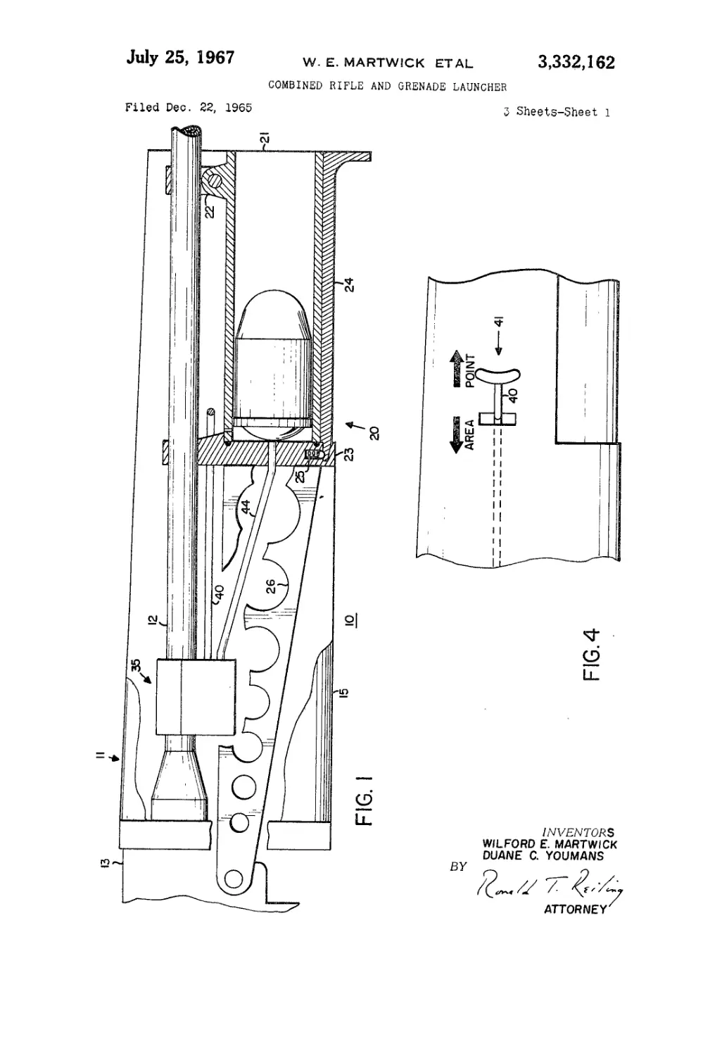
FIGURE 1 is a partial cross-sectional view of the ap-
plicants’ dual purpose weapon;
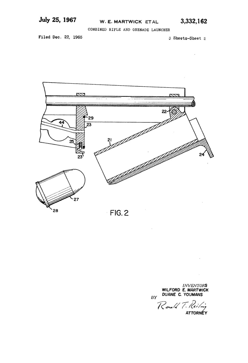
FIGURE 2 is a partial cross-sectional view of the area
projectile barrel;
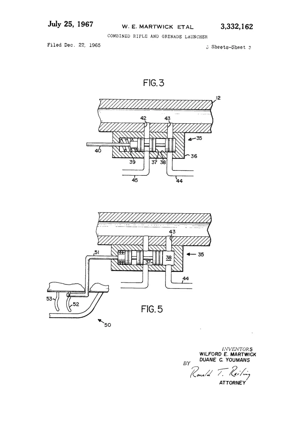
FIGURE 3 is a cross-sectional view of the valve means;
FIGURE 4 is a schematic representation of the me-
chanical means for selecting the mode of operation of
the dual purpose weapon; and
FIGURE 5 is a cross-sectional view of the valve means.
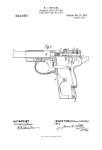
Referring now to FIGURE 1, reference numeral 10
generally depicts the applicants’ dual purpose weapon.
In this particular embodiment, the point round weapon
comprises an M-16 rifle 11 having a barrel 12 and a
breech mechanism 13. The M-16 rifle is, of course, oper-
able to fire a point round. The applicants’ invention is not
limited to any particular type of rifle.
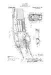
The conventional hand guard of the M-16 is replaced
with a modified hand guard 15 which includes the area
projectile launching mechanism 20. Area projectile launch-
ing mechanism 20 comprises an area barrel 21 hinged
to rifle barrel 12 at pivot 22. An area barrel breech block
23 is attached to rifle barrel 12 in a position contiguous
to the left end of area barrel 21 as viewed in FIGURE 1.
Area barrel 21 is latched in its operating position (FIG-
URE 1) substantially parallel with rifle barrel 12 by
means of a latch member 24 which co-acts with breech
block 23. Latch member 24 is held in the latched posi-
tion by detant block 25.
As illustrated in FIGURE 2, area barrel 21 is easily
pivoted to the loading position by unlatching latch mem-
ber 24 and rotating area barrel 21 about pivot 22. An
area projectile 27 is also illustrated in FIGURE 2. It
should be noted that area projectile 27 has an obturator
band 28 thereon which prevents the escape of gases
supplied to the area barrel 21 as will be explained herein-
after. Obturator band 28 also functions to hold area pro-
jectile 27 in place in area barrel 21 when it is not being
fired. О rings 29 are provided in breech block 23 to pro-
vide a gas seal between area barrel 21 and the breech
block. Recoil links 26 are connected between breech block
23 and breech mechanism 13 of the M-16 rifle.
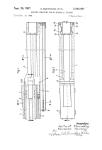
A valve means 35 is attached to rifle barrel 12 proxi-
mate the breech mechanism 13. Valve means 35 com-
prises a valve body 36 having a slideable piston 37
positioned in a chamber 38 therein (see FIGURE 3).
Piston 37 is biased in a first position in FIGURE 3 by
spring means 39. A connecting rod 40 is attached to piston
means 37 at one end thereof. Chamber 38 of valve means
35 is in fluid communication with rifle barrel 12 by
means of conduits 42 and 43. Chamber 38 is in fluid com-
munication with area barrel 21 by means of a conduit
44. Chamber 38 is in fluid communication with breech
mechanism 13 by means of fluid conduit 45 in this
particular embodiment. This communication is only nec-
essary because the M-16 is a gas operated rifle. When a
non-gas operated rifle is utilized in tht applicants’ unique
dual purpose weapon conduits 42 and 45 are not necessary.
As is clear from FIGURE 3, when piston 37 is the first
position as shown, it prevents fluid communication be-
tween rifle barrel 12 and area barrel 21. However, fluid
communication is allowed between rifle barrel 12 and
breech mechanism so as to allow operation of the M-16
rifle in a conventional point round mode of operation.
Connecting rod 40 is connected on one end to piston
37 and on the other end to a connecting rod handle 41.
Connecting rod handle 41 is positioned contiguous to
rifle barrel 12. It is illustrated in FIGURE 4. Connecting
rod handle 41 collectively define mechanical means
connected to valve means 35 for operation thereof. As
previously indicated, when piston 37 is biased in the first
3,332,162
position dual purpose weapon 10 functions as a conven-
tional rifle firing a point round. Operating rod handle 41
is illustrated in the first position in FIGURE 4. The
operator of dual purpose weapon 10 can change the
mode of operation thereof merely by slightly displacing
operating rod handle 41 so as to overcome the biasing
effect of spring 39 and position valve means 35 in the
second position.
FIGURE 5 illustrates valve means 35 in the second posi-
tion. In the second position, rifle barrel 12 is in fluid
communication with area barrel 21 through conduit 43,
chamber 38 and conduit 44. A different mechanical means
50 is connected to valve means 35 in FIGURE 5. Mechan-
ical means 50 comprises a connecting rod 51 attached
to one end of piston 37 on one end and on the other end
to a trigger member 52. Trigger member 52 is located
contiguous to the trigger 53 of rifle 11. The operator can
change the mode of operation by merely displacing trigger
52.
Dual purpose weapon 10 operates in the following
manner. Assume that a point round is loaded in rifle 11.
Latch member 24 is forced forward (away from the oper-
ator of dual purpose weapon) so as to unlatch area barrel
21. Area barrel 21 is pivoted about pivot 22 into the
loading position and an area projectile, such as 27, is
positioned within the area barrel 21. Area barrel 21 is
pivoted back to the operating position substantially parallel
to rifle barrel 12. Latch member 24 is forced rearwardly
(towards the operator) into breech block 23 and is locked
by locking means 25. At this point, valve means 35 is
biased in the first position and the dual purpose weapon
can be utilized as a conventional rifle firing a point round.
The area projectile can be carried loaded in area barrel
21 for as long as desired while utilizing the dual purpose
weapon as a conventional rifle.
When it is desired to fire the area projectile the operator
of the dual purpose weapon slightly displaces operating rod
handle 41 (or trigger 52) by pulling it towards himself
and holding it in this position. This displaces piston means
37 to the second position and places rifle barrel 12 and
area barrel 21 in fluid communication. The point round
is then fired from rifle 11 and generates expanding gases
behind the point round. A portion of the gas generated
by the point round is supplied to the area barrel 21
through conduit 43, chamber 38 and conduit 44. The
breech of area barrel 21 is sealed by О ring 29 and ob-
turator band 28 of the area projectile. Consequently,
the portion of the 'gas supplied from rifle barrel 12 to
area barrel 21 is sufficient to fire (propel) the area pro-
jectile out of area barrel 21. Area barrel 21 can then be
reloaded in the manner described above.
Thus the applicants have provided a unique dual purpose
weapon wherein the operator can quickly and easily select
the mode of operation of the weapon. This is accom-
plished by utilizing valve means which can be enclosed
in a first position or a second position by mechanical means
connected thereto. The applicants’ dual purpose weapon
allows the operator to carry the area barrel loaded at
all times and to fire it by merely displacing his hand on
the hand guard so as to displace the mechanical means.
While we have shown and described a specific embodi-
ment of this invention, further modification and improve-
5
10
15
20
25
30
35
40
45
50
55
60
4
ments will occur to those skilled in the art. We desire to be
understood, therefore, that this invention is not limited
to the particular form shown and we intend in the ap-
pended claims to cover all modifications which do not
depart from the spirit of the scope of this invention.
We we claim is:
1. A dual purpose weapon including a rifle having a
barrel and breech mechanism and adapted to fire a point
round in combination with:
(a) an area barrel hinged upon the rifle barrel, said
area barrel being adapted to be latched in a operating
position substantially parallel with said rifle barrel,
said area barrel being further adapted to be pivoted
to a loading position so that an area projectile may
be positioned therein;
(b) valve means mounted upon said rifle barrel proxi-
mate the breech mechanism, said valve means being
operable in a first position to prevent fluid communi-
cation between said rifle barrel and said area barrel,
said valve means being operable in a second position
to place said rifle barrel in fluid communication with
said area barrel; and
(c) mechanical means connected to said valve means,
said mechanical means being operable to place said
valve means in the second position whereby the point
round and the area projectile are fired simultaneously.
2. The combination set forth in claim 1 wherein said
mechanical means comprises a connecting rod attached to
said valve means and a connecting rod handle positioned
contiguous to said rifle barrel.
3. The combination set forth in claim 1 wherein said
valve means comprises a slideable piston biased in the
first position.
4. The combination set forth in claim 2 wherein recoil
links are connected between said area barrel and said
breech mechanism.
5. The combination set forth in claim 2 wherein said
valve means comprises a slideable piston biased in the
first position and said connecting rod is attached to said
piston.
6. A dual purpose weapon including a rifle having a
barrel and breech mechanism and adapted to fire a point
round in combination with:
(a) an area barrel mounted upon the rifle barrel sub-
stantially parallel with said rifle barrel;
(b) valve means mounted upon said rifle barrel proxi-
mate the breech mechanism, said valve means includ-
ing a slideable piston means biased in a first position
to prevent fluid communication between said rifle
barrel and said area barrel, said piston means being
operable in a second position to place said rifle barrel
in fluid communication with said area barrel; and
(c) mechanical means including a connecting rod con-
nected to said piston means, said mechanical means
further including means attached to said connecting
rod for displacement thereof whereby said piston
means is placed in the second position and the point
round and the area projectile are fired simultaneously.
No references cited.
BENJAMIN A. BORCHELT, Primary Examiner.
July 25, 1967
W. E. MARTWICK ETAL
3,332,162
COMBINED RIFLE AND GRENADE LAUNCHER
5 Sheets-Sheet 1
Filed Dec. 22, 1965
INVENTORS
WIL FORD E. MART WICK
DUANE C. YOUMANS
July 25, 1967 w. E, martwick etal 3,332,162
COMBINED RIFLE AND GRENADE LAUNCHER
Filed Dec. 22, 1965 3 Sheets-Sheet г
riu.
INVENTORS
WILFORD E. MARTWICK
DUANE C. YOUMANS
BY
• f ^9
ATTORNEY
July 25, 1967
Filed Dec. 22. 1963
W. E. MARTWICK ETAL 3,332,162
COMBINED RIFLE AND GRENADE LAUNCHER
3 Sheets-Sheet з
INVENTORS
WILFORD E. MARTWICK
DUANE C. YOUMANS
BY
ATTORNEY