/


Текст
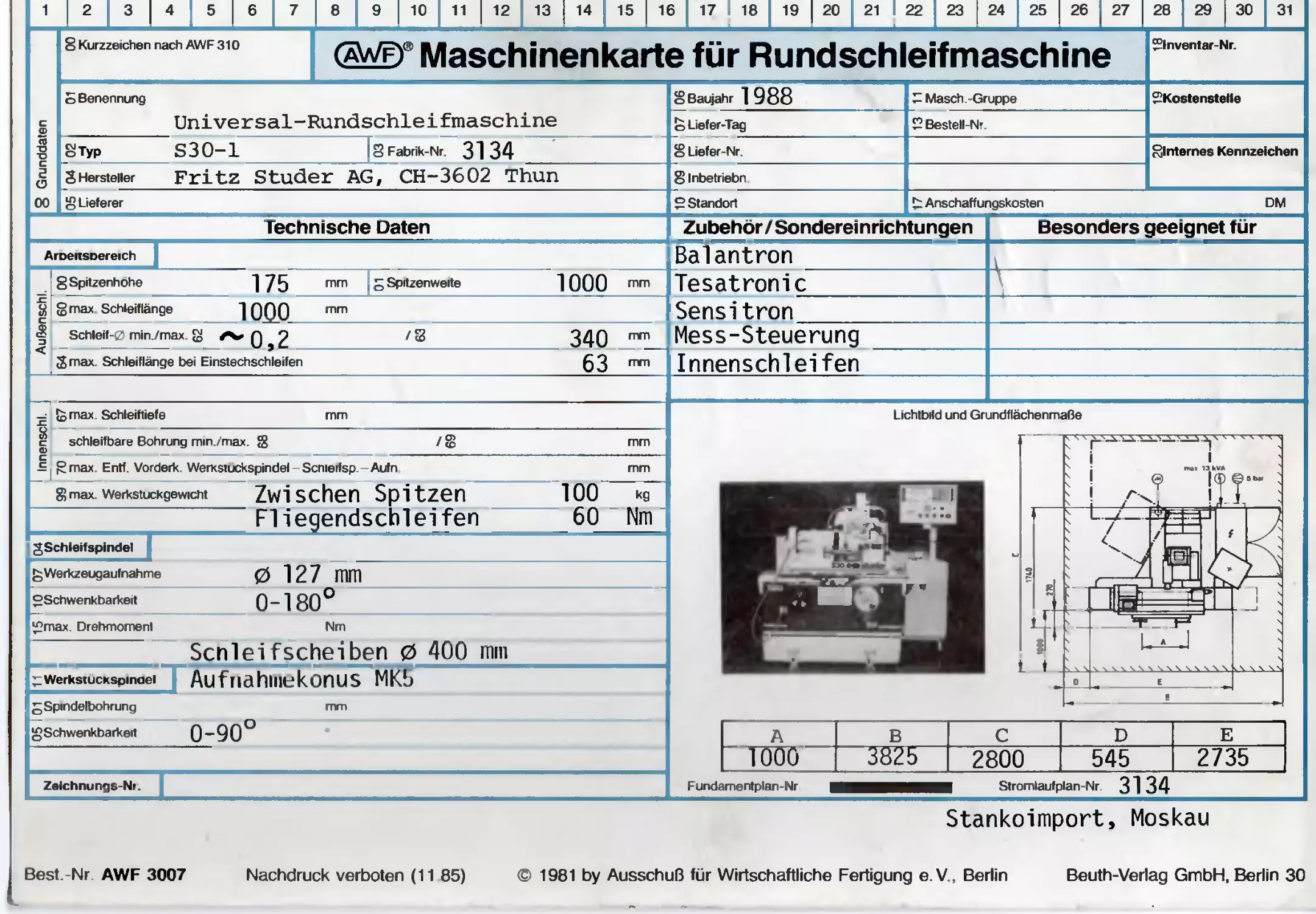
                    Stankoimport, Moskau
Best.-Nr AWF 3007
Nachdruck verboten (11 85)
© 1981 by Ausschuß für Wirtschaftliche Fertigung e.V., Berlin
Beuth-Verlag GmbH, Berlin 30
Jame: F.Hostettler
kW । 8 Spannung 380 V
8 Frequenz 50 Hz
26 Maße/Gewicht	Flächenbedarl 81-3,82 mxo B 2,80 m o Höhe
8 Antrieb 8Gesamtanschlußwert HlclX« "|3 kVA । £ Gesamtleistungsbedarf
*	Motor für		Hersteller	Type/Nr	Motor- Inv -Nr.	Bauform n. DIN 42950	COS«|	Leistung kW	Strom A	Drehzahl 1/min	Schutzart
In	Aussenschleife		n EMWB	R132S-2	728852			5,5		”ZSaö	IP 44
W	Innenschleifer)		EMWB	AF 100.	737093			1,5	5,2/3,0	3000	IP -4
VI	Werkstückantrieb EMVB			F80 M-6	732939			0,55	2,9/1,7	1000	IP 44


L
(nVorschubgeschwindigkeit						8 Zerspanwerte	für St 60	/ GG 20			bei Schnittgeschwindigkeit
Schleifspindal min/max $			. ,024 'S	12	mm/min	max Spanquerschnitt 8		/ 5	mm2 8		m/mm
Werkstucktisch min/max ®			511	5500	mm/min
						8 Betriebsstoffbedarf
8Splndeldrehzahlen		। in 1/min				8 Kühlmittel		80	l/mm	0	,3 bar
Schaltstufe		Drehzahlbereich	Anzahl der Stuten			Stufensprung
		von	DIS			8 Angaoen zum Umweltscnuiz
1		167'	2110	2		8 Lärmpegel				73	dB(A)
II						8 Emissionswerte			V
III
stutenlos von			bis		U/min

^Werkstückspindeldrehzahlen			in 1/min			rill /
Schaltstute		Drehzahlbereich	Anzahl der Stuten			Stufensprung
		von	DIS			z		'11.  Z /
I						Bemerkungen	J "		/ // / / /J
II						. 7,/
III		1	।
stutenlos von			30 b» 300		U/min
	 100 bi? 1000
* G = Gleichstrom. W = Wechselstrom, D Drehstrom. H Hydraulik P = Pneumatik
Bedienen Sie sich der Arbeitsergebnisse des AWF (SchnftenverzeicTinis kostenlos). Anleitung für den Gebrauch der AWF Betnebsmittelkarten Best -Nr. AWF 779
Ausschuß für Wirtschaftliche Fertigung e. V. (AWF) Düsseldorfer Straße 40 6236 Eschborn/Ts Telefon (061 96) 4 9641.
s«
8 Radwna
Radi
6 ZanQenspamjng
Clamping with collet
J^fctuna
^sfng device
ZU
S10J2
RWT
>4,1 BP Maccurgt'iZ
1 i Feb. 1988
2400036 !
•4V»6 N fcSC
1650
12 Einstechvorschub
Infeed drive
Longitudinal slide
lUängsschlitten
 50»S500twi/«in
© HO
Ul P15-11
® 46
112.
KW6
NW6
V. Quer schlitten
Cross slide
NW6
9 j?
il.Steuerbtock
Control bloc
SwteruAhchter
auf Sdutzhaubf
Hydraulic hinged
dressing attachment
on hinged base
Hudrauhkschema S3O-1
89
TaiIstock
S.Re« t stock

l.Hesskupf
Measuring head
Hydraulic hinged
dressing attachment
3.hydr Abrichter

1500min
101 iiiin
137 kW
2 MOOX
12. 08.88
	2’OOOH	VERSOHLEISSTEILSORTIMENT	S3O-1
2400.910	2’OOOH	ASSORTIMENT DE PIECES D’USURE	S3O-1
	2’OOOH	SET OF PARTS SUBJECT TO WEAR	S3O-1
RUFTROGS-NR.
NO DE COMMONDE
ORDER-NO.
19’134
MOSCH. -NR.	SERIE
MOCHINE-NO.	3134	SERIE 14
MACHINE-NO.	SERIES
-------------+-------------------------------------+---------
KUNDE
CLIENT	Stankoimport,Moskau
CUSTOMER
J KUNDEN—SCHEMO—VERZEICHNIS
-	Seite 1/3
p ****«»*#*******»W«HHHrt««««««***#«**»*«-*»*»#**#***********************
’ Serie Nr. 14 Nasch. Nr. 3134 Datum: 26.04.88 Wasch.typ: S 30-1
^'Ersatz für Ausgabe vom	: ....—...
Abgeleitet aus Serie—Schema-Verzeichnis	: 1399 OOS
Zuständige Servicestelle	:	CH
Kundenspez.Anpassungen vorhanden	:	Nein
Anpassungen ausgeführt durch:	:
Komm. Nr. : 19’ 134
Kunde : STANKOINPORT, MOSKAU
Netz	: 3 X 380 V 50 Hz	Steuerspannungs 110 V
Ausgeführte Anpassungen:
j Keine
|	MaaBaBBaBBBaaaaaaBaaamaaaaaaaaaaaBaBaaBuaaBWBBBannBnBnaBnBBBaBnntiBKunnanB
I
® at>naMnwaaananaaaaaaaaa*aaaaaaaaaaaaaaaaBanaMMnniinnnKt>ut:ni:nntinannttnnMnntinii
i	uanaMattBnauaaaaBaa8*aaaaa«*aaaaaaeaaaBaaM«MB8ttitBi>nKattnBunaaBnnMnnaaBa>tBau
auuvBBUBBnnuBBaMaBaaaa«aaaaaaaBB8aaaBBaat>t>MnB>inntit>BaBniiBiiBnnt:>iBnai»<innnnKti
UBB»BaBai»aa»inaaaaaaaa»aa«Baaaaaa8aa8aaaBBa8BnBnBaaaBBB»i»tnaBnnaBBanaaBBHBBB
t a a tt jt a a nt]>iBtiittiBBaBBa8aa«aaaaaaaaaaaaBBBMnnniinB>in>iB a a a tt a a nnaannuaa bbsbub ntta
p Wechsel1isten für verwendetes Sondermaterial:
Ze ich. Nr. / Bezeichnung
ana» nna	aaaaeaaaa*«*««*«aM8aaa««eaaaaaannnanaaaBBBaBaaanBBaBauaat:tittan
a a a s naa	aaaaaa»«***M**W««a*«aaa8waaeaaawaaanBssannanBnasaaaB8BaannaBB
	Seite 3/3 ***********************************************************************
	Serie Nr.		14	Nasch. Nr. 3134 Datum: 26.04.88	Masch. typ: S 30-1
			2. .	WE RKSTUECKSPINDELSTOCK
	1350	034	242 0	WERKSTUECKMOTOR MIT	FREßUENZUMFORM.	550	W
	1350	035	245	WERKSTUECKMOTOR	BEDIENUNG
			3. .	REITSTOCK
	1350	037	312 □	VENTIL SPANNVORRICHTUNG
	1350	039	315 0	FUSSSCHALTER	SPANN- VORRICHTUNG
			5. .	MESSKOPF
	1350	041	502 □	VENTIL MESSKOPF EINFOHREN
	1350	042	503	BEDIENUNG MESSSTEUERUNG
	1350	043	506	STEUERUNG MESSSTEUERUNG
			8..	STEUERUNG ALLGEMEIN
	1350	397	850	BEDIENUNGSFELD
		50..		VERDRAHTUNGSPLAENE
	1351	678	5990	ADRESSIERUNGSTABELLE	SPEISUNG
90..6ERAETEAN0RDNUNGSPLAENE
	1351 033 9000 1351 034 9010	ELEKTROPLAN ELEKTROPLAN	MASCHINE BEDIENUNG
	1350 978 9011	6ERAETEANORDNUNGSPLAN	BEDIENKASTENBODEN
	' 1351 035 9020	ELEKTROPLAN	ELEKTROSCHRANK
	1350 979 9021	6ERAETEAN0RDNUNGSPLRN	EINSPEISUNG
		SCHALTUNGSUNTERLAGEN
	1399 921	1/1	STUDER SYMBOLE 1
		STUEEKLISTEN SPEZIAL	(KEINE ABGABE AN DEN KUNDEN)
	1350 400	MONTAGE- UND VERDRAHTUNGSMATERIAL
	Seite 2/3
	Serie	> Nr.	14	Masch. Nr. 3134 Datum: 26.04.88	Masch. typ:	S 30-1
	1 Codeerklä		rung:	G = Grundausrüstung
				0	= Option
				K = Kundenspez. Ausführung
	Baugr. Blatt Code Bezeichnung	Variante
	Nr	•	Nr.
			0. .	Hauptst rom
	1350	000	000	ERDUNGSPLAN
	1350	001	001	EINSPEISUNG	40 A
	1350	440	002	HYDRAULIKPUMPE	0.	370 KW
	1350	442	003 0	KUEHLMITTELPUMPE	(INTECLON)	1.	100 KW
	1350	445	005 0	INNENSCHLEIFMOTOR	1.	500 KW
	1350	008	010	AUSSENSCHLEIFMOTOR	5.	500 KW
	1350	OOS	018	VORSCHALTTRAFO	220V/1400 VA
7	, 1351	389	019 G	STEUERTRAFO	110V/	450 VA
	1350	012	020 0	MASCHINENBELEUCHTUNG	24	' 70 W
	1350	013	022	VENTILATOR ELEKTROSCHRANK	39 W
	1350	014	028	BETRIEBSSTUNDENZAEHLE R	220 V
	1351	413	030 G	HYDRAULIKOELKUEHLER	0.	250 KW
	1351	019	041	SPEISUNGEN 24V= VENTILE STEUERLOGIK	12 A
	1351	415	050	NOT - AUS - KREIS
	1351	021	051 G	HAUPTSCHUETZEN
	1350	691	052 G	KUEHLMITTELHAUPTVENTIL	SCHNITTSTELLE	24 V=
	1351	082	080 0	DURCHMESSER-MESSSTEUERUNG MOVOMATIC
	1350	697	089 0	EINSPEISUNG-MESSSTEUERUNG MOVOMATIC
	1350	024	091 0	SENSITRON TYP 85
*
			1. .	MASCHINENSTAENDER
	1350	645	102 0	VENTILE	X-ACHSE	MIT SENSITRON
	1350	026	103	ENDSCHALTER	X-ACHSE
	1350	027	105	BEDIENUNG	X-ACHSE
	1350	028	106	STEUERUNG	X-ACHSE
	1350	715	107	STEUERUNG	X-ACHSE
	1350	030	108	STEUERUNG	X-ACHSE
	1350	031	112	VENTILE	Z-ACHSE
	1350	716	113	ENDANSCHLAEGE Z-ACHSE
2
3
5
8
9
10
11
13
MATERIAL-LEGENDE
Elektroschrank
Bedienkasten
u
Aenderung Nr.
9.1. BH Geier	V
31.8.6'1 Geier	w
	X
	Y
	z


GmtchMt
8
c
0
E
G
H
K
M
N
o
p
a
R
S
	S-Liste I	Studer Nr.	Typ / Lieferant type / Suppiier. Type / Uvreur
	1	2002 060		I " XO001 2002 060 Studer AO, Thun
	2	5855 123	2096.0
	17	5855 121	3165.0 ZB 4
	1	5855 122	3166.0 ZB 16 Carl Geister ♦ Co.
	1	2002 060	X0002 2002 060 Studer AO, Thun
	2	5855 123	2096.6
	9	5855 121	3165.0 ZB 4
	5	5855 122	3166.0 ZB 16 Carl Geisser 4- Co.
	1	2002 060	X0003 2002 060 Studer AG, Thun
	2	5855 123	2098.6
	15	5855 121	3165.0 ZB 4
	2	5855 122	3166.0 ZB 16 Carl Geister ♦ Co.
	1	2002 060	XO0O4 2002 060 Studer AG, Thun
	2	5855 123	2998.6
	13	5855 121	3165.0 ZB 4
	3	5855 122	3166.0 ZB 16 Carl Geister + Co. 	I
TAO.85
Electrical cabinet
Rrmoire Hectrique
Geter

Irügger *•»«

Oper ab nq cabinet
Bottier de commande
X 000t
X 000^
0V~ Vorschaltlrafo | Pre - auxiliary transformer | Transfo auxiliaire
0V~ Steuertrafo | Control transformier | Transfo de commande
OV* (.ÖZ')
X 0003
Montageblech | Rssembling sheet | T6le de montage
^erkstückantriebtrafo | Workhead drive transformer|
Transfo de VentraTnement de la piece ä usiner
E
Motoren | Rack | Trägarplatt« I Biverats
Motor« | Rack I Carrier plate | Variout
Moteura | Rack | Plateau de »upport | Divara
X 0004
15*
---------016
1,5*
Trafo | Transformers | Transformateurs
2,5*
1??
>t*
<1*
t*
049
O^A
ZHZ
Gehäuse Elektroschrank | Housing electrical cabinet
Boitier de l'armoire fclectrique
tmttlär
Emct Am*
Adiwficli wb ;
6
Erdungsplan
Earthing plan
Plan pour mise en terre
1350 000 BI. 000

end«rung Nr.l
21.*. 8n |
Geier
MATERIAL-LEGENDE
A	o	a> tfl	Studer Nr.	Typ / Lieferant Type / Supplier Type / Livreur
B	>	-J cA
C D E f C H J K L M N O P Q R S T U V w X V z		i 1 1 1 1 1 1 1 1 1 3	5730 551 5730 552 5730 560 5916 618 5B34 051 5834 050 5834 050 5834 050 5834 049 5835 818 5835 816 5835 817	I K0511 DIL 00 M*110V 5O/60Hz DIL 00 M«22OV 50/60Hz 22 DILM Klöckner-Möller MOO2O HA 30 B - L1O / 19A Bachofen, Uster Q0020 PKZM1 - 2,4 - NA * 3x220V PKZM1 - 1,6 - NA * 3x380V PKZM1 - 1,6 - NA * 3x420V PKZM1 - 1,6 - NA* 3x460V PKZM1 - 1	- NA * 3x5OOV NHI 1O-PKZM1 H - PKZM1 BK 2 5-PK Z MO Klöckner*Möller * nur wenn only if seulement quand l
Gmmim
Irugger |us«w
Rydraulic pump
l> l>
6
l
|t
1
3
5
M
9
IO
12
II
H^draulikpumpe
Pompe hydraulique
001 - 01
001- OB
001- 00
0.0020
050
001-01
001-08
001-05
220V	2,1 R
380V	1,2 R
WOV	1,1 Fl
<tGOV	1,08
500V	0.8R
K0511
	2		6
002- 0*	I 002 - 05	90 - 200	[	— 1.5 4
<	X	X	•
M 0020
0,33 kV | 1500 vpm
Erwuhw
Erutttwch ।
8________7________8
Hydraulikpumpe
Hydraulic pump 0,31 kV
Pompe hydraulique
L 1350 440 BI. 002
2
-enderung Nr.	u
12.4.81 Geier	V
21. H-. 01'  Geier	w
3.2. 88 Geier	X
	Y
	z


Studer Nr
Genchmi
Gejruit
N«nee«|efr
MATERIAL-LEGENDE
Typ / Lieferant
Type / Suppiier
Type / Livreur
5730 551 5730 55?		K0513	DIL OO M«11OV 5O/6OHZ DIL OO M*22OV 5O/6OHZ 22 DIL M Klöckner-Möller
5/30	560
		MO03D	ZA 28 / 2 SK
5917	439		* Universal 50Hz
5917	440		*	500V/5OHz
5917	441		* Universal 6OHz
			Kehl + Co.
5834	053	Q0030	PKZM1 - ß,0 “	NA	* 3x2?OV
5834	052		PKZM1 - 4,0 -	NA	* 3x380V
5834	052		PKZM1 - 4,0 -	NA	* 3x420V
5834	051		PKZM1 - 2,4 -	NA	* 3x460V
5834	051		PKZM1 - 2,4 -	NA	* 3x500V
5835	818		NHi 1O-PKZM1
5835	816		H - PKZM1
5835	817		BK25-PKZM0
			Klöckner-Möller
		X0030	HAN 6E
5860	903		0930-006-0301		(AG)
5860	910		0933-006-2701		(E8)
5860	909		0933-006-2601		(ES)
5860	904		0930-006- 1540		(TG)
			Harting
nur wenn
seulernent quand
1.40.85
Geier
rt Serie
Brügger t«sw.
3
?
3
Kühlmittelpumpenmotor
toolanl pump motor
Moteur de pompe d'arrosage
999
1
2
12
11
9
10
1350 442 BI. 003
001 - 01
001-08
001-03
0 0030 |
050
270V	V.Sft
380V	7,6 8
V20V	7,VP
V60V	7.2 R
500V	?,0R
3
X0030
M 0030
4,1 kW | 3000 upm
Eruulw
Erufctfwdt -
6________7_______8
KühlmiHelpumpe
Cool an t. pump 1,1 kW
Pompe d'arrosage
001-01
001-08
001-09
A
o
c
D
E
G
H
K
M
N
o
Q
R
S
MATERIAL-LEGENDE
innenschleif motor
«nderung Nr.|
11.*. 61 '
Geter
u
V
w
X
z
S-Liste	Studer Nr.	Typ / Lieferant Type / Supplier Type / Livreur
1	5730 551	1 KO514 Oll. 00 M»11OV 50/60HZ
	5730 55?	Oll 00 M*22OV 5O/60HZ Klöckner-Möller
	5910 429- 59IC 431	MC050 F90 S-2/B14 EMW8 Brienz
1	5834 054	Q005C PKZM1 - 10 - NA * 3x?2OV
1	5834 052	PKZM1 - 4 - NA ★ 3x380V
1	5834 052	PKZM1 -	4 - NA ★ 3x420V
1	5834 052	PKZM1 -	4 - NA * 3x460V
I	5834 052	PKZM1 -	4 - NA * 3x500V
1	5835 81B	NHi 10-PKZM1
1	5835 816	H - PKZM1
3	5835 817	BK25-PKZM0 Klöckner-Moller * nur wenn only if seulement quand 	I
Internal grindinq motor
Moteur de rectification intärieure
n ,	>
------------------------------
001 - 01
001 • 06
001 - 09
050
	I>	I»
*
l
1
3
Gw*iAm<
n. 10.85
Geier
•b Swift
Brügger [usow
B
6
5
8 051* | lAX-X


3-
M 0050
1,5kW | 3000 upm
001-01
001- 08
001- 09
c
D
* ♦
E
ttov	6.18
180V	3,5 8
V10V	3,1 8
V60V	1,9 8
soov	1,18
G
H
K
M
N
o
p
Q
R
S
u

X
z
Eruufw
EfMftAKC* :
AftMtrt wie :
13
6_________1_________8
Innenschleifmotor	,	.
Internal grinding motor 1,5kW r 1350 445 BI. 005
tioieur de rectification intärieure	f
9
10
11
12
tnderung Nr
,A>. 04
Geter
19.4,88"
'S uni
2
3
5
6
8
9
10
11
Rvssenschleif motor
A- Rnlaufteit
13
A - & - Schaltung
MATERIAL-LEGENDE
q> </> —i cA	Studer Nr.	Typ / Lieferant Type / Supplier Type / Livreur
1	5730 551	r KO512 DIL 00 M<110V 50760Hz
1	5730 552	OIL OO M«22OV 5O/6OHI
1	5730 560	22 DILM Klöckner-Möller
1	5730 551	KO1OO DIL 00 M»11OV 50760Hz
1	5730 552	OIL OO M.22OV 5O/60HZ
1	5730 560	22 DILM KlÖckner-MÖl1er
1	5730 551	KO1O1 DIL 00 M«110V 50760Hz .
1	5730 552	OIL OO M«220V 50/öOHl
1	5730 560	22 DILM Klöckner-Möller
1	5735 037	KO1O2 MEL30 AC * 110V-50760HZ
1	5735 036	KO1O2 MEL30 AC * 22OV-5O76OHz Bachofen, Uster
1	5735 802	ZB 66 Elesta, Bad Ragaz
	5910 842- 5910 848	MO1CO R132 S-27B3 IP 44 EMWB Brlenz
1	5834 056	QO1OO PKZM1 - 25 - NA * 3x220V
1	5834 055	PKZM1 - 16 - NA * 3x38OV
1	5834 055	PKZM1 - 16 - NA * 3x42OV
1	5B34 055	PKZM1 - 16 - NA * 3x46OV
1	5834 054	PKZM1 - 10 - NA * 3x500V
1	5835 818	NHi 10 - PKZM1
1	5835 816	H - PKZM1
3	5835 817	BK25 - PKZMO Klöckner-Möl1er * nur wenn only if seulernent quand '	1
txternal qrindinq motor
A- Rctuatin^ time
A- 0- Commutation

Irügger us«»
QOAOO
Moteur derectification extSrieure
—	Xi... 4'L../
t!-C.	. .
A- Temps d‘excitation
a- a- Commutation
8
oo v oi
	004- 00
	, 004- 09
.LrffO^ÖA-OI
004-00
004-09
c
o
1
3
5
i n		x	X-
•L
		s		i	r
	....	I»	I>
220V	20 fi
980V	42 8
V20V	44 ft
*t60V	40 ft
500V	9R
9*
43
E
m
G
K05A2I |-\\X
9
2	9,	6	040 - 03
			040- 02
			040- 04
			4,5*
4	3	5		4	3	5
4,5*
040-10

H
K
040-40
A.5*
4
KO4O2J
M
4
3
5
3
N
l
KOAOAl |-\\\
6
1
9
K0400|
6
l
6
o
666
tA
3~
O
O
O
M0400
5,5 kW | 3000 upm
040-20
040-24
KO4O4
24
22
040-23
24
KOAOOr
22
Q
R
s
4,5*
40 sec
01
040-22
040-29
M
84
XO4OO
01
u
V
040 - 01
040-08
040 - 09
K 0402
K0404
w
040
040
040
040
040
040
		—X
040	040 040 040
x
z
Eruafw
ErucrAwcft -
A^müchww ;
6_________7_________8________9________
Russenschleifmotor	.
External grinding motor 1
ttoteur de rectification exterieure
8
10
11
12
13
1350 008 BI. 010
3

Q
B
2
3
5
Typ / Lieferant
Type / Supplier
Type / Livreur
c
o
E
F
G
H
K
M
N
O
Q
R
s
Aenderung Nr.	u
M.9.01 Geier	V
	w
	X
	Y
	z
MATERIAL-LEGENDE
Vorschatttrafo
bt.dteschutischalter für 210V~ Verbraucher
r>
□
<z>
5859
5720
5855
GuädM
Studer Nr.
019
005
301
*1.50.85
FO18O
T0180
X0180
Pre - auxitiary transformer
Transfo auxiliaire
Switch for protection of equipment for ZZOV^ consumers
A
Commutateur de protection pour appareillaqes pour 220V"* usager
B
FAZG 6 - Hi1O
Klöckner-Möller
ET 1400VA
Lapp AG, Hitteau
91.506.035-41
Sprecher + Schuh
Geier |äs«i.
Irü^er us«.
R
EfMttfef
EcMtrtfwdi t
A l -:
o<n  oi
001-OB
00A-09
Lil
056-00
056-00
T0180
MW' ttOV

5*tOOVR
KO555
53

WV2.
IOV~
"ov--
ov~
OB«
08
8
X0A80
PtÖ
~ 000
8
001-01
001- 08
001- 08
c
D
E
F
G
H
K
nov~ g o^6-
nov~ 0
ov~
O
M
N
O
p
88
08
Q
R
s
u
v
w
X
z
13
6________7
VorschalÜrafo	,
Pre- auxiliary transformer 1W0VR L 1350 009 BI. 018
Transfo auxiüaire
9
10
11
12
MATERIALLEGENDE
A«nderung Nr.
vio.Bn
Geier
A B	1 OLA	S-Liste	Studer Nr.		Typ / Lieferant Type / Suppiier Type / Livreur
C D E F G H J K L M N 0 P Q R S T U V w X Y z		1 1	5859 01B 5720 008 5855 301 t		1 F0190 FAZG 4 - H110 Klöckner-Möller T0190 ET 450 VA Lapp AG, Hittnau XO19O 91.506.035-41 Sprecher + Schuh I
	GezeidMet		is.n.en	Geier		•k Serie
	nvpnm			Burri		MM


12	3	4 )	Steuertrafo	6	7	8	9	10	11	'	13 _ 	 		 ) Geräteschutischalter für Steuerspannung
Control transformer	Switch for protection of equipment for control voltage	*
Transfo de commande	Commutaieur de proteclion pour appareillages pour commande de tension e
Earthed control Circuit (With unearthed controJ circuit,
remove Connection and provide insulation checking)
Circuit de commande avec mise ä la terre (Pour un circuit de commande
sans mise a la terre, enlever le pontage et prevoir un detecteur d*isolement)
C
- D
E
F
G
H
J
K
t
M
N
O
P
Q
R
S
T
U
V
- w
X
Y
_______1	2
holt .
tnMam*
wie:
6________7_______8
Steuertrafo
Control transformer
Transfo de commande
s 10	11	12	13
wovriuov ; 1351 389 BI. 019
2
3
5
MATERIAL-LEGENDE
Studer Nr.
mdenjng Nr
5859
5720
5748
5748
Gmmmwi
G^riHt
Typ / Lieferant
Type / Supplier
Type / Livreur
018
113
055
110.85
F0200
H0200
T0200
ieier
Trafo
6	7________8________9
” ihinenbeleuchtung Z‘tV~
|______lampe |
Machine lightina ?‘»V~
[lamp|
10
11
Geräleschutischaller
13
Transformer______|______lamp ~	|_______Switch for protection of epuipment___
Eclair age de la machine l‘rv~
Transformateur	|______lampe |____________Commutateur de protection pour appareillages
6
FAZG 4 - H11O
Klöckner-Möller
HGW SK3112 24V/7OW
H3 24V/70W
Waldmann
ETS 7OVA 22OV/24V
Lapp AG, Hittnau
•bSm
Irugger »s«»

88
08
Iw I
EfMtt<WCfc «
220V*
0V~


88
C
D
E
G
H
T 0200
Z20V-
020-00
K
ov-
CH Ml IM
novR
ov**
020*02

0 1
F 0200 V-
020-01
H 0100
ZIV 110W
8
9
e	7________8________9_______10
Maschinenbeleuchtung 2I*V~ Halogen
11
12
M
N
o
p
08
a
R
s
u
V
W
Z
13
Machine lighting Halogen L 1350 012 BI. 020
Edairaqe de la machmt W* Halo^ine________________________________________
S
B
2
3
MATERIAL-LEGENDE
Typ / Lieferant
Type / Supplier
Type / Livreur
Studer Nr.
</)
C
D
E
F
G
H
K
M
N
O
P
Q
R
S
u
enderung NrJ
	V w X Y Z


5918 501	MO22O 7656 220V-50/6C
	Omni Ray
5918 502	LZ 24
	Omni Ray
5490 107	AFF - 0
	Carl Geisser AG
5855 000	33.B30.002 3P0
	Eg]i Fischer
GcnidMwl
1.10.85
Geier
•bSarto
trüber
R
Ventilator Elektroachrank
Fan eleclrical cabinet
Ventilaleur armoire ilectrique
--------------.............?
1350 013 BL 022
M 01*10
33 W| 3000 upm
Erufrfik
EfMC<WCfc i
AaMkhwte;
Ventilator Elektroochrank
Fan eleclrical cabinet	39 W
Ventilaleur armoire electrique
b
8
9
10
11
13
c
o

MATERIAL-LEGENDE
Betriebsstundenztthler
Spa. Jnosanzeige 220V
8
0
E
G
H
K
M
N
p
Q
R
S
u
Aenderung Nr.l
V
x
z
o >	S-Liste	Studer Nr.	Typ / Lieferant Type / Suppiier Type / Uvreur
	1	5833 402	I rr H0280 3SB 1001-6 BG 06
	1	5833 405	BA 9S-22OV - 130V
1	1	5833 406 5833 407	3SB 1902 - 1 AC 3SX 1 731 Siemens AG
	1	5737 608	P02B0 621.1 * 22OV/50Hz
	1	5737 609	621.1 * 220V/60Hz Wisar * nur wenn only if seulement quand 	1
MO. 85
Geier
Operating time counter
Tension indication 220V**

Compteur des heures de manche
Indication de tension 220v~

oie- ot	nov~	018-01
			XI
		XI
OB	0V~		06
pono
H 0180
J
K

N
o
p
Q
R
s
u
V

x
z
GWH*»«
Ow««
•bSeha
Brügger lui..
B
Efwa<wdi ।
8
0
6___________________________
Betnebsetundenzähler
Operating tim« counter
Compteur de« h«ur«a de marche
10
11
12
13
nov r 1350 014 BI. 028
2
3
e
nderungNr.
31B. en
Geier
A9.4.6B
Burn
A
B
C
D
E
F
G
H
J
K
L
M
N
O
P
Q
R
S
T
U
V
w
X
Y
z
		MATERIAL-LEGENDE
o >	S-Liste	Studer Nr.	Typ / Lieferant Type / Supplier Type / Livreur
		5918 013	2' ' 1 '		 ~ M0300 OLK-100-1-220 50/60Hz
			Bachofen, Uster
	1	5834 05.’	00300 PKZM1 - 4,0 - NA
	1	5835 818	NHi 10-PKZM1
			Klöckner-MÖller
Hydraulikoeiküh]er	 ) 5
Hydraulic oil cooler	\	: i	„V, j • f	’  p'r,. f . • /; >'»
Refroidisseur d’huile pour hydraulique	o -

M0300
0,25 kW
8
c
D
E
F
G
H
J
K
L
M
N
O
P
a
R
s
T
U
V
w
X
Y
z
	1					1	2	3	4	6	6	7	8	9	10	11	12	13
GttMttart	i'fr.e.en	Geier	AM			Eraaeliir	Mtsfuder Fre* Stuber A0 CKJ401TK*	H^draulikoelkühUr H-jdrauUc oil cooler	.	0.1.5 kW Refroidiweur dlnnlt pour hydraulique	: 1351 413	BL 030
G^ra*		lurri	MaM			httkrt i
						wit *
8
1	2	3	4	5	6
MATERIAL-LEGENDE
Studer Nr.
A*ndanmg Nr.
30.9.6'1
Geier
B
C
0
E
f
G
H
J
K
L
M
N
O
P
o
R
S
T
U
V
w
x
Y
z
</>
5710
2017
021
203
C0410
TYP / Lieferant
Type / Supplier
Type / Livreur
Elko PEH 153
10*000pF / 40V
Leitgeb
Support
Studer AG, Thun
5859	021	F0410	FAZG	16-HilO
5859	019	FC411	FAZG	6-H110
5859	019	F0412	FAZG	6-H110
Klöckner—Möller
5720
5751
5855
009
001
301
T0410
V0410
ET 660VA
Lapp AG, Hittnau
Trafo	Absicherung	) Speisungen	T*- 1 "1 1 Absicherung Gruppen
Traneformer	Fusing	Supplies	Fusing groups
Traneformateur	SfcuriU	RGmentation»	Sicurite groupes
\UftJbW


(
004-01
004-01
	004-08		004 - 08
		004 - 09	A ftO-tfUACX.	004-09

T 0140
52OV-	20,5V- 014-00
160V-M 	“
iioyd
330 VA
0V~
1*
FOHO
050
014- 04
466
2.5*
V 0140
044-02 g £ 044-03
2,5 *	2,5*
K 0544.4	_
014-06
66
+ C 0140
" 40’000)1 F
10V
F 0142
66	050
02Ö
i XOMO
PEQ
30V-
000
X0410
KBPC-25/04
Elbatex
ioy-
20V«
öv~
91.506.035-41
Sprecher + Schuh
330 VA
RUmentwon 21V*, Valve»
ov~
n
♦ 21V*^ 24
21^0-^-080
F 0144
050
15t.. 0VVO-21.080
12
13
GcnidtMt	42.4. 81	Geier	•b Serie	OG		EnMiHr ।
	 wpnm		B.F.	MM			EfMttAvch >

1351 019 BL 041
A
e
c
D
E
F
G
H
J
K
L
M
N
O
P
Q
R
S
T
U
V
\N
X
Y
z

2
3
5
8
9
Typ / Lieferant
Type / Suppiier
Type / Livreur
Studer Nr.
Aandarung Nr.
81.8.81
Geier
2.9.81
Geier
5831 107
5849 654
Gqprwft
MATERIAL» LEGENDE
Not - Stop - Auslösung
V
/
Ueberstromauslösen
10
11
13
Emergency - Stop - Release
Arret de securite * Declenchement
Overload release
Disjoncteur de surintensite
B
2*.8.81
S0500 RPV - K
Klöckner-Möller
Cerna 080 TGR
Antonioli, Lausanne
VlOsMeXttf.— «PW-v o -pc^or.« f
019- 01	- v
A
5 0500
1
050^1. 05A
A3
050-Q*
0.0300
050-AO
0.0010
050-0?
aoAoo
050-03
Q0030
A*
A*
A3
A3
A*
AH-
A3
050-0*

.< i'Ujf.
c
D
E
A3
F
Geier
Surri
b Sarit
bit Sarit
09
Eraatt durch :
Athftfcb wit;
050-05	AH- 1050-0^
01420 üA 050-06 FOW i^A 050-01 F 04-10 ÜÄ 050-08 F0180 050-09 fomi	1t 19 19 1t 1t 19 19 1t 1t 19 2t2- 20
	* Brücke» wenn kein Innenschleifen (QOO5O) Bridge, if no internal grinding (QOO5O) Pontage, si pas de rectif. incer.(QOO5O)
7	8	9	10	11	12	13
G
H
K
M
N
o
Q
R
s
u
v
w
X
Y
z
p
£______________________
Not - Bus- Kreis
Emergency - Off - Circuit
flrr§t de securite - Circuit
: 1351 415 BI. 050
MATERIAL-LEGENDE
Aenderung Nr.
3.3.81
Geier
23.11.81
Geier
5833
5830
5733
5733
5735
Gwtchn«
G-pnrft
Studer Nr.	Typ / Lieferant Type / Supplier Type / Livreur
5733 511 5733 521 5735 802	I «0510 SKR115 * 11OV-50760Hz SKR115 * 22OV-50760Hz ZB 66 Elesta, Bad Ragaz
040
214
511
521
802
11.1.81

2
3
6
P
8
9
10
S				 Sf.Frtigabe für Energien
Release for energ^
Liberation de l'energie		o®	©	0
oc<2>cf >. YWt’v
v, J-Ir 051 ~ 00
-{<0-—- -
3
K0S40\
K
11_______ \____________13
Schnellvt, .Zeitung
freigeben für Russenschleifen
Release rapid adjustment
for external yinding___________
Liberation approc.be rapide
____________pour redif. extSrieure
ft.iryc.' 54"<-’/äo^> />< ?<//<$«..'i
Qjf_________051-00
OSO" 04
B
C
D
E
«0511		002
«0512	siehe Blatt	010
	voir feuille
«0513	look at sheet	003
«0514		005
S0510 C11 7AT 378-600 FS1
G521/V13O/CO1/1
Socem SA
051-20
S0511
K0515
Geier
3.F.
4
6	051-21 _
3		5	1

n
G
6
6
9
•— 051
10

n eso
091
H
K
MP32O VI-5MAL-375-150
Precimatlon, Biel
SKR115 ♦ 110V-50/60HZ
SKR115 * 220V-5O/60HZ
ZB 66
Elesta, Bad Ragaz
* nur wenn
only if
seulement quand
rtSari»
N> Sam
06
S0540
054 --
051-13
01
01
051
50511 |^-X
«t
K0515 f
1
5 0510
051-21
11
12
5 0510	o»		u> an	CO «r	o cn		20-V0I
©	—	¥	aw	x	¥	B	¥
El El	□ s	EäS E3S		S S	US IS		E3 E3
o	X	s	—	*	—	E3	E3
El Kl El	s s s	US E3E3 uu		s □ □	DE3 QE3 SE3		E3 E3 U
n
051-01
051-02
051-03
051-10
Q
8
s
2
M
M
R1
R1
2
01 ov~	10	R2 >	<	R2 i	1	R2	R2	10 01
K0511	K0512	K0513	K0511
K 0510
	051 051	002 002 002 018 011	010 010 010 010	003 003 003 052	—x^~ 005 005 005
K0515


051 101 111
2
3
6
6
EfMttftr :
EfMtzAmh :
wis *
- Hauptschütxen
VWNWH Main contadora
8
9
10
11
12
13
CM3W>Thur
Contadeurs prlncipal
1351 021 BI. 051
MATERIAL-LEGENDE	)	Kühlmi ttelhauptvent i1
2
3
6
8
7
9

Studer Nr.
10
11
MATERIAL-LEGENDE
Umschaltpunkte
Steuereingänge
MnderungNr.
26.8.81
Geier
31.8.81
Geier
9.12.01
Geier

Nwiwnne»
Typ / Lieferant
Type / Supplier
Type / Uvreur

Switch-over points
Points de commutation
H rVC-(
Control inputs
Commande d’entr^e
B
C
D
5733 511	K0800 SKR115 * 110V-50/60HZ
5733 521	SKR115 * 220V-50/60HZ
5735 802	ZB 66
	Elesta, Bad Ragaz
5733 511	K0801 SKR115 * 110V-50/60HZ
5733 521	SKR115 * 220V-50/60HZ
5735 802	ZB 66
	Elesta, Bad Ragaz
nur wenn
only if
seulement quand
ii.fr, en
Geter
Burri
ö’T
R0690
£
I
i
E
G
K 0800 K OBOA
H
J
K
M
N
O
Q
R
S
u
V
tw
trmrtrt ।
Admldi wto i
	— —	—
101	101 101
	B	1
8
9
10
11
12
13
X
z
0-Meee- Steueruna
0- Meaauring control
0- RutocaVibrage
Movomatic
1351 082 BI. 080
MATERIAL-LEGENDE
Einspeisung Mess-Steuerung
Studer Nr.
AendenmgNr.
6.AA.M
Seiet
c
2402
5B60
5860
923
921
096
Cmirt—l
219.66
Geier
l.F.

Input
measuring control
2402 096
Studer AG,
X0892 HAN 16A
0920-016-2812
0920-016-0501
Harting
AO89O MOV DI 3 UN
Movomatic
h»l«
tmeaert
Mwifchwto ।
1350 697 BI. 089
typ / Lieferant
Typ* / SuppH«
Typ« / Uvraw
Alimentation autocalibrage

Einspeisung Mess-Steuerung Movomatic
Input measuring control Movomatic
Alimentation autocalibrage Movomatic
Publication		BA
Type		General
Edition		1.88
Page		08.339.01
Sensitron Beschreibung
Inhalt
1. Allgemein
2. Bedienung und Anzeige
OniicaHHe CeHCHTpona
CojiepiKaHHe
1. 06man HH$OpMaiIHH
2. OßcjiyxHBaHHe h noKaaa-
H«e
1. Allgemein
Das Sensitron ist ein elek-
troakustisches Gerät für die
KörperschalImessung.
Es wird zur Zykluszeitver-
ringerung eingesetzt.
Von der Handradzugabeposi-
tion nähert sich die
Schleifscheibe dem Werkstück
mit relativ grosser Ge-
schwindigkeit. Das Sensitron
erkennt den anschwellenden
Körperschall beim Berühren
von Schleifscheibe und Werk-
stück und schaltet die
X-Achse auf die Schleif-Vor-
schubgeschwindigkeit um.
1. Oöinan MH(])opMaiiHH
CencmpoH HBJiHeicH sjieKTpoaKycTH-
MeCKHM npnßOpOM JJJIH H3MepeHHH Kop-
nycHoro niyMa. CeHCMTpon npHMeHaeT-
CH flJIH COKpameHHH HJIHTeJIb HOCTH
HUIHClOBaJIbHOrO UHKJIH .
Pis nosHiiHH noxiaMn MaxoBHMKOM npn6-
JiHxaeTCH nuin<I>OBajibHHin xpyr c otho-
CHTeilbHO BEJCOKOft CKOpOCThK) K M3fle-
jihk). CencHTpoH onoaHaBaeT HapacTa-
HHe KopnyCHoro myMa np« npoKocHo-
BeHBH iiinn^oBajibHoro Kpyra k H3jze-
jimk) h nepeKJiiOMaeT ocb X Ha. cko-
pOCTb nOJiaMH pUIM$OBaHWH.
2, Bedienung und Anzeige
IST-Wert Balkenanzeige
Dauernde, direkte Anzeige
der am Pick-up gemessenen
Vibration.
Das Messgerät interpretiert
ein Signal, das die Marke
überschreitet, als Berührung
von Schleifscheibe und
Werkstück.
2, 06cjiyxnBaHHe h noxasaHHe
IIojiocoBoe noKasanne aeacTBMTejibHo-
ro 3HaHeHMH
üocTOflHoe h npsMoe yxasaHHe H3Me-
peHHoft BHßpauMM na 3ByKOCHHMaTejie.
MsMepHTejibHfcjß npnßop nHiepnpernpy-
eT cwrHaJi, npeBbnuaioinMtl onpejieJieH-
Horo 3HaMeHHHr b KanecTBe npuKoc-
HOBeHHH nuiH$Kpyra h H3jjeJiHH.
(cO
"Sensitron berührt“ LED
Anzeige
Die LED leuchtet, sobald und
so lange der IST-Wert über
der Marke liegt (jedoch min-
destens 0,5 sec).
Maschinengeräuschwahl in Z
0Z bedeutet ein kleines
Geräusch
99Z bedeutet ein grosses
Geräusch
(Dieser Wert wird bei aus-
geschalteter Maschine
mindestens 72 Std.
gespeichert)
"IIpHKOcHOBeHHe k CencHTpoHy" noKa-
Hne Ha CBeTQHSJiy^ioyineNi Anoxie
CBeTOHSJiy^iaioinHft hhojj cseTHi nax
TOJibKo h noxa xiefiCTBHTejibHoe 3Ha*ie-
HHe HaxoflHTCH Ha« onpexiejieHHEJM
3HaueHHeM /ojiHaKo He Menee HeM
0,5 ceK./.
noflöop ypoBHH myMa CTaHxa b %
0% OÖO3HaMHT HeKOTOpblH HM3KHH
ypoßeHb myMa
99 O6O3Ha’JHT HeKOTOPEJÜ BHCOKHft
ypoßeHb myMa
/3to sHa’ieHne sanoMHHaeTCH npH ot-
KJiKMeHHOM CTaHKe He Menee na 7 2m./
%
ADUS Disk SDE 03.105.01
Publication		BA
Type		General
Edition		1.88
Page		08.339.02
				Maschinenqeräuschpeqel- Einstellung
	r 	J	+ _J		Durch Tastendruck kann das Sensitron auf ein stärkeres oder schwächeres Grund- Geräusch eingestellt werden. Pro Tastendruck wird der Wert von 1Z verändert. Bei dauernd gedrückter Taste wird der Wert in den ersten 4 sec pro Sekunde je um 1Z verändert. Nachher wird der Wert pro Sekunde um ca. 4Z verändert. Der Wert, wird verändert, so lange wie die Taste gedrückt bleibt oder bis DZ oder 99Z erreicht sind.
				Berührunqsakkusti k
¥	>/o			Die Berührungsakkustik wird mit dieser Taste ein- und ausgeschaltet werden. Im eingeschalteten Zustand leuchtet die Tasten-LED. Die Berührungsakkustik er- zeugt so lange einen Pfeif- ton, als der Signalpegel über der Marke liegt. Im AUS-Zustand ist die Tas- ten-LED dunkel, und es wird kein Pfeifton erzeugt. Die Berührungsakkustik ist unabhängig vom Zustand "Sen- sitron EIN/AUS".
				Sensitron AKTIV/INAKTIV
-f	^/o	•		Die Funktion des Sensitrons wird mit dieser Taste ein- und ausgeschaltet. Die leuchtende Tasten-LED bedeutet, dass das Sensitron aktiv ist. Steigt in diesem Zustand der IST-Wert über die Marke, fällt ein Maschi- nensteuerrelais ab. Das Re- lais behält seinen Zustand so lange, als der IST-Wert über der Marke liegt, min- destens aber 0,5 sec lang. Bei inaktivem Sensitron ist die Tasten-LED dunkel. Das Maschinensteuerrelais ist dauernd abgefallen, d.h. im gleichen Zustand, wie wenn der IST-Wert beim aktiven Sensitron über der Marke liegt.
ycTaHOBKa ypoBHH iuyMa CTaHKa
MMnyjiBCHofi yciaHOBKoii no xjiaBHiqe
CeHCMTpoH Monte t 6htb oTperyjiwpo-
BaH Ha HeKOToptJfi öojiee hjih Menee
chjibhhh ypoBeHB hcxobhofo myMa.
IIpn KaxBOM HascaTMH KJiaBnuiM 3HaMe-
HHe H3MeHHeTCH no 1%. IIpn nOCTO-
hhho HaacaTofi xJiaBHiqe 3HaqeHHe H3-
MeHHeTCH b TeneHMH nepBBix 4 cex.
no 1% aa cexyHjjEj. 3aieM H3MeHHeT-
ch 3HaqeHHe no npnMepHo 4% 3a ce-
KynxiHi. 3HaMeHHe hsmchhctch noxa
KJiaBnma ocTaeTcn HsscaTOH hjih 3Ha-
’leHHH 0% HJIH 99% noCTHTHyTtJ.
ÄKyCTHKa npHKOCHOBeHHH
ÄKyCTHKa npHKOCHOBeHHH BKJIIOMaOTCH
H BtJKJIK)M:aeTCH 3TOH KJiaBHUieH. B
BKJIIOMeHHOM COCTOHHHH CBGTHT CBC-
TOHBJiynjaioiUHfi hhoh b xJiaBHine. Axyc-
THKa npHKOCHOBeHHH CO3HaeT CBHCT
noKa ypoBeHB cnrnajia npeBHCHT on-
peneneHHoe snaneHHe. B BtJKJUon:eHHOM
COCTOHHHH HO CB6THT CBeTOHBJIjnia-
KHUHH HHOH H CBHCT He nonaeTCH.
ÄKyCTHKa npHKOCHOBeHHH paßoTaeT
HeSaBHCHMO OT COCTOHHHH "CeHCHT-
POH BKJIOq./BBIKJEOq" .
CeHCHTpoH AKTMBHbin/HEAKTHBHbin
«DyHKIJHOHHpOBaHHe CeHCHTpOHa BKJIIO-
qaeTCH h BHXjnoMaeTCH STofi xJiaBH-
men. CBeTHiuHfiCH CBeTOHSJiyMaioinHfi
HHOJI B KJiaBHUie OßO3HaMHT, HTO CeH-
CHTPOH HBJIHeTCH aKTHBHHM B 3TOM
COCTOHHHH. ECJIH JieftCTBHTeJIB HOe
3HaqeHHe npn stom coctohhhh npeBH-
ujaeT sajjaHHoe 3HaneHHe to ciaHO’i-
Hoe pejie cpaßaTHBaeT. PeJie nojmep-
xaeT saieM CBoe coctohhh6 noxa
XieftcTBHTeJiBHoe 3Ha\reHHe CBtnne 3a-
jiaHHoro, ho no MHHHMyM 0,5 cex.
npn HeaKTHBHOM CeHCHTpOHe CB6TOH3-
JiyMaioiuwfi hhoh He cbctht. CTaHonnoe
pejie nocTOHHHo He HaTHHyT, T.e.
HaXOJJHTCH B TOM HCe CaMOM COCTOHHHH
KaK h npn aKTHBHoM CeHCHTpOHe, noxa
XieöcTBHTeJiBHoe simenne He BHnne 3a-
XiaHHoro sHaqeHHH.
SDE D3.1D5.G2
MATERIAL-LEGENDE
Studer Nr.
Aenderunfl Nr.
25.8.86
Geier
9.40.86
Geier
11.10.86
Geier
4'1.44.86
Geier
5.i. en
Gtiet
1330
1330
1332
5864
5864
5855
5855
Gwtchfitt
Geprüft
Ntrwwtftpr
669
664
752
205
207
181
188
1.40.85
A0910
A0911
W0911
XO912
X0913
X0914
Geier
Typ / Lieferant
Type / Supplier
Type / Uvreur
1330 669
Studer AG
1330 664
Studer AG.
1332 752
Studer AG
Thun
Thun
Thun
RAOE 304 TC 200
EOF 304 PBO 47 Z
Lemo
SL
C
SL
C.
3
Geisser + CO
12
Geisser + CO
ak Stria
Irügqer b«s«.
C
4___________2__________3___________4___________5__________6	7___________6__________9__________10__________Jj_____________________21
Einspeisung 24V=	Sensj. jn Eingänge	Sensitron Ausgänge 24 V* | berührt	|	aktiv
Input 24V.	Sensitron inputs	Sensitron Outputs 24v= | touched 1,(41)| active (M)
Alimentation 24V* K,	Sensitron entrees	Sensitron sorties 24V* | touche	actif (dA)
_________1	2
Enatrüf ______________
EnattAvd» >
Mmfcbw»;
6	7	8
Sensitron 85
10_____11_____12_____13
1350 024 BI. 091
A
B
C
- D
E
F
G
H
J
K
L
M
N
O
P
o
R
S
T
U
V
— w
X
Änderung Nr.
30.*. BH
Geier
lA.z.ee
Geier
	)	MATERIAL-LEGENDE
A	o	0>	Studer Nr.	Typ / Lieferant
B	>	in		Type / Livreur
C 0 E			5920 318 5920 418	m i Y1020 311 VL 04-20 Tecalto VBS - 1L 24021 E. Huber ÄG, Neuhausen
F G H			5920 319 5920 418	Y1021	211 VL 04-20 Tecalto VBS - 1L 24021 E. Huber AG, Neuhausen
J K L			5920 319 5920 418	Y1022 211 VL 04-20 Tecalto VBS - 1L 24021 E. Huber AG, Neuhausen
M N 0			5920 319 5920 418	Y1O23 211 VL 04-20 Tecalto VBS - 1L 24021 E. Huber AG, Neuhausen
P
Q R S				C3W (521 uit
T
U
V
w
X
Y
z
					।
Seiet
2.AO.85
KSn
Gk»cM*
Gonrti
Brügger xs«.
2
6
10
11
Sensitrongeschwindigkeit
Coarse speed
Feed returns to allowance
Sensitron speed
Vitesse d' tbauche
Vitesse de Sensitron
Kwn
wz-oo
A02-0A
1‘avance retourne i la
surtpaisseur
Sehr uppgeschwindigkeit
V
____________________3
Vorschub fährt auf
Zugabe mrück_________
0	,	1________8_________9_
'	Schlicht geschwindigkeit
________W_________________
Fine speed
_______ w
i 1350 645 BI. 102
CH 3601 Ihun
Vitesse de finition
w
6_______________________________
Ventile X- Rchse mit Sensitron
Valves X- axis with Sensitron
Vannes X-axe avec Sensitron
Enaskir
Erwc
a	•_ .
Msnmiin ww •
KA060 \
10t- 04-
	A
3
AQZ-02	A02-03
02 1	r i	ov: ]			[ i	02
	VA01D	V A02A	VA022	V A023

11"
2
A B		MATERIAL-LEGENDE
		V10	S-Liste	Studer Nr.		Typ / Lieferant Type / Supplier Type / Livreur
Aandwrung Nr.	c D E F G H J K L M N D P Q R S T U V w X Y z		1 1 1 1 1 1 1 1 1 1 1 1	5832 101 5832 101 5733 511 5733 521 5735 802 5733 511 5733 521 5735 802 5733 511 5733 521 5735 802 5733 511 5733 521 5735 802 5830 214 5830 214 5830 214		I 81030 BES 516-B2-EJ-16-602 Balluf 81031 BES 516-82-EJ-16-602 Balluf K1030 SKR115 * 110V-50/60H« SKR115 * 220V-50/60H« ZB 66 Elesta, Bad Ragaz K1031 SKR115 * 110V-50/60HJ SKR115 * 220V-50/60Hz ZB 66 Elesta, Bad Ragaz K1O32 SKR115 * 11OV-5O/6OHZ SKR115 ♦ 22OV-50760Hz ZB 66 Elesta, Bad Ragaz K1O33 SKR115 * 11OV-5O/6OHZ SKR115 ♦ 22Ov-5O/6OHz ZB 66 Elesta, Bad Ragaz S1030 MP 320 VI-5MAL-375-15O Precimation, Biel S1031 MP 320 VI-5MAL-375-15O Precimation, Biel S1032 MP 320 VI-5MAL-375-150 Precimation, Biel * nur wenn only if seulement quand 	I
9.31.33 Geier


		Guwdwwt		3.30.85	Geier		akSww	00	31
		G^nrtt			Brügger		baswa	06

3_________4_________
Vorschub rückwärts
auf Zugabe________
Feed returns to
allowance_________
Vavance retourne
ä la surtpaisseur
HöWr ’v’J-W-AXP
Zyklus Start
Cycle start
Mist tn mircht du cydt
*4. uw
•tU
6
5 3030
Ö
303-00
$3033 |^-X
Ö
303-03
6___________
Zugabe po- n
erreicht___________
Mlowance
Position reached
Position de
surepaisseur atteinte
5 3031
8
9
10
11
13
6
ö
303-01
Vorschub auf
festem Nullanschlag
Feed on fixed
tero stop__________
Avance sur butte
fixe zerp_________
________ __________
B 3030 TT

Ocfctv
303-03
Umschaltung auf Schlichtgeschwindigkeit
Change - over to fine speed
Commutation Sur Vavance de finition
Ü&ÜSßD ’ VKö

B
C
D
E
ö
F
13033 ff
303-0t
K3O33
V
I-
3
G
K
303-05
3
K 3031 \
3
303-OV
c	l	l L-1	p	l _]	L	z _]
	f?o	C	30	30	30
03	t			>			03
K3033
K 3032
K 3030
-Jk.—	—y—
060	306 303
K3033
		—		 -*—
303 306	303	306 308	303 303	303 303
M
N
O
P
Q
R
s
u
V
w
x
V
Z
1
EnttStr .
Emc4ufch i
wie -
Schleifvorschub Endschalter
Gnndina fetd Limit switch
Avance de rectification Inttrrupteur terminal
6	7	8	8	10	11	12	13
i 1350 026 BI. 103
1
1 u				MATERIAL-LEGENDE
A	o>		Typ / Lieferant
!T □ Studer Nr.		Type / Supplier
B	w		Type / Livreur
C		1
1	5733 511		K1050 SKR115 * 11OV-50/60Hz
D	1	5733 521		SKR115 * 220V-50/60HZ
1	5735 802		ZB 66
E		Elesta, Bad Ragaz
f	:i
1	5B33 400		S1O5O 3 SB 1000 - 2A B01
r	1	5B33 406		3 SB 1902 - 1AC
1	5833 403		3 SB 1400 - OB
H		Siemens
J
K
L
M
N
0
P
Q
R
S
T
indarung Nr.	U
	v	!
	w
	X
	Y
		* nur wenn
	z	only if
—		seulement quand -l
	G*»dMw< 1.50.85	Beier
	Gtjnrtt	Brügger k«s>m
	Wanaenjajr.
1	2	3	4	6	7	8	9	10	11	'	.	13
j	Automat / Hand		x	1	1	1	1 1	/
Automatic / Manual			A

Automatique / &	Manuelle		B
/ u .. /
,. im.ii r 1 /		11	C
1/ (UV	.	*	4
	1	—	D
			E
			F
			G
o	3		H
55050 VA			J
	*
			K
			L
			M
			N
			0
505-00			P
			Q
			R
			S
			T
	2
			U
	50		V
01	..	ov~	01

K5050

—	—X—’
	506		Y
	508
2*5	2*5		Z
1
ErMOfcf :
Ersatz fwch :
e_________7_________6________9
Schleifvorschub Bedienung
Srinding feed. operating
Avance de rectificaiion, maniement
ID_____11_____12_____13
: 1350 027 Ißl. 105
A

Studer Nr.
B
C
0
E
G
H
J
K
M
N
O
P
Q
R
s
u
iend«rung Nr.
	V w X Y z


GeztidNNt
NonMMftiK.
MATERIAL-LEGENDE
Typ / Lieferant
Type / Suppiier
Type / Livreur
5733	511	K1O6O	SKR115 * 110V-50/60HZ
5733	521		SKR115 * 220V-50/60Hz
5735	BO2		ZB 66
			Elesta, Bad Ragaz
* nur wenn
seulement quand
Zyklus
Cycle
Stop
Stop
Arret du cycle
1.40.85
Geier
•»Sw.
Iruggtr iwsn
K 4080 \	48 45 406-04	406-04
	3	3
506
KA033
080  02
K406D
1
K 5030.4
		4	4
		406-00
t		5
	6	406- 01
	3
	4
403 - 04	.	403- 04
	3	[
K 4030 \	»14034 /

	t	406-03	|
	l
	40
01	0V~
5
6
R4060
406
401
aoh
Erwtt Mir
ErMGfrrdt ।
IWIwilidi wio *
CH340inwn
6________7________8_________9______
Schleifvorschub Steuerung
Grinding feed control
ftvance de rectification, commande
7
10
11
12
oi
13
1350 028 BI. 106
A
E
C
- C
E
F
G
H
J
K
L
N
N
C
P
Q
R
S
T
U
V
- w
X
Y
z
1
2
3
5
6
8
9
10
11
12
13
enderung Nr.
2.2. 6A
Geier
5735
5735
5733
5733
5735
5735
5733
5733
5735
5733
5733
5735
Studer Nr,
511
521
802
511
521
802
511
521
802
037
036
802
MATERIAL-LEGENDE
Typ / Lieferant
Type / Suppltef
Type / Livreur
K1070
K1O71
K1C72
K1O73
Sehr upp ge schwindigkeit
Coarse speed
vitesse d' ebauche
Schlichtgeschwindigkei
F’me speed
Vitesse de finition
Sensitron Geschwindigkeit
Sensitron speed
Vitesse de Sensitron
VerzögerunG Vorschub Start
Deta^ feed start
Retardement mise en marthe dt Vavance
a
SKR115 * 110V-50/60HZ
SKR115 * 220V-50/60Hz
ZB 66
Elesta» Bad Ragaz
SKR115 * 11OV-5O/6OHz
SKR115 * 220V-50/60HZ
ZB 66
Elesta, Bad Ragaz
SKR115 * 110V-50/60HZ
SKR115 * 220V-50/60HZ
ZB 66
Elesta, Bad Ragaz
MEL 30AC * 110V-50/60U
MEL 3OAC * 22OV-5O/6OHZ
Bachofen, Uster
ZB 68
Elesta, Bad Ragaz
* nur wenn
only if
seulement quand

r<) t-' , Lil!			r >		AA				2?C<‘e-	s. f .. ,			AA
		6								*
1
KA030
6

ADA - 00
ADI- 00
A06
c
o
£
6
H
K.A060
AA
3
5
A
A
K5030.2 /
AOA-08
6
KAO 32 /
sF
AOA- 04
AOA'OA
A08
K
KDSA5
AOA-03
APA- OA
6
OSA
AOA-AO
OSA-00
KA03A
AA
8
N
3
A
A
K0800 j
AOA-08
3
APA-05
ADA-06
9
AA
o
p
APA- AA
o
11
K080A T
KA032
A
AOA-09
8
R
AA
s
u
2
2
2
2
	AO	AO	AO	AO
OA	i.	»	1		OA
KAOAO
KAOAA
KA0A3
KA0A2
—	——		——	->—
	A02	A02	A02 AA2	A02 AOA	AOA AAZ
Guaichfwt	11.8.66	Geier	»bS«w	0>e		Eruufar ;
GeprM		Brügger				ErMQtfwdi:
Hw*M(a*r						Adwfcliwii t
CHMOIIKr
6_________7_________8_________9______
Schleifvorschub Steuerung
Grinding feed control
Rvance de rectific ation, commande
7
io
n
12
13
v
w
x
z
1350 715 BI. 107
MATERIAL-LEGENDE
Studer Nr.
1________2_________3________4	5_________6
) leitrelais - Rusfunken | Messkopf-Einfahr - Vertoner. g
\enderung Nr
5735 300
5735 309
GMMdwwt
Gyirtt
TAO. 85
Typ / Lieferant
Type / Supplier
Type / Livreur
K1OBO KOF1 E1 3s-6h*110V-50/60Hz
KOF1 E1 3s-6h*220V-50/60Hi
Sodeco-Saia AG, Murten
* nur wenn
seulement quand
6eier

Brügger mm
Time relay - Sparking out | Measuring head moving in delaj
Relais lempotisf  ttincelage | Ttte de mesute - retardemert de la rrese en posit.
EnMlär
: 1350 030 BI. 108
Schleifvorschub Steuerung
Grinding feed Control
Avance de rectification, commande

106

MATERIAL-LEGENDE	HandrAtf ;nis<jiT.r,i i*t
2
3
4
5
6
7
6
9
10
11

Studer Nr.
Aendsrung Nr.	u
25,8.86 Geier	V
2A>.Bn Geier	w
30.9.69 Geier	X
	Y
	z


5913
5910
5835
5707
5705
5720
5855
Guwdwwl
5730
5730
5860
5860
5860
5860
5462
5462
5462
5834
5834
5834
5834
5834
5835
5835
6^mh
535
551
552
014
054
052
052
052
052
818
816
B17
219
009
208
107
MATERIALLEGENDE
A2420
K2420
M2420
Q2420
R2420
132
005
903
910
909
904
301
1.40.85
R2421
T242O
X2420
X2421
lotorschutischalter
Frequemumtormer | Werkstückmotor
Einschaltschütx
Typ / Lieferant
Type / Supplier
Type / Livreur
Freqrol FR-K-750 ER
Mitsubishi
DIL OO M*110V 50/6OHZ
DIL 00 M*22OV 50/ÖOHz
Klöckner-Möller
F80 - 6 B14B
EMWB Brienz
PKZM1 -
PKZM1 -
PKZM1 -
PKZM1 -
PKZM1 -
10 -
4 -
4 -
0,55kw
NA
NA
NA
NA
NA
* 3x22OV
* 3x380V
* 3x420V
* 3x460V
* 3x5OOV
Kotor protection switch
Contacteur pour moteur
Frequenc^ Converter | Workhead motor
Convertisseur de V^uence | Koteur de poupee porte-piece
Switch on contactor
A
Contacteur d'cnclenchement
NHi 10-PKZM1
H - PKZM1
BK25-PKZM0
Klöckner-Möller
1k n Z3W MOP 4000
Jneltro
M021-3420
M044-3120
M040-3620
Elma, Wetz Ikon
SW 014,5mm
SW 014,5mm
SW 014,5mm
100A t 1X / 25W
AL 25/100 72’0500
Dintrelec
ET 1400 VA
Lapp AG, Hittnau
HAN 6E
0930-006-0301
0933-006-2701
0933-006-2601
0930-006-1540
Harting
91.506.035-41
(DK)
(MA)
(DE)
tac
T2W0
itov
ODA- 01
ODA- D6
OOA- 09
«OV-
AbOO VR
0V~
Z4-Z-AA

Q ZbZO
050
K 2120
öööo
v
OOA-DA
OOA- 08
OOA- 08
c
D
(AG)
(EB)
(ES)
(TG)
Sprecher + Schuh
* nur wenn/only if/seulement
Geier
Brügger ws«m
ab Sait
3
quand
nov	6. AR
380V	3.5 R
H10V	3.ZR
•F60V	l,9R
500V	Z.AR
^4
RZWA
AOOa
stoyr
«0*2
wov«
VtZ-AO
242*43
W
tW-AI» | |bn
Z1Z-A5
ZVL-\T
AO W
ZVL- A6
Klb50
Z^Z-AI
lOV) 5U
MC
Hl
40V
5V
0.2-150 s
STF
(.Ein | On
Endenchee)


ZVi-AA
A.5$
XZ'tZA
peo
iooo
Enaatür
Ewrtz ferch :
Mmfidiwia ;
N
RZWO
AKa
AQ
9
6

E
F
G
H
K
M
N
IW A20 (0
o o o
o o o
rz^zo
u v w
bn
.. jn l
O.OOq
3
5
242-A9
na*
ZbZ-ZD ^6
ZbZ-A8
1
2M-19
4,
05A-QQ
X2420
242*20
0
P
26
a
212-2A
01
050
R
s
RA
R2
Dv~ ot
K 2420
u
w
x
MZbZO
0,55 kW lAOOOupm
e_______7_______8_______
Werkstückmotor
Vorkhead motor
(Aoteur de poupee porte - piece
9
10
11
242
242
242
12
13
0,55 kW r 1350 034 BI. 242
Z
I---------------------------------
MATERIAL-LEGENDE
A B		V10 1	J	2 Ui □ <A	Studer Nr.		Typ / Lieferant Type / Supplier Type / Livreur
enderung Nr.	C D E F G H J K l M N O P Q R S T U V w X Y z		1 1 1 1 1 1 1	5733 511 5733 521 5735 802 5833 401 5833 406 5833 403 5833 404		1 K2450 SKR115 * 110V-50/60Hz SKR115 * 220V-5O/6OHz ZB 66 Elesta» Bad Ragaz S2450 3 SB 1000-2EB 01 3 SB 1902-1AC 3 SB 1400-OB 3 SB 1400-00 Siemens * nur wenn only if seulement quand 	I


		Gmirhntl		•1.40.65	Geier		•bSw»
		Geprüft			Brügger		MSwto


1	2_____3____4______5_____6_____7_____8_____9_____10____11___V _____13
1Werkstückmotor	>	}
. 2___________ein__| aus __________________
Workhead motor	~ rAdut^ '-'v
_____________on | off_____________<?(</-____|________________________________
Moteur de poupde porte -piice
____________endenchfee | dedenchfee__________________________________________

345	2t5
i
tr—tedi
AHmlidi wio *
6________7_______8________9
Werkstückmotor Bedienung
Workhead motor operating
Moteur de poupie porte-pitce manitment
10_____11_____12_____13
: 1350 035 Ißl. 245
2
3
MATERIAL-LEGENDE
Barrel relurn

Studer Nr.
Retourner de contre-poupie
5920 022
5920 418
E
-tderung Nr.
1.40.85
V3120 Wandfluh
AM 42 60B - 24V=
Bachofen, Uster
VBS - 1L 24021
E. Huber AG , Neuhausen
GmidiMt
Gtw*
NvniiMiQfpr.
Typ / Lieferant
Type / Supplier
Type / Livreur
Seiet
A Sarit
'Brügger b»
B
Pinol« ivrück
: 1350 037 BI. 312
CH-3MI IN*
Reitstockpmole
Tailstock barrel
fourreau de la contre • poupee
Erwtih
Emtzferdi :
A^oMwia >
A
2
3
MATERIAL-LEGENDE
Pinole zurück
Barrel return
Retourner de contre-poupde
c
D
E
G
H
K
M
N
O
P
Q
R
S
nderung Nr.	u
8.6.86 Geier	V
	w
	X
	Y
	z
S-Liste	Studer Nr.	Typ / Lieferant Type / Supplier Type / Livreur
1	5733 511	1 K3150 SKR115 * 110V-50/6CHZ
1	5733 521	SKR115 * 220V-50/60HZ
1	5735 802	ZB 66 Elesta, Bad Ragaz
	5835 O01	S315O Bernstein F1/U1/DUN Fabrimex X3150 HAN 15D
1	5860 930	0920-010-0301 (AG)
1	5860 934 5860 933 5860 932	0921-015-3101 (EB) 0921-015-3001 (ES) 0920-010-0441 (TG) Harting * nur wenn only if seulement quand I
1.10.85
•bSwte
Ge»WI
Brüder imbSwm
B
EMM
AHmüdt ww *
tHjwinw
	312
Fusschalter Spannvorrichtung
Foot switch .clamping dtvict
Interrupts i ptdale, Bispositif de serrage
1350 039 BI. 315
2
3
MATERIAL-LEGENDE
Studer Nr.
nderung Nr
<n
□
(/)
5920 022
5920 41B
GenidtMl
GfeTMlt
Typ / Lieferant
Type / Supplier
Type / Livreur
Y5020 Wandfluh
AM 4Z 6OB - 24V=
Bachofen, Uster
VBS - 1L 24021
E. Huber AG, Neuhausen
n.AO.65
Geier
>rugger
* Serie
b«aS«w
~3
Measuring head moving in
T6te de rnesure en position
Emetar
Erutt ferch
Aehnhchwie
r
Messkopf einfahren
-J Xf.
: 1350 041 BI. 502
Messkopf- bnfahrventil
Measuring head - Moving in valve
Tlte de mesure vanne de mouvement
2
MATERIAL-LEGENDE
Studer Nr.
»nderung Nr
5733
5733
5735
5733
5733
5735
Typ / Lieferant
Type / Supplier
Type / Livreur
511
521
BO2
511
521
BO2
K5O3O.1
K5O3O.2
6
F
ein
SKR115 * 11OV-50760Hz
SKR115 * 22OV-50760Hz
ZB 66
Elesta, Bad Ragaz
SKR115 * 11OV-50760Hz
SKR115 * 22OV-50/60Hz
ZB 66
Elesta, Bad Ragaz
K5O31
5733
5733
SKR115 * 110V-50/60Hz
SKR115 * 220V-50/60HZ
511
521
5735 802	ZB 66 Elesta, Bad Ragaz
5833 400	S5O3O	3 SB 1000 - 2AB01
5833 406	3 SB 1902 - 1AC
5B33 403	3 SB 1400 - OB
	Siemens
5833 401	S5031	3 SB 1000 - 2EB01
5833 406	3 SB 1902 - 1AC
5B33 403	3 SB 1400 - OB
5B33 404	3 SB 1400 - OC
	Siemens
nur wenn
only if
seulement quand
4
b
3
Vorwahl Messtaster
Pre-selection measuring feeler
Presfclection palpeur de mesure
ikopf	'			 	r
au«
Measuring head
on | off
T&te de mesure
enclenchfee I dfeclenchfce
—	—	_d-—	— —	J—
los 106	soe 101 106 106	101	503 506
GtNKtWMrf	1.10.65	Geier	Bk Sw»			Eruttlür
G^ruh		"Brügger	bto Serie			EfMftAirdi :
						Athnfch wie:
e___________________________
Maas- Steuerung Bedienung
Measuring control operating
Rutocalibrage maniement
: 1350 042 BI. 503
3_____________4	b	i	Ü	y	lu	II	12	13
	1	MATERIAL-LEGENDE 1-	-	- - -								(	Messkop? ein		aus		1	>’
A 8 C D E F G H J K L M N D P n		01A	S-Liste	Studer Nr.		Typ / Lieferant Type / Supplier Type / Livreur				Measuring head on | o?f
										Tlte de mesure enclenchfee | declenchee				*
			1 1 1	5733 511 5733 521 5735 802		I S5O6O SKR115 * 110V-50/60HZ SKR115 ♦ 220V-50/60HZ ZB 66 Elesta, Bad Ragaz * nur wenn only if seulement quand I				Zl^//?11		TT_
										406-01		K 5031 \	n 6
										K5	030.1 X	3 1 , 506-00
Änderung Nr.	R S T U V w X Y z											l
										on ov~		10 on

										k Rnrn

											——
											oeo	501 OHO


										1	2346678910	11	12	13
		GenichMt		n.io.85	Geier		»fern			Eruttiür	Hees- Steuerung Steuerung ’	Meaauring control, Control	1350 043 BL 506 <h'ÄX°	Rutocalibrage, Commande
					Brügger					ErMttAird» :
		HonMUftpr								AdwAdi wit:
A
B
C
- D
E
F
G
H
J
K
L
M
N
O
P
Q
R
S
T
U
V
~ w
X
Y
z
MATERIAL-LEGENDE
Bedien^.igsf eld
A B		o >	S-Liste	Studer Nr.		Typ / Lieferant Type / Supplier Type / Livreur
C						I
D E			-1 1	1330 656 2402 005		AB5O0	1330 656 2402 005 Studer AG, Thun
F
G
H
J
K
L
M
N
O
P
Q
R
S
T
tendarung Nr.	u
3. 3.01 Geier	V
	w
	X
	Y
	z
						I
		Gwächiwt		1.10.B5	Geier		•kStrit
		Gapriift			Brügger
Control panel
Panneau de riglage
/
K1060
RMO
50510
HO28O
R6500
5 5031
55030
Sl'röO
51050
50500
Ersatzlw
EraattAm* '
A->— g-a.
6________7_________8
ledienungtfeld
Control panel
Panneau de rtglage
: 1350 397 BI. 850
066S ’ia	8Z.9 IS£1	«uo«^)uau>iie,p ateaMJpe.p auuuiufitit aai^ddns jo uueiotip Buittazppu uaSungtad; anaqe^sB’unjjiggjjpy	-*uio»c*o	| 0V«TM«8M «j^pmswe											2 A X M A n i s 8 0 d 0 N W 1 X r H 9 d 3 a □ a V

										MIR	IJJOJ.		nu*g
				9-hl 0££V  <8«“J				30		MS*	was	L9VVU	iMipMitg

				tt-O	-60		»0		a aputwoa ap uo^suai > aSvitOA XOJ4UO0 a Bunuuvdsjana^S


				l»O	-A*Z+		*z


									a 9»UUVA »p U0|9Udl « 9uoy«ud4 « u»ßunuu9dsxj)u»A

Z09/Zi-£/ZtU/ZOU/1-60/080/690/290/000				l»O	•AO		20
				t»o	-A*Z+		22								j|<|6uAJ9puev
2 SO				k*O	•AH»		12
ZOG/Zt£/2 t t/20t/160/090/6S0				t»O	•AW*		02
									« «joj »u)«nb uoTiBiuawyitf * Xxddnt pvn() * öunsiadg qovj-fir
				o*o	•Aßt-		»t-o»o
				0*0	-Aßt*		Gt-OtO
				0*0	•AZt-*		ZU -0*0
				0*0	-Aß>		ao-o»o
									apuvtMioa ap uojauai aßwixoA xoj^uoo Sunuuwdsuana^s
																Auf Karte verfilmt
9O9/E09/9LE/9V2/ZVZ/EH-/8OI-/ZOI-/901./GOI-/EOI-/090/690/U9O/0I-0				610	-AO		zo
909/EO9/9UE/9tzZ/ZtrZ/EL 1/	/Z0l/90i./90i-/EOU/160/690/ U 90/04-0				LSO	-AOZZ/OUV		zz
090				6tO	~AOZZ/OLU		1.0-61.0
									ajywjxjxnw,p uotsu»i az uoysua) KjWfXTxnV ab Ounuuwdatjxjh

Ul L /68C/0EO/82O/ZZO/020				BtO	• AO		90
68O/OEO/82O/ /OZO				81.0	~AOZ2		98
trtt/ /82O/22O				ato	• AO22		to^ato
									nvaa?H MdE 11»N
ZUZ / 6 i-0/8 UO/OI-O/900/EOO/ZOO				too	n		60-100
2*Z/ÖUO/810/04-0/900/E0Q/ZOO				LOO	n		90- too
2fr2/6t0/8l0/0t0/G00/£00/200				IOO	n		zo-too
				ozjuznu anioal ap			Y.Japo»)WAH		uoi^duosad
jaqtunu qaaq« tpjeMO}				jaqurnu V»q« tuoji	iei;uav><j		zaqumu		uoi}du3sas,
««1«. M’tH				•jq^tnuoK	l«'Auapd		•JN		ßunqiazqosat
...		 । ।	1 —___________________________	i	-
•t	m '	H	»l	«	»t	El	21	U	01	6	8	l	B	g	*	£	l	l
Auf Karie
verfilmt
A»nd»njnflNr
-ri.5. en
Geier

Kanal | Conduit 65165
X0003
Kanal | Conduit 65 | 65
		Genictawt	«.5. en	Geier	ab Serie	06		Ereetiter «	•eesfuder fe^tluearAO CH-MI ISn	6eräteanordnungsplan Bedienkatlenboden Compontnt »nengement plw Operating cibinet btrttom Flin tfimpbntitiifl öt* compMid« Fwd de Wii« de cowande	MnAT«* 5 30-A
		Geprüft		3urri	bh Serie			CnaeBink ।
		NenMMfe*r,						fatoMwit'
		’	2	3	«	6	6	7	B	S	10	11	11	13	14	1*	16
1350 978 Bl. 9011
n ia i»
AenderungNr
• *.5.81
Geier
31.8.81
Geier
X0002
T0190
Tl*tlO
TO*1O
Kanal | Conduit 12165 L660
XOOO*
T0200
hinten
rear
arriere
vorne
front
avant
25.1.88
Geier
Kanal ' Conduit U|65	L660
Kanal | Conduit *5165 t1150
Kanal | Conduit 11|65 1310
Kanal | Conduit 11165 1310
Kanal | Conduit *5165 L31Q
T 0180
Kanal | Conduit *5|65	1660
Kanal I Conduit 21165 030
R2*20
X0001
Kanal i Conduit 21I65 030
V0*10	C0*10
8 2*11
		fimkhnrt	3.3.81	Geier		06		Enatttir i	Mtsfuder Mekurfar AO	Geräteanordnuntjsplan Elektroschrank Component arrangement plan electnc cabinet Pland'implantation des composent» armdire tledr.	530-4	j351 035	Bl. 9020
		GaphHt		3urri				«—a ,-a . ErMM*NOI •
		NwiMatepr.						MMlcftwto'
		1	2	3	*	6	6	7	8	8	10	11	12	13	M	16	16	17	18	18
I J-	Auf Karte
Jcd |	verfilmt
g < C-<c»aO-oOZZ«~ x<-TO-nmon
A«f»d«funoNf	1	2			3	4	6	6	7	8	9	10	11	12	13	14	16	16	17	16	\	19
	A B C D E F G H J K l M N 0 P Q R S T U V w X Y l	J				DIN 40 713 (NEU)				Kurzbez		) JIC			Kurzbez.	Deutsch		English	> / Frangaic		A 0 C D E F G M J K L M N 0 p Q R S T U V w X Y l
						X1011 4 *				X		AOM PL «S			PI	Steckverbinder (i.l. Stecket Nr. • 1011, Kontakt R)		Plugged connection (e.g. Plug no. • 10H, contact R)	Connection avec fiche (ex. fiche Nr. • 1011, contact R)
						Print 116 y	116 J. Stecker Plug flehe				X		Print 116	116 1, Stecker ' Plug flehe			PL	Steckverbinder (bei Printen)		Plugged connection ( on print»)	Connection avec fiche (sur circuit»)
						..15						4.15				Wrap- Klemme Nr. 15 (Kimme mit Schraub und WrapanschluM) (Klemmennt. nicht identisch niitJrahtnr)		Wrap terminal no. 15 (Terminal with screw and wrap connection) (Terminal and wire nurnber are not identical)	Borne Wrap Nr. 15 (Borne avec vis et connection wrap) (Nr.de borne et du cable pas Identique)
												4				Anschlussklemme (lösbare Verbindung) (Klemmennummer und Brahtnummer sind normairweise identisch)		Terminal (detachable) (Terminal and wire have normally the same number)	lorne (detachable) (la borne ainsi gue le cable ont normalement le meme numero)
						001-00			01			ooT-oo		J1		Hauptstromleitung Steuer Stromleitung Erdleitung (Erdu	Jede Verbindung ist 'im Scherns mit einer Hummer versehen ng)	Ham conductor	conductor ...	.	. . isnumbered Control current conductor Earth conductor (Earthing)	Conducteur principal Conducteur decommande Conducteur de terre(mis	Chague conductor • a un numtro dans le Schema e ä la terre)
						QQ1-42						Q01-42 BI 0
						Bit
												S 10 11 11 13 1h 15 16				leispiei mit Mmslerarg eines Kontaktes		tiample of a contact address 0100- •—y Beferen« no. of eltment —•‘Address of coli / Numbtt of sheet 0100- OTÖ ♦— Address of contact # • Normal!} closed contacts = • Normally open contacts	Exemple d'adressage dun contact  010 0	, Nr de ref erance d' Element —w/Adress de bobine / Nr. de la page • OlOO öiö *—Mress du contact « normallement ferme normallement ouvert
						c KO	JS KOIOO\ .00	»0100 öiö 11. 010					OlOOCA=				•0100 —j flementbeieichnung —♦/ Adresse der Spule / llattnummer 0200 ölb •— Adresse des Kontaktes -*-• Oeffner Schliesser
												01ÖÖCR 0100 Li 11. 070
																STUD£R - Ma»chintnver<jrahtvnfl	STUDER - machint wiring	CSblag*	machinc STUDER rct • Uechselstromführende Kabel	red • A.C. cabl«	rouge	•	cibl« courant altvrnatif blau • bleichstromführende Kabel	blue • D C. cable	bleu	•	clble courant- continu schwarz  Neiispeisung	Hack • Hain« supply	noir	•	alimentation reseau gelblgriin• Erdung	gtllMJgrten • Earthing	javnefvert « Kist ä latent
		GemdwMM	15 6.87	M.R.	fc ta	S*w					EfMttlw		•WSfUdBT Studer Symbole 1	.1399 921 Bl.1 <64 MO1 Ov	p
		Omni*		B.r.		S«w					fraNKterch =
		N«r									Mwtlch wit
		1		3	4	5	8	7	6	9	ID	11	12	13	14	16	18	17	18	16
Fritz Studer AG CH-3602 Thun
Telefon 033 391111
Telefax 033 37 28 91 Telex 921111
VERTRAG NR. 64-2/90701-136
TRANS NR. A15051
Publicotion		PP
Type		S20, S30, S40, S50
Edition		09.86
Poge		01
Prüfprotokoll für Rundschleifmaschinen	S20, S30, S40, S50
Proces verbal d’essai pour rectifieuses cylindriques type
Test certificate for cylindrical grinding machines
Kunde	✓
Client
Customer
Typ
Type
Type
S3o-n
-looo
Masck-Nc 3434/44.
No. mach.	'
Mach. No.
Gegenstand der
Messung
Objet de mesure
Measurtng object
Parallelität bezyv.
Geradheit der
Tischflächen zur
Führungsbahn des
Bettes
al waagrecht
b) senkrecht
Pianöite et parallä-
lisme de la surface
de la table par
rapport oux glis-
siferes du banc.
a) dans le sens
horizontal
bl dans le sens
vertical
Parallelism and
straightness, res-
pectively, cf the
table guide-ways:
al Horizontal
bi Vertical
Messgerät Appareil de mesure Meosuring equipment	Messonleitung Instruction pour l’exäcution de la mesure Definition of measuring method	Fehler Ecart Deviation
		xuMtsis pm cdmlssible fun permltcabl« pm	gerne*, in fitn mesvri en fim aetual pm
Messuhr	Schwenktisch in Nullstellung schwenken. Messständer auf Querschlitten. al Taster gegen Anschlagflöche stellen. Tisch längs bewegen und Anzeigeänderung ablesen. bl Taster gegen Auflagefläche stellen Tisch längs bewegen. Ablesen.	al 8 7400 mm oder/ou/or 10 7650 mm oder/ou/or 15 71000 mm	V
Comparateur Dial-indicator	Amener la table orientable ä la position zero. Placer le Support du comparateur sur le chariot transversal. ol Placer le palpeur du comparateur cantre la surface de butäe. Döplacer la table et relever les variations offichäes par 1’oiguille. bl Placer le palpeur du comparateur sur la sur- face d’appui de la table. Döplacer la table et relever les variations de l’affichage. Swivelling top-table set to 0 deg., indicatorhal- der ottached to cross slide a)	Indicator registering on table front face. Move table ond take indicator reading. b)	Indicator registering on top of table and take indicator reading.	bl 10 /400 mm oder/ou/or 15 7650 mm oder/ou/or 20 71000 mm örtliche Toleranz Toferonce Locale Local tolerance 5 7300 mm	43
Rundlauf der
Aufnohmebohrung
der Werkstück-
spindel
Faux-rond de
l’alösage de la
broche porte-
pifece.
Run-out of
workhead spindle
bore/taper
Parallelität der
Werkstückspindel-
achse zur Längs-
schltftenbewegung
al in der Waag-
rechtebene
bl in der Senk-
rechtebene
Parollölisme entre
Taxe de la broche
porte-piece et le
däplacement du
chariot longitudi-
nal.
a) dans le sens
horizontal
bl dons le plan
verticol
Zylindrischer Messdorn mit Aufnahmeschaft entsprechend der Werk- stücxspindel Messuhr	Messdorn in Aufnohmebohrung einsetzen. Messuhr (a)/<b) anstellen. Spindel drehen und grösste Anzeigeänderung ablesen. Messung bei al Messung bei bl	al 3 b) 6 7100 mm	4,5 2.S
Arbre de controle cylin- drique avec queue de montage correspandante ä l'alösage de la broche porte-piece. Comparateur	Monter l’arbe de controle dans l'olösage de la broche parte-piece, Placer le palpeur du comparateur cantre l'orbre en (al et (bk Tourner la broche et relever les variations de l’affichage. Mesure en al Mesure en bl		•
Gauge mandrel according to spindle bore/taper Dial-indicator	Gauge mandrel mounted in spindle. Take rea- dings on dial-indicator in plane (al and (bl by rotating workhead spindle Reading at al Reading at bl
Zylindrischer Messdorn mit Aufnahmeschaft entsprechend der Werk- stückspindel Messuhr	Schwenktisch in Nullstellung (von Messung 11. Messdorn in Werkstückspindel einsetzen.	* Messuhr bei 1 anstellen Spindel drehen bis auf Mittelstellung des Rundlcuffehlers. Längsschlitten um Messlänge verschieben. Spindel drehen bis Mittelstellung. Differenz von 1 zu 2 ermitteln. oi 2 gleich oder näher der Schleifscheibe als 1 bl 2 gleich oder höher als 1	al 6 Z100 mm bl 8 7100 mm	6
Arbre de controle cylin- drique avec queue de montage correspandante ä l’alösage de la broche porte-piece. Comparateur	La table orientable est en position zöro (voir mesure 11. Monter l'arbre de controle dans la broche porte-piece. Placer le comparateur en 1 contre le l’arbre. Tourner la broche jusqu’ä ce que le compa- roteur cffiche la moitiä du faux-rond mesurä. (Röpäter en pos. 21. D6terminer la diff 6 re nee entre 1 et 2. al 2 est ä la meme distance de la meqle que 1 ou plus pres. bl 2 est ä la meme houteur que 1 ou plus haut.
Publicotion
Type
Edition
Page
PP
S20, S30, S40, S50
09,86_____________
02
Gegenstand der
Messung
Objet de mesure
Measuring object
Messgerät
Apporeil de mesure
Measuring equipment
Messanleitung
Instruction pour l’exöcution de la mesure
Definition of measuring method
Fehler
Ecort
Deviation
zulässig (im
admissäi« firn
permissabl« (im
gsmes. m pm
mesuri «n (im
actual pm
Parallelism of
workhea d-spindle
oxis in reference
to fable movement
al in the horizon-
tal plane
bl in the vertical
plane
Gauge mandrel selected
according ta spindle
bare/taper
Dial-indicatar
Swivelling top-table set ta 0 deg., Gauge
mandrel fitted to spindle bare/taper. Dial-
indicatar positioned in plane 1. Rotate spindle
ta establish mean of oroor run-out Repeat in
plane 2. Note difference of reading at 1 and 2.
al 2 equal or closer to grinding wheel than 1.
bl 2 equal or higher than 1.
3.2 NurS50
Parallelität der
Werkstückspindel-
achse zur Längs-
schlittenbewegung
c) in der Waag-
rechtebene
bl in der Senk-
rechtebene
Uniquement S50
Paralfelisme entre
Taxe de la brache
pcrte-pifece et le
döplacement du
chariat longitudi-
nal
al dans le plan
horizontal
bl dans le plan
vertical
Only S50
Parallelism of
workhead-spindle
axis in reference
ta fable movement.
al in the horizon-
tal plane
bl in the vertical
plane
al Höhengleich-
heit der 0° -
zur 30°-Position
der Werkstück-
spindelachse,
bl Parallelität der
Werkstücksprn-
delachse zur
Bewegu ngsebene
des Querschlittens,
in der Senkrecht-
ebene.
al Difference de
hauteur de Taxe
de la broche
porte-piece dans
les posifions 0° et
30° de la poupöe
porte-piöce
bl Paralfelisme de
l'axe de la bro-
che parte-pifece
ovec le plan du
mouvement du
chariot transversal
dans le plan ver-
tical.
al Same height of
0° pasifian in
reference to 30°
position on work-
nead spindle oxis.
bl Parallelism of
workhead-
spindle axis
swivelled towards
wheelhead in
reference to cross-
slide movement
(in the vertical
planet.
Zylindrischer Messdorn
mit Aufnahmeschaft
entsprechend der Werk-
stückspindel
Messuhr
Arbre de contröle cylin-
drique avec queue de
montage correspandante
ä l’ofesage de la broche
parte-pfece.
Comparateur
Gauge mandrel
according to spindle
bare/taper
Dial-indicator
Zylindrischer Messdorn
mit Aufnahmeschaft
entsprechend der Werk-
stückspindel.
Messuhr
Arbre de contröle cylin-
drique avec queue de
montage correspandante
ö l'afesage de la broche
porte-piöce.
Comparateur
Gauge mondrel selected
according ta spindle
bore/taper
Dial-indicator
Schwenktisch in Nullstellung (von Messung II
Messdorn in Werkstückspindel einsetzen, Mess-
uhr bei 1 und 2 onstellen.
Differenz von 1 zu 2 ermitteln.
ol 2 gleich oder näher der Schleifscheibe als 1
b) 2 gleich oder höher ols 1.
La fable orientable est en position zöro
(voir mesure II
Monter l'arbre de contröle dans la broche
porte-piece.
Placer le palpeur du comparateur contre le
l'arbre de mesure.
Dfeterminer la difference entre 1 et 2.
al 2 est ä la möme distance de la meule que
1 au plus prfes.
bl 2 est ä la möme hauteur que 1 ou plus haut.
Swivelling top-table set to 0 deg., Gauge man-
drei fitted ta spindle bore/taper.
Dlal-indicator positioned in plane 1 and 2.
Note difference of reading cf 1 and 2.
al 2 equal or doser to grinding whell than 1.
bl 2 equal or higher than 1.
Messdorn in Werkstückspindel einsetzen
al Messuhr bei 1 anstellen, Werkstückspindel-
stock um 30° schwenken.
Differenz von 1 zu 2
bl Messuhr bei 2 anstellen. Spindel drehen bis
auf Mittelstellung des Runalauffehlers.
Mit Quer- und Längsschlitten Messtaster um
Messlänge verschieben. Spindel drehen bis
Mittelstellung. Differenz von 2 zu 3.
Monter l'arbre de contröle dans Io broche
porte-piece
al appliquer le comparateur en 1.
Faire pivoter la poupöe porte-piece de 30°.
Appliquer le comparateur en 2-
Döterminer la difference entre 1 et 2.
b) appliquer le comparateur en 2. Tourner la
broche jusqu'ä la position correspondant ä
la moitife du faux rond mesurö.
A l'aide des chariots longitudinal et transversa!
döplacer le palpeur du comparateur de la
longueur de mesure.
Tourner la broche jusqu'ä la position corres-
pondant au demi faux-rond.
Difference entre 2 et 3.
Gauge-mandrel mounted
a) Set dial-indicator at 1, swivel workhead
by 30°
Note difference from 1 to 2
bl Dial-indicator positioned at 2- Rotate spindle
ta establish mean of arbor run-out. Move
dial-indicator with cross-slide and longitudinal
fable ta position 3. Rotate spindle to establish
mean of arbor run-out.
Note difference cf two readings.
al
6 7100 mm -	।
bl
8 /100 mm «
a)
20
bl
20 /50 mm
Fritz Studer AG CH-3602 Thun
Telefon 033 391111
Telefax 033 37 28 91 Telex 921111
Publication		PP
Type -		S20, S30, S40, S50
Edition		09.86
Page		03
	Gegenstand der Messung Objet de mesure Measuring object						Messgerät Apporeil de mesure Meosuring equipment	Messonleitung Instruction pour l’exäcution de Io mesure Definition of meosuring method	Feh E« Devic zulässig pm admicsibl« pro purmissabl« firn	er Jtion gsmus. m pm m*«uri en fitn octual pm
5.	Parallelität der Reitstockpinoie zur Löngsschlit- tenbewegung al in der Waag- rechtebene bl in der Senk- rechtebene Paralleiisme entre l’axe de la contre- paupfee et le dfeplacement du chariot longitu- dinal al dans le plan horizontal bl dans le plan vertical Parallelism of tailstock-barrel axis in reference to table movement al in the horizon- tal plane bl in the vertical plan	12 11		—	]b	. a	Zylindrischer Messdorn mit Aufnahmekonus entsprechend der Finale Messuhr Arbre de controle cylin- drique avec queue de montage correspandante au cöne de la contre- poupfee. Comparateur Gauge mandrel according ta barrel-taper Dial-indicator	Schwenktisch in Nullstellung (von Messung 1) Messdarn in Reitstockpinoie einsetzen. Mess- taster bei 1 anstellen. Längsschlitten um Mess- länge verschieben. Differenz von 1 zu 2 ermitteln. a) 2 gleich oder näher der Schleifscheibe als 1 bl 2 gleich oder höher als 1. Table orientable en positian zfero (d’aprfes mesure 1L Placer l'arbre de mesure dans le cöne de ta contre-poupfee. Appliquer le palpeur en t Dfeplacer le chariot longitudinal de la longueur ae mesure. Dfeterminer la difference entre I et 2. al 2 est 6 la mfeme distance de la meule que 1 ou plus prfes bl 2 est ä la m ferne hauteur que 1 ou plus haut Swiveiling top-table set ta 0 degrees. Gauge mandrel mounted ta barrel-taper. Dial- indicator positioned at 1. Move longitudinal table ta position 2- Note difference of two readings. a) 2 equal ar closer to grinding wheel than 1. bl 2 equal or higher than 1.	a) 6 /100 mm b) 8 /100 mm	6
					1
6.1	Abstandgleich- heit der Werk- stückspindel- und der Reitstock- pinolenachse zur Längsbewe- gung al in der Waag- rechtebene bl in der Senk- rechtebene Parallfelisme du dfeplacement de la table ä laxe des braches parte-pifece et contre-poupfee al dans le plan horizontal bl dans le plan vertical Axis alignment of tailstock-barrel and workhead- spindle in refe- rence to table movement al in the horizon- tal plane bl in the vertical plan	0	11	*2	Ib	]	Zylindrische Messdorne mit Aufnahmeschaft ent- sprechend der Werk- stückspindel bezw. der Reitstockpinoie Messuhr	Schwenktisch in Nullstellung (von Messung 11 Messdorne in Werkstückspindel resp. Reit- stockpinole einsetzen. längsschlitten um Messlänge verschieben. Differenz von l zu 2 ermitteln. a)	2 gleich oder der Schleifscheibe entfernter als 1 b)	2 gleich oder höher als 1.	520/30/40 al 20 bl 20	4G

					—		Arbre de controle avec queues de mon- tage correspondantes oux afesages de la broche parte-pifece et du fourreau Comparateur Gauge mandrel according to barrel-taper and workhead-spindle, respectively. Dial-indicator	Table orientable en position zfero (d*aprfes me- sure 11. Placer les arbres de controle aans la broche porte-pifece et dans le fourreau. Appliquer le palpeur du comparateur en 1. Dfeplacer le chariot longitudinal en position 2. Dfeterminer la difference entre 1 et 2. al 2 est ä la mfeme distance de la meule que 1 ou plus loin. bl 2 est ä la meme hauteur que 1 ou plus haut. Swiveiling top-table set to 0 degrees. Gauge mandrels mounted to tailstock barrel- taper and workhead spindle. Nate difference from 1 to 2 (move longitudinal slide al 2 equal or farer to grinding wheel than 1. bl 2 equal or higher than 1.	550 □1 50 bl 50

6.2	S50 Abstandgleich- heit der Spitzen- aufnahmeachse (Werkstückspin- delstock) und der Reitstockpinolen- achse zu Längs- bewegung. al in der Waag- rechtebene bl in der Senk- rechtebene S50 Paralfelisme du dfeplacement de la table o Taxe des paintes al dans le plan horizontal bl dans le plan vertical				Jb		Zylindrische Messdorne mit Aufnahmeschaft ent- sprechend der Werk- stückspindel bzw. der Reitstockpinoie Messuhr Arbre de controle avec queues de mon- tage correspondantes c la broche porte-piece et au fourreau. Comparateur	Schwenktisch in Nullstellung (von Messung 11. Messdorne in Spitzenaufnohme bzw. Reit- stockpinole einsetzen Längsschlitten ver- schieben. Differenz von 1 zu 2 ermitteln. a)	2 gleich oder der Schleifscheibe entfernter als l. bl 2 gleich oder höher als 1. Table orientable en position zfero (d’aprfes mesure 11. Placer les orbres de controle dans la broche porte-piece et dans le fourreau. Appliquer le palpeur du comparateur en 1. Mesurer la difference entre 1 et 2 (dfeplacer la coulisse longitudinalel a) 2 est ä la meme distance de la meule que 1 ou plus loin. b)	2 est ö la meme hauteur que 1 ou plus haut.	al 20 bl 20
		—	11	i*

Publication	PP
Type Edition	S20, S30, S40, S50 09.86
Page	04
Gegenstand der
Messung
Objet de mesure
Measuring object
Messgerät
Appareil de mesure
Measuring equipment
Messonleitung
Instruction pour l'exöcution de la mesure
Definition of measuring method
Fehler
Ecort
Deviation
zulässig pm	gern«*. m pm
admissibl« pm	mesuri en pm
permissabie pm actual pm
S50
Axis olignment of
tailstock-borrel
and workhead-
axis in reference
ta table mave-
ment
al in the horizon-
tal plane
bl in the vertical
plane
Gauge mandrels
according ta bcrrel-taper
and workhead-spindle,
respectiveiy.
Dial-indicatar
Swivelling top-table set to 0 degrees.
Gauge mandrels mounted to tailstock
borrel-taper and workhead spindle.
Note difference from 1 to 2 (move longitudi-
nal slidel.
al 2 equal or farer to grinding wheel
than 1.
bl 2 equal or higher than 1.
Rundlauf des
Aufnahmekegels
der Schleifscheibe
Faux-rond du
cöne de l’arbre
porte-meule.
Run-out of
wheel-spindle
nose
Zylindrischer Messring
mit Innenkegel
entsprechend der
SchleifspindeL
Messuhr
Bague cylindrique avec
cöne femelle correspa n-
dant ä celui de la
broche parte-meule.
Comparateur
Gauge-ring according
ta spindle-taper
Dial-indicator
Messring auf Schleifspindel aufsetzen.
Messtaster bei lal/lbl anstellen.
Spindel gleichmässig drehen und grösste
Anzeigeänderung ablesen.
Monter la bague de mesure sur la broche
porte-meule.
Appliquer le palpeur du comparateur en al,
puis en bl. Tourner la broche et relever la
Variation maximale de l’affichage.
Gouge ring mounted on spindle. Take readings
on dial-indicator in plane al and bl by
rotating wheel-spindle smoothly.
8.1 Parallelität der
Schleifspindel zur
Längsschlittenbe-
wegung.
Messung in Senk-
rechtebene
Paralfelisme entre
la broche porte-
meule et !e mou-
vement du chariot
longitudinal. Me-
sure dans le plan
vertical.
Parallelism of
wheelhead-
spindle axis in
reference to
table movement
in the vertical
plane
Zylindrischer Messring
mit Innenkegel entspre-
chend der Schleifspindel.
Messuhr
Bague cylindrique ä
cöne femelle correspon-
dant ä celui de la broche
parte-meule.
Comparateur
Gauge ring with tapered
bare according ta
spindle nose
Dial-indicatar
Messtaster bei 1 anstellen.
Spindel drehen bis auf Mittelstellung des
Rundlauffehlers.
Längsschlitten um Messlänge verschieben.
Spindel drehen bis Mittelstellung.
Differenz von 1 zu 2 ermitteln.
Placer le comparateur en 1 sur la bague.
Tourner la broche jusqu’a ce que le compa-
rateur offiche la moitfe du faux-rond mesurö.
IRäpäter en pas. 21.
Dfeterminer la difference entre 1 et 2.
Dial-indicator positioned in plane 1.
Rotate spindle to establish mean of arbor
run-out. Repeat in plane 2.
Note difference of reading at 1 and 2-
10 /100 mm
8.2 Parallelität der 2.
Schleifspindel zur
Längsschlittenbe-
wegung.
Messung in Senk-
rechtebene
Paralfelisme entre
la 2feme broche
porte-meule et le
mauvement du
chariot longitudi-
nal. Mesure dans
le plan vertical.
Parallelism of
2nd wheelhead-
spindle axis in re-
ference ta table
movement in the
vertical plane
Zylindrischer Messring
mit Innenkegel entspre-
chend der 2. Schleif-
spindel.
Messuhr
Bague cylindrique 6 cöne
femelle correspondant ä
celui de la 2feme broche
porte-meule.
Comparateur
Gauge ring with tapered
bare according to 2nd.
spindle nose
Dial-indicator
Messtaster bei 1 anstellen, längsschlitten
verschieben.
Differenz von 1 zu 2 ermitteln.
Appliquer le palpeur du comparateur en i.
Däplacer le chariot longitudinal.
Däterminer Io difference entre 1 et 2.
Take indicator readings in position 1 and 2
by moving the longitudinal table.
25 /100 mm
Höhengleichheit
der Schleifspindel-
und der Werk-
stückspindelachse
Zylindrischer Messring
mit Innenkegel und
Messdorn mit gleichem
Durchmesser mit
Aufnahmeschoft.
Messuhr
Querschlitten in vorderster Stellung.
Messring/Messdorn montieren und in Mittel-
stellung des Rundlauffehlers drehen.
Differenz der beiden Messstellen ermitteln.
(Messständer auf Schwenktisch verschiebenl.
100
WO
Fritz Studer AG CH-3602 Thun
Telefon 033 391111
Telefax 033 37 28 91 Telex 92 1111
Gegenstand der
Messung
Objet de mesure
Meosuring object
Egohtö de hauteur
de laxe de Io
broche porte-
meule et de Taxe
de la broche
porte-pifece.
Axis-height align-
ment of wheel-
spindle and work-
head spindle axis
Rechtwinklig keil
der Querschlitten-
bewegung zur
Longsschlitten-
bewegung
Perpendtcularife
du mouvement du
chariot longitu-
dinal.
Perpendicularity
of cross-slide
movement vs.
longitudinal
tobte axis.
30° Schräg-
Stellung. Genauig-
keit der Quer-
schlitten- zur
Longsschlittenbe-
wegung
Pfecision du mou-
vement du chariot
transversal
ä 30° par
rapport au mou-
vement du chariot
longitudinal.
30 deq. angle of
cross-slide
movement vs.
longitudinal
table axis.
al Rundheit des
fliegend ge-
schliffenen
Prüflings
bl Achsialruhe
der Werkstück-
spindel
al Faux-rond de
la piece
test rectiffe
en l'air.
b) Jeu axial de la
broche porte-
pifece.
al Roundness on
live spindle
b) Axial run-out
of live-spindle

Messgerät
Apporeil de mesure
Meosuring equipment
Bague de mesure c cone
femelle et orbre de
controle meme dia-
rrfetre avec queue de
montage.
Comporoteur
Gauge mandrel accord-
ing to workhead and
gauge-ring on spindle-
nose with identical
diameter.
Publicotion		PP
Type		S20, S30, S40, S50
Edition		09.86
Poge		05
Messanleitung
Instruction pour l’exöcution de Io mesure
Definition of meosuring method
Amener le chariot transversal en fin de course
vers lavont. Monter Io bague de mesure et
l’arbe de controle. Taurner les broches pour
les amener au paint correspondant ä la moiti6
du faux-rond mesufe. Dfeterminer la difference
entre les deux mesures. (Döplacer le Support
de comporoteur sur la table pivotante).
Cross-slide in forward position. Gauge
mandrel/gauge ring mounted to workhead
and wheel-spindle, respectively.
Rotate spindles to their mean position.
Note difference of two measurements.
Fehler
Econ
Deviation
zulässig pm	in pm
admissible p*n m«sur4 «n pm
pcrmissabt« pm actual pm
Winkellehre 90° Messuhr	Querschlitten in hinterer Endstellung. Winkellehre 90° parallel zu Längsschlitten- bewegung ausrichten (al. Messtaster bei (bl anstellen. Querschlitten um dem Messweg verschieben. Differenz ermitteln.	S20 5 /50 mm S30/S40 12 /200 mm
Equerre Comporoteur	Chariot transversal en fin de course ä l’arrifere. Caler une aile de l'fequerre parallfelement au mouvement du chariot longitudinal (al. Appliquer le palpeur du comporoteur en (bl. Döplacer le chariot transversal sur la distance de mesure. Dfeterminer la difference.	S50 10 /100 mm
Master square Dial-indicotar	Cross-slide in rear position. Master-square aligned parallel to longitudinal table (o). Dial-indicator attached to wheel-head posi- tioned at (bl. Move cross-slide to forward Position and ncte reading.
Winkellehre 30° Messuhr	Querschlitten in hinterer Endstellung. Winkellehre 30° parallel zu Längsschlitten- bewegung ausrichten la). Messtaster bei (bl cnstellen. Querschlitten um den Messweg verschieben. Differenz ermitteln.	10 /100 mm
Faussefequerre 30° Comporoteur ä ccdran	Chariot transversal en fin de course ä l’airifere. Caler une aile de la fausse öquerre poralfe- lement au mouvement du chariot longitudi- nal (al. Appliquer le palpeur du comporoteur en (b). Däplacer le chariot transversal de la course de mesure. Relever la difference.
Angle plate Dial-indicator	Cross-slide in rear position. Angle plate alignea parallel to longitudinal table (al. Dial-indicator attached to wheel-head and positioned ct (b). Move cross-slide to forward position and note reading.
Prüfstücke (a), (bl Talyround Messuhr	a)	Prüfling rundschleifen. Messen auf Talyround. b)	Stirnseite schleifen und ohne auszuspannen den Messtaster gegen die Stirnfläche stellen. Spindel drehen lassen und Ausschlag ablesen.	al R = 0,4 = 0,2	0,3
Pifeces test (al, Ib).	al Rectification circulaire de la piece test.	= 0,1
Controleur «Talyround»	Mesure ä l’aide du Talyround.	oder/ou/or
Comporoteur	b) Rectification de la fcce frontale et sans changer de montage, appliquer le palpeur du comporoteur contre la face frontale. Faire tourner la broche porte-pifece et relever les vcriotions de l’affichoge.
Test-piece (a, b)	o) GrindFng of test-piece and measuring of	R = 0,5
Talyround	roundness on Talyround
Dial-indicator	b) Face-grinding of test-piece with subse- quent measuring on the live-spindle on with dial-indicator.	bl 1	Oz2
Publication	PP
Type ' Edition '	S20, S30, S40, S50 09.86
Poge '	06
Gegenstand der
Messung
Objet de mesure
Medsuring object
Messgerät
Appareil de mesure
Meosuring equipment
Messanleitung
Instruction pour I'ex6cution de Io mesure
Definition of meosuring mefhod
Fehler
EcaO
Deviation
zulässig pm
admissible pm
pertnissable pm
mesuri «n firn
actual pm
Geradheit der
Montellinie beim
Schleifen
zwischen Spitzen
Rectitude de la
gfenferotrice
rectifife entre
pointes.
Messbügel selbst-
zentrierend, mit Fein-
zeiger, Skalenwert max.
I pm oder Prüfgerät
mit entsprechender Ge-
nauigkeit.
Machoire de mesure
avec autocentrage et
avec comparateur de
prfecision, division
1 pm max., ou sysfeme
de mesure ovec prfect-
son correspondante
Rundschleifen des Prüfstückes mit griffiger
Scheibe.
Prüfen der Geradheit der Mantellinie Toleranz
im Radius (R-r!
Rectification cylindrique de la pifece test
avec une meule ayant du mordant.
ContrÖle de la rectitude de la gfenäratrice IR-rL
Surface-
straightness of
mandrel ground
befween dead-
centers
Meosuring baw self-
centering with fine-indica-
tar, scale graduation
max. 1 ju m or checking
Instrument with
corresponding accuracy.
Grinding of test-piece between dead-centers.
Meosuring of surface-straightness (R-rJ
Prüfstück
Pifece test
Test-Piece
0 ~50 x 400 mm
0 ~80 x 650 mm

Durchmesser messen	Mesurer les diamfetres Measure diameter Durchmesser d/2 auf-	Inscrire les dia-	Outline diameter tragen	mötres d/2	d/2 Anfangs- und End-	Relier le premier	et	Connect start and punkt verbinden	le dernier paint	final point								-
			=		=	=		-p	=	=	= =
Basis gerade Stellen	Redresser la base	Set basis Straight			Fe Ec D	hl or evi	sr ati	on	8	11		|e
szzi			400								3/400 mm


175/225
						4Q0			1


			650-1600								3/650 mm

								1
a/ooi		r

		NH
Fritz Studer AG CH-3602 Thun
Telefon 033 391111
relefax 033 37 28 91 Telex 921111
Publicotion	PP
Type Edition	S20, S30, S40, S50 09.86
Page	07
Gegenstand der
Messung
Objet de mesure
Measuring object
al Höhengleich-
heit der Innen-
schleifspindel-
zur Werkstück-
spindelachse
bl Parallelität
der Innen-
schleifspindel zur
Längsschlitten-
bewegung in der
Senkrechtebene
al Egalitfe de hau-
teur de faxe de
la broche pour
rectification Inte-
rieure et de laxe
de la broche
porte-piece.
bl Paralfelisme de
la broche de
rectification Inte-
rieure et du mou-
vement du chariot
longitudinal dans
le plan vertical.
al Axis-height
alignment of
LD.- spindle versus
workhead-spindle
axis
b) Parallelism of
I.D.-spindle axis
in reference ta
table movement in
the vertical plane.
Genauigkeit der
Schleifspindel-
stockzustellung
al gegen
Anschlag
oder
bl nach Programm
Prfecision de
lavance en plon-
gfee de la poupfee
porte-meule.
al Rfepfetabilitfe
de la position
en butfee
ou
bl aprfes exfecu-
tion du Pro-
gramme d'avance
Repeatability
test of cross-slide
infeed
al against dead-
stop
or
bl to programmed
position
CH-3601 Thun,
Messgerät Apporeil de mesure Measuring equipment	Messonleitung Instruction pour l'exfecution de Io mesure Definition of measuring method	fehler Ecort Deviation
		xulacüg pm admiufbl« pm p«rmt«sablc pm	gerne«, m pm m«sur4 «n pm octual pm
2 Messdorne von gleichem Durchmesser mit entsprechender Auf- nahme Messhur	Messdorn in Werkstückspindel und in Innen- schleifspindel-Aufnahme einbauen. a) Messtaster bei Ixinstellen. Differenz von 1 zu 2 ermitteln. bl Messtaster bei 2 anstellen. Mit Längsschlitten verfahren. Differenz von 2 zu 3 ermitteln.	ol 20 bl 10 /10C mm	<0 oo V
2 arbres de contröle de mfeme diamfetre avec queue de montage approprifee Comparateur	Manter les arbres dans la broche parte- pifece et dans l'alfesage pour broche de rectification intferieure. al Appliquer le palpeur en 1 puis en 2. Dfeterminer la difference entre 1 et 2- bl Appliquer le palpeur du comparateur en 2. Döplacer le chariot longitudinal. Dfeterminer la difference entre 2 et 3.
2 Gauge mandrels with equal diameter for LD. ond workhead-spindle, respectively.	al Mount gauge mandrels to workhead and I.D.-grinding attachement. Take indicator readings at position 1 and 2. bl Take readings in 2 and 3 by moving the longitudinal table.
Messuhr	a) Schleifspindelstock auf Anschlag stellen. Messtaster gegen Schleifspindelstock an- stellen. Schleifspindelstock zurück- und gegen Anschlag verfahren. Anzeigewert ablesen. Messung sechsmal durchführen und grösste Anzeigeänderung ermitteln. bl Schleifspindelstock nach Programm auf X = 0 fahren. Messtaster gegen Schleifspindelstock anstellen. Schleifspindelstock zurück- und auf den eingegebenen Wert (X = 01 verfahren. Messung sechsmal durchführen und grösste Anzeigeänderung ermitteln.	S20-2 S30-1 $40-2 ol 1	0,-7
Comparateur ä cadran	al Amener Io poupfee parte-meule en butfee. Appliquer le palpeur du comparateur contre Io poupfee parte-meule. Reculer la poupfee parte-meule et la ramener contre la bufee. Relever la valeur affichfee. Effectuer cette mesure 6 fois et dfeterminer la plus grande Variation de la valeur affichfee. bl Amener la poupfee porte-meule selon Programme sur X = 0. Appliquer le palpeur du comparateur contre la poupfee parte-meule. Reculer Io poupfee et la ramener sur la valeur Programm fee X = 0. Effectuer la mesure 6 fais et dfeterminer le plus grand fecart.	$20-4 $40-3 $40-4 $40-5 $50 bl
		3
Did-indicotor	al Infeed at dead-stop. Dial-indicator on wheelhead and set to zero. Retract cross-slide and advance to dead-stop. Take reading ond repeat six- times. Note largest deviation. bl Wheelhead at programmed 0 position. Dial-indicator against wheelhead and set to zero. Retract cross-slide by programmed amount and advance to programmed 0 position. Take reading and repeat six-times. Note largest deviation.
Unterschrifi
Signatare
Signatare
m
irrsuBiSHi
ORANSISTORIZED
Inverter
K
Instruction Manual
Single-Phase input
220/240VAC series
1B (NA) 66037-B
A MITSUBISHI
ELECTRIC
FORWORD
Thank you for your purchase of Mitsubishi Mutti-Purpose Inverter FREQROL-K.
This is a variable frequency power supply unit to control the speed of squirrel-cage induction motors. This In-
struction manual is intended both to explain the unit and to outline Operation procedures.
This unit is not difficult to operate, but inconect Operation may lead to some troubles, so read this Instruction
manual carefully before Operation. If you use to unit properly, we are sure it will give you many years of satisfac-
tion.
Please make sure to attach this instruction manual to the unit when the unit is shipped.
CONTENTS
1.	UNPACKING ............................................................................... 1
2.	TRANSPORTING ............................................................................ 1
3.	INSTALLATION............................................................................. 1
4.	WIRING AND POWER SUPPLY RATING........................................................... 1
Wiring .............................................................................. 1
5.	OPERATIONS............................................................................... 4
5-1 Points to check before operations.................................................... 4
5-2 Preparations before operations....................................................... 4
5-3 Operations .......................................................................... 5
5-4 Operation's precautions.............................................................. 6
6.	MAINTENANCE AND INSPECTION............................................................... 7
7.	CONSTRUCTION AND ARRANGEMENT OF CONTROLLER PARTS......................................... 8
8.	TROUBLESHOOTING ANDCOUNTERMEASURE........................................................ 9
8-1 Troubleshooting chart................................................................ 9
8-2 Failures indicated by iighting of alarm indication lamps and how to deal with them . 13
8-3 Measuring voltage and current.......*............................................... 15
9.	STANDARD SPECIFICATIONS................................................................  17
10.	PROTECTIVE FUNCTIONS...................................................................  18
11.	INPUT/OUTPUTTERMINAL .................................................................   19
-J 1. UNPACKING
After unpacking your FREQROL-K, first check the following points.
o Refer to the name plate to confirm that the model and the Output rating rs indeed the one you ordered.
(See table 1)
o Check where there has been any damage or breakage to the FREQROL-K during transportation.
If you have any doubts about the above, or find any damage to the unit, please contact your local Service
representative.
Table 1 FR-K Series Configuration
Motor Output (kW)	0.37	0.75
Without Operation	FR-K-	FR-K-
panel	S370B	S750B
With Operation	FR-K-	FR-K-
panel	S370BM	S750BM
Note: The Operation panel is provided with a frequency setter, a frequency meter and a FWD/REV starting
switch.
2.	TRANSPORTING
When transporting the FREQROL-K, handle it gently to prevent damage. There are depressions on both the
top and the bottom where the unit can be grasped, and these should be held when it is moved.
Do not apply too much force to the fan at the bottom of the unit. The unit is covered with a plastic case,
and care should be taken not to apply force only to this cover during transport.
3.	INSTALLATION
o Place the inverter in a clean and well ventilated location. Avoid locations exposed to direct sunlight, or
subject to high temperatures, humidity, dust or corrosive gases.
o Install the inverter securely on the wall with volts or screws, vertically so that the letters "FREQROL-K"
appears front.
o Since the inverter does generate some heat during operations, any other equipment or parts should be
installed at least 10 cm away from up and the bottom to prevent heat confined.
The brake resistor attached to the rear of the unit also generates heat, so the unit should not be placed on
a wall with low heat resistance.
o |f your inverter is one equipped with an Operation panel, take care to put it in a place where it can be
easily operated.
4.	WIRING AND POWER SUPPLY RATING
4-1 Wiring
Connect wiring correctly according to following instructions and refer to Fig. 1, Standard Wiring
Diagram.
Fow wiring of the peripheral devices such as MCCB, refer to Table 2, Selection of Peripherais.
(1)	When the wiring cover located at the bottom of the inverter is pushed inward and then pulled
toward die operator, the wiring cover alone is removed thus exposing all terminal blocks. A
corrugated gripping surface has been provided for your convenience. Now perform wiring.
-1-
(2)	The wirings of the frequency setter, FVD/REV start switches, frequency meter and calibration
resistor of meter equipped with an Operation panel in Fig. 1 have already connected.
(3)	Do not wire the power cable in srafe  aeeaner tisat the line source voltage is directly applied to
the Output terminals U, V and WL
(4)	It is not always necessary to proeide wäing to the reset switch, since the circuit can be restored
by cutting off MCCB or Mavwtic Contactor (MS) if the Output protective circuit has been
activated to stop the Controller.
(5)	Since terminals P and N hast been psvvided for brake unit and discharge resistor Connections,
avoid connecting only diichnps ranster. or any other equipment, to these terminals.
(6)	Since the frequency setting Signal current is extremely low if it is necessary to use contacts in the
frequency setting circuit, use toro pars of parallel contacts or twin contacts for extremely low
current to prevent poor contact.
(7)	Use shielded wires or twisted wires as the wire cable in connections to the control terminals
to prevent the control circuit from being induced by other equipment, and also connect them
away from the main Circuit and high voltage circuit (Relay sequence circuit of 220V AC or 240V
AC.)
Twisted wäre
Frequency setter
Shielded wire
(8)	The Output wires from Ihe inverter are protected from short-circuiting (i.e., short-circuiting
among terminals U, V and W) by an overcurrent protective circuit. However, there is no pro-
tection against short-circuit caused by accidental leakage such as grounding. Therefore, care
should be taken to position the wires so as to prevent them from making contact with the chassis,
etc.
(9)	Rotation direction of the motor is counterclockwise as seen from the load side with the normal
wiring to the Output terminals U, V and W.
2
o
Fig. 1 Standard Wiring Diagram
Power su ppi y
Single-phase
220V 50Hz
or 240V 50Hz
These parts are built into inverters
equipped with an Operation panel.
Model with Operation panel
1FM
Operation panel
Calibration resistor
Frequency meter
(across terminals
Forward
rotation
SD
FWD
SWFj
STF
swr!
REV
STR
Frequency
setter
Terminal
block
Reverse
rotation
Start connection switch (*1)
10
Frequency setter connection
switch (*2)
To input external start signal
STF, STR and SD), set the switch SWF or SWR
to position OFF.
(The switches are set at position ON when
shipping.)
2: To input external frequency setting signal (across
terminals 2 and 5), set the switch SW2 to Posi-
tion OFF.
(The switch is set at position ON when shipping.)
SW2
-3-
5.	OPE RAT IONS
5-1 Points to check before operatioas
After Installation and wiring of FRGQROL-K b eompleted, check the following points before opera-
ting.
If insulation is to be checked whh amegger, perform onty the test between Controller and grounding.
Never perform a megger tert betameB*e emrter's tenninals.
Also do not perform a megger test« 4a eaa*oi Circuit terminals.
Refer to section 6 for details on megger insutation tests.
(1)	Check whether wiring conforms to Ihe Standard wiring diagram.
(2)	Check for points short-csroMted by broken wire, etc.
(3)	Check if any wire is strained.
(4)	Check tightness of screws, of «enmnats and other fasteners.
(5)	Check motor load condftions.
5-2 Preparations before operations
When inspection is compieted, open die setting panel flap on the inverter front panel and make the
following setting.
5-2-1 Selection of maximum ouqurt frequency (set with connector)
By changing the position of the connector on the P.C. board, set the maximum Output frequency.
The maximum Output frequency is set to 60Hz at shipping. (Don't change the connector while inverter
is operating)
3	2 1			3	2 1				3	2	1
o o o o	o o	-Connector	o o	o o	o o		o o	o o o o
1. 6OHz (At shipping)			2. 120Hz			3. 240 Hz
Note: If you are using a general-type motor, do not set the maximum Output frequency to 240Hz.
(This setting is for special-designed motors.)
5-2-2 Selection of frequency setting Signal (set with sleect switch)
The settings 0-5V and 0-10V are available for frequency Signal. The 0-5V position is set at shipping. If
another setting is required, select as follows:
(1)	For 0-5V DC Signal: set the select switch to the down position. (at shipping)
(2)	For 0-10V DC Signal: set the select switch to the up position.
5-2-3 Setting of acceieration/deceleration time (set with ACCEL/DECEL dials and select switches)
Set acceleration and deceleration times by setting the ACCEL and DECEL dials and the accelera-
tion and deceleration time magnifying select switches.
(1)	Acceleration and deceleration times can be set independantly.
(2)	Acceleration and deceleration time refers to the time during which Output frequency is
increasing from 0 to maximum frequency or decreasing from maximum frequency to 0.
(3)	The relationship between the figures on the notches of the ACCEL and DECEL dials and the
Position of the acceleration and deceleration time magnifying select switch is shown in the
figure below. Set them at positions appropriate according to applications and kinds of the
motor load.
-4-
Select switch		X10 X1 X0.2	X10 X1 © X0.2	X10 XO.2
	J 1) f> rö 5 j cd CD n	150 10 m 140/-15 0 F'-'X 20 12o[121	£4 I40 110Vl0V^/6750 100^j 8 ^x60 90 80 70	C0 CN		 /	f <o \ r- 0-4	/ Voo 00 \	</	r& loKS-/0 \ t-CO CN £ 3/ CO CN	0-2 0.2 2 8 /^15 9 1 \°’4 2-64vOt23\06 2.41121	r4 0.8 22\11X>_>C5/ 1 2X<£8_i>1-2 1-8 1.6 1-4
	D 5) □ c	10 ~ 150 sec. (10 seconds increment)	1 ~ 15 sec. (1 second increment)	0.2 ~ 3 sec. (0.2 second increment)
(4) Both the acceleration and deceleration times are set at 5 seconds at shipping.
5-3 Operations
When the preparations have been completed, begin inverter operations in the following procedure:
(1) First close the MCCB, then the magnetic contactor (MS) by pushbutton. The power pilot lamp
on the inverter panel should light in yellow. The motor will not yet rotate in this state. Touch the
motor with your hand to see that there are no buzzing sounds or Vibration.
(2)	If there are no abnormalities, turn the FWD start switch (or REV start switch) on. Gradually turn
the knob of frequency setter clockwise. When the knob is turned to "3Hz" position, the motor
will start rotating. And turned farther clockwise, the frequency (rotation of the motor) will in-
crease gradually up to its maximum frequency setting (60Hz, 120Hz or 240Hz)
(3)	When the frequency setter has been set at the desired frequency, and the FWD start switch (or
REV start switch) has been turned on, motor revolutions will increase to the set value within the
time set by the acceleration time setting dial described above, and then continueto operate at the
setting frequency. If the motor does not accelerate smoothly and the ALARM lamp blinks during
the acceleration or the “ALARM" indication lamp lights up, this is because the acceleration time
has been set at too short period in relation to the motor load, and the acceleration time should
thus be lengthened.
(4)	When the FWD start switch (or REV start switch) is turned off while the motor is rotating, motor
speed is decelerated in the time period set by the DECEL dial. When the frequency falls below
3Hz, the DC dynamic brake will be activated and the motor will stop immediately. If the motor
speed does not decelerate smoothly and the ALARM lamp blinks during the deceleration or the
"ALARM" indication lamp lights up, this is because the deceleration time is not sufficient for the
motor load, and the deceleration time should thus be lengthened.
(5)	If the FWD start switch and the REV start switch are turned on simultaneously, the motor will not
rotate. Also, if the FWD start switch and the REV start switch are simultaneously activated while
the motor is rotating, the motor will begin decelerating in the same männer as when the FWD (or
REV) start switch is turned off.
(6)	If the FWD start switch is turned off and the REV start switch turned on while the motor is rotat-
ing forward, the motor speed will decelerate to a frequency of 3Hz, at which point the rotation
direction will automatically be reversed, accelerating gradually tothe frequency that has been set.
The same is also true of movement from reverse to forward rotation.
-5-
(7)	If the settings of the acceleration or deceleration times are changed during motor operations, the *
previous settings will remain in memory and the changes will not take effect. Note that this '
unit is designed for changes in tfie setting of acceleration and deceleration time to be made at a
inverter frequency below3Hz.
(8)	If the protective circuits, such as hon against overcurrent and regenerative overvoltage are
activated, the alarm indication Ian* wdi li^it up in red and the shut-off state will continue. To
reset
after a shut-off, perform the iohoaäng operations:
o First turn off the power suppig rth the MCCB or the Magnetic contactor (MS), then turn
it on.
o Short-circuit the terminals behauen RES (reset) and SD (common) of the control Circuit by the
reset switch, then (after dbout 0.1 second), re-open.
(9)	Use the calibration resistor to adjust the frequency meter so that the frequency is indicated as 60,
120 or 240Hz when the conunanded voltage (across terminals between 2 and 5) is set to 5V DC
or 10V DC by the frequency setting input signal select switch.
Inverters equipped with a frequency meter have already been adjusted at the factory before
shipping.
(10)	When the DC dynamic brake actrvates at below 3Hz during deceleration, it may cause a high-
pitched noise. This noise is common, and does not indicate any abnormalities (The DC dynamic
brake functions for about 0.5 second.)
5.4 Operation's Precautions
When the confirmations described above have been completed you may begin normal operations, but
keep the following points in mind when doing so.
(1)	When a general type motor is being driven by the inverter, the temperature, noise and vibrations
will be somewhat higher than they would be with a commercial power supply.
(2)	Since cooling efficiency decreases at low speed operations, it is necessary to reduce the torque
from the rated motor torque. (Refer to the catalog for the torque reduction ratio.)
(3)	The FREQROL-K is capabie of Controlling plural motors at the same time. When the inverter is
used to control more than one motor, care should be taken that the total current requirement for
the simultaneously operated motors is within the rated Output current of the inverter.
(4)	If the FREQROL-K is being used to control multipole motors with 8 or more poles, submersible
motors, or other special-purpose motors, carefully examine the rated current and other electrica!
specification.
(5)	Do not add a capacrtor nor surge absorber to the Output Circuit of the inverter. This may activate
the overcurrent protection.
(6)	If you are using a motor with mechanical brakes, the brake exciting circuit should not be con-
nected to the inverter Output, and make certain theat brake action can be affected after turning
off the inverter's power supply.
(7)	If using motors of different capacity or special-purpose motors, or if more than one motor is being
used simultaneously, add a thermal overload relay to the inverter Output circuit to protect the
motor from being bumed up. In this case turn the electronic thermal relay setting dial (TH) on
the Operation panel as far as it will go in the clockwise direction.
(8)	Since the built-in brake resistor will cause temperature increases, mount it on noninflammable
materials such as metal or concrete.
-6
6.	MAINTENANCE AND INSPECTION
The FREQROL-K is the static type, so almost no daily maintenance is required. The following maintenance
practices should, however, be observed.
(1)	Since the capacitor in the inverter remains charged at high vottage for a while after the inverter is turned
off, perform inspections only after Charge indication lamp "CHARGE" goes out. Also, the cooling fan
will continue to run for some time after the power has been turned off, so be careful to keep hands away
from this area.
(2)	From time to time, inspect the inverter for dust and dirt accumulated inside, and clean it if there is a
buildup.
(3)	Check the tightness of terminal block screws and mounting screws. If they come any loose, tighten
them securely. Make certain there are no defects in the wiring parts or components. Replace defective
wiring part if found, or contact your Service representative.
(4)	Megger test
a)	When performing a megger test on the external equipment, remove all inverter terminals so that the
test voltage will not be applied to the inverter.
b)	Perform megger tests only for the main Circuit of the inverter as shown in Fig. 2. Do not apply the
test voltage to the control circuit.
c)	To check the FREQROL-K control circuit, use a multimeter (setto high resistance ränge position).
Do not use a megger or buzzer.
Fig. 2 Megger Test
7.	CONSTRUCTION AND ARRANGSKM* OF HWERTER PARTS
As noted above, wiring requires only	wiring cover at the bottom of the inverter. To
inspect the inverter's inferior, however.pmawflatMfem:
(1)	When the wiring cover is remove^,	CBBer*^ two set screws will be exposed. Remove these
screws and slide the plastic cover qpaadL
(2)	The P.C. board of the control canitlHBtaBi «Badted by set screws.
F»3 T*»HMt-S370B, S750B
Control circuit terminal arrangement
(M4)
-8-
8.	TROUBLESHOOTING AND COUNTERMEASURE
In the unlikely event that there should.be problems with the inverter orits should lose any of its functions,
use the troubleshooting chart below to identify the cause and apply the appropriate countermeasure. If your
Problem is not described below, the inverter is out of Order, one of the parts has been damaged or if you have
any other problem not dealt with here, contact with your local Service representation.
8-1 Trou bleshooting Ch art
(1)	Motor does not run.
No
(cont'd on next right Page)
-9-
(cont'd from left page)
Note 3: Imbalanced should be within 1% of maximum Output voltage.
-10
(2) Motor buzzes and does not run.
(3) Motor runs at constant speed and cannot be controlled.
Note 5.
(5) Motor does not run smootNy
Note 7.
Note 7: Activation of protection function against Stalls causes unstable accaleration/deceleration.
12
8-2 Failures Indicated by Lighting of Alarm Indication Lamps and How to Deal with Them
The protective functions can be activated by various conditions, as shown below. If an alarm indication
lamp lights up, it is important to keep your head and examine the cause of the problem, and then to
apply the appropriate countermeasure.
Alarm	Cause	Description	Countermeasure
Alarm indication lamp "ON“	Acceleration time is too short.		Lengthen acceleration/ deceleration time.
	Inverter's Output circuit is turned on and off.	Check whether the magnetic contactor has been turned on after the inverter start Signal (ST) went ON.	Correct sequence if wrong. If it is necessary to turn on and off of inverter's Output circuit, increase the capacity of inverter by five times or more.
	Peak load reached instantaneously.		Ad just machine so that peak load is not reached. Increase capacity of in- verter by 1 or 2 dass.
	Load is too heavy.	Even after acceleration time has been lengthened, motor hardly runs before the alarm indication lamp lights up. (The electronic thermal relay has been activated due to overload or overheating caused by low speed opera- tions, thus turning alarm indication lamp on.)	Since static friction torque is larger than the torque of motors under 3Hz at Start- up, increase capacity of motor and inverter. Lighten the load or change opera- tions partern.
	Built-in brake is being used too frequently.	Deceleration may be done in several stages. If the maximum number allowable is exceeded, however, this will increase the frequency of use of the brake, and an alarm indication lamp will come on.	Either lengthen the decel- eration time or lessen its frequency. Add an exter- nal brake unit.
	Either a capacitor for power factor improvement or a capacitor for surge absorber has been inserted at inverter's Output circuit.	There is an overcurrent because impedence of capacitor is small against high frequency.	Remove them. If they have been factory-set, care should be taken not to forget to remove them. It is recommended to insert a reactor into the input circuit in Order to improve the power factor.
	Short-circuit or ground fault in the Output circuit of the inverter.	Ground faults do not always cause an overcurrent trip (OCT) state. If a ground fault occurs, it may lead to inverter trouble.	Locate the short-circuited points and apply the ap- propriate countermeasure.
	Motor is turned on again during free running (running by inertia force after power has been turned off).	Since inverter Starts Opera- tion at 3Hz, motor runs by regenerative Operation, which generates overcurrent.	Restart the motor only after it has stopped com- pletely. In automatic Operation, use a timer to start the motor after it has stopped com- pletely.
Alarm	Cause	Description	Countermeasure
Alarm indication lamp "ON"	Activation of the temperature detecäon relay of the rediation fin. . .. ..... ..	When the fin for cooling power modules is over- heated, the temperature sensor activates to stop Output	Cooling fan trouble or Ventilation obstruction in radiation fin has caused a rise in temperature, so remove those troubles.
	External noise.	Consider the possibility of external noise when the alarm indication lamp lights up for causes other than these described above.	Twisted wire or shield wire are used fo the fre- quency setting signal Cir- cuit (10, 2, 5). Shield wire should be connected to terminal "5" only and do not connect shield wire with grounding or around terminal of other circuit (i.e., Instrumentation circuit).
	Instantaneous power failure.	If there has been an in stantaneous power failure for 15 msec or more, and the power supply has been restored before the motor has stopped after a free running, overcurrent may occur.	Reset the inverter and restart it. If you wish to keep the alarm state on display, use an external circuit.
Note: If you cannot identify the trouble even after checking all the points listed above, try discon-
necting the motor from the inverter. If the alarm indication lamp still comes on, there has been
a breakdown in the inverter.
-14-
8-3 Measuring Voltage and Current
Since the primary and secondary voltage and current contain high frequency, data may differ depend-
ing upon the Instrument used and the circuit to be measured.
If you use a measuring Instrument for commercial frequency, select one listed in Table 3 and measure
the circuit as shown in Fig. 5
Variation of the indicated value are shown in Fig. 6. However, even measuring Instruments of the same
accuracy may be inconsistent because of differences in factors such as manufacturer, model type or
year made, etc.
Example: Output voltage of inverter
Take the indicated value of
rectifier typa Voltmeter as
100%.
Rectifier type
Moving-iron type
Electrothermic type
Fig. 6 Variation of Indicated Value Depending on the Type of the
Measuring Instrument
-15-
Table 3 TerminalstobtUaand and Measuring Instrument
Item	Terminals tobenoend ' Measuring instrument		Remarks (reference value)
Supply voltage: V1	Across terminals LI and N ।	Moving-iron type		Commercial voltage: 198to 264V AC
Current at power supply: 11	Line current at ta rann di	Moving-iron type L1 and N.	' £
Power at power supply: PI	Terminals LI and N	Electro-dynamo- ’	meter type i	P = Wh
Power factor at power supply: Pf1	Measure supply voltage (VI), current at power supply (11) and power at power supply (PI), andcaicuiate power factor using equation shown below: Pf1 =	.	x 100% v3Vixli
Voltage at Output: V2	Across termrais U and V, V and W, and Wand U.	Rectifier type -yf- (Moving-iron type is not available)	Difference between each phase should be within 10%
Current at Output: 12	Line current at terminals U, VandW.	Moving-iron type	Below rated current of inverter Difference between each phase is ±1% or lower.
Power at Output: P2	Terminals U. V and W and across termmab U and V, and VandW.	Electro-dynamo- meter type	P2 = W21 + W22
Power factor at Output: Pf2	Calcuiate in a sänilar männer as for power supply, using the following equation: Pf2 = 	7^.,		x 100% <3 V2XI2
Output of Converter	Across terminals P and BN	Moving-coil type [Q] (such as multi- meter)	Charge lamp lights up when voltage is 70V DC or more. 1.35 x V1 Maximum 380V DC during regeneration.
Frequency setting Signal	Across terminals 2 and 5	Moving-coil type (such as multi- Q meter) (internal resistance: 5 0 kS2 or more)	0 to 5V DC (0 to 10V DC)	Terminals"5" is common.
Power supply for fre- quency setting	Across terminals 10 and 5	ditto	5V DC
Power supply for frequency	Across terminals FM and SD	ditto	About 5 V DC at maximum frequency (when frequency meter is connected.)	Terminal "SD" is common.
Forward Operation Signal	Across terminals STF and SD	ditto	Open: 13V DC to 19V DC ON voltage: 1V DC or less OFF voltage: 13V DC or more
Reverse Operation signal	Across terminals STR and SD
Reset	Across terminals RES and SD
Base shut-off (alarm) Signal	Across terminals B and C	Moving-coil type IQ] (such as multi- meter)	Measuring continuity Continuity when power supply is shut off or during normal operations.
-16-
9.	STANDARD SPECIFICATIONS
Item		FR-K-S370B	FRK-S750B
Output rating	Norminal Output (kW)	0.37	0.75
	Output capacity (kVA)	0.95/1.0	1.5/1.7
	Rated Output current (A)	2.5	4.0
	Maximum Output voltage	Single-phase 220V or 240V
Power source requirement (kVA)		1.5	2.5
Weight (kg)		3.5	3.5
Construction		Totally enclosed type IP50
Power supply	Voltage/frequency	Single-phase AC220V/AC240V 50Hz
	Allowable voltage regulation	198to264V
	Allowable frequency regulation	50Hz +5%
Control specifications	Control method	Sinusoidal PWM, Voltage-control
	Frequency ränge	1 : 10 (6 - 60Hz) or 1 : 20 (6 - 120Hz) or 1 : 40 (6 - 240Hz) selectable (Operation Starts at 3Hz)
	Frequency resolution (Hz/maximum frequency)	0.25/60, 0.5/120, 1.0/240
	Frequency accuracy	±0.5% (25°C± 10°C)
	Voltage/frequency ratio	Voltage/Frequency ratio constant until 50Hz, Voltage is constant above 50Hz
	Overcurrent resistance	300% for one minute
	Frequency setting Signal	0 - 5V DC, 0 - 10V DC changeable
	Acceleration/deceleration time	0.2 - 3.0 sec. (in 0.2 sec. increments), 1-15 sec. (in 1 sec. increments), 10-150 sec. (in 10 sec. increments) selectable
	Regenerative braking torque	Approx. 120% of rated motor torque (short time rating)
	Protective functions	Protection against Stalls caused by overcurrent, protection against stalls caused by regenerative overvoltage, overcurrent protection, regenerative overvoltage protection, instantaneous power failure, thermo detect of the heatsink alarm against overload.
Environmental conditions	Ambient temperature	-10°C to +40° C (To be free from freezing)
	Ambient humidity	Below 90% (To be free from condensation)
	Atmosphere	To be free from corrosive gas
	Altitude	Less than 1,000 m
	Vibration	Less than 0.5G
-17-
10.	PROTECTIVE FUNCTION
The protective functions listed below are buitinao the FR-K Series inverters.
When the protective circuits are activatedL ouqaut is stopped by shutting off the base of the transistor so that
the modules are protected. This will cause *e motor to stop after a brief free run. To start again, it is neces-
sary to either reset by using the reset termindl “RES", or to turn off and on the power.
Protection against stalls caused by overcurrent	If an overcurrent more than 150% of the rated current occurs during acceleration, the frequency inrreaw is stopped and frequency is kept until the load current has been reducedL thuspreventing the inverter from the stall. If an overcurrent larger than 150% of therated current occurs during normal operations (at constant speed), the frequency is decreased until the load current has been reduced, thus preventing the werter from the stall. When the load current has been decreased below 150%^ frequency will be increased again and acceleration will be continued to reach the set frequency level.
Protection against stalls caused by regenerative overvoltage	This protective circuit detects any regenerative energy during deceleration, so that the frequency decrease will be stopped until the Output voltage of the capacitor has been reduced, thus preventing the inverter from the stall. When the regener- ative energy has been reduced, frequency will be decreased again and deceleration conti nuedL
Overcurrent protection	If an overcurent large than 200% of rated Output current is detected through the Output current, the overcurrent protection circuit will be activated to cut off the transistor circuit and keep it off. (When an overcurrent protection circuit has been activated. the alarm indication lamp will light up.) (Activation of the overcurrent protection circuit is caused mainly by a power supply decrease, extreme load inertial (GD?), extremely short preset acceleration time, or a short-circuit in the inverter secondary circuit, so to remove the trouble and restore the circuit examine all possible failure.)
Regenerative overvoltage protection	When an overvoltage is caused by regenerative energy at the Converter Output, the protection circuit is activated to cut off the transistor circuit and keep it off. (An alarm indication lamp will light up in such cases.) (Activation of the regenerative overvoltage protection circuit is caused mainly by an extremely short preset deceleration time, so lengthen the preset deceleration time or consider using the optional brake unit.)
Instantaneous power failure protection	If a power failure continues for 15 msec or more, the instantaneous power failure protection circuit is activated to cut off the transistor circuit and keep it off. (An alarm indicator will light up in such cases.) If the power failure is within 15 msec, the protection circuit will not work and the control circuit will continue Operation.
Overload protection (electronic thermal relay)	Any overload while the motor is running under its rated condition or overheating at low speed running is detected by an electronic thermal relay, which cuts off the transistorcircuitand keeps it off. (Alarm indication lamp will light up in such cases.) (Check the cause of the overload and either lighten the load, change the opera- tions pattern or reconsider the capacity of inverter and motor.)
Overload alarm	If the motor becomes overloaded, an alarm indication lamp will go on and off. If overload increases further, the overcurrent protection function will be activated. If the alarm indicator goes on and off during acceleration/deceleration, preset to longer acceleration/deceleration times. If an alarm indication begins blinking during fixed speed Operation, lighten the load or reconsider the capacity of inverter and motor.
Note: When the overcurrent protection, regenerative overvoltage protection, or instantaneous power failure pro-
tection is activated, an alarm indicator lamp lights up and that state will be retained. However, when the
magnetic contactor (MS) is opened by an alarm Signal, the alarm display will not be retained. If you wish
to retain the alarm display, design the circuit so that main circuit and control Circuit are configurated
independently. In Order to retain the display of an alarm, disconnect control circuit power terminal R1
and S1, and connect the separate power.
-18-
11.	INPUT/OUTPUT TERMINAL
Terminal Symbol	Terminal name	Rating	Description
L1, N	AC powered supply input terminal	Single-phase 220V 50Hz or 240V 50Hz
1	Earth terminal	-	Be sure to ground both inverter and the panel box which encloses inverter.
u.v.w.	Output terminals for motor	—	Connection for three-phase induction motor.
P.BN	Output terminals for Converter	—	Terminals for connection of regenerative brake unit. Never connect anything other than brake unit to these terminals.
10-5	Power supply ter- minal for frequency setting	5VDC+0.01VDC Allowable load current: 6 mA	Use these terminals as power supplies for external setters such as the variable resistor for frequency setting (motor speed setting).
2-5	Terminals for input Signal of frequency	Input resistor 11 kfi ± 1 k£2	Maximum frequency (60Hz, 120Hz, or 240Hz) is obtained at 5V (10V).
STF-SD STR-SD	Input terminal for forward start Signal Input termial for reverse start Signal	Input resistor 2.5 kfi Open voltage 14 to 20V DC Optoelectronic isolator Control lable by means of open- collector.	Forward start by closing terminals between STF and SD, stoppage by opening them Reverse start by closing terminals between STR SD, stoppage by opening them. Closing terminals between STF and SD, and STR SD simultaneously causes stop command.
FM-SD	Output terminal for frequency meter	Allowable load current: 1 mA Optoelectronic iso- lator Output voltage form is pulse.	Appromixately 5V DC is obtained at maximum frequencies (60Hz, 120Hz, or 240Hz) and Output voltage is in proportion with the frequencies. Connect moving-coil type ampere meter (DC 1 mA) with terminals FM and SD. Use calibration variable resistor 10K 1/3W by inserting it in series.
RES-SD	Input terminal for Signal	Input resistor 4.7 kfi Open voltage 14 to 20V DC Optoelectronic iso- lator Controllable by means of open- controller	For resetting emergency stop of the inverter caused by the activation of protection circuit. Resetting initializes each part of the control circuit immediately, and the circuit to inverter and Converter is shut off. To give this reset command, it is necessary to short-circuit across terminals RES and SD for 0.1 second or more. Initial reset is automatically performed inside the Controller 0.2 to 0.4 seconds later after power up.
B-C	Output terminal for alarm	Contact Output 0.3A cos0 = 0.4 30V DC 0.3A	Normally closed contact that provides alarm Signal when protective circuit is activated. When this Signal is provided, power to the Con- verter and inverter are cut off and the motor will stop after free running.
19
i
Terminal Symbol	Terminal name	Rating	Description
RUN-SE	Output terminal Controller operations	Open-collector of transistor Allowabie load 23VDC0.1A	Open-collector: L ... when the commanded frequency is above 3Hz H ... normally Use power supply 24V DC with ripple voltage within 10%.
SU-SE	Output terminal for correspondence of frequencies		Output terminal that indicates whether the actual frequency corresponds to the preset frequency: Open-collector: L ... corresponds H ... does not correspond
Fig. 7 Block Diagram
> MCCB
S
£ Single-phase
AC220V 50Hz
or AC240V 5OHz
Electronic thermal1—=—1 Protection
relay setter	circuit
Start sw.
(reverse) ,
—-cf o—QSTF
Start sw.	j—
(torward|y; lSTR
RESi
I Reset
SDP —
Movinq cotl type
-------------OSD
Frequency meter
0240
10
Frequency setter
2W 1 kn
Command
oreurt
5 o-"oi
_Command
voltage select switch
Control
Circuit
x0.2
0x1
° x10
Acceleration
time setting dial
RUN
r=>SUi
SE'
.* *
20
time setting
dial------'
9
A MITSUBISHI ELECTRIC CORPORATION
HEAD OFFICE MITSUBSH DEMOBLOG MARUNOUCHI TOKYO 100TELEX J24532 CABLE MELCO TOKYO
NAGOYA WORKS 1-14 YADA-MINAMI 5 . HIGASHI-KU . NAGOYA . JAPAN
7

IB (NA) 66037-B (B611) REC Printed in Japan
Specifications subject to change without notice