/


Автор: Pugh E.W. Johnson L.R. Palmer J.H.
Теги: computer systems computing technology information processing data processing
ISBN: 0-262-16123-0
Год: 1991


Текст
IBM’s 360 and Early 370 Systems
Copyrighted Material
History of Computing
I. Bernard Cohen and William Aspray, editors
Editorial Board: Bernard Galler, University of Michigan, Ann
Arbor, Michigan; J. A. N. Lee, Virginia Polytechnic Institute,
Blacksburg, Virginia; Arthur Norberg, Charles Babbage Institute,
Minneapolis, Minnesota; Brian Randell, University of Newcastle,
Newcastle upon Tyne; Henry Tropp, Humboldt State College,
Arcata, California; Michael Williams, University of Calgary,
Alberta; Heinz Zemanek, Vienna
Memories That Shaped an Industry, Emerson W. Pugh, 1984
The Computer Comes of Age, R. Moreau, 1984
Memoirs of a Computer Pioneer, Maurice V. Wilkes, 1985
Ada: A Life and Legacy, Dorothy Stein, 1985
IBM’s Early Computers, Charles J. Bashe, Lyle R. Johnson, John H.
Palmer, and Emerson W. Pugh, 1986
A Few Good Men from Univac, David E. Lundstrom, 1987
Innovating for Failure: Government Policy and the Early British Computer
Industry, John Hendry, 1990
Glory and Failure: The Difference Engines of Johann Muller, Charles
Babbage, and Georg and Edvard Scheutz, Michael Lindgren, 1990
John von Neumann and the Origins of Modern Computing, William
Aspray, 1990
IBM’s 360 and Early 370 Systems, Emerson W. Pugh, Lyle R.
Johnson, and John H. Palmer, 1991
Copyrighted Material
IBM’s 360 and Early 370 Systems
Emerson W. Pugh,
Lyle R. Johnson, and
John H. Palmer
The MIT Press
Cambridge, Massachusetts
London, England Copyrighted Material
© 1991 Massachusetts Institute of Technology
All rights reserved. No part of (his book may be reproduced in any form
by any electronic or mechanical means (including photocopying, recording,
or information storage and retrieval) without permission in writing from
the publisher.
Photographs for which credit is not given in the captions are from IBM
sources.
This book was printed and bound in the United States of America.
Library of Congress Cataloging-in-Publication Data
Pugh, Emerson W.
IBM’s 360 and early 370 systems / Emerson W. Pugh, Lyle R.
Johnson, and John H. Palmer.
p. cm.—(History of computing)
Includes bibliographical references and index.
ISBN 0-262-16123-0
1. IBM 360 (Computer) 2. IBM 370 (Computer) 1. Johnson, Lyle R.
II. Palmer, John H. Ill, Title. IV. Series.
QA76.8.112P84 1991
004.1'25—dc20 90-13540
CIP
Copyrighted Material
Contents
Series Foreword ix
Foreword by I. Bernard Cohen xi
Preface лт
Acknowledgments л/л
1
Embracing Electronics 1
Wheels and lelays. Electronic card-oriented machines. Laige-scale
computers. Solid-state computers. Software, an emerging dilemma.
Organizing for change.
2
A Circuit Technology Gamble 48
Early solid-state developments. Toward integrated circuits. Creating
the Components Division. Initiating the SET development. Chips and
modules. Cards and boards. Automated manufacturing. Achieving
production goals. Anxiety over monohthics.
3
A Unified Product Line 113
Demise of the 8000 series. SPREAD and its compatibility objective.
Processor architecture and the address-size problem. Design
competition. Building the new product line. Solving the conversion
problem. System!360 commitment and deliz>eiy.
Copyrighted Material
VI
Contents
4
Memories and Control Stores 175
Seeking alternatives to ferrite cores. Main memory solutions.
Satisfying systems requirements. The manufacturing buildup. Control
stores.
5
Strength in Storage Products 220
Early tape storage developments. Half-inch tape for System/360.
Hypertape. The Advanced Disk File. Removable disk packs.
Magnetic drums. A magnetic strip file. Л photo-storage system. The
prof table file facility.
6
Software Support 291
The initial plan. Proposals for enhanced function. Announcement
and commitment. Genesis of DOS. The trauma of developing
OS/360. PLU, the universal programming language. Ventures
in time sharing.
7
High-End Computers 368
“Stretch—where do we go from here?” The resource crunch.
Models 91 and 95. A cracked-stripe crisis. The ACS project.
Cache-enhanced memory.
8
Monolithics and New Systems 424
Monolithic integrated circuits. The road to System!3. Magnetic
films. Monolithic memory devices. Main memories. Introducing
System!370.
9
New Challenges in Storage 489
Defections en masse. Merlin. The first Winchester file. Creating the
floppy disk. New life for half-inch tape. Mass storage trends. FS, the
Future System.
Copyrighted Material
Contents vii
10
Toward Terminal-Oriented Systems 554
The batch processing tradition. Beginnings of online processing.
Early teleprocessing products. Process control. Database trends.
General-purpose time-sharing. Display terminals. Advances in
keyed input.
11
In Retrospect 618
Managing research and development. Striving for product
leadership. A vision and its realization.
Appendix Л.* System Introduction Dates 1964—1977 643
Appendix B: Computer Improvements 1953—1979 645
Appendix C: Financial and Employee Data 1950—1979 647
Appendix D: Top Corporate Officers 1911—1989 649
Appendix E: Corporate Organization 1956—1976 651
Appendix F: System!360 Code, Formats, and Instructions 671
References and Notes 679
Index 793
About the Authors 821
Copyrighted Material
Series Foreword
The MIT Press series in the History of Computing is devoted
to the history of computers and information processing in the
broadest terms. The scries encompasses all aspects of modern
computing—systems, hardware, and software—as well as the
preliminary development of data processing and the mecha-
nization of calculation. Historically based inquiries into the
social, political, philosophic, and economic as well as the tech-
nical aspects of the introduction and use of computer and
information processing fall within our purview.
The series includes both general works and specialized mono-
graphs. Some of the volumes concentrate on a particular de-
velopment, such as magnetic memory, while others trace in full
the technical history of an industrial company of significance
in the computer industry. While most of the books in the series
deal with the twentieth century, and particularly the most re-
cent part of this century, others trace anterior developments.
Thus the series includes a biography of Ada, countess of Lov-
elace, and another on Georg and Edvard Scheutz, both asso-
ciated with the work in the nineteenth century of Charles
Babbage. The series also includes autobiographical studies of
key figures in modern computing.
I. Bernard Cohen
William Aspray
Copyrighted Material
Foreword
IBM’s 360 and Early 370 Systems is a companion volume to IBM’s
Early Computers (1986). The earlier work covered the introduc-
tion of computers and concentrated on the years from 1945 to
1962. The present offering deals with a subsequent period,
roughly the decade and a half from 1960 to 1975. Whereas
the first volume included a variety of machines ranging from
electromechanical punched-card devices to all-electronic digital
stored-program computers, the present volume is largely con-
fined to a single computer family, System/360, that comprised
several processor models and a broad range of peripheral
equipment. The central theme of the work is the creation of
System/360, starting from the concept of a family of compatible
computers and carrying the story forward through the agonies
of invention, design, development, engineering, production,
and software preparation.
IBM engineers aimed not only to unify computers of widely
different price categories, but also to produce a computer fam-
ily capable of serving the needs of both science and business—
two communities whose data processing requirements had pre-
viously been considered so divergent that different kinds of
computers were designed for them. The job of chronicling and
understanding the development of System/360 proved to be of
herculean proportions because of the enormous scale of the
research and development effort, involving IBM laboratories
and plants at home and abroad, to create a single line of
machines for a worldwide market. The scale of the venture
altered IBM’s operations on almost every level. In 1966 the
staff of Fortune magazine described the decision to produce
System/360 as “the most crucial and portentous—as well as
perhaps the riskiest—business judgment of recent times.” Re-
portedly IBM was billion in developing
xii Foreword
products and expanding facilities to produce the system. No
firm had ever spent so much on a new product line.
It is difficult for us today to imagine the circumstances that
stimulated IBM’s 1962 decision to attempt a single family of
compatible computers. Al that time the company was success-
fully producing half a dozen distinctive classes of computers,
and the programs prepared for a given class were not expected
to work on the computers of another class. This situation was
accepted as entirely natural because until that time computers
had always been developed as independent units, each de-
signed for a limited purpose or price range. Some top IBM
executives saw that the mounting clutter of hardware and soft-
ware threatened to impede the company’s growth, but—as the
authors bring out very clearly—the decison to render obsolete
all existing classes of computers introduced an internal conflict
because it keenly distressed those engineering managers with
a vested interest in improving the most profitable of these
computers.
The present volume shows how the decision to displace ex-
isting computers was linked with two other far-reaching deci-
sions, one to develop and use entirely new circuit components,
the other to undertake the manufacture of essentially all
needed circuit components within the company. A consequence
of the second decision was to transform IBM from the leading
buyer to the largest manufacturer of semiconductor devices.
The considerations that led to these bold decisions, and the
technical and managerial difficulties encountered on the way
to their fulfillment, form the core of the present volume.
Readers may be surprised at the number and variety of
development and engineering problems that cropped up dur-
ing System/360 development and production. The diverse
functional units that comprise a computer system are based on
numerous technologies, and only with great difficulty were all
of these technologies brought to fruition in concert. Meanwhile
one competitor was forging ahead in the supercomputer mar-
ketplace and others were successfully targeting IBM’s low-end
computers. While the new architecture did succeed well in
attracting customer orders to the System/360 models in the
main segment of the product line, it had to be simplified for
the least-expensive model being planned and it was branded a
disappointment by time-sharing enthusiasts. To add to the
mounting confusion ®00yft^fiVt?9W^e/q^plethora of unfavorable
Foreword xiu
publicity led top IBM executives to doubt (erroneously, as the
authors point out) the adequacy of their new circuit compo-
nents. Then came a wave of problems in meeting delivery
schedules for an unexpectedly large early bulge of computer
orders and for the software needed to support the installed
computers. As delineated here, the company’s ultimate success
in meeting customer requirements involved an unusually high
degree of esprit de corps of IBM employees at all levels.
The present work draws heavily on IBM’s archives and on
oral history interviews with many of the primary participants.
The authors show how the processes of design and manufac-
turing were related to both the internal pressures of advancing
technology (the “state of the art”) and the external forces of
the marketplace. While it may be wished that more information
could have been provided on the actual details of computer
applications and products, this would have swelled a large book
to unmanageable proportions. Often, in organizing the discus-
sions of events, people, and decisions, the authors cut through
detail by stressing the influences of technological forces. They
tacitly ask us to see the play of events from the vantage point
of a director of engineering or chief scientist, focussing not so
much on particular aspects of applications or products as on
key technologies—circuitry, memory, storage, and software, to
name some of the most important. Executive directives to im-
prove the company’s technologies not only influenced research
priorities but led to a continual ferment of task forces, strategy
reviews, special development projects, and management
changes. This ferment is vividly captured by the authors who
provide many important insights into the managerial processes
involved in research and development.
System/360 was, in the end, a success story. The authors tell
us that the new architecture succeeded beyond original expec-
tations, the circuitry met and even surpassed expectations, and
the company’s existing strengths in memory and disk storage
did suffice—as many had expected. The software effort was
overly ambitious and plagued with numerous delays, but even
here the result set the stage for orderly long-term growth. We
may be grateful that the authors do not limit their presentation
to successful technical achievements but discuss problem issues
and failures. The latter include a number of major develop-
ment reverses and production difficulties that could easily have
derailed the whole efiQ@^*^eA/№$$f?0£sting aspect of this his-
xiv Foreword
tory is that IBM’s success with System/360 stimulated the
growth of plug-compatible firms, a trend that made the data
processing industry more dynamic and eventually challenged
IBM to find new ways of reducing development lead times and
product cycles.
It will come as something of a surprise to many readers that,
once System/360 had rewarded the company with a half-decade
of rapid growth, serious doubt arose whether its improved
successor, System/370, could sustain that growth. Accordingly,
a task force was set up in 1971 to outline plans for developing
a new system known in IBM as the Future System or FS. The
FS objective—“to provide customers with such advanced com-
puting capabilities that all current systems would be rendered
obsolete”—seems in retrospect to have been as bold as those
enunciated in the early stages of thinking about System/360.
For over three years a considerable part of IBM development
resources were directed toward FS, but the project was finally
terminated on grounds that it was technically too challenging
and the increasing success of System/370 made it economically
unattractive. The alternative was a continued evolution of the
360-370 architecture. It is a testimonial to this architecture
that computers embodying extended versions of it have been
manufactured ever since, not only by IBM but by various other
companies throughout the world. Today, computers based on
360—370 architecture still account for more than 25 percent of
the estimated value worldwide of all computers of all sizes
made by all manufacturers.
I. Bernard Cohen
Copyrighted Material
Preface
No new product offering has had greater impact on the com-
puter industry than System/360. A quarter of a century after
its 1964 announcement, the system’s architecture is still the
basis for computers that reportedly account for over half the
current worldwide value of all mid-range and mainframe com-
puters. Numerous anecdotal and fragmentary accounts of Sys-
tem/360 development have been published, but the subject has
not previously been covered in depth. The authors’ objective
in this book is to present as complete and balanced an account
of the development as possible in a single volume. To this end
we have enjoyed access to IBM records and people, as well as
complete freedom in telling the story.
System/360 development was initiated only a few years after
transistors began replacing vacuum tubes in computers and
only a few years before integrated circuits began replacing
individually packaged transistors, diodes, resistors, and other
circuit components. It was a transitional system in other sig-
nificant ways as well. For example, its development began when
over half of IBM’s revenues still came from electromechanical
punched-card equipment, but by the time of its announcement
well over half came from electronic computer systems.
So successful was this new line of computers that numerous
companies entered the computer industry to supply peripheral
equipment for it. Other companies, led by RCA, Amdahl, Hi-
tachi, and Fujitsu, created 360-compatible lines of computers
to enjoy the market opportunities created by IBM; and the
Soviet Union and its Eastern European allies jointly created
their own 360-compatible Ryad computers.
An important reason for its success and for the excitement
surrounding System/360’s introduction was the premise of
“compatibility.” PrO££tyW<Sftft$dWaf6fl^ny processor in the line
xvi Preface
could be run on any other processor with equal or greater
memory capacity and equivalent peripheral equipment. Fur-
thermore, with the aid of the read-only control stores intro-
duced with the system, users could run programs that had
been written for many of IBM’s prior computers. But there
were limitations. The smallest processor of the System/360 line,
announced a few months after the others, was not compatible,
in part because available solid-state components were too ex-
pensive to permit it to have all the functions of the larger
processors.
So important was compatibility to customers that the succes-
sor product line, introduced in 1970 as the IBM System/370,
was a technological modernization and minor architectural ex-
tension with no change in the basic architecture. Programs
written for 360 processors could be run on 370s without mod-
ification. The 370 system continued to broaden the range of
system compatibility. But even as integrated circuits began their
dramatic race toward ever higher densities and lower costs
during the 1970s, incompatibility at the low end persisted be-
cause computers were steadily reaching down to customers
with smaller data-processing workloads and budgets. The in-
troduction in 1969 of the low-cost System/3—which was not
compatible with System/360—was just one result of this. A
highly beneficial advance in system compatibility was achieved
by System/360, but the universal compatibility that its designers
hoped to achieve proved to be elusive.
From the vast number of events that occurred during the
approximately fifteen-year period (1960-1975) covered by this
book, we have stressed those that seem especially representative
and essential. Most of the 350,000 IBM employee-years of
effort applied to research and development during this period
were relevant to 360 and early 370 products. Over one
hundred individuals are introduced, but these constitute only
a small fraction of those who might well have been selected.
In trying to cover events in a balanced way, we have included
external developments that significantly influenced those in
IBM, and we have described failures as well as successes. The
most important success was System/360 itself. Among other
successful developments covered are the first all-semiconductor
computer memory, the cache, floppy disks, Winchester files,
and software offerings such as DOS and MVS. The most sig-
nificant failure by faco^3/^©cPAiM»yfe/companywide develop-
Preface xvii
ment effort in the early 1970s to create FS, the Future System
that was intended to obsolete System/360 and its descendant,
System/370.
The material in the book is organized to serve best those
readers who begin at the beginning and read to the end. How-
ever, recognizing that many readers may wish only to pursue
topics of special interest, we have attempted to make each
chapter complete within itself. In addition, the introduction of
each chapter provides a brief overview so that readers with
selectivity in mind can get a sense of the book’s content by
reading the chapter introductions and the last chapter before
turning to topics of particular interest.
Emerson W. Pugh
Lyle R. Johnson
John H. Palmer
Copyrighted Material
Acknowledgments
We are indebted to many people for the opportunity to write
this book and for help in its completion. Support was provided
by the IBM Corporation following a suggestion in 1979 to
Frank T. Cary, then IBM chairman, by Emanuel R. Piore,
former IBM vice president and chief scientist, that the com-
pany’s technical history be documented. Responsibility for the
project was assumed by the Research Division, then headed by
Ralph E. Gomory, and early planning for the project was
undertaken by Hirsh G. Cohen, then chairman of the Research
Review Board. The first book resulting from this effort, IBM s
Early Computers, by Charles J. Bashe and the present authors,
was published in 1986 as part of The MIT Press Series in the
History of Computing. Continuing encouragement and sup-
port for a second book have since been provided by John A.
Armstrong, IBM vice president, science and technology, and
by James C. McGroddy, IBM vice president and director of
research. We are grateful that the guidelines for the first
book—accuracy and balance—were carried forward without
change to the second.
The primary source materials for this book are IBM mem-
oranda and letters, technical reports, engineering notebooks,
task force reports, press releases, news magazines, product
announcements, and product manuals. We are indebted to
IBM collections for many of these documents and grateful to
employees, retirees, and others who gave freely of their time,
recollections, and personal records to help us make the cov-
erage as complete as possible. Many individuals provided their
recollections in recorded interviews. Another source was the
technical literature of conference proceedings and professional
journals, a source that expanded dramatically during the era
under discussion. W^flp^^iMteiAfifetecNd/to the authors of many
xx Acknowledgments
books on the history of computers and the information pro-
cessing industry that have provided us with valuable informa-
tion and insight.
Our special thanks go to those who contributed significantly
to the quality of the book by reading and commenting on the
entire manuscript: John U. Barton, Charles J. Bashe, I. Ber-
nard Cohen, Arthur L. Norberg, and Saul Rosen. Their sug-
gestions were especially helpful in pointing out additional
topics that should be covered as well as areas that needed more
discussion or clarification. We are also grateful for the com-
ments and suggestions of the following individuals who re-
viewed significant portions of the manuscript: William Aspray,
Richard P. Case, Carl L. Christiansen, Edwin D. Council!, Wil-
liam E. Harding, John M. Harker, Robert A. Henle, James H.
Pomerene, Peter R. Schneider, and Wayne D. Winger.
Barbara J. Henninger, Donald P. Kenney, John F. Maloney,
and Robert L. Pokorak were very helpful in guiding our re-
search at the IBM Archives, and many of the photographs in
the book were obtained from them. As members of the IBM
Thomas J. Watson Research Center, we enjoyed a range of
support services so extensive that individual mention is not
feasible. Finally, we gratefully acknowledge the competent and
enthusiastic support of Caroline C. Coppola, who lightened
our task by her efficient use of the text processing system and
by managing our growing collection of historical materials.
Emerson W. Pugh
Lyle R. Johnson
John H. Palmer
Copyrighted Material
IBM’s 360 and Early 370 Systems
Copyrighted Material
1
Embracing Electronics
'Wheels and relays. Electronic card-oriented machines. Large-scale
computers. Solid-state computers. Software, an emerging dilemma.
Organizing for change.
Asked in May 1956 to name the most exciting time in his
business life, Thomas J. Watson, Jr., was quick to answer,
"When IBM conclusively asserted its leadership in the data
processing field last year.” The occasion for the question was
his appointment as chief executive officer of the International
Business Machines Corporation. His remark concerning lead-
ership alluded to convincing evidence that the number of large-
scale electronic computers installed by IBM had surpassed the
number installed by its rival, Remington Rand. This emphasis
on computers revealed a good deal of confidence in the future,
for revenue from computers, while growing, was still small.
Not until 1962 would IBM’s revenues from computers exceed
those from electrical accounting machines, the company’s tra-
ditional products.
Tom Watson—as he liked to be called—had joined IBM as
a sales trainee in 1937, shortly after graduating from Brown
University. He remained in sales until 1940. Then he enlisted
in the U.S. Army Air Corps, where he rose to the rank of
lieutenant colonel as a pilot. In January 1946, following the
end of World War II, he returned to IBM. Thomas J. Watson,
Sr., appointed him assistant to the executive vice president, a
position intended to permit him to learn rapidly about the
business. By mutual understanding Mr. Watson—as his father
was always addressed—concentrated on restoring the company
from wartime to peacetime activities and on strengthening its
line of punched-card machines. Both men were aware that
wartime developments had advanced the state of electronics,
but it was the son who took the opportunity to focus on the
problem of how to prepare for an electronics era. Within ten
years of his return to IBM, he had propelled the firm to
leadership in the ele€tipi)«^7tW^a6VJa/ndustry.
2 Chaplet 1
This book is mainly concerned with a slightly later period:
the 1960s. As the decade began, Tom Watson authorized sev-
eral undertakings that were destined to prolong the company's
leadership for many years. These included the formation of a
transistor-circuit development and manufacturing organiza-
tion to satisfy much of the company’s need for solid-state com-
puter components. They included the creation of an all-new
computer line, the IBM System/360. These two ventures and
their impacts on the company and on the data processing
industry are grist for the ten succeeding chapters in this book.
This first chapter, however, reviews prior developments and
merely sets the stage for discussions of the 1960s.1 Its first two
sections treat the origins of IBM and the company’s first en-
gagements with electronics. Objecting to any suggestion that
data processing equipment had human qualities, Mr. Watson
resisted calling a machine a computer—a word used well into
the 1940s to designate a person who performed computations
using a desk calculator. IBM’s first computing machines were
therefore called calculators. The third section describes the
company’s development of fully electronic stored-program
computers, beginning with the Defense Calculator (IBM 701
computer), in the context of pioneering computer develop-
ments elsewhere. Entry into solid-state technologies and early
contributions in software development are discussed next. The
final section describes important organizational changes lead-
ing to the corporate organization within which System/360 was
defined and developed.
1.1 Wheels and Relays
Long before electronic digital computers were envisioned,
punched-card machines were employed for numerous kinds
of accounting and record-keeping applications.2 The utility of
card processing was first demonstrated in the successful use of
punched cards and tallying machinery during the processing
of the 1890 Census of the United States. This special-purpose
machinery had to be further developed and generalized by its
inventor, Herman Hollerith (1860—1929), before punched-
card machines could be convincingly useful to accountants and
bookkeepers. The Tabulating Machine Company formed in
1896 by Hollerith and others had achieved sufficient success
Copyrighted Material
Embracing Electronics 3
by 1911 to attract a competitor, the Powers Accounting Ma-
chine Company. That same year, Hollerith and his fellow stock-
holders sold their interests to the Computing-Tabulating-
Recording Company (CTR) in a merger of small firms that
included the International Time Recording Company and the
Computing Scale Company. A “computing” scale was one that
could give a grocer or butcher an analog indication of amount
of sale, as well as of weight.3
When Hollerith began developing punched-card methods
and machinery in the 1880s, the pencil, the pen, and the pi-
geonhole file reigned supreme in business. The decade was
one remarkable for innovation, however, for office typewriters,
adding machines, cash registers, computing scales, and time
recorders were getting their start as marketable devices. As a
result of industrial growth, by the turn of the century compa-
nies were becoming increasingly interested in cost-saving office
equipment and in maintaining tighter control over opera-
tions. The railroads and other large companies were the first
to use punched-card machines, but by 1918 the market was
widening.4
CTR and Powers for the most part employed а З’Л- by 7%-
inch card that Hollerith had introduced. The card had ten
horizontal rows and forty-five columns. Rows were associated
with the digits 0 through 9. To store a digit, say 5, in a column
was simply to punch a round hole at the intersection of the
column and row 5. Data for a class of accounting entities—
employees, for example—were typically stored in a deck that
assigned one card to each entity and systematically allocated a
band of card columns called a field to each item of data. In a
payroll card, for example, one field might hold employee iden-
tification number, another pay rate, and so on.
CTR lacked strong direction until the selection in 1914 of
Thomas J. Watson Sr. (1874—1956) as general manager. The
new manager had made a reputation as sales manager for the
National Cash Register Company, a thriving business machine
firm. Sensing growth possibilities in tabulating machinery, he
promptly strengthened CTR's resources for card-machine de-
velopment. The three main machines at the time consisted of
keypunch (keyboard-controlled card punch), card sorter, and
tabulator. The tabulator could be plugwired to associate up to
five accumulators with the fields of a deck. As a result, while
Copyrighted Material
4 Chapter 1
reading the deck card by card, it could sum numbers in as-
signed accumulators.
One shortcoming of CTR’s tabulator was that sums standing
in the accumulators could not be printed. Each sum was made
visible through a little window by decimal digits on the periph-
ery of an accumulator’s counter wheels; to save a sum, an
operator had to copy it down on paper. In 1914 the Powers
firm offered a printing tabulator, but fortunately for CTR’s
tabulating business, the expense of printing attachments
slowed their adoption. Among other factors that benefited
CTR was its tabulator’s reputation for low maintenance, a point
that commended the machine to many users, among them the
armed forces during World War I.
By the time CTR was able to field a printing tabulator in
1921, Mr. Watson had acquired a small cadre of innovative
inventors. Most of these men, among them some destined to
become leaders in punched-card machine development, lacked
college-level training. One exception was James Wares Bryce
(1880—1949), who had studied mechanical engineering for
three years at New York City College. Bryce started with CTR
as supervisory engineer for the time-recording division’s plant
in Endicott, New York. Endicott became the company’s engi-
neering center when Watson chose to consolidate activities
there. Later Bryce would rise to become Mr. Watson’s closest
engineering adviser and move to company headquarters in
New York City, where he maintained a small laboratory and
staff and was free to experiment more or less as he pleased.5
In 1924, its tabulating business on the rise, CTR was re-
named International Business Machines Corporation. The
company soon came to be referred to by its IBM logo. In 1928
IBM improved its prospects by introducing an eighty-column
card. The dimensions of the card were preserved by slimming
the punched holes and making them rectangular. The new
format, while still allocating ten rows for encoding digits, pro-
vided room at the top of the card for two additional rows.
These so-called X and Y rows enabled the company’s inventors
to undertake a series of important improvements in processing
capabilities. A convention wherein the minus sign of a number
was represented by a row X hole permitted elimination of
clerical steps in the handling of negative numbers. X and Y
punching moreover made it possible to encode alphabetic char-
acters, as had been trouble and expense
Embracing Electronics 5
of changing the encoding of numbers. Once the character set
was expanded, documents and reports could be printed with
names and descriptors as well as with numbers.
Not only were the IBM machines electrically powered, but
they owed their flexibility of operation to the use of electrical
controls. In operation, an adding wheel of an accumulator was
typically moved forward by clutching and gearing action from
a constantly rotating mechanism under the control of electri-
cally activated relays. The tabulators permitted considerable
plugwiring flexibility in the association of card fields and ac-
cumulators, in the punching of subtotals by attached card
punches, and in printing. The potentialities of the tabulators
for performing technical computations began interesting stat-
isticians and other scientists around 1928. The use of punched
cards was given another impetus in 1931 when IBM introduced
a machine capable not only of summation but of multiplication.
IBM’s electrical accounting machines matured as a product line
in the 1930s. During the long economic depression of that
decade, the company’s business was helped by the growth of
the federal government’s data processing requirements under
President Franklin D. Roosevelt’s New Deal.
Mr. Watson’s first important contacts with computing in sci-
ence, as contrasted to the business arithmetic of accounting,
came at Columbia University. There he met educators inter-
ested in computation, among them Wallace J. Eckert (1902-
1971), a young astronomer with visions of mechanizing the
calculation and printing of tables important to navigators. With
machines that IBM provided in the 1930s, Eckert became
America's leading advocate of the use of punched-card ma-
chines in scientific computation.6 Following this successful con-
tact, Bryce endorsed the plea of a Harvard physicist, Howard
H. Aiken (1900—1973), for an “automatic” calculator capable
of evaluating any desired sequence of arithmetic, exponential,
and trigonometric operations under the control of a series of
encoded instructions. After Aiken explained his challenging
objectives to Bryce in late 1937, planning and coordination
occupied over a year.7 With continuing guidance from Aiken,
construction of the machine began in 1939 in IBM’s main
development laboratory in Endicott.
Construction was slowed by World War II, but the completed
system was finally delivered and presented to Harvard Univer-
sity in 1944 as the IB^rj^titerfiMate^quence Controlled Cal-
6 Chapter 1
culator (ASCC).8 Fifty feet long and weighing 5 tons, it
remained the most advanced computing instrument ever built
of IBM’s relay and decimal wheel technology. Encoded instruc-
tions were presented to the machine in the form of punched,
3*/4-inch-wide paper tape made of card stock. The ASCC was
assigned to the navy for the duration of the war in an agree-
ment that gave naval officer Aiken control over a Harvard
computing laboratory. Later, before undertaking to design a
second machine—and to build it in his own laboratory—Aiken
renamed the ASCC the Harvard Mark I. During the following
decade, he extended the series by overseeing the design and
construction of Marks II, III, and IV.
The years of ASCC development were busy ones for Mr.
Watson. Elected president of the International Chamber of
Commerce in 1937, he promoted the concept of world peace
through world trade. When peace evaporated, he devoted him-
self to the war effort. Placing IBM at the disposal of the War
Department, he enlarged the company’s main plant in Endicott
and built a new plant in Poughkeepsie, New York, for produc-
tion of munitions. He ordered his inventors to lend top priority
to development projects suggested by the armed forces. One
such project, prompted by a request from the U.S. Army’s
Aberdeen Proving Ground, developed a calculator that em-
ployed electrical relays for calculation and storage as well as
for control. Two of these were delivered in December 1944
and thereafter served the war effort as America's fastest digital
calculators.9
Sharing in importance with the company’s other efforts dur-
ing this period was its continuing production of cards and
punched-card machines. These products were used widely by
the armed forces in personnel and supply administration. They
also helped with some of the processing steps required in
breaking enemy codes, calculating trajectory tables for artillery,
and solving other technical problems. Exemplary applications
at the naval observatory in Washington, D.C., where Wallace
Eckert had become director of the Nautical Almanac, stimu-
lated various uses of the equipment in other important
laboratories.
The armed forces were launching few new projects by 1945,
and prospects for the war’s end made postwar planning in-
creasingly urgent. IBM’s position was hardly enviable. The
company had made^ejay/s^tfefidtfateiia/provements to its stan-
Embracing Electronics 7
dard product line in over three years. Several years of sustained
development could easily be required to correct the situation.
During 1945 more of IBM’s engineers could concentrate on
improved electromechanical products, and after the war
ended, other engineers began returning from the armed
forces. The IBM 602 calculating punch, the company’s first
standard product to perform division, was introduced in 1946
and possessed many functional advantages over its predecessor
(the aging 601 multiplying punch). Hastily developed, it was
soon followed by improved versions. The first postwar tabu-
lator was announced in 1948. It could read and add at a rate
of 150 cards per minute and print up to 100 fines per minute.
As in prewar models, typebars moved vertically into place dur-
ing each print cycle.10
In 1949, by which time much of IBM’s electromechanical
fine had been modernized, the company’s high point in wheel
and relay products was reached with announcement of the
IBM 407 Accounting Machine (figure 1.1). This versatile tab-
ulator could read, accumulate sums, and print lines at the rate
of 150 cards per minute. Among the goals in its development,
which had started before the war, were higher printing speeds
and improved print quality The engineers met both goals by
replacing typebars with print wheels. During the printing of a
line, each print wheel started rotation at high speed, slowed to
select a character, and rocked toward the ribbon and paper at
just the right time to cancel out most of the remaining rotation
by the moment of impact. The 407 became IBM’s premier
tabulator of the 1950s.
1.2 Electronic Card-Oriented Machines
When the radio receiver became a consumer item in the 1920s,
the electronic vacuum tube was still considered an exotic de-
vice. Within two decades, nonetheless, most families in the
United States possessed a radio. The quality of reception was
much improved during the period, but vacuum tubes—or “ra-
dio tubes,” as they were better known—still had undesirably
short lives. Every community had a radio repair shop with
supplies of tubes, and many shops provided a self-service tube
tester on which customers could check suspect tubes. A tube
was subject to some of the fragilities of an incandescent light
bulb in that an intd?^rWfiOfefaflfiHo be raised to a high
8 Chapter 1
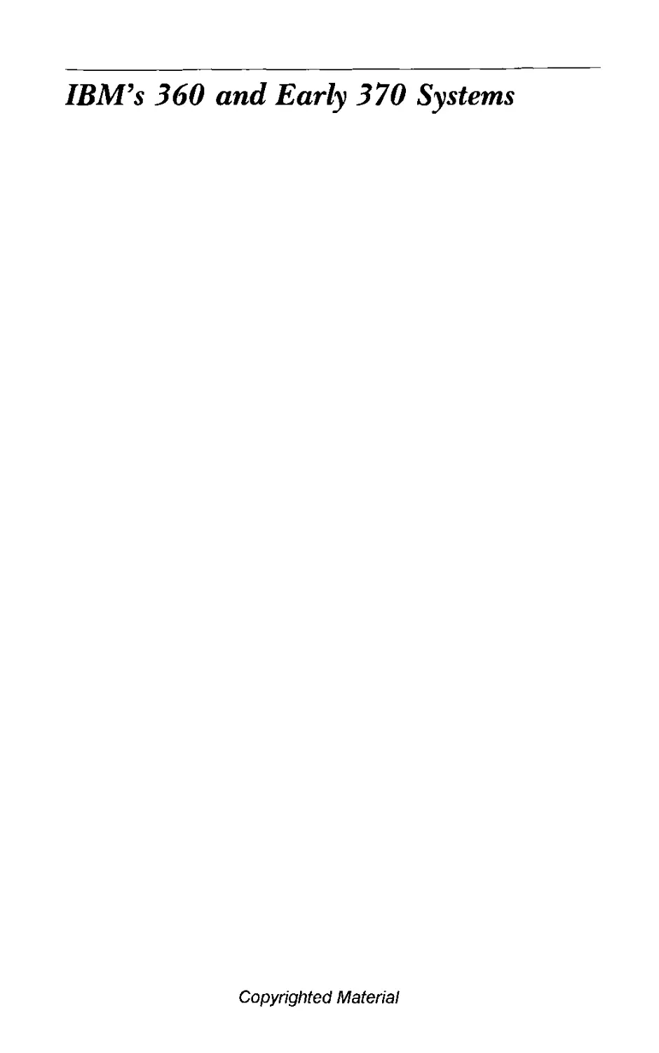
Figure 1.1 IBM 407 Accounting Machine
The 407 (foreground) is seen angularly from its front side and control
panel end. At the other end, largely hidden, are its card hopper and
stacker. Printed paper emerges from the printer at top center. This tabula-
tor, introduced in 1949, read 80-column cards at the rate of 150 per min-
ute. In list mode it accumulated sums and printed card detail during each
card cycle; in tabulate mode it omitted printing until it reached a control
break for sums. In both modes, the printing of each line for subtotals or
grand total took an extra cycle. There were 120 print wheels, and on the
periphery of each were forty-seven raised characters (digits 0—9, uppercase
alphabet, eleven business symbols). A large version of the machine had
twenty-eight accumulators: ten of eight digits, ten of six digits, four of four
digits, and four of three digits. Accumulators could be coupled to form
longer units. Just beyond the 407 is a 514 reproducing punch, which could
be operated either singly or (with the aid of cable connection) as a sum-
mary-punching device for the 407. Against the far wall is a 602 calculating
punch (right) and an alphabetic interpreter (left).
Copyrighted Material
Embracing Electronics 9
temperature. Among other capabilities, vacuum tube circuits
could amplify small electrical signals, a property that made
them indispensable in radios.
Prior to radio, electrical engineering had been concerned
largely with motors, relays, and power generation and distri-
bution. Of the electromagnetic relay’s many uses, two were
especially well known: with a relatively small expenditure of
electrical energy, it could complete a circuit capable of carrying
a much larger amount of electrical energy, and it could be
employed in switching circuits capable of establishing and
maintaining electrical paths for telegraph messages and tele-
phone conversations. One of the basic limitations of the relay
was that it involved mechanical motion, which in practice meant
that it required a few thousandths of a second to switch from
off to on, or vice versa. The vacuum tube, which involved no
mechanical motion, was capable of acting far more rapidly.
With the dawn of radio had come the need for an engineer-
ing discipline concerned with vacuum tubes and related com-
ponents. For the convenience of North American engineers,
the Institute of Radio Engineers was founded in 1912. The
new society supplemented the American Institute of Electrical
Engineers, which had been founded in 1889. In April 1930 a
new trade magazine, Electronics, appeared. Readers liked the
catchy, suggestive title and “electronics engineer” was soon
describing their profession.11 When the two professional soci-
eties chose to merge in 1963, they took the name Institute of
Electrical and Electronics Engineers.
During the heyday of radio, the switching capabilities of
vacuum tubes were little explored. IBM’s product designers,
for instance, were strongly inclined toward the mechanical
technology underlying the company’s products; their work
made some use of electromechanical switching devices (relays)
but none of vacuum tubes. To provide them with consulting
help, their main engineering organization in Endicott main-
tained a small electrical laboratory. Among the few assigned
there was Ralph L. Palmer, who joined IBM in 1932 after
earning an electrical engineering degree from Union College,
Schenectady, New York.12 Palmer had taken courses in elec-
tronics, but he soon found that relays were to be the major
concern in his new position. Among other things he checked
the properties of faster, smaller relays then being developed
Copyrighted Material
10 Chapter 1
for future IBM machines. By chance, the first major use of
these new relays was in the ASCC built for Harvard University.
After becoming supervisor of the electrical laboratory in
1937, Palmer found time to carry out a few small projects
involving electronics. Some of these were suggested by Bryce,
whose small staff at headquarters was getting acquainted with
electronic counting circuits by trying out available gas-filled
electron tubes and vacuum tubes. Palmer became interested in
the Eccles-Jordan trigger circuit, a vacuum tube circuit later
called a “flip-flop.” Like a relay, it had two stable states and
could serve as a storage device. In 1941 Palmer’s depart-
ment developed a way of adding two decimal digits using flip-
flops and, when this worked, went on to configure circuits
that served as electronic equivalents of a decimal-wheel
accumulator.
At this point Palmer was urged by the manager of engineer-
ing at Endicott—W. Wallace McDowell (1906—1985), a gradu-
ate of the Massachusetts Institute of Technology—to build a
vacuum tube device for multiplying. Multiplication was the
operation in which the high speed of vacuum tubes would show
to best advantage.13 Demonstrable by December 1942 was a
unit that formed a numerical product by repetitively adding
and shifting the multiplicand a suitable number of times. But
in the absence of any urgent need for it, the device was not
finished in fully electronic form; relays were used to accomplish
the subsidiary task of shifting.14 In 1943 Palmer entered the
U.S. Navy and work on the project dwindled.
In the course of responding to requests for development
services during the war, IBM's engineering leaders gathered
that significant advances were being made in the field of elec-
tronics. Voicing concern over the company’s inability to keep
pace, Mr. Watson asserted in October 1943 that he wanted
electronics used in one of IBM’s next accounting machines.
Perhaps indulging in hyperbole to make a point, he urged
Bryce to visit campuses and recruit “the most outstanding pro-
fessor in electronics.”15 Inasmuch as most of the country’s elec-
tronics experts were deeply involved in the war effort, nothing
directly came of the proposal. However, it may have stimulated
the hiring of young, less experienced electrical engineers, for
a few were acquired late in the war.
At the ASCC dedication in August 1944, Mr. Watson took
affront at an Aiken-pE^tfg^cpMSfe/^ease that casually sub-
Embiaang Electronics 11
ordinated IBM’s contributions. Later when he learned that
Aiken was planning to build—at Harvard, and without IBM’s
help—a machine more advanced than the ASCC, he ordered
his engineers to design and construct, as soon as possible, a
"supercalculator” capable of surpassing anything attempted at
Harvard. He apparently also wanted to use the occasion to
learn more about electronics and its product potentialities, for
he also urged Bryce's staff to design and demonstrate a small
electronic calculator.16 To provide guidance regarding scientific
requirements, he founded the Department of Pure Science and
in March 1945 installed Wallace Eckert as its director. (Eckert,
it will be recalled, possessed matchless experience in the use of
punched-card machines for scientific computation.) Upon ar-
riving, Eckert learned that one of his many responsibilities
would be to formulate the overall design of the supercalculator,
preparations for which were underway in the Endicott
laboratory.
Tom Watson, the elder of Mr. Watson's two sons, resumed
his career in IBM in January 1946.17 (It would be misleading
to write "Tom Watson, Jr.," because there is no evidence that
anyone in IBM ever addressed T. J. Watson, Sr., as “Tom.’’)
Whetting his interest in electronics was a pilot's knowledge and,
soon after his return, a visit to see a sensationally fast calculat-
ing instrument revealed and publicized by the army. Known
as ENIAC (Electronic Numerical Integrator And Computer),
it was the first electronic digital calculating machine of
productive usage. Developed under military secrecy at the
University of Pennsylvania's Moore School of Electrical
Engineering, its primary designers, John W. Mauchly and
J. Presper Eckert. Jr., (no relative of W. J. Eckert), had been
motivated by army ordnance’s massive wartime work load of
ballistics calculations. Completed shortly after the war's end.
the machine contained about 18,000 vacuum tubes and 1500
relays. Its electronic clock meted out pulses 100,000 times a
second. In the elapsed time of twenty pulses, it could add two
numbers. In the time required for fourteen additions at most,
it could do a multiplication. It performed arithmetic about a
thousand times faster than the electromechanical ASCC.18
The system was sorely handicapped, nevertheless. For lack
of faster input-output technologies, it emulated the ASCC in
reading data from cards and punching results into cards. Dur-
ing the war, upon Ьеэд^йййЧйай^папсе officer’s plea for
12 Chapter 1
special punched-card equipment, Mr. Watson had asked Bryce
to arrange fora satisfactory solution. Told nothing informative
of the main system, IBM engineers had fashioned card reading
and punching mechanisms as requested. The solution provided
ENIAC with a slow form of external storage in the sense that
card decks produced by the punch could be resubmitted
through the card reader. Cards punched with final results were
printed on standard IBM tabulators; input cards were pre-
pared on standard IBM keypunches.19 Because of the costly
nature of vacuum tube flip-flops, the only feasible electronic
storage technology known to them, the ENIAC designers had
limited the internal storage of their system to twenty high-
speed accumulators—a severe restriction; even the much
slower ASCC had seventy-two accumulators. Moreover their
machine lacked the job-switching convenience of encoded in-
structions; a user had to control it with the aid of elaborate
plugwired panels and banks of mechanical switches. As a result,
the laborious chore of readying it for a given computational
task could take days.20
In April 1946 Tom Watson saw a demonstration of the small
electronic calculator being completed by Bryce’s group. Al-
though the machine could be used to add, its primary function
was to multiply two numbers read from a card and punch the
product in a third field of the card. In function and size the
machine was almost trivial compared to the ENIAC. Still, Tom
saw it as an opportunity for gaining manufacturing experience
and encouraged a decision to produce a first lot of fifty. An-
nounced four months later as the IBM 603 Electronic Multi-
plier, the machine was too closely akin to IBM’s venerable 601
multiplying punch to make good use of the speed of electron-
ics. Nonetheless, it earned the distinction of being the first
manufactured electronic digital calculating machine.
IBM’s World War II practice had been to pay employees on
military leave a portion of their company salary. Tom Watson
would later attribute the company’s postwar vitality to this
practice, which motivated beneficiaries to return.21 Among a
number who brought back valuable experience in military elec-
tronics was Ralph Palmer. During the war, while stationed at
the Naval Computing Machine Laboratory in Dayton, Ohio,
he had been deeply impressed by the large numbers of vac-
uum tubes being successfully operated in secret military
equipment.22 Copyrighted Material
Embracing Electronics 13
Palmer returned to Endicott in early 1946 to learn that the
circuits he had once experimented with had served as proto-
types for circuits in the calculator being completed by Bryce’s
group and in the supercalculator under development in En-
dicott. At the instigation of Tom Watson, he soon was asked
to establish a product-oriented electronics development center
at the IBM Poughkeepsie site.23 There he moved into the main
dwelling on a recently purchased estate and, from a makeshift
office, began recruiting engineers and launching projects. His
major objective became the design of an electronic calculating
punch that would surpass the rudimentary IBM 603 in func-
tion, performance, and reliability.
While the Poughkeepsie laboratory was setting about to de-
velop a new calculator, the Endicott laboratory, which was pri-
marily engaged in modernizing the electromechanical product
line, was also building the supercalculator. The final specifica-
tions were approved in early 1946. In deference to Mr. Wat-
son’s desire for haste, Wallace Eckert had cautioned the
engineering team not to venture beyond the use of well-
understood component technologies.24 In mid-1947 the super-
calculator was moved into an area at corporate headquarters
in New York City, where the engineers and designers resumed
system testing.
The goal of “super” performance had led to the use of
vacuum tube circuits for the arithmetic unit, permitting a mul-
tiplication that took 6 seconds in the ASCC at Harvard to be
accomplished in a fiftieth of a second. The format for registers
accommodated a standard 80-bit “word” of information. (“Bit,”
short for “binary digit,” denotes a unit of storage that can be
set to either 0 or 1.) Each word could encode either a nineteen-
digit decimal number and its algebraic sign, or an instruction.
The arithmetic and control unit was fed instructions and data
by a storage hierarchy with the following capacities in words:
high-speed vacuum tube circuitry, 8; medium-speed relay cir-
cuitry, 150; and lower-speed paper tape, over 20,000. The
eighty-channel paper tape, the width of an eighty-column
punched card, was made of card stock. (The much narrower
paper tape used in communication devices typically had five
information channels.) Instruction sequences and numerical
tables stored in paper tapes could be read or searched on sixty-
six tape drives. The storage hierarchy was linked to the arith-
metic unit by severWj^'g/^atM^teaisih capable of routing 80
1-f Chapter I
bits in parallel. Two card readers augmented paper tape for
input. Needs for output were served by two card punches,
three tape punches, and three line printers. The word-sized
registers that constituted vacuum tube and relay storage were
addressable, and relay storage functioned as the memory of
the system. Formatted within words, instructions could be mod-
ified by other instructions, thus permitting a program to be
altered during execution. The relay memory sufficed to hold
a short program and a number of operands, but during exten-
sive calculations, many of the sequences of instructions were
executed directly as obtained from paper tapes.25
The supercalculator was demonstrated to the public in Jan-
uary 1948 as the IBM Selective Sequence Electronic Calculator
(SSEC). It contained 12,500 vacuum tubes and 21,400 relays
in panels and encased mechanisms that lined the walls of a
large room; during the dedication ceremonies, in fact, invited
dignitaries were able to stand within the machine itself. The
glowing tubes arrayed behind glass cabinet doors, the flashing
neon lamps on the operator’s console, and the bank of paper
tape mechanisms were visible to pedestrians through windows
on Fifty-seventh Street. Captured in at least one Hollywood
motion picture, the spectacle long influenced cartoonists in
their portrayals of computers.
Mr. Watson made the SSEC available to university scientists
free of charge and to industry scientists at the cost of operation.
Usage came to include extensive computations involving plan-
etary and lunar orbits, atomic fields, optics, ordnance, and
hydrodynamics. Eckert, who rated the system as having 250
times the computational capacity of the ASCC, hired a group
of young mathematicians to assist in preparing programs for
users. Members of this group later made impressive contribu-
tions to the discipline of programming.211 For example, a few
years after his SSEC assignment, John W. Backus led a pro-
grammer team in the development of the original FORTRAN
language and compiler.
The genuine advances made in the design of the SSEC were
unfortunately dimmed by the awkwardness of its hastily de-
veloped instruction set and the frequent downtimes that came
of employing so many vacuum tubes at this early stage in the
development of computer electronics. These shortcomings
were rendered all too conspicuous by operation of the machine
in a publicized scrvi^^^g^ ^pg^gyer, to compensate for
Embracing Electronics 15
Figure 1.2 IBM 604 Electronic Calculating Punch
The Type 604 electronic calculating unit (left) and cabled to it the Type
521 card reading and punching unit (right). First delivered in 1948, some
5600 systems were built over a ten-year period. More were installed than
built because mam were displaced bv computers, reconditioned, and then
installed again.
the relative slowness of the relay memory, the designers had
provided for a massive degree of parallelism in data flows and
auxiliary devices, making the machine bulky and expensive.
The cost-conscious engineers in Poughkeepsie studiously went
their own way and ignored the machine, and it would be left
to historians to note that the SSEC was the first operational
calculator with an electronic arithmetic unit that possessed the
distinguishing features of what would later be termed the
stored-program computer.27
Meanwhile Ralph Palmer’s Poughkeepsie center was devel-
oping the IBM 604 Electronic Calculating Punch (figure 1.2).
Delivered in late 1948, it far excelled its 603 predecessor on
all counts. Vacuum tubes of reduced size had become available,
and for the electronic circuitry of the calculating punch, Palmer
packaged each tube with associated resistors and capacitors in
a pluggable assemblyuhatJje,ttsted as a unu.before
insertion into the тасТпЬе.я The resulting units yielded a high
16 Chapter 1
circuit density and a commendably low time for fault diagnosis
and repair. The usual technique for isolating a malfunctioning
604 circuit was to observe the effects on system operation of
swapping identical pluggable units. Experience in manufactur-
ing the 604, which filled a pent-up need, soon placed IBM
among the front-runners in mass production of high-quality
electronic equipment.
The 604’s reader-punch could read a card containing oper-
ands and punch a calculated result at the rate of a hundred
cards per minute. During each card cycle, the 604 could exe-
cute up to forty (later increased to sixty) operational steps
under plugboard control, subject to timing restrictions based
on step durations. Flexibility of control was enhanced by a
capability for skipping steps under control of accumulator
content.
Encouraged by engineers engaged in aircraft design, IBM
in 1949 announced the Card-Programmed Electronic Calcu-
lator (better known as the CPC) that augmented the 604 and
its reader-punch with a tabulator and an optional unit with
electromechanical storage for sixteen ten-digit numbers.29 In
CPC operation, the 604 acted as a slave to the tabulator. De-
sired procedures could be wired on the 604 plugboard; cards
read at the tabulator could specify locations in storage and
associate them with the 604 procedures. Deliveries of the CPC
started late in 1949, and the outbreak of hostilities in Korea in
mid-1950 intensified demand. The nearly 700 CPCs built dur-
ing the first half of the 1950s were used, among other things,
to perform many of the engineering calculations that under-
pinned the booming jet aircraft industry.
Shortly after the SSEC was dedicated in 1948, Mr. Watson
asked his senior technical leaders and his SSEC designers at
Endicott to begin planning a reduced-capacity version that
could meet the needs of ordinary businesses. Confusion re-
sulted: any machine with much kinship to the SSEC would
have been so expensive to build, maintain, and operate that
the idea seemed farfetched. Instead product planners at head-
quarters wanted a 604-class machine with additional capabili-
ties, such as faster and more conveniently accessible storage
for utility or insurance rate tables. After looking over available
kinds of storage, the Endicott engineers rejected relays and
wide paper tape and agreed that electronic registers had to be
minimized to cut to try magnetic drum
Embracing Electronics 17
storage, which they had heard discussed the previous year in
a symposium at Harvard University.
Many factors conspired to slow the development of the mag-
netic drum calculator. Development resources were scarce; the
main activity needed to satisfy postwar product demand was
modernization of conventional card machines. Moreover,
product planners were dubious. At estimated rentals, which
always came out higher than desired, the projected number of
customers failed to justify producing the drum calculator. Dur-
ing the four years of indecision and on-and-off support for
their project, the designers naturally made worthy improve-
ments. Just as significant, changing circumstances in the mar-
ketplace were nurturing a demand for electronic calculators
that could improve on the CPC. The drum machine (figure
1.3) was finally announced in mid-1953 as the IBM 650 Mag-
netic Drum Calculator. It was designed to execute a program
stored in the drum memory, although plugboards were still
used to simplify format control for input and output. All the
excesses of the SSEC were absent; the result was a modestly
priced computer system with commendable provisions for self-
checking and reliability.
By December 1954, when the first 650 was delivered, an
even less expensive computer was under development in IBM’s
San Jose, California, laboratory. Reynold B. Johnson, the man-
ager there, chose to concentrate on equipment for inventory
processing, an application that needed high-capacity, direct-
access storage devices. Toward meeting the need with a device
of reasonable cost and physical bulk, his engineers undertook
to design a novel mechanism that would rotate a spindled stack
of magnetic disks. Suitable surfaces, recording methods, and
access mechanisms were developed. Matched to the disk device
was a processing unit that for frugality’s sake was designed to
make joint use of plugboard and memory techniques. The
system was announced in 1956 as the IBM 305 RAMAC (Ran-
dom Access Method of Accounting and Control). Up to 50,000
records of a hundred characters each could be stored on the
system’s fifty disks. Disk storage was simultaneously announced
as an optional attachment to the 650 system. These announce-
ments of the industry’s first disk storage units opened a new
era for computers, one in which the capacities of economical
direct-access storage devices could exceed those of main mem-
ory by a hundred Material
18 Chapter 1
Figure 1.3 IBM 650 Magnetic Drum Calculator
Development of this computer, the first with production exceeding 1000
systems, began in 1948. The system was announced in July 1953 with three
units: Type 650 central processing unit (center), Type 533 read-punch
(right front), and Type 655 power unit (partially seen, left). The machine's
design was organized around a word of ten decimal digits and an ap-
pended digit used to designate algebraic sign. The digits were represented
m a seven-bit biquinary code that had a degree of redundancy useful in
checking the correctness of transmissions. The machine was designed pri-
marily for general computations, but when it proved to be of interest for
accounting applications, a feature was added to make it convenient for
alphanumeric characters to be represented as pairs of decimal digits.
Among other attachments introduced at various times were a floating-point
unit, the 407 accounting machine, magnetic tape units, and magnetic disk
drives.
By mid-1956 IBM 650s, produced at the rate of one a day,
were used for both technical computations and business appli-
cations. Acceptances were sustained by a stream of product
enhancements, and the last 650 was built in 1962. Over 1,800
were produced, easily making the machine the most popular
electronic computer of the 1950s. Meanwhile, over a thousand
of the smaller and more specialized 305s were delivered before
production ended in 1961.30
Somewhat ironically, the 650 computer when announced was
viewed as prosaic by IBM executives, among them Tom Wat-
son, company president since January 1952. During its long
development period, the machine had slowly evolved from
conception as an em^ej|jj^g^^p^^gynouncement as a mod-
estly priced card-input computer. The 650’s designers made
Embracing Electronics 19
few claims to originality in technology or function, and head-
quarters numbered the announced product in a 600 series that
traced back to a multiplying punch introduced over twenty
years earlier. Moreover Tom Watson s primary attention had
long been riveted on large-scale digital computers, the arena
where new technologies—particularly magnetic tape—and new
marketing strategies were conspiring to generate high drama.
13 Large-Scale Computers
Long before ENIAC was completed in February 1946, Presper
Eckert and John Mauchly at the Moore School of Electrical
Engineering were envisioning a less expensive, more flexible
system. The ordnance department encouraged their work, and
in 1944 thev began discussing plans with a departmental con-
sultant, famed mathematician John von Neumann of the In-
stitute for Advanced Study. One outcome was a project
document by von Neumann. Dated June 1945 and entitled
"First Draft of a Report on the EDVAC” (the acronym stood
for Electronic Discrete VAriable Computer), it discussed an
idealized computing instrument and sei forth concepts ger-
mane to a digital computing system more flexible than either
ENIAC or the IBM ASCC. Postulated was a fast access, word-
addressable storage device, called memory, that would have the
capacity to hold needed elements of a computation—elements
that could include a program of encoded instructions, blocks
of input and output data, and tables of data and intermediate
results. During execution of a memory-contained program,
instruction-contained memory addresses could be altered, and
the altering could be contingent on the algebraic sign of a
computed result. Thus a program segment could be made to
loop repeatedly until the accumulator sign changed.31 Al-
though the “First Draft's'’ high level of abstraction excused it
from the army's security regulations—an exception nor made
for related engineering reports—the draft report was not pub-
lished. Distribution was within the project and later selectively
to computational experts who heard of the draft and requested
a copy.32
Security regulations were eased after the war ended. During
July and August 1946 the Moore School conducted a special
course entitled “Theory and Techniques for Design of Elec-
tronic Digital Compifi^ftK^SS^k^^^^ne from within the fac-
20 Chapter 1
ulty and from Army Ordnance, the Institute for Advanced
Study, the National Bureau of Standards, Electronic Control
Company (a Philadelphia firm newly established by Eckert and
Mauchly), Harvard University, RCA Laboratories, Bell Tele-
phone Laboratories, and the Cavendish Laboratory of Cam-
bridge University.33 There was no inducement to look to IBM
for lecturers. Because Ralph Palmer’s nascent electronic cal-
culator in Poughkeepsie, the supercalculator in Endicott, and
the Type 603 electronic multiplier announced later in the year
were all being developed in proprietary projects, no informa-
tion on them was available beyond IBM. To outside leaders in
computing and electronics, IBM appeared to be a small, slow-
moving company struggling to field some improved accounting
machines after a four-year wartime break in product an-
nouncements. The ASCC built for Harvard was technologically
passe, and from the standpoint of the Moore School so were
the relay calculators that IBM had delivered to the ordnance
department during the war.
Professionals from twenty organizations attended the sum-
mer school. Invited to nominate students, IBM named some
engineers from Wallace Eckert’s department, but the invitation
was withdrawn on the grounds that IBM had no government
computer contract.34 Although many of the lectures were re-
corded and edited, it was 1947 before the first collected volume
was issued. Meantime, in an Institute for Advanced Study re-
port dated June 1946, von Neumann and two colleagues dis-
cussed computer design principles.35 A revision dated
September 1947 later came to the attention of IBM engineers
and became influential in IBM. At the January 1947 Harvard
Symposium on Large Scale Digital Calculating Machinery, a
few IBM engineers heard a talk on “Preparation of Problems
for EDVAC-type Machines” by John Mauchly. Apparently
these engineers were the first IBM employees to hear a sub-
stantive exposition of EDVAC concepts.
During the years 1946—1950, American and British engi-
neers managed to develop three viable memory technologies:
magnetic drum, acoustic delay line, and cathode ray tube. Of
these the cathode ray tube was most conducive to fast access,
but because of engineering difficulties, its usage lagged behind
the others. By 1951 several EDVAC-influenced, one-of-a-kind
computers had been completed in government or university
laboratories with delay lines. Working
Embracing Electronics 21
with the same memory technologies were two profit-motivated
ventures of particular interest here. One of these, Engineering
Research Associates (ERA), founded after the war by ex-navy
officers familiar with electronic code-breaking equipment, went
on to build a series of drum-memory computers for the Na-
tional Security Agency.36 ERA obtained valuable engineering
experience but was hampered by its client’s extreme aversion
to publicity. The other firm, Eckert-Mauchly Computer Cor-
poration (successor to the short-lived Electronic Control Com-
pany), committed in 1947 to produce a computer system with
delay-line memory, magnetic tape drives, and magnetic tape
reels capable of storing large files of business records. It called
its postulated system L’NIVAC (UNIVersal Automatic Com-
puter). After a promising start, delays and engineering diffi-
culties led to rising costs that endangered the corporation.
Remington Rand, IBM’s foremost competitor in typewriters
and punched-card equipment, acquired the firm in 1950 when
the first UNIVAC was nearing completion. The Bureau of the
Census, the Air Force Comptroller (an office doing research
on optimal allocation of resources in event of war), and the
Army Map Service were expecting to receive the first three
UNIVACs.
Meanwhile, in late 1948 Tom Watson had questioned the
flat trend in IBM’s postwar engineering population, and, as a
result, the company had hired a number of young electronics
engineers in 1949. This influx enabled Palmer to begin catch-
ing up with outside work on memory, magnetic tape, and
EDVAC-like computer systems. Some of his engineers began
experimenting with a cathode ray tube called the Williams rube
in deference to its British inventor. Others constructed an ex-
perimental computer known as the Test Assembly. Still others
began outlining the nature of a Tape Processing Machine
(TPM), an accounting-oriented computer system. To ease the
long-standing, eighty-column limitation of the punched card,
plans called for files in which the number of recorded char-
acters in a magnetic tape record could be stipulated by the
user.
Confronting the designers of the magnetic tape drive was
the need for a tape-endangering acceleration and deceleration
during the recording or reading of each record. Experiments
with various tape-handling principles frustrated the TPM team
for months. Particul^^M^^JWWfff^as the failure of forced
22 Chapter I
air to hold a confined loop of plastic tape in a suitably light
and predictable state of tension. Finally, in late 1949, a perse-
vering IBM engineer, James A. Weidenhammer, who was using
a vacuum cleaner as an air supply, turned the cleaner around
and connected a hose to its suction end. To his surprise, the
tape loop reacted much more usefully to suction than it had
to compression, and the ‘vacuum-column” mode of tape han-
dling was on its way to becoming one of the most widely used
principles in the computer industry. By late 1950 Palmer’s
engineers were operating a cathode ray tube memory, running
programs on the experimental Test Assembly, and demonstrat-
ing magnetic tape drives and recording methods of the kind
needed for a TPM.
Advances in electronics, among them the advent of the ger-
manium diode (a semiconductor device that promised to re-
place many of the vacuum tubes in logic circuits) had been
raising the expectations of electronics engineers well before the
mid-1950 eruption of hostilities in Korea. When the United
States assumed a leading role in an intervention by the United
Nations, computational requirements surged in the country’s
defense industries, and electronics gained in stature as a result.
When Tom Watson solicited his staff for ideas concerning ways
to aid the defense effort, among those received was one sug-
gesting development of a new product: an electronic computer
that would far excel the CPC at engineering computations.
This idea met with favor and rapidly became a formal proposal.
At a meeting Tom Watson chaired in January 1951, diverse
views were expressed concerning the computer proposal,
which was said to be risky on both technical and financial
grounds. Computer development, on the other hand, offered
the company valuable, perhaps invaluable, experience. To set-
tle the issue, the chair finally asked for a show of hands—and
then told the nay-voting minority to ignore the endeavor until
it was safely underway. Engineers in the Defense Calculator
project, as it was dubbed, overcame challenging problems to
complete the company’s first product line computer, the IBM
701 Electronic Data Processing Machine (figure 1.4). For hard-
ware, the designers had borrowed heavily from that under
development for the TPM, and for system principles they had
turned to von Neumann’s plans for his IAS (Institute for Ad-
vanced Study) computer, which performed arithmetic in the
binary number syste^PWflfiJ&dAfe^tfc/ operands. The binary
Embracing Electronics 23
Figure 1.4 IBM 701 Electronic Data Processing Machine
Designed beginning in early 195], the 701 computer was announced at
IBM’s annual meeting in April 1952. Shown is the first production 70),
which was installed in December 1952 at IBM headquarters, 590 Madison
Avenue, New York City. (At the upper rear is a glassed-in work area.) The
machine, with its 36-bit word and circuitry for fixed-point arithmetic on
binary numbers, was intended primarily for computations in engineering
and science. After nineteen 701s had been produced, the system was
superseded by the IBM 704.
formats were conducive to fast technical computation but dif-
fered markedly from the TPM’s flexible alphanumeric formats
and decimal arithmetic.
Unlike some contemporary computers that were difficult to
move, the 701 system was configured of intercabled units, each
of which could pass through standard doorways and elevators.
This not only facilitated shipment, installation, and service but
was conducive to modularity and to the making of box-by-box
improvements during the life of the system. The first system,
shipped in December 1952 to the company’s computing bureau
in New York City, displaced the SSEC, which was so clearly
surpassed that it was scrapped. The second went to the Los
Alamos Scientific Laboratory in March 1953. Nineteen 701s
were built.
In late 1952 ERA (by then a division of Remington Rand)
received federal permission to announce a version of an un-
publicized system built for the National Security Agency.37 This
computer, known as the ERA 1103, vied closely with the 701.
Copyrighted Material
24 Chapter 1
In early 1954, for example, a meteorological committee in the
office of the Joint Chiefs of Staff requested that the two be
compared on their merits for a proposed Joint Numerical
Weather Prediction project. Based on trial calculations, an ap-
pointed group of experts found the speeds of the machines
comparable "with a slight advantage in favor of the 701.” The
designers of both machines had followed von Neumann’s ex-
ample and opted for circuits that performed arithmetic on
binary numbers. Despite the close match in computational
speed, the 701 was favored unanimously because its input-
output equipment was deemed significantly faster.38
While the binary machines contended at heavy computation
in what was essentially a new marketplace, Remington Rand’s
UNIVAC, which stored encoded alphanumeric characters and
performed decimal arithmetic, was striking directly at IBM’s
traditional business. Among the target applications were insur-
ance and utility accounting and billing, manufacturing control,
and federal record keeping. Endowed with ten magnetic tape
drives, UNIVAC was the first computer capable of storing and
processing large business files.39 The Bureau of the Census
took custody of the initial system in March 1951, but because
of the work load occasioned by the census of the previous year,
the cumbersome process of moving the system to a permanent
site was delayed for over a year. In June, meanwhile, the ma-
chine was dedicated with a blaze of publicity. Long awaited
and well recognized as historic, UNIVAC was the first elec-
tronic computer advanced as a commodity, not as an arcane
laboratory instrument. Speakers recalled that punched cards
had gained their foothold in census work and noted that now,
six decades later, magnetic tape was gaining a similar
foothold.40
Although UNIVAC serial #1, located up front in its Phila-
delphia factory, was visited by streams of people from govern-
ment and industry, those most seriously interested went home
sobered by the heavy investment likely to be required to exploit
the system successfully. Industry studies were launched, but
UNIVAC sales moved slowly. When Remington Rand at length
managed to generate widespread public interest in computers,
it was with the aid of a statistical model for election prediction.
In November 1952 one of the UNIVACs (by this time five
existed) was nationally televised during the evening of the
presidential election. computer ran the
Embracing Electronics 25
statistics program and printed a result that correctly predicted
a landslide victory for Dwight D. Eisenhower. But the predic-
tion came too early to gain the confidence of the responsible
impresarios, who were keenly aware of the possibilities of en-
countering program bugs or input blunders. They tempered
the computed results and later in the evening admitted their
offense. Despite the televised confusion, or perhaps to some
extent because of it, UNIVAC caught the public’s fancy and
became a household term for electronic computer.41 IBM, hav-
ing thrown its resources into the development of its Defense
Calculator, a computer for engineering computations, was
caught off guard by what soon became a snowballing interest
in computer systems capable of replacing punched-card files
and accounting machines.
Tom Watson conspicuously lacked a suitable competitor to
UNIVAC, that is, a computer that would appeal to accounting
managers as much as the Defense Calculator appealed to com-
putation center managers. As a result, he faced a long wait for
completion of an improved version of IBM’s experimental
Tape Processing Machine. Finally, in September 1953, the IBM
702 (figure 1.5) was announced, but even then the schedule
called for first delivery in sixteen months. The years 1953 and
1954, when UNIVAC was the big name in the marketplace,
were to remain unforgettable for many at IBM. Tom Watson
later attributed the agonizing episode to complacency, ‘’one of
the most insidious dangers we face in business.”42 Reflecting
some credit on IBM’s technical prowess during this period was
that Wallace Eckert’s small laboratory was completing NORC
(Naval Ordnance Research Calculator), a one-of-a-kind ma-
chine dedicated with a flourish in November 1954. Its elaborate
multiplication unit was to remain the fastest ever built with
vacuum tubes.
Despite UNIVAC’s technical achievement, it was no simple
feat to pay for a computer system by displacing costs in a
punched-card accounting machine installation. One of the rea-
sons Tom Watson had supported the Defense Calculator, a
computer for engineering calculations, was that IBM’s cost
studies could not justify large-scale computers for accounting.
Moreover, there was no experience from which to predict the
extent to which punched-card files could be consolidated or
the pace at which technology would advance. Having rather
abruptly acquired the Remington Rand
26 Chapter 1
Figure 1.5 IBM 702 Electronic Data Processing Machine
Development of the 702 computer began in 1949. The system was an-
nounced in September 1953 for first delivery in early 1955. The 702
system pictured here at IBM headquarters in New York City was used
temporarily for customer program testing before being delivered to a
governmental agency in California. At center is the operator’s panel with
electric typewriter and card reader. At the left in the background is the
arithmetic and logical unit. Clockwise from the left are the following pe-
ripherals: eight tape units (one obscured), card reader, line printer, and
card punch. Fourteen systems were produced, after which the system was
superseded by a functionally improved and faster one, the IBM 705.
organization was beset with technical questions. Potential cus-
tomers worried, among other things, about the durability of
magnetic recording, the risks (high at the time) of equipment
breakdowns, the difficulties in recruiting and training pro-
grammers, and the problem of ensuring audit trails given in-
visible magnetic recordings. The three UNIVACs delivered in
1952 went to mathematical computing centers, not to account-
ing locations. So did two of the three delivered in 1953—the
third going to a Remington Rand service bureau with a mixture
of jobs. By the following year IBM’s 701 and Remington Rand’s
ERA 1103—machines that excelled the UNIVAC in arithmetic
speed—had become the favorites for scientific computing. But
by this time, some customers were ready to try magnetic tape
for business applications. For this purpose, at least in most
part, UNIVACs were delivered in 1954 to Du Pont, General
Electric, Metropolitan Life Insurance, USAF Air Materiel
Command, and United States Steel (two systems).43
Copyrighted Material
Embracing Electronics 27
In 1954 analysts began predicting that the announced IBM
702 computer would be inferior to UNIVAC on some impor-
tant tasks, such as sorting of a file of records on magnetic
tape.44 As showcase UNIVACs began to replace large card-
machine installations, an atmosphere of crisis pervaded IBM
branch offices with large accounts. Company president Tom
Watson was faced with declining sales morale. In April he
established a new position, director of electronic data process-
ing machines, and filled it with a highly experienced sales
manager, T. Vincent Learson.45 A Harvard graduate with a
major in mathematics, Vin Learson had joined IBM in 1935
as a sales trainee. During the war, he had gained familiarity
with federal data processing as an IBM representative in Wash-
ington, D.C. He had risen to branch manager, to district man-
ager, and in 1949 to sales manager for accounting machines.
His new role in 1954 (figure 1.6) was to knit together the
already strenuous efforts being made in the product planning,
engineering, manufacturing, and sales organizations in a way
that would lead to informed, swift decisions concerning future
computer products.
Learson vigorously promoted action. Announced within
months were the IBM 704 computer (as successor to the 701)
and the IBM 705 (as successor to the 702). Both of the new
systems promised to be considerably more capable than their
predecessors. Moreover, as a result of Learson’s perception of
opposing risks, before the year ended both systems were sched-
uled to utilize ferrite-core memory, a less fully tested but in-
herently more reliable technology than the cathode ray tube
technology it displaced. Although the announcements were
well received, it was far from evident in 1954 that Remington
Rand would not improve its lead. In October the Census Bu-
reau quietly received its second UNIVAC (the thirteenth to be
built); many years later, Tom Watson would recall having been
‘absolutely panicked” upon learning of this.46
The UNIVAC memory was based on a technology that con-
verted electrical pulses into sonic pulses, routed the relatively
slow-moving sonic pulses down a cylindrical "tank” of mercury,
reconverted at the end of the tank to fast-moving electrical
pulses, and stored information by looping the pulse string
around and through the tank as long as necessary. Seven pulse
positions were used to represent each character. The number
Copyrighted Material
28 Chapter 1
Figure L6 EDPM gains status
Thomas J. Watson Jr. (center), T. Vincent Learson (left), and Ralph L.
Palmer in April 1954. Watson had just announced Learson’s promotion to
a new post, director of electronic data processing machines.
Copyrighted Material
Embracing Electronics 29
of required tanks made for bulky apparatus that could not
easily be expanded in capacity. Fortunately for IBM, ferrite-
core developments in 1954 were rendering older memory tech-
nologies obsolete. Remington Rand did not announce a UNI-
VAC successor with ferrite-core memory until mid 1955—
perhaps a year late from the standpoint of aggressive market-
ing—and later experienced delays in delivering the successor.47
It led in number of large-scale electronic computers installed
until the latter half of 1955. Then, as Tom Watson carefully
reckoned at the time, IBM took the lead.
When asked in May 1956 to name the most exciting time of
his career, Tom Watson recalled the previous year—a period
during which, he said, IBM had “conclusively asserted its lead-
ership in the data processing field.”48 The occasion for recol-
lection was a personal milestone. In his position as IBM
president, he was gaining full responsibility for direction of
the company (figure 1.7). Commenting in an editorial, the New
York Times wrote,
At 82, Thomas J. Watson Sr., chairman of International Business
Machines, has turned over the post of chief executive officer of his
company to his son, Thomas, Jr. As he does so, the elder Mr. Watson
can look back on a career rich with business achievement and social
accomplishment. One wonders how our complex society could get
along without the punch-card machines and associated devices which
I.B.M., under Mr. Watson, carried to so high a degree of perfection
and usefulness.
In the era of “electronic brains,” now beginning, I.B.M. is one of
the leaders on the technological frontier.49
Six weeks later the ailing father succumbed to a heart attack.
The company’s board of directors paused half a decade before
again naming a chairman.
That by 1956 IBM could be counted “one of the leaders on
the technological frontier” was a tribute to the persistence Tom
Watson had shown in promoting opportunities for advanced
development. Surely the large-scale computer deliveries that
gave the company numerical superiority elated him in part
because he saw them as tangible fruits of his own vision and
leadership. Computer products continued to bring him good
news during the last half of the decade. Both accounting ma-
chine and computer revenues were increasing, the latter at the
faster rate. Copyrighted Material
30 Chapter I
Figure 1.7 New IBM CEO
Thomas J. Watson. Jr., IBM president, receiving congratulations from his
father, Thomas J. Watson, Sr., IBM chairman, in May 1956. With the
handshake went the responsibilities of chief executive officer.
Copyrighted Material
Embracing Electronics 31
1.4 Solid-State Computers
Prior to the 1950s, IBM’s engineering activities had been pro-
vincial, secretive, and dominated by competing inventors. The
first portent of change was the hiring in 1945 of Wallace Eckert,
who as the head of IBM’s newly formed Pure Science Depart-
ment continued his ties with academia—Columbia University
appointed him professor of celestial mechanics in 1946. An
eloquent communicator, he had done much through his pre-
vious work and writings to bring the capabilities of IBM’s
punched-card machines to the attention of scientists and math-
ematicians. The contrast between Columbia University and
IBM’s engineering laboratory in Endicott was sharp. Whereas
scientists usually hurry to explain their discoveries in technical
journals, the patent application was the only acceptable way
for engineers in the Endicott laboratory to reach an outside
audience.
Eckert arrived when IBM’s stability was being threatened by
two ill-defined and highly unpredictable forces: an upward-
curving need for scientific computation and the advancing ca-
pabilities of electronics. Each required an expanding base of
technical knowledge, and during the next several years, soon
as vice president and later as president, Tom Watson quickly
learned to listen to Wally McDowell, Ralph Palmer, Wallace
Eckert, and others on matters affecting acquisition and creation
of technological know-how. Two important advancing
branches of technology concerned ferrite-core memory and
transistors, the main components of what later would be called
solid-state computers.
The idea of storing information by electronically controlling
the direction of magnetization in doughnut-shaped metallic
rings (“cores”) cropped up in the mid-1940s and was discussed
and explored in Wallace Eckert’s laboratory starting in 1946.
These experiments, intended only to reveal physical principles,
were far removed from product design and were terminated
in 1949 on the grounds that the fundamental concepts had
been demonstrated. By this time improved results were being
obtained at Harvard University with a nickel-iron alloy devel-
oped in Germany during World War II. Intrigued by the con-
cept, Ralph Palmer in 1950 established a project to investigate
the utility of magnetic cores. A year later, a newly available
ferrite material епссбйФ^Й^Й14W€6&£ation into possible use
32 Chapter 1
of magnetic cores to store the image of a punched card: each
core of an array was to represent the hole or no-hole status of
one intersection in the card’s eighty columns and twelve rows.
In May 1952 such an array was successfully tested in an ex-
perimental system.50
This experiment excited the input-output designers of the
yet-to-be-announced IBM 702 computer. Their devices con-
sisted largely of four peripheral units: card reader, card punch,
printer, and magnetic tape drive. They desired units capable
of “online” operation while connected to the main system and
of “offline” operation when disconnected. Offline, a card
reader and tape drive, suitably coupled, were expected to serve
as a card-to-tape device. Similarly a coupled tape drive and
card punch were to function as a tape-to-card device, and a
coupled tape drive and printer as a tape-to-printer device. To
support this flexibility, every reader, punch, or printer required
a fairly large buffer—a term for storage serving as a temporary
way station during transmission. An 80-character buffer was
needed for a reader or punch and a 120-character buffer for
a printer. Ferrite-core arrays—if perfected in time—promised
to meet the needs of the designers rather neatly. Such arrays
were tested successfully in 1953 and delivered, beginning in
February 1955, in peripherals of the 702 system.
Buffer development provided valuable experience, but the
capacity required for a computer's memory exceeded that for
a buffer by a factor of at least a hundred. IBM’s prompt
adoption of ferrite cores for memory owed much to the com-
pany’s role in the development and construction of computers
for SAGE (SemiAutomatic Ground Environment), America’s
continental air defense system.
In 1950 a digital computer project known as Whirlwind, led
by Jay W. Forrester of the Massachusetts Institute of Technol-
ogy, was tapped by the U.S. Air Force as a source of knowledge.
Lincoln Laboratory, established by MIT, soon took over many
of the technical tasks involved in SAGE development.51 One of
this laboratory’s first jobs was to recommend contractors that
could not only help in developing computers for SAGE but
could also manufacture, install, and service the computers.
Convinced that the successful contractor would learn enough
to become what he described as a “kingpin” in data processing,
Tom Watson gladly showed company facilities to a team
headed by Forrestci^/M'Wfttfilfe^ftf^l^ recommending IBM,
Embracing Electronics 33
the team wrote that it was impressed by the company’s “degree
of purposefulness, integration, and esprit de corps,” as well as
by its substantial experience in transferring electronic products
from laboratory to factory. The team also noted that IBM was
successfully maintaining rented equipment (IBM 604 elec-
tronic calculating punches) containing millions of vacuum
tubes.53
IBM built a laboratory and plant in Kingston, New York, to
develop and manufacture computers for SAGE. The labora-
tory gained in core memory know-how, for Forrester was an
important contributor to core memory technology and had
assumed a leading role in its development. His group at MIT
had tested, in 1953, an experimental forerunner of the core
memories that IBM began delivering to SAGE in early 1955.
Also active in ferrite-core memory development was Reming-
ton Rand’s EILA division, which first delivered such a memory
to the National Security Agency in late 1954.
IBM, which soon began manufacturing core memories for
all of its large-scale computers, interested some of its best me-
chanical designers in devising automatic means for fabricating
and testing cores and for wiring them into suitable arrays. The
first of IBM’s core memory units was designed to hold 4096
words, each of 36 bits. As used in the IBM 704 computer, the
unit could satisfy a request from the central processing unit
for access to any designated word during each 12-microsecond
“memory cycle.” Units based on this general technology served
in IBM products for several years.
It had taken IBM about eight years to move from core
experiments to ferrite-core memory deliveries. An even longer
period was required to outmode the vacuum tube circuits in
its large-scale computers. A circuit device called the transistor
was disclosed by the Bell Telephone Laboratories in 1948. The
transistor promised to perform the functions of a vacuum tube
while dispensing with filament heating, high voltages, and vac-
uums—thereby contributing to higher reliability and to reduc-
tions in size and power requirements. Members of the Bryce-
founded laboratory in IBM corporate headquarters soon began
experimenting with transistors they constructed by substan-
tially modifying commercially available germanium diodes.
Their work merged with a more substantial undertaking in
mid-1950, when company responsibility for advanced electron-
ics was consolidatedQ^P^^fif^h0’^^©^ Poughkeepsie labora-
34 Chapter 1
tory. A year later the transistor project was said to be “finally
in high gear” with a staff of three physicists, four engineers,
and two technicians. The making of transistors from diodes
ended in early 1952 when facilities for “growing” semiconduc-
tor crystals and for fabricating transistors were completed.
Because the transition from tubes to transistors involved
many changes in design disciplines for circuit engineers,
Palmer in 1953 suggested an internally conducted course in
transistor circuit design. The twenty-eight engineers selected
for the program received three weeks of lectures followed by
six weeks of laboratory work. During the laboratory phase,
teams were asked to design practical machines using transistor
circuits. Later constructed were three of the designs, among
them a transistorized version of the IBM 604 calculator. This
experimental, all-transistor calculator was demonstrated in Oc-
tober 1954. Against the 1250 vacuum tubes in the 604, it
contained over 2000 transistors, but its circuits occupied less
than half the volume and used only 5 percent as much power.54
For the sake of improved reliability, junction transistors were
chosen over better known and faster point-contact devices. The
circuits and the packaging techniques used were forerunners
of those employed in the IBM 608 calculator, first shipped in
December 1957 and the first solid-state computing product to
be manufactured. Although akin to the 604 in nature of op-
eration, the 608 was too expensive to make a significant inroad
into the large population of installed 604s.
Despite the constructive work with junction transistors,
Palmer believed that IBM was still lagging in transistor tech-
nology. Toward the remedy, he began urging an all-out effort
to develop transistors and other advanced technologies. In
early 1955 he and others debated over an opportunity to bid
on a high-performance computer desired by the University of
California Radiation Laboratory at Livermore. The circum-
stances encouraged the use of high-speed transistors available
from Philco Corporation. During the negotiations Palmer be-
came deeply concerned lest IBM, in buying transistors from
Philco, weaken its own experimental pursuit of faster and per-
haps better transistors. He convinced IBM management of the
wisdom of gaining time for in-house transistor development
by offering an even faster computer on a longer-than-specified
schedule. Delivery date was crucial to the customer, however,
and the IBM propos®Wfi£l^^tftfdW$/e contract went to Rem-
Embracing Electronics 35
Figure 1.8 IBM 7090 Data Processing System
Foreground left to right: operator’s panel, card reader, and line printer. At
the rear, boxes of the central processing unit, flanked on both sides by
magnetic tape units (six in view). The 7090 was first delivered in Novem-
ber 1959.
ington Rand, then regarded as the leader in large-scale
computers.
Although Tom Watson was reluctant to concede to a rival
the expertise to be gained in building an advanced machine,
he felt unable to fund the research and development projects
Palmer had in mind. Later in 1955 the National Security
Agency offered some support because it saw promise in IBM-
conceived ideas for faster ferrite-core memory. Meanwhile the
Los Alamos Scientific Laboratory outlined requirements for an
advanced computer, and in 1956 IBM won this contract with
a proposal for a system called Stretch.
Component development proceeded much as Palmer had
hoped. The IBM-developed transistor for Stretch could be
switched nearly three times faster than the Philco transistor,
and the circuit invented to exploit this technological advance
became a long-time industry favorite for top-performance
computers. Formulated during Stretch development, under
Palmer’s strict control, were carefully standardized circuit pack-
ages and memory devices that facilitated automated manufac-
turing of computer subassemblies. The fast memory and
transistor circuits developed for Stretch were first delivered in
late 1959 in the IBl^0^p^h^a,WfiFfe/figure 1-8), which func-
36 Chapter 1
Figure 1.9 IBM 1401 Data Processing System
The smallest version, the card system shown here, had three units: Type
1401 processing unit (center), Type 1402 card read-punch (left), and Type
1403 printer (right). The system was announced in October 1959. Mag-
netic tape units, and later disk drives, were optionally available. Over ten
thousand 140] systems were delivered, making it the most widely available
computer of its day.
tionally was a slightly enhanced version of the vacuum-tube
709 computer. The 709 was essentially a 704 with improved
hardware and instructions for input-output management, bet-
ter instructions for table lookup, and additional circuitry that
lowered the average time for multiplication. Because the 709
came very late in the vacuum tube era, the 7090 effectively
succeeded the 704 as well as the 709. The 7090 was a big step
forward in that it provided about six times the performance of
the 709 at well under twice the rental. The components it
contained soon gave a similar lift to the IBM 7080, a computer
that superseded the 705. After an arduous development effort
provoked by unusually ambitious goals, the Stretch computer
was delivered to Los Alamos in April 1961, about a year later
than originally expected. Eight close replicas of it were subse-
quently built (one embedded within the special-purpose Har-
vest system developed for the National Security Agency).
Stretch held the title of world’s fastest computer for three
years.
Solid-state technologies brightened the sales picture for IBM
when deliveries of its 1401 electronic data processing system
(figure 1.9) began in 1960. In this relatively low-cost computer,
Copyrighted Material
Embracing Electronics 37
solid-state components contributed to commendable process-
ing speed, and an economical 600 line-per-minute printer
rounded out the system. (Until this time, the company’s most
successful printers had used the 407 tabulator's 150 line-per-
minute technology.) The cost-performance characteristics and
functional capabilities of the 1401 enabled it to displace equip-
ment in numerous accounting machine installations. In con-
junction with tape devices, the 1401 also became popular as a
peripheral input-output system for use with large computers.
It could profitably edit tape reels on their way to the big com-
puter and print from output reels. In 1962 the company’s
annual revenue from stored-program computer systems ex-
ceeded, for the first time, that from accounting machines. With
the aid of the 1401, electronic computers were becoming IBM’s
main business.55
1.5 Software, an Emerging Dilemma
The first electronic computers were programmed by mathe-
maticians and engineers who realistically expected to take a
long time in writing and debugging each program. These pro-
grammers, who enjoyed exploring their new craft and indeed
needed some freedom to do so, tended to be unsympathetic to
standardization. With the arrival of production-oriented com-
puting centers, however, it became evident that much of a
computer’s time could easily be frittered away in program
debugging, job setup, restarts after hardware faults, and the
like. Suggested improvements usually demanded method stan-
dardization, the main prerequisite to joint usage of programs
by more than one person. By the time of 701 deliveries, IBM
was encouraging customers to exchange know-how and pro-
grams with one another. Although the idea was resisted at first
it led in 1955 to the formation of SHARE, an organization of
users preparing to install an IBM 704. Within a year, dozens
of tested 704 programs were available to members and the
endeavor was already regarded as successful. Other user or-
ganizations soon came into being.
The most compelling argument for cooperation was cost
reduction. The managers of computing centers with 701s, for
example, soon found themselves budgeting at least as much
for programming staff as for machine rental. IBM’s technical
computing bureau, 701 and itself in need
38 Chapter 1
of efficient programming methods, pushed the development
of special software for hiding awkward aspects of hardware
usage from customers. With this software, called Speedcoding,
job programs could be written in a convenient vocabulary that
included psuedo-instructions for logarithmic, exponential, and
trigonometric operations, as well as for floating-point opera-
tions (arithmetic operations done in the style of scientific no-
tation). Also convenient were conventions for requesting
decimal input-output operations and edited formats. The
computer-resident software acted as an “interpreter”; that is,
it analyzed pseudo-instructions one by one, calling on subrou-
tines to execute them. The system substantially reduced the
effort required to program many jobs and enlarged the ranks
of people who could write job programs. For these benefits,
however, the user ordinarily paid heavy penalties. The running
time for a job program prepared with Speedcoding was typi-
cally ten to twenty times longer than if the job program had
been conventionally written in notation akin to computer in-
structions. Speedcoding was therefore most appropriate for
relatively small jobs or seldom used programs.
The IBM 704 was endowed with the convenience of instruc-
tions for floating-point arithmetic, an advance that eliminated
one advantage of Speedcoding. Still desired, however, was soft-
ware that could ease the programming burden. An attractive
but largely undeveloped idea was that of a “compiler,” that is,
a program capable of directing the computer to translate a job
program written in the compiler’s convenient language into an
executable program. Once the job program had been com-
piled, the compiler would drop out of the way, and the result-
ing program could be executed over and over without
recompilation. The tantalizing question in 1954, however, was
whether a compiler would produce programs comparable in
running speed with those crafted conventionally. After absorb-
ing more IBM developmental effort than had been anticipated,
the first FORTRAN (FORmula TRANslating) system reached
704 users in 1957. It consisted of a mathematically oriented
high-level language and a compiler. A year later a SHARE
survey found over half of the respondents using FORTRAN
for a majority of jobs. Studies found that it halved program
preparation costs. Moreover it sharply reduced the delay from
onset of program preparation until first production run—a
telling advantage in milieu.
Embracing Electronics 39
FORTRAN’S acceptance in 704 installations soon sparked
work on adaptations for other computers and stimulated work
on high-level languages for accounting applications. 4 he suc-
cess of the compiler idea also whetted the appetites of com-
puter users for a widening class of manufacturer-provided
library programs. This class had started with programs for
sorting the records of a tape file and evolved to include pro-
grams for performing matrix algebra, statistical inference, and
many other computational tasks. It also included so-called util-
ity programs that assisted in tape copying, library maintenance
and search, and job-execution setup operations. The utility
programs progressed to a more systematic form in what was
first called a monitor and later, after further integration and
systematization, an operating system. Among the widely used
early software tools was a FORTRAN II Monitor System de-
veloped for the IBM 709 by North American Aviation, a
SHARE member, and introduced in 1959.56 In planning an
operating system for the IBM 7090 computer, IBM’s program-
mers continued the trend toward operating system unification
and included advances in input-output device control devel-
oped out of experience with accounting-oriented computers.
By the late 1950s, the computer industry was viewing a sub-
stantial, harmonious set of system programs as essential to
economical usage, hence to widespread marketing, of a com-
puter. This implied a growing work load for IBM’s systems
programmers because IBM had several kinds of computers
and was planning more. The company’s first three comput-
ers—the 701, 650, and 702—had set a precedent by differing
widely in their data formats and instruction repertoires. For
good reasons involving costs and intended usages, the 701
designers had stressed arithmetic speed, the 702 designers
character-handling convenience, and the 650 designers low
manufacturing cost. Once the pattern was set, designers had
little difficulty in finding additional reasons for distinctiveness.
As a result, by 1960, IBM was marketing six kinds of solid-
state computers, none of which could interchange programs.57
Out of the exuberance much had been learned, but the
attendant inefficiencies were becoming evident. For example,
consider a customer with two side-by-side IBM systems, one
obtained for accounting applications and the other for engi-
neering computations. The systems were incompatible at sev-
eral levels: iiistru^^;gfife(J^g^Pnlln4 language, and
40 Chapter i
operating system conventions. Consequently work balancing
was not feasible, for if one computer were down for unsched-
uled maintenance, its urgent jobs could not readily be shifted
to the other. Another impediment to optimal resource alloca-
tion was that programmers and operators could not readily
move from one system to the other, a matter of considerable
import to the armed forces and large industrial organizations.
Worse, in developing and supporting system programs for half
a dozen computer families, IBM was eroding its capacity for
work on improved programming methods. Its most highly
experienced programmers were too much in demand for prod-
uct support. Reflective members of management were becom-
ing increasingly concerned over the long-range consequences
of this circumstance.
The importance of programming as a discipline and as a key
contributor to IBM’s future was emphatically emphasized in
1961 with the addition to the corporate staff of a new position:
director of programming. Later that year, at the company’s
first major conference for programmers, the division presi-
dents agreed that henceforth their formal operating plans
would address programming and that system programs would
be tested in a manner akin to the well-established methods
used for hardware products. Moreover, each product division
was instructed to establish a programming technology organi-
zation for the conduct of applied research in software princi-
ples and techniques. In these steps, the company for the first
time recognized programming as a sibling of engineering.
1.6 Organizing for Change
The 1950s were tumultuous for IBM’s technical establishment.
Soon after the small but critical influx of electronics engineers
in 1949, recruiting efforts on behalf of the Defense Calculator,
Project SAGE, and smaller projects added more engineers and
scientists. From roughly 500 in 1948, the company’s laboratory
population grew in six years to over 3000. Engineering gained
in stature in 1950 when Tom Watson asked the Endicott lab-
oratory manager, Wallace McDowell, to come to New York City
as company director of engineering. In 1954, when McDowell
was elevated to vice-president of research and engineering, the
Poughkeepsie laboratory manager, Ralph Palmer, became di-
rector of eogirieeriiifcopyrighted Materiai
Embracing Electronics 41
Palmer had prodded his laboratory into the forefront
of electronics by providing educational programs for his
engineers, challenging them to their limit, responding to op-
portunities, and stimulating progress through direct commu-
nication. His style of leadership worked especially well where
there were close ties between exploratory projects and product
development. As the organization grew and the number and
diversity of advanced development projects increased, the
practical limitations of such a personal style became evident.
By the time Palmer reached headquarters, outside consultants
were telling Tom Watson that activities in the company’s main
laboratories were too tightly bound to immediate product ob-
jectives. In strong support of this view was Wallace Eckert,
whose small, physics-oriented IBM laboratory near the Colum-
bia University campus had no responsibility for the product
line.
An internally constituted task force recommended in 1955
that research and product development be separated, that a
distinguished scientist be brought in to head research, and that
all research activity report centrally rather than to product
development heads. The company that had benefited from
Palmer’s genius for combining research with product devel-
opment now seemed determined to separate the two functions.
New circumstances, it was believed, required new methods. In
agreeing, the IBM board of directors committed an investment
of about $50 million over five years toward a research
organization.58
The new research organization was established in January
1956. Temporarily named to head it, ironically, was Palmer,
who was placed in the unenviable position of having to divide
the laboratory he had formerly nurtured and managed into
separate development and research groups. In his view, this
shattered what he “had thought was a pretty well-grounded
organization.”59 Announced in September 1956 as the new
director of research was Emanuel R. Piore (figure 1.10), a
physicist who during a lengthy association with the Office of
Naval Research had become familiar with a broad range of
technologies and had dealt with many influential scientists.60
Research, as the organization Piore took over was known, em-
braced one segment of the Poughkeepsie laboratory, Eckert’s
laboratory in New York City, a Swiss laboratory founded the
Copyrighted Material
42 Chapter 1
Figure 1.10 Emanuel R. Piore
This photograph dates to the time of Pioie’s appointment in September
1956 as ГВМ director of research. During a previous ten-year association
with the Office of Naval Research, he had served for four years as ONR
chief scientist.
previous year at Zurich, and still-to-be-identified portions of
the San Jose laboratory.
The creation of Research dovetailed with larger plans. Stud-
ies of the growing volume and complexity of IBM’s business
had pinpointed many obstacles to effective decision making;
in effect, the company had outgrown its centralized structure.
The Military Products Division and an Electric Typewriter Di-
vision were established late in 1955, and the Supplies Division
and the Service Bureau Corporation in the first half of 1956.
These organizations continued to receive a good deal of staff
help from central headquarters until November 1956, when
Tom Watson met with other executives at Williamsburg, Vir-
ginia, to announce a reorganization that further dispersed
authority.
Aside from a class of decisions reserved to corporate head-
quarters, divisions were now charged with conducting their
Copyrighted Material
Embracing Electronics 43
affairs under guidelines provided by written directives from
the corporate staff. The newly constituted Data Processing
Division (DPD) brought together the U.S.-based activities re-
lated to development, manufacturing, and marketing of com-
puter and card-machine products. In the new alignment,
Palmer became DPD manager of product development. The
Military Products Division was assigned military contracts and
related work falling outside ordinary product definitions. The
Special Engineering Products Division was newly formed to
handle other customer requests for special processing and com-
munications equipment. Named to manage Special Engineer-
ing Products was Jerrier A. Haddad, who had joined the
Endicott electrical laboratory in 1945 after graduating from
Cornell University. Subsequently he had worked on the 604
and TPM projects, managed 701 engineering, headed the En-
dicott laboratory, and held company-wide responsibility for
advanced computer development. Wallace McDowell remained
vice president for research and engineering, but as a member
of corporate staff, he no longer directly controlled the engi-
neering laboratories, which now were assigned to appropriate
divisions. Because Research was treated as a corporate staff
function, however, he retained direct control over research
laboratories through Mannie Piore, his director of research.
(See appendix E, figure E.2 for an organization chart prepared
later but still almost identical to the one announced at
Williamsburg.)
The Williamsburg announcement used the term “group ex-
ecutive” to denote executives reporting to the company presi-
dent; typically a group executive was responsible for more than
one division. T. V. Learson was named group executive over
Military Products, Special Engineering Products, Service Bu-
reau Corporation, and Time Equipment. Arthur K. Watson
(1919—1974), Tom’s younger brother, who had served as pres-
ident of the IBM World Trade Corporation since 1954, re-
tained his position, which was accorded the status of group
executive.61 A Yale University graduate in international affairs
and a multilinguist, A. K.—also known by his nickname Dick—
had joined IBM in 1947 in sales (figure 1.11). After formation
of the World Trade Corporation in 1949, he had been ap-
pointed its vice president. Also formalized at Williamsburg was
a Corporate Management Committee, which was similar to a
committee of prior Tom Watson.62
44 Chapter I
Figure 1.11 Arthur K. Watson
Known as A. K. or Dick, the younger of the Watson brothers is shown
presiding over a February 1956 executive conference at the headquarters
of the IBM World Trade Corporation, wholly owned subsidiary of IBM.
At the time, WTC headquarters was located across First Avenue from the
United Nations, New York City.
Copyrighted Material
Embracing Electronics 45
After the corporate reorganization, Piore set out to increase
Research’s emphasis on basic disciplines. He sought an
academic-like atmosphere wherein individuals could discover
and demonstrate principles and devices pertinent to future
needs, and at the same time help to insure the company against
potentially disastrous technological surprises. These goals nat-
urally led Research into many investigations that were too wide-
ranging to interest the development divisions. For his central
laboratory, Piore chose a location some 40 miles south of
Poughkeepsie in northern Westchester County. Five years later
a new building was occupied and dedicated there as the IBM
Thomas J. Watson Research Center.
Within two years of the Williamsburg reorganization, IBM’s
thriving business again began posing impediments to prompt
decision making. So further divisionalization was undertaken
in May 1959. Out of DPD were carved the General Products
Division (GPD) and Data Systems Division (DSD), each with
development and manufacturing accountability for roughly
half of the product line. Effectively systems of $ 10,000 or more
monthly rental were assigned to DSD and those below that
rental level to GPD. A slimmed-down DPD survived as the
product marketing organization. Ralph Palmer, who had been
directing product development, moved to corporate staff as
director of engineering. T. V. Learson’s new assignment made
him group executive over DSD, GPD, and the Advanced Sys-
tems Development Division (ASDD), an organization newly
created to explore opportunities in fields like information re-
trieval, industrial process control, and terminal-based process-
ing. The post gave him control over most of the company’s
development resources. Jerry Haddad headed ASDD; previ-
ously he had headed the Special Engineering Products Divi-
sion, which was phased out, its missions dispersed to ASDD,
DSD, and GPD. Project SABRE, which was bringing to fruition
a pioneering reservation, ticketing, and control system de-
signed jointly by American Airlines and IBM, was transferred
from Research to ASDD. The Military Products Division be-
came the Federal Systems Division, a name more appropriate
in view of the new roles the division was playing in the space
exploration programs of the National Aeronautics and Space
Administration.
IBM’s growth had resulted in more and more laboratories,
thereby generating ft^^Si^rdination. Towards the
46 Chapter 1
avowed objective of “making sure that the company’s technical
resources were being used effectively,” a corporate-level Re-
search and Development Board, chaired by McDowell, con-
vened for its organizational meeting in May 1959. The nine
members included Palmer, Piore, and several laboratory man-
agers. The board’s mam responsibility was said to consist of
“making choices as to which technologies were of major im-
portance to IBM and then deciding the best way to implement
these choices.”6‘* The board planned monthly meetings, each
devoted to review and discussion of a few technical subjects.
The problem of holding to workable agendas became evident
when over twenty review topics were quickly suggested. Four
topics, all within Research’s bailiwick, were selected for review
at the first regular meeting in late May.
Board conclusions and recommendations regarding tech-
nology had to be communicated to other company executives.
This sensitive task fell to McDowell until February 1960, when
to complete his long career he returned to IBM Endicott as
resident vice president. The task then fell to Piore, who suc-
ceeded him as vice president for research and engineering.
Unnegotiable disagreements, which were few, had to be ap-
pealed upward to the Corporate Management Committee.
During 1959 the R&D Board devoted several reviews to
exploratory work on circuit technologies for the next genera-
tion of products. Among these, in addition to transistors, were
relatively new devices called cryotrons and tunnel diodes. Logic
circuits were stressed again in 1960, by which time the board’s
agenda also included magnetic thin-film memory, pattern rec-
ognition, copiers, magnetic recording, communications, dis-
plays, power supplies, high-performance computers, and
printers. Given so many topics, the research and engineering
staff had to lean heavily on presentations by experts from the
product development divisions and Research. These briefs and
the supporting charts could vary greatly in quality. Because of
the packed agendas and the numbers of technical experts
trooping in and out, meetings tended to be hectic. Out in the
laboratories, managers could be heard referring to the meet-
ings as “dog and pony shows.” Nevertheless, the board suc-
ceeded in becoming a useful forum for technical insight,
criticism, and consensus. It also provided an arena in which
Palmer and Piore could observe engineering and research
managers cope ипсР^РЗр’Й^ЙЙ-М^бй! knowledgeable peers.
Embracing Electronics 47
Best, it provided a formal mechanism whereby critical technical
gaps, once exposed, were unlikely to escape remedial attention
for long.
In the 1959 reorganization, Tom Watson had placed the
main burden of product development on Vin Learson.
Through long experience in the company, Learson was ac-
quainted with a wide circle of technical executives and technical
experts. He saw task force and committee reports and recom-
mendations as necessary links in company coordination, but
when matters had reached the point of decision, he was likely
to pick up the telephone and talk with those whose competence
and intuition he especially trusted. Being an adviser to Learson
was a mixed blessing: he could be impatient with overcautious
or delayed responses and had excellent recall of the erroneous
ones. Two engineers that he had long dealt with were Ralph
Palmer and Jerry Haddad, both of whom possessed an exten-
sive grasp of IBM’s technologies and main products. He also
worked closely with Mannie Piore, who by early 1960 was
chairing the R&D Board and serving as IBM vice president
for research and development.
Copyrighted Material
2 ______________________________________
A Circuit Technology Gamble
Early solid-state developments. Toward integrated circuits. Creating
the Components Division. Initiating the SLT development. Chips and
modules. Cards and boards. Automated manufacturing. Achieving
production goals. Anxiety over monolithics.
Companies organized by engineers responsible for secret elec-
tronics projects during World War II took an early lead in the
postwar development of computers. IBM scrambled to catch
up. Tom Watson and the company’s chief electronics engineer,
Ralph Palmer, assembled a cadre of electronics engineers who
by the mid-1950s gave the company a lead in the number of
computers developed and installed. But long before this was
achieved, the invention of the transistor at Bell Laboratories
in December 1947 had posed yet another challenge.
Like electronic vacuum tubes, transistors are able to modu-
late, amplify, and switch electric currents in circuits so as to
perform all the logical functions of electronic computers. In
transistors, these functions are implemented in a solid material
rather than in a vacuum, the electrical properties being
achieved by adding small amounts of carefully selected impur-
ities to semiconductor elements such as germanium and silicon.
Although it was far from obvious at the time, transistors were
destined not only to replace vacuum tubes but to lead to dra-
matic, continuing progress in electronics.1
Given an added responsibility for solid-state research and
development in 1950, Palmer began retraining engineers and
hiring others already educated in the new solid-state technol-
ogies. He urged them to redesign, as an experiment, some
existing products using transistors instead of vacuum tubes.
This accomplished, he challenged them to design the first all-
solid-state computing machine to be sold in the commercial
market. The resulting IBM 608 Transistor Calculator was
shipped to customers beginning in December 1957; however,
its system design was quickly outmoded by other IBM
products.2
Copyrighted Material
A Circuit Technology Gamble 49
Rapid progress in transistor technology, both inside and out-
side IBM, convinced Tom Watson and his management team
that leadership in computers required leadership in solid-state
technologies. Accordingly, in 1960 they established a compo-
nents organization with responsibility for developing and man-
ufacturing solid-state devices. Previously the company had
developed and manufactured its own circuit packaging and
interconnection technologies but had purchased its transis-
tors—even paying others, such as Texas Instruments, to man-
ufacture devices developed by IBM engineers. Within a year,
the new components organization was given the status of an
IBM division and its members had defined the initial transistor
devices, circuits, and packaging technologies to be developed
and manufactured. Given the name, Solid Logic Technology
(SLT), these components first appeared in a line of compatible
computers announced in April 1964 as the IBM System/360.
SLT was unique to IBM and contributed much to the success
of System/360; however, the company’s management became
convinced that SLT—on which the entire product line de-
pended—would be rendered obsolete almost immediately by
monolithic integrated circuits pioneered by others. This mis-
conception exacerbated the heavy pressures already felt by
development groups and was to influence major decisions for
nearly two years after System/360 was announced.
2.1 Early Solid-State Developments
Transistors were more expensive than vacuum tubes in 1957,
as Tom Watson well knew, but he believed transistor circuit
costs would drop rapidly once production was sufficiently high.
He was concerned, however, that vacuum tube circuits would
be selected for each new product if product development man-
agers were free to make their own decisions. This would per-
petuate the use of vacuum tubes and cause the company’s
transistor costs to fall too slowly. To accelerate progress, Wat-
son established a date after which no future products based on
vacuum tube circuits would be announced. 4 wo months before
the first IBM 608 calculator was shipped, Wallace McDowell,
vice president for research and engineering, issued the follow-
ing directive: “It shall be the policy of IBM to use solid-state
circuitry in all machine developments. Furthermore, no new
commercial тасЫп&ЯУ{ШЯ&Ж§Йа11 be announced which
50 Chapter 2
make primary use of tube circuitry. . . . Any variations of this
policy must be approved in writing through this office.”3
The policy had an immediate impact at all IBM laboratories.
In Endicott, development of an improved IBM 650 computer
with vacuum tube circuits was redirected to what became the
first solid-state, stored-program computer the company an-
nounced, the IBM 7070.4 The company’s engineers in Hursley,
England, began considering the use of read-only memories to
reduce the number of transistors required for computer logic,
largely because they believed transistors were too costly for
extensive use.5 Their efforts later influenced the development
of System/360 in ways that could not have been anticipated.
Ultimately Watson’s policy on transistors had all the beneficial
effects he envisioned—and more.
In the Poughkeepsie laboratory, the policy added impetus to
an already vigorous solid-state effort initiated by Ralph Palmer
in 1950. Circuits for the 608 calculator had been developed
using transistors purchased from outside vendors, but by the
time the first 608 was shipped, a transistor manufacturing line
had been established. As elsewhere at that time, much of the
transistor fabrication was done by hand and depended on the
dexterity of experienced operators, who often worked with
microscopes.6
Most of the transistors used in the 608 calculator were
formed by an alloying process proposed in 1950 by researchers
at General Electric. The process began with either a thin n- or
p-type germanium wafer or a tiny rectangular piece of the
wafer called a chip. (The designation n- or p-type signifies
whether electric current consists of negative or positive charged
carriers called electrons or holes, respectively.) Small metallic
dots were melted onto opposite sides of the chip, forming a
thin alloy region between each metal dot and the chip. With
proper selection of materials, the alloyed regions had charge
carriers of opposite sign to the germanium. Given n-type ger-
manium, for example, p-type alloy regions could be formed
on both sides by melting a metal such as indium, thus creating
a pnp transistor. Indium provided characteristics essential to
the process; it was soft enough not to crack the germanium, it
readily alloyed into germanium, it contributed p-type (hole)
conductors, and conducting leads could be soldered to it. For
making npn devices, a lead-antimony alloy was used. Antimony
provided n-type (ele<ttop^gi/^diMate7^/and lead provided nec-
Л Circuit Technology Gamble 51
essary metallurgical characteristics. In either case, final assem-
bly of the transistor consisted of attaching conducting wires to
three n- and p-type regions, named the emitter, base, and
collector regions to suggest their function in the operation of
the transistor.7
To achieve the high reliability required in computers, each
transistor was hermetically sealed in a tiny metal can to protect
it from moisture and other atmospheric contaminants. The
three contact wires passed through holes in a glass disk that
formed one end of the sealed can. Known as the stem or base,
this glass disk with wires through it was generally obtained
from manufacturers of vacuum tubes. Together with the can,
it accounted for a significant part of the cost of the device. (See
figure 2.1 for the structure of some early transistors.)
Toward the end of 1957, Palmer urged the automation of
alloy transistor production. He correctly believed this would
reduce costs and also result in a more uniform and reliable
product. The automatic production line was completed just
over a year and a half later. The process began with several
preformed elements: two metal-alloy spheres that served as
emitter and collector, a single-crystal germanium disk, a
washer-shaped metallic base contact, two contact wires for em-
itter and collector, and a mounting base. These elements were
combined, one at a time, during a 3-hour sequence of assembly
steps involving alloying, bonding, and inspection—all without
human intervention. Using photoelectric detectors and other
means at inspection points, faulty units were automatically re-
jected at various stages. Demonstrated to management in July
1959, this was the first fully automatic fabrication line for
transistors in the industry and achieved a throughput as high
as one finished transistor per second. True to Palmer’s expec-
tation, the line yielded transistors of better quality and lower
cost than those made by hand.8
Central to activities in Poughkeepsie was Project Stretch,
launched late in 1955 to develop advanced components and to
design a top-speed transistorized computer. Earlier that year,
while bidding on a government contract to build a large com-
puter using the fastest available transistors, Palmer had dra-
matically altered the thrust of IBM’s proposal. He asked for a
delayed delivery date so the company could develop its own
yet faster transistors and build a more capable computer. The
resulting bid was Aftfe/feintract went to Reming-
52 Chapter 2
ton Rand, forcing IBM to seek funding elsewhere for its own
supercomputer development. To the relief of Watson—and
greater relief of Palmer, whom Watson held responsible for
loss of the earlier contract—a contract was finally negotiated
to build a supercomputer for the Los Alamos Scientific Labo-
ratory. The resulting Stretch computer was slower than pro-
jected but still the most powerful computer in operation during
the early 1960s. Among the many accomplishments of the
project was the invention of current-switch circuits. Better
known now as emitter-coupled logic (ECL), this class of circuits
is still favored for applications requiring maximum switching
speed.9
The circuit cards IBM used beginning in 1959 for mounting
and interconnecting transistors with other circuit components
were referred to as SMS cards because they were part of a
Standard Modular System, consisting of circuits and the means
for mounting and interconnecting them (figure 2.2). First
shipped on the IBM 7090, the company’s most powerful com-
puter when delivered, SMS cards were subsequently used on
most of the company’s computers during the early 1960s. Even
after SLT was introduced in 1964, SMS was often used in new
peripheral equipment where circuits of relatively low speed
sufficed.
The discrete components of an SMS card were mounted on
one side, and their contact wires, which passed through holes
in the card, were soldered to conducting lines printed on the
other side. The transistors were readily distinguishable from
other components on the card because each one was housed
in a metal can, typically a quarter-inch high and a third-inch
in diameter. One conductor line could cross another with the
aid of staple-shaped jumper wires mounted, like components,
on the front side of the card; the ends of the wires protruded
through holes to the back side, where they were soldered to
the printed lines. Mass production was facilitated by limiting
components to one side and soldering to the other. Component
placement was automated by equipment under control of in-
structions from a punched-card reader, and all electrical con-
nections were made simultaneously by passing the back side of
the card over the crest of a stationary wave of molten solder.
When plugged into a socket of a receptor panel, the gold-
plated tabs at one end of an SMS card made electrical contact
with pins protrudin^<Wt/gih^d5A^f^f4fe of the panel. The V-
A Circuit Technology Gamble 53
(a)
JUNCTION
(d)
Figure 2.1 Early junction transistors
The first junction transistors were single crystals grown from molten ger-
manium with small amounts of impurities added to the melt as the crystal
was formed to create alternating n-type and p-type regions. An npn tran-
sistor of this kind is shown schematically in (a). I he base region of the
alloy device shown in (b) consisted of a single crystal of n-type or p-type
material to either side of which was created the opposite type of material
by fusing appropriately chosen metal contacts. The graded-base transistor
first used in the IBM Stretch computer in 1959 is shown schematically in a
hermetically sealed can in (c). The base region 2 was created by diffusing
n-type impurities into one side of a p-type germanium wafer. A small p-
type emitter region was then created in the diffused n-type base by alloy-
ing an appropriately chosen metal. The double-diffused transistor (d}
placed in production at IBM in 1959 was created with two diffusion steps.
The first was uniform over the wafer surface, creating a p-type base on the
n-type collector region. The second diffusion, limited to a small area by a
silicon-oxide mask, created a shallow n-type emitter in the previously dif-
fused base. The collector contact is made over the entire wafer area so as
to remove heat from the transistor as well as serve as an electrical con-
tact—hence the name, “heat sink.” ((a) and (b) from R. N. Hall, November
1952: “Power Rectifiers and Transistors,” Proceedings of the Institute of Radio
Engineers, pp. 1512-1518 (© 1952 IEEE); (c) from U.S. Patent 2,810,870,
filed 22 November 1955, L. P. Hunter. R. F. Rutz, and G. L. Tucker; (d)
from B. N. Slade, 1962: in Handbook of Semiconductor Electronics, 2d edition
ed. L. P. Hunter, New York: McGraw-Hill, p. 10-7, copyright 1962 by
McGraw-Hill, reprinted with permission.)
Copyrighted Material
54 Chapter 2
Figure 2.2 SMS circuit packaging
Standard 2.5-inch by 4.5-inch SMS circuit cards are shown plugged into
sockets that electrically connect the circuit components on the cards with
pins protruding out the bottom. The pins are interconnected by wires at-
tached to them by an automatic wire-wrap machine. The squared edges of
the pins ensure good electrical contact. The transistors in round metal cans
and other electronic circuit components (diodes, resistors, and capacitors)
and jumper wires are automatically mounted with their leads inserted
through small holes in the cards. The leads are then soldered to pre-
printed lines on the back of the card that make electrical interconnections
on the card. Sixteen gold-plated tabs at the bottom of the card make elec-
trical contact with external circuits when the card is plugged into the
socket.
Copyrighted Material
A Circuit Technology Gamble 55
notch in each module edge, used for alignment during proc-
essing of early modules, was later eliminated as other means
of alignment were found.
The interconnections among the pins of many cards com-
pleted what was normally called the logic circuitry of the com-
puter. In making these connections, a specially designed
machine, acting on instructions obtained from punched paper
tape, stripped the insulation from the ends of wires and
wrapped the bared ends around appropriate pins, one at a
time, to accomplish the back panel wiring. This method for
mounting and interconnecting solid-state components was
among the first uses of digital design information to control a
manufacturing operation and contributed to IBM’s growing
success in the design and manufacture of electronic
computers.10
2.2 Toward Integrated Circuits
Widespread at the time was a conviction that dramatic improve-
ments in semiconductor circuit packaging were imminent. Ma-
jor incentives for device miniaturization and improved
reliability were provided by the needs of the armed services
for smaller, more rugged circuits. The computer industry had
somewhat similar requirements, although it placed greater em-
phasis on high performance and low cost. Various schemes for
interconnecting transistors and other components into compact
circuit structures were under consideration in laboratories
throughout the country. The term integrated circuits was applied
loosely to all such structures that were perceived to integrate
solid-state circuit components into a single, closely packed
structure with greater density than previously achieved.
Working under funding provided in 1959 by the U.S. Army’s
Micromodule Program, RCA made a proposal for achieving
over 200 components per cubic inch, which was 10 to 100 times
the density provided by SMS. Circuit components were to be
mounted and interconnected on thin ceramic modules, a few
inches on a side. The modules were to be spaced one above
another and interconnected electrically to form a three-dimen-
sional circuit package. IBM’s recently established R&D Board
viewed this hypothetical circuit as a serious competitive threat,
not only because of RCA’s well-established capabilities in elec-
tronics but also signs of becoming a
56 Chapter 2
serious contender in the data processing business. RCA’s first
fully transistorized computer (the 501) had been installed late
in 1959, and rumors of more advanced computers for business
applications were confirmed when the RCA 601 was an-
nounced in April I960.11
The army’s micromodule program was also being evaluated
by Texas Instruments (TI), which had become IBM’s primary
supplier of transistors. During the summer of 1958, a newly
hired engineer, Jack S. Kilby, was asked to look into some of
these proposals. He had joined TI that summer after spending
eleven years working for Centralab, a small company that pro-
duced germanium transistors and other components for hear-
ing aids, radios, and television. In reviewing the micromodule
concept for TI, Kilby concluded it resembled an idea that had
failed at Centralab because it did not reduce the number of
separate components needed per circuit. Fearing he would be
locked into the micromodule program unless he “came up with
a good idea very quickly," he began thinking about ways to
build elements such as capacitors and resistors directly on a
chip with a transistor. This would sharply reduce the number
of individual components that had to be connected together.12
Such concepts were not entirely new to Kilby. The idea of
physically integrating the components of one or more circuits
was being widely discussed at the time. It dated back at least
to 1952, when a British radar authority, G. W. A. Dummer,
had envisaged fabricating electronic equipment in a solid block
with no connecting wires, saying: “The block may consist of
layers of insulating, conducting, rectifying, and amplifying ma-
terials, the electrical function being connected directly by cut-
ting out areas of the various layers.”13 By 1957 the Royal Radar
Establishment had placed a contract with the Plessy Company
to develop a “semiconductor integrated circuit,” but practical
implementation proved to be elusive.14
In July 1958 Kilby wrote in his notebook, “The following
circuit elements could be made on a single [semiconductor]
slice: resistors, capacitor, distributed capacitor, transistor.”
Here was the basic concept of monolithic integrated circuits,
one that would revolutionize the industry. As Kilby later ex-
plained, however, “to make a . . . resistor from good-quality
semiconductor seemed foolish” even to him because better-
quality resistors could be made for as little as one cent each
out of carbon. At tha€€W€f0^^K'6^i₽^§4‘ making good resistors
A Circuit Technology Gamble 57
and capacitors out of silicon or germanium had been given
little consideration, and semiconductor materials were expen-
sive.15 Nevertheless, his management encouraged him to try to
make a solid circuit. By September the thirty-five-year-old elec-
trical engineer had built and tested a fundamental electric
circuit, fabricated entirely of germanium elements intercon-
nected by gold wires.16 Five months later, in February 1959,
he filed for a patent on “Miniaturized Electronic Circuits.”17
Shortly after this, TI announced his invention at a convention
of the Institute of Radio Engineers.18
Rumors of TI’s impending announcement spurred Robert
N. Noyce, one of eight founders of the Fairchild Semiconduc-
tor Company, into documenting and patenting his own ideas
for making integrated circuits. There was no sudden insight,
Noyce recalls, but more a question of figuring out how to
combine what was known about semiconductor device process-
ing to create a complete circuit on a chip. Because the com-
pany’s initial products were silicon devices, his thoughts turned
to silicon rather than to germanium.
The two most crucial concepts, according to Noyce, had been
developed already. The first was batch processing, that is, mak-
ing many transistors on a single wafer, as was done throughout
the industry. The second was planar device structures, which
made it possible to have all transistor-creating process steps
performed on a wafer’s surface. Another critical step, also in
common use, involved the diffusion of dopant elements into
selected regions by masking the surface of the wafer and then
heating it in a gas containing the desired dopants. Silicon oxide
was used for the mask because it could withstand high tem-
peratures, could be patterned by chemical etching, and pro-
vided a good diffusion barrier for many materials. Of
particular interest to Noyce was a suggestion by Jean Л.
Hoerni, another Fairchild employee, that the planar oxide
coating used for masking be left on the wafer to protect the
device from the environment and to provide an insulating layer
through which holes could be etched for electrical contacts. A
patent Hoerni applied for in May 1959 came to be regarded
as a basic patent on planar device structures.19
The main problem remaining for Noyce was that of electri-
cally isolating devices. Normally in the batch processing of the
time, a wafer was diced into small chips, each holding one
transistor. In this c^pyn^£&tftfeferedbtion was simply a by-
58 Chapter 2
product of dicing. However, if the wafer is diced into chips
containing more than one transistor each, a method is needed
for preventing unwanted electrical currents between the tran-
sistors. Noyce’s method made use of reverse-biased junction
diodes fabricated on the chip. Kilby had also seen the need
and proposed a solution that involved shaping the semicon-
ductor in a variety of ways that were found to be less practical
than Noyce’s method.20
The planar oxide layer over the devices formed an excellent
electric insulator. It also provided a good surface on which to
deposit a conducting metal layer that could be photoetched to
create lines for interconnecting the transistors. Contact to the
transistors could be achieved by chemically etching small holes
through the oxide and filling or coating them with metal. “The
other element you needed was a resistor,” recalled Noyce, “and
it was relatively simple to make a diode-isolated piece of silicon
that acts as a resistor.”21
In July 1959 Noyce filed for a patent, “Semiconductor De-
vice-and-Lead Structure.” This was several months after Kilby
filed for his patent on integrated circuits, but the structure and
process steps Noyce used were more practical and pointed the
way to the planar, monolithic integrated circuits soon adopted
throughout the industry. Concerning his invention, Noyce
modestly admits, “If the invention hadn’t arisen at Fairchild,
it would have arisen elsewhere in the very near future. It was
an idea whose time had come.”22
Supporting Noyce’s view is the record of closely related ac-
tivities then underway in other laboratories. Particularly sig-
nificant was the work of Kurt Lehovec, research director of
Sprague Electric Company, who was also thinking about ways
to put several transistors on one wafer. Lehovec, like Noyce,
made use of reverse-biased pn junction diodes to isolate devices
on the wafer electrically from one another. Realizing the im-
portance of this, he wrote a patent application and filed it
himself to save time. His patent, “Multiple Semiconductor As-
sembly,’’ filed in April 1959, three months before Noyce’s filing
date, gave Lehovec priority to the claim governing electrical
isolation of devices on a single chip.23
A colleague of Noyce observed that his real stroke of genius
lay in patenting something that seemed obvious.21 Even if this
is a fair assessment, it should not be taken to diminish the
importance of combkDtjpgr^hlWi/WBtehafiques in a manner that
Л Circuit Technology Gamble 59
achieves an unexpectedly desirable result. As Noyce’s contri-
bution illustrates, it is often nearly as difficult to perceive what
constitutes an invention as to conceive the invention itself.
In 1959, the year in which Kilby, Noyce, and Lehovec filed
for patents on integrated circuits, IBM’s R&D Board asked
Robert A. Henle to define a company-wide program for de-
veloping semiconductor circuits and packaging for future
products. Henle, who had joined the company in 1951 with a
master’s degree in electrical engineering from the University
of Minnesota, was the chief designer of the circuits used in the
Type 608 calculator. Later, under his leadership, the current-
switch emitter-coupled logic (ECL) class of circuits was in-
vented.25 When the Data Systems and General Products divi-
sions were carved out of the Data Processing Division in May
1959, Henle was promoted to manager of exploratory systems
and device applications for the Data Systems Division.26
Two months later, he divided his organization into two de-
partments: one emphasizing high-speed circuits and packaging
and the other emphasizing low cost. The latter project—in-
tended to meet R&D Board objectives—soon acquired the ac-
ronym COMPACT (Cost-Oriented Machine Program in
Advanced Computer Technology).27 During the late summer
and early fall, Henle organized a series of joint studies with
component development activities throughout the company
and began the work of establishing clear-cut goals for
COMPACT.28
An early decision was to employ multilayer printed circuit
cards instead of limiting conductor printing to the outside
surfaces. In addition to facilitating denser packaging, multi-
layer cards would permit the use of conductive sheets (known
as ground planes) adjacent to the printed circuit lines to reduce
electrical noise and signal distortion, which was of special im-
portance to high-speed circuits. Henle’s objective of low man-
ufacturing and field-service costs was aided by using the same
packaging technology for low-speed as well as high-speed
circuits.29
Another important decision was to use silicon rather than
the then more commonly used germanium. Henle was well
versed in the characteristics of silicon devices. In 1956 he had
helped design circuits for airborne bombing and navigation
systems at IBM, using some of the first silicon transistors pro-
duced by TI.30 SilicSC’pjn^iftfiiri.dfai'arefe first used in military
60 Chapter 2
applications because they could function at higher tempera-
tures than germanium. A significant advantage of silicon, not
recognized until later, was that an easily formed silicon-oxide
layer could perform many functions: protect against contami-
nants, serve as a mask during processing, function as an elec-
trical insulator, and support conducting lines.
The decision to switch from germanium to silicon for Project
COMPACT was heavily influenced by William E. Harding,
whose first assignment at IBM had been to define the fabri-
cation process used in the company’s pioneering automated
transistor assembly system. Before joining IBM in December
1958, Harding had spent seven years designing transistors at
the Radio Receptor Corporation, and his last two years there
had been devoted to silicon devices. Because of this experience,
he was occasionally asked to help evaluate vendor capabilities
for supplying transistors needed by the IBM Military Products
Division.31 Following an April 1959 visit to the Fairchild Semi-
conductor Corporation in Palo Alto, Harding observed that by
concentrating heavily on silicon transistors, the firm had
achieved “one of the best efforts in this field.” He correctly
attributed the much higher prices Fairchild projected for sili-
con than germanium transistors “to low production quantities
or insufficient competition among manufacturers rather than
to inherently higher manufacturing costs.”32
A third decision of Project COMPACT related to the number
and types of circuit elements to be contained on a single silicon
chip, smaller than 0.1 inch square. The engineers recognized
that lower costs and higher circuit density might result from
fabricating more than one transistor per chip, but they deemed
impractical Kilby’s proposal for fabricating resistors, capacitors,
and transistors on a single chip. In particular they believed the
special silicon needed for transistors was too expensive to waste
on resistors. Better resistors could be made of carbon at lower
cost.33 Neither Henle nor Harding appears to have been aware,
until late in 1959, of Lehovec and Noyce’s ideas to use reverse-
biased diodes for electrically isolating components. Even if they
had been aware, it is doubtful they would have acted on these
ideas because Henle’s group had chosen a circuit that provided
a simpler solution. In this circuit, called direct-coupled transis-
tor logic (DCTL), collectors were electrically connected, making
it possible for transistors to share a common collector region.34
Copyrighted Material
A Circuit Technology Gamble 61
An important fourth decision was to adopt a structure and
processing steps, proposed by Harding, that made DCTL de-
vices particularly attractive. To make three transistors having
a shared n-type collector, for example, three separate base
regions were created on the surface of an n-type chip by vapor
diffusion of p-type material through three holes in a silicon-
oxide mask. Then, using a similar mask with three smaller
holes, n-type emitters were created by shallow diffusion into
the previously diffused base regions. The shared n-type collec-
tor material electrically isolated the bases and emitters of the
three transistors, making it unnecessary to etch the structure
into the then-conventional mesa-like shape. The devices were
therefore referred to as “mesa-less.” DCTL circuits were not
new, but this mode of fabrication was.35
The mode of fabrication had much in common with the
planar processing methods used in Noyce’s landmark patent
on integrated circuits. In particular, Harding proposed using
silicon-oxide masks to confine diffusion processes to desired
regions on the silicon chip. This followed naturally from pro-
cess techniques his group previously used to fabricate a ger-
manium transistor placed in production toward the end of
1959. In that process, a silicon-oxide layer was deposited on a
germanium wafer and then etched into the desired pattern to
serve as a mask for subsequent high-temperature diffusion
processes (see figure 2. Id). The greater ease of creating a
silicon-oxide layer on silicon was a major factor in the shift the
entire industry soon made from germanium to silicon. Hard-
ing’s use of silicon-oxide as a mask for high-temperature dif-
fusion process steps was based on work done at the Bell
Telephone Laboratories in 1957, work that had presumably
also stimulated that of Hoerni and Noyce.36
In addition to the name, there were three significant differ-
ences between the mesa-less structure Harding and Henle pro-
posed and the planar structures in Noyce’s patent application,
of which they were not yet aware. First, Henle’s use of a circuit
design in which three transistors shared a common collector
obviated the need for electrical isolation using reverse-biased
diodes. Second, separately fabricated resistors contributed to
lower cost and better control of their electrical properties than
was then attainable with on-the-chip fabrication. Third, the
nature of the layer of material between the transistor and the
deposited metallic c<Sff^(?{^!fSW^f?ftP(inspecified, presumably
62 Chapter 2
because of skepticism that silicon-oxide alone would be
adequate.
In December the R&D Board held a special meeting to re-
view the COMPACT technical objectives and status.37 An ag-
gressive 149 employee-years of development effort was
scheduled during the next year. Approximately one-third was
to be devoted to transistor development, one-third to packag-
ing, power supplies, and cooling, and one-third to circuits,
design automation, and reliability studies. That only one-third
of the effort was devoted to transistors was consistent with the
transistor share of manufacturing costs in fully packaged cir-
cuits and also reflected the view that improvements in circuit
design and packaging would have greater payoff in computer
cost and performance than would improvements in
transistors.38
A logic circuit was to consist of three transistors on a silicon
chip, mounted with other components on a thin ceramic mod-
ule about 0.22 inch long and 0.17 inch wide. Twenty modules
were to be mounted on a circuit card of less than 1 */2 inches
on a side. Multilayer wiring was essential in the card to facilitate
interconnections among all the circuits. Up to twelve of these
“first-level” cards were to be mounted, in turn, on a larger,
“second-level” board.39 A number of these tentative decisions
were changed, but the use of silicon chips with mesa-less
(planar) processing, ceramic modules, separately processed re-
sistors, and multilayer printed circuit cards and boards re-
mained unchanged as COMPACT became SLT.
23 Creating the Components Division
While Henle, Harding, and their colleagues in Project COM-
PACT were seeking a low-cost circuit technology, Ralph Palmer
was embroiled in a continuing make-versus-buy argument.
Tom Watson and other corporate leaders had long contended
that the company’s limited resources should be used to develop
and manufacture information processing systems, not elec-
tronic components. They also believed that companies special-
izing in components had expertise and economies of scale not
available to IBM. Against this view, Palmer argued that lead-
ership in component technologies would contribute to leader-
ship in computer systems. Advances in components, he
Copyrighted Material
A Circuit Technology Gamble 63
believed, would lead to new system concepts and unanticipated
product opportunities.40
As a result of the debate, decisions to make or buy compo-
nents were being made on a case-by-case basis. The company
had backed off from manufacturing vacuum tubes for logic
circuits in the late 1940s when vendors became responsive to
its standards for performance and reliability, but it had man-
ufactured its own cathode ray tubes for memory during the
early 1950s after vendors failed to supply tubes with adequate
quality.41 Palmer initiated ferrite-core fabrication studies in
1952, but the company’s decision to manufacture its own cores
was not made until four years later when its primary supplier,
General Ceramics, refused a simple royalty-bearing or prepaid
license on its basic patents and demanded to be a supplier for
a guaranteed percentage of IBM’s requirements. Not prepared
to compromise on these issues, IBM negotiated an agreement
with the Philips company in the Netherlands, permitting it to
use core materials developed by Philips and not covered by the
General Ceramics patents. As a result, IBM was soon produc-
ing more ferrite cores than General Ceramics.42
While winning the argument for manufacturing cores, Pal-
mer was losing it for transistors, where the company still lagged
in several areas of technology. Many corporate leaders were
less optimistic than Palmer about the prospects of catching up.
For them, finding a supplier with a strong technical position
was important. In December 1957 an agreement was reached
with TI, making it IBM’s primary supplier of transistors. The
contract also provided for ' exchange of patent licenses, pur-
chasing arrangements, interchange of technical information,
and joint development” of transistors and diodes. TI, a small
company engaged in geophysics and petroleum exploration
prior to World War II, had produced advanced electronics
equipment during the war and entered the semiconductor
business soon after the transistor was invented. By 1956 TI
placed first in the United States in the sale of such devices.
IBM’s manager of contract relations reported that the engi-
neering, manufacturing, and purchasing organizations had
“picked Texas Instruments as the most logical and capable
company to become a partner to IBM.” Among the reasons he
cited was that TI had “achieved several outstanding “firsts” in
the semiconductor industry. These include the development
and production in °f the hrst silicon
64 Chapter 2
transistor, and the introduction and mass production of com-
mercially practicable high frequency germanium transistors.”43
Enthusiasm for the I I contract was not shared by Palmer
and his engineering managers who believed they were rapidly
catching up in transistor technology. They were further disen-
chanted when, because of the contract, IBM’s newly developed
automatic production line for transistors was taken apart and
shipped to TI toward the end of 1959, giving TI use of the
world’s first fully automatic production line for transistors. At
first it was used only to make transistors for IBM, but later it
was duplicated, improved, and used to produce transistors for
others—even for IBM’s competitors.44 Shipment of this first-
of-a-kind automatic production line to another company was a
disappointment to the engineers who had developed it. They
expected to see their creation provide manufacturing leader-
ship to IBM, not to TI.
Although Ralph Palmer and Mannie Piore differed on many
aspects of research and development, they warmly agreed that
product competitiveness was at risk unless IBM developed and
produced its own advanced electronic components. They ac-
quired an ally for this view in the spring of 1959 when Mervin
J. Kelly, retiring chairman of the Bell Telephone Laboratories,
was engaged by Tom Watson as a “consultant on research and
engineering matters.” Recognized as one of the world’s leading
technical administrators, Kelly had steered Bell Telephone's
transistor development from the beginning.45 From him, Wat-
son could obtain experienced counsel and, in particular, a can-
did evaluation of Piore’s performance as research director.
Piore chose to work closely with Kelly, benefiting wherever
possible from the consultant’s influence with Watson. In the
fall of 1959, he initiated a series of meetings to assess IBM’s
position in solid-state technologies. The second meeting was
held at World Headquarters, the name used at the time for
corporate headquarters, located at 590 Madison Avenue, New
York City. Kelly, Palmer, Piore, and several managers with
solid-state development responsibilities attended.46 Among the
managers was Bernard N. Slade, who had joined the company
in 1956 after working eight years at RCA on transistor tech-
nology. His first assignment at IBM had been to establish a
laboratory and production line for alloy transistors. Later, at
Palmer’s urging, he had initiated development of the automatic
line that went to TI.Copyrighted Material
A Circuit Technology Gamble 65
The policy of not manufacturing semiconductor components
was clearly unpopular with Slade and most others at the meet-
ing. A TI press release, criticized at the meeting for ‘‘essentially
claiming credit for IBM-developed transistors,” fueled the at-
tack on the 1957 agreement with TI.48 One complaint was that
the agreement did not permit IBM to buy freely from other
vendors and thereby encourage TI to price competitively. An-
other concern had to do with the impact on hiring and morale.
Echoing Palmer’s position, Slade asked how scientists and en-
gineers could be hired or motivated to develop new transistor
devices if the company would not manufacture them. He also
questioned whether computer-product superiority could be
maintained without leadership in solid-state components. Only
the Poughkeepsie laboratory manager, H. Tyler Marcy, pro-
vided arguments to the contrary, noting that IBM was gaining
valuable technical information from TI. Then, touting IBM’s
accomplishments, he observed that even without a components
organization, the company had “come out with transistorized
machines in quantity before other companies—even before
Bell Telephone.” Nevertheless, the group, including Marcy,
concluded that IBM should develop and manufacture its own
components. Following Watson’s endorsements of this recom-
mendation, a components organization was created in the fall
of I960.49
Only an engineering manager confident of his position
would have challenged the one-sided arguments presented at
that meeting, and Ту Marcy had reason to be confident. In the
summer of 1957, he had been promoted from a headquarters
staff assignment to manager of the Poughkeepsie laboratory—
one more promotion in his rapid rise following an initial as-
signment in 1946 with the company’s first military system proj-
ect, the B-52 bombing and navigation system. Prior to joining
IBM, he had graduated from MIT in electrical engineering in
1940 and had worked at the MIT Lincoln Laboratory on war-
time projects.
In spite of (or perhaps partly because of) his outspoken
demeanor during the early discussions, Marcy was chosen to
head the new components organization. Mervin Kelly wrote
him a letter of congratulation. No formal announcement was
made, however, because of unexpected problems in finding a
replacement for Marcy as manager of the Poughkeepsie
laboratory.50 Copyrighted Material
66 Chapter 2
Vin Learson’s first choice for replacing Marcy had been John
W. Gibson (figure 2.3), who had joined IBM in June 1953
immediately after receiving the Ph.D. degree from Johns Hop-
kins University. Largely as a result of his work on ferrite-core
processing, IBM had become one of two manufacturers capa-
ble of meeting MIT’s ferrite-core specifications for the SAGE
air defense system. Beginning in 1956, Gibson worked closely
with Piore on research planning. Then during a half-year leave
of absence in 1959, he served on the staff of James R. Killian,
Jr., special assistant for science and technology to the president
of the United States. Returning to IBM that June, he spent
about a year and a half managing the Research organization’s
new unit in Mohansic, New York, and then its Engineering
Science Department.51
Gibson surprised Learson by refusing the promotion to di-
rector of the Poughkeepsie laboratory. When Learson subse-
quently sought Jerry Haddad’s advice, Haddad put things in
perspective: “We hired Gibson to work in components. Com-
ponents is the man’s life; this is what he wants to do. You’ve
offered the job to the wrong man. Now, Marcy will do a brilliant
job of manager of the Components operation, no question
about it. But Gibson knows a lot more than Marcy does about
that technology, and Marcy will be just as happy, if not happier,
working as manager of the laboratory.” As soon as Marcy con-
firmed that he was willing to continue as Poughkeepsie labo-
ratory manager and wait for another promotion, the earlier
decision was reversed. The new Components organization was
announced in October 1960 with Gibson in charge.52
The new organization was charged with changing the com-
pany’s mode of operation. Instead of buying most of its semi-
conductor devices, it was to manufacture them. IBM was to
convert itself from the largest buyer to the largest manufac-
turer of semiconductor components for computers. To do this,
the new components organization was to grow from 1000 to
3000 employees in less than five years. Within the first year,
pressure mounted to give the organization greater autonomy
and responsibility. Piore urged that it be made a separate di-
vision to help move the company “from a potentially lagging
position to one of leadership.”53 On 13 July 1961 the compo-
nents activity became the Components Division. John Gibson
now reported to T. V. Learson, IBM vice president and group
executive in charge (5fo0jc/^I^dVW«fdesfelopment divisions. Ac-
A Circuit Technology Gamble 67
Figure 2.3 John W. Gibson
Gibson is shown in a components laboratory of the Data Systems Division
in November 1960, one month after being named manager of the newly
formed Components organization.
Copyrighted Material
68 Chapter 2
cording to Learson, “Full divisional status is designed to ensure
that engineering developments of our laboratories will be
promptly translated into operational hardware for computers
of the future.”54
Kelly, Palmer, Piore, and others reasoned that if the com-
pany's scientists and engineers correctly judged the direction
of advances in technology, components could be optimized for
computer systems, and computer systems could be tailored for
advances in components. The attendant risk, which would soon
haunt them all, was that incorrect technological choices for
components could jeopardize the entire product line.
2.4 Initiating the SLT Development
The moves that led to the Components Division were viewed
positively by Henle and Slade, who perceived them as increas-
ing the probability that their own developments would be used.
Both men reported directly to Gibson. Henle headed circuit
design, and Slade assumed responsibility for manufacturing.
Transferring in from Research to manage device development
was Lloyd P. Hunter, a physicist who had arrived at IBM in
1951 with thirteen years of experience in solid-state research.
His credentials included a Ph.D. from Carnegie Institute of
Technology, several years at Westinghouse, and a few years at
the Oak Ridge Laboratory during World War II. During his
nine years with IBM, he had established a strong research
activity in solid-state device design and processing.55
Reporting to Hunter were Harding and several others from
Slade’s previous group, as well as a number of Hunter’s close
associates from Research. All of this was disquieting for Hard-
ing, who had helped lead the shift from germanium to silicon
against the opposition of Hunter and his Research contingent
who had favored germanium because of its higher speed. Now
he was assigned to work under Hunter’s supervision. While
favoring creation of the Components organization, Harding
had been concerned lest it prematurely increase the pressure
to turn Project COMPACT into a product development effort,
thus preventing realization of the device opportunities he fo-
resaw. In particular, he was concerned that it might force a
return to germanium.56
If market requirements for new computers were to force an
immediate implemer^^j^^^X^^CT technologies, he la-
A Circuit Technology Gamble 69
merited, germanium would have to be used. To avoid this
outcome, he documented and circulated his own recommen-
dations. Even at Fairchild—which Harding said was ahead of
all others, including TI, RCA, and Sperry Rand—silicon de-
vices were projected to cost more than eighty cents apiece for
some time. Germanium devices made in IBM for fifty cents or
purchased from TI for sixty cents thus seemed more attractive,
but if the company could wait a bit longer, he asserted, “the
future of silicon device technology holds much greater prom-
ise.” Accordingly he outlined his ideas for moving from dis-
crete germanium devices “to planar silicon devices.”57 By this
time Harding was aware of the Fairchild work on planar,
monolithic integrated circuits, as evidenced by his use of the
word planar, which he had come to regard as “more elegant”
than mesa-less. His change in terminology and greater confi-
dence in his own ideas appear to have been the primary impact
Noyce’s ideas had on him at this time.58
Among those who shared Harding’s concerns and optimism
was Robert S. Schwartz, who, like Harding, had been trans-
ferred from Slade’s group to Hunter’s. Schwartz had first met
Harding in 1949 when both were postgraduate students. Prior
to joining IBM Research in 1956, Schwartz had worked on the
Manhattan Project, obtained a Ph.D. in organic chemistry from
the Polytechnic Institute of Brooklyn in 1950, worked as chief
chemist for the small Hogan Company, and in 1954 helped
organize the Clairex Corporation to develop and manufacture
photoconductive semiconductor devices. At IBM he worked
initially on transistors used in Stretch and the IBM 7000 series
of computers. He also helped recruit Harding in 1958.59
One of Schwartz’s projects was to find a low-cost way of
protecting transistors from moisture and other atmospheric
contaminants. To this time, high-quality transistors had been
sealed hermetically in metal cans, a process that contributed
significantly to device cost. Plastic encapsulation, which had
sufficed for radios and other consumer products, was not sat-
isfactory for meeting military specifications or the rigid re-
quirements IBM established for its computer products.
Workers at Bell Laboratories, Motorola, and elsewhere had
attempted unsuccessfully to coat transistors by dipping them
into molten glass of sufficiently low melting point that the heat
would not damage them. Early in 1960, Schwartz’s group be-
gan experimenting sulfur glass (of low
70 Chapter 2
melting point) on silicon and melting the powder to form a
layer. This protected devices on the silicon surface against
humidity, but the project was dropped because the glass layer
cracked and broke away when subjected to extremes in
temperature.60
Two of Schwartz’s colleagues, Jacob Riseman and John A.
Perri, then asked a critical question: would a conventional,
high-temperature-melting-point glass serve if a thin silicon-
oxide layer were first created on the wafer to protect devices
from the molten glass? It was well known that such glasses
more nearly matched the thermal expansion of silicon and thus
would not be as likely to crack as the low-temperature glasses.
Perri was in Schwartz’s group, and Riseman, who usually
worked in another area, knew Schwartz and Harding well,
having been a young professor at Brooklyn Polytechnic when
they were there as students.61
To answer their own question, Riseman and Perri ground
up a Pyrex beaker, brushed the resulting powder over the
surface of an oxide-protected silicon chip containing diodes,
and heated it above the Pyrex softening temperature of about
800°C. The glass melted, forming a sheet over the oxide layer.
To the elation of all, when the diodes were tested after cooling
to room temperature, their electrical characteristics were found
to have changed very little. Next the devices were placed in a
conventional home pressure cooker and cooked for half an
hour at twice atmospheric pressure. Again no significant
changes occurred in electrical properties. It was by far the most
successful experiment to that time, causing Harding to plan
on using this type of glass layer to protect semiconductor de-
vices developed for COMPACT.62
Concern over device development plans and schedules
reached a head in March 1961 when the top-level Corporate
Management Committee approved development of a proposed
8000 series of computers.63 Designed by members of the Data
Systems Division (DSD) to replace the 7000 series, the first
machine in the series was scheduled to be announced in less
than six months. On this schedule, only minor changes in
existing SMS technology seemed possible. Harding, Schwartz,
Slade, and their colleagues objected to building new machines
in soon-to-be-outdated component technology, but Vin Lear-
son had more global concerns. Even before the Corporate
Management Comn^^^g^^^J^e 8000 series, he had
A Cncvil Technology Gamble 71
Figure 2.4 Erich Bloch
Erich Bloch, who organized and led the SET development effort, is shown
here reviewing semiconductor manufacturing facilities in 1970, soon after
he was appointed \ice president for operations of the IBM Components
Division.
expressed the view that it did not accommodate computer
development plans of the engineers in Endicott. To seek a
more appropriate plan, Learson had already promoted a suc-
cessful development manager in Endicott, Bob O. Evans, to
systems development manager at Poughkeepsie. Learson also
recognized the desirability of scheduling the development of
computer systems to take advantage of new component tech-
nologies. To understand this issue better, he requested an in-
terdivisional task force study of "the feasibility of using an
advanced technology in the 8000 Series Machines.”64
The man chosen to lead this study was Erich Bloch (figure
2.4), a native of Germany who had moved to Switzerland at
age fourteen. There ^o^^ng^hjs^yecollegc education and
72 Chapter 2
studied electrical engineering for two years at the Swiss Federal
Institute of Technology before emigrating to the United States
in 1948. Taking courses at night and working days as a research
assistant in an industrial laboratory, Bloch obtained a bachelor’s
degree in electrical engineering from the University of Buffalo.
He joined IBM in January 1952 and soon developed the first
ferrite-core storage units used in commercial products. Later
he initiated development of the company’s first ferrite-core
memory with over 1 million bits. Subsequently, while serving
as engineering manager for the high-performance Stretch
computer, he had become involved in the development of the
SMS circuit and packaging technology.65
In April 1961 Bloch assembled the Advanced Technology
Study Committee, consisting of himself, Harding, Henle, and
six other highly qualified engineers from the General Products
and Data Systems divisions and from Group Staff. The com-
mittee’s findings were issued after two weeks of study. The
primary conclusions were that the cost and performance of
SMS were not adequate for the needs of future computers and
that semiconductor technology based on microminiaturization
techniques had matured to a point where it could be considered
seriously for the proposed 8000 computer series. The com-
mittee recommended “use of planar, glass passivated chip tran-
sistors.” Hermetic sealing of devices in cans, as typically
practiced, was ruled out because of its high cost and because
its reliability was not adequate for computers that were ex-
pected to contain far more transistors than their predecessors.
The report further opined, contrary to the opinion of many
engineers inside and outside IBM, “At the present time, it is
contemplated that one transistor per chip will yield optimum
cost.”66
The dominant reason for limiting each chip to one transistor
concerned yield. Consider a process in which each transistor
has a 50 percent probability of being good. The corresponding
chip yield is 50 percent for one-transistor chips but only 25
percent for two-transistor chips and less than 13 percent for
three-transistor chips. The lower yield and larger size projected
for chips holding more than one transistor made them more
expensive. This simplistic analysis of chip yield was not exact,
however, for if one transistor on a chip is good, an adjacent
one has a better than average chance of being good because
of similar processing;^^^^^^^ the limited data then
Л Circuit Technology Gamble 73
available, however, the tendency was to underestimate the im-
portance of this proximity effect. The committee’s decision was
also influenced by Harding’s conviction that glass-passivated
planar structures could be fabricated for a few cents per chip—
less than one-tenth the cost of the hermetically sealed transis-
tors. If Harding was right, there seemed little need to put more
than one transistor on a chip.67
The decision to use only one transistor per chip dealt the
final blow to DCTL circuits, whose principal advantages re-
sided in low-power dissipation and simple circuit configura-
tions that encouraged having several transistors per chip. With
these advantages lost, the slower speed, smaller output signals,
and tighter process tolerances became overwhelming disadvan-
tages. The task force therefore recommended using a class of
circuits called diode-inverter logic, with speeds in the 20- to
30-nanosecond range. Such speeds approximated those of the
circuits developed for the high-performance Stretch computer
and were expected to be adequate for most of the proposed
8000 series computers.
Because the anticipated development effort would require
resources from several divisions, the committee proposed a task
force organization with overall responsibility assigned to the
new Components function. The proposed schedule allowed
eight months for demonstrating the feasibility of the planar
glass-passivated transistor structure and another ten months
for putting a pilot production line in operation. Even this
admittedly tight schedule would require a one-year delay (to
October 1962) in announcing the first model of the 8000 se-
ries.68 Within three months of the committee’s report, the new
Components function had become the Components Division,
and Bloch had been selected to lead the development of the
proposed circuit technology, which had already been named
Solid Logic Technology (SLT). The projected wait for SLT
contributed to a decision to drop the 8000 series in favor of a
more advanced computer series. Known as the New Processor
Line (NPL) during development, it was announced in April
1964 as the IBM System/360.
Sensing a high-pressure product development effort for
SLT, Henle chose to remain in charge of advanced component
development. Project IMPACT, aimed at circuit speeds of 1
nanosecond—more than ten times faster than the fastest SLT—
continued to be his effort was initiated
74 Chapter 2
to develop a lower-speed, low-cost version of SLT, perhaps
putting more function on each silicon chip. Yet another project
was aimed at identifying a replacement for SLT in the future.
Henle also continued as an adviser to the SLT program, and
his views were sought by corporate management.69
In August 1961, three and a half months after his Advanced
Technology Study report was issued, Bloch completed a forty-
page document, “Solid Logic Technology Program—Objectives
and Directions,” describing with remarkable clarity and detail
the SLT that was announced nearly three years later (figure
2.5). For his proposed circuit families, only three basic circuit
components were needed: transistors, diodes, and resistors.
The transistors and diodes were to be fabricated on silicon
wafers using planar processing. The resistors were to be fab-
ricated on the flat surface of the ceramic module together with
the conducting lines that interconnected the silicon devices.
The plan called for a silicon wafer to be diced into approxi-
mately 1000 tiny chips, and for each chip to contain either a
single transistor or two diodes. In contrast to the chip structure
proposed less than four months earlier, the new plan placed
all electrical contacts on one side.70
Limiting electrical contacts to one side of the chip promised
a substantial cost reduction in packaging and electrical inter-
connection. This possibility had been identified in Harding’s
memorandum of October 1960, but successful implementation
awaited a low-resistance contact to the collector base junction.
The new plan achieved the low-resistance contact by creating
the transistor structure entirely within a relatively thin (lightly
doped) single-crystal layer grown on a highly conductive (heav-
ily doped) wafer. The resistance through this so-called epitaxial
layer was further reduced by doping the collector contact re-
gion when the emitter was created.71
A logic circuit was to be comprised of tiny diode and tran-
sistor chips, 0.025 inch square, mounted on the printed cir-
cuitry of a half-inch-square ceramic module. A printed circuit
card, similar to but smaller than the smallest SMS card, could
accommodate up to six modules of one circuit each. By con-
trast, only one circuit per card was typical of the smallest of
the SMS cards. SLT cards, in turn, were to be mounted on
printed circuit boards with provisions for interconnecting over
one hundred circuits.72
Copyrighted Material
Л Circuit Technology Gamble 75
Figure 2.5 Planar transistor construction proposal
Process steps are illustrated for creating SLT transistor chips as proposed
in Bloch’s report of 1 August 1961, “Solid Logic Technology Program—
Objectives and Directions." The process begins with a heavily doped n-type
(labeled n+) single-crystal silicon wafer that serves as a highly conductive
substrate. The wafer is diced into approximately one thousand individual
chips about 25 mil (0.6 mm) on a side after the process steps are com-
pleted. For ease of explanation, the process steps are described in terms of
one of the many transistors being created simultaneously. On one side of
the wafer, a layer of lightly doped n-type silicon is grown epitaxially, that
is, under conditions that cause it to form as a single-crystal layer with the
same crystal structure as the underlying silicon wafer. The epitaxial layer
becomes the collector of (he transistor. A thinner p-type region to become
the base (arrow b) is created by vapor diffusion into the epitaxial layer
through a hole in a silicon-oxide mask (a). The small n-type emitter (arrow
e) is created by vapor diffusion through a smaller hole in an oxide mask
centered within each of the previous holes. At the same tune, another hole
through the oxide permits n-type material to diffuse into the n-type epi-
taxial layer adjacent to the emitter, creating a highly conductive region
(arrow c) for electrical contact (b). Next a silicon-oxide layer is formed over
the wafer, through which emitter, base, and collector contact holes are
etched (c). A metallic layer is deposited on the oxide layer and etched to
form separate areas making electrical contact to the emitter, base, and
collector (d). Following this, the wafer is sealed by a deposited glass layer
through which circular contact holes are etched (e). Low-melting-point
solder balls are then poured over the wafer, causing each hole to be filled.
These balls are melted sufficiently to make good mechanical and electrical
contact to the metallic contact lands on the oxide layer under the glass and
to provide a means for attaching the chip to the module (f).
Copyrighted Material
16 Chapter 2
At the same time he was defining the specifications for SLT,
Bloch was selecting people for the development project. When
asking Harding to take responsibility for developing the chips
and modules, Bloch told him, “Tell me what you want, and
you will have it.” Within four days, Harding had identified the
tasks to be done and the people he needed. “We said who we
wanted by name, and we were given them,” Harding recalls.73
From the small nucleus initially selected, the SLT development
program grew in a year and a half to over 900 people.74
2.5 Chips and Modules
The SLT chips announced in April 1964 (figure 2.6) were
almost indistinguishable in appearance from those proposed
at the start of the project. This similarity is deceiving, however,
for in the interim subtle changes and inventions made possible
the compatible processing steps essential to a reliable, manu-
facturable, cost-effective product. The SLT module with at-
tached chips constituted the most complex metallurgical
structure the company had ever made.75 Its development, in-
cluding glass passivation for chips and means for attaching
chips to modules, was assigned to Schwartz, who reported to
Harding. Some sense of the complexity of these tasks may be
gained by considering the efforts of William A. Pliskin, who
was responsible for developing just one of these processes, the
passivation glassing. Before joining IBM in October 1959, Plis-
kin had spent ten years at the Texaco research center working
on catalysis, trying to make surfaces chemically active. At IBM
his job was to find ways of protecting surfaces from chemical
or physical change. “I just changed sides,” he recalls. “Instead
of trying to make surfaces active, I decided I’d try to make
them inactive.”76
The types of Pyrex glass originally used by Perri and Rise-
man to show feasibility and to obtain dominant patents on glass
passivation were never used in products. Pyrex contains high
levels of impurities, against which a silicon-oxide layer pro-
vided inadequate protection.77 Furthermore, few metals having
the necessary high electrical conductivity are able to withstand
the high temperatures of glassing. Of those investigated, only
aluminum required no supplemental metals to make good elec-
trical contact to the transistor and to provide adhesion to the
underlying silicon-o^pjJ^flfeff AF&gfl&fare a search for glasses
A Circuit Technology Gamble 17
Figure 2.6 SLT transistor chip with ball terminals
The structure of SLT transistors is illustrated schematically, with vertical
chip dimensions enlarged for clarity. Typical chips are 0.028 inches (0.71
mm) on a side. An Al-Si stripe is shown connecting the emitter to the ball
on the left and another connects the p-type base to the ball at the right.
The ball to the rear makes contact to the collector via a large metallic
contact area and n-type diffusion through the eptiaxial layer. The ball is
about 0.005 inch (0.12 mm) in diameter. The process of attaching the balls
begins by etching small holes through the glass and oxide layers using a
hydrofluoric acid solution. The entire surface is then subjected to a sputter
cleaning process to assure that the metallic layer, deposited into the holes,
makes good electrical contact and reseals the holes. The deposited metal,
which is less than half a micrometer thick, consists of three layers: chro-
mium (Cr), copper (Cu), and gold (Au). On top of these layers is deposited
a 38 micrometer film of lead (Pb) and tin (Sn) to which the copper balls
are subsequently soldered. Each copper ball is precoated with a thin layer
of nickel (Ni) and gold (Au) to assure a good solder contact. Nearly 4,000
balls are held in place on each wafer by a molybdenum template, and the
system heated to about 335°C, causing the lead-tin solder to melt and cre-
ate a solid bond between the balls and the electrical contacts below. (From
P. A. Totta and R. P. Sopher, May 1969: IBM Journal of Research and Devel-
opment, pp. 226-238. Copyright 1969 by International Business Machines
Corporation: reprinted with permission.)
Copyrighted Material
78 Chapter 2
with melting points well under that of aluminum was
undertaken.
For quite a while, the glass providing the lowest softening
point and the best match to the thermal expansion of silicon
was an experimental glass made by the Corning Glass Works
in Corning, New York. With a softening point nearly 200°C
above the required temperature, it was useless for transistors,
but it could serve for passivating diodes, which were contacted
directly through holes in the glass without the aid of metalized
aluminum contacts on the chip. This glass provided valuable
experience but did not solve the larger problem. The search
finally led to Drakenfield, a specialty glass company in Wash-
ington, Pennsylvania, that made the glass found in the brightly
colored words printed on Pepsi Cola bottles. This lead-boro-
silicate glass could be fused to the silicon-oxide surface at tem-
peratures just a few degrees below the critical eutectic
temperature of the aluminum-silicon layer that bonded the
aluminum lines to the silicon substrate. It had good chemical
and electrical properties and adhered well to the surface, but
its thermal expansion coefficient was almost twice that of sili-
con, causing the glass to crack or craze. Further experiments
revealed that cracking or crazing could be avoided by making
the glass layer sufficiently uniform and less than 60 millionths
of an inch (1.5 micrometer) thick.79
To achieve an ultrathin, uniform layer in a manner suitable
for mass production, Pliskin placed the glass in a colloidal
suspension (finely ground glass suspended in a liquid) and
sedimented the particles out of the liquid onto the wafer sur-
face using a centrifuge. In addition to providing uniform glass
depositions, the small colloidal particles could be fused into a
thin layer at temperatures somewhat lower than the softening
temperature of bulk glass. The dielectric constant, viscosity,
volatility, and other parameters of the liquid had to be selected
and controlled carefully.80
The glass layer applied in this manner ultimately provided
better protection for transistors than hermetic sealing in a can,
but before this came to pass, many process adjustments were
needed. An early problem concerned a change in the electrical
properties of aluminum during fusing of the glass. Careful
work revealed that silicon atoms that diffused into the alumi-
num at these temperatures changed the electrical resistance of
the aluminum lines. alterin8 the electrical
A Circuit Technology Gamble 79
properties unpredictably, the aluminum conductors were
doped during deposition with enough silicon (about 3 percent)
to prevent additional silicon from diffusing into them. This
solution soon became standard practice throughout the semi-
conductor industry.81
The complexity of chip processing is further revealed by a
discovery made while chips were still being produced in small
quantities. An unexpectedly low yield was observed for re-
worked devices—that is, devices in which improperly fabricated
aluminum conductors had been etched off and replaced. To
ensure that all the aluminum was removed during this process,
a thin layer of the silicon-oxide under the aluminum was also
removed. This silicon-oxide layer contained phosphorous im-
purities that had entered it during the high-temperature dif-
fusions that created the emitter. The observation that reworked
devices had a high rate of failure led to the discovery that this
layer was crucial to glass passivation and protection of the
underlying semiconductor devices. This protective layer
(shown to be P2O5.SiO2 in figure 2.6) was patented by the IBM
engineers who first recognized its importance.82
The half-inch-square ceramic module was expected to pose
fewer technical problems than the silicon chip, and as a result
fewer resources were committed to it. But even before Bloch
had completed his description of SLT in the summer of 1961,
this view had changed. “We have insufficient effort on the first
level packaging problem,” John Gibson advised the R&D
Board.83 Responsibility for strengthening the effort was as-
signed to Edward M. Davis, who had joined IBM in September
1958 with a Ph.D. in electrical engineering from Stanford Uni-
versity. Davis says he selected IBM over other firms because of
its “open-ended frontier nature and the enthusiasm of the
people. ... It was an exciting era in semiconductor technology,
with germanium, silicon, and gallium arsenide materials, and
many new device types. ... I wasn’t given a specific assignment
at first, just told to go do something useful.” He began working
on the newly invented tunnel diodes, whose high-speed switch-
ing led to their use in a few applications. But by early 1961,
tunnel diodes were showing less promise than Davis had
hoped, and he gladly accepted the assignment to develop the
SLT ceramic module in Schwartz’s group.84
In Bloch’s April 1961 report, the ceramic module was de-
picted with indentatfiifiK^P^if^^ftlcilitate planar electrical
80 Chapter 2
contact to the top and easy electrical contact to the bottom of
each chip. But by the time Bloch issued his August report,
these indentations had been eliminated. Chips with contacts on
one side were to be mounted, in a “flip-chip” manner, on the
module’s flat surface.85
The critical experiments on which these changes were based
had been completed in a matter of weeks by Davis and his
group. Thick conducting lines and resistors were “printed” on
the module surface with silk-screening equipment borrowed
from Davis’s wife, who was taking an evening art course at
Vassar College in Poughkeepsie. In contrast to the evaporated
thin-film resistors previously studied, these thick-film resistors
had very stable characteristics. Another factor in the selection
of thick-film conducting lines and resistors was the recent avail-
ability of palladium-based materials from Du Pont with well-
defined mechanical and chemical properties. One characteristic
of the material selected for resistors was that molten solder did
not adhere to (or wet) it. The module could therefore be
dipped into solder to form electrical bonds without altering
the resistor characteristics. The material for the conducting
lines, on the other hand, was selected to be wet by solder,
causing their conductivity to be enhanced during soldering. A
hierarchy of eutectic solders with different melting points was
used so that each soldering step could be done at a lower
temperature than the previous one.
To achieve the relatively precise resistor values required by
the circuits, the silk-screened resistors were fabricated wider
than necessary and then trimmed to the desired size. A tiny
sandblast unit, designed for making dentures, was used in the
initial experiments. Precise values of resistance were achieved
by controlling the sandblast automatically, based on the mea-
sured electrical value of the resistor. To reduce the cost of
tooling and the time to get into production, many design de-
cisions were based on existing production tools. Module pins
were spaced at ’/«-inch intervals so that holes for them could
be drilled into SLT cards using tooling designed for SMS cards.
The decisions to put all electrical contacts on one side of the
chip and to position chips with automated equipment was based
on experience from the automated transistor assembly line.86
An early plan for attaching semiconductor chips to the flat
ceramic modules called for soldering the metallic terminals on
the chips to the таШЦйр7$/Ие8/ pteirttai on the modules. One
Л Circuit Technology Gamble 81
approach was to place tiny gold-antimony solder balls at each
of the three electrical contact points on each chip and then
position the chips on the module with the solder balls touching
the electrical contacts. The entire unit was then heated and
cooled to solder the chips to the module. Two critical problems
resulted. First, the somewhat ragged edges of the chips fre-
quently touched the conducting lines on the module, causing
electrical shorts. Second, the mechanical bond was too rigid to
allow for differing thermal expansions. Both problems were
solved by replacing the solder balls with copper balls coated
with solder. By separating chips from modules, the copper balls
kept chip edges from touching the conductors. Also each ball
served as a lever arm that absorbed much of the stress of
thermal expansion.87 The nature of the copper ball contacts is
shown in figure 2.6.
Module fabrication (figure 2.7) began with a ceramic alumina
substrate, 0.455 inch square, with twelve holes around its pe-
rimeter. Alumina was chosen because it has high electrical
resistance, matches well the thermal expansion coefficient of
silicon chips, and withstands the high temperatures applied
during processing. Conducting lines and resistors were printed
on the top surface by forcing pastes containing appropriate
materials through a prepatterned, stainless-steel screen laid
over the module. The module was then fired at high temper-
atures to create the desired electrical and mechanical proper-
ties. Next, copper pins were inserted into the holes in the
perimeter of the module, and the module was immersed in
molten solder to increase the conductivity of the conductors
and to place solder on the conductors for chip attachment. The
module was then inserted into a tester and the resistors were
trimmed to the desired values by “sandblasting” excess mate-
rial. Chip joining was the penultimate step. Each chip was
positioned with its solder-coated copper balls accurately located
on the circuit pattern on the module. Using a flux to promote
good soldering, the entire module was heated to reflow the
solder and attach the chips. Survival of the transistor during
the soldering step provided dramatic proof of the protection
afforded by the glass layer.88
Encapsulation of the module was the last step. Although the
silicon chips were adequately protected by the oxide and glass
layers, a means was needed to protect the resistors and con-
ducting lines from ссСфуп^®акМ^фЛ$Л-ес1 the entire structure
82 Chapter 2
Figure 2.7 SLT module fabrication
Bare substrate: SLT module fabrication begins with a (95 percent alumina)
substrate, 0.455 inch square and 0.06 inch thick., with twelve holes around
its perimeter. Print circuit pattern: Conducting lines are printed on the top
surface by forcing pastes containing gold, palladium, and glass through
a prepatterned, stainless steel screen laid over the module; the module
is then fired at 750°C to 800°C to transform printed lines into metallic
conductors. Print resistors. The large black rectangular resistor areas are
created by a similar printing process using a palladium-silver-glass compo-
sition dispersed in an organic vehicle After firing at about 800°C, pallad-
ium oxide is formed in a matrix of the palladium-silver-glass binder; the
palladium oxide is primarily responsible for the resistor properties. Insert
connecting pins' Copper pins (230 mils long and 20 mils in diameter)
are inserted into the holes in the perimeter of the module for connecting
the circuit on the module to the next level of packaging Dip into solder.
The entire module is immersed in molten solder at 300°C, wetting the pins
and the circuit pattern but not the resistors Next, the pins are crimped to
provide a standoff (aii space) between the module and the card. Trim resis-
tors- The module is inserted into a tester to measure its electrical character-
istics; simultaneously the resistors are trimmed to the desired resistance
values. Attach transistor or diode chips Next each chip is positioned with its
solder-coated copper balls accurately located on the ciicuit pattern on the
module The entire module is heated to about 300°C to reflow the solder
and attach the chips. The enlarged view, lower left, shows (1) the attached
chips, (2) the conducting lines, and (3) the trimmed resistors. Seal in metal
shell Finally, the circuit is covered by a room-temperature vulcanizing rub-
ber to protect the lines aCdpyfii^QftXfiM^&sAtrnosphere, and an alumi-
num shell is placed over the assembly for mechanical protection.
A Circuit Technology Gamble 83
from mechanical damage. Initially a silicon varnish was tried,
but by mid-1962 this coating was found to provide inadequate
protection against solvents used in subsequent assembly pro-
cesses. Early in 1963 a room-temperature vulcanizing (RTV)
silicon rubber was found to perform well, except that it did
not provide adequate protection against mechanical damage.
Experiments with protective coatings over the RTV led to an
epoxy-molded coating that was used until extended testing at
extreme temperatures revealed that the rubber got between
the chips and the module, cracking and lifting the chips. The
final solution, implemented in mid-1964, was to protect the
resistors, lines, and solder contacts by coating the top side of
the module with a silicon gel and then placing a preformed
aluminum shell over the ceramic module, crimping its sides
tightly to the sides of the module. The bottom of the module
was coated with a red R TV rubber layer to seal the holes
around the pins and the joint between the metallic shell and
the ceramic module.89
When SLT was announced with System/360 in 1964, there
were thirty-two types of circuits in four circuit families, having
nominal operation times of 6, 10, 30, and 300 nanoseconds.90
Depending on usage, switching times could vary upward and
downward from the nominal values. IBM’s computer designers
were alert to combinations of parameters that favored fast
performance, frequently achieving 20-nanosecond delays with
circuits nominally specified at 30 nanoseconds. For high-per-
formance machines, designers typically achieved only about 8
nanoseconds using the nominal 6-nanosecond circuits. The 30-
nanosecond circuit family (SLT-30) accounted for over half of
all production.91
2.6 Cards and Boards
From the outset of the COMPACT project in the summer of
1959, Henle had urged one general packaging scheme for
high-speed and low-speed circuits so as to reduce the costs of
manufacturing and maintenance.92 His goal led rather natu-
rally to multilayer printed circuit cards having signal lines ad-
jacent to conducting sheets known as ground planes. A ground
plane, separated by a thin insulating layer from current-carry-
ing signal lines, helps decrease circuit noise by reducing elec-
trical coupling betIn SMS packaging, by
84 Chapter 2
contrast, transistors and other components were mounted onto
cards with printed wiring on one side only. The cards plugged
into an array of sockets from which pins, projecting rearward,
were interconnected by individual wires running from one pin
to another. In computer assembly, a specially designed Gard-
ner-Denver wire-wrap machine, driven by digital design infor-
mation, automatically made the interconnections among these
“back panel” pins. Design changes could be made quickly by
altering the digital information in the punched paper tape,
and computers delivered to customers could be modified by
manually replacing one or more cards and reconnecting ap-
propriate wires in the back panel.93
It was not too difficult to envision modified SMS-like cards
having signal lines on both sides with ground planes laminated
between. However, the plan to replace the SMS card sockets
and back panel wiring with printed circuit boards posed a
critical problem: how could engineering changes be made once
electrical lines had been prefabricated on circuit boards? Lines
printed on boards could not be altered nearly as easily as back
panel wiring. Using information on the frequency and nature
of engineering changes experienced with SMS, an analysis
made early in 1961 indicated the cost of engineering changes
might be seven times higher with COMPACT than with SMS.
Radically new ideas were needed.94
Fortunately new solutions were already being devised by a
manufacturing research group located in the General Products
Division’s facilities in Endicott. The group’s proposal was pre-
sented to Erich Bloch in July 1961 by Alfred H. Johnson, who
was well known for his prior contributions to SMS. Indeed it
was Johnson who had presented the Endicott laboratory SMS
packaging proposal to Ralph Palmer three years earlier.95 The
basic concept of the new proposal for SLT was to have a
common pattern for internal ground and voltage planes for
all boards. Only the two external signal planes were to be
customized with a unique line pattern for each board type.
Moreover, a computer-controlled light source was to expose
photoresist on these outside surfaces, thereby creating custom-
ized circuit patterns as the last step in the manufacturing
process.96
Circuit boards, so produced, were to support and electrically
interconnect the smaller circuit cards on which SLT modules
were mounted. Theco£^cjWteb<Ma&r0ftckaging structure pat-
A Circuit Technology Gamble 85
ented for SLT began with an 83/s-inch by 12'/2-inch multilayer
board with ground and voltage planes inside and signal lines
on the outside. The signal lines ran parallel to the long dimen-
sion of the board on one side and parallel to the short direction
on the other. Interconnection of these lines was facilitated by
a regular array of approximately 6200 holes in the internal
ground and voltage planes, through which conductors passed
without touching the internal planes except in selected cases.
Metallic pins (0.03 inch in diameter and 7/16 inch long) were
inserted through about one-third of these holes and soldered
in place prior to etching of the orthogonal signal lines. SLT
cards were plugged onto these pins, which protruded through
the front of the board. A molded plastic stiffener bonded to
the surface of the board made the structure rigid, and rectan-
gular openings through it defined where cards could be
plugged onto the board and helped to guide the card socket
onto the pins (figure 2.8). The portions of the pins that pro-
truded through the back side of the board were squared by
swaging to allow for electrical interconnection by discrete wires
using automated wire-wrap machines. The squared edges of
the pins provided good electrical contact to the wires without
soldering. These discrete wires were used to make intercon-
nections that could not be accommodated by the printed cir-
cuitry and to make engineering changes found to be desirable
either during production or after the finished computer had
been installed in a customer’s office.97
Initially Bloch attempted to constrain system designers to
two card sizes, the small card plus one that was twice as high
and capable of holding up to twelve modules. But system de-
signers pressured him to make cards also with three and four
times the height of the small card to accommodate more cir-
cuits. Then to provide greater flexibility in interconnecting the
circuits, cards were also fabricated with one, two, three, and
four times the basic width. The larger number of circuit pack-
aging options made it easier to implement system designs but
also increased the cost of SLT because more parts had to be
built and placed in inventory.
SLT cards were made of the same materials and by similar
process steps as SLT boards. The cards had one or two internal
ground (or voltage) planes and customized printed wiring on
the two outside surfaces. Holes preetched in the ground planes
permitted module jiiiflPIWb&tfVWataTb/and soldered into holes
86 Chapter 2
Figure 2.8 SLT packaging
Four figures from U.S. Patent 3,300,686 illustrate critical parts of SLT
packaging. Many different types of circuit cards have been mounted to a
large circuit board (Fig. 1). A small part of the large circuit board to which
cards 17 and 17a have been attached is shown in Fig. 2, and a module 15
is shown mounted and soldered to card 17. The module itself is detailed in
Fig. 3. The V-notch in each module edge, used for alignment during pro-
cessing, was later eliminated as other means of alignment were found. The
card with its spring units that slide over the pins is shown in Fig. 4. The
standard SLT board accommodates up to eighty small cards, each with 24
pin socket positions. The small cards, approximately 0.04 inch thick and
P/e. inches square, held up to six ‘/2-inch square modules. (From U.S. Pat-
ent 3,300,686, filed 24 January 1967: A. H. Johnson, W. R. McConnell,
and P. R. Schulz, “Compatible Packaging of Miniaturized Circuit
Modules.”)
Copyrighted Material
A Circuit Technology Gamble 87
predrilled through the card without contacting the internal
conducting planes, except in selected cases where contact was
desired. First, the modules were placed on the card with their
pins inserted through the predrilled holes, which were plated
internally with copper followed by a tin-lead solder. Then the
card was passed over a stationary wave of molten solder, caus-
ing all pins to be soldered to the plated holes to ensure good
electrical and mechanical attachment.98
One of the first design problems the IBM Endicott manu-
facturing research group addressed was to determine the num-
ber of pins per card needed to permit designers to interconnect
circuits on one card with those on another. By studying the use
of interconnections in the earlier SMS circuit package, the
Endicott engineers discovered an interesting relationship to-
ward the end of I960. The circuit-to-pin ratio of existing and
proposed single, double, and compact SMS cards had a com-
mon logarithmic relationship. This logarithmic relationship
soon came to be known as Rent’s Rule, named not after the
IBM engineer who first observed it but after the one who
studied and refined it to make it one of the more important
relationships in the design of circuit packaging."
2.7 Automated Manufacturing
After initial decisions concerning SLT cards and boards were
made, development responsibility was transferred from man-
ufacturing research to the engineering group in the IBM Glen-
dale laboratory just outside Endicott. Johnson and his
colleagues turned their attention to creating manufacturing
procedures, a task more consistent with their defined respon-
sibilities.100 Prior to this, all laminated circuit cards had been
purchased from outside vendors. Now SLT cards and boards
were to be manufactured internally in order to maintain con-
trol over proprietary designs, to provide quick response to
engineering changes, and to ensure quality control. The man-
ufacturing process was to include several steps, beginning with
impregnating the glass-cloth material with epoxy resin. Then
came copper plating conductive layers, laminating the multi-
layer structure, and photoresist patterning of the external con-
ductive layers. The final steps were attaching the delicate
spring contacts to the cards and inserting the pins in the
boards101 (See figurc^ftfoftfed Material
88 Chapter 2
Figure 2.9 Card manufacture
Top: An operator is shown lowering drill heads after placing a laminated
circuit card panel in a computer-controlled drilling machine capable of
drilling more than 6000 precision holes at once. The curved tubes supply
individual drill heads with power. Bottom: Laminated panels are shown
emerging from an 86-foot-long machine in which both sides of the panels,
and the inside surfaces of each of the drilled holes, are coated with electro-
less and electroplated films of copper. The double-track machine—one of
two at the Endicott plant—carried panels through more than sixty chemi-
cal and cleaning steps in a single pass. Plating currents and many of the
baths were monitored by an IBM 1710 control system.
Copyrighted Material
A Circuit Technology Gamble 89
To gain experience with these steps, a dual-purpose facility
was designed and equipped during late 1962 for simultaneous
process development and pilot production. Johnson chartered
a plane weekly to fly from Endicott to Poughkeepsie to give
Bloch status reports.102 A sense of the information he verbally
reported can be gleaned from the following account in the
1963 annual report of the Endicott Manufacturing Research
Laboratory: “The MRL is analyzing all of the laminate material
properties including the electrical dielectric constant, dissipa-
tion factor, insulation resistance, the mechanical flexural
strength and flexural modulus, peel strength, and the chemical
resistance to chlorinated solvents, flammability, and
durability. . . . The feasibility of using random-mat materials
and premixed (short glass fibers and epoxy resin) compounds
was investigated. The use of these latter materials and com-
pounds results in a material that is more suitable for punching
operations, will substantially reduce costs, and provide an im-
proved product.”103
In November 1963 ground was broken for a new process
technology building in Endicott to house manufacturing facil-
ities for SLT cards and boards. Although specifically designed
for SLT production, the building incorporated design features
permitting adaptation to more advanced technologies. Versa-
tility was achieved by providing large, open manufacturing
areas. Obstruction by stairways, locker rooms, rest rooms, ele-
vators, and first aid rooms was avoided by housing these in
four towers, or shafts, extending out from the main building.
The service floor was sandwiched between two manufacturing
floors (one on the ground floor and the other on the third
floor) to facilitate distribution of chemicals, water, compressed
air, and other utilities to manufacturing areas. Construction of
this 400- by 200-foot, three-story building was completed, and
manufacturing begun, in less than a year.104
One of the more exciting parts of the effort for Johnson was
developing a means for customizing circuit lines on the boards.
In the case of cards, the relatively small number of circuits per
card and the large number of cards of each type made hand
layout of the wiring pattern economical. For circuit boards, by
contrast, hundreds of circuits had to be interconnected by
thousands of lines. To accomplish this, the design automation
group in Poughkeepsie developed programs for the IBM 7090
computer that prodGopjV/ghfesti^eiefl’fii'ng description of each
90 Chapter 2
board type. This included a layout of the printed signal lines
on each side of the board as well as of “overflow” lines that
had to be wired by the Gardner-Denver wire-wrap machine.
The description, stored in a magnetic tape reel, was then car-
ried or transmitted to an IBM 1410 computer that converted
the engineering description into the language of production
equipment. This pioneering computer-controlled manufactur-
ing line for producing individually customized parts was di-
rected by a production control input tape that indicated part
numbers and quantities to be made each day. Input to the line
consisted of digital information and partially assembled boards.
The output consisted of fabricated and tested boards as well
as of reports for the production and quality control groups
(figures 2.10 and 2.11).105
Although the Endicott engineers were responsible for de-
veloping cards, boards, and associated manufacturing meth-
ods, engineers from other locations were involved. Erich
Bloch’s strategy was to work around organizational structures
and, as technical problems were identified, to assign groups or
individuals who offered the best proposals. Modifications to
the Gardner-Denver wire-wrap machines and the software and
handler for testing SLT boards were developed in Poughkeep-
sie, for example, while the board tester itself was made in
Kingston. Johnson recalls that he and his colleagues in Endicott
conducted competitions in which groups from other IBM lab-
oratories told how they planned to solve a given problem.
Johnson believes he selected the winners, whereas winners gen-
erally felt they had been selected directly by Bloch—a differ-
ence of perception best viewed as a tribute to Bloch’s
management style.106
Like the cards and boards, chips and modules were designed
to facilitate economical manufacturing. By the end of 1962,
experimental tooling was performing many process steps, and
plans were in place for a fully integrated manufacturing sys-
tem. As initially conceived, the production facility for ceramic
modules was to consist of interconnected processing equip-
ment, with all units operating on a 2-second cycle. Ceramic
blanks were to enter the system at one end and emerge from
the other—with lines and resistors fabricated and with transis-
tor and diode chips mounted, tested, capped, and labeled—all
at the rate of one every 2 seconds. The module production
Copyrighted Material
A Circuit Technology Gamble 91
Figure 2.10 Automated circuit board production system
A schematic of the automated system for producing customized printed
circuit boards illustrates the data flow from engineering design to final
product. The output from the Design Automation IBM 7090 Data Process-
ing System is a reel of magnetic tape containing a complete engineering
description of a board to be produced. This reel of tape is then carried or
teleprocessed to a postprocessing IBM 1410 Data Processing System where
the engineering description is converted into the language of the various
items of production equipment. This data is then used by an on-line Com-
puter Controller, part of an IBM 1440 Data Processing System. The Com-
puter Controller communicates with the various items of production
equipment by means of a Transistor Computer and Machine Switch
(TCMS). Two pieces of production equipment discussed in the text are the
Printed Circuit Generator (PCG) and the Gardner-Denver wire wrap
machine. Copyrighted Material
92 Chapter 2
A Ac AJBJWW a arts S ff ® b лСс-Я
Figure 2.11 SLT circuit board
Top: A typical line pattern created on an SLT board by the printed circuit
generator exposure system. Bottom: The back side of a finished SLT
board. The board is 8% by 12‘/2 inches and has approximately 6200 plated-
through holes and 2064 pins. These pins, which pass through the plated-
through holes, form the male portion of the card connectors on one side
of the board and provide the terminals for wire-wrap interconnections on
the other.
Copyrighted Material
A Circuit Technology Gamble 93
line was similar in design philosophy to the alloy transistor line
shipped to TI in 1959.107
Facing the overwhelming complexity of automating all as-
pects of SLT chip and module production, Harding tried sev-
eral times to obtain the help of Elliot L. Fritz, who had led the
development of the first fully automatic transistor manufac-
turing line.108 Fritz’s management refused, however, arguing
that he was managing a much larger group in the main plant
than he would manage if assigned to the SLT effort. Finally
Vin Learson personally interceded, observing that the size of
the group was not the primary measure of the importance of
an assignment.
In December 1962 Fritz assumed responsibility for chip and
module manufacturing with full assurance of management
support. Three months later he won approval for building
what he called the “accelerated high-production equipment”
needed for a distinctively different manufacturing system (fig-
ures 2.12—2.16). Rather than interconnecting process and fab-
rication stages together in a lock-step fashion, he planned for
each stage to operate independently, the output of each stage
being stored in racks and manually moved to the next. In one
sense it was less automated than the earlier transistor manu-
facturing line, but by making stages independent, Fritz gained
flexibility in the design of each stage and facilitated future
modifications. “A spirit of competition was created,” according
to Fritz, “and morale improved significantly as each group
defined its own objectives.” No longer was each development
group held down to the speed objective set for the slowest part
of the process.109
To achieve the higher reliability, performance, and yield
theoretically predicted for discrete devices, each transistor and
diode device had to be tested before being mounted on the
module. To accomplish this economically, automatic chip han-
dling and test equipment was designed to perform up to forty
different electrical tests on each chip at a rate of more than
three chips per second.110
Although almost all of IBM’s high-volume manufacturing
equipment was designed internally, much of it was built by
outside vendors. “No one realized the extent to which IBM
was improving the vendors’ knowledge of high-production
equipment,” Fritz recalls, “until ads began to appear in trade
journals. Then pcop№)feftg$ifrt Matofe/why the improvements
94 Chapter 2
Figure 2.12 Wafer processing
Left: A technician checks a chamber in which silicon crystals are grown,
while a finished cylindrical rod of silicon (hanging in the opened chamber
in the foreground) cools before being ground to a uniform diameter of
about 1'/« inches and then cut into thin wafers, which are lapped and pol-
ished. A very thin layer of epitaxial silicon is then vapor grown onto the
surface of the wafers in a vacuum chamber. Top right: Areas that will
become the electrical regions of each chip are photographically defined on
the wafers. Bottom right: Gas diffusion of the wafers takes place in
furnaces.
Copyrighted Material
A Circuit Technology Gamble 95
Figure 2.13 Chip metallurgy and dicing
Top left: Wafers are removed from a vacuum chamber after metallic evap-
oration. Bottom left: Tiny copper spheres—about five-thousandths of an
inch in diameter—are spread over each wafer to provide the electrical con-
tacts between the circuit pattern on the module and the active regions of
the chip. Top right: After three spheres are joined to each device, the
wafer is diced into over 1000 chips using a slurry saw. Bottom right: The
final testing and sorting of each chip is done automatically. In three tenths
of a second, a chip can be given as many as forty electrical tests.
Copyrighted Material
96 Chapter 2
Figure 2.14 Module metallurgy
Bottom left: Circuit patterns and resistors are screen-printed onto SLT
substrates using a rotating head that squeegees special inks through a
metal mask (or screen) to prmt the desired pattern. Top left: As the screen
printing machine Operates, at a rate of better than one substrate per sec-
ond, the printed patterns are periodically inspected to control ink flow and
precise pattern registration. Top right. The copper connecting pins, which
permit each module to be plugged into a circuit board, are fed from a
vibratory bowl into an automatic machine that produces four complete
assemblies per second. Bottom right: After connecting pins have been
inserted, substrates are dipped into solder baths to ensure good electrical
connection and to provide the solder on the circuit pattern that will hold
the chip transistors and diodes in place. The soldering machine carries
racks of thirty-two substrates through a seven-step, 28-second solder bath
cycle.
Copyrighted Material
A Circuit Technology Gamble 97
Figure 2.15 Resistor trimming
Top: Tiny nozzles, located beneath this rotary worktable, blast a mixture of
extra-fine sand and air at each resistor to remove just enough material io
achieve precisely the desired electrical resistance. Bottom: Each resistor
trimming machine has two sets of‘'sandblasting'' equipment built into the
console.
Copyrighted Material
98 Chapter 2
Figure 2.16 Completing the SLT module
Top: The SLT circuit is completed by positioning chip transistors and
diodes at specific locations on the substrate. The automatic chip positioning
machine can complete circuits at a rate of better than one per second.
Bottom left: The automatic assembly machine puts a protective aluminum
shell over the substrate to complete the circuit module. Bottom right: After
the individual modules are thoroughly tested, they are plugged into circuit
cards and soldered in place. Completed cards are plugged into large circuit
boards, which are used in assembling computers.
Copyrighted Material
Л Circuit Technology Gamble 99
hadn’t been kept proprietary.”111 Similar questions were being
asked about the automated transistor fabrication line com-
pleted in 1959, for which no patent applications had been filed.
While vigorously seeking patent protection for its products, the
company had paid little attention to the proprietary nature of
its production tools and methods. Prior to SLT, wafers were
scribed and broken into chips, leaving ragged edges and some-
times damaged chips. One of the first tooling patents IBM
obtained was for the slurry saw invented to dice wafers into
chips (figure 2.13).112 Fritz “spent many hours working with
the patent department to get that patented—trying to impress
them that even though it wasn’t in the end product per se, it
was a patentable process.”
The technological innovations of SLT were accomplished
with a sense of urgency that bordered on panic. Recall that a
decision had been made to delay a whole series of computers
until SLT was ready. The difficulty of satisfying customer needs
with old technologies put a lot of pressure on engineering
groups to improve their schedules. Overtime and no vacations
became the norm. The typical work schedule for Elliot Fritz
was 7:30 A.M. to 7:30 P.M., six days a week—and he took
much of his paperwork home. When he became aware that
“people who were getting vacations had made reservations that
couldn’t be cancelled,” he reserved a week’s accommodation at
a nearby resort. The tactic worked. For the first time, his
scheduled vacation was not deferred.113
2.8 Achieving Production Goals
When the Components Division was formed in July 1961, its
employees were scattered among many locations in Pough-
keepsie. A year later, 450 acres of farmland were purchased
for the division in East Fishkill, about 12 miles south of Pough-
keepsie. In September 1962 construction began on Building
310, a 100,000 square foot manufacturing facility. Nine months
later, ground was broken for Building 300, a development
laboratory with five times the floor space of Building 310.
Within three years of its construction, the manufacturing build-
ing was expanded twice, becoming three and one-half times its
original size. Forty-five thousand SLT modules were experi-
mentally produced by Poughkeepsie’s pilot line in 1962. East
Fishkill manufacturra^ffl^Wfift^ that number in 1963, a
100 Chapter 2
hundred times the number in 1964, and almost a thousand
times as many in 1965, when shipments of System/360 began.
By then IBM’s production of semiconductor logic circuits ex-
ceeded the combined production of all other companies in the
world.114
Toward the end of 1963, as the SLT manufacturing buildup
was commencing, Tom Watson, Jr., announced a number of
significant changes. Research had been removed from the cor-
porate staff and elevated to divisional status. Mannie Piore—
the one-time director of Research who played a key role in
forming the Components Division—was promoted from cor-
porate vice president for research and engineering to group
executive, a line position that in his case carried responsibility
for the Advanced Systems Development, Federal Systems, and
Research divisions. Vin Learson, already a vice president with
group executive status, was given responsibility for the Data
Processing Division that marketed all computer products, in-
cluding the soon-to-be-announced System/360 line. John Gib-
son, a newly elected IBM vice president, was made group
executive with responsibility for the three development divi-
sions that previously had reported to Learson: the Compo-
nents, Data Systems, and General Products divisions.115
Three people had been crucial to Gibson’s success: Erich
Bloch, who led SLT development from its inception; Bernard
Slade, who was responsible for development and manufactur-
ing activities in East Fishkill; and William Harding, who re-
ported to Slade and had primary responsibility for developing
SLT chips and modules and the means for manufacturing
them. Although Harding received project guidance from Bloch
and day-to-day technical and management direction from
Slade, he is better remembered for giving than for taking
directions. His strong technical conviction, intimidating vocab-
ulary, booming voice, and commanding appearance became
legend (figure 2.17).
In January 1962 Harding made an estimate of future mod-
ule production that became the basis for manufacturing and
market planning: 0.3 million modules in 1963, 2.8 million in
1964, and 28 million in 1965.116 But during 1963, as announce-
ment of System/360 loomed closer, Slade was pressured to
commit to higher levels of production. The 2.8 million module
production planned for 1964 was based on dates when equip-
ment could be insta|I^y/f^^M8?8r/^hieved, and yield im-
A Circuit Technology Gamble 101
Figure 2.17 William E. Harding
Bill Harding is shown accepting, on behalf of IBM, the 1969 corporate
award of the International Society for Hybrid Microelectronics presented
for the technical contributions of SLT. The SLT chip and module struc-
tures and the processes and tools for producing them had been created
under his technical leadership.
Copyrighted Material
102 Chapter 2
proved. Thus the number was an informed guess, which—
under management pressure—he had more than doubled by
March 1963.117 Early in 1964, as detailed plans for announce-
ment were made, the marketing organization offered its view
that sales of the new system would be considerably higher than
projected. Slade again came under pressure, this time to double
production for 1965 and beyond—an almost impossible task
because the 28 million modules planned for 1965 assumed
both full utilization of equipment and good yields. When Slade
advised management that the higher number could not be
achieved, he was told to reconsider all possibilities and come
back with a more acceptable response. After lengthy delibera-
tions with Harding and his manufacturing managers, Slade
proposed buying enough equipment to build 36 million mod-
ules in 1965—a compromise between the projected 28 million
and the requested 54 million. Still, he said, he was not willing
to commit his organization to producing more than 28 million
modules in 1965. It was not the desired answer.
In March 1964, about a month before System/360 was an-
nounced, Slade was replaced by Edward J. Garvey, who was
committed to the higher number. Slade was given an assign-
ment helping IBM plants in Essonnes, France, and Sindelfin-
gen, Germany, transform from assemblers of prefabricated
parts to manufacturers of high-technology components. In re-
sponse to the company’s need for alternative sources and its
commitment to worldwide manufacturing, chips and modules
were to be produced in Essonnes and cards and boards in
Sindelfingen. To manage this pioneering initiation of produc-
tion in far-flung manufacturing sites, extensive use was made
of precisely documented instructions and digitized design and
manufacturing information.118
Garvey was a likely candidate for bringing about the desired
production levels in East Fishkill. He had created the manu-
facturing research organization in Endicott. Under his lead-
ership, Al Johnson and others had developed the packaging
and manufacturing system for SMS and, later, the card and
board approach for SIT.119 Nevertheless, as time passed, Garv-
ey’s estimated production for 1965 gradually declined. The
number of modules actually produced was precisely the 36
million for which Slade had offered to equip the plant but to
which he had refused to make a commitment (table 2.1).120
Copyrighted Material
A Clicuit Technology Gamble 103
Table 2.1
SLT module production in millions per year
1963 1964 1965 1966
Harding’s 1962 projection 0.3 28 28 —
East Fishkill, New York, actual 0.5 6.0 36 90
Burlington, Vermont, actual 0 0 2.3 27
Essonnes, France, actual 0 0.1 5.9 26
Establishing the new working procedures and reporting re-
lationships involved in moving from low-level production to
high volumes was not easy. One of Garvey’s top managers
became convinced that he was not getting the information he
needed—that problems were being hidden. He began a cam-
paign for lower-level managers to blow the whistle, that is, to
bypass intermediate managers and talk directly to him. He
came down the hall one day carrying a policeman’s whistle,
shouting, “blow the whistle, blow the whistle.” Then, to em-
phasize the point, he blew the whistle. By and large, however,
he had misconstrued the circumstances. People were simply
too busy solving problems to spend much time communicating
with higher-level managers.121
As Slade had predicted, a myriad of problems were encoun-
tered during the rapid scale-up in manufacturing capacity.
Perhaps the most severe problem came from introducing high-
volume evaporation equipment for depositing metallic layers
onto silicon wafers. In 1964 depositions were made in batches
of ten to twelve wafers, but beginning in March 1965, equip-
ment was placed in production to handle batch sizes up to
seven times that many.122 At the same time, in an effort to
improve operator efficiency, the fixtures for holding the
chrome-copper-gold evaporation masks against the wafers
were replaced by new ones, which were later found to permit
the wafers to slide. The resulting misalignment allowed gold
to react with aluminum, thereby causing a gold-aluminum in-
termetallic to degrade the electrical properties of terminals.
The “purple plague,” as it was called because of its visual
appearance, required weeks of intensive study before its cause
and cure were determined.123
An increase in the number of processed wafers exhibiting
poor chrome-to-copper adhesion was rhe first evidence of an-
other problem. ThecJ^^^ be a new source used
104 Chapter 2
for evaporating chrome. Previously a heated crucible had been
used. To improve the thickness uniformity, the high-produc-
tion equipment used a flat tungsten filament plated with
chrome as the source. The plating process put impurities into
the chrome source, causing the deposited layer to contain
chrome oxide. Analyzing and correcting this problem took
about a month.124
Reliability problems were usually detected by tests in which
devices were subjected to weeks of extreme cycles in temper-
ature and humidity. Thus before a problem could be discov-
ered and cured, a substantial number of wafers might be
processed. So severe were the anticipated reliability problems
in September 1965 that the manager of SLT device and module
quality engineering issued an order to stop production. As
described in his monthly report, “Sufficient evidence of a major
reliability problem was gathered to support a recommendation
to stop all device and module shipments. This recommendation
was accepted.” At that time, over 8 million completed SLT
modules—representing 25 percent of Fishkill’s total 1965 pro-
duction—had been impounded by the Quality Control De-
partment. Many of these were scrapped following a gigantic
evaluation and screening program in which millions of mod-
ules were baked to accelerate failures and then retested.125
In October IBM advised its customers that problems had
occurred in scaling up System/360 production, causing delayed
shipments. The following press release was issued:
International Business Machines Corporation announced today that
its customers are being advised that during 1966 most System/360’s
will be delivered 60 to 120 days later than originally scheduled. The
delays will result from problems in building up the rate of production
of the System/360 as rapidly as necessary to meet the unprecedented
customer demands for the new equipment.
System/360 deliveries started in April of this year and more than
300 have already been installed. The reliability and performance of
installed systems have been beyond expectations and there are no
basic technical problems in the System/360.126
The production problems encountered in 1965 highlighted
that SLT manufacturing, like SLT development, required so-
phisticated chemical, metallurgical, and process skills. The
manufacture of SLT was quite different from IBM’s previous
experience, which involved the assembly of circuit components
Copyrighted Materiar r
Л Circuit Technology Gamble 105
into functional units. Nevertheless, by the end of 1965, the
main SLT production problems had been solved—fortunate,
since an unexpectedly large number of orders for System/360
had driven up the demand for SLT.127
2.9 Anxiety over Monolithics
In the August 1961 report that established the objectives and
directions for SLT development, Erich Bloch observed that
microminiaturization, as planned, would provide “a first step
towards the ultimate goal of truly integrated circuits.”128 Dur-
ing the ensuing years while SLT was being developed, IBM’s
technical management team was fully aware that others in the
semiconductor industry were making rapid advances. The
R&D Board, in particular, reviewed the competitive situation
frequently.
Monolithic devices—those with entire circuits on a single
chip—were the alternatives most frequently discussed. In Sep-
tember 1963, about seven months before System/360 was an-
nounced, Bob Henle gave the board his analysis of monolithic
integrated circuits versus hybrid, SLT-like circuits: “Monolithic
circuits as presently produced by T.I., Fairchild, General Elec-
tric, Westinghouse, Sylvania, and others do not constitute a
competitive threat either now or in the next five years for
reasons of cost, performance, or reliability. It is furthermore
our conclusion that monolithic circuits will not be successful in
their present form and will go through an evolution, which
will bring them closer to extensions of the SLT chip
technologies.”
Hybrid circuits were expected to provide higher speed and
better uniformity of performance than monolithics, according
to Henle, because of the poorer control achievable in certain
monolithic elements. For example, resistors for monolithics
were formed by utilizing the bulk resistivity of the silicon be-
tween ohmic connectors, and capacitors were generally formed
by reverse-biasing silicon diodes. Tolerances of ± 20 percent
in the values of these resistors and capacitors were considered
good, but this was ten times poorer than tolerances then being
achieved in SLT hybrid circuits. Also, the larger silicon area
used for monolithic devices made defects more likely, resulting
in a lower yield and higher cost.129
Copyrighted Material
106 Chapter 2
Because of the near-term advantages anticipated for SLT,
technical management expected a generally favorable reaction
to its introduction. To everyone’s surprise and chagrin, how-
ever, the external response to SLT in 1964 was almost entirely
negative. Technical leaders at Bell Laboratories—whose views
were often accepted as gospel by IBM executives—expressed
disdain for such heavy use of solder and championed their
own thermal compression (TC) bonding method for making
electrical contacts to chips. Government agencies deeply in-
volved in funding the development of monolithic integrated
circuits criticized SLT as outmoded. Component suppliers, who
were being cut out of the lucrative IBM market by SLT, had
nothing good to say. And, not surprisingly, IBM’s competitors
in the computer industry belittled SLT.130
So much publicity was accorded the invention of monolithic
integrated circuits that the term integrated circuit lost its gen-
erality. Increasingly the term was applied only to circuits fab-
ricated entirely on a single semiconductor chip, that is, to
monolithic integrated circuits. To minimize the damage from
stories being circulated that SLT was not really an integrated
circuit but only a “hybrid,” the following statement was care-
fully crafted for use by IBM salesmen and others who worked
with customers:
The SLT circuit module is a form of integrated circuit; specifically,
it is a Hybrid Integrated Circuit.
The popularity of the term, “integrated circuit,1' has resulted in its
widespread use in describing the more specific type of Semiconduc-
tor/Monolithic Integrated Circuits. To prevent misunderstandings,
the general term should not be used to describe the SLT circuit
module; rather, the terms Hybrid Integrated Circuit, or Hybrid Cir-
cuit should be used.131
In December 1964, eight months after the announcement of
System/360, RCA and Scientific Data Systems heightened con-
cerns in IBM by announcing computer systems that employed
monolithic integrated circuits. RCA’s announcement was taken
particularly seriously because that company had sufficient ca-
pabilities in research, engineering, manufacturing, and mar-
keting to threaten IBM’s product line. RCA had introduced
four computers in a new Spectra 70 series, designed to compete
directly with System/360. The two larger computers in the
series featured monolithic integrated circuits. Datamation de-
Copyngntea Material
A Circuit Technology Gamble 107
scribed RCA’s decision to become the first commercial data
processing manufacturer to make computers in quantity with
fully integrated circuits as the result of “studies that began over
two years ago. The Spectra 70 solid-state chips—which place
two complete logic circuits with 15 transistors and 13 resistors
in a single element about the size of this О—were found to be
producible early this year, thus giving RCA a green light.” The
RCA engineers, who had made their component choices about
a year after those made at IBM, were able to use monolithic
integrated circuits (in addition to more conventional circuits)
in their computers. The extra time also permitted them to copy
important System/360 features. One disadvantage of the strat-
egy was that it placed RCA about a year behind IBM in man-
ufacturing and shipping its computers.132
When SLT came under attack in 1964, long-term cost and
reliability data were not yet available, and its versatility and
extendibility had not yet been demonstrated. The chorus of
external criticism was difficult to ignore. Corporate leaders
were led to believe that something was seriously wrong. As a
result, engineers received little thanks for a job well done and
were pushed ever harder to make SIT succeed in spite of its
presumed deficiencies. At the same time, a number of top-
rankingengineering managers were blamed for poor decisions.
Primary responsibility was deemed to reside with John Gib-
son, who had managed the Components Division in which SLT
was developed. Gibson had been promoted to vice president
and given responsibility for three divisions in October 1963.133
Now, in November 1964, only thirteen months later, he was
removed from his position and stripped of his title. He was
asked to initiate development contracts with component ven-
dors to provide the company with the most advanced possible
technologies. Meanwhile, Dick Watson, who had been pro-
moted to the new position of senior vice president in May 1964
with Gibson among those reporting to him, sought to under-
stand the circumstances surrounding the perceived “SLT fi-
asco.” Looking back to the events surrounding the creation of
the Components Division and SLT, he concluded the Corpo-
rate Management Committee had failed to recognize the “tre-
mendous burden on one general manager to start up an entire
new division as well as to be a leader in the technology.”134
Whether one focuses on management’s pressure to make
SLT succeed in spitd^^MGgF^f^fittefedafieficiencies, its decision
108 Chapter 2
to seek advanced technologies from outside vendors, its desire
to explain away the perceived failures of its technical leaders,
or its effort to minimize embarrassment in the market—the
conclusion is the same: IBM’s corporate leaders did not per-
ceive SLT as best in 1964. The Components Division was dis-
solved in January 1965 and its activities divided between two
new product divisions: the Systems Development and Systems
Manufacturing divisions. The intent was to make component
development groups more responsive to the needs of system
designers and to permit the component manufacturing group
to concentrate on production issues.
Gradually, however, the advantages of SLT became evident
to corporate leaders as comparative cost, performance, and
reliability data were obtained. Additional merits emerged as
advanced development projects chose to enhance SLT rather
than develop entirely new circuit technologies. Among the first
enhancements was ASLT (Advanced SLT), a two-level module
for high-performance computer systems. Others were SLD
(Solid Logic Dense), with two to five circuits per module,
achieved primarily by printing resistors on the back side of the
module, and ULD (Unit Logic Device), a smaller version with
clip connections instead of pins for use in the instrumentation
unit of Saturn V for the Apollo moon flight.135
Both the ASLT and SLD modules had sixteen instead of
twelve pins and had wiring and resistors fabricated on both
sides of the ceramic module to increase circuit density (figure
2.18). SLD modules, manufactured beginning in 1967, pro-
vided nominal circuit switching speeds of 30, 100, and 700
nanoseconds. The slowest version was used in operator-ori-
ented machines where low cost and high density were more
important than speed; an example was the IBM Magnetic Tape
Selectric Composer for cold type composition in which SLD
was first announced.136 Circuit switching times of 4 to 5 na-
noseconds were attained with ASLT through use of current-
switch emitter-follower circuits and higher-density packaging.
Circuit packaging densities three to five times those of standard
SLT were achieved by placing components on the tops and
bottoms of two standard ceramic substrates and by attaching
one substrate on top of another to create a double piggyback
module.137 The demand for SLT and SLD so consumed the
company’s manufacturing resources that a decision was made
to have Texas InstrurrfetffttfHS^fld^^Qfl^ASLT.
A Circuit Technology Gamble 109
Figure 2.18 ASLT, SLT, and SLD modules
ASLT (left), SLT (center), and SLD (right) modules photographed on a
rmrror to reveal the structure of the bottom and top. (From P. A. Totta
and R. P. Sopher, May 1969: IBM Journal of Research and Development,
pp. 226—238. Copyright 1969 by International Business Machines Corpora-
tion; reprinted with permission.)
The reliability of SLT was exceptional. As reported at an
engineering symposium in 1968, it was four times better than
the goals established in 1962. After 90 billion hours of resistor
operation in System/360 computers, not a single component
failure could be attributed to the screened resistors. The overall
circuit failure rate was about 0.001 percent per thousand
hours, nearly a hundred times better than that achieved by
SMS. In practice this meant that a System/360 Model 30 central
processing unit in heavy use would typically experience fewer
than one circuit failure in three years. System failures were far
more likely to be caused by electromechanical components.138
Except for unanticipated costs incurred due to the excep-
tionally rapid scale-up of production in 1964 and 1965, the
cost of producing SLT was lower than projected—beginning
at five dollars per module in 1964 and falling rapidly to an
ultimate cost of about forty cents during 1966. Despite high
start-up costs, the ultimate and average manufacturing costs of
SLT circuits appear to have been less than half as much as for
equivalent monolithics available from component suppliers for
each year up through at least 1968.139
After the worst of the SLT manufacturing problems had
been solved, Tom his views—seeking, as
110 Chapter 2
к
Figure 2.19 Electronic device evolution
The vacuum tube (left) is similar to those used in the IBM 604 Electronic
Calculator first shipped in 1948. A hermetically sealed can with one tran-
sistor mounted inside (center) is of the type used in SMS circuit packaging
beginning in 1959. The SLT chip (right) contains a transistor similar to the
one in the can but has its own glass seal and ball contacts that provide the
function of the much larger and more expensive can. Monolithic devices
with one or more complete circuits per chip were shipped by competitors
about a year after SLT. But lacking the unique glassing and ball contact
systems developed at IBM, they were typically packaged in cans of the type
shown at center.
Copyrighted Material
A Circuit Technology Gamble 111
Figure 2.20 Device packaging evolution
The eight-tube pluggable unit introduced on (he IBM 701 computet in
1953 was a substantial improvement o\er the single-tube pluggable unit
introduced on the Type 604 calculator four years earlier The SMS card
(foreground, left) provided similar logical functions with discrete, solid-
state diodes and hermetically sealed transistors when it was first shipped on
the IBM 7090 in 1959. The SL’l card (foreground, right) was first shipped
on System/360 computers in 1965, providing three to six times the logical
function of the SMS card.
Copyrighted Material
112 Chapter 2
he often did, advice from outside the company. In an October
1965 memo, apparently intended only for his own use, Watson
observed that IBM had been “so up against the wall saleswise
that had we waited another nine months to announce the line,
we would have lost positions that we could ill afford to lose.”
Following this statement, he reasoned: “Since the best of out-
side advice has convinced me that if we were to announce in
April of 1964 we must have announced in the circuitry in which
we are now manufacturing [SLT], I conclude that this decision
was correct.”140 Five months later, in March of the following
year, the Components Division was reestablished with John
Gibson as president.141
The unique Solid Logic Technology—developed and man-
ufactured by IBM's fledgling Components Division—had pro-
vided dramatic improvements in circuit cost, performance,
reliability, and density over previous transistor circuits and
packaging systems (figures 2.19 and 2.20). The most significant
of these improvements may have been the nearly one hundred-
fold reliability improvement of SLT over SMS. Even very large
System/360 processors, with ten times more circuits than
smaller processors built with SMS, could expect to run ten
times longer between circuit failures. With the benefit of hind-
sight, it is clear that SLT was an exceptionally fine circuit
technology for its time. It contributed to the good cost perfor-
mance of System/360 and, as discussed in section 8.1, provided
the basis for IBM’s development of monolithic integrated
circuits.
Copyrighted Material
3_____________________________________________________
A Unified Product Line
Demise о/ the 8000 series. SPREAD and its compatibility objective.
Processor architecture and the address-size problem. Design competi-
tion. Building the new product line. Solving the conversion problem.
System!360 commitment and delivery.
During the 1950s IBM helped found a computer industry by
introducing four distinctive vacuum tube computer systems,
each designed as an economical solution to a limited class of
customer requirements. The most popular of the four was a
mid-range computer, the 650. Its popularity was extended by
a series of functional improvements that continued throughout
the decade. Two systems deemed deserving of similar improve-
ment were the large-scale ones: the 701, designed for scientific
or engineering computation, and the 702, designed for busi-
ness applications. During the vacuum tube era, the 702 was
improved as the 705, the 701 was redesigned as the 704, and
the 704 was functionally enhanced as the 709. The fourth
system, the small-scale 305 RAMAC, developed late in the
vacuum tube era, introduced disk storage to the industry.
In 1956 IBM contracted to build the Stretch supercomputer
and thereby stepped up its work on fast transistors. The circuit
family and advanced memory technology that resulted made
their debut in 1959 in the 7090, a sixfold faster edition of the
709. Later the components appeared in the 7080, a faster and
functionally improved version of the 705, and other large-scale
products. In these large-scale advances the customer’s prob-
lems in stepping up to a more powerful IBM computer, from
the 705 to the 7080, for example, were eased by design. En-
hanced instruction sets typically contained subsets that made it
relatively easy to continue running existing application pro-
grams, thereby providing useful continuity in the aspect of
design then known as logical organization. In the intermediate
and small-scale contexts, however, IBM’s development labora-
tories were displacing the 650 and extending the application
domain with several unrelated types of computers. The most
promising of these had been designed to
114 Chapter 3
displace much of IBM’s aging rental inventory of electric ac-
counting machines. For both large and small computers, the
company was broadening its offerings along a new dimension
of technology: system software for facilitating customer pro-
gramming and operation. New departures in logical organi-
zation and software were also evident in the offerings of
competitors. Indeed computer individuality had become a hall-
mark of the industry.
The many and varied computer developments undertaken
within IBM during the 1950s constituted a valuable learning
experience. Among the lessons, however, lurked a troubling
question: was IBM endangering prospective long-range growth
by tailoring computers to several application-oriented and
price-related segments of the market? While that practice re-
duced hardware costs, the consequent product line variety was
driving up marketing, service, and software development ex-
penses. Beyond that, proliferation of computer types might
lead to customer confusion and antagonism. Rapid growth of
the company’s computer revenue initially denied credibility to
such gloomy conjectures.
In 1961, however, the company’s engineering leaders took a
stand against proliferation and adopted some extremely am-
bitious goals. Their recommendations were detailed in the re-
port of a corporate task group code-named SPREAD. As a
result the development laboratories faced the gargantuan task
of developing a broad series of processors with new compo-
nents and a logical organization that was not only new but
completely standardized across the line. The resulting series of
compatible computers was announced in April 1964 as the IBM
System/360.
3.1 Demise of the 8000 Series
In May 1959 IBM president Tom Watson announced a reor-
ganization designed to accommodate continued growth. Pre-
viously engineering development, manufacturing, and
marketing of card-machine and computer products had been
the responsibility of the Data Processing Division. Now that
division would be limited to marketing and sales, and devel-
opment and manufacturing—which had come largely to mean
computer systems—were to be shared by two new units: the
General Products Ditidjs^w^jQilDfWai’atb/plants and laboratories
A Unified Product Line 115
at Endicott, San Jose, Burlington (Vermont), and Rochester
(Minnesota), and the Data Systems Division (DSD), with similar
facilities at Poughkeepsie.
The new divisions divided responsibility at a rather loosely
defined boundary: punched-card, RAMAC, and 650-class
products for GPD, and 700-series class and up products for
DSD.1 To honor this allocation, some in-development products
were juggled among laboratories. Work on the 1620, a small
computer for scientific applications, was moved from Pough-
keepsie to San Jose. The mid-range 7070 computer, for which
the company had begun taking orders the previous autumn,
was reassigned from Endicott to Poughkeepsie—to the dismay
of DSD engineers in Poughkeepsie because the Endicott-de-
signed 7070 had been selected for the product line after a
drawn-out contest with a Poughkeepsie-designed machine. In-
deed that competition had been the most contentious of several
spawned during a decade of interlaboratory rivalry between
long-established Endicott and upstart Poughkeepsie. Aggra-
vated by separation of the laboratories into divisions with in-
dividual profit responsibilities and by lackluster 7070 sales,
DSD resentment over the transfer manifested itself in a new
design project. Although initial deliveries were still months
away, the objective was to relegate the 7070 to obscurity by
rapidly developing a replacement.2
Gerrit A. Blaauw, a Stretch-experienced designer, was as-
signed to the project. In 1952 Blaauw had received a Ph.D.
from Harvard, where he worked on design of the Mark III
and Mark IV computers. Following similar work in the Neth-
erlands, he joined IBM in 1955. Blaauw envisioned two com-
puters that would bracket the 7070—the faster doubling its
performance at less cost? Ralph Palmer, corporate director of
engineering, managed to squelch this plan by early autumn,
arguing that the 7070’s release to manufacturing should not
be compromised by the proposed diversion of laboratory re-
sources. 1 The design effort survived, nonetheless, as the “70AB
project” with tightened performance and cost objectives.’’ Func-
tional specifications completed in March 1960 projected rentals
similar to those of large configurations of GPD’s venerable 650
system. These rentals whetted the Endicott-Poughkeepsie ri-
valry by bringing the 70AB into competition with the 1410, a
system being readied in Endicott for announcement later in
the year? Copyrighted Material
116 Chapter 3
Meanwhile, in early 1960 DSD’s systems development man-
ager stepped aside to devote full time to difficulties in Stretch
completion. Spurred by Charles R. DeCarlo, the top DSD de-
velopment executive, his replacement soon undertook a reas-
sessment of the plans for new systems. A task force of planners
and engineers worked for several weeks in March and April
to identify and remedy product weaknesses that threatened to
becloud DSD’s future. The division’s product line was divided
into two major parts stemming from the company’s first vac-
uum tube computers, the IBM 701 designed for scientific (non-
business) work and the 702 for business applications. Now with
the 7070 inherited from GPD, and with the Stretch machine
being developed for applications demanding the highest at-
tainable performance, there would be four distinctive tradi-
tions in DSD’s product line. Such variety in systems and their
components could deny suitable manufacturing volumes and
thereby presage unsatisfactory profits.7
The task force chairman, Frederick P. Brooks, Jr. (figure
3.1), had worked with Blaauw on the design of Stretch before
transferring to Research in mid-1959. A 1953 graduate of
Duke University, he too had earned a Ph.D. in Harvard’s pi-
oneering computer science program under Howard Aiken be-
fore joining IBM in 1956. Presuming to base future products
on a set of modular components, he and his colleagues pro-
posed a detailed plan for two compatible processors. (A pro-
cessor is the central element of a computer that interprets and
executes instructions. Compatible processors have identical in-
struction repertoires.) Attachable to each processor would be
a floating-point arithmetic unit as well as input-output units
designed to a standard interface. For online data storage, disk
files were expected largely to replace magnetic tapes. This last
was predicated on the new applications and modes of operation
deemed feasible with IBM’s technological lead in disk devices
of large capacity.
In May the plan was refined at a three-day conference at the
Fox Hill estate, a meeting center in Connecticut. With the help
of engineers working on circuit, memory, disk, and input-
output device technologies, nine postulated complete systems
were examined; the estimated monthly rentals of the systems
ranged from $20,000 to $70,000. For scientific applications,
estimated performance ranged from one-sixth to six times the
speed of DSD’s recerjj^ojrM^F)^iU^tie^fiJ9O computer. For busi-
A Unified Product Line 117
Figure 3.1 Frederick P. Brooks, Jr.
From project inception in late 1961 to near announcement in April 1964,
Fred Brooks was project manager for System/360. After February 1964 he
managed development of OS/360 during the first of the two years that
were to ensue before delivery of that operating system's initial version.
Then he left IBM to accept a professorship at the University of North
Carolina.
ness applications, comparisons were made with the RCA 601
computer announced in April. The results were disquieting:
performance per dollar of the proposed systems ranged from
only 0.7 to 1.3 times that of the RCA machine. (Interestingly,
although nobody seriously challenged the 601 yardstick, RCA
later abandoned trying to achieve the cost and function on
which the announcement had been based. In 1962, it withdrew
the 601 as a product.)8
Brooks was soon persuaded to join DSD as systems planning
manager—his mission being to develop a new family of com-
puters for the division.9 Following closely the two-processor
plan sketched out at Fox Hill, he took Blaauw’s 70AB as the
starting point for the lower-speed processor.10 That machine’s
projected performance threatened to unseat the Endicott lab-
Copyrighted Material
118 Chapter 3
oratory’s 1410 as a growth machine for 1401 customers.1' But
the mounting popularity of the 1401 weighed heavily in favor
of the 1401-compatible 1410, which was announced in Septem-
ber I960.12
By late in the year, the design and development of Brooks’s
family was considered sufficiently advanced to permit an-
nouncement of the first computer within a year. (Product an-
nouncement is public divulgence of specifications; normally it
marks the beginning of the period during which orders are
solicited and delivery schedules are established.) Units in the
plan were identified by numbers suggesting a technological
step beyond the contemporary 7000 series, and the set of four
processors was termed the 8000 series. The least powerful two,
planned respectively for business and scientific applications,
were the 8103 and 8104. Mid-range, Blaauw’s 70AB had be-
come the augmented and improved 8106; its high-speed float-
ing-point computing attachment, the 8112, was intended to
extend the performance of the series up to that of Stretch.13
Fundamental design parameters such as word and character
size were standard for all units, but to improve cost/perfor-
mance ratios, some of the idealized objectives postulated at Fox
Hill had been abandoned. In particular, the properties of com-
patibility among processors and of combined business-scientific
processing capability within each had been compromised. The
processors were neither compatible nor “upward compatible,”
a term that relates one processor to a larger one that includes
the smaller’s instruction repertoire as a subset. The lead ma-
chine in development, the 8106, had been modeled in SMS,
the same circuit technology then being shipped in the 7090s.
The fate of the 8000 series depended on Vin Learson, the
company’s vice president responsible for both product divi-
sions. In 1954 Learson, a seasoned sales executive, had been
selected by Tom Watson to oversee exploitation—with the 702,
704, and 705 computers—of the potential market for comput-
ers manifested by customers of IBM’s first large-scale com-
puter, the 701. Later, after presiding over the company’s
divisions for military and special systems, he had again assumed
product responsibility with the reorganization of May 1959.
By early 1961 Learson had been made dubious of the 8000
series by Donald T. Spaulding, his staff head. Spaulding saw
the 8000 series as just one, albeit the most ambitious, of three
plans evolving in a deyi^ip'tije'iiV^flwWonment better charac-
A Unified Product Line 119
terized by suspicion and rivalry than by coordination and co-
operation.14 Spaulding had been concerned about computer
proliferation for some time. As GPD development head in mid-
1959, he had told the engineers planning the 1410 that failure
to make it compatible with the 1401 would be tantamount to
“thumbing our nose at our customers.” In October 1960, when
he joined Learson’s staff, IBM offered eight computers with
transistor circuit technology. Not one of the first six to be
announced (7070, 7090, 1401, 1620, 7080, Stretch) could run
programs written for another. Spaulding’s view was that “if we
implement all this ... we are going to wind up with chaos,
even more chaos than we have today.”15 Compounding the
proposed incompatibility within 8000-series units was GPD’s
plan for a higher-performance version of the 1410.16 Beyond
that, there was the IBM World Trade Corporation laboratory
in Hursley, England (near Winchester), where engineers had
designed a small computer, code-named SCAMP, for scientific
applications. Because the machine’s forecast volume was un-
profitably small, Hursley was planning to enlarge the volume
by designing upscaled versions that would serve business as
well as scientific applications.17
Having both sales and product development experience,
Spaulding was exceptionally well aware of the costs that inde-
pendent designs could entail. Beyond the evident extravagance
in building machines that would clearly compete for the same
applications and customers, there were redundancies in cus-
tomer training, sales and service personnel training, and sys-
tems programming—a rapidly growing activity.18 In 1957, after
releasing its pioneering FORTRAN compiler, IBM had orga-
nized systems programming teams around each machine in the
product line. The organization grew as software became in-
creasingly popular and indispensable. By 1960 the program-
ming organization had outgrown its initial quarters in New
York City and had occupied two floors of the Time & Life
building near Rockefeller Center. Since systems software was
being written and supported for each distinctive processor,
needless processors implied needless growth in programming
costs.
Fred Brooks presented DSD’s 8000-series plan to divisional
and corporate executives in January 1961.19 The presentation
went well, as was expected of one of the company’s masters of
the art of technical , prophecy, wit, fervor,
120 Chapter 3
Figure 3.2 Bob O. Evans
Evans, development vice president of the Data Systems Division, is shown
here in the Poughkeepsie laboratory, demonstrating a model of System/360
on 7 April 1964, the day the system was announced. In 1961, only ten
years after joining IBM. he almost singlehandedly persuaded management
to abandon a less ambitious product plan for one that resulted in System/
360. In 1985 Bob Evans, Fred Brooks, and Erich Bloch received the Na-
tional Medal of Technology at a White House ceremony for their work in
developing System/360, described as revolutionizing the industry.”
and careful preparation fortified his comfortable grasp of sys-
tem considerations. Engineers could admire him for the clarity
of his technical writing and yet be almost spellbound by his
presentations.
Within days, nonetheless, Learson evidenced his concern in
a dramatic way. He promoted a GPD engineering manager,
Bob O. Evans, to the position of DSD systems development
manager at Poughkeepsie; as a result, Brooks reported to Ev-
ans. Evans (figure 3.2) had been managing 1401, 1620, and
1410 development. It was a shrewd move in several ways. First,
Learson clearly signaled his skepticism of the 8000 series by
replacing Brooks’s manager. Second, as an Endicott executive
injected into Poughkgegsi^^gij^jmg^t expected to reflect
Л Unified Product Line 121
some of Learson’s concern for the health of the entire product
line. Finally, Evans himself moderated the stigma of interloper
from a rival laboratory. He was a familiar figure in Pough-
keepsie, having begun his engineering career there a decade
earlier and having spent the previous winter there on a special
assignment to expedite the faltering 7070 program.20 A 1949
electrical engineering graduate of Iowa State College, widely
respected for fairness and technical awareness, Evans possessed
a huge appetite for work and a seasoned engineer’s distaste
for falling into avoidable pitfalls.
During January and February Evans developed a growing
conviction that the 8000 scries was inadequate to meet IBM’s
needs. First, the timing of the series was out of step with circuit
technology: because the in-development COMPACT technol-
ogy (which evolved into SLT) would not be ready, the SMS
circuits of the 7000 series were being chosen by default. Evans
was reluctant to launch a broad new product venture without
the cost, performance, and reliability advantages expected of
new circuits. Second, the plan ignored GPD’s success with the
compatible 1401 and 1410 systems, a family open to additional
members already being planned. DSD’s 8000 series could at
best transform a proliferated product line into a split line,
which Evans saw as bandaging, not curing, the company’s ail-
ment. In March, following this line of reasoning, he recom-
mended against announcing the 8000 series. His subsidiary
reasons, some of them subjective and instinctive, alleged that
the processor instruction set was too complex and that scientific
application capability had been “tacked on.’’ He recommended
a new start, with interdivisional participation, on the design of
a “total cohesive product line.” He estimated that deliveries
could begin about four years later, in 1965. Since customers
would not wait that long for improved performance, the gap
would have to be filled.21
To meet near-term product requirements, Evans proposed
relying on derivatives of the 1401 and the 7090. Work already
underway would carry the 1401 line upward from the 1410
with a faster 1410X. Moreover, study teams he had chartered
soon after his arrival in Poughkeepsie were reporting that both
spartan and deluxe versions of the 7090 were not only tech-
nically feasible but could provide customers with greater cost-
effectiveness and an attractively widened range of products.
Copyrighted Material
122 Chapter 3
Evans’s recommendations were roundly opposed by Brooks
and others, among them Charlie DeCarlo, who was Evans’s
manager.22 Brooks immediately wrote a rebuttal, charging that
Evans’s interim plan would “temporize” with warmed-over
products rather than “attack with newly designed products.”23
In April the report of a committee chartered to study the
readiness of COMPACT circuit technology appeared to lend
weight to Evans’s position (see chapter 2).24 Toward ending the
stalemate, Learson replaced DeCarlo with Jerry Haddad, who
had managed development of the company’s first large-scale
product, the 701. Haddad had no vested interest in the 8000
series, having spent the preceding two years as head of the
Advanced Systems Development Division, an organization es-
tablished to explore new applications and environments for
computers. In early May, when Haddad sided with Evans in
the dispute, Learson terminated the 8000-series
development.25
Evans immediately convened a planning conference for the
principal purpose of detailing ideas for the temporizing plan.
Having won the debate, Evans magnanimously adopted
Brooks’s disparaging word. He asked the top engineer on the
8106 project to develop a faster version of the 7090 and asked
Brooks to undertake the search for the ultimate system family.
Following Evans’s example of setting aside hard feelings, both
men accepted.26 Brooks later recalled, “I was dumbstruck at
being asked to take charge of the juiciest part of his work,
namely the new product line.”27 Later in the year the World
Trade Corporation agreed to abandon the SCAMP project at
its Hursley laboratory. In an environment of product line ra-
tionalization, the project’s computer was made expendable by
its lack of roots in any well-established predecessor.28
3.2 SPREAD and Its Compatibility Objective
In the early summer of 1961 Brooks redirected his team to-
ward the challenging goal of designing a processor family ca-
pable of replacing IBM’s disparate product lines.29 Meanwhile
Evans became concerned lest the 8000 series, having once com-
manded the loyalties of team members, would unduly influence
their new work. Concluding that the Brooks-Blaauw team
would benefit from some new thinking, he determined to get
Copyrighted Material
A Unified Product Line 123
Figure 3.3 Gene M. Amdahl
During his iwo terms as an IBM employee (1952-1955, 1960-1970), Gene
Amdahl was a leader in the design of several computers, most notably Sys-
tem/360. Although he and project manager Fred Brooks clashed occasion-
ally, they shared strict objectivity, broad knowledge, and persuasive skill.
Amdahl’s value to the project stemmed from his ability to represent and
defend the emerging plan, as well as from his technical contributions to it.
Gene M. Amdahl (figure 3.3) involved. Amdahl had earned a
Ph.D. in physics at the University of Wisconsin in 1952, the
year he joined IBM. Evans had watched in 1953 as Amdahl, a
relatively new employee, quickly became a leader in the design
of the 704, a much-admired vacuum tube progenitor of the
7090 computer. After losing a struggle for design control of
the Stretch computer, Amdahl had resigned in 1955. He had
returned in 1960, however, to work in Research, and later he
had supplied a crucial prop for Evans’s arguments by leading
the study team that found a variety of ways to improve the
7090 and thereby extend its competitive life. Moreover, Evans
knew that Amdahl was favorably regarded in IBM's top re-
search and engineering offices, a circumstance that made him
a potentially valuaWfc^^^yg^of a serious fight over
124 Chaptei 3
compatibility. Now Evans managed to recruit Amdahl from
Research, and Brooks agreed to install him as head of design.30
As Brooks’s plans progressed, it became evident by autumn
that the company’s divided development organization posed a
grave barrier to product unification. The formation in 1959 of
two autonomous product divisions with separate profit respon-
sibilities had naturally fostered an atmosphere of indepen-
dence and competition.31 A particularly obdurate proponent
of divisional self-determination was John W. Haanstra, vice
president for development in GPD (figure 3.4). An electrical
engineering graduate of the University of California, he had
proved himself a leader in the 1950s during the grueling days
of disk-storage development at the San Jose laboratory. Now
his vision of GPD’s future rested on his unshakable faith in the
futures of disk-storage technology and a 1401 product family.
Projects at the Endicott and San Jose laboratories reflected his
views by including a low-cost 1401-like processor and an in-
novative low-cost disk file intended to feature removable disk
assemblies.3- Seeing no censure of GPD’s plans or performance
in Learson’s rejection of DSD’s 8000 series, he felt little incli-
nation to participate in Brooks’s search for a company-wide
replacement plan.
While Brooks’s group labored on its long-range assignment,
the major part of Evans’s organization was carrying out the
short-range plan. Two lower-cost, reduced-function versions
of the 7090 (the 7040 and 7044) were being readied for De-
cember announcement. A faster version of the 7090 (the 7094)
was to follow by a month and a faster version of the 1410 (the
7010) by less than a year. Because the 7010 clearly fell within
DSD’s performance range, Evans persuaded Learson to trans-
fer engineering responsibility for the 1410, along with that for
the 7010, from Endicott to Poughkeepsie. The move benefi-
cially removed decisions affecting both machines from the
realm of interdivisional negotiation.33
Spaulding, on Learson’s staff, soon came to feel that the
objective of an across-the-board family of processors in a new
circuit technology was dropping out of sight in the welter of
business-as-usual development activity. He advised Learson
that product line unification could be saved only by extending
the scope of technical planning beyond that of Brooks’s small
group and enlisting the participation of all divisions that would
be affected by it. Le3J3pfr/gft^chfe?a0aneluded that in the devel-
A Unified Product Line 125
Figure 3.4 John W. Haanstra
Haanstra was president of the General Products Division, the products of
which accounted for most of IBM's profit. The centerpiece of the division’s
product line was the highly successful 1401 computer. As System/360 de-
velopment progressed. Haanstia came to believe the company must not
abandon a winner. He would not accede to cessation of 1401-related devel-
opment to improve the prospects of an integrated new product line, and
he was removed from his job shortly before System/360 was announced.
John Haanstra s dynamic leadership, celebrating independence, action, and
winners, left an indelible mark on a broad segment of IBM’s development
community. Copyrighted Material
126 Chapter 3
opment divisions, genuine commitment was most likely to be
gained through the personal participation of top engineering
executives. So important a program, Learson felt, should not
have to be carried out by these men on the basis of an edict
from his office. To ensure their best efforts, he needed their
clear imprimatur.34
Accordingly Learson established a task group under the
code-name SPREAD, an acronym (for Systems Programming,
Research, Engineering, And Development) meant to connote
wide scope. In October he asked Haanstra to chair the study
and named Evans as vice chairman. These two, with the aid of
eleven representatives drawn from research, development, and
marketing activities, were asked “to establish an over-all IBM
plan for data processor products.”35 SLT was to be presumed,
the one explicit constraint. Beyond that the group was asked
to address certain factors, among them, “the 15 to 20 engi-
neering groups generating processor products and the need
for the establishment of consistency” and “the explosive growth
in applied programming demanded by a larger number of
dissimilar systems.”36
Part of Learson’s motivation for creating the SPREAD task
group was the technical difficulty of achieving a viable com-
pany-wide line of computers; the advice and consent of other
experts was, of course, keenly desired. Another part was to
overcome the political obstacle presented by Haanstra, whose
strong reservations about constraining GPD’s freedom were
well known. Learson’s first concern was to flatter or conduce
him into compliance or to bring his reluctance to a head. An
in-depth study of the company’s needs could be expected to
appeal to Haanstra’s instincts for technical decision making.
His style of leadership in GPD was characterized by laboratory
visits during which he would identify a project to be reviewed,
assemble persons whom he felt could best represent what was
being done and why, and then lead a wide-ranging discussion
of alternatives, some of which he would introduce and sketch
out on a blackboard. Quitting time was often ignored and
dinner time observed by sending out for sandwiches. His en-
gineering insight and imaginative challenges could leave en-
gineers, their plans greatly disrupted, both chagrined and
inspired. While this devouring zest seemed likely to make him
relish an opportunity to lead a blue-ribbon technical group,
Copyrighted Material
Л Unified Product Line 127
the part it actually played is unknown. For reasons of his own,
he agreed to lead the task group.
SPREAD members left their desks early in November to
convene at a Connecticut motel. (Experience had shown that
company premises did not sufficiently isolate delegates from
job distractions during studies lasting more than one or two
days.) The SPREAD deliberations, which lasted eight weeks,
began with establishment of more specific objectives, among
them:
The establishment of logical design, engineering, and applied pro-
gramming ground rules, within which a processor product line con-
sistent across divisions and World Trade must be defined.
The definition of a new line of processor products.
It was understood that the task group’s definition would consist
of broad specifications suitable for management approval. De-
tailed designs would be the responsibility of the company’s
development units. The phrase “consistent across divisions and
World Trade” recalled the unrelated processor designs that
had gone forward earlier in the year in GPD, DSD, and the
Hursley laboratory. It meant that, unless the group could pres-
ent compelling contrary argument, upward compatibility was
to be a requirement of the forthcoming line of processors: each
machine would be able to execute—without change—any pro-
gram operable on a less powerful machine.
With each processor a member of a graded, compatible line,
processor capabilities could not cater to a particular application
class. A looming question was whether the observed differences
between business and scientific applications truly demanded
differing processor instruction sets for cost-effective perfor-
mance. Contemporary products, among them the 7070, 7090,
and 1410, while still manifesting either a business or scientific
emphasis, were tending to blur some of the distinctions evident
in earlier products. Customers increasingly seemed inclined to
serve both an accounting office and an engineering department
with a single computer facility. Haanstra led an investigation
that took the form of examining instruction repertoires from
across the industry and seeking to identify instructions used
solely for either business or science. Only floating-point arith-
metic instructions were found to have singular applicability
(not used for businefikjpjf'ff^/ia^tfig^ertsy instructions—add, sub-
128 Chapter 3
tract, multiply, and divide—enable programmers to perform
basic arithmetic operations on a pair of numbers without wor-
rying about their magnitudes. Ordinary fixed-point instruc-
tions, such as add and subtract, must be preceded by any shift
instructions necessary to ensure that the correct pairs of digits
are combined to form the result.) This effort concluded that
floating-point capability should be offered as a separately
priced, field-installable processor option.37
Design ground rules were the next subject on the agenda.
DSD representative Fred Brooks, who had been studying the
problems inherent in attaining a broad range of compatible
processors since May, was instrumental in framing rules. These
included design fundamentals—for example, “negative data
fields will be represented in true, not complement, form’’—
and also enumerated functions deemed too important to be
later traded for cost reductions. One such function was self-
checking. The task group concluded that “all data paths shall
be so completely checked that no single malfunction goes un-
detected. Controls shall be so checked that the probability of
undetected control malfunction is no higher than that of un-
detected data-path malfunction.”38 That the rules developed
were commendably succinct and cogent suggests that Brooks
had previously arrived at a clear idea of the design character-
istics and level of detail appropriate for processor
standardization.
Controls were of particular concern to John W. Fairclough
(figure 3.5), a delegate from the Hursley laboratory. Fairclough
(pronounced “faircluff”) had graduated from the University
of Manchester in 1954, just when that institution’s pioneering
computer work was being turned to commercial purposes by
Ferranti, Ltd., his first employer. Ferranti sent him to the
United States in 1955 to develop and sell computer compo-
nents. Finding the activity personally unsatisfying, he left Fer-
ranti in 1957 and joined IBM in the Poughkeepsie laboratory
to work on Stretch. In 1958 he returned to England to join
the IBM United Kingdom laboratory, which moved from Lon-
don to Hursley Park in December. There he set up and man-
aged the SCAMP project until it was discontinued. Fairclough
was the agent through whom SCAMP’s control store became a
central topic in task group deliberations.39
A simplified view of computer operation will illuminate the
function of a controiG&pyeiglifed Mafeosl computer designers of
A Unified Product Line 129
Figure 3.5 John W. Fairclough
Fairclough managed development of Model 40 at IBM’s laboratory in Hur-
sley, England. Earlier he had managed Hursley’s SCAMP project, which
led to an important System/360 technological feature: the conti ol store.
Model 40 was the first System/360 model tested and the first shipped to a
customer, in April 1965. Here, in October 1964, John Fairclough stands in
front of an open access door of the model 40 processing unit.
Copyrighted Material
130 Chapter 3
the late 1940s had identified control as the functional element
that orchestrates the interaction of the other elements: mem-
ory, processing, input, and output. The fundamental opera-
tions of a computer, the “instructions’^ that exemplify its unique
character and from which its programs are constructed, are
executed by controlling the passage of information among its
components: memory, registers (circuits in the processing unit,
for storing data, memory addresses, and control information),
elementary processing circuits (e.g., for adding, shifting, and
comparing), and input-output devices. Prior to program ex-
ecution, each individual instruction is encoded as a string of
bits and stored in memory. (A bit is a digit that can have just
two values; it is either 0 or 1. The word itself is a contraction
of the phrase binary digit.) Typically one part (the operation
code) of the coded representation identifies the type of the
instruction (e.g., add, subtract, floating add, conditional
branch), and the other part is an address identifying a memory
location.
Execution of each instruction requires a sequence of infor-
mation passages in two phases: instruction and execution. In
the instruction phase, the instruction to be executed is fetched
from memory and its parts distributed to appropriate control
registers. Immediately following is the execution phase,
wherein the purpose of the instruction is realized. Addition,
for example, may be accomplished by transferring the number
designated by the address-part of the add instruction from
memory to a data register, then dispatching it (together with a
previously fetched or calculated number already in another
register) to an adder, and then replacing the second factor by
the sum. The collection of such information passage schedules,
for instruction fetching and for each operation code, consti-
tutes a detailed execution plan.
The data-flow structure of a computer is established during
design by selecting the sizes and types of registers and elemen-
tary processing units postulated in the execution plan and by
connecting the output of each such component to the input of
any others to which its information may on occasion be sent,
as specified in the schedules of the plan. Each connection is
made through a two-position electronic “gate’’ that may be
opened by changing the voltage level of a control wire. Other
control wires may have other effects. For example, a control
wire connected to it to add with the wire
Л Unified Product Line 131
set at one voltage level and subtract at the other. Each distinct
rudimentary passage of information in a computer is associated
with, and caused by, a particular pattern of control wire
voltages.
The control element of a computer consists of the means by
which the control wires enumerated in the data-flow design
are caused to exhibit the sequences of voltage patterns implicit
in the execution plan—those patterns necessary to the fetching
and executing of successive instructions. This can be accom-
plished by an assemblage of electronic logic circuits whose
outputs are the control wires and whose inputs are provided
by control registers and clock circuits, which establish the time
intervals of the instruction and execution phases and their
subphases.
Control circuits are inherently complex and nonmodular.
Moreover, they tend to be developed impromptu, and so the
subject of processor control design originally eluded concep-
tual formulation. In 1951, however, Maurice V. Wilkes at Cam-
bridge University suggested a systematic approach to processor
controls. His main idea was that the required control-wire volt-
age patterns could be retained as words in a special-purpose,
high-speed “store.” The word format assigned a bit position to
each distinctive control wire in the processor. The Os and Is of
a word could thus be used to trigger desired down-up voltage
patterns on the control wires. For the execution phase of an
instruction, the store was to be entered by addressing it, as a
form of memory, with the binary address constituted from the
operation code, thus obtaining the first word of the associated
sequence. Each word obtained could have appended to it the
address of its successor in the sequence. By admitting signals
from the processor to the control-store access circuits, selected
successor addresses could vary based on the data, as when
multiplication is performed as a series of adds and shifts de-
termined by multiplier digits.
Wilkes called the stored words micro-orders, since they were
somewhat similar in form, but subsidiary in function, to in-
structions stored in main memory. (The word “order” was then
a synonym for “instruction.” “Microinstruction" will be used
here.) In his scheme, most of the logic circuits conventionally
used for processor control would be replaced by a memory, or
store, with its access circuits. Control element design would
then consist mainl^^/ghfaO^^teogframming”—writing se-
132 Chapter 3
quences of microinstructions to be permanently recorded in
the store.
The control store, although smaller than main memory,
would have to be faster because it would be accessed more
frequently. Since the stored information would be read but not
written during computer operation, it would be a read-only
store. This functional limitation facilitated a wide range of
implementations. A control store could even be constructed,
as Wilkes observed, from logic circuits marshaled more system-
atically than in conventional control.40 As a practical matter,
however, engineers would need means for conveniently chang-
ing or replacing microinstructions during checkout of engi-
neering models of new processors.
Wilkes’s idea was a few years in advance of suitably fast and
inexpensive store technologies. Then, at the Hursley labora-
tory, interest was stimulated by Tom Watson’s edict that future
products would be designed for transistors, not vacuum tubes.
This came in late 1957, when Hursley engineers were devel-
oping a model of a very small computer they hoped would
qualify for the product line. The new policy, coupled with the
still-inflated cost of transistors at the time, upset their projected
manufacturing costs. A control store using magnetic cores was
suggested as a way of reducing the number of needed transis-
tors. Further, the read-only property afforded special econ-
omies because the number of cores needed was sharply less
than would have been the case for read-write access.41 The
model proved the feasibility of read-only store as a control
mechanism, but the small computer's failure to find a market
niche contributed to the decision to build a larger machine.
SCAMP, the computer that resulted, was running at Hursley
with an improved read-only store when the project manager,
John Fairclough, left Hursley to participate in SPREAD.
Fairclough’s experience with control stores soon provided
the task group with important insights. The feasibility of an
upwardly compatible processor line having been agreed to,
members wondered whether they should take the next, and
ultimate, step of adding downward compatibility, thereby mak-
ing one repertoire of instructions available on all processors
from the smallest to the largest. At that time, computer instruc-
tion repertoires were typically far more lean in low-cost, low-
performance computers than in high-performance computers,
due in considerable control circuits that
A Unified Product Line 133
had to be added in augmenting a set of instructions by con-
ventional means. Fairclough argued that the read-only control
store was the technological key to up-down compatibility: for
any processor design, the incremental product cost of control
was confined to the modest cost of additional words in the
store.
If product cost was not a problem, evident savings in devel-
opment and manufacturing costs stemming from the consoli-
dation of instruction sets would be within reach—
documentation and testing being two important activities that
would benefit. Fairclough lifted this expectation higher by
claiming that engineering development itself was easier for a
design based on a control store. First, by cleanly separating
data flow from control, the store imposed a more rigorous
design discipline than had been provided by conventional
methodologies. The extra rigor could lead to better simulation
of proposed designs and hence to fewer surprises when a
design was realized and tested. Second, design flexibility would
be enhanced because it is easier conceptually—and, with suit-
able store technology, easier in practice—to change control
store content than to change circuits and wiring. Such flexibility
seemed particularly desirable in an undertaking that w'ould
require several geographically separated laboratories to de-
velop compatible processors on a coordinated basis.4'2
Finally, there would be a dramatic reduction in IBM’s soft-
ware development costs. The number of programs necessary
to provide a particular function, such as FORTRAN compila-
tion, could be reduced from one compiler per processor per
memory design point to one compiler per design point. (A
memory design point is the minimum memory capacity nec-
essary for program execution; its choice represents a design
compromise among memory capacity, program function, and
program running time.)
Beyond the laboratories, a single instruction set would pro-
vide savings in the training and operating expenses borne by
the marketing and service forces. For computer users, more-
over, this advantage was augmented. Downward compatibility
would serve programming efficiency because application pro-
grams written for one processor w’ould be operable on others
(smaller as well as larger), so long as required main-memory
capacity and input-output equipment were available. Further-
more, programs writffcpyfis^flhf machine would utilize
13-f Chapter 3
all of the functional capabilities of the larger, rather than a
subset as was likely to be the case for upward compatibility
only. Two-way compatibility would thereby facilitate both
modes of customer growth: replacement of a single central
computer and decentralization to several smaller computer
sites.
Despite the immediate appeal of the idea, compatibility was
not accepted by SPREAD members as axiomatic. Representa-
tives from the marketing divisions and from Learson’s staff
listed its advantages and disadvantages, as they saw them, in
five categories. Under “competitive marketing,” for instance,
appeared this concern: “IBM compatibility may encourage
competition to be compatible with us, in order to tap our
support efforts.” Under “transition” appeared another con-
cern: “The new family will not be compatible with existing
programs. Some customers will be dissatisfied unless an alter-
native is provided to permit utilization of his prior machine
investment.”43 Moreover, compatibility posed a novel design
and product implementation problem: no member of the fam-
ily could be announced until all had been designed. These
considerations would work to extend the period during which
temporizing products would have to hold the line against com-
petitive systems. For the sales divisions, endorsement of com-
patibility meant risking new obstacles to near-term revenue
growth commitments.44
Putting aside short-term concerns and weighing marketing
pros and cons, the task group’s marketing representatives en-
dorsed compatibility as “a major advance.” The SPREAD final
report, completed in late December, stated its principal conclu-
sion as follows: “It is recommended that the processor product
line comprise five compatible CPU’s. . . . The internal perfor-
mance ratio between successive entries should be between three
and five, with the low-end entries having smaller spacing ra-
tios.”45 A companion recommendation concerning program-
ming support included this warning: “Should downward
compatibility not materialize, the number of versions of Ap-
plied Programming support packages will be multiplied by the
number of processor types having distinct instruction sets.”46
Recommended for processor development assignments were
three laboratories: the smallest processor to Endicott, the next
to Hursley, and the top three to Poughkeepsie. Hursley had
never developed a п^^уг^^рд^а^^/with an announcement
A Unified Product Line 135
once scheduled for January 1962, its SCAMP project had come
close to qualifying. Before agreeing to SCAMP termination, in
fact, A. K. Watson, president of the World Trade Corporation,
had obtained Learson’s agreement that Hursley could develop
a processor utilizing SLT.47 Finally, an “implementation’’ sec-
tion of the report proposed a management plan for uniting
the many geographically and organizationally separated com-
pany units on which success would depend.
A bright future was foreseen in the SPREAD plan for pro-
cessors. The report noted that “a net Corporate growth objec-
tive of 20 percent per annum for processors has been assumed.
This rate of growth, projected from the 1961 installed position
of 29.1 million points, requires 151 million processor points in
1970.” (A point had long been defined as rental revenue of
one dollar per month. For consistency’s sake, it was customary
to combine rental and sales results after adjusting the latter
into points.) Also noted was a clear-cut trend for revenue from
input-output and peripheral equipment to grow at a faster
pace than processor revenue. This, in conjunction with pro-
cessor market forecasts obtained from the divisions showing
20 percent annual growth, was described as evidence for IBM’s
likelihood of achieving the processor growth objective for all
computer-related products over the balance of the decade.
In early January 1962, a week after its report appeared, the
task group—at Learson’s request—presented its results to other
top executives and members of their staffs in the auditorium
of the new IBM T. J. Watson Research Center, in Yorktown
Heights, New York. Deep concerns were expressed over the
prospect of committing the company’s future to a single plan
that some saw as grandiose. Attendees naturally wondered
what Learson’s view would be. He not only had authority over
the development divisions but was a member of the company’s
top management council. His decision might well govern at
corporate headquarters. Learson concluded the meeting by
observing that nothing better had been put forward. There-
fore, his development units would accept SPREAD'S plan and
“do it.”48
3.3 Processor Architecture and the Address-Size Problem
Early in 1962 Fred Brooks characterized the development task
facing the companyP°®K©^f*R®^0'lf/roposal places unprece-
136 Chapter 3
dented challenges before each part of the business, but it fore-
casts unprecedented opportunities, strengths, and profits if
these are met. The challenge to DSD is to bend every effort to
giving IBM the best product line, so designed that it can be
marketed in volume. We accept this challenge.”49
Leadership was vested in DSD by virtue of its assignment to
build three of the five compatible processors. Within this di-
vision was created an office of Corporate Processor Control,
suggested by SPREAD as an instrument of “centralized design
control in our divisionalized business.” As manager of the new
office, Brooks was charged with formulating the “logical spec-
ifications of both hardware and software” for the forthcoming
product line. His was the prerogative of approving product
objectives and specifications written by the implementing
groups.50 This cross-divisional arrangement, whereby GPD re-
linquished freedoms normally regarded as critical to profit
goals, was an organizational compromise forced by the nature
of the new technical plan. Planners and engineers in Endicott—
veterans of battles with their Poughkeepsie counterparts over
computer turf—were dubious about a joint venture in which
DSD would provide the technical arbiter. Moreover, they had
some evidence that skepticism would be tolerated in GPD.
Following a promotion to GPD president in late November,
Haanstra had been absent frequently from SPREAD meetings.
His granting of day-to-day leadership to Evans could be viewed
as a hint that his support for the resulting plan was fragile.
In embarking on a design program of exceptional scope and
import, Brooks decided to try some unusual measures for safe-
guarding confidential information. This concern for security
became a factor in his naming of the processor family. He
reasoned that industrial espionage often succeeds by picking
up the name of a new design or technology and then piecing
together items associated with that name. Brooks first chris-
tened the processor family with the name of its intended circuit
technology, arriving at SLT Series and warning that “SPREAD”
was not to be used. Later in the year, however, a more descrip-
tive name, NPL, for New Processor Line, took root and was
sanctioned. For the five individual processors, he conjured up
a more enduring camouflage. Accepting three-digit labels, a
prevalent industry convention for naming processors, he let
first digits 1, 2, 3, 4, 5 suggest increasing processor perfor-
mance. The remainiGgplWh^i^ft^^f^^ach label were chosen
Л Unified Product Line 137
according to a principle of “intentional confusion.” At the time,
the integers 101, 250, 315, 400, and 501 happened to label
computers being marketed by five competitors. These he chose
as labels for his in-development processors. His hope was that
any careless reference to a 315, for example, if overheard or
encountered outside the company, might be taken to refer to
the mid-range NCR 315, marketed by the National Cash Reg-
ister Company.51
The principal initial objective of Brooks’s design department
was to establish an NPL “architecture,” a word he had recog-
nized during his 1959—1960 sojourn in Research as one that
might be useful for distinguishing overt (user-related) aspects
of a computer’s design from the inescapable welter of design
detail.52 When he joined DSD in 1960, he sharpened the term
and used it to characterize aspects of his work with Blaauw on
the 8000 series.53 Later, before working on NPL, he defined
the term as follows:
Computer architecture, like other architecture, is the art of deter-
mining the needs of the user of a structure and then designing to
meet those needs as effectively as possible within economic and tech-
nological constraints. Architecture must include engineering consid-
erations, so that the design will be economical and feasible; but the
emphasis in architecture is upon the needs of the user, whereas in
engineering the emphasis is upon the needs of the fabricator.54
Whereas a building architect’s work is embodied in drawings
and specifications of a generally familiar nature, the output of
the computer architect can be most succinctly described as a
programmer’s “manual of operation” (not the same as an op-
erator’s “manual of operation.”) At the time, the major aspects
of the “structure” defined by the manual were character codes,
data and instruction formats, and the consequences of execut-
ing each instruction in the computer’s repertoire.
Prior to NPL, the company’s computer designers had been
free to honor cost objectives not only by selecting technologies
but also by fashioning functional and architectural refinements.
The SPREAD compatibility objective, in contrast, postulated a
single architecture for a series of five processors spanning a
wide range of cost and performance. None of the five engi-
neering design teams could count on being able to bring about
adjustments in architectural specifications as a way of easing
difficulties in achieviSgpf'dgrfiteffitJV^a^^afmance objectives.
138 Chapter 3
The technical challenge of working with one architecture
was coupled with the managerial challenge of working with
engineering teams from three major organizations. Since En-
dicott and Hursley, respectively, were to build the 101 and 250
processors, Brooks found it politic to invite these laboratories
to install representatives on his architecture staff. Hursley re-
sponded by stationing the principal designer of SCAMP, An-
tony Peacock, at Poughkeepsie. (A mathematics graduate of
Imperial College, London University, Peacock had joined IBM
in 1957, soon after the laboratory was established. He had
impressed Brooks during a visit that Evans and Brooks had
made to Hursley the previous summer, before the demise of
SCAMP.) Endicott’s response was to send representatives to
Poughkeepsie for working sessions, but these engineers main-
tained their affiliation to the Endicott laboratory and spent
most of their time there. Finding this unsettling, Brooks in
early March wrote Evans: “The GPD people feel like they will
not get a fair hearing, so they are not participating in the daily
squabbles, but are nursing their woes for a big bang.” Brooks
hoped to “let the steam out” of the interlaboratory tension
gradually through the influence of Peter Fagg, his engineering
head for the 315, 400, and 501 processors.55
Fagg (figure 3.6) had joined IBM at the Poughkeepsie lab-
oratory in 1954. Three years later he transferred to Endicott,
where he played a leading role in 1410 development while
working on projects managed by Evans. In 1961, after Evans
had enlisted him to help with the temporizing plan, he headed
development of the downscaled 7090, announced at year end
as the 7040. In Fagg, Brooks fortunately found not only a lead
engineer but one said to enjoy “the confidence of the GPD
team.” This was an important attribute, since in engineering
matters Pete Fagg wielded the cross-divisional authority con-
ferred on Brooks.
The reservations in Endicott concerning NPL had two main
roots. First, GPD could only influence, not control, the archi-
tecture of new products destined for its sector of the product
line. Second, and more deeply felt, was the irony of a DSD-led
venture with IBM’s future at stake. GPD products, which in-
cluded punched-card equipment, held an overwhelming ad-
vantage in the contest with DSD for revenue. The division had
a still-fresh and eminently well-received computer, the 1401,
as its centerpiece рй>(фкф^еТ)У^£44/0 had successfully ex-
A Unified Product Line 139
Figure 3.6 Peter Fagg
In 1961 Bob Evans developed a temporizing plan for pre-Systcm/360 com-
puters. To implement parts of the plan he brought several engineers with
whom he had worked in Endicott to the Poughkeepsie laboratory. Senior
among these was Pete Fagg, responsible for the 7010, 7040, and 7044
Later, as engineering development manager for System/360. Fagg galvan-
ized several geographically separated development units into designing
computers that shared a single, novel architecture.
tended the concept, and GPD was planning to broaden the
family. Disk storage units of various speeds and capacities were
being developed at the San Jose laboratory—among them a
removable, interchangeable disk pack that would lend disk
storage the operational flexibility of tape reels. Low-cost card
reading and punching devices and new document readers
would provide additional input-output versatility. With the low-
end computer potential still largely untapped, there seemed to
be almost unlimited horizons for the 1401 and its extensions.
The NPL plan would replace all of this hard-won promise, in
about 1964, with an untested design from a rival camp.
As 1962 began, Brooks and his team were planning proces-
sors whose fundamental architectural feature was a register
copyrighted Material
140 Chapter 3
stack. GPD engineers, and Fagg as well, were particularly skep-
tical about the stack concept, but it had come to be favored
because it provided a rather neat solution to the address-size
problem. A computer has to be directed by a program, a se-
quence of instructions previously selected and specified from
the computer’s repertoire. The gist of the problem is that
programs for low-cost computers had always contained a high
density of relatively short addresses, while large-scale comput-
ers had to have much longer addresses but had features that
reduced the density of addresses. Memory addresses—num-
bers that identify memory locations—inevitably account for
much of the bulk of programs. The address-size problem had
been recognized even before SPREAD as a threat to economical
realization of a compatible product line.57
While instruction formats vary considerably among comput-
ers, a prevalent format has two main parts: an operation code
and a memory address, both of fixed length (in number of
bits) when encoded and stored in memory. The former speci-
fies the operation to be performed; the latter is a memory
location whose content will be used or affected by the opera-
tion. Such single-address instructions for arithmetic operations
are usually defined in the context of a special electronic register
called the accumulator. During instruction execution, accu-
mulator content serves as one operand, and the memory ad-
dress identifies the location of the other; the result replaces
the accumulator-held operand. This discipline capitalizes on
the fact that some arithmetic expressions may be progressively
calculated by a succession of basic operations, each using the
result of the prior operation as an operand. A formula rep-
resented by the expression, a (b + c) + d, for example, can be
calculated with four instructions that load the accumulator with
b, add c, multiply by a, and add d. In evaluating expressions as
convenient as this one, there is no need to store in memory
and refetch interim results, or to encumber the instruction
stream with instructions for doing so. While such savings in
execution time and program length assume the substantial
complement of electronic circuits required of an accumulator,
in all but slow computers two fast multidigit registers are
needed anyway to control operation of a parallel adder. In
such an adder, the corresponding digits of two operands are
added simultaneously. Designating one such register as the
accumulator, the siijg)^p^/^f^a?^g|e-accumulator designs
Л Unified Product Line 141
proved to be rather economical for a number of early large-
scale computers, among them the IBM 701 and its descendants
down through the 7090. These machines processed (in parallel
by bit) binary numbers encoded as 36-bit words in either fixed-
point or floating-point format.
In lesser computers, on the other hand, circuit costs usually
had been reduced by adding numbers a pair of digits at a time,
reusing the single-digit adder circuit serially until all pairs had
been processed. Where the sum is delivered a digit at a time
to memory, two one-digit registers will suffice to control adder
operation. The IBM 1401, in which a number was represented
by a string (any length) of decimal digits (each encoded in 6
bits), worked in such a way. Its instruction format endowed
arithmetic instructions with two memory addresses, identifying
the low-order digits of the two operands; in execution, the
result replaced one of the operands. Compared to an accu-
mulator-equipped machine, a performance penalty stemmed
from the two memory references per digit accompanying ex-
ecution of an arithmetic instruction. In business applications,
however, where arithmetic expressions are generally simpler
and less prevalent than in technical applications and flexibility
in number lengths is particularly important, hardware savings
justified the penalty.58
In attempting to reconcile the architectural differences be-
tween the 1401 and the 7090, Brooks began with the realization
that one or more accumulators would be the only realistic
starting point for high-speed machines. In technical applica-
tions, arithmetic power and addressing efficiency are essential
to competitive performance. Slower machines could be de-
signed, he reasoned, with the accumulator realized in cheaper
storage, perhaps magnetic-core memory. Digit-by-digit opera-
tion would still be possible.
Addressing efficiency, however, is governed not only by the
incidence of addresses in programs but also by the size of an
address. Address size is the number of bits in the binary integer
comprising the address part of an encoded instruction, and is
thus a function of maximum memory capacity. The capacity
truly needed for a given processor was governed by many
variables, an important one being processor speed. As speed
had increased, so always had optimal memory capacity. At the
time, for example, the memory capacity of a Stretch was over
Copyrighted Material
7 42 Chaptei 3
ten times that of a 7090, which in turn was roughly twelve
times that in the 1401.
The choice of address size would clearly cater to the fastest
processor, and the result would be too large for the slowest.
How much too large? NPL planners believed that to allow for
memory growth over the life of their fastest processor, they
needed addresses capable of addressing memories eight times
larger than those permitted in Stretch. This maximum was
roughly a thousand times larger than the 1401-class capacities
probably needed by typical users of the low-end NPL 101.
Because ten bits are required to accommodate a factor of a
thousand in a binary integer (2,0 = 1024), programs for the 101
processor would carry ten useless bits in every address. Ob-
viously competitive machines not burdened by compatibility
would have a significant performance advantage in all opera-
tions sensitive to instruction length—for example, in program
loading and in fetching instructions from memory for execu-
tion. In addition, their shorter instructions would permit more
efficient usage of main memory, a critical consideration in the
comparative evaluation of small computers.59
One way of mitigating this address-size problem was to re-
duce the incidence of addresses in programs beyond what
could be achieved with the single-address instruction format.
Brooks, Blaauw, and Amdahl in their 1961 work had used
incidence of memory references as a principal criterion for
evaluating alternative architectures. A study of 7090 programs
showed that many memory addresses were redundant in the
sense that intermediate results were being shuffled between
memory and the single accumulator solely to free the accu-
mulator for further processing.6(1 In computing a sum of prod-
ucts, ab + cd + ef, for instance, product ab was formed in the
accumulator and stored in memory; product cd was formed in
the accumulator and ab was then fetched back to form the sum
ab + cd, which in turn had to be stored in memory, and so on.
In this case and many others, the single accumulator was a
bottleneck. One possibility was to provide two or more accu-
mulators, each able to obtain operands from the others as well
as from memory. This could ease the bottleneck by reducing
the number of redundant memory requests in the instruction
stream. Using two accumulators, for instance, a sum-of-prod-
ucts program could form products in one accumulator and the
progressive sum in t^gpyjb^ferfl/feg/^^jefit of reduced redun-
Л Unified Product Line 143
dancy would be partially offset, however, by bits added to the
instruction format to indicate which of several accumulators
was to be used.
Brooks and his pre-SPREAD team carried forward to the
NPL project a method of employing multiple accumulators
without any need for augmenting the instruction format. The
registers would be organized into a stack in which only the top
register would be filled from memory and only the top two
would ever be involved in arithmetic. The operation of the
stack would be analogous to that of a plate dispenser that holds
cafeteria plates in a column supported by a spring; hence
loading and dispensing operations would involve only the top
position. Thus whenever a load instruction brought an oper-
and from memory to the top of the stack, operands already
there would be “pushed down” one level. A store instruction
would move the top number to memory and push up those at
the second and lowrer levels. Arithmetic instructions used the
top two numbers as factors; the result replaced the topmost,
and the third and lower levels were pushed up.61
One of the attractive features of the method was that it was
general: any arithmetic expression could be evaluated by a
program of load and arithmetic instructions utilizing a register
stack. A programmer could write such a program most readily
by first converting the expression into a parenthesis-free form
devised in 1929 by J. Lukasiewicz, a Polish logician.62 The
reverse sequence of operands and operation symbols in that
form—when translated into load and arithmetic instructions,
respectively—became precisely a program for evaluating the
expression using a register stack. The stack served to hold
operands and interim results and deliver them (at the top)
when needed; regardless of the number of registers, no reg-
ister addresses need appear in the instruction stream.63 In
evaluating ab + cd, for example, the stream could be LOAD
a, LOAD b, MULTIPLY, LOAD c, LOAD d, MULTIPLY, ADD.
During execution, the top register would contain a, then b (with
a pushed down to level 2), then ab, then c (with ab pushed
down), and so on.
The synergism between arithmetic expressions and stack-
organized interim storage had been discovered by designers of
programming language compilers.6'’ In fact, Brooks first heard
about the stack concept, under the term push-down accumulators,
in mid-1960 from IBM programmer who
144 Chapter 3
had led development of the FORTRAN programming lan-
guage.65 Later, in September of that year at a meeting of the
British Computer Society, discussion had revealed that a reg-
ister stack was to be an architectural feature of a machine being
designed at English Electric Company, Ltd., where it was called
a nesting store.66 In May 1961 the Burroughs Corporation
revealed it had chosen the stack concept for the recently an-
nounced Burroughs B5000.67
Although stack architecture commendably minimized mem-
ory references, its appeal for NPL began to wane in the early
weeks of 1962 as studies revealed its cost and performance
implications. Cost would limit the number of stack registers in
each processor. To accommodate expressions requiring stack
depth beyond that number, main memory would be utilized
for stack overflow, but this required additional control circuits
for stack management. Further, since data processing does not
consist solely of arithmetic expression evaluation, a program-
mer would on occasion need to use special instructions for
readjusting the order of stack-stored data, adding back some
of the program space saved by the stack.68 In the slower pro-
cessors, where cost restraints would dictate that the stack be
realized in magnetic-core memory, stack control operations
could become quite detrimental to performance.69
In early March Brooks decided that the stack architecture
he had been nurturing since the previous summer was not a
defensible answer to the addressing dilemma. The stack’s ad-
vantages and disadvantages were a controversial standoff for
fast processors, but for slower processors the disadvantages
clearly prevailed. Giving up the stack meant reconsidering the
whole matter of multiple registers and addressing. After ten
weeks of work under the SPREAD charter, Brooks decided
there must be a new beginning. In his colorful jargon, he was
“back to GO with no plan.”70
3.4 Design Competition
Brooks and Amdahl discussed how best to proceed so as to
dispel a “starting all over” mentality. Their key asset was the
keen grasp of architectural problems and trade-offs that their
planners and engineers had acquired during the previous sev-
eral weeks of intense activity. They decided to hold a thirty-
day design competitiOo/j^l^iflebh/lttstene/forrned of one or more
A Unified Product Line 145
members would each submit an architecture. After these sub-
missions had been presented and discussed, Brooks would se-
lect a winner.71
Amdahl set forth the competition ground rules in a mid-
March memorandum. His guidance on team formation sug-
gested the artistic, human side of design: “To obtain maximum
freedom for creative expression, the design teams should forge
themselves by the natural forces of mutual respect, personal
gravitation, and compatibility of philosophy.”72 Reflecting the
disarray provoked by abandoning stack architecture, Amdahl,
Blaauw, and Peacock each headed teams, and ten other teams
were formed. As ultimate arbiter, Brooks was careful to keep
his own counsel during the competition, remarking only that
he was summarizing his views on a sketch kept in a “secret
drawer” in his office.
The goal was to formulate an architecture that would permit
excellent cost/performance ratios across a whole line of pro-
cessors. The basic problems revealed themselves most conspic-
uously at the ends of the line. At the least expensive end, where
memory capacity would tend to be modest—and particularly
so relative to the length of a typical program—compactness of
instruction format was a leading requirement. At the most
expensive end, where effectiveness at floating-point computa-
tion was compelling, instruction brevity vied for importance
with avoidance of unnecessary traffic between processor and
memory. Any design meant to satisfy such requirements must
creatively reconcile addressing methods, processor register
usages, and instruction and data formats. Amdahl, Blaauw, and
Brooks were all exceptionally well qualified for their assign-
ments by professional experience and past achievement. Prior
to joining Brooks, one-time 704 designer Amdahl had been
leading a project for designing a high-end computer. As an
outcome of their labors in designing Stretch, Blaauw and
Brooks had written well-known technical articles concerning
addressing, indexing, instruction formats, and related consid-
erations.73 One of their emphases in these studies had been
generality, a feature stressed in Stretch. All three men, long
drawn toward architectural considerations, presumably had
been aware of everything substantive about indexing and ad-
dressing methods with the exception of the stack concept, the
most recent idea to emerge. In devoting so much effort to stack
Copyrighted Material
146 Chapter 3
analysis, Brooks undoubtedly had been assuring himself that
nothing novel would go unexamined.
When the competition entries were discussed in mid-April,
Brooks guided a selection that drew principally on the Amdahl
and Blaauw entries. Arithmetic operations on decimally en-
coded operands of variable length were defined as memory-
to-mcmory instructions, as in the 1401. For operations on
fixed-point binary data, however, sixteen word-length (32-bit)
registers were specified, to be addressed by 4-bit fields in the
instructions. Built with fast semiconductor circuits for high-
performance computers, these registers would be the multiple
accumulators whereby high-speed (register-to-register and
storage-ro-register) fixed-point arithmetic operations could be
achieved. At the low end, a small extension of magnetic-core
memory would be used for the registers, and the performance
advantage would be limited to the program fetching and stor-
age efficiency effects of the short 4-bit addresses. For the mid-
range machines, small special-purpose memories could be used
that were faster than main memory but cheaper than SLT
circuits.74
The study of 7090 programs had indicated that four regis-
ters were sufficient to eliminate 90 percent of the redundant
memory fetches and stores found in a single-accumulator ma-
chine program. Sixteen registers were specified, however, be-
cause the registers were to play a role in memory addressing
and in “indexing,” as well. Using a technique known as base-
register addressing, the number of instruction bits needed to
address the largest memory (22> or 16,777,216 characters) was
pared from 24 to 16. An instruction memory-address-part
would consist of a 4-bit register identification and a 12-bit
“displacement.” During program execution, each fetch of an
instruction referencing memory would be accompanied by the
addition of 24 bits from the identified register (the “base”
address) to the 12-bit displacement, forming a 24-bit sum to
be used for accessing memory when the instruction just fetched
was executed. One base register quantity would furnish access
to any character in the 4096-character range of the displace-
ment'(212-4096).75
The base-register concept lacked full revolutionary flavor
only because such address arithmetic during instruction fetch-
ing had been common in computers since the advent of the
IBM 704 in the mid-<t$£P9g&toiWefetyafor instruction address-
Л Unified Product Line 147
parts in which the memory address was coupled with the des-
ignation of one of several “index” registers.76 By specifying
that address arithmetic be applicable to every instruction ref-
erencing memory, the NPL architects achieved improved in-
struction density through the use of the indexing capability
that was needed anyway.77
The sixteen registers were labeled general-purpose registers
because they combined the functions of fixed-point arithmetic,
addressing, and indexing.7K Four additional registers were
specified, to hold floating-point-encoded numbers and receive
floating-point results. In the set of floating-point arithmetic
instructions, 4-bit register designations specifying operand lo-
cations referred to these four registers; those specifying the
locations of base addresses and index quantities referred to the
general-purpose register group. The twenty registers, storing
data more readily and speedily available to programs than any
other system data, were collectively termed the local store.
The NPL addressing scheme would saddle programmers
with a new responsibility: writing programs that would suitably
load base registers during program execution. The architec-
ture included one convenience for doing so: an instruction that
loaded a designated register with the address of the next in-
struction in sequence, thereby providing a base for references
to the block of 4096 characters beginning with that instruction,
wherever located. Bases stored as constants, when loaded into
designated registers, permitted access to information beyond
that range. The additional responsibilities did not burden pro-
grammers using high-level languages because compilers could
be designed to treat base-register management as an extension
of the allocation tasks already being handled for memory and
index registers. In assembly language programming, however,
base-register management had to be shared by the program-
mer, who would include instructions for loading base registers
and special statements concerning registers and bases. The
assembler would assign registers and calculate displacement
values for memory-referencing instructions.79
One motivation for base-register addressing was its utility in
program relocation.80 Software capable of adjusting instruc-
tion-contained values as required in moving a program within
memory increased programming productivity. The relocating
loader, as such software was called, normally had to modify a
substantial numbertamed addresses, but
148 Chapter 3
with base-register addressing it would modify few.81 Exceptions
had to be made for “address constants”—numbers generated
during assembly or compilation and destined for loading base
registers. Such constants would be identified during assembly
or compilation and suitably augmented during loading.82
Base addressing and general-purpose registers provided a
way out of several quandaries, but other major questions had
to be settled as well. The most fundamental related to data
representation, where compatibility required a code acceptable
to both scientific and commercial processing. For representing
binary numbers in fixed- and floating-point forms, the former
needed a nominally standard word of sufficient precision
(number of bits) to embrace the needs of most applications.
Half- and double-precision operations could be specified for
use where the single-precision standard was excessive or in-
adequate. In accounting applications, on the other hand, dec-
imal numbers had to be represented, and the code for this
would require at least 4 bits per digit. Also, the code for al-
phanumeric (mixed alphabetic and numeric) fields needed at
least 6 bits per character. Decimal and alphanumeric data
would be stored and processed in fields that could vary in
length, continuing the convenience and conceptual simplicity
that IBM customers had first enjoyed with punched-card ma-
chines and then with the large-scale 702 and low-end 1401
families.
Opinions differed most on how to encode decimal digits and
alphanumeric characters. The major alternatives were to em-
ploy either a 6-bit code for characters that subsumed digits,
following well-established practice in products from IBM and
elsewhere, or an 8-bit code for characters, plus an option for
packing two decimal digits into one character space, as in the
IBM 650 and 7070. In the 6-bit case, there would be two
“waste” bits for each digit of decimal data because 4 bits suffice
to encode ten digits. In the 8-bit case, there would be some
waste for each alphanumeric character because 6 bits suffice
to encode twenty-six letters, ten digits, and a number of punc-
tuation marks. The architecture staff split—Amdahl and
Blaauw, for instance, taking opposite sides—over the question,
which had many ramifications. Once a decision had fixed mem-
ory’s addressable “atom” at either 6 or 8 bits, word length
would be constrained to a multiple thereof.
Copyrighted Material
A Unified Product Line 149
Blaauw’s case for 8 bits was victorious. One telling argument
concerned storage efficiency, a consideration that embraced
the capabilities and effective speeds of tape and disk devices
as well as of main memory. Statistics on accounting files showed
numeric data occurring over twice as frequently as alphanu-
meric data.83 Also influential was concern that the sixty-four
alphanumeric characters afforded by 6 bits might soon prove
inadequate for new application areas involving typewriter-like
terminals and printers with fonts providing for lowercase as
well as for the conventional uppercase characters. The term
byte, coined in Project Stretch as a crisp way of designating a
data unit one level above a bit, was now invoked to denote
either the 8-bit equivalent of an NPL character or the address-
able unit of memory capacity. The 8-bit byte became the fun-
damental unit underlying the information formats of the new
architecture.
The code relating bytes to characters is shown in appendix
F, figure F. 1, and includes code positions for lowercase letters.
Figures F.2 and F.3 reveal the final versions of the data and
instruction formats, and figure F.4 shows the final complement
of instructions, listed by 8-bit operation code and classified by
applicable data type. Note that the principal instructions for
floating-point computing are of concise RR format, which takes
operands from two registers and returns the result to one of
them, and of RX format, which modifies that process to take
the second operand from memory.
Another major challenge for the architects concerned means
of attaching input-output (I/O) devices to processing units.
Since its introduction in IBM’s 700-series computers in 1958,
the focus for input and output activities in medium-to-large
processors had been the data channel. The channel, a rudi-
mentary, special-purpose processor, was often packaged in the
same frame as the processor. In any case, it was electrically
connected to both memory access circuits and I/O devices.
Upon activation by execution of an input or output instruction,
it activated and controlled the appropriate device and served
as a way station during data transmission between the device
and memory. Meanwhile, the processor executed subsequent
instructions, subject to interruption only when the channel
needed access to memory in order to store or obtain a unit of
the data being transferred.
Copyrighted Material
150 Chapter 3
Most input and output devices worked in conjunction with
an interposed control unit that adapted the signals native to
the various kinds of devices (e.g., disks, tapes, card readers,
printers) to the formats required by a channel. In the products
that NPL was being designed to replace, the variety in proces-
sor architectures was outdone by an even greater variety in I/O
control units. Often there were distinctive device and control-
unit combinations for each type of processor. A reduction in
this costly proliferation had been an objective from the start.
SPREAD’S architectural ground rules had put it simply: “When
one processor is substituted for a slower one, the I/O gear shall
not need to be changed.” The NPL solution was to impose
upon engineering designers, in addition to processor architec-
ture, an I/O interface specification that prescribed standard
physical features, electrical characteristics, and communication
protocols involved in connecting a control unit to a channel. A
34-wire cable carried the specified electrical signals. The wires
included two 9-wire subsets (each for a byte plus a parity bit)
for carrying information to and from the I/O devices. As in-
dicated by control signals otherwise transmitted, a byte of in-
formation constituted either data, an 8-bit address identifying
a device, a code calling for an auxiliary operation (such as
positioning of a disk’s access mechanism), or device-status in-
formation intended for the processor. Because the protocols
specified for the signaling wires observed an interlocked re-
quest-and-response discipline that avoided dependence on cir-
cuit speeds, the interface could accommodate a wide range of
control-unit circuit speeds and data rates.
The I/O interface specification had the great practical ad-
vantage of permitting channels and control units to be de-
signed independently at different times and places. It became
the key to the many kinds of I/O devices that could be drawn
upon in configuring an NPL system to a customer’s individual
requirements/4
The evolution of NPL architecture was a fluid process
marked by continuous adjustments stemming from reactions
of five engineering groups in three laboratories, as well as of
the programming and market planning activities in both DSD
and GPD. It culminated in a two-week meeting in October
1962, which Brooks called the “fall festival.” In setting it up,
he vowed to settle all objections. The prospects for a successful
outcome were dramQdpjd^rhteefi^fafened by a novel text-pro-
Л Unified Product Line 151
cessing system developed for the purpose of incorporating,
within hours, revisions into the thick, highly technical architec-
ture manual. In conducting the meeting, Brooks followed a
prepared agenda. He heard pro and con arguments on each
point at issue and then dispensed what he termed "drumhead
justice.” His decisions were incorporated overnight into the
manual, fresh copies of which became available to attendees
each morning,85
The fall festival (repeated a year later to resolve lower-level
details) truly marked the translation of SPREAD objectives into
an explicit processor architecture. The architecture manual
held together the company’s product plan. Success now hinged
on continued success in the engineering development of five
processors embodying the given architecture, each targeted for
specific cost, performance, and reliability objectives.
3.5 Building the New Product Line
The architecture manual approved in the fall of 1962 deter-
mined what must be the same about NPL’s models, but success
in the marketplace would depend on their cost and perfor-
mance differences. SPREAD had postulated that the range of
performances would span the existing product line. A decade
of design experience had demonstrated that processor perfor-
mances could readily exceed the speed ranges of given com-
ponents, the main design trick being to employ greater degrees
of simultaneity in the faster processors. An adder, for instance,
can process one digit at a time, forming a multiple-digit sum
in a sequence of steps, or it can do much of the processing of
the digits simultaneously, obtaining the sum in fewer steps at
the cost of more hardware.
The principal components planned for NPL were improved
ferrite-core memories, new read-only stores, and the new SLT
circuit family. The development of these was the responsibility
of component engineering groups. In a continuing dialog, the
engineering managers of the NPL processors explained their
speed and cost objectives to the component managers, moni-
tored component progress closely, and undertook to develop
processors (with anticipated components) to meet their perfor-
mance and cost objectives. This iterative process was laced with
problems. Manufacturing cost is a function of manufacturing
volume, which dep^fRi^&^ft/r^^§n$files, which depends on
152 Chapter 3
product excellence and price, which depends, back again, on
cost. The cost of a circuit depends not only on intrinsic factors
but also, for example, on the number of circuit types and
quantities to be manufactured and stocked. Finally, the dialog
involved many sources of cost, among them electrical power
supplies, cables, frames, and cooling mechanisms.
The frustrations of coordination were by no means new to
IBM engineers, particularly those at Endicott and Poughkeep-
sie, but new and perplexing aspects did differentiate NPL de-
velopment from previous undertakings. First and foremost
were the rigorous architectural limitations. Previous computer
developments had either borrowed from existing architecture,
thereby gaining the advantages of familiarity, or had enjoyed
the freedom of an architectural formulation that could be mod-
ified during the design process. By contrast, the NPL architec-
ture was unfamiliar, quite complicated, and controlled by a
staff overseeing five processor developments. Whenever am-
biguities in the architecture manual were taken to the archi-
tecture staff for resolution, the negotiated correction often led
to expressions of dismay from one or more of the four other
design groups. Cost and technical implications of the correction
could vary from one design to another, leading to a reopening
of the matter, a revised outcome, and rework for the group
that had raised the question. Design groups soon learned to
delay questions to the architecture staff until after they had
taken steps to increase their bargaining power. One method
was to form an alliance with other groups; another, often more
powerful, was to make a substantial engineering investment in
a desired interpretation. The circumstances thus conspired to
delay the divulgence of ambiguities by those most likely to
discover them. The dominant force of the compatibility objec-
tive, however, worked to uncover problems and provoke timely
solutions.
The simultaneity of so many major processor developments
heavily affected the laboratory activities charged with provid-
ing components. The local store, sixteen general-purpose and
four floating-point registers specified by the architecture, pro-
vides a revealing example. At the low end of the line, in the
processor code-named 101, the designers intended to realize
the local store as an extension of ferrite-core main memory.
The 501 designers, striving for high performance, planned to
use SLT circuits. Kh^yrfgfii^ddtfsfaria/in-between processors
A Unified Product Line 153
searched for compromises, and for a time all planned on using
special ferrite-core arrays that, although faster than main mem-
ories, would be substantially more economical than circuits.
Following the recommendations of Poughkeepsie’s memory
engineers, it was then decided that the same core technology
would suffice for the 315 and 400, thereby reducing develop-
ment and manufacturing costs. But this put the two NPL man-
agers in contention for favorable specifications, each
attempting to influence the design of the component in his
favor. Many of the issues were decided in favor of the 400, the
larger of the two processors. Later, when the 400 engineering
manager decided to use SLT circuits after all, it was too late to
amend the earlier decisions. As a result, the local store supplied
for the 315 came not only with higher speed than required but
with costs higher than planned because now development and
manufacturing start-up costs were no longer being shared.
The existence of five NPL projects on similar schedules
added to the difficulties normally anticipated in introducing a
new circuit technology. One objective of each processor man-
ager was early completion of an engineering model, whereby
the design could be checked and operational problems revealed
before manufacturing specifications were written. Supplying
circuit modules for five models was a grim challenge for the
SLT production facilities being established at Endicott and
Poughkeepsie. The circuit modules benefited from standard-
ization within the several speed levels, but the cards, on which
modules were mounted and interconnected, and the boards
into which cards were plugged, embodied specifics of the five
models and were standardized only in their general physical
and electrical properties. Deliveries of cards and boards thus
became critical events in processor test schedules. Card and
board specifications from processor designers reached the fab-
ricating groups at Endicott in a continuous stream. The engi-
neering manager for Poughkeepsie’s 315 soon divined that
Endicott’s deliveries favored the 101 being constructed in En-
dicott, presumably because its representatives were on hand to
answer questions, suggest short cuts, and the like. He amelior-
ated the problem by assigning to Endicott an engineer who
normally delivered specifications on Monday mornings and
battled to return with parts late on Friday.86 The pressure for
SLT components was mitigated to a considerable extent by
Copyrighted Material
154 Chapter 3
building many of the I/O devices and control units with the
earlier SMS circuit technology.
Some of the allied difficulties in providing circuits, main
memories, and control stores are discussed in chapters 2 and
4. Moreover, behind the processor design scene lurked a seri-
ous concern that compatibility might be harming cost/perfor-
mance ratios. While Brooks allayed fears at management levels,
Amdahl and his staff handled others at the engineering level.
The staff’s knowledge of technological trade-offs helped it win
arguments. Amdahl favored jostling doubtful engineering de-
signers into line through the mechanism of constructive sug-
gestion, using his considerable insight to suggest design
avenues that proved cost-effective. The tactic, when used skill-
fully, leaves little room for escape.
Informal working relationships that went beyond those
based merely on organizational channels served the program
well. For example, when a second engineering model of the
315 processor was needed, the 315 manager lacked the staff
to build it, so he convinced the Poughkeepsie plant manage-
ment to have experienced manufacturing personnel construct
it in the engineering laboratory. The arrangement benefited
in two ways: he was able to meet his schedule without diverting
his engineers from their primary tasks, and manufacturing
gained early experience with a design put into production later.
Completion of processor design and modeling came as proof
that the architecture of a computer can be independent of
physical implementation.87 Figure 3.7 shows the principal
structural aspects of the architecture. Access to main storage
was shared by the processing unit and the channels, which
controlled the progress of I/O operations.
Major engineering choices made in the several processor
implementations are summarized in figure 3.8. Although none
of the speed ranges that affect processing unit performance
(shown as sets of cycle and circuit delay times) exceeds 6 to 1,
the range of internal performance from fastest model to slow-
est was 50 to 1, because size and degree of simultaneity join
with basic speed in governing processing speed. The data-flow
block of the figure indicates, for instance, that size varies by a
factor of 8 (“width” indicates the number of bits that are trans-
mitted or processed together). The circuit delay column shows
a speed range of 6 to 1. The factors 8 and 6 imply a difference
of nearly 50 to 1 in th^7/^We^/W^?e?te/bits could be processed
Л Unified Product Line 155
STORAGE
ARITHMETIC ANO LOGIC
Figure 3.7 Functional schematic of a System/360 computer
During normal instruction execution, instructions were successively fetched
from main storage (memory) to rhe processing unit, and data flowed one
or both ways between the two. An I/O instruction initiated by the process-
ing unit delegated control to a channel, whereupon data flowed between
main storage and the I/O device under control of that channel. One or
more I/O operations could proceed concurrently with subsequently initi-
ated processor operations, subject only to the availability of shared equip-
ment Memory and its access circuits were shared on all models, but a
channel could interrupt the processing unit in order to get data (for out-
put) or store data (on input). I/O control units mitigated between the
standard channel-to-control-unit interface and individual device types.
Multiplexor channels handled, by subchannels, several slower-speed de-
vices simultaneously; selector channels handled one higher-speed device at
a time. (From G. A. Blaauw and F. P. Brooks, Jr., 1964: “The Structure of
System/360: Part I—Outline of the Logical Structure,” IBM Systems Journal
3, pp. II9-I35. Copyright 1964 International Business Machines Corpora-
tion. Reprinted with permission.)
Copyrighted Material
156 Chapter 3
Figure 3.8 System/360 parameters and estimated relative processor
performance
Data are as of system announcement in April 1964. Model numbers are
those announced, not the 3-digit code-names used during development.
Cycle (time) is given in microseconds (millionths of a second) and circuit
delay in nanoseconds (billionths of a second). Main storage (memory) was
of ferrite-core technology; capacity in bytes was a power of 2, lending util-
ity to a special multiplier, represented by the letter K, equal to 210 = 1024.
Thus, for instance, Model 30 was offered with a choice among these mem-
ory capacities (in bytes): 8K, 16K, 32K, and 64K. Controls used read-only
stores for all but Model 70. Later in 1964 Model 70 main storage capacity
range was extended to 1024K bytes, and a multiplexer channel was an-
nounced for models 60, 62, and 70. In April 1965 those models were re-
placed by new Models 65 and 75. The Model 65 control cycle was 0.20
microseconds and its main storage capacity range was 128K-1024K bytes.
For both of the new models, the main storage cycle was improved to 0.75
microseconds. After shipments began, the Model 30 main storage and local
store cycles were improved to 1.5 microseconds. The nominal circuit delay
of 5 nanoseconds in the data flow of Model 75 was not achieved in prac-
tice, where 8 nanoseconds was typical. (From P. Fagg, J. L. Brown, J. A.
Hipp, D. T. Doody, J. W. Fairclough, and J. Greene, 1964: “IBM System/
360 Engineering,” Proceedings of the Fall Joint Computer Conference,
pp. 205-231.) _ - их лл x • f
rr Copyrighted Material
Л Unified Product Line 157
in the largest and smallest models. The same two models ex-
hibited great disparity in simultaneity of processing operations.
In the 501 (announced as Model 70), for instance, instruction
preparation and execution units were physically distinct, so that
execution could be overlapped with next-instruction fetching.
Similar design strategies were selectively combined to achieve
a graded range of internal performances.88
3.6 Solving the Conversion Problem
In advocating a compatible line of computers, the SPREAD
report devoted considerable discussion to the pros and cons of
compatibility. Many of the cited advantages implicitly assumed
a customer who already possessed a system chosen from a
compatible line. Among these advantages was that “a phased
growth program can be economically and realistically justified”
and that “it will be easier to interchange customer-developed
application material.”89 Phased growth was already being of-
fered in the 701, 702, 7070, and 1401 families. At the time of
the report, most recently announced processors, and those
anticipated by the temporizing plan, were offering useful de-
grees of consistency with installed predecessors.
To customers who had been enjoying phased growth, the
appeal of an NPL computer was likely to be dashed by poten-
tially heavy “conversion” costs. Conversion, the task of reestab-
lishing old applications on a replacement computer, is most
onerous where the old and new systems differ markedly. Re-
programming, and the translation of data files into new for-
mats, were error-prone processes that could require substantial
amounts of computer and personnel time. Moreover, conver-
sion often needed to be accomplished without disrupting nor-
mal business operations. Concerning conversion, the SPREAD
report had warned that the new processor line would have to
include an “alternative” that would enable a customer to utilize
his investment in applications.
The only hint at a possible alternative was a statement with
no evident basis: “The plan must . . . incorporate existing
processors as subsystems to the new family wherever applica-
ble.” The report did not raise the possibility that competitors
might offer products compatible with IBM’s old products,
thereby attracting IBM customers concerned about conversion
costs.90 This specter forcibly a year later,
158 Chapter 3
in March 1963, by a single sentence in a meeting report for-
warded to DSD executives: “A real exposure exists for com-
petition to build compatible computers to our current line at
improved price/performance.”91 A solid basis for this conjec-
ture had cropped up at the Endicott laboratory, which was
responsible for designing and manufacturing SLT circuit
cards, boards, and cables. For the purpose of testing these
components in a realistic setting, engineers there had decided
in October 1960 to build a 1401 processor using SLT compo-
nents.92 This device, the “SLT feasibility model,” had to be
delayed until a number of early problems with the new com-
ponents had been solved. But by early 1963, it was running
well enough to serve its purpose and also to illustrate the threat
posed by any competitor that could obtain circuits significantly
faster and cheaper than IBM’s five-year-old standard circuits.93
The belated attention to conversion was due in large part to
hopes that special software could be designed for translating
any program written for one kind of computer into an equiv-
alent program operable on another kind. Projects to demon-
strate the feasibility of such automatic conversion, begun
optimistically in 1962, were soon abandoned as the technical
difficulties became better understood. To reproduce all of the
effects of each instruction in the original program, a one-to-
many translation was required, causing performance of the
translated program to deteriorate beyond acceptable limits.94
In early 1963 two more avenues were hastily examined:
semiautomatic conversion and simulation. Hope for the former
was grounded in its contribution to a satisfactory 705-to-1410
conversion completed in 1962 by a resourceful customer. In
an NPL context, the idea was that under the direction of still-
to-be-written software, a 1401 computer would partially trans-
late application programs written for existing computers into
provisional NPL programs, which after being edited and
touched up by customer programmers would form a complete
translation. Although the needed 1401 software portended a
large and complex effort, an August proposal for semiauto-
matic conversion triggered a twenty-man effort for preparing
software specifications. Urgency impelled the company’s mar-
keting activities to participate. In November it was estimated
that a 100 employee-year effort would be required for devel-
oping and documenting programs—a far from attractive
prospect.95 Copyrighted Material
,4 Unified Pioducl Line 159
Simulation, whereby one processor could be made to imitate
a second, was a well-proved technique. A simulator program
running on the first processor could read as data an application
program written for the second, examining instructions one
by one and interpreting the implications in terms of instruc-
tions that the first processor would immediately execute. The
first processor’s memory contained not only the simulator pro-
gram but also areas used to represent registers and memory
of the other. The area representing the other processor's mem-
ory was initially loaded with the application program. Then
one of the simulator's subroutines would fetch an instruction
from simulated memory, analyze the instruction, load simu-
lated registers, and then branch to another subroutine de-
signed to simulate execution of the given instruction. The
procedure was repeated for succeeding instructions. Because
many instructions had to be executed by the simulating pro-
cessor for every instruction that was simulated, program ex-
ecution by simulation was normally slow.
The performance deterioration tended to be smaller if the
two processor architectures were similar. Studies concerning
methods of simulating DSD’s 7000-series machines on NPL
systems concluded that for two processors of comparable arith-
metic speed, the simulated machine would run forty times
slower than the real one—discouraging news. The specter of
conversion remained, however, and by late 1963, the IBM
World Trade Corporation laboratory in La Gaude, France, had
begun work on programs for simulating seven of IBM’s exist-
ing computers on NPL systems. Projected performance dete-
rioration ranged from a factor of two or three (in simulating
the 7070 with NPL 400) to a factor of about ten (in simulating
either a 7070 with NPL 250 or a 7090 with NPL 501).96
Straightforward to write, simulators could enable customers to
run existing programs on NPL machines without reprogram-
ming and without the programmer involvement needed for
semiautomatic conversion. Unfortunately their performance
was too poor to meet conversion needs for any but the most
infrequently used programs.
The lack of any convincing scheme for conversion fueled
GPD president John Haanstra's long-standing reluctance to
replace the 1400 series by NPL. As a result, the SLT feasibility
model was transmuted during 1963 into a product develop-
ment effort parallelifigWWe?1. Extraordinary efforts
160 Chapter 3
at Endicott yielded an operational SLT version of the 1440
processor in December. The design for this processor actually
realized three processors by including extra circuits that pro-
vided for running programs written for a 1401 or 1460, as well
as those written for the 1440 itself.97 The project even acquired
a tentative product designation: 1470. Bolstered by the 2-mi-
crosecond memory being readied for the smaller NPL proces-
sors, the 1470 vied in performance with DSD’s 1410. The
prospect of delivering 1400-series systems with NPL circuits
and memory was viewed with alarm in DSD. The problem for
Bob Evans, DSD vice president for development since mid-
1962, was that Haanstra had come up with a reasonably prom-
ising way of retaining 1401 customers that otherwise might be
attracted to 1401-compatible offerings by other companies.
The NPL program had nothing to match it.98
Other work had been going on, of course, partly because
designers were beginning to sense the new freedom offered
by control stores. In mid-1963 engineers at the Endicott labo-
ratory had proposed augmenting control storage and adding
microprograms that would permit the NPL 101 to execute
optionally 1440 instructions at the manual resetting of a
switch.99 Because the economic viability of this was less evident
than its feasibility, work on the idea had proceeded at a low
level compared to the 1470 project.100 Market planners none-
theless had been highly intrigued. The study was expanded in
October to evaluate combining a simulator-like program with
microprograms (in control store) to process and execute 1401
programs.101
During the summer, moreover, microprogram solutions for
conversion to the larger NPL models had been suggested but
not intensively studied by Poughkeepsie engineers.102 One rea-
son was that the designs of the two largest models did not
include microprogram control. Another was that the rich in-
struction sets of 7000-series machines would require larger
increments of read-only storage than sufficed for the 1401 set.
But in the fall engineers discovered a way to operate the read-
only control store of the mid-range NPL 315 at a higher
speed—one sufficient for the needs of the faster NPL 400.
Joseph L. Brown, the Model 400 engineering manager, made
a risky decision to substitute the faster store for conventional
control circuits.103 This was a drastic change so late in devel-
opment, but Brown the possibility of find-
Л Unified Product Line 16]
ing a solution to the conversion dilemma.104 Upon learning
that a fifth of the nearly 3000 words available in the control
store would not be needed, he assigned one of the engineers,
Stuart G. Tucker, to study ways of using the excess to expedite
conversion.
Tucker, a 1955 graduate in electrical engineering from Yale,
had joined IBM in that year to work on Stretch and was system
design manager for the NPL 400. Because the simulator de-
velopment project was just then being transferred to La Gaude,
Larry M. Moss, who had been managing it in Poughkeepsie,
was available to work with Tucker. Moss, who had recently
done an initial design of an NPL program for simulating the
7070, observed to Tucker that special microcoded instructions
might greatly improve the performance of the simulator. The
two began work on that basis, and their first result was exciting:
one added NPL instruction could replace the basic interpretive
loop of the simulator and reduce NPL 400 execution time from
68 to 1.5 microseconds. Turning to other inviting portions of
the simulator, they designed additional instructions, some of
which simply replaced 7070 instructions on a one-for-one basis.
The process ended when available control storage was ex-
hausted. They further tuned performance by adding circuits
for a few special tasks, such as one for representing the 7070’s
decimal addresses in binary form.105 The result was a simulator
that had the same intent and form as its predecessor but was
written with the aid of thirty-five specially designed micropro-
grammed instructions. Tucker and Moss reckoned that an NPL
400 capable of running their modified simulator, and thereby
of correctly processing a 7070 program, would deliver results
at least as fast as a 7070.
Soon after he and Tucker started their work, Moss deemed
the new combination of software, microcode, and hardware
sufficiently different from a conventional simulator to merit a
new name. He suggested emulator, a word whose root goes
beyond the notion of imitate to embrace “equal” or "excel.”
An emulator came to consist of two entities, a software part
and a processor part (the latter being microprograms and spe-
cial circuits) called the compatibility feature. Emulators, which
became widely used, enabled customers to run current-line
programs on NPL processors at near-equal speeds. Indeed
some NPL users never bothered to convert many of their pro-
grams, running therf*0)in^te€ftifeteriafri” for years.
162 Chapter 3
On 3 December 1963, however, while the emulator concept
was as yet unproved, an action that had been anticipated and
feared came to pass: Honeywell announced a low-cost com-
puter, the H-200, so markedly similar to the IBM 1401 that
the announcement promised an accessory program, named
“Liberator,” for translating any 1401 program into an equiva-
lent H-200 program. Prices and performance hints indicated
computing efficiency up to five times that of the four-year-old
1401.106 The announcement sent a shock wave through GPD,
and caused concern in IBM’s other development and market-
ing divisions as well. Although DSD’s product line was not
being attacked, the event was seen in Poughkeepsie as likely to
stimulate Haanstra into readying for market a 1401 successor
in NPL technology. Whether or not he completed the NPL
101, the NPL sales forecast would plummet.
At Endicott, the details of Honeywell’s announcement were
taken as indicating that the 1470 plan was insufficiently ambi-
tious; in performance per dollar the planned machine appar-
ently had been outdone by the H-200. Moreover, because the
101H project (the one adding a block of control store loaded
with 1401-type microprograms to the NPL 101) was still not
sufficiently advanced to yield meaningful performance data,
Haanstra established a new 1401 -S (S for Super) project. His
plan was to exploit component technologies developed for
NPL, as well as speed-enhancing features such as NPL’s
packed-decimal code, in a machine that would run 1401 pro-
grams directly, that is, without emulation. Personnel borrowed
from several projects prepared specifications in a hectic 30-day
period that included Christmas and ended one day after New
Year's Day, 1964.107
During December the 101H project had been making sub-
stantial progress. Microprograms for the entire 1401 instruc-
tion set were completed, as were designs for some speed-
enhancing circuitry. Local storage (not needed in 1401 mode)
was used to store constants and tables needed by certain mi-
croprograms (e.g., for translating decimal 1401 memory ad-
dresses to binary 101 form). As a result, the designers could
show how, with no auxiliary program and without the use of
any part of memory, a 101H would process 1401 programs
faster than the 1401 itself.108 Haanstra, unmoved by the claim,
argued that the 101H would not only perpetuate two program-
ming methods at cusO^^fgjfletfcllhate/T^ that chose to replace a
A Unified Product Line 163
1401 with a 101H, but deprive customers of an opportunity to
choose between the 1401-S and NPL.104
Meanwhile Honeywell reported over 200 orders for its sys-
tem, and John Gibson, who had replaced Learson as product
division head, was experiencing sales division pressure for
prompt action.110 Accepting Haanstra’s recommendation, he
approved scheduling a mid-February 1964 announcement of
the 1401-S.111 Bob Evans immediately wrote Gibson protesting
sabotage of NPL by a strategy in which “we lay our own com-
petition right on top.” He warned that through reduction of
manufacturing volumes, the 1401-S would cause higher prices
for NPL processors.112
Late in January 1964 the president of the sales division wrote
Gibson that a 101H competitive in price and performance
would be the best response to Honeywell because it would
“offer the customer the opportunity to grow in the NPL line,
which is the direction we want them to take.” His earlier sup-
port for the 1401-S had been based, he added, on engineering’s
vagueness concerning 101H performance and lack of commit-
ment to prompt announcement. He still wanted immediate
announcement.113 On a report sent to Gibson showing a break-
down of 196 “losses” to Honeywell in eight weeks, he scrawled,
“Help—I’m being slaughtered.””4
At a meeting in Poughkeepsie early in February, the 1401-S
project was terminated. Another improvement in the estimated
performance of the 101H in its 1401 mode of operation was
cited as a reason; it had evolved as an emulator with no soft-
ware part. More fundamental perhaps was a sober realization—
emerging from second thoughts to the babel of responses pro-
voked by Honeywell’s announcement—that NPL had to be
given every opportunity to succeed. NPL was seen as the last
and only hope of ever giving IBM’s development, marketing,
and service energies a single focus.”5 Perhaps sensing the
meeting’s outcome, Haanstra did not attend. Instead he sent
his systems development manager, whose decision, he said,
“will stand for the division.” His own unreconstructed position
concerning the 1401 had been set down the previous day: “We
must have a position which sticks to the 1401 as a fundamen-
tally sound and proper method for commercial data process-
ing. I do not believe we should in the GP small machine area
imply in any fashion whatsoever that the 1401 approach to
problem solving is people must change.
164 Chapter 3
. . . We must sustain a position of [the] 1401 as a right pro-
gramming approach now and into the future.”116
At the time, the 1401 was the most numerous computer in
the world, and Haanstra was IBM’s most rapidly advancing
engineer. His self-assurance, exceptional drive, and success in
setting and achieving barely reachable goals made him inval-
uable in the eyes of top management. Yet Haanstra was re-
placed as GPD’s president early in March. The action was not
widely announced, and Haanstra was more or less furloughed,
not ostracized. No longer was the question for top management
one of right or wrong. It was conceivable that Haanstra was
wiser than Evans—after all, John Backus, the company’s lead-
ing programmer, thought NPL was misguided.117 The relevant
point, however, was timing: NPL was available, and it was
needed. Placing any obstacle in its way had become
unthinkable.118
3.7 System!360 Commitment and Delivery
In early 1963, IBM’s plan for NPL projected announcements
scattered over a period of fifteen months. In June the plan
specifically called for an announcement of an early version of
the NPL 250 in January 1964; further announcements would
disclose the 101 in June, the 250, 400, and 501 in September,
and the 315 in March 1965. But competitive activity soon pro-
voked reconsideration of this plan. The activities of the Control
Data Corporation in the upper end of the processor spectrum
were particularly provocative. A CDC 3600 announced a year
earlier was proving increasingly successful against IBM’s larg-
est temporizer, the 7094. And IBM had nothing to match the
still more powerful CDC 6600, announced in August 1963
after having been reported under development a year ear-
lier.119 A faster version of the 7094 was announced in May
1963 for delivery within a year, but it was not sufficiently
powerful to bar further inroads by CDC.120 In October RCA
announced its model 3301, which bettered IBM’s 7010.121 In
December the General Electric Company made a major an-
nouncement; its 400 and 600 series of machines challenged
IBM across the board.122 The products of the temporizing plan
conceived in 1961 were revealing their weaknesses only a year
after first deliveries.
Copyrighted Material
A Unified Product Line 165
Because IBM could not yet respond effectively, the quick-
ening pace of competition was wrenching to Tom Watson. The
company seemed to be entering a period similar to another he
remembered vividly. Over a decade earlier, soon after he had
become company president, Remington Rand had enjoyed a
period of supremacy by delivering UNIVACs to commercial
customers while IBM was still developing a counterpart, the
702 computer.123
In the fall of 1963, Watson made two organizational changes
to equip the company better for the critical period ahead. To
promote more timely decisions, he discontinued the Corporate
Management Committee, which he had chaired. Since its pred-
ecessor was formed in 1954, it had grown in size from three
to nine members. Then he moved Vin Learson, responsible
for computer development and manufacturing since 1959, to
the post of top sales executive. Learson had risen through sales
ranks in the 1940s and 1950s. Now that the New Processor
Line bore his stamp, he was being challenged to lead the effort
to convince computer users of its excellence. At the same time,
Watson chose his brother to head corporate staff. Dick Watson
had been an officer of the IBM World Trade Corporation since
its formation in 1949 and its president since 1954. Now he was
being called upon to support and monitor the divisions as they
introduced NPL into a toughening environment.124
An acceleration in NPL announcements had been proposed
late in the summer as a helpful response to competition. En-
thusiasm for the idea was buoyed by engineering progress—
for instance,the engineering model of the 250 processor had
been running since April at the Hursley laboratory. In Novem-
ber Dick Watson asked each of his corporate staffs for an
appraisal of the product divisions’ readiness for early 1964
announcement of all NPL models. The corporate staff, whose
usual mode of operation, quite reasonably, was to ‘view with
alarm,” cited a long list of concerns. These included lack of a
marketing plan that fully recognized the scope of NPL, absence
of proper commitments to publishable specifications of pro-
gramming support, and numerous engineering inadequacies,
all the way down to problems with the cables needed for inter-
connecting frames. The tenor of the corporate response was
that announcement had to follow problem solutions, that so-
lutions could not likely be found and verified by early 1964,
and that sales lossesCA^feft^fWfa^hlay could be mitigated
166 Chattel j
by announcing marginal improvements to current comput-
ers. |2э Three months earlier, in September, Evans had advo-
cated a full announcement of NPL in the first half of 1964 and
urged against further temporizing, saying, “DPD is starved—
their hunger is understandable . . . but continual competition
with temporary machines will only dilute our already overcom-
mitted resources and ability to meet the NPL challenge.”126
Now he viewed the suggestion to extend the temporizing plan
as a prescription for disaster.
At this juncture, the Honeywell H-200 announcement gen-
erated new concerns. Bob Evans and Fred Brooks seized the
opportunity to prepare a careful case for announcing NPL
processors simultaneously in early 1964.127 Pete Fagg prepared
a summary list of all processing units, I/O devices, and features
being developed. For each and by processor model (as appli-
cable), he indicated the dates on which product testing (nor-
mally done before announcement) would be concluded, as well
as shipping dates negotiated with manufacturing. In the subset
of items recommended for announcement, most of the testing
was expected to begin before March and be concluded in the
second and third quarters, Dates of first shipment ranged
throughout the following year, 1965.128
The responsibility for formulating an announcement plan
and for securing necessary approvals rested with John Gibson,
the executive to whom, following Learson's shift to sales, the
presidents of the product divisions now reported. In January
1964 Brooks wrote Gibson advocating simultaneous announce-
ment of processors and of a wide range of I/O devices on 7
April 1964. He argued that piecemeal announcement could
misguide customers and IBM salesmen and that announce-
ment soon was needed to provide enough preparation time for
the customers who would order the first-to-be-delivered NPL
machines. Most significantly, he argued that the equipment was
technically ready for announcement. A product’s technical
readiness normally had been confirmed for top management
by the “support” of IBM’s product testing organization. But
Brooks asserted that conventional, simultaneous testing of all
units to be announced was not feasible because of the extraor-
dinary breadth of the planned announcement. Instead top
management should accept, as a basis for concurrence, signif-
icant testing already completed, assurances from development
and manufacturing ©®^agJ&dadt/Wateflahedules would be met,
A Unified Product Line 167
and attendant risk assessments that Brooks proposed to collect
and present by mid-March. With the aid of satisfactory answers
to conversion needs, Brooks had been able to gather support
for his plan from the sales division.129 Brooks’s rationale put
into words a growing conviction in the product divisions that
the pace of technological change was outmoding some of IBM’s
traditional testing practices.
Late in January Gibson informed Tom Watson of the plan
for the 7 April announcement. NPL was to be made public
under the name IBM System/360.130 One system number, em-
bracing processors with five distinctive engineering designs,
would symbolize the singleness of architecture. The integer
360, betokening all points of the compass, would suggest the
universal applicability of the new’ machines, the broad range
of price and performance, and the company-wdde scope of the
undertaking.131 To anticipate his decision on announcement,
Watson chaired a series of meetings in mid-March. The infor-
mation presented to him was collected and orchestrated by
Paul W. Knaplund, a Harvard graduate with an M.A. in math-
ematics from the University of Wisconsin. In fourteen years
with IBM he had risen through sales and product division
ranks to the position of assistant group executive under Gibson.
Two significant risks were discussed: possible delay in the avail-
ability of operating system software for larger processors and,
because of the inherent problems in forecasting manufacturing
yields and in building new plants, possible bottlenecks in pro-
ducing enough SLT modules to satisfy early demands. Con-
cluding that the development, manufacturing, and sales
organizations were sufficiently ready, Watson decided to pro-
ceed with announcement.132
On 7 April 1964, the company released specifications and
prices on a scale unprecedented in the computer industry.
Forty-four peripheral I/O and storage devices were an-
nounced. Six models embodying nineteen processor-memory
configurations were announced.133 The six models corre-
sponded to NPL processors as follows: Model 30 (NPL 101),
Model 40 (NPL 250), Model 50 (NPL 315), Model 60 (NPL
400), Model 62 (Model 60 with a faster memory), and Model
70 (NPL 501). Figure 3.9 illustrates arrangements of system
units in typical installations of Models 40 and 50.
Tom Watson, Evans, and Brooks spoke at a press conference
in the PoughkeepsieQgBiWfc&H by nearly 200 editors
168 Chapter 3
Figure 3.9 System/360 Models 40 and 50
Typical system configurations were photographed on IBM premises early
in the System/360 era. The Model 40 (top) includes (clockwise from left) a
card read-punch, magnetic tape units with associated control, two magnetic
disk storage drives, and the central processing unit (including memory)
with attached control panel. The operator works at an L-shaped printer-
keyboard within reach of the control panel Off-camcra at the right is a
high-speed printer. For the Model 50 (bottom) tape units form two sides of
an inner ring, with other units behind them.
Copyrighted Material
A Unified Product Line 169
and writers. The stage backdrop displayed a huge compass
rose. For television cameras, Evans demonstrated a System/360
Model 60. The running model contained conventional circuitry
for control because it had been built before the NPL 400
designers, only six months earlier, had turned to read-only
store control.134
Soon after the announcement, Dick Watson again advanced
in the company’s management hierarchy. He and Learson were
elected senior vice presidents, a new position for IBM, and one
interposed between the president and the line executives. Lear-
son retained responsibility for U.S. sales, and Watson gained
responsibilities that included research, development, and
manufacturing.135
Orders for System/360 computers promptly exceeded fore-
casts: over 1100 were received in the first month. After five
months the quantity had doubled, making it equal to a fifth of
the number of IBM computers installed in the U.S.136 More-
over, the average configuration was more extensive than antic-
ipated—by as much as 50 percent in the case of the Model 40.
Largely governing the translation of unanticipated demand
into increased production was manufacturing capacity for SLT
modules, cards, and boards.137 The Components Division vig-
orously planned for expansion, and in the six months following
the System/360 announcement, its planned module production
for 1966 was doubled from 62 million to 120 million.138 (IBM’s
actual module production in 1966 was 143 million.)
In June a jarring note crept into the bright sales picture
when Evans visited a highly respected customer installation at
MIT and found the professionals there adamant that hard-
ware-aided dynamic address translation (DAT) was essential to
computer efficiency in a time-sharing environment. Tune shar-
ing was a still-experimental mode of operation whereby users
at several consoles could share the facilities of a computer;
under the direction of a suitable control program, the proces-
sor served user programs briefly and successively. The most
fundamental problem in managing sporadic usage by indepen-
dent users was that of reallocating memory areas to user pro-
grams dynamically, that is, in the course of ongoing operations.
MIT, unwilling to continue time-sharing development on a
computer without the DAT feature, ordered a model of GE’s
new 600 series of computers; soon after Bell Telephone Lab-
oratories did the sar£&ffiighted Material
170 Chaptrt 3
These publicized rejections of System/360 dismayed the Wat-
sons and aggravated other misgivings, among them that SLT
might prove to have been too timid an advance in the light of
the industry’s ado over integrated circuits. Another was that
CDC’s successes in the high-end computer sector might con-
tinue unchecked. IBM’s own high-end development work had
been seriously squeezed during System/360 development, and
engineering was now trying to catch up on a crash basis. In
short, 1964 was proving for the Watsons to be a year that began
with tough decisions, had its moments of euphoria, and was
now spawning a series of disappointments over weaknesses in
the company’s product line.
Tom Watson told his brother and Learson that ever since
successfully overtaking Univac, the company had been gradu-
ally losing its competitive edge: “We rarely embark on engi-
neering goals that are enough ahead of the market to give us
any sort of breathing spell whatsoever.” On a small and infor-
mal basis, he revived a corporate management committee that
he said would “advise both of you and back you up in your
own decisions to better the situation.”140 It was soon established
as the Management Review Committee (MRC) and its twice-
weekly meetings became the usual setting for Tom Watson’s
major decisions.141
Dick Watson chartered a November review of the status of
IBM development. 'Го be included was an assessment, by prod-
uct, of the company’s technological position in relation to com-
petitive products.142 Not surprisingly, IBM was depicted as the
leader in product scope and overall capability. But in some ten
of fourteen product classes, the assessments deemed IBM
products inferior or merely comparable to those those of at
least one competitor. Among the inferior ratings were those
bestowed upon magnetic-tape drives and memory speeds.143
Events had become conducive to a less-than-favorable view
of those whose labors had produced System/360. Gibson was
particularly exposed, for it was he who reported to Dick Watson
on the progress being made in getting System/360 components
tested and into production. In October, when Gibson reported
(hat a number of schedules were slipping and that SLT com-
ponents were somewhat short, Watson had gone so far as to
forbid him to report a problem unless a solution had already
been devised and put in place.144 Soon thereafter a substantial
hitch developed in QS^r^teartfitfh^regramming support, ne-
A Unified Product Line 171
Table 3.1
Initial deliveries of System/360 models announced on 7 April 1964
Model Delivery date Customer
Model 30 June 1965 McDonnell Aircraft Corp.
Model 40 April 1965 Globe Exploration Company
Model 50 Augusr 1965 Bank of America
Model 65a November 1965 Lincoln Laboratory
Model 75a January 1966 NASA Institute of Space Study
a. Models 60, 62, and 70 announced on 7 April 1964 were replaced by
faster Models 65 and 75 announced on 22 April 1965.
cessitating an arduous recasting of plans. Late in November, a
day before the start of the technology review, Gibson was re-
placed by Knaplund as head of the product division group.
After directing SLT development, Gibson had directed System/
360 development and manufacturing through a tumultuous
year—from six months before announcement to six months
after—but fell afoul of waning expectations during that
period.145
Two months later, in a move partly designed to quell inter-
divisional strains that might hinder the critical manufacturing
effort, the separate development and manufacturing portions
of the General Products, Data Systems, and Component divi-
sions were combined. The three divisions became two; the
Systems Manufacturing Division (SMD) and the Systems De-
velopment Division (SDD). John Haanstra, coming back into a
senior management position, was named SDD president. Bob
Evans, too, rose to division president but to president of the
Federal Systems Division, where he would no longer be in-
volved in decisions affecting System/360. Fred Brooks moved,
within development, to a programming management position
for which he had volunteered just prior to the
reorganization.116
The year 1965 saw first deliveries, on or before scheduled
dates, of all announced models of System/360 (see table 3.1).147
But manufacturing, striving to reach the high level of com-
ponent production needed for future system deliveries, struck
a snag at midyear that interrupted module production. In
October, after the problem had been cleared up, IBM an-
nounced slippages of two to four months in 1966 shipment
schedules. Copyrighted Material
172 Chapters
The day before the delays were announced, Tom Watson
personally appraised the company’s position. IBM’s future, he
thought, was grimly threatened. IBM had a good product in
System/360, but the danger was one of pervasive overcommit-
ment in development and manufacturing. Straws in the wind
told him that he should brace for more bad news concerning
manufacturing, and he had been warned by at least one re-
gional sales manager that the company’s reputation could not
survive another “drastic” extension of delivery schedules.148
Watson turned to his most resilient executive, Vin Learson,
for help. They concluded that the company had the human
and physical resources to meet its schedules. What was really
needed was leadership. Learson came over from sales, unan-
nounced, to run the product development and manufacturing
operation for as long as necessary. He chose the head of the
corporate manufacturing staff as his lieutenant.149 The two
drafted four senior engineering managers and, without formal
announcement, made each responsible for operations at se-
lected laboratory and plant locations. Laboratory and plant
managers were told that the four would decide how to meet
System/360 manufacturing commitments, an objective that
must take precedence over all other business plans. The “four
horsemen,” as they came to be known, were John Gibson, John
Haanstra, Clarence E. Frizzell, and Henry E. (Hank) Cooley.
Gibson became responsible for components manufacturing. (A
year earlier, Dick Watson had dropped him from a job that
included components manufacturing.) To direct operations at
Boulder, Colorado and San Jose, California, Haanstra tempo-
rarily gave up his job of SDD president.150 To manage opera-
tions at Endicott and at Rochester, Minnesota, Frizzell
temporarily gave up the job of SMD president. Cooley, SDD
director of processor and storage development, temporarily
managed operations in Poughkeepsie and Kingston, N.Y.
Years later Cooley recalled the circumstances that confronted
him: “There were literally hundreds of engineering problems.
. . . You had your list of 200 to 300 problems on every CPU
[central processing unit] and every piece of I/O. None of them
by themselves were show-stoppers, but when you took that
myriad of typical early manufacturing problems on every box,
and you superimposed that upon all the logistical problems
that we were in, due to everything being brand new, it was an
absolute nightmare.their posts struggling
A Unified Product Line 173
with problems, Learson’s team brought new energies and a
useful conduit to Learson at the top of the business. Cooley
would remember the period as “a gray blur of 20-hour days,
seven days a week, never being home.”151
In mid-December 1965, six weeks after Learson had installed
his team, the IBM board of directors heard an unusual admis-
sion from IBM president Albert L. Williams. Commenting on
the shipment delays announced in October and on the need
for still-higher levels of production, he said, “We have to admit
that all of us in the business underestimated the size of the
job.”152 Within three months of his admission, computer sys-
tems were again being shipped on schedule.153
At the board of directors meeting in January 1966, Tom
Watson announced that Williams would step down as president
on the first of April, although his influence on operations
would persist through his continuing role as an MRC member.
Abolished were the senior vice president posts through which
Vin Learson and Dick Watson had divided direction of the
company. Learson was elected company president (effective 1
April) and Watson vice chairman of the board. These moves
left the MRC essentially unchanged (it consisted of the two
Watsons, Williams, and Learson), and from the announcement
it was clear that high-level decisions and approvals would con-
tinue to originate there. But jurisdiction over products was
returning to Learson. He was the MRC “contact point” for
product development and U.S. marketing.
Dick Watson was left with “the IBM World Trade Corpora-
tion, plus over-all corporate planning, staff, and administrative
functions.”154 He had been brought twenty months earlier into
the top line management post in the company’s most ambitious
development program. Despite little relevant experience, he
might have succeeded in less perilous times. Instead he became
a victim of the host of serious problems that beset the System/
360 program in the post-announcement period. Learson, on
the other hand, had made the decision to develop System/360.
He had presided over its development and early sales and had
bolstered the manufacturing effort at a critical juncture. Now,
with rewards about to be reaped, he was well positioned to
become the first IBM chief executive officer from outside the
Watson family—if and when Tom, Jr., stepped down from the
post.
Copyrighted Material
174 Chapter 3
System/360, although originally fraught with problems and
misgivings, proved to be a sales success. From 1965 to 1970
IBM revenue rose from $3.6 billion to $7.5 billion (a compound
annual growth rate of about 14 percent), and the number of
IBM-installed computing systems tripled from 11,000 to
35,000.155 The 360’s price/performance ratios remained com-
petitive during the period. Full compatibility among processors
helped to preserve the customer's growing investment in pro-
grams. Modularity in devices, coupled with standard interfaces,
permitted customers to configure systems that matched their
needs and then to readily reconfigure as their needs changed.
More extraordinary, however, were the technical achieve-
ments embodied in the system. Its architects and engineers
shattered the data processing industry’s conventional distinc-
tion between computers for business and computers for sci-
ence. Moreover, they sharply broadened the range of
performance considered feasible with a single architecture.
They immediately achieved a range in computational perfor-
mance of about 25 to 1 and went on to develop high-end
models and low-end models that dramatically extended System/
360’s range.
Copyrighted Material
4
Memories and Control Stores
Seeking alternatives to ferrite cores. Main memory solutions. Satisfy-
ing systems requirements. The manufacturing buildup. Control
stores.
The speed, capacity, and reliability of the main memory deter-
mined a computer’s performance and its customer appeal more
than any other factor during the time frame covered by this
book. Leadership in memory technology was therefore crucial
to leadership in the computer industry.
As the 1960s began, ferrite-core memories had become dom-
inant because they cost less and were more reliable than other
memory technologies of comparable speed. Their function was
deceptively simple. Each bit of information, represented by a
1 or 0, was stored by the direction of magnetization within one
of the tiny doughnut-shaped cores wired into a three-dimen-
sional memory array. The clockwise ot counterclockwise direc-
tion of magnetization about the hole of each core could be
switched by the coincidence of electric currents in drive-line
wires on which the core was strung. A separate sense line,
wired through the hole of each core, detected when a core
switched from the 1 to 0 state. (See figure 4.1.)
Among the customers who especially appreciated ferrite-
core memories were those who had previously used IBM 701
or 702 computers equipped with cathode ray tube memories.
Application programs were frequently run twice on the 701
because the computer provided no other way to know if an
error had occurred. On the 702, errors were detected all too
frequently by the parity-check, error-detection circuitry. The
improvement in reliability with ferrite cores was dramatic. The
electronic circuits occasionally failed, but the ferrite cores al-
most never did. The increased capacity and reliability of fer-
ritc-corc memories helped programmers to use their time more
efficiently and to write code that solved complex problems
more rapidly. By the 1960s the term core memory, or simply core,
had become synoi£Qft/f^^$Ma^d£/iputer main memory.1
176 Chapter 4
Figure 4.1 Coincident current selection memory array
Top: The Is and Os of digital information are stored by the clockwise or
counterclockwise magnetization of individual ferrite cores in the memory
array. In a simple two-dimensional (2D) selection array, an individual core
can be written or read by applying coincident current pulses to the X and
Y lines wired through it. Each pulse is half as large as needed to reverse
the magnetization, so that only that core, experiencing the sum of the two
“half-select” pulses, is switched. Bottom: In a three-dimensional (3D) selec-
tion array, all cores in each X plane are wired by a single X drive line, and
all cores in each Y plane are wired by a single Y drive line. Thus, all cores
along the intersection of the selected Xs and Y, planes receive the sum of
these two pulses—a full-select pulse for readout, causing all bits on this
"word line” to be read out simultaneously. Writing is accomplished by
pulses on the same Xs and Ys planes (of polarity opposite to that used for
reading) to create all Is, plus half-select pulses on selected Z planes with
polarity chosen to inhibit those cores from switching, thus storing Os. The
Z-plane lines are therefore referred to as inhibit lines. (Top figure from
the IBM News, 10 November 1967, bottom figure from R. G. Counihan’s
internal IBM report of 9 September 1951.)
Copyrighted Material
Memories and Control Stores 1 77
Nevertheless, IBM’s engineers had begun seeking alternatives
even before the first core memories were shipped, for three
primary reasons: (1) substantial further reduction in the cost
of wiring ferrite cores was not expected, (2) cores big enough
to be strung on wires would always require large drive currents
and voltages, thus limiting improvements in speed and cost,
and (3) IBM’s technologically aggressive competition created a
sense of urgency.
This chapter begins by describing the company’s efforts to
find cost-effective memory technology alternatives. Only under
pressure from an imminent product announcement and ship-
ment schedule did the development organization reluctantly
commit all early System/360 processors to ferrite cores. Close
cooperation between development and manufacturing groups
during the early design stages resulted in exceptionally cost-
effective designs that facilitated high-volume production. The
limits of ferrite cores were clearly revealed, however, by the
need to employ other technologies in high-speed, read-only
control stores and by the inability to devise a truly low-
cost, large-capacity memory—an inability that contributed to
one of the more embarrassing aspects of the System/360
announcement.
4.1 Seeking Alternatives to Ferrite Cores
In ferrite-core memories, IBM had won a leading position
through a long series of events, beginning with hiring a Uni-
versity of Illinois student in 1950 who had written his doctoral
thesis on the subject. Two years later the company entered into
an agreement with MIT to collaborate in the design of com-
puters for the SAGE air defense system. This project, under
the direction of Jay W. Forrester of MIT, developed the first
ferrite-core memories large enough to serve as main memories
for computers. In support of this project and in anticipation
of requirements for commercial computers, Ralph Palmer es-
tablished a ferrite-core fabrication capability. By early L956
IBM was shipping computers with ferrite-core memories and
replacing some cathode ray tube memories already installed.
A key objective Palmer established for Project Stretch in 1955
was to develop high-performance ferrite-core memories,
driven and sensed by semiconductor circuits rather than by
vacuum tubes. One &Mtett£/microsecond read-write
178 Chapter 4
cycle main memory, first shipped on the IBM 7090 computer
in December 1959.2
At the same time, Palmer’s emphasis on automated produc-
tion was achieving exceptional results. By 1961 automated pro-
duction techniques had reduced manufacturing costs for tested
cores to one-third of a cent each—one hundred times less than
the price paid to an outside manufacturer, General Ceramics,
eight years earlier. Fully assembled ferrite-core memories with
all necessary support circuitry cost five to ten cents per bit, or
about ten times less than the cathode ray tube memory used
on the IBM 701 computer introduced in 1953. The reduction
in manufacturing costs came much more rapidly than antici-
pated, causing ferrite-core memories to be one of the more
profitable segments of the company’s business.3 Nevertheless,
IBM’s technical leaders believed substantially better cost/per-
formance ratios would be possible using some other
technology.
For a while it seemed as though ferroelectric (rather than
ferromagnetic) structures might provide the best solution for
low-cost memory. As early as 1951 researchers at IBM and
elsewhere had proposed using ferroelectric capacitors to create
a coincident-voltage selection array, analogous to a coincident-
current selection ferrite-core array. A logical 1 or 0 was rep-
resented by the polarity of the electric field in a capacitor
instead of by the direction of magnetization in a ferrite core.
A particularly attractive structure was suggested by researchers
at the Bell Telephone Laboratories in 1952. They proposed
creating as many as 100 memory elements on a 1 centimeter
square ferroelectric single crystal. Metallic conducting layers
deposited on both sides were etched into ten parallel lines, with
lines on one side perpendicular to those on the other. This
created 100 locations where the lines on one side of the crystal
crossed over those on the other. Each crossover functioned as
a ferroelectric capacitor capable of storing a 1 or 0. Fabrication
of many memory elements in one structure was expected to
result in low costs.4
By 1956 the ferroelectric effort at IBM had expanded to
include a basic and an applied group in Poughkeepsie and a
small basic studies group at the Watson Laboratory in New
York City. Three years later, the effort was terminated. The
most successful ferroelectric material (barium titanate) con-
sumed too much Worse, the switching
Memories and Control Stores 179
threshold was frequency dependent, and the electrical prop-
erties changed slightly each time the polarization was reversed.
Efforts in laboratories outside IBM were abandoned for similar
reasons.5
The significance attached to finding an alternative to con-
ventional ferrite-core memories was heightened by repeated
failures to reach an agreement with M IT on the use of concepts
covered by Forrester’s patent. In 1959 MIT (through its patent
management firm, Research Corporation) demanded a royalty
of two cents per core used in coincident-current memories. At
that time, IBM’s ferrite-core memories were based on seven
patents assigned to IBM, as well as licenses acquired under five
other patents. If a company had to pay two cents per bit to use
the Forrester patent and the same amount for each of these
other patents, it would pay twenty-six cents per bit, making
core storage economically infeasible. Based on this analysis,
IBM rejected the demand, claiming it was ten to twenty times
too high. MIT indicated it had already refused an offer of one
cent per bit from others, so an impasse resulted.6
To help break the deadlock, IBM increased its efforts on
memory concepts not covered by Forrester’s patent, but be-
cause an interference with an RCA patent was being argued
in the courts, there was no way to be sure which of Forrester’s
claims, if any, would be held valid.7 Indeed, in 1960 the Board
of Patent Interference awarded RCA what many believed to
be Forrester’s ten broadest claims—a happy result for IBM,
which had a cross-licensing agreement with RCA—but a civil
action initiated by MIT to recover these claims was plodding
forward in the courts.8 Meanwhile IBM and its competitors
continued to equip computers with ferrite-core memories. The
liability for patent royalties on past production was growing,
but the potential obligation on future production loomed
larger. Uncertainties over core memory patent claims and roy-
alty obligations hung like a cloud over the computer industry.
The task of freeing the company from this patent bondage
by finding alternative technologies fell on Maurice A. (Moe)
Every (figure 4.2). With a bachelor’s degree in power engi-
neering and several years' experience at IBM in magnetic tape
unit development, logic design, and drafting services, Moe
Every had been given his first assignment in memory toward
the end of 1958 with Project Stretch. By January 1961 he had
acquired responsibili?p/f^tMfefibWd#eriafe memory development
180 Chapter 4
Figure 4.2 Maurice A. Every
Given company-wide responsibility for solid-state memory development in
1961, Moe Every is here shown holding a two-core per bit ferrite-core
memory plane of the type used in the Harvest 0.7-microsecond cycle mem-
ory shipped to the National Security Agency in January 1962. Other mem-
ory components are displayed on the table. The completed memory is
housed in a large cabinet behind him. Every was responsible for develop-
ment of all System/360 memories until Erich Bloch was given that respon-
sibility in the fall of 1963.
Copyrighted Material
Memories and Control Stores 181
in the Data Systems Division, the General Products Division,
and the newly formed Components Division. (Solid-state mem-
ory included ferrite cores and ferroelectrics and excluded vac-
uum tube and electromechanical devices.)9 Six months later,
the R&D Board extended Every’s responsibility to include all
divisions.10 More a student of people and organizations than
of technologies, he nevertheless had a quick grasp of essential
issues and was confidently stubborn in his decisions. Weil suited
for dealing with engineering problems of ferrite-core memo-
ries and for overcoming the parochialism of geographically
separated development groups, Every was to be sorely tested
by the enticements and disillusionments that becloud advanced
technologies.
Working closely with IBM patent attorneys, he concluded
the most promising technology that might avoid Forrester’s
patent involved the two-core-per-bit principle used in the high-
speed memory developed near the end of Project Stretch.11
More speculative alternatives included newly invented tunnel
diode devices, superconducting memory cells that operated at
very low temperatures, and a variety of structures employing
thin magnetic films. Then late in 1962 engineers at the T. J.
Watson Research Center observed an unusually fast magneti-
zation reversal process in a ferrite structure they believed was
not covered by Forrester’s patent. In less than a week, a patent
application was completed and filed. Known as the Flute be-
cause of its appearance, the device consisted of many parallel
hollow ferrite tubes, on a single substrate, with a wire threaded
the length of each tube. Other wires were laid over the tubes,
perpendicular to their length. Each bit of stored information
was defined by the direction of tube magnetization at an inter-
section of the internal and external wires.
Moe Every quickly dispatched one of his senior engineers to
help the researchers exploit the idea. More than twenty-five
people were soon assigned to the project, but their efforts were
in vain. Heavy electrical attenuation on the sense lines made
the Flute unattractive. The project was not a complete failure,
however, for when the project was in full force—and before
the limitations of the device were understood—it was shown to
Forrester and described as one of the many ways to circumvent
his patent. Project Flute thus played a role in achieving more
favorable terms in the patent negotiations.12
Copyrighted Material
182 Charier 4
Any help for resolving the Forrester patent impasse was
desperately sought as the end of 1963 approached. The com-
pany’s annual production of ferrite cores was over one billion;
a two-cent royalty payment per core would exceed $20 million
per year, and these numbers were expected to increase sharply
once System/360 computer shipments commenced. In Febru-
ary 1964, only two months before System/360 was announced,
an agreement was finally reached: IBM agreed to pay a one-
time fee of $13 million for the use of Forrester’s patent if at
least one of the claims was validated. One month later RCA
and MIT reached an agreement that, among other things,
affirmed the validity of Forrester’s patent. Soon after, IBM
sent a check to MIT for $13 million. Larger than any previous
payment for a patent, it was substantially less than the two
cents per core MIT had demanded in 1959.13
Work on tunnel diode memories started long before the
Forrester patent became a critical issue and followed a more
normal research pattern than had the Flute project. During
1957 and 1958 Leo Esaki had observed a phenomenon known
as electron tunneling in heavily doped junctions of germanium
while working toward his Ph.D. in physics at the University of
Tokyo. (He received the Nobel Prize for this work in 1973.)
Researchers at IBM recognized the significance of the discov-
ery, and several small studies were undertaken to use the phe-
nomenon in high-speed circuits. This interest in his invention
no doubt contributed to Esaki’s decision to join IBM in 1960.
By 1963 a small special-purpose, tunnel diode memory (sev-
enteen words of 74 bits each) was developed and installed in a
Stretch computer in Poughkeepsie. Its read-write cycle was
tested in the laboratory at 200 nanoseconds and used in Stretch
at 600 nanoseconds. In the long run, however, the reliability,
cost, and speed of tunnel diode devices made them less attrac-
tive than conventional transistors or ferrite cores for computer
logic or memory.1 ’
Even before tunnel diodes were discovered, IBM had begun
work on devices based on an invention by Dudley Buck of
MIT. First described publicly at the summer general meeting
of the American Institute of Electrical Engineers in 1955,
Buck’s ' cryotron” device made use of superconductivity, a phe-
nomenon then known to occur only in a small number of
metals at very low temperatures. Buck described the cryotron,
in its simplest form, straight piece of wire
Memories and Control Stores 183
about one inch long with a single-layer control winding wound
over it. Current in the control winding creates a magnetic field
which causes the central wire to change from its supercon-
ducting state to its normal state.” Buck proposed using these
two states to store information. He further noted that cryotrons
exhibited gain; that is, a small current could be used to control
a larger current, making cryotrons suitable as active elements
in computer logic.15
Less than two weeks after Buck’s talk, researchers at the
T. J. Watson Research Center began analyzing the device. Of
particular significance was their observation that supercon-
ducting elements made of thin metallic films would operate at
higher speeds than wire elements and that the gain in film
devices was nearly proportional to the difference in width be-
tween the control line and the signal line.16 During the next
year, the effort grew, and a program was defined for making
a large-scale, Stretch-typc computer in four to five years.17
Responding to an air force request for improvements to the
SAGE air defense system, IBM's Military Products Division in
Kingston, New York, initiated work on thin-film supercon-
ducting devices late in 1956. An improved version of Buck’s
cryotron, named the Crowe Cell after its IBM inventor, became
a central feature of this effort.18
The early euphoria faded, however, as difficult technological
problems emerged. Thin film device processing was a new art.
It was difficult to fabricate many devices on a single substrate
and have all of them function correctly. Devices could be ren-
dered inoperable by tiny holes or cracks in the thin-film lines.
Two years after it started, the SAGE improvement effort was
terminated.19 Some work continued in Kingston and in Re-
search with a mixture of funding from IBM and Project Light-
ning, a National Security Agency-sponsored program. In mid-
1961 the NSA funding was also terminated, largely because of
the inability to achieve adequate control of device processing
that involved vapor deposition of thin metal lines through
metallic masks in a large vacuum system.20
At this stage the vice president for research and engineering,
Mannie Piore, personally interceded. He urged the new direc-
tor of Research to entrust the cryotron effort to a small group
of experts in solid-state physics and process technology. Within
a year and a half, circuits containing up to thirty cryotrons had
been fabricated on these devices re-
184 Chapter 4
vealed a new problem: devices with adequate gain for com-
puter logic required such large resistors that switching speeds
were reduced by thermal heating. The objectives of the pro-
gram were therefore changed from high-speed memory and
logic to a low-cost memory. Manufacturing costs were to be
kept low by processing large numbers of devices on a single
substrate. Good process yield was critical. Success in this, Re-
search people reasoned, required the environment of a devel-
opment laboratory where individuals were “more accustomed
to pursuing well-defined objectives” than were those in
Research.21
Under pressure from the Research Division, the R&D Board,
and Mannie Piore, Moe Every in late 1962 accepted responsi-
bility for the project on behalf of the Data Systems Division.
He pressed forward, virtually demanding success from the
engineers, but success was just as elusive in a development
laboratory as it had been in Research. By the summer of 1963,
it was obvious that the cryotron memory could not be devel-
oped soon enough for System/360, and the project was trans-
ferred to the Components Division for increased emphasis on
process technologies. Another year and a half later, it was
abandoned altogether.22
Among Every’s reasons for transferring the cryotron project
to the Components Division was that another technology—thin
magnetic films—had captured the attention of the company’s
technical leaders and required most of his attention. Like cry-
otrons, thin magnetic films were initially considered in IBM as
a way to improve the SAGE system, but when serious technical
problems were encountered, the SAGE improvement effort
was dropped. Research took over responsibility for thin mag-
netic films and completed a small prototype memory in the
Zurich, Switzerland, laboratory in late-1961. By July 1962 the
effort had been transferred to the Data Systems Division where
a product was to be developed. Once again severe technological
difficulties were encountered. After transferring responsibility
for cryotron development to the Components Division in mid-
1963, Every assumed personal responsibility for the thin mag-
netic film effort—but to no avail. Success could not be achieved
soon enough for initial System/360 computers. (A thin mag-
netic film memory was later developed for a high-end System/
360 processor as described in section 8.3.)
Copyrighted Material
Memories and Control Stores 185
Spurred on by pressure from top corporate management,
Moe Every had challenged the dominance of ferrite cores, but
he had failed to achieve a viable product with the Flute, tunnel
diodes, cryotrons, or thin magnetic films. Nor were these four
the only alternatives that had received substantial attention and
resources.25 Dissipation of resources and management time on
alternative technologies was to contribute to Every’s removal
as head of memory development in the fall of 1963, only half
a year before System/360 was announced.
4.2 Main Memory Solutions
Although Moe Every and other technical leaders spent a lot of
time worrying about revolutionary advances, most of those
working in memory development busied themselves in making
evolutionary improvements to magnetic-core memories. This
was Every’s first priority as well, and nothing delighted him
more than telling researchers that their novel ideas would
never catch up with the progress being made in conventional
ferrite-core memories.
Early in 1961 Every asked engineers to design an air-cooled
memory to replace the 2.18-microsecond cycle Stretch memory,
first shipped in the IBM 7090 computer in 1959. To achieve
uniformity in switching characteristics, it had been necessary
to stabilize core temperatures by immersing the ferrite-core
array in transformer oil, which increased the cost of the mem-
ory and the cost of servicing it. The solution for achieving air
cooling was found not in improved cooling methods but in
reducing the size of the ferrite cores. Smaller cores dissipated
less energy during magnetization reversal and facilitated cool-
ing by having a larger area-to-volume ratio. The new 19—32
mil core (a mil is one-thousandth of an inch), with its 19 mil
inside diameter and 32 mil outside diameter, was almost small
enough to fit inside the 30—50 mil core used in the oil-cooled
memory.24 The resulting memory had the same number of
cores (approximately 1.2 million) as the oil-cooled version but
was physically smaller. It easily achieved a 2.0-microsecond
read-write cycle, about 10 percent faster than its predecessor.
Shipped on the IBM 7080 and 7094 computers beginning in
1962, it was further improved with its cycle reduced to 1.4
microseconds for use on the IBM 7094-11 computer, shipped
beginning in April l§@3109h^ecf Material
186 Chapter 4
Soon after work on the air-cooled 2.0-microsecond memory
was initiated, Every turned his attention to the low-cost mem-
ory requirements of smaller systems. In November 1961 he
organized the Mecca task force, so named to symbolize the
religious fervor with which it was to seek ways to provide
ferrite-core memories “at the lowest entry, development, and
manufacturing cost consistent with IBM engineering stan-
dards.” Improved reliability and serviceability were also im-
portant objectives. Robert J. Flaherty, hired with a bachelor’s
degree in physics to work on the Stretch computer project in
1956, was in charge. The eight members of the task force
represented such skills as memory design, circuit design, pack-
aging, and array wiring. They soon established more specific
objectives, such as achieving megabit memories with read-write
cycles under 4 microseconds and costs less than one cent per
bit.26
The most important concept to come out of the study was
an array wiring pattern that permitted the same wire to serve
as both the sense and inhibit line. Invented by six members of
the Mecca task force, this wiring pattern reduced the number
of wires through each core from four to three. Previously this
had been impossible because of electrical noise induced in the
sense line by the inhibit pulse, as well as by the coupling be-
tween the sense line and X drive lines. The functions of the
X, Y, and Z (inhibit) lines are described in figure 4.1.27
The process of invention began when Flaherty focused the
task force discussions on the figure-eight sense line pattern
used on the Stretch memories. In this pattern a current pulse
on an X line, parallel to a figure-eight sense line, induced one
polarity noise in the sense line before the figure-eight crossover
and opposite polarity noise after the crossover. This noise-
cancellation feature of the figure-eight sense winding pre-
vented its use as an inhibit line because the polarity of drive
currents on the inhibit and X-drive lines had to be the same
for the entire length. The task force solution to this funda-
mental geometric problem was to use noise cancellation be-
tween lines on two core planes instead of entirely on one plane.
This new wiring pattern permitted a combined sense-inhibit
line but required that this line be shifted by two rows in the
center of the core plane instead of by one row as had been
done for the sense line in the previous figure-eight pattern.28
Copyrighted Material
Memories and Control Stores 187
The mechanism for implementing this offset wiring pattern
in a manufacturable way was invented by Robert L. Judge, a
task force member and one of the six inventors of the basic
wiring pattern. Before joining IBM in 1956, he had spent
nearly seven years at Fort Sill, Oklahoma, in charge of tool-
makers, model makers, and draftsmen. His first assignment at
IBM was to help devise a mechanism to grasp the wires after
they were threaded through cores and automatically wrap
them around terminal posts on the core frame. When imple-
mented on the core threading machine, the time for this op-
eration on a 64-by-64 core plane was reduced from more than
2 hours to less than 1 minute. Subsequently he devised a mech-
anism that put the figure-eight wiring pattern in the Stretch
core planes.29 A modification of this mechanism was used to
achieve the Mecca wiring pattern. As described in Judge’s pat-
ent, “The offset is formed by first threading the wires in
straight rows and then shifting one half of the core plane with
respect to the other half” (figure 4.3).
Using the small 19—32 mil core as planned, there was not
enough room for a hollow needle to carry the third wire
through the cores as required by automatic core wiring ma-
chines; even the first two wires were a problem. Judge had
another solution for this problem: stretching the end of each
wire until it broke, he caused the leading end to become work
hardened and shaped like a miniature bullet so the wire could
serve as its own needle.30
The cost of array stringing was to be reduced even further
by using very large core frames (12.2 inches by 6.5 inches)
capable of holding 32,768 ferrite cores. Because of improve-
ments in core processing and testing, fewer than one core out
of 8000 was expected to be bad. Thus an average of only four
cores per wired array would have to be replaced by the labo-
rious process of cutting and replacing the wires through the
defective cores. To facilitate the use of large core frames in
small memories, each frame was wired so that it was divided
into eight segments of 32 by 128 cores. For small memories,
each segment could be wired as a single core plane and then
interconnected with other segments as if they were on separate
planes in a three-dimensional stack of core planes. For the
large 1.2-million-bit memory, 36 large core planes were stacked
on top of each other to form one very large three-dimensional
3i Copyrighted Material
188 Chaplet 4
Figure 4.3 Wiring jig and core array
Top: Two parts of the wiring jig are displaced relative to each other by
two rows after the first set of horizontal wires has been threaded through
the cores. The second set of horizontal lines is then threaded through the
cores, creating a two-row crossover The bullet-shaped tips of the wires
serve as threading needles. Bottom: A completed core plane with 130 Y
lines, 256 X lines, and Z sense lines wired through 33,280 cores is shown
ready for assembly into the M7 or M9 memory systems used on the Mod-
els 40 and 50, respectively. The use of 130 Y lines instead of the Mecca-
proposed 128 provided extra storage for internal processor control and
buffer functions. (The wiring jig schematic is from U.S. Patent 3,314,131,
filed 29 April 1964: R. L. Judge, “Wire Threading Method and
Apparatus.”) Copyrighted Material
Memories and Control Stores 189
Another Mecca recommendation was to eliminate jumper
wires for interconnecting the X and Y lines from one core
plane to the next. To accomplish this, the conducting terminals
at the edges of the core planes were modified so they touched
the appropriate terminals on adjacent planes stacked above
and below them. These terminals were then soldered or welded
together to form a rigid, electrically interconnected three-
dimensional array.32
While Judge was developing the tooling for wiring and as-
sembling the Mecca arrays, Flaherty initiated development of
the 2.5-microsecond cycle memory to be used on the System/
360 Model 40 and the 2.0-microsecond cycle memory for the
Model 50 (figure 4.4). Mecca technology was also used in the
smaller 2.0-microsecond main memories designed in Endicott
for the Model 30. After the first 1000 Model 30s were shipped,
an improved 1.5-microsecond memory was introduced. The
Mecca performance objective of read-write cycle times under
4 microseconds had been substantially bettered.33 Just before
the IBM System/360 was announced, engineering management
estimated that Models 30, 40, and 50 would be ready for first
customer shipment by June, May, and September 1965, re-
spectively—dates that were either met or bettered.34
Reports of schedules met and performance objectives sur-
passed fail to reflect the difficulties and state of panic that
frequently existed during development. One engineer who will
never forget those events is Edwin D. Councill. Joining IBM
in 1956, with a bachelor’s degree in electrical engineering from
the University of Tennessee, he had helped develop the high-
performance main memories used in the IBM 7090 and Stretch
computers. Rising rapidly in the ranks, Councill became man-
ager of memory unit development in Moe Every’s organization,
a position he held until the summer of 1963 when a disagree-
ment with Every reached a head.
The difference of opinion related to the means for driving
the lines of the 1-microsecond memory for the Models 62 and
70 processors. Having become ’very concerned about the
health of this program,” Councill spent three weeks working
directly with the engineers, and concluded that the best avail-
able transistor drivers .had voltage capabilities about 30 percent
too low. His solution was to abandon the direct transistor drive
recommended by the Mecca study and use a load-sharing ma-
trix switch of the type^SvSi/efl Project Stretch. In load
190 Chapter 4
sharing, the power of several transistor drivers is combined to
drive one line.35
The matrix switch for Stretch contained sixteen magnetic
switch cores used as transformers. The output from thirty-two
separate transistor drivers drove thirty-two primary windings,
which were coupled positively and negatively to the sixteen
switch cores in such a way that only one core experienced the
positive input from all sixteen drivers when an appropriate
sixteen drivers were activated. The positive and negative ori-
entations of the selected primary windings were such that each
of the other fifteen cores experienced exactly eight negative
and eight positive input pulses. Proper selection of sixteen out
of thirty-two drivers permitted any one of the sixteen cores to
be so activated. In this way the output power of sixteen tran-
sistor drivers could be combined to drive any one selected line
in the memory array.36
Direct drive of each line with a single transistor driver, if
possible, was known to be a less expensive solution. But Coun-
cill had concluded it was impossible in a 1-microsecond cycle
memory. When Every refused to endorse the change, Councill
demanded an independent technical audit. Every agreed, but
when the audit supported Councill’s view rather than his own,
he refused to make the change he believed would delay the
schedule and increase the cost. He relieved Councill of all
management responsibilities and assigned him to help debug
the slower 2-microsecond memories that were also in difficulty.
Then Every assumed personal responsibility for the 1-micro-
second project, urging the engineers to use every conceivable
way to make direct drive work. They even tried an experimen-
tal circuit conceived in the IBM San Jose laboratory, but to no
avail.37
Even on the slower 2-microsecond, Mecca design memories,
problems were so severe that the engineering team worked
around the clock toward the end of 1963, trying to solve an
electrical noise problem. One morning Councill, who was in
charge of the day shift, came in wearing a black outfit because
he believed the Mecca approach would be killed that day. But
the engineers on the night shift had found the problem and
solved it. The slower-speed Mecca memories had survived one
more time.38 By then, however, memory development prob-
lems were threatening critical System/360 schedules and Every
was relieved of his г^в^Ий6(Й^/^а^епа/
Memolies and Control Stores 191
Ai^mbly (CoAioms 3 Fonsl
Figure 4.4 Main memory for System/360 Model 40
The M7 main memory used in the Svstein/360 Model 40 is shown in a 65K
byte version with coxers removed It consists of two 32K bxte arrays shown
in the center of the two swinging gates to the left. Semiconductor support
circuits are mounted on the outside of these two arrays, and memory logic
circuits occupy the frame at the right The gates that hold the two 32K
byte arrays and support circuits can be swung open to provide access to
connecting cables and circuit elements near the center of the memory
system.
Copyrighted Material
7 92 Chapter 4
The search for a replacement for Moe Every led almost
inevitably to Erich Bloch, the man who had built the first
commercial ferrite-core buffer memory, who had distinguished
himself as engineering manager of Stretch and had initiated
and managed the SLT development. Bloch agreed to assume
responsibility for memory development but only if he could
retain responsibility for SLT.39 As a result, memory develop-
ment was moved from the Data Systems Division to the Com-
ponents Division and placed under Bloch, who retained
responsibility for SLT as well.40
This was a crucial decision. Obtaining the specialized semi-
conductor components required fordriving, sensing, and con-
trolling magnetic memory elements was critical. In the past,
Every and his engineers had to persuade Bloch to use his Solid
Logic Technology (SLT) development resources to create spe-
cial devices for them—hardly an easy task when the SLT proj-
ect was also operating with limited resources and nearly
impossible objectives. The engineer responsible for the 2.0-
and 2.5-microsecond Mecca memories recalls what a major
breakthrough it was when they finally persuaded Bloch to
provide SLT cards with thirty-six modules in addition to the
smaller six- or twelve-module versions originally planned.41
Now, with Bloch in charge of both SLT and memory devel-
opment, he had only to convince himself of such needs. Even
before the organizational change was announced, he estab-
lished a task force to study ways to improve the solid-state
circuitry then planned for all memories.42
Shortly after his role as head of memory development was
announced, Bloch established another task force to review the
status of the 1-microsecond memory program. Ed Councill was
one of the members. The group endorsed the use of load-
sharing matrix switches to drive the memory as Councill had
so persistently urged in the past. Simultaneously they recom-
mended use of a much smaller 13—21 mil ferrite core, which
would reduce the current levels needed to switch the cores and
result in faster switching speeds. With a 21 mil outside diam-
eter, the smaller core was almost small enough to fit inside the
19—32 mil cores then being used in the Mecca memories.43 The
manufacturing organization initially opposed the change, be-
lieving the manufacturing tools for wiring such small cores
could not be developed in time, but wiring studies done by
Bob Judge in had convinced the
Memories and Control Stores 193
task force members otherwise. Bloch accepted their recom-
mendation and ordered the change to smaller cores in January
1964, thus adding an element of risk to the more conservative
decision to use a load-sharing switch.44
That March, less than one month before System/360 was
announced, Bloch gave his risk assessment for memory pro-
grams to John Gibson, who now had responsibility for all Sys-
tem/360 development. Seemingly little concerned about the
problems of wiring the smaller cores for the 1-microsecond
memory, Bloch said, “The present program does not have a
model available, but considerable insight into the problems has
been gained from former activity and hardware.” Noting the
recently devised plan to use a smaller core and a load-sharing
matrix switch, he asserted, “The drive scheme, circuits, core,
and core plane parameters have been thoroughly analyzed and
no major technical obstacle is evident that would prevent meet-
ing the program specifications.” Failure to achieve cost objec-
tives and a schedule slippage of up to three months were his
primary concerns. “In view of the high technical confidence,”
Bloch asserted, “announcement is recommended.” 45
Subsequent events justified Bloch’s optimism. In April 1964,
the month System/360 was announced, the first fully wired
core planes were completed, and by July a model memory was
operating at the desired 1-microsecond cycle. The electrical
design was very conservative, so that by August, an improved
cycle of only 0.75 microsecond was achieved. Bob Judge’s in-
vention—creating work-hardened bullet-shaped ends to the
wires so they served as their own needles—was critical to the
economical fabrication of arrays using the smaller cores.46
The existence of a faster main memory was a major factor
in the decision to respecify some System/360 models. In April
1965, the Model 60 with its 2-microsecond memory and the
Models 62 and 70 with their announced 1-microsecond mem-
ories were officially withdrawn and replaced by Models 65 and
75 with the new 0.75-microsecond memory.4' Announced for
delivery beginning in March 1966, the first Model 65 was
shipped in November 1965, four months ahead of schedule.
Shipment of the higher-performance Model 75, announced
for the first quarter of 1966, began in January. Both shipments
began on or before the dates originally announced for the
lower-performance models they replaced.48
Copyrighted Material
194 Chaplet 4
4.3 Satisfying Systems Requirements
Each manager of one of the System/360 processors sought to
obtain memory technologies uniquely suited to his needs. To
keep development, manufacturing, and service costs low, mem-
ory developers tried to satisfy as many requirements as possible
with the same basic design. Frugality was important to all, but
the more nearly a technology could be designed to favor one
system over the others, the better would be the relative cost
and performance of that system. Difficult negotiations resulted
in more memory designs than proposed by memory develop-
ment but fewer than requested by the systems designers.
Bloch’s engineering risk assessment presented to John Gibson
one month before the System/360 announcement addressed
the status of three main memory development projects, four
local stores used as registers or buffers, three read-only control
stores, and one large-capacity memory. All had unique char-
acteristics and problems, and all were essential to the success
of the products to be announced in April 1964.49
Achieving low cost was a severe challenge in small ferrite-
core memories, where the cost per bit of shared electronic
circuits increased as the number of bits in the memory de-
creased. Emphasis on speed for many applications further ag-
gravated costs. For example, the Model 50 main memory with
a read-write cycle of 2 microseconds cost 0.8 cent per bit,
whereas the four times faster local memory cost 100 times as
much per bit (table 4.1). Although the costs per bit were dra-
matically larger for local stores than for main memories, local
stores were affordable because of the smaller number of bits
per unit. For example, a minimum-sized 64-kilobyte main
memory for the Model 50 cost two and a half times as much
to manufacture as the 2304-bit local memory.50
A difficult challenge facing System/360 designers was to at-
tain computers with a fifty-fold performance range, using main
memories with cycle times from 0.75 to 2.5 microsecond—a
memory-speed ratio of only 3.3. The primary solution was to
vary the number of bytes transferred to the processor per
memory cycle: one for the Model 30, two for the Model 40,
four for the Model 50, and eight for the Model 65 and above.
This factor of 8 in the information supplied per memory cycle,
times the factor of 3.3 in read-write time, provided a potential
memory system about 26. Innovative
Memories and Control Stores 195
Table 4.1
Some memory technologies for System/360 CPUs
CPUs Memories Technology Cycle (ns) Cents per bit
Model 30 main (M-2I) 30-50 mil core, 3D 1500 1.3
(CPU cycle protect (SP-2) 19-32 mil core, 3D 1500 20
750 nsec) local (M-21) 30-50 mil core, 3D 1500 1 3
control (CCROS) card capacitor 750 1.1
Model 40 main (M-7) 19-32 mil core, 3D 2500 0.8
(CPU cycle protect (SP-7) 19-32 mil core, 3D 2000 20
625 nsec) local (S-7) 19-32 mil core, 3D 1200 25
control (TROS) transformer 625 1.4
Model 50 main (M-9) 19-32 mil core, 3D 2000 0.8
(CPU cycle protect (SP-7) 19-32 mil core, 3D 200 20
500 nsec) local(S-9) 2 core/bit, 2D 500 80
control (C-13) balanced capacitor 500 3.1
Model 65 main (M-4I) 13-21 mil core, 3D 750 1.6
(CPU cycle protect (SP-4I) 2 core/bit, 2D 300 150
200 nsec) local SLT (30 ns) 200 400
control (C-90) balanced capacitor 200 2.5
Model 75 main (M-4I) 13-21 mil core, 3D 750 1.6
(CPU cycle protect (SP-4I) 2 core/bit, 2D 300 150
195 nsec) local SLT (10 ns) 195 750
Model 95 main 1 (M-120) magnetic film, 2D 120 7.0
(CPU cycle main 2 (M-96) 13-21 mil core, 3D 780 1.6
60 nsec) protect (SP-95) ASLT 60 1000
Note: The first 1000 Model 30 processors were equipped with a 2.0-micro-
second (read-write cycle) memory, but all subsequent Model 30s had the
1.5-microsecond memory listed here. Local memory on the Model 30 was
actually a portion of the main memory reserved for that function. Ihis
reduced the cost of local memory but degraded the effective speed of main
memory. The effective performance of memories on the larger processors
was improved by reading and writing more than 1 byte per cycle. The
number of bytes transferred per cycle was as follows: Model 30 , 1; Model
40, 2; Model 50, 4; Models 65, 75, and 95, 8. The average manufacturing
cost over the life of each program, as projected shorth after announce-
ment, is shown in the last column.
Copyrighted Material
196 Chapter 4
designs were needed to provide an additional factor of 2 in
processor performance range.
At the low end, the effective performance of main memory
was degraded by the use of the memory unit for certain func-
tions of the central processing unit (CPU). In the Model 30,
for example, 512 bytes were allocated to such functions. Half
of these bytes provided for the sixteen general-purpose regis-
ters of 4 bytes each, the four floating-point registers of 8 bytes
each, and several other registers (not available to the user) for
internal CPU functions and to facilitate servicing by customer
engineers. The other half of this 512-byte memory “bump”
was used by the multiplexer channel for storing channel con-
trol words.51 'These high-priority special functions degraded
main memory performance because the single unit could not
respond simultaneously to them and to main memory requests.
It was such a low-cost way to provide these functions, however,
that it justified having a higher-speed memory on the Model
30 than on the larger Models 40 and 50, which allocated less
main memory to special functions. The Model 30 memory had
a read-write cycle of 2 microseconds when announced, but
after the first thousand were shipped, an improved 1.5-micro-
second memory was introduced.52
At the high end, the primary method for improving memory
performance was known as interleaving, a technique whereby
memory is implemented by two or more electronically inde-
pendent units, any one of which can be accessed while others
are still responding to previous requests. The Model 65 had
two-way interleaved memory in all except the minimum mem-
ory version. The Model 75 provided two-way interleaving with
its minimum memory configuration and four-way interleaving
for its other versions. Memory performance did not increase
directly in proportion to the interleaving, partly because a
second request could be for information contained in an al-
ready busy unit. The performance improvement was in fact
very sensitive to the program being executed. A rule of thumb
used at the time was that performance would improve approx-
imately as the square root of the number of interleaves. Two-
way interleaving was expected to provide a factor of about 1.4
and four-way interleaving a factor of 2 improvement.53
In System/360 the fundamental unit of information, a byte,
occupies nine bits of memory. Information is stored in eight
of the bits while the used to signal errors
Memories and Control Stores 197
by always being set so that the sum of the nine Is and Os is
odd. Detection of even parity during information transmission
signals an error and interrupts processing.54 System designers
generally refer to bytes as having 8 bits, whereas hardware
designers are more likely to refer to 9. The difference between
the logical bit count of 8 and the physical count of 9 is avoided
by specifying memory capacity in bytes. Furthermore, since
byte addresses are represented internally as binary numbers,
memory capacity in number of bytes is always a power of 2.
(For concise expression of large memory capacities, an impor-
tant convention is the use of “K bytes”—sometimes spoken as
“kilobytes”—to denote the binary number of bytes closest to
one thousand: K=2,o=1024. Similarly, “M bytes”—sometimes
spoken as “megabytes”—denotes 2"° (1024K= 1,048,576) bytes.
Thus a “1 megabyte” memory has 1,048,576 bytes, each byte
consisting of 8 data bits or 9 physical bits.)
Memory capacity is itself a major factor in performance.
Consider two processors—one ten times faster than the other.
To a first approximation, the faster processor needs ten times
the memory capacity to run for a given length of time before
having to get more data from magnetic disk or tape storage.
In fact, the larger memory provides more advantage than im-
plied by this approximation. In the larger program space,
longer program segments can be run without shuttling infor-
mation in and out of memory; thus, memory size generally
needs to be increased less than proportionally with processor
speed. Consistent with these generalities, the minimum capac-
ity provided with the Model 30 was 8K bytes, whereas the
minimum provided with the thirty times faster Model 65 was
128K bytes—only sixteen times more. The ratio of sixteen also
applied to the maximum capacities, which in both computers
were eight times the minimum.55
The importance to system performance of an additional ele-
ment in the memory hierarchy—a large-capacity, low-cost solid-
state memory—was recognized early. Long before System/360
planning began, there had been discussions of the large dis-
parity between ferrite-core main memory access times of a few
microseconds and the thousands of times longer access times
of electromechanical magnetic disks and drums. A solid-state
memory technology with costs and performance between main
memory and electromechanical storage was believed to have
many applications if<?C££^d/4i£/lda^la/ped.
198 Chapter -f
Responding to this need, Moe Every initiated a study of
relevant manufacturing techniques in mid-1961. By May of the
following year, a small project was underway to develop a low-
cost, Large Capacity Store (LCS). The proposed LCS was to be
based on ferrite-core technology but positioned between disk
storage and main memory in cost, performance, and capacity.
The unit was occasionally referred to as a Large Capacity Mem-
ory (LCM) because it was expected to be more attractive if used
as an extension to main memory rather than as a high-speed
auxiliary (disk or drum) storage unit. In particular, access to
information stored in LCS was to be via the address-part of an
instruction, the same as for main memory. Early in 1963 the
project was moved from Poughkeepsie to Kingston, where
there was still a surplus of engineers and technical staff from
Project SAGE/111
To improve upon Mecca costs was difficult. In attempting to
do so, the engineers designed very large memory planes with
a so-called 2’/.»D memory organization, a cost-reducing orga-
nization in which many words are strung on the same drive
line, often referred to as a word line. The orthogonal lines are
called bit lines because they pass through 1 bit in each of many
words. The costs of sense amplifiers and bit drivers were kept
low by having only enough to drive or sense one word at a
time and by employing a system that switched them from word
to word as needed. This added level of selection, imposed on
a simple two-dimensional (2D) wiring scheme, led to the de-
scriptive, if imprecise, terminology of 2’/?D. Wiring costs were
further reduced by using one wire for both the bit line and
sense line functions. This involved a cost and performance
tradeoff because the cycle had to be lengthened to allow tran-
sient noises on the line to settle down after information was
written. The array that resulted had only two wires through
each core and achieved a read-write cycle of 8 microseconds/17
Late in 1963 IBM offered to supply four LCS units to the
National Aeronautics and Space Administration (NASA) for
use with the special-purpose computing system (for Gemini
and Apollo mission control) in Houston, Texas. A product cost
under $100,000 per megabyte unit (one cent per bit) was es-
timated for the assumed production of no fewer than eighty-
one units of one-to-two megabytes each.
By the time System/360 was announced, LCS had become a
particularly promineg^^^i^^ Model 50 and smaller
Memories and (lon/rol Sloie\ 199
processor had a multiplexer channel to facilitate attachment of
slow input-output (I/O) devices such as printers and terminals,
but no multiplexer channel was planned for larger models.
Instead a Model 50 (or smaller processor) with its multiplexer
channel was to be used to handle online I/O for a larger pro-
cessor, permitting the latter to concentrate on the primary
computing load. Communication between the two processors
was to be by a shared LCS, addressed by each as an extension
of main memory. This proposal raised the forecast sales of LCS
from 81 to more than 500 units and resulted in a drop in the
estimated average cost from 1 to 0.5 cent per bit.™ “I want to
emphasize the vital nature of the Large Capacity Memory for
use on the System/360,” Fred Brooks advised Erich Bloch in
a memorandum written ten weeks before the System/360
announcement.5-'
An assumption of this plan and sales forecast was that the
System/360 operating system would support a shared-memory
multiprocessing configuration in which two processors could
be linked by sharing the same LCS. But as it turned out,
multiprocessing support was not attempted for the early re-
leases of the operating system. Indeed programming objectives
were not established for sharing LCS between two processors
until two months after System/360 was announced. And when
the first multiprocessing support was finally made available in
1967, processors were linked by channels rather than by a
shared memory.*’11
I his situation may surprise some readers, but hardware and
systems planning had always run well ahead of associated soft-
ware planning. The case for using LCS was advanced so close
to the April 1964 announcement that programmers had no
time to make a detailed analysis. The previous plan had called
for a multiprocessing configuration in which communication
between the two processors was by a channel-to-channel
adapter and a shared disk storage unit.51
The Data Systems Division manager of programming sys-
tems, Carl H. Reynolds, agreed to provide the programming
support for the new configuration with LCS without detailed
study for several reasons. Among these, a special-purpose pro-
gram being developed for NASA to support a similar config-
uration could provide a model for more general support; he
and Brooks were permitted to specify the multiprocessing con-
figurations to be suf₽fM^(e^™₽^essing support did not
200 Chapter 4
have to be available in the first release of the operating system;
and each development manager was expected to accept his fair
share of the risks inherent in the massive undertaking repre-
sented by System/360. However, because the complexity of
developing such a large operating system was not well under-
stood, the programming groups inadvertently accepted far
more than their fair share of the burdens and risks.62
One month after the April 1964 announcement, Fred
Brooks raised the question of treating LCS as though it were
a very high-speed disk or drum storage unit. The immediate
problem he wanted to solve was that the designs of the smaller
processors limited the size of memory they could address.63
Specifically, the Model 30 was constrained to 64K bytes and
the Model 40 to 256K bytes. By using LCS like a drum or disk
storage file, soon dubbed the core file, information could be
requested by file name in blocks of reasonable size, and trans-
ferred into main memory for execution by the processor. At-
tachment was to be by a so-called storage channel. Enthusiasm
for the core file and storage channel increased in the ensuing
months as new uses were envisioned. In October Brooks wrote
Bob Evans: “I have personally investigated the possibility of
substituting the Large Capacity Store for the 2301 drum as a
systems residence device . . . such a substitution will prove
feasible and our large systems, I believe, will move in this
direction.” He then cautioned, “There are at present serious
technical problems involved in the substitution, and it is ap-
parent that these will require four to eight weeks of technical
work before they can be solved.” Because the programming
group was already overcommitted, he urged deferring creation
of a specific plan until the end of the year.64
Interest in attaching LCS as a storage unit was heightened
as the problems of using it as a simple unshared extension of
main memory were more fully considered. The primary prob-
lem related to performance. Since memory speed is a funda-
mental limiter of processor speed, program executions in the
8-microsecond LCS would be approximately ten times slower
than in the 0.75-microsecond main memory of a Model 65 or
75.65 The obvious solution, in theory, was to avoid putting
frequently used information into LCS. But the operating sys-
tem was to allocate memory for both its own and user pro-
grams. And, as Brooks noted, “The problem is very hard. The
basic foundation of tBe/aJiMj40ff(flMdferial963, is that the system
Memones and Contiol Stores 201
treats cores as homogeneous.” Without rewriting most of the
operating system, it would be impossible to provide a truly
satisfactory means for allocating frequently used data and pro-
grams to high-speed core rather than to the slower-speed
LCS.66 Problems were compounded early in 1965 when John
Haanstra, president of the newly created Systems Development
Division, made a commitment to NASA to provide a means
whereby a programmer could distinguish between high-speed
and low-speed memory.67
The software problems came on top of already severe engi-
neering difficulties, resulting from the attempt to squeeze LCS
cost to the lowest possible level. Of all the memory projects
included in Bloch’s risk assessment just before the System/360
announcement, LCS was the only one described as having “a
high technical risk.”68 Thus in October 1964, when the Ampex
Corporation announced the capability of developing a 1 million
to 100 million bit LCS with a read-write cycle under 3 micro-
seconds for a price under three cents per bit, IBM was inter-
ested. Under pressure from Dick Watson to obtain vendor
technologies, John Gibson negotiated a contract in February
1965 in which Ampex was to supply fifty 2-megabyte LCS units
by the end of 1966 for one and a half cents per bit—half the
price of their original offer.69 Although the system and soft-
ware problems of attaching LCS had not been analyzed when
this contract was signed, there was recognition that the higher
speed of the Ampex LCS would be beneficial to system
performance.
The Ampex development effort soon ran into technical
problems. Schedules slipped repeatedly, so that by March 1966
more than a nine-month slippage was projected. By then the
Ampex LCS had been bid as part of a system at NASA God-
dard, in Greenbelt, Maryland, causing IBM to assign some of
its own engineers to help solve the problems. But even the
combined engineering effort was not able to solve the problems
of the basic Ampex design. The contract with Ampex was
terminated in September 1967, and IBM renegotiated con-
tracts with its customers to replace the proposed 2.5-microse-
cond LCS with the slower IBM version or with more main
memory.70
In the spring of 1965, when the engineering problems at
Ampex first began to surface, the overall LCS situation was
brought to the atteiCK^W/'/Cl^^6Wf6f>f£ftlnstra by Hank Cooley,
202 Chapter -f
director of processors-storage in the Systems Development Di-
vision. Haanstra, however, was unwilling to accept the fact that
multiprocessing support for LCS would not be provided. “Carl
Reynolds is committed to providing that support,” he shouted
at Cooley. When told that Reynolds still had no firm plan to
meet the commitment, Haanstra abruptly ended the discussion.
It was not until late that summer that the vice president for
marketing first alerted IBM branch offices to the problem,
saying: “Support for the bulk storage [LCS] is being developed
as part of the extensions to Operating System/360, but is cur-
rently not in an announcement status. . . A review of instal-
lation plans must be made.” The cautious use of the phrase
"not in an announcement status” alerted the sales force to the
embarrassing fact that software support for LCS, which had
appeared to be central to the operation of high-performance
System/360 processors with online I/O devices, would not be
provided in a timely manner—if at all.71
Neither LCS project had been able to achieve cost/perfor-
mance levels competitive with those of IBM’s main memories.
Manufacturing costs achieved for the 2.0- and 2.5-microsecond
main memories for the Models 40 and 50 were less than one
cent per bit—only twice the most optimistic cost projection for
the IBM-designed 8-microsecond LCS. Indeed an early sug-
gestion of Bloch was to tie together enough low-cost main
memories to make an LCS.72 Sensible as this proposal may
seem, it was ultimately rejected, as were all other LCS improve-
ment proposals for System/360. A multiplexer channel specif-
ically designed for handling I/O devices on large systems was
placed in manufacturing by the end of 1964, thus eliminating
the primary requirement for LCS.73 Defeated in the use of
their memory on System/360 by system and software issues
beyond their control, the development engineers could take
pride, nevertheless, in its use for a variety of special applica-
tions such as the first Apollo moon mission.74 (See figure 4.5.)
The LCS experience highlighted a computer system reality:
solid-state memory differed substantially from electromechan-
ical magnetic disk and tape storage in performance and cost,
and there was no technology with a cost and performance
between these two. System designers would have to continue
designing systems capable of functioning effectively in spite of
large differences in speed between the two types of storage.75
The decisions made,(jnp^vg/tt®tfitVAa^Wd/overtly, during the de-
Memories and Control States 203
Figure 4.5 Large Capacity Store (LCS)
The single LCS memory plane (bottom) contains 294,912 cores and can
store 32,768 bytes of information. These, the largest fet i ite core planes
made, were wired automatically using the bullet-tipped wire feeding
method invented by Judge. It was quite an impressive sight to watch sixty-
four wires being fed in parallel, down the 4-foot length of a core plane
The women (top) are assembling thirt\-two of these core planes into a
single unit and interconnecting the bit-sense lines from plane to plane.
Sixty-four core planes are m the 2,097,152 byte IBM 2361 core storage
unit (bottom, right).
Copyrighted Material
204 Chapter 4
velopment of System/360 and its operating systems did not
provide the user with adequate means for selectively allocating
data and instructions to main memory units of different
speeds. In the long run, this outcome appears to have been
beneficial because a better way to use high-speed and low-speed
memory on the same processor, to improve its cost/perfor-
mance ratio, was provided by the cache, an innovation de-
scribed in section 7.6.
4.4 The Manufacturing Buildup
IBM-supplied operating systems consisting of tens to hundreds
of thousands of program instructions were important to cus-
tomer acceptance of System/360. A small portion of an oper-
ating system resided permanently in main memory, whereas
major portions were brought in from disk or tape storage when
needed. The quantity of main memory required for perma-
nently resident software ranged from 4K bytes in a small,
rudimentary operating system to 64K bytes for the most ver-
satile system, handling concurrent jobs with a complex I/O
configuration.76 In the intermediate to high range, these num-
bers increased with time both because early estimates were
optimistic and because new functions were added.
Users were eager to take advantage of the convenience of
operating systems that were provided without charge as was
then customary. The only added cost to the user was that of
renting or buying enough main memory to use the operating
systems effectively—a price they were willing to pay. As a result,
more bytes of main memory were installed per system than
originally expected. This effect, coupled with the larger sales
of System/360 than forecast, placed unexpected demands on
the memory manufacturing organization. Fortunately the man-
ufacturing engineers had acquired considerable experience
since the initiation of ferrite-core memory mass production
techniques for Project SAGE in 1953.
Tested cores had cost 33 cents in 1953; one year later, IBM
was producing them for 5 cents each. By the time System/360
was announced, the manufacturing cost in IBM had dropped
to less than 0.2 cent per core. By 1970 fully tested cores were
costing the company an average of only 0.03 cent each (figure
4.6).77 These cost reductions resulted from continuing changes
in compositions ant^^yp^^^gg^^^^^ods plus dramatic im-
Memories and Control Stores 205
YEAR OF PRODUCTION
Figure 4.6 Core production and costs
IBM production of ferrite cores is shown in billions of cores per year from
1955 to 1970 and the average manufacturing cost in cents per core. The
dramatic 2000-fold increase in production quantity and 200-fold reduction
in cost during this fifteen-year period require the use of a logarithmic
scale. (From E. W. Pugh, 1984; Memories That Shaped an Industry, (Cam-
bridge, Mass.: The MIT Press), p. 245.)
provements in automated core pressing and testing. For ex-
ample, in the year before System/360 was announced, press
tool life was increased by a factor of two and test handler speeds
were doubled. In the following year, seventeen 16-station ro-
tary presses were converted to 32-station presses, and core-test
handler rates were again increased.78 By the mid-1960s, the
manufacture of ferrite cores had become IBM's showcase for
automated mass production.
Typical of those who developed the manufacturing equip-
ment was Leopold P. Schab, an apprentice toolmaker who had
graduated from Poughkeepsie Technical High in 1941. Serving
briefly in the military, Leo Schab held a number of different
jobs before joining IBM in 1948 as a tool and model maker,
working on electric typewriters and punched-card equipment
until these projects were transferred out of Poughkeepsie. In
1957 he was assigned to ferrite-core manufacturing to design
and build improved core presses. At that time, each press
produced about using eiSht rotating
206 Chapter 4
stations. Most cores were 30—50 mil, small enough to fit inside
the hole of the core first pressed for Project SAGE but large
enough to fit around the 19—30 mil core introduced in June
1961. By 1963 the annual core production forecasts had
climbed into the billions. After calculating the staggering num-
ber of presses and operators potentially required, Schab began
to design a double press with thirty-two stations in which two
pressings occurred simultaneously as the stations rotated. First
used for production of 30—50 mil cores in December 1964,
these presses produced forty-two cores per second and re-
quired only one operator per press (figure 4.7).
“We got the machines out,” Schab recalls with pride, “and
then the schedule zoomed again, so we introduced a quadruple
press with 48 stations.” These presses also required only one
operator and were first used in October 1966 to manufacture
the smaller 13—21 mil cores at a rate of 102 cores per second.79
Another key contributor was Leon Nowakowski, who had
come to the United States from Poland in 1949. He joined
IBM after spending seven years working on manufacturing
systems for chain saws and pumps while earning his master’s
degree in mechanical engineering at Columbia University. At
IBM he was immediately assigned to the development of high-
speed core testers. Concluding that the reciprocating motion
of the solenoid-operated probe then used to test individual
cores was not suitable for high-speed testing, he replaced it
with a rotating drum equipped with electrical probes that pro-
truded radially from the surface. Cores were fed into a vibra-
tory bowl that spiraled them to the outside edge, where they
were picked up one at a time by the electrical probes as the
rotating drum was indexed past the pickup position. A vacuum
system in the rotating drum helped to pull the cores onto the
probes. As the drum rotated, each core came to a test station
where electrical contact was made to the end of the probe, and
a series of electrical tests were made. Test results determined
whether the vacuum mechanism later released the core into
the bin for accepted cores or into another for rejects.
By the time Nowakowski was transferred to semiconductor
manufacturing in 1960, these core handlers were operating at
a speed of 12 cores per second.80 Core testing speeds continued
to be improved. By 1968 a speed of 180 cores per second was
accomplished.81 A significant improvement was the creation of
small, indented cyliqj^j^W8tMS»r^7e surface of the drum
Memories and Control Stores 207
Figure 4.7 Ferrite-core fabrication
Top: Dry feirite power is mixed with a binder, a lubricant, and distilled
water. The binder provides cohesion between ferrite granules during
pressing, and the lubricant prevents excessive wear of the punch from
abrasion by the powder Bottom: Seveial thirty-two-punch rotary presses
are shown producing ferrite cores for IBM System/360 under the watchful
attendance of an operator. Photographs were taken in the IBM Pough-
keepsie plant in late 1964— . . . . .. , . .
H H Copyrighted Material
208 Chapter 4
into which cores were pulled and held by the vacuum. When
the nested core reached the test station, the electrical probe
was inserted through the hole in the core and engaged with
multiple electrical contacts.82 These improvements to the drum
handler were patented by others at IBM, but Nowakowski’s
original innovation could not be patented because inventions
by individuals at the Philips Corporation and elsewhere were
judged to be too similar. Philosophically he observed, “If the
physical problems are similar, creative human minds will come
up with similar solutions even if they are 3000 miles apart.”83
Core production and testing costs were lowered so much
that total memory costs were determined primarily by the costs
of electronic support circuits and array wiring. Improvements
in these technologies were also dramatic. The IBM-invented
core threading machine reduced the time to thread the X and
Y wires in a 64x64 core plane from 25 hours to 12 minutes
when it was first implemented in production in 1956. Subse-
quent innovations yielded equivalent reductions in the time for
other steps in array wiring. A key objective of the 1961 Mecca
study was to devise memories that would require fewer support
circuits and still be able to use low-cost wiring techniques. Major
emphasis was also placed on the process by which individual
core planes were assembled and wired into 3D arrays. Finally,
when Erich Bloch was given responsibility for memory devel-
opment late in 1963, he made use of his control of the SLT
development effort to provide the best possible cost-perfor-
mance circuits and packaging for System/360 memories.
As a result of this sustained effort, the average manufactur-
ing cost of the 2.5-microsecond cycle memories used on the
Model 40 computers was just under one cent per bit. Even the
higher-performance 0.75-microsecond memory had an aver-
age manufacturing cost of less than three cents per bit. By
contrast, IBM’s first commercial ferrite-core memory, used on
the computers in 1956, had an average product cost of four-
teen cents per bit, already five times less than the cost of the
IBM 701 cathode ray tube memory introduced in 1953. In less
than twelve years, the cost of memory had been reduced by a
factor of seventy.84
All ferrite-core pressing, firing, and testing was done in
Poughkeepsie. Core plane wiring, array assembly, and memory
unit assembly and test were assigned to the plant in Kingston,
as was the responsib^j^fgai^^ring the large Model 65
Memolies and Control Stores 209
and 75 computers. These assignments were well within the
capability of the Kingston plant until the requirements for
memory started to grow.85 This growth can be quantified in
terms of the production of individual cores. Production of all
core types was 919 million in 1963; three years later, it had
increased almost tenfold.86 So many automatic wire feeders
were needed for wiring core arrays that an entire department
and a production line were established in Kingston to manu-
facture them. As quickly as wire feeders were produced, they
were placed in the manufacturing lines for making the mem-
ories. By the end of 1964 a new problem emerged, even if wire
feeders could be produced fast enough to wire core planes on
schedule, there would not be sufficient floor space in the plant
to assemble the core planes into memories.87
Early in 1965 plans were announced to build new plants in
Raleigh, North Carolina, and Boulder, Colorado.88 The Boul-
der plant was intended to off-load Poughkeepsie in magnetic
tape drive manufacturing and Kingston in memory manufac-
turing, but increased demand for magnetic tape drives and
start-up problems in Boulder reduced the prospects for mem-
ory manufacturing. The situation was becoming desperate.
Then a newly appointed general manager at Kingston, who
had spent several years in Japan as director of manufacturing
in the Far East, proposed that workers in the Orient could be
found with sufficient manual dexterity and patience to wire
core planes by hand. Taking bags of cores, rolls of wire, and
core frames to Japan, he returned ten days later with hand-
wired core planes as good as those that had been wired by the
automatic wire feeders in the Kingston plant. Following this,
an organization was established in Japan to find vendors to do
this work. Soon the work expanded to Taiwan, where a few
thousand people were employed. It was slow, tedious, meticu-
lous work to string wires through each of the thousands of tiny
cores in each core plane, but the cost of labor in the Orient
was so low that production costs were actually less than with
full automation in Kingston. With much of the core plane
wiring moved to the Orient, the Kingston plant was able to
concentrate on assembling core planes into 3D arrays and ar-
rays into memory units.89
Competitors also established core plane wiring operations in
the Orient, permitting them to perform this operation just as
inexpensively as IBNlQ/^tgrtitedtMaia/’aiJitomatic wire threading
210 Chapter 7
equipment. Nevertheless, the company maintained a substan-
tial overall cost advantage primarily because of its unique de-
signs for memory arrays, support circuits, and packaging that
had originated in Project Stretch, the Mecca task force, and
the SLT development.
4.5 Control Stores
The company’s involvement with control stores was begun by
engineers in its Hursley laboratory. Responding to Tom Wat-
son’s October 1957 mandate that no future products would
use vacuum tubes, these engineers began experimenting with
read-only control stores as a way to reduce the number of
expensive transistors needed for control logic. Information on
the setting of logic gates for execution of each function was
permanently stored in the read-only memory rather than being
wired in lhe logic itself. Because read-only operation sufficed
for this application and because information access time rather
than memory read-write cycle time was the critical parameter,
a variety of capacitive and magnetic designs offered higher
performance at lower cost than could be achieved with con-
ventional ferrite-core memories. The Hursley group, under
John Fairclough, had proposed using a magnetic transformer
read-only memory in their SCAMP computer. Although Proj-
ect SCAMP was terminated in favor of other developments,
Fairclough successfully used the SCAMP experience to get
read-only control stores adopted as a design feature of System/
360 processors.
Control stores were specified as the primary means for
achieving compatibility among processors with different costs
and performance and to facilitate engineering changes. Engi-
neers were initially reluctant to employ this new concept es-
pecially since control stores with the necessary cost and
performance were not yet available. To overcome this antici-
pated resistance, the SPREAD report had virtually mandated
the use of control stores for all System/360 processors by stip-
ulating that a control store would have to be used unless en-
gineers could show that its cost/performance ratio would be
more than 50 percent worse than that of a conventional control
system.90
A cost justification for not using control stores was seldom
attempted because in preliminary cost es-
Memories and Control Stores 211
timates, but the cost/performance stipulation did open the door
to rejecting control stores based on inadequate performance.
The faster the processor, the easier this justification became
because control stores needed cycle times four to ten times
shorter chan main memories, according to the SPREAD report.
Control stores were therefore never seriously considered for
the Model 70; for the Model 60, there had been heated dis-
cussions. In January 1963 Fred Brooks, with Corporate pro-
cessor design responsibility, finally capitulated to the engineers
and agreed to accept conventional control for the Model 60,
but this decision was reversed before the summer had passed
because of progress in control store design. Even on the Model
50, control store use was in doubt until early 1963.91
Primary responsibility for control store development was as-
signed to Antony Proudman in the Hursley laboratory. A 1954
graduate of the University of Cambridge with two years’ mili-
tary service and three years’ experience at Standard Tele-
phones and Cables Limited, Proudman had joined the
laboratory in 1959. After reviewing about eighteen different
types of read-only memory designs then described in the tech-
nical literature, his engineering group, not surprisingly, de-
cided to build an improved version of the Transformer Read-
Only Store (TROS) they had used on SCAMP.92 Because of
the relatively slow switching times of magnetic transformers,
TROS was expected to have adequate speed only for the Mod-
els 30 and 40 processors.
To achieve the higher performance desired for larger Sys-
tem/360 processors, Proudman devised another solution. Mak-
ing use of the relatively fast switching speeds achievable with
small capacitors, he chose to use an array of capacitors in which
control information was permanently stored by the manner in
which the capacitors were connected to the drive and sense
lines. It was a scheme he devised “while sick in bed with a fever
of 103°F,” as he recalls, “calculating signal levels with a slide
rule.” To overcome the poor signal-to-noise ratio typical of
such a scheme, Proudman planned to represent each bit with
two capacitors, instead of one, in such a way that signals were
balanced against each other to reduce the electrical noise. This
design feature led to the name Balanced Capacitor Read-Only
Store (BCROS, pronounced bee-cross).93 (See figure 4.8.)
As the fall of 1962 approached, it became clear that the
BCROS project in to be terminated in
212 Chapter 4
Figure 4Я Balanced Capacitor Read-Only Store (BCROS)
This schematic shows the flag configuration for 2 bits of BCROS. As im-
plemented for the System/360, Model 65, BCROS was a word-organized
storage system with 2816 words of 100 bits each. It was called a balanced
capacitor memory because each bit position consisted of two capacitors
whose output signals were balanced against each other to create either a 1
or a 0. To accomplish this, each bit position consisted of the intersection of
four lines: two address lines, called drive and balance lines, one driven
positive and the other driven negative; and two sense lines running per-
pendicular to the bit lines. Each address line had a large tab to create
capacitive coupling with one or the other of the two sense lines. The posi-
tioning of the two tabs determined whether a 1 or 0 was stored as illus-
trated in the figure (From S. A. Abbas et al .July 1968: IBM Journal of
Research and Development, pp. 307—317. Copyright 1968 by International
Business Machines Corporation; reprinted with permission.)
Copyrighted Material
Memories and Control Stores 213
order to make more resources available to develop the lower-
performance TROS. It was then that Fernando (Fred) Neves,
a young engineer on Moe Every’s planning staff, became in-
terested in the proposal. Joining IBM in 1957 with a bachelor’s
degree in electrical engineering, Neves had worked on the
Project Stretch oil-cooled memories prior to joining Every’s
planning staff. In the staff assignment, he learned that no
control store technology had been selected for the Model 50,
and indeed, even its use was being debated. Neves also learned
of Proudman’s BCROS design and the plan to terminate that
effort. Seeing an opportunity, he quickly sketched out a
BCROS design for the Model 50.
When Neves proposed the project to Moe Every, he was told
to sell it to others. So he did—finally presenting it to Peter
Fagg, who had engineering responsibility for all System/360
processors. Fagg offered to provide $350,000 for exploratory
work to develop BCROS for the Model 50, according to Neves,
“contingent upon my meeting certain checkpoints that I had
helped to set.” When Every said he had no people to assign to
the project, Neves responded by locating a logic designer and
a mechanical engineer. Then, while at Hursley to study BCROS
first hand, he persuaded Proudman to let three engineers from
Hursley continue their work in the United States. Only then
did Neves become a manager.
The project was established in the Kingston laboratory where
it could use engineering manpower and facilities no longer
needed by Project SAGE. In April 1963, three months after
the project was started, the first checkpoint was met. A small
feasibility model was operated at 0.30-microsecond cycle, easily
achieving the speed required by the Model 50. Work was then
begun on a prototype, which was completed before the end of
the year.94
At about this time, Joseph L. Brown became development
manager of the Model 60. Its cost-performance targets were
not being met, and its projected sales accordingly were low.
Brown immediately reconsidered the use of a control store,
which he believed would make rhe machine less expensive and
easier to design.95 At Brown’s urging, Neves and his group
sketched out a BCROS design that could be used on both the
Model 50 and Model 60. But when this design was adopted,
Every appointed a second-level manager to take over the
BCROS effort. IronCoiii^^btetfjVfead'/Jtfeen so successful in de-
214 Chapter 4
vising and promoting read-only memories that he had created
a project that needed a more experienced manager. Reporting
to the new manager, Neves and his group were to complete
the original BCROS for use on the Model 50 processor in case
the higher-speed version, suitable for both the Model 50 and
Model 60 processors, was not developed on schedule. Three
engineering groups, under the new manager, were given the
task of developing the new version.96
As implemented, BCROS was a word-organized storage sys-
tem with 2816 words of 100 bits each, a cycle of 0.25 micro-
second, and an access time of 0.1 microsecond as required by
the Model 60 and 62 processors.97 In August 1964, when the
improved main memory with smaller ferrite cores was operated
at 0.75 microsecond instead of the specified 1 microsecond,
pressure was placed on the designers of BCROS to improve its
performance so the processor could take full advantage of the
faster-than-anticipated main memory. A minor change in ter-
minating resistors reduced the BCROS cycle to 0.20 microse-
cond and its access to 0.09 microsecond. These speed
enhancements permitted a newly designated processor, the
Model 65, to be announced as replacement for both the Models
60 and 62?8
The design flexibility inherent in the control store contrib-
uted to rhe success of the Model 65. Although it was somewhat
slower than the Model 75, many customers preferred it because
of its excellent compatibility features. One such feature, imple-
mented with control store microcode plus special software, was
known as the 7070 emulator and enabled the Model 65 to
function like the older IBM 7070 computer. This was impor-
tant to customers who wanted the greater power of a System/
360 computer but had a large investment in software written
for the 7070. The use of control stores on the Models 30, 40,
and 50 processors to assist in conversion to System/360 became
an important factor in the acceptance of the new product line.
The word emulator was subsequently adopted by the industry
to describe this capability on any computer.99
Meanwhile development of the TROS for smaller processors
had progressed rather smoothly. Engineering decisions were
aided by experience with the TROS previously built for
SCAMP. The information storage elements consisted of loops
of magnetic metal that were wired to function as transformers.
The transformers all word lines could
Memories and Control Stores 215
be threaded through each of them. This permitted a read-only
memory to be implemented with only one transformer per bit
position, independent of the number of words in the memory.
Information was permanently coded by threading a word line
either through or around each of the transformer loops in
succession—through the transformer for a 1 and around it for
a 0. Information was read out by an electrical pulse on the
selected word line, with sense amplifiers (coupled to the trans-
formers) registering an output signal for a stored 1 and no
signal for a stored 0.
The product design effort was directed toward making
TROS easier to manufacture and service and capable of having
its stored information easily altered in the field. These objec-
tives were accomplished by fabricating ladder-shaped word
lines on Mylar strips, two to a strip. A square hole was created
between each pair of ladder rungs, large enough to permit one
leg of a U-shaped portion of a magnetic transformer to pass
through it. Information was coded into each word line strip
after it was fabricated by breaking the electrical continuity of
the word line, to one side or the other of the transformer leg,
by punching a hole through it. If broken on one side, the word
line current was caused to pass through the transformer, in-
ducing a signal in the sense line; if broken on the other side,
the current passed around the transformer so that no signal
was induced.100 (See figure 4.9.)
In October 1963 Proudman received some unsettling news:
the engineering manager of the Model 30 at the Endicott
laboratory had sent a cable to his manager, John Fairclough,
to advise him that they planned to replace TROS with an
Endicott-developed control store known as a Card Capacitor
Read-Only Store (CCROS, pronounced see-cross).101 The gen-
esis of the program was in 1959, when the advanced technology
group in Endicott had begun developing read-only memories
for a variety of applications. This was about a year after the
Hursley group had begun its work on read-only control stores.
Late in 1962 the Endicott group undertook to build a CCROS
that they believed would be cheaper and functionally superior
to the Hursley-proposed TROS.102
Information in CCROS was stored on cards shaped like IBM
punch cards so that information could be coded into them
using a standard card punch machine. Each card had twelve
copper word lines, twelve rows of the
216 Chapter 4
Figure 4.9 Transformer Read-Only Store (TROS)
Top: An 8K-word TROS of the type used in the System/360 Model 40 is
shown being tested at the IBM Hursley laboratory. With 8192 words of 54
bits each, it facilitated emulation of the older 1401 and 1410 computers in
addition to the basic Model 40 control functions. Bottom left: Mylar tapes,
each with two ladder-shaped printed conductors, are shown with U-shaped
portions of three magnetic transformer loops passing through the holes
between the rungs, Bottom right: The view of a single Mylar tape shows
how small circular punched holes can be used to break a conducting line,
thus forcing the current to pass either through the transformer loop or
around it. (Bottom schematics are from D. M. Taub and B. W. Kington,
September 1964: IBM Journal of Research and Development pp. 443-459.
Copyright 1964 by International Business Machines Corporation; re-
printed with permission.)
Copyrighted Material
Memories and Control Stores 217
standard eighty-column card, and the word lines had rectan-
gular enlargements at regular intervals, corresponding to pos-
sible hole positions in the punched card. The word line cards
were mated flat against a board of orthogonal copper bit lines
such that bit lines crossed word lines at the rectangular enlarge-
ments. A voltage applied to one of the twelve word lines in-
duced a voltage on each of the intersecting bit lines. Where a
rectangular enlargement had been punched out, the voltage
was small and interpreted as a 0. The larger voltage at an
unpunched intersection was read as a 1. Memory content could
be changed simply by replacing the cards with new ones, dif-
ferently coded by a standard card punch machine. An efficient
means for changing control store content was believed to be
especially important for the Model 30, the compatibility feature
of which had to be made adaptable to thousands of differently
configured IBM 1401 systems.103 (See figure 4.10.)
Unlike the BCROS, the CCROS had only one rather than
two capacitors per bit. This reduced its cost but resulted in an
inherently poorer signal-to-noise ratio. Nevertheless, the En-
dicott engineers contended that satisfactory operation could be
achieved at rhe relatively low speeds required by low-perfor-
mance processors.
John Fairclough believed that changing control store designs
so late in the development cycle was too risky, but an indepen-
dent audit in December 1963 concluded the risk was not
great.104 As a result, a decision was made to pursue both TROS
and CCROS designs. Development responsibility for CCROS
was moved from Endicott to the Hursley laboratory—perhaps
naively—to provide a fairer comparison between the two ap-
proaches. If CCROS were found to be superior, it was to re-
place TROS in the Model 40 as well as in the Model 30. An
Endicott engineer was sent to Hursley to serve as a consultant
and to facilitate the project transfer.105
By September 1964 the CCROS project in Hursley had run
into trouble: electrical noise in the memory was unexpectedly
high. Because the project was already behind schedule and
because Fairclough believed major design changes were nec-
essary, he decided to drop the effort and put all control store
work in Hursley back on TROS. The Model 40 engineering
group in Hursley reinstated TROS as its control store. TROS
was also selected for a small processor (the Model 20) being
Copyrighted Material
218 Chapter 4
Figure 4.10 Card Capacitor Read-Only Store (CCROS)
An IBM customer engineer is shown inserting a punched-coded card into
a CCROS on a System/360 Model 30 computer. The card in the engineer's
left hand reveals how some pads on the card have been punched out to
store the desired information. Cards are the size and shape of standard
IBM punched cards Each CCROS board accommodates eight cards, four
to a side. With 12 by 60 bits per card and 96 by 60 bits per board, the
CCROS had a total of 4032 words of 60 bits each on its 42 boards. A word
could be read every 0.75 microsecond.
Copyrighted Material
Memories and Control Stores 219
developed in IBM Germany and for the Type 2841 file control
unit.106
Fairclough’s decision would have terminated all work on
CCROS if the engineers in Endicott had not been given early
warning. Their colleague at Hursley had advised them that the
Hursley engineers were “more interested in completing TROS
than in giving CCROS a fair trial.”107 Thus, when Fairclough’s
decision came, the Endicott engineers were already making
CCROS engineering models to assist in the development of the
Model 30 processor. They immediately changed their activity
to a product development program and later released their
own CCROS to manufacturing. The original plan to use the
same control store technology for the Models 30 and 40 was
abandoned. The Hursley laboratory developed TROS and
used it in its Model 40. The Endicott laboratory developed
CCROS and used it in its Model 30.108
Initially the reliability of CCROS was not as good as that of
TROS. The electrostatic shielding and fittings were unsatisfac-
tory, causing service personnel to resort to the expedient of
spraying customer carpets with an antielectrostatic fluid to re-
duce machine errors until engineering changes could be made.
Card replacement was less easy than predicted. Air bags used
to hold the cards in place were cumbersome, and reliability
problems were aggravated when cards were changed in the
field.109 Ultimately both CCROS and TROS met their engi-
neering objectives and provided reliable service, but the com-
bined control store programs failed to benefit from the cost
savings that would have been achieved through higher-volume
production and unified field service if a single design had been
selected.
Internal technical entrepreneurship and competition—the
cornerstone of product development under Watson, Jr., and
his father before him—had not served the company well this
time. It was a stark reminder of the complexities and uncer-
tainties of the development process. No management tech-
nique was right for all circumstances.
Copyrighted Material
Strength in Storage Products
Early tape storage developments. Half-inch, tape for System!360. Hy-
pertape. The Advanced Disk File. Removable disk packs. Magnetic
drums. A magnetic strip file. A photo-storage system. The profitable
file facility.
Members of the 1961 SPREAD task group were optimistic
about the company's future. Preliminary market studies sug-
gested a 20 percent per year growth in revenue from proces-
sors might be achieved during the next five years. If this were
correct, the growth in revenue from computer systems would
be even larger because customers were attaching an increasing
number of storage devices and other peripheral equipment to
their processors. Devising a computer system that would facil-
itate this trend became one of the objectives of the SPREAD
task group.1
Peripheral equipment, also known as input-output (I/O)
equipment, was IBM’s forte. When the company entered the
computer business in the early 1950s, it was already the pri-
mary supplier of electromechanical punched-card machines,
some of which became essential elements of computer systems.
Leadership in magnetic tape storage was achieved through
numerous innovations, including the widely copied vacuum
column tape handling system that permitted rapid start-stop
operation without damaging the tape. After falling behind
some competitors in printer speeds by staying too long with
mechanisms originally devised for tabulating machines, the
company regained ascendancy with the introduction in 1959
of the high-speed Type 1403 chain printer on the IBM 1401
computer. In disk storage, IBM had clear leadership. The IBM
305 RAMAC, announced in 1956, was the first disk storage
product to be manufactured and sold. The technologically ad-
vanced IBM 1301 disk storage, announced shortly before the
SPREAD task group convened, seemed to ensure leadership
for many more years. Furthermore the company had numer-
ous advanced developments underway in high-speed tape,
magnetic strip, and
Strength tn Storage Products 221
The standard I/O interface and compatibility among proces-
sors, proposed by the SPREAD task group, were expected to
help IBM capitalize on its strength in peripheral equipment by
reducing the programming and systems design effort needed
to configure and install systems for a variety of customer needs.
As stated in the SPREAD report: ’’The hardware price/perfor-
mance race will continue regardless of compatibility. However,
compatibility will improve our ability to cope with the situa-
tion.”3 Nowhere in the SPREAD report was it suggested that
competitors might build compatible peripheral products to at-
tach to IBM processors. This form of competition was essen-
tially nonexistent at that time and was not envisioned as a
primary threat. As it turned out, however, plug-compatible
competition, especially in magnetic tape and disk storage de-
vices, became an important part of the computer industry only
a few years after System/360 was announced. Developments
leading to this new form of competition are treated in this
chapter, whereas IBM’s response is covered primarily in chap-
ter 9.
Innovations of the 1950s had made possible commercially
viable magnetic tape and disk storage products. Further im-
provements were anticipated, but it was not clear what form
they would take. Thus engineers throughout the industry pur-
sued many approaches to storage that failed to find long-term
market acceptance cither because of the cost of converting
customer files from one medium to another or because of more
fundamental technological limitations. Three of these relatively
unsuccessful developments by IBM are discussed in this chap-
ter: Hypertape, a magnetic strip file, and photo storage. Mag-
netic drums, which were phased out during the System/360
era, are also discussed. Primary emphasis is given, however, to
the development of half-inch magnetic tape storage and mag-
netic disk storage, both of which survived as long-term solu-
tions to computer storage requirements.
In planning for System/360, IBM chose not to develop sub-
stantially improved half-inch tape storage units in order to
concentrate its resources on the development of new processors
and solid-state components. As a result the company became
particularly vulnerable to plug-compatible competition in tape
drives. But even in disk storage, where IBM generally main-
tained its technological lead, the opportunities provided by
Copyrighted Material
222 Chapter 5
System/360 stimulated the creation and growth of plug-com-
patible vendors.
5.1 Early Tape Storage Developments
In the years since the EDVAC project was pursued at the
University of Pennsylvania, there has been a tendency to em-
phasize the significance of its use of an electronically stored
program. But at the time of its public announcement in 1947,
the primary interest to IBM’s technical leaders was its planned
use of magnetic tape to store data. Higher densities and data
rates could be achieved than were possible using punched
cards. Magnetic media for data storage had been studied at
IBM from time to time since the early 1930s, but no product
had resulted. Now, only one month after the EDVAC an-
nouncement, these studies were reinitiated in the company’s
Endicott laboratory. Emphasis was to be on magnetic tape.
Little progress was made, however, because of several higher-
priority projects, including one actively supported by T. J.
Watson, Sr., to create punched cards with greater storage
capacity.
Meanwhile Watson’s older son, Tom, was becoming increas-
ingly concerned that the Prudential and other insurance com-
panies were showing interest in supporting the Eckert-Mauchly
Computer Corporation’s effort to develop a computer with
magnetic tape storage. If these important customers had inter-
est in such a system, he reasoned, IBM had to be among the
first to provide it. He initiated an effort to recruit electronics
engineers, and by the summer of 1949, he had approved the
transfer of the magnetic tape storage project to Ralph Palmer’s
electronics laboratory in Poughkeepsie. There the Tape Pro-
cessing Machine (TPM) project was established, and in time
the company’s first commercial, stored-program computers
and magnetic tape storage units were developed.4
In August 1949 the first computer built by the Eckert-
Mauchly Computer Corporation (BINAC) was demonstrated
to visitors from many organizations. IBM engineers attending
the demonstration noted that plastic tape coated with a thin
magnetic material was used with the system. They also learned
that EMCC planned to shift to half-inch-wide metallic tape for
UNIVAC because of its greater strength, uniformity, and fire
Copyrighted Material
Strength in Storage Products 223
resistance. One month later at a Harvard symposium, they
learned that the Raytheon Manufacturing Company was de-
signing a computer (later named RAYDAC) that would use
tape storage units employing half-inch-wide plastic tapes
coated with a thin layer of iron oxide.5
The IBM engineers decided to work with oxide-coated plas-
tic tape rather than plated metal tape because of its lower cost,
lighter weight, and the ease with which it could be repaired by
splicing. Furthermore, its use in sound recording suggested
there would be future improvements and that it would be
readily available. The problem facing the engineers was to
move the tape past a magnetic recording head, starting and
stopping it rapidly without breaking it. The Raytheon engi-
neers were moving their tape relatively slowly and still exper-
iencing breakage.
A key engineer in IBM's tape drive development was James
A. Weidenhammer, whom Palmer had asked to transfer with
the project from Endicott to the Poughkeepsie laboratory (fig-
ure 5.1). Weidenhammer, whose tape drive experience pre-
dated magnetic tape, had joined IBM in the Endicott
laboratory in 1938 with a bachelor’s degree in mechanical en-
gineering from Lehigh University. There he was soon assigned
to design the paper tape stepping mechanism for the IBM
ASCC (Harvard Mark I) computing machine being built for
Harvard. Transferring to Poughkeepsie in the summer of
1949, Weidenhammer recruited half a dozen engineers to help
develop the company’s first magnetic tape drives.
After experimenting with a variety of methods, the engineers
began developing a device that became known as the pinch
roller. It consisted of an idler roller positioned between two
capstans, one of which was continuously rotating, the other
stationary. When the idler roller was pressed against one cap-
stan or the other, the tape passing over it was pinched between
the roller and capstan, causing it to accelerate in the first case
or to stop in the second case. A pinch roller was placed to
either side of the read-write head. To move the tape to the
right, the pinch roller on the right was activated. Motion to the
left was initiated and stopped by the one on the left.
As the tape was being accelerated rapidly past the read-write
head, the tape reels to the right and left of the head had to be
rotated so as to supply or take up the tape at essentially the
Copyrighted Material
224 Chapter 5
Figure 5.1 James A. Weidenhammer
The inventor of the vacuum column and numerous other features widely
used on tape drives is pictured in his laboratory in 1966.
Copyrighted Material
Strength in Storage Products 225
same rate. Considerable slack in the tape would be needed
between the pinch rollers and the higher-inertia take-up and
supply reels to prevent tape breakage. The Eckert-Mauchlv
and Raytheon companies were planning to use multiple spring-
mounted pulleys, with the tape threaded back and forth to take
up the slack. Weidenhammer hoped to achieve faster start-stop
motion by devising a system with even lower inertia. An early
proposal had been to use air jets instead of pulleys to form the
tape into loops, but experiments to blow tape loops into rec-
tangular vertical columns failed because the tape stuck to the
sides. Then one day, Weidenhammer recalls, “for some reason
or other I just switched things around . . . and it worked much
better.” Instead of applying pressure at the top of the column,
he applied a vacuum at the bottom to draw the tape in.
The resulting inward leakage of air where the tape entered
the column kept the tape from sticking. Vacuum columns were
used in pairs: one associated with the tape supply reel and one
with the take-up reel. Pressure-sensitive switches recessed in
the wall of the vacuum column detected the position of the
loop as it passed by and activated the drive mechanisms of the
supply and take-up reels.6 (See figure 5.2.)
The vacuum column and pinch roller were basic drive mech-
anisms of IBM’s first tape drive product, the Type 726 tape
reader and recorder, which was shipped to customers with the
IBM 701 computer beginning in 1953. Information was stored
in seven tracks, including a redundancy check track. Half-inch-
wide plastic tape, coated with magnetic iron oxide, provided a
storage density of 100 characters per inch along each track.
Forward and rewind speeds were 7 5 inches per second. Reeling
the standard 1200-foot-long tape from one end to the other
required more than 3 minutes. An improved drive (Type 727),
first shipped in 1955, doubled the recording density to 200
characters per inch and increased the rewind speed from 75
to 500 inches per second. The length of tape on the reel was
doubled to 2400 feet, and retractable capstans were introduced
to ease tape threading.7
The first of the Type 729 tape drive series, announced for
use on the IBM 709 computer in 1957, introduced the two-
gap read-write head, an innovation that improved the reliabil-
ity of the drive by providing a second gap to check the validity
of information just written by the first gap. Previously most
Copyrighted Material
226 Chapter 5
Oct. 9, 1962
J. A. WEIOENHAMMER ET AL
3,057,568
TAPE FEED MECHANISM
Original Filed Hay 26. 1952
13 Sheets-Sheet i
Figure 5.2 Tape feed with vacuum columns
Figures from the patent filed by James A. Weidenhammer and Walter S.
Busiik illustrate the vacuum columns used to buffer the tape slack for
rapid start-stop motion and reveal their location relative to the pinch roller
drives, read-write head, and take-up and supply reels. (From U.S. Patent
3,057,568, filed 28 May 1952. “Tape Feed Mechanism,” J. A. Weidenham-
mer and Walter S. Busiik.)
Copyrighted Material
Strength in Storage Products 227
Table 5.1
Early IBM tape drives
Type Shipa Characters per inch Inches per second Major new feature
726 1953 100 75 vacuum columns
727 1955 200 75 retractable capstan
729 1958 200 75 two-gap head
729 III 1959 556 112.5 transistor electronics
729 II, IV 1960 556/200 112.5 dual-density drive
729 V, VI 1962 800/556/200 112.5 triple-density drive
7330 1961 556/200 36 low-cost drive
a The product announcement dates were as follows: 726 in May 1952, 727
in September 1953, 729 in January 1957, 729 III in September 1957, 729
Il and IV in September 1958, 729 V and VI in September 1961, and 7330
in September 1960.
users risked the possibility of an error rather than performing
the time-consuming backspace, read-forward operation
needed for write verification.8 The next member of this series,
the Type 729 III, provided a substantial improvement in in-
formation density and tape speed. Only a few hundred of these
were delivered before they were replaced by models offering
the very important capability of handling tapes recorded at two
different densities. These dual-density tape drives gave cus-
tomers the ability to run at the higher density and throughput
while providing backward compatibility to the older tapes in
their libraries. These drives were very popular; more than 8000
were delivered. The final members of the 729 family offered
800 characters per inch, the highest density and data rate
available in the standard half-inch tape when first shipped in
April 1962 (table 5.1).9
Low-cost tape drives with lower performance had also been
developed. These culminated with the announcement in late
1960 of the Type 7330 tape drives, which offered densities of
200 and 556 characters per inch and a tape speed of 36 inches
per second. Thus, the company’s low-cost drives offered data
rates up to 20,000 characters per second and the higher-cost
series offered up to 90,000. By the time System/360 deliveries
began in 1965, approximately 20,000 tape drives from these
two series were in use with the company’s various computing
systems.10
Copyrighted Material
228 Chapter 5
5.2 Half-Inch Tape for System!360
Initial planning for System/360 called for attachment of the
latest model 729 and 7330 tape drives rather than a completely
new line of tape drives, for several reasons. First, the company’s
relatively secure position in tape storage products eliminated
any sense of urgency. Second, magnetic tape storage was the
responsibility of the Poughkeepsie laboratory, where resources
were heavily committed to the development of new processors
and Solid Logic Technology (SLT). And third was the wide-
spread expectation among systems planners that future com-
puters would make greater use of disk than tape storage.11 The
planned use of 8-bit bytes rather than 6-bit characters posed a
special problem. To solve this problem, a tape adapter unit was
to be designed to convert three 8-bit bytes from the channel
into four 6-bit characters for the tape unit, and vice versa, with
logic to generate proper parity bits during the conversion. This
concept had been used successfully with tape control units for
the Stretch supercomputers that first introduced the 8-bit
byte.12
Meanwhile a group of engineers responsible for manufac-
turing magnetic heads decided, quite on their own, to try to
build a head capable of reading and writing nine information
tracks on a standard half-inch tape. If successful this would
eliminate the need for an electronic adapter to store the Sys-
tem/360 nine-bit byte (including one parity bit) on the conven-
tional seven-track, half-inch tape. When the experimental nine-
track head was successfully tested in January 1963, the product
plan was revised to use the IBM 729 tape drives only in early
System/360 shipments. Introduction of nine-track tape drives
would follow in 1966.13
At this juncture Pete Fagg, engineering development man-
ager for System/360, successfully argued for committing the
necessary resources to develop tape drives with nine-track
heads in time for the first shipments of the new system. The
new drives were to be little changed from the 729 drives except
that they could be equipped with either a seven-track or a nine-
track head. Seven-track heads would still be needed to read
tapes previously written in the seven-track format. The drives
were to be housed in shorter boxes, however, consistent with
the height of other System/360 units. Three models were to be
Copyrighted Material
Strength in Storage Products 229
offered, differing in tape speed and data rate.14 The units were
placed into product test in November 1963.15
While product testing was underway, numerous new features
were added, primarily to the control unit, to improve market-
ability. One of the first changes was to incorporate a read-
backward capability, as well as a more powerful error detection
method known as cyclic redundancy check. The read-backward
capability made it possible to program sort operations to read
in one direction and alter the sequence of entries in the other.
Read-backward capability had long been provided by UNI-
VAC, but IBM had chosen to provide a very fast rewind ca-
pability instead. Now IBM would offer both capabilities. Only
two months before the System/360 announcement, a decision
was made to offer a tape drive control unit and a drive pack-
aged in a single frame to provide the lowest possible cost for
a customer needing only one tape drive. This was done to
provide more flexibility to salesmen competing with Honeywell
at the low end of the line. In addition, a second tape control
unit was offered that attached to two System/360 channels
rather than one and was capable of performing simultaneously
a read operation on one channel and a write operation on the
second.16
Having accepted responsibility for numerous last-minute
features, the development group was presented with yet ad-
ditional challenges after the drives were announced. Most sig-
nificant, following the RCA Spectra announcement in
December 1964 that included tape units having 30,000 and
60,000 bytes per second (Bps) data rates, a decision was made
to increase the speeds of the two slower tape drives from 22,500
to 30,000 Bps and from 45,000 to 60,000 Bps, respectively,
while leaving the higher-performance unit at 90,000 Bps.17
The slowest unit was speeded up simply by changing a pulley,
but increasing the speed of the intermediate unit required the
use of the transport designed for the fastest unit and added
over $400 in product cost. Nevertheless, the new speeds were
announced one month later (January 1965) with no change in
rental prices.18 All changes had to be communicated and dis-
cussed with the IBM plant in Montpellier, France, which was
to manufacture the same tape drives for the European market.
In spite of these changes, the first delivery of a System/360
tape subsystem was made on schedule in April 1965 to the
Midland, Texas, offG®py^gffit@oQte^7^xploration Company, a
230 Chapter 5
subsidiary of the Shell Oil Company. There it was attached to
a Model 40, the first System/360 computer to be shipped to a
customer.19 The tape drives bore the product type numbers
2401, 2402, and so on, depending on the configuration, and
were therefore known as the 2400 series (figure 5.3). Similarly
the control units were designated the 2800 series.
One month before this shipment was made, a plan was an-
nounced to move all domestic tape drive and tape control unit
manufacturing and engineering activities from Poughkeepsie
to Boulder, where new manufacturing and development facil-
ities were to be built. The huge demand for System/360 had
forced the company to expand existing manufacturing facilities
and to seek new locations. So quickly was this decision made
that the engineers in Poughkeepsie—and the laboratory man-
ager himself—learned of the move by reading the notice posted
on the bulletin boards.20 Initial tape drive production would
be in Poughkeepsie, with production buildup in Boulder. As-
sembly of tape drives was to begin in Boulder in June 1965
using parts made in Poughkeepsie, and assembly of control
units would begin in Boulder in August. By the end of 1965,
all unit assembly would be in Boulder. Production in Boulder
was to increase to 1200 tape drives per month over a period
of seven months—a substantial challenge because only a small
number of experienced manufacturing people were to be
transferred to Boulder, primarily in management positions.21
At the same time that IBM was struggling to enlarge its
production facilities, engineering and corporate management
had become concerned with a more basic problem. By failing
to develop new tape drive technologies during the develop-
ment of System/360, the company had lost much of its product
leadership. Using existing IBM tape drives as the norm, com-
petitors had designed their newer drives to provide superior
performance in one or more respects. A task force evaluation,
mandated by Dick Watson in the fall of 1964, concluded that
the company’s standard tape storage units lagged those of
CDC, GE, and RCA in tape speed, data rate, and start-stop
capability. Only in storage density and error correction capa-
bility were IBM products judged to be equal. On balance, the
report concluded the company’s half-inch-tape products were
inferior to many available or promised by its primary compet-
itors. The company had technologically superior storage prod-
Copyrighted Material
Strength in Storage Products 231
Figure 5.3 Type 2401 tape drive
A Type 2401 tape drive is photographed with its door open. The upper
and lower portions of the door are glass to permit observation of the two
tape reels and also the tape loops in the two vacuum columns. Because the
swinging-door access to the tape reels (shown here) might block aisles in
crowded installations, a sliding power window was designed and ready for
customer shipment before the end of 1965. The schematic (bottom right)
details the tape drive mechanism.
Copyrighted Material
232 Chapter 5
ucts using wider tape (as described in subsequent sections) but
these products had failed to attract many customers.22
By December a two-part plan of action had been defined for
improving half-inch tape drives. The first part called for con-
verting the 2400 series of 800 Bpi tape drives to 1600 Bpi,
using a new magnetic recording method known as phase en-
coding in place of the NRZI (non-return-to-zero-IBM) method
used previously in all IBM half-inch tape machines. The den-
sity increase would also double the data rate. The second part
called for developing entirely new tape transport systems ca-
pable of operating at yet higher data rates. The first part of
the plan was to be implemented immediately, whereas the sec-
ond part would require a substantial development effort.23
Product announcement of 1600 Bpi phase encoding in less
than five months was believed to be possible because of recently
completed studies of nonsaturation recording on thick oxides
and because of experience gained with phase encoding on the
wide-tape, high-performance Hypertape development effort.24
Modifications of the 2400 series tape drives were to be limited
to changes in the read-write head and circuits so that Models
1, 2, and 3 (representing the three tape speeds) could be con-
verted easily and reissued as Models 4, 5, and 6. Conversion
of some units in the field by customer engineers was initially
planned, but subsequent evaluations showed it would be too
costly. The Data Systems Division market planning group “non-
concurred” with a plan to offer 800 Bpi NRZI recording as a
compatibility feature on the new units only after the initial
announcement, insisting that the two capabilities must be made
available at once. This decision was made even though it de-
layed the product announcement by adding an additional ten
weeks of product testing.25
The improved 2400 series drives were announced in August
1965 at a rental increase of $50 per month (6 to 15 percent,
depending on the model) and a $150 per month increase (16
to 23 percent) for the control units. Compatibility with the
earlier seven-track and nine-track formats was provided, thus
continuing the precedent set on the Type 729 dual-density
units by providing the ability to read and write previous for-
mats. Production was to be in Boulder although all develop-
ment and early production tests had been conducted in
Poughkeepsie. Initial shipments began in August 1966, one
year after announceQspjtogEtec/Ateteriabdels were very success-
Strength in Storage Products 233
ful, reaching a peak installed inventory of 38.558 drives in
January 1970.26 In response to competitive pressures, espe-
cially from Honeywell, cost-reduced versions of the 2400 tape
drive series had been announced in April 1965 for attachment
to the System/360 Models 20 and 30. These so-called Type
2415 drives were upgraded to include phase encoding, as well
as NRZI recording, four months later. The installed inventory
of 2415 tape drives exceeded 11,000 by June 1970 and was
still growing.27
These improved tape drives for System/360 were soon chal-
lenged by a fundamentally new form of competition from
Midwestern Industries, a small Tulsa-based company that had
been acquired by the Telex Corporation in 1962. Telex itself
had been a small family-owned business, making hearing aids
and a limited line of acoustic products, prior to 1959 when it
was acquired by a group of investors intent on growth through
acquisitions.28 About three years after being acquired by Telex,
the management of Midwestern Industries recognized a poten-
tially profitable market in supplying IBM plug-compatible tape
drives to IBM customers. This presented little technical chal-
lenge because the company was already manufacturing tape
drives for others.
The primary problem according to Stephen J. Jatras, presi-
dent of Telex, was to convince potential customers “that they
would be supplied with service equal that they are accustomed
to from IBM.” Equally difficult, he advised rhe chairman of
the board, was to supply such service, but a solution had been
found:
We have recently found a method for satisfying the service require-
ments for this kind of equipment. Several of the large leasing com-
panies such as Data Processing Associates (formerly Doheny Leasing
Company) and Management Associates. Inc. have recently sprung
up and made a major penetration into the IBM replacement market.
Both of these companies have established service branches primarily
staffed with ex-IBM personnel.
I have recently talked with the Chairman of the Board of both of
the companies and discussed the possibility of marketing our digital
tape transports through their organizations. Both have expressed
interest.29
If this marketing and service support could be confirmed,
Jatras proposed that Telex offer an IBM plug-compatible tape
Copyrighted Material
234 Chapter 5
drive to organizations with installed IBM systems. In this way
Telex would not have to establish its own service organization
or bear the burden of systems planning or software support.
Because the costs of these activities were included in the prices
IBM charged, Telex figured to be able to undercut IBM’s price
substantially and still make a good profit. Also because most
IBM equipment was rented with only a one-month cancellation
clause, there should be little delay in replacing equipment once
a customer made the decision.
By early 1966 Midwestern Industries had modified some of
its tape drives to perform like the IBM 729, and it had obtained
a purchase order for twelve from Du Pont.30 Because IBM had
no plans to upgrade tape drives on pre-System/360 computers,
the Telex subsidiary had found a lucrative market. Then in
July 1967 Telex initiated the System/360 plug-compatible busi-
ness by offering the Telex 4800 tape drive series as a direct
plug-to-plug interchangeable replacement for the IBM Series
2400. It provided the same information storage density and
performance as the IBM drives at a 50 percent price reduction.
The number of IBM-compatible tape drives Telex installed
increased from 116 at the end of 1967 to 3,186 by the end of
1970. This was.only 3 percent of the 110,000 tape drives IBM
itself had by then installed, but during the preceding three-
year period, the number of installed Telex drives had increased
twenty-seven fold, whereas IBM’s had only doubled.31
IBM’s profit margin on tape drives was large enough to
permit a reduction in price. But would it have been wise to
reduce the price on 110,000 drives in order to regain some of
the 3186 drives Telex had installed? Rather than cutting prices,
the company chose to meet this competition (as discussed in
section 9.5) by introducing a substantially improved line of
half-inch tape drives, but these would not be available for
another year or more.
5.3 Hypertape
Two years before IBM decided to make only minor modifica-
tions to its half-inch tape drives for System/360, it had under-
taken an ambitious effort to develop dramatically superior tape
storage units using one-inch wide tape. This effort began in
the summer of 1960 when Jim Weidenhammer was charged
Copyrighted Material
Strength in Storage Products 235
with designing a commercial product based on technologies in
an automated tape-cartridge library called Tractor, then being
developed for attachment to the National Security Agency’s
Harvest supercomputer.
Each Tractor reel contained an 1800-foot-long tape, 1.75
inches wide, capable of holding 120 million characters and
providing a data rate of 1.4 million characters per second. Each
tape reel, together with a take-up reel, was enclosed in a dust-
proof cartridge, designed to be mounted, dismounted, stored,
and retrieved by the automated tape library. The cartridges
were about 11 inches high, 24 inches long, 3 inches wide, and
weighed 15 pounds. The fully automated library could ex-
change one cartridge for another on a drive in 18 seconds and
be prepared to do it again within 30 seconds. The Harvest
system had three automated libraries, each of which could store
and retrieve up to 160 tape cartridges, giving it far more online
storage than any other system of that era.32
Weidenhammer, who had been responsible for many tape
drive innovations including the widely copied vacuum column,
decided to evaluate three technologies in addition to those used
either in Tractor or in current commercial products. These
technologies were magnetic-plated rather than oxide-coated
tapes, phase encoding rather than NRZI recording, and a sin-
gle-capstan drive rather than the dual-capstan drive of Tractor
or the more conventional pinch-roller drive.
The pinch-roller drive used with half-inch tape products had
been shown to damage the magnetic recording surface at the
high speeds of Tractor and was thus ruled out for Hypertape.
With the dual-capstan Tractor drive, air flow through holes in
the two oppositely turning capstans kept the tape free when
stopped. Rapid acceleration in either direction was achieved
by reversing the air flow in one of the capstans to draw the
tape in to its surface. By contrast, the single capstan ultimately
used in Hypertape was always in contact with the tape. Slippage
of the tape was avoided by wrapping it halfway around the
capstan, which was itself covered with a thin layer of grooved
rubber. Smooth acceleration was facilitated by a viscous fluid
coupling between the capstan and its drive shaft. The drive
shaft was accelerated in either direction by a voice-coil-actuated
frictional coupling with one of two oppositely rotating drive
rollers, each coupled to its own 15-pound flywheel and driven
Copyrighted Material
236 Chapter 5
by a synchronous motor. This system was less costly than the
dual-capstan drive of Tractor and provided faster start-stop
capability.33 (See figure 5.4.)
Weidenhammer’s interest in phase-encoding recording was
stimulated by promising results reported by a small research
project in San Jose. In NRZI recording the information state
of a recorded bit is represented by the change or absence of
change in direction of polarization of the magnetized medium.
Thus a change of polarization in either direction could rep-
resent a 1. In phase encoding, a change of polarization occurs
at every bit location, the 1 or 0 value being represented by the
direction of change. In order to achieve a change in the desired
direction, it may be necessary to insert an additional change
between bit locations. Phase encoding is self-clocking, partially
self-checking, and more easily adapted to error correction than
NRZI. (See figure 5.5.)
As recording densities increased, another characteristic of
phase encoding became important. In contrast to NRZI, which
exhibited variable distances along a tape track between changes
in magnetic polarity, phase encoding required one or two mag-
netization reversals per bit regardless of the information pat-
tern. This greatly eased the problem of finding information
signals within the background noise. However, a potential dis-
advantage of phase encoding was greater sensitivity to signal
loss due to head-to-tape separation because of the increase in
average signal frequency. Considering all factors, Weidenham-
mer initially concluded, “It does not appear that any immediate
change [from NRZI] should be made in the existing Hyper
program since the value of a phase modulation recording sys-
tem is still quite doubtful.”34 New information soon brought a
reversal of this decision, however.
Additional stimulus for pursuing phase encoding was soon
provided Weidenhammer during a trip to the Potter Instru-
ment Company with Joe Logue and Ту Marcy in December
1960. The visit was arranged in response to “Mr. Potter’s in-
terest in quoting on a high-performance magnetic tape system
for IBM use.” The capability of his company was evidenced by
the high-performance tape system it had furnished for the
Bendix G-20 computer. Unlike Tractor or Hyper, the Potter
tape transport system subjected the magnetic-oxide surface to
severe rubbing and friction, according to Weidenhammer, who
observed that this “aaJ^$hfe<sbMaw<fe/high error-free perfor-
Strength in Storage Products 237
ACTUATOR
T4»£ BEARING CAP CAPSTAN ₽I_AT£
Figure 5.4 Hypertape single capstan drive
A single clutched capstan is used to control the motion of the tape. The
tape is kept from slipping over the capstan surface by wrapping it 180°
around the capstan, using 1 pound tape tension, and by covering the cap-
stan surface with a thin layer of grooved rubber The mechanism that con-
trols the motion of the tape and capstan was designed in a single
subassembly as shown (top and bottom). The sealing of this area prevents
loose wear particles from entering the tape compartment. To eliminate the
problem of flexing a rigid shaft during stop-start operation, flexible cou-
plings are mounted on the rubber roller shafts. Flywheels are mounted on
the drive roller shafts to minimize speed variation due to high start-stop
ratio. A two-speed synchronous motor (not shown) drives both the forward
and reverse drive roller shafts and produces tape speed of 112.5 inches
per second for normal operation and 225 inches per second for high-
speed rewind. To minimize tape vibration and overshoot, the capstan is
coupled to its drive shaft by a viscous fluid layer. (From R. A. Barbeau and
J. I. Aweida, 1963: “IBM 7340 Hypertape Drive," Proceedings of the Fall
Joint Computer Conference, pp. 595-596, © 1963 IEEE.)
Copyrighted Material
238 Chapter 5
DATA BITS
+
NRZI
PHASE
ENCODING
TIME —*
Figure 5.5 NRZI and phase-encoding waveforms
Changes of recording current, and thus of tape magnetization direction,
occur for NRZI only when Is are recorded. Voltage signals induced in the
read head by magnetization changes are interpreted as Is and absence of
signals as Os. There is no significance to the polarity of the voltage signals.
Using phase encoding, a recording current change occurs at every bit time,
and its direction depends on whether the bit recorded is a 1 or a 0. To
achieve this, the direction of current must be changed between bit times
whenever the bit to be recorded is the same as the preceding bit. The
arrows drawn at the cut rent transitions indicate the polarity of voltage pro-
duced in a read head upon a subsequent pass.
mance of the system more remarkable.” Although Potter de-
clined to discuss signal levels and thresholds to avoid disclosure
of confidential information, Weidenhammer concluded that his
use of “double transition recording,” a form of phase encoding,
must be responsible for the good results.35
Spurred by Potter’s results, Weidenhammer and his engi-
neers successfully demonstrated phase encoding by March
1961. An immediate practical advantage was a decrease in the
number of tracks needed to record eight data bits. Using NRZI
with an error correction code and synchronizing bits, five extra
bits were needed, whereas only two extra bits were needed for
error detection and correction with phase encoding. Thus, ten
rather than thirteen tracks were needed per byte. By retaining
the 1-inch width of the tape, each track could be made wider
and the signal-to-noise ratio further improved.36
In October 1961, following successful completion of product
test, the Type 7340 Hypertape drive and Type 7640 control
unit were announced for use on certain computers in the 7000
series. The Hypertape system (figure 5.6) offered the highest
data rate available in the industry: 170,000 characters per sec-
ond at a tape speed of 112.5 inches per second. The single
capstan drive was tape from stop to full
Strength in Storage Products 239
Figure 5.6 IBM 7340 Hypertape Drive
Two Hvpertape units are pictured with an operator mounting the two-reel
cartridge. The cartridge is 17 inches long, 10.2 inches high (including the
handle), and 2.2 inches wide. Once mounted, the tape is automatically
loaded; it is drawn out of the cartridge so as to pass by the read-write
head, leaving slack to either side of the head in the form of a tape loop in
the two vertical vacuum columns. The automatic loading process proceeds
as follows: the left reel turns, moving the tape into the left column until a
pressure-activated switch signals “tape in left column' , then the right reel
turns, moving tape into the right column until a piessure-activaied switch
signals “tape in right column'’; finally, both reels turn for one second or
until the “tape bottom’’ switch is activated. The tape drive is now loaded
and ready for read-write operation.
Copyrighted Material
240 Chapter 5
speed in only 2.5 milliseconds. An average interrecord gap of
only 0.45 inch was possible, in part, because of the rapid start-
stop capability. Control units provided simultaneous read and
write with two channels. The Hypertape system used two-reel
cartridges for ease of handling and to protect the tapes as did
Tractor, but Hypertape cartridges were somewhat smaller in
all dimensions. Once the cartridge was mounted, a section of
the tape was automatically withdrawn from it and drawn down
over the drive capstan so as to create a loop of tape in each of
the two vacuum columns on either side of the capstan. Auto-
matic tape loading was accomplished in less than 10 seconds.37
The Hypertape announcement was conservatively based on
tests with specially formulated magnetic-oxide-coated tape, but
work to develop a superior nickel-cobalt plated tape was al-
ready underway. The magnetic characteristics of thin nickel-
cobalt films were theoretically superior to those of magnetic
oxides, and the film could be made thinner and smoother, thus
offering the potential for future increases in recording density.
To attempt to achieve these advantages in practice, a pilot
production line was established in a former pickle factory on
the bank of the Hudson River just south of the IBM main plant
in Poughkeepsie—the same facility in which the company had
initiated the manufacture of vacuum tubes and transistors dur-
ing the late 1950s.38
Specialists in magnetic materials and process technologies
were recruited from the Research Division and elsewhere to
help develop the process when severe difficulties were encoun-
tered. Some of the manufactured tape had very good prop-
erties, but to produce good nickel-cobalt-plated tapes
consistently proved to be difficult. The effort was terminated
in February 1963, and Hypertape was modified to use mag-
netic-oxide coated tapes. Three months later, the first deliveries
of the Hypertape drives and control units were made to the
National Revenue Service of Canada.39
Prior to announcement of the Hypertape drive, a project
was initiated to provide a similar product for smaller comput-
ers. The data rate was reduced from 170,000 to 34,000 char-
acters per second, and only single channel operation was
provided. The resultant products were announced in April
1963, shortly before first deliveries were made of the higher-
performance units. The primary market was expected to be
users of large systerrgo^j^^/Waternfif’t by doing some tape
Strength in Storage Products 241
processing on smaller systems, leaving the larger systems free
to work on computation rather than I/O operations. The lower-
performance Model 2 Hypertape system was never shipped
outside IBM, however, because of unfavorable market re-
sponse to all Hypertape products. Among the factors contrib-
uting to this poor reception were the cost of converting from
half-inch to one-inch tape libraries, the loss of customer con-
fidence caused by delays due to the attempted use of plated
tape, and the small number of customers who needed faster
tape units.40
The poor acceptance of Hypertape hung like a cloud over
efforts to develop similar products for System/360. Little man-
power was made available. Finally, a decision was reached in
September 1963 to terminate the effort altogether.41 Four
months later and less than three months before System/360
was announced, the project was reactivated. The systems and
marketing groups had determined that “a number of custom-
ers think a higher performance tape will benefit them.” These
customers had large data files and were running more shifts
than they wished. It was concluded that sales of some computer
systems could not be made without higher performance tape
units.42
Because of the time lost between termination and reinitiation
of the development effort, it was not possible to complete
normal product tests in time for the April 1964 announcement
of System/360. Nevertheless, the 7340 Model 3 Hypertape
drive and 2802 control unit were announced based on tests
conducted on modified versions of the earlier products. The
new unit provided a double-density option of 3022 bytes per
inch in addition to the 1511 bytes per inch of previous units,
doubling the data rate to 340,000 bytes per second.43 Little
difficulty was encountered in product development. The first
System/360 Hypertape unit was shipped to the Internal Reve-
nue Service in West Virginia in mid-1965, but only one other
unit was installed outside of IBM. It went to the Boeing Com-
pany, in Seattle.
Performance was extremely good at both locations. Hyper-
tape outperformed any other commercially available tape
product. But only a small number of customers could benefit
significantly from the higher performance, and many of these
felt the cost of converting half-inch tape libraries to Hypertape
was too high. Furtheffqupj^fith#/йЬгЬфДо record nine tracks of
242 Chapter 5
data on conventional half-inch tape, demonstrated in January
1963 and announced with System/360 in April 1964, reduced
the relative benefits of one-inch tape. Thus, the projected mar-
ket for high-performance one-inch tape storage never
materialized.44
5.4 The Advanced Disk File
In January 1952, eleven months before the company’s first
electronic stored-program computer (the IBM 701) was in-
stalled in its headquarters building at 590 Madison Avenue,
IBM established its laboratory in San Jose, California. One
purpose was to attract engineers who were not willing to leave
the West Coast for laboratories in Endicott or Poughkeepsie.
Chosen to head the new laboratory was Reynold B. Johnson
(figure 5.7), an Endicott engineer and inventor who had been
hired some twenty years earlier by T. J. Watson, Sr. While a
high-school teacher in Michigan, Johnson had devised a novel
method for scoring multiple-choice tests by sensing conductive
pencil marks on answer sheets. Watson became interested, but
a panel of company executives concluded Johnson’s idea was
not practical—it would require too much care on the part of
students in marking the answer sheets. Nevertheless, Watson
personally offered a job to Johnson, who had just lost his
teaching position in the economic depression. He rewarded
Watson by helping to create the IBM 805 Test Scoring Ma-
chine, which introduced this method of recording responses
when announced in 1937. Following that, Johnson's continuing
record of achievement made him a good choice to lead the
new laboratory.45
Arriving at San Jose, Johnson advertised in several West
Coast papers for scientists and engineers. He acquired a staff
of thirty by midsummer and twice that many by the end of the
year. Several engineering tasks assigned from headquarters
served to keep the group active while Rey Johnson sought to
create new projects. Even before coming to San Jose, he had
been interested in solving a fundamental problem of punched-
card data processing: tasks that ran in a predictable manner
could be handled with little clerical intervention, but more
haphazard tasks, typified by warehousing activities, required
frequent manual reference to individual punched-card rec-
ords. When many needed to handle this
Strength in Storage Products 243
Figure 5.7 Reynold B. Johnson
Rey Johnson established IBM's first laboratory in California and initiated
work leading to the first disk storage device, with which he is pictured a
few years before he retired from IBM in 1971 First used with the IBM
RAMAC computer, the storage device had fifty 24-inch diameter magnetic-
oxide-coatcd disks on a vertical spindle. A dual read-write head assembly
moved vertically on a shaft to the desired location before being inserted
into the stack to access the desired tracks on both sides of the selected disk.
task, the drawers of punched cards were typically set out on
tables for easy access in an inelegant layout known as a tub file.
With electronic computers being little more than monstrously
expensive curiosities and with IBM punched-card equipment
"selling like hotcakes,” Johnson recalls that “to replace the tub
files became our humble objective.”46
An air force request near the end of 1952 for proposals for
automating the handling of materiel information flow further
pointed out the need for a storage device capable of holding
large quantities of data and providing rapid access for random
requests. Working with his colleagues in Poughkeepsie, John-
son initially proposed the use of rotating drums with infor-
mation stored in a thin magnetic layer plated on the surface.
Copyrighted Material
244 Chapter 5
Magnetic drums for digital storage had been developed during
the late 1940s, and IBM engineers had acquired considerable
experience with them. But Johnson by then had become more
interested in the possibility of storing information on the sur-
faces of a stack of spinning disks. This was fundamentally more
attractive than drums because of superior volumetric efficiency.
It was as though information was stored in the three-dimen-
sional space inside a drum rather than just on the outside
surface.47
The genesis of the disk idea had been provided by Jacob
Rabinow, an inventor at the National Bureau of Standards,
who had reported experimental work on a notched-disk mem-
ory in August 1952. His proposal was to mount many disks on
a long shaft, bent to form the arc of a circle. A large pie-shaped
notch was cut in each disk. When all notches were aligned
toward the center of the circle formed by the bent shaft, a set
of magnetic read-write heads could be rotated through the
notches to the desired disk. The disk was then caused to spin,
permitting information to be read or written on the surface.
According to Rabinow, “The problem of rapidly accelerating
and decelerating the desired disk presented considerable
difficulty.”48
In January 1953, a newly hired IBM San Jose engineer
suggested that the disks be spaced along a straight shaft and
spun continuously. The read-write heads were to be withdrawn
from between the disks, moved parallel to the shaft to a new
location, and reinserted. The mechanics of head insertion and
removal and movement from one disk to another would be
difficult, but the approach appeared to be more attractive than
Rabinow’s use of notched disks.
In April a shaft-mounted array of 120 disks was rotated at
speeds up to a thousand revolutions per minute. The results
were encouraging, although it was clear that disk oscillation
could be a serious problem and would contribute to excessive
head wear if the head remained in contact with the disk sur-
face. Finding a solution to this problem was crucial. One of the
engineers proposed forcing air under pressure through orifices
in a spring-loaded head so as to create a cushion of air between
the head and the disk. So successful were early experiments
that Johnson urged that the proposal to the air force be revised
to specify disk storage rather than drums. But his urging came
too late; the bid hadgjf^^^g^^jgjted.4’
Strength in Storage Products 245
The project proceeded, nevertheless, and produced the first
commercially successful disk storage device for digital infor-
mation. It consisted of fifty rapidly spinning aluminum disks
mounted on a vertical shaft; two read-write heads, on a single
access mechanism, could be moved from one location in the
stack to any other in less than a second, the average access time
being 0.6 second. Up to 5 million characters could be stored
on the magnetic-oxide-coated surfaces of the fifty disks. This
disk storage was an integral part of the Type 305 RAMAC
(Random Access Method of Accounting and Control) com-
puter.50 An engineering model of the disk storage device was
demonstrated to the public in May 1955, and RAMAC was
manufactured in quantity beginning in 1957. Over a thousand
were built before production ended in 1961.
The primary competition for RAMAC was the Univac File
Computer. First delivered toward the end of 1956, the latter
utilized up to ten magnetic drum storage units, each with a
capacity of 180,000 characters. Information was stored in
tracks on the drum surface much as RAMAC stored data on
tracks on the surfaces of many disks. A Univac drum had one
read-write head for each track so that the average time to access
data was only 17 milliseconds. This was much less than the
600-millisecond average access time of RAMAC, but one RA-
MAC could hold nearly three times as much information as
ten Univac drums, making its cost/performance ratio superior
for most applications.51
Among the many contributors to RAMAC was Louis D. Ste-
vens (figure 5.8), who had joined Johnson in May 1952, only
four months after the San Jose laboratory was established. With
a master’s degree in electrical engineering from the University
of California at Berkeley and three years’ experience with mag-
netic drum and tape units in Poughkeepsie, he was a strong
contributor from the beginning. By the end of 1953, he had
been placed in charge of the project so that Johnson could
spend more time on advanced development projects. Johnson
already had several new projects underway by the time the first
RAMAC came off the production line in June 1957. Stevens
was now given the task of deciding how to make use of these
exploratory projects to satisfy storage requirements as ex-
pressed by computer systems designers in Poughkeepsie and
Endicott.52
Copyrighted Material
246 Chapter 5
Figure 5.8 Louis D. Stevens
Lou Stevens is shown in late 1957, a few months after the first RAMACs
started coming off the production line. He led the development of RA-
NI AC beginning late in 1953 and continued to play a leading role in stor-
age product developments until he retired in 1984.
At Ralph Palmer’s suggestion, Stevens asked John Haanstra
to establish a task force to study system requirements and
hardware capabilities and then make product development rec-
ommendations. Haanstra, who had recently been promoted to
a development manager under Stevens, was already identified
as possessing outstanding managerial potential. That Novem-
ber Haanstra's task force recommended a three-pronged ap-
proach to large-capacity storage. Stevens’s group was to
develop a billion-character device using a tape-strip storage
medium, a 50-million-character disk file, and a million-char-
acter fast-access device. The goals for average access time were
0.5 second for the tape strip device, 0.1 second for the disk
array, later known as the Advanced Disk File (ADF), and 0.01
second for the fast-access device. The plan was technologically
aggressive. The access time objectives ranged from slightly
shorter than achiev^pby/g^^^^e^ixty times shorter- Pos-
Strength in Storage Products 247
tulated delivery dates for all devices were in the 1960—1961
time frame. Palmer was sufficiently impressed with the work
of the task force that he persuaded Haanstra to come east as
his assistant manager, leaving Stevens to shoulder the burden
of major new commitments without Haanstra’s help.53
Stevens’s problems were somewhat mitigated by the fact that
the goals proposed for the 0.1 second access device were similar
to those set by Rey Johnson two years earlier for the Advanced
RAM (Random Access Memory) project. In establishing these
goals, Johnson had relied heavily on suggestions of Jacob J.
Hagopian who had joined IBM in July 1952 to become the
thirty-third member of the San Jose laboratory (figure 5.9).
When he joined IBM, Jake Hagopian was already an experi-
enced engineer. He had received his master’s degree in elec-
trical engineering from Worchester Polytechnic Institute twelve
years earlier, served as an instructor at the MIT Naval Radar
Training School during World War II, and then worked for
several aerospace companies. Just prior to joining IBM, he was
employed by the Northrop company in Hawthorne, California,
where he worked on celestial guidance systems for aircraft and
missiles. These employed magnetically recorded data that spec-
ified the azimuth and elevation angles of telescopes to lock
onto certain stars.
Because of this experience, Rey Johnson designated him a
magnetic recording consultant for the laboratory—Johnson’s
technique for ensuring that special talents of one engineer were
available to others. As Hagopian says, “Johnson created a very
cooperative environment throughout the laboratory.” In his
role as a consultant, Hagopian became involved with the early
planning of RAMAC. Later he was given responsibility for
defining the magnetic disk surface and designing the read-
write heads and electronics. Working with the Fuller Paint
Company in San Francisco, he devised a “paint” with magnetic-
oxide “pigment” that he applied to the surface of the disk by
pouring it from a small cup near the center of a spinning disk
and allowing the centrifugal force to spread it uniformly over
the surface. Improved again and again over the years, this
basic spin-coating process was used for decades for coating the
surfaces of magnetic recording disks.
The cost and complexity of the forced-air bearings in RA-
MAC caused Hagopian to consider using recording heads in
contact with the dis£°^H^£4$M&'i?(dvanced RAM project.
248 Chapter 5
Figure 5.9 Jacob J. Hagopian
Jake Hagopian, who pioneered IBM’s work on self-acting air bearings and
created the initial design proposals for the Advanced Disk File in 1954, is
pictured here seven years later working on an experimental keyboard-to-
magnetic tape recorder-playback unit.
Copyrighted Material
Strength in Storage Products 249
During the spring of 1954, he fabricated dummy recording
heads, and coated the surface with molybdenum disulfide as a
lubricant to see how rapidly the coating would wear off. To his
surprise and delight, the head did not even touch the disk
when it was spinning rapidly. Instead the head appeared to
float above the disk surface. Hagopian assumed it was held up
by a laminar film of air created by the rotating surface.54
These results were recorded in his engineering notebook
late in June (figure 5.10).55 On the same day, he wrote a patent
disclosure for a “self-lubricating airhead” in which he asserted,
“The theory of the proposed method is that a laminar film of
air follows a moving surface and will compress between this
and a fixed surface bearing.” He did not attempt to define the
optimum shape of the bearing surface but did suggest that “a
cylindrical bearing face will probably prove satisfactory, with
the chord altitude in the order of a few thousandths of an
inch.” This cord length corresponded to a very small curvature,
but as subsequent studies revealed, it was not small enough.
Eighteen days later, he successfully ran an experiment that
showed that even "a perfectly flat capsule (no bevel) will float
satisfactorily.” From his observations, he concluded that a “lam-
inar sublayer film is the principal load carrying medium.”56
His work convinced Johnson of the value of trying to develop
what became known as self-acting air bearings or simply sliders
to maintain the desired head-to-disk spacing. In spite of Ha-
gopian’s recommendation that sliders have a curved, aerodyn-
amically shaped surface, the success of his perfectly flat capsule
caused others to believe this was the best shape. Indeed if
sliders had been fabricated with as much curvature as Hago-
pian proposed, they almost certainly would have failed. As we
shall see, the controversy over the proper shape for self-acting
air bearings was not resolved until three years later.57
At the same time Hagopian was discovering the phenome-
non of self-acting air bearings, he was pondering ways to im-
prove RAMAC’s overall performance. In September 1954 he
documented his proposal for a “ganged head assembly, with
one head per disk face,” and by February he had submitted to
Rey Johnson a proposal for developing a “high-performance
magnetic disk random access memory.” The heads were to be
moved in concert from track to track with all heads at the same
radial distance from the center of the rotating stack of disks.
To move the heads to track, he proposed
250 Chapter 5
du
Figure 5.10 Self-acting air bearing
This description of an experiment made "to demonstrate that it is possible
to obtain air lubrication for a magnetic head riding against a disk without
the use of an airhead and air supply system” and the accompanying
sketches were recorded in his engineering notebook and signed by J. J.
Hagopian on 28 June 1954. His experiments were made with the flat-
bottom device (left) but he asserted that "proper aerodynamic design as
shown at the right should give imptoved and stabler operation.”
Copyrighted Material
Strength in Storage Products 251
that they be mounted on a shaft, parallel to the axis of the
disks, so that a simple rotary motion could be used to achieve
access times in the range of 0.1 second (figure 5.11).58
By contrast, the fifty-disk RAMAC had only two read-write
heads mounted on a single arm that moved up and down on
a post parallel to the axis of the rotating disks. Once the heads
were positioned adjacent to the selected disk, they were in-
serted into the stack; one head read a track on the upper
surface, and the other read the corresponding track on the
lower surface of the same disk. By eliminating the need to
move a recording head from one disk to another, Hagopian
expected to reduce the average access time substantially. More-
over, if one track and its counterparts on all other disk sur-
faces—a set of tracks later called a cylinder—could be read one
after the other by electrically switching from one head to an-
other, then a disk device could read a cylinder of information
at rates comparable to those of drums. To select the desired
read-write head, he proposed a matrix of relay switches. This
proposal was adopted by Johnson as the basis for the Advanced
RAM project early in 1955.59
With intervening modifications, Hagopian’s 1954 proposals
became the primary basis for the Advanced Disk File (ADF)
development project initiated by Stevens following Haanstra’s
November 1957 study. By then the steel-belt-driven rotary ac-
cess mechanism had been replaced a more robust hydraulic
system, but the basic concept of mounting all heads on a comb-
like structure and moving them in concert remained un-
changed as did the planned use of self-acting air bearings
(sliders). Indeed the controversy over the merits of flat versus
curved slider surfaces had finally been resolved. This was
achieved by a team led by John M. Harker, who had been hired
by Rey Johnson in May 1952, with a master’s degree in me-
chanical engineering from the University of California (figure
5.12).
During the summer of 1957, Jack Harker assembled a small
team of engineers from the Research and development labo-
ratories to study the frequent occurrence of “head crashes” in
which the aerodynamic conditions of sliders changed inexpl-
icably, causing the slider to strike and then rub against the thin
magnetic coating of the spinning disk. This problem was ac-
centuated by disk wobble and surface irregularities, as well as
by the need to move from one location
252 Chapter 5
Figure 5.11 High-speed random access file
This schematic of a magnetic disk file was drawn by J. J. Hagopian in his
engineering notebook on 30 September 1954. The entry was witnessed by
Arthur J. Critchlow who had been seeking ways to make information more
readily available for keypunch operations and who played a key role in the
development of RAMAC. Hagopian’s proposal was adopted by Reynold B.
Johnson early in 1955 as the basis for the Advanced RAM project, which
evolved into the Advanced Disk File and finally the IBM 1301 Disk Storage
announced in June 1961. Novel features of the 1301 that Hagopian pro-
posed in 1954 include the use of self-acting air bearings, a dedicated read-
write head for each disk surface, and a comblike access arm and mecha-
nism to move all heads simultaneously to the same cylindrical location
within the disk stack.
Copyrighted Material
Strength in Storage Products 253
Figure 5.12 John M. Harker
Jack Harker is shown pondering a difficult problem with a fellow engineer
in the late 1950s. A leading contributor to disk storage for many years, he
was a major contributor to the understanding of self-acting air bearings
and to their early use in disk storage products.
to another. The difficulty of maintaining the desired flying
height may be appreciated by considering the following. If a
recording head slider the size of a nickel could be scaled up to
the size of a large transport plane, the correspondingly scaled
flying height above the earth would be less than one inch.60
Finding no measurable difference between sliders that crashed
and those that did not, Harker’s group decided to grind the
bottom surface of all sliders as uniformly flat as possible using
optical flats to measure the flatness. They expected these to
perform uniformly well. Instead they all failed. It was, in ret-
rospect, the first major breakthrough. They had learned that
some curvature was necessary. But how much was needed?
Copyrighted Material
254 Chapter 5
Using the technical literature on air lubrication as a guide,
they programmed solutions to equations of slider behavior to
be run on the laboratory’s IBM 650 computer. Mathematical
models had previously treated air as an incompressible fluid to
reduce computational effort, but the computer-executed anal-
yses of Harker’s group treated air as a compressible fluid,
making it possible to analyze more subtle effects. The desirable
slider curvatures were so small that the group spent much of
its time developing improved methods for machining and mea-
suring the curvature. When placed on a flat surface, the height
of the leading and trailing edges of a one-inch slider were
much less than one-thousandth of an inch above the surface.
To machine such a small curvature, they hit upon the idea of
bending the beam out of which the slider was to be cut and
then lapping the concave side flat. When the tension was re-
laxed, a gentle convex curvature resulted. The procedure was
simple, controllable, and accurate. Later in manufacturing, the
lapping plate was bent to create the desired curvature.61
By iteratively comparing experimental results with compu-
tationally predicted results, the group ascertained the causes
of head crashes. A handbook of data they produced helped
designers select the best slider convexity for a given load. The
failure of earlier efforts to determine what curvature, if any,
was needed in sliders almost certainly resulted from an inability
to fabricate and measure accurately the very small curvatures.
A series of reports written by the group was subsequently
published and became a basic reference in the design of self-
acting air bearings.62
By early 1958 tests of self-acting air bearings and of an
experimental hydraulic actuator were sufficiently promising
that a year-end target date was set for completing an ADF
prototype, but the project fell behind schedule in spite of long
hours and heroic efforts by the engineers. The prototype was
not available until August 1959, eight months later than sched-
uled. Even then it proved to be less reliable than expected,
placing the project at the center of an IBM-wide crisis. Project
Stretch, laboring toward completion of a supercomputer for
the Los Alamos Scientific Laboratory, was expecting its modi-
fied version of the ADF in March 1960. The SABRE airline
reservation system, being developed for American Airlines, was
relying on ADF. Furthermore, plans for future mainline com-
Copyrightea Material
Strength in Storage Products 255
puter systems were predicated on the promised ADF
capabilities.63
In January 1960 Haanstra (promoted six months earlier to
assistant general manager of the General Products Division)
ordered a technical audit of the project. One member of the
three-man audit committee was Albert S. Hoagland. In the late
1940s he had worked with Haanstra and Stevens, fellow grad-
uate students at the University of California, on the design and
construction of a drum computer. He continued working on
magnetic recording while getting his Ph.D. in electrical engi-
neering and joined IBM in Rey Johnson’s research group in
mid-1956. Given responsibility for research in magnetic re-
cording, he conducted studies during 1957 whose results sig-
nificantly affected subsequent development work. These
included work on a track-following servo system and a remov-
able disk, as well as work on a magnetic strip file and a single
disk file, both incorporating vertical magnetic recording.64
The audit report Hoagland helped to prepare observed that
"successful development of the ADF is dependent upon the
proper application of three new technologies: a gliding head-
disk combination, high-speed high-accuracy hydraulics, and
high-density vertical magnetic recording.” Concluding that
these three technologies had not been tested sufficiently, the
report provided a list of tasks to be completed before the ADF
could be expected to pass its scheduled tests.65
More important than specific engineering recommendations
was the audit committee’s recommendation that the manage-
ment of the project be strengthened. They recommended that
Victor R. Witt (figure 5.13) be asked to give up his recently
acquired position as laboratory manager to manage the ADF
project.66 Prior to joining the company in 1951, Witt had had
ten years’ experience at Western Electric and Sperry Gyroscope
and had obtained his bachelor’s degree in electrical engineer-
ing from New York University while holding a full-time job
with the latter company. His first assignment with IBM was to
evaluate magnetic tapes for use with the company’s first elec-
tronic stored-program computers, the 701 and 702. In this
assignment he designed and built a test device that scanned
tape for small defects. Then he worked with engineers at Du
Pont and the Minnesota Mining and Manufacturing Company
(3M) to help them meet IBM’s requirements.67
Copyrighted Material
256 Chapter 5
Figure 5.13 Victor R. Witt
Vic Witt is shown in January 1968 when he was given responsibility for
overall management of the Systems Development Division San Jose loca-
tion in addition to his role as director of storage products. During the
1960s, Witt was the driving force behind IBM's disk storage product devel-
opment effort.
Witt was not easily persuaded, but in May 1960 he agreed
to relinquish his role as laboratory manager in order to assume
technical responsibility not only for ADF, as originally pro-
posed, but for all storage development in San Jose. At the same
time Alan F. Shugart (figure 5.14) was put in charge of ADF
engineering. Shugart had joined IBM in 1951 as a customer
(maintenance) engineer, immediately after receiving a bache-
lor's degree in engineering physics from the University of Red-
lands, California. Transferring to the San Jose development
laboratory in 1955, he had gained experience in several RA-
MAC development and product engineering assignments. Re-
spected for his ability to handle practical engineering problems,
Shugart was now charged with developing a manufacturable
and reliable product on a very tight schedule.68
Copyrighted Material
Strength in Storage Products 257
Figure 5.14 Alan F. Shugart
Al Shugart is shown in January 1968 when he was promoted to product
manager for direct-access storage, reporting to Vic Witt. Shugart played an
important role in the development of IBM storage products from the mid-
1950s until he joined the Memorex Corporation in 1969.
Crucial to Shugart’s success was the appointment of Jack
Harker as manager of ADF mechanical technology. After suc-
cessfully managing the 1957 study of self-acting air bearings,
he had been assigned to several other projects. Most recently
he had been in charge of a low-cost file project. Of particular
significance was Harker’s experience with two critical technol-
ogies: hydraulic actuators and air bearings.69 Having led the
study of self-acting air bearings only two and one half years
earlier, Harker was dismayed to learn that one of the task force
recommendations was to abandon such bearings for ADF. His
management, in fact, ordered him to develop forced-air bear-
ings similar to those on RAMAC. To do what he believed was
technically correct, Harker says he had to do something that
was “not completely honest.” He arranged to have engineers
in the Advanced Systems Development Division work on
forced-air bearings for ADF by citing their experience with
Copyrighted Material
258 Chapter 5
RAMAC. Meanwhile, he got help from people in Research
who had previously worked with him on self-acting air bear-
ings. He officially referred to this as the backup effort but later
admitted, “I never had any plan to use the forced-air bearings.”
The problem this time was not with the air bearings but
rather with the disks. The permissible variations in flatness
over a full revolution of the disk had previously been included
in disk specifications, but now it was necessary to specify vari-
ations over shorter distances because of the small flying height
of the head. Once this was done and procedures were devised
and implemented for eliminating irregularities over short dis-
tances, the self-acting air bearings worked as well as predicted
by the earlier study.70 Harker and his team of engineers were
not the first to propose or to work with self-acting air bearings,
but they were the first to achieve a practical implementation in
a disk storage product. As in most other significant innovations,
their success is attributable not only to their wisdom and en-
gineering skills but also to their luck and dogged persistence.
The vertical magnetic recording, originally proposed for the
advanced disk file project by Hagopian and studied by Hoag-
land’s Research group, was reluctantly abandoned in favor of
longitudinal magnetic recording as practiced with RAMAC. By
magnetizing the bit regions (for Is or Os) up or down perpen-
dicular to the disk surface rather than longitudinal to it, the
engineers had hoped to achieve a higher density of data, but
practical considerations forced them to abandon the effort.71
Twenty years later (in the 1980s), vertical magnetic recording—
now more commonly called perpendicular magnetic record-
ing—was once again under consideration. Many U.S. compa-
nies expressed concern that the Japanese, who were said to
have pioneered the field, were leading in this “new” recording
method. Thus far, however, the presumed advantages of per-
pendicular magnetic recording for large disk storage systems
have not been realized in practice.72
The final stages of ADF development were plagued by a
myriad of engineering problems, any one of which might have
resulted in failure. Only those who have participated in devel-
oping complex advanced technology systems can appreciate
the fear of failure that comes with each new problem, the
elation when a solution is found, and the frustration when yet
another problem surfaces. Out-of-flatness of disks, surface con-
tamination, sticky v^^^fik^jfly^ife^ystems, and corrosion
Strength in Storage Products 259
caused by minute amounts of hydrochloric acid in cleaning
agents were only some of the problems identified and solved.73
In June 1961 the ADF was announced as the IBM 1301 Disk
Storage. It could be ordered with a single twenty-five-disk mod-
ule or with two modules, one mounted above the other on the
same rotating vertical spindle. Each module was served by a
separate comblike access mechanism that moved twenty-four
arms in concert. Each arm had two slider-supported recording
heads, one for the surface above the arm and one for the
surface below. Once the comb had been positioned, the active
head was selected by electronic switching. A single module
provided storage capacity for 28 million six-bit characters, and
a 1301 unit could contain two of these. Up to five units could
be attached to a computer, resulting in maximal system capacity
of 280 million characters.74 The 1301 pioneered in two major
areas: self-acting, air-bearing slider technology and a separate
read-write head for each disk surface with a comblike structure
to hold the heads and move them in concert from one cylinder
of data to the next. These innovations were the bases for
decades of improvements in storage density and access times.
Where the RAMAC technology of 1956 had been limited to
twenty tracks per inch and 100 bits per inch along the track,
the 1301 technology of 1961 provided for fifty tracks per inch
and up to 520 bits per inch. This thirteen-fold increase in bit
density was attributable in part to a reduction in average head-
to-surface distance from 800 to 250 microinches. The 1301,
with its software support, provided functional versatility by
permitting the user to specify sector lengths within each cyl-
inder and by providing I/O instructions for cylinders of data,
as well as for tracks and sectors. As a result, the 1301 vied with
drums in the speed of reading or writing large blocks of data
and programs.75
During the next three years, the basic 1301 ADF technology
was improved to achieve a further increase in storage density.
The first improved version was announced in September 1963
as the IBM 1302 Disk Storage.76 The number of tracks per
inch and bits per inch had both been doubled, resulting in a
fourfold increase in bit capacity to 117 million 6-bit alphanu-
meric characters per module. A recording density of 1050 bits
per inch had been achieved by reducing both the thickness of
the magnetic storage medium and the spacing between the
recording head and density had been dou-
260 Chapter 5
bled to 100 per inch while maintaining the same access time,
largely by the addition of a second comb of read-write heads.
One access mechanism read the inside 2.5-inch band of 250
tracks and the other the outside band of the same width and
number of tracks. An analysis of thermal expansion effects
under extreme operating conditions had revealed that ade-
quate registration could not be maintained by a single access
mechanism over a 5-inch span.77
Because the heads of each access mechanism could not read
or write tracks serviced by the other, the 1302 did not have a
dual access mechanism as usually defined; however, it did pro-
vide performance advantages over the 1301, for which one
access mechanism covered all five inches of storage tracks. The
maximum access time from track to track was 180 milliseconds,
and data found on the same cylinder could be accessed in less
than the rotational time of 33 milliseconds. Average access time
to a record was 165 milliseconds, and an entire cylinder of
234,000 characters could be scanned in 1.3 seconds.78
In April 1964 the IBM 2302 Disk Storage was announced as
part of the initial System/360 announcement (figure 5.15). It
was nearly identical to the 1302 with the exception of the
electronic interface to the control unit. No change had been
made in the number of disks or the number of bits or tracks
per inch, and the average random access time of 165 millise-
conds also remained unchanged. The 2302 used forty-six in-
side surfaces of the stack of disks for information storage,
whereas the 1302 used only forty, saving six surfaces for spares
in case defects were found during operation. This change in
use was accomplished entirely by a new control unit announced
as part of System/360.79
The storage disks used in all of these ADF-based files fol-
lowed the RAMAC tradition. They were 0.1-inch-thick, 24-
inch-diameter aluminum disks, with a thin layer of magnetic-
oxide coating on both sides.80 The magnetic-oxide coating used
on ADF disks was similar to that used on RAMAC, and the
coating was still applied by pouring the material onto the spin-
ning disk surface. The 1200-microinch coating masked sub-
strate surface imperfections adequately for RAMAC’s 800
microinch spacing between the read-write head and the mag-
netic coating, but the introduction of self-acting air bearings
and closer head-to-disk spacing of ADF necessitated improved
Copyrighted Material
Strength in Storage Products 261
Figure 5.15 IBM 2302 Disk Storage
Announced with System/360 in 1964, the 2302 disk storage device was sim-
ilar in appearance to the first advanced disk file product, the 1301 an-
nounced in 1961, and it was nearly identical to the 1302, which was
announced in 1963 with four times the storage capacity of the 1301.
surface smoothness. Rough grinding, lapping, polishing, and
cleaning steps were added to meet these requirements.81
5.5 Removable Disk Packs
Three months after Haanstra’s November 1957 task force
study recommended a three-pronged approach to large-capac-
ity storage development, Ralph Palmer added yet another mis-
sion to the San Jose laboratory: data processing systems with
rentals no higher than those of the 305 RAMAC.82 Faced with
this additional task, Stevens removed Harker from the ADF
project and assigned him to a team that was trying to define a
“Small RAMAC.” After talking to product planners, the team
pondered whether a few million characters of capacity could
be provided inexpensively by disks the size of phonograph
records and whether from a disk drive
262 Chaptei 5
in a manner analogous to the use of tape reels. Tape storage
was cheap, they reasoned, largely because a reel of tape could
be removed from the drive and stored on a shelf. Thus a small
number of relatively expensive tape drives could service an
entire library of relatively inexpensive tape reels. If the concept
of removable media could be applied to disks as well, it would
reduce dramatically the cost of disk storage.84
A preliminary report on the low-cost data processing ma-
chine effort in June recommended work in four areas: appli-
cations and systems, processing unit, printer, and file. Stevens
gave Harker responsibility for developing the Low-Cost File
(LCF). This development involved the use of ADF slider and
recording technology in conjunction with a simplified actuator
and comb mechanism. Early in 1959 when the small RAMAC
project was dropped in favor of another approach to small
systems, Harker continued setting objectives for a low-cost disk
unit to accommodate a removable disk pack with a capacity of
2 million characters.84 Less than a year later, Harker was re-
turned to the ADF project as manager of mechanical devel-
opment, one of the managerial changes made to strengthen
the ADF project following a rather grim audit report in Jan-
uary 1960.
Replacing Harker was James D. Carothers, who had been
responsible for electrical design for the low-cost file. He had
joined IBM in Poughkeepsie in 1951 with a bachelor's degree
in electrical engineering from the University of Kansas. His
first assignment was to design test equipment for magnetic
drums used with the IBM 701 computer. Soon after completing
a year-long assignment maintaining a 701 installed at the Lock-
heed Corporation in Burbank, California, Carothers requested
a permanent assignment in California. He was transferred to
the San Jose laboratory in 1955. There he contributed to RA-
MAC and several other projects before joining Harker’s proj-
ect, which he later managed.
The plan was to use as much of the ADF technology as
possible so the small LCF group could concentrate on cost-
reduction features. Because very fast access was not required,
a less expensive hydraulic system could be used with simple in
and out motion. To reduce the cost of the logic circuits, the
heads always returned to their home position before being
driven to the newly selected track. Later an optional feature
was offered in whiclj^e^tetfriWateas/reduced by moving di-
Strength in Storage Products 263
rectly from track to track. In both cases, the location of the
actuator mechanism was determined by a counter with input
from a photo-cell detector. The detector sensed the passage of
slots (one per track) in a wheel that rotated clockwise or coun-
terclockwise when the actuator moved forward or back. Motion
of the actuator was stopped at the desired location by driving
a detent into a geared wheel whose rotation, like that of the
slotted wheel, was directly coupled to the linear motion of the
comblike structure to which the read-write heads were at-
tached. Two actuator speeds were available, the slower speed
being used whenever the distance remaining to be traversed
was less than ten tracks.
The most important feature for reducing cost was disk pack
removability. This would permit a disk drive to service more
data than could be stored in a single disk pack. The first
experimental implementation was primitive and would have
required the customer to remove a nut with a wrench before
removing the pack itself. The lack of a protective cover caused
John Haanstra to ask what would happen if coffee were spilled.
At the same time, interest was developing in interchangeability—
the ability for a disk pack written on one drive to be read on
any other drive of the same type. Tо achieve interchangeability
would require much tighter control of all mechanical toler-
ances. Because of the difficulty of controlling mechanical tol-
erances even within a self-contained storage unit, the prospect
of dealing with interchangeable disks was intimidating.85
The individual responsible for meeting these mechanical de-
sign challenges was Robert E. Pattison. He had taught engi-
neering mechanics at the University of Michigan and Wayne
State University while pursuing a graduate degree prior to
joining IBM in 1950 at the Endicott laboratory. After eight
years of various assignments ending with two years on the
corporate staff in New York City, Bob Pattison sought a trans-
fer to San Jose, where he finally received an assignment on the
LCF project, working first for Jack Harker and later for Jim
Carothers.
Carothers and Pattison found the solution for protecting disk
packs by likening the problem to that of protecting a cake with
a cake cover. The cake sits on a circular base, with its sides and
top surrounded by a cover. A simple mechanism is often pro-
vided for attaching the coyer to the base so that the base, cover,
and enclosed cake caйЧК^ЙЙУМ^у^еапз of a handle on top
264 Chapter 5
of the cover. Pattison set for himself the objective of designing
an equally simple way to protect and transport the far more
sophisticated disk pack.
Not surprisingly, the disk pack cover Pattison designed
looked much like a cake cover (figure 5.16). To mount the disk
pack on an empty drive, the plastic bottom was first removed,
leaving the disk pack firmly secured inside the cover by means
of a coupling between its axle and the handle on top of the
cover. The disk pack was then lowered, with its hollow axle
sliding over the conical-shaped drive spindle, creating a pres-
sure fit. A twist of the cover handle released the cover so that
it could be removed, leaving the disk pack mounted on the
drive. The drive lid was then shut and the system turned on.
To remove the disk pack, the drive was first turned off. This
automatically withdrew the access arms and read-write heads
from the disks through an opening in a cylindrical protective
shroud that surrounded the disks. The lid was then lowered
over the disks, its sides just fitting between the disks and the
protective shroud. A clockwise twist of the handle engaged the
attachment mechanism of the cover to the inside of the disk
pack axle and simultaneously released the disk pack from the
conical drive spindle. The disk pack, now securely attached
inside the cover, could be lifted off the drive.86
While Pattison worked to perfect the mechanism, there were
continuing discussions concerning the number of disks to be
included in a single pack. Ease of handling dictated a small
number, but a lower cost per bit would result from a larger
number. Carothers had the group work both on a five-disk
and a ten-disk unit during late I960. Greater emphasis was
placed on the ten-disk pack because of problems the ADF was
experiencing in achieving its targeted 500 bit-per-inch record-
ing density. Because the LCF was slated to use the same mag-
netic recording technology, more disks than planned might be
needed to achieve any capacity objective the systems planners
set.
Many in the laboratory objected to such a large pack on the
grounds that it would be too cumbersome. Haanstra asserted
that no pack should have more than six disks. This would
provide ten recording surfaces because the two outer surfaces
could not be protected and were therefore not to be used.
When the development engineers refused to accept a goal for
the number of bits achieve the desired
Strength in Storage Products 265
Figure 5.16 IBM 1316 Disk Pack
Top: The IBM 1316 disk pack was the industry’s first removable disk pack
and was used with the IBM 1311 disk storage drive. It contained six 14-
inch diameter disks, information being stored on the ten inner surfaces.
Bottom: The disk pack, with protective cover removed, is shown mounted
in the disk drive with read-write heads inserted.
Copyrighted Material
266 Chapter 5
storage capacity, Vic Witt decided to enlarge the diameter of
the disks from 13 to 14 inches. This is how the parameters for
the first removable disk pack were determined, as well as the
long-time industry standard of 14-inch-diameter disks.87
In October 1962 the LCF was announced as the IBM 1311
Disk Storage Drive. Its interchangeable pack contained six 14-
inch-diameter disks in a 4-inch-high stack, weighed 10 pounds,
and held up to 2 million characters. Announced simply as the
IBM Disk Pack, it was later designated the IBM 1316. The first
host for the new disk storage unit with removable disk packs
was the IBM 1440 Data Processing System. Sales of this pro-
cessing system were disappointing, however, in part because it
was initially introduced without the capability of attaching mag-
netic tape. IBM’s plan for a transition from tape to disk storage
had been too sudden and absolute for the market.88
Although the 1311 used essentially the same recording tech-
nology developed one year earlier for the 1301, its recording
density was doubled by reducing the space between the head
and the disk by about a factor of two. After numerous failed
approaches, the engineers accomplished this by drilling small
holes in the forward part of the slider. This let air escape,
reducing the air pressure under the slider and thus decreasing
its flying height. Loose particles became an even greater hazard
to disk and slider surfaces, forcing even greater care in man-
ufacturing. A tougher and thinner magnetic coating was also
introduced. The 1311 provided storage for 2 million charac-
ters. Each disk surface could be thought of as twenty pie-
shaped regions; the segment of track lying within a region was
called a sector. A sector was the smallest addressable unit and
had a capacity of 100 characters. Average access time to any
sector was 250 milliseconds; however, the optional direct-seek
feature reduced this to 150 milliseconds by permitting the
access mechanism to move directly from any cylinder to the
selected cylinder without returning to the home position.89
The IBM 1311 met a need for versatile storage. A disk pack
with storage capacity of roughly 25,000 punched cards or a
fifth of a tape reel served well as auxiliary storage in many
system environments. It provided a functional balance between
a low-cost computer and a medium- to low-volume accounting
machine application. The removable disk pack helped to speed
the end of the punched-card machine era. It deserves its place,
with the self-acting comblike array of re-
Strength in Storage Products 267
cording heads, as one of three primary innovations that con-
tributed to the dramatic success of disk storage.90
Soon after the 1311 development program was completed,
a project was undertaken to improve the storage capacity, ac-
cess time, and reliability of the removable disk file. A further
object was to develop a single model that could be attached by
a control unit to the channel of any of the proposed System/
360 processors.
The resulting product was announced simultaneously with
other elements of System/360 as the IBM 2311 Disk Storage
Drive (figure 5.17). It used the same disk pack as its predeces-
sor, but the capacity was more than doubled by a new drive
capable of reading and writing 1110 bits per inch (up from
1020) and 100 tracks per inch (up from 50). The increased
recording density was accomplished by using a new magnetic
recording head developed for the 1302 and 2302 and by adopt-
ing double-frequency recording in which a timing pulse was
inserted between each pair of information bits. To double the
track density and to improve the average access time from 150
to 85 milliseconds, the actuator was redesigned to have an
intermediate speed in addition to the fast and slow speeds of
its predecessor. The rotational speed of the disk was also in-
creased from 1500 to 2400 revolutions per minute. To reduce
the number of errors caused by dust particles, the engineers
devised a way to cause the rotating disks to act as a pump to
force filtered air to flow between the disk surfaces from the
axle toward the outer edge.91
A special advanced shipment to Allstate Insurance Company
was made in June 1965, with regular customer shipment be-
ginning one month later. A decision had already been made
to improve the access time from 85 to 75 milliseconds by in-
creasing the speed of the actuator. As Haanstra had advised
Tom Watson in April, this change would ensure that the IBM
disk drive would be competitive with the recently announced
but yet to be delivered Honeywell storage devices.92 Tests un-
der a variety of conditions revealed no errors attributable to
this higher speed. The measured average access time was ac-
tually 62 milliseconds, ensuring that even disks rotating at the
lowest speed permitted by product specifications would meet
the 75-millisecond access time to be announced in September.93
By the end of 1964, somewhat over 6000 IBM 1311 disk
drives and 41,000 d i h i p p ed, consistent with
268 Chapter 5
Figure 5.17 IBM 2811 Disk Storage Drive
Announced with System/360 in 1964, the IBM 2311 was similar to the first
removable disk drive, the 1311. Like its predecessor, the 2311 used the
1316 disk pack, however, it achieved over two times the capacity, primarily
through an increase in track density from 50 to 100 per inch.
Copyrighted Material
Strength in Storage Products 269
the long-term forecast made fourteen months earlier. Accord-
ingly 115,000 disk packs were forecast for the projected 16,700
IBM 2311 disk drives over the life of that product. But the
demand for disk packs by System/360 users far exceeded ex-
pectations. By early 1965, orders for disk packs had over-
whelmed the manufacturing capability. Customers were asked
why they needed so many. The conclusion was unexpected. In
spite of the relatively high cost of disk packs, the report con-
cluded, “Customers are using disks like tape reels; that is, they
want to put each new application on a separate pack, regardless
of any spare capacity on present packs.”94
“It has recently been necessary to increase the Disk Pack
delivery schedule from three to five months,” the president of
the Data Processing Division lamented. “On top of some of our
customers’ other difficulties with System/360 installations, this
lengthy schedule is a continuing and major irritant. Although
somewhat unrealistically, a great many customers honestly be-
lieve that Disk Packs should be as available as magnetic tapes.”95
Vic Witt obtained funding to increase disk pack production
from 50,000 to 87,000 per year in March 1966 and six months
later he received approval for a further increase to 142,000
packs per year. Even so production was not expected to exceed
demand until 1968. Witt appointed a “disk pack czar” to “set
up an emergency reserve of 600 disk packs at San Jose ... to
be delivered to regions on emergency basis with emergency
determined by him,” to “set a delivery limit of 50 packs per
month for 1967 to all customers ordering more than 50 packs,”
to “analyze the possibility of air shipments,” and to take other
appropriate steps to solve the problem.96
Meanwhile Tom Watson and others at corporate headquar-
ters were anticipating a new problem. With disk packs being
used much like tape reels, how long would it take outside
suppliers to learn how to make them and enter this lucrative
market? To discourage this, Watson reasoned, production must
be increased so that disk packs would be available on demand.9'
To accomplish this quickly, suppliers to IBM would have to be
established by providing them proprietary design and manu-
facturing information. Supporting this idea, the vice president
for marketing wrote, “I understand the issue of giving away
proprietary know-how, but it is only a matter of time before
others will be producing disk packs, with or without IBM s
help. Memorex has plans to do so.”98
270 Chapter 5
Memorex, which had been established in 1961 by Laurence
L. Spitters and three other former employees of Ampex Cor-
poration to manufacture and sell magnetic tape, was already a
leading supplier of high-quality computer tape, especially in
the European market. Seeing an opportunity to exploit its
expertise in magnetic coatings and its base of “several thousand
customers’' using its computer tape, Memorex began manufac-
turing the higher-valued and potentially more profitable disk
packs in 1966.
The mission of a Memorex subsidiary, Peripheral Systems
Corporation, formed in 1967 to develop a key-to-disk data
entry device, was soon changed to develop a plug-compatible
IBM 2311-type disk drive. Not only would this require less
development effort, but the company’s salesmen were already
selling tapes and disk packs to users of IBM 2311 drives who
were the most likely customers for a plug-compatible version
made by Memorex. A prototype disk drive was demonstrated
at the Fall Joint Computer Conference in November 1967, and
volume production of the Memorex 630 (2311 -type) disk drive
was underway by mid-1968." These actions by Memorex were
the first steps in the creation of an entire industry devoted to
supplying IBM plug-compatible disk storage products.
5.6 Magnetic Drums
Magnetic drums were developed by several groups for digital
storage in the late 1940s. By 1954 IBM alone had ten different
drums under development, one serving as the main memory
in its Type 650 data processing system, the most popular com-
puter of the decade. Ferrite-core memories soon replaced
drums for main memory, but drums continued to be built for
use as economical auxiliary storage. Compared to ferrite-core
memory, drum storage tended to be more than a hundred
times slower, but it was also a hundredfold cheaper per bit,
permitting much larger capacities at the same cost. Applica-
tions for drums included the SAGE air defense system and
various other military systems.100
Indeed the magnetic drum announced with System/360 had
its genesis in the company’s Military Products Division in Kings-
ton. A commercial product proposal made by engineers in the
Kingston laboratory in June 1961 for a “million character ver-
tical drum" drew h<<a(^^/^f^A4ifgffa£ering experience with
Strength in Storage Products 271
military systems.101 The engineers rejected phase encoding be-
cause of “severe pulse crowding” and selected NRZI at about
the time the opposite conclusion was being reached in San Jose
for disk files and in Poughkeepsie for Hypertape. Al Shugart
expressed concern about this decision and also gave his view
that the high-performance storage function of drums could be
satisfied more effectively by disks. Nevertheless, “impressed
with the engineering talent available, and the soundness of
their plan,” he decided to fund the work of the Kingston
engineers, thus saving engineering resources in San Jose for
other projects.102
Less than a year after the April 1964 announcement of
System/360 that included the drum developed in Kingston,
Witt moved responsibility for drums to San Jose. A desirable
change in the long run, the transfer aggravated some already
difficult engineering problems. In the summer of 1965, for
example, Shugart struggled with the decision of the product
engineering group in Kingston to stop handling engineering
changes while San Jose was yet unprepared to undertake
them.103
A more serious problem was an irregularity in the perfor-
mance of the read-write heads, which was attributed to thermal
expansion of the plastic sliders. The San Jose engineers quickly
redesigned the sliders using a ceramic material that was me-
chanically more stable and exhibited very little variation with
changing temperature. The ceramic heads exhibited better
uniformity in their performance, but Shugart soon decided he
preferred the old problems of plastic sliders to the new prob-
lems of ceramic sliders. Every time the drum was turned on,
all sliders momentarily touched the drum surface until the
proper gliding attitude was established. A ceramic slider, being
very hard, did far more damage to the drum surface than did
a plastic slider.
At the same time that Shugart ordered a return to plastic
sliders, he replaced the program manager with Bob Pattison,
who had successfully solved mechanical problems for the low-
cost file and was now working on more advanced removable
disk files. Pattison concluded that a key problem was organi-
zational; the previous manager had to obtain some of the most
crucial components from the file technology group over whom
he had little control. Accordingly Pattison insisted on having
control of all aspectSo^rt^ettj^feVfel^pg^ent. Then he assigned
272 Chapter 5
one of his engineers to lead an exhaustive experimental and
statistical analysis to define all tolerances pertaining to slider
function over the full range of operating conditions. Then,
rather than attempting to improve the performance of the
plastic sliders, he designed all parts of the system to operate
satisfactorily under all possible slider variations. This is how
the drum storage development was successfully completed,
with shipments beginning in the second half of 1966.104
The IBM 2301 Drum Storage provided the highest-perfor-
mance storage initially available with System/360. Information
was stored on the nickel-cobalt plated surface of a 10.7-inch
diameter, 12.4-inch-long aluminum cylinder. Fixed-position
read-write heads were fabricated in pairs, forming a dual-head
floating “shoe” assembly. Eleven shoes were grouped to form
a “rack” assembly, two of which were mounted, one above the
other, in each of twenty vertical slots in the cage surrounding
the drum. There were thus 880 read-write heads, with 80 of
them held in reserve to provide alternate tracks in case others
were faulty. Separate heads were provided for reading four
tracks, prerecorded at the factory with clocking information.
Data were read, 4 bits in parallel, from the drum and reassem-
bled by the 2820 control unit into 8-bit bytes. The maximum
capacity of the drum was 4.09 million bytes, of which 20,486
bytes could be read each revolution by four heads operating
in parallel. The drum completed one revolution every 17.5
milliseconds (about 3500 rpm), providing an average access
time of 8.6 milliseconds to any record and a data rate of 1.2
million bytes per second.105
The rapid access to stored information provided by drums
was essential for a small number of applications, for example,
the airline reservation system—but because most customers
were reported to have “a wait and see attitude,” a campaign
was initiated to obtain data showing drums to be cost-effective
on the Models 65 and 75. In June 1967 it was reported that
salesmen, facing competition with the Univac 1108 computer,
had found that configuring a drum in these systems helped to
achieve the sale. Nevertheless, only two of every three Model
65s or 75s on order had even one drum configured in the
system, and many of these orders for drums were cancelled.
Fewer than one hundred were ultimately built, less than one-
tenth the original market forecast.106
Copyrighted Material
Strength in Storage Products 273
The lack of customer enthusiasm for drums resulted from
many factors. One was that the number of customers using
computers for real-time applications was still quite limited. A
more important reason was the pace of improvements in disk
files. The cost per bit was far lower because a single read-write
head served many tracks, whereas there was one head per track
on a drum. The performance disadvantage for disks had been
reduced by the use of one or more heads per disk surface, thus
permitting all tracks on the same cylinder—that is, equidistant
from the spindle—to be read without head movement. This
provided disk storage with some of the high-speed character-
istics of drums. For example, the IBM 2302 disk file (with
forty-six disk surfaces available to the customer) had two heads
per surface, each serving half the 500 tracks per surface. Con-
ceptually the 2302 disk file could be viewed as 250 "drums,”
sharing a single set of 92 heads, one head for each track, that
could be moved from drum to drum (cylinder to cylinder in
the disk) in less than 200 milliseconds. The average access time
while the heads were located at any one cylinder was 17 milli-
seconds—only about twice as long as that of a 2301 drum.
Because of the relatively low customer interest in fixed-head,
magnetic drum storage, an improved fixed-head storage device
was not offered until 1970. Then, consistent with Shugart’s
view that the high performance of drums could be provided
better by disks, the new fixed-head storage device used disk
rather than drum technology.
5.7 A Magnetic Strip File
In his 1957 study, John Haanstra had proposed three major
storage technology thrusts, characterized by average access
times of 10, 100, and 500 milliseconds and costs consistent with
the large differences in performance. Seven years later, when
System/360 was announced, these thrusts had evolved into
three distinct products. Two of the products were the 2301
drum and the 2302 disk storage systems with average access
times of 8.6 and 165 milliseconds, respectively. The third prod-
uct was the 2321 Data Cell Drive, known as the MARS file
during much of its long and tortuous development. When
proposed in 1957, its projected online capacity of 1 billion
characters exceeded the needs of all but a few customers.
Nevertheless, its VWfifertafommended in order to
274 Chapter 5
retain technological leadership in storage and because cus-
tomer needs might progress more rapidly than projected.
The MARS file development would probably not have been
started if the future progress in disk files had been known.
Had it not been for competitors attempting to build similar
devices, it is likely the effort would have been terminated long
before the product was announced. As it was, the project was
pursued heroically in the face of a string of engineering diffi-
culties and market uncertainties. The MARS file was intended
to provide on-line storage for large quantities of data at costs
far less than those of disk storage. Access times were to be
longer than those of disks but much shorter than those af-
forded by conventional tape storage.
Noting that RAMAC disks stored information with a density
of twenty tracks per inch and 100 bits per inch along the track,
the 1957 report projected that densities greater than fifty tracks
and 1000 bits per inch should be possible in a few years. Even
so, storage of 1 billion characters would require a surface area,
equivalent to a square 25 feet on a side. The problem for the
storage designer was to configure the storage media and struc-
ture the device so as to achieve the access time requirements.
According to the report, “The most reasonable approach
would appear to be to cut this surface into thin strips and
record the information with tracks running along the strips.”
Three exploratory projects provided insight. The first was a
small project called SCRAM (Strip Circular Random Access
Memory) underway for about a year at an IBM Research lo-
cation in Ossining, New York. The Haanstra study observed
that “many of the tape selection and handling techniques de-
veloped in this program would be applicable,” although the
circular configuration was not viewed positively. The second
project—conducted with IBM funding by the Telecomputing
Corporation of Burbank, California—was directed toward de-
veloping a storage cell for a hundred tape strips, a means for
selecting any tape in the cell, and a means for recording and
reading information on the tape.107 The third project was ini-
tiated, coincidentally with the Haanstra study, by Al Hoagland
in the San Jose Research Laboratory. With the acronym RATS
(Random Access Tape Store), this project was intended to cre-
ate technology for the desired billion-character strip file. A
small prototype, dubbed Mighty Mouse, served to test new
ideas. While some Mouse were used in
Strength in Storage Products 275
the development effort, others were more helpful in determin-
ing what not to do. For example, information was to be stored
on ferric oxide (FesO-i) “steam-homo” surfaces of thin steel
strips using perpendicular magnetic recording, much as had
been proposed and then rejected for the ADF. Not only were
the presumed advantages of perpendicular magnetic recording
not realized in practice, but the problems of handling steel
strips proved to be far greater than those of plastic strips.108
Soon after initiation of Research’s Mighty Mouse project,
Stevens established a product development program at San
Jose. By February 1958 an initial design had been sketched
for the proposed Very Large Capacity Memory (VLCM).
Ten thousand magnetic-oxide-coated plastic strips 1 foot long,
1 5/8 inches wide, and 0.005 inch thick were to be stored in a
rectangular array of ten replaceable bins. Each bin was to move
independently of the others and contain ten replaceable cells;
each replaceable cell was to contain ten subcells of ten strips
each. With a proposed recording density of 1000 bits per inch
and fifty tracks per inch, the total unit would accommodate
nearly a billion bits. Selected strips were to be removed from
the bin, rotated past a magnetic recording head, and then
returned to the bin on command.
Engineering design and modeling were underway by mid-
year. The first model of the strip-handling mechanism was
completed using magnetic-oxide-coated Mylar strips. Success-
ful separation, pick, and restore operations were demonstrated
by the end of the year, but difficulties arose the following year
in strip separation for selection and also in strip-to-head com-
pliance for reading and recording. Back-coating of the strips
with carbon, and changes in the strip path materials, were
necessary to reduce static-electric attraction and frictional ef-
fects. These were only the first in a long series of difficulties.
By 1960, when Witt was optimistically promising product
announcement in the following year, the product configuration
had undergone drastic change. The rectilinear bin motion had
been abandoned in favor of four rotary bins, each holding 250
million characters of storage. The proposed configuration had
two pairs of intermeshed counter-rotating bins, with each pair
serviced by a single stationary access station—the so-called bow-
tie arrangement. To highlight these significant design changes,
the project name was changed from VLCM to MARS (Modular
Access Random Storfig^yr/gbiechWafeRBAwo years, the engineers
276 Chapter 5
concerned themselves with testing a single subcell file to estab-
lish reliability of strip selection and transport, reading and
recording, and restoration to its subcell. Even then product
announcement was far in the future.109
In September 1962 Witt was faced with a proposal to return
to the rectangular bin configuration abandoned two years ear-
lier. By then a number of significant changes had occurred.
The number of strips in a cell had been decreased and the
strip width increased to preserve the capacity per cell. More
important, the dual intermeshed bowtie arrangement had been
replaced by a single rotary bin. Witt was convinced that another
change of geometry would only postpone the time when critical
engineering problems must be addressed. Accordingly he re-
jected the proposal and asked Al Shugart to take charge of the
project.110
Under Shugart’s direction, the MARS file was in and out of
the testing laboratory for another eighteen months. Hope of
introducing the product in advance of System/360 had long
since faded. At the end of 1963, Witt warned Shugart that it
was his “honest opinion that further delays in the program
might lead to its eventual termination.” Some of the planning
staff at the division’s headquarters had asserted that advances
in disk storage technology would rob the strip machine of its
market. Compelled to respond, Shugart wrote Witt in Septem-
ber 1963 detailing fifteen reasons that the program should be
continued.111 But what probably saved the program was a con-
tract negotiated in January 1964 with the Allstate Insurance
Company that included twenty MARS files.112
Shugart “solved” the problem of short strip life by changing
the product specifications to permit more frequent strip re-
placement, but his request to relax strip access time specifica-
tions was rejected.113 In the April 1964 System/360
announcement, the MARS file became the 2321 Data Cell
Drive. A serious problem for Shugart was IBM’s product test-
ing organization’s refusal to certify the product’s reliability and
performance prior to product announcement. When approval
was finally given two months later, Shugart wrote Witt a one-
line memo, concluding with “Hallelujah!”114
Even after product test approval was given, new problems
emerged, causing the machine to be in and out of the testing
laboratory again and again. Strip manufacture was a critical
problem. The needc^prj^g^^jv?«eRBrolled dimensions had
Strength in Storage Products 277
forced the engineering group to make strips themselves to test
equipment. Near the end of 1964, Shugart complained to Witt
that the Supplies Division had produced only one-fourth of
their 10,000-strip commitment. There were severe problems
of coordination between Shugart’s development group in San
Jose and the Supplies Division, with its development effort in
Poughkeepsie and its manufacturing facility in Dayton, Ohio.
To solve these problems, strip manufacture was transferred to
the General Products Division plant in San Jose.115
An early MARS file shipment was made with a System/360
Model 40 to the Allstate Insurance Company in September
1965. But several months later, 200 Data Cell Drives were
warehoused awaiting programming support, complicated by
the need for procedures to deal with strip damage and other
types of errors. Furthermore the General Products Division
had proved no better able to meet the rigid requirements for
strip manufacture than the previously maligned Supplies Di-
vision. As late as 1967 production of the 2321 was halted until
inadequacies in component specifications were corrected. Ac-
cording to one engineering assessment: “The achievement of
the functional specification produced a design with virtually no
tolerance for error in manufacture or service. The right people
can make the machine perform well, but there are few people
of this skill level.”116 Nevertheless by the end of the year, the
engineering effort had settled down to relatively routine mat-
ters, and customer satisfaction with the 2321 was reported to
be good. This was ten years after the development project was
initiated and nine years after those who initiated the project
claimed feasibility had been demonstrated for all critical
elements.
The technology of the 2321 data cell drive was first described
publicly by Al Shugart and a colleague at the 1966 Spring Joint
Computer Conference in Boston. The storage medium con-
sisted of a 21/4-inch by 13-inch polyester strip, 0.005 inch thick,
with an iron-oxide coating for magnetic recording on one side
and an antistatic coating of carbon on the other. Ten strips
were contained in each subcell. Each strip had a pair of coding
tabs for identifying its position in the subcell, and a single
latching slot for picking it up. From a circular array of 10 cells
with 20 subcells each, a cell drive positioned a selected subcell
beneath an access station. At this station, the selected strip was
withdrawn from the^B^<r^hteEfdW0i$aiWd pasi a magnetic head
278 Chapter 5
for data transfer. The strip was then returned to its original
location in the subcell.1,7 (See figure 5.18.)
Highlights cited in the April 1964 System/360 product an-
nouncement included online capacity of 400 million bytes, var-
iable-length records of up to 2000 bytes, and typical times for
selecting a storage strip and mounting it on the drum ranging
from 175 to 600 milliseconds. Once the strip was mounted on
the drum, average access time from one track to another was
95 milliseconds, and the rotational delay was 25 milliseconds.118
There was no follow-on product for the 2321. Some have
suggested it was mechanically so complex that significant im-
provements were impossible, but larger, faster, and more reli-
able units were projected and could have been developed. The
primary reason improved strip files were not developed was
that disk drive technology was advancing rapidly: disk access
times were far superior and their costs per bit were dropping
toward those of data cells. Cost and performance projections
for disks and tapes were squeezing out the data cell. For very
low-cost storage, nothing could compete with the cost of a tape
reel sitting on a shelf. The narrowing market niche for the
data cell was too small to support future development costs.
5.8 A Photo-Storage System
The storage devices initially available with System/360 con-
tained a variety of magnetic media: half-inch tape, one-inch
tape, 24-inch-diameter disks, 14-inch-diameter removable disk
packs, drums, and 21Zi-inch by 13-inch strips. Only after several
years did it become clear that the surviving media would be
half-inch tape and 14-inch-diameter removable disks.
Reacting to the uncertainties in memory and storage two
years before the System/360 announcement, Vin Learson asked
Jerry Haddad to provide guidance. Haddad assembled a task
force of fifteen technical leaders who interviewed many others
and deliberated several weeks before submitting the “Final
Report of the Store Task Group” in May 1962.119 Learson had
hoped the study would do for storage what SPREAD had done
for processors, but as Haddad later admitted, it did not. The
competing hardware technologies were too numerous and in
too great a state of flux to permit a clear vision of the future.120
Most experimental storage devices, like existing products,
used magnetic recorgy^-j^feg /^^irriaticallv different ap-
Strength in Storage Products 279
zo signal caauE
Figure 5.18 IBM 2321 Data Cell Drive
Top: The components of the data cell drive are shown arranged in a me-
chanical section (left) and electrical section (right). Each section is a self-
contained frame to facilitate manufacturing, shipping, and installation.
Bottom left: The data cell array holds ten cells of twenty subcells each.
Bottom right: The magnetic head has forty laminated elements (twenty
write and twenty read). Each read or write element is aligned with its adja-
cent element on a 0.090-inch center-to-center spacing. The head can be
moved to five different positions, thus providing for 100 tracks per strip.
Limits of head-to-track registration repeatability are compensated by mak-
ing the read elements narrower than the write elements, 0.007 inch versus
0.018 inch. Strip-to-head spacing is approximately 75 micro-inches. (From
A. F. Shugart and Y. H. Tong, 1966: “IBM 2321 Data Cell Drive," Pro-
ceedings of the Spring Boston, Massachusetts,
pp. 335-345, © 1966 IEEE.)
280 Chapter 5
proaches existed. Among these was the use of light-sensitive
media with a light source for creating images or scanning
surfaces. Research on light-sensitive emulsions for storing in-
formation had been underway since the mid-1950s in San Jose.
In 1961 an information-retrieval system developed by Rey
Johnson’s laboratory under the name Walnut was publicly dem-
onstrated. It was completed and delivered to the U.S. Central
Intelligence Agency the following year. Walnut was the first
automated system for storing, searching, and retrieving mil-
lions of pages of documents. The heart of the system was the
document file, about the size of a large desk. Within it was a
circular bin holding two hundred plastic cells, each capable of
storing fifty strips of film. Each filmstrip held ninety-nine pho-
tographic images of documents, arranged in rows of three.
The Walnut design permitted up to 100 document files, or a
total capacity of 99 million photographic images.
Key words and an abstract of each document were stored in
a disk file to permit computer search. When a match was found,
the computer printed the item on a list and produced a
punched card for automatic retrieval. Walnut accomplished
retrieval by copying rather than removing the document. The
appropriate storage cell was aligned automatically adjacent to
a tweezerlike mechanism that grasped the selected filmstrip
and positioned it for photographic reproduction onto an “ap-
erture card,” which was an IBM card with a window of light-
sensitive material capable of receiving images of four docu-
ments. These images could be scanned visually with a special
reader or used as negatives to produce full-sized copies.121
The Walnut project was started because of a desire to com-
bine the presumed benefits of strip storage in bins (as in MARS)
with the high-density potential of photographic media. The
commercial availability of Kalvar, a new photographic material
that could be developed by heat without wet-chemical process-
ing, seemed to make the concept particularly attractive.
Jack D. Kuehler was responsible for the photooptics effort.
He had joined the company at the Sanjose Research laboratory
in January 1958 and had advanced to manager of the pho-
tooptics group in January 1961. Prior to joining IBM, Kuehler
had received a bachelor’s degree in mechanical engineering
from the University of Santa Clara and had been an engineer-
ing supervisor at the Naval Radiological Defense Laboratory
in San Francisco and^pf6^§$^A$9ft^r with General Motors.
Strength in Storage Products 281
His most significant early contribution was to recognize that
Kalvar was not sufficiently stable for the storage application.
Kuehler developed a diazo film process that replaced the Kal-
var process, and he helped convince the National Security
Agency to accept the change. When the manager of the Walnut
project was promoted to head the Advanced Systems Devel-
opment Division laboratory in Mohansic, New York, in Septem-
ber 1962, Kuehler was given responsibility for completing the
effort.122
The use of Walnut technology for commercial applications,
such as storing engineering drawings, had been considered
almost from the beginning, but work on commercial applica-
tions did not get going in earnest until April 1961 when Lou
Stevens returned from a two-year assignment at headquarters
and was put in charge of the project. He code named the
project Cypress, his home telephone exchange. At about this
time, the Atomic Energy Commission was looking for a way to
store over a trillion bits of information for online access by
computers performing large computations such as simulations
of nuclear explosions.123
The most promising technology at first appeared to be a
photooptic storage system being developed in the T. J. Watson
Research Center by the same group that had developed a 1 Cl-
inch-diameter optical disk for the 55,000-word dictionary of
the Mark II Russian-to-English translator. The predecessor
IBM Mark I language translator had gained considerable fame
the previous year (May 1960) by translating Nikita Khru-
shchev’s speech concerning the U-2 spy plane flight over the
Soviet Union soon after it was delivered to the Supreme Soviet.
The Watson Research Center group was now attempting to
devise a digital storage system using long strips of photographic
film, stored in tubes and moved about pneumatically.
Jack Kuehler and others from San Jose reviewed this ap-
proach and concluded that a better solution would be to modify
the Cypress system to hold photographic chips of digital infor-
mation. As a result Cypress became two projects: one for image
storage and one for digital. Harker headed the image storage
project, and Kuehler headed the digital project. Both reported
to Stevens. When Stevens was promoted to manager of the Los
Gatos laboratory in March 1965, Kuehler was given responsi-
bility for both parts of the project.124
Copyrighted Material
282 Chapter 5
In the summer of 1965, IBM announced that it was working
on digital photographic memory systems for the Atomic En-
ergy Commission. These systems could store an unprecedented
1 trillion bits of information. Under contracts amounting to
$2.1 million, the two machines were installed in September
1967 (Livermore) and March 1968 (Berkeley) as the IBM 1360
Photo Digital Storage and Retrieval System. Three additional
systems were built under special contracts: two for the National
Security Agency and one for the Los Alamos laboratory of the
AEC. Three of the five were still in operation in 1977, and the
last system was used until the end of 1980.125
The image portion of the Cypress project yielded the IBM
1350 Photo Image Storage and Retrieval System for engineer-
ing drawings, which received a limited announcement in May
1966 (figure 5.19). As described in a letter to IBM branch
managers: "To achieve IBM’s future objectives in the image
handling market, we are beginning a controlled marketing
program for the 1350 Photo Image Retrieval System. The plan
is to market our present product capability to determine the
detailed requirements of a future general purpose system in
this new market area.” By the end of the year, it was deter-
mined that “major additional functional capabilities” were re-
quired to achieve market acceptance. Accordingly branch
managers were advised: “Effective immediately, the IBM 1350
is withdrawn from our product line. No orders will be accepted.
All marketing activity should cease and all outstanding pro-
posals should be withdrawn immediately.”126
In the digital Cypress system, data were stored on 35- by 70-
millimeter silver halide photographic film chips. Thirty-two
chips, with a combined capacity of 150 million bits, were
housed in a small plastic cell, identical to the one used in the
IBM 1350 Photo Image Retrieval System. A pneumatic trans-
port system under computer control moved cells automatically
to and from the data recording and reading stations. The first
file purchased with a system contained 2250 cells and also
housed the pneumatic blowers for cell transport. Additional
files contained 4500 cells each. Any cell could be accessed and
delivered through the pneumatic tube system to a reader in
less than 3 seconds.
Data were recorded on the silver film chip by direct exposure
to a beam of electrons. Each of the thirty-two frames on a chip
contained 492 trackc^y#|^d2WWa£aoh/ Double-frequency re-
Strength in Storage Products 283
Figure 5.19 IBM 1350 Photo Image Retrieval System
The cell and pneumatic retrieval system of the IBM 1360 Photo Digital
Mass Storage and 1350 Photo Image Retrieval Systems were essentially
identical. The small schematic (bottom) shows the photodigital cell with
one of thirty-two silver halide photographic chips partially removed. Shift-
ing of the cell storage tray relative to the pneumatic transport channels
plus use of a pneumatic switching device facilitated removal of any one cell
from storage for delivery to a reader in less than 3 seconds. (From J. D.
Kuehler and H. R. Kerby, 1966; “IBM Photo Digital Mass Storage System,”
Proceedings of the Fall Joint Computer Conference, © 1966 IEEE.)
Copyrighted Material
284 Chapter 5
cording was used, with a 1 being encoded as an opaque-trans-
parent mark on the film, and a 0 as a transparent-opaque mark.
The writer consisted of a recorder and developer that received,
exposed, and developed film automatically, processing up to
800 million bits per hour. The reader used a cathode ray tube
flying-spot scanner to recover data from the film chip. Infor-
mation was read at an instantaneous rate of approximately 2.5
million bits per second within a chip.127
Cypress functioned very well as designed but failed to find
a lasting market niche. Its primary limitations were an inability
to erase previously written information, a slow write process,
and a very complex chemical and mechanical system for pro-
cessing film. These limitations would have seemed less severe
had it not been for rapid progress in magnetic recording, which
had none of these limitations. Development of the trillion-bit
photodigital storage system did help to identify the limits of
customer needs and to provide insight into alternative tech-
nologies. It also provided exceptional training for project mem-
bers. One of these was Jack Kuehler, who in 1970 replaced Vic
Witt as head of the San Jose laboratory.
5.9 The Profitable File Facility
A clue to the importance of the magnetic disk in the history
of computer system storage lies in the rich variety of machine
configurations that have been designed around it. Three years
before System/360 was announced, Vic Witt’s technical plan-
ning staff had conducted studies to determine, for example,
the advantages that might be achieved by using a programmed
controller to coordinate the activities of several disk drives. In
their study they had simulated the performance of a cluster of
storage units with various parameters and configurations, and
in particular, the performance of twelve 1311s packaged in a
single frame with a common control unit.128
Two system advantages stood out. The first was the improve-
ment in availability that could be achieved by reserving one or
two of the disk drives as spares. Since most disk drive failures
were caused by the electronics or drive mechanism rather than
by the disks, the customer could resume operation following a
failure simply by moving the disk pack to a spare drive. The
failed drive could then be repaired without causing the cus-
tomer to halt тасЫй^/Ъ^^^МЙбМэФЙ^ second advantage was
Strength in Storage Products 285
higher system throughput. For example, it was possible to
queue requests in the controller so that one or more disk drives
could “seek” data while another file was recording or reading
information. This feature, called seek overlap, was sufficiently
advantageous that it was built into the control units for the
2311 disk drives in spite of the added costs of extra logic
circuitry, registers, and design effort.129
As in the case of seek overlap, many other advantages of
multiple disk drives were achievable whether they were pack-
aged in one box or separately. There were, however, inherent
cost savings and marketing advantages in providing multiple
drives and their control unit in a single assembly. John Haan-
stra quickly recognized such a “file facility” as meeting the
needs of many large systems users and became its champion.
For engineers assigned to design the new drives, it made
little difference how many drives were to be packaged in one
box. The primary design problems related to recording heads,
self-acting sliders, disk surfaces, actuator mechanisms, and sup-
port electronics. Design objectives for these components were
established one month after the 2311 was announced with
System/360. The new drive was to be an extension of the 2311,
which was itself an extension of the original 1311 removable
disk file. Objectives called for quadrupling the storage capacity
of each disk pack by doubling the number of disk surfaces and
the number of bits per inch along each track.130
Achieving these objectives was the job of Bob Pattison who
previously had managed the mechanical development of the
1311 and 2311 files. This time he was responsible for devel-
oping the entire product. His previous design decisions made
his new job easy. He had designed and built the actuator mech-
anism to accommodate more read-write heads than were ac-
tually used because of indecision regarding the number of disks
to be placed in each pack. Even after the final product decision
was made to use only six disks, Pattison continued to insist that
the actuator mechanism be built to handle the number of heads
required by an eleven-disk pack without any degradation in
performance. Thus no actuator redesign was needed; the hy-
draulic actuator and detent wheel designed for the 2311 were
used on the new 2314. When it was used to accelerate twenty
heads, rather than ten as in the previous units, however, large
vibrations occurred^^g^^anjping techniques were
286 Chapter 5
needed to maintain proper positioning and flying height of the
heads.131 (See figure 5.20.)
Haanstra, who years earlier had balked at an eleven-disk
pack for the 1311, again protested that so large a package
would be unwieldy, but Witt was convinced that the use of disk
packs was changing; they were being used much less for shelf
storage than when they were first introduced. Price and per-
formance were more important than ease of handling. This
time Witt’s view prevailed.
From an engineering point of view, the most significant
changes were made to the recording head and slider. Previous
heads had been fabricated from a ferromagnetic metallic alloy
of nickel and iron known as permalloy. Only by using thin
laminations of permalloy to reduce eddy currents had the high
data rates of previous disk drives been accommodated. The
two-times-higher recording density and data rate planned for
the new file now made permalloy heads less attractive. The
solution was to shift from permalloy to a nonconducting ferrite
with suitable magnetic properties. In addition, the slider was
fabricated out of ceramic rather than metal to achieve better
wear characteristics and also to match better the thermal ex-
pansion characteristics of the new ferrite heads.132
As the end of 1964 approached, the engineering work was
going well, but no decisions had been reached on how the disk
drives should be packaged. In addressing this issue, Witt told
Shugart, “We need an aggressive and outstanding additional
announcement to our file line in 1965, and it is my belief that
this should be the file facility.” He further asserted that it must
have "suitable queuing to clearly provide the functional re-
quirements of time sharing by multiple terminals.” Shortly
thereafter, Haanstra came to San Jose in his role as president
of the newly established Systems Development Division. A pri-
mary topic related to features he considered essential for time-
sharing applications. Both he and Witt were reacting to interest
expressed by customers to General Electric’s announced plan
to deliver computers suited for time sharing. Concerned that
market planners at the division’s headquarters were failing to
respond to GE’s announcements, Witt wrote to them, “You
have been in agreement with our hardware plan and know
what its potential is. We need a complementing marketing and
pricing strategy.”133
K 6 57 Copyrighted Material
Strength in Storage Products 287
2311/2314 ACTUATOR
Figure 5.20 Hydraulic actuator and detent wheel
The hydraulic actuator used in the IBM 2311 and 2314 disk files (top), was
capable of providing very rapid linear accelerations to a piston to which
was attached a comblike structure with multiple read-write heads. Solenoid
valves inside the actuator selected oil flow rates corresponding to low-, me-
dium-, and high-speed drive. The linear motion of the cylinder was trans-
lated to circular motion by geared wheels that facilitated track counting
and position control. A detent inserted into a slot on the outer edge of the
detent wheel (bottom) held the read-write heads over the selected tracks.
To move the heads from one set of tracks to another, (1) the detent was
withdrawn, (2) the high-speed solenoid was selected if the distance to be
covered was greater than fifteen tracks on the 1311 or twenty-one tracks
on the 2314, (3) the intermediate-speed solenoid was selected initially or
whenever the distance was between that number and three tracks, (4) the
low-speed solenoid was used for distances of three tracks or fewer, and (5)
the detent was inserted into the desired slot on the detent w'heel to stop
the motion and hold the heads over the desired track. A U.S. twenty-five
cent coin (quarter) shownQ#PiK&l&^$)M^^^ndicates its size.
288 Chapter 5
The combined pressure of Haanstra and Witt swiftly brought
forth a preliminary cost estimate based on existing hardware
and design sketches. The result so encouraged Haanstra that
he called for product announcement in the second quarter of
1965. Nevertheless, the formal pricing analysis presumed an-
nouncement in the third or fourth quarter on the assumption
that Haanstra’s desire for an earlier announcement was una-
chievable. Market forecasts were made assuming two different
configurations for the file facility: one that contained eight disk
drives plus a spare and a control unit in a single box and
another that contained four disk drives plus a spare and a
control unit.134
Urging Witt to announce the product quickly, Haanstra
wrote, “I assume we are moving forward with all flags flying
to announce the file facility at the earliest possible date.” Witt
responded affirmatively for the nine-drive version.135 This con-
figuration was bid early in April to United Airlines on an
“exception basis,’' that is, without the tests and reviews required
for product announcement. The prospect of having to accept
additional preannouncement commitments increased the pres-
sure for prompt announcement. The decision to announce
only the nine-drive unit was motivated by limited manufactur-
ing capacity. By making only the largest configuration available
at first, the unit would appeal primarily to customers with large
systems who had the greatest need for very large, low-cost
storage.136
Announcement of the file during a nationwide recognition
of the first anniversary of the System/360 announcement was
stymied by lack of a plan for software support. The program-
ming group had too many higher-priority tasks.137 When the
group did respond, it estimated the support effort to be mod-
est. The primary concern was overruns in which the rate of
arrival of data from the disks could exceed the data-handling
capacity of the channel or processor. This was a major problem
“on all multiplexer channels and on the Model 30 selector
channel’’ and was initially solved by limiting use of the storage
facility to the Model 40 and larger processors.138
Announcement of the IBM 2314 Direct Access Storage Fa-
cility, ten days after the System/360 anniversary celebration,
coincided with the withdrawal of processor Models 60, 62, and
70 and their replacement by the higher-performance Models
65 and 75.139 Each й^гр^сДжЙ/Ф'/й/арасНу of 29.2 million
Strength in Storage Products 289
*
Figure 5.21 IBM 2314 Direct Access Storage Facility
Announced in April 1965, the IBM 2314 provided eight disk drives and a
spare plus a control unit all in one facility, A new disk pack with eleven
disks doubled the number of storage surfaces over those available in the
first removable disk pack. Increased recording density provided a storage
capacity of 29.2 million bytes per pack or 233 million bytes in the eight-
pack facility.
bytes, four times greater than the 2311. The full eight-drive
2314 facility had a capacity of 233 million bytes. The access
time and latency of the new devices were the same as those of
the older 2311, but the 2314 offered a two-times-higher data
rate of 310 thousand bytes per second. Probably most impor-
tant to the customer was the four-times-lower price per mega-
byte of storage.140 (See figure 5.21.)
The market acceptance of the 2314 was far better than an-
ticipated, aided by OS/360 (operating system for System/360),
which made it possible for systems to operate for extended
periods of time without operator intervention. Large databases
could be accessed, and the system shifted automatically from
job to job, so long as the necessary instructions and data were
on line. OS/360 helped to make the 2314 the most profitable
storage product to that time. In turn, the 2314 contributed to
the success of System/360.
The 2314 also created a rich opportunity for companies
entering the embryonic industry of plug-compatible manufac-
turers and suppliers. At a trade show in the spring of 1968,
Memorex demonstrated its IBM 2314-compatible (Type 660)
disk drive, which it soon manufactured in volume. Only half a
Copyrighted Material
290 Chapter 5
year earlier, Memorex had become the first manufacturer of
plug-compatible disk drives when it announced its IBM 2311-
compatible (Type 630) disk drive. Initially Memorex sold its
disk drives to systems suppliers such as Digital Equipment
Company and RCA or to leasing companies, but in mid-1970
it began marketing directly to end users.141 The rapid growth
of the plug-compatible business was to have a profound impact
on IBM’s engineering efforts and employees.
In January 1969, in response to the needs of its customers
as well as pressures from competition, IBM made the 2314
available in its component parts: the controller, a box of four
drives, and the box with one (spare) drive. The average access
time was also reduced from 75 to 60 milliseconds. Six months
later, a box with two drives was also provided so that customers
could configure their storage facilities with even greater flexi-
bility.142 The next year, a storage unit (the 2319) was configured
with three 2314 drives plus control electronics for “native at-
tachment” to the smaller of the just-announced System/370
processors. By 1972 the cumulative revenue from sales and
rentals of 2314 and 2314-based disk storage systems in the
United States was $1.2 billion, slightly more than that of either
of the two largest revenue producing System/360 processing
units, the Models 30 and 40.143
Copyrighted Material
6
Software Support
The initial plan. Proposals for enhanced function. Announcement
and commitment. Genesis of DOS. The trauma of developing
OS/360. PLH, the universal programming language. Ventures
in time sharing.
As the decade of the 1960s began, there were perhaps 30,000
programmers in the United States, a dramatic rise from the
few hundred only ten years earlier.1 Most programmers
worked for computer users, writing programs (sometimes
called “routines”) to adapt the business processes or engineer-
ing calculations of their employers to computers. A process or
calculation so adapted is called an “application,” and the pro-
gram that implements it on a computer is called an “application
program.”
An application program is a substantial investment. To create
it, the application itself must first be formulated in detail. Then
it must be coded into an ordered list of hundreds of arithmetic,
logical, and input-output (I/O) instructions for execution by a
particular computer. Each instruction is coded as a string of
two or more multidigit numbers. The first denotes an opera-
tion chosen from the computer’s repertoire. The others des-
ignate operation-relevant data and devices, typically appearing
as addresses of memory locations or higher-speed electronic
storage registers. The program must be given a physical form
so that it may be loaded into the computer memory for exec-
ution. (A deck of punched cards was a familiar medium in the
early 1960s.) Finally it must be tested rigorously and errors
corrected.
In an era of proliferating computer architectures, computer
deliveries typically lagged sales by a year or more to provide
buyers time to develop new or revised application programs
and operating procedures prior to delivery. Another conse-
quence was that users sought to utilize programs or parts of
programs (“subroutines”) prepared and tested elsewhere. Gen-
eral-purpose programs that were useful at many installations
were frequently shaT£/^n^^7W&£ri5yianufacturers strove to
292 Chapter 6
identify and write such “system programs" and to provide them
free of charge to customers in order to “support” their product
offerings and enhance them relative to competition. By the
time the planning of System/360 began, programming support,
known as “software,” had become an essential supplement to
the “hardware.”2
This chapter is an account of IBM’s development of the
initial general-purpose programs for System/360. Ambitious
goals, provoked by the boldness of the overall product plan,
led to severe development difficulties, delivery delays, and
compromises of the goals. The first three sections describe how
a conservative initial plan for software support came to be
viewed as inadequate, causing a more challenging plan to be
adopted and then further debated. Technical unknowns and
schedule uncertainties were swept away in the adoption of
a still more ambitious goal just prior to System/360
announcement.
High hopes collided with technological imperatives as pro-
grammers discovered they could not achieve the desired uni-
versality of their product, Operating System/360. A new
product was hastily planned to fill the gap. The result, related
in section four, was the highly successful Disk Operating Sys-
tem/360, progenitor of the “DOS” line, but programming sup-
port for System/360 and its descendants thus became forever
bilateral. The story of the struggle to complete OS/360 is told
in the fifth section. It was an undertaking of unprecedented
scope that continued for more than three years after the Sys-
tem/360 announcement.
The last two sections separately describe the development of
PL/I and time sharing systems. The PL/I effort began almost
simultaneously with that of System/360. Just as the new com-
puters were intended to meet the needs of business and sci-
entific users, so the new programming language, PL/I, was to
enable programmers to use one language for all purposes. The
concept was sound, but the innovations it demanded caused
PL/I to fall behind the rest of the System/360 undertaking. Its
late introduction robbed it of any chance to achieve a principal
objective: displacement of FORTRAN and COBOL. Time
sharing was still an experimental means for broadening access
to computers and was not included in the April 1964 an-
nouncement of System/360. Then external pressures from
imaginative custome^Q^p^^p^/^^y/ayesearchers pushed the
Software Support 293
company into a scramble to exploit this new operational mode
that—like so many other new concepts—failed to develop as
rapidly as predicted by its pioneering leaders inside and outside
IBM.
6.1 The Initial Plan
IBM was at the forefront of computer software development
in the 1950s.3 Each computer in its product line was supported
by a set of system programs written by product division pro-
grammers and available to customers from an IBM program
library. By early 1962, the programming systems department
of the Data Systems Division (DSD) was a sprawling organiza-
tion that spanned three cities and the division’s wide-ranging
product line of intermediate and large-scale computers. It oc-
cupied two floors of the Time 8c Life building in New York
City, one-third of the division’s newest laboratory building in
Poughkeepsie, and an outpost in Los Angeles. At Poughkeepsie
it manned the largest single computer installation in IBM. In
the General Products Division (GPD), responsible for IBM’s
smaller computers, the same function was organized as smaller,
decentralized groups at the Endicott and San Jose laboratories.
The two product divisions were preparing to spend $20 million
on programming in 1962.4
From their mid-1950s origin as a small marketing support
function, the programming departments had grown to share
a tentative partnership with engineering in that computer de-
signers were required by policy to obtain a commitment for
programming support. Because commitments were explicit
with respect to the peripheral devices being covered, device
engineers also needed the cooperation of programmers. Most
engineers knew little about programming support beyond
their need for it. The nature of software was left largely
to the programmers, who obtained much of their guidance at
user-organization meetings and from experienced field rep-
resentatives. Schedules, however, were the province of the en-
gineering managers; programming plans were always fitted to
hardware delivery schedules. If time was short, programmers
were challenged to commit to the full extent of their ability,
deferring lower-priority items to a later delivery. For each
computer system, program development was a continuing proj-
ect originating with ^ajejojjW^/lAteferdi/initial plan, harassed by
294 Chaptey 6
hardware changes and improvements, and driven by evolving
methodologies and mounting demands from the user
community.
During a decade of evolution in the 1950s, two major classes
of general-purpose programs had been established. In the first
class were programs that rearranged or relocated data. Two
distinct types were sort programs and utility programs. Input
to a sort program was typically a magnetic tape containing a
file of records in some sequence; its output was another tape
with the same records in a different sequence as required by a
specific application. Utility programs generally copied records
from one medium to another, for example, from magnetic
tape to printed pages. An indispensable utility program, the
program loader, moved program instructions from an input
medium to designated locations in memory, thus readying the
program for execution. The technique of generalization was
used to give sorts and utilities general-purpose capability. A
sort program can be written, for example, so that only a few
instructions need to be altered to change it from a program to
sort a file of 100-character records on a “control field” at a
particular position in each record to a program to sort 150-
character records on a control field at a different position. A
generalized sort program so alters itself before beginning to
sort records. ’
The second class of general-purpose program facilitated a
task faced by every computer user: writing application pro-
grams. A program in its final, ready-for-execution form con-
sists of a collection of instructions, each stored at a designated
memory location. Each instruction is a sequence of component
parts (e.g., operation-code, register designations, memory ad-
dresses, and peripheral device identifications) represented by
binary numbers, each digit of which is stored as a 0 or 1 in
memory. Programs in that form, or in near-ultimate form,
ready for loading into memory, are said to be in machine lan-
guage. Because of the difficulty of writing programs in machine
language, the preparation of an application program had come
to consist of two parts. The first consisted of describing the
desired computing procedure in a programming language de-
signed to be more amenable to human comprehension than
machine language. The second was a mechanical part in which
that formulation, called the source program, was translated by
the computer into £<jpp^^l»MiWe program, called the
Software Support 295
object program, ready for loading and execution. Programs by
which such translations were accomplished soon became an
important class of general-purpose program.
Major translator program subtypes are assemblers and compil-
ers, distinguished by the nature of the source language. An
assembler translates from an assembly language, a near-machine-
language defined for a particular computer, in which instruc-
tion parts are represented by meaningful words such as ADD,
STORE, TAX, and NETPAY, rather than by numbers. A com-
piler translates from a high level language such as FORTRAN
or COBOL, which caters to the needs of the programmer
rather than to the characteristics of a specific computer.6
For each “statement” in the source program, compilers gen-
erate many machine-language instructions. Assemblers work
on a one-for-one basis, except that a many-for-one capability
(invoked by a programmer-written “macro instruction”) was
provided for most assemblers in the particular case of instruc-
tions to operate I/O devices, including tape and disk storage
units. This practice relieved assembly-language programmers
of the complexities of I/O programming. The code underlying
the I/O capability of assemblers and compilers was generally
referred to in IBM parlance as the IOCS (input/output control
system). Because of its importance to the performance of ap-
plication programs that used it, IOCS was considered to be as
important a programming aid as assemblers and compilers.
During the 1950s important embellishments were added to
the basic general-purpose programs to facilitate, for example,
user-defined processing during sorting, correction or amend-
ment of a compiled program without recompiling, incorpora-
tion of already-compiled programs into a program being
prepared, and dealing with a program too large to fit into
memory. By the end of the decade the more elaborate general-
purpose programs were viewed as systems for doing program-
ming. The phrase programming system had been coined to
categorize them, and was often used to refer to an organized
collection of them, whether created by the user or by the
supplier of the computer system hardware.
At IBM the programmers were restive. Caught in a bind
between computer designers and customers and lacking any
textbook discipline to unify them, they were not sure how to
wield power, but they wanted more voice in product develop-
ment. Spurred by di^fW^d^W^^f^fiicrs, IBM management
296 Chapter 6
in June 1961 ordered computer system development managers
to begin integrating programming with engineering in a more
rational way.7
Mindful of this six months later when he began the New
Processor Line (NPL) development, Fred Brooks asked the
DSD programming department to provide him with experi-
enced programmers capable of advising on processor architec-
ture and formulating programming objectives. At this time,
however, programmers in the two product divisions’ program-
ming systems departments were fully occupied preparing new
and augmented system programs for the current product line;
they had little to no time to devote to planning for the proposed
NPL.8 The temporizing plan launched by Bob Evans of DSD
in mid-1961 was partly responsible. Several major machines
were being readied for announcement (the 7094, 1620 Model
2, 1440, and 7010) and others were nearing initial shipment
(the 7072, 7040 and 7044). Programming activity for those
temporizing products was at its height. In addition, new gen-
eral-purpose program subtypes, such as COBOL compilers,
demanded the attention of programmers who might otherwise
have been available for early participation in NPL planning.
The manager of DSD’s Programming Systems department
was Robert E. Ruthrauff (figure 6.1), who had developed pro-
gramming systems at Douglas Aircraft in the mid-1950s before
joining IBM’s midwestern regional sales office as an adviser on
the installation and use of such programs. His subsequent as-
sociation with programming development led to his selection
for the top DSD programming post in 1961. He wanted to
help Brooks, but his department’s heavy work load made him
reluctant to part with senior programmers.9
In March 1962, Ruthrauff agreed to share the services of
George A. Grover, a DSD programming manager.10 Grover, a
1951 graduate of Amherst, had joined IBM in 1954. At that
time the company was using its first product computer, the
701, in a service bureau for scientific applications in New York
City. He was hired there as a novice programmer after an-
swering what he said was “the first ad I had ever seen for
mathematicians that didn’t require an advanced degree.” Suc-
ceeding assignments had brought him to the Poughkeepsie
laboratory to manage programming support for Harvest, a
huge one-of-a-kind computer for the National Security
Agency. During his Brooks, Grover lim-
Software Support 297
Figure 6.1 Robert E. Ruthrauff
Bob Ruthrauff managed the Data Systems Division programming systems
department during 1962. In that year the need to begin System/360 plan-
ning competed with substantial work being completed for (he current
product line. In 1963 he managed System/360 programming in DSD dur-
ing the struggle to unify both the design and the individual product divi-
sions. He stepped down from that post in 1964 to lead a project
developing programming tools for use in software development, a key
technology initiative.
ited his NPL efforts to participating in the architecture debates
while spending half his time completing the Harvest job. His
main NPL activity was to evaluate the effects on programming
systems of ideas such as those for a register stack and for base-
register addressing. The architecture was beginning to settle
down before Grover finally had time to turn his attention to
the operating system.
Conceived in the mid-1950s by users of the largest comput-
ers, operating system was by 1962 becoming the collective name
for an integrated set of general-purpose programs that facili-
tated computer programming and operation. Included were
assemblers, compilers, IOCS, and frequently used utility and
Copyrighted Material
298 Chapter 6
sort programs. The operating system was distinguished from
a mere programming system by its most crucial component,
the control program. It supervised and supplied services (such
as I/O operations) to the other component programs and to
application programs. Because of their subservient role, such
programs were said to “run under” the control program. Dur-
ing computer operation, the control program began by sur-
veying the first job in a queue or stack of incoming jobs. Then
it communicated as necessary with the system operator, loaded
needed programs from a tape- or disk-stored library, initiated
job execution, and reassumed control at job completion to
manage job-to-job transition and initiate the next job. It also
kept a log of system activity for billing and analysis purposes.
The control program was the means by which computers con-
trolled their own operation. The increasing speed and cost of
large systems had made computer-controlled operation eco-
nomically necessary.”
Two questions for Grover soon demanded answers. How
many different operating systems would be required to support
the new product line? What level of technology should be
chosen for the largest and functionally most luxurious? Con-
cerning the first question, the compatibility of NPL processors
was expected to limit the number of different versions of the
same program that would be needed. The functional capability
of a control program, however, is limited by the amount of
memory allocated to it. Therefore, a single control program
would not suffice for computing systems having memory ca-
pacities differing by a factor of fifty. Expensive computers with
large memories could accommodate—and merited having—a
more elaborate control program than less expensive ones. To
a lesser degree, the constraint of memory size would affect
other programs as well. Certainly more than one operating
system was needed. The fundamental problem was to strike a
reasonable balance between user service and ultimate program
development and maintenance expense.12
The second question concerning technological choices was
particularly difficult because the technology of control pro-
grams was in a state of flux. One basic issue concerned the
potential benefit of a multiprogramming mode of computer
operation. In contrast to the traditional stacked-job operation
wherein each job was completely executed before the next was
started, in multiprog^apyrrp^dlAfetofa/rol program could rap-
Software Support 299
idly switch usage of the processing unit among two or more
job programs—the objective being to increase system through-
put by achieving fuller utilization of hardware resources. For
example, whenever a processor became idle because the pro-
gram being executed was awaiting completion of an input op-
eration, the processor could be reassigned to a ready program
if one existed. Similarly program switching might increase the
utilization of I/O devices. Although multiprogramming typi-
cally led to higher processor usage, some of the gain had to be
attributed to the extra processing occasioned by job switching
itself. An experiment concerning the merits of multiprogram-
ming had recently been completed by Grover’s colleagues using
the Stretch computer. The results suggested that multipro-
gramming could improve system throughput, at least for sys-
tems with ample memory and disk storage.13
Grover was wary, however, of the unpredictable develop-
ment schedules and computer performance that could result
from introducing advanced technology abruptly into the new
product line, and so in November 1962 he chose a conservative
strategy. The operating systems committed for delivery with
first shipments of the new computers would embody only cur-
rent technology. Multiprogramming and allied advances would
be provided later, on schedules not linked to the delivery of
hardware. Ideally these advances would be enhancements to
the largest operating system. If that were not possible, Grover
was prepared to have them appear in a new and separate
operating system.
Consulting with programmers in Poughkeepsie and Endi-
cott, he formulated a plan for three operating systems of in-
creasing functionality and assumed memory capacities. The
largest would provide functions similar to those in systems
recently delivered or already under development for large
IBM computers.14 It was intended for computers with 128K
bytes of memory capacity or more. The smallest operating
system assumed a memory of 8K bytes or more; the one in
between assumed a memory of 32K bytes or more. Grover also
included a programming system, too rudimentary to be called
an operating system, for card systems with as little as 2K bytes
and no disk or tape devices. Following notation in the SPREAD
report, he labeled his proposed systems with Roman numerals:
I for the small programming system and II, III, and IV for
the operating systei6®/o§o^^?₽Olc®SferfeA'’ith successively larger
300 Chapter 6
memories. He then postulated the general capabilities of each
and negotiated commitments for implementation of I and II
at the Endicott laboratory, III at Hursley in England, and IV
at Poughkeepsie.15
In early January 1963, Grover hosted a three-day meeting,
attended by market planners and programmers from the three
laboratories, for the purpose of adding detail to his preliminary
specifications. The meeting was held in the large upstairs din-
ing room of Nick Beni’s Anchor Inn, a restaurant on the
outskirts of Poughkeepsie.16 Much of the discussion addressed
the question of configurations. In postulating an operating
system and its component programs, it is necessary to specify
what processor features, memory capacity, and devices it will
require for operation, and what additional devices and features
it will support if attached.17
Results of the meeting were documented by Richard P. Case,
an engineer who had recently joined Grover’s staff. Case (fig-
ure 6.2) was one of several engineers brought from Endicott
to Poughkeepsie by Bob Evans in 1961 to galvanize the tem-
porizing plan. He had joined IBM at Endicott in 1956 after
graduating from Case Institute of Technology with a degree
in electrical engineering. He had advanced to engineering
manager for the mid-range IBM 1410 before transferring to
Poughkeepsie to manage development of the temporizing 7040
and 7044 computers. In the fall of 1962, shortly after being
named engineering manager of the NPL 400 processor, he
wrote a memorandum critical of the progress toward an inte-
grated NPL plan and, more seriously, of the prospects for
improvement. Programming headed his problem list.18
In a tribute to the technical scope of Case’s memorandum,
Brooks had challenged him to help where help was most
needed, whereupon Dick Case had opted to become Grover’s
design manager. At the restaurant, Case produced a large sheet
of paper and laid it out in tabular form. Columns headed by
Roman numerals represented the individual systems, and rows
were labeled with features to be specified. Among these fea-
tures were basic configuration, control program facilities, and
system programs to be provided. At the interstices he carefully
filled in requirement, support, and capability detail. Displayed
as the current consensus, Case’s document was dubbed the
“map of the world.” It became the medium for negotiation of
Copyrighted Material
Software Support 301
Figure 6.2 Richard P. Case
In an unusual switch, Dick Case left an engineering management position
in 1962 to participate in programming planning. That choice led to his
management of the development of those components of OS/360 other
than the control program. He advanced through other programming man-
agement positions until 1966, when he became responsible for systems ar-
chitecture development in the Systems Development Division.
NPL programming objectives, and the evolving plan became
known as the four Romans.19
6.2 Proposals for Enhanced Function
By the end of March 1963, according to a schedule defined
near the end of the previous year, Brooks and Grover expected
to bring the programming plan to its next level of detail:
written specifications defining function and use. That schedule,
which would keep programming development in step with
engineering, was critically dependent on an infusion of expe-
rienced help from the programming systems departments.20
However, Bob Ruthrauff, the head of that department for
DSD, was encountering delays in completing current work.
Copyrighted Material
302 Chaplet 6
The scheduled November shipment of an enhancement of the
7090/7094 operating system had been missed and was reset for
March, and he was preparing announcement of a similar delay
in the availability of the 7040/7044 operating system.21 Simi-
larly, at the Endicott and San Jose laboratories, programmers
were racing to support shipments at midyear of new computers
in the 1401 and 1620 product lines. Grover’s need for help
with NPL had come at a time when programmers were already
overburdened supporting products intended to provide time
for NPL development.
In February Brooks declared a six-week delay in NPL soft-
ware specifications. He warned three levels of superiors that
software planning was floundering for lack of staff, adding
that the DSD programming department had failed to identify
a responsible implementing authority. As he well knew, that
department was organized functionally; managers were re-
sponsible for distinctive classes of programs across the pro-
gramming product line, not for all the support required by
one particular computer. Hence no single DSD manager was
eligible to take responsibility for NPL. programming support.22
Both Brooks (DSD advanced systems manager) and Ruth-
rauff (DSD programming systems manager) reported to Carl
H. Reynolds, a Harvard graduate with a master’s degree in
physics from Brown University. After joining IBM in 1954 as
an applied science representative, Reynolds (figure 6.3) ad-
vanced through system development management positions to
the post of DSD manager of systems planning and develop-
ment, in which he reported to Bob Evans, DSD vice president
for development. Evans, already troubled by the crisis-prone
environment in programming, heeded Brooks’s warning and
took action. He separated programming development from
systems planning and development. To head programming, he
chose Reynolds, who continued to report to him—thereby giv-
ing programming greater stature than before. Reynolds
quickly made an organizational separation between NPL and
current product support, placing NPL programming under
Ruthrauff.23 Brooks then transferred his own programming
planning unit (Grover's staff) to Ruthrauff. Brooks was able
to do this without surrendering his special corporate-wide pre-
rogative to approve all NPL plans.Reynolds later added the
planning responsibility to his increasingly self-sufficient orga-
Copyrighted Material
Software Suppott 303
Figure 6.3 Carl H. Reynolds
C'arl Reynolds managed the Data Systems Division programming systems
department tn 1963 and 1964. Eai 1\ in 1965 his responsibility broadened
when he was named director of ptogramming in the new Systems Develop-
ment Division. The thiee veais were turbulent ones in IBM progtammmg,
as Svstem/360 software was shaped and implemented as an advance in
both scope and technology. Reynolds left IBM in each 1966 to become
piesident of the Computer Usage Development Corporation, a pioneering
software company.
Copyrighted Material
304 Chapter 6
nization but not before a requirement championed by Brooks
triggered a reappraisal of Grover’s plan.
About three months earlier, Brooks had read the report of
an audit committee convened by Evans to evaluate DSD’s prog-
ress on NPL.25 Concerning programming support, it warned
that the design independence being given the laboratories
building the Roman systems was bound to weaken the advan-
tages of NPL processor compatibility that was to make it pos-
sible for a user's operating system and application programs
to be moved as a unit to any processor with adequate memory,
storage, and I/O equipment. The problem was that a customer
upgrading hardware would normally want the greater flexibil-
ity offered by a step upward in operating system function as
well. That would not be possible, however, unless the Roman
designs were such that application programs assembled or com-
piled by one of the Romans could run under control of a larger
one.
Confronted by Brooks, Grover argued that source programs
(those expressed in FORTRAN, COBOL, or assembly lan-
guage) could so migrate and would run after being recompiled
by the user on the transferred-to operating system. He agreed
that object program compatibility, as recommended by the au-
dit committee, would avoid the uncertainty, cost, delay, and
hazards of the recompilation step, but he believed this would
be too difficult to achieve. To do so, the Roman systems de-
signers would have to agree on a detailed taxonomy of control
program functions and the precise means by which both system
and application programs could invoke such functions. Be-
cause of the graded Romans plan, such functions would be
members of a four-level hierarchy. The collection of agreed-
to functions, their precise definitions, and their specific means
of invocation, constituting the interface between a control pro-
gram and the problem programs it controlled, would stand as
a new design constraint on programmers already heavily chal-
lenged to attain balance among operating system function,
performance, and memory utilization. Brooks was not con-
vinced. He saw the added constraints as a necessary price to
be paid to achieve an essential NPL property. In January 1963
he instructed Grover that application programs compiled or
assembled by any of the first three systems must run under
any larger system.26
Copyrighted Material
Software Support 305
Grover was not alone in favoring a less daunting objective.
Particularly at Endicott, where the smaller pair of Romans was
to be built, the programmers believed operating system tech-
nology was not yet ready for such systematization. Although
IBM’s engineers had stepped up to a somewhat comparable
challenge in committing to build five compatible processors,
the company’s programmers lacked a similar architectural vi-
sion and had no mechanism analogous to the engineers’ control
store to facilitate compatibility. To Reynolds and Ruthrauff,
however, the advantages of systematization appeared compel-
ling. Nondisruptive user growth was the fundamental objective
of NPL.
After the February reorganization, Reynolds assigned Ruth-
rauff’s group the task of adding detail to Grover’s plan. In the
process they were to establish dates for announcement and
delivery of the Romans. This closer study of requirements had
a result not welcomed by market planners: the minimum mem-
ory required to use each of the four Roman systems (I, II, III,
and IV) was doubled, to 4K, 16K, 64K, and 256K bytes, re-
spectively.27 One encouraging conclusion was that stacked-job
capability, previously deemed available beginning with Roman
III at 32K bytes, would now be feasible for Roman II at 16K
bytes, a memory size expected to be very popular.
In April a few programmers, having completed current sys-
tems projects at Poughkeepsie and Endicott, became available
to augment NPL planning. Ruthrauff’s design effort expanded
into a hierarchy of three councils, and design progress was
slowed. Programmers from three divisions, owing their expe-
rience to computers as diverse as the 1401 and Stretch, strug-
gled to agree on detailed specifications for three operating
systems tightly integrated by the requirements of programming
language compatibility and object program compatibility.
George H. Mealy, new to IBM, joined the effort. Coming
from the RAND Corporation, Mealy was a technical leader in
the system programming field. A prominent figure at SHARE,
an organization of users of large-scale IBM computers, he had
been sharply critical of IBM’s record of general-purpose pro-
gram development.28 His presence clearly indicated that Rey-
nolds and Ruthrauff intended to have NPL programming
plans subjected to stringent user-oriented reviews. During this
period, the range of I/O and storage devices (and their config-
urations) to be 11 and III led to a re-
306 Chapter 6
definition of each into a pair of distinct but related operating
systems. As a result, the four Romans were renamed the six
"M-systems": Ml-M6.2y
In mid-1963 IBM’s Federal Systems Division (FSD) offered
an appealing new perspective that threatened the M-systems.
Nearly a year earlier, at Grover's request, FSD programmers
had launched a study of an operating system for customers
wanting to connect a central computer to distant data-entry
devices and printers by communications lines. Suggestive meth-
ods and products were at hand in SABRE, a leading-edge
system for handling airline reservations. Using an IBM-written
control program, American Airlines was phasing SABRE into
multicity operation on IBM-designed equipment.30 Banks and
brokerage firms headed a long list of prospects for similar
transaction-oriented systems if common processes could be
identified and costs reduced. Grover’s choice of FSD had been
prompted by the division's successful development for the Na-
tional Aeronautics and Space Administration of a 7090 control
program for Project Mercury, the first U.S. manned space
project. The Mercury system received radar and telemetry data
transmitted from tracking stations, analyzed them, and pre-
pared data for flight controllers.31 This system was a prime
example of a real-time system, so called because data process-
ing was required to keep ahead of actual events, without fail.
Response time was important but less inviolate in SABRE. To
recognize this difference, SABRE was often called an online
(rather than real-time) system.
In the Mercury system, much as in SABRE, programs were
kept in a state of readiness and executed in a multiprogram-
ming fashion whenever pertinent data arrived. The control
program normally allowed a program to run until it needed
more data, unless it had to be interrupted by a program of
higher priority. Thereupon, a ready program—one previously
suspended but since provided with data—was chosen to con-
tinue. Every time data arrived, the control program inter-
rupted the active program, handled the arrival, and thereby
prepared for its next program-scheduling decision. Thus ap-
plication programs, such as those relating to space capsule
position and fuel consumption, shared computer services in an
unpredictable manner dictated largely by the arrival times of
data.32
Copyrighted Material
Software Support 307
The FSD programmers had at first proposed to generalize
the Mercury system and embrace the conceptually similar op-
erations of the SABRE reservation system, where the basic
input and output consisted of messages from or to airline ticket
agents.35 The result would be an NPL control program for any
large-scale real-time system dedicated, as were SABRE and
Mercury, to a particular application.
Early in 1963 this thinking broadened in concert with a
growing realization that remote terminals could be valuable to
users whose message volume was too low to require a dedicated
system. If stacked-job processing could be interrupted to han-
dle arriving messages, real-time processing could still be justi-
fied. Moreover, the FSD team learned that Ruthrauff’s
designers were planning to use a performance-enhancing pro-
cedure pioneered in SABRE, where arriving messages (neces-
sarily unsorted) had to be processed against disk-stored
records. This procedure suspended the processing of a trans-
action awaiting data from relatively slow disk storage and rein-
stituted the processing of a once-suspended-but-now-ready
transaction. If no transaction already underway were ready,
the control program turned to the next transaction in the input
queue.
A third area of interest involved what was called SPOOL
(Simultaneous Peripheral Operations On Line), a mode of op-
eration introduced in 1960 for utility programs governing
card-to-tape, tape-to-card, and tape-to-printer jobs. In a
SPOOL configuration, the peripheral card and printer devices
were connected to the processor. During brief intervals, the
processor was switched from its application program to an
unrelated utility program, often when it would otherwise have
been idle. Spooling typically made light demands on the pro-
cessor and could be accomplished with surprisingly little effect
on the running time of a main application.34
The FSD workers came to see multiprogramming, if broadly
conceived, as a technique that could unify many desirable ca-
pabilities in a single design. Described in a July 1963 report,
their system was too brilliantly conceived and clearly explained
to be ignored. The key design artifact, called a Message Control
Block (MCB), held information required by the control pro-
gram in directing the execution of a task, which was defined
as the processing required for a suitably chosen unit of input
data. Tasks could in the context of ap-
308 Chapter 6
plications and represented by MCBs that the control program
created and used to make scheduling decisions. The MCB of
a temporarily interrupted task, for instance, could inform that
the task was “waiting,” give the reason it was waiting (e.g.,
completion of a particular input operation), and identify the
next instruction to be executed in resuming the task. The
report proposed solutions to many problems, including per-
haps the biggest problem of all: dynamic allocation of memory
space to concurrently executing programs.35
The FSD plan was presented in early August 1963 at a
meeting of NPL programming managers and leading staff
members. For comparison, the M-plan also was presented. Fi-
nally, Mealy presented a third prescription for control pro-
grams based on a set of his own “general specifications.”36 Since
joining in April, he had discovered a technological kinship with
the FSD workers. His proposal, similar to theirs in many re-
spects although less fully worked out, had arisen from different
origins. The FSD plan emerged from a pragmatic amalgam of
related operating modes, the dominant strain being message
processing. Mealy’s was more of an evolutionary leap from
earlier generalized job processing systems, based on his belief
that future operating systems would “face an operating envi-
ronment that is much more complex than that faced by current
systems and which is in a rapid state of evolution.” Reinforcing
this view, he asserted, “These factors, together with a bewil-
deringly large variety of functions to be fulfilled by the system,
not all of which are known at the present time, place a high
premium on system modularity, adaptability, extensibility, and
maintainability. ... It is, therefore, of the utmost importance
that the design of the operating system afford a framework in
which both job and message processing can coexist and interact
in a natural manner.”37
The meeting was not intended to provoke a decision con-
cerning the official plan. Indeed the FSD plan seemed suitable
only for large machine configurations and offered no solution
for smaller operating systems. The meeting left little doubt,
however, that the programming plan was still subject to review.
It was in this uncertain environment that programmers at three
laboratories began writing specifications for the M-systems.38
The hesitancy of programming management to embrace a
multiprogramming design objective in the late summer of 1963
resulted from the 1ас<РФ11Ш/ШК<М to develop and deliver
Software Support 309
an operating system with a control program capable of flexible,
generalized multiprogramming. In fact, the architectures of
IBM’s existing computers would have made the attempt very
difficult. Mercury and SABRE were successful multiprogram-
ming systems, but they were dedicated to specific applications
and made use of modified large-scale equipment.
On the other hand, a multiprogramming objective was plau-
sible because NPL hardware had been endowed with novel
architecture that assumed the cooperation of a memory-resi-
dent control program. Processor features, suitably exploited
by the program, enabled fully automatic operation, essential
to multiprogramming. Among those critical features were in-
terruption, supervisor state, and memory protection. They uti-
lized a processor control register that stored the current
Program Status Word (PSW), 8 bytes of information about
status of the currently executing program. It was the respon-
sibility of the control program to supply the PSWs of programs
to be concurrently executed. When the control program loaded
a PSW into the register, the associated program was set run-
ning, for one of the register fields was continuously consulted
by the processor to obtain the memory address of the next
instruction to be executed.
Control program supervision of execution was initiated by
“interruptions.” Processing was automatically interrupted
when certain prescribed conditions arose, such as the comple-
tion of an I/O operation. An interruption began by storing a
code indicating its cause in the PSW register. Then the register
content was stored in 8 bytes of memory reserved for the
purpose, and a new PSW was loaded into the register from
memory. The latter act effected a transfer of processor control
to the “supervisor” portion of the control program, which pro-
ceeded to analyze the interruption conditions (via the code
stored with the old PSW) and invoke appropriate action. Such
action might, if the interruption was caused by a machine or
program error, include logging the error and returning control
to the interrupted program by reloading the old PSW. If the
interruption was caused by completion of an I/O operation,
control might be returned to the program that had initiated
the operation, and had been awaiting that event, by loading its
PSW.
No system or application program could usurp the supervi-
sor's central dispatd^flgyr^feieTMaianta/ial LOAD PSW instruc-
310 Chapter 6
tion could be executed only by the supervisor because two
complementary operating states (supervisor and problem) were
distinguished by a single PSW bit. If LOAD PSW was encoun-
tered in the problem state, it was not executed; an interruption
instead transferred control to the supervisor for handling of
the program error. All I/O instructions were similarly reserved
to the supervisor; that is, they were privileged.
Protection of the memory-contained supervisor program
from destruction by any problem program was achieved by the
memory protection feature. A 4-bit register was associated with
each 2K byte block of memory. The register acted as a com-
bination lock, for data could not be stored in a memory block
unless a 4-bit code (the “key”) in the PSW register matched the
code in that block’s register. By controlling the codes in assem-
bled PSWs and in memory block registers (loaded as memory
blocks were allocated to programs), the supervisor could pro-
tect memory space allocated to any program from disruption
by another program and, as a by-product, protect itself from
damage. Instructions to set and read the lock combinations
were privileged.39
Martin A. Belsky, a leader of the FSD work, was particularly
active in advocating that multiprogramming be the technolog-
ical base of the proposed NPL operating systems. A graduate
in mathematics from New York University, Belsky (figure 6.4)
had received a master’s degree from Harvard in 1951. He was
hired by IBM in 1954, as an experienced programmer, at the
701-equipped service bureau.40 In 1958 he began his involve-
ment with advanced systems for federal government agencies
and later began managing FSD’s contract work for DSD’s rap-
idly growing programming department.
In a September 1963 meeting with Reynolds and Ruthrauff,
Belsky argued that to design sequential stacked-job monitors
first and add multiprogramming later would inevitably con-
front users with a troublesome conversion of their applications.
This conversion problem could be avoided, he believed, if
IBM’s control program designers anticipated multiprogram-
ming from the start. Deliveries could still be staged to spread
the development work. Stacked-job versions, their designs
structured for multiprogramming, could be delivered first.
The control program portions supporting multiprogramming
could be delivered later. A user could thus move to the mul-
tiprogramming modoipyp^tey/sMbfariatting those portions into
Software Support 311
Figure 6.4 Martin A. Belsky
Marty Belsky played a key role in the technical decisions that shaped OS/
360. As the system evolved in the months following announcement, details
did not measure up to his vision, and he was forced out of a continuing
design role. After managing design automation at the Poughkeepsie labo-
ratory, he came back into software management in the System/370 era.
playing a key management and technical role in the development of the
virtual storage operating systems. He left IBM for the Burroughs Corpora-
tion in 1982
the system, without changing application programs. Object
program compatibility, whereby compilers and compiled pro-
grams could migrate to a larger operating system, would be
achieved by disciplines already contemplated for the M-series.
The technical risks inherent in adopting this more ambitious
plan were offset, according to Belsky, by the promising flexi-
bility of the MCB technology inherent in the FSD multipro-
gramming system proposal of July 1963.“
Reynolds and Ruthrauff were moved by this argument.
Compatibility among processors, the standard I/O interface,
and object program compatibility were NPL technical strategies
which, however bold, were not alone sufficient. They believed
Copyrighted Material
312 Chapter 6
multiprogramming would soon become the norm for large
computer installations. User migration to that mode would be
costly and disruptive if programs had to be recompiled—or,
worse, altered.
Ruthrauff also was concerned that no dominant design
theme had emerged from the ongoing work, on the separate
M-system specifications. Disparate designs raised the risk of
failure to meet the crucial object program compatibility objec-
tive. He noted that late in August, Mealy had pressed for
greater design unity, writing, “We should talk in terms of a
single NPL operating system . . . each version of each compo-
nent having different features, core requirements, and perfor-
mance characteristics, but the same method of communication
with other components.”42 Whether or not a single system with
interchangeable, modular components could be contrived, as
Mealy and Belsky urged, Ruthrauff sensed in the FSD tech-
nology the possibility of design unification that would make
object program compatibility far more achievable.
In October 1963 Ruthrauff recruited Belsky from FSD to
manage development of the M6 control program. Detailed,
voluminous specifications for the M-systems became available
the following month. Belsky did not regard the M-systems as
appropriate but felt that as a new manager from outside, he
could not in one stroke refute so much work. Besides he still
lacked answers to many technical questions concerning the
implementation of multiprogramming, and so he recruited a
key subordinate from FSD and assigned him the task of for-
mulating a technical plan for multiprogramming that could be
helpful in justifying any subsequent decision.43 Toward much
the same end, Reynolds asked his planning staff to prepare a
comprehensive set of objectives for a multiprogramming con-
trol program. Thus, as the end of 1963 approached, the
planned programming support for NPL did not include gen-
eralized multiprogramming capability, but the possibility of
including such capability in the future was receiving a lot of
attention.
63 Announcement and Commitment
Throughout 1963, the second year of NPL development, the
company’s operating divisions groped for a consensus on when
and how to announrigop^egiWecf ДОаМУй/t line. Crucial input to
Software Support 313
the debate came from the DSD’s programming systems de-
partment, which was to build Roman IV, the most technolog-
ically advanced of the Romans and the one to which the others
were bound by compatibility objectives. Announcement would
mark the transformation of a still-flexible programming plan
into a public commitment of functional specifications and de-
livery schedules.
In April, only six weeks after being appointed DSD pro-
gramming systems manager, Carl Reynolds completed his first
assessment of the company’s capabilities for developing NPL
software. Few programmers had yet been assigned to NPL,
and the Romans were still only broadly conceived. Neverthe-
less, preparation of detailed specifications was underway, and
projections based on past experience had yielded tentative
schedules. In reviewing this situation, Reynolds accepted Ruth-
rauff’s conclusions: the Romans would not be ready for an-
nouncement until September 1964, the first three could be
delivered in December 1965, and Roman IV could be phased
in during 1966.44 These dates lagged the engineers’ analogous
dates for the NPL processors by several months,45 a highly
undesirable state, and Reynolds was pressured to accelerate
development. In the weeks that followed, he and his managers
came up with some helpful ideas for expediting program de-
livery. He resolutely refused earlier announcement, however,
citing the thinness at all levels of experienced managers and
other resources.46 Nearly all of the product divisions’ program-
mers were still laboring with commitments for “temporizing”
products.47
Asked in May 1963 to characterize the risks of announcing
as early as January 1964, with sketchy specifications and a
necessarily inexact development plan, Reynolds warned that
overly hasty planning ran the risk of delivery delays that could
dwarf the five-month slip divulged in January for the 7040/
7044 operating system. That system had been announced, he
said, “according to a comparable plan.”48 His position gained
strength from the Data Processing Division (DPD), which was
responsible for sales and revenues. DPD preferred to announce
with detailed programming information and performance
specifications that could contribute to orderly market planning
and to stability in customer orders. DPD’s stance on NPL,
however, was complicated by its desire for early announcement
of functionally redu^WjW^fOdrfKrfeha/smaller processors, ver-
314 Chapter 6
sions it held were necessary to fill what it viewed as serious low-
end gaps in the IBM product line. The waxing and waning of
plans to do so produced confusion that hampered scheduling
throughout much of 1963.49
By early autumn participation in the endless deliberations
on announcement led Reynolds to conclude that there were
other problems with the NPL program that ranked with Pro-
gramming’s lack of readiness. One was customer conversion to
NPL and another was price/performance ratios that appeared
to be only marginally competitive. More significant, he saw lack
of a firm near-term announcement date as sapping resolve to
solve problems and make decisions.50 In his own department,
for instance, basic control program design was still unsettled
after six months of concentrated work. There was a spreading
perception that everything not committed was certain to
change. NPL momentum was waning amid a welter of prob-
lems and proposals for which there was no universally recog-
nized deadline for resolution. A defined announcement date
would force resolution of many of these issues.
Reynolds abruptly changed his position in September and
recommended a March 1964 announcement, only six months
off. Contrary to more typical practice, user manuals would in
that event not be ready until long after product announce-
ment—by his estimate, in fact, not until November 1964. He
also conceded an increased risk of failure to deliver announced
functions on schedules.51 But his recommendation rounded
out an announcement plan that had wide support from engi-
neering managers, and Bob Evans lost no time in establishing
it as the plan of DSD.52 There followed a period of determined
advocacy in which GPD and DPD were enlisted, a corporate
staff study was made, and the initial effects of the Honeywell
H-200 announcement were endured.55 By early January, all
divisions had agreed to an announcement date of 7 April
1964.54 1'his cleared the way for Fred Brooks, in his special
role as corporate processor manager, to make a declaration of
announcement readiness that led to final approval from Tom
Watson.
Meanwhile, Reynolds’s commitments were being labeled as
reckless by some on whose support he depended. Among these
were some DSD programmers, as well as others in corporate
staff, who had gamely supported his prior recommendation
against an early anntgj^^g^^Bpnding to these expres-
Software Support 315
sions of concern in December 1963, Evans told the besieged
Reynolds to set up a technical audit of his organization and
plans.
Following a two-week inquiry in January 1964, an audit com-
mittee wrote a scathing indictment of programming manage-
ment. Citing a “lack of organized project direction and control”
and an “obvious lack of management decision-making,” it laid
some of the blame at the door of top divisional and corporate
management, which it said had repeatedly devoted itself to
solving hardware problems while depriving programming of
comparable attention. One of its key recommendations was the
establishment of a design task force of no more than ten mem-
bers to settle the programming support objectives, to do a
complete system design to include all operating system com-
ponents, and to establish implementation assignments and
schedules. The level of detail of the design was to be limited
to that necessary to "minimize incompatibilities that can show
up at system test time,” thereby leaving considerable design
detail for later specification. The report estimated that by so
limiting its design work, the task force could do its job in eight
to twelve weeks. After that its members would become a per-
manent "design control” organizational unit, reviewing imple-
mentation plans for conformance to the central design.56
Reynolds had to assess the idea of a twelve-week design task
force in the context of his November target for user manuals
based on actual programming of crucial parts of the programs.
He could foresee that in March, key people in his department
would be extremely busy organizing announcement informa-
tion. If a task force failed to finish its design because of an-
nouncement pressures, valuable time could be lost by
programmers waiting to implement the design. With this in
mind, Reynolds and Ruthrauff named a design task force but
gave it only three weeks and issued it a pared-down assignment.
The primary task was to recommend whether or not to replace
the M-systems with Belsky’s integrated plan. Consistent with
this recommendation, it was to produce a basic design for
required control programs and to establish revised system
component design points and work assignments for each
laboratory.57
I’he task force was to be directed jointly by Belsky and
O. Scott Locken, who had headed development of the recently
released 1410/7010 58 Locken (figure 6.5)
316 Chapter 6
Figure 6.5 О. Scott Locken
Scott Locken managed development of OS/360’s control program, its most
complex and technologically advanced component. Less than a year after it
was released he took on the challenging assignment of managing the devel-
opment of TSS/360, the time-sharing operating system (for System/360
Model 67) at a time when it was beset with delivery schedule and perfor-
mance problems. He held that post until several, successively improved
versions of the system had been delivered.
was an electrical engineering graduate of the University of
Denver and had joined IBM in that city in 1950 as a service
representative. His career developed into machine installation
management, and he joined the DSD programming systems
department in that capacity late in the decade. When the 1410/
7010 operating system was delivered in November 1963, ahead
of schedule, Locken and other seasoned members of that de-
velopment team were added to Ruthrauff’s organization.
By the time he and Locken received their assignment, Belsky
had achieved an improved description of a multiprogramming
control program, which he presented to the design task force.
A key concept was that of a task, the smallest unit of application
work that could reasonably be scheduled by the control pro-
Copyrighted Material
Software Support 317
gram. Tasks could be assigned priorities that the control pro-
gram would consider along with the availability of needed
resources such as programs, data, memory space, and channels.
In the light of Belsky’s work, the task force refined the M-
system concepts of control program structure and added
important detail. The newly postulated control program con-
sisted of two major parts: a supervisor and a scheduler. The
function of the supervisor was to maintain dynamic control
over hardware operations by answering requests for service
from problem programs, by responding to interruptions from
event-detection mechanisms in the hardware, and by keeping
a running account of the status of all system resources. The
extensive supervisor services intended to control the operations
of peripheral devices were now called data management in-
stead of IOCS. The proposed scheduler would enqueue work
on its way into the computer system and initiate tasks in concert
with the supervisor.
Belsky’s second key concept, control-program modularity, was
meant to facilitate implementation. He postulated one control
program comprised of parts that could be selectively omitted
or pruned to produce combinations of reduced function and
memory requirements. Rudimentary supervisor and scheduler
parts, for instance, could yield a simple stacked-job monitor
suitable for small NPL models. The selecting and combining
process would be done once by the user’s computer under
control of a special program for system generation. For the
user, the result would be similar to a choice among several
operating systems. The main difference was in the help pro-
vided to developers: most functions would be programmed
only once, thereby solving the long-standing problem of com-
patibility among control programs. The new requirement—
that the modular parts fit together properly—was to be met by
establishing a set of system rules for control-program devel-
opers. Successful compliance with the rules could be facilitated
by building all elements of the control program at one location,
Poughkeepsie. The laboratory’s increased work load would be
eased by distributing some of its previous assignments to En-
dicott and Hursley.59
During 1963 IBM had introduced operating systems for
disk-based 1440 and 1620 computers with as few as 16,000
characters of memory. This was a new and commendable low,
and the estimate поуИЗ^/Ш^ЙЭДЙ?^ NPL computer with as
318 Chaplet 6
few as 16K bytes of memory would suffice for the minimum
control program. The control program itself would occupy 6K
bytes, leaving 10K bytes for an application program, compiler,
or the like. The estimate was buttressed by another recom-
mendation: that the time had come to make disk storage a
prerequisite for operating system use. This made the memory
limitation less severe because a control program could store
low-usage segments of itself on disk and quickly load a seg-
ment, as needed, into a transient memory area reserved for
that purpose.
Full acceptance of multiprogramming, control-program
modularity, and disk storage—together with a redistribution of
laboratory programming assignments—were the major rec-
ommendations of the task force.60 Important strides were also
made in postulating the nature of the control program, among
them the basic organization of the scheduler and of the data
management components.61 The task force injected a caution-
ary note by observing that the postulated schedules bordered
“on the unattainable.” Such warnings were, however, by now
typical of almost any NPL project. The recommendations were
accepted by Reynolds in mid-March.62
While the task force deliberated, Reynolds and Ruthrauff
acted to strengthen the organization. The logical choice to head
the new design control function was Belsky, who was increas-
ingly seen as the technical conscience of the development team.
I'he key job of control program implementation manager, pre-
viously Belsky’s, went to Locken. Ruthrauff recommended that
the impression of a new beginning could be strengthened if he
stepped down from the manager's post. Coincidentally Fred
Brooks, seeing operating system development as the final chal-
lenge in the NPL. undertaking, had recently offered his skills
to Reynolds. Late in February, Reynolds replaced Ruthrauff
by Brooks.
The task force’s rapid progress was somewhat reminiscent
of the way in which NPL hardware architecture had emerged
two years earlier. Brooks was sufficiently pleased to let the
process continue by transferring some of the design work from
Locken to Belsky. Brooks described the responsibilities trans-
ferred as ‘architecture," thereby introducing the word into the
programming development vocabulary. They included func-
tional definition, external specifications, system rules, and
interfaces between and application pro-
Software Suppoi t 319
grams. Belsky agreed with this change, but he faced great
difficulty in finding the senior programmers he needed. His
best sources—Locken and the Endicott and Hursley laborato-
ries—already felt the pinch of schedules.63 Moreover, many
programmers seemed to be dubious about the benefit to be
gained in separating design and implementation, which had
always been firmly linked.
The General Products Division had been represented on the
task force by senior programming managers, but the decision
to produce the control program in Poughkeepsie troubled
other GPD managers. 7'he M-plan had recognized GPD's profit
responsibility for low-end NPL computers by assigning devel-
opment of the related (М2 and М3) operating systems to GPD’s
Endicott laboratory. Now, at the eleventh hour, GPD planners
took the position that the control program to be built by DSD
at Poughkeepsie must support computers of 16K bytes of mem-
ory capacity configured with magnetic tape units and without
magnetic disk devices, a feat deemed unachievable by many
programmers. Reynolds reluctantly agreed that it would do so
but warned that object program compatibility might have to
be sacrificed.64
The revised programming plan was announced on 7 April
1964 in conjunction with the System/ЗбФ hardware, which con-
sisted of six processor models with memory capacities ranging
from 8K to 512K bytes, as well as a large set of peripheral
devices. The list of announced programs in table 6.1 hints at
the scope of the new work load facing IBM’s programmers.
The single operating system featured a modular control pro-
gram that could be tailored to occupy as little as 6K bytes of
memory capacity. Among the many other system component
programs listed, the compilers represented the biggest devel-
opment jobs. There were 10K byte compilers for 16K byte
memories. Augmented-function 44K and 2Ф0К byte compilers,
intended for use with more versatile control programs, were
for computers with 64K and 256K bvte memories, respectively.
The name chosen for the single operating system was Oper-
ating System/360 (OS/360).
Systems with the minimum 8K bytes of memory, available
only with the low-end Model 30 processing unit, would be
supported by a separate set of stand-alone programs to be
written at Endicott. This “Special Support” would include as-
Copyrighted Material
320 Chapter 6
Table 6.1
Announced System/360 programs
Special support Date
Operating system/360 Date programming systems
Control Program Card Basic Assembler
Basic Monitor functions Program IQ 1965
including 2400 Series Tape Assembler Program 3Q 1965
Tapes. 2311, 2671, Disk Assembler Program 3Q 1965
1402, 1403. 1442, 1443, Tape Sort/Merge Program
and 2201. 4Q 1965 (Single Channel) 3Q 1965
Time Sharing and Tape Sort/Merge Program (Dual Channel) 3Q 1965
Disk Sort/Merge Program 3Q 19bb
2701 and 2702 with Card New Programming 4Q 1965
1030 1050, 1060, Language
Telegraph Terminal Controls and 2250 mdl Tape FORTRAN IV (16K) 2Q 1965
1 7340 7320, 1302, Card and Tape I/O IQ 1965
2301 and 2321. 2Q 1966 Subroutines
Tape IOCS 3Q 1965
Assembler—Level 1 (ЮК) 4Q 1965 Disk IOCS 3Q 1965
Level 2 (44K) 4Q 1965 Report Program Generator
Level 3 (200K) 2Q 1966 Card 4Q 1965
FORTAN—Level 1 (10K) 4Q 1965 Tape 3Q 1965
Level 3 (200K) 4Q 1965 Disk 3Q 1965
New Programming Card Utility Programs Tape Utility Programs IQ 1965 3Q 1965
Level 1( 10K) 4Q 1965 Disk Utility Programs 3Q 1965
Level 2 (44K) 4Q 1965 Disk File Organization 3Q 1965
Level 3 (200K) 2Q 1965 Routine Optical and Magnetic
COBOL—Level 1 (10K) 4Q 1965 Reader Programs 3Q 1965
Level 2 (44K) 2Q 1966 Process Control Programs 4Q 1965
Report Program Testing Aids 3Q 1965
Generator Level 1 (1 OK) 4Q 1965 7090/7094 Support
Sort/Merge Package 3Q 1964
2400 Series Tapes
and 2311 4Q 1965
7340, 1302 and 2301 2Q 1966
Utilities—Level 1 (10K) Simulators 4Q 1965
IBM 7090/7094, 7070/7074 IQ 1966
IBM 1410/7010, 7080 2Q 1966
Note: The two lists are taken from one of the 7 April 1964 announcement letters.
The date columns indicate the scheduled program availability dates, ranging from
the best quarter of 1965 to the second quarter of 1966. The second date for OS/360
Control Program (2Q66) was universally interpreted to apply to all control program
functions beyond 'Basic”: data management for communications devices, concurrent
running of a job utilizing those devices with a "background” application program
("Time Sharing"), and concurrent running of several jobs (generalized multipro-
gramming) Four-digit device numbers in the control program sections designate the
input/outpuc (I/O) and storage devices supported by the data management portion.
Special Support programs required 8K bytes. I/O and storage device programming
was facilitated by (1) the Card and Tape I/O Subroutines, which could be combined
with programs assembled by the Card Basic Assembler, and (2) Tape and Disk
toes, which provided Pr°g™mmer by macro in-
structions offered in the Tape^naTiisK AssemolerTrograms.
Software Support 321
semblers, IOCS, compilers, sorts, and utilities but no governing
control program.65
A dozen software manuals backed up the eleven pages of
information in the announcement letters mailed to branch of-
fices, but these contained information both preliminary and
broad. Indeed OS/360 objectives had been so recently restruc-
tured that specifications were still largely incomplete. On the
positive side, two Poughkeepsie-produced Special Support pro-
grams, a small assembler and a FORTRAN compiler, were
running on a simulated System/360 processor (the simulator
ran on an IBM 7090 computer). It was already evident, how-
ever, that early customers who wanted to use OS/360 would
have to launch operations with less efficient software. The
announcement postulated delivery of most OS/360 compo-
nents in the period from fourth quarter 1965 to second quarter
1966. In particular, it promised delivery of a stacked-job con-
trol-program version by the end of 1965 and of a multipro-
gramming version six months later.
6.4 Genesis of DOS
Disk Operating System/360 (DOS/360), popularly known as
“DOS,” came to be the most widely used of the four operating
systems IBM built to support the System/360 models an-
nounced in April 1964. DOS was not then announced or even
envisioned, yet only one year later, it had been conceived,
specified, and announced. Hundreds of System/360 customers
were planning to use it, and programmers at the Endicott
laboratory were feverishly working to build, test, and deliver
it by the end of the year.
DOS and a companion operating system were the offspring
of the failed marriage of OS/360 to a 16K byte memory. As
announced, OS/360 would run on any System/360 computer
with a memory of at least that size. Many Model 30 processors
with 16K byte memories were expected to be ordered by cus-
tomers of the four-year old 1401 system, a product of GPD’s
Endicott laboratory. Yet OS/360’s modular control program
had been planned and would be developed at DSD’s Pough-
keepsie laboratory. GPD’s management was uncomfortable
with this arrangement, which conflicted with a broadly held
view that separation of responsibility from authority was a first
step toward failure. CTA^3/tffl(/dV6/QZ2qiped a long history of
322 Chaplet 6
rivalry and suspicion between the Endicott and Poughkeepsie
laboratories, rooted mainly in competition for product line
responsibility. Philosophical and organizational differences be-
tween the respective programming organizations had now wid-
ened the gulf.
The two programming staffs had been culled from a single
programming department in New York City when DSD and
GPD were formed in 1959 from one predecessor division. In
the following year the divisions embraced different organiza-
tional philosophies. The GPD programmers became part of
individual development organizations in Endicott and San Jose
and were integrated with market planners and engineers into
discrete computer systems development units. In contrast, DSD
deemed system programming too new a technology to be split
organizationally, and a single department was maintained.
Poughkeepsie was the headquarters, but the New York City
location accommodated the many programmers who preferred
to live in the metropolitan area. In DSD the separate computer
systems development units thereby negotiated with one pro-
gramming department for both definition and staffing of pro-
gramming support for their products.
James H. Frame, programming manager at Endicott, was a
zealous advocate of the GPD arrangement. Frame (figure 6.6)
was a 1950 liberal arts graduate of St. John’s College in An-
napolis, Maryland, who had joined IBM in Washington, D.C.,
in 1956. Finding general-purpose programs a key to installa-
tion success, he transferred to the product divisions, headed
IOCS development for the 7070, and was working in Endicott
when invited to undertake GPD programming activity at that
laboratory.
Only in the systems development environment, Frame ar-
gued, could programmers learn to meet schedules and control
costs. He was openly critical of the DSD approach, which he
believed contributed to unnecessary expense, often in the guise
of advanced technology work. Frame accepted that program-
ming schedules had to be governed by engineering schedules
and he challenged his managers to live with that by avoiding
unnecessary formalities. A change in processor specifications,
for example, could be as effectively communicated by “shout-
ing it over the cubicle walls” as by circulating a thick new
specifications document.
Copyrighted Material
Software Support 323
Figure 6.6 James H. Frame
Jim Frame was the General Products Division programming systems man-
ager at Endicott when drastic changes in the System/360 software plan
became necessary in 1964. He and his people took on major new commit-
ments, but the accompanying conflict within the company led to his re-
moval soon afterwards. Only a few months later, however, Car) Reynolds
offered him a programming management job in the new Systems Develop-
ment Division. He advanced through subsequent posts to become manager
of IBM’s new programming laboratory in Santa Teresa, California, when
it opened in 1975. Frame left IBM in 1978, discouraged that top corporate
management had not, in his opinion, developed an understanding of soft-
ware and its role in computer systems.
The IBM 1410 computer had been the focus of particular
DSD resentment of Frame’s approach. In providing initial pro-
gramming support, Endicott had included a COBOL compiler
at just the time of an informal industry contest to be the first
to implement the revised COBOL (COBOL-61) language. With
the aid of a novel method, Frame’s programmers had released
their compiler in January 1962, whereupon they were duly
cited in a national business weekly as having won the race for
IBM.66 Soon after, all 1410 development was transferred to
DSD. By then, users were complaining that the compiler was
Copyrighted Material
324 Chapter 6
unsatisfactorily slow. Still smarting from GPD’s publicity coup,
DSD programmers found themselves correcting problems they
attributed to Frame’s unstructured development methods.
This event extended the schism between the two divisions
about how programming should be done just when the NPL
plan needed unprecedented interdivisional cooperation. A fi-
nal divisive event was Frame’s refusal to participate substan-
tially in early NPL planning activities because his programmers
were too busy writing programs for the 1440 and 1460 com-
puters, scheduled for mid-1963 deliveries.
The organizational disagreement was aggravated by funda-
mental differences of opinion between programmers in the
two divisions concerning the design of the system programs.
For small computers, GPD’s responsibility, the critical property
of a system program was the amount of memory required. A
straightforward, conventional way of structuring IOCS had
been to lump the subroutines needed for all operational modes
of all devices in one package. During assembly or compilation
of an application program, the package was included and calls
to subroutines were appropriately knit into the program. GPD
was hostile to any design that used a package because it could
too easily tie up valuable memory space with unused or un-
necessarily elaborate subroutines.
James M. O’Brien, an IBM systems engineer in New Orleans,
had been brought to the Endicott laboratory in 1960 by Jim
Frame to develop an assembler and IOCS for the IBM 1410,
a computer that was to be offered with as few as 10,000 char-
acters of memory. O’Brien’s idea for using memory economi-
cally was developed while working with an IBM customer in
New Orleans. In his view, I/O subroutines should be “tailored”
rather than “canned,” that is, be fashioned according to the
needs of a particular application program rather than made
capable of meeting a composite of anticipated needs. The gen-
erative type of macro instruction provided with the IBM 705
Model III Autocoder (an assembler circa 1959) had stimulated
some of the ideas he needed to produce a tailored IOCS.
O’Brien and his colleagues had just completed applying these
design concepts to Autocoder and IOCS for the IBM 1410 and
1440 computers in mid-1963 when Jim Frame assigned them
to work with Bob Ruthrauff’s staff in specifying the four Ro-
mans. Their job would be to design the Roman I and II systems
Copyrighted Material
Software Support 325
to be developed at Endicott for smaller processors with 4K and
16K byte memories, respectively.
The Poughkeepsie design team was comprised of DSD pro-
grammers with experience on larger computers for which
memory space was less critical. Responsible only for Roman
IV, they had nonetheless sketched out a plan for all three
control programs that would deliver the recently ordained ob-
ject program compatibility among the Romans. They proposed
to identify all the control-program functions in Roman IV and
specify the conventions needed to enable application programs
to invoke those functions. Designers of Romans I, II, and III
were expected to select nested subsets of the Roman IV func-
tions and, in implementing them, adhere to the Roman IV
conventions.
O’Brien objected that if Roman II, designed to operate on
a computer having as little as 16K bytes of memory, were
required to be object-program compatible, the price paid in
memory space would be exorbitant. Predicting that function
subsetting would yield a “nothing system,” he proposed re-
placing the Romans with what he called “Greeks.” His Greeks
would be “generative,” like the systems he had recently com-
pleted, and they would forego object-program compatibility.67
His DSD counterparts scorned his proposal, which they as-
serted would lead to little more than a rehash of George Gro-
ver’s original Romans. O’Brien and his GPD colleagues also
contended that a programming system jammed into a 4K byte
memory (Roman I) would be too rudimentary to be useful—a
position that estranged them from their own division's market
planners, who wanted substantive software to attract the nu-
merous customers of IBM 1400-series systems with 4000-char-
acter memories. The objections of O’Brien and his colleagues,
unpopular outside programming circles in Endicott and every-
where in Poughkeepsie, were rejected in the summer of 1963
soon after the Romans had evolved into the M-series. By virtue
of Brooks’s position as IBM processor manager and its respon-
sibility for developing three NPL processors, DSD had deci-
sion-making prerogatives that Reynolds and Ruthrauff wielded
on programming questions.68 The GPD position was, more-
over, viewed as obstructionist at Poughkeepsie.
Control program planning sessions were moved to rented
quarters in the back room of a firehouse at Croft Corners, a
Poughkeepsie the laboratory. The
326 Chapter 6
isolation was supportive of the intense task of writing specifi-
cations for the M-series control programs, which were com-
pleted in November. A week later, the Honeywell H-200 was
announced. It was a direct competitor to GPD’s most popular
computer, the IBM 1401. A response was needed. For the next
two months, Frame applied most of his resources to developing
a programming plan for the 1401-S, division president John
W. Haanstra’s preferred answer to the Honeywell challenge.
Combining improved 1401 processor architecture with NPL
circuit and memory technologies, the 1401-S was condemned
by DSD as a machine that could mortally wound the NPL
enterprise. After a few weeks of vacillation, IBM management
agreed. By early February, when the 1401-S plan was dropped,
a completely new technical plan for NPL operating systems was
being formulated in Poughkeepsie by Reynolds’s design task
force. A principal feature of the plan was a single, modular
control program.
O’Brien found the single control program approach even
less promising at the 16K byte memory size than the plan it
replaced. Wanting no part of the implementation, Frame
agreed with DSD that all control program functions would be
programmed at the Poughkeepsie laboratory to ensure com-
patibility. GPD management was not pleased with that result.
By not participating in development of the crucial control com-
ponent of OS/360, GPD would lose any opportunity to control
specifications of the programming support for Model 30 sys-
tems with 16K bytes of memory that were expected to become
a major source of the division’s revenue. Nevertheless, GPD
was forced to accept the outcome because the 1401-S debacle
had so tarnished its image that Haanstra had lost his job as
division president. In contrast, DSD leaders had championed
the new product line and had brought it to the brink of an-
nouncement. Their voices would prevail during the critical
preannouncement period.
When System/360 was announced in April, OS/360 was the
centerpiece of the programming support. Although the tech-
nologically less complicated Special Support programs were
assigned to Jim Frame in GPD, he and O’Brien were already
planning to develop something more interesting: an operating
system for users with a minimum of an 8K byte memory and
one disk storage unit. Consisting of at least a rudimentary
control program, arCd^Agtufirft/Wateeshbler, and an IOCS, it
Software Support 327
could be expected to add significantly to the sales appeal of
low-end System/360 computers. O’Brien believed he could de-
sign and build such a system, having planned a comparable
one for the proposed 1401-S computer dropped early in the
year.69
The controversy over support at the 16K byte memory level
was far from over. In June DSD programmers in Poughkeepsie
began pooling improved estimates of memory requirements
for OS/360 control-program functions. The result, for a plau-
sible minimum of function, was substantially higher than the
6K byte requirement assumed prior to announcement.70
Where a computer included disk storage, some hope remained
because the quick-access property of disks made it reasonable
to plan for loading some disk-stored subroutines into memory
on an as-needed basis.71 But for a computer with 16K bytes of
memory and tape but no disk, a configuration Carl Reynolds
had been indisposed to support, the control program would
commandeer an unreasonable proportion of memory space.
The product divisions did not face the consequences squarely
at first. DSD proposed that disk storage had been accepted in
the user community to the extent that IBM could now simply
abandon operating system support for tape-only systems.72 But
now, two months after announcement, GPD was able to exhibit
a survey of customer orders showing that over 20 percent of
the orders for Model 30 with 16K byte memories and larger
were for tape-only configurations.73 Discussion turned to less
ambitious support for these so-called “16K tape” computers,
to be added to Frame’s assignment. This practical proposition
stalled during August while DSD and GPD feuded over which
division would pay for the hitherto unplanned work.71 The
dispute had to be escalated and was finally resolved at the
group executive level by a token transfer of two men, and
funds to support them, from DSD to GPD.75
In early October before any announcement of Frame’s re-
vised support for “16K tape” systems had been readied by sales
headquarters staff for branch offices, DSD reported that a
performance analysis of OS/360 for use with 16K byte mem-
ories showed that that memory level might have to be aban-
doned altogether. So many control-program subroutines were
forced out onto disk storage by the 6K byte memory limit that
disk-to-memory traffic was unacceptably time-consuming. In a
hypothetical FORTl?0®^@&5^WW^ffi/that pitted the OS/360
328 Chapter 6
compiler against the Special Support compiler, this traffic con-
tributed to a startling sixfold speed disadvantage for OS/360.76
The best solution seemed to be to extend GPD’s new operating
system responsibility for “ 16K tape” computers to include those
with 16K byte memories and disk storage. The minimum mem-
ory requirement for OS/360 would be adjusted upward to 32K
bytes, with disk storage required. Before the end of the month,
John Gibson, group executive for the development divisions,
assigned GPD the so-called “16K disk” responsibility, along
with $1 million from DSD’s 1965 budget.77
GPD had regained responsibility for operating system sup-
port for its Model 30 under daunting circumstances. The can-
celed OS/360 support had been scheduled for late 1965
delivery. Frame had to schedule his two new operating systems
for the same time because DPD, the sales division, would agree
to nothing later. No one in the company would seriously con-
sider delaying shipment of Model 30 hardware; too much new
revenue was at stake.
The contrast between the scheduling of engineering and
programming development at the time is worth remarking.
There was sufficient experience with engineering development
that management could readily understand the basis for pro-
jecting relatively long development schedules. Programming
development, on the other hand, was still poorly grasped, and
nobody seemed to be able to argue persuasively that any de-
fined task need take more than fifteen months. Pessimistic
arguments were inevitably parried by instructions to subdivide
the assignment and enlist enough additional programmers to
complete the work on schedule.
The most prominent victim of the stressful summer of 1964
in IBM’s programming departments was Jim Frame, the man
who stepped forward to accept responsibility for fulfilling
IBM’s commitment to provide operating system support for
computers with 16K bytes of memory. He had made no attempt
to conceal his disdain for DSD, the division most influential
with corporate management. His estrangement grew during
the summer’s negotiations. Even in his own division, his pen-
chants for operating instinctively and for making commitments
based on what he felt was needed, rather than on what his
projected resources would permit, came under question. In
October, Frame was replaced by Earl F. Wheeler (figure 6.7).
An electrical engineQopg'/gtoteiAjtf^aefe/Union College in 1955,
Software Support 329
Figure 6.7 Earl F. Wheeler
Second-in-command to Jim Frame when the eventful year of 1964 began,
Earl Wheeler replaced him in the top General Products Division program-
ming management post in Endicott late in the year. Under his direction,
the substantial System/360 programming commitments made by GPD in
that period were fulfilled and functional improvements added. An engi-
neer by training, Wheeler later moved through a succession of system
management positions. He was elected IBM vice president, programming
in 1985.
Wheeler began his career as an engineer at the Endicott labo-
ratory. In the fall he entered the air force and was immediately
assigned as the first programmer for the IBM 650s being in-
stalled at a number of bases. Back at an IBM branch office two
years later he headed development of a military inventory
control system using two 650 tape/disk systems. He then re-
turned to Endicott and was supervising a small systems pro-
gramming group when Frame became the manager there.
Wheeler was Frame’s senior subordinate during the early
1960s.
The management change at Endicott came just a month
before John Gibson, to whom the DSD and GPD presidents
Copyrighted Material
330 chapter 6
reported, surrendered his position to his assistant group ex-
ecutive. For senior vice president Dick Watson, the 16K pro-
gramming imbroglio was merely the most drawn out of the
postannouncement disappointments that Gibson had failed to
prevent.
On the last day of 1964, IBM announced a new lineup of
system programs for System/360. The number of operating
systems had increased from one to four. The three added
systems had minimum requirements as follows: disk and 8K
bytes of memory, tape and 16K bytes, disk and 16K bytes. The
8K byte operating system was the one Frame and O’Brien had
begun early in the year and kept alive during the chaotic events
of 1964. The new schedule called for its delivery in the third
quarter of 1965, making it the only operating system with
planned availability well before the end of 1965. It and GPD’s
Special Support were expected to help customers with early
hardware deliveries get started and thereby hold the line until
the larger operating systems were delivered.78
New names were subsequently given to GPD’s programming
assignments. Special Support became BPS (Basic Programming
Support). The operating system for use with 8K byte memories
became BOS (Basic Operating System). The operating systems
for 16K byte memories were built as two versions of one basic
system and were named TOS (Tape Operating System) and
DOS (Disk Operating System).
Wheeler faced a serious mismatch between commitments
and resources. An immediate source of help was the other two
GPD product development laboratories. The programming de-
partment at San Jose, experienced by reason of the IBM 1620
and 1710 computers developed there, agreed to take on added
work. Wheeler prevailed upon San Jose to do the 10K byte
assembler and the Report Program Generator (RPG), both of
which had to be operable with OS/360 as well as with DOS/
TOS. The Rochester, Minnesota, laboratory had no experi-
enced system programmers, but its management agreed to take
over responsibility for maintenance of 1400-series software by
building a capability with the help of a few experienced trans-
ferees from Endicott. Л concerted recruiting effort was also
undertaken. At Endicott, nearly three-quarters of the recruits
came from elsewhere in the company, mostly from IBM’s
World Trade Corporation. World Trade staff, distributed all
Copyrighted Material
Software Support 331
across Wheeler's organization, not only soon played a vital role
but lent the department a cosmopolitan flavor.79
Throughout 1965 the Endicott team labored to write, doc-
ument, and test the collection of stand-alone programs and the
three operating systems to which it had become committed
during 1964. Success in meeting committed schedules was,
predictably, best for the work first assumed and worst for the
commitments assumed under pressure during the redefinition
of 16K support.
The BPS programs were released on schedule beginning in
March, with most of the programs released in August and
September 1965.80 Availability of BOS was announced in Oc-
tober, missing its third-quarter schedule by only two weeks.81
In August, however, Wheeler had had the sad duty of inform-
ing Reynolds that there was no chance of delivering DOS by
the end of the year, and its delivery was reset for March 1966.82
The system encountered subsequent delays and was finally
available in June.83
Despite its inauspicious beginnings, DOS was destined to
become the most widely used operating system in the world.
It benefited from, and contributed to, the growing popularity
of disk storage. DOS was later available in a limited multipro-
gramming version for systems with at least 32K bytes of mem-
ory, a step reflecting its original role as the lowest level of the
multiprogramming operating system OS/360.84 It was func-
tionally stabilized—an IBM euphemism marking cessation of
enhancements and improvements—for System/360 users in
1971.85 By then there had been some twenty-six releases of
DOS, each intended to improve its function or performance.
This long series well demonstrated that the changing nature
of computer usage and the growth of installation resources
entail constant evolution of an operating system. Indeed DOS
continued to evolve, but only as an operating system for Sys-
tem/370, IBM’s name for the evolutionary stage reached by
System/360 as the 1970s began.
6.5 The Trauma of Developing OS/360
The announcement of OS/360 in April 1964 promised initial
delivery of a stacked-job version for the fourth quarter of 1965.
Multiprogramming capability was to follow six months later.
As Carl Reynolds su£ta^$/tisef Msteabfead, with the 16K prob-
332 Chapter 6
lem not yet apparent, the prospects seemed brighter than at
any other time during his fourteen months as DSD program-
ming systems manager. Early in the year the impending an-
nouncement had, predictably, brought to an end the
arguments about control program function and structure. The
design task force in February developed a technical plan that
capitalized on long months of wrangling and indecision. It
unified programming support at the 16K memory level and
above as no previous plan had. OS/360 would demand coor-
dinated development of assemblers, compilers, and utilities by
far-flung groups at several U.S. and European laboratories.
But the technologically basic element, the modular control pro-
gram, was to be developed entirely at Poughkeepsie, where
Reynolds’s development team was extraordinarily sound. Fred
Brooks combined inspirational leadership with deep technical
insight; his lieutenants were Marty Belsky, Dick Case, and Scott
Locken, all seasoned managers with strong technical creden-
tials. They were leading the key jobs of design control, compiler
development, and control program development, respectively.
Reynolds’s optimism was marred by worry about the com-
mitment of the GPD Endicott laboratory programmers led by
Jim Frame. Reynolds was counting on them to develop a num-
ber of OS/360 components: two assemblers designed to re-
quire, respectively, 10K and 44K bytes of memory and a
COBOL compiler and Report Program Generator, each re-
quiring only 10K bytes of memory. They were also doing the
Special Support programs for 8K byte memory systems, and
Reynolds knew they had been organizing these into a ru-
dimentary disk-based operating system that had not been
announced. Frame was still evasive about naming the program-
mers doing the OS/360 work, stating that in his “functional”
organization those persons were distributed throughout the
entire department and that no person’s work was associated
exclusively with OS/360.
Reynolds was irked by this response, as he had been by the
previous winter’s diversion of all of Frame’s programmers from
their NPL assignments to planning of support for the 1401-S.
That action had been sheltered by the determined indepen-
dence of GPD president John W. Haanstra. But Haanstra was
gone, a victim of the 1401-S debacle, and Reynolds now sought
a signal of cooperation from GPD, asking that C. Lawrence
Foster be Iransferr e^^y^J^^^hs^fo? located in Poughkeep-
Software Support 333
sie, he was serving as GPD programming liaison to Fred
Brooks’s development team. Foster’s management parried by
offering his skills only as an adjunct to the liaison job, a con-
dition Reynolds had indicated he would not accept. A 1955
graduate of San Diego State College, Foster had been a pro-
grammer in the air force civil service when he joined GPD at
the original New York City location. When GPD programming
was decentralized and moved to the laboratories, he accepted
an offer to transfer to San Jose, where he had managed several
developments, notably a successful disk-based operating system
for GPD’s small 1620 computer.
Reynolds sent an ultimatum to DSD’s president. GPD’s atti-
tude and actions, he said, left him with “neither the authority
nor the cooperation to insure achievement of a single program-
ming system.” He demanded that Earl Wheeler and most of
Frame’s Endicott programmers be transferred to DSD and
placed under Brooks. Otherwise, he said, “I see no point in
continuing.”86 Group vice president John Gibson was forced
to step into the fray and settle it: Larry Foster went to work
for Locken, and the Endicott programmers working on OS/
360 components were organized into a unit managed by
Wheeler outside of Frame’s jurisdiction.87 The chastened GPD
executive who telephoned instructions to a still-protesting
Frame said, “Jim, I don’t care if you’re organized functionally
or hexagonally.” While complying, Frame told his GPD col-
leagues that DSD was losing no time in “stamping out the last
vestiges of Haanstraism.” This event occurred in April, only
two weeks after the announcement, and created a divisive en-
vironment in which to solve the soon to be discovered “16K
tape problem.” The separate Endicott programming groups
were reunited six months later following Frame’s departure.
In May Brooks received alarming news: an analysis that
rigorously checked the schedules for each major component
of OS/360 against the schedules for dependent components
had revealed conflicts that would put the project sixty days
behind schedule by the end of the year. The major mismatches
were between Belsky’s schedule for control-program design
and the requirements of developers of other operating system
components for the functional and interface information
thereby to be provided.88 Brooks showed the report to Belsky
and Locken and got different reactions. Belsky said that the
painstaking nature o£<$jb^^6tegin0^/^oined him from speed-
334 Chapter 6
ing it up very much even if he had more help; the presumed
delay was simply the price of a high-quality system. Locken,
who had already subdivided the huge control-program devel-
opment job into some forty functional segments, said that if
the design job were returned to him, he could, by efficient
coordination within his organization, meet the schedule. Belsky
countered that because the design job was not amenable to
such an approach, the result would be a poorer design achieved
no sooner.
At the time, Locken had some sixty programmers to Belsky’s
dozen. Wary of assigning fundamental design activities to large
organizations, Brooks hesitated, but he could hardly decide to
delay a committed program when a manager of Locken’s cal-
iber offered an alternative. He returned design authority to
Locken, leaving Belsky’s organization in place to review the
work for coherence and overall quality, a responsibility he
bolstered by giving Belsky the prerogative to disapprove any
element of Locken’s design.89 With this precarious balance of
responsibility, the OS/360 project moved into the summer
months.
By June the sheer scope of OS/360 development had begun
to strain Reynolds’s resources. Schedules established at an-
nouncement called for two year-end 1964 milestones: publi-
cation of manuals and completion of product testing by IBM’s
internal testing organization. The purpose of a product test
was to evaluate the actualities of a product (or, as in this in-
stance, of its design and development plan) against its specifi-
cations. Such tests were performed at two or three stages of
evolution by engineers or programmers who were not part of
the development team. The product testing organization re-
ported to the executive responsible for making the “whoa or
go” decision if the product failed its preannouncement or pre-
shipment test. OS/360 had not undergone a preannouncement
test; the specifications completed in November 1963 for the
M-series control programs had become obsolete in early 1964
when the planners switched to the modular control program
concept. Instead such tests had been postponed to start in
autumn, when well-documented specifications were scheduled
to reach product testers and technical manual writers.
Scott Locken’s control program task was daunting. Each of
the forty functional segments was, by itself, a substantial pro-
gram. For example, Ctyiyegtitey /Wftfaagfement” was a program
Software Support 335
segment that would establish and maintain an indexed library
of all of a user’s system and application programs. Locken
established a “Development Workbook,” an encyclopedic com-
pendium of programmer-generated specifications to serve as a
communication medium among development programmers,
test programmers, and manual writers. Forty test-start and test-
end date pairs has been negotiated with test programmers.
Each pair was augmented by a date for completion of specifi-
cations and a date for Belsky’s design control approval, nec-
essary precursors to testing.90 Finally a system test of all
segments, checking their consistency and operability as a unit,
was set for three weeks ending in early December.
Beyond the schedules for control program design, docu-
mentation, and testing were schedules for the compilers and
other programs comprising OS/360. A July appraisal of prog-
ress found that control program segments were behind sched-
ule. The plan to publish manuals describing a tested system in
December appeared to be optimistic by as much as three
months.91 Locken conceded only that his situation was “nip-
and-tuck.”92 But in early August, at the height of the contro-
versy over the 16K tape problem, he went somewhat further:
no one area was in “catastrophic” trouble, he said, but there
was a “gradual erosion” everywhere.93
In September OS/360 manager Brooks began spending one
week out of every four at the University of North Carolina,
where he had accepted a post as chairman of its new Depart-
ment of Information Science. Reynolds had recruited him in
February with the understanding that he would leave IBM in
the summer of the following year to begin his new career.94
Dick Case, assistant manager of OS/360 since July, now began
serving part time as acting manager. In October, while Rey-
nolds and Brooks were negotiating for “16K disk” support
from GPD, concern mounted over OS/360 delays.95 In the
battle to design and document the many parts of OS/360 si-
multaneously, Case’s office became the main command post.
At one meeting, Belsky insisted that the year-end objective
could not be achieved. Locken vigorously opposed that view
and, according to Case, proceeded to "blame all trouble on
Design Control.” This was the name of Belsky’s organization,
without whose approval no Locken specification could enter
test or be prepared for publication. Provoked by missed sched-
ules, the break betw@e^/tfkftte0W3f8rt8?gers had been brewing
336 Chapter 6
throughout the summer. It extended to their subordinates and
erupted at the meeting in an accusation of bad faith and a
shouted denial. In a confidential note to Brooks, Case asserted,
“A major catastrophe may be in the wind.”96
For Brooks the dilemma was summed up by his plans and
controls staff: “If we allow Design Control [Belsky’s staff] to
perform their review function adequately, will we ever get into
. . . test? If we don’t, will we ever get out of . . . test?”97 For
Locken, the solution was clear: dissolve Belsky’s activity, reas-
sign its members to the implementing groups, and let the
implementing managers “do their jobs” of designing and build-
ing an operating system. Belsky accepted none of this. Locken,
he said, had both set the schedules and failed to meet them.
Belsky recommended that the entire OS/360 schedule be
slipped three months. Since it was unthinkable to him, as it
was to Locken, that machines be shipped without an operating
system, he proposed that a simple, interim control program be
prepared by a task force drawn principally from his own staff.98
The obvious risks in this proposal attest to the growing mood
of desperation in the early autumn of 1964.
Later in October, a “realistic” staff estimate placed delivery
of the first version of the operating system six months beyond
the year-end 1965 commitment.99 Soon user manuals describ-
ing the OS/360 control program were rescheduled for staged
publication during the first quarter of 1965.100 But Reynolds
stoutly maintained that the first version of OS/360 would be
delivered in 1965 because “our fundamental plan is sound.”101
Pressure inevitably came to bear on Marty Belsky who, un-
derstaffed and competing unequally with other managers for
programmers, was gradually buried in draft specification doc-
uments for review.102 Whenever drafts moved informally from
one stage to the next, as Locken sometimes deemed necessary,
subsequent work was tentative and subject to major revision
after Belsky’s reviewers had acted.103 The reviewers worked as
hard as the developers, but the nature of their job forced them
to value clean design above meeting schedules.104
Locken was particularly insistent that the arrangement could
not work, that Design Control had no motivation to approve
his specifications until they were burdened with unneeded
function in the guise of coherent design, and that as a result
he could not schedule anything with confidence. Design Con-
trol, he said, shouliiolg^ngJiterfrftl&idj^6 For his part, Belsky
Software Support 337
claimed the penalties of compartmentalizing the system design
to permit parallel work by 150 people (the combined size of
the control program and other program component develop-
ment staffs) were now evident. He asked that he be given full
responsibility for completing the OS/360 design, writing the
manuals, and ruling on appeals for change from implementers.
In his view, the delay in system delivery was justified and could
be limited to a month and a half. “It is never too late,” Belsky
said, “to do the right thing.”106
Brooks concluded that the status quo was no longer an op-
tion.107 After he conferred with Reynolds, Belsky’s activity was
abolished in January 1965.108 Some of the talented people
thereby released took on implementation assignments, but oth-
ers were too disaffected by the experience to make satisfactory
adjustments to new roles. John Haanstra may have influenced
the decision. In the wake of the 16K disputes, Tom Watson
had sent him to Poughkeepsie to discover ways of managing
programming development more predictably. Haanstra
“camped” in Reynolds’s office during the last few weeks of
1964, reading mail, attending meetings, and consulting. But in
contrast to the strong recommendations he had recently made
regarding circuit technology, he now drew a blank. Early in
the new year he left, saying, according to Reynolds, little more
than, “Well, hell, I don’t know what else to do. Goodbye.”109
Haanstra’s departure was occasioned by his appointment to
an important new post. In January 1965 Tom Watson an-
nounced that the General Products, Data Systems, and Com-
ponents divisions were being discontinued. Constituent parts
of the divisions were assigned to two new divisions: the Systems
Development Division (SDD) and the Systems Manufacturing
Division. John Haanstra was appointed SDD president. Bob
Evans became president of the Federal Systems Division. By
the December 1964 programming announcement that added
BOS, TOS, and DOS, Carl Reynolds, SDD director of pro-
gramming, now had responsibility for delivering four operat-
ing systems and the stand-alone Special Support, a broad array
of programs that had been planned and specified during three
years of interdivisional wrangling.110
Before leaving for FSD, Evans had discussed with Reynolds
the impending departure of Fred Brooks from the OS/360
management job. An experienced development manager was
needed to replace hi(JK>/Jyy^hf^tA^^L'dReynolds to recruit Fred-
338 Chapter 6
erick M. Trapnell, Jr., assistant director of engineering for the
IBM World Trade Corporation and formerly director of the
Hursley laboratory. Reynolds did, and in mid-March Fritz
Trapnell took over the management of an operating system
that, only nine months prior to its scheduled delivery, was
encountering numerous difficulties.11’
One Design Control staff member, Lawrence M. Cohn, fig-
ured in a reorganization of the control-program development
group, Perhaps the harshest critic of Locken’s 1964 work, Cohn
went to work for him as manager of the advanced multipro-
gramming supervisor work. Cohn was a veteran of system
programming work on the 705 and 7080 and had been a key
member of the group that developed the 7040 operating sys-
tem. Larry Foster was made manager of the more limited
supervisor. By these moves Locken divided responsibility for
the supervisor portion of the control program for the first time
according to the delivery schedule. Foster was responsible for
all program segments used by both supervisor configurations
as well as those unique to sequential stacked job operation.112
Locken’s new organization had to respond to Belsky’s recent
criticism that the functional flexibility attainable through mod-
ular control-program design was not being fully realized: too
much emphasis was being placed on a primitive system for first
shipment and on the maximum announced system. The need
for greater subsetting was now fully addressed with a plan that
offered three supervisor levels and two job-scheduler levels.
The supervisor was made modular in terms of one of its major
tasks, the management of memory space. Its first level allocated
memory to one job at a time. The second level permitted the
operator to partition memory into fixed-size spaces at the be-
ginning of a job session and supported multiprogramming
among programs allotted to the spaces. The third level man-
aged memory as one space, portions of which could be allo-
cated as needed to the tasks of concurrently executing
programs; when tasks were completed, their memory spaces
were freed for reallocation. The job scheduler also provided
modularity. Its first level read and analyzed job descriptions
and initiated the execution of each job in turn. Its second level,
which permitted job inputting concurrent with program ex-
ecution, established a job queue and, in accordance with pri-
orities, initiated task execution whenever resources were
available. Copyrighted Material
Software Support 339
For convenience of description, the useful combinations of
supervisor and scheduler were named. (The names changed
during 1965 and the second, ultimate set of names is used
here.) The level-1 supervisor and level-1 scheduler, which sup-
ported sequential stacked-job operation, were jointly referred
to as the Primary Control Program (PCP). Substitution of the
level-2 supervisor yielded a mode in which messages from
remote terminals could be processed concurrently with stacked
jobs; the combination of level-2 supervisor and level-2 sched-
uler further supported multiprogramming among stacked,
prioritized tasks in memory partitions of specified sizes. These
two combinations were called Multiprogramming with a Fixed
number of Tasks (MFT). The level-3 supervisor and level-2
scheduler provided multitasking with dynamic memory allo-
cation; that is, the memory space assigned to a task could grow
(within practical limits) or shrink as execution proceeded. This
last combination was called Multiprogramming with a Variable
number of Tasks (MVT).
Together with Locken’s job-scheduler and data-management
managers, Foster worked out a plan for completing a sequence
of OS/360 PCP “models” (versions) between April and Septem-
ber 1965. The main idea was to endow each with more function
than its predecessor, thereby facilitating progressive testing.
System/360 hardware had begun arriving at the Poughkeepsie
machine room late in 1964. The satisfaction of testing pro-
grams on actual, not simulated, System/360 hardware had been
marred initially by reliability problems, a common experience
for system programmers on new machines. These had been
fixed fairly quickly with the exception of failures in the 2841
control unit for the disk storage drives. Its problems persisted
and inhibited checkout of the control program, the operating
system component in greatest schedule difficulty.113 To speed
progress, Locken in April 1965 established a three-shift, seven-
day-a-week schedule to take advantage of all available “good”
machine time.114
The details of Foster’s “build plan” were of critical impor-
tance to the groups building compilers, sorts, and utility pro-
grams in Poughkeepsie, Endicott, and San Jose. Those
processing programs could not be tested in stand-alone fashion
on System/360 because they called on the control program for
vital services such as I/O and subroutine loading. Thus a staged
matching plan had a first level among the
340 Chapter 6
many parts of the control program and at a second level be-
tween it and the processing programs. Fundamental design
changes can be cruelly disruptive to such a plan, and two such
changes did become necessary in the spring of 1965. One was
needed to eliminate unwanted duplicate device status infor-
mation established by different control program parts; another
changed the linkage conventions, the fundamental rules by
which one program invokes another. Foster was forced to re-
cast his build plan into three series of models; the second would
embody and support the first design change, and the third
would complete the process. Implementers of the compilers
and other processing programs struggled to plan correspond-
ing versions of their programs without rescheduling their
completion.
In early June when trials of the first model of the second
series began, its performance was painfully sluggish. Reynolds
was invited to the machine room to watch some test cases run.
Returning to his office, he wrote a memorandum to Trapnell
citing a “severe” performance problem and asking that a plan
be made to fix it. Clearly there would be more design
changes.'15 Fritz Trapnell’s report to Reynolds for the month
of July cited a number of problems ranging from persistent
hardware trouble with disk file control units to delays in test
case development. Appearing for the first time, however, and
heading the problem list, was “the shortage of time between
now and the . . . test entry dates that are scheduled.”116
In mid-July Reynolds and Trapnell had decided that the OS/
360 delivery commitment made on announcement day sixteen
months earlier could not be met. The bad news was conveyed
up through management ranks in meetings with development
and sales executives. Trapnell held a marathon rescheduling
session with his managers. On 25 August he committed to
deliver PCP in March 1966, three months late. In the haste to
alert customers to the new schedule, no reevaluation of the
commitment to deliver the multiprogramming versions was
made; the new schedule distributed to branch offices continued
to show that date as June 1966. The schedule was accompanied
by a new profile of the system, highlighting the graded control
program options determined earlier in the year.1,7
The delay of PCP had its reverberations. John Haanstra,
SDD president, had grandly initiated the planning of a new
generation computetc^Wgft^&^I^Mapn the heels of System/
Software Support 341
360, and the task forces involved in that effort were demanding
help from the programming community (see section 8.6). Little
help was forthcoming, and the whole effort ground to a near
halt in the months that followed. To add to SDD’s woes, the
division had recently accepted a special corporate assignment
to develop an operating system for time-sharing applications,
and the huge resource requirements and scheduling implica-
tions of that project were already seen as ominous. Moreover,
Trapnell had agreed with sales division executives that prior
to test completion, OS/360 would be released to certain custom-
ers scheduled for early deliveries of System/360 hardware.
These customers willingly accepted the risk of frustration with
an incompletely tested system, knowing that their IBM repre-
sentatives would receive special training in Poughkeepsie. This
unusual plan was an attempt to rectify the long-standing sched-
ule discrepancy between hardware deliveries and OS/360 re-
lease. Now Trapnell had not only to renegotiate the schedule
for training but also to plan for an increase in the size of his
special training classes.1,8
The effect of the delay on Cohn’s assignment to produce
MVT in June 1966 was studied next. The increased effort to
get PCP delivered without further delay would affect Cohn’s
resources. Haanstra worked with Reynolds, Trapnell, and
Cohn to fix a new date. Cohn saw MF Г as a commitment that
would affect him in 1966, in the same manner as PCP had and
advocated that it be dropped completely. His recommendation,
however, was not supported by Locken and Foster, who viewed
MFT as a useful and conservative technological step beyond
PCP. Much of the programming was already done, and most
customers could convert to it more easily than to MVT. Rey-
nolds was not swayed by their arguments, however. He had
come to view memory partitioning as a temporary expedient
along the road to the more flexible memory management of
MVT. Reynolds concluded that MFT should be abandoned to
hasten the arrival of MVT. Agreeing with Reynolds, Haanstra
moved to drop MFT, but quickly ran into strong opposition
from the Data Processing Division (DPD). Finally, a compro-
mise was reached: only the more advanced (priority schedul-
ing) version of MFT would be dropped. The sequential
scheduling version would follow delivery of MVT by enough
time that it could be virtually ignored until then. Even with
this relief, however, done by June 1966.
342 Chapter 6
In November 1965 branch offices were advised that MVT
would be delivered in November 1966, five months late, and
that the reduced version of MFT would follow in July 1967.119
The announcement, coming only weeks after IBM announced
a revenue-punishing delay in hardware shipments, followed on
the heels of Learson’s delegation of special powers to four
engineering executives (the “four horsemen,” among them
Haanstra) to the end of improving the grim delivery situation.
While this period marked the turnaround point of the com-
pany’s hardware problems, trouble with programming contin-
ued to mount. By this time, the besieged OS developers had
dubbed their system, the largest ever undertaken, “Big Oz”—
doubtless with the Wizard’s land of Oz in mind.
By December, Big Oz was beginning to come together. Foster
and Locken were devoting much of their time to the integra-
tion of PCP with other parts of the operating system and to
the mandatory testing by the product testing department.
While working closely with Cohn, who had gained responsibil-
ity for both the MVT supervisor and job scheduler, Trapnell
learned that the MVT developers were finding technical prob-
lems far more serious than its schedule. In the crucial matter
of memory management, for instance, there appeared to be a
fundamental design flaw. As the mix of programs changed
during multiprogrammed execution, memory areas were tend-
ing to become too numerous and fragmented to be managed
effectively. In view of the lack of any good solution, Trapnell
told Reynolds of “serious risk in assuming that large-scale cus-
tomers (or any others) could be supported ... on any realistic
schedule.”120 Belsky, whom Reynolds asked to investigate the
matter, confirmed the gravity of the problem.121 For the first
time, Big Oz was in trouble from the standpoint of sheer
technological feasibility.
In mid-January 1966 Reynolds asked Trapnell to undertake
to formulate changes to MVT specifications that would avoid
the major problems. Thirty specific points of difficulty had
been identified.122 Cohn established committees of key techni-
cal staff, who undertook what became a successful response to
Reynolds’s suggestion. During this work, the chemistry be-
tween Cohn and Trapnell was sorely tried. Their differences
came to a head in April, when Trapnell bowed to various
pressures by insisting that PCP performance improvement de-
served highest priorj^p^fl^h^^M^/T/ should be further de-
Software Support 343
laycd. Flatly disagreeing, Cohn resigned as MVT manager.
Because PCP (Release 1 of OS/360) had just been shipped,
albeit with performance weaknesses that needed to be fixed,
Trapnell was able to convince Larry Foster to become MVT
manager.123
By a late April announcement, MVT delivery was resched-
uled for the second quarter of 1967, and the sequential-sched-
uling version of MFT was rescheduled for November 1966.124
The announcement restored MFT to its role as precursor of
MVT. Since its near demise six months earlier, MFT had been
kept alive by DPD personnel who wanted it as a control pro-
gram for use in special customer situations. Assisted by persons
in Locken’s organization sympathetic to their goals, they in fact
brought out an interim version before it was completed and
released by SDD’s Kingston, New York, laboratory.125 An im-
proved version, incorporating the priority job scheduler, was
released much later in August 1968.126
MVT, when delivered in August 1967, came as the realiza-
tion of ideas Belsky and his FSD colleagues had outlined four
years earlier.127 Released a year later than had been expected
in April 1964, MV Г went on with later releases to become
IBM’s evolving top-of-the-line programming support for suc-
cessor systems to System/360. With DOS, it would share un-
precedented longevity for operating systems. BOS, TOS, PCP,
and MFT served their useful purposes for several years until
system improvements and customer preferences gradually wid-
ened the reach of DOS and MVT.
The question of how MVT came to be a year late in delivery
was later addressed by Fred Brooks. Narrowing the basic de-
velopmental problem down to the control program, he noted
that its design had been preceded by only one generation of
control programs and that contemporary designers of other
large control programs suffered similar disappointments. At
its peak, over a thousand people at the Poughkeepsie labora-
tory had been working on OS/360, he noted, among them
“programmers, manual writers, machine operators, clerks, sec-
retaries, managers, support groups, and so on.” Generously he
opined that much unnecessary debugging and consequent de-
lay had resulted from his 1964 decision not to hold the design
responsibility to a small team of architects. But suggesting that
some of the effort to recruit help had been counterproductive,
Copyrighted Material
344 Chapter 6
he defended what he called Brooks’s Law: “Adding manpower
to a late software project makes it later.”128
Larry Foster, who undertook to shepherd both PCP and
MVT through their final, hectic months of development, was
not able to bring MVT to completion. He gave up his position
as MVT manager following an illness after only six months on
the job. His departure was but the latest in a series that dem-
onstrates the stressful environment in which the System/360
operating systems were developed. George Grover, Jim Frame,
Bob Ruthrauff, Marty Belsky, Larry Cohn, and Larry Foster
left their positions with their reputations intact but with their
usefulness temporarily impaired. The cost to IBM of the Sys-
tem/360 programming support is, in fact, best reckoned in
terms of the toll it took of people: the managers who struggled
to make and keep commitments to top management and to
customers, and the programmers who worked long hours over
a period of years, against obstacles of every sort, to deliver
working programs of unprecedented complexity. Many in both
groups left, victims of a variety of stresses ranging from tech-
nological to physical.
The principal symbol of these men and women is Carl Rey-
nolds, whose services to the company were lost even before the
first version of OS/360 was delivered. Cool under fire, solicitous
of and available to subordinates at every level, he was an un-
usually competent manager. The technical flaws discovered in
MVT in late 1965 were the last crisis over which he had to
preside. He left IBM in January 1966, after three years in a
position in which never-ending problems made it impossible
to savor success and intruded inexorably into personal life. His
desire that the programming support be ambitious, that it show
“where we’re going, not where we’ve been,” was the principal
tenet of his leadership. Opinions vary on whether that was
right, but his conviction and sincerity were never in doubt. On
his desk was a small plaque, turned toward his visitors, that
captured his philosophy. It read, “Be Best.”
In January 1966 Watts S. Humphrey was named SDD direc-
tor of programming. By that time the department spanned
seven IBM laboratories and two nonlaboratory locations in the
United States, and was directing work at five IBM World Trade
Corporation European laboratories. Humphrey was director
of programming until mid-1968. His tenure was marked by
delivery of all the software for System/
Software Support 345
360 (except BPS and BOS, delivered in 1965) and numerous
improvements to it, and by the planning of many improve-
ments delivered later.129
6.6 PUT) the Universal Programming Language
When the SPREAD task group convened in the late autumn
of 1961, high level programming languages were a proved but
largely unexploited tool for application programmers. Scien-
tific applications had been the first to benefit, when IBM intro-
duced FORTRAN in 1957. Experience with it provoked new
language features enabling improved operational flexibility
with FORTRAN II in 1958.130 In the summer of 1961 the
company announced functional additions to the language and
promised a redesigned compiler for its 7090 flagship com-
puter.131 FORTRAN IV, as the upgraded language came to
be called, eliminated certain quirks of its predecessor and ra-
tionalized ad hoc extensions to it. Incompatibility, whereby a
program written at the II level would have a different mean-
ing—or no meaning—by the rules of IV, was kept to a mini-
mum. Even this amount of incompatibility, however, sufficed
to prevent new IV-level compilers from translating existing II-
level programs, a circumstance that would mar the transition
period.
SHARE, the computer user organization comprised of in-
stallations doing primarily scientific applications on IBM com-
puters, acted to mitigate incompatibility and to preserve
installation investment in FORTRAN II application programs.
Members specified and wrote a program to translate appli-
cation programs from Il-level language to IV-level. SIFT
(SHARE Internal FORTRAN Translator) was completed in
mid-1962.132 The new language level was destined for long life,
but in late 1961 its promise was still unrealized. IBM program-
mers had a year’s work ahead of them to finish the compiler
for the 7090.133
COBOL, a language for commercial business applications,
was in an even more rudimentary state. Its definition had been
evolving for two years under the aegis of an industry commit-
tee. Although IBM and some of its customers had a few months
of experience with predecessor Commercial Translator, IBM's
first COBOL compilers had not yet been delivered.134
Copyrighted Material
346 Chapter 6
John Haanstra, SPREAD chairman and development vice
president of IBM’s General Products Division (GPD), noted
that these programming initiatives, however promising individ-
ually, challenged the task group objective of eliminating the
distinction between scientific and commercial computers. Sep-
arate programming languages, he proposed, were no more a
technological necessity than were separate architectures. A
truly general-purpose language would simplify application
programmer training and assignment, and would mean that
compilers for only one language (not two) would need to be
supplied to support high level language programming.135
There was no way to prove Haanstra’s conjecture, but the
idea fell on fertile ground. Individual customers were becom-
ing increasingly sensitive to training and operating costs as
computers became commonplace and applications more di-
verse. A single programming language of broad applicabil-
ity might well reduce these costs dramatically. Furthermore,
company executives had been told earlier in the year to
nourish IBM’s programming resources and to step up pro-
gramming technology initiatives.136 Considering these factors,
the SPREAD task group issued a programming challenge to
match the processor compatibility objective by recommending
“an effort to design a unified language for handling scientific,
commercial, and information handling applications.”137
The task group did not, however, support the recommen-
dation with lists of advantages, disadvantages, and ground
rules as in the processor recommendation, nor did it suggest
a comparable implementation plan that identified needed tech-
nologies. The unified programming language objective entered
the SPREAD prescription for a new processor line (NPL) on
the coattails of the processor compatibility objective.
The prospect of a new programming language different
from both FORTRAN and COBOL found many opponents in
IBM as development units began to implement the SPREAD
objectives. Many users were just getting started with FOR-
TRAN IV and COBOL and would be reluctant to change to
yet another language. All three languages might at first have
to be supported by compilers, spelling increased IBM costs.
The transition would be smoother and more certain if either
existing language was augmented, in a compatible manner, to
provide combined scientific and commercial processing capa-
bility. COBOL was <So^7«^MdbMaJ®r/^idustry committee, but
Software Support 347
IBM had invented FORTRAN and, with the assistance of
SHARE, advanced it in two evolutionary steps. It was the clear
choice for further development into a universal language.138
Late in 1962 a unit of the Data Systems Division (DSD)
sought to graft commercial data processing features onto FOR-
TRAN IV so that programs written in that language would be
viable in an NPL environment that included a new and more
broadly applicable “FORTRAN V.”139 The designers were
increasingly hampered, however, by FORTRAN language
conventions linked to assumptions that were soon to be out-
moded.140 At a February 1963 project review attended by
DSD’s new manager of programming, Carl Reynolds, as well
as by development vice president Bob Evans, the adequacy of
the proposed compatible V-level language was evaluated.141 By
this time NPL architecture, processor, and operating system
plans had matured, adding new dimensions to programming
language requirements. Among these were full access to mod-
ern system facilities such as those associated with multipro-
gramming, and control of messages arriving from terminals.
In this new context, FORTRAN V was deemed too timid an
advance to capture the allegiance of high level language pro-
grammers. Its designers warned that the addition of more
function would be hampered by idiosyncrasies in the language
that had been allowed to remain in the shift from II to IV.
Evans ruled that compatibility with IV could be sacrificed but
only if a much more powerful language would result. FOR-
TRAN VI, an advanced language project still in the concept
stage, thereby became the vehicle for equipping NPL with a
unified programming language. It was to be universal, modern,
and incompatible with earlier FORTRAN versions.
An advanced technology unit of Reynolds’s programming
department undertook a study of the best features of existing
programming languages and new capabilities to be added.142
This work was completed by midsummer 1963.143 The task of
actually specifying a powerful new language was, however,
estimated to require well over a year, eliminating any possibility
that the language and compilers for it could be announced
with the new product line. This result left a gap in the pro-
gramming announcement plan in that no version of FOR-
TRAN, or replacement for it, was specified for NPL. In
August, consequently, all work on the universal language was
halted as a task fo/SPJ^W^fl^^'^nd compiler specialists
348 Chapter 6
scrambled to define “NPL FORTRAN.” A backlog of SHARE
requests for extensions to FORTRAN IV was a major factor
in their work.144 Another was realization that SIFT programs
would generally be required to convert user programs to NPL
due to persisting usage of Il-level language and its compilers
and to slightly different interpretations of IV-level language
among new IBM compilers. These considerations nudged the
task force toward a specification not compatible with FOR-
TRAN IV.145
Evans saw in these developments complete failure of his plan
to utilize IBM’s strength in FORTRAN as a bridge to a uni-
versal programming language for NPL. Impressed by
SHARE’S dedication and competence, he sought to retrieve the
initiative by a joint undertaking. At a SHARE meeting in Au-
gust, Evans proposed that IBM and the SHARE FORTRAN
Project collaborate over a period of six months to define lan-
guage extensions. He specified only that the result must be a
major step forward in the applicability of FORTRAN and in
its ability to interact with modern equipment and operating
systems.146 The proposal was quickly accepted. SHARE viewed
the new forum as an opportunity to both present requirements
and shape solutions, and thus to become a full partner in
language development.147 SHARE wanted to start with the
constraint that the result be compatible with FORTRAN IV,
and Evans, wisely, did not object.
Arrangements were completed in September to have three
people from SHARE and three from IBM form a committee,
soon dubbed the 3x3 Committee. The chairman was Bruce A.
Rosenblatt of Standard Oil of California, and George Radin
headed the IBM delegation. Holder of a 1952 master’s degree
in English literature from Columbia University, Radin went on
to graduate work in mathematics and physics at New York
University. While employed in management roles in computing
centers first at NYU and then back at Columbia, he developed
an interest in the theory of programming languages and their
translation. He joined IBM in February 1963, about eight
months before the 3x3 Committee met for the first time in
mid-October. Weekend meetings of three or four days, twice
a month, continued most of the winter. This regime gave mem-
bers ten days between meetings in which to complete assign-
ments, write proposals, and perform their regular jobs.148
Copyrighted Material
Software Support 349
A March 1964 completion date was set, consistent with IBM’s
expectation of a September announcement of a new product
line, about which SHARE committee members were told in
detail and in confidence.149 Soon, however, Evans began work-
ing toward a March or April announcement. SHARE members
balked at Radin’s proposal that they accordingly plan to finish
in December. Evans, visiting the third meeting to make a per-
sonal appeal, gained a compromise completion date of 1 Feb-
ruary.150 The committee was further challenged when it
concluded that compatibility with FORTRAN IV must be aban-
doned and a whole new base defined. Hard work on both sides
led to a report ready for presentation to SHARE members at
its March meeting. No name had been given to the specifica-
tion, which was referred to simply as “a new programming
language.”151
The reaction of individual SHARE members was mixed,
ranging from approval to “complete denunciation.”152 The
overall reaction was favorable, however, and comments were
used as input to a second report in June. For IBM the SHARE
reaction provoked inclusion of four compilers for a new lan-
guage in the System/360 announcement in April 1964. Within
OS/360, compilers were announced at each of its three grad-
uated programming language levels, designed for processor
models with at least 16K, 64K, and 256K bytes of memory,
respectively. (These levels were later designated D, F, and H.)
A stand-alone C-level compiler for use with the smallest model,
an 8K byte memory version of the Model 30 with punched-
card I/O devices and no operating system support, was also
announced. FORTRAN and COBOL were offered at just two
levels. This emphasis on the new language was a signal that
FORTRAN and COBOL compilers would be phased out as
IBM products when the new language emerged and was
accepted.153
Thus began an era of several years in which IBM tried to
settle, and its customers tried to discern, the company’s true
intentions concerning long-term support of individual pro-
gramming languages. Cross-purposes abounded. For users, the
new language offered hope for a single, effective method of
programming, but its definition was incomplete and unpub-
lished, and effective compilation was yet to be demonstrated.
Furthermore, there was a big investment in FORTRAN pro-
grams and a growin^©p|y/&^e0OBO*a/For IBM, any improve-
350 Chapter 6
ment in the support of those popular languages worked against
the success of its new language venture.
Just prior to the announcement, IBM had refashioned Sys-
tem/360 programming support to feature a single operating
system (OS/360) with a modular control program to be built
entirely at Poughkeepsie. This occasioned a redistribution of
programming assignments. In particular, the laboratory at
Hursley, England, which had been working on a control pro-
gram assignment (Roman III) for over a year, would be left
without substantive programming work. One member of the
Strategy Committee advocating these moves was a program-
ming manager with a British background, Michael de V. Rob-
erts. Holder of a Ph.D. in theoretical chemistry from the
University of London, Roberts had used Cambridge’s EDSAC
in research before joining Ferranti, Ltd. as a programmer. In
1957 he emigrated to the United States and was hired by IBM.
By 1962 he had joined IBM’s World Trade Corporation en-
gineering staff, and was instrumental in finding programming
assignments for the company’s European laboratories. Roberts
advocated that all of the new programming language compilers
be assigned to Hursley, where excellent work had already been
done on System/360 assemblers and on an experimental FOR-
TRAN compiler.154 Carl Reynolds accepted the recommenda-
tion, and by April 1964, a few seasoned compiler experts from
the United States were assigned to Hursley to expedite the
effort.155
The Hursley team faced a daunting task. There were four
compilers to be built (at the C, D, F, and H levels of memory)
on schedules already announced, for an incompletely defined
programming language. Among many omissions were the
block concept of program structure, later borrowed from AL-
GOL, and the so-called compile-time facilities, for which there
was no precedent at all.156 Furthermore, the language was
ambiguous in two fundamental senses: no precise syntactic
rules were presented for distinguishing valid from invalid pro-
grams, and the meaning of a valid program was in many in-
stances ill-defined in that two readers of the definition could
come to different conclusions as to exactly what computational
procedure was specified. This was not at all unexpected; the
problem of defining a programming language precisely was
well known. But the extent of the inadequacies and ambiguities
became clear only was certain that some
Software Support 351
aspects of the language would be changed when compilation
was studied, because time had constrained the 3x3 Commit-
tee’s study of trade-offs between ease of expression and imple-
mentation efficiency. The problem of lack of definition was
aggravated by the '‘size” of the language. It drew liberally on
the best features of FORTRAN, COBOL, and ALGOL and
included many features not found in any of the three. Thus it
was a bigger language than any predecessor, and would require
much greater definition and implementation efforts.157
Hursley immediately set out to clarify the language, obtain-
ing from Radin in April a prediction of the additions and
changes expected in the 3x3 Committee’s second and final
report. A semiformal language resolution process emerged,
wherein questions about the current definition—“language
points” in Hursley parlance—were resolved by a board of se-
nior people. In June 1964, at the first meeting for the purpose,
fifty-two language points were raised and resolved.158
Although SHARE had not claimed any right to ongoing
language control, its 3x3 Committee members nonetheless felt
disenfranchised when, during their visit to the Hursley labo-
ratory in July, resolutions of the fifty-two language points were
presented as faits accompli.159 Hursley continued intense lan-
guage definition activity through the summer and fall, cul-
minating in IBM’s release in December of a “detailed and
comprehensive description of a new programming language,
NPL.” With 171 pages, the document was over twice the length
of the original 3x3 Committee report. The name, NPL, firmly
linked the language to System/360, the new processor line
that had been known by the same acronym before it was
announced.160
Reynolds and Fred Brooks, OS/360 manager, were con-
cerned about the SHARE estrangement and by Hursley’s strug-
gle merely to define the product it was to build. They
concluded that the NPL task had too many dimensions to be
handled by a laboratory group established to write compilers.
In December 1964, Reynolds established Mike Roberts as NPL
manager, responsible for language definition and control, im-
plementation (at Hursley), and product introduction.161 Join-
ing his staff would be two key SHARE people who had joined
IBM during the year: James L. Cox, a 3x3 Committee mem-
ber, and H. Paul Rogoway, who not only had been manager of
the parent SHARE p^X^bdtfV^afiqiarticipated in many of
352 Chapter 6
the Committee meetings. Cox established and managed the
language definition and control function in the United States;
Rogoway participated and became manager of it in mid-1965.
Cox then became manager of the implementation work at
Hursley. These assignments confirmed, as had the composition
of the 3x3 Committee, the value accorded by the company to
user experience in programming product definition.
Relief for Hursley had begun in September. The card-ori-
ented C-level compiler was reassigned to the IBM laboratory
at Boeblingen, Germany, where the System/360 Model 20 and
its programming system were being developed.162 In December
the D-level compiler that, like the C-level, would implement a
subset of the language, was also transferred to Boeblingen in
an action provoked by inoperability at the 16K byte memory
level of OS/360. The German laboratory was selected to build
a compiler at that level for the new DOS and TOS operating
systems.163
The task of building four compilers for an incompletely
defined language, committed in April, had clearly been under-
estimated. In spite of these problems, the company could not
adopt an external policy of caution. Initial success of the new
language would be measured by the number of System/360
installations that planned to use it rather than FORTRAN and
COBOL, and customers would not make the desired commit-
ment unless IBM signaled its determination to make the lan-
guage widely available, broadly applicable, and competitive in
performance.164
In the first quarter of 1965, Carl Reynolds and his colleagues
began to issue a series of such signals, beginning with a dra-
matic order by Reynolds: all IBM compilers written in the
future were to be written in NPL instead of in assembly lan-
guage.165 Hursley had planned from the start that the H-level
compiler would be so written and would be compiled by the
earlier-scheduled F-level compiler. Later in the year, the Rey-
nolds edict was extended to include all system programs of
whatever type.166 At the end of the quarter, Roberts stated at
a SHARE meeting that IBM would develop three programs
for translating programs written in ALGOL, COBOL, and
FORTRAN to NPL and soon after enlisted the IBM laboratory
at La Gaude, France, for the task.167 By May Roberts had
chosen a permanent name for the language: PL/I.168 It was
Copyrighted Material
Software Support 353
announced concurrently with the availability of the long-
awaited first official IBM manual describing the language.169
Other computer manufacturers faced a dilemma: to support
PL/I with compiler announcements would add momentum to
an undertaking for which IBM had the initiative and a con-
trolling role; to hold back would risk being left behind in a
product type that might find great popularity. In August a
tutorial presentation on PL/I by IBM to its competitors was
arranged by a neutral sponsor, the Business Equipment Man-
ufacturers Association.170 Each side had something to gain: for
IBM, the opportunity to promote PL/I’s benefits; for the oth-
ers, information to help resolve their support quandary. IBM
received, in the event, little help from its competitors. Almost
two years later they had announced only two compilers for
general availability.171
When the specially equipped System/360 Model 67 was an-
nounced in mid-August (see next section), its operating system
included a PL/I compiler.172 This followed a precedent estab-
lished late in 1964, when Fred Brooks had insisted that the
IBM type 1800 process control system include a PL/I compiler
“on a similar schedule with FORTRAN” as a component of its
operating system.173 The language, as Roberts later recalled,
“was being put on everything in sight.”174
During these months the emergence of language points from
the compiler development projects continued at a rate of about
100 per month with no sign of slackening. To bring the lan-
guage under control, a “formal definition” project was started
at the IBM laboratory in Vienna, Austria.175
By the late summer of 1965, PL/I had developed into a
highly visible, worldwide IBM undertaking. The System/360
project then entered the stage at which deliveries of both ma-
chines and programs began. For PL/I, however, on-time deliv-
eries of its compilers—crucial to the momentum of its
introduction—proved elusive. Of the four compilers originally
announced, only two were delivered—both later and with less
function than planned. The first setback came in September
1965, when Boeblingen’s card-oriented compiler was with-
drawn. It had been redefined from C level to D level, been
twice rescheduled, and was finally dropped due to a combi-
nation of implementation problems and lack of user interest.176
Of more concern was that performance projections of pro-
grams compiled by FQ^^ffettiSd^WateeaTOS and DOS operating
354 Chapter 6
systems revealed serious disadvantages compared with the D-
level FORTRAN and COBOL compilers then nearing comple-
tion.177 Added to this performance problem was the fact that
PL/I-D had, like PL/I-C, already slipped its schedule twice.
Then in December, compiler performance itself proved also to
be low.178 As the product through which users of small System/
360 configurations would begin their acquaintance with the
language, PIVI-D was critically evaluated during develop-
ment.179 Throughout 1966 the Boeblingen programmers
struggled to find a balance among language function, perfor-
mance, and compiler storage requirement. As compromises
were made, postulation of improved versions of the compiler
(to follow delivery of the first) added complexity to planning
and implementation. After a third rescheduling, PL/I-D for
TOS and DOS was delivered in mid-1967, over a year after
the first versions of those operating systems were delivered.180
At Hursley PL/I-H fell victim to a host of problems. Partic-
ularly damaging was the inability to implement the crucial list-
processing facility in PL/I-F, which was needed for PL/I-H
development. The H compiler was withdrawn without public
explanation in a June 1966 announcement.181 Work on PL/I-H
had actually been suspended six months earlier as the Hursley
laboratory marshaled all resources behind scheduled release of
PL/I-F with OS/360 at the end of March.182 Formal testing,
begun in early January, was halted abruptly when most test
programs failed. In February renewed testing was slowed by
diversion of a System/360 Model 40, ordered to augment test
capacity, from Hursley to the San Jose laboratory, which had
apparently been able to demonstrate a more urgent need to
the Poughkeepsie plant. At the same time, some of the design
difficulties encountered were found to require substantial com-
piler rework.183 When OS/360 was released, PL/I-F was an-
nounced as delayed until 31 August.184 The five-month delay
relative to first delivery of OS/360 signaled trouble to customers
and was a major blow to PL/I introduction. The PL/I-F release
letter, when it did come, divulged that the trouble was perfor-
mance: “the compiler will not be suitable for production in a
high compile volume environment.”185
The letter also promised dogged pursuit of original goals:
“Changes to the language and to the compiler implementations
will be made where necessary to enable PL/I to meet its goal
Copyrighted Material
Software Support 355
of comprehensive excellence.” IBM made good on that com-
mitment; subsequent versions of both the D and F compilers
added function and performance.186 But they came too late for
the PL/I language to fulfill the hopes of those who had con-
ceived and nourished it. Some users embraced it and continued
to use it, but for most the dependability of FORTRAN and
COBOL was a decisive factor in the critical early months of
System/360 introduction.187 There was, at that time, a window
of opportunity for PL/I that opened briefly. It closed forever,
however, when the early implementations proved that plans to
develop the language and its compilers had called for too
much, too soon.
The Hursley laboratory went on to develop new compilers
announced in 1970. The first (the Optimizer) consummated
the promise of the failed H compiler. Available for both OS/
360 and DOS, it was a major advance over PL/I-F in all respects.
The second (the Checker) featured advanced programmer
productivity features, thereby addressing an issue of growing
importance as both applications and operating systems grew
more complex. In addition to providing extensive program
diagnostic information, it was equipped to run with the new
Time Sharing Option (TSO) of OS/360, which catered to online
program development and testing by programmers at remote
terminals.188 Such time-sharing use of computers was still ex-
perimental when System/360 was being planned, but by 1970
it was clearly destined to be a key development, fueling a vast
expansion in the accessibility of computers.
6.7 Ventures in Time Sharing
The idea of gaining access by terminals to broad classes of
computer services, as contrasted to the fairly cut-and-dried
kinds of responses envisioned for a Sabre-like terminal, had
come up for discussion at MIT in 1958 and 1959. The faculty’s
interest in terminals led in 1960 to formation of a preliminary
study committee that reexamined MIT’s long-range computa-
tional needs. In April 1961 the study affirmed the need for
research in methods of time-shared operation.189 At about this
time John McCarthy of the MIT faculty gave a special evening
lecture that opened as follows;
Copyrighted Material
356 Chapter 6
I am going to discuss the important trend in computer design toward
time-sharing computer systems. By a time-sharing computer system
I shall mean one that interacts with many simultaneous users through
a number of remote consoles. Such a system will look to each user
like a large private computer. The new applications that time sharing
will make possible will be of as much additional benefit to science
and management as resulted from the introduction of the stored-
program digital computer.190
The talk ended on the speculative note that computation might
eventually “be organized as a public utility, just as the telephone
system is a public utility.” Several of the features mentioned as
needed in a time-sharing computer, such as a generalized in-
terrupt system and hardware-assisted memory protection, had
been anticipated in the design of multiprogramming comput-
ers, for example, in an IBM supercomputer then being first
delivered.191
A few months later, in November, MIT demonstrated a
three-terminal time-sharing system on the IBM 709 computer.
The 709, which had replaced the Computation Center’s 704,
soon was replaced in turn by a much faster 7090. As described
in May 1962, the 7090 operation consisted of a “foreground”
application with three users at online typewriter terminals as
well as of “background” batch processing of lower priority.
Available were nineteen magnetic tape units; normally seven
were allocated to background work—two to each foreground
user, and one to supervisory software. Improvements being
visualized included replacing many of the tape units by disk
storage. “First indications” were said to suggest that program-
mers would readily use online terminals—if and when termi-
nals became generally available.192
MIT forged ahead with its CTSS (Compatible Time-Sharing
System), as this first system was called. Plans were made with
IBM to double the capacity of the 7090’s memory and to obtain
special registers for memory protection and program reloca-
tion. Also ordered were a 1301 disk unit and a 7750 pro-
grammed transmission control unit for attaching more
terminals along with some small computers being used in ex-
periments.193 Meanwhile, MIT’s ideas gained support in other
universities and laboratories, and time-sharing explorations got
underway in IBM’s Research organization, its Advanced Sys-
tems Development Division (ASDD), and its Data Systems
Division (DSD).
Copyrighted Material
Software Support 357
In Research, programmers working to adapt high-level pro-
gramming techniques to small computers had become inter-
ested in methods for allocating memory and relocating
programs during the course of multiprogrammed operation.194
Because memory allocation is related to almost every aspect of
program behavior and computer operation, measurements
were expensive, and convincing evaluations were for the most
part lacking. Deemed especially worthy of measurement was a
method used in Atlas, a large computer designed in England.
While seeking a harmonious combination of ferrite-core mem-
ory and magnetic drum storage, the Atlas developers at Man-
chester University and Ferranti Ltd. had designed an
innovative feature they termed the “one-level store.” Given a
memory of modest capacity and drum storage of large capacity,
the feature afforded users the luxury of programming for a
one-level store (OLS) as capacious as drum and memory com-
bined. To bring the illusion to pass, during program execution
the hardware and software automatically shuttled “pages”
(fixed-size blocks) of program content between the drum and
the memory on an as-needed basis. The system could execute
a program too large to be contained in memory. Moreover,
where programs avoided referring to the same portions of
OLS, the system could allocate pages for two or more programs
executing intermittently, thereby greatly alleviating one of the
basic problems inherent in multiprogramming.195
In the realization, memory and drum areas were concep-
tually marked off into “pages” of 512 words each. As docu-
mented, Atlas had a 32-page memory and a drum with about
200 pages. Its instruction format provided for addressing of
words in an OLS of over 2000 pages. As in other computers,
instructions had to be executed within the confines of memory.
Each address encountered during program execution was ex-
amined to determine where the page indicated by the address
resided. If the indicated page was already in memory, the usual
case, execution continued in conventional fashion by accessing
the addressed word of the page. But if the page was out on
the drum, it was copied into memory, whereupon execution
could continue as usual.196
Obviously the advantages of the OLS were obtained at some
penalty in searching and copying time. The scheme was feasible
because the addresses consulted by a program tend to cluster
here and there in isiap^^/^d/^diMdl^r/^rogram’s address space,
358 Chapter 6
thereby making it likely that page-copying operations would
be relatively infrequent. Moreover, to hasten the determination
whether an OLS page was already in memory, the hardware
contained thirty-two registers with accompanying circuitry that
could effectively search the registers in parallel. A parallel-
search bank of registers was known at the time as an “associa-
tive memory.’’
The OLS scheme, while intriguing in conception, was not
easy to evaluate in terms of overall performance. Clearly the
number of pages moved during program execution could de-
pend on many factors, among them design decisions, program
behavior, and data structures. Because average performance
was elusive and worst-case performance poor, and because
associative memory was expensive, OLS was not attractive for
inclusion in an across-the-board product line.197
For IBM Research, on the other hand, the uncertainties in
OLS represented an opportunity. By 1963 its experimental
programming department was planning to perform experi-
ments that would simulate various versions of an OLS with a
modified 709 computer. Envisioned was a "virtual memory” of
much greater capacity than provided by the computer’s actual
memory.198 Subsequently the plan was expanded to permit
imitation of a whole computer system, thereby realizing a “vir-
tual machine.” Once given a virtual memory system, it was seen
to be feasible with appropriate software to create virtual ma-
chines, to operate several of them in time-shared fashion, and
in fact to provide each active terminal with a virtual machine
of its own. An attractive advantage of this, assuming that the
virtual machine aped a standard IBM computer, was that a
large library of standard programs would be available.199
Still intact was Research’s original goal of measuring OLS
performance under various assumptions and job work loads.
An IBM 7044 computer was soon modified by Research for
this purpose. It was dubbed the M44, but the manual written
for users described a virtual machine called 44X. Governing
the M44 was a control program (termed Modular Operating
System) that established and managed virtual machines in ac-
cordance with user demand. User programs were executed in
part interpretively and in part directly. Users typically worked
at terminals and reached the computer via its attached 7750
programmed transmission control unit.200
Copyrighted Material
Software Support 359
In 1962, meanwhile, engineers and programmers in ASDD
began assembling a time-sharing system for use in evaluating
terminal designs and in exploring terminal applications and
operating modes. Among the system’s IBM products were a
7090 computer, a 1301 disk, file, a 7320 magnetic drum, and a
number of 1050 terminals. The computer was equipped with
optionally available features for a program-controlled clock,
elapsed-time interruptions, memory protection, and program
relocation that permitted a program compiled as if to occupy
the low end of memory to be executed in any available area of
memory. In many respects the system was akin to that of MIT’s
CTSS. Its scheduling procedures were adapted from a control
program developed for Project Mercury.201
A third experimental system, sponsored by DSD, was de-
signed in 1962 and tested the following year. Included in it
were a 7044 computer, 1301 disk, 7320 drum, 7740 commu-
nication control unit, and some 1050 terminals and standard
card and tape devices. The user’s language was a FORTRAN
subset augmented by a set of commands for use in operating
the system from a terminal. In a mode of operation said to be
“conversational,” each unit of program input, an individual
statement, was acknowledged by the system and then imme-
diately executed. This interpretive mode of execution made it
feasible for the system to retain the information needed to
prompt a user in FORTRAN, making FORTRAN the only
programming language the user needed to learn. On the other
hand, the convenience provided by the interpretive mode was
paid for at job execution, which tended to require more time
than needed in standard practice where a program was first
compiled and then executed. Preliminary trials with the system
suggested that it could widen computer usage, especially
among people who valued convenience and short job-turna-
round times.202
To recapitulate, then, three experimental IBM time-sharing
systems had been planned or developed before 1964. Mean-
while the MIT computation center, while upgrading its CTSS
system, was deep in the throes of installation and expansion,
with IBM much involved in providing added equipment.203
The MIT engineers were formulating requirements for their
computers of the future, and one of their major goals was a
system that could provide, via terminals, prompt responses to
users. At a SHAREQW£4?fi^4^3?£13₽6ary 1963 Fred Brooks
360 Chapter 6
reassured IBM customers that as the head of IBM’s advanced
system design department, he too believed that the next major
advance in scientific computing would come from radically
reducing turnaround time, adding, “If this basic theorem is
true, then a major part of the coming break-through will be
on-line consoles, either in the installation location or remote,
supported by programming systems such that production can
be done in the background.”204 This was the general theme
that IBM adhered to for the next fourteen months, but when
System/360 was announced in April 1964, the general response
of the MIT engineers was one of disappointment. Apparently
they had wanted something similar to the address-translation
system in Atlas. Gene Amdahl promptly visited them and lis-
tened to their arguments regarding 360 inadequacies but went
away without a clear understanding of their position, per-
plexed over what he felt was a lack of objectivity in their
comments.
Despite the close relationship between IBM and the MIT
Computation Center, opposing motivations were at work to
separate technical leaders in the two endeavors. Brooks and
Amdahl were battling to effect a mainstream revolution by
unifying the architecture and control programs of business and
scientific computers both large and small—a prodigious un-
dertaking. They had looked carefully at the economics and
diverse needs of a mass market, considered the needs of time-
sharing users along with the needs of many other kinds of
users, and arrived at what they considered a commendable
compromise in architecture. On the other hand, the MIT en-
gineers were determined to change the way computing power
was meted out in universities and laboratories. Circumstances
were urging them to be bold in proceeding from initial exper-
iment toward their avowed goal, a model of the computer
utility envisioned by John McCarthy three years earlier. The
bone of technical contention between the two groups of de-
signers, intermediaries believed, lay in methods for dynami-
cally reallocating memory space. MIT seemed to want
hardware features for dynamic address translation akin to the
parallel-search registers in the Atlas computer. Amdahl and
Brooks, however, believed their System/360 architecture would
yield excellent performance per dollar and avoid the unforgiv-
able sin of basing an entire product line on unevaluated tech-
niques or technologig?Jpyrig/,ted Materiai
Software Support 361
In May 1964, an IBM representative was told that the com-
puter figuring in MIT’s plan was a modified General Electric
635 computer, apparently a prototype of a machine later an-
nounced as the 645. IBM volunteered two counterproposals,
one in June and another in early August. Both were rejected
by MIT.
While agreeing that time sharing was an important new di-
rection, members of an IBM task force convened in the sum-
mer failed to reach a consensus concerning action. They
attributed their inability to reach a consensus to the paucity of
data for assessing computer architectures with respect to time
sharing. Among the palliatives finally recommended were to
prepare the Advanced Systems Development Division’s exper-
imental system for public demonstrations and to compensate
for the experience and prestige being lost at MIT by contract-
ing to develop a leading-edge time-sharing system for another
leading-edge customer. No particular technique for dynamic
memory allocation was endorsed by the task force on the
grounds that available analyses and data made conclusions pre-
mature. In mid-August, meanwhile, a version of the DSD’s
time-sharing system was announced as a way by which scien-
tists, engineers, and business-people could obtain computer
services at terminals. This system was called QUIKTRAN, the
name for its modified FORTRAN language.205
The Bell Telephone Laboratories, an influential user of IBM
computers, soon disclosed their interest in the use of General
Electric computers for time sharing. Despite IBM’s most per-
suasive efforts, which included a sales visit by senior vice pres-
idents Vin Learson and Dick Watson, the customer rejected
the use of System/360 for time-sharing purposes. Promptly
thereafter, in November, Learson established a corporate ac-
tivity charged with responding in a satisfactory way to customer
time-sharing requirements.206
Learson’s action suggested displeasure with DSD, already
under criticism at headquarters for alleged product weaknesses
and delays. In January 1965, the two product divisions were
phased out; their development resources were assigned to the
new Systems Development Division (SDD) and their manufac-
turing facilities to the new Systems Manufacturing Division.
After having directed the company-wide development of Sys-
tem/360, Bob Evans, development vice president of besieged
DSD, was appointedqn^M^fifElat^fil'W/ijt'deral Systems Division.
362 Chapter 6
This move abruptly cut him off from IBM’s commercial prod-
uct development. Years later, when questioned about this, he
testified: “Well, I was given a little punishment. I was sent out
to the Federal Systems Division because the viewpoint of the
very demanding IBM management was that we had this new
System/360 and the fundamental mistake had been made in
the architecture that we had missed dynamic address transla-
tion. . . . The viewpoint at that time was that time sharing was
going to grow very much more swiftly than it did in retro-
spect.”207 Although he added that other reasons probably con-
tributed, he clearly viewed time sharing as the one contributing
most to his “punishment.”
By mobilizing help from throughout the company, the cor-
porate time-sharing activity planned a system of the sort fa-
vored by MIT before transferring the time-sharing mission to
SDD. In August 1965 the company announced the System/360
Model 67, a modified version of Model 65. The Model 67
contained address translation hardware with eight parallel-
search registers for recently used page table entries. An-
nounced also was TSS (Time Sharing System), an operating
system meant to manage page tables and provide the support
expected to be useful in time-shared operation. Targeted for
the first release of TSS in June 1967 was a control program
backed up by a command discipline for terminal users, as well
as support for the use of assembly language and FORTRAN
compilers. Planned for later release was software support for
additional languages and for a multiprocessor version of the
Model 67 with up to four processing units. The first Model 67
was shipped in July 1966, by which time the scheduled date of
first TSS release was being viewed as optimistic.208
Soon came disappointing news concerning projected system
performance: actual paging was much more frequent than had
been expected from simulation studies. After hearing from
internal committees, management decided that retrenchment
was unavoidable. In January 1967 IBM announced that the
first TSS release would be limited to “experimental, develop-
mental, or instructional use.” Although the second release was
predicted to be suitable for production use, various functional
improvements previously slated for inclusion were withdrawn,
the better to concentrate on performance improvements.209
In the company’s annual report for 1966, chairman Tom
Watson reported tha^jp^/^dthfe^dy production problems
Software Support 363
encountered with System/360 had been overcome and produc-
tion had reached a worldwide rate of over a thousand systems
a month. He also reported that a substantial part of the re-
quired programming systems support had been completed
during 1966. Watson followed his mention of achievements
with a few concerns:
We have experienced delays in meeting our original objectives for
some of the advanced programming systems needed to enable the
large-scale computers and time-sharing systems to achieve their max-
imum capability. While significant progress is being made in this area,
it has been necessary to withdraw ar this time certain of the most
advanced programming systems support for time sharing. The high-
est priority will continue to be placed on programming systems
development to improve the usefulness of System/360 to our
customers.210
TSS was first released in October 1967, and subsequent re-
leases improved its performance.211 Meanwhile, Model 67 cus-
tomers changed their plans, typically using interim software
aids provided by IBM. Tending to absolve the TSS designers
for their difficulties was news that other time-sharing projects
were also experiencing difficulty in attaining desired levels of
performance. Among these was MIT’s MUI.TICS (MUI.Ti-
plexed Information and Computing Service) project, a highly
touted successor to CTSS. In recapitulating the history of Mul-
tics, its developers made particular note of the “second major
phase of software development," which consisted of "module
implementation and unit checkout followed by merging into
larger aggregates for integrated testing.” Observing that this
phase had been well underway early in 1967, they reported:
Up to then most software and hardware difficulties had been antici-
pated on the basis of previous experience. But what gradually became
apparent as the module integration continued was that there were
gross discrepancies between actual and expected performance of the
various logical execution paths throughout the software. The result
was that an unanticipated phase of design iteration was necessary.212
The authors conceded that during the fix-up phase they had
rediscovered the humbling truth that “design iterations are a
required activity on any large scale system which attempts to
break new conceptual ground such that individual program-
mers cannot comprehend .the entire system in detail.”
r copyngnfea Material
364 Chapter 6
Having been victimized by over-optimism, time sharing tem-
porarily floundered during the last half of the 1960s. Its po-
tential remained convincing, however, and it continued to
receive much attention. Experimentation, analysis, measure-
ment, and system improvement attracted an extraordinary
amount of space in technical journals. Experimenters found
that a little deliberate effort toward localizing memory refer-
ences in a user program could substantially reduce paging
activity and thereby improve overall performance.213 Users de-
manded to be heard in software redesigns and, in the case of
TSS, heavily influenced the developments that replaced the
original command set and the scheduling algorithm.214 The
improved scheduler was guided by a table of parameters that
could be varied by an installation manager, and parameter-
changing experiments with the TSS system used at IBM’s
T. J. Watson Research Center led to substantial improvements
in terminal responsiveness and Model 67 throughput.215
While TSS was undergoing improvement, other systems
were being developed for the Model 67, among them MTS
(Michigan Terminal System). The University of Michigan in
1966 had begun MTS as a provisional operating system for a
360 Model 50. In 1967 it adapted the system to a Model 67
with paging and a high-speed drum and in 1968 installed the
two-processor version of the Model 67. Thereafter the perfor-
mance of MTS was continually improved by upgrading hard-
ware and software. The original plan had been to employ TSS
when it reached a satisfactory level of performance, but the
success achieved in step-by-step expansion discouraged this.
The Michigan programmers were materially aided by the ex-
pertise they attained in borrowing and adapting service-type
software from systems such as TSS and OS/360. After the MTS
system was adopted by additional universities (two in Canada,
one in England, one in Michigan), software development for
MTS could benefit from resource pooling.216
Another memorable software system for the Model 67 was
developed at an IBM scientific center in Cambridge, Mas-
sachusetts. In 1964, when members of IBM Research were
recommending the use of virtual-machine principles to time-
sharing planners, the principles were picked up by the Cam-
bridge team, who wanted, among other things, a system
capable of testing operating systems. For its System/360 Model
40, the team develogg^^^^^idge Monitor System),
Software Support 365
which provided terminal services for a single user, and CP
(virtual-machine Control Program), which could establish and
concurrently service up to a dozen virtual System/360 ma-
chines. Each virtual 360 could be assigned to support an active
terminal.217 Later the control program was modified to pro-
duce CP-67, a version that exploited the address-translation
features and increased speed of the Model 67 to double the
capacity for virtual machines.218 CP-67/CMS, as this software
package was known, benefited from the opportunity its design-
ers had to incorporate function on a judicious, step-by-step
basis. It provided a versatile link to all kinds of 360 programs
and was adopted by a number of Model 67 customers.219
Meanwhile, IBM’s development division decided that TSS
was too expensive to fit well into future plans. Because of its
incompatibility with OS/360 (the operating system for the users
of most large 360 computers), TSS afforded no smooth way
for the typical user to grow into time sharing. To correct this,
ISO (Time Sharing Option) software was designed for use in
conjunction with the MVT version of OS/360, and became
available in 1971. While running in one region of memory it
afforded time-sharing users a choice of popular programming
languages and a wide range of OS-related services.220
The time-sharing impetus of the 1960s brought to the fore
several programming languages, two of which became widely
known. Rapidly accepted was BASIC, a language formulated
in a Dartmouth College computing center supported by the
National Science Foundation. BASIC’s designers wanted a lan-
guage sufficiently elementary to allow a student to program
and run jobs after only a few hours of instruction while pro-
viding a fairly useful range of capabilities for the more prac-
ticed programmer. The system that resulted became popular
in the academic community. It was conventional in style and
clearly had its antecedents in the FORTRAN language.221
The second language, known to terminal users as APL (A
Programming Language) was truly unconventional. It had first
begun to take shape around 1957 as a disciplined notation for
describing a wide range of data processing topics—procedures,
algorithms, methods, formulas, or the like. The notations used
in logic and mathematics quite properly subordinate many
kinds of detail of interest to computer engineers, program-
mers, and system analysts. Examples of such detail include
register formats an^opfoa^itatftfWefertaiings. Not surprisingly,
366 Chaptn 6
some mathematicians were puzzled or scornful at their first
encounter with APL, a notation designed to permit documen-
tation of all kinds of digital processes as well as of standard
mathematical procedures. In 1960, the new notation moved
from Harvard University to IBM with its originator, Kenneth
E. Iverson. After receiving a Ph.D. in mathematics from Har-
vard in 1954, Iverson joined the faculty there. With Fred
Brooks, then a graduate student, he began to write a book on
data processing (Automatic Data Processing, Wiley, New York,
1963). He found both the English language and mathematical
notation awkward in describing even simple concepts such as
sorting. Frustrated by the same problem in his teaching, he
began to develop “a more precise notation” for “the commu-
nication of complex formal procedures between people." At
IBM Research, he continued to demonstrate and refine his
work. Because branch operations were defined, a sequence of
statements written in his notation could constitute a program.
One highlight of the notation was that operations on arrays
were symbolized, a feature that often contributed greatly to
program brevity.222
The notation made systematic use of numerals, subscripts,
superscripts, Greek letters, and special symbols as well as of
ordinary letters in uppercase and lowercase, standard and
boldface versions. Hence, when implementation of the notation
as a terminal-based programming language began in 1964, the
first task was to linearize and adapt the notation to a set of
eighty-eight characters, the maximum then available with the
Selectric typing element of the IBM 1050 terminal. An element
with many special characters, including some Greek letters, was
manufactured for APL users by the company’s typewriter di-
vision. After some experimentation, a typewriter-based time-
sharing system was developed for System/360. Called APL\360,
it supplemented the main vocabulary with a set of terminal
commands for signing on the system, for managing user work-
spaces, and the like. The user’s program was executed state-
ment by statement, interpretively, a convenient mode of
operation for many purposes and one that proved to be rather
efficient for array operations.
APLX360 service was launched within the company in late
1966 and software became available to IBM customers in 1968.
Before long, APL was being implemented throughout the com-
puter industry. Th<cd^^)feJWlaf©^ance of the language
Software Support 367
makes it feasible for beginners to start with a subset and then
gradually progress to powerful operators and more concise
statements.223 Throughout the 1960s, as it happened, IBM’s
plans were stressing language unification.224 The novelties of
its character set and the limitations of interpretation for large
or repetitive work loads helped to keep APL from fitting closely
into these plans.225 APL survived to find an abiding niche as a
superlative tool for those who want to program one-time jobs
with minimal effort. The value of such a tool tends to come
to the fore in computing bureaus, information centers, and
laboratories.
Despite travail in the leading-edge centers with advanced
software systems of the kind exemplified by ML'LTICS and
TSS, by the latter 1960s it was clear to planners that terminal
products were about to experience exceptional growth. Some
of the demand was expected to come from general-purpose
time sharing of the type desired by universities and laborato-
ries, but of growing importance were industry-oriented ter-
minals for order entry, database inquiry, data collection, and
the like. Another area about to experience growth was remotely
requested batch processing. To meet the needs of these diverse
applications, many types of terminals and support systems were
being planned.226
Copyrighted Material
7_______________________________
High-End Computers
“Stretch,—where do we go from here?” The resource crunch. Models
91 and 95. A cracked-stripe crisis. The ACS project. Cache-en-
hanced memory.
During the era of vacuum tube computers, IBM gained a lead
in computing performance in 1954 when it demonstrated the
Naval Ordnance Research Calculator, a one-of-a-kind com-
puter. Developed for the naval proving ground at Dahlgren,
Virginia, the machine featured an exceptionally fast arithmetic
unit. The following year IBM undertook Project Stretch, a
determined effort to advance the state of the computing art
with the aid of transistors. Stretch systems, first delivered in
1961, presided as the world’s fastest computers for over three
years.1 The high-performance transistor circuits and ferrite-
core memory units developed in this project gave the company
a strong technical position at the outset of the solid-state com-
puter era and encouraged IBM’s technical leaders to view su-
percomputer projects as indispensable stimuli to invention and
advanced development.
In 1961 these leaders outlined two new supercomputer en-
deavors. One yielded System/360 Models 91 and 95, two closely
related models delivered about six years later. The other, which
explored exceptionally fast components and then undertook
development of an ambitious computer called the Advanced
Computing System (ACS), was terminated in 1969. As ex-
plained in this chapter, neither effort was as successful as
hoped, although both made important technical contributions.
For example, the Model 91 project much advanced the idea of
“pipelining” while designing a notably fast arithmetic unit.
Last discussed is the development of System/360 Model 85,
which was too balanced in its objectives to be a true supercom-
puter but which briefly served as IBM’s high-end product of-
fering. The Model 85 designers introduced the “cache,” a fast
local store that automatically retained enough recently fetched
memory content to f°r memory words,
High-End Computers 369
thereby significantly increasing overall memory performance.
The Model 85 was a disappointment in the marketplace, but
the cache was destined to become the decade’s most influential
advance in centra! processing organization.
The 91 and 95, ACS, and 85 projects shared little in the way
of objectives or personnel and are discussed from three sepa-
rate perspectives. One purpose of this chapter is to highlight
the distinctive aspects of IBM’s high-end computer design and
development in the 360 era. A problem these projects faced
was that they often had to adjust to priorities influenced by the
needs of the mainstay System/360 models as well as to corpo-
rate strategies that expected high-end projects to develop rad-
ically new components. An even more acute problem was that
the Control Data Corporation was racing ahead to gain lead-
ership in high-end computers.
At the end of the chapter, the strands in Model 85 and Model
91 development come together in System/360 Model 195, a
high-performance system in which the best features of the two
predecessors were combined.
7.1 “Stretch—Where Do We Go from Here?”
The transition from vacuum tubes to transistors still occupied
many computer development engineers in 1959. Within IBM,
the effort most influential in this transition had been Project
Stretch, launched four years earlier as a research program for
developing advanced components and for designing a top-
speed computer desired at the Los Alamos Scientific Labora-
tory. The project, which was centered in the Poughkeepsie
product development laboratory, was also developing a special-
purpose system for the National Security Agency (NSA). Called
Harvest, the NSA system was being designed as a greatly ex-
panded Stretch; measured in number of circuit components,
it was by far the largest computer system that IBM had ever
undertaken to develop.
Project Stretch had already yielded excellent components,
among them a ferrite-core memory unit with a 2.18-microse-
cond cycle and a family of current-switch circuits with average
delays of 20 nanoseconds. (Unless otherwise stated, memory cycle
will denote the time required to perform a read or write op-
eration and get ready for the next request. Circuit delay will
denote the time гефШМГфЛГб0 /tfafiiriaftit to perform its logic
370 Chapter 7
operation and communicate the result to other circuits.) The
Stretch components appeared initially in the IBM 7090 com-
puter system, first shipped in late 1959. Prospects for further
improvement in solid-state technology seemed bright because
laboratories in the electronics industry were already reporting
experiments with faster circuits. Engineers in IBM’s Pough-
keepsie laboratory, for instance, were exploring circuits that
acted in less than a tenth the time of Stretch circuits.2 Although
these experiments were not attempting to reproduce all of the
conditions that limit switching rates in practice, they suggested
that Stretch circuits would not long suffice for superspeed
computers.
IBM’s research laboratories were also investigating a number
of unconventional candidates for logic circuits, among them
superconductive switches based on the physics of near-abso-
lute-zero temperatures. These laboratories—collectively re-
ferred to within the company as “Research”—were directed by
Mannie Piore, who reported to executive vice president Al
Williams, head of corporate staff. Noting that electronic com-
puter systems already were accounting for nearly 30 percent
of the company’s combined revenue from computers and tra-
ditional punched-card machines and that the percentage was
growing, Williams advised Piore in latter 1959 that it was be-
coming increasingly necessary for Research to advise product
planning departments of novel technologies that might affect
the computer business. While promising to strengthen coor-
dination, Piore took the opportunity to remind his boss that
research activities, because they typically deal with goals at least
five years distant, have to be treated with “wisdom” to avoid
putting marketing people “in the position of chasing rain-
bows.”3 (Indeed many of the hopes for low-temperature com-
ponents later proved to be illusory.) At the same time, in
characterizing some of Research’s work, Piore mentioned the
“hard look” being taken at a “Super Stretch” that might be
needed in five or six years.
A few months later, in mid-1960, Piore was named vice
president for research and engineering, a post that consider-
ably expanded his sphere of responsibility. Shortly, with ad-
vanced computers in mind, he rehired Gene Amdahl. Some
seven years earlier, Amdahl had been lead designer of the IBM
704, a highly regarded vacuum tube predecessor of the 7090.
Following that, he first formulations of
High-End Computer!; 371
Stretch, lost a jurisdictional battle, and resigned from IBM.4
Now returning, Amdahl was soon installed as Research man-
ager for advanced computer design, where one of his duties
was to look for fruitful relationships between new components
and design ideas.5 In addition to the work on superconductive
switches, Research was experimenting with several other de-
vices, among them a tunnel diode that under laboratory con-
ditions could be switched in less than half a nanosecond.
In January 1961 Amdahl attended a meeting convened by
Maxwell O. Paley, a Poughkeepsie product development man-
ager whose responsibilities included Stretch copies being mar-
keted under special contracts. An electrical engineer trained at
Pennsylvania State College, Paley had joined IBM in 1949 and
taken an assignment in production engineering. After working
up to the position of development manager for plugwired
calculators, he had become proficient in guiding computer
projects through the difficult transition from design engineer-
ing to manufacturing. Now, at the time of the January meeting,
Stretch was just entering final system testing prior to shipment
to Los Alamos. Manufacture of IBM 7030s, as Stretch replicas
were called, was underway.
Paley held a position where he needed to be able to advise
on the technical prospects for upgrading 7030 performance in
case development of a faster version be deemed desirable. His
rationale for calling the meeting was expressed as a question:
“Stretch—where do we go from here?” The meeting consisted
largely of oral reports concerning projects in the component
and product development divisions. One team was experi-
menting with improved Stretch circuits said to be suitable for
use in a modestly faster successor to the 7030. Work of a more
fundamental nature was outlined by Bob Henle, who discussed
advanced development programs for two prospective circuit
families called COMPACT and IMPACT. The thrust in the
former was towards medium speeds, wide usage, and low-cost
production. Of greater interest to Paley was the latter program,
which aimed for very fast circuits. At the meeting’s close, Am-
dahl outlined his Research assignment: to complete in four
years an engineering model of a computer with roughly ten
times the performance of the 7030.6
How to compare the performances of differing computers
had long troubled computer manufacturers and users. When
the first electronic c^fi^XCt£^®ciWWe6snatfroduced, multiplication
372 Chapter 7
took longer by far than any other internal operation except
division (division attracted less interest than multiplication be-
cause it was executed much less often). Multiplication took so
long because it was normally accomplished as simply as possible
by a series of additions—the objective being not to maximize
speed but rather to minimize the need for circuitry, which was
still very expensive. The time required for multiplication
served as a useful measure for contrasting the arithmetic
speeds of digital machines of unlike technologies, for example,
mechanical calculators versus relay calculators versus vacuum
tube computers. It was soon obvious, nonetheless, that the
measure was too arbitrary for assessment of computers built
with similar technologies but distinctively different
architectures.
To improve their judgments in comparing computers, ana-
lysts began making use of techniques called “instruction mix”
and “program kernel.” The first replaced the time for multi-
plication by a weighted average of the times required for a
representative mixture of operations. This was easy to carry
out, but the answers obtained were only moderately helpful in
evaluating the effects of architectural differences. The second
method observed that much of the processing involved in a
job typically stemmed from a short subsegment, or “kernel,”
of the job program. Therefore much could be learned about
relative performances in a given application by programming
and timing appropriate kernels. But even such comparisons
could easily be muddied by difficulties in obtaining correct
timing information (as was usually the case with computers still
under development), by lack of representative job samples, or
by inability to compensate correctly for architectural differ-
ences. In the case of the IBM 7030 and IBM 7090, these
differences were profound. To resort to a metaphor to make
a point, the 7090 and the 7030 were related as a family sedan
is related to a bus. A bus can be used as a sedan, but not in a
way that demonstrates its effectiveness for carrying passengers
over long hauls.
During 1960 the need for a characterization of the 7030’s
potential performance was met with a generalization that it was
expected to perform the work of about eight 7090s. This ex-
pectation was heavily influenced by the commendably short
times required for Stretch arithmetic operations. Objectives for
the Stretch computt^p^/^j^^g^/jointly by Los Alamos
High-End Computers 373
Scientific Laboratory and IBM—had always stressed high arith-
metic speeds. One problem with this emphasis was that the
computer industry’s perception of representative computa-
tional loads had changed considerably during the five years of
Stretch development and construction. Program compilation
had become important, for example, because programmers
had begun making considerable use of the FORTRAN lan-
guage and compiler. This was an effective way to conserve
programmer time, but programs so prepared were inherently
less likely than hand-tailored programs to enhance a comput-
er’s performance by exploiting the distinctive characteristics of
the computer.
In February 1961, during test runs of actual application
programs obtained from Los Alamos, the performance expec-
tations for Stretch were found to be optimistic. Among those
very interested in the tests were representatives of the Law-
rence Radiation Laboratory of Livermore, California. Like its
companion organization at Los Alamos, this laboratory was
operated by the University of California for the Atomic Energy
Commission.7 The existing difficulties in predicting computer
performance now took a very practical turn. The computation
center at Livermore was directed by Sidney Fernbach, on
whose behalf the Atomic Energy Commission had ordered the
first 7030. After considering the results of the test runs, IBM
and Fernbach agreed that across a range of applications a 7030
should be said to equal five, not eight, 7090 computers. After
the price of the 7030 was appropriately lowered, orders from
several customers were reconfirmed. IBM then discontinued
its 7030 sales effort because, as Tom Watson explained to the
press, the company would lose money on every additional con-
tract. The episode left the Livermore computing center with a
gap in planned computational capacity and an extra $5.7 mil-
lion (the 7030 price having been lowered from $13.5 million
to approximately $7.8 million).8 To remedy the gap, Fernbach
soon began seeking another large computer.
In July 1961 Vin Learson, the executive with jurisdiction
over IBM component and computer development, learned that
the Livermore organization would be inviting bids for “a ma-
chine approximately four times the 7090.”9 Requested was a
computer with a word length of at least 48 bits, a requirement
that ruled out any easy adaptation of IBM’s popular 7090, a
computer endowed The 7030, although
37-f Chapter 7
technically qualified by its speed and its 64-bit word, was too
expensive. Moreover, a 7030 cost reduction effort was unpal-
atable because it would gravely interfere with Learson’s prior-
ities; his Data System Division (DSD) was in the midst of
scrapping one product line plan and of framing a more am-
bitious one—the one that would produce System/360. Facing
the need for an unusually heavy commitment of resources to
development of a new family of computers, DSD executives
advised against responding to the Livermore request for bid.
Learson agreed, but lest IBM’s stake in large computers suffer
from continued neglect, he asked Piore to prepare a special
ten-year plan for properly advancing “technologies and sys-
tems work’ in the supercomputer area.10
Piore convened a committee of influential technical execu-
tives in late August. After much debate, the committee agreed
upon the outlines of two programs. The first, named Project
X, called for delivery within five to six years of a system ten to
thirty times more powerful than Stretch. These objectives were
akin to those that Amdahl had been envisioning.11 The second
program, later dubbed Project Y, called for Research to start
bringing together endeavors deemed likely to provide the tech-
nologies needed for machines a hundred times faster than
Stretch.12 The committee recommended that DSD assume
overall responsibility for Project X, obtain needed technology
from the recently formed Components Division, and receive
consulting help from Research. Bob Evans, DSD’s manager of
systems planning and development, was reluctant to have DSD
accept another technically demanding responsibility in the
form of Project X, but he had been urging Amdahl to join him
and help design the new product line. Piore’s bargaining po-
sition was that if Amdahl chose to move from Research, the
responsibility for Project X had to go with him.13
Amdahl accepted the proffered assignment and transferred
from Research to DSD. Early in October, Piore was informed
of a new DSD plan calling for development of a series of
computers using SLT, a proposed circuit family based on work
done in Project COMPACT. Design of the new line was to be
“the responsibility of Drs. Brooks and Amdahl.”14 After touch-
ing on a few details concerning an interim plan, the memoran-
dum continued: “As you have been informed, we have
established a project file for a machine that is ten to twenty
times STRETCH our position that the
High-End Computers 375
solid logic technology which is being developed can be ex-
tended up this far and therefore the series must incorporate
this range of computer.” Here the division, in agreeing to
proceed, appeared to be optimistic that a Project X computer
could be handled as the top entry in a DSD product family.
The SPREAD task group met in November 1961 to wrestle
with the question of feasible responses to the need for a unified
product line. While it labored, Tom Watson was informed that
the Control Data Corporation (CDC) was likely to be the lead-
ing contender for Fernbach’s special contract.15 Founded about
half a decade previously by engineers leaving Sperry Rand, the
new firm had designed and successfully produced and mar-
keted the CDC 1604, a fairly fast solid-state binary computer
oriented toward engineering computation. It also marketed
some smaller computers and was reportedly developing larger
computers.
In December, with Project X in mind, Amdahl formed a
committee and asked it to review prospects for fast circuits.16
The committee was chaired by James H. Pomerene, an elec-
trical engineer trained at Northwestern University. Pomerene
had once led engineering in John von Neumann’s computer
project at the Institute for Advanced Study in Princeton, New
Jersey. Since shortly after joining IBM in 1956, he had served
as lead engineer in the development of Harvest, the expanded
Stretch system being readied for secret assignments in the
NSA. In view of progress being made in Project IMPACT and
of Research’s work on the tunnel diode, Pomerene’s committee
thought it likely that IBM would be able to achieve circuits
with delays of three nanoseconds or less. Circuit delay was
defined as the overall time for a transistor circuit to perform
a basic logical operation on arriving signals and to transmit
output signals to other circuits. The most speculative part of
the circuit delay projection was said to be circuit-to-circuit
transmission delay, which because of the reductions being
made in internal delays would comprise a higher proportion
of overall delay than ever before. The committee therefore
recommended expansion of work on circuit packaging, the
activity with the strongest bearing on transmission delay. It also
recommended that the project be strengthened by adding en-
gineers familiar with the production techniques being devel-
oped for SLT circuits. Finally, noting that the project was using
transistors obtained <EP0jfPgf^^:M^z&^miconductor, it recom-
376 Chapter 7
mended that suitable transistors be developed within IBM.17
The recommendations were favorably received and soon acted
upon.
As 1961 closed, the SPREAD report made news within IBM
by recommending that the company’s scattered development
laboratories cooperate in creating a unified product line based
on SLT circuits. The report spoke of a product line in which
the top performer would provide modest growth for 7030
customers, carefully noting that whether faster computers—
the Project X computer, for example—could be compatible
with the product line was still in doubt.18 Meanwhile, because
Project X dealt with still-experimental circuits, the members of
IBM’s Research and Development Board seemed disposed to
give it time in which to explore designs and technologies. Mind-
ful of Learson’s keen interest and of the balkiness of advanced
technologies, Piore, as chairman of the R&D Board, chose to
monitor the project closely.
Fred Brooks, the advanced systems development manager
in DSD who was responsible for development of the new uni-
fied computer line, reported to Bob Evans. Amdahl, design
manager, reported to Brooks. Although his main assignment
concerned the unified computers, Amdahl assisted Brooks by
keeping an eye on Project X. Initially assigned to the project
were a few engineers with Project Stretch experience.19 His
long tenure as Harvest engineering manager made Pomerene
a strong candidate for the post of Project X manager, but he
declined an offer of the job on the grounds that he felt “used
up” and wanted to accept an opportunity in Research to jell
some ideas of his own.20
Amdahl summarized Project X’s technical requirements at
the R&D Board meeting of January 1962. To achieve ten to
twenty times the computational power of Stretch, he foresaw
needs for a circuit family with delays of 2 nanoseconds or less,
a low-capacity memory unit with a 100-nanosecond memory
cycle, and a main memory of million-word capacity.21 At the
board’s next monthly meeting, Project X’s need for personnel
was projected as seven by the end of 1962, twenty a year later,
and sixty in the third year.22 The board’s foremost concern was
whether suitable circuit and memory technologies would be
available in time to support the project’s targeted announce-
ment in late 1965 and first delivery in 1967.23
Copyrighted Material
High-End Computers 377
The Project X engineers were familiar with Stretch. Two of
its general characteristics were a 300-nanosecond machine cycle
and an average circuit delay of 20 nanoseconds. The machine
cycle was precise, being delineated by a fast digital clock, but
observed circuit delay could vary substantially depending on
wire lengths, number of circuit outputs, and other factors. All
computers of the day fetched instructions and operands from
memory, decoded instructions to produce the electrical signals
that activated units capable of executing instructions, and
stored results in memory. In the Stretch era, technological
balances made decoding several times faster than floating-point
operations, even though massive arrays of circuits were em-
ployed to hasten the shifting, adding, and carry propagation
subtasks involved in these operations. The natural way of or-
ganizing the circuitry was to equate decoding time with ma-
chine cycle and to design circuit networks that functioned
within the orderly confines of machine cycles. (This treatment
of machine cycle differed from that of the IBM 7090 tradition,
where “machine cycle” usually meant memory cycle.) In the
typical network, many of the circuit outputs became inputs to
other circuits in patterns that were repeated, level by level, up
to a dozen or so levels of circuits. In machine operation, net-
works were expected to complete their tasks by the end of one
machine cycle and start over from a clean beginning at the
next. The times required for arithmetic operations were nor-
mally expressed in terms of machine cycles. The Stretch de-
signers had worked hard to formulate methods for speeding
up floating-point arithmetic. Their floating-point arithmetic
unit, which contained tens of thousands of transistors, typically
accomplished addition in five machine cycles and multiplication
in nine.
The Project X engineers intended to surpass Stretch on sev-
eral scores. First, they were postulating circuit speeds that
would permit shortening the machine cycle by roughly a factor
of ten. Presuming that the newer circuits would be denser,
cheaper, and more reliable, they furthermore intended to
make more luxurious use of them in reducing the number of
machine cycles required for arithmetic operations. In the out-
come, their computer would use about three-quarters of a
million transistors, approximately three times the number in
Stretch.24
Copyrighted Material
378 Chapter 7
The engineers were tentatively assuming circuit delays in the
neighborhood of 2 nanoseconds and a machine cycle of 25
nanoseconds in mid-1962.25 Because decoding is a function
that can be done in various ways, the presumed machine cycle
depended not only on circuit delay but on engineering consid-
erations that could vary from one circuit family to another—
or from one set of designers to another—as a result of circuit
characteristics and design compromises. In view of all this,
machine cycle could not well be regarded as an accurate pre-
dictor of processing unit performance. Nonetheless, given the
upper bound of one decoded instruction per machine cycle,
machine cycle attracted interest as a unit of time that provided
an upper bound on processing rates. In a computer that en-
codes at most one instruction per machine cycle, a cycle of 25
nanoseconds, say, implies the decoding of at most 40 million
instructions per second. Thus limited by decoding, no battery
of execution hardware can average more than 40 million in-
struction executions per second. Of course for many reasons,
among them the delays associated with program branches, no
computer was expected to sustain instruction executions at its
top decoding rate. But in striving for effectiveness, every de-
signer tried to make optimal use of cycles. To this end, one
thrust was toward overlapping of instruction executions. An-
other was toward finding methods for paring down the number
of machine cycles required for floating-point addition, multi-
plication, and division.
The heavy stress on fast floating-point arithmetic was con-
sistent with the expected high degree of overlapping. The
overlapping would permit instructions and operands to be
fetched and queued in advance of assigning tasks to the float-
ing-point arithmetic unit, and it would permit results to be
shunted to memory afterward. To the extent that overlapping
succeeded, floating-point tasks could tend to become a bottle-
neck, justifying intensive effort to speed them up. The design-
ers of less expensive computers, by contrast, avoided so much
overlapping, chose slower and less costly components, and in-
vested less circuitry in schemes for increasing the arithmetic
rates.
When Project X got underway, its goal was a performance
of ten to twenty times Stretch—roughly, that is, fifty to a
hundred times the IBM 7090 for processing in which the
7090’s word length the company’s fastest
High-End Computers 379
product computer was the IBM 7094, announced in January
1962 as an improved 7090. It employed the 36-bit word of its
predecessor. The 7094 designers had started with a slightly
faster memory, improved the speed of the arithmetic unit, and
added hardware and instructions for double-precision arith-
metic. The typical computing speed of the 7094 was roughly
1.5 times that of the 7090. In the 7094, floating-point multi-
plication took about 10 microseconds for ordinary precision
and about twice that for double precision.26 For a broad mix-
ture of applications including record keeping, program com-
pilation, and ordinary engineering computations, the 7094 was
very effective. But for heavy computations—those involved in
numerical weather forecasting and nuclear physics, for exam-
ple—its arithmetic speeds were viewed as sluggish and its mem-
ory capacity of 32,768 words as rather limited. Its limitations
presented an opportunity for IBM’s competitors.
In May 1962 CDC announced its CDC 3600, a computer
with a 48-bit word and a modular memory of up to eight units
of 32,768 words each. The unit memory cycle was 1.5 micro-
seconds, and unit operations could be partially overlapped to
increase the effective data rate of memory. The announcement
did not stress peripheral devices and software, but anyone
making reasonable assumptions had to conclude that the 3600’s
potential was impressive. By rating the machine’s internal per-
formance as 50 percent above that of the 7094, IBM analysts
implicitly raised their expectations for an even larger CDC
computer.27 News of a much faster computer came in July,
when trade publications reported that the Atomic Energy Com-
mission had contracted for a CDC 6600 system that employed
a 60-bit word and was expected to set new standards in com-
puter performance.28 This raised tantalizing questions for Data
Systems Division planners because their top computer in de-
velopment, the NPL 501 (which later became System/360
Model 75), was designed to provide in the neighborhood of
six times the performance of the 7090. If the 6600 truly out-
classed the 501, CDC could dominate the high end for years
because the Project X computer, though expected to outper-
form the 6600 by a considerable margin, was targeted for
delivery in 1967. CDC’s target for first delivery was 1964.
Copyrighted Material
380 Chapter 7
7.2 The Resource Crunch
CDC’s 3600 and 6600 announcements came at a time when
divisional needs for development resources were mounting
rapidly within IBM. As a result, Ralph Palmer, corporate di-
rector of engineering, and his superior, Piore, became increas-
ingly concerned that Project X might be slighted. In August
1962 Piore wrote Bob Evans of the importance of holding the
project to a 1965 announcement.29 Evans replied that while
agreeing in spirit, he was experiencing “an intolerable crossfire
in trying to implement the program’’ within his budget, on the
one hand, and the schedule slippages occurring in the Com-
ponents Division, on the other.30
That same month, the component engineers summarized
test results they obtained with portions of an arithmetic unit
built of IMPACT circuits. The goal, described as a circuit delay
of 1 nanosecond, had not been met; the average delay was
high by 60 percent.31 (How they had defined circuit delay is
not clear.) Corrective measures were being considered, among
them auxiliary use of tunnel diodes at the circuit inputs. While
reporting on this to the R&D Board—which Piore chaired and
of which Palmer was a member—Bob Henle mentioned that
he was seeking governmental support to supplement what he
considered an inadequate budget. Deeming Project X sched-
ules to be in jeopardy, Piore asked Palmer, as engineering
director, to so inform Learson.32 Palmer wrote Learson that
the R&D Board believed the company would lose its position
in the high-speed computer field unless the work on Project X
components was strengthened.33 Acknowledging that the
board might be right, Learson parried by replying that the
corporate staff had been organized “to help and supervise in
this regard” and posed the question, “Could we have an
agreed-upon program that might help to back the necessary
effort?”34 Presumably Learson, who managed the development
divisions, wanted to see some headquarters initiative that would
increase his resources.
Learson, the company’s dominant voice in decisions con-
cerning component and product development, had supported
Evans in successfully urging an NPL product plan. Now both
were conspicuously responsible. Both assigned top priority to
applicable technologies and designs; both believed that the
company’s future re^^y^i^^l^^g^^PL. Neither seemed to
High-End Computers 381
feel that the circumstances permitted them to provide more
than spartan support to projects not contributing directly to
NPL announcement.
At the time, a sharp distinction was typically made in IBM
between product programs and advanced technology (ad tech)
projects. The former constituted strong divisional commit-
ments that were supported by extensive services and controlled
by rigorous procedures. The latter, typically intended to dem-
onstrate the feasibility of new components or concepts, re-
ceived lower priorities but enjoyed more freedom of action.
Evans, who had been promoted to DSD vice president for
development in August, apparently wanted to avoid having
Project X take resources away from NPL. He moved Project X
into his ad tech department at year’s end, much against the
advice of Fred Brooks, who had been campaigning for stronger
project commitments.35
Among the organizations contacted regarding Project X
funding was NSA, whose scientists, it turned out, were can-
vassing the field for fast circuits. They found merit in IMPACT
circuits, which by this time had been renamed ACP (Advanced
Circuit Program). A team including Bob Henle of the Com-
ponents Division and Jim Pomerene of DSD formulated a re-
sponse to an agency requirement called Redman. A contract
was reached for a two-phase task to start formally in May 1963.
The first phase was for demonstrating circuit feasibility on a
small scale while designing a special processing unit, and the
second was for constructing and documenting the special
unit.36
During the first half of 1963, Project X engineers conducted
cost-versus-performance studies of several hypothetical com-
puter configurations predicated on two architectures, one
somewhat akin to that of NPL and the other to that of the
7090. A 30-nanosecond machine cycle was assumed through-
out. Various other system parameters were treated as variables.
The memory cycle was varied upward in steps from 100 nano-
seconds—the postulated cycle of a magnetic-film memory then
under development.37 The design exercise proved more in-
structive than decisive, perhaps because of persisting uncer-
tainties over component specifications.
Out of his increasing concern for schedules, Piore stayed in
touch with Project X managers. In March he wrote Learson
that the project’s sch<$W$affl?<^^S$ent in 1965 still seemed
382 Chapter 1
technically attainable, but that the project needed an extra $0.5
million in 1963 and a budget increase of $2 million for the
following year.38 In April, after the Corporate Management
Committee (CMC) had criticized Piore and Learson for the
company’s “inadequate technical position” at the high end, the
project received an addition of about $0.4 million.39 Given this,
project management held to the established announcement
target.40 While trying to nourish a CMC consensus for a further
increase in Project X support, Piore noted that IBM’s admitted
disappointment in having to withdraw Stretch computers, fol-
lowed by the decision not to respond to an important Atomic
Energy Commission requirement, had raised doubts among
leading scientific centers over IBM’s long-range commitment
to supercomputers.41
Meantime, serious engineering difficulties with the ferrite-
core memory for the largest NPL computer (the 501) were
making new demands on Learson’s resources. The 1964 bud-
get included only $5 million for Project X, nearly $3 million
less than requested. In a late-July memorandum to Piore, Lear-
son tacitly defended this by explaining: “The 501 and 501-
improved are the key to our business. ... If we have a buck
anywhere, let’s put it on the 501.”42
The NPL 501 had been planned as a computer that would
roughly equal Stretch at floating-point computations while
being more adaptable to a wide range of applications. Inquiries
from diverse users with requirements at or above this level
stressed the importance of meeting 501 schedules and raised
questions concerning a growth path for 501 customers. The
notion of an NPL machine one step above the 501, an option
considered earlier, again began to receive consideration. Some
analysts in corporate headquarters, moreover, suggested that
any added costs in making the Project X computer compatible
with NPL could be more than offset by savings gained through
having the computer use NPL software.43
In August 1963 CDC’s lead designer, Seymour R. Cray, in-
vited reporters to his secluded laboratory in Chippewa Falls,
Wisconsin, and formally announced the CDC 6600, a system
said to be undergoing final checkout. From sketchy details in
the Minneapolis Morning Tribune, IBM analysts estimated that
the 6600 could be two to three times faster than the unan-
nounced NPL 501.44 Apparently Tom Watson had been fore-
warned on the topic the information that
High-End Computers 383
truly jolted him was mention of a “professional staff of only
14 engineers and four programmers—Cray’s entire staff num-
bers only 34, including the night janitor.”45 The numbers
seemed remarkably small to him, and he memorized them for
use in future executive meetings.
Later it would become clear that Cray had started planning
a superspeed computer in I960, which gave him a significant
lead over Project X. Improving on available circuitry and de-
vising some very effective packaging techniques, he and his
chief engineer had arrived at logic circuits suitable for a 100-
nanosecond machine cycle. Overcoming many problems, they
had then designed a large ferrite-core memory consisting of a
number of units operable with overlapping memory cycles and
a central processor with numerous high-speed registers for
instructions and operands. The central processor contained
several specialized processing units capable of overlapped op-
erations to some degree. Among these units were one for
floating-point addition, one for fixed-point addition, two for
indexing, two for floating or fixed multiplication, and one for
floating or fixed division. Unit operation times varied upward
from three machine cycles for relatively simple operations to
ten for floating-point multiplication and twenty-nine for float-
ing-point division. Input and output activities were managed
by ten small processing units.46
An apt occasion for Tom Watson to address CDC’s coup
came in early September at IBM’s 1963 executive conference,
the latest in a series the company held annually in isolated
locations—this time atjenny Lake. Wyoming. He described the
company’s position in the high end as unsatisfactory. DSD was
told to increase Project X activity. Research was told to galvan-
ize an effort toward developing a computer with performance
goals far above those of Project X.47 After the conference, while
applicable projects in Research were being strengthened and
coordinated to hasten computer design, Piore prudently cau-
tioned Watson that none of the projects would bear fruit soon
enough to counter inroads by the CDC 6600.48
To save on software development and to clarify the large-
machine growth path, considerable thought had been given to
having Project X adopt NPL-compatible architecture. Follow-
ing Watson’s directives atjenny Lake, this view prevailed and
the planned computer was redesignated “NPL 604.” In late
September, at a stud^gj^efctditete/dMatf treated several aspects
384 Chapter 7
of the 604, Amdahl chaired a subcommittee that addressed the
topics of computer organization and performance. Envisioning
a way of buffering operands that permitted different kinds of
arithmetic instructions to be executed on an overlapping basis,
the subcommittee postulated separate floating-point execution
units for addition, multiplication, and division. Because the
Project X designers had brought floating-point operations
down to substantially fewer machine cycles than reported for
the 6600, Amdahl was optimistic over the prospects for 604
performance—even though circuit delays were assumed to fall
between 3 and 5 nanoseconds, somewhat higher than originally
hoped. Assuming at most fifteen levels of circuit logic, average
circuit delay was said to imply a machine cycle of perhaps 60
nanoseconds.49
DSD engineers for some time had questioned whether the
laboratory tests being conducted in the Components Division
could accurately reveal the ACP circuit delays likely to be en-
countered in large-machine practice. These doubts came to a
head in October when a team of DSD engineers asserted of
the 604 machine cycle that “the projected delay for the 604,
assuming 15 levels of logic, would be between 35-45 nanose-
conds for the circuits plus 60 nanoseconds for wire. Some
additional time must be assumed. ... If this is on the order of
5-10 nanoseconds, the best delay of the chain could range
from 100—115 nanoseconds.”50 Bob Henle, manager of circuit
technology in the Components Division, countered with a reply
that in extensive tests involving up to 2000 transistors, obser-
vations on worst-case paths in a layout functionally similar
to a 604 arithmetic unit had justified an estimate of a
62.5-nanosecond machine cycle.51 After a study by an interdivi-
sional task force, agreement was reached in November that “the
604 cycle time at this stage in the system and technology devel-
opment lies between 65 and 75 ns.”52
Meanwhile, after questioning subordinates, Tom Watson had
concluded in October that “with present technology the best
result we can guarantee is something that is 1.3 times the
6600.”53 He questioned whether this truly represented a best
effort on the part of IBM and asked Al Williams, IBM presi-
dent, to have the company’s leading engineers pool ideas for
bringing the company’s top computer up to at least three times
the performance of the 6600. At a lower organizational level,
high-end experts that with the aid of a
High-End Computers 385
half-microsecond memory still under development, 604 per-
formance could be lifted to twice that of the CDC 6600.54
Watson’s general feeling that the company had allowed itself
to become “somewhat noncompetitive” naturally intensified the
pressure on the 604 project to find additional ways of increas-
ing machine performance.53
In a late October reorganization, Tom Watson placed the
corporate staff under the direction of his brother, Dick Watson,
who had long headed the IBM World Trade Corporation. He
moved Learson from the sphere of development to that of
sales, where Learson’s past sales experience and vested interest
in making the new product line succeed could add strength.
Piore was appointed group executive for the Advanced Systems
Development, Federal Systems, and Research divisions. Jerry
Haddad was named director of the corporate technology and
engineering staff, replacing Ralph Palmer. During most of the
previous fifteen years, Palmer had been the company’s most
influential electronics engineer. He had been recognized as an
IBM Fellow earlier in 1963, an appointment that gave him
freedom to chose his own work. He now turned his attention
to research in the field of biomedical engineering. (In 1969 he
was named an IBM vice president and member of the Cor-
porate Technical Committee, a successor to the R&D Board.
He retired in 1970.)
Some product-oriented engineering executives were dis-
tressed by Learson’s departure as group executive over the
development divisions. During the preceding decade, Learson
had weathered many of the hardships of development with
them and they had come to trust his judgments concerning
people and priorities. Now they saw the stalwart behind NPL
being replaced by physicist John Gibson. They noted that as a
former member of Research who had risen rapidly to become
the head of the Components Division, Gibson had had few
opportunities to acquire product experience.
Project X changed management in late 1963 while being set
up as the NPL 604 product program. The outgoing manager
wrote a memorandum to file attaching a report on “the pro-
posed logic organization of the 604 machine prior to the de-
tailed design phase of the program.”56 He happened to sign
his memorandum the day the newly appointed president of
the IBM World Trade Corporation wrote Al Williams of "a
serious prestige in the entire world.
386 Chapter 7
CERN, well described in the memorandum as a European
laboratory for nuclear research sponsored by thirteen coun-
tries, had just reported its decision to order a CDC 6600.57
This contract, the second for a 6600, was a key endorsement
that could be presumed to bolster CDC’s marketing plan.
7.3 Models 91 and 95
In December 1963, while realigning the high-end computer
project, Fred Brooks, IBM processor manager in DSD, gave
Gene Amdahl, his architecture manager, a special mandate to
control both the technology and the architecture of the NPL
604.58 The practical effect of this arrangement was to lend
technical control to Amdahl while new engineering managers
were being familiarized with the expanding project.59
In March 1964 an Amdahl-headed team reviewed three al-
ternatives for the 604 arithmetic units in the light of estimated
transistor counts and performance evaluations based on ker-
nels of important high-end application programs. Opting for
a method that accomplished division by iteratively performing
multiplication, the team set out to improve performance per
dollar by combining the multiply and divide units. By this time,
empirical facts had largely settled the disagreements concern-
ing circuit speeds, and the 604 engineering manager judged
the average circuit delay to be 5 nanoseconds.60 Amdahl’s re-
view came at a busy time, for in April NPL was to be announced
as System/360 Models 30, 40, 50, 60, 62, and 70. The basic
components in all six models were SLT circuit logic and ferrite-
core memory. The fastest ferrite-core unit featured a 1-micro-
second memory cycle. The announcement alluded to the 604
computer by mentioning in a footnote that an ultrahigh per-
formance Model 90 under development would be “upward
compatible with Models 30—70.”61
The small community of likely customers for Model 90 ex-
pressed disappointment at prospective schedules for the ma-
chine, and as a result Tom and Dick Watson became
increasingly critical of IBM’s progress at the high end. After
twice hearing Tom Watson single him out for not having shown
enough interest in high-end machines, Bob Evans in July took
the unusual route of responding in writing. He conceded he
had erred in 1961, following the Stretch price reduction, in
recommending that to the Atomic Energy
High-End Computers 387
Commission’s request for proposals regarding another large
computer: “IBM lost a year because my decision kept Project
X on the small planning basis that was started in September
1961 rather than an intensified hardware program, and I have
learned a lesson.”62 But in an attempt to clarify the issue of
interest, Evans noted that he had devoted a good deal of time
and energy to the project and had staffed it with top-notch
people.
By summer 1964, the Model 90 engineers had further im-
proved their designs for floating-point arithmetic, bringing
addition down to two machine cycles and multiplication to
three. The improved system, termed the Model 92, was de-
scribed to branch offices in an August 1964 letter that autho-
rized individually negotiated contracts; this form of contract
was familiar to high-end customers, who often came forward
with their own special requirements. The system called for
ferrite-core memory units with a half-microsecond memory
cycle and for initial delivery in thirty months.63 Notices on DSD
bulletin boards reported that the system had been developed
in an ’’advanced technology systems function” under Lawrence
E. Ranter.64 Kanter had joined IBM in 1951 after receiving a
master's degree in electrical engineering from Rensselaer Poly-
technic Institute. He had held positions in 704 and 709 engi-
neering, assisted on Harvest, and managed the 7094 project.
Shortly before taking over the Model 90 series in June 1964,
he had received a master’s degree in industrial management
from MIT under one of IBM’s programs for educational leave.
During May, the Components Division had chosen to modify
its high-speed circuits, thereby creating some consternation in
DSD. I’he revised and simplified circuit family, first called
ACPX and later ASLT, dispensed with the tunnel diodes that
had been serving a supplementary function intended to
heighten speed. NSA agreed to use of the new family and, in
September, Kanter recommended and obtained approval for
its use in the Model 92. Increased reliability and a modest gain
in speed were claimed for the revised circuits, although Ran-
ter’s engineers continued to cite average circuit delay as 5
nanoseconds.65
While outlining the nature of the Model 92 at the Fall Joint
Computer Conference in October 1964, Amdahl mentioned
the machine cycle as “no more than 90 nanoseconds.”66 The
CDC 6600, which 100-nanosecond cycle,
388 Chapter 7
was discussed at the same conference. The descriptions indi-
cated that a Model 92 could execute arithmetic operations in
fewer machine cycles than required by the 6600. The 6600
required ten machine cycles for multiplication, whereas the
Model 92 required only three cycles. The 6600 was designed
with two multiplication units, which doubtless improved its
average multiplication rate somewhat, but in its successor to
the 6600 CDC replaced the two by a unit that multiplied in
five machine cycles. Presumably nobody missed one message:
the first 6600 had been delivered; the Model 92 had not. For
neither system were listeners given a revealing discussion
of circuit speeds and usages, details doubtless deemed
proprietary.
In his paper, Amdahl mentioned that the performance of
the Model 92 was expected to be “on the order of 15 times
that of the Model 70,” a much larger ratio than existed else-
where between neighboring models of System/360. Planned to
be faster and more expensive than the 6600, the Model 92 left
IBM without a toe-to-toe competitor to the CDC machine. This
in mind, the sales organization asked DSD for a spartan version
of the 92 that would compete more directly with the 6600.67
DSD management resisted such a redesign but in November
agreed to the less onerous task of supporting contracts for a
system containing the relatively inexpensive 1-microsecond fer-
rite-core memory technology announced in April (for Models
62 and 70). This system, called the Model 91, was assumed to
have the 92’s recently lowered 75-nanosecond machine cycle.
The role remaining for the 92 was to vie with an improved
CDC 6600, announcement of which, was anticipated.68
The improved 6600 was announced in December as the CDC
6800. Announcement articles attributed the forthcoming com-
puter a 25-nanosecond machine cycle and execution speeds
four times those of the 6600.69 These attributes seemed likely
to make the 6800 faster than the Model 92. To aggravate the
dismal prospect for IBM, CDC was said to be planning the
initial 6800 shipment for 1967. The first Model 92 was also
scheduled for 1967, although Dick Watson was urging delivery
of a 6600 competitor before that time.70
In early 1965 Tom Watson consolidated IBM component
and computer development in the Systems Development Di-
vision (SDD), a new division; component and computer man-
ufacturing were Mtgeriatr in the Systems
High-End Computers 389
Manufacturing Division. He spoke of the change as responsive
to success with the single-system concept of System/360, but
contributory reasons may well have been dissatisfaction with
past responses to technical challenges. In related announce-
ments, Piore was made chief scientist, a new corporate position,
and Evans became president of the Federal Systems Division.
Apparently Evans would have preferred to remain in com-
mercial product development, for he later described his trans-
fer as a punishment.71 And indeed, Tom Watson did feel at
the time that IBM had gotten into the habit of underestimating
the capabilities of its competitors.72
Heading SDD, the huge new development division, was John
Haanstra. He had managed a development division in 1962
and 1963 until being relieved of authority in a dispute over
NPL. Viewed by his colleagues as brilliant, ambitious, and bold,
he had earned his engineering reputation in the development
of magnetic disk storage systems.73 His appetite for technical
discussion and his inclination toward stubborn affirmation
often awed and sometimes offended other engineers.
Haanstra’s return to favor owed much to opportune timing.
Dick Watson had been named senior vice president about eight
months earlier, and the entire development and research com-
plex had come under his control. Just when he needed tech-
nical guidance in satisfying his brother’s desires for action,
Haanstra had begun promoting technically audacious plans
with information gained through broad consulting authority.
Foremost among these was a plan that called for the heavily
burdened Components Division to develop very advanced
monolithic circuits.74 The plan had been undertaken, though
many of the division’s engineers favored evolutionary progress
based on System/360 circuits and viewed the plan as unneces-
sarily risky.75 Now, as a result of the reorganization, these
engineers were under Haanstra’s control.
While Haanstra was taking stock of SDD's problems in early
1965, he demanded an explanation for the disparity between
projected machine cycles: 25 nanoseconds in the CDC 6800
versus 75 nanoseconds in the Model 92. Studies were launched,
but none yielded definitive answers for lack of sufficient infor-
mation concerning CDC’s circuits and packaging methods. The
closest thing to an answer was provided by two engineers who
set out to put themselves “in the position of CDC engineers
who have the 6600 i^^PfiynS^^^cH^pSbduction and then con-
390 Chapter 7
jecture how we might attack the problem of meeting the 6800
commitment.”76 They assumed that the 6800 would be a direct
remapping of a 6600—either the standard version or one in
which desired improvements already had been tested. Going
methodically through packaging and wiring requirements, they
estimated that the postulated 6800 machine cycle would be-
come possible if the central processing unit could be suitably
compressed. They deemed wiring and cooling as serious prob-
lems for CDC, but they advised that solutions by mid-1966
were not altogether improbable. Their final conclusion was that
they had “conceptualized a way of going from the 6600 to the
6800 that involves no technological breakthrough.”
Their exercise attributed CDC’s projected 25-nanosecond
cycle to design strategies and packaging practices that favored
speed, not to superior circuit technology. Meanwhile, other
IBM analysts compared the Model 92 performance to that of
a CDC 6600 by simulating the behaviors of the machines on
kernels of application programs. They judged the IBM design
the easier to program and accorded it a two-to-one advantage
in functional capability per machine cycle, thereby more or less
implying that given a 50-nanosecond machine cycle the Model
92 could deliver the internal performance of the CDC 6800.77
In view of its circuit and system studies, IBM’s most convincing
option appeared to be to stay on course.
System/360 Models 60, 62, and 70 were withdrawn in April
1965 and replaced by the performance-enhanced Models 65
and 75.78 Foremost among the announced improvements was
a reduction in unit memory cycle from 1.0 to 0.75 microsecond.
The new memory unit was attractive from a cost viewpoint,
and a Model 92 memory system permitting overlapped oper-
ation of up to sixteen of the improved units was designed to
provide a suitable balance between memory access and proces-
sor rates. Soon after, successful tuning on the part of designers
reduced the Model 92 machine cycle from 75 to 60 nano-
seconds. Then, in a special bid, a thin-film memory with a
0.125-microsecond memory cycle was offered in a Model 92.
(The memory cycle of the planned thin-film unit was subse-
quently reduced to 0.120 microsecond.) Nomenclature was ra-
tionalized in July, when all core-memory versions of the 91
and 92 were renamed Model 91, standardized for a 60-nano-
second machine cycle, and endowed with memories based on
Copyrighted Material
High-End Computers 391
0.75-microsecond memory technology. The version with thin-
film main memory was given a distinctive label, Model 95.79
The engineering design of the Model 91 and its components
was documented in papers submitted to the IBM Journal of
Research and Development between September 1965 and Febru-
ary 1966. While conceding that adequate acknowledgment
would be impossible in an effort of the magnitude under dis-
cussion, the twenty authors of the eight papers mentioned as
contributors about sixty additional engineers. The reason there
were so many contributors was that the Model 91 endeavor
had been a broad effort to produce new technologies as well
as to design a computer. In discussing their ASLT (Advanced
SLT) circuits, the authors explained that while there had been
reports of “2-nanosecond circuits” for years, the implications
for circuit delay could easily have been misconstrued:
For example, 2 nsec is approximately the time required for the
electromagnetic wave representing the state of a circuit to travel along
12 inches of printed circuit conduction path; thus, if the particular
implementation of the ultra-fast circuits requires that, on the average,
the circuits be spaced 12 inches apart, one will have a delay of not 2
nsec, but 4 nsec per circuit. Furthermore, circuit delay quoted in the
literature sometimes fails to consider the effect of interactions among
circuits connected to the input and output of the device under test.
These so-called “loading effects” typically add from 2 to 4 nsec to
the basic circuit delay. Thus, when all factors have been considered,
one finds that the circuit delay in the systems environment may not
be 2 nsec, but may in fact be much closer to 6 nsec. As a result of
this confusion, the performance objectives for the ASLT technology
were always stated in terms of delay “in the environment.”80
ASLT circuits were packaged at three to five times the density
of SIT. The circuit delay, which typically ranged from 4 to 6
nanoseconds, was often stated as an average of 5 nanoseconds.
The machine cycle was 60 nanoseconds. Useful techniques for
predicting individual circuit delays made it feasible to design
for ten to twelve levels of logic per machine cycle.81
The basic Model 91 contained five federated elements: in-
struction unit, floating-point unit, fixed-point unit, and two
storage control elements. The last two elements controlled the
overlapping memory units as well as data channels for disk
storage and input-output devices. The floating-point unit, with
its numerous buffer registers for operands and in-process op-
erations, contained <$l®^Xt^^sdtM3fErEaidition and another for
392 Chapter 7
multiplication. The 91 was designed to complete a floating-
point addition in two machine cycles, a low number by previous
standards.
Many of the ideas developed for the Model 91 set precedents
for the designs of subsequent high-speed computers. In de-
veloping the floating-point unit, the engineers notably ad-
vanced a technique called pipelining. As used in the 91 context,
the meaning of pipeline was akin to that of “bucket brigade.”
Let fireman A’s task be to grab a pail, fill it by scooping water
from a convenient pond, and hand it to fireman B. Let B’s task
be to dump the contents on a fire and toss the empty pail back
to A. If the tasks take equal time, employing two pails and
having each fireman act at every task cycle will double produc-
tivity. Pipeline provisions in the 91 permitted one addition to
be launched at every cycle, thereby permitting n additions to
be completed in n + 1 cycles. Multiplication exploited a more
complicated form of pipelining to perform a multiplication in
three cycles, a remarkably low number. Moreover, because the
add and multiply subunits worked independently, two floating-
point additions and one floating-point multiplication could be
performed in the span of three cycles. This tied in well with
the design goal of providing a capability for executing instruc-
tions at a rate of up to one per machine cycle. The decoding
circuits, memory system, internal registers, instruction unit,
and floating-point unit were designed to act concurrently, and
as many as ten instructions could be in various stages of execu-
tion at any given time.
The primitive method underlying multiplication of binary
operands successively adds and shifts the multiplicand under
control of bits in the multiplier; if these bits are processed one
by one, their number determines the number of add-shift or
shift stages. One way to halve the number of stages is to ex-
amine the bits a pair at a time and suitably shift and add or
subtract the multiplicand. The 91 design went far beyond this
to treat six pairs simultaneously and consolidate the six partial
results in a carry-save adder tree. (A carry-save adder post-
pones carry propagation and its associated delays by accumu-
lating so-called “sum” bits in one register and “carry” bits in
another.) Because each use of the adder tree retired 12 bits of
the multiplier, a 56-bit floating-point multiplier could be pro-
cessed in five iterative uses of the tree. These iterations were
pipelined to reduce cfe^^jteWdfigHtowing the iterations, the
High-End Computers 393
sum and carry totals were added together to yield the desired
product. Division, which took twelve machine cycles, was per-
formed using an algorithm that converged on the quotient
through iterative multiplication.
The instruction unit held a number of instructions in read-
iness for execution. While marshaling instructions and related
operands, it assigned 4-bit “tags” to the registers of the needed
operands. By checking tags, control circuitry acting with the
instruction unit could launch the execution of an instruction
whenever resources were available, even though previously
launched executions were still underway.82 At times, for ex-
ample, the next iteration of an instruction loop could start
before the current iteration ended. If all instructions of a loop
were present in the registers of the instruction buffer, more-
over, the system recognized the fact and saved time by pro-
cessing the loop without having to refetch the instructions from
main memory.
IBM’s first application of monolithic circuits was for storage
of keys in the memory protection device for Models 91 and
95. Each bit of capacity in this device employed a bipolar
transistor circuit called a “cell” in IBM Research, where the
circuit was invented in 1964.83 This cell was characterized by
its low power requirements, large sense signals, high stability,
and high degree of compatibility with ASLT circuits.84 A silicon
chip with integrated circuitry for sixteen cells, as well as for
associated drive and sense functions, was described in 1965; it
contained eighty transistors, four diodes, and numerous resis-
tors.85 A later improvement replaced some of the resistors by
more easily manufactured diodes. The final design employed
somewhat smaller chips and fitted the entire storage array
neatly onto an ASLT board. The array, which could deliver a
protection key within a machine cycle, was highly successful
and soon stimulated the design of similar arrays of higher
capacity.86
The Model 91 memory consisted optionally of four, eight,
or sixteen, memory units, each capable of independent oper-
ation. The memory cycle was equivalent to thirteen machine
cycles, but only one idle unit could be activated per machine
cycle, and when several units were functioning concurrently,
they naturally ended their tasks on separate machine cycles.
To avoid having a series of requests to neighboring memory
addresses all refer thereby defeating the
394 Chapter 7
advantages of concurrency, addresses were interleaved among
units. With four units, for instance, four-way interleaving as-
signed addresses 0, 4, 8, . . . , to a first unit, 1, 5, 9, . . . , to a
second unit, and so on. Interleaving was not confined to high-
end systems; two way interleaving was optional on Model 65
and four way on Model 75.87
In late 1965, while ASLT failure data was being accumulated,
some mysterious aluminum-connector failures were noticed
along with explicable defects. A “cracked emitter stripe” prob-
lem, more clearly identified in early 1966, soon blossomed into
a crisis. By chance this engineering problem came on the heels
of a January 1966 announcement of the Model 91 as a regular
product (previously it was limited to special bid, special contract
situations).88 The first Model 91 delivery was delayed nine
months as a result of the problem.89
The first shipped System/360 Model 91 was loaded into mov-
ing vans in late October 1967 and routed from the Pough-
keepsie plant to Greenbelt, Maryland. Its destination was the
Goddard Space Flight Center, a major laboratory of the Na-
tional Aeronautics and Space Administration (NASA). In-
stalled in November, it passed the federal government’s
acceptance tests in December and began regular operation in
January 1968. It was configured with 2 megabytes of ferrite-
core memory.90 It was compatible with other models of System/
360 except for two slight, performance-enhancing departures
that were immaterial in most applications.91 During the first
half of 1968, NASA also accepted the only two Model 95s
produced—one at its Institute for Space Studies in New York
City and one at Greenbelt. Each Model 95 had 1 megabyte of
thin-film main memory and 4 megabytes of ferrite-core auxil-
iary memory.92
In January 1968 IBM described the 91 as “the fastest, most
powerful computer now in user operation.” In July it reported
that thin-film memory gave the Model 95 "‘a performance
edge—up to twice as fast on certain problems—over the Model
91” and ended its press release on this note: “The Model 90
series was initiated by IBM as a program to advance the state
of computer art and to serve a limited number of sophisticated
data processing users. With its program objectives met and all
deliveries now scheduled over the next twelve months, IBM
has stopped accepting orders for these computers.”93 Despite
its elegant processingfjgj^ftf^Ms^oWl computer was being
High-End Computers 395
dropped, at least in part to bolster prospects for a forthcoming,
less expensive Model 85. In addition to the two Model 95s, the
90-series endeavor produced fifteen Model 91s, among them
four for IBM’s own use.94
Because of difficulties in development, the CDC 6800 ini-
tially scheduled for 1966 delivery was delayed and then
superseded by the 7600, a kindred design with a machine cycle
longer by 10 percent. In January 1969 a trade magazine. Da-
tamation, reported that the first CDC 7600 system was being
installed at the Lawrence Radiation Laboratory. That the com-
puter contained “extremely densely packed discrete compo-
nent circuit cards” was mentioned in a deprecatory tone.95 By
this time, discrete circuits were considered outmoded; only
monolithic integrated circuits could be touted as state of the
art. Nonetheless, CDC’s cost-effective strategy of squeezing the
last measure of performance out of mature logic and memory
technologies was still succeeding. In the case of the 6600 family,
the strategy was profiting the firm beyond anybody’s expecta-
tions. Reportedly CDC built about a hundred 6600-class com-
puters and even more of its less expensive versions of the
design.96
7.4 A Cracked-Stripe Crisis
The SLT circuit family, designed for moderate speeds, made
considerable use of diodes to economize on transistors, which
were more expensive. The ASLT circuit technology developed
for the Model 91 employed current-switch circuits that made
much heavier use of transistors. With its many circuits, the
Model 91 contained a very large measure of transistors.97
Despite its advances in speed and circuit density, ASLT tech-
nology leaned heavily on SLT metallurgical and manufacturing
know-how. One consequence of this was that good news about
SLT tended to heighten confidence in ASLT. By the time
rigorous failure testing of ASLT modules began in 1965, SLT
had undergone many millions of module hours of testing and
was proving itself in the field.
The ASLT specifications challenged the manufacturing en-
gineers by calling for, among other feats, a very thin aluminum
connector known as the emitter stripe. Many of the stripes
turned out in 1965 by IBM’s ASLT pilot line were too thick,
at least in part becaufiOpfr^j^fttilih^^fiatountered in measuring
396 Chapter 7
stripe thickness. The thickness had to be brought down to
specifications before testing processes could be fully indicative.
Various kinds of failure-inducing problems were noticed, ex-
plained, and corrected—the circumstances expected in bring-
ing up a line. By this time, IBM’s manufacturing people were
working very closely with people from Texas Instruments (TI),
the company selected to take over ASLT production. Mean-
while, in two 91s being put together by Ranter’s engineers,
increasing numbers of ASLT parts were being exposed to
power-on conditions. Wisely, parts were individually monitored
in case the need arose for future analyses.98
In January 1966 the components manufacturing organiza-
tion pinpointed the ASLT emitter stripe as a trouble spot.
Symptoms of failure varied in puzzling ways. In general, the
problem manifested itself as a sharp increase in resistance,
somewhat as if the stripe had burned out in the manner of an
electrical fuse. But usually the stripe did not melt, although it
might become discolored and deformed, and the offending
defect came to be identified as a microscopic discontinuity—
one that sometimes confused investigators by temporarily heal-
ing itself.
Nobody knew why stripes were failing, although experimen-
tal attempts to induce failure soon implicated high levels of
current density, that is, electrical current per unit of cross-
sectional area. The existence of a serious problem was verified
in February. Specifications were revised in early March to
thicken the stripes, and production was cut back pending as-
sessment. For a brief time, the attempted thickening was in-
effectual, creating more confusion. While this was being
corrected, the problem was deemed a crisis: TI was asked in
April to all but stop ASLT production.99
By April technical leaders in IBM’s Components Division
and in TI had mounted task forces in their endeavors to arrive
at an explanation of the principles underlying stripe failure.
Learson, newly appointed president of IBM, was being prod-
ded for action by chairman Tom Watson, and by the end of
May, a thicker stripe was believed to be reducing the failure
rate by a factor of ten. But June brought doubts whether a
factor of ten would suffice, and TI was asked to begin making
some “thick-thick” stripes.100 IBM’s task force now formally
included Research, which had previously been helping on the
basis of consukation^^^^.^i^t^£|^force, Jack Riseman co-
High-End Computers 397
ordinated work toward identifying the causes of failures.101
The leading candidate for cause of failure had come to be
electromigration, a phenomenon in which metallic mass is re-
distributed by the movement of ions in the presence of electric
current. Coming into question, among other things, were the
effects of impurities on aluminum’s tolerance to electromigra-
tion. Impurities were under suspicion because experiments in
a thesis project at Rensselaer Polytechnic Institute had found
indications that some kinds of impurities facilitate electromi-
gration in large aluminum conductors.102 Research, an organ-
ization that possessed the necessary equipment, agreed to
undertake experiments that would test stripes of very pure
aluminum.
The task force found strong support for electromigration as
a troublemaker in a report from a government-sponsored in-
vestigation of failure mechanisms in transistor circuits. Fair-
child Semiconductor engineers had subjected aluminum
connectors to very high current densities and observed physical
deformations and sharp deteriorations in conductivity. The
amount of damage had been positively correlated with current
density and operating temperature. Direct current had proved
more conducive to failure than alternating current, an outcome
believed to be indicative of electromigration.103 By July elcc-
tromigration was accepted as the culprit, and accumulating
evidence was permitting rough predictions of reliability. ASLT
production was resumed with a thicker, wider stripe. In mid-
September, Charles Branscomb, SDD president, reported that
circuits with altered dimensions were behaving very satisfac-
torily under extensive testing.104 Partially completed by then
was a mathematical model for predicting stripe failure as a
function of relevant variables.105 After being further verified
and tested, the predictive model was made public.106
Deliveries of Model 91s subjected to various delays and ex-
isting ASLT cards were scrapped at a cost of at least $14
million.107 On the plus side, a predictive understanding of
stripe failure spared IBM potential embarrassment by warning
of the danger of failures in its fastest SLT circuits. The circuit
cards at risk in Models 65 and 75, the major users of the
circuits, were soon replaced by cards with enlarged stripes.
As for the future, the prospects for tiny connectors had
changed. Aluminum could no longer be considered eminently
suitable for the nextCto^rrighfefydfelateitalogic miniaturization; it
398 Chapter 7
was too susceptible to damage from electromigration. Many
engineers began assuming that aluminum would need to be
displaced by other materials, and in view of this, the Compo-
nents Division excused Research from its obligation to inves-
tigate pure aluminum. When Research priorities changed as a
result, the affected scientists lost custody over the electron-
beam apparatus needed for preparing test films. Nevertheless,
out of a feeling that aluminum was too useful to be abandoned
abruptly, they obtained permission to continue some experi-
ments with films made in the department that had gained
custody of the apparatus.
In preparing the high-purity films, a chunk, of aluminum
made molten in a vacuum by an impinging electron beam was
evaporated and then redeposited as a layer. Films made in
Research in December 1966 and subjected to months of life
testing gave very positive indications of high longevities.
Inexplicably, reasonably comparable work in the Components
Division did not support this finding, as became evident at a
joint meeting in late May 1967. After the meeting, one of the
Research scientists, acting on an impulse, measured a test stripe
for electrical resistivity. Upon obtaining results that differed
from handbook constants for pure aluminum, he concluded
that the stripe must contain impurities. The mystery was dis-
pelled when further analysis showed that the Research stripes
contained copper.108 During evaporation, presumably, the elec-
tron beam had somehow encountered and dislodged copper.
Further investigation showed that small amounts of copper can
greatly reduce aluminum’s susceptibility to electromigration.
Copper “doping” was shown to lengthen the lifetimes of alu-
minum connectors by at least seventy times.109 On the strength
of their results, the discoverers in Research filed for a patent
in 1969 and reported on their work the following year.110 Cop-
per doping restored aluminum to preeminence as a metal for
use in integrated circuits, a matter of great import for IBM
and other firms.11'
7.5 The ACS Project
When Ralph Palmer and Mannie Piore recommended the un-
dertaking of Project X in August 1961, they also touched on
the desirability of preparations for an even more ambitious
computer. Later, aftqs^yfigft^sMaffe^ been negotiated, Piore
High-End Computers 399
summarized the desired preparations in the form of a chal-
lenge to Research: “The Research organization has accepted
the responsibility to bring together background research pro-
grams which will provide IBM with the technology necessary
to build machines in the range of one hundred times Stretch.
The first phase of this program will definitely not be recogniz-
able as a machine development program because it will con-
centrate on a study of all the basic factors involved in the
componentry and organization before attempting to specify a
machine.”112 While in Research during 1962, Jim Pomerene
undertook to analyze certain aspects of systems with a multi-
plicity of identical units. That summer, he reported to the R&D
Board of work done under the auspices of Project Y, a term
used to identify work germane to Piore’s challenge.113 Project
Y was stressing circuit devices, and Pomerene soon returned
to the Poughkeepsie product development laboratory, where
there were projects offering a more stimulating environment
for system analysis.114
After CDC announced its 6600 in August 1963, Tom Watson
asked Research to undertake the design of a machine of highest
attainable performance.115 In November, by which time exist-
ing programs had been reviewed against this urgent require-
ment, some of the departments in Yorktown Research were
merged and realigned. One of the resulting departments, Ex-
perimental Computers and Programming, became the focal
point for an expanded Project Y. Heading the department was
John E. (Jack) Bertram, who had been managing control sys-
tems research at the San Jose laboratory. Possessing a doctorate
in electrical engineering from Columbia University, Bertram
had joined IBM in 1958.116
While Research was reorganizing, Tom Watson asked Piore
and others to explain how CDC had developed a 6600-class
computer with a staff of so few people. Piore replied that the
secret lay in “singleness of purpose . . no restrictions . . . and
an ability to subcontract much of the work,” adding that the
technical leader must have been empowered to make all nec-
essary decisions. He noted that IBM had succeeded in the early
1950s with a similar endeavor, the Naval Ordnance Research
Calculator (NORC).117 His analogy, while very instructive, does
less than full justice to CDC’s ultimate achievement. NORC
had been planned as a one-of-a-kind machine, whereas the
6600 system was in a family of large
400 Chapter 7
computer products.118 Of course when Piore wrote, only one
6600 had been ordered and product viability was still
unconfirmed.
During 1964 Bertram turned much of his department into
a center of learning and invention concerning ultraspeed com-
puter principles and techniques.119 Meantime, he urged the
company’s technology leaders to provide him with superior
components. Technical spokesmen in Research advised their
superiors that the existing silicon planar technology seemed
capable of circuit delays as low as about two nanoseconds, twice
the delay Bertram desired. Although they had some promising
evidence that a germanium technology might permit further
reductions in circuit delay, they warned that it was extremely
difficult to make valid comparisons between existing transistors
and other devices “when neither the device characteristics
nor the circuits in which they are to operate are fully
understood.”120
Magnetic thin-film technology was promising significant in-
creases in memory speed, but circuit logic continued to be a
source of frustration. The circumstances were not entirely con-
ducive to consensus. Some in Research argued that a low-
volume need for ultraspeed logic was less important than the
future high-volume needs anticipated for cost-improved logic.
They favored high priorities for LSI (large-scale integration),
a promising area apparently best explored by subordinating
the question of speed.121 With less than high enthusiasm, Re-
search supported the Next Generation Technology (NGT) pro-
gram in the Components Division, a program that influential
researchers thought was optimistic and undermanned. NGT
proposed to develop several families of silicon-based mono-
lithic circuits, the fastest with a 2-nanosecond circuit delay.122
Meanwhile, Project Y’s requirement for special circuits led to
debates between Research and corporate staff. Practical expe-
rience seemed to fit the Components Division for developing
an improved round of circuits after ASLT, whereas Research
had been established to explore considerably newer physical
principles, such as those likely to be needed in large-scale
integration.
The quandary, as the director of Research noted in an Au-
gust memorandum to Dick Watson, was that “Tom Watson has
made it abundantly clear during recent months that he holds
Research accountabl€djo^/^lWe£fiWd^9ffflfy of our product tech-
High-End Computers 401
nology.”123 Judged by such a standard, he added, one could
easily see many shortcomings in the past performance of Re-
search, which was handicapped by having somewhat less than
half of the company’s resources for exploratory work and by
having no direct way of influencing product development. His
memorandum, which contained a number of suggestions for
improving the company-wide process of developing new tech-
nologies, was clearly indicative of the growing difficulty of
managing and coordinating IBM’s farflung research and de-
velopment efforts.
Since May 1964, when Dick Watson had been appointed
senior vice president, Research and the product development
divisions had reported to him. His considerable management
experience—as head of IBM’s subsidiary World Trade Cor-
poration and as member of the Corporate Management Com-
mittee—had included relatively little direct contact with the
development of new technologies. His direct involvement in
these matters now came at a hectic time. The System/360 en-
deavor was meeting with a host of engineering and manufac-
turing problems; his brother, Tom, was demanding a tough
emphasis on technical superiority; and his technical leaders
and development forces were seriously overworked. Symptom-
atic of top-level management’s concern over technology, the
long-standing R&D Board was replaced in May by a Corporate
Technology Committee with increased emphasis on long-range
planning. While members of several corporate staffs labored
that summer and fall to help the new committee frame ac-
ceptable technical strategies, Tom Watson continued to express
concerns over technical fitness. Finally, in November, he asked
Dick Watson and Vin Learson to assist him in tightening up
IBM’s ‘’attitude,” which he deemed overconservative and in-
attentive to the capabilities of competitors. Among the points
he made to stress what he saw as a reluctance to innovate was,
“We rarely embark on an engineering goal that we do not
reach.”124
In early 1965, out of his apparent conviction that IBM en-
gineering had been weakened by undertaking too many need-
less projects, John Haanstra carried functional specialization
to unusual lengths in organizing SDD. Toward encouraging
better management of resources, he instituted a rigorous
method of project coordination and control based conceptually
on a needs-versus-c^&tfffitf&^^S^afThe method was some-
402 Chapter 7
what blind to individual leadership and ingenuity—matters
very much at the heart of solving problems and delivering
products. Moreover, the required paperwork soon became an
annoyance to his engineers, who were facing grim problems in
getting System/360 models through the necessary production
phases.
Having assigned development to Haanstra, the Watsons
again turned their attention to the problems IBM faced in
developing a superior high-end computer. In early May, fol-
lowing reviews with Research leaders, Piore wrote Dick Watson
that Research was confident of a machine five times faster than
the CDC 6800 and felt that it was possible to build one ten
times faster. The tenfold improvement was said to be predi-
cated on success in developing a high-speed germanium tran-
sistor and accompanying circuit packages sufficiently fast to
support a 10-nanosecond machine cycle. The fivefold improve-
ment assumed that the NGT project would attain circuits with
1.5-nanosecond delays and thereby support a 20-nanosecond
machine cycle. Although advances in magnetic thin-film mem-
ory, ferrite-core memory, and magnetic disk storage were being
presumed, circuitry was said to be the critical technology. Piore
summed up by recommending a program that included per-
formance “10 times the 6800” with “initial target date of
1968.”’26
A week later, after deciding that a suitable response to the
CDC challenge required an unfettered development labora-
tory, Tom Watson became interested in the choice of a suitably
aggressive project leader. Preparatory to a meeting with IBM’s
president, Al Williams, concerning selection criteria, he dic-
tated a discussion memorandum that offered technical fallout
and corporate image as the main justifications for expanding
resources on advanced computers. The memorandum began
as follows:
For more than two years, it has been apparent in the IBM Company
that we were behind in the large scientific area. This is an area where,
since the days of our Harvard machine, we have attempted to lead.
Although four or five years ago there was some doubt as to whether
or not we should continue to try to lead in this area because of
expense and other considerations, at some point between two and
three years ago it became evident that the fallout from the building
of such large-scale machines was so great as to justify their continu-
ance at almost any cost Therejgrey two years- under Vin
High-End Computers 403
Learson and Dick Watson, this subject has had the highest priority,
at least in the upper areas of the management of the corporation. In
spite of this, our present 92 effort is merely a response to the chal-
lenges of the 6800 as they have been announced. Almost never have
we leaped ahead of them, but merely responded to their leads. . .
Now we have decided to take a new approach, set up a separate
team, and go for broke on a very advanced machine in a very short
time to come up with something so much better than the 6800 as to
once more, in the eyes of the public, put IBM far away in the prestige
lead.127
California was soon selected as the locale and Max Paley as
the director for a supercomputer laboratory. By this time, Jack
Bertram had devoted over a year to formulating plans for an
advanced computer and associated compiler. He and a cadre
of about a dozen of his researchers were asked to form the
nucleus of a project for continuing Project Y. Bertram accepted
a position as Paley’s design manager.
The Corporate Technical Board (one of two R&D Board
successors that existed during a transition from R&D Board to
Corporate Technical Committee) planned to hear from Ber-
tram at its June 1965 meeting, but the report was postponed
because he was ill. When illness also kept Bertram from at-
tending the July meeting, Haanstra attended and reported on
projects for the high end. Foremost among these was Paley’s
project, which then intended to build a system with the aid of
monolithic circuits, thin-film main memory, and ferrite-core
bulk memory. Plans called fora heavily pipelined floating-point
processor with a 10-nanosecond machine cycle. Already being
mentioned was a second-version system with multiple proces-
sors. Completion of a prototype system was targeted for the
second half of 1967. The project planned to be underway in a
West Coast site within three months.128 Paley’s technical plan,
which included multiple-head magnetic disks and optimizing
compilers, was sufficiently challenging to be risky. But thanks
to the spadework done in Project Y, the goals were successfully
defended.
As director of Advanced Computing Systems (ACS), Paley
began reporting to Haanstra’s vice president for systems. The
lure of working on a pioneering system aided Bertram, who
took with him about fifteen Project Y contributors. Addition-
ally, Paley obtained about thirty engineers from the Pough-
keepsie and San Technically qualified
404 Chapter 7
observers were impressed with the assembled team, which soon
numbered over fifty.129 His appointment as IBM Fellow in the
spring of 1965 had given Gene Amdahl freedom to negotiate
an assignment. He returned to California, as he had long de-
sired, and became a consultant to Paley.
During late 1965, in conjunction with a good deal of conten-
tion over resources and priorities for advanced circuit projects,
the Corporate Technical Board agreed that ACS schedules
could safely be delayed about two years—the presumption
being that the Model 91 would remain competitive until 1970.
By this time, Haanstra’s schedules for high-speed monolithic
NGT circuits were being viewed as optimistic. Bertram had
turned to Motorola, one of the circuit suppliers with which
IBM had technology exchange agreements, to discuss improve-
ments to the supplier's MECL (Motorola Emitter Coupled
Logic) family; like the Model 91 circuits, this family utilized
current-switch circuits. Meanwhile, the corporate technical
staff completed a study of circuit trends and the Corporate
Technical Board commissioned a task force study of the status
of and opportunities for high-end computers.130
Bertram’s planned computer, called ACS-1, included special
data channels and elaborate techniques for maintenance, mem-
ory management, and instruction handling. Although the hy-
pothetical processor was conventional in the sense that it
preserved the discipline associated with a single instruction
counter, it invoked parallelism in instruction fetching and de-
coding as well as in operand fetching and arithmetic opera-
tions. By decoding more than one instruction per machine
cycle, it went beyond the Model 91 methodology. Specified
were arithmetic units for concurrently performing up to three
index arithmetic operations, two floating-point additions, and
one floating-point multiplication per machine cycle. Index
arithmetic instructions took one machine cycle; and the float-
ing-point add and multiply units were pipelined, permitting
each to launch up to one operation every machine cycle. As a
result, the peak ACS-1 execution rate was six instructions per
machine cycle. Toward sustaining high performance, the ma-
chine was endowed with thirty-one operand registers and
thirty-one index registers. Under development was a special
optimizing compiler intended to ensure effective machine uti-
lization for jobs programmed in high-level languages such as
FORTRA N.131 Copyrighted Material
High-End Computers 405
ACS-1 lost valuable support in 1966. Amdahl isolated him-
self and, abetted by the lengthened schedule, during 1967
formulated an alternative. Assuming given technologies, he
proposed an “ACS-360” that would be compatible with System/
360 and for given performance require at most as much hard-
ware as ACS-1. Reviews conducted in the first half of 1968
supported Amdahl’s claims. The redesign threw Paley’s whole
effort into question, for suddenly the putative advantages of
unfettered design had become less defensible. The absence of
any fallback strategy for this unexpected outcome naturally
contributed to confusion and personal animosity. During the
fracas, the corporate staff seriously began to question the rel-
evance of ACS goals, inasmuch as the company’s main stake
seemed to be in the burgeoning database area.132
Although Bertram had been humbled, his strengths for tech-
nical leadership had not gone unnoticed. In mid-1968, he was
appointed assistant general manager of the Advanced Systems
Development Division. Many of his former subordinates from
Project Y returned to Research. Amdahl replaced Paley, who
soon resigned from IBM and established a consulting firm.
The question became what to do with ACS-360. Technical
feasibility remained a concern. Morale had been damaged.
Amdahl’s design made ACS a rival to SDD’s Poughkeepsie
laboratory complex, the traditional home of large IBM com-
puters. Influential SDD engineers asserted that the circuitry
being developed for ACS was ill suited for product usage. By
this time, the Model 91 had been dropped, and ACS sales
prospects were highly problematical. The indecision ended in
1969 when SDD abandoned ACS-360 development and as-
signed other tasks to the ACS laboratory at Menlo Park, Cali-
fornia. Attempts were made to find Amdahl a challenging new
assignment, but he resigned in 1970 and formed a company
for producing computers compatible with large models of Sys-
tem/370, IBM’s successor to System/360.
From 1950 onward, Tom Watson, Ralph Palmer, Vin Lear-
son, Jerry Haddad, Mannie Piore and others had followed the
credo that to stimulate a large development organization one
must commit engineers to bold, exciting goals. Many of these
challenges, particularly those involving the main business, were
met constructively. But before the ACS experiment ended, the
go-for-broke spirit that engendered it had been moderated by
industry changes atfif^ffi^flM^fleftractions. Haanstra, an
406 Chapter 7
ardent booster, had been smothered by product management
problems in late 1965. Clamoring for management attention
were System/360 software problems in 1966 and 1967, person-
nel defections to plug-compatible device manufacturers in
1968, and a computer industry recession in 1969. Only because
of Tom Watson’s keen interest, participants have said, did the
ACS project persist until 1969.133
Among the ACS-stimulated inventions were some involving
prepare-to-branch techniques, branch-history-table methods,
and advances in compiler optimization. These subsequently
found wide use in IBM systems, helping to reduce the execu-
tion delays occasioned by program branches.134
7.6 Cache-Enhanced Memory
Fred Brooks asserted in April 1963 that the NPL 501 (an-
nounced a year later as System/360 Model 70 and still later
reannounced as the Model 75) was “going to become inade-
quate in the marketplace much earlier” than NPL models of
lower performance.135 His superior at the time, Max Paley, was
considering development of a model with over twice the per-
formance of the 501, but after Project X was recast as an NPL
product program, the notion of a model between the 501 and
Project X lay dormant for a year.136 Then in October 1964,
by which time Model 70 had been accorded a lukewarm recep-
tion in the marketplace, DSD framed a resource plan for a
“Model 80."
Selected to develop the additional model were the Model 65
engineers. Their machine had been well received, and they
welcomed the new job as an opportunity to sustain their mo-
mentum. From early 1965, they moved a few at a time into the
new project, which they referred to as 65X until Model 85
became the accepted designation. Hampering the project until
midyear was a heavy work load occasioned by Model 65 testing.
Finally, in August 1965, a task force of over twenty engineers
met, grappled with a long agenda, and wrote Model 85 engi-
neering specifications.137 One general objective was perfor-
mance four times that of the Model 65. Tentatively selected
for memory was the planned M-250, a ferrite-core unit in-
tended to be three times faster and considerably less expensive
than the 0.75-microsecond memory unit in production for the
Model 65. For logic,of the Model 91 was
High-End Computers 407
favored. Strongly endorsed was use of a control store, a com-
ponent said to have proved its large-machine utility in the
Model 65.138 The project expected to outdo the CDC 6600 by
providing comparable arithmetic power, greater reliability, and
a higher degree of programming convenience.
The Model 85 engineers soon found themselves embroiled
in battles over priorities for logic, memory, and control store
components. Their division president, Haanstra, was actively
promoting NGT circuits aimed at providing several circuits per
chip.139 In October they switched allegiance from ASLT to the
fastest NGT family.140 However, NGT had gotten off to a
relatively late start and was in trouble. Acting on a request
from higher management, Jerry Haddad, the director of the
corporate engineering and technology staff, reviewed NGT in
December 1965 and concluded that not until 1969 could it
ensure sufficient manufacturing capability. Haddad contended
that a strategy for reaching integrated circuits by evolutionary
improvements in SLT and ASLT could expedite delivery while
reducing risk and expense.141 His review came at a time of
disenchantment with Haanstra’s problem-solving capabilities;
as Tom Watson noted, “almost a year in the job, Haanstra still
has no priority list.”142 During the course of changes in circuit
plans triggered by Haddad’s review, Haanstra was replaced
and reassigned to the Federal Systems Division, where as a
division vice president he reported to Bob Evans.143
Strong support for evolutionary circuit strategy surfaced
within SDD, and the leaders in component engineering ac-
corded top priority to a program that later took the name MST
(Monolithic System Technology).114 This program proposed to
conserve resources by making every possible adaptation of ex-
isting packaging, design automation, engineering change, doc-
umentation, and manufacturing methods.145 After careful
study, the Model 85 design team opted for MST circuits.
Since the earliest computers, designers had been cramped
by the seemingly inescapable performance limitations imposed
upon them by available memory technologies. Once again,
faster, cheaper ferrite-core main memories were viewed as crit-
ical to the company’s future. Under development was the M-
250 unit with its 250-nanosecond memory cycle and a slower,
more economical M-500 unit with a 500-nanosecond memory
cycle. The M-250 was accorded highest priority by Erich Bloch,
manager of memoryO$£W?l#$$$dW(?/®Qt assuming Bloch could
408 Chapter 7
meet his schedule, it was still debatable whether the manufac-
turing organization could meet Model 85 requirements on a
timely basis. At this juncture, in early 1966, Jim Pomerene
of SDD began promoting a new approach to memory
organization.
Out of a persistent interest in parallelism, Pomerene had
been exploring the merits for improved system performance
and reliability of ganging together numbers of identical func-
tional units. Some of his ideas had helped to crystallize discus-
sions between IBM and the Atomic Energy Commission
concerning a hypothetical Parallel Network Digital Computer
(PNDC) with thirty-two processing units under the control of
one instruction stream.146 The parallel computer was not built
because it appeared to be cost-effective in too few applications,
but the idea of parallel units also stimulated work on memory
systems with exceptionally high degrees of reliability—systems
that might well justify their extra costs in special applications.
In mid-1965, Pomerene had initiated Project HASTY (High
Availability STudY) with direct encouragement from Haanstra
and Dick Watson.147
A trend making Project HASTY timely was that as space,
defense, and business operations increasingly became depen-
dent on computer systems, interest mounted in methods for
providing computer systems with exceptionally high percent-
ages of availability, that is, exceptionally low percentages of
system downtime. One way to heighten availability was to in-
crease the reliability of components, and great strides had been
taken in reliability since the first generation of electronic com-
puters. Partially offsetting this gain was that as components
became cheaper and more reliable, designers tended to use
more. Another way to improve availability was to configure a
system with two or more units of a kind and provide for
continued system operation while one of the units was under
repair. Computer installations usually included more than a
bare minimum of I/O devices for just this purpose. This idea
had been carried further in real-time and online systems. In
airline reservation systems, for example, two or more process-
ing units, physically linked, were programmed to cope auto-
matically with a need for unscheduled maintenance on one of
the processing units.148
A third way of improving availability had combined error-
detection methods wg£^/^^tMaf£ff§pctive action. The prac-
High-End Computers 409
tice of appending a parity bit to each encoded character re-
corded on magnetic tape was widely followed, for example. If
1 bit of a character’s representation was garbled during a tape
operation, the parity-checking circuitry detected the fact and
alerted the control program, which repeated the tape operation
until either obtaining a successful completion (the usual out-
come) or reaching the predetermined retry limit (in which case
the operator was informed of the problem). A still not widely
used generalization of the parity bit principle permitted auto-
matic correction of a single-bit error. IBM’s Stretch computer
designers, in adapting error-correction principles originally de-
veloped at the Bell Telephone Laboratories, had appended
8 parity bits to their computer’s 64-bit word. In memory
operations and word transmissions, Stretch error-detection-
and-correction circuitry detected and corrected single-bit er-
rors—the kind most likely to occur—and detected double-bit
errors.
Quite apart from higher availability, other possibilities had
been intriguing computer designers. The demand for more
and more memory capacity was forcing engineers to accom-
modate bulky memory apparatus and to devote an increasing
proportion of each memory cycle to transmission. At the same
time, the promise of monolithic circuitry was making it increas-
ingly reasonable to consider tucking a low-capacity, high-speed
monolithic memory into the central processing unit. Nobody
had yet made a truly convincing case for the utility of a local
store, as such a memory was called. Language evolves casually
in laboratories, and the central registers in a System/360 com-
puter often were referred to collectively as a local store as well.
Project HASTY had stepped into the picture with the idea
of using single-bit error correction to provide higher memory
availability. In December 1965, Pomerene reported on a pos-
tulated memory configuration that, if built with ordinary
ferrite-core memory units, was estimated to have a mean-
time-to-error of four years of operation—a very commendable
availability. What made the configuration novel, by contrast to
conventional memory configurations, was that each bit of a
computer word was associated with a different memory unit.
Hence, given that words appended error-detection-and-cor-
rection fields, the memory as a whole could be made to function
correctly even if one unit was faulty. The HASTY configura-
tion Pomerene оПе1€<пэдвф/^<£М§^Дйр1е assumed thirty-nine
410 Chapter 7
separate memory units. In this hypothetical memory, a request
for a computer word activated all of the units and yielded a
32-bit information word, along with 7 appended bits for error
detection and correction. Lest thirty-nine units be viewed as
awkwardly large, recall that the Model 91 could be obtained
with sixteen memory units.
A HASTY memory could be engineered in many ways, de-
pending on the amount of novelty deemed economical. One
plan involved thirty-nine units and called for array-organized
units of conventional design, thereby gaining the cost advan-
tages of volume production. Each request for a computer word
exercised all units and brought out a “block” of thirty-two times
the desired content. The question arose whether to disregard
the excess content or to preserve the block temporarily in a
local store. Because each block contained consecutive word
locations, there was a good chance that consecutive requests
might refer to the same block, in which case preserving the
block could save time by avoiding the need to fetch it
repeatedly.
Among others working for Pomerene was Donald H. Gibson,
who had joined IBM in 1956 after graduating in electrical
engineering from the University of Kentucky. Gibson had
gained design experience while working on processing and
memory units for SAGE, Stretch, and System/360 computers.
When asked to analyze some application programs in an at-
tempt to estimate the extent to which successive memory re-
quests could be met from a block (before another block had to
be brought in), he soon chose to stress two points. First, it
seemed highly desirable to assume a local store containing
more than one block. Second, block access could be analyzed
just as well if one stepped away from the HASTY context and
assumed conventional modes of memory operation, thereby
making the work easier to explain and attracting the interest
of more people.
From the standpoint of attaining efficiency in block access,
a suggestive context was the Model 91 memory system’s option
for sixteen-way interleaving. The Model 91’s machine cycle was
60 nanoseconds, its memory cycle was thirteen machine cycles
(780 nanoseconds), and requests could be issued to idle mem-
ory units at the rate of one per machine cycle. Obviously one
way to obtain maximum memory efficiency from the system
would be to dedicateQ6£pri^|^pws&fig/of sixteen-word blocks,
High-E nd Computers 411
thereby ensuring that memory units would always be idle when
their turn came. Thus in fetching a single block, the first fifteen
units could be put to work in fifteen machine cycles (900 na-
noseconds), and the sixteenth, last-instructed unit could com-
plete its memory cycle 780 nanoseconds later. During a period
of 1680 nanoseconds, therefore, the system would have satis-
fied a request for sixteen words. What Gibson referred to as
the “effective access time” would be just over 100 nanoseconds
per word in this example, and moreover block accesses could
be partially overlapped to reduce the effective time to as low
as 60 nanoseconds. The big question, of course, as Gibson
noted in January 1966, was whether programs could make
good use of the “extra” words in the block.149
The answer to Gibson’s question lay in a tantalizing aspect
of program behavior—the degree to which programs cluster
their references to memory locations. The general subject of
clustering was not absent from the technical literature, but
discussions of it were not very instructive in a quantitative
sense. For example, years earlier, with interleaved memory
units in mind, Pomerene had written, “Because consecutive
locations are often referenced, the average speed of memory
can be increased by reading ... a block of consecutive machine
words.”150 But the attainable increase in average speed was still
unknown, for the job of characterizing the nature of programs
by gathering large samples of behavioral data remained un-
done. When Gibson showed an interest in tackling this problem
in a context more general than provided by Project HASTY,
Pomerene encouraged him to do so.
Gibson postulated a main memory and a smaller, faster mem-
ory used as a local store. To obtain a few rough benchmarks,
he made assumptions about hardware speeds and then, for
various block sizes, derived the percentages of words that had
to be useful to the program to justify block access. For blocks
of sixteen or thirty-two words, the seemingly practical sizes, his
initial analysis suggested that the speed of block access would
better conventional memory operation if at least 35 percent of
the words in the block were used.151 His next step was to
analyze fourteen available programs written originally in the
FORTRAN language by an aerospace firm. The job was far
too tedious to be attempted clerically, so he resorted to com-
puter processing. The analysis tabulated numbers of memory
requests and block assumptions con-
412 Chapter 7
cerning block size and local store capacity.152 The results were
more encouraging than he had dared hope. For a local-store
capacity of 128 blocks of 16 words each, over 95 percent of all
memory requests could be satisfied by the local store.153
At the time, the monolithic storage technology being devel-
oped for the memory-protection unit of Models 91 and 95 was
being considered for use in the Model 85 control store. Assum-
ing that it could serve the local store as well, Gibson and a
coworker described the main engineering problems foreseen
in developing an automatically controlled local store of capacity
128 blocks, assuming sixteen words per block.154 Their tech-
nical note, circulated in late January 1966, gave the block trans-
fer scheme credence with fellow engineers and helped gain
time to produce more convincing system evaluations.
SDD’s official position on memory development was reiter-
ated in January: “All reasonable strategies responding to the
market requirements in the 1968 to 1972 period require very
large quantities of M-250 and M-500 memories. These mem-
ories can be available soon enough only if aggressive manufac-
turing and engineering programs are initiated now.”155 By
chance, on the very day this position was stated, SDD’s director
of systems heard what he considered “startling conclusions” in
a talk by Pomerene. He asked his architecture department to
assess the likely implications, observing: “These conclusions
lead one to believe that with the proper size data path between
a relatively large and slower memory and a small but fast
memory, the effective execution will be that of the small fast
memory. It is the first data I’ve seen that shows any promise
of solving a memory hierarchy problem.”156 The reply noted
that while the novelty of Gibson’s work resided less in concept
than in the quantitative nature of the results being generated,
the results were encouraging. Although the efficacy of block
transfer was said to need study under a wider variety of cir-
cumstances, the architecture department’s net appraisal was:
“We see promise in these findings. . . . For example, if indeed
a small, fast memory backed up by a larger, slower (and less
expensive) memory can provide the performance of tradition-
ally used large, fast (and expensive) memory, there is obviously
money to be saved. Such an approach might well also partially
alleviate the M250 . . . production capability problem.”157
The Corporate Technical Board, meanwhile, had chartered
a task force study of early March the study
High-End Computers 413
voiced strong approval of the ACS project while rating the
projected Model 85 weak on floating-point performance.158
Concerning the Model 91 product, it recommended two follow-
on developments: a faster improved successor and a version
with a slimmed-down arithmetic unit as a substitute for the
Model 85. The former recommendation materialized years
later as System/360 Model 195, but SDD’s large system devel-
opment manager, Joe Brown, a supporter of the Model 85 and
Gibson’s work, turned aside the latter recommendation.
Because the possibility of delay in delivery of M-250 memory
jeopardized his plans, the Model 85 engineering manager soon
began to view Gibson’s block transfer scheme as a form of
insurance against delay. He also needed insurance against
preemptive priorities, for by April he was contending with the
ACS project over early M-250 deliveries. In June he began
relying principally on Gibson’s scheme in conjunction with
memory technology borrowed from the Model 65, a strategy
that permitted him to concede to a plan that would allocate
the first hundred M-250 memory units to ACS.159
Following Haanstra’s removal as SDD president in early
1966, Project HASTY lost its high-placed sponsors and by
midyear had been disbanded.160 Jim Pomerene helped for-
mulate a long-range strategy for SDD large systems and then
accepted a position on the staff of the Corporate Technical
Committee. Don Gibson accepted an invitation to stay in SDD
and work for Carl J. Conti, who had joined IBM in 1959 after
receiving a degree in physics from the Case Institute of Tech-
nology. Conti had gained recognition for his work with simu-
lators that estimated the performances of large computers.
Long interested in finding better ways of using local stores in
high-end computers, he now led a service activity that sup-
ported engineers with simulation studies. With development
exigencies pushing the Model 85 project toward a local store,
Conti, Gibson, and other project engineers began stressing
local-store designs and evaluations. By this time, Gibson had
garnered support from system experts in Research and in
SDD’s Model 67 time-sharing project. In conversations with
people in the sales division, however, he was encountering what
he described as a strong “show-me” attitude. One possible way
of overcoming skepticism, he decided, was to place some of his
encouraging statistics in professional papers. Wariness on the
part of critics couldSi^/eXlWUWitefiar methods conceptually
414 Chapter 7
akin to his own were known to have reported disappointing
results. These methods retained recently used words in a small
local store but did not fully exploit the advantages offered by
block transfer.161
Conti launched the task of evaluating block transfer in an
elaborate, designer-supportive manner in June 1966. As man-
ager of large-systems technical support, he saw to the prepa-
ration of appropriate software tools for computer simulation
of processor performance under a whole range of job pro-
grams and hardware parameters. While designs were being
pinned down, he helped engineers evaluate the effects of per-
formance-tuning modifications. Judging that the local store
analysis for the Model 85 would entail a heavy work load, Conti
negotiated hundreds of computer hours per month for the
rest of 1966. His requirements were met, for the most part, on
a 7094 and a Model 50 in Poughkeepsie and a Model 75 in
Kingston.162
Gibson began sharing engineering responsibility for design-
ing the Model 85 memory system in July.163 In August he
wrote, “The Model 85 Block Transfer Scheme, otherwise
known as the ‘Muffer,’ will be simulated each weekend during
August by the Design Support group in cooperation with the
Model 85 Engineering Group.”164 “Muffer” was apparently a
contraction of “memory buffer.” New questions arose contin-
ually. An important one concerned the relative efficacies of
various methods for handling data leaving the processor. For
example, should a local store word altered by the processor be
accompanied immediately by an update of the corresponding
word in memory, a convention called “store through,” or
should memory updates be batched and accomplished later?165
Another question concerned suitable replacement algorithm,
that is, discipline for deciding which of the numerous blocks
in a local store was to be replaced by an incoming block. The
initial support studies were so preoccupied with fundamental
questions of this nature that Gibson began to worry lest effects
related to variations in applications and operating-modes be
addressed too late to forestall concerns on the part of the sales
division.166 Conti threw himself vigorously into the whole de-
sign exercise; his advocacy forced a number of important issues
into the open and contributed much to the development of
local store procedures.167
Copyrighted Material
High-End Computers 115
During August 1966 Gibson completed a technical report
for submission to the following year’s Spring Joint Computer
Conference.168 In this busy month, six people involved in
Model 85 design processed over two dozen application pro-
grams and set aside germane data in “a library of 173 tapes’’
for use in timing runs. Gibson in his monthly progress report
summarized matters as follows: "A popular “best” design point,
as of now, looks to be a 16K-byte buffer . . . with 64-byte
blocks. . . The performance of this buffer design approxi-
mates that of a corresponding M250 machine, varying faster
or slower according to the trace tape being used.” Still more
rigorous tests were being planned, he added.169
In September Gibson sought Conti’s help in organizing an
IBM-wide symposium concerning memory hierarchies. He
named over a dozen possible speakers, noting that “we should
plan for many attendees and should specifically invite key man-
agement people.”170 The idea materialized in a two-day Storage
Hierarchy Systems Symposium planned jointly by Engineering
Education and Conti’s activity. Held three months later at the
701 Building in Poughkeepsie, it was addressed primarily to
IBM professionals interested in storage management, partic-
ularly those conducting work under names such as paging,
virtual storage, and block transfer. Among the two dozen pa-
pers presented was one concerning the Model 85’s “buffer
storage.”171
Noting in September that the buffer scheme in the Model
85 continued “to look very good,” Chuck Branscomb, SDD
president, asked his engineering directors either to rejustify
the development of M-250 memory or to delineate a more
convincing memory strategy.172 This request apparently stoked
the still-smoldering controversy over large-system strategy.
Paley, director of the ACS project, advocated stopping Model
85 development in favor of a Model 91 derivative.173 While the
case he made was sketchy, he managed to stir up sympathetic
and cogent reactions. Erich Bloch, whose memory develop-
ment activity was responsible for the M-250, observed that
novelties in design were likely to make Model 85 development
unnecessarily expensive and time-consuming. On the other
hand, buoyed by data from twelve weeks of heavy simulation,
Gibson reported in early November that all of his results in-
dicated that the block transfer, local store scheme, in conjunc-
tion with conventioif&AM&^fi^WQ^ type in the Models 65
416 Chapter 7
and 75, would yield the approximate memory performance of
an M-250 design.174 As must have seemed prudent to most of
the SDD managers involved, the M-250 program was further
supported, but the episode clearly reveals the growing impact
that simulation studies were having on computer design. For
the message being conveyed by Conti and Gibson was all based
on numerical results—they had no buffer storage hardware on
which to check or demonstrate their conclusions.
The last substantial attack on the Model 85 came in February
1967 from Gene Amdahl, who sought to investigate “the some-
what conflicting and confusing body of thoughts and facts”
surrounding the 85 and 91. On the strength of his “personal
involvement and convictions concerning the high end machine
area,” he was granted an opportunity to form a study commit-
tee. His stated objective was to heighten the arithmetic perfor-
mance of the Model 85, but when no avenues to this readily
materialized he used the facts and ideas gathered for the oc-
casion to promote a cost-reduced Model 91, which, he asserted,
could improve IBM’s dollar return at the high end.175 His
report may have helped to clarify some of the trade-offs avail-
able to the company, but the Model 85 was little affected.
During an internal review in 1967, some of IBM’s systems
engineers concerned with airline reservation systems faulted
the Model 85 for insufficient growth relative to the Model 65
in communications capability and disk file capacity.176 In No-
vember, a technical audit team charged with evaluating the
soundness of the methods being used to predict Model 85
performance applauded the system designers for completing
a “staggering” task of simulating application programs.177
When announced in January 1968, the System/360 Model
85 was described as three to five times faster than the Model
65 for a wide range of data processing jobs. The gain was
attributed to faster circuits, more elaborate processor, and
novel memory system. The memory cycle of the monolithic
local store matched the processor’s 80-nanosecond machine
cycle. A 16-byte-wide data path to memory, combined with
four-way memory interleaving, meant that a block of 64 bytes
could be obtained in one overlapped fetch from four memory
units. Because of its local store, the system handled memory
requests three to four times faster, on the average, than indi-
cated by the speed of its core memory technology. In view of
operational complic^jQffW/Sfe^^M^^tf^by single-bit error cor-
High-End Computers 417
rection—a feature new to System/360—and by the lengthier
cables required for increased memory capacities (up to 4 mega-
bytes), the designers relaxed the unit memory cycle to roughly
a microsecond. This lengthening of the memory cycle from
0.75 nanosecond in the Model 65 had little detrimental effect
on system performance because of successful application of the
local store.178 In addition to the local store, the highlight of the
Model 85, the system contained many other new features.179
The local store, which had a standard capacity of 16 kilo-
bytes, figured heavily in three Model 85 papers submitted to
the IBM Systems Journal.™ Because muffer, Gibson’s suggested
term, had not taken root, the submitted papers designated the
local store as a high-speed buffer, a name by then firmly
embedded in instruction manuals for the Model 85. The pa-
pers were nearly ready for publication when the Journal’s editor
contended that the name was too shopworn to do justice to
innovation. His suggestion, cache, substituted with the consent
of the authors, was soon adopted throughout the industry.181
In principle, a cache serves its processor the way a desktop
serves a scholar in a library. The cache provides temporary
storage for operands and instructions; the desktop provides a
temporary resting place for documents. The processor, like the
scholar, needs some discipline by which to promote efficient
use of local storage. In the scholar’s case, this means avoiding
unnecessary trips to the stacks by wisely choosing books to be
returned, thereby making room for the next armload of more
relevant books.
In the Model 85 discipline, sector and block were defined as
areas of 1024 and 64 bytes, respectively. Hence each sector
consisted of sixteen blocks. Memory was mapped into memory
sectors, of which there were thousands, and cache into cache
sectors, of which there were sixteen. Typically, in machine
operation, address information in the cache’s control mecha-
nism linked each cache sector with one (and only one) of the
sixteen memory sectors most recently pointed to by processor
operations. These memory sectors were considered “active”
and all others “inactive.”
The unit of exchange in moving content from memory to
cache was the block. Whenever the processor requested a word
from an inactive memory sector, the sector was activated and
linked to a cache sector, the desired word was routed directly
to the processor, the word was copied
418 Chapter 7
(at a slower pace) from memory into its cache sector. Whenever
the processor requested a word from an active sector, one of
two outcomes would prevail. If the block, that contained the
word were not in the cache, the word was sent from memory
to the processor and (at a slower pace) the block was copied
into cache. But if the block were present in cache, the word
was obtained from it. What made the system a success was that
most requests called for words from cache-contained blocks.
To satisfy such a request, the Model 85 required only two
machine cycles—one for consulting control tables in the cache
and another for fetching from the cache. Since these activities
could overlap in successive fetches, the maximum fetch rate
was one word per machine cycle. Typically well over 95 percent
of the words requested by the processor came directly from
the cache.182
Store-to-memory operations, which could be expected to oc-
cur much less frequently than fetches, received special treat-
ment. The memory word pointed to was updated, and, if its
block were present in cache, so was the cache. As a conse-
quence, memory content was always current, and cache sectors
were always free for reassignment. Because simulation studies
had revealed that the cache was of little benefit to memory
requests arising from data channels, channel fetches were
routed around the cache. To ensure consistency in memory
content, however, channel stores were treated in the manner
of processor stores.
Conti’s design support team had performed timing studies
on twenty-six applications chosen as representative of the work
loads expected for the Model 85. Job programs were first
effectively executed under control of a trace program that
recorded every executed instruction in conjunction with its
location, its operands, and the operand locations. In all, this
work produced over 700 tape reels of information concerning
160 million instruction executions. Given these reels, timing
programs tabulated elapsed times while varying relevant fac-
tors, among them, cache capacity, block size, sector size, arith-
metic times, store procedure, and sector replacement
discipline. I/O instructions were not simulated because they
worked on a time scale too long to dovetail with processor
timing; hence the results were said to measure “internal per-
formance.” The internal performances of other large System/
360 models were denDG^/^itehfttafeadts for comparison. One
High-End Computers 4 J 9
seldom-remarked advantage of System/360 was that by holding
architecture constant, it permitted, for the first time, reason-
ably objective comparisons across a whole span of computer
models.
Summary data concerning the internal performances on
eleven selected jobs of three optional Model 85 configurations,
as well as of Models 75 and 91, were published in the IBM
Systems Journal articles (table 7.1). These data show the Model
85 to be about four times the Model 65 in internal perfor-
mance. In job steps such as 6 and 7, processing speed is clearly
limited by memory speed, for increasing cache capacity is more
effective than increasing arithmetic speed. Few of the job steps
exploit the Model 91’s true strength: its speed at floating-point
arithmetic. That strength is best indicated in steps 10 and 11,
where the Model 91 performed at about twice the speed of the
fastest Model 85 configuration. The fastest 85 averaged about
four machine cycles for floating-point addition and seven for
multiplication, yielding arithmetic rates slow relative to the
Model 91.183 The variations in the Model 91 column (from 3.4
to 13.9) demonstrate how utterly misleading it can be to char-
acterize the performance of a high-end computer with a single
number, inasmuch as high-end performance is especially de-
pendent on application. By the time this table was prepared,
one cited measure of performance had come to be millions of
instructions per second (mips). IBM analysts tended to treat
the Model 75 as a 1-mips computer, a rough calibration that
may be helpful in interpreting the table.
The Model 85 was not greeted enthusiastically in the mar-
ketplace. Announced relatively late in the System/360 era, its
price apparently seemed high to customers who had begun to
hope for dramatic benefits from monolithic circuits. Some of
the planned data channel and disk storage improvements did
not materialize for the announcement and had to be an-
nounced later.184 Moreover, in 1969 the U.S. data processing
industry began experiencing a slowdown that became a serious
recession in 1970. As a result of the circumstances, only about
thirty Model 85s were built.185
Technically the Model 85 left its mark. Its MST circuit com-
ponents served as forerunners for the circuit logic of IBM’s
System/370 computers. Its reliability and serviceability features
represented a long step forward. With their massive empirical
studies, Conti and set new standards for
420 Chapter 7
Table 7.1
Internal performance for sample instruction sequences
System/360 Model
85 with
Instruction Sequence Taken from the Following Job Steps Storage Allocated to Segment 75 85 with 16K Cache 85 with 32K Cache 16K
Cache and High-speed Multiply 91
1. Compile job step using OS/360 FORTRAN IV (H) 218 1.3 3.2 3.6 3.2 3.6
2. cobol compile 82 1.3 3.7 4.3 3.7 N.A.
3 Assembly job step using os/360 Assembler (F) 44 1.3 3.6 4.5 3.6 3.5
4. Link edit job step 96 1.3 3.8 4.5 3.8 3.8
5. Sorting operation using os/360 sort 16 1.2 3.2 4.1 3.2 3.4
6. Heat transfer problem 17 1.5 3.9 4.5 4.1 4.1
7. Data reduction problem 199 1.5 4.2 4.4 4.4 4.1
8. Curve fitting by least squares method 173 1.6 4.6 4.8 5.3 5.2
9. Integral evaluation within a 3-level nested Do-loop 63 k7 4.5 4.5 5.4 7.6
10. Matrix eigenvalue calcu- lations within nested Do-loops 105 1.7 3.6 3.6 4.6 9.1
11 Partial differential equa- 28 1.8 4.6 4.6 6.4 13.9
tion solution using
ADI method
Note' Numbers shown are ratios compared to Model 65 CPU (except for the storage
allocated column, which refers to kilobytes of memory). Only CPU activity was
simulated, thus figures represent internal performance only; they do not reflect
either the total times required to run the programs or throughputs. The ratios are
subject to a 10 percent tolerance, except for the Model 75 ratios which are subject
to a 15 percent tolerance The ratios are for the instruction sequences tested and
are not necessarily correct for a complete job step.
Source' C. J. Conti, D. II. Gibson, and S. H. Pitkowsky, “Structural Aspects of the
System/360 Model 85, part 1, General Organisation," IBM Systems Journal 7, pp. 2—
14. Copyright 1968 International Business Machines Corporation. Reprinted with
permission.
Copyrighted Material
High-End Computers 421
Figure 7.1 Cache recognition and the Model 85
Top: The largest award at the annual IBM corporate awards dinner on 21
May 1968 went to CarlJ. Conti (left) and Donald H. Gibson (center) for
their achievements in conceiving and justifying the principles embodied in
the Model 85 cache. Shown with them is Jerrier A. I laddad. who then
headed the corporate engineering, programming, and technology staff
Bottom: A System/360 Model 85 configuration in which the processor (cen-
ter) is surrounded by data channels (lower left), tape drives (upper left),
printers and printer control units (top center), disk drives (top right), card
input-output units (upper right), and memory units (right). The cache was
located in the processor. Installations often had many more disk drives
than shown here.
Copyrighted Material
422 Chapter 7
computer designers. And the machine’s cache received the
ultimate accolade: it was accepted as the starting point for
memory design by computer designers everywhere.
Among the major technical contributions ensuing from
IBM’s high-end projects of the 1960s were the cache, the ele-
gant arithmetic units of the Model 91, and copper doping for
improving the reliability of aluminum conductors in integrated
circuits.186 All three advances came into play in the System/360
Model 195 announced in August 1969.187 Its 32-kilobyte cache
embodied methodological improvements that made it even
more effective than the one pioneered in the Model 85.188 Its
processor design was akin to that of the Model 91; in fact,
much of the logical design was a faithful translation. Its MST
circuits were sufficiently faster than those of ASLT to support
a machine cycle of 54 nanoseconds, 10 percent below that in
the Model 91. For computations high in floating-point instruc-
tions, the 195’s internal performance averaged perhaps three
times that of the fastest Model 85 and could go substantially
higher with favorable problems and programs.189 Although the
Model 195 vied with the CDC 7600, it was first delivered in
March 1971, about two years after the first delivery of the
7600.190
Much of the travail over IBM’s high-end products of the
1960s has to be attributed to a late start in development of the
Model 91. The Stretch computer had been delivered in 1961,
about a year later than originally expected, thereby engaging
resources that might otherwise have been devoted to devel-
opment of a successor. Aggravating the delay were the huge
problems the company faced in entering the component busi-
ness while simultaneously designing, developing, and manu-
facturing a whole new product line. These problems pushed
the management team into making decisions that proved to be
detrimental to rapid progress in the high end.
IBM tradition, moreover, had prized high-performance
computers for the stimuli they could provide to component
and system development. There are, after all, only a very lim-
ited number of ways by which the leaders of a large, widely
dispersed organization can motivate engineers and program-
mers to do their utmost. The accepted IBM way was to extol
excellence, assiduously promote the advantages of retaining
technical leadership, set very high goals for advanced projects,
and rely upon company’s body of
High-End Computers 423
technical experience to solve problems and attain goals. In the
case of the Models 91 and 95, the efforts to obtain superior
circuits and memories engendered delays by requiring extra
coordination, analysis, justification, and redesign.191 The ad-
vanced efforts yielded valuable gains in the form of transistors,
circuits, methods for automated design, and improved designs
for processing units and memories. However, as in the prior
case of the IBM 7030 based on the Stretch computer, unex-
pected costs and delays made the number of delivered com-
puters unprofitably small.
Following a more pragmatic strategy, CDC meanwhile dem-
onstrated that special design, packaging, and assembly tech-
niques could squeeze additional performance out of existing
technologies and thereby profitably satisfy the needs of many
high-end customers.192 IBM’s experience in the 1960s sug-
gested that future advances in technologies ought to be paid
for primarily by ordinary computers, where the increasing
expense of component development could be distributed over
a broad customer base.
Copyrighted Material
8
Monolithics and New Systems
Monolithic integrated circuits. The road to System!3. Magnetic films.
Monolithic memory devices. Main memories. Introducing System!370.
Except in IBM’s own press releases, little praise could be found
for the Solid Logic Technology (SLT) announced with System/
360. In the evolving terminology of the time, “integrated cir-
cuit” increasingly implied a monolithic integrated circuit in
which all elements were fabricated on one silicon chip. By
contrast, a “hybrid” integrated circuit, such as SLT, had some
elements such as resistors fabricated on a different substrate.
Component vendors, some of them losing lucrative IBM busi-
ness because of SLT, joined IBM’s competitors in criticizing
the technology for being only a hybrid. Widely reported by
the business and trade press, these deprecations began to un-
nerve an IBM management team that would not be able to
obtain comparative information on the actual cost and perfor-
mance of SLT and early monolithic circuits for more than a
year.
Management’s concerns were heightened when several of
their own technical leaders joined in the criticism. Among these
was John Haanstra, whose attempts to circumvent System/360
by continuing the popular 1401 line of computers had cost
him his position as president of the General Products Division.
Seeking new opportunities for leadership, he argued that the
company was lagging in integrated circuits. His September
1964 report, “Monolithics and IBM,” urged immediate devel-
opment of a monolithic technology with ten to a hundred
circuits per chip.1
Partly in response to Haanstra’s recommendations, the Com-
ponents Division was dissolved in January 1965. Its activities
were divided between two new divisions: the Systems Manu-
facturing Division, with responsibility for meeting current
product commitments, and the Systems Development Division
(SDD), with responsgijjjte^^jjjj^fem and component de-
Monohthics and New Systems 425
velopment. If dozens of circuits were to be placed on a single
chip, it was reasoned, components and systems should be de-
signed together.2 In a dramatic turn of events, Haanstra was
put in charge of SDD. A dynamic leader with strong convic-
tions, Haanstra attempted to manage the entire division as if
it were a single project. He organized the division so that all
important decisions, and many lesser ones, had to be brought
to him for resolution. “Bring me a crisp problem and I’ll
crunch out a decision,” Haanstra advised his subordinates, who
learned to dread his “crispy-crunch sessions” that could drag
on into the night, even into the early morning hours.3
A major attempt was made to leapfrog the competition by
achieving ten to a hundred circuits per chip while leading
component suppliers were struggling to reach five, but after
more than a year of heroic effort, the company settled for
goals similar to those of others in the industry. The final result
was a family of circuits called MST (Monolithic Systems Tech-
nology). MST was based on SLT but exceeded it in density and
function per dollar by use of monolithic semiconductor devices
and numerous packaging improvements. The high-perfor-
mance version of MST was introduced in the System/360
Model 85, announced in January 1968. A less expensive ver-
sion was used in System/3, a small computer announced in July
1969. The foremost role of MST, however, was to provide
improved cost/performance for System/370, the product line
that superseded System/360 in the 1970s.
On another front, the company led in the application of
monolithic integrated circuits to computer memories, in part
because of Haansta’s early enthusiasm and support. After gain-
ing experience with small, special-purpose memories, IBM be-
gan shipping the industry’s first semiconductor main memories
for commercial computers in June 1971. This accomplishment
gave evidence of the high priority the company had long placed
on memory development and was perhaps the most significant
technological advance associated with System/370.
8.1 Monolithic Integrated Circuits
A key figure in Haanstra’s push for monolithic circuits was
Joseph C. Logue, one of the company’s leaders in transistor
circuit development during the 1950s. After formation of the
Advanced Systems in 1959, the division’s
426 Chapter 8
president, Jerry Haddad, recruited Joe Logue to head the
division’s development efforts. When Logue returned to com-
ponent development in January 1964, it was more than two
years after the key SLT decisions had been made. During this
time the industry had reported considerable progress in fab-
ricating one or more circuits per chip. Feeling strongly that
SLT was too conservative and finding little work on monolithic
circuits in IBM’s development laboratories, Logue initiated and
promoted a project to create a Next Generation Technology
(NGT).4
By February 1964, six months before Haanstra’s influential
report on monolithics, Logue had already drawn up a “five-
year planned program in advanced component technology.’’
Crediting the Williams tube and ferrite-core memories with
profound impacts on computer architecture, Logue asserted:
“An equally profound impact will be experienced by systems
when we have a [monolithic] technology that breaks the pro-
portional cost barrier for logic. A major effort in the next five
years will be directed toward developing such a technology and
understanding how it can be used in computing systems.”5
During much of 1964, Logue busied himself with defining the
NGT program, contacting potential user groups in the devel-
opment divisions, and seeking manpower and funding. Pro-
jecting a development effort of more than fifty people by year-
end 1965 and seventy by year-end 1966, he began identifying
individuals to be transferred into his group.6
Logue, whose own efforts were primarily targeted to high-
performance circuits, reached an agreement with Research that
a project to develop low-cost monolithic circuits in the T. J.
Watson Research Center would function as a part of his cor-
porate-wide effort. The Research project had been underway
since the fall of 1963 and had already grown to thirty-four
people.7 Its primary mission was to work on field effect tran-
sistors (FET), using a metal-oxide-silicon (MOS) structure. De-
vices of this type had been made at Bell Laboratories in 1960,
but real excitement was generated two years later when work
at RCA and Fairchild indicated that FETs could be made at
low cost and with very high yields. Going down this path, the
group at Research ultimately provided IBM with advanced
technology for low-cost logic and memory.8
During early 1965 in his new role as head of the development
division, Haanstra p0g^p4(#hk^I)4<3^n0fogram toward increas-
Monolithics and New Systems
427
ingly ambitious goals. Enamored of the needs-capability meth-
ods of the U.S. Department of Defense for setting project
objectives, he listened to ”needs” expressed by his systems de-
signers and passed them on as “requirements” to his compo-
nent engineers. Whenever the latter suggested the
requirements were unrealistic, Haanstra accused them of “ad-
dressing your own capabilities rather than the company’s
needs.” The engineers had been striving to develop circuits
with 2-nanosecond delays per stage, which would thereby be
five times faster than the fastest SLT circuits and more than
two times faster than Advanced SLT (ASLT) circuits. Despite
the severe technical obstacles to achieving this goal, Haanstra
urged an even more challenging one.9
Andrew H. Eschenfelder, the director of component devel-
opment in SDD, was caught between Haanstra's unrelenting
pressure for more aggressive goals and the view of most of his
engineers that the goals were already unrealistic. Eschenfelder
had begun his IBM career in 1952 immediately after getting a
Ph.D. in physics at Rutgers. He rose rapidly in the Research
organization, working initially on ferrite cores and later on
semiconductor devices. He replaced John Gibson as general
manager of the Components Division when Gibson was pro-
moted to group executive in October 1963. Thus Eschenfelder
had borne the brunt of the problems in raising SLT module
production from fewer than 0.5 million in 1963 to 6 million in
1964 and in obtaining another tenfold increase the following
year. It was he who had replaced Bob Slade with Ed Garvey in
1964 when Slade refused to commit to the higher production
quantities. When the manufacturing and development activi-
ties of the Components Division were separated in January
1965, Eschenfelder remained in charge of component devel-
opment under Haanstra.10
Progress on NGT failed to meet expectations during 1965,
and corporate leaders increasingly questioned whether the
company could afford to wait for NGT when competition was
already announcing products containing monolithic circuits. In
July 1965 Dick Watson urged that monolithic circuits be read-
ied for announcement in computers prior to 1967. Two
months later, he applied even more pressure to Haanstra:
“When can I expect to hear the results of your efforts to
identify a monolithic processor for announcement prior to
1967?"11 Copyrighted Material
428 Chapter 8
In a defensive response, Haanstra mentioned two major
thrusts to bring monolithics to the marketplace. “The first
effort involves utilization of monolithics in substantial quanti-
ties and for significant applications where they are superior to
other technologies. Significant quantities of these components
will be both announced and shipped in customer machines
during 1966.” Here the intent was to mount monolithic circuit
chips purchased from Fairchild, Westinghouse, and Texas In-
struments on SLT-type modules. Negotiations were already
underway to purchase monolithics from these vendors. The
second effort, to which Haanstra had ordered Eschenfelder to
apply major resources, was NGT. Here the objective was to
produce “totally integrated machines with not only new com-
ponents, but new packaging, cooling, and design automation.”
This, according to Haanstra, would result in next generation
systems that would “not be announceable under normal cir-
cumstances in 1966.”12 This statement, while phrased to sug-
gest conservatism, implied that NGT might be ready for
announcement soon after 1966, a possibility viewed as highly
unlikely by most of the company’s circuit experts.
At this point the NGT program called for eight to twelve
circuits per chip and up to thirty-six chips mounted on a 1.5-
inch-square, multilayer ceramic module. Each module layer
consisted of a ceramic sheet on which conducting lines were
printed. Plated-through holes (coated with a metallic conduc-
tor) permitted the lines on one sheet of the multilayer structure
to be interconnected with lines on other sheets. Although IBM
engineers were not alone in attempting to develop multilayer
ceramic structures, they believed they were ahead of the com-
petition. If successful, their structure would accommodate in-
terconnecting lines for several hundred circuits. By contrast,
SLT used a half-inch-square ceramic module with one layer of
printed lines that interconnected several silicon chips, creating
only one circuit on each module. Plans called for an NGT
module to have 144 pins to plug into the next level of pack-
aging, whereas SLT modules had only 12 pins.13
Eschenfelder reported an increasing number of serious tech-
nical problems during 1965, but Haanstra was convinced that
firm management resolve would force engineering solutions.
Meanwhile, engineers and their managers considered it futile
to speak out against the onrush of the NGT program. It had
been endorsed by t^e0^f^pggt^^^^/nical Board headed by
Monolithics and New Systems 429
chief scientist Piore, who, like Haanstra, had close ties to the
Watsons. Under these circumstances, no one could rally op-
position until some highly placed person had assembled and
defended a consensus view.
That task fell to Jerry Haddad in November 1965. As IBM
director of the corporate technology and engineering staff, he
was asked to review NGT by Paul Knaplund, who had replaced
John Gibson as group executive for the development and man-
ufacturing divisions. “I am requesting that you personally head
a task group effort to address the proposed SDD program for
development and introduction of the Next Generation of Tech-
nology,” Knaplund wrote. Among other things, he asked Had-
dad to seek the views of John Gibson, who had been demoted
one year earlier because of the perception that SLT was neither
sufficiently aggressive nor properly managed.14
The requested study came at a time when the Corporate
Technical Board, of which Haddad was a member, was in the
midst of reviewing the company’s seven-year strategy for solid-
state circuits. Continuation of the current thrust would mean
reendorsing NGT. During an early December meeting of the
board, Haddad provided a preliminary version of his task
group study and said he would vote against the NGT-based
strategy. The key problems he cited with that strategy were a
low probability that IBM-developed monolithic circuits could
be used in products before 1969 and excessive risk that NGT
might slip even beyond then. What was needed, he asserted,
was an evolutionary extension of SLT. Criticizing the NGT
program for putting too much emphasis on devices and cir-
cuits, he observed that the “key to long life and success actually
lies in the packaging.” His final report was available one week
later.15
In making his report, Haddad knew that some engineers
were already “bootlegging” an SLT extension called SLX.
Their idea was to mount IBM-developed monolithic circuits
on SLT modules modified to have sixteen rather than twelve
contact pins. Three of the sixteen pins were used for providing
power to the chips. The remaining thirteen pins were sufficient
to permit more than one circuit per module to be intercon-
nected by the next layer of packaging. A few weeks before
Haddad’s study got underway, Haanstra and his manager for
processor and storage technologies (Hank Cooley) had already
given limited endorgfejp^n^f^c/tbfe^^gyiously bootlegged SLX
430 Chapter 8
effort by officially allowing it to continue, providing it did not
delay NGT. With Haddad’s support, this project could now
operate more openly.16
Haddad also proposed changing the name from SLX to MLT
(Monolithic Logic Technology) in order to attract support from
executives who wanted more than a warmed-over SLT. The
name MLT served until late 1967, when it was changed to MST
(Monolithic Systems Technology) to avoid any conflict with
Fairchild, which used MLT to designate its micrologic tech-
nology, or with MLT, Inc., a Chicago firm.17 (MST is used
throughout the rest of this section.)
In February 1966 the MST project became an official part
of the component development effort. Joe Logue assigned
responsibility for it to James L. Walsh, an electrical engineering
graduate of the University of Rhode Island who had joined
IBM in 1952, one year after Logue. Initially assigned to the
Tape Processing Machine, Walsh had subsequently worked on
the experimental transistorized 604, the Stretch computer, and
several other projects before joining the NGT effort.13
In helping to define MST and establish target dates and
resource requirements, Walsh’s guiding principle was to make
all possible use of existing production tooling in Endicott and
East Fishkill. To the extent that the highly automated SLT
manufacturing lines could be used in producing MST, time
and money would be saved. Walsh proposed a program that
would produce three classes of circuits. The first two were
intended for use in systems where low cost was at least as
important as performance. Delays per stage were to be about
10 nanoseconds, with MST 10-2 somewhat faster than MST
10-1. (As implemented, the average delays were 9 and 12 na-
noseconds, respectively.) The third class, MST-4, was intended
for top-performance systems and had a nominal delay per
stage of 4 nanoseconds—a slight gain in speed over the ASLT
circuits used in the fastest System/360 processors. Further-
more, MST-4 had much in common with ASLT. Both used
current-switch emitter-follower logic and a ceramic module
with sixteen pins. Indeed, the entire module, card, and board
packaging for MST-4 was based on ASLT designs.
The most important cost reduction came from using a single-
layer ceramic module, as contrasted to the ASLT method in
which two nearly standard SLT ceramic modules were placed
one atop another toGop^tig/tfepi^^feaak structure. The piggy-
Monolithics and New Systems 431
-l/ = -3.0V
Figure 8.1 MST logic circuit
The schematic represents the basic current-switch emitter-follower logic
circuit of MST. The maximum logic capability of MST 10-2 (used in Sys-
tem/370) is fan-in of 4. fan-out of 10. emitter dots 4. and collector dots 4.
(From P. E. Fox and W. J. Nestork, September 1971: “Design of Logic
Circuit Technology for IBM System/370 Models 145 and 155," IBM Journal
of Research and Development pp. 384-390. Copyright 1971 by International
Business Machines Corporation; reprinted with permission.)
back module had provided sufficient ceramic area for screened
resistors and printed conductors needed to create more than
one circuit per module using individual transistor and diode
chips. With monolithics, however, all of the device elements
and interconnecting conductors for one or more circuits were
contained on each silicon chip, making the piggybacking of
ceramic modules unnecessary. To obtain circuit compatibility
throughout the family, current-switch emitter-follower circuits
(figure 8.1) were chosen for MST-10 as well as for MST-4.19
Considerable resistance to Walsh’s plan came from engineers
responsible for the design of future computer systems, who
preferred NGT’s more aggressive goals. It was not a surprising
position. IBM’s systems designers had traditionally champi-
Copyrighted Material
432 Chapter 8
oned advanced components, often spending some of their own
development funds to finance speculative component devel-
opment projects. At other times they had played one program
against another to create internal competition. Playing this
traditional role to the hilt, Pete Fagg (manager of processor
development for small and intermediate-sized machines) de-
manded that Eschenfelder honor his earlier commitment not
to allow the work on MST to deter progress on NGT. Having
obtained commitments for delivery of experimental NGT com-
ponents, he had no intention of letting Eschenfelder off the
hook.20
Despite pressure from Fagg and others, events of early 1966
soon removed all doubt that MST, not NGT, would be the
primary effort. Perhaps the most significant event was recog-
nition in January of “cracked-stripe” failures in the emitter
stripes of ASLT circuits. The cause of failure was not initially
known, but an intensive interdivisional research effort revealed
it to be caused by electromigration, a phenomenon in which
metal ions are displaced by the impact of electrons carrying
electric current through metal conductors. Where conductor
width is narrowest, the density of electron bombardment is
highest and may ultimately result in a complete break, or crack,
in the conductor. Before the problem was solved by increasing
the stripe cross section, substantial costs and delays in product
shipment had occurred. Later it was discovered that small ad-
ditions of copper to aluminum could be used to lock aluminum
atoms in place and thus reduce electromigration.
When the cracked-stripe problem was discovered, no Com-
ponents Division existed. Component manufacturing had been
placed in the Systems Manufacturing Division. Most of the
technical resources needed to solve the problems confronting
manufacturing reported to Eschenfelder in Haanstra’s SDD.
The cracked-stripe problem helped to highlight this organi-
zational flaw.
Also causing concern were Haanstra’s unorthodox manage-
ment methods. In March 1966, just over a year after he had
been put in charge of SDD, Haanstra was relieved of his com-
mand and placed in the Federal Systems Division reporting to
its president, Bob Evans. Haanstra remained with IBM until
August 1967, when he accepted the position of Information
Systems Consultant with the General Electric Company. Within
eight months he wa?;^p^eg«Ha»®tarnanager of the GE In-
Monolithics and New Systems 433
formation Systems Equipment Division. He tragically died in
August 1969 when the small airplane he was piloting crashed.21
Replacing Haanstra as SDD president was Charles E. Bran-
scomb, who had distinguished himself many times since joining
the company in 1950 with a master’s degree from North Car-
olina State College. Perhaps his most notable achievement was
directing development of the IBM 1401 computer. Announced
in 1959, it soon became the most popular computer of the era
and played a major role in converting users of punched-card
systems to electronic computers.22 Branscomb had been in
charge of the product development and engineering planning
staff, under Learson and then Gibson, during much of System/
360 development. Then in the spring of 1964, he accepted the
assignment of IBM director of instructional systems develop-
ment, with responsibility for creating a product line of com-
puters, terminals, and software specifically designed to provide
computer-assisted instruction. Institutional barriers to entering
the educational market and the difficulties of creating the
needed software were recognized. But the insurmountable na-
ture of the problem was not yet fully understood when Bran-
scomb relinquished responsibility for this endeavor to become
president of SDD.
In the same month (March 1966) that Branscomb assumed
responsibility for SDD, the Components Division was reconsti-
tuted, and John Gibson was reinstated as its president. Among
those reporting directly to Gibson were Eschenfelder as direc-
tor of development and Garvey as head of the Fishkill manu-
facturing plant. Eschenfelder’s highest-priority task was to
identify the cause of cracked stripes and find a solution. Failing
to accomplish this as rapidly as desired, he was replaced by
Pete Fagg in August. Ironically, only one month later, Bran-
scomb advised corporate management that the cracked-stripe
problem “has been solved by altering some of the dimensions
on this chip, without changing the over-all characteristics of
the circuits.” Obviously the actions that made this announce-
ment possible had been implemented long before Eschenfelder
was replaced by Fagg.23
Fagg reorganized the development operation to focus more
effort on the cracked-stripe problem. He also put Bill Harding,
the driving force behind SLT, in charge of all logic products.
Very shortly, Harding terminated the NGT project so that
MST, the monolithiccould be emphasized.
434 Chapter 8
At the same time, he promoted Jim Walsh from a “technology
manager” to “program manager” for MST, a position Walsh
held for two years until MST was released to manufacturing.24
It is ironic that Fagg, who had opposed backing down from
NGT goals, now had overall responsibility for meeting the less
aggressive goals of MST. With the NGT program terminated,
Logue left the Components Division to accept a position on
the corporate technology and engineering staff, reporting to
Jerry Haddad.
In making the transition from a technology manager to a
product program manager, Jim Walsh was aided by his new
manager and mentor, Bill Harding. Frustrated by the difficulty
of getting cooperation within the large manufacturing orga-
nization, Walsh asked Harding for advice. “You’re just dealing
with the wrong people,” Harding responded, “let me show you
how to do it.” He picked up the telephone and called the plant
manager, Ed Garvey: “Call all your important managers to-
gether in the plant. We’ll be over in about two minutes. Walsh
is going to give a talk.” Harding and Walsh went to the plant,
where Harding announced, “We’re going to do MST. We’re
going to do anything we want to do, providing it’s MST. You
guys are going to do it with us. Walsh is now going to tell you
what MST is.” After Walsh had spoken, Garvey rose and said:
“That's it. This is what we’re going to do. Everybody turn to.”
After that the plant cooperated—so much so that MST was
developed directly on one of the manufacturing lines rather
than on a separate pilot line as was more customary in IBM.25
All MST current switches used npn transistors, which were
made by a series of diffusion steps through masks into the p-
type wafer. A mask consisted of a thermally grown oxide layer
through which the desired pattern was etched. Most resistors
were made with a p-type base diffusion into an n-type epitaxial
layer. Over the final layer of thermally grown oxide, there was
placed a layer of sputtered silicon dioxide (SiOa). The array of
unconnected transistor and resistor structures under this layer
was called a master slice. (See figure 8.2.)
Contact hole openings were etched through the sputtered
SiOa layer. On top of this was evaporated a copper-aluminum
conducting layer that was then etched into the desired inter-
connecting “printed circuit” lines. This step was called “per-
sonalization” because it determined the type of logic functions
on the chips. After overlay of sputtered
Monolithics and New Systems 435
Figure 8.2 MST transistor dimensions
The basic npn transistor shown here was used in all MST current switches.
For the emitter follower and some collector clamps, either two of these
transistors in parallel or a larger transistor with two of the same emitters
was used. Emitter current in the current switch was 2.5 mA, while total
emitter follower up-level current was 10 mA when the output was termi-
nated. Two emitters were used to reduce the current density in the metal
emitter stripes. (From P. E. Fox and W. J. Nestork, September 1971: “De-
sign of Logic Circuit Technology for IBM System/370 Models 145 and
155,” IBM journal of Research and Development pp. 384—390. Copyright 1971
by International Business Machines Corporation; reprinted with
permission.)
Si02 was applied to protect electrical contact lands on the chip.
The MST chip was thus protected from moisture and other
contaminants by a glass (SiOa) encapsulating scheme, similar
to that developed for SLT. Holes were then opened in the
overlay to accept the evaporated chromium-copper-gold plus
tin-lead pads to form part of the chip-to-module contact sys-
tem. (See figure 8.3.)
The first level of MST packaging was a '/s-inch square ce-
ramic module similar to the SLT module, except for having
sixteen rather than twelve pins. Early MST modules held up
to four silicon chips, and the chips typically contained one to
Copyrighted Material
436 Chapter 8
Figure 8.3 MST chip
The MST chip shown here has twenty solder contact points and was de-
signed for use on MST10-2 modules with an above-average number of
circuits. Modules used in the System/370 Models 145 and 155 contained an
average of six circuits, with a range of two to sixteen. (From P. E. Fox and
W. J. Nestork, September 1971: “Design of Logic Circuit Technology for
IBM System/370 Models 145 and 155,” IBM Journal of Research and Develop-
ment pp. 384-390. Copyright 1971 by International Business Machines
Corporation; reprinted with permission.)
Copyrighted Material
Monolithics and New Systems 437
two circuits—the maximum being four. As chip processing
yields improved, larger chips with more circuits replaced the
small chips of the earlier versions. Within a year or so, all of
the original module sets were implemented with only one large
chip per module. By maintaining the same pin assignments,
modules with a given set of circuits could be used interchange-
ably whether they were implemented with one or more chips.
By 1971 a variety of technology improvements made it possible
for MST to support up to twenty-five circuits per chip.26
The chip-to-module contact system used in MST was known
as controlled-collapse chip connections, or simply C-4. It per-
mitted monolithic chips, with many contacts in a small area, to
be mounted on ceramic modules in the same flip-chip manner
pioneered in SLT. The new process depended on a controlled
volume of tin-lead solder in a controlled area to make electrical
and mechanical contact with the module lands. The contribu-
tion to this tin-lead volume from the chip pad was controlled
in the pad evaporation process. The module land contribution
was controlled by glass dams, screened over the chip-contacting
fingers near their ends (figure 8.4). Because the dams were not
wettable, they limited the amount of solder available from the
module for each contact to the amount picked up by the fin-
gertip when the module was dipped in molten solder. During
the solder reflow step, the surface tension of the molten solder
on all the pads pulled the chip into final alignment with the
module fingers. It also determined the chip-to-module standoff
spacing with excellent accuracy.27 IBM’s unique C-4 chip-join-
ing technology was continually improved after its first use in
MST, ultimately permitting over a hundred contacts to a single
chip. Among the many advantages claimed for C-4 chip joining
was its adaptability to automated mass production techniques.
The second level of packaging was an epoxy-glass card, with
two internal voltage planes and two surface signal planes.
Plated-through holes were on a 0.125-inch grid to match the
module pins. Cards were available in one, two, or four units
of width of 1.75 inches; all cards had a uniform 2.75-inch
height plus contact tabs. The third-level package, the back
panel or board, had multiple voltage planes and either two or
four signal planes (figure 8.5). The choice for a given appli-
cation was determined principally by the circuit density
desired.
Copyrighted Material
438 Chapter 8
Figure 8.4 MST and SLT modules
An MST module (bottom) is shown ready to accept a single monolithic
circuit chip. Printed conducting lines connect the sixteen pins to the C-4
contact points on the chip. The chip is shown (top, right) mounted on the
module. By contrast, the SLT module (top, left) has several tiny diode and
transistor chips mounted within the lines and provides (in this case) three
large rectangular-shaped resistors as part of the module wiring needed for
one logic circuit. (From P. E. Fox and W. J. Nestork, September 1971:
“Design of Logic Circuit Technology for IBM System/370 Models 145 and
155,’’ IBM Journal of Research and Development pp. 384—390. Copyright 1971
by International Business Machines Corporation; reprinted with
permission.)
Copyrighted Material
Monolithics and New Systems 439
Figure 8.5 MST packaging
Photographs of a four-wide card (top) and board with mounted cards (bot-
tom) give a sense of the size and structure of fully packaged MST circuitry.
(From P. E. Fox and W. J Nestork, September 1971: “Design of Logic
Circuit Technology for IBM System/370 Models 145 and 155,” IBM Journal
of Research and Development, pp. 384-390. Copyright 1971 by International
Business Machines permission.)
440 Chapter 8
Once the electromigration problem was solved, other prob-
lems fell into place relatively easily. MST passed its final prod-
uct test prior to release to manufacturing late in 1968. Because
of limited manufacturing resources, a decision had been made
early in 1967 to have Texas Instruments manufacture the high-
performance MST-4 circuits.28 (It will be recalled that TI had
been engaged to manufacture the IBM-developed ASLT for
similar reasons.)
The first product shipped with MST-4 circuits was the Sys-
tem/360 Model 85, initially delivered in December 1969. The
first product shipped with MST-10 circuits was the IBM Sys-
tem/3, announced in July 1969 and first delivered in January
1970.29 The modules used in System/3 held an average of five
circuits and provided logic delays in the 8- to 12-nanosecond
range. Press releases noted that “the MST ceramic substrate is
very similar to that employed in SLT. ... A typical MST chip
measures 43x63 mils, although larger size MST chips—ap-
proximately 80 mils square—are also being produced.”30 In
June 1970 the first IBM System/370 computers were an-
nounced—at the outset, MST provided System/370 with an
average of about six circuits per module.
Perhaps even more important than the four to eight times
greater circuit density of MST relative to SLT was its greater
reliability. Expressed in number of failures per thousand hours
of operation for a given number of circuits, MST proved to be
about ten times more reliable than SLT, which in turn had
been nearly a hundred times more reliable than SMS. Signifi-
cant improvements in density, heat dissipation, speed, and cost
were also achieved with each of these advances.31
In assessing the company’s decision not to introduce mono-
lithics as soon as some of its competitors, it is worth noting that
the first computer shipped with monolithic integrated circuits
was the Scientific Data System SDS-92, announced eight
months after System/360. Its circuit speeds were three to four
times slower than SLT. Of greater concern to IBM was the
RCA Spectra 70 series, also announced eight months after
System/360. Monolithic circuits were used only in the higher-
performance RCA processors and were equivalent in speed
(about 10 nanoseconds) to SLT circuits used in IBM Models
65 and 75. Delivery of these RCA machines did not begin,
however, until mid-1966, more than a year after quantity ship-
ments of System/360c^^/^^rj|^f^J/gjther the delivery dates
Monolithics and New Systems 441
achieved by these two companies nor any other evidence sug-
gests that IBM could have delivered computers with monolithic
integrated circuits as soon as with SLT, even if it had possessed
the combined wisdom of all organizations. Indeed this was the
conclusion of outside experts contacted by Tom Watson during
1964 and 1965.33
The planar silicon processing, chip passivation with a glass
layer, and flip-chip mounting of SLT all survived in MST and
established a technological path that continues to set IBM’s
integrated circuit technologies apart from that of the rest of
the industry. The SLT program laid a foundation for a cost-
effective monolithic technology without taking the final step of
creating resistors and electrical isolation barriers on the chips.
In SLT electrical isolation was achieved (as in the past) by using
separate chips for each device, and resistors were fabricated
on the surface of the ceramic module. The final step of putting
resistors and electrical isolation barriers on the chip required
years of circuit design and process control experience before
monolithic integrated circuits could match the yield and reli-
ability of SLT. The SLT program had emphasized chip passi-
vation and packaging technologies at the module, card, and
board levels, where much of the costs and circuit delays occur.
Ease of manufacture was a key element in all designs, and
high-volume production equipment was developed
simultaneously.
The benefits of automated production were not widely
understood at the time. Upon returning from an industry-wide
conference on integrated circuits in September 1964, for ex-
ample, two IBM engineers (R. A. Henle and E. M. Davis)
reported that the conference attendees substantially underes-
timated the cost savings achievable through production meth-
ods of the type developed for SLT. Most attendees seemed to
agree with the manager of the Westinghouse integrated circuits
program, who estimated that SLT would cost three to four
dollars per circuit in 1968 whereas monolithic circuits might
cost only a dollar.34 Years later it became clear that his estimates
were correct for monolithic circuits but almost ten times too
high for SLT.
IBM engineering managers, under pressure from the two
Watsons to purchase monolithic circuits and promptly get them
into IBM computers, obtained considerable knowledge of
monolithic circuit yi^CjSyfflgtifeabAtotef/ahajor producers such as
442 Chapter 8
TI, Fairchild, and Motorola through contract negotiations as
well as through professional conferences and technical publi-
cations. During 1965, when SLT module yields were over 90
percent, monolithic chip yields were less than one-quarter as
good. By 1966 the cost per circuit for SLT was under one
dollar, compared to two to three dollars for monolithics. The
cost per circuit for SLT remained under that of monolithics
through 1969 at least. By then much of the industry had stan-
dardized on the cost-effective dual-inline package (DIP) pi-
oneered by Fairchild and had also achieved yields, reliability,
and costs at the chip level competitive with those of SLT.35
The introduction of MST, with monolithic devices, may have
given IBM a slight cost/performance lead once again, but any
advantage was smaller than uncertainties caused by accounting
differences. An earlier introduction of MST might have been
possible if the development effort had focused on that rather
than on the failed attempt to leapfrog the industry with NGT.
What benefit such a strategy would have had in the long run
is unclear, however, since the multilayer ceramic work begun
with NGT facilitated IBM’s introduction of multilayer ceramic
packaging after MST.36
Reflecting back on early negative reactions to SLT, Bill Hard-
ing asserts: “Outsiders denigrated SLT in 1964 because they
could not envision the type of sophisticated automated equip-
ment IBM had developed to handle and test every single chip
(before mounting) at high speed and low cost. Even if others
could have envisioned such equipment, their low-volume mar-
kets provided no basis for such developments.”37 From this
perspective, it is quite possible that manufacturers with much
lower-volume requirements (e.g., TI, Fairchild, and Motorola)
were correct in jumping directly from discrete semiconductor
devices to monolithics even though the costs of monolithics
were higher than those of SLT for many years. At the same
time, IBM, with a far larger production volume, could afford
to invest in the tooling required to handle and test individual
transistors at low cost, as well as in equipment for processing
large numbers of wafers simultaneously. Many of the manu-
facturing tools IBM developed for SLT were constructed un-
der contract by outside vendors who subsequently modified the
tools and made them available to others. As a result it became
increasingly difficult for IBM to maintain the circuit cost ad-
vantage it had gener^^j^gt^^jgg the 1960s.38
Monolithics and New Systems 443
8.2 The Road to System!3
In 1959, six years after IBM had started delivering stored-
program computers to its customers, computer systems were
generating about 30 percent of the company’s revenue from
data processing products.39 This percentage was confidently
expected to continue rising as computer technologies im-
proved, computer usage widened, and more accounting cen-
ters became able to afford computers. Many small businesses
were still not prospective computer users; their low-volume
data processing work loads could be handled least expensively
by plugwired card-processing machines or, at the very low end
of the processing spectrum, by clerical aids.
IBM could not safely stand still with its large inventory of
electromechanical plugwired tabulators. Novel products were
needed, but the form they should take was not clear. By 1959
the most convincing answers were coming from two schools of
thought. One leaned toward development of magnetic disks
with some form of replaceability. Envisioned were removable
disk packs that with the aid of a disk drive’s direct-access prop-
erty would be more versatile than either card decks or tape
reels. The other school held that more efficient punched-card
machines could be obtained by combining many functions in
one unit to reduce drastically the need to transport card decks
from one machine to another. Neither school of thought was
hostile to usage of small stored-program processing units
where economy permitted.
Presumably Ralph Palmer wanted to encourage a productive
synthesis of these viewpoints when, in 1958, as product man-
ager in the Data Processing Division, he assigned the respon-
sibility for low-end system development to the San Jose
laboratory. Lawrence A. Wilson was transferred from the En-
dicott laboratory to head the new mission. Wilson had first
encountered punched cards while a machine operator at the
University of Illinois, where he majored in statistics and ac-
counting. Later, after serving as director of Public Health Sta-
tistics in Illinois, he moved on to a similar position in Louisiana.
He had been working at the U.S. Census Bureau when he
joined IBM in 1939. During World War II, he headed the
Census Bureau’s machine tabulating unit and then rejoined
IBM in 1945. A transfer to development the following year
gave him an opportS^ty/SD^^i/W^ter/a/ major interest: that of
444 Chapter 8
making punched-card machines more economical by combin-
ing processing functions and increasing card-handling rates.
After spearheading development of a census-oriented product
that combined card sorting, selecting, accumulating, and print-
ing, he went on to achieve a card-handling rate of 1000 cards
per minute for a sorter that read punched-card holes electron-
ically with the aid of light beams and sensors.40
Traditionally IBM’s tabulators and calculators had been de-
signed with wide card paths that called for the eighty columns
of a card to be read in parallel. As a card’s twelve rows swept
successively past a bank of eighty metallic brushes, the brushes
responded to holes by physically completing electrical circuits.
Treating eighty characters in parallel fit in well with the prop-
erties of the electromechanical machines, but it poorly matched
the capabilities of small computers designed to process oper-
ands a character at a time. At San Jose, Wilson asked one of
his teams to design a combined reader and punch that fed
cards lengthwise (column by column) and dealt with columns
one at a time.41 Linder this scheme, twelve reading devices and
punching dies were required versus the traditional eighty, a
considerable saving in apparatus. To compensate partially for
the attendant reduction in data rate, the engineers developed
ways of moving cards more rapidly and used light sensing to
read holes.
Wilson’s department was also developing other products,
among them an improved calculator in the plugboard tradition
(the transistorized IBM 609 announced in 1960), faster card
readers, and replaceable disk drives. It designed a low-cost
stored-program computer, but in the course of a fight over the
computer’s incompatibility with the Endicott laboratory’s
highly successful IBM 1401 computer system, divisional head-
quarters moved the project to Endicott. The computer in ques-
tion was announced in October 1962 as the IBM 1440 Data
Processing System. San Jose’s novel contributions to the 1440
included the 1311 disk drive and its replaceable disk pack, as
well as a serial reader-punch designated 1442 Card Read-
Punch. The faster of two 1442 models read 400 cards per
minute; its punching rate varied from about 90 cards per
minute when punching all columns to about three times that
when punching only the first few columns of each card.42 The
replaceable disk pack was a significant innovation, but the 1440
Copyrighted Material
Monolithics and New Systems 445
system was not sufficiently advanced over the older IBM 1401
in performance per dollar to interest many small businesses.
The 1442 read-punch was just a first step for Wilson, who
proceeded with a more elaborate machine capable not only of
reading and punching but of printing on cards, merging input
decks, and categorizing cards into output decks. The ensuing
product was designated the IBM 2560 Multi-Function Card
Machine (MFCM) when announced in November 1964 with
the System/360 Model 20.43 The MFCM had two hoppers for
input decks and five stackers for output decks. Consistent with
its column-by-column mode of operation, the card rates for
punching and printing depended on number of columns
treated. Few card machines ever received attention at computer
conferences, but the MFCM was novel, and the following ex-
cerpt is from a paper that described it at the 1966 Spring Joint
Computer Conference:
The MFCM reads 500 cards per minute and punches at a rate of
160 columns per second. The card throughput during punching is
a function of the number of columns punched or spaced, beginning
with column 1. It varies from a minimum of 91 cards per minute for
80 columns punched to a maximum of approximately 340 cards per
minute for 1 column punched. With the optional print feature in-
stalled, the machine can print 138 characters per second per line.
Throughput when printing is also a function of the number of col-
umns printed and varies from a minimum of 99 cards per minute
when printing 64 characters to a maximum of 397 cards per minute
when printing 1 character. Since the Model 20 operates in a time-
sharing mode, the machine prints and punches simultaneously and
thus only the operation requiring the greatest amount of time limits
the throughput of the machine.44
The basic print head for the card printer consisted of a five-
by-seven wire matrix; up to six lines could be printed during
card passage, given all six of the optionally available print
heads. All operations were controlled by the Model 20 pro-
cessing unit, which was designed to serve part time as the
MFCM’s control unit. The processing unit, with its 3.6-micro-
second memory cycle, could control the multifunction unit and
an attached printer with time left over for application
processing.
The Model 20 designers had been subjected to more than
their share of stresses and changes in direction. Early on, John
Haanstra had wanteSaiP)®«^deihM4lffltaivould execute 1401 in-
446 Chapter 8
structions. Dick Watson wanted the machine done in Germany.
Later Fred Brooks, corporate processor manager, wanted Sys-
tem/360 architecture. In the outcome, cost objectives became
decisive.45 The Model 20 incorporated System/360 addressing
techniques and executed a subset of System/360 instructions,
but because of departures such as its distinctive treatment of
input-output (I/O) devices and its reduced register set, it was
not compatible with the 360 family.46
The lack of compatibility did not deter customers, who wel-
comed Model 20. As in the case of the 1401 family and the
360 Model 30, the hardware was accompanied by a Report
Program Generator software package that eased the transition
many customers had to make from plugwired control panels
to stored programs. A basic Model 20 configuration with the
MFCM, a newly designed line printer, and a processing unit
could be obtained for less than $2000 in monthly rental. The
1401 had reached down to a comparable figure of about $3000.
Of course, as customary of 360 models, Model 20 was suffi-
ciently modular to permit a wide variety of configurations, to
provide growth paths for work load increases, and to accom-
modate improved technologies through subsequent announce-
ments of enhanced capabilities or lower entry costs.
Wilson, who in 1964 was appointed an IBM Fellow in rec-
ognition of his innovative contributions, judged the most fea-
sible way of attaining another reduction in card-machinery
costs to be that of miniaturizing everything, including the
cards. Privileged by his appointment to choose his own research
topic, he decided to investigate the prospects for smaller cards.
He and a small team set up experiments to help establish
optimality—given the existing state of the electromechanical
art of card handling—in hole size, punching density, and card
layout. The work led him to propose a card 21/2 inches by 3}A
inches. IBM’s standard 80-column card, by contrast, was 31/*
by 7% inches. The reduction in size opened the way for sig-
nificant reductions in the bulk of a multifunction card machine.
In 1966 Wilson’s work on the small card, as well as the
responsibility for developing a low-cost card-oriented com-
puter system, were transferred to the product development
laboratory in Rochester, Minnesota. This location, after starting
as a manufacturing plant, had been given its first development
responsibilities around 1959. Market studies soon indicated
that a small-card syfiepyrightehflAtoeaia/eptable to customers if
Monolithics and New Systems 447
Figure 8.6 Small card
This annotated schematic shows the features of the small card IBM an-
nounced in 1969. The card, which was 25/s inches high and 3’4 inches
wide, could store up to ninety-six encoded characters. The upper three
print lines were reserved to exhibit encoded content; the program was free
to print anything in the fourth line.
the price were right. Cost targets were established. Selected as
the main audience for an entry announcement were small
businesses with too little data processing volume to justify the
expense of a Model 20.47
In 1968 the engineering work on the card machines was
interrupted to make changes desired by product planners. The
size of the card was slightly increased to 25/sx3,/4 inches,
thereby making it feasible to have four lines of printing instead
of the three originally planned.48 The card’s encoding scheme
employed 6 bits per character, and the card layout provided
for three tiers of 32 character positions each, yielding a card
capacity of 96 characters (figure 8.6). Per unit of area, the new
card’s information capacity was over three times that of IBM’s
traditional card.
The 3.7 system, as the small-card system had been known
during development, was announced on 30 July 1969 as the
IBM System/3 Model 10. The announcement concerned nine
units, of which three bore the following designations: 5410
Processing Unit, 5424 Multi-Function Card Unit, and 5203
Copyrighted Material
448 Chapter 8
Figure 8.7 System/3 Model 10
A minimal configuration of IBM System/3 Model 10, plus an optional 5475
data entry keyboard. Model 10 and the small card were announced in July
1969. Later announced were Model 6 (in 1970), Model 15 (1973), Model 8
(1974), Model 12 (1975), and Model 4 (1976). While keeping up with ad-
vancing technologies, these models variously added communication facili-
ties, faster printing, additional memory, additional disk capacity, magnetic
tapes, cighty-column card I/O, diskette I/O, and display stations.
Printer. These constituted a stored-program card system ob-
tainable for a monthly rental of under $1000 a month.49 Wil-
son’s dream of a diminutive punched-card system had been
realized. An operator sitting at a desklike work surface could
literally reach out and touch all three units of the configuration
(figure 8.7).
The timely availability of MST logic circuits permitted Sys-
tem/3 designers to produce a remarkably compact and capable
processing unit. MST circuits also were used in the multifunc-
tion card unit, which had been scaled down in size to suit the
proportions of the small card. Solid Logic Dense (SLD) circuits,
tightly packaged versions of SLT, were used in other units of
the system.50 The System/3 architects designed without obli-
gation to System/360 architecture—a cost-justified decision de-
fended successfully before IBM’s Corporate Technical
Committee.51 Adopted was a set of 28 instructions, as com-
Copyrighted Material
Monolithics and New Systems 449
pared to 37 in Model 20 and 143 in the full System/360 rep-
ertoire. Memory capacity was modular, ranging from 8K to
32K bytes. An enhanced version of the Report Program Gen-
erator, RPG II, soon proved adequate for preparation of a
wide range of application programs. Also provided were a
variety of generalized application programs that could be tai-
lored to local needs by specifying parameter values.
The System/3 MFCU had two hoppers and four stackers. In
operation, cards read selectively from the two hoppers passed
through read, wait, punch, and print stations on their way to
the stackers. Reading, punching, and printing were performed
column by column, that is, three characters at a time. The print
station, which employed print wheels, was capable of printing
across a card with up to four lines, each consisting of thirty-
two character positions. The MFCU came in two versions: in
the faster, card-per-minute rates were read 500, punch 120,
and print 120, while in the less expensive version, these rates
were halved. Because operations could proceed in parallel,
throughput varied with operation mix. The major output de-
vice, the 5203 line printer, employed the chain-printing tech-
nique with interchangeable chain cartridges; here again, two
versions were offered, one printing at 200 lines per minute
and the other at half that rate.52 For the sake of flexibility in
output, a version of the company’s Selectric typewriter was
made available as the IBM 5471 Printer-Keyboard.
A deck of cards could be sorted during repetitive passes
through the MFCU, or sorting tasks could be done offline
without help from the processing unit by using the 5486 Card
Sorter, a device more compact in construction than traditional
card sorters but basically akin in multipass operation. The 5486
fed cards at rates of 1500 or 1000 cards per minute, depending
on the version available.
Another offline device, the 5496 Data Recorder, served for
keying source data into cards. This was IBM’s first keypunch
to buffer the keystroked content of a whole card, that is, to
store keyed data temporarily until the operator acquiesced in
the punching of a card. The buffers were implemented with
delay-line technology. Buffering allowed the operator to redo
keystrokes and thereby correct recognized blunders before
they had been punched. The machine was designed to operate
either as a keypunch or as a verifier, which was conducive to
high utilization of eq^^fiWftf^fbW^tQd^he additional advantage
450 Chapter 8
that by simply switching modes a card with errors detected
during verification could be replaced immediately by a cor-
rectly punched card. Numerous other features enhanced the
speed and convenience of operation. Another form of entry
unit consisted of the 5475 Data Entry Keyboard, which was
designed to operate online under direction of a processor pro-
gram that simulated the functions of the 5496, if desired.
Provision for compact disk drives was the final touch that
made System/3 Model 10 a flexible and expandable system. A
5444 Disk Storage Drive that fitted into a drawer beneath the
MFCU could provide online direct-access storage of approxi-
mately 5 million bytes. The drive’s spindle accommodated two
disks, the lower attached permanently and the upper remov-
able and interchangeable. The access mechanism had four
read-write heads, one for each surface of the disks. The per-
manent disk was typically used for storing frequently used
programs, whereas removable disks served in countless ways.
Two 5444 units could be ordered, giving the system a total
capacity of nearly 10 million characters.53
In 1968 Larry Wilson was appointed director of an SDD
laboratory being formed at Boca Raton, Florida, where the
company already operated a manufacturing facility. In October
1969 an IBM General Systems Division was formally estab-
lished for development and manufacture of low-end system
products. The main facilities acquired by the new division were
the plants and laboratories at Rochester and at Boca Raton,
locations where major expansions in floor space were already
nearing completion. The new division’s responsibilities in-
cluded products classified as unit-record systems (which in-
cluded System/3 products), card I/O machines, data entry
devices, data acquisition and process control machines, and
small scientific computers.54 By the end of 1969, System/3 or-
ders were nearing three times the preannouncement objective
for the year, a favorable omen for the new division.55
System/3 development activity was centered in Rochester,
where the processors and card machines were developed, but
it involved several other IBM laboratories. The disk drive was
developed in Hursley, England; the printer in Boeblingen,
Germany; the tape drives in Boulder, Colorado; the keyboard
in Raleigh, North Carolina; and the MST logic components in
East Fishkill, New York. Early versions used ferrite-core mem-
ory, while later ones memory. The number
Monolithics and New Systems 451
of processors built exceeded expectations, and system mainte-
nance was less than expected.56
The System/3 processors were not the first incompatible com-
puters developed by IBM during the System/360 era. There
had been specialized low-end computers for process-control
applications and engineering computations. Moreover com-
patibility had been compromised in the 360 Model 20. But
System/3, the first instance of an independently developed
product line for accounting applications, constituted a candid
concession that System/360 could not bridge the widening op-
portunities in the marketplace, at least not with the technolo-
gies available at the time. Even as designers had continued to
seek ways of broadening the applicability of System/360 archi-
tecture, the opportunities at the low end had outdistanced their
grasp. This circumstance, a trying one for company manage-
ment, was an important incentive for the formation of the
General Systems Division.
System/3 was very successful in using punched cards as a
medium by which small businesses could be introduced to
stored programs. In fact it carried punched-card machine tech-
nology to its highest point in an era that thrived from approx-
imately 1890 to 1980. But within a few years of the System/3
announcement, magnetic disk technology had advanced to a
point that doomed the punched card. The multifunctional card
unit did not survive System/3. The artifact directly associated
with the end of the punched-card era was IBM’s own invention,
the floppy disk. Convenience in usage, utility of direct access,
and economy of mechanism combined to give the floppy disk
complete superiority over punched cards.57
8.3 Magnetic Films
Early work, on integrated circuits was not limited to semicon-
ductor devices. Indeed many early workers believed that
greater levels of integration could be achieved with thin-film
structures. Thin magnetic film memory elements were first
proposed in 1951 by M. Scott Blois, an officer in naval com-
munications, soon after he learned of Jay Forrester’s work on
magnetic cores. Noting that magnetization reversal in metallic
cores induced electrical currents (eddy currents) that opposed
and slowed reversal, Blois proposed using very thin metal films
to reduce this effectCFpjiTygfctec/Mdiee^liently evaded the prob-
452 Chapter 8
lem by using nonconducting ferrite materials for magnetic
cores, but by then Blois had identified other advantages of
magnetic films.
The magnetic film memory proposal came at a fortuitous
time. The Korean War had rekindled interest in developing
new military technologies, and Blois was asked to organize an
effort within the Bureau of Standards laboratory in Corona,
California. There he and his colleagues proposed a particularly
simple memory structure consisting of a thin metallic film de-
posited on the surface of a flat substrate such as glass and
etched into an array of circular or rectangular spots. Each
magnetic spot stored one bit of information—a 1 or 0 being
determined by whether the spot was magnetized to the right
or to the left. Conducting lines over the array of spots carried
electrical current that switched the magnetization between the
1 and 0 states; the output signal induced by magnetization
reversal was detected by the same lines.58
By the end of 1953 Blois and his group had demonstrated
that individual film spots could be read or written selectively
by the coincidence of current in two lines passing over the
desired spot, in a manner analogous to the operation of ferrite-
core arrays. The primary advantages projected for thin films
were low-cost fabrication of many spots on a single substrate
and low-cost assembly using sheets of preprinted wiring. To-
ward the end of 1954 yet another advantage was reported: a
rotational switching observed in films was much faster than the
magnetization reversal of ferrite cores.59
Once feasibility had been demonstrated, Blois became im-
patient to move on to other challenges. Before leaving the
Corona laboratory in 1954, he interested several companies in
thin magnetic film memories, among them IBM and Reming-
ton Rand.60 Remington Rand, which became part of Sperry
Rand the following year (June 1955), invoked the special re-
lationship of its Engineering Research Associates subsidiary
with the National Security Agency to obtain a government-
funded contract to build a thin-film memory. The plan called
for fabrication of a 16-by-16 array of magnetic film spots on a
5-inch-square glass substrate and assembly of 96 such sub-
strates into a memory array of 1024 words of 25 bits each. A
read-write cycle of 2 microseconds was projected.61
A flood of researchers entered the field after this design was
optimistically describ^^^^^-Jpint Computer Confer-
Monolithics and New Systems 453
ence in New York City near the end of 1956. Then unexpected
difficulties were encountered, especially in fabricating full ar-
rays with all elements having the desired characteristics. Even
a year later, fully operational arrays had not been achieved.
Indeed the primary contribution of the Sperry Rand effort was
in revealing that 3D selection of magnetic films, in a manner
analogous to the selection of ferrite cores in a core array, might
never be possible. New approaches were needed.62
The first fully operational magnetic film memory was built
at the MIT Lincoln Laboratory and tested in the experimental
TX-2 computer in 1959. Critical to the success of this small
320-bit memory was a novel orthogonal drive mode in which
rotational magnetic switching was facilitated by having the bit
and word lines perpendicular rather than parallel to each
other.63 Each word line passed over all spots of a given word,
oriented so that its drive current rotated the magnetization in
the storage spots perpendicular to their 1 and 0 states. Bit
lines, perpendicular to the word lines, acted as sense lines
during reading, the polarity of the induced voltage indicating
whether a 1 or a 0 had been stored. To write new information,
the word line and bit lines were simultaneously driven, and
the polarity of currents in the bit lines determined whether
the magnetization rotated to the 1 or 0 states.64
In 1956, a few months before Sperry Rand engineers issued
their optimistic report, a thin magnetic film development effort
was begun in IBM’s Military Products Division laboratory in
Kingston, New York. Intended to provide new technology for
improving the SAGE air defense system, the effort was ter-
minated two years later because of technical difficulties. Basic
studies, rather than a development effort, were needed.65
At this time a strong basic research program was underway
in the IBM research laboratory in Zurich, Switzerland. Among
the researchers was Walter E. Proebster, hired in 1956 with a
doctor’s degree from the Technical University in Munich
where he had designed electronic vacuum tube circuits for the
university’s experimental computer. One year after Proebster
was hired, Piore decreed that only basic research would be
done in the Zurich laboratory. In response Proebster proposed
a laboratory mission in thin magnetic films, arguing it would
provide challenging basic work both for engineers and scien-
tists. The proposal was adopted, and a strong magnetic film
research group was Zurich. Then in June
454 Chapter 8
1960, at the annual Research Planning Conference, Proebster
proposed that the capabilities of the Zurich laboratory be used
to build a small prototype film memory.
Piore reiterated his opposition to development work in Zu-
rich, but the Poughkeepsie laboratory manager, Ту Marcy,
rather dramatically stepped in front of Piore and said, “Let
him talk,” so Proebster continued his remarks. Soon after,
Proebster was authorized to pursue precisely the challenge he
wanted: build the world’s fastest computer memory.66 He chose
the orthogonal 2D selection scheme demonstrated at MIT and
decided to deposit magnetic spots not on glass but on a metallic
substrate as had been first accomplished at the International
Computers and Tabulators laboratory in England.67 The me-
tallic substrate ensured uniform temperature during process-
ing and also provided an electrical ground plane for the
memory array.
Only a few months after Proebster was authorized to pro-
ceed, Sperry Rand announced its Univac 1107 computer with
a small, 0.6-microsecond cycle, thin magnetic film memory in
addition to a large conventional ferrite-core main memory. The
film memory used the orthogonal 2D selection scheme devised
at MIT.68 Additional information, released during the fall of
1961, advised that the Univac 1107 would be shipped in April
1962. The film memory contained thirty-six glass substrates,
each holding 128 magnetic memory spots—a total of 4608 bits.
Datamation reported in the December 1961 issue that it was
“the fastest erasable memory yet announced.” To the dismay
of IBM management, the Datamation article also correctly re-
ported, “IBM has apparently withdrawn the 0.5 microsecond
core memory planned for the Los Alamos Stretch.”69
The announcements by IBM’s arch-rival greatly increased
the pressure on Proebster’s small research group, and Piore
began contemplating how to transfer technologies developed
in Switzerland to laboratories and factories in Poughkeepsie,
New York. A partial solution came when Gene Amdahl trans-
ferred from the T. J. Watson Research Center to Poughkeepsie
to help develop the System/360 computers. This opened Am-
dahl’s previous position of director of experimental systems.
Proebster was offered the job and accepted. In February 1962
he arrived at the Research Center with a thin-film-memory
model and three top-flight engineers from Zurich.70
Copyrighted Material
Monolithics and New Systems 455
To counter the negative impact of the Sperry Rand an-
nouncements, the veil of secrecy was lifted from IBM’s work
in the Zurich laboratory where Proebster’s group had success-
fully tested a memory with a 100-nanosecond read-write cycle.
Consisting of one 2-inch silver substrate with 672 bits, it had
seven times fewer bits than the memory announced by Sperry
Rand but was six times faster.71 Speaking as IBM vice president
for research and engineering at a New York City news confer-
ence, Piore said of the experimental memory: “It is really only
the beginning of what we believe will be the technology used
in the generation of computers five to ten years from now.”
The news release became an embarrassment for Proebster be-
cause measurements taken soon after it was scheduled revealed
a source of electrical noise that would prevent operation of
larger memories at the reported 100-nanosecond cycle.72
Even before the news conference, Moe Every (with corpo-
rate-wide responsibility for memory development) had initi-
ated a small magnetic-film effort in close cooperation with
Proebster, but in direct competition, he had also initiated what
came to be known as the cylindrical film project: tiny glass
cylinders, the size of ferrite cores, were coated on the outside
surface with a thin layer of ferromagnetic metal. The plated
cylinders were not wired in the manner of ferrite cores. Instead
a bit sense line ran through each cylinder, and word line straps,
perpendicular to the bit sense lines, ran to either side. Individ-
ual cylindrical cores were selected by the coincidence of current
through the appropriate bit and word lines.73 The use of or-
thogonal drive lines caused the magnetization to switch by a
fast rotational process, much as in flat films, and it was believed
to circumvent Forrester’s patent.
The pros and cons of flat films versus cylindrical films were
hotly debated, and a fierce competition evolved. Finally, at the
July 1962 meeting of the R&D Board, a decision was made to
abandon work on cylindrical films because flat films were
judged to offer potentially higher speeds and lower costs, albeit
with a longer development schedule and greater risks. Bob
Evans, with development responsibility for the Data Systems
Division, documented this decision in a memorandum to Piore,
saying, “Flat films are a much higher risk program . . . but we
are willing to undertake it. I will require the full support of
IBM resources, especially that of Research.”74
Copyrighted Material
456 Chapter 8
In only a few weeks, millions of dollars of production equip-
ment for cylindrical films was scrapped. “I was amazed at how
fast the decision was implemented,” Proebster recalls.75 The
technical problems of flat films were not so easily dispatched,
however. New problems seemed to be discovered more rapidly
than old ones were solved. Following an in-depth review of the
program by Every, Gibson, Proebster, and others in May 1963,
Bob Evans wrote to Piore: “It seems evident that this program
will not yield the high-speed unit necessary in any reasonable
time and with a palatable cost. . . . Unless new information is
brought forth soon, I will have no recourse but to support an
alternative approach—probably cylindrical films.”76
The discouraging prospect of returning to the recently aban-
doned cylindrical films triggered heated discussions among
Learson, Palmer, Piore, and the heads of several divisions. The
consensus was that thin-film memories could not be developed
for early System/360 shipments. There was, however, still hope
of providing early upgrades for large systems, which were
potentially the weakest sector of the product line. Stressing the
importance of fast memory to large systems, Evans wrote: “It
was concluded we cannot afford to fail in this area. Therefore,
another thrust will be made with Moe Every assuming total
project managership from this point on. ... A checkpoint is
scheduled for November 1963.”77
Moe Every arrived at his first film memory project meeting
brandishing a bull whip to emphasize his management style
and his personal commitment. Schedules were shortened, new
equipment was ordered, and long hours of overtime became
routine, but the fundamental problems persisted. What was
desperately needed was time to try new approaches, free of
the pressures of a product development schedule. That op-
portunity came in the fall when the plan to use film memories
as early upgrades of System/360 memories was abandoned.
Problems with film memories were a sufficient reason for this
decision. In addition, serious problems had surfaced in the 1-
microsecond ferrite-core main memories that were essential to
initial System/360 shipments. In a realignment intended to
address these problems, Every was replaced by Erich Bloch as
head of solid-state memory development.78
The fundamental problems that caused Every to fail in his
effort to “bull whip” thin-film memories into existence were
primarily caused byc®^'gi%e(?4ffe^®lrrents induced in the
Monolithics and New Systems 45 7
substrate when drive lines were repeatedly pulsed. The mag-
netic fields caused by these repeated current pulses could cause
a loss of stored information or a change in the drive current
needed to read or write information. Other effects included
stray fields from nearby drive lines and magnetic bits and the
so-called trapped flux of magnetic spots. Magnetic film devices
that had easily passed earlier tests routinely failed newer worst-
case tests that simulated these effects.79
IBM engineers were seeking solutions to these newly under-
stood phenomena when corporate management presented its
own solution. That solution was to buy thin-film memories
from Texas Instruments (TI). TI was developing a thin-film
memory for the National Security Agency with a speed and
density far better than had been achieved at IBM.
“Could engineers at TI have gotten that far ahead of us?”
IBM engineers wondered. “Or had they failed to develop
worst-case test patterns that would show their design was in-
operable?” Corporate management suspected the former; the
engineers were convinced of the latter. Only after extensive
testing of TI memory plates by IBM engineers—and agree-
ment by TI that the tests were appropriate—did corporate
management yield to the views of the engineers. The internal
development program was continued.80
By then IBM engineers had solved the technical problems
by adding a flexible sheet of high-permeability magnetic ma-
terial to the film array. The drive lines were sandwiched be-
tween it and the storage spots. Often referred to as a keeper
because of its role in providing low-energy return paths for
magnetic fields from the storage spots, the soft magnetic sheet
also had the far more complex function of minimizing the
adverse effects of induced eddy currents in the ground plane.
The flexible magnetic keeper was fabricated by combining a
ferrite powder of high magnetic permeability with a silicone
rubber binder and casting the resultant material onto a Mylar
sheet. Measurements revealed an efficiency of about 73 percent
in eliminating all of the undesirable effects.81
In February 1968 the company’s first (and last) thin-film
memory product was shipped on the first of two System/360
Model 95s to the National Aeronautics and Space Administra-
tion (NASA) in New York City. The second was shipped six
weeks later to the NASA Goddard Space Flight Center. These
were the highest-peffepjni^WEt? fitfatep'Bters IBM had delivered
458 Chapter 8
to that time. The film memory consisted of four independent
units, each in a 60-by-74-by-30-inch box containing four film-
memory arrays of 64K bytes. The capacity of the total memory
was just over one megabyte. With its 60-nanosecond access and
120-nanosecond cycle, the memory remained for many years
the industry’s fastest megabyte memory in operation.82 (See
figure 8.8.)
Long before the first film memory product was shipped, an
advanced development effort was launched to create film mem-
ories that could compete with ferrite-core memories for cost
and reliability and with newly developed monolithic devices for
high performance.
8.4 Monolithic Memory Devices
During the tumultuous months surrounding the April 1964
announcement of System/360, Bob Henle found his own plans
dramatically altered. Three years earlier, after helping to set
objectives for SLT, he had chosen to continue working on
advanced technologies rather than joining the larger SLT de-
velopment program. Many of his advanced technology objec-
tives were now eclipsed by the goals Joe Logue was setting for
the “mainstream effort” to develop NGT. Furthermore Henle
had recently abandoned the use of tunnel diodes in high-speed
circuits, and Ed Davis had been assigned to work with him in
reformulating high-speed circuits and packaging for the top-
of-the-line System/360 computers. The components they de-
veloped, called ASLT, employed current-switch circuits and
obtained suitable density and performance, in part by stacking
two SLT-type ceramic modules one atop the other. By June
the plans for ASLT were completed, and Ed Davis was chosen
to lead the development effort.83
Just when these events had left Henle feeling ‘‘somewhat
adrift,” he was appointed an IBM Fellow, the company’s high-
est recognition for technical contributions. With the honor
came the opportunity to choose to work in any technical area
and the challenge to make a choice worthy of his newly elevated
status. In the past his decisions had always been constrained
by well-defined objectives of the organization. Without such
constraints, what was he to do?
Henle considered working on novel topics, among them
some notions he hado^J*^rfVddftftfategahization of the human
Monolithics and New Systems -159
Figure 8.8 Magnetic film memory
The magnetic film memory shipped on the Svstem/360 Model 95 in Febru-
ary 1968 provided 60-nanosecond access to a million bytes of information.
It consisted of four memory units of the type shown here. Each memory
unit had seventy-two bit plates organized in two 6-by-6 arrays. Each bit
plate—labeled in the photograph as a (hin (flat) film array—consisted of a
3-inch-square copper plate with a layer of ferromagnetic metal deposited
on one side and photoetched into 4176 tiny rectangular memory elements
(bits) Conducting lines, laid over the plates, carry electric currents used to
cause or detect magnetization reversal in the individual memory elements.
Bit drive and sense and word drivers
at the center, of the memoryunit.
460 Chapter 8
brain. Ultimately, however, his interests and capabilities
brought him back to semiconductors, in particular to the use
of monolithic integrated circuits for memory. Unlike logic cir-
cuits, which require a variety of layouts, all storage circuits in
a memory are identical. As Henle observed, this simplifies the
problem of providing for circuit interconnections. He also
came to question his previous concerns about yields and tol-
erances. “I had some regrets that my attitude toward mono-
lithic circuits had been quite so negative,” he later recalled.
“The more I looked at it, the more I appreciated that there
were some real opportunities for doing some designs that did
not require resistors with very tight tolerances and that circuits
could be designed to make use of the fact that all resistors on
the same chip are likely to deviate in the same manner from
their nominal values.”84 (See figure 8.9.)
As an IBM Fellow, Henle reported to Bill Harding, who was
responsible for advanced component development. In October
1964 he wrote Harding that “memories provide an ideal vehicle
for integrated circuits.” Six weeks later he followed up with a
more formal report on monolithic memory arrays, with copies
to Bloch, Logue, and others, asserting, “There appears to be
considerable potential, and I have started some hardware work
along the indicated lines.”85
Henle was influenced by Logue’s enthusiasm for monolithic
circuits. Although Logue, in his NGT project, was emphasizing
logic rather than memory, his five-year plan had noted: “Mono-
lithic circuits fabricated on a single silicon chip offer the po-
tential for high performance register storage.”86 Henle was also
influenced by monolithic circuit work outside IBM. He and Ed
Davis had recently attended the IEEE Integrated Electronics
Subcommittee Invitational Meeting on Integrated Circuits at
the Naval Post Graduate School in Monterey, California. Their
joint trip report asserted: “There is little doubt that monolithic
integrated circuits represent the future computer circuit tech-
nology. . . . During discussions on memories it was felt that
very high speed small memories will be made in the near future
in monolithic integrated circuits.” They also reported, doubt-
less with pleasure, a consensus among system manufacturers
that monolithics needed to offer more circuit functions before
broad usage in systems would be justified. The prevalent view
according to Davis and Henle was summarized by a Bell Lab-
oratories representatd^yw^utet/tftfe^eqabted as saying, “Today’s
Monolithics and New Systems 461
Figure 8.9 Robert Л. Henle
A pioneering designer of transistor circuits for computers, Bob Henle was
the chief designer of the complementary npn-pnp circuits used in the ex-
perimental, transistorized 604 calculator in 1954. He was also a major con-
tributor to the circuits used in Stretch and the 7000 series of computers in
the early 1960s and managed projects COMPACT and IMPACT, which
were progenitors of the SLT and ASLT circuits used in System/360 com-
puters. Appointed an IBM Fellow in the spring of 1964, he used the op-
portunity to spearhead IBM’s entry into monolithic memory technology.
integrated circuit technologies will require considerable further
effort before they can fully replace a hybrid technology such
as SLT.”87
During his search for a memory device suitable for imple-
mentation in monolithic technology, Henle came in contact
with two individuals from the T. J. Watson Research Center:
Arnold S. Farber and Eugene S. Schlig. Like Henle, the two
had rather recently given up work on tunnel diode devices.
They had concluded that in addition to possessing poor elec-
trical stability, tunnel diodes were not attractive for integration
because they were normally made with germanium or gallium
arsenide rather than silicon.
Copyrighted Material
462 Chapter 8
After Farber had devised a memory cell using a transistor
gate and tunnel diode latch, the two collaborated in replacing
the latch with a “direct-coupled transistor latch consisting of
two transistors and two resistors.” Their intent was to create a
memory circuit that could be implemented on a silicon chip,
but because of limited time and resources, they actually worked
with discrete components wired together by hand. That Sep-
tember Schlig described in his engineering notebook several
versions of a storage device that would come to be known as
the Farber-Schlig cell. The following month they submitted an
invention disclosure, which was initially rejected in Research.
Farber's effort to sell the idea elsewhere in IBM brought him
in touch with Henle.88
Many factors had contributed to the poor initial reception
of the invention in Research. When it was proposed, Research
had been working on monolithic integrated circuits for about
two years with a primary thrust on field effect transistors (FET)
for low-cost logic.89 Farber and Schlig were not part of this
effort. Their cell had yet to be built and tested as a monolithic
circuit, it was designed for memory rather than logic, and it
used bipolar instead of FET devices. Furthermore, with its five
transistors and four resistors, it was neither simple nor elegant.
Henle, however, valued the memory cell as a “belt and suspen-
ders” approach that would provide the wide operating margins
essential to good yields with many storage elements per chip.90
Seeking a way to fabricate the cell as a monolithic circuit,
Henle came upon Benjamin J. Agusta, who had recently re-
turned to IBM after three years obtaining a Ph.D. in electrical
engineering. Agusta had joined the company in 1956 as a
manufacturing engineer after receiving a master’s degree from
MIT in electrical engineering and working a couple of years
with other companies. At IBM he designed electrical test equip-
ment for ferrite cores and memory arrays and became the
manager of the group. In 1960 IBM inaugurated an educa-
tional program to send qualified employees to colleges or uni-
versities for training in advanced technical fields. In addition
to salary and benefits, the program paid for moving, tuition,
and other school-related costs. Agusta applied and was ac-
cepted. Shortly after System/360 was announced, he returned
from Syracuse University and was offered several positions.
Accepting one in Bill Harding’s area, he was assigned to one
Copyrighted Material
Monolithics and New Systems 463
of the two groups Harding had challenged to be the first in
IBM to fabricate full-function monolithic logic circuits.
Having spent three years in graduate school studying solid-
state electronics, Agusta felt he knew as much about designing
monolithic circuits as anyone else. Other engineers were rush-
ing forward with logic designs, so Agusta decided to try his
hand in designing a memory circuit—a natural decision for a
person once responsible for memory test equipment. He de-
signed a 3-by-3 memory array on one chip and placed support
circuits (such as drivers and sense amplifiers) on other chips.
His manager, while enthusiastic, was under too much pressure
to demonstrate the company’s first monolithic logic circuit to
provide any resources for memory circuits. Nevertheless by the
end of the summer, Agusta had bootlegged enough help to
fabricate the small array. Some of the nine memory cells
worked, a clear success for a first try. At this point he met Bob
Henle, who urged him to try the memory cell designed by
Farber and Schlig. Recognizing that it would have “high noise
tolerance and good process tolerance,” Agusta immediately
incorporated it in a 4-by-4 array design.91
In January 1965 following a meeting at which Henle’s work
was reviewed, Erich Bloch formally established a monolithic
memory project. The first objective was to design a memory
protect unit for high-performance computers.92 Such a unit
had to store protection keys (assigned to blocks of memory)
and compare them with authorization codes (assigned to pro-
grams), thereby providing the means by which blocks could be
protected from modification by an unauthorized program.
These units were ideal candidates for monolithic memory.
They were of sufficiently small capacity to be produced with
limited production facilities, and they had to operate faster
than main memory. When implemented with SLT logic and a
special two-core-per-bit array, as they were for Models 65 and
75, the cost per bit was quite high, giving monolithics an op-
portunity to achieve a lower cost. Most important for high-end
processors, some form of semiconductor memory technology
was seen as essential to meet the speed objectives.
That June, Ben Agusta and his colleagues reported success-
ful fabrication of a 16-bit monolithic memory array on a silicon
chip that was 70 mil on a side. The chip contained 148 com-
ponents (80 transistors, 64 resistors, and 4 diodes) according
to their report, and consisted “of a direct
464 Chapter 8
coupled latch and a current switching circuit that can be non-
destructively read.” The cell was based on the one designed
and tested by Farber and Schlig using discrete components.93
Gene Schlig remembers well how he first learned about the
planned use of their memory cell. “I have wonderful news,”
Arnie Farber had said, “but first let me tell you that SDD is
planning a monolithic memory, which is going to use our mem-
ory cell.” “That’s wonderful,” Schlig replied. “But that’s not
the wonderful news,” Farber responded. “The wonderful news
is that they named it after us.”94
The development engineers made two significant design
changes to the Farber-Schlig cell. First, it was modified for a
three-dimensional selection scheme so that each of the sixteen
cells on a chip was part of a different word. Nine chips, for
example, could be interconnected to provide sixteen words of
9 bits each. In this way, a malfunctioning chip would cause
only 1 bit in each of sixteen words to be faulty. Error detecting
and correcting codes were available for correcting a word with
only one faulty bit. The second change was to replace two of
the four resistors in each cell with diodes, thereby endowing
the cell with wider operating margins. In discrete devices this
would have increased the cost, but Agusta recognized that in
monolithic technology, a diode could be fabricated in direct
contact with the collector of the transistor during the same
diffusion step that created the base of the transistor. He called
this configuration a “di-istor” because it combined the functions
of a diode and a transistor. It required no additional processing
steps, and it reduced the cell area, permitting the 16-bit chip
to be reduced from 70 mil to 55 mil on a side, a modification
made in the fall of 1965.95
Two of the 55-by-55-mil chips were mounted, pads down,
on a half-inch (1.27 cm) SLT module; six modules were
mounted on each card, resulting in 192 bits per card. A mem-
ory protect unit, containing 1024 words of 9 bits each, was
fashioned out of forty-eight cards. Announced on the Model
91 in January 1966, it was the first announced application of
monolithic memory technology in a commercial system.96 (See
figure 8.10.)
In late 1965 investigations were undertaken of a new mem-
ory principle that offered an exciting application for mono-
lithic memory. The basic objective was to couple a small, high-
speed memory to a in such a waY as t0
Monolithics and New Systems 465
Figure 8.10 Memory protect chip on core plane
The 4-by-4 bit monolithic memory chip used in the Model 95 memory-
protect unit is here photographed on a ferrite-core memory plane of the
type used in System/360 Models 30, 40, and 50 computers. The chip is 55
mil on a side. Three wires are threaded through the 19-mil-diameter hole
of each core, two wires being perpendicular to rhe third.
Copyrighted Material
466 Chapter 8
achieve approximately the speed of the former and the econ-
omy of the latter. Each time a word was needed from the large
unit, a block of words containing the desired word was to be
moved to the small unit. To the extent that subsequent requests
were to words already moved into the high-speed unit, an
improvement in memory performance would result. A lot of
design and simulation work was performed to validate the
concept and provide a specific product design. First announced
on the System/360 Model 85 in January 1968, the high-speed
storage unit coupled with the main memory soon became
known as a cache, a concept now recognized as one of the more
important contributions to computer memory design.
An early plan was to make the cache of magnetic film tech-
nology, but acceptance of monolithic storage for the memory
protect unit led to its use for the cache as well. The Farber-
Schlig cell was implemented, this time with 64 cells per chip,
each chip being 112 mil (2.85 mm) square. Two identical 64-
bit chips were mounted, pads down, on an SLT module. The
Model 85 cache was of capacity 16K (optionally 32K) bytes and
its read-write cycle was 80 nanoseconds.97
Monolithic technology was also used to provide a writable
control store for the Model 85. It consisted of two parts: a
read-only unit of 2000 words and a writable unit of 500 words,
both with 108 bits per word. The read-only unit used an im-
proved version of the Balanced Capacitor Read-Only Store
(BCROS) originally designed for the Models 50 and 65. Its
function was identical to that of control stores in earlier System/
360 computers. The writable control unit, implemented with
monolithic memory of the type used in the cache, was included
primarily for microdiagnostic capability, however, it also pro-
vided flexibility for a variety of low-cost features; for example,
the control words needed for a compatibility feature could be
loaded directly from main memory.98
8.5 Main Memories
The monolithic memory cells that played special roles in a few
System/360 computers were of great significance as stepping
stones to main memories. In January 1965, before the first 4-
by-4 memory chip had been processed, Bob Henle and others
wrote an internal report that discussed the potentialities in
application of monoli^jwxjr^^^/^^^^fonstruction of megabit
Monolithics and New Systems 467
memories. Preliminary designs indicated the possibility of
reaching costs of only a fraction of a cent per bit. The authors
cautioned, however, that these favorable costs were “dependent
on solving yield problems on a scale not yet achieved.”99 Earlier
Henle had speculated on the possibilities of achieving adequate
reliability for a megabit memory and indicated that he was
‘very optimistic.”100
During the following months Erich Bloch requested evalu-
ations of the progress being made in monolithic, thin magnetic
film, and ferrite-core technologies. Monolithics won approval
over thin magnetic films for the Model 85 cache, but the pri-
mary thrust for main memory continued to be ferrite cores. A
major development effort was targeted to achieve a 275-na-
nosecond read-write-cycle, ferrite-core memory with costs per
bit of approximately one cent. Shipment with new processors
was to begin in 1970. Crucial design features included immer-
sion of the core array and the drive and sense circuits in an
inert fluorochemical liquid to prevent overheating, and the use
of a tiny 13-mil-outside-diameter core that could almost nest
inside the smallest core in System/360 computers. As planned,
a unit of 32K bytes would occupy a volume of less than 0.5
cubic foot.101 Good progress was being made in all aspects of
this program, including the development of automated pro-
duction equipment to handle the small cores. A unique scheme
was devised for testing and replacing faulty cores during the
wiring operation, thus avoiding the expensive cutting and splic-
ing of wires previously required.102 By mid-1967, however,
doubts were being raised over whether the cost and perfor-
mance objectives could be achieved. Of particular concern were
the production tooling costs, then estimated at $50 million.
Years of production would be needed to amortize such a huge
capital investment.103
Among those expressing concern was Ed Davis, who in Feb-
ruary had replaced Bloch as manager of memory products.
Davis questioned the desirability of being locked into ferrite
cores for so many years by this huge capital investment. He
also noted that main memories accounted for 40 percent of
the cost of small processors and 60 percent of large processors
and that these percentages seemed destined to rise as the cost
of semiconductor logic circuits continued to fall faster than the
cost of ferrite cores.104 These considerations heightened inter-
esc in monolithic meagf^ighted Material
468 Chapter 8
In July 1967 the possibility of adopting monolithic memory
across the board was the main topic discussed at an executive
session of the Corporate Technical Committee. Joe Logue, who
served as committee staff director under Piore, was among
those pressing for monolithic memories. He had left the NGT
project after a more evolutionary approach to monolithic logic
was adopted over his objections and was now pressing for a
revolutionary entry into monolithic memory. This time he
would be on the winning side.105
That September Davis and Henle met with the SDD presi-
dent to discuss the prospects for monolithic memories. Davis
left the meeting feeling he had been given “marching orders”
to devise a strategy for the use of monolithic main memories
in all future computers.106 By year end he and his staff had
completely revised the strategic plan for memory development.
Monolithic semiconductor memories were to be used for mem-
ory requirements of up to 5 million bits per unit—500 times
more bits per unit than previously projected. Magnetic film
memories were to be used whenever more than 10 million bits
per unit were needed. The two technologies would overlap in
the gap between. Consistent with his new strategy, Davis pro-
posed that the work on advanced core technology be greatly
reduced and that the monolithic main memory effort become
a product program.
In early January 1968 Davis presented the revised plan to
forty-three key technical leaders at a meeting held in the Con-
ference Dining Room of the 701 Building in Poughkeepsie.
Over eighty flip-charts covered such subjects as proposed com-
puter shipment dates, memory product yields and costs, chip
layouts, reliability and serviceability, program checkpoints,
risks, alternatives, and long-term projections. “Until the Mem-
ory Products decision is finally made,” Davis admonished the
attendees, “please hold this meeting in the strictest confidence.”
Two weeks later a shortened presentation received the con-
currence of the corporate Management Review Committee
(MRC).107
Ed Davis believes careful selection of the name for the pro-
posed monolithic memory technology helped win corporate
approval for the project. The technologies used in the Model
95 memory protect and in the Model 85 cache had been called
Phase 1 and Phase 2, respectively, because they were the first
two phases of a plan^^^pj^^gram. To suggest min-
Monolithics and New Systems 469
imum risk in applying monolithics to full-sized main memories,
the engineers therefore dubbed the new technology Phase 21.
This name led many to believe that the new devices were only
slight modifications of those already developed for Phase 2.108
But in fact Phase 21 was quite different. It used the Harper
cell, so named for its IBM inventor. This cell was much denser
than the Farber-Schlig cell, and it had been rejected previously
for Phase 2 because of anticipated lower yield. Furthermore
Phase 21 was to have twice as many bits per chip as Phase 2,
and the memory drive, sense, and decode circuits were to be
placed on the same chip with the storage cells. To reduce power
dissipation, the cell also used a novel pulsed-power
technique.109
By the middle of January 1968 the Davis strategy had been
accepted throughout the company. Terminated were expen-
ditures for advanced ferrite-core memory production equip-
ment, which had already reached the rate of $3 million per
month.110
The shift of development and manufacturing resources was
daring. Monolithics had not yet come close to achieving the
cost and reliability of ferrite cores. The shift could have re-
sulted in the loss of a very profitable leadership position be-
cause the rest of the industry continued to press forward with
ferrite-core development. More than two years later the pre-
vailing view in the computer industry was expressed in an
invited paper presented at an international technical confer-
ence: “It is shown that ever since their introduction, core mem-
ories have occupied a leading position in the market-place, and
are likely to do so for very many years into the future.”111
Indeed many of the IBM engineers who had devoted their
careers to ferrite-core memories had trouble accepting the new
strategy. They did not believe the company should terminate
development of a proven technology to concentrate on un-
proven monolithics. The wisdom or folly of the decision could
not be ascertained for years, but it immediately increased the
challenge and more clearly defined the competition for those
working on either monolithic or magnetic film memories.
Less than a month after ferrite-core development was
stopped, the company’s first magnetic film memory was
shipped on a System/360 Model 95 to NASA in New York City.
A second unit was shipped one month later to the Goddard
Space Flight CenterCtyj)^fir^Mhfe/M/120 because of its 120-
470 Chapter 8
nanosecond read-write cycle, this product gave IBM leadership
in high-performance main memory.112 Moreover development
of a follow-on magnetic film memory had been underway for
two years. Separately processed drive and sense lines, bit plates,
and magnetic keepers were to be laminated into a single unit.
The thinness of the proposed structure reduced the separation
between the film storage elements and the magnetic keeper to
one-third that in the Ml20, facilitating a threefold increase in
storage density. A projected cost of one or two cents per bit—
for memory cycles of 100 or 60 nanoseconds, respectively—
gave this projected magnetic film memory a significant cost/
performance advantage over ferrite-core technology.113
Magnetic films also had several advantages over monolithics.
One advantage of films was their projected higher reliability.
Another was that unlike semiconductor elements, they did not
lose stored information when power was turned off. A primary
advantage of monolithics was their modularity: cost per bit was
nearly independent of the number of bits per memory unit.
In contrast, films reached a low cost per bit only in large-
capacity units where the expensive electronic drive and sense
circuits could be shared over many bits.
Reliability and retention of information with loss of power
were thought to be particularly important in large memories,
where films would also have their most favorable costs per bit.
Taking these considerations to the limit, Ed Davis proposed
that the contest between magnetic films and monolithics be
settled in the context of high-capacity “bulk memories,” that
is, those large enough to replace magnetic drum (fixed-head
file) storage units. To facilitate this, he terminated the follow-
on film memory project in April, thereby permitting greater
emphasis on a coupled-film effort underway in the T. J. Watson
Research Center and the Hursley laboratory.114 Because the
only remaining magnetic film effort was for bulk memory, IBM
became dependent on monolithics for all main memory.
The term coupled film referred to a storage element consisting
of two magnetic films, so fabricated on opposite sides of a flat
drive line that the magnetic fields emanating from each film
coupled them in a stable head-to-tail magnetization state. Un-
like the terminated projects, where conducting lines, storage
elements, and a magnetic keeper were separately fabricated
and then laminated together, all parts of the coupled-film struc-
tures were fabricate^^j^Jte^^jfjstrate. In this respect
Monolithics and New Systems 471
coupled films had much in common with monolithic memory.
But because the drive and sense circuits were semiconductor
devices, they had to be fabricated separately in the case of
magnetic film memory.
To provide competition for the coupled-film effort, Davis
initiated a semiconductor bulk memory project. The project
relied on a 512-bit-per-chip FET technology already being de-
veloped in East Fishkill in cooperation with Research. To be
more competitive with films, the project increased its goal to
2000 bits per chip. The stated objectives of the two efforts can
be summarized as follows:
FETs
Cost in cent per bit 0.1—0.2
Access time in microseconds 160
Failures per month 0.5
Films
0.01-0.05
5-10
0.02
Although the speed, reliability, and cost objectives of coupled
films were superior, the FET schedule was the more aggressive.
Product shipment by 1972 was projected for FETs and two
years later for films. With a combined staff of 165, both projects
reported to the same manager in the development laboratory
in Burlington, Vermont. This laboratory had been established
in 1965 as the primary location for magnetic film and semi-
conductor memory development.
By autumn 1969 substantial progress had been made in both
programs. A number of batches of exploratory 2-inch bit plates
had been processed with coupled-film memory elements on 6-
mil centers. Thirty-six of these plates had been subjected to
temperature-humidity cycling for 1500 hours without degra-
dation of electrical characteristics. A process scale-up to 10-
inch plates, each with about 2 million bits, was underway.
Meanwhile tests of FET devices had indicated that adequate
reliability could be achieved using error correction codes.115
By December the difficult task of evaluating and comparing
the results of the competitive efforts was completed. IBM’s film
effort, which had been pursued over a dozen years, was finally
terminated, leaving monolithics as the company’s only signifi-
cant memory development program. The unique advantages
of film-memory technology were not considered to be signifi-
cant, and as a consequence, the principal basis for comparison
was cost. The rationale for terminating the program was doc-
umented, in part, estimate indicated a
472 Chapter 8
long-term product cost advantage for the film technology rel-
ative to FET’s of 2-to-l or less. Our analysis indicated that this
advantage was offset by higher engineering costs and other
cost adders resulting from the introduction of a new and dif-
ferent technology into Manufacturing. We further concluded
that with the great disparity in applied resources to the film
technology as opposed to the FET technology, both within and
without IBM, the likelihood of improving the relative position
of the film technology was small.”116
Another argument for dropping films resulted, ironically,
from a proposal intended to extend their scope. The pro-
posal—to fabricate a coupled-film array directly on a silicon
chip together with needed semiconductor support circuits—
was envisioned as an ultimate improvement that could result
in a structure similar to that of monolithic semiconductors.
Thus it also made it possible to project FETs and magnetic film
memories far into the future using similar assumptions about
process technologies. The proposal was therefore carefully re-
viewed by a task force established in the fall of 1969.
Inasmuch as semiconductor support circuitry for magnetic
films is more complex than for FETs, the task force reported
that “a relatively large magnetic array must be used before the
silicon area required for support circuitry will be less than the
area required for an entire FET storage array plus its support
circuitry.” Assuming the same rate of progress in support cir-
cuits for magnetic film arrays as for FETs, the crossover was
found to occur at approximately 64,000 bits per chip. Presum-
ably, therefore, coupled films would be more expensive then
FETs until it was possible to fabricate over 64,000 bits per chip.
The report further observed that “historical trends suggest that
such advanced levels of miniaturization will not be achieved
until after 1980.” Whether management believed so many bits
per chip could ever be achieved, the prospect in 1969 was too
dim to justify further development of magnetic films.117
The decisions to halt development of ferrite-core and mag-
netic film memories were partially justified in September 1970
when the industry’s first computer with all-semiconductor main
memory, the IBM System/370 Model 145, was announced. Six
months later, the Model 135 was announced. Both models had
Phase 21 monolithic memories.118 (See figure 8.11.)
At issue when ferrite cores were dropped in 1967 was
whether bipolar or F^^p^^pj^p/^^jgj/devices should be used.
Monolithics and New Systems 473
Figure 8.11 Monolithic semiconductor memory
The first all-semiconductor main memories shipped in a commercial com-
puter used a two-level ceramic module with two silicon chips on each level
(bottom). Each chip contained 128 bits of bipolar memory with associated
support circuits, resulting in 512 bits per module. The chips are 71 mil
square and the module 0.5 inch square with twenty-two pins. Each module
is protected by a rectangular aluminum can and mounted onto a circuit
card. Two cards are partially extracted from the 32K byte Phase 21 mem-
ory unit (top). The Phase 21 module was used at the same time in four
other applications: a writable control store for the same Model 145 com-
puter, writable control stores for the 3330 disk storage and for the 2305
fixed-head file, and main memory on the System/7 computer.
Copyrighted Material
474 Chapler8
This issue was brought into sharp focus again in April 1968
when Gordon E. Moore, one of the founders of Fairchild
Semiconductor, said of the prospects for semiconductor mem-
ories: “It seems clear that small memories requiring highest
possible speed will employ active semiconductor storage. . . .
The interesting question revolves around medium to large
memory systems of the order of 105-107 bits.” For large mem-
ories, Moore indicated FETs were preferred.119 This contrasted
with IBM’s primary thrust in bipolars.
Bipolars were being used at IBM, despite higher projected
costs, because they could be implemented sooner. Davis wanted
to be first in the market with a monolithic memory. Whether
it was bipolar or FET was secondary. IBM’s design and man-
ufacturing experience in small bipolar units made bipolars a
natural choice. Furthermore IBM faced a unique dilemma in
FET technology. Since 1963 its Research Division had been
pursuing a program using n-type FETs, whereas most of the
industry had opted for p-type. While offering intrinsically
higher performance, the n-type devices had proved harder to
make. Some experts urged Research to shift to p-type so a
product could be achieved more quickly. Others favored stick-
ing with n-type in hopes of achieving devices superior to those
produced by the rest of the industry. Either course of action
was likely to put the company behind in the race to introduce
FET memories. In bipolars IBM was clearly ahead.120
The internal contest between magnetic films and monolithics
involved an FET technology developed in Research. The proj-
ect manager had, himself, recently transferred from Research.
Soon after the coupled-magnetic film effort was terminated,
the FET project changed its objective from replacing bulk
memory to the more realistic objective of displacing bipolar
semiconductor devices in main memory. The problems of fab-
ricating reliable n-channel devices were so severe that a shift
to p-channel was considered time and again. Ultimately, how-
ever, success with n-channel was achieved. Key problem solu-
tions provided by Research included a specific crystal
orientation that was found to give higher charge mobility and
lower surface charge density, a substrate bias that reduced
undesirable charge leakage, and layered usage of phosphosil-
icate glass over silicon dioxide to protect silicon device
surfaces.121
Copyrighted Material
Monolithics and New Systems 475
Table 8.1
Representative main memory technologies
Date’ Processor Technology6 Cycle m3/ Mbyte' kW/ Mbyted U bite
1953 701 CRT (1024) 12 240 980 70
1955 704 Core (50—80) 12 160 340 14
1959 7090 Core (30-50) 2.2 13 41 8
1965 S/360-50 Core (19-32) 2.0 1.5 5.5 1
1965 S/360-65 Core (13—21) 0.75 11 48 3
1968 S/360-95 Thin film (4096) 0.12 8.8 23 7
1971 S/370-145 Bipolar (128) 0.25 0.23 9.6 1.2
1973 S/370-145 Bipolar (1024) 0.25 0.028 2.4 0.4
1973 S/370-158, 168 MOSFET (1024) 0.46 0.028 1.0 0.2
1974 S/370-158, 168 MOSFET (2048) 0.48 0.014 0.36 0.1
1979 4331 SAMOS (65 536) 0.90 0.0009 0.05 0.02
’Year of delivery of the first processor using this memory technology.
bNumbers in parentheses represent bits per cathode ray tube, per thin-film
substrate, or per semiconductor chip—or in the case of core technology,
inside-outside diameters of cores in thousandths of an inch.
'Volume in cubic meters of a megabyte memory array, support circuits,
packaging, cooling space, and proportionate share of power supply, regula-
tion, and distribution. Volume is extrapolated for memories of less than 1
megabyte capacity. A byte is assumed of 9 bits, even where bytes are not
the addressable unit.
dPower in kilowatts consumed by the operation of a megabyte memory.
'Manufacturing cost (achieved or expected) after the initial learning
period.
A 1024-bit n-type FET memory chip was placed in produc-
tion in 1971. In August the following year, the System/370
Model 158 was announced with up to 2 megabytes of FET
memory; shipments began in April 1973. Despite selecting the
faster n-channel FETs, the engineers had almost matched the
shipment schedule of Intel, the leading outside producer. Its
p-channel FET memory chip (also with 1024 bits) was an-
nounced in 1970 and shipped in large commercial computers
beginning in the 1972—1973 time frame. Continuing progress
in semiconductor technology soon left little doubt about the
wisdom of IBM’s early shift to monolithic memories. (See table
8.1.)
An interesting postscript to this story relates to the devel-
opment and production .of the industry’s first FET memory
r r Copyrighted Material
476 Chapter 8
chip to have 64K bits. The chip was placed in manufacturing
in IBM in 1977, and it was first shipped in 1979 with 2-mega-
byte main memories for IBM 4341 computers.122 This was just
one year sooner than had been predicted a decade earlier by
the task force established to assess the future of magnetic-film
and monolithic memories.
8.6 Introducing System/370
In October 1964, six months after announcement of System/
360, A. K. Watson urged that the divisions begin preparing
for the dramatic changes likely to arrive with monolithic cir-
cuits.123 The main part of the implied assignment fell to SDD,
the division established in January 1965 under the leadership
of John Haanstra. Planning for NGS, the “next-generation
system,” was underway in SDD within a month; announcement
was postulated to be in 1967 or 1968.124
During 1965 the hypothetical system was variously called
NGS or “NGT system”—the NGT alluding to the monolithic
circuits being developed by SDD under the name New Gen-
eration Technology. Planning activities were widened in June,
when representatives were named to NGS subcommittees deal-
ing with dynamic relocation, multiprocessing, extended ad-
dressing, channel improvements, control storage, and
maintenance.125 An advanced technology activity in Pough-
keepsie planning AOS, an advanced operating system for Sys-
tem/360, began coordinating with NGS planners.126 Meanwhile
the main programming center in New York City favored an
extended operating system (EOS) of its own conception.
In August, Haanstra decided that EOS should include dy-
namic storage relocation—a function desired for time-sharing
applications—and be ready for announcement within two
months and delivery within two years.127 This demand added
confusion to a seriously splintered situation, for SDD was al-
ready developing the DOS, OS, and TSS operating systems.
While members of the NGS committees also wanted to include
provisions for time sharing in their postulated system, they
were extremely distressed over the emerging redundancies in
software.128 Work on plans for NGS hardware continued for
several months.129 But System/360 manufacturing problems
and growing concerns over the slow progress on the OS control
Copyrighted Materia!
Monolithics and New Systems 411
program soon tempered Haanstra’s demands for new circuits,
advanced hardware, and another operating system.130
The recollections of James M. Hewitt suggest the kinds of
pressures that engineering management was subjected to at the
time. Hewitt, an electrical engineer trained at the University
of Washington, had joined IBM in 1955 after working a few
years elsewhere. After gaining considerable experience as an
IBM representative to customers with large data centers, he
had accepted an opportunity in 1963 to serve as administrative
assistant to Bob Evans, vice president for development in the
Data Systems Division (DSD). In May 1964 he moved up to a
similar assignment with the divisional president of DSD. A year
later he was reporting to Haanstra as SDD’s manager of general
systems, a job in which he was expected to formulate and
coordinate requirements for large and high-end computers
and pass the requirements on to the engineering and program-
ming development activities. In late November 1965 Haanstra
was placed on special assignment as one of the “four horsemen”
dedicated to getting System/360 products manufactured and
shipped as rapidly as possible. On the evening of this assign-
ment Haanstra summoned Hewitt, who hurried over to find
Haanstra garbed in hat and coat. While the two were descend-
ing a flight of stairs, Hewitt learned that he had been promoted
and his responsibility was being extended to systems of all sizes.
For some time moreover, he would be managing the enlarged
area of responsibility without any guidance from Haanstra. In
the parking lot he interrupted to ask how long Haanstra would
be on special assignment. “It’ll be over in thirty days,” was the
answer, at which point Haanstra rolled up the window of his
car and pulled away in the dark.131 Haanstra’s special assign-
ment took over two months, and when it ended SDD had a
new president, Chuck Branscomb.
A realization throughout SDD that the division was overcom-
mitted in software effectively halted EOS and stymied the plan-
ning work on NGS before the end of 1965, although in the
confusion it took two or three months for the planning com-
mittees to lose momentum.132 Goals obviously had to be cut
back, and by year end Hewitt had in hand a draft document
that casually relaxed schedules in its opening line, “These ob-
jectives summarize the requirements for New Systems (NS) to
be announced and delivered before 1970.”133 The NGS com-
Copyrighted Material
478 Chapters
mittee made its last, and again ineffectual, plea for help from
the programming department in January 1966.134
During 1966 the SDD organization Haanstra had created
was gradually remodeled along the lines of more traditional
system and component responsibilities. An architecture and
technology department, formed in June with Dick Case as its
head, was given responsibility for the continuing aspects of
System/360 architecture, NS architectural planning, and man-
aging the architectural transition from System/360 to NS.135 At
the time, formal long-range strategy documents were coming
into favor at corporate headquarters, which viewed them as
the most feasible way of coordinating future plans and divi-
sional activities. Case’s department was named to prepare a
strategy document for the systems area. “Evolution, not revo-
lution” was the dominant theme of the strategy that resulted.
The sales success of System/360 was confirming the soundness
of having one unified architecture for a whole range of models,
and few planners doubted that ingenuity would permit an even
wider span in the future.
Not only was 360 architecture seen as something to cling to,
but there were 360-related problems to be avoided or miti-
gated. Foremost among these was the customer’s travail in
converting applications to a new architecture. While users had
been willing on one occasion to go to unusual lengths to enjoy
the advantages of a unified line of 360 computers, they clearly
did not want to experience another radical changeover. Hence
among the goals stressed for the next generation of IBM com-
puters was that the processors be capable of executing System/
360 programs naturally—that is, without need for emulation.
The major uncertainties over NS goals concerned market ex-
pectations in the time-sharing and database areas. During
1966, incidentally, NS came to stand for “Next System,” al-
though company documents and conversation rarely went be-
yond use of the two letters, “NS.” By March 1967 an NS
architecture had been carefully documented, and a whole array
of committees was in place to facilitate the approval process.136
An architectural effort that in happier circumstances might
have produced a consensus now failed to do so. System/360
was doing very well in the marketplace. The basic circuit, mem-
ory, and storage technologies needed to produce viable NS
systems were still far from available. Moreover SDD was still
plagued by its contiq^^/^ftf^iA^^W maturing its two most
Monolithics and New Systems 479
ambitious operating systems, OS/360 and TSS/360, where the
number of people writing programs was much the highest in
IBM experience. The general mood during 1967 and 1968
expressed disappointment and favored retrenchment. One les-
son drawn was that future software developments would have
to conserve resources wherever possible through function con-
solidations and judicious redesigns. Future expenditures could
be justified more readily in the case of OS, which enjoyed a
broad demand, than in the case of TSS, which was being pre-
pared for a relatively small number of computer centers bent
on pioneering. Until late 1965 it had been postulated that OS
and TSS could be superseded by one advanced operating sys-
tem, but scheduling urgencies had ruled out the kinds of pa-
tient analyses and agreements that might have made this
practical.
In May 1968, during the course of contention over Model
85 architecture, which was intended to represent a first step
toward NS architecture, the Programming organization alleged
that it could not define NS support because a sufficiently rig-
orous definition of its architecture was lacking. The Architec-
ture department disagreed and appealed to management.
While a degree of harmony was being restored, it became clear
that the architecture was in better shape than the NS strategy
as a whole. Too much of the technical and business plan was
still not firm. The general idea was to have a two-wave intro-
duction of NS computers commencing in summer 1969. The
first wave was intended to take advantage of advances in hard-
ware technology while embellishing System/360 architecture
and OS and DOS software. A second wave, starting two to four
years later, was intended to feature an operating mode with
dynamic address translation, that is, address translation just
prior to instruction execution. It was clear that the second wave
would require additional circuitry and, significantly from the
standpoint of programming resources, advanced versions of
the DOS and OS operating systems. These plans had been
receiving lip-service throughout SDD, but the hard-pressed
hardware and software development managers were clearly
loath to commit the effort required to negotiate the final de-
tails. In fact, there was still controversy over how address trans-
lation should be accomplished, largely because the TSS
software methods with which IBM had the most experience
were causing so mueb^rj^jte^^afer/a/
480 Chapter 8
SDD’s dilemma was that if the cost of dynamic address trans-
lation were trivial, nearly all computer users would want it. In
view of ever-declining costs, this implied that at some point
dynamic address translation would be justified for the entire
product line. The tough questions concerned when and how
to make the move. To start by making the feature optional,
while moderating the technical risks, was likely to engender
confusion and be disruptive to future software development.
To introduce the feature across the line entailed taking greater
overall risks. Any strategy for introducing the feature involved
controversial trade-offs, even though some of the operational
effects of dynamic address translation were being illuminated
every day by System/360 Model 67 experience. Such a feature
could be expected to make fuller use of memory (thus tending
to improve performance) while necessitating extra processing
overhead (thus tending to reduce performance). The net ef-
fect, which varied by class of application, tended to be most
favorable where memory area was subject to swiftly changing
assignments of memory, as was typically the case in time-shar-
ing and teleprocessing operations.
One of the appealing arguments for dynamic address trans-
lation spoke somewhat subjectively to the gains in effectiveness
that could be expected from programmers once they were
relieved of the nuisances inherent in conventional methods of
planning memory use. Not only could the “virtual memory”
provided by translation ease the planning and preparation of
software, but it could generalize the utility of programs. For
example, given a virtual memory, at least some of the OS/360
FORTRAN compilers designed for upward steps in memory
capacity could be replaced by one compiler, and similar con-
siderations could apply to many other kinds of programs. As
a corollary, a customer adding more memory capacity could
expect immediately improved system performance without any
reprogramming of applications.
The NS plan called for staggering processor announcements
as a way of smoothing out manufacturing work loads, thus
avoiding one of the serious problems experienced with 360.
Two large models were selected for a first announcement in
mid-1969.138 A long-range strategy drafted in SDD in late 1968
expected the most fully engineered of these two, a cost-reduced
version of System/360 Model 85, to be shipped in the third
quarter of 1970.139 alluded to a second
Monolithics and New Systems
481
wave of NS computers—a wave containing dynamic address
translation—in the context of “1972—1974,” but second-wave
specifics were avoided and dynamic address translation was not
listed as crucial to attainment of strategic goals. The main
capabilities deemed essential for the NS marketplace—over
and above faster circuits and memory—were higher reliability
and improved peripherals, transmission control units, and net-
work protocols. TSO, a planned time-sharing option for OS,
was expected to be ready in 1971.
While the given plan was potentially helpful in easing SDD’s
resource problems, neither the sales division nor higher eche-
lons of management were fully convinced that dynamic address
translation would materialize sufficiently soon to satisfy the
needs of the many customers newly interested in moving into
new kinds of database and terminal applications. These doubts
were heightened in mid-1969 when the initial NS announce-
ment was postponed because of an estimated six-month delay
in Merlin, an improved form of disk storage deemed essential
to NS sales.140
Bob Evans was appointed president of SDD in October 1969
(replacing Chuck Branscomb, who was promoted to Data Pro-
cessing Group assistant general manager). While president of
the Federal Systems Division, Evans had been away from prod-
uct line development since early 1965. As a member of the
Corporate Technical Committee (CTC), however, he had en-
joyed access to the committee’s flow of technical strategy doc-
uments and presentations, and this had helped him keep up
to date on long-range plans for new technologies. Product
plans were another matter, and upon taking over SDD he was
surprised and upset to find that the NS line was to be intro-
duced without dynamic address translation capabilities. He im-
mediately launched studies and began mobilizing upper-level
management support for revising the plan to include the ca-
pability as soon as possible, even if this meant another delay in
announcing NS.141
Why did Evans seize so firmly upon the virtual memory
issue? His own explanation suggests that he considered virtual
memory timely and moreover wanted to avoid being punished
twice for the same offense. Recall his testimony that in early
1965 he had been removed from product development for
failing to satisfy a small but influential set of customers who
wanted dynamic ad(^g^^^j^^^fypder his leadership, fur-
482 Chapter 8
thermore, the Federal Systems Division—working as it did in
the space and defense contexts—had developed many pro-
grams for job circumstances that highlighted the virtues of
flexibility in allocating system resources. The division tended
to represent the viewpoints of customers with so-called leading-
edge applications, the kinds of applications in which virtual
memory was likely to be most valuable.142
Evans won support for changing the NS plan and set in
motion an energetic corrective effort. Relocation (a term origi-
nated with a narrower meaning) had long been SDD’s code
word for dynamic address translation. By April 1970 Dick
Case, SDD’s director of systems architecture, could remark to
an IBM audience, “It’s a tall order to speak on the subject of
relocation because of the constant change and confusion that
have occurred over the past few months.” The discipline was
now borrowing ideas liberally from System/360 Model 67
(which at the time had thirty-nine users) and its main operating
system, TSS.143 Under the new plan, NS programs would use
virtual addresses that at execution time would be acted upon
by a translator to produce memory addresses. According to
Case, “This translator is implemented through a combination
of hardware and software to produce a virtual memory that,
as far as the programmer is concerned, is directly addressable
as if it were main memory. The size of this virtual memory is
limited only by the address field and not by installation eco-
nomics. The content of this virtual memory may exist else-
where in the system, principally on direct-access storage
devices.”144 Case spoke of memory, the term customarily used
by IBM engineers and system programmers. But later, in pub-
lications for customers where the company’s corresponding
term was storage, the virtual memory capability he was discuss-
ing would be described as virtual storage, and revised versions
of the current operating systems would be designated DOS/VS
and OS/VS.
NS formally became System/370 in June 1970 with the an-
nouncement of Models 155 and 165.145 By comparison to their
antecedents—System/360 Models 50 and 65—the new models
typically executed instructions three to five times faster. Much
of the gain in processing rate came from the use of MST
circuits and from the inclusion of a cache that heightened the
effective speed of ferrite-core memory. In support of the
higher execution disk storage capac-
Monolithics and New Systems 483
ities, and overall data rates were increased twofold to eightfold.
Printer speed was nearly doubled, that is, to 2000 lines per
minute in the context of the standard forty-eight-character font
and, as had long been the case, to even higher speeds with
reduced character sets. Among the system’s contributions to
reliability were hardware for automatic correction of single-bit
errors and detection of double-bit errors during memory ac-
cesses, as well as for automatic retry of faulty instruction ex-
ecutions—features that had been introduced to the product
line in the System/360 Model 85. The MST circuits themselves
were tenfold more reliable than the comparable SLT circuits
in System/360.146
The new models, which could execute both System/360 pro-
grams and newly written System/370 programs, were sup-
ported by existing operating systems. Emulators were
provided, moreover, for most of the pre-360 IBM computers;
many programs written for these obsolete computers were still
being emulated on System/360 computers.
System/370 Model 145 was announced in September 1970.
With the boost from MST circuits, its instruction execution
rate ranged from three to five times that of the 360 Model 40.
But technologically, the main news in the announcement con-
cerned memory, which consisted entirely of monolithic circui-
try, a first in the industry.147 For IBM the event ended a decade
and a half of heavy reliance on ferrite-core memory. Subse-
quent usage of ferrite cores was limited to military computers
designed for special environments and to the 370/Model 195,
which when announced in June 1971 continued to use the
memory of the 360 version of the 195. Faster magnetic tape
drives were announced in November for both 360 and 370
systems.148
The System/370 Model 135 was announced in March 1971.
Relative to the 360 Model 30, the 135’s instruction execution
rate was up by factors of 2 to 4.5 for commercial applications
and 3.5 to 7 for scientific computations.149 By doubling the
widths of data paths and improving memory rates with mono-
lithic memory, the 135 and 145 designers avoided the expense
of a cache. The first wave of 370 announcements ended with
Model 135. Coming about six years after the corresponding
360 models, the wave as a whole roughly tripled processor
performance and improved the quality of service at a price
increase of about 2fcE£f^fecFA^&/feAcchnical vantage point,
484 Chapter 8
the price increase was immaterial because it merely equaled
inflation: the cost-of-living index in the United States rose by
about 25 percent in the period 1964—1970. (A threefold in-
crease in performance during six years is equivalent to a tech-
nological rate of improvement of 20 percent per year.)
The compromises arrived at in changing the NS plan omitted
relocation hardware from Models 155 and 165. All subsequent
models were constructed with such hardware except for one,
the 370 Model 195, which remained similar to its 360 prede-
cessor except for a few added instructions. The relatively few
195s served a special niche in the marketplace and tended to
be valued more for top performance than for utmost operating
flexibility.
The era of virtual memory, the second wave for System/370,
did not come easily. A sharp business recession made 1970 a
painful year for IBM in the United States, where revenue
growth from the company’s main computer line came to a
virtual standstill, casting a pall over the System/370 introduc-
tion and lending support to critics of the NS plan. The CTC,
having long heard persuasive arguments that the data pro-
cessing industry’s next big growth area would involve central-
ized databases and terminals, now listened seriously to the
argument that System/370 was too timid architecturally to par-
take in the potential growth. In December 1970, after a review
of relevant technical strategies, the CTC tendered this opinion
to the Management Review Committee, IBM’s top decision-
making body: “To have competitive leadership will require
bringing together new technology for logic and memory, new
architecture, new programming and new input/output devices
as well as CPUs. This is a major undertaking and a task equal
to, if not larger than, our change to System/360.”150
In mid-1971 a SPREAD-like task force created the concep-
tual groundwork for a Future System (FS), which was projected
to be very advanced in functional capabilities and ease of use.
Following the work of the task force, an “advanced systems”
organization was formed in SDD and charged with the respon-
sibility of designing FS and developing needed hardware and
software.151 FS planning started at an awkward time for Evans
and in 1971 began to draw heavily upon his engineers and
programmers. Moreover, corporate interest in what was antic-
ipated to be a very innovative FS dimmed some of the glamour
that might otherwiseJ^v^^f^jy^S. Within the company
Monolithics and New Systems 485
the first 370 wave was called the “vanilla” version, and with
370’s expected life span ticking away, every delay in the virtual
memory announcement made the 370 appear less exciting to
IBMers.
Virtual memory capabilities were announced for System/370
in August 1972. Opting for a 24-bit virtual address, whereas
Model 67 had provided for as many as 32 bits, the 370 design-
ers arrived at a reasonably inexpensive system. Announced
were four operating systems that supported dynamic address
translation. Two of these were OS/VS1 and OS/VS2, successors
to OS/MFT and OS/MVT, respectively.152 Another was DOS/
VS, successor to DOS.153 The fourth was VM/370, a successor
to CP67/CMS that brought that originally experimental virtual
machine operating system to full product status.154 Announced
at the same time were Models 158 and 168, large computers
that introduced FET monolithic memory, featured dynamic
address translation, and superseded Models 155 and 165.155
Announced for Models 155 and 165 was optional translation
hardware that permitted users of these machines to advance
with the new software, thereby sharing in the advantages of
virtual memory.156 Also disclosed by announcement was the
translation hardware already present in Models 135 and 145.157
The dynamic address translation feature of the new models,
coupled with supporting operating system functions, enabled
System/370 to execute programs written as if to be executed
in a memory of 16 megabytes. While the method followed
principles originally introduced in Ferranti’s Atlas computer,
it benefited much from IBM’s extensive experience with TSS
and allied virtual memory research projects undertaken during
the System/360 era.158
System/370’s virtual memory of 16 megabytes had its actual
representation as an area in disk storage. During execution,
elemental units (pages) of program content were moved on an
as-needed basis from disk to memory, or vice versa, by the
control program. Page size was 2K bytes in DOS/VS and OS/
VS1 and 4K bytes in OS/VS2 and VM/370. One of the main
advantages of the method was that a disk-stored page could be
brought to any available page-sized frame in physical memory.
No longer was it necessary to define a separate memory area
for each of the programs being executed concurrently; instead
it sufficed to avoid having programs claim the same territory
Copyrighted Material
486 Chapter 8
in the far more capacious virtual memory in disk storage. This
ensured increased efficiency in the use of memory.159
Tables kept in memory enabled the system to locate any page
required during execution of a particular instruction. The ta-
bles related virtual page number (as given in the instruction)
to real frame number. The operating system initialized tables
when an application program was loaded onto disk prior to
execution. During the program’s execution, the operating sys-
tem fetched a page from disk to memory whenever the trans-
lation tables signaled the need. Such an event, called a page
fault, provoked an interruption of program execution—and
allocation of the processor to another program—while the
needed page was being copied into memory. The control pro-
gram then updated the tables to reflect the presence of the
new page and the absence of any page replaced.160
A crucial addition to System/370 processing units was a bank
of translation registers (8, 16, or 128 registers, depending on
model) that recorded the most recently used page table entries.
These registers were searched rapidly during each address
translation and, because of the tendency of program addresses
to cluster, yielded the desired entry except in the unusual
instance of a page fault.161 The adoption of paging had been
supported by a great deal of simulated and actual experience
indicating that page faults would occur infrequently, typically
about 1 percent of the time. Much the same phenomenon had
been observed for much smaller blocks when the cache was
being developed for System/360 Model 85. The improving
grasp of the behavioral properties of programs that helped to
make the cache a success now helped the designers of virtual
memory. System/370 designers were bolstered by a world of
knowledge not available when System/360 was designed.
The product line was soon rounded out with announcement
of System/370 Model 125 in October 1972162 and Model 115
in March 1973.163 A second version of OS/VS2 elaborated the
address tables so that each program was prepared and loaded
as if it had private access to the entire 16-megabyte address
space. This was particularly welcomed by interactive users at
terminals, who had previously been grouped in several por-
tions of virtual memory, which had the effect of limiting con-
current service to one user from each group. Delivered in mid-
1974, release 2 of OS/VS2 was dubbed MVS (Multiple Virtual
Storage). A new MVS broke most of
Monolithics and New Systems 487
Figure 8.12 IBM System/370 Model 168 Multiprocessor
Announced in February 1973 with two Model 168s and control program
embellishments enabling joint or independent operation of the two proces-
sors, the combined multiprocessing (MP) system was available with memory
capacity of up to 16 megabytes and could be linked to other System/370
computers. Shown is an engineering model with printers (foreground),
tape drives (left), direct access storage devices (right), and two consoles and
processors (center and rear). A Model 158 MP system with up to 8 mega-
bytes of memory was announced simultaneously.
the operating system’s links to its seven-year-old progenitor,
OS/MVT.164
System/370 multiprocessing configurations were announced
in 1973 (figure 8.12). By then the computer industry’s recession
had been long forgotten and System/370 orders were taxing
IBM’s manufacturing capabilities. As discussed in section 9.7,
the impetus for FS declined and the project wound down,
formally closing in February 1975.165
Seventeen System/370 models were designated, of which the
last were announced in 1976. The demand for increased mem-
ory capacity had continued to grow, and by 1975 methods were
being planned to ease the 24-bit address limitation. As a first
step, the 370 line was divided into two 370-compatible lines, a
30xx series of large computers and a 43xx series of midrange
computers. Memory capacity for the larger computers was in-
creased in 1981 by the aid of
488 Chapter 8
two unused bit positions in the page table entries. The effect
of this was to quadruple the memory space available to the
dynamic address translation system. In 1983, System/370 Ex-
tended Architecture again increased capacities and began pro-
viding users with a 31-bit virtual address. Compatibility with
System/370 remained a primary consideration.166 Because the
370 successors inherited much of their architecture from the
360 and 370 systems and can execute 370 programs, they are
characterized as 370-type computers.
Copyrighted Material
9 _____________________________________________
New Challenges in Storage
Defections en masse. Merlin. The first Winchester file. Creating the
floppy disk. New life for half-inch tape. Mass storage trends. FS, the
Future System.
As the end of the 1960s approached, the success of System/
360 was confirmed. Many customers had selected larger pro-
cessors than anticipated, and typically they had equipped their
processors with more memory and storage capacity than pro-
jected. Some of the technological uncertainties of the early
1960s had also been resolved. For example, the use of conven-
tional half-inch tape had continued to grow, even as magnetic
disks became the primary medium for online storage. The
possibilities for participating in the IBM tape and disk storage
business attracted few firms at first, but seeing their success,
others followed. Many IBM employees formed their own com-
panies or joined established plug-compatible manufacturers to
benefit from this opportunity.
Facing a more stable technology and besieged by new forms
of competition, IBM sought ways to maintain its position. Cut-
ting prices of existing storage products was generally not at-
tractive because competitors would almost certainly follow suit.
Furthermore the rental revenue lost by IBM would have far
exceeded that lost by its competition, which had acquired less
than 3 percent of the magnetic disk storage and 10 percent of
the magnetic tape storage attached to IBM processors by the
end of 1970.1 The rate of increase of competitive attachments
was, however, of deep concern. The most promising strategy
appeared to be that of attempting to outrun the competition
by rapid technological advances.
As described in this chapter, emphasis on technological prog-
ress resulted in the introduction of the track-following servo
on the Merlin disk file, development of the first Winchester
file, creation of the floppy disk, and cost-reductions to half-
inch tape storage units. The strategy produced significant cost/
performance 1трго€йэдеп^?ё(йМэаЙ7а/negative side effect for
490 Chapter 9
IBM. The greater the company’s technical leadership, the
greater was the risk of theft of proprietary information and
the more eagerly competitors sought to hire away IBM
employees.
Dramatic cost reductions in memory and storage were en-
visaged, and this encouraged reconsideration of the way in
which information processing systems were structured. Attract-
ing mounting interest was a vision of memory and storage as
a hierarchy of devices that could be treated collectively. Striving
to lead in this trend, IBM engineers in Boulder shifted the
objectives for their Mass Storage System (MSS) from that of
automating a tape library to that of providing a low-cost exten-
sion of standard disk files. By 1971 the placement of all mem-
ory and storage management under system control, in a
manner completely transparent to the user, had become a pri-
mary goal of a companywide Future System (FS) endeavor to
create an entirely new product line. With objectives more ag-
gressive than those that produced System/360, FS ultimately
was abandoned, becoming the largest failed development ef-
fort in the company’s history.
9.1 Defections en Masse
In December 1967 twelve employees resigned from IBM’s San
Jose product development laboratory to form a new company,
Information Storage Systems (ISS). Their plan was to manu-
facture and sell storage products. All had worked in Vic Witt’s
storage products group. Most were engineers, but some were
systems planners and financial analysts. Never before had IBM
employees quit en masse. Such a strong sense of loyalty existed
that even the voluntary departure of one engineer from the
closely knit development team was unexpected. In a sponta-
neous expression of anger—and perhaps some jealousy—the
former colleagues of the defectors quickly labeled them the
“dirty dozen.” The appellation stuck as the primary way to
identify the group and the event.2
Why did they leave? To answer this question, Chuck Bran-
scomb, president of the Systems Development Division (SDD),
flew out from headquarters. The dozen had departed only one
month after Memorex announced its first plug-compatible
(IBM 2311 type) disk drive. Within a few months, Memorex
demonstrated its drive, an IBM 2314
New Challenges in Storage 491
type unit. By this time, Memorex managers knew they had
found a good business. What they did not know was how
lucrative it would become. IBM’s 2314 price was based on
estimated sales of about 600, but five times that many were
ultimately installed by IBM alone. The resultant high profit
margin enabled others to copy the device, sell it at a lower
price, and still make a good profit. Furthermore the plug-
compatible manufacturers had to spend very little on technol-
ogy development, systems design, or software support—most
of which had already been provided by IBM.3
The new opportunities made people with knowledge of IBM
technology and business plans more valuable outside the com-
pany—where they were in short supply—than inside. The
dozen who formed ISS found little difficulty in selling their
wares. Less than a year and a half after leaving IBM, they had
reached an agreement to supply Telex with disk drives.
Telex—the first supplier of IBM-plug-compatible tape drives—
was thus able to expand its product line to include disk drives
(the Telex 5311 and 5314) that could be substituted for the
IBM 2311 and 2314 units.4
Branscomb concluded that, in addition to the financial in-
centives that had lured the dozen, there were contributing
factors that could have been avoided. Overtime had become a
way of life during the frenetic efforts to meet System/360
schedules, and for a variety of reasons, the practice had been
continued too long. One reason was that the company’s full-
employment practice made the hiring of new people a long-
term commitment. Fearing that the huge demand for System/
360 might soon subside, top management resisted authorizing
the hiring of as many people as engineering groups requested.
The safer solution, it had seemed, was to make do with fewer
people by working longer hours.
Six months before the departure of the dirty dozen, the San
Jose laboratory manager had written Branscomb expressing
concern over the assumed forty-eight-hour work week in Vic
Witt’s operating plan. Technicians received overtime pay, he
noted, but many engineers and managers did not. This source
of dissatisfaction was compounded by practices that encour-
aged managers to hire more engineers than technicians. There
were already two engineers for each technician, forcing engi-
neers to undertake tasks more properly assigned to technicians.
Finally the competiCspy/B^tJ^/V^eA'ftM’s engineers induced
492 Chapter 9
them to work even more hours than were scheduled in order
to get ahead, a practice by no means unique to IBM or its
engineers. Citing these problems, the laboratory manager ob-
served: “I am not one who believes you can protect a man
against himself, and we certainly don’t want to stifle initiative.
Hence it would be foolhardy to limit the hours our people can
work. However, we are very demanding. . . . Perhaps we have
come to expect this kind of dedication and are taking it too
much for granted.”5
For many engineers, a greater morale problem was monot-
ony. The excitement they had experienced when the first disk
storage products were being developed was gone. Now the
only challenge was to squeeze out more performance and re-
duce the costs of familiar devices. Their frustration was height-
ened by increased conservatism at corporate headquarters.
Believing that engineering managers had assumed too much
risk during System/360 development, corporate managers had
introduced new procedures and increased the staff for moni-
toring engineering activities. As a result, engineers were be-
coming overburdened by paperwork.
Corporate and divisional management took several actions
to improve morale soon after the dozen left to form ISS. These
ranged from increased overtime compensation for profession-
als to increased discretion for local management to grant
awards for outstanding contributions. The actions even in-
cluded a budget for installing drapes and carpets in offices of
higher-level employees.6
Tom Watson supported these actions, but he believed there
was a more fundamental problem. He had long been con-
cerned about the divided responsibilities between laboratory
managers and systems managers who reported up through
different lines of command. Laboratory managers were re-
sponsible for support functions: facilities, finance, personnel,
machine shops, quality control, and so forth. Their responsi-
bility was product quality and employee morale. Systems man-
agers were responsible for development plans and schedules.
Conflicts between system managers and laboratory managers
were frequent. Vic Witt, to whom storage product systems
managers reported, objected to giving the San Jose laboratory
manager any authority over the quality of the products his
groups developed. In early 1968 Watson corrected this prob-
lem with a сотрапу-фй^/gl^^g^^jtfep way laboratories were
New Challenges in Storage 493
Figure 9.1 Management changes in San Jose
This photograph appeared in rhe IBM News, San Jose edition, dated 25
January 1968. The caption read: “Victor R. Witt, director of storage prod-
ucts, who has been given additional responsibility as location manager at
SDD San Jose, is shown with others involved in the new organization align-
ment. From left, standing, are Ira H. Lohman, manager of the SDD San
Jose Laboratory, who now reports to Mr. Witt; Alan F. Shugart, who was
promoted to product manager of direct access storage; and Glenn C.
Bacon, who was promoted to systems manager, education systems.’’
managed. As one result, Witt (who continued as director of
storage products) was given the added responsibility for the
San Jose and Boulder laboratories, with the laboratory man-
agers as well as systems managers at both locations reporting
to him. Shugart was promoted to product manager of direct
access storage devices (DASD), reporting to Witt.7 (See figure
9.1.)
Still the problems in San Jose persisted. Employee morale
and work assignments are fundamentally difficult issues. More-
over Witt and Shugart were in constant conflict. Witt managed
by the book, demanded adherence to the schedule, and be-
lieved in driving people as hard as possible. Shugart, a more
charismatic leader, was known for protecting his employees
from management pressures. He enjoyed socializing with
them, whereas Witt tended to remain aloof. Not only did the
two men have very different management styles, but Shugart
was continually challenging Witt’s authority and pushing for
Copyrighted Material
494 Chapter 9
Figure 9.2 Jack D. Kuehler
Jack Kuehler is pictured here soon after being appointed San Jose labora-
tory manager in the summer of 1970. He began his IBM career at San
Jose in 1958 as an associate engineer. In 1989 he became the first IBM
president to have joined the company as an engineer.
more responsibility. By the summer of 1969 these two strong-
willed men had reached an impasse. Shugart resigned and
joined the Memorex Corporation, in Santa Clara, as a vice
president of product development. In the months that fol-
lowed, a stream of IBM employees followed him. An apocry-
phal story portrays Shugart as “sitting in a tavern across from
the IBM plant, signing engineers with a stack of contracts at
one hand and a stack of Memorex stock options at the other.”8
That fall Bob Evans succeeded Chuck Branscomb as SDD
president. Nine months later Evans replaced Vic Witt with Jack
Kuehler (figure 9.2). Kuehler had left San Jose four years
earlier for a headquarters assignment after successfully leading
the Cypress photostorage development effort. Most recently,
he had served as director of the company’s laboratory in Ra-
leigh, North Carolina. Highly respected in San Jose and with
Copyrighted Material
New Challenges in Storage 495
Figure 9.3 IBM 3330 Disk Storage Facility
The IBM 3330, announced in June 1970, offered up to 800 million bytes
of storage in a full facility, as shown here. Each disk pack provided 100
million bytes of storage. The average access time was 30 milliseconds. The
woman pictured here is placing the plastic dust cover over a disk pack,
preparatory to removing the disk pack from the spindle and placing it on
the base of the shelf-storage unit in her left hand.
a management style midway between that of Witt and Shugart,
he was an ideal choice. Witt, who had led IBM’s most significant
and successful product development effort for ten years, was
appointed an IBM Fellow and asked to use his talents and
experience to help oversee company-wide developments as a
member of the Corporate Technical Committee.9
Kuehler's work was cut out for him. In addition to address-
ing long-term problems of employee morale and placing
greater emphasis on advanced technologies, he was responsible
for maintaining leadership in storage products in spite of the
loss of proprietary information and key employees to the rap-
idly growing plug-compatible industry.
9.2 Merlin
The IBM 3330 Disk Storage (figure 9.3), christened Merlin
during its development, was announced in June 1970, shortly
before Kuehler replaced Witt as director of the San Jose lab-
oratory. Shipments to customers began fourteen months later.
Available for use with the simultaneously announced System/
370 processors (Models 155 and 165) and also with the System/
360 Models 85 and 195, the 3330 storage system provided
Copyrighted Material
496 Chapter 9
• up to 800 megabytes of storage in a single facility
• 806,000-bytes-per-second data rate—two and a half times
that of the 2314
• 30-millisecond average access time—half that of the 2314
• two disk drives in each 3330 module and up to four modules
per facility
• interchangeable disk packs
• 100-megabyte storage capacity per 3336 disk pack—over
three times that of the disk pack used on the 2314
The new 3830 Storage Control was simultaneously offered
with capability of controlling up to four 3330 Disk Storage
units—a total of eight drives. According to the announcement:
New functions include rotational position sensing, which increases
channel availability by releasing the channel during most of record
search time. Multiple requesting permits up to eight (one per disk
drive) channel command sequences to be active in the facility, which
offers overlapped latency on multiple devices within the subsystem.
Data integrity is improved by extensive error detection and correction
capabilities. Command retry enhances error recovery by permitting
the channel and control unit to retry operations without CPU pro-
gram intervention.10
The 3830 was said to contain “a device which loads storage
control programs and non-resident diagnostic programs.” This
single statement, almost hidden in the announcement, revealed
the novel floppy-disk technology that would play a major role
in future computer developments.
Two innovations in the Merlin drive itself are of particular
interest: the track-following servo system and the voice-coil
actuator, so named for its similarity to the element used to
vibrate a loudspeaker diaphragm. Both represented years of
IBM development effort, but the voice-coil actuator found its
way into competitive products even before Merlin was an-
nounced. Nevertheless Merlin was the first disk storage prod-
uct to use a voice-coil actuator under control of a track-
following servo system. This combination provided better re-
sponse time, higher track density, and more reliable operation
than previously attainable.
The idea of using a track-following servo dates back at least
to Jake Hagopian’s “High Speed Random Access File” proposal
in the fall of 1954.11 was rejected for the
New Challenges in Storage 497
Advanced Disk File (ADF) because adequate precision was
achieved more economically using a mechanical detent to po-
sition the read-write heads. Nevertheless servo systems were
studied in Research more or less continuously after that.
The first voice-coil actuator in an IBM storage product was
used in the Type 726 tape drive (announced in 1952) to ac-
celerate the tape by bringing an idler pulley into frictional
coupling with either the constantly rotating or the nonrotating
capstan. This use of voice coils was continued in later tape
drives. By the end of the 1950s, engineers in San Jose were
using a voice coil experimentally to move read-write heads
from one track to another on a rotating drum to reduce the
cost of having one head for each track. A product did not
result, however, because of other limitations of drum storage.12
By 1961 a small advanced technology project had been es-
tablished to develop servo systems and voice-coil actuators for
future applications. The first disk storage product to use a
voice-coil actuator was Ramkit, which served as low-cost inter-
nal storage for a variety of products rather than as a stand-
alone product. Among products using Ramkit were two small
computers developed in San Jose: the IBM 1130 for scientific
applications and the IBM 1800 for process control. These com-
puters were first shipped in December 1965 and April 1966,
respectively.13
The Ramkit removable disk cartridge contained one 14-inch-
diameter disk and used the same recording technology as the
2311 disk file. To keep costs low, a mechanical detent system
constrained the voice-coil actuator to stepping the head se-
quentially from track to track. Stepping time was 15 millise-
conds. The time to traverse multiple tracks was equal to 15
milliseconds times the number of tracks traversed.14
The success of the voice-coil actuator on Ramkit encouraged
the actuator technology group to propose voice-coil actuators
for future large files of the 2311 type. A contest ensued. The
product development group countered by revising its hydraulic
design to match the voice-coil performance at a lower cost.
This was followed by an improved voice-coil design. So contin-
ued a seemingly endless internal competition until an impor-
tant new element was added: the technology group proposed
that, in addition to moving read-write heads from one set of
tracks to another, a voice-coil actuator could be used with a
Copyrighted Material
498 Chapter 9
track-following servo system to achieve smaller track-to-track
spacings.15
A preliminary evaluation of this proposal was sufficiently
promising that a small product development effort was initi-
ated in March 1965. Code named the 23XX, the proposed
device was later called the 2314B and finally Merlin. During
1965 and early 1966, substantial improvements were made to
the design of the track-following servo, but failure to achieve
a satisfactory voice-coil motor resulted in replacement of the
design engineer. By September 1966 several voice-coil designs
had been evaluated with promising results.16 Two key partici-
pants in establishing this project were Jim Carothers and Bob
Pattison. Carothers, who had served as the 2314 product man-
ager, was now a program manager with responsibility not only
for the 2314 but also for the 2314B and Ramkit. Pattison, his
long-time associate, reported to him as product manager for
the 2314. Pattison had been deeply involved in evaluating the
voice-coil and servo technologies. It was he who had established
a four-man study team to make the initial evaluation of using
voice-coil actuators with track-following servos.17
When serious problems were encountered during the final
development stage of the 2301 and 2303 drum storage units
in the spring of 1966, Shugart asked Pattison to leave Caroth-
er’s area to take charge of drum development. Once the drums
passed final product test, Pattison initiated work on a fixed-
head file using disk rather than drum technologies. This proj-
ect led to the use of Merlin recording technology in a config-
uration with one fixed head for each track, thus achieving the
high performance of magnetic drums with the volumetric stor-
age efficiency of magnetic disks. Considerable savings in en-
gineering and manufacturing costs also resulted from using
similar technologies for both applications. Known as Zeus dur-
ing development, this fixed-head file was announced in Janu-
ary 1970 as the IBM 2305 Fixed Head Storage Facility. It was
initially used on two large System/360 processors, the Models
85 and 195.18
Pattison did not have the pleasure of seeing the fixed-head
file project to completion, however. Soon after the dirty dozen
departed in December 1967. he was asked to return to the
2314B disk file project that he had helped initiate some years
earlier. The project was in deep trouble. Of the four key per-
sons who had contr^bu^e^o^)t^a^g^-^p sYstem and voice-coil
New Challenges in Storage 499
actuator designs, only Harold C. Stephens had not left IBM
for the plug-compatible competition. Hal Stephens had joined
IBM in 1961 with a bachelor’s of science in engineering from
the University of Utah. His initial assignment to the removable
disk, pack project began six years of close association with Pat-
tison, as well as with many of the engineers who had joined
Memorex or had just left to form ISS.19
In December 1967 Memorex employees attempted unsuc-
cessfully to recruit Stephens as well, by then the most experi-
enced track-following servo designer in IBM—perhaps in the
world. Two and one-half years earlier, it was he who had
proposed the phase-null servo method after evaluating five
alternative approaches.20 His decision not to leave IBM made
him a key player in Pattison’s effort to retain IBM’s technolog-
ical leadership in disk storage devices.
Of the three critical engineers who left the project, two went
with the dirty dozen. The third had departed five months
earlier to build for Memorex a voice-coil actuator motor iden-
tical to the one he had just designed for IBM. The Memorex
Model 630 disk file displayed that fall contained this voice-coil
motor, making Memorex the first company to offer a stand-
alone disk storage product with a voice-coil actuator. The sec-
ond company to offer a voice-coil actuator in a stand-alone
disk storage system was ISS, the company founded by the dirty
dozen. The ISS product was an IBM 2314-compatible disk
storage system, reengineered by the ex-IBM engineers to pro-
vide more function at a lower cost.21
Bob Pattison’s job was to maintain the forward progress of
the development effort in spite of the loss of key personnel
and to ensure that the company’s new product would be su-
perior to those now being developed by ex-IBM engineers for
ISS and Memorex. In May 1968, less than six months after the
dirty dozen left, Pattison had defined more aggressive product
development objectives. Noting that the engineers in his group
would have to be magicians to achieve these objectives, he
christened the project and the proposed product Merlin.22
The Memorex Model 630 file, with a voice-coil actuator, used
a detent mechanism (similar to those on IBM’s disk files) for
holding the read-write heads to a fixed radial position. IBM’s
new product was to replace the mechanical detent mechanism
with a track-following servo system. With Hal Stephens’s help,
Merlin became the fitX®^jli^k)^^>n^©^oduct with this capabil-
500 Chapter 9
ity. Had he been lured to Memorex, that company might well
have shipped products with this innovation even before IBM.
The speed and precision of the track-following servo and
electronically controlled voice-coil actuator contributed sub-
stantially to the success of the IBM 3330 disk file. Its feedback
system had the following elements: one dedicated disk surface
with special prerecorded tracks defining the position of each
data cylinder, a servo head to read the prerecorded tracks, an
electronic control system that generated a position error signal
and translated it into actuator drive current, and an actuator
motor that generated force directly proportional to drive
current.23
The voice-coil actuator was made of a wire-wound cylindrical
bobbin supported by a carriage and moved forward and back
in a magnetic field structure similar to that of a loudspeaker
(figure 9.4). Current in the bobbin was controlled by monitor-
ing servo track crossings in such a manner that the read-write
heads arrived at the selected cylinder with very little overshoot
and an average seek time of 30 milliseconds. Feedback control
was continuously provided in the track-following mode, per-
mitting the servo head to follow the tracks in spite of radial
runout and temperature effects. The net effect of all tolerance
improvements permitted a track density of 192 per inch in the
first model, delivered in 1971.
To reduce the head-to-disk spacing from 85 microinches of
the IBM 2314 to 50 microinches of the IBM 3330, the gap-
defining poles of the magnetic element had to be flush with
the face of the slider. Because the thermal and hydroscopic
properties of epoxies used to bond the ferrite core to the slider
were found to be inadequate, a compatible ferrite-ceramic-glass
material combination was developed. A new slider ceramic was
also developed that had a thermal expansion coefficient com-
patible with ferrite and glass and was of sufficient hardness,
density, and grain structure to provide a satisfactory bearing
surface. The slider geometry was changed to rectangular, and
the bleed holes were replaced by a central slot to achieve
greater stability for the desired separation between head and
disks. A spring element in each support arm provided the
mechanical load for the associated slider.24 This design im-
proved the tolerances associated with the mechanical load and
made it possible to set the flying height of each slider very
accurately. As a resul^ a li^a^tp-^^^icing of 50 microinches
New Challenges in Storage 501
in »ound bobbin
Figure 9.4 IBM 3330 voice-coil actuator
The IBM 3330 actuator was made of a wire-wound cylindrical bobbin sup-
ported by a carriage (top) and moving in a magnetic field structure similar
to that of a loudspeaker—hence the term voice-coil motor. The head-arm
assemblies are shown (bottom), ready for insertion into the disk pack. The
stationary circuit card to the right of the assemblies contains read-write
electronics. Flexible wires called pigtails connect these electronics to the
read-write heads. The 3330 was the first production disk file to incorporate
a track-following feedback control system. The system consisted of one
dedicated disk surface with special prerecorded tracks defining the position
of each data cylinder, a servo head to read the prerecorded tracks, control
circuits that generated a position error signal and translated it into actua-
tor drive current, and an actuator motor that generated force directly pro-
portional to the drive current. (From J. M. Harker, D. W. Brede, R. E.
Pattison, G. R. Santana, and L. G. Taft, September 1981: “A Quarter Cen-
tury of Disk File Innovation,' IBM Journal of Research and Development 25,
p. 684. Copyright 1981 Machines Corporation;
reprinted with permission.)
502 Chapter 9
was achieved with the 3330-1, first shipped in 1971, and 35
microinches with the 3330-11, first shipped in 1974. Both prod-
ucts stored 4040 bits per inch. The Model I had 192 tracks per
inch and the Model II had 370.25
An interesting sidelight to the 3330 development was the
continuing effort by Research and advanced technology groups
to replace the magnetic oxide recording surface with an elec-
troplated metallic surface. During the early stages of develop-
ment of the 3330 in 1966 when it was still called the 23XX,
plated disks were the plan of record. The higher magnetic
moment and smoother surface of plated metallic materials
made them superior to oxides, at least in theory.26 Poor wear
characteristics and difficulties in achieving uniformity over the
disk surface were, however, continuing practical problems. As
a result the engineering plan reverted to the long-familiar
magnetic-oxide coating as the disk file began to approach prac-
tical realization. When severe difficulties with the oxide surface
were encountered in product test, Jerry Haddad’s Engineering,
Programming, and Technology staff at Corporate Headquar-
ters concluded the time was right to force a shift to the “su-
perior” electroplated materials. Once again, however, Vic Witt’s
engineers overcame the difficulties, and magnetic oxide was
used again. Indeed, only a few years later, an even higher
recording density was achieved on the 3330-11—still using mag-
netic oxides. Haddad later recalled, “There was always criticism
of Vic Witt because he never seemed to be eager to jump to a
new technology. He always improved the technology he had.
Quite frankly, in retrospect, he was probably more often right
than wrong.”27
The head-slider combination for the IBM 2305 (Zeus) fixed-
head file, also first shipped in 1971, used a batch manufactur-
ing process in which nine head elements and a flat slider with
a taper at the leading edge were machined from a single block
of ferrite. This design, with its large air-bearing surface, re-
quired a loading force of about 1.2 kilograms to achieve a 50-
microinch flying height.28
The Zeus fixed-head file, in its highest-performance version,
had an average access time of 2.5 milliseconds in contrast to
30 milliseconds for the new Merlin (3330) movable-head disk
storage facility. To achieve this factor of twelve improvement
in access time, however, one had to sacrifice capacity (10.8
versus 800 megabyteg^j^j^jj M?Sfl*ndous price premium,
New Challenges in Storage 503
of $69,000 versus only $4500 for each megabyte of online
storage capacity.29
9.3 The First Winchester File
Merlin technologies would satisfy the storage requirements of
large systems for years to come, but there was no equivalent
solution for small to intermediate systems. A practical tempo-
rary solution was provided by modifying 2314 disk storage
units. The cost of producing these was much lower in 1970
than when they were first introduced, and the development
costs had been fully recovered. Furthermore sales of 2314-
compatible drives to IBM customers by plug-compaiible ven-
dors, combined with IBM’s own replacement of System/360
with System/370, were expected to make available thousands
of used 2314 drives. These could be put into good-as-new
condition at very little cost. To reduce cost further, an inte-
grated file adapter could be used in place of a stand-alone
control unit. This so-called native attachment was facilitated by
use of higher-density monolithic circuits. The high data rate
of the 2314 had overrun the System/360 Model 50 and smaller
processors from time to time, requiring a program “retry” to
obtain data. But all System/370 processors were expected to be
able to handle these transmission rates with ease.
By the time Merlin was announced in June 1970, a plan for
reusing 2314s was well defined. The plan called for packaging
three drives plus control circuitry and a service panel in the
box previously used for housing four drives. Because of limited
space in the box, the power supply was to be placed in the
processor to which the three-drive configuration was attached.
The power supply and control circuits used to attach three
drives were sufficient to handle the needs of additional 2314s
packaged in the conventional manner of one, two, or four
drives in a box without any additional control circuitry. This
disk storage facility was announced as the IBM 2319 and used
on System/370, first on the Model 145 announced in September
1970 and then on the Model 135 announced early in the fol-
lowing year (figure 9.5).30
The 2319’s price was sufficiently low to cut into the profits
of IBM’s plug-compatible competition, and it soon became an
issue in a flurry of antitrust suits. The Memorex suit is partic-
ularly interesting. ВЙЙ^УСШ&ЬЙ W4&£9ionstrate that any of rhe
504 Chapter 9
Figure 9.5 IBM 2319 Disk Storage Facility
Announced in September 1970, the IBM 2319 consisted of three 2314-
type disk drives packaged in a box with control circuitry that permitted
native attachment to System/370 processors.
Copyrighted Material
New Challenges in Storage 505
engineering decisions had been made for reasons other than
to improve the cost or performance of the 2319, Memorex
sought to show that the price had been set illegally low—even
though it afforded IBM a handsome profit. Memorex argued
that a higher price would have yielded even higher profits for
IBM and that the antitrust laws therefore required that the
higher price be set. This unusual argument failed when the
judge ruled as follows:
Users clearly benefited from these [IBM] product innovations and
price cuts. They had a detrimental impact on Memorex and the other
plug compatible manufacturers because of the need to undertake a
new round of reverse engineering programs. However, this kind of
conduct by IBM is precisely what the antitrust laws were meant to
encourage. . . . Memorex sought to use the antitrust laws to make
time stand still and preserve its very profitable position. This court
will not assist it and the others who would follow after in this
endeavor.31
In the long run reconfigured old technology could not con-
tinue to meet the needs of small to intermediate systems. Re-
sponsibility for developing appropriate new technology fell to
Kenneth E. Haughton (figure 9.6) in the summer of 1969, one
month after Shugart left the company. Ken Haughton had
been with IBM for twelve years. Prior to that, he had served
two years in the Marine Corps and had obtained a bachelor’s
degree in mechanical engineering from the University of Cal-
ifornia at Berkeley and a master’s degree in mechanical engi-
neering from Iowa State College. He took a summer job in
1956 at IBM’s laboratory in Vestal, New York, before begin-
ning studies toward a Ph.D. at Cornell University. Within a
year, he concluded he had been "starving long enough” and
applied for a permanent job with IBM in San Jose. No sooner
had he joined the Research organization than he was loaned
to the development laboratory to participate in Jack Harker’s
study of self-acting air bearings. Following this, Haughton re-
turned to Research, but he frequently served as a consultant
to the development group.
In 1960 the company instituted a graduate study fellowship
program to help provide more well-trained engineers to meet
its growing needs. The fellowship, available only to IBM em-
ployees, provided full salary and all expenses. Jack Harker and
two other engineerfc^^e^£efgpject applied and were
506 Chapter 9
Figure 9.6 Kenneth E. Haughton
Ken Haughton is pictured with the IBM 3340 Disk Storage Unit—the first
Winchester file—at the time of its announcement in March 1973. He initi-
ated the project in the summer of 1969 and led the development effort
until after product announcement.
accepted, leaving Al Shugart without the engineers needed to
complete the project. Haughton transferred from Research to
replace Harker as manager for mechanical development, a
position he held while the ADF was put through product test
and then announced as the IBM 1301 Disk Storage in June
1961. In the meantime, Haughton himself applied for the
fellowship program, was accepted, and attended the University
of California at Berkeley for two and one-half years to obtain
a Ph.D. in mechanical engineering.
Upon returning in January 1964, he joined the Photodigital
Cypress project, and later headed an advanced storage tech-
Copyrighted Material
New Challenges in Storage 507
nology group. In this latter assignment he learned in the spring
of 1969 that the product development group had initiated a
project to make a low-cost hie by removing disks and heads
and otherwise cost reducing the 3330 disk storage unit. When
Haughton protested “it was crazy” not to consider new tech-
nologies, he was told to come up with a proposal. On the day
of Dwight Eisenhower’s funeral (31 March 1969) when IBM
was officially closed, Ken Haughton, Jack Harker, and three
other engineers came to work and spent the day “dreaming
up configurations.” Then after Shugart left the company that
summer to join Memorex, the new manager for storage prod-
ucts persuaded Haughton to assume responsibility for the low-
cost file.
Specifications were negotiated with engineers responsible for
small systems in the company’s Boca Raton laboratory. By Au-
gust it was agreed that the storage unit should contain two
spindles, each with a disk capacity of 30 megabytes. The en-
gineers called it a “30-30.” Recognizing this as the common
name of a popular rifle manufactured by the Winchester Com-
pany, Haughton said, “If it’s a 30-30, then it must be a Win-
chester.” In this manner, the first Winchester file and its many
descendants were christened?2
A critical feature of the new file combined a lightly loaded
read-write head with a lubricated disk surface. This made it
possible for the head to “land” and “take off” from the disk
surface, although the heads were returned to a region of the
disk where no data were stored before turning the unit off.
This eliminated the mechanism previously needed to raise the
heads off the disk surfaces before stopping. It also reduced
the mass of the head assembly that had to be moved in “seek-
ing” from track to track. All in all, substantial savings were
realized.
The starting point for head design was a fixed-head file built
in the IBM Los Gatos laboratory in the late 1960s as a refresh
buffer for a high-resolution video display. It was the first file
to employ an iron-oxide particulate surface lubricated with a
silicon oil. High linear density was achieved with recording
heads developed by Data Disk Corporation for video stop-
action functions. These heads had three small pads arranged
in a triangle; the magnetic element at the apex served as one
of the pads. They had a low mass and were lightly loaded with
about 20 grams by The lubricated par-
508 Chapter 9
ticulate disk, developed at IBM, minimized wear during peri-
ods of in-contact operation. Rights to produce this tri-pad head
were obtained, and a new version was developed for use in a
disk drive embedded in a programmable buffered terminal.33
The resulting tri-pad head proved to be costly to manufac-
ture as well as imprecise in operation, so Haughton initiated
an effort to design a head that could operate with well-defined
flying characteristics and be produced in quantity by simple
processes. A small taper-flat bearing area, such as used in the
2305 Zeus fixed-head file, was provided by the outer two rails
of the tri-rail design. The center rail defined the width of the
magnetic element at the trailing edge. This Winchester head
maintained a spacing of about 20 microinches with a load of
less than 20 grams. Its elegant simplicity soon earned it indus-
try-wide acceptance.34 (See figure 9.7.)
The Winchester disk file, announced in March 1973 and first
shipped that November as the IBM 3340 Disk Storage Unit,
introduced several innovations in addition to the Winchester
head. The low cost of the head-slider structure made it feasible
to use two heads per surface, thereby cutting stroke length in
half and lowering the costs of the carriage and the actuator.
The disks, the disk spindle and bearings, the carriage, and the
head-arm assemblies were incorporated into a removable
sealed cartridge called an IBM 3348 Data Module (figure 9.8).
Since each head read only data it had written, many engineer-
ing tolerances could be relaxed even in a design calling for
higher density.35 A track density of 300 tracks per inch and an
access time of 25 milliseconds were achieved.
Another feature was the optional availability of fixed heads
in addition to the movable heads. Users requiring faster data
access could place their most frequently used data (such as file
addresses) on cylinders serviced by these fixed heads. By elim-
inating track-to-track “seek” delays, fixed heads offered an
average access time of only 5 milliseconds. (This availability of
some high-performance, fixed-head access storage in a device
with predominantly low-cost movable-head storage virtually
eliminated the need for stand-alone fixed-head files such as
Zeus, the IBM 2305.) The 3340 provided three types of data
modules, having 35 megabytes, 70 megabytes, and 70 mega-
bytes of which 0.5 megabyte were accessible with fixed heads.
The higher-capacity module weighed 2 pounds more than
the smaller IG-poun^f^h^/iK^Mfcw^isions of both modules
New Challenges in Storage 509
Figure 9.7 Winchester head and suspension assembly
Top: The Winchester tri-rail slider schematic reveals the tapered air bear-
ing, the glass-bonded wire-wound ferrite core, and read-write gap. Right:
The slider is shown mounted to the suspension. Bottom: A two-head arm
is pictured; two to four heads could be mounted on one data arm, two on
each side. (From R. B. Mulvany, November 1974: “Engineering Design of
a Disk Storage Facility with Data Modules,’’ IBM Journal of Research and
Development, pp. 489-505. Copyright 1974 by International Business Ma-
chines Corporation; reprinted with permission.)
Copyrighted Material
510 Chapter 9
were 8- by 16- by 18-inches in height, width, and length,
respectively.36
The 3340 announcement was timed to coincide with an-
nouncement of the System/370 Model 115 processor. Two to
four 3340 drives could be attached, providing a storage capac-
ity of up to 280 million bytes. Attachment was direct—that is,
no separately housed channel and control units were needed—
an advantage made possible in part by the higher circuit density
of MST over the SLT circuits originally introduced with Sys-
tem/360.37
The next significant improvement in the company’s storage
products came in the form of a storage unit known during its
development by the code name Madrid. Announced in mid-
1975 and first delivered in 1976 as the IBM 3350 direct-access
storage device, it extended Winchester technology by increas-
ing the number of disks per drive and the recording density
so as to provide a four and a half times increase in capacity
per spindle. Influential in these improvements was a decision
not to provide a customer-removable data module (disk pack).
Tolerances associated with disk pack removability were thus
eliminated entirely.38 (Advances in disk file technologies are
summarized in table 9.1.)
Disk storage design had gone full circle. The IBM RAMAC—
the industry’s first disk storage product—contained a perma-
nently installed stack of fifty disks. Removable disk packs had
been introduced on the 1311 to provide lower average storage
costs. Now designers were returning to fixed disks in the 3350
to permit higher recording densities and a lower cost per bit
of online storage. Disk packs by now had achieved too much
capacity and too high a cost to be used for single data files.
With many different files on a single pack, there was an in-
creasing tendency not to remove disk packs from the system.
Even for archival records, many users were transferring infor-
mation from disks to lower-cost magnetic tapes rather than
removing an entire pack for shelf storage. Thus the decision
to offer a higher-density nonremovable disk storage unit was
consistent with the trend in customer usage.34
9.4 Creating the Floppy Disk
Like many other significant innovations, the floppy disk had
an inauspicious begtitopjfrgjftitB/ A#ef®fe£>ment was initiated to
New Challenges in Storage 511
Figure 9.8 IBM 3348 Data Module
Top; A 70-megabyte data module weighing 8.6 kilograms (19 pounds) is
pictured. The flexible sliding door at the front opens in the manner of a
roll-top desk. Bottom; Internal design features are revealed by the cutaway
schematic. (From R. B. Mulvaney, November 1974; "Engineering Design of
a Disk Storage Facility with Data Modules.' IBM Journal of Research and
Development, pp. 489-505. Copyright 1974 by International Business Ma-
chines Corporation: reprinted with permission.)
Copyrighted Material
512 Chapter 9
Table 9.1 Advances in disk file technologies
Year of first ship Product 1957 1961 1962 1301 1963 1311 1966 2314 1971 3330 1973 3340 1976 3350
350 1405
Recording density
Areal density (Mb/in.z) 0.002 0.009 0.026 0.051 0.22 0.78 1.69 3.07
Linear bit density (bpi) 100 220 520 1025 2200 4040 5636 6425
Track density (tpi) 20 40 50 «« 100 192 300 478
Key geometric parameters (microin )
Head-to-disk spacing 800 650 250 125 85 50 18 *»
Head gap length 1000 700 500 250 105 100 60 50
Medium thickness 1200 900 543 250 85 50 41 •*
Air bearing & magnetic element
Bearing type Surface contour hydrostatic flat ** hydrodynamic cylindrical *« ** taper flat **
Slider material Al *• stainless steel ceramic •* ferrite **
Core material laminated mu-metal ** ** ferrite •• ’* **
Slider/core bond epoxy ** *» ** ** glass integral *«
Disk
Diameter (in.) 24 ** 14 *• *• «* **
Substrate thickness (in) 0.100 “ *« 0.050 ** 0.075 «a «»
Rpm 1200 ** 1800 1500 2400 3600 2964 3600
Fixed/removable fixed ** ** removable pack ** module fixed
Data surface/spindle 100 ** «« 10 20 19 6 15
Actuator
Access geometry Heads x-y ** 2 heads/ actuator linear radial 1 head/ surface ** ** 2 heads/ surface **
Positioning motor-clutch hydraulic «« »• voice coil motor
Final position detent ** ** «4 ** servo surface
Ac tuators/spindle (max no.) 3 ** 2 1 ** »* ** *»
Avg. seek time (ms) 600 ** 165 150 60 30 25 **
Readlwnte electronics
Data rate (Kbytes/s) 8.8 17 5 68 69 312 806 886 1198
Encoding NRZI ** »* и 2f mfm *» *•
Detection ampl ** ** «« peak delta •• »*
Clocking 2 osc *» dktrk osc vfo *» Ы *»
(From J. M Harker, D. W. Brede, R. E Pattison, G. R. Santana, and L. G. Taft, September 1981:
“Quarter Century of Disk File Innovation," IBM Journal of Research and Development 25, p. 678
Copyright 1981 by International Business Machines Corporation, reprinted with permission.)
Copyrighted Material
New Challenges in Storage 513
satisfy a requirement of post-System/360 processors and con-
trol units for an inexpensive, reliable, and convenient storage
medium with which to store and ship microcode and, when
necessary, to load the microcode into semiconductor control
stores. The function of the device was referred to as ICPL
(Initial Control Program Load). Satisfying this requirement was
not an attractive assignment for engineers in San Jose; the
revenue was expected to be small compared to that of other
storage products, the designers’ efforts would be hidden be-
cause the unit was to be incorporated in other products, and
the systems plans might change, causing the “requirement” to
disappear.40
System/360 processors needed no ICPL device because they
had read-only control stores that retained microcode perma-
nently even after power was turned off. But by 1966 Bob Henle
and others were predicting that monolithic semiconductor con-
trol stores would be cheaper and faster than the System/360
control stores and moreover would provide a useful write ca-
pability. These predictions were validated in the Model 85,
which was announced in January 1968. Not only did it have
the first cache, fabricated with semiconductor memory chips,
but it also had two types of control store: read-only and writ-
able. The read-only portion was implemented with capacitive
storage. The writable portion, which was implemented with the
same semiconductor technology as the cache, could be loaded
as needed with diagnostic routines from main memory. The
primary disadvantage of semiconductor control stores was vol-
atility: stored information was lost when power was turned off.
Systems designers now planned to eliminate the need for any
read-only memory by having a separate, nonvolatile device for
loading microcode into semiconductor control store. The ob-
jectives suggested for this ICPL device were a manufacturing
cost under $200 and a storage medium costing under $5 that
could hold 256,000 to 1,024,000 bits, be replaceable, and be
easy to ship.41
In November 1967 Witt assigned the task of designing the
ICPL device to David L. Noble, a forty-nine-year-old engineer
who had received his bachelor’s degree in electrical engineer-
ing from Rensselaer Polytechnic Institute in 1940. Noble had
subsequently taught electrical and mechanical engineering at
Rensselaer, served in the naval reserve, and been one of the
founding engineerscg^y^fgg^gjg^Research Associates in
514 Chapter 9
1946, a company that later became part of Remington Rand.
In 1956 he joined IBM in Poughkeepsie and then transferred
to the San Jose laboratory after working on a variety of proj-
ects, including the development of magnetic ink character sen-
sing equipment for banking equipment. Noble’s first
assignment in San Jose was as manager of magnetic transducer
and recording electronics for the Advanced Disk File (IBM
1301). Most recently he had managed a small group that was
attempting to develop an audio file, for voice storage and
readback over conventional telephone lines, using the IBM
1311 disk file. The demand for this product was not sufficiently
promising at the time, however, so the effort was abandoned.
Noble’s new assignment may have seemed less exciting, but at
least it responded to a well-defined need.42 (See figure 9.9.)
For the next few months Dave Noble worked alone, seeking
ways to satisfy the ICPL requirement. He considered various
devices already in use or under development. These included
the magnetic belt recorder used in IBM dictating equipment,
a grooved magnetic recording disk used in a Telefunken dic-
tating machine, the RCA-introduced forty-five-revolution-per-
minute phonograph records, a stretched-membrane disk de-
vice under development in the IBM Los Gatos laboratory, and
a stereo eight-track tape cartridge. None was fully satisfactory,
so he combined some of the features of these devices with ideas
of his own to propose an entirely new device, the Minnow
floppy disk. In February 1968 Witt authorized him to proceed
with its development. Shortly before this, Noble’s effort had
been doubled; he was now the lead engineer of a two-man
project.43
The device Noble proposed had a self-centering flange, sim-
ilar to one used in the Telefunken dictating equipment, for
central clamping to a turntable of an otherwise unconstrained
disk. A vertical axis of rotation was specified to permit gravity,
working against a fixed stop, to ensure complete insertion of
the disk. The disk material initially selected was similar to that
used for half-inch magnetic tape: 1.5-mil thick, plastic coated
on one side, with a 0.5-mil-thick layer of magnetic oxide. The
oxide particles were randomly oriented, however, rather than
linearly as with half-inch tape. Disks cut from this material
were affixed to an 8-inch-diameter foam pad to provide the
stiffness and resilience needed for satisfactory head-to-disk
compliance.44 Copyrighted Material
New Challenges in Storage 5/5
Figure 9.9 David L. Noble
Dave Noble led the early development of floppy disk storage units begin-
ning with the first read-only version, Minnow, delivered in 1971 This pho-
tograph was taken in preparation for the 1974 IBM awards banquet in
New York City. There he received 'an Outstanding Conti ibution Award
for developing the IBM Diskette, a direct access flexible disk that holds as
much information as 3,000 punched cards" This statement refers to the
first floppy disk for read-wnte operation, the Igar (IBM 33FD), shipped to
customers beginning in 1973. The covers of the Igar unit in this photo-
giaph were specially made of plexiglass to permit observation of disk inser-
tion and removal and of the read-write and ti ack-accessing mechanisms.
Copyrighted Material
516 Chapter 9
The turntable was rotated by bringing a continuously rotat-
ing rubber idler wheel into contact with it. Head movement
was controlled by a lead screw mechanism similar to one in the
IBM magnetic belt dictating machine. Two solenoids placed at
an angle of about 45 degrees operated in sequence to drive an
eccentric crank and rotate the lead screw, one revolution at a
time, in either a forward or a reverse direction. Experimentally
observed reliability problems were solved by replacing these
linear solenoids with rotary solenoids that also helped reduce
the movement time between adjacent tracks to a third of a
second. A third solenoid was employed to engage the head
against the recording surface.45 The stringent cost limitations
led to several decisions: to rotate the disk rather slowly, to have
the head rest on the surface, to use a self-clocking encoding
scheme, and to employ simple read-channel electronics. Disks
were to be written only at the factory where very tight toler-
ances could be maintained. Initial success with 1100 bits per
inch of track led to a final design of thirty-two tracks and 1594
bits per inch on the inner track, for a formatted disk capacity
of 81,600 bytes.46
The search for a suitable mailing jacket resulted in funda-
mental design changes. A decision to enclose the flexible disk
permanently inside a plastic jacket eliminated the need for the
foam pad to add rigidity. It also eliminated the need for a
turntable. The inside of the jacket was lined with a nonwoven
fabric that protected the disk from abrasion and served as a
wiping surface to clean it as it rotated.47 This enclosure pro-
vided exceptional ease of handling and protection and was
later recognized as having been a primary contributor to the
widespread acceptance of the floppy disk. To regain some of
the stiffness lost through elimination of foam backing, the 8-
inch-diameter disk substrate thickness was doubled to 3 mil.
In addition, the magnetic coating was applied to both sides to
reduce the tendency to curl and to provide identical sliding
surfaces. Information was still to be recorded on only one side.
A spring-loaded pressure pad was placed opposite the read
head to press the disk surface lightly against the head through
an elliptical aperture in the jacket. The magnetic coating on
the disk was burnished to reduce roughness, and the read-
write head had a wear-resistant stainless steel contact surface
with a 2.5-inch spherical radius.48
Copyrighted Material
New Challenges m Storage 517
Before a product could be shipped, procedures in place at
that time required successful completion of three levels of
reliability testing designated as product tests A, B, and C. Com-
pletion of A test was normally required before a product could
be announced; it verified that the product built by the devel-
opment group met design objectives. Completion of В test was
required for release of the product to manufacturing; it dem-
onstrated that the documentation supplied to manufacturing
by the development group adequately specified the product.
Completion of C test was required before a product could be
shipped; it demonstrated that manufactured hardware per-
formed as specified.49
Minnow passed A test in February 1969, only one year after
Noble had been authorized to begin its development. During
the year the project had grown from a two-man to a twenty-
five-man effort. В test was successfully completed in June. Only
one month later two engineers left the project tojoin Memorex.
Another left for Memorex in September, just as Minnow en-
tered C test.50 During the ensuing months and years, as Noble’s
group pressed forward with improvements to floppy disk tech-
nologies, additional engineers left the project to use their
knowledge to speed development of similar products at Me-
morex. Not surprisingly Memorex was the first company, after
IBM, to produce floppy disk products and soon became a
strong competitor with this technology.51
Dave Noble’s Minnow devices were incorporated in the con-
trol unit for the 3330 disk drives and in the System/370 pro-
cessors, with customer shipments beginning in 1971. Given the
internal product designation 23FD, Minnow soon found use
in many other IBM products. Over 20,000 of these drives were
built at an average manufacturing cost just over $520 each.52
Well before development of the read-only Minnow was com-
pleted, work on a higher-density, read-write version was begun.
Initially code named Figaro, the read-write version of Minnow
was renamed Igar in the fall of 1970 by dropping the initial f
and final о to symbolize the removal of all “fat” and “overhead.”
Technological problems were limited because the factory units
used to write information on the read-only disks were modifi-
cations of Minnow itself. However, the new requirement that
disks serve as an information exchange medium did pose chal-
lenges; disks written under the worst conditions expected in
the field had to be t&apjfl^d^/VW^Ij/drives. Detailed studies
518 Chapter 9
were undertaken in which tracks were recorded at nominal
spacing and also at closer spacings. These tracks were then
read while the head was moved off the nominal location in
small increments until read-out errors occurred. Many other
parameters were systematically varied. Using these data, a
Monte Carlo simulation was carried out on a computer to
determine the probabilities of errors occurring under various
conditions anticipated in practice. Given these studies, design
parameters were selected to achieve low production costs while
meeting requirements for reliable performance.53
Even while meeting the requirements for disk exchange, the
engineers managed to quadruple the rotational velocity of the
Igar disk to 360 revolutions per minute and to triple its effec-
tive storage capacity without altering its size from the 8-inch
diameter of the original read-only Minnow diskette. The ca-
pacity increase was accomplished by increasing the linear den-
sity on a track from 1594 to 3268 bits per inch (on the inside
track), by using more of the disk surface for tracks, and by
increasing track density from 32 to 48 per inch. There were
77 tracks rather than 32 as in the read-only product. In addi-
tion, the time for track-to-track movement of the head was
reduced from 333 to 50 milliseconds, using a Geneva mecha-
nism and a low-cost 90° stepper motor.
On Minnow, the start of a sector had been indicated by eight
sector holes uniformly spaced around the outer edge of the
disk. The holes were sensed with a photodetector. The Igar
read-write version required more room at the outer edge for
additional tracks, and its designers wanted to allow for differ-
ent record lengths in the future. Therefore the outer sector
holes were eliminated, and a single index hole was located
inside the innermost track. Detection of this hole indicated the
beginning of a track. Individual sectors, identified by recorded
markers on the track, were located at uniform angular posi-
tions from this beginning point. The use of the eight sector
holes was known as hard sectoring. The use of magnetic markers
was called soft sectoring and provided greater flexibility for fu-
ture applications.54
Considering the pervasive use of floppy disks in later prod-
ucts, it is surprising that a critical problem faced by the pro-
gram was to find users for a read-write version. The foremost
obstacle was a Boulder laboratory effort to develop a low-cost
storage device cassette similar to an
New Challenges in Storage 519
audio cassette. This unit was less expensive than the floppy
disk drive, but it had the disadvantage of providing only se-
quential access.
In the spring of 1971 two members of the project undertook
the task of selling Igar to potential users in IBM’s product
development laboratories in Atlanta, Austin, Endicott, Kings-
ton, Poughkeepsie, Raleigh, and Rochester. As contention be-
tween Boulder’s cassette and San Jose’s floppy disk heightened,
Bob Evans commissioned a study to resolve the issue. By the
end of the summer he had concluded that Igar was “mandatory
in many SDD terminals and acceptable to most,” whereas the
tape cassette was “inadequate for too many.” Accordingly all
SDD projects were urged to convert to Igar to reap the benefits
of higher-volume usage.55 (See figure 9.10.)
Igar was included in product announcements in 1971 and
first shipped with these products in 1973. Its internal IBM
designation was 33FD, and the storage diskette was designated
Type 1. The original read-only diskette had not been given a
product designation. The first announcement of a product
containing the 33FD was that of the IBM 3671 Brokerage
Control Unit in 1971. Although announced later, the first
product to be shipped with the Igar read-write diskette was a
data entry system, code named Viking, developed in the Roch-
ester laboratory. The Viking designers’ intent was to eliminate
the need for punched cards by permitting operators to enter
data directly from a keyboard onto magnetic media. The orig-
inal plan was to use a tape cassette developed in the Boulder
laboratory, but the convenience and reliability of the diskette
made it more appropriate. Announced in January 1973 as the
IBM 3740 Data Entry System and shipped to customers only
four months later, this product contributed to the demise of
punched cards and keypunch equipment.56
The success of the 33FD (Igar) led to requirements for a
variety of improvements that were implemented in the Roch-
ester laboratory, which had been given responsibility for flex-
ible disk product development. The 43FD, announced and
shipped in 1976, offered dual-head drive, permitting diskettes
to be recorded on both sides. This was followed one year later
by the double-density, double-sided, 53FD diskette announced
and shipped during 1977. The greater density was achieved
with the help of a modified frequency modulation (MFM) en-
coding in which clo^^MS^/ecfe^tefwt'eh at the beginning of a
520 Chapter 9
Figure 9.10 Disk drive and flexible diskette
Left: The igar disk drive is shown mounted in a laboratory test stand.
Announced in 1971 and shipped in products beginning in 1973, it was the
first flexible diskette product to offer read-write capability. This rear pho-
tograph reveals the following drive features: disk drive hub shaft pulley
(top, center); drive bell to motor pulley (lower, left); head access lead screw
(right of drive and motor pulleys) by which the large rectangular head-
carriage assembly is driven; and the rotary-solenoid stepper motor (bot-
tom, right). The electronics control card has been removed from this unit
to permit the led screw and head carriage assembly to be seen. A movable
cover assembly, the latch handle and right side of which are discernible
(top and right), is used to permit diskette insertion and removal. Right: An
artist’s illustration of a diskette reveals the center hole through which the
disk clamping mechanism engages the drive hub and clamps to the disk.
Below the center hole, the elongated opening through the envelope per-
mits the read-write head to contact the disk. The jacket is peeled back at
the upper right to reveal the disk and the nonwoven fabric on the inside
jacket surface that protects the disk from abrasion.
Copyrighted Material
New Challenges in Storage 521
Table 9.2
IBM diskettes and drive characteristics
Diskette type Year shipped Capacity (byces)a Encoding Inner track (bpi) Recorded sides Total tracks
ь 1971 81,664 FM 1594 I 32
1 1973 242,944 FM 3268 1 77
2 1976 568,320 FM 3408 2 154
2D 1977 1,212,416 MFM 6816 2 154
Drive Year Velocity Data rate Bit cell Track-to-track
typec shipped (rpm) Heads (bps) duration (p.s) movement (ms)
23FD 1971 90 1 33,333 30 333
33FD 1973 360 I 250,000 4 50
43FD 1976 360 2 250,000 4 5
53FD 1977 360 2 500,000 2 5
а Capacities shown are typical formatted values.
b The 23 FD diskette did not have a product type designation.
c The 23FD and 33FD were code named Minnow and Igar, respectively.
bit cell only when data bits were not recorded in the previous
and present bit cells.57 This approach reduced the bit cell size
by half, thus doubling the bit capacity. Proposed for use on the
original read-only diskettes in 1969, MFM encoding had been
rejected because of reliability problems, but by 1977 the re-
quirements for greater capacity and the availability of im-
proved disk surfaces and analog integrated circuits combined
to make MFM encoding the most cost-effective choice.
Improvements in 8-inch-diameter diskettes (floppy disks)
and drives through 1977 are summarized in table 9.2.58 By
1977 nineteen companies were manufacturing floppy disk
drives in the United States. Their combined worldwide output
had exceeded 200,000 units per year and was growing
rapidly.59
9.5 New Life for Half-Inch Tape
The planned move of tape drive manufacture and develop-
ment from Poughkeepsie to Boulder, announced in March
1965, posed difficult problems. Engineers willing to move to
Boulder were needed, and it was essential to find an experi-
enced manager who could oversee the transfer and take re-
sponsibility for continued success. Vic Witt, who soon acquired
responsibility for tape-storage development in addition to
Copyrighted Material
522 Chapter 9
Figure 9.11 Wayne D. Winger
This photograph was taken at the time of Winger’s promotion in 1968
from program manager to product manager, tape devices, reporting to
Max E. Femmer, SDD laboratory manager in Boulder. Winger had trans-
ferred to Boulder from Poughkeepsie in 1965.
DASD, prevailed upon Wayne D. Winger (figure 9.11) to be-
come the tape drive development manager in Poughkeepsie
and move with the project to Boulder.
Winger had helped develop electrical circuits for IBM’s first
tape drive shortly after he joined the company in 1950 with a
newly earned master’s degree in electrical engineering from
Purdue University. He had been with the company about a
year when Witt joined as an experienced engineer. Working
together on tape products, they soon learned to respect one
another’s capabilities. In the late 1950s Winger managed the
development of a small computer, the IBM 1620. Most recently
he had been in charge of component forecasting and planning
for the Components Division.60 In his new assignment, he be-
came the driving force behind an IBM effort to regain tech-
nological leadership in magnetic tape products.
Reporting to Winger was Jesse I. Aweida, who was in charge
of developing the most advanced member of the 2400 tape
Copyrighted Material
New Challenge in Storage 523
drive series, later named the 2420 Model 7. He transferred
with the project to the Boulder laboratory in July 1966. Aweida
had joined IBM in Poughkeepsie immediately after graduating
in June 1956 with a bachelor’s degree in mechanical engineer-
ing from Swarthmore College. He had worked on the IBM
608 Transistor Calculator and on the Hypertape project, under
Jim Weidenhammer, before being given his present
responsibility.61
Distinguishing features of the new tape drive were to be a
tape speed of 200 inches per second, a 2-millisecond start time,
and automatic tape threading. A pneumatic capstan, similar to
that used earlier on Tractor, was expected to replace the belt,
capstan, and pinch rollers used on half-inch tape drives.62 An
important shift in plan occurred in May 1965 when the pro-
posed pneumatic capstan drive was replaced by a single-capstan
drive, directly coupled to a low-inertia motor. Named the
Fisher motor after the IBM engineer who initiated its devel-
opment in San Jose, its armature windings were printed on a
flat sheet and then wrapped around a mandrel to form low-
inertia windings (figure 9.12). The capstan was then attached
directly to the armature of the motor. This low-inertia, high-
torque motor soon became a standard in tape drive designs.
To bring the tape up to speed very rapidly without breaking
required very smooth acceleration. In its first product realiza-
tion, the Fisher motor accelerated tape from a standstill to 200
inches per second in less than 2 milliseconds.63 Previously the
fastest 2400-series tape drive had required almost twice that
time to reach its operational tape speed of only 112.5 inches
per second.
A second major innovation consisted of placing stubby vac-
uum columns in series with longer columns so that initial ac-
celerations could be accommodated by motion in short, low-
inertia loops in the stubby columns, followed by readjustments
in the longer loops. The stubby columns were placed horizon-
tally between the drive capstan and the long vertical columns
(figure 9.13). Another feature of the stubby columns was their
tapered V-shape, which permitted a greater length of tape in
a small space. More important, it created a two-to-one ratio in
force on the tape, depending on whether the loop was
stretched out near the exit of the column or was deep in the
tapered column. This automatically maintained the position of
Copyrighted Material
524 Chapter 9
Three-point mounting frame
“C” magnets (4X)
Flux shield
Stationary magnet flux
return path
Reflective tachometer disc
Etched copper
motor armature
Vacuum tape
drive Capstan
Figure 9.12 Fisher motor
Exploded view of the high-torque, low-inertia motor that helped the 2420
Model 7 cape drive accelerate tape to a speed of 200 inches per second in
less than 2 milliseconds. (From J. P. Harris, W. B. Phillips, J. F. Wells, and
W, D. Winger, September 198): “Innovations in the Design of Magnetic
Tape Subsystems,” IBM Journal of Research and Development 25, pp. 691-
699. Copyright 1981 by International Business Machines Corporation; re-
printed with permission.)
the tape loop without any need for the pressure-sensing
switches used in long vacuum columns.
A third innovation related to head design. At high acceler-
ations and velocities, tapes have a tendency to fly away from a
head, thereby interfering with reading and writing. Among
early proposed solutions was the use of vacuum to draw the
tape down to the head. Later, while gaining additional expe-
rience with the aerodynamics of tape and head systems, Aw-
eida’s group learned how to shape and slot the head so that
the necessary close proximity of head to tape could be achieved
without the use of vacuum or other “brute force” methods.64
A fourth innovation, especially appreciated by users, was
automatic tape threading. Previously, after mounting a reel,
the operator had to thread the tape leader by hand through
the tape path.65
During 2420 Model 7 development, plans were made to use
the new technology lower-cost members
New Challenge in Storage 525
Figure 9.13 IBM 2420 Model 7 tape path
Among the important innovations of the IBM 2420 Model 7 tape drive
was the introduction of stubby or tapered vacuum columns in addition to
the tall vacuum columns previously used. The stubby horizontal columns,
located just above the two vertical columns, have a tapered V shape that
causes the loop of the tape to become smaller as it nears the apex. Because
the force on the loop is proportional to its area across the column, the
force decreases as the loop approaches the apex and increases as it ap-
proaches the wide entrance to the column, thus maintaining its position
near the center of the tapered column without the need of pressure sen-
sors. By reducing the mass of tape moved during rapid accelerations,
stubby columns made possible faster start-stop operation. (From J. P. Har-
ris, W. B. Phillips, J. F. Wells, and W. D. Winger, September 1981: "Inno-
vations in the Design of Magnetic Tape Subsystems," IBM Journal of
Research and Development, pp. 691-699. Copyright 1981 by International
Business Machines permission.)
526 Chapter 9
of the 2400 tape drive series. This so-called Prime program
was intended to reduce manufacturing costs and improve
product reliability and performance. In the fall of 1967 Winger
presented Witt with two proposals. The first was to replace
each of the 2400 Models 4, 5, and 6 with upgraded units. The
speeds of each of the two lower-cost units were to be increased
by one-third (to 37.5 ips and 75 ips, respectively) while the
Model 6 replacement would retain the 112.5 ips tape speed?6
The second plan called for replacing the three drives with a
single drive, with a speed somewhere between 75 and 112.5
ips, thus avoiding a head-on competition with the plug-com-
patible tape drive vendors. The second proposal was adopted
with a tape-speed objective of 100 ips, just half the speed of
the Model 7. The resulting lower data rate (160,000 bytes per
second) permitted attachment of the newly defined 2420 Model
5 tape drive to System/360 processors as small as the Model
30, whereas the higher data rate of the Model 7 limited its
attachment to the Model 50 and larger.67
Jack F. Wells was selected by Winger to develop the Model
5. Wells had begun his IBM career in 1954 as a customer
engineer (serviceman) following two years of college and duty
as an electronics instructor in the military. He received card
machine training in Endicott and later attended classes on the
701 and 704 computers. While he was in the field, his sugges-
tions for improving tape drives earned him a transfer to the
Poughkeepsie development laboratory in 1957. There he
worked with Jim Weidenhammer on the Tractor tape project
and later helped develop the low-cost 2415 tape drives for
System/360. He spent a year in Europe helping to place the
2415 into production in Germany and France just before being
assigned to Wayne Winger in the Boulder laboratory.
The objective given Wells for the Model 5 was to retain the
innovations of the Model 7 while restructuring the product for
greater ease of manufacture and service. Wells and his team
made many changes. They reduced the number of cooling
motors and simplified the plumbing and ducting. They sim-
plified the assembly process and used modular packaging in
which circuit components for each function were packaged as
a single unit. Power components for the right reel motor, for
example, were packaged as a unit on the right side. Their
changes reduced manufacturing cost by nearly 40 percent (fig-
ure 9.14).68 Copyrighted Material
New Challenge in Storage 527
0) (b)
Figure 9.14 IBM 2420 Models 7 and 5
Front and back views of the IBM 2420 Model 7 (a and c) and Model 5 (b
and d) reveal some of the changes made to create the cost-reduced Model
5. The large swinging gate to the rear of the Model 7 (c) contains SLT
logic circuits in the upper portion and power and double-fan cooling units
below. In the Model 5 (rf), the smaller swinging gate contains the logic
circuits implemented in MST, and the smaller power and single-fan cool-
ing units arc contained in the easily accessed box that is no longer part of
the gate. Copyrighted Material
528 Chapter 9
Aweida’s Model 7 tape drive was announced in January
1968, and the first production units were installed at Boeing
in Seattle in December of the same year. Wells’s Model 5 was
announced that December, with shipments beginning the fol-
lowing October.69
The technological leadership regained through the Models
5 and 7 was soon threatened. In July 1969 Jesse Aweida and
three others resigned to form Storage Technology Corporation
(STC). Their objective was to make advanced plug-compatible
tape drives. Describing his motivations, Aweida said: “I felt
there was a market opportunity for me to establish a new
business, run my own company, and make a lot of money. . . .
The high-performance tape drive market was expanding, and
there was a lot of demand for a good product in that area.”
A partial model for Aweida’s proposed business was pro-
vided by Telex, an instrumentation company that had been
manufacturing tape drives for special applications for several
years before it received a contract from Du Pont in 1967 to
replace installed IBM 729 drives. Following this, Telex began
manufacturing and marketing IBM-compatible tape drives for
the general market. Its sales increased rapidly. Telex, however,
lacked some of the advantages enjoyed by STC, which was
managed by ex-IBM employees and located in Boulder near
IBM’s own development and manufacturing facilities. Less
than thirteen months after being founded, STC began deliv-
ering IBM-compatible, 2420-like tape drives.70
Very few people knew that Jack Wells had left IBM with
Aweida. Then, after a weekend of soul-searching, he changed
his mind and told Wayne Winger he wanted to remain with
IBM. He later recalled his reasons for staying as a mixture of
“fear and old-fashioned loyalty.” He felt uncomfortable about
taking for personal gain concepts he and his colleagues had
developed or learned at IBM. Representatives of the venture
capital company came to his house one night to persuade him
to change his mind again: “If it’s money you need, we’ve got
the money.” They offered him an interest-free loan of $50,000,
which he was expected to invest in STC stock as one of the
company founders. But by then Wells had made a firm
decision.
Even before STC was formed, IBM management had come
to view plug-compatible manufacturers as a serious threat.
Most of the compang;§jjj^ft^d/t|a^/^rives were rented on a
New Challenge in Storage 529
one-month lease and therefore could be quickly replaced. Fore-
stalling erosion of the installed base by developing an improved
product became Jack Wells’s next assignment. There was con-
siderable contention between those led by Witt and Winger,
who believed IBM should meet the plug-compatible competi-
tion with improved half-inch tape drives, and others led by the
recently appointed SDD president, Bob Evans, who believed
that conventional tape drives should be displaced by disk files
and automated tape libraries. Evans ultimately yielded, and
Wells was authorized to develop a new line of half-inch tape
drives.71
The mechanical design of Aweida’s STC tape drives more
closely resembled the older 2420 Model 7 than the newer
Model 5 that Wells had designed before Aweida left. Thus, in
Wells’s judgment, the IBM Model 5 drives were superior to
those of STC, even without further improvements. Therefore,
he used the Model 5 as the mechanical basis for the new IBM
line, which was announced in November 1970 as the 3420
series.72
The primary innovations of the 3420 family were in the
design of the control unit, which for the first time was imple-
mented with a microprogram in a read-only memory. Previ-
ously a separate switching unit (the IBM 2816) was required
to permit more than one processor to use the same tape drive.
This capability was now incorporated in the control unit. In
addition a significant improvement in availability and service-
ability was achieved by making possible the diagnostic testing
of a tape unit from the controller without taking the tape unit
offline. The new control and switching unit (the IBM 3803)
offered all of these capabilities in a single box that occupied
about 6 square feet of floor space, only about a third the space
needed by the two boxes it replaced.
Improved function, density, and cost were achieved by using
monolithic circuits (MST) rather than the older SLT and by
means of design innovations that permitted a three-fold re-
duction (eighty to twenty-four) in the number of signal and
control wires interconnecting the tape drives with their con-
trollers. Another attractive feature of the 3420 series was its
ability to handle NRZI-coded tapes as well as phase-encoded
tapes, thus permitting customers to run their old tapes without
first converting them to phase encoding.73
Copyrighted Material
530 Chapter 9
Table 9.3
IBM magnetic tape systems
Model Shipa Characters per inch6 Inches per second Characters per second Characters per second per $ rental
726 1953 100 75 7,500 17.6
727 1955 200 75 15.000 27.3
729-III 1958 556 112.5 62,550 69.5
729-VI 1962 800 112.5 90,000 94.8
2401-6 1966 1,600 112.5 180,000 216
2420-7 1968 1,600 200 320,000 304
3420-7 1971 1,600 200 320,000 478
3420-8 1973 6,250 200 1,250,000 1,440
a The year of first customer shipment is listed. The product announcement
dates were as follows: 726 in May 1952, 727 in September 1953, 729-III in
September 1957, 729-VI in September 1961, 2401-6 in August 1965, 2420-
7 in January 1968, 3420-7 in November 1970, and 3420-8 in March 1973.
b The characters per inch listed here are the highcst-density tapes handled
by the drives. After the 729-ГЦ, most of the tape drives were provided
with rhe capability of using older, lower-density tapes in addition to the
higher density.
First shipped in 1971 with linear densities of 800 and 1600
bits per inch, the 3420 tape storage subsystem was improved
in 1973 with the introduction of 6250 bits per inch and group-
coded recording (table 9.3). The IBM engineers had also re-
duced the interblock gap (IBG) from 0.6 inch to 0.3 inch with
a corresponding improvement in access time and reel capacity.
The IBG reduction was made possible by further refinements
in the high-torque, low-inertia motor capstan design to provide
1-millisecond acceleration from zero to 200 inches per sec-
ond.74 The engineers realized that their hard-won improve-
ments would likely provoke rapid response from STC and
other tape drive manufacturers, and indeed they did. But the
IBM engineers had once again achieved product technology
leadership, however briefly that leadership might last.
9.6 Mass Storage Trends
Vic Witt’s accomplishments were recognized by his appoint-
ment as IBM Fellow in mid-1970, soon after the 3330 disk
storage was announced. During the decade in which he led the
development of disk storage devices, these devices had evolved
from the very first IBM’s RAMAC to the
New Challenge in Storage 531
industry’s dominant class of online storage (figure 9.15). When
disks overtook tapes as the primary online storage medium for
IBM systems, shortly before 1970, the average IBM data proc-
essing system had about 0.1 megabyte of main memory and
one thousand times that capacity in online disk and tape stor-
age. The capacity of tape and disk storage offline (that is, on
a shelf disconnected from the computer system) was far larger.
For offline archival storage, magnetic tape dominated: custom-
ers shelved an average of a hundred reels of tape for each
mounted reel but only about two disk packs for each mounted
pack.
During Witt’s ten-year reign, the online storage capacity of
the typical computer had increased more than twenty-fold. The
average capacity of main memories and the average processor
performance had also increased about twenty-fold, but the
increase in revenue from memories and processors had not
matched that from storage products. The revenue IBM re-
ceived from disk and tape storage had increased from 12 per-
cent of average system rental to 33 percent. Memory revenue
had increased from 18 to 23 percent, and the revenue from
processors (excluding memory) had dropped from 55 to 25
percent. The remainder of system revenue came from periph-
eral devices such as terminals and printers.75
Despite the relatively modest capacity of early disk files,
many IBM systems planners began predicting the demise of
magnetic tape storage before System/360 development began.
But by 1965, when tape storage development was added to
Witt’s responsibilities, the company was attempting to regain
technological leadership in half-inch tape products. Not only
had the demand for conventional tape storage persisted, but
no significant demand for the innovative Hypertape or Mars
file had materialized.
Three years earlier, sensing the technological uncertainties
in memory and storage, Vin Learson had asked Jerry Haddad
to undertake a study to provide guidance for hardware and
systems development. With the help of fifteen experienced
technical people, Haddad submitted in May 1962 what was
called the “Final Report of the Store Task Group.”76 Learson
had hoped the study would do for storage what SPREAD had
done for processors, but this was not achieved because of the
uncertainties surrounding each of the multitudinous storage
Copyrighted Material
532 Chapter 9
MEGABYTES OF ONLINE MEMORY AND STORAGE
Figure 9.15 Online memory and storage capacity
Megabytes of online memory and storage capacity installed on the average
IBM data processing system from 1963 to 1978. Note that a logarithmic
scale has heen used to permit storage capacities, typically a thousand times
greater than memory capacities, to be plotted on the same figure, and also
to permit the hundred-fold increase in the capacities of both to be shown.
Copyrighted Material
New Challenge in Storage 533
technologies then being considered.77
Even the terminology was in confusion, with disk and tape
devices being referred to as input-output (I/O), storage, aux-
iliary storage, files, or memory depending on context or whim.
Only gradually did engineers come to favor the terms mem-
ory for main memory and storage for channel-attached units.
Disk packs and tape reels on a shelf were increasingly referred
to as offline storage rather than I/O, but punched cards on the
shelf, in a cabinet, or in a card reader continued to be called
I/O, even though they performed many of the same function
as a reel of tape.
A frequently mentioned systems requirement was for mass
storage, an imprecisely defined term that referred to any stor-
age device with substantially more capacity than main memory
and better performance than tape storage for randomly used
information.78 A review of mass storage technologies in 1966
by a Honeywell engineer characterized products as of four
types: drums, fixed disks, removable disks, and tape strip de-
vices. The dominant manufacturers were listed as Bryant, Bur-
roughs, Control Data, IBM, NCR, RCA, and Univac.
Predicting continuing improvements in the cost/performance
of these devices, the author noted: “A number of storage,
recording, and reading techniques not previously used for
mass storage have been proposed as replacements for magnetic
recording. So far, none has succeeded on a broad scale.”79
Seeking to find a superior solution for very low-cost mass
storage, Witt challenged Wayne Winger to find a way to put
magnetic tape in a Cypress-size cartridge. Such a system would
necessarily have similarities to the MARS and Cypress files,
both of which had encountered severe technical problems, but
Witt believed the primary difficulties with MARS related to
strip handling rather than to cell storage and retrieval. Simi-
larly, he reasoned, the Cypress system had been complicated
by its chemical processing of photographic media more than
by its cell handling. If Winger’s specialists in magnetic tape
handling and recording put their minds to the problem, Witt
believed a truly innovative solution might result.
It was over a year after he moved to Boulder before Winger
could spare resources for more than preliminary studies. By
then his observations of tape-library operations at several in-
stallations had convinced him that a lot of machine time and
Copyrighted Material
534 Chapter 9
labor could be saved if the process could be automated and
placed under computer control. At the McDonnell Douglas
Corporation in St. Louis, for example, he had watched “boys
and girls in tennis shoes, running back and forth between the
machine room and the tape library, carrying as many as eight
to ten reels on one arm.” Tapes could easily be misplaced in
the library or on the machine floor, thus wasting expensive
time and delaying the completion of critical jobs.80
Under Winger’s general direction, the project began to take
shape in the Boulder laboratory.81 By 1970 the proposed de-
vice, now code named Comanche, was described as an online
tape library that provided computer-controlled access to stored
information. Each tape cartridge was 1.125- by 1.250- by 3.312-
inches in size, weighed about 3 ounces, and could store up to
7.5 million bytes of information. The capacity of a half-inch
tape reel was six times greater, but observation revealed that
most tape reels were allocated a single job file and were thus
only partially filled. It was estimated that in 80 percent of all
cases, the unused capacity would permit a tape reel to have its
data stored in one Comanche cartridge.
Comanche tape was designed to be read and written in a
manner similar to that of conventional half-inch tape. After
the cartridge was loaded into the read station, the full length
of the tape was automatically drawn out of the cartridge, leav-
ing one end attached to the cartridge lid and the other to the
spool. The tape was looped over a capstan that drove it past
the read-write heads. Sixteen read-write heads served the 128
parallel tracks, sixteen at a time, by means of a lateral displace-
ment mechanism that moved them to any one of eight posi-
tions. The data rate was 660 kilobytes per second at a tape
speed of 133 inches per second. The basic Comanche library
module contained the home position for the cartridge retrieval
mechanism, the library controller electronics unit, and storage
space for 1440 cartridges. Up to eight additional library mod-
ules could be attached, providing space for 13,512 cartridges
with a total capacity of 101 billion bytes. The average time to
retrieve a cell and place it on the read station was specified as
6 seconds.
An internal report prepared in 1970 to help assess the mar-
ket for Comanche contained analyses of customer needs based
on 38 case studies. Among the many tables and graphs was
one listing the reel changes per day
New Challenge in Storage 535
Table 9.4
Tape library activity
Reel changes per day Displaceable manpower
GM-Chevroiet 1,300 14
Saint Gobain 800 8
Martin Marietta 1,600 21
Renault 1,500 13
PT&T 300 14
Farmland Industries 100 3
Credit Lyonnais 750 19
and the manpower required for that activity in seven customer
installations (table 9.4). Competition in automated tape librar-
ies was expected from Ampex and Precision Instruments, both
of which had “recently announced on-line mass memory prod-
ucts.” But a greater threat, according to the report, came from
"well-qualified companies like CDC and Memorex, which have
technical executives who have moved from IBM.”82
Despite the apparent thoroughness of the market study and
the engineering design, Comanche was not announced as a
product until four and one-half years later. During that time
the market was reassessed repeatedly, and numerous design
changes were made, guided by a growing consensus in IBM
that individual storage devices should be designed as part of a
hierarchy of devices, capable of serving user needs with little
user involvement. This view had been nourished by the success
of the cache, an automatic staging device first introduced with
the Model 85 in 1968, and by the use of automatic staging of
data between main memory and auxiliary storage in some time-
sharing systems. The possibility that automatic data staging
could be utilized throughout the storage system was brought
to the attention of corporate leaders by a storage hierarchy
task force report commissioned by the Corporate Technical
Committee (CTC) early in 1970. Noting that half of a typical
user’s cost was in software and that much of the complexity in
user programs resulted from the need to manage information
transfers between main memory and the much slower channel-
attached storage, the CTC report asserted, “Fully automatic
storage management is to be the goal.”
Copyrighted Material
536 Chapter 9
Concerning the problems of handling the movement of in-
formation between online and offline storage, the report op-
ined, “Comanche should be evaluated against alternative
hardware technologies as a DASD extension, rather than as a
tape replacement. Its marketing strategy should be based pri-
marily on this application, and it should be supported by au-
tomatic data staging.”83 An exploratory study of automatic
staging already being conducted in a small project in Boulder
was to be strengthened. As a result of these studies, a decision
was made to redesign Comanche to provide low-cost storage
for infrequently used data normally held on disks.
No one anticipated the magnitude of the job of writing the
microcode needed for automatic staging between disk and mass
storage. The basic task was challenge enough; in addition,
microcode was needed to assure the integrity of data in the
face of possible application program bugs or equipment fail-
ure. Before the job was completed, the lines of microcode
written for controlling the MSS outnumbered the lines of code
in the Disk Operating System (DOS) initially released with
System/360.84 Indeed the combined hardware and software
engineering task of the 3850 became so large as to consume
most of the Boulder laboratory resources, causing the labora-
tory director to take charge of the effort through the last few
months of development. At the same time, Jack Kuehler trans-
ferred the half-inch tape development mission to San Jose in
order to make more of the Boulder laboratory personnel and
other resources available for the mass store.85
When the IBM 3850 MSS was announced in October 1974,
it had evolved almost beyond recognition (figure 9.16). Car-
tridges were no longer rectangular in shape. They were cir-
cular cylinders, 2 inches in diameter and 4 inches long, each
holding a spool containing 770 inches of tape. Cartridges were
stored in a two-dimensional array of bins, which were hexag-
onal, rather than square, to save space. Using a recording
format similar to that pioneered by Ampex for videotape re-
cording, each MSS cartridge now contained up to 50 million
bytes. One significant difference between the video recorders
and MSS was that the video heads operated in contact with the
magnetic tape, whereas the MSS heads were designed to op-
erate with a small separation created by a self-acting air
bearing.
Copyrighted Material
New Challenge in Storage 537
Figure 9.16 IBM 3850 Mass Storage System
Top; The IBM 3850 Mass Storage System in operation. Bottom; The
honeycomb storage compartments on either side of the storage unit are
shown with some compartments holding data cartridges and other com-
partments empty. The access mechanism can be seen to the rear between
the compartments. Copyrighted Material
538 Chapter 9
No longer was the unit viewed as a tape library. Rather it
was viewed as a way to store infrequently used information
that otherwise would reside on disk storage. The MSS consisted
of a 3330 disk storage unit and one or two 3851 Mass Storage
Facilities. Information under control of the MSS was stored in
DASD format images on the low-cost cartridge tape. The MSS
transferred data from a cartridge to the 3330 drive when re-
quested, in a process called staging. Once staged, data behaved
precisely like other data resident on a 3330 disk file. When
additional 3330 space was required for incoming data, a cyl-
inder of 3330 data was automatically selected for destaging back
to its data cartridge. Each 3330 cylinder of data was recorded
at a fixed location on cartridge tape, so that specific cylinders
could be located by identifiers along the edge of the tape. Each
cartridge was capable of storing 202 cylinders in the 3330
format. Therefore, two cartridges were the equivalent of one
3336 Model 1 disk pack.86 (See figure 9.17.)
There were eight models of the MSS, differing in storage
capacity as well as in staging capability. The smallest model
accommodated 706 tape cartridges or 35 billion bytes, and the
largest held 472 billion bytes. By contrast, the MARS file an-
nounced ten years earlier had provided an online capacity of
only 400 million bytes, little more than 1 percent of the smallest
mass store configuration.
9.7 FS, the Future System
The CTC study that urged conversion of the Comanche au-
tomated tape library to an automatic low-cost extension of disk
storage had been commissioned for somewhat broader pur-
poses. Issued in April 1970, just two months before the first
System/370 computers were announced, the report was in-
tended to help determine whether FS—the Future System to
follow System/370—should be another evolutionary step be-
yond System/360 or should aspire to dramatically new
functions.
Because of the sharp differences in cost and performance
between solid-state memories and electromechanical disk and
tape storage units, the report noted, several types of storage
technologies were needed to optimize the cost/performance
ratio for the system as a whole. The collection of storage devices
attached to a system hierarchy. The access
New Challenge in Storage 539
(c)
Figure 9.17 Mass storage tape
(a) Two data cartridges have the same 100-megabyte storage capacity as
the 3336 disk pack, (b) The 2-inch-diameter, 4-inch-long data cartridge
holds a 770-inch-long tape capable of storing up to 50.4 million bytes.
After retrieval, the tape is automatically threaded onto a data recording
device and wrapped around a read-write mandrel in a helixlike position.
The read and write heads revolve within the mandrel, (d) The recording
process forms diagonal recorded tracks on the tape.
(d)
Copyrighted Material
540 Chapter 9
times in a hierarchy could range from nanoseconds in a cache
to over a minute in magnetic tape units. Software supplied by
IBM handled the routine tasks of transferring records from
one device to another, but many aspects of managing the stor-
age hierarchy were left to the user. For example, the user
specified file characteristics, chose access methods, assigned
devices to files, and wrote application programs that included
commands to move information between storage and main
memory as required.
The task force report noted that application programmers
would be more effective if relieved of all memory and storage
management activities. The movement of information between
cache and main memory was already being handled without
their help, as was the software-assisted staging of blocks of
information between main memory and disk storage in the
time-sharing Model 67. In fact Model 67 methods were being
considered for broad use in System/370. A long-term goal, the
report asserted, was to make the movement of information
throughout all of the hierarchy transparent to the user. “Sys-
tems managed hierarchies should, and in fact will, evolve to a
significant extent in and during the FS time frame,” the report
opined. Recommended for FS was a product strategy centered
about storage rather than about a central processing unit as in
the case of System/360. The storage emphasis was urged in
part by the 200-fold increase in online storage capacity expe-
rienced by average configurations during the previous ten
years. Toward orderly development of system-managed stor-
age, the report urged coordinated corporate-wide research and
advanced technology efforts emphasizing “evaluation, simula-
tion, modeling, and predictive capability.”87
Within three months considerable progress was made toward
achieving the report’s recommendations. For example, a new
position of storage subsystem architecture manager was created
and filled in the Boulder laboratory, with responsibility for
coordinating storage subsystem activities in the Boulder and
San Jose laboratories. The first two people hired to join the
subsystem architecture group had served on the storage hier-
archy task force.88 Serious consideration was being given to
redirecting Comanche, and Dick Case (SDD director of systems
architecture) was using the report as a guide in revising the FS
objectives.89
Copyrighted Material
New Challenge гп Storage 541
For a year and a half, the corporation treated the work on
storage hierarchies primarily as a research and advanced de-
velopment activity. Then external market pressures conspired
with internally projected improvements in computer technol-
ogies to galvanize action, and a system-managed storage hier-
archy became the central feature of an FS product
development effort launched in autumn 1971. The external
pressure consisted of a downturn in the computer industry in
1970 and early 1971 that contributed to fewer System/370
orders than anticipated. Various planned improvements were
being developed for 370 as quickly as possible, but in the
meantime many executives and analysts had come to believe
that only a dramatically improved computer system could sat-
isfy enough new customer requirements to maintain the com-
pany’s long-term revenue growth. These concerns were
heightened by predictions that the cost of basic computer tech-
nologies—and thus product prices—would drop rapidly within
a few years. The largest predicted drop was for solid-state
memories.90
Shipments of the industry’s first computer equipped with
monolithic semiconductor memories, the IBM System/370
Model 145, began in June 1971. A 1024-bit FET memory chip
was in production for the Model 158 computer (announced
August 1972). Dramatic cost reductions were foreseen as FET
process technology improved. The cost per bit was projected
to drop as much as 30-fold in five years—and still another 30-
fold in the following five. If product prices followed this trend,
IBM would have to sell thirty times as much memory capacity
in five years and 900 times as much in ten years just to maintain
its current revenue. Moreover a 10-fold reduction in the cost
per bit of disk storage was projected for the next decade. To
maintain its 15 percent per year revenue growth in memory
and disk storage, under this analysis, IBM would have to sell
forty times as much disk capacity and 3600 times as much
memory capacity in 1980 as in 1970.91
The projected advances in memory and storage constituted
a challenge to consider novel systems designs. At the time only
one-third of the typical customer’s data processing dollars were
spent for hardware; two-thirds were spent for programming,
systems analysis, data recording, operations, and manage-
ment.92 It seemed clear that customers would gladly spend
more money for hafi^K^ghff^W^teffl^ware could reduce the
542 Chapter 9
human burden. Addressing this issue late in 1970, the Cor-
porate Technical Committee reported to the Management Re-
view Committee, “A number of new architectural concepts
(systems and programming) exist that can have a profound
effect on the design of future systems.” Examples listed were
storage system hierarchies, parallel systems, vector processing
systems, high-level language organization, large-scale multipro-
cessing, and service-free systems. New logic, memory, architec-
ture, programming, input-output devices, and CPU’s would
have to be brought together in a coordinated plan if the po-
tential were to be realized. According to the report:
This is a major undertaking and a task equal to, if not larger than,
our change to System/360. . . Before the FS is in concrete, a Spread-
like committee will be needed.93
By August 1971 the proposed task force had been estab-
lished under senior vice president John R. Opel, a member of
the Corporate Management Committee since 1967 and the
executive in charge of the corporate finance and planning
staffs. Opel had joined IBM in 1949 as a sales representative
in Jefferson City, Missouri, immediately after receiving a mas-
ter’s degree in business administration from the University of
Chicago. He had risen rapidly in the company after Tom Wat-
son selected him as his administrative assistant in 1959.94 Dick
Case, recently appointed director of advanced systems for SDD
with responsibility for developing FS, worked closely with Opel
in establishing and running the task force. Together, the two
were believed to combine the necessary technical understand-
ing, knowledge of key people and organizations, and authority
to bring the study to a successful conclusion.
A sharp reduction in the cost of application program devel-
opment was set as a primary FS goal by the Opel task force.
FS was intended to displace the 370 line with a system of novel
architecture, much as System/360 had displaced its predeces-
sors. Several proposals were reviewed before one presented by
George Radin was adopted. At the time, Radin was in charge
of System/А, an exploratory project in the Research Division.
Previously he had worked on the development of PL/I and
then on the time-sharing operating system for the System/360
Model 67. His proposal fora so-called single-level store, in which
users would not have to concern themselves with the physical
New Challenge in Storage 543
location of information in the system, drew particular interest.
Unlike any previous computer system, all information would
be addressed in the same manner whether it was in main
memory or a disk or tape storage unit. No longer would ap-
plication programmers have to concern themselves with the
location of programs or data in the system; application pro-
grams would be much easier to write and their performance
more predictable because of built-in algorithms for handling
the entire data base. An entirely new architecture was proposed
in which the traditional roles of hardware, microcode, and
software were redefined.95
Information stored in the system was to be thought of as
objects, for example, programs, data segments, and message
queues. Addressing was to be object-oriented rather than byte-
oriented. Whenever a new object was needed, the system would
create a pointer that identified the nature of the object and
provided a unique specification that would henceforth identify
the object within the system. To assure an adequate supply of
unique pointers, FS was expected to use 6 bytes (48 bits) to
specify them. Six bytes sufficed to provide one million new
pointers every second for about nine years. To obtain a desired
object, a user simply supplied its name. The system translated
the user-supplied name to a pointer and then performed all
operations necessary to provide access to the object. To accom-
plish this, the system would have to have all memory and
storage devices under its complete control. It would have to
have an index (or hierarchy of indices) to all information ever
stored in the system as well as an updated record of all current
addresses. Means for handling errors in transmission or lost
records were needed as well as for resolving conflicts among
users attempting to modify the same records, and means were
needed to handle a myriad of other complex situations.96
In addition to providing this function, there was the problem
of achieving it with an acceptable price and performance. At
the time the FS decision was made, there was inadequate
knowledge of storage hierarchies to determine whether the job
could be done in a cost-effective way, but the potential benefits
were large enough to warrant taking a significant risk.97 Fur-
thermore the members of the Opel task force were encouraged
to adopt this goal in part by the company’s recent success with
monolithic memories. Even if a systems-managed information
storage system coulcPfieiT'S&^fi^iftre^^Gnction as effectively as
544 Chapter 9
hoped, the very low cost predicted for future semiconductor
memories should permit systems to have such large memories
that problems caused by ineffective data staging would be min-
imized for most applications.
Among other important concepts in Radin’s proposal was
that of a capability architecture. The idea, which was receiving
considerable attention in computer science research groups at
the time, was to constrain the manner in which a user (or part
of the system) was permitted to express things in such a way
that only permitted activities could be expressed. In this man-
ner the architecture would provide a high level of security and
integrity without the performance penalties inherent in check-
ing authorizations during each access of an object.98
Another key concept, layered architecture, defined at more
than one level the interface presented to programs by any FS
system. There were, in fact, to be three architected interfaces
that would embody, from lowest to highest, increasingly user-
oriented specifications for construction of programs. The low-
est-level interface was the New Machine Interface (NMI), com-
parable in purpose and level to System/370’s processor
architecture. The NMI was similar to System/370 with respect
to computational instructions, data representation, and the use
of registers for addressing. It was markedly different, however,
in its use of pointers for addressing and for authorization (the
function provided by System 360’s storage protection feature),
and in its input-output instructions.
The NMI was to be embodied in the logic circuits and control
microprograms of four compatible FS processors of graduated
speeds and costs." Engineers would be free to implement var-
ious functions in either microprograms or circuits as one ave-
nue to achieving a broad range of cost and performance for
the FS line, The only program meant to run on the NMI was
a control program. Memory capacity remained a principal de-
terminant of control-program function, but because memory
costs were coming down rapidly, a single, full-function control
program was expected to be available on every FS computer.
The facilities offered by the control program and their man-
ner of invocation by application programs constituted the mid-
dle-level FS interface, known as the Execution Discipline
Interface (EDI). The single-level store feature of FS would, for
instance, be evident at the EDI. It would be realized by control
program functions tfiO₽)W@ft^e^^^f$Ot/stantial elaborations of
New Challenge in Storage 545
the paging programs then being designed to establish virtual
memory on System/370. It was here at the EDI that the storage
hierarchy would be presented as the uniformly addressed re-
pository for all programs and data relevant to installation op-
eration. The EDI, as a complete programming interface,
included many NMI functions, such as computational instruc-
tions, in unchanged form. Thus the two interfaces could be
said to coincide in part, and for the rest to be separated by a
layer of system software invocable by programs running at the
EDI level.
Another layer of software, comprising a single, highly optim-
ized compiler, would separate the EDI from the highest-level
interface, known as the Application Development Interface
(ADI). The ADI would offer a high-level language, specially
designed for fast compilation. Application programmers could
choose between it and established high-level languages. IBM-
supplied compilers would furnish compilation service from
established high-level languages down to the ADI and would
be much easier to write than in the past because of the high
level of the target language. The ADI was the system technol-
ogy focus of the company’s strategy to maintain its growth by
making customer application development more cost-effec-
tive.100 (See figure 9.18.)
With its three tightly controlled and durable interfaces, the
FS product line could be the beneficiary of a high concentration
of programming skills. The single NMI enabled a single op-
erating system to work on all FS systems. That operating system
was constrained to offer a single interface to programs, the
EDI. The high-level ADI would be established by a single
compiler on which considerable skill could be lavished to en-
sure reliable, high-performance compiling at all FS
installations.
Not surprisingly there was considerable contention from the
beginning over just what capabilities should be incorporated
in each of the three levels, and indeed whether or not the three
layers were needed. By mid-1972 an extreme position had been
taken by development groups at the Endicott and Boeblingen
laboratories. They proposed, after considerable study, that the
lower two interfaces be eliminated and that all four processors
implement the highest level with a minimum of intervening
compilation. Microprograms would be used to implement
much of the functic^pl^iiterflty^i&fefied to be accomplished
546 Chapter 9
Figure 9.18 An early FS representation
This schematic was used to help explain FS architecture to IBM’s top exec-
utives in mid-1972. The three interfaces are shown as horizontal planes,
although the middle one is stepped down to show that the EDI was, in
part, identical to a part of the NMI. The interfaces are separated by layers
of software labeled as to function. Conventional operating systems (e.g.,
OS and DOS) and emulators for current systems (e.g., SYS 3 and SYS 360)
run on the EDI. The pediment of the entire structure is the hardware and
firmware (microcode) of an FS processor offering basic functions for infor-
mation storage, processing, and source/sink. (The term source/sink was
used in FS to specify all traditional I/O except for tape and disk storage,
which were part of the single-level store.) At the top, the user works either
at the ADI level or at a multifaceted interface (not a part of the architec-
ture) that is comprised of a variety of programming languages and facili-
ties. (From the "SDD Strategy—FS Section” presented to the IBM
Management Committee by R. P. Case in July 1972.)
Copyrighted Material
New Challenge in Storage 547
by software. This approach became known as direct imple-
mentation of the ADI. It would provide the greatest flexibility
to each processor development group in making trade-offs
among the use of logic, control stores, memory, storage, and
software to achieve the specific price and performance objec-
tive of each FS machine.101
Enthusiasm for this approach was building, and it reached a
climax during a meeting in Bob Evans’s office early in August.
Following the meeting Evans observed, “the meeting last
Thursday was thoroughly exciting because it was the top de-
velopment minds of IBM searching for a better way.” Then
summarizing his own views, he told Case: ‘I think direct im-
plementation is a great tool to force the development organi-
zation to engage the total system. ... I am hoping that you
can bring everyone around to the direction which I believe is
the consensus of the majority of the technical community.”102
One of those Evans hoped Case could bring around was
George Radin. Documenting his contrary views two weeks later,
Radin advised Case he was convinced that direct implementa-
tion was “dead wrong.” In support of his view, he cited innu-
merable problems in the present version of the highest-layer
(ADI) architecture, which the proposal would have imple-
mented directly without benefit of well-defined lower layers.
“The definition process,” Radin asserted, “has only just begun.
It will take years to complete.”103
Early in September Case held a meeting of thirty-one tech-
nical leaders, including Evans and Radin, “to review the out-
standing architectural issues with the FS plan.” By the time the
discussions were over, Radin had yielded to the majority view.
Case was able to report “there was unanimous acceptance of
the plan.”104 The next day Evans advised Opel: “There is agree-
ment across the labs that direct implementation is right and
can at least be equivalent and has more potential. I believe this
is the right decision and have so instructed the labs to
proceed.”105
Agreement of Radin and his group had been achieved by a
compromise in which direct implementation would be at the
EDI level with only “some ADI flavor to it.” By dramatically
lowering the highest level of FS to essentially the EDI level,
most of the unsolved problems of the ADI could be avoided
in direct implementation of what came to be called the FS
machine (FSM). ElirOb^D^tipWegf/WS^xii^cturally specified inter-
548 Chapter 9
faces within the FSM gave engineers the opportunity to make
engineering cost versus performance trade-offs throughout the
machine. In theory, at least, this would help them design ma-
chines with superior cost/performance ratios over the entire
performance range of the product line. At the same time the
entire Advanced Systems Development Division (ASDD),
headed by Jack Bertram, was assigned responsibility for “iden-
tifying and solving the marketing, support, and service prob-
lems for FS.”106
In view of the controversial rationale for eliminating layered
architecture, the system architects reporting to Case believed
they were victims of a power play by engineers who desired to
gain increased responsibility. The architects felt that elimina-
tion of the internal interfaces would complicate the design and
negate any advantages that might be derived from increased
design flexibility. Fred Brooks, formerly project manager for
System/360 and now a professor at the University of North
Carolina and part-time consultant to Case, summarized his
view of the FSM and the entire FS project in June 1973 with
one short sentence: “Complexity is the fatal foe.’’107
The view of Case’s architects that the internal levels were
desirable is supported by the engineering groups’ decision to
reconstitute the NMI level in fact, if not in name, by May 1974,
so they could share microcode and design concepts and better
coordinate their efforts. 108 On the other hand some project
management benefits from the shift to FSM are suggested in
a review of FS accomplishments conducted for Case one year
after the September 1972 shift was made. Recalling that two
years earlier FS had been ’’regarded with skepticism by many
and derision by some,” the report asserted that now, “There is
evidence of genuine total system design awareness and concern
throughout all divisions and locations doing FS-related work.
. . . Architecture and programming are tied closely, as are
engineering and manufacturing.”109
Whether shifting from the three-level architecture to FSM
was wise or foolish, the schedule slippages continued with re-
markable uniformity. At the time of the Opel task force in
September 1971, FS announcement was projected in forty-five
months, for June 1975. A year later announcement was still
projected to be forty-five months away. In April 1974, eighteen
months after the FSM approach was adopted, the projected
announcement date J»® 1978—still just forty-
New Challenge in Storage 549
five months away.110 Such schedule slippages typically charac-
terize a project in which the number of remaining problems
fails to diminish significantly.
By the fall of 1974 time was running out. The existing Sys-
tem/370 plan could not be expected to maintain the company’s
market position until FS was delivered. Furthermore some of
the basic premises that led to FS were being questioned. The
costs of monolithic semiconductor memories, while dropping
rapidly, were not falling as rapidly as the IBM project leaders
had projected. Furthermore the introduction of sophisticated
database software (e.g. IMS) and terminal-oriented software
(e.g. CICS) had encouraged new applications and increased
the demand for computer power, memory, and storage well
beyond that anticipated by the Opel task force in 1971. System/
370 was now selling sufficiently well to justify extending its life.
At the same time that the need for FS appeared to be de-
creasing, the estimated cost of achieving it was increasing. Be-
cause of the complexity of FS, many of those responsible for
implementing portions of it still professed an inability to un-
derstand its architecture. In terms of sheer effort, it was esti-
mated that all the programmers in IBM would be kept busy
until 1978 implementing FS; none would be available to work
on incremental improvements to System/370. This was unac-
ceptable in the competitive marketplace in which System/370
had to survive until FS was ready. Furthermore preliminary
studies of the time to execute code written for the FSM indi-
cated that system performance might be substantially lower
than anticipated.111
Jack Bertram, president of ASDD, observed that the sched-
ule for FS portended "a revenue gap which begins to be sig-
nificant as early as 1976, and certainly demands a major action
before the 1979—1981 time frame.” Accordingly he proposed
an alternative strategy that would permit product announce-
ment two to three years earlier and permit product shipments
to begin early in 1979. He summarized his ten-page proposal
in one sentence, “Maintain the 370 architecture with only min-
imum incremental additions to support new function.’112
Two weeks later in mid-November 1974, Evans, in close
consultation with top corporate management, had made his
decision.113 Observing that the FS schedule was unacceptable,
he wrote, “It is necessary to further extend the architecture of
System 360/370. . . the general direction
550 Chapter 9
which we will examine in more detail in the immediate weeks
ahead.”114 Numerous task force studies of specific issues atten-
dant to such a major shift in corporate product strategy were
quickly established. In mid-February 1975, two months after
the intensive review was initiated, Evans issued a one-page
memo to forty-four key development leaders, announcing:
“Most of the task forces have completed their work and the
foundation is now set. ... As appropriate in the near future
you will be briefed in more detail on the new plan. In the
meantime I ask that you give your fullest support.”115
To carry out the new plan, Bertram was promoted from
president of the relatively small Advanced Systems Develop-
ment Division to the newly created position of vice president
for development and manufacturing of the Systems Products
Division that had responsibility for the development and man-
ufacture (in the USA) of all processors. In March 1977 the first
member of the new series of processors was publicly revealed
in an announcement that began as follows:
The 3033 Processor, a member of the System/370 family, together
with extensions to MVS and System/370 architecture, will provide
large systems users with significantly increased data processing
capability.116
Most hardware developments for FS were modified for use
in the new System/370 line, but the systems designs, microcode,
and software were largely discarded, making FS the most ex-
pensive development-effort failure in IBM’s history. People
involved with the project agree that it failed largely because of
the vastness of the undertaking. Some suggest the organization
and leadership were inadequate. Others focus on the conflicts
and uncertainties surrounding the issue of direct implemen-
tation versus the three-level architecture. Many more believe
the FS objectives were themselves the problem, simply too far
ahead of available technologies.
Yet another factor is significant; the competitive situation
had changed. The success of System/360 and System/370 had
made the introduction of an entirely new architecture across
the product line far more risky. Consider the fact that the
introduction of the Honeywell H-200 (IBM 1401-like) com-
puter almost derailed System/360 when Endicott engineers, led
by Haanstra, stubbornly attempted to meet this competition
Copyrighted Material
New Challenge in Storage 551
with an improved 1401 (the 1401-S) rather than with the low-
end of the proposed System/360 line. In contrast to this isolated
competitive threat to the birth of System/360, FS was under-
taken when the company’s primary product line had become
a defacto industry standard. No matter how good FS might be
or how successfully its objectives were met, it would enter a
market in which IBM no longer had control of its own product
line. There were leasing companies eager to extend the life of
installed 360 and 370 systems. Independent software devel-
opers and manufacturers of plug-compatible peripheral prod-
ucts and memories would eagerly provide the leasing
companies—or IBM’s own customers—with improved
offerings.
Even IBM-compatible central processing units were manu-
factured by others. Among them was the Amdahl Corporation.
Gene Amdahl, who had played an important role in IBM’s
earlier developments, left the company in 1970 to develop,
manufacture, and sell large computers. During 1974, when
IBM was reaching its agonizing decision to drop the FS project,
the Amdahl Corporation was constructing and debugging its
first System/370-compatible computer. Known as the Amdahl
470 V/6, this machine was targeted for the top of the IBM line.
The first one was installed in June 1975, only four months
after the FS project was terminated. These 370-compatible
machines were regarded as a serious threat, in part because
the Japanese and German computer companies funding the
Amdahl Corporation had the financial, technical, and market-
ing resources to exploit any foothold achieved in the IBM
customer base.117 Not surprisingly IBM’s first post-FS proces-
sor, the 3033, was also targeted for the top of the line.
By making incremental extensions so easy and profitable,
perhaps System/360 had made it impossible, ever again, to take
such a large leap in computer system design across the entire
product line. The industry might never again come so close to
having one architecture for all computer systems as had been
achieved by System/360. Greater ease in the use of storage
systems would be forthcoming, and so would easy-to-use, ter-
minal-oriented systems, but they would arrive step by step
rather than in one grand announcement.
In August 1973, just two years after the Opel task force set
the objectives for FS and eighteen months before FS was ter-
minated, a project the IBM laboratory in
552 Chapter 9
Rochester, Minnesota, to develop a replacement for System/3.
Offering several processing units of differing cost and perfor-
mance, System/3 handled basic commercial applications such
as billing, inventory control, and sales analysis for businesses
with data processing requirements too small for the low end
of the System/360 line. The proposed replacement system was
to permit attachment of terminals for the increasingly popular
transaction-driven applications while still performing the typ-
ical batch-processing tasks of a System/3. For nearly a year
before the project was formally established, the Rochester
group had held weekly meetings to establish guidelines for the
system. They met several times with members of the FS team
and had embraced many of the FS design concepts—in partic-
ular the single-level store, addressing by object, capability ar-
chitecture, a layered design and implementation, and a high-
level machine interface to the user.
Accomplishing all of these pioneering features in a low-cost
system was a major challenge, but the complexity of the task
was greatly reduced by the limited requirements of the custom-
ers for whom it was intended. Most System/3 applications were
relatively simple and were written in only one high-level lan-
guage, RPG II. By contrast many System/360 applications, for
which FS was intended, were written in machine-dependent
assembly language, making conversion to a new system diffi-
cult; furthermore several high-level languages (e.g., FOR-
TRAN, COBOL, and PL/I) had been used to write application
programs for System/360. Because magnetic tapes were infre-
quently used with System/3, the Rochester group decided to
treat tape devices as I/O, further simplifying their design by
limiting the single-level store to main memory and disk storage.
Finally, being a relatively small project, the System/3 replace-
ment effort could be handled entirely in one laboratory, unlike
FS that had significant development activities in more than ten
locations.
In October 1978 the new low-end system was announced as
the IBM System/38. Deliveries did not begin until July 1980,
however, nearly one year later than planned because of prob-
lems in achieving adequate performance in batch-processing
applications of System/3. Much of the System/38 hardware
capacity and software design had been tailored for the new
architectural features needed to facilitate terminal-oriented,
transaction-driven programmer pro-
New Challenge in Storage 553
ductivity. Because these features offered little of value for batch
operations, a substantial amount of revision and fine tuning
was needed before the batch-operation performance objectives
were met. During the final development stage of System/38,
there were approximately five hundred programmers and sys-
tem architects involved. In the view of the engineer responsible
for that development, more than ten times as many people
would have been needed to complete FS.118
The System/38 development team was justifiably proud to
have been the first to place so many pioneering architectural
features in a computer system product. Of particular note is
their successful implementation of the single-level store, which
had been the central feature of FS. Even today System/38 and
its successor AS/400 series are popular offerings for small and
mid-range installations where they compete with 370-class sys-
tems supplied by IBM and Hitachi, as well as with systems of
different architectures produced by Digital Equipment Cor-
poration, Hewlett-Packard, Data General, and many others.
How much more successful System/38 might have been if FS
had been brought to fruition, thus providing a natural growth
path for System/38 users, is just one of many fascinating spec-
ulations surrounding the FS project.
Copyrighted Material
10__________________________________________
Toward Terminal-Oriented Systems
The batch processing tradition. Beginnings of online processing.
Early teleprocessing products. Process control. Database trends.
General-purpose time-sharing. Display terminals. Advances in keyed
input.
During the 1960s computer users accustomed to dealing face
to face with the personnel of a data processing center increas-
ingly found it possible to enter information, submit requests,
and receive their results via input-output devices located at a
distance from the computer center. It became convenient to
refer to such devices, however diverse they might be in func-
tional detail, as “terminals.” System/360’s versatility and mod-
ularity encouraged the use of terminals. This chapter, which is
concerned with modes of operation rather than with hardware
or software technologies, recalls IBM’s major responses to op-
portunities beginning in the 1950s and notes some of the prod-
ucts instrumental in the transition to terminals.
Computer processing as first practiced was almost entirely
batch processing. As discussed in the first section, the main
form of batch input, the keypunch, was gradually supple-
mented to some extent by character recognition devices that
worked on magnetic or optical principles. Meanwhile magnetic
disks began making it economically practical to hold inventory
files in direct-access storage devices and to process inventory
transactions as they arrived. Section 2 discusses online proc-
essing, as this new processing mode was called. Online proc-
essing was soon greatly stimulated by increases in disk
capacities and progress in airline reservation systems.
Terminals connected to a computer over telegraph or tele-
phone lines came to be called remote terminals. The remote
terminals required more connection equipment than local ter-
minals, which attached to the computer over relatively short
distances through plant or office wiring. From the standpoint
of attachment, the local terminals were akin to ordinary input-
output devices.
Copyrighted Material
Toward Terminal-Oriented Systems 555
IBM’s first terminal product line is discussed in the third
section. Following that, three sections treat process control,
database, and time-sharing—distinctive application areas that
received considerable attention during the pioneering of ter-
minals. Mechanical printers, the main form of output in the
1960s, were increasingly supplemented toward the end of the
decade by display devices. As discussed in the next-to-Iast sec-
tion, displays were very congenial to online terminal applica-
tions. Finally, the last section deals with newly developed input
devices and the inevitable decline of the keypunch following
IBM’s introduction of the floppy disk.
10.1 The Batch Processing Tradition
When electronic digital computers were first offered for busi-
ness data processing, mechanized accounting relied on data
entry by keystroke. The main classes of keyboard devices were
the cash register, adding machine, desk calculator, bookkeep-
ing machine, and keypunch (that is, keyboard-controlled card
punch). One popular keypunch was the IBM 26 printing card
punch (figure 10.1). Electrically driven, it stepped the card
being punched past a one-column punching station in unison
with the operator's keystrokes. Efficiency was served by pro-
visions for skipping rapidly over unused card columns. The
keypunch read the preceding (just completed) card in column-
by-column unison with the card being punched and if so in-
structed passed information from card to card as a substitute
for keystrokes. The operator could use a control card to delin-
eate groups of columns and assist in varying the treatment
accorded each group. Mounted on a drum, the control card
was turned and read in unison with each card being punched.
Accounting processes typically identified a population of ac-
counting entities and associated the population with a deck
containing one card for each entity. To facilitate processing,
columns were uniformly grouped into fields throughout all
cards of a given deck. Each item of data would be assigned its
own field. In a deck consisting of one card per employee, for
example, employee identification number would be punched
in the same field of every card. Cards could be obtained with
coloring and imprinting that conveniently displayed the field
layout of a given deck. Punched decks used again and again
were called master fifePPynghted Material
556 Chapter 10
Figure 10.1 IBM 26 Printing Card Punch
The machine pictured has an alphanumeric keyboard; a smaller numeric
keyboard was optional. During operation, cards to be punched fed from
the card hopper (upper right) into view of the operator, left through the
punching-printing mechanisms, onward left through the read station, and
at completion into the card stacker (upper left). A program drum was
housed internally (upper center), where a window viewed a drum-mounted
control card. The serial printer formed each character of dots from a 7x5
matrix by selectively impulsing steel print wires. Without the printer, the
machine was known as IBM 24 Card Punch. Similar to the 24 was the IBM
56 Card Marking Verifier, which was used to check punching accuracy by
feeding a punched deck while an operator keystroked from sources used
in producing the deck. The 56 locked its keyboard to signal any discrep-
ancy between keystroke and card content, and it marked each card that
passed inspection with an edge notch near the upper right corner. The
alphanumeric keyboard differed from that of a typewriter (uppercase only)
in its special characters and control keys. It differed conspicuously in the
placement of numerals: upon shifting to numeric mode, striking the char-
acters M,. (M comma period) yielded 789, JKL yielded 456, and UIO
yielded 123. The zero key was in the top (fourth) row. Introduced in 1949,
the punches were improved members of a keypunch line that traced back
to devices used in the U.S. Census of 1890.
Copyrighted Material
Toward Terminal-Oriented Systems
557
The bulk of work for punched-card installations usually
came in periodic jobs that produced weekly, monthly, quarterly,
and annual documents and summaries. Most installations were
also called upon sporadically for special summaries of infor-
mation from their card files. Jobs typically involved several
decks, some of temporal value only, and several kinds of ma-
chines. To suggest a few of the principles involved, consider
one method for the check preparation stages of payroll ac-
counting. Let a master file in employee number order hold
relatively permanent data concerning hourly workers. Weekly
input consisting of employee number, hours worked, and data
pertaining to deductions and to premium hours is keypunched,
yielding one card per employee. The deck so obtained—an
example of a detail deck—is machine sorted on employee num-
ber and then merged with the master file in such a way that
each master card precedes a detail card having the same em-
ployee number. The expanded deck is read by a machine that
calculates, for each pair of cards, an employee’s gross and net
pay and then punches applicable earnings information into a
blank card. The resultant earnings deck is machine sorted into
an order appropriate for paycheck distribution and then read
by a machine that prints continuous-form paychecks and stubs.
After again being sorted, if necessary, the earnings deck is
further processed to print disbursement listings for the payroll
department. Finally, to restore it to its original status, the mas-
ter file is passed through a machine that shunts aside detail
cards.
One factor contributing to the success of punched-card ac-
counting was meticulous attention to control counts and bal-
ances, a discipline that added to the complexity of procedures.
Moreover, every payroll procedure had to be designed to ac-
commodate numerous complications, among them missing
detail cards, master record changes, layoffs, rehirings,
discontinuities in accounting periods, awkward contract rules,
and tax peculiarities. Though the usual payroll computation
required relatively little arithmetic, the procedure could be
made lengthy by the provisions needed for handling excep-
tional cases. The extent to which provisions for “exceptions”
constituted the main body of payroll came as a rude surprise
to some of the first endeavors at transplanting payroll appli-
cations from accounting machines to computers, and it prob-
ably contributed to W9^6?/ceptions that helped to
558 Chapter 10
divide the accounting and scientific branches of data process-
ing. It was all too easy for a theoretician to characterize payroll
simplistically as “one multiplication and three additions per
employee.”
Several kinds of machines were available to perform the
specific functions of sorting, merging, calculating and punch-
ing, adding and printing, and separating merged decks.1
Skilled operators were required to control and operate the
machines and to move decks of cards from file cabinet to
machine, from machine to machine, and finally back to file
cabinet. Beyond the keyboard machines, IBM’s basic classes of
card machines were the printing tabulator (figure 1.1), sorter,
reproducer, calculating punch, and collator. Also available was
the interpreter, a machine whose main function was to read a
punched card and print content directly upon the card itself.
Some variety in models and optional features was typical of
product classes, and machines were often customized for un-
usual applications.2
The tabulator was the equivalent of several adding machines.
With its multiple accumulators, it could sum several fields in
one pass of a deck. It could be directed to print tables, choosing
data selectively from the contents of card fields and accumu-
lators. It could match numbers and test for inequality, a ca-
pability often used in controlling the printing of subtotals.
Assume, for example, an organization in which departments
are numbered, and consider an employee earnings deck with
cards in department number order. In reading and processing
this deck, let a tabulator sum gross earnings in two accumula-
tors, say A and B. Also let the tabulator compare the depart-
ment number field of each card with that of the previous card
and, if the contents differ, print from and clear A before
continuing. Sums so printed will be departmental subtotals,
and the pass can end by printing the last subtotal from A and
the grand total from B. (The procedure is assumed to handle
the complications of first and last cards.) This capability typi-
cally could be extended to three levels of subtotals within the
grand total, for instance, county within state within region
within a country total. If needed for subsequent processing,
the subtotals could be punched into cards by a reproducer
electrically connected to a tabulator for the purpose of sum-
mary punching.
Copyrighted Material
Toward Termmal-Orienled Systems 559
Operators directed the card machines with the aid of plug-
wired control panels. For periodical runs of a given procedure,
wired panels could be kept in readiness or, to save on panels,
be rewired from diagrams in advance of usage. In either case
the panels could be slipped into place whenever needed. Even
when wired panels were available, however, minutes could be
required in setting up machines for a run. Panels and decks
had to be removed and replaced, manual switches and paper
carriages had to be adjusted, control measures had to be in-
voked, and the like. As a result, the machine center was inef-
ficient for jobs involving a few cards—and particularly so if the
job involved the use of several machines. The intended mode
of operation was analogous to a production process that justi-
fies setup only for a commodity lot of some minimum size.
When a term was needed to distinguish it from other possibil-
ities, the mode of operation became known as batch processing.
Keypunching was the most labor-intensive step in batch pro-
cessing, and product designers and application analysts were
always interested in ways of reducing the need for keystrokes.
One helpful maneuver was to arrange for source data to be
submitted on cards prepunched with items from the master
file. Given a turnaround card, as a prepunched card was often
called, a keypunch operator had to deal only with added hand-
written information. The logical extreme of this principle came
in applications—among them some forms of installment pay-
ments—where all needed information could be prepunched.
For some turnaround usages the standard card was unneces-
sarily long, leading to use of shorter cards (commonly of
twenty-two or fifty-one columns) that were more convenient
for mailing, handling, or affixing to merchandise items.
A step toward increased automaticity in data entry arrived
with mark sensing mechanisms that could react to pencil marks
on source documents. IBM pioneered this field in 1937 with a
test-scoring machine for use by educators; two years later it
offered mark sensing as an optional feature for a reproducing
card punch.3 Digits indicated on a card by properly placed
pencil marks were read and punched into the card. A typical
usage of mark sensing came in the context of utility billing,
where meter readers could manually record the digits of num-
bers by making marks on turnaround cards.
Another way of conserving keystrokes was that of obtaining
perforated paper from cash registers or
560 Chapter 10
other keyboard devices. A tape punch could be smaller and
less expensive than a card punch, and paper tape technology
had long been used in conjunction with the telegraph. In 1941,
in response to military needs, IBM introduced devices for
punching cards from teletype tape and for perforating teletype
tape from cards. These devices were later improved, and in
1953 they were redesigned to fit the frame of the IBM 26
keypunch.4 While paper tape never became popular for data
entry, it remained of interest for some important applications
and paper-tape mechanisms were familiar features of the one-
of-a-kind digital calculators and computers assembled in var-
ious laboratories during the latter 1940s and early 1950s—the
period during which electronic technology was introduced to
data processing. Later, paper tape was used to some extent
with inexpensive product computers.
Computer systems with magnetic tape drives were intro-
duced in the 1950s. The payoff for accounting applications
was not entirely convincing at the start, but one outstanding
feature of magnetic tape was that it eased the record-length
restriction imposed by a card; given this new freedom, method
analysts were sometimes able to consolidate several related card
files in the course of establishing a tape file. In one pass
through a set of magnetic tapes, a large-scale computer system
often could complete as much processing and updating as
tabulators and calculating punches had accomplished in several
passes through decks of punched cards.
Procedure writing was modified in a revolutionary way by
the advent of computers. People trained to wire control panels
for punched-card machines had to be retrained as program-
mers for general-purpose computers. (One small consolation
was that the familiar eighty-column card was found to be a
convenient medium for inputting computer programs.) Pro-
grams for some of the distinctive steps in batch processing—
record sorting, for example—were soon supplied by computer
manufacturers. But application programmers soon found that
far too much of their time was being expended on the prepa-
ration of instruction sequences for reading and writing tape
records.
The management of tape operations, while conceptually sim-
ple, involved details that illustrate the drudgery of unaided
programming. Tape drives typically conducted parity-bit
checks; whenever а indicator was turned
Toward Terminal-Onented Systems 561
on by computer circuitry. The source of error often being a
transient condition—perhaps a flake of dust—the computer
program was expected to check the error indicator after the
reading or writing of each record. If the indicator was on, it
turned it off, repositioned the tape, and repeated the offending
operation. If the error persisted after a predetermined number
of retry attempts, the system normally was halted and the
operator alerted by a typed message. There were many other
complications. On a tape, a file of records was typically pre-
ceded and followed by special label records that identified and
characterized the file. The first label record, properly recog-
nized and processed, ensured that the reel intended by the
programmer had actually been mounted. In the simplest tape
formats, records were separated by gaps (blank intervals).
When a mounted reel was not in motion, the read-write head
stood at a gap. During a read or write operation, the tape
accelerated, one record flitted past the head, and the tape
stopped with the head on the next gap. This turned out to be
inefficient because, with typical records, half or more of the
tape might well be allocated to gaps. To improve IBM 702
running times, it became customary to clump records system-
atically into blocks; as a result, the number of time-consuming
start-stop motions on the part of a tape drive was limited to
the number of blocks, not the number of records. Given an
IBM 709, where it was easy to continue with processing during
cape operations, it saved time to set aside a pair of block-length
areas in memory for each tape file; in the case of an input file,
for instance, a block could be read into one area while records
in the other area were being processed. It was also customary
to record, periodically, all aspects of a partially completed job
as a so-called checkpoint. Whenever a job was interrupted, the
tapes were repositioned to the last checkpoint before restarting
the job. All of these considerations made programming for
input-output operations complicated and tedious.
Although piecemeal subroutines had been helpful, general-
ized programs called input-output control systems were in use
by 1960 in installations that accepted suitable programming
standards. These relieved the programmer of the need to write
subroutines for labels, blocks, buffer areas, retries, and check-
points. Having once described the application-relevant attri-
butes of needed files and their constituent records, the
programmer simply instruction (macroin-
562 Chapter 10
struction) for each kind of record needed or completed during
execution of the main loop of a program. The explicit instruc-
tions needed for managing the implied operations were pro-
vided by IOCS, as an input-output control system was usually
known.5
Electronic computers had not gone far before their potential
appetite for data began to focus serious attention on optical
character recognition. OCR, as it came to be called, required
techniques previously considered excessively complicated, but
given the processing speeds of the electronic computer, which
made it feasible to subject observed patterns to extensive logical
and mathematical analysis, experimenters could see new pros-
pects for success. IBM began by working with patterns for
controlled fonts, such as those produced by its 407 printer and
by embossed credit cards. When its first experimental recog-
nition device was demonstrated in 1954, the company had
already made considerable progress toward developing mech-
anisms that could feed checks and other paper documents at
the high rates required for economical use of an OCR device.
IBM’s only products capable of sorting checks at the time
were its standard sorters, which required that checks be pre-
pared on punched cards. The banking industry wanted some-
thing more versatile, and in July 1956 the American Bankers
Association proposed magnetic-ink character recognition
(MICR) as the proper basis for mechanization of check sorting.
Most checks have to be processed several times, and the asso-
ciation deemed MICR less sensitive than OCR to stray marks
and smudges. The bankers recommended a special numeric
font and a character recognition technique developed for Bank
of America by the Stanford Research Institute. In 1958 the
interested suppliers of machinery, checks, and magnetic ink
agreed with the bankers on a character font called Type E-
13B. (The highly distinctive shapes of these characters still
adorned checks in 1990.)
Although IBM supported most of the banker’s recommen-
dations, it chose to use a recognition technique akin to one
planned for use in optical recognition. Its first MICR reader-
sorter, announced in January 1959, could feed, read, sort, and
stack checks at rates up to 900 per minute. The checks could
be on regular paper or punched-card stock, and they could be
of intermixed sizes. In MICR practice, bank number and ac-
count number were After amount drawn
Toward Terminal-Oriented Systems 563
Figure 10.2 IBM 1419 Magnetic Character Reader
Announced in August 1961 as a computer input unit, the 1419 could read
magnetically inscribed checks at up to 1600 per minute while sorting the
checks into thirteen categories.
had been clerically inscribed, the bulk of check reconciliation
and routing work could be handled automatically. A check
sorter-reader (figure 10.2) announced in 1961 became a long-
lived IBM product, and the techniques that contributed to it
were further developed for use in OCR. The company in 1960
announced an optical reader for two kinds of numeric char-
acters used in 407 printers. Three years later, it announced an
optical reader suitable for credit card accounting. At a retail
establishment, with the aid of a manually operated press, cus-
tomer information from an embossed credit card could be
imprinted on the face of an IBM punched card. The punched
cards were mailed to a central location and passed through the
OCR machine, which scanned the imprinted characters and
transcribed them by punching card columns. The method
helped to meet an urgent need in the billing operations of the
oil companies that were pushing credit card sales at gasoline
stations, and within two years, a hundred of the readers were
on order or installed. OCR thus began to facilitate credit card
accounting, much as MICR was facilitating check
reconciliation.
Meanwhile, the Social Security Administration was seeking
data-entry machines that could assist with a growing volume
of quarterly earning^J^^gg/gJ large employers were
564 Chapter 10
already reporting earnings on magnetic tape, an alternative
being encouraged, but a host of others were submitting forms
prepared on business machines of many kinds, and at one line
per employee these forms contained nearly 60 million lines of
information. Seeking assistance, the agency in 1961 requested
proposals from OCR manufacturers, of which there already
were several. IBM responded in early 1962 and was awarded
a contract. The company’s product development engineers
worked closely with scientists from the Research organization
in meeting what turned out to be a more substantial challenge
than originally expected. Delivered in 1965, the resultant ma-
chine was capable of reading over 200 distinctive fonts. It
remained in service for over a dozen years, and the technical
advances made during its development assisted the company
in designing other OCR products.6
A capability for printing reports and documents of high
visual quality was taken for granted by users of the 407 tabu-
lator. The machine was endowed with carriage control features
that suited it to a wide variety of printing tasks, and adaptations
of it were offered as attachable printers with every large IBM
computer announced prior to System/360.7 But these printers
were limited to about 150 lines per minute, and a several-fold
increase in printing speed was urgently desired.
The high-speed printer technology favored by IBM’s com-
petitors employed a drumlike mechanism bearing a full char-
acter set for each printing column. As a drum revolved on its
horizontal axis, column-width hammers printed a line by in-
dividually driving the paper against each column at appropri-
ate instants. Mechanical limitations made such methods
conducive to wavy lines, an imperfection to which the eye is
keenly sensitive. In an effort to circumvent the problem, IBM
engineers concentrated on two alternatives. In the first, which
employed a matrix of print wires for each pair of columns,
half the characters of a line were formed by driving appropri-
ate wires and then the matrices were shifted a column to form
the other half. Although matrix printing at slower speeds had
already proved itself in the single print-head of the Type 26
keypunch, high-speed line printing posed so many mechanical
difficulties that the method was abandoned. A valuable by-
product was a hydraulically operated carriage for stepping
paper at high speeds. Undertaken in 1957 was development
of a second akernatjy@p^%lbfeafAife?fejb^ck two decades to early
Toward Terminal-Oriented Systems 565
IBM experiments with a horizontally reciprocating type bar.
During the printing of a line, whenever the moving bar pre-
sented a desired character to a particular column, that column’s
hammer struck the paper against the bar. In the variation now
reexamined, type elements were affixed to an endless chain
that traveled repeatedly and rapidly along the line, thereby
conserving space and permitting a smooth, continuous motion
to replace reciprocation. The complicated controls needed for
timing hammers were feasible given the speed of transistor
circuitry. One strength of the method was that imprecisions in
hammer timing resulted not in wavy lines but in variations in
the distance between characters, a blemish to which the eye is
remarkably tolerant. To keep chain velocity within desired lim-
its, the chain was endowed with five copies of the character set,
still a marked reduction over the one set per column required
for a drum printer. A further advantage was that print style
could be changed simply by replacing a chain.8
The chain printer was announced in October 1959 as the
1403 printer, a unit (figure 10.3) of the IBM 1401 data proc-
essing system. Seeking a low-rental system to woo accounting
machine users, the system designers allocated some of the po-
tential of their processing unit to the task of controlling the
chain printer. The 1403 had a set of 48 characters and printed
at a rate of 600 lines per minute. It provided a standard for
quality in high-speed printers, and contributed much to the
popularity of the 1401 system. In large-scale computer instal-
lations, the 1401 system often proved economical as an adjunct
for editing incoming data and printing output. In this role, it
prepared magnetic tape reels for the larger computer, which
undertook the main processing jobs and wrote output tape
reels for return to the 1401, where the outcome was edited
and printed.
The 1401, like IBM’s 702 computer of earlier years, was
designed to appeal to people accustomed to tabulators. By
capitalizing on advances made since the introduction of the
702, however, 1401 software designers were able to heighten
the appeal by simulating tabulator functions in a generalized
way. Users were provided with a program preparation disci-
pline that employed four tablelike specification forms and a
software translator. The language of the forms made it easy
for people experienced with plugwired control panels (and
others, for that mattOdp^i^l^e^rvtJe^^^t record formats, spec-
566 Chapter 10
Figure 10.3 IBM 1403 Printer
Announced in October 1959 as an element of the 1401 computer system.
Characters were printed ten to the inch in a line as long as 132 characters.
Character sets could be changed by chain replacement. Rated speed was
600 lines per minute (and higher for a numerical character set). The prin-
ciple of circulating a character chain or train was further developed in
printers that brought the rated speed to 1100 lines per minute in the Sys-
tem/360 era and to 2000 lines per minute for System/370.
Copyrighted Material
Toward Terminal-Oriented Systems
567
ify calculations, record subtotals, and print results in desired
formats. The translator, a 1401 program, analyzed control
statements submitted on punched cards and generated a pro-
gram capable of running the job intended by the user. Called
RPG (Report Program Generator), this software system soon
became a major tool for batch processing. Widely used and
later extended for subsequent computers, it played an impor-
tant role in introducing computers to businesses.
Because of its commendable performance per dollar of
rental, the small, straightforward 1401 computer displaced
punched-card machines in many medium-sized accounting
centers. For centers with ponderous files and high volumes of
record processing, large-scale computers were more appropri-
ate. The large-scale IBM 702 and its improved successors were
often configured with ten or more magnetic tape drives and a
smaller complement of card readers, card punches, and print-
ers. In a significant step towards efficient usage of equipment,
the 702 designers had provided for flexibility in the use of the
various peripheral devices. In an online mode of operation,
peripherals were connected to the processing unit and directed
under program control. In the offline mode, any available card
reader and tape drive could be coupled to serve as a card-to-
tape device; similarly, a tape drive and card punch could be
coupled as a tape-to-card device and a tape drive and printer
as a tape-to-printer device. The aforementioned use of the
1401 for subsidiary editing and printing was a generalization
of the offline mode.
A major advance in peripheral control came with develop-
ment of the data channel, a special-purpose unit for managing
data transfers between input-ouput devices and memory. A
data channel handled tasks issued to it by the processing unit,
proceeding concurrently with other processing. Channel op-
erations affected the processing unit only to the extent of
preempting some (usually small) percentage of the memory
cycles desired by the processing unit. And programming aids,
such as the IOCS mentioned earlier, spared the application
programmer of detailed involvement in channel operation.
As technologies improved and jobs flowed through comput-
ers more rapidly, it became obvious that the widely varying
needs of applications for peripherals was an impediment to
efficiency. The speed of the processing unit and the configu-
ration of online per^^^4O^ri$atch the peak needs of
568 Chapter 10
large applications. But some jobs made little use of the proc-
essing unit, and others came nowhere near using all of the
peripherals. Theoretically, the answer to this seemed to be to
execute two or more memory-resident programs by frequently
activating one program and then another—a technique that
came to be called multiprogramming. In this way, unlike jobs
could be executed together in an attempt to make reasonably
full use of both the peripheral complex and the processing
unit. This attractive idea was discussed, experimented with,
and tried in a number of limited ways prior to the 1960s. On
the practical side, multiprogramming required additional
memory capacity, which was still a very limited resource. One
clear-cut need was a practical means of protecting files, pro-
gram libraries, and temporarily inactive programs from unin-
tended incursions by the program being executed, which might
well be a new program undergoing a test. And even in pro-
grams considered tested, it was well known that quirks could
crop up. The general absence of hardware-assisted memory
protection slowed the introduction of multiprogramming until
the System/360 era.
Work done to make it more convenient for engineers to write
and revise programs led to FORTRAN, a software tool com-
bining an appealing programming language and a compiler.
In computing centers where the tool prevailed, the number of
jobs processed per day could be surprisingly high. Control
programs called stacked-job monitors were popular—via
printed messages, these cued computer operators concerning
card-deck and tape-reel replacements. The objective of the
monitor was to minimize lulls between jobs. Often a job pro-
gram was quickly written and run and then modified before
being again executed—a mode of operation different from that
in accounting centers where much of the work consisted of
periodic runs of fairly stable programs.
By the early 1960s, IBM’s designers believed that the
stacked-job mode of operation in engineering computing cen-
ters and the batch-processing mode typical of accounting cen-
ters could and should be brought together and systematized
within one framework. They also believed that multiprogram-
ming was timely. In their System/360 design, they provided for
tapid switching of control from one memory-resident program
to another. They provided for access-surveillance circuitry that
permitted a progranPftPMf^$e$)Wf^fi,?34nly into that program’s
Toward Terrmnal-Onented Systems 569
preassigned regions of memory. Their plan for software also
stipulated that each execution of an input-output instruction
would be monitored to prevent the issuing program from tres-
passing upon storage areas assigned to other programs.
The System/360 designers presumed that batch processing
would continue to be important for many kinds of applications.
But largely because of the growing importance of magnetic
disk drives, they were keenly aware of the utility of a newer
kind of processing dealing with small units of work called
transactions, queries, or the like. The foremost feature in this
was that the input, processing, and output phases of a unit of
work could be accomplished in one conveniently prompt online
session.
10.2 Beginnings of Online Processing
Two years before IBM delivered its first product computer,
Thomas J. Watson, Jr., the company’s executive vice president
at the time, urged the manager of his Future Demands de-
partment to devote "some new mind” to the problem of airline
reservations. “It seems to me,” he observed in 1951, “that with
magnetic tapes and electronic calculators it will now be possible
for us to build an adequate space control setup for airlines.”9
While the department had been aware of this need for years,
it was still unable to recommend any convincing way of mech-
anizing reservations. None of the limited-purpose reservation
devices being suggested elsewhere struck the analysts in Future
Demands as satisfactory solutions. Watson agreed with this
assessment, noting the lack of a storage mechanism that could
quickly refer to the information needed during a telephone
conversation between a customer and an agent.
Meanwhile, IBM engineering was coming to grips with three
projects that would slowly improve the prospects for reserva-
tion systems. The most extensive of the three concerned de-
velopment and production of computers for Project SAGE, the
continental air-defense system sponsored by the U.S. Air Force.
The project was pioneering, among other things, in commu-
nicating radar data over telephone lines. The system called for
cathode ray tube display of aircraft trajectories and for oper-
ator interaction with the system through input mechanisms at
the display consoles. With these capabilities for rapid interac-
tion, SAGE processii£^M^(3$^^ffWfom batch processing.10
570 Chapter 10
A second project, this one funded by IBM, addressed the
special needs of inventory applications and laboriously devel-
oped a magnetic disk storage device. Disks promised to be
structurally lighter and to provide more storage capacity per
cubic foot than attainable with magnetic drums, the principal
contending technology. A multiple-disk device with a capacity
of 5 million characters was announced in 1956 as part of the
IBM 305 RAMAC, a relatively low-cost computer system ca-
pable of accessing any of 50,000 stored records in less than a
second. For inventory applications, direct access constituted a
historic leap beyond the slow, inherently sequential kinds of
access provided by decks of punched cards or reels of magnetic
tape. Records could be consulted in any order and at any time.
Customer orders could be entered in the order of arrival and
output documents could be printed at once. Pricing tables
could be stored to facilitate the processing of unusual discounts
and shipping rates, and inventory replenishment and back-
order information could be printed expeditiously. This general
approach to inventory accounting came to be called online
processing.
The disk device brought with it new considerations, among
them one known as update-in-place. In conventional batch
processing, the records of a file were updated in the course of
punching a new deck or rewriting the entire file on magnetic
tape. The older deck or reel then would be archived as a
starting point in case misfortune later necessitated reconstruc-
tion of the file. Online processing, which altered records di-
rectly, had to provide comparable file assurance by periodically
punching or writing records in machine-readable form and by
logging changes made between these checkpoints.
The third relevant development concerned steps being taken
toward data communications. In 1941 IBM had developed a
tape-controlled card punch and a card-controlled tape punch
for the army air corps. These had been designed as supple-
ments to the paper-tape readers and perforators used in teleg-
raphy, not as solutions to a general need for card transmission.
By 1949 the company’s engineers were proposing a card-to-
card system that would dispense with paper tape and com-
municate over telephone lines, which would permit higher
transmission rates than in telegraphy. This work culminated in
the IBM Data Transceiver announced in 1954. (The name
merged the nouns A pair of trans-
Toward Terminal-Oriented Systems 571
ceivers, one transmitting and another receiving, could send
eleven cards per minute. By modulating four different audio
frequencies, four pairs of transceivers could simultaneously use
a voice-grade telephone channel. The modulation signals were
synchronized with the aid of a method similar to that used in
telegraphic transmission. With this “start-stop” method, trans-
mission of every character took ten intervals: a start interval,
eight code-bit intervals, and a stop interval. The Data Trans-
ceiver consisted physically of a modified IBM 26 keypunch and
a line adapter, an additional box containing the circuits needed
to control operations and make required conversions while
sending and receiving signals. (Modem, a term derived from
modulating-demodulating, was another name applied to line
adapters.) The Data Transceiver was used for many purposes,
among them sending input data to remote computer centers
and receiving job results. Its main use was to transmit data
from outlying locations to a headquarters location. Contribut-
ing much to its success were methods that checked transmis-
sions and facilitated retransmission of incorrectly received
cards. Efficiency of transmission was increased by using the
keypunch’s facilities for skipping blanks and duplicating re-
petitive fields.11
Experience gained in card-to-card transmission led to fur-
ther development and announcement in early 1960 of the IBM
7701 magnetic tape transmission terminal. This machine used
a special magnetic tape drive and accommodated a novel
method of line control, called STR (Synchronous Transmitter
Receiver), that improved upon the start-stop method by syn-
chronizing the transmitter and receiver for the duration of a
block of characters. One of the objectives in developing STR
was to make fuller use of the 1200-bit-per-second capacity of
voice-grade channels. The 7701 operated at a maximum of
150 characters per second and was designed with a dial-up
telephone feature that permitted transmission by long-distance
toll calls as well as over leased lines. It was aimed at companies
and agencies that could benefit substantially from prompt data
communication between field office and central locations. An-
nounced in conjunction with the 7701 was a trademark, IBM
TELE-PROCESSING, which was said to describe the new con-
cept of “IBM data processing equipment linked by telephone
or telegraph facilities.”12
Copyrighted Material
572 Chapter 10
While progress was being made elsewhere, the specific needs
of the airlines were not neglected. A discussion in 1953 between
an officer of American Airlines and a senior IBM salesman,
who fortuitously struck up a conversation on a transcontinental
flight, sparked a concerted attack on the diverse requirements
that seemed to be involved in meeting those needs. There
followed shirt-sleeve interactions between teams of technical
experts, and by mid-1954 IBM had allocated several engineers
to a joint study with American Airlines. The endeavor widened
and in 1957 IBM’s part was assigned to the newly constituted
Research organization. At this point the project was named
SABER (Semi-Automatic Business Environment Research), an
acronym later changed, for copyright reasons, to SABRE. In
1959 the project was transferred to an IBM division concerned
with advanced systems.
Over the span of the project, the economic viability of the
system was improved by advances in computer technologies.
In 1962 the IBM 1301 disk storage unit, with a capacity of
over 50 million characters, became available; for record storage
the system relied principally on sixteen 1301s. Already avail-
able was the transistorized IBM 7090 computer, which had
surpassed its predecessor by offering improved reliabilities and
a several-fold increase in performance per dollar. Two 7090s
shared memory in an arrangement that permitted one to han-
dle SABRE reservations and the other, while standing by as a
substitute if so needed, to process work of lower priority. The
computers hosted a network designed to service agent termi-
nals at more than a thousand reservation points and ticket
counters. One of the principal goals, a delay of at most 3
seconds between the keying of inquiry data and the agent’s
perception of a system response, was satisfactorily met.13
SABRE went far beyond the inventorying of seats sold and
available. American’s application programs improved other
services by storing passenger names, telephone numbers, spe-
cial requirements, and hotel and automobile reservations. The
system was sufficiently versatile to include processing for
standby passengers, crew scheduling, flight planning, fuel man-
agement, waiting-room displays, maintenance reporting, and
related activities. The implications of SABRE-like processing
for improving service and efficiency ensured that progress with
the system would be carefully watched by other industries.
Although much wa^'$®i'f(^4^^?^/*/9bout online processing
Toward Terminal-Onented Systems 573
from other inventory applications, no business application
nearly so ambitious had been attempted. As a result, well be-
fore the system added the last segment of its terminal network
in 1964, it had become one of the most influential data proc-
essing endeavors ever attempted.
The SABRE project provided a classic example of the vision
and persistence needed to pioneer in data processing. When
the project started in 1954, the first computerized batch-proc-
essing accounting applications were just being heralded, and
the first operational center in the SAGE network was two years
away. Until 1959 the project was heavily preoccupied with
characterizations of intended applications, record layouts,
process definitions, storage requirements, peak transaction
rates, peak data flows, and the like. Queueing theory and sim-
ulation studies were invoked to estimate the capabilities re-
quired to satisfy response time and reliability objectives. The
go-ahead contract with IBM was let in 1959. Following that,
functional specifications were written in greater detail, and
programming began, with American Airlines writing the ap-
plication programs and IBM writing the control program that
would handle hardware allocation, task scheduling, fault re-
covery, and the like. The control program included provisions
for the needed degree of multiprogramming. Debugging of
routines began in 1961 on IBM premises with the aid of sim-
ulators and standard equipment.
After hardware for the central system was delivered to
American Airlines in January 1962, program debugging could
proceed more realistically. Increasingly, use was made of test
programs that simulated inputs from agent terminals. The
operations for a test city, after being processed on a trial basis,
were assumed by the system in April 1963. The system assumed
responsibility for several more cities before cutover was delayed
by an engineering and system change that doubled memory
capacity. System operations embraced the last of the planned
cities in 1964, marking the first time that any firm’s major
revenue-producing operations had been entrusted to a com-
puter system.14 Thirteen years later, in recognition of the sig-
nificance of the project, some of the original SABRE
equipment came to rest in the Smithsonian Institution.15
General interest in online processing and remote terminals
began surging aroutjd 19Mfe^n most of the airlines and a
number of other companies were planning online applications.
574 Chapter 10
In 1962 IBM announced contracts with Pan American World
Airways and Delta Airlines for SABRE-like systems.16
Adding to the enthusiasm for online processing were dra-
matic developments underway in the National Aeronautics and
Space Administration (NASA). For Project Vanguard, which
dealt with the first of a series of artificial satellites, IBM pro-
vided the computer programs needed for calculating orbits
and for processing in-flight tracking data. These ran in Wash-
ington, D.C., on an IBM 709 computer; backup was provided
by maintaining communications with another 709 at an IBM
laboratory in Poughkeepsie. For Project Mercury, which
launched the first American into earth orbit, the computer
configuration consisted of three IBM 7090s and associated
communications and display equipment. From a NASA loca-
tion in Greenbelt, Maryland, two of the computers operated
in direct communication with the launch center at Cape Ca-
naveral, Florida, and a worldwide network of tracking sites.
An IBM-prepared control program managed the computers,
which had to stay ahead of critical in-flight decisions. For ex-
ample, during spacecraft launch, the computations that gov-
erned whether conditions could be viewed as favorable for
undertaking an earth orbit had to be completed within 10
seconds of booster-rocket cutoff. For Project Gemini, the next
effort, NASA contracted with IBM for five 7094 computers
and an associated control program. This computer complex
began spacecraft monitoring in 1965; it permitted one real and
one practice mission (or two practice missions) to be run con-
currently. The processing load required for space operations
had risen steeply largely because of increases in real-time in-
puts and displays and of additional computations required for
commanding a rendezvous of two spacecraft.17
Projects Mercury and Gemini gave IBM’s Federal System
Division engineers and programmers an opportunity to for-
mulate and rigorously test new ideas for multiprogramming
and multiprocessing. Experience thereby gained permitted the
programmers to make important contributions during the de-
velopment of System/360 operating systems.
While large-scale computers were providing most of the
drama, developments of a more mundane nature were begin-
ning to bring office equipment under computer control. The
designers of the agent’s terminal for SABRE supplemented
push buttons with ifiPflKSS^^^s^/F^ading special punched
Toward Terminal-Oriented Systems 575
Figure 10.4 IBM Selectric® Typewriter
This typewriter, announced in 1961, featured a stationary paper carrier
and a spherical typing element that moved during operation and elimi-
nated the chronic problem of clashing typebars. Depression of a key briefly
inhibited other keys, after which a premature second depression was rec-
ognized and remembered for the next printing cycle, thereby accommodat-
ing irregular keying rhythms. The typing element could be replaced easily.
cards that contained semipermanent flight information. For
general use, however, they chose a version of the Selectric, a
new IBM-developed typewriter (figure 10.4) with properties
that recommended it for terminal service. First, it reduced
noise and vibration, conserved space, and eased paper trans-
port by eliminating carriage movement. Motion was limited to
movement of a mechanism that printed one character at a time.
The print element, which superficially resembled an orna-
mented golf ball, twitched and turned in uncanny ways while
printing a line. Second, all characters were of equal width,
which made it easy to count character spaces and plan field
layouts. Third, the print element could be readily replaced,
thereby making it easy to interchange character sets and fonts.
Finally, the typewriter’s printing rate was fifteen characters per
Copyrighted Material
576 Chapter 10
Figure 10.5 IBM 357 Data Collection System
The system shown includes a card reader, a badge reader, and (partially
obscured by the shop foreman) a board for manual data entry. Twenty
such terminals could be connected to a modified card punch at a central
location across distances of up to a mile.
second, about half-again faster than its predecessors.18 Electric
typewriters were not new to computers, but typically they had
served as an operator’s device at the computer console. In
SABRE, to the contrary, terminal typewriters became pervasive
units in a far-flung system.
10.3 Early Teleprocessing Products
United States Steel and IBM jointly undertook in 1951 a study
of methods of reducing factory management’s need for hand-
written reports, messenger services, and keypunching serv-
ices.19 This study led first to development of a prototype
production recording system and then in 1959 to announce-
ment of the IBM 357 Data Collection System (figure 10.5). Up
to twenty terminals could be connected by wire to the control
unit of a centrally located keypunch. At a terminal, typical
Copyrighted Material
Toward Terminal-Oriented Systems 577
data-entry operations consisted of inserting a worker-identi-
fying plastic badge the size of a 22-column punched card or
of inserting a prepunched 80-column card encoded to report
job progress, machine status, or the like. A quantity could be
reported by manually setting up digits on a simple mechanical
device. At the central location, where messages were punched
in cards, date and time of punching were automatically
punched along with each incoming message. Manufacturing
and assembly operations could be tracked by processing
batches of message cards on ordinary punched-card equip-
ment. The 357 long remained in IBM’s product line and be-
came a familiar sight in IBM’s own plants. Applications
eventually widened to include, for example, large hospitals,
where it was used to report patient billing data, and race tracks,
where it was helpful in consolidating gate admissions.20
By 1960 it was clear that a variety of computer-based appli-
cations could benefit from communicating with distant termi-
nals. Far less clear was how to meet the perceived opportunities
in a way that would permit development of a manageable
number of products. One early response was the IBM 1009
data transmission unit, which employed the STR mode of
transmission and enabled one 1401 computer to transmit to
another, by telephone or high-speed telegraph line, at data
rates of up to 150 characters per second.21 Each transmission
session was treated as a job that busied both 1401s until com-
pleted. Card decks or magnetic tape reels prepared by the
receiving 1401 were processed later, either by the 1401 or
another computer. New and faster card and magnetic tape
transmission terminals were announced in 1961, when the
1009’s transmission rate was doubled.22
In early 1962 IBM announced a 7750 programmable trans-
mission control unit for connection to any of the company’s
midrange and large computers. Essentially a special-purpose
computer, the 7750 could link a computer to dozens of ter-
minals by telephone or telegraph lines. Among the functions
it served were terminal polling, code conversions, error rec-
ognition, message assembly, and message queuing. Transmis-
sions were expected to range in speed from five or six
characters per second (with, for example, Data Transceivers
on telegraph lines) to much higher rates for card, magnetic
tape, and 1009 terminals.23 Aimed at large teleprocessing ap-
plications, the 7750 SABRE experience;
578 Chapter 10
Figure 10.6 IBM 1050 Data Communications System
This system was designed for multipurpose transmission over leased lines.
Among modular units available were (right to left) the 1058 printing card
punch, 1056 card reader, 1051 control unit (under the telephone), Selec-
tric-like 1052 printer-keyboard, 1053 printer, and (beneath the printer)
1054 paper tape reader and 1055 paper tape punch.
for their prospective reservation systems, Pan American Air-
ways soon ordered three of the units and Delta Airlines two.24
The following year saw announcement of another stored-
program communication control system, the IBM 7740, which
was well suited to the task of displacing the clerical steps in-
volved in moving segments of paper tape here and there
among the low-speed devices in traditional message centers.
Among the functions it was designed to accomplish were re-
ceiving, sending, routing, logging, accounting, error handling,
and traffic summarization.25 For message buffering, queuing,
and related purposes, the system could have up to five drives
for removable disk packs. One of the problems ordinarily en-
countered in automating message centers was estimating the
storage capacity required for message buffering and queuing;
by 1964 IBM mathematicians had developed and published
methods of estimating such capacities.26
In 1962 and 1963 the company announced three families of
teleprocessing terminals called the IBM 1030, 1050, and 1060
systems. Generalizing on experience gained with the IBM 357,
the designers of the 1030 data collection system provided for
data entry and printing at key locations within plants. As a
result, one suitably programmed computer could coordinate
the operations of dispersed factories by analyzing incoming
data and sending back summary information useful in sched-
uling plant operation^J^Iggq^Qp (figure 10.6) was de-
Toward Terminal-Oriented Systems 579
signed to serve a broad spectrum of administrative
transmissions; among the components it could include were
Selectric typewriter, card reader, card punch, paper rape
reader, and paper tape punch. The 1060 system was more
specialized; it had been designed in conjunction with a study
done jointly with First National Bank of Chicago. Its basic
component, a teller unit, consisted of a keyboard, a printer,
and an insertion chute wherein passbooks and receipts could
be imprinted. In the typical online savings transaction, after a
teller had keyed in passbook and transaction information the
computer checked the account balance, updated the account
file, posted a new balance on the passbook, and printed items
needed for control and auditing. With an optional feature the
teller's device could function usefully offline, accumulating in-
formation for later transmission to the computer.27
In early 1964 IBM announced an audio response unit (ARU)
that, in conjunction with a computer and a modified telephone
set, made it possible to use push-button telephones as termi-
nals.28 The client called the information service and reached
the ARU. After being connected, the client used the tele-
phone’s push buttons to enter an inquiry in prearranged dec-
imal code. The ARU passed the request to the computer, which
retrieved the desired information and encoded it in a digital
form that the audio response unit could translate into spoken
words. These words went out to complete the call.
IBM’s work on audio-response technology met a need at the
New York Stock Exchange for a better method of servicing
calls for information concerning three kinds of stock prices:
last sale, current bid, and current asked. In an IBM system
installed in 1964, mark-sense card readers were placed at con-
venient locations on the floor of the exchange. These card
readers, as well as the telephone lines of subscribers to the
information service, were connected to a computer with the
aid of a 7750 programmed transmission control unit. Floor
personnel marked price data on cards and dropped the cards
into the hopper of the nearest card reader. The computer
maintained a price file on magnetic drums, each call identified
a stock of interest, and an audio response unit of special design
announced prices to the caller. The system handled other,
lower-priority jobs as well as inquiries.29
The telephone is obviously a convenient terminal for short,
explicit responses tcCqpyn^&^J^aj^q^ries. Among the firms
580 Chapter 10
that first benefited from computer-controlled audio response
were telephone companies themselves. One service they had
long wanted to mechanize was that of furnishing correct in-
formation to callers dialing out-of-date numbers. Such calls
had been handled clerically by special operators equipped with
large, frequently updated directories of changed numbers.
Southwestern Bell Telephone Company considered several less
convincing ways of mechanizing this service before turning to
IBM for help. In 1965 it installed an IBM system consisting of
two small computers, four disk drives, two audio response
units, and a specially developed device for switching the inter-
cepted calls—some of the system’s units being duplicated for
the sake of higher reliability.30 Telephone companies soon rec-
ognized other opportunities for dispensing with special oper-
ators, bulky directories and rate books, and time-consuming
manual computations.
One of the objectives of System/360 was to provide a uniform
interface to peripherals, that is, auxiliary storage and input-
output units. One contribution toward this was provision of
modularity in the data channels through which peripherals
communicated with main memory. Channel capability for sus-
taining operations involving one peripheral was defined as a
subchannel. Provided were two kinds of data channels: selector
and multiplexer—the former oriented toward fast and the lat-
ter toward slow peripherals. A selector channel had one sub-
channel, whereas a multiplexer channel could have from 96 to
256 subchannels depending on model specifics. The multi-
plexer channel, moreover, was endowed with the capability for
simulating a selector channel under certain conditions. The
larger 360 models, designed to accommodate numerous mag-
netic tape and disk drives with high data rates, could attach up
to six selector channels. The smaller models were expected to
have one multiplexer channel and to employ selector channels
on an optional basis.
A System/360 data channel typically dealt directly with a
peripheral’s control unit, which was capable of matching the
device’s characteristics to the channel’s standard interface. Con-
ventional input-output devices—among them magnetic tape
drives, magnetic disk drives, card machines, and printers—
typically were attached through control units designed specif-
ically for them. Specialization was less appropriate for control-
ling terminals, in nature and to
Toward Terminal-Oriented Systems 581
operate at relatively lower data rates. But the terminals were
subject to line usage disciplines that helped to classify them
from the standpoint of control, and System/360 was announced
with only two transmission control units: the 2701 Data
Adapter Unit and the 2702 Transmission Control Unit. The
former accommodated only 4 communication lines but was
capable of handling much higher data rates than the latter,
which accommodated up to 31 lines.31 Announced a year later
was the 2703 Transmission Control Unit, which increased to
176 the number of lines for low-speed terminals. Simulta-
neously announced was the 2712 Remote Multiplexor (not to
be confused with a multiplexer channel), which could assemble
messages from up to 14 low-speed lines and communicate with
the central computer over a faster line, thereby saving on
communications charges.32
Given the versatility and effectiveness of System/360, the 360
designers deemed it good economics to displace programmable
control units by relying on the computer and its software to
simplify the tasks placed on the 2701, 2702, and 2703. In all
but large, specially developed 360 teleprocessing configura-
tions, programmable control units were avoided. The economic
trade-offs changed later when monolithic circuits and memo-
ries made it relatively less expensive to add stored-program
capabilities to control units.
Announced in 1965 were the 2740 and 2741 communication
terminals (figure 10.7), Selectric typewriters supplemented
with circuitry that permitted them to serve online roles while
retaining their value as typewriters; at the flip of a switch, either
terminal could be used as an office typewriter. The 2740 was
designed with the wider variety of features for interchanging
information in networks of terminals and computers. The 2741
was widely used for computer-controlled interactive terminals,
as in time-sharing applications.33 Both devices could be used
in local (channel-attached by cable) or remote hookups. The
two products played important roles in bringing the capabilities
of computers directly to users.
System/360 encouraged and widened the field of teleproc-
essing applications and brought requirements for faster and
more flexible communications. In early 1967, IBM announced
Binary Synchronous Communications (BSC), a set of conven-
tions that permitted faster data rates than previously available.
The 2701 and 2703Cap)rt§,hfe®tft?a№9/ekified to enable them to
582 Chapter 10
Figure 10.7 IBM 2741 Communications Terminal
The 2741 was designed for local or remote access to System/360 computer
facilities for interactive applications such as time sharing and text process-
ing A similar product, the 2740 Communications Terminal, was designed
to serve as a sending and receiving device in networks that included other
2740s as well as computers. When not in use for communications, a 2740
or 2741 could be employed as a Selectric typewriter.
operate in the BSC mode. Newly announced with BSC was the
IBM 2780 Data Transmission Terminal, which supported 300
line-per-minute printing, as well as rapid card reading and
punching.34
Designed for priority-sensitive multiprogramming, System/
360 could lend online terminal tasks a high priority while batch
jobs used the central processing unit whenever it was idle. This
went a long way toward making online applications economi-
cally feasible. For their part, the designers of the OS/360 and
DOS/360 operating systems viewed terminals as input-output
devices of a special kind. Conceptually this was a useful anal-
Copyrighted Material
Toward Terminal-Oriented Systems 583
ogy, and the analogy implied a need for new data-management
functions to help customers program online applications. Such
functions were provided but for lack, of experience from which
to generalize the designers were unable to make terminal op-
eration as convenient as desired by large classes of customers.
This was partially corrected in 1969 with an IBM program
product called Customer Information Control System.
The advantages of BSC were extended to the small System/
360 computers (Models 20 and 25) in early 1969. For medium-
speed online transmission to Model 25 and larger configura-
tions, the IBM 2770 Data Communication System was an-
nounced in July 1969. The 2770 was said to surpass all other
IBM terminals in the variety of available input-output devices,
among them keyboard, card punch, card reader, paper-tape
devices, magnetic character reader, and matrix printer.35 By
this time, System/360 had played a significant role in bringing
online applications to the attention of many segments of busi-
ness data processing. As a result, terminals would truly flourish
during the System/370 era.
10.4 Process Control
The main trend in terminals was to increase the degree of
interaction between human beings and computer systems, but
in the emerging field called process control, the objective was
to reduce it sharply. The basic idea was to sample process
variables on a rapidly recurring basis, communicate the sam-
pled data to a programmed computer, and then receive com-
puter outputs that could guide in readjustments of the process
whenever it departed from desired norms. The idea of process
was envisioned as sufficiently general to embrace various forms
of industrial production, military operations, health care, lab-
oratory experimentation, and more. The mode of operation
was often termed real time to denote that input data could be
lost if the computer system did not accept the data within a
predetermined time interval. In the usual online mode, re-
sponse time was more permissive in that an overburdened
computer system could subject a terminal operator to an in-
convenient delay.
Around 1957 IBM engineers chose continuous-flow proc-
esses, as typified by oil refineries, for pioneering investigation
of process control; ?fle^WfifWa£gr'Mart with large activities
584 Chapter 10
where even a small percentage of improvement in a process
could yield appreciable savings. Process control variables, such
as pressure and temperature, were usually measured by instru-
ments that yielded analog indications. These indications had
to be digitized for use by a digital computer, and the first
objective was to systematize measurement. During this period,
the engineers were fortunate to be able to work with American
Oil in developing a control system for a large petroleum refin-
ery in Whiting, Indiana, that distilled 140,000 barrels of crude
oil daily. This application became operable in 1960 on an IBM
704 computer connected to the refinery at a distance of a mile.
Data from about 200 measuring devices were received auto-
matically and processed, and guidance in the form of recom-
mended process adjustments was relayed back to the refinery
and printed for the operators. Eight programmers and four
process engineers worked about a year to complete and test
the programs required in this pioneering application. The 704
was used because it was near at hand, not because a computer
that large was necessarily needed to control the refinery
process.36
In late 1960 much of the IBM responsibility for process
control was transferred to the product development organi-
zation in San Jose. Because large computers were too expensive
for most kinds of control applications, the San Jose engineers
selected a small one, the IBM 1620 computer. The 1620, de-
signed for professionals whose computing needs had become
too complex for desk calculators, consisted of a processing unit
with a typewriter, a paper tape reader, and a paper tape
punch.37 The engineers supplemented the 1620 with needed
control equipment to produce three pilot systems called the
IBM 1720 Process Control Computer Systems. Once these were
in operation at customer sites, the engineers went on to widen
the appeal of the system by increasing its modularity, which
permitted them to provide an entry with reduced function at
a low price. The result, the company’s first regularly available
process control system, was announced in 1961 as the IBM
1710 Control System. The 1710 was endowed with less elabo-
rate and expensive interrupt circuitry than the 1720, but still
permitted priority processing of programs. It scanned up to
300 input sources and digitized the data for transfer into mem-
ory.38 Computer output informed process managers whether
a process was within provided corrective
Toward Terminal-Onented Systems 585
guidance if it was not. Process control was leading IBM into
unfamiliar ground, and a memorandum to branch managers
noted that “customer coverage will require contact with cus-
tomer groups not called on in our usual Data Processing activ-
ity, such as operations managers in electric utilities, control
engineering and research groups in continuous process indus-
tries, and quality control managers in manufacturing
industries.”39
Within five months of announcement, the 1710 system was
expanded in capability to support closed-loop control.40 In this
mode of operation, computer output could bypass the operator
and directly bring about corrective changes in the process. This
not only made process control more economical but expanded
its utility to processes that could change rapidly and benefit
from instantaneous responses. The application of small com-
puters to process control opened up a field destined to expand
as computers became increasingly economical. Several
hundred 1710s were subsequently installed, and some were
still in use twenty years later.
Some activities of a process-related nature involve central
processing of data obtained over telephone lines from measur-
ing and counting devices at remote locations; oil or natural gas
pipelines, electric power networks, and water-supply systems
provide examples. Designed for such applications was the IBM
1070 Process Communication System. It was announced in
April 1964 with System/360 and first enhanced in function a
year later. The 1070, which extended the 1030-1050-1060 se-
ries of teleprocessing systems, depended primarily on multi-
programmed System/360 models as host computers but could
also be used with IBM 1440 or 1460 computers. The 1070
system included a 1071 Terminal Control Unit and attachable
units that could acquire process data and communicate directly
with the computer. An operator at the terminal could view
computer messages on a row of signal lamps (optionally a
Selectric printer) and input a message on a row of button
switches. The terminal was ruggedly and compactly con-
structed and could be operated under computer direction for
long periods on an unattended basis. Multiple terminals could
communicate with the computer, feeding it production and
quality-control information from widely scattered activities.
Managers at the computer site could be alerted to noteworthy
trends41 Copyrighted Material
586 Chapter 10
The IBM 1800 Data Acquisition and Control System was
announced in November 1964. This successor to the 1710 was
designed with Solid Logic Technology circuits, and its process-
ing speeds and sampling rates were considerably higher than
those of the 1710. A low-cost computer with a 16-bit word (the
soon-to-be announced IBM 1130) had served as the starting
point for the the 1800 designers. They added more checking
features, provisions for memory protection, and an interrupt
structure that allowed much flexibility in responding to various
classes of inputs.42 An 1800 control program called TSX (Time-
Sharing executive), delivered in 1966, made it possible to run
a batch job using processor time left idle by a high-priority
real-time control application. (The OS and DOS operating sys-
tems delivered multiprogramming features later in 1966.)
MPX, an 1800 control program with additional multiprogram-
ming capabilities, was announced the following year.43 The
1800 system was sufficiently versatile to serve many computer
applications previously considered outside the confines of proc-
ess control.
Several thousand 1800s were installed during the product’s
lengthy lifetime. Meanwhile, although the demand for process
control computers continued to rise, the overall demand for
small computers was rising even more rapidly because of a
boom in new kinds of technical applications. The successor to
the 1800 was designed to be useful not only for process control
but for data acquisition and control in many kinds of laboratory
and industrial tasks; it was announced in 1970 as the IBM
System/7. Initially, the emphases on connectibility to other com-
puters made it difficult to convey the advantages of System/7
without getting involved in the extensive terminologies associ-
ated with large-computer architecture, operating system soft-
ware, data communications, and process control. The new
product was off to a slow start until its reception was improved
with the aid of tangible applications and demonstrations. Ap-
plications served in addition to industrial process control in-
cluded the monitoring of water and air pollution, hospital
patients, vehicular traffic, badge-lock door entry, telephone
tolls, laboratory experiments, and energy conservation in build-
ings. The dependence on host computers was reduced in a
new model added in 1973. Design engineers involved have said
that "the system ultimately was successful, but in areas not
entirely anticipated as intended, mostly
Toward Terminal-Oriented Systems
587
in areas other than process control. In retrospect, it was an
expensive machine, ahead of its time in its orientation to host
support and hierarchical interconnection, which often was at a
disadvantage when compared to less sophisticated, stand-alone
minicomputers.”44
The utility of small computers for diverse applications
opened up business opportunities for companies with strengths
in the so-called minicomputer arena, including numerous com-
panies relatively new to the computer industry. Among the
firms most frequently mentioned in a 1969 survey of process-
control computers were Control Data Corporation, Data Gen-
eral, Digital Equipment Corporation, and Hewlett-Packard.45
10.5 Database Trends
In the 1950s, when the magnetically recorded tape reel began
replacing the punched-card deck as a medium for storing busi-
ness records, the main barrier to replacement was a practical
one: computer systems were still too costly to displace account-
ing machines except in centers with very large jobs. Even in
such centers, programming and operating expenses were mat-
ters of concern. Computers were usually justified by plans that
called for breaking even with a few initial applications and then
realizing a payoff by assimilating more work. Naturally there
was keen interest in proposals for raising the effectiveness of
programmers through the use of generalized software and
convenient languages. Also alluring was the prospect of con-
solidating master files from related applications, thereby re-
ducing the expenses tied to file-updating operations.46
The 1950s also saw a tide of interest in magnetic tape on the
part of librarians. The index cards of public and institutional
libraries were too well suited to their purpose to be replaced
by tape, but in the realm of technical publications, professionals
clamored for faster ways of scanning literature abstracts and
indexes. Social investment in research was mounting, the pace
of technical change increasing, and the volume of technical
literature growing rapidly. In laboratories, where people are
accustomed to experimenting, the result was a spate of small
but often well-publicized computer projects concerning tape-
based indexes, abstracts, and searches. In this work, soon
known as information retrieval, IBM played an active role.47
Typically each docutJk^fyWg^g$(X^g^ftajted by an abstract that
588 Chapter 10
contained source data, a brief summary, and some keywords
suggesting subject matter. To guide a search for document
citations within a given technical area, the requestor submitted
a date range of interest and a few relevant keywords; to narrow
the search, results could be limited to documents that satisfied
relationships among keywords. For example, the requestor
could limit a search to documents having both of two given
keywords. The result was a printed listing of all citations con-
forming to the stated conditions. Moreover, each time a new
batch of abstracts was added to the tape, subscribers to the
service could be informed of the additions likely to be relevant
to them. IBM experimented with service of this nature at some
of its laboratories.48 Later, terminals and online services would
make it possible for individuals to conduct such searches from
their offices.
Among the pioneers in developing information retrieval
services was the National Library of Medicine of the U.S. Public
Health Service. This library undertook to amass a set of related
citation files—its so-called database—on magnetic tape. In
1964, it began preparing Index Medicus (a periodical guide to
medical literature) with the aid of the database. Also it
launched a bibliographic search service that batched requests
and processed them during occasional passes through portions
of the database.49 Chemical Abstracts Service, publisher of
Chemical and Biological Activities, soon began a similar search
service, and several other services followed suit.50
Most of these retrieval services relied on tape storage and
batch processing until the early 1970s, when advances in disk
storage began making it economically feasible to store the da-
tabases in direct-access devices and to request searches from
online terminals. By this time^ alphanumeric display devices
made it convenient to “browse” during a search, that is, to view
document citations and content summaries rapidly, quietly, and
without wasting output paper. The browser could skim
through responses of little interest and dwell on those of gen-
uine interest. If the terms of a search request had admitted
too many irrelevant or marginal citations, the browser could
rephrase the request to narrow its scope and then immediately
rerun the search. Browsing and request rephrasing well ex-
emplify the interactive mode of computer operation. Helpful
in exploiting the direct-access property of disk storage was a
data structure calleda given database, this
Toward Terminal-Oriented Systems 589
supplementary file listed keywords in dictionary order and
accompanied each by information concerning the locations of
records containing the keyword. The expense of an inverted
file normally was well repaid through machine time saved in
the course of finding records while responding to queries.
In the 1960s when information retrieval was still content
with batch processing, the accounting and inventory branches
of data processing—where the financial stakes tended to be
much higher—were pushing beyond batch processing. Experts
were urging data processing centers to consolidate files and
thereby to begin exploiting the advantages of direct-access de-
vices and online data processing. Consolidation involved many
procedural complications, and the attempts to reformulate file
maintenance and search procedures led to a welter of experi-
mentation and to a good deal of conceptual and semantic
confusion. The word database, apparently borrowed from the
field of information retrieval, came to be used generically for
collections of related files. Diverse software tools called database
management systems evolved, each influenced by somewhat dif-
ferent sets of requirements.51 IBM became involved in several
of these activities, among them a project engendered by
NASA’s Apollo moon-landing program. In 1961 the Space
Division of North American Aviation was named prime con-
tractor for the Apollo spacecraft, a three-astronaut command
and service module. The spacecraft, which promised to be one
of the most complex products ever built, eventually came to
have about 2 million parts.
The Space Division foresaw an urgent need for mechanized
control of engineering data. One of many specific requirements
was a parts file that could (among other things) associate sub-
assemblies with constituent parts. This constituent-part appli-
cation was undertaken when IBM was introducing the high-
capacity 1301 magnetic disk drive (first delivered in 1962).
Although the 1301 appeared to be advantageous for the ap-
plication, the Space Division was reluctant to accept the uncer-
tainties and extra programming effort implied by update-in-
place methods, as required by disks. These methods, which
constituted a big departure from tape file usage, required each
customer to rethink the answers to questions concerning record
insertion, file search, checkpoint, and restart. The Space Divi-
sion decided to treat file inquiries on a batched basis and pro-
ceeded to program a file of eighteen reels
590 Chapter 10
of magnetic tape. After this rejection of disk storage, people
in the local IBM branch office began pondering how to make
disks more palatable from a programming viewpoint. This
problem and the even more technical one of how to have one
database serve several applications was already attracting wide
attention.
In 1964 a system engineer in IBM’s account team for North
American Aviation outlined the nature of a software tool in-
tended to help in programming for disks and database appli-
cations. That such applications might involve interaction with
terminal operators was recognized. The broad objective of
DATE (Disk Applications Teleprocessing Environment), as the
proposal was called, was to generalize from IOCS (input-output
control system) functions to needs in the complex milieu of
direct-access devices and online processing. Hypothetically, in
programming an application the programmer would treat files
of “logical” records—that is, records with a format convenient
for the programmer—much as in the case of magnetic tapes
and IOCS. The application program would obtain access to its
logical records by passing requests to the DATE software,
which would possess descriptions of logical records as well as
of the actual database records held in disk storage. For the
sake of flexibility, database records were permitted to have
more complicated structures than had been the case in the tape
files served by IOCS.
The DATE proposal was endorsed by the branch office, and
its author soon began the design of GUAM (Generalized Up-
date Access Method), a set of routines for providing DATE-
like functions under the IBM 7010 operating system. When
the Space Division decided to reprogram the constituent-part
application for a 7010 computer with a 1301 disk drive, the
branch office interested it in using GUAM. The revised appli-
cation was in operation by autumn 1965.
Meanwhile the Space Division had programmed two termi-
nal-oriented applications, one that tracked engineering speci-
fications and another that tracked critical parts. Both of these
ran under a teleprocessing control program written jointly by
Space Division and IBM programmers. The engineering spec-
ifications job employed an IBM 1460 computer, a 1301 disk
unit, a 1311 disk unit, about twenty 1050 terminals, and a 7770
audio response device for some of the output. The other ap-
Copyrighted Material
Toward Terminal-Oriented Systems 591
plication used much the same equipment except that it did not
employ audio response.
An estimated half of the information in the engineering
specification file, and nearly all of that in the critical parts file,
overlapped that in the constituent part file—a degree of re-
dundancy viewed as wasteful and potentially troublesome. By
this time, plans called for a large System/360 model to displace
the existing computers, serve the existing applications, and
provide resources for several additional applications. The
Space Division’s director of data processing decided that the
best way of avoiding file redundancy and of exploiting System/
360’s advanced capabilities was to build on DATE, GUAM, and
the teleprocessing control program—the objective being to cre-
ate unified software that would simplify application program-
ming for disks and terminals. Because this implied a big
undertaking, and one that could profit from a whole range of
expertise, the partnership with IBM was strengthened.
In an early and critically important collaboration, the con-
cepts underlying DATE and GUAM were enhanced for Sys-
tem/360 in a software design called DL/I (Data Language No.
I). By late 1966 DL/I subprograms were being used to move
applications from the 7010 to a System/360 Model 50. Library
programs were handled informally at the time, and a few other
aerospace companies were given a chance to try DL/I on the
grounds that their evaluations might strengthen its prospects
for survival. A workbook prepared in the summer of 1966 had
a distribution of over a hundred copies.52
Encouraging progress with DL/I led to a software develop-
ment project called ICS (Information Control System). The
project involved Caterpillar Tractor as well as the Space Divi-
sion and IBM. ICS was designed to function under the OS/
360 operating system. In 1967, batch-oriented portions of the
ICS software were put to use by the Space Division, and again
these were shared with other aerospace firms. North American
Aviation underwent a merger and was renamed North Amer-
ican Rockwell in September 1967 (it would become Rockwell
International in 1973). Development of the full, online-termi-
nal version of ICS continued, although by 1968 it was agreed
that IBM could concentrate on ICS generalizations that would
make the system more widely useful while the Space Division
would hasten completion of the version it needed. In August
1968 a production in the Space Division
592 Chapter 10
became the first job to run under online ICS, which before
that time had been renamed IMS (Information Management
System) at IBM’s request to avoid the possibility of a copyright
problem.53
During 1968 and 1969 North American Rockwell instituted
more IMS applications, among them eight teleprocessing ap-
plications. During this period, its hardware configuration con-
sisted of a System/360 Model 65 with a half-megabyte memory,
four 2314 disk storage facilities, and numerous terminals and
input-output units. Meanwhile, IBM programmers were
broadening the appeal of IMS and adapting it to memory
capacities as low as a quarter of a megabyte. IBM released IMS
as a program product in 1969 and subsequently worked closely
with user associations in specifying additional features.54
IMS made it convenient to use terminals and direct-access
storage in conjunction with a combined database. An applica-
tion program could obtain access to logical records during
program execution by phrasing requests to IMS. The conven-
tional practice of allocating equal storage capacity to each rec-
ord of a given class had been abandoned. Instead, the IMS
database structure—which was said to be “hierarchical”—ad-
mitted tree-like patterns and enabled data items to vary in
number from record to record, much as the number of chil-
dren can vary from node to node in family trees. The flexibility
thereby gained made it feasible to expand records without
upsetting the application programs already using the database.
This facilitated the introduction of new applications within the
context of an existing database.55
The IMS designers had successfully woven many ideas and
techniques into a practical software product. IMS constituted
an important advance toward liberating application program-
mers from the intricacies of database representation, but while
granting this, an IBM mathematician asserted in 1970 that the
degree to which a representation could be altered without
affecting existing application programs was still too limited.
Outlining a “relational view” of data, he postulated data entities
and relations and derived a discipline said to make it easier to
grasp the various implications of database operations.56 The
relational view opened up new vistas for analysis, gradually
gained credence with computer scientists, and within a decade
became influential in database experiments and product pro-
posals. Meanwhile I6t$>jwg6feteA<iid9r/gfeining users and estab-
Toward Terminal-Oriented Systems 593
lishing itself as one of IBM’s most widely used and long-lived
software products.
10.6 General-Purpose Time Sharing
Prior to the System/360 era, the standard mode of computer
operation ran jobs one at a time to completion. In some special
modes, one or a few prescribed events could be recognized by
the circuitry, which thereupon would interrupt the job pro-
gram and transfer control to a program designed to take ap-
propriate action before returning control to the job program.
Later the idea was extended, and the sharing of a processing
unit among two or more programs became known as multi-
programming. Efficiency urged that the sharing programs re-
side in memory.
In the latter 1950s, multiprogramming was tried in limited
ways, but its acceptance tended to be impeded by a dearth of
empirical justification. Then in 1962 a team in IBM’s large-
computer division published the results of their multiprogram-
ming experiments with three sets of application programs. Set
1 made heavy use of magnetic tape, light use of the central
processing unit (CPU), and no use of disk devices. Set 2 used
the CPU heavily, disk moderately, and tape lightly. Set 3 con-
tained a mixture of programs from the other two sets. The
number of application programs executed in multipro-
grammed fashion during the trials varied from one to six and
averaged about three. Elapsed time for processing the jobs one
after another was found to exceed the comparable time for
multiprogrammed processing by the following ratios: 1.5 (Set
1), 1.3 (Set 2), and 2.0 (Set 3).57 Despite its narrow scope, the
work helped to advance the feeling that multiprogramming
was too significant to ignore. Abetting the feeling was a wid-
ening interest in online applications and application-oriented
terminals. The work load generated by online terminals could
vary tremendously, and to make the operation economical it
was essential to exploit unused processing capacity for batch
jobs, an objective best reached with the aid of
multiprogramming.
Fuller utilization of hardware was originally stressed as the
main advantage of multiprogramming. But in June 1959 an
international computer conference heard an explanation of
how a mode of op^Wt©^€^^^afftitty related to multipro-
594 Chapter 10
gramming might lead to more effective utilization of human
beings.58 The general idea was that numerous individuals, in-
teracting with a computer by working at terminals, would time-
share the system. Seemingly each would enjoy the use of a
computer, but in fact each would have its services only during
brief and intermittent intervals. What could make this feasible,
arguably, was the huge disparity between the slow responses
of people at keyboards and the fast responses of computers.
One distinctive aspect of the time-sharing mode was that user
programs would be too numerous to reside in memory while
idle. Typically, therefore, each time a user’s job was permitted
to take control of the computer, the job program and associated
data would be brought in from direct-access storage, and when
the job relinquished control, its image in direct-access storage
would be updated.
The idea of time-sharing appealed strongly to computer
center managers in research and development organizations,
where there was growing discontent with service delays of
hours, even of days, in debugging runs and computations.
Given a successful (that is to say, busy) computer center, delays
were inescapable under the batched-job mode of operation.
Access via the terminals in a time-sharing mode promised
sharp reductions in many of these delays. Equally enamored
were faculty members who wanted facilities for expediting
graduate-level research projects and for affording computer
familiarity to large numbers of undergraduates. MIT was fer-
tile ground for such aspirations. Its Computation Center, es-
tablished in 1956 as a joint undertaking between the university
and IBM, was operating an IBM 704 computer on a three-
shift basis. One eight-hour shift was allocated to MIT’s staff
and students, another was designated for the staffs and stu-
dents of twenty-three associated New England colleges and
universities, and the third was reserved for machine mainte-
nance and research studies by people from IBM. Besides IBM’s
help in providing computational services, the National Science
Foundation and the Rockefeller Foundation supported MIT
research in ways of improving the use of computers in
science.59
In 1960 an MIT faculty committee began promoting time-
sharing as the mode of computer operation most likely to
answer the institute’s long-range computational needs. The
Computation Center<3$8M9’$^Mdteri^ree-terminal time-shar-
Toward Terminal-Oriented Systems 595
ing operation in 1961. After replacing its 709 computer (itself
a successor to the 704) by a transistorized IBM 7090 computer,
the center began expanding terminal operation with the aid of
an IBM 7750 programmable transmission unit, a 1301 disk
unit, special hardware for confining an active program to its
assigned region of memory, and a special register for program
relocation. (Here relocation meant that a program assembled or
compiled to reside at the low end of memory could be executed
in any suitably large region of memory.) In the terminology of
the day, terminal tasks ran in the “foreground” with a higher
priority than was accorded to batch jobs, which ran in the
“background” using resources that otherwise would have been
idle.
The general-purpose time-sharing MIT advocated was a
more complicated mode of operation than that required for a
SABRE-like application. The latter might support far more
terminals, but the requests from its terminal users all used the
same job program, the resources needed in serving a request
were generally predictable, and the peak request rate could be
estimated from empirical studies. The demand for memory
and processing promised to be less predictable in time-sharing,
where terminal users could establish personal files and invoke
a whole gamut of services, including mathematical computa-
tion, information retrieval, simulation, program compilation
for one of several optional programming languages, debug-
ging, and experimental applications. Moreover, users would be
expected to share a growing library of programs and data files.
During 1961 and 1962 time-sharing projects of an explora-
tory nature were established in IBM’s research, advanced sys-
tems, and product development organizations. Not only were
these projects cognizant of MIT’s work, but the company main-
tained close contact with the MIT Computation Center
through sales and special engineering personnel. In April
1964, nonetheless, MIT engineers criticized IBM’s announced
System/360 design for not responding more directly to their
views concerning requirements posed by time-sharing. They
soon ordered, from General Electric, a computer with the de-
sired embellishments. IBM management convoked a task force
that made useful suggestions but effectively endorsed the work
of the 360 designers by reporting that too little was known
about the time-sharing mode of operation to justify recom-
Copyrighted Material
596 Chapter 10
mendations concerning optimum methods of memory
allocation.
At the time, enthusiasm for time-sharing was running high,
The Department of Defense was sponsoring several time-shar-
ing projects, and crusaders were heralding time-sharing as the
wave of the future. When other customers began following
MIT’s lead, IBM’s senior executives were faced with a difficult
decision. Their winning strategy throughout the 1950s had
been to compete vigorously and wherever feasible to work
closely with venturesome customers. Moreover, although the
volume of initial orders for System/360 computers was en-
couraging, continued acceptance might be slowed by any IBM
action perceived as a retreat from a technically challenging
application area.
In the fall of 1964, senior vice president T. V. Learson
summoned consultants and designers from throughout IBM
and formed a corporate-level team that drafted specifications
for what became the System/360 Model 67. An operating sys-
tem called TSS (Time-Sharing System) was also planned. The
team and its responsibilities were subsequently reassigned to
the product development division. Announced in 1965 and
first delivered in 1966, the Model 67 was IBM’s first product
computer to feature dynamic address translation, a provision
deemed by MIT engineers to contribute significantly to the
effectiveness of memory allocation during rapidly changing
circumstances. The computer was essentially a Model 65 with
additional circuitry to facilitate dynamic address translation; it
could be operated as a Model 65 whenever so desired. Industry
experts commended the Model 67, but its sales were dampened
by the company's tardiness in delivering TSS.
TSS was specified at a time when systems programmers,
having gained confidence from their successes in the early
1960s, were caught up in a tide of heady optimism. The TSS
designers had the ill fortune of being called on for a maximum
effort only months before the development problems in OS/
360, IBM’s principal software system, were discerned. In set-
ting goals they adopted optimistic schedules and specified an
overabundance of function. Soon faced with disappointing
progress, they had to reduce their objectives, as Tom Watson
noted in the IBM Annual Report for 1966.
IBM’s TSS project was not alone in experiencing difficulties
with time-sharing sctft^jW’ff^f&ftAtetehfilectric, in concert with
Toward Terminal-Oriented Systems 597
MIT and Bell Telephone Laboratories, was developing a func-
tionally luxurious operating system called MULTICS (MUL-
Tiplex Information and Computing Service) for an announced
GE-645 computer. One goal for this system was to serve up to
300 terminal users at a time, and this turned out to be very
difficult to achieve.60 General-purpose time-sharing systems, of
which MULTICS and TSS were ambitious examples, drew
heavily on developmental resources, and for several years none
claimed to be working as well as expected.61 In 1967 an indus-
tryobserver counted about forty general-purpose time-sharing
installations in the United States—up from ten in 1965 and
from one (the MIT demonstration) in 1961. Some of the cost
of development was being offset by a research agency in the
Department of Defense, which sponsored six of the first
dozen.62
MIT’s original conception—that of a large, centralized utility
capable of providing almost all kinds of services for almost all
users—was soon partially jostled aside. The main market sector
came to consist of computer users who wanted to exploit some
of the advantages of interactive terminals by starting with soft-
ware that could be used on a small computer or multipro-
grammed with other applications on a larger computer. Many
of these time-sharing undertakings were limited to one pro-
gramming language such as APL, BASIC, or QUIKTRAN. As
interest in terminals spread, so did the concern for economical
usage across a spectrum of computer sizes and a variety of
services.63 In 1972 IBM encouraged wider usage of terminals
by adding dynamic memory allocation to the inducements al-
ready available in System/370. Time-sharing came to be just
one of the modes of operation available under existing oper-
ating systems.64
The kinds of applications originally tried in time sharing—
among them computing, information retrieval, personal filing,
program development, simulation, and experimentation—re-
mained reasonably representative of actual practice in the mid
1970s except for a change affecting relatively small computa-
tions. Traditionally engineers and students had been depen-
dent on slide rules for many of their calculations involving
multiplications, divisions, trigonometric functions, and expo-
nential and logarithmic functions. When the low precision of
the slide rule did not suffice, the usual resort was to a handbook
with tables of logarit$i?fl^IS^$!W^fdhctions; with the aid of
598 Chapter 10
addition, subtraction, and interpolation, the logarithm table
could be made to yield answers of medium precision, but the
process was tiresome. During the first decade of time-sharing,
one use for a terminal was to request minor calculations that
needed to be carried to more decimal places than possible with
a slide rule. This humble use of terminals was soon largely
outmoded by hand-held calculators, which owed their existence
to dramatic advances in monolithic circuits.
Hewlett-Packard introduced its Model 35 hand-held scien-
tific calculator in 1972. Two years later, Texas Instruments
brought out its SR-50, a less expensive device priced at $169.95
(and soon discounted). The SR-50 user could key requests for
arithmetic operations, reciprocals, squares, square roots, pow-
ers, roots, factorials, trigonometric and hyperbolic functions,
common and natural logarithms, or generation of it. Answers
were calculated to thirteen decimal places and rounded to ten
significant digits for display. Magnitudes over IO10 or under
IO-10 were automatically converted into floating-point num-
bers. The SR-50’s circuit logic, which employed about 25,000
transistors, was optimized for density. The calculator was about
6 inches long, 3 inches wide, and 1 inch high at its highest
(battery-containing) end. Its battery was rechargeable.65 Hand-
held calculators soon displaced slide rules and handbook tables,
meanwhile performing many calculations that might otherwise
have been requested via terminals.
10.7 Display Terminals
Го discuss an idea with colleagues, an engineer typically resorts
to blackboard and chalk, though in the absence of these, other
media will do. Nothing is more revealing of the attitudes of
quantitative science than a commonplace ritual in the labora-
tory cafeteria: an animated talker, ballpoint pen in hand,
glances about for an extra paper napkin on which to draw a
curve or schematic chart. Coordinate lines and superimposed
curves are constructs by which relationships among variables
are habitually visualized and explained. Equations are indis-
pensable for documenting and analyzing relationships, but
graphs are better suited to intuitive-level expression, for in
many cases a few curves can convey the gist of a whole table
of computed results. Engineers had this in mind when pro-
gram-controlled cathSQjgM^hfS^A^i^^ displays were attached
Toward Terminal-Oriented Systems 599
to early computers. Such display units were optional output
devices on IBM’s first product computer, the 701, and its suc-
cessor, the 704.
Inasmuch as maps are conducive to rapid comprehension,
the SAGE air defense system was designed to make use of
consoles with CRTs for displaying the tracks of radar-reported
aircraft. The designers also pioneered in permitting operators
to communicate to the computer program with the aid of a
display. The beam that created a track’s image on the CRT
surface was controlled by the computer program, which sup-
plied the coordinates needed in drawing and “refreshing’’ the
image. An operator could designate one track among several
by pointing to it with a “light gun.” The light gun, which
contained a photocell capable of sensing the CRT beam as it
went by in the course of refreshing images, was connected to
circuitry that could interrupt the computer program at the
moment the beam was sensed; from the coordinates in control
at that moment, the program could identify a point and its
intersecting track. Having identified a track, the operator could
use a keyboard to tell the program to execute prearranged
operations on the track—one useful operation being to attach
an alphabetic label to the track’s image, thereby permitting the
operator henceforth to identify the track by simply typing its
label. The designers view their system as the first practical
instance of operator-display interaction.66
The potentialities for more general forms of operator-dis-
play interaction soon became evident to computer people.67
The prospects also attracted the interest of design managers
in the aircraft and automobile industries. One practical ques-
tion was whether computers and displays could shorten the
elapsed time required for product design. Another was
whether they could significantly reduce the expenses involved
in preparing and storing engineering drawings. In automotive
design centers, for example, where neatly arranged drafting
tables occupied acres of floor space, the task of updating draw-
ings was ever on the increase. In the late 1950s the General
Motors Research organization (GMR), an early user of com-
puters for design computations, addressed the question of
whether computers could facilitate the design process.
GMR was familiar with two available displays for computer
output: the IBM 740 CRT Recorder and the IBM 780 CRT
Display. These prod(k^yxv^rttedf>ftf$fsA’aievices meant to aid sci-
600 Chapter 10
entists and engineers in quickly perceiving and recording the
effects of adjustments in their mathematical equations. Control
circuitry in the 740 converted computer-stored information
into beam deflection voltages fora 7-inch tube that presented
displays to a camera. The 780, which contained a 21-inch tube
controlled from the 740, displayed an enlarged version of the
image presented to the camera. Displayed curves and charac-
ters were generated by directing a beam to successive points,
each represented in memory as a pair of coordinates.68
As its first step, GMR undertook a feasibility study. The
equipment used was later described by the study leader:
A 740 cathode ray tube recorder attached to the 704 computer was
already being used to plot results of engineering computations. It
satisfied the requirement for graphical output. The associated 780
display unit provided a graphical on-line display which, along with a
simple switchboard, became an elementary man-machine console. A
program-controlled film scanner was devised using the 740 recorder;
a photocell detector was substituted for the film magazine, and its
output signal was connected to a computer sense switch. With this
breadboard setup, lines on film could be digitized under program
control. Programs were written for graphic input and output and for
the manipulation of images in three dimensions.69
Progress made during the feasibility study justified establish-
ment of a project. The project planned and specified DAC-I
(Design Augmented by Computers), a combination of hard-
ware and software that could support interactive graphical
communication.
DAC-I began experimental operation in early 1963, at which
time the hardware complex consisted of a special image proc-
essing system (the IBM 7960) developed and built to GMR’s
specifications. The system operated as an attachment to a large
computer, the IBM 7094. It was assumed that much of the
input to the system would consist of drawings stored on 35-
millimeter film. The system was therefore designed to scan
film and to convert images on the film into sets of numerical
coordinates. Computer-stored images could also be projected
and photographed. The console of the image processing sys-
tem included a set of special-function keys, a display CRT, a
card reader, an alphanumeric keyboard, and a device that
when pointed at the display could inform the computer pro-
gram of coordinate position within the display grid. In 1964
Copyrighted Material
Toward Terminal-Oriented Systems 601
DAC-I was described at the Fall Joint Computer Conference.
Experience with the system was said to have demonstrated that
graphics could assist a user in analyzing, manipulating, and
changing drawings during the course of step-by-step design.
Graphic design obviously had a long way to go to be widely
practical, for among the needs discussed were software, faster
computers, and greater direct-access storage capacity.70
Announced in 1964, jointly with Systcm/360, was the IBM
2250 Display Unit (figure 10.8). The 2250 was based in part
on experience IBM had gained in developing equipment for
SAGE, GMR, design applications in its own laboratories, and
advanced technology projects (among them one advocating
display consoles for System/360 computer operators). The unit
had an alphanumeric keyboard, and appended to it a block of
keys for signaling requests to the program. Typed input could
be displayed and amended as desired before being sent on to
main memory. With a third form of input—a hand-held elec-
tronic pointer called the light pen—an operator could desig-
nate a display position to the computer program by methods
similar in principle to those used in SAGE. Supported by suit-
able programs, an operator could request the system to per-
form image operations, among them draw, erase, move,
rescale, and restructure. A program could display a “menu” of
alphanumeric commands, inviting the operator to point to a
desired command; essentially this permitted software designers
to expand the fixed set of control keys provided by the hard-
ware designers. Optionally supplementing the 2250 was a re-
corder for filming a displayed image and producing microfilm,
and a scanning device for digitizing microfilm images as com-
puter input.71
When the 2250 was announced, the actual accomplishments
of interactive displays were still so limited that product plan-
ners were at a loss to know which potential applications to
emphasize. One idea was to use the 2250 to display and update
client account records during telephone calls. This excellent
idea was somewhat premature in that the proportion of cus-
tomer files held in direct-access storage was still very small.
Moreover, the 2250 was too expensive for the purpose—its
natural domain was design, an area soon widely discussed.
Professional societies were formed to promulgate methods, and
surveys soon could point to long lists of technical articles con-
cerning computer di£ph^©fiBafe/Vfafl^i^ernents for effective in-
602 Chapter 10
Figure 10.8 IBM 2250 Display Unit
Drawings, tables, and text could be visually presented with the aid of over
a million (1024 times 1024) display points. The display occupied a square-
loot area on the face of the cathode ray tube and was refreshed forty times
per second with information held in a buffer. The operator communicated
with the display program through the keyboard or a hand-held light pen.
The 2250 was announced in April 1964 with Mode) 1, a single display and
control unit, and Model 2, a cluster of up to eight 2250s hooked to a 2840
Display Control. These control units attached to System/360 channels. Op-
tional features included alphanumeric keyboard, light pen, 32-key pro-
grammed-function keyboard, and a character generator that improved
display efficiency. Model 2 was replaced by Model 3, which included a
32,768-byte buffer in its control unit, and Model 4, which attached the
2250 to the IBM 1130 computer and relied on 1130 memory capacity for
its regeneration buffer. Pictured here is a Model 4. The 1130 in the Model
4 could act as a remote terminal and communicate with System/360
computers.
Copyrighted Material
Toward Terminal-Oriented Systems 603
teraction between engineering designers and graphic displays
were profound. Sophisticated software had to be developed,
know-how amassed, and hardware economy improved through
development of better procedures and technologies.72 The
2250 was improved and supported and remained a long-lived
product. The many experiments and jobs performed with it
made it an important testing ground for computer-aided
design.73
More suitable for wide acceptance was a less expensive and
functionally simpler CRT device: the IBM 2260 Display Station
announced in 1965 (figure 10.9). Clusters of up to two dozen
2260s could be supported by one control unit. Each 2260 could
display up to 960 alphanumeric characters, arranged in 12
lines of 80 characters each, and accept input from a keyboard.
For applications in which few characters had to be entered
relative to the number displayed, the 2260 had several advan-
tages over a typewriter terminal. Its output rate was dramati-
cally faster, permitting a saving in operator time; it was quiet;
and it saved on paper. Text being typed could be displayed,
proofread and corrected before being transmitted to the com-
puter. Where a cluster of 2260s was teamed with a printer, any
of the 2260 operators could ask that displayed text of particular
interest be printed.74
The 2260 was well suited for use at the terminals of online
business applications, but customer acceptance was at first
somewhat slowed by the available range of software tools for
preparing needed programs. How to make the tools truly con-
venient was still problematical in October 1965, when the IBM
Data Processing Division established a small project in Detroit
to begin defining the needs and possibilities. At the time, Mich-
igan Bell Telephone Company wanted to improve service to
customers calling in with questions and complaints. Service
could be much improved, it appeared, if a customer’s record
could be displayed to a company representative while the rep-
resentative was on the telephone with the customer. About a
year later, the IBM project was moved to the Chicago area and
its scope of interest widened to include customer service for
all public utilities. In the fall of 1967, the project staff was
increased and told to proceed from software definition to ac-
tual development. The partially completed product was an-
nounced in April 1968 as the Public Utility Customer
Information Contr^p^/^/gty7^a^g)ths later it was rean-
604 Chapter 10
Figure 10.9 IBM 2260 Display Station
Announced in March 1965, this station could be obtained with any of
three display capabilities: six forty-character rows, twelve forty-character
rows, or twelve eighty-character rows. The character set included twenty-
six alphabetic, ten numeric, twenty-three special symbols, and a few addi-
tional control symbols. The number of displays that could attach to the
2848 Display Control depended on system configuration. An optional 1053
printer attachable to the 2848 could print screen content.
Copyrighted Material
Toward Terminal-Onented Systems 605
nounced as CICS (Customer Information Control System) be-
cause it had become clear that the software under preparation
would assist customer representatives throughout much of in-
dustry.76 CICS, made available as a program product in July
1969, rapidly became popular.77
One early use of the IBM 2260 was at the Credit Data
Corporation in Anaheim, California. This firm maintained files
with objective credit history data on about 11 million people
in the western part of the United States. It served thousands
of retail stores and other subscribers. By 1969 its data center
operated two System/360 Model 50s. Two hundred IBM 2260
display stations, six IBM 2314 disk files, and needed input
devices and printers normally ran online with one Model 50;
the other, while serving as a standby, was used for batch proc-
essing, program debugging, or rental service. At the display
stations dedicated to serving charge authorization requests, the
operators wore telephone headsets and conversed with clerks
in retail establishments. Within seconds the operator could key
identification information, view the applicant’s credit record,
and reply to the clerk. Queries concerning long-term credit or
charge card applications, where immediacy was less important,
were answered by mail if a printout was appropriate.78
Travel and hotel reservations, credit status information, cus-
tomer service and payment records, and customer order and
shipment records were categories that included many oppor-
tunities for the use of disk files and display stations. IBM’s
Advanced Administrative System (AAS) provided an early ex-
ample of the 2260’s use for customer order entry and control.
It was used to manage the company’s production base, which
included installed inventory, uninstalled inventory (equipment
built but not yet delivered), and orders placed for future de-
livery. AAS was recommended by a study group in 1965 and
placed in operation in 1969. It was designed to handle an
average of 50 inputs per second during a 12-hour day and to
respond to 95 percent of the inputs within 5 seconds. Initially
the central complex in White Plains, New York, consisted of
numerous disk devices and four large computers (three Sys-
tem/360 Model 65s and one Model 85) connected by high-
speed telephone lines to nine Model 30s. The remote comput-
ers were connected by low-speed telephone lines to over 300
branch, plant, and headquarters locations. At these locations,
Copyrighted Material
606 Chapter 10
by 1971, there were 1500 terminals, each including a 2260
display and a 1053 printer.79
The 2260 was originally offered with a typewriter layout for
its keyboard. Made optional later to facilitate entry of numeric
data was a keyboard akin to that of the alphanumeric key-
punch. Announced in 1968 as the IBM 2265 was a technolog-
ically improved model in which control functions were pared
to the minimum needed for one station and the control cir-
cuitry was repackaged with the display unit. The result was a
display station that could be situated atop the user’s desk.80
In 1971 IBM announced the 3270 Information Display Sys-
tem.81 The basic units in the system were a buffered, keyboard-
augmented 3277 display (figure 10.10) and a 40-character-per-
second matrix printer. A 66-character-per-second version of
the printer was optional. The new display was functionally
improved over its predecessor, the 2260 display station, and
exhibited up to twice as much information. Clusters of display
units and occasional printers came to serve a remarkable va-
riety of needs for online access to computer-controlled files.
Among the application contexts were CICS, IMS, information
retrieval, time-sharing, data entry, and System/370 operator
consoles.82
The 1970s brought with them prospects for increasingly
compact and inexpensive circuits. Data processing capacity be-
came more affordable, encouraging designers to envision new
kinds of business machines and managers to rely more heavily
on computers as a means of heightening productivity and im-
proving services. Terminal and communication devices pros-
pered as a result. New IBM terminal systems were soon
forthcoming for banks, supermarkets, retail stores, brokerage
offices, and other business sectors. IBM prepared for this
growth by standardizing on versatile new transmission control
devices. 'Го reduce the load placed on host computers by net-
work communications, the IBM 3705 Communications Con-
troller was announced in early 1972. It could coordinate
transmission between a computer and remote terminals on up
to 352 telephone lines. Endowed with its own small processor
and memory capacity of up to 240 kilobytes, it could be pro-
grammed to emulate prior transmission control devices and to
perform many of the line management and data conversion
tasks formerly handled by System/360 host computers.83 An-
nouncement of the a programmable
Toward Terminal-Oriented Systems 607
Figure 10.10 IBM 3277 Display Station
The 3277 was announced in May 1971 as part of the 3270 Information
Display System. It could be obtained with screens for 480 or 1920 charac-
ters—the former having twelve lines of 40 characters each, the latter hav-
ing twice the lines and twice the characters per line. Among its many new
features were highlighting for improved operator effectiveness in brows-
ing, programmed audible alarm for alerting the operator to special circum-
stances, a light pen to facilitate operator responses, and provisions for
limiting access to authorized users. Display stations could be clustered with
a 3271 Control Unit for remote communication and with a 3272 Control
Unit for local attachment through the data channels of System/360 and
System/370 computers. Copyrighted Material
608 Chapter 10
controller attaching up to 32 lines, followed a year later.84 A
versatile new line discipline called Synchronous Data Link Con-
trol was introduced to complement the programmable
controllers.85
Increasing demand in the System/370 era made terminals a
center of interest. Needs for daily, weekly, monthly, quarterly,
and annual accounting jobs still existed, and huge numbers of
business documents still had to be printed and distributed. But
the dominance of batch processing was fading. Quickly typed
requests, answered in seconds, could easily entail more instruc-
tion executions than would have been required two decades
earlier by an hour of batch processing. Requests for volumi-
nous jobs could be requested at one location, processed at
another, and printed at a third. The nature of processing was
shifting toward networks containing computers and terminals
of increasingly diverse kinds.
10.8 Advances in Keyed Input
While broadening its computer line during the 1960s, IBM
continued to bring the benefits of new technologies to
punched-card installations with too little work to justify the
expense of a computer. An example of the company’s im-
proved machines was an IBM 609 plugboard-controlled cal-
culator announced in 1960 as a growth machine for the
popular, decade-old 604 electronic calculating punch. The
609’s designers made good use of transistor circuits and ferrite
cores to increase the utility of their product, but their machine
was destined to be eclipsed by small stored-program comput-
ers.86 The 80-column card machines that truly thrived were
those for input, the best example being the IBM 29 keypunch
announced in 1964 (figure 10.11). In its peak year, 1971, the
revenue from this product exceeded $130 million in the United
States.87 Leading the machine’s functional improvements over
the IBM 26 keypunch was an 8-character buffer that supported
a capability for automatic insertion of left zeros during the
keying of numeric fields. The vacuum tube circuits of the older
punch were replaced by transistor circuits. Complementing the
new punch was an improved verifier.88
At the time of the IBM 29’s announcement, magnetic tape
was competing rather unsuccessfully with punched cards as an
entry medium, althdftj^f^^f^Mti^^cording data one char-
Toward Terminal-Oriented Systems 609
Figure 10.11 IBM 29 Card Punch
Announced in October 1964, this keypunch improved on the IBM 26 in
function and appearance and accommodated more special characters. With
the aid of a buffer, the design permitted the punching of a keystroked
number to be delayed until the operator touched the left-zero bar, at
which point needed left zeros were automatically inserted and the whole
field was punched. While automating the tedious and error-prone left-zero
chore, this also offered the operator an opportunity to correct blunders
before the punching of a field. Both the card punch and the 59 Card
Verifier that resembled it were quieter in operation than their
predecessors.
Copyrighted Material
610 Chapter 10
acter at a time onto magnetic tape had been available from
Remington Rand since 1951. In 1965, however, a newly formed
company, Mohawk Data Sciences (MDS), introduced a more
economical key-to-tape recording device that included an 80-
character input buffer, the storage equivalent of an IBM card.
The buffer, which optionally could be doubled in capacity,
offered several advantages. Because its content was not written
to tape until a whole input record had been keyed, an operator
could immediately correct blunders sensed during keying.
Moreover, the recording device could be switched from re-
cording mode to verify mode, and in the latter mode an op-
erator who detected an error in a record could easily amend
the record—a time saver not available in card verification,
where the only way to correct a card was to punch a replace-
ment card. Given these advantages for the MDS recorder, a
data entry shop could get by with fewer keyboard machines
than where required to have both keypunches and card veri-
fiers. Tape was a reusable recording medium, furthermore,
whereas the card was not. Finally, by being quieter than card
punching, tape recording was more conducive to an officelike
atmosphere.89
Personnel costs had been going up, and analysts reckoned
the cost of a keypunch operator at over eight times the rental
of a keypunch. Although the rental of an MDS recorder was
about three times that of an IBM keypunch, analysts in New
York State’s Division of the Budget estimated that recorders
could be justified over card devices if operator productivity
could be increased by at least 20 percent. They deemed this
attainable. The state installed 200 of the recorders in 1966 and
the following year reported satisfactory payoff.90
MDS delivered 1500 recorders by mid-1966. Bolstered by a
sales agreement with National Cash Register, deliveries rose to
about 9000 by mid-1968, when MDS spokesmen speculated
that their firm had displaced at least 2 percent of the popula-
tion of installed keypunches and verifiers. Other firms began
jumping into the field; by year-end 1969, at least thirty were
marketing keyboard-to-tape devices and MDS estimated the
number of units in operation to be nearing 50,000.91 But be-
cause the keyboard-to-tape device competed rather too evenly
with keypunches, card-related improvements soon undercut its
economic advantages. In 1969 IBM announced System/3, a line
of low-cost сотри t Ma/Q'/afew 96-column card that
surpassed the traditional card by holding over three times the
Toward TermmaTOnented Systems 611
Figure 10.12 IBM 5496 Data Recorder
A compact unit announced in 1969 for keying data into the three-tiered,
96-column card used with IBM System/3. (Here the card handling, punch-
ing, and printing mechanisms are out of sight to afford a closer view of
the keyboard.) Key entry was buffered with provisions for rapid erasing,
skipping, duplicating, and right-adjusting of fields under four program
levels. The original reading speed of twenty columns per second for verify
mode was later tripled. A 64-character set of alphameric and special sym-
bols was standard.
information per unit of area. The announcement included a
buffered IBM 5496 Data Recorder (figure 10.12) that could
serve both as keypunch and verifier, thereby countering one
of the main advantages of the MDS recorder. Another blow to
tape entry came in 1970 with announcement of the IBM 129
Card Data Recorder, a buffered keypunch for 80-column
cards. It resembled the IBM 29 but was one of IBM’s first
products to use field-effect transistors. At roughly 6000 tran-
sistors per chip, the circuits on seven dime-sized chips stored
the contents of two data cards and the equivalent of six control
cards, thereby permitting a level of function and convenience
not available with awkward control card drums. The two data
buffers permitted an operator to save time by keying steadily
Copyrighted Material
612 Chapter 10
into alternating buffers without any regard to the mechanical
timing considerations involved in punching or moving cards.92
Although the IBM 129 was successful in prolonging the use
of 80-column keypunches, it arrived during a transitional pe-
riod for input media and functional requirements. Already
being eyed, for example, was the possibility of improving serv-
ice and perhaps lowering overall costs by having a cluster of
keyboard devices share the logical capabilities of a low-cost
computer. Other forces had been at work to reduce the psy-
chological distance between office typing and keypunching,
among them the Selectric typewriter, which had been an-
nounced in 1961 for manual operation and the following year
for operation in consoles and terminals. As a result, Selectrics
were visible not only as office typewriters but also as compo-
nents of many computer-related products and systems. The
millionth Selectric was produced in December 1968.93
IBM’s Office Products Division had innovated in 1964 by
announcing the Magnetic Tape/Selectric Typewriter, better
known as the MT/ST. This machine led the way in what was
first called power typing and later expanded upon with the
term word processing. The tape drive recorded one character at
a time, in step with the typewriter's print cycle, thereby facili-
tating backspacing and correction by strike-over. The tape
could be searched rapidly for reference points at 45 inches per
second. The most popular MT/ST model had two tape drives,
enabling the operator to print pages and freshly record a tape
while intermixing content from the keyboard and a previously
recorded tape. The 100-foot tape, which was recorded at 20
characters per inch, occupied a small cartridge. Announced in
1966 as a specialized member of the MT/ST family was a
composer for commercial printers and in-house publication
shops.
The IBM Magnetic Card/Selectric Typewriter (MC/ST) an-
nounced in 1969 continued with magnetics by using a surface
the size of an 80-column card to record up to 50 lines of 100
characters each. This device traded some of the function avail-
able with tape for a quieter and simpler typing station; its
popularity stemmed at least in part from the appeal in, and
utility of, associating each typed page with a given magnetic
card. Using SLD (Solid Logic-Dense) circuit components placed
on two 9- by 15-inch circuit boards, the designers obtained a
commendably comp^py^^i^ MQferiSlhe design also made it
Toward Terminal-Oriented Systems 613
feasible to expedite electronic repairs by simply replacing
boards. A communicating version of the MC/ST was an-
nounced in 1971 and a special version with proportional spac-
ing the following year.94
While the MT/ST was awakening interest in new ways of
expediting conventional typing jobs, it also was prompting cus-
tomers to take note of circumstances wherein the keystrokes
of such jobs might advantageously be recorded for computer
entry. Designers in the System Development Division re-
sponded to customer interest with the IBM 50 Magnetic Data
Inscriber, a keyboard-operated device that recorded on tape
cartridges of the kind used in the MT/ST, and with the IBM
2495 Tape Cartridge Reader. These products were announced
in April 1968 in conjunction with software that supported their
use with System/360 models. Information retrieval was one of
the applications congenial to the IBM 50 inscriber, but because
the product came late and suffered from the limitations of all
other key-to-tape devices, it played a minor role.95
Data entry began to break ground early in the 1970s by
bringing together the potentialities of cost-improved circuits
and disks. Information required for business data processing,
it was observed, in many milieus was first keystroked during
the preparation of systematized forms, such as those used in
preparing invoices, orders, waybills, insurance policies, and the
like. In such cases, one way to hold keystroking near a mini-
mum would be to time-share a computer and have software
interactively guide the operator in the preparation of forms.
Prompting, checking, filling, copying, and editing services
could spare the operator of keying little except truly new data.
Inasmuch as transmission and processing costs still ruled out a
fully interactive mode for work so mundane as data entry,
designers sought more costworthy solutions, and in March
1971 the company announced the IBM 3735 Programmable
Buffered Terminal, a data-entry station with a control unit
about the size of a small file cabinet. The product was designed
to provide some of the advantages of interactive mode while
limiting the amount of traffic with the host computer. In one
suggested mode of operation for a remote terminal, the control
unit could accumulate records arrived at by day in the course
of helping an operator prepare documents. Then at night it
could transmit the accumulation to a central computer and, if
Copyrighted Material
614 Chapter 10
necessary, receive and print information needed for the next
day’s operation.
For each kind of business form to be used, the 3735 customer
wrote a descriptive guide in a language provided. After being
processed once by the central computer, the information pro-
vided by the guide would reside in the control unit’s disk
storage. There it shared space with other guides, with areas
set aside for accumulated input, and with a microcoded pro-
gram capable of interpreting the stored guides. Disk capacity
was modular and could range upward from 62.8 kilobytes to
several times that amount. Modes of operation possible with
the 3735 could range from infrequent communication with the
computer to transaction-oriented inquiries of the kind required
to determine inventory or price status. A card reader could be
attached for additional input; with a second printer, two related
forms could be completed jointly. Later announcements en-
hanced the control unit with increased capabilities for perform-
ing arithmetic, conducting inquiries, and temporarily holding
application records obtained from the centrally located file.96
In 3735 operation, after calling for a desired guide by keying
its three-digit identifier, the operator was instructed how to set
the Selectric’s tab stops. The paper form was inserted, and
from there on the 3735 aided in advancing paper, spacing,
filling and appending symbols during keying, inserting items
calculated or obtained from the computer or the card reader,
skipping fields deemed superfluous by logic tests, arranging
and storing content in format suitable for transmission, and so
on. Operator productivity was thereby increased over prior
modes of operation.
The idea of moving some of the data entry function outward
from the keypunch room toward the point of data origin was
destined to become increasingly influential. For example, the
chore of transferring source materials to a centralized key-
boarding shop in a formal way had always entailed some over-
head in administrative controls and person-to-person
negotiations while affording opportunities for misunderstand-
ing and error. But new technologies were making it increas-
ingly feasible to place the keyboarding function in the hands
of people familiar with and directly responsible for the data.
What had made the keypunch so widely used was that it was
well optimized for centralized keyboarding, an activity that for
decades had been same everywhere. But
Toward Terminal-Oriented Systems 615
decentralization portended a splintering environment, one
with diverse needs that could be sorted out and successfully
reoptimized only after a period of trial and error. The whole
data entry function had to be reconsidered, bearing in mind
new avenues for flexibility and economy as the need for well
as continuity with the best features of the past.
Announced in early 1973, when the use of keypunches was
still on the rise, was the IBM 3740 Data Entry System. The
system included two kinds of manual stations, one with a single
keyboard and another with dual keyboards. The recording
medium was the IBM Diskette, a thin, flexible disk housed in
an 8-inch-square plastic jacket. (Diskettes were also called
floppy disks.) The diskette’s many advantages ended a long
period of indecision over which medium could reasonably be
expected to displace the punched card. Weighing under two
ounces, the reusable diskette was easy to handle, could be
mailed in a cardboard sleeve, and was equivalent in storage
capacity to about 3000 80-column cards. Its reliability, which
had been proved in demanding applications, owed in part to
a disk’s engineering advantage: that of constant rotation. Tape
devices, by contrast, have to endure rapid starts and stops and
compensate for inertial forces that vary as reels wind and un-
wind. Another significant advantage of the disk lay in its ca-
pability for direct access to stored records. Available in the
3740 system was a data converter that could either read a stack
of diskettes and record the content on standard magnetic tape
or reverse the process to read tape and write diskettes. Also
available was a unit that could read stacked diskettes directly
into a System/370 computer.
Operator convenience and effectiveness was heightened in
the 3740 by provision for visual display of stored control in-
formation (of the kind once stored in the control cards for
program drums) as well as of the record being keyed. The
dual keyboard station (figure 10.13) was optimized toward low
cost; among the hardware elements shared was the display
apparatus—displayed content was split and presented to the
two operators with the aid of mirror optics. The dual station
was intended primarily for use in centralized data entry shops.
The single station was designed for other needs as well; to this
end it could be embellished with various options and attach-
ments, among them a second disk drive, communication facil-
Copyrighted Material
616 Chapter 10
Figure 10.13 IBM 3742 Dual Data Station
This station was announced in January 1973 with the 3740 Data Entry
System. Each operator was provided with keyboard, diskette drive, three-
line display, up to ten program levels, and the advantages of buffering—
including verify mode—while sharing a power supply and a control unit.
ities, and a 40-character-per-second matrix printer.97 The
versatility of the 3740 system was increased in late 1973 with
announcement of a programmable single-keyboard station that
could execute stored programs and provide expanded capa-
bilities for arithmetic, editing, and search operations. These
features made it possible for the single station to offer form
preparation services (much as in the 3735) while storing data
on diskettes. A line printer was announced at the same time.98
Other improvements and additions were to follow.
As an inexpensive and convenient storage medium, the dis-
kette encouraged the evolution of smaller stored-program
computers.99 In conjunction with continuing declines in the
costs of display technology and data transmission, it hastened
the trend toward decentralization of the data entry function.
And it foretold conspicuous changes in data entry by presaging
the demise of the punched card.
Copyrighted Material
Toward Terminal-Oriented Systems 617
The online mode of data processing was pioneered in the
1960s, starting with especially needy applications that could
justify heavy starting costs. Because these applications strained
the limits of technology, their designers often had to improvise
as they went along. The know-how gained was invaluable, but
a jumble of too many uncoordinated contributions resulted.
By 1970 the situation invited comparison to the stacked-job
batch processing scene of a decade earlier, when too many
incompatible computers threatened to impede progress. What
online processing needed was conceptual systematization and
functional generalization, leading to unified communication
protocols, terminal management software, and control unit
subassemblies.
During the early 1970s IBM task forces labored almost con-
tinually to find solutions that would clarify responsibilities for
customer application programs, operating systems, communi-
cation controllers, and terminal control units. The result was a
set of definitions, assumptions, and rules that IBM announced
in September 1974 as Systems Network Architecture (SNA). A
little over a decade earlier, System/360 had been announced as
a set of specifications for the functions of forthcoming com-
puters. Now SNA set forth functional and structural ground
rules for future terminal-oriented systems, thereby making it
easier and more economical to expand existing applications
and add new ones.100
Copyrighted Material
11
In Retrospect
Managing research, and development. Striving for product leader-
ship. A vision and its realization.
Competition was a driving force behind IBM’s rapid growth
in the electronic computer industry and served as a particularly
effective goad for Tom Watson, who describes himself as "ter-
ribly afraid of failure” in the early years. Becoming "absolutely
panicked” by news that a second UNIVAC had been installed
at the Census Bureau, he drove himself and his associates until
in 1955 the number of customer installations with large IBM
computers exceeded those with Remington Rand computers.
A strong believer in the value of internal competition as well,
Watson wanted engineers, engineering groups, and entire IBM
divisions to compete with one another.1
Despite internal competition, employees were team players
when it came to achieving company objectives. As reported by
Jay W. Forrester, when citing reasons for selecting IBM in 1952
to participate in developing the SAGE air-defense system, “In
the IBM organization we observed a much higher degree of
purposefulness, integration, and esprit de corps than we found
in the Remington Rand organization.” On behalf of his team
of experts from the MIT Lincoln Laboratory, he further noted,
“Of considerable interest to us was the evidence of much closer
ties between research, factory, and field maintenance in IBM.”2
Another primary factor in the company’s success was its
determination to participate broadly in all aspects of the infor-
mation processing business as they embrace research, devel-
opment, manufacturing, and marketing. In addition to a full
range of hardware products, IBM provided customer services
including maintenance, software support, and educational pro-
grams for executives and data processing personnel. Conspic-
uously important was the singular emphasis on one business.
Companies such as Remington Rand, GE, RCA, and Honeywell
spread their risks by^^j^g^v^^^^siness segments, but at
In Retrospect 619
IBM success depended solely on the information processing
business.
Tom Watson has emphasized yet another factor, saying, “I
attribute our success in the main to the power of IBM’s beliefs.”
Three basic IBM beliefs that he associates with his father
were respect for the individual, service to the customer, and
excellence in all activities. “The third IBM belief is really the
force that makes the other two effective. We believe that an
organization should pursue all tasks with the idea that they can
be accomplished in a superior fashion. IBM expects and de-
mands superior performance from its people in whatever they
do.”3
Other reasons for the company’s success have been cited, as
have disparate views on their relative importance, but concern-
ing the success itself there is unanimity. IBM’s annual revenue
increased ninefold during the 1950s, reaching $1.6 billion in
1959 (appendix C). Much of this revenue gain came from
traditional electromechanical accounting machines. After ini-
tiating work on electronic computers in 1948, however, the
company installed its first product computer, an IBM 701, in
1953. One year later shipments began of the low-cost IBM 650,
the first computer to be installed in numbers greater than one
thousand, and in 1960 shipments began of the IBM 1401, the
first computer to be installed in quantities exceeding ten thou-
sand. In 1962, less than a decade after delivering its first com-
puter, the company surpassed $1 billion in annual revenue
from electronic computer systems. For the first time its revenue
from computer systems exceeded that from accounting
machines.4
Problems caused by the rapid growth in the computer seg-
ment were the primary motivation for the SPREAD study. In
particular, the growing diversity of computer types and pe-
ripheral devices was making it difficult and expensive to recruit
and train people at the rate needed to develop and maintain
software and to educate and serve customers. It did not appear
possible to maintain the growth rate unless this situation was
remedied. The solution proposed by the SPREAD report in
December 1961 was to build a new product line with compat-
ible processors and a standard input-output interface. This
would enable programs written for one processor to run on
others and permit the whole gamut of peripheral products to
attach interchangeatfP^M'S^^iMQfe^fs.
620 Chapter 11
The SPREAD report expressed concern over the plan’s in-
herent market risks: “IBM compatibility may encourage com-
petition to be compatible with us, in order to tap our support
efforts . . . [and] allow competition to better anticipate our
product line and to react more effectively.”5 In the minds of
the task group, these concerns were offset by the anticipated
benefits of compatibility for IBM. Indeed the company contin-
ued to grow rapidly after the compatible System/360 line was
introduced—albeit at a declining rate.
This chapter recapitulates these events from three different
perspectives. The first section provides a more coherent view
of IBM’s research and development than permitted by the
topics covered in earlier chapters. Included are illustrative ex-
amples of management practices, an overview of research and
advanced development activities, and mention of some tech-
nological strengths that were especially important to IBM. The
second section discusses the System/360 effort from a top man-
agement viewpoint and places the effort in perspective with
Project Stretch that preceded it and with the massive Future
System (FS) effort that followed it. The bold engineering plan
of the SPREAD Report is revisited in the last section. Emphasis
is placed on the extent to which the plan was realized and the
resulting impact on IBM and the rest of the information proc-
essing industry.
11.1 Managing Research and Development
Prior to World War II, IBM’s product technologies had evolved
at a relatively slow pace. There was little need for basic re-
search. The company’s sales organization was constantly on the
alert to identify unsatisfied customer needs and new product
offerings of competitors. This information was passed on to
the company’s engineers, whose job it was to provide the newly
identified functions in future products.
Dramatic progress in electronics during the war called into
question these traditional methods. Returning employees who
had gained experience with electronics in the military helped
the company frame a new approach to research and develop-
ment. Ralph Palmer, manager of the electrical shop in the
Endicott laboratory before the war, was moved to Poughkeep-
sie to establish an electronics capability. It was natural for him
to follow company tiGd^OghteiriAfcrtqabftsize manufacturability,
In Retrospect 621
reliability, and serviceability in product design. But beyond that
he saw that new technologies implied novel products, and he
helped spread the message that these technologies could
shorten product lives, rendering products obsolete more rap-
idly than in the past. Accordingly he initiated exploratory de-
velopment projects in technologies he believed might impact
the product line. Later he was asked to separate research from
development, thereby forming a distinct research organization
whose functions would be to explore new ideas not ready for
product development and help avoid technological surprises
by maintaining close contacts with outside scientific and engi-
neering organizations.6
The new IBM Research organization was created in 1956,
the year Tom Watson replaced his father as chief executive
officer. Believing the business had outgrown its centralized
management structure, the younger Watson decentralized con-
trol of product development, manufacture, and marketing ac-
tivities. Simultaneously he established a corporate staff to
coordinate research and development, to assure that long-
range product opportunities were served, and to help resolve
conflicts among the divisions. When the SPREAD task group
convened in November 1961, the General Products and Data
Systems divisions were over two years old and a Components
Division had recently been created. These three development
divisions reported to group executive Vin Learson.
Within the company’s development community, decisions
were often made by a “contention system” in which individuals
or groups actively argued their cases until they either had
reached a consensus or had clearly defined the points of dis-
agreement. Escalation of issues to a higher level of manage-
ment was fairly common, but there was seldom need to go
beyond Learson. Some disputes were not resolved easily. John
Haanstra often told his subordinates he would not take their
objections or recommendations seriously unless they put their
jobs on the line. Indeed Learson had occasion to remove Haan-
stra as president of the General Products Division when Haan-
stra stubbornly insisted on developing an improved 1401-type
computer to combat Honeywell’s offering at the low end,
rather than relying on the proposed System/360 line. The con-
tention system worked well largely because executives such as
Learson enforced and protected the unity of purpose. By and
large, the managem6ftPK0l^^lW^6^ed internal competition
622 Chapter 11
and made it function constructively, unlike the experience of
some of IBM’s rivals. Personal ambitions and parochial inter-
ests were of course at work, but individuals were expected to
demonstrate that recommended actions would advance com-
pany objectives.
Commitment to achieving mutually defined goals was a nat-
ural result of the sense of common purpose. In 1962, when
Bob Slade projected Solid Logic Technology (SLT) module
production, he was also committing to achieve his projection.
Under management pressure he reformulated his plan to dou-
ble his projection for 1964. But when asked to double his
already ambitious commitment for 1965, he refused. The in-
creased risks to the company, in his judgment, would exceed
the potential benefits. Managers above him disagreed, and he
was replaced by Ed Garvey, who accepted responsibility for the
higher production. In a sense, both men were right. Garvey
achieved somewhat higher production, but as predicted by
Slade, numerous problems occurred; one problem forced IBM
to announce a highly undesirable 60- to-120 day delay in com-
puter shipments. Carl Reynolds similarly found himself under
intense pressure to commit to System/360 software support
more comprehensive and integrated than any previously pro-
vided. Reynolds resisted many requests, but experience in the
development of operating systems was still very meager and
he ultimately agreed to more than could be accomplished in
the time available.
In launching advanced developments, top technical manage-
ment often established general objectives and then asked lower-
level engineering and programming managers to provide more
specific goals and proposals. Management then typically ne-
gotiated the goals upward to spur maximum achievement. In
the case of SPREAD, however, this technique was not invoked;
the initial proposal was deemed to be challenging enough. The
main product line was to be entrusted to a single, as yet un-
defined processor architecture implemented with circuits of a
yet-to-be-developed SLT. A taut development schedule added
to the risk. The proposed product shipment schedule was
squeezed between the latest date that market planners believed
customer requirements could be satisfied by limited improve-
ments to the current systems and the earliest date that Erich
Bloch believed SLT could be ready.
Copyrighted Material
In Retrospect 623
Soon after System/360 was announced, the Watson brothers
became alarmed that SLT might not be an adequate circuit
technology on which to base the product line. While undertak-
ing corrective actions described in previous chapters, they also
pressured the Research Division. “Unless I am wrong, we have
been able to create nothing of a substantial nature in Research
for our investment of dozens of millions of dollars over the
past ten years,” Tom Watson wrote his younger brother in
November 1964. Expressing concern about the lack of Re-
search contributions in circuitry, printing, memory and other
product technologies, he said, “It seems to me that anyone who
has been in charge of these over a fairly lengthy period of time
should now be removed . . . and that we as a company should
get an opportunity to try someone else.”7 To emphasize their
concerns, they constrained the Research budget, forcing a 6
percent reduction in personnel, down to 1,260 by the end of
1965—a year when the number of employees in the develop-
ment organizations grew by 12 percent to nearly 18,800.8
That Research had contributed little to System/360 should
not be surprising. The organization was still relatively new in
1962 when the important System/360 decisions were made. It
had been formed by separating basic research from develop-
ment; consistent with this, Mannie Piore, hired to lead Re-
search, had emphasized basic research. One of his primary
objectives was to create as quickly as possible an organization
capable of attracting the highest caliber scientists. Although
Research projects were established in fields of interest to IBM,
they emphasized long-term rather than short-term goals.
The Watson brothers also took steps to ensure that more of
the advanced technology activities in the company’s develop-
ment laboratories were focused on current needs, and they
stimulated contacts with outside suppliers, hoping to obtain
components superior to those available within IBM. Gradually,
however, it became evident that progress in monolithic inte-
grated circuits would be slower than projected by outside sup-
pliers—and far slower than predicted by Haanstra following
his 1964 study. Early monolithics were expensive because chip
manufacturing yields were low and the available packaging was
inadequate. Years elapsed before the SLT cost/performance
ratio was matched by monolithics. Efforts to purchase other
kinds of components also foundered. Low-cost, large-capacity
core memories (frofrP^^S^^^f^'^/ltra-fast magnetic film
624 Chapter 11
memories (from Texas Instruments) were two of several ad-
vanced components that ultimately could not be delivered by
outside suppliers. As a result, corporate management regained
its confidence in IBM’s own development capabilities.
By 1968 corporate executives had begun to worry lest pres-
sure to develop System/360 and early improvements to it might
have squeezed out too many projects targeted for longer-term
needs. Furthermore Tom Watson had recently made labora-
tory managers responsible for product development activities
previously handled by another management chain. Concern
was expressed that this added burden might diminish labora-
tory management support for ad tech efforts.9 (Ad tech referred
to exploratory work done in the advanced-technology depart-
ments each laboratory was encouraged to have and could in-
clude research as well as advanced development.) To address
these concerns, Dick Watson asked for a review of advanced
technology activities throughout the company. Learson en-
dorsed the idea, asserting, “Historically, this area has always
been starved.. .. Don’t you believe we must set up a percentage
figure that must be spent and freeze it—accounting for its
expenditure by vigorous means to prevent raids.”10
Surprisingly, the review failed to support the concerns and
preconceived views. Instead it revealed a remarkable amount
of exploratory work in company laboratories outside the Re-
search and Advanced Systems Development Divisions. In fact
these two divisions accounted for only about one-fifth of the
company’s expenditures for exploratory activities. Despite the
pressure for near-term results, most product development
managers—following the early example of Ralph Palmer—
were nurturing advanced technology explorations relevant to
their future needs. Exploratory projects that reported to prod-
uct development managers were not part of the official ad tech
sponsored by laboratory managers and were therefore not nor-
mally monitored by the Corporate Technical Committee. The
existence of such activities was known, but their extent had
never before been quantified and was far larger than
anticipated.
Exploratory projects, depending on how some large projects
were classified, accounted for 17 to 25 percent of the company’s
total research and development (R&D) expenditures in 1968.
The quality of exploratory projects was reported to be gener-
ally good, but thertCajD^jg/rfedidtetepebblems in balance and
In Retrospect 625
coordination. Too much was being spent on processor tech-
nologies, too little on display, terminal, and communication-
based technologies, and far too little on software technologies.
To improve balance and coordination the report recom-
mended future annual reviews by the Corporate Technical
Committee.11
Initially there was support for this recommendation, but
Mannie Piore and Jerry Haddad decided against it. Under such
a system, in their judgment, long-term exploratory projects
would become increasingly vulnerable to raids by local, divi-
sional, or corporate managers faced with urgent short-term
needs. They also reasoned that the increased visibility might
lead to cuts in R&D funding, which was revealed to be higher
than reported by most other companies and higher than gen-
erally recognized in IBM. Using definitions consistent with
others in the industry, the company’s R&D expenditures were
between 10 and 13 percent of gross revenue.12 Steps were taken
to improve project balance, but high-level reviews were avoided
except as warranted by special circumstances. Activities in the
Research and Advanced Systems Development Divisions con-
tinued to be monitored closely because advanced development
was their primary function.
Work in the Research Division, at that time, encompassed
such diverse topics as computational techniques, chemistry and
materials process technologies, lasers, semiconductors, optical
lens designs for semiconductor device fabrication, electropho-
tography, ink-jet printers, advanced memory and storage de-
vices, computer design, software concepts and development
tools, and robotics. In the Advanced Systems Development
Division work was underway on computer-aided design, med-
ical database systems, home terminals, low-cost printers and
displays, automobile diagnostic systems, automatic bank teller
machines, and many other projects. In the development divi-
sions, ad tech projects emphasized semiconductor devices and
processes, memory and storage, computer designs, systems
simulation, performance-measurement tools, speech process-
ing, communication systems, displays, and tools for developing
large software systems. Representing a small but important
fraction of the company's advanced technology effort was the
Federal Systems Division’s support of government military and
aerospace requirements.13
Copyrighted Material
626 Chapter 11
Research and development managers rightfully take greater
pride in successes than failures. However, Tom Watson placed
this in a novel perspective in November 1964, when he noted
that technical goals were so often met that he wondered
whether advanced technology managers were undertaking suf-
ficiently daring projects.14 Perhaps the progress reports pre-
sented to him had been too sparing of unproductive early
projects—among them hydraulic logic, microwave logic, and
cryogenic logic and memory.15 One large and promising proj-
ect in Research in 1964 was an attempt to use germanium
rather than silicon as a semiconductor for very fast logic de-
vices.16 Although the project met many of its technical objec-
tives, it was terminated because of silicon’s superior thermal
stability and ease of processing. Some projects pursued pre-
maturely included language translation and artificial intelli-
gence in the 1950s and computer-assisted instruction in the
early 1960s.’7 The latter led to a product that coincided with
System/360, but poor market reception induced the company
to abandon computer-assisted instruction for many years.
Work on language translation and artificial intelligence was
terminated before reaching the stage of product development.
By the 1980s the cost of computer processing had dropped to
levels that made all three concepts attractive for further re-
search and development.
Because advanced technology deals with the unknown, proj-
ect outcomes are uncertain. Many attractive ideas never come
to fruition, others are modified again and again until some
useful result is obtained. Only a few have significant impact,
and contributions may occur in ways not anticipated. These
are the facts of life in research and development laboratories,
and they help to explain why the amassing of technical capa-
bilities is one of the more frustrating tasks facing company
executives.
Confronting the numerous problems following the System/
360 announcement, Tom Watson and other corporate execu-
tives tended to focus more on what had not been obtained
from research and advanced development than on what had
been obtained. In fact the corporation had obtained a great
deal. Two examples suffice to make the point: disk storage and
control stores. A third compelling example is provided by the
cache, which was developed only a few years later. In the case
of disk storage, theflflpjid^h^eft^tesaMarge storage capacity
In Retrospect 627
and direct access—were successfully achieved and further pur-
sued. Only the degree of success and the long-term importance
of disk storage came as surprises. Control stores and the cache,
on the other hand, came as by-products of work initiated with
other objectives in mind.
Research on read-only control stores was launched in the
IBM development laboratory in Hursley, England, following
Tom Watson’s 1957 mandate against designing future products
with vacuum tubes. Because transistors were costly at that time,
the Hursley engineers began experimenting with control stores
to reduce the number of transistors needed to build a com-
puter. The experimental computer resulting from this effort,
SCAMP, was dropped from consideration as a product before
the SPREAD task group convened. But as a result of the Hur-
sley work, control stores were convincingly advocated for Sys-
tem/360 to help achieve compatibility. As an added bonus,
control stores became the basis for emulators that made it
possible for customers to run existing application programs on
System/360 without rewriting them. These crucial benefits were
the unforeseen result of a project begun to reduce the number
of transistors in SCAMP—an experimental computer that
failed to become a product.
The cache resulted from an advanced technology project
that proposed using many memory units in parallel to achieve
unusually high availability. Each bit in a word was to be stored
in a separate memory unit. With the hardware contemplated,
each memory access required moving a whole batch of words
from memory into high-speed registers. The question whether
the extra words should be discarded or could somehow be used
led to extensive computer simulations of transferring blocks of
words of various sizes and by different algorithms between
main memory and small high-speed storage units. Out of these
simulations came the detailed design of the first memory sys-
tem with a high-speed cache. Improved system availability mo-
tivated the study, but the result was much improved cost/
performance using available memory devices.
Other examples of successful research and advanced devel-
opment projects could be cited, but it is appropriate that the
three examples presented here relate to memory and storage.
IBM’s leadership in these technologies contributed directly to
the company’s success. A second critical area of leadership was
in the use of compu^/^S^^^AfH^fl^tion and simulation for
628 Chapter 11
product design. For example, development of the first cache
made extensive use of computer simulations, thereby avoiding
the cost and time that otherwise would have been required to
build and test alternative hardware models. A third important
area of leadership was in automated mass-production tech-
niques. In addition to creating sophisticated production equip-
ment, the engineering organization emphasized product
design for ease of manufacture. Furthermore, because most
products were rented with the cost of service included in the
rental price, equipment was designed and manufactured to
achieve high reliability and ease of service. Palmer applied
these concepts to early electronic vacuum-tube machines and
then to solid-state computers. Automated fabrication of ferrite-
core memories and the industry’s first fully automated transis-
tor manufacturing line were examples of this in the 1950s. For
System/360, automated production and testing helped make
SLT the most cost-effective circuit technology of the 1960s.
11.2 Striving for Product Leadership
Few things stand out so clearly in IBM’s management of the
development process as the continual assessment of market
requirements and technical capabilities until well-defined goals
could be established. Frequently these goals were set to push
the limits of technology. Project Stretch was the most significant
effort of this type in the late 1950s. Initiated in Research but
soon moved into the Poughkeepsie product development lab-
oratory, this project accelerated IBM’s explorations of solid-
state technology. It proved to be one of the most influential
endeavors in the company’s history. Well before the Stretch
computer was completed, Palmer exploited its advanced cir-
cuits and memories in the top-of-the-line IBM 7090 and then
in other large 7000-series computers. The circuit packaging
technology was also used in the most widely sold computer of
the era, the IBM 1401. These benefits of Project Stretch re-
vealed the “technical fallout” value of supercomputer devel-
opments to the company’s strategy-minded executives and
reaffirmed the importance of concerted challenges for moti-
vating development engineers.18
Project Stretch had attracted some of the company’s best
engineers and given them an opportunity to analyze and doc-
ument principles of data representa-
In Retrospect 629
tions, instruction sets, and hardware structures. The
knowledge these engineers acquired later gave them a strong
voice in the design of System/360. The influence of the project
on IBM’s supercomputer efforts was less constructive. The
Stretch computer was delivered to Los Alamos in April 1961,
a year later than planned. Even though it reigned for three
years as the world’s fastest computer, its performance was less
than had been projected. Tom Watson lowered the price and
publicly proclaimed his embarrassment. The ensuing ruckus
cooled IBM’s hopes of making a viable product of the machine
and temporarily postponed consideration of a faster successor
to Stretch.19 By the time the design of IBM’s next supercom-
puter (System/360 Model 91) was underway, the main-line 360
effort had top priority.
Far more than Project Stretch, the System/360 development
plan was based on an in-depth analysis of market requirements
and technology projections. Market requirements led to the
attempt to create a fully compatible line of processors capable
of handling all jobs for all types of customers. Projected ad-
vances in solid-state technology led to the decision to base the
line on an entirely new circuit family, SLT. To ensure contin-
ued product leadership, a decision was made to manufacture
all parts of SLT, thereby avoiding the need to rely on vendors
for any critical parts.
The System/360 development plan was bold. All objectives
had to be achieved on schedule for the massive undertaking
to be successful. Engineers, technologists, programmers, and
managers at all levels put their jobs on the line to accomplish
their parts of the high-risk endeavor that would consume most
of the company’s development and manufacturing resources
for many years. Fortune magazine in 1966 called IBM’s decision
to produce System/360 ’’the most crucial and portentous—as
well as perhaps the riskiest—business judgment of recent
times.”20
In the fall of 1963, less than six months before announce-
ment, Vin Learson was struggling with horrendous problems
in memory development. The ultra-high-speed magnetic film
memory had been abandoned for use in early System/360 com-
puters. An around-the-clock engineering effort had finally
eliminated project-threatening electrical noise in the low-cost
2-microsecond memory, but the 1-microsecond memory for
the higher-performafi^yf&S^&A?^6#^ still in deep difficulty.
630 Chapter 11
Learson’s solution to continuing problems in memory devel-
opment was to replace the manager with Erich Bloch, who had
an outstanding record as a development manager.
Meanwhile Tom Watson was dealing with broader corporate
issues. Al Williams, president of IBM since 1961, planned to
retire in 1966. Dick Watson, who was five years younger than
Tom, seemed the logical choice to replace Williams. As head
of the IBM World Trade Corporation, Dick had presided over
its phenomenal success. With twice the growth rate of the
domestic company, its annual revenue in 1962 had passed $650
million, more than one-quarter of IBM’s total revenue.21 In
October 1963 Dick Watson was placed in charge of corporate
staff functions so that he could become familiar with all IBM
activities. Then in late May 1964, less than two months after
System/360 was announced, he and Vin Learson were ap-
pointed to two newly created senior vice presidential positions.
Learson had responsibility for marketing of all company prod-
ucts in the U.S. Included in Dick Watson’s responsibilities were
development and manufacturing activities that Learson had
long headed.
Failing to comprehend the complexity of the problems Lear-
son had been handling, the two Watsons felt they had made a
logical division of responsibilities. The development and man-
ufacturing activities appeared to have sufficient momentum to
continue moving forward while the younger Watson became
familiar with them. By contrast the sales organization was just
getting started selling System/360s. So concerned was Tom
Watson about the potential loss of customers that he called the
two senior vice presidents into his office and sternly admon-
ished Learson, “If the sales force needs new features or extra
software to move those machines, I want you to shout loud
and clear and we will produce them for you.” To his brother
he said, “Be responsive to the sales side of the business.”22
Such admonition was hardly necessary for a hard-driving
executive like Learson. In short order he had the sales force
selling System/360s at such a rapid rate that increased demands
were placed on the manufacturing organization. Simulta-
neously he demanded software and system support to satisfy
special needs of customers. Responding to announced plans of
MIT and the Bell Telephone Laboratories to buy General Elec-
tric computers for time-sharing applications, Learson pressed
for action. The Wdt^Bs^ly designed Model 67
In Retrospect 631
computer and TSS software support announced in August
1965.
On another front, in December 1964 RCA announced its
Spectra 70 series, designed with features to make it compatible
with System/360. Great publicity was given to its use of mono-
lithic integrated circuits in contrast to the SLT hybrid inte-
grated circuits in System/360. Erroneously concluding the
development of SLT had been a mistake, the Watsons demoted
John Gibson in November 1964 and dissolved the Components
Division two months later. A new division under John Haanstra
was established to move forward aggressively in all product
technologies. In July 1965 the hard-pressed programming or-
ganization advised corporate management that it could not
meet its schedule for the large operating system, OS/360; a
three-month delay was announced to branch offices in
September.23
Tom Watson kept himself fully abreast of these matters.
Indeed only six months after the 360 announcement, a grow-
ing list of problems had caused him to establish an executive
task force (later formalized as the Management Review Com-
mittee) consisting of himself, Dick Watson, Al Williams, Vin
Learson, and Richard H. Bullen (vice president and group
executive, corporate staff) to determine how to handle the
more serious problems.24 But the real impact of System/360
problems was largely confined to the engineering and pro-
gramming managers and those who reported to them. Adding
to the enormous pressure these people felt to meet tight sched-
ules was a growing conviction that corporate leaders were giv-
ing far too much attention to perceived inadequacies and not
enough to the successes.
In the fall of 1965, however, the problems surrounding Sys-
tem/360 were brought forcibly home to Tom Watson, who
recalls feeling that “everything looked black, black, black.”25
The triggering event was a product shipment delay due to SLT
component failures. Under continual pressure to increase pro-
duction, the Components Division had installed new equip-
ment in the East Fishkill plant in the spring to process seven
times as many silicon wafers per batch. Because of the many
weeks required to process devices through all steps and to
perform quality assurance tests, it was September before a
disastrous flaw in many devices was clearly revealed. Easier-to-
use fixtures for hold£fi^Wl?&$ the wafers in the new
632 Chapter 11
equipment allowed wafers to slip, causing faulty processing. By
the time this problem was discovered, analyzed, and corrected,
over 8 million SLT modules—25 percent of the plant’s 1965
production—had been impounded by the Components Divi-
sion’s quality control department. In October 1965 the com-
pany was obliged to advise its customers that ’‘during 1966
most System/360s will be delivered 60 to 120 days later than
originally scheduled.”26
It was not the sort of announcement Tom Watson took
lightly. The preceding day he had written a draft memoran-
dum to help collect his thoughts. In a section titled, “WE MUST
BE DOING SOMETHING WRONG,” he noted as problems
that many manufacturing groups were working 50 percent
overtime on a regular basis and that engineers and program-
mers were heavily over-committed—yet not once in the last two
years could he recall anyone telling him directly that they could
not do their job without more people and money. Then musing
over the failures and demotions of many individuals under the
stress of System/360, he lamented, “We somehow have an or-
ganization that destroys more men than it produces at the
upper end of the scale.”27 It seems likely that this observation
expressed as much a concern for his own brother’s future as
it did for the careers of those cited in his memo who had
already paid the price for perceived failures. Brought in with
an outstanding record as head of the IBM World Trade Cor-
poration, Dick Watson was now being overwhelmed by mount-
ing problems in the development and manufacturing
organizations.
The flaw discovered in SLT modules was the most significant
technical problem impeding shipment of System/360 hard-
ware, but there were numerous other problems just as serious.
Among these was the problem of controlling the flow of com-
ponent parts and subassemblies made at one IBM plant for
use at another. This problem had not previously been signifi-
cant, but with System/360 the plants had become heavily inter-
dependent. The result was a huge logistics problem for which
the company was inadequately prepared. Furthermore the
parts completed at one plant and shipped to another derived
no revenue for the company until they were finally assembled
into a finished product. Creating this large “parts in process”
inventory added substantially to the amount of money needed
before significant sKlfW^fl^^M^F^^ew system could take
In Retrospect 633
place. “In reality the 360 had soaked up all our funds,” Tom
Watson recalls.28 Further delays in shipping 360 hardware were
intolerable. The product had to be delivered to bring in money
needed to run the company.
To identify and solve all problems impeding product ship-
ment, a task force was established in November 1965. There
was only one person to lead it—Vin Learson. Reporting directly
to him was the vice president, manufacturing, as his deputy,
plus four senior technical managers. Relieved of all other re-
sponsibilities, these four technical managers were given near
dictatorial powers to take any necessary action. In less than five
months computer systems were again being shipped on
schedule.
Consistent with his long-stated desire, Al Williams stepped
down as president of IBM at the end of March 1966. The
Board of Directors had already elected Learson to replace him.
Dick Watson was elected vice chairman of the board, but his
role in IBM appeared to be permanently diminished. In 1970
he accepted a presidential appointment as United States am-
bassador to France.
In the aftermath of the System/360 trauma, Tom Watson
and other corporate executives took steps to ensure that the
company would never again become committed to such a high-
risk program. Near the end of the economic downturn of 1970
and 1971, however, much of this caution was discarded as John
Opel’s task force set in motion an effort to create the Future
System (FS). With technological objectives at least as risky as
those of System/360, its purpose was to provide customers with
such advanced computing capabilities that 360 and 370 systems
would be rendered obsolete. Three and a half years later,
following an effort that involved much of the company’s de-
velopment resources, the project was abandoned. Not only
were many of the technical objectives still beyond near-term
realization, but the marketplace for FS was by then more ready
for evolutionary improvements to System/370 than for a rev-
olutionary new system.
11.3 A Vision and Its Realization
IBM’s several decades of success with electromechanical ac-
counting machines owed much to the use of standard, inter-
changeable parts aiftPAM/fiWed^aijriahality provided by the
634 Chapter 11
eighty-column punched card. During the 1950s, a 6-bit code
for recording alphanumeric characters on magnetic tape and
disk surfaces emerged as the nearest thing to a unifying con-
cept among IBM’s diverse computers. After providing for nu-
merals, uppercase letters, special symbols of the kind used in
commerce, and a few tape control marks, the 64 possibilities
in the code lacked room for the lowercase letters. This lack
was of little concern to most data processing centers, where
more urgent problems claimed attention.
The designers of the 8000 series of computers broke with
the prevailing code and proposed an 8-bit code. They did so
on grounds that had been thoroughly analyzed during the
design of the IBM Stretch computer, where one basic objective
had been to harmonize binary representation (which is con-
ducive to fast arithmetic) with a flexible capability for operating
on word segments. Attainment of this objective required an
unusually high degree of generality in identifying portions of
words. Binary addressing—with its inherent ability to call for
a half, a quarter, or successively shorter parts of a word by
simply appending more bits to a word’s address—became the
key to addressing flexibility. The bit, the 8-bit byte, and the 64-
bit word were among the several field sizes readily treated in
Stretch formats. The designers of the 8000 series, who wanted
to carry over as much of this flexibility as seemed economically
justifiable, adopted the principle and chose to stress an 8-bit
byte and a 32-bit word.29
In March 1961, Bob Evans criticized the IBM Data Systems
Division’s (DSD) postulated 8000 series as inadequate.30 He
faulted the lack of a new circuit technology and he felt that
the designers had not gone sufficiently far in specifying instruc-
tion-set compatibility among their processing units. Among the
points he made was that the proposed change to an 8-bit char-
acter code was too important to the company to be undertaken
unilaterally by one division. At that time, the General Products
Division, which developed low-cost computers, had a compel-
ling vested interest in the popular IBM 1401 computer. The
1401 not only used the 6-bit code in tape and disk recording,
but its whole instruction set was also designed around the code.
Because the reigning 6-bit code played such a fundamental
role in the 1401’s architecture, Evans felt that DSD’s adoption
of an 8-bit code could easily lead to the perpetual confusion
of two IBM charactejc^d^/e&lRbsfugb he argued successfully
In Retrospect 635
against producing the 8000 series, he did not attempt to settle
the question of which code would be preferable as a future
standard.
The ensuing effort to win company-wide support for a uni-
fied product line led to the SPREAD task group and to its
report.31 The plan included the use of SLT circuits, the for-
mulation of one computer architecture, the design of one in-
put-output interface, and the simultaneous development of five
computer models with a broad range of performances. The
new product line was intended to provide “upward compati-
bility,” that is, to permit the programs executable on a given
model to be executed on any faster model—assuming only that
the faster model was configured with the required memory
and input-output capacities. Recommended also was "down-
ward compatibility,” a more stringent provision that called for
programs executable on large processing units to be executable
on smaller units as well—subject to the same provisos as for
upward compatibility.
Inasmuch as downward compatibility would require small
models to have a more luxurious instruction set than previously
considered optimal, a compromise was suggested in event the
manufacturing cost of these models was unduly increased by
the requirement. The compromise, which would have divided
the computer line into two parts so as to ease the realization
of downward compatibility by applying it only within each of
two parts, was not instituted—in great part because of the
successful use of control stores. Indeed the SPREAD task
group members placed so much significance on control stores
that they mandated their use in all processors of the new line—
except where the cost of conventional logic could be shown to
be less than two-thirds the cost of microprogrammed, control-
store logic.
The utility of a product plan stems from its soundness of
assumption and vision, its self-consistency, and its technical
feasibility. No plan sufficiently bold to constitute a genuine
advance is expected to be realizable in full detail. With this
practical consideration in mind, an observer can hardly fail to
be impressed by the quality of architectural and engineering
wisdom of the SPREAD plan. It was suggested by the plan that
five processing units were to span the main part of the product
line. These turned out to be System/360 Models 30, 40, 50, 65,
and 75. The objectiMBc^ogrt^#fifeii&>&pmong these models was
636 Chapter 11
fully met. The designers of all except the Model 75 elected to
use control storage. Later, after control storage had demon-
strated its merits, it was used in processors more powerful than
the 75. One minor but noticeable departure from plan con-
cerned System/360’s performance spread, which stepped
downward from Model 75 in ratios somewhat smaller than
foreseen. As a result, the Model 30 was probably faster and
more expensive than had been intended by the SPREAD
group.
One of SPREAD’S basic guidelines asked that each model in
the new product line be competitive in its own segment of the
marketplace. The objective was met. Contributing much to its
attainment were a highly efficient memory-addressing tech-
nique, the new SLT circuit family, and memory-protection
and program-interruption mechanisms that facilitated
multiprogramming.
Granting that each model was cost-competitive in its perfor-
mance range, much of System/360’s warm welcome neverthe-
less has to be attributed to the system’s unified architecture. It
was obvious to customers that compatibility would facilitate
smooth growth in computer installation capacity. The distract-
ing differences between small, medium, and large computer
systems were reduced in degree and kind—although software
realities still required that some inconvenient accommodations
be made to the wide gamut of possible memory capacities. The
distinctions between computers for accounting applications
and technical computations were obviated for System/360 com-
putation centers. As a consequence, large companies or gov-
ernmental agencies with numerous computer centers could
foresee significant savings through better work balancing, re-
duced personnel training, increased sharing of programs, and
better long-term protection of programming investments.
These savings could be used to improve services by providing
new applications more rapidly.
System/360’s single architecture was beneficial to IBM as well
as to its customers. It eventually reduced training and com-
munication costs for development engineers, system program-
mers, maintenance engineers, and marketing representatives
throughout the company. Its standard input-output conven-
tions systematized the attachment of peripheral devices,
thereby reducing the number of kinds of I/O control units that
Copyrighted Material
In Retrospect 63 7
had to be designed and manufactured while affording the
advantages of larger production volumes.
The most important benefit to IBM of System/360’s unified
architecture was expected to be a requirement for fewer soft-
ware systems than would be needed for a fragmented product
line. The software proposed by SPREAD was conservative in
nature, being largely based on support already provided for
the 7000-series computers and for SABRE. Envisioned were
three programming systems: one rudimentary system plus two
stacked-job operating systems. The larger operating system,
postulated for machines with at least 128 thousand characters
of memory, was intended to permit regular job processing to
be interrupted by a real-time application whenever messages
arrived from terminals. The need for only two major software
systems plus a real-time control program was expected to re-
duce the load on IBM’s system programmers, thereby expe-
diting the development of increasingly useful software.
Although the general objective of having only a few oper-
ating systems was realized, the SPREAD task group was not
entirely successful in envisioning the future structure of soft-
ware. It did not fully appreciate the importance of generalized
multiprogramming and, as a result, failed to anticipate the
technical challenge and scope of OS/360. Moreover, it called
for a unified programming language capable of replacing and
improving upon COBOL and FORTRAN. A commendable
language, PL/I, was developed, but after customer tastes had
intervened there were three languages to be supported—not
one as had been hoped.
Control-program design, crucial to the SPREAD task group’s
visionary plan, proved to be more troublesome than hardware
design for a number of reasons. First, little had been written
about the subject and some of the concepts underlying oper-
ating systems had not been clearly defined and communicated
to IBM’s own programmers. Second, multiprogramming was
novel, and the new operating modes permitted by it had to be
defined and supported on the strength of very meager expe-
rience. Third, the important new roles anticipated for magnetic
disk storage devices and remote terminals placed many new
functional requirements on the software systems. And fourth,
some of the vaunted advantages of System/360 architecture,
among them the high degree of modularity, led to memory
capacities of a size^^f'Q^O^^^ploitcd properly only
638 Chapter 11
through substantial elaboration of the functions previously per-
formed by control programs.
Prior to System/360, software undertakings had often missed
their scheduled completion dates and occasioned cost overruns.
But none of these endeavors had been sufficiently extensive to
forewarn IBM of the heavy resource requirements and nu-
merous technical difficulties later experienced in producing
OS/360. Contributing to the job’s magnitude were the many
new functions introduced for multiprogramming and System/
360’s unprecedented diversity of types of peripheral devices,
each of which had to be separately supported. Adding to the
strain on resources was an executive decision to expand the
System/360 product line to include hardware for time-sharing
applications. The result was Model 67 and an operating system,
TSS/360, especially for use with it. Because the specifications
set for the first versions of OS and TSS proved to be too
ambitious, both systems were delivered late and some functions
envisioned for TSS had to be omitted. Even DOS, an operating
system with little new technology, was delivered late because
the need for it was tardily perceived.
It should be noted that the large reservoir of programming
talent and experience in IBM’s sales division was an important
factor in the success of System/360. System engineers and pro-
grammers in the Data Processing Division not only performed
critically essential services in installing the operating systems,
but they also developed many general-purpose programs use-
ful to customers. Foremost among these were Information
Management System (IMS) and Customer Information Control
System (CICS), two program products that helped large classes
of users bridge a gap between their application requirements
and the generalized data-management functions in OS/360.
Although TSS was successfully applied by a number of time-
sharing installations, the project as a whole may best be char-
acterized as a constructive experiment. OS, not TSS, was
chosen as the system best suited for continuing improvement
in the 370 era. What made TSS truly valuable was that, while
expanding System/360 architecture to include dynamic address
translation, IBM’s System/370 engineers and architects were
guided by experience gained from Model 67 and TSS. The
same experience materially assisted the company’s system pro-
grammers in developing DOS/VS, MVS, and VM/370—the
three main operating;(^^t£}ftTg>tf(flfa£e7ft/computers. Time-shar-
In Retrospect 639
ing, supported in a variety of ways, ultimately found its proper
role as one of several modes of operation required in the
diversifying marketplace.
In matching technological possibilities to customer require-
ments, SPREAD was very successful. In early 1964 IBM plan-
ners estimated that by year-end 1970 approximately 3000
System/360 medium and large computers (identified at delivery
time as Models 40, 50, 65, and 75) would be installed with
customers in the United States; the attained number was about
5000.32 The so-called “high end” above the Model 75 did not
truly figure in SPREAD’S broad purview, but it is a tribute to
the soundness of SPREAD’S vision that the designers of System/
360 Models 85, 91, 95, and 195 were able to accept the limi-
tations of the one architecture, thereby avoiding the need for
large expenditures in the production of high-end operating
systems.
The larger problems in wedding architecture and technology
came in the development of computers with Model 30 perfor-
mance or below. There the demand for computers was keenly
sensitive to price, making it difficult for forecasters to distin-
guish between the demand for the Model 30 and that for the
Model 20, which was being developed for first-time computer
users. The Model 20 designers bowed to stringent cost limita-
tions and produced a computer with a simplified architecture
that was akin to, but not compatible with, that of System/360.
Model 20s were typically programmed with the Report Pro-
gram Generator (RPG), and programs so written could be
recompiled for a Model 30—if or when a customer needed a
larger computer. The number of Model 20 processors installed
by the end of 1970 in the United States exceeded 7,400, a
larger number of installations than for any other System/360
model.33 Although the Model 30 fell short of the Model 20 in
the number of processor installations, its rental and sales rev-
enue was more than twice as great.34
Near the end of the System/360 era, the stern price dictates
at the low end led to the introduction of the first model of
System/3, a low-cost product line that later introduced several
more models. System/3 customers, among them many first-time
computer users, programmed their accounting applications in
RPG II, an improved version of RPG.
Crucial to the successful development of System/360 was an
experienced than a decade had
640 Chapter 11
sought challenge and was habituated to meeting and overcom-
ing obstacles in the course of product development. While
supporting the development and production of System/360 to
the hilt, the strategy-minded executive team also concerned
itself with projects deemed necessary to obtain technologies
and architectures for a product line to follow System/360. It
was in these forward-looking efforts—which included the
Model 67 and TSS, the Model 91, the Advanced Computing
System (ACS), and the Future System (FS)—that IBM suffered
its greatest frustrations during the System/360 era. Nothing so
steadying as a SPREAD report guided any of these efforts. Yet
the same gritty determination to overcome obstacles that made
a success of System/360 carried over to them, perhaps to un-
fortunate lengths in the case of the ACS and FS projects that
hindsight suggests should have been curtailed at an earlier
stage.
The most significant technical achievement of the era lay in
the attainment of product-line compatibility. The compatible
System/360 models announced in April 1964 had a perfor-
mance range of roughly 25 to 1. Within six years the additions
of the Models 25 and 195 had increased the range to about
200 to I.35 Ranges of this magnitude require means for effi-
ciently addressing memories of widely disparate capacities.
This addressing requirement was met with the aid of base
registers, a principal feature of the architecture. The standard
input-output interface successfully permitted attachment of a
broad selection of peripheral devices to the two standard kinds
of data channels, thus making it possible to tailor systems to
specific customer requirements and to upgrade installed sys-
tems one unit at a time. In addition to benefiting IBM and its
customers, this feature of System/360 also made it possible for
small companies to enter the industry by specializing in one
segment—for example, magnetic tape or disk storage.
Also widely acclaimed was the 8-bit byte, whereby System/
360 took the lead in moving from the prevalent 6-bit standard
to one much more suitable for text processing. Business and
scientific data processing were effectively married by the pro-
vision of four distinct classes of processing instructions. There
were logical instructions (for example, compare, shift, trans-
late) and three types of arithmetic instructions: fixed-point
binary, fixed-point decimal (for variable length numbers), and
floating-point hexad^flya^/fsri^M^feha/needs of advanced op-
In Retrospect 641
erating systems were met by a comprehensive program inter-
ruption capability, separate supervisor and problem states for
processors, and the storage protection feature.
System/360 served the needs of customers by reducing their
data processing costs and supporting the undertaking of ad-
ditional applications. Not only did its architectural unity con-
tribute to lower costs and higher efficiency, but it also helped
to dispel the aura of mystery surrounding computers by per-
mitting reasonably accurate performance comparisons across a
whole product line. System/370, announced in 1970, extended
these benefits by providing cost/performance improvements,
enhanced function, and continued compatibility. By then more
than half of IBM’s revenues were derived from System/360
offerings.
So attractive and successful were the system concepts that
others chose to develop 360-compatible lines. The first such
offering was RCA’s Spectra 70 series, announced only eight
months after System/360. In 1972 the Soviet Union and its
Eastern European allies announced production had begun of
their 360-compatible Ryad computers, and in 1975 the Amdahl
Corporation became the first of several companies in the
United States, and later in Japan and Western Europe, to begin
shipping 370-compatible processors.36 Even more rapidly, an
entire industry was created to supply plug-compatible periph-
eral products. Led by Telex with tape drives in 1967 and
Memorex with disk storage units in 1968, this industry enjoyed
dramatic early growth.
A significant trend during the quarter century following the
introduction of System/360 was the increasing number of com-
puters designed for users with data processing work loads too
limited to make efficient use of the generalized input-output
capabilities and extensive instruction set provided by 360—370
architecture. By 1989 the worldwide inventory of minicom-
puters, personal computers, workstations, and other computer
systems typically priced under $100,000 had attained a value
nearly equal to that of all other computer systems. None of
these relatively small computers used the 360—370 architecture.
The continuing popularity of 360—370 architecture is re-
vealed, however, in higher priced computer systems. In 1989,
a quarter of a century after System/360 was announced, com-
puters based on 360—370 architecture accounted for more than
half of the estimate&^^B^fci’rti^fi^&tie of these larger com-
642 Chapter 11
puter systems installed worldwide. Approximately $160 billion
of the worldwide inventory consisted of large mainframe sys-
tems priced over $1 million of which more than 70 percent
were based on 360-370 architecture. IBM had manufactured
the vast majority of all installed 360—370 systems, but increas-
ing numbers were being supplied by Fujitsu Limited and Hi-
tachi Limited, either directly or indirectly through cooperative
arrangements with vendors such as the Amdahl Corporation.37
Broad acceptance and durability thus join compatibility and
modularity as bases for the abiding importance of the com-
puter architecture first embodied in IBM’s 360 and early 370
systems.
Copyrighted Material
Appendix A
System Introduction Dates 1964—1977
Table A.l
Announcement and shipment dates
System Model Announced First Shipped
360 30 1964 April 1965 June
40 1964 April 1965 April
50 1964 April 1965 August
60 1964 April not shipped3
62 1964 April not shipped3
70 1964 April not shipped5
92 1964 August not shippedr
91 1964 November 1967 October
20 1964 November 1966 Marchd
65 1965 April 1965 November
75 1965 April 1966 January
95 * 1968 February
44 1965 August 1966 September
67 1965 August 1966 May
25 1968 January 1968 October
85 1968 January 1969 December
195 1969 August 1971 March
22 1971 April 1971 June
370 155 1970 June 1971 January
165 1970 June 1971 April
145 1970 September 1971 June
135 1971 March 1972 April
195 1971 June 1973 August
158 1972 August 1973 April
168 1972 August 1973 May
125 1972 October 1973 April
115 1973 March 1974 March
158-3 1975 March 1976 September
168-3 1975 March 1976 June
115-2 1975 November 1976 April
125-2 1975 November 1976 February
135-3 1976 June 1977 February
145-3 1976 June 1977 May
138 1976 June 1976 November
148 1976 June 1977 January
a Replaced by Model 65
0 Replaced by Model 75
c Redesignated as Model 91
d Model 20 architecture differed in some respects from the other models
*Offered on special government contract
Note: Table entries are sequenced by announcement date. System/370
models announced afteCl4^W?f®^Waite^S^ (Source: A. Padegs, 1981:
“System/360 and Beyond,” IBM Journal of Research and Development 25,
pp. 377-390, with 360 Model 20 added.)
Appendix В
Computer Improvements 1953—1979
Technological advances in the first three decades of the com-
puter era produced dramatic changes in speeds, capacities, and
prices of computer systems. Data illustrating these changes are
presented in the tables. The computers used for comparison
were mid-range in speed and price. The first, the IBM 650,
had vacuum tube circuits and a magnetic drum memory. The
last, the IBM 4341 Processor, was System/370-compatible; it
had monolithic integrated logic circuits of up to 704 circuits
per chip and memory circuits utilizing chips that stored 64K
bits. All data are as of announcement; dollar figures are not
adjusted for inflation. (Source: Data used to prepare a chart
for the cover of the 1979 IBM Annual Report.)
Table B.l
Price of computer processing
System Announcement year Purchase price per instruction executed per second Ratio
650 1953 $242.29 692
System/360 Model 30 1964 6.13 18
System/370 Model 135 1971 2.71 8
4341 1979 .35 I
Table B.2
Computer processing speed
System Announcement year Sample ratio3
650 1953 1
1401 1959 7
System/360 Model 30 1964 43
System/370 Model 135 1971 214
4341 1979 1143
Processing ratios are tests run by IBM.
646 Appendix В
Table В.З
Computer main memory capacity
System Announcement year Characters Ratio
1401 1959 4000 1
System/360 Model 30 1964 66,000 17
System/370 Model 135 1971 246,000 62
4341 1979 4,194,000 1049
Table B.4 Price of computer disk storage
Machine Announcement year Purchase price per million characters Ratio
350 1956 $9760 238
1301 1961 3313 81
2314 1965 1243 30
3330-11 1973 191 5
3370 1979 41 1
Table B.5 Disk read-write speed
Machine Announcement year Characters per second Ratio
350 1956 10,000 1
1301 1961 90,000 9
2314 1965 312,000 31
3330 1970 806,000 81
3350 1975 1,198,000 120
3370 1979 1,859,000 186
Copyrighted Material
Appendix С
Financial and Employee Data
1950—1979
Table C.l
Revenue, net earnings, and employees
Year Revenue ($ millions) Net earnings ($ millions) Employees at year end (thousands)
1950 266 37 30
1951 335 32 35
1952 412 34 41
1953 497 39 46
1954 570 59 50
1955 696 73 56
1956 892 87 73
1957 1203 110 84
1958 1418 152 87
1959 1613 176 95
1960 1817 205 104
1961 2202 254 116
1962 2591 305 127
1963 2863 364 138
1964 3239 431 150
1965 3573 477 172
1966 4248 526 198
1967 5345 651 222
1968 6889 871 242
1969 7197 934 259
1970 7504 1018 269
1971 8274 1079 265
1972 9533 1279 262
1973 10,993 1575 274
1974 12,675 1838 292
1975 14,437 1990 289
1976 16,304 2398 292
1977 18,133 2719 310
1978 21,076 3111 326
1979 22,863 3011 337
Note: Data are for IBM and its subsidiaries including those responsible for
IBM operations outside the United States. Beginning at $183 million in
1949, IBM's revenue during the decades of the 1950s, 1960s, and 1970s
increased at rates equivalent to compound annual rates of 24, 16, and 12
percent, respectively. (Sources: IBM annual reports and, for years 1949-
1954, IBM archives.) Copyrighted Material
Appendix D
Top Corporate Officers 1911—1989
Table D.l
Chairmen, presidents, and chief executive officers
Chairman President CEO2 Term as chairman or president
George W. Fairchild Percy H. Brundage 1911 July to 1924 December 1911 July
George W. Fairchild (acting) X 1911 August to 1912 April
Frank N. Kondolf (None) X 1912 April to 1914 December 1915 January to 1915 March
(None) Thomas J. Watson1 x 1915 March to 1949 September 1925 January to 1949 September
Thomas J. Watson John G. Phillips a 1949 September to 1956 June 1949 September to 1952 January
(None) Thomas J. Watson, Jr. b 1952 January to 1961 May 1956 June to 1961 May
Thomas J. Watson, Ji Albert I„ Williams T. Vincent Learson X 1961 May to 1971 June 1961 May to 1966 March 1966 April to 1971 June
T. Vincent Learson Frank T. Cary 1971 June to 1972 December 1971 June to 1974 February
Frank T. Cary c 1973 January to 1983 February
Copyrighted Material
650 Appendix D
Table D.l (continued)
Chairman President CEO2 Term as chairman or president
John R. Opel d John R, Opel e John F. Akers f John F. Akers x 1974 February to 1983 February 1983 February to 1986 May 1983 February to 1989 May 1986 June to —
Jack D. Kuehler 1989 May to —
Thomas J. Watson joined the Computing-Tabulating-Recording Company in May 1914 as general manager. In February 1924 the company name was changed to International Business Machines Corporation. 2 A letter in the CEO column indicates service as chief executive while also serving as chairman or president. Letters other than x indicate that the term as chief executive differed from the term as chairman or president, as follows: a - term ended 1956 May d - term began 1981 January b - term began 1956 May e - term ended 1985 January c - term ended 1980 December f - term began 1985 January
Copyrighted Material
Appendix E
Corporate Organization 1956—1976
Before November 1956 organization charts were rarely seen
in IBM, reflecting Thomas J. Watson, Sr.’s penchant for in-
volving himself in company operations at all levels and for
assigning responsibilities and tasks as he saw fit. Watson turned
the role of chief executive over to his son in May 1956. That
November Watson, Jr., announced a major organizational
change to his executives at a conference in Williamsburg, Vir-
ginia. Corporate organization charts subsequently became rou-
tine; a few of them are reproduced here to depict the divisional
structures and executive relationships that prevailed during
the System/360 and early System/370 era.
Copyrighted Material
Copyrighted Material
652 Appendix E
Copyrighted Material
Figure E.l Corporate organization in June 1956
Two years before the November 1956 Williamsburg conference Tom Watson began decentralizing a
monolithic organization in which seventeen persons reported to him as president. The chart depicts the
result as of June 1956 just after the death of chairman Thomas J. Watson, Sr. In November 1954 A. L.
Williams and L. H. LaMotte were made executive vice presidents and divided responsibility for all com-
pany functions. In 1955 and 1956 four autonomous divisions, each with a general manager, were estab-
lished: military products, electric typewriter, supplies, and time equipment (T-E), the latter in October
1956. The independence of these units allowed headquarters executives to focus attention on the rapidly
developing computer business. (EAM and EDPM were abbreviations for electric accounting machine and
electronic data processing machine. The labels denoted the functionally related but technologically sepa-
rated punched-card and computer product lines.) The IBM World Trade Corporation subsidiary, of
which A. K. Watson was president, is not shown on the chart.
Corporate Organization
р/ГйМп?
Appendix Е
^presidents, and the increasing scope and complexity of the product line were forcing too many decisions to top management
^levels. The Williamsburg reorganization of November 1956 remedied that by completing the process of divisionalization and
^establishing the position of group executive. The Data Processing Division, responsible for computer development, manufactur-
ing, and U.S. sales and service, was managed by one of the two executive vice presidents. The other directed an integrated and
strengthened group of corporate staff departments. There were no major changes during the year following the Williamsburg
announcement.
Corporate Organizatu
656 Appendix E
Copyrighted Material
Икиге Е.З Corporate organization in December 1961
T3ie SPREAD task group made its report in December 1961 and thereby initiated System/360 development. In the preceding four
vgirs the number of divisions had increased in net by two. In October 1958 the Time Equipment Division was sold. In May 1959
computer product development and manufacturing were separated from the Data Processing Division (DPD) and established
t^der group executive T. V. Learson as the Data Systems and General Products divisions, responsible for large and small comput-
ers, respectively. Marketing and service functions remained with DPD. The two new divisions absorbed the custom development
vfifcrk of the Special Engineering Products Division, and its personnel became members of a new Advanced Systems Development
I^yision. The new Federal Systems Division combined the former Military Products Division's development units with a marketing
u&it from DPD. In October 1960 a components activity was organized to develop and manufacture electronic circuits; in July
1961 it became the Components Division, headed by J. W. Gibson. In May 1961 Tom Watson was named to the post of chairman
of the board, vacant since his father died; A. L. Williams was named president.
Corporate Organization 657
658 Appendix E
Copyrighted Material
»ta processing
DIVISION
SCIENCE RESEARCH
ASSOCIATES, INC
IATA SYSTEMS DIVISION
ICNERAL PRODUCTS
DIVISION
DEVELOPMENT DIVISION
FEDERAL SYSTEMS
DIVISION
DIVISION
INDUSTRIAL RROOUC
01 VISION
SUPPLIES DIVISION
SERVICE BUREAU
CORPORATION
Figure E.4 Corporate organization in April 1964
By the time System/360 was announced, organizational responsibilities reflected major shifts. During the previous October, A. K.
Watson had left the presidency of the World Trade Corporation to become closely involved with System/360 by heading the
corporate staff. T. V. Learson, who had been responsible for product development, was named to head sales for the crucial pre-
and post-announcement periods, and J. W. Gibson, who had headed the Components Division, took his place. E. R. Piore,
formerly head of the research and engineering staff, became the executive responsible for a group of divisions that included
i, an activity that attained divisional status. J. W Haanstra, General Products Division president since December 1961, was
.ttmoved from that post in March 1964. В. O. Evans, another key product division executive, remained Data Systems Division vice
'«resident for development as System/360 was announced.
Corporate Organization 659
660 Appendix E
Figure E.5 Corporate organization in June 1964
Eight weeks after System/360 announcement, the post of senior vice president was established for T. V. Learson and A. K.
Watson, who between them covered all line functions. The urgent tasks of System/360 engineering, manufacturing, and software
development (with shipments to begin in 1965) fell on Watson’s side to J. W. Gibson’s group of product divisions.
Corporate Organization
662 Appendix E
Figure E.6 Corporate organization in February 1965
In August 1964 the Electric Typewriter Division, with a diversifying product line, was renamed Office Products Division, Stresses
in the product division group led in November 1964 to J. W. Gibson’s replacement by P. W. Knaplund as group executive. Then
in January 1965 the three divisions of rhe group were reorganized into two: the Systems Development and Systems Manufactur-
ing divisions (SDD and SMD). J. W. Haanstra, who had been out of management for nearly a year, was named SDD president. B.
O. Evans, who had been a product division development vice president, became president of the Federal Systems Division. E. R.
Piore moved to the new post of chief scientist. A month later (not shown here) Tom Watson established the Management Review
Committee (the four top line executives plus the corporate staff head) to meet twice weekly and thereby link himself and presi-
^nt Williams more closely to day-to-day progress toward shipping System/360.
Q.
§
Corporate Organization
Copyrighted Material
I......
VICE PRESIDENT
AND
CHIEF SCIENTIST
VICE PRESIDENT
AND
CHIEF SCIENTIST
E. R. PIORE
E. R. PIORE
664 Appendix E
VICE PRESIDENT ANO CROUP EXECUTIVE VICE PRESIDENT ANO GROUP EXECUTIVE
F, T. CARY M. B. SMITH
1
• COMPONENTS DIVISION • DATA PROCESSING DIVISION • FIELD ENGINEERING DIVISION • SYSTEMS DEVELOPMENT DIVISION • SYSTEMS MANUFACTURING • FEDERAL SYSTEMS DIVISION • INFORMATION RECORDS DIVISION • OFFICE PRODUCTS DIVISION • SERVICE BUREAU CORPORATION
DIVISION
VICE PRESIDENT ’ VICE PRESIDENT
AND AND
CROUP EXECUTIVE GROUP EXECUTIVE
G.E.JONES E. G. FU8INI
• IBM WORLD TRADE • ADVANCED SYSTEMS
CORPORATION DEVELOPMENT
DIVISION
VICE PRESIDENT ’ AND GROUP EXECUTIVE CORPORATE PLANS ANO PROGRAMS STAFF
W.C.HUME
CORPORATE PLANNING • MANUFACTURING • MARKETING • PROGRAMMING • SERVICE • SYSTEMS ENGINEERING • TECHNOLOGYfi ENGINEERING
• RESEARCH DIVISION
• SCIENCE RESEARCH
ASSOCIATES. INC.
« INSTRUCTIONAL
SYSTEMS
DEVELOPMENT
DEPARTMENT
• PRODUCTION
SYSTEMS
Figure E.7 Corporate organization in April 1966
Following announcement of delays in System/360 manufacturing schedules, Tom Watson announced in January 1966 that T. V.
Learson had been elected IBM president effective in April. A. K. Watson, who had shared direction of the divisional groups with
Learson, became vice chairman of the board. The affairs of the corporation were to be managed by a four-person corporate
office, within which Learson and A. K. Watson would serve as ‘contact points” for the group executives: darkened corners on the
left indicate Learson’s groups, on the right, Watson’s. In February a group of divisions headed by F. T. Cary—the data processing
group—combined, below the level of president for the first time since 1959, computer marketing and service with development
and manufacturing. In March the Components Division was reestablished after a fourteen-month eclipse. J. W. Haanstra left the
Q-esidency of the Systems Development Division to work for В. O. Evans as a Federal Systems Division vice president. The
^upplies Division was renamed Information Records Division.
Corporate Organization
666 Appendix E
Copyrighted Material
RESEARCH DIVISION
CORPORATE OFFICE CONTACTS
CHAIRMAN OF THE 0OARO PRESIDENT
f r I I---------------------------------1
Rgure E.8 Corporate organization in June 1971
EBltial System/370 shipments were made early in 1971, and in June shipments began of the last System/360 model developed by
ISM. T. V. Learson became chairman of the board, and F. T. Cary replaced him as president. Tom Watson had been chairman
ten years, president for nine years before that, and chief executive officer for the final fifteen of those years. As chairman of
t&e executive committee of the board, he continued as a member of the corporate office until he retired from IBM in January
Щ74. A. K. Watson gave up his vice chairman post in April 1970 to become U.S. Ambassador to France. The data processing
group included a General Systems Division, formed in 1969 to develop and manufacture a small computer product line below the
range of System/360. В. O. Evans, who had been away from commercial product development for four-and-a-half years, became
president of the Systems Development Division in October 1969.
Corporate Organization
Copyrights Material
668 Appendix E
• GENERAL
PRODUCTS
DIVISION
COMMUNICATIONS
PRODUCTS
DIVISION
DATA PROCESSINC
DIVISION
FEDERAL. SYSTEMS
DIVISION
FIELD ENGINEERING
DIVISION
GENERAL BUSINESS
GROUP/
INTERNATIONAL
I GENERAL SYSTEMS
DIVISION
INFORMATION
RECORDS DIVISION
' OFFICE PRODUCTS
01VI SION
ESTATE
CONSTRUCTION
DIVISION
• SCIENCE RESEARCH
ASSOCIATES. INC.
' RESEARCH DIVISION
Figure E.9 Corporate organization in December 1976
Beginning in 1972 the product and marketing divisions of the data processing group were regrouped, redirected, and renamed,
with most changes occurring in that year. The integration of marketing and product development was less important than it had
be^p in 1966 when System/360 was being introduced. At the same time a technological trend, the large-scale integration of
ciiguits, worked to reunite development and manufacturing within individual divisions. On the last day of 1972 T. V. Learson
restored and F. T. Cary became IBM chairman of the board as well as president. J. R. Opel became president in February 1974.
Tlgjy soon confronted the failure of the Future Systems (FS) development that had been launched in 1971, and began the task of
cofgtinuing System/370 development along more evolutionary lines.
Corporate Organization
Appendix F
System/360 Code, Formats, and
Instructions
Copyrighted Material
672 Appendix F
Copyrighted Material
Copyrighted Material
Figure F.l Extended Binary-Coded-Decimal Interchange Code (EBCDIC)
This 8-bit code was developed for System/360 by extending the range of an earlier IBM 6-bit code.
It assigned a distinctive 8-bit byte (e.g., 11000010 represents B) to each character used on keyboard,
printing, and display devices as well as to certain control characters (left quadrant). It established the
code by which input was encoded in memory and by which bytes in memory were interpreted when
printed or displayed. (From G. A. Blaauw and F. P. Brooks, Jr., 1964: “The Structure of System/360:
Part I—Outline of the Logical Structure,” IBM Systems Journal 3, pp. 119-135. Copyright 1964 Inter-
national Business Machines Corporation. Reprinted with permission.)
A Unified Product Line
674 Appendix F
Figure F.2 System/360 data formats
The addressable unit in memory, the byte, was comprised of 8 bits. The
rectangles indicate the lengths of the numbers that could be processed by
one instruction; numerals in the rectangles indicate number length in bits.
Sign (S) is a single bit. Numerical processing was most often performed on
halfword, word, and double word length numbers in fixed-point and float-
ing-point formats. Fixed-point numbers had 15 or 31 binary (base 2) dig-
its; floating-point numbers had 6 or 14 hexadecimal (base 16) digits (each
encoded in 4 bits) plus a 7-bit characteristic to indicate radix point location.
Numerical data could also be processed in packed decimal form: variable
length strings of decimal digits each encoded in 4 bits with sign encoded in
the rightmost 4 bits. To prepare numbers for processing, where necessary,
a special instruction (Pack) translated from zoned decimal format (8 bits
per digit EBCDIC encoding with sign encoded in the rightmost zone) to
packed decimal format; another (Convert to Binary) translated from
packed decimal to fixed-point format. Unpack and Convert to Decimal in-
structions provided reverse translations. (From G. A. Blaauw and F. P.
Brooks, Jr., 1964: “The Structure of System/360: Part I—Outline of the
Logical Structure,” IBM Systems Journal 3, pp. 119-135. Copyright 1964
International Business Machines Corporation. Reprinted with permission.)
Copyrighted Material
A Unified Product Line 675
Figure F.3 System/360 instruction formats
An instruction had one of five formats, depending on the number and
type of its operands. An operand (number to be processed by an instruc-
tion) was either in memory (“storage” in the figure), in one of sixteen 32-
bit general-purpose registers, in one of four 64-bit floating-point registers,
or in the instruction itself (“immediate”). An instruction occupied one, two,
or three halfwords (two, four, or six bytes), according to the number of
memory operands (none, one, or two). A memory operand was addressed
by its leftmost (lowest address) byte. During instruction execution a mem-
ory address was formed by adding the contents of the register identified by
В (base) to the displacement D. For the RX format, a third component of
the sum was the contents of a register identified by X (index). An operand
in a general-purpose or floating-point register was addressed by register
number (0—15) encoded in 4 bits. For processors in which the registers
were realized with circuits, the concise RR (register-to-register) format in-
structions offered fast processing, since no memory reference was made
for operands. (From G. A. Blaauw and F. P. Brooks, Jr., 1964; "The Struc-
ture of System/360: Part I—Outline of the Logical Structure,’ IBM Systems
Journal 3, pp. 119-135. Copyright 1964 International Business Machines
Corporation. Reprinted with permission.)
Copyrighted Material
676 Appendix F
fe BBSsSSSg
= 5
fe 3893§85S
Copyrighted Material
Copyrighted Material
SHIFT SHIFT SHIFT ZOAfi MVLTIK.H
1OO1 Ю1О lOtl 1100 ал BRA SLA 8RDL LE»T Sr. RIGHT Я LEFT 8 RIGHT DL RIO START I/O
not 8LDL SHIFT LEFT DL TIO TEST I/O
1110 8RDA SHIFT RIGHT П HIO HALT I/O
1111 8LDA SHIFT LEFT D TCH TEST CHANNEL
SS Fermat
LOGICAL
DECIMAL
u» llOOxixx HOlxxxx lllOxxxx llllzxxx
0000
0001 MVN MOVE NUMERIC MVO MOVE WITH OFFSET
0010 MVC MOVE PACK PACK
0011 MVZ MOVE ZONE UNPK UNPACK
0100 NC AND
0101 CLC COMPARE LOGICAL
0110 ОС OR
Mil XC EXCLUSIVE OR
1000 ZAP ZERO AND ADD
1001 CP COMPARE
1010 AP ADD
1011 8P SUBTRACT
1100 TR TRANSLATE MP MULTIPLY
1101 TRT TRANSLATE AND TEST DP DIVIDE
1110 ED EDIT
1111 EDMK EDIT AND MARK
коп: a * Nouuitt»»
•L " «mau LOGICAL
nt, - DOUBL* LOGICAL
t) - VHWOBKALItBD
D DOITBLB
Figure F.4 System/360 instruction complement
System/360 instructions are listed by name, abbreviated name, and 8-bit operation code. They are
grouped by instruction format and type into subsets of sixteen operation codes. Multiple groups of
arithmetic instructions resulted from the various data formats. The listing indicates, for example,
that the decimal instructions (lower right) operated on variable length numbers in packed decimal
format, were of SS (storage-to-storage) format, and that one of them, named ADD, had abbreviated
name AP and operation code 11111010. The quadrant organization suggests how one aspect of
instruction interpretation was achieved during execution. An operation code with initial bits 1 and 1
signaled, for instance, that the instruction was of SS format, and was therefore 6 bytes long with two
4-bit operand-length parts and two 16-bit memory-address parts (see figure F.3). (From G. A. Blaauw
and F. P. Brooks, Jr., 1964: “The Structure of System/360: Part I—Outline of the Logical Structure,’’
IBM Systems journal 3, pp. 119—135. Copyright 1964 International Business Machines Corporation.
Reprinted with permission.)
A Unified Product Line
References and Notes
Chapter 1
1. C. J. Bashe, L. R. Johnson, J. H. Palmer, and E. W. Pugh, 1986: IBM’s
Early Computers (Cambridge, Mass.: The MIT Press). This heavily referenced
work is relied upon for most of the content and interpretation tn chapter 1.
2. G. D. Austrian, 1982: Herman Hollerith, Forgotten Giant of Information Pro-
cessing (New York: Columbia University Press).
3. T. G. Belden and M. R. Belden, 1962: The Lengthening Shadow (Boston:
Little, Brown). The standard source on the life of Thomas J. Watson, Sr.,
who began managing the Computing-Tabulating-Recording Company on 1
May 1914. In 1924 the company was redesignated International Business
Machines Corporation. He relinquished the job of IBM chief executive of-
ficer on 8 May 1956.
4. J. A. Yates, 1989: Control through Communication, The Rise of System in
American Management (Baltimore: The Johns Hopkins University Press).
5. Think, April 1949: “The Light He Leaves Behind,” IBM periodical. Bryce
was credited with over 500 U.S. and foreign patents. In 1936 he was one of
ten men honored as "greatest living inventors” at the centennial celebration
of the U.S. Patent Office in 1936.
6. W. J. Eckert, 1940: Punched Card Methods in Scientific Computation (New
York: The Thomas J. Watson Astronomical Computing Bureau, Columbia
University).
7. B. Randell (ed.), 1982: The Origins of Digital Computers, Selected Papers, 3d
ed. (New York: Springer-Verlag). This informative selection, which is de-
voted largely to technical advances before 1949, reprints Aiken's 1937 pro-
spectus (pp. 195—201), adding a circa 1944 photograph of the machine that
was built. Also reprinted (pp. 133-143) are important portions of "An Elec-
tric Tabulating System,” Hollerith’s paper on the first punched-card census
system.
8. IBM brochure, 1945: “IBM Automatic Sequence Controlled Calculator”;
also, Staff of the Harvard Computation Laboratory, 1946: A Manual of Op-
eration for the Automatic Sequence Controlled Calculatoi (Cambridge: Harvard
University Press).
9. W. J. Eckert, July 1948: “The IBM Pluggable Sequence Relay Calculator,”
Mathematical Tables and Olhg^^hf^^Ql^ja3i (a 9иапег|У Published by
680 Notes to Pages 7-11
the National Research Council), pp. 149—161. The machines were best known
in IBM as “Aberdeen relay calculators.” After joining IBM in 1945, W. J.
Eckert obtained a pair for his laboratory. The relay technology of the arith-
metic unit gave the machine roughly a tenfold speed advantage over IBM’s
standard decimal wheel products. IBM did not pursue calculation by relays
but instead went on to explore vacuum tubes, a circuit technology it consid-
ered more viable from a product standpoint.
10. G. F. Daly, 1955: Historical Record of Card and Machine Development, IBM
staff report.
11. Electronics, 17 April 1980: p. 16. This fiftieth anniversary issue notes that
electronics did not appear in dictionaries until years after 1930 but that “some-
one ran across it in a contemporary British publication and plucked it from
obscurity to serve as the name” for the new magazine.
12. Ralph L. Palmer graduated from Union College, Schenectady, New York,
in 1931. He joined IBM in 1932 at its Endicott laboratory, became supervisor
of the electrical department in 1940, joined the U.S. Navy in 1943, and after
returning to IBM in early 1946 was asked to form an electronics group in
the Poughkeepsie laboratory. He rose to Poughkeepsie laboratory manager
(1950), IBM director of engineering (1954), and manager of product devel-
opment (1956). In 1959 he became corporate director of engineering and
began serving as charter member of the IBM Research and Development
Board. In 1963, at the launching of the company’s fellowship program for
recognizing technical achievement, he was named IBM Fellow and chose to
pursue research in the biomedical field. In 1969 he was named an IBM vice
president and returned to consulting roles. He retired from IBM in 1971.
13. W. Wallace McDowell joined IBM in 1930, after graduating from the
Massachusetts Institute of Technology, and was soon transferred to the lab-
oratory in Endicott. He rose to laboratory manager in 1942, corporate di-
rector of engineering in 1950, vice president for research and engineering
in 1954, and resident vice president for IBM Endicott in 1960. He retired
in 1968.
14. В. E. Phelps, 1980: “Early Electronic Computer Developments at IBM,”
Annals of the History of Computing 2, pp. 253—267. Byron Phelps worked with
Palmer and carried on the work after Palmer left for the Navy, as described
in Bashe et al., 1986.
15. “Minutes of Engineering Meeting Held in Mr. Watson's Office,” 6 Oc-
tober 1943.
16. W. W. McDowell, 10 March 1945: memorandum to J. C. McPherson.
Also J. C. McPherson, 9 April 1945: memorandum to F. W. Nichol. At the
time, John C. McPherson was IBM director of engineering.
17. Thomas J. Watson, Jr., a Brown University graduate, joined IBM as a
sales trainee in 1937. He entered the U.S. Army Air Corps in 1940 and
returned to IBM in January 1946 as assistant to the executive vice president
(Charles A. Kirk). He was named vice president in June 1946, executive vice
president in September 1949, president in January 1952, president and chief
executive officer in May 1956, and chairman.and chief executive officer in
May 1961. In June 197£9$^M?^fM<^3e§fi?attack the previous year, he
Notes to Pages 11-15 681
assumed a less demanding post (chairman of the executive committee of the
board of directors) while continuing as a member of the IBM Management
Review Committee. (At that time, T. V. Learson became chairman and chief
executive officer, and F. T. Cary became president.) After retiring in January
1974 at age sixty, Watson continued as chairman of the executive committee
of the board of directors until 1979, when he resigned to become a U.S.
ambassador. He returned to the IBM board of directors in 1981. He left the
board in 1984, at age seventy, and became a member of the IBM advisory
board.
18. H. H. Goldstine, 1972: The Computer from Pascal to von Neumann (Prince-
ton: Princeton University Press). In a Fortune, 31 August 1987 interview,
p. 27, 1'. J. Watson, Jr., recalled visiting ENIAC in 1946.
19. Goldstine, 1972. See p. 164 for IBM’s contribution.
20. The task of instructing ENIAC was markedly eased in 1948 by a mode
of operation that minimized plugwiring but slowed machine speed. See ibid.,
p. 233, and F. J. Alt, July 1972: “Archaeology of Computers—Reminiscences,
1945—1947," Communications of the Association for Computing Machinery 15,
pp. 693—694. Alt recalls estimates that the new mode decreased speed by a
factor of five or more.
21. T. J. Watson, Jr., 19 January 1983: discussion with C. J. Bashc.
22. R. L. Palmer, 25 July 1967: interview by L. M. Saphire.
23. J. W. Birkenstock, 25 May 1982: interview by E. W. Pugh.
24. W. J. Eckert, 6 December 1945: to J. C McPherson, “Specifications of
Proposed Calculator.’
25. J. C. McPherson, F. E. Hamilton, and R. R. Seeberjr., October 1982: “A
Large-Scale, General-Purpose Electronic Digital Calculator—the SSEC,” An-
nals of the History of Computing 4, pp. 313—326. This is a paper written for
publication in 1948 but, for reasons later forgotten, simply filed away. In the
same issue of the Annals, C. J. Bashe adds background in “The SSEC in
Historical Perspective,’’ pp. 296—312. Much of the machine’s organizational
structure was contributed by Robert R. “Rex” Seeber, a mathematician who
had worked on a Bureau of Ships computation project at Harvard under
the direction of Commander Howard Aiken and then joined IBM in the
summer of 1945. The SSEC was sometimes called a super-calculator during
construction, and the term appears in U.S. Patent 2,636,672 filed 19 January
1949, “Selectric Sequence Electronic Calculator.”
26. The SSEC programmers worked under Rex Seeber’s direction. Among
them were John W. Backus, Frank S. Beckman, Edgar F. Codd (who much
later developed relational database constructs), Harlan L. Herrick, Joachim
Jeenel, Hollis A. Kinslow, William F. McClelland, Donald A. Quarles, Jr., and
Elizabeth Stewart. A complete list of the programmers is not available.
27. It is noteworthy that the SSEC’s relay storage of 150 words (each of 80
bit positions), while small, provided a random-access memory of greater
capacity than provided by EDSAC, generally considered the first operational
stored-program computer of a fully electronic nature. See M. V. Wilkes,
D. J. Wheeler, and S. Gill, 1951: The Preparation of Programs for an Electronic
Copyrighted Material
682 Notes to Pages 15-24
Digital Computer (Cambridge, Mass.: Addison-Wesley), p. 3, which mentions
512 words of 17 bits each for EDSAC. It is of historical interest that com-
puting machine literature of the 1940s did not use the term stored-program
computer. In a 15 February 1949 IBM technical report, “A Calculator Using
Acoustic Delay Line Storage,” Nathaniel Rochester contrasted control by
memory-contained instructions and control by plugwired panels with the aid
of the expression, "a stored (rather than a plugged) program.” In his “Review
of Radio Progress in 1950: Electronic Computers," Proceedings of the Institute
of Radio Engineers, April 1951, pp. 375—376, he introduced the term stored
program to a much wider audience.
28. U.S. Patent 2,637,763 filed 9July 1948: R. L. Palmer, “Pluggable Support
for Electron Tube and Circuit.’
29. J. W. Sheldon and L. Tatum, 1952: “The IBM Card Programmed Elec-
tronic Calculator,' Proceedings Joint AIEE-IRE Computer Conference, December
1951, pp. 30-36; reprinted in Randell, 1982, pp. 233-239. Use of the term
stored program in an adjectival sense may date from this paper, where there
are several mentions of “stored program machine.1'
30. F. E. Hamilton and E. C. Kubie, January 1954: “The Magnetic Drum
Calculator Type 650,” Journal of the Association for Computing Machinery 1,
pp. 13-20. Also see F. M. Fisher, J. W. McKie, and R. B. Mancke, 1983: IBM
and the U.S Data Processing Industry—An Economic History (New York: Prae-
ger), p. 17; H. Kinney, March/April 1982: Think 48, “More Byte for the
Buck," pp. 2-11.
31. J. von Neumann, June 1945: “First Draft of a Report on the EDVAC,”
reprinted in N. Stern, 1981: From ENIAC to UNIVAC, An Appraisal of the
Eckert-Mauchly Computers (Bedford, Mass.: Digital Press), pp. 177-246. Section
11.3 of the report concerns contingency and starts by saying, “A further
necessary operation is connected with the need to be able to sense the sign
of a number, or the order relation between two numbers, and to choose
accordingly between two (suitably given) alternative courses of action.”
32. Goldstine: 1972, p. 196.
33. С. C. Chambers, 10 September 1947: Preface to Theory and Techniques far
Design of Electronic Digital Computers 1, University of Pennsylvania, Moore
School of Electrical Engineering Report No. 47-21.
34. Bashe, et al., 1986: p. 614, note 57.
35. A. W. Burks, H. H. Goldstine, and J. von Neumann, 28 June 1946:
“Preliminary Discussion of the Logical Design of an Electronic Computing
Instrument,’’ Institute for Advanced Study, Princeton, New Jersey. A second
edition of 2 September 1947 is reprinted in John von Neumann, Collected
Works, ed. A. H. Taub (New York: Macmillan, 1963), vol. 5. The second
edition is the one found in IBM archives.
36. E. Tomash and A. A. Cohen, 1979: “The Birth of an ERA: Engineering
Research Associates, Inc., 1946-1955,” Annals of the History of Computing 1,
pp. 83-97.
37. Ibid.
38. Goldstine, 1972: pp. exfyfrirjhted Material
Notes to Pages 24—33 683
39. J. P. Eckert, Jr., J. R. Weiner, F. F. Welch, and H. F. Mitchell, 1952: “The
UNIVAC System,” Proceedings Joint AIEE-IR.E Computer Conference, December
1951, pp. 6—16.
40. L. R. Johnson, recollection as a U.S. Air Force representative at the June
1951 dedication of the Census UNIVAC.
41. A. F. Draper, 1953: “UNIVAC on Election Night,’' talk to meeting of
American Institute of Electrical Engineers, reprinted in Annals of the History
of Computing 10 (1988), pp. 210—212.
42. T. J. Watson, Jr., 1963: A Business and Its Beliefs (New York; McGraw-
Hill), pp. 63-64.
43. Commemorative Program for National Computer Conference 1981 Pi-
oneer Day Banquet, 6 May 1981: list of UNIVAC I Installations.
44. S. Rosen, March 1969: "Electronic Computers: A Historical Survey,’'
Computing Surveys 1, pp. 7-36.
45. T. Vincent Learson, a Harvard graduate, joined IBM in 1935 as a sales
trainee and was assigned to Boston. Between 1942 and 1946, he was an IBM
special representative in Washington, D.C. After serving in various sales
management posts at the branch and district levels, he moved to headquarters
to become sales manager of Electric Accounting Machines in September
1949, sales manager of Electronic Data Processing Machines in April 1954,
and vice president of sales in November 1954. A group executive from 1956,
he headed the development group from May 1959 to October 1963 and the
sales group from October 1963 to February 1966. Named IBM president
effective April 1966, he became IBM chairman and chief executive officer
in June 1971. He retired in December 1972 and except for a break in 1976
continued to serve on the board of directors until 1982.
46. T. J. Watson, Jr., 13 June 1983: interview by J. B. Rochester in Compu-
terworld, pp. 10—17.
47. H. Lukoff, 1979: From Dits to Bits- A Personal History of the Electronic
Computer (Portland: Robotics Press). Also news supplement, July 1955: Jour-
nal of the Association for Computing Machinery 2, pp. 218-219; Datamation, June
1978: “The Last of the First," pp. 145-149. After acquiring a successor
named UNIVAC II, the original product came to be referred to as UNIVAC
I.
48. T. J. Watson, Jr., 1 June 1956: IBM Business Machines, p. 4.
49. New York Times, 10 May 1956.
50. Bashe, et al., 1986: section 7.1. Llewellyn H. Thomas led the work that
started in the IBM Watson Laboratory in 1946. An Wang conducted impor-
tant work at Harvard. Munro K. Haynes, with a recently acquired Ph.D.
from the University of Illinois, was the specialist Palmer hired.
51. К- C. Redmond and T. M. Smith, 1980- Project 'Whirlwind, The History of
a Pioneer Computer (Bedford, Mass.: Digital Press). Also J. F. Jacobs, October
1983: “SAGE Overview," Annals of the History of Computing 5, pp. 323-329.
52. T. J. Watson, Jr., 19 January 1983: discussion with C. J. Bashe.
53. E. W. Pugh, 1984: Memories That Shaped an Industry (Cambridge: MIT
Press), pp. 93-94. Among facilities was Kenneth
684 Noles to Pages 34-43
H. Olsen, later a founder of Digital Equipment Corporation. He has recalled,
in conversation with Pugh, thinking that Remington Rand—the best-known
computer developer at the time—was so surely the appropriate contractor
for SAGE that the review of IBM was being conducted as a formality meant
to satisfy government officials on the point of thoroughness. Hence some of
IBM’s technical activities came as a big surprise to him.
54. New York Times, 8 October 1954: "New Calculator Shown by I.B.M.”
55. F. M. Fisher, J. J. McGowan, and J. E. Greenwood, 1983: Folded, Spindled,
and Mutilated—Economic Analysis and U.S. v. IBM (Cambridge, Mass.: The
MIT Press), p. 290.
56. A. S. Noble, Jr., June 1963: “Design of an Integrated Programming and
Operation System, Part I, System Considerations and the Monitor," IBM
Systems Journal 2, pp. 153—161.
57. The six computer systems being marketed were, in order of announce-
ment date, the 7070, 7090, 1401, 1620, 7080, and 7030. The number soon
grew to eight; see Bashe, et al., 1986, p. 578.
58. G. L. Tucker, 8 June 1966: unedited transcription of an address to
Research managers, pp. 5-6.
59. Bashe, et al., 1986: p. 545.
60. Emanuel R. Piore, born in Russia, came to the United States at the age
of nine. He graduated from the University of Wisconsin in 1930, remained
as instructor and graduate student, and earned a Ph.D. in physics in 1935.
Subsequently, he was associated with Radio Corporation of America, Colum-
bia Broadcasting System, Massachusetts Institute of Technology, and from
1940 to 1955 the U.S. Navy, in which he rose to chief scientist in the Office
of Naval Research before joining AVCO Manufacturing Company as vice
president for research. He joined IBM as director of research in September
1956, was made an IBM vice president and appointed head of the corporate
research and engineering staff in June 1960, was appointed to the IBM
board of directorsand the Corporate Management Committee in April 1962,
was named a group executive in October 1963, and became IBM chief
scientist in January 1965. He retired from IBM in December 1971.
61. Arthur K. Watson entered Yale University with rhe class of 1942 but his
studies were interrupted when he volunteered in the U.S. Army Ordnance
Corps. He attained the rank of major, returned to graduate from Yale, and
joined IBM in 1947. In 1948 he accompanied his father on a European
business trip, acting as interpreter and unofficial travel secretary. In 1949,
upon establishment of the IBM World Trade Corporation, he became its
vice president and a member of its board of directors. He rose to WTC
general manager in 1952, WTC president in 1954, IBM vice president and
group executive in 1959, WTC board chairman in 1963, IBM senior vice
president in 1964, and IBM vice chairman of the IBM board of directors in
1966. He resigned from IBM to become U.S. ambassador to France in 1970.
In 1972 he returned and was reelected to IBM’s board of directors. He died
in July 1974.
62. The CMC (Corporate Management Committee) existed from November
1956 to September 1963p?6X^©1^^1^4fi^e§/s were L. H. LaMotte, T. V.
Notes to Pages 46-48 685
Learson, H. W. Miller, Jr., A. K. Watson, T. J. Watson, Jr., and A. L. Williams.
M. B. Smith was added in 1958, О. M. Scott in 1961, and E. R. Piore in
1962. LaMotte dropped out in 1961 when he retired from IBM.
63. Minutes of meetings of the IBM Research & Development Board and its
successors. The R&D Board was formed in May 1959; it had its last meeting
in April 1964. Its successor, the IBM Corporate Technology Committee, was
formed in May 1964 and last met in January 1965. Yet another successor,
the IBM Corporate Technology Board, met first in April 1965 and last in
May 1966. The IBM Corporate Technical Committee (CTC) formed in June
1966 was destined for longer life; its procedures were fairly similar to those
of the R&D Board until March 1970, when CTC participation became a full-
time activity, membership was reduced (to include E. R. Piore, R. L. Palmer,
R. E. Gomory, R. A. Henle, and G. F. Kennard), and duties were expanded
to permit product-strategy reviews when so requested by top management.
Chapter 2
1. Intrinsic to the electrical characteristics of all transistors are the unique
properties of semiconductor materials such as germanium and silicon. In the
pure state, these materials have almost no electrical charges free to conduct
current—hence the name semiconductor. Small additions of "impurity'’ ele-
ments known as dopants can dramatically alter this characteristic. Certain
dopants increase the number of negatively charged free electrons in the
semiconductor, resulting in what is called n-type material because electrical
current results from the flow of these electrons with their negative charges.
Other dopants decrease the number of electrons, causing vacancies or "holes”
in the sea of electrons bound to atoms. Relative to the electrons, these holes
appear to be positively charged. Material so doped is said to be p-type because
electrical current results from the "movement” of positively charged holes as
bound electrons fill them, leaving new holes behind Junctions between
p-type and n-type materials act as rectifiers or diodes, permitting current to
flow easily in one direction but not in the other. Typical transistors have two
junctions and are known either as npn or pnp transistors, depending on
whether p-type or n-type material is used in the central base region. The
regions to either side of the base are called the emitter and collector, in rec-
ognition of their roles in emitting or collecting charge carriers from the base.
Holes or electrons injected into the device through external leads temporarily
alter the conduction characteristics across the junctions, causing a transistor
to perform the functions of conduction, modulation, switching, and ampli-
fication of electrical signals—functions critical to the computer circuits m
which they are used.
2. C. J. Bashe, L. R. Johnson, J. H. Palmer, and E. W Pugh, 1986: IBM’s
Early Computers (Cambridge, Mass.: The MIT Press), pp. 372, 386-387. The
IBM 608 transistorized calculator was based on a transistorized research
version (first demonstrated to the public in October 1954) of IBMs 604
electronic calculator. The nearest technological competitors to the IBM tran-
sistorized machines were built in England. At Manchester University, I.
Kilburn’s group completed two versions of a small transistorized research
computer in November 1953 and April 1955, respectively. Described as
Copyrighted Material
686 Notes to Pages 50—57
’’somewhat unreliable and slow," the November 1953 computer may be the
first transistorized machine to run a program. These research computers
were the basis for the MV950 computer designed by the Metropolitan-
Vickers Company. The first production model was completed in 1956. Six
were made, primarily for use within the Metropolitan-Vickers Company.
The solid-state components used in the IBM 608 were more advanced than
those in the MV950: junction rather than point contact transistors, and
ferrite-core memory with all-transistor support circuits versus a magnetic
drum. The MV950, however, made use of stored-program control, whereas
the 608 used the ten-year-old plugboard control technology of IBM’s highly
successful vacuum tube 604 calculator. See S. Lavington, 1980: Early British
Computers (Manchester, England: Digital Press), pp. 48-49.
3. Bashe et al., 1986: p. 387.
4. E. B. Eichelberger, 12 August 1986: interview by E. W. Pugh. In addition
to transistors, metallic ferromagnetic cores were used in a multiport shift
register in the data path of the IBM 7070, which was announced before the
IBM 7090 but delivered after it. Several ERA computers also used magnetic
core logic.
5. E. W. Pugh, 1984: Memories That Shaped an Industry (Cambridge, Mass.:
The MIT Press), pp. 200-202.
6. Bashe et al., 1986: pp. 377-387.
7. R. N. Hall and W. C. Dunlop, 1950; "P-N Junctions Prepared by Impurity
Diffusion,” Physical Review 80, pp. 467-468; R. N. Hall, November 1952:
"Power Rectifiers and Transistors,’ Proceedings of the Institute of Radio Engi-
neers, pp. 1512—1518; J. S. Saby, November 1952: “Fused Impurity P-N-P
Junction Transistors,” Proceedings of the Institute of Radio Engineers, pp. 1358-
1360.
8. Bashe et al., 1986: pp. 399—403.
9. Ibid., pp. 390-395.
10. Ibid.,- pp. 406-414.
11. R&D Board Minutes, 10 March 1960: presentation by B. N. Slade with
supporting foils. In 1956 RCA delivered its first digital computer, BIZMAC,
which was developed for the army for business-type applications. RCA an-
nounced its first fully transistorized computer, the 501, in December 1958
and shipped the first one late in 1959. See F. M. Fisher, J. W. McKie, and R.
B. Mancke, 1983: IBM and the U.S. Data Processing Industry—An Economic
History (New York: Praeger Publishers), pp. 71-75.
12. M. F. Wolff, August 1976: “The Genesis of the Integrated Circuit,” IEEE
Spectrum, pp. 45-53. Jack St. Clair Kilby was born in Jefferson City, Missouri,
on 8 November 1923.
13. G. W. A. Dummer, May 1952: “Electronic Components in Great Britain,”
Proceedings Electronic Components Symposium, Washington, D.C.
14. Wolff, August 1976: p. 45.
15. T. R. Reid, February 1985: “The Chip,” Science 85, pp. 8—14; 1985: The
Chip. The ^ l,c' Made It (New York:
Notes to Pages 57-60 687
16. The fundamental electric circuit was a phase-shift oscillator; Wolff, Au-
gust 1976.
17. U.S. Patent 3,138,743, filed 6 February 1959: Jack S. Kilby, “Miniaturized
Electronic Circuits.'’
18. Wolff, August 1976: p. 48.
19. U.S. Patent 3,025,589, filed 1 May 1959: J. A. Hoerni, “Method of
Manufacturing Semiconductor Devices”; U.S. Patent 3,064,167, filed 1 May
1959: J. A. Hoerni, “Semiconductor Device.”
20. U.S. Patent 3,138,743, filed 6 February 1969.
21. Wolff, August 1976: p. 51.
22. Ibid.; U.S. Patent 2,981,877, filed 30 July 1959: Robert N Noyce, “Semi-
conductor Device-and-I.ead Structure."
23. Ibid.; U.S. Patent 3,029,366, filed 22 April 1959: K. Lehovec, “Multiple
Semiconductor Assembly "
24. Victor Grinich, as quoted by Wolff, August 1976: p. 51.
25. Bashe et al., 1986: pp. 378—398.
26. R. A. Henle replaced Joseph C. Logue as manager of exploratory systems
and device applications when Logue took an assignment in the Advanced
Systems Development Division under Jerrier A. Haddad. The Poughkeepsie
laboratory manager, H. T. Marcy, initiated the low-cost circuit study group
under Henle. Members of the study included Sullivan Campbell, Robert S.
Schwartz, and William E. Harding. See R. A. Henle, 12 March 1986: inter-
view by E. W. Pugh.
27. R. J. Domenico headed Project COMPACT, and J. L. Walsh headed
Project IMPACT; both reported to Henle. Project IMPACT (Integrated
Machine Program in Advanced Computer Technology) was intended to
achieve very high performance circuits. Background information is provided
by R. A. Henle, 1 July 1959: to H. T. Marcy, “New Department Numbers";
20 August 1959: to B. N. Slade, “Project COMPACT"; 12 March 1986:
interview by E. W. Pugh.
28. R. A. Henle, 25 November 1959: Department 537 Monthly Progress
Report.
29. R. A. Henle, 24 June 1960: to E. J. Rymaszewski and W. V. Vikelis,
“Packaging.''
30. J. L. Craft, R. A. Henle, E. Shapiro, and R. A. Thorpe, 1 November
1958: "Transistor Feedback Amplifiers,” IBM Research Report. The work
was completed in April 1956 and was sponsored by the IBM Military Products
Division, Owego, New York.
31. W.E. Harding, 13 August 1958: to B. N. Slade. "Visit to Texas Instru-
ments to discuss Silicon High Current, High Speed Switching Transistors' ;
W. E. Harding, 22 January 1986: interview Ъу E. W. Pugh; Bashe et al.,
1986: p. 400.
32. W. E. Harding, 22 April 1959: to B. N. Slade, "Visit to Fairchild Cor-
poration, Palo Alto, California.’’
33. R. A. Henle, 12 March Pugh-
688 Notes to Pages 60—65
34. R. J. Domenico, 10 December 1959: “Portion of the COMPACT Pres-
entation Made to the Research and Development Board at Mohansic on
December 9, 1959"; R. A. Henle and J. L. Walsh, June 1958: “The Appli-
cation of Transistors to Computers,” Proceedings of the Institute of Radio En-
gineers, pp. 1240-1254.
35. B. N. Slade, 11 December 1959: to R. J. Domenico, “Summary of Project
COMPACT Device Program for Research and Development Board.” In
support of its DCTL development, IBM initiated licensing negotiations with
the Philips Corporation, which held important patents on DCTL. See R. J.
Domenico, 26 May 1960: in R. A. Henle’s Department 540 highlights report.
36. C. J Frosch and L. Derick, September 1957: “Surface Protection and
Selective Masking during Diffusion in Silicon," Journal of the Electrochemical
Society 104, pp. 547-552.
37. R. D. Munn, 23 December 1959: "Special COMPACT Meeting Held
December 9th at Mohansic Laboratory."
38. Domenico, 10 December 1959. A key part of the presentation to the
R&D Board was given by Slade and dealt with the advantages of, and the
processes for, making transistors in which electrical isolation of devices was
achieved without etching the structures into the then-conventional mesa-like
shape. In particular, the mesa-less structure permitted the use of printed
circuit techniques in making contact between the transistor and the pads on
the module. The proposal assumed (as had Noyce) that one terminal—in
this case, the collector—would be at the back side of the chip. To facilitate a
planar contact structure at the top for the other two terminals, the chip was
recessed in the ceramic module in a depression exactly as deep as the thick-
ness of the chip. See Slade, 11 December 1959.
39. R. G. Counihan, 10 December 1959: "Resume of COMPACT Packaging
Presentation to R&D Board, Wednesday, December 9.”
40. Pugh, 1984: pp. 23-26. James W. Birkenstock, IBM vice president for
commercial development, was a strong proponent of buying rather than
making components. See Bashe et al., 1986: p. 402.
41. Bashe et al., 1986: pp. 67, 126-127; J. J. Isole, 22 April 1982: discussion
with E. W. Pugh.
42. Pugh, 1984: pp. 117-125, 151-153, 245.
43. P. N. Whittaker, 23 January 1958: “IBM-Texas Instruments Agreement
Summary.’ Texas Instruments did not begin manufacturing products such
as calculators, computers, and educational toys until many years later.
44. Bashe et al., 1986: p. 402.
45. Business Machines, April 1959: “IBM Engages Top Consultant.”
46. E. W. Pugh, 29 October 1959: “Report of First Meeting”; 4 November
1959: "Report of Second Meeting.”
47. Bashe et al., 1986: p. 399.
48. Texas Instruments, 22 June 1959: “New Product News Release.’1
49. E. W. Pugh, 4 November 1959: “Report of Second Meeting.*’ The meeting
called by E. R. Piore at on 4 November 1959 to
Notes to Pages 65—70 689
consider the company’s approach co component development and manufac-
ture was attended by D. Dewitt, G. R. Gunther-Mohr, L. P. Hunter, M. J.
Kelly, H. T. Marcy, R. L. Palmer, E. W. Pugh, and B. N. Slade.
50. H. T Marcy, 11 July 1989: interview by E. W. Pugh.
51. J. W. Gibson, 3 August 1981: discussion with E. W. Pugh; 7 April 1982:
discussion with E W Pugh; Research News, 30 April 1959: “J. W. Gibson
Appointed Resident Manager”; September 1960: “IBM Research
Organization."
52. J. A. Haddad, 2 June 1988: interview by E. W. Pugh. J. W. Gibson
reported to W. B. McWhirter, who was president of the Data Systems Division
when the Components function was established. Marcy remained as Pough-
keepsie laboratory manager. Just over a year later, Marcy’s next opportunity
came; he accepted the position of vice-president for development in the
General Products Division, a position he held until a year after System/360
was announced.
53. Corporate Management Committee Meeting, 28 March 1961: minutes
of meeting; B. L. Havens, 21 June 1961: to E. R. Piore, “Components
Division”; E. R. Piore, 22 June 1961: to R. H. Bullen, “Components Division.”
54. R. H. Bullen, 8 December 1964: to A. K. Watson, “History of the Com-
ponents Division.”
55. Bashe et al., 1986: pp. 378-395.
56. Harding, 22 January 1986: interview by E. W. Pugh.
57. W. E. Harding, 13 October 1960: to R. J Domenico, “Semiconductor
Devices Required for COMPACT.”
58. Harding, 22 January 1986.
59. G. C. Schwartz, 16 January 1987: letter to E. W. Pugh; W. E. Harding,
1 December 1986: discussion with E. W. Pugh. Robert S. Schwartz died of a
myocardial infarction on 11 April 1964. The post alloy diffused graded-base
transistor invented by Schwartz and Slade was the primary logic transistor
used in Stretch and the 7000 series of computers.
60. W. A. Pliskin, March 1960 and May 1960: monthly progress reports on
“Surfaces and Encapsulation”; 6 February 1986: interview by E. W. Pugh.
61. Harding, 22 January 1986; I. Riseman, 17 November 1986: interview by
E. W. Pugh.
62. The first experiment was conducted by J. Riseman and J. A. Perri and
described by H. S. Lehman, J. P. Martin, J. A. Perri, and W. A. Pliskin, 1
July 1960: Semiconductor Development Monthly Progress Report. On 29
September 1961, John A. Perri and Jacob Riseman filed for what became
two patents covering their glass passivation concepts: U.S. Patent 3,247,428,
“Coated Objects and Methods of Providing the Protective Coverings There-
for,” and U.S. Patent 3,415,680, “Objects Provided with Protective
Coverings."
63. Corporate Management Committee Meeting, 29 March 1961: Minutes
indicate approval of the 8000 series.
Copyrighted Material
690 Notes io Pages 71—76
64. E. Bloch, 18 April 1961: to В. O. Evans, “Advanced Technology Study.”
This report also makes reference to the "CMC's endorsement of the 8000
series as DSD’s new product line.” В. O. Evans was the Endicott system
manager Learson selected to be systems development manager in
Poughkeepsie.
65. Bashe et al., 1986: pp. 237-239; 255-256; 444-448.
66. E. Bloch, 18 April 1961. The Advanced Technology Study Committee
met from 3 April to 18 April 1961. Its members were L. R. Adams (GPD),
E. Bloch (DSD), R. J. Domenico (DSD Components Group), E. J. Garvey
(GPD), W. E. Harding (DSD Components Group), R. A. Henle (DSD Com-
ponents), L. E. Kanter (DSD), С. E. Stephens (DSD), and R. E. Swanson
(Group Staff).
67. R. A. Henle, 12 March 1986: interview by E. W. Pugh.
68. Bloch, 18 April 1961.
69. R&D Board Minutes, 16 November 1961: presentation by R. A. Henle.
Some integrated circuit devices fabricated by Henle’s group are described in
a presentation by J. B. Mackay, R&D Board Minutes, 21 December 1961.
See also Henle, 12 March 1986-
70, E. Bloch, 1 August 1961: “Solid Logic Technology Program—Objectives
and Directions,” IBM document.
71, The importance of epitaxial growth (in which Motorola was a leader)
had been identified by W. E. Harding in his October 1960 memorandum.
By mid-1963 the IBM effort was as advanced as any other. L. Owen Hill,
who joined the company in May 1963, recalls his surprise to find a group
working on epitaxy having seven people with Ph.D.s—more Ph.D.s working
on epitaxy than the rest of the industry combined, in his judgment. A major
associated challenge was developing manufacturing equipment to achieve
high production volumes at low cost. See L. O. Hill, 1 October 1986: interview
by E. W. Pugh; Harding, 13 October 1960.
72. E. Bloch, 1 August 1961,
73. Harding, 22 January 1986.
74. R. E. Markle, 5 February 1963: to J. W. Gibson, “SLT Review.’’ An SLT
organization chart (attached to Markle’s memo) indicates 935 people were
assigned to the SLT effort. The following reported directly to Erich Bloch:
R. S. Schwartz (Component Development), W. E. Harding (Engineering and
Pilot Manufacturing), E. Slobodzinski (Circuits), L. R. Adams (Packaging in
Endicott), and A. F. DiMarco (Information and Process Control). The chart
also showed Bloch assuming personal responsibility for manufacturing ser-
vices and E. J. Garvey responsible to him for hardware manufacturing in
Endicott. This chart shows Harding reporting directly to Bloch, which he
did from November 1962 through August 1963. Before and after those
dates, he reported administratively to B. N. Slade while receiving technical
direction from Bloch in the SLT task force organization.
Harding, a fourth-level manager, had by far the largest group under Bloch
with the following managers reporting to him: I. M. Hymes (Module Engi-
neering), W. H, Miller Jpfofep&ngineering), E. L. Fritz (Me-
Notes to Pages 76-79 691
chanical Equipment Engineering), and W. R. Ohlhorst (Pilot Manufacturing).
Reporting to Schwartz were E. M. Davis (Integrated Circuit Module Devel-
opment) and D. DeWitt (Semiconductor Development); J. Riseman had tech-
nology development under DeWitt. The two largest functions reporting to
Garvey in Endicott were A. H. Johnson (Manufacturing Research) and S.
Blackford (Manufacturing Engineering).
75. E. M. Davis, W. E. Harding, R. S. Schwartz, and J. J. Corning, April
1964: “Solid Logic Technology: Versatile, High-Performance Microelectron-
ics," IBM Journal of Research and Development 8, pp. 102—114.
76. W. A. Pliskin, 6 February I486: interview by E. W. Pugh.
77. J. A. Perri, May 1965: “Glass Encapsulation,’' Semiconductor Products and
Solid Stale Technology, pp. 19—21; U.S. Patent, 3,247,428 filed 29 September
1961: J. A. Perri and J. Riseman, “Coated Objects and Methods of Providing
the Protective Coverings Therefor"; U.S. Patent 3,415,680, filed 29 Septem-
ber 1961: J. A. Perri and J. Riseman, “Objects Provided with Protective
Coverings.”
78. P. A. Totta and R. P. Sopher, May 1969: “SLT Device Metallurgy and
Its Monolithic Extension,” IBM Journal of Research and Development 3, pp. 226-
238. The melting point of aluminum is fairly high (660°C), but when it is
heated on silicon, the aluminum and silicon diffuse into each other, creating
an alloy with a melting point as low as 577°C—the so-called eutectic temper-
ature of the aluminum-silicon alloy. This became the upper-limit temperature
for fusing the glass-passivation layer onto the chip surface.
79. The glass selected for passivating the surface of transistor chips was
known as Drakenfield E 1527, containing 29 percent SiO^, 51 percent PbO,
9 percent B2O3, 3 percent AI2O3, and 2 percent Na^O. See Fotta and Sopher,
May 1969; Pliskin, 6 February 1986.
80. Pliskin, 6 February 1986. Silicon wafers, on which transistors and metallic
film contacts had been processed, were placed in the colloidal suspension
near the outer diameter of the centrifuge. High-speed spinning drove the
glass particles through the liquid onto the wafer’s surface. As implemented
for SLT, the glass particles were generally under 0.1 micrometer in diameter.
The liquid was poured off, leaving a compact, uniform powdered glass film.
The wafers were then fired for 5 to 10 minutes at a temperature near the
softening point of the glass, causing the glass particles to fuse together into
a transparent sheet tightly bonded to the wafer's silicon-oxide surface. See
W. A. Pliskin and E. E. Conrad, 1964: “Techniques for Obtaining Uniform
Thin Glass Films on Substrates," Electrochemical Technology 2, pp. 196—200.
81. Totta and Sopher, May 1969; U.S. Patent 3,382,568, filed 22 July 1965:
L. L. Kuiper, “Method for Providing Electrical Connections to Semiconductor
Devices.” The story of this invention is told by P. A, Totta, 21 May 1986:
interview by E. W. Pugh.
82. U.S. Patent 3,343,049, filed 18 June 1964: W. H. Miller and F. Barson,
“Semiconductor Devices and Passivation Thereof.” See also W. E. Harding,
25 March 1986: discussion with E. W. Pugh.
83. R&D Board Minutes, 11 May 1961: "COMPACT Presentation.” byj. W.
Gibson. Copyrighted Material
692 Notes to Paget 79-85
84. E. M. Davis, 17 July 1986: interview by E. W. Pugh.
85. Bloch, 1 August 1961.
86. Davis, 17 July 1986.
87. U.S. Patent, 3,303,393, filed 27 December 1963: I. M. Hymes, R. P.
Sopher, and P. A. Totta, “Terminals for Microminiaturized Devices and
Methods of Connecting Same to Circuit Panels."
88. Davis et al., April 1964.
89. R. R. Dion, 12 August 1970: to file, “Recollections on the Encapsulation
Efforts.”
90. IBM Technical Information Release, 7 April 1964. To create these four
nominal circuit speed ranges, according to the technical information release:
“Three general types of transistors are being made. One is designed to
operate in a 6 nanosecond circuit, the second in a 10 or 30 nanosecond
circuit, and a third in a 300 nanosecond circuit. Two general types of diodes
are also being produced. One is designed to operate in circuits with speeds
from 10 nanoseconds to 300 nanoseconds, the other in 6 nanosecond circuits.
Each of these types are chips that contain actually two diodes.”
91. W. E. Harding, 31 October 1986: discussion with E. W. Pugh.
92. R. A. Henle, 24 June 1960: to E. J. Rymaszewski and W. V. Vilkelis,
“Packaging."
93. Bashe et al., 1986: pp. 406-414.
94. R. B. Miller, D. A. Jameson, and H. J. Bromelkamp, 6 June 1961:
“COMPACT Packaging: Analysis and Exposures," IBM Technical Report.
95. Bashe et al., 1986: pp. 408-413, 667n.l01, 667n.l02. Poughkeepsie
engineers had tended to view the adoption of Endicott’s SMS proposal as an
aberration of the normal development process in which engineers in Pough-
keepsie were normally the source of electronic component and packaging
technologies, but they had failed to reckon with the resourcefulness of the
Endicott engineers. Even while SMS was being readied for first product
shipment, the Endicott group had begun to devise ways to make printed
circuit wiring as easy to change as the back panel wiring of SMS. A. H.
Johnson, 1 April 1986: interview by E. W. Pugh.
96. U.S. Patent 3,300,686, filed 30 July 1963: A. H. Johnson, W. R. Mc-
Connell, and P. R. Schulz, “Compatible Packaging of Miniaturized Circuit
Modules”; L. R. Adams and R. L. Gamblin, August 1961: “A Wiring Pro-
cedure,” IBM Technical Disclosure Bulletin 4, p. 29; F. W. Olson, December
1961: “Printed Circuit Generator," IBM Technical Disclosure Bulletin 4, p. 11.
As described by Johnson and his colleagues in lheir patent application, "The
process is to coat the unetched copper foil [on the surface of the board] with
a photoresist which is exposed by a spot of light by moving the foil and spot
relative to one another on orthogonally moving servo tables. The unexposed
resist is washed away and the copper foil is etched away to leave the desired
line pattern. With this technique, reliable printed circuit lines can be pro-
duced having a width as little as 0.010 inch.”
97. IBM Technical 1964.
Notes to Pages 87—99 693
98. A. H. Johnson, 19 January 1987: discussion with E. W. Pugh.
99. Peter R. Schulz's discovery of this logarithmic relationship is documented
by E. F. Rent, 6 February 1961. to L. R. Adams, “Microminiature Logic and
Packaging Summary.” The story is also related by A. H. Johnson, 1 April
1986: interview by E. W. Pugh. Peter Schulz worked in Manufacturing Re-
search under Al Johnson and Edward F. Rent worked at the IBM Glendale
laboratory, just outside Endicott, New York. Early data on what became
known as Rent's Rule were reported by W. K. Springfield, 27 November
1961: “An Approach to High Density Packaging," IBM Technical Report.
His graph of logic blocks per card versus signal pins per card revealed, for
example, that a card containing three logic blocks typically needed nine pins
(three pins per block) whereas one with thirty logic blocks would require
about forty-five pins (only one and a half pins per block).
100. L. R. Adams had responsibility for SLT packaging development in the
IBM Glendale laboratory outside Endicott.
101. General Products Division, 1963: Manufacturing Research Laboratory
Annual Report.
102. A. H. Johnson, 1 April 1986: interview by E. W. Pugh.
103. General Products Division, 1963.
104. IBM News, 25 May 1964: General Products Endicott edition, p. 1. The
new structure was officially designated Building 18.
105. The flexibility of this system was particularly beneficial during the early
phases of manufacture when many engineering changes were being made.
As the rate of changes diminished and production volumes soared, the
Printed Circuit Generator was used less frequently to make final product.
Instead its primary task became that of creating photomasks to be used again
and again for exposing the same wiring patterns. See A. H. Johnson, April
1965: “An Example of Computer-Controlled Batch Fabrication in the IBM-
SLT Program,” presented during a conference on circuit packaging at Pur-
due University. P. W. Case headed the circuit board design automation effort
in Poughkeepsie. Bradford Dunham of the Research Division recalls showing
Case how SLT board wiring could be laid out automatically without any
overflow, but the improved method was apparently not adopted because it
did not offer enough advantages to make the change desirable. See B.
Dunham discussion with E. W. Pugh, 29July 1986.
106. Johnson, 1 April 1986; J. Isole, 6 March 1986: discussion with E. W.
Pugh.
107. E. L. Fritz, 13 March 1986: interview by E. W. Pugh.
108. Harding, 22 January 1986. E. L. Fritz’s work on the first automatic
transistor manufacturing line is discussed by Bashe et al., 1986: pp. 399-
403.
109. Fritz, 13 March 1986; W. J. Schuelke, April 1967. “Modular Approach
to System Design," Automation.
110. IBM Brochure, c. 1965: “IBM Solid Logic Technology."
111. Fritz, 13 March 1986. IBM’s designs for evaporator systems capable of
depositing metallic layers simultaneously were
694 Notes to Pages 99—106
among many innovations that were soon found in vendor catalogs for use
by the entire semiconductor industry.
112. U.S. Patent 3,241,265, filed 27 June 1963: H. Wing, “Bombardment
Cutter."
113. Fritz, 13 March 1986.
114. IBM News, Components Division, 16 July 1971: “CD Observes Its Tenth
Anniversary This Week.”
115. Business Machines, December 1963: “New Organization Changes in
IBM.” Andrew H. Eschenfelder, who had been assistant director of Research
since December 1961, became general manager of the Components Division
when Gibson was promoted.
116. W. E. Harding, 10 January 1962: “SLT Operating Plan for 1962 and
1963.”
117. С. E. Pfannes, 5 January 1968: “Historical Performance and Delivery
Data Report.”
118. An excellent survey of IBM semiconductor manufacturing technologies
is provided by W. E. Harding, 1981: “Semiconductor Manufacturing in IBM,
1957 to the Present: A Perspective,” IBM Journal of Research and Development
25, pp. 647-658.
119. Bashe et al., 1986: pp. 407-411.
120. Pfannes, 5 January 1968; B. N. Slade, October 1970: “Comparison of
Projected versus Actual Domestic Manufactured Quantities.”
121. This well-known story is related by Fritz, 13 March 1986.
122. E. T. Beaudette, R. J. Eschbach, D. F. Kalan, and H. Schoonmaker, 26
August 1963: Monthly Progress Report on “Evaporation Tooling-TX-
Diode"; L. DuBois et al., September 1964- Monthly Progress Report on “High
Production Tooling"; R. R. Dion and D. F. Kalan, 30 November 1965:
“Rough History of Evaporation Area.”
123. Quality Control Report, 21 March 1966: “Forward Voltage Shift Phe-
nomenon on East Fishkill’s SLT Product.”
124. L. Maissel, J. Riseman, R. P. Sopher, and P. A. Totta, 5 October 1965:
to W. E. Harding, "Audit Committee—SLT.”
125. W. D. King, 27 September 1965: “Report for Device Quality Engineer-
ing”; R. R. Dion, 3 September 1970: "Interview with Mr. W. D. King.”
126. IBM Press Release, 26 October 1965: issued by Corporate
Communications.
127. R. R. Dion, 28 September 1965: to W. D. Macgeorge, “SLT Evaporation-
Balling Process Engineering Progress Report”; IBM News, 20 February 1965:
“East Fishkill Revisited: Upsurge in SLT Production.”
128. E. Bloch, 1 August 1961: “Solid Logic Technology Program—Objectives
and Directions.”
129. R. A. Henle, 12 September 1963: “Integrated Circuits,” a report to the
Corporate Technical Committee.
130. Harding, 22 januarpW9'’ted Material
Notes to Pages 106-109 695
131. C. Elkind, 8 May 1964: to C. G. Francis. “SLT Statement for DPD Field
Force.”
132. Datamation, December 1964: “RCA’s New Spectra 70 Series,” pp. 34-
36. In December 1964, Scientific Data Systems also announced a computer
with monolithic integrated circuits, the SDS-92. Shipped in 1965, it was the
first commercial computer to use monolithic integrated circuits. Circuit delays
were up to 85 nanoseconds, or three to four times slower than SLT. The
RCA computers were first shipped in mid-1966 with circuit speeds equivalent
to the AOI-11 (10 nanoseconds) SLT circuits. See F. M. Fisher, J. W. McKie,
and R. B. Mancke, 1983: “IBM and the U.S. Data Processing Industry,"
pp. 147, 204-205.
133. Andrew H. Eschenfelder, who was brought in from Research to replace
Gibson as head of the Components Division in October 1963, bore the brunt
of the component manufacturing problems and was dismissed from that
position following the cracked-stripe problem discussed in sections 7.4 and
8.1. See A. H. Eschenfelder, 4, 12 April 1982: interviews by E. W. Pugh.
134. R. H. Bullen, 8 December 1964: to A. K. Watson, “History of the
Components Division.” John W. Gibson was replaced as group executive for
the Components, Data Systems, and General Products divisions by Paul W.
Knaplund on 23 November 1964. Knaplund was elected an IBM vice pres-
ident one day later.
135. Totta and Sopher, May 1969.
136. IBM Solid Logic Technology, c. 1970: IBM Components Division; IBM
News, 16 July 1971.
137. R. F. Sechler, A. R. Strube, and J. R. Turnbull, January 1967: “ASLT
Circuit Design,” IBM Journal of Research and Development, pp. 74-85;
R. H. F. Lloyd, January 1967: “ASLT: An Extension of Hybrid Miniaturiza-
tion Techniques,” IBM Journal of Research and Development, pp. 86-92. The
density of ASLT was further increased by use of some larger chips that
supported three transistors and had five copper-ball contacts.
138. E. F. Platz, 22 August 1968: “Reliability of Hybrid Microelectronics,”
WESCON symposium; IBM Components Division, 15 December 1966:
“Semiconductor Device, Circuit, and Packaging Strategy,” figure 2.10. The
example of a Model 30 having typically fewer than one circuit failure in
three years assumes 4000 SLT circuits and up to seven days per week use of
16 hours per day throughout the year.
139. This comparison is based on reports by С. E. Moshier, 22 September
1970: “Summary of Digital IC Statistics, 1964 to 1969," and F. D. Long and
L. N. Hyman. 24 August 1970: “Cost Tracking Study.’ Moshier’s report is
based on information compiled by the Electronic Industries Association; the
report by Long and Hyman used internal IBM data. See also Semiconductor
Device, Circuit, and Packaging Strategy,” October 1965: report prepared for
presentation to the Corporate Technology Board by D. I. Doody with the
help of personnel from Corporate Staff, SDD, SMD, FSD, and Research,
and A. G. Anderson, 15 September 1965: to D. T. Doody, “Semiconductor
Devices, Circuits, and Packaging Presentation to CTB, September 7, 1965.’’
Copyrighted Material
696 Notes to Pages 112-119
140. T. J. Watson, 25 October 1965: memorandum marked “Draft
Confidential.’’
141. IBM News, 16 July J 971.
Chapter 3
I. IBM Business Machines, Special Organization Issue, June 1959.
2. В. O. Evans, May, November 1968: interview by L. M. Saphire.
3. J. C. McPherson, 21 September 1959: memorandum, “STRETCH Ma-
chine Modification.” Stretch was a large-scale, high-performance computer
system being developed for the Los Alamos Scientific Laboratory of the
Atomic Energy Commission.
4. Evans, May, November 1968.
5. S. W. Dunwell, 30 December 1959: to J. C. McPherson, “70AB
Presentation.”
6. IBM document, 17 March 1960: “Preliminary Functional Specifications—
70AB”, Evans, May, November 1968. The General Products Division’s new
1410 system was, like the larger configurations of its aging vacuum tube 650
system, priced near the boundary dividing the GPD and DSD portions of
the product line.
7. F. P. Brooks, Jr., 6 May 1986: interview by J. H. Palmer. M. E. Femmer,
June 1968: interview by L. M. Saphire. The task force was convened by Max
E. Femmer, who took over the systems development post from Stephen W.
Dunwell in January 1960.
8. F. P. Brooks, Jr., 6 May 1986; IBM document, undated: “Fox Hill Con-
ference—An Organization and Technology for a New DSD Product Line—
May 11 to May 13, 1960.” The document was distributed to conference
participants by В. O. Evans of GPD, chairman, on 16 May. Concerning the
RCA 601, see F. M. Fisher, J. W. McKie, and R. B. Mancke, 1983; IBM and
the U.S. Data Processing Industry: An Economic History (New York: Praeger
Publishers), pp. 73—74.
9. J. C. McPherson, 5 August 1960: memorandum, "New DS Machine Fam-
ily.” Brooks was brought over from Research by Max E. Femmer, DSD
systems development manager, who had been engineering plans manager
for Research before joining DSD early in the year.
10. W. Buchholz, 21 October 1960: “DSD Product Line,’’ two pages of
handwritten notes.
11. IBM document, 5, 8 July 1960: “Functional Check List, Transistor
Counts, Raw Arithmetic Speeds.” The document compares the 1410 to the
70AB.
12. Evans, May, November 1968.
13. W. Buchholz, 19, 24 January 1961: “DSD Product Line,’’ five pages of
handwritten notes; The Computer Museum Report, Summer and Fall 1984
issues: В. O. Evans, “IBM System/360.”
14. Fortune, September 1966: Г. A. Wise, “IBM’s $5,000,000 Gamble.”
15. D. T. Spaulding, M. Saphire.
Noles to Pages 119—124 697
16. This machine was then known as the 1410X. By this time (early 1961),
the two product divisions were each planning computers that blatantly over-
ran the product line boundary that divided them, generally construed (by
one measure) to be $10,000 of monthly rental. Among DSD people, the
rationale for planning the low-end 8103 and 8104 was a statement reportedly
made by Tom Watson, Jr., in 1959, soon after the two divisions were formed.
At a meeting at which company executives were urged to be more farsighted,
he assigned to DSD's Poughkeepsie laboratory the task of planning IBM's
next generation of computer systems. See В. O. Evans, 1986: “System/360:
A Retrospective View," Annals of the History of Computing 8, pp. 155-179;
В. O. Evans, 14 October 1986 discussion with J. H Palmer.
17. Evans, May, November 1968; The Computer Museum Report, Summer and
Fall 1984 issues: В. О Evans, “IBM System/360."
18. Spaulding, September 1968.
19. F. P. Brooks, Jr., 10 January 1961: to J. C. Batchelder et al., "Presentation
of DSD Product Plan"; Brooks, 6 May 1986.
20. Evans, May, November 1968.
21 В. О Evans, 23 March 1961: to W. B. McWhirter, “DS Product Line.’'
22. В. O. Evans, 14 October 1986: discussion with J. H. Palmer.
23. F. P. Brooks, Jr., 24 March 1961: to W. B. McWhirter, “DSD Product
Plan."
24. E. Bloch, 18 April 1961: “Advanced Technology Study Committee
Report."
25. J. A. Haddad, 20 October 1986: discussion with J. H. Palmer.
26. В. O. Evans, 1986:“System/360: A Retrospective View," Annals of the
History of Computing 8, pp. 155-179. Evans. May, November 1968. The en-
gineer who headed development of the 7094 (the faster 7090) was Lawrence
E. Ranter.
27. F. P. Brooks, Jr., in J. D. Aron et al., 1983: “Discussion of the SPREAD
Report, June 23. 1982," Annals of the History of Computing 5, pp. 27-44. The
discussion evoked the recollections of these IBM participants: J. D. Aron,
F. P. Brooks, Jr., В. O. Evans. J. W. Fairclough, W. P. Heising, and
W. H. Johnson. Also participating were B. A. Galler (Annals editor-in-chief),
A. Finerman, and N. Stern.
28. Hursley engineers were deeply disappointed that SCAMP was struck
down without regard to its intrinsic merit. The projects lasting influence
became apparent a few months later when the Hursley laboratory was chosen
to design one of the processors for the new product line.
29. Brooks, Jr., 1983.
30. G. M. Amdahl, December 1967, October 1970: interview by L. M.
Saphire.
31. Spaulding, September 1968.
32. IBM document, 15 November 1961: “General Products Division. Answers
to SPREAD Committee Questionnaire."
33. Evans, May, November 'gtyynghfed Material
698 Notes to Pages 126-137
34. Spaulding, September 1968.
35. The acronym SPREAD was jocularly taken to mean "Spaulding’s plan to
reorganize each and all divisions’’ or “Spaulding’s plan to ruin engineering
and development.”
36. Final Report of SPREAD Task Group, 28 December 1961: J. W. Haan-
stra, chairman, В. O. Evans, vice chairman, with J. D. Aron, F. P. Brooks,
Jr., J. W. Fairclough, W. P. Heising, H. Hellerman, W. H. Johnson, M. J.
Kelly, D. V. Newton, B. G. Oldfield, S. A. Rosen, and J. Svigals. Reprinted
in Annals of the History of Computing 5 (1983), pp. 6-26. See Introduction
section.
37. J. Svigals in H. Hellerman et al., 1984: “The SPREAD Discussion Con-
tinued," Annals of the History of Computing 6, pp. 144—151. A floating-point
number, the operand of a floating-point instruction, has two numerical pans.
One is the digits of the number; the other indicates the position of the radix
point (called decimal point in decimal numbers) relative to the digits of the
first part.
38. Final Report of Spread Task Group, 28 December 1961: Processor Design
section.
39. J. W. Fairclough, February 1968: interview by L. M. Saphire. William
Elliott, the first manager of the U.K. laboratory, persuaded Fairclough to
return; Fairclough had worked for him at Ferranti.
40. M. V. Wilkes, July 1951: “The Best Way to Design an Automatic Calcu-
lating Machine," Manchester University Computer—Inaugural Conference,
pp. 16-18.
41. A. Peacock, June 1968: interview byL. M. Saphire.
42. Fairclough, February 1968.
43. Final Report of SPREAD Task Group, 28 December 1961: Marketing
section.
44. Svigals, 1984.
45. Final Report of SPREAD Task Group, 28 December 1961: Processor
Design section.
46. Final Report of SPREAD Task Group, 28 December 1961: Software
section.
47. G. L. Tucker, 23 October 1961: to A. K. Watson, “The Hursley Program";
F. M. Trapnell, Jr., 1 November 1961: to G. L. Tucker; G. L. Tucker, 14
November 1961: to A. K. Watson, “Hursley Program.’’
48. Fortune, September 1966; Svigals, 1984.
49. F. P. Brooks, Jr., 15 January 1962: to C. Garrison, Jr., “1620 Growth
Product.”
50. Final Report of SPREAD Task Group, 28 December 1961: Implemen-
tation section.
51. F. P. Brooks, Jr., 24 January 1962: to G W. Allen et al., “Nomenclature
and Security"; IBM document, 8 October 1962: “Summary—F. P. Brooks,
Jr.” October 1962 seems of the phrase New Proc,
essor Line. The five competitive3machines, in order of increasing size and
Notes to Pages 137-144 699
speed, were: Burroughs E101, Packard Bell 250, National 315, Honeywell
400, and RCA 501.
52. L. R. Johnson, 10 December 1959: “A Description of Stretch,” IBM
Research Report.
53. F. P. Brooks, Jr., 1 September 1960: toN. P. McKinney.
54. F. P. Brooks, Jr., 1962: “Architectural Philosophy," in Planning a Computer
System, ed. W. Buchholz (New York: McGraw-Hill). During their work on
NPL, Brooks and his colleagues developed a more concrete definition: “The
term architecture is used to describe the attributes of a system as seen by
the programmer, i.e., the conceptual structure and functional behavior, as
distinct from the organization of the data flow and controls, the logical
design, and the physical implementation.” See G. M. Amdahl, G. A. Blaauw,
and F. P. Brooks, Jr., 1964: “Architecture of the IBM System/360,” IBM
Journal of Research and Development 8, pp. 87-101.
55. F. P. Brooks, Jr., 5 March 1962: to В. O. Evans, “Monthly Highlight
Report—February 1962.”
56. H. T. Marcy, 11 July 1989: interview by E. W. Pugh.
57. Brooks, Jr., 1983; P. Fagg, 17 September 1986: interview by J. H. Palmer.
58. W. Buchholz, 1962: “Instruction Formats," in Planning a Computer System,
ed. W. Buchholz (New York: McGraw-Hill).
59. G. M. Amdahl, G. A. Blaauw, and F. P. Brooks, Jr., 1964: “Architecture
of the IBM System/360,” IBM Journal of Research and Development 8, pp. 87-
101.
60. G. M. Amdahl, 1964: “The Structure of System/360: Processing Unit
Design Considerations,” IBM Systems Journal 3, pp. 144-164.
61. F. P. Brooks, Jr., 1963: “Recent Developments in Computer Organiza-
tion," in Advances in Electronics and Electronic Physics, ed. L. Marton (New
York: Academic Press).
62. J. Lukasiewicz, 1957: Aristotle’s Syllogistic from the Standpoint of Modern
Formal Logic, 2d ed. (Oxford: Clarendon Press), p. 78.
63. Brooks, Jr., 1963; К. E. Iverson, 1962: A Programming Language (New
York; John Wiley), pp. 160-165, 173; R. M. McClure, May 1972: “An Ap-
praisal of Compiler Technology,” Proceedings of the Spring Joint Computer
Conference, pp. 1—9.
64. K. Samelson and F. L. Bauer, 1960: “Sequential Formula Translation,’
Communications of the ACM 3, pp. 76—83.
65. F. P. Brooks, Jr., 19 September 1960: to J. W. Backus, “Patent Coverage
for Push-Down Accumulators.”
66. F. P. Brooks, Jr., 27 October I960: to J. W. Backus, “Push-Down Accu-
mulators"; G. M. Davis, 1960: “The English Electric KDF 9 Computer Sys-
tem," The Computer Bulletin 4, pp. 119-120; Data Processing, July-September
1961: "KDF 9: English Electric’s High-Speed General Purpose Computer."
67. R. S. Barton, May 1961: "A New Approach to the Functional Design of
a Digital Computer," ^а^епаГ J°ir“ Cmferen,:e-
700 Notes to Pages 144—148
pp. 393-396; Datamation, May 1961: W. Lonergan and P. King, “Design of
the B5000 System," p. 28.
68. Brooks, Jr., 1963; Amdahl, Blaauw, and Brooks, Jr., 1964.
69. Brooks, Jr., 1983.
70. Amdahl, Blaauw, and Brooks, Jr., 1964; Brooks, Jr., 6 May 1986.
71. Brooks, Jr., 6 May 1986.
72. G. M. Amdahl, 13 March 1962: “Processor Design Competition,” SLT
memorandum P9017.
73. G. A. Blaauw, 1959: “Indexing and Control-Word Techniques,” IBM
Journal of Research and Development 3, pp. 288-301; G. A. Blaauw, F. P. Brooks,
Jr., and W. Buchholz, 1959: “Processing Data in Bits and Pieces,” Institute of
Radio Engineers Transactions on Electronic Computers EC-8, pp. 118-124; F. P.
Brooks, Jr., 1962: “Architectural Philosophy,” in Planning a Computer System,
ed. W. Buchholz (New York: McGraw-Hill).
74. Brooks, Jr., 6 May 1986.
75. G. A. Blaauw and F. P. Brooks, Jr., 1964: “The Structure of System/360:
Part I—Outline of the Logical Structure,” IBM Systems Journal 3, pp. 119-
135.
76. An indexed address-part designated an index register as well as a memory
address. The register contents were added to the address-part during in-
struction fetching. The sum was the “effective address” used to access mem-
ory during execution. By augmenting index register contents on each
execution of a sequence of instructions, the processing performed by that
sequence could be successively applied to members of a memory-stored
sequence of data items.
77. For the storage-to-register arithmetic operations frequently used in pro-
cessing arrays of data, the System/360 memory-address-part in fact included
two register designations: base and index. The effective address upon ex-
ecution was the sum of the two register quantities and the displacement,
affording to array-processing programs the facility of “double indexing.” See
G. M. Amdahl in H. Hellerman et al., 1984: "The SPREAD Discussion
Continued," Annals of the History of Computing 6, pp. 144-151.
78. A limited form of base-register addressing was used in a Philco Corpo-
ration computer introduced in 1960. See R. J. Segal, J. L. Maddox, and P.
Plano, December 1958: “Performance Advances in a Transistorized Com-
puter System: The TRANSAC S-2000," Proceedings of the Eastern Joint Com-
puter Conference, pp. 168—174.
79. Amdahl, Blaauw, and Brooks, Jr., 1964.
80. Amdahl, 1964.
81. The reason was that many of the addresses used to access memory would
be formed from the contents of base registers loaded during program ex-
ecution from the current value of the instruction counter, a value that would
automatically embody the amount by which the program had been relocated
when loaded.
Copyrighted Material
Notes to Pages 148-158 701
82. IBM Student Text, 1965-1966: “A Programmer’s Introduction to the
IBM System/360 Architecture, Instructions, and Assembler Language” (IBM
Form C20-1646-0).
83. Amdahl, Blaauw, and Brooks, Jr., 1964; Brooks, Jr., 6 May 1986.
84. A. Padegs, 1964: ‘‘The Structure of System/360: Channel Design Consid-
erations,” IBM Systems Journal 3, pp. 165-180; IBM Systems Reference Li-
brary Manual, undated: “IBM System/360 I/O Interface—Channel to Control
Unit—Original Equipment Manufacturers' Information” (IBM Form A22-
6843-0); A. Padegs, 1981: “System/360 and Beyond," IBM Journal of Research
and Development 25, pp. 377—390.
85. F. P. Brooks, Jr., 21 September 1962: to P. Fagg et al.; Brooks, Jr., 6 May
1986. The importance of the text processing system was given tangible
recognition in 1964 when its developer, James W. Franklin, a member of
Brooks’s department, received an IBM Outstanding Contribution Award.
See IBM News—DS Development Laboratories, 10 August 1964: “James Franklin
Wins Award.”
86. The Model 315 engineering manager was John A. Hipp. Managers of
the other models, during all or critical phases of development were: 101,
Jack E. Greene; 250, John W. Fairclough; 400, Joseph L. Brown; 501, Daniel
T. Doody.
87. P. Fagg, J. L. Brown, J. A. Hipp, D. T. Doody, J. W. Fairclough, and J.
Greene, October 1964: “IBM System/360 Engineering,' Proceedings of the Fall
Joint Computer Conference, Part 1, pp. 205—231.
88. W. Y. Stevens, 1964: “The Structure of System/360: Part II—System
Implementations,” IBM Systems Journal 3, pp. 136-143. The 50:1 internal
performance range cited here and in contemporaneous documents was tem-
pered somewhat by a companion paper: “approximately 50:1 for scientific
computation and 15:1 for commercial data processing.” See G. A. Blaauw
and F. P. Brooks, Jr., 1964: “The Structure of System/360: Part I—Outline
of the Logical Structure,” IBM Systems Journal 3, pp. 119—135.
89. Final Report of SPREAD Task Group, 28 December 1961: Marketing
section.
90. Final Report of SPREAD Task Group, 28 December 1961: Implemen-
tation section.
91. M. J. Franklin, 11 March 1963: to M. O. Paley, “Compatible NPL.“
92. L R. Adams, 10 October 1960: to file, "Minutes of Meeting in A. John-
son’s Office on 10/3/60 in Regards to Compact Packaging.”
93. C. W. Allen, 1 February 1963: to J. W. Gibson et al.; R. D. Sampere, 23
September 1963: to E. J. Grenchus, “IBM 1401 SLT Feasibility Model"; S.
Boyko et al., 24 September 1963: “Evaluation of SI.T Two-Card Model,"
IBM Report TD 01.250.
94. Datamation, May 1963: A. Opler, “Automatic Program Translation,” p. 45;
R. Goldfinger, 20 August 1963: to L. N. Eselson, “Code to Code Translation”;
R. Goldfinger, 9 December 1963: “Status Report on Conversion Activity for
Presentation on 13 December 1963: to
G. F. Kennard, “Compatible NPL. '
702 Notes to Pages 158-162
95. S. Graham, 28 August 1963: to L. N. Eselson et al., a report on program
conversion; С. H. Reynolds, 4 September 1963: to T. R. Horton, “Conversion
to NPL"; R. A. Young, 12 September 1963: to F. P. Brooks, Jr., et al., “NPL
Transition"; S. Graham, 26 September 1963: to V. A. Tauber, “Program
Conversion Report”; R. Goldfinger, 9 December 1963; R. P. Kelisky, 10
January 1964: to H. H. Goldstine, “Program Translation from 1400 and
7000 Machines to NPL.” The 705-Ю-1410 conversion was accomplished by
the Naval Aviation Supply Office with substantial assistance from systems
engineers at IBM’s Philadelphia’s North branch office.
96. Kelisky, 10 January 1964. Simulators were planned for these IBM com-
puters: 1401, 1410, 1620, 7070, 7080, and 7090/7094.
97. S. I. Zwirble and A. B. Cerand, 5 December 1962: to A. B. Crowell, “SLT
Redesign Proposals for the 1440-1460 System"; IBM document, 18 Decem-
ber 1962 (updated 22 March 1963): “GPD Planned Program—Product Ori-
ented”; A. B. Cerand, W. A. Wheeler, and D. O. Zimmerman, 4 November
1963: “Proposed Processor’, W. A. Wheeler, 18 December 1963: to I. L.
Thayer, “Weekly Newsletter.”
98. T. C. Papes, 18 November 1963: to D. E. Slattery, “1470.”
99. C. J. Bashe, 7 June 1963: to I. H. Lohman, “101 vs. 1440 SLT”; D. E.
Slattery, 17 June 1963: to A. J. Barr and E. S. Hughes, Jr., “101 with 1440
ROM.”
100 G. R. Ahearn and К. K. Womack, 13 August 1963: to E. S. Hughes,
Jr., “Progress Report on ROM 1440 Study"; E. S. Hughes, Jr., 20 August
1963: to J. H. Frame, “101 Converted for 1440 Performance’’; J. A. Haddad,
14 November 1963: to J. W. Haanstra, “1401 Simulation"; T. C. Papes, 18
November 1963.
101. В. M. Updike, 28 October 1963: to J. H. Frame and E. S. Hughes, Jr.,
“101-1401 Series Compatibility Package”; В. M. Updike, 26 November 1963:
to D. E. Slattery, “1401 Simulation on 101—ROM Aided.”
102. P. G. Comba, 24 July 1963: to file, “Simulation of Current Line on NPL,
via ROM Microprograms”; D. H. Furth, 1 August 1963: to В. O. Evans,
“Machine Conversion."
103. E. W. Pugh, 1984: Memories That Shaped an Industry—Decisions Leading to
IBM System/360 (Cambridge, Mass.: The MIT Press), pp. 228-229.
104. J. L. Brown, 1 November 1963: to D. H. Furth, “Machine Conversion."
105. S. G. Tucker, 1965: “Emulation of Large Systems," Communications of
the ACM 8. pp. 753-761.
106. EDP Weekly, 9 December 1963: “Honeywell 200,” p. 3; G. F. Kennard,
20 December 1963: to J. W. Gibson, “Program Translation and Upgrading
Machines."
107. E. S. Hughes, Jr., 21 December 1963: to D. E. Slattery, “1401-S Work
Schedule"; F. P. Ruane and W. E. Byrnes, 2 January 1964: to E. S. Hughes,
Jr., “Program Cost Estimate—1401-S Program"; J. P. Bovard, 19 December
1963: to A. B. Cerand et al., “1401-S Design Objectives."
108. J. W. Gibson, 20 Degrafeffo^^^^atson.Jr. (draft), “Program
Translating and Upgrading Machines"; A. J. Barr, 24 January 1964: to J. P.
Notes to Pages 163—164 703
Bovard a al.. “Performance of the Mark I and 101 Systems”; A F. Collins,
24 January 1964: “Estimating Kickoff”; M. A. McCormack, T. T. Schansman,
and К. K. Womack, 1965: "1401 Compatibility Feature on the IBM System/
360 Model 30,” Communications of the ACM 8, pp. 773-776.
109. J. W. Haanstra, 27 December 1963: to G. F Kennard, "1401-S versus
101 Read-Only Memory."
ПО. M. T. Hague, 20 December 1963: to J. W. Gibson, “Minneapolis
Honeywell 200.”
111. H. T. Marcy, 7 January 1964: toj. W. Haanstra, “1401S Meeting—Dr.
J. W. Gibson—1/7/64”; G. F. Daly, lOJanuary 1964: to D. E. Slattery, “1401S.”
112. В. O. Evans, 8 January 1964; to P. W. Knaplund, “IBM Future
Products.”
113. W. C. Hume, 28 January 1964: to J. W. Gibson, “Honeywell 200.”
Warren C. Hume was president of the Data Processing Division, responsible
for all U.S. computer sales.
114. IBM document, undated: “Analysis of H 200 Activity as of January 27,
1964,” DP Commercial Analysis report.
115. P. W. Knaplund, 10 February 1964: to T. J. Watson, Jr. and A. L.
Williams, “Strategy for 1401 Growth System.”
116. J. W. Haanstra, 3 February 1964: to P. W. Knaplund, “1401S versus
101H.”
117. John Backus was a member of Research (and of an elite committee
chosen by Evans to audit NPL progress) when he wrote, near the end of
1962, a strongly worded criticism of the fundamental SPREAD recommen-
dation. It received considerable attention (he presented it to Learson) because
of his standing as an innovator whose ideas were firmly rooted in the eco-
nomics of computing and because it questioned a fundamental NPL precept,
product line compatibility at the processor architecture level. Backus believed
that that constraint on designers would expose portions of the line to more
efficient competitive processors, if not immediately, certainly during the
anticipated life of the architecture. Further, he argued, such compatibility
was unnecessary in view of the growing prospect of the preservation of user
programming investment through use of high level programming languages
and their compilers. This trend was independently a threat to NPL, he said,
because of the plan to make one (say, FORTRAN) compiler serve all NPL
models at a particular memory level: different model implementations would
doom compiled programs to inefficiency on (at worst) all models except one.
Backus proffered an alternate plan that would divide the product line
among several independent Brooks-like design czars. They would be helped
in their decisions by computer-assisted design evaluation tools (for both
hardware and software) that (he conceded) had not yet been invented.
To press his case, Backus was pitted by Learson against the formidable
front of Evans, Brooks, and Amdahl. His arguments failed because he could
no more prove his major points than his opponents could disprove them.
The incident served to remind IBM’s management that the company-wide
project was technological
instincts of its engineering leadCTS.
in part, by the faith and
704 Notes to Pages 164-167
118. The delicate task of keeping both 1401- and NPL-related work pro-
ceeding viably and harmoniously throughout 1963 at the Endicott laboratory
fell to Ernest S. Hughes, Jr., the engineering manager to whom all related
projects reported. (His position in the General Products Division was equiv-
alent to Peter Fagg’s in the Data Systems Division.) He was able to resolve
and mitigate the conflicting signals emanating from his division president’s
office and DSD's Poughkeepsie laboratory. Although the issue would have
been settled in early 1964 in any case, the announcement of the Honeywell
H-200 made the final period a tumultuous one and amplified the challenge
faced by Hughes.
119. P. K. Spatz, 22 August 1963: to J.E. Zollinger, “CDC 6600 Announce-
ment—Minneapolis Morning Tribune—August 21, 1963.”
120. IBM Product Announcement, 16 May 1963: IBM 7094 II Data Proc-
essing System, Letter 263-39.
121. G. F. Kennard, 22 October 1963: to T. J. Watson, Jr. and A. L. Williams,
“RCA 3301.”
122. EDP Weekly, 9 December 1963: “GE Compatibles—400,” pp. 2-3.
123. C. J. Bashe, L. R. Johnson, J. H. Palmer, and E. W. Pugh, 1986: IBM's
Early Computers (Cambridge, Mass.: The MIT Press), pp. 574-575.
124. IBM News Bulletin, 31 October 1963: “Executive Changes and New
Divisions Announced.”
125. M. T. Hague, 11 November 1963: to J. R. Opel, “NPL Alternatives.”
126. В. O. Evans, 23 September 1963: to G. F. Kennard, “NPL.”
127. В. O. Evans, 27 December 1963: to G. F. Kennard, “NPL
Announcements.’
128. P. Fagg, 21 January 1964: to F. P. Brooks, Jr., “NPL Plan.”
129. F. P. Brooks, Jr., 23 January 1964: to J. W. Gibson, J. W. Haanstra, and
G. F. Kennard, “System/360 Announcement."
130. J. W. Gibson, 27 January 1964: toT. J. Watson, Jr., “System/360—NPL
Series.”
131. IBM News, 25 April 1964: “System/360 Unveiled to Global Audience,”
p. 3; IBM News—DS Development Laboratories, 10 August 1964: “Speak Up”;
J. M. Hewitt, 8 February 1989: interview by E. W. Pugh. The slash in the
name was introduced to emphasize new concepts by setting the name apart
from predecessors (e.g., 7090 System) and to support the notion of one
system (not a “360 series") in which compatibility among components au-
gured unprecedented capability for growth.
132. W. B. McWhirter, 24 February 1964, 11, 16, 18 March 1964: ‘NPL
Review,” minutes of top management meetings on the indicated dates.
133. IBM Product Announcement, 7 April 1964: IBM System/360, Letter
264-26; 7 April 1964: IBM 2321 Data Cell Drive, Letter 264-27. The second
letter attached new pages for the sales manual price list section. They listed
all models of all machines and devices newly announced or previously an-
nounced but now configurable m^S^^ny36.0^ystem.
Notes to Pages 169-172 705
134. IBM Press Release, untitled. 7 April 1964; IBM Press Release—Tech-
nical Information, 7 April 1964: “Forty-Four Devices Announced for IBM
System/360"; IBM News Extra, 7 April 1964: “IBM Announces System/360’’;
IBM News, 25 April 1964: “System/360 Unveiled to Global Audience."
135. IBM News Bulletin, 27 May 1964' "Executive Promotions Announced.”
136. J. T. Ahlin, 7 May 1964: toC.E. Branscomb et al., “System/360 Orders";
P. W. Knaplund, 11 September 1964: to С. E. Frizzell and G. F. Kennard,
“System/360 Order Position."
137. L. L. Horn, 14 May 1964: to J. T Ahlin et al., “System/360 Require-
ments”; J. T. Ahlin, 28 May 1964: to L. L. Horn, “System/360 Requirements."
138. С. E. Frizzell, 8 April 1965: to A. K. Watson, “Manufacturing Require-
ments for System/360."
139. В. O. Evans, 1986: “System/360: A Retrospective View,” Annals of the
History of Computing 8, pp. 155-179.
140. T. J. Watson, Jr., 5 November 1964: to T. V. Learson and A. K. Watson,
memorandum marked “Personal and Confidential.”
141. T. J. Watson, Jr., 1 March 1965: to Distribution A, “Management Review
Committee.”
142. A. K. Watson, 23 October 1964: to J. W. Gibson. G. E. Jones, and E. R.
Piore, “Research & Development Review."
143. IBM document, undated: “Research and Development Review, 24—25
November 1964—Group Staff Review of IBM’s Technological Position in
the Marketplace.”
144. J. W. Gibson, 13 October 1964: to file, “Status Report on System/360”;
A K. Watson, 20 October 1964. to J. W. Gibson, “Status Report on System/
360."
145. J. W. Gibson, 7 April 1982: interview by E. W. Pugh; P. W. Knaplund,
14 September 1979: testimony in U.S. v. IBM, U.S. District Court, Southern
District of New York, p. 90544.
146. Knaplund, 14 September 1979: pp. 90548-90549; H. T. Marcy, 11 July
1989: interview by E. W. Pugh; IBM News Bulletin, 28 January 1965: “DP
Development and Manufacturing Operations Realigned."
147. Stipulation of Fact, System 360, 12 May 1975: U.S. v. IBM, U.S District
Court, Southern District of New York, pp. 8-9.
148. T. J. Watson, Jr., 25 October 1965: memorandum marked "Draft Con-
fidential”; IBM corporate communications department, 26 October 1965:
“Statement Released to Dow Jones Wire, 12 Noon.’’
149. IBM News Bulletin, 2 November 1965: “Additional Responsibilities
Assigned to L. L. Horn.” Lincoln L. Horn, an IBM vice president, was
Learson’s choice.
150. Haanstra never got his job back. Early in 1966, in the wake of manage-
ment changes at the top of the company, Charles E. Branscomb replaced
him as SDD president. Haanstra became a vice president of the Federal
Systems Division, reporting to Bob Evans In .1967 Haanstra resigned from
IBM. Evans returned (гоСТЭД^/тотЖйЙте SDD president.
706 Notes to Pages 173-181
151. H. E. Cooley, 9, 15 June 1987: interview by E. W. Pugh.
152. Minutes of the 14 December 1965 meeting of the IBM Board of Direc-
tors, attachment: Announcements (Chairman’s text).
153. Cooley, June 1987.
154. IBM News Bulletin, 25 January 1966: “Executive Elections and New
Corporate Office Announced.” The Corporate Office, the top administrative
body of the company, had the same membership as the MRC. The MRC
became the formal setting for the deliberations of the members of the Cor-
porate Office.
155. F. M. Fisher, J. W. McKie, and R. В Mancke, 1983: IBM and the US.
Data Processing Industry: An Economic History (New York: Praeger Publishers),
p. 141.
Chapter 4
1. J. H. Morrissey, 22 July 1982: discussion with E W. Pugh. The cathode
ray tube in the 701 and 702 computers was usually referred to as a William’s
tube after its inventor, Frederic C. Williams, of the University of Manchester
in England. Morrissey was a programmer, beginning in 1954, for the IBM
701 installed at Los Alamos, and later for the IBM 702 installed at the Bank
of America in San Francisco before and after the Williams tube (cathode ray
tube) memory was replaced by a ferrite-core memory. He later joined IBM.
2. C. J. Bashe, L. R. Johnson, J. H. Palmer, and E. W. Pugh, 1986' IBM’s
Early Computers (Cambridge, Mass.: The MIT Press), pp. 232—267. Munro
K. Haynes joined IBM in October 1950 with a Ph.D. from the University of
Illinois. His doctoral thesis was on the use of magnetic cores for digital
computing systems.
3. E. W. Pugh, 1984: Memories That Shaped an Industry—Decisions Leading to
IBM System/360 (Cambridge, Mass.: The MIT Press), pp. 242-245.
4. D. R. Young, 27 March 1952: “Circuits Employing Ferroelectric Con-
densers." The report describes presentations by J. R. Anderson of B.T.L.
and others on ferroelectrics at the AIEE Winter Meeting, 21-25 January
1952.
5. Bashe et al., 1986: pp. 537-540.
6. С. E. McTiernan, 24 November 1959: report of a meeting between rep-
resentatives of IBM and Research Corporation concerning a license under
Forrester’s patent 2,736,880.
7. An Wang, who later founded Wang Laboratories, demonstrated infor-
mation storage in magnetic cores in a shift register in 1948. His patent and
one by an independent inventor, Frederick W. Viehe, were believed by IBM
patent attorneys to dominate Forrester’s patent. Jan Rajchman was the in-
ventor on the patent, assigned to RCA, whose claims overlapped those in the
Forrester patent and were being argued in the courts.
8. J. W. Birkenstock, 24 April 1961: to T. J. Watson, Jr., “Forrester Patent.’'
9. Pugh, 1984: pp. 175-183.
10. R&D Board Minutes,
Notes to Pages 181-185 707
11. Pugh, 1984: pp. 176, 213-215.
12. R. E. Elfant, 4-5 December 1980: discussions with E. W. Pugh, W. L.
Shevel, Jr., January 1959: “Observations of Rotational Switching in Ferrites,’’
IBM Journal of Research and Development, pp. 93-95; R. F. Elfant, April 1963:
“Direct Observation of Rotational Switching in Polycrystalline Ferrite Mate-
rials,” Journal of Applied Physics 34, pp. 1112-1113; E. A. Bartkus, J. M.
Brownlow, W. A. Crapo, R. F. Elfant, K. R. Grebe, and O. A. Gutwin, April
1964: “An Approach toward Batch Fabricated Ferrite Memory Planes,” IBM
Journal of Research and Development, pp. 170-176.
13. Pugh, 1984: pp. 208-212.
14. IBM Data Systems News, 13 May 1963: “DL Tunnel Diode Memory An-
nounced; Installed in Poughkeepsie STRETCH”; Bashe et al., 1986:
pp. 560-561.
15. D. A. Buck, April 1956: “The Cryotron—A Superconductive Computer
Element,” Proceedings of the Institute of Radio Engineers, pp. 482—493. A unique
characteristic of superconductors is zero electrical resistance; if an electric
current is established in a superconducting loop, it flows continually unless
interrupted by an external force.
16. C. R. Borders, 7 July 1955: "Report on the Paper Presented by D. A.
Buck of MIT at the Summer General Meeting of the AIEE,” Watson Labo-
ratory staff meeting; D. R. Young, 2 November 1982, 5 October 1983:
discussions with E. W. Pugh. R. L. Garwin is credited with recognizing the
importance of using thin-film devices.
17. R. L. Garwin, 31 October 1956: “IBM Superconducting Computer
Program."
18. J. W. Crowe, October 1957: “Trapped-Flux Superconducting Memory,”
IBM Journal of Research and Development, pp. 295—303; R. L. Garwin, October
1957: “An Analysis of the Operation of a Persistent-Supercurrent Memory
Cell,” IBM Journal of Research and Development, pp. 304—308. James W.
Crowe’s interest in superconducting devices was stimulated by Dudley A.
Buck, a college classmate.
19. R. B. Delano, Jr., 15 October 1958: “Superconducting Investigation—
Final Report on Technology,’’ for the period 1 July 1957-26 September
1958.
20. Project Lightning, 31 July 1961: Tenth Quarterly Progress Report and
Final Summary for the period 1 March 1961—31 May 1961.
21. E.N. Adams, 14 January 1981: discussion with E. W. Pugh; Research
Plan, December 1962: Engineering Science Department plan for 1963-1964.
Gilbert W. King had succeeded E. R. Piore in January 1961 as director of
Research.
22. H. L. Caswell, 13 January 1981: discussion with E. W. Pugh.
23. When the cylindrical film project in the Data Systems Division (DSD) was
terminated in the fall of 1962 to permit the flat film project to be transferred
into DSD from Research, Hans O. Leilich convinced Moe Every to establish
a small effort on a novel chain store device The genesis of the project was
a so-called Phasor device сЖеЙеЙей¥Жй(1 in 1960 and improved by
708 Notes to Pages 185—192
James Sagnis and Paul E. Stuckert early in 1962. The word line consisted of
a copper conducting strip (electroplated with a magnetic layer) along which
enlarged regions with holes through them formed the storage elements and
gave the strip a chainlike appearance. The intent was to achieve a low-cost
film memory. By the end of 1963, there were nearly as many people working
on the chain store as on the flat film effort. When the flat film project was
transferred to Burlington, Vermont, in 1965, the chain store project was
terminated by W. L. Shevel, who reported to Erich Bloch. See E. W. Pugh,
March 1981: The IBM Magnetic Film Memory Development Effort (Yorktown
Heights, N.Y.: IBM) pp. 96-99, 160-161.
24. R. S. Partridge, 10 December 1981: discussion with E. W. Pugh. Del
Elder was in charge of designing the air-cooled 2-microsecond memory.
25. R. S. Partridge, 1975: “IBM Core Memories Shipped.”
26. R.J. Flaherty et al., 15 December 1961: “MECCA, A Preliminary Report.”
27. U.S. Patent 3,381,282, filed 6 April 1964: R.J. Flaherty, H. J. Hallstead,
R. L. Judge, C. J. Schug, R. L. Vaudreuil, and J. W. Wyckoff, “Core Matrix
Winding Pattern.” The other two members of the Mecca task force were G.
Lee and F. Neves.
28. R.J. Flaherty, 4 January 1982: discussion with E. W. Pugh.
29. Pugh, 1984: pp. 157, 170; R. L. Judge, 12January 1982: discussion with
E. W. Pugh.
30. U.S. Patent 3,314,131, filed 29 April 1964: R. L. Judge, “Wire Threading
Method and Apparatus.”
31. Flaherty et al., 15 December 1961.
32. Judge, 12 January 1982.
33. Pugh, 1984: p. 234. Thomas S. Cooper was the manager of the Endicott
engineers who developed the main memory for the Model 30 using Mecca
technology.
34. Stipulation of Fact, System/360, 12 May 1975: U.S. v. IBM, U.S. District
Court, Southern District of New York. The IBM Product Announcement of
April 1964 said shipments would begin in the third quarter of 1965. The
Models 30 and 40 were shipped in the second quarter and the Model 50 was
shipped in the predicted third quarter. Engineering projections versus actual
shipments were as follows' Model 30, June versus June; Model 40, May
versus April; and Model 50, September versus August.
35. E. D. Councill, 17 December 1981: discussion with E. W. Pugh; E. R.
Hee, 15 January 1982: discussion with E. W. Pugh. Edward R. Hee was the
first line manager responsible for the M-4 (1-microsecond cycle) memory
and reported to Councill, who headed much of the memory development
work.
36. Bashe et al., 1986: pp. 257-258.
37. Councill, 17 December 1981.
38. Flaherty, 4 January 1982.
39. L. A. Russell, 14 with E. W. Pugh.
Notes to Pages 192-196 709
40. A. H. Eschenfelder, 12 April 1982: interview by E. W Pugh. Erich Bloch
headed both SLT and memory development beginning late in the fail of
1963. He reported to Andrew H. Eschenfelder, who had replaced John W.
Gibson as head of the Components Division, and Robert E. Markel was
appointed manager of SLT, reporting to Erich Bloch.
41. Flaherty, 4 January 1982.
42. Eschenfelder, 12 April 1982.
43. Partridge, 10 December 1981. Ralph S. Partridge was brought back from
England to head this task force study in December 1963. Fourteen months
earlier, he had been sent to the IBM laboratory in Hursley, Fngland, by
M. A. Every to work on technology for the System/360 Model 40 computer.
The task force study was biased toward load-sharing matrix switches partly
because Gregory Constantine (who invented them on Project Stretch) was
also a member.
44. Once the decision was made, Councill recalls, the manufacturing group
“did a super job of getting the wiring tools in place.” See Councill, 17
December 1981. Revealing a strong admiration of his previous manager's
style, Ralph S. Partridge, the task force leader, described Bloch's decision as
being consistent with Moe Every’s long-established practice: “Any time some-
thing had to be reworked because of technical problems. Every took advan-
tage of the opportunity to make it a better product than originally planned."
See Partridge, 10 December 1981.
45. E. Bloch, 11 March 1964: to J. W. Gibson, “Memory Programs," with
attached “Memory Risk Assessment," dated 10 March 1964.
46. Councill, 17 December 1981.
47. IBM Product Announcement, 22 April 1965: IBM System/360, Models
65 and 75, Letter 265-40.
48. Stipulation of Fact, System/360, 12 May 1975.
49. Bloch, II March 1964.
50. E. W. Pugh, 15 October 1965: presentation to A. K. Watson on “Func-
tional Use of Memory,’ plus detailed notes prepared m support of the
presentation.
51. P. Fagg, J. L. Brown, J. A. Hipp, D. T. Doody, J. W. Fairclough, and J.
Greene, 1964: “IBM System/360 Engineering," AFIPS Conference Proceedings
26, Fall Joint Computer Conference, pp. 205-231.
52. Pugh, 15 October 1965. The M-2I main memory is used on the Model
30 in sizes from (С) 8K to (F) 64K bytes. The 8K byte unit has a 512-byte
bump. Half of this (256 bytes) is used for CPU local storage: sixteen (4 byte)
general purpose registers, four (8 byte) floating point registers, and “scratch
pad" registers for the customer engineer and CPU but not for the user. This
leaves 256 bytes to store thirty-two unit control words (UCW) for multiplexer
channels for an 8K byte machine. The M-7 main memory is used on the
Model 40 in sizes from (D) 16K to (H) 256K bytes. Each 16K bytes of main
memory has 256 bytes of bump for control but no buffering of 16 overlapped
devices on the miiltiplex^rj^^^^^y j^^J^8^de\ices on Models G and H).
710 Notes to Pages 196-200
The M-9 main memory is used on the Model 50 in sizes from (F) 64K to (I)
512K bytes, packaged in the processor frame. A bump of 1024 bytes on each
64K byte memory unit permits 64 subchannels on F 50 and 128 on G 50, H
50, and I 50 memory sizes. A special feature permits 256 on H 50 and I 50
sizes. The bump is used to buffer multiplexer channels and store its UCWs.
The M4I (0.75-microsecond cycle) memory was used on the Model 65 in
sizes from (G) 128K to (J) 1024K bytes, and on the Model 75 in sizes from
(H) 256K io (J) 1024K bytes.
53. Pugh, 15 October 1965; Fagg et al., 1964.
54. IBM Systems Reference Library Manual, November 1970: “IBM System/
360 Principles of Operation,’’ IBM Form GA22-6821-8, pp. 7-8.
55. Pugh 15 October 1965; Fagg et al., 1964.
56. E. W. Pugh, 11 April 1966: “Chronology of the LCS Programs.” The
LCS development was headed by Robert W. Staats until early 1964. He was
replaced by Del E. Elder, who had previously led the development of the
air-cooled 2-microsecond memory to replace the 2.18-microsecond oil-cooled
memories designed in Project Stretch.
57. A tutorial on the operation of 2'/гО memories, such as the 8-microsecond
cycle IBM 2361, is provided by L. A. Russell, R. M. Whalen, and H. O.
Leilich, 1968: “Ferrite Memory Systems,” IEEE Transactions on Magnetics 4,
pp. 134-145.
58. R. C. Warren, 4 April 1964: telegram to IBM Branch, District, and
Regional managers, “Multiprocessing Support for System/360”; Pugh, 11
April 1966.
59. F. P. Brooks. Jr., 31 January 1964: to E. Bloch, “Large Capacity
Memories.’’
60. The first multiprocessing support for System/360 was an OS/360 exten-
sion called Attached Support Processor (ASP). Available in March 1967, it
supported two processing units linked by a channel-to-channel adapter rather
than by shared memory. The first multiprocessing support for System/360
processors with shared memory was OS/360 MVT Model 65 Multiprocessing,
available in March 1969. The shared memory consisted of the IBM 2365
(0.75-microsecond cycle) main memory units used with Model 65 processors;
LCS could not be attached to this configuration. See IBM Programming
Announcement, 31 March 1967: IBM System/360 Attached Support Proces-
sor System, Letter P67-29; IBM Programming Announcement, 27 March
1969: OS/360 Release 17 may be Ordered, Letter P69-43.
61. F. P. Brooks, Jr., 13 November 1963: to W. C. Hume, “NPL Multipro-
cessing Plan.”
62. F. P. Brooks, Jr., 1 July 1964: to M. A. Belsky and O. S. Lockcn, “APE
Configuration”; С. H. Reynolds, 8 January 1990; O. S. Locken, 9 January
1990: discussions with J. H. Palmer.
63. F. P. Brooks, Jr., 6 May 1964; to P. Fagg, “Bulk Core.’’
64. F. P. Brooks, Jr., 23 October 1964: to В. O. Evans, “Large Capacity
Slor<’' Copyrighted Material
Notes to Pages 200—206 711
65. E. W. Pugh, E. I. Jordan, G. T. Paul, and S. G. Tucker, 10 May 1965:
“LCS Task Force Report." A more detailed analysis revealed that attachment
of the 8-microsecond cycle LCS to a System/360 Model 50, 65, or 75 would
typically degrade their performance to 40, 18, and 13 percent, respectively,
of that achieved with main memory alone.
66. F. P. Brooks, Jr., 8 March 1965: to С. H. Reynolds, "User-Choice Storage
Allocation."
67. F. P. Brooks, Jr., 2 March 1965: to O. S. Locken.
68. Bloch, 11 March 1964.
69. E. Bloch, M. O. Paley, and W. G. Thornton, 17 February 1965: to J. W.
Haanstra, “LCS”; Pugh, 11 April 1966.
70. Pugh, 11 April 1966; E. Bloch, undated: “History of Ampex Contract.”
71. J. R. Opel, 27 August 1965: memorandum to Branch, Marketing, and
Systems Engineering Managers, “Multiprocessing and 2361 Support for Sys-
tem/360.”
72. J. W. Haanstra, 4 February 1965: to G. B. McCarter, “LCS”; A. H.
Eschenfelder, 16 February 1965: toj. W, Haanstra, “LCS.”
73. IBM Product Announcement, 23 December 1964: 2870 Multiplexor
Channel for System/360, Models 60, 62, and 70, Letter 264-96; Pugh, 11
April 1966.
74. R. L. Judge, 12 January 1982: discussion with E. W Pugh. Numerous
other uses for LCS were achieved by imaginative customers: for example, as
a swapping device, instead of a drum, for a System/360 Model 67 time-
sharing system, at Carncgie-Mellon University, and for checkpoint/restart
and other functions on a System/360 Model 75 at the Triangle Universities
Computation Center. See H. Katzan, Jr., 1971: “Storage Hierarchy Systems,”
Spring Joint Computer Conference, pp. 325-336. Limited support of LCS
by OS/360 was finally announced in mid-1968 and resulted in a few hundred
orders by 1970. See E. W. Pugh, 8 April 1970: to Corporate Technical
Committee, “Storage Hierarchy White Paper.'
75. E W. Pugh, December 1971: “Storage Hierarchies: Gaps, Cliffs, and
Trends,” IEEE Transactions on Magnetics, pp. 810—814.
76. Pugh, 15 October 1965.
77. R. S. Partridge, 19 May 1981: to E. W. Pugh, “Ferrite Core Production
in IBM”; R. W. Cobb, 1 May 1967: “IBM Core Usage”; F. C. Schuenzel, 29
January 1963: to B. N. Slade, “1962 Achievement Summary.”
78. E. C. Schuenzel, 30 January 1964: to B. N. Slade, “Summary of 1963
Achievements—Magnetic Products Engineering"; 18 January 1965: to E. J.
Garvey, “1964 Achievement Summary—MR, Mask, and Memory Products.”
79. L. P. Schab, 9 October 1967: “Press History"; IBM News, November 1967:
“Cores’'; L. P. Schab, 18 January 1982: discussion with E W. Pugh.
80. L. Nowakowski, 22 January 1982: discussion with E. W. Pugh.
81. E. W. Pugh, D. L. Critchlow, R. A. Henle, and L. A Russell, 1981: “Solid
State Memory Development in IBM.” IBM Journal of Research and Development
2 5. no. 585-602. Copyrighted Material
712 Notes to Pages 208—215
82. U.S. Patent 3,539,004, filed 17 June 1968: G. O. Baker, R. H. Cadwal-
lader, and С. P. Marinelli, “Handling and Testing Miniature Magnetic
Elements.”
83. Nowakowski, 22 January 1982.
84. R. S. Partridge, April 1974: "Storage Specification and Cost Sheets.”
Comparing the costs of manufacturing of one company with another is
difficult because so many factors enter into the analysis. Nevertheless, it was
believed in IBM that its costs for a fully functioning memory were about
half that of its competition.
85. E. K. Friedli, 23 April 1982: discussion with E. W. Pugh. Ernest K. Friedli
came to the IBM Kingston plant in 1962 as new products coordinator for
Project Stretch. He was subsequently given corporate responsibility for all
memory manufacturing for System/360.
86. R. W. Cobb, 1 May 1967: to file, "IBM Core Usage.”
87. Friedli, 23 April 1982.
88. W. Newman, 29 April 1982: discussion with E. W. Pugh. Newman had
memory product manufacturing responsibility in the Boulder plant soon
after it was opened.
89. Friedli, 23 April 1982. George Tamke was the general manager of the
Kingston plant who initiated core plane wiring in Japan.
90. Final Report of SPREAD Task Group, 28 December 196T “Processor
Products.”
91. S. G. Tucker, 13 September 1982: discussion with E. W. Pugh.
92. G. S. Burgess, 16 April 1962: “Read-Only Memory Systems,” IBM Tech-
nical Report 12-036.
93. A. Proudman, 5, 16 August 1983: discussions with E. W. Pugh; S. A.
Abbas et al., July 1968: IBM Journal of Research and Development, pp. 307—
317.
94. F. Neves, 21 December 1981: discussion with E. W, Pugh.
95. Tucker, 13 September 1982. Stuart G. Tucker served briefly as the first
manager of the Model 60 (then called the 400) computer project before
being replaced by Richard P. Case, then by Lawrence E. Kanter, and finally
by Joseph L. Brown.
96. Neves, 21 December 1981.
97. IBM Product Announcement, 7 April 1964: “IBM System/360," Letter
264-26.
98. Neves, 21 December 1981.
99. Tucker, 21 December 1981.
100. D. M. Taub and B. W. Kington, September 1964: “The Design of
Transformer (Diamond Ring) Read-Only Stores,” IBM Journal of Research
and Development, pp. 443-459; W. A. Warwick, 12 April 1962: to N. A.
Killgren (U.K. Patent Department) “Proposed Transformer Read Only
Memory.”
Copyrighted Material
Notes to Pages 215-223 713
101. J. E. Greene, 17 October 1963: cable to J. W. Fairclough; 26 November
1963: “Engineering Justification for Use of CCROM in the 101.” Jack E.
Greene was engineering manager for the Model 30 (earlier known as Model
101) development effort in Endicott and reported to Ernest S. Hughes, Jr.
102. P. A. Lord, 16 September 1982: discussion with E. W. Pugh. John W.
Haskell, who had led the one-to-three man advanced technology effort in
Endicott since 1960, initiated the CCROS effort in 1962. The CCROS was
initially called CCROM (Card Capacitor Read-Only Memory).
103. J. W. Haskell, March ) 966: “Design of a Printed Card Capacitor Read-
Only Store,” IBM Journal of Research and Development 10, pp. 142-157.
104. J. W. Fairclough, 6 December 1963: to D. E. Slattery, “Use of the
CCROM in the 101 System1'; C. J. Bashe, 9 December 1963: to H. T Marcy,
“Possibility of Using CCROM Instead of TROM in NPL Systems”; F. M.
Trapnell, Jr., 2 December 1963: to H. T. Marcy, “CCROM for 101.” The
independent audit was conducted by C. J. Bashe, approved by H. T. Marcy
(vice president GPD Development), and agreed to by E. Bloch.
105. Lord, 16 September 1982.
106. D. B. Havens, 6 October 1964: to С. E. Frizzell and H. T. Marcy; TROS
Project Highlight Report, September 1964,
107. Lord, 16 September 1982. Lord worked with Haskell before being
transferred to Hursley to continue work on CCROS. He alerted the Endicott
group to the problems in Hursley, with the result that a product development
effort was initiated in Endicott under Carl D. Southard.
108. J. E Greene, 6 January 1982: discussion with E. W. Pugh.
109. E. W. Pugh, 1984: pp. 224-225. Engineers involved in the TROS versus
CCROS issue differ on the relative technical merits. Endicott engineers tend
to believe the greater ease of information change was important to the
emulation of 1401s; for example, see E. S. Hughes, 11 January 1982: dis-
cussion with E. W. Pugh.
Chapter 5
1. Final Report of SPREAD Task Group, 28 December 1961: J. W. Haanstra,
chairman, В. O. Evans, vice chairman, with J. D. Aron, F. P. Brooks, Jr.,
J. W. Fairclough, W. P. Heising, H. Hellerman, W. H. Johnson, M. J. Kelly,
D. V. Newton, B. G. Oldfield, S. A. Rosen, and J. Svigals. Reprinted in Annals
of the History of Computing 5 (1983), pp. 6-26.
2. L. D. Stevens, 1981: “The Evolution of Magnetic Storage,” IBM Journal of
Research and Development 25, pp. 663—675; C. J. Bashe, L. R. Johnson, J. H.
Palmer, and E. W. Pugh, 1986: IBM's Early Computers (Cambridge, Mass.:
The MIT Press), pp. 199-210, 489-493, 277-300, 307-310.
3. Final Report of SPREAD Task Group, 28 December 1961: Marketing
section.
4. Bashe et al., 1986: pp. 103, 114-117, 189-195.
5. В. E. Phelps, 19 August 1949: "Notes on Eckert-Mauchly Demonstration”:
N. Stern, 1981: From Dig'“' РГ“5’
714 Notes to Pages 225—229
pp. 120, 153. One of the earliest efforts to use magnetic-coated plastic tapes
was reported by R. M. Bloch, September 1949: “The Raytheon Electronic
Digital Computer,’' in Proceedings of a Second Symposium on Large-Scale Digital
Calculating Machinery (Cambridge: University Press, 1951), pp. 50-64. Bloch
reported on 0.5-inch wide, 0.003-inch-thick plastic tape, coated with iron
oxide, recorded at 100 pulses to the inch, at the relatively slow speed of 30
inches per second.
6. Bashe et al., 1986: pp. 195 -210.
7. IBM Sales Manual, January 1955: IBM Type 701 EDPM, Type 726
Magnetic Tape Reader and Recorder, and Type 727 Magnetic Tape Unit
and Type 753 Tape Control Unit.
8. J. P. Harris, W. B. Phillips, J. F. Wells, and W. D. Winger, September 1981:
“Innovations in the Design of Magnetic Tape Subsystems,” IBM Journal of
Research and Development, pp. 691-699.
9. R. B. Stryker, 27 May 1988: interview by E. W. Pugh; Bashe et al., 1986:
pp. 211-224. The Type 729 III was primarily notable for its use of transistor
rather than vacuum tube circuits.
10. D. G. Harrington, 19 September 1960: to L. C. Wood, “IBM 7330 Low
Speed Synchronous Tape Unit for Use on the IBM 1401 Data Processing
System Models D and E”; G. E. Lyons, 10 October 1961: to file, “7330—800
BPI”; R. V. McFadden, 4 October 1962: to file, “7330 II."
11. В. O. Evans, 16 May 1960: to G. A. Blaauw and 18 others, “Fox Hill
Report." The Fox Hill Conference, chaired by Evans in May 1960, attempted
to define "an organization and technology for a new DSD product line.” One
of the conclusions was that "the file-based system concept offers great poten-
tial as the beginning of a new line of DSD computers."
12. J. D. Calvert, 24 July 1962: to G. M. Amdahl et al., “Functional Objec-
tives—Half Inch Tape." Attached to the memorandum is the P0061 SLT
Architecture Memo dated 19 July 1962, “Half Inch Tape.’’
13. D. W. McGlaughlin, 27 February 1963: Project File, 9-Track 729; 27
March 1963: “Forecast Assumptions for 929 Announcement in 1964.”
14. P. Fagg, 21 March 1963: to R. V. McFadden, “929Tape Drive Program’ ;
R. G. Hier, 22 March 1963: to J. T Ahlin, "Forecast for 929 Tape Units on
NPL Systems"; D. W. McGlaughlin, 26 April 1963: Project File, 9-Track 729
(929). The three tape drives planned for System/360 were to have the fol-
lowing data rates and tape speeds: 90,000 bytes per second (Bps) ar 112.5
ips, 45,000 Bps at 56.25 ips, and 22,500 Bps at 28.12 ips.
15. R. F. Holmes, 14 April 1964: Project File, 2400 Series Tape Units—
Project Status and History. The tape drives announced as the 2400 series
were known as the 929 tape drives during development.
16. W. D. Winger, 12 May 1988: interview by E. W. Pugh; IBM Product
Announcements, 7 April 1964: IBM System/360, Letter 264-26 and artached
sales manual pages 2401-2404 and 2802-2816, “2401, 2, 3, 4 Magnetic Tape
Units and Control” and “2803, 4 Tape Control”; R. F. Holmes, 27 July 1964:
Project File, 2400 Series Tape Units—Project Status and History. Another
decision made late in was to offer two indepen-
Notes to Pages 229—232 715
dently operating drives in one box in addition to the single unit in a box. By
sharing the cost of power supplies and other hardware, the cost of the two
drives in a single box was lower than the cost of two separately packaged
drives. The product test group refused to support the announcement of
these new offerings with System/360 because they could not be tested m
time. Nevertheless, the announcements were made, with the development
group accepting full responsibility.
17. RCA’s New Spectra 70 Series, December 1964: Datamation, pp. 34-36.
The Spectra 70 tape units, like those of IBM’s System/360, had nine tracks
of data so that 1 byte of 8 bits plus a parity bit could be recorded across the
tape. Thus a data rate of 60,000 bytes per second (Bps) was achieved with a
data rate per track of 60,000 bits per second (bps).
18. IBM Product Announcement, 4 January 1965: IBM System/360, Letter
265-4, “Faster Tape Data Rates’’; R. F. Holmes, 29 December 1964: Project
File, 2400 Series Tape Units—Project Status and History; 20 January 1965:
Project File, 2400 Series Tape Units—Project Status and History.
19. R S. Rohde, 24 May 1965: Project File, 2400/2800 Series Tape Controls—
Project Status and History; “Pages From the Past,’’ 1976: an IBM booklet
produced for the thirty-fifth anniversary of the company’s Poughkeepsie
facilities.
20. R. B. Stryker, 27 May 1988: interview by E W. Pugh; W. Newman, 29
April 1982’ discussion with E. W. Pugh; E. K. Friedli, 23 April 1982: dis-
cussion with E W. Pugh. The Poughkeepsie laboratory manager was William
R. Rave. Max E. Femmer headed the new Boulder laboratory, and Robert
B. Stryker, who was responsible for product engineering on the 2400 tape
drive series, reported to Femmer.
21. P. G. Morris and R. M. Kluess, 9 March 1966: to J. R. Sullivan, “2400/
2800 Series Tape System Re С-Test of Boulder Units.” Production buildup
in Boulder proceeded reasonably well; by the end of 1966, all major problems
had been resolved.
22. C. J. Bashe, 24 November 1964: “Research and Development Review,
Group Staff Presentation.” This review was requested by A. K. Watson, 23
October 1964: to J. W. Gibson, G. E. Jones, and E. R. Piore, “Research and
Development Review.”
23. R. A. Barbeau, 7 December 1964: to R. V. McFadden, "Summary of
Half-Inch Magnetic Tape Task Force Committee, Week Beginning Novem-
ber 30, 1964.” The first part of the plan called for achieving a data rate of
180,000 Bps; the second part, a data rate of 300,000 Bps.
24. U.S. Patent 3,449,756, filed 10 August 1965: R. A. Barbeau, R. C.
Bradford, N. R. Fraim, and D. E. Lockett, “Gap Length-Limited Saturation
Depth Recording.”
25. С. B. Poland, 25 January 1965: to R. V. McFadden, “Dual Density 2400
Series (80K-1600 bpi)"; G. Bate, W. T. Frost, R. Herrera, A. S. Hoagland,
and J. J. Sorhor, 4 May 1965: to R. V. McFadden, "Review of Recording
Method for 2400A Series Tape Drives”; R. V. McFadden, 5 May 1965: to
V. R. Witt, “1600 bpi R M. Beckett, 10 May
1965: to V. R. Witt, “1600 bpi Non-Poltcy Announcement.
716 Notes to Pages 233-240
26. IBM Product Announcement, 9 August 1965: Faster Magnetic Tape
Drives for System/360, Letter 265-64; R. S. Howell, 22 August 1966: to L. F.
Kilcoyne and R. B. Stryker, “240X/2803 Phase Encoding Unit C Test.”
27. IBM Product Announcement, 5 April 1965: System/360 Models 20 and
30, Letter 265-38, ‘‘Low Cost Stand Alone and Peripheral Tape Capabilities”;
9 August 1965: Faster Magnetic Tape Drives for System/360, Letter 265-64.
The new drives featured NRZI recording, high-speed rewind, read-backward
capability, and nine-track and seven-track read-write heads. The control unit
and power supply were housed with the first pair of drives, and additional
drives were housed two per frame as satellites.
28. Telex, Inc., 31 March 1962: Annual Report.
29. S. J. Jatras, 21 January 1966: to R. M. Wheeler, “IBM Tape Transport
Replacement Market”; Telex, Inc., 1965: Annual Report.
30. S. J. Jatras, 19 May 1966: to H. D. Chapman, P. D. Bennett, Ansel
Kleiman, and H. M. Greenspon, “Cross License Agreement with IBM.”
31. The Telex Corporation, March 1971: “Offering Memorandum” to raise
$20 million to help finance the “end-user plug-to-plug replacements of IBM
computer peripheral equipment”; Telex Response to IBM Interrogatories,
Defendant’s Exhibit 1538 in US v. IBM, US District Court, Southern District
of N ew York.
32. Bashe et al., 1986: pp. 224-227. Harvest, with its Tractor libraries,
functioned exceptionally well for fourteen years, providing automated access
to vast collections of data that would have been impossible with any other
system of that era. A Hamming code was used for error detection and
correction.
33. R. A. Barbeau and J. I. Aweida, 1963: "IBM 7340 Hypertape Drive,”
Proceedings of the Fall Joint Computer Conference, pp. 591-602; Winger, 12 May
1988.
34. J. A. Weidenhammer, 5July 1960: to file, “Meeting on Phase Modulation
Recording.” Emil Hopner had initiated the study of phase modulation (phase
encoding) in the San Jose laboratory.
35. J. A. Weidenhammer, 12 December 1960: to file, “Notes on Visit to Potter
Instrument Company on December 2, 1960”; A. Gabor, 1960: “Digital Mag-
netic Recording with High Density Using Double Transition Method,” IRE
International Convention Record, PT. 9, pp. 179—185.
36. G. D. Mentzer, 24 March 1961: "Project File, 7600 Series Magnetic Tape
Control Unit”; 8 May 1961: “Project File, 76AA Magnetic Tape Control
Unit." The use of 8 data bits and 2 parity bits per line of Hypertape permitted
numerical packing in which two digits were stored in each 8-bit line using
conventional 4-bit coding for each decimal digit. The capability was offered
for use with the 7074 and 7080 computers.
37. IBM Product Announcement, 23 October 1961: IBM 7340 Ilypertape
Drive and IBM 7640 Hypertape Control for IBM 7074/7080/7090 Data
Processing Systems, Letter 261-74; 19 February 1962: IBM 7340 Hypertape
Drive, Letter 262-18, “An Automatic Cartridge Loader ’; E. C. McMillan 11
Copyrighted Material
\'oles to Peges 240-245 717
September 1961: “IBM 7340-7640 Hypertape System A Test of August 25,
1961”; Barbeau and Aweida, 1963.
38. E. Shapiro, 21 October, 12 November 1986: interview by E. W. Pugh.
Shapiro recalls that Bernard Leland and C. S. (Bud) Roark plated the first
Mylar tapes at IBM, and H. Tyler Marcy subsequently established a formal
development project.
39. R. B. Stryker, 8 September 1961: Project File, 7340 Plated Tape; 8
October 1962: Project File, HYPERTAPE System/Plated Tape; R. S. Howell,
I May 1963: to R. F. Boedecker, R. V. McFadden, and W. R. Rave, "HY-
PERTAPE C Test."
40. IBM Product Announcement, 9 April 1963: Off-Line Hypertape Drive
and Control, Letter 263-30, introduced the new IBM 7340 Hypertape Drive,
Model 2, and the IBM 7641 control unit for attachment to 1401, 1410, and
1460 systems; R. S. Howell, 26 February 1963- to R. V. McFadden and W. R.
Rave, “B Test of the IBM 1410/7341 HYPERTAPE Attachment Using HT-
2 Oxide Tape ’•
41. R. E. McGayhey, 23 September 1963: Project File, HYPER II (D30E)
Drive; R. B. Stryker, 8 August 1963: Project File, Hyper II (D30E) Drive; 8
April 1963; Project File, Hyper II Drive.
42. R. E. McGayhey, 12 February 1964. Project File, HYPER II D30D Drive.
He reported, "The HYPER II program has been reactivated as of January
16, 1964."
43. IBM Product Announcement, 7 April 1964: IBM System/360, Letter 264-
26, and attached sales manual, pp. 7330-7340 and 7340-7501, "7340 Hy-
pertape Drive ”
44. The System/360 version of Hypertape, the 7340 Model 3, and its control
unit were withdrawn from the market in January 1968 when the 2420 Model
7 tape drive was announced. See IBM Product Announcement, 30 January
1968: IBM 2420 Model 7, Letter 268-14.
45. Bashe et al., 1986: pp. 273-277.
46. R. B. Johnson, 2 March 1988: remarks made upon receipt of the IEEE
Computer Society Computer Pioneer award.
47. Bashe et al., 1986: pp. 277-282.
48. J. Rabinow, August 1952: “The Notched-Disk Memory.” Electrical Engi-
neering, pp. 745—749.
49. L. D. Stevens, December 1957: “Chronological Summary, Evolution of
the RAMAC.” Stevens identifies G. A. Hotham as the engineer who proposed
using continuously spinning disks on a straight shaft. William A. Goddard,
who was placed in charge of four engineers and given responsibility for
initiating development of a disk storage device in April 1953, proposed the
use of the forced-air bearing. Goddard was a research engineer in an aircraft
company prior tojoining IBM in December 1952.
50. This acronym was originally derived by IBM engineers from the phrase
random access memory accounting, but this was officially changed following
a review of possible tradQfi^0r/grfrfed^©i^g^'ith RAM, already used by
another company for its random access memory. See M L. Lesser and J. W.
718 Notes to Pages 245—254
Haanstra, 10-12 December 1956: “The RAMAC Data-Processing Machine:
Systems Organization of the IBM 305,” Proceedings of the Eastern Joint Computer
Conference, pp. 139-146; G. Smith, 18 October 1956: to Branch Managers,
withdraws the word RAM because of “possible trademark infringement”;
IBM Manual of Operation, 1957: “305 RAMAC, Random Access Method of
Accounting and Control.”
51. Bashe et al., 1986: pp. 282-300.
52. L. D. Stevens, 12 December 1967: interview by L. M. Saphire.
53. M. M. Gibson, J. W. Haanstra, andT. Noyes, 15 November 1957: “Large
Capacity Random Access Memory Study,” IBM Technical Report; Bashe et
al., 1986: pp. 302-304.
54. J. J. Hagopian, 23 November 1988: interview by E. W. Pugh. G. A.
Hotham is the person who first approached Hagopian for help with the
magnetic disk storage.
55. J. J. Hagopian, 28 June 1954: IBM Engineering Notebook, p. 49.
56. J. J. Hagopian, 28 June 1954: invention disclosure, “Self-Lubricating
Airhead." The experiment showing that a flat capsule would float over the
disk surface was witnessed by John Sponsler, the patent attorney who con-
vinced Hagopian to describe only the flat surface in his patent application;
see Hagopian, 23 November 1988.
57. Experimentation on air lubrication, using self-acting forces for creation
of an air film between the read-write head and the recorded surface, was
also underway at the IBM Watson Laboratory in New York City and at the
IBM Airborne Computer Laboratory in Vestal, New York, near Endicott,
during 1954. It appears that Hagopian's work on air bearings was conducted
without knowledge of related work in other laboratories. More important, it
is his work that led to the first use of this type of recording head in a product.
58. J. J. Hagopian, 30 September 1954: engineering notebook, pp. 72-73;
15 October 1954: “High Speed Random Access File”; 11 February 1955: to
R. B. Johnson, “Proposed Program for Development of a High Performance
Magnetic Disk Random Access Memory”; U.S. Patent 3,007,144, filed 14 May
1956: J. J. Hagopian, “Data Storage Apparatus"; R. B. Johnson, 26 October
1988: discussion with E. W. Pugh.
59. G A. Bergfors and R. M. Hermes, 1955: First Quarter Development
Report, “High Speed Increased Capacity RAM Project”; 1955: Second Quar-
ter Development Report, “Advanced RAM Component”; R. V. Muffley and
C. A. Bergfors, 1955: Third Quarter Development Report, “Advanced RAM
Component.” The second and third quarterly reports are illustrated by J. J.
Hagopian’s high-speed random access file schematic, redrawn by a
draftsman.
60. This analysis assumes that the slider is 0.7 inches long and flies 250
microinches above the disk surface and that a transport plane is under 250
feet long. A Boeing 747, for example, is 232 feet in length.
61. К. E. Haughton, 24 August 1988: interview by E. W. Pugh.
62. W. A. Gross, July 19(Mp‘2A(£jg(fjjmz^thrication Study, Part I: Some
Theoretical Analyses of Slider Bearings/ pp. 237-255; W. A. Michael, “Part
Noles to Pages 255-259 7] 9
II: Numerical Solution of the Reynolds Equation for Finite Slider Bearings,"
pp. 256-259; R. K. Brunner, J. M. Harker, К. E. Haughton, and A. G.
Osterlund, “Part III; Experimental Investigation of Pivoted Slider Bearings,"
pp. 260-274; all in the IBM Journal of Research and Development 3.
63. Bashe et al., 1986: pp. 304-306.
64. J. M. Harker, 29 August 1988: discussion with E. W. Pugh; A. S. Hoag-
land, 8 February 1984: interview by E. W. Pugh.
66. A. S. Hoagland, H. A. Mussell, and J. M. Norton, 5, 6 February 1960:
to C. J. Bashe, “ADF Technical Audit Committee Report,” parts 1 and 2,
with a cover memo dated 8 February. J. M. Norton chaired the audit com-
mittee established on 21 January 1960.
67. V. R. Witt, 15 July 1969: interview by L, R. Saphire; 7 April 1982:
interview by C. J. Bashe.
68. Harker, 29 August 1988. In August 1960, when many of the problems
appeared to be under better control, Witt held the first of a series of cor-
porate-wide Random Access Memory Program (RAMP) conferences to cel-
ebrate achievements to that time and to bring together interested engineers
and technologists to discuss critical problems. See V. R. Witt, 31 July 1962:
opening remarks at the RAMP IV Conference.
69. A. F. Shugart, 14 March I960: to C. J. Bashe, “ADF Program”; 4 March
I960: to file, "1401 RAMAC.” At the same time, A. S. Hoagland was bor-
rowed from Research and briefly made acting manager of magnetic record-
ing development. Hoagland and Shugart both reported to the manager of
technical development for the division, Charles J. Bashe, until Wirt took on
responsibility for all storage product development in San Jose in May 1960.
70. Harker, 29 August 1988; A. F. Shugart, 20 June 1960: to file, “ADF
Capacity Specification.”
71. A. S. Hoagland and J. M. Harker, 13 April 1960: to J. W. Haanstra,
“ADF Program”; Hagopian, 15 October 1954. The material under study in
San Jose during the late 1950s was a steam-generated РезОч layer on a steel
surface.
72. C. J. Spector, 10 February 1988: discussion with E. W. Pugh. Promising
new materials for perpendicular magnetic recording in the late 1980s were
barium ferrite or sputtered cobalt-chromium films. Recording densities
achieved in commercial disk files had reached 20,000 bits per inch, making
it ever harder for perpendicular recording to achieve greater densities than
longitudinal recording.
73. Hoagland and Harker, 13 April 1960.
74. IBM Product Announcement, 2June 1961. IBM 1410 and 7000 Systems,
Letter 261-41, “1301 Disk Storage.” Of the fifty surfaces in a module, only
forty were available for data storage. The two outside surfaces were unused.
Of the inner surfaces, one was used for clocking and another for format
control, and six surfaces were reserved for use during servicing.
75. Bashe et al., 1986: p. 308.
76. IBM Product Announcement, 23 September 1963: IBM 1302 Disk Stor-
age, Letter 263-76. Copyrighted Material
720 Notes to Pages 260—266
77. R. Herrera, E. M. Knapp, and W. H. Peterson, 2 April 1963: “Proposal
for a Four (4) Times 1301,” IBM Technical Report.
78. W. H. Peterson, G. V. Harries, and V. R. Witt, 9 July 1963: “Preliminary
Product Specifications—Type 1302 Disk Storage,” IBM Technical Report.
79. W. H Peterson, D. D. Johnson, and V. R. Witt, 24 February 1964:
‘Product Specifications—Type 1302-N Disk Storage”; IBM Product An-
nouncement, 7 April 1964: IBM System/360 Letter 264-26 and attached sales
manual pp. 1301-1302, “1302 Disk Storage.” The IBM 2302 was actually
announced as the 1302 Disk Storage Models N1 and N2 on 7 April 1964,
but in less than a year the name IBM 2302 Models 1 and 2 had been adopted.
The IBM 2841 Control Unit attached it to a System/360 channel.
80. A unique feature of RAMAC disks was that each began as two disks of
half the desired thickness. These were coated and tested, to select the best
magnetic recording surfaces; then they were glued together into a single
laminated disk, 0.1 inch thick. This increased yield because only one side of
each disk needed to be magnetically good prior to lamination. The process
also apparently resulted in flatter disks. By the time the ADF (1301) disk file
was manufactured, laminated disks had been discontinued in favor of a one-
piece substrate 0.10 inch thick.
81. R. B. Mulvany and L. H Thompson, September 1981: “Innovations in
Disk File Manufacturing,” IBM Journal of Research and Development 25,
pp. 711-723. See also U.S. Patent 3,198,657, filed 17 September 1964: P. D.
Kimball and E. R. Biome, “Process for Spin Coating Objects." Significant
improvements in spin coating of disk surfaces with magnetic oxide were
described in U.S. Patent 3,198,657, filed 17 September 1964: P. D. Kimball
and E. R. Biome, “Process for Spin Coating Objects."
82. J. M. Harker, H. K. St. Clair, and D. L. Stephenson, 5 June 1958: “Low
Cost Data Processing Machines, Preliminary Report," IBM Technical Report.
83. The genesis of the idea for a removable disk pack appears to have been
the Single Disk File project in A. S. Hoagland’s Research group as described
by К. E. Haughton, 24 August 1988: interview by E. W. Pugh.
84. Harker, St. Clair, and Stephenson, 5 June 1958; J. M. Harker, 9 February
1959: “Objectives for a Low Cost Random Access File Program”; J. D. Car-
others, 31 October and 1 November 1988: interview by E. W. Pugh. The
dropping of the small RAMAC coincided with Lawrence A. Wilson’s move
to San Jose. Wilson was responsible for the new approach to small systems
that ultimately resulted in the IBM 1440. He followed this with System/3.
85. R. E. Pattison, 13 October 1988: interview by E. W. Pugh.
86. J. D. Carothers, 31 October, 1 November 1988: interview by E. W. Pugh.
87. A. F. Shugart, 5 December 1960: to V. R. Witt. “Systems/Technical
Managers Meeting of December 1 and 2, 1960”; Harker, 29 August 1988.
88. IBM Product Announcement, 11 October 1962: IBM 1311 Disk Storage
Drive, Letter 262-70. The IBM 1401, 1440, 1620, and 1710 were the first
computers to which the IBM 1311 Disk Storage Drives were attached. The
announcement conservatively cited the average access time as 150 millise-
Copyrighted Material
Notes to Pages 266—269 721
conds, rather than 135, as determined by “typical applications’ studied in
the laboratory. Another optional feature, available for systems able to transfer
a full track of information at a time, provided a 50 percent increase in
capacity by eliminating the spaces needed to signal the beginning of each
sector.
89. J. D. Carothers, R. K. Brunner, J. L. Dawson, M. O. Halfhill, and R. E.
Kubec, 1963; “A New High Density Recording System; The IBM 1311 Disk
Storage Drive with Interchangeable Disk Packs," Proceedings of the Fall joint
Computer Conference, pp. 327-340.
90. Among the numerous patents obtained to cover innovations related to
removable disk packs, two are particularly significant: U.S. Patent 3,176,281,
filed 11 December 1961; R. E. Pattison, “Portable Memory for Data Process-
ing Machine"; U.S. Patent 3,206,214, filed 23 October 1961: T. G. Leary,
“Transporting and Protecting Cases for Drum and Disk Records."
91. IBM Product Announcement, 7 April 1974: IBM System/360, Letter 264-
26 and attached sales manual pp. 2301-2360, "2311 Disk Storage Drive”;
IBM 2311 Disk Storage Drive, 1967; "Original Equipment Manufacturers’
Information," IBM Systems Reference Library.
92. J. W. Haanstra, 29 April 1965: to T. J. Watson, Jr., “Honeywell File
Announcement."
93. R. E. Baker, 7 July 1965: to R. E. Pattison, “IBM 2311 Fast Actuator,
Project No. 5966”; W. Yee, 14 July 1965: "Minutes of Meeting on 2311 High
Speed Actuator." The actuators were produced in the IBM Rochester plant
and shipped to San Jose beginning in August 1965. A troublesome problem
did reveal itself about a year after customer shipments began. Tiny disk
defects that caused no problems for the 1311 disk drive could result in errors
on the 2311 because of its higher bit and track densities. The 2311 design
provided thirty spare tracks in each disk pack, but the scanning scheme
employed to identify defective tracks when a disk was first mounted on a
customer’s disk drive missed many defects, leaving them to be found as "hard
errors” during operation. The problem was brought under control by de-
veloping an improved disk surface analysis procedure during manufacture.
See, for example, J. M. Hewitt, 22 November 1966: to V. R. Witt, “2316Disk
Packs"; D. Walker, 2 November 1967: to file, “Surface Analysis of Home
Address Areas."
94. R. C. Newton, 15 September 1966: report on telephone call to Fairchild
Semiconductor intended "to determine the reason for the huge demand for
disk packs and disk cartridges."
95. G. B. Beitze), 19 August 1966: to С. E. Frizzell, “Disk Packs." Beitzel was
president of the Data Processing Division, and Clarence E. Frizzell was pres-
ident of the Systems Manufacturing Division.
96. V. R. Witt, 30 November 1966: to F. T. Cary, “Disk Pack Chronology";
17 November 1966: to F. T. Cary, “Disk Pack Production’; 14 November
1966: to R. H. Bursch, “Disk Pack Program."
97. J. D. Kuehler, 5 October 1966: to V. R. Witt, "Disk Packs."
98. T. R. Horton, 3 “D.sk Packs."
722 Notes to Pages 270—276
99. Memorex Corporation, 1967: Annual Report, p. 8; L. L. Spitlers, 7 March
1977: testimony in US v. IBM, US District Court, Southern District of New
York, pp. 42038-42091; D. J. Guzy, 15, 18 November 1976: testimony in
U.S. v. IBM, pp. 32368, 32851-32854. The three other founders of Memorex
were W. L. Noon (a chemical engineer), D. F. Eldridge (a physicist), and
A. T. Challman (of marketing).
100. A. D. Booth and К. H. V. Booth, 1953: Automatic Digital Calculators
(London: Butterworths Scientific Publications), p. 19; S. W. Dunwell, 17
February 1949: to G. A. Roberts, “Magnetic Drum Storage"; L. M. Borden,
5 February 1954: “Summary of IBM Magnetic Drum Usage."
101. Million Character Vertical Drum Proposal, 7 June 1961: prepared by
Department 543 of the Command Control Center, Kingston, New York. This
proposal was prepared by the drum development group under M. Battaglia.
102. C. R. Rosato and H. S. Hoffman, 13 September 1961: to A. F. DiMarco,
“Status-Project NEED”; A. F. Shugart, 6 July 1961: to H. T. Marcy, “Phase
Encoding"; 1 July 1961: to file, “FAST-MCVD.” Project FAST, proposed by
engineers in San Jose, was a competitive project to the Kingston MCVD.
103. R. Lorenz, Jr., for A. F. Shugart, 6 August 1965: to V. R. Witt, “2301
and 2303 Drum Storage Units.”
104. R. E. Pattison, 13 October 1988: interview by E. W. Pugh. Pattison
replaced Lou Blenderman as program manager for drums, and Carmen
Rosato carried out the statistical studies that led to successful development
of the IBM 230! and 2303 drums.
105. IBM Document, 29 April 1966: Functional Specifications for IBM 2301
Drum Storage Unit. The high data rate limited use of the 2301 to the Model
65 and larger System/360 processors. Subsequently a modified version (Type
2303 Drum Storage), with a lower data transfer rate of 2.5 million bits or
0.3 million bytes per second, was offered for use on smaller processors. See
IBM Document, 19 January 1966: Functional Specifications for IBM 2303
Drum Storage Unit. Also announced was the IBM 7320 Random Access File
for attachment to the IBM 7090 and 7094 computer systems. The 7320 was
nearly identical to the 2301 and 2303 drums; see IBM Data Systems News, 19
December 1962: “High-Speed IBM 7320 Random Access File to Be Manu-
factured at the Kingston Plant”; 15 April 1963: “First IBM 7320 Units
Shipped from Kingston."
106. С. B. Rogers, Jr., 2 March 1967: to J. M. Hewitt, “2301/2303 Drum
Production"; G. P. Fusco, 6 June 1967: to T. G. Bartholdi, J. J. Ferrar, В. C.
Loper, and M. I. Montana, “2301 Drum Sales Campaign.”
107. Gibson, Haanstra, and Noyes, 15 November 1957: pp. 10—23, 27-30.
108. A. S. Hoagland and C. F. Muehlenweg, October 1958: “Random Access
Memory Magnetic Strip File Storage—Mighty Mouse,” IBM Research Re-
port, RJ-155.
109. V R. Witt, 25 August 1960: “General File Discussion," presented at first
RAMP conference; J. R. Geddes and Y. H. Tong, 15 June 1964: “2321 Data
Cell Drive—From Conception to Production”; P. Lazarus, 25 January 1961:
“MARS Program," presegg^^^^^^onference.
Noles to Pages 276-281 723
110. A. F. Shugart, 19 February 1963: to C. J. Bashe, “MARS Geometry";
18 February 1963: to V. R. Witt, “MARS Package”; 19 February 1963: to H.
E. Johnson, “ Strip Length." Peter Lazarus served as manager of the MARS
project reporting to V. R. Witt from April 1961 co December 1962. A. F
Shugart followed him, also reporting to V. R. Witt.
111. A. F. Shugart, 16 December 1963: to V. R. Witt, “13AA Status"; V. R.
Witt, 19 December 1963: to A. F. Shugart, “13AA Status' ; A.F. Shugart, 3
July 1963: “13AA Program Technical Review”; A. F. Shugart, 24 September
1963: to V. R Witt, “13AA Program.’’ The letter of 24 September 1963
responded to a memo written to Charles J. Bashe by William F. Morgan.
112. A. F. Shugart, 13 January 1964: to file, “Allstate Insurance.”
113. A. F. Shugart, 27 January 1964: to E. A. Reisner, “1321 Strip Wear";
24 March 1964: to R. E. Parker, “13AA Strip Life”; 26 August 1964: to V. R.
Witt, “2321 Strip Life’’; 19 Febraury 1964: to file, “13AA Access Time."
114. A. F. Shugart, 9 June 1964: to V. R. Witt, “2321 Status Report of June
9, 1964."
115. V. R. Witt, 30 April 1964: to J. W. Swaine, Jr., “2321 Data Cell Drive—
Strips and Cells"; A. F. Shugart, 24 October 1964: to V. R. Witt, “2321 Strips
and Cells’’; 28 October 1964: to V. R. Witt, "2321 Strips and Cells.’’
116. H. W. Smith and Y. H. Tong, 17 December 1965: “2321 Data Cell Drive
during Early Production," IBM Technical Report; G. C. Bacon, 19 April
1967: to file, “2321.”
117. A. F. Shugart and Y. H. Tong, 1966: “IBM 2321 Data Cell Drive,"
Proceedings of the Spring Joint Computer Conference, pp. 335-345. Each strip
had 100 recording tracks. Dual-frequency recording at a nominal density of
3500 flux reversals per inch provided each track with 17,500 bits of storage
capacity. The capacity of each strip was therefore 1.75 million bits, leading
to a capacity of 3.5 billion bits for the full storage array consisting of ten
cells, twenty subcells per cell, and ten strips per subcell. Recording was
accomplished in a serial-serial fashion. At a nominal strip velocity of 250
inches per second, the data transfer rate was 437,500 bits per second.
118. IBM Product Announcement, 7 April 1964: IBM System/360, Letter
264-26 and attached sales manual pp. 2301-2360, "IBM 2321 Data Cell
Drive.” The price for a Data Cell Drive was $136,500 or $2,800 rental per
month. Data cells, containing 200 magnetic storage strips each, could be
purchased for $350.
119. Final Report of STORE Task Group, 7 May 1962: J. A. Haddad,
chairman, with R. D. Anderson, J. W. Backus. C. J. Bashe, L. H. Blenderman,
R. Boyd, D. J. Crawford, P. O. Crawford, Jr., S. L. Jamison, D. R. Jarema,
M. L. Lesser, H. E Petersen, D. A. T. Reid, L. A. Russell, J. C. Smith, and
J. Svigals.
120. J. A. Haddad, 2June 1988: interview by E. W. Pugh.
121. IBM San Jose News, 9 August 1961: "Walnut Makes Fast Copies of
Documents Stored by Millions.’
122 IBM San lose News, 5 October 1962: "N. A. Vogel Heads ASDD Eastern
. Copyrighted Material
724 Notes to Pages 281—288
123. J. M. Harker, I July 1988: interview by E. W. Pugh.
124. Bashe et al., 1986: p. 565; Harker, 1 July 1988.
125. L. D. Stevens, 8 March 1989: private communication.
126. Branch Manager Letter, 11 May 1966: “Controlled Marketing of 1350
Photo-Image Retrieval System"; Branch Manager Letter, 19 December 1966:
“Withdrawal of the 1350 Photo-Image Retrieval System”; D. W. Kean, 1977:
“IBM San Jose—A Quarter Century of Innovation."
127. J. D. Kuehler and H. R. Kerby, 1966: “IBM Photo-Digital Mass Storage
System,' Proceedings of the Fall Joint Computer Conference, pp. 735-742; R. M.
Furman, 15 May 1968: “IBM 1360 Photo-Digital Storage System,” IBM
Technical Report. A chip was ready for reading approximately 3 minutes
after recording began. The developer accepted chips from the recorder at a
maximum rate of one chip every 18.5 seconds. Chemicals were gravity fed
from three pairs of replaceable supply containers. After proper heating, air-
driven diaphragm pumps introduced a discrete volume (up to 5 cc) of
chemicals into the processing cavities at the two chemical processing stations
(develop/stop and fix/wash). Heated fresh water, introduced at two stations,
ensured complete washing, while heated air, introduced at the final three
stations, dried both chip and cavity and provided a heated cavity to the load-
unload station.
128. RAMP IV Conference proceedings, 10 September 1962: the conference
was held 31 July—1 August 1962.
129. Carothers, 31 October, 1 November 1988. Because the programming
groups in IBM were overcommitted, they were unable to support the seek-
overlap feature in the early releases of the System/360 operating systems.
Use of the feature was first implemented by competitive software. See H. C.
Stephens, 20 October 1988, interview by E. W. Pugh.
130. R. Lorenz, Jr., D. D. Johnson, and V. R. Witt, 6 May 1964: “1311-C
Design Objectives."
131. Carothers, 31 October, 1 November 1988.
132. Stephens, 20 October 1988.
133. V. R. Witt, 30 December 1964: to J. F. Manning and A. F. Shugart,
“File Facility"; 5 March 1965: to J. F. Manning, “GE 400 Series."
134. J. J McNulty, 3 February 1965: to R. H. Gartner, “1311-C Financial
Evaluation"; Forecast Assumptions, 24 March 1965: “1311-C Multi File,"
IBM Technical Document.
135. J. W. Haanstra, 26 March 1965: to V. R. Witt, “Disk Pack Size"; V. R.
Witt, 29 March 1965: to J. W. Haanstra, “File Facility.”
136. R. M. Beckett, 6 April 1965: to J. W. Haanstra, “Direct Access Storage
Facility - 2314”; Carothers, 31 October, 1 November 1988.
137. R. В Drew, 6 April 1965: to R. M. Beckett, “2311-C," J. J. McNulty, 8
February 1965: to R. M. Beckett, "Applied Programming Support for 1311-
C." Celebration о f the first anniversary о f the System/360 announcement was
scheduled for 12 April rather than 7 April 1965.
Copyrighted Material
Notes to Pages 288-293 725
138. F. M. Trapnell, Jr., 31 March 1965: to C. R. Tobias, "Functional Objec-
tives ID No. 414 dared 3/30/65, 2314 Direct Access Storage Facility”; D. F.
Miivaney, 12 April 1965: to J. T. Lawson, “2314-File Facility.”
139. IBM Product Announcements, 22 April 1965: IBM System/360, Letter
265-41, ‘‘2314 Direct Access Storage Facility” and "IBM System/360, Models
65 and 75”; J. W. Haanstra, 21 April 1965: to T. R. Horton, H. E. Cooley,
and С. H. Reynolds, “2314 File Facility."
140. E. W. Pugh et al., 8 April 1970: Report to the Corporate Technical
Committee, “Storage Hierarchy White Paper.” Expressed in monthly rental
per megabyte, the IBM 2314 cost approximately $22 compared to $90 for
the IBM 2311.
141. L. L. Spitters, 7 March 1977: testimony in U.S. v. IBM, U.S. District
Court, Southern District of New York, pp. 42066-42069.
142. IBM Product Announcements, 10 January 1969: Two New Models of
IBM 2314 Provide Increased Modularity and Access Speed, Letter 269-4; 11
July 1969: New 2314 Direct Access Storage Facility (DASD) Configurations
Provide Increased Modularity, Letter 269-50.
143. C. A. Northrop, October 1978: testimony in U.S. v. IBM, U.S. District
Court, Southern District of New York The cumulative revenues through
1972 of the models 30, 40, and 50 processors were 1.10, 1.15, and 0.93
billion dollars, respectively. These revenues include main memories, which
were packaged with the processors. The cumulative revenues through 1972
for the Models 65, 67, and 75 processors were 0.37, 0.04, and 0.05 billion
dollars, respectively, not including memories, which were packaged
separately.
Chapter 6
1. T. A. Dolotta ct al., 1976: Data Processing in 1980—1985 (New York: John
Wiley & Sons), pp. 172-173.
2. The word software, embracing programs and their documentation, was
coined around 1960. Appropriately complementary to hardware, it suggested
the less permanent forms that programs took: mere holes in punched cards
and recorded spots on magnetic tape. The two words were deemed not
sufficiently evocative of IBM products when IBM’s sales head urged his field
forces to discontinue their use. His memorandum began, ‘ Shakespeare once
wrote: “ . a rose by any other name would smell as sweet.” ” There was
probably a brief diminution of use, but the convenience of the words soon
overcame his injunction. See W. C. Hume, 23 May 1962: to Branch Managers,
“IBM Service.’’
3. C. J. Bashe, L. R. Johnson, J H. Palmer and E. W. Pugh, 1986; IBM's
Early Computers (Cambridge, Mass.: The MIT Press), pp. 323-367.
4. IBM Data Systems News—Special Issue, April 1962: “Software for IBM’s
Large Computers” p. I, and “Rapid Growth in Four Years’ p. 7; C. Garrison,
Jr., 7 March 1962: to Branch Managers, “Eighteenth International SHARE
Meeting—March 5-9, 1962,” Attachment A (talk to be given by В. O. Evans).
New York was the earliest center of IBM’s system programming work, the
result of the company’s of its early computers
726 Notes to Pages 294—296
in the headquarters building at 590 Madison Avenue. Operations were con-
solidated at 425 Park Avenue in 1957; in November 1959 they were moved
to the Time & Life Building.
5. A generalized sort program begins by reading a control record containing
record length, control field location and length, and other information about
the file to be sorted. It uses those data to modify its key instructions appro-
priately and then begins the sorting process. The first generalized sort pro-
gram was completed for Remington Rand’s UNIVAC in 1952; see F. E.
Holberton, May 1954: “Application of Automatic Coding to Logical Proc-
esses," Symposium on Automatic Programming for Digital Computers (Washington,
D.C.: Office of Naval Research, Department of the Navy), pp. 34-39. By
1957 generalization had been applied to the task of printing reports on large-
scale computers from sorted magnetic tape files; see W. C. McGee, 1959:
“Generalization: Key to Successful Electronic Data Processing," Journal of the
ACM 6, pp. 1—23. A report program generator (RPG), released in 1960 for
the IBM 1401, worked with card files, and was proving particularly useful
to users of that low-cost computer. See C J. Bashe et al., 1986: pp. 479-480.
6. An assembler makes appropriate substitutions for instruction parts written
as words. For an operation code written as ADD (chosen from a set specified
in the assembly language definition), the assembler substitutes the binary
number chat is the operation code for the add instruction. For a memory
address written as a programmer-chosen word (e.g. TAX), the assembler
chooses a memory location for the tax datum, substitutes its address for the
word, and arranges that other source program references to TAX emerge
from the translation process as the address of that location. Instructions may
be “labeled” by words in a similar manner so that they can be conveniently
designated in program branching instructions. The programmer is thereby
relieved of memorizing numerical operation codes and of planning, listing,
and looking up the numerical memory address of each instruction and item
of data as he programs. Compilers offer the same "memory-allocation” fa-
cility but translate high level languages that make no concession to the highly
structured form of computer instructions. Their designs are instead
grounded in particular classes of applications. In FORTRAN, a language
IBM introduced in 1957 for engineering and scientific applications, source
program "statements” written by the programmer utilize the familiar nota-
tion of algebra. In COBOL, developed by an industry committee over 1959—
1961 for business data processing, statements have a character reminiscent
of rather stilted English-language sentences. For FORTRAN, see J. W.
Backus, R. J. Beeber, S. Best, R. Goldberg, L. M. Haibt, H. L, Herrick, R. A.
Nelson, D. Sayre, P. B. Sheridan, H. Stern, I. Ziller, R. A. Hughes, and R.
Nutt, February 1957: “The FORTRAN Automatic Coding System," Proceed-
ings of the Western Joint Computer Conference, pp. 188-198. For COBOL, see
J. E. Sammet, 1962: “Basic Elements of Cobol 61,” Communications of the ACM
5, pp. 237-253.
7. IBM document, undated: “Action Program,’ a list and schedule of actions
to be taken by divisions following IBM’s first conference on programming,
held at the Bald Peak Colony Club in Melvin Village, New Hampshire. See
c J- Bashc « al- 1986: Material
Notes to Pages 296-304 727
8. IBM Data Systems News—Special Issue, April 1962: "What is Software?” p. 3.
9. F. P. Brooks, Jr., 14 December 1961: to R. E. Ruthrauff, “Applied Pro-
gramming People.”
10. F. P. Brooks, Jr„ 9 March 1962: to S. G. Campbell, "Arrangements for
Sharing Services of G. Grover.”
11. G. H. Mealy, 1962: “Operating Systems,” prepared for presentation at
the University of Michigan Engineering Summer Conferences at Ann Arbor,
Michigan, June 18-19, 1962, later distributed with SHARE Secretary Distri-
bution 94; Datamation, May 1964: T. B. Steel, Jr., “Operating Systems,’• p. 26.
12. G. A. Grover, 18 May 1988: interview by J. H. Palmer.
13. E. F. Codd, E. S. Lowry, E. McDonough, R. H. Ramey, and C. A. Scalzi,
27 February 1962: “STRETCH Experiment in Multiprogramming (Results
of Trials),” IBM Technical Report.
14. A. S. Noble Jr., 1963: “Design of an Integrated Programming and Op-
erating System—Part 1, System Considerations and the Monitor,” IBM Systems
Journal2, pp. 152—161. Also see S. Rosen, April 1964: "Programming Systems
and Languages, a Historical Survey,” Proceedings of the 1964 Spring Joint
Computer Conference, pp. 1-15.
15. R. P. Case, 17 December 1962: to Distribution, “Programming
Objectives.”
16. G. A. Grover, 7 January 1963: to G. M. Amdahl et al., “Programming
Objectives.”
17. R. P. Case, 9-10-11 January 1963: IBM Engineering Notebook No.
5303, pp. 5-10.
18. R. P. Case, 13 November 1962: to P. Fagg, “Reflections and
Recommendations.”
19. R. P. Case, 10 January 1963: untitled chart.
20. F. P. Brooks, Jr., 6 December 1962: to В. O. Evans and С. H. Reynolds,
“Programming Systems Schedules.”
21. IBM Programming Announcement, 19 December 1962: IBM 7090/7094
IBJOB Processor, Letter P62-100; IBM Programming Announcement, 25
January 1963: IBM 7040/7044 Programming Systems, Letter P63-4.
22. F. P. Brooks, Jr., 4 February 1963: to В. O. Evans, G. F. Kennard, and
С. H. Reynolds, “Software Schedule Slippages for NPL.”
23. IBM Data Systems News—General Edition, 20 March 1963: “Programming
Systems Made Separate Function under С. H. Reynolds in Major Lab Re-
alignment." Donald J. Gavis was named to head current systems
programming.
24. F. P. Brooks, Jr., 13 March 1963: to G H. Reynolds, “NPL Programming
Budget”; F. P. Brooks, Jr., 4 April 1963: to В. O. Evans, “GPD Integration
into NPL Programming Control."
25. J. J. Sochor, 19 November 1962: to В. O. Evans, "Evaluation of the DS
NPL Program.” An audit is a project review by a panel of experienced
professionals not directly ðà °f УТ*
or two, plans and results are made available for scrutiny and people for
728 Notes to Pages 304-308
interview- In an environment of mutual respect, the procedure can yield
objective suggestions for improvement.
26. F. P. Brooks, Jr., 23 January 1963: to G.A. Grover, “Software Design."
27. F. P. Brooks, Jr., 16 April 1963: to R. E. Ruthrauff. Roman I had in fact
been changed from a 2K to 4K bytes memory requirement earlier. That shift
was one of the configuration decisions made at the Anchor Inn meeting in
January.
28. G. H. Mealy, 10 January 1963: to SHARE Membership, distributed as
document C-3106 with SHARE Secretary Distribution 100.
29. The M stood for monitor, a word synonymous with (and predecessor of)
"control program.’’
30. Bashe et al., 1986: pp. 516—522.
31. Grover, 18 May 1988.
32. M. J. Buist and G. M. Weinberg, 1960: “Real-Time Multiprogramming
in Project Mercury,” in Ballistic Missile and Space Technology, ed. D. P. LeGalley
(New York: Academic Press); J. J. Donegan, C. Packard, and P. Pashby,
August 1964: “Experiences with the Goddard Computing System during
Manned Spaceflight Missions,” Proceedings of the 19th National Conference of
the ACM, pp. A2.1-1 to A2.1-8.
33. In SABRE, the processing programs were too voluminous for memory,
and many were kept in drum storage. With flight and passenger records in
disk storage, there was an extraordinarily high amount of traffic between
external storage and memory.
34. IBM introduced SPOOL with its intermediate-scale 7070 computer an-
nounced in 1958. It was viewed as a special case of "automatic priority
processing,” wherein the 7070 processor could be automatically interrupted
by a "priority signal” resulting from completion of an input-output (I/O)
operation. The processor was then automatically switched to a subroutine
that could be related or, in the SPOOL case, unrelated to the interrupted
program. In SPOOLing, the subroutine initiated the next utility operation
on the I/O device before returning control to the main program. The SPOOL
motive was to allow daily utility work to be done without the cost of separate
peripheral equipment. See IBM Product Announcement, 2 September 1958:
The IBM 7070 Data Processing System, Letter 258-85; IBM Genera) Infor-
mation Manual, 1959: “7070 Data Processing System” (IBM Form D24-7004-
0).
35. T. Kallner, L. Lee, R. Maher, В. I. Witt, and J. Wood, 15 July 1963:
“Functional Objectives for a Multi-Programming Monitor.’’ The misnomer
“Message Control Block” was a hangover from the FSD project’s original
objective: a generalized real-time control program. It soon became “Task
Control Block” (TCB).
36. R. P. Case, 19 August 1963: to file, “Programming Systems Design
Proposal & Status Meeting—August 5/6, 1963.”
37. G. H. Mealy, July 1963: “NPL Operating Systems—General Specifica-
tions,’ paragraph 2.4. The leport is in„five parts bearing dates in the range
9 July lo 31 July 1963. WigWedftfefeW g
Notes to Paget 308-314 729
38. M. A. Belsky contact report, date stamped 9 August 1963.
39. G. M. Amdahl, 1964: “The Structure of System/360: Processing Unit
Design Considerations," IBM Systems Journal 3, pp. 144-164: IBM Student
Text. 1965: "A Programmer's Introduction to the IBM System/360 Archi-
tecture, Instructions, and Assembler Language ’ (IBM Form C20-1646-0),
pp. 2-7, 182-204.
40. Programmers at the bureau were expected to work some shifts as com-
puter operators. As the newest recruit. Belsky drew most of the third-shift
assignments until George Grover arrived to assume that role two months
later.
41. M. A. Beisk), 12 September 1963: to J. D. Aron, “NPL Meeting with
Carl Reynolds and Bob Ruthrauff."
42. G. H. Mealy. 26 August 1963: “NPL Operating System—General Speci-
fications," paragraph 1.2.
43. The FSD programmer so obtained was Bernard I. Witt.
44. R. P. Case, 10 April 1963: Engineering Notebook No 5303, pp. 40-41,
С. H. Reynolds, 13 November 1963: to G. F. Kennard, “NPL Schedules."
45. В. O. Evans, II April 1963: to G. F. Kennard. “NPL Programming
Systems' ; G. F. Kennard, 16 April 1963: to T. V. Learson, “250 Programming
Support.’’
46. С. H. Reynolds, 3 May 1963: to В. O. Evans, “Programming Systems.’’
47. At Endicott, programmers were preparing to release the initial support
for the 1440 in the summer. In GPD’s San Jose programming department,
announcement of the removable disk file (1311) for attachment to the 1620
had provoked development of a disk-based operating system for that scien-
tifically oriented computer, which was to be available in August. This last
example is typical of the unending nature of programming plans for a single
computer. The 1620 was first delivered in the fall of 1960. Two and a half
years later, the programming development team was still hard at work.
Reynolds was unable to break this cycle. At the August 1963 SHARE meeting,
a list of planned improvements to the just-compieced 7040/7044 program-
ming support was announced. See F. P. Brooks, Jr., 19 August 1963: to С. H.
Reynolds, “7040/44 Programming Systems."
48. С. H. Reynolds, 25 May 1963: to M. O. Paley, "NPL Announcement
Schedules."
49. G. F. Kennard, 16 April 1963; G. F. Kennard. 6 May 1963: to T. V.
Learson, “250 Programming Support"; G. F. Kennard, 12 July 1963: to С. H.
Reynolds, “Programming Systems Commitments"; С. H Reynolds, 29 Julv
1963: to R. E. Ruthrauff, “FORTRAN on Small Binary 250."
50. С. H. Reynolds, 12 November 1963: to T. R. Horton. “Critical NPL
Concerns.'-
51. С. H. Reynolds, 13 November 1963: to G. F. Kennard, “NPL Schedules."
52. В. O. Evans, 23 September 1963: to G. F. Kennard. “NPL": V. A. Tauber,
25 October 1963: to J. T Ahlin et al., "NPL Announcement Planning Meet-
ing, Poughkeepsie—Oct<ffi0p^4g®Ml3./Wa?eria/
730 Notes to Pages 314-327
53. G. F. Kennard, 29 October 1963: to W. C. Hume, “NPL Announcement”;
В. O. Evans, 27 December 1963: to G. F. Kennard, “NPL Announcements.”
54. R. P. Case, 8 January 1964: Engineering Notebook No. 5303, p. 115.
55. T. R. Horton, 7 November 1963: to A. K. Watson, “Critical NPL Concerns
(Systems Engineering and Programming).”
56. L. C. Wood, 23 January 1964: to С. H. Reynolds, “NPL Programming
Review.”
57. R. P. Case, 12 February 1964: IBM Engineering Notebook No. 5303,
p. 119; R. P. Case, 19 February 1964: IBM Engineering Notebook No. 7848,
p 1
58. Datamation, May 1964: N.L. Barnett and A. K. Fitzgerald, “Operating
System for the 1410/7010,” pp. 39-42.
59. R. P. Case, 2 March 1964: IBM Engineering Notebook No. 7848, p. 4.
60. R. P. Case et al., 5 March 1964: to С. H, Reynolds, “Report of the
Strategy Committee of the NPL Programming Task Force."
61. G. H. Mealy, 19 November 1964: to С. H. Reynolds, "Why Close the
SPREAD Gap?”
62. R. P. Case, 11 March 1964: IBM Engineering Notebook No. 7848, p. 5.
63. Ibid., pp. 6-9.
64. С. H. Reynolds, 24 March 1964: to С. E. Frizzell, “NPL Programming.”
65. IBM Product Announcement, 7 April 1964: System/360, Letter 264-26;
Second Supplement to DP Letter 264-26, April 1964: Revised General In-
formation and Programming sales manual pages; IBM Programming An-
nouncement, 7 April 1964: IBM System/360—Programming Support
Package, Letter P64-56.
66. Business Week, 20 January 1962: “Young Team Wins a COBOL Race,”
p. 60.
67. R. E. Woody, 16 June 1988: interview by J. H. Palmer.
68. F. P. Brooks, Jr,, 4 April 1963: to В. O. Evans, “GPD Integration into
NPL Programming Control."
69. IBM document, 28 January 1964: “Design Objectives for Mark I
Monitor.”
70. R. P. Case, 15 June 1964: IBM Engineering Notebook No. 7848, pp. 33-
34.
71. C. L. Foster, 24 July 1964: to H. Reinstein, “Very Hasty Study of 16K.”
72. С. H. Reynolds, 18 June 1964. to file, “Operating System/360 Review—
Action Summary.”
73. D. E Slattery. 25 June 1964: to J. W. Gibson.
74. С. H. Reynolds, 11 August 1964: to L. C. Wood, “16K Tape Operating
System Decision."
75. С. E. Frizzell, 26 August 1964: to G. F. Kennard, “System/360 16K Tape
Operating System”; P. W. Knaplund, 23 September 1964: to С. E. Frizzell
and G. F. Kennard, "16KGtyBy/S^pi||®iftAIaitffii7SA’Ograms.”
Notes to Pages 328—335 731
76. T. D. Hoffman, 2 October 1964: to Attendees, “Meeting on 16K OS/
360.”
77. J. W. Gibson, 29 October 1964: to С. E. Frizzell et al., “16K and 32K
Programming Support for System/360.”
78. IBM Programming Announcement, 31 December 1964: IBM System/
360 Programming Support, Letter P64-201. In November Wheeler was sum-
moned to a meeting with the GPD and DSD presidents and group executive
Gibson. He was asked for, and gave, his commitment to develop the three
new operating systems on schedules that had been postulated by Frame.
79. W. Mutschler, 12 January 1965: to R. L. Dougherty, “S/360 Staffing
Effort 11/9/64 to 1/8/65 ”
80. IBM Programming Announcement, 8 March 1965: System/360 Basic
Programming Support Assembler and Basic Utility Programs, Letter P65-
11. These programs were written at the Poughkeepsie laboratory. Subsequent
announcements of the availability of BPS programs began with P65-32 on 3
August, when these programs for magnetic tape systems were released:
Assembler, IOCS, Sort/Merge, FORTRAN.
81. IBM Programming Announcement, 14 October 1965: IBM System/360—
Basic Operating System (8K Disk), Letter P65-44.
82. E. F. Wheeler, 19 August 1965: memorandum to С. H. Reynolds.
83. IBM Programming Announcement, 15 June 1966: IBM System/360 Disk
Operating System, Letter P66-45.
84. IBM Programming Announcement, 7 December 1966: System/360 Disk
Operating System, System Release 6, Letter P66-111.
85. IBM Programming Announcement, 30 December 1971: DOS for System/
360 Users Functionally Stabilized—Future Releases to Aim at System/370,
Letter P71-175.
86. С. H. Reynolds, 21 April 1964: to G. F. Kennard, “Operating System/
360.”
87. J. W. Gibson, 22 April 1964: to С. E. Frizzell and G. F. Kennard,
“Operating System/360.”
88. A. M. Pietrasanta, 7 May 1964: to F. P. Brooks, Jr., “Operating System/
360 Schedules.”
89. F. P. Brooks, Jr., 1975: The Mythical Man-Month, Essays on Software Engi-
neering (Reading, Mass.: Addison-Wesley). pp. 47-48; Document, undated:
“SDD Programming Project Management, 1966—1967,” exhibits for a course
given during the indicated years by the Systems Development Divisions
technical education department, exhibit entitled OS/360 Poughkeepsie Man-
power Analysis; R. P. Case, 14-15 May 1964: Engineering Notebook No.
7848, pp. 18-19. Brooks’s decision also reassigned design responsibility for
compilers and other component programs from Belsky to Dick Case.
90. A. M. Pietrasanta, 9 July 1964; to F. P. Brooks, Jr., “Analysis of Control
Program Schedules”; A. M. Pietrasanta, 7 October, 1964: to M. A. Belsky et
al., “Control Program Segmented Alpha Tests, Minutes of Meeting 10-7-64.
91. Pietrasanta, 9 July I9(&opyrighted Material
732 Notes to Pages 335-339
92. R. P. Case, 13 July 1964: Engineering Notebook No. 7848, pp. 38—39.
93. R. P. Case, 7 August 1964: Engineering Notebook No. 7848, pp. 49-50.
94. R. P. Case, 13 July 1964. Brooks's decision had been made in 1963; he
and Reynolds planned that he would manage OS/360 for about a year.
95. A. M. Pietrasanta, 8 October 1964: to F. P. Brooks, Jr., “System Schedule
Changes.'1
96. R. P. Case, 8 October 1964: Action Log. The Action Log was a notebook
Brooks and Case used to communicate with each other. In it they filed
handwritten accounts of their usually separate meetings and decisions.
97. A. M. Pietrasanta, 13 October 1964: to R. P. Case, “Project Status and
Proposals.’’
98. M. A. Belsky, 12 October 1964: to F. P. Brooks, Jr., et al., “Catastrophe
Action.”
99. A. M. Pietrasanta, 21 October 1964: to F. P. Brooks, Jr., “Beta
Evaluation.”
100. R. P. Case, 18 December 1964: Action Log.
101. С. H. Reynolds, 4 November 1964: to M. A. Belsky et al., “Operating
System/360 Review—November 3, 1964."
102. R. E. May, 18 September 1964: to M. A. Belsky, “Design Control—
Language Processor Effectiveness and Exposure.”
103. A. M. Pietrasanta, 7 October 1964: to M. A. Belsky et al., “Control
Program Segmented Alpha Tests, Minutes of Meeting 10-7-64.”
104. R. P. Case, 17 September 1964: Action Log; F. P. Brooks, Jr., 9 Decem-
ber 1964: Action Log.
105. R. P. Case, 8 October 1964: Action Log.
106. M. A. Belsky, 7 December 1964: to F. P. Brooks, Jr., “Immediate Estab-
lishment of an Architecture Group.”
107. R. P Case, 13 December 1988: interview by J. H. Palmer.
108. R. P. Case, 14 December 1964: Action Log; F. P. Brooks, Jr., 22 Decem-
ber 1964: Action Log; F. P. Brooks, Jr., 7 January 1965: to M. A. Belsky et
al., “Procedural Changes”; DSD announcement bulletin, 15 January 1965:
“Programming Systems Changes Announced."
109. С. H. Reynolds, 12 April 1989: interview by J. H. Palmer; С. H.
Reynolds, 2 November 1964: to J. M. Hewitt, “Mr. Watson letter”; R. P.
Case, 20 November 1964: Action Log.
110. IBM News Bulletin, 28 January 1965: “DP Development and Manufac-
turing Operations Realigned.”
Ill. DSD Announcement Bulletin, 3 February 1965, “F. M. Trapnell, Jr.,
Selected as Operating System/360 Manager.”
112. L. Cohn and C. L. Foster, 18 February 1965: to O. S. Locken, “Super-
visor Responsibilities.”
113. R. P. Case, 29 December 1964: Action Log; R. P. Case, 28 March 1965:
Action Log; F. M. to L. N. Eselson, “Control
Notes to Pages 339-343 733
Program Development Schedules”; F. M. Trapnell, Jr., 15, 21 April 1965: to
С. H. Reynolds, “Machine Room Situation"; W. R. Crowley, IBM Engineering
Notebook No. 15302, pp. 42-47; F. M. Trapnell, Jr., 2 August 1965. ю С. H.
Reynolds, “Monthly Technical Report—OS/360—July, 1965.”
114. O. S. Locken, 23 April 1965: to All Control Program Personnel, “In-
tegration Effort."
115. С. H. Reynolds, 9 June 1965. to T. E. Climis and F. M. Trapnell, Jr.,
“OS/360 Performance."
116. Trapnell, 2 August 1965.
117. F. M. Trapnell, Jr., 18 August 1965: to W. R. Crowley et al., “Resched-
uling of OS/360”; T. E. Climis, 13 August 1965: memorandum to T. R.
Horton; С. H. Reynolds, 16 August 1965: memorandum to J. W. Haanstra;
J. W. Haanstra, 3 September 1965: memorandum to T. J. Watson, Jr., et al.;
IBM Programming Announcement. 20 September 1965: IBM Operating
System/360, Letter P65-42; IBM Product Announcement, 20 September
1965: attached Programming sales manual pages. Letter 265-72. Branch
office managers received first notification of the new schedule in a memo-
randum of 3 September from John R. Opel, Data Processing Division vice
president for marketing: “System/360 Programming Systems.”
118. С. H. Reynolds, 17 August 1965: to P. W. Knaplund, “Pre-Beta Slip-
pages"; F. M. Trapnell, Jr., 30 August 1965: to W. R Simmermacher, “Pre-
Beta Release of OS/360.”
119. F. T. Cary, 30 November 1965: to Sales Representatives and Systems
Engineers, “Equipment and Programming Systems Delivery Schedules.”
Manufacturing problems, leading to delays of two to four months in 1966
System/360 shipments, arose soon after the OS/360 delivery problem. In his
memorandum Cary, DPD president, undertook to explain the delays in
shipping both hardware and software.
120. F. M. Trapnell, Jr., 8 April 1966: to file. In this memorandum Trapnell
reviewed events leading to redefinition and redesign of MVT in late 1965
and early 1966.
121. M. A. Belsky, 28January 1966: to W. S. Humphrey, Jr., F. M. Trapnell,
Jr., and L. C. Wood.
122. A. D. Kolwicz and H. C. Reinstein, 28 January 1966: to F. M. Trapnell,
Jr., “OS/360 and VMS."
123. IBM Programming Announcement, 31 March 1966: IBM Operating
System/360 (Primary Control Program), Letter P66-22.
124. IBM Product Announcement, 29 April 1966: Operating System/360,
Letter 266-30.
125. IBM Programming Announcement, 7 December 1966: Operating Sys-
tem/360 Release 8, Leiter P66-114.
126. IBM Program Announcement, 30 August 1968: System/360 Operating
System Release 15/16, Letter P68-120.
127. IBM Program Announcement, 8 August 1967: OS/360 Release 12,
Letter P67-81. Copyrighted Material
734 Notes to Pages 344-347
128. Brooks, 1975: pp. 25, 30-31, 48.
129. Holder of an M.S. in physics from the Illinois Institute of Technology
and an M.B.A. from the University of Chicago, Humphrey joined IBM in
1959. He had been engineering manager responsible for system and circuit
design of Sylvania Electric Company's MOBIDIC computer. In late 1964 he
was given responsibility for formulating IBM’s product and marketing re-
sponse to losses of important time-sharing computer sales at MIT and Bell
Telephone Laboratories.
130. J. W. Backus and W. P. Heising, 1964: "FORTRAN," IEEE Transactions
on Electronic Computers EC-13, pp. 382-385.
131. IBM Product Announcement, 22 August 1961: IBM Applied Program-
ming—IBM 7090 Data Processing System, Letter 261-62.
132. Datamation, March 1963: J. J. Allen, D. P. Moore, and H. P. Rogoway,
“SHARE Internal FORTRAN Translator," p. 43.
133. IBM Programming Announcement, 18 February 1963: IBM 7090/7094
IBSYS Processor Operating System, Letter P63-17. A FORTRAN IV com-
piler for IBM’s Stretch computer was shipped earlier, in the summer of 1962.
134. Bashe et al., 1986: pp. 363—366.
135. W. P. Heising, in J. D. Aron et al., 1983: "Discussion of the SPREAD
Report, June 23, 1982," Annals of the History of Computing 5, pp. 27—44.
136. IBM Business Machines, July 1961: "Milestone: Programmers’
Conference.’’
137. Final Report of SPREAD Task Group, 28 December 1961: J. W. Haan-
stra, chairman, В. O. Evans, vice chairman, with J. D. Aron, F. P. Brooks,
Jr., J. W. Fairclough, W. P. Heising, H. Hellerman, W. H. Johnson, M. J.
Kelly, D. V. Newton, B. G. Oldfield, S. A. Rosen, and J. Svigals. Reprinted
in Annals of the History of Computing 5 (1983), pp. 6—26. See Implementation
section.
138. В О. Evans, 20 August 1962: to W. B. McWhirter, "FORTRAN.”
139. IBM document, 15 January 1963: "Proposed FORTRAN Extensions."
140. Notable among these was the rule that a programmer’s FORTRAN
statement of up to sixty-six characters was to be written in the last sixty-six
positions of a seventy-two-position line. The first five positions were to be
blank if not used for a statement label; the sixth was to be blank unless used
to mark a continuation line that accommodated statements of more than
sixty-six characters. Such fixed-length, fixed-field practices dated from a time
when programs were recorded only in card decks. In the new world of
terminals and communications lines, it would be more economical and nat-
ural to begin an unlabeled statement wherever desired, to identify a label
when present by an interposed punctuation character, and to use another to
indicate the end of a statement.
141. G. Radin, 1978: “The Early History and Characteristics of PL/I,” 4sso-
ciationf or Computing Machinery SIGPLAN Notices 13, pp. 227-24 1. The journal
issue contains papers presented at the ACM SIGPLAN History of Program-
ming Languages Confengg^-^gJfl^^jljyS June 1978. The full record
Notes to Pages 347-349 735
of the conference was published in 1981 as History of Programming Languages,
ed. R. L Wexelblat (New York: Academic Press),
142. F. H. Pcssin and B. G. Weitzenhoffer, 18 April 1963: ‘ A Review of
FORTRAN IV with some Suggestions for Modification, Part I.”
143. F. H. Pessin and B. Gordon, 1 August 1963 (draft); "APOLLO.” The
tentative name for a universal language was an acronym for ’‘all procedure-
oriented languages lumped into one" or, in a more jaded version, “a proce-
dure-oriented language long overdue.”
144. N. Rochester, 13 August 1963: Report to the R&D Board, “A Plan for
Scientific Language Development"; N. Rochester, 20 November 1963: "A
Plan for Scientific Programming Language.”
145. R. P. Case, 3 December 1963: IBM Engineering Notebook No. 5303,
pp. 107-108.
146. Evans, in Aron et al., 1983. Evans had visited the SHARE meeting in
Miami Beach to give a talk. The collaborative idea arose from a breakfast
meeting with David J. Farber of Bell Telephone Laboratories.
147. B. A. Rosenblatt, June 1978: Transcript of discussant’s remarks at the
PL/I session of the ACM SIGPLAN History of Programming Languages
Conference. See note 141. The SHARE FORTRAN Committee members
felt “we were having very little effect on IBM in either getting them to listen
or adopt any of these enhancements that we wanted to see” in FORTRAN.
148. The IBM programmers who joined Radin on the 3x3 Committee were
C. W. Medlock and B. G. Weitzenhoffer. From SHARE, with Rosenblatt,
came H. S. Berg of Lockheed California and J. L. Cox of Union Carbide.
There were four unofficial members who attended almost all meetings and
participated as advisers: L. C. Brown and R. A. Larner of IBM, T. W. Martin
(Westinghouse Electric), and H. P. Rogoway (Hughes Dynamics) of SHARE.
Additions to the committee following its first report in March 1964 were
M. D. McIlroy of Bell Telephone Laboratories for SHARE and R. C. Shep-
pard of Procter and Gamble for GUIDE, an organization of IBM installations
with primarily business computing applications.
149. R. Goldfinger, 29 October 1963: to S. B. Behman et al., “NPL FOR-
TRAN Activity.”
150. Rochester, 20 November 1963; R. P. Case, 18 November 1963: IBM
Engineering Notebook No. 5303, p. 106.
151. SHARE Advanced Language Committee, 1 March 1964: “Report of the
SHARE Advanced Language Development Committee”; R. Goldfinger, 14
February 1964: “Report of the SHARE-IBM Advanced Language Project,
Orientation Meeting," a memorandum distributing the report in IBM. The
report was completed by mid-February. There was evidently some sensitivity
in the committee to the headlong nature of the schedule. Bernice Weitzen-
hoffer, an IBM member, wrote to her management on 6 November 1963:
“There is not enough time to carefully specify new language statements in
detail.” And the report introduction stated, "A deadline consistent with IBM
scheduling was imposed in order to allow consideration of the language for
the new equipment.” a revision of the report, to
736 Notes to Pages 349—352
read, “A deadline was, however, established so that the language could be
considered in the plans of IBM.”
152. B. G. Weitzenhoffer, 4 March 1964: “Report of the SHARE Advanced
Language Development Committee,’ a report of a meeting of the SHARE
FORTRAN Project.
153. IBM Programming Announcement, 7 April 1964: IBM System/360—
Programming Support Package, Letter P64-56. The alphabetic designations
for compiler design points borrowed from the same notation for processing
units. A System/360 Model F40, for instance, was configured around a Type
2040 Model F processing unit. The letter F was taken from the power of 2
in the expression for the unit’s memory capacity. Thus the 2040 Model F
(the sixth letter of the alphabet) had 26 (or 64)K bytes of memory. A more
direct locution (e.g., 64K Model 40) was used in informal communication.
But the alphabetic practice found lasting favor in programming terminology
where, however, the naming was less indicative of size. For instance, the
F-level compiler had a design point of 44K bytes and so could run on a
64K byte System/360 with a control program occupying 20K bytes or less.
154. J. A. Nash, 6 January 1964: “NPL Scientific Compilers,” IBM World
Trade Laboratories (Great Britain) Ltd. report.
155. M. de V. Roberts, 29 June 1987: interview by J. H. Palmer. The U.S.
group assigned to Hursley included L. C. Brown and R. A. Larner (advisers
to the 3x3 Committee) and T. C. Peters. Also instrumental were program-
mers who had transferred to Hursley somewhat earlier, including F. I. Ra-
bidou and G. H. Bosworth. Bosworth was the first manager of the project at
Hursley.
156. J. E. Sammet, 1969: Programming Languages: History and Fundamentals
(Englewood Cliffs, N.J.: Prentice-Hall), p. 541. Sammet’s encyclopedic book
includes comprehensive sections on the characteristics of PL/I as specified
by IBM in 1966. ALGOL (ALGOrithmic Language), a language fordescrib-
ing computational processes, was developed by an international committee
of programming language experts and published in its initial version in 1958.
See ibid., pp. 172-196.
157. M. E. Hopkins, 1971: “An Optimizing Compiler Design,” Information
Processing 71 (Amsterdam: North-Holland Publishing Company); T. E. Chea-
tham, Jr., 1971: "The Recent Evolution of Programming Languages,” Infor-
mation Processing 71 (Amsterdam: North-Holland Publishing Company).
158. G. H. Bosworth, 13 July 1964: to distribution list, “Report on NPL
Resolution Meeting, Poughkeepsie, July 6-10, 1964.”
159. H. P. Rogoway, 28 July 1964: to N. Rochester, “IBM-SHARE NPL
Meeting.”
160. IBM manual, December 1964: “NPL Technical Report,” published by
IBM World Trade Laboratories (Great Britain) Ltd.
161. IBM Data Systems Division Announcement, 11 December 1964: “Dr.
M. de V. Roberts Programming Systems NPL Manager.”
162. B. G. Weitzenhoffer, 29 September 1964: to W. L. Donally, "8K Subset
of NPL.” Copyrighted Material
Notes to Pages 352-353 737
163. M. A. McCormack, 22 October 1964: to В. M. Updike, “Trip Report";
IBM Intracompany Agreement (GPD and World Trade Corp.), 24 Novem-
ber 1964, “16K New Programming Language (card)”; D.E. Slattery, 24 No-
vember 1964: to B. L. Havens, “NPL for Basic Operating System.”
164. During the winter of 1964-1965 some in IBM warned that difficulties
encountered since announcement had already made achievement of the
original “profound" objective unlikely Sec D. H. Furth, 24 December 1964:
to T. C. Papes, “NPL”; В. E. Roberts, 16 February 1965: to L. C. Wood,
“NPL and Language Policy Information Sheets.”
165. С. H. Reynolds, 5 January 1965: to R. B. Bevier et al., “Compiler
Writing.” In the same month, Radin and Rogoway reported in an industry
journal paper that the 3x3 Committee had used a related but more stringent
capability as a guideline when defining NPL; see G. Radin and H. P. Rogo-
way, 1965: “NPL: Highlights of A New Programming Language," Commu-
nications of the ACM 8, pp. 9-17.
166. С. H. Reynolds, 24 August 1965: to M. A. Belsky et al., "PL/I Policy
Statement.” Reynolds's initiative proved premature and was withdrawn in
April 1966 by his successor, W. S. Humphrey. It nevertheless marked the
beginning of a step-up in IBM development of systems for writing system
programs. Beginning in 1969 increasing amounts of the coding for such
programs was done in PL/S, a PUI-based programming language. See W. S.
Humphrey, 19 April 1966: to С. T. Apple et al, "PL/I Policy Statement”;
W. R. Brittenham. 31 July 1974: “The Development of PL/S,” IBM Technical
Report.
167. M. de V. Roberts, 28 June 1965: to G. Vilain, Telex message; G. Vilain,
2 July 1965: to M. de V. Roberts, Telex message.
168. Roberts, 29 June 1987. During the winter, the conflict between IBM’s
NPL, being developed in England, and the abbreviation for that country's
National Physical Laboratory had become an issue. See J. P. Thorne, 4
February 1965: to G H. Reynolds, “New Programming Language (NPL)."
The Roman “1” in the new name followed the FORTRAN precedent and
hinted at enhancements in the future.
169. IBM Programming Announcement, 14 May 1965: “Programming Lan-
guage/One Specifications for IBM Operating System/360," Letter P65-22.
The name PL/I was not an abbreviation, a position taken to minimize copy-
right infringement exposure. It was inadvertently announced in a spelled-
out form, an error that was not perpetuated.
170. EDP Industry and Market Report, 24 September 1965: “PL/1—The New
Programming Language and Its Potential Impact on the Computer Indus-
try," pp. 1-5.
171. J. A. Nash, 19 May 1967: to W. S. Humphrey et al., “PL/I Strategy
Distribution,” with attached draft, “Total PL/I Strategy 1967-1973." The two
competitors were General Electric and Scientific Data Systems.
172. IBM Programming Announcement, 19 August 1965: IBM System/360
Model 67 Time Sharing System (TSS), Letter P65-38.
Copyrighted Material
738 Notes to Pages 353-355
173. F. P. Brooks, Jr., 28 September 1964: to H. T. Marcy, ‘FORTRAN for
1800 Series.” This occurred a few weeks before the development units of
the two product divisions were combined into a single Systems Development
Division. С. E. Frizzell, president of GPD and sponsor of the 1800 system,
called Bob Evans of DSD to charge that the New Programming Language
was “just a pipe dream.” See В. O. Evans, 20 October 1964: to P. W. Kna-
plund, “New Programming Language.’' In October 1966 PL/I for the 1800
was withdrawn.
174. Roberts, 29 June 1987.
175. J. L. Cox, 14 October 1965: to M. de V. Roberts, “PL/I Language
Definition Group"; K. Bandat, 8 October 1965: to J. L. Cox et al., “Minutes
of First Working Meeting of Language Definition Group”; K. Bandat, E. F.
Codd, R. A. Larner, P. Lucas, J. E Nicholls, and K. Walk, 8 October 1965:
toj. L. Cox et al., “Unambiguous Definition of PL/I." The Hursley laboratory,
as an intended principal beneficiary, played a substantial role in the devel-
opment undertaken at Vienna. Technical conflicts between the two labora-
tories, aggravated by the press of schedules on both sides, developed in early
1967 and could not be resolved. This situation, and a result that was not
easy to use for the working compiler writer or PL/I programmer, denied the
Vienna laboratory a full measure of recognition when the task was finished.
176. G. M. Benson, 21 July 1965: to J. T. Lawson, “Withdrawal of 16K PL/
I Compiler ’; W. P. Simonet, 13 August 1965: to T. E. Climis et al., “BPS/
360—PL/I Compiler (16K-Card).”
177. L. C. Brown, 23 August 1965: to J. L. Cox et al., “D-Compiler Object
Size, PL/I”; J. E. Nicholls, 11 November 1965: to G. M. Bonsall et al., “Study
of the PI7I D Compiler for the Small Commercial User.’’
178. M. de V. Roberts, 9 February 1966: to R. B. Bevier, “PL/I BOS
Performance.”
179. С. B. Rogers, Jr., 9 May 1966: to W. S. Humphrey, “BOS PI7I”; IBM
Programming Announcement, 10 August 1966: TOS/360, DOS/360, Letter
P66-69; IBM Programming Announcement, 27 September 1966: PL/I in
TOS/360 and DOS/360, Letter P66-85.
180. IBM Programming Announcements, 26 June, 17 July 1967: Basic PL/
I for DOS/360, Basic PL/I for TOS/360, Letters P67-63 and P67-71.
181. J. A. Nash, 20 December 1965: to F-Compiler Group, “F-Compiler
Product Plan”; J. W. Fairclough, 20 December 1965: to С. H. Reynolds and
B. L. Havens, Telex message; IBM Programming Announcement, 16 June
1966: IBM Operating System/360 (OS/360), Letter P66-46.
182. Fairclough, 20 December 1965.
183. J. L. Cox, 18 February 1966: to F. M. Trapnell, Jr , et al., “PL/I Compiler
Status,” Telex message.
184. IBM Product Announcement, 29 April 1966: Operating System/360,
Letter 266-30.
185. IBM Programming Announcement, 18 August 1966: IBM Operating
System/360 (OS/360 Rele^
186. Nash, 19 May 1967.
Notes to Pages 355-357 739
187. R. W. Berner, 1 March 1967: "Trip Report—SHARE,” a General Electric
Co. document.
188. IBM Corp., 1983: IBM at Hursley—The First Twenty-Five Years—A Tech-
nical History, ed. S. Harvey (Hursley Park: IBM United Kingdom Laboratories
Limited), pp. 24-25.
189. F. J. Corbato, M. M. Daggett, R. C. Daley, R. J. Creasy, J. D. Hellwig,
R. H. Orenstein, and L. K. Korn, 1963: The Compatible Time-Sharing System,
A Programmer’s Guide (Cambridge, Mass.: The MIT Press). The preface men-
tions that H. M. Teager and J. McCarthy of MIT delivered an unpublished
paper on time-shared program testing at an August 1959 meeting of the
Association for Computing Machinery; an MIT preliminary study committee
formed in 1960 then produced in April 1961 an unpublished but widely
circulated report. This work and that of a subsequent working committee
heavily influenced the design of CTSS.
190. J. McCarthy, 1962: "Time-Sharing Computer Systems,” in Management
and the Computer of the Future, ed. M. Greenberger (Cambridge, Mass.: The
MIT Press). This paper was one of a series of spring 1961 evening lectures
given at MIT’s School of Industrial Management in celebration of MIT’s
centennial year. Printed with it were the remarks of J. W. Mauchly and G. M.
Amdahl, lecture discussants who had been provided in advance with a draft
of the lecture. Amdahl’s title is given in the book as manager, advanced
systems design, IBM Data Systems Division, though at the time of the lecture
he was still in the IBM Research organization. Amdahl disagreed with
McCarthy on a number of points and doubtless reinforced his reputation as
an independent thinker and man of strongly held views.
191. E. F. Codd, E. S. Lowry, E. McDonough, and C. A. Scalzi, 1962:
‘‘Multiprogramming,’’ in Planning a Computer System, ed. W. Buchholz (New
York: McGraw-Hill).
192. F. J. Corbato, M. Merwin-Daggett, and R. C. Daley, May 1962: “An
Experimental Time-Sharing System," Proceedings of the Spring Joint Computer
Conference, pp 335—344.
193. Corbato et al., 1963: p. 4.
194. R. A. Nelson, 27 November 1961: “Problems in Automatic Storage
Allocation,’- IBM Research Report.
195. Communications of the Association for Computing Machinery 3, June I960:
“ATLAS, A New Concept in Large Computer Design,’’ pp. 367-368.
196. T. Kilburn and R. B. Payne, December 1961: "The Atlas Supervisor,’'
Proceedings of the Eastern Joint Computer Conference, pp. 279-294; T. Kilburn,
D. B. G. Edwards, M. J. Lanigan, and F. H. Sumner, 1962: "One-Level
Storage System," IRE Transactions on Electronic Computers EC-11, pp- 223—
235. The OLS address-examination process started with an address and by
examining one or more of three tables—To, Tj, T2, say yielded page lo-
cation. The gist of the process is evident from the basic characteristics of the
tables. To has one row and within that row records the memory location and
OLS address of the page containing the instruction currently being executed.
Ti has 32 rows; each row relates a memory-contained page to its correspond-
ing OLS address. T2 has in use and relates the 0LS
740 Notes to Pages 358-362
pageaddress to the page’s current location. Inasmuch as instruction fetching
usually proceeds sequentially, during instruction fetch the address lookup
tried a short-cut by going first to table To. Whenever an instruction came
from the same memory page as the previous instruction, this short-cut
yielded the desired memory location. In operand fetching or if the instruc-
tion-fetch short-cut failed, a lookup in Ti (the parallel-search registers) de-
termined whether the desired OLS page was in memory and, if so, yielded
its memory address. This lookup usually succeeded, but if not, an operating
system “paging’’ routine was invoked: the lengthier table T2 was consulted
to ascertain the page’s position in drum storage, the page was copied
(“paged”) into memory, and the tables were updated.
197. F. P. Brooks, Jr., 19 December 1972: deposition taken in Control Data
Corporation v. IBM, U.S. District Court, District of Minnesota, Third Divi-
sion, pp. 411-412. Brooks mentioned that G. A. Blaauw had designed a
paging system for the 8106 in the 1960-1961 period, so clearly the NPL
designers were familiar with the hardware requirements. (IBM’s incipient
8000-series was later abandoned in favor of System/360 development.)
198. R. A. Nelson, 1 January 1963: “Experimental Programming,” IBM
Research Order (brief plan for the coming year).
199. R. A. Nelson, 20 October 1964: “Mapping Devices and the M44 Data
Processing System,” IBM Research Report. Robert Nelson, one-time member
of the team that developed FORTRAN and its first compiler, conceived the
idea of virtual machine.
200. R. A. Nelson and R. W. O'Neill, 17 August 1966: “The IBM Research
M44/44X Data Processing System," IBM Technical Information Exchange.
201. H. A. Kinslow, October 1964: “The Time-Sharing Monitor System,”
Proceedings of the Fall joint Computer Conference, pp. 443—454.
202. T. M. Dunn and J. H. Morrissey, April 1964: “Remote Computing—an
Experimental System, Part 1, External Specifications,” and J. M. Keller, E. C.
Strum, and G. H. Yang, “Part 2, Internal Design,” Proceedings of the Spring
joint Computer Conference, pp. 413—443.
203. Corbato et al., 1963: p. 4.
204. F. P. Brooks, Jr., February 1963: presentation, “Engineering Consid-
erations in the Design of Large Scale Data Processing Systems,’’ Proceedings
of the Twentieth Meeting of SHARE, pp. 2-114 to 2-119.
205. IBM Programming Announcement, 13 August 1964: QUIKTRAN—
7040/7044 Remote Computing System, Letter P64-156.
206. W. S. Pfirman, 16 October 1968: to E. Bloch, “TSS,” with enclosure
entitled “Chronology of Time Sharing.”
207. В. O. Evans, 10 May 1973: testimony in Telex v. IBM, U.S. District
Court, Northern District of Oklahoma, p. 3950.
208. IBM Product Announcement, 16 August 1965: IBM System/360 Model
67, Letter 265-67; IBM Programming Announcement, 16 August 1965: IBM
System/360 Model 67—Time Sharing System (TSS), Letter P65-36; IBM
Kingston News, 11 July 1 fMod<l 67 Shipped to MIT's
Notes to Pages 362—365 741
Lincoln Laboratory’’; IBM Programming Announcement, 19 August 1966:
IBM System/360 Model 67, Letter 266-58.
209. IBM Programming Announcement, 16 January 1967: IBM System/360
Model 67, Letter 267-3. The letter also noted that “earlier versions of Release
1 will be available to selected accounts by June 1, 1967.”
210. T. J. Watson, Jr., 24 January 1967: “Letter to the Stockholders,” IBM
Annual Report for the Year Ended December 31, 1966.
211. A. S. Lett and W, L. Konigsford, December 1968: “TSS/360: A Time-
Shared Operating System,” Proceedings of the Fall Joint Computer Conference,
pp. 15—28.
212. F. J. Corbato, J. H. Saltzer, and С. T. Clingen, May 1972: “Multics—
The First Seven Years,” Proceedings of the Spnng Joint Computer Conference,
pp. 571—583.
213. B. S. Brawn and F. G. Gustavson, December 1968: “Program Behavior
in a Paging Environment,” Proceedings of the Fall Joint Computer Conference,
pp. 1019-1032.
214. R. E. Schwemm, May 1972: “Experience Gained in the Development
and Use of TSS," Proceedings of the Spnng Joint Computer Conference, pp. 559-
569.
215. W. J. Doherty, October 1970: “Scheduling TSS/360 for Responsiveness,”
Proceedings of the Fall Joint Computer Conference, pp. 97—111. The work re-
ported was done with the first version of TSS to contain a table-driven
scheduler; see IBM Program Announcement, 20 January 1969: TSS/360
Improved with Availability of Version 4, Letter P69-10.
216. M. T. Alexander, May 1972- “Organization and Features of the Michi-
gan Terminal System,” Proceedings of the Spnng Joint Computer Conference,
pp. 585-591; D. W. Boettner and M. T. Alexander, 1975: “The Michigan
Terminal System," Proceedings of the Institute of Electrical and Electronics Engi-
neers 63, pp. 912—918.
217. The Cambridge Scientific Center’s 360 Model 40 was unique in that it
included a parallel-search register bank to speed dynamic address translation.
With funds supplied by Cambridge, IBM engineer A. Bruce Lindquist and
colleagues designed and built a 64-register associative memory and integrated
it into a 360/40. The one-of-a-kind result was shipped to Cambridge early in
1966. (See A. B. Lindquist, R. R. Seeber, and L. W. Comeau, 1966: "A Time-
Sharing System Using an Associative Memory,” Proceedings of the IEEE 54,
pp. 1774—1779.) Lindquist joined IBM in 1959 as assistant to Robert R.
“Rex” Seeber, architect of IBM’s 1948 Selective Sequence Electronic Calcu-
lator (SSEC), who was an early advocate of associative memory.
218. Nelson and O'Neill, 17 August 1966; R. J. Creasy, 1981: “The Origin
of the VM/370 Time-Sharing System," IBM Journal of Research and Develop,
ment 25, pp. 183-490, R. A. Meyer and L. H. Seawnght, 1970: "A Virtual
Machine Time-Sharing System,” IBM Systems Journal 9, pp. 199-218; D.
Sayre, March 1988: discussion with J. H. Palmer.
219. The availability of CT-67/CMS was announced informally because it was
developed outside of rheC1SWtM,t®/eM$§0$ organizations in the product
742 Notes to Pages 365—373
and marketing divisions. See IBM Installation Newsletter 68-10, 31 May 1968,
“New Type 111 Programs,’’ pp. 13—15.
220. A. L. Scherr and D. C. Larkin, October 1970: “Time-sharing for OS,”
Proceedings of the Fall Joint Computer Conference, pp. 113-117.
221. J. G. KemenyandT. E Kurtz, 1968: “Dartmouth Time-Sharing,"Science
762, pp. 223-228.
222. К. E. Iverson, May 1962: “A Programming Language," Proceedings of
the Spring Joint Computer Conference, pp. 345—351; К. E. Iverson, December
1962: “A Common Language for Hardware, Software, and Applications,"
Proceedings of the Fall Joint Computer Conference, pp. 121-129.
223. A. D. Falkoff and К. E. Iverson, 1973: “The Design of API.,” IBM
Journal of Research and Development 17, pp. 324—334.
224. К. E. Iverson and A. D. Falkoff, 1978: “The Evolution of APL," Asso-
ciation for Computing Machinery SICPLAN Notices 13, pp. 47-57. See note 141.
F. P. Brooks, Jr., a discussant of the paper when it was delivered, pointed
out that while IBM’s strong commitment in the mid-1960s to language uni-
fication with PL/I had no noticeable effect on FORTRAN, COBOL, and
ALGOL, it impeded APL implementation to APL’s detriment.
225. G. C. Driscoll, Jr., and D. L. Orth, 1986: “Compiling APL—the York-
town APL Translator,” IBM Journal of Research and Development 30, pp. 583—
593. Here empirical light is shed on interpretation versus compilation at the
level of machine usage during program execution. This level does not ad-
dress overall cost, which would require that many other variables relating to
work load, hardware, and available software he taken into consideration.
226. L. C. Hobbs, 1972: "Terminals,” Proceedings of the IEEE 60, pp. 1273—
1284.
Chapter 7
1. C. J. Bashe, E R. Johnson, J. H. Palmer, and E. W. Pugh, 1986: IBM’s
Early Computers (Cambridge, Mass.: The MIT Press).
2. R. A. Henle, 18 May 1959: to file, “Meeting to Review High Speed Circuit
Activity."
3. A L. Williams, 14 October 1959: to H. R. Keith; Williams, 14 October
1959: to E. R. Piore; Williams, 16 October 1959: to Piore; Piore, 9 November
1959: to W’illiams.
4. Bashe et al., 1986, p. 431.
5. IBM Business Machines, November 1960.
6. M. O. Paley, 10 January 1961: minutes of meeting on 5 January.
7. Later some of the names changed. In 1990 the laboratories, known as
Lawrence Livermore National Laboratory and Los Alamos National Labo-
ratory, are operated by the University of California System for the U.S.
Department of Energy.
8. Bashe et al., 1986: Chap. 11. The Los Alamos installation did not figure
in price reduction; its favorab,e Price
9. T. V. Learson, 5 July 1961: to W. B. McWhirter.
Notes to Pages 374-379 743
10. T. V. Learson, 31 August 1961: to E. R. Piore, “Super Stretch."
11. J. A. Haddad, 1 September 1961: to W. B. McWhirter.
12. R. L. Palmer, 13 October 1961: to file, ‘Project X Meeting."
13. G. M. Amdahl. 14 October 1970: interview by L. Saphire.
14. W. B. McWhirter, 2 October 1961: to E. R. Piore.
15. Y. P. Dawkins, 29 November 1961: to T. J. Watson, Jr., and О. M. Scott.
16. Committee members with Pomerene were F. K. Buelow, J. M. Engel,
F. B. Hartmann, and M. Klein from the Components Division; R. M Meade
from the Data Systems Division; and J. B. Gunn, W. A. Notz, D. E. Rosen-
heim, and M. G. Smith from Research. In December 1961, Pomerene trans-
ferred from DSD to Research.
17. Report of the December 1961 Study Committee, 23 January 1962: “Proj-
ect X Technology ’’
18. Final Report of the SPREAD Task Group, 28 December 1961: J. W.
Haanstra, chairman, В. O. Evans, vice chairman, with J. D. Aron, F. P
Brooks, Jr., J. W. Fairclough, W. P. Heising, H. Hellerman, W. H. Johnson,
M. J Kelley, D. V. Newton, B. G. Oldfield, S. A. Rosen, and J. Svigals.
Reprinted in Annals of the History of Computing 5 (1983), pp. 6—26.
19. The first manager of Project X was Robert M. Meade, who joined IBM
in 1955 after receiving the M Е.Е. degree from Renssaeler Polytechnic
Institute.
20. J. H. Pomerene, July 1986: interview by L. R. Johnson
21. Minutes of IBM R&D Board Thirty-fourth Meeting, 11 January 1962.
22. Minutes of IBM R&D Board Thirty-fifth Meeting, 8 February 1962.
23. Minutes of IBM R&D Board Thirty-seventh Meeting, 12 April 1962.
Production was estimated at twenty systems. One problem was lack of funds
for study of auxiliary storage. In F. P. Brooks, Jr., 27 April 1962: to W. B.
McWhirter, "Project X Funding," development cost was estimated at $28
million for the Data Systems Division and $21 million for the Components
Division.
24. J. M. Hewitt, 25 August 1966: “Large Systems to Satisfy the Needs of
IBM’s Prestige Market,” IBM News (SDD Laboratory—Poughkeepsie).
25. D. W. Anderson, D. M. Powers, and F. J. Sparacio, 14 June 1962: "P0052
Architecture Memorandum.” Also Minutes of IBM R&D Board Thirty-ninth
Meeting, 7 June 1962.
26. IBM Systems Reference Library, 1962: "IBM 7094 Principles of Opera-
tion" (Form A22-6703-1); Datamation, February 1962: "The 7094—IBM an-
nounces 90 successor," p. 41. Told in 1958 to use Stretch s 72-bit-wide
memory unit while hurriedly redesigning the 709 (a computer with a 36-bit
word) for transistors, the 7090 designers had opted to have the memory unit
deliver 72 bits whenever operations called for a word. The 7094 designers
made better use of these "double-word" accesses to economize on memory
cycles The 7094 memory cycle was 2.0 microseconds, a reduction from the
2.18 microseconds of «ЙШАУ' 7°94’
arithmetic involved а ГогтгРиЖan Ш^сЪкасюпягс' that represented
744 Notes to Pages 379—382
a number’s exponent, a 27-bit “fraction” (binary point assumed at the left),
and a sign bit for the fraction. In adding instructions for double-precision
arithmetic, the 7094 designers used the fractions of a double word to obtain
a 54-bit fraction. The sign and characteristic appeared in the left half of the
double word, while the sign and characteristic fields of the right half were
ignored. The 7094 was superseded by the faster 7094-11 announced in May
1963.
27. Datamation, May 1962: “The CDC 3600, Large-Scale Modularity from
32-262K,” pp. 37-40. Also W. B. McWhirter, 9 May 1962: to T. J. Watson,
Jr., “CDC 3600.”
28. Electronic News, 9 July 1962.
29. E. R. Piore, 1 August 1962: to В. O. Evans, “Project X.”
30. В. O. Evans, 9 August 1962: to E. R. Piore, “Project X.”
31. J. L. Walsh, 30 August 1962: “IMPACT Technology Status Report,” IBM
Technical Report.
32. Minutes of IBM R&D Board Forty-first Meeting, 16 August 1962.
33. R. L. Palmer, 24 August 1962: to T. V. Learson, “R&D Board Meeting.”
34. T. V. Learson, 28 August 1962: to R. L. Palmer.
35. F. P. Brooks, Jr., 9 April 1963: to В. O. Evans. This memorandum harks
back to “the decision made in November to change Project X from an
exploratory program to a 604 product program.” This decision, which
Brooks again argues was the right one, apparently had been reversed by
Evans around the end of 1962.
36. Minutes of IBM R&D Board Forty-fourth Meeting, 13, 14 December
1962: Appendix F. Also R. L. Christensen, 16 November 1962: to R. L.
Palmer, “Government Technical Liaison—R&E Staff Monthly Report”; M. L.
Lesser, 30 November 1962: to R. L. Palmer, “Project X”; and G. F. Kennard,
21 December 1962: to T. V. Learson, “Project X.” D. W. Murphy and J. R.
Turnbull, November 1964: “Design of ACP Tunnel-Diode-Coupled Cir-
cuits,” IBM Journal of Research and Development 8, pp. 506—518, describe the
circuits.
37. Extended Development Memorandum 2, 29 March 1963, and Extended
Development Memorandum 3, 20 August 1963: IBM technical staff reports.
38. E. R. Piore, 26 March 1963: to T. V. Learson, “Project X”; T. V. Learson,
I April 1963: to E. R. Piore, “Project X”; and D. R. Jarema, 15 March 1963:
to M. B. Smith, “Project X and Y.”
39. T. V. Learson and E. R. Piore, 29 March 1963: to T. J. Watson, Jr., A. L.
Williams, H. W. Miller, Jr., О. M. Scott, M. B. Smith, and A. K. Watson,
“CDC 3600 vs. IBM Product Line.” Also О. M. Scott, 9 April 1963: to
T. J. Watson, Jr., et al; E. R. Piore, 22 April 1963: to M. B. Smith; T. J.
Watson, Jr., 23 April 1963: to A. L. Williams; G. F. Kennard, 10 May 1963:
to T. V. Learson, “Project X”; and R. W. Hubner, 16 May 1963: to G. F.
Kennard, “Project X.”
40. R. M. Meade, 12 June 1963: to J. C. Logue, “Information for Systems
Managers Reviews.” Copyrighted Material
Notes to Pages 382—385 745
41. E. R. Piore. 12 July 1963: to T. J. Watson, Jr., "Computers beyond
STRETCH for Scientific Computation"; A. L. Williams, 15 July 1963: to
E. R. Piore, "6600/Project X”; E. R. Piore, 18 July 1963' to A. L. Williams.
42. T. V. Learson, 31 July 1963: to E. R. Piore, "Project X” and E. R. Piore,
13 August 1963: to T. V. Learson.
43. W. G. Bouricius, 27 September 1963: to E. R. Piore, “Project X Status
and NPL Compatibility”; W. G. Bouricius, 21 September 1963: to E. R. Piore,
“Machine Organization (Project X).”
44. P. K. Spatz, 22 August 1963: to J. E. Zollinger, “CDC 6600 Announce-
ment—August 21.”
45. T. J. Watson, 28 August 1963: to A. L. Williams, T. V. Learson, H. W.
Miller, Jr., E. R. Piore. О. M. Scott, M. B. Smith, and A. K. Watson. Also
Business Week, 31 August 1963: “Computers Get Faster Than Ever,’1 pp. 28—
29.
46. J. E. Thornton, October 1964: “Parallel Operation in the Control Data
6600,” Proceedings of the Fall Joint Computer Conference, part 2, pp. 33—40. Also
see J. E. Thornton, October 1980: “The CDC 6600 Project,” Annals of the
History of Computing 2, pp. 338-348.
47. G. L. Tucker, 30 September 1963: to E. R. Piore, “Highest Performance
Computer.” Tucker directed Research at the time.
48. E. R. Piore, 23 September 1963: to T. J. Watson, Jr.
49. Report of Machine Organization Committee. 19-20 September 1963: “A
Superspeed, NPL-Compatible Computer.” The committee members were
G. M. Amdahl (chairman), T. C. Chen, J. C. Cocke, E. Hofler, H. G. Kolsky,
and R. M. Meade.
50. R. J. Domenico, 30 October 1963: to J. C. Logue, “Review of ACP
Technology.” Members of the review group were Domenico (chairman),
R. W. Emery, E. F. Morris, E. A. Ostrowski, and G. E. Werner.
51. R. A. Henle, 5 November 1963. to J. C. Logue, “Review of ACP
Technology.”
52. Extended Development Memorandum 4, 11 November 1963: “ACP Pack-
aging Investigations and Timing Studies.” Sections were provided by R. E.
Goldschmidt and R. J. Litwiller; no authors were given for the main report;
G. A. Maley, R. M. Meade, and F. K. Buelow headed subgroups. Also R. A.
Henle, 21 November 1963: to J. C. Logue, “604 Technology Study.”
53. T. J. Watson, Jr., 17 October 1963: to A. L. Williams.
54. Tucker, 30 September 1963. As a preamble to a discussion of Project Y,
Tucker provided the following summary of Project X for Piore’s benefit:
"Amdahl and Kolsky tel) me X will be about 2x6600 (about 6 million exe-
cuted instructions per second). (This requires a 1/2 p.sec 1/2M bit core mem-
ory committed by Every, and impact circuits. The present schedule calls for
wiring layout by 2Q64, power on 4Q64, checked-out model 3Q65, shipment
from Plant 3Q66.) The Research program will be aimed at about a ten-fold
improvement over this performance.”
Copyrighted Material
746 Notes to Pages 385-388
55. T. J. Watson, Jr., 20 November 1963: to J. W. Gibson, J. W. Haanstra,
G. F. Kennard, T. V. Learson, E. R. Piore, M. B. Smith, and A. K. Watson.
56. R. M. Meade, 19 December 1963: to file, “604 Machine Description,”
with attachment.
57. G. E. Jones, 19 December 1963: to T. J. Watson, Jr.
58. F. P. Brooks, Jr., 10 December 1963: to G. M. Amdahl, J. G Logue, and
P N. Stoughton, “Responsibilities for 604.” This memorandum gives Stough-
ton, as NPL large scientific systems manager, “over-all systems management
responsibility for the 604.” It adds that Amdahl “shall personally have the
responsibility for determining: (1) the system architecture; (2) selection of I/
О devices; (3) selection of memory sizes and speeds from technically feasible
alternatives; (4) specifications of sizes and types of local stores; (5) relation-
ships among I-box, E-box, multiple processors, if any, channels, and auxiliary
processors; (6) layout of data flow; (7) instruction execution algorithms; and
(8) method of measuring performance and official performance figures. In
addition, he shall concur with circuit and packaging decisions, functional
specifications, forecast assumptions, and programming objectives and
specifications.’’
59. F. P. Brooks, Jr., 26 December 1963: to P. Fagg, J. C. Logue, and P. N.
Stoughton. Here W. G. Thornton is appointed 604 engineering manager,
reporting to J. C. Logue, who as 604 program manager is to report to
Stoughton. Logue, who had managed the ad tech department that had
included Project X, soon moved to the Components Division, where he
headed the NGT program for developing integrated logic circuits.
60. W. G. Thornton, 9 March 1964: to P. N. Stoughton, “604 System and
Status.”
61. IBM Product Announcement, 7 April 1964: IBM System/360.
62. В. O. Evans, 8 July 1964: to T. J. Watson, Jr.
63. IBM Branch Manager Letter 291, 17 August 1964: “System/360—Models
192 and J92."
64. DSD Headquarters information bulletin, 19 August 1964: “IBM to Ex-
pand Power of System/360.” The bulletin mentioned D. J. Galage and M. J.
Flynn as ' principal contributors to the systems approach”; at the time Galage
was engineering manager and Flynn was CPU design manager.
65. P. K. Spatz, 9 November 1965: to J. A. Haddad, “ACPX,” with attach-
ment, “Chronology (ACPX vs. Motorola Circuits Decision).” The chronology
has Kanter making his recommendation at a 4 September 1964 meeting that
included Eschenfelder, Evans, Gibson, Haddad, Kennard, and Piore.
66. G. M. Amdahl, October 1964: “The Model 92 as a Member of the System/
360 Family," Proceedings of the Fall Joint Computer Conference., part 2, pp. 69—
72. Also in these proceedings, T. C. Chen, “The Overlap Design of the IBM
System/360 Model 92,” pp. 73-80; and C. Conti, “System Aspect: System/
360 Model 92,” pp. 81-95.
67 G. F. Kennard, 16 October 1964: to C. J. Adolfson, В. O. Evans, F. W.
Keeney, and P. N. Stoughton, .“Model 80.” Also J. R. Morris, 16 October
1964: to file. “360/80.” HrefiPiK^pro^pecQ^^^odel 91 was called Model 80.
Notes to Pages 388—393 747
The performance of the Model 70 was improved later by changes made
when it became the Model 75.
68. G. F. Kennard, 17 November 1964; to F. T. Cary, “New Product Release—
1BM/360 Models 191 and J91Here George Kennard, Data Systems Division
president, released the Model 91 to Frank Cary, Data Processing Division
president. DPD limited the Model 91 to negotiated contracts, as for the
Model 92, until a standard product announcement of the Model 91 in
January 1966.
69. Communications of the Association for Computing Machinery 8, February 1965:
“Characteristics of Control Data’s 6000 Series Systems,’’ p. 139.
70. A. K. Watson, 29 December 1964: to A. H. Eschenfelder, С. E. Frizzell,
G. F. Kennard, and D. T. Spaulding, “Technology Improvements.’’
71. В. O. Evans, 10 May 1973: testimony in Telex v. IBM, U.S. District Court,
Northern District of Oklahoma, tr. 3950-3951.
72. T. J. Watson, Jr., 5 November 1964: to T. V. Learson and A. K. Watson.
73. Bashe et al., 1986: chap. 8.
74. A. R. DiPietro, 12 November 1982: interview by E. W Pugh.
75. E. M. Davis, 27 April 1987: interview by E. W. Pugh.
76. P. R. Low and R. M. Meade, 17 March 1965: to file, “CDC 6800.”
77. T. C. Chen, 11 March 1965: to J. W. Haanstra.
78. IBM Product Announcement, 22 April 1965: IBM System/360, Models
65 and 75.
79. J. W. Haanstra, 22 April 1965: to F. T. Cary. Also P. W. Knaplund, 7
July 1965: to W. G Hume and G. E. Jones.
80. Description of System/360 Model 9], January 1967: IBM Journal of Re-
search and Development 11. The individual papers are M. J. Flynn and P. R.
Low, “Some Remarks on System Development,’ pp. 2-7; D. W. Anderson,
F. J. Sparacio, and R. M. Tomasulo, “Machine Philosophy and Instruction
Handling,’’ pp. 8-24; R. M. Tomasulo, “An Efficient Algorithm for Exploit-
ing Multiple Arithmetic Units,” pp. 25-33; S. F. Anderson, J. G. Earle, R. E.
Goldschmidt, and D. M. Powers, “Floating-Point Execution Unit”, pp. 34-
53; L. J. Boland, G. D. Granito, A. U. Marcotte, B. U. Messina, and
J. W. Smith, “Storage System,” pp. 54-68; J. L. Langdon and E. J. Van
Derveer. “Design of a High-Speed Transistor for the ASLT Current Switch,”
pp. 69-73; R. F. Sechler, A. R. Strube, and J. R. Turnbull, “ASLT Circuit
Design,” pp. 74-85; R. H. F. Lloyd, “ASLT: An Extension of Hybrid Min-
iaturization Techniques,” pp. 86-92.
81. L. J. Boland, 17 December 1986: discussion with L. R. Johnson. Boland
contributed to the logical design of Models 91 and 195.
82. R. M. Tomasulo, January 1967: "An Efficient Algorithm for Exploiting
Multiple Arithmetic Units,” IBM Journal of Research and Development 11,
pp. 25-33.
83. A. S. Farber and E. S. Schlig, 30 October 1964: “A New High Speed
Local Memory Circuit."
748 Noles to Pages 393-396
84. E. S. Schlig, 29 September 1965: to D. W. Rosenheim, “Advantages of
the Farber-Schlig Cell.” Also Schlig, 11 October 1965: to Rosenheim, “Ad-
vantages of the Farber-Schlig Cell (2).”
85. B. Agusta, P. Bardell, and P. Castrucci, October 1965: “A 16-Bit Mono-
lithic Memory Array Chip,’’ presented to IEEE Professional Group on Elec-
tron Devices in Washington, D.C., and reported in Computer Design, February
1966, p. 22.
86. B. A. Agusta and R. W. Fletcher, May 1966: “Single 3-Dimensional
Memory Cell,” IBM Technical Disclosure Bulletin 8, pp. 1851-1852. Also IBM
East Fishkill Facility, 15 May 1967: “SP-95 Device Development and Manu-
facturing Terminal Report.”
87. IBM Field Engineering Manual, 1968: “Theory of Operation, 2395 Pro-
cessor Storage.”
88. IBM Product Announcement, 18 January 1966: IBM System/360 Model
91. Although special versions had been bid earlier, this was the only an-
nouncement of a conventional nature.
89. Stipulation of Fact, Model 90 Program, 11 February 1975: U.S. v. IBM,
U.S. District Court, Southern District of New York, paragraph 33.
90. IBM Press Release, 16 January 1968: “IBM System/360 Model 91.”
91. A. Padegs, September 1981: “System/360 and Beyond,” IBM Journal of
Research and Development 25, p. 379, reports that delaying program interrup-
tions and permitting the result of a divide operation to be off by one bit in
the low-order bit position "required some adjustments in software but did
not affect compatibility for application programs in any significant way.”
92. IBM News, SM Diviston-Poughkeepsie, 25 July 1968: “NASA Accepts Super-
computers,” pp. 1, 3.
93. IBM Press Release, 1 July 1968: "Two IBM Super-Speed Computers Put
into Operation by NASA.”
94. Stipulation of Fact, Model 90 Program, 11 February 1975: U.S. v. IBM,
U.S. District Court, Southern District of New York. Paragraph 40 of the
stipulation reads, “The Model 90 CPU and memory program, under a
method of internal cost allocation used to analyze that program in 1968, was
estimated to have a loss in excess of $100 million.” Presumably the estimate
charged to the Model 91 and 95 project many related developments, among
them ASLT and thin-film memory.
95. Datamation, January 1969: “The CDC 7600."
96. The U.S. v. IBM Stipulation of Fact, Model 90 Program, 11 February
1975, paragraph 37 states that CDC’s 6600 program built ninety-four very
large computers (6600 or 6700) and 121 other series-6000 computers. Larger
numbers were reported in Science 199, 27 January 1978, in a news item
concerning Seymour R. Cray.
97. E. Bloch, 27 August 1964: to A. H. Eschenfelder, "High Speed Machines.’’
98. P. W. Knaplund, 20 December 1965: to E. M. Davis, “Transfer of ACPX
to TI.”
Copyrighted Material
Notes to Pages 396-397 749
99. V. N. Chernyshov, 21 January 1966: to G. Allen with copies to E. M.
Davis and others; F. Barson, 22 February 1966: to file, “Reliability Tests—
Minutes of Meeting, February 16, 1966"; J. P. King, 8 March 1966: to J.
Demboski, “ASLT Module Shipments"; E. M. Davis, 27 April 1987: interview
by E. W. Pugh. The following references are accompanied by selected quo-
tations. W. S. Graff, 15 March 1966: to E. J. Garvey, “Device line is switching
today to thicker (SLT Spec.) aluminum’’; W. S. Graff, 1 April 1966: to E. J.
Garvey We intend to populate a portion of the Mod 91 engineering mode)
with modules containing thick aluminum stripes"; and W. S. Graff, 22 April
1966: to A. N. Provost of TI, “Our concern . . has heightened . we are
finding more “cracked" stripes in our machine removals.”
100. J. Cunningham, 28 April 1966: to list, "ASLT Reliability Problem Task
Force"; T. J. Watson, 23 May 1966: to T. V. Learson; and F. T. Cary, 2June
1966: to T. V. Learson, “ACPX and SLT Review." Also T. V. Learson, 25
June 1966: to G. L. Tucker.
101. H. L. Caswell, 27 June 1966: to file, “Steering Committee Responsibil-
ities." The steering committee actually consisted of leaders of functional
groups in the task force. Leaders listed are I. Abzug, C. W. Allen, J. D.
Johnson, W. S. Graff, L. E. Kanter, P. R. Low, W. H. Miller, J. A. Riseman,
G. Rosenberger, A. Holmes, H. Yourke, and С. E. Stephens.
102. R. V. Penney, 1964: “Current-Induced Mass Transport in Aluminum,"
Journal of Physics and Chemistry of Solids 25, pp.335-345.
103. H. Sello, I. A. Blech, and A. S. Grove, May 1966: “A Study of Failure
Mechanisms in Silicon Planar Epitaxial Transistors," RADC-TR-66-36, a
progress report on work done May-December 1965 for an air force devel-
opment center by Fairchild Semiconductor, a division of Fairchild Camera
and Instrument Corporation.
104. С. E. Branscomb, 14 September 1966: “Model 91 Program," to G. B.
Beitzel and G. E. Jones. Also see R. E. Loomis, E. F. Platz, N. G. Ainslie, and
R. P. Sopher, 17 October 1966: “Task Force Report on the Investigation of
the Cracked Stripe Impact on 360 Systems,” which mentions a failure model
that incorporates work of D. Chhabra and D. Jepsen. For other relevant
IBM reports, see references in L. J. Fried, 17 February 1967: “SLT (ASLT)
Failure Analysis Methods and Some Common Failure Modes,” IBM Tech-
nical Report.
105. H. Sello and I. Blech, 1967: "Failure of Thin Aluminum Current-
Carrying Strips on Oxidized Silicon,” Physics of Failure in Electronics 5, 496-
505. In presenting this at a symposium in November 1966, the authors
mentioned the yet unpublished theoretical model of D. S Chhabra and N. G.
Ainslie of IBM.
106. D. S. Chhabra, N. G. Ainslie, and D. W. Jepsen, May 1967: “Theory of
Failure in Thin-Film Conductors," Electrochemical Society Spring Meeting,
Electronics Division Semiconductor Sessions. R. G. Shepheard and R. P.
Sopher of IBM presented "Effects of Current Density and Temperature on
Lifetime of Aluminum Thin Film Conductors,” at the same sessions, and
W. E. Mutter of IBM presented “Electromigration in Metal Film Conductors"
at the meeting’s Dielectn&)#y<iV'$fttetttfMateriabns.
750 Notes to Pages 397—400
107. J. H. Fant, 15 October 1968- to A. B. Credle, “Cost of System/360 Model
91-95 Program.’’
108. I. Ames and F. M. d’Hcurle were principals on the project, as was R. E.
Horstmann, who found the copper. See J. L. Spiegel, H. M. Weiss, and B.
N. Wiener, 27 December 1968: “Report on Designation of Inventors for
Copper Doped Aluminum Solution to Cracked Stripe Problem,” by IBM
patent attorneys at Fishkill and Yorktown.
109. I. Ames, 19 December 1986: interview by E. W. Pugh. The testing
process, which accelerated aging by applying abnormal temperatures and
current densities, left some doubt over the optimum percentage of copper
and the true gain in longevity.
110. U.S. Patent 3,725,309, filed 15 January 1969: I. Ames, F. M. d’Heurle,
and R. E. Horstmann, “Copper Doped Aluminum Conductive Stripes.” Also,
by the same authors, July 1970: “Reduction of Electromigration in Aluminum
Film by Copper Doping," IBM Journal of Research and Development 14, 461—
463.
111. Ames, 1986. In a 1983 survey, Ames had found indications of copper-
doped aluminum usage by twenty-two companies, among them nearly all
American manufacturers of transistors. Also see L, Fried, J. Havas, J. S.
Lechaton, J. S. Logan, G. Paal, and P. A. Totta, 1982: “A VLSI Bipolar
Metallization Design with Three-Level Wiring and Area Array Solder Con-
nections,” IBM Journal of Research & Development 26, 362-371, which reported
that in IBM, “Aluminum alloyed with 4% Cu continues to be the principal
conductor metal because it is orders of magnitude more resistant to Al
electromigration than pure Al.”
112. E. R. Piore, 28 November 1961: to C. Benton, Jr., J. W. Gibson, J. W.
Haanstra, W. C. Hume, G. F. Kennard, W. B. McWhirter, G. M. Moodie,
and J. E. Swaine, Jr.
113. Minutes of IBM R&D Board Forty-first Meeting, 16 August 1962:
appendix J.
114. J. H. Pomerene, July 1986: interview by L. R. Johnson.
115. W. B. McWhirter, 5 September 1963: to G. I- Tucker. This memoran-
dum was written at Jenny Lake, Wyoming.
116. IBM Research News, November 1963, and IBM News Research Division, 7
July 1965.
117. T. J. Watson, Jr., 31 October 1963: to E. R. Piore and others; Piore, 19
November 1963: to T. J. Watson, Jr.
118. Bashe et al., 1986, p. 419.
119. С. V’ Freiman, 12 September 1986: interview by L. R. Johnson.
120. D. E. Rosenheim, 14 July 1964: to G. L. Tucker, “Future High Speed
Technology’; J. W. Gibson and E. R. Piore, 7 August 1964: to A. K. Watson.
121. G. R. Gunther-Mohr, 10 September 1964: to E. R. Piore and J. A.
Haddad, “Research Activities in NGT and Y.” Also, S. P. Keller, 15 Septem-
ber 1964, same addressees and subject.
Copyrighted Material
Notes to Pages 400-406 751
122. G. L. Tucker, 24 August 1'161 to A. H. Eschenfelder, “Corporate
Components Strategy.”
123. G. L. Tucker, 21 August 1964: to A. K. Watson, “Technological Strat-
egy.” Also A. H. Eschenfelder, 9 September 1964: to J. A. Haddad, “High
Performance Technology.’
124. T. J. Watson, Jr., 5 November 1964: to T. V. Learson and A. K. Watson
125. SDD Planning Guide, 2d ed., January 1966.
126. E. R. Piore, 10 May 1965: to A. K. Watson. Also see J. E. Bertram, 25
March 1965: to A. K. Watson, “Technology Needs for Project Y” (signed for
Bertram by Research Director G. L. Tucker).
127. T. J, Watson, Jr., 17 May 1965: “Memorandum for discussion with Mr.
Williams.”
128. Minutes of IBM Corporate Technical Board, 6 July 1965: Appendix C.
129. M. O. Paley, March 1966: Advanced Computing Systems—First Six
Months Planning and Status Report.
130. Minutes of IBM Corporate Technical Board, 7 December 1965; R. L.
Garwin and L. Robinson (for the Super-Machine Task Force), 1 March 1966:
"Super-Machine Task Force Report.” Also E. G. Fubini and J. W. Haanstra,
20 January 1966: to Г. V. Learson and A. K. Watson, “Creation of Task
Force on High Performance Machines." The task force was created “to
provide a uniform factual basis for decisions concerning the opportunity and
options in the high performance machine area.” It was scheduled to meet
19-27 January in Yorktown and Palo Alto and to report to the Corporate
Technical Board on I March after having made "a coherent review of the
candidate programs for super-machine status (Model 91, PNDC, and ACS),
as well as well-developed possibilities for foliow-on machines at a later time."
Task force members were G. M. Amdahl, J. E. Bertram, H. A. Ernst, R. L.
Garwin, A. Johnson, H. Kolsky, W. F. O’Connell, Jr., L. Robinson, D. E.
Rosenheim, W. V. Vilkelis, and J. Worthington.
131. H. Schorr, 1968: “The ACS-1 System,” IBM Programming Symposium
Record, pp. 427-480. A portion of this paper reads: “By multiple decoding
it is possible in every cycle to initiate the execution of three index-type
operations and three of the next eight arithmetic or logical-type instructions.
Eight arithmetic-type instructions are examined to determine three execut-
able instructions so that an instruction held up due to logical dependencies,
register conflicts, memory interference, etc., does not impede the execution
of any logically independent instructions that follow it. This is especially
useful around loops where the last instructions of the loop arc usually de-
pendent upon previous instructions, but where the instructions at the begin-
ning of the loop are usually independent of those at the end.
132. G. F. Kennard, 14 October 1986: interview by L. R. Johnson; J. C.
Logue, 16 July 1968: to J. A. Haddad and E. R. Piore, “FSD Parallel Processor
Proposal”; and M. L. Lesser, 2 August 1968: to J. A. Haddad, "“Forcing
Function” for Computer System Advances.”
133. Computer, March 1973: "Attacking on the Flank,” pp. 37-39; G. M.
Amdahl, 14 October 197^Р/ЛУ£Й^®^Ь^Э^5Йр^1ге.
752 Notes to Pages 406-408
134. J. Cocke, March 1988: ‘‘1987 Turing Award Acceptance Speech,” ACM
Communications 31, pp. 250—253; F. E. Allen, September 1981: “The History
of Language Processor Technology in IBM,” IBM Journal of Research and
Development25, pp. 535—548; and J. Cocke and E. H. Sussenguth, 30 October
1989: discussions with L. R. Johnson. The basic ideas of “prepare to branch"
and “branch-history’* table were contributed by Sussenguth, who worked on
architecture for both Bertram and Amdahl.
135. F. P. Brooks, Jr., 9 April 1963: to В. O. Evans, “Project X Transfer.”
136. M. O. Paley, 17 July 1963: to F. P. Brooks, Jr., and J. G Logue, “602
vs. Project X.” M. O. Paley, 26 July 1963: to file.
137. S. H. Pitkowsky, 27 August 1965: to W. R. Demmer. The task force,
which met 9—13 August 1965, was chaired by Pitkowsky, who became Model
85 CPU manager.
138. S. H. Pitkowsky, 19 August 1965: to file, “NDRO Control Store Re-
quirement for the Model 85.”
139. J. C. Logue, 3 April 1964: to A. H. Eschenfelder, “Advanced Compo-
nents Technology, 5-Year Plan.” Logue managed the NGT program,
140. W. R. Demmer, 12 November 1965: Model 65X Project Status and
History, SDD Project File. Demmer was Model 85 Engineering Manager.
141. J. A. Haddad, 8 December 1965: to A. G. Anderson, В. O. Evans, E. G.
Fubini, J. W. Haanstra, E. R. Piore, and G. L. Tucker. The memorandum
starts, “Two weeks ago Mr. Knaplund asked me to head a task force to review
the SDD NGT program.”
142. T. J. Watson, Jr., 11 October 1965: to A. L. Williams.
143. In FSD, Haanstra headed one of the division’s system centers. He
resigned from IBM about eighteen months later.
144. A. H. Eschenfelder, 1 February 1966: to P. Fagg, “NGT and MLT
Programs," writes, “Our top priority program is MLT. We have now deter-
mined the effort necessary to successfully pursue that program. The net
result is that Logue expects NGT to be delayed by at least six months.” The
name MLT (monolithic logic technology) was changed to MST in J. L. Walsh,
24 October 1967: to list, “MLT Program Name Change.”
145. J. L. Walsh, 17 February 1966: “MLT Program.”
146. M. O. Paley, 15 February 1966: to file, “PNDC"; H. E. Cooley, 18
February 1966: to M. O. Paley, “PNDC.” For an oft-cited discussion of the
limitations of PNDC-like systems, see G. M. Amdahl, April 1967: “Validity
of the Single Processor Approach to Achieving Large Scale Computing Ca-
pabilities,” Proceedings Spring Joint Computer Conference, pp. 483—485.
147. J. H. Pomerene, 13 August 1965: to J. W. Haanstra, “1st Progress
Report, Project Hasty.’- The professionals identified were E. Boehm (pro-
gramming), W. Comfort (programming), J. L. Craft (systems), D. H. Gibson
(systems), R. A. Henle (technology), and W. D. Pricer (technology).
148. J. W. Haanstra, 17 December 1965: to A. K. Watson, “Third Progress
Report, Project Hasty.” (G. F. Kennard signed for Haanstra). Also U.S. Patent
Copyrighted Material
Notes to Pages 411—414 153
3,436,734, filed 21 June 1966: J. H. Pomerene and R. W. Melville, “Error
Correcting and Repairable Data Processing Storage System.”
149. D. H. Gibson, 21 January 1966: “Interim Report on Block Transfer
System Design Study,” Hasty Technical Note 12, IBM Poughkeepsie.
150. J. H. Pomerene, 7 June 1962: to W. E. Proebster, “Useful Storage
Configurations.” Current during the first half of the 1960s were several ideas
for improving the efficiency of storage hierarchies. The work of T. Kilburn
and his ATLAS team on automatic paging to memory from a magnetic drum
became known in 1960; see, for example, "ATLAS, A New Concept in Large
Computer Design,” Communications of the Association far Computing Machinery
3, June I960, pp. 367-368. Also relevant was the “look-aside” proposal in L.
Bloom, M. Cohen, and S. Porter, January 1962: “Considerations in the
Design of a Computer with High Logic-to-Memory Speed Ratio,” Proceedings
of Sessions on Gigacycle Computing Systems, Winter Meeting of American Insti-
tute of Electrical Engineers, pp. 53-63.
151. Gibson, 21 January 1966.
152. These programs were made available by a study group in the System/
360 Model 67 project. The FORTRAN program that directed the analysis
was written by J. Morrissey, a consultant to Hasty. The replacement algo-
rithms considered were first-in-first-out, last-in-first-out, random, a greatest-
address-span method suggested by J. L. Craft, and a cyclical method pro-
posed by G. G. Scarrott in “The Efficient Use of Multilevel Storage," Pro-
ceedings of IFIP Congress 65 (Washington, D.C.: Spartan), pp. 137—141.
153. Gibson, 21 January 1966.
154. D. H. Gibson and D. H. Pricer, 24 January 1966: “Local Memory
Suitable for Block Transfer,” Hasty Technical Note 11, IBM Poughkeepsie.
155. G. F. Kennard, 14 January 1966: to W. K. Lind, “M-250 and M-500
Manufacturing Requirements.”
156. J. M. Hewitt, 14 January 1966: to C. L. Christiansen and R. F. Schauer.
Hewitt was SDD director of systems, Christiansen headed an architecture
department, and Schauer was corporate processor manager.
157. C. L. Christiansen, 20 January 1966: to J. M. Hewitt.
158. Garwin and Robinson, 1 March 1966.
159. L. E. Kanter, 31 January 1966: to W. F. O'Connell, Jr., and J. H.
Pomerene; W. R. Demmer, 22 April 1966: to V. D. Winkler, “Monolithic
Control Store.” R. A. Adelaar, 31 March 1966: to J. M. Hewitt, “M250
Requirements—ACS." Also see G. F. Kennard, 18 April 1966: to M. O. Paley,
“M250 Requirements-ACS.”
160. The HASTY memory was never built, but a few years later, when
Pomerene mentioned error correcting to Ed Davis, who was having problems
obtaining satisfactory yields from monolithic memory devices, correction fell
into place as a method of obtaining reliable operation given less-than-ideal
devices and inspection procedures. See E. M. Davis, 27 April 1987: interview
by E. W. Pugh.
161. D. H. Gibson, 21 JSipjWgfifdS AfafMfConnel1’ Jr- "Status of 1BM
Work on Block Transfer Systems” (O'Connell was SDD marketing require-
154 Notes to Pages 414—416
ments manager for the Model 85). Also R. E. Matick, 1977: Computer Storage
Systems and Technology (New York: Wiley), pp. 533-534.
162. D. H. Gibson, 5 August 1955: to W. F. O’Connell, Jr., “Model 85 Design
Support.”
163. J. H. Pomerene, 2 August 1966: to H. E. Cooley and J. F. Manning,
“One Level Store Simulations.”
164. D. H. Gibson, 8 August 1966: toj. L. Brown, C. J. Conti, W. R. Demmer,
W. F. O’Connell, Jr., and S. H. Pitkowsky, "Model 85 Design Support Runs.”
165. J. S. Liptay, 9 August 1966: to file, “Buffer Design”; J. S. Liptay, 12
August 1966: to D. H. Gibson.
166. D. H. Gibson, 12 August 1966: to W. F. O’Connell, Jr., “Model 85
Design Support.”
167. C. J. Conti, 23 August 1966: to file, “Mode! 85 Buffer Design.” Also
S. H. Pitkowsky, 31 August 1966: to Conti; J. S. Liptay, 31 August 1966: to
file; Conti, 12 September 1966: to Pitkowsky; and J. F. Sowa, 12 September
1966: to file.
168. D. H. Gibson, 25 August 1966: “Considerations in Block-Oriented
Systems Design,” SDD rechnica! report. The abstract reads, “A study of block
transfer systems design, using customer-based IBM 7000 series data, is re-
ported. The study pertains to a CPU accessing memory for a block of words
at a time, rather than for a single word. Results of the study show that block
transfer is an efficient memory access method which can provide high per-
formance, superior to single-word access,”
169. D. H. Gibson, 1 September 1966: to W. F. O’Connell, Jr., “Model 85
Design Support Results During August.” Also see S. H. Pitkowsky, 26 Sep-
tember 1966: to file.
170. D. H. Gibson, 20 September 1966: to C. J. Conti, “Block Transfer
Systems Symposium.”
171. Storage Hierarchy Systems Symposium, December 1966: “Program and
Presentation Abstracts,’ IBM Systems Development Division.
172. С. E. Branscomb, 19 September: to H. E. Cooley, “Buffer Memory.”
173. M. O. Paley, 3 October 1966: to С. E. Branscomb, “Scientific Systems
or Is the 85 Right?" Also see Paley, 22 March 1966: to Branscomb, “Large
Scientific Systems.”
174. D. H. Gibson, 3 November 1966: to J. L. Brown, C- J. Conti, W. R.
Demmer, J. M. Hewitt, and W. F O’Connell, Jr.
175. G. M. Amdahl, 16 February 1967: toj. L. Brown, H. E. Cooley, W. R.
Demmer, J. J. Hewitt, L. E. Kanter, and W. F. O’Connell, Jr., “High End
Machine Strategy: The Models 85 and 91." Amdahl chaired and reported
for the committee, said to include C. Conti, D. Gibson, D. Spencer, and R.
Tomasulo, while obtaining significant participation from S. Pitkowsky. The
sessions discussed a cost-reduced 91 as well as the Model 85. Amdahl, an
ASLT advocate, jousted over circuits with Pitkowsky, who defended MST-4.
See Pitkowsky, 23 February 1967: to file, “Comments on Memo by G. M.
Amdahl.” Copyrighted Material
Notes to Pages 416-419 755
176. L. V. Gribble, 23 October 1967: to H. F. Longstreth, “M85 Review.’-
177. C. Haugh, 21 November 1967: to J. M. Hewitt, “Mod 85 Performance
Audit Report.” The questions addressed were whether the buffer scheme
could be expected to provide promised performance under IBM operating
systems and how projected 85 performance compared with actual 91
performance.
178. IBM Product Announcement, 30 January 1968: IBM System/360 Model
85, and IBM Press Release, 29 January 1968: “Model 85 Most Powerful IBM
System/360 Available.” The half-megabyte and megabyte memory options
had a 1.04-microsecond memory cycle, the 2-megabyte and 4-megabyte op-
tions a 0.96-microsecond cycle. The half-megabyte option provided two-way
interleaving, the other options four-way interleaving.
179. A Model 85 feature new to System/360 computers was that the read-
only control store was augmented by a writable control store, reloadable
from memory, which greatly facilitated the use of emulators and diagnostic
programs. In another new feature, instruction retry, an execution generating
an error indication could be repeated up to eight times in an effort to
overcome what might be a transient fault. Still another new feature of the
Model 85, floating address, permitted any memory unit to be manually
assigned an address range appropriate to continued operation despite failure
on the part of one of the memory units. Among the options that could be
obtained in configuring a Model 85 were a speeded-up multiplication unit
and an augmented local-store capacity. The model also contained more
checking and error-correction circuitry and provided maintenance engineers
with more diagnostic data than previously provided in System/360 products.
See N. Bartow and R. McGuire, May 1970: “System/360 Model 85 Microdi-
agnostics,” Spring Joint Computer Conference.
180. J. S. Liptay, 1968: “Structural Aspects of the System/360 Model 85—II.
The Cache,” IBM Systems journal 7, pp. 15—21. Also, in the same series, C. J.
Conti, D. H. Gibson, and S. H. Pitkowsky, “I. General Organization,’ pp. 2—
14, and A. Padegs, "III. Extension to Floating-Point Architecture,” pp. 22-
29.
181. L. R. Johnson, IBM Systems Journal editor during the pre-publication
process, suggested cache after consulting a thesaurus.
182. One of the principal control elements in the cache consisted of a sixteen-
register parallel-search comparator. Each register identified an active mem-
ory sector and contained fields for the sector s memory and cache addresses.
Given a memory-address argument, the comparator could yield cache loca-
tion. Another element was a map that contained a bit for each block in cache.
As blocks of an active sector were loaded, their map bits were turned on;
later when the sector returned to inactive, the bits were cleared to off. Still
another control element was an ordered list of sixteen tags that identified
cache sectors. Whenever a processor access referred to a sector, the tag of
that sector effectively went to the top of the list. This discipline placed the
tag of the least recently used sector at the bottom of the list, thereby iden-
tifying that sector as the next to be returned to inactive status.
183. Liptay, 1968. Copyrighted Material
756 Notes to Pages 419—423
184. IBM Systems Development Division, 6 January 1969: “Large Systems
Technical Strategy.’ A summary chart on p. B-24 presents the “nominal
MIPS” of the Model 65 (0.67 mips). Model 75 (1.0 mips), Model 85 (3.3
mips), Model 91 (4.0 mips), and the computer later announced as Model 195
(6.0 mips). Given especially congenial problems and programs, the machines
could exceed these figures, and indeed the Models 91 and 195 sometimes
more than doubled the mips given as nominal. Models 65 and 75 had
machine cycles of 200 and 195 nanoseconds, respectively.
185. IBM Product Announcement, 28 January 1970: IBM System/360 Mod-
els 85, 195 Enhanced by New Storage Facility, High Speed Channel; S. H.
Lent, 30 November 1970: to L. E. Kanter, “Model 85 Inventory Write-off."
186. In 1966, J. H. Pomerene joined the Corporate Technical Committee
staff, a small corporate team that aided the IBM chief scientist in monitoring
divisional technical plans and corporate technical awards. His presence en-
sured that the significance of the cache was promptly known in corporate
headquarters.
187. IBM Product Announcement, 20 August 1969: The System/360 Model
195. Also IBM Product Announcements, 30 June 1970: System/360 Model
195 Enhancements; 24 June 1971: System/370 Model 195; and 9 February
1977: Withdrawal of System/360 Model 195 and System/370 Model 195.
188. C. J. Conti, March 1969: “Concepts for Buffer Storage,” Computer Group
News, Institute for Electrical and Electronics Engineers, pp. 9—13.
189. J. O. Murphey and R. M. Wade, April 1970: “The IBM 360/195,”
Datamation, pp. 72-79.
190. Appendix A.
191. Contrast the coordination with advanced development efforts, task
forces, architecture groups, and contending projects experienced by the
designers of the Model 90 series with the circumstances insisted upon by
Seymour Cray, who formed his own company in 1972 and whose penchant
for small groups and isolation was well described in "Midwest Computer
Architect Struggles with Speed of Light,” Science /99, January 1978, pp. 404—
409.
192. The Control Data Corporation sued IBM in December 1968 over broad
antitrust complaints that involved matters such as industry structure and
pricing and marketing practices. The case was settled out of court in 1973.
Many of the same complaints were later taken to court in suits brought
against IBM by the U.S. Department of Justice and by several private firms.
Thirteen of fourteen federal judges in these cases found for IBM, the
fourteenth was overruled, and the Department of Justice dropped its suit in
1982, stipulating that the suit was without merit. Those interested in the
history of these cases should consult F. M. Fisher, J. J. McGowan, and J. E.
Greenwood, 1983: Folded, Spindled, and Mutilated—Economic Analysis and U S.
v. IBM (Cambridge, Mass.: The MIT Press) and F. M. Fisher, J. W. McKie,
and R. B. Mancke, 1983: IBM and the U.S. Data Processing Industry—an Eco-
nomic History (New York: Praeger).
Copyrighted Material
Notes to Pages 424-430 757
Chapter 8
1. J. W. Haanstra, September 1964; “Monolithics and IBM,” IBM Technical
Report.
2. IBM News, September 1965: special Poughkeepsie edition, “Systems De-
velopment Division' ; 16July 1971: “Component Division Tenth Anniversary
This Week.'
3. J. M. Hewitt, 8 February 1989: interview by E. W. Pugh
4. J. C. Logue, 30 March 1970: to L. M. Saphire, “Interview TC-68 in the
IBM Oral History of Computer Technology.” Logue reported in this assign-
ment to W. J. Pietenpol until Pietenpol left the company and was replaced
by W. E. Harding. See Component Development Organization Chart of 16
October 1964.
5. J. C. Logue, 11 February 1964: “Five Year Planned Program—Advanced
Component Technology.'
6. J. C. Logue, 3 April 1964: to A. H. Eschenfelder, “Advanced Components
Technology 5 Year Plan’; 7 July 1964: to H. S. Beattie, “Next Generation
Technology.”
7. D. E. Rosenheim, 16 June 1964: to W. E. Harding, “NGT."
8. S. Triebwasser, 7 April 1975: to R. E. Gomory, “Development of FET-LSI
Technology.”
9. H. T. Marcy, 11 July 1989: interview by E. W. Pugh.
10. IBM Research News Bulletin, 14 April 1981: “A. H. Eschenfelder to Retire”;
A. H. Eschenfelder, 4, 12 April 1982: interviews by E. W. Pugh.
11. A. K. Watson, 1 September 1965: to J W Haanstra, "Monolithic Proces-
sor'; P W. Knaplund. 29 July 1965; to A. K. Watson, "Monolithic Processor."
12. J. W. Haanstra, 13 September 1965: to A. K. Watson, “Monolithic
Processors."
13. R. W. Landauer, 16 September 1964: "CTC Presentation on CD Program
in NGT of Friday, September 18”; R. C. Siebold, 15 November 1965: to file,
“NGT3 4 ns Circuit Model.”
14. P. W. Knaplund, 16 November 1965: to J. A. Haddad, "NGT Program
in SDD.” Paul Knaplund had replaced John Gibson as vice president and
group executive in November 1964.
15. J. A. Haddad, 8 December 1965: to A. G. Anderson, В. O. Evans, E G.
Fubini, J. W. Haanstra, E. R. Piore, and G. L. Tucker; NGT Task Force
Report, 14 December 1965: by J. A. Haddad (chairman), W. J. Brown, J. J.
Isole, B. N. Slade, E. J. Slobodzinski, P. K. Spatz, and C. F. Weiss. Jr.
16. The bootleg work on SLX was underway early in the fall of 1965, led by
William J. Nestork and Arthur R. Strube and supported by G. Robert
Gunther-Mohr, manager of component plans.
17. T J. Grontkowski, 3 December 1974: to hie.
18. J. L. Walsh, 1 February 1966: "MET Organization"; 8 March 1989:
interview by E. W Pugh: A. H. Eschenfelder, 2 February 1966: to С. E.
Copyrighted Material
758 Notes to Pages 431—440
Frizzell, J. W. Gibson, J. W. Haanstra, J. A. Haddad, L. L. Horn, and P. W.
Knaplund, “MLT Responsibility.”
19. J. L. Walsh, 24 January 1966: “MLT Presentation”; A. R. Strube, 16
March 1966: “MLT Programs.’
20. P. Fagg, 27 January 1966: to A. H. Eschenfelder, “NGT and MLT
Programs”: A. H. Eschenfelder, 1 February 1966: to P. Fagg, “NGT and
MLT Programs.’’ By October 1965 J. W. Haanstra and H. E. Cooley had
agreed to let work on SLX proceed, providing it did not affect work on
NGT. This agreement, reached before Haddad’s study, was a partial basis
for P. Fagg's later complaint to A. H. Eschenfelder that work on MLT should
not affect progress on NGT.
21. Electronic News, 20 August 1969: “Haanstra Dies in Plane Crash”; IBM
Corporate Announcement, 23 August 1967: “Haanstra Takes General Elec-
tric Post.’
22. C. J. Bashe, L. R. Johnson, J H. Palmer, and E. W. Pugh, 1986: IBM's
Early Computers (Cambridge, Mass.: The MIT Press), pp. 469, 472-474.
23. С. E. Branscomb, 14 September 1966: to С. B. Beitzel and G. E. Jones,
“Model 91 Program." A. H. Eschenfelder returned to Research in July 1967
as director of the San Jose Research Laboratory and held various positions
in Research until he retired in April 1981; see IBM Research News Bulletin,
14 April 1981.
24. P. Fagg, 8 September 1966: “MLT.” Walsh served as program manager
until after MST 10-1 and 10-2 were released to manufacturing. In June 1968
he was replaced by E. J. Rymaszewski, who led MST through the product
engineering phases.
25. J. L. Walsh, 8 March 1989: interview by E. W. Pugh; H. L. Caswell, 20
May 1966: “Manufacturing Participation in MLT Program.”
26. P. E. Fox and W.J. Nestork, September 1971; “Design of Logic Circuit
Technology for IBM System/370 Models 145 and 155,” IBM Journal of Re-
search and Development 15, pp. 384—390; W. J. Nestork, 24 August 1989:
private communication.
27. L. F. Miller, May 1969: “Controlled Collapse Reflow Chip Joining," IBM
Journal of Research and Development 13, pp. 239-250.
28. J. M. Hewitt, 16 February 1967; to J. L. Brown.
29. R. L. Taylor, September 1981: “Low-End General-Purpose Systems,” IBM
journal of Research and Development 25, pp. 429-440.
30. IBM Press Release, 21 August 1969: “Used in System/3—IBM Engineers
Describe Monolithic Systems Technology (MST)”; O. Bilous and E. J. Ry-
maszewski, 18 August 1969: “Medium Density Monolithic Logic Technol-
ogy’” Western Electronic Show and Convention (WF.SCON) International
Circuit Packaging Symposium, San Francisco.
31. E. Bloch, 9 October 1979: testimony in U.S. v. IBM, U.S. District Court,
Southern District of New York, p. 91502; IBM Component Division Docu-
ment, 5 Julyl967: “Semiconductor Device, Circuit and Packaging Strategy.”
Copyrighted Material
Notes to Pages 440—446 759
32. Datamation, December 1964: “RCA’s New Spectra 70 Series,” pp. 34-36;
F. M. Fisher, J. W. McKie, and R. B. Mancke, 1983: IBM and the U.S. Data
Processing Industry (New York: Praeger Publishers), pp. 147, 204-205.
33. T. J. Watson, Jr., 25 October 1965: a memorandum marked ‘‘Draft
Confidential."
34. E M. Davis and R. A. Henle, 9 October 1964: "Impressions of Integrated
Circuits Conference—Monterey, California, September 16-18, 1964.” The
person they quoted from Westinghouse was Edgar A Sack. Others they
noted at the conference were James Early of BTL, Gordon E. Moore of
Fairchild, and James D. Meindl of Fort Monmouth.
35. IBM Component Division Document, 5 July 1967: "Semiconductor De-
vice, Circuit and Packaging Strategy."
36. Multilayer ceramic modules were not developed in time for use with
MST, nor were they needed to provide interconnection for the number of
circuits per module of MST. Multilayer ceramic modules were developed
later, however, and used extensively in IBM’s computers as circuit densities
continued to increase. Excellent summaries of the development of IBM
semiconductor logic and related electronic packaging are provided by E J.
Rymaszewski, J. L. Walsh, and G. W. Leehan, September 1981: “Semicon-
ductor Logic Technology in IBM," IBM Journal of Research and Development
25, pp. 603—616; D. P. Seraphim and I. Feinberg, September 1981. “Elec-
tronic Packaging Evolution in IBM,” IBM Journal oj Research and Development
25, pp. 617-629.
37. W. E. Harding, 24 January 1990: discussion with E. W. Pugh.
38. E. L. Fritz, 13 March 1986: interview by E. W. Pugh.
39. A. L Williams, 14 October 1959: to H R. Keith, "Technological
Breakthroughs.”
40. Bashe, et al., 1986: pp. 478-479; Endicott IBM News, 7 October 1955:
"Senior Development Engineer Lawrence A. Wilson,’ p. 7.
41. D. W. Kean, 1977: IBM San Jose, The First Quarter Century, IBM publica-
tion, p. 41, includes a 1959 photo of a development model of the serial
reader-punch.
42. IBM Product Announcement, 11 October 1962: “IBM 1440 Data Pro-
cessing System”; IBM press release, 11 October 1962: “IBM Announces New
Low-Cost Computer.” For further background on 1440 development, see
Bashe et al., 1986, pp. 478-479.
43. IBM Product Announcement, 18 November 1964: "IBM System/360
Model 20 . . Punched Card Processing.”
44. С. E. Spurrier, 1966: "The IBM 2560 Multi-Function Card Machine,”
Spring Joint Computer Conference Proceedings, pp. 315—321.
45. G. F. Nielsen, 23 August 1989: discussion with L. R. Johnson (Nielsen
was Model 20 engineering manager); also Kean, 1977: p. 72, where it is
noted that IBM’s Boeblingen and San Jose laboratories collaborated on
Model 20 development with five engineers from San Jose—E. R. Wooding,
G. F. Nielsen, J. Onwiler—spending eighteen
760 Noles to Pages 446—451
months in Boeblingen while D. Rex of San Jose was leading MFCM
development.
46. A. Padegs, September 1981: “System/360 and Beyond,” IBM Journal of
Research and Development 25, pp. 377-390. On p. 379, the author says: “Model
20, although nominally called part of the System/360 family, was incompatible
with System/360. Its architecture provided for a maximum main storage of
64K bytes, and it had 37 instead of System/360’s 143 instructions. Other
differences were that it did not include the supervisor state, had its own set
of I/O instructions, and had a 32-bit instead of the 64-bit program-status
word (PSW). Compatibility for running application programs was affected
because the Model 20 omitted floating-point and 32-bit general registers,
had eight 16-bit instead of sixteen 32-bit general registers, and had a special
direct-addressing mode for forming storage-operand addresses."
47. J. T. Engh, 13 July 1988: interview by E. W. Pugh. Also IBM Newsma-
gazine, 11 August 1969: “The Story behind System/3,” pp. 8-9, and IBM
News (Rochester, Minn., edition), 11 August 1969. Engh directed develop-
ment of System/3 punched-card equipment.
48. J. T. Engh, 31 July 1989: discussion with L. R. Johnson.
49. IBM Product Announcement, 30 July 1969: “System/3, Featuring New
Size Punched Card and Low Price Disk Capability, Introduced for Small
Business Use." Monthly rentals for the minimal configuration: 5510 proc-
essing unit (with 8K byte memory, $310), 5424 MFCU (250/60/60 card rates,
$350), 5203 printer (100 line per minute, $285), RPG II software ($35), and
Utilities software ($10)—for a total of $990.
50. IBM News (Rochester, Minn., edition), 10 September 1969: “System/3
Uses Monolithic, SLD—IBM’s Most Advanced Circuitry,’ p. 2.
51. H. Tashjian, 28 August 1989: discussion with L. R. Johnson. Tashjian
became System/3 engineering manager in 1965 and then system manager
some time before the announcement.
52. IBM Original Equipment Manufacturers’ Information, 1970: “IBM 5203
Printer” (IBM Form GA33-1504-1); IBM manual, 1969: “IBM System/3 Card
System Introduction" (IBM Form GC21-7505-0). The cited rates for card
printing pertained to the three upper lines; printing of an optional fourth
line reduced the card rate.
53. IBM manual, 1969: “IBM System/3 Disk System Introduction" (IBM
Form GC21-75J0-0).
54. IBM News (Rochester, Minn, edition), 25 November 1969; p. 3.
55. IBM Magazine, 16 February 1970; “Cary Praises Boston Metro for Passing
System/3 Goal," p. 3.
56. Tashjian, 28 August 1989.
57. R. L. Taylor, September 1981: “Low-End General-Purpose Systems,” IBM
journal of Research and Development 25, pp. 429—440. This informative paper
reviews design objectives and technical evolution of the low-end family con-
sisting of Systems 3, 32, 34, and 38.
Copyrighted Material
Notes to Pages 452-453 761
58. M. S. Blois, 22 May 1980: discussion with E. W. Pugh; August 1955,
“Preparation of Thin Magnetic Films and Their Properties,”youma/ of Applied
Physics 26, pp. 975—980.
59. R. L. Conger, 1955: “Magnetization Reversal in Thin Films,’' Physical
Review 98, pp. 1752—1754. In less than a year, evidence that rotational
switching was slower than originally anticipated was presented by Blois’s
colleagues, R. L. Conger and F. C. Essig, 1956: “Resonance and Reversal
Phenomena in Ferromagnetic Films,’' Journal of Applied Physics 104, pp. 915—
923.
60. Blois, 22 May 1980. Discharged from the navy in August 1954, Blois
received a medical doctorate from Stanford five years later and pursued a
career in medical research.
61. A. V. Pohm and S. M. Rubens, 1956: “A Compact Coincident-Current
Memory," Proceedings of the Eastern Joint Computer Conference, pp. 120-123; S.
M. Rubens, 30 May 1980: discussion with E. W. Pugh. The 16-by-I6 film
spots on a glass substrate were each 0.4 centimeter in diameter.
62. R. J. Petschauer, 23 May 1980: discussion with E. W. Pugh. Petschauer
joined ERA in June 1956 and designed circuits for the thin magnetic film
memory described by Rubens and Pohm at the 1956 Eastern Joint Computer
Conference.
63. J. I. Raffel, April 1959: “Operating Characteristics of a Thin Film Mem-
ory," Journal of Applied Physics 30, pp. 60S—61S; J. I. Raffel, T. S. Crowther,
A. H. Anderson, and T. O. Herndon, January 1961: “Magnetic Film Memory
Design," Proceedings of the Institute of Radio Engineers, pp. 155—164; U. S.
Patent 3,495,224, filed 19 April 1960: J. I. Raffel, “Thin Film Memory
System.”
64. C. D. Olsen, A. V. Pohm, and S. M. Rubens, April 1956: in The Symposium
on Relaxation of Ferromagnetic Materials at the Armour Research Foundation
in Chicago (unpublished), showed how the rotational switching threshold in
thin magnetic films could be reduced if a magnetic field was applied per-
pendicular to the magnetization reversal direction; see D. O. Smith, 21 May
1980: discussion with E. W, Pugh. More detailed results were presented in
an invited paper at the Conference on Magnetization and Magnetic Materials
by C. D. Olsen and A. V. Pohm, 1958: “Flux Reversal in Thin Films of 82%
Ni, 18% Fe," Journal of Applied Physics 29, pp. 274-282. By this time Donald
O. Smith, a physicist at the Lincoln Laboratory, had become enamored of
rotational magnetization switching in films; see, for example, D. O. Smith,
1956: “Magnetization Reversal in Thin Films,” Physical Review 104, pp. 1280-
1281; 1958: “Magnetization Reversal and Thin Films," Journal of Applied
Physics 29, pp. 264—273. Jack I. Raffel, an electrical engineer at the Lincoln
Laboratory, based his unique orthogonal drive mode on the experimental
results of D. O. Smith; see J. I. Raffel, 20-21 May 1980: discussion with E.
W. Pugh. Failure of the researchers at Sperry Rand to be the first to use the
orthogonal drive mode—which was suggested by their own research—was
attributed in part to their contract with NSA, which specified too precisely
the type of selection scheme to be used. A. V. Pohm, 23 May 1980: discussion
With E. w. Pugh. Copyrighted Material
762 Notes to Pages 453-456
65. R. Bottomley, 23 June 1980: discussion with E W. Pugh; ECPX 0005
Final Report, 1 February 1959: “Memory Study and Development Program.’’
Robert Bottomley, an engineer who joined IBM in 1950 as a circuit designer
and joined the SAGE project in 1954, was assigned the task of writing the
exploratory project proposals for upgrading SAGE. These projects were
officially known as Engineering Change Proposals Experimental (ECPX).
66. W. E. Proebster, 12 November 1960: discussion with E W. Pugh.
67. E. M. Bradley, 1960: “A Computer Storage Matrix Using Ferromagnetic
Thin Films,” Journal British Institute of Radio Engineers 20, pp. 765—784.
68. Electronic News, 12 December 1960: “Two Commercial Computers Make
Their Debut at Univac.”
69. H. R. J. Grosch, December 1961: “Remrand Announces “Third Gener-
ation” 1107,” Datamation, p. 42. Although first shipment of the 1107 com-
puter was projected for April 1962, the first was not delivered to the
Computer Science Corporation’s new quarters in Los Angeles until the fall
of 1962, according to Datamation, November 1962: p. 17. The Remington
Rand effort on thin magnetic films was led by Sidney M. Rubens for many
years.
70 Proebster, 12 November 1960. The engineers who came with Proebster
from Zurich were Wolfgang Dietrich, Helmut Louis, and P. Steiner. Proebster
brought his Model III prototype, which was to use eight 2-inch bit plates,
each with 64x36 bits made of permalloy rectangles 0.3 mm by 0.65 mm.
The Model I, with only one 2-inch bit plate of 672 bits, 0.5 mm by 1.0 mm
in size, had been tested at a 100-nanosecond cycle in Zurich.
71. E. W. Pugh, 13 October 1960: “Notes on Thin Magnetic Film Memory
Program for Research and Development Board Presentation”; R&D Board
Minutes, 11 October 1960, R&D Board Minutes, 16 January 1961: report
on film program by E. W. Pugh, Appendix A.2.
72. E. R. Piore, 7 February 1962: in IBM press release, “Experimental Thin
Film Memory”; Proebster, 12 November 1960. The electrical noise in the
Zurich thin-film memory resulted primarily from coupling between the bit
line and the sense line with which it was paired, as described by G. F. Bland,
8 January 1981: discussion with E. W. Pugh.
73. Q. W. Simkins, 17 January 1962: to M. A. Every, “Preliminary Specifi-
cation for Orthogonal Mode Cylindrical Cores”; 20 June 1962, “Cylindrical
Film Memory Program,” presentation to an internal technical liaison meeting.
74. В. O. Evans, 28 September 1962: to E. R. Piore, “Memory Technology."
75. Proebster, 12 November I960. Q. W. Simkins assumed leadership of the
flat magnetic film memory program, having previously been in charge of the
cylindrical film effort.
76. В. O. Evans, 4 June 1963: to E. R. Piore, “Thin Film Memory.”
77. В. O. Evans, 22 June 1963: to M. O. Paley, С. H. Reynolds, H. D. Ross,
Jr., and V. A. Tauber, “High Speed Memory."
78. E. W. Pugh, personal recollections.
Copyrighted Material
Notes to Pages 457-462 763
79. A. V. Pohm, R. J. Zingg, T. A. Smay, G. A. Watson, and R. M. Stewart,
Jr., 1963: Proceedings of the Intermag Conference, p. 9—5—1. Pohm et al. of Iowa
State University were the first to analyze all of the undesirable effects asso-
ciated with the use of a metallic ground plane in a thin film memory.
80 J. W. Gibson, 7 April 1982: discussion with E. W. Pugh. In April 1964
IBM purchased a thin magnetic film memory array with 6400 bits that was
commercially offered by TI for evaluation. Applying recently devised tests
to the array, the IBM engineers concluded that it failed to perform accept-
ably. These tests had previously revealed inadequacies in IBM’s own thin-
film memory designs, forcing a reevaluation of the project and an interest
in vendor approaches. Failure of the TI units to pass the tests, and TI’s
acceptance of the test results, contributed to the decision to continue IBM’s
own development effort. See, for example, R. W. Cobb, 15 January 1964:
“Competitive Equipment Memo #3—Texas Instruments REDMAN Mem-
ory”; W. C. Sandlin (of TI), 15 April 1964: to К. B. Scow with specification
sheets on TI’s 256-word by 25-bit thin-film memory (the MS-13) selling at
$5800 in quantities under 10 and for $2200 in quantities of 250 or more;
E. W. Pugh 27 October 1964: to E. Bloch, “Evaluation of TI MS-13 Memory
Array”; C. J. Townsend, 26 October 1964: to V. T. Shahan, “Evaluation of
TI-MS13 Memory Array.”
81. G G. Ravi and G. G. Koerber, March 1966: “Effects of a Keeper on Thin
Magnetic Bits,” IBM Journal of Research and Development, pp. 130-134.
82. E. W. Pugh, V. T. Shahan, and W. T. Siegle, 1967: “Device and Array
Design fora 120-Nanosecond Magnetic Film Main Memory,” IBM Journal of
Research and Development II, pp. 169—178.
83. In early April 1964 E. M. Davis was placed in charge of ASLT (then
called ACP) packaging, reporting to Henle; see R. A. Henle, 6 April 1964:
to E. M. Davis, “ACP Internal Via Holes.” Simultaneously the decision was
made to transfer ACP technology to product engineering and to place Davis
in charge beginning on 1 June 1964; see R. A. Henle, 7 April 1964: “Transfer
of the ACP Technology to Product Engineering.”
84. R. E. Henle, 16 April 1987: interview by E. W. Pugh.
85. R. A. Henle, 22 October 1964: to W. E Harding, “Memory Technology
and NGT”; 4 December 1964: to W. E. Harding with “Notes on Solid State
Memory Arrays.”
86. J. C. Logue, 11 February 1964: “Five Year Planned Program—Advanced
Component Technology.”
87. E. M. Davis and R. A. Henle, 9 October 1964: “Impressions of Integrated
Circuits Conference—Monterey, California, September 16—18, 1964.” The
Bell Laboratories representative quoted by Davis and Henle was James Early.
Although Davis and Henle reported the consensus at the meeting was that
monolithic circuits were not yet ready to replace hybrids, they also noted
that vendors believed IBM’s commitment to SLT would prove unfortunate
by about 1968 when the vendors' projected monolithics would provide all
functions and be cheaper.
88. E. S. Schlig, 3 April 1987: interview by E W. Pugh.
Copyrighted Material
764 Notes to Pages 462—466
89. R. W. Landauer and W. E. Proebster were key participants in creating
the Research monolithic circuit effort, which was managed by D. E. Rosen-
heim beginning in the fall of 1963. From that program came the now widely
used term LSI (Large Scale Integration). In 1965 Rosenheim was given
corporate-wide responsibility for LSI development, and Sol Triebwasser took
over line management of the Research LSI effort, which emphasized field-
effect transistors, logic circuits, and a programmable interconnect method
for connecting good devices on a chip into circuits after a preliminary testing.
Emphasis was switched from logic to memory m mid-1965, permitting the
Research effort to contribute to IBM’s first FET main memory, shipped on
the System/360 Model 158 in April 1973.
90. Henle, 16 April 1987.
91. B. J. Agusta, 24 April 1987: interview by E. W. Pugh. To pinpoint the
date when the first 3-by-3 memory array was fabricated and tested, Agusta
(at E. W. Pugh’s April 1987 request) telephoned Paul Castrucci, who had
been responsible for the processing effort. Castrucci recalls that the process-
ing was done during the Labor Day weekend of 1964 and that successful
testing was completed within a week. See B. Agusta, 11 May 1987: letter to
E. W. Pugh, “IBM Monolithic Memory History.”
92. E. M. Davis, 27 April 1987: interview by E. W. Pugh; Henle, 16 April
1987.
93. B. Agusta, P. Bardell, P. Castrucci, and M. Hess, June 1965: “Monolithic
Memory Status Report No. I."
94. Schlig, 3 April 1987.
95. Agusta, 24 April 1987. In order to achieve a monolithic circuit imple-
mentation of the Farber-Schlig memory cell using only one layer of metal
interconnect lines, Agusta used a novel underpass connection structure to
reduce resistance and silicon area. The underpass was structured using ex-
isting diffusion processes by superposing an isolation diffusion on an arsenic
subcollcctor diffusion. J. K. Shortle was the engineering manager for the SP-
95 and Model 85 cache development programs. These programs were more
often referred to as Phase I and Phase II during development because they
were the first two phases of a four-phase program to develop increasingly
sophisticated monolithic memory devices. The term di-istor did not survive.
96. E. W. Pugh, D. L. Critchlow, R. A. Henle, and L. A. Russell, September
1981: “Solid State Memory Development in IBM,” IBM Journal of Research
and Development 25, pp. 585-602 (esp. p. 591).
97. B. Agusta, February 1969: “64-Bit Planar Double Diffused Monolithic
Memory Chip,” presented at the 1969 International Solid-State Circuits Con-
ference in Philadelphia, Pennsylvania, 19—21 February, 1969.
98. IBM Systems Reference Library, June 1968: “IBM System/360 Model 85
Functional Characteristics,1' 2d ed. The writable control store in the Model
85 was announced in late January 1968, about three weeks after the first
IBM writable control store was offered on the very small System/360 Model
25. The Model 25 control store was implemented with the same ferrite-core
technology as was the main memory. See IBM Product Announcement, 3
Copyrighted Material
Notes to Paget 467—469 765
January 1968; IBM System/360 Model 25, Data Processing Division an-
nouncement letter. 268-4.
99. G. Constantine, I. Feinberg, R. W. Fletcher, H. K. Hazel, and R. A.
Henle, 27 January 1965: “Potential for Monolithic Megabit Memories.1'
100. R. A. Henle, 18 December 1964; toj. W. Gibson, “Solid State Arrays
for Memories.’’
101. J. J. Troy, 1 August 1966; to E. Bloch and H. E. Cooley, “Film-Mono-
lithic Review"; Proposed Corporate Memory Strategy, 15 August 1967. The
Beta memory project was known as the M250 memory in 1965 when its
read-write cycle was projected at 250 rather than 275 nanoseconds. During
the two years since 1965, its projected cost per bit had doubled from a half
cent to about one cent; see Corporate Memory Strategy, August 1965.
102. L. V. Auletta, H. J. Hallstead, and D. J. Sullivan, December 1969;
"Ferrite Core Planes and Arrays: IBM’s Manufacturing Evolution," IEEE
Transactions on Magnetics 5, pp. 764-774.
103. F. T. Cary, 15 January 1968: to T. V. Learson.
104. Proposed Corporate Memory Strategy, 15 August 1967.
105. C. J. Bashe, 11 July 1967: to E. M. Davis.
106. E. M. Davis, 8 September 1967; to W. L. Shevel. С. E. Branscomb was
the president of the Systems Development Division. A fourth person at the
meeting was E. Slobodzinski, who was manager of memory special circuit
design. Following this meeting, Davis asked W. Lee Shevel (who had recently
replaced W. B. Ittner as manager of bipolar products) to provide him with
estimates of bipolar capability and realistic checkpoints for a bipolar memory
development effort. Shevel assigned Edward R. Hee the job of organizing a
task force study to provide the answers.
107. E. M. Davis, 16 January 1968: to I. Abzug et al., “Memory Products
Monolithics/Ferrite Review held January 11, 1968”; M.R.C. Presentation, 24
January 1968. An announcement to nonmanagerial members of memory
development was made near the end of the month in the Poughkeepsie 701
Building auditorium; see Pugh et al., September 1981.
108. E. M. Davis, 27 April 1987: interview by E. W. Pugh.
109. R. A. Henle, 17 October 1966: to P. Stoughton, “Low Power Dissipa-
tion—Monolithic Memories”; Pugh et al., September 1981; U.S. Patent
3,564,300, filed 6 March 1968: R. A. Henle, “Pulse Power Data Storage Cell";
U.S. Patent 3,688,280, filed 22 September 1970: J. K. Ayling and R. D.
Moore, “Monolithic Memory System with Bi-Level Powering for Reduced
Power Consumption." The Harper Cell was named after its IBM inventor,
Leonard Roy Harper, U.S. Patent 3,423,737, filed 21 June 1965 and issued
21 January 1969, "Nondestructive Read Transistor Memory Cell.” The pri-
mary claims of the Harper patent were subsequently lost in a patent inter-
ference with U.S. 3,772,660, filed in 1963 and issued in 1972 to Robert H.
Norman and assigned to Fairchild Camera and Instrument Company, with
which IBM had a patent cross-licensing agreement. Technical and historical
information on the various memory cells is provided by John Ayling, 26
April 1968: to E. M. Davis, A Survey.’
766 Notes to Pages 469-476
110. Cary, 15 January 1968.
111. B. W. Rickard, 1970: “Core Memories, the Perennial Leader,’ Digests
of the Intermag Conference, p. 7.3.
112. Q. W. Simkins, 26 February 1968: to E. M. Davis, “Monthly Progress
Report”; 4 April 1968: to T. J. Armstrong, “Film Memory Development
Input to CD Weekly Staff Report.’
113. E. W. Pugh, March 1981: The IBM Magnetic Film Memory Development
Effort (Yorktown Heights, N.Y.: IBM) pp. 203-207; Q. W. Simkins, 25 May
1966: to A. Setzer, “M120I Film Memory Stripline."
114. Q. W. Simkins, 11 April 1969: to D. D. Metzger, “Omega Termination.”
115. Pugh, March 1981: pp. 213-219.
116. Q. W. Simkins, 15 May 1970: to file, “Termination of the IBM Magnetic
Film Memory Program.” The Burroughs Corporation terminated its work
on thin magnetic films at almost the same time. Having learned that prices
charged for ferrite-core memories were dropping below ten cents per bit,
they concluded they would not be able to charge enough for their planned
500-nanosecond cycle film memory to cover their estimated manufacturing
cost of about eight cents per bit. The projected cost for the film memory
Burroughs terminated in 1970 was thus a hundred times higher than the
one IBM terminated in the same year and four to eight times higher than
the one terminated two years earlier. See E. Bittman, 24 February 1981;
interview by E. W. Pugh.
117. E. W. Pugh, J. M. Daughton, J, W. Sumilas, and L. M. Terman, 18
September 1969: “FET versus Magnetic Film Technology for ASU and Large
Memory Use"; E. W. Pugh, 1985: “Technology Assessment,” Proceedings of
the IEEE 73, pp. 1756-1763.
118. Pugh et al., September 1981. The Phase 21 technology was also used
for writable control storage on the Model 145, the 3330 disk storage, and
the 2305 fixed-head file, as well as main memory on the non-System/360-
compatible System/7 processor. SeeJ. K. Ayling, February 1971: “Monolithic
Main Memory Is Taking Off," and J. K. Ayling and R. D. Moore, February
1971: “Monolithic Main Memory,” International Solid State Circuits Confer-
ence, University of Pennsylvania.
119. G. E. Moore, April 1968: “Semiconductor Memories,” Abstracts of the
Intermag Conference, p. 4.5.
120. E. M. Davis, 27 April 1987: interview by E. W. Pugh.
121. R. F. Elfant, 4, 5 December 1980: interview by E. W. Pugh. Robert F.
Elfant transferred to Poughkeepsie to work in memory analysis and strategy,
under W. Lee Shevel in April 1967, after having had extensive involvement
in the Flute and coupled film memory projects in Research. Six months later
he took over responsibility for the FET effort.
122. Pugh et al., September 1981.
123. A. K. Watson, 9 October 1964: to J. W. Gibson and E. R. Piore. As an
IBM senior vice-president, Watson urged the group executives to “put to-
gether a group of engineers from each of your divisions who will now be
starting to design the ne:GQ&yiieCjhteol Лйаййй/and do this on a continuing
Notes to Page 476 767
basis, taking advantage of possible improvements in monolithics technology,
any new memory technology, printing, etc.’’
124. P. Fagg and E. S. Hughes, 5 February 1965: “Minutes of 27 January
1965 meeting on New Generation Systems.” New models, called 18, 28, 38,
58, 68, and 98, were presumed to use NGT circuits throughout, emphasize
microcode, achieve System/360 compatibility through emulation, provide
new features largely through microcode, and yield over four times the in-
ternal performance of System/360 across the Model 20 to 92 spectrum—but
do so with a more evenly spaced series of performance steps. Announcement
was assumed to be 1967 or 1968.
125. R. F. Schauer, 1 June 1965: “Processor Architecture.” This memoran-
dum named representatives to committees called Multiprocessing, Dynamic
Relocation, Extended Addressing, Channel Improvements, Control Store,
and Diagnostics & Maintenance for the new "series-8” machines. Also see
Carl L. Christiansen, undated: "The Evolution of NS and S/370,” an eleven-
page history based on personal files and observations by a participant in
many of the meetings concerning the next generation system. The chronol-
ogy ends in February 1967 at the time of publication of working document
NS-AR-990005-Рок, "The Architecture of the Next System.”
126. F. T. Carnella, 12 July 1965: "Minutes of Meeting on EOS/360 Hardware
Requirements.” Attending the meeting, in addition to Carnella, were G.
Blaauw, C. Christiansen, R. Franciotti, D. J. Gavis, W. P. Heising, I. Krongold,
G. Radin, and B. Strong. Working groups were named to study dynamic
storage relocation and multiprocessing.
127. C. L. Christiansen, 16 August 1965: “EOS Hardware Requirements,”
to J. L. Brown, P. Fagg, J. G. Fitzgibbons, and D. T. Hazard. The first
paragraph reads, “During a recent review of EOS plans, John Haanstra
decided that the EOS "package" should consist of (1) Shared high-speed
storage, (2) Dynamic storage relocation, and (3) Channels more independent
and “intelligent” than at present. Announcement capability is desired for
October 15, 1965 and shipment no later than 3Q67.”
128. P. Fagg, 24 August 1965: “Time Sharing below the Model 67,” toj. M.
Hewitt. At the time, Fagg was the SDD manager of processor development
for small & intermediate systems. The memo says, in part, “At present, IBM
is going down three time sharing roads relatively independently: Model 67
and TSS, EOS and associated hardware, and AOS and future 360 Systems.
In order to be successful in the long run, I feel it is mandatory that we plan
time sharing as a natural addition to 360 Architecture. This means it must
be applicable across the 360 line. This implies that any final additions to
hardware should be acceptable to small systems as well as large processors
and that the hardware decisions be made similar to the way they were made
in System/360.”
129. NGS Architectural Committee Initial Progress Report, 1 September
1965: 67 pages. Intended “primarily as a mechanism for updating the sub-
committees on each others current status,” this consisted of an overview plus
reports from the storage management subcommittee (W. A. Clark, chair-
man), task management subcommittee (A. Padegs, chairman), I/O manage-
ment subcommittee (W. V. language subcommittee
768 Notes to Pages 477-478
(R. M. Bailey, chairman). The storage report assumed two domains of ad-
dressability, the larger—with a range of 240 bytes—for referring to an in-
stallation’s entire database. The NGS steering committee consisted of G. A
Blaauw, C. L. Christiansen, R. F. Schauer, and A. Peacock.
130. A. Peacock, 27 October 1965: "NGS Objectives," toj. W. Haanstra and
others. NGS was advanced as "total information system, i.e., one capable of
containing and manipulating the entire data base of a company, economic
unit, or logically connected area.” Haanstra replied on 8 November 1965
that “it is difficult to agree with a set of objectives when one doesn’t know
the trade-offs between them” and added scattered thoughts, effectively weak-
ening NGS.
131. J. W. Hewitt, 8 February 1989: interview by E. W. Pugh.
132. C. L. Christiansen and R. F. Schauer, 30 December 1965: to a list of 24
addressees, “NGT System Definition Status.” The authors say SDD had
decided in November that the next product line ‘should be more than just
a remapping of System/360 processors, storages and channels” from the SLT
circuit family to a contemplated Next Generation Technology family. Also
noted was that work on objectives for the Advanced Operating System—a
hypothetical system for jointly superseding OS/360 and TSS/360—unfortu-
nately had been interrupted; more or less by default, TSS was being assumed
as support for time sharing.
133. J. M. Hewitt, 29 December 1965: "NS Objectives." This was the cover
sheet for a bulky document intended to provide preliminary objectives for
“New Systems (formerly called NGT).” The document starts by saying,
“These objectives summarize the requirements for New Systems (NS) to be
announced and delivered before 1970.”
134. P. Fagg, 26 January 1966: to W. S. Humphrey, “360 NGT.” This memo
observes that “for the past three months, we have been endeavoring unsuc-
cessfully to obtain a proper programming planning effort aimed at 360 NGT
Clearly, programming is the real key towards solution of such fundamental
problems as high availability and time-sharing, which are the cornerstones
of our 360 NGT effort. Prompt action is required, as we are targeted towards
an April 1 completion of our 360 NGT Architectures.”
135. C. L. Christiansen, 29 June 1966: to O. R. Zetterberg, “Reassignment
of System Design Personnel," mentions the recent establishment of an Ar-
chitecture and Technology function under R. P. Case. C. L. Christiansen (for
R. P. Case) 29 June 1966: to H. E. Cooley, “June Highlight Report for
Architecture and Technology," notes among other items that a radix-sort
program had been written for the Research M-44 computer in an effort to
acquire data on virtual memory systems.
136. R. P. Case, 24 August 1966: “Systems Strategy Task Force." Also A.
Peacock, 14 November 1966: “NS Architecture and the Interim Machines,”
which refers emphatically to “Next System architecture," a new activity under
C. Davis. Davis, 21 March 1967: to file, “NS Architecture Resolution Com-
mittees," explains that the mechanism for getting agreement to NS architec-
ture consists of committees of interested people. The top committee, chaired
by R. P. Case, included ^yHewi^la^^stems), J. F. Manning (inter-
Noles to Pages 479-483 769
mediate systems), J. T. Lawson (small commercial systems), E. R. Wooding
(small scientific systems), J. D. Kuehler (communications), F. M. Trapnell
(OS), E. F. Wheeler (DOS), D. H. Furth (programming architecture), R. G.
Mork (application systems architecture), and P. Lazarus (system components).
Below this was a steering committee, chaired by Davis, that had nine sub-
committees and embraced about eighty people.
137. G. F. Kennard, 3 May 1968: “NS Architecture—Interrupt Scheme and
Features,’’ to R. P. Case; and R. P. Case, 23 May 1968: “NS Architecture."
Case points out that he had adequately documented NS architecture six
months previously, that concurrences were not being honored, and that more
executive pressure was required. One obstacle to issue resolution was said to
be the lack of a substantive plan for operating systems beyond 1969. Ten-
tative agreements were reached in June; see R. P. Case, 14 June 1968: “NS
Architecture," a report on a meeting with G. F. Kennard, E. Bloch, D. J.
Gavis and others on strategy for staged operating system support, staged
implementation of hardware features, and architectural aspects of the
strategy.
138. С. E. Branscomb, 2 October 1968: to F. G. Rodgers, “Strategy.’' Also
see J. J. Webster, 3 October 1968: to file, “NS Architecture and Product
Plans.”
139. IBM Systems Development Division, 6 January 1969: “Large Systems
Technical Strategy." Prepared in response to a request from the Corporate
Technical Committee, this document was sent to selected corporate, group,
and divisional staffs inviting comment at the strategic-issue level. Large Sys-
tems was only one of a number of technical areas from which long-range
strategies were periodically requested by the CTC. To simplify the divisional
planning process, SDD packaged this technical strategy for CTC as sections
V and VI of a larger planning document.
140. F. T. Cary, 11 March 1980: testimony in U.S. v. IBM, U.S. District
Court, Southern District of New York, tr. 101361-101363.
141. В. O. Evans, 10 May 1973: testimony in Telex v. IBM, U.S. District
Court, Northern District of Oklahoma, tr. 3938-3942.
142. Ibid.: tr. 3948-3952.
143. G. F. Kennard, 3 November 1969: to В. O. Evans, “Relocate," a brief
history of NS.
144. R. P. Case, 29 April 1970: “Relocation: Its Meaning and Value,’ IBM
SDD technical report.
145. IBM Product Announcement, 30 June 1970: IBM/370—Powerful New
Computing System. Available with 370 was the IBM 2880 Block Multiplexer
channel announced earlier in the year for 360 Models 85 and 195. The 2880,
which supported about twice the data rate of a 2860 channel, could be mixed
with 2860s and 2870s. If so desired, it could be used in 2860 mode.
146. E. Bloch, 2 October 1979: testimony in U.S. v. IBM, U.S. District Court,
Southern District of New York, tr. 91502.
147. IBM Product Announcement, 23 September 1970: System/370 Mode)
145 and 2319 Disk Storage tg&pJWghfed Material
770 Notes to Pages 483-486
148. IBM Product Announcement, 5 November 1970: Two New Magnetic
Tape Subsystems Can Be Attached to S/360, S/370.
149. IBM Product Announcement, 8 March 1971: System/370 Family Adds
Latest Monolithic Member, the Model 135.
150. CTC report to MRC, 17 December 1970: p. 4. Also, E. R. Piore to В. O.
Evans, 6 July 1971: “System/370 Enhancement Plans”; and CTC Report to
MC, 22 July 1971: “System/370 Enhancement Technical Plans.”
151. R. P. Case, 4 October 1989: discussion with L. R. Johnson, J. H. Palmer,
and E. W. Pugh.
152. IBM Program Announcement, 2 August 1972: New System Control
Programming—OS/VS1 and OS/VS2—Provides Virtual Storage for OS In-
stallations. At this point, the generic term OS referred to PCP, MFT, and
MVT in the 360 context and to VS I and VS2 in the 370 context.
153. IBM Program Announcement, 2 August 1972: Virtual Storage Adds
New Functions and Potential to DOS.
154. IBM Program Announcement, 2 August 1972: VM/370 Provides Virtual
Machine, Virtual Storage, and Time Sharing Support for Six System/370
Models; R. J. Creasy, 1981: “The Origin of the VM/370 Time-Sharing Sys-
tem,” IBM Journal of Research and Development 25, pp. 483—490; R. P. Par-
melee, T, I. Peterson, С. C. Tillman, and D. J. Hatfield, 1972: “Virtual
Storage and Virtual Machine Concepts," IBM Systems Journal 11, pp. 99—130.
155. IBM Product Announcements, 2 August 1972: System/370 Model 158—
A Powerful Advanced Function System; and System/370 Model 168—Ad-
vanced Function Growth for the 165.
156. IBM Product Announcement, 2 August 1972: Dynamic Address Trans-
lation Facility for Purchased S/370 Models 155 and 165. Affected customers
could thereby share the benefits of virtual memory. Modified systems were
designated as 155-11 or 165-11.
157. IBM Product Announcement, 2 August 1972: Virtual Storage and New
DASD Attachments Expand Capabilities of System/370 Models 135 and 145.
158. L. A. Belady, R. P. Parmelee, and L. A. Scalzi, 1981: “The IBM History
of Memory Management Technology,” IBM Journal of Research and Develop-
ment 25, pp. 491-503.
159. M. A. Auslander and J. F. Jaffe, 1973: “Functional Structure of IBM
Virtual Storage Operating Systems-Part I: Influence of Dynamic Address
Translation on Operating System Technology,” IBM Systems Journal 12,
pp. 368-381; J. P. Birch, 1973: “Functional Structure of IBM Virtual Storage
Operating Systems-Part III: Architecture and Design of DOS/VS,” IBM Sys-
tems Journal 12, pp. 401-411; T. F. Wheeler, Jr., 1974: “OS/VS1 Concepts
and Philosophies,” IBM Systems Journal 13, pp. 213—229.
160. IBM Student Text, February 1973: “Introduction to Virtual Storage in
System/370" (IBM Form GR20-4260-I).
161. R. P. Case and A. Padegs, 1978: “Architecture of IBM System/370,”
Communications of the Association for Computing Machinery 21, pp. 73—96; R. P.
Case, 16 May 1978: testimony in US v. IBM, US District Court, Southern
District of New York, tr. Material
Notes to Pages 486—492 771
162. IBM Product Announcement, 4 October 1972: S/370 Model 125 Offers
Virtual Storage, Advanced Capabilities.
163. IBM Product Announcement, 13 March 1973: IBM System/370 Model
115 Brings Advanced Function to Current System Users.
164. IBM Program Announcement, 3 July 1974: OS/VS2 Release 2 Available.
A. L. Scherr, 1973: “Functional Structure of IBM Virtual Storage Operating
Systems-Part II: OS/VS2-2 Concepts and Philosophies,” IBM Systems Journal
12, pp. 382-400. Also M. A. Auslander, D. C. Larkin, and A. L. Scherr,
1981: “The Evolution of the MVS Operating System,” IBMJournal of Research
and Development 25, pp. 471—482.
165. Case, 4 October 1989.
166. A. Padegs, September 1981: “System/360 and Beyond,” IBM Journal of
Research and Development 25, pp. 377-390, and A Padegs, May 1983: “System/
370 Extended Architecture, Design Considerations,’' IBM Journal of Research
and Development 27, pp. 198-205. Also, in the 1983 issue, R. L. Cormier,
R. J. Dugan, and R. R. Guyette, “System/370 Extended Architecture, The
Channel Subsystem,” pp. 206-218.
Chapter 9
1. IBM Documents, 1971: “PCM Competition”; “PCM Companies 1971.”
2. J. M. Harker, 1 July 1988: interview by E. W. Pugh. The “dirty dozen”
were John Harmon (first president), Jim Woo (second in command and
became the second president), Martin Halfhill, Russell Brunner, John
McNulty, Robert Crouch (lawyer), Frank Sordello, Rick Wilford, Steven
MacArthur, Carl Westenskow, Stanley Brown, and Harold Yang. This list of
the dozen was supplied by Martin Halfhill to Harold Stephens; see H. C.
Stephens, 20 November 1988: interview by E. W. Pugh.
3. К. E. Haughton, 24 August 1988: interview by E. W. Pugh.
4. The Telex Corporation Annual Report, 1969: “Another important devel-
opment is an agreement entered into on April 21, 1969 between Telex
Computer Products Division and Information Storage Systems, Inc. Under
this agreement Telex will market and service end-user disc drives manufac-
tured by ISS. The disc drives are used as replacement equipment in data
processing systems and compare favorably to all models being manufactured,
including IBM’s Models 2311 and 2314. . . . Like our own digital tape drives,
the disc drives are used as plug-to-plug replacements in IBM data processing
installations and have a considerable cost advantage. There are two models
of the disc drives, 5311 with 10 recording surfaces and 5314 with 20 record-
ing surfaces. These models are similar to the IBM 2311 and 2314 but have
many superior features including much faster access time which results in
greatly increased throughput.”
5. I. H. Lohman, 19 May 1967: to С. E. Branscomb; С. E. Branscomb, 12
May 1967: to I. H. Lohman. Both letters were labeled “Personal.” Brans-
comb’s letter to Lohman requested “a balanced perspective from your view-
point of our overall soundness as a division.”
Copyrighted Material
772 Notes to Pages 492—499
6. I. H. Lohman, 11 June 1968: to A. F. Shugart, “Engineering Motivation”;
15 July 1988: to E. W. Pugh; 4 January 1968: to С. E. Branscomb, “Labo-
ratory Environment—Action and Recommendations.”
7.1. H. Lohman, 14 July 1988: private communication; IBM News, 25 January
1968: “Lab Organization Changes Made; A. F. Shugart to Manage Direct
Access.”
8. Electronics Week, 14 January 1985: “Award for Achievement,” pp. 40-44.
9. IBM News, Poughkeepsie, 25 November 1969: “New SDD President”; IBM
News, San Jose, 27 July 1970: “Jack D. Kuehler New Lab Director; Victor R.
Witt is Appointed Fellow.' In his first headquarters assignment in the east,
Kuehler had reported as director of systems components for the Systems
Development Division to С. E. Branscomb.
10. IBM Product Announcements, 30 June 1970: “The 3330: for massive
data bases up to 800 million bytes,” Letter 270-53; “IBM System/370—
Powerful New Computing System,” Letter 270-52.
11. J. J. Hagopian, 13 September 1954: engineering notebook, p. 65; 15
October 1954: “High Speed Random Access File.”
12. R. J. Black, 26 November 1988: interview by E. W. Pugh.
13. D. W. Kean, 1977: “IBM San Jose—A Quarter Century of Innovation.’
Walter S. Buslik, who was the lead engineer for the Ramkit file, had previ-
ously worked with James A. Weidenhammer on the vacuum column and
other tape drive innovations in Poughkeepsie.
14. J. D. Carothers, 31 October 1988: interview by E. W. Pugh.
15. 1Ъе Actuator Technology Group was headed by Robert J. Black, who
joined IBM in 1957. He worked on the voice-coil actuator for the experi-
mental magnetic drum project before leaving IBM in 1959 and returned in
1961 to manage the Actuator Technology Group. After leaving IBM again
in 1969, he consulted for Memorex, Microform Data Systems, and other
companies fora couple of years before being recruited by ex-IBM employees
to work at Xerox. Lawrence Beach worked with Black on the early voice-coil
designs. See Black, 26 November 1988.
16. H. C. Stephens, 20 October 1988: interview by E. W. Pugh.
17. R. E. Pattison, 13 October 1988: interview by E. W. Pugh. Pattison recalls
that the four-man project he initiated to evaluate the use of a voice-coil
actuator with a track-following servo consisted of Marty Halfhill (manager),
Roy Applequist, Russ Brunner, and Hal Stephens.
18. IBM Product Announcement, 28 January 1970: “System/360 Models 85,
195 Enhanced by New Storage Facility, High-Speed Channel,’’ Letter 270-
16.
19. Pattison, 13 October 1988; Stephens, 20 October 1988.
20. H. C. Stephens, 21 April 1965: to M. O. Halfhill, “Servo Surface.”
21. Stephens, 20 October 1988.
22. R. E. Pattison, 13 May 1968: “Merlin Disk Pack Development Program—
Phase I Cost Estimate Kick Off Meeting”; G. R. Santana, 7 March 1989: in
Copyrighted Material
Notes to Pages 500-508 773
private communication with E. W. Pugh confirmed the origin of the term,
Merlin.
23. Feasibility of a similar positioning concept was previously demonstrated
by Hoagland; see A. S. Hoagland, 1961: “A High Track-Density Servo-Access
System for Magnetic Recording Disk Storage,” IBM Journal of Research and
Development 5, pp. 287-296. The signal pattern used on the servo track was
important in attaining accurate, cost-effective track following; see U.S. Patent
3,534,344, filed 21 December 1967: G. R. Santana, “Method and Apparatus
for Recording and Detecting Information.”
24. U.S. Patent 3,579,213, filed 17 April 1968: R. A. Applequist, “Magnetic
Head Accessing Mechanism Utilizing Spring Bias.”
25. J. M. Harker, D. W. Brede, R. E. Pattison, G. R. Santana, and L. G. Taft,
September 1981: “A Quarter Century of Disk File Innovation,” IBM Journal
of Research and Development 25, pp. 677—689. This is an excellent review
article. The Model 11 with 370 tracks per inch was announced in July 1963;
see IBM Product Announcement, 17 July 1963: “New 3330 Series Models
Double Capacity,” Letter 273-44.
26. D. Walker, 14 March 1966: “23XX Summary.”
27. J. A. Haddad, 2 June 1988: interview by E. W. Pugh.
28. U.S. Patent 3,579,214, filed 17 June 1968: E. R. Solyst, “Multichannel
Magnetic Head with Common Leg.”
29. IBM Product Announcements, 28 January 1970: “System/360 Models 85,
195 Enhanced by New Storage Facility, High-Speed Channel,” Letter 270-
16; 30 June 1970: “The 3330: for Massive Data Bases Up to 800 Million
Bytes,” Letter 270-53.
30. IBM Product Announcements, 23 September 1970: “System/370 Model
145 and 2319 Disk Storage Facility,” Letter 270-80; 8 March 1971: “System/
370 Family Adds Latest Monolithic Member, the Model 135,” Letter 271-17.
31. Memorex and ILC Peripherals Leasing Corporation v. IBM, 11 August
1978: “Judgement and Order” by Samuel Conti, Judge, U.S. District Court,
Northern District of California. An appeal of this decision by Memorex in
the U.S. Court of Appeals for the Ninth Circuit lost in August 1979, when
the court ruled: “This case, like Telex and CalComp before it, sought to punish
competitive behavior by IBM—introducing new products at better prices.
The antitrust laws should be used to encourage, not punish, this behavior.”
32. К. E. Haughton, 18 September 1969: to file, “History of Winchester
File”; undated: “Education and Employment Information.” The three en-
gineers who joined Haughton and Harker in “dreaming up" disk storage
configurations were Dwight Brede, George Santana, and James Sweet. The
new manager for Storage Products was Marty Kelly.
33. J. T. Ma developed this fixed-head refresh buffer. IBM obtained rights
to produce the Data Disk Corporation's tri-pad head, and a new version was
developed by W. S. Buslik for use in a disk drive embedded in the IBM 3735
Programmable Buffered Terminal.
34. U.S. Patent 3,823,416, filed 1 March 1973: M. W. Warner, “Flying Mag-
netic Transducer Assembt^opjWijfj^EfiMefBfltetf.’
774 Notes to Pages 508-516
35. R. B. Muivany, 1974: "Engineering Design of Disk Storage Facility with
Data Modules,” IBM Journal of Research and Development 18, pp. 489—505.
Walter S. Buslik was the first to propose that recording heads should be
enclosed with the storage disks in a sealed container; see U.S. Patent
3,710,357, filed 2 July 1970: W. S. Buslik, “Magnetic Disk Storage File in
Sealed Enclosure.”
36. IBM Product Announcement, 13 March 1973: “The IBM 3340 Drives,”
Letter 273-23.
37. IBM Product Announcement, 13 March 1973: “IBM System/370 Model
115 Brings Advanced Function to Current System Users,” Letter 273-22.
38. IBM Product Announcement, 15 July 1975: “IBM 3350 and 3344 .
New Direct Access Storage Products for the Intermediate and Large System/
370 User,” Letter 275-34.
39. The last major innovation of the 1970s for large disk files was the
introduction of thin-film heads on the IBM 3370 in 1979. Work on thin-film
head structures was begun in the T. J. Watson Research Center in the late
1960s as thin magnetic film memory efforts were being terminated in favor
of monolithic semiconductor memories. Several individuals who had worked
with permalloy memory structures turned their attention to alternative uses
of magnetic film technologies. See L. T. Romankiw, I. M. Croll, and M.
Hatzakis, 1970: “Batch-Fabricated Thin-Film Magnetic Recording Heads,”
IEEE Transactions on Magnetics MAG-6, pp. 597-601. A cooperative effort,
involving the T. J. Watson Research group and development and manufac-
turing personnel in San Jose, resulted in the structure first shipped on the
IBM 3370 disk file in 1979. The advantages of this structure are the precise
control of the gap, the inherently thin pole tips that enhance the sharpness
of the readback pulse, the excellent frequency response of the element, and
the relative ease of manufacture using processes similar to those developed
for semiconductor circuits. See D. A. Thompson and L. T. Romankiw, 1980:
“Film Head Development,” Disk Storage Technology, pp. 3—5; Robert E. Jones,
Jr., 1980: “IBM 3370 Film Head Design and Fabrication,” Disk Storage Tech-
nology, pp. 6-9, order no. GA26-1665-0, available through IBM branch
offices.
40. J. T. Engh, 13 July 1988; interview by E. W. Pugh.
41. D. L. Noble, 31 August 1976: “The Floppy Disk Evolution—Part I,
Minnow, the 23FD.”
42. D. L. Noble, 15 January 1989: to E. W. Pugh, “Personal/Work History”;
V. R. Witt, 25 January 1965: to D. L. Noble.
43. Noble, 31 August 1976.
44. J. T. Engh, September 1981: “The IBM Diskette and Diskette Drive,”
IBM Journal oj Research and Development 25, pp. 701—710.
45. Noble, 31 August 1976.
46. Engh, September 1981.
47. U.S. Patent 3,668,658, filed 22 December 1969: R. Flores and H. E.
Thompson, “Magnetic Record Disk Cover.”
Copyrighted Material
Notes to Pages 516~523 775
48. U.S. Patent 3,678,481, filed 13 March 1970: W. L. Dalziel, J. B. Nilson,
and D. L. Wartner, “Data Storage Apparatus Employing a Single Magnetic
Disk.”; Engh, September 1981.
49. К. E. Haughton, 24 August 1988: interview by E. W. Pugh.
50. Noble, 31 August 1976.
51. D. L. Noble, 14 September 1976: “The Floppy Disk Evolution—Part II,
Igar, the 33FD.”
52. V. R. Witt, 3 August 1978: to A. G. Anderson, “Nomination for Corporate
Recognition Award—D. L. Noble.”
53. Noble, 14 September 1976.
54. Engh, September 1981.
55. L. H. Blenderman was given responsibility for the floppy disk effort in
1970 and is credited with cost reducing the device and finding enough users
to keep the project alive at a critical stage. Noble reported to Blenderman at
this time. The low-cost cassette storage unit under development in Boulder
had, over time, the code names Pine, Flagstaff, and Haystack. See Noble, 14
September 1976; Engh, 13 July 1988.
56. IBM Product Announcements, 21 September 1971: “3670 Brokerage
System Designed for Inquiries, Direct Order Entry,’’ Letter 271-74; 22 Jan-
uary 1973: “3740 Data Entry System Designed for Use with IBM Diskette,"
Letter 273-3; 14 April 1975: “3670 Brokerage System to Be Withdrawn,”
Letter 275-13. The 3670 Brokerage System was first shipped to a customer
in October 1973; the 3740 Data Entry System was first shipped to a customer
in May 1973.
57. D. J. Kaistrom, 1976: “Simple Encoding Schemes Double Capacity of a
Flexible Disc,” Computer Design 15, pp. 98—101.
58. Engh, September 1981.
59. Witt, 3 August 1978. The U.S. companies manufacturing floppy disk
units in 1977 were Burroughs, CalComp, Control Data, Data Point, DEC,
GSI, IBM, Innovex, Memorex, Micro Peripherals, Micropolis, MFE, Per Sci,
Pertex, Remex, Shugart, Sycor, Sykes, and Wangco.
60. W. D. Winger, 12 May 1988: interview by E. W. Pugh.
61. J. I. Aweida, 22 January 1990: discussion with E. W. Pugh. Aweida was
given responsibility for developing the 2420 Model 7 in late 1964, about six
months before Winger was put in charge of tape drive development.
62. J. I. Aweida, 10 February 1965: to R. B. Humphrey, “Status of Pneumatic
Capstan Drive." Consistent with pressure from A. K. Watson to seek outside
help to ensure technical excellence, vendors were contacted, but when vendor
developments were judged to lag those of IBM, concerns were raised lest
rejected vendors might accuse the company of stealing their ideas. To avoid
legal difficulties, engineers were reminded to "keep their engineering note-
books and machine logs completely up to date.” R. V. McFadden, 18 February
1965: to R. B. Humphrey, R. B. Stryker, and J. A. Weidenhammer, "Ad-
vanced Tape Drive”; G. V. Harries for V. R. Witt, 6 April 1965: to H. E.
Cooley, “Technological Material
776 Notes to Pages 523—531
63. R. V, McFadden, 18 February 1965: to R. B. Humphrey, R. B. Stryker,
and J. A, Weidenhammer, “Advanced Tape Drive.’' Gene Fisher was the
engineer in the IBM San Jose laboratory who initiated development of the
motor that later bore his name.
64. J. F. Wells, 7 July 1988: interview by E. W. Pugh.
65. J. P. Harris, W. B. Phillips, J. F. Wells, and W. D. Winger, September
1981: “Innovations in the Design of Magnetic Tape Subsystems,” IBM Journal
of Research and Development, pp. 691—699; R. B. Humphrey, 17 May 1965: to
J. I. Aweida, T. E. Brandenburg, F. V. Carrea, N. R. Fraim, and J. H. Tiao,
“Advanced Drive Prototype Status Meeting”; Winger, 12 May 1988.
66. W. D. Winger, 27 October 1966: to V. R. Witt, “D30R Prime Program”;
R. E. Murphy, 7 November 1966: to V. R. Witt, " Таре Device Development
Status Report for Week Ending November 4, 1966”; W. D. Winger, 25
August 1967: to V. R. Witt, “D30R Technology Follow on.”
67. P. J. Badum, 7 December 1967: to J. F. Wells, “Proposed Schedules for
the D30R Program"; W. D. Winger, 8 December 1967: “Product Objectives—
2420 Extension Program.”
68. Wells, 7 July 1988.
69. IBM Product Announcements, 30 January 1968: “IBM 2420 Model 7,"
Letter 268-14; 2 December 1968: “IBM 2420 Model 5,” Letter 268-86; R. B.
Stryker, 2, 31 December 1968: to W. D. Winger, “Tape Device Engineering
Status Report”; L. R. Bellamy, Jr., and A. W. Smith, 1 May 1969: to M. D.
Cross, "Unit C Test of 2420-7 R/W Head (EC 731722).”
70. J. I. Aweida, 18 May 1977: testimony in U.S. v. IBM, U.S. District Court,
Southern District of New York, pp. 49097-49100. Three others who left
IBM with Aweida were Tom Kavanaugh (a field engineer), Zoltan Herger
(a mechanical engineer), and Juan Rodriguez (a circuit design engineer).
Charlie von Ryan, a product planner, initially planned to leave but like Wells
changed his mind over the weekend; see J. F. Wells, 7 July 1988: interview
by E. W. Pugh.
71. Wells, 7 July 1988.
72. IBM Product Announcement, 5 November 1970: “IBM 3803/3420 Mag-
netic Tape Subsystem,” Letter 270-93.
73. Winger, 12 May 1988; Wells, 7 July 1988; R. B. Stryker, 27 May 1988:
interviews by E. W. Pugh.
74. Harris et al., September 1981; IBM Product Announcement, 7 March
1973: “3803/3420 Magnetic Tape Subsystem Dramatically Increases Speed
and Storage,” Letter 273-21.
75. E. W. Pugh et al., 8 April 1970: "Storage Hierarchy White Paper,"
prepared for the Corporate Technical Committee by Pugh (chairman) with
Will Anacker, Bill Clark, Bob Day, Bob Furlong, Don Gibson. Ray Hedberg,
Russ Hileman, Bill Madden, Dick Mattson, and Wes Stetler.
76. Final Report of STORE Task Group, 7 May 1962: J. A. Haddad, chair-
man, with R. D. Anderson, J. W. Backus, C. J. Bashe, L. H. Blenderman, R.
Boyd, D. J. Crawford, P. Crawford, Jr., S. L. Jamison, D. R. Jarema, M.
Lesser, H. E. Petersen, J. C. Smith, and J. Svigals.
Notes to Pages 533—538 777
77. J. A Haddad, 2 June 1988: interview by E. W. Pugh.
78. A. S. Hoagland, May 1962: “Mass Storage," Proceedings of the IRE 50,
pp. 1087-1092.
79. T. H. Bonn, December 1966: "Mass Storage: A Broad Review,’’ Proceed-
ings of the IEEE 54, pp. 1861—1870.
80. W. D. Winger, 12 May 1988: interview by E. W. Pugh.
81. The project was known as the Library File for about half a year. In
September 1966 it was given the name Cybernet. In January 1970 it was
renamed Comanche because the Control Data Corporation was using the
name Cybernet. Paul Badum was the first manager of the project. He left
IBM in January 1971 to form the Xytex company to make an automated
tape library using standard half-inch tape reels. He was replaced briefly by
Robert Stryker, then by Robert Humphrey, and finally by Jack F. Wells, who
managed the product through announcement and first customer shipment
82. IBM Document, 1 March 1970: “Comanche Phase 2 Forecast Assump-
tions," issued by S. E. Barnes. Two recently announced competitive products
were described in the report:
The Ampex Terabit Memory (TBM) subsystem is a high-density magnetic
tape store. Digital data is recorded on transverse tracks on 2-inch-wide tape
by means of a rotating head, similar to that used in video recorders. Each
reel of tape can hold about 2.5 billion bytes; a maximum subsystem with 64
transports can hold about 160 billion bytes. Data transfer rate is 750 kilobytes/
sec. The price paid for the high storage density is low reliability. The
high density also entails a large minimum block size of about 25,000 bytes
in the TBM system. Some of these disadvantages may not be inherent in the
system, but may be the result of tradeoffs made to optimize for the initial
application under the NSA contract.
The Precision Instrument Company has developed a mass online read-
only store called the Unicon, and has a contract for installation of one on a
360/75 at Pan-American Petroleum. It uses a laser to make holes in a metallic
coating on plastic tape, with read-out also by laser and a photo-multiplier.
The Unicon has very high storage density of 13 million bits per square inch.
Accessing strips in a cell is said to be similar to the 2321 scheme. A single
cell of 400 strips can hold a trillion bits. Data rate is 4 megabits/sec.
83. Pugh et al., 8 April 1970; E. W. Pugh, 13 April 1970: to H. E. Cooley,
"Storage Hierarchy Task Force Report”; December 1971: “Storage Hierar-
chies: Gaps, Cliffs, and Trends,’ IEEE Transactions on Magnetics, pp. 810—
814.
84. H. J. Zentgraf, 12 August 1988: interview by E. W. Pugh. Clayton Johnson
led the small exploratory study of data staging between DASD and
Comanche.
85. W. D. Winger, 3 January 1989: to E. W. Pugh. Arthur Collins was the
Boulder laboratory director who personally took charge of the development
of the Mass Storage System during the last few months.
86. IBM Product Announcement, 9 October 1974: “3850 Mass Storage Sys-
tem Extends the Virtual Storage Concept," Letter 274-49; IBM Manual,
Copyrighted Material
778 Notes to Pages 540-547
November 1974: “Introduction to the IBM 3850 Mass Storage System
(MSS)”; IBM Document, 1 March 1970.
87. Pugh et al., 8 April 1970.
88. E. W. Pugh, 16 July 1970: to members of the Storage Hierarchy Task
Force; 9 December 1970: to the Corporate Technical Committee, “Storage
Hierarchy White Paper—Eight Months Later.” Robert E. Ruthrauff was
appointed storage subsystem architecture manager in Boulder and imme-
diately recruited William Clark and Raymond Hedberg who had served on
the Storage Hierarchy Study.
89. G. F. Kennard, 29 April 1970: to В. O. Evans, “Storage Hierarchy.”
90. R. P. Case, 4 October 1989: discussion with L. R. Johnson, J. H. Palmer,
and E. W. Pugh; G. Radin, 18 September 1989: discussion with L. R. Johnson
and J. H. Palmer.
91. E. W. Pugh, April 1971: “Research Storage Study"; December 1985:
“Technology Assessment,” Proceedings of the IEEE, pp. 1756—1763.
92. E. W. Pugh, March 1973: “Revenue Extension Study.”
93. CTC Report to the MRC, 17 December 1970: “Systems.”
94. Time, 11 July 1983: “The Colossus That Works,” pp. 44—54; Vita, January
1989: John R. Opel.
95. G. Radin, 26 March 1990: interview by E. W. Pugh. The term one-level
store was originally used to describe this concept, but gradually single-level
came to be preferred to distinguish it from the virtual memory concept,
which was first called a one-level store.
96. IBM Document, 8 April 1974: “FS Architecture and Hardware—A Brief
Description.’’
97. Pugh et al., 8 April 1970.
98. G. Radin and P. R. Schneider, 21 May 1976: “An Architecture for an
Extended Machine With Protected Addressing," IBM Technical Report; Ra-
din, 26 March 1990.
99. The smallest processor, FS1, was to be developed at the Hursley labo-
ratory in England. The others, FS2, FS3, and FS4, were assigned to labora-
tories in Boeblingen, Germany, and in Endicott and Poughkeepsie, New
York, respectively.
100. IBM Document, 10 July 1972: “SDD Strategy - FS Section," a series of
34 charts used in a presentation to IBM’s Management Committee by R. P.
Case; P. R. Schneider, 17 April 1990: interview by E. W. Pugh and J. H.
Palmer.
101. IBM Document, 3 August 1972: “FS Review—Architectural Issues,” a
series of 150 charts used in presentations to В. O. Evans by R. P. Case and
others. The Endicott position was articulately espoused by A. A. Magdall,
manager of advanced systems development at that laboratory. Boeblingen
also favored a single interface, but at a lower level described as an enriched
EDI or a stripped-down ADI; see K. Ebbinghaus, 1 September 1972: to D.
J. Gavis, “ADM Direct Implementation Versus Layered Approach Position
of the Boeblingen Lab.”
Copyrighted Material
Notes to Pages 547-550 779
102. В. O. Evans, 7 August 1972: to R. P. Case, “FS.”
103. G. Radin, 24 August 1972; to R. P. Case, “FS."
104. R. P. Case, 11 September 1972: to file, "FS Issues Review.’’
105. В. O. Evans, 12 September 1972: to J. R. Opel, “FS.”
106. P. R. Schneider, 17 April 1990: interview by E. W. Pugh and J. H.
Palmer; C. L. Christiansen, 18 September 1973: to R. P. Case, “FS Accom-
plishments.” At the time the layered structure was replaced by direct imple-
mentation, one of the four machines (the Hursley one) was dropped leaving
only three FS machines to cover the entire performance range, thus reducing
somewhat the difficulty of coordinating the development efforts.
107. F. P. Brooks, Jr., 20—22 June 1973: notes on R P. Case's review of FS;
R. P. Case, August 1973: “Brooks’s notes collected and summarized”; F. P.
Brooks, Jr., 16 June 1972: to R. P. Case, with copy of notes on the status of
FS.
108. Schneider, 17 April 1990.
109. C. L. Christiansen, 18 September 1973: to R. P. Case, “FS
Accomplishments.”
110. R. P. Case, 19 June 1973: “FS Project—Schedule History.’’
111. Schneider, 17 April 1990; M. E. Hopkins, August 1974: draft memo-
randum, “The Decline and Fall of FSM.” Marty Hopkins and Jean Voidman
were assigned the task of evaluating problems in writing and using FSM
software by Irving Ziller, who reported to Herbert Schorr, vice president of
ASDD.
112. J. E. Bertram, 31 October 1974: to file, “An Alternative FS Strategy.”
Responding to Evans’s request for comments, Case said the proposal was
feasible with the exception of an overly optimistic schedule, but he added,
“I believe it is not desirable from the viewpoint of technological progress nor
from the viewpoint of revenue and profit growth”; see R. P. Case, 31 October
1974: to В. O. Evans, “An Alternative FS Strategy."
113. Paul J. Rizzo, IBM senior vice president and group executive, Data
Processing Product Group, initiated studies in the fall of 1974 that led to the
termination of the FS effort in February 1975. T. E. Climis led the devel-
opment studies, B. S. Goldberg led the marketing studies, and D. J. Gavis
led the engineering-manufacturing studies. See Schneider, 17 April 1990.
114. В. O. Evans, 16 November 1974: to file, “A Potential Systems Direction."
115. В. O. Evans, 19 February 1974: to attached distribution list, “Product
Plan.”
116. IBM Product Announcement, 25 March 1977: “Large Systems An-
nouncement Overview,’’ Letter 277-20; “3033 Processor Complex Offers
Growth, Improved Price/Performance and New Function,’’ Letter 277-21.
Peter R. Schneider was responsible for the System/А operating system in
Research and for the NMI and FSM architectures for FS, both assignments
under George Radin. Following termination of FS, he became director of
architecture for the Data Processing Product Group with responsibility for
Copyrighted Material
780 Notes to Pages 551-564
the architecture implemented by the 303X and follow-on computer series of
the System/370 class.
117. G. M. Amdahl, February 1979: “TheEarly Chapters of the PCM Story,"
Datamation, pp. 113—116. An initial $2 million investment in the Amdahl
Corporation was made by the Heizer Corporation, a venture capital firm.
Crucial subsequent funding of $6 million each was provided by Fujitsu, Ltd.,
of Japan and Nixdorf Computers of Germany.
118. G. Glenn Henry, 20 April 1990: interview by E. W. Pugh; IBM Product
Announcement, 24 October 1978: “IBM System/38 Announced,” letter 678-
54; D. N. Reynolds and G. Glenn Henry, August 1979: “The IBM System/
38,” Datamation, pp. 141—143.
Chapter 10
1. C. J. Bashe, L. R. Johnson, J. H. Palmer, and E. W. Pugh, 1986: IBM’s
Early Computers (Cambridge, Mass.: The MIT Press), where chap. 1 provides
a functionally oriented review of punched-card machines up to the 1940s.
2. In 1937 IBM’s Tabulating Machine Division was renamed Electric Book-
keeping and Accounting Machine Division. In 1939 this division was com-
bined with the Proof Machine Division to form the Electric Accounting
Machine Division. When the EAM division’s foremost product class, tabula-
tor, was restyled “accounting machine,” nomenclature was muddied. In the
customer’s installation of electric accounting machines (later often referred
to, usefully though redundantly, as EAM machines), every machine class but
the foremost one retained a distinctively descriptive name. Most customers
continued to refer to the exceptional class as tabulator, or simply “tab,” as
they had for decades.
3. G. F. Daly, January 1955: “Historical Record of Card and Machine De-
velopment,” IBM staff report. The scoring machine was the Type 805, and
the mark sensing was offered as an option on a Type 512 high-speed
reproducer.
4. Ibid. The original devices were the IBM Types 40 tape-to-card punch and
57 card-to-tape punch. Improved versions were respectively designated 42
and 60 in 1946 and 43 and 63 in 1949. All dealt with five-channel tape, the
tradition in telegraphy. Additional devices, the 44 and 64, respectively, were
introduced in 1949 for eight-channel tape. See G. F. Nielsen, December
1952, “Converters between Teletype Tape and IBM Cards,” Joint AIEE-IRE-
ACM Computer Conference Proceedings, pp. 11-14. In 1953, the tape-to-card
devices were redesigned around the 24 (nonprinting) and 26 keypunches;
the redesigns were designated 46 (nonprinting) and 47 (printing), each avail-
able for either five- or eight-channel tape.
5. S. F. Grisoff, 23 March 1962: “An Introduction to Input/Output Control
Systems,” IBM technical report.
6. R. B. Hennis, September 1968: “The IBM 1975 Optical Page Reader, Part
1, System Design,” IBM Journal of Research and Development 12, pp. 346—353.
Also Bashe et al., 1986: sect. 12.5.
7. The statement reasonably assumes that the IBM 7040 and 7044 computers
announced in 1961 were Crppjm’gftitaet computers.
Notes to Pages 565—577 781
8. Bashe el al., 1986: sect. 12.4.
9. T. J. Watson, Jr., 28 March 1951: memorandum to G A. Roberts, “Airline
Space Control."
10. R. R. Everett, C. A. Zraket, and H. D. Benington, October 1983: “SAGE—
A Data Processing System for Air Defense," Annals of the History of Computing
5, pp. 330-339.
11. IBM Product Announcement, 28 May 1954: Type 65 Data Transceiver
and Type 66 Printing Data Transceiver. The 65 was based on the 24 key-
punch and the 66 on the 26 keypunch. In a supplementary announcement
of 13 December 1954, the modem was designated as of two kinds: Type 67
Telegraph Signal Unit and Type 68 Telephone Signal Unit. The transmittal
rate over telegraph circuits was about five cards per minute.
12. IBM Product Announcement, 16 March 1960: IBM TELE-PROCESS-
ING. In addition to the new solid-state IBM 7701, this letter announced an
improved feature for the Data Transceiver permitting use of dial telephone
lines and higher-speed telegraph circuits. It also announced that TELE-
PROCESSING was a trademark term for the concepts involved in linking
IBM data processing equipment by telephone or telegraph facilities.
13. Bashe et al., 1986: sect. 12.7.
14. R. W. Parker, September 1965' “The SABRE System," Datamation,
pp. 49-52.
15. IBM Poughkeepsie Lab News, 22 July 1977, “SABRE Goes to Washington,"
p. 3.
16. IBM Kingston News, 21 March and 4 April 1962. As major components,
the Pan American system had ordered two IBM 7080 computers and three
IBM 7750 programmed transmission control units. The Delta system had
ordered two IBM 7074 computers and two 7750s.
17. S. E. James, September 1981: “Evolution of Real-Time Computer Systems
for Manned Spaceflight," IBM Journal of Research and Development 25,
pp. 417-428.
18. H. S. Beattie and R. A. Rahenkamp, September 1981: "IBM Typewriter
Innovation,’’ IBM Journal of Research and Development 25, pp. 729—739, and
in the same issue, F. T. May. “IBM Word Processing Developments,’’ pp.
741-753. Also brochures "IBM Selectric” (Form No. 542-0013) and “IBM
Selectric® Input/Output Writer" (Form No. 543-0033-2). The Selectric ver-
sion announced in 1962 as the Input/Output Writer (often called I/O Selec-
tric) was still in development and held trials when the Selectric was
announced in 1961.
19. D. R. Jarema and E. H. Sussenguth, September 1981: “IBM Data Com-
munications: A Quarter Century of Evolution and Progress,” IBM Journal of
Research and Development 25, pp- 391-404.
20. IBM Product Announcement, 16 September 1959: IBM 357 Data Col-
lection System, and IBM Endicott News, 17 August 1962, p. 2.
21. IBM Product Announcement, 22 July 1960: IBM 1009 Data Transmis-
sion Unit. Copyrighted Material
782 Notes to Pages 577-581
22. IBM Product Announcement, 16 October 1961: New Family of TELE-
PROCESSING Terminals. Announced were a new IBM 1013 Card Trans-
mission Terminal, the new IBM 7702 Magnetic Tape Transmission Terminal
(it superseded the 7701), and the doubling of the maximum transmission
rate of the 1009. Later, on 7 November 1962, the IBM 7710 Data Commu-
nication Unit was announced; for point-to point transmission between two
1401s, it raised the maximum rate to 5100 characters per second, said to be
the highest rate then available with high-speed common carrier equipment.
23. IBM Product Announcement, 31 January 1962: IBM 7750 Programmed
Transmission Control. Also N. Sternad, March 1963: “Programming Con-
siderations for the 7750,” IBM Systems Journal 2, pp. 57-75.
24. IBM Kingston News, 21 March and 4 April 1962.
25. IBM Product Announcement, 27 June 1962: IBM 7740 Communication
Control.
26. I. Delgalvis and G. Davidson, 1964: “Storage Requirements for a Data
Exchange,” IBM Systems Journal 3, pp. 2—13.
27. IBM Product Announcement, 27 May 1963: IBM 1030 Data Collection
System; IBM Product Announcement, 12 March 1963: IBM 1050 Data Com-
munication System; and IBM Product Announcement, 8 November 1962:
IBM 1060 Data Communication System.
28. IBM Product Announcement, 9 January 1964: IBM 7770 Audio Re-
sponse Unit. This ARU stored a vocabulary (maximum 128 words) in analog
form on a small drum; it was supplemented at System/360 announcement
by the 7772 Audio Response Unit, which received (from a vocabulary stored
in the computer’s disk files) digitally coded words that it converted into audio
form.
29. IBM Kingston News, 20 October 1964: “Ship Stock Exchange System.”
The New York Stock Exchange’s computing center was using two IBM 7010
computers. See H. V. Gelder, March 1964: “On-line Stock Quotation,” Da-
tamation, pp. 37—41, for discussion of an audio response system being devel-
oped for the American Stock Exchange at much the same time by the
Teleregister Corporation.
30. R. L. Bence, November 1965: “Real-Time Information Retrieval via
Audio Response Systems,” Proceedings of the 1965 Fall Conference and Business
Exposition, Data Processing Management Association, pp. 483-497. Auto-
mating number changes saved money from the start by eliminating special
directories and reducing average operator time per call by sixty percent. The
system was in fact designed to displace the operators completely, but until
contemplated changes could be made in telephone central offices, an oper-
ator still had to ask the caller for the number being called and key that
number as input to the audio response system.
31. IBM Product Announcement, 7 April 1964: IBM System/360. The IBM
2701 Data Adapter Unit attached to either a multiplexer or selector channel
and provided for up to four start/stop lines or up to two STR communication
lines. The modular IBM 2702 Transmission Control Unit attached to a
Copyrighted Material
Notes to Pages 581-586 783
multiplexer channel; the basic unit provided for up to fifteen communication
lines and a special feature permitted up to sixteen more lines.
32. IBM Product Announcement, 7 July 1965; IBM System/360 Tele-
processing. Among products introduced were the 2703 Transmission Control
Unit and the 2712 Remote Multiplexor. Up to two 2712s could be teamed
with a 2702 and up to four with a 2703.
33. IBM Product Announcement, 7 July 1965.
34. IBM Product Announcement, 30 January 1967: Binary Synchronous
Communications and the IBM 2780 Data Transmission Terminal. Also J. L.
Eisenbies, 1967: “Conventions for Digital Data Communication Link Design,’
IBM Systems Journal 6, pp. 267—302.
35. IBM Product Announcement, 20 January 1969: 4800 BPS Capability
Introduced for 2701, 2703, S/360 Models 20, 25; IBM Product Announce-
ment, 11 July 1969: 2770 Terminal System Latest to Join IBM’s Binary
Synchronous Family.
36. R. H. Crowther, J. E. Pitrak, and E. N. Ply, June 1961: “Computer Control
at American Oil—I. Application to the Process Unit,” Chemical Engineering
Progress 57, pp. 39—43. Also/ВЛ/ San Jose News, 16 November 1960: “Process
Control Development Assigned Here.”
37. IBM Product Announcement, 21 October 1959: IBM 1620 Data Pro-
cessing System. The system was later functionally enhanced as the 1620
Model 2; among other improvements, its table lookup arithmetic method
was replaced by a conventional arithmetic unit and increased in speed by a
factor of four. See IBM Product Announcement, 13 August 1962: IBM 1620
Data Processing System.
38. D. W. Kean, 1977: IBM San Jose, A Quarter Century of Innovation (San
Jose: IBM), pp. 67—69; IBM Product Announcement, 6 March 1961: IBM
1710 Control System, and IBM San Jose News, 15 March 1961.
39. IBM Memorandum to Branch Managers, 6 March 1961: “Control Sys-
tems Marketing.”
40. IBM Product Announcement, 9 August 1961: IBM 1710 Control Sys-
tem—Closed Loop Control. Also see Automatic Control 16, February 1962:
“First Commercial Closed-Loop Computer Control System, A Review,”
pp. 37-39, which notes that an RW-300 computer at Texaco’s Port Arthur
refinery took over a process on 12 March 1959 to become the first computer-
controlled industrial process.
41. IBM Product Announcement, 26 April 1965: IBM 1070 Process Com-
munication System.
42. IBM San Jose News, 20 January 1965: “IBM 1800 Milestone in Control
Systems Development.”
43. IBM Programming Announcement, 8 August 1966: IBM 1800 Time-
sharing Executive System (TSX-Phase 1) now available; IBM Programming
Announcement, 18 November 1966: TSX-Phase 2 now available; IBM Pro-
gram Announcement, 28 June 1968: 1800 MPX, Real-Time Multiprogram-
ming Operating System is now available.
Copyrighted Material
784 Notes to Pages 587-592
44. T. J. Harrison, B. W. Landeck, and H. K. St. Clair, September 1981:
“Evolution of Small Real-Time IBM Computer Systems," IBM Journal of
Research and Development 25, pp. 441-451.
45. D. J. Theis and L. C. Hobbs, March 1969: "Mini-computers for Real-
time Applications,’’ Datamation, pp. 39-61.
46. W. C. McGee, January 1959: “Generalization: Key to Successful Electronic
Data Processing,” Journal of the Association for Computing Machinery 6, pp. 1-
23; R. C. McGee and H. Tellier, July/August 1960: “A Re-evaluation of
Generalization,” Datamation 5, pp. 25-29.
47. H. P. Luhn, October 1960: “Keyword-in-Context Index for Technical
Literature (KWIC Index)," American Documentation 11, pp. 288-295.
48. H. P. Luhn, April 1961: “Selective Dissemination of New Scientific In-
formation with the Aid of Electronic Processing Equipment,” American Doc-
umentation 12, pp. 131—138.
49. C. J. Austin, December 1964: “The MEDLARS System,” Datamation 10,
pp. 28-31; L. Karel, C. J. Austin, and M. M. Cummings, 7 May 1965:
“Computerized Bibliographic Services for Biomedicine,” Science 148,
pp. 766-772. At the time, and for more than a decade, database was usually
written as “data base.”
50. M. L. Neufeld and Martha Cornog, July 1986: “Database History - from
Dinosaurs to Compact Discs,” Journal of the American Society f or Information
Science 37, pp. 183-190.
51. J. P. Fry and E. H. Sibley, March 1976: “Evolution of Data-Base Man-
agement Systems," ACM Computing Surveys 8, pp. 7-42.
52. “Early History of DL/I,” a staff report prepared in IBM's Santa Teresa
Laboratory in 1980, names Uri Berman as the IBM system engineer who
launched DATE, designed GUAM, and helped write GUAM routines. When
DATE succeeded for the 7010, Berman interested Peter Nordyke of North
American in a System/360 implementation of DATE. Working together, they
designed DL/I. Bob Patrick, a consultant to North American, worked with
them in the summer of 1966 to document their design in a workbook.
53. R. R. Brown, March 1968: “Cost and Advantages of On-Line DP,” Da-
tamation 13, pp. 40-43; A. J. Barnett and J. A. Lightfoot, 1969: “A S/360
On-line Production Order and Reporting System using the Information
Management System (IMS)," Information Processing 1968 (Amsterdam: North-
Holland), pp. 1192—1196; W. P. Grafton, September 1983: “IMS: Past, Pres-
ent, Future,” Datamation 29, pp. 159, 160, 163, 164, 168, 171; and R. Bennett,
January 1984: Letter to the Editor, Datamation 30, pp. 23-24.
54. IBM Program Announcement, 29 April 1968: Three New Type II Pro-
grams on Information Systems to be Available Mid 1969; IBM Product
Announcement, 3 September 1969: Information Management System/360
(IMS/360) Program Product (5736-CX3) Is now Available Through PID.
55. W. C. McGee, 1977: “The Information Management System IMS/VS part
I—General Structure and Operation,” IBM Systems Journal 16, pp. 84-95.
56. E. F. Codd, June 1970: “A Relational Model of Data for Large Shared
Data Banks,” Cominunica^^Uyof^lh^^s^^^^ifor Computing Machinery 13,
Noles to Pages 593-597 785
pp. 377—387. The mathematician alluded to was Codd. Also M. W. Biasgen,
12 February 1982: "Database Systems," Science 215, pp. 869-872.
57. E. F. Codd, E. S. Lowry, E. McDonough, R. H. Ramey, and C. A. Scalzi,
27 February 1962: "Stretch Experiment in Multiprogramming (Results of
Trials),” IBM technical report. A paper based on this report was presented
5 September 1962 at a National Conference of the Association for Computing
Machinery. An earlier paper by the project was E. F. Codd, E. S. Lowry, E.
McDonough, and C. A. Scalzi, November 1959: “Multiprogramming Stretch,
Feasibility Considerations," Communications of the Association for Computing
Machinery 2, pp. 13-17.
58. C. Strachey, June 1959: "Time Sharing in Large Fast Computers,” Pro-
ceedings of the International Conference on Information Processing (Paris:
UNESCO, I960), pp. 336-340.
59. IBM Business Machines, 1 August 1957: “Science Explores New Frontiers
with the 704,” pp. 3—5.
60. Computers and Automation, January 1966: “GE-645 Computer System” in
a column on new products, p. 45. reports on a GE press conference an-
nouncing that the 645 had been designed for “large-scale, time-sharing
operations” in which it could attach over 1000 terminals, accommodate over
300 people at the same time “in some applications,” and support batch
processing as well as conversational interaction. An operating system called
MULTICS was reportedly being developed by the Massachusetts Institute of
Technology, Bell Telephone Laboratories, and General Electric Company.
Also see F. J. Corbato, J. H. Saltzer, and С. T. Clingen, 1972: “Multics—The
First Seven Years,'' Spnng Joint Computer Conference, pp. 571—583. The first
two authors were from MIT and the third from a Honeywell subsidiary
formed in 1970 when Honeywell bought the bulk of GE’s computer product
line. GE’s decision to retreat from computers is discussed in F. M. Fisher,
J.W. McKie, and R. B. Manke, 1983: IBM and the U.S. Data Processing Industry,
An Economic History (New York' Praeger Publishers), pp. 180—202; the GE-
645, it is noted on p. 187, was withdrawn within a year of being announced.
61. R. E. Fikes, H. C. Lauer, and A. L. Vareha, Jr., 1968: "Steps Toward a
General-Purpose Time-Sharing System Using Large Capacity Core Storage
and TSS/360," Proceedings 1968 Association f or Computing Machinery National
Conference, pp. 7-18.
62. J. J. Glauthier, October 1967: “Computer Time Sharing, Its Origins and
Development,’’ Computers and Automation, pp. 23-27.
63. B. W. Arden, June 1975: "Interactive Computing," Proceedings of the
Institute of Electrical and Electronics Engineers 63, pp. 836—842.
64. M. A. Auslander and J. F. Jaffe, 1973: "Functional Structure of IBM
Virtual Storage Operating Systems, part I, Influences of Dynamic Address
Translation on Operating System Technology,” IBM Systems Journal 12,
pp. 368—381. Also see M. A. Auslander, D. C. Larkin, and A. I.. Scherr,
September 1981: “The Evolution of the MVS Operating System,” IBM Jour-
nal of Research and Development 25, pp. 471—481.
Copyrighted Material
786 Notes to Pages 598—603
65. Datamation, March 1974: “Scientific Calculator.”
66. C. R. Wieser, October 1983: “The Cape Cod System,” Annals of the History
of Computing 5, pp. 362-369. This paper describes a SAGE prototype com-
pleted in 1953. In the same issue, pp. 391—392, Robert R. Everett is identified
as the inventor of the light gun for the Cape Cod System, a system said to
have made the first practical use of interactive computer graphics.
67. I. E. Sutherland, May 1963: “Sketchpad, a Man-Machine Graphical Com-
munication System,” Spring Joint Computer Conference, pp. 329—346. J. C. R.
Licklider and W. E Clark, 1962: “On-line Man-Computer Communication,”
Proceedings of the Spring Joint Computer Conference, pp. 113—128, provided
clear statements of “some of the directions in which advances can be made.”
68. IBM Product Announcement, 12 October 1954: “IBM Type 740 Cathode
Ray Tube Output Recorder”; IBM Reference Manual, 1958: 704 Data Pro-
cessing System, pp. 64-68.
69. E. L. Jacks, October 1964: “A Laboratory for the Study of Graphical
Man-Machine Communication,” Proceedings of the Fall Joint Computer Confer-
ence, pp. 343—350.
70. B. Hargreaves, J. D. Joyce, G. L. Cole, E. D. Foss, R. G. Gray, E. M.
Sharp, R. J. Sippel, T. M. Spellman, and R. A. Thorpe, October 1964: “Image
Processing Hardware for a Man-Machine Graphical Communication Sys-
tem,” Proceedings of the Fall Joint Computer Conference, pp. 363—386. The first
three authors were from General Motors Research Laboratories, the remain-
der from IBM’s Kingston product development laboratory.
71. IBM Systems Reference Library, 1964: IBM System!360 System Summary,
pp. 17-18; and IBM Product Announcement, 29 October 1964: “IBM Sys-
tem/360 Graphic Input/Output,” which announced the IBM 2280 Film Re-
corder, the IBM 2281 Film Scanner, and the 2282 Film Recorder/Scanner.
The 2282 could record or scan one at a time. Also see I. Abzug, January
1965: “Graphic Data Processing,” Datamation, pp. 35—37; and T. Appel, T. P.
Dankowski, and R. L. Dougherty, 1968: “Aspects of Display Technology,”
IBM Systems Journal 7, pp. 176-187. For studies leading toward the 2250 see
“Advanced Scientific Computing System,” 27 February 1962: by IBM task
group T. Cox, J. Dammann, W. VanGieson, E. Weber, and H. Wolpe;
J. E. Dammann, 1 September 1961: to C. L. Christiansen; C. L. Christiansen,
16 April 1963: to R. P. Case and others; C. L. Christiansen, 27 January 1964:
to J. L. Brown and others; and C. L. Christiansen, 27 January 1964: to H.
Wolpe.
72. A. Van Dam, 1966: “Computer Driven Displays and their Use in Man/
Machine Interaction,” Advances in Computers 7 (New York: Academic Press),
pp. 239-290, reviewed the history of general-purpose displays (those that
handle both graphic and alphanumeric information) and concluded that
customer interest was high but that the high cost of display hardware and
the inadequacies of existing software were restricting growth. Also С. I.
Johnson, 1968: “Principles of interactive systems,” IBM Systems Journal 7,
pp. 147-174 (from an issue devoted to eighteen articles on interactive
graphics).
Copyrighted Material
Notes to Pages 603—608 787
73. IBM Kingston News, 26 September 1966: “IBM 2250 is Improved, New
Model to Be Built Here.1' Also E. M. Thomas, 1967: “GRASP-a Graphic
Service Program," Proceedings National Meeting Association for Computing Ma-
chinery, pp. 395-402.
74. IBM Kingston News, 20 April 1965: “IBM 2260 Display Developed at SD
Kingston Laboratory.’’ The 2260s attached to 360 computers via an IBM
2848 Display Control Unit.
75. IBM Program Announcement, 29 April 1968: Three New Type II Pro-
grams on Information Systems to Be Available Mid 1969. One of the three
was the Public Utility Customer Information Control System.
76. IBM Program Announcement, 5 March 1969: Additional Information
on Customer Information Control System. This reannouncement notes that
while the system was initially designed for electric, gas, and telephone infor-
mation systems, “it has potential use in other high throughput teleprocessing
oriented systems.”
77. IBM Program Announcement, 8 July 1969: System/360 Customer In-
formation Control System Program Product Ready for Shipment. Also see
IBM News Data Processing Division, 25 November 1969, reporting that recip-
ients of Outstanding Contribution Awards for CICS were G. W. Anderson,
program manager, and T. B. Riggins, senior industry development analyst,
who was described as CICS “architect responsible for overall system
design.”
78. Datamation, March 1969: “Credit Reporting System,’’ pp. 148-149.
79. J. H. Wimbrow, 1971: “A Large-Scale Interactive Administrative System,"
IBM Systems Journal 10, pp. 260-282.
80. IBM Kingston News, 11 March 1968: “New IBM 2265 Display Station to
Be Manufactured at IBM Kingston,”
81. IBM Press Release, 6 May 1971: “IBM 3270 Information Display System
Can Save Time for Both User and His Computer”; IBM Kingston News, 12
May 1971: “Kingston Lab Develops a Display for the 70’s.”
82. IBM Systems Manual, October 1975: "An Introduction to the IBM 3270
Information Display System.”
83. IBM Press Release, I March 1972: “New IBM Communications Con-
troller Has Own Processor for Improved Remote Computing.”
84. IBM Product Announcement, I February 1973: IBM 3704 Communi-
cations Controller Expands Teleprocessing Capability.
85. R. A. Donnan and J. R. Kersey, 1974: “Synchronous Data Link Control:
A Perspective,” IBM Systems Journal 13, pp. 140—162.
86. IBM San Jose News, 4 May 1960: “609 Announced, to Be Built at San
Jose,” pp. 1-2. For 604 history see Bashe et al., 1986: pp. 59-68.
87. C. A. Northrop, October 1978: testimony in U.S. v. IBM, U.S. District
Court, Southern District of New York.
88. H. P. Hartkemeier, 1966: Data Processing: How to Operate Punching, Sorting,
Accounting, and Electronic Statistical Machines (New York: Wiley). This book
explains the functional a^AMradgnaL^tatdKteristics of many card-related
788 Notes to Pages 610—617
machines of the 1950s and 1960s, including IBM Types 24, 26, 29, 59, 82,
83, 85, 101, 402, 403, 407, 514, and 557.
89. L. D. Wilson and E. Roggenstein, December 1952: “Input Devices,’’ Joint
A1EE-IRE-ACM Computer Conference, pp. 53-58; and D. E. Lundstrom, 1987:
A Few Good Men from Univac (Cambridge, Mass.: The MIT Press), pp. 105-
107. Also “Peripherals and Terminals,” 1975: Computer Yearbook '76, ed.
H. Waldman (Detroit: International Electronics Information Services), pp.
65-69.
90. D. G. Price, June 1967: “Whither Keypunch?” Datamation, pp. 23-24.
91. R. F. Carey, June 1970: “A History of Keyed Data Entry,” Datamation,
pp. 73-76; G. R. Trimble, Jr., and A. J. Penta, June 1970: “Evaluation of
Keyboard Data Entry Systems,” Datamation, pp. 93-99.
92. IBM Press Release, 5 November 1970: “Keypunch with Monolithic Mem-
ory Announced by IBM.”
93. H. S. Beattie and R. A. Rahenkamp, September 81: “IBM Typewriter
Innovation,” IBM journal of Research and Development 25, pp. 729—739. Also
IBM Rochester News 6, 25 April 1969: “Millionth “Selectric” Built,” p. 2, and
a 1984 IBM brochure (Form G360-1100-0) reporting that an estimated eight
million Selectrics were then in use.
94. F. T. May, September 81: “IBM Word Processing Developments,” IBM
Journal of Research and Development 25, pp. 741—753.
95. IBM Poughkeepsie News 5, 27 May 1968: “Lab Shares in Development of
2 New Key Entry Products,” p. 1; IBM Rochester News 5, 25 June 1968:
“Rochester TBMers Develop Programs for New 2495 Tape Cartridge
Reader.” Apparently a few days before the IBM announcement, Data Corp,
announced its TR-6708 tape reader for IBM MT/ST tapes in what was
described as a “keypunch alternative”; see Datamation, May 1968: “The МТ/
ST Tape Reader,” p. 65.
96. IBM Press Release, 8 March 1971: “The IBM 3735 Programmable Buff-
ered Terminal.” Also IBM Systems Manual, 1972: “IBM 3735 Programmable
Buffered Terminal Concept and Application” (Form GA27-3043-2).
97. IBM Press Release, 22 January 1973: "IBM Announces 3740 Data Entry
System with Direct Key-to-Diskette Capability.”
98. IBM Press Release, 20 December 1973: “IBM Announces Programmable
Work Stations. Expanded Capabilities for 3740 Data Entry System.” Also see
IBM Systems Manual, June 1974: “IBM 3740 Data Entry System, System
Summary and Installation Manual,” 3d ed.
99. E. V. W. Zschau, June 1973: "The IBM Diskette and Its Implications for
Minicomputer Systems,” Computer, pp. 21-26.
100. J. P. Gray and C. R. Blair, April 1975: “IBM’s Systems Network Archi-
tecture,” Datamation, pp. 51—56; E. H. Sussenguth, 1978: “Systems Network
Architecture: A Perspective,” Proceedings International Conference on Computer
Communications, pp. 353—358; and D. R. Jarema and E. H. Sussenguth, Sep-
tember 1981: “IBM Data Communications: A Quarter Century of Evolution
and Progress,” IBM Journal of Research and Development 25, pp. 391-404.
Copyrighted Material
Noles to Pages 618-629 789
Chapter 11
1. T. J. Watson, Jr., 13June 1983: interview in Computerworld.
2- J- W. Forrester, 12 May 1953: to A. G. Hill, “Selection of a Company to
Work with the Lincoln Laboratory on the Transition System.”
3. T. J. Watson, Jr., 1963: A Business and Its Beliefs (New York: McGraw-Hill),
pp. 7, 12, 29, 34.
4. C. J. Bashe, L. R. Johnson, J. H. Palmer, and E. W. Pugh, 1986: IBM's
Early Computers (Cambridge, Mass.: The MIT Press), pp. 73, 108-109, 162,
171, 473, 583.
5. Final Report of the SPREAD Task Group, 28 December 1961: J. W.
Haanstra, chairman, В. O. Evans, vice-chairman, with J. D. Aron, F. P.
Brooks, Jr., J. W. Fairclough, W. P. Heising, H. Hellerman, W. H. Johnson,
M. J. Kelly, D. V. Newton, B. G. Oldfield, S. A. Rosen, and J. Svigals.
Reprinted in Annals of the History of Computing 5 (1983), pp. 6-26. See Mar-
keting section.
6. Bashe, et al., 1986: pp. 523-570.
7. T. J. Watson, Jr., 19 November 1964: to A. K. Watson.
8. J. C. Suits, 15 May 1967: to E. W. Pugh, “Research on Research
Management.”
9. E. G. Fubini, 13 May 1968: to F. T. Cary; 13 May 1968: to A. K. Watson,
“Ad Tech.”
10. T. V. Learson, 17 May 1968: to E. G. Fubini, “Ad Tech"; E. G. Fubini,
31 May 1968: to T. V. Learson, “Ad Tech.” The study of ad tech, or advanced
technology efforts, was assigned to Eugene G. Fubini, IBM vice president
and group executive. Prior to joining IBM in 1965, Fubini had served since
1961 in the United States government as Assistant Secretary of Defense and
Deputy Director of Research and Engineering, Department of Defense.
Among his responsibilities at IBM were the Research and Advanced Systems
Development Divisions.
11. E. W. Pugh, 8 January 1969: “Ad Tech in IBM," a report prepared and
presented to the Corporate Technical Committee by E. W. Pugh for E. G.
Fubini.
12. E. W. Pugh, 28 January 1969: to file, “Total R&D for 1969”; 26 December
1968: to file, “Applications Ad Tech and P.D. in IBM”; E. G. Fubini, 4
February 1969: to E. R. Piore, “Mr. Pomerene’s Summary of Comments on
Ad Tech Presentation by Dr. E. W. Pugh,” with attachment.
13. E. W. Pugh, 5 February 1969: to file, “Ad Tech in ASDD”; 8 January
1969: “Ad Tech in IBM.”
14. T. J. Watson, Jr,, 5 November 1964: to T. V. Learson and A. K. Watson.
15. Bashe et al., 1986: pp. 552, 567-8.
16. Pugh, 8 January 1969.
17. Bashe et al., 1986: pp. 565, 558-9.
18. Ibid., pp. 254-261, 395-399, 471.
19. ibid., pp. 451-452. Copyrighted Material
790 Notes to Pages 629-642
20. Fortune, September 1966: T. A. Wise, “IBM’s $5,000,000,000 Gamble,’'
p. 118.
21. IBM Annual Report for year ended 31 December 1962: p. 4.
22. T. J, Watson, Jr., and Peter Petre, 1990: Father, Son & Co.—My Life at
IBM and Beyond (New York: Bantam Books), p. 352.
23. J. R. Opel, 3 September 1965- to Branch Managers, “System/360 Pro-
gramming Systems.1'
24. T. J. Watson, Jr., 1 March 1965: to Distribution A, “Management Review
Committee.” This memorandum officially converted the executive task force
to the Management Review Committee.
25. Watson and Petre, 1990: p. 356.
26. IBM Press Release, 26 October 1965: “Statement Released to Dow Jones
Wire by Corporate Communications, 12 Noon.”
27. T. J. Watson, Jr., 25 October 1965: memorandum marked “Draft Con-
fidential,’’ pp. 7-10.
28, Watson and Petre, 1990: pp. 357-358.
29. F. P. Brooks, Jr., 6 May 1986: interview by J. H. Palmer.
30. В. O. Evans, 1986: “System/360: a Retrospective View,” Annals of the
History of Computing 8, pp. 155—179.
31. Final Report of the SPREAD Task Group, 28 December 1961.
32. Evans, 1986.
33. F. M. Fisher, J. W. McKie, R. B. Mancke, 1983: IBM and the U.S. Data
Processing Industry: An Economic History (New York: Praeger), p. 153.
34. C. A. Northrop, October 1978: testimony in U.S. v IBM, U.S. District
Court, Southern District of New York. The cumulative processor revenues
through 1972 are as follows in millions of dollars: Model 20, 470; Model 30,
1102; Model 40, 1152; Model 50, 932; Model 65, 370; Model 67, 44; and
Model 75, 50. Main memories were packaged and sold as part of the pro-
cessor for the Model 50 and below.
35. R. P. Case and A. Padegs, 1978: "Architecture of the IBM System/370,’’
Communications of the ACM 21, pp. 73-95.
36. F. M. Fisher, J. W. McKie, and R. B. Mancke, 1983: IBM and the U.S.
Data Processing Industry, pp. 204—213, 416-417; E. S. McCollister, January
1977: “Saga of the Spectra,” letter in Datamation, p. 11; N. C. Davis and S.
E. Goodman, 1978: “The Soviet Bloc’s Unified System of Computers,” Com-
puting Surveys 10, pp. 93—122.
37. International Data Corporation, May 1989: “Multiuser Processor Data
Book” (1DC #4188); September 1989: “Large-Scale Market Dynamics” (IDC
#4376); October 1989: “Retirements and Current Asset Value of the Mul-
tiuser System Installed Base” (IDC #4443); November 1989: “Worldwide
Multiuser Systems Reference Book (IDC #4485).” Computer systems as
reported by IDC include CPUs and basic peripherals such as data storage
devices, terminals, and printers; multiprocessor configurations are counted
as single systems. Inventory values are given in terms of estimated current
market value with old<Joj[<jyriyhftw/ Material depreciated by significant
Notes to Page 642 791
amounts. Installations in the Soviet Union and Eastern European countries
are not included in these IDC figures, but their effect on the totals or the
ratios would not be large. The estimated worldwide inventory of all computer
systems of all types and sizes was about $500 billion in 1989.
Copyrighted Material
Index
Aberdeen Proving Ground, 6
Abernathy, Roger, 759n45
Accounting machine, 7-8, 114,
555-559, 619, 780n2. See also
Tabulator
ACP (Advanced Circuit Program),
381,384, 387. See also ASLT
ACPX circuits, 387. See also ASLT
ACS (Advanced Computing
System), 403-406, 413, 415, 640
Ad lech (advanced technology),
381, 623-628, 789nl0
Adams, L. R., 690n66, 690n74,
693nl00
Adders, 140-141, 151, 392-393
Address, 130, 131, 140-143, 146—
148, 291, 294, 357, 485-487, 675,
700n76, 700n77, 726n6
Advanced Administrative System,
605
Advanced Disk File (ADF), 242-
261, 496-497, 720n80
Advanced Technology Study
Committee, 72-73, 690n66. See
also COMPACT project; SLT
Agusta, Benjamin J., 462-466
Aiken, Howard H., 5—6, 11, 116
Ainslie, Norman G., 749nl05
Air bearings, 247-249, 250, 266,
271-272, 500, 507-509, 718n57
Air Force Comptroller, 21
ALGOL, 351, 352, 736nl56
Alloy-transistors, 50-51, 53
Allstate Insurance Company, 267,
276
Amdahl Corporation, 551, 641-
642, 780nll7
Amdahl, Gene M., 123
employment with IBM, 123, 370,
405,551 Copyrighted
high-end activities, 371, 374-376,
384, 386-388, 404-405, 416
management style, 145, 154
NPL design, 123-124, 144-146,
148, 154, 374, 386, 454
special studies, 745n49, 746n58,
751П130,752nI34,754nl75
on time sharing, 359—360,
739nl90
American Airlines, 45, 254, 306,
572- 573
American Institute of Electrical
Engineers (AIEE), 9, 182. See also
IEEE
American Oil Company, 584
American Stock Exchange, 782n29
Ames, Irving, 750nl08
Ampex Corporation, 201-202, 270,
535, 536, 623, 777n82
Anacker, Wilhelm, 776n75
Anderson, Gerald W., 787n77
Anderson, J. R., 706n4
Anderson, R. D., 723nl 19
Antitrust litigation, 503-505,
773n31
APL, 365-367, 597, 742n224
Apollo moon flight, 432, 589
Applequist, Roy, 772nl7
Application Development Interface
(ADI), 545-547
Application programs, 113, 158,
291, 294, 298, 304, 306, 345, 627,
728n33
Applications, 1 13, 118, 127, 291,
345, 636
Architecture, 137—152, 318-319,
426, 478-479, 487-488, 542-549,
551, 622, 636-637, 641,699n54
Army Map Service, 21
Material
794 Index
Army micromodule program, 55-
56
Aron, Joel D., 697n27, 698n36
Artificial intelligence, 626
ASCC (IBM Automatic Sequence
Controlled Calculator), 5-6, 10-
14, 223, 402
ASDD (Advanced Systems
Development Division), 45, 100,
122, 257, 356, 359, 361, 548, 549,
624-625
ASLT (Advanced SLT)
characteristics, 108-109, 387, 391,
393-397, 407, 430-432, 695nl37
cracked-stripe failures, 394-397,
432-433, 695nl33
management of, 458, 763n83
Assemblers, 148, 295, 297, 319-
321, 324, 326, 330, 332, 362,
726n6
Assembly language, 295, 726n6
Associative memory, 358, 741n217
Atlas computer, 357, 360, 485,
753nl50
Atomic Energy Commission (AEC),
281-282, 373, 379, 386, 408
Audio file, 514
Audio response unit, 579
Aweida, Jesse L, 522-530, 775n61
Backus, John W., 14, 143, 164,
681n26, 703nll7, 723nll9
Bacon, Glenn C., 493
Badum, Paul, 777n81
Bailey, R. M„ 767nl29
Base register addressing. See
Registers, base
Bashe, Charles J., 713nl04, 719n69,
723nl1 1, 723n119
BASIC, 365, 597
Batch processing, 554, 559
Battaglia, M., 722nI01
BCROS (Balanced Capacitor Read-
Only Store), 211-214, 466
Beach, Lawrence, 772nl5
Beckman, Frank S., 681n26
Beitzel, George B„ 721n95
Bell Telephone Laboratories
error-correction, 409
ferroelectric memory, 178—179
Kelly, Mervin J , 64, 65
Moore School Lectures, 19-20
time sharing, 169, 361, 597, 630,
734nl29
Copyrighted
transistors and circuits, 33, 48, 61,
69, 106, 426, 460-461, 763n87
Belsky, Martin A., 310-312, 315-
319, 332, 333-337, 338, 342, 343,
344, 729n40, 731n89
Bendix G-20 computer, 236
Berg, Hans S., 735nl48
Berman, Uri, 784n52
Bertram, John E., 399—400, 403-
405, 548-550, 751nl30
B-52 system, 65
BINAC, 222
Bipolar memory devices, 473—475
Birkenstock, James W., 688n40
Bit defined, 130
BIZMAC, 686nll
Blaauw, Gerrit A., 115, 116, 145,
148-149, 740nl97, 767nl26,
767nl29
Black, RobertJ., 772nl5
Blackford, S., 690n74
Blenderman, Louis H., 722nl04,
723nll9, 775n55
Bloch, Erich, 71
on integrated circuits, 105
joins IBM, 71-72
management style, 90, 192
memory development, 192-193,
208, 407, 415, 456, 460, 463, 467,
630, 709n40, 713nl04
NS strategy, 769nl37
SLT development, 71-76, 85, 100,
622, 690n66, 690n74, 709n40
Bloch, Richard M., 713n5
Blois, M. Scott, 451-452, 761n60
Boca Raton IBM facilities, 450, 507
Boeblingen IBM laboratory, 352,
353-354, 450, 545, 759n45,
778n99, 778nl01
Boehm, Elaine M., 752nl47
Boeing Company, 241
Boland, Lawrence J., 747n81
Bosworth, George H., 736nl55
Bottomley, Robert, 762n65
Boulder IBM facilities, 172, 209,
450, 490, 518-519, 536, 540,
715n20
Boyd, R., 723nll9
BPS/360 (Basic Programming
Support/360), 330-331, 345,
731n80. See also Special Support
Branscomb, Charles E., 397, 415
433, 477, 490-495, 705nl’50
,771n5, 772n9
Index 795
Brede, Dwight, 773n32
Brooks, Frederick P., Jr117
on APL, 742n224
Brooks’s Law, 343—344
FS (Future System), 548
at Harvard, 366
joins IBM, 116
leaves IBM, 335, 337
management style, 138, 150—151
new programming language, 351
NPL design, 135-151, 154, 211,
325, 374, 376, 381, 386
OS/360 development, 171, 199 -
200, 296, 301-304, 318, 332,
333-337, 731n89, 732n94,
732n96
pre-SPREAD activity, 116-124,
696n9
SPREAD task group, 128, 697n27,
698n36
System/360 announcement, 166,
167, 314
on lime-sharing, 359-360
Brown, Joseph L., 160—161, 213—
214, 413, 70In86, 712n95
Brown, Lawrence C., 735nl48.
736nl55
Brunner, Russell, 771n2, 772nl7
Bryant company, 533
Brvce, James Wares, 4-5, 10-12,
679n5
Buck, Dudley A., 182-183, 707nl8
Buelow, F. K., 743nl6, 745n52
Bulk memories, 471
Bullen, Richard H., 631
Bureau of the Census, 21
Bureau of Standards, 452
Burlington IBM facilities, 103, 115,
471, 707n23
Burroughs Corporation, 144, 533,
766nll6, 775n59
Business Equipment Manufacturers
Association (BEMA), 353
Buslik, Walter S., 772nl3, 773n33,
774n35
Byte. 149, 150, 196-197, 634, 640
Cache, 368, 417-422, 464-466,
482, 626-627, 764n95
CalComp (California Computer
Products Company), 775n59
Cambridge Scientific Center, 364—
365, 74In217
Campbell, Sullivan,
112, 369-370. 375-377, 391,
396-398, 407, 424-442
Clairex Corporation, 69
687п1вРУ1дМес1 Material
Capability architecture, 544
Capstan tape drive, 235
Card tub file, 243
Carnegie-Mellon University, 711n74
Carnella, Frank T., 767nl26
Carothers, James D., 262-264
Carry-save adder, 392
Cary, Frank T., 733nll9, 747n68
Case, Paul W., 693nl05
Case, Richard P., 301
FS development, 540, 542, 547-
548, 779nl 12
NPL engineering, 300, 712n95
NPL programming, 300
NS architecture, 301, 478, 482,
768nl35,768nl36, 768nl37
OS/360 management, 301, 332,
335-336, 731n89, 732n96
Cassette storage, 518-519, 775n55
Caterpillar Tractor Company, 591
Cathode ray tube memory. See
Memory technologies
CCROS (Card Capacitor Read-Only
Store), 215-219
Ccntralab company, 56
Ceramic modules, 79-83, 430-431,
435-437. See also SLT; MST
CERN (European Organization for
Nuclear Research), 386
C-4 chip joining, 437
Chairmen of IBM, 649-650
Challman, A. T., 722n99
Channel, 149-150, 155, 156, 199.
200, 202, 496. 567, 580, 640
Chemical Abstracts Service. 588
Chen, Tien Chi, 745n49
Chhabra, Devendra S., 749nl05
Chief executive officers of IBM,
649-650
Chip, 50
Christiansen, Carl L., 767nI26,
767nl29
CIA (Central Intelligence Agency).
280
CICS (Customer Information
Control System), 549, 583, 603-
605, 638
Circuit delay, 156, 369, 376-377,
387
Circuit technologies, 33-35, 48-
796 Index
Clark, William A., 767nl29,
776n75, 778n88
Climis, Ted E., 779nl 13
Clock circuits, 131
COBOL, 295, 345, 346, 349, 351,
352, 726n6
Cocke, John, 745n49, 752nl34
Codd, Edgar F., 681n26, 784n56
Codes for data representation, 148-
149, 634-635, 672-673
Cohn, Lawrence M., 338, 341—343,
344
Collins, Arthur F., 777n85
Columbia University, 5, 31,
Comanche tape library, 534-536,
777n81
Commercial Translator, 345
COMPACT project, 59-62, 68-70,
83-84, 121, 122, 371, 374,
687n27. See also SLT
Compatibility
consequences of, 133-134, 137—
138, 142, 152, 154-157, 174,
703nll7
defined, 116, 118
in 8000 senes, 118
in NPL, 137-138, 142, 152, 154-
157, 298, 7O3nll7
pre-System/360, 39-40, 113-114,
157
in SPREAD, 127, 132-134, 137,
157, 346, 619-620, 635
in System/360, 1 14, 167, 174, 627,
635-637, 640
Competition, internal, 144-151,
219, 470, 497, 519, 618, 621-622
Compilers
announcement, 319
base-register management, 148
COBOL, 296, 323-324, 332, 345,
349,354
for compatible processors, 133
defined, 38, 295, 726n6
FORTRAN, 38, 1 19, 321, 327-
328, 345, 349, 354, 734nl33
operating system component, 297
OS/360, 319, 332, 339, 349
PL/I, 349-355
TSS/360, 362
versus interpreters, 742n225
Components Division. See also East
Fishkill IBM facilities
cryotron, 184
dissolved, 108, 171,4
established, 49, 62-68, 73, 621,
656-657, 688n49, 689n52
expansion, 169
management of, 65-66, 71, 100,
107-112
memory development, 192
production pressure, 631
re-established, 1 12, 433, 664-665
SLT development, 73—112
Computer-assisted instruction, 433,
626
Computer Conferences
1947 Harvard Symposium, 17, 20
1949 Harvard Symposium, 223
1956 Eastern Joint, 452-453
1964 Fall Joint, 387-388
1966 Spring Joint, 277, 445
1967 Spring Joint, 415
Computer improvement summary,
645-646
Computing Scale Company, 3. See
also CTR
Constantine, Gregory, 709n43
Conti, Carl J., 413-416, 418-421,
754nl75
Control Data Corporation (CDC)
CDC 3600 computer, 164, 379
CDC 6600 computer, 164, 379,
382-388, 390
CDC 6800 computer, 388-390,
395
CDC 7600 computer, 395, 422
Cybernet, 777n81
floppy disks, 775n59
high-end success, 170, 382—383,
395, 399, 748n96
process control, 587
storage devices, 230, 533, 535,
777n81
Control function, 128-131
Control panel, 559-560
Control programs
components, 309—310, 316—317,
338-339, 741n215
defined, 298
functions, 307-308, 316-317, 326,
338-339, 357-358
interface, 304
memory size dependence, 298,
324-325
modularity, 312, 317-318 319
326, 338-339, 350
OS/360 development, 334—344
Material
Index 797
in real-time and online systems,
306-307
TSS and CP-67, 362, 365
Control stores
capacitive, 211-219
early developments, 131-132,627
laboratory rivalry, 215-219
magnetic, 211-219
monolithic, 466, 513
in SCAMP, 132, 211, 214
system benefits of, 132-133, 160-
162, 214, 636
writable, 466, 764n98
Control unit. See Input-output
Conversion, 157-164, 167, ЗЮ-
ЗИ, 314
Cooley, Henry E., 172, 201-202,
429-430
Cooper, Thomas S., 708n33
Copper doping of aluminum, 398,
422
Core memory, 175
Corning Glass Works, 78
Corporate Management Committee
(CMC), 43, 46, 70, 107, 165,
684n62
Corporate Office, 706nl54
Corporate Technical Board, 403-
404, 412, 428-429, 685n63
Corporate Technical Committee
(CTC), 385, 403, 413. 448, 468,
481, 484, 495, 535, 538-542, 625,
685n63. See also R&D Board
Corporate Technology Committee,
401, 685n63
Corporate technology staff, 434
Councill, Edwin D., 189-192,
708n35, 709n44
Coupled films, 470-471
Cox, James L., 351-352, 735nl48
CPC (IBM Card-Programmed
Electronic Calculator), 16-17
Cracked-stripe failures, 394-397,
432-433, 695nl33
Craft, John L„ 752nl47
Crawford, David J., 723nll9
Crawford, Perry O.,Jr., 723nll9
Cray, Seymour R., 382-383,
748n96, 756nl91
Credit Data Corporation, 605
Critchlow, Arthur J., 252
Crothers, James D., 498
Crowe Cell, 183
Crowe, James W.,
-их дд^О).. 292, 321-331, 343, 352,
7O7ni f°Pyn^Med 476, 485, 536, 638
Cryotron, 182-184
CTC. See Corporate Technical
Committee
CTR (Computing-Tabulating-
Recording Company), 3-4
Current-switch circuits, 52, 59, 108,
395, 430-431
Customer education, 618
Cybernet. 777n81
Cypress project. 281-284. 533
Dartmouth College, 365
DASD (direct access storage
devices), 493
Data Disk Corporation, 507-508,
773n33
Data entry, 449-450, 555, 559-560,
562-564, 601-616. See also IBM
data entry products
Data formats, 674
Data General Corporation, 553, 587
Data processing costs, 541
Data transmission methods, 570-
571, 577, 581-582, 608
Database, concept, 589
Davis, Claud M.. 768nl36
Davis, Edward M , 79-80, 441,
458-461, 467-475, 690n74,
753nl60, 763n83
Day, Robert, 776n75
DeCarlo, Charles R., 116, 122
Defense Calculator. See IBM 701
computer
Delta Airlines, 574, 578
Demmer, William R, 752n140
DeWitt, David, 688n49, 690n74
d’Heurle, Francois Max, 750nl08
Dietrich, Wolfgang, 762n70
Digital Equipment Corporation
(DEC), 290, 553, 587, 683n53,
775n59
DiMarco, A. F., 690n74
DIP (dual-in-line package), 442
Dirty dozen, 490-492, 771n2
Disk storage. See magnetic disk
storage
Display methods and products,
598-608
Domenico, Robert J., 687n27,
690n66, 745n50
Doody, Daniel T., 701 n86
DOS/360 (Disk Operating System/
798 Index
DPD (Data Processing Division), 43,
100, 1 14, 313, 314, 341, 343, 638,
703nl 13, 721n95
Drakenfield company, 78, 691n79
DSD (Data Systems Division)
dissolved, 171, 337, 361
8000 series, 70-71, 1 16-122, 634
established, 45, 115, 621
logic and memory, 184, 192, 384,
7O7n23
management of, 100
NPL leadership, 136
product line, 116
programming, 293, 296, 313, 319,
321-328, 347
Project X, 374-376
reorganized, 388-389
time sharing, 356, 359
Dummer, G. W. A., 56
Dunham, Bradford, 693nl05
Dunwell, Stephen W., 696n7
Du Pont (E. I. du Pont de Nemours
and Company), 26, 80, 234, 528
Dynamic address translation (DAT),
169, 362, 479-482, 485-488,
741n217
Early, James, 759n34, 763n87
East Fishkill IBM facilities, 99-105,
433, 450, 471, 63]
Eccles-Jordan trigger circuit (flip-
flop), 10
Eckert, J. Presper,Jr., 11, 19
Eckert-Mauchly Computer
Corporation, 21, 222
Eckert, WallaceJ., 5-6, 11, 13—14,
31, 41
ECL (emitter-coupled logic). See
Current-switch circuits
EDSAC (Electronic Delay Storage
Automatic Calculator), 681n27
Education of employees, 34, 48,
462-463, 505-506, 526
EDVAC (Electronic Discrete
Variable Automatic Computer),
19-20, 222
8000 series, 70-73, 116-122, 124,
634-635, 740nl97
Eisenhower, Dwight D„ 25, 507
Elder, Del E., 710n56
Eldridge, D. F., 722n99
Electric Typewriter Division, 42
EIcctromigration. See Cracked-stripe
failures C
Electronic Control Company, 20—21
Electronic device evolution, 110-
111
Electronics, origin of word, 9,
680nl1
Elfant, Robert F., 766nl21
Elliott, William, 698n39
Emery, R. W., 745n50
Employees
defection of, 490-495, 498-500,
507, 517, 528-529, 776n70
education of, 34, 48, 462-463,
505-506, 526
hours worked, 162, 339, 344, 491-
492
morale, 492-493
number of, 647
Emulation, 161-163, 214, 627
Endicott IBM facilities
circuit cards and boards, 84-90,
153, 158
computers of note, 5, 13-14, 16-
17
control stores, 215, 713nl02
early development site, 4, 31
8000 series, 71
FS (Future System), 545, 778n99
of GPD, 115, 293, 321
manufacturing facilities, 84-90,
102
memory and storage, 189, 222,
223
programming development, 293,
300, 317, 319-322, 330-331,
332-333, 729n47
rivalry with other laboratories,
115, 136, 215-219, 321-324,
692n95, 697nl6
SPREAD assignment, 134, 138
System/360 deliveries, 172
System/360 opposition, 159-160,
162, 550-551
Watson’s transistor edict effect,
49-50
Engel, J. M., 743nl6
Engh, James T., 760n47
Engineering Research Associates,
Inc. (ERA), 21, 23, 26, 452,
686n4
English Electric Company, Ltd., 144
ENIAC (Electronic Numerical
Integrator and Computer), 11-
12,681n20
Copyrighted Material
Index 799
EP&T (Engineering, Programming,
and Technology) staff, 421, 502
Epitaxial layer, 74-75, 434, 690n71
Ernst, Heinrich A., 751nl30
Error detection and correction,
408-410, 416, 483, 753nl60
Esaki, Leo, 182
Eschenfelder, Andrew H., 427, 433.
694nl 15, 709n40, 758n23
Essonnes IBM facilities, 102-103
Evans. Bob O., 120
DSD vice president, 120, 160
early career, 121
8000 series, 71, 120-122,634-
635,690n64
floppy disk decision, 519
Fox Hili conference, 696n8.
714nl 1
FS (Future System), 547
FSD president, 171, 337, 361—362.
389
magnetic films, 455-456
management style, 122, 302, 348
new programming language, 347—
349, 735nl46, 738nl73
NPL involvement, 120-124, 160,
163, 166, 167-168, 296, 300.
302-304, 314, 374, 376
Project X. 374, 380-381, 386-387
SDD president, 481, 494, 705nl50
SPREAD task group, 126, 136,
697n27, 698n36
System/370, 481-484
tape libraries, 529
timesharing, 169.361-362
Everett. Robert R., 786n66
Every, Maurice A., 179-193, 198,
213, 455-457, 707n23, 709n44
Execution Discipline Interface
(EDI), 544-547
Fagg, Peter, 138, 139, 166, 213,
228, 432-434, 704nll8. 767nI28
Fairchild Semiconductor Company,
57-60, 69, 105, 375, 426, 442,
474, 749nl03
Fairclough, John W„ 128, 129, 132—
133, 210-219, 697n27. 698n36,
698n39. 701n86
Farber, Arnold S.. 461-466
Farber. David J., 735nl46
Farber-Schlig cell, 461-466. 469
Federal Systems Division (FSD), 45,
100, 171, 306-308, 337, 361-362,
574, 625, 705nl50. See. also
Military Products Division
Femmer, Max E., 696n7, 696n9,
715n20
Fernbach, Sidney, 373
Ferranti, Ltd., 128, 357, 698n39
Ferrite-core memories
alternatives to, 177-185
core sizes, 185, 187, 192-193
costs of, 204—205, 467, 712n84
early developments, 31—33, 175—
177
Forrester’s patent, 179-182
manufacturing, 63, 187-189, 204-
210, 628
NPL plans, 151, 152-153
for System/360, 186-204, 709n52,
790n34
termination of development, 467—
469
vendor technologies, 623
Ferroelectric memories, 178—179
FE Fs (field effect transistors), 426,
471-476
Finerman, Aaron, 697n27
First National Bank of Chicago, 579
Fisher, Gene, 776n63
Fisher motor. 523-524
Fixed-head files, 498, 502, 508
Flaherty, RobertJ., 186-193,
708n27
Floating point arithmetic, 116, 118,
127-128, 147, 149. 391-393,
698n37
Floppy disks, 496, 510-521,
775n55, 775n59
Flute memory, 181
Flynn, Michael J , 746n64
Forrester. Jay W.. 32, 177, 179-182,
451, 455, 618, 706n7
FORTRAN
antecedent to BASIC, 365
influence on PL/I, 347-349,
734nI40
introduced, 14. 38-39. 143-1 14.
345
and performance evaluation, 373
purpose. 295. 726n6
for System/360, 347-348, 349
for time sharing, 359, 361, 362
Copyrighted Material
800 Index
Foster, C. Lawrence, 332—333, 338—
340, 341, 342, 343, 344
Four horsemen, 172, 477, 633
I401-S project, 162-163, 326, 327,
332
1470 project, 160, 162
Fox Hill Conference, 116-117
Fox Hill Report, 714nll
Frame, James H,, 322-324, 326-
330, 332-333, 344
Franciotti, R., 767nl26
Franklin, James W., 70In85
Friedli, Ernest K„ 712n85
Fritz, Elliot L., 93-99, 690n74
Frizzell, Clarence E., 172, 721n95,
738nl73
FS (Future System), 484, 487, 490,
538-553, 620, 633, 640
FSD. See Federal Systems Division
Fubini, Eugene G., 789nl0
Fujitsu Limited, 642, 780nll7
Fuller Paint Company, 247
Furlong, Robert, 776n75
Furth, Donald H., 768nl36
Future System. See FS
Galage, Dominick J., 746n64
Galler, Bernard A., 697n27
Gardner-Denver wire-wrap
machine, 84, 90
Garvey, Edward J., 102-103,427,
434, 622, 690n66, 690n74
Garwin, Richard L., 707nl6,
751nl30
Gavis, Donald J., 727n23, 767nl26,
769nl37, 779nll3
General Ceramics Corporation, 63,
178
General Electric Company
business segments, 618
computer announcements, 164,
361
PL/I, 737nl7l
storage devices, 230
time sharing, 169, 361, 595—596,
630
transistors, 50, 105
UN1VAC user, 26
General Motors Research
Laboratories, 599-601
General Systems Division (GSD),
General-purpose programs, 291—
292, 294-295, 297-298, 726n5,
726n6
Geneva mechanism, 518
Germanium devices, 685nl. See also
Transistors
Gibson, Donald H., 410—421,
752nl47, 754nl75, 776n75
Gibson, John W., 67
joins IBM, 66
magnetic film memories, 456
management assignments, 66—67,
100, 107, 112, 166, 385, 427, 429,
433, 631, 689n52, 695nl34
SLT, 79, 170-171, 631
System/360 announcement, 167,
193, 194
System/360 shipments, 172
systems and software, 163, 328,
329-330, 333
vendor technologies, 201—202
Glass passivation layer, 69-70, 76-
79, 435. See also MST; SLT
Glendale IBM laboratory, 87
Globe Exploration Company, 229-
230
Goddard Space Flight Center, 394,
469
Goddard, William A., 717n49
Goldberg, B. S., 779nl 13
Goldschmidt, Robert E., 745n52
GPD (General Products Division)
dissolved, 171
established, 45, 114-115, 621
1401-S project, 162-163
IBM 1401 line, 121, 138-139, 159,
634, 696n6
magnetic strip manufacture, 277
management of, 100, 424, 689n52
NPL reluctance, 136, 138-139,
159-160
programming, 293, 296, 319, 321-
331, 729n47
Greene, Jack E., 701n86, 713nl01
Grover, George A., 296-306, 325,
344,729n40
GSD. See General Systems Division
GUIDE organization, 735nl48
Gunn, J. B. (Ian), 743nl6
Gunther-Mohr, G. Robert, 688n49,
757nl6
450-451
Generalization of programs, 294, Haanstra, John W., 125
726n5 Copyrighted <03-404
Index 801
Federal Systems Division,
705nl50, 752nl43
1401-S project, 162-164, 326, 332,
550-551
GPD manager, 124-125, 136, 164
HASTY project, 408, 413
LCS commitment, 201
leaves IBM, 432-433, 752nl43
management style, 124, 125, 126-
127, 164, 201-202, 401, 402, 425,
427, 428, 477, 621
monolithic circuits, 407, 424-425,
427-433
programming decisions, 337, 341,
346
SDD president, 171, 337, 389, 413,
425, 631
SPREAD task group, 126, 127,
698n36
storage technologies, 246—247,
251, 255, 263-267, 273-274,
285-288
System/360 deliveries, 172, 477
System/360 opposition, 159—160,
550-551
System/370 planning, 340-341
Haddad, Jerrier A.
ACPX decision, 746n65
advanced technology reviews, 625
disk storage, 502
8000 series, 122
high-end advocacy, 405
joins IBM, 43
Learson consultant, 47, 66
management positions, 43, 45,
421, 434, 687n26
NGT, 407, 429-430
Store task group, 278, 531,
723nll9
Hagopian, Jacob J., 247-252, 258,
496, 718n54
Halfhill, Martin, 771n2, 772nl7
Hallstead, Herbert J., 708n27
Hand-held calculator, 598
Hard sectoring, 518
Harding, William E., 101
Advanced Technology Study
Committee, 72—74, 690n66
COMPACT project, 60-62, 68-70,
687n26
joins IBM, 60
management style, 100, 434
monolithics, 433-434,
silicon versus germanium, 59-60,
68-69
SLT, 73-76, 100-101, 442,
690n71,690n74
Harker, John M., 251—254, 257-
258, 261-262, 263, 505-506, 507
Harper cell, 469
Harper, L. Roy, 765nl09
Hartman, Frank B., 743nl6
Harvard Mark I, 6. See also ASCC
Harvard University, 5, 20, 31, 223,
366
Harvest computer, 36, 235. 296,
369, 375, 387, 716n32
Haskell, John W., 713nl02,
713nlO7
HASTY project, 408-413, 752nl47
753nl60
Haughton, Kenneth E., 505—510
Haynes, Munro K., 683n50, 706n2
Hedberg, Raymond, 776n75,
778n88
Hee, Edward R., 708n35, 765nl06
Heising, William P., 697n27,
698n36, 767nl26
Heizer Corporation, 780nll7
Hellerman, Herbert, 698n36
Henle, Robert A., 461
ACP, 381, 384
COMPACT project, 59-62, 83,
687n26
Components organization formed,
68
HASTY project, 752nl47
IMPACT project, 73, 371, 380,
381
joins IBM, 59
monolithic memories, 458—468,
513
SLT, 72-74, 105, 441, 690n66
Herrick, Harlan L., 681n26
Hewitt, James M., 477, 753nl56,
768nl36
Hewlett-Packard (HP), 553, 587,
598
Hileman, Russell, 776n75
Hill, L. Owen, 690n71
Hipp, John A., 701n86
Hitachi Limited, 553, 642
Hoagland, Albert S., 255, 258, 274-
275,719n69
Hoerni, Jean A., 57
,ЫоНсг. Edward V., 745n49
Herman H.. 2-3
802 Index
Honeywell H-200, 162-163, 166,
314, 326, 550, 621,704nll8
Honeywell Inc., 229. 233, 267, 618
Hopkins, Marlin E., 779n 111
Hopner, Emil, 716n34
Horstman, R. E., 750nl08
Hotham, Geoffrey A., 717n49,
718n54
Hughes, Ernest S., Jr., 704nl 18,
713n101
Hume, Warren C., 703n 113
Humphrey, Robert, 777n81
Humphrey, Watts S., 344—345,
734nl29, 737nl66
Hunter, Lloyd P., 68-69, 688n49
Hursley IBM laboratory
control stores, 50, 128, 132, 210-
219, 627
FS (Future System), 778n99,
779nl06
magnetic films, 470
NPL 250 model, 134-135, 138,
165
programming assignments, 300,
317, 350-355
rivalry with Endicott, 215-219
SCAMP project, 119, 122, 128,
132, 134-135, 210-211, 697n28
System/3 disk drive, 450
Hybrid integrated circuits, 101, 106.
See also Integrated circuits
Hvmes, I. M,, 690n74
Hypertape, 232, 234-242, 271, 523
IBM 305 RAMAC, 17, 1 13, 220,
245, 246, 247, 251, 257, 258, 259,
260-261
IBM 407 accounting machine, 7-8,
37
IBM 602 calculating punch, 7-8
IBM 603 electronic multiplier, 12.
20
IBM 604 electronic calculating
punch, 15-16, 33
IBM 608 transistor calculator, 34,
48-50, 685n2
IBM 609 calculator, 608
IBM 650 computer, 17-18,39, 113,
115, 148, 619
IBM 701 computer, 2, 22-24, 39,
1 13, 122, 141, 157, 175, 225, 296,
619
IBM 702 computer, 25-27, 32, 39,
185
IBM 7090 computer
characteristics, 35-36, 52, 113,
141-142, 178, 185, 370, 372-373,
113, 157, 165, 175, ^Copyrighted 572, 686n4, 743n26
IBM 704 computer, 27, 38, 1 13,
123, 146, 356
IBM 705 computer, 27,36, 113,
324
IBM 709 computer, 36, 39, 113,
225, 356, 358, 561
IBM 805 Test Scoring Machine,
242
IBM 1130 computer, 497, 586
IBM 1401 computer
chain printer, 37, 220, 565
characteristics, 36, 141, 146, 634
circuit packaging, 628
8000-series competition, 121,634
Endicott laboratory, 321
Honeywell competition, 162—163
NPL semi-automatic conversion,
158
number shipped, 619
RPG, 726n5
System/360 predecessor, 37, 113—
114, 1 19, 138, 157, 159-160
temporizing plan base, 121
IBM 1410 computer, 115. 124,
138-139, 323-324, 696n6,
696nl 1
IBM 1440 computer, 160, 266, 296,
324, 444, 729n47
IBM 1460 computer, 324
IBM 1620 computer, 1 15, 119, 296,
330, 333, 522, 584, 729n47
IBM 1710 computer, 330, 584
IBM 1720 computer, 584
IBM 1800 computer, 497, 586
IBM 3033 processor, 551
IBM 3670 Brokerage
Communication System, 775n56
IBM 4341 computer, 476
IBM 7010 computer, 121, 124, 164,
296
IBM 7030 computer, 371-374
IBM 7040 computer, 124, 138, 296
IBM 7044 computer, 124, 296, 358,
359
IBM 7070 computer, 50, 115, 119,
121, 148, 157. 161,686n4,
728n34
IBM 7072 computer, 296
IBM 7080 computer, 36, ИЗ, 119,
Index 803
components from Stretch, 35, 628
FORTRAN compiler, 345
System/360 predecessor, 119
temporizing plan base, 121, 123,
124
IBM 7094 computer, 124, 164, 185,
296, 379, 697n26, 743n26
IBM 7094-11 computer, 185,
743n26
IBM AS/400 computer series, 553
IBM card read-purich devices
1442 card read-punch, 444
2560 MCFM, 445
5424 MCFL’, 447-449
IBM channels and control units
2802 control unit, 241
2841 storage control, 219, 339,
720n78
2860 selector channel, 155, 580
2870 multiplexer channel, 155,
156, 202, 580, 711n73
2880 block multiplexer channel,
769nl45
3671 brokerage control unit, 519
3803 control and switching unit,
529
7640 control unit, 238
IBM data entry products. See also
IBM Selectric-related products
26 printing keypunch, 555-556
29 keypunch, 608-609
50 magnetic data inscriber, 613
129 keypunch, 611
357 data collection system, 576
1419 magnetic character reader,
562-563
3735 programmable buffered
terminal, 613-614
3740 data entry system, 519, 615-
616, 775n56
5496 data recorder, 449, 611
IBM Diskette, 615-616. See also
IBM storage products
IBM display products
740 CRT recorder, 599-600
780 CR T display, 599-600
2250 display unit, 601-603
2260 display station, 603-606
2265 display, 606
3270 information display system,
606-607
IBM printer products
1403 chain printer 22^^^
5203 printer, 448-449 *
IBM process control products
1070 process communication
system, 585
1710 and 1720 control systems,
584
1800 data acquisition and control
system, 586
System/7, 586
IBM Selectric-related products
Magnetic Card Selectric
Typewriter (MC/ST), 612
Magnetic Tape Selectric
Composer, 108,612
Magnetic Tape Selectric
Typewriter (MT/ST), 612
Selectric Input/Output Writer,
781nl8
Selectric typewriter, 575-576,
781nl8, 788n93
terminals with Selectric
mechanisms, 449, 579, 581, 614
IBM storage products
23FD, 517, 521
33FD, 519-521
43FD, 519, 521
53FD, 519, 521
350 disk storage, 512
726 tape unit, 225-227, 497
727 tape unit, 225-227
729 tape unit, 225-227, 528
1301 disk storage, 220, 259-260,
356, 359, 512, 572. 589
1302 disk storage, 259-260
1311 disk storage drive, 265-267,
444, 510,512,720n88,729n47
1316 disk pack, 265-269
1350 photo image storage, 282-
284
1360 photo digital storage, 282-
284
1405 disk storage, 512
2301 drum storage. 272
2302 disk storage, 260-261, 273
2305 fixed head file facility, 498,
502, 508
2311 disk storage drive, 267-270,
287, 490-491, 497
2314 direct access storage facility,
284-290, 490-491, 503, 512
2319 disk storage facility, 290,
503-505
2321 data cell drive, 273-278, 279
dr*ve ser*es' 230-232,
804 Index
IBM storage products (cont.)
2415 tape drive, 232-233, 526
2420 Model 5, 526-530
2420 Model 7, 523-530
3330 disk pack, 495—503, 512
3336 disk pack, 496, 538, 539
3340 disk storage unit, 506, 508—
512
3348 data module, 508-512
3350 direct access storage, 510,
512
3370 disk file, 774n39
3420 tape drive series, 529—530
3830 storage control, 496, 517
3850 MSS, 536-539, 777n84
3851 Mass Storage Facility, 539
5444 disk storage drive, 450
7320 drum storage, 359
7330 tape unit, 227—228
7340 Hypertape drive, 234-242
IBM System/3, 447-451, 552, 639,
760n49,760n5I
IBM System/7, 586
IBM System/38, 552-553
IBM System/360. See also NPL (New
Processor Line)
announcement, 49, 114, 167—169,
319-321, 349, 360, 643
circuit reliability, 112
delivery problems, 104, 171-173,
622, 733nl 19
development plan, 629
memories for, 188-204
Model 20, 217-219, 352, 445-446,
639, 760n46
Model 25. 640, 764n98
Model 30, 167, 171, 189, 194-196,
217-219, 290, 349, 526, 635, 639
Model 40, 167-169, 171, 189, 191,
194-196, 217-219, 290, 364, 635,
741n217
Model 50, 167-168, 171, 189,
194-196, 199, 211-214, 503, 526,
635
Model 60, 167-169, 171, 193, 195,
211-214
Model 62, 171, 193, 195, 214
Model 65, 171, 193-197, 212-214,
272, 362, 390, 397, 407, 413, 596,
635, 756nl84
Model 67, 353, 362, 364-365, 480,
482, 485, 540, 596, 630-631,638,
640
Model 70, 167, 171, 193, 195-196,
211, 388, 406
Model 75, 171, 193, 195-196, 272,
390, 397, 406, 420, 635, 746n67,
756nl84
Model 85, 406-408, 412-422, 466,
495, 498, 513, 639, 755nl79,
756nl84, 764n95
Model 90 series, 386-387, 395,
397, 748n94
Model 91, 390-397, 404, 410,
419-420, 629, 639, 640, 747n68,
748n94, 756nl84. Seealso NPL,
604 processor
Model 92, 387-390, 747n68
Model 95, 195, 391, 393-395, 469,
639, 748n94
Model 195, 422, 495, 498, 639,
640, 756nl84
named, 167, 704nl31
operating systems, 199-202, 291-
367
performance range, 154—157, 174,
636, 640
processor architecture, 635—637,
639-641, 671-677
Stretch influence, 628-629
success of, 169, 174, 489, 639,
641-642
360-compatible computers, 631,
641-642
IBM System/370
announcement, 482, 643
disk storage for, 503, 517
evolved from System/360, 331,
633, 641
extensions of, 549-550
legacy from Model 67 and TSS,
482, 638
Model 1 15, 486, 510
Model 125, 486
Model 135, 483, 485, 503
Model 145, 483, 485, 503, 541
Model 155, 482, 485, 495
Model 158, 475, 485, 541
Model 165, 482, 485, 495
Model 168, 485, 487
Model 195, 483
orders for, 541, 549
370-compatible computers, 641 —
642
virtual memory, 479-482, 484-
486
Copyrighted Material
Index 805
IBM terminal and data transmission
products
65 and 66 data transceiver, 570-
571, 781nl1
67 and 68 signal unit, 781nl 1
1009 data transmission unit, 577,
782n22
1013 card transmission terminal,
782n22
1030 data collection system, 578
1050 data communication system,
359, 366, 578-579, 606
1060 bank system, 579
2701, 2702, 2703 transmission
control units, 581
2740 and 2741 communication
terminals, 581-582
2770 data communication system,
583
2780 data transmission terminal,
582
3704 and 3705 communications
controllers, 606-607
7701 magnetic tape transmission
terminal, 571
7702 magnetic tape transmission
terminal, 782n22
7710 data communication unit,
782n22
7740 communication control, 359,
578
7750 programmable transmission
control, 356, 358, 577, 579
7770 and 7772 audio response
units, 579, 782n28
IBM World Trade Corporation, 43,
119, 122, 135, 159, 165, 330-331.
344, 350, 385, 630, 632
ICPL (Initial Control Program
Load), 513-514
IEEE (Institute of Electrical and
Electronics Engineers), 9, 460. See
also Institute of Radio Engineers
Igar, 517-521
IMPACT project, 73, 371, 375,
380-381, 687n27
IMS (Information Management
System), 549, 590-592, 638
Indexing. See Registers, index
Information retrieval, 587—588
Information Storage Systems, Inc.
(ISS), 490-491, 499, 771n4
Input-output
channel, 149-150, 155, 156, 199,
200, 202, 496, 567, 580, 640
circuit technology, 154
computer components, 130
control unit, 150, ] 55
interface, 150, 174,640
Input-output control system. See
IOCS
Institute for Advanced Study, 20,
22, 375
Institute of Electrical and
Electronics Engineers. See IEEE
Institute of Radio Engineers (IRE),
9, 57. See also IEEE
Instruction retry, automatic, 483,
755nl79
Instructions, 113, 127-130, 140-
143, 146-147,149, 159,291,294.
309-310, 675, 676-677, 726n6
Integrated circuits, 48, 112. See also
Monolithic integrated circuits
COMPACT project, 59-62, 68-70,
83, 371, 374
defined, 55, 106
early developments, 55-62
hybrid versus monolithics, 105-
112, 424-442, 623, 631
patent practice, 57-59
planar processing, 57-58, 61-62
in RCA Spectra 70 series, 106-107
in Scientific Data Systems
computer, 106
silicon versus germanium, 57, 59—
61
Inter-block gap, 530
Internal Revenue Service, 241
International Computers and
Tabulators Ltd., 454
International Time Recording
Company. See CTR
Interruption feature, 309
Inventory applications, 17, 570
I/O standard interface, 221
IOCS (Input-Output Control
System), 295, 297, 324, 326, 561-
562, 590
Ittner, William B., 765nl06
Iverson, Kenneth E., 366
Jamison, S. L., 723n 119
Jarema, David R., 723nll9
latras, Stephen J., 233-234
Copyrighted AfateWjoachim, 681 n26
806 Index
Jenny Lake executive conference,
383
Johnson, Alfred H., 84—90, 690n74,
693n99, 751П13О
Johnson, Clacton, 777n84
Johnson, Lyle R., 755n 181
Johnson, Reynold B., 17, 242-255,
280
Johnson, Walter H., 697n27,
698n36
Judge, Robert L., 187-189, 708n27
К bytes defined, 197
Kanter, Lawrence E., 387, 396,
690n66, 697n26, 712n95, 746n65,
749nl01
Kelly, Martin J., 698n36, 773n32
Kelly, Mervin J., 64, 65, 688n49
Kennard, George F., 746n65,
747n68, 769nl37
Kernel in performance
measurement, 372, 390
Khrushchev, Nikita, 281
Kilburn, Tom, 685n2, 753nl50
Kilby, Jack S., 56-58, 60
Killian, James R., Jr., 66
Kilobytes defined, 197
King, Gilbert W., 707n21
Kingston IBM facilities
magnetic drum storage, 270—271,
722nl01
memory development, 183, 198,
213, 453
memory manufacturing, 172, 208—
209, 712n85, 712n89
SAGE project, 33
SLT board tester, 90
software development, 343
Kinslow, Hollis A., 681n26
Knaplund, Paul W., 167, 171, 429,
695nl34, 757nl4
Kolsky, Harwood G., 745n49,
75Inl30
Korean War, 22, 452
Krongold, Israel L, 767nl26
Kuehler, Jack D„ 280-284, 494-
495, 536, 768nl36, 772n9
La Gaude IBM laboratory, 159,
161, 352
Laboratories, IBM. See location or
name
Laboratory manager responsibilities,
492-493
Laboratory population, 40
LaMotte, Louis H., 684n62
Landauer, Rolf W., 764n89
Language translation, 281, 626
Large Capacity Memory (LCM),
198. See also LCS
Large Capacity Store. See LCS
Larner, Ray A., 735nl48, 736nl55
Lawson, J. T., 768nl36
Layered architecture, 544—548
Lazarus, Peter, 723nllO, 768nl36
LCS (Large Capacity Store), 198-
204, 710n60, 7Iln65, 711n74
Learson, T. Vincent, 28
on advanced technology, 624
career summary, 683n45, 684n62
Components Division creation, 65—
68
contention system, 621
8000 series, 70-71, 118-122,
690n64
large system emphasis, 373-374,
380-382, 405
management positions, 27, 43-45,
100, 118, 165, 169, 173, 385, 396,
621, 630, 631,633
management style, 47, 93, 120-
121, 124-126, 172-173,630-631
memory and storage, 278, 456,
531, 629-630
SCAMP project, 135
SPREAD task group, 124-126,
135
System/360 deliveries, 172—173,
633
time sharing, 361, 596
Lee, G„ 708n27
Lehovec, Kurt, 58-60
Leilich, Hans O., 707n23
Leland, Bernard, 717n38
Lightning project, 183. See also NS A
Lindquist, A. Bruce, 741n2)7
Line adapter, 571, 581
Litwiller, Robert J., 745n52
Lesser, Murray L., 723nll9
Loader programs, 147-148, 294,
7OOn81
Local store, 152-153, 162, 156
Locken, O. Scott, 315-316, 318—
319, 332, 333-336, 338-339, 341,
342
Logical organization, 114, See also
Architecture
Copyrighted Material
Index 807
Logue, Joseph C., 236, 425-426,
430, 434, 458-460, 468, 687n26,
746n59,757n4
Lohman, Ira H„ Jr., 493, 771n5
Lord, Philip A., 7l3nl07
Los Alamos Scientific Laboratory,
23, 35-36, 52, 254, 369, 371-373,
629, 696n3, 742n8
Los Angeles programming location.
293
Los Gatos IBM laboratory, 281,
507, 514
Louis, Helmut, 762n70
Low-Cost File (LCF), 262-266
LSI (Large Scale Integration),
764n89
Lukasiewicz, J., 143
Ma, J. T., 773n33
McCarthy, John, 355, 739nl90
McClelland, William F., 681n26
McDonnell Douglas Corporation,
534
McDowell, W. Wallace, 10, 40, 43,
46, 49-50, 680nl3
Machine cycle
ACS, 403
CDC computers, 383, 388-389,
395
design significance, 377-378
Stretch computer, 377
System/360 computers, 378, 381,
384, 387-391, 416, 422. 756nl84
McIlroy, M. D., 735nl48
Macro-instruction, 295
McWhirter, William В , 689n52
Madden, William, 776n75
Madrid disk file. 510
Magdall, Albert A., 778nlQl
Magnetic character recognition,
562-563
Magnetic disk storage, 242-270,
284-290, 489-521
access mechanisms, 249-251, 252,
496-500, 518, 772nl5, 772nl7
advances in, 512, 521, 626-627
air bearings, 247-250, 266
disk pack manufacture, 269,
721n93
early developments. 243—245
encoding, 519-521
floppy disks, 496, 510-521
head crashes, 251-254
Copyrighted A<^<ter 213
magnetic coating, 247, 502, 507-
508, 516, 721n93
removable disk packs, 261-270,
284-290, 497
sectors, 266, 518
system use, 284-290, 317-318,
326-328, 356, 496, 513-514, 517,
519, 637, 728n33
versus tape storage, 531-533
Magnetic drum storage, 243—244,
245, 270-273, 357?364
Magnetic films, 181, 184-185, 451-
458, 459, 469-475, 623-624
Magnetic strip storage, 273-278,
279
Magnetic tape storage, 222-242,
521-538, 539
automatic threading, 524
cassette storage, 518-519, 775n55
drive mechanisms, 223-225, 235—
236, 237, 523, 524
early developments, 222-227
encoding schemes, 232, 235-238,
529
Fisher motor, 523, 524
head design, 228, 524
Hypertape, 234-242
improvements in, 530
manufacture of. 229-230
plated versus oxide coated, 235,
240
plug-compatible units, 233-234,
528-530
for System/360. 228-242
system use, 319, 327, 535
vacuum columns, 225, 523-524,
525
Magnetic-core memories. See
Ferrite-core memories
Maintenance. 618
Maley, G. A., 745n52
Management Review Committee
(MRC), 170, 173, 468, 631,
706nl54, 790n24
Management style
Amdahl, Gene M, 144-145, 154
Bloch, Erich, 90, 192
Brooks, Frederick P., Jr., 138,
144-145, 150-151
Davis, Edward M., 470
Evans, Bob O. 122, 302, 348
Every. Maurice A., 185, 213,
808 Index
Management Style (cont.)
Fritz, Elliot L., 93-99
Garvey, Edward J., 103
Haanstra, John W„ 124, 125, 126—
127, 163-164, 201-202, 389,
401-402, 425, 426-427, 621
Harding, William E., 100, 434
Johnson, Reynold B., 247
Kuehler, Jack D., 494-495
Learson, T. Vincent, 47, 93, 120-
121, 126, 172-173, 630-631
Marcy, H. Tyler, 65, 454
Palmer, Ralph L., 48
Piore, Emanuel R., 64
Reynolds, Carl H., 344
Shugart, Alan F., 493-494
Watson, Arthur K., 107, 170
Watson, Thomas J., Jr., 49-50, 64,
165, 170-173, 219, 407, 441,
618-619, 630, 632
Watson, Thomas J., Sr., 219
Witt, Victor R., 492, 493, 502, 533
Manchester University, 128, 357,
685n2
Manning, James F., 768nl36
Manufacturing
automation, 51, 84-85, 87-99, 628
cost considerations, 151 — 152
design for, 52, 76, 80, 84, 90, 187-
189, 198, 430, 434, 441, 628
engineering model construction,
154
ferrite cores, 204-210
inter-plant logistics, 632—633
make versus buy decisions, 62—64,
688n40
organizing for, 171, 432-433
outside U.S., 102, 103, 209, 229,
526
patent practice, 99
quality control, 104
SLT, 87-99, 169, 170, 622,
733nll9
storage products, 229-230, 269,
276-277
Texas Instruments relationship,
63-64, 65, 108, 440
Marcy, H. lyler, 65-66, 236, 454,
687n26, 688n49, 689n52,
713nl04, 717n38
Markel, Robert E., 709n40
MARS file, 273-278, 279, 533, 538
Martin, T. W„ 735nl48
Mass Storage System (MSS), 490,
536-538, 777n84
Mass storage trends, 530—538
Master slice, 434-435
Mattson, Richard, 776n75
Mauchly, John W., 11, 20, 739nl90
Meade, Robert M., 743nl6, 743nl9,
745n49, 745n52
Mealy, George H„ 305, 308, 312
Mecca task force, 186-193
Medlock, C. W., 735nl48
Meindl, James D., 759n34
Memorex Corporation, 269-270,
289-290, 490-491, 494, 499-500,
503-505, 507, 517, 535, 641,
722n99, 773n31, 775n59
Memory. See also Ferrite-core
memories; Memory technologies
automatic allocation, 308, 338,
357-358
bump, 196
capacity trends, 531, 532
computer component, 130
improvements, 475
instruction execution, 291, 294
interleaving, 196, 394, 410-411
LCS, 198-204
operating systems use, 204, 298,
317-318, 324-325, 326-328, 330
processor performance effect, 175,
194-197
protection feature, 309, 310, 393,
465
on 360—370 systems, 155, 156,
194-204, 472-473, 475, 482-488
Memory technologies, 175—219,
451-476
cathode ray tube, 175, 706nl
cryotron, 182-183
cylindrical films, 455-456, 707n23
ferrite cores, 175—210, 467-469
ferroelectric, 178-179
Flute, 181
load-sharing switch, 189-190,
709n43
magnetic films, 181, 184—185,
451-458, 459, 469-475
monolithic, 458—476
read-only, 210-219
semiconductor, 458-476
solid-state, 179—181
superconducting, 182-184
for System/360, 195
Copyrighted Material
Index 809
tunnel-diode, 181
two-core-per-bit, 181
Williams tube, 706nl
Merlin, 495-503
Mesa-less structure, 688n38. See also
Planar transistor structures
Metropolitan Life Insurance
Company, 26
Metropolitan-Vickers Company,
685n2
M-500 memory project, 407, 412
Michigan Bell Telephone Company,
603
Microinstruction, 131-132
Microprogramming, 131-132, 160—
162
Midwestern Industries. See Telex
Corporation
Military Products Division (MPD),
42-45, 60, 183, 453. See also
Federal Systems Division
Miller, H. Wisner, Jr., 684n62
Miller, W. H., 690n74
Minnow floppy disk, 514—517, 521
MIT and Lincoln Laboratory
cryotron, 182-183
ferrite-core memories, 177, 179—
182
magnetic films, 453
SAGE, 32-33, 618
time sharing, 169, 355—356, 359—
361, 362, 593-597, 630, 734nl29
TX-2 computer, 453
MLT. See MST
Mohansic IBM laboratory, 66, 281
Mohawk Data Sciences, 610
Monitor, 728n29. See also Control
programs
Monolithic integrated circuits. See
also Integrated circuits
for logic, 424-442, 483
for memory, 458—476, 483
Monolithic memories
bipolar versus FET, 472-476
cache, 464—466
control store, 466
main memory, 466-476, 483
memory protect, 464-465
versus magnetic films, 469—475
Monte Carlo simulation, 518
Montpellier IBM plant, 229
Moore, Gordon E., 474, 759n34
Morgan, William F„ 723n 11 1 544-548
Mork, Ralph G„ 768nl3^Opyrigftfed MafeVafk State, 610
Morris, E. F., 745n50
Morrissey, John H , 706nl,
753nl52
MOS (metal-oxide-silicon), 426
Moss, Larry M., 161
Motorola, 69, 404, 442
MST (Monolithic Systems
Technology), 424-442, 483
applications of, 407, 422, 425, 440,
483, 510, 529
design for manufacture, 430, 434,
441
name change, 752nl44
SLT comparison, 438, 440-442,
483
Multiplication method, 392
Multiprocessing support, 710n60
Multiprogramming
basic concepts, 298-299, 306-312,
318, 568-569, 593
in DOS/360, 331
novelty, 637
NPL features, 309-310
in OS/360, 321, 338-339, 637
programming language impact,
347
in time sharing, 356—358
MVS (Multiple Virtual Storage),
550
NASA (National Aeronautics and
Space Administration), 45, 201,
306, 394, 457, 469, 574, 589
National Bureau of Standards, 20,
244
National Cash Register Company
(NCR), 137, 533, 610
National Library of Medicine, 588
National Physical Laboratory,
737nl68 '
National Revenue Service of
Canada, 240
National Science Foundation, 365
National Security Agency. See NSA
Naval Aviation Supply Office,
702n95
Naval Computing Machine
Laboratory, 12
Nelson, Robert A., 740nI99
Nestork, William J., 757nl6
Neves, Fernando, 213-214, 708n27
New. Machine Interface (NMI),
810 Index
New York Stock Exchange, 579
Newman, William, 712n88
Newton, Douglas V., 698n36
NGT (Next Generation
Technology), 400, 404, 407, 425-
434
Nick Beni’s Anchor Inn, 300,
728n27
Nielsen, Glen F., 759n45
Nixdorf Computers, 780nI 17
Noble, David L„ 513-521, 775n55
Noon, W L., 722n99
NORC (Naval Ordnance Research
Calculator), 25, 368, 399
Nordyke. Peter, 784n52
Norman, Robert H., 765nl09
North American Aviation, 589-591
North American Rockwell, 591 —
592. See also North American
Aviation
Norton, J. NL, 719n66
Notz, William A., 743nl6
Nowakowski, Leon, 206-208
Noyce, Robert N., 57-61, 688n38
NP1. (New Processor Line). See also
IBM System/360
101 processor, 152, 153, 164, 167,
701n86
250 processor, 164, 165, 167,
701n86
315 processor, 153-154, 160, 164,
167,701n86
400 processor, 153, 160-161, 164,
167, 300, 701n86
501 processor, 152, 157, 164, 167,
379, 382, 406, 701n86
604 processor, 383-386
announced as System/360, 167-
169, 386
engineering design, 73, 151-157
I/O interface, 149-150
named, 136—137, 698n51
processor architecture, 135-151,
297, 309-310
projected announcement, 164—
167, 312-314
NPL (New Programming
Language). See PL/I
NRZI, 232-233, 236-238, 271,529
NS (Next System), 476, 478-482
NSA (National Security Agency),
23, 35-36, 183, 235, 281, 296,
369, 381, 387, 452, 457
Object-oriented addressing, 543
O’Brien, James M., 324-326, 330
O'Connell, W. F., Jr., 751nl30,
753nl61
Ohlhorst, W. R., 690n74
Oldfield, Bruce G., 698n36
Olsen, C. D„ 761n64
Olsen, Kenneth H., 683n53
One-level store, 778n95
Online storage trends, 530-538
Online versus offline, 567
Onwiler, Walter, 759n45
Opel, John R., 542-543, 547
Opel task force, 542-543, 548-549,
633
Operating modes, 559, 567-569
Operating systems. See also Control
programs; DOS/360; OS/360;
Time sharing
announcement risk, 167
AOS and EOS, 476-477, 768ni32
BOS/360, 330-331, 345
defined. 297-298
the four Romans, 301, 304-306,
313, 324-325, 728n27
memory size dependence, 204,
298, 317-318, 324-325, 327-328,
330
planning for System/360, 298-312,
315-319, 325-328
processor architecture for, 309-
310, 640-641
for 7000 series. 301-302, 313, 338,
729n47
the six M-systems, 306, 308, 311-
312, 315, 317, 325-326, 334
for 1620 and 1400 series, 316,
317, 333, 729n47
in SPREAD report, 637
stacked job, 298, 305, 307, 317,
637
for System/370, 482, 485-486, 638
TOS/360, 330, 352, 353-354
Operation code, 130, 140, 291, 294,
676-677, 726n6
Optical character recognition, 562-
564
Organization changes
1956 CEO change, 29
1956 corporate reorganization.
42-43, 621,654-655
1959 corporate reorganization, 45,
114-1 15, 1 18, 124, 322, 656-657
Copyrighted Material
Index 811
1963 corporate reorganization,
100, 165, 385, 630, 658-659
1964 corporate reorganization,
169, 170-171,630, 660-661
1965 corporate reorganization,
171, 337, 361,388-389, 631,
662-663
1966 corporate reorganization,
173, 633, 664-665, 705nl50,
706n]54
Components Division, 65-68, 656-
657, 664-665, 690n74
Corporate Management
Committee, 165, 684n62
expansion of technical resources,
13, 33, 40-42, 403
Management Review Committee,
170, 631
Organization charts, 651-669
OS/360 (Operating System/360)
announcement, 319-321, 326, 331
components, 320, 330, 332, 349
delivered, 342-343, 354, 638
design and development, 292,
315-319, 326-328, 331-345
early planning, 296-312
LCS support, 199-204
MFT, 339, 341-343, 485
MVT, 339, 341-344, 365, 485-
487, 733nl20
PCP, 339, 340-344
schedule, 312-314, 321, 333-337,
340-344, 631, 733nl 17
TSO, 355, 365
versus TSS, 365, 638
Ostrowski, E. A., 745n50
Padegs, Andris, 767nl29
Paley, Maxwell O., 371, 403-405,
415
Palmer, Ralph L., 28
on buy versus make, 62—65,
688n49
career summary, 680nl2
early contributions and positions,
9-10, 12-13, 15, 31, 33-35, 40-
41, 45-46, 48, 443, 620-621
8000 series, 115
Endicott electrical laboratory, 620
exploratory projects, 621, 624
high-end advocacy, 34. 51-52, 380,
398, 405
on mag
Copyrighted Material
IBM fellowship, 385
magnetic films, 456
magnetic storage, 222-227, 246-
247
management style, 48
manufacturing, 51, 63—64, 178,
620-621, 628
solid-state work, 48-55
Stretch exploitation, 628
Pan American World Airways, 574,
578
Paper tape, 13, 559-560
Parity bit, 196-197
Partridge, Ralph S., 709n43
Patent practice
cross-licensing, 765nl09, 773n33
ferrite-core memories, 179—182,
208
integrated circuits, 56—59
magnetic film memories, 455
manufacturing processes, 99
SLT, 76, 79, 86, 99
Patrick, Robert L., 784n52
Pattison, Robert E., 263-265, 271-
272, 285-286, 498-499, 722nl04
Peacock, Antony, 138, 145, 767nl29
Performance measures, 372, 390,
419, 756nl84
Peripheral equipment, 220-222
Peripheral Systems Corporation. See
Memorex Corporation
Perpendicular magnetic recording,
255, 258, 275
Perri, John A., 70, 76, 689n62
Personalization of chips, 434
Peters, Thomas C., 736nl55
Peterson, H. E„ 723nll9
Petschauer, Richard}., 761n62
Phase encoding, 232, 235-238, 271,
525, 716n34
Philco Corporation, 34, 700n78
Philips Corporation, 208
Photo storage, 278-284
Pietenpol, William J , 757n4
Pinch roller, 223-225
Piore, Emanuel R„ 42
advanced technology reviews, 625
basic research emphasis, 453, 623
career summary, 684n60
Components Division established,
64-68, 688n49
cryotron advocacy, 183-184
netic films, 453-456
812 Index
Piore, Emanuel R. (cont.)
major posts, 4), 46-47, 100, 370,
389, 428-429, 684n62
supercomputer advocacy, 370, 374,
380, 382, 399, 405
Pipelining, design principle, 392
Pitkowsky, Stanley H., 752nl37,
754nl75
Planar transistor structures, 57-62,
441. See also COMPACT project;
Integrated circuits; MST; SIT;
Transistors
Plessy Company, 56
PL/I, 345-355
compiler development, 349-355,
736nl53
concept, 292, 346, 637, 742n224
language development, 346—353,
735nI51, 738nl75
named and renamed, 351—352,
737nl68, 737nl69
3x3 Committee, 348-349, 351-
352,735nl48, 736nl55, 737nl65
Pliskin, William A., 76-79
PUS, 737nl66
Plug-compatible competition, 221-
222, 233-234, 269-270, 289-290,
489-495, 498-500, 528-530, 551,
771n4,780nll7
Pohm, Arthur V., 761n64
Pomerene, James H., 375, 376, 381,
399, 408-413, 753nl60, 756nl86
Potter Instrument Company, 236—
238
Poughkeepsie IBM laboratory
design automation, 89—90
of DSD, 115, 293
electronics mission, 13, 620
ferroelectric memories, 178-179
manager of, 65, 715n20
programming development, 300,
317, 319, 321-322, 326, 331-343,
350, 731n80
programming systems department,
293, 296, 322
rivalry with Endicott laboratory,
114-115, 136, 322-324, 692n95,
697nl6
storage technologies, 222-230,
240, 243
Stretch project, 51, 369, 628
System/360 responsibilities, 134
transistor manufacturing
automation, 51
Poughkeepsie IBM plant, 114-115,
153, 154, 172, 207
Power typing, 612. See also IBM
Selectric-related products
Powers Accounting Machine
Company, 3, 4
Precision Instruments, 535, 777n82
Presidents of IBM, 649-650
Pricer, W. David, 752nl47
Printed circuit cards and boards. See
SLT; SMS
Printing techniques, 7—8, 37, 556,
564-566, 606
Processors
computer component, 130
for FS, 542-549, 778n99
IBM-compatible, 551
multiprogramming, 288-289,
306-310
System/38, 551-553
System/360, 137-157
System/370, 483-487, 550-551
Product testing, 166, 334-336, 354,
517
Proebster, Walter E., 453-456,
762n70, 764n89
Program Status Word (PSW), 309-
310
Programming languages, 295, 345-
348, 726n6, 735nJ43. See also
ALGOL; APL; BASIC, COBOL;
Commercial Translator;
FORTRAN, PL/I
Programming systems, 295, 299
Programs, 291-367. See also
Assemblers; Application
programs; Compilers; Control
programs; Emulation; Input-
output Loader programs;
Operating systems; RPG;
Simulator programs; Sort
programs; Subroutines; Utility
programs
announcement list, 320
development organization and
procedures, 119, 293-294, 295-
296, 302, 323-324, 328, 332-333,
729n47
Copyrighted Material
Index 813
forms of, 294-295
for FS, 544—547
general purpose, 291-292, 294-
295, 297-298, 726n5, 726n6
and processor compatibility, 133,
304, 703nll7
role of, 140, 291-292, 618
as sequence of instructions, 130,
291
in SPREAD report, 637
for System/360, 199-202, 296-
367, 637-639, 710n60
for System/370, 485-487
translation of, 158
Project Mercury, 306-307, 359
Project X, 374-383, 406
Project Y, 374, 399-403. See also
ACS
Proprietary information, 490, 495,
499-500, 775n62
Proudman, Antony, 211-213
Prudential Insurance Company, 222
Pugh, Emerson W., 688n49, 776n75
Punched cards, 3—5, 222, 446—447,
451, 555-560, 610-612
Purple Plague, 103
Quality control, 104
Quarles, Donald A., Jr., 681n26
Rabidou, Fullam I., 736nl55
Rabinow, Jacob, 244
Radin, George, 348—349, 351, 542—
547, 735nI48, 737nl65, 767nl26,
779nll6
Radio Receptor Corporation, 60
Raffel, Jack I., 761n64
Rajchman, Jan A., 706n7
Raleigh IBM facilities, 209, 450,
494
RAMAC, 220, 245-247, 259, 260-
262, 274, 510, 720n80
Ramkit, 497
RAMP conferences, 719n68
R&D Board, 46-47, 55, 59-62, 79,
105, 181, 184, 376, 380, 385, 401,
403, 455, 685n63, 688n38
RATS (Random Access Tape
Storage), 274-275
Rave, William R., 715n20
RAYDAC computer, 223
Raytheon Manufacturing Company,
223
RCA (Radio Corporation of
America)
business segments, 618
early computers, 20, 56, 117, 164,
686nll
ferrite-core memories, 179-182,
706n7
phonograph records, 514
semiconductor devices, 55-56, 69,
426
Spectra 70 series, 106—107, 229,
440, 631, 641,695nl32, 715n 17
storage devices, 229, 230, 290,
533,715nl7
Read-only store, 132, 151, 160. See
also Control stores
Redman project, 381
Register fundamentals, 130-131,
291
Register stack, 139-140, 143-144,
297
Registers, accumulator, 140—143,
146-147
Registers, base, 146-148, 297, 640,
700n78, 700n81
Registers for paging, 486
Registers, index, 147, 700n76,
700n77
Registers, memory protection, 310
Reid, D. A. T„ 723nll9
Relays, electrical, 6, 9-10, 13, 16,
679n9
Relocation. See Dynamic address
translation
Remington Rand Inc., 1,21, 23-28,
33-35, 51-52, 165, 452, 610, 618,
683n53. See also Sperry Rand
Removable disk packs, 261—270,
284-290, 497, 510
Rensselaer Polytechnic Institute,
397
Rent, Edward F., 693n99
Rent’s rule, 87, 693n99
Report Program Generator. See
RPG
Research and Development Board.
See R&D Board
Research Corporation, 179
Research in IBM
budget of, 623
criticized by Tom Watson, 400-
401,623, 626
Copyrighted Material
814 Index
Research in IBM (cont.)
emphasis on long term, 623
failed projects, 626
logic and memory, 68, 181-184,
398, 426, 454, 461-462, 471-475,
764n89
organization of, 41,46, 100, 621,
623
people from, 403, 454, 695nl33
storage technologies, 240, 258,
281, 497, 774n39
Stretch project, 628
systems and software, 356-357,
358, 364, 366, 542, 779nll6
Research Planning Conference,
453-454
Revenues of IBM, 647
Rex, Donald K., 759n45
Reynolds, Carl H., 303
announcement planning, 313-315
DSD programming head, 302-304,
325, 347
on Large Capacity Store, 199-204
leaves IBM, 303, 344
management style, 344
PL/I, 347, 350, 351, 352, 737nl66
post-announcement, 331-338,
340-342
SDD programming head, 303, 337
software planning, 305, 310-311,
315, 318, 319, 327, 622
staffing, 318, 337-338
Riggins, Thomas B. (Ben), 787n77
Riseman, Jacob, 70-76, 396,
689n62, 690n74, 749nl01
Rizzo, Paul J., 779nll3
Roark, C. S„ 717n38
Roberts, Michael de V., 350, 351,
352, 353
Robinson, Louis, 751nl30
Rochester IBM facilities, 115, 330,
446, 450, 519, 551-553, 721n93
Rochester, Nathaniel, 681n27
Rogoway, H. Paul, 351-352,
735nl48, 737nl65
Roosevelt, Franklin D., 5
Rosato, Carmen, 722nl04
Rosen, Seymour A., 698n36
Rosenblatt, Bruce A., 348, 735nl48
Rosenheim, Donald E., 743nl6,
751nl30, 764n89
Royal Radar Establishment, 56
RPG (Report Program Generator),
330, 332, 446, 449, 567, 639,
726n5
RPG II, 552
Rubens, Sidney M., 762n69
Russell, Louis A., 723nll9
Ruthrauff, Robert E., 296, 297,
301-302, 305, 310-312, 315, 318,
324, 325, 344, 778n88
Ryad computers, 641
Rymaszewski, Eugene J., 758n24
SABRE, 45, 254, 306-307, 572-
576,728n33
SAGE, 32-33, 40, 177, 183-184,
204, 569, 599, 618, 683n53,
762n65
Sagnis, James C.,Jr., 707n23
Sammet,Jean E., 736nl56
San Jose IBM facilities
circuit technology, 190
competition with Boulder, 519
employee defections, 490-495
established, 242-243
of GPD, 115, 293
low-cost computer systems, 261
magnetic disk storage, 17, 124,
139, 244-270, 284-290, 774n39
magnetic drum storage, 270-273
magnetic strip storage, 273-278,
279
magnetic tape storage, 536
photo storage devices, 278—284
programming, 322, 330, 333, 339,
729n47
RAMAC, 17, 245-247
Santa Teresa IBM laboratory, 323
Santana, George, 773n32
Saturn V, 108
SCAMP project, 119, 122, 128, 132,
135, 210-211, 627, 697n28
Schab, Leopold P„ 205-206
Schauer, Ralph F., 753nl56,
767nl29
Schlig, Eugene S., 461-466
Schmidt, John, 759n45
Schneider, Peter R., 779nl 16
Schorr, Herbert, 779nl 11
Schug, Charles J., 708n27
Schulz, Peter R., 693n99
Schwartz, Robert S., 69-70, 79,
687n26, 689n59, 690n74
Scientific Data Systems (SDS), 106,
Copyrighted Ма4адаё95п 132, ?37n 171
Index 815
Scott, Orland M., 684n62
SCRAM (Strip Circular Random
Access Memory), 274
SDD (Systems Development
Division), 108, 171, 337, 361, 362,
424-425, 490, 494
Seeber, Robert R., Jr., 681n25,
741n217
Selectric typewriters, See IBM
Selectric-related products
Semiconductors, 685nl. See also
Monolithic memories; SLT, Solid-
state circuits; Transistors
Service Bureau Corporation, 42
70AB computer project, 115-118,
696nlI
SHARE organization, 37, 305, 345,
348-349, 351, 352, 735nl47
Sheppard, R. C., 735nl48
Shevel, W. Lee, 707n23, 765nI06,
766nl21
Shortle, Jack K„ 764n95
Shugart, Alan F , 256—257, 271-
273, 276-278, 493-495, 507,
719n69
Shugart Associates, 775n59
SIFT programs, 345, 348
Silicon devices, 685nl. See also
Transistors
Simkins, Q. William, 762n75
Simulation, 158-159, 627-628
Simulator programs, 159, 161
Sindelfingen IBM plant, 102
Single-level store, 542-543, 778n95
Slade, Bernard N., 64-65, 68, 70,
100-103, 427, 622, 688n38,
688n49, 690n74
SLD (Solid Logic Dense), 108-109
Sliders. See Air bearings
Slobodzinski, Edward, 690n74,
765nl06
SLT (Solid Logic Technology), 68-
112. See also COMPACT project
announcement risk, 167
cards and boards, 74, 83—90, 91—
92, 153
chips and modules, 75, 76-83, 94-
98, 99, 102-103, 109
circuit types, 83, 692n90
cost of, 109, 441-442
cracked-stripe problem. 397
criticism of, 106-107, 424-425,
623
125
Special Engineering Products
Division, 43, 45
Special Support, 319—321, 326, 328,
development organtzatiGop^Q/litec/
enhancements, 108-109
epitaxial layer, 74, 690n71
evaluated, 108-112,440-442,628
feasibility test, 158, 159-160
glass passivation layer, 69-70, 76-
79, 689n62, 691n78, 691n79,
691n80
initial proposal, 72—76, 105
manufacture of, 87-105, 169, 170,
441-442, 629, 631-632
NPL plans, 151, 152-153
patent practice, 76, 79, 86, 99
a SPREAD constraint, 126, 622
versus monolithics, 105-112, 170,
438, 440-442, 623, 631
Small RAMAC, 261-262
SMD (Svstems Manufacturing
Division), 108, 171, 337, 361, 424,
72In95
Smith, Donald O., 761n64
Smith, J. C., 723nl 19
Smith, McLain B., 684n62
Smith, Merlin G., 743nl6
Smithsonian Institution, 573
SMS (Standard Modular System),
52-55, 70, 72, 74, 80, 83-84, 87,
118, 121, 154
SNA (System Network
Architecture), 617
Social Security Administration, 563
Soft sectoring, 518
Software, 292, 725n2. See also
Programs
Solid Logic Technology. See SLT
Solid-state circuits, 48—112, 424-
442. See also ASLT; Integrated
circuits; Monolithic integrated
circuits; MST; SLT
Solid-state memories, 179-181, 541.
See also Ferrite-core memories;
Memory technologies; Monolithic
memories
Sort piograms, 294, 298, 339,
726n5
Southard, Carl D., 713nlO7
Southwestern Bell Telephone
Company, 581
Soviet Union, 641
Spaulding, Donald T„ 118-119,
816 Index
Spectra 70 series, 631, 641
Speedcoding, 38
Spencer, D., 754nl75
Sperry Rand, 69, 375, 452-454. See
also Remington Rand Inc.
Spitters, Laurence L., 270
Sponslcr, John, 718n56
SPOOL, 620, 728n34
Sprague Electric Company, 58
SPREAD task group
control stores, 210-211
established, 122-127, 345, 375-
376, 619, 621, 698n35
proceedings, 127-128, 132-134
report, 134-136, 150, 151, 157,
220, 346, 619-620, 622, 635-638,
639
Springfield, W. K„ 693n99
SSEC (IBM Selective Sequence
Electronic Calculator), 13-14, 23,
741n217
Staats, Robert W., 710n56
Stack architecture. See Register
stack
Staging of data, 535, 538
Steiner, Paul, 762n70
Stephens, С. E., 690n66
Stephens, Harold C., 499-500,
772nl7
Stern, Nancy, 697n27
Stetler, Wesley, 776n75
Stevens, Louis D., 245-247, 251,
261-262, 275, 281
Stewart, Elizabeth A., 681n26
Storage. See Magnetic disk storage;
Magnetic drum storage; Magnetic
tape storage
Storage hierarchies, 535-543,
778n88
Storage Technology Corporation
(STC), 528-530
Storage terminology, 533
Store task group, 278, 531
Stored program, 681n27, 682n29
Stoughton, Philip N., 746n58,
746n59
Stretch computer
characteristics, 142, 185, 369, 372-
373, 377, 409
multiprogramming experiment,
299, 593
project history, 35-36, 51-52, 254,
628-629, 734nl33
System/360 progenitor, 113, 119,
149, 620, 628-629, 696n3
use of byte, 149, 634
Strong, Benjamin R., 767nl26
Strube, Arthur R., 757nl6
Stryker, Robert B., 715n20, 777n81
Stuckert, Paul E., 707n23
Subroutines, 291, 324, 339, 728n34
Supervisor state, 309-310
Supplies Division, 42, 277
Sussenguth, Edward H., 752nl34
Svigals, Jerome, 698n36, 723nll9
Swanson, Robert E., 690n66
Sweet, James, 773n32
Sylvania Electric Products
Company, 105
System/A, 542, 779nll6
Tabulating Machine Company, 2.
See also CTR
Tabulator, 3-4, 7-8, 558, 780n2.
See also Accounting machine
Tamke, George, 712n89
Tape cassette, 518-519
Tape library automation, 490, 533-
538
Tape Processing Machine. See TPM
Tape storage. See Magnetic tape
storage
Tashjian, Harry, 760n51
Task force studies
Advanced Technology Study, 72-
74, 690n66
COMPACT, 59
Cracked-Stripe, 749nl01
FS (Future System), 542-543
Large Capacity Storage Study, 246
Low-Cost Circuits Study, 687n26
Machine Organization Committee,
745n49
Mecca memories, 186-193,
708n27
Monolithic Memory, 765nl06
NGT, 429, 757nl5
Programming Support, 315—319,
326, 332
Research and Development
Review, 230-232, 715n22
SPREAD, 114, 126-128, 132-136,
210-211, 619-620, 621, 622,
635-638, 639, 640
Storage Hierarchy, 535-541,
778n88
Copyrighted Material
Index 817
Store, 278, 531-532
Super-Machine, 75lnl30
Technical University of Munich,
453
Telecomputing Corporation, 274
Telefunken, 514
Teleregister Corporation, 782n29
Telex Corporation, 233-234, 491,
528, 641, 771n4
Temporizing plan, 121-124, 164,
166, 296, 313
Terabit Memory, 777n82
Terminals, 554, 571-583, 598-608.
Seealso IBM terminal and data
transmission products
Test Assembly, 2)
Texas Instruments, Inc., 49, 56—58,
63-65, 105, 396, 440, 442, 457,
624, 688n43
Text processing, 150—151, 701n85.
See also Word processing
Thin-film heads, 774n39
Thomas J. Watson Research Center.
See also Research in IBM
cryotron, 182-184
established, 45
Flute, 181
magnetic films, 454, 470
monolithics, 426, 461—462, 470—474
photooptic storage, 281
Spread presentation, 135
thin-film heads, 774n39
Thomas, Llewellyn H., 683n50
Thornton, W. G., 746n59
Time & Life IBM programming
location, 119, 293, 322, 725n4
Time sharing, 355—367, 593-597
concept, 169, 292-293, 355-356,
594, 638-639
CP67/CMS, 364-365, 741n219
CTSS, 356, 359, 363, 739nl89
early projects, 355-359, 734nl29,
739nl89, 741n219
MTS, 364
MULTICS, 363, 367, 597, 785n60
paging, 357—358, 364, 739nl96,
740nl97
processor features for, 356, 358-
359, 362
QUIKTRAN, 361, 597
System/360 Model 67, 630-631,
638, 640
terminals for, 355-356, 358-359, Univac i
366-367, 581-582 Copyrighted Material
TSO, 355, 365
TSS, 362-365, 367, 476, 479, 485,
597, 631, 638, 640, 741n215
virtual machine, 358, 364—365,
740nl99
virtual memory, 358
VM/370, 485, 638
Tomasulo, Robert M., 754nl75
TPM (Tape Processing Machine),
21-23, 25
Track-following servo, 496-501,
772nl7
Tractor tape library, 234-236, 523,
716n32
Transistors. See also COMPACT
project; Integrated circuits; SLT;
SMS
alloy-transistors, 50-51
automated manufacturing, 51, 64-
65, 628
current-switch circuits, 52, 59
early developments, 33-36, 48-55,
113
integrated circuits, 55-62
silicon versus germanium, 57, 59-
60
terms defined, 48, 50-51, 685nl
Watson's edict, 49-50, 132, 627
Translation registers, 486
Trapnell, Frederick M„ Jr., 337-
338, 340-343, 733nl20, 769nl36
Triangle Universities Computation
Center, 711n74
Triebwasser, Sol, 764n89
TROS (Transformer Read-Only
Store), 211-219
Tucker, Gardiner L., 745n47,
745n54
Tucker, Stuart G , 161
Tunnel diodes, 181-182,461
Turnaround card, 559
U-2 spy plane, 281
ULD (Unit Logic Dense), 108
Unicon mass storage, 777n82
United Airlines company, 288
United States Steel Corporation, 26,
576
UNIVAC (UNIVersal Automatic
Computer), 21, 24-27, 165, 170,
222, 229, 618
Univac 1107 computer, 454, 762n69
Univac 1108 computer, 272
818 Index
Univac storage products, 245, 533
University of California, 34, 373
University of Illinois, 177
University of Michigan, 364
University of North Carolina, 335
University of Pennsylvania, 11, 19,
222
University of Tokyo, 182
U.S. Air Force (and Army Air
Corps), 1, 21, 26, 32
U.S. Census (and Census Bureau),
2, 21, 24, 618, 683n40
Utility programs, 294, 297-298,
307, 339, 728n34
Vacuum column, 223-226
Vacuum tubes, 7, 9-15, 49-50, 63,
110-111, 113,627
Vaudreuil, Raymond L., 708n27
Vertical magnetic recording, 255,
258, 275. 719n72
Vestal IBM laboratories, 718n57
Viehe, Frederick W., 706n7
Vienna IBM laboratory, 353,
738nl75
Viking data entry system, 519
Vilkelis, Walter V., 751nl30
Virtual machine, 358, 364-365,
740nl99
Virtual memory, 358, 480—482,
484—486. See also Dynamic
address translation
Virtual storage. See Virtual memory
Voice-coil actuator, 496-500, 501,
772nI5, 772nl7
Volatile storage, 513
Voidman, Jean, 779n 111
von Neumann, John, 19
Walnut project, 280
Walsh, James L., 430-434, 687n27
Wang, An, 706n7
Watson, Arthur K. (Dick), 44
advanced technology review, 624—
625
career summary, 684n61
high-end computers, 386, 408
management positions, 43, 107,
165, 169, 173, 385, 630-631,632,
633, 684n61, 684n62
management style, 107, 170
product concerns, 170, 230-232,
330, 361, 427
on
Research defirienciesc^Jj^jfec/ 774n35
System/360 plans, 135, 165, 446
U.S. ambassador to France, 633
vendor technologies, 201, 441,
775n62
Watson laboratory, NYC, 178,
718n57
Watson, Thomas J., Jr., 28, 30
advanced technology reviews, 624-
626
career summary, 680nl7
component manufacturing, 62
electronics initiative, 12-13, 21-22,
222
large computer emphasis, 19, 27—
29, 52, 382-386, 399, 402-403,
405-406, 628-629
management style, 49—50, 64, 165,
170-173, 219, 441, 618-619, 630,
632
online processing, 567, 570
outside expertise use, 64, 109-110,
441
plug-compatible competition, 269
reorganizations, 100, 114, 165,
170, 173, 337, 388-389, 492-493,
621, 630, 631, 697nl6
on Research deficiencies, 400-401,
623, 626
System/360 issues, 167-168, 172,
314, 362-363, 623, 632
transistor initiative, 48-50, 132,
627
Watson, Thomas J ., Sr., 1, 3, 5, 10,
29-30, 222, 679n3
Weidenhammer, James A., 22, 223-
227, 234-242, 523, 526, 772nl3
Weitzenhoffer, Bernice G.,
735nl48, 735nl51
Wells, Jack F., 526-530, 777n81
Werner, George E., 745n50
Westinghouse Corporation, 105,
441
Wheeler, Earl F„ 328-331, 333,
768nl36
Whistle blowing, 103
Wilkes, Maurice V., 131-132
Williams, Albert L., 173, 370, 384,
385, 630, 631, 633, 684n62
Williams lube, 426, 706nl
Williamsburg conference, 42-45,
654-655
Wilson, Lawrence A., 720n84
Winchester file, 503-510, 773n32,
hidex 819
Winger, Wayne D., 522—528, 533-
534
Witt, Victor R„ 256, 493
floppy disks, 513
IBM Fellow, 495, 530
joins IBM, 255, 522
magnetic disk storage, 266, 269,
286-288
magnetic drum storage, 271
magnetic strip storage, 275-276
management style, 493, 502, 533
manager of storage, 255-256,
284-288, 493, 521-522, 533
RAMP conferences, 719n68
Wooding, E. R , 759n45, 768nl36
Word processing, 612. See also Text
processing
World Headquarters, 64
World Trade Corporation. See IBM
World Trade Corporation
Worthington, John, 75 In 130
Wright, W. V„ 767nl29
Writable control store, 466, 764n98
Wyckoff, John W„ 708n27
Xytex company, 777n81
Zeus file, 498, 502, 508
Ziller, Irving, 779nl 11
Zurich IBM laboratory, 184, 453-
455, 762n70
Copyrighted Material
About the Authors
Emerson W. Pugh holds the B.S. and Ph.D. degrees from Carnegie-
Mellon University, where he was an assistant professor before joining
IBM in 1957. He managed the development of the high-performance
magnetic-film memory array used in the System/360 Model 95 com-
puter and subsequently held a number of management positions,
including director of operational memory for the Data Processing
Group and director of technical planning for the Research Division.
He is a trustee or director of several professional organizations and
served in 1989 as president of the Institute of Electrical and Elec-
tronics Engineers (IEEE). Coauthor of Principles of Electricity and
Magnetism (1960) and IBM’s Early Computers (1986), he is author of
the first book in The MIT Press Series in the History of Computing,
Memories That Shaped an Industry (1984).
Lyle R. Johnson started college at South Dakota State University but
upon becoming an army air corps cadet was moved to the University
of Chicago, where he earned a B.S. in physical science and subse-
quently an M.B.A. He served as a radar meteorologist in World War
II and was air force project officer for the Pentagon installation in
1952 of the second UNIVAC, the one that first left the factory. Later
he guided preparations for an IBM 702 computer system at Ford
Motor Company and managed development of sort and utility pro-
grams at Sperry Rand. At IBM since 1958, his corporate positions
have included editorship of the IBM Systems Journal and member of
the Corporate Technical Committee staff. He is coauthor of IBM’s
Early Computers (1986).
John H. Palmer served as a navy radio, radar, and sonar technician
in World War II. He later received the A.B. and M.S. degrees in
engineering science at Harvard University, where he did graduate
work in Howard Aiken’s pioneering computer science curriculum.
Joining IBM in 1950, he worked on the logical and engineering
design of the Type 610 “personal’’ computer introduced in 1957.
Later that year he joined the new Applied Programming department.
Management positions he subsequently held include programming
development manager in the General Products Division and pro-
gramming standards manager in the Systems Development Division.
He is coauthor of IBM's Early Computers (1986).
Copyrighted Material