/


Текст
SAMSUNG P68SA Chassis
393
General Information
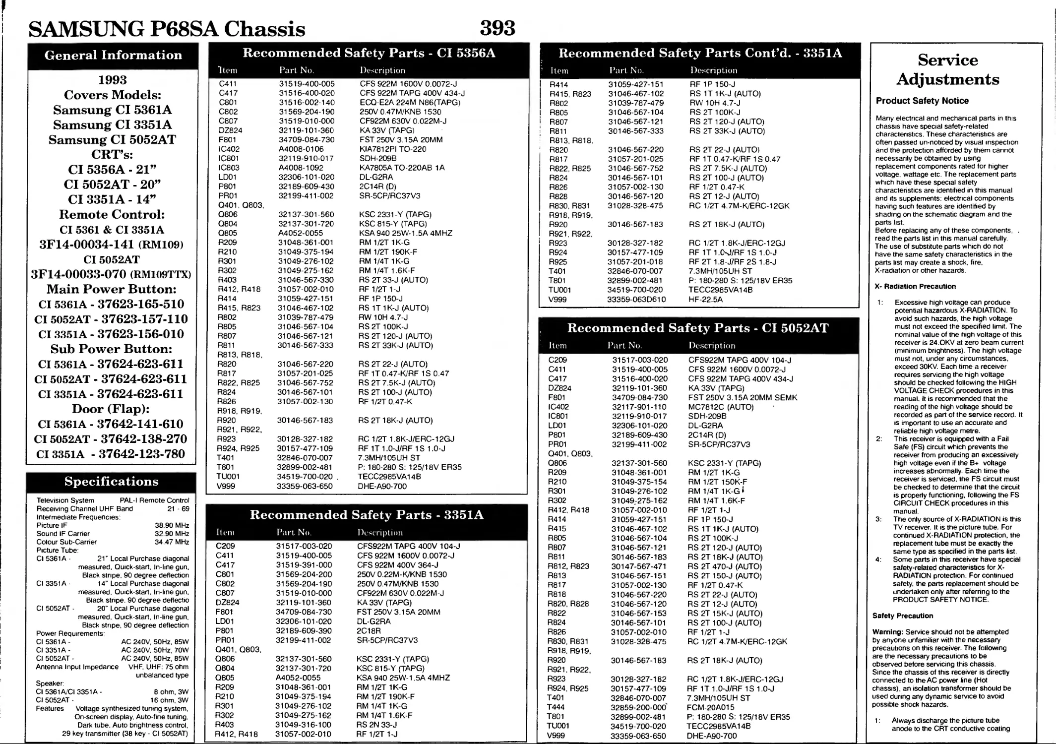
Recommended Safety Parts - CI 5356A
1993
Covers Models:
Samsung CI 5361A
Samsung CI 3351A
Samsung CI 5052AT
CRT’s:
CI 5356A - 21”
CI 5052AT - 20”
CI 3351A -14”
Remote Control:
CI 5361 & CI 3351A
3F14-00034-141 (RM109)
CI 5052AT
3F14-00033-070 (RM109TTX)
Main Power Button:
CI 5361A - 37623-165-510
CI 5052AT - 37623-157-110
CI 3351A - 37623-156-010
Sub Power Button:
CI 5361A - 37624-623-611
CI 5052AT - 37624-623-611
CI 3351A - 37624-623-611
Door (Flap):
CI 5361A - 37642-141-610
CI 5052AT - 37642-138-270
CI3351A -37642-123-780
Specifications
Item Part No. Description
C411 31519-400-005 CFS 922M 1600V 0.0072-J
C417 31516-400-020 CFS 922M TAPG 400V 434-J
C801 31516-002-140 ECQ-E2A 224M N86(TAPG)
C802 31569-204-190 250V 0.47M/KNB 1530
C807 31519-010-000 CF922M 630V 0.022M-J
DZ824 32119-101-360 KA 33V (TAPG)
F801 34709-084-730 FST 250V 3.15A 20MM
IC402 A4008-0106 KIA7812PI TO-220
IC801 32119-910-017 SDH-209B
IC803 A4008-1092 KA7805A TO-220AB 1A
LD01 32306-101-020 DL-G2RA
P801 32189-609-430 2C14R (D)
PR01 32199-411-002 SR-5CP/RC37V3
Q401, Q803,
Q806 32137-301-560 KSC 2331-Y (TAPG)
Q804 32137-301-720 KSC 815-Y (TAPG)
Q805 A4052-0055 KSA 940 25W-1.5A 4MHZ
R209 31048-361-001 RM 1/2T 1K-G
R210 31049-375-194 RM 1/2T 190K-F
R301 31049-276-102 RM 1/4T 1K-G
R302 31049-275-162 RM 1/4T 1.6K-F
R403 31046-567-330 RS 2T 33-J (AUTO)
R412, R418 31057-002-010 RF 1/2T 1-J
R414 31059-427-151 RF 1P 150-J
R415, R823 31046-467-102 RS 1T1K-J (AUTO)
R802 31039-787-479 RW10H 4.7-J
R805 31046-567-104 RS2T 100K-J
R807 31046-567-121 RS2T120-J (AUTO)
R811 30146-567-333 RS 2T 33K-J (AUTO)
R813, R818,
R820 31046-567-220 RS 2T 22-J (AUTO)
R817 31057-201-025 RF 1T0.47-K/RF 1S 0.47
R822, R825 31046-567-752 RS 2T 7.5K-J (AUTO)
R824 30146-567-101 RS2T100-J (AUTO)
R826 31057-002-130 RF 1/2T 0.47-K
R918, R919,
R920 30146-567-183 RS 2T 18K-J (AUTO)
R921, R922,
R923 30128-327-182 RC 1/2T 1.8K-J/ERC-12GJ
R924, R925 30157-477-109 RF 1T 1.0-J/RF 1S 1.0-J
T401 32846-070-007 7.3MH/105UH ST
T801 32899-002-481 P: 180-280 S: 125/18V ER35
TU001 34519-700-020 . TECC2985VA14B
V999 33359-063-650 DHE-A90-700
Recommended Safety Parts Cont’d. - 3351A
Item Part No. Description
R414 31059-427-151 RF 1P 150-J
R415, R823 31046-467-102 RS 1T1K-J (AUTO)
R802 31039-787-479 RW 10H 4.7-J
I R805 31046-567-104 RS 2T 100K-J
i R807 31046-567-121 RS 2T 120-J (AUTO)
; R811 30146-567-333 RS 2T 33K-J (AUTO)
: R813, R818. R820 31046-567-220 RS 2T 22-J (AUTO)
R817 31057-201-025 RF 1T 0.47-K/RF 1S 0.47
R822, R825 31046-567-752 RS 2T 7.5K-J (AUTO)
R824 30146-567-101 RS 2T 100-J (AUTO)
R826 31057-002-130 RF 1/2T 0.47-K
R828 30146-567-120 RS 2T 12-J (AUTO)
R830, R831 R918, R919, 31028-328-475 RC 1/2T4.7M-K/ERC-12GK
R920 30146-567-183 RS 2T 18K-J (AUTO)
R921, R922, R923 30128-327-182 RC 1/2T 1.8K-J/ERC-12GJ
R924 30157-477-109 RF 1T 1.0-J/RF 1S 1.0-J
R925 31057-201-018 RF2T1.8-J7RF 2S 1.8-J
T401 32846-070-007 7.3MH/105UH ST
T801 32899-002-481 P: 180-280 S: 125/18V ER35
TU001 34519-700-020 TECC2985VA14B
V999 33359-063D610 HF-22.5A
Recommended Safety Parts - CI 5052AT
Television System
Receiving Channel UHF Band
Intermediate Frequencies:
Picture IF
Sound IF Carrier
Colour Sub-Carrier
PAL-I Remote Control
21 - 69
38.90 MHz
32.90 MHz
34.47 MHz
Recommended Safety Parts - 3351A
Picture Tube:
Cl 5361A - 21" Local Purchase diagonal
measured. Quick-start. In-line gun.
Black stripe. 90 degree deflection
Cl 3351A - 14" Local Purchase diagonal
measured. Quick-start, In-line gun.
Black stripe. 90 degree deflectio
Cl 5052AT - 20" Local Purchase diagonal
measured. Quick-start. In-line gun.
Black stripe, 90 degree deflection
Power Requirements'
Cl 5361 A- AC 240V, 50Hz, 85W
Cl 3351 A- AC 240V. 50Hz, 70W
Cl 5052AT - AC 240V, 50Hz, 85W
Antenna Input Impedance VHF. UHF: 75 ohm
unbalanced type
Speaker:
Cl 5361A/CI 3351A - Bohm, 3W
CI5052AT- 16 ohm, 3W
Features Voltage synthesized tuning system,
On-screen display, Auto-fine tuning.
Dark tube. Auto brightness control,
29 key transmitter (38 key - Cl 5052AT)
Item Part No. Description
C209 31517-003-020 CFS922M TAPG 400V 104-J
C411 31519-400-005 CFS 922M 1600V 0.0072-J
C417 31519-391-000 CFS 922M 400V 364-J
C801 31569-204-200 250V 0.22M-K/KNB 1530
C802 31569-204-190 250V 0.47M/KNB 1530
C807 31519-010-000 CF922M 630V 0.022M-J
DZ824 32119-101-360 KA 33V (TAPG)
F801 34709-084-730 FST 250V 3.15A 20MM
LD01 32306-101-020 DL-G2RA
P801 32189-609-390 2C18R
PR01 32199-411-002 SR-5CP/RC37V3
Q401, Q803,
Q806 32137-301-560 KSC 2331-Y (TAPG)
Q804 32137-301-720 KSC 815-Y (TAPG)
Q805 A4052-0055 KSA 940 25W-1,5A 4MHZ
R209 31048-361-001 RM1/2T1K-G
R210 31049-375-194 RM 1/2T 190K-F
R301 31049-276-102 RM 1/4T1K-G
R302 31049-275-162 RM 1/4T 1.6K-F
R403 31049-316-100 RS 2N 33-J
R412, R418 31057-002-010 RF 1/2T 1-J
Item Part No. Description
C209 31517-003-020 CFS922M TAPG 400V 104-J
C411 31519-400-005 CFS 922M 1600V 0.0072-J
C417 31516-400-020 CFS 922M TAPG 400V 434-J
DZ824 32119-101-360 KA 33V (TAPG)
F801 34709-084-730 FST 250V 3.15A 20MM SEMK
IC402 32117-901-110 MC7812C (AUTO)
IC801 32119-910-017 SDH-209B
LD01 32306-101-020 DL-G2RA
P801 32189-609-430 2C14R (D)
PR01 32199-411-002 SR-5CP/RC37V3
0401, Q803,
Q806 32137-301-560 KSC 2331-Y (TAPG)
R209 31048-361-001 RM 1/2T 1K-G
R210 31049-375-154 RM 1/2T 150K-F
R301 31049-276-102 RM 1/4T 1K-G1
R302 31049-275-162 RM 1/4T 1.6K-F
R412, R418 31057-002-010 RF 1/2T 1-J
R414 31059-427-151 RF 1P 150-J
R415 31046-467-102 RS 1T1K-J (AUTO)
R805 31046-567-104 RS2T100K-J
R807 31046-567-121 RS 2T 120-J (AUTO)
R811 30146-567-183 RS 2T18K-J (AUTO)
R812, R823 30147-567-471 RS 2T 470-J (AUTO)
R813 31046-567-151 RS 2T 150-J (AUTO)
R817 31057-002-130 RF 1/2T 0.47-K
R818 31046-567-220 RS 2T 22-J (AUTO)
R820, R828 31046-567-120 RS 2T 12-J (AUTO)
R822 31046-567-153 RS 2T 15K-J (AUTO)
R824 30146-567-101 RS 2T 100-J (AUTO)
R826 31057-002-010 RF 1/2T 1-J
R830, R831 31028-328-475 RC 1/2T4.7M-K/ERC-12GK
R918, R919.
R920 30146-567-183 RS 2T 18K-J (AUTO)
R921, R922,
R923 30128-327-182 RC 1/2T 1.8K-J/ERC-12GJ
R924, R925 30157-477-109 RF 1T 1.0-J/RF 1S 1.0-J
T401 32846-070-007 7.3MH/105UH ST
T444 32859-200-000' FCM-20A015
T801 32899-002-481 P: 180-280 S: 125/18V ER35
TU001 34519-700-020 TECC2985VA14B
V999 33359-063-650 DHE-A90-700
Service
Adjustments
Product Safety Notice
Many electrical and mechanical parts in this
chassis have special safety-related
characteristics. These characteristics are
often passed un-noticed by visual inspection
and the protection afforded by them cannot
necessarily be obtained by using
replacement components rated for higher
voltage, wattage etc. The replacement parts
which have these special safety
characteristics are identified in this manual
and its supplements: electrical components
having such features are identified by
shading on the schematic diagram and the
parts list.
Before replacing any of these components, .
read the parts list in this manual carefully.
The use of substitute parts which do not
have the same safety characteristics in the
parts list may create a shock, fire.
X-radiation or other hazards.
X- Radiation Precaution
1: Excessive high voltage can produce
potential hazardous X-RADIATION. To
avoid such hazards, the high voltage
must not exceed the specified limit. The
nominal value of the high voltage of this
receiver is 24.OKV at zero beam current
(minimum brightness). The high voltage
must not, under any circumstances,
exceed 30KV. Each time a receiver
requires servicing the high voltage
should be checked following the HIGH
VOLTAGE CHECK procedures in this
manual. It is recommended that the
reading of the high voltage should be
recorded as part of the service record. It
is important to use an accurate and
reliable high voltage metre.
2: This receiver is equipped with a Fail
Safe (FS) circuit which prevents the
receiver from producing an excessively
high voltage even if the B+ voltage
increases abnormally. Each time the
receiver is serviced, the FS circuit must
be checked to determine that the circuit
is properly functioning, following the FS
CIRCUIT CHECK procedures in this
manual.
3: The only source of X-RADIATION is this
TV receiver. It is the picture tube. For
continued X-RADlATlON protection, the
replacement tube must be exactly the
same type as specified in the parts list.
4: Some parts in this receiver have special
safety-related characteristics for X-
RADlATION protection. For continued
safety, the parts replacement should be
undertaken only after referring to the
PRODUCT SAFETY NOTICE.
Safety Precaution
Warning: Service should not be attempted
by anyone unfamiliar with the necessary
precautions on this receiver. The following
are the necessary precautions to be
observed before servicing this chassis.
Since the chassis of this receiver is directly
connected to the AC power line (Hot
chassis), an isolation transformer should be
used during any dynamic service to avoid
possible shock hazards.
1: Always discharge the picture tube
anode to the CRT conductive coating
SAMSUNG P68SA Chassis
Service Adjustments Cont’d.
before handling the picture tube. The
picture tube is highly evacuated and if
broken, glass fragments will be violently
expelled. Use shatter proof goggles and
keep picture tube away from the
unprotected body during handling.
2 When replacing a chassis in the cabinet,
always be certain that all protective
devices are put back in place, such as
non-metallic control knobs, insulating
covers, shields, isolation resistor,
capacitor,
network, etc.
3. Before returning the set to a customer,
always perform an AC leakage current
check on the exposed metallic parts of
the cabinet, such as antennas,
terminals, screwheads metal overlays,
control shafts etc To be sure the set is
safe to operate without danger of an
electrical shock Plug the AC line cord
directly to a AC outlet (do not use a line
isolation transformer during this check).
Use an AC voltmeter, having 50000 per
v or more sensitivity, in the following
manner: connect a 1500Q 10 watt
resistor, paralleled by a 0.15uF, AC type
capacitor, between a known good earth
ground, (water pipe, conduit etc.) and
the exposed metallic parts one at a
time. Measure the AC voltage across the
combination of 15000 resistor and
0.15mfd capacitor. Reverse the AC plug
at the AC outlet and repeat the AC
voltage measurements for each
exposed metallic part. The measured
voltage must not exceed 0.3 v RMS.
This corresponds to 0.5 milliamp AC.
Any value exceeding this limit
constitutes a potential shock hazard and
must be corrected immediately.
Alignment and Adjustment
1: High Voltage Check
Caution: There is no HIGH VOLTAGE
ADJUSTMENT on the chassis. But B+ power
must be adjusted in + 125v under the full
colour bar pattern and normal picture control
level.
1: Connect an accurate high voltage metre
to the second anode of the picture tube.
2: Turn on the receiver. Set the
BRIGHTNESS and CONTRAST control
to minimum, (Zero beam).
3: The high voltage should be measured
less.
4: Rotate the BRIGHTNESS and
CONTRAST control to both extremes to
be sure. The high voltage does not
exceed the limit under ant conditions.
2: Horizontal Phase Adjustment
If you want to move the centre of the picture,
adjust HORIZONTAL phase control (VR401).
3: Vertical Height Adjustment
The SIZE control (VR301) on the main board
changes the size of the picture, having an
equal effect on the top and the bottom.
4: Screen Adjustment
1: Tune in an active channel.
2: Make the picture normal condition (no
blooming or no flyback line) with the VR
screen.
5: Focus Adjustment
Adjust the FOCUS control on FBT for well
defined scanning lines in the centre area of
the screen
6: R-F AGC Adjustment
1: Tune the set in the strongest station in
your area
2: Turn the AGC control (VR101) on the IF
board to fully clockwise position.
3: Adjust the AGC control until noises
(snow) disappear from the screen.
7: Colour Purity Adjustment
Note: Before attempting ant purity adjust-
ments. the receiver should be operated for at
least fifteen minutes. Purity adjustment
requires Rubber Wedge Kit.
1: Demagnetise the picture tube and
cabinet using a degaussing coil.
2: Turn the CONTRAST and
BRIGHTNESS controls to the maximum.
3: Receiver the green colour pattern.
4: Loosen the clamp screw holding the
yoke, and slide the yoke backward or
forward to provide the vertical green belt
(zone) in the picture screen.
5: Remove the Rubber Wedges
6 Rotate and spread the tabs of the purity
magnet (fig. 3), around the neck of the
picture tube until a green belt is
obtained in the centre of the screen. At
the same time, centre the raster
vertically by adjusting the magnet.
7: Move the yoke slowly forward or
backward until a uniform red screen is
obtained. Tighten the clamp screw.
8: Check the purity of the red and blue
raster.
9: Tighten the clamp screw of the yoke
temporarily.
10: Obtain a white raster, referring to the
“CRT WHITE BALANCE
ADJUSTMENT".
11: Proceed with the convergence
adjustment.
8: CRT White Balance Adjustment
Preparation:
1: Operate the receiver for at least twenty
minutes before attempting the white
balance adjustment.
2: Receive a black and a white signals.
(Lion head pattern is better).
3: Set the colour control to the centre
position.
4: Set the brightness and contrast controls
to the maximum jjosition.
5: Set the red. blue and green low light
controls to the mechanical centre
position.
6: Set the blue and red drive controls to the
mechanical centre position.
7: Set the screen VR control on FBT to the
minimum position, (fully counter-
clockwise).
8: Connect 1 to 2 and 3 to 4 in CN402.
Steps:
1: Rotate the SCREEN control on FBT,
(T444), gradually clockwise until the first
horizontal line appears slightly on the
screen.
2: Adjust the two CUT - OFF controls to
obtain the slightly lightened honzontal
line in the same levels of three colours,
(red, green, blue).
The line looks like white if the CUT - Off
controls are adjusted properly.
3: Reset the CN042 on the MAIN board to
obtain a raster (“NORMAL" Position)
4: Adjust the blue and red drive controls to
obtain a proper white - balanced picture
in high light areas
5: Set the contrast control to the minimum
position and turn the brightness control
slightly counter-clockwise to obtain a
dark grey raster Then check the white
balance in low brightness. If the white
balance is not good enough repeat
steps 1 — 4 for the correct white
balance.
9: Convergence Adjustments
Note: Before attempting any convergence
adjustment, the receiver should be operated
for at least fifteen minutes.
Centre Convergence Adjustment:
1: Receive the crosshatch pattern with a
colour bar signal generator.
2: Adjust the BRIGHTNESS and
CONTRAST controls for a well defined
pattern.
3: Adjust the two tabs of the 4-pole
Magnets to change the angle among
them, (fig. 2), and superimpose the red
and the blue vertical lines in the centre
area of the picture screen, (fig. 2).
4: Turn both taps while at the same time
keeping the angle constant and
superimpose the red and the blue
horizontal lines at the centre of the
screen, (fig. 3).
5: Adjust the two tabs of 6-poie Magnets
to superimpose the red/biue line and
green one Adjust the angle to affect
the vertical lines and rotate both
magnets to affect the horizontal lines.
6. Due to the interaction between these
adjustments the steps 3, 4 and 5 should
be repeated until satisfactory results
are obtained.
Circumference Convergence Adjustment
1: Loosen the clamping screw of
deflection yoke to allow the yoke to tilt.
2: Put a wedge as shown in fig. 1
temporarily. Do not remove the cover
paper on adhesive part of the wedge.
3: Tilt front of the deflection yoke up or
down to obtain better convergence in
circumference, (fig 3). Push the
mounted wedge into the space between
the picture tube and the yoke to fix the
yoke temporarily.
4: Put the other wedge into bottom space
and remove the cover paper to stick.
5: Tilt the front of the yoke right of lift to
obtain the convergence in
circumference, (fig. 3).
6: Keep the yoke position and put another
wedge in either upper space. Remove
the cover paper and stick the wedge on
picture tube to fix the yoke.
7: Detach the temporarily mounted wedge
and put in another upper space. Stick it
on picture tube to fix the yoke.
8: After fixing three wedges re-check
overall convergence. Tighten the screw
firmly to fix the yoke and check the
yoke is firm.
9: Stick three adhesive tabs on wedges as
shown in fig. 1.
10: AFT Adjustment
Equipment:
No Raster (Sound OK)
Pattern generator (PM5518)
Digital Voltmeter
Preparation:
1 Set the supply voltage to AC 220v
2 Set the RF output frequency of Gen to
38.9 MHz and then Multi-burst pattern
3 Connect the RF out of PM5518 to
Tuners Pin. (IF).
4 Connect the DC voltmeter to J153
5 : Adjust the DC voltage of J153 tape 4v
by controlling the T104.
Trouble
Shooting
Guides
No Power
No Picture (Raster OK)
No Raster and No sound
Measure the +125V on the main board
Yes - more lhan [ No
I Check •» 16.5V kne I
NORMAL | ABNORMAL
| Check 5V kne
| See No Power |
~| [ Check/Replace R817
NORMAL___________________I ABNORMAL
I Check 6V line ~
NORMAL
[ Check IC101
NORMAL [
I Check 0402, IC601
NORMAL [
Check Contrast. Bnght.
Colour Volume levels
]I Check/Replace IC8~
ABNORMAL
J I Check/Replace Q805, 0806*
ABNORMAL
| Check/Replace IC101
ABNORMAL
Check/Replace Q402, IC601
No sound (Picture OK)
No Vertical Scan (One Horiz, Line Raster)
SAMSUNG P68SA Chassis
395
Main Diagram
С'вЙ-И-ЯЫ»
SAMSUNG P68SA Chassis 396
CRT Set up
! Voltage Charts
LOC NO PAL В G PALSEC AM-BG PAL SEC AM - В GDK PALI
IC502 DELETE TDA8395 TDA8395 DELETE
C517 DELETE POLY 223 POLY 223 DELETE
C518 DELETE 16V 4 7MF 16V 4 7MF DELETE
C519 DELETE POLY 1 04 POLY 1 04 DELETE
C520 DELETE POLY 224 PLOY 224 DELETE
C625 C-C CH47 C-C CH47 D'K CONVW TO C-C CH47
L601 1 2ИН 1 2ИН 12ИН
Z101 0FWG19 56 OFWG19 56 TSF5321 TSF5321
Z201 TPS5.5M В TPS5.5M В TPS55M В DELETE
Z202 DELETE DELETE TPS6.5M В DELETE
Z203 TPS5 74 № TPS5.74 NB TPS5 74 he DELETE
Z601 SFSH55 MCB SFSH5.5 MCB D/к CONVER та SFE6 0M В
Z602 DELETE DELETE DELETE
Aioe 1/2W 47( 1/2W 47( 1/2W 47( DELETE
D101 1N4003 1N4003 1N4003 DELETE
C106 16V 4 7MF 16V 4 7MF 16V 47MF DELETE
IC102 LA7910 LA791O LA7910 DELETE
C121 50V 0 41HF 50V 0 4A1F 50V 0 4WF DELETE
C123 50V 0.4WF 50V 0 4WF 50V 0 4WF DELETE
RR21 1/8 10K 1/8 1DK 1/8 10K DELETE
RR20 1/8 ЮК 1/8 10K 1/8 10K DELETE
L104 5 8ИН 5 6ИН 5.6ИН DELETE
L105 5 ВЛН 5 0ИН 5 ВИН DELETE
TU001 O-B TECC298 5VA14B TECC29 85VA14B TECC298 5VA14B TECC298 5VA14B
TU001 H-B TCC2989 VA15B TCC2989 VA15B TCC2989 VA15B TCC2989 VA15B
RD02 O-B DELETE DELETE DELETE DELETE
RD02 H-B IN4148 IN4148 IN4148 IN4148
RD05 O-B DELETE DELETE DELETE DELETE
RD05 H-B IN4148 IN4148 IN4148 IN4148
DEFLECTION
YOKE
ADJUST THE ANGLE
(VERTICAL LINES)
ROTATE TWO TABS
AT THE SAME TIME
(HORIZONTAL LINES)
Main Diagram
Waveforms
Figure 2. PURITY AND CONVERGENCE MAGNETS
APOLE MAGNETS MOVEMENT
red/blue
GREEN ’
, PREEN
RED/BLUE
WOLE MAGNETS MOVEMENT
Center Convergence by Magnet*
INCLINE THE YOKE UP (OR DOWN)
Circumference Convergence by DEF. Yoke
INCLINE THE YOKE RIGHT (OR LEFT)
Figure X Dot Movement Pattern
Remote Control
Diagram
D/К Converter
Diagram
LOC NO 14' MINI b£CK 20“ 21“
RR17 1/8 2K 1/8 4 7K 1/8 4.7K
R210 1/2 190-F 1/2 150K-F 1/2 150K-F
C214 2KV 681 2KV 271 2KV 271
R824 DELETE 2W 100 2W 100
C417 400V 364 200V 434 200V 434
L404 DS46 23IMH DS46 15MH DS48 15WH
T444 FTK-14004P FCM20A015 FCM20A015
R911 1/8 100 1/8 150 1/8 150
V999 HF-22 5A HF-29 1S HF-29 1S
C901 121 fCH. 221 (RH) 221 (RH)
R306 1/2W 2 2 V2W 15 1/2W 15
C309 POLY272 POLY472 POLY472
PCB 33004-1 ¥8 171 33004-147 481 33004-147 481
P801 2C18R 140M270 140M270
0402 2SD1650 KSD5072YD KSD5072YD
V999 A A34KOV42X 51GGB95X A48KAD82X 54HGB99X A51KRE83X 01
R924 1W 0 47 1W1 1W 0 47
R925 2W 1.8 1W1 2W 1.8
L402 DELETE DELETE 1.7R:32449 412-650 1R: 32449 412-680
R304 1/2W 680 1/2W 680 1/2W 330
CN80 2 32479-029 380 32479-029 330 32479-029 340
NON-FTC- CAT ITC-CAT
MR001 DELETE 1/1 1 2K
MR002 DELETE 1/1 1.2K
MR003 1/1 1 2K DELETE
VR402 DELETE VR-2K
Resistors
Cartion No Mark
Composition m
Metal Oxide (RSI
Meta) Film (RM)
Fustbie IRFi
Cement Wire (RW1
Network RN
Capacitors
Ceramic - SI No Mark
Ceramic - Rh (RH)
Ceramic - Ch (CH)
Polyester (induct) (P)
Polyester (Noninducl (PMU)
Polypropylene (PR)
Melal Polyeslef IMP)
M P Polypropylene (MPP)
Tanialium (T)
Non Polar (NP)
LOC 3GROUP 4 GROUP 5GROUP 6GROUP
TIC03 MA88461P W115 PCF84C81P /CTV972 PCF84C81P /CTV972 PCF84C81P /СТВ972
TIC02 SAA5246P/ E SAA5246P/ E SAA5246P/ E SAA5246P/ E
TX02 60MHZ 9.8304MHZ 9.8304MHZ 9 8304MHZ
TR12 1/8W1M DELETE DELETE DELETE
TC13 RH30 DELETE DELETE DELETE
TCI 4 RH30 DELETE DELETE DELETE