/


Текст
FN HERSTAL
OWNER’S MANUAL
FS2000 Carbine
Cal. 5.56 x 45 mm NATO
2
NEW GUN OWNER’S RECORD
Model : ...........................................................
Serial number (*) : ............................................
Date of purchase : ...........................................
Purchased from : ..............................................
Purchase price : ...............................................
(*) The serial number of your carbine has been engraved on the left side of
the frame.
The descriptions and illustrations in this Owner ’s Manual may differ slightly from
the present configuration of the product. This would reflect the constant evolution
of the product during its industrial life.
Data in this manual is technical only and of no contractual value.
Caution :::::
This manual has been written exclusively for the FN HERSTAL FS2000 carbine.
Warnings and instructions are different for each type of gun.
If your FN HERSTAL carbine has an
inscription other than «FN HERSTAL
BELGIUM FS2000 cal. 5.56 x 45» on
the rear left side of the frame or if
the external appearance of the carbine
does not correspond to the illustrations
of this manual, you must contact your
dealer/departmental armorer or write
us immediately to obtain the free
Owner ’s Manual that has been written
specifically for your carbine.
FNH USA, LLC
PO Box 697
McLean, VA 22101
703-288-1292
www.FNHUSA.com
3
Foreword
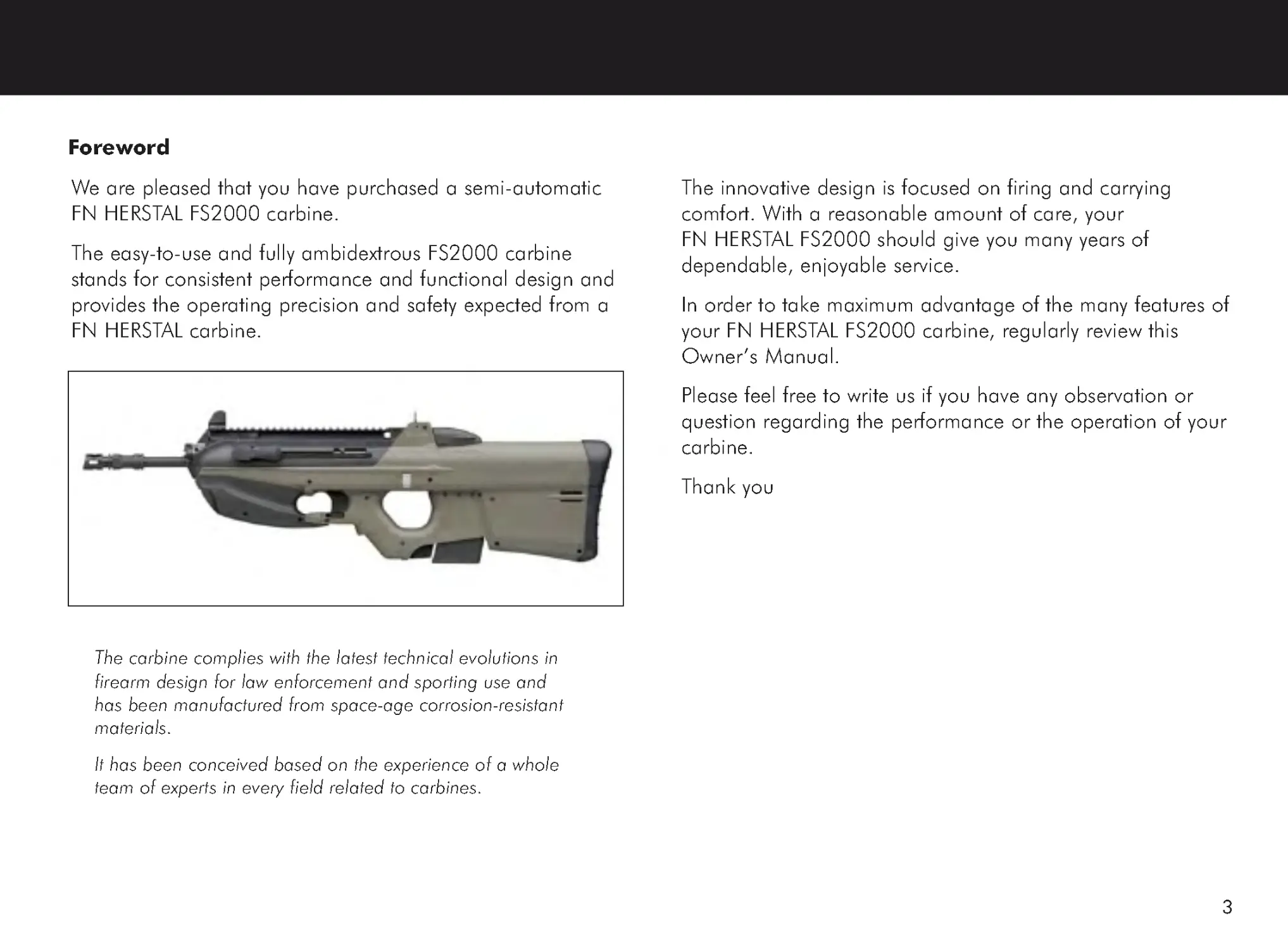
We are pleased that you have purchased a semi-automatic
FN HERSTAL FS2000 carbine.
The easy-to-use and fully ambidextrous FS2000 carbine
stands for consistent performance and functional design and
provides the operating precision and safety expected from a
FN HERSTAL carbine.
The carbine complies with the latest technical evolutions in
firearm design for law enforcement and sporting use and
has been manufactured from space-age corrosion-resistant
materials.
It has been conceived based on the experience of a whole
team of experts in every field related to carbines.
The innovative design is focused on firing and carrying
comfort. With a reasonable amount of care, your
FN HERSTAL FS2000 should give you many years of
dependable, enjoyable service.
In order to take maximum advantage of the many features of
your FN HERSTAL FS2000 carbine, regularly review this
Owner ’s Manual.
Please feel free to write us if you have any observation or
question regarding the performance or the operation of your
carbine.
Thank you
4
Safety and warranty notes
Safety and warranty notes
Safety and warranty notes
Safety and warranty notes
Safety and warranty notes
Like all firearms, the FN HERSTAL FS2000 carbine, if handled in a careless or
reckless manner, can be very dangerous.
For that reason, the carbine has been sold under the express understanding that
FN HERSTAL declines any responsability and invalidates any guarantee and
liability claims for incidental or consequential damages (injuries, loss of use of
property, commercial loss, loss of earnings and profits,...) resulting in whole or
partly from :
•
a discharge with criminal intent or through negligence
•
improper or careless handling
•
unauthorized servicing
•
the modification or the alteration of the basic carbine design
•
the use of non-original parts
•
the alteration of the safety devices
•
the use of incorrect “arms & ammunition” combinations
•
the use of defective, damaged, unsafe,..., ammunitions
•
the use of reloaded ammunition
•
an inadequate care of the carbine (e.g. corrosion, damage,...)
•
a disregard of malfunctions
•
a resale in contradiction to legislation
•
other circumstances beyond our direct and immediate control
FN HERSTAL reserves the right to refuse servicing a carbine wich has been
modified (removal of metal from the barrel, modifications of the firing
mechanism and/or other parts,...) and will, in such a case, always recommend
to restore the carbine to its original specifications. Parts and labor required for
TABLE OF CONTENTS
1. Safety information .................................... 6
2. Technical information ............................. 12
2.1. Nomenclature ....................................... 12
2.2. Description ............................................ 14
2.3. Technical data ....................................... 15
2.4. Functioning ........................................... 16
3. Contents of the storage box .................... 19
4. Using the carbine ................................... 20
4.1. Safety checks ......................................... 20
4.2. Loading the magazine ........................... 22
4.3. Loading and charging the carbine .......... 23
4.3.1. Loading the carbine .................... 23
4.3.2. Charging the carbine .................. 23
4.4. Firing the carbine .................................. 24
4.5. Unloading the carbine ........................... 25
4.6. Adjustment of the back-up sight ............. 28
4.7. Installation of a sling (accessory) ............ 29
4.8. Installation of the safety rod ................... 30
4.9. Installation of the safety lock .................. 31
5
5. Field stripping ......................................... 32
5.1. Disassembly of the carbine .................... 32
5.1.1. Safety checks and cocking
the hammer ............................... 32
5.1.2. Barrel receiver ............................ 32
5.1.3. Bolt and bolt carrier assembly ..... 33
5.1.4. Gas plug and piston ................... 34
5.1.5. Hammer group assembly ............ 36
5.2. Complementary disassembly .................. 37
5.2.1. Extractor ..................................... 37
5.2.2. Handguard ................................ 37
5.2.3 . Magazines ................................. 38
5.3. Complementary reassembly ................... 40
5.3.1. Extractor ..................................... 40
5.3.2. Handguard ................................ 40
5.3.3 . Magazines ................................. 41
5.4. Reassembly of the carbine ..................... 43
5.4.1. Hammer group assembly ............ 43
5.4.2. Gas plug and piston ................... 44
5.4.3. Bolt and bolt carrier assembly ..... 45
5.4.4. Barrel receiver ............................ 48
6. Cleaning and lubrication ........................ 50
6.1 . Lubricant and solvents specifications ...... 51
6.2 . Cleaning and lubrication tools .............. 51
6.2.1 . Tool and combination scraper
OREA 892 .................................. 51
6.3. Cleaning and lubrication before firing .... 52
6.4. Cleaning and lubrication after firing ....... 54
6.4.1. Barrel receiver ............................ 54
6.4.2. Bolt and bolt carrier assembly ..... 55
6.4.3. Hammer group assembly ............ 56
6.4.4. Frame and handguard ................ 57
6.4.5. Magazine ................................... 57
7. Taking care of the carbine ...................... 58
8 . Troubleshooting ..................................... 59
8.1 . Immediate actions ................................. 59
9 . Accessories ............................................. 60
6
1. SAFETY INFORMATION
As a carbine owner, you accept a set of demanding
responsibilities. How you take these responsibilities can mean
the difference between life and death.
There is no excuse for careless or abusive handling of any
firearm. At all times, handle your FS2000 and any other
firearm with intense respect for its power and potential danger.
x Always keep the muzzle of your carbine pointed in a safe
direction.
Never point any firearm at anything you do not intend to
shoot. Be extremely alert and aware of all persons and
property within the range of your ammunition.
x Never rely totally on your firearm’s mechanical «safety»
devices.
Always assume that your carbine can be fired at any time,
even with all safety mechanisms engaged.
The fire selector is the only apparent external safety device of
the FS2000 carbine : when this fire selector is at the position
‘S’ (SAFETY), it is impossible to operate the trigger.
The FS2000 carbine has also several passive safety
mechanisms that enhance safety.
As with other carbines, you must always treat your FS2000 as
ready-to-fire, and only load a round and cock the carbine
when shooting is imminent.
Like any mechanical device, a «safety» can sometimes fail; it
can be jarred or inadvertently manipulated into an unsafe
condition.
Mechanical «safeties» merely aid safe gun handling and are
no excuse for pointing your carbine’s muzzle in an unsafe
direction.
Safe gun handling does not stop with your carbine’s
mechanical «safety» devices : it starts there. Always treat this
carbine with the respect due to a loaded, ready-to-fire
carbine.
Read and understand the cautions and proper
handling procedures outlined in this booklet
before using your new firearm.
7
x Avoid carrying your FS2000 with a round in the chamber.
For good safety practice, it is recommended that a round is
not chambered until immediately before you will fire the
carbine.
If it is nevertheless necessary to carry the FS2000 with a round
in the chamber, set the fire selector at the position ‘S’
(SAFETY).
For law enforcement personnel, refer to the procedures of
your department on carrying a loaded carbine with a round in
the chamber.
x Whenever you handle your FS2000, or hand it to
someone, make sure it is completely unloaded.
To fully unload your FS2000, proceed as described in § 4.5.
It is vital that, when unloading, you remove the magazine
from your carbine so that a round is not automatically
chambered when releasing the charging handle.
Always keep the chamber and bolt empty unless shooting is
imminent.
x Do not transport your carbine loaded.
Keep it unloaded, whether carried on a sling, in a gun
carrying bag or another kind of container.
For law enforcement personnel, refer to the procedures of
your department on carrying a loaded carbine.
x Beware of barrel obstructions.
When preparing to shoot your carbine, check for a barrel
obstruction as follows : first fully unload the carbine as
described in § 4.5.
Be certain no live round is in the chamber !
Then glance down the barrel to be sure it is clear of any
obstruction. It takes only a small obstruction to dangerously
increase pressures. Before the first firing, clean the bore with
a cleaning rod and rag, and wipe away any anti-rust
compounds in the chamber and around the breech block.
x Be alert to the signs of ammunition malfunction.
If you detect an off sound or light recoil when a round is fired,
fully unload the carbine as described in § 4.5 .
With the charging handle pulled and held rearwards and the
chamber empty, glance down the barrel to make sure that an
obstruction does not remain in the barrel.
If there is an obstruction, completely clear the barrel before
loading and firing again.
Failure to follow these instructions can cause extensive
damage to your carbine and possible serious injury to
yourself and others.
8
1. SAFETY INFORMATION (CONTINUED)
x Be certain your carbine is completely unloaded before
cleaning.
Because so many gun accidents occur when a firearm is being
cleaned, special and extreme care should be taken to be sure
your carbine is unloaded before disassembly, cleaning and
reassembly.
Keep ammunition away from the cleaning location. Never test
the mechanical function of any firearm with live ammunition.
x Always completely unload your carbine when not in use.
Your responsibilities do not end when your firearm is
unattended. Store your carbine and ammunition separately
and well beyond the reach of children.
Take all safeguards to ensure that your carbine does not
become available to untrained, inexperienced or unwelcome
hands.
At all times, comply with the local and state laws.
For law enforcement personnel, refer to the procedures of
your department on storing your carbine.
x Make sure of adequate ventilation in the area that you
discharge a firearm. Wash hands thoroughly after
exposure to ammunition or cleaning a firearm.
Lead exposure can be obtained from discharging firearms in
poorly ventilated areas, cleaning firearms or handling
ammunition. Lead is a substance that has been known to
cause birth defects, reproductive harm and other serious
injury.
x Use the proper ammunition.
The barrel and the bolt of this carbine have been made with
substantial safety margins over the pressures developped by
the 5.56 x 45 mm NATO ammunition.
However, FN HERSTAL assumes no liability for accidents wich
occur through the use of rounds of different caliber or not
manufactured according to the SAAMI or NATO standards.
FN HERSTAL cannot assume any responsability for the use of
unsafe or improper arms and ammunition combinations. It is
your responsability to read and heed all warnings in this
Owner’s Manual and on ammunition boxes.
x Examine every round you put in your FS2000 carbine.
Your FS2000 carbine is designed and chambered for 5.56 x
45 mm NATO ammunitions. The chambering for your carbine
is printed clearly on the left side of the frame.
Failure to use correct ammunition may result in serious injury
to yourself or others.
9
x Before dry-firing, visually and physically check if the
chamber is empty.
x Treat every carbine with the respect due to a loaded gun,
even though you are certain the gun is unloaded !
x Keep your fingers away from the trigger while unloading,
loading and removing the magazine.
Only touch the trigger when you are ready to shoot.
x Be sure of your target and backstop.
Take additional care during low light periods. Know the range
of your ammunition. Never shoot at water or hard objects.
x Dropping your FS2000 or any other gun when loaded
can cause an accidental discharge.
Although the FS2000 carbine has been provided with a
special safety device to prevent firing when it is accidentally
dropped on its flash-hider (even when it is cocked), be
extremely careful, like with any other firearm, to avoid
dropping the carbine.
x Always set the fire selector at the position ‘S’ (SAFETY)
before crossing a fence, climbing a tree, jumping a ditch
or negotiating other obstacles with a loaded and/or
cocked carbine.
Never place your carbine on a car or on any unstable object.
For law enforcement personnel, refer to the procedures of
your department.
x If your FS2000 fails to fire, keep the muzzle pointed in a
safe direction.
Hold this position for a minimum of 30 seconds. Put the fire
selector on ‘SAFE’ and then remove the magazine. Carefully
pull the charging handle rearwards and remove the round.
If the primer is indented, the round should be disposed of in a
way that it can not cause harm.
If the primer is not indented, completely unload the carbine.
Your carbine should be examined by a qualified gunsmith/
your departmental armorer and the cause of the malfunction
should be corrected before further use.
10
1. SAFETY INFORMATION (CONTINUED)
x Wear eye and ear protection when shooting.
Unprotected, repeated exposure to gunfire can cause hearing
damage. Wear ear protectors (shooting earplugs or muffs) to
guard against such damage.
Wear shooting glasses to protect your eyes from flying
particles. Always keep a safe distance between the muzzle of
your firearm and any persons nearby, as muzzle blast, debris
and ejecting shells could inflict serious injury.
Also, wear eye protection when disassembling and cleaning
your carbine to prevent the possibility of springs, spring-
tensioned parts, solvents or other agents from contacting your
eyes.
x Be defensive and on guard against unsafe handling
around you and others.
Do not be timid when it comes to gun safety. If you observe
other shooters violating any of these safety precautions,
politely suggest safer handling practices.
x Supervise and teach firearms safety to all members of
your family.
This is especially important when children and non-shooters
are involved. Closely supervise newcomers to the shooting
sports. Encourage enrollment in shooting safety courses.
x Never drink alcoholic beverages or take any type of drugs
before or during shooting.
Your vision and judgement could be dangerously impaired,
making your carbine handling unsafe to you or to others.
x Periodic maintenance : avoid unauthorized servicing.
Your FS2000 is a mechanical device wich will not last forever,
and as such, is subject to wear and requires periodic
inspection, adjustment and service. Like all FN HERSTAL
firearms, your carbine should be serviced by a FN HERSTAL
Recommended Service Center.
FN HERSTAL cannot assume any responsability for injuries
suffered or caused by unauthorized servicing, alterations or
modifications of FN HERSTAL firearms.
x FN HERSTAL reserves the right to refuse service on
firearms that have been altered, added to or substantially
changed.
Removal of metal from the barrel or modifications of the firing
mechanism and/or operating parts may lead to FN HERSTAL’s
refusal of service on such firearms. FN HERSTAL will charge
the owner for parts and labor to return the firearm to original
FN HERSTAL specifications.
11
Read and heed all warnings in this Owner ’s
Manual, on ammunition boxes and with all
accessories that you install on your firearm.
It is your responsability to secure the most
up-to-date information on the safe
handling procedures for your
FN HERSTAL FS2000 Carbine.
FN HERSTAL assumes no liability for incidents
which occur when unsafe or improper gun
accessories or ammunition
combinations are used.
It can be very dangerous to alter firing
mechanism parts of this or any firearm.
BE CAREFUL !
12
Sling swivel
Inspection
cover
2. TECHNICAL INFORMATION
2.1. Nomenclature
Right hand view
Magazine
Barrel
Ejection
opening
door
Picatinny rail
Fire
selector
Butt plate
Magazine
release
button
Barrel
receiver
Frame
13
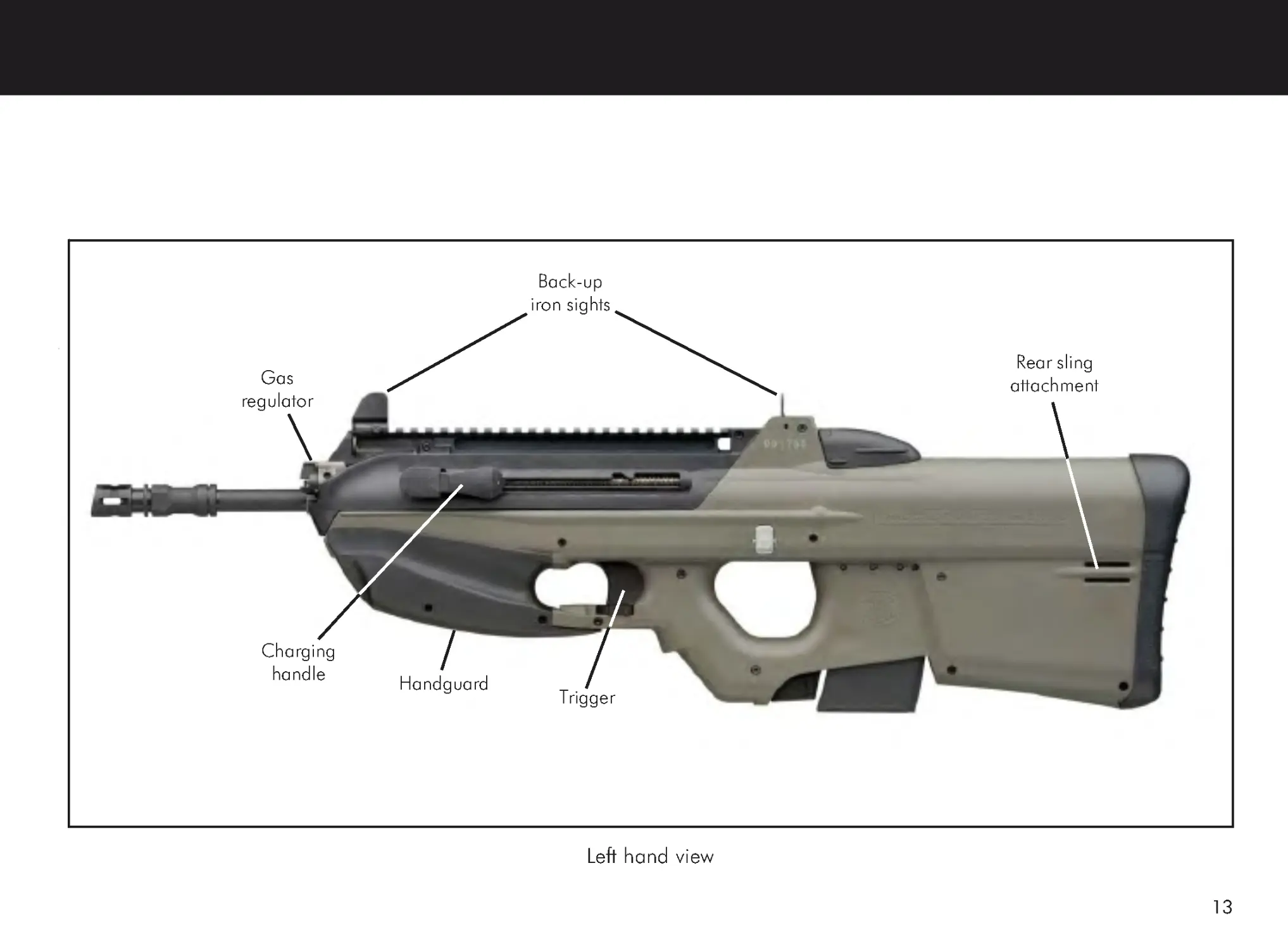
Left hand view
Charging
handle
Trigger
Handguard
Back-up
iron sights
Gas
regulator
Rear sling
attachment
14
2.2. Description
The FN Herstal FS2000 is a bullpup integrated weapon
system. Its outer shape has been designed with rounded
contours without any protruding parts even when equipped
with accessories. The innovative design is focused on firing
and carrying comfort.
The FN Herstal FS2000 is fully ambidextrous without any
modification due to the forward ejection. The fire selector, the
magazine release button and the charging handle are easily
reachable by either hand.
The basic caliber of the FN Herstal FS2000 is the 5.56 x 45
mm standard ammunition.
Any standard sighting system can be fixed on the upper
MIL-STD-1913 Picatinny rail at the appropriate eye relief. The
FN Herstal FS2000 is provided with back-up adjustable sights.
The standard handguard can be replaced by accessories such
as a tri-rail handguard, a laser designator, a flashlight... Any
configuration of the FN Herstal FS2000 respects the original
ergonomics of the firearm. The natural balance and the
carrying comfort are never downgraded.
The FN Herstal FS2000 carbine features one firing mode :
semi-automatic.
15
2.3. Technical data
FFFFFunctional data
unctional data
unctional data
unctional data
unctional data
Operating principle :
Gas operated, rotating bolt
Caliber :
5.56 x 45 mm NATO
Firing mode :
Semi-automatic
Magazine :
M16 type
Magazine capacity :
10 rounds or 30 rounds
Barrel length :
17.4” (443 mm)
Number of grooves :
6
Twist and direction :
7’’ (180 mm) right hand
Ejection :
Forwards
Safety :
Manual safety :
locking of the trigger.
Locking safety :
firing impossible as long
as the bolt is not locked.
Drop safety :
automatic locking of the
hammer.
Dimensions and weight
Dimensions and weight
Dimensions and weight
Dimensions and weight
Dimensions and weight
Overall length :
29.1” (740 mm)
Width :
3.2” (80 mm)
Height :
10.2” (259 mm)
Weight :
7.6 lb (3.450 kg) (without
magazine)
7.94 lb (3.606 kg)
(with empty 10-round magazine)
7.86 lb (3.567 kg)
(with empty 30-round magazine)
Ballistics
Ballistics
Ballistics
Ballistics
Ballistics
The following data apply to FS2000 carbine firing
5.56 x 45 mm ammunition.
Muzzle velocity :
2985 ft/s (910 m/s)
Effective range :
546.8 yd (500 m)
Safety range :
3280 yd (3000 m)
Sight
Sight
Sight
Sight
Sight
Back-up sights :
-
front sight : adjustable in elevation
-
rear sight : foldable and adjustable in windage
Inferface for sight :
10” (254 mm)-length Picatinny rail (MIL-STD-1913).
16
2.4. Functioning
Composition
The FS2000 carbine consists of the following assemblies and
components :
•
The barrel receiver group
The barrel receiver is located on the top of the front part of
the frame. It consists of the barrel, its support and the
Picatinny rail (MIL-STD-1913).
•
The frame group
The frame group consists of a polymer frame onto wich the
fire selector and the trigger have been installed.
•
The handguard group
The handguard group is located under the front of the
frame.
•
The bolt and bolt carrier group
The bolt and bolt carrier group is located inside the frame.
The bolt and bolt carrier group converts the recoil energy
generated when firing a round into kinetic energy necessary
for the operation of the carbine.
•
The hammer group
The hammer group is located inside the frame. The
hammer group controls the firing operation of the firearm.
•
The magazine
The magazine is inserted into the bottom of the frame.
•
The flash hider plug
The flash hider plug can be fitted onto the flash hider in
order to protect the barrel.
17
Ejection towards the front
•
After extraction of the case, this one remains held on
the bolt by the extractor.
•
So the case follows the bolt during its backward moving
and a part of its forward moving (in opposite to usual
systems where ejection follows extraction).
•
During the forward moving of the bolt and bolt carrier
(bolt and slide pushed forwards under the force of the
spring, return), the release unit raises the extractor
which releases the case.
•
The case is then propelled into the switch by the action
of the ejector.
•
During the following of the forward moving of the bolt
and bolt carrier, the switch is raised and pushes the
case into the ejection tube.
•
The case is then propelled through the case anti-return
and is pushed by the bolt alignment lever.
•
The case continues going forwards and goes out of the
weapon by the ejection opening door located on the
front right side of the weapon.
Safety features
•
The fire selector is the only apparent external safety
device of the FS2000 carbine.
The operation of the FS2000 carbine depends on the
setting of the fire selector featuring 2 positions :
The position ‘S’
‘S’
‘S’
‘S’
‘S’ (SAFETY
SAFETY
SAFETY
SAFETY
SAFETY)
When the fire selector is set at this position, it is
impossible to operate the trigger.
The position ‘1’
‘1’
‘1’
‘1’
‘1’ (SEMI-
SEMI-
SEMI-
SEMI-
SEMI-AAAAAUT
UT
UT
UT
UTOMA
OMA
OMA
OMA
OMATIC
TIC
TIC
TIC
TIC)
When the fire selector is set at this position, the
carbine fires semi-automatically on the condition
that the carbine has been loaded and cocked as
described in § 4.3, one shot will be fired for each
trigger pull.
•
The hammer is blocked and the firing pin can not
protrude until the bolt carrier has reached its most
forward position.
•
The primary sear is automatically locked if the carbine
is dropped.
18
Ammunition
The FS2000 carbine should only be used with 5.56 x 45 mm
ammunition.
This is indicated on the left side of the frame.
The barrel and the bolt of the FS2000 carbine
have been made with substantial
safety margins in order to be able to cope
with pressures developped by
the 5.56 x 45 mm NATO ammunition.
Neverthless, FN HERSTAL cannot assume any
responsability for incidents which result
from the use of rounds of different caliber
or not fabricated according
to the SAAMI or NATO standards.
EXAMINE EACH ROUND BEFORE YOU PUT IT IN
YOUR CARBINE !
2.4. Functioning (continued)
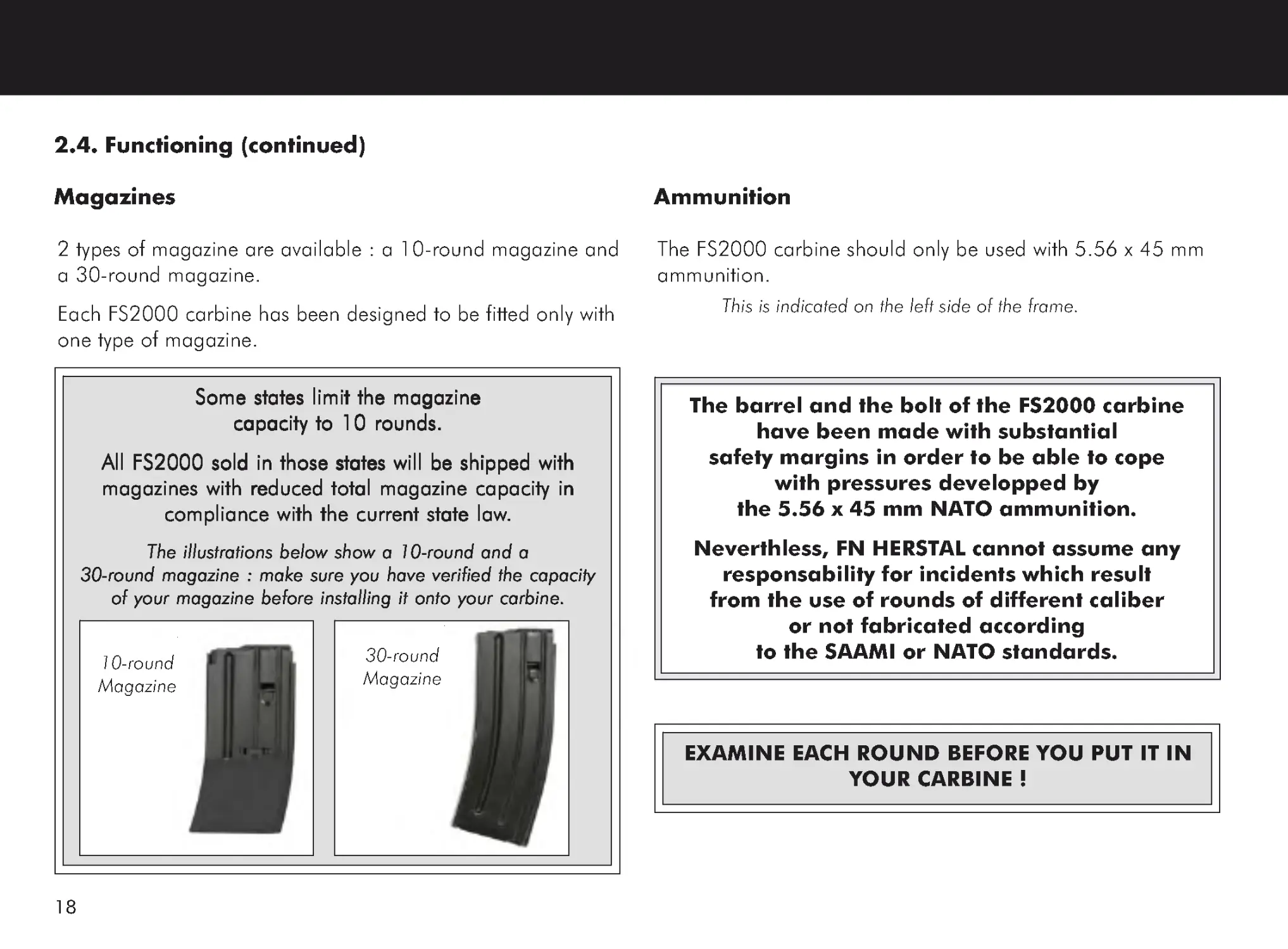
Magazines
2 types of magazine are available : a 10-round magazine and
a 30-round magazine.
Each FS2000 carbine has been designed to be fitted only with
one type of magazine.
Some states limit the magazine
Some states limit the magazine
Some states limit the magazine
Some states limit the magazine
Some states limit the magazine
capacity to 10 rounds.
capacity to 10 rounds.
capacity to 10 rounds.
capacity to 10 rounds.
capacity to 10 rounds.
All FS2000 sold in those states will be shipped with
All FS2000 sold in those states will be shipped with
All FS2000 sold in those states will be shipped with
All FS2000 sold in those states will be shipped with
All FS2000 sold in those states will be shipped with
magazines with reduced total magazine capacity in
magazines with reduced total magazine capacity in
magazines with reduced total magazine capacity in
magazines with reduced total magazine capacity in
magazines with reduced total magazine capacity in
compliance with the current state law
compliance with the current state law
compliance with the current state law
compliance with the current state law
compliance with the current state law.....
The illustrations below show a 10-round and a
The illustrations below show a 10-round and a
The illustrations below show a 10-round and a
The illustrations below show a 10-round and a
The illustrations below show a 10-round and a
30-round magazine : make sure you have verified the capacity
30-round magazine : make sure you have verified the capacity
30-round magazine : make sure you have verified the capacity
30-round magazine : make sure you have verified the capacity
30-round magazine : make sure you have verified the capacity
of your magazine before installing it onto your carbine.
of your magazine before installing it onto your carbine.
of your magazine before installing it onto your carbine.
of your magazine before installing it onto your carbine.
of your magazine before installing it onto your carbine.
10-round
Magazine
30-round
Magazine
19
3. CONTENTS OF THE STORAGE BOX
The FS2000 carbine is supplied in a storage box.
The storage box contains the following items :
A FS2000 carbine;
A 30-round magazine;
The magazine capacity is reduced to 10 rounds if required
by the current state law.
An Owner ’s Manual;
A safety lock and 2 keys;
A safety rod;
Some tools needed for field stripping and setting the
carbine :
-
A wrench, front sight OREA 255,
-
A tool and combination scraper OREA 892,
-
A tool for adjusting sight screw OREA 893.
An user maintenance kit (optional) composed of :
-
A cleaning handle, complete OREA 271/1,
-
A cleaning brush assembly OREA 184,
-
A chamber cleaning brush assembly OREA 258,
-
A cleaning brush OREA 895,
-
An oil can OREA 700.
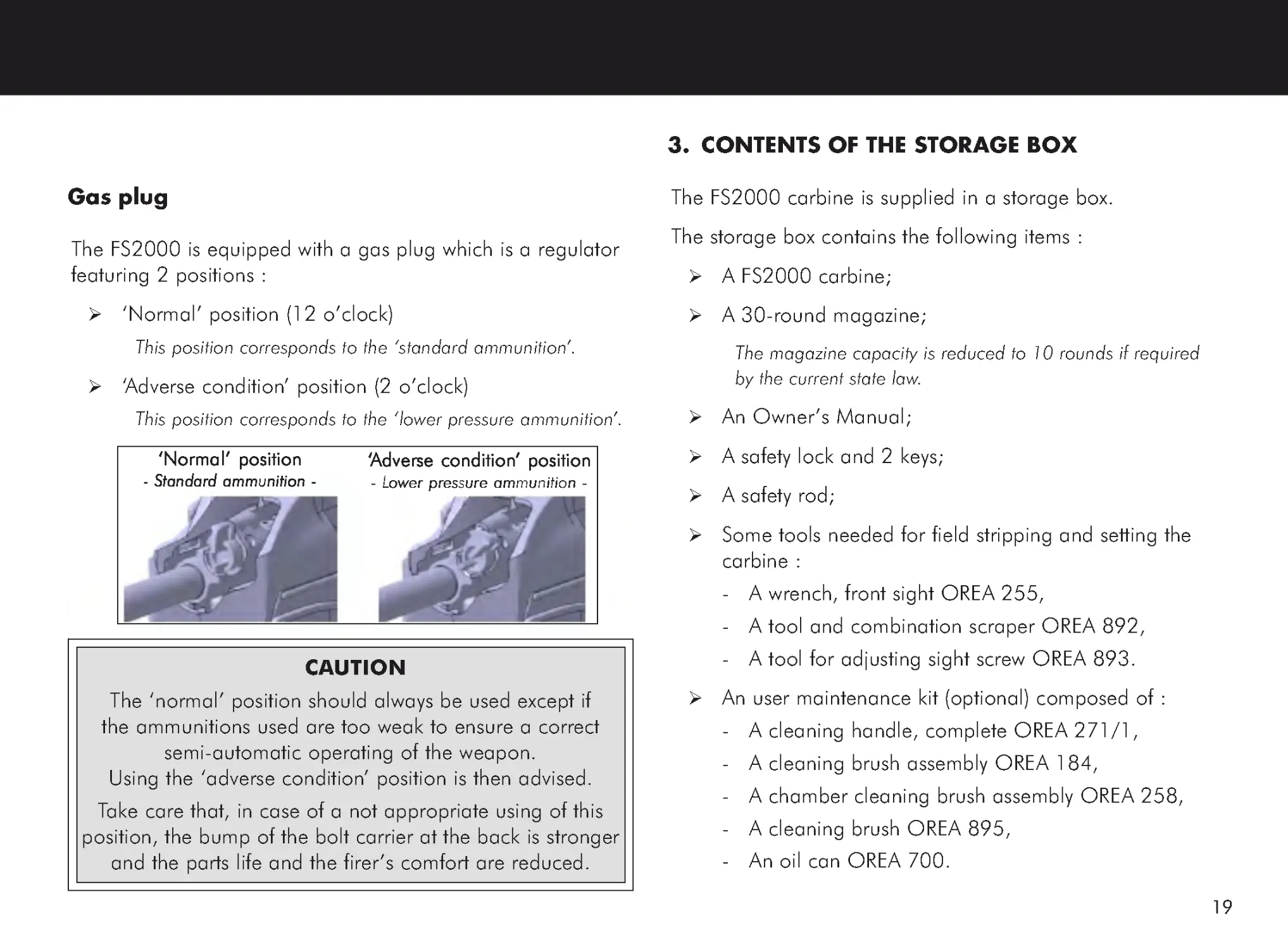
Gas plug
The FS2000 is equipped with a gas plug which is a regulator
featuring 2 positions :
‘Normal’ position (12 o’clock)
This position corresponds to the ‘standard ammunition’.
‘Adverse condition’ position (2 o’clock)
This position corresponds to the ‘ lower pressure ammunition’.
‘‘‘‘‘Adverse condition
Adverse condition
Adverse condition
Adverse condition
Adverse condition’ position
’ position
’ position
’ position
’ position
-
L-L
-
L-L
-
Lower pressure ammunition -
ower pressure ammunition -
ower pressure ammunition -
ower pressure ammunition -
ower pressure ammunition -
‘Normal’ position
‘Normal’ position
‘Normal’ position
‘Normal’ position
‘Normal’ position
-
Standard ammunition -
-
Standard ammunition -
-
Standard ammunition -
-
Standard ammunition -
-
Standard ammunition -
CAUTION
The ‘normal’ position should always be used except if
the ammunitions used are too weak to ensure a correct
semi-automatic operating of the weapon.
Using the ‘adverse condition’ position is then advised.
Take care that, in case of a not appropriate using of this
position, the bump of the bolt carrier at the back is stronger
and the parts life and the firer ’s comfort are reduced.
20
4. USING THE CARBINE
4.1. Safety checks
•
Keep carbine pointed in a safe direction.
•
Set the fire selector to the position ‘ SSSSS’ (SAFETY
SAFETY
SAFETY
SAFETY
SAFETY).
•
If the magazine is still present into the carbine, press the
magazine release button and remove the magazine out
of the carbine pulling it downwards.
•
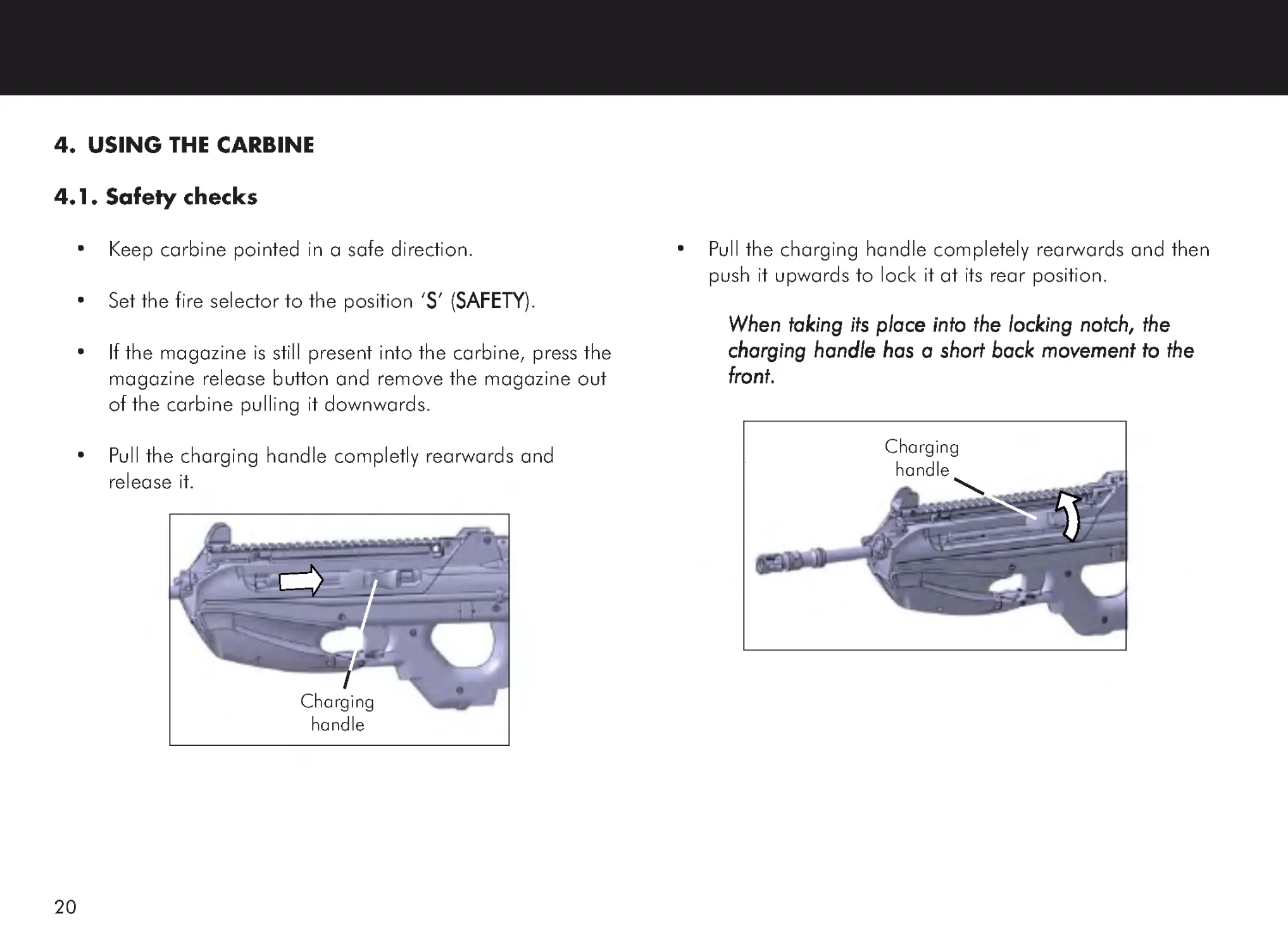
Pull the charging handle completly rearwards and
release it.
•
Pull the charging handle completely rearwards and then
push it upwards to lock it at its rear position.
When taking its place into the locking notch, the
When taking its place into the locking notch, the
When taking its place into the locking notch, the
When taking its place into the locking notch, the
When taking its place into the locking notch, the
charging handle has a short back movement to the
charging handle has a short back movement to the
charging handle has a short back movement to the
charging handle has a short back movement to the
charging handle has a short back movement to the
front.
front.
front.
front.
front.
Charging
handle
Charging
handle
21
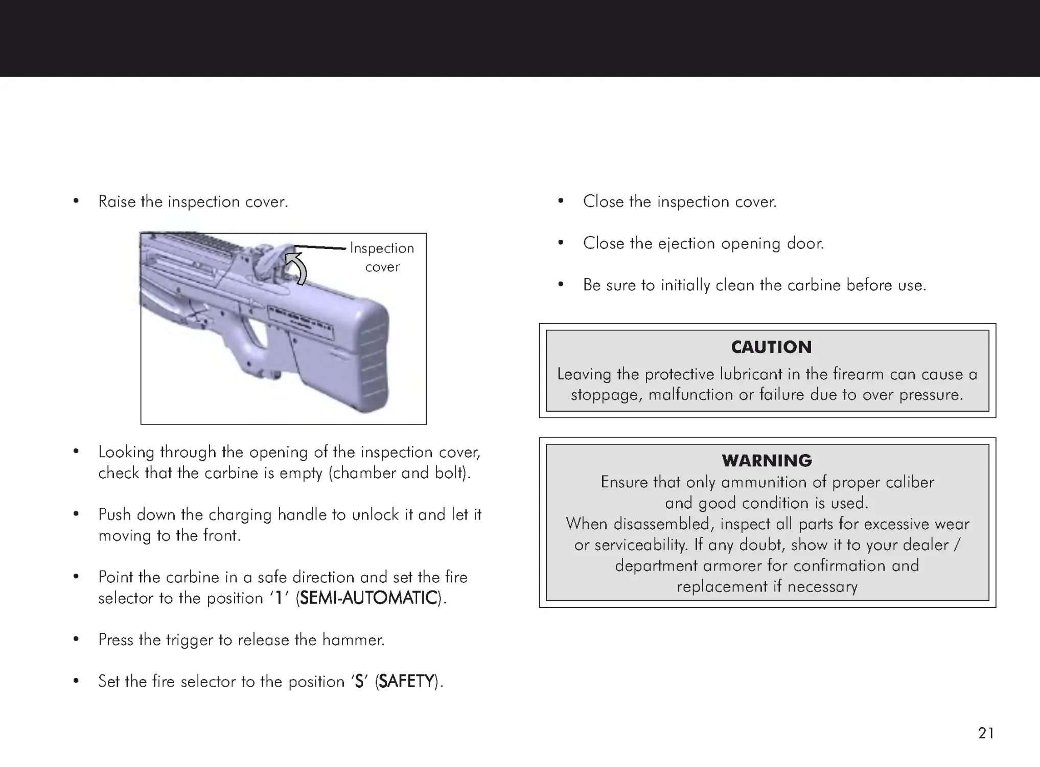
•
Raise the inspection cover.
•
Looking through the opening of the inspection cover,
check that the carbine is empty (chamber and bolt).
•
Push down the charging handle to unlock it and let it
moving to the front.
•
Point the carbine in a safe direction and set the fire
selector to the position ‘ 11111’ (SEMI-
SEMI-
SEMI-
SEMI-
SEMI-AAAAAUT
UT
UT
UT
UTOMA
OMA
OMA
OMA
OMATIC
TIC
TIC
TIC
TIC).
•
Press the trigger to release the hammer.
•
Set the fire selector to the position ‘SSSSS’ (SAFETY
SAFETY
SAFETY
SAFETY
SAFETY).
•
Close the inspection cover.
•
Close the ejection opening door.
•
Be sure to initially clean the carbine before use.
Inspection
cover
CAUTION
Leaving the protective lubricant in the firearm can cause a
stoppage, malfunction or failure due to over pressure.
WARNING
Ensure that only ammunition of proper caliber
and good condition is used.
When disassembled, inspect all parts for excessive wear
or serviceability. If any doubt, show it to your dealer /
department armorer for confirmation and
replacement if necessary
22
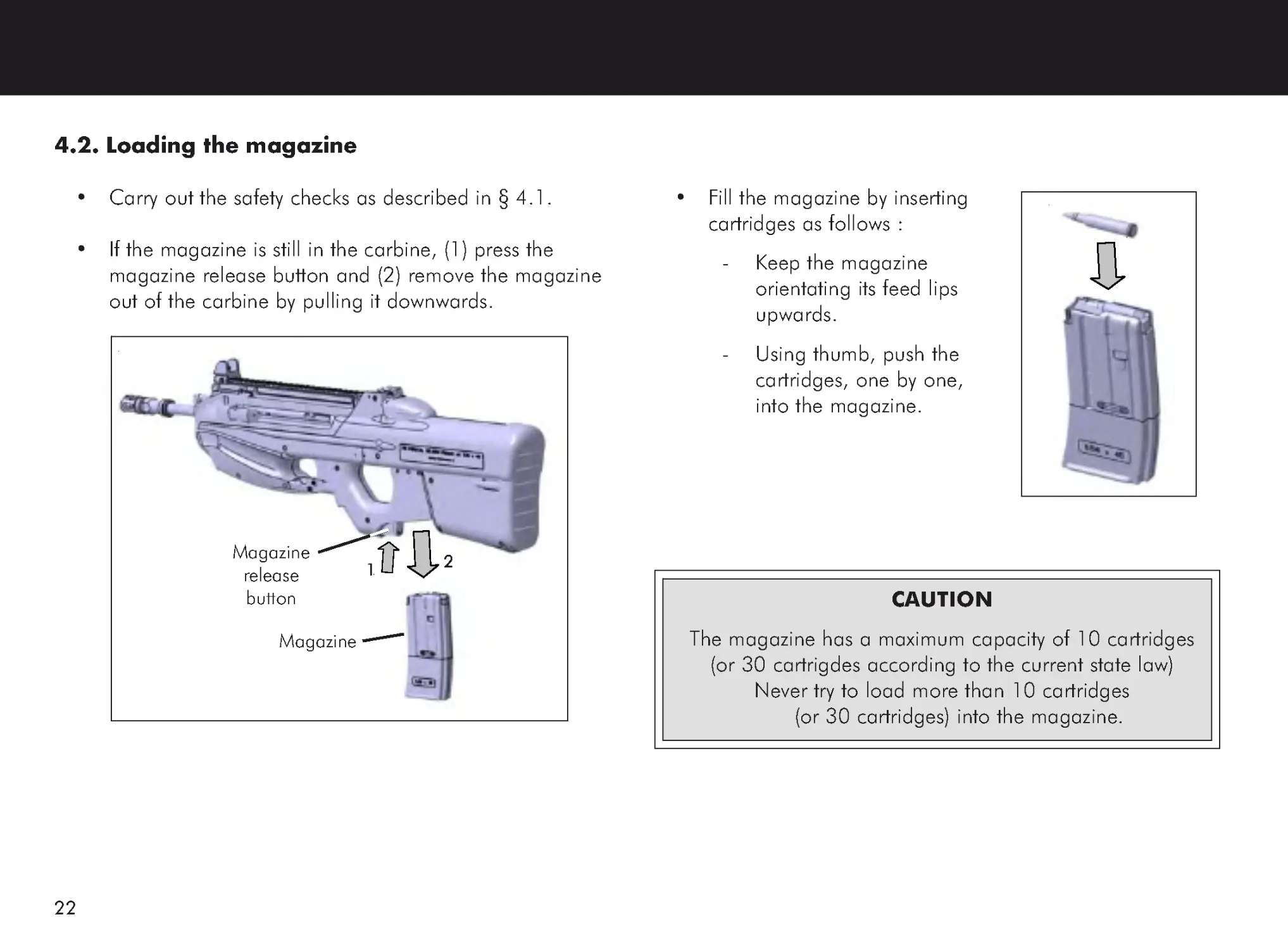
4.2. Loading the magazine
•
Carry out the safety checks as described in § 4.1.
•
If the magazine is still in the carbine, (1) press the
magazine release button and (2) remove the magazine
out of the carbine by pulling it downwards.
•
Fill the magazine by inserting
cartridges as follows :
-
Keep the magazine
orientating its feed lips
upwards.
-
Using thumb, push the
cartridges, one by one,
into the magazine.
CAUTION
The magazine has a maximum capacity of 10 cartridges
(or 30 cartrigdes according to the current state law)
Never try to load more than 10 cartridges
(or 30 cartridges) into the magazine.
Magazine
release
button
Magazine
11111
22222
23
4.3. Loading and charging the carbine
4.3.1. Loading the carbine
•
Set the fire selector to the position ‘SSSSS’ (SAFETY
SAFETY
SAFETY
SAFETY
SAFETY).
CAUTION
The safety checks should have been carried out.
The carbine should have been correctly
cleaned and lubricated.
Fire
selector
•
Install a loaded
magazine into the
carbine by pushing
on its bottom.
•
Ensure the
magazine is locked
by pulling it
downwards.
4.3.2. Charging the carbine
•
Pull the charging handle completely rearwards and then
release it.
This causes the
hammer to be cocked
and the first cartridge
to be chambered.
Never hold back the
Never hold back the
Never hold back the
Never hold back the
Never hold back the
charging handle
charging handle
charging handle
charging handle
charging handle
during its forward
during its forward
during its forward
during its forward
during its forward
motion.
motion.
motion.
motion.
motion.
Magazine
Charging
handle
24
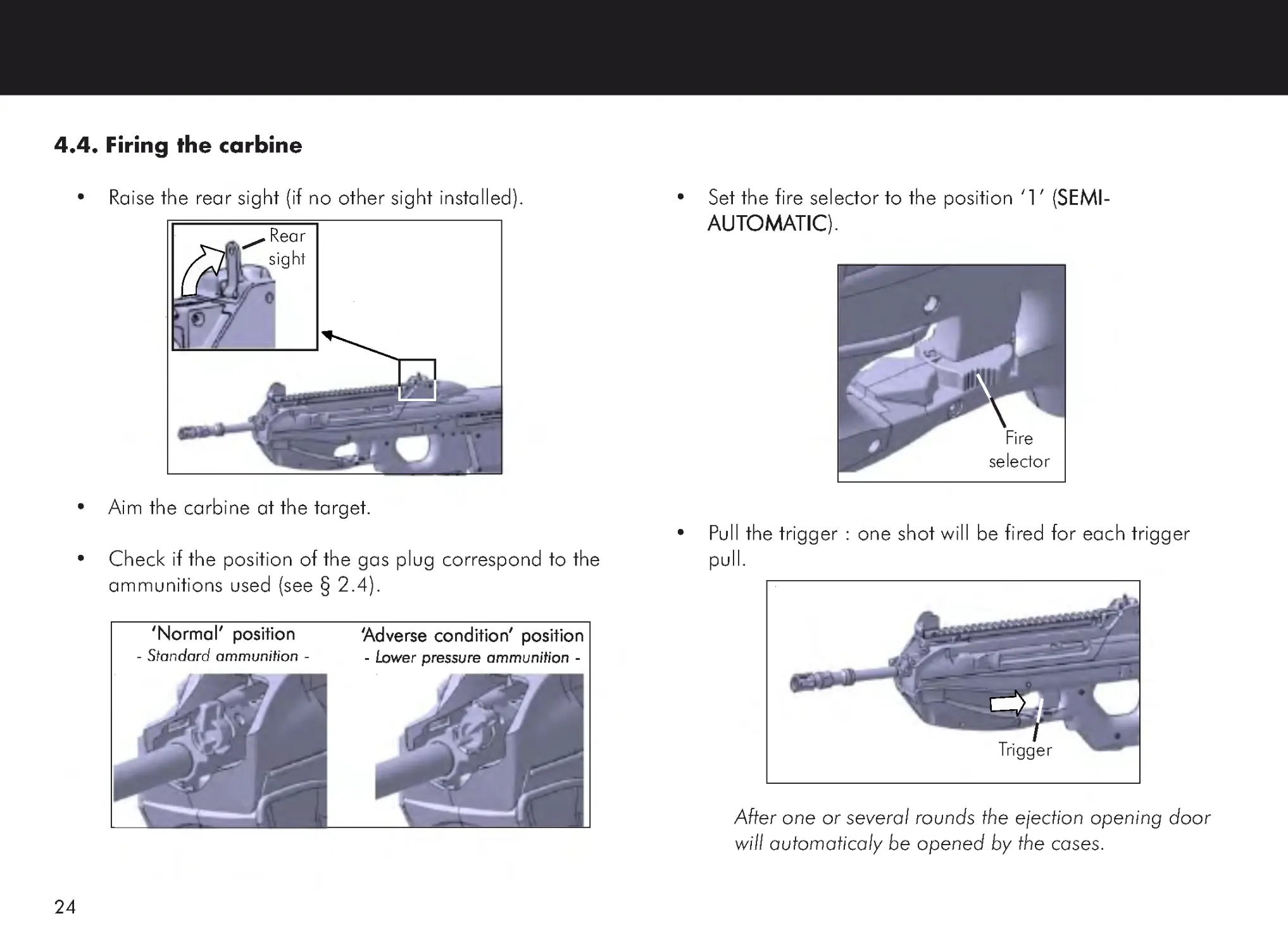
4.4. Firing the carbine
•
Raise the rear sight (if no other sight installed).
•
Aim the carbine at the target.
•
Check if the position of the gas plug correspond to the
ammunitions used (see § 2.4).
•
Set the fire selector to the position ‘ 11111’ (SEMI-
SEMI-
SEMI-
SEMI-
SEMI-
AAAAAUT
UT
UT
UT
UTOMA
OMA
OMA
OMA
OMATIC
TIC
TIC
TIC
TIC).
•
Pull the trigger : one shot will be fired for each trigger
pull.
After one or several rounds the ejection opening door
will automaticaly be opened by the cases.
Rear
sight
‘‘‘‘‘Adverse condition
Adverse condition
Adverse condition
Adverse condition
Adverse condition’ position
’ position
’ position
’ position
’ position
-
L-L
-
L-L
-
Lower pressure ammunition -
ower pressure ammunition -
ower pressure ammunition -
ower pressure ammunition -
ower pressure ammunition -
‘Normal’ position
‘Normal’ position
‘Normal’ position
‘Normal’ position
‘Normal’ position
-
Standard ammunition -
-
Standard ammunition -
-
Standard ammunition -
-
Standard ammunition -
-
Standard ammunition -
Trigger
Fire
selector
25
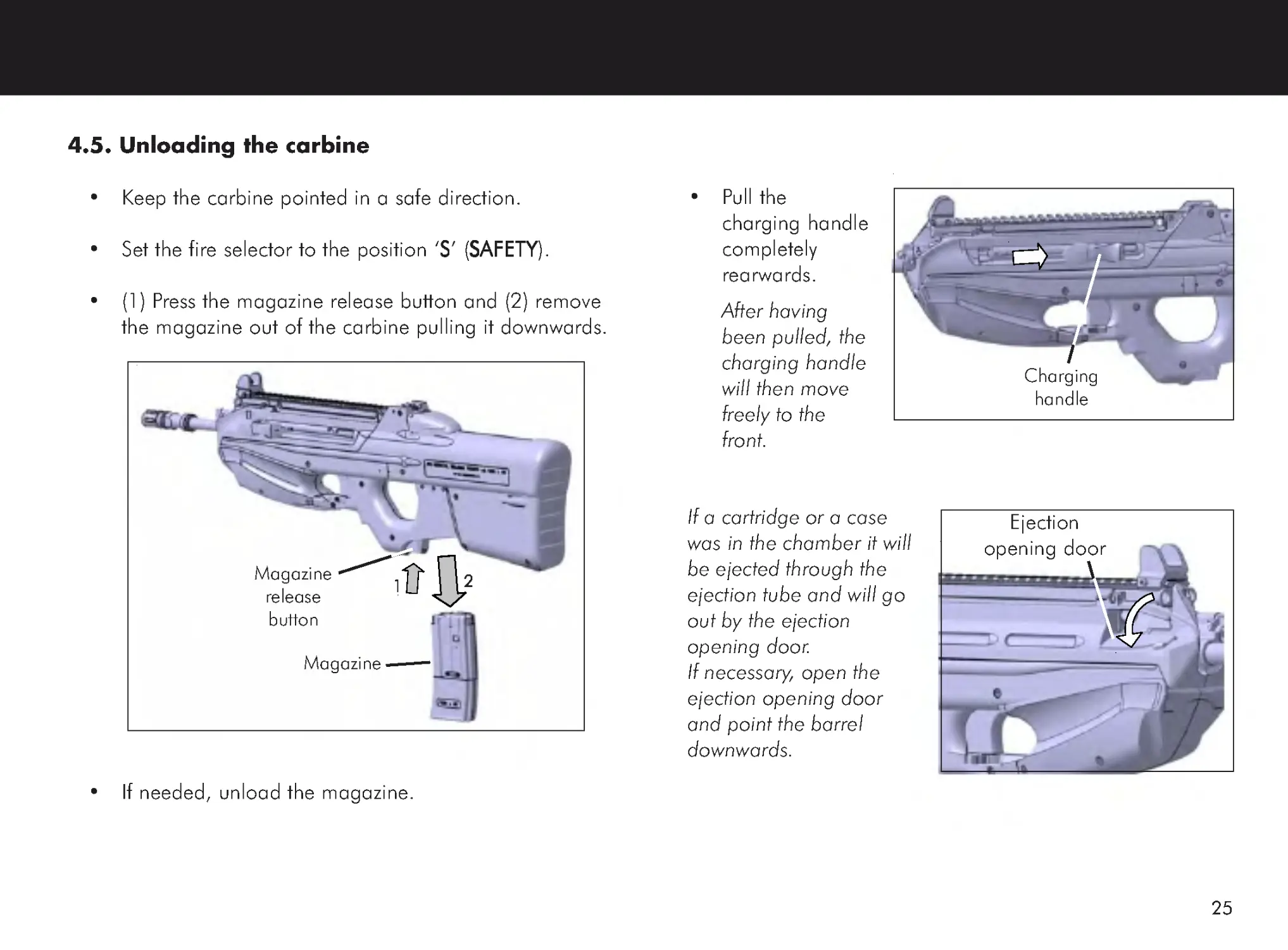
4.5. Unloading the carbine
•
Keep the carbine pointed in a safe direction.
•
Set the fire selector to the position ‘SSSSS’ (SAFETY
SAFETY
SAFETY
SAFETY
SAFETY).
•
(1) Press the magazine release button and (2) remove
the magazine out of the carbine pulling it downwards.
•
If needed, unload the magazine.
•
Pull the
charging handle
completely
rearwards.
After having
been pulled, the
charging handle
will then move
freely to the
front.
If a cartridge or a case
was in the chamber it will
be ejected through the
ejection tube and will go
out by the ejection
opening door.
If necessary, open the
ejection opening door
and point the barrel
downwards.
Ejection
opening door
Magazine
release
button
Magazine
11111
22222
Charging
handle
26
4.5. Unloading the carbine (continued)
•
Pull the charging handle completely rearwards and
then push it upwards to lock it at its rear position.
When taking its place into the locking notch, the
When taking its place into the locking notch, the
When taking its place into the locking notch, the
When taking its place into the locking notch, the
When taking its place into the locking notch, the
charging handle has a short back movement to the
charging handle has a short back movement to the
charging handle has a short back movement to the
charging handle has a short back movement to the
charging handle has a short back movement to the
front.
front.
front.
front.
front.
•
Raise the
inspection cover.
•
Looking through the opening of the inspection cover,
check that the carbine is empty (chamber and bolt).
•
Push down the charging handle to unlock it and let it
moving to the front.
This handling brings the bolt and bolt carrier
This handling brings the bolt and bolt carrier
This handling brings the bolt and bolt carrier
This handling brings the bolt and bolt carrier
This handling brings the bolt and bolt carrier
assembly back to the front and release the tension
assembly back to the front and release the tension
assembly back to the front and release the tension
assembly back to the front and release the tension
assembly back to the front and release the tension
of the return spring
of the return spring
of the return spring
of the return spring
of the return spring.....
•
Point the carbine in a safe
direction and set the fire
selector to the position ‘ 11111’
(SEMI-
SEMI-
SEMI-
SEMI-
SEMI-AAAAAUT
UT
UT
UT
UTOMA
OMA
OMA
OMA
OMATIC
TIC
TIC
TIC
TIC).
Inspection
cover
Charging
handle
Fire
selector
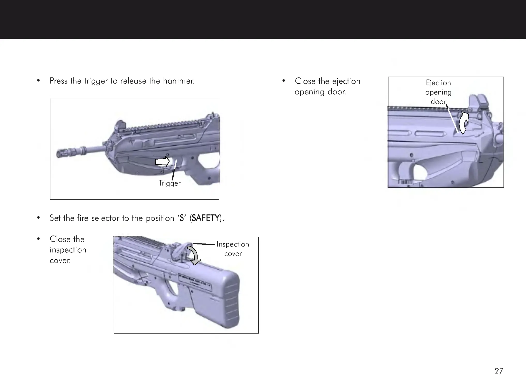
27
•
Press the trigger to release the hammer.
•
Set the fire selector to the position ‘SSSSS’ (SAFETY
SAFETY
SAFETY
SAFETY
SAFETY).
•
Close the
inspection
cover.
•
Close the ejection
opening door.
Trigger
Ejection
opening
door
Inspection
cover
28
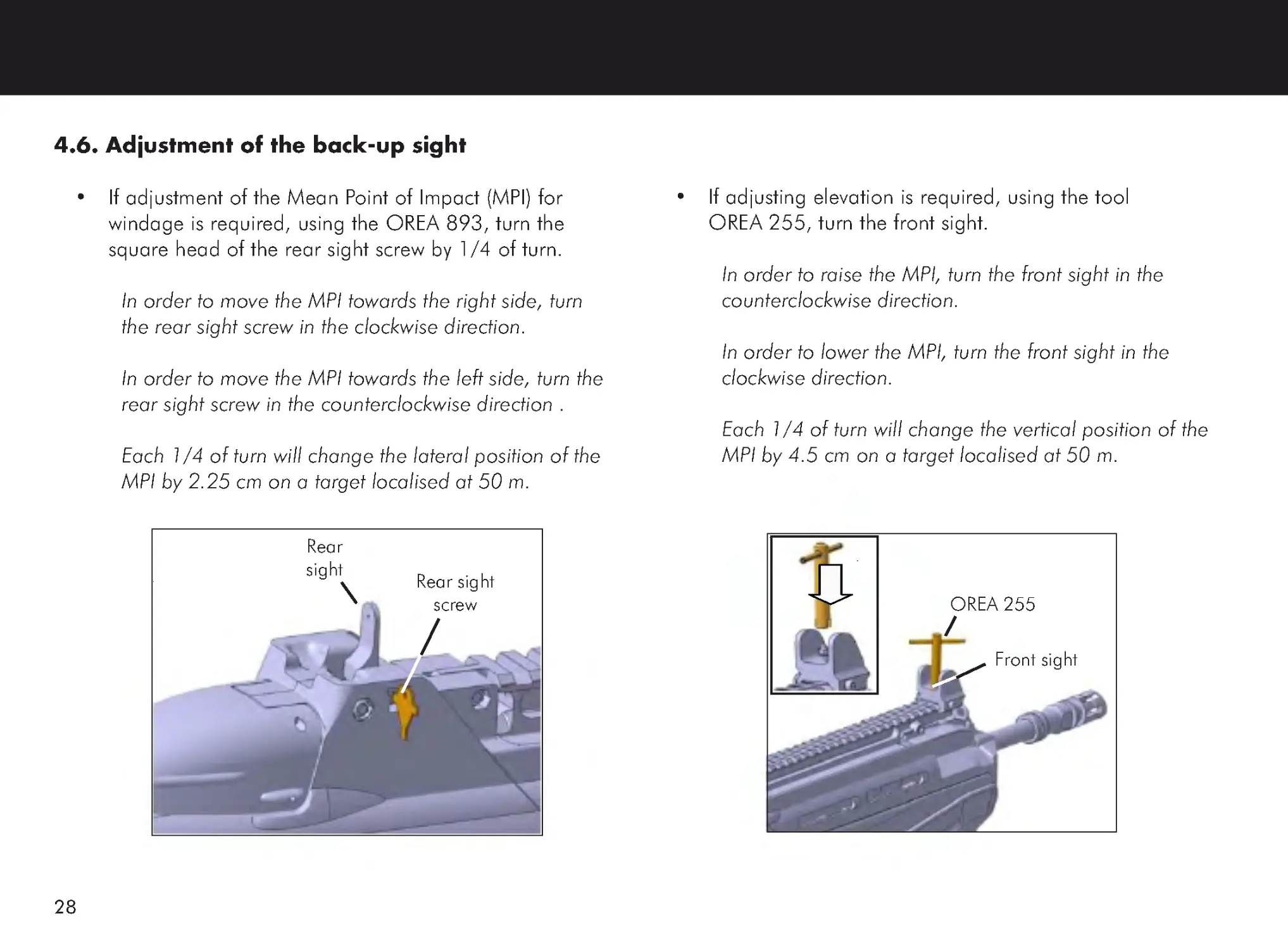
4.6. Adjustment of the back-up sight
•
If adjustment of the Mean Point of Impact (MPI) for
windage is required, using the OREA 893, turn the
square head of the rear sight screw by 1/4 of turn.
In order to move the MPI towards the right side, turn
the rear sight screw in the clockwise direction.
In order to move the MPI towards the left side, turn the
rear sight screw in the counterclockwise direction .
Each 1/4 of turn will change the lateral position of the
MPI by 2.25 cm on a target localised at 50 m.
•
If adjusting elevation is required, using the tool
OREA 255, turn the front sight.
In order to raise the MPI, turn the front sight in the
counterclockwise direction.
In order to lower the MPI, turn the front sight in the
clockwise direction.
Each 1/4 of turn will change the vertical position of the
MPI by 4.5 cm on a target localised at 50 m.
OREA 255
Front sight
Rear
sight
Rear sight
screw
29
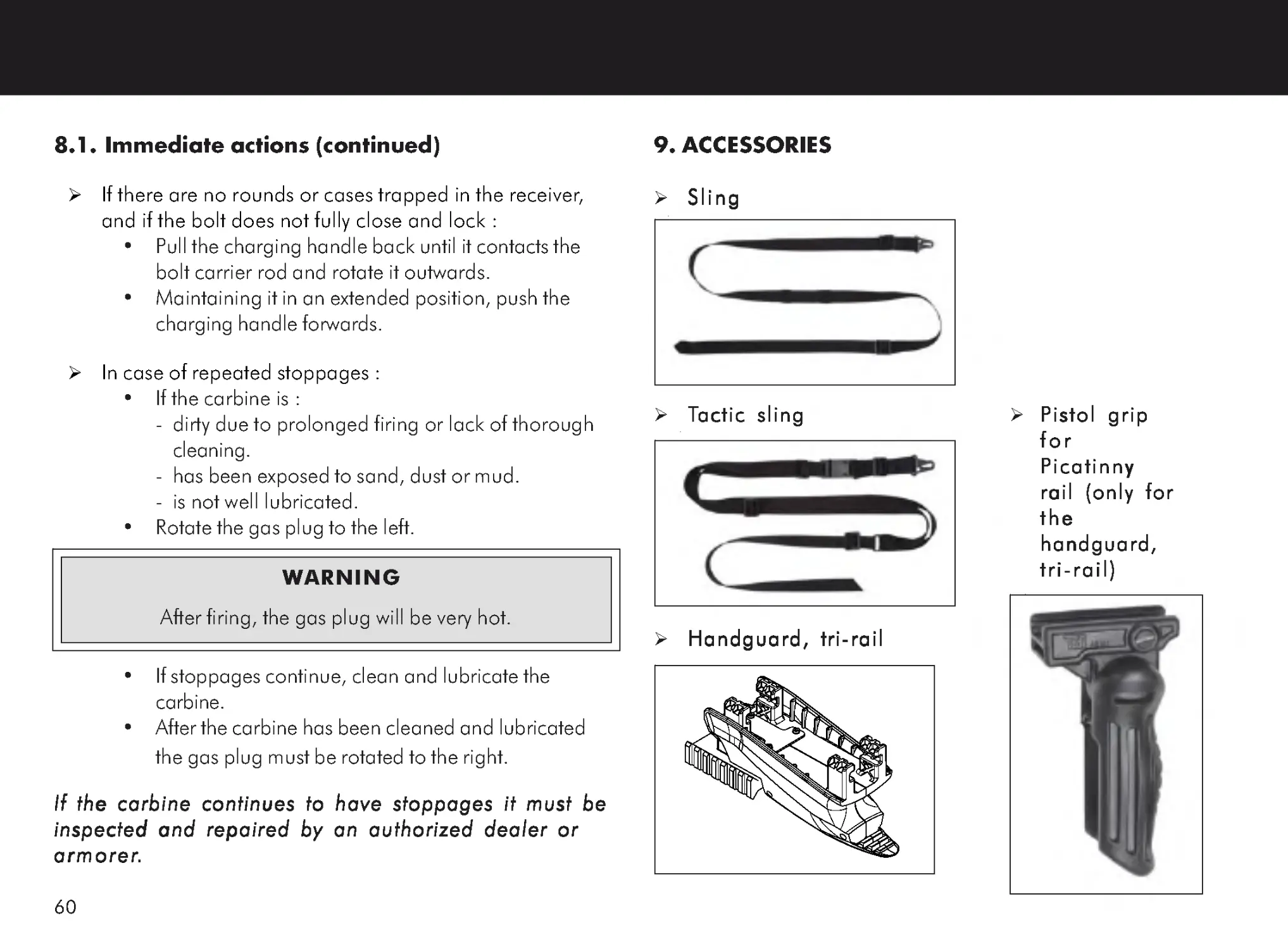
4.7. Installation of a sling (accessory)
•
Position the rear of the sling at the left side of the frame
with the buckle facing the frame.
•
Pass the rear of the sling from the top of the frame
through the slot on one side of the frame, under the
carbine and up through the slot on the other side of the
frame. Pass then the rear of the sling through the
buckle.
Do not tighten the sling around the frame.
Do not tighten the sling around the frame.
Do not tighten the sling around the frame.
Do not tighten the sling around the frame.
Do not tighten the sling around the frame.
•
Hook the snap-hook of the sling in the sling swivel.
Frame
Sling
Tactic sling
Buckle
Slot
Snap -hook
Snap -hook
Sling swivel
Sling
30
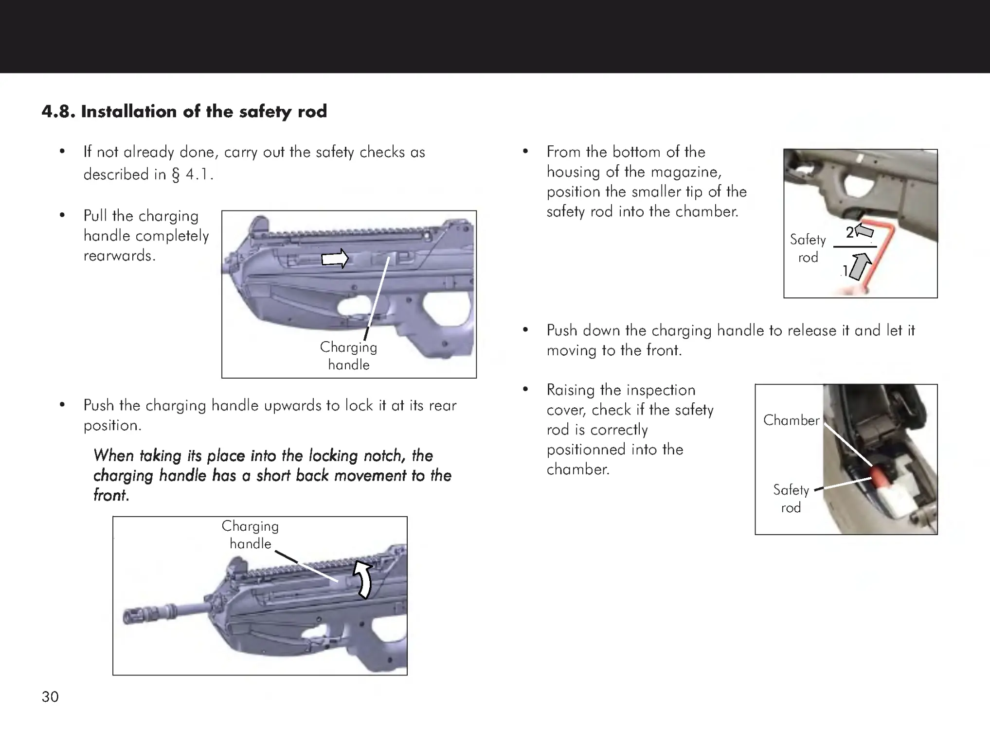
4.8. Installation of the safety rod
•
If not already done, carry out the safety checks as
described in § 4.1 .
•
Pull the charging
handle completely
rearwards.
•
Push the charging handle upwards to lock it at its rear
position.
When taking its place into the locking notch, the
When taking its place into the locking notch, the
When taking its place into the locking notch, the
When taking its place into the locking notch, the
When taking its place into the locking notch, the
charging handle has a short back movement to the
charging handle has a short back movement to the
charging handle has a short back movement to the
charging handle has a short back movement to the
charging handle has a short back movement to the
front.
front.
front.
front.
front.
Charging
handle
Charging
handle
•
From the bottom of the
housing of the magazine,
position the smaller tip of the
safety rod into the chamber.
•
Push down the charging handle to release it and let it
moving to the front.
•
Raising the inspection
cover, check if the safety
rod is correctly
positionned into the
chamber.
11111
22222
Safety
rod
Chamber
Safety
rod
31
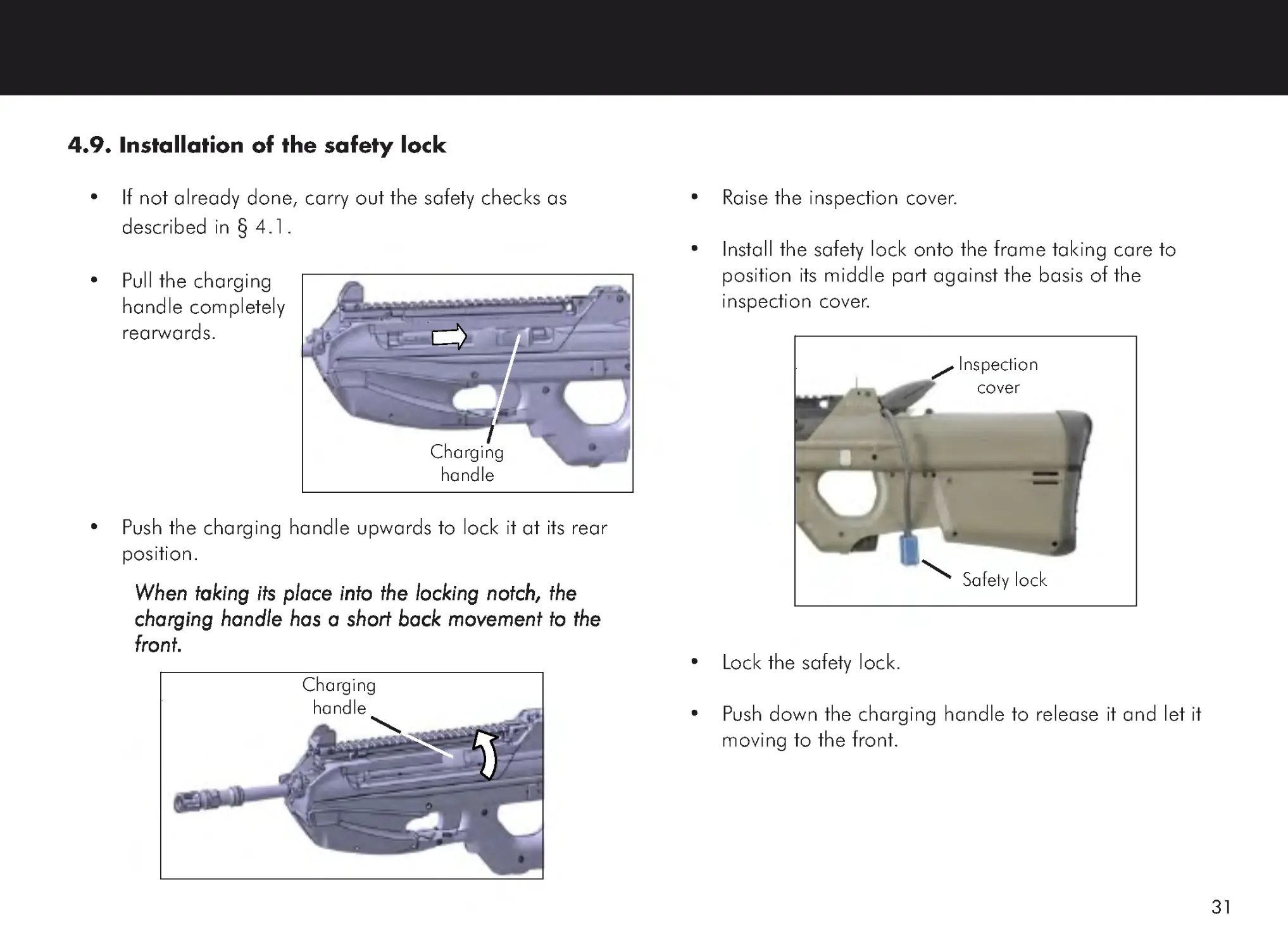
•
Raise the inspection cover.
•
Install the safety lock onto the frame taking care to
position its middle part against the basis of the
inspection cover.
•
Lock the safety lock.
•
Push down the charging handle to release it and let it
moving to the front.
Inspection
cover
Safety lock
4.9. Installation of the safety lock
•
If not already done, carry out the safety checks as
described in § 4.1 .
•
Pull the charging
handle completely
rearwards.
•
Push the charging handle upwards to lock it at its rear
position.
When taking its place into the locking notch, the
When taking its place into the locking notch, the
When taking its place into the locking notch, the
When taking its place into the locking notch, the
When taking its place into the locking notch, the
charging handle has a short back movement to the
charging handle has a short back movement to the
charging handle has a short back movement to the
charging handle has a short back movement to the
charging handle has a short back movement to the
front.
front.
front.
front.
front.
Charging
handle
Charging
handle
32
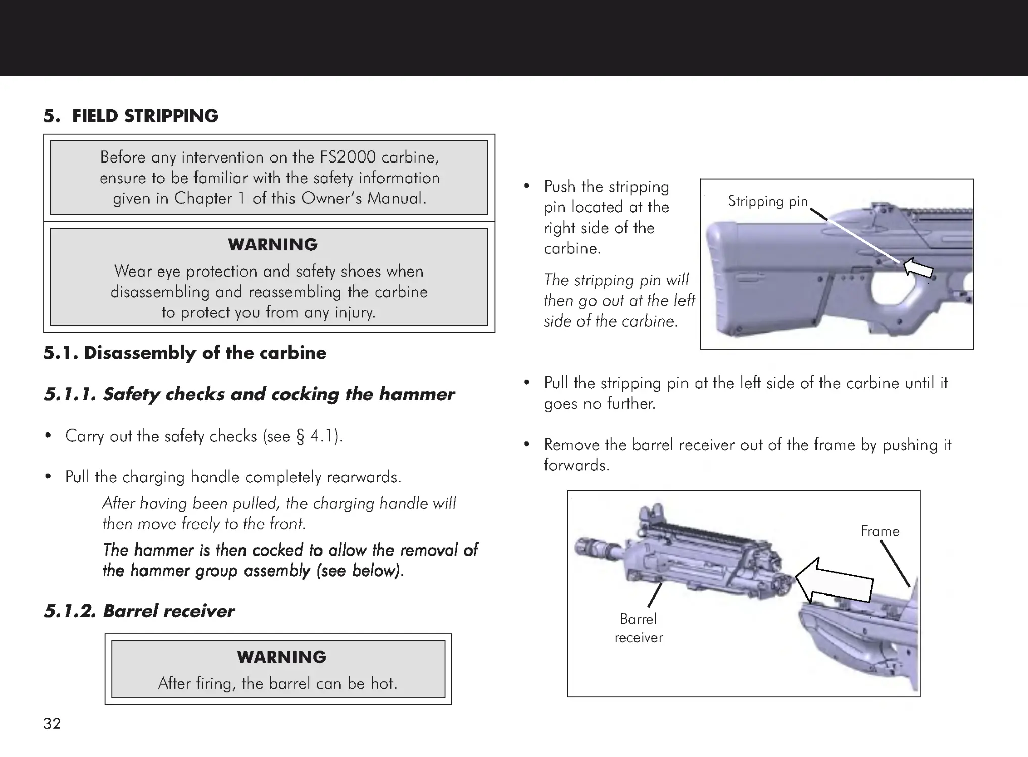
5. FIELD STRIPPING
5.1. Disassembly of the carbine
5.1.1. Safety checks and cocking the hammer
• Carry out the safety checks (see § 4.1).
• Pull the charging handle completely rearwards.
After having been pulled, the charging handle will
then move freely to the front.
The hammer is then cocked to allow the removal of
The hammer is then cocked to allow the removal of
The hammer is then cocked to allow the removal of
The hammer is then cocked to allow the removal of
The hammer is then cocked to allow the removal of
the hammer group assembly (see below).
the hammer group assembly (see below).
the hammer group assembly (see below).
the hammer group assembly (see below).
the hammer group assembly (see below).
5.1.2. Barrel receiver
Before any intervention on the FS2000 carbine,
ensure to be familiar with the safety information
given in Chapter 1 of this Owner ’s Manual.
• Push the stripping
pin located at the
right side of the
carbine.
The stripping pin will
then go out at the left
side of the carbine.
• Pull the stripping pin at the left side of the carbine until it
goes no further.
• Remove the barrel receiver out of the frame by pushing it
forwards.
WARNING
After firing, the barrel can be hot.
Stripping pin
Frame
Barrel
receiver
WARNING
Wear eye protection and safety shoes when
disassembling and reassembling the carbine
to protect you from any injury.
33
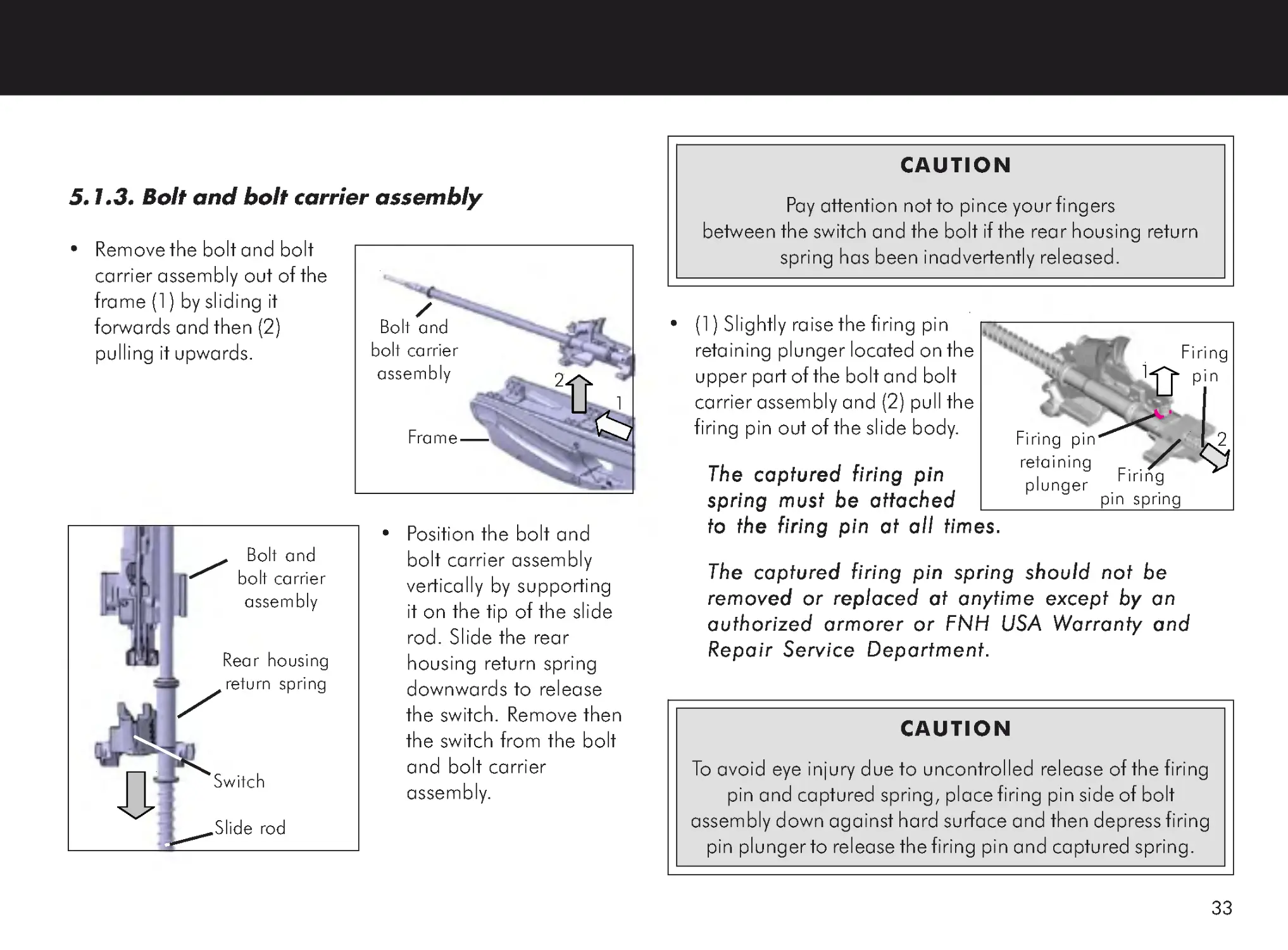
• (1) Slightly raise the firing pin
retaining plunger located on the
upper part of the bolt and bolt
carrier assembly and (2) pull the
firing pin out of the slide body.
The captured firing pin
The captured firing pin
The captured firing pin
The captured firing pin
The captured firing pin
spring must be attached
spring must be attached
spring must be attached
spring must be attached
spring must be attached
to the firing pin at all times.
to the firing pin at all times.
to the firing pin at all times.
to the firing pin at all times.
to the firing pin at all times.
The captured firing pin spring should not be
The captured firing pin spring should not be
The captured firing pin spring should not be
The captured firing pin spring should not be
The captured firing pin spring should not be
removed or replaced at anytime except by an
removed or replaced at anytime except by an
removed or replaced at anytime except by an
removed or replaced at anytime except by an
removed or replaced at anytime except by an
authorized armorer or FNH USA W
authorized armorer or FNH USA W
authorized armorer or FNH USA W
authorized armorer or FNH USA W
authorized armorer or FNH USA Warranty and
arranty and
arranty and
arranty and
arranty and
Repair Service Department.
Repair Service Department.
Repair Service Department.
Repair Service Department.
Repair Service Department.
5.1.3. Bolt and bolt carrier assembly
• Remove the bolt and bolt
carrier assembly out of the
frame (1) by sliding it
forwards and then (2)
pulling it upwards.
• Position the bolt and
bolt carrier assembly
vertically by supporting
it on the tip of the slide
rod. Slide the rear
housing return spring
downwards to release
the switch. Remove then
the switch from the bolt
and bolt carrier
assembly.
Switch
Rear housing
return spring
Slide rod
Frame
Bolt and
bolt carrier
assembly
2
1
CAUTION
Pay attention not to pince your fingers
between the switch and the bolt if the rear housing return
spring has been inadvertently released.
Bolt and
bolt carrier
assembly
CAUTION
To avoid eye injury due to uncontrolled release of the firing
pin and captured spring, place firing pin side of bolt
assembly down against hard surface and then depress firing
pin plunger to release the firing pin and captured spring.
Firing
pin spring
Firing
pin
Firing pin
retaining
plunger
1
2
34
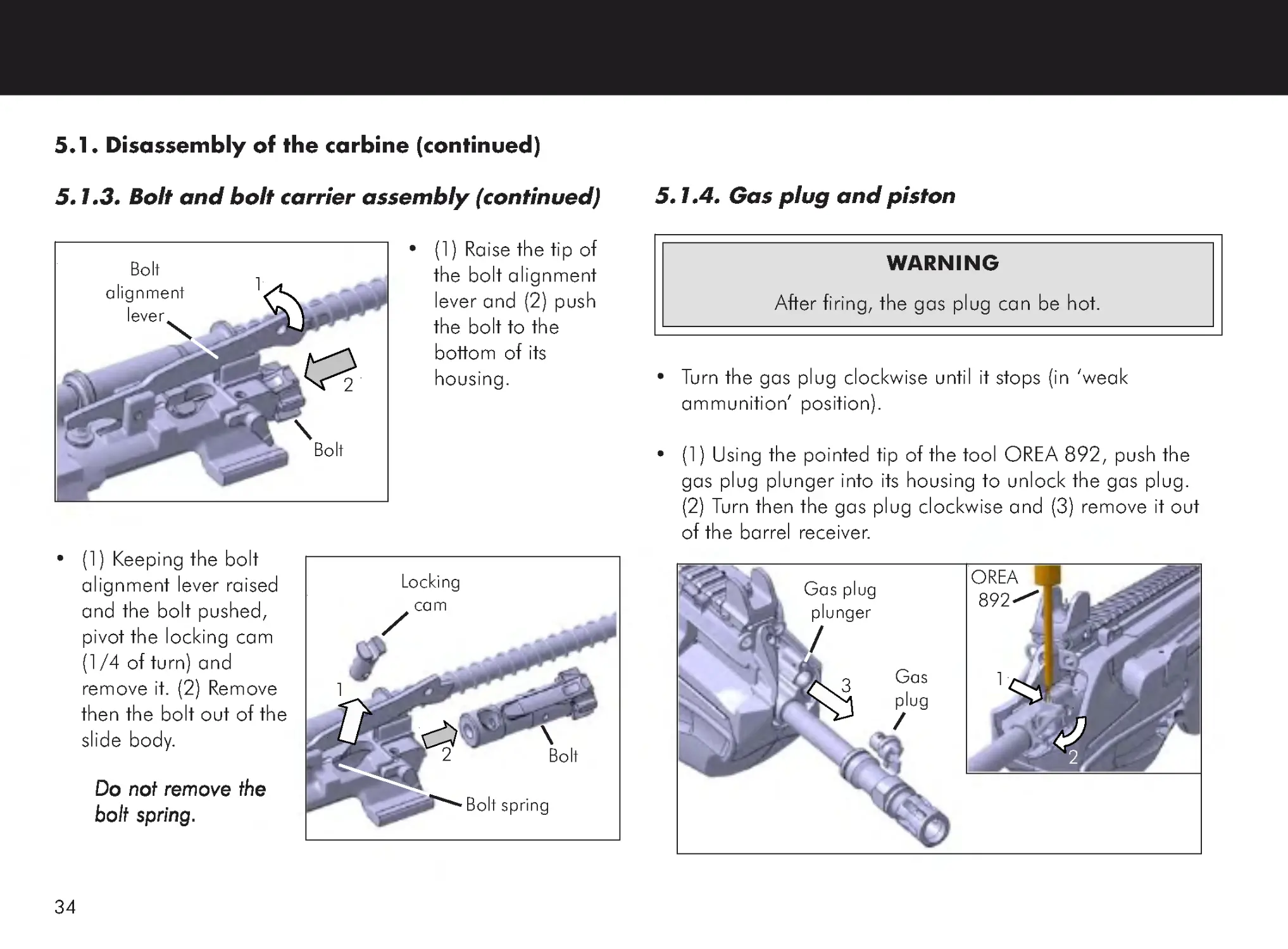
5.1. Disassembly of the carbine (continued)
5.1.3. Bolt and bolt carrier assembly (continued)
• (1) Raise the tip of
the bolt alignment
lever and (2) push
the bolt to the
bottom of its
housing.
• (1) Keeping the bolt
alignment lever raised
and the bolt pushed,
pivot the locking cam
(1/4 of turn) and
remove it. (2) Remove
then the bolt out of the
slide body.
Do not remove the
Do not remove the
Do not remove the
Do not remove the
Do not remove the
bolt spring
bolt spring
bolt spring
bolt spring
bolt spring.....
5.1.4. Gas plug and piston
• Turn the gas plug clockwise until it stops (in ‘weak
ammunition’ position).
• (1) Using the pointed tip of the tool OREA 892, push the
gas plug plunger into its housing to unlock the gas plug.
(2) Turn then the gas plug clockwise and (3) remove it out
of the barrel receiver.
WARNING
After firing, the gas plug can be hot.
1
2
Bolt
Locking
cam
Bolt spring
2
1
3 Gas
plug
OREA
892
Gas plug
plunger
1
2
Bolt
alignment
lever
Bolt
35
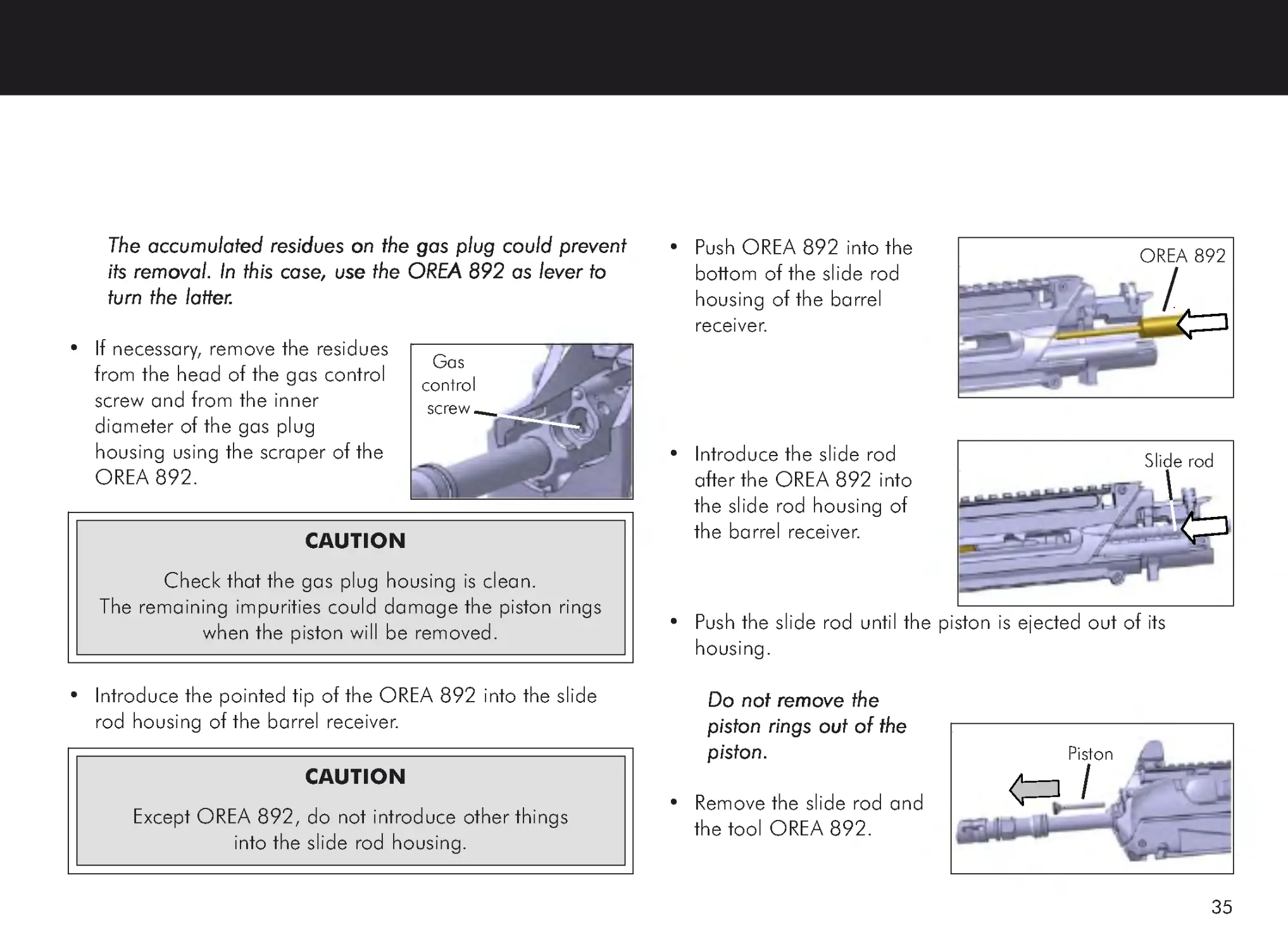
The accumulated residues on the gas plug could prevent
The accumulated residues on the gas plug could prevent
The accumulated residues on the gas plug could prevent
The accumulated residues on the gas plug could prevent
The accumulated residues on the gas plug could prevent
its removal. In this case, use the OREA 892 as lever to
its removal. In this case, use the OREA 892 as lever to
its removal. In this case, use the OREA 892 as lever to
its removal. In this case, use the OREA 892 as lever to
its removal. In this case, use the OREA 892 as lever to
turn the latter
turn the latter
turn the latter
turn the latter
turn the latter.....
• If necessary, remove the residues
from the head of the gas control
screw and from the inner
diameter of the gas plug
housing using the scraper of the
OREA 892.
• Introduce the pointed tip of the OREA 892 into the slide
rod housing of the barrel receiver.
• Push OREA 892 into the
bottom of the slide rod
housing of the barrel
receiver.
• Introduce the slide rod
after the OREA 892 into
the slide rod housing of
the barrel receiver.
• Push the slide rod until the piston is ejected out of its
housing.
Do not remove the
Do not remove the
Do not remove the
Do not remove the
Do not remove the
piston rings out of the
piston rings out of the
piston rings out of the
piston rings out of the
piston rings out of the
piston.
piston.
piston.
piston.
piston.
• Remove the slide rod and
the tool OREA 892.
CAUTION
Except OREA 892, do not introduce other things
into the slide rod housing.
CAUTION
Check that the gas plug housing is clean.
The remaining impurities could damage the piston rings
when the piston will be removed.
OREA 892
Slide rod
Piston
Gas
control
screw
36
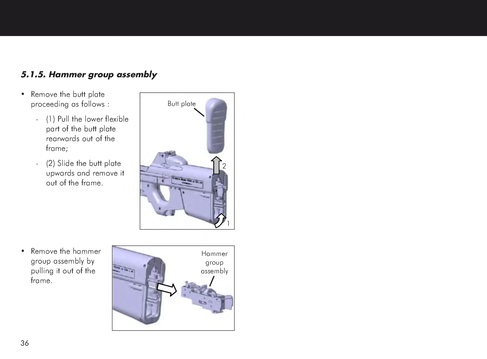
5.1.5. Hammer group assembly
• Remove the butt plate
proceeding as follows :
-
(1) Pull the lower flexible
part of the butt plate
rearwards out of the
frame;
-
(2) Slide the butt plate
upwards and remove it
out of the frame.
• Remove the hammer
group assembly by
pulling it out of the
frame.
2
Butt plate
1
Hammer
group
assembly
37
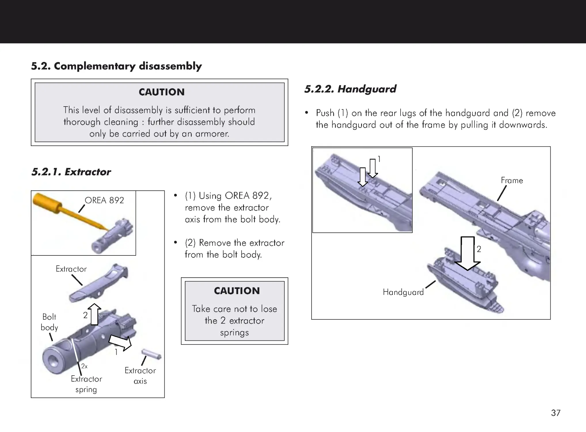
5.2. Complementary disassembly
5.2.1. Extractor
• (1) Using OREA 892,
remove the extractor
axis from the bolt body.
• (2) Remove the extractor
from the bolt body.
5.2.2. Handguard
• Push (1) on the rear lugs of the handguard and (2) remove
the handguard out of the frame by pulling it downwards.
CAUTION
This level of disassembly is sufficient to perform
thorough cleaning : further disassembly should
only be carried out by an armorer.
CAUTION
Take care not to lose
the 2 extractor
springs
1
2
Extractor
Extractor
axis
Bolt
body
OREA 892
Extractor
spring
2x
Handguard
Frame
1
2
38
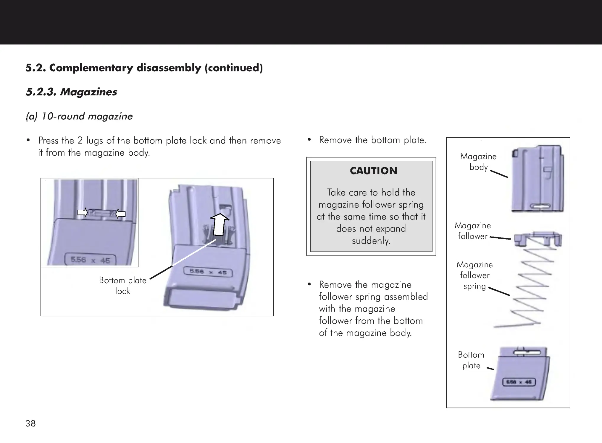
5.2. Complementary disassembly (continued)
5.2.3. Magazines
(a) 10-round magazine
• Press the 2 lugs of the bottom plate lock and then remove
it from the magazine body.
• Remove the bottom plate.
• Remove the magazine
follower spring assembled
with the magazine
follower from the bottom
of the magazine body.
Magazine
body
Magazine
follower
spring
Magazine
follower
Bottom
plate
Bottom plate
lock
CAUTION
Take care to hold the
magazine follower spring
at the same time so that it
does not expand
suddenly.
39
(b) 30-round magazine
• Using the rim of a spent round or the tip of a flat head
screwdriver, push in the spring on the bottom plate access
slot and slide the floor plate off the magazine body to the
rear.
Depending on the type of magazine used, the removal of
the bottom plate could be slightly different.
• Remove the magazine
follower spring assembled
with the magazine follower
from the bottom of the
magazine body.
CAUTION
Take care to hold the magazine follower spring at the
same time so that it does not expand suddenly.
Screwdriver
Magazine
body
Bottom
plate
Magazine
body
Magazine
follower
spring
Magazine
follower
Bottom
plate
40
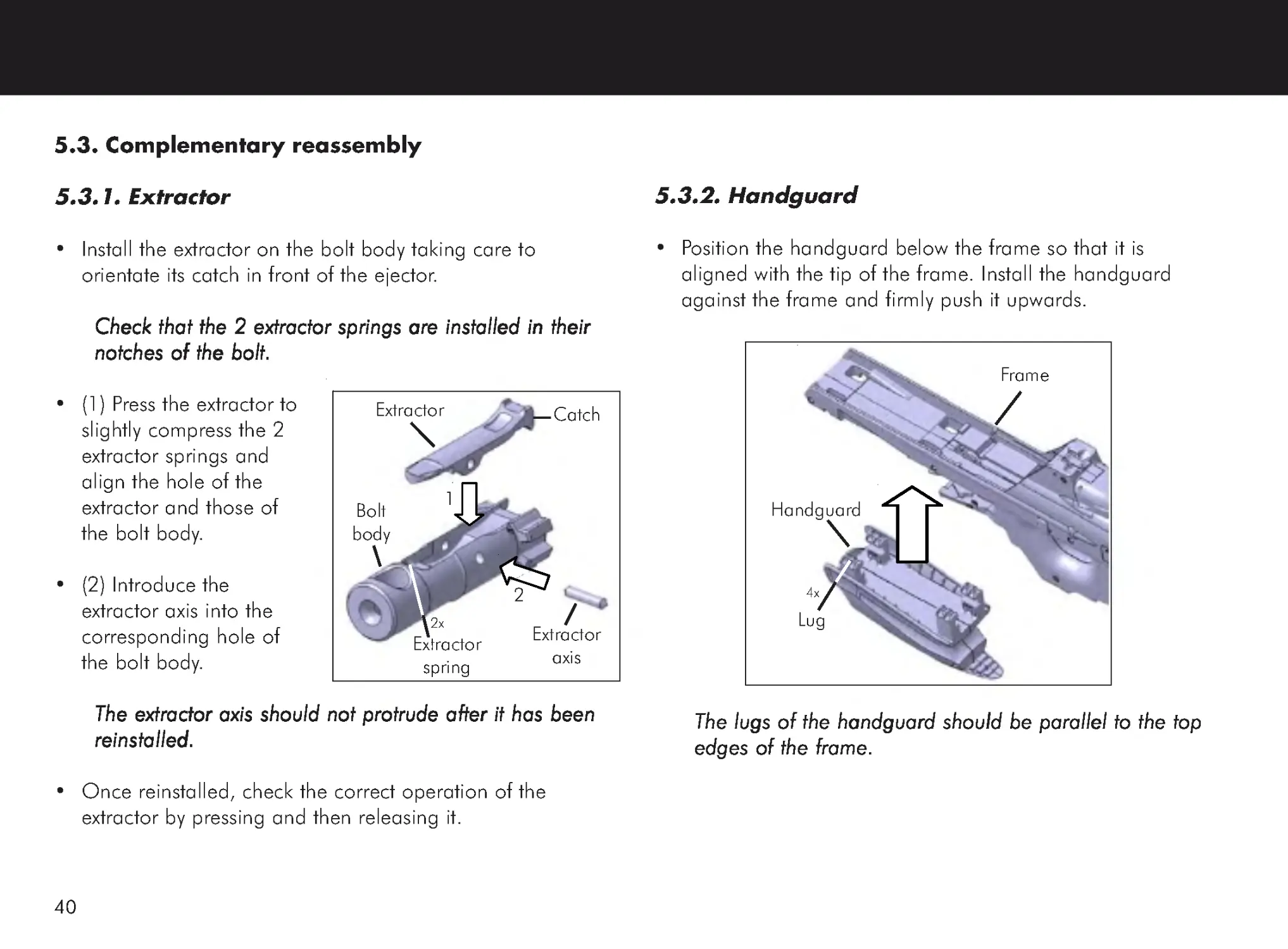
5.3.2. Handguard
• Position the handguard below the frame so that it is
aligned with the tip of the frame. Install the handguard
against the frame and firmly push it upwards.
The lugs of the handguard should be parallel to the top
The lugs of the handguard should be parallel to the top
The lugs of the handguard should be parallel to the top
The lugs of the handguard should be parallel to the top
The lugs of the handguard should be parallel to the top
edges of the frame.
edges of the frame.
edges of the frame.
edges of the frame.
edges of the frame.
5.3. Complementary reassembly
5.3.1. Extractor
• Install the extractor on the bolt body taking care to
orientate its catch in front of the ejector.
Check that the 2 extractor springs are installed in their
Check that the 2 extractor springs are installed in their
Check that the 2 extractor springs are installed in their
Check that the 2 extractor springs are installed in their
Check that the 2 extractor springs are installed in their
notches of the bolt.
notches of the bolt.
notches of the bolt.
notches of the bolt.
notches of the bolt.
• (1) Press the extractor to
slightly compress the 2
extractor springs and
align the hole of the
extractor and those of
the bolt body.
• (2) Introduce the
extractor axis into the
corresponding hole of
the bolt body.
The extractor axis should not protrude after it has been
The extractor axis should not protrude after it has been
The extractor axis should not protrude after it has been
The extractor axis should not protrude after it has been
The extractor axis should not protrude after it has been
reinstalled.
reinstalled.
reinstalled.
reinstalled.
reinstalled.
• Once reinstalled, check the correct operation of the
extractor by pressing and then releasing it.
1
2
Extractor
Extractor
axis
Bolt
body
Extractor
spring
2x
Catch
Handguard
Frame
Lug
4x
41
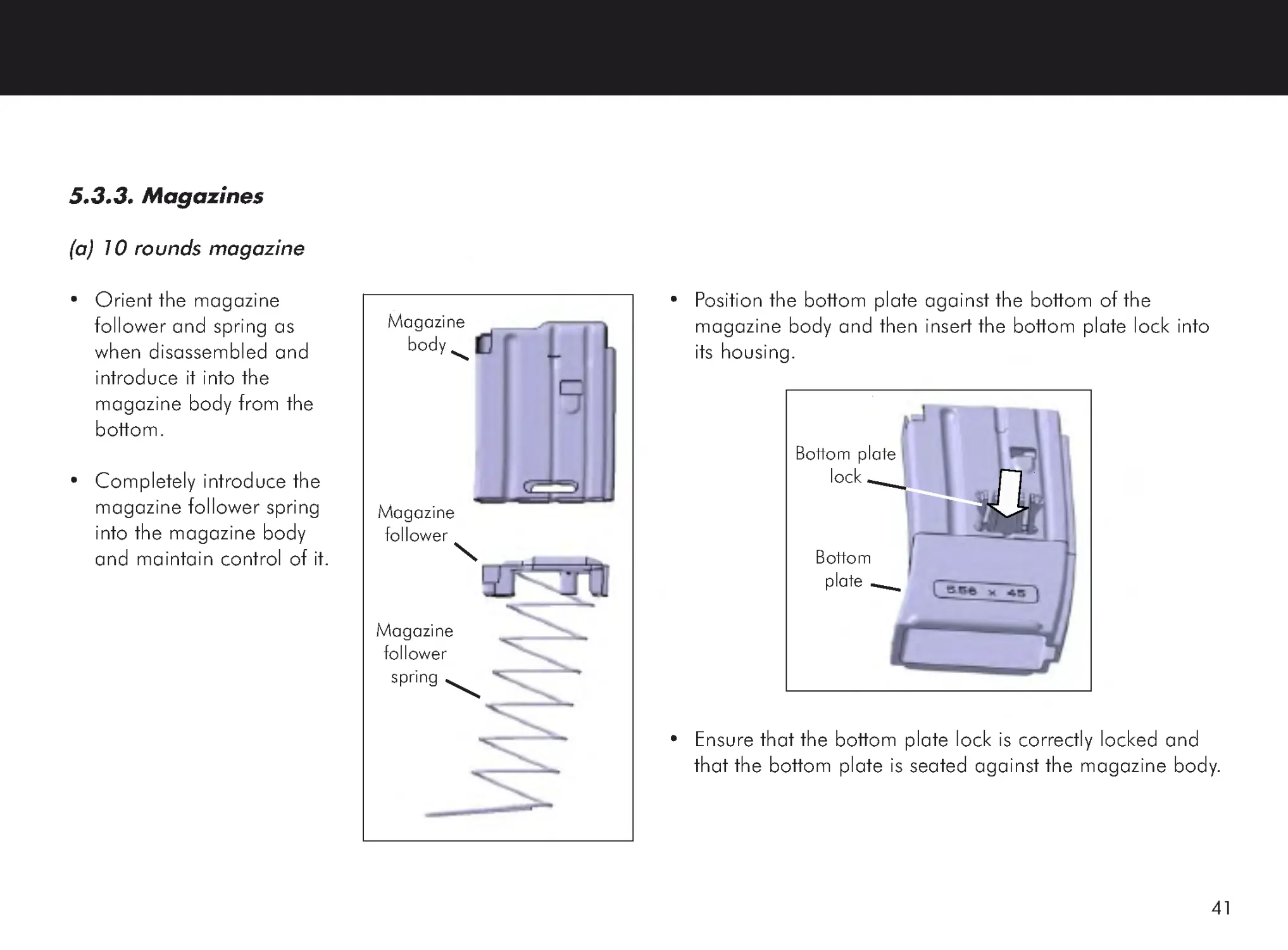
5.3.3. Magazines
(a) 10 rounds magazine
• Orient the magazine
follower and spring as
when disassembled and
introduce it into the
magazine body from the
bottom.
• Completely introduce the
magazine follower spring
into the magazine body
and maintain control of it.
Magazine
body
Magazine
follower
spring
Magazine
follower
• Position the bottom plate against the bottom of the
magazine body and then insert the bottom plate lock into
its housing.
• Ensure that the bottom plate lock is correctly locked and
that the bottom plate is seated against the magazine body.
Bottom plate
lock
Bottom
plate
42
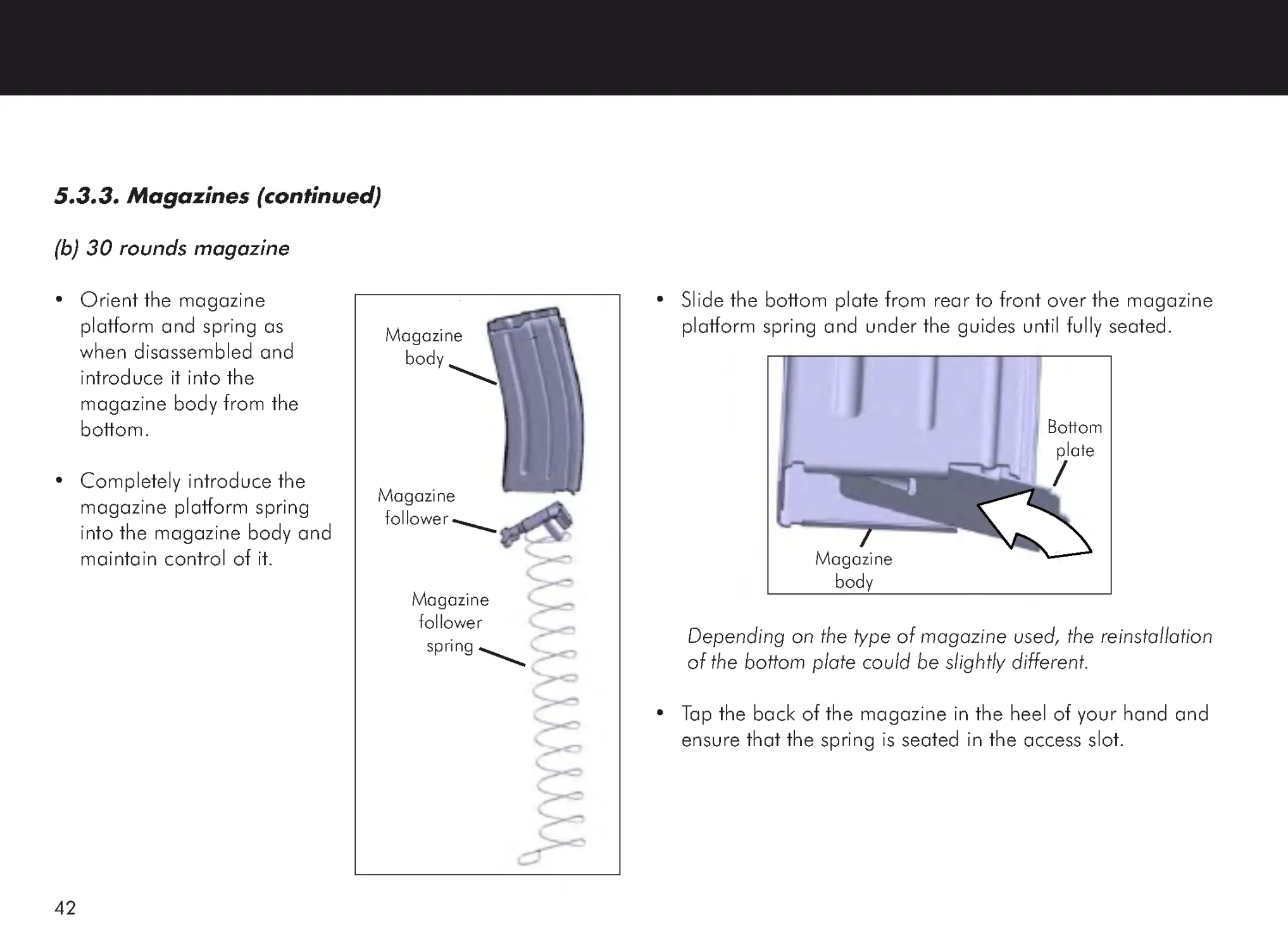
5.3.3. Magazines (continued)
(b) 30 rounds magazine
• Orient the magazine
platform and spring as
when disassembled and
introduce it into the
magazine body from the
bottom.
• Completely introduce the
magazine platform spring
into the magazine body and
maintain control of it.
• Slide the bottom plate from rear to front over the magazine
platform spring and under the guides until fully seated.
Depending on the type of magazine used, the reinstallation
of the bottom plate could be slightly different.
• Tap the back of the magazine in the heel of your hand and
ensure that the spring is seated in the access slot.
Magazine
body
Magazine
follower
spring
Magazine
follower
Magazine
body
Bottom
plate
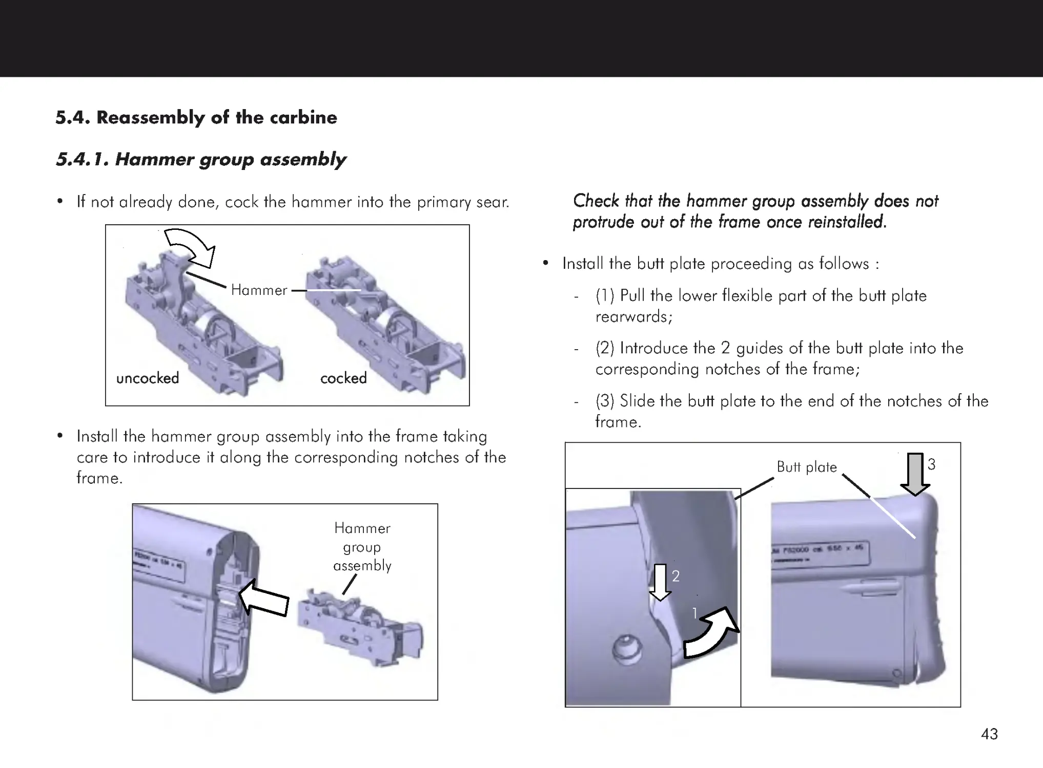
43
Check that the hammer group assembly does not
Check that the hammer group assembly does not
Check that the hammer group assembly does not
Check that the hammer group assembly does not
Check that the hammer group assembly does not
protrude out of the frame once reinstalled.
protrude out of the frame once reinstalled.
protrude out of the frame once reinstalled.
protrude out of the frame once reinstalled.
protrude out of the frame once reinstalled.
• Install the butt plate proceeding as follows :
-
(1) Pull the lower flexible part of the butt plate
rearwards;
-
(2) Introduce the 2 guides of the butt plate into the
corresponding notches of the frame;
-
(3) Slide the butt plate to the end of the notches of the
frame.
5.4. Reassembly of the carbine
5.4.1. Hammer group assembly
• If not already done, cock the hammer into the primary sear.
• Install the hammer group assembly into the frame taking
care to introduce it along the corresponding notches of the
frame.
Hammer
group
assembly
uncocked
uncocked
uncocked
uncocked
uncocked
cocked
cocked
cocked
cocked
cocked
Hammer
Butt plate
3
2
1
44
5.4. Reassembly of the carbine (continued)
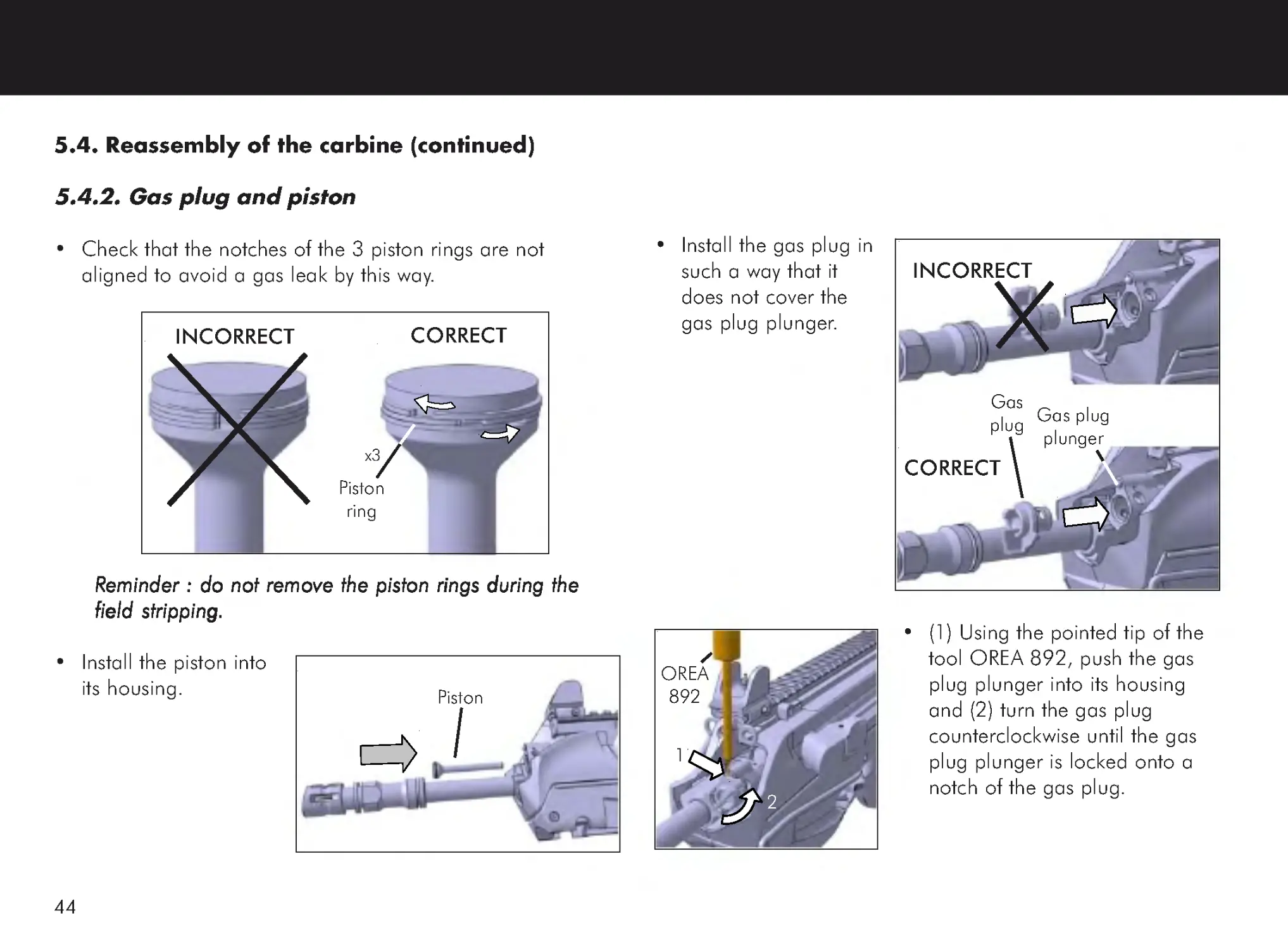
5.4.2. Gas plug and piston
• Check that the notches of the 3 piston rings are not
aligned to avoid a gas leak by this way.
RRRRReminder : do not remove the piston rings during the
eminder : do not remove the piston rings during the
eminder : do not remove the piston rings during the
eminder : do not remove the piston rings during the
eminder : do not remove the piston rings during the
field stripping
field stripping
field stripping
field stripping
field stripping.....
• Install the piston into
its housing.
CORRECT
INCORRECT
Piston
ring
x3
• Install the gas plug in
such a way that it
does not cover the
gas plug plunger.
• (1) Using the pointed tip of the
tool OREA 892, push the gas
plug plunger into its housing
and (2) turn the gas plug
counterclockwise until the gas
plug plunger is locked onto a
notch of the gas plug.
OREA
892
Piston
CORRECT
INCORRECT
Gas
plug Gas plug
plunger
2
1
45
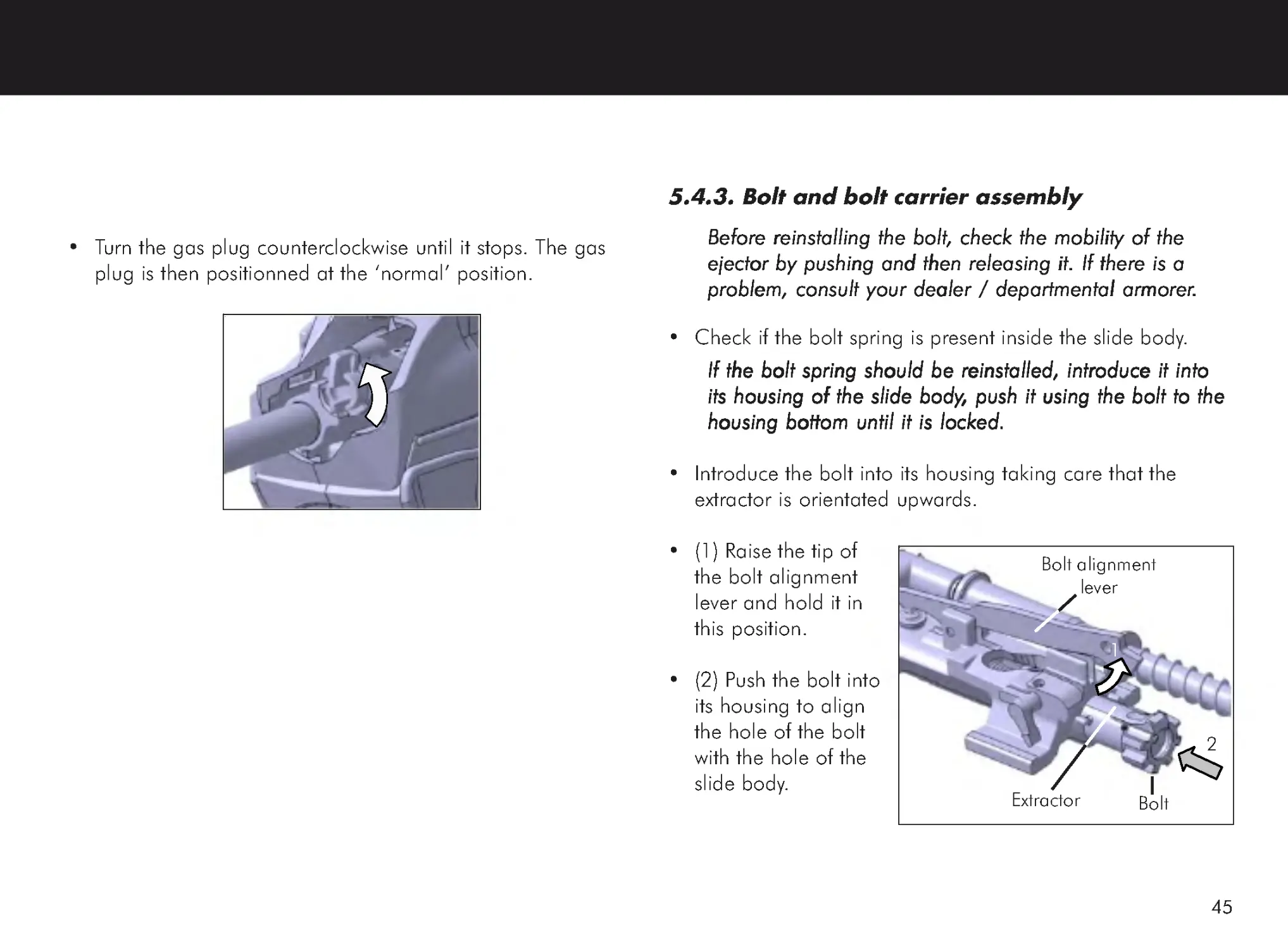
5.4.3. Bolt and bolt carrier assembly
Before reinstalling the bolt, check the mobility of the
Before reinstalling the bolt, check the mobility of the
Before reinstalling the bolt, check the mobility of the
Before reinstalling the bolt, check the mobility of the
Before reinstalling the bolt, check the mobility of the
ejector by pushing and then releasing it. If there is a
ejector by pushing and then releasing it. If there is a
ejector by pushing and then releasing it. If there is a
ejector by pushing and then releasing it. If there is a
ejector by pushing and then releasing it. If there is a
problem, consult your dealer / departmental armorer
problem, consult your dealer / departmental armorer
problem, consult your dealer / departmental armorer
problem, consult your dealer / departmental armorer
problem, consult your dealer / departmental armorer.....
• Check if the bolt spring is present inside the slide body.
If the bolt spring should be reinstalled, introduce it into
If the bolt spring should be reinstalled, introduce it into
If the bolt spring should be reinstalled, introduce it into
If the bolt spring should be reinstalled, introduce it into
If the bolt spring should be reinstalled, introduce it into
its housing of the slide body
its housing of the slide body
its housing of the slide body
its housing of the slide body
its housing of the slide body, push it using the bolt to the
, push it using the bolt to the
, push it using the bolt to the
, push it using the bolt to the
, push it using the bolt to the
housing bottom until it is locked.
housing bottom until it is locked.
housing bottom until it is locked.
housing bottom until it is locked.
housing bottom until it is locked.
• Introduce the bolt into its housing taking care that the
extractor is orientated upwards.
• (1) Raise the tip of
the bolt alignment
lever and hold it in
this position.
• (2) Push the bolt into
its housing to align
the hole of the bolt
with the hole of the
slide body.
• Turn the gas plug counterclockwise until it stops. The gas
plug is then positionned at the ‘normal’ position.
1
2
Bolt alignment
lever
Bolt
Extractor
46
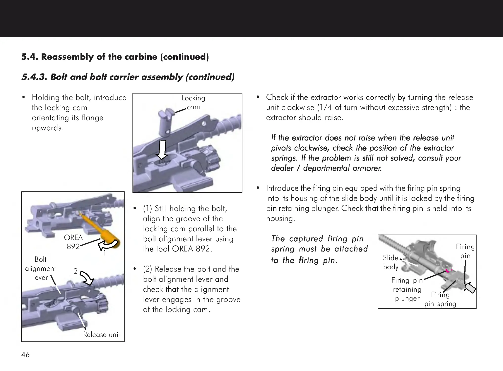
• Check if the extractor works correctly by turning the release
unit clockwise (1/4 of turn without excessive strength) : the
extractor should raise.
If the extractor does not raise when the release unit
If the extractor does not raise when the release unit
If the extractor does not raise when the release unit
If the extractor does not raise when the release unit
If the extractor does not raise when the release unit
pivots clockwise, check the position of the extractor
pivots clockwise, check the position of the extractor
pivots clockwise, check the position of the extractor
pivots clockwise, check the position of the extractor
pivots clockwise, check the position of the extractor
springs. If the problem is still not solved, consult your
springs. If the problem is still not solved, consult your
springs. If the problem is still not solved, consult your
springs. If the problem is still not solved, consult your
springs. If the problem is still not solved, consult your
dealer / departmental armorer
dealer / departmental armorer
dealer / departmental armorer
dealer / departmental armorer
dealer / departmental armorer.....
• Introduce the firing pin equipped with the firing pin spring
into its housing of the slide body until it is locked by the firing
pin retaining plunger. Check that the firing pin is held into its
housing.
The captured firing pin
The captured firing pin
The captured firing pin
The captured firing pin
The captured firing pin
spring must be attached
spring must be attached
spring must be attached
spring must be attached
spring must be attached
to the firing pin.
to the firing pin.
to the firing pin.
to the firing pin.
to the firing pin.
5.4. Reassembly of the carbine (continued)
5.4.3. Bolt and bolt carrier assembly (continued)
• Holding the bolt, introduce
the locking cam
orientating its flange
upwards.
• (1) Still holding the bolt,
align the groove of the
locking cam parallel to the
bolt alignment lever using
the tool OREA 892.
• (2) Release the bolt and the
bolt alignment lever and
check that the alignment
lever engages in the groove
of the locking cam.
Locking
cam
OREA
892
Bolt
alignment
lever
1
2
Release unit
Firing
pin spring
Firing
pin
Firing pin
retaining
plunger
Slide
body
47
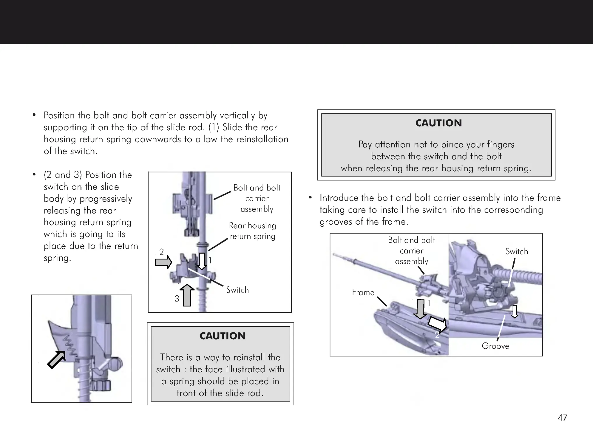
• Position the bolt and bolt carrier assembly vertically by
supporting it on the tip of the slide rod. (1) Slide the rear
housing return spring downwards to allow the reinstallation
of the switch.
• (2 and 3) Position the
switch on the slide
body by progressively
releasing the rear
housing return spring
which is going to its
place due to the return
spring.
Switch
Rear housing
return spring
1
2
3
• Introduce the bolt and bolt carrier assembly into the frame
taking care to install the switch into the corresponding
grooves of the frame.
CAUTION
There is a way to reinstall the
switch : the face illustrated with
a spring should be placed in
front of the slide rod.
Bolt and bolt
carrier
assembly
Frame
Bolt and bolt
carrier
assembly
1
2
Switch
Groove
CAUTION
Pay attention not to pince your fingers
between the switch and the bolt
when releasing the rear housing return spring.
48
5.4. Reassembly of the carbine (continued)
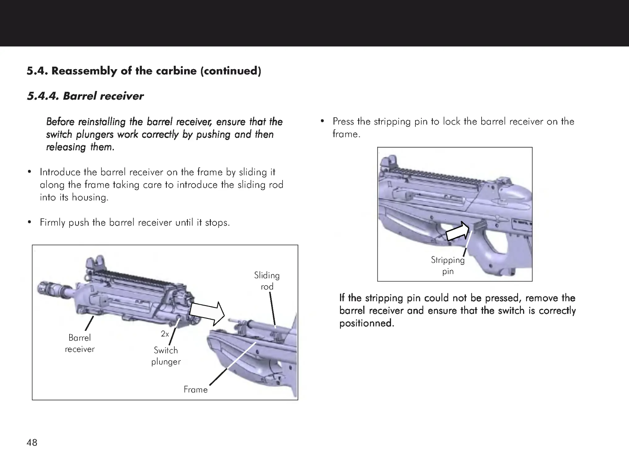
5.4.4. Barrel receiver
Before reinstalling the barrel receiver
Before reinstalling the barrel receiver
Before reinstalling the barrel receiver
Before reinstalling the barrel receiver
Before reinstalling the barrel receiver, ensure that the
, ensure that the
, ensure that the
, ensure that the
, ensure that the
switch plungers work correctly by pushing and then
switch plungers work correctly by pushing and then
switch plungers work correctly by pushing and then
switch plungers work correctly by pushing and then
switch plungers work correctly by pushing and then
releasing them.
releasing them.
releasing them.
releasing them.
releasing them.
• Introduce the barrel receiver on the frame by sliding it
along the frame taking care to introduce the sliding rod
into its housing.
• Firmly push the barrel receiver until it stops.
• Press the stripping pin to lock the barrel receiver on the
frame.
If the stripping pin could not be pressed, remove the
If the stripping pin could not be pressed, remove the
If the stripping pin could not be pressed, remove the
If the stripping pin could not be pressed, remove the
If the stripping pin could not be pressed, remove the
barrel receiver and ensure that the switch is correctly
barrel receiver and ensure that the switch is correctly
barrel receiver and ensure that the switch is correctly
barrel receiver and ensure that the switch is correctly
barrel receiver and ensure that the switch is correctly
positionned.
positionned.
positionned.
positionned.
positionned.
Barrel
receiver
Frame
Sliding
rod
Switch
plunger
2x
Stripping
pin
49
• Examine the outer shape of the carbine and ensure it is
correctly reassembled.
• Pull the charging handle completely rearwards and then
release it.
• Set the fire selector to the position ‘1’ (SEMI-
SEMI-
SEMI-
SEMI-
SEMI-AAAAAUT
UT
UT
UT
UTOMA
OMA
OMA
OMA
OMATIC
TIC
TIC
TIC
TIC).
• Pull the trigger.
• Set the fire selector to the position ‘S’ (SAFETY).
50
Before cleaning the FS2000 carbine,
Before cleaning the FS2000 carbine,
Before cleaning the FS2000 carbine,
Before cleaning the FS2000 carbine,
Before cleaning the FS2000 carbine,
ALALALALALWWWWWAAAAAYS ensure that it is unloaded
YS ensure that it is unloaded
YS ensure that it is unloaded
YS ensure that it is unloaded
YS ensure that it is unloaded
(see § 4.5).
(see § 4.5).
(see § 4.5).
(see § 4.5).
(see § 4.5).
KKKKKeep the ammunition away from the cleaning site and
eep the ammunition away from the cleaning site and
eep the ammunition away from the cleaning site and
eep the ammunition away from the cleaning site and
eep the ammunition away from the cleaning site and
never test the mechanical function of your carbine with
never test the mechanical function of your carbine with
never test the mechanical function of your carbine with
never test the mechanical function of your carbine with
never test the mechanical function of your carbine with
live ammunition.
live ammunition.
live ammunition.
live ammunition.
live ammunition.
Before each shooting sequence, ALWAYS check the barrel
for obstructions and ensure that it is dry and clean.
Completely clean the carbine, ensure that there is no round in the
chamber and then, after having cleaned its bore, glance down the
barrel in order to ensure that it is free of any obstruction.
Take into account that the smallest obstruction can
dangerously increase pressure.
6. CLEANING AND LUBRICATION
The frequency at which the FS2000 carbine should be
cleaned and lubricated depends on the ammunition used, the
weather, the shooting conditions and other external factors.
When using normal ammunitions under normal conditions, it
is a good rule to clean and lubricate the FS2000 carbine
after every use or, in case of intensive shooting, after each
2000 rounds. Correct maintenance will enhance the longevity
of the carbine and will ensure a correct operation.
Excessively dirty ammunition may require more frequent cleaning
and too much dirt can affect the functioning of even the finest
firearm.
It is important to keep your carbine clean and correctly lubricated !
Do not use too much lubricant as this could cause the build-up of
dirt, grit or powder residue which could affect the functioning of
the carbine.
Before any intervention on the FS2000 carbine,
ensure to be familiar with the safety information
given in Chapter 1 of this Owner ’s Manual.
51
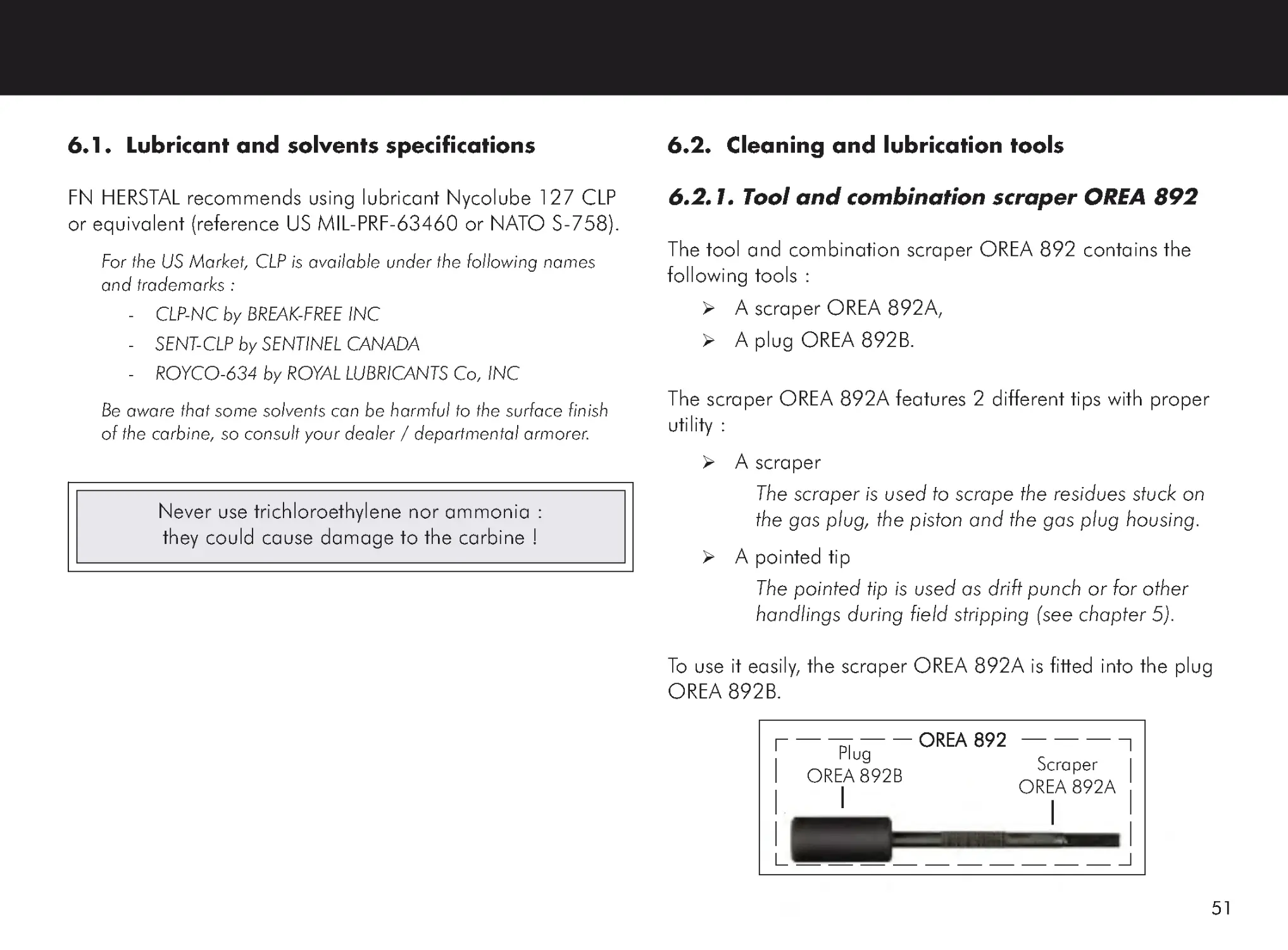
6.2. Cleaning and lubrication tools
6.2.1. Tool and combination scraper OREA 892
The tool and combination scraper OREA 892 contains the
following tools :
A scraper OREA 892A,
A plug OREA 892B.
The scraper OREA 892A features 2 different tips with proper
utility :
A scraper
The scraper is used to scrape the residues stuck on
the gas plug, the piston and the gas plug housing.
A pointed tip
The pointed tip is used as drift punch or for other
handlings during field stripping (see chapter 5).
To use it easily, the scraper OREA 892A is fitted into the plug
OREA 892B.
6.1. Lubricant and solvents specifications
FN HERSTAL recommends using lubricant Nycolube 127 CLP
or equivalent (reference US MIL-PRF-63460 or NATO S-758).
For the US Market, CLP is available under the following names
and trademarks :
-
CLP-NC by BREAK-FREE INC
-
SENT-CLP by SENTINEL CANADA
-
ROYCO-634 by ROYAL LUBRICANTS Co, INC
Be aware that some solvents can be harmful to the surface finish
of the carbine, so consult your dealer / departmental armorer.
Never use trichloroethylene nor ammonia :
they could cause damage to the carbine !
Scraper
OREA 892A
Plug
OREA 892B
OREA 892
OREA 892
OREA 892
OREA 892
OREA 892
52
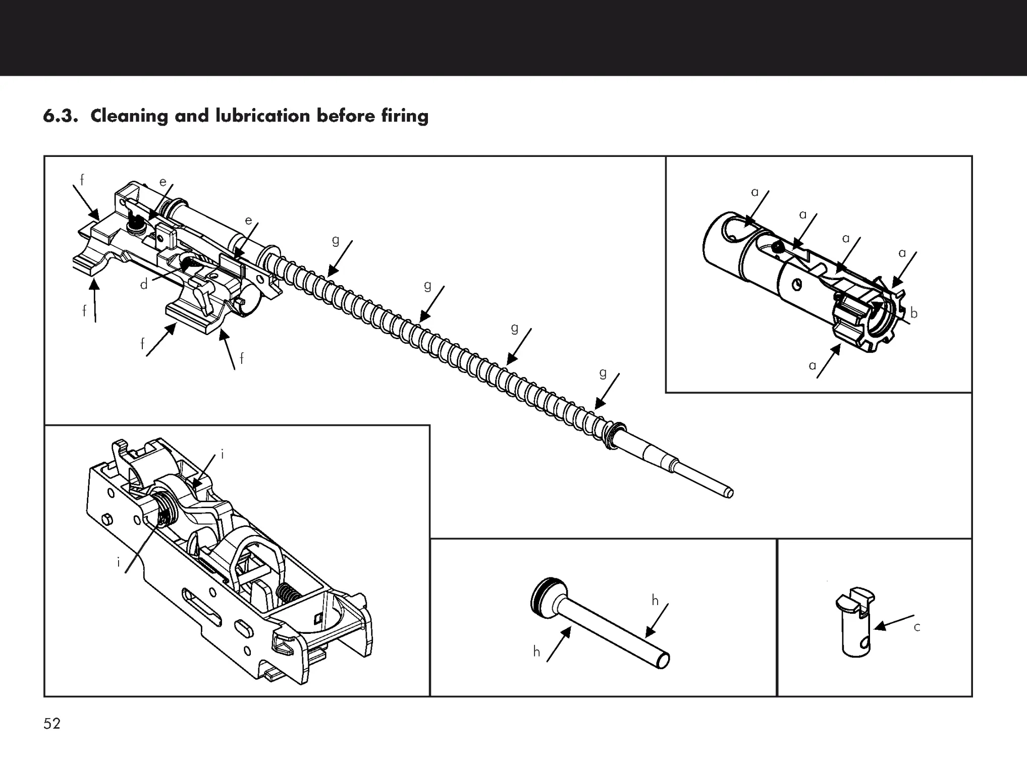
6.3. Cleaning and lubrication before firing
a
a
a
a
a
b
g
g
g
g
e
d
f
f
f
f
i
i
h
h
c
e
53
The following procedure assumes that the FS2000
The following procedure assumes that the FS2000
The following procedure assumes that the FS2000
The following procedure assumes that the FS2000
The following procedure assumes that the FS2000
carbine has correctly been cleaned and lubricated
carbine has correctly been cleaned and lubricated
carbine has correctly been cleaned and lubricated
carbine has correctly been cleaned and lubricated
carbine has correctly been cleaned and lubricated
the last time it has been used (see § 6.4).
the last time it has been used (see § 6.4).
the last time it has been used (see § 6.4).
the last time it has been used (see § 6.4).
the last time it has been used (see § 6.4).
•
Carry out the field stripping procedure (see § 5.1) and, if
necessary, some parts of the complementary disassembly
procedure (see § 5.2).
•
Introduce a cleaning handle (equipped with a swab) into
the barrel through the chamber. Fit a clean rag (a piece of
flannel) into the swab and then remove the cleaning
handle to remove the maintenance lubricant. Repeat this
handling until the piece of flannel goes clean out of the
barrel.
•
Using a soft cloth, clean the bolt and bolt carrier
assembly proceeding as follows :
-
Wipe the external surfaces of the bolt and bolt carrier
assembly clean.
-
Wipe the return spring clean.
-
Compress the return spring and wipe the liberated
part of the slide rod clean.
-
Push the rear housing return spring to compress the
return spring and wipe the visible part of the slide rod
clean.
•
Lubricate the bolt and bolt carrier assembly proceeding as
follows :
-
Oil the bolt body (arrows a).
-
Oil the ejector and ensure it is completely lubricated
by pushing and then releasing it several times
(arrow b).
-
Slightly oil (1 drop of oil) the locking cam (arrow c)
and the unlocking ramp (arrow d).
-
Slightly oil (1 drop of oil) the bolt alignment lever
(arrows e).
-
Oil the slides of the slide body (arrows f).
-
Oil the slide rod on its overall length (arrows g).
-
Push the rear housing return spring to compress the
return spring and oil the visible part of the slide rod
(arrows g).
•
Oil the piston rod (arrows h).
•
Slightly oil (a drop of oil) the 2 hammer springs (arrows i).
•
Reassemble the carbine (see § 5.3 and § 5.4).
54
•
Using the chamber cleaning brush, clean the piston
housing of the gas block proceeding the same way as for
the chamber (see upper).
•
Using the scraper OREA 892A, scrape the front face and
the rod of the piston to remove the residues.
•
Using the scraper OREA 892A, scrape the gas plug to
remove the residues until having a smooth surface.
6.4. Cleaning and lubrication after firing
•
Carry out the field stripping procedure (see § 5.1) and, if
necessary, some parts of the complementary disassembly
procedure (see § 5.2).
6.4.1. Barrel receiver
•
Clean the chamber proceeding as follows :
-
Introduce a chamber cleaning brush into the
chamber.
-
Clean the chamber by turning the chamber cleaning
brush.
-
Remove the chamber cleaning brush from the
chamber.
CAUTION
Do not force during the introduction of the
chamber cleaning brush into the chamber.
CAUTION
Do not scrape the piston rings.
CAUTION
Do not force during the introduction of the chamber
cleaning brush into the piston housing of the gas block.
55
•
Introduce a cleaning brush through the chamber and
clean the inside of the barrel on its overall length with
backward and forward motion until it is visually clean.
•
Introduce a cleaning handle (equipped with a swab) into
the barrel through the chamber. Fit a clean rag (a piece of
flannel) into the swab and then remove the cleaning
handle to remove the maintenance lubricant. Repeat this
handling until the piece of flannel goes clean out of the
barrel.
•
Once the inside of the barrel is clean, to protect it until
the next use, carry out this handling one more time using
a piece of flannel slightly oiled.
•
Oil the piston rod.
•
Oil the 2 switch plungers.
6.4.2. Bolt and bolt carrier assembly
•
Using a cleaning brush, remove the copper particles stuck
on the bolt.
•
Using a cleaning brush, remove the particles stuck on the
extractor.
•
Using a soft cloth, wipe the locking cam and the firing pin
clean.
•
Using a soft cloth, clean the bolt and bolt carrier
assembly proceeding as follows :
-
Wipe the external surfaces of the bolt and bolt carrier
assembly clean.
-
Wipe the return spring clean.
-
Compress the return spring and wipe the liberated
part of the slide rod clean.
-
Push the rear housing return spring against the
compressed return spring and wipe the liberated part
of the slide rod clean.
56
6.4.3. Hammer group assembly
•
Check the general cleanness of the hammer group
assembly. If necessary, use a soft cloth to clean it.
•
Slightly oil (1 drop of oil) the 2 hammer springs.
6.4. Cleaning and lubrication after firing
(continued)
6.4.2. Bolt and bolt carrier assembly (continued)
•
Lubricate the bolt and bolt carrier assembly proceeding as
follows :
-
Oil the bolt body.
-
Oil the ejector and ensure it is completely lubricated
by pushing and then releasing it several times.
-
Slightly oil (1 drop of oil) the locking cam and the
unlocking ramp.
-
Slightly oil (1 drop of oil) the bolt alignment lever.
-
Oil the slides of the slide body.
-
Oil the slide rod on its overall length.
-
Push the rear housing return spring to compress the
return spring and oil the liberated part of the slide
rod.
57
6.4.4. Frame and handguard
•
Check the general cleanness of the frame and the
handguard. If necessary, use a soft cloth to clean them.
•
Check the general cleanness of the 2 metallic rails
located inside the frame. If needed, using a cleaning
brush, clean the 2 metallic rails.
•
Oil the 2 metallic rails located inside the frame.
TTTTTo allow a good oil flow on the overall length of the
o allow a good oil flow on the overall length of the
o allow a good oil flow on the overall length of the
o allow a good oil flow on the overall length of the
o allow a good oil flow on the overall length of the
metallic rails, position the carbine vertically and wait
metallic rails, position the carbine vertically and wait
metallic rails, position the carbine vertically and wait
metallic rails, position the carbine vertically and wait
metallic rails, position the carbine vertically and wait
some minutes for the completed oil flow
some minutes for the completed oil flow
some minutes for the completed oil flow
some minutes for the completed oil flow
some minutes for the completed oil flow.....
6.4.5. Magazine
•
Check the general cleanness of the magazine. If
necessary, use a soft cloth to clean it.
•
The inside of the magazine can slightly be oiled and then
directly wiped using a soft cloth.
Reassemble the carbine (see § 5.3 and § 5.4).
58
7. TAKING CARE OF THE CARBINE
x Always keep the carbine in immaculate condition and
good working order.
x Always clean and lubricate the carbine after use.
x Regularly inspect the carbine, its parts and accessories.
If something seems abnormal, do not hesitate to report it to
your dealer / departmental armorer.
x Never modify or repair parts of your carbine (or any other
one) by yourself.
YYYYYour carbine is a mechanical device subject to wear
our carbine is a mechanical device subject to wear
our carbine is a mechanical device subject to wear
our carbine is a mechanical device subject to wear
our carbine is a mechanical device subject to wear
and which will not last forever : it requires periodic
and which will not last forever : it requires periodic
and which will not last forever : it requires periodic
and which will not last forever : it requires periodic
and which will not last forever : it requires periodic
inspection, adjustment and service.
inspection, adjustment and service.
inspection, adjustment and service.
inspection, adjustment and service.
inspection, adjustment and service.
The carbine should be checked every 10,000 rounds
The carbine should be checked every 10,000 rounds
The carbine should be checked every 10,000 rounds
The carbine should be checked every 10,000 rounds
The carbine should be checked every 10,000 rounds
and/or once a year because damage, wear
and/or once a year because damage, wear
and/or once a year because damage, wear
and/or once a year because damage, wear
and/or once a year because damage, wear,,,,,
corrosion, ... are not always visible from the outside.
corrosion, ... are not always visible from the outside.
corrosion, ... are not always visible from the outside.
corrosion, ... are not always visible from the outside.
corrosion, ... are not always visible from the outside.
FFFFFor that purpose, send the carbine to your dealer
or that purpose, send the carbine to your dealer
or that purpose, send the carbine to your dealer
or that purpose, send the carbine to your dealer
or that purpose, send the carbine to your dealer.....
LLLLLaw enforcement personnel has a departmental armorer
aw enforcement personnel has a departmental armorer
aw enforcement personnel has a departmental armorer
aw enforcement personnel has a departmental armorer
aw enforcement personnel has a departmental armorer
which will inspect the carbine on a yearly basis.
which will inspect the carbine on a yearly basis.
which will inspect the carbine on a yearly basis.
which will inspect the carbine on a yearly basis.
which will inspect the carbine on a yearly basis.
FN HERST
FN HERST
FN HERST
FN HERST
FN HERSTAL can not assume any responsibility for
AL can not assume any responsibility for
AL can not assume any responsibility for
AL can not assume any responsibility for
AL can not assume any responsibility for
injuries caused by unauthorized servicing
injuries caused by unauthorized servicing
injuries caused by unauthorized servicing
injuries caused by unauthorized servicing
injuries caused by unauthorized servicing, alterations
, alterations
, alterations
, alterations
, alterations
or modifications to its firearms.
or modifications to its firearms.
or modifications to its firearms.
or modifications to its firearms.
or modifications to its firearms.
59
8. TROUBLESHOOTING
8.1. Immediate actions
If the carbine fails to fire :
•
Set the fire selector to position ‘S’ (SAFE)
‘S’ (SAFE)
‘S’ (SAFE)
‘S’ (SAFE)
‘S’ (SAFE).
•
Remove and check the magazine.
•
If the magazine is empty :
-
Insert a loaded magazine.
-
Cock the weapon.
-
Set the fire selector to position ‘1’ (FIRE)
‘1’ (FIRE)
‘1’ (FIRE)
‘1’ (FIRE)
‘1’ (FIRE) and
resume firing.
•
If there are still rounds in the magazine :
-
Pull the charging handle fully to the rear and
release it.
-
Check that the rounds are correctly positioned
in the magazine.
-
Insert the magazine.
-
Cock the weapon.
-
Set the fire selector to position ‘1’ (FIRE)
‘1’ (FIRE)
‘1’ (FIRE)
‘1’ (FIRE)
‘1’ (FIRE) and
resume firing.
Before any intervention on the FS2000 carbine,
ensure to be familiar with the safety information
given in Chapter 1 of this Owner ’s Manual.
If carbine does still not fire :
•
Set the fire selector to position ‘S’ (SAFE)
‘S’ (SAFE)
‘S’ (SAFE)
‘S’ (SAFE)
‘S’ (SAFE).
•
Remove the magazine.
•
Pull the charging handle fully to the rear and hold it.
•
Pressing the charging handle upwards let it move
forwards without releasing it, the handle will be
held to the rear after a short movement.
•
Open the cover, check that the chamber and
receiver are clear, close the cover.
•
Insert a loaded magazine.
•
Release the charging handle by pushing it
downwards.
•
Set the fire selector to position ‘1’ (FIRE)
‘1’ (FIRE)
‘1’ (FIRE)
‘1’ (FIRE)
‘1’ (FIRE) and
resume firing.
WARNING
Never try to remove a cartridge or a case by hand.
Use a tool such a screwdriver.
Do not strike the primer of a cartridge with the tool.
60
8.1. Immediate actions (continued)
If there are no rounds or cases trapped in the receiver,
and if the bolt does not fully close and lock :
•
Pull the charging handle back until it contacts the
bolt carrier rod and rotate it outwards.
•
Maintaining it in an extended position, push the
charging handle forwards.
In case of repeated stoppages :
•
If the carbine is :
-
dirty due to prolonged firing or lack of thorough
cleaning.
-
has been exposed to sand, dust or mud.
-
is not well lubricated.
•
Rotate the gas plug to the left.
•
If stoppages continue, clean and lubricate the
carbine.
•
After the carbine has been cleaned and lubricated
the gas plug must be rotated to the right.
If the carbine continues to have stoppages it must be
If the carbine continues to have stoppages it must be
If the carbine continues to have stoppages it must be
If the carbine continues to have stoppages it must be
If the carbine continues to have stoppages it must be
inspected and repaired by an authorized dealer or
inspected and repaired by an authorized dealer or
inspected and repaired by an authorized dealer or
inspected and repaired by an authorized dealer or
inspected and repaired by an authorized dealer or
armorer
armorer
armorer
armorer
armorer.....
WARNING
After firing, the gas plug will be very hot.
9. ACCESSORIES
Sling
Sling
Sling
Sling
Sling
TTTTTactic sling
actic sling
actic sling
actic sling
actic sling
Pistol grip
Pistol grip
Pistol grip
Pistol grip
Pistol grip
for
for
for
for
for
Picatinny
Picatinny
Picatinny
Picatinny
Picatinny
rail (only for
rail (only for
rail (only for
rail (only for
rail (only for
the
the
the
the
the
handguard,
handguard,
handguard,
handguard,
handguard,
tri-rail)
tri-rail)
tri-rail)
tri-rail)
tri-rail)
Handguard, tri-rail
Handguard, tri-rail
Handguard, tri-rail
Handguard, tri-rail
Handguard, tri-rail
61
NOTES
NOTES
FN HERSTAL
FNH USA, LLC
PO Box 697
McLean, VA 22101
Catalog 3480054050
August ‘06