/


Теги: military affairs military equipment rocket launchers
Год: 1984


Текст
United States Patent [i9]
Carter
[45]
4,426,909
Jan. 24, 1984
[54] NOISE, FLASH AND SMOKE SUPPRESSOR
APPARATUS AND METHOD FOR ROCKET
LAUNCHER
[75] Inventor: Charles R. Carter, Huntsville, Ala.
[73] Assignee: The Boeing Company, Seattle, Wash.
[21] Appl. No.: 313,227
[22] Filed: Oct. 20, 1981
[51] Int. Cl.3 .......... F41F 3/04; F41F 17/12
[52] U.S. 0...................... 89/1.816; 89/14 D
[58] Field of Search ....... 89/1.809, 1.816, 1.8,
89/1.7, 1.703, 1.704, 1.706, 140, 1.705
[56] References Cited
U.S. PATENT DOCUMENTS
227,341 5/1880 Zellner .............. 89/14 D
2,043,731 6/1936 Bourne ............... 89/14 D
2,625,235 1/1953 Caulkins ............. 89/14 D
3,255,668 6/1966 Vilbajo ........... 89/1.705
3,745,876 7/1973 Rocha ................. 89/1.816 X
3,800,656 4/1974 Schnabele ............ 89/1.701
4,203,347 5/1980 Pinson et al....... 89/1.816
4,227,438 10/1980 Precoul ........... 89/1.816
FOREIGN PATENT DOCUMENTS
665167 3/1936 Fed. Rep. of Germany .. 89/14 D
17032345 12/1971 Fed. Rep. of Germany . 89/14 D
Primary Examiner—David H. Brown
Attorney, Agent, or Firm—Schwartz, Jeffery, Schwaab,
Mack, Blumenthal & Koch
[57] ABSTRACT
A shock suppressing device adapted to be attached to
the aft end of a shoulder fired rocket launcher. The
device comprises an elongated, flexible, tubular member
formed of a compressible, permeable fabric. The mem-
ber has an expanded diameter substantially greater than
the diameter of the exhaust opening in the aft end of the
rocket launcher tube. In one embodiment, the rear of
the member is covered with fabric so that the member
forms a bag covering the exhaust opening of the rocket
launcher. The member has a sufficient expanded vol-
ume to contain the exhaust gases generated by a
launched rocket thereby confining these exhaust gasses
and their associated flash, smoke and blast wave. The
blast wave is dissipating by forcing it to penetrate the
member. In another embodiment, the rear of the mem-
ber is open thus causing the generated shock wave to be
accelerated rearwardly while being dissipated. The full
expansion of the shock wave is not allowed until the
shock wave has been reduced significantly.
22 Claims, 12 Drawing Figures
126
U.S. Patent Jan. 24, 1984
Sheet 1 of 3
4,426,909
FIG. 1
(PRIOR ART)
IGNITION
PEAKi
PRESSURE
(RELATIVE)
ATMOS
0
PEAK PRESSURE FROM NOZZLE PLUG EJECTION AND
EXPANSION OF GAS PULSE SHOCKS
SECONDARY OR BASELINE NOISE SOURCE
“1-----11
2 3 4 5 6
FIG. 2
TIME - M/S
FIG. 3
FIG. 4
U.S. Patent Jan. 24, 1984
Sheet 2 of 3 4,426,909
FIG. 8
126
U.S. Patent Jan. 24, 1984
Sheet 3 of 3
4,426,909
FIG. 10
FIG. 11
142^ 144^
448 446
FIG. 12
4,426,909
1
NOISE, FLASH AND SMOKE SUPPRESSOR
APPARATUS AND METHOD FOR ROCKET
LAUNCHER
BACKGROUND OF THE INVENTION
1. Field of the Invention
The present invention relates to a shock suppressing
apparatus and method for a shoulder fired rocket
launcher.
2. Discussion of Related Art
A typical shoulder fired rocket launcher comprises an
elongated tube which, in its firing position, is placed on
the shoulder of the operator, with the forward end
through which the rocket is discharged being posi-
tioned several feet forward of the operators’s head, and
with the rear end being a short distance rearwardly of
the operator’s head. The rocket itself is located in the
rear end of the launch tube, and the rocket nozzle is
closed by a plug. Upon ignition, there is a very rapid
pressure build-up in the rocket propellant chamber, and
at a predetermined design pressure level, the nozzle
plug is expelled from the nozzle rearwardly at a high
velocity, generally in the supersonic range. The rocket
is then propelled forwardly through the tube toward its
intended target, with the exhaust of the rocket being
emitted outwardly from the rear end of the launch tube.
Recent developments in shoulder fired rocket pro-
pelled weapons have produced systems that release
energy levels in the crew areas that create increased
hearing loss hazards. The firing of one of these weapons
generally creates a peak noise pulse that can exceed 180
decibels at the gunner’s position. In this environment,
the gunner is required to wear earplugs or earmuffs or
possibly both. Even with this protection, gunners may
suffer major temporary or permanent hearing loss prob-
lems that could degrade their effectiveness in perform-
ing regular duties. Also, the flash and smoke produced
by one of these weapons gives away the gunner position
and makes it vulnerable to return fire.
Attempts to solve the problem have been concen-
trated on tailoring the propulsion system to minimize
peak noise levels. As discussed above, most small rocket
engines have a plug in the throat of the nozzle to allow
the chamber pressure to build up to a required level
before firing, at which time the plug is expelled. The
plug velocity after expulsion is supersonic and creates a
shock wave for a short distance after it leaves the rocket
nozzle. The shock wave created by the plug has been
found to be a minor source of rocket engine noise. The
major peak noise source is the initial pulse of rapidly
expanding high pressure exhaust gasses issuing from the
rocket propellant chamber, through the nozzle and into
the atmosphere just after the plug is expelled. To reduce
the peak noise level, considerable research has been
conducted to optimize the pressure level and propellant
bum time reached before the plug is expelled. Research
has been successful in varying these parameters, how-
ever, it has not been successful in reducing the noise
level to any significant extent. A further attempt to
reduce the noise level is based on energy conservation.
This technique is illustrated by the “Armbrust Weapons
System.” The basic technique is both to perform me-
chanical work and to contain the gases generated by the
firing inside a pressure vessel. In this system, both the
missile and an inert mass are enclosed in a pressure
chamber of a launch tube, with the motor being placed
between the missile and the inert mass. When the
5
10
15
20
25
30
35
40
45
50
55
60
65
2
weapon is fired, the missile and the inert mass move in
opposite directions to minimize recoil, and the motor
exhaust products are trapped inside the pressure cham-
ber. The gases are released over a relatively long period
of time with the noise being reduced by trapping the
exhaust gases and releasing them over a long period of
time.
While the approach used in the Armbrust System is
effective in sound reduction, it has several severe draw-
backs. It is heavy since the missile and the inert mass
must have the same mass and the pressure chamber
must be strong enough to hold the motor exhaust prod-
ucts. Thus, this apparatus is approximately twice as
heavy as a conventional rocket system. Also, it is expen-
sive to fabricate.
Another attempt to reduce the noise generated by a
shoulder-fired rocket is disclosed in U.S. Pat. No.
4,203,347 issued to Pinson et al. The Pinson system uses
a transient shock suppressor attached to the aft end of
the launcher. The suppressor comprises a circumferen-
tial housing structure having a longitudinal axis and a
forward end adapted to be mounted to the rear of a
launch tube so that the longitudinal axis is in general
alignment with the longitudinal axis of the launch tube.
The housing structure is made from metal and mounts a
plurality of baffles which extend radially inward from
the housing toward the longitudinal axis of the housing.
The baffles define a longitudinally aligned opening
which permits rearward ejection of a nozzle plug from
a rocket mounted in the launch tube and permits rear-
ward discharge of gaseous exhaust from the rocket. The
Pinson et al suppressor permits expansion of the gases
coming from the rocket nozzle to near atmospheric
pressure through a series of expansion chambers
bounded by the baffles and the housing structure. The
pressure levels reached in these chambers are very high
and create the requirement for a heavy structural hous-
ing and baffles. This controlled expansion reduces the
energy of the sound pressure wave emitted from the
system and moves the noise emitter further away from
the gunner’s ear position. This design reduces the noise
level at the gunner’s position, however, the suppressor
which is inherently heavy acts as a secondary nozzle
which may propel the launcher downrange. Also, the
suppressor of Pinson et al has little effect on suppressing
the flash and smoke produced by the rocket.
U.S. Pat. No. 3,745,876 issued to Rocha discloses a
telescoping ammunition launcher comprising two or
more flash and blast deflector sections which may be
telescoped into a small size and may be attached to the
firing tube of a firearm. No mention is made in the
Rocha disclosure concerning noise suppression, and it
does not appear that the Rocha device was designed to
be used as a noise suppressor.
SUMMARY OF THE INVENTION
One object of the present invention is to provide a
method and apparatus for suppressing rocket motor
noise, flash and smoke emitted from the launch tube of
a rocket launcher.
A further object of the present invention is to sup-
press noise, flash and smoke without adding any appre-
ciable carry weight or volume to the launching appara-
tus itself.
A further object of the present invention is to provide
an apparatus which can be easily attached to the launch
4,42
3
tube of a rocket launcher and stored in a collapsed state
for later deployment.
Another object of the present invention is to provide
an apparatus which can be automatically deployed upon
firing a rocket.
An even still further object of the present invention is
to provide an apparatus which is made from an energy
absorbing material so as to attentuate a shock wave
produced by a fired rocket and emitted from the rear of
a launch tube.
A still further object of the present invention is to
provide an apparatus and method whereby a gunner
firing a rocket launcher is protected from hearing loss
or other physical injury by a shock wave emitted from
the rear of the rocket launcher.
Another object of the present invention is to provide
an apparatus for reducing noise, flash and smoke emit-
ted by a rocket motor, which apparatus is relatively
economical to manufacture, yet is effective and reliable
in use.
In accordance with these and other objects, the pres-
ent invention comprises an elongated, flexible, tubular
member formed of a compressible, permeable fabric.
The member is connected to the rear exhaust end of a
rocket launching device and has an expanded diameter
substantially greater than the diameter of the exhaust
opening in the exhaust end of the rocket launching
device.
In one embodiment, the rear of the tubular member is
covered with fabric, whereby the member forms a bag
enclosing the exhaust opening. The volume of the mem-
ber when expanded is sufficient to contain the gases of
an exhaust blast wave generated by a launched rocket.
Accordingly, the blast wave is forced to pass through
the permeable fabric and thus the energy of the blast
wave is dissipated while both the flash and smoke are
contained.
In accordance with other aspects of the present in-
vention, a sound energy absorbent lining is connected to
the member and covers the entire inner surface of the
member to increase the sound absorbent qualities of the
member. Furthermore, a heat protective lining may be
connected to the sound energy absorbent lining in order
to protect the fabric of the member from direct expo-
sure to heat generated by the rocket firing blast. The
sound energy absorbent lining may comprise expanded
foam and the heat insulative lining may comprise radi-
ant heat reflective mylar.
In accordance with other aspects of the invention, the
fabric covering the rear of the member may be attached
to a nozzle plug within the rocket. In this manner, when
the rocket is fired, the member is automatically de-
ployed from a collapsed position.
Another aspect of the invention comprises the use of
a porus cylindrical metallic element which is attached
between the exhaust opening of the rocket launcher and
the covered end of the member. The metallic element
serves to catch debris generated by the plug and igniter
devices and prevent the debris from penetrating the
fabric of the tubular member.
In another embodiment of the present invention, the
tubular member is made in a generally cylindrical shape
and has an open rear end. In this embodiment, the mem-
ber serves to prevent the blast wave from fully expand-
ing at the rear of the rocket launcher. The pressure
created causes the blast wave to be accelerated rear-
wardly through the member which attentuates the blast
wave. The wave is finally allowed to expand fully at the
6,909
4
open rear end of the member which is disposed behind
the position of the gunner.
BRIEF DESCRIPTION OF THE DRAWINGS
5 The above and other objects of the present invention
will become more readily apparent as the invention is
more fully described in the detailed description, refer-
ence being had to the accompanying drawings in which
like reference numerals represent like parts throughout,
10 and in which:
FIG. 1 shows a rocket launcher on which the present
invention is adapted for use;
FIG. 2 shows a graph depicting the pressure felt at
the gunner’s position of the rocket launcher shown in
15 FIG. 1 versus time in milliseconds after a rocket is fired;
FIG. 3 is a schematic view showing an embodiment
of the suppressor of the present invention in its stored
disposition;
FIG. 4 is a schematic view showing the suppressor of
20 FIG. 3 being automatically deployed by the firing of a
rocket;
FIG. 5 is a schematic view showing the suppressor of
FIG. 3 fully deployed;
FIG. 6 is a schematic view showing a second embodi-
25 ment of the suppressor of the present invention in its
stored disposition;
FIG. 7 is a schematic view showing the suppressor of
FIG. 6 after being manually deployed and just after the
rocket has been fired;
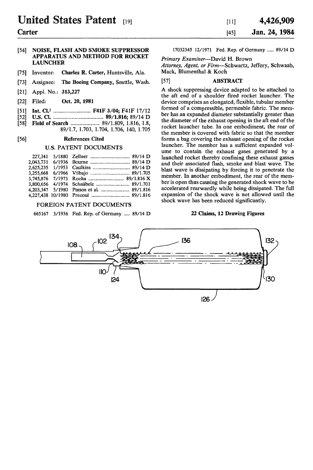
30 FIG. 8 is a schematic view showing the suppressor of
FIG. 6 in its fully deployed disposition;
FIG. 9 is a schematic view showing a third embodi-
ment of the present invention in its stored disposition;
FIG. 10 shows the suppressor of FIG. 9 after having
35 been manually deployed and just after the rocket has
been fired;
FIG. 11 is a schematic view showing the suppressor
of FIG. 9 in its fully deployed disposition; and
FIG. 12 is a sectional, fragmentary view showing a
40 portion of the material from which the suppressor is
made.
DETAILED DESCRIPTION OF THE
PREFERRED EMBODIMENTS
45 A standard rocket launcher 100 is shown in FIG. 1,
and can be seen to comprise an elongated launch tube
102 having one or more handles 104 and a sighting
device 106. A rocket 108 is mounted in the aft end of the
tube, and a nozzle 110 of the rocket is closed by a plug
50 112 positioned in the throat of the nozzle 110. When the
propellant in the rocket is ignited, the plug causes the
pressure in the combustion chamber to build up to a
required level before the plug 112 is expelled. When the
pressure is at the proper level, the plug is expelled from
55 the nozzle 110 and moves a short distance outwardly
through the aft end of the launch tube 102 at a very high
velocity, generally in the supersonic range. The rocket
108 then proceeds out the front end of the tube 102.
The ignition of the rocket is in many respects similar
to an explosion. As depicted in FIG. 2, in the first milli-
second after ignition, the ejection of plug 112 is fol-
lowed by a pulse of high pressure gas. This pulse, as
shown in FIG. 1, is a combination of a blast wave 122
created by the exhaust shown at 118, and a shock wave
116 generated by the plug 112. Accordingly, the peak
noise levels are generated within the first millisecond or
so after ignition. After the initial shock or shocks, there
is a quasi-steady state noise generated by the gases
5
4,426,909
6
which continue to be discharged from the aft end of the
launch tube 12, due to the shearing stresses and violent
mixing that occurs between the exhaust products and
the ambient atmosphere. This quasi-steady state noise is
indicated in the graph of FIG. 2 as the secondary or 5
baseline noise source.
In addition to producing noise, the gas 118 contains
propellant particles that are undergoing combustion and
very hot particles that emit light. These two items are
the primary cause for the rocket motor flash. Aluminum 10
oxide particles in the propellant combustion products
are white in color and produce the smoke in the gas jet.
The present invention consists primarily of reducing to
a substantial extent the pressure pulse produced and
thus the noise emitted thereby and enclosing the light 15
generating particles thereby reducing the rocket motor
flash.
FIG. 3 is a schematic drawing which depicts launch
tube 102 having rocket 108 mounted therein prior to
firing. Plug 112 is seen to be located within the throat of 20
nozzle 110. A suppressor member in the form of a bag
126 has its rear portion 128 mounted to plug 112 in any
convenient manner. For example, the bag 126 may be
glued to plug 112. The forward end of bag 126 is
mounted to a cylindrical housing 124 which is attached 25
to the rear of launch tube 102. A cover 130 is received
on the open end of housing 124. A handle 132 is conve-
niently attached to cover 130 for removing same from
the housing. It should be understood that housing 124
may be mounted to the rear of launch tube 102 by any 30
convenient means. For example, a spring loaded latch
clip (not shown) may be used for this purpose. Also, the
forward end of bag 126 is mounted to housing 124 at
point 134 in a variety of ways. The bag has been glued
to housing 124 with good results. 35
As discussed above, upon ignition, the pressure
within the pressure chamber of rocket 108 builds up
until plug 122 is expelled from the throat of nozzle 110.
As shown in FIG. 4, since plug 112 is attached to the
rear 128 of bag 126, upon being emitted from the rocket, 40
it carries the rear of bag 126 rearwardly with it thus
deploying bag 126. Also, the deployment of bag 126
causes an attentuation in the blast wave 122 as it ex-
pands past bag 126. FIG. 5 shows bag 126 completely
deployed due to the expansion of gases emitted from the 45
rocket 108.
In operation, it takes approximately four milliseconds
for the bag to be completely inflated as shown in FIG.
5. Once fully deployed and inflated, the bag has a vol-
ume of approximately eight cubic feet which is suffi- 50
cient to contain all of the gases emitted from rocket 108.
Also, in the embodiment shown, the launch tube 102 has
a diameter of approximately 21 to 3 inches. Obviously,
the volume of bag 126 would vary in accordance with
the size of the rocket launcher used. 55
The material from which the bag is produced must be
highly durable and also capable of absorbing sound.
FIG. 12 shows a cross-section of a portion of bag 126 to
indicate the layers of material used in the bag. The
material is generally designated by the reference nu-
meral 142 and comprises an outer layer 144 which is a
woven or knit fabric made from a durable synthetic
substance such as nylon or, more preferably, an aramid
fiber such as “Kevlar.” Accordingly, the fabric used in
layer 144 is permeable and sufficiently flexible to be
compressed and received within housing 124 where it is
stored prior to use. Additionally, fabric 144 is suffi-
ciently strong to resist the pressure wave generated by
the motor of rocket 108. Under certain circumstances,
bag 126 may contain only this single layer of fabric.
However, for maximum effect, a layer of sound absor-
bent material 146 should be bonded to fabric 144. Layer
146 can be a flexible expanded foam core designed for
producing a maximum sound absorbent effect. Addi-
tionally, a layer 148 of reinforced tensilized mylar is
bonded to foam core 146 to protect core 146 and fabric
144 from excessive heat produced by the rocket motor.
If the suppressor bag 126 is to be used on launch tube
having a rocket with a long burning motor, it is highly
desirable to use mylar layer 148 to shield the foam layer
and fabric from heat damage. In use, the initially gener-
ated heat is shielded from the foam layer and fabric by
the mylar. The pressure wave then ruptures the mylar
allowing the burnt gases to penetrate the porous foam
core and permeable fabric.
The embodiment of the invention shown in FIGS.
3-5 is quite effective for use with a plug 112 made from
an expanded foam material, such as styrofoam. In actu-
ality, the plug tends to disintegrate into many small
pieces and use of a plug made from more dense material
poses a danger of having the pieces penetrate bag 126.
In order to overcome the danger of having other plugs
penetrate bag 126, a flexible, cylindrical wire element
136 can be mounted within bag 126 as shown in FIGS.
6-8. It will be seen that element 136 is connected be-
tween attachment point 134 and cover 130. Element 136
is opened directly in the path of plug 112 for receiving
the plug and confining the debris produced thereby.
Element 136 is preferably made from knitted aluminum
wire which can easily be compressed to fit within hous-
ing 124.
In use, inasmuch as full deployment of bag 126 is
expected within four milliseconds of initiation of opera-
tion of the rocket motor, in order to avoid structural
damage to element 136, it is necessary to manually initi-
ate deployment of the present invention. As shown in
FIG. 7, the gunner grasps handle 32 and pulls bag 126
and element 36 from housing 124 until they reach ap-
proximately 90 percent of their full extension. When the
motor of rocket 108 is fired, the plug 112 is projected
into the center of cylindrical element 136 where the
debris produced by the plug is caught in the knitted
wire fabric of element 136. Element 136 also absorbs a
small portion of the energy in the blast wave produced.
The blast wave, shown at 122 in FIG. 7, is attentuated
by the relaxed material of bag 126 and causes full exten-
sion and deployment of element 136 and the bag and
fully inflates the bag.
In each of the above described embodiments, it can be
seen that bag 126 is added to the launcher to contain all
the gas produced by the rocket motor. The bag is in-
stalled so that all noise producing elements can be
trapped inside the bag. Since the exhaust gases are con-
tained within the bag, any flash or smoke produced is
obscured by the bag. The bag operation begins in a fully
collapsed or partially collapsed condition so that the
entire volume is available to contain the motor exhaust
gases. When the plug 112 is ejected from the motor, the
ensuing blast wave must penetrate the bag before it
reaches the gunner’s position. The walls of the bag are
made from material which absorbs the blast wave en-
ergy as it penetrates the wall of the bag. The bag is
partially collapsed when the blast wave penetrates the
wall. This presents the blast wave more wall surface
area to penetrate thereby removing more blast wave
energy. The inflated bag separates the gas jet from the
4,426,909
7
atmosphere, therefore, no eddies are generated between
the gas jet and the atmosphere. By producing bag 126
from material 142 described above, an effective noise
reduction of more than 10 decibels can be achieved.
FIGS. 9, 10 and 11 show a third embodiment of the
present invention in which the suppressor member 138
is similar to bag 126 except that member 138 has an open
rear 140. As shown in FIG. 9, when in the stored posi-
tion, member 138 is attached at 134 to housing 124. The
open rear 140 is attached to cover 130. When readied
for use, member 138 is partially extended by the gunner
by grasping handle 132 and pulling member 138 from
the housing as shown generally in FIG. 10. When
rocket 108 is fired, the blast wave and exhaust gas fully
extend member 138 as shown in FIG. 11. Since member
138 is designed to only partially contain the exhaust gas,
it will require a smaller extended and compressed vol-
ume than bag 126 and can thereby be made lighter in
weight. It has been found that with a launch tube 102
having a diameter of 2% to 3 inches, member 138 can be
made cylindrical in shape with a diameter of six to eight
inches and an overall length of 24 inches and member
138 will produce acceptable results.
The material of member 138 can be exactly the same
as that of bag 126 and is shown at 142 in FIG. 12. As
explained above, fabric layer 144 may be used alone if
conditions warrant or can be used in conjunction with
sound absorbent layer 146 and heat shielding layer 148.
The three-layer configuration is preferred for maximum
effect.
In operation, when rocket 108 is fired as shown in
FIG. 10, the relaxed condition of member 138 presents
a maximum surface area to the blast wave generated.
This causes a weakening of the blast wave which must
expend energy inflating member 138 and penetrating
the material thereof. Member 138 also has the effect of
confining the blast wave thereby causing the wave to
accelerate rearwardly toward the open rear 140 thus
preventing the wave from expanding near the gunner.
As the wave is accelerated rearwardly, the energy of
the wave is attentuated so that when the wave finally
expands past the rear opening 140, the energy released
has significantly diminished. Member 138 retains much
of the noise suppressing capability of bag 126 by par-
tially containing the exhaust gases and also retains some
of the capabilities for obscuring the flash and smoke.
The above description is considered illustrative of the
invention but not limitative. Clearly, numerous modifi-
cations, additions or changes can be made in the present
invention without departing from the scope thereof, as
set forth in the appended claims.
What is claimed is:
1. In combination with a rocket launching device,
said rocket launching device comprising an elongated
launch tube, said launch tube having a forward end
from which a rocket is fired, and a rear exhaust end
through which exhaust gases exit during firing of the
rocket, said exhaust end having an exhaust opening of a
predetermined diameter, a shock suppressing apparatus
comprising:
an elongated, flexible, tubular member formed of a
compressible, permeable mesh fabric formed of
fibers, said fabric being sufficiently strong to resist
a pressure wave generated by firing said rocket and
said member having an expanded diameter substan-
tially greater than the diameter of said exhaust
opening; and further including a forward end for
5
10
15
20
25
30
35
40
45
50
55
60
65
8
attachment to said exhaust opening and a rear end
extending away from said forward end; and
means for attaching said forward end of said tubular
member to said rear exhaust end of said launch tube
such that said tubular member remains connected
to said launch tube during firing of said rocket.
2. The invention as set forth in claim 1, wherein said
fabric is made of an aramid fiber.
3. The invention as set forth in claim 1 wherein said
tubular member has an open rear for accelerating a
shock wave rearwardly to a position behind a gunner
operating said launcher.
4. The invention as set forth in claim 1, wherein said
rear end of said member is covered with said fabric
whereby said tubular member forms a bag enclosing
said exhaust opening, said tubular member receiving the
gases of an exhaust blast wave generated by a launched
rocket thereby forcing said blast wave to pass through
said permeable fabric and dissipating energy of said
blast wave; and means for holding said bag in alignment
with said rocket launching device prior to firing of said
rocket, whereby gases of an exhaust blast can pass di-
rectly into said tubular member.
5. The invention as set forth in claim 4 and further
wherein a rocket to be fired is contained in said launch
tube, said rocket having a nozzle containing a nozzle
plug, said fabric covering said rear of said tubular mem-
ber being attached to said plug whereby said member is
deployed from a collapsed position upon firing said
rocket.
6. The invention as set forth in claim 4 and further
including a cylindrical metallic element extending from
said exhaust opening to said covered end of said mem-
ber.
7. The invention as set forth in claim 6, wherein said
element is made from aluminum wire.
8. The invention as set forth in claim 1 or 4 and fur-
ther including a sound energy absorbent lining con-
nected to said fabric.
9. The invention as set forth in claim 8, wherein said
sound energy absorbent lining comprises expanded
foam.
10. The invention as set forth in claim 8 and further
including a heat insulative lining connected to said
sound energy absorbent lining.
11. The invention as set forth in claim 10, wherein
said heat insulative lining comprises radiant heat reflec-
tive mylar.
12. A method of suppressing a shock wave generated
by a rocket launching device, wherein the rocket
launching device comprises an elongated launch tube, a
forward end from which a rocket is fired, and a rear
exhaust end through which exhaust gases exit during
firing of the rocket, said exhaust end having an exhaust
opening with a predetermined cross-sectional area, said
method comprising:
providing an elongated, flexible, tubular member
formed of a compressible, permeable mesh fabric
formed of fibers and having an expanded diameter
substantially greater than the diameter of said ex-
haust opening;
attaching said tubular member over the rear exhaust
opening in an uninflated condition; and
suppressing a shock wave generated by firing the
rocket in the launch tube by causing said shock
wave to inflate said member thereby partially ab-
sorbing the shock wave in the fabric of said mem-
ber without destroying said fabric material and
4,426,
9
without said tubular member becoming detached
from said launching device.
13. The method as set forth in claim 12 and further
comprising providing an open rear end on said member
for accelerating said shock wave rearwardly in said 5
member to a position behind a gunner.
14. The method as set forth in claim 12 including
providing a fabric covering over the rear of said mem-
ber to form a bag surrounding said exhaust opening
thereby containing said shock wave and causing said
shock wave to penetrate the fabric of said member, and 1
holding said bag in alignment with said rocket launch-
ing device prior to firing said rocket.
15. The method as set forth in claim 12 or 14 and
further comprising providing a sound absorbent lining
connected to said fabric. 15
16. The method as set forth in claim 14 and further
comprising connecting the covering over the rear of
said member to a plug contained in the nozzle of a
rocket within said rocket launching device and auto-
matically deploying said member upon firing of said 20
rocket.
17. The method as set forth in claim 14 and further
comprising providing a cylindrical metallic element
aligned with the rear of said exhaust opening.
18. In combination with a rocket launching device, 25
said rocket launching device comprising an elongated
launch tube, said launch tube having a forward end
from which a rocket is fired, and a rear exhaust end
through which exhaust gases exit during firing of the
rocket, said exhaust end having an exhaust opening of a 30
predetermined diameter, a shock suppressing apparatus
comprising:
an elongated, flexible, tubular member formed of a
compressible, permeable fabric, said fabric having
an expanded diameter substantially greater than the
diameter of said exhaust opening; and said elon- 35
gated, flexible, tubular member further including a
forward end for attachment to said exhaust open-
ing, and a rear end extending away from said for-
ward end;
means for attaching said forward end of said tubular
member to said rear exhaust end of said launch
tube;
wherein said rear end of said member is covered with
said fabric whereby said tubular member forms a
bag enclosing said exhaust opening, and said tubu-
lar member has a sufficient expanded volume to
contain the gases of an exhaust blast wave gener-
ated by a launched rocket thereby forcing said blast
wave to pass through said permeable fabric and a
dissipating energy of said blast wave, and
further wherein a rocket to be fired is contained in
said launch tube, said rocket having a nozzle con-
taining a nozzle plug, said fabric covering said rear
of said tubular member being attached to said plug
whereby said member is deployed from a collapsed 55
position upon firing said rocket.
19. In combination with a rocket launching device,
said rocket launching device comprising an elongated
launch tube, said launch tube having a forward end
from which a rocket is fired, and a rear exhaust end
through which exhaust gases exit during firing of the 60
rocket, said exhaust end having an exhaust opening of a
predetermined diameter, a shock suppressing apparatus
comprising:
an elongated, flexible, tubular member formed of a
compressible, permeable fabric said fabric having 65
an expanded diameter substantially greater than the
diameter of said exhaust opening; and said elon-
gated, flexible, tubular member further including a
909
10
forward end for attachment to said exhaust open-
ing, and a rear end extending away from said for-
ward end;
means for attaching said forward end of said tubular
member to said rear exhaust end of said launch
tube;
wherein said rear end of said member is covered with
said fabric whereby said tubular member forms a
bag enclosing said exhaust opening, and said tubu-
lar member has a sufficient expanded volume to
contain the gases of an exhaust blast wave gener-
ated by a launched rocket thereby forcing said blast
wave to pass through said permeable fabric and a
dissipating energy of said blast wave, and
further including a cylindrical metallic element ex-
tending from said exhaust opening to said covered
end of said member.
20. The invention as set forth in claim 19 wherein said
element is made from aluminum wire.
21. A method of suppressing a shock wave generated
by a rocket launching device, wherein the rocket
launching device comprises an elongated launch tube, a
forward end from which a rocket is fired, and a rear
exhaust end through which exhaust gases exist during
firing of the rocket, said exhaust end having an exhaust
opening with a predeterminted cross sectional area; said
method comprising
providing an elongated, flexible, tubular member
having an enclosed rear to form a bag, said member
being formed of a compressible, permeable fabric
and having an expanded diameter substantially
greater than the diameter of said exhaust opening;
attaching said tubular member over the rear exhaust
opening in an uninflated condition such that said
bag surrounds said exhaust opening, and connect-
ing the enclosed rear of said member to a plug
contained in the nozzle of a rocket within said
rocket launching device;
automatically deploying said member upon firing said
rocket; and
suppressing a shock wave generated by firing the
rocket in the launch tube by causing said shock
wave to inflate said member thereby partially ab-
sorbing the shock wave in the fabric of said mem-
ber and causing said shock wave to penetrate the
fabric of said member.
45 22. A method of suppressing a shock wave generated
by a rocket launching device, wherein the rocket
launching device comprises an elongated launch tube, a
forward end from which a rocket is fired, and a rear
exhaust end through which exhaust gases exit during
50 firing of the rocket, said exhaust end having an exhaust
opening with a predetermined cross sectional area; said
method comprising
providing an elongated, flexible, tubular member
having an enclosed rear and containing a cylindri-
cal metallic element, said tubular member being
formed of a compressible permeable fabric and
having an expanded diameter substantially greater
than the diameter of said exhaust opening;
attaching said tubular member over the rear exhaust
opening in an uninflated condition such that said
cylindrical metallic element is aligned with the rear
of said exhaust opening; and
suppressing a shock wave generated by firing the
rocket in a launch tube by causing said shock wave
to inflate said member thereby partially absorbing
the shock wave in the fabric of said member and
causing said shock wave to penetrate the fabric of
said member.
*****