/


Теги: weapons military affairs
Похожие


Текст
TABLE OF CONTENTS
Paragraph Page
CHAPTER 1, INTRODUCTION
Section I. General ......... 1 1
II. Description and data 2 2
CHAPTER 2. OPERATING INSTRUCTIONS
Section I, Service upon receipt of materiel .......... 5 5
II. Controls 7 6
III. Operation under usual conditions 10 10
CHAPTER 3, ORGANIZATIONAL MAINTENANCE INSTRUCTIONS
Section I* Repair parts, tools, and equipment 21 15
II. Lubrication 24 16
III. Preventive - maintenance services 27 18
IV. Troubleshooting 29 20
V. Maintenance of Rifle 31 23
VI. Maintenance of bipod 35 38
APPENDIX I. BASIC ISSUE ITEMS
Section I. Preface ... . 39
II. Basic Issue ......... ,. 42
APPENDIX II. ORGANIZATIONAL MAINTENANCE, REPAIR PARTS,
AND SPECIAL TOOL LIST
Section I. Preface...*,*................................................ 44
П. Repair parts and special tools .............................. 45
a
CHAPTER 1
INTRODUCTION
Section D GENERAL
1. SCOPE
a. . This manual contains instructions for operator and organizational mainten-
ance of the Stoner rifle and bipod.
b. Appendix I contains a list of basic issue items, repair parts, and tools and
equipment which are required for operational maintenance of the weapon.
c. Appendix II contains a list of repair parts, special tools and equipment
which are required for performing organizational maintenance of the weapon.
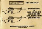
FIGURE 1 . STONER RIFLE - LEFT AND RIGHT VIEW
1
Section II- DESCRIPTION AND DATA
2. DESCRIPTION
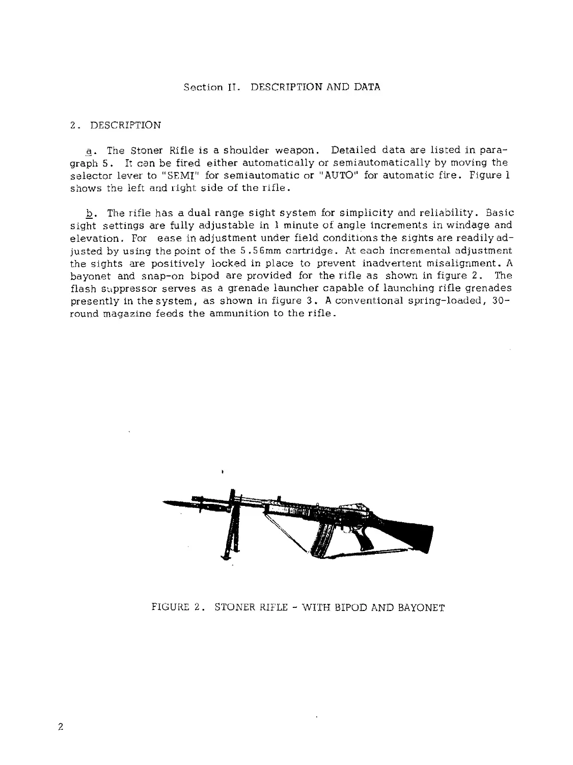
a. The Stoner Rifle is a shoulder weapon. Detailed data are listed in para-
graph 5. It can be fired either automatically or semiautomatically by moving the
selector lever to "SEMI" for semiautomatic or ''AUTO" for automatic fire. Figure 1
shows the left and right side of the rifle.
b. The rifle has a dual range sight system for simplicity and reliability. Basic
sight settings are fully adjustable in 1 minute of angle increments in windage and
elevation. For ease in adjustment under field conditions the sights are readily ad-
justed by using the point of the 5 ,5 6mm cartridge. At each incremental adjustment
the sights are positively locked in place to prevent inadvertent misalignment. A
bayonet and snap-on bipod are provided for the rifle as shown in figure 2, The
flash suppressor serves as a grenade launcher capable of launching rifle grenades
presently in the system, as shown in figure 3. A conventional spring-loaded, 30-
round magazine feeds the ammunition to the rifle.
FIGURE 2. STONER RIFLE - WITH BIPOD AND BAYONET
2
FIGURE 3 . RIFLE GRENADE AND BIPOD ON RIFLE
3. NAME AND SERIAL NUMBER
The name and serial number of the rifle are stamped on the top of the receiver in
front of the rear sight (figure 6) .
4. TABULATED DATA
a. Weights in Pounds .
Rifle (w/o magazine or sling)
Empty Magazine
Full Magazine (30 Rds.)
Sling
7.75.lbs
0.50 lbs (Steel)
0.25 lbs (Aluminum)
1.25 lbs (Steel Magazine)
1.00 lbs (Aluminum Magazine)
0.31 lbs
Cleaning Rod & Attachments
Firing Weight (fully loaded with sling
and magazine)
Bayonet Knife, M7
Scabbard, M8A1
Grenade Sight
Bipod
Bipod Case
0.25 lbs.
9.56 lbs (w/Steel Magazine)
9.31 lbs (w/Aluminjim Magazine)
0.60 lbs
0.30 lbs
0.06 lbs
0.88 lbs
0.31 lbs „
b. Lengths (in inches) .
Rifle with Flash Suppressor 40.25 inches
Rifle with Bayonet 45.65 inches
Barrel (Bolt Face to Muzzle) 20.00 inches
Barrel with Extension and Flash Supressor 21.67 inches
c. Mechanical Features.
Rifling
Bore Dia.(Max.)
Groove Dia.(Max)
Sight Radius
Right-hand twist (6 grooves) ,
one turn in 12 inches.
0.220 inches
0.2245 inches
21.5 in. (from rear of rear
sight aperture to midpoint
of front sight)
Trigger Pull
Maximum
Minimum
Method of Operation
Type of Lock Mechanism
Method of Feeding
Cooling
d. Ammunition
Caliber
Type
e. Firing Characteristics .
Muzzle Velocity
Muzzle Energy
Chamber Pressure
Cyclic Rate of Fire
Maximum Rate of Fire
Semiautomatic
Automatic
Maximum Sustained Rate of Fire
Maximum Effective Rate of Fire
Semiautomatic
Automatic
Maximum Range
Maximum Effective Range
8 lbs
5 lbs
Gas
Rotating Bolt
Magazine (30 rds)
Air
5.56mm (.223 caliber)
Ball, Tracer
3250 fps +40 fps
1300 ft lbs (approx)
50,000 +2000 psi
750 - 900 rds per min
75 - 100 rds per min
150 - 200 rds per min
20 - 30 rds per min
20 - 30 rds per min
75 - 100 rds per min
2,895 yds (2653 meters)
500 yds (460 meters)
4
CHAPTER 2
OPERATING INSTRUCTIONS
Section I. SERVICE UPON RECEIPT OF MATERIEL
5. GENERAL
a, . When a weapon is received, it is the responsibility of the officer in charge
to determine whether the materiel has been properly prepared for service by the
supplying organization and to be sure it is in condition to perform its function.
b. All repair parts, tools, and equipment will be checked with the listing in
Appendix I,
c. A record will be made of all missing parts, tools, and equipment and of any
malfunctions. Deficiencies will be corrected as quickly as possible.
6. SERVICES
When preparing weapons for use that are packed with volatile - corrosion in-
hibitor (VCD / the following procedures shall be followed:
a. Rifle -
(1) Unpacking. Open container and remove weapon and equipment. Remove
VCI wrapping from all surfaces. Clean per paragraph (2) below and assemble.
(2) Cleaning. Wipe off excess oil with a clean dry cloth. Run a clean dry
patch through the bore of the weapon before firing.
(3) Lubrication. Lubricate as indicated in paragraphs 24 through 26.
(4) Inspection. Perform inspection as indicated in paragraph 33.
b. Bipod. For service pertaining to the bipod refer to paragraph 35.
5
Section П. CONTROLS
7. GENERAL
This section describes, locates, and illustrates the various controls provided
for the operation and organizational maintenance of the rifle and bipod.
8. RIFLE CONTROLS
_a. Barrel Latch. The barrel latch (figure 4) is located on the bottom of the rifle
to the rear of the forearm grip. It consists of three parts, latch, lockpin and spring
assembly, The lockpin is attached to the rear of the latch and locks and holds the
barrel into position.
b. Bolt Stop. The bolt stop (figure 4) is located inside and at the rear of the 'ma-
gazine well. It holds the bolt and carrier in the open position when required by the
operator or when the last round has been fired. To engage the bolt, pull the cocking
handle to the rear and push up on the bolt stop. To release, pull back on the cock-
ing handle or strike the butt sharply with the hand.
c. Cocking Handle. The cocking handle (figure 5) is located on the top of the
receiver. This control allows for manual cocking of the weapon when required.
d. Safety. The safety is located just forward of the trigger (figure 5) . When
pushed ail the way forward through the slot in the trigger guard, the safety is in the
"OFF" or FIRE" position. When pulled all the way to the rear, towards the trigger,
it is in the "SAFE" position. This safety can be moved off safe without removing
the trigger.finger from the trigger guard by pushing forward with the trigger finger.
FIGURE 4. BARREL LATCH AND BOLT STOP
6
COCKING HANDLE
FIGURE 5. COCKING HANDLE, SELECTOR LEVER AND TRIGGER
e, Selector Lever, The selector lever (Figure 5) is located on the left side of
the trigger housing group, above and to the rear of the trigger. It is movable to two
positions, "SEMI" and "AUTO".
£• Trigger, The trigger (Figure 5) is located below the receiver directly behind
the feedway. Its function is to control the firing of the weapon with the selector
lever in the SEMI or AUTO positions.
c[. Rear Sight.
(1) The rear sight assembly (Figure 6) is located on top and to the rear of
the receiver assembly and is held in place by two pins. The rear sight assembly
provides short or long-range settings and windage adjustments. There are two
apertures on an L-shaped sight. The short range aperture is used for short (0-300
meter) ranges. The long range aperture is used for long (300-500 meter) ranges.
The apertures are marked and identified "300" and "500,,, respectively.
(2) The windage adjustment is located on the right side and to the rear
of the rear sight assembly. Adjustments are made by inserting the point of a cart-
ridge into the lower hole containing the plunger of the windage scale drum, and
pushing in with the cartridge, rotating the drum in either direction. To move the
point of impact of the bullet to the left, rotate the desired amount of increments
in the direction of the arrow stamped "L" on the drum. Reverse the direction of
rotation to move the impact of the bullet to the right. An index and scale are
located at the base of the rear sight for correction reference,
NOTE: Each graduation moves the bullet1 s point of impact one inch for every
hundred meters of range, i.e., one inch at 100 meters, two inches at 200 meters,
etc.
7
h- Front Sight, The elevation adjustment for zeroing the weapon is in the
front sight base (figure 7) and adjustments are made by using the tip of a cart-
ridge, To raise or lower the front sight post, depress the detent at the base
of the front sight „post and turn the post in the desired direction. To move the
point of impact up, turn the sight post in the direction of the arrow and the word
'‘UP" stamped on the base.
NOTE: Each graduation moves the bullet's point of impact one inch for every
hundred meters of range, i.e., one inch at 100 meters, two inches at 200 meters,
etc.
!_• Gas Valve» The head of the gas valve (figure 8) (the side with the slot)
is located on the right side of the sight base, midway between the barrel and
gas cylinder- In order to fire ball ammunition in either the "SEMI" or "AUTO"
positions, the slot must be in the vertical position. The slot should be in the
horizontal position to launch grenades.
9. BIPOD (Figure 9)
a. Spring Lock. The Spring lock is located near the bipod hinge (figure 9) .
When the legs of the bipod are brought together, the lock springs up automatically
and locks the legs in this position. To open the legs, the lock must be depressed
and when fully open the lock automatically locks in the open position.
b. Spring Control. The clamping of the bipod is controlled by two springs,
one spring mounted inside of the other. The springs are located directly beneath
the bipod hinge.
o,. Leg Extension Control. Bipod leg extension is controlled by spring catches
mounted in the leg extensions. Leg adjustment is accomplished by depressing the
catch located on the inner side of each leg and extending the legs to desired height.
О
NAME AND SERIAL NO.
FRONT SIGHT BASE
FIGURE 8 . GAS VALVE
FIGURE 9. BIPOD CONTROLS
9
Section III. OPERATION UNDER USUAL CONDITIONS
10. GENERAL
This section contains instructions for the operation of the weapon under
conditions of moderate temperatures and humidity.
11. PREPARATION FOR FIRING
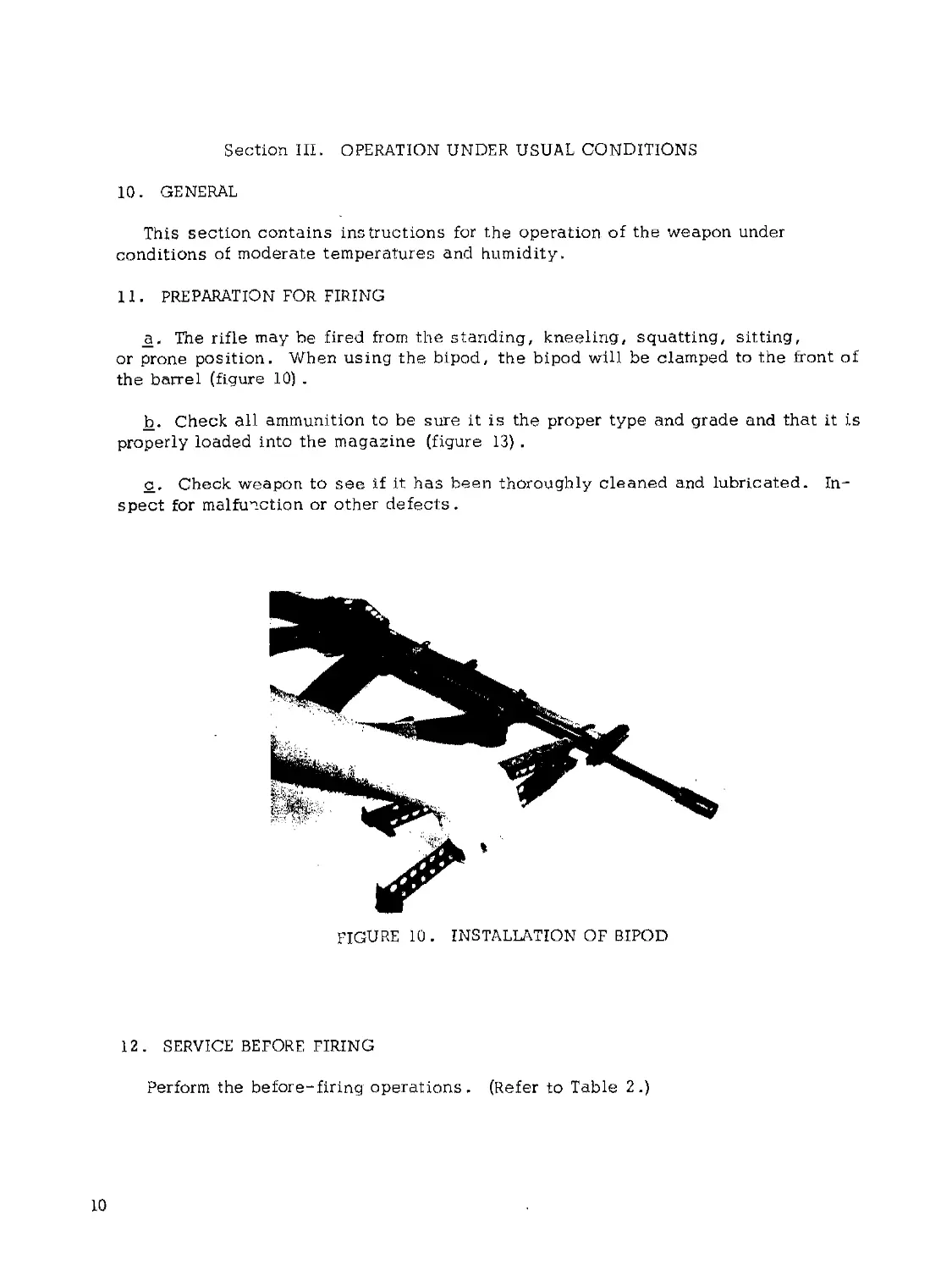
_a. The rifle may be fired from the standing, kneeling, squatting, sitting,
or prone position. When using the bipod, the bipod will be clamped to the front of
the barrel (figure 10) .
b. Check all ammunition to be sure it is the proper type and grade and that it is
properly loaded into the magazine (figure 13) .
c. Check weapon to see if it has been thoroughly cleaned and lubricated. In-
spect for malfunction or other defects.
FIGURE 10 . INSTALLATION OF BIPOD
12. SERVICE BEFORE FIRING
Perform the be fore-firing operations. (Refer to Table 2.)
10
13. LOADING
a. Loading the magazine. The magazine has a 30-round capacity and may
be loaded with any amount up to that capacity. All types of 5 . 5 6mm ammunition
may be loaded. Figure 11 shows the magazine with three 10 round clips of 5.56mm
ammunition and a loading adapter that slips over the end of the magazine to facil-
itate loading the magazine. Figure 12 illustrates how to load the magazine. Looking
down on the magazine follower, it has a raised portion on the right rear of the fol-
lower. Cartridges are loaded into the magazine so that the tips of the bullets are
forward of the raised portion on the follower. See figure 13 .
FIGURE 11. 10 ROUND CLIPS AND
LOADING ADAPTER
FIGURE 12 . LOADING MAGAZINE
b. Loading the Rifle. The magazine may be inserted with the action open or
closed. With the bolt closed, insert a loaded magazine into the magazine well until
the magazine support and magazine latch (see figure 14) engage the magazine and
lock it into place. Pull down on the magazine to insure that it is locked. Pull
back and release’the cocking handle, allowing the bolt to strip the top round from
the magazine, feeding and chambering. Push the cocking handle all the way for-
ward .
11
EMPTY LOADED
FIGURE 13* 30 ROUND MAGAZINES
FIGURE 14. MAGAZINE
SUPPORT AND LATCH
14. FIRING
The rifle may be fired semiautomatically or automatically by moving the
selector to the desired position.
a< 11 SEMI" (Semiautomatic). With the selector lever in this position, the
rifle will fire one round each time the trigger is pulled.
b. "AUTO" (Automatic) . With the selector lever in this position, the rifle will
continue to fire until the magazine is exhausted or trigger is released.
15, MISFIRE, HANGFIRE, AND COOKOFF
a_. MisfireA misfire is a complete failure to fire. A misfire in itself is
not dangerous but, since it cannot be immediately distinguished from a delay in
the functioning of the firing mechanism or from a hangfire (b below), it should
be considered as a possible delayed firing until such possibility has been
eliminated. Such a delay for example, could result from the presence of grit,
sand, frost, ice, or improper or excessive oil or grease which might create a
partial mechanical restraint which, after some indeterminate delay, is overcome
and the firing pin is then driven into the primer in the normal manner. In this
connection, no round should be left in a hot weapon any longer than the circum-
stances require because of the possibility of a cookoff (c below) . Refer to
paragraph 19 for removal procedures.
12
b. Hangfire. A hangfire is a delay in the functioning of a propelling charge at
the time of firing. The amount of delay is unpredictable but, in most cases, will
fall within the range of a split second to several minutes. Thus, a hangfire cannot
be distinguished immediately from a misfire and therein lies the principal danger of
assuming a failure of the weapon to fire immediately upon actuation of the firing
mechanism is a misfire, whereas, in fact, it may prove to be a hangfire.
WARNING: During the prescribed time intervals, the weapon will be kept trained
on the target. All personnel will stand clear of the muzzle. Refer to paragraph 16
for removal procedures.
c. Cookoff. A cookoff is a functioning of any or all of the explosive components
of a round chambered in a very hot weapon due to the heat of the weapon. If the pri-
mer or propelling charger should cookoff, the projectile may be propelled from the
weapon with normal velocity even though no attempt was made to fire the primer by
actuating the firing mechanism. In such a case, although there may be uncertainty
as to whether or when the round will fire, the precautions to be observed are the
same as those prescribed for a hangfire (b above) . To prevent a cookoff, a round
which has been loaded into a very hot weapon should be fired or removed within 5
seconds. Refer to the following paragraphs for removal procedures.
16. PROCEDURES FOR REMOVING A ROUND IN CASE OF FAILURE TO FIRE
a. General. After a failure to fire, due to the possibility of a hangfire or cook-
off, the following general precautions, as applicable, will be observed until the round
has been removed from the weapon and the cause of failure determined.
(1) Keep the weapon trained down range. All personnel will stand
clear of the muzzle.
(2) Before retracting the bolt, either to remove the round or recock as the
case may be, personnel not required for the operation will be cleared
from the vicinity.
(3) The round, after removal from the weapon, will be kept separate from
the other rounds until it has been determined whether the round or the
firing mechanism was at fault. If it is determined that the round is at
fault, it will continue to be kept separated from the other rounds until
disposed of. On the other hand, if examination reveals that the firing
mechanism was at fault, the round may be reloaded and fired after cor-
rection of the cause for failure to fire.
b. Time Interval. The definite time intervals for waiting after failure of weapon
to fire are prescribed as follows: Always keep the round locked in the chamber for
5 seconds from the time a misfire occurs, to insure against an explosion outside of
the weapon in the event a hangfire develops, If the barrel is hot and a misfire stops
automatic operation of the weapon, wait 5 seconds with the round locked in the
chamber to insure against hangfire dangers, then extract immediately to prevent a
cookoff. If the round cannot be extracted within 10 seconds, it must remain locked
in the chamber for at least 5 minutes due to the possibility of a cookoff.
13
WARNING;: Do not retract the bolt when a hangfire or cookoff is suspected .
A hangfire will normally occur within 5 seconds from the time the., primer is struck and
a cookoff after 10 seconds of contact with the chamber in a hot barrel. One hundred-
fifty rounds fired in a 2-minute period will make a barrel hot enough to produce a
cookoff.
17. DOUBLE FEED
A double feed is malfunction which occurs when the empty case fails to eject and
another round is picked up by the bolt , Neither can feed or chamber properly and
both become jammed and deformed. Both rounds can be ejected manually using the
cocking handle. The cause normally is a short recoil which indicates a dirty gas
cylinder or faulty ammunition.
18. SERVICE DURING FIRING
No during-firing service operations are required for this weapon.
19. UNLOADING
To unload a cocked, loaded rifle use the following procedures:
a, . Move the safety lever to (Safe) position, (all the way to the rear)
b. Remove the magazine from the weapon.
c. Move cocking handle to the full rearward position and eject the ammunition
in the firing chamber.
CAUTION: Do not attempt to clear rifle without manually holding cocking
handle in the fully open position.
4- Holding the cocking handle in the fully open position, insert index finger
into the magazine well and push bolt stop upward. Gradually release the manual pres-
sure on the cocking handle, allowing the bolt to rest against the bolt stop. Keep
manual pressure on the cocking handle.
e. Look through the ejection port and into firing chamber to make sure the cham-
ber is clear of ammunition.
20 . SERVICE AFTER FIRING
Perform the after-firing operations. (Refer to table 2.)
14
CHAPTER 3
ORGANIZATIONAL MAINTENANCE INSTRUCTIONS
Section I. REPAIR PARTS, TOOLS, AND EQUIPMENT
2 L GENERAL
Repair parts, tools, and equipment are issued to the using organization for op-
erating and maintaining the materiel. Tools and equipment should not be used for
purposes other than prescribed and, when not in use, should be properly stowed.
22. REPAIR PARTS
Repair parts are supplied to the using organization for replacement of those parts
most likely to become worn, broken, or otherwise unserviceable, when replacement
of these parts is authorized to the using organization. Repair parts supplied to the
using organization are listed in Appendix I, which is the authority for requisitioning
replacements. Repair parts supplied for organizational maintenance are listed in
Appendix П.
23 . SPECIAL TOOLS AND EQUIPMENT
Special tools are listed in Appendix I.
15
Section II. LUBRICATION
24. LUBRICATION INSTRUCTIONS
The lubrication instructions (Table 1) prescribes cleaning and lubrication pro-
cedures as to locations, intervals and proper materials.
Table 1. LUBRICATION INSTRUCTIONS
Item Procedure
RIFLE BIPOD Immediately after firing, the barrel bore and other surfaces exposed to powder residue or gases will be thoroughly clean- ed with brushes saturated with CR. Other surfaces will be cleaned with SD. After cleaning, all surfaces and compon- ents will be thoroughly dried with clean cloths or swabs (patches) » Clean, after firing and weekly thereafter with SD or TPM; wipe dry and oil with PL special (or LAW for below 0°F. weather conditions) . Clean and oil all moving parts. MATERIALS TO BE USED CR - CLEANING COMPOUND, SOLVENT, Rifle bore cleaner SD - DRY-CLEANING SOLVENT or TPM — THINNER, PAINT, MINERAL SPIRITS PL Special - LUBRICATING OIL, GENERAL PURPOSE, above 0°F. LAW - LUBRICATING OIL, WEAPONS, below 0 F
16
25. GENERAL LUBRICATION INSTRUCTIONS
a. U s u a 1 Co nd it i on s . Lubrication intervals specified in Table 7, are for
normal operation and where moderate temperature and humidity prevail.
fe* Reports and Records . Report unsatisfactory performance of materiel or
effect of prescribed lubricants and preserving materials.
26. SPECIFIC LUBRICATION INSTRUCTIONS
_a. General. Lubrication will be performed more frequently than specified
in table to compensate for abnormal operation and extreme conditions, such as high
or low temperatures, prolonged periods of high-rate operation, or continued expo-
sure to moisture, any one of which may quickly destroy the protective qualities of
the lubricant.
b. Changing Grade of Lubricants . Lubricants are prescribed in accordance
with temperature ranges: above 0°F., and below 0°F, The time to change the grade
of lubricants is determined by maintaining a close check of the operation of the wea-
pon during the approach to changeover periods in accordance with weather forecast
data* Ordinarily, it will be necessary to change grade of lubricants only when air
temperature is consistently above or below 0°F.
c. Extreme Cold Weather. Apply a light coat of weapons lubricating oil (LAW)
to all operating mechanism surfaces. Materiel should be exercised more frequently
during the periods of low temperature to insure proper functioning.
d* Extreme Hot Weather. Special lubricants will ordinarily not be required at
extremely high temperatures, as lubricants prescribed for temperatures above 0°F.
provide adequate protection. However, more frequent servicing than specified in
Tables 2 and 3 is necessary because the heat tends to dissipate the lubricants.
e. Humid and Salt-Air Conditions. High humidity, moisture, or salt air con-
taminate lubricants, necessitating more frequent service than specified in Tables
2 and 3.
f. Before Immersion. Lubricate materiel before amphibious operation as pre-
scribed in Table 3 .
Я- After Immersion. After immersion, perform the maintenance described in
paragraph 27, which covers maintenance operations after immersion and includes
special lubrication instructions.
h, . Sandy or Dusty Conditions.. If firing or prolonged travel has occurred under
dusty or sandy conditions, clean and inspect all lubricated surfaces for fouled lub-
ricants. Lubricate as necessary.
17
Section Ш. PREVENTIVE-MAINTENANCE SERVICES
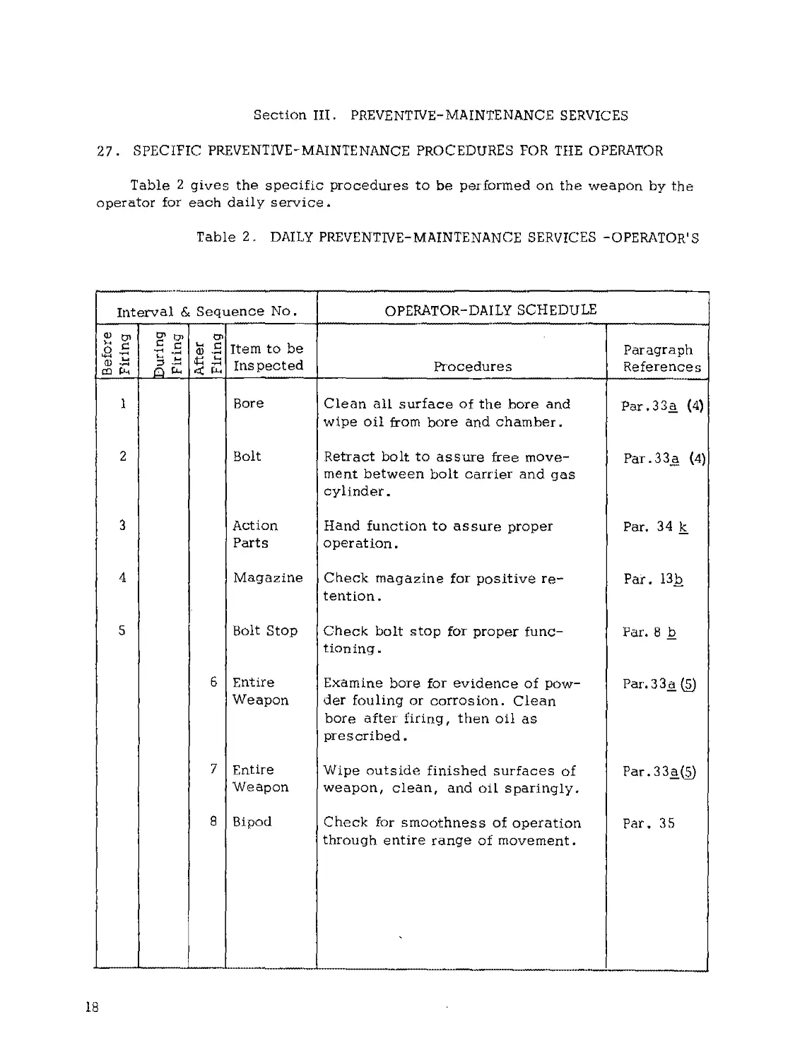
27. SPECIFIC PREVENTIVE-MAINTENANCE PROCEDURES FOR THE OPERATOR
Table 2 gives the specific procedures to be performed on the weapon by the
operator for each daily service.
Table 2. DAILY PREVENTIVE-MAINTENANCE SERVICES -OPERATOR'S
Interval & Sequence No. OPERATOR-DAILY SCHEDULE
Before Firing During 1 Firing I After I Firing | Item to be Inspected Procedures Paragraph References
1 Bore Clean all surface of the bore and wipe oil from bore and chamber. Par.33a (4)
2 Bolt Retract bolt to assure free move- ment between bolt carrier and gas cylinder. Par. 3 3 a, (4)
3 Action Parts Hand function to assure proper operation. Par. 34 к
4 Magazine Check magazine for positive re- tention. Par. 13b
5 Bolt Stop Check bolt stop for proper func- tioning Par. 8 b
6 Entire Weapon Examine bore for evidence of pow- der fouling or corrosion. Clean bore after firing, then oil as prescribed, Par.33a (5)
7 Entire Weapon Wipe outside finished surfaces of weapon, clean, and oil sparingly. Par. 3 3a(5)
8 Bipod Check for smoothness of operation through entire range of movement. Par, 35
18
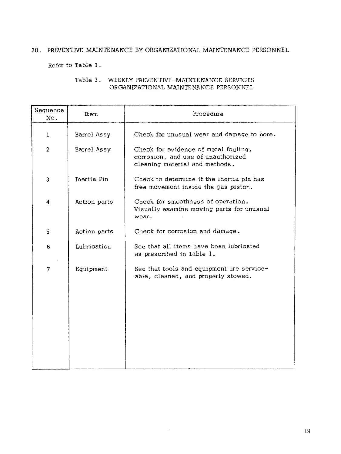
28. PREVENTIVE MAINTENANCE BY ORGANIZATIONAL MAINTENANCE PERSONNEL
Refer to Table 3.
Table 3. WEEKLY PREVENTIVE-MAINTENANCE SERVICES
ORGANIZATIONAL MAINTENANCE PERSONNEL
Sequence No. Item Procedure
1 Barrel Assy Check for unusual wear and damage to bore.
2 Barrel Assy Check for evidence of metal fouling, corrosion, and use of unauthorized cleaning material and methods.
3 Inertia Pin Check to determine if the inertia pin has free movement inside the gas piston.
4 Action parts Check for smoothness of operation. Visually examine moving parts for unusual wear.
5 Action parts Check for corrosion and damage.
6 Lubrication See that all items have been lubricated as prescribed in Table 1.
7 Equipment See that tools and equipment are service- able, cleaned, and properly stowed.
19
Section IV. TROUBLESHOOTING
29. SCOPE
This section contains troubleshooting information and tests for locating and
correcting some of the troubles which may develop in the weapon. Troubleshooting
is the systematic study of trouble signs, testing to determine the defective comp-
onent, and applying corrective action. Each malfunction is followed by probable
causes and suggested procedures to be followed.
30. TROUBLESHOOTING GUIDE
Table 4 is intended to be used only as a guide in troubleshooting. This table
does not cover all possible malfunctions that may occur; only the more common mal-
functions are listed. The tests and corrective actions are governed by the scope of
the operator or organizational level of maintenance.
Table 4 . TROUBLESHOOTING
Malfunction Probable Cause Corrective Action
Bolt fails to lock to 1. Faulty Magazine . 1. Replace Magazine.
the rear after the last round. 2. Broken bolt stop and/or spring. 2 . Refer to higher echelon (direct support) for cor- rective action.
Failure to feed. 1 . Faulty Magazine. 2 , Dirty or carboned gas port. 3 . Lubrication inadequate . 4 . Damaged or weak driving spring. 1. Replace Magazine. 2. Clean. 3. Apply lubricant as required. 4 . Refer to higher echelon (direct support) for cor- rective action.
Failure to cycle when 1. Frozen ejector. 1. Disassemble andclean
set on 11 AUTO" . 2 . Insufficient gas . 3. Broken timer assy. 4. Faulty selector lever. 2 . Clean gas cylinder. 3 . Refer to higher eche- lon (direct support) for corrective action. 4 . Refer to higher eche- lon (direct support) for corrective action.
20
Table 4. TROUBLESHOOTING - Continued
Malfunction Probable Cause Corrective Action
Failure to fire. 1. Improperly installed hammer or trigger spring. 2. Faulty ammunition. 3. Broken or damaged firing pin. 4. Dirty chamber. 5< Broken hammer spring. 6. Broken timer assembly. 7 . Misalined or worn trigger or hammer spring. 1. Disassemble and install properly. 2 . Remove and replace ammunition. 3. Refer to higher ech- elon (direct support) for corrective action, 4. Clear and clean. 5. Refer to higher ech- elon (direct support) for corrective action. 6 . Refer to higher ech- elon (direct support) for corrective action. 7. Refer to higher ech- elon (direct support) for corrective action .
Failure to extract. 1. Broken extractor spring. 2. Broken extractor. 3 , Short recoil. 1. Refer to higher ech- elon (direct support) for corrective action. 2 . Refer to higher ech- elon (direct support) for corrective action. 3. Clean gas cylinder.
Failure to chamber. 1. Ruptured cartridge case. 2 . Damaged round . 1. Remove. 2, Recharge weapon.
Failure to eject. 1. Short recoil. 2. Frozen ejector. 3, Damaged ejector. 1. Clean gas cylinder. 2. Remove and clean. 3. Refer to higher ech- elon (direct support) for corrective action.
Fires with safety on safe position. 1. Faulty safety. 2. Broken trigger. 1. Refer to higher ech- elon (direct support) for corrective action. 2. Refer to higher ech- elon (direct support) for corrective action.
21
Table 4. TROUBLESHOOTING - Continued
Malfunction
Probable Cause
Corrective Action
With selector lever on "SEMI", fires when trigger is released. 1. Faulty hammer or trigger. 1. Refer to higher ech- elon (direct support) for corrective action.
With selector lever on "SEMI", fires automati- 1. Faulty disconnect spring. 1. Refer to higher ech-
cally . 2. Faulty disconnect. •2. elon (direct support) for corrective action. As Above.
3. Faulty selector lever. 3. As Above.
Bolt seizes, will not 1. Carbon dirty or burred 1. Hold rifle in vertical
rotate. bolt group. position and strike butt sharply on ground while pulling back on cocking handle.
CAUTION: Strike butt
squarely on ground to
prevent breakage, of
stock. Remove bolt
group and clean.
22
Section V. MAINTENANCE OF RIFLE
31. GENERAL
Maintenance includes all measures taken to keep the rifle in top operating
condition. This includes normal cleaning, inspection for defective parts, repair,
and lubrication. The individual is authorised to disassemble his rifle to the extent
called field "stripping". (See Figure 27) The amount of disassembly he is allowed
to perform without supervision is adequate for normal maintenance. The frequency
of disassembly and assembly should be kept to a minimum, consistent with main-
tenance and instructional requirements .
The rifle has been designed so that it can be taken apart and put together easily.
No force is needed if it is disassembled and assembled correctly. As the rifle is
disassembled, the parts should be laid out from left to right. This makes assembly
easier because the parts are assembled in the reverse order of disassembly. Dis-
assembly may be accomplished in the field using only a cartridge.
32. DISASSEMBLY
a. Removing the Magazine. Grasp the rifle around the forestock with the left
hand, keeping the muzzle pointed away from you in a safe direction. Grasp the maga-
zine with the right hand. With the thumb of the right hand, depress the magazine
latch toward the magazine. Rotate ths magazine forward and remove.
b. Inspection for Safe Condition.
(1) Pull the cocking handle on the top of the receiver to the rear until
the action is fully open.
(2) Lock the action open by pushing up on the bolt stop. See Figure 4
and Paragraph 8b.
(3) Return the cocking handle to the forward, locked position.
(4) Move the safety to the safe position. See Figure 5 and Para-
graph 8d.
(5) Look in the receiver and chamber to be sure that the weapon is cleared of
all ammunition and is safe to disassemble. Feel the inside of the chamber with
your little finger to verify that it is empty.
(6) Pull the cocking handle to the rear until the bolt stop is released, then
ease the bolt forward, closing the action. When the pressure of the bolt is taken
off the bolt stop, the compressed bolt stop spring expands and forces the bolt stop
down and out of the path of the bolt.
c. Removing the Driving Spring Assembly and Carrier, Piston and Bolt Assembly.
(1) With the bolt closed and safety on safe, push the take-down pin out to-
ward the right side of the weapon with the point of a cartridge. (Figure 15)
23
(2) Holding the rifle with the left hand under the receiver, muzzle pointing
down, pull out the take-down pin with the right hand until the trigger housing
group is allowed to pivot downward. The take-down pin cannot be removed from
the trigger housing assembly.
(3) Still holding the weapon in the left hand, grasp the driving spring
assembly and remove. (Figure 16).
(4) Place the right hand over the back of the receiver (Figure 17) and rotate
the rifle muzzle up slowly. The carrier, piston and bolt assembly will slide out
of the receiver assembly.
d. Removal of the Trigger Housing Group from the Receiver Group. Remove the
trigger housing group retaining pin (Figure 18) and remove the trigger housing group
from the receiver group.
FIGURE 18. REMOVING THE TRIGGER
HOUSING GROUP RETAINING PIN
FIGURE 17. REMOVING THE CARRIER,
PISTON AND BOLT ASSEMBLY
24
е. Removal of the Forestock Assembly, Barrel, and Cocking Handle Assemblies,
from the Receiver Group,
(1) Remove the forestock assembly retaining pin. (Figure 19)
(2) Grasping the forestock assembly, slide it forward and remove it
from the receiver assembly.
(3) Depress the barrel latch, (Figure 20) and remove the barrel assembly.
(4) Pull back on the cocking handle until the guides on the handle are
aligned with the disassembly notches on the receiver (Figure 21) and remove.
FIGURE 20. DEPRESSING THE BARREL
FIGURE 19. REMOVING THE FORESTOCK
ASSEMBLY RETAINING PIN
LATCH
FIGURE 21. COCKING HANDLE GUIDE
LUG AND DISASSEMBLY NOTCH
FIGURE 22. REMOVING THE STOCK
RETAINING PIN
2 5
f. Removal of the Stock from,the Trigger Housing Group,
(1) To remove the stock from the trigger housing group, remove the stock
retaining pin (Figure 22) .
(2) Rotate the bottom of the stock up and remove.
NOTE: The stock retaining pin, forestock assembly retaining pin, and
trigger housing group retaining pin are interchangeable.
Я* Removal of the Firing Pin, Cam Pin, and Bolt Assembly from the Carrier-
Piston and Bolt Assembly.
(1) Push down on the base of the firing pin until it is flush with the back
of the carrier cap assembly (Figure 23). Failure to do this will cause damage
to the firing pin during disassembly. While holding the firing pin in this pos-
ition, rotate the carrier cap assembly clockwise with the side of the index
finger pressing against the cap roller, until the cap carrier is on line with the
bottom of the bolt carrier, (Figure 24) and the word "UP" is on top.
FIGURE 23. FIRING PIN AND
CARRIER CAP ASSEMBLY
FIGURE 24. CARRIER CAP ASSEMBLY
IN LINE WITH BOTTOM OF BOLT
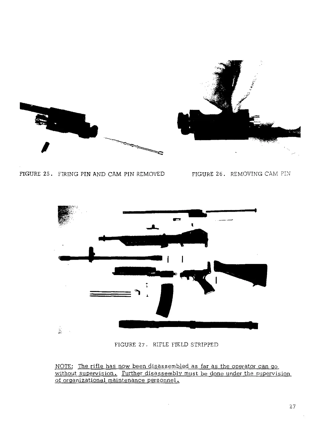
(2) Remove the firing pin from the bolt carrier. (Figure 25)
(3) Remove the cam pin from the bolt. (Figure 25 and 26)
(4) Remove the bolt from the bolt carrier.
26
FIGURE 26. REMOVING CAM PIN
FIGURE 25. FIRING PIN AND CAM PIN REMOVED
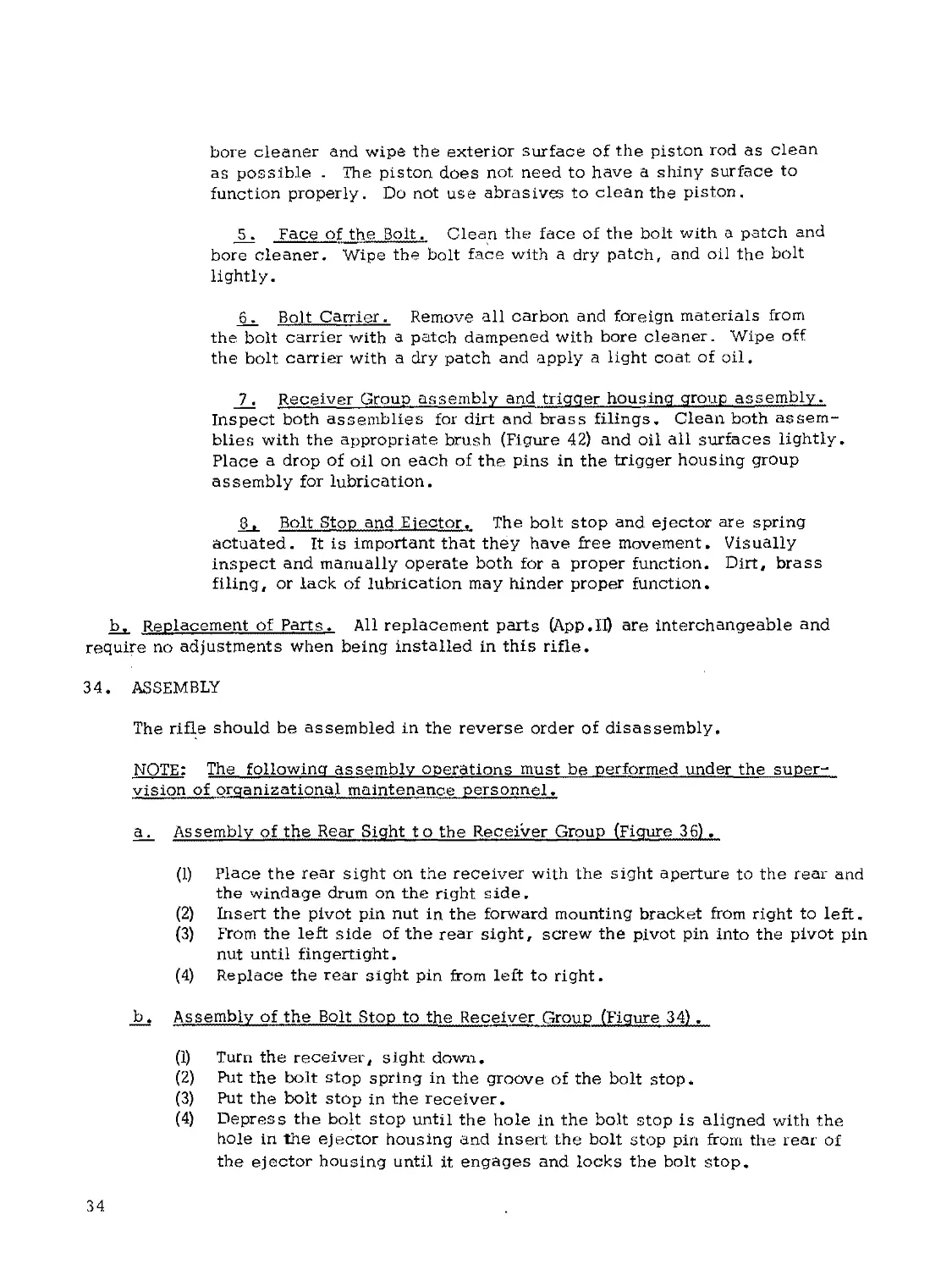
FIGURE 27 < RIFLE FIELD STRIPPED
NOTE: The rifle has now been disassembled as far as the operator can go
without supervision. Further ...disassembly must be done under the supervision
of organizational maintenance personnel,
27
h. Disassembly of the Trigger Housing Group,
(1) To disassemble the trigger housing group, cock the hammer, then
pull the safety to its safe (rearmost) position within the trigger guard .
FIGURE 28. DISENGAGING LOCK
FIGURE 29. PUSHING THE LOCK
PLATE FORWARD
PLATE TANG
(2) Hold the trigger housing group in the vertical position. Insert the
point of a cartridge into the hole that the lock plate tang is engaged in and push
the lock plate forward. (Figure 28 and 29) The lock plate must remain forward
during disassembly of the trigger housing group so that the trigger pins can be
removed.
(3) With the tip of a cartridge remove the magazine latch pin and remove
the magazine latch. (Figure 30) Remove the timer pin and remove the timer.
Remove the hammer pin and remove the hammer. Remove the trigger assembly
pin. (Figure 3 1)
NOTE: All four pins are of the same size and are called trigger pins. For clarity
of description they will be called hammer pin, timer pin, magazine latch pin, and
trigger pin when returning these parts to the trigger housing group.
FIGURE 30. REMOVING THE MAGAZINE
DITCH PIN
28
FIGURE 3 1. TRIGGER HOUSING GROUP - DISASSEMBLED
(5) To remove the trigger assembly, push clown on the rear of the sear
and push up on the trigger assembly as shown in Figure 32 . Remove the
trigger assembly.
(6) Remove the safety by sliding it to the rear inside the trigger guard
and pulling down. (Figure 33)
(7) Remove the lock plate by grasping the extended front edge and
pulling out from guide pins .
k- pls as sembly of the Receiver Group.
(1) Remove the bolt stop (Figure 34) by pushing out the bolt stop pin,
and remove the bolt stop and bolt stop spring.
(2) Remove the ejector by depressing ths ejector detent, sliding the
ejector lock plate aside, and pulling out the ejector (Figure 35) .
(3) Remove the rear sight assembly by pushing out the rifle sight pin
(Figure 35) . Unscrew and remove the pivot pin screw from the pivot pin nut.
(4) Remove the rear sight assembly.
NOTE: The rifle is now detailed - stripped as far as permitted under super-
vision of organizational maintenance personnel. See Figure 37.. Further
disassembly is restricted to DIRECT SUPPORT PERSONNEL ONLY.
29
FIGURE 33. REMOVING SAFETY
FIGURE 34. REMOVING BOLT STOP,
PIN AND SPRING
FIGURE 35. DEPRESSING EJECTOR DETENT
FIGURE 36.
removing the rear
SIGHT ASSEMBLY
30
1.
2.
37 FIGURE 37, RIFLE DETAILED - STRIPPED
1. Driving Spring 14. BUttstOCK Assy 27. Magazine Latch
2. Carrier & Piston Assy 15. Receiver Group 28. Lock Plate
3. Firing Pin 16. Forestock Assy 29. Hammer
4. Bolt Assy 17. Receiver Pin 30. Timer
5. Cam Pin 18. Bolt Stop 31. Magazine Assy
6. Barrel Assy 19. Bolt Stop Spring 32. Sling
7. Pivot Pin Screw 20, Bolt Stop Pin 33. Patches
8. Pivot Pin Nut 21. Ejector Assy 34. Adapter
9. Rifle Sight Pin 22. Ejector Lock 35. Comb Tool
10. Rear Sight Assy 23. Trigger Housing 36, Bore Brush
11. Cleaning Rod Bracket 24. Trigger Assy 37. Oiler
12. Cocking Handle 25. Trigger Pins
13 c Cleaning Rod 26. Safety
33. CLEANING, INSPECTION AND REPAIR
a, Cleaning and Inspection.
(1) Cleaning materials.
(a) Bore cleaner is used for cleaning the bore, chamber, barrel extension,
and gas cylinder. It also provides temporary protection from rust.
(Ь) Hot, soapy water or plain hot water is a substitute for bore cleaner.
(c) Dry-cleaning solvent is used for cleaning rifles which are coated with
grease, oil, or corrosion-preventative compounds.
31
CAUTION: Use warm, soapy water clean plastic parts . Some cleaning'
solvents and gasoline tend to soften and distort this material.
(2) Lubricants .
(a) Special preservative lubricating oil is used for lubricating the
rifle at normal and low temperatures.
(b) Medium preservative lubricating oil is used instead of special
preservative oil when the rifle is exposed to high temperatures, high humidity,
or salt water.
(c) "Lubriplate" rifle grease should be applied to working surfaces in
extremely humid weather or whenever there is a likelihood that the rifle will
be subjected to immersion in either fresh or salt water. After immersion in
either fresh or salt water, the rifle should be cleaned, dried, and properly
lubricated as soon as possible.
(3) Equipment furnished for cleaning the rifle.
(a) Cleaning Rod.
(Ь) Bore Cleaner
(c) Rifle Oil.
(d) Brushes (See Figure 42)
(e) Cleaning patches. Satisfactory caliber 5.56mm patches can be
obtained by cutting .30-caliber patches into quarters.
(4) Before firing.
(a) The bore and chamber should be cleaned and dried. A light coat
of oil should be placed on all metal parts except those which come in contact
with ammunition.
(b) Lubriplate should be applied to the parts that show friction wear.
This is particularly important when the rifle is exposed to rain or salt water.
A small amount of Lubriplate is applied to those parts that show wear. Lub-
riplate is not used in extremely cold temperatures or when the rifle is exposed
to extremes of sand and dust.
(c) In cold climates (temperatures below freezing) the rifle must be
kept free of moisture and excess oil. Moisture and excess oil on the working
parts cause them to operate sluggishly or to fail completely. The rifle must be
disassembled and wiped with a clean dry cloth. Dry-cleaning solvent may be
used if necessary to remove oil or Lubriplate. Parts that show signs of wear
maybe wiped with a patch lightly dampened wrth a special preservative lubri-
cating oil. It is best to keep the rifle as close as possible to outside
32
temperatures at all time due to the collection of moisture which occurs when
cold metal comes in contact with warm air. If the rifle is brought into a
warm room, it should be allowed to reach room temperatures so that conden-
sation will appear before the weapon is cleaned,
(d) In hot, dry climates, the rifle must be cleaned daily, or more often,
to remove sand and/or dust from the bore and working parts. In sandy areas,
the rifle should be kept dry to prevent the collection of sand. The muzzle
and receiver should be kept covered during sand and dust storms.
(5) After firing or daily during disassembly',
(a) The rifle must be cleaned after it has been fired because firing pro-
duces deposits of primer fouling, powder ashes, carbon, and metal fouling.
The ammunition has noncorrosive primer which makes cleaning easier, but no
less important. The primer still leaves a deposit that may collect moisture
and promote rust if it is not removed. The cleaning described below will re-
move all deposits except metal fouling which is relatively incommon and is
removed by Ordnance Personnel.
(b) The rifle should be disassembled (Field Stripped, Figure 27) and
cleaned in the following manner after it has been fired.
1Bore. Run patches dampened with bore cleaner or hot soapy
water back and forth through the bore several times. Next, attach
the bore brush to the cleaning rod and run it back and forth through
the bore once or twice. Follow this with more wet patches. Run
several dry patches through the bore and inspect each patch as it is
removed. The bore is clean when a dry patch comes out clean with
no evidence of fouling. Finally, run an oily patch through the bore
to leave a light coat of oil inside the barrel.
NOTE: The patch or brush must be pushed all the way through the bore
before it is withdrawn.
2 Chamber and barrel extension. Using the appropriate brushes
(Figure 42) clean the lugs of the barrel extension and the chamber.
After removing the carbon, particles of dirt anchor brass filings, dry
the chamber with a clean patch. The lugs of the barrel extension
should be oiled lightly,
3. Gas cylinder. Using the appropriate brush (Figure 42) clean
the inside of the gas cylinder. Put two patches on the patch holder
of the cleaning rod, moisten them with bore cleaner and swab the
cylinder bore. Dry the cylinder bore with clean dry patches. Use
no abrasives in cleaning the cylinder and do not oil the interior
surfaces.
__4. Carrier and piston assembly. Shake the assembly to determine
if the inertia pin in the piston rod has free movement. If it is not free,
remove the roll pin and piston-head and clean. Saturate patches with
33
bore cleaner and wipe the exterior surface of the piston rod as clean
as possible . The piston does not need to have a shiny surface to
function properly. Do not use abrasives to clean the piston.
5. Face of the Bolt. Clean the face of the bolt with a patch and
bore cleaner. Wipe the bolt face with a dry patch, and oil the bolt
lightly.
6. Bolt Carrier. Remove all carbon and foreign materials from
the bolt carrier with a patch dampened with bore cleaner. Wipe off
the bolt carrier with a dry patch and apply a light coat of oil.
7. Receiver Group assembly and trigger housing group assembly.
Inspect both assemblies for dirt and brass filings. Clean both assem-
blies with the appropriate brush (Figure 42) and oil all surfaces lightly.
Place a drop of oil on each of the pins in the trigger housing group
assembly for lubrication.
8, Bolt Stop and Ejector, The bolt stop and ejector are spring
actuated. It is important that they have free movement. Visually
inspect and manually operate both for a proper function. Dirt, brass
filing, or lack of lubrication may hinder proper function.
b, Replacement of Parts, All replacement parts (Арр.П) are interchangeable and
require no adjustments when being installed in this rifle.
34. ASSEMBLY
The rifle should be assembled in the reverse order of disassembly.
NOTE: The following assembly operations must be performed under the super-
vision of organizational maintenance personnel,
a. Assembly of the Rear Sight to the Receiver Group (Figure 36),
(1) Place the rear sight on the receiver with the sight aperture to the rear and
the windage drum on the right side.
(2) Insert the pivot pin nut in the forward mounting bracket from right to left.
(3) From the left side of the rear sight, screw the pivot pin into the pivot pin
nut until fingertight.
(4) Replace the rear sight pin from left to right.
b, Assembly of the Bolt Stop to the Receiver Group (Figure 34),
(1) Turn the receiver, sight down.
(2) Put the bolt stop spring in the groove of the bolt stop.
(3) Put the bolt stop in the receiver.
(4) Depress the bolt stop until the hole in the bolt stop is aligned with the
hole in the ejector housing and insert the bolt stop pin from the rear of
the ejector housing until it engages and locks the bolt stop.
34
с* Installation of the Elector Assembly (Figure 35) .
(I) Insert the ejector into the ejector hole*
(2) Slide the ejector lock plate into position.
d. Assembly of the Cocking Handle, Barrel, and Forestock Assembly with
the Receiver Group.
(1) Replace the cocking handle (Figure 21) .
(2) To replace the barrel assembly, depress the barrel latch FIRST and
insert the barrel into the receiver group (Figure 20) . Lock the barrel
into place by releasing the barrel latch.
(3) Replace the forestock assembly by aligning the hooks on the lower
receiver and slide the forestock assembly to the rear. Insert the
forestock assembly pin (Figure 19) .
e. Assembly of the Trigger Housing Group,
(1) Place the lock plate in the left side of the trigger housing group
(Figure 31) insuring that the lock plate is held in position by the
two lock plate guide pins. The lock plate must remain forward during
assembly of the trigger housing group.
(2) Place the safety into its slot within the trigger guard and leave on
its "Safe" setting, (Figure 33)
(3) Depressing the rear of the sear, insert the trigger assembly from the
top of the trigger housing. (Figure 32)
(4) Replace the trigger pin.
(5) Replace the hammer assembly (Figure 38) and insert the hammer pin.
(6) Cock the hammer, replace the timer assembly in the trigger housing
group (Figure 39) and insert the timer pin*
(7) Replace the magazine latch assembly (Figure 40) and insert the mag-
azine latch pin.
(8) Align the trigger pins, and push the extending edge of the lock plate
to the rear. The lock plate tang should be seated in the lock plate
tang hole (Figure'28).
NOTE: The following assembly operations may be performed by the operator
without supervision of organizational maintenance personnel.
35
FIGURE 38. REPLACING THE HAMMER
ASSEMBLY
FIGURE 39. REPLACING THE TIMER
ASSEMBLY
FIGURE 40. REPLACING THE MAGAZINE
LATCH ASSEMBLY
FIGURE 41. DISENGAGING THE TIMER
f,„ Assembly of the Stock .and Trigger Housing Group.
Replace the stock by locking it in the rear of the trigger housing
group and inserting the stock retaining pin (Figure 2 2).
36
q. Replace the Trigger Housing Group on the Receiver Group*
(1) With the hammer cocked, and the safety in the "Safe" position, move
the timer forward, disengaging it" from the hammer (Figure 41) t
(2) Place the trigger group on the receiver group, (Figure 18) and replace
the trigger housing group retaining pin.
h. Assembly of the Bolt Assembly, Cam Pin and Firing Pin with the Carrier-
Piston Assembly.
(1) Replace the bolt in the bolt carrier with the ejector groove in the bolt
facing toward the cam track in the bolt carrier. (Figures 23 and 24)
(2) Insert the cam pin thru the cam track and into the cam pin hole in the
bolt. (Figure 26) The flat side of the cam pin guide lug must be in line with the
lower side of the bolt carrier, as shown in Figure 23.
(3) Replace the firing pm in the bolt carrier. Check to see that the "UP"
on the carrier cap assembly is in the correct position (Figure 24). Push until it is
flush with the rear of the carrier cap assembly. Holding the firing pin in this posi-
tion, rotate the carrier cap assembly 1/4 turn counterclockwise, so the tang on the
carreir cap assembly is in the downward position as shown in Figure 23,
i. Replacing the Carrier-Piston, Bolt and Driving Spring Assemblies.
(1) Holding the rifle in the left hand, muzzle pointing down, insert the
carrier-piston and bolt assembly. The bolt must be in the forward position with
the cam pin aligned with the bolt carrier ail. (Figure 17)
(2) Replace the driving spring assembly (Figure 16).
1. Locking the Trigger Group and Stock to the Receiver Group. Before rotating
the trigger housing group and stock upward, check to be sure that the take-down
pin has been pulled to the right as far as it will go. Then rotate the trigger housing
group and stock upward and lock them to the receiver group with the take-down pin
(Figure 15).
k. Functioning Test, A functioning check will be performed after assembly of
the rifle. A complete function check of the weapon consists of checking the opera-
tion of the selector lever in the "Semi" (Semiautomatic)and "Auto" (Automatic) positions.
The following sequence is used,
(1) Safe Position, Clear the rifle, leaving it cocked with the bolt closed.
Place the safety on the "Safe" position and the selector lever on "Semi" . Pull
the trigger. The hammer should not fall.
37
(2) ’'Semi'' position. With the hammer still cocked from the safety check,
move the safety to the "Off" position and pull the trigger. You should hear the
hammer strike the firing pin. While holding the trigger to the rear, recock the
rifle. Release the trigger slowly. An audible metallic click should be heard
indicating that the disconnect operates properly. The hammer should not fall.
Again pull the trigger. The hammer should fall.
(3) "Auto11 position. Recock the rifle. Turn the selector lever to the "Auto"
position. Pull the trigger. The hammer should fall. While still holding the
trigger to the rear, recock the rifle, the hammer should have been released auto-
matically. Release the trigger and pull it again. The hammer should not fall
because it should have been released automatically.
SECTION VI. MAINTENANCE OF BIPOD
35. MAINTENANCE
The only maintenance required to be performed is cleaning and inspection of
the adjustable legs and hinge springs.
зе
APPENDIX I
BASIC ISSUE ITEMS LIST
Section I. PREFACE
1 . GENERAL
This appendix is a list of the basic issue items that are required for stockage by
first-echelon maintenance. It includes the first-echelon maintenance tools and repair
parts accompanying the equipment, all of which constitute the major end item for issue
to users.
2 . EXPLANATION OF COLUMNS
a. Source, Maintenance, and Recoverability Code. This column lists a code that
indicates the selection status and source of supply of the repair part, the lowest echelon
capable of installing or manufacturing the repair part, and the recoverability and expend-
ability aspects of the repair part. An example of this code is P,O,R. The "P" indicates
that the item is a mission stockage list repair part that is procured and stocked on a nat-
ional program basis, the "O" indicates that the repair part is authorized to first echelon,
and the "R" indicates that the repair part is an expendable, recoverable item. When repair
parts supply responsibility has been assigned to a technical service other than Ordnance,
the basic number of the supplying technical service is listed in the first position of the
source code, for example, "11" for a Signal Corps item. Refer to paragraph 4 for an explan-
ation of all codes appearing in this manual.
b. Federal Stock Number, This column lists the Federal stock number which has been
assigned by the Cataloging Division, Armed Forces Supply Center.
c. Description. This column lists the Federal item name (shown in capital letters)
and any additional description required for supply operations . The abbreviation "w/c”
(with equipment) when used as a portion of the nomenclature indicates that the major item
or major combination includes all armament, equipment, accessories, and repair parts
issued with the item. The technical service or manufacturer's part number is also included
for reference.
d. Unit of Issue. This column lists the minimum quantity that will be supplied. All
items are considered as each except where the unit of issue is shown as ft., in., such as
for bulk materials; the requisition should indicate the exact amount that is required, for
example, 6 ft.
.e. Quantity Authorized. This column lists the quantity of the listed item authorized
for stockage by first echelon.
f_. Illustration. This column indicates the figure number of the illustration that depicts
the item. When more than one item appears on an illustration, the item number is also
indicated.
39
3. abbreviations
assy............................................................assembly (ies)
cal.........., . . . ......................................*........caliber
ctg . . . . ,...................................................cartridge
ctn ...............................................................carton
equip. ...........*...............................................equipment
wdn.............................................................. wooden,
w/e........................................................ with equipment
4 . EXPLANATION OF CODES
a.. Source
Code
P
Explanation
Applied to repair parts which are
high-mortality parts procured by
technical service, stocked in and
supplied from the technical serv-
ice depot system, and authorized
for use at indicated maintenance
echelons ,
b. Maintenance Level.
Code
О
c. Recover ability.
Code
NR
R
Explanation..
Assigned to all repair parts auth-
orized to first (1st) echelon.
Explanation
Indicates a repair part or assembly
that is nonexpendable and recover-
able and is economically repairable.
Indicates a repair part or assembly
that is expendable and recoverable
and is economically repairable and,
when available, is furnished by sup-
ply on an exchange basis.
d. Illustration.
Code
NI
Explanation
Indicates a standard military issue
item and therefore not illustrated in
this handbook.
40
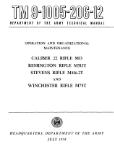
1 . Bipod
2 . Carrying Case
3 . Receiver Brush
4 . Gas Cylinder Brush
5 . Utility Brush
6 . Chamber Brush
7 . Locking Lug Brush
Figure 42. BIPOD, CLEANING BRUSHES, AND CARRYING CASE,
41
APPENDIX I, Section П, BASIC ISSUE ITEMS LIST
Table 5. BASIC ISSUE ITEMS
Source, Maint and Recoverability Code Federal Stock No. DESCRIPTION Unit of Issue Quantity Auth | Illust
Technical JT Service No. Source 2 Maintenance <7- Level — (d) •M XJ ft! CD > 0 0 0 cxi Fig. No.
MAJOR ITEMS The following items are requisitioned for initial issue only, RIFLE, 5.56MM Stoner, w/e Л Я (~\т T MT Ki , — 1
IVlkJU 1N 1 t O1 pOO — COMPONENTS OF MAJOR ITEMS Ths items listed below are issued as components of the major items for initial is- sue. Replacement items will be requisitioned separately under their individual stock num- bers . RIFLE, 5.56MM, Stoner REPAIR PARTS FOR; 9
RIFLE, 5.5GMM, Stoner (See Appendix II) TOOLS AND EQUIPMENT FOR: RIFLE, 5.56ММ, Stoner
BAYONET: Knife 1 1 1 1 1 1 1 1 1 1 1 1 1 1 1 1 1 1 1 1 1 1 1 1 NI 42-3 42-6 42-7 42-4 42-5 37-36 42-2 13 37-13 NI 37-32
I*11 \ k_J 1. jL. j 1 dl ii X IXCj , IT tp t->* 4>*X x/ £ I BRUSH, Cleaning: chamber BRUSH, Cleaning: locking lug---—
Diwori; 1 у an I riy • yds и у X111U UI "* "* "* "* — — —
L51 \ U к/1 Л/ C dll Xl iy « LIL XL XL у BRUSH, Cleaning: rifle bore - СДЯР CAWVIMO' Ki ....... _ _ „ _ „
LHcL, X1 IN 1л ♦ DlpOu MAGAZINE ASSY: Steel (cartridge cap ,30)-- ROD, CLEANING, 5.56MM SCABBARD: bayonet, knife CT TMTZ C1TTM- ,*roklrinn _
kj»U In . WcDDiny — MISCELLANEOUS MATERIEL The items listed under subheadings below are not Issued with the major items but are requisitioned and issued in accordance with tables of organization and equipment, tables of allowances , or as otherwise auth- orized.
42
APPENDIX I, Section П, BASIC ISSUE ITEMS LIST
Table 5. BASIC ISSUE ITEMS Cont.
Source, Maint and Recoverability Code Federal Stock. No. DESCRIPTION Unit of Issue । Quantity Auth Illust
Technical g Service No. (b) Ф о □ о и Maintenance Level Recoverability & Fig. No.
AMMUNITION Ammunition for use with this weapon is listed in SM-9-5-1305. ARTICLES FOR INSTRUCTIONAL PURPOSES The following item WILL BE TAKEN into the field upon permanent change of station and into the theater of operation. CARTRIDGE, 5.56 MM DUMMY: The following item WILL NOT BE TAKEN into the field upon permanent change of station or into the theater' of operations. Unit will turn in all equipment to the commanding officer of the station from which it departs. The receiving officer will make a report to the Army commander, without delay, show- ing number, type, and condition of item re- ceived. GRAPHIC TRAINING AID: Above item, when available, will be listed in DA Pam 310-5 . bx. 1 NI NI
43
APPENDIX II.
ORGANIZATIONAL, MAINTENANCE REPAIR PARTS AND SPECIAL
TOOL LIST
Section I. PREFACE
1 . GENERAL
This appendix lists all items required or authorized for organizational main-
tenance .
2 . EXPLANATION OF COLUMNS
a* Figure and Index Number. This column lists the figure and index number in
this manual which illustrates the item.
b. Description. This column lists the repair part or tool with its basic nomen-
clature .
c, . Quantity per Unit. This column lists the quantity of the item used on each
weapon.
d. Quantity Authorized, This column lists the quantity of each item recommended
for stockage at the organizational level per weapon. Where a large quantity of weapons
(50 or more) is assigned to an organizational unit, standard allowance percentages
should be used.
44
Section П. REPAIR PARTS AND SPECIAL TOOL LIST
Table 6. ORGANIZATIONAL MAINTENANCE REPAIR PARTS AND SPECIAL TOOLS
ILLUSTRATION К H
FIG. NO. ITEM NO. DESCRIPTION - Й <y ь 5: о g
REPAIR PARTS FOR RIFLE: STONER
37 6 Barrel Assembly... * 1
37 4 Bolt Assembly. * 1
37 18 Bolt Stop., 1 1
37 20 Bolt Stop Pin . * 1 2
37 19 Bolt Stop Spring 1 2
37 14 Buttstock Assembly. 1
37 17 Buttstock Assembly Pin (Receiver Pin) , . 1 2
37 5 Cam Pin * •. 1 1
37 2 Carrier and Piston Assembly 1
37 12 Cocking Handle 1
37 1 Driving Spring 1
37 3 F ring Pin 1 1
37 16 Forestock Assembly 1
37 17 Forestock Assembly Pin (Receiver Pin). 1 2
37 31 Magazine Assembly. 1
37 27 Magazine Latch * 1
37 8 Pivo* Pin Nut . 1
37 7 Pivot Pin Screw 1
37 10 Rear Sight Assembly. 1
37 9 Rifle Sight Pin 1
37 37 30 Timer . . 1
24 Trigger Assembly 1
37 25 Trigger Pin * 4 6
37 26 Safety 1
37 23 Trigger Hous mg 1
37 17 Trigger Housing Pin (Receiver Pin) 1
37 21 Ejector Assembly. 1
37 22 Ejector Lock Plate 1
SPECIAL PURPOSE TOOLS
37 35 Combination Tool *
*1 or more per Organizational Unit, as required.
45