/


Текст
EN
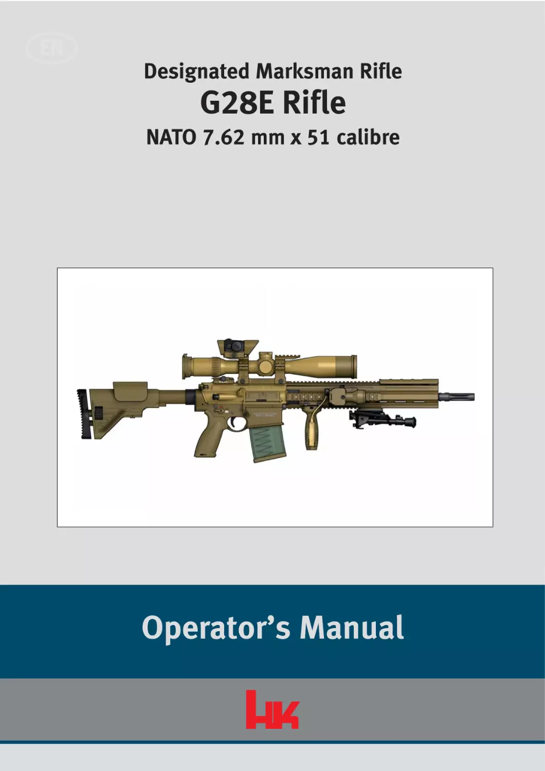
Designated Marksman Rifle
G28E Rifle
NATO 7.62 mm x 51 calibre
Operator’s Manual
Risk of death from gunshot wounds!
Accidental discharge of weapon may occur when loaded weapon is handled inappropriately.
> Do not use the weapon until you have read and understood this manual completely.
> Follow the safety instructions when handling the weapon.
> Carry out a safety check before working on the weapon.
Refer to the protection notice under ISO 16016!
Note the total of fired rounds in the Weapon firing log!
Functional elements - left side view
The illustrations on the front and back fold-out pages show the functional elements of the
weapon from the left and right sides. The text refers frequently to these illustrations.
Opening the fold-out pages while reading will make it easier to understand the text.
1 2
3
4
19
Fig. Ia:
1
2
3
4
5
6
7
8
9
10
I
18
17
16
56
15 14
13
7
12
8
11
9
10
G28E, left side view
Flash hider
Barrel
Picatinny-rail cover, short
3-20 x 50 telescopic sight
Red-dot sight Micro T1
Telescopic sight mount
Quick-release rear sight
Charging handle
Cheek rest, adjustable
Buttstock cap, concave
11
12
13
14
15
16
17
18
19
Safety lever, ambidextrous
Trigger
Bolt catch/release
Eye for carrying sling
Forward grip (with recess for LLM keypad)
Picatinny-rail
Picatinny-rail cover, long
Bipod
Gas nozzle, adjustable
Functional elements - right side view
The illustrations on the front and back fold-out pages show the functional elements of the
weapon from the left and right sides. The text refers frequently to these illustrations.
Opening the fold-out pages while reading will make it easier to understand the text.
1
2
3
4
5
6
10
7
8
9
10a
10b
17 16
Fig. IIa:
1
2
3
4
5
6
7
8
9
15 14
13 12 11
G28E, right side view
Eye for carrying sling
Buttstock, adjustable
Forward assist
Cartridge case deflector
Ejection port cover
Locking screws for handguard
LLM (laser light module)
Handguard
LLM keypad
10
10a
10b
11
12
13
14
15
16
17
Magazine
Magazine lips
Follower
Locking pin, front
Magazine catch
Trigger guard
Pistol grip
Locking pin, rear
Release lever for buttstock
Extension wheel
II
Table of contents
Table of contents
Part I
Description
1
Using this manual/Scope . . . . . . . . . . . . . . . . . . . . . . . . . . . . . . . . . . . .3
1.1
Purpose of this manual . . . . . . . . . . . . . . . . . . . . . . . . . . . . . . . . . . . . . .3
1.2
Target audience for this manual . . . . . . . . . . . . . . . . . . . . . . . . . . . . . . .3
1.3
Warnings, notes and information . . . . . . . . . . . . . . . . . . . . . . . . . . . . . .3
2
Fundamental safety instructions . . . . . . . . . . . . . . . . . . . . . . . . . . . . . .7
2.1
The operator’s manual as an integral component of the safety concept . . .7
2.2
Safety instructions for handling the weapon . . . . . . . . . . . . . . . . . . . .7
2.3
Safety instructions for firing . . . . . . . . . . . . . . . . . . . . . . . . . . . . . . . . . .9
2.4
Exclusion of liability and warranty . . . . . . . . . . . . . . . . . . . . . . . . . . . . .9
3
Description of the weapon . . . . . . . . . . . . . . . . . . . . . . . . . . . . . . . . . .10
3.1
Designation . . . . . . . . . . . . . . . . . . . . . . . . . . . . . . . . . . . . . . . . . . . . . .10
3.2
Approved ammunition . . . . . . . . . . . . . . . . . . . . . . . . . . . . . . . . . . . . .10
3.3
Intended use . . . . . . . . . . . . . . . . . . . . . . . . . . . . . . . . . . . . . . . . . . . . .11
3.4
Illustration . . . . . . . . . . . . . . . . . . . . . . . . . . . . . . . . . . . . . . . . . . . . . . .12
3.5
Scope of the system . . . . . . . . . . . . . . . . . . . . . . . . . . . . . . . . . . . . . . .12
3.6
Assembly groups and accessories . . . . . . . . . . . . . . . . . . . . . . . . . . . .15
4
Technical description . . . . . . . . . . . . . . . . . . . . . . . . . . . . . . . . . . . . . .17
4.1
Safety features . . . . . . . . . . . . . . . . . . . . . . . . . . . . . . . . . . . . . . . . . . .17
4.2
Cutaway view . . . . . . . . . . . . . . . . . . . . . . . . . . . . . . . . . . . . . . . . . . . . .18
4.3
Functional elements . . . . . . . . . . . . . . . . . . . . . . . . . . . . . . . . . . . . . . .20
4.4
Sequence of functions for firing . . . . . . . . . . . . . . . . . . . . . . . . . . . . . .21
5
Cleaning kit and auxiliary materials . . . . . . . . . . . . . . . . . . . . . . . . . .23
5.1
NATO 7.62 x 51 mm cal. G28E cleaning kit . . . . . . . . . . . . . . . . . . . . .23
5.2
Auxiliary materials . . . . . . . . . . . . . . . . . . . . . . . . . . . . . . . . . . . . . . . .24
i
Table of contents
Part II Handling
ii
6
Checks . . . . . . . . . . . . . . . . . . . . . . . . . . . . . . . . . . . . . . . . . . . . . . . . . .27
6.1
Carrying out a safety check . . . . . . . . . . . . . . . . . . . . . . . . . . . . . . . . .27
6.2
Carrying out a function check . . . . . . . . . . . . . . . . . . . . . . . . . . . . . . . .28
7
Preparations . . . . . . . . . . . . . . . . . . . . . . . . . . . . . . . . . . . . . . . . . . . . .29
7.1
Adjusting the buttstock . . . . . . . . . . . . . . . . . . . . . . . . . . . . . . . . . . . .29
7.2
Using the carrying sling . . . . . . . . . . . . . . . . . . . . . . . . . . . . . . . . . . . .33
7.3
Fitting the telescopic sight protective case on the weapon . . . . . . . .35
7.4
Carrying the weapon with the telescopic sight protective case . . . .36
7.5
Using the weapon with a silencer . . . . . . . . . . . . . . . . . . . . . . . . . . . .37
7.6
Filling the magazine . . . . . . . . . . . . . . . . . . . . . . . . . . . . . . . . . . . . . . .39
7.7
Preparing the weapon for firing . . . . . . . . . . . . . . . . . . . . . . . . . . . . . .41
7.8
Additional preparations in unusual climatic conditions . . . . . . . . . .42
8
Operation . . . . . . . . . . . . . . . . . . . . . . . . . . . . . . . . . . . . . . . . . . . . . . . .43
8.1
Inserting the magazine . . . . . . . . . . . . . . . . . . . . . . . . . . . . . . . . . . . . .43
8.2
Chambering a round . . . . . . . . . . . . . . . . . . . . . . . . . . . . . . . . . . . . . . .43
8.3
Chambering a round silently . . . . . . . . . . . . . . . . . . . . . . . . . . . . . . . .43
8.4
Chambering a round with one hand . . . . . . . . . . . . . . . . . . . . . . . . . .44
8.5
Firing position and aiming . . . . . . . . . . . . . . . . . . . . . . . . . . . . . . . . . .45
8.6
Adjusting the mechanical sights . . . . . . . . . . . . . . . . . . . . . . . . . . . . .50
8.7
Firing . . . . . . . . . . . . . . . . . . . . . . . . . . . . . . . . . . . . . . . . . . . . . . . . . . .51
8.8
Removing the magazine . . . . . . . . . . . . . . . . . . . . . . . . . . . . . . . . . . . .52
8.9
Reloading the weapon . . . . . . . . . . . . . . . . . . . . . . . . . . . . . . . . . . . . .53
8.10
Unloading the weapon . . . . . . . . . . . . . . . . . . . . . . . . . . . . . . . . . . . . .53
8.11
Empty the magazine . . . . . . . . . . . . . . . . . . . . . . . . . . . . . . . . . . . . . . .54
Table of contents
9
Cleaning . . . . . . . . . . . . . . . . . . . . . . . . . . . . . . . . . . . . . . . . . . . . . . . . .55
9.1
General instructions for cleaning . . . . . . . . . . . . . . . . . . . . . . . . . . . . .55
9.2
Disassembling the weapon . . . . . . . . . . . . . . . . . . . . . . . . . . . . . . . . .55
9.3
Cleaning the weapon . . . . . . . . . . . . . . . . . . . . . . . . . . . . . . . . . . . . . .61
9.4
Assembling the weapon . . . . . . . . . . . . . . . . . . . . . . . . . . . . . . . . . . . .65
10
Faults: Causes and remedies . . . . . . . . . . . . . . . . . . . . . . . . . . . . . . . .71
11
Protection, packaging and storage . . . . . . . . . . . . . . . . . . . . . . . . . . .75
11.1
Protecting the weapon . . . . . . . . . . . . . . . . . . . . . . . . . . . . . . . . . . . . .75
11.2
Packaging the weapon . . . . . . . . . . . . . . . . . . . . . . . . . . . . . . . . . . . . .76
11.3
Storing the weapon . . . . . . . . . . . . . . . . . . . . . . . . . . . . . . . . . . . . . . . .76
12
Transport and shipping . . . . . . . . . . . . . . . . . . . . . . . . . . . . . . . . . . . .77
12.1
Preparing the weapon for transport . . . . . . . . . . . . . . . . . . . . . . . . . . .77
12.2
Transporting the weapon . . . . . . . . . . . . . . . . . . . . . . . . . . . . . . . . . . .77
12.3
Shipping the weapon . . . . . . . . . . . . . . . . . . . . . . . . . . . . . . . . . . . . . .77
13
Destruction and disposal . . . . . . . . . . . . . . . . . . . . . . . . . . . . . . . . . . .78
13.1
Destroying the weapon . . . . . . . . . . . . . . . . . . . . . . . . . . . . . . . . . . . .78
13.2
Disposing of the weapon . . . . . . . . . . . . . . . . . . . . . . . . . . . . . . . . . . .78
Part III 3-20 x 50 telescopic sight and Micro T-1 red-dot sight
14
Description of 3-20 x 50 telescopic sight . . . . . . . . . . . . . . . . . . . . . .82
14.1
Safety instructions for handling the telescopic sight . . . . . . . . . . . . .82
14.2
Technical data . . . . . . . . . . . . . . . . . . . . . . . . . . . . . . . . . . . . . . . . . . . .83
14.3
Accessories / Scope of delivery . . . . . . . . . . . . . . . . . . . . . . . . . . . . . .84
14.4
Functional elements of the 3-20 x 50 telescopic sight . . . . . . . . . . .84
15
Handling the 3-20 x 50 telescopic sight . . . . . . . . . . . . . . . . . . . . . . .85
15.1
Adjusting the telescopic sight . . . . . . . . . . . . . . . . . . . . . . . . . . . . . . .85
15.2
Maintenance and care of the telescopic sight . . . . . . . . . . . . . . . . . .91
15.3
Temperatures . . . . . . . . . . . . . . . . . . . . . . . . . . . . . . . . . . . . . . . . . . . . .92
iii
Table of contents
iv
16
Description of the Micro-T1 red-dot sight . . . . . . . . . . . . . . . . . . . . .93
16.1
Safety instructions for handling the Micro T-1 red-dot sight . . . . . . .93
16.2
Technical data . . . . . . . . . . . . . . . . . . . . . . . . . . . . . . . . . . . . . . . . . . . .94
17
Handling the Micro-T1 red-dot sight . . . . . . . . . . . . . . . . . . . . . . . . . .95
17.1
Adjusting the Aimpoint Micro T-1 red-dot sight . . . . . . . . . . . . . . . . .95
17.2
Maintenance and care of the Micro T-1 red-dot sight . . . . . . . . . . . .97
17.3
Temperatures . . . . . . . . . . . . . . . . . . . . . . . . . . . . . . . . . . . . . . . . . . . .98
17.4
Fitting the Micro T1 red-dot sight . . . . . . . . . . . . . . . . . . . . . . . . . . . . .98
17.5
Changing the position of the lens hood of the Micro T-1 red-dot sight . . .99
Part I
Description
1
1.1
Using this manual/Scope
Purpose of this manual
1
Using this manual/Scope
1.1
Purpose of this manual
The first part of this manual (“Description”) describes the design and functioning, the second
part (“Handling”) the handling of the G28E weapon, and the third part (“3-20 x 50 telescopic
sight and Micro-1 red-dot sight”) the description and handling of the 3- 20 x 50 telescopic
sight and Micro T-1 red-dot sight.
1.2
Target audience for this manual
This manual is intended for soldiers, police, security forces, and other persons who are
authorised to use this weapon. This manual does not assume extensive technical or
weapons-specific knowledge.
1.3
Warnings, notes and information
To ensure the greatest possible safety during handling, important information and technical
notes are specially highlighted.
Part I: Description
3
1
1.3
1.3.1
Using this manual/Scope
Warnings, notes and information
Warnings and warning levels
Warnings are depicted as follows (example):
Risk of death from gunshot wounds!
Accidental discharge of weapon may occur when loaded weapon is handled inappropriately.
> Do not use the weapon until you have read and understood this manual completely.
> Follow the safety instructions when handling the weapon.
> Carry out a safety check before working on the weapon.
The following colours and signal words are used in the warnings to indicate various danger
levels:
Colour / signal word
Meaning
Direct, imminent danger!
Non-compliance will lead to death or extremely serious injury.
Possible imminent danger!
Non-compliance could lead to death or serious injury.
Dangerous situation!
Non-compliance could lead to minor injuries.
Non-compliance could lead to material damage.
4
Part I: Description
1
1.3
1.3.2
Using this manual/Scope
Warnings, notes and information
Symbols used
Symbol
Meaning
Supplementary information on the weapon, on practical handling
of the weapon or on using this manual.
1.3.3
1.
Call to perform an action in a sequence of actions:
Here you have to do something!
>
Stand-alone step or call to perform an action in a warning:
Here you have to do something!
>>
The sequence of actions is not complete, and is continued on the
next page: Please turn the page!
•
Bullet point
Conventions for illustrations
The detail of illustrations and drawings may vary from your particular weapon.
The information “right”, “left”, “front” and “rear” applies to the position of the weapon as
seen in the direction of fire.
Part I: Description
5
1
1.3
Using this manual/Scope
Warnings, notes and information
Illustrations and their constituent elements
support the descriptions in this manual, and
are identified as follows:
C
2
• The name of an illustration comprises
the current page number and a consecutive lower-case letter starting again from
“a” on each page, e.g. 6a.
B
A
• Calls to perform an action are indicated
by upper-case letters enclosed in circles.
• Components relevant to the action are
highlighted in blue. Where necessary the
components are marked with numbers
and identified in a legend.
1
Fig. 6a:
1
2
Example of an illustration
Charging handle
Bolt catch/release
• Motions are indicated by orange-coloured arrows.
1.3.4
Conventions for cross references
Cross references represent relationships between the text and an illustration or an specific
section. Cross references are in italics and enclosed in (brackets).
• Example of a cross reference between text and illustration: (6a-1)
The cross reference refers to numeral 1 in the illustration numbered 6a on page 6, the
charging handle.
The text frequently refers to the front and back fold-out pages, which are identified by the
Roman numerals I (front) and II (back).
• Example of a cross reference between sections: (Section 1.3.3)
The cross reference refers to Section 1.3.3, conventions for illustrations.
6
Part I: Description
2
2.1
2
Fundamental safety instructions
The operator’s manual as an integral component of the safety concept
Fundamental safety instructions
The weapon has been designed and manufactured according to recognised safety rules.
Nevertheless, use of the weapon may result in injury or death of the user and third parties,
or damage to the weapon and other material property.
2.1
>
Follow all of the instructions in this operator’s manual. Non-compliance may result in
injury or death.
>
Do not handle the weapon if you are tired, feel unwell, or have consumed alcohol, drugs
or medicines.
>
Follow the applicable regulations for the handling of weapons.
The operator’s manual as an integral component of the safety concept
The operator’s manual is an integral component of the weapon.
2.2
>
Do not use the weapon until you have read and understood this operator’s manual completely.
>
Keep the operator’s manual for the entire service life of the weapon.
>
If you receive any supplements or amendments, be sure to add them to the operator’s
manual.
>
Pass the operator’s manual on to any subsequent operator or owner.
>
Do not entrust the weapon to anyone who has not read and understood this operator’s
manual completely.
Safety instructions for handling the weapon
>
Special care must be taken when handling firearms, because the position and direction
of the weapon can be changed very easily.
>
Use the weapon and ammunition only if they are in perfect technical condition.
Part I: Description
7
2
2.2
8
Fundamental safety instructions
Safety instructions for handling the weapon
>
Treat the weapon as if there were a round in the chamber and the safety released until
you have carried out a safety check.
>
Make sure that the weapon is always unloaded when it is handled for purposes other
than loading or firing.
>
Use the weapon only for its intended purpose. Do not use the weapon as a club, hammer, pry bar, etc. Using the weapon for other than its intended purpose may result in
accidental discharge of weapon or damage to the weapon.
>
Do not play with the weapon.
>
Never point the weapon at people when handling or practising with it.
>
Do not touch the trigger when loading, unloading, aiming or handling the weapon in any
other way. Always place your trigger finger on the outside of the trigger guard.
>
Do not use excessive force when handling, disassembling, cleaning and assembling the
weapon.
>
Avoid dry firing of the hammer. Dry firing of the hammer can lead to premature wear.
>
Store weapon and ammunition separately. Be sure to prevent access to the weapon and
ammunition by unauthorised persons, especially children.
>
Never give or take the weapon unless it is unloaded and the bolt group is in the open
position.
>
Do not entrust the weapon to anyone who is not entitled to possess the weapon. Observe
applicable regulations.
>
Immediately rectify any faults that compromise safety.
>
Exposure to exceptional stresses such as when the weapon is banged or dropped can
have a negative effect on safety. After excessive stresses, have the weapon inspected by
the manufacturer or trained firearms personnel.
>
Do not rely on safety features. Safety features are no substitute for careful, correct handling of the weapon.
>
When using accessories and ammunition, follow the instructions provided by their
respective manufacturers.
>
When not in use, keep the weapon in the transport case to avoid damage to the weapon
and telescopic sight/red-dot sight.
>
Where the operational situation allows, protect the telescopic sight/red-dot sight with
the telescopic sight protective case.
Part I: Description
2
2.3
2.3
2.4
Fundamental safety instructions
Safety instructions for firing
Safety instructions for firing
>
Wear hearing protection when firing.
>
Wear safety goggles when firing.
>
Keep your hands out of the path of the bolt group when firing.
>
Keep the muzzle area clear when firing.
>
During training do not fire at doors, panes of glass, walls, concrete, stone, or smooth surfaces (including water) and, where the situation allows, avoid this also during operations. A bullet can penetrate these objects or be deflected in an unsafe direction.
>
Pull the trigger only if the weapon is pointing at the target and the area behind the target
is not endangered.
>
Use only properly loaded, undamaged DM111 A1 cartridges (NATO interchangeability
designation AB22) of the NATO 7.62 mm x 51 calibre.
>
Wear protective gloves when touching the barrel, flash hider or silencer after firing. The
barrel, flash hider and silencer heat up during firing.
Exclusion of liability and warranty
Heckler & Koch GmbH accepts no liability and provides no warranty for incidents arising from:
• non-compliance with this manual,
• incorrect handling of the weapon,
• negligence,
• improper use,
• modifications, attachments to or conversion of the weapon without the express written
consent of Heckler & Koch GmbH, or
• use of accessories or spare parts from other manufacturers without the express written
consent of Heckler & Koch GmbH.
Part I: Description
9
3
3.1
3
Description of the weapon
Designation
Description of the weapon
The G28E rifle (NATO 7.62 mm x 51 calibre) is a gas-operated weapon with a rotating bolt
head. The transparent polymer magazine (IIa-10) holds 10 or 20 cartridges.
3.1
Designation
Designated Marksman Rifle G28E
3.2
Approved ammunition
The ammunition approved for use is DM111 A1 full metal jacket soft core cartridges (NATO
interchangeability designation: AB22) of NATO 7.62 mm x 51 calibre.
The use of tracer ammunition (DM21 A2, NATO interchangeability designation AB24) reduces
the service life of the barrel and hence the weapon’s accuracy considerably swifter than is the
case with use of other ammunition types. The use of tracer ammunition - other than in combat - is therefore permissible only under specific orders and only for trajectory or wind observation during training. After use of tracer ammunition, the barrel is to be cleaned with particular care under the supervision of those in command.
10
Part I: Description
3
3.3
3.3
Description of the weapon
Intended use
Intended use
The G28E rifle is a small-arms weapon for use against chest-high targets with high first-round
hit probability out to a range of 600 m, and for delivering precision suppressive fire against
human targets out to 800 m.
Part I: Description
11
3
3.4
3.4
Description of the weapon
Illustration
Illustration
Fig. 12a:
3.5
G28E Rifle
Scope of the system
The scope of system shows a custom variant. Please contact Heckler & Koch for more information on accessories.
Fig. 12b:
12
Weapon transport case
Part I: Description
3
3.5
Item
1
2
3
4
5
6
7
8
9
10
11
12
13
14
15
16
17
18
19
20
21
22
23
24
25
26
27
28
29
30
31
32
33
Description of the weapon
Scope of the system
Weapon transport case
HLR15 laser rangefinder
12 cm trigger cable
60 cm trigger cable
Magazine case for 20-cartridge magazine
Magazine, 20 cartridges
G28E rifle, compl.
Bipod
Adapter for bipod
Quick-release sight (diopter)
Forward grip
Eye for carrying sling, front
G28E sights, compl., comprising:
Telescopic sight, compl., comprising:
3-20 x 50 telescopic sight
Mount for telescopic sight, compl.
Red-dot sight Micro T1
LMT-225 sights, compl. (BWB-supplied LMT)
comprising:
LLM laser light module, compl.
17 cm trigger cable
LLM mounting point, compl.
G28E telescopic sight protective case
G28E carrying sling, compl.
CR2032 battery
CR123A battery
List of contents for G28E weapon transport case
Personal case
7.62 x 51 mm cal. G28 cleaning kit
Set of Picatinny-rail covers, compl.
G28E muzzle cap
Torque wrench 2 - 25 Nm
SW11 insert for torque wrench
G28E operator’s manual (EN)
G28E weapon firing log (EN)
G28E instruction charts (EN)
Magazine case for 10-cartridge magazine
Magazine, 10 cartridges
Charging handle with right-hand pawl
G28E tactical carrying sling
Cartridge case collector
G28E weapon transport case
Part I: Description
Quantity
1
1
1
3
8
1
1
1
1
1
1
1
1
1
1
1
1
1
1
1
6
2
1
1
1
1
3
1
1
1
1
1
2
2
1
1
1
1
13
3
3.5
Description of the weapon
Scope of the system
Fig. 14a:
Item
1
2
3
4
5
14
Accessories transport case
G28E accessories transport case
G28E accessories transport case
JT LMT 225 return shipment set, incompl.
Merlin LR night sight adapter, compl.
CNDV-T3 Insight thermal imaging adapter, compl.
List of contents for G28E accessories transport case
Part I: Description
Quantity
1
1
1
1
1
3
3.6
Description of the weapon
Assembly groups and accessories
3.6
Assembly groups and accessories
3.6.1
Assembly groups
1
2
3
4
Fig. 15a:
5
Assembly groups
1 Upper receiver, compl.
2 Charging handle, compl.
3 Bolt group, compl.
4 Handguard, compl.
5 Lower receiver, compl.
Part I: Description
15
3
3.6
3.6.2
Description of the weapon
Assembly groups and accessories
Accessories
2
1
4
3
5
7
6
8
Fig. 16a:
9
11
12
Accessories
1 Objective lens port cover
2 Killflash filter
3 3-20 x 50 telescopic sight with telescopic
sight mount
4 Micro T1 red-dot sight
5 Ocular port cover
6 Quick-release sight
16
10
7
8
9
10
Picatinny-rail covers
Laser light module (LLM 01)
Bipod
Forward grip (with recess for LLM keypad)
11 Eye for carrying sling, front
12 Magazine
Part I: Description
4
4.1
Technical description
Safety features
4
Technical description
4.1
Safety features
4.1.1
Safety lever
The safety lever (Ia-11) prevents discharge
of the weapon through accidental pulling of
the trigger (Ia-12). In the “Safe” position the
safety roller blocks the trigger. Only when
the safety lever is clicked to the “Single fire”
position will the safety roller release the trigger.
4.1.2
Fig. 17a:
“Safe” position
Fig. 17b:
“Single fire” position
Firing pin safety
The firing pin safety (18a-7) prevents accidental operation of the firing pin (18a-8), for
example if the weapon is dropped. The firing
pin safety blocks the firing pin and prevents
the firing pin from striking the cartridge
primer. Only when the trigger (Ia-12) is pulled does the hammer (18a-11) release the
firing pin safety, just before the hammer strikes the firing pin.
Part I: Description
17
Cutaway view
Fig. 18a:
18
Cutaway view
18
Technical description
Cutaway view
4.2
4
4.2
1
2
16
4
7
15 14
5 6
Part I: Description
17
3
13 12 11
8
9
10
19
1
2
3
4
5
6
7
8
9
Technical description
Cutaway view
Gas piston
Rod
Chamber
Bolt head
Control bolt
Bolt group
Firing pin safety
Firing pin
Buffer
4
4.2
10
11
12
13
14
15
16
17
18
Part I: Description
Recoil spring
Hammer
Disconnector
Trigger
Sear notch on sear release rocker
Bolt catch/release
Barrel extension
Ejector
Gas bore
4
4.3
4.3
Technical description
Functional elements
Functional elements
The safety lever (Ia-11) is used to make the weapon safe and to enable the single-fire function. The safety lever is ambidextrous.
The magazine catch (IIa-12) allows quick changing of magazines.
The handguard (IIa-8) is fastened to the barrel nut with two locking screws (IIa-6). The handguard is not attached to the barrel (Ia-2), this helps ensure the accuracy of the weapon. The
handguard is equipped with Picatinny-rails at the 6, 9 and 12 o’clock positions. The
Picatinny-rails not required are protected with removable covers (Ia-3, Ia-17).
The Picatinny-rails (Ia-16) can be used to attach various mechanical and optical sights, laser
light modules, the bipod (Ia-18) and the forward grip (Ia-15).
The adjustable buttstock (IIa-2) can be locked in four positions over an adjustment travel of
67 mm.
The adjustable buttstock cap can be extended with the extension wheel (IIa-17) by a continuously variable amount up to 42 mm. The integrated cheek rest (Ia-9) can be adjusted over a
continuous height adjustment travel of 15 mm.
The charging handle (Ia-8) is used to open the bolt group (18a-6) and to chamber a round or
unload the weapon.
The forward assist (IIa-3) is used to chamber a round silently and to lock the bolt group manually in case of fouling.
The pistol grip (IIa-14) has a recess for storing the multi-purpose tool.
The ejection port cover (IIa-5) prevents foreign bodies from entering the chamber and the
path of the bolt group. Movement of the bolt group automatically opens the ejection port
cover to allow cartridge case ejection.
Where a silencer is used, the adjustable gas nozzle (Ia-19) must be turned to the “S” position.
20
Part I: Description
4
4.4
4.4
Technical description
Sequence of functions for firing
Sequence of functions for firing
Initial state: The weapon has a magazine inserted (Section 8.1)
The bolt group (18a-6) is pulled all the way back manually by means of the charging handle
(Ia-8). This causes the bolt group (18a-6) to cock the hammer (18a-11). The sear notch on the
sear release rocker (18a-14) holds the hammer in the cocked position.
When the charging handle is released, the bolt group snaps forwards again, driven by the
force of the recoil spring (18a-10). The bolt head (18a-4) pushes a cartridge from the magazine (IIa-10) into the chamber (18a-3). The extractor engages the cartridge on the cartridge
rim. As the bolt group continues to move forwards, the control bolt (18a-5), driven by the control cam, rotates and locks the bolt head in the barrel extension (18a-16).
There is now a round in the chamber.
4.4.1
Sequence of functions in the “Single fire” position
Initial state: The weapon has a round in the chamber (Section 8.2)
Pulling the trigger (Ia-12) releases the cocked hammer (18a-11). Just before the hammer strikes the firing pin (18a-8), the hammer releases the firing pin safety (18a-7). The firing pin strikes the cartridge primer. The cartridge is fired. The bullet moves down the barrel (Ia-2).
After the bullet passes the gas bore (18a-18), the gas pressure from the barrel acts on the gas
piston (18a-1). The gas piston acts on the rod (18a-2), which initiates the recoil of the bolt
group (18a-6). As the bolt group recoils, the control bolt (18a-5), driven by the control cam,
rotates and unlocks the bolt head (18a-4) from the barrel extension (18a-16). As the bolt
group continues to recoil, the extractor extracts the cartridge case from the chamber (18a-3).
As soon as the cartridge case reaches the ejection port, the two spring-loaded ejectors
(18a- 17) eject the cartridge case to the right and the rear. The cartridge case strikes the cartridge case deflector (IIa-4) and is deflected to the right and away from the shooter.
Part I: Description
21
4
4.4
4.4.2
Technical description
Sequence of functions for firing
Sequence of functions when the magazine is empty
The firing cycle can be repeated until the bolt group (18a-6) has fed the last cartridge from
the magazine (IIa-10). When this happens the follower (IIa-10b) of the magazine pushes the
bolt catch/release (18a-15) upwards. After the last round is fired, the bolt catch/release
holds the bolt group in the open position as the bolt group moves forwards.
When the bolt catch/release is pushed, the bolt group snaps forwards, driven by the force of
the recoil spring (18a-10). If a filled magazine was inserted prior to this action, the weapon
now has a round in the chamber.
22
Part I: Description
5
5.1
Cleaning kit and auxiliary materials
NATO 7.62 x 51 mm cal. G28 cleaning kit
5
Cleaning kit and auxiliary materials
5.1
NATO 7.62 x 51 mm cal. G28 cleaning kit
The cleaning kit can be ordered from Heckler & Koch using the HK-Ident.-No. shown.
3
2
1
4
13
5
6
14
12
7
8
9
11
10
15
Fig. 23a:
1
2
3
4
5
6
7
8
NATO 7.62 x 51 mm cal. G28 cleaning kit (HK-Ident.-No. 236 605)
Case for cleaning kit
Oil brushes
Barrel cleaning brushes
Chamber cleaning brushes
Oil paintbrush
Cleaning rods
Pull-through holder
Cleaning rod with rotatable handle
9
10
11
12
13
14
15
Part I: Description
Cleaning rod guide
Cleaning pull-throughs
Cleaning hose
Cleaning brush
Cleaning brush, brass
Cleaning cloth
Oil bottle
23
5
5.2
5.2
Cleaning kit and auxiliary materials
Auxiliary materials
Auxiliary materials
Auxiliary materials are obtainable via the supply chain.
Required auxiliary materials are listed at the beginning of each section.
The following auxiliary materials are required in this manual:
• Grease
• Low-temperature oil (MIL-L-14107), e.g. O-157
• Oil (MIL-L-63460), e.g. S-761
• Oil paper
• Cleaning cloth
• Cleaning pull-throughs (NATO Stock Number 7920-12-131-7354)
• Telescopic sight lens cleaning cloth (NATO Stock Number 6640-12-124-6982)
• Telescopic sight cleaning paintbrush (NATO Stock Number 7920-12-120-0355)
24
Part I: Description
Part II
Handling
6
6.1
Checks
Carrying out a safety check
6
Checks
6.1
Carrying out a safety check
Successful completion of a safety check verifies that there is no ammunition in the weapon.
The safety check is especially important when accepting a weapon and when you are unsure whether or not a weapon is loaded.
1.
Remove magazine (Section 8.8).
2.
Pull charging handle all the way back and hold it (27a-A).
3.
Push bolt catch/release and hold it (27a-B).
Risk of injury when the bolt group moves forwards quickly!
The bolt group snaps forwards when the bolt catch/release is pushed.
> Do not reach into the path of the bolt group.
4.
Push charging handle (Ia-8) all the way
forwards and lock it.
5.
Look into the chamber. There must not
be any cartridge in the chamber
(27 a- C). If there is a cartridge in the
chamber, then a fault is present
(Section 10).
6.
Push bolt catch/release. The bolt group
(18a-6) snaps forwards.
7.
Click safety lever (Ia-11) to the “Single
fire” position.
8.
Pull trigger (Ia-12). The hammer
(18a- 11) is released.
9.
Click safety lever to “Safe” position.
C
B
A
Fig. 27a:
Part II: Handling
Carrying out a safety check
27
6
6.2
6.2
Checks
Carrying out a function check
Carrying out a function check
Successful completion of a function check verifies that the weapon is functional. The function check is especially important after assembly of the weapon and after rectification of
faults.
1.
Carry out safety check (Section 6.1).
2.
Remove magazine (Section 8.8).
3.
Move charging handle (Ia-8) backwards and forwards all the way several times.
4.
Let charging handle snap forwards.
5.
Click safety lever (Ia-11) to “Safe” position.
6.
Pull trigger (Ia-12). The hammer (18a-11) is not released.
7.
Click safety lever to the “Single fire” position.
8.
Pull trigger and hold it. The hammer is released.
9.
Move charging handle backwards and forwards all the way several times.
10. Release trigger. The disconnector (18a-12) releases the hammer.
11. Pull trigger. The hammer is released.
12. Insert empty magazine (IIa-10) into the weapon until the magazine catch (IIa-12) engages.
13. Verify that the magazine is firmly seated.
14. Pull charging handle all the way back. The bolt group (18a-6) is held in the open position by the bolt catch/release (Ia-13).
Risk of injury when the bolt group moves forwards quickly!
The bolt group snaps forwards when the bolt catch/release is pushed.
> Do not reach into the path of the bolt group.
15. Push charging handle all the way forwards and lock it.
16. Push bolt catch/release. The bolt group snaps forwards.
17. Remove magazine.
18. Pull trigger. The hammer is released.
19. Click safety lever to “Safe” position.
28
Part II: Handling
7
7.1
7
Preparations
Adjusting the buttstock
Preparations
2
3
4
5
1
Fig. 29a:
1
2
3
7.1
Multi-purpose tool
3 mm Allen key
Tool, jaw-size 11 mm
Disassembly tool
4
5
Torx key 10
4 mm Allen key
Adjusting the buttstock
Required auxiliary materials:
• Multi-purpose tool
The buttstock can be locked in four positions.
1.
Rotate cover of pistol grip 90° anticlockwise.
2.
Remove cover.
3.
Remove multi-purpose tool (29a) from
the pistol grip. >>
A
Fig. 29b:
Part II: Handling
Inserting the Allen key in the
threaded pin
29
7
7.1
Preparations
Adjusting the buttstock
4.
Insert 4 mm Allen key (29a-5) in threaded pin.
5.
Loosen threaded pin by turning anti-clockwise using 4 mm Allen key.
6.
Press release lever for buttstock (IIa-16) and hold it.
7.
Slide buttstock (IIa-2) to desired position.
8.
Release the release lever for buttstock.
9.
Slide buttstock until it locks in desired position.
10. Tighten threaded pin by turning clockwise (29b-A).
The buttstock is fixed and can no longer be moved.
11. Stow multi-purpose tool in pistol grip.
12. Insert cover into pistol grip.
13. Rotate cover 90° clockwise.
The extension wheel (IIa-17) is used to make fine adjustments of the buttstock cap (Ia-10).
14. Turn extension wheel clockwise to
extend buttstock cap (30a-A).
15. Turn extension wheel anti-clockwise to
reduce buttstock cap (30a-A).
A
Fig. 30a:
30
Part II: Handling
Turning the extension wheel
7
7.1
7.1.1
Preparations
Adjusting the buttstock
Adjusting the height of the cheek rest
Required auxiliary materials:
• Multi-purpose tool
1.
Rotate cover of pistol grip 90° anticlockwise.
2.
Remove cover of pistol grip.
3.
Take out multi-purpose tool (29a).
4.
Insert 3 mm Allen key (29a-1) in screw.
5.
Loosen both screws by turning anticlockwise using 3 mm Allen key (31a-A).
6.
Slide cheek rest to desired position
(31a-B).
7.
Tighten screws by turning clockwise
using 3 mm Allen key.
8.
Stow multi-purpose tool in pistol grip.
9.
Insert cover into pistol grip.
B
A
Fig. 31a:
Sliding the cheek rest to the
desired position
10. Rotate cover 90° clockwise.
Part II: Handling
31
7
7.1
7.1.2
Preparations
Adjusting the buttstock
Removing the cheek rest
Required auxiliary materials:
• Multi-purpose tool
1.
Rotate cover of pistol grip 90° anticlockwise.
2.
Remove cover of pistol grip.
3.
Take out multi-purpose tool (29a).
4.
Insert 3 mm Allen key (29a-1) in screw.
5.
Loosen screws by turning anti-clockwise using 3 mm Allen key (32a-A).
6.
Remove screws.
7.
Remove cheek rest (32a-B).
8.
Stow multi-purpose tool in pistol grip.
9.
Insert cover into pistol grip.
B
A
Fig. 32a:
10. Rotate cover 90° clockwise.
32
Part II: Handling
Removing the cheek rest
7
7.2
Preparations
Using the carrying sling
7.2
Using the carrying sling
7.2.1
Mounting the carrying sling on the weapon
2
The carrying sling can be attached to the
plate or the buttstock.
1.
Thread front loop of carrying sling
(33 a-1) into front eye for carrying sling
(33a-2).
2.
Thread rear loop of carrying sling
(33 b- 2) into rear eye for carrying sling
(33 b- 1) or plate (33 c-1).
Fig. 33a:
1
2
2
Fig. 33b:
1
2
1
Attaching the carrying sling
Loop, front
Eye for carrying sling, front
2
1
Attaching the carrying sling
Eye for carrying sling, rear
Loop, rear
Fig. 33c:
1
2
Part II: Handling
1
Attaching the carrying sling
Plate
Loop, rear
33
7
7.2
7.2.2
Preparations
Using the carrying sling
Carrying method
Right-handed shooters wear the carrying
sling over the right shoulder. Left-handed
shooters wear the carrying sling over the
left shoulder.
1.
Pull carrying sling over head and shoulder (34a).
2.
Adjust length of carrying sling with front
buckle (34b-2) and rear buckle (34b-4).
Fig. 34a:
1
Fig. 34b:
1
2
3
34
2
Pulling the carrying sling over
head and shoulder
3
4
Carrying sling
Loop, front
Buckle, front
Magazine pouch for 20-cartridge
magazine, detachable
4
5
Part II: Handling
Buckle, rear
Loop, rear
5
7
7.3
7.3
Preparations
Fitting the telescopic sight protective case on the weapon
Fitting the telescopic sight protective case on the weapon
1.
Place telescopic sight protective case
(35a-1) over the 3-20 x 50 telescopic
sight.
2.
Thread rear retaining loop (35a-3)
behind pistol grip (IIa-14).
3.
Thread front retaining loop (35a-2)
behind forward grip (Ia-15).
1
2
Fig. 35a:
1
2
3
Fitting the telescopic sight
protective case
Telescopic sight protective case
Retaining loop, front
Retaining loop, rear
Fig. 35b:
Part II: Handling
3
Position of the telescopic sight
protective case
35
7
7.4
7.4
Preparations
Carrying the weapon with the telescopic sight protective case
Carrying the weapon with the telescopic sight protective case
>
Fit the telescopic sight protective case
on the weapon (Section 7.3).
Fig. 36a:
36
Part II: Handling
Carrying the weapon with the
telescopic sight protective case
7
7.5
7.5
Preparations
Using the weapon with a silencer
Using the weapon with a silencer
Firing with a silencer places greater stress on the weapon and thus contributes to faster
wear and heavier fouling. If the weapon is used with a silencer, the weapon must be cleaned
and lubricated more heavily at intervals of 500 rounds.
An incorrectly adjusted gas nozzle (Ia-19) can compromise the functional reliability of the
weapon.
Replace the silencer with a new one after 2000 fired rounds.
Risk of injury from hot silencer!
The silencer heats up during firing.
> Let silencer cool off for at least 15 minutes after firing.
Required auxiliary materials:
• Multi-purpose tool
1.
Rotate cover of pistol grip 90° anticlockwise.
2.
Remove cover of pistol grip.
3.
Take out multi-purpose tool (29a).
4.
Insert 4 mm Allen key (29a-5) into
gas nozzle (Ia-19).
5.
Click the adjustable gas nozzle to
position “S” (silencer) with 4 mm
Allen key (38b).
6.
Stow multi-purpose tool in pistol grip.
7.
Insert cover into pistol grip.
8.
Rotate cover 90° clockwise. >>
Fig. 37a:
Part II: Handling
Rotating the adjustable gas
nozzle
37
38
7
7.5
Preparations
Using the weapon with a silencer
8.
Fit silencer. See Operator’s manual
on silencers for further information.
9.
After removal of silencer, return
adjustable gas nozzle to position “N”
(normal) with 4 mm Allen key (38a).
Fig. 38a:
Gas nozzle at position “N”
Fig. 38b:
Gas nozzle at position “S”
Part II: Handling
7
7.6
7.6
Preparations
Filling the magazine
Filling the magazine
Danger of material damage due to damaged or fouled cartridges!
Damaged or fouled cartridges can damage the weapon and cause malfunctions.
> Do not use damaged or fouled cartridges.
Danger of material damage from an overfilled magazine!
An overfilled magazine can lead to malfunctions.
> Do not fill the magazine with more than the number of cartridges indicated on the
magazine.
Danger of material damage from keeping a magazine filled for long periods!
Keeping a magazine filled for long periods can result in damage to the magazine
spring and cause malfunctions.
> Empty the magazine before you place the weapon in storage (Section 8.11).
1.
Take hold of magazine (IIa-10).
2.
Push cartridge under the magazine lips (IIa-10a) (40a-A). >>
Part II: Handling
39
7
7.6
Preparations
Filling the magazine
Danger of material damage from tracer ammunition!
Firing of tracer ammunition (DM21 A2, NATO interchangeability designation: AB24) is
permitted only in combat, since combustion residue from the tracer charge in the
round damages the barrel and decreases accuracy.
> Use tracer ammunition (DM21 A2, NATO interchangeability designation: AB24) only in
operational emergency situations.
3.
4.
Push cartridge to the rear as far as it will
go (40a-B).
A
Repeat steps 2. - 3. until the magazine
is full.
B
Fig. 40a:
40
Part II: Handling
Filling the magazine
7
7.7
7.7
Preparations
Preparing the weapon for firing
Preparing the weapon for firing
Required auxiliary materials:
• Cleaning pull-throughs
1.
Disassemble the weapon (Section 9.2).
2.
Screw together cleaning rod with rotatable handle (23a-8), two cleaning rods (23a-6)
and pull-through holder (23a-7).
3.
Place at least three clean cleaning pull-throughs (23a-10) in pull-through holder.
During cleaning do not rest the weapon on the red-dot sight or telescopic sight.
4.
Push locking pin of cleaning rod guide (62a-1) in all the way to the left.
5.
Insert cleaning rod guide (23a-9) from the rear all the way into the upper receiver
(62a- A).
6.
Push locking pin of cleaning rod guide in all the way to the right (62a-B).
7.
Pull clean cleaning pull-throughs from the rear through the barrel (Ia-2) several times
until the barrel is free of oil and foreign bodies.
8.
Remove cleaning rod guide from upper receiver.
9.
Visually check weapon for damage.
10. Assemble weapon (Section 9.4).
11. Carry out function check (Section 6.2).
12. Open ocular port cover (16a-5) and objective lens port cover (16a-1).
13. Click opened ocular and objective lens port covers into place on 3-20 x 50 telescopic
sight.
Part II: Handling
41
7
7.8
7.8
Preparations
Additional preparations in unusual climatic conditions
Additional preparations in unusual climatic conditions
High air humidity and ambient temperatures between -35 °C and +40 °C do not require any
special measures.
In cold conditions, freezing condensation can compromise the functional reliability of the
weapon. To prevent the formation of condensation, do not bring the weapon from cold conditions into warm conditions and shortly thereafter again into cold conditions.
Required auxiliary materials:
• Oil
• Low-temperature oil
42
>
When there are high concentrations of dust or temperatures above +40 °C, lubricate the
lubrication points of the bolt group (64a) and the lubrication points of the functional elements (64b) more heavily.
>
At temperatures below -35 °C, lubricate all moving parts of the weapon with low-temperature oil.
Part II: Handling
8
8.1
Operation
Inserting the magazine
8
Operation
8.1
Inserting the magazine
8.2
1.
Fill magazine (Section 7.6).
2.
Click safety lever (Ia-11) to the “Safe” position.
3.
Hold filled magazine (IIa-10) by the base and insert into weapon until magazine catch
(IIa-12) clicks into place.
Chambering a round
Risk of injury from accidental discharge of weapon!
A weapon with a round in the chamber is always a potential source of danger.
> Load the weapon only immediately before firing.
> Unload the weapon immediately after firing (Section 8.10).
8.3
1.
Insert magazine into weapon (Section 8.1).
2.
Pull charging handle (Ia-8) all the way back.
3.
Let charging handle snap forwards. The weapon now has a round in the chamber and is
set to “Safe”.
Chambering a round silently
Risk of injury from accidental discharge of weapon!
A weapon with a round in the chamber is always a potential source of danger.
> Load the weapon only immediately before firing.
> Unload the weapon immediately after firing (Section 8.10).
1.
Insert magazine into weapon (Section 8.1).
2.
Pull charging handle (Ia-8) all the way back and hold it.
3.
Move charging handle slowly forwards.
4.
Press forward assist (IIa-3) with thumb or heel of hand and close bolt group (18a-6) fully
until it snaps audibly and tangibly into place.
Part II: Handling
43
8
8.4
8.4
Operation
Chambering a round with one hand
Chambering a round with one hand
If an arm or hand is wounded in combat, chambering a round with one hand is permissible.
Risk of injury from accidental discharge of weapon!
A weapon with a round in the chamber is always a potential source of danger.
> Load the weapon only immediately before firing.
> Unload the weapon immediately after firing (Section 8.10).
Initial state: After the last round is fired the magazine is empty. The follower pushes the bolt
catch/release upwards. Bolt group is held in rear position.
1.
Insert magazine (Section 8.1).
2.
Hold weapon by the handguard (IIa-8).
Risk of injury when the bolt group moves forwards quickly!
The bolt group snaps forwards when the bolt catch/release is pushed.
> Do not reach into the path of the bolt group.
Risk of death from gunshot wounds!
Accidental discharge of weapon may occur when loaded weapon is handled inappropriately.
> Follow the safety instructions when handling the weapon.
> Do not point the muzzle under any circumstances at yourself or comrades.
3.
44
Ram weapon buttstock (IIa-2) into the ground until bolt group (18a-6) closes and locks.
The weapon now has a round in the chamber and is set to “Safe”.
Part II: Handling
8
8.5
8.5
Operation
Firing position and aiming
Firing position and aiming
The supported shoulder firing position is the most stable and provides the best probability
of hitting. Where possible, provide also rear support for the weapon, e.g. with a sandbag.
Risk of injury from recoil!
The weapon’s recoil can cause serious injury.
> When firing, pull the weapon firmly into your shoulder.
> When firing keep your eye at least 9 cm away (45a-A) from the 3-20 x 50 telescopic
sight.
> Keep your hands out of the path of the bolt group when firing.
8.5.1
Firing position
>
Rest weapon on the handguard (IIa-8) or bipod (Ia-18).
>
Do not rest weapon on the barrel (Ia-2) or magazine (IIa-10).
A
Fig. 45a:
Firing position
Part II: Handling
45
8
8.5
8.5.2
Operation
Firing position and aiming
Firing position with telescopic sight protective case
1.
Open both front couplings (46a-1) of
telescopic sight protective case.
2.
Remove front cover for telescopic sight
protective case (46a-2).
3.
Open both rear couplings (46a-3) of
telescopic sight protective case.
4.
Remove rear cover for telescopic sight
protective case (46a-4).
>
>
1
2
Rest weapon on the handguard (IIa-8)
or bipod (Ia-18).
Fig. 46a:
Do not rest weapon on the barrel (Ia-2)
or magazine (IIa-10).
1
2
3
4
46
Part II: Handling
3
4
Telescopic sight protective case
Coupling, front
Cover for telescopic sight protective
case, front
Coupling, rear
Cover for telescopic sight protective
case, rear
8
8.5
8.5.3
Operation
Firing position and aiming
Aiming with 3-20 x 50 telescopic sight
• Correct aiming
Point of impact centred
ü
• Aiming errors
Shooting left
Shooting right
W
Shooting high
W
Shooting low
W
Shooting low and left
W
Shooting low and right
W
W
Part II: Handling
47
8
8.5
8.5.4
Operation
Firing position and aiming
Aiming with Micro T1 red-dot sight
• Correct aiming
Point of impact centred
ü
48
Part II: Handling
8
8.5
8.5.5
Operation
Firing position and aiming
Aiming with mechanical dioptre sight
• Correct aiming
Point of impact centred
ü
• Aiming errors
Shooting left
Shooting right
W
Shooting high
W
Shooting low
W
Shooting low and left
W
Shooting low and right
W
W
Part II: Handling
49
8
8.6
8.6
Operation
Adjusting the mechanical sights
Adjusting the mechanical sights
The position of point of impact also depends on the ammunition. Use of different types of
ammunition can change the elevation and windage of the position of point of impact. The
sights can be adjusted to correct for the changed position of point of impact.
Position of point of
impact
Corrective measures
Information
1. Raise diopter (50a-A).
Turning the diopter by
a half turn changes
the position of point
of impact by approx.
4 cm at a range of
100 m.
2. Turn diopter in direction “D” (Down)
(50 a-B).
1. Raise diopter (50a-A).
2. Turn diopter in direction “U” (Up)
(50 a- B).
1. Press safety button for windage adjustment screw (50b-A).
Turning the windage
adjustment screw by
2. Turn windage adjustment screw in direc- a quarter-turn
changes the position
tion “L” (Left) (50b-B).
of point of impact by
1. Press safety button for windage adjust- approx. 3 cm at a
ment screw (50b-A).
range of 100 m.
2. Turn windage adjustment screw in direction “R” (Right) (50b-B).
A
B
A
B
Fig. 50a:
50
Turning the diopter
Fig. 50b:
Part II: Handling
Turning the windage adjustment screw
8
8.7
8.7
Operation
Firing
Firing
Follow safety instructions for firing (Section 2.3).
1.
Prepare weapon for firing (Section 7.7).
2.
Chamber a round (Section 8.2).
3.
Point weapon at target.
4.
Click safety lever (Ia-11) to the “Single fire” position.
Risk of injury from recoil!
The weapon’s recoil can cause serious injury.
> When firing, pull the weapon firmly into your shoulder.
> When firing keep your eye at least 9 cm away (45a-A) from the 3- 20 x 50 telescopic
sight.
> Keep your hands out of the path of the bolt group when firing.
5.
Take aim (Section 8.5.3, Section 8.5.4 and Section 8.5.5).
6.
Pull trigger (Ia-12). A cartridge is fired.
7.
After firing, or to reload, click safety lever to the “Safe” position.
Note the total of fired rounds in the Weapon firing log!
Part II: Handling
51
8
8.8
8.8
Operation
Removing the magazine
Removing the magazine
1.
Click safety lever (Ia-11) to the “Safe” position.
Danger of material damage from dropping the magazine!
Dropping the magazine can damage the magazine lips (IIa-10a) and cause malfunctions.
> Remove the magazine by hand.
> Avoid impacts on the magazine lips.
In combat, for rapid change of magazine, the empty magazine may be allowed to fall to the
ground.
2.
Take hold of magazine (IIa-10).
3.
Press magazine catch (52a-A).
4.
Remove magazine (52a-B).
A
B
Fig. 52a:
52
Removing the magazine
Part II: Handling
8
8.9
8.9
Operation
Reloading the weapon
Reloading the weapon
Risk of injury from accidental discharge of weapon!
A weapon with a round in the chamber is always a potential source of danger.
> Chamber a round only immediately before firing.
> Unload the weapon immediately after firing (Section 8.10).
After the last cartridge in the magazine is fired, the bolt catch/release locks the bolt group
in the open position.
8.10
1.
Remove magazine (Section 8.8).
2.
Insert magazine into weapon (Section 8.1).
3.
Push bolt catch/release (Ia-13). The bolt group (18a-6) snaps forwards.
4.
Click safety lever to “Safe” position. The weapon now has a round in the chamber and is
set to “Safe”.
Unloading the weapon
1.
Remove magazine (Section 8.8).
2.
Pull charging handle (Ia-8) all the way back and hold it. A cartridge is ejected.
3.
Press bolt catch/release (Ia-13) and hold it. >>
Part II: Handling
53
8
Operation
8.10 Unloading the weapon
4.
Push charging handle all the way forwards and lock it.
Risk of injury when the bolt group moves forwards quickly!
The bolt group snaps forwards when the bolt catch/release is pushed.
> Do not reach into the path of the bolt group.
8.11
5.
Look into the chamber (18a-3). There must not be any cartridge in the chamber. If there
is a cartridge in the chamber, then a fault is present (Section 10).
6.
Push bolt catch/release. The bolt group (18a-6) snaps forwards.
7.
Click safety lever (Ia-11) to the “Single fire” position.
8.
Pull trigger (Ia-12). The hammer (18a-11) is released.
9.
Click safety lever to the “Safe” position.
Empty the magazine
Risk of injury from igniting the cartridges!
Impacts to the primer can ignite the cartridge.
> Slide the cartridges into your hand as you empty the magazine.
> Prevent any impacts to the primer.
> Prevent cartridges from falling.
>
54
Slide cartridges forwards out of the magazine (IIa-10).
Part II: Handling
9
9.1
Cleaning
General instructions for cleaning
9
Cleaning
9.1
General instructions for cleaning
Regular cleaning and care of the weapon and accessories
•
•
•
•
maintain functional reliability and accuracy,
increase service life,
prevent accidents, and
save repair costs and time.
>
Clean weapon each time it is fired and at intervals of 1000 rounds.
>
Clean weapon each time it is fired with a silencer and at intervals of 500 rounds.
Risk of material damage from the use of excessive force!
The use of excessive force during disassembly, cleaning and assembly can damage the
weapon.
> Do not use excessive force when disassembling, cleaning and assembling the weapon.
9.2
Disassembling the weapon
Risk of injury from improperly assembled weapon!
Improper assembly can compromise the safety and functioning of the weapon.
> Only disassemble the weapon to the extent described in this manual.
Part II: Handling
55
9
9.2
9.2.1
Cleaning
Disassembling the weapon
Disassembling the 3-20 x 50 telescopic sight
Required auxiliary materials:
• Torque wrench 2 - 25 Nm
• Insert for torque wrench
Except in the case of damage or heavy fouling, the 3-20 x 50 telescopic sight may not
be disassembled. Specifically when the
weapon and barrel are cleaned, the
3- 20 x 50 telescopic sight remains on
the upper receiver.
If the 3-20 x 50 telescopic sight has to be
disassembled, zeroing must be carried out
after it is re-mounted, in order to check the
point of impact.
9.2.2
1.
Insert the insert for torque wrench into
torque wrench.
2.
Loosen locking screws of telescopic
sight mount by turning anti-clockwise with torque wrench (56a).
3.
Remove 3-20 x 50 telescopic sight (Ia-4) from upper receiver.
Fig. 56a:
Disassembling the 3-20 x 50
telescopic sight
Disassembling the “Merlin LR” night sight adapter
Required auxiliary materials:
• Torque wrench 2 - 25 Nm
• Insert for torque wrench
56
1.
Insert the insert for torque wrench into torque wrench.
2.
Loosen locking screws of mount for “Merlin LR” night sight adapter by turning anti-clockwise with torque wrench.
3.
Remove “Merlin LR” night sight adapter from handguard.
Part II: Handling
9
9.2
9.2.3
Cleaning
Disassembling the weapon
Disassembling the “CNDV-T3” thermal imaging adapter
Required auxiliary materials:
• Torque wrench 2 - 25 Nm
• Insert for torque wrench
9.2.4
1.
Insert the insert for torque wrench into torque wrench.
2.
Loosen locking screws of mount for “CNDV-T3” thermal imaging adapter by turning anticlockwise with torque wrench.
3.
Remove “CNDV-T3” thermal imaging adapter from handguard.
Disassembling the weapon into assembly groups
Required auxiliary materials:
• Multi-purpose tool
• Torque wrench 2 - 25 Nm
• Insert for torque wrench
1.
Carry out safety check (Section 6.1).
2.
Rotate cover of pistol grip 90° anticlockwise.
3.
Remove cover of pistol grip.
4.
Take out multi-purpose tool (29a).
5.
Insert cover into pistol grip.
6.
Rotate cover 90° clockwise.
7.
Insert disassembly tool (29a-3) in the rear locking pin (IIa-15).
8.
Using disassembly tool, press rear locking pin in (57a) and at the same time pull it out
to the right as far as disassembly position.
9.
Fold lower receiver downwards.
Fig. 57a:
Pressing in the rear locking pin
with disassembly tool
10. Press front locking pin (IIa-11) in to the right and pull it out as far as disassembly position.
11. Remove lower receiver.
12. Rotate cover of pistol grip 90° anti-clockwise. >>
Part II: Handling
57
9
9.2
Cleaning
Disassembling the weapon
13. Remove cover of pistol grip.
14. Stow multi-purpose tool in pistol grip.
15. Insert cover into pistol grip.
16. Rotate cover 90° clockwise.
17. Press buffer (18a-9) into extension and hold it.
18. Press in locking pin for recoil spring and hold it (58a).
19. Pull buffer and recoil spring (18a-10) forwards out of the buttstock.
20. Pull charging handle (Ia-8) back.
21. Remove bolt group (18a-6) from upper receiver.
22. Remove charging handle from upper receiver.
23. Insert the insert for torque wrench into torque wrench.
24. Loosen locking screws for handguard anti-clockwise with torque wrench (58b).
25. Pull locking screws for handguard (IIa-6) to the right as far as disassembly position.
26. Pull handguard (IIa-8) forwards off barrel (Ia-2).
Fig. 58a:
58
Pushing in locking pin for recoil
spring
Fig. 58b:
Part II: Handling
Loosening locking screws for
handguard
9
9.2
9.2.5
Cleaning
Disassembling the weapon
Disassembling parts of the gas drive
3
9.2.6
1.
Disassemble the weapon into assembly
groups (Section 9.2.4).
2.
Pull rod (59a-3) to rear and hold it.
3.
Pull rod upwards and forwards out of
upper receiver (59a).
4.
Remove gas piston (59a-2) from gas
block (59a-1).
Fig. 59a:
1
2
3
2
1
Removing the rod
Gas block
Gas piston
Rod
Disassembling parts of the gas drive
To make it easier to disassemble the gas
nozzle when there is heavy fouling, oil
must be applied to the gas nozzle.
1.
Disassembling parts of the gas drive
(Section 9.2.5).
2.
Push leaf spring down and hold it
(59 b- A).
3.
Turn gas nozzle clockwise as far as it
will go (59b-B).
4.
Remove gas nozzle (59b-C).
1
C
B
2
Fig. 59b:
1
2
Part II: Handling
A
Push leaf spring down
Gas nozzle
Leaf spring
59
9
9.2
9.2.7
Cleaning
Disassembling the weapon
Disassembling the bolt group
1
2 3 4
1.
Disassemble the weapon into assembly
groups (Section 9.2.4).
2.
Push locking pin (60a-7) into bolt head
carrier (60a-3) from the right.
3.
Pull locking pin out of the bolt head carrier to the left as far as will go.
4.
Lift firing pin safety (60a-4).
Fig. 60a:
5.
Take firing pin (60a-6) and pressure
spring for firing pin (60a-5) to the rear
and out of the bolt head carrier.
6.
Pull control bolt (60a-2) out of bolt head
(60a-1).
7.
Pull bolt head out of bolt head carrier.
1
2
3
4
5
6
7
8.
Rotate cover of pistol grip anti-clockwise.
9.
Remove cover.
5
6
7
Components of the bolt group
Bolt head
Control bolt
Bolt head carrier
Firing pin safety
Pressure spring for firing pin
Firing pin
Locking pin
10. Take multi-purpose tool (29a) out of pistol grip.
If the ejectors cannot be pushed into the bolt head, send weapon in for repair.
11. Using 4 mm Allen key (29a-5), check that ejector (18a-17) is functioning. For this, push
ejector into bolt head (18a-4).
12. Stow multi-purpose tool in pistol grip.
13. Insert cover into pistol grip.
14. Rotate cover of pistol grip clockwise.
60
Part II: Handling
9
9.3
9.3
Cleaning
Cleaning the weapon
Cleaning the weapon
Required auxiliary materials:
• Oil
• Cleaning pull-throughs
Note the total of fired rounds in the Weapon firing log!
Clean the barrel from the chamber to the muzzle. The flash hider (Ia-1) must be screwed
firmly onto the barrel to prevent damage to the muzzle. Always match the number of
cleaning pull-throughs to the 7.62 mm calibre. Keep enough cleaning pull-throughs (minimum of three) ready before cleaning.
Risk of material damage from incorrect cleaning agents and care products!
Incorrect cleaning agents and care products can damage the weapon.
> When cleaning the weapon, use the specific cleaning agents.
> Do not use any metallic objects, plastics (nylon, etc.) or chemical cleaning agents
(benzine, tetrachlorethylene, trichlor, etc.) and any fuel (kerosene, paraffin, diesel,
etc.) to clean the weapon.
> Use of pull-through cleaning chains, steel rods or steel brushes for barrel cleaning is
prohibited.
> Do not clean the weapon in an ultrasonic bath.
1.
Disassemble the weapon (Section 9.2).
2.
Visually check the weapon for damage.
3.
Clean fouled parts and surfaces using cleaning cloth (23a-14).
4.
Lubricate cleaned metal parts thinly.
5.
Screw together cleaning rod with rotatable handle (23a-8), two cleaning rods (23a-6)
and chamber cleaning brush (23a-4).
6.
Clean chamber (18a-3) with chamber cleaning brush in and against the direction of fire.
7.
Add three further cleaning rods to chamber cleaning brush.
8.
Insert cleaning rod with rotatable handle from the rear into cleaning rod guide (23a-9). >>
Part II: Handling
61
9
9.3
9.
Cleaning
Cleaning the weapon
Screw together barrel cleaning brush and cleaning rods.
10. Push locking pin of cleaning rod guide (62a-1) in all the way.
11. Insert cleaning rod guide (23a-9) with cleaning rod with rotatable handle and barrel
cleaning brushes fully into upper receiver from the rear (62a-A).
12. Push locking pin of cleaning rod guide in all the way (62a-B).
Danger of material damage if the barrel cleaning brush is not pulled completely
through the barrel!
Not pulling the barrel cleaning brush completely through the barrel can damage the
inside of the barrel and decrease accuracy.
> Pull the barrel cleaning brush completely through the barrel from the chamber end.
This allows the bristles of the barrel cleaning brush to straighten out again. Pull the
barrel cleaning brush out of the chamber to the rear in line with the barrel bore axis.
Danger of material damage from incorrect cleaning direction!
It is forbidden to clean the barrel from the muzzle end of the weapon. This damages the
barrel and decreases accuracy.
> Clean the barrel only from the chamber end and with the cleaning rod guide inserted.
During cleaning do not rest the weapon on the red-dot sight or telescopic sight.
13. Push lubricated barrel cleaning brush at
least 20 times completely through barrel (Ia-2) from the rear.
14. Push in locking pin of the cleaning rod
guide (62a-1) and pull it out as far as it
will go.
B
1
15. Remove cleaning rod guide with
cleaning rod with rotatable handle from
upper receiver. >>
A
Fig. 62a:
1
62
Part II: Handling
Pushing in locking pin of
cleaning rod guide
Locking pin of cleaning rod guide
9
9.3
Cleaning
Cleaning the weapon
16. Replace barrel cleaning brush with pullthrough holder (23a-7).
17. Insert clean cleaning pull-throughs in
pull-through holder.
18. Insert cleaning rod guide with cleaning
rod with rotatable handle and pullthrough holder with clean cleaning pullthroughs fully into upper receiver from
the rear.
19. Push locking pin of cleaning rod guide
in all the way.
Fig. 63a:
Cleaning inside extension
20. Pull clean cleaning pull-throughs through the barrel several times until the barrel is free
of oil and foreign bodies.
21. Replace pull-through holder with oil brush (23a-2).
22. Pull lubricated oil brush through barrel.
23. Pull out locking pin of the cleaning rod guide as far as it will go.
24. Remove cleaning rod guide from upper receiver.
25. Clean magazine (IIa-10) and follower (IIa-10b) with cleaning cloth.
26. Screw together chamber cleaning brush with cleaning rod with rotatable handle and two
cleaning rods.
27. Wrap chamber cleaning brush in lubricated cleaning cloth.
28. Clean inside extension with lubricated cleaning cloth (63a). >>
Part II: Handling
63
9
9.3
Cleaning
Cleaning the weapon
29. Clean bolt head (64a-1) with brass cleaning brush (23a-13).
30. Clean inside gas block (59a-1) with barrel cleaning brush.
31. Clean inside gas nozzle (59b-1) with barrel cleaning brush.
32. Lubricate the gas nozzle thinly.
33. Lubricate the lubrication points of bolt group (64a).
34. Lubricate the lubrication points of functional elements (64b).
35. Assemble weapon (Section 9.4).
1
1
2
2
3
3
4
4
5
Fig. 64a:
1
2
3
4
5
64
Lubrication points of the bolt
group
Bolt head
Control bolt
Pressure spring for firing pin
Firing pin
Operating surfaces of the bolt group
Fig. 64b:
1
2
3
4
Part II: Handling
Lubrication points of the
functional elements
Gas piston
Buffer
Recoil spring
Barrel extension
9
9.4
Cleaning
Assembling the weapon
9.4
Assembling the weapon
9.4.1
Assembling the bolt group
1.
Insert bolt head in bolt head carrier
(65 a).
2.
Insert control bolt (65a-1) into bolt
head carrier (65a-2) with bore in the
longitudinal direction.
3.
Push pressure spring for firing pin
(60a- 5) onto firing pin (60a-6).
4.
Press firing pin and pressure spring for
firing pin from the rear into bolt head
carrier as far as they will go and hold
them (65b-A).
5.
Press locking pin completely into bolt
head carrier (65b-B).
1
3 2
4
Fig. 65a:
1
2
3
4
Inserting the control bolt
Control bolt
Bolt head
Extractor
Bolt head carrier
A
B
Fig. 65b:
Part II: Handling
A
Pressing in the locking pin
65
9
9.4
9.4.2
Cleaning
Assembling the weapon
Assembling the gas nozzle
1
9.4.3
1.
Push leaf spring down and hold it
(66 a- A).
2.
Place gas nozzle against gas block
(66 a-B).
C
2
A
3.
Turn gas nozzle anti-clockwise as far as
it will go (66a-C).
4.
Release leaf spring (66a-2). Leaf spring
snaps into gas nozzle.
Fig. 66a:
5.
Click gas nozzle to position “N” (38a), if
weapon is being used without silencer.
1
2
6.
Click gas nozzle to position “S” (38b), if weapon is being used with silencer.
Inserting gas nozzle into the
gas block
Gas nozzle
Leaf spring
Inserting the rod and gas piston
1.
Insert gas piston (66b-2) into gas block
(66 b-1).
2.
Insert rod into upper receiver in assembly position (66b).
3.
Press rod (66b-3) against spring force
towards the rear and insert in gas piston.
3
Fig. 66b:
1
2
3
66
B
Part II: Handling
2 1
Inserting the rod
Gas block
Gas piston
Rod
9
9.4
9.4.4
Cleaning
Assembling the weapon
Assembling the assembly groups
Required auxiliary materials:
• Torque wrench 2 - 25 Nm
• Insert for torque wrench
1.
Assemble bolt group (Section 9.4.1).
2.
Assemble gas nozzle (Section 9.4.2).
3.
Insert
rod
and
(Section 9.4.3).
4.
Push handguard (IIa-8) onto the barrel (Ia-2) from the front as far as it will go.
5.
Insert the insert for torque wrench into torque wrench.
6.
Set torque wrench to 8 Nm.
7.
Press in locking screws for handguard and tighten them with the torque wrench until the
torque is reached (67a).
gas
piston
Fig. 67a:
Tightening locking screws for
handguard
The bolt group can only be inserted into the weapon if the bolt head is in the forward position. Otherwise the control bolt blocks the bolt group from being inserted into the upper
receiver.
8.
Insert charging handle (Ia-8) into opening in upper receiver and push it forwards about
5 cm.
9.
Pull bolt head (60a-1) forwards out of the bolt head carrier (60a-3) as far as it will go. >>
Part II: Handling
67
9
9.4
Cleaning
Assembling the weapon
10. Engage guide cam of bolt group in guide
groove of charging handle (68a).
3
2
11. Push bolt group (68a-2) all the way forwards until charging handle locks.
12. Insert buffer (18a-9) into recoil spring
(18a- 10).
1
13. Insert buffer with recoil spring into buttstock (IIa-2).
14. Push buffer behind locking pin for
recoil spring.
15. Using front locking pin (IIa-11), insert
lower receiver into front bore for locking
pin of upper receiver at an angle of
about 45°.
Fig. 68a:
1
2
3
Inserting bolt group into
charging handle
Guide cam of the bolt group
Bolt group
Guide groove of the charging handle
16. Push front locking pin in all the way to
the left.
17. Swing upper receiver down onto lower
receiver as far as it will go (68b).
18. Rotate cover of pistol grip 90° anticlockwise.
19. Remove cover of pistol grip.
20. Take out multi-purpose tool (29a).
Fig. 68b:
21. Insert cover into pistol grip.
22. Rotate cover 90° clockwise. >>
68
Part II: Handling
Assembling lower receiver and
upper receiver
9
9.4
Cleaning
Assembling the weapon
Risk of material damage from the use of excessive force!
Use of excessive force while fitting the locking pins can damage the weapon.
> Do not use excessive force when assembling the weapon.
> Use the multi-purpose tool when fitting the rear locking pin.
23. Insert disassembly tool (29a-3) in the rear locking pin (IIa-15) and hold it.
24. Push rear locking pin in all the way to the left.
25. Remove cover of pistol grip.
26. Stow multi-purpose tool in pistol grip.
27. Insert cover into pistol grip.
28. Rotate cover 90° clockwise.
29. Carry out function check (Section 6.2).
9.4.5
Disassembling the 3-20 x 50 telescopic sight
Required auxiliary materials:
• Torque wrench 2 - 25 Nm
• Insert for torque wrench
1.
Insert the insert for torque wrench into
torque wrench.
2.
Set torque wrench to 8 Nm.
3.
Place 3-20 x 50 telescopic sight on the
upper receiver.
4.
Tighten locking screws for telescopic
sight mount with torque wrench until
the torque is reached (69a).
Fig. 69a:
Part II: Handling
Tightening the screws of the
telescopic sight mount with torque wrench
69
9
9.4
9.4.6
Cleaning
Assembling the weapon
Assembling the “CNDV-T3” thermal imaging adapter
Required auxiliary materials:
• Torque wrench 2 - 25 Nm
• Insert for torque wrench
1.
Insert the insert for torque wrench into torque wrench.
2.
Set torque to 12 ± 1 Nm.
3-20 x 50 telescopic sight and the optronics adapters may not be in contact with each other.
9.4.7
3.
Place thermal imaging adapter on handguard.
4.
Tighten locking screws for “CNDV-T3” thermal imaging adapter mount clockwise with torque wrench until torque is reached.
5.
Pull rubber sleeve over 3-20 x 50 telescopic sight so that no light can emerge between
3- 20 x 50 telescopic sight and the optronics.
Assembling the “Merlin LR” night sight adapter
Required auxiliary materials:
• Torque wrench 2 - 25 Nm
• Insert for torque wrench
1.
Insert the insert for torque wrench into torque wrench.
2.
Set torque to 12 ± 1 Nm.
3-20 x 50 telescopic sight and the optronics adapters may not be in contact with each other.
70
3.
Place night sight adapter on handguard.
4.
Tighten locking screws for “Merlin LR” night sight adapter mount clockwise with torque
wrench until torque is reached.
5.
Pull rubber sleeve over 3-20 x 50 telescopic sight so that no light can emerge between
3-20 x 50 telescopic sight and the optronics.
Part II: Handling
10
10
Faults: Causes and remedies
Faults: Causes and remedies
Users are strictly prohibited from troubleshooting that goes beyond the scope of this manual! Only authorised specialists may troubleshoot such faults in the weapon.
Safety risk from not knowing whether or not the weapon is loaded!
In the event of a fault, the weapon may be loaded, even if you expect it to be unloaded.
> In the event of a fault, treat the weapon as if a round is chambered and the safety is
disengaged.
> In the event of a fault, verify whether the weapon is actually loaded.
> Follow the fundamental safety instructions (Section 2) for rectifying faults.
The following points do not constitute a complete list of all the possible faults. Faults/causes
other than those named here are also possible.
Risk of material damage from feed or ejection faults!
Feed or ejection faults cam damage the weapon.
> In the event of feed or ejection faults, verify whether the barrel is free (visual check),
particularly that there is no round in the barrel.
Fault
Cause
Remedy
Bullet is stuck in the Improperly loaded an assembled Send weapon in for repair.
barrel.
ammunition.
Cartridge has not
fired.
Defective ammunition
Wait at least one minute. Unload
weapon (Section 8.10). Do not
re-use cartridges that have failed
to fire.
Firing pin sluggish, damaged or
broken.
Send weapon in for repair.
Hammer defective.
Send weapon in for repair.
Part II: Handling
71
10
Faults: Causes and remedies
Fault
Cause
Remedy
Bolt group does not
open after firing.
Defective ammunition
Unload weapon (Section 8.10).
Clean weapon if necessary
(Section 9.3). Send weapon in
for repair if necessary.
Gas drive fouled or defective.
Clean gas nozzle. Send weapon
in for repair if necessary.
Case rim ripped off.
Unload weapon (Section 8.10).
Send weapon in for repair if
ecessary.
Chamber is fouled.
Clean chamber.
Rearward movement of bolt
group too short.
Unload weapon (Section 8.10).
Carry out function check (Section
6.2). Check setting of gas nozzle. Clean weapon if necessary
(Section 9.3). Send weapon in
for repair if necessary.
Defective ammunition
Use different ammunition.
Extractor, pressure spring for
extractor, ejector or pressure
spring for ejector damaged.
Send weapon in for repair.
Chamber is fouled.
Unload weapon (Section 8.10).
Clean weapon (Section 9.3).
Cartridge deformed.
Use different cartridge.
Recoil spring defective.
Send weapon in for repair.
Cartridge or cartridge case is not ejected.
Cartridge is not loaded into the chamber.
72
Part II: Handling
10
Faults: Causes and remedies
Fault
Cause
Remedy
Cartridge does not
feed.
Magazine not correctly inserted.
Insert magazine correctly.
Magazine spring defective.
Send magazine in for repair.
Magazine or magazine lips
damaged.
Use different magazine.
Rearward movement of bolt
group too short.
Unload weapon (Section 8.10).
Carry out function check
(Section 6.2). Check setting of
gas nozzle. Clean weapon if
necessary (Section 9.3). Send
weapon in for repair if necessary.
Rearward movement of bolt
group too long.
Check setting of gas nozzle.
Bolt group does not Magazine spring defective.
stay in open position Rearward movement of bolt
after last round.
group too short.
Send magazine in for repair.
Rearward movement of bolt
group too long.
Check setting of gas nozzle.
Bolt catch/release damaged.
Send weapon in for repair.
Defective ammunition
Use different ammunition.
Part II: Handling
Unload weapon (Section 8.10).
Carry out function check
(Section 6.2). Check setting of
gas nozzle. Clean weapon if
necessary (Section 9.3). Send
weapon in for repair if necessary.
73
10
74
Faults: Causes and remedies
Fault
Cause
Remedy
Magazine sticks in
magazine well.
Magazine damaged.
Exchange magazine. Send
damaged magazine in for repair.
Magazine catch defective.
Send weapon in for repair.
Weapon fires with a
significantly higher
rate of fire.
Gas piston defective.
Send weapon in for repair.
Windage or elevation of point of
impact changed.
Sights misaligned.
Adjust sights (Section 8.6,
Section 15.1 and Section 17.1).
Other type of ammunition.
Use another type of ammunition
or adjust sights (Section 8.6,
Section 15.1 and Section 17.1).
Sights damaged.
Send weapon in for repair.
Part II: Handling
11
Protection, packaging and storage
11.1 Protecting the weapon
11
Protection, packaging and storage
Protection guards the weapon against external influences and maintains its functional reliability even if it is not used for long periods. If the weapon is expected to be stored for more
than 6 months, the weapon must be protected.
If the weapon is expected to be stored for not more than 6 months, then it is sufficient to
clean the weapon (Section 9.3).
11.1
Protecting the weapon
Required auxiliary materials:
• Grease
• Oil
• Oil paper
1.
Clean weapon (Section 9.3).
2.
Seal both ends of the barrel (Ia-2) with grease.
3.
Wrap weapon in oil paper.
Part II: Handling
75
Protection, packaging and storage
11
11.2 Packaging the weapon
11.2
Packaging the weapon
With the exception of operational scenarios, the weapon is to be stored and transported in
the air-tight and water-tight transport case. The transport case has a pressure valve which
must be open for transport by air, to balance the pressure inside the transport case.
11.3
1.
Unload weapon (Section 8.10).
2.
Empty the magazine (Section 8.11).
3.
Package weapon without ammunition in transport case.
4.
For transport by air, open pressure valve.
Storing the weapon
Store the weapon and ammunition separately.
1.
Follow applicable regulations for the storage of weapons and ammunition.
2.
If the weapon is expected to be stored for more than 6 months, protect the weapon
(Section 11.1).
3.
If the weapon is expected to be stored for not more than 6 months, clean the weapon
(Section 9.3).
4.
Package the weapon (Section 11.2).
5.
Store the weapon in an enclosed, weather resistant room.
Risk of accidents caused by unauthorised persons!
Unauthorised persons who have no experience with weapons can cause accidents.
> Be sure to prevent access to the weapon and ammunition by unauthorised persons,
especially children.
6.
Protect rooms where weapons are stored against break-in and fire.
Whenever the weapon is stored for more than 1 year:
7.
76
Check the grease seal on the barrel and the oil film on the metal parts annually.
Part II: Handling
12
Transport and shipping
12.1 Preparing the weapon for transport
12
Transport and shipping
12.1
Preparing the weapon for transport
1.
Package the weapon (Section 11.2).
2.
Secure the weapon in vehicle.
Risk of material damage from vibrations!
Vibrations during transport can damage the weapon.
> During transport, secure the transport case against slipping and damage from outside influences.
> Avoid impacts and vibration of the weapon.
12.2
Transporting the weapon
Transport weapon and ammunition separately. Where possible, transport the weapon in a
transport case, weapon carrying case, or at least with the telescopic sight protective case in
place.
>
12.3
Follow applicable regulations for the transport of weapons and ammunition.
Shipping the weapon
Ship weapon and ammunition separately. Ship the weapon only in the transport case.
>
Follow applicable regulations for the shipping of weapons and ammunition.
Part II: Handling
77
13
Destruction and disposal
13.1 Destroying the weapon
13
Destruction and disposal
13.1
Destroying the weapon
>
13.2
Disposing of the weapon
>
78
Follow applicable regulations for the destruction of weapons and ammunition.
Follow applicable regulations for the disposal of weapons and ammunition.
Part II: Handling
Part III
3-20 x 50 telescopic sight and Micro T-1
red-dot sight
14
Description of the 3-20 x 50 telescopic sight
14.1 Safety instructions for handling the telescopic sight
14
Description of 3-20 x 50 telescopic sight
The information in this Section is extracted from the telescopic sight operator’s manual of the
manufacturer Schmidt & Bender, adapted in this case to the G28E weapon system. The content may therefore vary from the Schmidt & Bender operator’s manual. Refer additionally to
the Schmidt & Bender operator’s manual.
General information
The telescopic sight is a precision optical instrument. It should be handled with appropriate
care, the greatest possible avoidance of damage and no excessive force. The telescopic sight
must be protected against excessive impact and vibration.
During transport or storage of the weapon without the transport case, the telescopic sight
protective case is to be firmly mounted on the weapon wherever the operational situation
allows.
14.1
82
Safety instructions for handling the telescopic sight
>
Do not attempt to carry out work on the telescopic sight. Repairs may be carried out solely by the manufacturer Schmidt & Bender or authorised specialist firms.
>
To avoid eye injuries, never look without protection through the telescopic sight at the
sun or laser light sources.
>
Protect the telescopic sight from any impact other than that experienced in normal use.
>
Avoid exposing the telescopic sight for an unnecessarily lengthy period to direct sunlight. Intense lengthy sunlight causes high temperatures inside the scope which can
damage the telescopic sight.
>
When firing with the weapon, keep your eye at least 9 cm away from the ocular of the
telescopic sight.
Part III: 3-20 x 50 telescopic sight and Micro T-1 red-dot sight
14
Description of the 3-20 x 50 telescopic sight
14.2 Technical data
14.2
Technical data
14.2.1
General data
14.2.2
• Field of view
-
13 - 2.1 m/100 m
• Exit pupil
-
11.4 - 2.5 mm
• Optimum eye relief
-
90 mm
• Laser protection class
-
L4 (DIN/EN 207)
• Twilight factor
-
10,1 - 31,6
• Transmission
-
90 %
• Ocular adjustment range
-
+2 to -3 dptr
• Parallax compensation
-
25 m -
• Weight
-
920 g
∞
Dimensions of the 3-20 x 50 telescopic sight
Fig. 83a:
Dimensions in mm
Part III: 3-20 x 50 telescopic sight and Micro T-1 red-dot sight
83
14
Description of the 3-20 x 50 telescopic sight
14.3 Accessories / Scope of delivery
14.3
Accessories / Scope of delivery
The accessories form part of the scope of delivery of the G28E.
1 3-20 x 50 telescopic sight with telescopic sight mount
and accessories (comprising Items 1 - 4)
2 Killflash filter
3 Objective lens port cover
4 Ocular port cover
14.4
Functional elements of the 3-20 x 50 telescopic sight
Ocular port cover
Ocular adjustment
Elevation adjustment
Windage adjustment
Magnification control
Brightness control
Rotary swivel for parallax
compensation
Objective lens
Killflash filter
Objective lens port cover
Fig. 84a:
84
Functional elements of the 3-20 x 50 telescopic sight
Part III: 3-20 x 50 telescopic sight and Micro T-1 red-dot sight
15
Handling the 3-20 x 50 telescopic sight
15.1 Adjusting the telescopic sight
15
Handling the 3-20 x 50 telescopic sight
15.1
Adjusting the telescopic sight
15.1.1
Diopter compensation
Eyesight deficiencies can be counterbalanced to some extent with diopter compensation.
Set the telescopic sight to maximum magnification. Rotate the ocular to the left until it
stops and now rotate it to the right until you
can see the reticle with optimum sharpness
of image (85a).
Fig. 85a:
Adjusting the ocular
As eyesight can vary widely over the longer term, regular adjustment of the ocular setting is
to be recommended.
15.1.2
Parallax compensation
Using the adjustment swivel for parallax
compensation, the parallax of the telescopic
sight can be adjusted individually without
the shooter having to interrupt target acquisition.
The adjustment swivel for parallax compensation is marked with target ranges. Where
Index arrow mark
the range to target is known (acquisition by
Fig. 85b: Rotary swivel for parallax comlaser rangefinding), turn the adjustment swipensation
vel for parallax compensation until the desired range to target aligns with the index
arrow mark. If the range to target is not
known, set the maximum magnification. Turn the adjustment swivel for parallax compensation towards the estimated range to target until you see an image of the target with maximum
sharpness.
The parallax is now correctly adjusted. The approximate range to target can be read on the
adjustment swivel for parallax compensation.
Part III: 3-20 x 50 telescopic sight and Micro T-1 red-dot sight
85
15
Handling the 3-20 x 50 telescopic sight
15.1 Adjusting the telescopic sight
15.1.3
Elevation adjustment
The 3-20 x 50 telescopic sight has an elevation adjustment knob with engraved ballistic compensation, aligned with the trajectory of the DM111 A1 full metal jacket soft core
cartridge. This enables the shooter to adjust
the weapon system rapidly to the relevant
range to target between 100 m and 800 m.
In tandem with this, use of a laser rangefinder is recommended.
Index arrow mark
Fig. 86a:
Elevation adjustment
To adjust elevation, turn the elevation
adjustment knob until the engraved range to
target aligns with the index arrow mark.
Shooting low is corrected by turning the elevation adjustment knob clockwise (86a).
Shooting high is corrected by turning the elevation adjustment knob anti-clockwise.
Each click of the elevation adjustment knob changes the reticle in elevation by 0.1¯ (1.0
cm/100 m).
15.1.4
Windage adjustment
Shooting left is corrected by turning the windage adjustment knob clockwise (86b).
Shooting right is corrected by turning the
windage adjustment knob anti-clockwise.
Each click of the windage adjustment knob
changes the reticle in windage by 0.1¯ (1.0
cm/100 m).
Fig. 86b:
86
Windage adjustment
Part III: 3-20 x 50 telescopic sight and Micro T-1 red-dot sight
15
Handling the 3-20 x 50 telescopic sight
15.1 Adjusting the telescopic sight
15.1.5
Using the reticle illumination
The reticle, lit entirely in red, gives support
to the shooter in poor lighting conditions by
showing the reticle clearly against the dark
target.
First, adjust the reticle brightness to the prevailing lighting conditions. For this, turn the
reticle brightness knob from 0 towards 11
until the step is reached where the reticle is
clearly illuminated without dazzling the
pupil of your eye.
Fig. 87a:
Reticle brightness knob
You can switch off the reticle illumination by turning the knob from a step it has clicked into,
to a position between two steps (87a). Power supply is interrupted in such an intermediate
position (standby mode). Just before firing, click the knob into the pre-selected step and the
reticle illumination is switched on with the selected brightness.
Switch off the reticle illumination after using the telescopic sight!
A microchip switches the illumination off automatically after six hours.
15.1.6
Changing the battery
To change the battery, unscrew the cover of
the light unit. Remove the dead battery.
Dispose of the battery in an environmentally
friendly way! When inserting the new battery, ensure that the plus sign on the battery is
showing upwards (87b). Battery changing
must be performed in the dry. The battery is
a commercial off-the-shelf CR 2032 / 3 V
button cell. Operating continuously at the
highest light intensity, the battery supplies
approx. 100 hours of power.
Fig. 87b:
Changing the battery
Part III: 3-20 x 50 telescopic sight and Micro T-1 red-dot sight
87
15
Handling the 3-20 x 50 telescopic sight
15.1 Adjusting the telescopic sight
15.1.7
Description of the reticle
The specially developed G28E telescopic sight reticle offers the shooter numerous ways to
estimate ranges with the aid of coverage measurements. In combination with parallax adjustment (focusing) and ballistic compensation, this enables the shooter even at longer range to
deliver precision fire, especially where a laser rangefinder is used.
The reticle system is in the first focal plane. The coverage measurements therefore remain in
the same ratio even if the 3-20 magnification is altered.
The coverage measurements can be seen in Figs. 89a, 89b and 89c. The values are in mils
( ¯ ) and correspond to 0.1 m/100 m or 1 m/1000 m.
The telescopic sight reticle consists of the centering bars, the mil dots and the lead bars for
range estimation (89a).
The distance between the centering bars equates to 10¯ (1 m/100 m or 10 m/1000 m).
The distance between the mil dots and lead bars for elevation and windage is in each case
1¯ equating to 0.1 m/100 m or 1 m/1000 m. The distance between mil dot and lead bar is
accordingly 0.5¯ = 0.05 m/100 m or 0.5 m at 1000 m.
The lead circles have an external diameter of 0,2¯ (2.0 cm/100 m).
The internal diameter is 0.1¯ (1.0 cm/100 m).
The stadia pattern allow rapid rangefinding for persons, in steps of 200, 400, 600, 800 and
1000 m. Coverage measurements for head, shoulder and torso dimensions enable rangefinding without use of a laser rangefinder.
In practice, the reticle can be used to calculate the range to target, whereby the shooter
measures with the reticle [the range of] a target whose size he knows or reckons.
The ranges calculated in this way can then be used to adjust the parallax and target ballistics.
88
Part III: 3-20 x 50 telescopic sight and Micro T-1 red-dot sight
15
Handling the 3-20 x 50 telescopic sight
15.1 Adjusting the telescopic sight
10¯ = 10 MIL
Centering bars
5¯ = 5 MIL
Lead bars
Height of head with neck (25 cm)
MIL-Dot
Shoulder length (45 cm)
Torso height with head (100 cm)
Stadia pattern
Fig. 89a:
Reticle coverage measurements
Fig. 89b:
Coverage measurements, Detail y
Belt line
1¯ ? 1 MIL = 0.1 m at 100 m or 1 m at 1000 m
Fig. 89c:
Coverage measurements, Detail x
Part III: 3-20 x 50 telescopic sight and Micro T-1 red-dot sight
89
15
Handling the 3-20 x 50 telescopic sight
15.1 Adjusting the telescopic sight
15.1.8
Calibrating the adjustment knobs
If point of impact displacement is detected,
the knob for elevation and/or windage must
be re-calibrated.
For this, the mean point of impact of a shot
group must be established.
The difference between the target point
(aiming point) and the mean point of impact
of the shot group must be corrected by turning the windage adjustment knob and/or
the elevation adjustment knob (Section
15.1.3 and Section 15.1.4).
Fig. 90a:
Calibrating the adjustment
knobs
If the mean point of impact coincides with the target point (aiming point), the windage and
elevation adjustment knobs must be set to this range to target.
For this, the two Allen screws in each of the elevation and windage adjustment knobs must
be loosened with a 2 mm Allen key (90a).
Turn the windage and/or elevation adjustment knob so that the engraved range figure showing the actual range to target is at the index arrow. Re-tighten both Allen screws.
15.1.9
Using the killflash filter
The killflash filter prevents light sources from being reflected in the objective lens and disclosing the shooter’s position. The killflash filter prevents the shooter from being dazzled by
sunlight from an oblique angle.
Note that use of the killflash filter lowers the illumination of the telescopic sight, with potentially negative impact at twilight.
15.1.10
Using the port covers
To guard against external influences and weather conditions such as sand, dirt, rain, snow,
etc, the ocular and objective lens port covers should be closed after each use of the telescopic sight. Before each firing, care should be taken to open the port covers and click them into
place. This prevents them from swinging to and fro in an uncontrolled way during firing.
90
Part III: 3-20 x 50 telescopic sight and Micro T-1 red-dot sight
15
Handling the 3-20 x 50 telescopic sight
15.2 Maintenance and care of the telescopic sight
15.2
Maintenance and care of the telescopic sight
For cleaning the metal parts, use a clean and slightly moistened cleaning cloth.
To clean the lenses, use the accompanying telescopic sight cleaning set. Before being wiped
clean, any heavy dust coating and dirt particles should first be removed with the paintbrush.
Slight fouling can then be removed with the lens cleaning cloth. To help the cleaning process
with the lens cleaning cloth, breathe slightly on the lenses before cleaning.
Heavy fouling can be removed either with the cleaning fluid in the telescopic sight cleaning
set or with lukewarm water in which a small amount of surfactant is dissolved.
Beware! Whatever the circumstances, avoid dry rubbing of the external surfaces of the lenses. This can destroy the lens coatings.
Part III: 3-20 x 50 telescopic sight and Micro T-1 red-dot sight
91
Handling the 3-20 x 50 telescopic sight
15
15.3 Temperatures
15.3
Temperatures
The 3-20 x 50 telescopic sight can be used in temperatures from -25° to +55° C.
The temperature range for storage of the telescopic sight is between -55° and +70° C.
92
Part III: 3-20 x 50 telescopic sight and Micro T-1 red-dot sight
16
Description of the Micro-T1 red-dot sight
16.1 Safety instructions for handling the Micro T-1 red-dot sight
16
Description of the Micro-T1 red-dot sight
The information in this Section is extracted from the operator’s manual of the manufacturer
Aimpoint, adapted in this case to the G28E weapon system. The content may therefore vary
from the Aimpoint operator’s manual.
General information
The Micro T-1 red-dot sight is a passive reflex collimator illuminated-dot sight. When storing
the Micro T-1 red-dot sight, always remove the battery and close the anti-dust port covers.
Close port covers only if the lens surface is dry.
16.1
Safety instructions for handling the Micro T-1 red-dot sight
>
Do not attempt to carry out work on the Micro T-1 red-dot sight. Repairs may be carried
out solely by the manufacturer Aimpoint or authorised specialist firms.
>
Protect the Micro T-1 red-dot sight from any impact other than that experienced in normal use.
>
Avoid exposing the Micro T-1 red-dot sight for an unnecessarily lengthy period to the
direct effects of cold temperatures. The effects of exposure to lengthy cold temperatures
can influence battery life negatively. Also, the rotary switch can ice up, preventing it from
turning normally.
Part III: 3-20 x 50 telescopic sight and Micro T-1 red-dot sight
93
16
Description of the Micro-T1 red-dot sight
16.2 Technical data
16.2
Technical data
16.2.1
General data
94
• Weight
-
105 g
• Open shutter
-
20 mm
• Optical magnification
-
1 x, eye relief unlimited
• Dot size
-
4 MOA (1.2 mrad)≙ 11.6 cm at 100 m
• Optical coating
-
Anti-reflex and bandpass coatings, T-1 is NVD
compatible
• Dot brightness
-
Dot brightness manually adjustable
Part III: 3-20 x 50 telescopic sight and Micro T-1 red-dot sight
17
Handling the Micro-T1 red-dot sight
17.1 Adjusting the Aimpoint Micro T-1 red-dot sight
17
Handling the Micro-T1 red-dot sight
17.1
Adjusting the Aimpoint Micro T-1 red-dot sight
Beware! Do not continue adjusting windage and elevation if you feel a resistance. The elevation adjustment screw is mounted on the top of the red-dot sight. The windage
adjustment screw is mounted on the right-hand side of the red-dot sight.
Position of point of
impact
Corrective measures
Information
1. Turn cover of elevation adjustment
screw anti-clockwise.
Turning the elevation
adjustment screw by
one click changes the
position of point of
impact by approx.
1.3 cm at a target
range of 100 m.
2. Remove cover of elevation adjustment
screw.
3. Insert cover of elevation adjustment
screw into elevation adjustment screw.
4. Turn elevation adjustment screw clockwise.
1. Turn cover of elevation adjustment
screw anti-clockwise.
2. Remove cover of elevation adjustment
screw.
3. Insert cover of elevation adjustment
screw into elevation adjustment screw.
4. Turn elevation adjustment screw anticlockwise.
Part III: 3-20 x 50 telescopic sight and Micro T-1 red-dot sight
95
17
Handling the Micro-T1 red-dot sight
17.1 Adjusting the Aimpoint Micro T-1 red-dot sight
Position of point of
impact
Corrective measures
Information
1. Turn cover of windage adjustment screw
anti-clockwise.
Turning the windage
adjustment screw by
one click changes the
position of point of
impact by approx.
1.3 cm at a target
range of 100 m.
2. Remove cover of windage adjustment
screw.
3. Insert cover of windage adjustment
screw into windage adjustment screw.
4. Turn windage adjustment screw clockwise.
1. Turn cover of windage adjustment screw
anti-clockwise.
2. Remove cover of windage adjustment
screw.
3. Insert cover of windage adjustment
screw into windage adjustment screw.
4. Turn windage adjustment screw anticlockwise.
After correction of the Micro-T1 red-dot sight, zeroing must be carried out to verify the position of point of impact.
Check whether the Micro-T1 red-dot sight is seated firmly on the Picatinny-rail.
Turn rotary switch to “0” (anti-clockwise).
Close the anti-dust port covers.
96
Part III: 3-20 x 50 telescopic sight and Micro T-1 red-dot sight
17
Handling the Micro-T1 red-dot sight
17.1 Adjusting the Aimpoint Micro T-1 red-dot sight
17.1.1
Changing the battery
To change the battery, unscrew the threaded cover anti-clockwise with the tool. Remove the
dead battery. Dispose of the battery in an environmentally friendly way! When positioning the
battery cover, ensure that the O-ring is present on the battery cover and not damaged. When
inserting the new battery, ensure that the plus sign on the battery is showing upwards.
Battery changing must be performed in the dry. Screw in the battery cover fully clockwise with
the tool. The battery is a commercial off-the-shelf CR 2032 / 3 V button cell. Check that the
illuminated red dot appears when the rotary switch is turned clockwise.
17.1.2
Using the anti-dust port covers
To guard against external influences and weather conditions such as sand, dirt, rain, snow,
etc, the anti-dust port covers should be closed after each use of the Micro T-1 red-dot sight.
To prevent the port covers from loss when being removed, they should be removed in a
downward direction. The bungee is then stretched around the Micro T-1 red-dot sight and the
rail. This prevents the port covers from swinging to and fro in an uncontrolled way during
firing.
17.2
Maintenance and care of the Micro T-1 red-dot sight
For cleaning the metal parts, use a clean and slightly moistened cleaning cloth.
Beware! Do not clean the lenses with your fingers under any circumstances. Wipe off the lenses with a special lens paper/cloth or remove the dirt by blowing. Alternatively the
lens can be breathed on and the dirt wiped off with a clean piece of clothing. Do not
use your fingers to clean the lenses. Before being wiped clean, any heavy dust
coating and dirt particles should first be removed with the paintbrush.
Slight fouling can then be removed with the lens cleaning cloth.
Part III: 3-20 x 50 telescopic sight and Micro T-1 red-dot sight
97
17
Description of the Micro-T1 red-dot sight
17.3 Temperatures
17.3
Temperatures
No specific measures are required in extreme heat, salty air and high altitudes.
17.4
Fitting the Micro T1 red-dot sight
Required auxiliary materials:
• Torque wrench 2 - 25 Nm
• Insert for torque wrench
The red-dot sight can be fitted on the front
or rear Picatinny-rail of the telescopic sight
mount, according to choice.
When the red-dot sight is fitted on the rear
Picatinny-rail, the view of the elevation
adjustment knob of the telescopic sight is
partly obscured.
98
Fig. 98a:
Tightening the screw of the rail
mount with torque wrench
1.
Set torque wrench to 8 Nm.
2.
Insert the insert for torque wrench into
torque wrench.
3.
Place Aimpoint Micro T-1 red-dot sight at desired position on Picatinny-rail.
4.
Tighten screw for rail with torque wrench until the torque is reached (98a).
5.
When using the anti-dust port covers, ensure they are correctly fitted and can be easily
opened.
6.
Check whether Micro-T1 red-dot sight is seated firmly on Picatinny-rail.
7.
Adjust Aimpoint Micro T-1 red-dot sight (Section 17.1).
Part III: 3-20 x 50 telescopic sight and Micro T-1 red-dot sight
17
Handling the Micro-T1 red-dot sight
17.5 Changing the position of the lens hood of the Micro T-1 red-dot sight
17.5
Changing the position of the lens hood of the Micro T-1 red-dot sight
Required auxiliary materials:
• Multi-purpose tool
1.
Rotate cover of pistol grip 90° anticlockwise.
2.
Remove cover of pistol grip.
3.
Take out multi-purpose tool (29a).
4.
Loosen screw of lens hood by turning
anti-clockwise using torx key 10
(29a- 4).
5.
Remove lens hood forwards.
6.
Loosen screw of lens hood by turning
anti-clockwise using torx key 10.
7.
Remove lens hood to the rear.
8.
Insert lens hood from the rear into the Micro T1 red-dot sight.
9.
Tighten lens hood screw clockwise with torx key 10.
Fig. 99a:
Changing the position of lens
hood
10. Insert lens hood from the front into the Micro T1 red-dot sight.
11. Tighten lens hood screw clockwise with torx key 10.
12. Stow multi-purpose tool in pistol grip.
13. Insert cover into pistol grip.
14. Rotate cover 90° clockwise.
Part III: 3-20 x 50 telescopic sight and Micro T-1 red-dot sight
99
Rifle
G28E
Calibre
NATO 7.62 mm x 51
Approved ammunition
DM111 A1 full metal jacket soft core (AB22),
exceptionally DM21 A2 tracer (AB24)
Operating principle
gas-operated
Bolt system
locked rotating bolt head
Magazine capacity
10 or 20 cartridges
Mode of fire
single fire
Dimensions
Length, max.
1082 mm
Length, min.
965 mm
Width
78 mm
Height1
340 mm
Barrel length2
421 mm
Sight radius
494 mm
Weight
Weapon without magazine1
approx. 7.49 kg
Magazine, 10 / 20 cartridges (full)3
approx. 0.34 kg / approx. 0.68 kg
Magazine, 10 / 20 cartridges (empty)
approx. 0.11 kg / approx. 0.15 kg
Other data
Trigger pull
1
2
3
approx. 27 N
Muzzle velocity -v0-3
approx. 785 m/s - 790 m/s
Muzzle energy -E0-3
approx. 2950 J
Barrel profile / twist
Groove/land profile, 4 grooves / right-hand twist - 305 mm
with 3-20 x 50 telescopic sight and Micro T-1 red-dot sight, bipod and forward grip
without flash hider
DM111 A1 full metal jacket soft core ammunition (AB22)
Technical data
No Compromise
Quality . Innovation . Service . Safety
Heckler & Koch GmbH
Heckler & Koch-Str. 1
78727 Oberndorf/N.
Germany
© Copyright 05/2013
Subject to change
Printed in Federal Republic of Germany
Telephone:
Fax:
E-mail:
Internet:
+49 (0) 74 23 / 79-0
+49 (0) 74 23 / 79-23 50
TD@heckler-koch-de.com
www.heckler-koch.com
Ident.-No. 975 578
Version 002.0513
OD 0000