/


Текст
May 25,1926.
1,586,048
H. SCHMEISSER
FIRING MECHANISM FOR MACHINE PISTOLS
Filed August 8, 1925 2 Sheets-Sheet 1
e. у
May 25,1926. 1,586,048
H. SCHME1SSER
FIRING MECHANISM FOR MACHINE PISTOLS
Filed August 8, 1925 2 Sheets-Sheet 2
//an-s
Л*/-'
Patented May 25, 1926. 1,586,048
UNITED STATES PATENT OFFICE.
HANS SCHMEISSER, OF SUHL, GERMANY.
FIRING MECHANISM FOB MACHINE PISTOLS.
Application filed August 8, 1925. Serial No. 48,985.
My invention relates to improvements in
machine pistols and more particularly to
an improved firing mechanism for pistols of
the stated type in which a heavy breech
• block is provided for effecting, through its
weight or inertia, the locking of the weapon
during the closing operation, and in which
further a percussion bolt or firing pin is lo-
cated, within the breech block and provided
10 with a coiled spring abutting against the
bottom of the breech casing and acting to
always exert a pressure on the percussion
bolt or firing pin so as to tend to force the
latter, together with the breech block, into
IB a front position in the breech casing.
Machine pistols of this type have the ad-
vantage of simplicity of construction and
attendance which involves or ensures effici-
ency and reliable operation. Nevertheless
20 practice shows that small arms of this type
possess certain disadvantages and it is the
chief object of the present invention to do
away with such disadvantages.
With this object in view I construct, in
20 the first line, the firing mechanism in a
manner tliat not only a series or sequence
of shots can be automatically fired, but also
only a single shot can be fired by an opera-
tion of the trigger, and that the means pro-
80 vided for changing from “single shot” to
“sequence” or vice' versa can be readily op-
erated by the forefinger or the thumb while
the pistol is held in firing position, new con-
structional parts and the arrangement being
35 such as to conform to the type of the pistol
as regards simplicity of construction, reli-
ability and efficiency of operation.
Further the invention refers to overcom-
ing a certain disadvantage of pistols of the
40 stated type which disadvantage consists in
that the safety device usually provided there-
in, is constructed and arranged in a manner
entirely different from the safety devices
usually employed in military small-arms,
45 carabines and the like. For in pistols of the
type as hitherto suggested the handle for
operating the breech is located in an angular
slot of the breech casing. This arrangement
is objectionable for the reason that the same
60 is not fully reliable and that persons who
have been trained with military arms are
not familiar therewith. I, therefore, pro-
vide in the pistol embodying my invention
a safety device which comes up to that of
tlie usual military arms as regards reliability
and handling.
Furthermore I combine with the afore-
stated safety device an arrangement which
ensures, in assembling the constituent parts
of the pistol, a ready insertion of the closing в
spring which in a pistol of this type is of
considerable length, whereas in pistols of
the type as hitherto constructed, it is very
difficult to insert the spring therein.
With the above recited and other objects вв
in view, reference is had to the following
specification and drawings in which there
is exhibited one example or embodiment
of the invention which is in no way in-
tended as a limitation upon the scope of the 70
appended claims as it is to be understood
that variations and modifications which
properly fall within the scope of said claims
may be resorted to when found expedient.
In the accompanying drawings forming а 7в
part of this specification and wherein like
characters designate like parts throughout
the several views:—
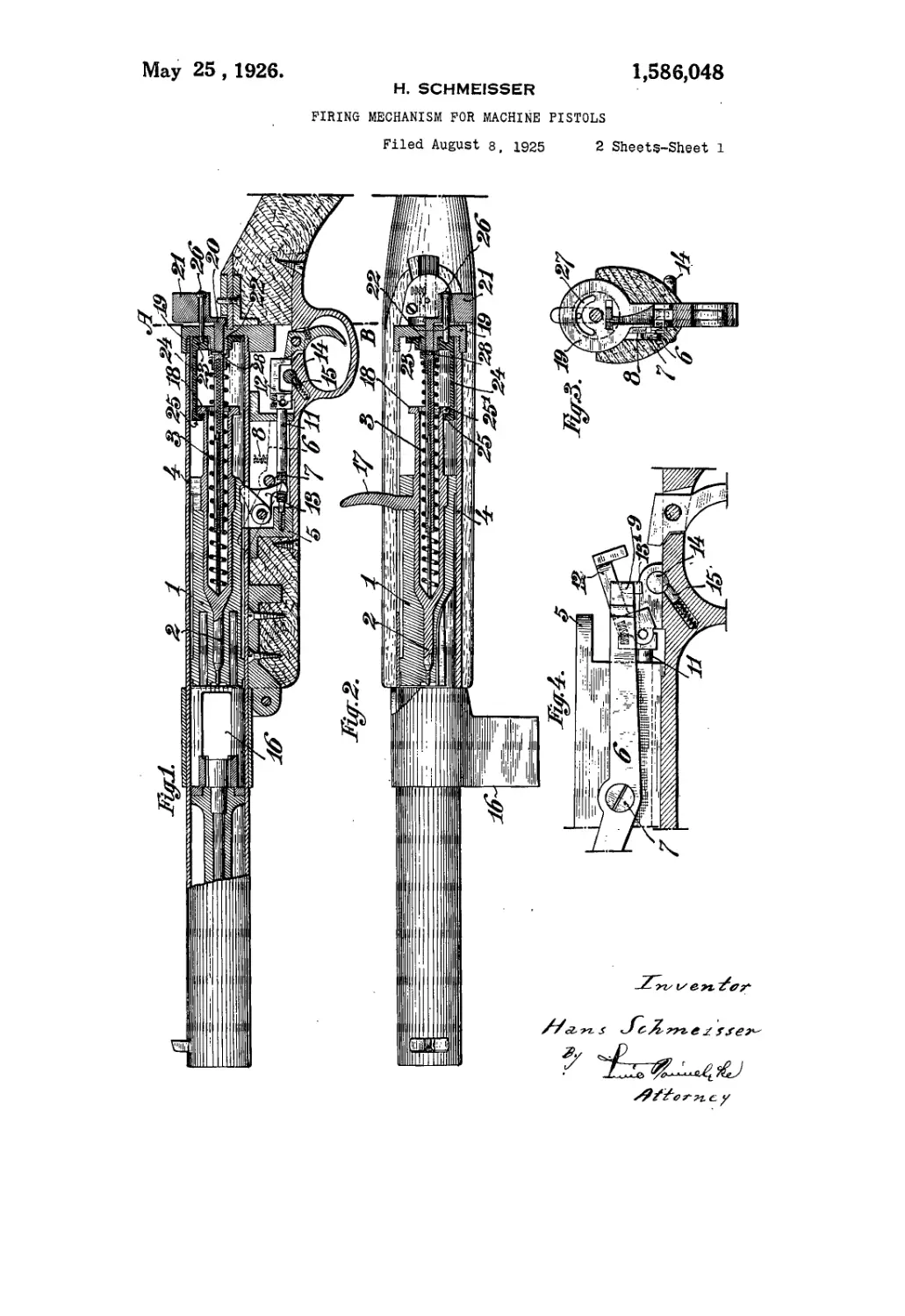
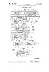
Figure 1 is a side elevation of the pistol,
partly in section and with the butt partially 80
shown; Figure 2 is a plan view thereof,
likewise partly in section and with the butt
partially shown; Figure 3 is a cross-section
taken on the line A—В of Figure 1; Figure
4 is a sectional view of the portion of the 88
pistol illustrating the trigger mechanism on
a larger scale and set for single shot firing;
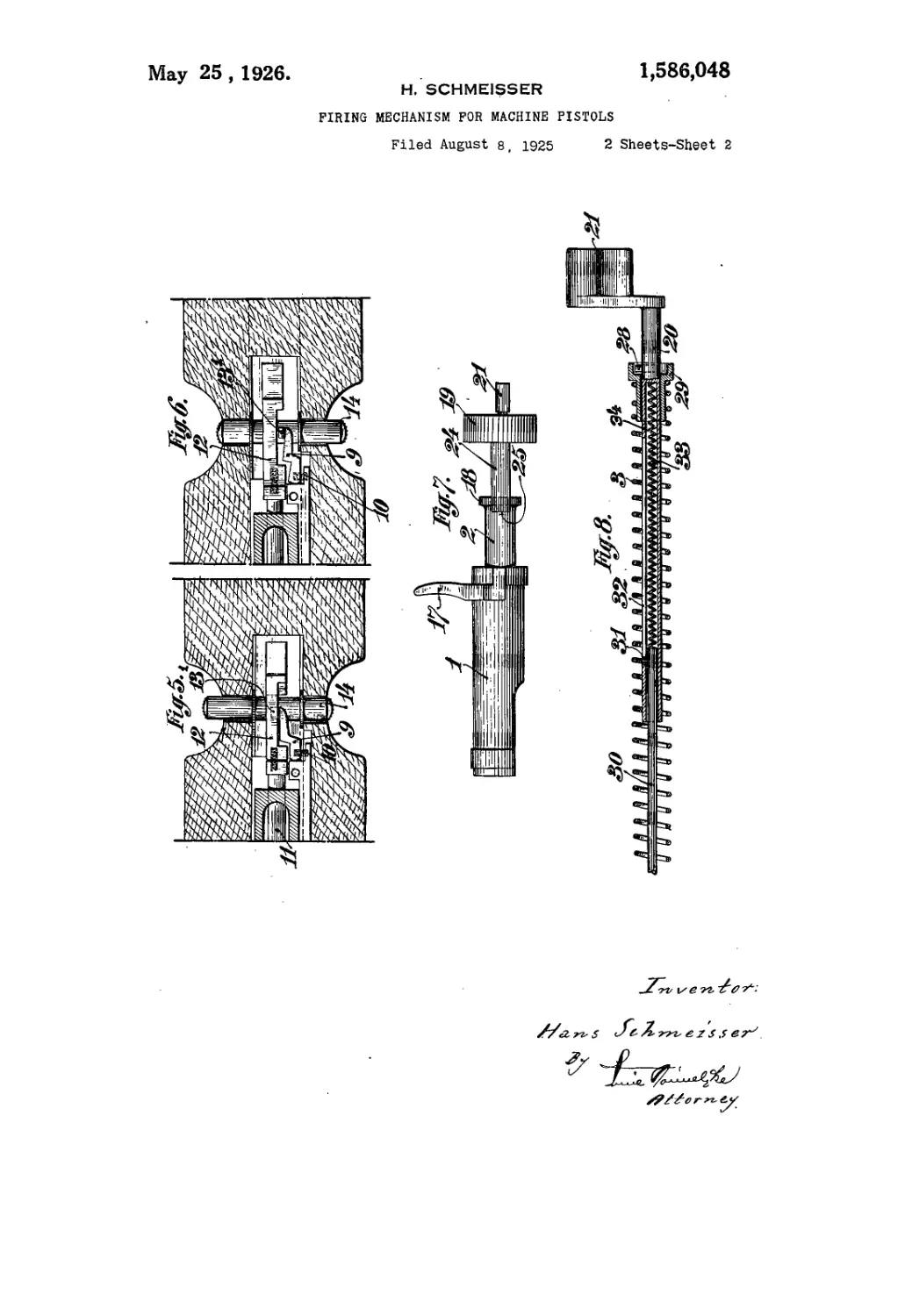
Figure 5 is a corresponding plan view ac-
cording to a horizontal section through a
rear portion of the pistol; Figure 6 is a
similar view with the change-over bolt in
a different position; Figure 7 is a plan view
of the breech removed from the pistol and
showing the safety device and the end or
bottom plate of the breech casing, the °®
safety device being set “safe”; and Figure
8 is a longitudinal sectional view of a part
removed from the pistol to show a means
for guiding the closing spring.
Referring to •' the drawirigs the pistol 100
shown therein is constructed and arranged
in the usual manner, as regards its main
parts such as the barrel, the cylindrical
breech block 1 with the percussion bolt or
firing pin 2 enclosed therein and the closing 108
spring 3, the block, the pin and the spring
being located in the breech casing 4 as usual.
The interrupting lever 6 is pivotally con-
structed, as at 7, to a part of bracket 5 at-
tached to the underside of the breech cas- 110
ing. The one arm of the lever is held down,
by the action of a li'ght spring 8, in hori-
£31
1,666,048
zontal position, while the other arm thereof
extends upwards with its top projecting
into the casing so as to lie in the path of
the reciprocating breech-block. Pivoted to
в the horizontal arm of the lever 6 is a link
9 which is adapted to swing in a horizontal
plane and is subject to the action of a light
coiled spring 10, as clearly shown in Fig-
ures 5 and 6. The rear end of the sear
10 11 which is, as usual, arranged to be dis-
placeable lengthwise, is connected to a
spring-controlled pawl 12 adapted to turn
in a vertical plane, but normally held in
alinement with the sear or rod 11 by the
10 action of the spririg of the pawl. The front
end of the sear or rod 11 is engaged, as
usual, by the arresting lever 13 which locks
the breech-block in the cocked or one end-
position in the usual manner as clearly
20 shown in Figure 1.
The spring-controlled pawl 12 is shaped
to form a U with the cavity downwards for
the link 9 of the lever 6 to normally en-
gage therein under the action of the spring
26 10, as will be seen in Figure 5, while at the
same time a depending nose.131 of the link
9 engages in a recess of the change-over
bolt 14, see Figures 4 and 5. By shifting
the bolt 14 the nose 131 can be disengaged
30 from the spring-controlled pawl 12, that is
to say, moved from the position illustrated
in Figure 5 to that shown in Figure 6. The
sear or rod 11 is controlled in the usual
manner by a coiled spring, see Figure 1,
acting against the front end thereof in
order to press and hold the spring-controlled
pawl 12 in contact with the trigger. The
change-over bolt is yieldingly-locked in its
active or end positioi}, shown in Figures 5
40 and 6, by a spring-actuated pin 15 having a
round end to enter into correspondingly
shaped recesses cut in the bolt.
The operation of the mechanism above
described is as follows:—
In case of firing continuously or a “se-
quence” the changing bolt 14 is set to the
position shown in Figure 6 so that the link
9 pivoted to the lever 6 is out of engagement
with the spring-controlled pawl 12. If the
weapon is cocked, as shown in ^Figure 1, a
pressure exerted on the trigger, will cause-
the sear or rod 11 to be shifted in the direc-
tion toward the muzzle of the barrel and the
lever 13 to be disengaged from the breech-
block 1 so that the latter will forcibly ad-
vance, under the action of the spring 3, to
shift a cartridge from the magazine 16 into
the barrel and to fire a shot.. The explosion
gases then act to push the breech-block back
• into its rear position and the lever 6 is there-
by turned about its pivot 7 so that its up-
wardly extending arm will go down and re-
cede from the breech casing whilst its hori-
zontal arm will be raised without, however^
lifting the spring-controlled pawl 12. The
latter remains, upon continued pressure ofi
the trigger together with the sear or rod 11
in its shifted or front position and the lever
13 remains also in its inactive position, so
that the breech-block is not locked or ar-
rested upon the firing of the single shot,
but is free to advance after each shot under
the action of the spring 3 for continuous
firing as long as cartridges are supplied by
the magazine.
If only one shot is to be fired the changing
bolt 14 must be shifted into the position
shown in Figure 5, so that the link 9 will
engage in the spring-controlled pawl 12, as
illustrated in Figure 5. If then the trigger
is operated, the sear or rod 11 will likewise
be moved in the direction towards the barrel
and the cocked breech-block will be released
to fly forward into the firing position. On
its return movement the lever 6 is actuated
in the same manner as before, that is to say,
the front arm of the lever.goes down and
the rear arm thereof is raised, the latter,
however, acting at the same time to lift the
spring-controlled pawl 12 by means of . the
link 9 pivoted to the lever, as will be readily
understood by an inspection of Figures 4
and 5. In this way the contact connection
of the trigger with the sear or rod 11 is
interrupted, so that then, even on a con-
tinued pressure on the trigger, the catching
or arresting lever 13 will arrest the again
advancing breech-block and lock the same
in cocked position. When the parts have
adopted their position the front arm of the
interrupting lever will be opposite a cor-
responding groove or recess provided in the
breech-block and will be forced by the spring
8 to engage therein, whilst at the same time
the rear arm of the lever is lowered again
and the spring-controlled pawl 12 caused to
again come in contact with the trigger. By
a further pressure exerted on the trigger a
further shot will be fired and it will l>e seen
that thus single shots can be fired, as re-
quired or desired.
The percussion bolt or firing pin 2 is or
constitutes, in the embodiment shown, a part
of its own adapted to be inserted into (he
breech-block and locked therein by a handle
17 provided on the bolt for the purpose, so
that the block and the bolt practically form
a unit when assembled. The rear end of the
bolt 2 projects beyond the hind' face of the
block 1 and its rear extremity is shaped to
form a collar 18. The end or bottom plate
19 of the breech casing 4 is united with the.
latter, in the embodiment shown, by being
screwed onto the rear end of the same and
a central bore is provided in the plate 19
for the reception of a short shaft 20 adapted
to be turned in the bore and having, at its
outer end, the usual safety wing or handle
rigidly attached thereto or integral there-
with, while its inner end is shaped to form
1,586,048
a sleeve which projects into the breech-cas-
ing. On the inner face the plate 19 is shaped
to form a sleeve or hub 22 having a left-
handed thread on its periphery for a safety
6 disc 23 to be screwed thereon with a slight
play so as to permit of being easily un-
screwed or rotated.
The safety disc 23 possesses an arm 24
extending, in the breech-casing, in the di-
10 rection towards the barrel and having an
inwardly projecting nose 25 at its free end..
The safety handle is connected with the disc
23 by a screw 26 or the like, a semicircular
slot 27 being provided in the bottom plate
IB 19, see Figure 3, for the screw or the like to
pass therethrough. The collar 18 of the per-
cussion bolt is cut out at a certain point
to form a recess 251 of a width sufficient to
allow the nose 25 of the arm 24 of the safety
20 disc 23 to pass therethrough, the said recess
251 being located so as to be opposite the
nose 25 when the safety handle 21 is turned
over to the left-hand side, as shown in Fig-
ure 2, in order that the breech-block with
25 the percussion bolt may not be prevented by
the nose 25 from performing the required
movements in the breech-casing.
In case that the breech-block is in the
rear or cocked position and it is desired
30 to put the weapon “safe”, the safety wing
or handle 21 is turned over to the right-
hand side, thereby causing the nose of the
arm 24 to grip over the collar 18 of the
percussion bolt, as shown in Figure 1, and
35 to lock or retain the breech-block in the rear
position, so that pressure on the trigger
will not have any firing effect, that is to
say, the pistol is “safe”. It goes without
saying that the breech-block is already suf-
40 ficiently locked and the weapon is fully
“safe” as soon as handle 21 has been turned
over to the right-hand side for a short por-
tion of its entire path only since the nose
25 of the arm 24 will catch and hold the.
46 collar 18 and consequently lock the percus-
sion belt and the breech-block, immediately
upon receding from its position in front
of the recess 251. Hence it follows that
the weapon is also fully “safe” when the
50 handle 21 has a vertical position, as shown
in Figures 1 and 3.
In the front face of the hub 22 of the
bottom plate 19 two radial grooves of
semicircular cross-section are provided—
55 the grooves are not shown—for the recep-
tion of the projecting end of a cross-pin
28 provided in the shaft 20 of the safety
handle. The free end of the pin 28 is
pressed into the one or the other groove
60 through the action of the spring 3 for the
purpose of locking the handle 21 in its two
end positions.
Instead of constructing the safety mech-
anism as shown in the illustrated embodi-
66 ment, the safety arm 24 of the handle 21
8
may be arranged to immediately engage the
breech-block and to thus lock both the block
and the percussion bolt when the handle 21
is put “safe”. In such a modification the
percussion bolt 2 need not project from TO
the rear end of the breech-block into the
breech-casing and also the collar 18 may be
dispensed with. The connection of the per-
cussion bolt with the breech-block may
likewise be effected in any suitable manner ТВ
and is not limited to the construction illus-
trated in the drawings. (
The closing spring 3 is coiled about and
guided by the sleeve 34 forming an elon-
gation of the shaft 20 of the safety handle 80
21. The rear end of the spring 3 encircles
a socket 29 having a suitable seat for the
end of the spring to abut against while the
socket 29 engages over the pin 28, as will
be clearly seen in Figure 8. A bolt 30 is 83
inserted in the sleeve 34 and adapted to
telescope therein against the action of a
fine coiled spring 33. The sleeve 34 has a
longitudinal slot 32 and the bolt 30 has
a pin 31 at its inner end, projecting into the 00
slot 32 so as to guide the bolt and prevent
the same from being ejected from the sleeve
by the spring 33.
The sleeve 34 and the telescopic rod or
bolt 30 acting as a yielding elongation of 05
the former, serves in their totality as a
means for holding and guiding the main
spring 3 of the weapon, both when the
parts constituting the weapon are assembled
and also for the main spring prior to the 100
asembling operation so that the insertion
of the spring can be performed in a ready
manner.
Upon unscrewing the bottom plate 19 the
spring 33 will expand and at the same time 105
the elongating rod or bolt 30 will be driven
out of the sleeve 34, from the position shown
in Figure 1 to the position illustrated in
Figure 8, where the pin 31 terminates the
movement of both the rod 30 and the light 110
spring 33 in the sleeve. As will be under-
stood from Figure 8 the sleeve combined
with the yielding rod constitute a means
for guiding the main spring 3 to the extent
of its length both when assembled in the 118
weapon and for the assembling purpose so
that insertion of the spring 3 can be ef-
fected without any difficulties.
It will be evident that my invention,
while still being adhered to in its main es- 120
sentials, may be varied and adapted in
many ways, according to requirement de-
sired or most suitable under different cir-
cumstances.
What I claim is:-— “5
1. A firing mechanism for a machine pis-
tol of the type set forth, comprising a
breech-block adapted to lock the pistol
through inertia, a percussion bolt enclosed
in said breech-block, a main or closing °
1,5бв,04ё
spring acting to propel both the said breech-
block and the said percussion bolt, an in-
terrupting lever, a link pivoted to the said
lever, a sear rod, a spring-controlled pawl
5 pivotally connected with the said sear rod,
and a change-over bolt, for bringing the
said link in engagement or out of engage-
ment with the said pawl, substantially as
and for the purpose set forth.
10 2. A firing mechanism for a machine
pistol of the type set forth, comprising a
breech-block, adapted to lock the pistol
through inertia, a percussion bolt encased
in said breech-block, a closing spring act-
15 ing to propel both the said breech-block and
the said percussion bolt, interrupting lever,
a link pivoted to the said lever, a sear
rod, a spring controlled pawl pivotally con-
nected with the said sear rod, a change-over
20 bolt for bringing the said link in or out
of engagement with the said pawl, a safety
handle, and means for locking the breech-
block and the percussion bolt, when cocked,
through the said handle, substantially as
25 and for the purpose set forth.
3. A firing mechanism for machine pistols
of the type set forth, comprising a breech-
block adapted to lock the weapon through
inertia, a percussion bolt encased in said
30 breech-block, a closing spring adapted to
propel both the said breech-block and the
percussion bolt, an, interrupting lever, a
link pivotally attached to the said lever, a
sear rod, a spring-controlled pawl pivotally
° connected with the said sear rod, a change-
over bolt for bringing the said link in and
out of engagement with the said pawl, a
breech casing, a bottom plate closing the
rear end of the said breech casing, a safety
handle mounted in the said bottom plate
so as to be capable of rotation, an arm
movably connected with the said bottom
plate and connected with the said handle
46 to Co‘°Peral'e therewith, a collar on the rear
end of the percussion bolt for the said arm
to engage with and a recess in said collar
for the said arm to disengage therefrom,
substantially as and for the purpose set
Bo forth.
4. A firing mechanism for a machine pis-
tol of the type set forth, comprising a
breech-block adapted to lock the weapon
through inertia, a percussion bolt encased in
и said breech-block, a closing spring adapted
to propel both the said breech-block and the
percussion bolt, an interrupting lever, a
link pivotally attached to the said lever, a
sear rod, a spring-controlled pawl pivot-
al ally connected with the said sear rod, a
change-over bolt for bringing the said link
in and out of engagement with the said
pawl, a breech-casing, a safety handle
mounted in the said bottom plate on a shaft
so as to be capable of rotation thereabout,
an arm movably connected with the said
bottom plate and connected with the said
.safety arm to co-operate therewith, a sleeve
integral with the said shaft, and a yielding
rod, telescopically mounted in the said
sleeve, substantially as and for the purpose 79
set forth.
5. A firing mechanism for a machine pis-
tol of the type set forth, comprising a
breech-block adapted to lock the weapon
through inertia, a percussion bolt encased in 75
said breech-block, a closing spring adapted
to propel both the said breech-block and the
percussion bolt, an interrupting lever, a
link pivotally attached to the said lever, a
sear rod, a spring-controlled pawl pivot- 80
ally connected with the said sear rod, a
change-over bolt for bringing the said link
in and out of engagement with the said
pawl, a breech casing, a bottom plate clos-
ing the rear end of the said breech casing, 88
a safety handle mounted in the said bot-
tom plate on a shaft so as to be capable of
rotation, an arm movably connected with
the said bottom plate and connected with
the said shaft to co-operate therewith, a
sleeve integral with the said shaft, a yield-
ing rod telescopically mounted in said sleeve,
a collar on the rear end of the said per A,
cussion bolt for the said arm to engage
therewith, and a recess in the said collar for
the said arm to disengage therefrom, sub-
stantially as and for the purpose set forth.
6. A firing mechanism for a machine pis-
tol of the type set forth comprising an in-
terrupting lever, a link pivoted to the lever,
a sear rod, a spring-controlled pawl pivot-
ally connected with said sear rod, and a
change-over bolt for said link.
7. A firing mechanism for a machine pis-
tol of the type set forth, comprising a
breech-block adapted to lock the weapon
through inertia, a percussion bolt encased in
said breech-block, a closing spring adapted
to propel both the said breech-block and the
said percussion bolt, an interrupting lever, a
link pivotally attached to the said lever, a
sear rod, a spring-controlled pawl pivot-
ally connected to the said sear rod, a
change-over bolt for bringing the said link
in and out of engagement with the said
pawl, a breech-casing, a bottom plate clos-
ing the rear end of the said breech casing,
a safety handle mounted on a shaft in the
said bottom plate so as to be capable of ro-
tation, an arm movably connected with the
said bottom plate ana connected with the
said handle to co-operate therewith, a sleeve
integral with the said shaft, a yielding rod
telescopically mounted in the said sleeve,
means in connection with the said sleeve and
05
10
10.
Ill
Hi
12i
1®
shaft for adapting the said closing spring
to lock the said safety handle in the one or
the other one of its two end positions, a col-
lar on the rear end of the said percussion
bolt for the said arm to engage therewith, 1,1
1,586,048
в
and a recess in the said collar for the said
arm to disengage therefrom, substantially as
and for the purpose set forth.
8. A firing mechanism for a machine pis-
5 tol of the type set forth comprising an in-
terrupting lever having a link pivoted at
one end thereof, a sear rod having a pawl
pivoted at one end thereof, and means co-
operating with said link in order to permit
to a continuous or a single firing of the pistol,
depending upon the position of the link and
pawl.
4 9. A firing mechanism for a machine pis-
tol of the type set forth comprising a spring-
pressed interrupting lever having a spring- 15
pressed link pivoted at one end thereof, a
spring-pressed sear rod having a spring-
pressed pawl pivoted at one end thereof,
and means cooperating with said link in
order to'permit a continuous or a single fir- 20
ing of the pistol, depending upon the posi-
tion of the link and pawl.
In testimony whereof I affix my signa-
ture.
HANS SCHMEISSER.