/


Теги: weapons military affairs patent
Год: 1989


Текст
United States Patent [i9j
[11] Patent Number: 4,867,040
Barrett
[45] Date of Patent: Sep. 19,1989
[54] SELF-UNLOCKING DEVICE FOR
RECOILING BOLT CARRIER AND BARREL
IN A SEMI-AUTOMATIC RIFLE
[76] Inventor: Ronnie G. Barrett, P.O. Box 1077,
Murfreesboro, Tenn. 37130
[21] Appl. No.: 115,821
[22] Filed: Nov. 2,1987
[51] Int. Cl,4..........................F41D 5/02
[52] U.S. Cl..................... 89/172; 89/174;
89/185; 89/169
[58] Field of Search........ 89/172, 174, 185, 164,
89/188, 169
[56] References Cited
U.S. PATENT DOCUMENTS
749,341 1/1904 Tobisch .
2,328,108 8/1943 Swebilius .
3,757,636 9/1973 Chiabrandy .
FOREIGN PATENT DOCUMENTS
411164 6/1910 France ......... 89/169
531031 7/1955 Italy .......... 89/169
Primary Examiner—Deborah L. Kyle
Assistant Examiner—Stephen Johnson
Attorney, Agent, or Firm—Harrington A. Lackey
[57] ABSTRACT
A semi-automatic rifle including a recoiling barrel
adapted to carry rearward the elongated bolt carrier
containing the bolt for compressing the recoil spring,
and a self-unlocking device including a self-unlocking
rod longitudinally slidably mounted on the bolt carrier
normally engaging the rear face of the barrel in a bat-
tery position and a trigger actuating device for thrusting
the self-unlocking rod forward during the early stage of
recoil for separation of the bolt carrier from the barrel
before the barrel reaches the end of its recoil movement.
7 Claims, 4 Drawing Sheets
U.S. Patent Sep. 19,1989
Sheet 1 of 4
4,867,040
FIG.3
U.S. Patent Sep. 19,1989
Sheet 2 of 4
4.867.040
FIG. 6
U.S. Patent Sep. 19,1989
Sheet 3 of 4
4,867,040
U.S. Patent Sep. 19,1989 Sheet 4 of 4 4,867,040
,040
2
the difference between the speed of the decelerated
barrel and the speed of the accelerated bolt carrier.
The utilization of the self-unlocking device made in
accordance with this invention permits a smoother fir-
ing cycle for the semi-automatic rifle having a recoiling
barrel.
BRIEF DESCRIPTION OF THE DRAWINGS
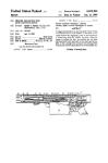
FIG. 1 is a side elevational view of a semi-automatic
rifle made in accordance with this invention, with por-
tions broken away;
FIG. 2 is an enlarged fragmentary side elevation of
the rifle disclosed in FIG. 1, with portions broken away,
and illustrating the elements in battery position;
FIG. 3 is a fragmentary side elevational view of the
front end portion of the housing, which is an overlap-
ping continuation of FIG. 2;
FIG. 4 is a section taken along the line 4—4 of FIG.
3;
FIG. 5 is a fragmentary top plan view taken along the
line 5—5 of FIG. 2, with portions broken away;
FIG. 6 is an enlarged fragmentary section taken along
the line 6—6 of FIG. 5;
FIG. 7 is an enlarged fragmentary section taken along
the line 7—7 of FIG. 2;
FIG. 8 is a fragmentary sectional elevation of the
rifle, similar to that disclosed in FIG. 2, with portions
broken away, and illustrating the elements in firing
position;
FIG. 9 is an enlarged section taken along the line
9—9 of FIG. 8;
FIG. 10 is a fragmentary section taken along the line
10—10 of FIG. 9, with portions broken away;
FIG. 11 is a fragmentary sectional elevation similar to
FIG. 10, illustrating the bolt in a preliminary stage of
separation from the barrel;
FIG. 12 is a fragmentary sectional elevation similar to
FIG. 8, with portions broken away; and illustrating the
bolt separating from the barrel, while both are recoiling
rearward;
FIG. 13 is an enlarged fragmentary sectional eleva-
tion of the rifle in which the bolt has extracted the
cartridge and the barrel is in te rearmost position; and
FIG. 14 is an enlarged fragmentary side elevational
section of the rifle in which the bolt is moving forward
to pick up and chamber a cartridge, and the barrel is in
its forward position.
DESCRIPTION OF THE PREFERRED
EMBODIMENT
Referring now to the drawings in more detail, FIG. 1
discloses a semi-automatic rifle 10 made in accordance
with this invention, including a housing 12 having an
upper receiver 13 and a lower receiver 14. The receiv-
ers 13 and 14, preferably separable, may be detachably
joined about their front ends about the hinge bar 15
(FIG. 3), and secured at their rear ends by the locking
pin 16, (FIG. 1). When the receivers 13 and 14 are
secured together they form the housing 12 preferably
having a polygonal cross-section, and preferably the
hexagonal cross-section disclosed in the drawings.
The lower receiver 14 is provided with a rear stock
member 17, a front bipod 18, an intermediate depending
hand grip 19 and trigger 20. The upper receiver 13 may
be provided with a sight, such as the telescopic sight 21
(FIG. 1).
4,867
1
SELF-UNLOCKING DEVICE FOR RECOILING
BOLT CARRIER AND BARREL IN A
SEMI-AUTOMATIC RIFLE
5
BACKGROUND OF THE INVENTION
This invention relates to semi-automatic rifles, and
more particularly to a self-unlocking device for separa-
tion of the bolt carrier from the barrel in a semi-
automatic rifle during recoil. 10
In the “Anti-Armor Gun” disclosed in my prior U.S.
Pat. No. 4,677,897, issued July 7,1987, a recoiling barrel
is provided for carrying rearward the bolt carrier and
the bolt, while still locked to the barrel, in order to
absorb the energy of recoil after the gun is fired. The 15
front of the bolt is provided with radially projecting
bolt lugs which are adapted to engage the locking lugs
in the rear end of the barrel in order to lock the bolt
within the barrel in battery and firing positions. The
barrel is also provided with an abutment member which 20
engages a barrel travel stop fixed within the housing to
stop the rearward movement of the barrel. When the
barrel stops, the bolt carrier and bolt continue their
rearward travel simultaneously rotating the bolt to un-
lock the bolt lugs from the barrel to completely separate 25
the bolt carrier from the barrel. The barrel springs then
return the barrel to its original forward position.
In the gun disclosed in U.S. Pat. No 4,677,897, the
rearward movement of the recoiling barrel is always
stopped abruptly, placing substantial stress upon the 30
interlocking lugs of the bolt and the barrel. Moreover,
the sudden impact and stopping of the recoiling barrel is
transmitted in the form of a “kick” to the shoulder of
the operator of the weapon.
Furthermore, the extractor mechanism is subjected to 35
a substantial degree of shock and fatigue upon the
abrupt stopping of the barrel and the sudden com-
mencement of the extraction of the cartridge.
SUMMARY OF THE INVENTION
It is therefore an object of this invention to provide in
a semi-automatic rifle of the above-described type, a
self-unlocking device which will commence separation
of the bolt carrier from the barrel during the recoil of
the barrel before the barrel is abruptly stopped. 45
The utilization of a self-unlocking device in accor-
dance with this invention provides an advance separa-
tion of the bolt carrier from the barrel during recoil and
will accelerate the bolt carrier and decelerate the barrel
prior to a termination of the recoil movement of both 50
elements. The deceleration of the barrel will permit the
barrel to impact the barrel travel stop member with
lesser force than normal which will provide less wear
and fatigue of the various parts of the rifle, and will
produce less felt recoil in the shoulder of the operator. 55
The additional acceleration of the bolt carrier pro-
vided by the self-unlocking device made in accordance
with this invention provides extra speed and momentum
for the bolt carrier so that a smaller and lighter bolt
carrier may be utilized within the rifle. 60
An early separation of the bolt carrier and the barrel
during recoil also creates less shock upon the extractor
mechanism.
Furthermore, the extraction of the spent cartridge
will occur during the rearward movement of the barrel 65
while the bolt carrier and bolt are separating from the
barrel to render the extraction function less abrupt. The
speed of the extraction of the spent cartridge is equal to
4,867
3
Fixed within the front end of the lower receiver 14 is
a front bushing 23 (FIG. 3) for slidably receiving the
elongated barrel 24 for longitudinal, reciprocable move-
ment. The enlarged cylindrical rear end portion of the
barrel 25 (FIG. 12) is slidably received within a rear 5
bushing or annular stop member 26. An annular key or
abutment member 27 is detachably received within a
corresponding arcuate slot 28 formed circumferentially
in the surface of barrel 24, preferably between the rear
end of the reduced portion of the barrel 24 and the 10
integral front end portion of the enlarged barrel portion
25.
Connected between the front bushing 23 and the
abutment member 27 are a pair of elongated, coiled
barrel springs 29. The barrel springs 29 are pre-ten- 15
sioned to bias the abutment member 27, and therefore
the barrel 24, forward to its forward battery position
disclosed in FIGS. 2 and 3.
When the barrel 24 is recoiling rearward, the barrel
springs 29 are extended, but the rearward movement of 20
the barrel 24 is limited by the engagement of the abut-
ment member 27 against the stop member 26.
Formed as an integral extension of the enlarged rear
barrel portion 25 is an enlarged, hexagonal barrel exten-
sion 30 having a front abutment face 33. The barrel 25
extension 30 contains a barrel chamber 31 for receiving
a cartridge 32.
As disclosed in the drawings, front and rear annular
abutment or buffer rings 34 and 35 are located adjacent
opposite ends of the stop member 26, and are made of 30
relatively hard, but resilient material such as hard rub-
ber, to absorb the shock of the impact of the abutment
member 27 when the barrel is in recoil and the front
face 33 of the barrel collar 30 when the barrel is moving
toward its battery position. 35
The barrel extension 30 includes a locking chamber
36 between the rear face 37 of the barrel portion 25 and
a plurality of circumferentially spaced barrel locking
lugs 38. The barrel extension 30 includes an exposed
rear face or surface 39. 40
The front end of the barrel 24 is provided with a
muzzle brake 40 (FIG. 1).
The polygonal, and specifically the hexagonal, cross-
sectional exterior surfaces of the barrel extension 30 and
the abutment member 27 are equal, but of slightly lesser 45
dimension than the hexagonal cross-section of the upper
receiver 13, so that the barrel 24 travels longitudinally
straight within the housing 12 and without rotation.
Also received within the housing 12 behind the barrel
extension 30 is an elongated bolt carrier 42 having an 50
upper surface of semi-hexagonal cross-section for com-
plementary slidable movement within the correspond-
ing inner surface of the upper receiver 13. The bolt
carrier 42 is received within the housing 12 between the
barrel 24 and the rear main or recoil spring 43. The 55
front end of the coiled recoil spring is preferably pro-
vided with a buffer pad or member 44 for engaging the
rear end of the bolt carrier 42.
A bolt 45, having a cylindrical bolt body 46 terminat-
ing in a front bolt head 47 including the circumferen- 60
tisJly spaced bolt lugs 48, is slidably received within the
front cavity 49 of the bolt carrier 42 for relative longitu-
dinal and rotatable movement. Three bolt lugs 48 are
shown.
As viewed in FIG. 10, the longitudinal dimension of
the locking chamber 36 is just large enough to accom-
modate reception of the bolt head 47, whereby the bolt
locking lugs 48 may rotate between engagement and
,040
4
disengagement with the corresponding barrel locking
lugs 38, in a well known manner.
The rear end of the bolt cavity 49 defines a rear seat
50 for engagement by the rear end of the bolt 45 in
order to limit the rearward travel of the bolt 45 within
the bolt carrier 42. A bolt spring 51 is contained within
a smaller cavity to the rear of the bolt cavity 49 for
urging the bolt 45 forward relative to the bolt carrier
42.
Coaxially and slidably received within the bolt car-
rier 42 and the bolt 45 is an elongated firing pin 52.
The rear end of the firing pin 52 is provided with a
vertical slot 53 for receiving the upper end portion of
the cocking lever 54. The rear end of the firing pin 52
terminates in an upturned hook 55 for engagement with
the corresponding sear hook 56 of the vertically mov-
able sear 57. The sear 57 is adapted to be moved upward
by a transfer bar 58 when pivoted upward by the trigger
lever 59 rotating upward on the trigger pivot pin 60
when the trigger 20 is pulled.
Projecting radially inward from the wall of the bolt
carrier 42 into the bolt cavity 49 is a cam pin 61 received
within an elongated helical slot 62 formed in the wall of
the bolt body 46. The cam slot 62 extends helically
through an arc of approximately 37 deg. about the cir-
cumference of the bolt body 46, so that when the bolt 45
is retracted within the bolt cavity 49, the bolt lugs 48 on
the bolt head 47 are rotated through an arc of approxi-
mately 37 deg. Since the barrel locking lugs 38 are also
three in number and circumferentially spaced 120 deg.
apart, a rotation of the bolt head 47 through 60 deg. will
permit the corresponding bolt lugs 48 to disengage the
barrel locking lugs 38 so that the bolt head 47 is free to
move longitudinally into and out of the locking cham-
ber 36 of the barrel collar 30.
In order to retain the bolt 45 in its protracted or
forwardly extending position relative to the bolt carrier
42, a 7 pivotal latch 64 is mounted on the body of the
bolt carrier adjacent its front end and normally biased
into a latch recess 65 in the bolt body 46. An elongated
latch actuator rib 66 is fixed on the interior surface of
the top wall of the upper receiver 13, so that as the bolt
head 47 approaches the locking chamber 36, the rib 66
engages the latch lever to cause it to disengage the latch
recess in the bolt body and permit the bolt 45 to rotate
within its bolt cavity 49, in a conventional manner.
In order to manually move the bolt carrier 42 within
the housing 12, a transverse bolt handle 68 is provided,
as illustrated in FIGS. 5 and 6.
In a conventional manner, an opening 69 is provided
in the bottom of the lower receiver 14 for receiving a
magazine including a plurality of loaded cartridges
which are urged upward into the housing 12 between
the rear bushing 26 and the recoil spring 43. Thus, as
illustrated in FIG. 14, when the bolt carrier 42 is fully
retracted, and then released, the bolt 45 picks up the top
cartridge 32 from the magazine 70 and carries the car-
tridge forward into battery position within the barrel
chamber 31.
The self-unlocking device made in accordance with
this invention includes a self-unlocking lever 73 which
has its upper end pivotally connected to the body of the
bolt carrier 42 by a pivot pin 74 (FIGS. 2, 12 and 14).
The self-unlocking lever 73 is illustrated in the drawings
as being pivotally connected to the left side of the bolt
carrier 42 when the operator is looking forward toward
the muzzle of the barrel. When the self-unlocking lever
73 is in its inoperative, substantially upright, position, as
4,8(
5
illustrated in FIG. 2, the lever 73 is long enough to
depend below the bolt carrier 42 and into a slotted
opening 75, which is continuous with and extends rear-
wardly of the magazine opening 69, as best illustrated in
FIGS. 2 and 7.
Adapted to be operated by the self-unlocking lever 73
is in elongated self-unlocking rod 76 adapted to freely
reciprocate longitudinally within an elongated guide
bearing 77 integrally mounted on the side of the bolt
carrier 42.
At the rear end of the lever slot 75 and in the rear-
ward path of the self-unlocking lever 73 is an abutment
or shoulder 78 adapted to'engage the rear surface of the
lower and portion of the self-unlocking lever 73 when
the bolt carrier 42 is traveling rearward, as illustrated in 15
FIG. 12. As the bolt carrier 42 travels rearward, and
when the lever 73 engages the shoulder 78, the self-
unlocking lever 73 is pivoted forward about its pivot pin
74, and while engaging the rear end of the self-unlock-
ing rod 76, projects the rod 76 forward from the front 20
end of the bolt carrier 42, as illustrated in FIG. 12. The
self-unlocking rod 76 is long enough so that its front
end, when projected forward from the front end of the
bolt carrier 42 by the forwardly pivoting self-unlocking
lever 73, causes the front end of the rod 76 to engage
and bear against the rear face 39 of the barrel extension
30, causing the bolt carrier 42 to move rearwardly and
away from the barrel extension 30 and the barrel 24.
In the normal operation of the rifle 10 made in accor- 30
dance with this invention, the barrel 24 is normally
biased to its forward position by the barrel springs 29,
while the bolt carrier 42 is also normally biased to its
forward battery position with the bolt head 47 received
within the locking chamber 36 of the barrel extension 35
30, and the bolt lugs 48 are locked behind the barrel lugs
38, as best illustrated in FIGS. 9 and 10. The bolt carrier
42 is urged to its forward battery position by the rear
recoil spring 43.
In order to load the rifle 10, the operator grasps the
bolt handle 68 and pulls the bolt carrier 42 to the rear
against the recoil spring 43, simultaneously and auto-
matically unlocking the bolt head 47 from the locking
chamber 36 of the barrel extension 30. After the bolt
carrier 42 and the bolt 45 are retracted behind the car- 45
tridge opening 69, the magazine spring 71 (FIG. 14)
urges a cartridge 32 up into the receiver or housing. The
bolt handle 68 is then released to let the recoil spring 43
force the bolt carrier 42 forward. Simultaneously, the
bolt head 47 picks up the top cartridge 32 projected 50
upwardly by the magazine 70 and carries it forward into
the barrel chamber 31, and the bolt head 47 again enters
the locking chamber 36 of the barrel collar 30 and is
counter-rotated 37 deg. to lock the bolt head 47 within
the locking chamber 36. 55
The rifle 10 is fired by pulling the trigger 20, which
lifts the trigger lever 59, to move upward through the
transfer bar 58 and the sear 57 to unlatch the hooks 55
and 56 permitting the firing pin 52 to be urged forward
by the firing pin spring, not shown, in a conventional 60
manner. The front end of the firing pin 52 projecting
from the bolt detonates the primer within the cartridge
32 causing the powder to ignite and rapidly project the
projectile or bullet 80 from its cartridge 32 down the
barrel 24, as illustrated in FIG. 8. 65
The forward moving bullet 80 and the expanding
gases creates a reaction which drives the barrel 24 rear-
ward against the action of the barrel springs 29.
•7,040
6
The relative positions of the elements of the gun 13 in
battery position are disclosed in FIG. 2, while he rela-
tive positions of the elements in the firing position are
disclosed in FIG. 8.
5 As the barrel 24 commences its rearward movement
immediately after the firing of the cartridge 32, the bolt
carrier 42 and the bolt 45 are likewise carried rear-
wardly so a substantial mass absorbs the energy of recoil
as they move rearwardly against the action of the recoil
spring 43.
After the barrel 24 and the bolt carrier 42 have
moved rearwardly approximately J", the bullet 80 is
leaving the muzzle of the barrel 24.
After the recoiling barrel 24 and the bolt carrier 42
have moved approximately 1", the self-unlocking lever
73, in its inoperative position, as illustrated in FIG. 2,
engages the shoulder 78 which commences the pivoting
of the lever 73 about its pivot pin 74. While the self-
unlocking lever 73 is in its depending and operative
position, the front end of the self-unlocking rod 76 is in
flush engagement with the rear face 39 of the barrel
extension 30, as illustrated in FIG. 2.
As the self-unlocking lever 73 rides over the abut-
ment shoulder 75, and swings forward, it moves the
self-unlocking lever 76 forward against the barrel exten-
sion face 39 to move the bolt carrier 42 away from the
barrel extension 30 and consequently the barrel 24.
As the self-unlocking rod 76 forces the bolt carrier 42
away from the barrel extension 30, the bolt 45 is pro-
tracted a corresponding amount, since the bolt head 47
is still locked in the locking chamber 36 (FIG. 11).
However, as the bolt protracts relatively from the bolt
carrier 42, the bolt body 46 is rotated by virtue of the
connection between the cam pin 61 and the helical slot
62. Further rearward relative movement of the bolt
carrier 42 away from the barrel extension 30 causes the
bolt head 47 to complete its 37 deg. rotation within the
unlocking chamber 36 so that the bolt head 47 is free to
move rearwardly from the unlocking chamber 36 and
rearward past the barrel extension 30 to become com-
pletely disengaged from the barrel 24, as illustrated in
FIG. 12.
While the self-unlocking rod 76 continues to force the
bolt carrier 42 away from the barrel extension 30, the
barrel 24 is decelerating, while the bolt carrier 42 is
accelerating to increase the separation space between
the bolt carrier 42 and the barrel 24.
FIG. 11 discloses the bolt carrier 42 as it begins its
separation from the barrel extension 30 with the bolt
head 47 rotated through a few degrees from its locked
position within the locking chamber 36.
In FIG. 12, the bolt carrier 42 has moved farther
away from the barrel extension 30, the bolt head 47 has
been counter-rotated through its full 37 deg. so that it
registers with the opening between the barrel locking
lugs 38, and the bolt 45 is fully protracted relative to the
bolt carrier 42 to complete the separation of the bolt
carrier 42 from the barrel 24.
After the bolt carrier 42 is fully separated from the
barrel extension 30, both elements continue their rear-
ward travel, with the bolt head 42 withdrawing the
spent cartridge 32 from the barrel chamber 31.
After the barrel has traveled its full distance of ap-
proximately 2j", the abutment member 27 on the barrel
24 impacts against the front resilient buffer member 34
and stop member 26 to stop the rearward movement of
the barrel 24. However, because the speed of the rear-
ward movement of the barrel 24 has been reduced, not
,040
8
(d) bolt spring means in said bolt carrier, normally
biasing said bolt forward,
(e) cam and slot means interconnecting said bolt car-
rier to said bolt to provide limited rotary move-
ment of said bolt relative to said bolt carrier during
longitudinal movement of said bolt relative to said
bolt carrier,
(f) an elongated recoil spring within said housing for
urging said bolt carrier forward,
(g) an elongated barrel comprising an enlarged rear
barrel extension,
(h) said barrel extension having radially inward di-
rected barrel locking lugs for engaging and disen-
gaging said bolt locking lugs in a battery position,
(i) support means in said housing for slidably receiv-
ing said barrel, stop means in said housing for limit-
ing the rearward movement of said barrel within
said housing,
(k) barrel spring means connecting said barrel and
said housing to bias said barrel forward to a battery
position,
(1) a self-unlocking member mounted for longitudinal
movement on said bolt carrier and being adapted to
engage said barrel extension in said battery posi-
tion,
(m) trip means operatively connected to said self-
unlocking member to cause said self-unlocking
member to move forward against said barrel exten-
sion during the initial recoil movement of said bolt
carrier and said barrel to thrust said barrel away
from said bolt carrier, thereby automatically caus-
ing said bolt locking lugs to rotate relative to said
bolt carrier to disengage said barrel locking lugs
and to separate said bolt from said barrel.
2. The invention according to claim 1 in which said
barrel extension has a rear face, said self-unlocking
member comprises an elongated rod and means slidably
mounting said rod on said bolt carrier for longitudinal,
reciprocable movement, said rod having a front end
normally abutting said rear face in said battery position,
said trip means being operatively associated with said
rod for projecting said rod forward to thrust said barrel
extension away from said bolt carrier.
3. The invention according to claim 2 in which said
trip means comprises a trip member movably mounted
upon said bolt carrier, said rod having a rear end en-
gageable with said trip member, an abutment member
on said housing in the path of rearward movement of
said trip member whereby engagement of said trip
member with said abutment member, when said trip
member moves rearward, causes said rod to move for-
wardly to thrust said barrel extension away from said
bolt carrier.
4. The invention according to claim 3 in which said
abutment member and said stop means are longitudi-
nally spaced apart upon said housing at such a distance,
and the length of said rod is such, that said trip member
is actuated to thrust said rod forward to separate said
barrel from said bolt carrier before the rearward move-
ment of said barrel is stopped by said stop means.
5. The invention according to claim 4 in which said
stop means comprises a barrel travel stop member fixed
within said housing and encompassing at least a portion
of said barrel, and further comprising a barrel abutment
member fixed on and substantially encompassing said
barrel and adapted to engage said stop member to limit
the rearward movement of said barrel.
4,867
7
only by the extension of the barrel springs 29, but also
by the self-unlocking rod 76, the impact of the abutment
member 27 against the front buffer ring 34 has been
substantially reduced by the time the barrel has stopped.
The barrel springs 29 then retract the barrel 24 to its 5
forward position, as illustrated in FIG. 2.
As the bolt carrier 42 continues its rearward move-
ment, the extractor, not shown, in the bolt head 47
extracts the spent cartridge 32 and discards it through
the ejection opening 81 (FIG. 13) in the upper receiver 10
13. This extraction process is relatively smooth com-
pared with conventional extraction functions, because
the extraction occurs while the barrel 24 and the bolt
carrier 42 are still in rearward motion. Moreover, the
speed of the extraction of the spent cartridge is the 15
difference between the rearward velocity of the bolt
carrier 42 and the rearward velocity of the barrel 24.
After the spent cartridge 32 has been extracted and
ejected, and the bolt carrier 42 has reached the limit of
its rearward motion, fully compressing the recoil spring
43, the compressed energy in the recoil spring 43 then
urges the bolt carrier 42 forward again to pick up an-
other cartridge from the magazine 70, as illustrated in
FIG. 14, to carry a fresh cartridge 32 home into the 2J
barrel chamber 31, with all of the elements restored to
their battery position.
Moreover, when the bolt carrier 42 returns to its
battery position, the front end of the self-unlocking rod
76 impacts against the rear face 39 of the barrel exten- 30
sion 30 to force the rod 76 rearward to engage and pivot
rearward the self-unlocking lever 73 to its upright, inop-
erative position, in front of the shoulder 60 and within
the lever slot 75, as illustrated in FIG. 2.
The semi-automatic rifle 10, with all of its elements
returned to battery position is now in position for a
repeat cycle.
Because of the self-unlocking device, including the
self-unlocking lever 73, abutment shoulder 78 and self-
unlocking rod 76, a recoil of the moving elements in the 40
rifle 10 is reduced. The reduced velocity of the recoil-
ing barrel 24 produces less impact when the barrel is
stopped by its engagement with the stop member 26,
and thereby produces less felt recoil. Also, as previously
mentioned, the extraction of the spent cartridge is ac- 45
complished with less abruptness, less shock, and with
less wear upon the extractor parts, to produce a
smoother extraction operation.
Moreover, because of the increased velocity of the
bolt carrier 42 produced by the self-unlocking device, a 50
bolt carrier 42 of reduced mass may be utilized with
equal effectiveness in providing sufficient energy for
moving the bolt carrier 42 to its extreme rearward posi-
tion against the action of the recoil spring 43.
Moreover, a muzzle brake 40 of increased efficiency 55
may be utilized, since less recoil action is required for
operation, in view of the operation of the self-unlocking
device.
What is claimed is:
1. A semi-automatic rifle comprising: 60
(a) an elongated housing,
(b) an elongated bolt carrier received within said
housing for longitudinal, reciprocable movement,
said bolt carrier having a coaxial forward-opening
bolt cavity,
(c) an elongated bolt slidably received within and
projecting forward from said bolt cavity, said bolt
comprising radially projecting bolt locking lugs,
4,867,040
9
6. The invention according to claim 3 in which said
trip member comprises a lever arm and means pivotally
supporting said lever arm on said bolt carrier above said
rod, said lever arm lying in the longitudinal path of said
rod and said abutment member, whereby when said
lever arm engages said abutment member during the
rearward movement of said bolt carrier, said lever arm
10
engages the rear end of said rod for moving said rod
forward.
7. The invention according to claim 3 in which said
5 abutment member is in the lower portion of said hous-
ing below said bolt carrier.
io
15
20
25
30
35
40
45
50
55
60
65