/


Текст
ТМ 9*1425*484*10
D /С I. // ;
-ю/г?, |-з
TECHNICAL MANUAL
OPERATOR'S MANUAL
FOR
DRAGON WEAPON GUIDED
MISSILE SYSTEM,
SURFACE ATTACK:
M47
HOW TO USE
THIS MANUAL
INTRODUCTION 1-1
OPERATING
INSTRUCTIONS
MAINTENANCE
INSTRUCTIONS
(MEDIUM ANTITANK/ASSAULT
WEAPON SYSTEM)
AMMUNITION 4-1
REFERENCES A-1
COMPONENTS OF
END ITEMS LIST
ADDITIONAL
AUTHORIZATIONS LIST
EXPENDABLE SUPPLIES _ ,
AND MATERIALS LIST D '
OF THE ARMY
JULY
This copy is a reprint which includes current
pages from Changes 1 thru 3-
ТМ 9-1425-484-10
Cl
ши®
RADIATION HAZARD
The anti-reflective coating on the AN/TAS 5 infrared
optics contains thorium fluoride which is slightly
radioactive. The only potential hazard involves
ingestion (swallowing or inhaling) of the coating
material. Dispose of broken lenses, etc., in accor-
dance with AR 385-11.
b
*ТМ 9-1425-484-10
TECHNICAL MANUAL )
)
NO. 9-1425-484-10 )
HEADQUARTERS
DEPARTMENT OF THE ARMY
Washington D.C. 31 July 1979
OPERATOR'S MANUAL
DRAGON WEAPON G.M. SYSTEM SURFACE ATTACK: M47
REPORTING ERRORS AND RECOMMENDING IMPROVEMENTS
You can help improve this manual. If you find any mistake or
if you know of a way to Improve the procedures, please let us
know. Mail your letter, DA Form 2028 (Recommended
Changes to Publications and Blank Forms), or DA Form 2028-2
located in the back of this manual direct to: Commander,
U. S. Army Missile Command, ATTN: DRSMI-SNPM,
Redstone Arsenal, Alabama 36898. A reply will be furnished
to you.
Page
HOW TO USE THIS MANUAL.............................ii
CHAPTER I INTRODUCTION ..........................1-1
CHAPTER 2 OPERATING INSTRUCTIONS.................2-1
CHAPTER 3 MAINTENANCE INSTRUCTIONS ..............3-1
CHAPTER 4 AMMUNITION.............................4-1
APPENDIX A REFERENCES.............................A-1
APPENDIX В COMPONENTS OF END ITEMS LIST ..........B-1
APPENDIX C ADDITIONAL AUTHORIZATION LIST..........C-1
APPENDIX D EXPENDABLE SUPPLIES AND MATERIALS LIST . . .D-1
♦Thii manual cupercedes TM 9—1425—480—10, dated 1 June 1977 including all changee.
i
ТМ 9-1426 484 -10
HOW ТО USE THIS MANUAL
If you spend a few minutes looking through this manual, you'll
see that it has a new look that is very different from the
manuals you have been using. The new look is not just to make
this manual look good, but to make it easier for you to read
and use so you can do your job right. We got rid of as many
big words as we could. Each chapter is set up to lead you
through it step by step for ease of understanding. Now check
out the front cover and you'll see the black bars on the right-
hand edge with chapter titles next to them. So HOW DO YOU USE
THIS MANUAL?
LIKE THIS:
1. Suppose you want to know about tracking a target.
2. Look at the cover, and you'll see the chapter titles lis-
ted top to bottom. Find "OPERATING INSTRUCTIONS".
3. Bend the pages a bit and look at the edges. You'll see
black bars on some of the pages that are lined with the bars
on the cover.
4. If you put your thumb-
nail on the black bar
that is aligned with
the one on the cover
for OPERATING INSTRUC-
TIONS you'll find the
beginning of chapter 2.
ii
ТМ 9—1425—484—10
HOW ТО USE THIS MANUAL - CONTINUED
5. Right under the chapter
title you'll see a list
of all the sections by
title and page number.
6. Look down the list un-
til you come to Section
III. GENERAL OPERATING
INSTRUCTIONS . . . 2-21.
7. Now that you have reached
the section you want you
will see the title of
each paragraph» paragraph
and page number.
8. Now look down the list
until you come to "Trac-
king a Target" and read
across. The information
you want is located in
paragraph 2-12 on page
2-39. Now flip to page
2-39.
ill
ТМ 9-1425-484-10
а
HOW ТО USE THIS MANUAL - CONTINUED
9. Now that you’re at the
paragraph you want, you
will find something
else that's new. SOME
PROCEDURES HAVE BOXES
AROUND THEM. The
"boxed" procedures and
the pictures go toge-
ther, so you don’t have
to look for a picture
by number or look on
other pages to find
what gizmo (1) looks
like. In this TM, it’s
right there.
that are not boxed, you don't
Either you’ve seen it before, and
or you just don't
10. When you find procedures
need to look for a picture,
now know where the control (or whatever) is,
need one to do the job.
11. You can find procedures in other sections in the same
way. First, find the section you think the procedure should
be in, open the manual to that section, and find the page num-
ber of the procedure from the list at the beginning of the sec-
tion.
12. You can also use the table of contents on page i in the
front of this manual.
13. You don't have a subject matter index because you have
an index in each chapter and section of this manual.
iv
ТМ 9-1425-484—10
CHAPTER I
INTRODUCTION
Page
Section I. GENERAL INFORMATION 1-1
Section II. EQUIPMENT DESCRIPTION 1-5 |
Section III. FUNCTIONAL DESCRIPTION 1-13
Section I. GENERAL INFORMATION
Para Page
Scope 1-1 1-2
Maintenance Forms and Records 1-2 1-3
Reporting Equipment Improvement Recommendations 1-3 1-3
(EIR's)
Nomenclature Cross-Reference 1-4 1-4
List of Abbreviations 1-5 1-4
1-1
ТМ 9-1425-484-10 СЗ
1-1. SCOPE
This manual is for your use in operating and maintaining the
DRAGON G.M. System, Surface Attack: M47 which consists of the
following major items.
a. SU-36/P Tracker, G.M., Infrared.
b. M222 Guided Missile and Launcher Surface Attack or M223
Guided Missile and Launcher Surface Attack Practice.
1-2
С2
ТМ 9-1426-484-10
1-1. SCOPE - CONTINUED
с. AN/TAS 5 Night Vision Sight, Infrared
1-2. MAINTENANCE FORMS AND RECORDS
Maintenance forms and records you are required to use are
explained in TM 38-750, the Army Maintenance Management System
(TAMMS).
1-3. REPORTING EQUIPMENT IMPROVEMENT RECOMMENDATIONS
(EIR'S)
If your DRAGON needs improvement, let us know. Send us an
EIR. You, the user, are the only one who can tell us what you
don’t like about your equipment. Let us know why you don’t
like the design. Tell us why a procedure is hard to perform.
Put it on an SF 368 (Quality Deficiency Report). Mail it to
us at Commander, U.S. Army Missile Command; ATTN: DRSMI-NEM,
Redstone Arsenal, Alabama 35898. We’ll send you a reply.
TM 9-1425-484-10
С2
1-4. NOMENCLATURE CROSS-REFERENCE
A cross-reference between official nomenclature and the no-
menclature used in this manual is provided in table 1-1. All
references in this manual to the items listed will be by TM
nomenclature.
Table 1-1. Nomenclature Cross-Reference
TM Nomenclature Official Nomenclature
DRAGON M47 Guided Missile System, Surface Attack: M47 (DRAGON)
Day Tracker Infrared Tracker G.M. SU-36/P
Round M222/M223 Guided Missile and Launcher, Surface Attack
Night Tracker Night Vision Sight; Tracker, Infrared AN/TAS-5
M175 Mourtt Guided Missile Launcher Mount M175
1-5. LIST OF ABBREVIATIONS
A list of abbreviations used in this manual and their defi-
nitions are listed below.
Abbreviation Definition
APC BRT CTRS IR PMCS Armored Personnel Carrier Brightness Contrast Infrared Preventive Maintenance Checks and Services
PSI VPC LOS para ASP CB Kph Pounds per Square Inch Vehicle Power Conditioner Line of Sight Paragraph Ammunition Supply Point Circuit Breaker Kilometers per hour
ТМ 9-1425-484-10
Section II. EQUIPMENT DESCRIPTION
Para Page
Equipment Capabilities 1-6 1-6
System Characteristics 1-7 1-9
Support Equipment Used with the Dragon 1-8 1-9
1-5
ТМ 6—1426—484—10
1-6. EQUIPMENT CAPABILITIES
a. The DRAGON (figure 1-1) is a light weight recoiless, anti-
tank assault weapon. It is capable of defeating enemy armor,
fortified bunkers, concrete gun emplacements, and other harden-
ed targets on the battlefield. It can be operated by the indi-
vidual soldier. When employed with the Mechanized Infantry, it
can be mounted and fired from the Armored Personnel Carrier
(APC) or machine gun tripod as shown in figures 1-2 and 1-3 be-
low.
b. The DRAGON can be fired in daylight conditions using the
day tracker providing the gunner can see the target through the
tracker scope.
c. The DRAGON can be fired using the night tracker during
darkness or daylight periods of limited' visibility such as
smoke or fog.
Figure 1-1
1-6
С2
TM 9-1425-484-10
1-6. EQUIPMENT CAPABILITIES - CONTINUED
Figure 1-2
1-7
ТМ 9-1425-484-10
а
1-6. EQUIPMENT CAPABILITIES - CONTINUED
Figure 1-3
С2 ТМ 9-1425-484-10
1-7. SYSTEM CHARACTERISTICS
a. Day Tracker. Operating temperature range -32*C (-25°F) to +63°C C+145°F) Weight to 3.1 kg (6.75 lbs.)
b. Night Tracker. Operating temperature range -32°C (-25°F) to +52°C (+125°F) Weight: With 1 battery and 1 bottle 9.82 kg (21.65 lbs.) Rucksack with stiffner 5.18 kg (11.41 lbs.) Coolant bottles (5) with carry- ing case 5.56 kg (12.24 lbs.) Batteries (6) with carrying case 5.15 kg (11.35 lbs.)
c. Ml75 Mount. Operating temperature range -32°C (-25°F) to +63°C (+145°F) Weight to 37.6 kg (82.8 lbs.)
d. Round (M222/M223). Operating temperature range -32°C (-25°F) to +63°C (+145°F) Weight to 11.5 kg (25.3 lbs.) Effective Range Minimum 65 Meters Maximum 1,000 Meters Warhead (See Chapter 4) M222 HEAT M223 INERT (practice)
1-8. SUPPORT EQUIPMENT USED WITH THE DRAGON.
a. Support equipment issued with your DRAGON is listed in
Appendices В and C. Appendix D lists the expendable supplies
and materials that you need to keep your DRAGON in number one
1-9
ТМ 9-1425-484-10
1-8. SUPPORT EQUIPMENT USED WITH THE DRAGON-CONTINUED
operating condition.
b. When you are using the DRAGON on an APC you will require
the following items of support equipment. These items are
shown on Figure 1-4, 1-5 and 1-6.
c. These items of equipment are installed on the APC in the
locations shown. If your APC doesn't have them installed see
your supervisor and get your track mechanic to install them.
Make sure you tell the track mechanic to remove all the support
equipment if the APC is turned in for overhaul or repair.
1-10
шпВц
1-8. SUPPORT EQUIPMENT USED WITH THE DRAGON - CONTINUED
fi
о
ТМ 9—1426—484—10 <
1-8. SUPPORT EQUIPMENT USED WITH THE DRAGON - CONTINUED
Figure 1-6
Figure 1-6
1-12
ТМ 9-1425-484-10
Section III. FUNCTIONAL DESCRIPTION
Para Page
DRAGON Functional Description 1-9 1-14
Day Tracker Functional Description 1-10 1-15
Night Tracker Functional Description 1-11 1-15
Ml 75 Mount Functional Description 1-12 1-16
M222/M223 Round Functional Description 1-13 1-17
1-13
ТМ 9-1426-484-10
1-9. DRAGON FUNCTIONAL DESCRIPTION. (SEE FIGURE 1-7)
a. When you launch your missile the tracker receives infra-
red (IR) signals from the missile flare. These IR signals tell
the tracker the position of the missile in relation to the gun-
ner's line-of-sight (LOS). The tracker sends control signals
to the missile through the guidance wire coming out the rear
end of the missile.
b. While the missile is in flight the tracker measures mis-
sile position errors and sends a control signal to the missile
which fires a pair of side thrusters. When the side thrusters
fire, the missile position is corrected and its forward speed
is increased. This is a continuous process until missile im-
pact.
c. When the missile has traveled 65 meters, the arming func-
tion is completed. Upon missile impact, a crush switch closes
and completes an electrical circuit to the primer charge, which
detonates the main explosive charge.
1-14
С2
ТМ 9-1425-484-10
110. DAY TRACKER FUNCTIONAL DESCRIPTION. (SEE FIGURE 1-8)
The day tracker automatically guides the missile along the
gunner's LOS by flight direction commands generated in the
tracker, which is transmitted to the missile through a guidance
wire until missile impact.
Figure 1-8
1-11. NIGHT TRACKER FUNCTIONAL DESCRIPTION. (SEE FIGURE 1-9)
The night tracker senses heat from the target, and changes it
into a picture that is displayed in the sight reticle. Control
and guidance of the missile are the same as with the day track-
1-16
TM 9-1425-484-10
1-12. M175 MOUNT FUNCTIONAL DESCRIPTION. (SEE FIGURE 1-10)
The M175 mount provides a stable launch platform to fire the
missile from the M113A1 APC and the М3 or M122 machine gun tri-
pod. The tracker mount provides the electrical connection be-
tween the round and tracker. A remote firing mechanism is lo-
cated on the right rear side of the cradle for easy access by
the gunner. The azimuth and elevation damper assemblies reduce
vibration and provide a firm but steady tracking action.
Figure 1-10
1-18
С2
ТМ 9-1425-484-10
1*13. М222/М223 ROUND FUNCTIONAL DESCRIPTION (SEE FIGURE 1*11)
The M222/M223 round consists of a smooth bore fiberglass
launch tube with missile stored inside. The launch tube has
a tracker battery that provides power to the tracker and fires
the missile. The tracker bracket provides the electrical con-
nections necessary for missile, trigger and tracker operation.
The bipod is attached to the forward end of the launch tube and
supports the launcher during operations.
1*17(1*18 blank)
ТМ 9-1425-484-10
CHAPTER 2
OPERATING INSTRUCTIONS
Page
Section I. DESCRIPTION AND USE OF OPERATOR'S 2*1
CONTROLS AND INDICATORS
Section II. PREVENTIVE MAINTENANCE CHECKS AND 2-8
SERVICES
Section III. GENERAL OPERATING INSTRUCTIONS 2-21
Section IV. EMERGENCY PROCEDURES 2-42
Section V. OPERATING THE M175 MOUNT ON APC 2-45
Section VI. OPERATING THE M175 MOUNT ON TRIPOD 2-72
Section VII. OPERATING THE NIGHT TRACKER 2-87
Section I. DESCRIPTION AND USE OF OPERATOR'S
CONTROLS AND INDICATORS
Para Page
Day Tracker Controls 2-1 2-2
Round Controls 2-2 2-3
M175 Mount Controls 2-3 2-4
Night Tracker Controls and Indicators 2-4 2-5
2-1
TM 9-1426-484-10
2-1. DAY TRACKER CONTROLS.
SIGHT ADJUSTING RING - Rotates
and allows you to focus the tar-
get for the sharpest image.
FIRING MECHANISM - Consists of a
trigger and safety. When you push
and hold the safety in and squeeze
the trigger, a pulse is generated
that fires the missile.
2-2
ТМ 9-1425-484-10
2-2. ROUND CONTROLS
FRICTION LOCK — Allows you to
adjust the height of the round
to your firing position.
FOOT ADJUST - Allows you to
adjust the level of the round
for better tracking.
2-3
TM 9-1425-484-10
2-3. M175 MOUNT CONTROLS
TRIGGER
SAFETY
ELEVATION CONTROL - Moves
the cradle vertically during
tracking and firing.
LATCH HANDLE - Locks the
swingarm In either the
"TRAVEL LOCK" or the "READY
TO FIRE" position.
REMOTE FIRING MECHANISM -
Has safety button and trigger
Identical to tracker. Safety
button must be depressed at
time the trigger is squeezed
In order to fire the missile.
AZIMUTH DAMPER - Provides
horizontal movement of the
cradle during tracking and
firing.
ТМ 9—1426—484—10
2-4. NIGHT TRACKER CONTROLS AND INDICATORS
COOLANT GAUGE - Gives
a quick check of coolant
level. Indicates pres-
sures of 1000 to 8000 PSI.
COOLANT
CARTRIDGE
MONITOR
BATTERY
MONITOR
ACTUATOR SWITCH - Is a four
position switch. ON ... powers
up the tracker, AIR/BATT CHECK
... quick test of coolant and
voltage supply, OFF/LOCK ...
stops everything, RELEASE ...
unlocks coolant bottle.
EYEGUARD - Has
shutter that pre-
vents detection of
stray light. Shutter
opens when eye is
pressed against eye-
cup.
COOLANT CARTRIDGE AND BATTERY
MONITOR—If these indicators
light during operation, you have
10 minutes or less of coolant in
the cartridge or 10 minutes or
less of power.
2-5
ТМ 9-1425-484-10
24. NIGHT TRACKER CONTROLS AND INDICATORS - CONTINUED
RETICLE ADJUST - Lets you
focus the reticle.
CTRS CONTROL- Varies
the contrast of the sight
picture.
BRT CONTROL — Controls
light intensity of sight
picture.
TM 9-1426-484-10
2-4. NIGHT TRACKER CONTROLS AND INDICATORS - CONTINUED
button and trigger. Safety but-
ton must be depressed at time
the trigger is squeezed in order
to fire the missile.
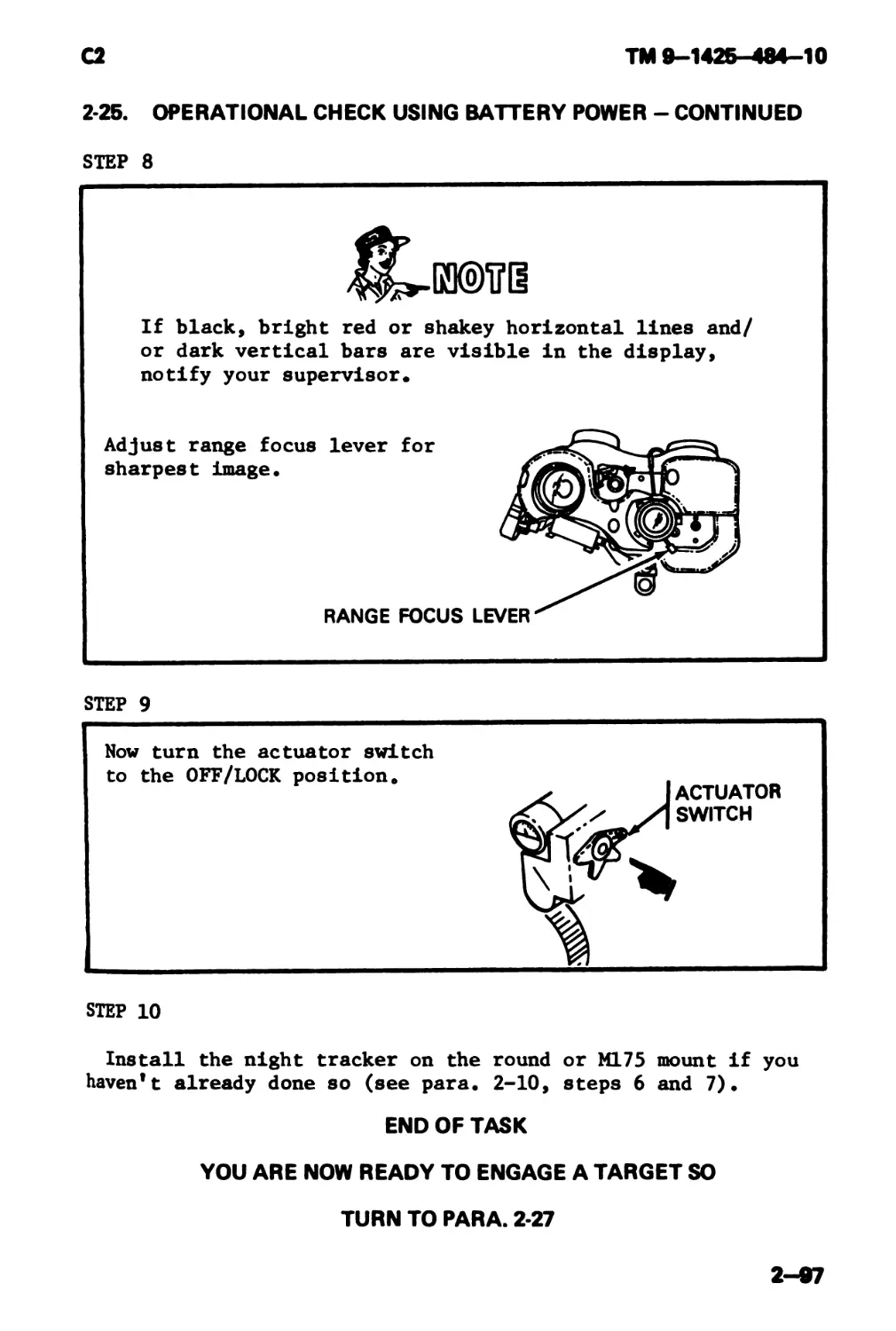
RANGE FOCUS LEVER -
Is used with BRT and CTRS
controls to adjust for
best picture.
2—7
ТМ 9-1425-484-10
Section II. PREVENTIVE MAINTENANCE CHECKS
AND SERVICES
Para Page
Service Upon Receipt 2-5 2-9
Preventive Maintenance Checks end Services (PMCS) 2-6 2-9
Day Tracker Table 2-1 2-10
Night Tracker Table 2-2 2-13
Round ТеЫе 2-3 2-16
M175 Mount Table 2-4 2-17
2-8
ТМ 9-1426-484-10
2-6. SERVICE UPON RECEIPT
If you are issued any of the following items, inventory it.
While performing the inventory, check the items for damage. If
anything is missing or damaged, notify your supervisor.
ITEM
Day Tracker
Night Tracker
M175 Mount
INVENTORY PER
Appendix B, page B-3 to B-5
Appendix B, page B-6 to B-8
Appendix B, page B-9 to B-ll
Shipping containers listed in Appendix В are reusable
and must not be discarded.
END OF TASK
Follow-on Task: Perform PMCS (see para. 2-6)
2-6. PREVENTIVE MAINTENANCE CHECKS AND SERVICES (PMCS)
a. Before you operate. Always keep in mind the CAUTIONS
and WARNINGS. Perform your BEFORE (B) PMCS.
b. After you operate, be sure to perform your AFTER (A)
PMCS.
c. Column entries used in PMCS.
(1) Column 1, Item No. Numbers the checks and services in
the order they are to be performed. The column will be used
as a source of item for the "TM Number" column on DA Form 2404,
Equipment Inspection and Maintenance worksheet, in recording
results of PMCS.
(2) Column 2, Interval. Specifies the intervals at which
the PMCS will be performed. The "B" interval requires the
check to be performed "Before Operation". The "A" interval re-
quires the check to be performed "After Operation". The "Q"
interval requires the check to be performed "Quarterly".
(3) Column 3, Item to be Inspected. Identifies the por-
tion of the system to be inspected.
2-9
TM 9-1425-^484—10
2-6. PREVENTIVE MAINTENANCE CHECKS AND SERVICES (PMCS) -
CONTINUED
(4) Column 4, Procedures. Provides the procedure for per-
forming the check.
(5) Column 5t For Readiness Reporting. Equipment is not
ready/available if: Column 5 contains the criteria which will
render the system incapable of performing its primary mission.
TABLE 2-1
PREVENTIVE MAINTENANCE CHECKS AND SERVICES
FOR
DAY TRACKER
В * BEFORE A - AFTER Q - QUARTERLY
Item No. Interval Item to be Inspected Procedures Check for and have repaired or adjusted as necessary For readiness reporting equipment is not ready/available if:
В A Q
ми®
When inspecting the tracker
firing mechanism, DO NOT
install the tracker on the
round.
Check operation of firing
mechanism.
Push the safety button in.
Does it operate smoothly?
Hold the safety in and
squeeze the trigger. Did
it click?
Release the safety. Now
squeeze the trigger again.
The safety should prevent
the trigger operation.
Firing
Mechanism
inoperable
2-10
сз
ТМ 9—1425—484—10
2-6. PREVENTIVE MAINTENANCE CHECKS AND SERVICES (PMCS) -
CONTINUED
TABLE 2-1
PREVENTIVE MAINTENANCE CHECKS AND SERVICES
FOR
DAY TRACKER - CONTINUED
В-BEFORE A-AFTER Q-QUARTERLY
Item No. Interval Item to be Inspected Procedures Check for and have repaired or adjusted as necessary For readiness reporting equipment is not resdy/avalable if:
В A Q
2
Optics
Make a visual inspection of
lenses for dirt or for signs
of internal moisture. Look
through the sight and check
for a clear unfogged sight
picture. If dirty, clean
them. See para. 3-3. If
foggy, turn in to Direct
Support Maintenance.
Lenses have
internal
moisture or
sight picture
not visible.
Guide
Pins
Check all four guide pins
for damage or missing pins.
Guide pins
damaged or
missing.
2-11
ТМ 9—1425—484—10
а
2-в. PREVENTIVE MAINTENANCE CHECKSAND SERVICES (PMCS) -
CONTINUED
TABLE 2-1
PREVENTIVE MAINTENANCE CHECKS AND SERVICES
FOR
DAY TRACKER - CONTINUED
В-BEFORE A-AFTER Q-QUARTERLY
Item No. Interval Item to be Inspected Procedures Chock for and have repaired or adjusted as necessary For readiness reporting . equipment is not reedy/avekabte if:
В A а
Don’t poke anything inside the connector. If you do you will damage the connec- tor.
4 • • Con- nector Remove connector cover and visually inspect cover and connector for damage or dirt. If its dirty, clean it. See para. 3-3. Connector is damaged.
5 • Tracker Housing Check paint for chips or scratches. Spot paint as necessary. See para. 3-9. PRACKER I 1OUSING
6 • Eyeguard Rotate the eyeguard. Eyeguard is missing.
7 • Tracker Notify Support Maintenance to perform operational test. Tracker fails operational test.
2—12
TM 9-1425-484-10
2-6. PREVENTIVE MAINTENANCE CHECKS AND SERVICES (PMCS) -
CONTINUED
TABLE 2-2
PREVENTIVE MAINTENANCE CHECKS AND SERVICES
FOR
NIGHT TRACKER
В - BEFORE A - AFTER Q - QUARTERLY
Item No. Interval Item to be Inspected Procedures Check for and have repaired or adjusted as necessary For readiness reporting equipment is not ready/available if:
В A Q
When inspecting the tracker firing mechanism, DO NOT install the tracker on the round.
1 • • Firing Mechan- ism Check operation of firing mechanism. Push the safety button in. Does it operate smoothly? Hold the safety in and squeeze the trigger. Did it click? Release the safety. Now squeeze the trigger again. The safety should prevent the trigger operation. Firing Mechanism inoperable
2 • • Optics Make a visual inspection of the lenses for dirt or for signs of internal mois- ture. If dirty, clean then See para. 3-4. If you see internal moisture, turn in to Direct Support Mainten- ance. Lenses have internal moisture. .
2-13
ТМ 9—1425—484—10
2-6. PREVENTIVE MAINTENANCE CHECKS AND SERVICES (PMCS) -
CONTINUED
TABLE 2-2
PREVENTIVE MAINTENANCE CHECKS AND SERVICES
FOR
NIGHT TRACKER - CONTINUED
В - BEFORE A - AFTER Q - QUARTERLY
Item
No.
Interval
Item to be
Inspected
В
Q
Procedures
Check for and have
repaired or adjusted
as necessary
For readineM
reporting
equipment is not
ready/avateble
if:
3
Guide
Pins
Check all four guide pins
for damage or missing pins.
Guide pins
damaged or
missing.
EYE GUARD
GUIDE
PIN
CONNECTOR
Illi
CONNECTOR
COVER
Don’t poke anything inside
the connector. If you do
you will damage the connec-
tor.
Connec-
tor
Remove connector cover and
visually inspect cover and
connector for damage or
dirt. If it's dirty clean
it. See para. 3-4.
Connector is
damaged.
2-14
TM 9-1425-484-10
2-8. PREVENTIVE MAINTENANCE CHECKS AND SERVICES (PMCS) -
CONTINUED
TABLE 2-2
PREVENTIVE MAINTENANCE CHECKS AND SERVICES
FOR
NIGHT TRACKER - CONTINUED
В-BEFORE A-AFTER
5
6
7
8
Item
No.
Interval
В A Q
• •
•
• •
Item to be
Range
Focus
Control
Q-QUARTERLY
Procedures
Check for end have
repaired or adjusted
Check for freedom
ment. _
For reediness
reporting
equipment is not
ready/avaHable
if:
Control binds
of
move-
RANGE
CONTROL [ Tj5J
Night Tracker Perform operational check. See para. 2-25 and 2-26. Fails opera- tional check.
Eyeguard Rotate the eyeguard. Eyeguard is missing.
Night Tracker Notify Support Maintenance to perform operational test. Night tracker fails opera- tional test.
2-15
ТМ 9—1426—484—10
2-6. PREVENTIVE MAINTENANCE CHECKS AND SERVICES (PMCS) -
CONTINUED
TABLE 2-3
PREVENTIVE MAINTENANCE CHECKS AND SERVICES
TOR
ROUND
В - BEFORE A - AFTER Q - QUARTERLY
Item
No.
Interval
Item to be
Inspected
В
A
Q
Procedures
Check for and have
repaired or adjusted
es necessary
reporting
equipment is not
reedy/avateblo
If:
1
Round
CONNECTOR
RACEWAY
Inspect for dirt or damage.
If dirty, clean it. See
para. 3-6. If damaged,
notify your supervisor.
2
Connec-
tor and
raceway
Inspect connector and race-
way for damage. If damaged
notify your supervisor.
2-16
ТМ 9—1426—484—10
2-6. PREVENTIVE MAINTENANCE CHECKS AND SERVICES (PMCS) -
CONTINUED
TABLE 2-4
PREVENTIVE MAINTENANCE CHECKS AND SERVICES
FOR
M175 MOUNT
В - BEFORE A - AFTER Q - QUARTERLY >
Item No. Interval В A Q Item to be Inspected Procedures Check for and have repaired or adjusted as necessary For readiness reporting equipment is not ready/available if:
Ш0Б0®
When inspecting the remote
firing mechanism, DO NOT
install a round in the
mount.
Remote
Firing
Mechan-
ism
Check operation of remote
firing mechanism.
Push the safety button in.
Does it operate smoothly?
Hold the safety in and
squeeze the trigger. Did
it click?
Release the safety. Now
squeeze the trigger again.
The safety should prevent
the trigger operation.
2-17
ТМ 9-1425-484-10
2-6. PREVENTIVE MAINTENANCE CHECKS AND SERVICES (PMCS) -
CONTINUED
TABLE 2-4
PREVENTIVE MAINTENANCE CHECKS AND SERVICES
FOR
M175 MOUNT - CONTINUED
В * BEFORE A - AFTER Q * QUARTERLY
Interval
Item to be
Inspected
Procedures
Check for and have
repaired or adjusted
as necessary
For readiness
reporting
equipment is not
ready /available
if:
M175 Inspect for damage. If
MQunt damaged, notify your super-
visor.
3
Don’t poke anything inside
the connector. If you do
you will damage the connec-
tor.
Connec- Inspect for dirt or damage,
tors If dirty, clean it. See
para. 3-5. If damaged,
notify your supervisor.
2-18
Cl
TM 9—1426—484—10
2-4. PREVENTIVE MAINTENANCE CHECKSAND SERVICES (PMCS) -
CONTINUED
TABLE 2-4
PREVENTIVE MAINTENANCE CHECKS AND SERVICES
FOR
M175 MOUNT - CONTINUED
В-BEFORE A-AFTER Q-QUARTERLY
Item No. Interval Item to be Inspected
В A Q
Procedures
Check for and have
repaired or adjusted
aaneceaaary
For readiness
reporting
equipment is not
ready/available
if:
4.
Mount
Shock
Absorber
Inspect for dirt or damage.
If dirty, clean it. If
damaged or missing, notify
your supervisor.
CONTROL
5.
Elevation
Control
Check that the elevation
control provides smooth up
and down movement of the
cradle. You should feel
resistance to any rapid
movement of the cradle.
2-18.1
ТМ 9-1425-484-10
Cl
2-8. PREVENTIVE MAINTENANCE CHECKS AND SERVICES (PMCS) -
CONTINUED
TABLE 2-4
PREVENTIVE MAINTENANCE CHECKS AND SERVICES
FOR
Ml 75 MOUNT - CONTINUED
В-BEFORE A-AFTER
Q-QUARTERLY
Item No. Interval Item to be Inspected Procedures Check for and have repaired or adjusted as necessary
В A Q
6. • • Azimuth Damper 1 r "ч! AZIMUTH'*' DAMPER Check that the azimuth dam- per provides smooth left and right movement of the cradle. You should feel resistance to any rapid movement of the cradle. If not, notify your super- visor. w
ForreadineM
reporting
equipment b not
ready/avaRabie
if:
2-18.2
ТМ 9-1425-484-10
2-6. PREVENTIVE MAINTENANCE CHECKS AND SERVICES (PMCS) -
CONTINUED
TABLE 2-4
PREVENTIVE MAINTENANCE CHECKS AND SERVICES
FOR
Ml75 MOUNT - CONTINUED
В-BEFORE A-AFTER Q-QUARTERLY
7.
Interval
В A Q
• •
Item to be
Inspected
Procedures
Check for and have
repaired or adjusted
as necessary
For readiness
reporting
equipment is not
ready/available
if:
Spring clip (1), must touch
both clip retainer (2) and
tracker bracket (3) as
shown. If not, notify your
supervisor.
S/N 2038Э0 AND UP
2-18.3
TM 9-1425-484-10
Cl
2-8. PREVENTIVE MAINTENANCE CHECKS AND SERVICES (PMC8) -
CONTINUED
TABLE 2-4
PREVENTIVE MAINTENANCE CHECKS AND SERVICES
FOR
M175 MOUNT - CONTINUED
В-BEFORE A-AFTER Q-QUARTERLY
hern No. Interval Item to be Inspected Procedures Check for and have repaired or adjusted as necessary For reediness reporting equipment not ready/avateble if:
В A Q
8. • • Check Round Fit 7^-G3©,u’@S For steps 8 through 10, use LET if possible, If LET is not available, use an ex- pended round or Field Hand- ling Trainer (FHT). Install LET, Expended Round or FHT. See para. 2-16.
2-18.4
Cl
ТМ 9—1425—484—10
2-в. PREVENTIVE MAINTENANCE CHECKSAND SERVICES (PMCS) -
CONTINUED
TABLE 2-4
PREVENTIVE MAINTENANCE CHECKS AND SERVICES
FOR
Ml75 MOUNT - CONTINUED
B-BEFORE A-AFTER Q-QUARTERLY
Item
No.
Interval
Item to be
Inspected
Procedures
Check for and have
repaired or adjusted
as necessary
For readiness
reporting
equipment is not
reedy/avaHable
if:
8.
Check
Round
Fit
(Con't.)
Observe cradle hook (1) §s
tracker aubmount (3) is
mated with LET. There must
be visible clearance be-
tween hook (1) and plate
(2).
If hook (1) will not allow
proper mate of tracker sub-
mount, notify your super-
visor.
2-18.5
TM 9-1426 484 -10
Cl
2 8z PREVENTIVE MAINTENANCE CHECKSAND SERVICES (PMCS) -
CONTINUED
TABLE 2-4
PREVENTIVE MAINTENANCE CHECKS AND SERVICES
FOR
Ml 7 5 MOUNT - CONTINUED
B-BEFORE A-AFTER Q-QUARTERLY
Item No. Interval Item to be Inspected Procedures Check for and have repaired or adjusted as necessary For reedtoeoe reporting equipment to not ready/avaiabie if:
В A Q
9. • • Check Round Fit * For steps 8 through 10, use LET if possible. If LET is not available, use an ex- pended round or Field Hand- ling Trainer (FHT). Install LET, Expended Round or FHT. See para. 2-16. Observe spring clip snaps in place behind guide pin
If spring clip does not en-
gage guide pin as shown,
notify your supervisor.
2-18.6
ТМ 9-1425-484-10
2-6. PREVENTIVE MAINTENANCE CHECKSAND SERVICES (PMCS) -
CONTINUED
В-BEFORE A-AFTER Q-QUARTERLY
Item
No.
Interval
Item to be
Inspected
Procedures
Check for and have
repaired or actuated
as necessary
Forreadfneea
reporting
equipment is not
ready/avaflable
if:
Check
Tracker
Fit
Install tracker (day or
night). See para. 2-17.
Observe spring clip snaps
In place behind guide pin
as shown.
If spring clip does not en-
gage guide pin as shown,
notify your supervisor.
2-18.7
ТМ 8—1426 484 -10
Cl
2-8. PREVENTIVE MAINTENANCE CHECKSAND SERVICES (PMCS) -
CONTINUED
TABLE 2-4
PREVENTIVE MAINTENANCE CHECKS AND SERVICES
FOR
Ml75 MOUNT - CONTINUED
В-BEFORE A-AFTER Q-QUARTERLY
Item No. Interval Item to be Inspected Procedures Check for and have repaired or adjusted as necessary ForreadineM reporting equipment is not ready/avaiabie if:
В A Q
10. • • Cradle Strap Check that the cradle strap operates easily and locks onto the Tee-bolt securly, if not notify your super- visor. See para. 2-16 and 2-19.
2-18.8
Cl
ТМ 9-1426 484 -10
2-4. PREVENTIVE MAINTENANCE CHECKSAND SERVICES (PMCS) -
CONTINUED
TABLE 2-4
PREVENTIVE MAINTENANCE CHECKS AND SERVICES
FOR
Ml 75 MOUNT - CONTINUED
В-BEFORE A-AFTER
Q-QUARTERLY
Item
No.
11.
Interval
Item to be
Inspected
Launcher
Mount
Adapter
for
or
super
Procedures
Check for and have
repeired or adjusted
as necessary
Check screws (1) on launch-
er mount adapter (2)
tightness. If loose
missing, notify your
visor
For readiness
reporting
equipment is not
ready/available
if:
2-19
TM 8-1426 484 -10
Cl
2-в. PREVENTIVE MAINTENANCE CHECKSAND SERVICES (PMCS) -
CONTINUED
TABLE 2-4
PREVENTIVE MAINTENANCE CHECKS AND SERVICES
FOR
M175 MOUNT - CONTINUED
B-BEFORE A-AFTER Q-QUARTERLY
hem No. Interval Item to be Inspected Procedures Check for and have repaired or adjusted as necessary Forreedtnesa reporting equipment is not ready/avaHabte if:
В A Q
I12- • M175 Mount Operate the M175 Mount, see para. 2-19, steps 1 thru 6. If the M175 Mount does not operate as stated, notify your supervisor.
13. • Ml 7 5 Mount Notify Support Maintenance to perform operational check and mechanical in- spection, see TM 9-4935- 484-14.
2-20
ТМ 9-1425-484-10
Section III. GENERAL OPERATING INSTRUCTIONS
Para Page
Select e Carrying Position 2-7 2-22
Select a Firing Site 2-8 2-24
Select a Firing Position 2-9 2-25
Prepare the Round for Firing 2-10 2-29
Acquire Target and Evaluate Range 2-11 2-35
Tracking a Target 2-12 2-39
Firing the Missile 2-13 2-40
2-21
TM 9-1425-484-10
There are things that should be done before you get in a tac-
tical situation. Make sure you have performed your PMCS like
it tells you in para. 2-6.
2-7. SELECT A CARRYING POSITION.
Any of five positions can be used.
ACROSS BACK
2-22
TM 9-1425-484-10
2-7. SELECT A CARRYING POSITION - CONTINUED
Careful now. If you carry your weapon with the
tracker mated to the round, the DRAGON is ready-
to-fire. Keep distances short, as in movement
between firing positions. WATCH YOUR STEP!
Tracker mated to round.
Tracker mated to round.
YOU ARE NOW READY TO
SELECT A FIRING SITE
GO TO NEXT PAGE
2-23
TM 9-1425-484-10
2-8. SELECT A FIRING SITE
ШИПИ®
you can.
MJ Stay out of this zone.
Blast can cause severe
injury.
a. Field of fire ... Be sure your field of fire down range
is clear of obstructions, such as trees, brush, buildings,
power lines or large rocks that interfere with your LOS. Pre-
mature warhead detonation could occur if the missile should hit
them.
b. Rear danger area ... Be sure no friendly troops are in
zone 2 or 3. The area directly behind the launcher should be
clear of obstructions and loose objects for at least 30 meters.
Solid objects in the backblast danger zone can deflect shock
waves or debris toward you.
YOU ARE NOW READY TO PREPARE THE ROUND FOR FIRING
TURN TO PARA. 2-10.
2-24
ТМ 9-1425-484-10
-9. SELECT A FIRING POSITION
Any of four positions can be used.
DO NOT push tube forward on bipod legs, it may cause
the bipod to collapse.
A. Keep legs as straight as possible with feet against feet
of bipod.
B. Hold launcher on meaty part of shoulder and neck while
leaning body forward at waist.
SITTING
C. Keep right eye firmly in eyepiece.
D. Pull down and back on the tracker.
2-25
ТМ 9-1426 484 -10
2-9. SELECT A FIRING POSITION - CONTINUED
DO NOT push tube forward on bipod legs, it may cause
the bipod to collapse.
A. Knees on ground spread outward at a convenient angle and
toes on ground.
B. Buttocks resting on heels of boots.
C. Body leaning forward at waist.
KNEELING
D. Hold launcher on meaty part of shoulder and neck.
E. Keep right eye firmly in eyepiece.
F. Pull down and back on the tracker.
2-26
3
ТМ 9—1425—484—10
*-9. SELECT A FIRING POSITION - CONTINUED
A. Legs spread a comfortable distance apart with feet
pointed outward.
DO NOT push tube forward on bipod legs, it may cause
the bipod to collapse.
B. Lean body forward against wall of position and keep
elbows tucked in.
STANDING-SUPPORTED
C. Keep right eye firmly in eyepiece.
D. Pull down and back on tracker.
TM 9—1425—484—10
2*9. SELECT A FIRING POSITION - CONTINUED
Injury to your backside and legs may occur if they
extend into the backblast area.
The prone position is the least desirable,
difficult to track moving targets from this
tion.
It’s
posi-
A. Forward end of launch tube resting on dirt mound (minimum
six inches high).
B. Body position at near 90 degree angle to the tube with
elbows on ground.
PRONE
C. Keep right eye firmly in eyepiece.
D. Pull down and back on the tracker.
2-28
TM 9-1425-484-10
2-10. PREPARE THE ROUND FOR FIRING
STEP 1
RELEASE THE BIPOD!
Unsnap the bipod
retainer strap.
sure
BRACE
Push the bipod forward to
release and eject the for-
ward shock absorber.
Check to make
the launch tube is
nose cone is visible.
that the forward end of
clear and the
missile
step 2
[й©?@
Make sure that the forward
bipod brace is engaged in
the lock position.
EXTEND THE BIPOD LEGS AND ADJUST THE HEIGHT
д. Grasp the legs by the
friction
lo ck.
B. Push the
number 4
lease the lock.
legs down to
or 5, and re-
FRICTION
LOCK
GO TO NEXT PAGE
2-29
ТМ 9-1426-484-10
2-10. PREPARE THE ROUND FOR FIRING - CONTINUED
STEP 3
Select a firing position that best meets your situation (see
para. 2-9).
For purposes of illustration the sitting position is used in
this section.
REMOVE THE DAY TRACKER FROM THE CARRYING BAG
A. Pull the carrying bag flap
open and hold it open with
your right hand.
• Don't attempt to lift the day tracker using the shock
absorbers as handles. They might tear off.
• Do not touch the lens! You can damage them by just
touching them with your fingers.
B. Reach in and grab the day
tracker by the telescope
barrel.
C. Lift the day tracker from
the bag.
GO TO NEXT PAGE
2-Э0
TM 9—1425—484—10
MO. PREPARE THE ROUND FOR FIRING - CONTINUED
STEP 4
CONNECTOR
COVER
A.
B.
Pull the connector cover
off the day tracker and
stow it on the velcro strip
on top of the forward shock
absorber.
Pull the connector cover
off the round
STEP 5
ШИ0И®
Be careful not to press the safety and trigger while
mating the day tracker to the round.
MATE DAY TRACKER TO ROUND
A. Place tracker guide pins
in slots of tracker bracket
guide rails.
B. Slide day tracker firmly
to the rear using both
hands, until the spring
clip locks the guide pin
in place. If the tracker
won't mate, refer to para.
3-2.
GO TO NEXT PAGE
2-31
ТМ 9—1426—484—10
2-10. PREPARE THE ROUND FOR FIRING - CONTINUED
STEP 5 - CONTINUED
GO TO NEXT PAGE
2-32
TM 9-1426-484-10
2-10. PREPARE THE ROUND FOR FIRING - CONTINUED
STEP 6
ADJUST FOR HEIGHT AND A LEVEL SIGHT PICTURE
A. Look through the sight
and if you see this ...
C. Obtain a level sight picture.
Adjust the bipod friction
lock and foot adjusts and..
STEP 7
PREFORM A FINAL CHECK
Is danger zone clear? (See para. 2-8).
Is launch tube clear? (See para. 2-10),
Is tracker mated? (See para. 2-10).
Is tracker lens cover off? (See para. 2-10).
Are ear plugs in? (See para. 2-8).
STEP 8
Lock your body into a good firing position.
If you wear glasses, remove them.
GO TO NEXT PAGE
2-33
TM 9—1425—484—10
a
2-10. PREPARE THE ROUND FOR FIRING - CONTINUED
STEP 9
2-34
2
ТМ 9-1425-484-10
11. ACQUIRE TARGET, EVALUATE RANGE AND DETERMINE
ENGAGEABILITY USING DAY TRACKER.
ТЕР 1
A.
ACQUIRE TARGET
Look at target through the sight.
B.
C.
SIGHT ADJUSTING RING
EYEGUARD
Focus the sight using the
sight adjusting ring.
Rotate the eyeguard to fit
your face.
asm®
Do not engage targets at less than 65 meters,
warhead will not be armed.
The
A target 20 feet (.6.09 meters) in length will completely
fill the area between the stadia lines at maximum range
(1,000 meters) and will exceed the stadia lines at a
closer range.
GO TO NEXT PAGE
2-36
TM 9-1425-484-10
2-11. ACQUIRE TARGET, EVALUATE RANGE AND DETERMINE
ENGAGEABILITY USING DAY TRACKER - CONTINUED
STEP 2
EVALUATE RANGE
A. Flank targets.
IN RANGE OUT OF RANGE
B. Head-on/Going-away targets.
GO TO NEXT PAGE
2-36
TM 9-1425-484-10
2-11. ACQUIRE TARGET, EVALUATE RANGE AND DETERMINE
ENGAGEABILITY USING DAY TRACKER - CONTINUED
STEP 2 - CONTINUED
C. Oblique targets. To determine range to oblique targets,
the rule is if more of the flank is visible, use the full
distance between the stadia lines. If the front or rear
shows more than the' flank, use a stadia line and cross-
hairs (1/2 stadia sight picture).
IN RANGE OUT OF RANGE
MORE FRONT OR REAR VISIBLE
GO TO NEXT PAGE I
2-37
ТМ 9-1425-484-10
Q
2-11. ACQUIRE TARGET, EVALUATE RANGE AND DETERMINE
ENGAGEABILITY USING DAY TRACKER - CONTINUED
STEP 3
A. A moving target may be able to find a covered position
protecting himself from your DRAGON. You must be able
to judge if your missile will successfully hit the tar-
get after launch. The tracker sight can be used to help
you make this determination. Line up the tracker sight
directly in front of your target. If there is no ob-
struction or covered area along the expected path of the
target and the target is moving 35kph or less, you can
successfully launch and destroy him.
END OF TASK
YOU ARE NOW READY TO TRACK A TARGET
GO TO NEXT PAGE
2-38
С2
TM 9—1425—484—10
2-12. TRACKING A TARGET
STEP 1
MOVING TARGET
A. Center the crosshairs on the center of visible mass of
the target.
FLANK
OBLIQUE
FRONT OR REAR
B. Excessive or jerky movement of the tracker while the
missile is in flight may cause you to miss the target.
C. Track target for approximately two seconds prior to
trigger squeeze. This establishes a smooth tracking
rate used during missile flight.
STEP 2
STATIONARY TARGET
Center the crosshairs on the
center of visible mass of the
target until missile impact.
END OF TASK
YOU ARE NOW READY TO FIRE THE MISSILE
GO TO NEXT PAGE
2-39
TM 9-1425-484-10
a
2-13. FIRING THE MISSILE
Always keep downward and rearward pressure on the
round. Don’t push forward against the bipod, it
could collapse.
Just before you squeeze the trigger, take a breath
and HOLD IT! You must hold your breath until missile
impact. Normal breathing causes your shoulder to
move up and down. One-eighth inch movement at the
shoulder can cause a miss of two meters at maximum
range.
A. Depress the safety and squeeze the trigger. Maintain
crosshairs on center of visible mass until missile im-
pact.
• If you have a malfunction and your missile doesn’t
fire, take immediate action like it tells you in
para. 2-14. You can also use the troubleshooting
charts in para. 3-2.
• When the missile appears in your sight picture IGNORE
IT.’! DON’T TRY TO FLY THE MISSILE.’
B. Keep crosshairs on the target and let the tracker do the
guiding of the missile . . .
_____________________________________________GO TO NEXT PAGE
2-40
С2
ТМ 9-1425-484-10
2-13. FIRING THE MISSILE-CONTINUED
C. After missile impact, release
the spring clip at rear left
side of tracker bracket assem-
bly, slide
remove.
tracker forward and
SPRING CLIP
ZSKBODGO©
and rear of the launch tube are hot
The battery
so don’t touch them
In combat you will want to destroy the expended
launch tube so the enemy cannot use it against you
as a field expedient mine or booby trap.
or
During non-combat exercises you may want to keep
the expended launch tube for repair of damaged
field handling trainers. Be sure to have the
launch tube certified free of explosives.
(See TM 9-1410-480-34)
END OF TASK
ТМ 9—142Б—484—10
a
Section IV. EMERGENCY PROCEDURES
2*14. IMMEDIATE ACTION
What do you do when your missile doesn't fire?
You may have one of two situations . . .
a MISFIRE or HANGFIRE
'^ЙМзиои©
A hangfire cannot be immediately distinguished from
a misfire. A hangfire is a delayed firing and can
be hazardous.
Whatever the case you need to follow these steps.
STEP 1
A. Squeeze the trigger again while tracking the target.
B. If missile hasn't fired, carefully feel near the tracker
battery. If battery is hot, go to step 2. If battery
is cold, go to step 3.
2-42
С2
ТМ 9-1426-484-10
2-14. IMMEDIATE ACTION-CONTINUED
STEP 2
HANGFIRE
A. If your tracker battery is hot, you may have a hangfire.
In a non-combat situation wait 5 minutes before going
to step B.
B. Remove the tracker and carefully lay the round on the
ground away from your firing site. Keep the round
pointed at the enemy. Obtain another round and continue
the mission.
C. Notify your supervisor.
2-43
TM 9—1425—484—10
2-14. IMMEDIATE ACTION - CONTINUED
STEP 3
MISFIRE
A. If your tracker battery is cold, you have a misfire.
B. Loosen, then remate the tracker to the round. Acquire
your target and squeeze the trigger again.
C. Now if the missile hasn't fired, carefully feel near the
battery. If hot, go back to step 2.
D. If the battery is still cold, remove the tracker. Next,
carefully lay the round on the ground away from your
firing site. Keep the round pointed at the enemy.
E.
Obtain another round and continue the mission.
If your missile fails to fire after attempting to
fire with a new round, you may have a faulty tracker.
Notify your supervisor.
END OF TASK
2-44
ТМ 9-1425-484-10
Section V. OPERATING THE M175 MOUNT ON APC
Para Page
Prepare the Mount for Installation of the Round 2-15 2-46
Install the Round 2-16 2-50
Install the Day Tracker 2-17 2-55
Install the Night Tracker 2-18 2-55
Operating Procedures — M175 Mount 2-19 2-56
Preparation for Movement 2-20 2-68
2-45
TM 9-1425-484-10
a
I OVERVIEW |
The M175 mount provides a stable platform from which to fire
the missile. The M175 mount should be installed by your track
mechanic using TM 9-1425-484-24. Make sure you have performed
your PMCS like it tells you in para. 2-6.
2-15. PREPARE THE MOUNT FOR INSTALLATION OF THE ROUND
Once your vehicle has reached a good firing site you will
want to prepare the mount for installation of the round.
STEP 1
Remove the protective cover and stow it.
GO TO NEXT PAGE
2-45
ТМ 9-1425-484-10
2-15. PREPARE THE MOUNT FOR INSTALLATION OF THE ROUND -
CONTINUED
STEP 2
2-47
TM 9-1425-484-10
2*15. PREPARE THE MOUNT FOR INSTALLATION OF THE ROUND -
CONTINUED
STEP 3
2—48
TM 9-1425-484-10
15. PREPARE THE MOUNT FOR INSTALLATION OF THE ROUND -
CONTINUED
ГЕР 4
Lift the strap assembly up and over to the right side of the
cradle.
STRAP ASSEMBLY
END OF TASK
YOU ARE NOW READY TO INSTALL THE ROUND
GOTONEXTPAQE
2-49
ТМ 9—1426-484—10
2-16. INSTALL THE ROUND
STEP 1
Remove the forward shock from the round (see para. 2-10).
Fold and secure the bipod to the round with the bipod strap.
ж
TH
• Keep the forward shock in case you have to remove the
round from the mount. Always replace the shock to
prevent excess moisture and dirt from entering the
round.
• When installing the round in the mount make sure that
the hooks on the bipod are aligned with the notches
in the rubber shock mount on the forward end of the
GO TO NEXT PAGE
2-60
TM 9-1425-484-10
2-16. INSTALL THE ROUND - CONTINUED
STEP 2
2-51
TM 9-1425-484-10
2-16. INSTALL THE ROUND - CONTINUED
STEP 2 - CONTINUED
C. Now push forward on the round. This will cause the tang
in the center of the adaptor to engage the bipod brace.
If this does not happen the tracker mount will not mate
with the round.
<30 TQ NEXT PAGE
2-52
ТМ 9-1425-484-10
2*16. INSTALL THE ROUND - CONTINUED
STEP 3
Make sure you secure the strap assembly after you
load the round in the cradle assembly. The strap
must be secured when the Round is fired. The
strap must also be secured while traveling.
Place the strap assembly on the rear of the cradle
over the rear of the round and attach it to the Tee-
bolt. If the strap will not catch to the Tee-bolt,
adjust it. (See TM 9-1425-484-24).
STEP 4
CONNECTOR COVER
CONNECTOR
COVER
CONNECTOR
COVER
GO TO NEXT PAGE
A.
Remove the connector cover
from the round
Remove the two connector
covers from the tracker
mount (top and bottom).
2-53
TM 9-1426-484-10
2-16. INSTALL THE ROUND - CONTINUED
STEP 5
A.
Lift the tracker mount
and rotate it down onto
the tracker bracket on
the round. Make sure
that the four guide pins
on the tracker mount
(two on each side) fit
into the slots in the
tracker bracket.
GUIDE
PINS
TRACKER BRACKET
ЕМЙИОиЗ©
Keep your hands off the remote firing mechanism until
you are ready to acquire the target.
B„. Push down on the tracker
mount and pull it to the
rear until the spring clip
on the left side of the
tracker bracket engages
the guide pin on the
tracker mount. /
RIGHT SIDE VIEW
END OF TASK
YOU ARE NOW READY TO INSTALL THE TRACKER
LEFT SIDE VIEW
GO TO NEXT PAGE
2-64
Cl
TM 9—1425-484—10
2-17. INSTALL THE DAY TRACKER
Be careful not to press the safety and trigger while
mating the day tracker to the round.
MATE DAY TRACKER ТОМ17Б MOUNT
A.
B.
c.
Place tracker guide pins
in slots of tracker bracket
guide rails.
Slide day tracker firmly
to the rear using both
hands, until the spring
clip locks the guide pin
in place. If the tracker
won't mate, refer to para
3-2.
TRACKER
BRACKET
LENS
COVER
VELCRO
STRIP
lens cover and
the velcro strip
Remove the
stow it on
on top of the front shock
absorber
GO TO NEXT PAGE
2-55
ТМ 9-1425-484-10
Cl
2-18. INSTALL THE NIGHT TRACKER
Installation of night tracker is the same as the day tracker
(see para. 2-17).
Now that the round and tracker have been installed on
the mount you still have a few more important things
to check.
Is the field of fire and firing danger zone clear?
(See para. 2-8).
Is the antenna down and secured?
Is the driver's hatch and cargo hatch closed?
Is all equipment stored on top of the APC secured?
Is all other loose debris removed?
YOU ARE NOW READY TO OPERATE
THE M175 MOUNT AND ENGAGE A
TARGET
GO TO NEXT PAGE
2-58
ТМ 9-1425-484-10
2-19. OPERATING PROCEDURES - M175 MOUNT
STEP 1
A. Reach inside the commander's hatch and on the ceiling of
the APC you will find the azimuth latch.
GO TO NEXT PAGE
2-56.1/(2-56.2 blank)
TM 9-1425-484-10
2-19. OPERATING PROCEDURES - M175 MOUNT - CONTINUED
STEP 2
Remove the quick release pin by depressing the button on top
and remove it from the adaptor post and stow it.
GO TO NEXT PAGE
2-57
TM 9-1425-484-10
2-19. OPERATING PROCEDURES - M175 MOUNT - CONTINUED
STEP 3
A. Before you rotate the mount
and swingarm to the firing
position, take a close look
at the latch handle assembly
and adaptor.
LATCH
BAR
DETENTS
You will notice the latch
handle has a latch bar and
is spring loaded (squeeze
the handle and check it
out).
ADAPTOR
C.
Now take a look at the
adaptor and you will see
that it has two detents.
GO TO NEXT PAGE
2-58
ТМ 9-1425-484-10
2-19. OPERATING PROCEDURES - M175 MOUNT - CONTINUED
STEP 3 - CONTINUED
D.
When the swingarm and latch
bar are engaged in the for-
ward detent position the
mount is said to be in the
travel lock position.
E.
When the swingarm and latch
bar are engaged in the rear
detent position the mount
is said to be
position.
SWINGARM
FORWARD DETENT
in the
firing
GO TO NEXT PAGE
2-59
TM 9-1425-484-10
2-19. OPERATING PROCEDURES - M175 MOUNT - CONTINUED
STEP 4
A. Using your right hand, grasp the right rear side of the
cradle and rotate the mount on the azimuth damper until
the rear shock on the round butts against the hatch
cover. The cradle will move just enough for the ear on
the cradle to clear the adaptor post on the brush shield.
GO TO NEXT PAGE
2-60
сз
ТМ 9-1425-484-10
219. OPERATING PROCEDURES - М175 MOUNT - CONTINUED
STEP 4 - CONTINUED
B. Squeeze the latch handle and hold it.
C. Now push the swingarm forward until the swingarm engages
the stop on the brush shield mount. As you push forward,
make sure that the elevation control clears the adapter
post on the brush shield.
D. Slightly elevate the rear of the mount and pull the
swingarm to the rear. Once the swingarm has passed
the forward detent position (see step 3) release the
latch handle and pull the swingarm back to the firing
position. Be sure that you keep the rear of the mount
elevated until it clears the hatch cover.
GO TO NEXT PAGE
2-61
TM 9—1425—484—10
2-19. OPERATING PROCEDURES - M175 MOUNT - CONTINUED
AIMING CORRECTIONS IN AZIMUTH
A. Push against the rear of the M175 mount with your neck
and shoulder for right to left tracking.
B. Pull against the remote firing mechanism with the palm
of the right hand for left to right tracking.
GO TO NEXT PAGE
2-62
ТМ 9-1425-484-10
2-19. OPERATING PROCEDURES - М17Б MOUNT - CONTINUED
STEP 7
Sighting, aiming and firing the missile are the same as you
did in para. 2-11, 2-12 and 2-13 except that you use the remote
firing mechanism to launch the missile.
STEP 8
UNLOAD/RELOAD
After missile impact, release the bottom spring clip at the
left rear side of the tracker mount on the round.
A new round can be loaded in either the travel lock
or ready to fire position.
GO TO NEXT PAGE
2-83
TM 9-1425-484—10
2-19. OPERATING PROCEDURES - M175 MOUNT - CONTINUED
STEP 9
If the tracker mount is thrown up and over with too
much force, it will spring back and mash your fingers
or damage the equipment.
A. Slide the tracker mount forward.
B. Lift the tracker mount up and over to ttfe right.
GO TO NEXT PAGE
2-84
TM 9—1425—484—10
2-19. OPERATING PROCEDURES - M175 MOUNT - CONTINUED
STEP 10
The tracker battery and the breech will probably be
HOT! DO NOT touch or grab them or you will get burned.
If strap assembly is secured, release it by pressing down on
the center of strap (it takes a lot of pressure with the ball
of right hand) while lifting hook clear of "T" bolt with left
hand.
2-65
ТМ 9—1425—484—10
а
2-19. OPERATING PROCEDURES - М175 MOUNT - CONTINUED
STEP 11
2-66
TM 9-1425-484-10
1
•19. OPERATING PROCEDURES - M175 MOUNT - CONTINUED
TEP 11 - CONTINUED
В
Use the carrying sling and
raise the rear end of the
round, then slide the round
back and out of the cradle.
C. Discard the used launch
tube and install a new
round (see para. 2-16).
Be sure the quidance wire
is clear of the APC before
loading a new round.
In combat you will want to destroy the expended
launch tube so the enemy cannot use it against you
as a field expedient mine or booby trap.
END OF TASK
ONCE YOUR MISSION IS OVER PREPARE FOR MOVEMENT
______________GO TO NEXT PAGE___________
2-67
TM 9-1425-484-10
Cl
2-20. PREPARATION FOR MOVEMENT
WITH ROUND AND TRACKER INSTALLED
The M175 mount may be secured in the travel lock position
with the round and tracker installed, see Steps 1 through 7.
With round and tracker removed, see Steps 8 through 18. The
mount can also be left in the ready to fire position during
movement if action is anticipated. When the mount is secured
in the "travel lock" position, protection is provided by the
brush shield and protective cover.
The night tracker is powered by battery or VPC. When
preparing for movement and you are using battery power,
go to para. 2-28, steps 1 and 2. If you are using the
VPC go to para. 2-28, steps 4, 5 and 6.
STEP 1
• When rotating the mount to the travel lock position
with the round and tracker installed, make sure you
keep your hands off the firing mechanism. You don't
want to accidentally fire the missile.
• Keep your left hand on the latch handle when rotating
the mount or you may injure your hand.
Slightly elevate the rear of the mount using your right hand
and shoulder.
2-68
3
ТМ 9-1426-484-10
20. PREPARATION FOR MOVEMENT - CONTINUED
WITH ROUND AND TRACKER INSTALLED - CONTINUED
TEP 2
A. Squeeze the latch handle
Make sure you keep the rear of the mount elevated
until the rear shock on the round clears the hatch
cover.
B. Push the swingarm forward past che travel lock detent
position (see para. 2-19, step 3) until the swingarm
engages the stop on the brush shield mount.
QO TO NEXT PAGE
2-69
TM 9—142&-484—10
Cl
2-20. PREPARATION FOR MOVEMENT - CONTINUED
WITH ROUND AND TRACKER INSTALLED - CONTINUED
STEP 3
A
Release the latch handle,
but keep your hand on the
swingarm
LATCH
HANDLE
Lower the rear of the mount
to a near level position.
Now, pull the swingarm back and maneuver the mount on
the azimuth and elevation damper until the ear on the
cradle engages the slot in the adaptor post and the
swingarm locks in the travel lock position.
GO TO NEXT PAGE
2-70
Cl
ТМ 9-1425-484-10
2-20. PREPARATION FOR MOVEMENT - CONTINUED
WITH ROUND AND TRACKER INSTALLED - CONTINUED
STEP 4
Remove the quick release pin
from its stowed position and
insert it into the hole in
the top of the adaptor post.
STEP 5
STEP 6
Protective cover must be installed to protect controls
and moving parts from freezing rain and other adverse
weather conditions.
PROTECTIVE
COVER
Install the protective cover.
TEP 7
Rotate the turret until the brush shield is facing the front
f the APC, (see para. 2-19, step 1).
YOU ARE NOW READY TO MOVE OUT
With round and tracker removed:
00 TO NEXT PAGE
2-71
TM 9-1425-484-10
Cl
2-20. PREPARATION FOR MOVEMENT - CONTINUED
WITH ROUND AND TRACKER REMOVED
STEP 8
мои®
Keep your hands off tracker and remote firing mechan-
ism while removing the tracker from a live round.
Remove the day/night tracker, see para. 2-23, step 1.
STEP 9
Removal procedure for live round is same as removal
procedure for expended round.
Release the bottom spring clip at the left rear side of the
tracker mount on the round.
Round can be removed in either the travel lock or
ready to fire position.
GO TO NEXT FAGS
2-72
Cl
TM 9-1425-484-10
2*20. PREPARATION FOR MOVEMENT - CONTINUED
WITH ROUND AND TRACKER REMOVED - CONTINUED
STEP 10
мм
If the tracker mount is thrown up and over with too
much force, it will spring back and mash your fingers
or damage the equipment.
A. Slide the tracker mount forward.
B. Lift the tracker mount up and over to the right.
2-72.1
ТМ 9-1425-484-10
Cl
2-20. PREPARATION FOR MOVEMENT - CONTINUED
WITH ROUND AND TRACKER REMOVED - CONTINUED
STEP 11
When removing an expended round, the tracker battery
and the breech will probably be HOT! DO NOT touch
or grab them or you will get burned.
If strap assembly is secured, release it by pressing down on
the center of strap (it takes a lot of pressure with the ball
of right hand) while lifting hook clear of "T" bolt with left
hand.
00 TO NEXT PAGE
2-72.2
ci TM 9-1425-484-10
2-20. PREPARATION, FOR MOVEMENT - CONTINUED
WITH ROUND AND TRACKER REMOVED - CONTINUED
STEP 12
A. Push the pawl down and forward
to release the round.
GO TO NEXT PAGE
2-72.3
TM 9—1425-484—10
Cl
2-20. PREPARATION FOR MOVEMENT - CONTINUED
WITH ROUND AND TRACKER REMOVED - CONTINUED
STEP 12 - CONTINUED
B.
C.
Use the carrying sling and
raise the rear end of the
round, then slide the round
back and out of the cradle.
Discard the used launch tube. Be sure the guidance wire
is clear of the APC.
D
After removing live round, replace front shock absorber
and secure bipod, see TM 9-6920-484-12. Stow round in
APC.
w
IfS
In combat you will want to destroy the expended launch
tube so the enemy cannot use it against you as a field
expedient mine or booby trap.
00 TO NEXT PAGE
2-72.4
Cl TM 9-1425-484-10
2-20. PREPARATION FOR MOVEMENT - CONTINUED
WITH ROUND AND TRACKER REMOVED - CONTINUED
STEP 13
A. Squeeze the latch handle
and hold it.
B. Push the swingarm forward to the travel lock detent posi‘
tion (see para. 2-19, step 3).
00 TO NEXT PAGE
2-72.5
ТМ 9-1425-484—10
Cl
2-20. PREPARATION FOR MOVEMENT - CONTINUED
WITH ROUND AND TRACKER REMOVED - CONTINUED
STEP 14
A. Release the latch handle. LATCH
HANDLE
B. Maneuver the mount on the azimuth and elevation damper
until the ear on the cradle engages the slot in the
adaptor post and the swingarm locks in the travel lock
position.
00 TO NEXT PAGE
2-72.6
Cl
TM 9-1425-484-10
2-20. PREPARATION FOR MOVEMENT - CONTINUED
WITH ROUND AND TRACKER REMOVED - CONTINUED
STEP 15
Remove the quick release pin
from its stowed position and
insert it into the hole in
the top of the adaptor post.
ADAPTOR POST
2-72.7
TM 9-1425-484-10
Cl
2-20. PREPARATION FOR MOVEMENT - CONTINUED
WITH ROUND AND TRACKER REMOVED - CONTINUED
STEP 17
STEP 18
Protective cover must be installed to protect moving
parts from freezing rain and other adverse weather
conditions.
Install the protective cover
PROTECTIVE
COVER
STEP 19
Rotate the turret until the brush shield is facing the front
of the APC, (.see para. 2-19, step 1).
I
2-72.8
ТМ 9-1425-484-10
Cl Section VI. OPERATING THE M175 MOUNT ON TRIPOD
Para Pago
Prepare the M175 Mount for Use on Tripod 2-21 2-73
Firing Positions 2-22 2-81
Preparation for Movement 2-23 2-83
2-72.9/2-72.10 Blank
TM 9—1425—484—10
OVERVIEW I
When necessary, you can remove the M175 mount from the swing-
arm mounted on the APC and mount it on the М3 or M122 machine
gun tripod. This gives you an added capability of firing the
DRAGON from another stable mount. Make sure you have performed
your PMCS like it tells you in para. 2-6.
2-21. PREPARE THE M175 MOUNT FOR USE ON TRIPOD
REMOVE THE M175 MOUNT FROM THE SWINGARM
STEP 1
Remove the quick release pin from the adaptor post and stow
it (see para. 2-19, step 2).
2-73
ТМ 9-1426-484-10
2-21. PREPARE THE M176 MOUNT FOR USE ON TRIPOD - CONTINUED
REMOVE THE M175 MOUNT FROM SWINGARM - CONTINUED
STEP 3
Loosen the keeper knob on the swingarm.
STEP 4
2-74
TM 9-1425-484-10
2-21. PREPARE THE M17S MOUNT FOR USE ON TRIPOD - CONTINUED
STEP 5
C. Day or Night tracker.
GO TO NEXT PAGE
2-75
ТМ 9-1425-484-10
2-21. PREPARE THE M175 MOUNT FOR USE ON TRIPOD - CONTINUED
STEP 5 - CONTINUED
D. Ml75 Mount.
E. Round.
GO TO NEXT PAGE!
2-76
TM 9—1425-484-10
>-21. PREPARE THE M175 MOUNT FOR USE ON TRIPOD - CONTINUED
>TEP 6
SET UP THE TRIPOD AND INSTALL THE ADAPTOR
A. Unfold your tripod and position it in your firing site
B. Insert the adaptor into the hole in the tripod and push
down so that the keeper engages.
If you use the М3 tripod,
position the pintle bracket
narked М3 over the front
leg of the tripod.
2. If you use the M122 tripod,
position the pintle bracket
narked M122 over the front
leg of the tripod.
GO TO NEXT PAGE
ТМ 9-1426—484—10
а
2-21. PREPARE THE М175 MOUNT FOR USE ON TRIPOD - CONTINUED
STEP 7
INSTALL THE M175 MOUNT INTO THE TRIPOD
A. Loosen the top keeper
knob on the adaptor
B. Install the mount on the
tripod mount adaptor.
C. Tighten the top keeper knob. This will lock the mount
into the adaptor.
GO TO NEXT PAGE
2-78
ТМ8—1425—484—10
2-21. PREPARE THE M175 MOUNT FOR USE ON TRIPOD - CONTINUED
STEP 8
A. Prepare the mount (see para. 2-15).
B. Install the round (see para. 2-16).
C. Install the tracker (see para. 2-10, steps 5, 6 and 7).
If the M122 tripod is used with the night tracker you
must sand bag the legs of the tripod.
STEP 9
ADJUST THE HEIGHT OF THE M175 MOUNT
A. Once you have installed your round and tracker you may
need to adjust the height of the mount so you can see
through the sight and handle the controls comfortably.
B. Assume a firing position ... if you cannot see through
the sight, adjust the height as it tells you in C and D.
GO TO NEXT PAGE
2-7®
TM 9—1426—484—10
2-21. PREPARE THE M175 MOUNT FOR USE ON TRIPOD - CONTINUED
STEP 9 - CONTINUED
*^Й£йа[йК1ок)©
Keep your hands off the remote firing mechanism.
C. Loosen the bottom keeper knob, then using both hands,
grasp the cradle on both sides directly over the azimuth
damper and pull down until you can see through the sight
(it will only move about 2 1/2 inches). Now tighten the
bottom keeper knob.
D. If you still cannot see through the sight, adjust the
forward tripod leg or dig the tripod into the ground.
END OF TASK
YOU ARE NOW READY TO ASSUME A GOOD
FIRING POSITION AND ENGAGE A TARGET
GO TO NEXT PAGE
2-80
:г
ТМ 9-1425-484-10
2-22. FIRING POSITIONS
The sitting position is used with the М3 and M122 tripod,
fou will note that there are minor differences in positioning
the body under the round.
STEP 1
SITTING-M122 TRIPOD
A. Right leg is over the top of the two rear tripod legs.
B. Left leg is over the top of the front tripod leg.
C. Sighting, aiming and firing are the same as when mounted
on the APC.
GO TO NEXT PAGE
2-81
TM 9-1425-484-10
2-22. FIRING POSITIONS - CONTINUED
STEP 2
2-82
:2
ТМ 9-1425-484-10
2-23. PREPARATION FOR MOVEMENT
STEP 1
REMOVE THE TRACKER
A. Locate the top spring clip
on the left rear side of
the tracker mount and push
it forward to release the
guide pin. At the same
time slide the tracker
forward and lift it out
of the bracket.
GO TO NEXT PAGE
2-83
ТМ 9-1425-484-10
PREPARATION FOR MOVEMENT - CONTINUED
STEP 2
Remove the round from the mount like it tells you in para-
graph 2-19, steps 8, 9, 10 and 11.
STEP 3
2-84
2
TM 9—1426-484—10
23. PREPARATION FOR MOVEMENT - CONTINUED
TEP 3 - CONTINUED
2-86
TM 9—1425—484—10
2-23. PREPARATION FOR MOVEMENT - CONTINUED
STEP 4 - CONTINUED
Before you remove the adaptor be sure you have re-
leased the tension on the adaptor height adjust.
Place the palm of your left hand over the top of
the adaptor and apply downward pressure. At the
same time loosen the bottom keeper and allow the
adaptor to rise slowly to its top position.
B. Pull the tripod latch up
while you remove the adap-
tor from the tripod.
LATCH
C. Fold the tripod and move
all of your equipment back
to your vehicle.
END OF TASK
2-86
ТМ9-1425-484-10
Section VII. OPERATING THE NIGHT TRACKER
Para Page
Prepare the Night Tracker for Use 2-24 2-88
Operational Check Using Rettery Power 2-25 2-93
Operational Check Using Vehicle Power Conditioner (VPC) 2-26 2-98
Sighting, Aiming and Firing, Using the Night Tracker 2-27 2-101
Preparation for Movement 2-28 2-102
2-87
TM 9-1425-484-10 Q
Ioverview |
The night tracker lets you acquire, track and fire at tar-
gets during periods of reduced visibility in day or night oper-
ations. It is self contained. When employed with the Mechan-
ized Infantry on the APC it is capable of the same self con-
tained operation or can be operated using vehicle power and
associated equipment installed in the APC.
a. The night tracker is carried in a rucksack which has
three coolant cartridges and three batteries in it.
b. The APC has three cases of coolant cartridges each con-
taining five cartridges and one case of batteries with five
batteries for sustained operations. The vehicle power condi-
tioner (VPC) can be used instead of batteries to provide power
for the night tracker. A battery charger in the APC is used to
recharge weak batteries. Empty coolant cartridges are returned
to the unit supply to be recharged.
c. Make sure you have performed your PMCS on the night
tracker like it tells you in para. 2-6.
2-24. PREPARE THE NIGHT TRACKER FOR USE
STEP 1
Remove the night tracker from
the rucksack or storage in the
APC by grabbing it by the firing
2-88
С2
ТМ 9—142Б—484—10
2-24. PREPARE THE NIGHT TRACKER FOR USE - CONTINUED
STEP 2
A coolant
installed
cept when
Damage to
аоотеи
cartridge must always be
on the night tracker ex-
exchanging cartridges,
actuator may occur.
night tracker for
Check the
mounting of a coolant cart-
ridge and battery. If cart-
ridge and battery are in-
stalled go to para. 2-25 or
2-26.
COOLANT
CARTRIDGE
BATTERY
STEP 3
COOLANT CARTRIDGE INSTALLATION
A. Install a coolant cartridge as follows.
B. Locate the actuator switch
on the right side of the
coolant gauge. This switch
has four positions. A de-
cal is located on top of
the tracker showing these
positions.
2-88
TM 9-1425-484-10
a
2-24. PREPARE THE NIGHT TRACKER FOR USE - CONTINUED
STEP 3 - CONTINUED
2-90
2
TM 9—1425—484—10
24. PREPARE THE NIGHT TRACKER FOR USE - CONTINUED
ГЕР 4
BATTERY INSTALLATION
A.
B.
C.
Install a battery as follows.
Slide the battery down onto
the guide pins until the
battery connector has seated
properly.
GO TO NEXT PAGE
2-91
TM 9-1425-484-10
С
2-24. PREPARE THE NIGHT TRACKER FOR USE - CONTINUED
STEP 4 - CONTINUED
END OF TASK
IF YOU ARE USING BATTERY POWER, TURN TO PARA. 2-25
AND CONDUCT YOUR OPERATIONAL CHECK.
IF YOU ARE USING THE VPC, TURN TO PARA. 2-26 AND
CONDUCT YOUR OPERATIONAL CHECK.
2-92
ТМ 9-1425-484-10
2-25. OPERATIONAL CHECK USING BATTERY POWER
STEP 1
ant cartridge (see para. 2-24).
GO TO NEXT PAGE
2-93
TM 9-1425-484-10
Q
2-25. OPERATIONAL CHECK USING BATTERY POWER - CONTINUED
STEP 2
A security shutter is molded into the eyepiece to
prevent detection of stray light by the enemy. The
shutter will open when your eye is pressed against
the eyecup.
A. Now sight through the eyepiece.
If monitor lights come on, you have ten minutes or
less operating time. If the lights are still on
after replacing battery or coolant cartridge, see
para. 3-2.
B. If the coolant cartridge monitor light is on, replace the
coolant cartridge. Return empty coolant cartridges to
your unit supply for recharging.
COOLANT
CARTRIDGE
MONITOR
BATTERY
MONITOR
C. If the battery monitor light is on or the reticle is not
lighted, replace the battery. Recharge all weak batter-
ies using the PP-7382/TAS battery charger and follow the
operating procedures in TM 11-5855-254-14 & P.
GO TO NEXT PAGE
2-94
TM 9-1425-484-10
2-25. OPERATIONAL CHECK USING BATTERY POWER - CONTINUED
STEP 3
Remove the lens cover and
store it on the velcro strip
on top of the front shock
absorber.
STEP 4
Move the actuator switch one more
click so that the pointer is
aimed straight up going from the
AIR/BATT CHECK position to the
ON position and wait 15 seconds
for cool down.
LENS COVER
I
STEP 5
Sight through the eyepiece and
train the night tracker on a
GO TO NEXT PAGE
2-95
ТМ 9-1425-484-10
2-25. OPERATIONAL CHECK USING BATTERY POWER - CONTINUED
STEP 6
Turn the reticle adjust ring RETICLE
STEP 7
Adjust BRT (brightness) and
GO TO NEXT PAGE
2-96
a
ТМ 9-1426-484-10
2-25. OPERATIONAL CHECK USING BATTERY POWER - CONTINUED
STEP 8
If black, bright red or shakey horizontal lines and/
or dark vertical bars are visible in the display,
notify your supervisor.
Install the night tracker on the round or M175 mount if you
haven't already done so (see para. 2-10, steps 6 and 7).
END OF TASK
YOU ARE NOW READY TO ENGAGE A TARGET SO
TURN TO PARA. 2-27
2-97
ТМ 9-1426-484-10
2-26. OPERATIONAL CHECK USING VEHICLE POWER CONDITIONER
(VPC)
STEP 1
И0И®
When performing the operational check of the night
tracker, remember to keep your hands off the firing
mechanism.
Prepare the night tracker as you did in para. 2-24 and in-
stall it on the M175 mount like you did in para. 2-10, steps
6 and 7.
Connect P2 of cable 2W1
to the vehicle power
source.
В
Connect Pl of cable 2W1
to JI on the VPC.
GO TO NEXT PAGE
2-96
TM 9-1425-484-10
2-26.
OPERATIONAL CHECK USING VEHICLE POWER CONDITIONER
(VPC) - CONTINUED
STEP
4
2-99
ТМ 9-1425-484-10
2-26. OPERATIONAL CHECK USING VEHICLE POWER CONDITIONER
(VPC) - CONTINUED
STEP 4 - CONTINUED
C. Connect P2 of cable 2W2 to
the night tracker battery
connector.
GO TO NEXT PAGE
2-100
TM 9-1425-484-10
2*26. OPERATIONAL CHECK USING VEHICLE POWER CONDITIONER
(VPC) - CONTINUED
STEP 5
Turn on the VPC by placing
circuit breaker CB1 in the
ON position.
STEP 6
Conduct the remainder of your operational checks as you did
in para. 2-25.
END OF TASK
YOU ARE NOW READY TO ENGAGE A TARGET
GO TO PARA. 2*27
2*27. SIGHTING, AIMING AND FIRING, USING THE NIGHT TRACKER
The procedures for sighting, aiming and firing with the night
tracker are the same as you did with the day tracker in para.
2-11, 2-12 and 2-13. If your missile fails to fire, perform
immediate action (see para. 2-14).
2-101
ТМ 9-1426-484-10
a
2-28. PREPARATION FOR MOVEMENT
The night tracker can be removed from the round/M175 mount or
it can remain on the round during movement under the following
conditions.
a. Short moves from one firing position to another.
b. When the round is installed in the M175 mount and. the
mount is secured in the travel lock position.
The night tracker is powered by battery or VPC. When
preparing for movement and you are using battery power
go to step 1. If you are using the VPC go to step 4.
REMOVE THE NIGHT TRACKER - BATTERY POWERED
STEP 1
Remove the lens cover from the
velcro strip on top of the
night tracker and place it
over the lens.
STEP 2
Rotate the actuator switch two
clicks in the clockwise direction,
moving from the ON position to
the OFF/LOCK position.
STEP 3
Remove the night tracker from the round/M175 mount as you did
in para. 2-13/2-23 and place it in the rucksack or storage rack
inside the APC.
GO TO NEXT PAGE
2-102
ТМ 9—1425—484—10
2-28. PREPARATION FOR MOVEMENT - CONTI NUED
REMOVE THE NIGHT TRACKER - VPC POWERED
STEP 4
Follow the procedures in step 1 and 2.
STEP 5
2-103
TM 9-1425-484-10 4
2-28. PREPARATION FOR MOVEMENT - CONTINUED
REMOVE THE NIGHT TRACKER - VPC POWERED - CONTINUED
| STEP 6
Install a battery on the night tracker (see para. 2-24, step
4).
| STEP 7
Remove the night tracker from the M175 mount as you did in
para. 2-23, step 1.
| STEP 8
Place the night tracker in the rucksack or storage rack in-
side the APC.
END OF TASK
2-104
TM 9-1426-484—10
CHAPTER 3
MAINTENANCE INSTRUCTIONS
Page
Section I. TROUBLESHOOTING
3-1
Section II. MAINTENANCE PROCEDURES
3-13
Section I. TROUBLESHOOTING
Para
Page
Use of Troubleshooting Charts
3-1
3-2
Symptom Index Contents
3-2
3-2
3-1
TM 9-1425-484-10 a
3-1. USE OF TROUBLESHOOTING CHARTS
The symptom index lists the common malfunction which you may
find during the operation or maintenance of the DRAGON M47 or
its components. You should perform the tests/inspections and
corrective actions in the order listed.
3-2. SYMPTOM INDEX CONTENTS
This manual cannot list all malfunctions that may occur, nor
all test or inspections and corrective actions. If a malfunc-
tion is not listed or is not corrected by listed corrective
actions notify your supervisor.
SYMPTOM INDEX
(7) DELETED
Day/Night tracker - Tracker will not mate with round.
Night tracker - Bottle light ON.
Night tracker (battery powered) - Actuator switch to ON -
No power.
Night tracker (battery powered) - Actuator switch ON -
Battery monitor light
ON.
Night tracker (VPC powered) - Actuator switch to ON -
No power.
Cl) M175 Mount - Elevation or azimuth damper weeps (slight
leak).
M175 Mount - Tracker mount won't mate with round.
3-2
ТМ 9-1425-484-10
DELETED
ТМ 9—142Б—484—10
DAY TRACKER
GO TO NEXT PAGE
TM 9-1425-484-10
DAY TRACKER
Continued from previous page
TM 9-1425-484-10
NIGHT TRACKER
ТМ 9-1425-484-10
NIGHT TRACKER
(Battery Powered)
TM 9-1425-484-10
NIGHT TRACKER
(Battery Powered)
ТМ 9—1425—484—10
NIGHT TRACKER
(VPC Powered)
TM 9-1426-484-10
M175 MOUNT
3-10
TM 9-1425-484-10
M17S MOUNT
GO TO NEXT PAGE
3-11
ТМ 9—142Б—484—10
M17S MOUNT
Continued from previous page
3-12
ТМ 9-1425-484-10
Section II. MAINTENANCE PROCEDURES
Para Page
Clean the Day Tracker and Carrying Bag 3-3 814
Clean the Night Tracker and Rucksack 84 816
Clean the M175 Mount 3-5 818
Clean the M222/M223 Round 3-6 820
Clean the Day/Night Tracker Storage Box and Case 3-7 821
Clean the Vehicle Power Conditioner (VPC) 3-8 821
Spot Painting 89 822
Spot Paint the Day/Night Tracker, M175 Mount, and the M222/M223 Round 810 822
Spot Paint the M213 Tracker Storage Box 811 823
8-13
TM 9-1425-484-10
3-3. CLEAN THE DAY TRACKER AND CARRYING BAG
MATERIALS ITEM NO. APPENDIX
Ethyl alcohol 1 D
Lens brush 2 D
Lens tissue 3 D
Cleaning cloth 4 D
Detergent 8 D
Wood dowels 11 D
Brush 12 D
STEP 1
A. Remove the day tracker and other
contents from the carrying bag.
B. Clean the carrying bag. Wipe
the inside and outside of the
carrying bag with a damp clean-
ing cloth. To clean more dif-
ficult stains use detergent,
water and a brush. Allow time
for bag to air dry.
STEP 2
A. Clean all metal parts on the day tracker with a dry clean-
ing cloth.
B. Clean rubber or synthetic parts using detergent and water.
C. Dry all parts with a dry cleaning cloth.
STEP 3
Don't touch the lenses! You can damage them by just
touching them with your fingers.
A. To clean the lens on the tracker, use
the lens brush and gently brush away
any dirt, dust, or lint.
GO TO NEXT PAGE
3-14
ТМ9-142Б-4М-10
3-3.
CLEAN THE DAY TRACKER AND CARRYING BAG - CONTINUED
STEP 3 - CONTINUED
В
Fold a sheet of lens tissue
in half. Insert the wood
dowel between the tissue
about 1/2 inch from the end
and about 1/2 inch from the
folded edge.
C.
Now, fold the end of the
tissue nearest the wood
dowel over tightly and roll
the tissue on to the dowel
like rolling a cigarette.
You will have to hold the
tissue when cleaning the
lens.
D.
Put a few drops of ethyl
alcohol on the lens tissue.
E.
Beginning at the center of
the lens, wipe in an expand-
ing circular motion with a
light pressure.
F.
Repeat if necessary. (Use
fresh lens paper).
G.
The tracker lenses can be
cleaned in an emergency by
rinsing with drinking water,
temperature permitting. This
comes in handy if you need
to flush mud from the lenses
prior to normal cleaning.
V2
INCH
GO TO NEXT PAGE
3—1B
ТМ 9-1426-484-10
3-3. CLEAN THE DAY TRACKER AND CARRYING BAG - CONTINUED
3-4. CLEAN THE NIGHT TRACKER AND RUCKSACK
MATERIALS ITEM NO. APPENDIX
Ethyl alcohol 1 D
Cleaning cloth 4 D
Detergent 8 D
Brush 12 D
Cotton pads 13 D
STEP 1
A. Remove the night tracker and other contents from the
rucksack.
Do not intermix charged and discharged batteries or
coolant bottles.
GO TO NEXT PAGE
3-16
TM 9-1425-484-10
34. CLEAN THE NIGHT TRACKER AND RUCKSACK - CONTINUED
STEP 1 - CONTINUED
B. Clean the rucksack. Wipe the inside and outside of the
rucksack with a damp cleaning cloth. To clean more difficult
stains use detergent, water, and a brush. Allow time for the
rucksack to air dry.
STEP 2
A. Clean all metal parts on the night tracker with a dry
cleaning cloth.
B. Clean rubber or synthetic parts using detergent and water.
C. Dry all parts with a dry cleaning cloth.
STEP 3
Don't touch the lenses! You can damage them by just
touching them with your fingers.
A. Remove the lens cover.
B. To clean the lens on the night tracker . . . take a good
deep breath and blow whatever you can off the lens.
C. If you still have dust or smudges on I .
the lens, put a little alcohol on one /г
of the cotton pads. / i
Start in the center of the lens
using a circular motion and work
to the outside edge to remove any
trash from the lens. If necessary
clean it again using another clean
cotton pad and a few drops of al-
cohol and repeat the above proce-
dure.
GO TO NEXT PAGE
3-17
TM 9-1425-484-10
34. CLEAN THE NIGHT TRACKER AND RUCKSACK - CONTINUED
STEP 4
3-5. CLEAN THE M175 MOUNT
MATERIALS ITEM NO. APPENDIX
Cleaning cloth 4 D
Detergent 8 D
Trichloroethane 10 D
A. Clean all metal parts with a dry cleaning cloth.
шипи®
Trichloroethane may be hazardous if handled improperly.
Avoid prolonged or repeated breathing of vapor. The
work area must have adequate ventilation. Avoid pro-
longed or repeated contact with skin, by wearing suit-
able protective gloves and goggles.
GO TO NEXT PAGE
3-18
ТМ 9-1425-484-10
3-Б. CLEAN THE М175 MOUNT - CONTINUED
В. If elevation and azimuth dampers show signs of weeping
(slight leak) . . .
1. Dampen a cleaning cloth with trichloroethane and wipe
it away.
2. Then wipe it dry with a dry cleaning cloth.
C.
Clean the bipod support with detergent and water. Allow
time for material to dry.
D. Clean the front and rear shock mounts with detergent and
water. Wipe dry with a dry cleaning cloth.
Don't poke anything inside the connector,
you will damage the connector.
If you do
E. Clean the top and bottom connectors on the tracker mount
with a dry cleaning cloth. Wipe away all visible dirt.
END OF TASK
3-19
ТМ 9-1425-484-10
34. CLEAN THE М222/М223 ROUND
MATERIALS ITEM NO, APPENDIX
Cleaning cloth 4 D
Detergent 8 D
Brush 12 D
....
Do not use excess water when cleaning the round
A. Clean the fiberglass launch tube and the forward and rear
shock absorbers using a mild detergent and water.
B. Take a clean dry cleaning cloth and wipe away any excess
moisture.
C. Clean all metal parts with a clean dry cleaning cloth.
D. Clean the webbed strap using a brush and a mild deter-
gent and water. Scrub it clean and let it air dry.
Don't poke anything inside the connector. If you do
you will damage the connector.
E. Clean the connector with a dry cleaning cloth. Wipe
away all visible dirt.
END OF TASK
3-20
TM 9-1426-484-10
3-7. CLEAN THE DAY/NIGHT TRACKER STORAGE BOX AND CASE
MATERIALS
Cleaning cloth
Detergent
ITEM NO. APPENDIX
4 D
8 D
Clean the day tracker storage case and night tracker storage
rack inside the APC using detergent and water. Wipe dry with
a clean dry cleaning cloth.
END OF TASK
3-8. CLEAN THE VEHICLE POWER CONDITIONER (VPC)
MATERIALS ITEM NO. APPENDIX
Cleaning cloth 4 D
Detergent 8 D
3-21
TM 9-1425-484-10
3-9. SPOT PAINTING
им
Be sure your workplace has
Don't inhale fumes and don't smoke
Most paints are flammable,
good ventilation,
when painting.
DO NOT use spray paint.
A. Spot painting of the day/night tracker, M175 mount, and
the M213 tracker storage box is limited to spot painting of
exposed metal.
B. Spot painting of the M222/M223 round is limited to the OD
portion of the launch tube. Don't get paint on colored bands
or ID markings.
C. Use only the materials listed in Appendix D.
3-10. SPOT PAINT THE DAY/NIGHT TRACKER, M175 MOUNT, AND
THE M222/M223 ROUND
MATERIALS ITEM NO. APPENDIX
Paint O.D. enamel, 5 D
quick dry
Acid swabbing brush 9 D
When spot painting the day/night tracker, keep the
lens cover and connector cover in place while paint-
ing and until paints dry.
Apply paint over chips, scratches
exposed and allow time for paint to
and nicks where metal is
dry.
END OF TASK
3-22
TM 9-1425-484-10
3-11. SPOT PAINT THE M213 TRACKER STORAGE BOX
MATERIALS
ITEM NO
APPENDIX
Paint GR, Enamel
Acid swabbing brush
7
9
D
D
Using the brush and gray enamel paint, apply paint over chips
scratches, and nicks where metal is exposed and allow time for
paint to dry.
END OF TASK
3-23/(3-24 blank)
ТМ 9-1425-484-10
CHAPTER#
AMMUNITION
Para Page
Ammunition Care and Handling 4-1 4-2
M222 Round Identification (HEAT) 4-2 4-3
M223 Round Identification (PRACTICE) 4-3 4-3
TM 9—1425—484—10
4-1. AMMUNITION CARE AND HANDLING
a. The M222 tactical round DODAC 1427-PL23 is classified
Quantity-Distance (Q-D) Class (04) 1.1, Compatibility Group E,
Department of Transportation (DOT) Class A, for shipping; the
M223 practice round DODAC 1427-PL22 is classified as Q-D Class
(04) 1.3, Compatibility Group C, and DOT Class В for shipping.
b. 1
talner
The
DRAGON round
is shipped and stored in a wooden con-
c. The :
ammunition
round should
always be handled as a complete round of
им®
Do not attempt to remove the missile from the launcher.
Do not subject the round to rough handling or dropping.
Mishandling may damage the launch propulsion system or
missile components and cause a malfunction at launch or
in flight.
d. Always protect rounds in storage from sun, weather, and
moisture. Use at least 6 inches of dunnage underneath the con-
tainers, and place a waterproof covering over and around the
stack.
e. The shelter provided should be adequate, well ventilated,
and easily accessible so the round will remain in a serviceable
condition, ready for immediate use.
f. The nose end of all shipping containers in the storage
area must be pointed in the direction presenting the least dan-
ger to personnel and equipment in case of fire or accidental
explosion.
TM 9-1425-484-10
4-2. M222 ROUND IDENTIFICATION (HEAT)
LAUNCHER TUBE END PROPULSION
COLOR BAND COLOR BAND
GUIDED MISSILE AND LAUNCHER, 1
SURFACE ATTACK: M222 II
DECAL
ROUND NOMENCLATURE LAUNCHER TUBE END BAND 1" WARHEAD BAND Г PROPULSION BAND BASIC COLOR
GUIDED MISSILE AND LAUNCHER SURFACE ATTACK- M222 (HEAT WHD.) BLACK YELLOW BROWN OLIVE DRAB
43. M223 ROUND IDENTIFICATION (PRACTICE)
LAUNCHER TUBE END
COLOR BAND
PROPULSION
COLOR BAND
GUIDED MISSILE AND LAUNCHER,
SURFACE ATTACK PRACTICE M223
DECAL
ROUND NOMENCLATURE LAUNCHER TUBE END BAND 1" WARHEAD BAND 1" PROPULSION BAND BASIC COLOR
GUIDED MISSILE AND LAUNCHER SURFACE ATTACK- PRACTICE: M223 (INERT. WHD.) OLIVE DRAB BLUE BROWN OLIVE DRAB
4-37(4-4 blank)
Cl
ТМ 9-1425-4M-10
APPENDIX A
REFERENCES
A-1. GENERAL
For applicable publications refer to IM 9-1425-480L, List of
Applicable Publications (LOAP).
A-1/(A-2
blank)
ТМ •—1428-484—10
APPENDIX В
COMPONENTS OF END ITEM LIST
Section I. INTRODUCTION
B-1. SCOPE
This appendix lists integral components of the basic issue
items for the DRAGON M47 to help you Inventory items required
for safe and efficient operation.
B-2. GENERAL
This Components of End Item list is divided into the follow-
ing sections:
a. Section II. Integral Components of End Item. These
items, when assembled, comprise the DRAGON M47 and must accomp-
any it whenever it is transferred or turned in. The illustra-
tions will help you identify these items.
b. Section III. Basic Issue Items. These are the minimum
essential items required to place the DRAGON M47 in operation
to operate it, and to perform emergency repairs. Although
shipped separately packed they must accompany the DRAGON Weapo
System during operation and whenever it is transferred between
accountable officers. The illustrations will assist you with
hard-to-identify items. This manual is your authority to re-
quisition replacement BII based on ТОЕ/МГОЕ authorization of
the end item.
B-3. EXPLANATION OF COLUMNS
a. Illustration. This column is divided as follows:
(1) Figure Number. Indicates the figure number of the
illustration on which the item is shown.
(2) Item Number. The number used to identify item called
out in the illustration.
b. National Stock Number. Indicates the National Stock Num
ber assigned to the item and which will be used for requisi-
tioning.
TM 9-1425-484-10
B-3. EXPLANATION OF COLUMNS - CONTINUED
c. Part Number. Indicates the primary number used by the
manufacturer, which controls the design and characteristics of
the item by means of its engineering drawings, specifications,
standards, and Inspection requirements to identify an item or
range of items.
d. Description. Indicates the Federal item name, and, if
required, a minimum description to identify the item.
e. Location. The physical location of each item listed is
given in this column. The lists are designed to inventory all
items in one area of the major item before moving on to an ad-
jacent area.
f. Usable on Code. "USABLE ON" codes are Included to help
you identify which component items are used on all models.
g. Quantity Required (Qty. Reqd.). This column lists the
quantity of each item required for a complete major item.
h. Quantity. This column is left blank for use during an
inventory. Under the Reev'd column, list the quantity you act-
ually receive on your major item. The Date columns are for
your use when you inventory the major item at a later date;
such as for shipment to another site.
Section II. INTEGRAL COMPONENTS OF END ITEMS
Q
ILLUS STOCK NUMB» PART NO. DESCRIPTION
RG NO. ITEM NO.
1 Bl 1430-00- 078-8340 5422779 TRACKER, INFRARED GUIDED MISSILE: SU-36/P AND CARRY- ING BAG
1 10276500 TRACKER, INFRARED
2 1430-00- 237-1838 10679932 CARRYING BAG
3 5510-00- 240-0067 10276598 DOWEL, WOOD
4 7920-01- 032-3624 10276224 BRUSH, DUSTING, LENS
5 6640-00- 597-6745 NNN-P40, TY II PAPER, LENS
B-3 6 8105-00- 137-9133 PPP-B-26 BAG, PLASTIC, STYLE 3 6" X 8"
LOCA- TION USABLE ON CODE OTY REDD QUANTITY
RECVD DATE DATE
BAA BAA BAA 1 EA 1 EA 1 EA 3 EA 1 EA
50 SH
TM9-1
1 EA 426-484-10
Section II. INTEGRAL COMPONENTS OF END ITEMS-CONTINUED J
r
ILLUS STOCK NUMBER PART NO. DESCRIPTION LOCA- TION USABLE ON CODE QTY REQD QUANTITY
RG NO. ITEM NO. RECVD DATE DATE
Bl 7 8125-00- 824-9058 L-B-00560 BOTTLE, SCREW CAP 1 EA
8 TM 9- 1425-484- 10 TECHNICAL MANUAL DRAGON WEAPON SYSTEM MEDIUM ANTITANK/ASSAULT WEAPON M47 1 EA
9 MS27683-1 DRUM, SHIPPING 1 EA
a
ТМ 9-1425-484—10
Figure В-1. Integral Components - Day Tracker
B—5
Section II. INTEGRAL COMPONENTS OF END ITEMS - CONTINUED
ILLUS STOCK NUMBER PART NO. DESCRIPTION LOCA- TION USABLE ON CODE OTY REQD QUANTITY
HG NO. ITEM NO. RECVD DATE DATE
B2 1430-01- 13036203 NIGHT VISION SIGHT BAS 1 EA
046-9594 TRACKER INFRARED, AN/IAS-5
1 13036204 NIGHT VISION SIGHT BAS 1 EA
2 6140-01- 056-5321 SMC77205: BATTERY BAS 5 EA
3 SMC80479( CARTRIDGE ASSY BAS 3 EA
4 8465-01- 019-9103 13036246 RUCK SACK ASSY BAS 1 EA
5 SMC80445 KIT, LENS, CLEANING BAS 1 EA
6* 8105-01- SMC804731 PLASTIC BAG BAS 1 EA
071-3658 -001
7* 5855-01- SMC8O4735 PADS, COTTON BAS kS REQ.
072-4276 -001
8* SMC80473I -001 BOTTLE, PLASTIC BAS 1 EA.
TM 9—1
0
Section II. INTEGRAL COMPONENTS OF END ITEMS - CONTINUED
ILLUS STOCK NUMBER PART NO. DESCRIPTION LOCA- TION USABLE ON CODE QTY REQD QUANTITY
RG NO. ITEM NO. RECVD DATE DATE
B2 9 IM 9- 1425- 484-10 TECHNICAL MANUAL DRAGON WEAPON SYSTEM MEDIUM ANTITANK/ASSAULT WEAPON M47 1 EA
10 *1terns 6, 13036252 7, and 8 DRUM, SHIPPING make the kit (item 5) BAS 1 EA
TM 9-1425-484-10
Figure B-2. Integral Components - Night Tracker
В-8
C
Section II. INTEGRAL COMPONENTS OF END ITEMS - CONTINUED
illus STOCK NUMBER PART NO. DESCRIPTION LOCA- TION USABLE ON CODE QTY REDO QUANTITY
RG NO. ITEM NO. RECVD DATE DATE
B3 1440-01- 030-8438 10277377 MOUNT, GUIDED MISSILE LAUNCHER M175 BAR 1 EA
1 10277325 MOUNT, GUIDED MISSILE LAUNCHER M175 BAR 1 EA
2 1420-01- 049-5358 10277400 COVER, PROTECTIVE BAR 1 EA
3 1440-01- 050-4880 10277391 ADAPTER, TRIPOD BAR 1 EA
4 5305-00- 725-4114 MS90726- 166 SCREW, CAP, HEX-HEAD BAR 1 EA
5 5365-01- 050-9961 10277399 SPACER, PLATE BAR 1 EA
6 10277378 ARM ASSEMBLY, GM LAUNCHER MOUNT BAR 1 EA
7 10277160 CONTAINER BAR 1 EA
TM 9—1
TM 9—1425—484—10
Oue government pmNTiNG office 1982—ДО-033/625 Region
Figure B-3. integral Components * М17Б Mount
(SHEET 1 OF 2)
B-10
ТМ 9-1425-484-10
Figure В-3. Integral Component* - М17Б Mount
(SHEET 2 OF 2)
B—11/(5—12 blank)
Cl
TM 9—1426—484—10
APPENDIX C
ADDITIONAL AUTHORIZATION LIST
Section I. INTRODUCTION
C-1. SCOPE
This appendix lists additional items you are authorized for
the support of the DRAGON M47.
C-2. GENERAL
This list identifies items that do not have to accompany the
DRAGON M47 and that do not have to be turned in with it. These
items are all authorized to you by СТА, MTOE, TDA, or JTA.
03. EXPLANATION OF LISTING
National stock numbers, descriptions, and quantities are pro-
vided to help you identify and request the additional items you
require to support this equipment. If the item you require
differs between serial numbers of the same model, effective
serial numbers are showniin the last line of the description.
Section II. ADDITIONAL AUTHORIZATION LIST
National Stock Number Description U/M Qty Auth
Part Number & FSCM Usable on Code
Machine Gun Tripod or M122 ea. ! ।
Machine Gun Tripod М3 ea. 1
SMC 804438 80063 PACK, BATTERY ea. *lor 3
SMC 80 4439 8006 3 PACK, COOLANT CARTRIDGE ea. 3
ТМ 9-1425-484-10
Cl
Section II. ADDITIONAL AUTHORIZATION LIST - CONTINUED
National Stock Number Description U/M Qty Auth
Part Number & FSCM Usable on Code
SMD 772049 80063 VEHICLE POWER CONDITIONER ASS’Y. ea. 1 *
SMD 774994 CHARGER BATTERY PP-7382/TAS ea. 1
5952299 M213 G.M. IR TRACKER CASE ea. 1
13043958 NIGHT TRACKER RACK (BRACKET ASSEMBLY) ea. 1
* Mechanized Units Only
ТМ 9—1425—484—10
APPENDIX D
EXPENDABLE SUPPLIES AND MATERIALS LIST
Section I. INTRODUCTION
D-1. SCOPE
This appendix lists expendable supplies and materials you
will need to operate and maintain the DRAGON M47. These items
are authorized to you by СТА 50-970, Expendable Items (Except
Medical, Class V, Repair Parts, and Heraldic items).
D-2. EXPLANATION OF COLUMNS
a. Column 1 - Item number. This number is assigned to the
entry in the listing and is referenced in the narrative in-
structions to identify the material (for example, "Use cleaning
cloth, item 4, App. D").
b. Column 2 - Level. This column identifies the lowest
level of maintenance that requires the listed item.
(Enter as applicable)
C - Operator/Crew
0 _ Organizational Maintenance
F - Direct Support Maintenance
H - General Support Maintenance
c. Column 3 - National Stock Number. This is the National .
stock number assigned to the item; use it to request or re- I
quisition the item. I
d. Column 4 - Description. Indicates the Federal item name,
and, if required, a description to identify the item. The last
line for each item indicates the part number followed by the
Federal Supply Code for Manufacturer (FSCM) in parentheses, if
applicable.
ТМ 9—1425—484—10
D-2. EXPLANATION OF COLUMNS - CONTINUED
e. Column 5 - Unit of Issue (U/I). Indicates the measure
used in performing the actual maintenance function. This mea-
sure is expressed by a two-character alphabetical abbreviation
(for example, ea., in., pr.). If the unit of measure differs
from the unit of issue, requisition the lowest unit of issue
that will satisfy your requirements.
Section II. EXPENDABLE SUPPLIES AND MATERIALS LIST
hem No. Level National Stock Number DMCnpUOn U/i
1 c 6810-00-241- 4709 ALCOHOL, ETHYL GL
2 c 7920-01-032- 3624 BRUSH, LENS EA
3 * c 6640-00-597- 6745 BOOK PAPER, LENS BK
4 c 8305-00-272- 1800 CLOTH, CLEANING MX
5 c 8010-00-965- 2081 PAINT O.D. - ENAMEL, QUICK DRYING GL
6 DELETED
7 c 8010-00-087- 0103 PAINT GR - ENAMEL QT
8 c 7930-00-282- 9699 DETERGENT GL
9 c 7920-00-514- 2417 BRUSH, ACID SWABBING • GR
10 c 6810-00-223- 2734 TRICHLOROETHANE MIL-T-7003 GL
TM 9-1426-484-10
Section II. EXPENDABLE SUPPLIES AND MATERIALS LIST - CONTINUED
ham No. Level пвиопм Stock Number DMCnpOOn U/l
11 c 5510-00-240- 0067 DOWEL, WOOD EA.
12 c 7920-00-282- 2470 BRUSH, SCRUB EA.
13 c SMC 804739- 001 PADS, COTTON AS REQ.
D—3/(D—4 Ыепк)
By Order of the Secretary of the Army:
E.C. MEYER
General, United State» Army
Chief of Staff
Official:
ROBERT M. JOYCE
Brigadier General, United State» Army
The Adjutant General
Distribution:
To be distributed in accordance with DA Form 12-32, Section II,
Organizational Maintenance requirements for DRAGON Weapon System.
U.S. GOVERNMENT PRINTING OFFICE: 1984-746-036:3326
ALQHO DOTTBD UHl
RECOMMENDED CHANGES TO EQUIPMENT TECHNICAL MANUALS
W®©S0S’,mi THBMAMUAL?
\ L “i IW [ THEN. . .JOT DOWN THE Д •*! J DOPE ABOUT IT ON THIS VL -ilflr-h.1 form, TEAR IT OUT, FOLD J] IT AND DROP IT IN THE Лс Г/ [MAIL.1 , FROM, (YOU. UNIT'S COMPLETE Л0ОЕЕШ CDR, 1st Bn, 65th ADA AHN: SP4 John Doe Key West, FL 33040
°ATI 14 January 1975
PUBLICATION NUMBER TM 9-1430-550-34-1 DATE 7 Sep 72 T,TLI Unit of Radar Set AN/MPQ-51 Tested at the HFC
BE EXACT. . .PIN-POINT WHERE IT IS IN TNIS SPACE TELL WHAT IS WRONG AND WHAT SHOULD BE DONE ABOUT ITi "B" Ready Relay KI 1 is shown with two #9 contacts. That contact which is wired to pin 8 of relay KI6 should be changed to contact #10. Reads: Multimeter В indicates 600 К ohms to 9000 К ohms. Change to read: Multimeter В indicates 600 К ohms minimum. Reason: Circuit being checked could measure infinity. Multimeter can read above 9000 К ohms and still be correct. NOTE TO THE READER: Your comment в will go directly to the writer responsible for this manual» and he will prepare the reply that is returned to you. To help him in his evaluation of your recommendations» please explain the reason for each of your recommendations» unless the reason is obvious. All comments will be appreciated» and will be given immediate attention. Handwritten comments are acceptable. For your convenience» blank "tear out" forms» preprinted» addressed» and ready to mail» are included in this manual.
PAGE NO. 9-19 21-2 RARA- ORARH step 1C FIGURE NO. 9-5 <? V . A TABLE NO. 21-2
TYPED NAME, GRADE OR TITLE. AND TELEPHONE NUMBER SP4 John Doe, Autovon 222-2222 Bign)herel
DA . ^0^74 2028-9 (TEST) ₽.S.—IF YOUR OUTFIT WANTS TO KNOW ABOUT YOUR HAKE
W i AU6 74 A-SZA-W 41—/ A CARBON TORY OF THIS ANO GIVE IT TO YOUR HEADQUARTERS.
FILL IN YOUR
UNIT'S ADDRESS
FOLD BACK
DEPARTMENT OF THE ARMY
OFFICIAL BUSINESS
rknalty for rrivatk u«k. taoe
Commander
U. S. Amy Missile Command
ATTN: DRSMI-NPM
Redstone Arsenal» Al 35809
TRAR АЫЖО DOTTED 1МЛ
FOLD BACK
RIVERM OF DA FORM МЖ1 (TiST)