/


Теги: weapons military affairs patent
Год: 1956
Текст
E. H. BRADLEY
2,765,710
Oct. 9, 1956
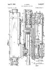
BREECH BLOCK CONTROLLING MECHANISM FOR A RETARDED BLOW BACK GUN
Filed Dec. 27, 1952
2 Sheets-Sheet 1
ATTORNEY'S.
Oct 9, 1956
E. H. BRADLEY
2,765,710
BREECH BLOCK CONTROLLING MECHANISM FOR A RETARDED BLOW BACK GUN
Filed Dec. 27, 1952
2 Sheets-Sheet 2
INVENTOR.
ATTORNS.-'r'S.
United States Patent Office
2,765,710
Patented Oct. 9, 1956
1
2,765,710
BREECH BLOCK CONTROLLING MECHANISM
FOR A RETARDED BLOW BACK GUN
Earl H. Bradley, Seekonk, Mass.
Application December 27,1952, Serial No. 328,244
12 Claims. (Cl. 89—195)
This application refers to a gun and more particularly
to the control for a breech block for a semi-automatic
piston or .the like.
Experts find a fixed barrel type of construction as used
in the semi-automatic pistons of a smaller cahbre, such
for instance as .22 calibre having a solidly fixed barrel,
more accurate than a larger calibre piston where the bar-
rel slides relative to the frame.
In arms of larger calibre having cartridges powerful
enough to be of military value it is not practical to pro-
vide a slide heavy enough so that the gun can safely op-
erate as a straight blow black weapon. Military pistols
have therefore been made with locked breeches so that
during the period when the bullet is moving through the
barrel, the barrel and breech recoil together. This mo-
tion is usually used to unlock the breech, permitting the
slide to continue its motion, removing the empty cartridge
case.
This construction necessarily means that the barrel can-
not be fixed in the frame and that the accuracy of the
arm is substantially less than could be realized with a
fixed barrel.
One of the objects of this invention is to provide in
the larger calibre semi-automatic pistols or other guns
a fixed barrel and still prevent detrimental motion of the
slide during the initial period when gas pressures in the
barrel are dangerously high.
More specifically an object of this invention is to mul-
tiply the inertia of a small weight by requiring that its
movement occur through a mechanical disadvantage. Yet
more specifically this mechanical disadvantage is pro-
vided by causing the small weight to move through a sub-
stantial distance.
Another object of the invention is to retard the move-
ment of the breech block by adding to its effective inertia
without increasing its weight or by utilizing a small addi-
tional weight in addition to the weight of the breech block
itself.
Another object of the invention is to provide greater
reliance upon inertia, which is constant, than upon fric-
tion, where the two are involved, the friction being more
variable and thus to provide a more uniform operation
of the breech block.
With these and other objects in view, the invention con-
sists of certain novel features of construction as will be
more fully described and particularly pointed out in the
appended claims.
In the accompanying drawings:
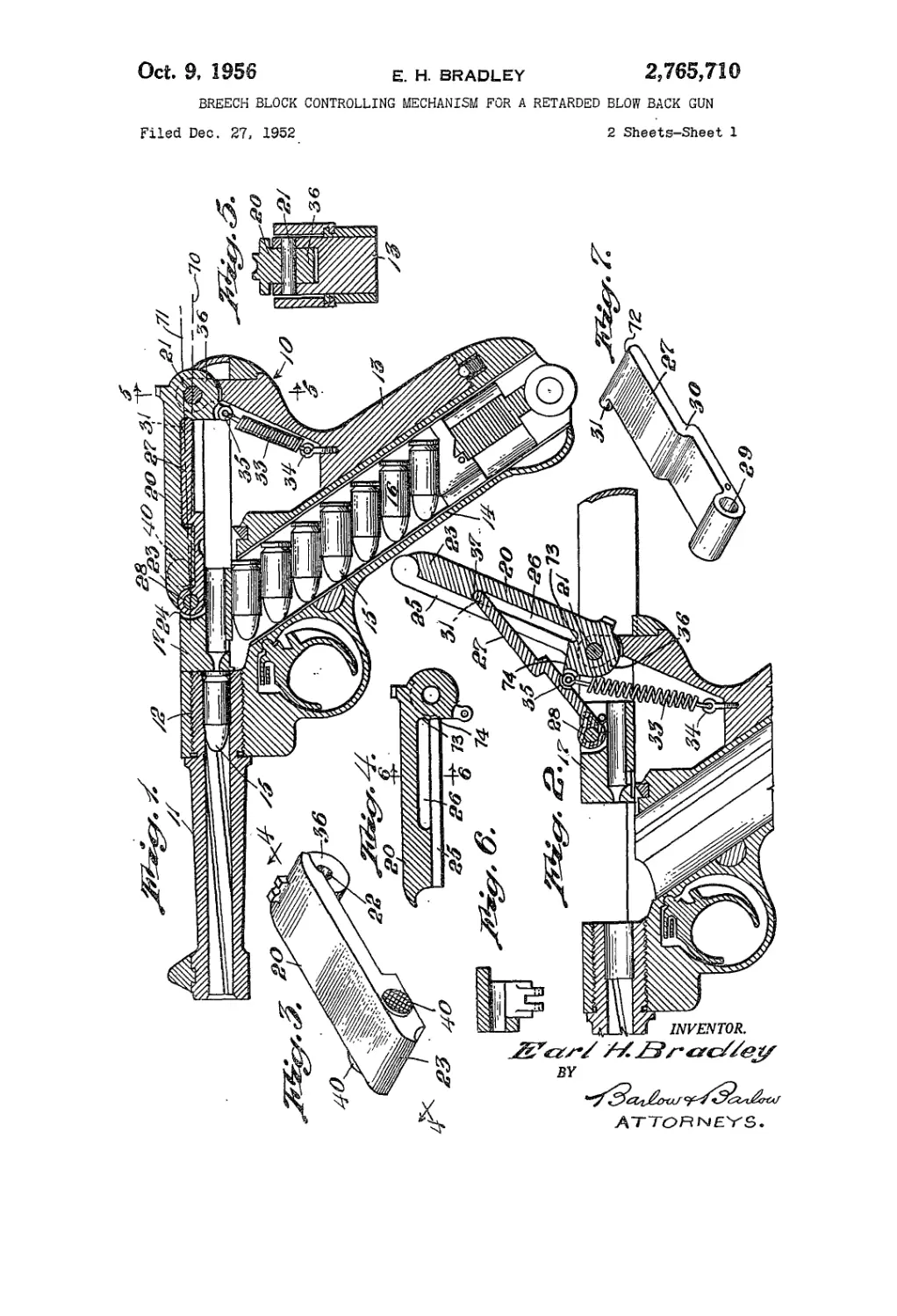
Figure 1 is a sectional view showing the breech block
in firing position;
Figure 2 is a fragmental view of the part shown in
Figure 1 but showing the breech block in open position;
Figure 3 is a perspective view of the first link or the
link pivoted to the frame of the gun;
Figure 4 is a sectional view on line 4—4 of Figure 3;
Figure 5 is a sectional view on line 5—5 of Figure 1
through the pivotal connection of this link to the frame;
Figure 6 is a section on line 6—6 of Figure 4;
10
15
20
25
30
35
40
45
50
55
60
65
70
2
Figure 7 is a perspective view of the other or second
link which is pivoted to the breech block;
Figure 8 is a side elevational view of a modified con-
struction;
Figure 9 is a similar view but showing the breech block
just prior to its release from the retarding mechanism;
Figure 10 is a section view taken substantially along
line 10—10 of Figure 8; and
Figure 11 is a perspective view of the breech block re-
tarding mechanism.
In proceeding with this invention instead of using a
toggle link connection between the frame and the breech
block in which the pivots must be near a straight line
in order to provide the resistance necessary and in which
friction plays a large part, I have provided a linkage in
which the pivots may be further from a straight line in
the initial firing position with a greater proportion of the
resistance provided by inertia, which is constant and
therefore provides a more reliable operation, and in order
to accomplish this, one means is to pivot one link on the
frame at one end and pivot another link on the breech
block at one of its ends, while providing a sliding connec-
tion by means of a slot and pin-like arrangement between
the two links so that the resistance may be great due to
the inertia and large movement required at the firing
position when the forces are greatest, but one in which
as the forces reduce, the mechanical advantage due to
the swinging of the links will increase so that when the
forces are weak, the movement of the slide may be the
greatest in arriving at its full open position.
With reference to the drawings 10 designates generally
the frame of a pistol of the retarded blow back semi-
automatic type in which the barrel 11 is fixed to the frame
such as being threaded as at 12 into a portion of the frame
at its inner end. A handle is provided at 13 which re-
ceives a clip 14 of cartridges comprising bullets 15 and
shells 16. A breech block 17 is slidable with reference
to the frame 10 and is controlled by means which will
add to its inertia at the initial or firing position but which
towards the end of its movement will decrease its resist-
ance and permit it to move to wide open position, as
shown in Figure 2.
This mechanism in one form comprises a first link 20,
as shown in perspective in Figure 3, which is pivoted to
the frame by means of a pin 21 extending through the
opening 22 at one end of the link. The end 23 of this
link is partially received in the breech block which is
recessed as at 24 to receive this and the other link which
controls the breech block. By observation of Figures
3 and 4, the end 23 of link 20 will be seen to be thicker
than the major portion of the link, thus increasing the
weight of the link at this end 23. This first link 20 is re-
cessed as at 25, and one of its walls is slotted as at 26.
The second link 27, as shown in Figure 7 in perspective,
is pivoted as at 28 in a recess in the breech block 17 by
the pin 28 extending through the opening 29 in one end
of the link 27. This link 27 fits into .the recess 25 in the
link 20 and is stepped as at 30 so that its trunnion pin
or other circular projection 31 will extend into the slot
26 and be pivoted as well as slidable in this slot. This
ling 27, which is the second link, nests within the first
link 20, as shown in Figure 1, when the parts are in fir-
ing position. Link 27 has a semi-circular end 72 which in
the closed position engages a semi-circular groove 73 in
link 20 which is located between the mid point of link
20 and its pivot 21. When in this nested position, the
axis of the pivot 31 is outwardly of a line between the
axes of the pivots 21 and 28 so that the angle between
line 70 connecting pivots 21 and 28 and the line 71 con-
necting pivots 31 and 28 is less than 30° so that when
pressure is applied on the axis 28 toward the axis 21,
there will be a tendency of the link 20 to swing about
3,765,710
3
its pivot 21 clockwise to the position, as shown in Fig-
ure 2. A spring 33 is anchored as at 34 in the handle
and is attached as at 35 on the bearing 36 at one side of
the iaxis of the pivot 21 so as to tend to swing the link 20
downwardly into firing position.
Assuming the cartridge shown in Figure 1 is fired,
the pressure of the gasses in the chamber tending to drive
the bullet out of the barrel exerts a force upon the
breech block 17 tending to move the breech block rear-
wardly. The pressure received by the breech block 17
will be applied through pivot pin 28 toward pivot pin
21 through the link 27 which applies pressure at bearing
72 along line 71 slightly outwardly from the center of
the pivot 21. Thus there wiil be a tendency for link 20
to swing clockwise as shown in Figure 1 about the pivot
21. As these three pivots 28, 72, and 21 are nearly in
line, there is a mechanical disadvantage so as to add
resistance to the inertia of the breech block 17 against
sliding rearwardly under the pressure of the gases. Thus
this inertia causes the breech block to move very slowly
from its firing position and sufficient so that there will
be a retarding for a length of time to permit the bullet
15 to be discharged from the barrel. As the first link
20 swings about pivot 21, its surface 74 acts upon link
27 to shift the point at which it bears upon link 20
away from pivot 21. After the link 20 lifts at its end
23 to a point at which the angle between the link 27 and
the wall of the slot 26 is greater than a right angle,
the pivot 31 slides rapidly in the slot 26 and more rapidly
increases the leverage at its point of application to the
lever 20 by increasing its distance from the pivot 21,
thus increasing the mechanical advantage which the re-
ducing gas pressure applies to the link 20 which force
tends to swing it about the pivot 21 until near the end
of its stroke where the link 27 is applying its force at
the end 37 of the slot 26, as shown in Figure 2, so as to
give a maximum leverage on the link 20 in swinging it
through its motion about the pivot 21. The spring 33
is increasing its resistance, however, to the motion of
the links, it being shown as applying its maximum force
in the open position in Figure 2. As soon as the breech
block is withdrawn, as shown in Figure 2, another bullet
from the clip will be advanced into position so that when
the breech block again closes, the bullet will be in the
barrel ready to again fire. By this arrangement I am able
to maintain the barrel fixed and the breech block without
substantial motion until the bullet has left the barrel.
Thus the accuracy of the gun is materially increased.
If it is desired to open the breech block by hand, it
is merely necessary to place the thumb and finger on
opposite sides of the knurled portions 40, 40 of the first
link 20 and swing this by hand about the pivot 21.
As the other parts of this gun are standard equipment,
it is thought unnecessary to describe the same in detail.
In Figures 8-11, inclusive, there is shown a modifica-
tion in which a lever 50 (see Figure 11) is arranged
so as to provide for the delayed action in the opening
of the breech block of the gun just subsequent to the
firing thereof. This lever 50 comprises parallel arms
51 and 52 joined at one end thereof by an integral bridge
53 which is arcuate in substantially the curvature of
the gun barrel or semi-circular as seen in Figures 10 and
11. These arms 51, 52 are each provided with aligned
mounting openings 54 and each has a recess 55 extending
inwardly from the upper edge thereof and in line with
each other. One wall of each recess is of the form of a cam
surface 56. The arm 51 is extended rearwardly beyond
the recess 55 as at 57, the upper edge of which tapers
downwardly as at 57' so as to provide a rest arm as will
presently appear.
The lever 50 is pivotally mounted on the gun body
at a location adjacent the inner edge of the breech block
58 as by means of pivot pins or trunnions 59 which may
be suitably secured on either side of the gun body to
5
10
15
20
25
30
35
40
45
50
55
00
05
70
75
4
project therefrom through the said openings 54 and with
their ends upset in a manner of a rivet. The arms 51,
52 are sufficiently spaced from the gun body to permit
free rocking motion thereof, and a torsion type spring
60 encircles each pivot pin 59 and is arranged to exert
a yieldable force on said lever 50 to swing it in a counter-
clockwise direction as seen in Figures 8 and 9 to resilient-
ly hold the bridge portion 53 in engagement with the
gun barrel (see Figure 10). Pins 61 project from the
breech block 58 to be received in said recess 55 to en-
gage the cam surfaces 56 thereof. In the instant dis-
closure the pins 59, 61 are positioned to be in a plane
extending axially of the gun barrel.
Referring to Figure 8, it will be apparent that upon a
rearward movement of the breech block 58, the pin 61
will exert a force on the cam surface 56 in a direction
tending to rock the lever 50 about its fulcrum 59. The
surfaces of the cams 56 are made a little greater than
a right angle to a plane passing centrally through pins
59, 61, and said force will act on said cam surfaces in
a direction tending to move said lever 50 in a clockwise
direction. When the gun fires, pressure of the shell on
the breech block 58 will be transmitted through pins 61
on to cam surfaces 56 and rock lever 50 about its ful-
crum 59. It is apparent that the motion of the lever at
the bridge 53 is much greater than the rearward motion
of the breech block 58 so that the inertia affect of the
lever 50 is considerably greater than the corresponding
weight in the breech block and causes a hesitation in the
rearward movement of the said breech block 58. Thus,
I am able to control the hesitation or retard the opening
of the breech block 58 by a choice of length of lever arm
forwardly of the fulcrum 59 or by increasing or de-
creasing the distance between the said fulcrum 59 and the
cam surface 56. Also, as the angle of the surface 56
is increased, the turning component increases and the re-
tarding effect of the inertia of the lever 50 decreases.
A substantial part of the inertia of lever 50 is due to
the weight of the bridge 53. In order to obtain sufficient
multiplication of the inertia of the weight at the ends
of arms 51, 52, the center of gravity of the lever arm
on one side of the pivot should be a distance much
greater from the pivots 59 than are the cam surfaces 56.
I have described the angle of the cam surfaces 56
as being made greater than a right angle, and in practice
it will be found than an angle up to 100 degrees will
be required depending upon the material of the lever
50 for the turning components of the force exerted upon
the cam surfaces 56 to be sufficient to overcome the
effect of the friction between the pin 61 and the surfaces
56 caused by the pressure of said pins 61 on said surfaces
56. I have shown the surfaces 56 as being linear. How-
ever, these surfaces may be varied to give a large initial
delay and then an increasing angle above this delayed
action to provide lesser delay at a subsequent period in
the opening movement of the breech block 58.
Upon the lever 50 being rocked to position its cam sur-
faces 56 free of the pin 61, the breech block 52 will be
free to continue its action in the usual manner. Upon
the passing of the pin 61, which is adjacent to the arm
51, beyond the end of the reset arm 57, the lever 50
under urge of the spring 60 will be rocked in a counter-
clockwise direction toward the initial position, and the
tapered edge 57' will be at a position to be engaged by
said pin 61 upon the return or forward motion of the
breech block 58. The said pin 61 upon riding over the
edge 57' will cause said lever 50 to be moved clockwise
a distance sufficient for the pin 61 to pass thereby and
position each pin in its recess upon said lever rocking
to initial position under urge of said spring 60.
The action of said breech block 58 and lever 50 is
very sudden, and in order to prevent injury to the hand
of the user by the reset arm 57, a guard 62 is provided.
This guard 62 may be conveniently made of sheet ma-
2,765,710
5
terial cut to a form as shown (see Figures 8 and 9) to
be positioned to cover the path of movement of said
arm 57. The shield may he secured in place in any
convenient manner as by means of screw fastenings 63.
I claim:
1. In a retarded blow back gun, a frame, a barrel
fixed thereto, a breech block slidable relative to the
frame, a first link pivoted to the frame, a second link
pivoted to the breech block and means to connect said
links together at a location between the pivot of the
first link to the frame and the mid point thereof when
in closed position by a sliding relationship movable along
the first link away from its pivot to apply pressure above
the pivot of the first link to the frame to lift the link up-
wardly against the force of gravity.
2. In a retarded blow back gun, a frame, a barrel
fixed thereto, a breech block slidable relative to the
frame, a first link pivoted to the frame and provided
with a slot extending lengthwise thereof and a second link
pivoted at one end to the breech block with the other
end pivotally and slidably located in said slot at a loca-
tion between the pivot of the first link to the frame and
the mid point thereof when in closed position.
3. In a retarded blow back gun as in claim 1 wherein
a spring acts upon the link pivoted to said frame urging
the parts toward firing position.
4. In a retarded blow back gun as in claim 2 wherein
a spring acts upon the link pivoted to said frame urging
the parts toward firing position.
5. In a retarded blow back gun, a frame, a barrel
fixed thereto, a breech block slidable relative to the
frame, a lever pivoted to the frame and carrying a weight
on one side of the pivot and a cam surface on the other,
the distance of the center of gravity of the weight from
the pivot being much greater than the distance of said
cam surface from the pivot, means carried by the breech
block engaging said cam surface to swing the lever about
its pivot upon rearward movement of the breech block,
the shape of said cam surface being such that the contact
of the engaging means therewith increases its distance
from the pivot as the lever swings about the pivot.
6. In a retarded blow back gun, a frame, a barrel
fixed to the frame, a breech block slidable relative to
the frame, and means retarding movement of the block
comprising a fulcrumed lever and a member for applying
the reactive force of the bullet to said lever at an angle
slightly outwardly from the line connecting the centers
of the pivots of said member and lever, said member
sliding along said lever to apply its force at a greater
distance from the fulcrum as the breech block moves,
and at an intermediate position of movement of the block
suddenly shifting its action to thereafter change its re-
5
10
15
20
25
30
35
40
45
50
6
sistance to the movement of the block to open position.
7. In a retarded blow back gun, a frame, a barrel
fixed thereto, a breech block slidable relative to the
frame, a first link having a fixed pivot and a groove with
a semi-circular cross section at a point between its mid
point and its pivot, a second link having an end with a
semi-circular cross section which in closed position bears
in said groove of the first link with the line connecting
the center of said semi-circular end with the pivot of
the second link making an angle of less than 30° with the
line connecting the centers of the pivots of the two links.
8. In a retarded blow back gun as in claim 7 wherein
the first link is pivoted to the frame and the second link is
pivoted to the breech block.
9. In a retarded blow back gun, a frame, a barrel
fixed thereto, a breech block slidable relative to the
frame, a first link pivoted to the frame having a groove
with a semi-circular cross section at a point between its
mid point and its pivot and having its end farthest from
the pivot weighted, a second link pivoted to the breech
block and having an end semi-circular in cross section
which in closed position bears in said groove in the first
link with the line connecting the center of said semi-
circular end with the pivot of the second link making
an angle of less than 30° with the line of centers of the
first and second links when the linkage is closed with
the weighted end of the first link close to the pivot of
the second link.
10. In a retarded blow back gun as in claim 9 wherein
the first link has a slot running lengthwise and said sec-
ond link provided with cylindrical projection at its semi-
circular end engaging the slot so that neither link may
move without moving the other.
11. In a retarded blow back gun as in claim 10 wherein
the point of bearing of the second link upon the first
link is continually shifted until it reaches the end of its
slot during the rearward movement of the breech block
to increase its distance from the pivot of the first link.
12. in a retarded blow back gun as in claim 11 wherein
a spring acts upon the link pivoted to said frame urging
the parts towards firing position.
References Cited in the file of this patent
UNITED STATES PATENTS
804,506 Schwarzlose______________Nov. 14, 1905
821,922 Burgess___________________May 29, 1906
1,073,452 White__________________Sept. 16, 1913
1,147,780 Borchardt________________luly 27, 1915
1,985,493 Gebauer et al.___________Dec. 24, 1934
FOREIGN PATENTS
229,760 Germany___________________Jan. 7, 1911