/


Текст
Focit4046/4047
Punch/Reader-Punch
Technical description Edition 2
By Arif-Ru.narod.ru
SCOPE OF THE MANUAL
This document describes both the Facit 4046 punch and the Facit 4047 Reader/Punch Combination. It includes detailed operating information, interconnection details and interfacing
requirements to external equipment. This document does not include detailed circuit diagrams or circuit descriptions, and does not include sofware descriptions or servicing information.
CONTENTS
1 INTRODUCTION 5.10 5.11 Program Mode 22 Error Message
2. DESIGN AND CONSTRUCTION
2.1 Brief Description 6. CODE CONVERSION
2.2 Punch Tape Handling 6.1 ASCII to ASCII
2.3 Punch Tape Loading 6.2 ASCII to Telex (5 track)
2.4 Punching Accuracy 6.3 ASCII to Telex (USA -8 track RS358)
2.5 Reader Tape Handling 6.4 ASCII to EIA (RS244)
2.6 Reader Tape Loading 6.5 EIA (RS244) to ASCII
3. OPERATION 7. TELEX TAPE FORMATTING
3.1 Punch Buffer 7.1 Clear Text Punching
3.2 Punching Out Data 7.2 End of Message Code
3.3 Buffer Status Signalling 7.3 Time Out Function
3.4 Punch Speed 7.4 Line Length Adjustment
3.5 Time Out 7.5 Code Expansion
3.6 Tape Reader (t-acit 4047 Combination Only) 7.6 Reduction of Spaces
KEYBOARD CONTROLS 8. TEST MODE
4. 8.1 Test Mode 1 — Memory Test
4.1 Key Functions (Facit 4046) 8.2 Test Mode 2 — Channel 1 Communication Test
4.2 Key Functions (Facit 4047 Combination) 8.3 Test Mode 3 — Channel 2 Communication Test
8.4 Test Mode 4 — Test Tape Punching
5. PROGRAM MODE 8.5 Test Mode 5 — Test Tape Reading
5.1 Select Modes in Sequence 8.6 Test Mode 6 — Single Track Punching
5.2 Select Mode Directly 8.7 Test Mode 7 — Continuous Test Tape Punching
5.3 Change Parameter Value
5.4 Program Modes 1 to 4 9. INTERFACE CONNECTIONS
5.5 Program Mode 5 9.1 Data I/O Connectors
5.6 Program Modes 6 and 7 9.2 Current Loop Interface
5.7 Program Modes 8 and 9 (Facit 4045 Combination Only) 9.3 Initial Installation
5.8 Program Mode 12
5.9 Program Modes 13 to 22 10. TECHNICAL SPECIFICATION
APPENDIXES
1. CODE CONVERSION CHART (GENERAL) ASCII TO 5 TRACK TELEX
2. CODE CONVERSION CHART (NATIONAL AND INTERNATIONAL)
ASCII TO 5 TRACK TELEX
3. CODE CONVERSION CHART (US) ASCII TO EIA (RS244)
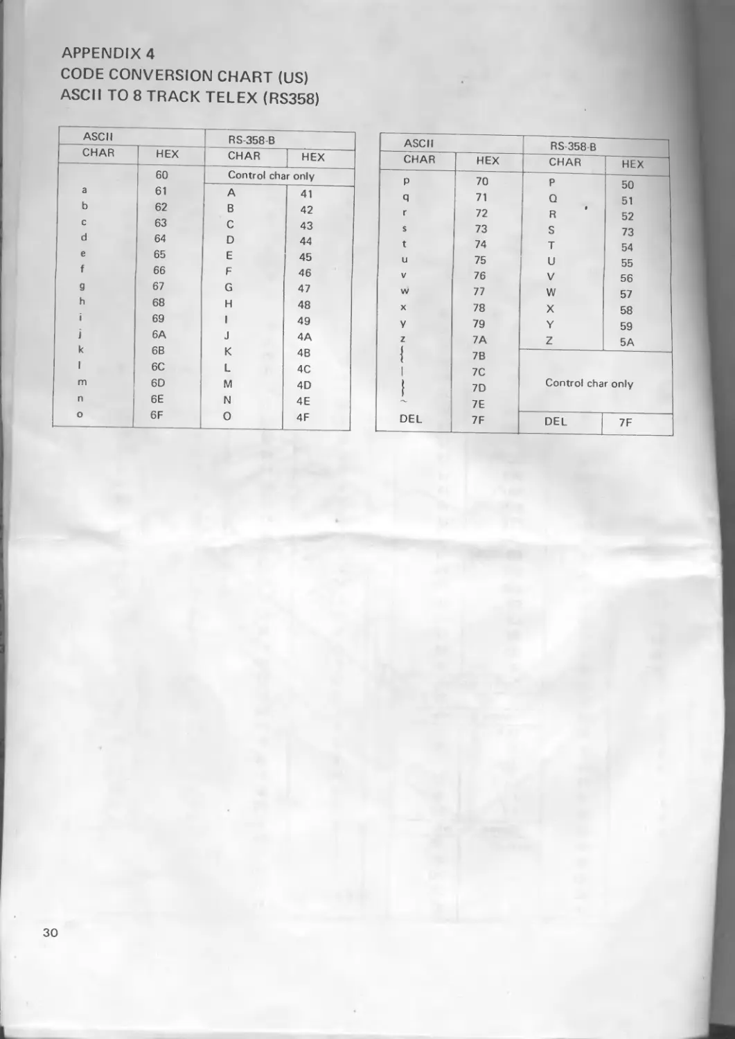
4. CODE CONVERSION CHART (US) ASCII TO 8 TRACK TELEX (RS358)
2
1. INTRODUCTION
The Facit 4046 is a paper tape punch for punching 5 to 8 track tapes. Five track is normally used to punch telextapes and 8-track mostly for punching NC-programs. The punching speed is 60 characters per second.
The Facit 4047 is a reader/punch combination. It can read and punch 5 to 8 track tapes. The punching speed is 60 characters per second and the reading speed is 120 characters per second.
Both units are designed as stand alone units for table top mounting. Two standard I/O ports are available with CCITT V 24/RS-232-C serial interface.
Facit 4046/4047 has a buffer of 3.5 К capacity. The buffer can be shared between the two I/O ports.
Code conversion can be performed. The codes included are the two used NC codes ISO and EIA and the national versions of the telexpode.
A small keyboard and status display are incorporated at the top of the unit; with this all operating system parameters may be quickly and easily entered with no necessity to change pc board DIP switch settings. The status display clearly indicates the unit's current operating status, and also shows simple error messages.
FCC Class A Computing Device: Information to User
WARNING
This equipment generates, uses and can radiate radio frequency energy and, if not installed and used in accordance with the instruction manual, may cause interference to radio communications. It has been tested and found to comply with the limits for a Class A computing device pursuant to Subpart J of Part 15 of FCC Rules, which are designed to provide reasonable protection against such interference when operated in a commercial environment. Operation of this equipment in a residential area is likely to cause interference, in which case the user at his own expense will Ьё required to take whatever measures may be necessary to correct the interference
Caution
Compliance with FCC regulations on Radiated Emissions(RFI) requires use of a sh.elded penpheral-to-host cable.
3
2. DESIGN AND CONSTRUCTION
2.1 Brief Description
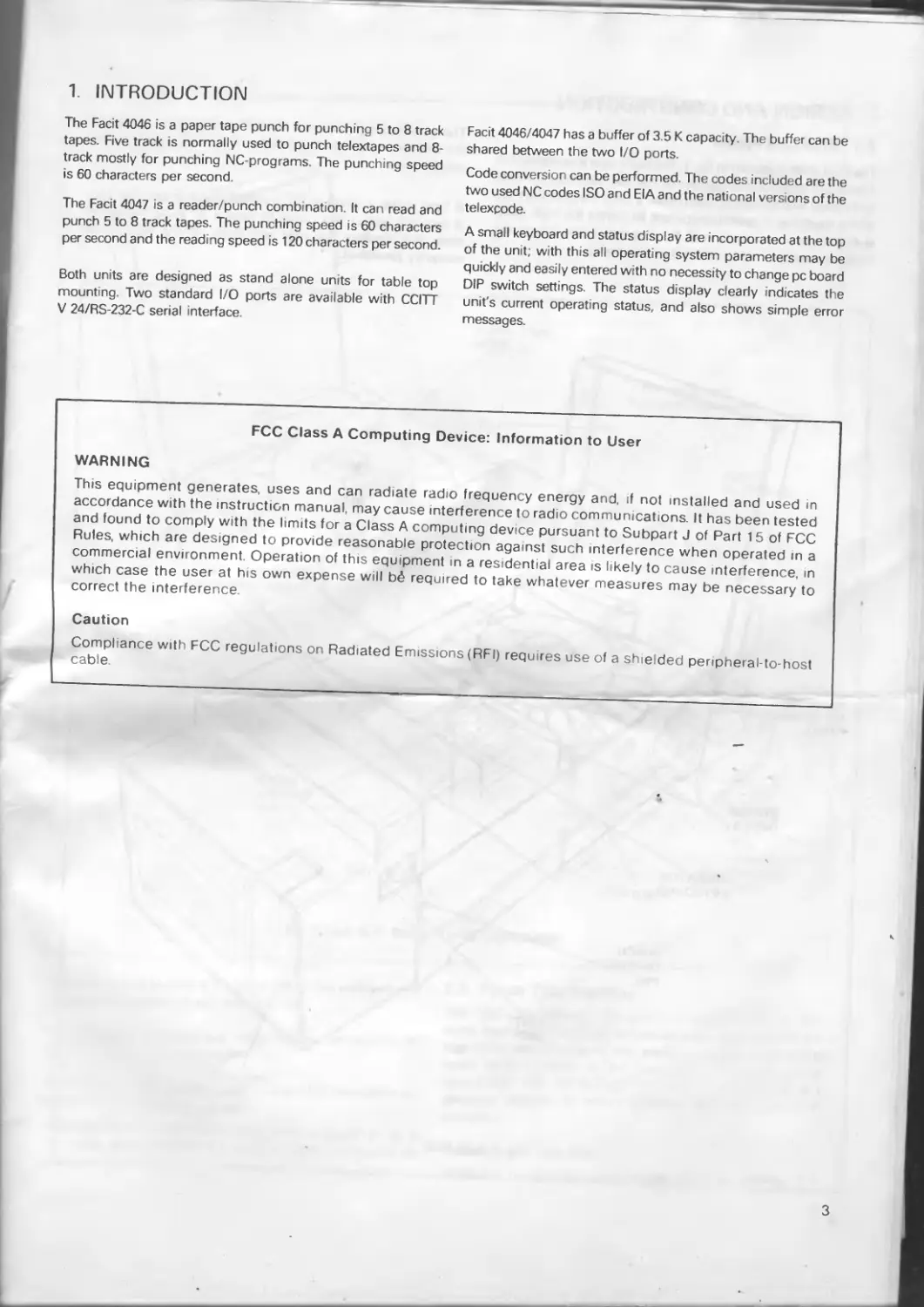
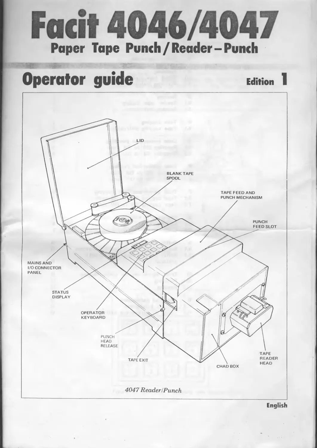
The Facit 4046 is shown in fig. 1. The blank tape is contained on a standard spool at the top rear of the unit, with the tape feed and punch mechanism housed under a cover towards the front of the machine. A semi-transparent lid covers the tape spool during normal operation, and the amount of tape left on the spool can easily be seen without raising the ltd.
The punched tape emerges from the exit slot at the left of the unit, no special arrangement is included for handling the punched tape.
A tape cutter is fitted in the punched tape exit slot. The tape is torn off against this cutter to leave a 'V' at the end of the tape; this enables the start and finish of the tape to be correctly identified. •
CHAD BOX
Fig. 1 Facit 4046
4
PUNCH
FEED SLOT
LID
BLANK TAPE SPOOL
TAPE FEED AND
PUNCH MECHANISM
MAINS AND
I/O CONNECTOR
PANEL
OPERATOR
KEYBOARD
Fig. 2 Facit 4047 Reader/Punch Combination
STATUS DISPLAY
PUNCH OPENING PEG
TAPE READER HEAD
EXIT SLOT
CHAD BOX
The chad box is located at the front left of the unit and may be removed by pulling it out from the top. ,
The operator's keyboard and status display are situated on top of the unit in front of the ltd
The mams ON/OFF switch, supply fuses and I/O connectors are fitted on the rear panel of the unit.
The Facit 4047 Reader/Punch Combination is shown in fig. 2 The reader head is mounted at the front of the unit next to the chad box.
2.2 Punch Tape Handling
The tape path through the punch is shown in fig 3. The blank tape leaves the spool and passes around a pulley on the tape guide arm. The guide arm applies a progressively acting brake which operates on the tape bobbin. This operates to ensure that tape fed through the punch is maintained at a constant tension to ensure accuracy and consistency of punching.
Tape Low and Tape End
When the punch tape supply is low, the error message Lo
5
appears in the display. When the tape is exhausted, or if a jam occurs in the feed mechanism, the message 'Err' blinks on and off in the display.
2.3 Punch Tape Loading
With mains power switched OFF, load tape onto the punch tape holder as follows (see fig. 3).
(1) Move the tape guide arm until it touches the magnetic catch. This action applies the brake to the tape bobbin and frees the tape feed and punch mechanism.
(2) Pull out 2 metres (6 feet) of tape from the new reel and place the reel onto the bobbin.
(3) Lock the bobbin by pushing the centre section down-
wards by hand as far as possible (see fig. 3).
(4) Push upwards the two punch opening pegs (located one at each side of the punch housing — see figs. 1 and 2), and pull forward the punch assembly to open the tape feed and punch slot (see fig. 3).
(5) Lead the tape around the guide pulleys and drop it into the tape feed and punch slot.
(6) Push back the punch assembly to close the tape feed and punch slot.
(7) Release the tape guide arm from the magnetic catch.
(8) Switch the power ON and depress the [FEED] key until the tape is taut, and feeding correctly from the spool.
Fig. 3 Punch Tape Loading
6
50 Characters - 127mm = 5 inches
oaoosaoaaQaaoaoaaoaoatiaaaoaoeasaoaeaatieeaitttoeitr
•••••
aooooooo
oooooaao
song oa
eaaaaagввазвава^ asaesaiB
6830 3333
gg 99 99
+ 0.5%
FEED HOLE CENTRED ON GRID
50TH FEED
HOLE (ACCURATE)
aotto Ba
5% I ACCEPTABLE LIMITS
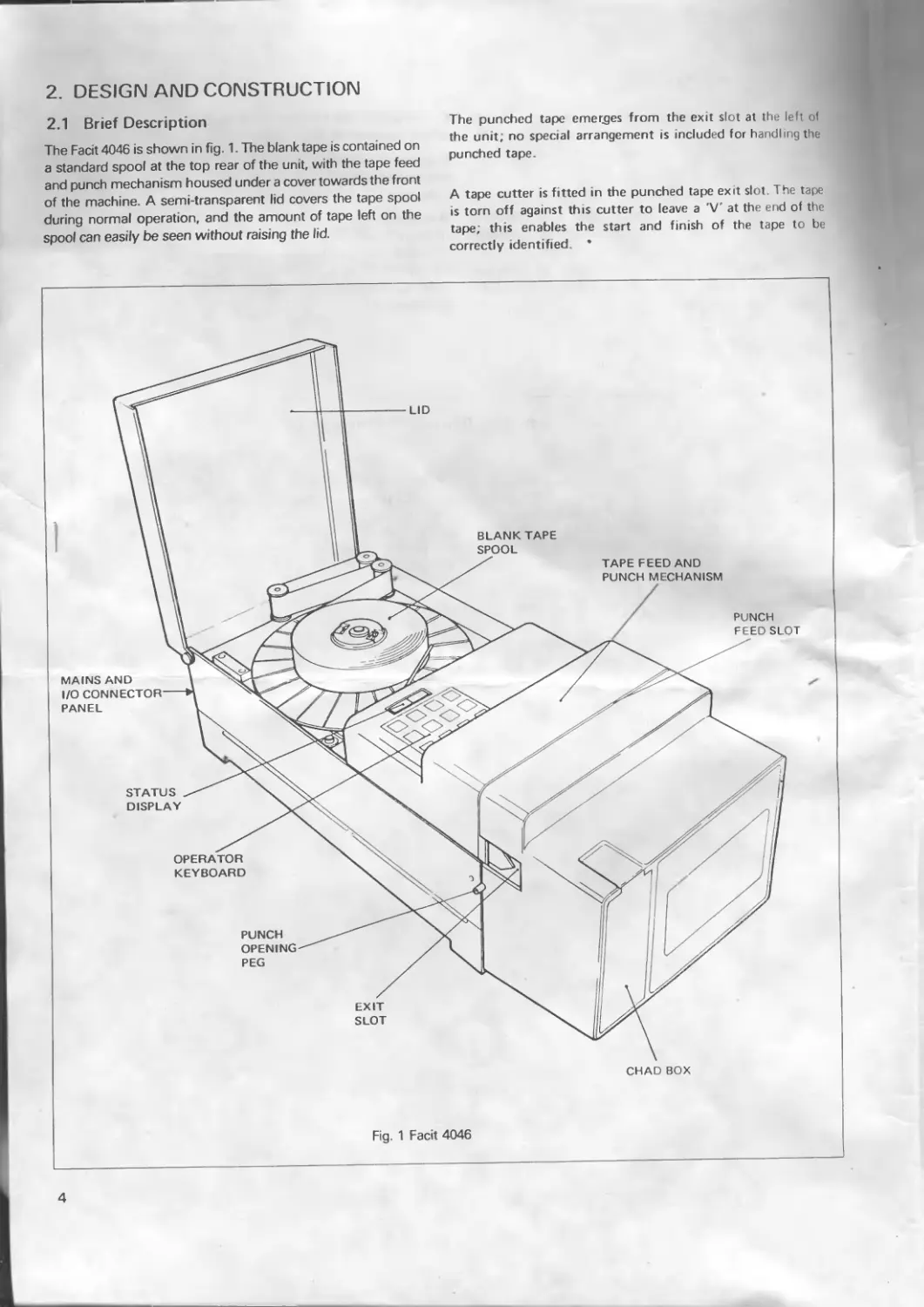
Fig. 4 Check Intercharacter Spacing
gggg sa
о
2.4 Punching Accuracy
The accuracy of punching can be checked by using the Facit template part no. 1114 00 50-00/0 as shown in fig. 4. It is recommended that this check is carried out approximately every 50th tape reel used.
(1) Lay the punched tape on the template as shown in fig. 4, with a feed hole accurately centred on the leftmost vertical line.
(2) Examine the 50th feed hole on the rightmost vertical line. If this line is visible within the hole, (i.e. within ± 0.5%), the punch accuracy is acceptable.
(3) If the vertical line is not visible (i.e. outside ± 0.5%) the punch mechanism requires servicing. .
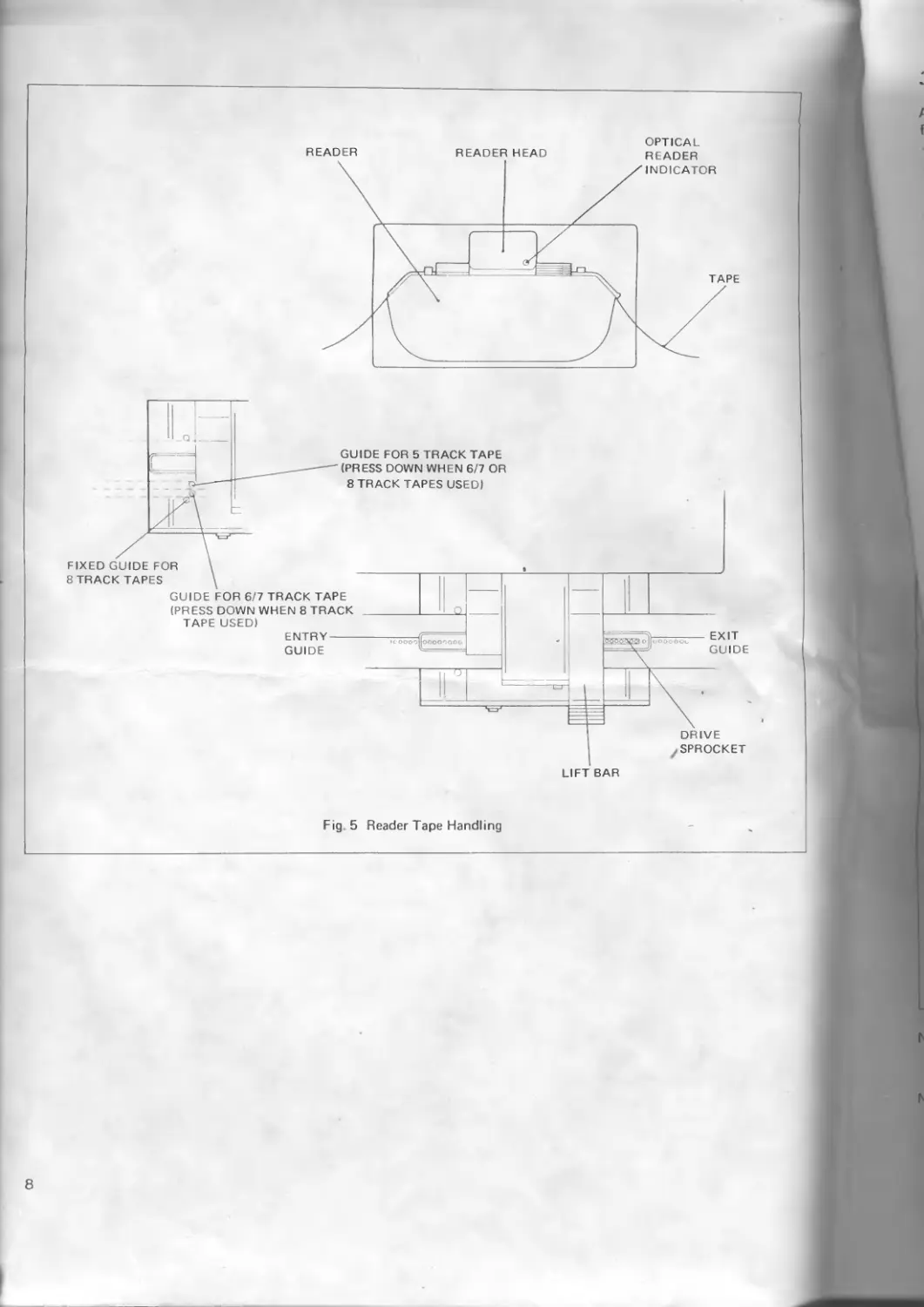
2.5 Reader Tape Handling (Facit 4047 Combination Only)
The tape path through the reader is shown in fig. 5. The tape passes under the entry guide wire, through the tape width selector (adjustable to suit 5, 6/7 and 8 channel tapes), past the reader head and over the drive sprocket The drive
sprocket teeth engage in the tape feed holes to pull the tape past the head.
An indicator lamp on the reader head is lit to show that the optical reader lamp is on.
The tape can be run quickly through the reader either forwards or backward^ without data being read, by depressing the [FF] or [FB] key respectively.
Reader Error
A malfunction of the tape reader mechanism stops the transmission of data and the message 'Err' blinks on and off in the display.
2.6 Reader Tape Loading (Facit 4047 Combination Only)
Paper tape is loaded into the reader as follows (see fig. 5): (1) Raise the lift bar to open the entry and exit guides. (2) Put the tape into the reader and over the drive sprocket.
(3) Lower the lift bar to hold the tape in position; ensure that the tape feed holes are engaged correctly in the drive sprocket.
7
READER
READER HEAD
OPTICAL READER
LIFT BAR
Fig. 5 Reader Tape Handling
3. OPERATION
An overall block diagram of the Facit 4046/4047 is shown in fig. 6.
The unit is intelligent and all programming functions are performed by entries made on the built-in keyboard.
All program parameters are held in RAM, and a battery is incorporated on the interface board to preserve the memory contents when the unit is switched off. The battery capacity is sufficient to retain the memory contents for several years.
3.1 Punch Buffer
The overall operation of the punch, and the control of incoming data, is performed by the buffer. Data can be entered via Channel 1 or Channel 2, or both simultaneously. Whichever channel receives data first, assumes priority over the other.
The buffer's total capacity (3.5 K) is shared between Channels 1 and 2 according to the buffer stop address selected for channel 1, in the Program mode (see section 5). Each 'buffer' accepts data from its source until full; an instruction is then sent to the source to stop transmission (see section 3.3).
The required code conversion of the incoming data is performed prior to reading into the buffer; data in the buffer is therefore always in the correct version for direct punching out.
3.2 Punching Out Data
Whichever channel has assumed priority for incoming data keeps this priority when punching data.
Data transfer from buffer to punch is controlled and selected in the Program mode (see section 5).
Fig. 6 Block Diagram
9
3.3 Buffer Status Signalling
The acceptance of incoming data via each channel is controlled separately by the Full or Empty status of its associated part of the buffer.
The buffer Full or Empty condition is indicated either by X-ON/ X-OFF protocol or Ready/Busy status signalling, selectable separately for each channel in the Program mode. (See section 5).
3.4 Punch Speed
The punching speed is 60 characters per second.
3.5 Time Out
If data is sent to both channels simultaneously, the channel receiving data first assumes priority and starts punching. An End of Message character or a Time Out selected in program mode (see selection 5) can change priority to the other channel. The Time Out function is explained fully in section 7 3.
3.6 Tape Reader (Facit 4047 reader/punch combination only)
Where a reader is included on the unit, data read from a punched tape is transmitted via channel 1 or channel 2 When the reader is started from the keyboard (start key) data is always transmitted via channel 1. When the reader is started remote, using the start reader code (see table 6, page 16), data can be transmitted via channel 1 or 2 depending on the channel used
to send the start reader code. The channel not affected by reading can accept data for punching.
If reading is attempted while data for punching remains in any of the buffers for channel 1 or 2, readings is inhibited and BUSY is displayed. Reading can start when the existing contents are punched and the channel buffer is empty. Reading takes place at a speed of 120 characters per second.
The reader stops when the Stop key is depressed, a stop reader code is received (either sent over the line or read on the tape), or when the tape end is reached.
The transmission continues until the buffer is empty even if the reader stops due to any of the conditions above. The transmission can be controlled using the XON/XOFF protocol <see table 5, page 15, program mode 3/4). Sending the code DC3 will stop transmission and the code DC1 will start transmission.
Starting the reader with X ON (DC1)
When X ON/OFF protocol is used DC1 will start the reader. DC3 will not stop the reader but the transmission will be stopped. When other mode than transparency mode is used, DC1 (17) must be set in program step 14, start reader, see page 16
When X ON/OFF protocol is not used DC1 and DC3 can be used to start and stop the reader in all modes without transparency mode.
Program step 14, start reader, must be set to 17 and program step 16, stop reader, must be set to 19
Reader Start with DC1 (XON.)
Program Step 3/4 Pr&qram Step 6/7 Program Step 9 Program Step 14 1—— Reader Start
2XXX 4XXX 0 0 0 DC1 (XON) > starts Reader
2XXX 4XXX 0 0 DC1 (XON) starts Reader
2XXX 4XXX *0 + 0 0 DC1 (XON) does NOT start Reader
2XXX 4XXX Ф0 17 (DC1) DC1 (XON) starts Reader
1XXX 3XXX 0 0 0 DC1 (XON) does NOT start Reader
1XXX 3XXX - 0 17 (DC1) DC1 (XON) starts Reader
1XXX 3XXX Ф0 0 17 (DC1) DC1 (XON) starts Reader
10
4. KEYBOARD CONTROLS
All the functions of the Facit 4046/4047 are controlled from a small keyboard located on the control panel. A digital readout consisting of four 7-segment displays is located above the keyboard.
Each key (except the [0] key) has two functions. In normal use the upper functions (printed on the keys) are applicable, and the display shows the operating status of the unit.
When the [PRGR] key is depressed, the unit enters the Program mode, and the lower function of each key then applies. The keyboard is used to enter numeric programming data, and the display shows the Program mode values. Programming is described in section 5.
□ о U IJ n О LI LI
TABLE 1
KEY FUNCTIONS IN OFF-LINE MODE
KEY DISPLAY FUNCTION
FEED FEEd Feed holes are punched in the blank tape while the key is depressed.
CODE EadE Both code and feed holes are punched in the blank tape while the key is depressed.
ON L L inE When this key is depressed and released, the unit goes On line and can communicate with externally connected equipment via the I/O ports.
PRGR prDg When this key is depressed and released, the unit enters the Program Mode (see section 5). The lower functions of all keys now apply.
TEST *E E5E When this key is depressed and released, the unit enters a comprehensive self-test mode (see section 8).
FEED
CODE
8
COPY
START
EXIT
Fig. 7 Keyboard and Display
TABLE 2
KEY FUNCTION IN ON-LINE MODE
KEY DISPLAY FUNCTION
DFF L i 1 □ FF When this key is depressed and released, the unit goes Off-line and is disconnected from the external equipment
KEY FUNCTIONS IN OFF-LINE MODE (READER)
The keyboard functions in normal use are explained in the following tables. Most of the keys operate only with the unit Offline, and some keys are functional only when the tape reader is present.
When the mains supply is initially switched on, the unit goes Off-line, and OFF appears in the display.
4.1 Key Functions (Facit 4046)
The keys described in Table 1 have functions only when the unit is Off-line. When On-line, the only functional key is the [OFF L] key (Table 2). The display shows the function initiated by each key when depressed.
4.2 Key Functions (Facit 4047)
The key functions already described in Tables 1 and 2 apply also to the Facit 4047 Reader/Punch Combination. The remaining keys allow control of the reader and are described in Tables 3 and 4.
TABLE 3
KEY DISPLAY FUNCTION
FF FF Tape in the Reader feeds forward while the key is depressed. Reading of data is inhibited.
FB Fb Tape in the Reader feeds backwards while the key is depressed. Reading of data is inhibited.
COPY EdP4 The punch and reader combination enters the Copy mode. A tape in the reader will be directly copied by the punch when the [START] key is depressed (see below).
START EoPH When this key is depressed and released in Copy mode, the Reader and Punch both start. A tape in the reader is directly copied by punch in accordance with the punch programming (see section 5).
| STOP EoPH When this key is depressed and released while in Copy mode, the Reader stops. The Punch continues until the buffer is empty
11
TABLE 4
KEY FUNCTIONS IN ON-LINE MODE (READER)
KEY DISPLAY FUNCTION
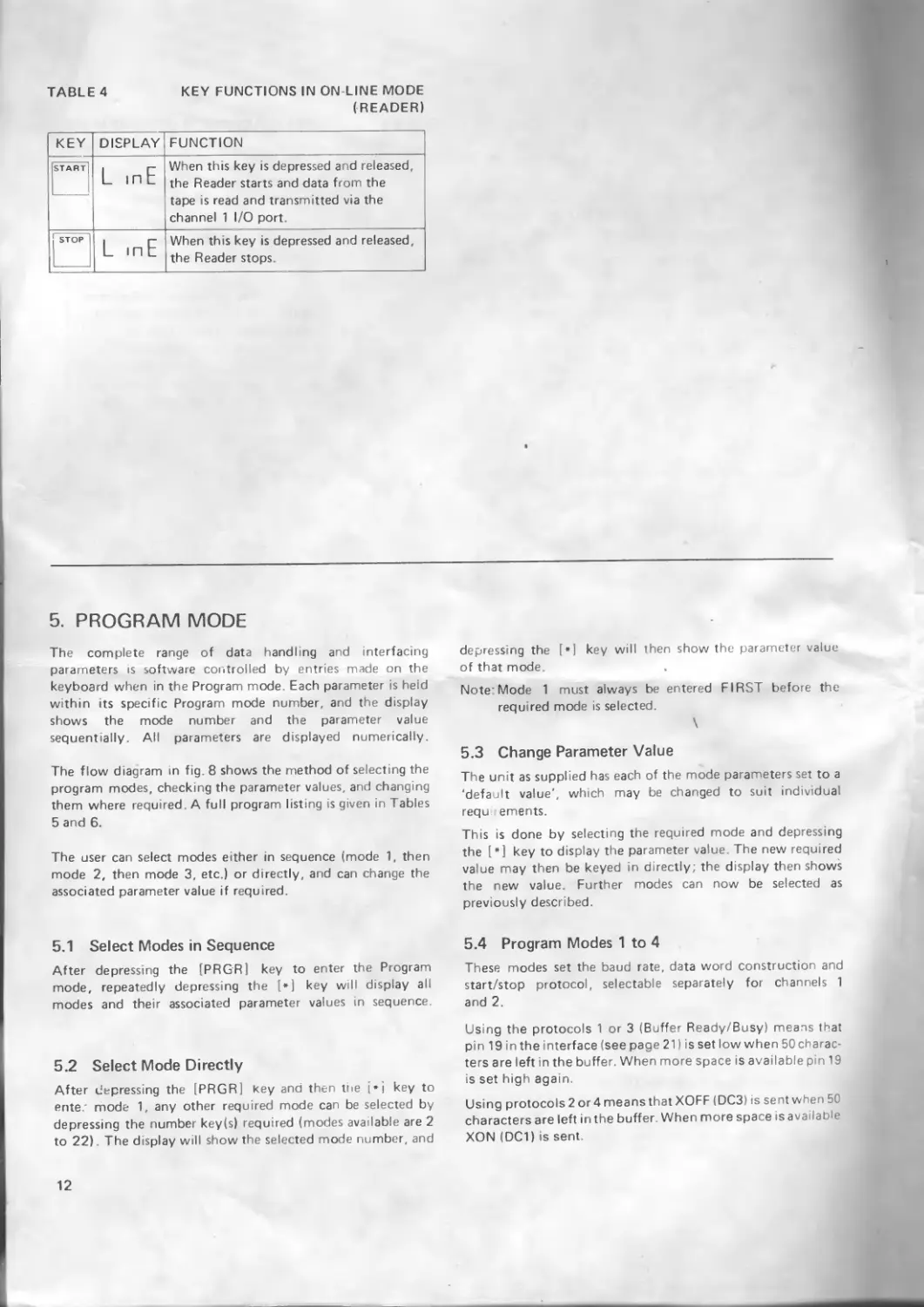
START L mF When this key is depressed and released, the Reader starts and data from the tape is read and transmitted via the channel 1 I/O port.
STOP L inE When this key is depressed and released, the Reader stops
5. PROGRAM MODE
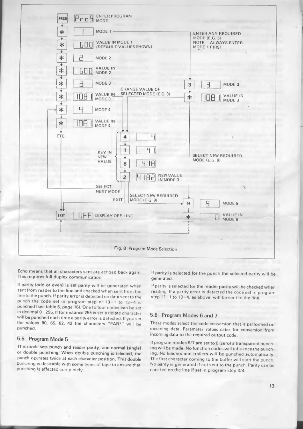
The complete range of data handling and interfacing parameters is software controlled by entries made on the keyboard when in the Program mode. Each parameter is held within its specific Program mode number, and the display shows the mode number and the parameter value sequentially. All parameters are displayed numerically.
The flow diagram in fig 8 shows the method of selecting the program modes, checking the parameter values, and changing them where required. A full program listing is given in Tables 5 and 6.
The user can select modes either in sequence (mode 1, then mode 2, then mode 3, etc.) or directly, and can change the associated parameter value if required.
depressing the [*] key will then show the parameter value of that mode.
Note: Mode 1 must always be entered FIRST before the required mode is selected.
\
5.3 Change Parameter Value
The unit as supplied has each of the mode parameters set to a 'default value', which may be changed to suit individual requ lements.
This is done by selecting the required mode and depressing the [*] key to display the parameter value, The new required value may then be keyed in directly; the display then shows the new value. Further modes can now be selected as previously described.
5.1 Select Modes in Sequence
After depressing the [PRGR] key to enter the Program mode, repeatedly depressing the [*] key will display all modes and their associated parameter values in sequence.
5.2 Select Mode Directly
After depressing the [PRGR] key and then trie [*j key to ente.' mode 1, any other required mode can be selected by depressing the number key(s) required (modes available are 2 to 22). The display will show the selected mode number, and
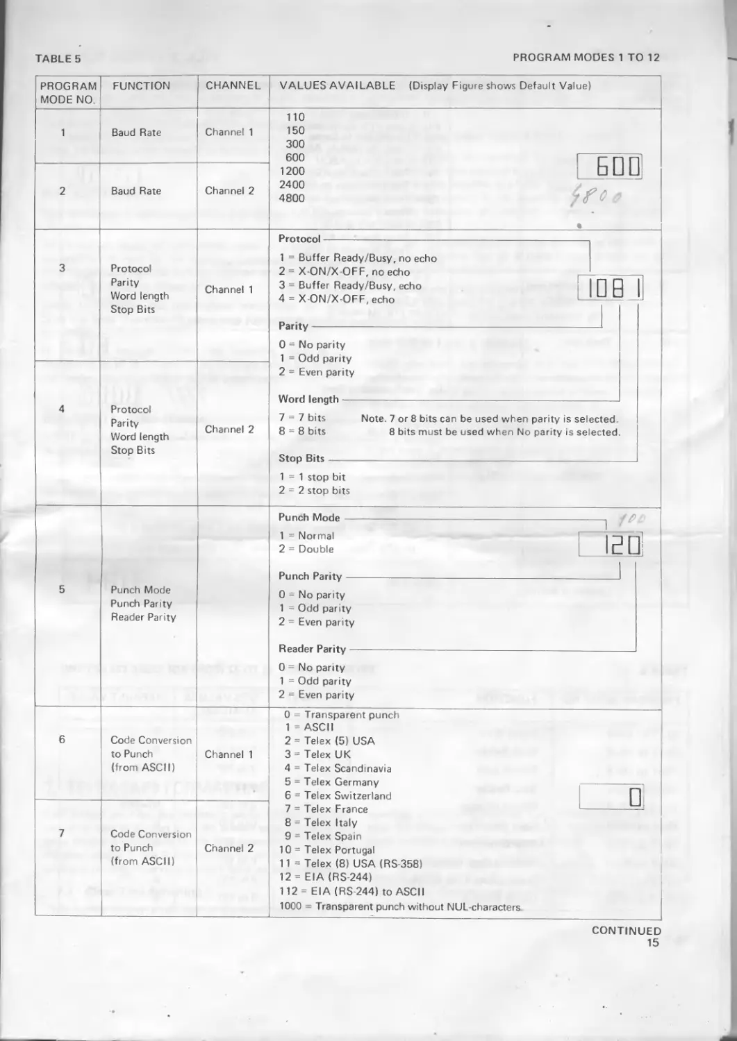
5.4 Program Modes 1 to 4
These mooes set the baud rate, data word construction and start/stop protocol, selectable separately for channels 1 and 2.
Using the protocols 1 or 3 (Buffer Ready/Busy) means that pin 19 in the interface (see page 21) is set low when 50 characters are left in the buffer. When more space is available pin 19 is set high again.
Using protocols 2 or 4 means that XOFF (DC3) is sent when 50 characters are left in the buffer When more space is available XON (DC1) is sent.
12
ETC
Рг □ 3
ENTER PROGRAM MODE
MODE 1
ED Q
Ё ’ I
EDO
VALUE IN
MODE 4
VALUE IN MODE 1 (DEFAULT VALUES SHOWN)
MODE 2
VALUE IN
MODE 2
MODE 3
CHANGE VALUE OF
VALUE IN SELECTED MODE (E.G. 3)
MODE 3
MODE 4
KEY IN NEW VALUE
ENTER ANY REQUIRED
MODE (E.G. 3)
NOTE - ALWAYS ENTER
MODE 1 FIRST %
MODE 3
IDB Г
VALUE IN MODE 3
SELECT NEW REQUIRED MODE (E.G. 9)
SELECT _
NEXT MODE SELECT NEW REQUIRED
EXIT MODE (E.G 9)
DISPLAY OFF LINE
MODE 9
VALUE IN
MODE 9
Fig. 8 Program Mode Selection
Echo means that all characters sent are echoed back again. This requires full duplex communication.
If parity (odd or even) is set parity will be generated when sent from reader to the line and checked when sent from the line to the punch. If parity error is detected on data sent to the punch the code set in program step nr 13-1 to 13-4 is punched (see table 6, page 16). One to four codes can be set in decimal 0-255 If for instance 255 is set a delate character will be punched each time a parity error is detected. If you set the values 80, 65, 82, 42 the characters "PAR*" will be punched
5.5 Program Mode 5
This mode sets punch and reader parity, and normal (single) or double punching When double punching is selected, the punch operates twice at each character position. This double punching is desirable with some types of tape to ensure that punching is effected completely
If parity is selected for the punch the selected parity will be generated
If parity is selected for the reader parity will be checked when reading. If a parity error is detected the code set in program step 13-1 to 13-4, as above, will be sent to the line.
5.6 Program Modes 6 and 7
These modes select the code conversion that is performed on incoming data. Parameter values cater for conversion from incoming data to the required output code.
If program modes 6/7 are set to 0 (zero) a transparent punching will be made No function codes will influence the punching No leaders and trailers will be punched automatically. The first character coming to the buffer will start the punch. No parity is generated if not sent to the punch Parity can be checked on the line if set in program step 3/4
13
5.7 Program Modes 8 and 9 (Facit 4047 Combination Only)
Mode 8 selects the code conversion performed when in Copy mode (see section 4.2).
Mode 9 selects the code conversion performed during tape reading.
If Copy is set to 0 (zero) a transparent copy will be performed. The reader will continue to read until stopped by Stop key or until end of tape. If the buffer is full the reader will stop and automatically start again when space is available in the buffer No function codes (program modes 13 to 22) will influence the copy. No parity is checked.
If copy is set to 100 a five track telex tape can be copied. A five track tape shall be in the punch. No function codes will influence the copy. If copy is set to 1000, no NUL-characters will be copied. All other characters will be copied as transparent copy.
If any other value is set for Copy the function codes set in Program 13-22 will influence the Copy. This means for instance that reader stop (16) will stop the reader Parity, if set in program step 5, will be checked by reading or generated by punching Detected parity errors will be punched as the code in program step no. 13.
If program mode 9 is set to 0 (zero) a transparent reading will be made. The function codes will not influence the reading Parity will be checked if set in program step No. 5. If program mode 9 is set to 1000, no NUL-characters will be sent. All other characters will be sent as in transparent reading.
5.8 Program Modes 10 and 11
Mode 10 sets the time period that the unit 'waits' for a late or missing End of Message code before terminating the message (see section 7.3). When in transparency mode the time out is automatically set to one second.
Mode 11 selects whether control codes (set in modes 13 to 22) are punched when received at the punch, or transmitted when read by the reader.
5.9 Program Mode 12
This mode effectively divides the buffer between channels 1 and 2, by specifying the end address for data from channel 1.
5.10 Program Modes 13 to 22
These modes allow the programming of specific control codes to which the unit will respond. Each control code may consist of up to four characters, and each mode is subdivided into four steps to select and hold each character. Each character is entered using its decimal value. These program modes, 13-22, are not valid when in transparency mode (codes 0,100 and 1000).
Program mode 13.
In program mode 13 the values can be 0-255 This program mode is used when parity control is made, reading a tape or punching a tape. In program mode 13 one to four characters
can be set, which will be sent or punched, when at parity error is detected.
Program mode 14.
This program mode is used to set one to four codes to start the reader. If you wish tb start the reader usingDCI code, set the value 17, decimal for DC1. See also 3.6 above
Program mode 15
Program mode 15 is used to set the code for End of Line. This code shall correspond to the code for End of Line sent over the line It is normally CR (dec 13) or LF (dec 10) or both of them together. If both CR and LF are sent the program mode 15 shall be set to 13 + 10. If no End of Line is sensed, the punch will start when the buffer is full or when End of Message (program mode 17) is sensed or after time out (program mode 10)
Program mode 16.
Program mode 16 is used to stop the reader. When the code set in this program mode is sensed the reader will stop. See also 3 6 above.
Program mode 17.
Program mode 17 is used for End of Message. The code set in this program mode will clear the buffer and make reading possible or punching from the other buffer. If no End of Message is sensed the time out will clear the buffer. The End of Message code can include CR or LPeodes If for instance the End of Message is * (dec 42) and this is always followed by CR + LF, the End of Message codes are set as follows: ♦CRLF, dec 42, 13, 10.
Program mode 18.
Program mode 18 is used to write in clear text. This function means that characters sent to the punched are represented in a hole pattern, which makes it possible to read the tape visually. The hole pattern is depending on the code set in program modes 6/7 above. For telex tape, five tracks are used and for all other tapes eight tracks are used. Clear text is used to label a telex message or an NC-program tape. The clear text is ended when End of Line is sensed. The clear text can also be ended using a code in program mode 19.
Program mode 20 and 21.
These two program modes are used only for telex code conversion in the Scandinavian countries Program mode 20 is used to set a code conversion, which translates the national use characters into special locantions in the telex code. Program mode 21 is used when international coding is used.
Program mode 22
Program mode 22 is used to cancel a message by writing the word CANCEL in clear text at the tape. This function is used only when punching telex tapes.
5.11 Error Messages
If any mistake is made by the operator during programming, the display shows the message 'Err' (not blinking). Depressing the [*j key will clear the display and allow further program entries.
14
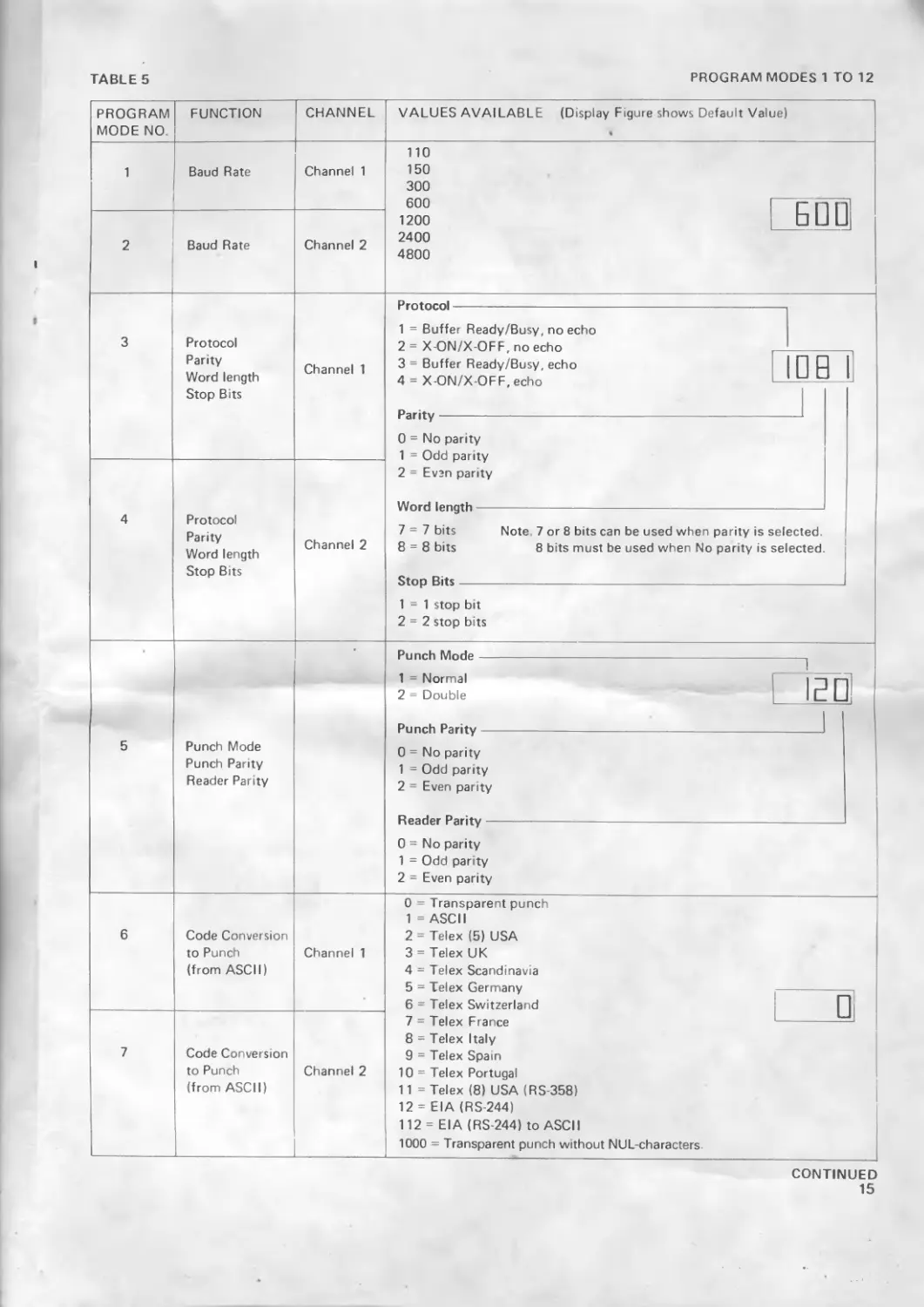
TABLE 5
PROGRAM MODES 1 TO 12
PROGRAM MODE NO. FUNCTION CHANNEL VALUES AVAILABLE (Display Figure shows Default Valued
1 Baud Rate Channel 1 110 150 300
600 1200 3 _
2 Baud Rate Channel 2
2400 4800 9
3 Protocol Parity Word length Stop Bits Channel 1
1 = Buffer Ready/Busy, no echo 2 = X-ON/X OFF, no echo 3 = Buffer Ready/Busy, echo 4 = X-ON/X-OFF, echo
0 = No parity 1 = Odd oaritv
4 Protocol Parity Word length Stop Bits Channel 2 2 = Even parity
7-7 bits Note. 7 or 8 bits can be used when parity is selected 8 = 8 bits 8 bits must be used when No parity is selected Stnn Rit«
1 = 1 stop bit 2 = 2 stop bits
5 Punch Mode Punch Parity Reader Parity Punch Mode 1
1 = Normal 2 = Double EL 1
Punch Parity 0 = No parity 1 = Odd parity 2 = Even parity 1
0 = No parity 1 = Odd parity 2 = Even parity
6 Code Conversion to Punch (from ASCII) Channel 1 0 = Transparent punch 1 = ASCII 2 = Telex (5) USA 3 = Telex UK 4 = Telex Scand navia 5 = Telex Germany 6 = Telex Switzerland 7 = Telex France 8 = Telex Italy 9 = Telex Spain 10 = Telex Portugal 11 = Telex (8) USA (RS 358) 12 = EIA (RS 244) 112= EIA (RS 244) to ASCII 1000 = Transparent punch without NUL-characters
7 Code Conversion to Punch (from ASCII) Channel 2
CONTINUED
15
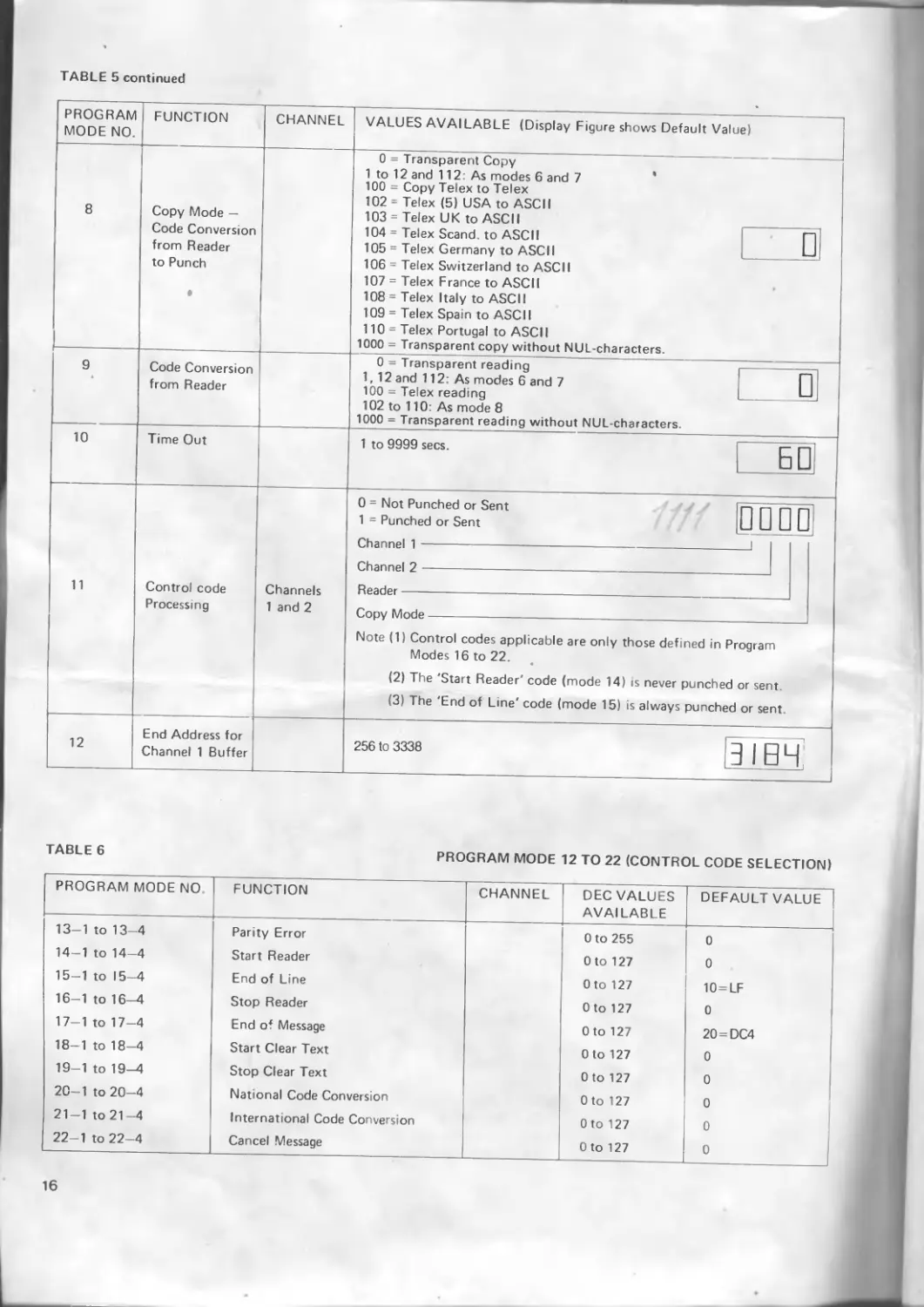
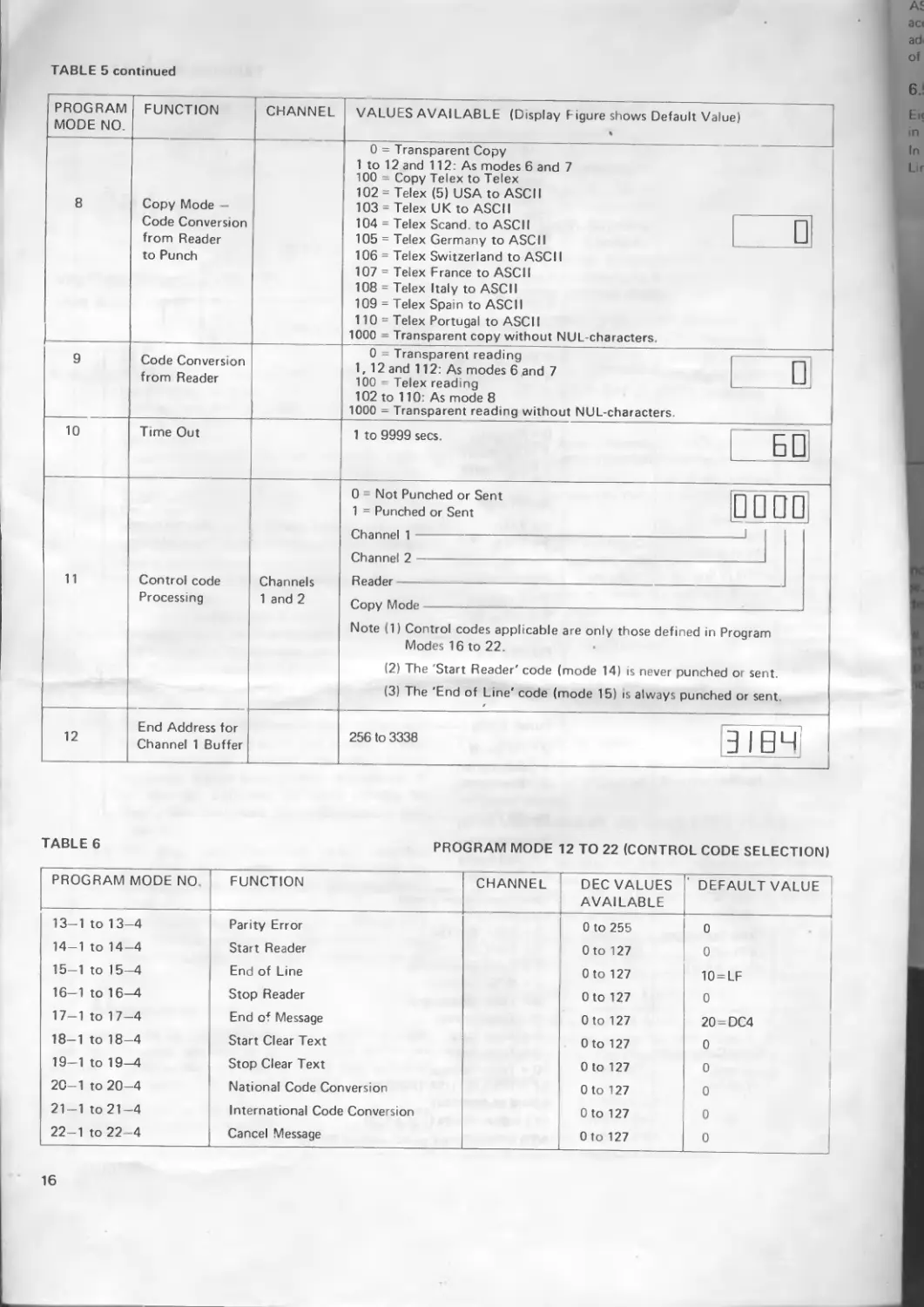
TABLE 5 continued
PROGRAM MODE NO. FUNCTION CHANNEL VALUES AVAILABLE (Display Figure shows Default Value
8 Copy Mode — Code Conversion from Reader to Punch • 0 = Transparent Copy 1 to 12 and 112: As modes 6 and 7 100 = Copy Telex to Telex 102-Telex (5) USA to ASCII 103 = Telex UK to ASCII
104 = Telex Scand. to ASCII 105 = Telex Germanv to ASCII
106 = Telex Switzerland to ASCII 107 = Telex France to ASCII 108 = Telex Italy to ASCII 109 = Telex Spain to ASCII 110 = Telex Portugal to ASCII 1000 = Transparent copy without NUL-characters. •
9 * Code Conversion from Reader n ~ -j:-
V— 1 Idllbpdltlll redUUiy 1,12 and 112: As modes 6 and 7 1ПП — TpIpv rpadinn L
102 to 110: As mode 8 1000 = Transparent reading without NUL-characters.
10 Time Out 1 to 9999 secs. I—1
11 Control code Processing Channels 1 and 2 0 = Not Punched or Sent 1 = Punched or Sent 1 1 □
1
V/iidiiiiui i (’"'Ьтяппр! .
Note (1) Control codes applicable are only those defined in Program Modes 16 to 22. « (2) The 'Start Reader' code (mode 14) is never punched or sent. (3) The 'End of Line' code (mode 15) is always punched or sent.
12 End Address for Channel 1 Buffer
256 to 3338 - L j
TABLE 6
PROGRAM MODE 12 TO 22 (CONTROL CODE SELECTION)
PROGRAM MODE NO. FUNCTION CHANNEL DEC VALUES AVAILABLE DEFAULT VALUE
13-1 to 13-4 Parity Error 0 to 255 0
14-1 to 14-4 Start Reader Oto 127 0
15—1 to 15—4 End of Line Oto 127 10=LF
16—1 to 16—4 Stop Reader 0 to 127 0
17-1 to 17-4 End of Message Oto 127 20 = DC4
18-1 to 18-4 Start Clear Text Oto 127 0
19-1 to 19-4 Stop Clear Text Oto 127 0
20-1 to 20-4 National Code Conversion Oto 127 0
21-1 to 21-4 International Code Conversion Oto 127 0
22-1 to 22-4 Cancel Message Oto 127 0
16
6. CODE CONVERSION
This section describes the code conversion which is performed on incoming data to convert it to the required format. The format is selected in Program modes 6 and 7, and details of individual character conversions are given in the Appendixes. Conversions of control characters depend upon the control codes selected in Program modes 12 to 21.
6.1 ASCII to ASCII
This conversion is performed directly and without any special formatting.
All characters, except defined control codes, are punched (or transmitted, if read by the reader). Control codes initiate their respective functions and are punched or sent, if this is selected by Program mode 11.
Codes for National and International conversions and for Start and Stop Cleartext, do not initiate any function during conversion.
If parity is included within the incoming data, it is transferred to bit 8 (if selected by Program mode 5); in this way codes other than ASCII can be transferred.
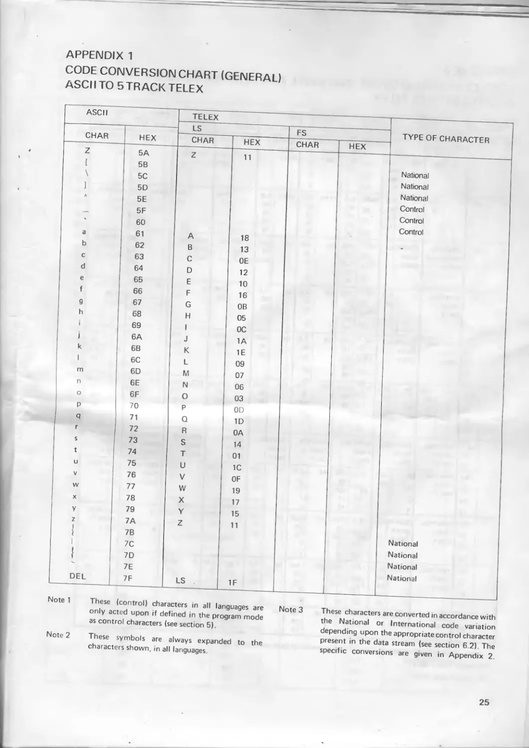
6.2 ASCII to Telex (5 track)
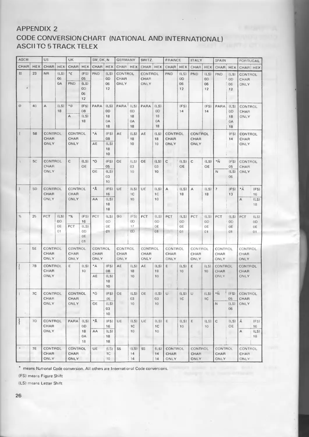
ASCII characters are converted to 5 track Telex characters in accordance with Appendixes 1 and 2, depending upon the National version set in Program modes 6 and 7. Whenever the code for International Conversion is detected, further characters are converted to their international versions. Changing from national to international and back can occur whenever required in the same message.
Formatting and code expansion of the telex message is performed in accordance with the procedures detailed in section 7. .
6.3 ASCII to Telex (USA 8 track - RS358)
ASCII characters are converted to 8 track Telex characters in accordance with Appendix 4. National and International versions are not available in 8 track telex, and any conversion control codes present in the incoming message are ignored. The code characters are however converted in accordance with Appendix 4
Clear text punching occurs in the manner as described in section 7.1, except that an 8 track matrix is used for the clear (readable) characters.
Formatting and code expansion are performed genrally as described >n seclions 7.4 and 7.5, except that the maximum telex line length is 72 characters instead of 69
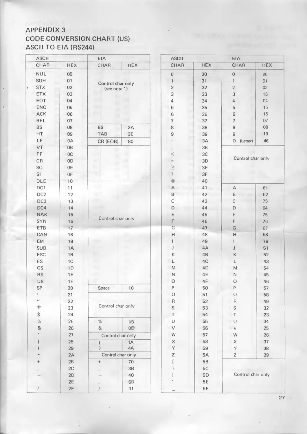
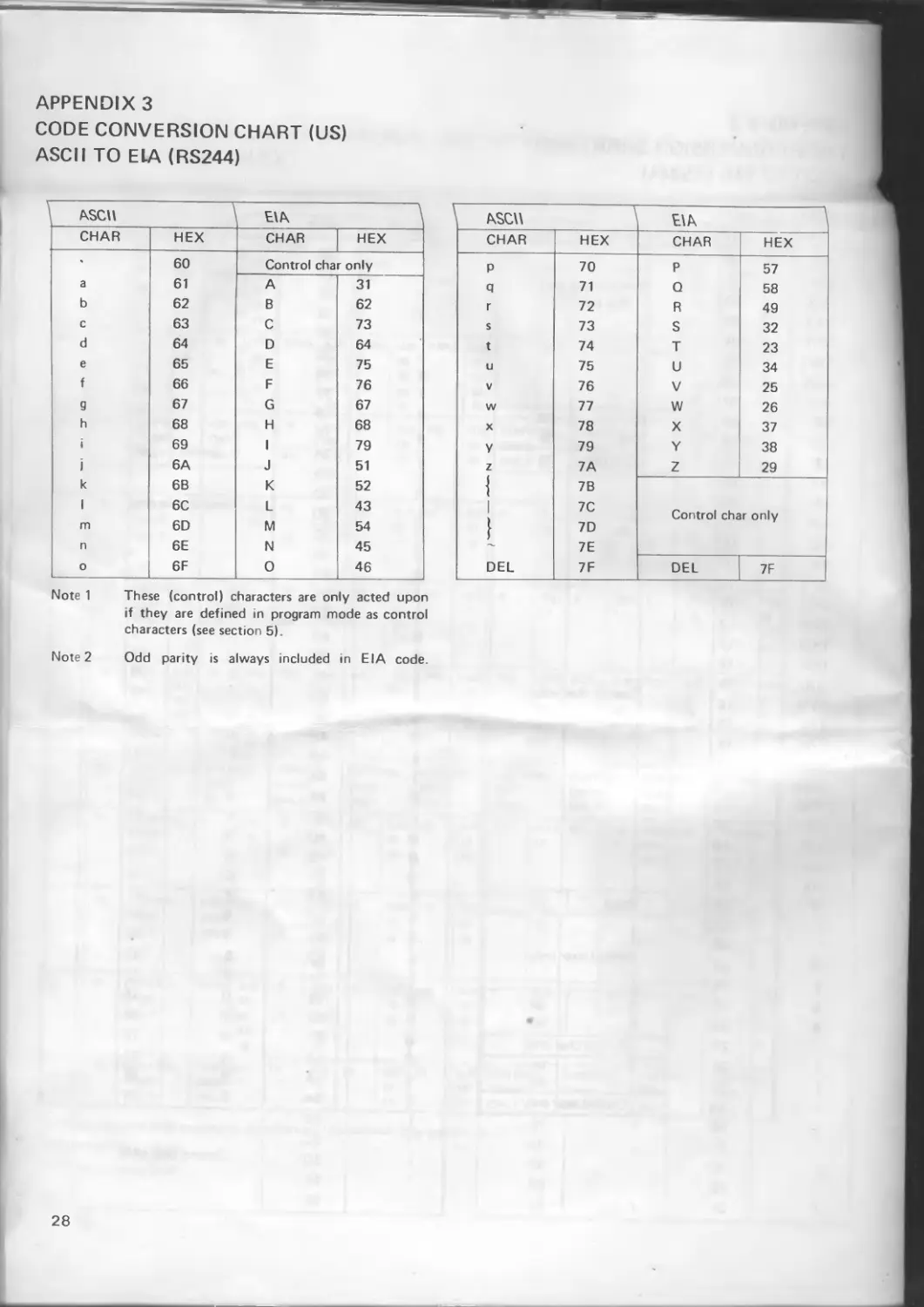
6.4 ASCII to EIA (RS244)
ASCII characters are converted to 8 track EIA characters in accordance with Appendix 3. The 5th track bit is always added to give odd parity, and is always punched irrespective of the punch parity setting in Program mode 5
6.5 EIA (RS244) to ASCII
Eight track EIA characters are converted to ASCII chaiacters in accordance with Appendix 3.
In the EIA code, character CR (EOB) is defined as the End of Line control code.
7 TELEX TAPE FORMATTING
This section describes the processing which is performed on incoming data to convert it to the 5 track telex format. The telex format is determined by the code conversion selected in Program modes 6 and 7 (see section 6). All other facilities available for the preparation of telex tapes are also described.
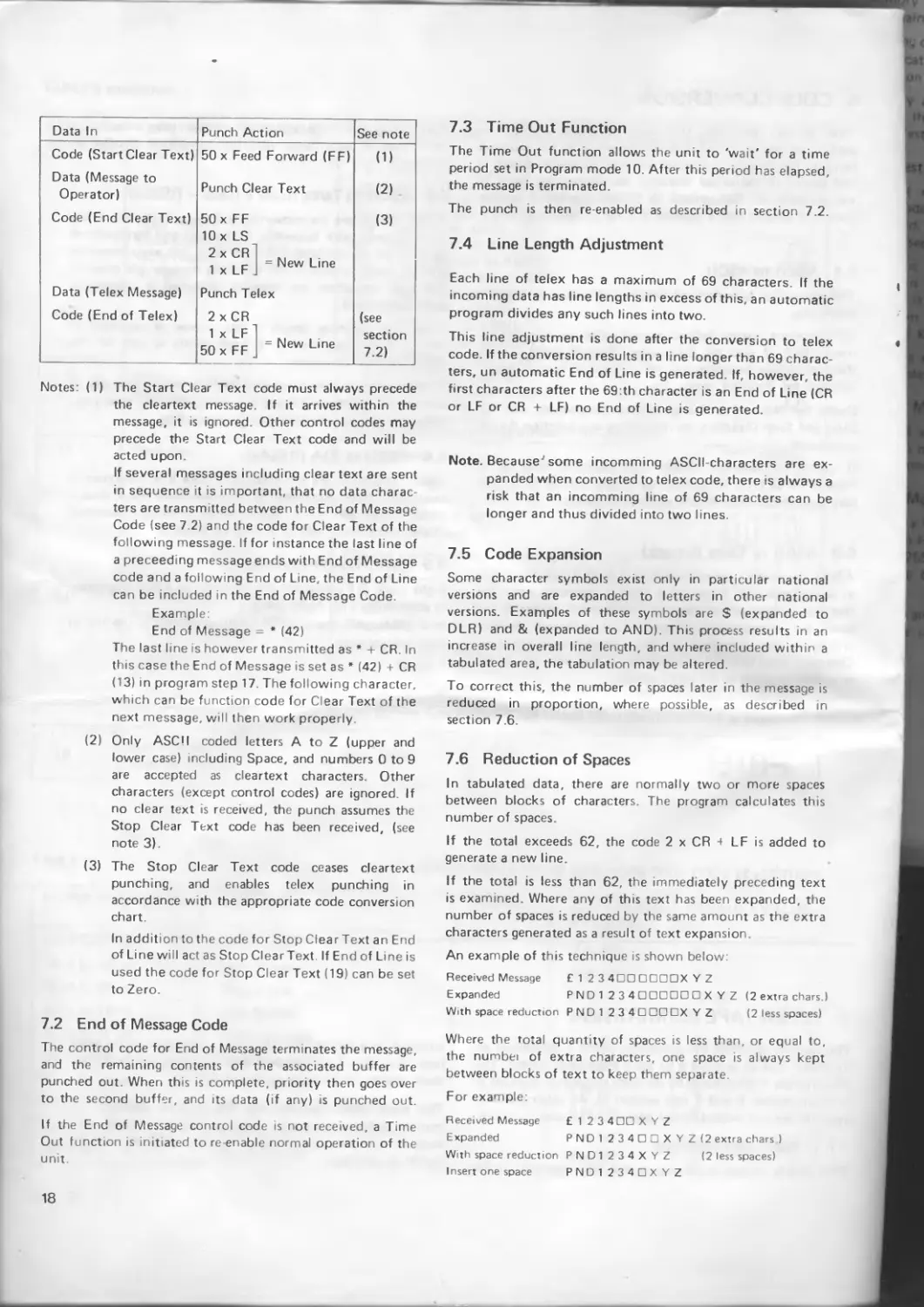
7.1 Clear Text Punching
This facility allows a message to the telex operator to be
punched, in a directly readable form, at the start of the telex tape. This Clear Text facility is entered and exited by control codes selected in Program modes 18 and 19.
The table below explains the transmission sequence for control codes and data for start/stop of cleartext and start/ stop of telex message, and describes the action taken by the punch at each step.
17
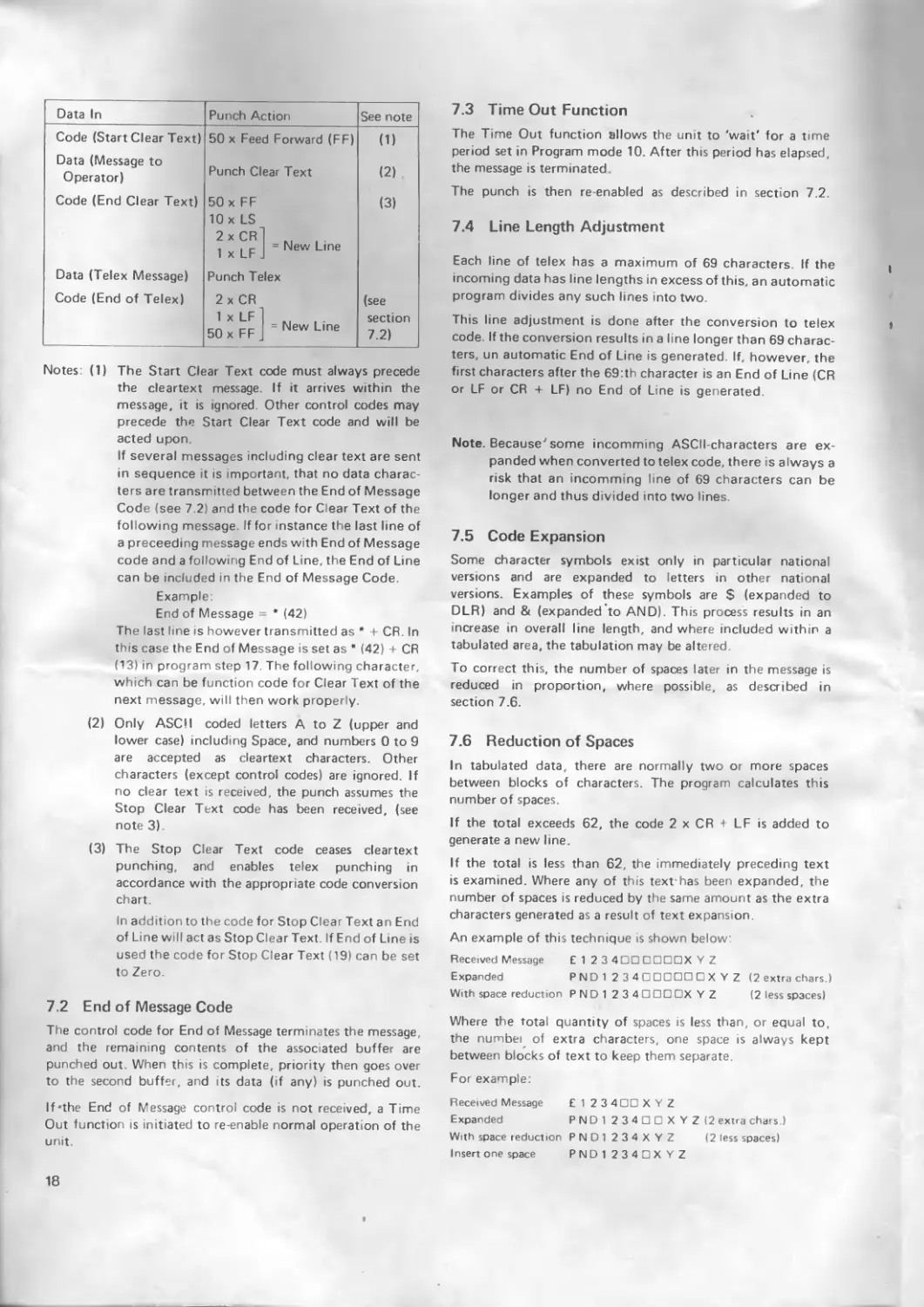
Data In Punch Action See note
Code (Start Clear Text) Data (Message to 50 x Feed Forward (FF) (1)
Operator) Punch Clear Text (2)
Code (End Clear Text) 50 x FF 10 x LS 2 x CR 1 .. . , r New Line 1 x LF j (3)
Data (Telex Message) Punch Telex
Code (End of Telex) 2 x CR 1 x LF = New Line 50 x FF (see section 7.2)
Notes: (1) The Start Clear Text code must always precede the cleartext message If it arrives within the message, it is ignored Other control codes may precede the Start Clear Text code and will be acted upon.
If several messages including clear text are sent in sequence it is important, that no data characters are transmitted between the End of Message Code (see 7 2) and the code for Clear Text of the following message. If for instance the last line of a preceeding message ends with End of Message code and a following End of Line, the End of Line can be included in the Fed of Message Code.
Example:
End of Message = * (42)
The last line is however transmitted as * + CR. In this case the End of Message is set as * (42) + CR (13) in program step 17 The following character, which can be function code for Clear Text of the next message, will then work properly.
(2) Only ASCH coded letters A to Z (upper and lower case) including Space, and numbers 0 to 9 are accepted as cleartext characters. Other characters (except control codes) are ignored. If no clear text is received, the punch assumes the Stop Clear Text code has been received, (see note 3).
(3) The Stop Clear Text code ceases cleartext punching, and enables telex punching in accordance with the appropriate code conversion chart.
In addition to the code for Stop Clear Text an End of Line will act as Stop Clear Text. If End of Line is used the code for Stop Clear Text (19) can be set to Zero.
7.2 End of Message Code
The control code for End of Message terminates the message, and the remaining contents of the associated buffer are punched out. When this is complete, priority then goes over to the second buffer, and its data (if any) is punched out.
If-the End of Message control code is not received, a Time Out function is initiated to re-enable normal operation of the unit
7.3 Time Out Function
The Time Out function allows the unit to 'wait' for a time period set in Program mode 10. After this period has elapsed, the message is terminated
The punch is then re-enabled as described in section 7.2.
7.4 Line Length Adjustment
Each line of telex has a maximum of 69 characters. If the incoming data has line lengths in excess of this, an automatic program divides any such lines into two.
This line adjustment is done after the conversion to telex code. If the conversion results in a line longer than 69 characters, un automatic End of Line is generated. If, however, the first characters after the 69:th character is an End of Line (CR or LF or CR + LF) no End of Line is generated
Note. Because7 some incomming ASCII-characters are expanded when converted to telex code, there is always a risk that an incomming line of 69 characters can be longer and thus divided into two lines.
7.5 Code Expansion
Some character symbols exist only in particular national versions and are expanded to letters in other national versions. Examples of these symbols are $ (expanded to DLR) and & (expanded’to AND). This process results in an increase in overall line length, and where included within a tabulated area, the tabulation may be altered.
To correct this, the number of spaces later in the message is reduced in proportion, where possible, as described in section 7.6.
7.6 Reduction of Spaces
In tabulated data, there are normally two or more spaces between blocks of characters. The program calculates this number of spaces.
If the total exceeds 62, the code 2 x CR + LF is added to generate a new line.
If the total is less than 62, the immediately preceding text is examined. Where any of this text has been expanded, the number of spaces is reduced by the same amount as the extra characters generated as a result of text expansion
An example of this technique is shown below:
Received Message £1 2 3 4DDDDDDXYZ
Expanded PND1 2 3 4 □ □□□□ □ X Y Z (2 extra chars.)
With space reduction PND1234DDDDXYZ (2 less spaces)
Where the total quantity of spaces is less than, or equal to, the numbei of extra characters, one space is always kept between blocks of text to keep them separate.
For example:
Received Message £ 1 2 3 4DD X Y Z
Expanded PND1 2 3 4 □ □ X Y Z (2 extra chars.)
With space reduction PND1 234XYZ (2 less spaces)
Insert one space PND 1 2343X Y Z
18
TABLE 5
PROGRAM MODES 1 TO 12
PROGRAM MODE NO. FUNCTION CHANNEL VALUES AVAILABLE (Display Figure shows Default Value) 1
1 Baud Rate Channel 1 110 150 300
600 1200 j[
2 Baud Rate Channel 2
2400 4800
3 Protocol Parity Word length Stop Bits Channel 1
1 = Buffer Ready/Busy, no echo 2 = X-ON/X-OFF, no echo 3 = Buffer Ready/Busy, echo 4 = X-ON/X-OFF, echo
0 = No parity 1 = Odd naritv
4 Protocol Parity Word length Stop Bits Channel 2 2 = Ev?n parity
7 = 7 bits Note. 7 or 8 bits can be used when parity is selected. 8 = 8 bits 8 bits must be used when No parity is selected. Stop Bits
1 = 1 stop bit 2 = 2 stop bits
1 5 Punch Mode Punch Parity Reader Parity Punch Mode 1
1 = Normal 2 = Double 2C 1 J
Punch Parity 0 = No parity 1 = Odd parity 2 = Even parity 1
0 = No parity 1 = Odd parity 2 = Even parity
6 Code Conversion to Punch (from ASCII) Channel 1 0 = Transparent punch 1 = ASCII 2 = Telex (5) USA 3 = Telex UK 4 = Telex Scandinavia 5 = Telex Germany 6 = Telex Switzerland 7 = Telex France 8 = Telex Italy 9 = Telex Spain 10 = Telex Portugal 11 = Telex (8) USA (RS-358) 12 = EIA (RS 244) 112 = EIA (RS 244) to ASCII 1000 = Transparent punch without NUL-characters
1
7 Code Conversion to Punch (from ASCII) Channel 2
1
CONTINUED
15
TABLE 5 continued
TABLE 6
PROGRAM MODE 12 TO 22 (CONTROL CODE SELECTION)
PROGRAM MODE NO FUNCTION CHANNEL DEC VALUES AVAILABLE DEFAULT VALUE
13-1 to 13-4 Parity Error 0 to 255 0
14-1 to 14-4 Start Reader Oto 127 0
15—1 to 15—4 End of Line 0 to 127 10 = LF
16-1 to 16^1 Stop Reader Oto 127 0
17-1 to 17-4 End of Message 0 to 127 20-DC4
18-1 to 18-4 Start Clear Text Oto 127 0
19-1 to 19—4 Stop Clear Text 0 to 127 0
20-1 to 20-4 National Code Conversion 0 to 127 0
21-1 to 21-4 International Code Conversion 0 to 127 0
22-1 to 22-4 Cancel Message Oto 127 0
16
6. CODE CONVERSION
This sect.on describes the code conversion which is performed on incoming data to convert it to the required format. The format is selected in Program modes 6 and 7, and details of individual character conversions are given in the Appendixes. Conversions of control characters depend upon the control codes selected in Program modes 12 to 21.
6.1 ASCII to ASCII
This conversion is performed directly and without any special formatting.
All characters, except defined control codes, are punched (or transmitted, if read by the reader). Control codes initiate their respective functions and are punched or sent, if this is selected by Program mode 11.
Codes for National and International conversions and for Start and Stop Cleartext, do not initiate any function during conversion
If parity is included within the incoming data, it is transferred to bit 8 (if selected by Program mode 5); in this way codes other than ASCII can be transferred
6.2 ASCII to Telex (5 track)
ASCII characters are converted to 5 track Telex characters in accordance with Appendixes 1 and 2, depending upon the National version set in Program modes 6 and 7 Whenever the code for International Conversion is detected, further characters are converted to their international versions. Changing from national to international and back can occur whenever required in the same message.
Formatting and code expansion of the telex message is performed in accordance with the procedures detailed in section 7.
6.3 ASCII to Telex (USA 8 track - RS358)
ASCII characters are converted to 8 track Telex characters in accordance with Appendix 4. National and International versions are not available in 8 track telex, and any conversion control codes present in the incoming message are ignored The code characters are however converted in accordance with Appendix 4.
Clear text punching occurs in the manner as described in section 7.1, except that an 8 track matrix is used for the clear (readable) characters.
Formatting and code expansion are performed genrally as described in sections 7.4 and 7.5, except that the maximum telex line length is 72 characters instead of 69
6.4 ASCII to EIA (RS244)
ASCII characters are converted to 8 track EIA characters in accordance with Appendix 3. The 5th track bit is always added to give odd parity, and is always punched irrespective of the punch parity setting in Program mode 5
6.5 EIA (RS244) to ASCII
Eight track EIA characters are converted to ASCII characters in accordance with Appendix 3.
In the EIA code, character CR (EOB) is defined as the End of Line control code.
7. TELEX TAPE FORMATTING
This section describes the processing which is performed on incoming data to convert it to the 5 track telex format. The telex format is determined by the code conversion selected in Program modes 6 and 7 (see section 6). All other facilities available for the preparation of telex tapes are also described
7.1 Clear Text Punching
his facility allows a message to the telex operator to be
punched, in a directly readable form, at the start of the telex tape This Clear Text facility is entered and exited by control codes selected in Program modes 18 and 19.
The table below explains the transmission sequence for control codes and data for start/stop of cleartext and start/ stop of telex message, and describes the action taken by the punch at each step
17
Data In Punch Action See note
Code (Start Clear Text) Data (Message to 50 x Feed Forward (FF) (1)
Operator) Punch Clear Text (2)
Code (End Clear Text) 50 x FF 10 x LS 2xCR] m , . r- New Line 1 x LF . (3)
Data (Telex Message) Punch Telex
Code (End of Telex) 2 x CR IxLFl kl (see section
cn r-r = New Line 50 x FF 7.2)
Notes: (1) The Start Clear Text code must always precede the cleartext message. If it arrives within the message, it is ignored. Other control codes may precede the Start Clear Text code and will be acted upon.
If several messages including clear text are sent in sequence it is important, that no data characters are transmitted between the End of Message Code (see 7 2) and the code for Clear Text of the following message. If for instance the last line of a preceed ng message ends with End of Message code and a following End of Line, the End of Line can be included in the End of Message Code.
Example:
End of Message = * (42)
The last line is however transmitted as * + CR. In this case the End of Message is set as * (42) + CR (13) in program step 17. The following character, which can be function code for Clear Text of the next message, will then work properly.
(2) Only ASCH coded letters A to Z (upper and lower case) including Space, and numbers 0 to 9 are accepted as cleartext characters. Other characters (except control codes) are ignored. If no clear text is received, the punch assumes the Stop Clear Text code has been received, (see note 3).
(3) The Stop Clear Text code ceases cleartext punching, and enables telex punching m accordance with the appropriate code conversion chart.
In addition to the code for Stop ClearText an End of Line will act as Stop ClearText. If End of Line is used the code for Stop Clear Text (19) can be set to Zero.
7.2 End of Message Code
The control code for End of Message terminates the message, and the remaining contents of the associated buffer are punched out When this is complete, priority then goes over to the second buffer, and its data (if any) is punched out.
If the End of Message control code is not received, a Time Out function is initiated to re-enable normal operation of the unit.
7.3 Time Out Function
The Time Out function allows the unit to 'wait' for a time period set in Program mode 10. After this period has elapsed, the message is terminated
The punch is then re-enabled as described in section 7.2.
7.4 Line Length Adjustment
Each line of telex has a maximum of 69 characters If the incoming data has line lengths in excess of this, an automatic program divides any such lines into two
This line adjustment is done after the conversion to telex code. If the conversion results in a line longer than 69 characters, un automatic End of Line is generated. If, however, the first characters after the 69:th character is an End of Line (CR or LF or CR + LF) no End of Line is generated.
Note. BecauseJ some incomming ASCII characters are expanded when converted to telex code, there is always a risk that an incomming line of 69 characters can be longer and thus divided into two lines.
7.5 Code Expansion
Some character symbols exist only in particular national versions and are expanded to letters in other national versions. Examples of these symbols are $ (expanded to DLR) and & (expanded to AND). This process results in an increase in overall line length, and where included within a tabulated area, the tabulation may be altered.
To correct this, the number of spaces later in the message is reduced in proportion, where possible, as described in section 7.6.
7.6 Reduction of Spaces
In tabulated data, there are normally two or more spaces between blocks of characters, the piogram calculates this number of spaces.
If the total exceeds 62, the code 2 x CR + LF is added to generate a new line.
If the total is less than 62, the immediately preceding text is examined Where any of this text has been expanded, the number of spaces is reduced by the same amount as the extra characters generated as a result of text expansion
An example of this technique is shown below:
Received Message £ 1 2 3 4OD □□□□X V Z
Expanded PND 1 2 34□□□□□□X Y Z (2 extra chars.)
With space reduction PND1 2 3 4 □ □□ DX Y Z (2 less spaces)
Where the total quantity of spaces is less than, or equal to, the numbei of extra characters, one space is always kept between blocks of text to keep them separate.
For example:
Received Message £ 1 2 3 4 □□ X Y Z
Expanded
PND 1 2 3 4 □ □ X Y Z (2 extra chars )
With space reduction PND1 234XYZ
(2 less spaces)
Insert one space PND1 2 3 4 и X Y Z
18
8. TESTMODE
When the [TEST] key is depressed in the Off-line mode, the unit enters the Test mode and the display shows TEST. Depressing the [*] key then selects the first of seven test routines, (the display shows 1). Depressing the [TEST] key then starts the first test routine. If this routine is completed without failure, the display then changes to 2, and depression of the [TEST] key starts the second test routine. This procedure is continued until all seven test routines are completed.
Any test routine may be entered by depressing the [*] key a number of times until the desired test routine number appears in the display. This test is then started by depressing the [TEST] key.
The test routine may be exited at any time by depressing the [EXIT] key.
A fault or failure in any test routine is shown on the display.
8.1 Test Mode 1 — Memory Test
The whole buffer memory (RAM 1 and RAM 2) is written with a '1' at each address location, and is then read. The memory is then cleared with 'O's' at each address location, and again read.
Reading of the memory starts with the lowest address first. If any location is found to be defective, its decimal address is shown on the display and testing stops.
A faulty address < 2047 indicates that RAM 1 is faulty; if > 2047 then RAM 2 is faulty. If no fault is present, the unit enters Test Mode 2.
8.2 Test Mode 2 — Channel 1 Communication Test
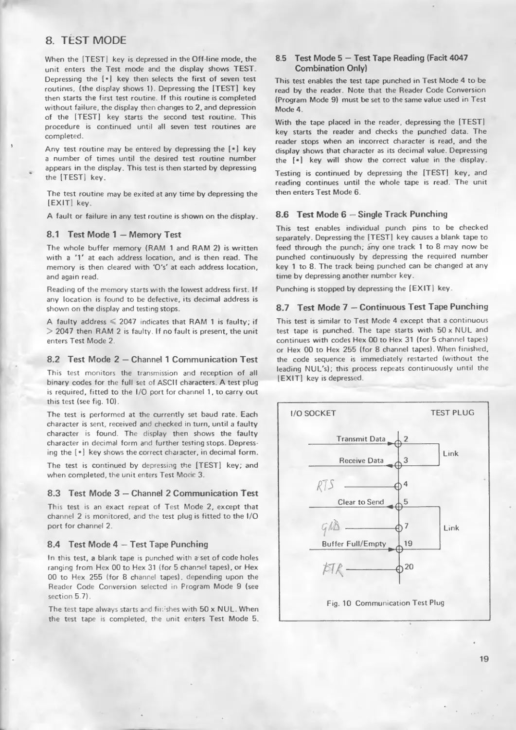
This test monitors the transmission and reception of all binary codes for the full set of ASCII characters. A test plug is required, fitted to the I/O port for channel 1, to carry out this test (see fig. 10).
The test is performed at the currently set baud rate. Each character is sent, received and checked in turn, until a faulty character is found. The display then shows the faulty character in decimal form and further testing stops. Depressing the [*] key shows the correct character, in decimal form.
The test is continued by depressing the [TEST] key; and when completed, the unit enters Test Mode 3.
8.5 Test Mode 5 — Test Tape Reading (Facit 4047 Combination Only)
This test enables the test tape punched in Test Mode 4 to be read by the reader. Note that the Reader Code Conversion (Program Mode 9) must be set to the same value used in Test Mode 4.
With the tape placed in the reader, depressing the [TEST] key starts the reader and checks the punched data. The reader stops when an incorrect character is read, and the display shows that character as its decimal value. Depressing the [*] key will show the correct value in the display.
Testing is continued by depressing the [TEST] key, and reading continues until the whole tape is read. The unit then enters Test Mode 6.
8.6 Test Mode 6 — Single Track Punching
This test enables individual punch pins to be checked separately. Depressing the [TEST] key causes a blank tape to feed through the punch; any one track 1 to 8 may now be punched continuously by depressing the required number key 1 to 8. The track being punched can be changed at any time by depressing another number key.
Punching is stopped by depressing the [EXIT] key.
8.7 Test Mode 7 — Continuous Test Tape Punching
This test is similar to Test Mode 4 except that a continuous test tape is punched. The tape starts with 50 x NUL and continues with codes Hex 00 to Hex 31 (for 5 channel tapes) or Hex 00 to Hex 255 (for 8 channel tapes). When finished, the code sequence is immediately restarted (without the leading NUL's); this process repeats continuously until the [EXIT] key is depressed.
I/O SOCKET
Transmit Data
2
Receive Data
KV
TEST PLUG
Link
3
8.3 Test Mode 3 — Channel 2 Communication Test
This test is an exact repeat of Test Mode 2, except that channel 2 is monitored, and the test plug is fitted to the I/O port for channel 2.
Clear to Send
5
Link
8.4 Test Mode 4 — Test Tape Punching
In this test, a blank tape is punched with a'set of code holes ranging from Hex 00 to Hex 31 (for 5 channel tapes), or Hex 00 to Hex 255 (for 8 channel tapes), depending upon the Reader Code Conversion selected in Program Mode 9 (see section 5.7).
The test tape always starts and fimshes with 50 x NUL. When the test tape is completed, the unit enters Test Mode 5.
Buffer Full/Empty
19
<)20
Fig. 10 Communication Test Plug
19
4046/4047
I/O CONNECTORS
data r 2 )en iy.
.^.y 2 Transmit Data
. 3 Receive Data
n )
4 Request to Send
5 Clear to Send______
___7 Signal Ground
19 Buffer Full/Empty
1 20 Data Terminal Ready
Fig. 12 I/O Connector Pin Allocations
21
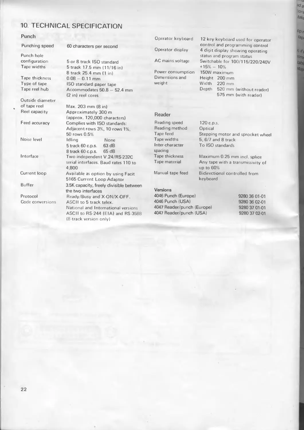
10 TECHNICAL SPECIFICATION
Punch
Punching speed
Punch hole configuration Tape widths
Tape thickness Type of tape Tape reel hub
Outside diameter of tape reel Reel capacity
Feed accuracy
Noise level
Interface
Current loop
Buffer
Protocol
Code conversions
60 characters per second
5 or 8 track ISO standard 5 track 17.5 mm (11/16 in) 8 track 25.4 mm (1 in) 0 08 — 0 11 mm
ISO standard paper tape Accommodates 50.8 — 52.4 mm (2 in) reel cores
Max. 203 mm (8 in)
Approximately 300 m (approx. 120,000 characters) Complies with ISO standards Adjacent rows 3%, 10 rows 1%, 50 rows 0.5%
Idling None
5 track 60 c.p.s. 63 dB
8 track 60 c.p.s. 65 dB
Two independent V.24/RS 232C serial interfaces. Baud rates 110 to 4.800
Available as option by using Facit 5165 Current Loop Adaptor
3.5K capacity, freely divisible between the two interfaces
Ready/Busy and X-ON/X-OFF. ASCII to 5 track telex.
National and International versions ASCII to RS-244 (EIA) and RS-358B (8 track version only)
Operator keyboard
Operator display
AC mains voltage
Power consumption Dimensions and weight
12 key keyboard used for operator control and programming control 4 digit display showing operating status and program status Switchable for 100/115/220/240V + 15%- 10% 150W maximum
Height 200 mm
Width 220 mm
Depth 520 mm (without reader) 575 mm (with reader)
Reader
Reading speed 120 c.p.s.
Reading method Opt.cal
Tape feed Stepping motor and sprocket wheel
Tape widths 5, 6/7 and 8 track
Inter-character To ISO standards
spacing Tape thickness Maximum 0 25 mm incl. splice
Tape material Any tape with a transmissivity of up to 60%
Manual tape feed Bidirectional controlled from keyboard
Versions
4046 Punch (Europe) 9280 36 01-01
4046 Punch (USA) 9280 36 02-01
4047 Reader/punch (Europe) 9280 37 01-01
4047 Reader/punch (USA) 9280 37 02-01
22
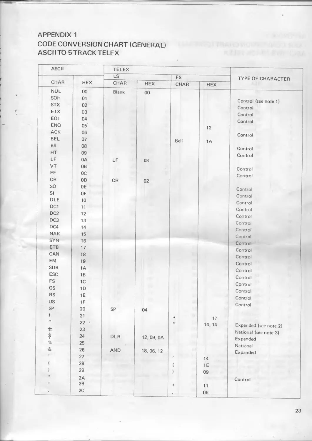
APPENDIX 1
CODE CONVERSION CHART (GENERAL)
ASCI I TO 5 TRACK TELEX
ASCII TELEX TYPE OF CHARACTER
CHAR HEX LS FS
CHAR HEX CHAR HEX
NUL 00 Blank 00
SOH 01 Control (see note 1)
STX 02 Control
ETX 03 Control
EOT 04 Control
ENO 05' 12
ACK 06 Control
BEL 07 Bell 1A
BS 08 Control
HT 09 Control
LF OA LF 08
VT OB Control
FF ОС Control
CR OD CR 02
SO OE Control
SI OF Control
DLE 10 Control
DC1 11 Control
DC2 12 Control
DC3 13 Control
DC4 14 Control
NAK 15 Control
SYN 16 Control
ETB 17 Control
CAN 18 Control
EM 19 Control
SUB 1A Control
ESC IB Control
FS 1C Control
GS 1D Control
RS 1E Control
US IF Control
SP 20 SP 04
I 21 • 17
99 22 • 99 14, 14 Expanded (see note 2)
23 National (see note 3)
$ 24 DLR 12, 09, OA Expanded
% 25 National
& 26 AND 18, 06, 12 Expanded
9 27 9 14
( 28 ( 1E
) 29 ) 09
* 2A Control
+ 2B + 11
• 2C t 06
23
APPENDIX 1
CODE CONVERSION CHART (GENERAL)
ASCIITO 5TRACKTELEX
ASCII TELEX LS FS TYPE OF CHARACTER
CHAR HEX CHAR HEX CHAR HEX
- 2D - 18
- 2E 07
/ 2F / 17
0 30 0 OD
. 1 31 1 1D
2 32 2 19
3 33 3 10
4 34 4 ОА
5 35 5 01
6 36 6 15
7 37 7 1C
8 38 8 ОС
9 39 9 03
• ЗА ОЕ
t ЗВ Control
ЗС Control
= 3D = OF
ЗЕ Control
? 3F ? 13
@ 40 National
A 41 А 18
В 42 В 13
c 43 С ОЕ
D 44 D 12
E 45 Е 10
F 46 F 16
G 47 G ОВ
H 48 Н 05
I 49 1 ОС
J 4А J 1А
К 4В К 1Е
L 4С L 09
M 4D М 07
N 4Е N 06
0 4F 0 03
P 50 Р 0D
Q 51 О 1D
R 52 R ОА
S 53 S 14
T 54 Т 01 ♦
u 55 и 1С
V 56 V OF
w 57 W 19
X 58 X 17
Y 59 Y 15
24
APPENDIX 1
CODE CONVERSION CHART (GENERAL)
ASCI I TO 5 TRACK TELEX
ASCII TELEX TYPE OF CHARACTER
LS FS
CHAR HEX
CHAR HEX CHAR HEX
Z 5A Z 11
1 5B National
\ 5C National
] 5D National
A 5E Control
5F Control
* 60 Control
a 61 A 18
b 62 В 13
c 63 C 0E
d 64 D 12
e 65 E 10
f 66 F 16
9 67 G OB
h 68 H 05
i 69 I ОС
j 6A J 1A
к 6B К 1E
1 6C L 09
m 6D M 07
n 6E N 06
о 6F 0 03
P 70 P 0D
d 71 Q 1D
r 72 R 0A
s 73 S 14
t 74 T 01
u 75 и 1C
V 76 V OF
w 77 w 19
X 78 X 17
У 79 Y 15
z 7A z 11
7B National
1 7C National
7D National
7E National
DEL 7F LS 1F
Note 1 These (control) characters in all languages are Note 3 only acted upon if defined in the program mode as control characters (see section 5),
Note 2 These symbols are always expanded to the
characters shown, in all languages
These characters are converted in accordance with the National or International code variation depending upon the appropriate control character present in the data stream (see section 6.2). The specific conversions are given in Appendix 2.
25
APPENDIX 2
CODE CONVERSION CHART (NATIONAL AND INTERNATIONAL)
ASCIITO 5TRACK TELEX
ASCII US UK SW, DK. N GERMANY SWITZ. FRANCE ITALY SPAIN PORTUGAL
CHAR HEX CHAR HEX CHAR HEX CHAR HEX CHAR' HEX CHAR HEX CHAR HEX CHAR HEX CHAR HEX char)HEX
ft 23 NR (LSI 06 OA •£ (FS) 05 PND (LS) OD 06 12 CONTROL CHAR ONLY CONTROL CHAR ONLY PND (LS) OD 06 12 PND (LS) OD 06 12 PND (LS) OD 06 12 CONTROL CHAR ONLY
PND (LS) OD 06 12
,40 A (LS) 18 (FS) OB PARA (LS) OD 18 OA 18 PARA (LS) OD 18 OA 18 PARA (LS) OD 18 OA 18 (FS) 14 (FS) 14 PARA (LS) OD 18 OA 18 CONTROL CHAR ONLY
A (LS) 18
I 5B CONTROL CHAR ONLY CONTROL CHAR ONLY •A (FS) OB AE (LS) 18 10 AE (LS) 18 10 CONTROL CHAR ONLY CONTROL CHAR ONLY (FS) 14 1 CONTROL CHAR ONLY
AE (LS) 18 10
\ 5C CONTROL CHAR ONLY C (LS) OE •o (FS) 05 OE (LS) 03 10 OE (LS) 03 10 C (LS) OE C (LS) OE •N (FS) 05 CONTROL CHAR ONLY
OE (LS) 03 10 N (LS) 06
5D CONTROL CHAR ONLY CONTROL CHAR ONLY •A (FS) 16 UE (LS) 1C 10 UE (LS) 1C 10 A (LS) 18 A (LS) 18 ? (FS) 13 •A (FS) 16
AA (LS) 18 18 A (LS) 18
% 25 PCT (LS) OD OE 01 •% (FS) 16 PCT (LS) OD OE 01 00 (FS) OD 17 _ OD PCT (LS) OD OE 01 PCT (LS) OD OE 01 PCT (LS) OD OE 01 PCT (LS) OD OE 01 PCT (LS) OD OE 01
PCT (LS) OD OE 01
- 5E CONTROL CHAR ONLY CONTROL CHAR ONLY CONTROL CHAR ONLY CONTROL CHAR ONLY CONTROL CHAR ONLY CONTROL CHAR ONLY CONTROL CHAR ONLY CONTROL CHAR ONLY CONTROL CHAR ONLY
7B CONTROL CHAR ONLY E (LS) 10 *A (FS) OB AE (LS) 18 10 AE (LS) 18 10 E (LS) 10 E (LS) 10 CONTROL CHAR ONLY CONTROL CHAR ONLY
AE (LS) 18 10
7C CONTROL CHAR ONLY CONTROL CHAR ONLY •o (FS) 05 OE (LS) 03 10 OE (LS) 03 10 U (LS) 1C U (LS) 1C •N (FS) 05 CONTROL CHAR ONLY
OE (LS) 03 10 N (LS) 06
7D CONTROL CHAR ONLY PARA (LS) OD 18 OA 18 •A (FS) 16 UE (LS) 1C 10 UE (LS) 1C 10 E (LS) 10 E (LS) 10 C (LS) OE A (FS) , 16
AA (LS) 18 18 A | (LS) 18
A 7E CONTROL CHAR ONLY CONTROL CHAR ONLY UE (LS) 1C Ю SS (LS) 14 14 SS (LS) 14 14 CONTROL CHAR ONLY CONTROL CHAR ONLY CONTROL CHAR ONLY CONTROL CHAR ONLY
means National Code conversion All others are International Code conversions
(FS) means Figure Shift
(LS) means Letter Shift
26
APPENDIX 3
CODE CONVERSION CHART (US)
ASCII TO EIA (RS244)
ASCII EIA
CHAR HEX CHAR HEX
NUL 00
SOH 01
Control char only
• STX 02 (see note 1)
ETX 03
EOT 04
ENQ 05
ACK 06
BEL 07
BS 08 BS 2A
HT 09 TAB 3E
LF OA CR (EOB) 80
VT OB
FF ОС
CR OD
SO OE
SI OF
DLE 10
DC1 11
DC2 12
DC3 13
DC4 14
NAK 15
SYN 16 Control char only
ETB 17
CAN 18
EM 19
SUB 1A
ESC 1B
FS 1C
GS 1D
RS 1E
US 1F
SP 20 Space 10
! 21
tt 22
23 Control char on!y
$ 24
% 25 % 08
& 26 & 0E
/ 27 Control char only
( 28 ( 1A
) 29 ) 4A
« 2A Control char only
+ 2B + 70
9 2C 9 3B
— 2D — 40
- 2E 6B
/ 2F / 31
ASCII EIA
CHAR HEX CHAR HEX
0 30 0 20
1 31 1 01
2 32 2 02
3 33 3 13
4 34 4 04
5 35 5 15
6 36 6 16
7 37 7 07
8 38 8 08
9 39 9 19
• ЗА 0 (Letter) 46
9 ЗВ
ЗС
3D Control char only
> ЗЕ
? 3F
@ 40
A 41 A 61
В 42 В 62
C 43 C 73
D 44 D 64
E 45 E 75
F 46 F 76
G 47 G 67
H 48 H 68
1 49 I 79
J 4А J 51
К 4В К 52
L 4С L 43
M 4D M 54
N 4Е N 45
0 4F 0 46
P 50 P 57
Q 51 Q 58
R 52 R 49
S 53 S 32
T 54 T 23
и 55 u 34
V 56 V 25
w 57 w 26
X 58 X 37
Y 59 Y 38
z 5А z 29
[ 5В
\ 5С
] 5D Control char only
A 5Е
5F
I
27
APPENDIX 3
CODE CONVERSION CHART (US)
ASCII TO EIA (RS244)
ASCH
CHAR HEX CHAR HEX
* 60 Control char only
3 61 A 31
b 62 В 62
c 63 C 73
d 64 D 64
e 65 E 75
f 66 F 76
g 67 G 67
h 68 H 68
i 69 1 79
i 6A J 51
к 6B К 52
I 6C L 43
m 6D M 54
n 6E N 45
о 6F 0 46
ASCW
CHAR HEX CHAR HEX
P 70 P 57
q 71 Q 58
r 72 R 49
s 73 S 32
t 74 T 23
u 75 u 34
V 76 V 25
w 77 w 26
X 78 X 37
У 79 Y 38
z 7A z 29
7B
7C 7D Control char only
7E
DEL 7F DEL 7F
Note 1 These (control) characters are only acted upon if they are defined in program mode as control characters (see section 5).
Note 2 Odd parity is always included in EIA code.
28
APPENDIX 4
CODE CONVERSION CHART (US)
ASCII TO 8 TRACK TELEX (RS358)
ASCII RS-358-B
CHAR HEX CHAR HEX
NUL 00 Blank 00
SOH 01 SOH 01
STX 02 STX 02
ETX 03 STX 03
EOT 04 EOT 04
ENO 05 ENQ 05
ACK 06 ACK 06
BEL 07 BEL 07
BS 08 BS 08
HT 09 HT 09
LF 0A LF (NL) OA
VT 0B VT OB
FF ОС FF ОС
CR OD CR OD
SO OE SO OE
SI OF SI OF
DLE 10 DLE 10
DC1 11 DC1 11
DC2 12 DC2 12
DC3 13 DC3 13
DC4 14 DC4 14
NAK 15 NAK 15
SYN 16 SYN 16
ETB 17 ETB 17
CAN 18 CAN 18
EM 19 EM (EUR) 19
SUB 1A SUB 1A
ESC IB ESC 1B
FS 1C FS 1C
GS 1D GS 1D
RS 1E RS 1E
US 1F US 1F
SP 20 SP 20
I 21 Control char only
22 rr 27. 27
23 Control char only
* 24 DLR
% 25 % 25
& 26 AND
r 27 9 27
( 28 ( 28
) 29 ) 29
* 2A Control char only
+ 2B + 2B
f 2C f 2C
— 2D — 2D
> 2E 2E
/ 2F / 2F
ASCII RS-258-B
CHAR HEX CHAR HEX
0 30 0 30
1 31 1 31
2 32 2 32
3 33 3 • 33
4 34 4 34
5 35 5 35
6 36 6 36
7 37 7 37
8 38 8 38
9 39 9 39
• ЗА Z ЗА
t ЗВ
ЗС
= 3D
> ЗЕ Control char only
7 3F
@ 40
A 41 A 41
В 42 В 42
C 43 С 43
D 44 D 44
E 45 E 45
F 46 F 46
G 47 G 47
H 48 H 48
I 49 1 49
J 4А J 4A
К 4В К 4B
L 4С L 4C
M 4D M 4D
N 4Е N 4E
0 4F 0 4F
P 50 P 50
Q 51 Q 51
R 52 R 52
S 53 S 53
T 54 T 54
U 55 U 55
V 56 V 56
w 57 W 57
X 58 X 58
Y 59 Y 59
z 5А z 5A
[ 5В
\ 5С
] 5D Control char only
5Е
— 5F
29
APPENDIX 4
CODE CONVERSION CHART (US)
ASCII TO 8 TRACK TELEX (RS358)
ASCII RS-358-B
CHAR HEX CHAR HEX
60 Control char only
a 61 A 41
b 62 В 42
c 63 C 43
d 64 D 44
e 65 E 45
f 66 F 46
9 67 G 47
h 68 H 48
i 69 1 49
j 6A J 4A
к 6B К 4B
1 6C L 4C
m 6D M 4D
n 6E N 4E
о 6F ° 4F
30
Facit4046/4047 Punch/Reader-Punch
facit
Australia EAI-Electronic Associates Pty Ltd P.O. Box 570 ARTARMON NSW 2064 Telephone 427-3322 Telex 21130 Austria Denmark Facit A/S Postbox 9 2730HERLEV Telephone 02-922400 Telex 35394 Finland Iceland GisliJ. Johnsen Skrifstofubunadur SF P.O. Box 132 IS 202 КОРАVOGUR Telephone 354-173111 Telex 2316 Korea K.D.C. Corporation C.P.O. Box 5956 SEOUL Telephone 723-8555/8236 Telex К 28428 The Netherlands Singapore Far East Office Eqpts Pte Ltd Unit 10-03 Alpha Bldg 45 KaUang Pudding Rd SINGAPORE 1334 Telephone 745 82 88 Telex 244 11 Switzerland Ericsson Information Systems AG Postfach25 CH-8702 ZOLLIKON-STATIOF Telephone 01-391 97 11 Telex 59142 Taiwan R.O.C.
Ericsson Information Systems Ges. ntb.H. Richard Strauss Str. 43 A-1232 VIENNA Telephone 0222-61 36 41 Telex 115807 Belgium EricssonS. A Dept imprimantes Rue de la Fusee 40 1130 BRUXELLES Telephone 02-243 82 11 Telex 26519 Oy Facit AB India Ericsson Information Sc stems В. V. South Africa Dimension
P.B. 279 SF-00181 HELSINGFORS Forbes Forbes Campbell & Co. Ltd Communications & Engineering Postbus 263 .1440 AG WOERDEN Compulogix PO Box 34560 Computer Technology Co. 147 Chien Kuo North Rd. Sec. 2
Telephone (90) 420 21 Telex 122060 France Facit S. A. 308, rue du Pdt. Salvador .Allende 92707 COLOMBES Cedex Telephone (1)780 71-17 Telex610 286 Great Britain Imports. "Forbes Building" Charanjit Rai Marg, Fort BOMBAY 400 001 Telephone 268081 Telex 011-2369 Ireland Ericsson Information Systems Ltd Harcourt Centre Harcourt Road DUBLIN 2 Telephone 3480-70911 Telex 40203 New Zealand Northrop Instruments and Systems Private Bag NEWMARKET AK Telephone 501-801.501-219 Telex21570 Norway JEPPESTOWN 2043 Telephone011-339 13 04 Telex4-25043 Spain Facit Paseo de la Habana 138 28036 MADRID Telephoned 57 11 11 Telex 47515 TAIPEI 104 Telephone 2-501 55 68 Telex 25117 Turkey Teknodata VowodaCaddes 152 Karakoy. ISTANBUL Telephone49 17 66.44 08 70 Telex 24135
Facit Telephone 753093 Ericsson Information Svstems A S Sweden L’SA
Facit Canada Inc. 1799 Argentia Road MISSISSAUGA. ONTARIO L5N3B1 Telephone 416 821-9400 Telex 06-218575 Maidstone Road ROCHESTER. Kent MEI 3QN Telephone 0634-401721 Telex 96417 Greece Computer Application Co.. Ltd Tc4cx 90292 Italy Facit Data Products S.p. A. Centro Direzionale Colleoni Palazzo Orione Ingresso 1 200 41 AGRATE BR1ANZA Avd. Facit Postboks6663. Rodelokka 0502 OSLO 5 Telephone 02-35 58 20 Telex 19449 Portugal Head Office Facit AB S-172 91 SUNDBYBERG Telephone 08-764 30 00 Telex 12639 Sweden Facit Inc. P.O. Box334 MERRIMACK. NH 03054 Telephone (603) 424-8000 Telex 692 8010 West Germany
Cyprus LBM (Lillytos) Ltd P.O. Box380 LIMASSOL Telephone 5164634 Telex 2080 Mesogeion Ave. 259 ATHENS Telephone 01-6719722 23 Telex 219 349 Hong Kong Gilman Office Machines (Milano) Telephone 039-63 63 31 Telex 326423 Japan Electrolux (Japan) Ltd F acit Division Regisconta Sari Avenida Duque de Louie 72 Apartado 2047 1101 LISBOA Cedex Telephone 1-560091 Telex 14306 Encsson Information Systems Sverige AB Avd. VMDD Box 11100 S-161 11 BROMMA Telephone08-28 28 60 Ericsson Information Systems GmbH Vogelsanger Weg 91 P.O. Box300229 4000 DUSSELDORF 30 Telephone 021L6109-0 Telex 8582415
Box 56. Elizabeth House. 5 F Gadelius Bldg Telex 10485
G.P.O. HONGKONG 7-8, Motoakasaka 1-Chome
Telephone 5-8930022 Minato-ku. TOKYO. Japan 107
Telex 62454 Telephone 479-3411
Telex 2424629
We reserve the right to change specifications without notice
Facit 4046/4047
Paper Tape Punch / Reader - Punch
Operator guide
Edition
English
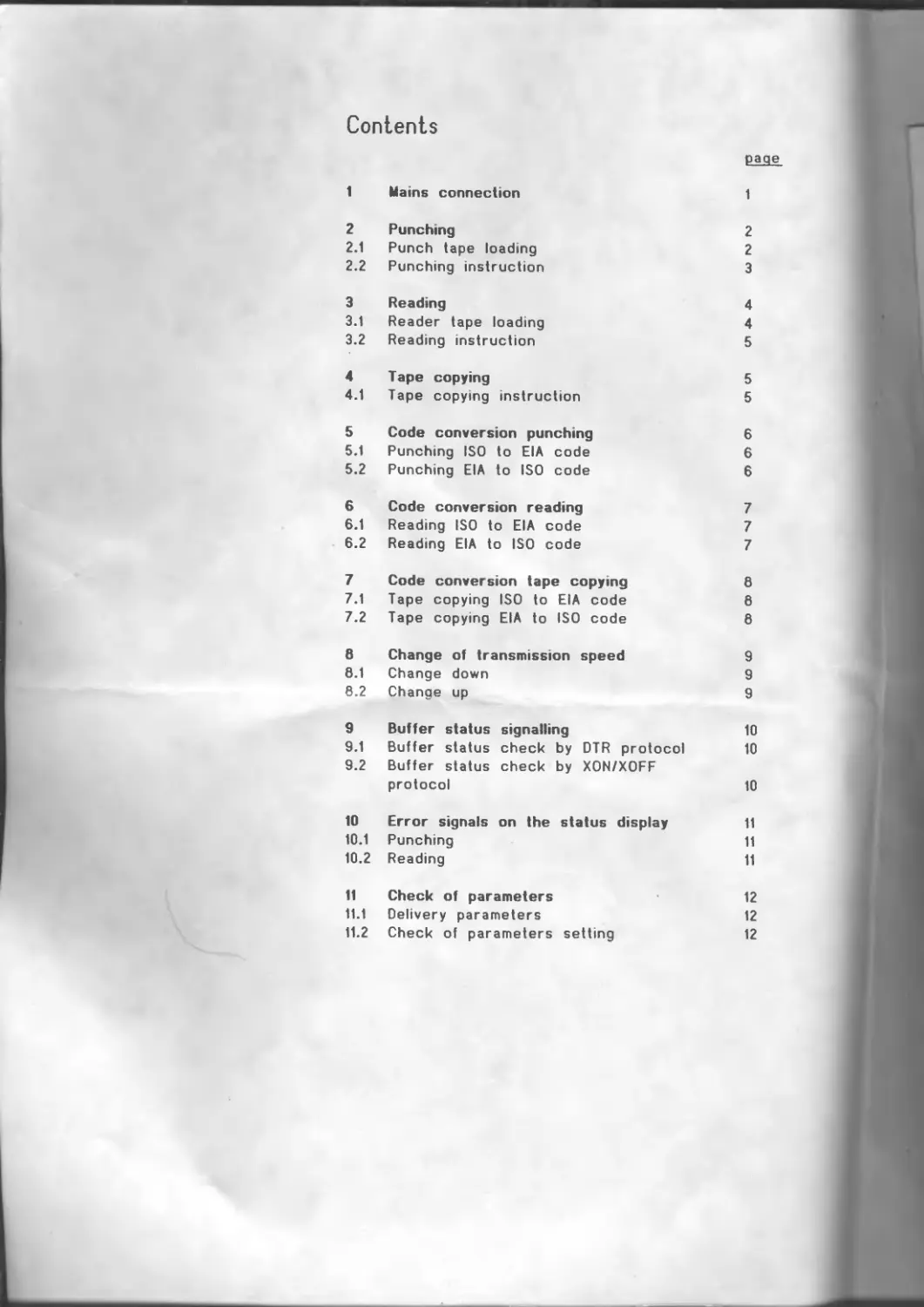
Contents
page
1 Mains connection 1
2 Punching 2
2.1 Punch tape loading 2
2.2 Punching instruction 3
3 Reading 4
3.1 Reader tape loading 4
3.2 Reading instruction 5
4 Tape copying 5
4.1 Tape copying instruction 5
5 Code conversion punching 6
5.1 Punching ISO to EIA code 6
5.2 Punching EIA to ISO code 6
6 Code conversion reading 7
6.1 Reading ISO to EIA code 7
6.2 Reading EIA to ISO code 7
7 Code conversion tape copying 8
7.1 Tape copying ISO to EIA code 8
7.2 Tape copying EIA to ISO code 8
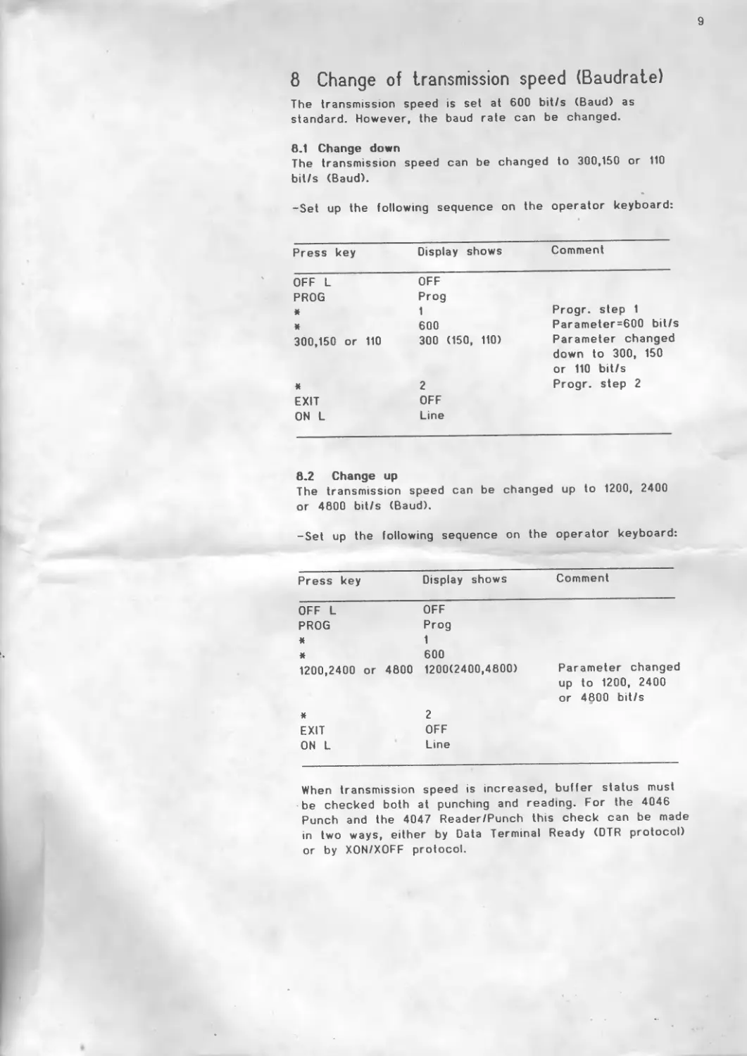
8 Change of transmission speed 9
8.1 Change down 9
8.2 Change up 9
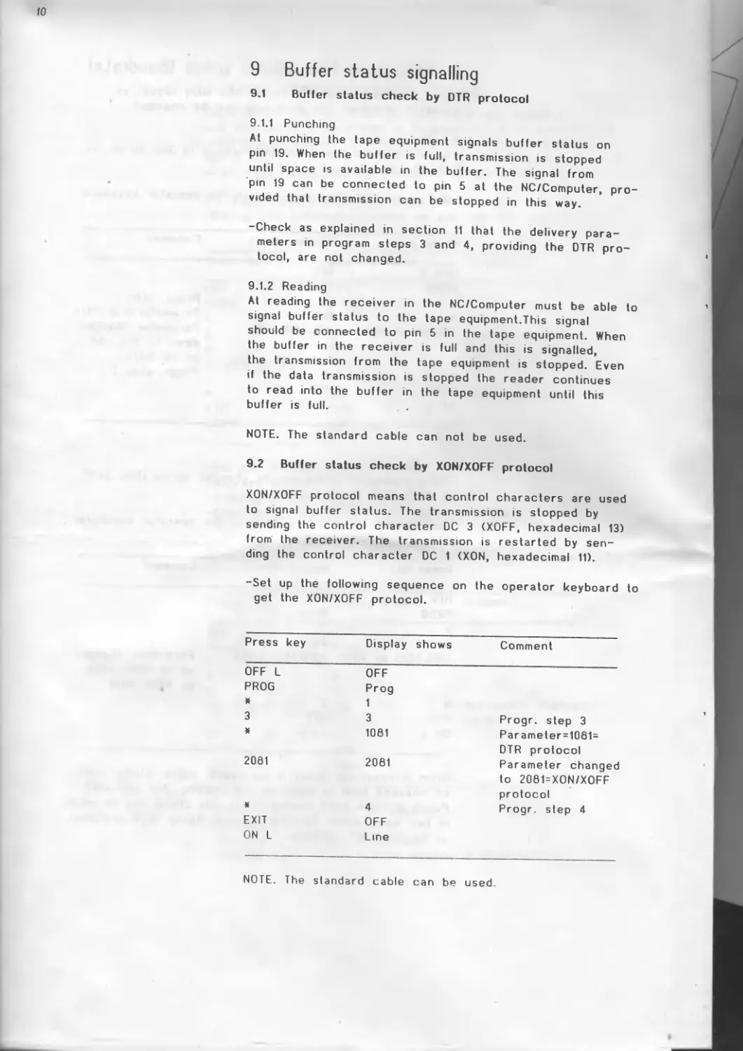
9 Buffer status signalling 10
9.1 Buffer status check by DTR protocol 10
9.2 Buffer status check by XON/XOFF
protocol 10
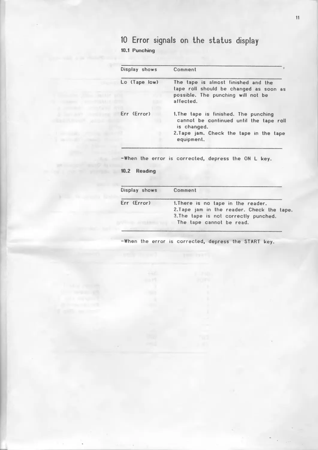
10 Error signals on the status display 11
10.1 Punching 11
10.2 Reading 11
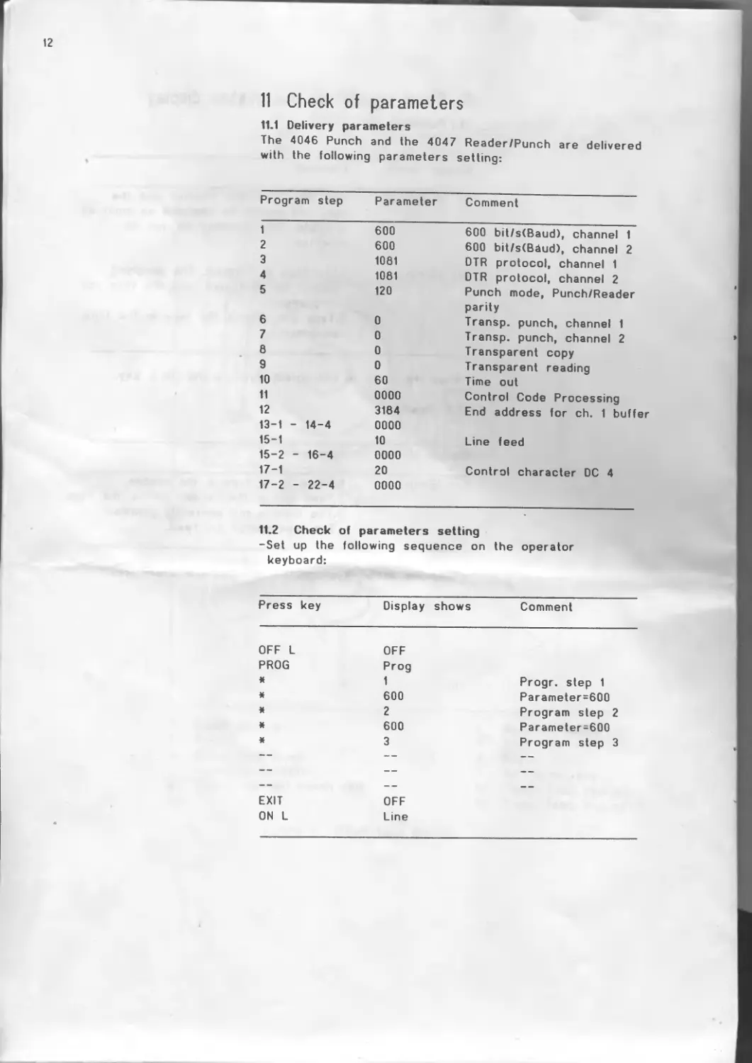
11 Check of parameters 12
11.1 Delivery parameters 12
11.2 Check of parameters setting 12
1
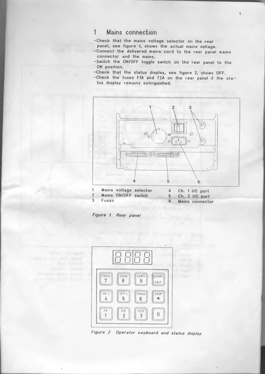
1 Mains connection
-Check that the mains voltage selector on the rear panel, see figure 1, shows the actual mains voltage.
-Connect the delivered mains cord to the rear panel mains connector and the mains.
-Switch the ON/OFF toggle switch on the rear panel to the ON position.
-Check that the status display, see figure 2, shows OFF.
-Check the fuses F1A and T2A on the rear panel if the status display remains extinguished.
1 Mains voltage selector
2 Mains ON/OFF switch
3 Fuses
4 Ch. 1 I/O port
5 Ch. 2 I/O port
6 Mains connector
Figure 1 Rear panel
Figure 2 Operator keyboard and status display
2
2 Punching
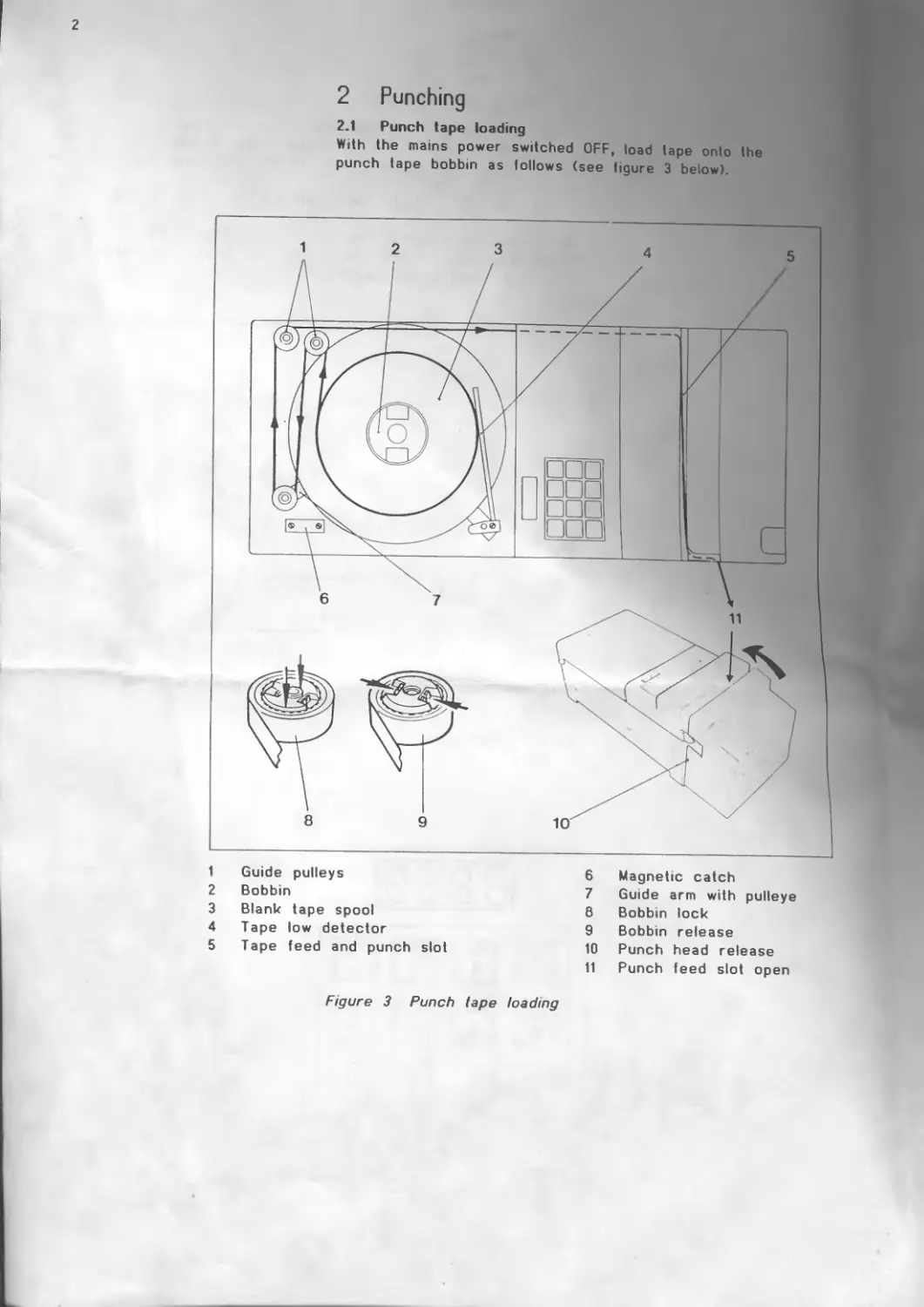
2.1 Punch tape loading
With the mains power switched OFF, load tape onto the punch tape bobbin as follows (see figure 3 below).
1 Guide pulleys
2 Bobbin
3 Blank tape spool
4 Tape low detector
5 Tape feed and punch slot
6 Magnetic catch
7 Guide arm with pulleye
8 Bobbin lock
9 Bobbin release
10 Punch head release
11 Punch feed slot open
Figure 3 Punch tape loading
3
-Move the tape guide arm until it touches the magnetic catch.
This action applies the brake to the tape bobbin and frees the tape feed and punch mechanism.
-Pull out about 2 metres (6 feet) of tape from the new reel and place the reel onto the bobbin with the free end running as shown.
-Lock the bobbin by pushing the centre section downwards by hand as far as possible (see figure 3).
-Push the two punch head releases upwards (located one at each side of the punch housing) and pull the punch assembly forward to open the tape feed and punch slot (see figure 3).
-Lead the tape around the guide pulleys and drop it into the tape feed and punch slot.
-Push back the punch assembly to close the tape feed and punch slot.
-Release the tape guide arm from the magnetic catch.
-Switch the power ON and depress fhe FEED key until the tape is tight and feeding correctly from the spool with feed holes punched.
-Depress the CODE key.
All tracks will be punched.
-Check that the holes are punched properly.
2.2 Punching instruction
-Connect the NC/Computer cable plug to the CHANNEL 1 I/O PORT connector on the rear panel (see figure 1).
-Depress the key ON L on the operator keyboard. The status display shows LINE.
-Start the punching from the NC/Computer.
NOTE. The data transmission should be made at 600 bit/s (Baud).
-Tear off the tape when the punching is ready.
If required, blank tape can be fed by depressing OFF L and FEED before tearing off the tape.
4
3 Reading
3.1 Reader tape loading (4047 Reader/Punch only). Load tape into the reader as follows (see figure 4 below).
1 Reader 6 Guide for 6/7 track tapes.
2 Reader head Operated as the 5 track tape guide.
3 Optical reader indicator 7 Fixed guide for 8 track tape
4 T ape
5 Guide for 5 track tape.
8 Entry guide
9 Exit guide
Press the guide upwards from the underside of the reader.(Press
10 Lift bar
11 Drive sprocket
flown when 6/7 or 8 track tapes are used).
Figure 4 Reader tape loading
5
-Raise the lift bar to open the entry and exit guides.
-Select the appropriate tape guides (see figure 4) for the tape which is to be used (5,6/7 or 8 track).
-Put the tape into the reader and over the drive sprocket.
-Lower the lift bar to hold the tape in position; ensure that the tape feed holes are engaged correctly in the drive sprocket.
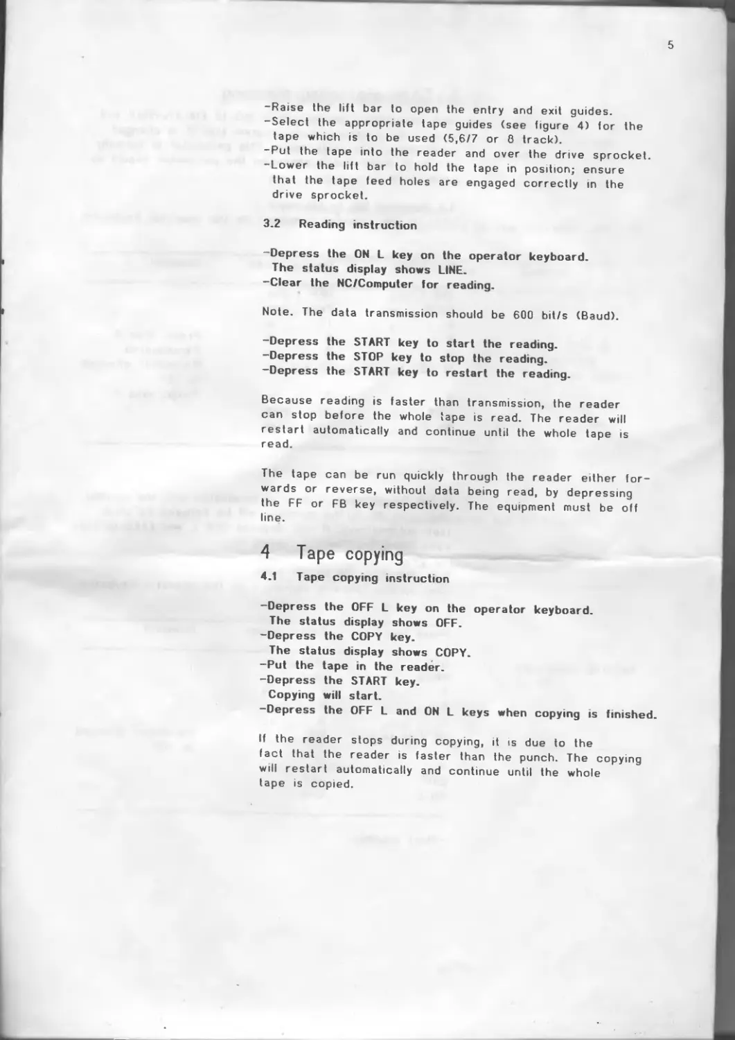
3.2 Reading instruction
-Depress the ON L key on the operator keyboard. The status display shows LINE.
-Clear the NC/Computer for reading.
Note. The data transmission should be 600 bit/s (Baud).
-Depress the START key to start the reading.
-Depress the STOP key to stop the reading.
-Depress the START key to restart the reading.
Because reading is faster than transmission, the reader can stop before the whole tape is read. The reader will restart automatically and continue until the whole tape is read.
The tape can be run quickly through the reader either forwards or reverse, without data being read, by depressing the FF or FB key respectively. The equipment must be off line.
4 Tape copying
4.1 Tape copying instruction
-Depress the OFF L key on the operator keyboard.
The status display shows OFF.
-Depress the COPY key.
The status display shows COPY.
-Put the tape in the reader.
-Depress the START key.
Copying will start.
-Depress the OFF L and ON L keys when copying is finished.
If the reader stops during copying, it is due to the fact that the reader is faster than the punch. The copying will restart automatically and continue until the whole tape is copied.
6
5 Code conversion punching
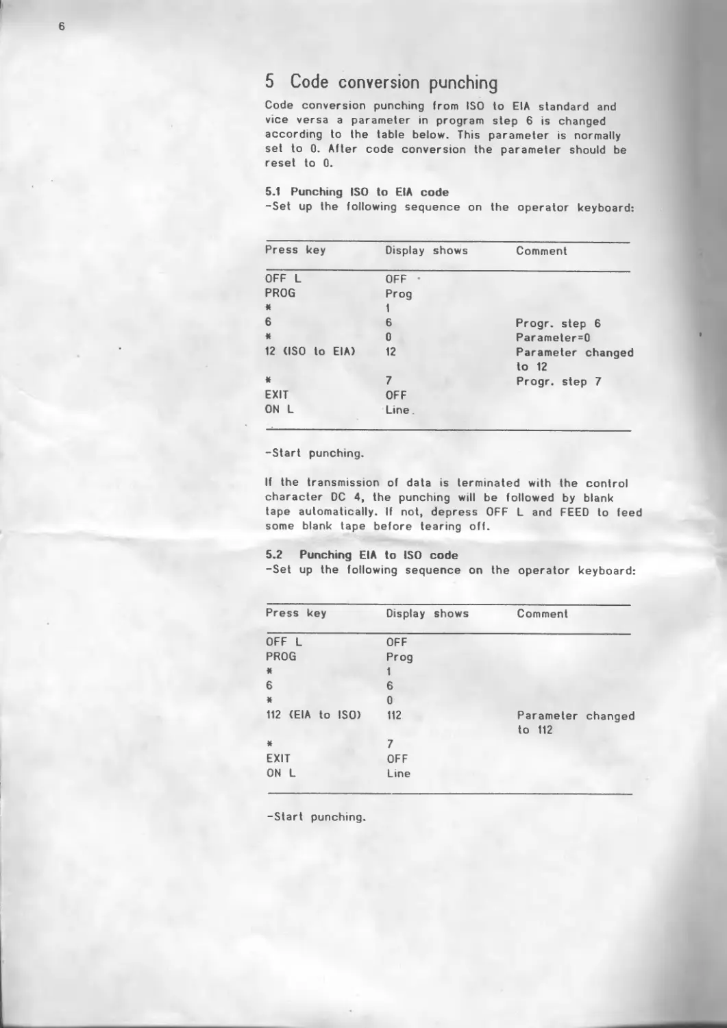
Code conversion punching from ISO to EIA standard and vice versa a parameter in program step 6 is changed according to the table below. This parameter is normally set to 0. After code conversion the parameter should be reset to 0.
5.1 Punching ISO to EIA code
-Set up the following sequence on the operator keyboard:
Press key Display shows Comment
OFF L PROG к 6 * 12 <ISO to OFF • Prog 1 6 Progr. step 6 0 Parameter=0 EIA) 12 Parameter changed to 12
ft EXIT ON L 7 Progr. step 7 OFF Line
-Start punching.
If the transmission of data is terminated with the control character DC 4, the punching will be followed by blank tape automatically. If not, depress OFF L and FEED to feed some blank tape before tearing off.
5.2 Punching EIA to ISO code
-Set up the following sequence on the operator keyboard:
Press key Display shows Comment
OFF L OFF
PROG Prog
я 1
6 6
ft 0
112 (EIA to ISO) 112 Parameter changed to 112
ft 7
EXIT OFF
ON L Line
-Start punching.
7
6 Code conversion reading
Code conversion reading from ISO to EIA standard and vice versa a parameter in program step 9 is changed according to the table below. This parameter is normally set to 0. *
After code conversion the parameter should be reset to 0.
6.1 Reading ISO to EIA code
-Set up the following sequence on the operator keyboard:
Press key Display shows Comment
OFF L OFF
PROG Prog
ft 1
9 9 Progr. step 9
ft 0 Parameter=0
12 (ISO to EIA) 12 Parameter changed to 12
ft 10 Progr. step 10
EXIT OFF
ON L Line
-Start reading.
6.2 Reading EIA to ISO code
-Set up the following sequence on the operator keybord:
Press key Display shows Comment
OFF L OFF
PROG Prog
ft 1
9 9
ft 0
112 (EIA to ISO) 112 Parameter changed
to 112
ft 10
EXIT OFF
ON L Line
-Start reading.
8
7 Code conversion tape copying
Code conversion tape copying from ISO to EIA standard and vice versa a parameter in program step 8 is changed according to the set up below. This parameter is normally set to 0.
After code conversion the parameter should be reset to 0.
7.1 Tape copying ISO to EIA code
-Set up the following sequence on the operator keyboard:
Press key Display shows Comment
OFF L OFF
PROG Prog
* 1
8 8 Progr. step 8
к 0 Parameter=0
12 (ISO to EIA) 12 Parameter changed to 12
* 9 Progr. step 9
EXIT OFF
COPY Copy
-Put the ISO tape into the reader.
-Depress START.
Copying in EIA code is started.
-Depress OFF and ON L when copying is terminated.
7.2 Tape copying EIA to ISO code
-Set up the following sequence on the operator keyboard:
Press key Display shows Comment
OFF L OFF
PROG Prog
ft 1
8 8
* 0
112 (EIA to ISO) 112 Parameter changed to 112
ft 9
EXIT OFF
COPY Copy
-Put the EIA tape into the reader.
-Depress START.
Copying in ISO code is started.
-Depress OFF and ON L when copying is terminated.
9
8 Change of transmission speed (Baudrate)
The transmission speed is set at 600 bit/s (Baud) as standard. However, the baud rate can be changed.
8.1 Change down
The transmission speed can be changed to 300,150 or 110 bit/s (Baud).
-Set up the following sequence on the operator keyboard:
Press key Display shows Comment
OFF L PROG * OFF Prog 1 Progr. step 1
ft 300,150 or 600 Parameter=600 bit/s 110 300 (150, 110) Parameter changed down to 300, 150 or 110 bit/s
ft EXIT ON L 2 Progr. step 2 OFF Line
8.2 Change up
The transmission speed can be changed up to 1200, 2400 or 4800 bit/s (Baud).
-Set up the following sequence on the operator keyboard:
Press key Display shows Comment
OFF L OFF
PROG Prog
ft 1
* 600
1200,2400 or 4800 1200(2400,4800) Parameter changed up to 1200, 2400 or 4800 bit/s
ft 2
EXIT OFF
ON L Line
When transmission speed is increased, buffer status must be checked both at punching and reading. For the 4046 Punch and the 4047 Reader/Punch this check can be made in two ways, either by Data Terminal Ready (DTR protocol) or by XON/XOFF protocol.
10
9 Buffer status signalling
9.1 Buffer status check by DTR protocol
9.1.1 Punching
At punching the tape equipment signals buffer status on pm 19. When the buffer is full, transmission is stopped until space is available in the buffer. The signal from pm 19 can be connected to pin 5 al the NC/Computer, provided that transmission can be stopped in this way.
-Check as explained in section 11 that the delivery parameters m program steps 3 and 4, providing the DTR protocol, are not changed.
9.1.2 Reading
At reading the receiver in the NC/Computer must be able to signal buffer status to the tape equipment.This signal should be connected to pin 5 m the tape equipment. When the buffer in the receiver is full and this is signalled, the transmission from the tape equipment is stopped. Even if the data transmission is stopped the reader continues to read into the buffer in the tape equipment until this buffer is full.
NOTE. The standard cable can not be used.
9.2 Buffer status check by XON/XOFF protocol
XON/XOFF protocol means that control characters are used to signal buffer status. The transmission is stopped by sending the control character DC 3 (XOFF, hexadecimal 13) from the receiver. The transmission is restarted by sending the control character DC 1 (XON, hexadecimal 11).
-Set up the following sequence on the operator keyboard to get the XON/XOFF protocol.
Press key Display shows Comment
OFF L OFF
PROG Prog
* 1
3 3 Progr. step 3
ft 1081 Parameter = 1081= DTR protocol
2081 2081 Parameter changed to 2081=XON/XOFF protocol
ft 4 Progr. step 4
EXIT OFF
ON L Line
NOTE. The standard cable can be used.
11
10 Error signals on the status display
10.1 Punching
Display shows Comment
Lo (Tape low) The tape is almost finished and the tape roll should be changed as soon as possible. The punching will not be affected.
Err (Error) I.The tape is finished. The punching cannot be continued until the tape roll is changed. 2.Tape jam. Check the tape in the tape equipment.
-When the error is corrected, depress the ON L key.
10.2 Reading
Display shows Comment
Err (Error) 1 .There is no tape in the reader. 2 .Tape jam in the reader. Check the tape. 3 .The tape is not correctly punched. The tape cannot be read.
-When the error is corrected, depress the START key.
12
11 Check of parameters
11.1 Delivery parameters
The 4046 Punch and the 4047 Reader/Punch are delivered with the following parameters setting:
Program step Parameter Comment
1 600 600 bit/s(Baud), channel 1
2 600 600 bitZs(Bdud), channel 2
3 1081 DTR protocol, channel 1
4 1081 DTR protocol, channel 2
5 120 Punch mode, PunchZReader
parity
6 0 Transp. punch, channel 1
7 0 Transp. punch, channel 2
8 0 Transparent copy
9 0 Transparent reading
10 60 Time out
11 0000 Control Code Processing
12 3184 End address for ch. 1 buffer
13-1 - 14-4 0000
15-1 10 Line feed
15-2 - 16-4 0000
17-1 20 Control character DC 4
17-2 - 22-4 0000
11.2 Check of parameters setting
-Set up the following sequence on the operator keyboard:
Press key Display shows Comment
OFF L OFF
PROG Prog
* 1 Progr. step 1
* 600 Parameter=600
* 2 Program step 2
600 Parameter=600
* 3 Program step 3
— —. — —
-- — — —
— — —
EXIT OFF
ON L Line
Facit 4046/4047
Paper Tape Punch / Reader - Punch
FACIT
Australia EAl-Electronic Associates Pty Ltd P.O. Box570 Denmark Facit A/S Hong Kong Gilman & Co Ltd Japan Electrolux (Japan) Ltd Singapore Far East Office Ecpts Pte Ltd Switzerland Encsson Information Systems AG
Postbox 9 Box 56, Elizabeth House. 4/F Facit Division Unit ЮХИ Alpha Bldg Postfach 25
ARTARMON NSW 2064 2730HERLEV G.P.O. HONGKONG Gadelius Bldg 45 Kallang Pudding Rd CH 8702 ZOLL1KON-STATION
Telephone 427-3322 Telephone 02-922400 Telephone 5-7909555 7-8. Motoakaisaka 1-Chome SINGAPORE 1334 Telephone 01-391.97.11
TeIex21130 Telex 35394 Telex 83667 Minato-ku, TOKYO. Japan 107 Telephone 745 82 88 Telex 59142
Austria Ericsson Information Systems Finland Oy Facit AB Iceland GisfiJ. Johnsen Telephone 179-3411 Telex 24246'29 Telex 244 11 South Africa USA Facit Inc.
Ges. m.b.H. P.O. Box 15 Skrifstofubiinadur SF The Netherlands Maynards Pty Ltd Nine Executive Park Drive
Hemalser Gurtel 17 SF-00101 HELSINKI 10 P.O. Box 132 Ericsson Information Systems В. V. Facit Information System P.O. Box 334
A-l 170 VIENNA Telephone 90-770 01 IS-202 KOPAVOGUR Postbus 263 2nd Floor, Garlicks Building MERRIMACK. NH 03054
Telephone 0222-439501 Telex 125290 Telephone 354-173111 3440AGWOERDEN P.O. Box 785567 Sandton Telephone (603) 424-8000
Telex 115807 France* Telex 2316 Telephone 3480-70911 2146JOHANNESBURG Telex 710-228-1077
Belgium Facit S. A. India Telex 40203 Telephone 786-3270.T Telex 4-25024 West Germany
Ericsson S. A. 308, rue du Pdt. Salvador Allende Forbes Forbes Campbell & Co. Ltd New Zealand Ericsson Information
Dept Imprimantes 92707 COLOMBES Cedex Communications & Engineering McLean Inform Technology, Ltd Spain Systems GmbH
Roe de la Fusee 40 Telephone (1)780 71 17 Imports. "Forbes Building" P.O. Box9464. Facit Vertriebsbereich
1130 BRUXELLES Telex 610 286 Charanjit Rai Marg. Fort NEWMARKET AK Paseo de la Habana 138 Facit Computer-Periphene
Telephone02-243.82.11 Great Britain Facit Maidstone Road ROCHESTER. Kent MEI 3QN BOMBAY 400 001 Telephone 501-801. 501-219 28036 MADRID Niederheider StraBe 3
Telex 26519 Telephone 268081 Telex 21570 Telephone 4 57.11.11 4000 DUSSELDORF 13
Canada Facit Canada Inc. TelexOll-2369 Ireland Norway Ericsson Information Systems A/S Telex47515 Sweden Telephone 0211/79 93 31 Telex 858 2415
1799 Argentia Road Telephone 0634-401721 Memory Ireland Computers Ltd Avd. Facit Head Office Facit AB
MISSISSAUGA ONTARIO Telex 96447 Clonard House Sandvford Road Postboks 6663. Rodelokka Box 54
L5N3B1 Telephone (416) 821-9400 Telex 06-218575 Greece Computer Application Co.. Ltd DUBLIN 14 Telephone 989733 Telex 30721 0502 OSLO 5 Telephone 02-35 58 20 Telex 19449 S-172 22 SUN'DBYBERG Telephone 08-28 27 20 Telex 12639
Cyprus Mesogeion Ave. 259 ATHENS Italy Portugal Sales Office
LBM (Lillytos) Ltd Telephone 01-6719722/23 Facit Data Products S.p. A. Regisconta Sari Ericsson Information Systems
P.O. Box 380 Telex219 349 Centro Direzionale Colleoni Avenida Duque de Louie 72 Sverige AB
LIMASSOL Palazzo Orione Ingresso 1 Apartado 2047 Avd. VMDD
Telephone 5164634 200 41 AGRATE BRIANZA 1101 LISBOA Cedex Box 11100
Telex 2080 (Milano) Telephone 1-560091 S-161 11 BROMMA
Telephone 0039-39 63.63 31 Telex 14306 Telephone08-29 00 20
Telex326423 Telex 10485
We reserve the right to change sp- cificatrons without notice
1103 89 40-00 5M 10.84