/


Теги: weapons military affairs patent
Год: 1895
Текст
(No Model.)
4 Sheets—Sheet 1,
0. JOHNSON.
GAS OPERATED FIREARM.
4 Sheets—Sheet 2.
C. JOHNSON.
GAS OPERATED FIREARM.
Patented Jan. 8, 1895.
(No Model.)
No. 532,380.
(EoModel.)
4 Sheets—Sheet 3.
C. JOHNSON.
GAS OPERATED FIREARM.
No. 532,380.
Patented Jan. 8, 1895.
(No Model.)
4 Sheets—Sheet 4.
C. JOHNSON.
GAS OPERATED FIREARM.
No. 532,380. Patented Jan. 8, 1895.
United States Patent Office.
CHRIST JOHNSON, OF WAUSAU, WISCONSIN, ASSIGNOR OF NINE-TWENTIETHS
TO OLE HANSEN, OF CHOATE, MICHIGA$.
GAS-OPERATED FIREARM.
SPECIFICATION fonaing part of Letters Patent No. 632,380, dated January 8.1896.
Application filed March 1,1884. Se'rial No. 601,936. (Nomodel.)
To all whom it may concern:
Be it known that I, Christ Johnson, a citi-
zen of the United States of America, residing
at Wausau, in the county of Marathon and
5 State of Wisconsin, have invented certain
new and useful Improvements inAIagazine-
Guns, of which the following is a specification,
reference being had to the accompanying
drawings.
to This invention relates to certain new and
useful improvements’!!! “fire arms” and par-
ticularly to that class known as “ magazine
guns.”
The primary object is to provide an* ex-
15 tremely simple and inexpensive combination
of parts, together with means for automati-
cally operating the same, whereby all manual
manipulation required with arms in use at
the present day, shall be entirely dispensed
20 with.
Furthermore, the invention contemplates
the employment of a novel and peculiar con-
struction of parts, whereby the expansive
force of the gas generated by the explosion
25 of a cartridge may be utilized and properly
directed to actuate certain power transmit-
ting mechanism and effect the withdrawal or
extraction of the exploded cartridge, and the
final ejection of the same, also the elevation
30 and placing of a loaded cartridge in firing po-
sition and the readjustment of the breech bolt.
With these and other objects in view vari-
ous combinations and arrangements of parts
are employed, which will be hereinafter more
35 fully set forth, and specifically pointed out in
the claims.
In describing the invention in detail, refer-
ence is had to the accompanying drawings,
forming part of this specification, and wherein
40 like letters indicate corresponding parts in
the several views, in which—
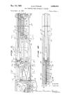
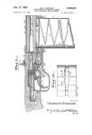
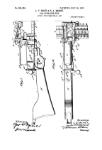
Figure 1 is a view in side elevation of а
magazine gun, showing a preferred construc-
tion arranged to embody ,my improvements.
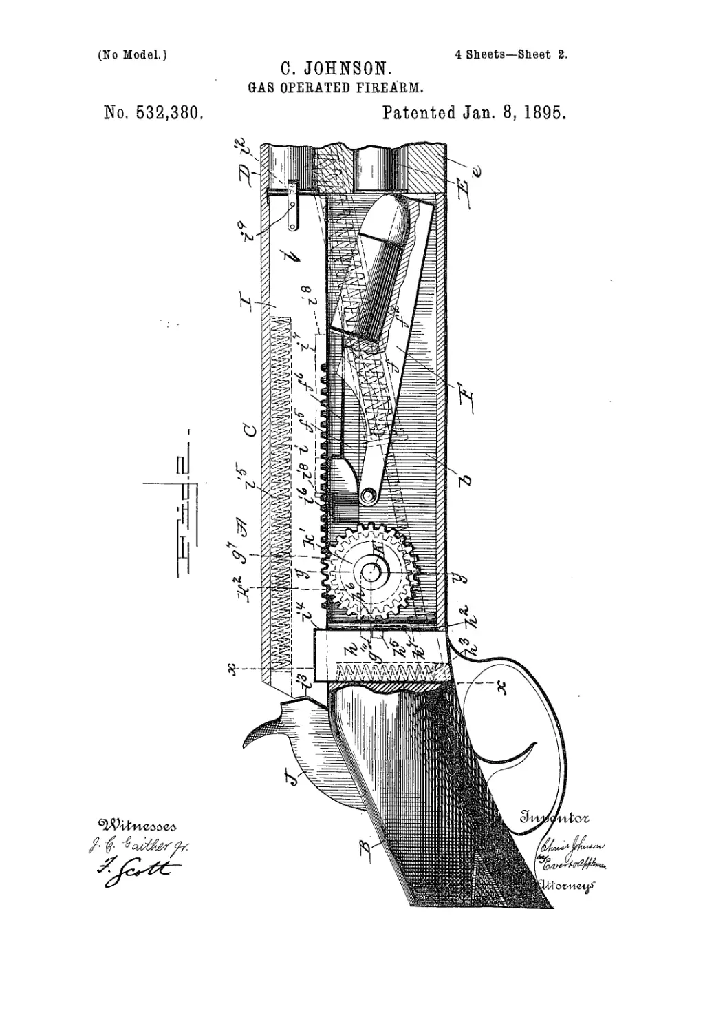
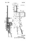
45 Fig. 2 is a vertical longitudinal section of the
same, showing the mechanism in firing posi-
tion. Fig. 3 is a similar view showing the
mechanism in action. Fig. 4 is a view in
cross section, taken about line x, x, of Fig. 2.
50 Figs. 5 and 6 are detail views in elevation and
perspective of the breech-bolt locking device.
Fig. 7 is a view in cross section taken on the
line —у—у— of Fig. 2. Figs. 8 and 9 are de-
tail sectional views of the breech-bolt actuat-
ing gearing. Figs. 10 and lllare detail views 55
in elevation of the cartridge carrier. Fig. 12
is a sectional view taken on the line x, x, of
Fig. 1.
In the drawings:—A, denotes the receiver
of -the gun proper; B, the stock; C, the breech 60
mechanism; D, the barrel, and E the maga-
zine formed in the tip stock e and provided
with the well-known form of spring pressed
follower for feeding the cartridges on to the
carrier F. 65
Suitably secured to the exterior at one side
of the receiving well—Ъ— is an upwardly in-
clined cylinder —g— which is headed and
provided with a piston —g2— fitting air-tight,
and a rod —g'1— and communicates with the ;o
barrel through the wall of the barrel and ter-
ra inatesadjacent the inner end of the shell
of the cartridge, for a purpose to be herein-
after explained.
. The.piston-rod —g9— is encircled by a re- у5
tractile spring— g5—which is inclosed within
the cylinder and serves to normally retain
the piston at the upper end of the cylinder, as
is indicated by dotted line in Fig. 1. Forming
a continuation of this piston-rod is a toothed 80
rack bar —gs-~ which is adapted to periodi-
cally engage a pinion —д’1— mounted on a
transversely journaled shaft —К—. At1 the
outer end and from opposite sides of this
rack, two studs —gB— project in opposite di- 85
rections and enter interior guides —g9— of a
short cylindrical casing—gw— which latter is
suitably attached to the stock. These guides
are curved at the ends so as to cause the
toothed bar or rod to partially rotate on each 90
stroke thereof, that is to say, on the out stroke
of the rod, the toothed surface' thereof will
face outward, so as to move by the pinion
without engaging the same and owing to the
terminal curvature of the guides, the rod at 95
the end of its travel will be partially rotated,
thus bringing the toothed face into mesh with
the pinion. The teeth of the rod preferably
correspond in number, with those of the pin-
ion or are otherwise suitably arranged so that 100
the latter will make a complete revolution
during the back-stroke, which results in ef-
9
532,380
feeling an engagement between a radial pro-
jection —r/"'—of the pin ion and an arm of the
latch 7? situated in the recess of the breech-
block—I— which latter isslidingiy mounted
5 in position and consists of a bar —г— pro-
vided at one end with a firing pin —r— and
at the other end wiih a suitable projection or
seat—r— to receive 1 he i tn pact of the ham mer
—J— said breech bloek also having the un-
io der side thereof adjacent said projection, cut
away to form a notch —г1— for the receptiojn
of a spring actuated lock-bolt —h—. This
bolt has a limited vertical movement in suit-
able guides—7гг—and is normally held en-
15 gaging the notch of the breech-block by an
upwardly acting spring —k°—. Slidinglj’
mounted in a recess of litis bolt —7г— and at
right angles to the length of th&saine, is a latch
—li?— one arm of which projects through an
го opening in the side-wall of the receiving well
and is adapted to be engaged by the radial
projection of the pinion aforesaid. The arm
is also provided.with a stud—7iG—which en-
ters an inclined guide-slot—7г7—formed in
25 the face of one of the bolt-guides —7г2—. (See
Fig. 2.) Thus as the arm is depressed by the
rotary movement of the radial projection
—9”'— the inclination of the slot —7г7— will
tend to draw said arm inwardly until it finally
30 becomes disengaged from said projection,
thereby allowing the pinion to continue its
rotation.
As the latch is partially depressed, it over-
comes the resistance of the spring—h3—and
35’ carries downwardly the lock-bolt —7г— there-
by releasing the breech-bolt —I— which latter
is immediately moved outwardly against the
action of itsspring — г7—by the revolving pin-
ion —7/— engaging the rack or toothed sur-
40 face—iK—thereof. Thesesuceessivestepslast
described, are made to follow closely one after
the other, by the following arrangement of
parts: Slidingly mounted on a square portion
of the shaft —к— which carries the fixed pin-
45 ion —p7— and the loosely mounted pinion
—k'— is a disk —7гг— from which two lugs or
studs—7?—k'— project respectively, radially
and axially. The former, located on the pe-
riphery, enters a cam guide-slot —ks— (see
50 Fig. 7) which causes the disk when rotated to
move to and from thepinion—kr—1 Thisslid-
ingmovementis utilized to effectalockingen-
gagement between the lug —7r4— above de-
scribed and a similar lug—7iB—projecting in
55 the opposite direction from thepinion—k’—.
Thus assuming the several members to be in
their normal position, as shown in Figs. 2 and
7, that is, with the radial lug resting centrally
of a depression —7.’— in the cam guide-slot,
60 from which it follows, that the wheels would
be sepaiatcd, the lug —k"— slightly in ad-
vance of the lug —k'— and the parts —7г7—
p'"— engaging. As the pinion —p7— is ro-
tated motion will be imparted directly to the
65 disk —IS— causingthe lug —7?— to ride out
of the depression, but before the disk has been
moved along the shaft sufficiently to effect an
I interlocking of the lugs —k1—№— the bolt
—7г— will be actuated as before stated, and
immediately following this step the lugs are 70
brought into engagement, and the pinion
thereby rotated sufficiently to move the
breech-bolt outwardly until properly checked.
During the outward travel of this bolt, its
spring is compressed and as thelugof the disk 75
-—— again enters the depression and be-
comes disengaged from pinion —k'— tire
spring acts, forcing the breech-bolt home and
reversing the rotation of the pinion —k'—
which latter assumes it normal position, with 80
its lug slightly in advance of the lug—A:4—at
the same time, the locking-bolt—7г—actuated
by its spring, is forced into the notch —г4—
and thereby secures the breech-bolt rigidly in
position. 85
The carrier —F— comprises a pivoted car-
riage —f— provided with a cartridge receiv-
ing seat —f2—т and is slotted as at —f3—.
Into this slot a pin —fi— of a slide —pro-
jects. The slide runs in suitable ways —fs— 90
with a projection thereof entering a slot or re-
cess —г7— of the breech-bolt, the end walls
of which form shoulders —i3— adapted to
abut against the projection and force the slide
back and forth. This'motion serves to ele- 95
vate and depress the carriage by reason of the
pin and slot connection.
The operation isas follows: With the parts
in position as illustrated by Fig. 2; as the
cartridge is exploded a portion of the gas 100
finds escape through the port —gi— and ow-
ing to its expansive force the piston —ps— is
driven downwardly in the cylinder, compress-
ing the spring —g3— and the toothed rod
moved rearwardly but not engaging the pin- 105
ion. At the limit of the stroke, the rod is
automatically shifted and the reaction of the
spring retracts the piston. It is this move-
ment that is utilized to actuate the breech .
mechanism and is first imparted to the pin- no
ion by the rack. As the pinion is rotated
through one-twelfth to one-tenth of a revo-
lution its radial projection first depresses the
lock-bolt —7г,— to release the breech-bolt and
the remaining portion of the rotary move- 115
ment is transmitted to the pinion —k'— as
above set forth, to force said breech-bolt out-
wardly and compress its spring. This out-
ward movement of the bolt withdraws the
exploded shell in theusnal manner by means 12c
of the spring-clamp jaws —г9— and ejects it
in a manner-and by any means well known in
the art. At thesametimetheshoulder—г8—
bringing up against the projection of the
slide, forces it outwardly and thereby ele- 125
vates the carriage and places the cartridge in
proper position to be engaged and forced into
the breech by the breech-block.
It will be noted that when the carriage is
elevated, a portion of the forward end par- 130
tially covers the entrance to the magazine
thus effectually preventing the escape of the
cartridges therefrom. The breech-bolt is re-
tained in the outward position until the pin-
633,380
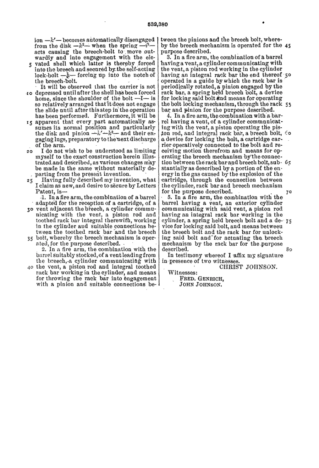
ion —к’—becomes automatically disengaged
from the disk —кг— when the spring —is—
acts causing the breech-bolt to move out-
wardly and into engagement with the ele-
5 vated shell which latter is thereby forced
into the breech and secured by.the self-acting
lock-bolt — ft,— forcing up into the notch of
the breech-bolt.
It will be observed that the carrier is not
io depressed until after the shell has been forced
home, since the shoulder of the bolt —I— is
so relatively arranged thatltdoes not engage
the slide until after th is step in the operation
has been performed. Furthermore, it will be
15 apparent that every.part automatically as-
sumes its normal position and particularly
the disk and pinion —7v'—7cs— and their en,
gaging lugs, preparatory to t heUext discharge
of the arm.
20 I do not wish to be understood as limiting
myself to the exact construction herein illns-
tratedand described, as various changes may
be made in the same without materially de-
, parting from the present invention.
25 Having fully described myjnvention, what
I claim as new, and desire to secure by Letters
Patent, is—
JL. In a fire arm, the combination of a barrel
adapted for the reception of a cartridge, of a
30 vent adjacent the breech, a cylinder commu-
nicating with the vent, a piston rod and
toothed rack bar integral therewith, working
in the cylinder and suitable connections be-
tween the toothed rack bar 'and the breech
35 bolt, whereby’ the breech mechanism is oper-
ated, for the purpose described. .
2. In a fire arm, the combination with the
barrel suitably’ stocked, of a vent leading from
the breech,-a cylinder communicating with
40 the vent, a piston rod and integral toothed
rack bar working in the cylinder, and means
for throwing the rack bar into engagement
with a pinion and suitable connections be-
tween the pinions and the breech bolt, where-
by the breech mechanism is operated for the 45
purpose described.
3. In a fire arm, the combination of a barrel
having a vent, a cylinder communicating with
the vent, a piston rod working in the cylinder
having an integral rack bar the end thereof 50
operated in a guide by which the rack bar is
periodically rotated, a pinion engaged by the
rack bar, a spring held breech bolt, a device
for locking said bolt And means for operating
the bolt locking mechanism, through the rack 5 5
bar and pinion for the purpose described.
4. In a fire arm, the combination with a bar-
rel having a vent, of a cylinder communicat-
ing with the vent, a piston operating the pis-
ton rod, and integral rack bar, a breech bolt, 60
a device for locking the bolt, a cartridge car- .
rier operatively connected to the bolt and re-
ceiving motion therefrom and means for op-
erating the breech mechanism bythe counec-
tiou between the rack bar and breech bolt, sub- 65
stantially as described by a portion of the en-
ergy in the gas caused by’ the explosion of the
cartridge, through the connection between
the cylinder, rack bar and breech mechanism
for the purpose described. . 70
5. In a fire arm, the combination with the
barrel having a vent, an exterior cylinder
communicating with said vent, a piston rod
having an integral rack bar working in the
cylinder, a spring held breech bolt and a de- 75
vice for locking said bolt, and means between
the breech bolt and the rack bar for unlock-
ing said bolt and'for actuating tha breech
mechanism by the rack bar for the .purpose
described. 80
In testimony whereof I -affix my signature
in presence of two witnesses.
CHRIST JOHNSON.
Witnesses:
Fred. Genrich,
John Johnson.