/


Теги: weapons military affairs patent
Год: 1995


Текст
IIIIIIIIIIIIIIIIIIIIIIIIIIIM
United States Patent [19] [11] Patent Number: 5,437,118
Sniezak et al. [45] Date of Patent: Aug. 1, 1995
[54] FRAME PLUG FOR SEMI-AUTOMATIC
HANDGUNS
[75] Inventors: Gary A. Sniezak, Windsor, Conn.;
Edward P. Schmitter, Easthampton,
Mass.
[73] Assignee: Smith & Wesson Corp., Springfield,
Mass.
[21] Appl. No.: 207,349
[22] Filed: Mar. 7,1994
[51] Int. Cl.*............................ F41C 23/10
[52] U.S. a...................................... 42/7
[58] Field of Search.................. 42/7, 71.02, 106
[56] References Cited
U.S. PATENT DOCUMENTS
932,183 8/1909 Schwarzlose ................. 42/7
4,593,487 6/1986 Ruger et al.................. 42/7
5,058,301 10/1991 Lishness et al.............. 42/7
Primary Examiner—Stephen C. Bentley
Attorney, Agent, or Firm—Chapin, Neal & Dempsey
[57] ABSTRACT
A frame plug or closure member which is fitted into a
cavity of a handgrip of a handgun is used to provide
added reenforcement and to extend the handgrip. The
plug has a tapered, semi-circular shaped base which is
integrally connected to one end of a flexible flat, elon-
gated member which has a foot at the other end thereof.
The curvature of the base matches the curvature of the
lower edge of the handgrip to provide a natural exten-
sion to the handgrip. The plug has a spine integrally
connected to both the base and flexible elongated mem-
ber so as to provide stiffness thereto. The handgrip has
a plug cavity and an adjacent gun magazine cavity
which open to the lower edge or butt thereof. The two
cavities are separated by an internal wall having a
through opening. The frame plug is fitted into the plug
cavity until the foot reaches the opening at which time
the foot snap fits into the opening thus securing the
frame plug to the handgrip.
10 Claims, 2 Drawing Sheets
U.S. Patent
Aug. 1, 1995
Sheet 1 of 2
5,437,118
FIG. 1
FIG. J
ж
5,437,118
1
FRAME PLUG FOR SEMI-AUTOMATIC
HANDGUNS
FIELD OF THE INVENTION
This invention relates to a frame plug or closure
member for firearms and more particularly to a plug
which is adapted to be fitted securely into a cavity in the
butt of the handgrip of semi-automatic handguns.
BACKGROUND OF THE INVENTION
Semi-automatic handguns having integrally molded
polymeric frames that typically have a generally hollow
handgrip, the major portion of which provides a cham-
ber used to accommodate a magazine. The remaining
portion is in the form of a downwardly opening cavity
located rearwardly of the magazine chamber. Other
than certain advantages that accrue during the molding
process, such as a substantial reduction in the amount of
polymer needed to mold the frame and the ease in re-
moving the frame from the mold in which it is formed,
the cavity serves no useful purpose in the gun, per se. In
its appearance as well as in the use of the gun, however,
the open cavity is generally considered to be a serious
drawback both from the standpoint of their appearance
and operation and various means have been proposed to
overcome such drawbacks.
U.S. Pat. No. 5,052,140 discloses a magazine guide
which attaches to the butt of the handgrip to aid with
the insertion of the magazine into the handgun. Addi-
tionally, a plug is fitted into the open cavity behind the
magazine cavity.
SUMMARY OF THE INVENTION
Accordingly, it is an object of the present invention
to provide a closure member and bumper to close a
cavity in the handgrip portion of the handgun to assist
in the protection of the gun and magazine against dam-
age should the gun be dropped, for example.
It is another object to provide additional structural
stability or stiffness to the handgrip portion of a molded
polymeric frame of the gun.
It is yet another object to close off the plug cavity to
prevent debris and dirt from entering the handgun.
It is another object to provide a buffer between the
user’s hand and the magazine to increase safety when
loading the magazine into the handgun.
It is another object to provide comfort to the user by
rounding off and extending the length of the butt of the
handgun.
It is still a further object to provide an inexpensive,
easily replaceable closure member should that member
be damaged.
According to the present invention, a closure mem-
ber which is adapted to be disposed within a cavity
formed in the handgrip of a handgun comprises an elon-
gated member having a base plug at the lower end
thereof. The elongated member includes a first latch
means at its upper end which is adapted to automati-
cally engage a second latch means disposed on an inter-
nal wall separating the cavity and the adjacent maga-
zine receiving chamber so that upon the interengage-
ment of the first and second latch means, the base plug
will be fitted into the lower end of the cavity to close
the same.
The above and other objects and advantages of this
invention will become more readily apparent when the
5
10
15
20
25
30
35
40
45
50
55
60
65
2
following description is read in conjunction with the
accompanying drawings.
BRIEF DESCRIPTION OF THE DRAWINGS
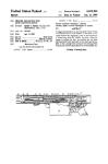
FIG. 1 is a partial cross-sectional elevational view of
a handgun which incorporates the closure member of
the present invention;
FIG. 2 is an elevational view of the butt of a handgrip
of the handgun of FIG. 1;
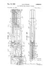
FIG. 3 is a side elevational view of the closure mem-
ber;
FIG. 4 is a front elevational view of the closure mem-
ber;
FIG. 5 is a bottom plan view of the closure member;
FIG. 6 is a cross-sectional view of the plug cavity of
the handgrip with the closure having been partially
inserted therein;
FIG. 7 is a cross-sectional view similar to FIG. 6 in
which the closure member has been fully inserted into
the cavity and latched therein;
FIG. 8 is a sectional view taken along line 8—8 of
FIG. 6, and
FIG. 9 is a sectional view taken along line 9—9 of
FIG. 7.
DETAILED DESCRIPTION OF THE
PREFERRED EMBODIMENTS
As shown in FIGS. 1 and 2, a semi-automatic hand-
gun 8 having a molded polymeric frame 10 is equipped
with a closure member or frame plug 11 constructed to
snap-fit into a cavity 12 of a handgrip 13. The plug
cavity 12 being defined by the inner surface 30 of the
back strap of the pistol handgrip and a transverse parti-
tion or wall 16 is of generally semi-circular shape adja-
cent to a gun magazine cavity or chamber 14. Both
cavities are open at their lower end or butt end 15 of the
handgrip and are separated by the partition or wall 16
which increases in thickness toward the upper end
thereof. As a result of this construction, the distance
between the surfaces 30 and wall 16 decreases progres-
sively from the lower to the upper end of the cavity 12.
An opening 17 is provided at a predetermined distance
above the lower end of the cavity which serves as a first
or female latch means for mating with a second or male
latch means provided as part of the closure member 11.
Referring to FIGS. 3-5, the closure member 11 is
preferably of integral construction formed by molding a
polymeric material, such as a “NYLON 6/6” with an
elastomer content to impart to the member a resilient-
flexibility or spring-like quality. The closure member 11
comprises at its lower end, a foot or base portion 20 in
the form of a base plug adapted to fit snugly into the
lower end opening 19 of the cavity 12. From its base 20,
the closure member includes an elongated resilient body
portion or retainer 21 having a planar forward or front
face 36 that extends from the upper surface of the base
to the top or head thereof as at 22. The closure member
includes a lower portion 31 of uniform width that ex-
tends upwardly from the base 20, an intermediate por-
tion 35 that tapers in width inwardly toward the lower
end of the head portion 22. The head includes a protrud-
ing nose 40 that extends forwardly of the planar surface
of the elongated member and serves as a male latching
member adapted to interengage with the opening 17 in
the wall 16 to lock the closure member securely in place
within the cavity, shown in FIGS. 1 and 7. Once so
locked, the closure member is permanently maintained
in a stationary position within the cavity and is gener-
5,437,
3
ally incapable of being removed therefrom without the
use of a tool or implement
As illustrated in FIGS. 3-5, the base 20 is of a gener-
ally semi-circular configuration having a flat or planar
undersurface 28, a straight side edge 23 and a conical 5
side edge 24. As best shown in FIGS. 1 and 7, the curva-
ture of the conical edge 24 is similar to the curvature of
the backstrap 26 surface of the handgrip 13 and when
fitted into the cavity 12, provides a neat and finished
look at the terminal end thereof. The base 20 is prefera- 10
bly hollow with an opening 27 along the straight edge
thereof. In addition to reducing the weight and amount
of polymer needed to mold the closure member, the
hollow base serves as a bumper to cushion or absorb
any shocks the gun might be subjected to, such as by
being dropped. The hollow base may also be filled with
a foam elastomer material or a similar material to in-
crease its shock absorbing capabilities. A chamfered
edge 18 at the upper end 25 of the conical side edge of
the base and the lower edge 15 of the handgrip provides
a neat transition groove to the base 20. A thin shelf or
ledge 29 is disposed on the upper surface of the base and
its peripheral edge is adapted to fit within the lower end
opening of the cavity 12, as best shown in FIG. 7, so as 25
to securely seat the base or foot 20 into the lower end
opening 19 of the cavity 12.
The elongated retainer 21 extends upwardly in gener-
ally a perpendicular relation from the upper surface 25
of the base 20 and is of a predetermined length a mea- 3q
sured from the upper surface 25 of the base to the under-
side 42 (FIG. 3) of the nose 40. That length is approxi-
mately equal to distance b (FIG. 6) from the lower edge
19 of the wall 16 to the lower edge of the opening 17.
With that dimensional relationship, the upper surface 25 35
of the base will engage the lower edge 19 of the cavity
12 substantially simultaneously with the nose 40 fitting
into the opening 17.
The lower body portion 31 of the elongated retainer
member 21 is of a width that is slightly smaller than the 49
width of the cavity 12 at its lower end. A fm-like flange
or support 37 extends outwardly of the rear surface of
the elongated member which serves as a stiffener and
having a beveled upper edge 38 which also assists in
guiding the closure member into the cavity 12. 45
A spine 39 extends longitudinally along the rear sur-
face of the tapered intermediate portion 35 of the elon-
gated closure member 32 and it extends from the upper
end of the fin 37 to the head portion 22 thereof. The
spine 39 diminishes in height and width from its lower 50
to its upper end so that the intermediate portion of the
elongated member has incrementally greater flexibility
or less stiffness at the upper end while conversely hav-
ing greater stiffness the lower end thereof. Accord-
ingly, as the member is being moved upwardly into the 55
cavity 12, as illustrated in FIG. 6, the nose 40, while
being urged by the resilient member into engagement
with the surface of the wall 16, will slide readily there-
over because at its head, the member, though resilient,
has sufficient flexibility to effectively minimize the fric- 60
tional drag between the two surfaces. Nonetheless, the
nose portion 40 of the elongated member will still be
urged biased against the wall to ensure that upon reach-
ing that point, it will snap into the opening 17. The fin
37 and nose 40 are each provided with a beveled upper 65
surface 38 and 43 to provide a lead angle to facilitate in
fitting the member into the cavity. Referring to FIG. 7,
the nose protrudes a distance which is less than the
118
4
width of the inner wall 16 of the opening 17 so that it
will not extend into the gun magazine cavity 14.
The closure member 11 is inserted into the plug cav-
ity 12 and oriented so that the conical edge 24 of the
base 20 is aligned with the back strap 26 of the handgrip
13. The configuration of the elongated member 21 and
the fin 37 requires the frame plug to be properly ori-
ented with the semi-circular shape of the lower end 19
of the plug cavity 12. As best shown in FIGS. 6 and 7,
as the elongated member 21 is fitted head first into the
cavity 12 and the outer surface 45 of the nose 40 slides
along the internal wall 16, the elongated member re-
mains in a relatively relaxed condition. Because of the
gradual increase of the thickness of the wall 16, as best
illustrated in FIG. 7, the plug cavity gradually narrows
so that as the lower portion of the member is moved
deeper into the cavity 12 with its nose 40 engaged with
the surface of the wall 16, the tapered intermediate
portion 35 will be flexed outwardly. The flexure of the
elongated member forces the nose 40 against the wall 16
so that upon reaching the opening 17, it will snap
therein thus interlocking the closure member 11 to the
handgrip 13 with the undersurface 42 of the nose en-
gaged with the lower edge of the opening 17. As best
shown in FIG. 1, that while the nose protrudes suffi-
ciently to engage the wall 16 (FIG. 6) of the opening 17
to secure the plug permanently in place in the handgrip,
it does not protrude into the adjacent magazine cavity
14 so as to interfere with the insertion and removal of
the magazine. As previously discussed, when the head
of the closure member interengages with the opening
17, the shelf 29 of the base or plug will also be latched
or locked within the lower end of the cavity 12 within
the handgrip of the gun.
Although the invention has been shown and de-
scribed with respect to an exemplary embodiment
thereof, it should be understood by those skilled in the
art that the foregoing and various other changes, omis-
sions, and additions in the form and detail thereof may
be made therein without departing from the spirit and
scope of the invention.
Having thus described my invention, what is claimed
is:
1. A closure member for a cavity in the handgrip of a
polymeric frame of a semi-automatic handgun, the cav-
ity being open at its lower end and defined in part by a
rear wall of a magazine receiving chamber, said wall
including a first coupling means located at a predeter-
mined distance above the lower end of the handgrip,
said closure member comprising at its lower end a plug
dimensioned and shaped to close the lower end opening
of the cavity, and an elongated retainer extending up-
wardly from said plug a distance approximately the
same as said predetermined distance and including a
second coupling means at its upper end for interengage-
ment with said first coupling means when said closure
member is fitted into said cavity, said elongated retainer
being resiliently flexible for urging said first coupling
means into engagement with said second coupling
means for holding said closure member in assembled
relation in said cavity and means for stabilizing the
closure member relative to said handgrip.
2. A closure member for a cavity in the handgrip of a
polymeric frame of a semi-automatic handgun, the cav-
ity being open at its lower end and defined in part by a
rear wall of a magazine receiving chamber, said wall
including a female latch member located on said wall a
predetermined distance above the lower end of the
5,437,
5
handgrip, said closure member comprising at its lower
end a plug dimensioned and shaped to close the lower
end opening of the cavity, and an elongated retainer
extending upwardly from said plug a distance approxi-
mately the same as said predetermined distance, said 5
retainer having a male latch member adjacent its upper
end for interengagement with said female latch member
when said closure member is fitted into said cavity, said
elongated retainer being resiliently flexible for urging
said male latch member into engagement with said fe- 10
male latch member and means for stabilizing said clo-
sure member to prevent inadvertent disengagement of
said latch members by movement of said member rela-
tive to the handgrip.
3. A closure member for a semi-automatic handgun as 15
set forth in claim 2, and in which said means for stabiliz-
ing said closure member comprises a shelf portion on an
upper surface of said plug which serves as a seat to
interfit snugly within the lower opening of the cavity.
4. A closure member for a semi-automatic handgun as 20
set forth in claim 3 and in which said plug has a cavity
having an opening at the peripheral surface thereof.
5. A closure member for a semi-automatic handgun as
set forth in claim 3, and in which said means for stabiliz-
ing said closure member against movement relative to 25
the handgrip comprises a lower portion of said retainer
which is of sufficient width to engage opposed inner
30
118
6
wall portions of the cavity and including an upper por-
tion which is tapered inwardly toward said second cou-
pling means, the upper portion of said retainer being
more flexible than its lower portion.
6. The closure member of claim 5, wherein said
means for stabilizing said closure member further com-
prises a flange which extends in a direction normal to at
least the lower portion of said retainer for engaging a
wall portion of said cavity disposed between said op-
posed inner walls to stabilize the position of the closure
member in said cavity and to reinforce the hand grip of
said handgun.
7. A closure member for a semi-automatic handgun as
set forth in claim 6 and in which said elongated retainer
has a ridge longitudinally extending from said support
to the upper end of said elongated retainer.
8. The closure member of claim 2, wherein the resil-
iency of said elongated retainer increases progressively
from one end thereof to the other.
9. The closure member of claim 8, wherein said elon-
gated retainer further comprises a relatively rigid lower
portion.
10. The closure member of claim 8, wherein an upper
portion of said elongated retainer is movable relative to
said lower portion during insertion of said closure mem-
ber into said cavity.
*****
35
40
45
50
55
60
65