/


Автор: DeCristoforo R.J.
Теги: woodworking directory handicrafts wood structures
ISBN: 0-912656-53-0
Год: 1977


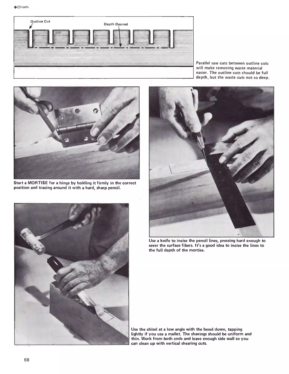
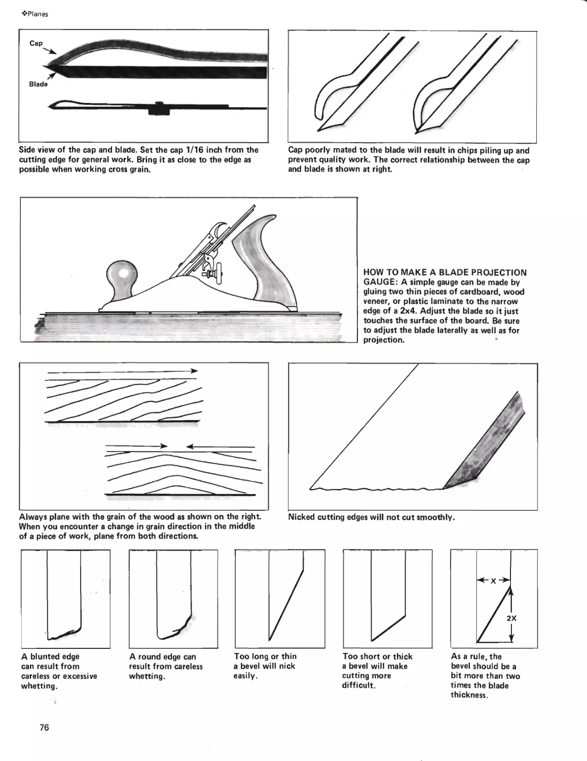
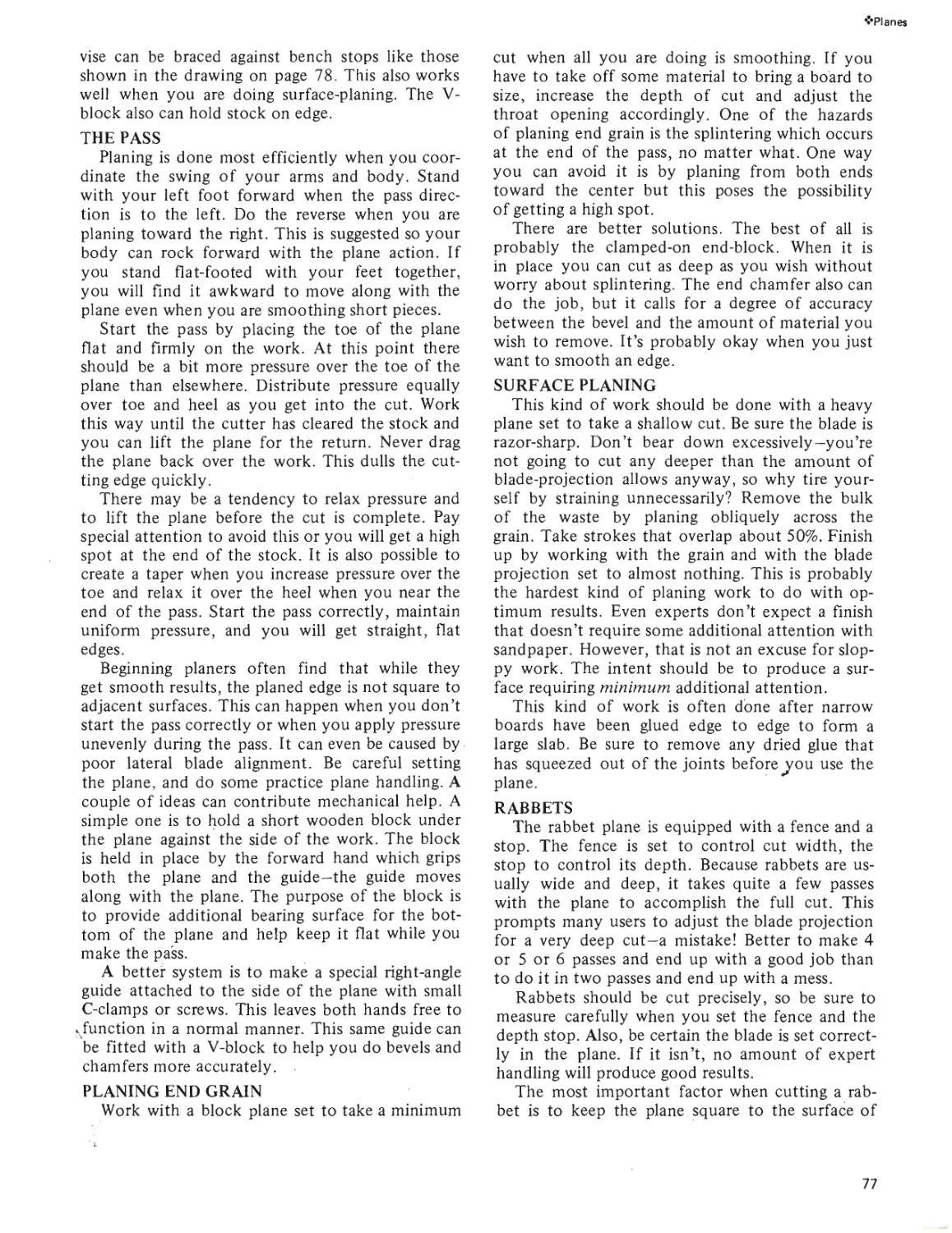
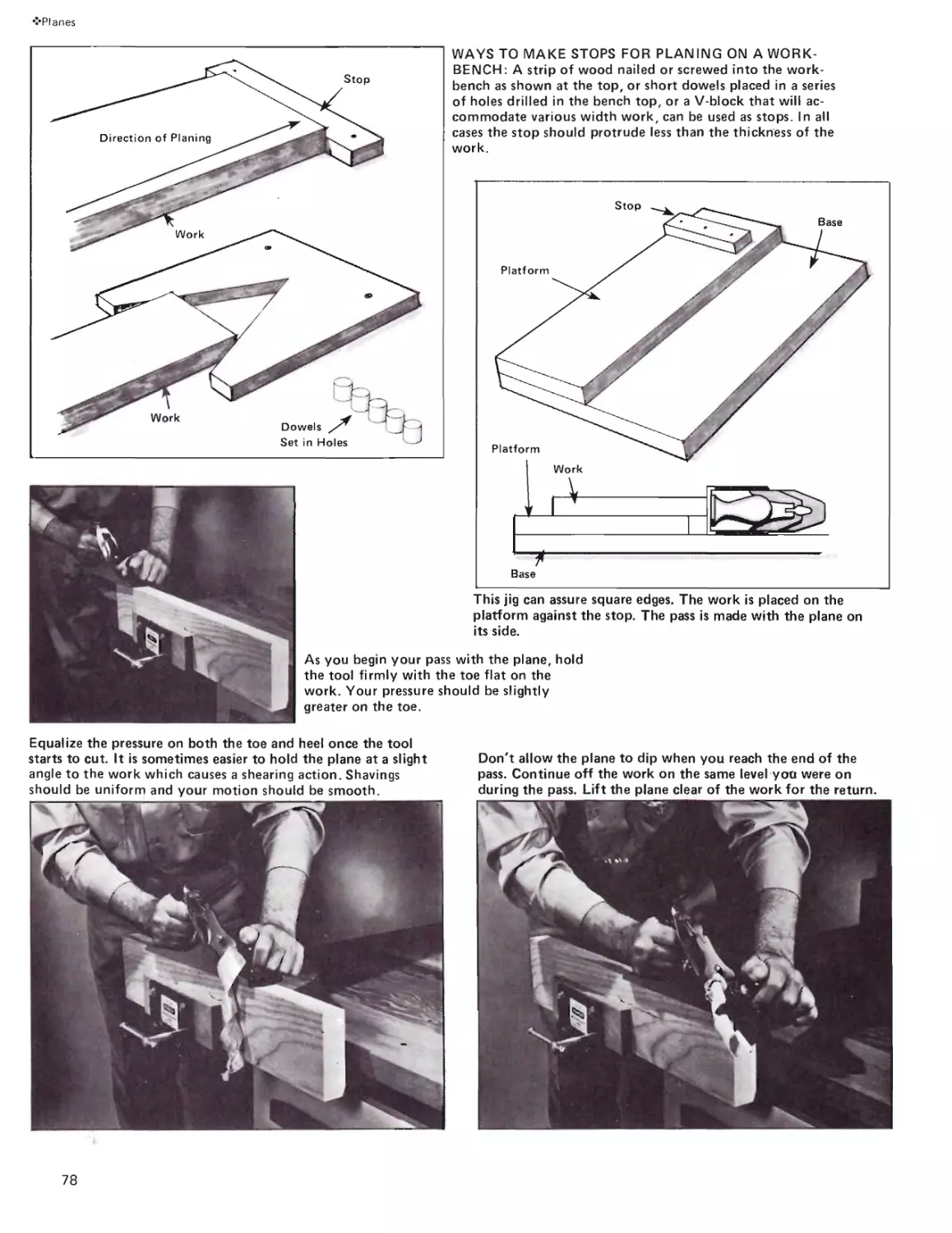
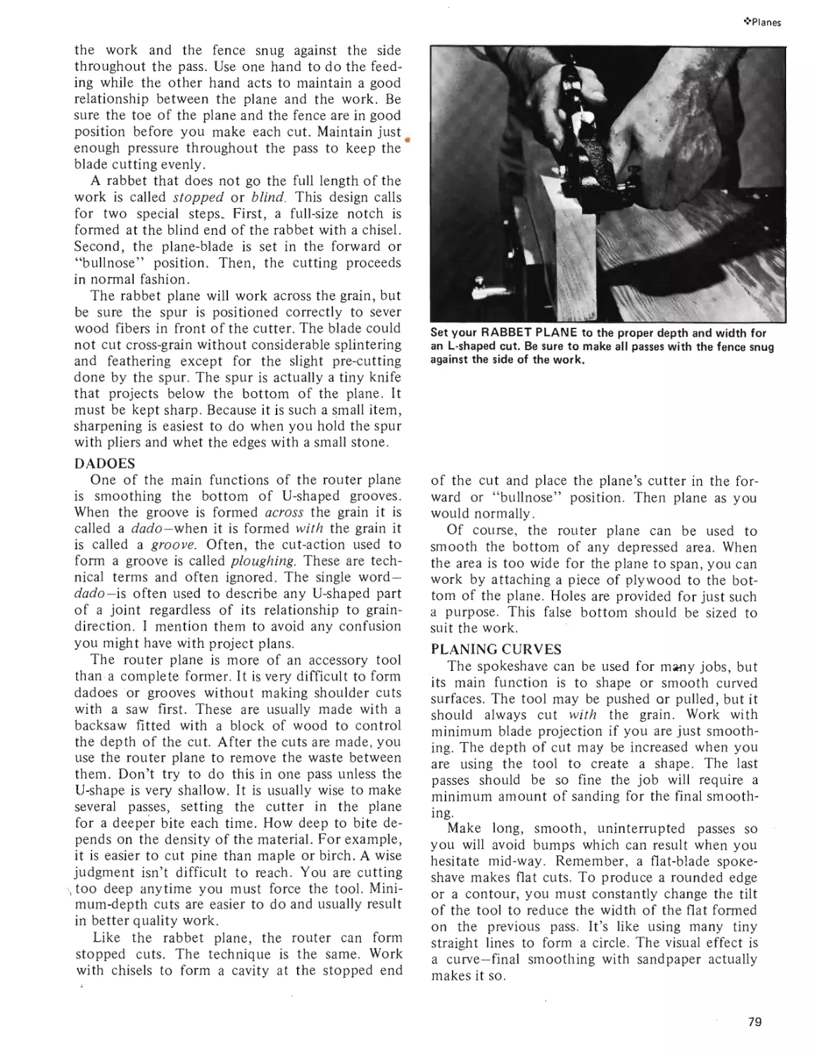
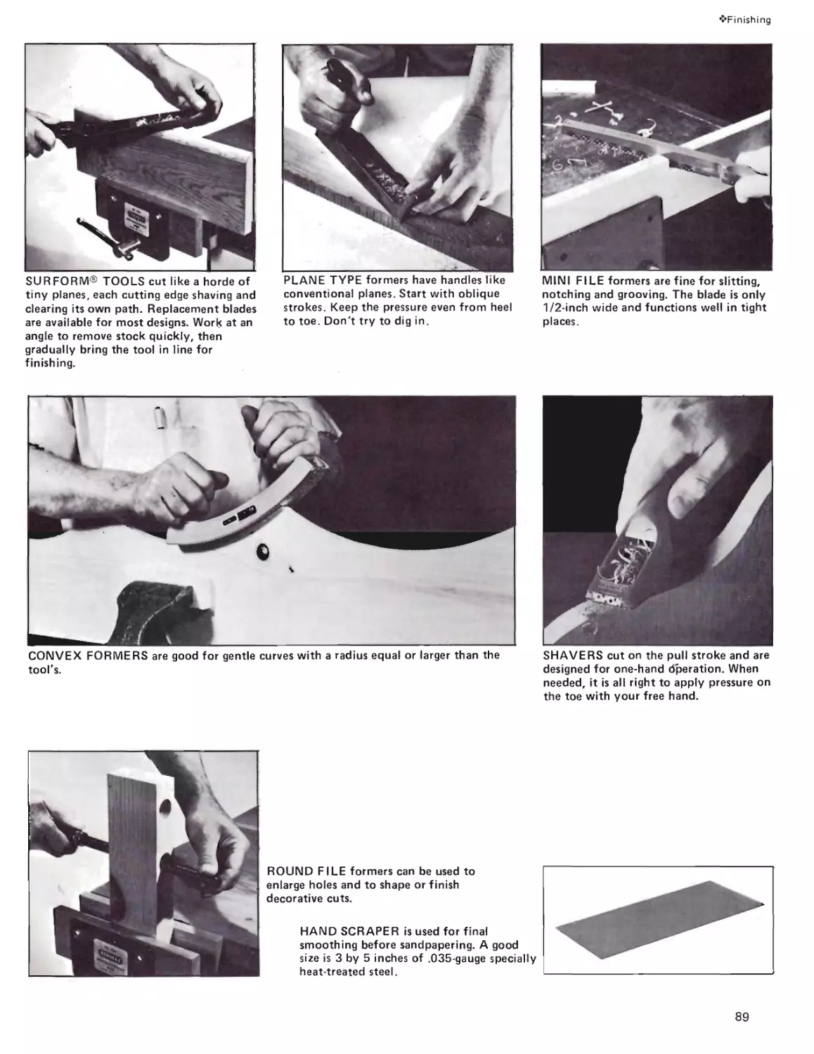
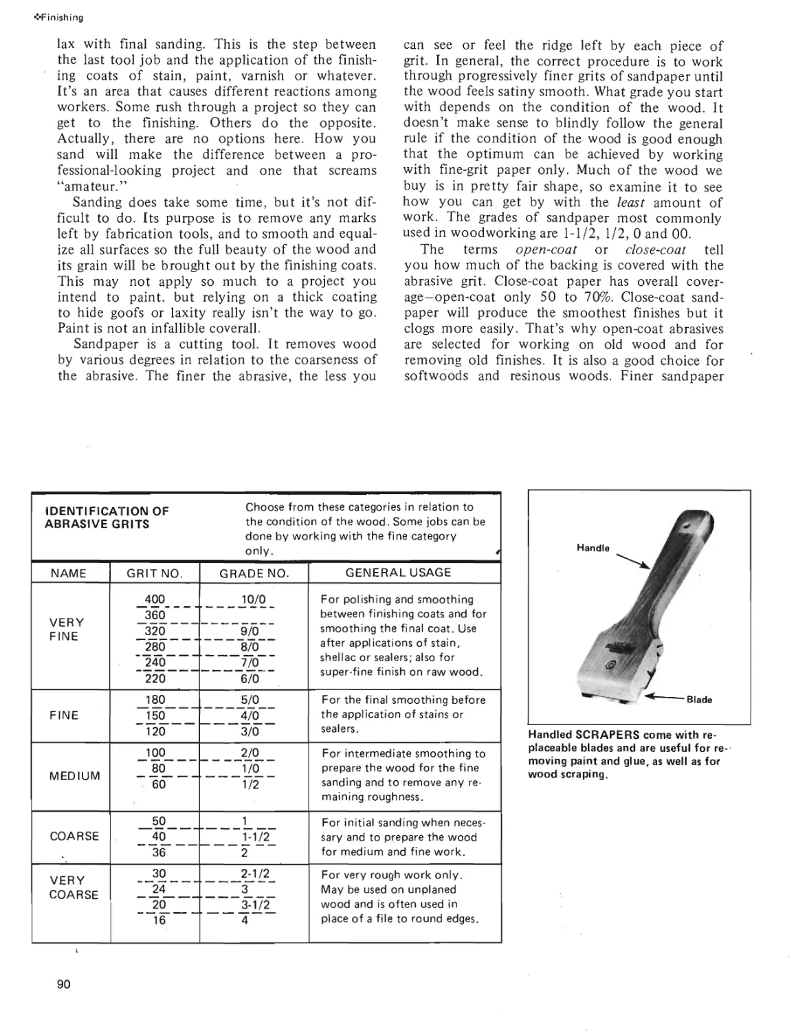
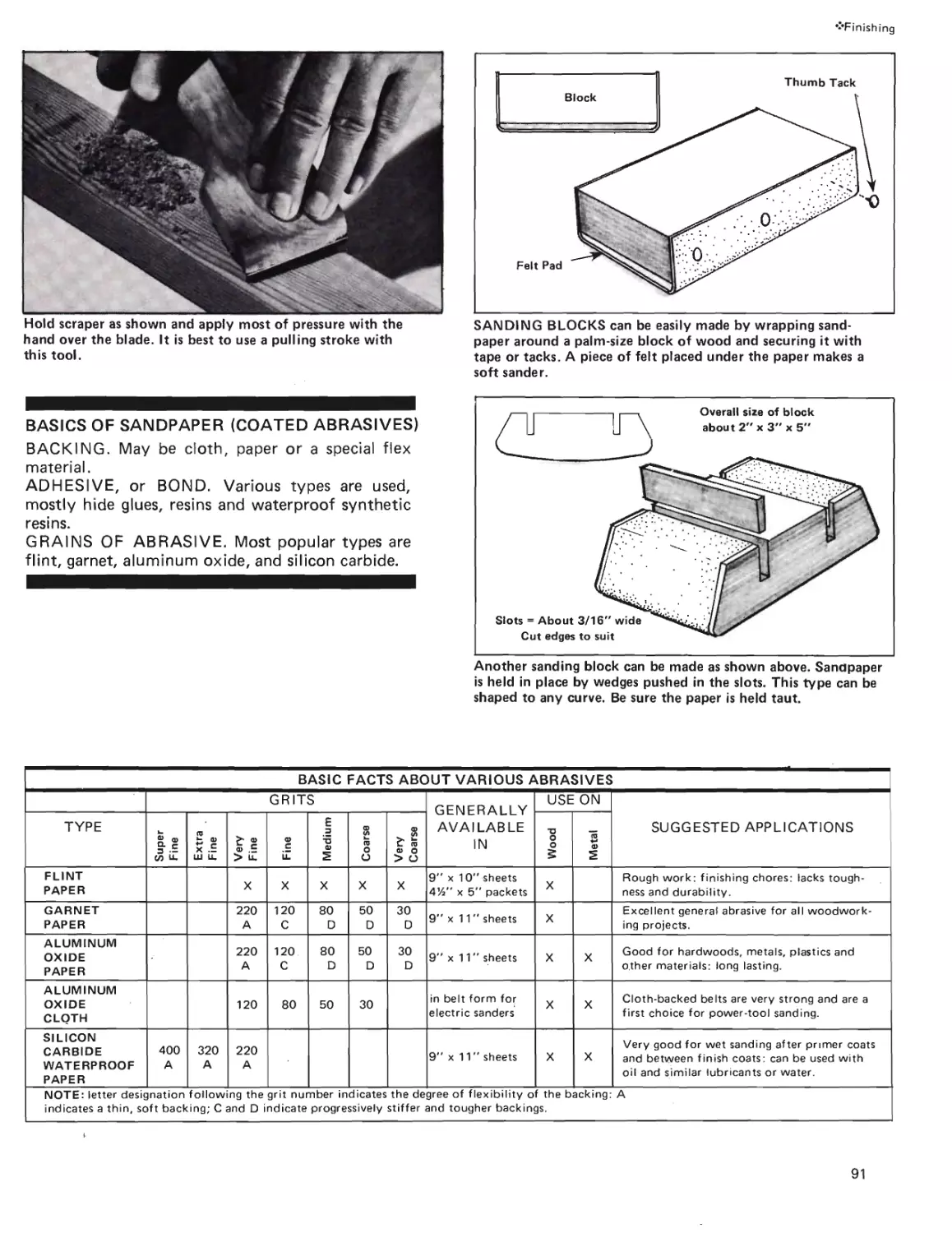
Текст
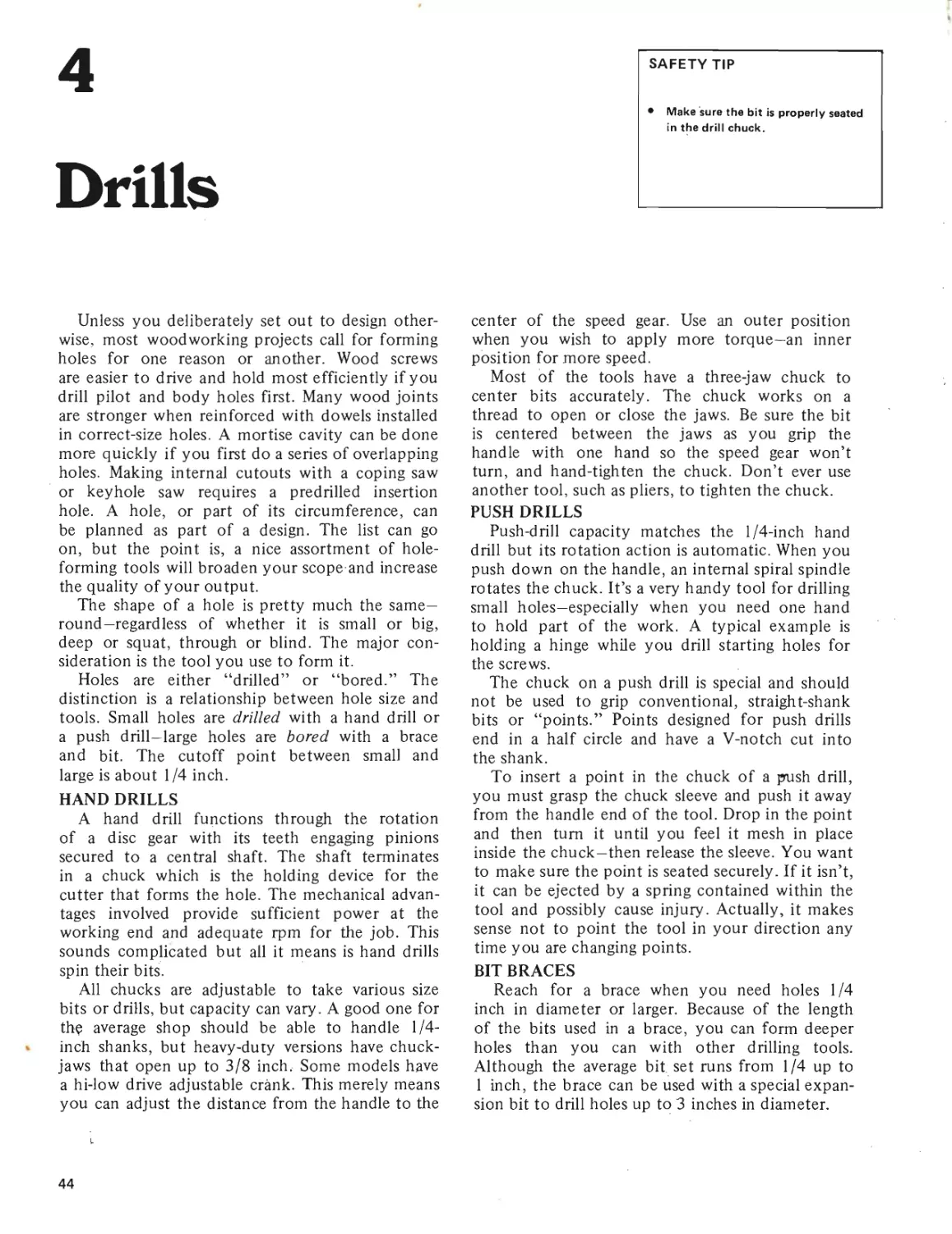
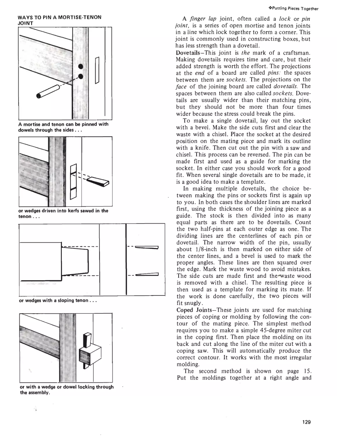
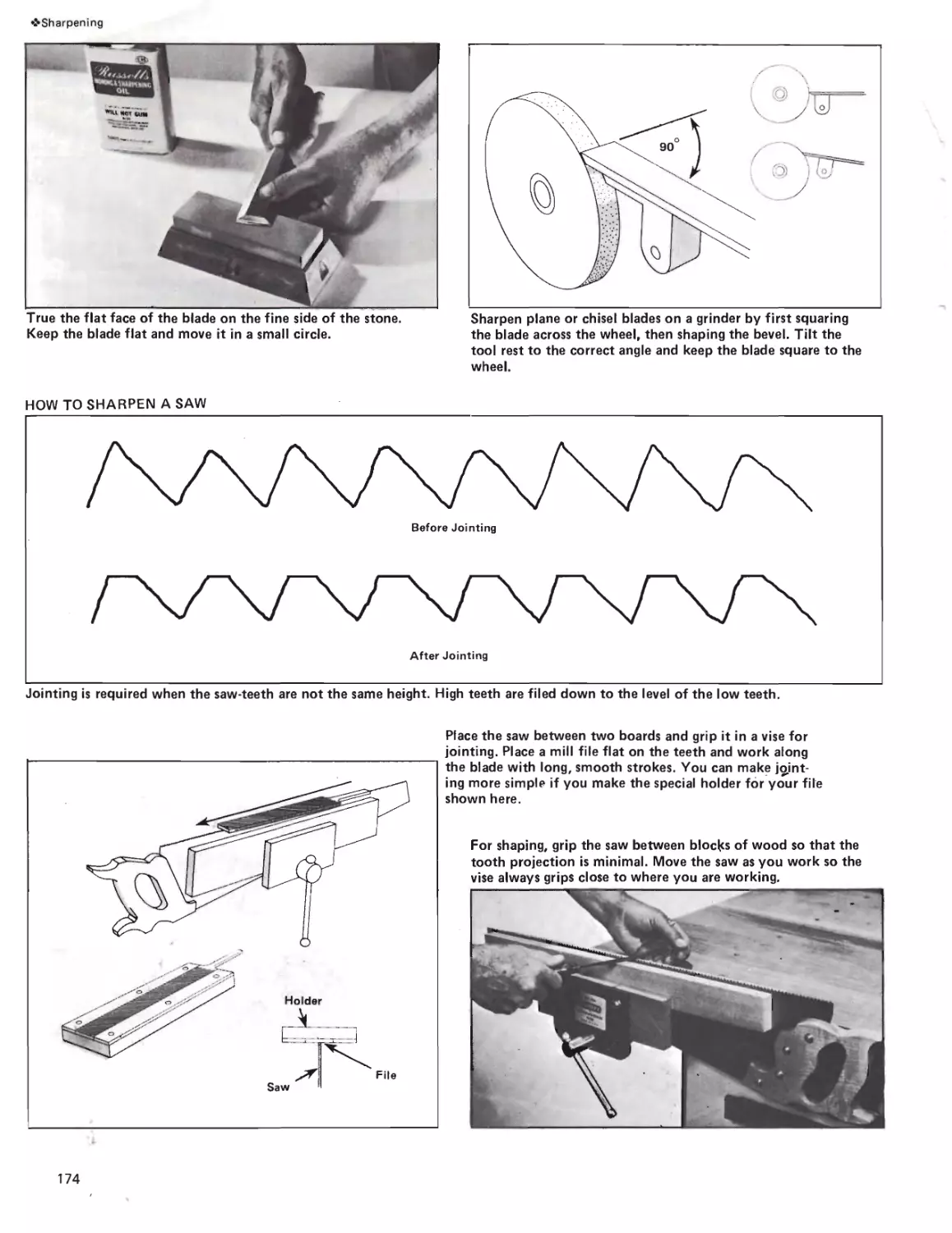
HANDTOOL
HANDBOOK
by R. J. DeCristoforo
Master your handtools with over 400 detailed photos, hundreds of timesaving tips and
exact directions for saws, hammers, chisels and planes. How to select wood, fasteners and glues.
How to maintain your tools. Plans for jigs, tools and projects you can build.
HANDTOOL
HANDBOOK
FOR WOODWORKING
------------------by R. J. Decristoforo----------------
Publisher: Bill Fisher; Editor-In-Chief: Carl Ship-
man; Editor: Jon Latimer; Editorial Assistance:
Jackie Craver; Art Director: Josh Young; Book
Design & Assembly: Chris Crosson; Typography:
Frances Ruiz, Mary Kaye Fisher, Cindy Coats-
worth ; Drawings: Dan Thrapp; Cover Photography:
Naurice Koonce.
NOTICE: To the best knowledge of the author
and publisher, the information in this book is cor-
rect. Because of the individual differences in tools
and personal work habits, the author and publisher,
H. P. Books (Fisher Publishing, Inc.), disclaim any
liability incurred in connection with information
contained herein.
Published by H.P. Books, P.O. Box 5367, Tucson, AZ 85703 602/888-2150
ISBN: 0-912656-53-0
Library of Congress Catalog Card Number: 77-89289 © 1977 H.P. Books. Printed in U.S.A.
Contents
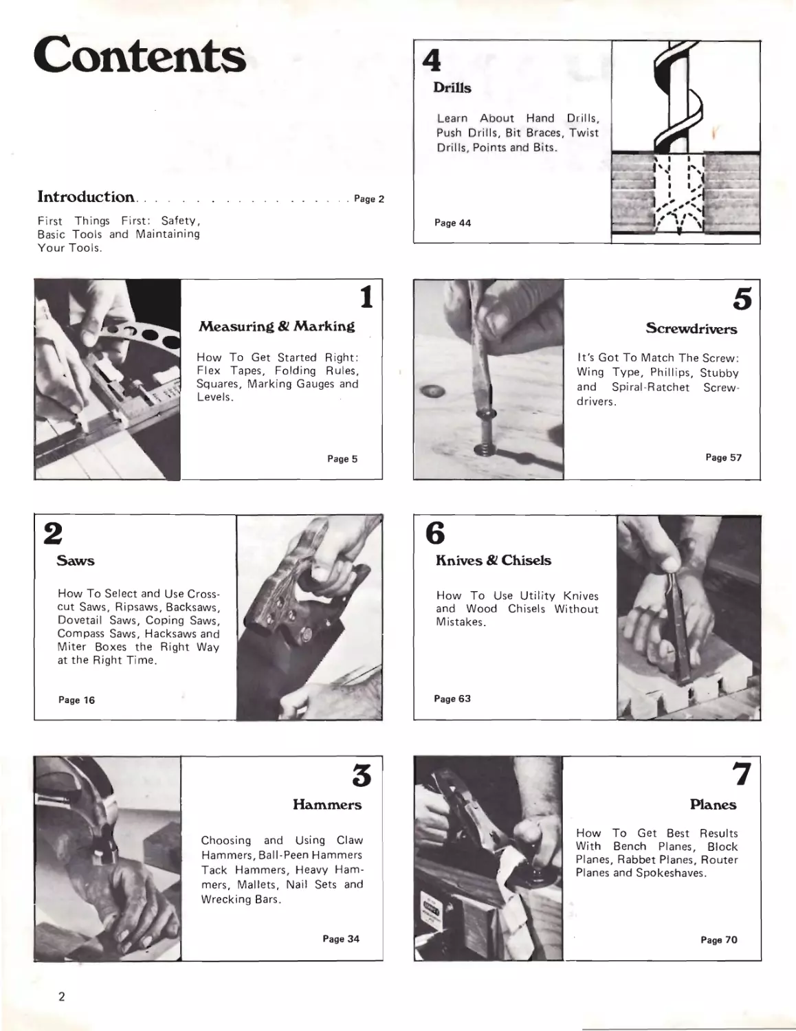
Introduction
Page 2
First Things First: Safety,
Basic Tools and Maintaining
Your Tools.
How To Get Started Right:
Flex Tapes, Folding Rules,
Squares, Marking Gauges and
Levels.
Measuring & Marking
Page 5
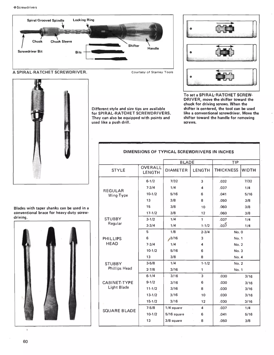
Screwdrivers
It's Got To Match The Screw:
Wing Type, Phillips, Stubby
and Spiral-Ratchet Screw-
drivers.
Page 57
2
Saws
How To Select and Use Cross-
cut Saws, Ripsaws, Backsaws,
Dovetail Saws, Coping Saws,
Compass Saws, Hacksaws and
Miter Boxes the Right Way
at the Right Time.
Page 16
Page 63
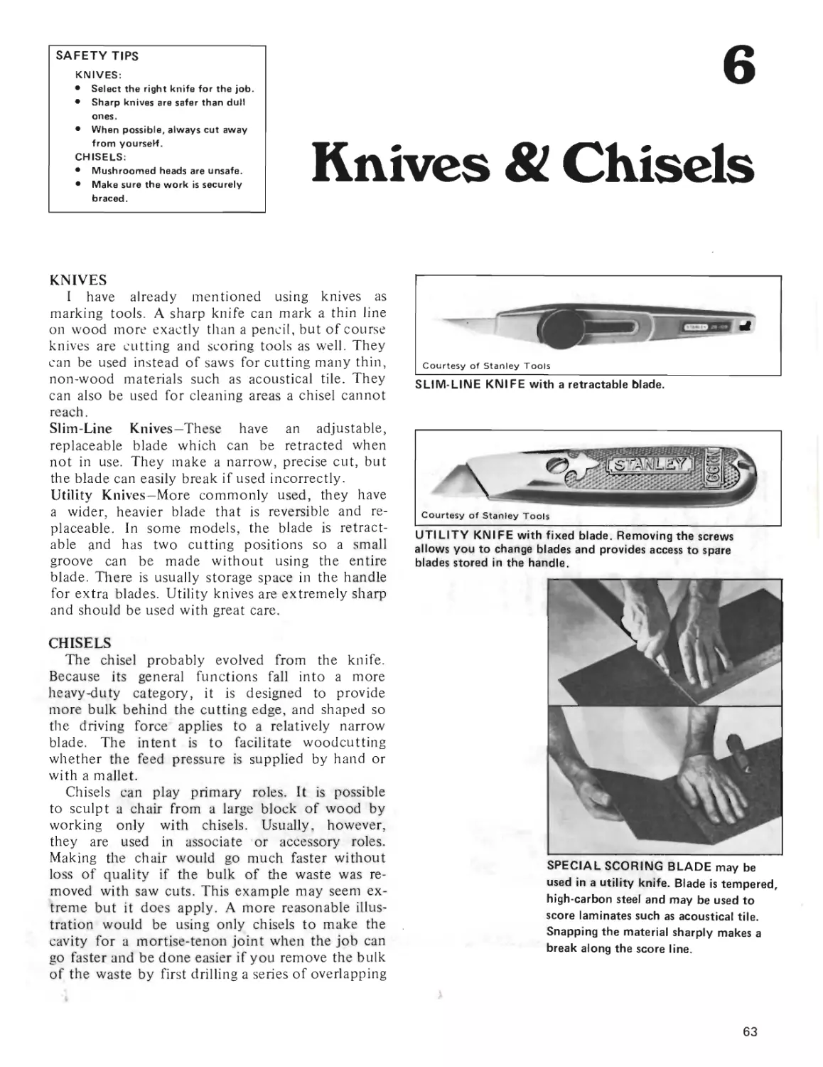
Knives & Chisels
How To Use Utility Knives
and Wood Chisels Without
Mistakes.
3
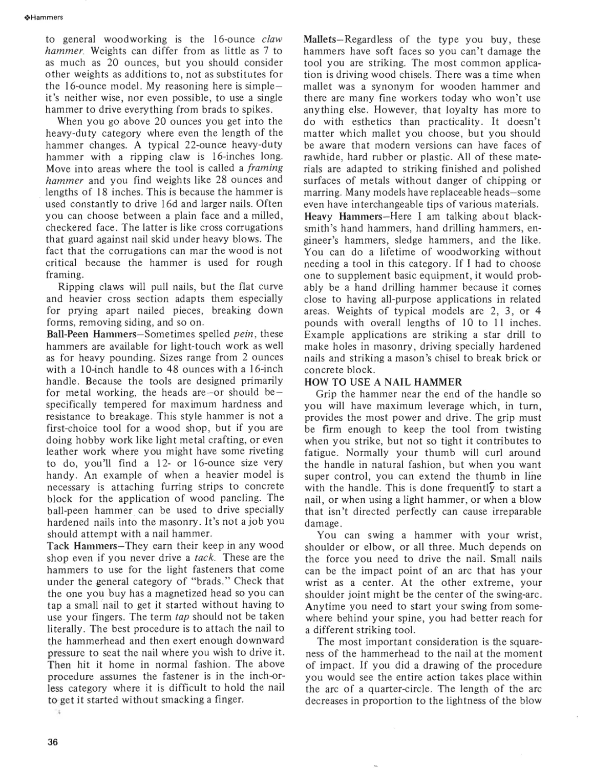
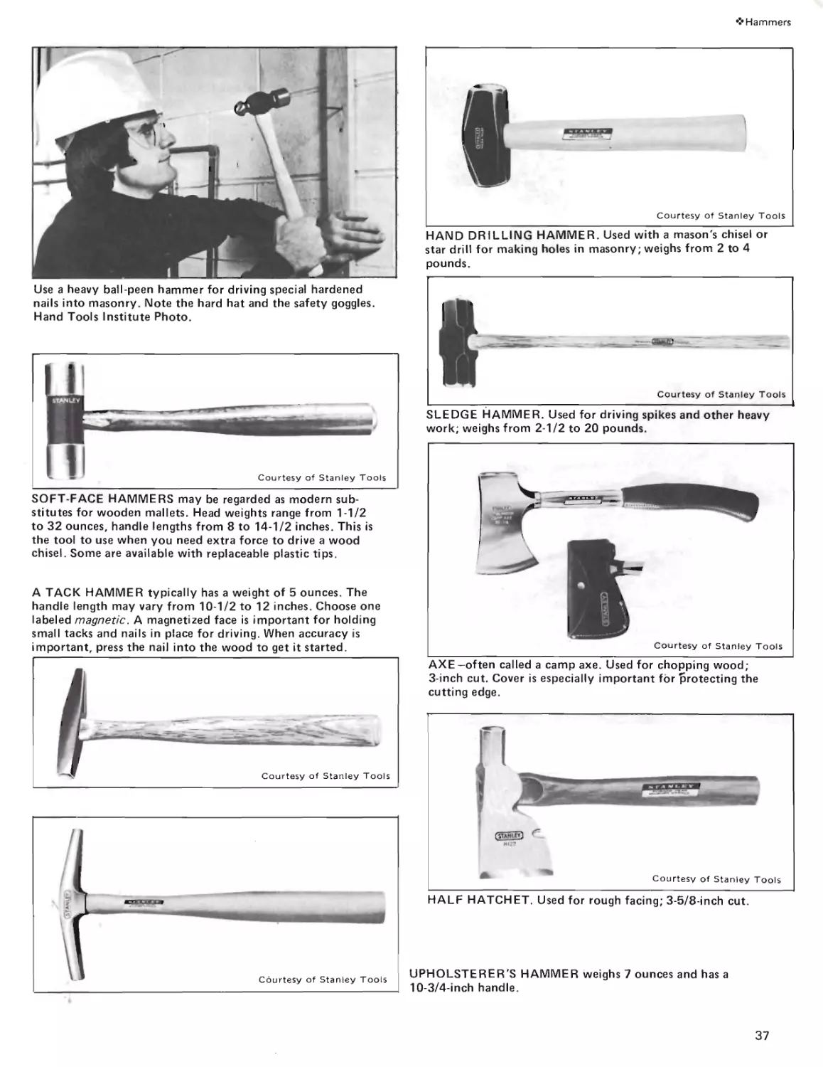
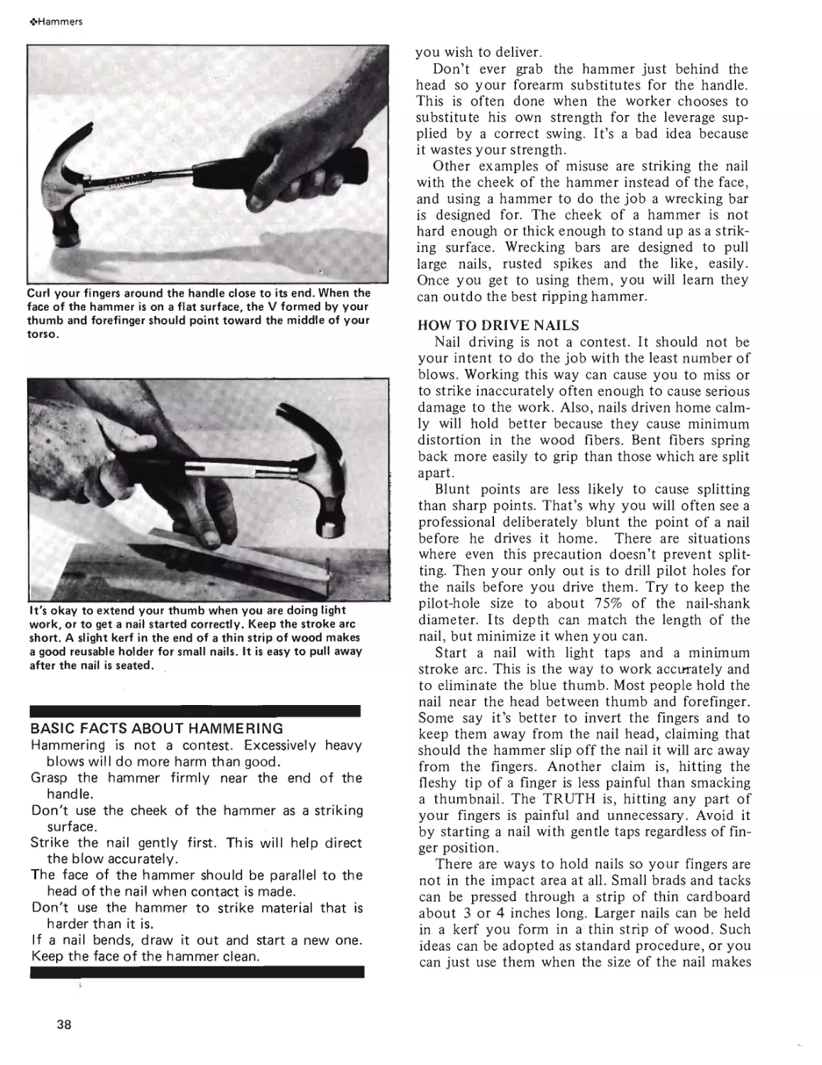
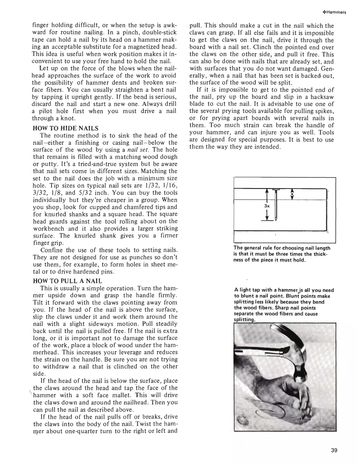
Hammers
Choosing and Using Claw
Hammers, Ball-Peen Hammers
Tack Hammers, Heavy Ham-
mers, Mallets, Nail Sets and
Wrecking Bars.
Page 34
How To Get Best Results
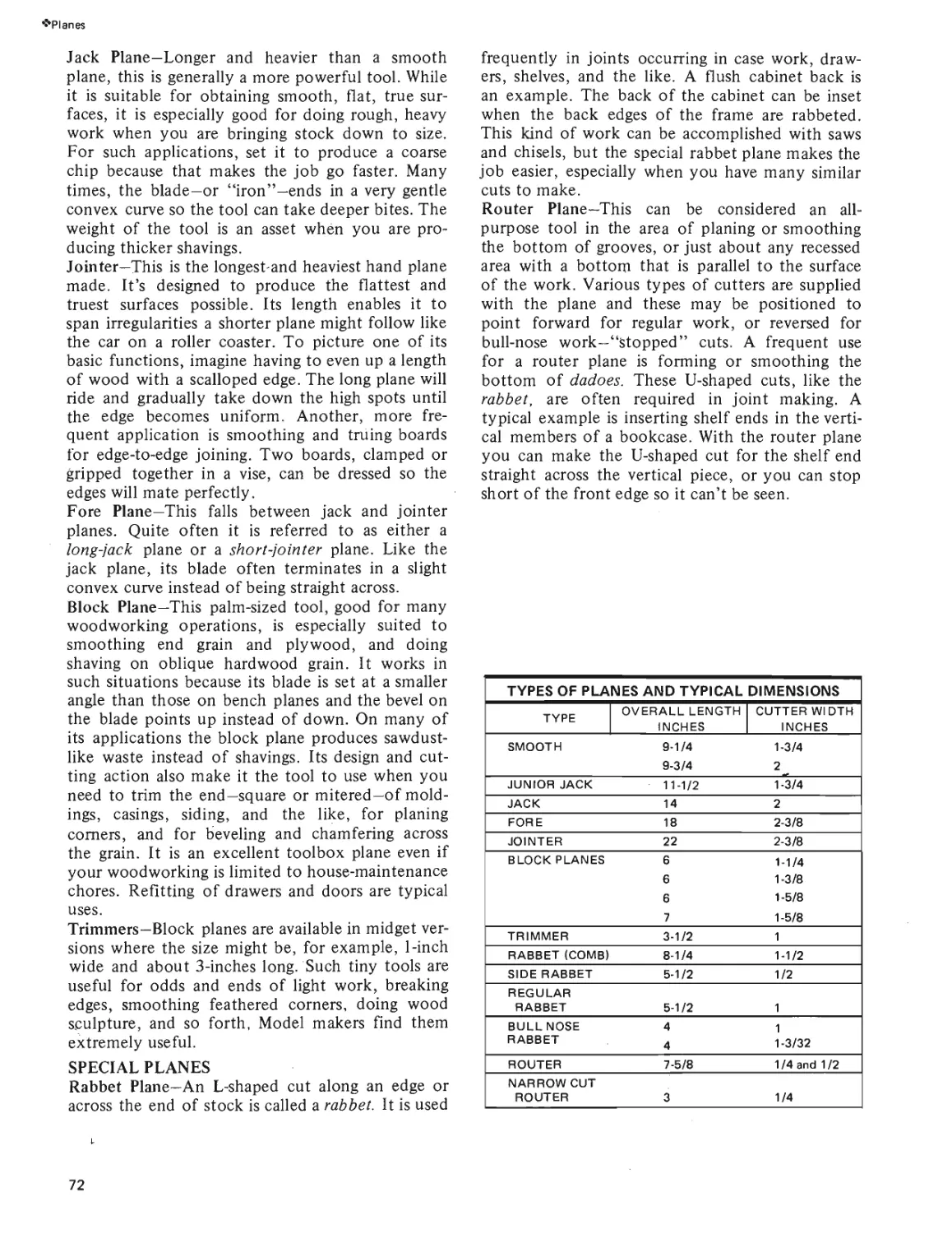
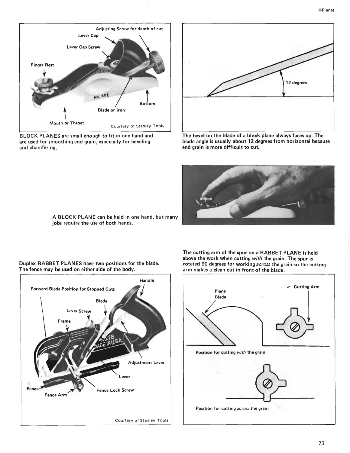
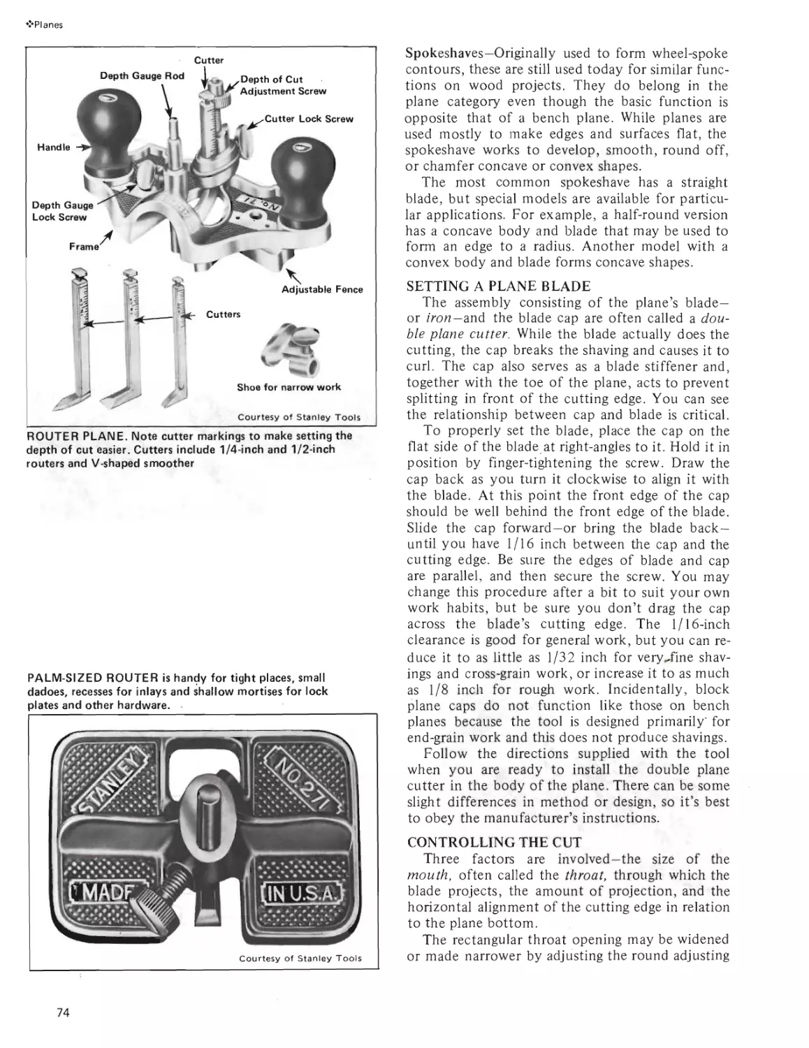
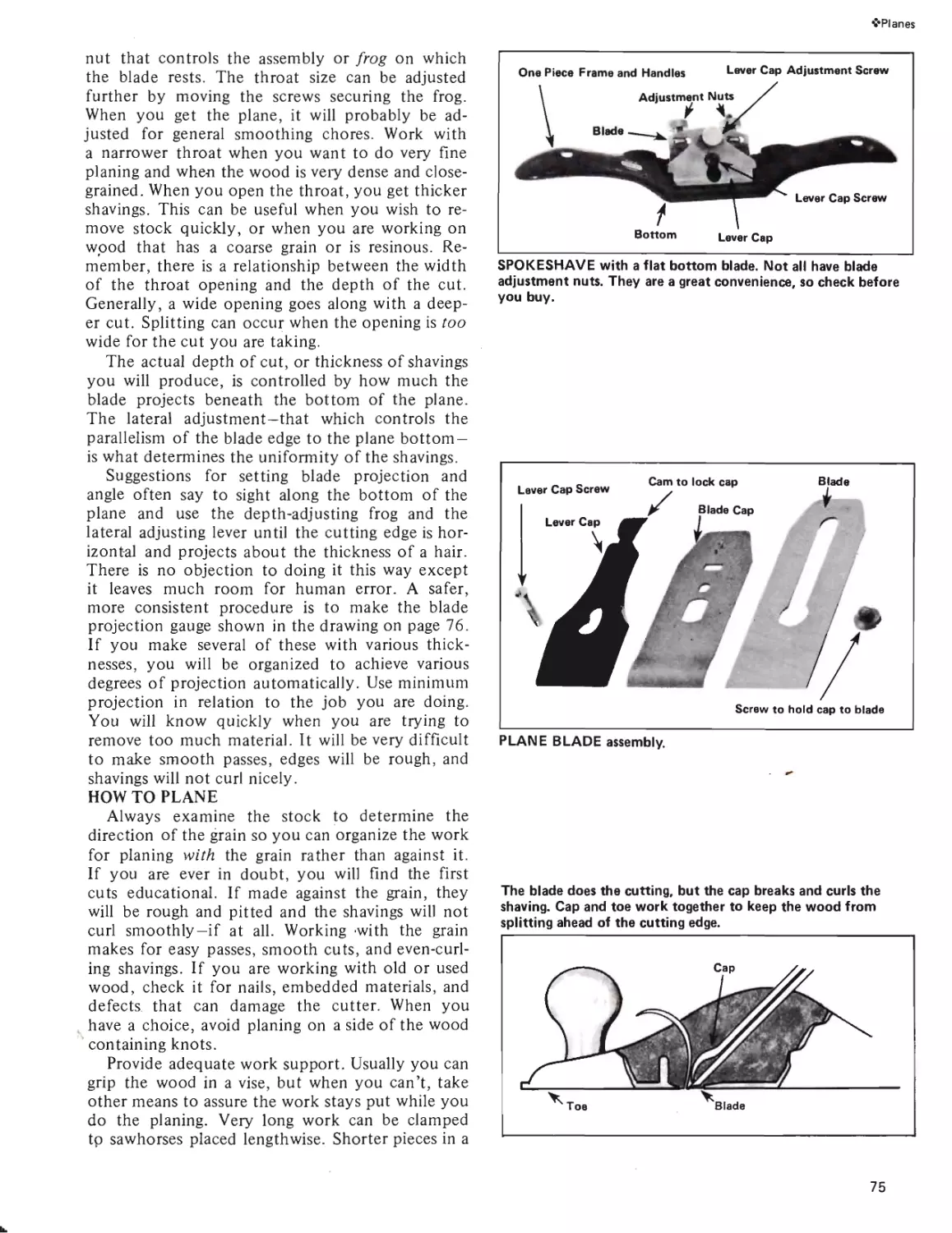
With Bench Planes, Block
Planes, Rabbet Planes, Router
Planes and Spokeshaves.
Planes
Page 70
2
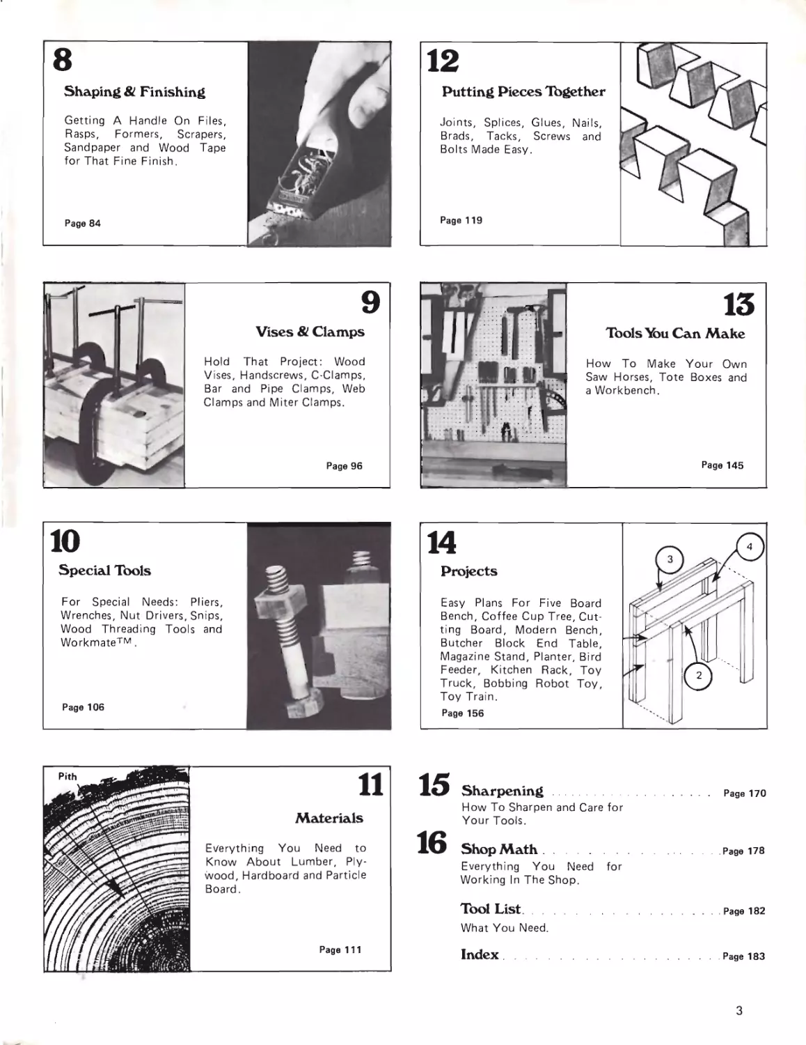
8
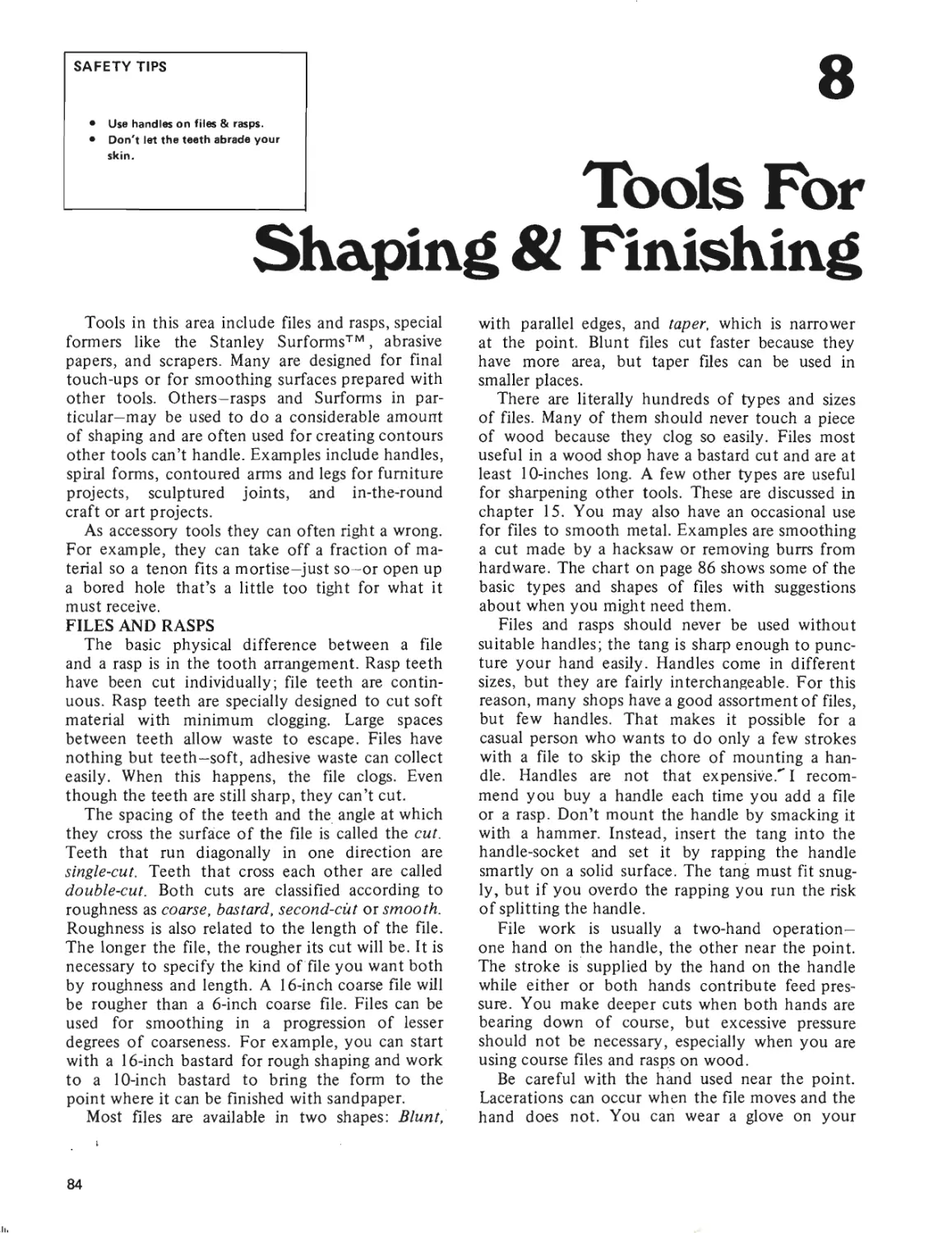
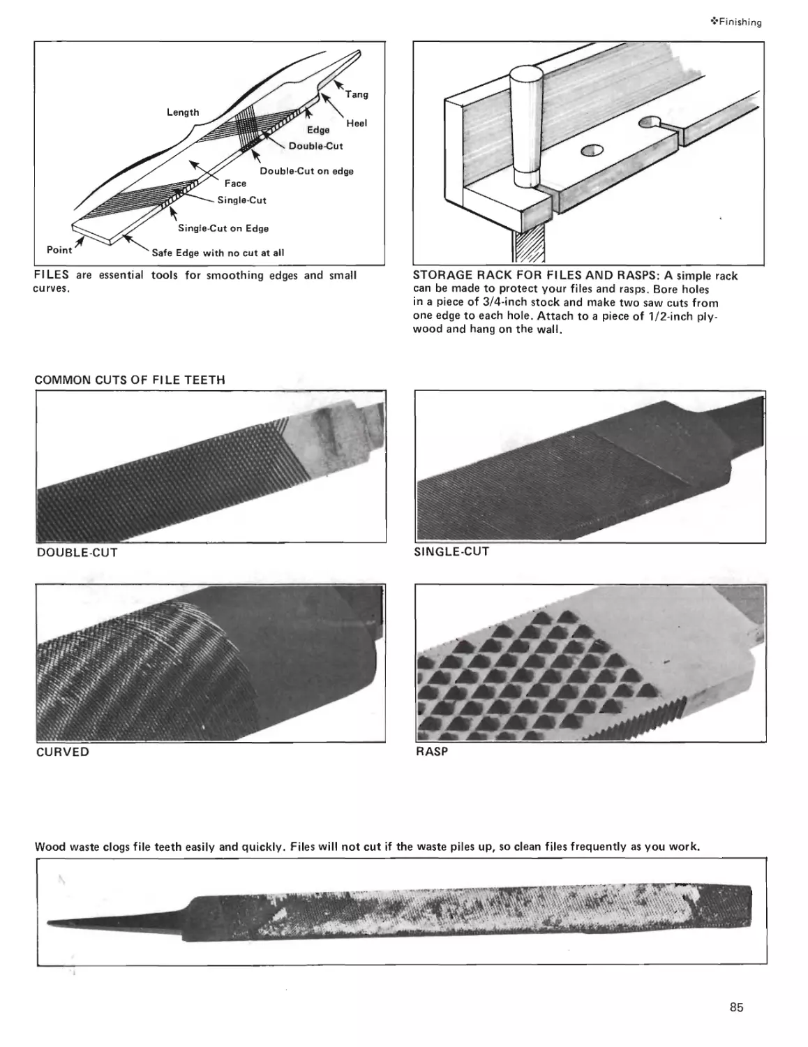
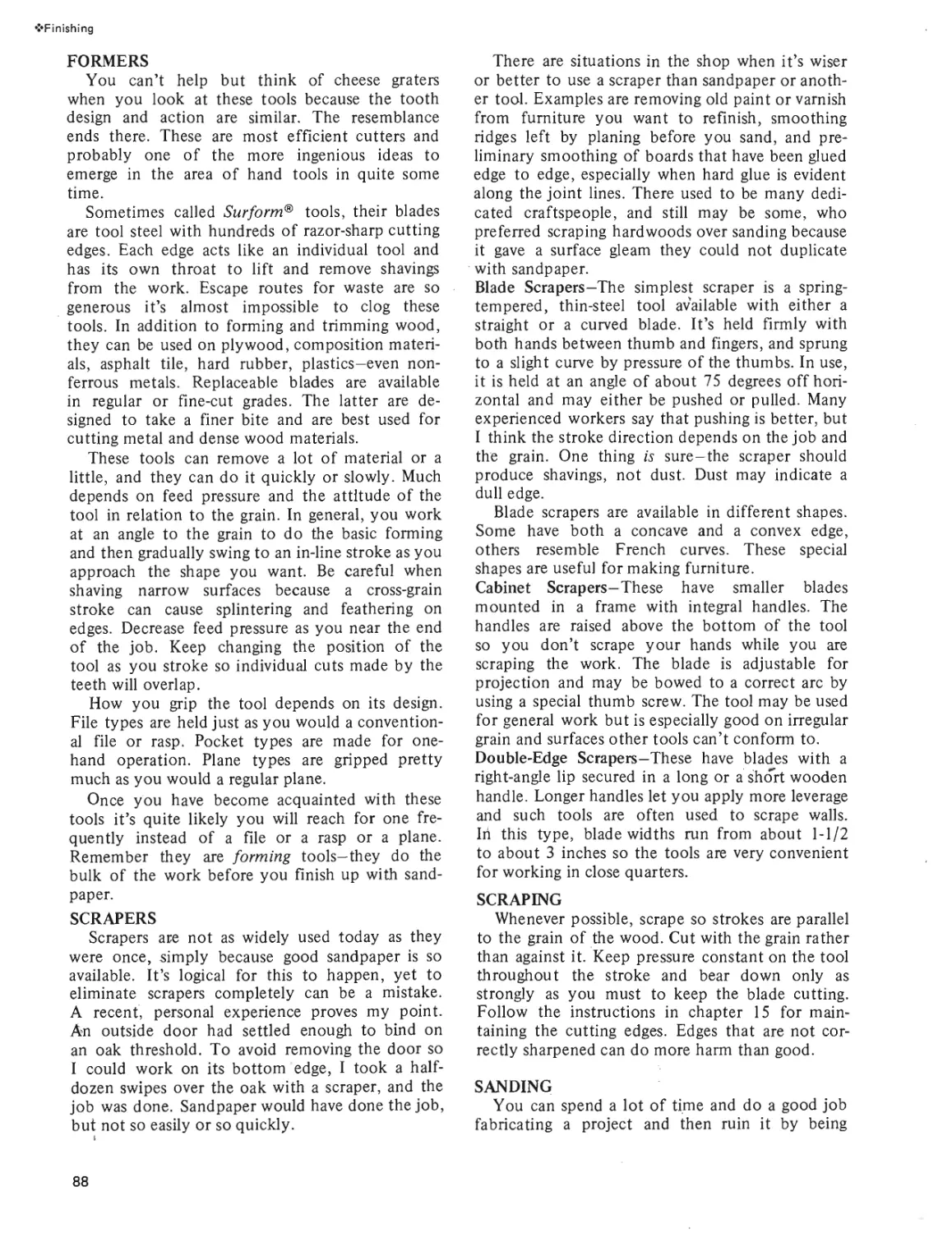
Shaping & Finishing
Getting A Handle On Files,
Rasps, Formers, Scrapers,
Sandpaper and Wood Tape
for That Fine Finish.
Page 84
Page 119
12
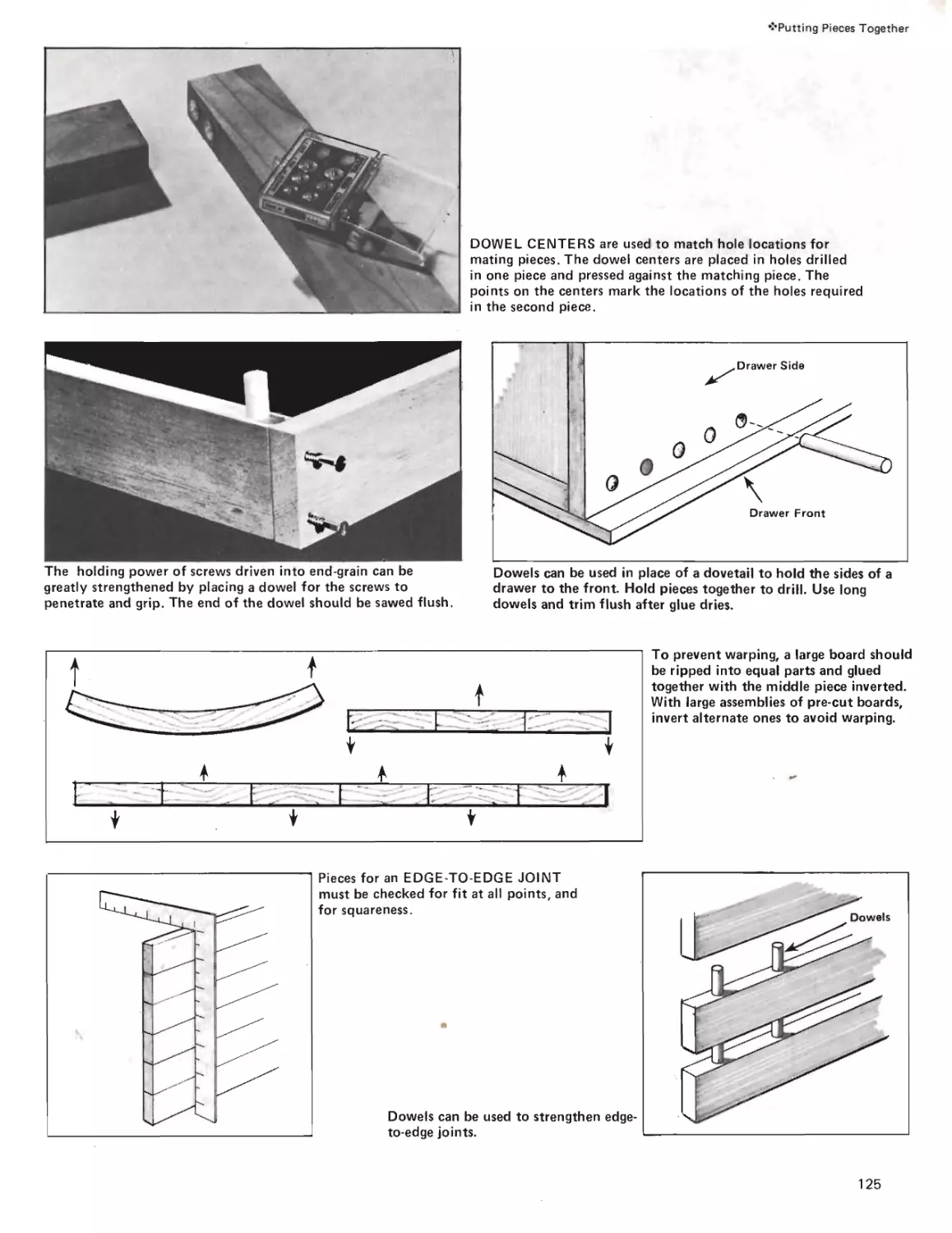
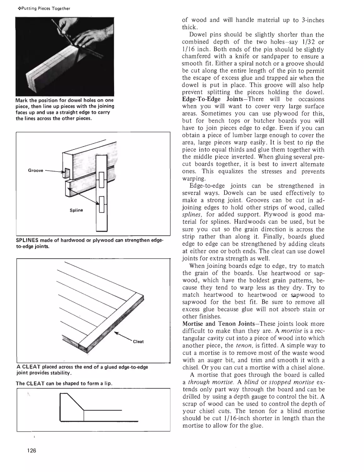
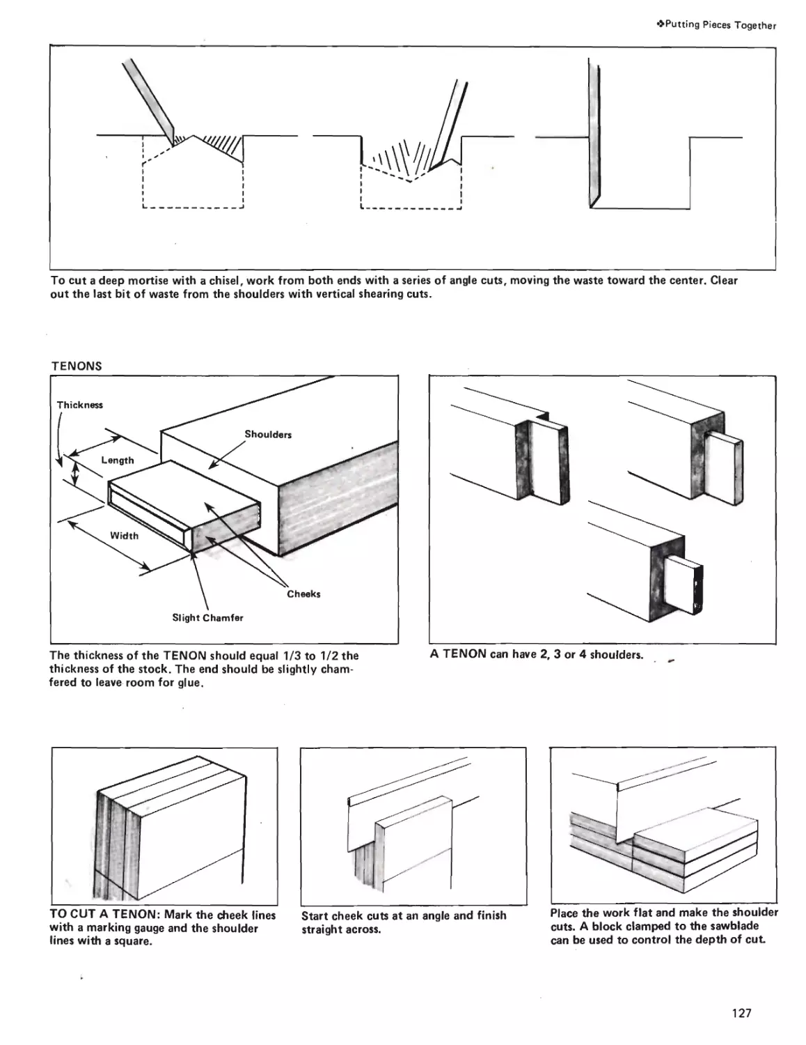
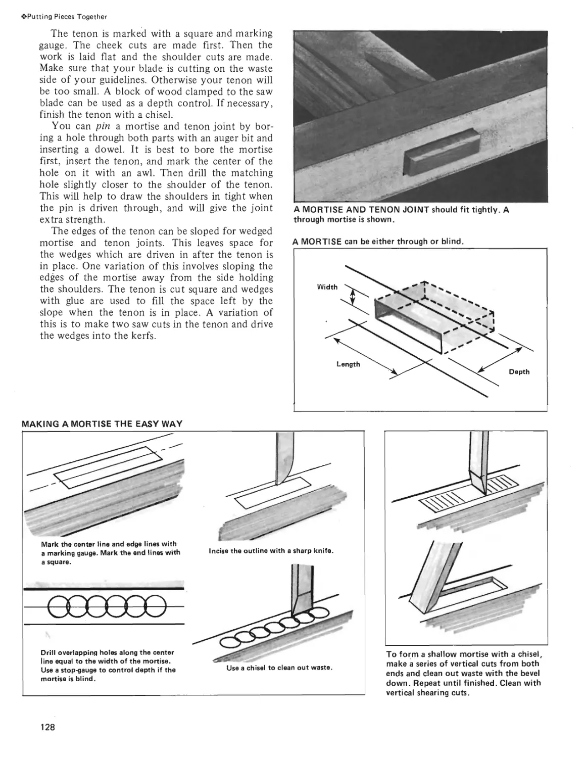
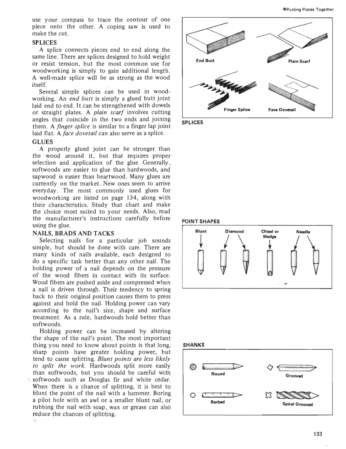
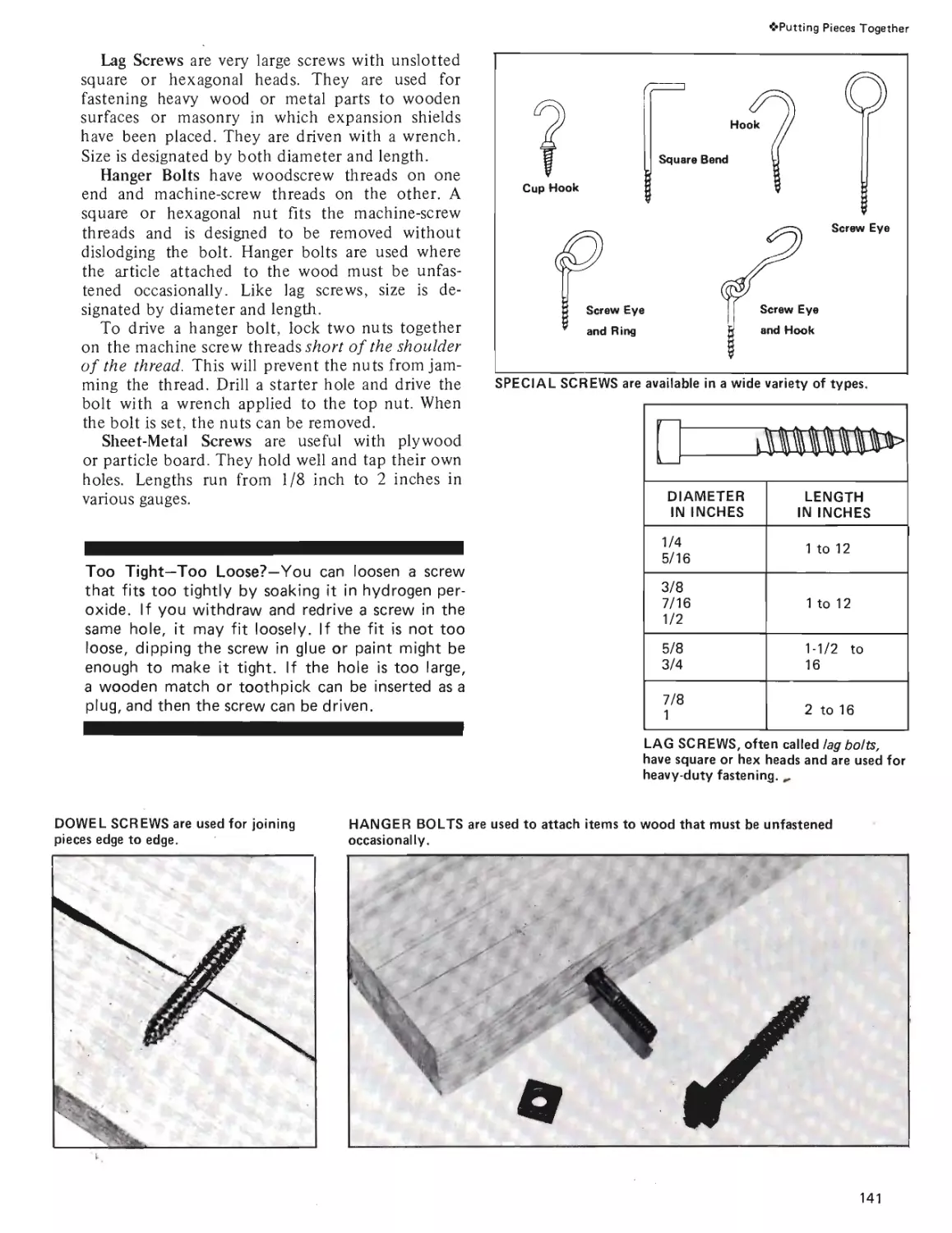
Putting Pieces Tbgether
Joints, Splices, Glues, Nails,
Brads, Tacks, Screws and
Bolts Made Easy.
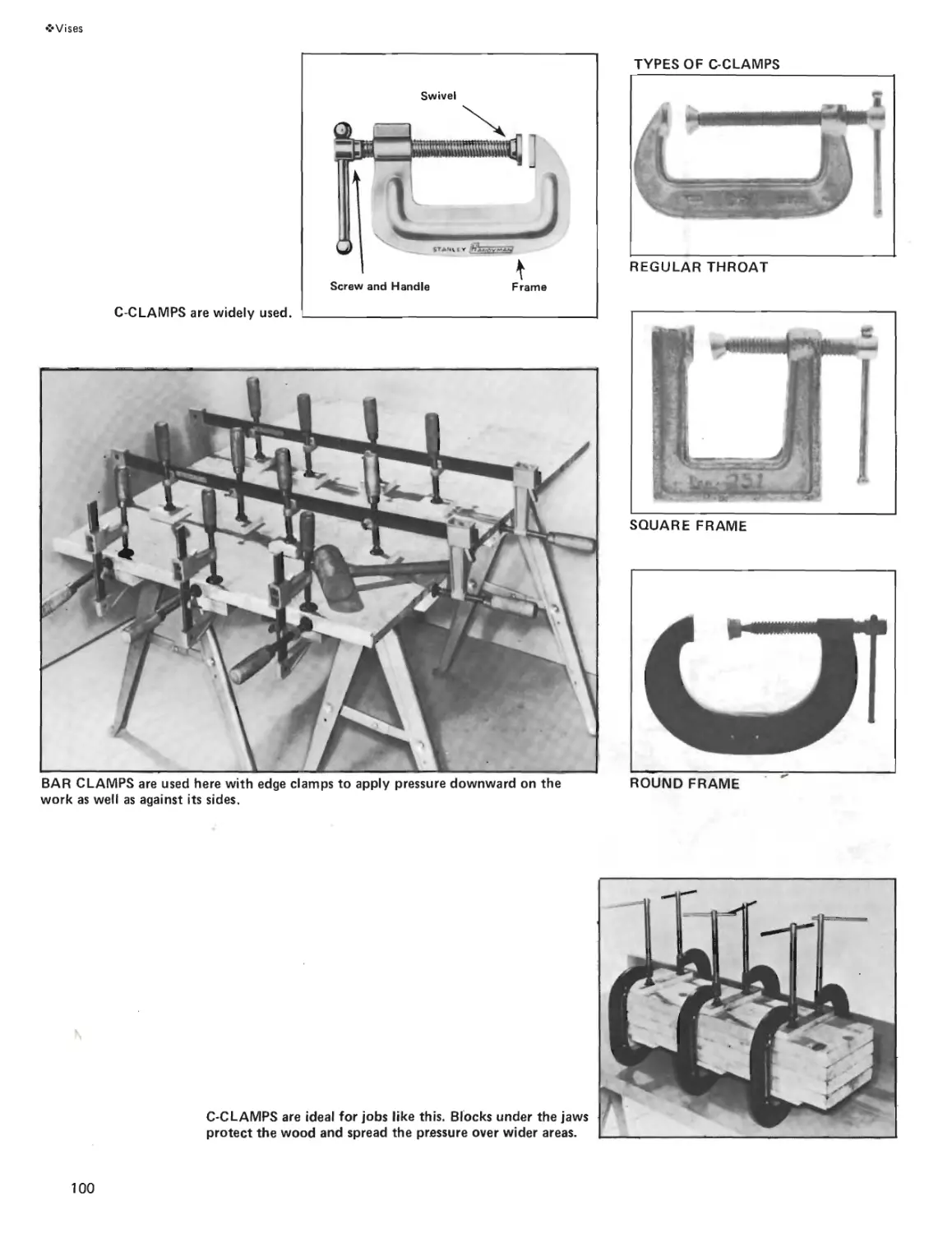
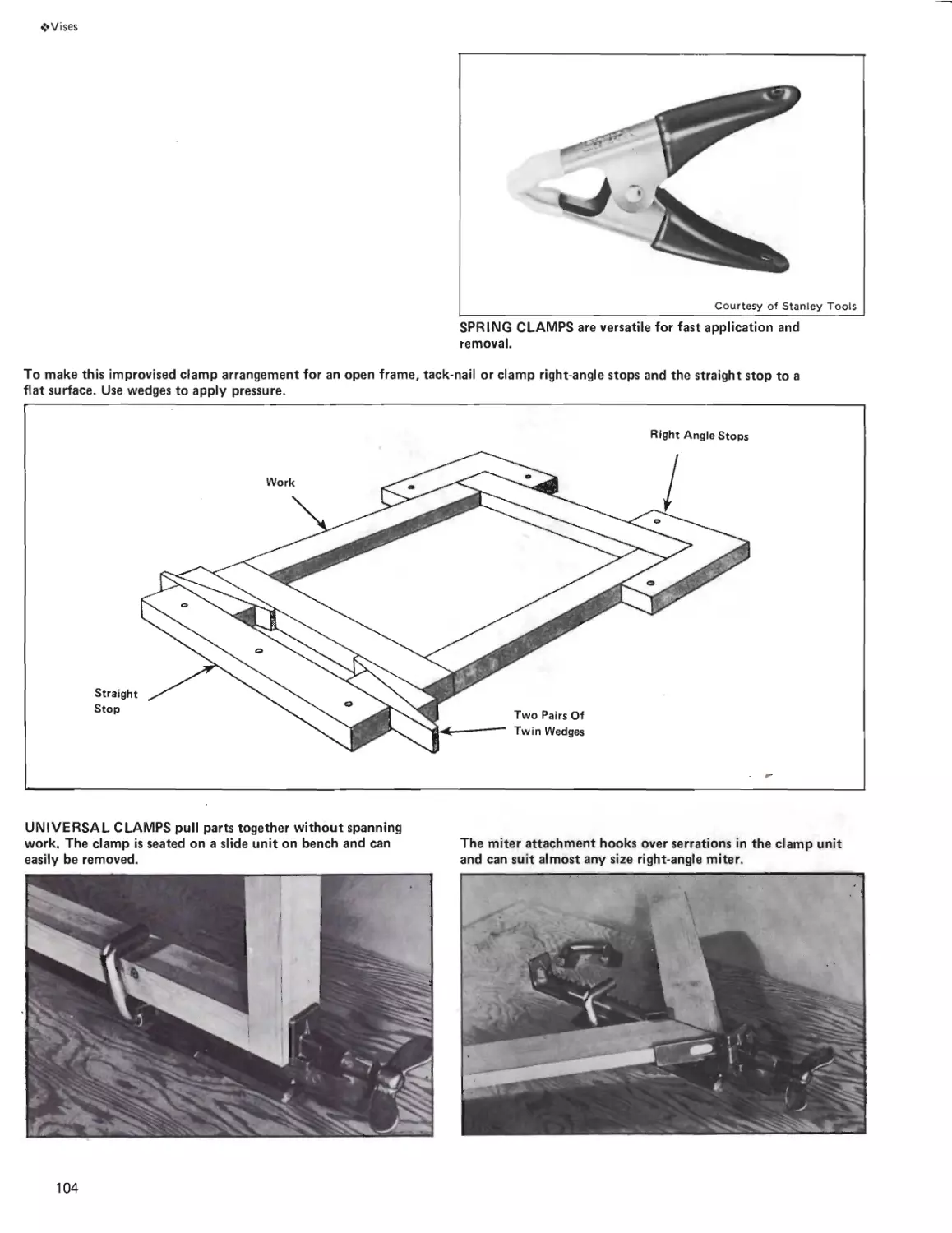
Vises & Clamps
Hold That Project: Wood
Vises, Handscrews, C-Clamps,
Bar and Pipe Clamps, Web
Clamps and Miter Clamps.
Page 96
13
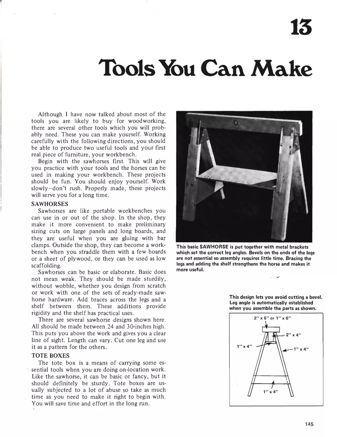
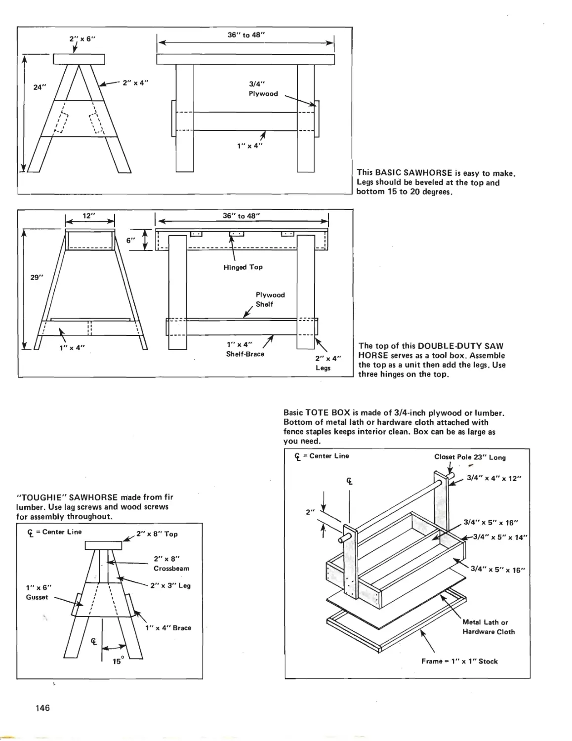
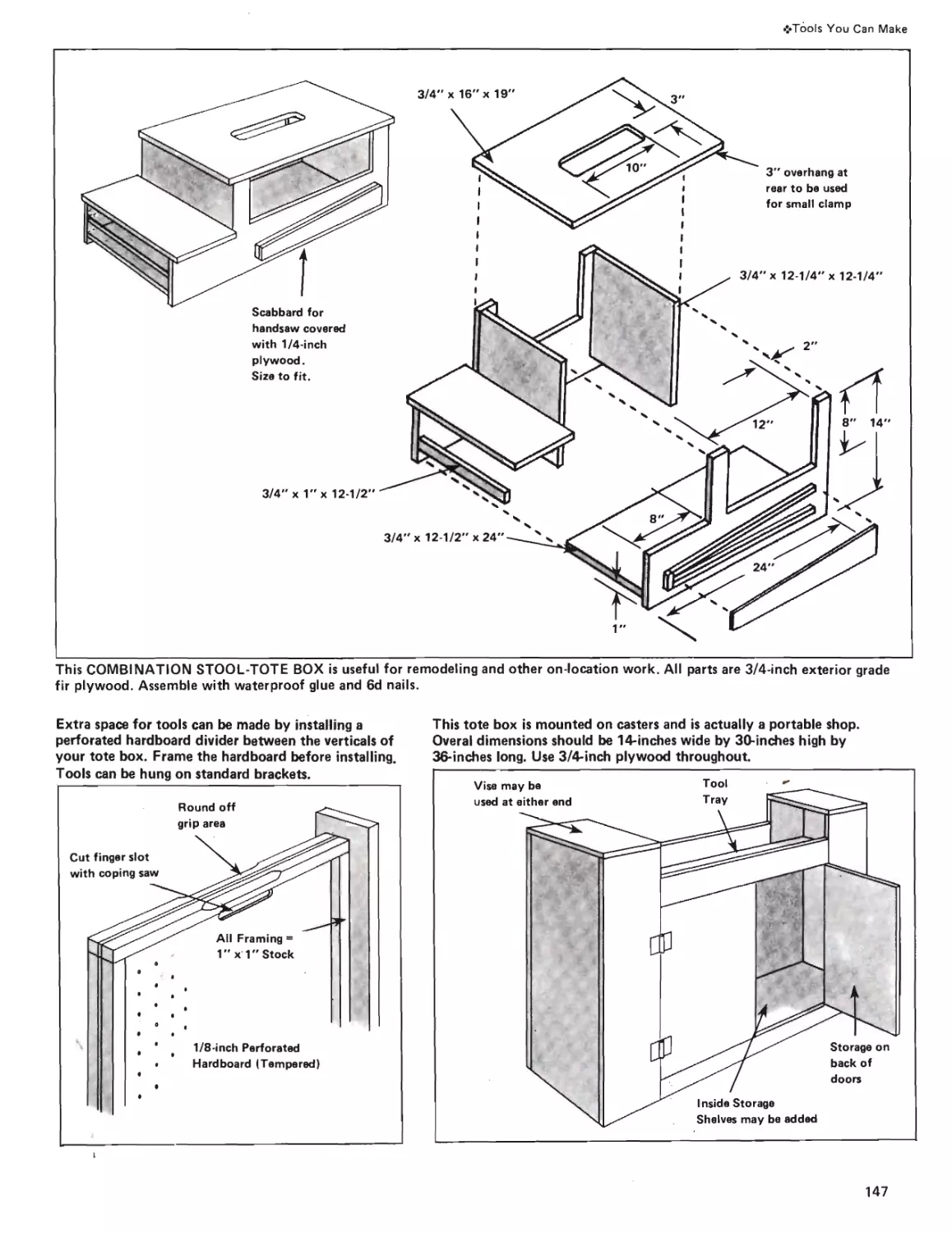
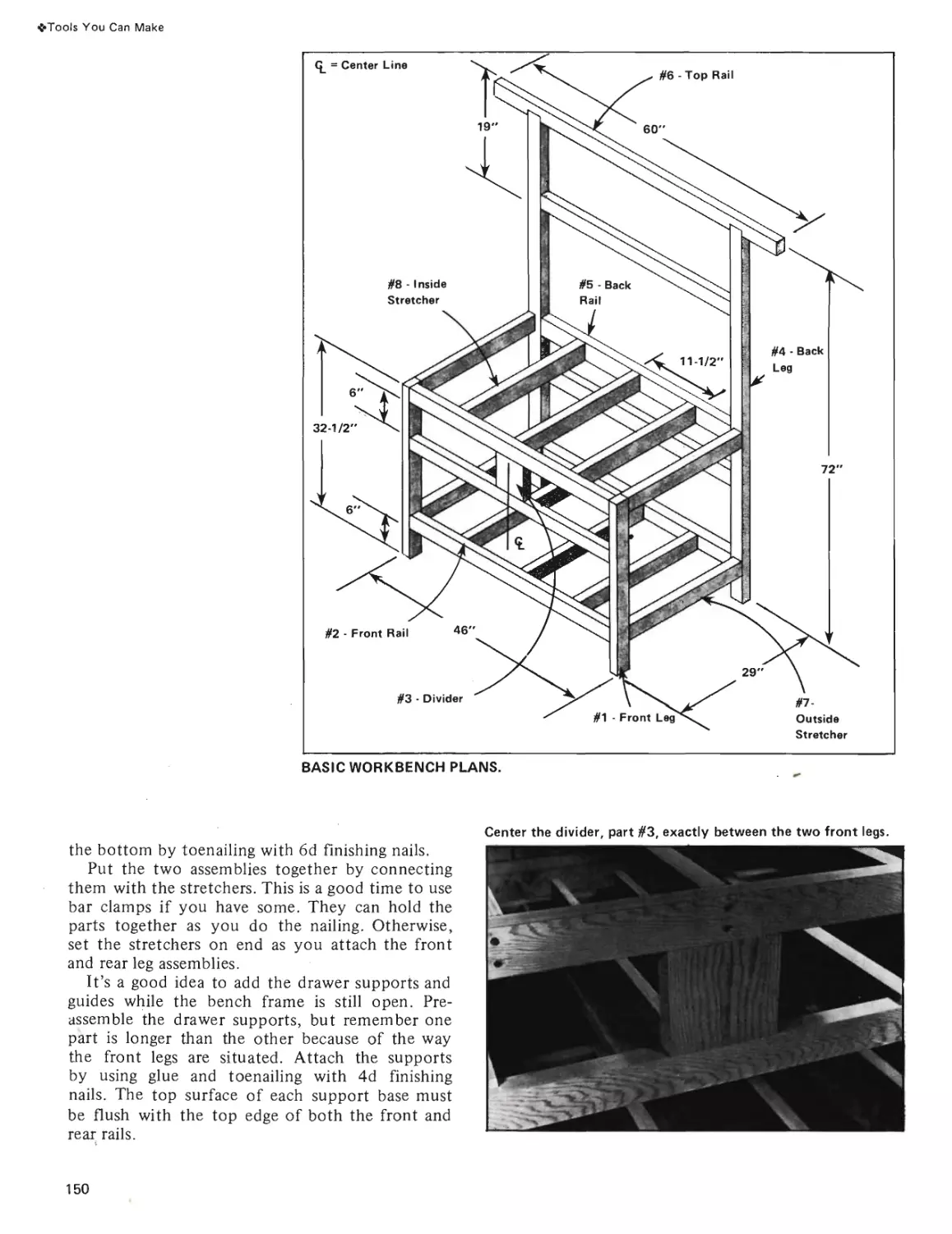
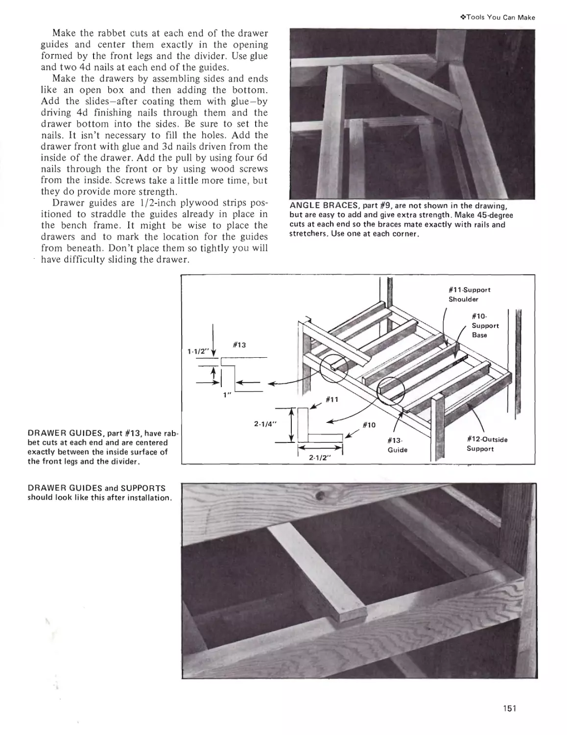
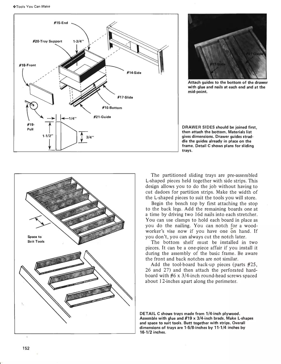
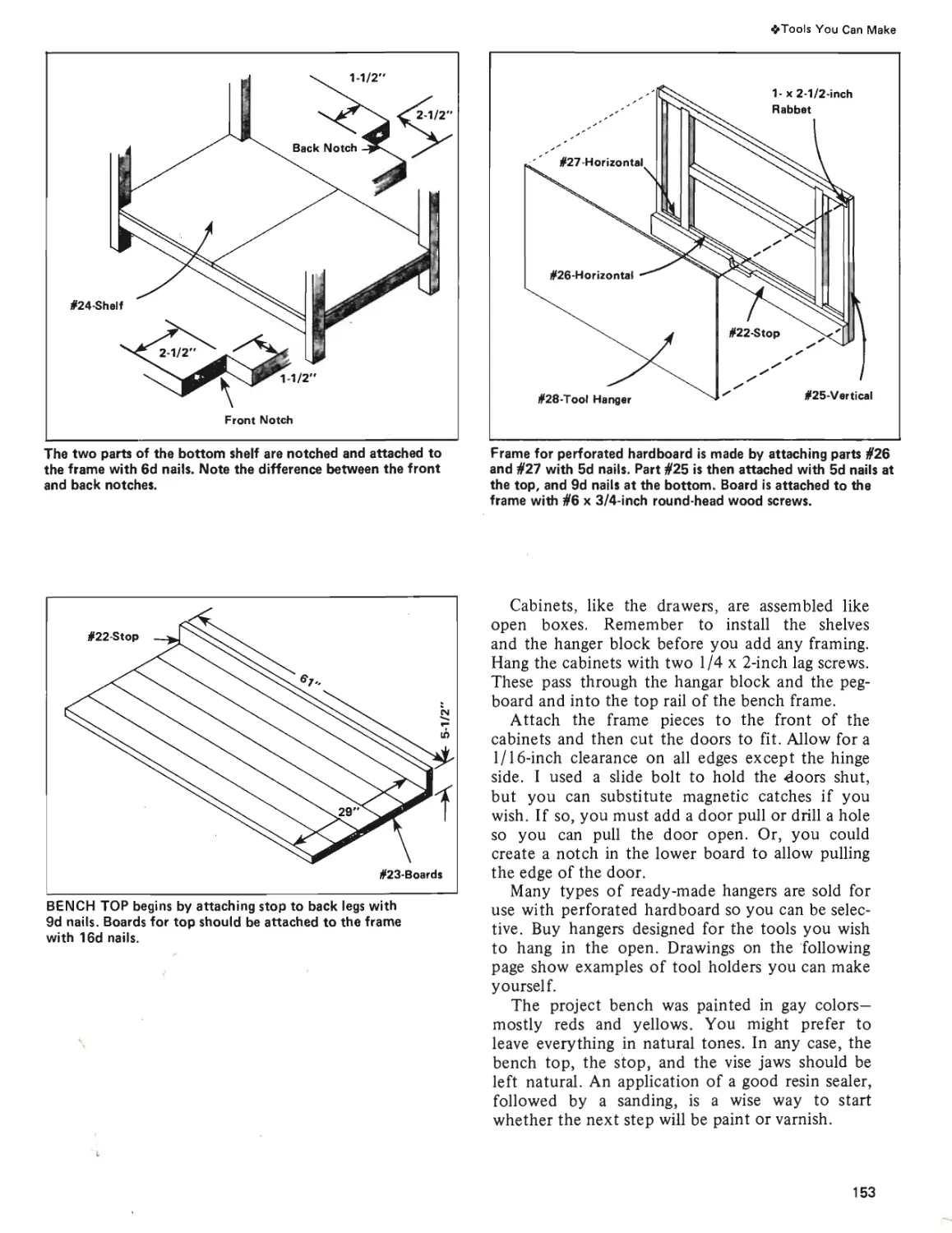
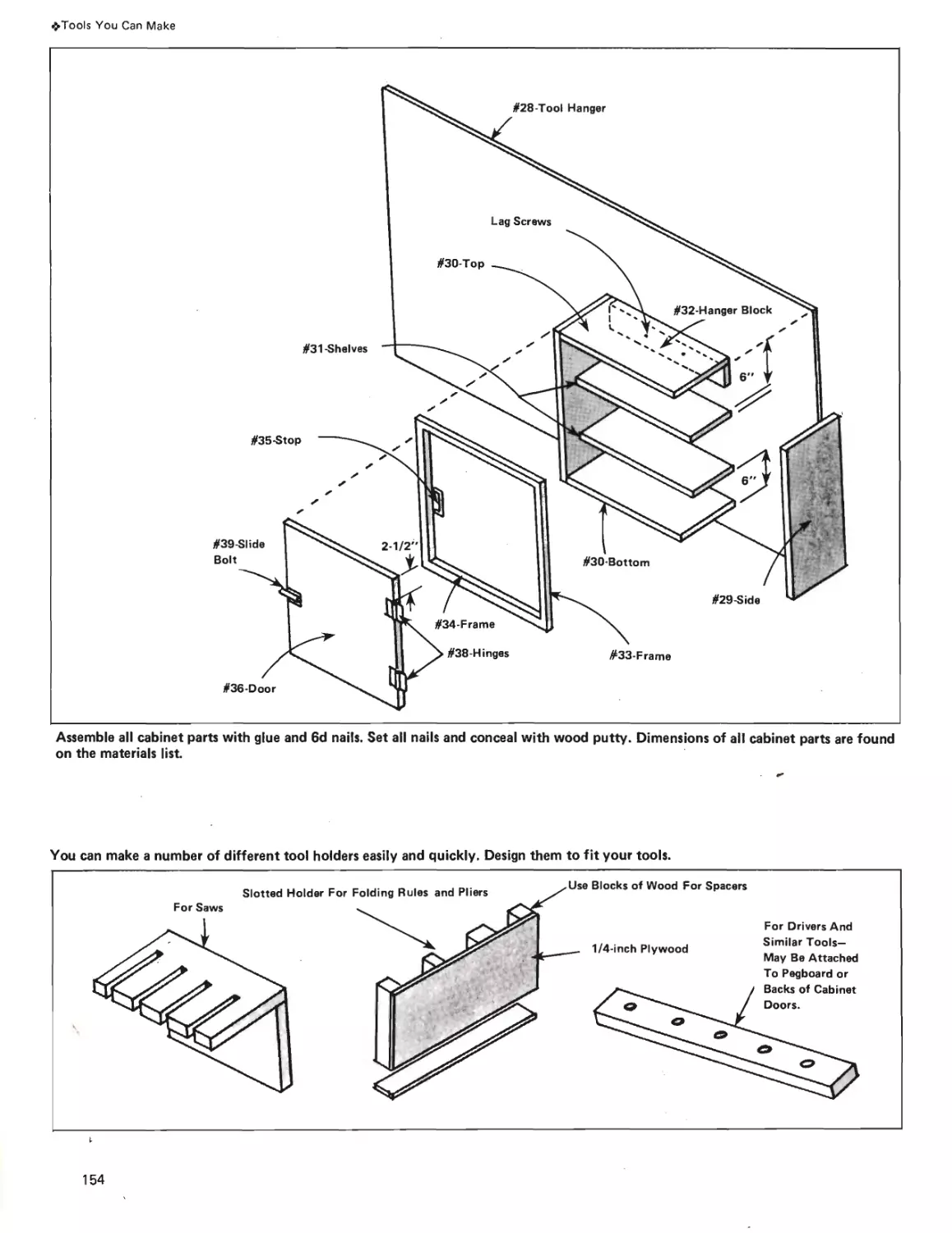
Tools \bu Can Make
How To Make Your Own
Saw Horses, Tote Boxes and
a Workbench.
Page 145
10
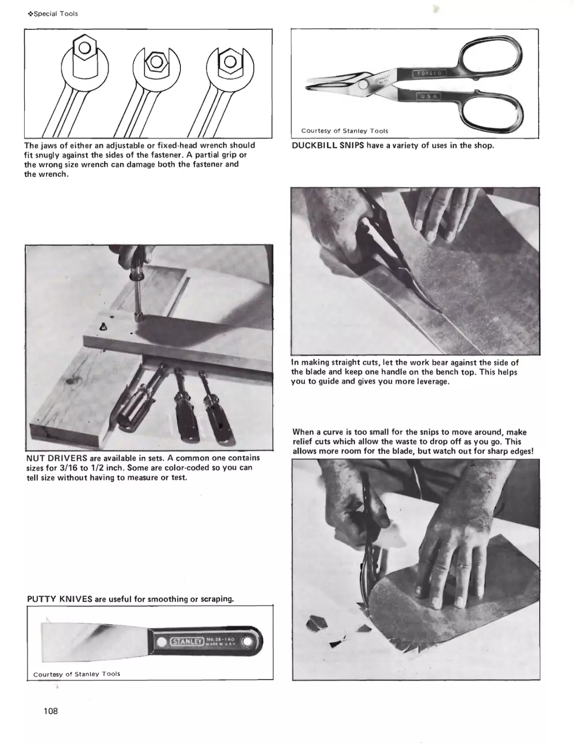
Special Tools
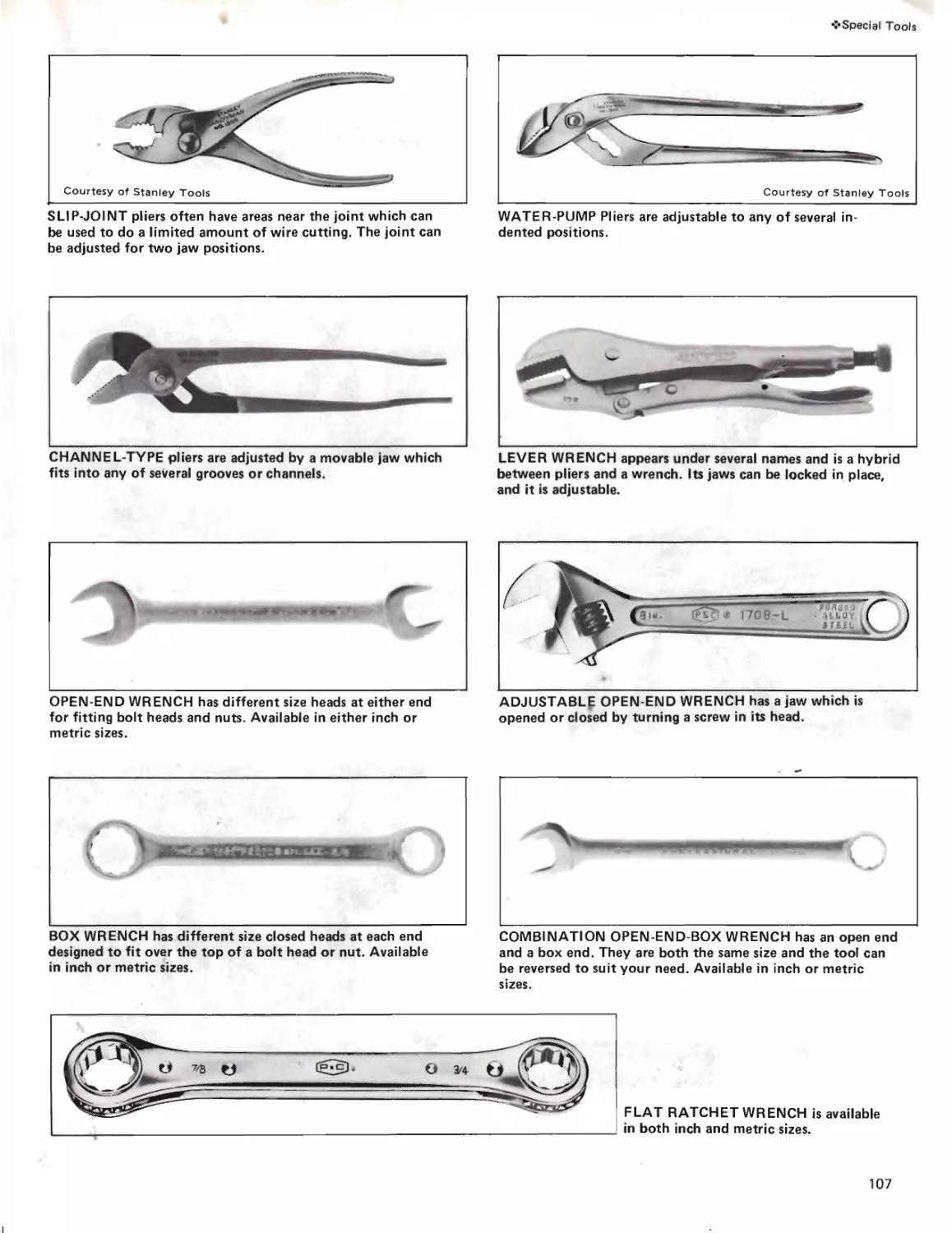
For Special Needs: Pliers,
Wrenches, Nut Drivers, Snips,
Wood Threading Tools and
Workmate™.
Page 106
14
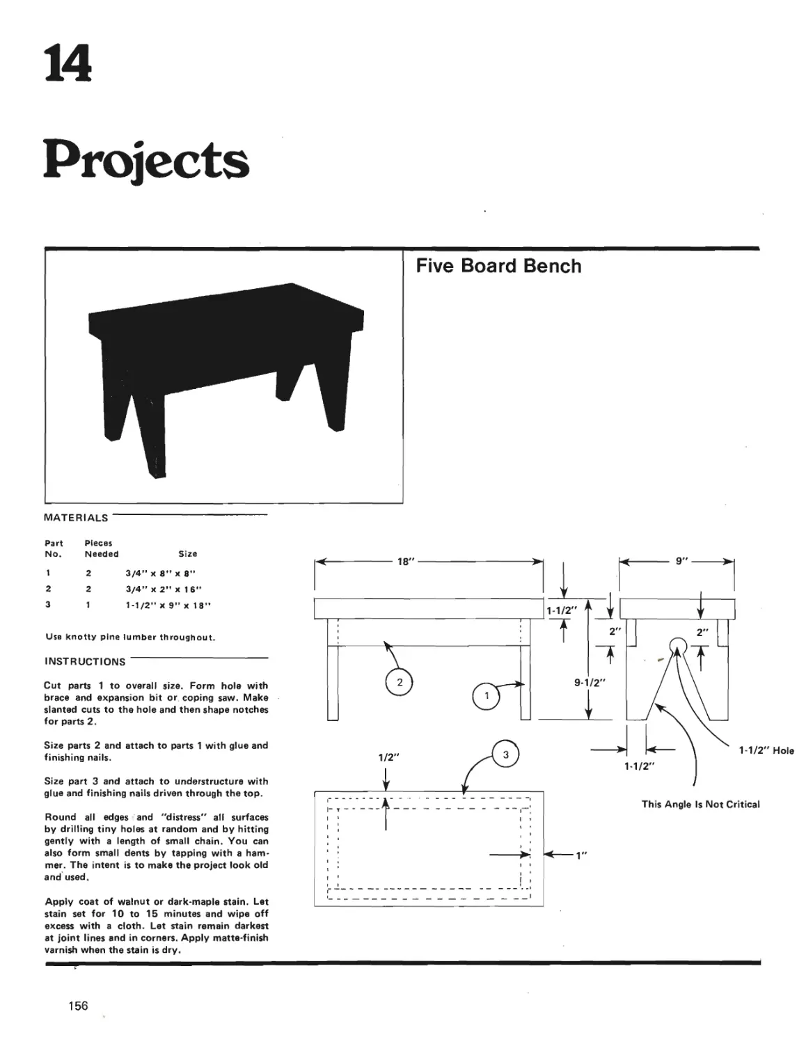
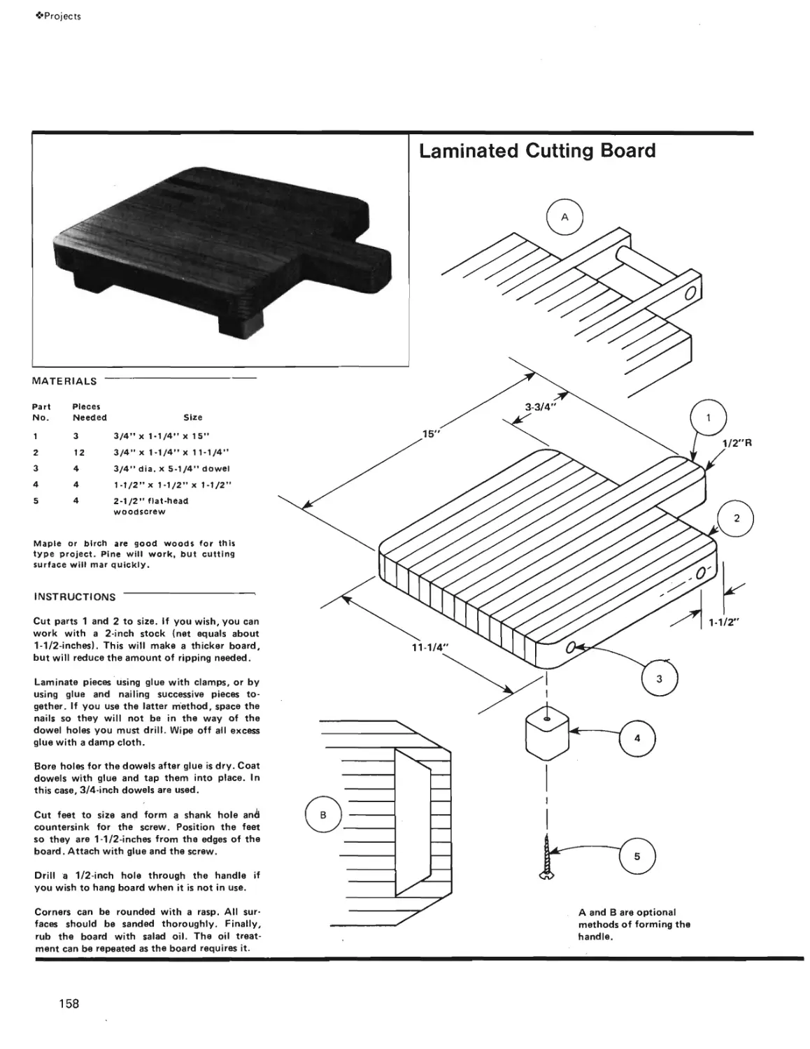
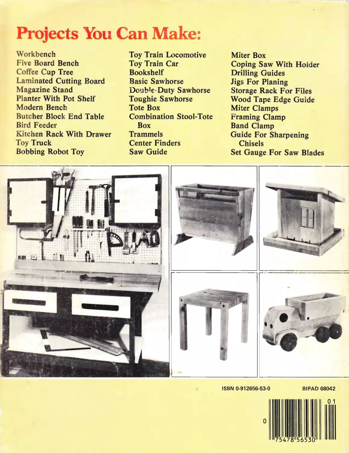
Projects
Easy Plans For Five Board
Bench, Coffee Cup Tree, Cut-
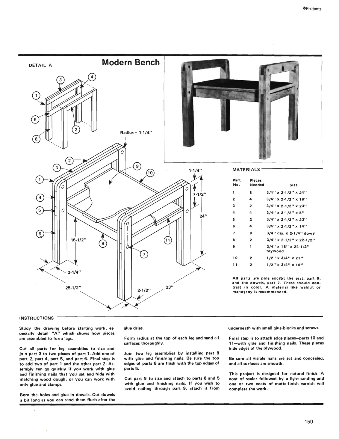
ting Board, Modern Bench,
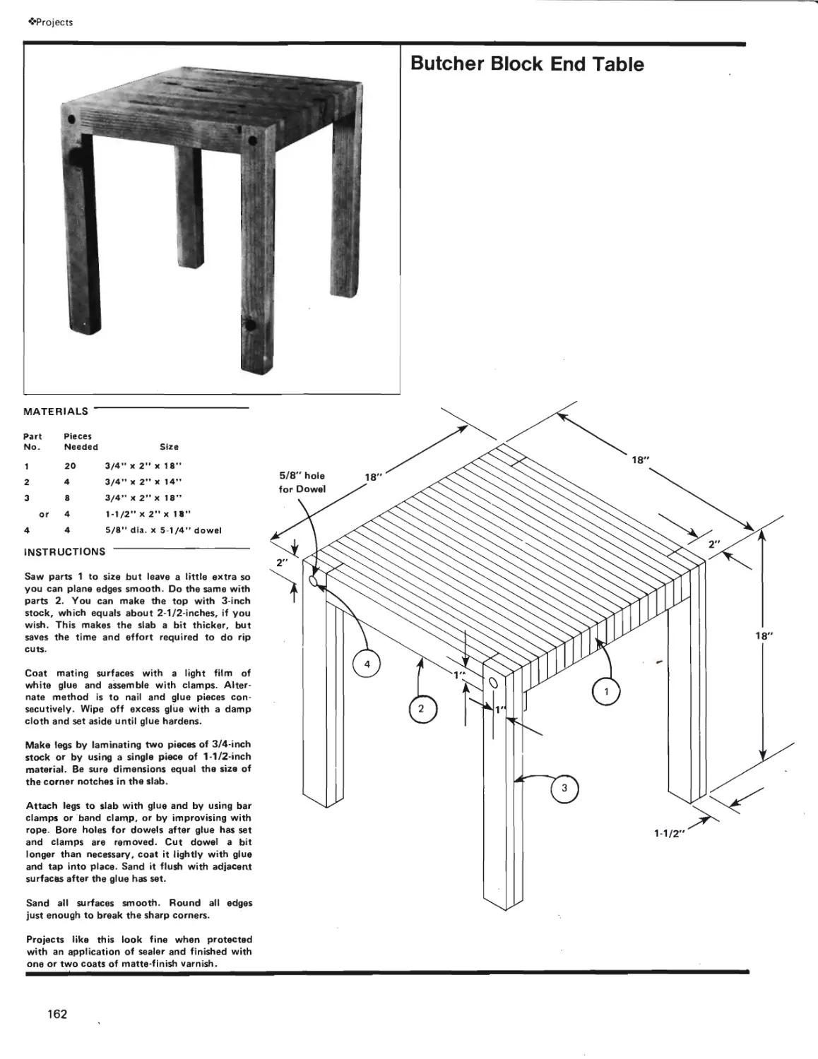
Butcher Block End Table,
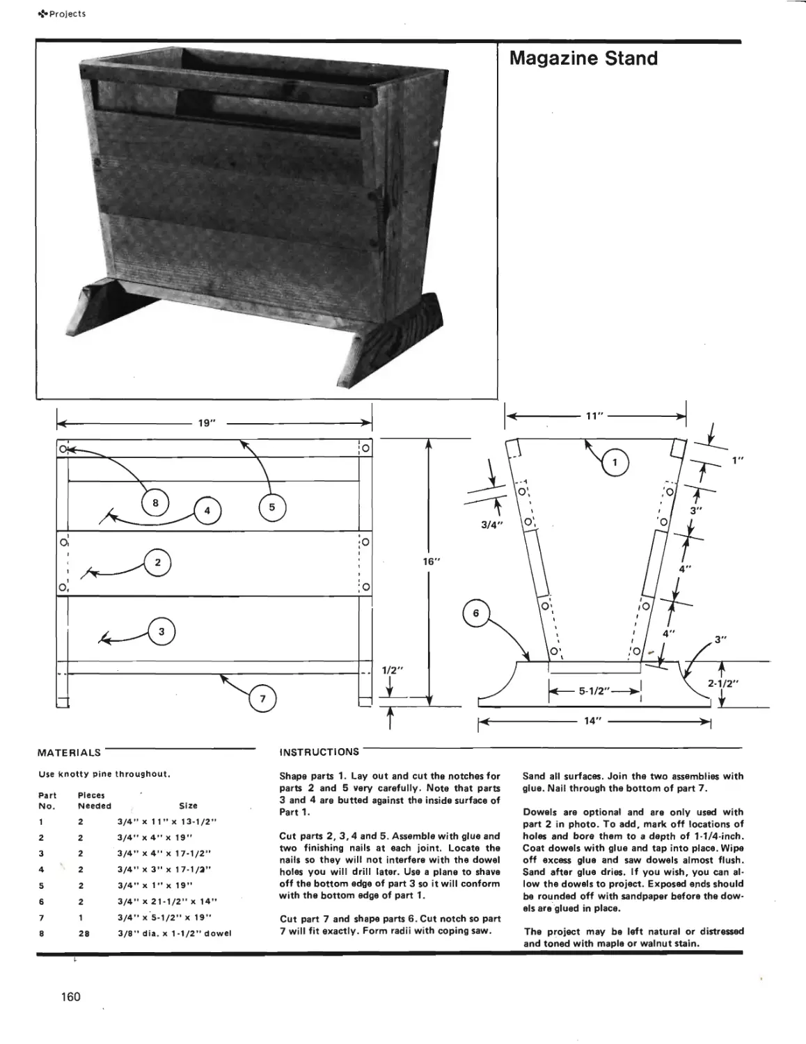
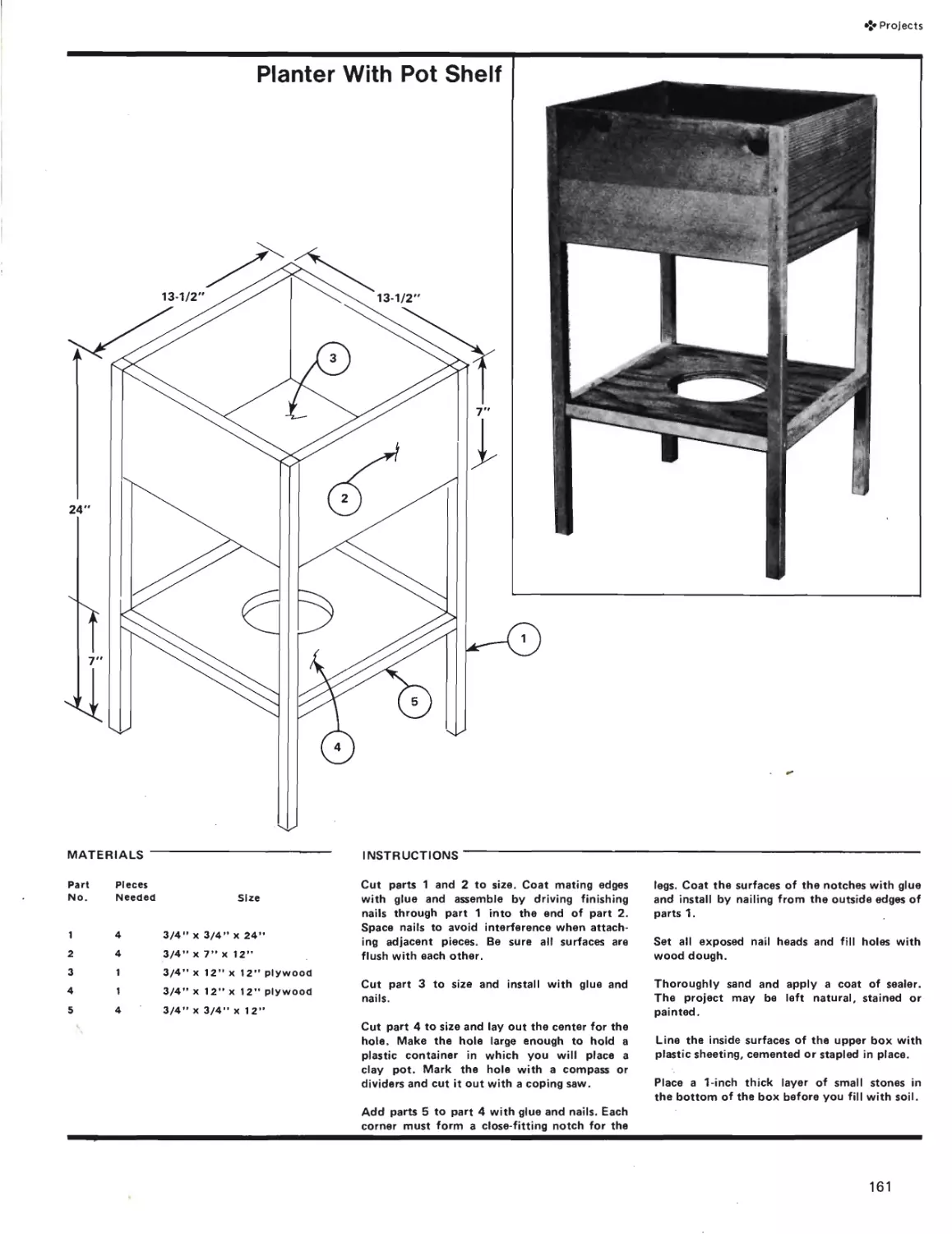
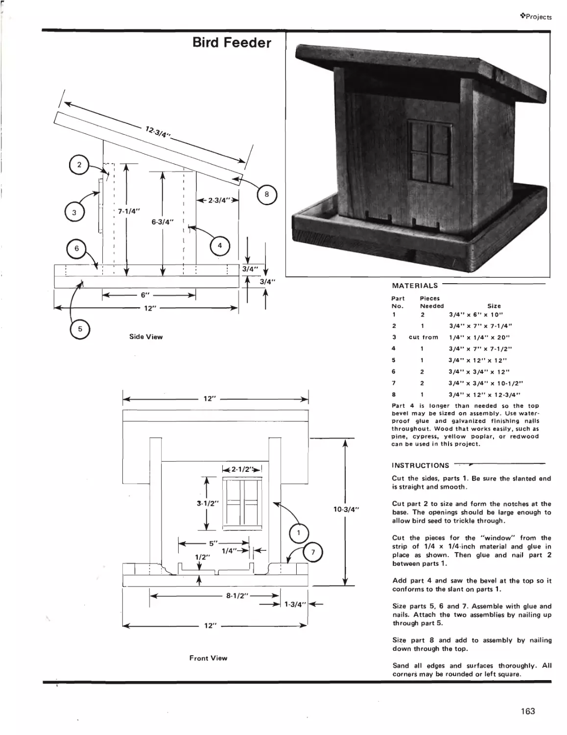
Magazine Stand, Planter, Bird
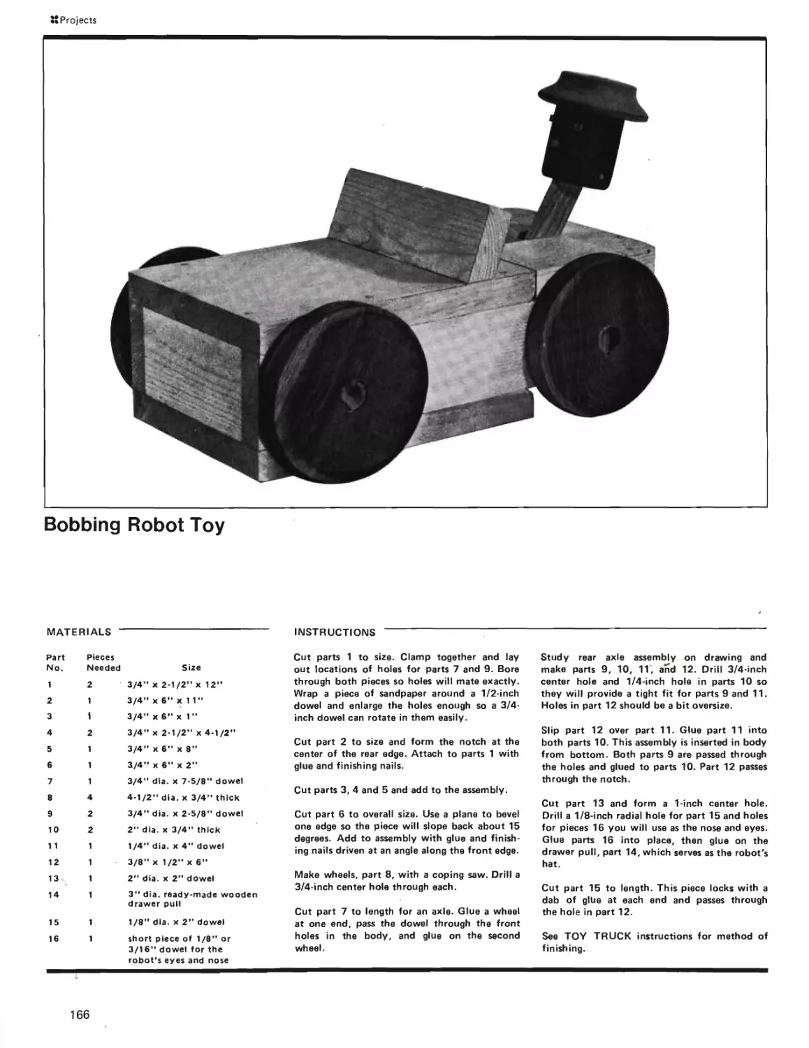
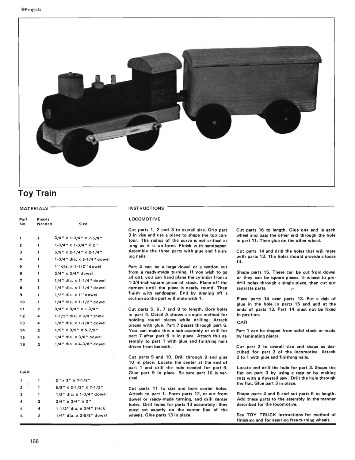
Feeder, Kitchen Rack, Toy
Truck, Bobbing Robot Toy,
Toy Train.
Page 156
11
Materials
Everything You Need to
Know About Lumber, Ply-
wood, Hardboard and Particle
Board.
Page 111
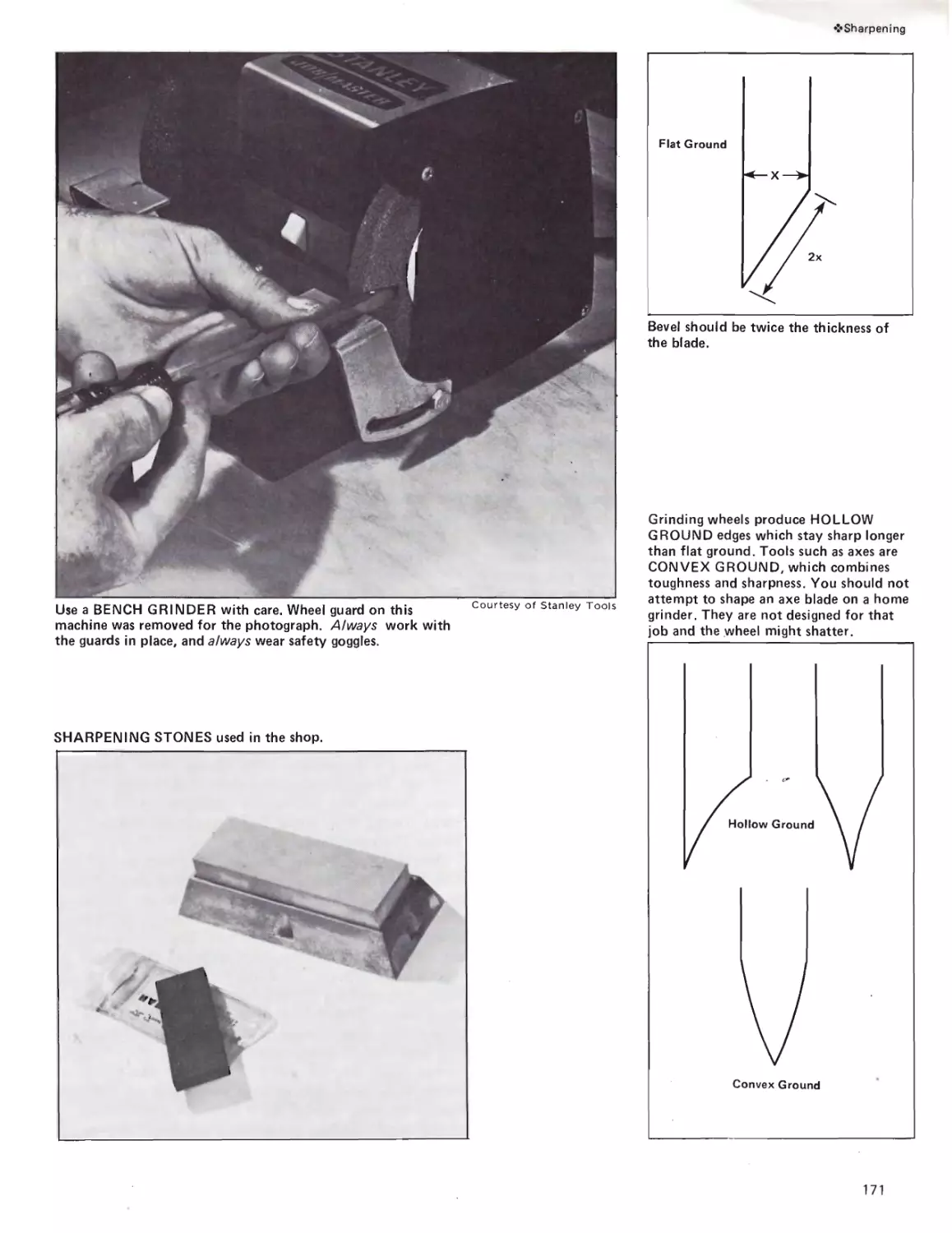
15
Sharpening
How To Sharpen and Care for
Your Tools.
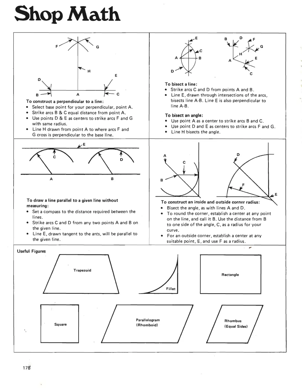
Shop Math............................
Everything You Need for
Working In The Shop.
Page 170
Page 178
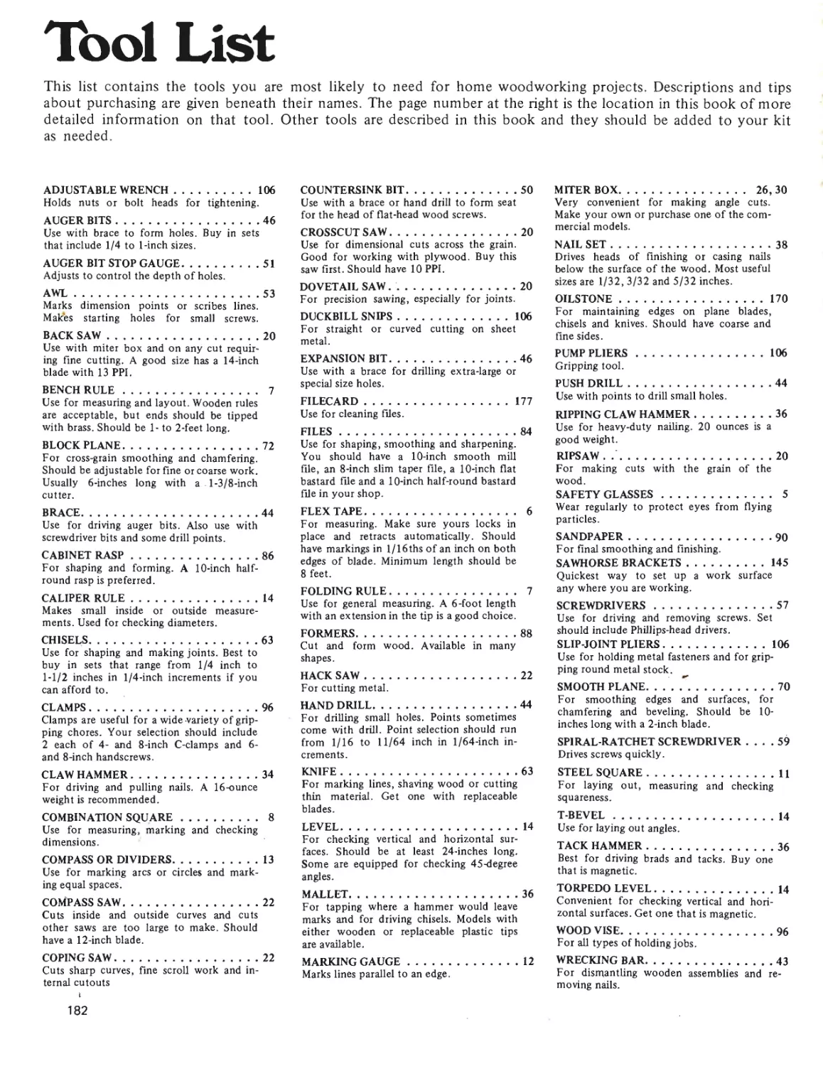
Tool List.......................... Page 182
What You Need.
Index................................Page 183
3
Introduction
Wouldn’t it be great if you could stare at your
fingers and they would become a plane or a chisel
or a hammer? Actually, this is what happens when
you hold a tool—your fingers form an intimate
bond between you and the tool. It is a marriage
of intellect and an inanimate object. Suddenly
the tool comes alive and performs . . . a miracle
anyone can accomplish. The keys are not secret
or a question of native ability. Interest plus Dedi-
cation equal Skill. The prime movers are in all of
us.
Tools don’t care whether their handler is an
amateur or a professional. A plane held and moved
a certain way will make the same cut for anyone.
The experienced worker has the advantage of trial-
and-error knowledge. If a plane skips and jumps,
or a saw chatters, or a screw refuses to set prop-
erly, stop and examine the problem. Don’t force
the tool. Find the reason for your trouble. This
book can help. Are you planing against the grain?
Is the piece you are sawing properly gripped and
supported? Are the lead holes for your screw
properly aligned? If you use your head as well as
your hands, you will find woodworking a creative,
relaxing avocation.
I have no doubt if you have not handled tools
yet—you can start right off and produce a project
you can be proud of. It may take you more time
than a neighbor who has been doing woodworking
for years, but there is no guarantee his project will
be better than yours.
Education is merely a foundation you build on.
It is necessary because no one is born with built-in
knowledge in any field. What you do with what
you learn is up to you. One thing is sure: Knowl-
edge doesn’t choose special individuals. You—the
individual—make the knowledge something special.
SAFETY-COUNT YOUR FINGERS
Any of the tools talked about in this book can
cut, scrape or bang you. You can read a book full
of do-and-don’t rules regarding safety and still be
in danger unless you accept and respect this simple
truth: Tools can’t think for you.
Tools are great buddies in a very disinterested
sort of way. They don’t care at all whether the user
is an amateur or an expert or what they are applied
to. Efficiency and even a large amount of safety
are part of quality tools, but in the final analysis
th£ worker is the most important factor.
I have worked with hand and power tools all
my life and like to boast that I am as whole as the
day I was born. I am afraid of tools—but it’s a
healthy fear that keeps me from becoming over-
confident and careless. I am aware that speed is
not as important as quality, and that fast work is
often more time-consuming than slow work. Your
output and quality will increase as you become
more proficient with tools, but it will be a natural
outcome—not the result of frenzied workshop
activities.
The first rules are:
• Work at a comfortable pace
• Be the master of the tools
• Don’t ever become overconfident.
DO AND DON’T RULES
Always use the correct tool for the job. Use the
tool correctly and, when called for, keep it sharp.
Put the tool away when you are through with it.
Keep the work area clean and well lighted. Having
a special shop uniform is a fine idea. An apron is
okay, but remember it does more to protect your
clothes than you.
A good first-aid kit should be a part of your basic tool set.
4
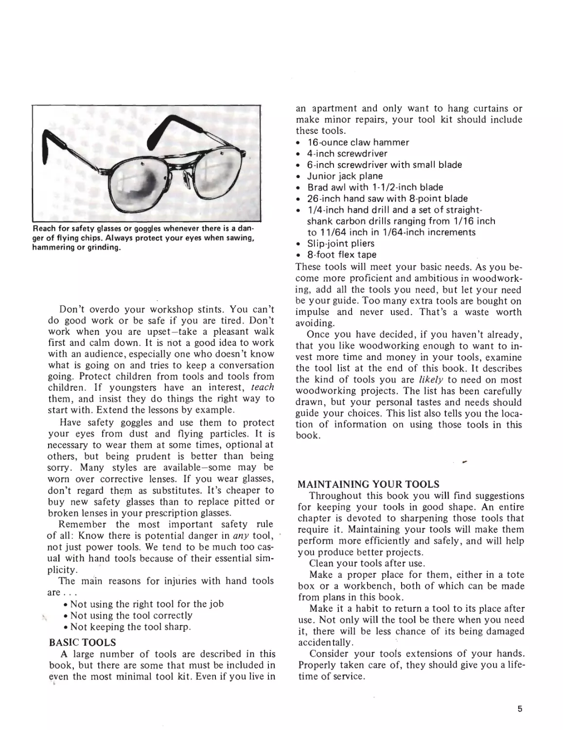
Reach for safety glasses or goggles whenever there is a dan-
ger of flying chips. Always protect your eyes when sawing,
hammering or grinding.
Don’t overdo your workshop stints. You can’t
do good work or be safe if you are tired. Don’t
work when you are upset—take a pleasant walk
first and calm down. It is riot a good idea to work
with an audience, especially one who doesn’t know
what is going on and tries to keep a conversation
going. Protect children from tools and tools from
children. If youngsters have an interest, teach
them, and insist they do things the right way to
start with. Extend the lessons by example.
Have safety goggles and use them to protect
your eyes from dust and flying particles. It is
necessary to wear them at some times, optional at
others, but being prudent is better than being
sorry. Many styles are available—some may be
worn over corrective lenses. If you wear glasses,
don’t regard them as substitutes. It’s cheaper to
buy new safety glasses than to replace pitted or
broken lenses in your prescription glasses.
Remember the most important safety rule
of all: Know there is potential danger in any tool,
not just power tools. We tend to be much too cas-
ual with hand tools because of their essential sim-
plicity.
The main reasons for injuries with hand tools
are . . .
• Not using the right tool for the job
• Not using the tool correctly
• Not keeping the tool sharp.
BASIC TOOLS
A large number of tools are described in this
book, but there are some that must be included in
even the most minimal tool kit. Even if you live in
an apartment and only want to hang curtains or
make minor repairs, your tool kit should include
these tools.
• 16-ounce claw hammer
• 4-inch screwdriver
• 6-inch screwdriver with small blade
• Junior jack plane
• Brad awl with 1-1/2-inch blade
• 26-inch hand saw with 8-point blade
• 1/4-inch hand drill and a set of straight-
shank carbon drills ranging from 1/16 inch
to 11/64 inch in 1/64-inch increments
• Slip-joint pliers
• 8-foot flex tape
These tools will meet your basic needs. As you be-
come more proficient and ambitious in woodwork-
ing, add all the tools you need, but let your need
be your guide. Too many extra tools are bought on
impulse and never used. That’s a waste worth
avoiding.
Once you have decided, if you haven’t already,
that you like woodworking enough to want to in-
vest more time and money in your tools, examine
the tool list at the end of this book. It describes
the kind of tools you are likely to need on most
woodworking projects. The list has been carefully
drawn, but your personal tastes and needs should
guide your choices. This list also tells you the loca-
tion of information on using those tools in this
book.
MAINTAINING YOUR TOOLS
Throughout this book you will find suggestions
for keeping your tools in good shape. An entire
chapter is devoted to sharpening those tools that
require it. Maintaining your tools will make them
perform more efficiently and safely, and will help
you produce better projects.
Clean your tools after use.
Make a proper place for them, either in a tote
box or a workbench, both of which can be made
from plans in this book.
Make it a habit to return a tool to its place after
use. Not only will the tool be there when you need
it, there will be less chance of its being damaged
accidentally.
Consider your tools extensions of your hands.
Properly taken care of, they should give you a life-
time of service.
5
Measuring
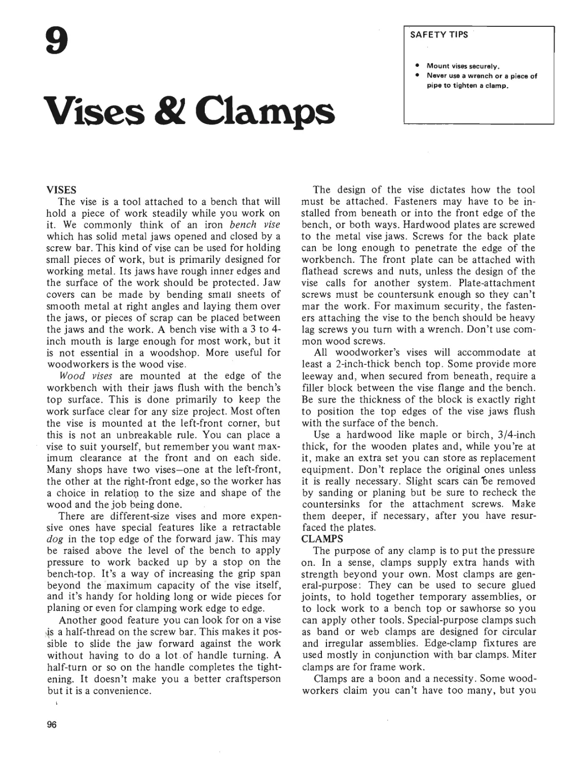
SAFETY TIPS
• Use the right tool for the job.
• Use the tool properly.
• Keep the tool in good condition.
• Put away tools you aren't using.
• Don't rush.
& Marking
The accuracy of any measuring device depends
on the user as much as on the design of the tool.
Many of us who work with wood get a little lax
because the tolerances are a bit larger than, say,
those in a machine shop. Actually, you should
strive to be as accurate as possible. Overage or
shortage of 1/32 or 1/16 inch on a shelf may not
be critical, but it can cause a lot of problems when
you are making a joint.
Marking the dimension point or line is as impor-
tant as placing and reading the rule properly. A
common practice is to place the rule flat and then
make a heavy, short line to mark the dimension. A
better way is to hold the rule on edge and slide
the point of the marker down the graduation line
so all you get on the work is a small dot. This is
easy to do with any rule with incised lines since
you have grooves for the point of the marker to
slide in. When the grooves are not present, mark
with the dot system anyway.
Cut lines may be marked with a hard pencil,
but you’ll get a finer line if you scribe with a knife.
Another advantage lies in letting the knife sever the
surface fibers. This helps you produce a smoother
line when you get to the sawing. If the knife-line
is difficult to see, you can mark over it with a
sharp pencil.
FLEX TAPES
These are the rules made of flexible-steel bands
that coil back into a small case. They are probably
today’s most popular measuring tool because they
are available in many sizes and for different appli-
cations. Blade widths run from 1/4 up to 1 inch;
lengths go up to 100 feet. Common graduations
are in inches marked off in 16ths and 8ths, but
they are also available in metric or in metric/
English so you can make conversions on the job.
Special tapes include those marked in lOthsand
lOOths, mason’s versions with modular graduations
for building block and brick, and even one that
tells loggers how many board feet can be cut from
a log.
A good tape will retract automatically and
smoothly. If it has a lock to hold the tape at any
extended position, so much the better. The blade
is usually coved, or curved across its width, which
gives it stiffness when extended. Wide tapes are
bulkier, but, when coved correctly, will span
greater distances. This may not be critical for
shop work, but can be a boon for on-location
jobs. Any tape under 8-feet long is inadequate in
a wood shop. You should be able to measure the
long dimension on a standard 4- x 8-foot plywood
panel. Needless to say, any tape should be clearly
readable, with fine, distinct graduation lines.
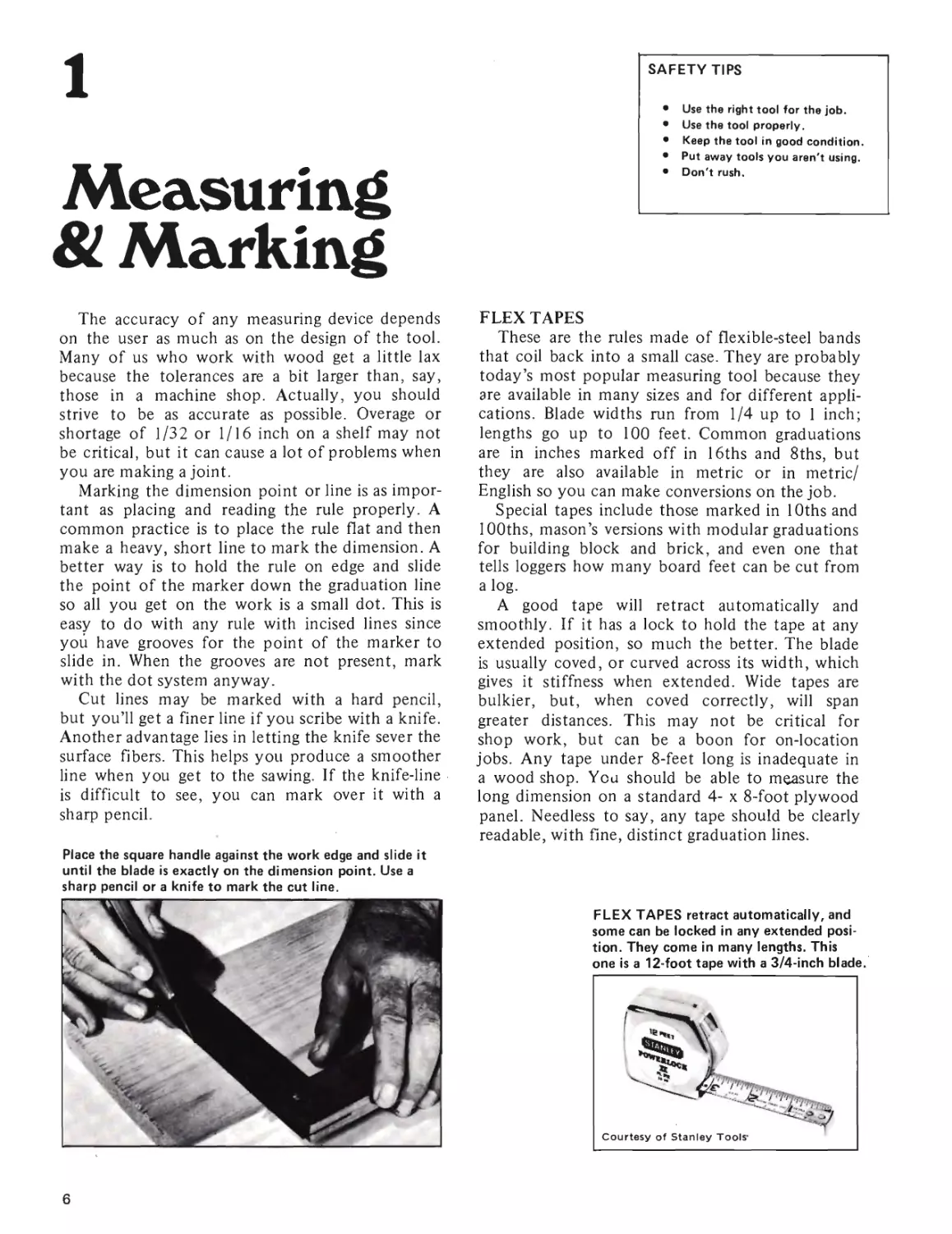
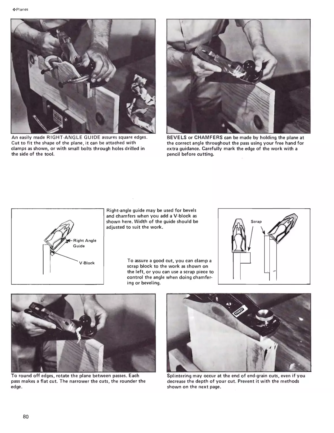
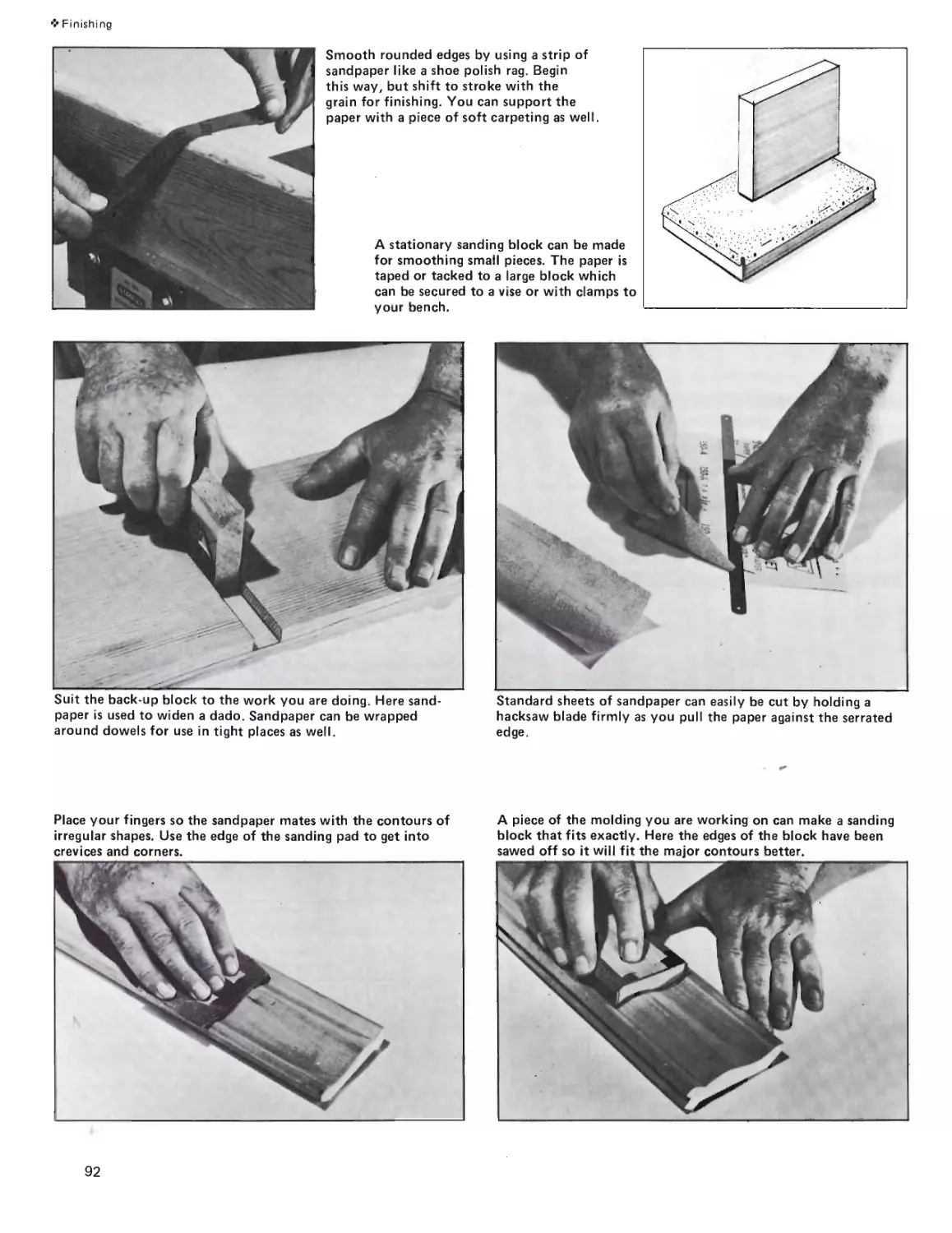
Place the square handle against the work edge and slide it
until the blade is exactly on the dimension point. Use a
sharp pencil or a knife to mark the cut line.
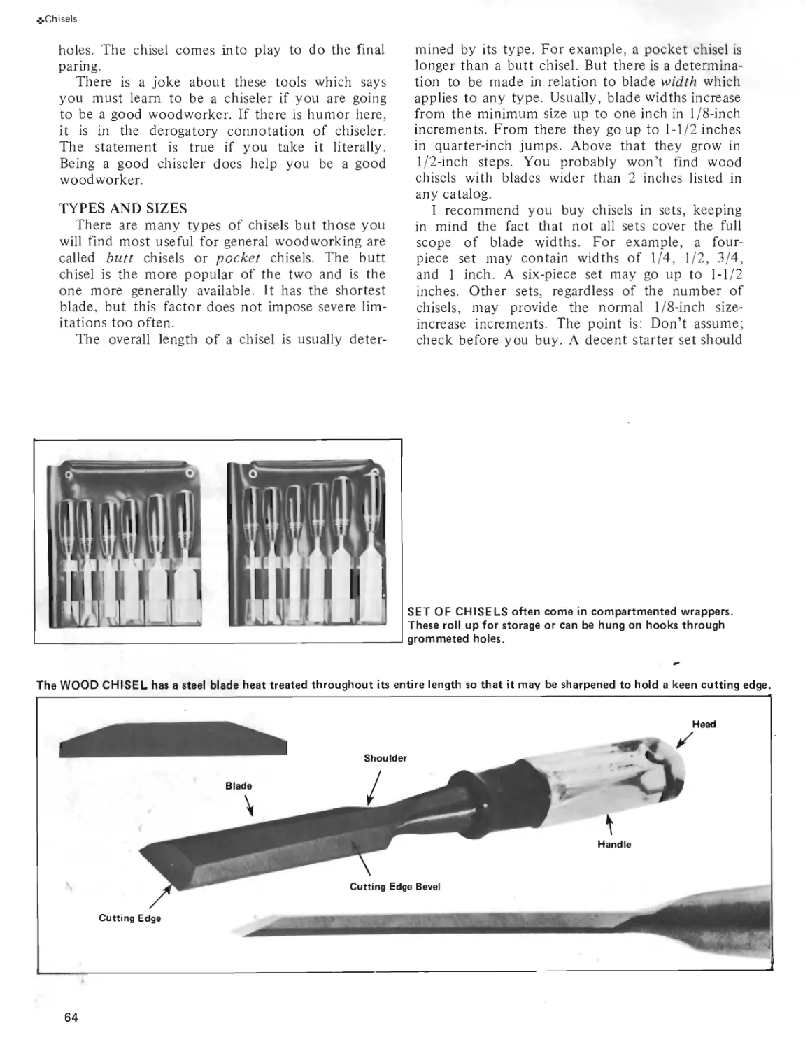
FLEX TAPES retract automatically, and
some can be locked in any extended posi-
tion. They come in many lengths. This
one is a 12-foot tape with a 3/4-inch blade.
6
❖Measuring
Tips can swivel or move to-and-fro, and either
type will let you do inside or outside measuring.
There are pro and con arguments for each design,
but the accuracy of the assembly is most impor-
tant. The swivel type requires you to move the tip
aside when you do a butt measurement—the other
automatically recesses into the blade and mini-
mizes the possibility of human error. Be sure the
recessing tip is always clean. Sawdust and dirt can
jam it and cause errors.
When you read the scale, and this holds true
for any measuring tool, look directly down on the
graduation line. Your line of sight should be at
right angles to the point regardless of the work
situation. Any other viewpoint can distort the
reading and cause inaccuracies. It is like reading a
speedometer from the left or right instead of head-
on.
An advantage of a flex tape is that you can
use it for non-straight measuring. For example,
you can wrap it around a circular object and read
off the circumference.
FOLDING RULE
These are most often called zigzag rules because
of the action they follow when opening or closing.
Most of them have a maximum length of 6 feet
and are 8-inches long in folded position. Many
woodworkers, especially carpenters, carry one in
addition to a flex tape and use it for most short
measurements. An advantage is that you can set
the first few blades at right angles to the rest of
the tool and reach overhead for a horizontal mea-
surement that might otherwise require standing
on a stool or ladder. Metal joints lock the rule in
folded or extended positions. When extended, it
is rigid enough to span openings.
When you buy, look for a folding rule with a
sliding brass extension built into the first blade.
This is calibrated and used when taking inside mea-
surements. The reading on the extension is added
to the amount of rule that is unfolded. This is
useful when measuring the opening of a door or
window, the width of an opening for a drawer,
and so on.
Like flex tapes, special folding rules are available
for engineers, masons and others, and in metric
or metric/English versions. Many modem rules
have permanently lubricated joints. If yours does
not, place a very small drop of light oil in the
joints occasionally.
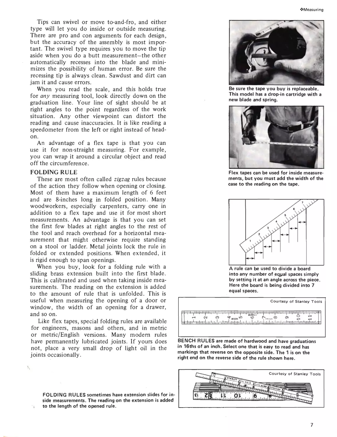
Be sure the tape you buy is replaceable.
This model has a drop-in cartridge with a
new blade and spring.
Flex tapes can be used for inside measure-
ments, but you must add the width of the
case to the reading on the tape.
into any number of equal spaces simply
by setting it at an angle across the piece.
Here the board is being divided into 7
equal spaces.
Courtesy of Stanley Tools
.................................1.....
r—I c\i CO ’T .. LO CO , co cn
iL 1111 1111 itI I nht 111 nfrlnrl iTrlm-l 11 i I; I! 11111 rl il 11 d П1}тп1|пглт1гн11111 itrhrtri гтт
FOLDING RULES sometimes have extension slides for in-
side measurements. The reading on the extension is added
to the length of the opened rule.
BENCH RULES are made of hardwood and have graduations
in 16ths of an inch. Select one that is easy to read and has
markings that reverse on the opposite side. The 1 is on the
right end on the reverse side of the rule shown here.
7
❖ Measuring
SQUARES
Squares are good for layout and for checking
cuts as well as for measuring and marking. One
basic use is as a guide for marking a line at right
angles to an edge. Another is checking that line
after you have cut it with a saw. In the latter cap-
acity, the blade of the square is placed on the sur-
face of the cut with the handle against an adjacent
edge. Both the tool and the work are held so you
can sight for openings between the blade and the
wood. Hold the pieces so you get backlighting
which makes errors more evident.
Try Square-For a long time this was the tool to
use and the fact that it is still listed in catalogs
indicates its continued acceptance. Such tools
have a metal blade and a metal or hardwood handle
fixed at a right angle. It is pretty much a single-
purpose tool unless the blade end of the handle is
provided with a 45-degree angle. In that case it’s
called a miter square and has the added feature of
being able to indicate 45-degree angles.
Blade lengths run from 6 to 12 inches with han-
dles of 4 to 8 inches. Size selection should be based
on intended use. A blade of 8 or 10 inches would
be minimum for average use in a wood shop.
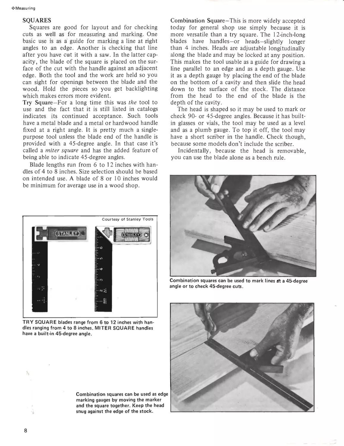
TRY SQUARE blades range from 6 to 12 inches with han-
dles ranging from 4 to 8 inches. MITER SQUARE handles
have a built-in 45-degree angle.
Combination squares can be used as edge
marking gauges by moving the marker
and the square together. Keep the head
snug against the edge of the stock.
Combination Square—This is more widely accepted
today for general shop use simply because it is
more versatile than a try square. The 12-inch-long
blades have handles—or heads—slightly longer
than 4 inches. Heads are adjustable longitudinally
along the blade and may be locked at any position.
This makes the tool usable as a guide for drawing a
line parallel to an edge and as a depth gauge. Use
it as a depth gauge by placing the end of the blade
on the bottom of a cavity and then slide the head
down to the surface of the stock. The distance
from the head to the end of the blade is the
depth of the cavity.
The head is shaped so it may be used to mark or
check 90- or 45-degree angles. Because it has built-
in glasses or vials, the tool may be used as a level
and as a plumb gauge. To top it off, the tool may
have a short scriber in the handle. Check though,
because some models don’t include the scriber.
Incidentally, because the head is removable,
you can use the blade alone as a bench rule.
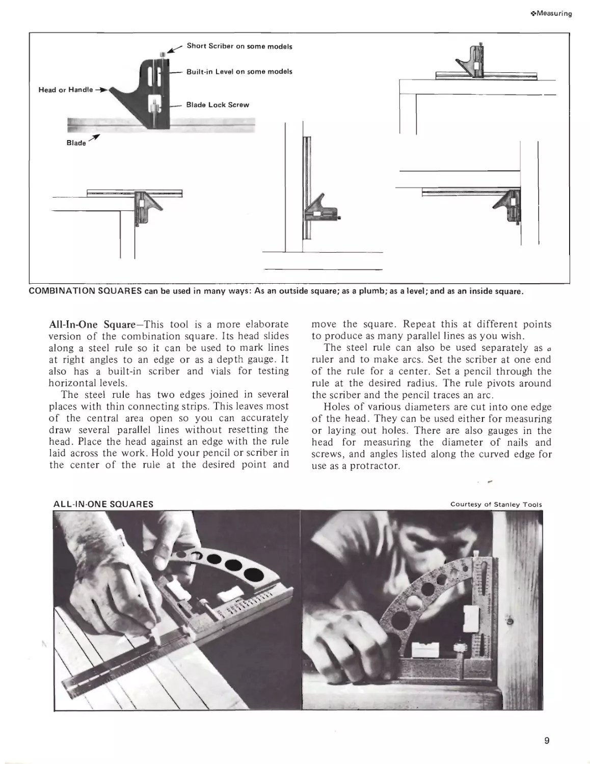
Combination squares can be used to mark lines Л a 45-degree
angle or to check 45-degree cuts.
8
<• Measuring
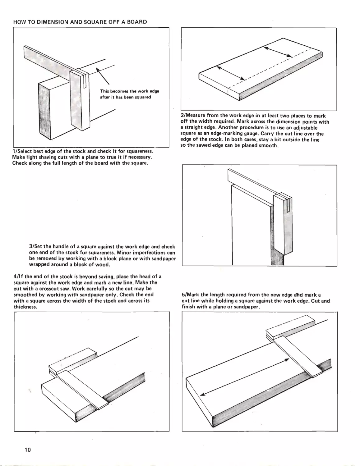
COMBINATION SQUARES can be used in many ways: As an outside square; as a plumb; as a level; and as an inside square.
All-In-One Square—This tool is a more elaborate
version of the combination square. Its head slides
along a steel rule so it can be used to mark lines
at right angles to an edge or as a depth gauge. It
also has a built-in scriber and vials for testing
horizontal levels.
The steel rule has two edges joined in several
places with thin connecting strips. This leaves most
of the central area open so you can accurately
draw several parallel lines without resetting the
head. Place the head against an edge with the rule
laid across the work. Hold your pencil or scriber in
the center of the rule at the desired point and
move the square. Repeat this at different points
to produce as many parallel lines as you wish.
The steel rule can also be used separately as a
ruler and to make arcs. Set the scriber at one end
of the rule for a center. Set a pencil through the
rule at the desired radius. The rule pivots around
the scriber and the pencil traces an arc.
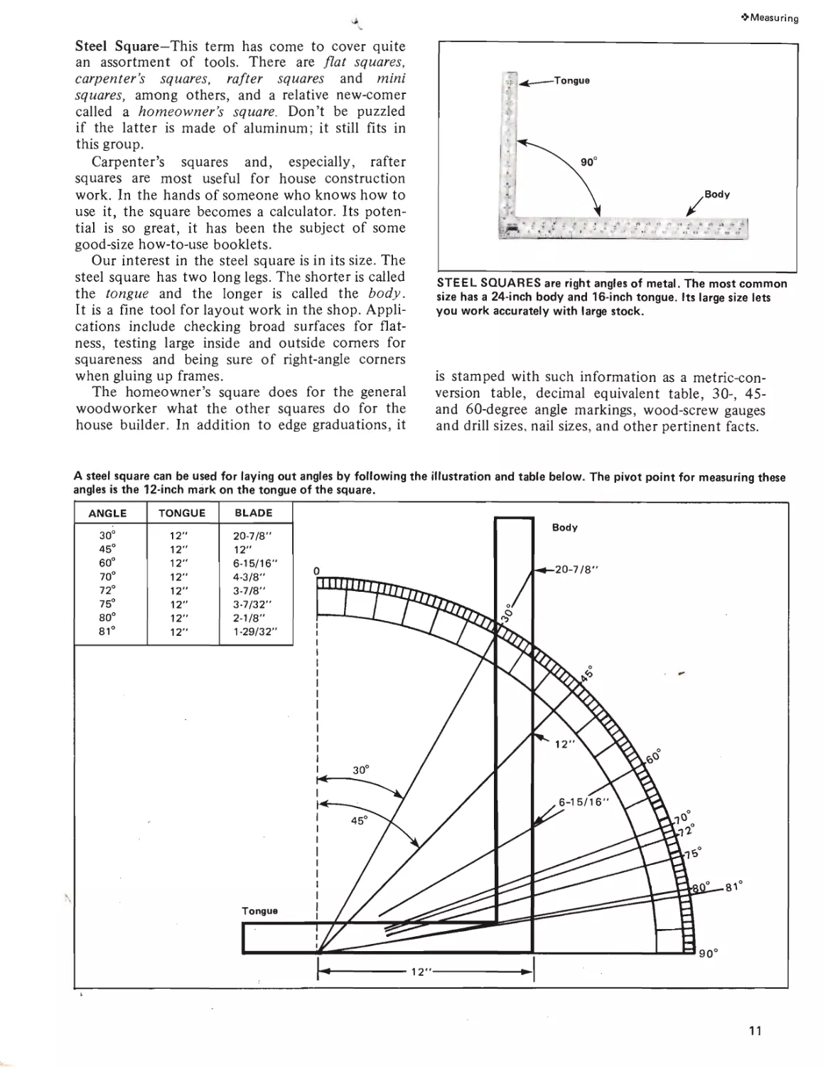
Holes of various diameters are cut into one edge
of the head. They can be used either for measuring
or laying out holes. There are also gauges in the
head for measuring the diameter of nails and
screws, and angles listed along the curved edge for
use as a protractor.
ALL-IN-ONE SQUARES
Courtesy of Stanley Tools
9
HOW TO DIMENSION AND SQUARE OFF A BOARD
1/Select best edge of the stock and check it for squareness.
Make light shaving cuts with a plane to true it if necessary.
Check along the full length of the board with the square.
3/Set the handle of a square against the work edge and check
one end of the stock for squareness. Minor imperfections can
be removed by working with a block plane or with sandpaper
wrapped around a block of wood.
2/Measure from the work edge in at least two places to mark
off the width required. Mark across the dimension points with
a straight edge. Another procedure is to use an adjustable
square as an edge-marking gauge. Carry the cut line over the
edge of the stock. In both cases, stay a bit outside the line
so the sawed edge can be planed smooth.
4/lf the end of the stock is beyond saving, place the head of a
square against the work edge and mark a new line. Make the
cut with a crosscut saw. Work carefully so the cut may be
smoothed by working with sandpaper only. Check the end
with a square across the width of the stock and across its
5/Mark the length required from the new edge tffid mark a
cut line while holding a square against the work edge. Cut and
finish with a plane or sandpaper.
10
❖ Measuring
Steel Square—This term has come to cover quite
an assortment of tools. There are flat squares,
carpenter’s squares, rafter squares and mini
squares, among others, and a relative new-comer
called a homeowner’s square. Don’t be puzzled
if the latter is made of aluminum; it still fits in
this group.
Carpenter’s squares and, especially, rafter
squares are most useful for house construction
work. In the hands of someone who knows how to
use it, the square becomes a calculator. Its poten-
tial is so great, it has been the subject of some
good-size how-to-use booklets.
Our interest in the steel square is in its size. The
steel square has two long legs. The shorter is called
the tongue and the longer is called the body.
It is a fine tool for layout work in the shop. Appli-
cations include checking broad surfaces for flat-
ness, testing large inside and outside comers for
squareness and being sure of right-angle corners
when gluing up frames.
The homeowner’s square does for the general
woodworker what the other squares do for the
house builder. In addition to edge graduations, it
STEEL SQUARES are right angles of metal. The most common
size has a 24-inch body and 16-inch tongue. Its large size lets
you work accurately with large stock.
is stamped with such information as a metric-con-
version table, decimal equivalent table, 30-, 45-
and 60-degree angle markings, wood-screw gauges
and drill sizes, nail sizes, and other pertinent facts.
ANGLE TONGUE BLADE
30° 12" 20-7/8"
45° 12" 12"
60° 12" 6-15/16"
70° 12" 4-3/8"
72° 12" 3-7/8"
75° 12" 3-7/32"
80° 12" 2-1/8"
81° 12" 1-29/32"
A steel square can be used for laying out angles by following the illustration and table below. The pivot point for measuring these
angles is the 12-inch mark on the tongue of the square.
11
Measuring
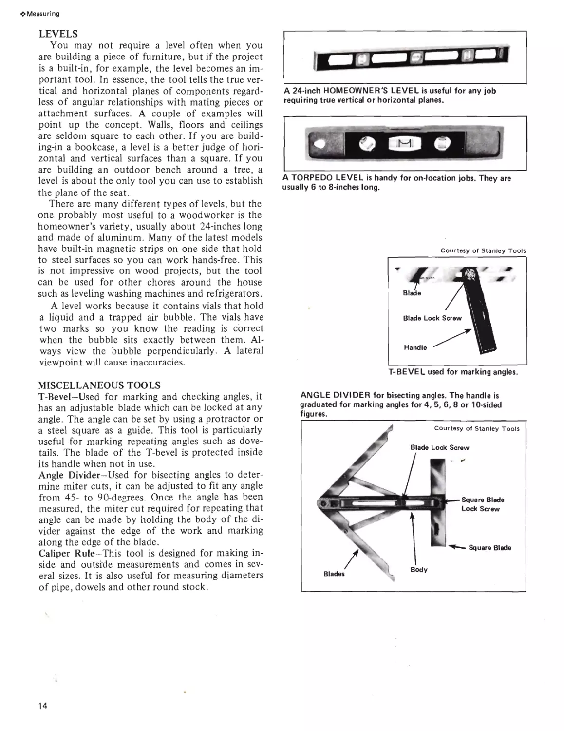
MARKING GAUGE
The marking gauge is one of the more accurate
tools for marking lines parallel to an edge. The
required distance is set by measuring from the
point of the marking pin to the face plate, or by
taking a reading directly from the scale on the
beam. Loosen the lock screw just enough to permit
the head to slide. Recheck the setting after secur-
ing the head. It’s never necessary to really bear
down on the lock screw. Doing so can strip the
threads which are cut directly in the wood.
Handle the tool with a gentle touch—its only
purpose is to mark a guide line. In some situations
it’s wise to hold the head in your palm with your
thumb extended to back up the pin. This doesn’t
always work because there is a limit to how far
you can stretch your thumb. Don’t allow the pin to
project any more than it must to mark the work.
Set it so the flat points away from the head and is
parallel to the line you are marking. Be especially
careful with pin projection when you are marking
cross-grain to avoid tearing surface fibers.
Be sure to keep the head snug against the work
throughout the pass. You may find it more con-
venient to push the tool rather than pull it. The
work you are marking and the grain of the wood
may have a bearing on this. Make your own judg-
ment—the important thing is to be accurate.
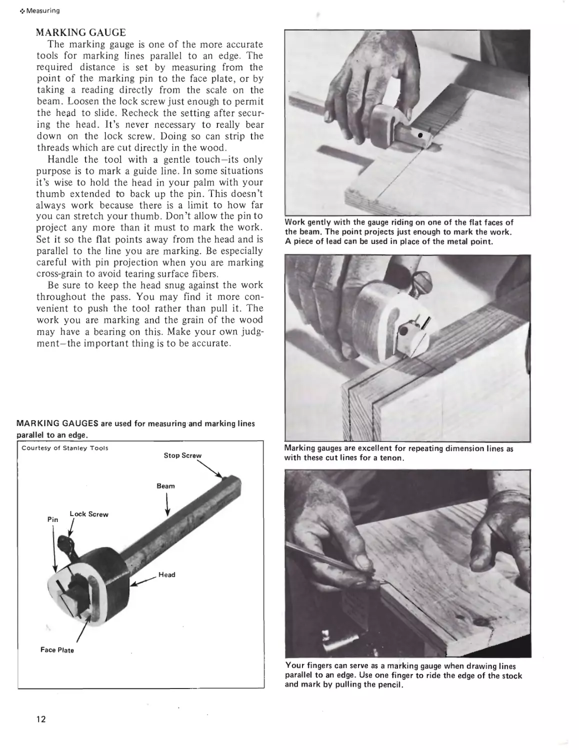
Work gently with the gauge riding on one of the flat faces of
the beam. The point projects just enough to mark the work.
A piece of lead can be used in place of the metal point.
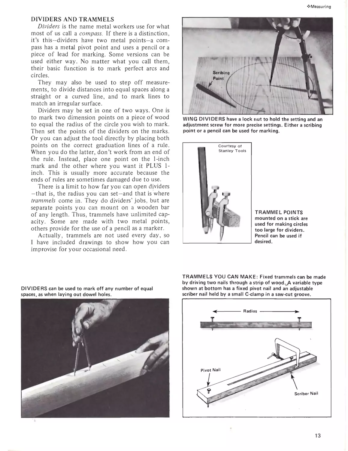
Marking gauges are excellent for repeating dimension lines as
with these cut lines for a tenon.
MARKING GAUGES are used for measuring and marking lines
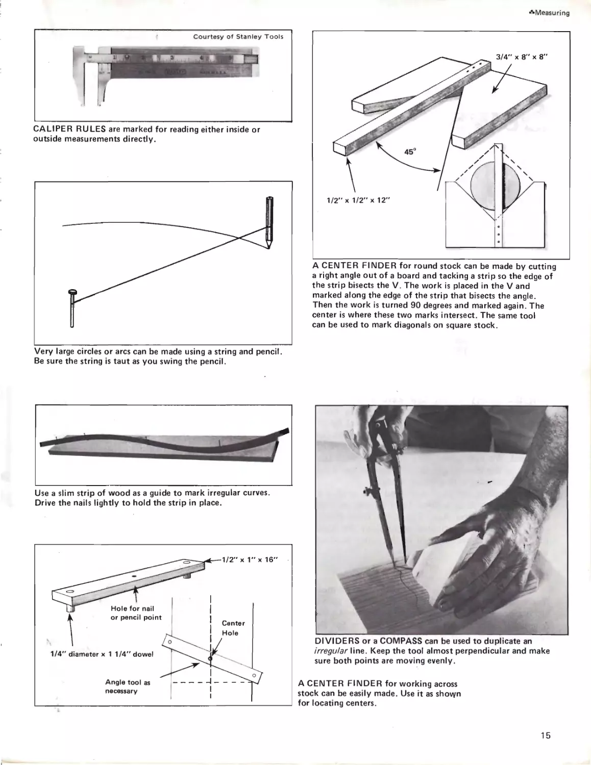
Your fingers can serve as a marking gauge when drawing lines
parallel to an edge. Use one finger to ride the edge of the stock
and mark by pulling the pencil.
12
•’•Measuring
DIVIDERS AND TRAMMELS
Dividers is the name metal workers use for what
most of us call a compass. If there is a distinction,
it’s this—dividers have two metal points—a com-
pass has a metal pivot point and uses a pencil or a
piece of lead for marking. Some versions can be
used either way. No matter what you call them,
their basic function is to mark perfect arcs and
circles.
They may also be used to step off measure-
ments, to divide distances into equal spaces along a
straight or a curved line, and to mark lines to
match an irregular surface.
Dividers may be set in one of two ways. One is
to mark two dimension points on a piece of wood
to equal the radius of the circle you wish to mark.
Then set the points of the dividers on the marks.
Or you can adjust the tool directly by placing both
points on the correct graduation lines of a rule.
When you do the latter, don’t work from an end of
the rule. Instead, place one point on the 1-inch
mark and . the other where you want it PLUS 1-
inch. This is usually more accurate because the
ends of rules are sometimes damaged due to use.
There is a limit to how far you can open dividers
—that is, the radius you can set—and that is where
trammels come in. They do dividers’ jobs, but are
separate points you can mount on a wooden bar
of any length. Thus, trammels have unlimited cap-
acity. Some are made with two metal points,
others provide for the use of a pencil as a marker.
Actually, trammels are not used every day, so
I have included drawings to show how you can
improvise for your occasional need.
WING DIVIDERS have a lock nut to hold the setting and an
adjustment screw for more precise settings. Either a scribing
point or a pencil can be used for marking.
TRAMMEL POINTS
mounted on a stick are
used for making circles
too large for dividers.
Pencil can be used if
desired.
DIVIDERS can be used to mark off any number of equal
spaces, as when laying out dowel holes.
TRAMMELS YOU CAN MAKE: Fixed trammels can be made
by driving two nails through a strip of wood.yX variable type
shown at bottom has a fixed pivot nail and an adjustable
scriber nail held by a small C-clamp in a saw-cut groove.
13
<• Measuring
LEVELS
You may not require a level often when you
are building a piece of furniture, but if the project
is a built-in, for example, the level becomes an im-
portant tool. In essence, the tool tells the true ver-
tical and horizontal planes of components regard-
less of angular relationships with mating pieces or
attachment surfaces. A couple of examples will
point up the concept. Walls, floors and ceilings
are seldom square to each other. If you are build-
ing-in a bookcase, a level is a better judge of hori-
zontal and vertical surfaces than a square. If you
are building an outdoor bench around a tree, a
level is about the only tool you can use to establish
the plane of the seat.
There are many different types of levels, but the
one probably most useful to a woodworker is the
homeowner’s variety, usually about 24-inches long
and made of aluminum. Many of the latest models
have built-in magnetic strips on one side that hold
to steel surfaces so you can work hands-free. This
is not impressive on wood projects, but the tool
can be used for other chores around the house
such as leveling washing machines and refrigerators.
A level works because it contains vials that hold
a liquid and a trapped air bubble. The vials have
two marks so you know the reading is correct
when the bubble sits exactly between them. Al-
ways view the bubble perpendicularly. A lateral
viewpoint will cause inaccuracies.
MISCELLANEOUS TOOLS
Т-Bevel—Used for marking and checking angles, it
has an adjustable blade which can be locked at any
angle. The angle can be set by using a protractor or
a steel square as a guide. This tool is particularly
useful for marking repeating angles such as dove-
tails. The blade of the T-bevel is protected inside
its handle when not in use.
Angle Divider—Used for bisecting angles to deter-
mine miter cuts, it can be adjusted to fit any angle
from 45- to 90-degrees. Once the angle has been
measured, the miter cut required for repeating that
angle can be made by holding the body of the di-
vider against the edge of the work and marking
along the edge of the blade.
Caliper Rule—This tool is designed for making in-
side and outside measurements and comes in sev-
eral sizes. It is also useful for measuring diameters
of pipe, dowels and other round stock.
A 24-inch HOMEOWNER'S LEVEL is useful for any job
requiring true vertical or horizontal planes.
A TORPEDO LEVEL is handy for on-location jobs. They are
usually 6 to 8-inches long.
T-BEVEL used for marking angles.
ANGLE DIVIDER for bisecting angles. The handle is
graduated for marking angles for 4, 5, 6, 8 or 10-sided
figures.
14
AMeasuring
Courtesy of Stanley Tools
CALIPER RULES are marked for reading either inside or
outside measurements directly.
Very large circles or arcs can be made using a string and pencil.
Be sure the string is taut as you swing the pencil.
A CENTER FINDER for round stock can be made by cutting
a right angle out of a board and tacking a strip so the edge of
the strip bisects the V. The work is placed in the V and
marked along the edge of the strip that bisects the angle.
Then the work is turned 90 degrees and marked again. The
center is where these two marks intersect. The same tool
can be used to mark diagonals on square stock.
Use a slim strip of wood as a guide to mark irregular curves.
Drive the nails lightly to hold the strip in place.
A CENTER FINDER for working across
stock can be easily made. Use rt as shovyn
for locating centers.
DIVIDERS or a COMPASS can be used to duplicate an
irregular line. Keep the tool almost perpendicular and make
sure both points are moving evenly.
15
2
Saws
SAFETY TIP
• Blades should be sharp; dull blades
slip, stick or skip and cause
injuries.
It seems likely that the very first saw was a thin,
flat stone with an edge rough enough to abrade
through a bone, or a piece of tough meat, or a
small branch. The next step was to search for a
more suitably shaped stone or, as the innovative
member of the group probably did, to chip away
at the edge of the original stone to thin it. That
brainy person could have been responsible for the
first manufactured serrated cutting edge.
Guesswork stops with the introduction of real
archeological evidence of saw-forms roughly
shaped from flint. Such items have been found
among the remains of Neanderthal man and he
goes back about 130,000 years. Such finds are not
isolated, but cover areas in France, Denmark,
Sweden, Switzerland, Northern Italy, and other
places.
If the history of the saw were to be well re-
searched, it would show a slow but steady evolu-
tion with contributions to its development by the
peoples of many nations. An interesting fact that
would emerge is how little the basic concept has
changed. We may eventually cut wood with laser
beams or the like, but as of now, we still use a thin
piece of material with a serrated edge.
The modern, efficient saw—and this applies to
many other tools as well—did not appear until the
advent of the Iron Age. The steps from this to
steel, plus the sophisticated technology for hand-
ling materials, have resulted in the super products
we enjoy today.
IN GENERAL
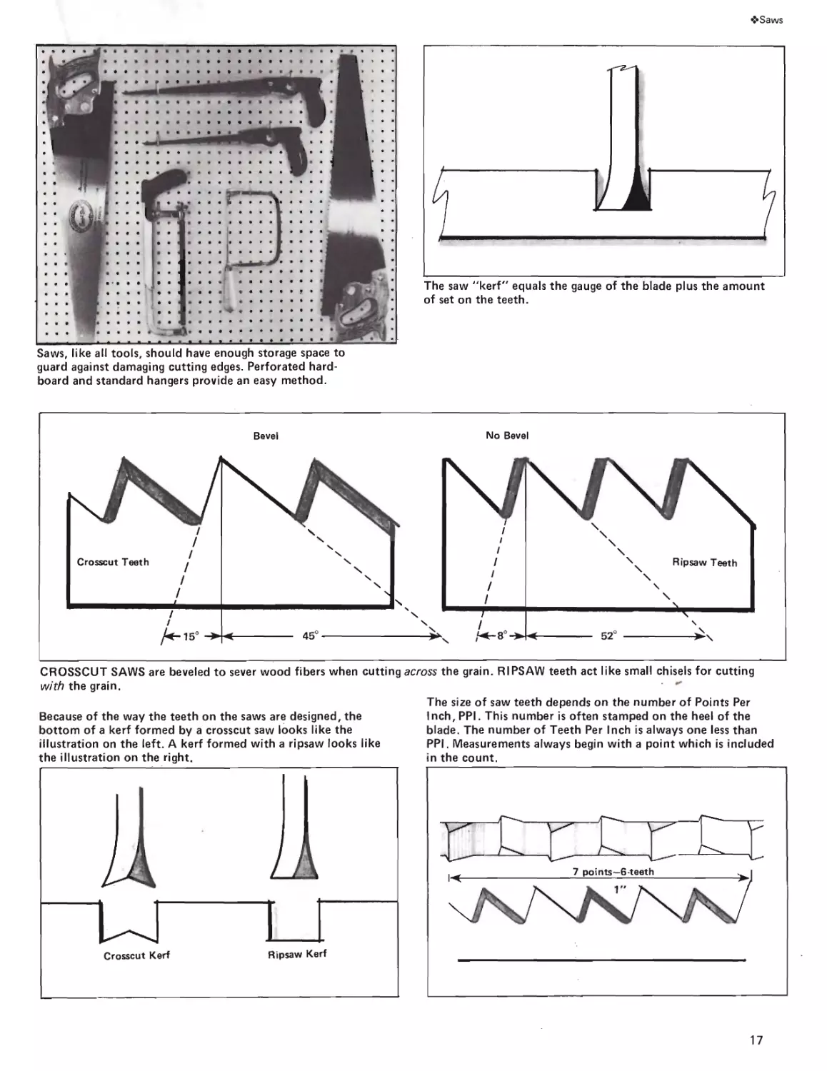
A saw cuts- because it has teeth—it cuts more
freely because the teeth are set. This merely means
alternate teeth are bent in opposite directions away
from the body of the blade. The idea is for the
kerf— the actual opening made in the wood when
you saw—to be wider than the thickness, or gauge
of the blade. Sawing is possible without set, but it
would be more difficult to stroke the tool because
the blade would be rubbing constantly against
the sides of the kerf.
The relief provided by the set is increased when
the blade is taper-ground. This is evident on a good-
quality saw where the blade is thinner at the back
edge than at the toothed edge. In essence, this
shape puts less blade thickness in the kerf. Top-
quality saws have a secondary taper which is wider
at the handle-end than at the toe. Taper grinding
makes it possible to minimize set and this results
in a tool that produces smoother cuts. It also con-
tributes to the proper distribution of thickness
and this helps to achieve good balance and flex-
ibility.
POINTS
Whether a saw will cut “coarse” or “fine” is
told by the number of points per inch—PPI. The
more points, the more teeth per inch. Actually, if
you deduct one from the PPI, you will know the
number of teeth per inch. What’s important to
user is this—the more PPI, the smaller the teeth
will be. This means slower cutting and smoother
results. Thus finesse tools like the backsaw and the
dovetail saw have a lot more PPI than the conven-
tional crosscut saw or ripsaw.
The PPI—and the shape of the teeth—are also
affected by the job the tool must do. Crosscut
teeth are designed to slick across the grain of the
wood like so many small, sharp knives. The teeth
are bevel-filed and the cutting edges slant at a
sharp angle so a shearing action—as opposed to a
chiseling action—results.
Ripsaw teeth are filed straight across with cut-
ting edges almost perpendicular to the blade. This
is good for cutting with the grain of the wood be-
cause each tooth acts like a tiny chisel, chipping
out its own bit of wood.
Another relevant factor is the less the PPI, the
larger each tooth can be. Thus, there are deeper
gullets between teeth which provide more room for
larger waste chips. This helps to prevent clogging
when the tooth takes a big bite, as when you are
cutting green or wet wood. You have more choice
of PPI in crosscut saws than you do with ripsaws.
16
❖Saws
Saws, like ail tools, should have enough storage space to
guard against damaging cutting edges. Perforated hard-
board and standard hangers provide an easy method.
The saw "kerf" equals the gauge of the blade plus the amount
of set on the teeth.
CROSSCUT SAWS are beveled to sever wood fibers when cutting across the grain. RIPSAW teeth act like small chisels for cutting
with the grain.
Because of the way the teeth on the saws are designed, the
bottom of a kerf formed by a crosscut saw looks like the
illustration on the left. A kerf formed with a ripsaw looks like
The size of saw teeth depends on the number of Points Per
Inch, PPI. This number is often stamped on the heel of the
blade. The number of Teeth Per Inch is always one less than
PPI. Measurements always begin with a point which is included
17
❖Saws
CROWNED SAWS
You won’t find this on all saws, but many ex-
perts look for it as an indication of careful design-
ing and super quality. A crowned saw is one where
the silhouette of the toothed edge shows a gentle
arc rather than a straight line from the heel to the
toe. The reason for the shape is to obtain maxi-
mum cutting effect with minimum drag. The arc
brings fewer teeth into contact with the wood
fibers. While you don’t have as many teeth in
full contact, those that are cut deeper, faster and
easier.
My personal observation, regardless of whether
a crowned saw helps you cut faster, is that it con-
tributes a degree of naturalness to the stroke. This
reduces fatigue and brings you closer to expertise.
In this sense it even contributes to the life of the
tool or, at least, to the prolonged sharpness of the
cutting edges. Good, clean stroking promotes
proper use.
This personal reaction to a product is something
you will have to contend with regardless of the
tool in question. Quite often, and assuming similar,
basic characteristics among an assortment of like
tools, the one that looks good, feels good, and
mates nicely with your hands as you work is the
tool you will swear by.
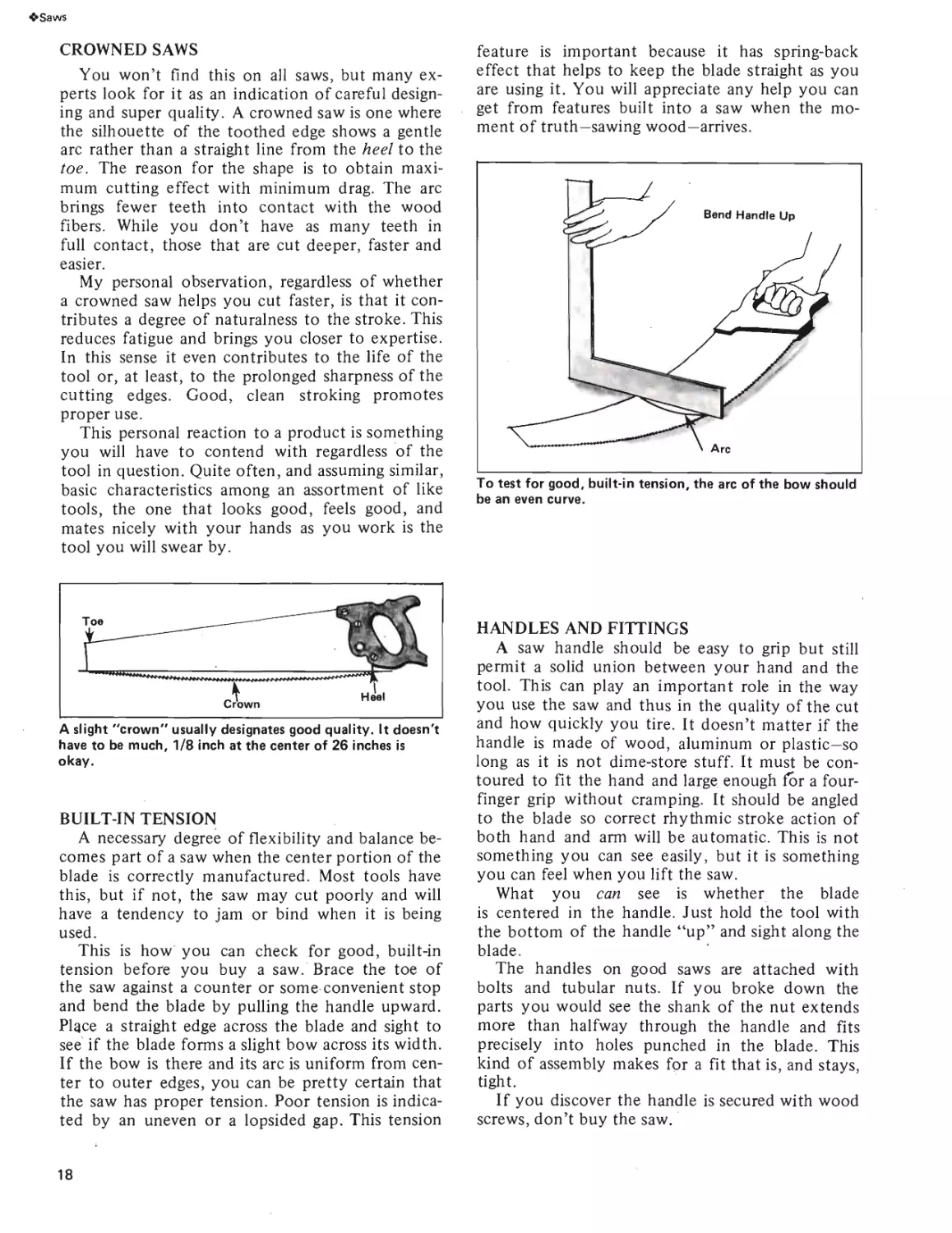
feature is important because it has spring-back
effect that helps to keep the blade straight as you
are using it. You will appreciate any help you can
get from features built into a saw when the mo-
ment of truth—sawing wood—arrives.
To test for good, built-in tension, the arc of the bow should
be an even curve.
A slight "crown" usually designates good quality. It doesn't
have to be much, 1/8 inch at the center of 26 inches is
okay.
BUILT-IN TENSION
A necessary degree of flexibility and balance be-
comes part of a saw when the center portion of the
blade is correctly manufactured. Most tools have
this, but if not, the saw may cut poorly and will
have a tendency to jam or bind when it is being
used.
This is how you can check for good, built-in
tension before you buy a saw. Brace the toe of
the saw against a counter or some convenient stop
and bend the blade by pulling the handle upward.
Plqce a straight edge across the blade and sight to
see if the blade forms a slight bow across its width.
If the bow is there and its arc is uniform from cen-
ter to outer edges, you can be pretty certain that
the saw has proper tension. Poor tension is indica-
ted by an uneven or a lopsided gap. This tension
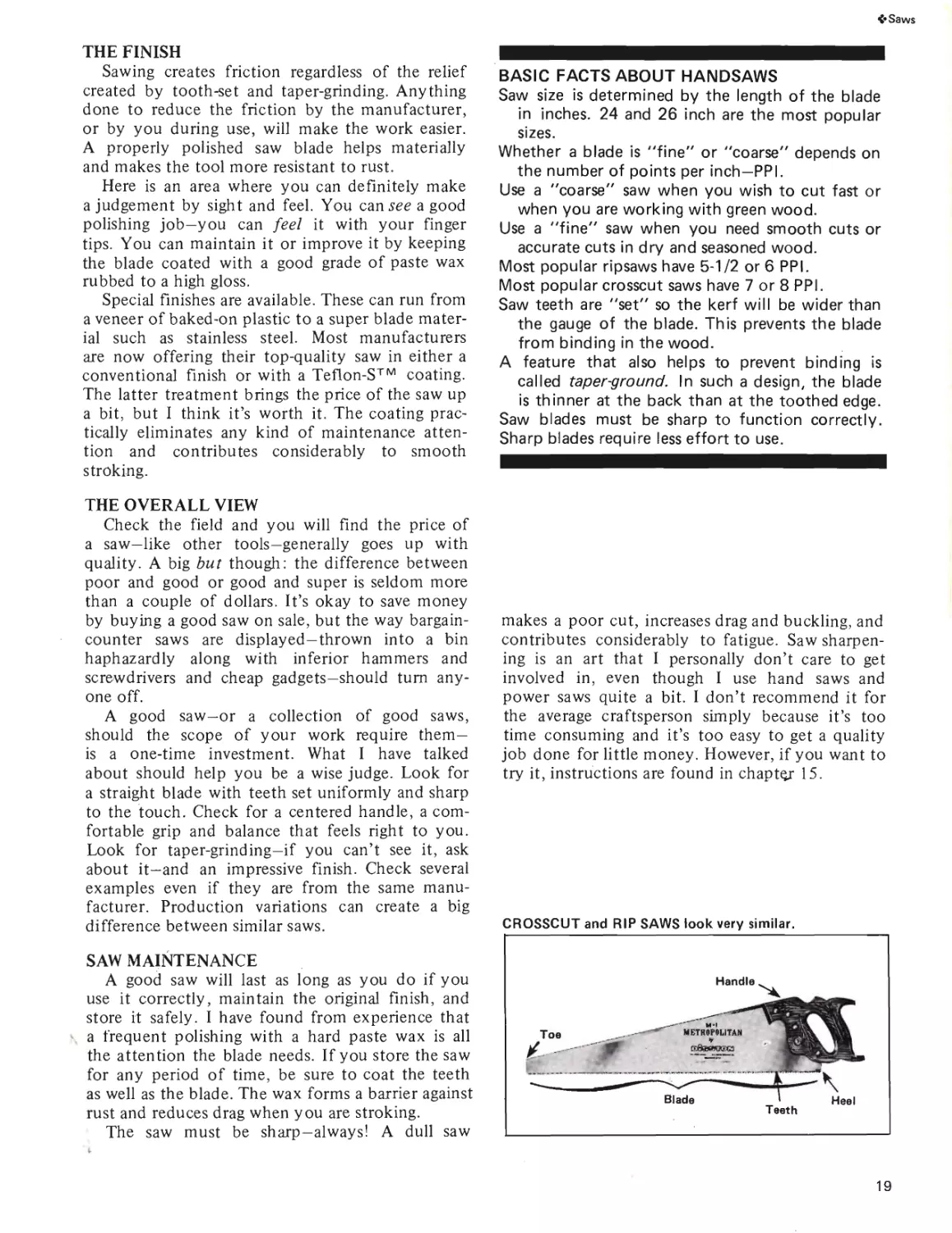
HANDLES AND FITTINGS
A saw handle should be easy to grip but still
permit a solid union between your hand and the
tool. This can play an important role in the way
you use the saw and thus in the quality of the cut
and how quickly you tire. It doesn’t matter if the
handle is made of wood, aluminum or plastic—so
long as it is not dime-store stuff. It must be con-
toured to fit the hand and large enough for a four-
finger grip without cramping. It should be angled
to the blade so correct rhythmic stroke action of
both hand and arm will be automatic. This is not
something you can see easily, but it is something
you can feel when you lift the saw.
What you can see is whether the blade
is centered in the handle. Just hold the tool with
the bottom of the handle “up” and sight along the
blade.
The handles on good saws are attached with
bolts and tubular nuts. If you broke down the
parts you would see the shank of the nut extends
more than halfway through the handle and fits
precisely into holes punched in the blade. This
kind of assembly makes for a fit that is, and stays,
tight.
If you discover the handle is secured with wood
screws, don’t buy the saw.
18
<*Saws
THE FINISH
Sawing creates friction regardless of the relief
created by tooth-set and taper-grinding. Anything
done to reduce the friction by the manufacturer,
or by you during use, will make the work easier.
A properly polished saw blade helps materially
and makes the tool more resistant to rust.
Here is an area where you can definitely make
a judgement by sight and feel. You can see a good
polishing job—you can feel it with your finger
tips. You can maintain it or improve it by keeping
the blade coated with a good grade of paste wax
rubbed to a high gloss.
Special finishes are available. These can run from
a veneer of baked-on plastic to a super blade mater-
ial such as stainless steel. Most manufacturers
are now offering their top-quality saw in either a
conventional finish or with a Teflon-S™ coating.
The latter treatment brings the price of the saw up
a bit, but I think it’s worth it. The coating prac-
tically eliminates any kind of maintenance atten-
tion and contributes considerably to smooth
stroking.
THE OVERALL VIEW
Check the field and you will find the price of
a saw—like other tools—generally goes up with
quality. A big but though: the difference between
poor and good or good and super is seldom more
than a couple of dollars. It’s okay to save money
by buying a good saw on sale, but the way bargain-
counter saws are displayed—thrown into a bin
haphazardly along with inferior hammers and
screwdrivers and cheap gadgets—should turn any-
one off.
A good saw-or a collection of good saws,
should the scope of your work require them—
is a one-time investment. What I have talked
about should help you be a wise judge. Look for
a straight blade with teeth set uniformly and sharp
to the touch. Check for a centered handle, a com-
fortable grip and balance that feels right to you.
Look for taper-grinding—if you can’t see it, ask
about it—and an impressive finish. Check several
examples even if they are from the same manu-
facturer. Production variations can create a big
difference between similar saws.
SAW MAINTENANCE
A good saw will last as long as you do if you
use it correctly, maintain the original finish, and
store it safely. I have found from experience that
a frequent polishing with a hard paste wax is all
the attention the blade needs. If you store the saw
for any period of time, be sure to coat the teeth
as well as the blade. The wax forms a barrier against
rust and reduces drag when you are stroking.
The saw must be sharp—always! A dull saw
BASIC FACTS ABOUT HANDSAWS
Saw size is determined by the length of the blade
in inches. 24 and 26 inch are the most popular
sizes.
Whether a blade is "fine" or "coarse" depends on
the number of points per inch—PPI.
Use a "coarse" saw when you wish to cut fast or
when you are working with green wood.
Use a "fine" saw when you need smooth cuts or
accurate cuts in dry and seasoned wood.
Most popular ripsaws have 5-1/2 or 6 PPI.
Most popular crosscut saws have 7 or 8 PPI.
Saw teeth are "set" so the kerf will be wider than
the gauge of the blade. This prevents the blade
from binding in the wood.
A feature that also helps to prevent binding is
called taper-ground. In such a design, the blade
is thinner at the back than at the toothed edge.
Saw blades must be sharp to function correctly.
Sharp blades require less effort to use.
makes a poor cut, increases drag and buckling, and
contributes considerably to fatigue. Saw sharpen-
ing is an art that I personally don’t care to get
involved in, even though I use hand saws and
power saws quite a bit. I don’t recommend it for
the average craftsperson simply because it’s too
time consuming and it’s too easy to get a quality
job done for little money. However, if you want to
try it, instructions are found in chapter 15.
CROSSCUT and RIP SAWS look very similar.
19
<»Saws
THE BASIC SAWS
Crosscut Saws—The crosscut saw—as the name
says-is designed for cutting across the grain of
the wood. Its teeth are shaped to cut like sharp-
pointed knives so they sever wood fibers rather
than tear them. If the experienced cabinetmaker
or carpenter had to limit himself to one saw, he
would probably choose the crosscut design be-
cause it comes closest to being all-purpose. It does
the optimum job across the grain and when used at
an angle to the grain as in miter cuts. It does a
respectable job when used with the grain although
it would lose a speed race if competing with a
ripsaw. It is the best saw to use on plywoods
because its smaller teeth do minimum damage
to surface veneers. For similar reasons, it is a wise
choice for cutting hardboards, particle boards
and the like.
Average blade-lengths are 16, 20, 24 or 26
inches with PPI running from 7 to 12. The lower
the PPI number, the faster the cut, but you pay
for speed in cut-quality. More teeth make smooth-
er cuts-а fact that applies generally to all saws.
Blade length also affects speed because you must
take shorter strokes with shorter blades. Short
saws are good convenience items for working in
tight areas, storing in a small tool box, or holding
in a tote box for on-location work. Although
24 and 26 inches are the most popular lengths,
remember that saw quality has nothing to do with
its size.
Incidentally, the length of a saw measures
the distance from the toe to the heel along the
cutting edge.
Ripsaws—Designed for cutting with the grain,
ripsaw teeth are much different from those on a
crosscut saw both in size and shape. Ripsaws are
usually offered in a 26-inch length with a PPI of
5-1/2. Ripsaw teeth have square instead of pointed
cutting edges. This creates the chiseling action
which is best for cutting along the grain line. You
can easily tell the difference between a ripsaw
and a crosscut saw if you examine the waste. The
crosscut saw spews out sawdust: the ripsaw pro-
duces small chips.
While the crosscut saw cuts on both the push
and the pull strokes, the ripsaw cuts on the push
stroke only. This induces a particular kind of
use-action, but it comes naturally if you let the
weight of the saw and the correct stroke supply
most of the tooth-to-work contact. Generally, any
special force you apply should be minimal. Exces-
sive pressure forces the teeth to penetrate more
deeply than they are supposed to. This will result
in clogging and snagging of the teeth, and buckling
in the blade. The truth is, the strength in your
arm has nothing to do with the combination of
cut-quality and sawing speed you should strive
for. The pert, five-foot female can do as well as
the husky, six-foot male.
The statement that crosscut saws and ripsaws
are interchangeable is erroneous. It is true that a
ripsaw will cut in any direction, but when you
examine and compare results, you will agree its
use should be limited to cutting with the grain of
the wood.
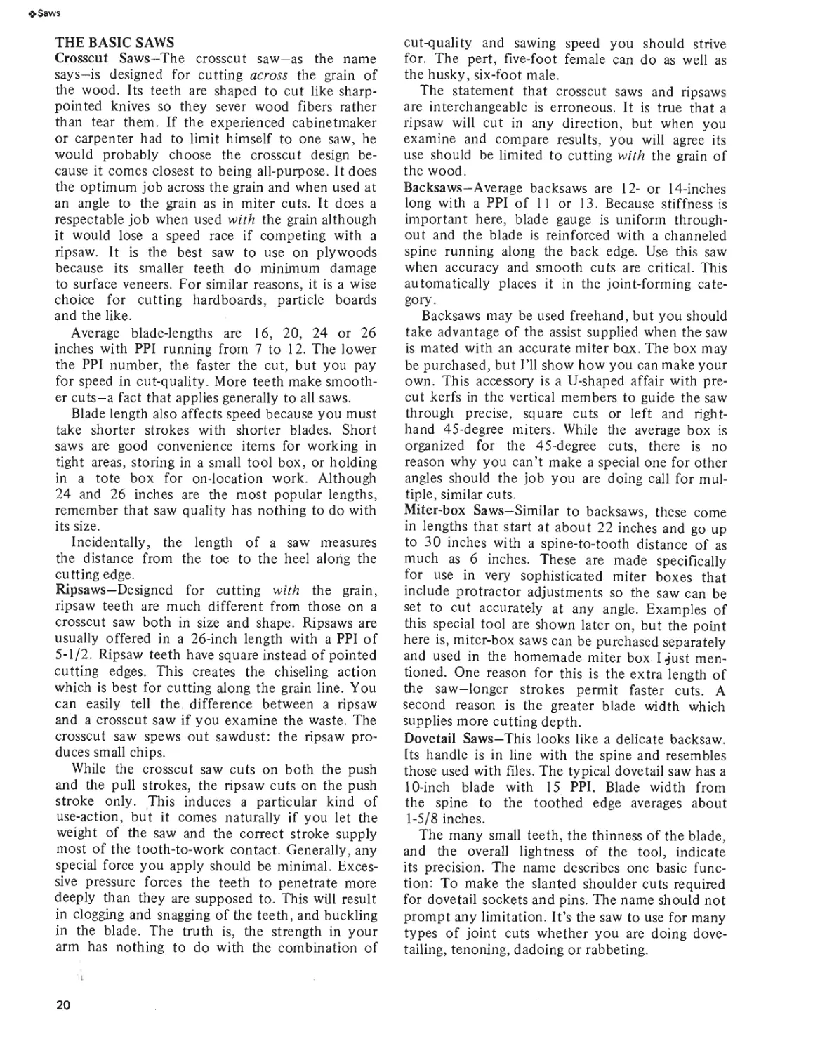
Backsaws—Average backsaws are 12- or 14-inches
long with a PPI of 11 or 13. Because stiffness is
important here, blade gauge is uniform through-
out and the blade is reinforced with a channeled
spine running along the back edge. Use this saw
when accuracy and smooth cuts are critical. This
automatically places it in the joint-forming cate-
gory.
Backsaws may be used freehand, but you should
take advantage of the assist supplied when the saw
is mated with an accurate miter box. The box may
be purchased, but I’ll show how you can make your
own. This accessory is a U-shaped affair with pre-
cut kerfs in the vertical members to guide the saw
through precise, square cuts or left and right-
hand 45-degree miters. While the average box is
organized for the 45-degree cuts, there is no
reason why you can’t make a special one for other
angles should the job you are doing call for mul-
tiple, similar cuts.
Miter-box Saws—Similar to backsaws, these come
in lengths that start at about 22 inches and go up
to 30 inches with a spine-to-tooth distance of as
much as 6 inches. These are made specifically
for use in very sophisticated miter boxes that
include protractor adjustments so the saw can be
set to cut accurately at any angle. Examples of
this special tool are shown later on, but the point
here is, miter-box saws can be purchased separately
and used in the homemade miter box I Just men-
tioned. One reason for this is the extra length of
the saw—longer strokes permit faster cuts. A
second reason is the greater blade width which
supplies more cutting depth.
Dovetail Saws—This looks like a delicate backsaw.
Its handle is in line with the spine and resembles
those used with files. The typical dovetail saw has a
10-inch blade with 15 PPI. Blade width from
the spine to the toothed edge averages about
1-5/8 inches.
The many small teeth, the thinness of the blade,
and the overall lightness of the tool, indicate
its precision. The name describes one basic func-
tion: To make the slanted shoulder cuts required
for dovetail sockets and pins. The name should not
prompt any limitation. It’s the saw to use for many
types of joint cuts whether you are doing dove-
tailing, tenoning, dadoing or rabbeting.
20
•>Saws
Courtesy of Stanley Tools
Reinforcement — Often called a Spine or Stiffener
DOVETAIL SAWS are used in making dovetails and for pre-
cision work.
BACK SAWS are used for fine work.
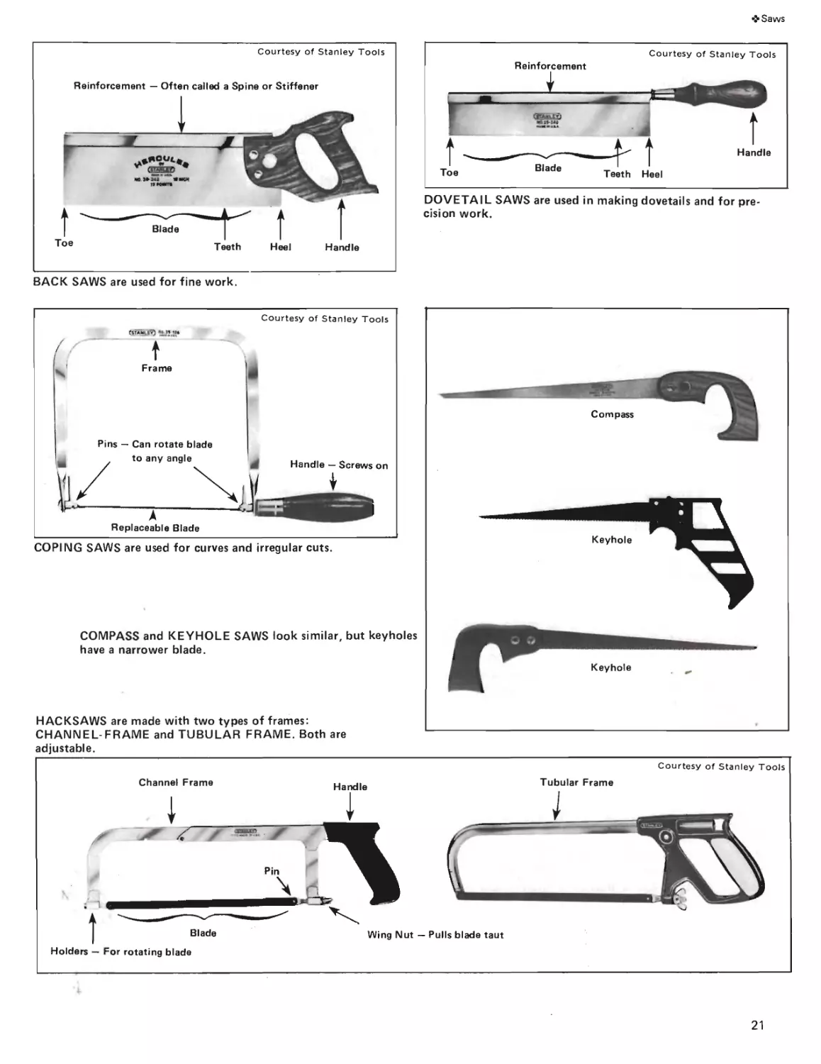
COPING SAWS are used for curves and irregular cuts.
COMPASS and KEYHOLE SAWS look similar, but keyholes
have a narrower blade.
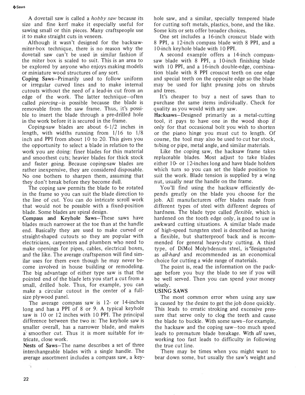
HACKSAWS are made with two types of frames:
CHANNEL-FRAME and TUBULAR FRAME. Both are
adjustable.
21
4» Saws
A dovetail saw is called a hobby saw because its
size and fine kerf make it especially useful for
sawing small or thin pieces. Many craftspeople use
it to make straight cuts in veneers.
Although it wasn’t designed for the backsaw-
miter-box technique, there is no reason why the
dovetail saw can’t be used in similar fashion if
the miter box is scaled to suit. This is an area to
be explored by anyone who enjoys making models
or miniature wood structures of any sort.
Coping Saws—Primarily used to follow uniform
or irregular curved lines and to make internal
cutouts without the need of a lead-in cut from an
edge of the work. The latter technique—often
called piercing—is possible because the blade is
removable from the saw frame. Thus, it’s possi-
ble to insert the blade through a pre-drilled hole
in the work before it is secured in the frame.
Coping-saw blades are about 6-1/2 inches in
length, with widths running from 1/16 to 1/8
inch and PPI from about 10 to 20. This gives you
the opportunity to select a blade in relation to the
work you are doing: finer blades for thin material
and smoothest cuts; heavier blades for thick stock
and faster going. Because coping-saw blades are
rather inexpensive, they are considered disposable.
No one bothers to sharpen them, assuming that
they don’t break before they become dull.
The coping saw permits the blade to be rotated
in the frame so you can suit the blade direction to
the line of cut. You can do intricate scroll work
that would not be possible with a fixed-position
blade. Some blades are spiral design.
Compass and Keyhole Saws—These saws have
blades much narrower at the toe than at the handle
end. Basically they are used to make curved or
straight-shaped cutouts so they are popular with
electricians, carpenters and plumbers who need to
make openings for pipes, cables, electrical boxes,
and the like. The average craftsperson will find sim-
ilar uses for them even though he may never be-
come involved in house building or remodeling.
The big advantage of either type saw is that the
pointed end of the blade lets you start a cut from a
small, drilled hole. Thus, for example, you can
make a circular cutout in the center of a full-
size plywood panel.
The average compass saw is 12- or 14-inches
long and has a PPI of 8 or 9. A typical keyhole
saw is 10 or 12 inches with 10 PPI. The principal
difference between the two is: The keyhole saw is
smaller overall, has a narrower blade, and makes
a smoother cut. Thus it is more suitable for in-
tricate, close work.
Nests of Saws—The name describes a set of three
interchangeable blades with a single handle. The
average assortment includes a compass saw, a key-
hole saw, and a similar, specially tempered blade
for cutting soft metals, plastics, bone, and the like.
Some kits or sets offer broader choices.
One set includes a 16-inch crosscut blade with
8 PPI, a 12-inch compass blade with 8 PPI, and a
10-inch keyhole blade with 10 PPI.
A second example offers a 14-inch compass-
saw blade with 8 PPI, a 10-inch finishing blade
with 10 PPI, and a 16-inch double-edge, combina-
tion blade with 8 PPI crosscut teeth on one edge
and special teeth on the opposite edge so the blade
may be used for light pruning jobs on shrubs
and trees.
It’s cheaper to buy a nest of saws than to
purchase the same items individually. Check for
quality as you would with any saw.
Hacksaws—Designed primarily as a metal-cutting
tool, it pays to have one in the wood shop if
only for that occasional bolt you wish to shorten
or the piano hinge you must cut to length. Of
course, the tool may also be used to cut bar stock,
tubing or pipe, metal angle, and similar materials.
Like the coping saw, the hacksaw frame takes
replaceable blades. Most adjust to take blades
either 10- or 12-inches long and have blade holders
which turn so you can set the blade position to
suit the work. Blade tension is supplied by a wing
nut, usually near the handle on the frame.
You’ll find using the hacksaw efficiently de-
pends greatly on the blade you choose for the
job. All manufacturers offer blades made from
different types of steel with different degrees of
hardness. The blade type called flexible, which is
hardened on the tooth edge only, is good to use in
awkward cutting situations. A similar blade made
of high-speed tungsten steel is described as having
a flexible, but shatterproof back and is recom-
mended for general heavy-duty cutting. A third
type, of DiMol Molybdenum steel, is "designated
as all-hard and recommended as an economical
choice for cutting a wide range of materials.
The point is, read the information on the pack-
age before you buy the blade to see if you will
be well served. Then you can spend your money
wisely.
USING SAWS
The most common error when using any saw
is caused by the desire to get the job done quickly.
This leads to erratic stroking and excessive pres-
sure that serve only to clog the teeth and cause
the blade to buckle. With some saws—for example,
the hacksaw and the coping saw—too much speed
leads to premature blade breakage. With all saws,
working too fast leads to difficulty in following
the true cut line.
There may be times when you might want to
bear down some, but usually the saw’s weight and
22
•2»Saws
a smooth stroke action gets the job done in effi-
cient fashion with minimum effort. Your intent
should be quality and accuracy, even if it requires
a few extra seconds to accomplish it.
Be sure the work is supported solidly. If the
wood being cut is not firm, you will encounter a
chatter that interferes with good sawing. A pair of
sawhorses is a must if you are cutting anything
that can’t be gripped in a vise, or clamped to a
workbench, or secured in one of the holding de-
vices I’ve illustrated in this book.
Don't make the sawhorses too high regardless
of how tall you are—24 inches seems to be about
right for general work, although an increase of 2
to 4 inches won’t cause a crisis. The low height
puts you above the work so you have a clear line
of sight and maximum freedom to stroke smooth-
ly. It also makes it possible to use a knee as a
convenient holddown. Check chapter 13 for more
information on sawhorses.
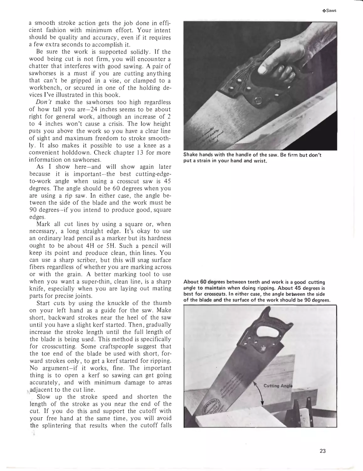
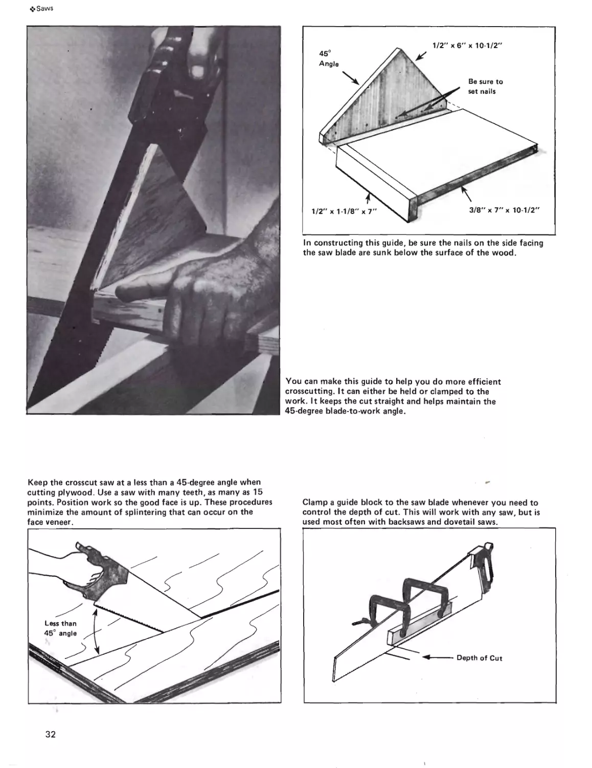
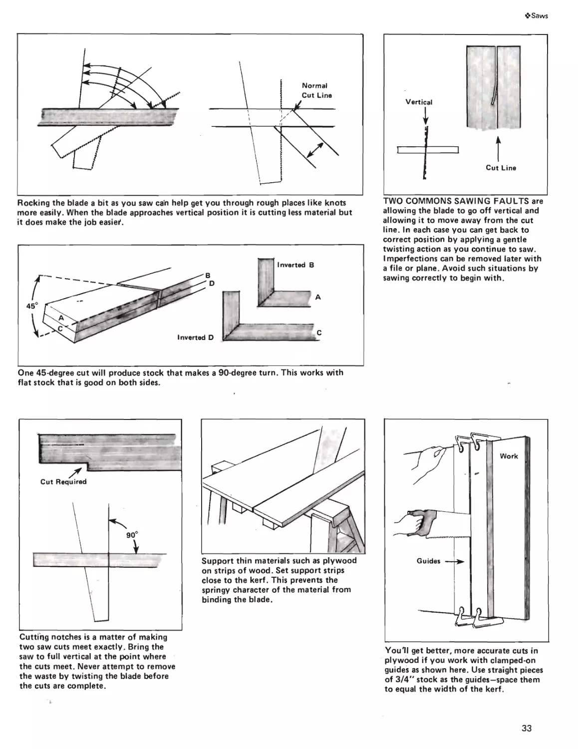
As I show here—and will show again later
because it is important-the best cutting-edge-
to-work angle when using a crosscut saw is 45
degrees. The angle should be 60 degrees when you
are using a rip saw. In either case, the angle be-
tween the side of the blade and the work must be
90 degrees—if you intend to produce good, square
edges.
Mark all cut lines by using a square or, when
necessary, a long straight edge. It’s okay to use
an ordinary lead pencil as a marker but its hardness
ought to be about 4H or 5H. Such a pencil will
keep its point and produce clean, thin lines. You
can use a sharp scriber, but this will snag surface
fibers regardless of whether you are marking across
or with the grain. A better marking tool to use
when you want a super-thin, clean line, is a sharp
knife, especially when you are laying out mating
parts for precise joints.
Start cuts by using the knuckle of the thumb
on your left hand as a guide for the saw. Make
short, backward strokes near the heel of the saw
until you have a slight kerf started. Then, gradually
increase the stroke length until the full length of
the blade is being used. This method is specifically
for crosscutting. Some craftspeople suggest that
the toe end of the blade be used with short, for-
ward strokes only, to get a kerf started for ripping.
No argument-if it works, fine. The important
thing is to open a kerf so sawing can get going
accurately, and with minimum damage to areas
adjacent to the cut line.
Slow up the stroke speed and shorten the
length of the stroke as you near the end of the
cut. If you do this and support the cutoff with
your free hand at the same time, you will avoid
the splintering that results when the cutoff falls
Shake hands with the handle of the saw. Be firm but don't
put a strain in your hand and wrist.
About 60 degrees between teeth and work is a good cutting
angle to maintain when doing ripping. About 45 degrees is
best for crosscuts. In either case, the angle between the side
of the blade and the surface of the work should be 90 degrees.
23
•>Saws
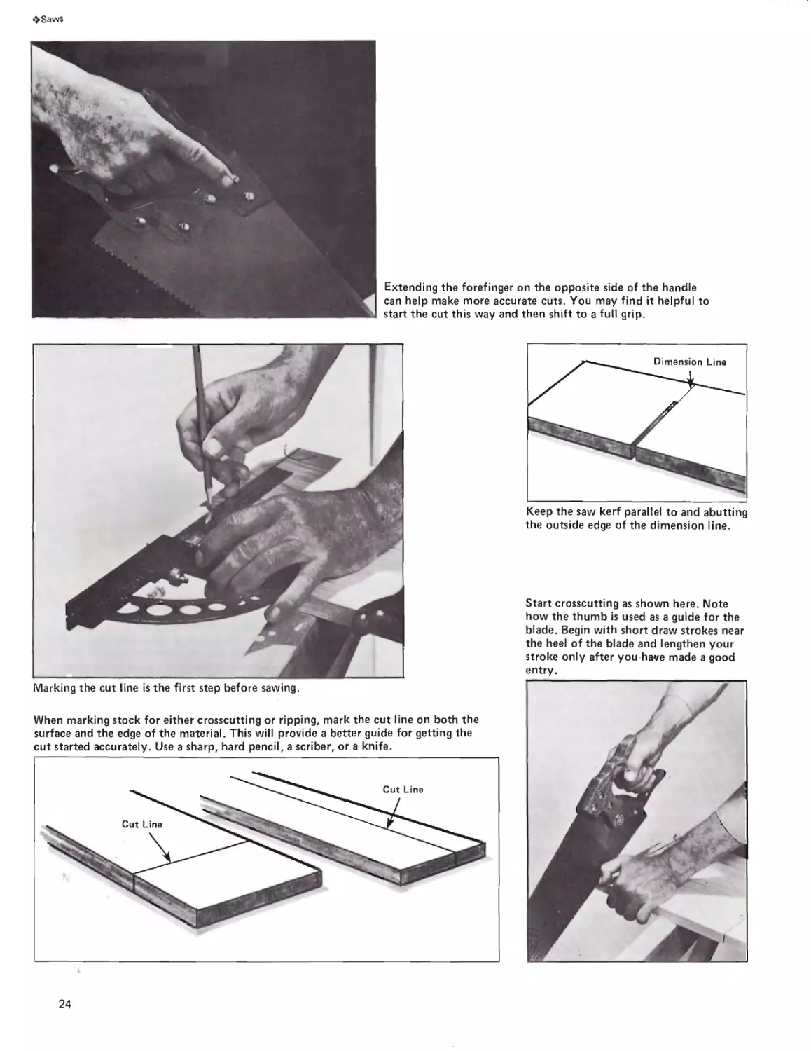
Extending the forefinger on the opposite side of the handle
can help make more accurate cuts. You may find it helpful to
start the cut this way and then shift to a full grip.
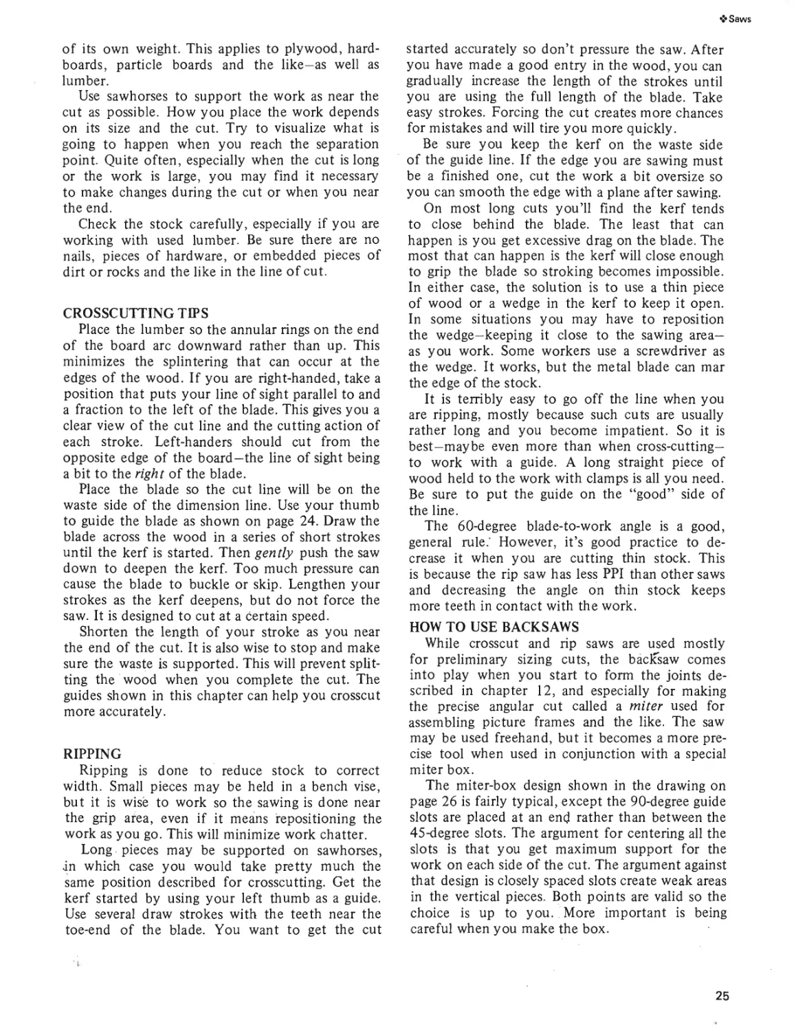
Marking the cut line is the first step before sawing.
When marking stock for either crosscutting or ripping, mark the cut line on both the
surface and the edge of the material. This will provide a better guide for getting the
cut started accurately. Use a sharp, hard pencil, a scriber, or a knife.
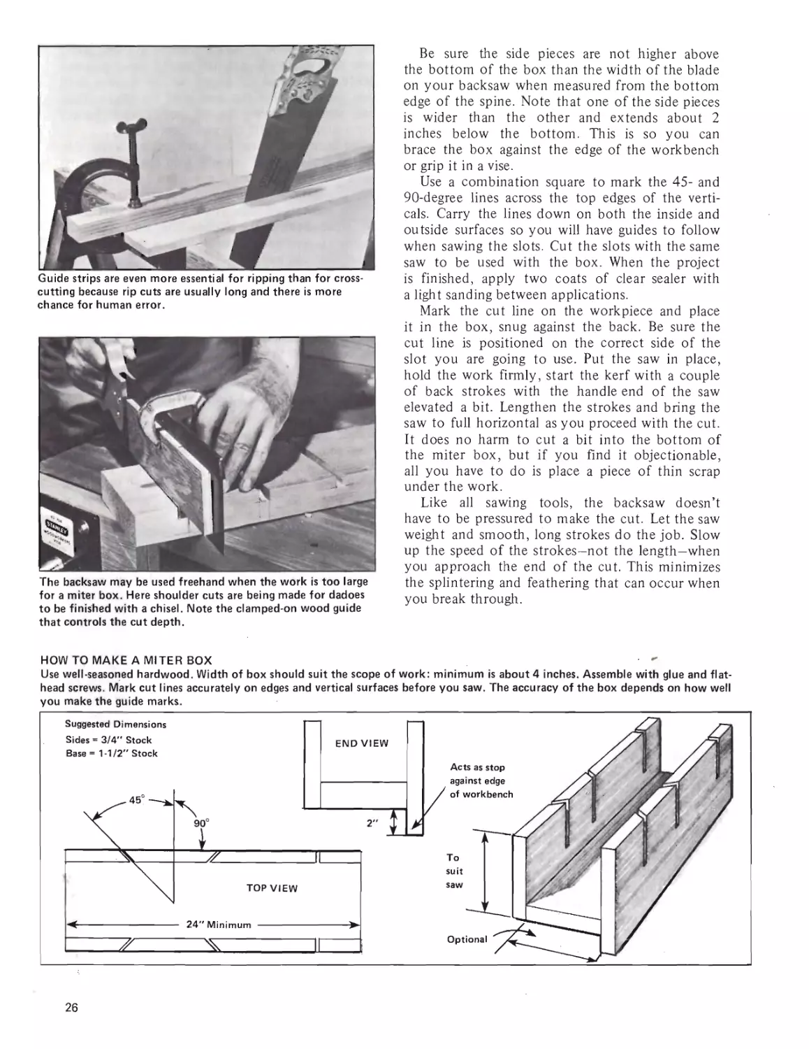
Keep the saw kerf parallel to and abutting
the outside edge of the dimension line.
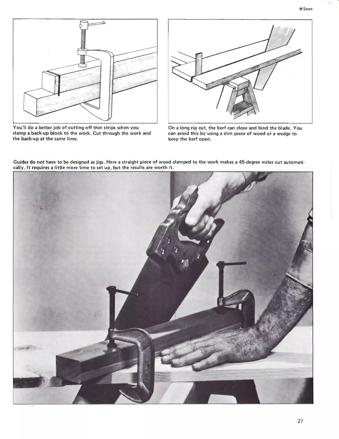
Start crosscutting as shown here. Note
how the thumb is used as a guide for the
blade. Begin with short draw strokes near
the heel of the blade and lengthen your
stroke only after you have made a good
entry.
24
❖ Saws
of its own weight. This applies to plywood, hard-
boards, particle boards and the like—as well as
lumber.
Use sawhorses to support the work as near the
cut as possible. How you place the work depends
on its size and the cut. Try to visualize what is
going to happen when you reach the separation
point. Quite often, especially when the cut is long
or the work is large, you may find it necessary
to make changes during the cut or when you near
the end.
Check the stock carefully, especially if you are
working with used lumber. Be sure there are no
nails, pieces of hardware, or embedded pieces of
dirt or rocks and the like in the line of cut.
CROSSCUTTING TIPS
Place the lumber so the annular rings on the end
of the board arc downward rather than up. This
minimizes the splintering that can occur at the
edges of the wood. If you are right-handed, take a
position that puts your line of sight parallel to and
a fraction to the left of the blade. This gives you a
clear view of the cut line and the cutting action of
each stroke. Left-handers should cut from the
opposite edge of the board—the line of sight being
a bit to the right of the blade.
Place the blade so the cut line will be on the
waste side of the dimension line. Use your thumb
to guide the blade as shown on page 24. Draw the
blade across the wood in a series of short strokes
until the kerf is started. Then gently push the saw
down to deepen the kerf. Too much pressure can
cause the blade to buckle or skip. Lengthen your
strokes as the kerf deepens, but do not force the
saw. It is designed to cut at a certain speed.
Shorten the length of your stroke as you near
the end of the cut. It is also wise to stop and make
sure the waste is supported. This will prevent split-
ting the wood when you complete the cut. The
guides shown in this chapter can help you crosscut
more accurately.
RIPPING
Ripping is done to reduce stock to correct
width. Small pieces may be held in a bench vise,
but it is wise to work so the sawing is done near
the grip area, even if it means repositioning the
work as you go. This will minimize work chatter.
Long pieces may be supported on sawhorses,
jn which case you would take pretty much the
same position described for crosscutting. Get the
kerf started by using your left thumb as a guide.
Use several draw strokes with the teeth near the
toe-end of the blade. You want to get the cut
started accurately so don’t pressure the saw. After
you have made a good entry in the wood, you can
gradually increase the length of the strokes until
you are using the full length of the blade. Take
easy strokes. Forcing the cut creates more chances
for mistakes and will tire you more quickly.
Be sure you keep the kerf on the waste side
of the guide line. If the edge you are sawing must
be a finished one, cut the work a bit oversize so
you can smooth the edge with a plane after sawing.
On most long cuts you’ll find the kerf tends
to close behind the blade. The least that can
happen is you get excessive drag on the blade. The
most that can happen is the kerf will close enough
to grip the blade so stroking becomes impossible.
In either case, the solution is to use a thin piece
of wood or a wedge in the kerf to keep it open.
In some situations you may have to reposition
the wedge-keeping it close to the sawing area—
as you work. Some workers use a screwdriver as
the wedge. It works, but the metal blade can mar
the edge of the stock.
It is terribly easy to go off the line when you
are ripping, mostly because such cuts are usually
rather long and you become impatient. So it is
best—maybe even more than when cross-cutting—
to work with a guide. A long straight piece of
wood held to the work with clamps is all you need.
Be sure to put the guide on the “good” side of
the line.
The 60-degree blade-to-work angle is a good,
general rule.' However, it’s good practice to de-
crease it when you are cutting thin stock. This
is because the rip saw has less PPI than other saws
and decreasing the angle on thin stock keeps
more teeth in contact with the work.
HOW TO USE BACKSAWS
While crosscut and rip saws are used mostly
for preliminary sizing cuts, the backsaw comes
into play when you start to form the joints de-
scribed in chapter 12, and especially for making
the precise angular cut called a miter used for
assembling picture frames and the like. The saw
may be used freehand, but it becomes a more pre-
cise tool when used in conjunction with a special
miter box.
The miter-box design shown in the drawing on
page 26 is fairly typical, except the 90-degree guide
slots are placed at an end rather than between the
45-degree slots. The argument for centering all the
slots is that you get maximum support for the
work on each side of the cut. The argument against
that design is closely spaced slots create weak areas
in the vertical pieces. Both points are valid so the
choice is up to you. More important is being
careful when you make the box.
25
Guide strips are even more essential for ripping than for cross-
cutting because rip cuts are usually long and there is more
chance for human error.
The backsaw may be used freehand when the work is too large
for a miter box. Here shoulder cuts are being made for dadoes
to be finished with a chisel. Note the clamped-on wood guide
that controls the cut depth.
Be sure the side pieces are not higher above
the bottom of the box than the width of the blade
on your backsaw when measured from the bottom
edge of the spine. Note that one of the side pieces
is wider than the other and extends about 2
inches below the bottom. This is so you can
brace the box against the edge of the workbench
or grip it in a vise.
Use a combination square to mark the 45- and
90-degree lines across the top edges of the verti-
cals. Carry the lines down on both the inside and
outside surfaces so you will have guides to follow
when sawing the slots. Cut the slots with the same
saw to be used with the box. When the project
is finished, apply two coats of clear sealer with
a light sanding between applications.
Mark the cut line on the workpiece and place
it in the box, snug against the back. Be sure the
cut line is positioned on the correct side of the
slot you are going to use. Put the saw in place,
hold the work firmly, start the kerf with a couple
of back strokes with the handle end of the saw
elevated a bit. Lengthen the strokes and bring the
saw to full horizontal as you proceed with the cut.
It does no harm to cut a bit into the bottom of
the miter box, but if you find it objectionable,
all you have to do is place a piece of thin scrap
under the work.
Like all sawing tools, the backsaw doesn’t
have to be pressured to make the cut. Let the saw
weight and smooth, long strokes do the job. Slow
up the speed of the strokes—not the length—when
you approach the end of the cut. This minimizes
the splintering and feathering that can occur when
you break through.
HOW TO MAKE A MITER BOX
Use well-seasoned hardwood. Width of box should suit the scope of work: minimum is about 4 inches. Assemble with glue and flat-
head screws. Mark cut lines accurately on edges and vertical surfaces before you saw. The accuracy of the box depends on how well
26
❖ Saws
You'll do a better job of cutting off thin strips when you
clamp a back-up block to the work. Cut through the work and
the back-up at the same time.
On a long rip cut, the kerf can close and bind the blade. You
can avoid this by using a slim piece of wood or a wedge to
keep the kerf open.
Guides do not have to be designed as jigs. Here a straight piece of wood clamped to the work makes a 45-degree miter cut automati-
cally. It requires a little more time to set up, but the results are worth it.
27
❖Saws
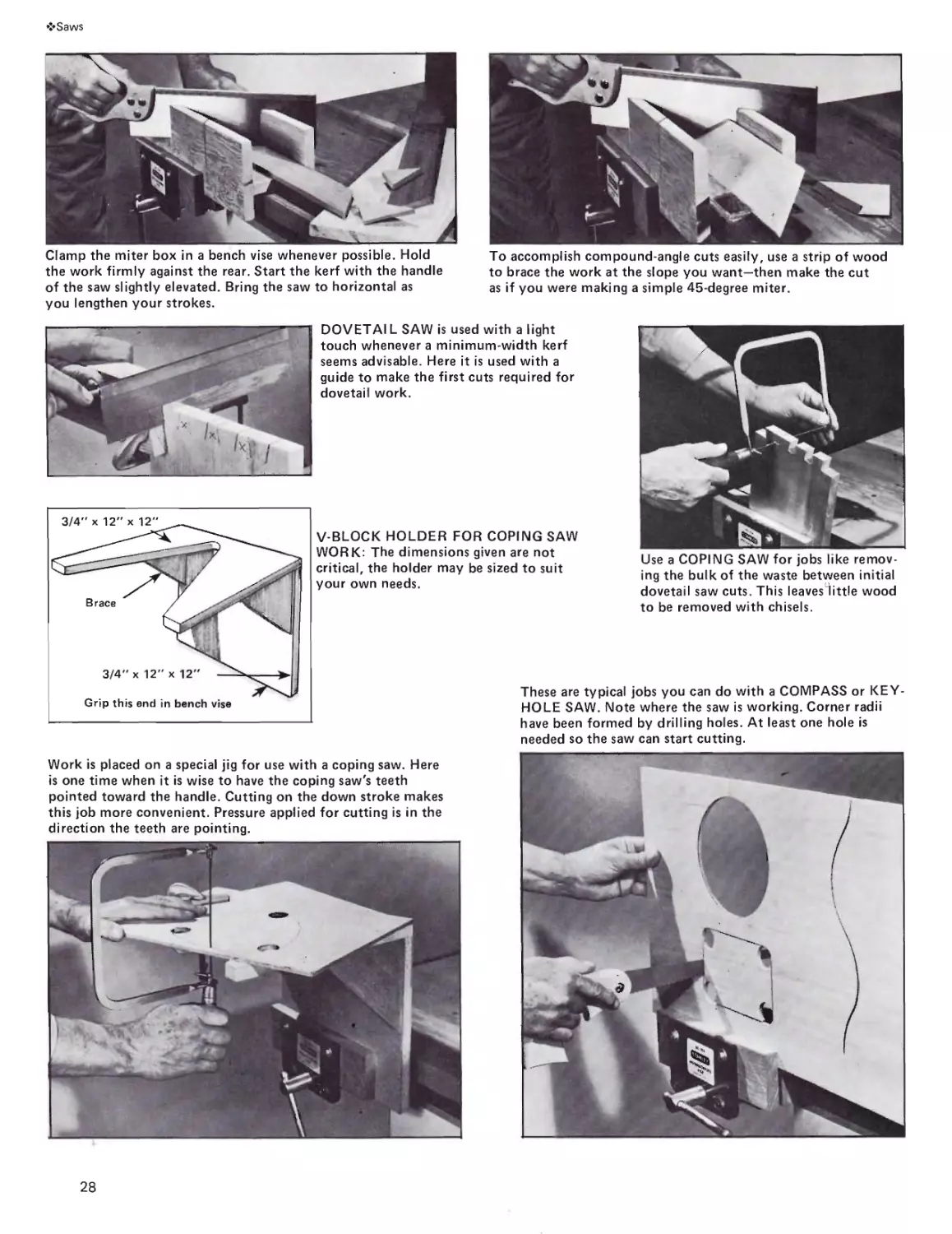
Clamp the miter box in a bench vise whenever possible. Hold
the work firmly against the rear. Start the kerf with the handle
of the saw slightly elevated. Bring the saw to horizontal as
you lengthen your strokes.
To accomplish compound-angle cuts easily, use a strip of wood
to brace the work at the slope you want—then make the cut
as if you were making a simple 45-degree miter.
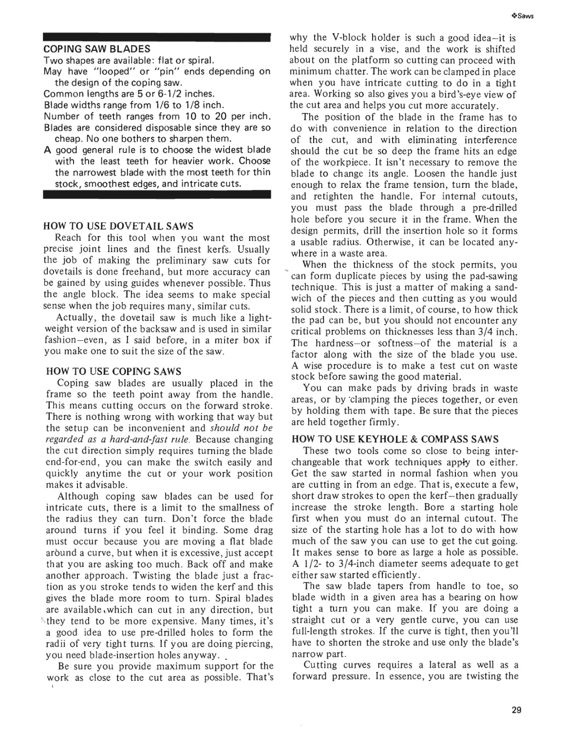
DOVETAI L SAW is used with a light
touch whenever a minimum-width kerf
seems advisable. Here it is used with a
guide to make the first cuts required for
dovetail work.
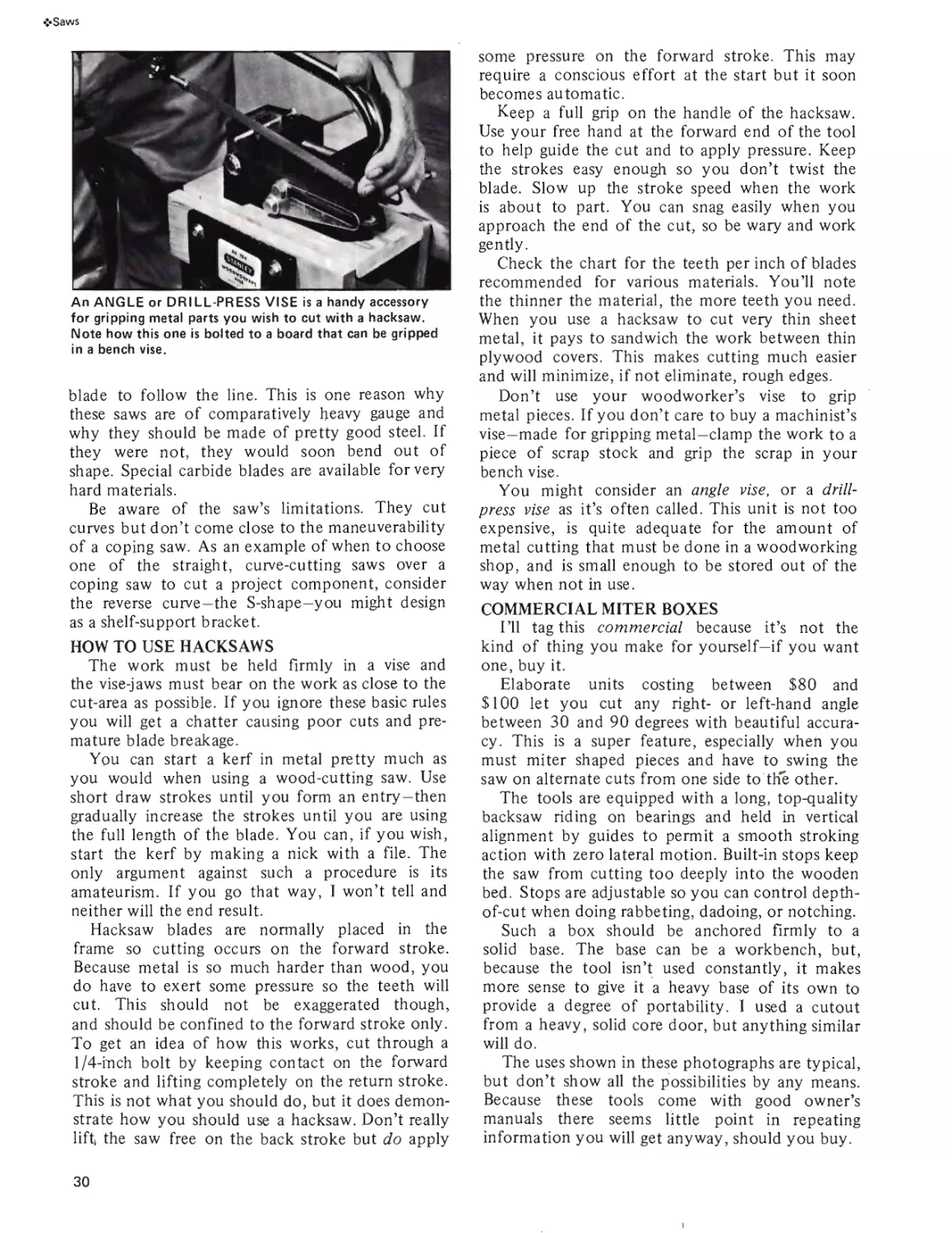
V-BLOCK HOLDER FOR COPING SAW
WORK: The dimensions given are not
critical, the holder may be sized to suit
your own needs.
Use a COPING SAW for jobs like remov-
ing the bulk of the waste between initial
dovetail saw cuts. This leaves"little wood
to be removed with chisels.
Work is placed on a special jig for use with a coping saw. Here
is one time when it is wise to have the coping saw's teeth
pointed toward the handle. Cutting on the down stroke makes
this job more convenient. Pressure applied for cutting is in the
direction the teeth are pointing.
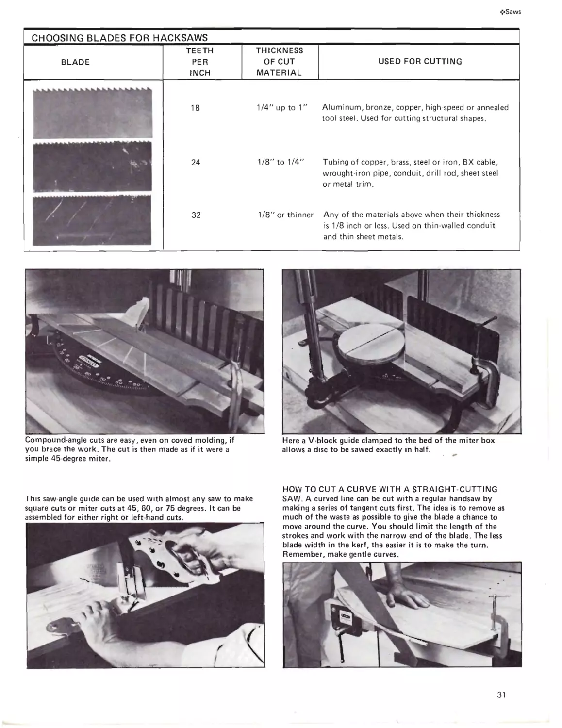
These are typical jobs you can do with a COMPASS or KEY-
HOLE SAW. Note where the saw is working. Corner radii
have been formed by drilling holes. At least one hole is
needed so the saw can start cutting.
28
❖Saws
COPING SAW BLADES
Two shapes are available: flat or spiral.
May have "looped" or "pin" ends depending on
the design of the coping saw.
Common lengths are 5 or 6-1/2 inches.
Blade widths range from 1/6 to 1/8 inch.
Number of teeth ranges from 10 to 20 per inch.
Blades are considered disposable since they are so
cheap. No one bothers to sharpen them.
A good general rule is to choose the widest blade
with the least teeth for heavier work. Choose
the narrowest blade with the most teeth for thin
stock, smoothest edges, and intricate cuts.
HOW TO USE DOVETAIL SAWS
Reach for this tool when you want the most
precise joint lines and the finest kerfs. Usually
the job of making the preliminary saw cuts for
dovetails is done freehand, but more accuracy can
be gained by using guides whenever possible. Thus
the angle block. The idea seems to make special
sense when the job requires many, similar cuts.
Actually, the dovetail saw is much like a light-
weight version of the backsaw and is used in similar
fashion—even, as I said before, in a miter box if
you make one to suit the size of the saw.
HOW TO USE COPING SAWS
Coping saw blades are usually placed in the
frame so the teeth point away from the handle.
This means cutting occurs on the forward stroke.
There is nothing wrong with working that way but
the setup can be inconvenient and should not be
regarded as a hard-and-fast rule. Because changing
the cut direction simply requires turning the blade
end-for-end, you can make the switch easily and
quickly anytime the cut or your work position
makes it advisable.
Although coping saw blades can be used for
intricate cuts, there is a limit to the smallness of
the radius they can turn. Don’t force the blade
around turns if you feel it binding. Some drag
must occur because you are moving a flat blade
around a curve, but when it is excessive, just accept
that you are asking too much. Back off and make
another approach. Twisting the blade just a frac-
tion as you stroke tends to widen the kerf and this
gives the blade more room to turn. Spiral blades
are available,which can cut in any direction, but
they tend to be more expensive. Many times, it’s
a good idea to use pre-drilled holes to form the
radii of very tight turns. If you are doing piercing,
you need blade-insertion holes anyway.
Be sure you provide maximum support for the
work as close to the cut area as possible. That’s
why the V-block holder is such a good idea—it is
held securely in a vise, and the work is shifted
about on the platform so cutting can proceed with
minimum chatter. The work can be clamped in place
when you have intricate cutting to do in a tight
area. Working so also gives you a bird’s-eye view of
the cut area and helps you cut more accurately.
The position of the blade in the frame has to
do with convenience in relation to the direction
of the cut, and with eliminating interference
should the cut be so deep the frame hits an edge
of the workpiece. It isn’t necessary to remove the
blade to change its angle. Loosen the handle just
enough to relax the frame tension, turn the blade,
and retighten the handle. For internal cutouts,
you must pass the blade through a pre-drilled
hole before you secure it in the frame. When the
design permits, drill the insertion hole so it forms
a usable radius. Otherwise, it can be located any-
where in a waste area.
When the thickness of the stock permits, you
can form duplicate pieces by using the pad-sawing
technique. This is just a matter of making a sand-
wich of the pieces and then cutting as you would
solid stock. There is a limit, of course, to how thick
the pad can be, but you should not encounter any
critical problems on thicknesses less than 3/4 inch.
The hardness-or softness-of the material is a
factor along with the size of the blade you use.
A wise procedure is to make a test cut on waste
stock before sawing the good material.
You can make pads by driving brads in waste
areas, or by ’clamping the pieces together, or even
by holding them with tape. Be sure that the pieces
are held together firmly.
HOW TO USE KEYHOLE & COMPASS SAWS
These two tools come so close to being inter-
changeable that work techniques apply to either.
Get the saw started in normal fashion when you
are cutting in from an edge. That is, execute a few,
short draw strokes to open the kerf-then gradually
increase the stroke length. Bore a starting hole
first when you must do an internal cutout. The
size of the starting hole has a lot to do with how
much of the saw you can use to get the cut going.
It makes sense to bore as large a hole as possible.
A 1/2- to 3/4-inch diameter seems adequate to get
either saw started efficiently.
The saw blade tapers from handle to toe, so
blade width in a given area has a bearing on how
tight a turn you can make. If you are doing a
straight cut or a very gentle curve, you can use
full-length strokes. If the curve is tight, then you’ll
have to shorten the stroke and use only the blade’s
narrow part.
Cutting curves requires a lateral as well as a
forward pressure. In essence, you are twisting the
29
•Z-Saws
An ANGLE or DRILL-PRESS VISE is a handy accessory
for gripping metal parts you wish to cut with a hacksaw.
Note how this one is bolted to a board that can be gripped
in a bench vise.
blade to follow the line. This is one reason why
these saws are of comparatively heavy gauge and
why they should be made of pretty good steel. If
they were not, they would soon bend out of
shape. Special carbide blades are available for very
hard materials.
Be aware of the saw’s limitations. They cut
curves but don’t come close to the maneuverability
of a coping saw. As an example of when to choose
one of the straight, curve-cutting saws over a
coping saw to cut a project component, consider
the reverse curve-the S-shape-you might design
as a shelf-support bracket.
HOW TO USE HACKSAWS
The work must be held firmly in a vise and
the vise-jaws must bear on the work as close to the
cut-area as possible. If you ignore these basic rules
you will get a chatter causing poor cuts and pre-
mature blade breakage.
You can start a kerf in metal pretty much as
you would when using a wood-cutting saw. Use
short draw strokes until you form an entry—then
gradually increase the strokes until you are using
the full length of the blade. You can, if you wish,
start the kerf by making a nick with a file. The
only argument against such a procedure is its
amateurism. If you go that way, I won’t tell and
neither will the end result.
Hacksaw blades are normally placed in the
frame so cutting occurs on the forward stroke.
Because metal is so much harder than wood, you
do have to exert some pressure so the teeth will
cut. This should not be exaggerated though,
and should be confined to the forward stroke only.
To get an idea of how this works, cut through a
1/4-mch bolt by keeping contact on the forward
stroke and lifting completely on the return stroke.
This is not what you should do, but it does demon-
strate how you should use a hacksaw. Don’t really
lift the saw free on the back stroke but do apply
some pressure on the forward stroke. This may
require a conscious effort at the start but it soon
becomes automatic.
Keep a full grip on the handle of the hacksaw.
Use your free hand at the forward end of the tool
to help guide the cut and to apply pressure. Keep
the strokes easy enough so you don’t twist the
blade. Slow up the stroke speed when the work
is about to part. You can snag easily when you
approach the end of the cut, so be wary and work
gently.
Check the chart for the teeth per inch of blades
recommended for various materials. You’ll note
the thinner the material, the more teeth you need.
When you use a hacksaw to cut very thin sheet
metal, it pays to sandwich the work between thin
plywood covers. This makes cutting much easier
and will minimize, if not eliminate, rough edges.
Don’t use your woodworker’s vise to grip
metal pieces. If you don’t care to buy a machinist’s
vise—made for gripping metal—clamp the work to a
piece of scrap stock and grip the scrap in your
bench vise.
You might consider an angle vise, or a drill-
press vise as it’s often called. This unit is not too
expensive, is quite adequate for the amount of
metal cutting that must be done in a woodworking
shop, and is small enough to be stored out of the
way when not in use.
COMMERCIAL MITER BOXES
I’ll tag this commercial because it’s not the
kind of thing you make for yourself—if you want
one, buy it.
Elaborate units costing between $80 and
$100 let you cut any right- or left-hand angle
between 30 and 90 degrees with beautiful accura-
cy. This is a super feature, especially when you
must miter shaped pieces and have to swing the
saw on alternate cuts from one side to the other.
The tools are equipped with a long, top-quality
backsaw riding on bearings and held in vertical
alignment by guides to permit a smooth stroking
action with zero lateral motion. Built-in stops keep
the saw from cutting too deeply into the wooden
bed. Stops are adjustable so you can control depth-
of-cut when doing rabbeting, dadoing, or notching.
Such a box should be anchored firmly to a
solid base. The base can be a workbench, but,
because the tool isn’t used constantly, it makes
more sense to give it a heavy base of its own to
provide a degree of portability. 1 used a cutout
from a heavy, solid core door, but anything similar
will do.
The uses shown in these photographs are typical,
but don’t show all the possibilities by any means.
Because these tools come with good owner’s
manuals there seems little point in repeating
information you will get anyway, should you buy.
30
•:*Saws
CHOOSING BLADES FOR HACKSAWS
BLADE TEETH PER INCH THICKNESS OF CUT MATERIAL USED FOR CUTTING
— 18 1/4" up to 1" Aluminum, bronze, copper, high-speed or annealed tool steel. Used for cutting structural shapes. 24 1/8" to 1/4" Tubing of copper, brass, steel or iron, BX cable, wrought-iron pipe, conduit, drill rod, sheet steel or metal trim. 32 1/8" or thinner Any of the materials above when their thickness is 1/8 inch or less. Used on thin-walled conduit and thin sheet metals.
Compound-angle cuts are easy, even on coved molding, if
you brace the work. The cut is then made as if it were a
simple 45-degree miter.
Here a V-block guide clamped to the bed of the miter box
allows a disc to be sawed exactly in half.
HOW TO CUT A CURVE WITH A STRAIGHT-CUTTING
SAW. A curved line can be cut with a regular handsaw by
making a series of tangent cuts first. The idea is to remove as
much of the waste as possible to give the blade a chance to
move around the curve. You should limit the length of the
strokes and work with the narrow end of the blade. The less
blade width in the kerf, the easier it is to make the turn.
Remember, make gentle curves.
This saw-angle guide can be used with almost any saw to make
square cuts or miter cuts at 45, 60, or 75 degrees. It can be
assembled for either right or left-hand cuts.
31
<• Saws
In constructing this guide, be sure the nails on the side facing
the saw blade are sunk below the surface of the wood.
You can make this guide to help you do more efficient
crosscutting. It can either be held or clamped to the
work. It keeps the cut straight and helps maintain the
45-degree blade-to-work angle.
Keep the crosscut saw at a less than a 45-degree angle when
cutting plywood. Use a saw with many teeth, as many as 15
points. Position work so the good face is up. These procedures
minimize the amount of splintering that can occur on the
face veneer.
Clamp a guide block to the saw blade whenever you need to
control the depth of cut. This will work with any saw, but is
used most often with backsaws and dovetail saws.
32
frSaws
Rocking the blade a bit as you saw can help get you through rough places like knots
more easily. When the blade approaches vertical position it is cutting less material but
it does make the job easiei*.
One 45-degree cut will produce stock that makes a 90-degree turn. This works with
flat stock that is good on both sides.
TWO COMMONS SAWING FAULTS are
allowing the blade to go off vertical and
allowing it to move away from the cut
line. In each case you can get back to
correct position by applying a gentle
twisting action as you continue to saw.
Imperfections can be removed later with
a file or plane. Avoid such situations by
sawing correctly to begin with.
Cutting notches is a matter of making
two saw cuts meet exactly. Bring the
saw to full vertical at the point where
the cuts meet. Never attempt to remove
the waste by twisting the blade before
the cuts are complete.
Support thin materials such as plywood
on strips of wood. Set support strips
close to the kerf. This prevents the
springy character of the material from
binding the blade.
You'll get better, more accurate cuts in
plywood if you work with clamped-on
guides as shown here. Use straight pieces
of 3/4" stock as the guides—space them
to equal the width of the kerf.
33
5
Hammers
SAFETY TIPS
• Make sure hammer heads are securely
fastened to their handles.
• Watch what you are pounding.
• Hold the nail near the head when
starting it.
If the first sawing tool was a rough-edged, flat
stone, then the first striking tool was surely a fist-
size rock. Like the person who decided to sharpen
the saw by chipping away at its edges, someone
thought enough to realize the hammer head could
be used more effectively if tied to the end of a
small branch. It is logical to assume there were
“light” and “heavy” hammers even then.
Like the saw, the basic concept of the hammer
hasn’t changed too much. It’s still a striking sur-
face attached to a handle, even though it has
evolved to a super product with specific designs
available for particular applications. The latter is a
thought to be aware of. A hammer is not an all-
purpose tool. You can’t—you shouldn’t—use a nail
hammer to bend metal or to split a brick or block.
A light hammer is not a good choice for house-
framing. A conventional hammer should not be
used to drive specially hardened masonry nails
or as the striking tool for cold chisels. The nail
hammer, or claw hammer—the design most useful
for cabinet and furniture making and for general
shop use—is not designed for such work. In addi-
tion to being inefficient, such usage can present a
hazard because of the possibility of chipping that
can cause eye or bodily injury.
The eye-injury factor deserves the utmost con-
sideration—to the point of reaching for safety
goggles everytime you reach for a hammer. Better
to be chicken than sightless.
THE NAIL HAMMER-IN GENERAL
A good hammer contributes to quality work.
It’s tough and durable, and its head is heat treated
for the correct degree of hardness. It has poise,
balance and beauty and, unless you just don’t give
a darn, it forces you to work professionally. The
casting blobs attached to rough and often impro-
perly shaped handles seen frequently in bargain-
counter trays do little to inspire craftspersonship.
Today’s top-quality hammers may have handles
of wood, steel or even fiberglass. Technical pros
and cons deal mostly with the shock-absorbing
qualities of the various materials, and with their
resistance to wear. For example, fiberglass can’t
rust—a steel handle can rust, but it can’t splinter
or crack like a wooden handle—a wooden handle
is replaceable, and so on. I know a couple of
good construction people who swear by wooden
handles because they don’t get as cold to the touch
as steel handles in inclement weather. Now that’s
a good argument!
In the final analysis, the choice of a hammer is
a more personal thing than it is with just about any
other tool. Do check the features that I describe.
When you find them on several hammers, base
your choice on how the hammer feels. Don’t go
out and buy a hammer—shop for one.
FEATURE CHECK LIST
The overall appearance must be impressive. A
good finish will not have rough edges or burrs
regardless of the type of hammer. If the handle is
wood, it should be straight-grained hickory and
attached to the head with a single, diagonally
placed wooden wedge, plus two steel wedges. The
striking face should be smooth and polished—its
edges should have a uniform bevel to guard against
chipping. The neck angle should provide sufficient
toe-in so the tool will hang properly. The latter
may be difficult to see or judge, but if all else is
up to par, it will be there.
Look for claws ground at the end so they can fit
narrow spaces between nails and between nail
heads and wood surfaces. The slot between the
claws should have a bevel to allow gripping a nail
anyplace along the shank—not just under the nail-
head.
Most professionals prefer a bell-face hammer
over one with a plain face. The bell curvature is al-
ways minimal, so the possibility of skidding off
the nail head is slight, but there. It takes a little
more getting used to. Its advantage is being able to
drive a nail flush with the work surface without
doing damage to adjacent areas.
TYPES OF HAMMERS
Claw Hammers—The nail hammer most applicable
34
❖Hammers
The COMMON CLAW HAMMER has a claw designed for maximum efficiency when pulling nails. The MODERN 16-OUNCE NAIL
HAMMER has a shock absorbing rubberized grip which contributes to firmer handling.
The head of a quality, wooden-handle
hammer should be attached with one
wooden wedge and two steel ones
The split in the claw of a hammer should
be beveled so it can bite into the shank
of a nail.
A blow that is slightly off with a plain
face is likely to bend the nail. A similar
blow with a bell face will still drive the
nail straight.
Experienced workers prefer the bell
face because it can drive a nail flush or
even slightly below the surface of the
work without leaving hammer marks.
35
❖Hammers
to general woodworking is the 16-ounce claw
hammer. Weights can differ from as little as 7 to
as much as 20 ounces, but you should consider
other weights as additions to, not as substitutes for
the 16-ounce model. My reasoning here is simple—
it’s neither wise, nor even possible, to use a single
hammer to drive everything from brads to spikes.
When you go above 20 ounces you get into the
heavy-duty category where even the length of the
hammer changes. A typical 22-ounce heavy-duty
hammer with a ripping claw is 16-inches long.
Move into areas where the tool is called a framing
hammer and you find weights like 28 ounces and
lengths of 18 inches. This is because the hammer is
used constantly to drive 16d and larger nails. Often
you can choose between a plain face and a milled,
checkered face. The latter is like cross corrugations
that guard against nail skid under heavy blows. The
fact that the corrugations can mar the wood is not
critical because the hammer is used for rough
framing.
Ripping claws will pull nails, but the flat curve
and heavier cross section adapts them especially
for prying apart nailed pieces, breaking down
forms, removing siding, and so on.
Ball-Peen Hammers—Sometimes spelled pein, these
hammers are available for light-touch work as well
as for heavy pounding. Sizes range from 2 ounces
with a 10-inch handle to 48 ounces with a 16-inch
handle. Because the tools are designed primarily
for metal working, the heads are—or should be—
specifically tempered for maximum hardness and
resistance to breakage. This style hammer is not a
first-choice tool for a wood shop, but if you are
doing hobby work like light metal crafting, or even
leather work where you might have some riveting
to do, you’ll find a 12- or 16-ounce size very
handy. An example of when a heavier model is
necessary is attaching furring strips to concrete
block for the application of wood paneling. The
ball-peen hammer can be used to drive specially
hardened nails into the masonry. It’s not a job you
should attempt with a nail hammer.
Tack Hammers-They earn their keep in any wood
shop even if you never drive a tack. These are the
hammers to use for the light fasteners that come
under the general category of “brads.” Check that
the one you buy has a magnetized head so you can
tap a small nail to get it started without having to
use your fingers. The term tap should not be taken
literally. The best procedure is to attach the nail to
the hammerhead and then exert enough downward
pressure to seat the nail where you wish to drive it.
Then hit it home in normal fashion. The above
procedure assumes the fastener is in the inch-or-
less category where it is difficult to hold the nail
to get it started without smacking a finger.
Mallets—Regardless of the type you buy, these
hammers have soft faces so you can’t damage the
tool you are striking. The most common applica-
tion is driving wood chisels. There was a time when
mallet was a synonym for wooden hammer and
there are many fine workers today who won’t use
anything else. However, that loyalty has more to
do with esthetics than practicality. It doesn’t
matter which mallet you choose, but you should
be aware that modem versions can have faces of
rawhide, hard rubber or plastic. All of these mate-
rials are adapted to striking finished and polished
surfaces of metals without danger of chipping or
marring. Many models have replaceable heads—some
even have interchangeable tips of various materials.
Heavy Hammers—Here I am talking about black-
smith’s hand hammers, hand drilling hammers, en-
gineer’s hammers, sledge hammers, and the like.
You can do a lifetime of woodworking without
needing a tool in this category. If I had to choose
one to supplement basic equipment, it would prob-
ably be a hand drilling hammer because it comes
close to having all-purpose applications in related
areas. Weights of typical models are 2, 3, or 4
pounds with overall lengths of 10 to 11 inches.
Example applications are striking a star drill to
make holes in masonry, driving specially hardened
nails and striking a mason’s chisel to break brick or
concrete block.
HOW TO USE A NAIL HAMMER
Grip the hammer near the end of the handle so
you will have maximum leverage which, in turn,
provides the most power and drive. The grip must
be firm enough to keep the tool from twisting
when you strike, but not so tight it contributes to
fatigue. Normally your thumb will curl around
the handle in natural fashion, but when you want
super control, you can extend the thumb in line
with the handle. This is done frequently to start a
nail, or when using a light hammer, or when a blow
that isn’t directed perfectly can cause irreparable
damage.
You can swing a hammer with your wrist,
shoulder or elbow, or all three. Much depends on
the force you need to drive the nail. Small nails
can be the impact point of an arc that has your
wrist as a center. At the other extreme, your
shoulder joint might be the center of the swing-arc.
Anytime you need to start your swing from some-
where behind your spine, you had better reach for
a different striking tool.
The most important consideration is the square-
ness of the hammerhead to the nail at the moment
of impact. If you did a drawing of the procedure
you would see the entire action takes place within
the arc of a quarter-circle. The length of the arc
decreases in proportion to the lightness of the blow
36
❖ Hammers
Use a heavy ball-peen hammer for driving special hardened
nails into masonry. Note the hard hat and the safety goggles.
Hand Tools Institute Photo.
HAND DRILLING HAMMER. Used with a mason's chisel or
star drill for making holes in masonry; weighs from 2 to 4
SOFT-FACE HAMMERS may be regarded as modern sub-
stitutes for wooden mallets. Head weights range from 1-1/2
to 32 ounces, handle lengths from 8 to 14-1/2 inches. This is
the tool to use when you need extra force to drive a wood
chisel. Some are available with replaceable plastic tips.
SLEDGE HAMMER. Used for driving spikes and other heavy
work; weighs from 2-1/2 to 20 pounds.
AXE-often called a camp axe. Used for chopping wood;
3-inch cut. Cover is especially important for protecting the
cutting edge.
A TACK HAMMER typically has a weight of 5 ounces. The
handle length may vary from 10-1/2 to 12 inches. Choose one
labeled magnetic. A magnetized face is important for holding
small tacks and nails in place for driving. When accuracy is
important, press the nail into the wood to get it started.
HALF HATCHET. Used for rough facing; 3-5/8-inch cut.
UPHOLSTERER'S HAMMER weighs 7 ounces and has a
10-3/4-inch handle.
37
❖Hammers
Curl your fingers around the handle close to its end. When the
face of the hammer is on a flat surface, the V formed by your
thumb and forefinger should point toward the middle of your
torso.
It's okay to extend your thumb when you are doing light
work, or to get a nail started correctly. Keep the stroke arc
short. A slight kerf in the end of a thin strip of wood makes
a good reusable holder for small nails. It is easy to pull away
after the nail is seated.
BASIC FACTS ABOUT HAMMERING
Hammering is not a contest. Excessively heavy
blows will do more harm than good.
Grasp the hammer firmly near the end of the
handle.
Don't use the cheek of the hammer as a striking
surface.
Strike the nail gently first. This will help direct
the blow accurately.
The face of the hammer should be parallel to the
head of the nail when contact is made.
Don't use the hammer to strike material that is
harder than it is.
If a nail bends, draw it out and start a new one.
Keep the face of the hammer clean.
you wish to deliver.
Don’t ever grab the hammer just behind the
head so your forearm substitutes for the handle.
This is often done when the worker chooses to
substitute his own strength for the leverage sup-
plied by a correct swing. It’s a bad idea because
it wastes your strength.
Other examples of misuse are striking the nail
with the cheek of the hammer instead of the face,
and using a hammer to do the job a wrecking bar
is designed for. The cheek of a hammer is not
hard enough or thick enough to stand up as a strik-
ing surface. Wrecking bars are designed to pull
large nails, rusted spikes and the like, easily.
Once you get to using them, you will learn they
can outdo the best ripping hammer.
HOW TO DRIVE NAILS
Nail driving is not a contest. It should not be
your intent to do the job with the least number of
blows. Working this way can cause you to miss or
to strike inaccurately often enough to cause serious
damage to the work. Also, nails driven home calm-
ly will hold better because they cause minimum
distortion in the wood fibers. Bent fibers spring
back more easily to grip than those which are split
apart.
Blunt points are less likely to cause splitting
than sharp points. That’s why you will often see a
professional deliberately blunt the point of a nail
before he drives it home. There are situations
where even this precaution doesn’t prevent split-
ting. Then your only out is to drill pilot holes for
the nails before you drive them. Try to keep the
pilot-hole size to about 75% of the nail-shank
diameter. Its depth can match the length of the
nail, but minimize it when you can.
Start a nail with light taps and a minimum
stroke arc. This is the way to work accurately and
to eliminate the blue thumb. Most people hold the
nail near the head between thumb and forefinger.
Some say it’s better to invert the fingers and to
keep them away from the nail head, claiming that
should the hammer slip off the nail it will arc away
from the fingers. Another claim is, hitting the
fleshy tip of a finger is less painful than smacking
a thumbnail. The TRUTH is, hitting any part of
your fingers is painful and unnecessary. Avoid it
by starting a nail with gentle taps regardless of fin-
ger position.
There are ways to hold nails so your fingers are
not in the impact area at all. Small brads and tacks
can be pressed through a strip of thin cardboard
about 3 or 4 inches long. Larger nails can be held
in a kerf you form in a thin strip of wood. Such
ideas can be adopted as standard procedure, or you
can just use them when the size of the nail makes
38
❖ Hammers
finger holding difficult, or when the setup is awk-
ward for routine nailing. In a pinch, double-stick
tape can hold a nail by its head on a hammer mak-
ing an acceptable substitute for a magnetized head.
This idea is useful when work position makes it in-
convenient to use your free hand to hold the nail.
Let up on the force of the blows when the nail-
head approaches the surface of the work to avoid
the possibility of hammer dents and broken sur-
face fibers. You can usually straighten a bent nail
by tapping it upright gently. If the bend is serious,
discard the nail and start a new one. Always drill
a pilot hole first when you must drive a nail
through a knot.
HOW TO HIDE NAILS
The routine method is to sink the head of the
nail—either a finishing or casing nail—below the
surface of the wood by using a nail set. The hole
that remains is filled with a matching wood dough
or putty. It’s a tried-and-true system but be aware
that nail sets come in different sizes. Matching the
set to the nail does the job with a minimum size
hole. Tip sizes on typical nail sets are 1/32, 1/16,
3/32, 1/8, and 5/32 inch. You can buy the tools
individually but they’re cheaper in a group. When
you shop, look for cupped and chamfered tips and
for knurled shanks and a square head. The square
head guards against the tool rolling about on the
workbench and it also provides a larger striking
surface. The knurled shank gives you a firmer
finger grip.
Confine the use of these tools to setting nails.
They are not designed for use as punches so don’t
use them, for example, to form holes in sheet me-
tal or to drive hardened pins.
HOW TO PULL A NAIL
This is usually a simple operation. Turn the ham-
mer upside down and grasp the handle firmly.
Tilt it forward with the claws pointing away from
you. If the head of the nail is above the surface,
slip the claws under it and work them around the
nail with a slight sideways motion. Pull steadily
back until the nail is pulled free. If the nail is extra
long, or it is important not to damage the surface
of the work, place a block of wood under the ham-
merhead. This increases your leverage and reduces
the strain on the handle. Be sure you are not trying
to withdraw a nail that is clinched on the other
side.
If the head of the nail is below the surface, place
the claws around the head and tap the face of the
hammer with a soft face mallet. This will drive
the claws down and around the nailhead. Then you
can pull the nail as described above.
If the head of the nail pulls off or breaks, drive
the claws into the body of the nail. Twist the ham-
per about one-quarter turn to the right or left and
pull. This should make a cut in the nail which the
claws can grasp. If all else fails and it is impossible
to get the claws on the nail, drive it through the
board with a nail set. Clinch the pointed end over
the claws on the other side, and pull it free. This
can also be done with nails that are already set, and
with surfaces that you do not want damaged. Gen-
erally, when a nail that has been set is backed out,
the surface of the wood will be split.
If it is impossible to get to the pointed end of
the nail, pry up the board and slip in a hacksaw
blade to cut the nail. It is advisable to use one of
the several prying tools available for pulling spikes,
or for prying apart boards with several nails in
them. Too much strain can break the handle of
your hammer, and can injure you as well. Tools
are designed for special purposes. It is best to use
them the way they are intended.
The general rule for choosing nail length
is that it must be three times the thick-
ness of the piece it must hold.
A light tap with a hammer js all you need
to blunt a nail point. Blunt points make
splitting less likely because they bend
the wood fibers. Sharp nail points
separate the wood fibers and cause
splitting.
39
❖ Hammers
Most people naturally hold a nail this way.
Others, for reasons explained in the text, suggest this method.
The important thing is to get the nail started by using light
taps. That is the best way to guard against hitting your fingers.
A staggered and spaced nail pattern is
much better than nails driven on the same
line which can cause splits.
T
The wood can split when nails are driven close to an edge as shown on the left. In
such situations its best to drill pilot holes first. Make the holes slightly smaller than
the shank of the nail. Drill them through the piece to be fastened.
Mails may be clinched when appearance
is not important. Be sure that the point
of the bend is where the nail emerges.
When clinching, you can back the head
of the nail with another hammer if
Joints designed like this are very strong
because they allow the nails to form an
Toenailing is nailing done at an angle to
hold a vertical piece in place. It's a good
idea to clamp a block in the position
shown to provide support for the vertical
piece while it is being nailed.
40
❖ Hammers
Nails that are clinched across the grain
are much stronger than nails that are
clinched with the grain.
Nails that are clinched from both sides of
an assembly make a very strong joint
Nails driven at a slight angle will provide
a better grip than nails that are driven
straight.
A nail that bends above the surface of the
work can be straightened and driven
home.
A typical, good quality nail set.
If the nail is bent throughout its length,
it can cause problems.
TO SET A FINISHING OR CASING NAIL: Drive the nail
in normal fashion but leave the head exposed. Choose a nail
set that is a bit smaller than the nail head. Hold the nail set
so it has a common vertical centerline with the nail. Strike
the set squarely, but only hard enough to sink the nail head
1/16 to 1/8 inch. Fill the hole with a matching wood dough
or putty.
HOW A SELF-CENTERING NAIL SET WORKS: The casing
of the tool is placed over the protruding nail head and the
spring-loaded plunger is struck to set the nail. These sets are
available in two sizes, one for brads and another for 4d and 6d
finishing nails.
41
Hold the self-centering nail set square to the surface of the work. Remember, the plunger does the setting, so strike gently. It might
pay to practice once or twice on scrap stock.
Hide a nail by using a sharp chisel to lift
a sliver of wood. Then drive the nail in
the depression and glue the sliver back
into place.
A special nail set is available for
corrugated fasteners. The
fastener is placed in the ex-
truded-aluminum housing and
hit with a solid-steel driver. This
tool can be used with most of
the popular sizes of corrugated
fasteners.
Even a common or box nail can be set
if you work with a flat-face punch in-
stead of a nail set. This is not the usual
procedure but it does work.
Courtesy of Stanley Tools
42
❖ Hammers
Avoid using the tip of the claw to pull nails. This can harm
the claw and loosen the handle. Get as much of the claw under
the nail head as possible.
A block of scrap wood placed under the hammerhead increases
leverage tremendously. The nail is removed easily and the
hammer is protected from undue stress.
Use a soft-face mallet to drive ripping claws between pieces
that must be pried apart. Never strike two steel hammer-
heads together.
WRECKING BAR, RIPPING BAR, CROW BAR or GOOSE-
NECK BAR are all names for this tool. This is the tool to use
when you have to pull many nails. Lengths range from 18 to
30 inches.
WONDER BAR™ is made of steel and is useful for many
kinds of pulling, prying, lifting and scraping. It has slots at
each end for nail pulling.
A NAIL CLAW can be used to pull large or very stubborn
nails. Beveled slot is specially designed for getting under a
43
4
Drills
SAFETY TIP
• Make sure the bit is properly seated
in the drill chuck.
Unless you deliberately set out to design other-
wise, most woodworking projects call for forming
holes for one reason or another. Wood screws
are easier to drive and hold most efficiently if you
drill pilot and body holes first. Many wood joints
are stronger when reinforced with dowels installed
in correct-size holes. A mortise cavity can be done
more quickly if you first do a series of overlapping
holes. Making internal cutouts with a coping saw
or keyhole saw requires a predrilled insertion
hole. A hole, or part of its circumference, can
be planned as part of a design. The list can go
on, but the point is, a nice assortment of hole-
forming tools will broaden your scope and increase
the quality of your output.
The shape of a hole is pretty much the same-
round—regardless of whether it is small or big,
deep or squat, through or blind. The major con-
sideration is the tool you use to form it.
Holes are either “drilled” or “bored.” The
distinction is a relationship between hole size and
tools. Small holes are drilled with a hand drill or
a push drill—large holes are bored with a brace
and bit. The cutoff point between small and
large is about 1 /4 inch.
HAND DRILLS
A hand drill functions through the rotation
of a disc gear with its teeth engaging pinions
secured to a central shaft. The shaft terminates
in a chuck which is the holding device for the
cutter that forms the hole. The mechanical advan-
tages involved provide sufficient power at the
working end and adequate rpm for the job. This
sounds complicated but all it means is hand drills
spin their bits.
All chucks are adjustable to take various size
bits or drills, but capacity can vary. A good one for
th$ average shop should be able to handle 1/4-
inch shanks, but heavy-duty versions have chuck-
jaws that open up to 3/8 inch. Some models have
a hi-low drive adjustable crank. This merely means
you can adjust the distance from the handle to the
center of the speed gear. Use an outer position
when you wish to apply more torque—an inner
position for more speed.
Most of the tools have a three-jaw chuck to
center bits accurately. The chuck works on a
thread to open or close the jaws. Be sure the bit
is centered between the jaws as you grip the
handle with one hand so the speed gear won’t
turn, and hand-tighten the chuck. Don’t ever use
another tool, such as pliers, to tighten the chuck.
PUSH DRILLS
Push-drill capacity matches the 1/4-inch hand
drill but its rotation action is automatic. When you
push down on the handle, an internal spiral spindle
rotates the chuck. It’s a very handy tool for drilling
small holes—especially when you need one hand
to hold part of the work. A typical example is
holding a hinge while you drill starting holes for
the screws.
The chuck on a push drill is special and should
not be used to grip conventional, straight-shank
bits or “points.” Points designed for push drills
end in a half circle and have a V-notch cut into
the shank.
To insert a point in the chuck of a push drill,
you must grasp the chuck sleeve and push it away
from the handle end of the tool. Drop in the point
and then tum it until you feel it mesh in place
inside the chuck—then release the sleeve. You want
to make sure the point is seated securely. If it isn’t,
it can be ejected by a spring contained within the
tool and possibly cause injury. Actually, it makes
sense not to point the tool in your direction any
time you are changing points.
BIT BRACES
Reach for a brace when you need holes 1/4
inch in diameter or larger. Because of the length
of the bits used in a brace, you can form deeper
holes than you can with other drilling tools.
Although the average bit. set runs from 1/4 up to
1 inch, the brace can be used with a special expan-
sion bit to drill holes up to 3 inches in diameter.
44
❖ Drills
Courtesy of Stanley Tools
Many hand drills and push drills have storage space for points in their handles.
Check to see if a set of points is included when purchasing your drill.
A good HAND DRILL has a strong speed gear and double
pinions. This one has a two-position crank so you can choose
greater torque or higher speed.
-<— Magazine Handle
^—Magazine Locking Ring
Courtesy of Stanley Tools
The PUSH DRILL has a built-in spiral
spindle that rotates the point when you
push down on the handle. Extra points
are stored in the magazine handle which
slides down over the spindle when the
locking ring is released.
---Enclosed Spiral Spindle
Chuck Sleeve
Chuck
Drill Point
A good BIT BRACE should have an adjust-
able ratchet mechanism which allows you
to work it either to the left, right, or
neutral. Sweep equals the diameter of the
handle's full swing.
45
❖ Drills
The terms light and heavy-duty are relative.
The larger the diameter of the full swing of the
handle, its sweep, the more torque you can apply
and the heavier the drill must be. Sweep on typical
models is 8, 10 or 12 inches.
Most braces have chucks designed to hold bits
with taper shanks, but some are available with
universal jaws that will grip 1/8- to 1/2-inch
straight shank bits as well.
Whatever size tool you buy, do be sure it has
an adjustable ratchet mechanism that can work
either clockwise or counterclockwise. Ratchet
action is convenient in normal use, but is especially
desirable when working in close quarters. Because
the brace can be used with special bits for screws,
the double-direction ratchet helps when removing
as well as when driving.
Be careful when placing a bit in the chuck.
Even though the chuck-jaws are designed to help
center the bit automatically, you can make a
mistake. Turn the chuck sleeve lightly as you
place the bit. When you are sure the bit is centered,
grasp the chuck firmly with one hand and turn
the handle with the other.
THE CUTTING TOOLS
Call them drills, bits, points, whatever—all
are designed to cut holes—each forms a circular
cavity by removing a core of wood in its own
fashion.
Twist Drills—Designed primarily for forming holes
in metal, some are made of carbon steel with a
point angle of about 80 degrees for wood drilling.
The point on the metal-cutting drills is flatter.
While they are not the most efficient way to drill
wood, they are usable.
Twist drills do get into large sizes-for power-
tool work—but the usual set for home and small
shops tops off at 1/2 inch. They may be purchased
in letter, number, and fractional sizes to cover just
about any diameter from zero-plus up. As a wood-
worker, your interest will probably lie in a frac-
tional-size set of 29 pieces starting at 1/16 inch and
rising in 1/64-inch increments to 1/2 inch.
Drill Points—These are used in push drills and in
hand drills. Those designed for push drills have
special shanks. Sizes start at 1/16 inch and go up
to 11/64 inch in 1/64-inch increments.
Auger Bits—This very special breed of cutting tool
should be used and stored like the wood chisel. A
good bit will pull itself into the wood with mini-
mum effort on your part. It will cut a clean hole,
finish neatly, and remove waste chips easily. Sizes
are graded by 1/ 16ths of an inch and by number.
Just remember, the number stamped on the bit
tells you the number of one-sixteenths. Thus, a
number 9 bores a 9/16-inch diameter hole. A good
size set of bits will include 13 pieces running from
1/4 inch up to 1 inch.
The lead of an auger bit designed for a brace
is a screw, not a point. The screw pulls the bit into
the wood. Theoretically, the depth of the hole cut
by each revolution of the bit is controlled by the
screw-thread pitch. A medium screw is best for
general woodworking. A steep pitch-fast screw-
would cut very thick chips and make the brace
harder to turn. A slow pitch—fine screw—may
make the job easier because it cuts thin chips, but
it may try your patience. The medium screw is
a happy compromise.
Expansive, or expansion bits are used in a
brace to form holes larger than you can make with
conventional bits. The tool has adjustable cutters.
It can be set up to form odd-size holes, for example,
a diameter between 15/16 and 1 inch. Viewed this
way, the tool takes on another dimension.
Most types are offered with two interchange-
able cutters that overlap in the size holes they can
bore. A typical short cutter can bore from 1/2 to
1-1/2 inch holes. Its companion cutter bores from
7/8 to 3 inches. Three inches seems to be the
maximum size for all the tools on the market, but
there are differences at the minimum end. So,
if the smallest hole you can form with the tool is
an important factor to you, do some checking
before you buy.
DRILLING-IN GENERAL
A certain amount of splintering will occur at
the breakout point when you are drilling through
stock, regardless of the tool in use. To avoid this,
back up the work with a piece of scrap material.
The work and the back-up piece can be gripped
together in a vise when the work is snjall. When
the work is large you can use clamps to secure
the back-up.
With auger bits, or any tool with a point that
will break through before the cutting lips, you
can avoid breakout splintering by drilling from
both sides of the wood. The exposed point will
mark the center of the hole so you can complete
the job accurately. There won’t be very much
wood left for the lead-screw to grip when you
switch to the opposite side of the work, so work
carefully.
It should never be necessary to exert excessive
feed pressure with any drilling tool-certainly not
with auger bits. The idea is to mate the rotation-
speed—which you control—to the cutting action of
the bit or drill. The cutter must work constantly,
so don’t go to the other extreme and just allow the
lips to rub. This won’t form a hole and it will lead
to premature dulling.
46
AUGER BITS are made in two styles. The DOUBLE TWIST, which is sometimes
called JENNINGS®, leaves a very clean hole. The SOLID CENTER type is stiffer and
is useful for very deep holes. Auger bits are sized by 16ths of an inch and run from
3/16ths to 1 inch. Size is identified by a number stamped on the tang which states
the number of 16ths.
Cutting Edge
DRILL POINTS are excellent for use in push drills. Sized by 64ths of an inch, they
typically range from 1/16 to 11/64 inches.
Spurs on the bit should be sharp and long enough to contact the work before the
cutting edges to assure clean entry. A complete circle tells you the brace is held
square to the work.
AUGER BITS come with two types of
tips. A brad point is for use with power
tools. A feed screw is essential for work
with hand tools. The feed screw pulls the
bit down into the work. The spurs make
the first contact and outline the hole to
assure clean entrance. The cutting edges
clean out the waste.
Good EXPANSION BITS come with a short and long cutter. Some come with a
47
❖ Drills
FORSTNER BITS are useful for blind or shallow holes on thin
stock, or on end grain where the screw of an auger bit may present
a problem. They are sized by 16ths of an inch ranging from 1/4 to
2 inches.
TWIST DRILLS for wood are sized by 64ths of an inch as shown on the chart on
page 54.
Splintering can be avoided when the
bit breaks through by stopping the drill
just short of completion, and finishing the
job from the opposite side.
Another way to avoid splintering when
the bit breaks through is to clamp a
backup block to the work.
48
❖ Drills
Holding the tool in accurate, vertical position
so the hole will be square to the surface is some-
thing you should learn to sight. Start by placing
the drill point on the mark. Hold the tool at the
top with one hand and then step back, and to the
side to sight the alignment. Check your judgment
with a square the first half-dozen times. Thereafter,
use the square occasionally as a spot check to be
sure you are not getting careless. Of course, no
law says you can’t use a square at all times if you
find that is a good procedure.
Other ways to achieve good, vertical align-
ment are shown in the accompanying drawings
detailing drilling guides you can make yourself.
The jigs take a little time to make and they must
be put together accurately, but they then become
part of your complement of tools. Those shown
are designed for some common drilling chores,
but you can adapt the basic concepts to any special
requirement you encounter.
It’s best to work with an adjustable T-bevel
when you must bore holes at an angle. If you
lack this tool, you can cut the angle you need in
a piece of stiff cardboard and use it as a gauge. If
you are working with an auger bit, it’s best to start
the feed screw as if you were boring a straight hole.
Then tilt the tool to the angle described by the
gauge you are using. Be careful when the spurs
contact the wood. You will be cutting on one side
of the hole and it will be easy to move off the
mark if you try to force the entry.
Make yourself a guide block when you have a
series of holes to drill at the same angle. Make the
initial hole through the guide accurately by work-
ing with a bevel-or drill a straight hole and then
bevel the block with a saw or a plane. Use the
guide by slipping it over the bit and then putting
the lead screw on the mark. Bring the guide down
flat on the work and clamp it in position to con-
trol the drilling angle.
HOW TO LOCATE AND START HOLES
The most accurate location method is to draw
intersecting lines crossing where the center of the
hole must be. This presents a graphic picture and
leaves no room for error. Use a hard pencil lightly
to form lines. Don’t use a knife or a scriber for this
kind of thing or you will create finishing problems.
All holes, even those to be drilled with a lead-
screw bit, should be started with an indentation
made with an awl or a punch. Exceptions occur
only when you are using a guidance system that
will not allow the bit to move off the mark.
When you use an awl, hold it at an angle of
about 45 degrees to the- work. Put the point
exactly on the intersection of the lines, then bring
the awl to vertical position before you apply pres-
sure to form the indentation. Follow the same pro-
4
cedure if you work with a prick punch or a center
punch. The difference here is you tap the punch
lightly with a hammer to form the indentation.
Many of us regard punches as metal-working tools
only, but there is no reason why they can’t be
used to contribute to hole-drilling accuracy in
wood as well.
If all this seems like a bit much just to start
a hole, remember the intent is to work efficiently
and accurately and to get the job done right the
first time.
SMALL HOLES
Holes up to 1/4-inch diameter can be made
with either a hand drill or a push drill. Start by
placing the drill point in the indentation you
formed with an awl or punch. Bring the tool to
vertical and start the rotation with very little
pressure. Once the drill is seated and biting, you
can increase both the pressure and the rotation
speed.
Usually the bit will clear chips from the hole
on its own. When it doesn’t, help the process by
retracting the bit occasionally. It’s very imporant
to do this when you are drilling a hole deep enough
to bury the flutes on the bit. When chips can’t
escape they will clog in the hole and cause over-
heating and distortion.
If you have trouble drilling a full-size hole in
one operation, work up to it by degrees. For ex-
ample, you can make a 1/4-inch hole in hardwood
by starting with a 1/16-inch drill and then en-
larging it to 1/8 inch before taking the final step.
This procedure should not be used with auger bits,
but it works okay with twist or push drills.
LARGE HOLES
What’s a large hole? Let’s just assume its dia-
meter is beyond the capacity of the maximum size
bit contained in a routine set of augers—a hole
you would form with an expansion bit.
The expansion bit is used in a brace, but it
takes a good deal more torque to drive than the
average auger. For one thing, you must remove
a large amount of waste. For another, this bit is
a one-sided cutter and this makes it likely that
you will be removing heavier chips.
Choose the shorter of the two cutters that will
do the job. Lock it in the bit so the distance from
the lead-screw center to the outside edge of the
spur equals the radius of the hole. Make a test
cut in scrap stock first before cutting good material
if the hole diameter is critical.
Start the cut by feeding in the lead screw, and
then apply as much pressure as you need to keep
the cut going. Normally, the brace is held in
vertical position, but there are times when tilting
it just a bit to put a little more pressure on the
cutter, makes the job go better. The tilt, of course,
49
{•Drills
must change with the rotation, but it should never
be extreme. Whether to use tilt and to what degree
depends on the size of the hole and the material
you are cutting. You can always make a logical
decision just by trying the idea.
One point—which applies to all auger bits as
well as expansion bits-the lead screw will bite
more strongly when penetrating surface grain than
when going into end grain. Boring into end grain
always requires greater pressure.
DEEP HOLES
A “deep” hole is one deeper than the length of
a conventional bit. An example is drilling a hole
through a lamp base for the electrical cord. Ex-
tension bits and extra-long augers are available for
such work—as is a bit extension which lets you
work with conventional-size augers. This
has a locking device for the auger bit at one end
and a taper shank at the other end so it can be
secured in a brace. It does have limitations. If you
want the extension to follow, the bit has to be at
least 11/16-Hich diameter. If the deep hole you
need must have a smaller diameter, then you have
to think in terms of extra-long, individual bits.
Quite often, the special long items are made for
particular functions and are called special names—
for example, car bits and electrician bits.
Be careful when drilling such holes because
it’s possible for the grain of the wood to throw
the bit off course without your being aware of
it. The best precaution is to drill from both ends of
the stock. Most times it won’t matter if the two
holes don’t meet exactly.
BLIND OR STOPPED HOLES
These are holes of limited depth needed, for
example, when drilling for screws or dowels.
Drilling techniques are normal, but some device
must be placed on the bit to indicate where you
should stop boring. The “stop” doesn’t have
to be more than a slim square of wood, drilled
to slip over the bit, or a length of tape wrapped
around the bit at the correct point.
Two items you can buy for use on auger bits
are shown in photos.
HOLES FOR SCREWS
The most unacceptable way to drive a screw
is to start it going with a hammer. You might as
well—in fact you would be better off—just using
a nail. If the screw is to hold as it should, and if
it is to drive with minimum effort, you must drill
lead holes and body holes first. When the wood
is soft and the screw is small, you might get by
using an awl to form a lead hole. In some situations
you can get by with just a body hole, but generally
you should follow the correct procedure described
here. See chapter 12 for more information.
First, mark the location of your holes and make
an indentation with an awl or punch. Drill a lead
hole to the desired depth. Remember, unless the
screw is properly started, it may enter at an angle,
or the screwdriver tip may slip and mar the work
surface. When joining two pieces of hardwood,
a body hole the same diameter as the screw shank
should be drilled in the piece to be attached. If
you are using a flat-head screw, countersink the
hole to the diameter of the screwhead.. When
fillister-head screws are used, or when a plug will
conceal the screw, the hole is counterbored so the
entire screw head can fit below the surface. Coun-
terboring may be done with a proper size twist bit,
a counterbore with a pilot, or an auger bit.
Special combination cutters are available so you
can form correct-size screw holes with either a
countersink or a counterbore in one operation.
These great time savers should be considered by
anyone doing any kind of woodworking.
COUNTERSINKING
Countersinking is done with a specially shaped
bit that forms an inverted cone shape so a flat-head
screw can be set flush with the wood surface.
Various types are available so you can do the work
with either a hand drill, push drill, or a brace.
Most times, countersinking is done after the
lead and body holes are formed. Reverse the pro-
cedure if you wish. Many people who work this
way claim the countersink is an excellent guide
for the holes that follow. Anyway, the countersink
depth should be just deep enough to seat the
screwhead. It’s okay to be a bit on the minus
side, especially in soft woods because the screw
will pull itself in. Going too deep is considered
sloppy work.
COUNTERSINK BITS, sometimes
called rose head bits, are used to widen
screwholes so the heads of flat-head
screws will fit flush with, or slightly
below the surface of the work. Properly
tempered, they may be used with soft
metals such as aluminum or brass.
50
❖Drills
BIT EXTENSIONS can be 12- to 18-inches long. They are
used to drill deep holes and to reach places you could not
get to with an ordinary bit. Hole must be at least 11/16-inch
diameter if the bit extension is to enter the hole behind the
bit.
Courtesy of Stanley Tools
TWO WAYS TO MAKE DEPTH INDI-
CATORS. You can drill a block of wood
and slip it over the bit, or wrap a length
of tape around the bit at the desired hole
depth.
BIT GAUGE at left can control hole depth. It is attached by a clamp to the shank of
the bit and can be used with any size cutter. The stop at right locks to the bit with
a thumb screw.
TYPES OF HOLES FOR SCREWS: For round-head screws, drill the lead hole first
and then open the top to body hole size. For flat-head screws, drill the lead hole first
and then countersink to the diameter of the screwhead. To hide screws with plugs,
drill the counterbore first, then the lead hole and finally the body hole.
51
❖Drills
TWO WAYS TO IMPROVISE COUNTERSINKING: On the
left the head has been cut from a screw. It can be tapped into
place with a hammer and, when removed, will leave a counter-
sunk hole. On the right a length of drill rod has been shaped to
match the desired screwhead, and it can also be used like a
punch. These ideas work best with softwoods, but can be used
with hardwoods when the screwhead is not too large.
COUNTERSINKING is done to form a beveled seat for the
head of a flat-head screw. Be sure to buy one designed for
wood screws. Those made for metal fasteners have a different
angle. Countersinks can be used with various tools. This one is
being driven with a hand drill.
After counterboring, drill the lead hole. Then open up the top
portion for the body hole.
A brace and bit can be used to form a counterbore. The coun-
terboring should be done first. Here a stop is used to control
the depth of the hole.
Drive the screw and then glue a length of proper size dowel
into the counterbore. After the glue dries the excess portion
of the dowel may be removed with a chisel and sandpaper.
The plug may be sanded flush or allowed to protrude as a
decorative detail.
52
❖Drills
DRILLING GUIDES: These guides may be used on any surface and with almost any
size bit. Align the one on the left with the bit after you have placed the point of the
feed screw properly, and clamp the guide into place. The one on the right is used for
drilling into edges. The opening should have side dimensions to match the diameter
of the bit.
DRILLING AT AN ANGLE: First, drill
the correct size hole through a block.
Then saw off or plane the block to the
correct angle. The block can then be used
as a guide for your bit
Sometimes production methods can result in more accurate and faster work. Here a
thick pre-drilled piece can be cut to produce any number of similar thin pieces with
identical hole patterns.
PAD DRILLING: When you want the
same hole through several similar pieces,
clamp the parts together and drill through
the assembly as though it were solid stock.
You can compensate for either an oversize or undersize hole by filling it with a dowel
The AWL looks like an ice pick, but it
should be cared for like a quality tool.
Don't abuse it.
Courtesy of Stanley Tools
53
STANDARD SIZES FOR TWIST DRILLS
SIZE IN INCHES DECIMAL EQUIVALENT NUMBER OR LETTER SIZE IN INCHES DECIMAL EQUIVALENT NUMBER OR LETTER
1/64 .0156 78 17/64 .2656 G
1/32 .0312 67 9/32 .2812 L
3/64 .0468 56 19/64 .2968 M
1/16 .0625 53 5/16 .3125 N
5/64 .0781 48 21/64 .3281 Q
3/32 .0937 41 11/32 .3437 R
7/64 .1093 36 23/64 .3593 U
1/8 .125 31 3/8 .375 V
9/64 .140 28 25/64 .3906 W
5/32 .156 23 13/32 .4062 z
11/64 .1719 18 27/64 .4218 -
3/16 .1875 13 7/16 .4375 -
13/64 .2031 6 29/64 .4531 -
7/32 .2187 3 15/32 .4687 -
15/64 .2344 A 31/64 .4813 -
1/4 .250 D 1/2 .5 -
For holes larger than 1/4 inch, it is usually best to switch to an auger bit, even though twist drills are
available.
Tools such as these help form holes for screws faster. The
type on right, called SCREW-SINK™, combines counter-
sink, body hole and lead hole. The style on the left, called
SCREW-MATE®, combines a lead hole and body hole with
a counterbore. These are available in sizes to suit screws
from #6 x 3/4 inches to #12 x 2 inches. They are easiest to
use with a power drill, but can be used in a hand drill.
54
Tilt the awl as you set the point on the
line intersection, bring it vertical, and
The PRICK PUNCH, top, makes a smaller mark than the CENTER PUNCH at bottom.
These can be used to make starting indentions for your bit.
then apply pressure. This gives you a clear
line of sight for greater accuracy. This
procedure should also be used with a
prick punch or a center punch.
Hold the hand drill as shown here, at least to get the hole
started. When you need more pressure, bring your palm down
on the handle. Arrow points to guide mark made with awl.
Start a push drill this way. You can't hold the chuck end
because it turns with the point. Let the tool come up on its
own at the end of each down stroke.
This is the proper way to hold a brace, but not to hold the
work. It should always be gripped with a vise or clamps.
55
❖Drills
HOW TO DRILL FOR DOWELS
Dowels are used quite often to reinforce vari-
ous types of wood joints, so the holes you drill
for them need to be pretty accurate in diameter,
depth, and verticalness. Trying to form them by
guiding the brace freehand is a rough way to go,
especially when you consider most jobs require
many similar holes.
You can work by making one of the drill guides
shown earlier, or you can buy a commercial dowel-
ing jig for use with various stock thickness and
different size bits. The jig includes an adjustable
stop to lock on the bit so you can control the
hole depth. It can be set to gauge the edge distance
of holes, but spacing is still a layout job you must
do. For example, when you are joining a number
of narrow boards edge to edge to make a large slab,
mark the hole spacing on the edge of one board
and then hold all the pieces together, edge up,
in a vise or with clamps. Then use a square to carry
the dimension points across all the edges. Mark the
same surface of each board lightly with a pencil—
it pays to know which side of the board should be
“up.”
Placing and setting the jig is detailed in instruc-
tional materials supplied with the tool so I won’t
repeat them here. Read them carefully and make
the setups accurately.
Methods of using dowels when assembling parts
are illustrated in chapter 12.
Typical doweling jigs include sleeves for various size bits and a
stop to control hole depth. The jig is adjusted to center the
hole in the stock, then clamped in place. The jig also guarantees
the hole will be perpendicular.
An off-beat, but practical application for a doweling jig
is drilling a deep hole through a pre-fabricated turning
for use as a lamp base.
56
SAFETY TIPS
• Keep the blade and handle in
good condition.
• Make sure blade fits screw slot.
• Never hold work with one hand
and drive with your other because
the blade can slip.
• Never pry or pound with a screw-
driver.
5
Screwdrivers
Screwdrivers are among the most-used tools in
the shop. You will seldom find a quality wood
project that doesn’t call for screws somewhere in
the assembly. The reason for screwdrivers is screws.
Screws differ in size, shape and application, and so
do the tools designed to drive them home. Properly
driven screws require two things—the use of proper
procedures and the proper matching of screw and
screwdriver.
Driving a screw into wood is easy to do with ef-
ficient results unless you choose to ignore basic
good practices. If you try to do without the
body and lead holes—which are discussed in the
preceding chapter—and try to tum the screw with
an inadequate driver, you can count the following
among your frustrations: screws that don’t seat at
all regardless of how strong you are—marred screw-
heads—broken screws that are miserable to extract
—distorted screwdriver tips—scarred work-blis-
tered palms—fatigue-and the like. Even if you seat
the screw, it may not hold because the maximum
holding power of any screw is achieved only
through correct installation procedures.
The driving force that turns a screw is a twisting
action, or torque. You supply this through the han-
dle and down to the tool’s tip seated in the screw’s
head slot. The larger the screwdriver, the more
power goes into the twist. You can assume that
screwdrivers are heavier and longer in direct rela-
tionship to the size of the screw they are designed
to drive. The physical size of the driver leads you
into a suitable power application. You naturally
use only your fingers to turn a slim, delicate-
looking driver. When the blade is 12 inches or
longer, and the handle is palm size, you lean into
the twist direction with biceps and shoulders,
forearm and wrist.
Generally, screwdriver sizes are determined by
the length of the blade. The longer the blade, the
broader and thicker the tip, and the bigger the
screw it will drive. To be equipped for general
screwdriving in a woodshop, you should have
an assortment that includes 3, 4, 6, 8, 10 and 12-
inch blades. If you wish to start with a minimum,
eliminate at the high side, not the low.
There are so many high-quality brands of screw-
drivers available today that it’s difficult to make
a bad choice unless you buy for price rather
than quality. Check for overall appearance and a
quality-controlled finish. Rough surfaces and
burred edges mean an inferior tool. Handles
can be hardwood or of a composition material.
The latter usually last longer and should be con-
sidered unless you react negatively for esthetic
reasons. The handle should fit your palm comfor-
tably and provide for a firm grip, whatever the
material. Most handles are round or octagonal,
and fluted so the tool won’t slip in your hand as
you turn it.
SCREWDRIVER TYPES
Conventional Screwdrivers—These have a wing-
type blade and are used to drive flat-head, oval-
head, and round-head slotted screws. The thick-
ness and width of the tip varies with the length
of the blade, so you can base your selection in
relation to the size of the screw. This style screw-
driver is the most abused and misusetf of all. It’s
used as a pry, a punch, a ripping tool, an ice pick,
and a can opener. The truth is, the style of the
tool makes it handy for such off-beat applications,
but those uses can ruin it for its intended purpose.
If you wish to use them that way, good practice
calls for having a few “specials” tagged for non-
screwdriving chores.
Phillips Screwdrivers-Cross-slotted screws are used
extensively on home projects as well as com-
mercial ones. For these you need a driver shaped
to fit the cross in the screw head. The most com-
mon type is known as a Phillips, but another—
often confused with the Phillips—is called Frear-
son. The difference between the two is in the shape
of the cross-slots. A Phillips screw head has modi-
fied U-shaped slots of uniform width—a Frearson
screw-head has V-shaped slots with tapered sides.
You can tell the difference between the two by
57
❖Screwdrivers
CONVENTIONAL SCREWDRIVER with wing-type blade.
A STUBBY SCREWDRIVER.
Courtesy of Stanley Tools
TYPICAL SCREW HEADS. Slotted head
on the left and Phillips head on the right.
Typical PHILLIPS screwdriver.
WING-TYPE BLADE is the most com-
mon for slotted screws. CABINET-TYPE
BLADE is often called wingless.
There are several types of OFFSET SCREWDRIVERS. Two
common types are one with two blades, at the top, and a
ratchet type which usually has changeable blades. Both are
available for slotted or Phillips-head screws.
A CABINET-TYPE BLADE works easily
in counterbored holes. Conventional wing-
type blades must have sufficient room to
avoid marring the wood.
A wrench may be used on a square-shank
screwdriver to apply more force to the
Some screwdrivers have special tips that
expand to hold a screw. This is conven-
ient when it is difficult to start a screw
by holding it with your fingers.
screw. Care should be taken not to apply
too much force or the screw might break.
58
❖ Screwdrivers
looking at the screwdriver tips. Cross blades on a
Phillips are almost square throughout—on a Frear-
son, they taper almost to a point.
Other types of cross-slot screws requiring special
drivers are called Reed and Prince and Pozidriv®.
The latter is used extensively in automotive and
appliance industries.
The Phillips is more than likely the one cross-
slot screw you will be involved with in wood-
working.
Wingless Drivers—Drivers with cabinet-type blades
—often called wingless—are useful in woodworking
for turning screws in counterbored holes. Sides of
the tips are parallel. Their width is equal to the
diameter of the shank. Generally, these blades are
lighter than those on conventional screwdrivers of
similar length. Some people find them more
convenient than a wing-type blade for driving
oval-head and round-head screws. Because they are
light and slim, even in the long lengths, they are
widely used in radio, TV, and electronic industries.
Stubby Drivers—When you are working in tight
quarters you can turn screws with stubby drivers.
Stubbies have a very short blade—1 or 1-1/2
inch are common—with fat handles so you can
grip them firmly.
Offset Drivers—Also for tight places, offsets come
in a variety of styles ranging from a length of rod
bent at right angles at each end, to a ratchet type
with interchangeable blades.
Spiral-ratchet or Yankee® Screwdriver—Pushing
down on this driver’s handle automatically pro-
vides turning action for the screw. It can be set for
retracting as well as driving and may be locked in
neutral position so it can be used as a common
driver. The tool has a chuck-like end for use with
different blade sizes and styles-it may even be
used with points for drilling holes.
Sizes range from light-duty to heavy-duty types
-overall length in extended position running from
about 10 to 28 inches. The automatic screwdriver
contains a spring to return the tool to the ex-
tended position unless it is secured by turning the
locking ring. Be sure to point the tool away from
yourself whenever you release the lock. It is best
to grasp the chuck with one hand and allow the
tool to extend gradually. It’s wise to store the tool
in its extended position, and to apply a drop of
light oil on the spindle and the chuck sleeve per-
iodically.
Special Screwdrivers-Blades made to fit a brace
can be used to turn very large screws. You get a
tremendous amount of leverage here, so it’s very
important to choose a blade to fit the screw, and
to provide adequate body and lead holes. The
brace provides enough torque so you can break a
screw easily if you don’t follow correct procedures.
This also applies when you are removing a tight
screw. Apply only as much leverage as you need to
loosen the screw—keep the blade tip snug in the
screwhead.
Another way to provide extra torque to drive
or to remove a screw is to work with a driver with
a square-shank blade. Here you can use a wrench
on the square shank to get extra leverage. You
can also break a screw this way, so don’t bully
the job.
HOW TO DRIVE A SCREW
The most common error when starting a screw is
applying excessive pressure on the driver. Screws
draw themselves into the wood, so down pressure
is needed mostly to keep the tip of the driver snug-
ly in the slot.
You can start screws by finger-turning them just
enough for them to catch. Then hold the screw
vertical with one hand as you put the driver in
place with the other. Once you are satisfied the
screw is penetrating correctly, shift your free hand
to somewhere near the tip of the blade so your
fingers act as guides to keep the driver seated
correctly.
Another way is to hold the screw on the driver
tip with the fingers of one hand while you grasp
the handle with the other hand. Retain the grip
as you place the point of the screw in the hole,
using one hand to guide the screw and the other
to do the turning.
Whichever way you go, do be sure the vertical
centerline of the screw is at right angles to the
work surface, and that the centerline continues up
through the screwdriver. Apply minimum torque
until the screw is solidly engaged. When the screw
is firm, increase the torque, but only enough to do
the job. Keep the driver vertical and use as much
down pressure as you need to keep the driver en-
gaged with the screw. "
THREADING SCREWS
There are times when it is difficult to drive
screws even when you have done a good job with
body and pilot holes. This occurs most often with
hardwoods like maple and birch. Don’t enlarge
the pilot hole or smack the screw with a hammer.
These never work. Sometimes you can get by with
scraping the screw threads against a bar of dry
soap. This acts as a lubricant to make driving
easier. A more professional technique is to make a
threading screw by filing off—lengthwise—half the
threaded portion of one of the screws you must
drive. Turn this screw into each of the holes before
you drive the permanent fastener. It will act like a
tap to pre-form threads so the regular screw will
drive easier. Be sure to store any threading screw
you make because it can be used whenever you are
in a similar situation.
59
❖ Screwdrivers
Different style and size tips are available
for SPIRAL-RATCHET SCREWDRIVERS.
They can also be equipped with points and
used like a push drill.
To set a SPIRAL-RATCHET SCREW-
DRIVER, move the shifter toward the
chuck for driving screws. When the
shifter is centered, the tool can be used
like a conventional screwdriver. Move the
shifter toward the handle for removing
screws.
Blades with taper shanks can be used in a
conventional brace for heavy-duty screw-
driving.
DIMENSIONS OF TYPICAL SCREWDRIVERS IN INCHES
BLADE TIP
STYLE OVERALL LENGTH DIAMETER LENGTH THICKNESS WIDTH
REGULAR Wing-Type STUBBY Regular PHILLIPS HEAD STUBBY Phillips Head CABINET-TYPE Light Blade SQUARE BLADE 6-1/2 7-3/4 10-1 /2 13 15 17-1/2 7/32 3 1/4 4 5/16 6 3/8 8 3/8 10 3/8 12 .032 7/32 .037 1 /4 .041 5/16 .050 3/8 .060 3/8 .060 3/8
3-1/2 3-3/4 1/4 1 1/4 1-1/2 .037 1 /4 .037 1 /4
5 6 7-3/4 10-1/2 13 1/8 2-3/4 /3/16 3 1/4 4 5/16 6 3/8 8 No. 0 No. 1 No. 2 No. 3 No. 4
3-5/8 2-7/8 1/4 1-1/2 3/16 1 No. 2 No. 1
6-1/4 9-1/2 11-1/2 13-1/2 15-1/2 3/16 3 3/16 6 3/16 8 3/16 10 3/16 12 .030 3/16 .030 3/16 .030 3/16 .030 3/16 .030 3/16
7-5/8 10-1/2 13 1 /4 square' 4 5/16 square 6 3/8 square 8 .037 1/4 .041 5/16 .050 3/8
60
❖ Screwdrivers
Too small a screwdriver tip makes the screw hard to drive and
can break the tip. Too wide a tip will mar the wood around the
screw.
The screwdriver tip should fit snugly in the slot and not be
wider than the screw head. The width is less critical when
round-head or oval-head screws are used because the tip does
not come into contact with the work.
Screws are easier to drive correctly
when the screwdriver tip is centered in
the slot and properly lined up with the
screw.
Once the screw is started, use your free hand as a guide to keep the driver in vertical
alignment.
Both hands are needed to turn a brace, so you must be
extra careful about keeping the blade tip and the screw mated.
Use a little more downward pressure on the handle to keep them
together.
When using a spiral-ratchet driver, keep your free hand on
the chuck sleeve and press with the other hand on the handle
to turn the screw. Let the ratchet turn under its own power.
61
•> Screwdrivers
Make a "threading screw" by filing off
about half the threaded area of a screw.
A body hole that is too small for the shank of the screw can cause splits, especially
if you are driving through thin wood or near edges.
Two uses for counterboring are when you wish to hide a screw with a plug as shown
on the left, and when you want to attach thick stock with a short screw.
head when you want to drive the screw at
an angle.
A dowel can be placed in a drilled hole to help hold screws
driven into weak end grain.
To lock a wood screw; a small hole is drilled through the
screw head at a 45-degree angle, and then a brad is driven
through it into the wood. Or it can be done with a staple
as shown.
62
SAFETY TIPS
KNIVES:
• Select the right knife for the job.
• Sharp knives are safer than dull
ones.
• When possible, always cut away
from yoursekf.
CHISELS:
• Mushroomed heads are unsafe.
• Make sure the work is securely
braced.
6
Knives & Chisels
KNIVES
I have already mentioned using knives as
marking tools. A sharp knife can mark a thin line
on wood more exactly than a pencil, but of course
knives are cutting and scoring tools as well. They
can be used instead of saws for cutting many thin,
non-wood materials such as acoustical tile. They
can also be used for cleaning areas a chisel cannot
reach.
Slim-Line Knives—These have an adjustable,
replaceable blade which can be retracted when
not in use. They make a narrow, precise cut, but
the blade can easily break if used incorrectly.
Utility Knives—More commonly used, they have
a wider, heavier blade that is reversible and re-
placeable. In some models, the blade is retract-
able and has two cutting positions so a small
groove can be made without using the entire
blade. There is usually storage space in the handle
for extra blades. Utility knives are extremely sharp
and should be used with great care.
CHISELS
The chisel probably evolved from the knife.
Because its general functions fall into a more
heavy-duty category, it is designed to provide
more bulk behind the cutting edge, and shaped so
the driving force applies to a relatively narrow
blade. The intent is to facilitate woodcutting
whether the feed pressure is supplied by hand or
with a mallet.
Chisels can play primary roles. It is possible
to sculpt a chair from a large block of wood by
working only with chisels. Usually, however,
they are used in associate or accessory roles.
Making the chair would go much faster without
loss of quality if the bulk of the waste was re-
moved with saw cuts. This example may seem ex-
treme but it does apply. A more reasonable illus-
tration would be using only chisels to make the
cavity for a mortise-tenon joint when the job can
go faster and be done easier if you remove the bulk
of the waste by first drilling a series of overlapping
SLIM-LINE KNIFE with a retractable blade.
UTILITY KNIFE with fixed blade. Removing the screws
allows you to change blades and provides access to spare
blades stored in the handle.
SPECIAL SCORING BLADE may be
used in a utility knife. Blade is tempered,
high-carbon steel and may be used to
score laminates such as acoustical tile.
Snapping the material sharply makes a
break along the score line.
63
*Ch i seis
holes. The chisel comes into play to do the final
paring.
There is a joke about these tools which says
you must leam to be a chiseler if you are going
to be a good woodworker. If there is humor here,
it is in the derogatory connotation of chiseler.
The statement is true if you take it literally.
Being a good chiseler does help you be a good
woodworker.
TYPES AND SIZES
There are many types of chisels but those you
will find most useful for general woodworking are
called butt chisels or pocket chisels. The butt
chisel is the more popular of the two and is the
one more generally available. It has the shortest
blade, but this factor does not impose severe lim-
itations too often.
The overall length of a chisel is usually deter-
mined by its type. For example, a pocket chisel is
longer than a butt chisel. But there is a determina-
tion to be made in relation to blade width which
applies to any type. Usually, blade widths increase
from the minimum size up to one inch in 1/8-inch
increments. From there they go up to 1-1/2 inches
in quarter-inch jumps. Above that they grow in
1/2-inch steps. You probably won’t find wood
chisels with blades wider than 2 inches listed in
any catalog.
I recommend you buy chisels in sets, keeping
in mind the fact that not all sets cover the full
scope of blade widths. For example, a four-
piece set may contain widths of 1/4, 1/2, 3/4,
and 1 inch. A six-piece set may go up to 1-1/2
inches. Other sets, regardless of the number of
chisels, may provide the normal 1/8-inch size-
increase increments. The point is: Don’t assume;
check before you buy. A decent starter set should
SET OF CHISELS often come in compartmented wrappers.
These roll up for storage or can be hung on hooks through
grommeted holes.
The WOOD CHISEL has a steel blade heat treated throughout its entire length so that it may be sharpened to hold a keen cutting edge.
64
^.Chisels
There are a number of specialty chisels including a MORTISING CHISEL with a
narrow blade for cleaning out a mortise, above, and a FIRMER CHISEL, at bottom,
with a thick blade for heavy cutting.
Three types of chisel handles are TANG,
at the left, which is best for hand pressure
and light mallet blows; SOCKET, which
will take more punishment than the tang
and has a replaceable handle; and
HEAVY-DUTY, which has a steel head
that contacts or connects with the blade
and may be struck with a steel hammer.
One-piece, all-steel wood chisels are available, although
uncommon. They stand up well under heavy use.
contain 1/4, 1/2, 3/4, and 1-inch chisels. If you
can buy more right off, great. I approve. If not,
you can always add later on.
GET A HANDLE ON IT
Most any chisel may be struck with a mallet
or a soft-faced hammer, but the amount of force
you use should be governed by the design of the
tool’s handle. The tang chisel, especially when
the handle is wood, will take the least punishment
and should be used mostly with hand pressure. Be
sure to keep the blows light when you must drive
it with a striking tool. Modern versions, with
plastic handles terminating in a crown-shaped
steel cap, permit the tool to hold up under harder
use.
ЗосЧе/Чуре handles have a round taper fitting
a mating cavity at the top of the one-piece blade.
Hardwood handles are still much in evidence
here. They are often available with tough leather
tips to guard against splitting. You may even find
some with a metal crown like a chair glide. In all,
the socket chisel is a more durable tool when used
on jobs needing a lot of driving with mallets.
The heavy-duty chisel has a one-piece blade
and shank that passes through the handle and
makes direct contact with a steel cap. You can
see that any blow on the cap passes directly
through the blade to the cutting edge without
putting any -strain on the handle. This chisel is
made for continuous use with striking tools. Just
because the design is called heavy-duty, you should
not think these tools are for rough-and-tough work
only. They are good, general-purpose wood chisels
and may be used with the same light-fingered
finesse as any of the others.
65
<>Ch i sei s
The BEVEL compresses the wood away
from the back of the blade. For clean
borderlines always point the bevel toward
the center of the cavity. Using a mallet is
safest when you are cutting across the
grain. Be careful to avoid splitting when
you are cutting with the grain.
Let the work you are doing determine
whether the chisel bevel should be up or
down. Keep the bevel up in open areas.
Keep the bevel down in confined areas. A
shoulder cut should be made with a saw
before you begin chiseling.
The bevel should be away from you when
shaping outside curves.
Be careful of splitting at the end of any
cut. It is best to stop short of an edge and
cut from the other direction.
Inside curves are easiest to cut when the
bevel is toward you.
HOW TO USE CHISELS
For most types of work it is best to use one
hand to control the tool and the other hand to
apply the pressure. Assuming you are right-
handed, hold the blade in your left hand with your
thumb on the beveled side. Keep your thumb as
close to the cutting edge as the work will permit.
Grasp the handle in your right hand almost as if
you were holding a hammer. In situations where
you must apply more pressure, work with the end
of the handle against your palm.
Remember, the chisel is a cutting tool, a super-
sharp one if you maintain it correctly. It will cut
you more easily than wood. In all situations, make
it a rule to keep both hands and the rest of your
body in back of the cutting edge.
The chisel may be used with the bevel either up
or down depending on the work being done.
Generally, the bevel-down attitude is used for
roughing cuts, the bevel-up technique for paring
cuts. When possible, make cuts with the chisel held
at a slight angle to the pass direction. The resulting
shearing action produces smoother results with less
effort.
Cut with the grain of the wood whenever you
have a choice. Making a number of shallow cuts is
always better than a single, heavy one. The angle
between the tool and the work is determined by
the job, and by the amount of material you wish to
remove. Regardless of whether you are working
with the bevel up or down, the closer to vertical
you hold the tool, the deeper it will cut. To form
a cavity, for example, work with the chisel almost
perpendicular. For a paring cut—just a minimum
shaving—hold the chisel almost flat on the work.
To form depressed areas you change the tool
66
Ф Chisels
To round a corner, make a series of cuts that are tangent to the arc you want. Work
with the chisel at a slight angle with the bevel up.
Score outlines with a sharp knife or the
chisel itself before starting to cut cavities.
This severs the surface fibers and assures a
clean entrance.
When working crossgrain, as in a lap joint, work from both
sides and leave a raised center area to be cut down last.
angle as you cut. Start with the tool in near-
vertical position and decrease the angle as you push
forward. When the bulk of the waste is removed,
work with the chisel almost flat with the bevel up
to do final paring cuts.
Use mallets only when you must, and then in
gentle fashion. Learn to work with finesse rather
than force. Don’t use chisels to do jobs more easily
accomplished with saws, drills, or planes. Bring
these other tools into play whenever possible to
remove maximum waste before you apply the
chisel.
Always be sure the chisels have keen cutting
edges. Dull edges do poor work and are actually
dangerous because they force you to apply more
pressure. This increases the possibility of slipping.
Check chapter 15 on sharpening for informa-
tion about maintaining chisel edges.
1-
Corners can be rounded by cutting verti-
cally with the chisel. Keep the cuts tan-
gent to the arc. Sandpaper can be used
for the final shaping.
67
ФСИ isels
Parallel saw cuts between outline cuts
will make removing waste material
easier. The outline cuts should be full
depth, but the waste cuts not so deep.
Start a MORTISE for a hinge by holding it firmly in the correct
position and tracing around it with a hard, sharp pencil.
Use a knife to incise the pencil lines, pressing hard enough to
sever the surface fibers. It's a good idea to incise the lines to
the full depth of the mortise.
Use the chisel at a low angle with the bevel down, tapping
lightly if you use a mallet. The shavings should be uniform and
thin. Work from both ends and leave enough side wall so you
can clean up with vertical shearing cuts.
68
❖ Chisels
Another way to make a MORTISE is to
make a series of perpendicular cuts and
then clean out the waste. Many people
find this method more accurate. Pencil
line on edge shows the mortise depth.
Chisel work can be reduced by drilling a series of overlapping holes to remove the bulk
of the waste. The cavity is then cleaned with the chisel. Note how the thumb is used as
a guide. Round ends of the mortise can be left if you decide to shape the tenon like the
one on the left.
Clean up an end by making paring cuts with the bevel up. Jobs like this should
always be started by making shoulder cuts with a backsaw.
Outline intricate cuts with a knife or
coping saw and clean with a chisel. Take
slight cuts and be sure the chisel is
SHARP.
Waste material between saw-cut
shoulders on a DADO can be removed if
you work bevel down with the chisel at
an angle of 45 degrees. Use your left hand
to control the depth of cut. Finish with
paring cuts.
69
SAFETY TIPS
• Blades should be kept sharp.
• Cut with the grain.
• Make sure the work is securely braced.
Planes
The plane came about when someone decided
he could do a controlled job of smoothing the edge
of a board if he secured a chisel at a particular an-
gle in a block of wood. The modern plane has
evolved into a very sophisticated piece of equip-
ment, yet the basic concept of a chisel-in-a-holder
remains.
A skilled woodworker will rate hand planes on a
par with any essential tool, even though much of
the wood materials we buy come S4S which
means surfaced or finished on four sides. A lot of
the material may be used as-is—especially when
you take pains to plan for using dimensioned lum-
ber. But it’s a rare project that doesn’t call for
dressing wood to some specific dimensions. Planes
are used to reduce widths and thicknesses, and to
smooth edges and surfaces cut with other tools.
They can square and true edges, do chamfering and
beveling, contribute to joints. They can take off a
lot of material or a shaving so fine you can almost
see through it. The latter application suggests the
need for a plane in any minimum tool box, if only
to remove a smidgen of material from a drawer or
door that doesn’t close smoothly. Thus the plane
becomes a maintenance tool as well as one to shape
components for projects.
BASIC PLANES
Smooth, jack, fore, and jointer planes all belong
in the bench-plane category. The major physical
differences are in length and weight. This may sug-
gest light and heavy-duty applications and that
thought is correct to a degree. There is consider-
able overlap in the functions of bench planes even
though each might be more appropriate or easier
to handle for a particular job.
A short, light plane might be the choice for
some final touches on work that is already level
and reasonably smooth. A long, heavy plane makes
sense when you are working on a rough surface and
wish to remove a Lot of material quickly. A long
plane also spans high points on irregular work so
it’s easier to bring the surface to true levelness. The
longest plane of all derives its name jointer from
its ability to smooth and true the edges of boards
to such a precise degree they may be joined to-
gether in tight-fitting joints.
Smooth Plane—The smallest of the bench planes,
this is a favorite among woodworkers. Its length
and weight contribute to easy handling and it is a
good learner’s tool, although experience will soon
indicate that a longer, heavier plane is better suited
for many woodworking chores. However, the
smooth plane will never become obsolete in your
shop no matter how much equipment you add in
this area. Many experts use the smooth plane to do
the final finishing work on surfaces previously
dressed with a jack plane. All plane blades must be
kept keen, but the smooth’s should be main-
tained razor-sharp constantly, and adjusted to pro-
duce an extremely thin shaving. Because this plane
is short, the worker must learn to apply equal
pressure throughout the pass. Otherwise, hollows
may form when smoothing down long work.
BASIC FACTS ABOUT BENCH PLANES'
The SMOOTH plane is light and small, only 9-1/4-
inches long. It is especially useful for final smooth-
ing.
The JACK plane is longer, 14 to 15 inches, heavier
than a smooth plane and is a good tool to use on
rough surfaces. A JUNIOR JACK plane is 11-1/2
inches long.
The FORE plane is 18-inches long. While it may
be used like a JACK or a JOINTER plane, it is
most often selected for flat finishing.
The JOINTER plane is the longest, 22 to 24 inches,
and heaviest hand plane and produces the smooth-
est and flattest surfaces. It is ideal for finishing
boards that will be joined edge to edge.
70
•’•Planes
The modern plane, properly used, will produce a smooth,
even finish.
A CORRUGATED BOTTOM has less contact with the work
than a SMOOTH BOTTOM, and therefore moves more easily
because there is less friction.
An advantage of a long plane is that it can span the high points on irregular work. A short plane rides the valleys and makes it more
difficult to true the edge.
The plane may seem complicated, but a short time spent familiarizing yourself with it will result in finer, more accurate work.
71
•5*P lanes
Jack Plane—Longer and heavier than a smooth
plane, this is generally a more powerful tool. While
it is suitable for obtaining smooth, flat, true sur-
faces, it is especially good for doing rough, heavy
work when you are bringing stock down to size.
For such applications, set it to produce a coarse
chip because that makes the job go faster. Many
times, the blade—or “iron”—ends in a very gentle
convex curve so the tool can take deeper bites. The
weight of the tool is an asset when you are pro-
ducing thicker shavings.
Jointer—This is the longestand heaviest hand plane
made. It’s designed to produce the flattest and
truest surfaces possible. Its length enables it to
span irregularities a shorter plane might follow like
the car on a roller coaster. To picture one of its
basic functions, imagine having to even up a length
of wood with a scalloped edge. The long plane will
ride and gradually take down the high spots until
the edge becomes uniform. Another, more fre-
quent application is smoothing and truing boards
for edge-to-edge joining. Two boards, clamped or
gripped together in a vise, can be dressed so the
edges will mate perfectly.
Fore Plane—This falls between jack and jointer
planes. Quite often it is referred to as either a
long-jack plane or a short-jointer plane. Like the
jack plane, its blade often terminates in a slight
convex curve instead of being straight across.
Block Plane—This palm-sized tool, good for many
woodworking operations, is especially suited to
smoothing end grain and plywood, and doing
shaving on oblique hardwood grain. It works in
such situations because its blade is set at a smaller
angle than those on bench planes and the bevel on
the blade points up instead of down. On many of
its applications the block plane produces sawdust-
like waste instead of shavings. Its design and cut-
ting action also make it the tool to use when you
need to trim the end—square or mitered—of mold-
ings, casings, siding, and the like, for planing
comers, and for beveling and chamfering across
the grain. It is an excellent toolbox plane even if
your woodworking is limited to house-maintenance
chores. Refitting of drawers and doors are typical
uses.
Trimmers—Block planes are available in midget ver-
sions where the size might be, for example, 1-inch
wide and about 3-inches long. Such tiny tools are
useful for odds and ends of light work, breaking
edges, smoothing feathered corners, doing wood
sculpture, and so forth, Model makers find them
extremely useful.
SPECIAL PLANES
Rabbet Plane-An L-shaped cut along an edge or
across the end of stock is called a rabbet. It is used
frequently in joints occurring in case work, draw-
ers, shelves, and the like. A flush cabinet back is
an example. The back of the cabinet can be inset
when the back edges of the frame are rabbeted.
This kind of work can be accomplished with saws
and chisels, but the special rabbet plane makes the
job easier, especially when you have many similar
cuts to make.
Router Plane—This can be considered an all-
purpose tool in the area of planing or smoothing
the bottom of grooves, or just about any recessed
area with a bottom that is parallel to the surface
of the work. Various types of cutters are supplied
with the plane and these may be positioned to
point forward for regular work, or reversed for
bull-nose work—“stopped” cuts. A frequent use
for a router plane is forming or smoothing the
bottom of dadoes. These U-shaped cuts, like the
rabbet, are often required in joint making. A
typical example is inserting shelf ends in the verti-
cal members of a bookcase. With the router plane
you can make the U-shaped cut for the shelf end
straight across the vertical piece, or you can stop
short of the front edge so it can’t be seen.
TYPES OF PLANES AND TYPICAL DIMENSIONS
TYPE OVERALL LENGTH INCHES CUTTER WIDTH INCHES
SMOOTH 9-1/4 1-3/4
9-3/4 2^
JUNIOR JACK 11-1/2 1-3/4
JACK 14 2
FORE 18 2-3/8
JOINTER 22 2-3/8
BLOCK PLANES 6 1-1/4
6 1-3/8
6 1-5/8
7 1-5/8
TRIMMER 3-1/2 1
RABBET (COMB) 8-1/4 1-1/2
SIDE RABBET 5-1/2 1/2
REGULAR RABBET 5-1/2 1
BULL NOSE 4 1
RABBET 4 1 -3/32
ROUTER 7-5/8 1/4 and 1/2
NARROW CUT
ROUTER 3 1/4
72
❖ Planes
BLOCK PLANES are small enough to fit in one hand and
are used for smoothing end grain, especially for beveling
and chamfering.
The bevel on the blade of a block plane always faces up. The
blade angle is usually about 12 degrees from horizontal because
end grain is more difficult to cut.
A BLOCK PLANE can be held in one hand, but many
jobs require the use of both hands.
Duplex RABBET PLANES have two positions for the blade.
The fence may be used on either side of the body.
Handle
Fence Arm
Courtesy of Stanley Tools
The cutting arm of the spur on a RABBET PLANE is held
above the work when cutting with the grain. The spur is
rotated 90 degrees for working across the grain so the cutting
arm makes a clean cut in front of the blade.
73
♦>Planes
ROUTER PLANE. Note cutter markings to make setting the
depth of cut easier. Cutters include 1/4-inch and 1/2-inch
routers and V-shaped smoother
PALM-SIZED ROUTER is handy for tight places, small
dadoes, recesses for inlays and shallow mortises for lock
plates and other hardware.
Spokeshaves—Originally used to form wheel-spoke
contours, these are still used today for similar func-
tions on wood projects. They do belong in the
plane category even though the basic function is
opposite that of a bench plane. While planes are
used mostly to make edges and surfaces flat, the
spokeshave works to develop, smooth, round off,
or chamfer concave or convex shapes.
The most common spokeshave has a straight
blade, but special models are available for particu-
lar applications. For example, a half-round version
has a concave body and blade that may be used to
form an edge to a radius. Another model with a
convex body and blade forms concave shapes.
SETTING A PLANE BLADE
The assembly consisting of the plane’s blade—
or iron—and the blade cap are often called a dou-
ble plane cutter. While the blade actually does the
cutting, the cap breaks the shaving and causes it to
curl. The cap also serves as a blade stiffener and,
together with the toe of the plane, acts to prevent
splitting in front of the cutting edge. You can see
the relationship between cap and blade is critical.
To properly set the blade, place the cap on the
flat side of the blade at right-angles to it. Hold it in
position by finger-tightening the screw. Draw the
cap back as you turn it clockwise to align it with
the blade. At this point the front edge of the cap
should be well behind the front edge of the blade.
Slide the cap forward—or bring the blade back—
until you have 1/16 inch between the cap and the
cutting edge. Be sure the edges of blade and cap
are parallel, and then secure the screw. You may
change this procedure after a bit to suit your own
work habits, but be sure you don’t drag the cap
across the blade’s cutting edge. The 1/16-inch
clearance is good for general work, but you can re-
duce it to as little as 1/32 inch for veryjme shav-
ings and cross-grain work, or increase it to as much
as 1/8 inch for rough work. Incidentally, block
plane caps do not function like those on bench
planes because the tool is designed primarily' for
end-grain work and this does not produce shavings.
Follow the directions supplied with the tool
when you are ready to install the double plane
cutter in the body of the plane. There can be some
slight differences in method or design, so it’s best
to obey the manufacturer’s instructions.
CONTROLLING THE CUT
Three factors are involved-the size of the
mouth, often called the throat, through which the
blade projects, the amount of projection, and the
horizontal alignment of the cutting edge in relation
to the plane bottom.
The rectangular throat opening may be widened
or made narrower by adjusting the round adjusting
74
❖Planes
nut that controls the assembly or frog on which
the blade rests. The throat size can be adjusted
further by moving the screws securing the frog.
When you get the plane, it will probably be ad-
justed for general smoothing chores. Work with
a narrower throat when you want to do very fine
planing and when the wood is very dense and close-
grained. When you open the throat, you get thicker
shavings. This can be useful when you wish to re-
move stock quickly, or when you are working on
wood that has a coarse grain or is resinous. Re-
member, there is a relationship between the width
of the throat opening and the depth of the cut.
Generally, a wide opening goes along with a deep-
er cut. Splitting can occur when the opening is too
wide for the cut you are taking.
The actual depth of cut, or thickness of shavings
you will produce, is controlled by how much the
blade projects beneath the bottom of the plane.
The lateral adjustment—that which controls the
parallelism of the blade edge to the plane bottom —
is what determines the uniformity of the shavings.
Suggestions for setting blade projection and
angle often say to sight along the bottom of the
plane and use the depth-adjusting frog and the
lateral adjusting lever until the cutting edge is hor-
izontal and projects about the thickness of a hair.
There is no objection to doing it this way except
it leaves much room for human error. A safer,
more consistent procedure is to make the blade
projection gauge shown in the drawing on page 76.
If you make several of these with various thick-
nesses, you will be organized to achieve various
degrees of projection automatically. Use minimum
projection in relation to the job you are doing.
You will know quickly when you are trying to
remove too much material. It will be very difficult
to make smooth passes, edges will be rough, and
shavings will not curl nicely.
HOW TO PLANE
Always examine the stock to determine the
direction of the grain so you can organize the work
for planing with the grain rather than against it.
If you are ever in doubt, you will find the first
cuts educational. If made against the grain, they
will be rough and pitted and the shavings will not
curl smoothly—if at all. Working 'With the grain
makes for easy passes, smooth cuts, and even-curl-
ing shavings. If you are working with old or used
wood, check it for nails, embedded materials, and
defects that can damage the cutter. When you
have a choice, avoid planing on a side of the wood
' containing knots.
Provide adequate work support. Usually you can
grip the wood in a vise, but when you can’t, take
other means to assure the work stays put while you
do the planing. Very long work can be clamped
tp sawhorses placed lengthwise. Shorter pieces in a
SPOKESHAVE with a flat bottom blade. Not all have blade
adjustment nuts. They are a great convenience, so check before
you buy.
Screw to hold cap to blade
PLANE BLADE assembly.
The blade does the cutting, but the cap breaks and curls the
shaving. Cap and toe work together to keep the wood from
splitting ahead of the cutting edge.
75
<*Plane$
Side view of the cap and blade. Set the cap 1/16 inch from the
cutting edge for general work. Bring it as close to the edge as
possible when working cross grain.
Cap poorly mated to the blade will result in chips piling up and
prevent quality work. The correct relationship between the cap
and blade is shown at right.
HOW TO MAKE A BLADE PROJECTION
GAUGE: A simple gauge can be made by
gluing two thin pieces of cardboard, wood
veneer, or plastic laminate to the narrow
edge of a 2x4. Adjust the blade so it just
touches the surface of the board. Be sure
to adjust the blade laterally as well as for
projection.
Always plane with the grain of the wood as shown on the right.
When you encounter a change in grain direction in the middle
of a piece of work, plane from both directions.
can result from
careless or excessive
whetting.
A round edge can
result from careless
whetting.
Too long or thin
a bevel will nick
easily.
Too short or thick
a bevel will make
cutting more
difficult.
As a rule, the
bevel should be a
bit more than two
times the blade
thickness.
76
***Planes
vise can be braced against bench stops like those
shown in the drawing on page 78. This also works
well when you are doing surface-planing. The V-
block also can hold stock on edge.
THE PASS
Planing is done most efficiently when you coor-
dinate the swing of your arms and body. Stand
with your left foot forward when the pass direc-
tion is to the left. Do the reverse when you are
planing toward the right. This is suggested so your
body can rock forward with the plane action. If
you stand flat-footed with your feet together,
you will find it awkward to move along with the
plane even when you are smoothing short pieces.
Start the pass by placing the toe of the plane
flat and firmly on the work. At this point there
should be a bit more pressure over the toe of the
plane than elsewhere. Distribute pressure equally
over toe and heel as you get into the cut. Work
this way until the cutter has cleared the stock and
you can lift the plane for the return. Never drag
the plane back over the work. This dulls the cut-
ting edge quickly.
There may be a tendency to relax pressure and
to lift the plane before the cut is complete. Pay
special attention to avoid this or you will get a high
spot at the end of the stock. It is also possible to
create a taper when you increase pressure over the
toe and relax it over the heel when you near the
end of the pass. Start the pass correctly, maintain
uniform pressure, and you will get straight, flat
edges.
Beginning planers often find that while they
get smooth results, the planed edge is not square to
adjacent surfaces. This can happen when you don’t
start the pass correctly or when you apply pressure
unevenly during the pass. It can even be caused by
poor lateral blade alignment. Be careful setting
the plane, and do some practice plane handling. A
couple of ideas can contribute mechanical help. A
simple one is to hold a short wooden block under
the plane against the side of the work. The block
is held in place by the forward hand which grips
both the plane and the guide—the guide moves
along with the plane. The purpose of the block is
to provide additional bearing surface for the bot-
tom of the plane and help keep it flat while you
make the pass.
A better system is to make a special right-angle
guide attached to the side of the plane with small
C-clamps or screws. This leaves both hands free to
^function in a normal manner. This same guide can
be fitted with a V-block to help you do bevels and
chamfers more accurately.
PLANING END GRAIN
Work with a block plane set to take a minimum
cut when all you are doing is smoothing. If you
have to take off some material to bring a board to
size, increase the depth of cut and adjust the
throat opening accordingly. One of the hazards
of planing end grain is the splintering which occurs
at the end of the pass, no matter what. One way
you can avoid it is by planing from both ends
toward the center but this poses the possibility
of getting a high spot.
There are better solutions. The best of all is
probably the clamped-on end-block. When it is
in place you can cut as deep as you wish without
worry about splintering. The end chamfer also can
do the job, but it calls for a degree of accuracy
between the bevel and the amount of material you
wish to remove. It’s probably okay when you just
want to smooth an edge.
SURFACE PLANING
This kind of work should be done with a heavy
plane set to take a shallow cut. Be sure the blade is
razor-sharp. Don’t bear down excessively—you’re
not going to cut any deeper than the amount of
blade-projection allows anyway, so why tire your-
self by straining unnecessarily? Remove the bulk
of the waste by planing obliquely across the
grain. Take strokes that overlap about 50%. Finish
up by working with the grain and with the blade
projection set to almost nothing. This is probably
the hardest kind of planing work to do with op-
timum results. Even experts don’t expect a finish
that doesn’t require some additional attention with
sandpaper. However, that is not an excuse for slop-
py work. The intent should be to produce a sur-
face requiring minimum additional attention.
This kind of work is often done after narrow
boards have been glued edge to edge to form a
large slab. Be sure to remove any dried glue that
has squeezed out of the joints before _you use the
plane.
RABBETS
The rabbet plane is equipped with a fence and a
stop. The fence is set to control cut width, the
stop to control its depth. Because rabbets are us-
ually wide and deep, it takes quite a few passes
with the plane to accomplish the full cut. This
prompts many users to adjust the blade projection
for a very deep cut—a mistake! Better to make 4
or 5 or 6 passes and end up with a good job than
to do it in two passes and end up with a mess.
Rabbets should be cut precisely, so be sure to
measure carefully when you set the fence and the
depth stop. Also, be certain the blade is set correct-
ly in the plane. If it isn’t, no amount of expert
handling will produce good results.
The most important factor when cutting a rab-
bet is to keep the plane square to the surface of
77
•>P lanes
WAV'S TO MAKE STOPS FOR PLANING ON A WORK-
BENCH: A strip of wood nailed or screwed into the work-
bench as shown at the top, or short dowels placed in a series
of holes drilled in the bench top, or a V-block that will ac-
commodate various width work, can be used as stops. In all
cases the stop should protrude less than the thickness of the
work.
As you begin your pass with the plane, hold
the tool firmly with the toe flat on the
work. Your pressure should be slightly
greater on the toe.
This jig can assure square edges. The work is placed on the
platform against the stop. The pass is made with the plane on
its side.
Equalize the pressure on both the toe and heel once the tool
starts to cut. It is sometimes easier to hold the plane at a slight
angle to the work which causes a shearing action. Shavings
should be uniform and your motion should be smooth.
Don't allow the plane to dip when you reach the end of the
pass. Continue off the work on the same level yoti were on
during the pass. Lift the plane clear of the work for the return.
78
•J’Planes
the work and the fence snug against the side
throughout the pass. Use one hand to do the feed-
ing while the other hand acts to maintain a good
relationship between the plane and the work. Be
sure the toe of the plane and the fence are in good
position before you make each cut. Maintain just
enough pressure throughout the pass to keep the
blade cutting evenly.
A rabbet that does not go the full length of the
work is called stopped or blind. This design calls
for two special steps. First, a full-size notch is
formed at the blind end of the rabbet with a chisel.
Second, the plane-blade is set in the forward or
“bullnose” position. Then, the cutting proceeds
in normal fashion.
The rabbet plane will work across the grain, but
be sure the spur is positioned correctly to sever
wood fibers in front of the cutter. The blade could
not cut cross-grain without considerable splintering
and feathering except for the slight pre-cutting
done by the spur. The spur is actually a tiny knife
that projects below the bottom of the plane. It
must be kept sharp. Because it is such a small item,
sharpening is easiest to do when you hold the spur
with pliers and whet the edges with a small stone.
DADOES
One of the main functions of the router plane
is smoothing the bottom of U-shaped grooves.
When the groove is formed across the grain it is
called a dado—when it is formed with the grain it
is called a groove. Often, the cut-action used to
form a groove is called ploughing. These are tech-
nical terms and often ignored. The single word —
dado— is often used to describe any U-shaped part
of a joint regardless of its relationship to grain-
direction. I mention them to avoid any confusion
you might have with project plans.
The router plane is more of an accessory tool
than a complete former. It is very difficult to form
dadoes or grooves without making shoulder cuts
with a saw first. These are usually made with a
backsaw fitted with a block of wood to control
the depth of the cut. After the cuts are made, you
use the router plane to remove the waste between
them. Don’t try to do this in one pass unless the
U-shape is very shallow. It is usually wise to make
several passes, setting the cutter in the plane
for a deeper bite each time. How deep to bite de-
pends on the density of the material. For example,
it is easier to cut pine than maple or birch. A wise
judgment isn’t difficult to reach. You are cutting
, too deep anytime you must force the tool. Mini-
mum-depth cuts are easier to do and usually result
in better quality work.
Like the rabbet plane, the router can form
stopped cuts. The technique is the same. Work
with chisels to form a cavity at the stopped end
Set your RABBET PLANE to the proper depth and width for
an L-shaped cut. Be sure to make all passes with the fence snug
against the side of the work.
of the cut and place the plane’s cutter in the for-
ward or “bullnose” position. Then plane as you
would normally.
Of course, the router plane can be used to
smooth the bottom of any depressed area. When
the area is too wide for the plane to span, you can
work by attaching a piece of plywood to the bot-
tom of the plane. Holes are provided for just such
a purpose. This false bottom should be sized to
suit the work.
PLANING CURVES
The spokeshave can be used for many jobs, but
its main function is to shape or smooth curved
surfaces. The tool may be pushed or pulled, but it
should always cut with the grain. Work with
minimum blade projection if you are just smooth-
ing. The depth of cut may be increased when you
are using the tool to create a shape. The last
passes should be so fine the job will require a
minimum amount of sanding for the final smooth-
ing.
Make long, smooth, uninterrupted passes so
you will avoid bumps which can result when you
hesitate mid-way. Remember, a flat-blade spoke-
shave makes flat cuts. To produce a rounded edge
or a contour, you must constantly change the tilt
of the tool to reduce the width of the flat formed
on the previous pass. It’s like using many tiny
straight lines to form a circle. The visual effect is
a curve—final smoothing with sandpaper actually
makes it so.
79
❖ Planes
An easily made RIGHT-ANGLE GUIDE assures square edges.
Cut to fit the shape of the plane, it can be attached with
clamps as shown, or with small bolts through holes drilled in
the side of the tool.
BEVELS or CHAMFERS can be made by holding the plane at
the correct angle throughout the pass using your free hand for
extra guidance. Carefully mark the edge of the work with a
pencil before cutting.
Right-angle guide may be used for bevels
and chamfers when you add a V-block as
shown here. Width of the guide should be
adjusted to suit the work.
To assure a good cut, you can clamp a
scrap block to the work as shown on
the left, or you can use a scrap piece to
control the angle when doing chamfer-
ing or beveling.
To round off edges, rotate the plane between passes. Each
pass makes a flat cut. The narrower the cuts, the rounder the
edge.
Splintering may occur at the end of end-grain cuts, even if you
decrease the depth of your cut. Prevent it with the methods
shown on the next page.
80
•’•Planes
Splintering can be avoided in at least two different ways. A
piece of scrap can be clamped to the edge of the work as shown
on the left. The scrap takes the splintering rather than
the work. Chamfering the end of the work as shown at
right will also reduce the chances of splintering.
BLOCK PLANES work well smoothing plywood edges. Use
minimum blade projection and maintain full contact between
plane bottom and work edge.
Block planes can be used to round or chamfer edges on
circular pieces. Passes are made across the edge rather than
along it.
When you want to remove a lot of material, make oblique
passes across the grain. Don't try to cut too deep — make more
passes instead.
81
❖ Planes
Arrow indicates the part of a stopped rabbit that must be cut
with chisels. Note the blade of the plane is in the forward, or
bullnose position.
ROUTER PLANES can be used to finish a dado. The job
should be started by making shoulder cuts with a saw as shown
at left.
Arrows point out the part of a groove that
must be cut with a chisel when a router
plane is used to make a stopped cut.
Making DADOES can be done quicker if you remove the bulk
of the waste with a chisel. Use the router plane with a V-cutter
for final smoothing.
Wide depressed areas can be smoothed if you equip the router
plane with a special bottom to span the work area. Be sure the
plywood is thick so it won't flex.
82
*>Planes
Grip the SPOKESHAVE with both hands and exert force
both downward and in the direction of the pass. Hold the
tool at a different angle for each pass when you are forming
a contour.
A good job with a spokeshave will leave little work to be done
with sandpaper. Start by using a strip of sandpaper as if it were
a shoe rag. Finish by sanding in line with the grain.
Like a block plane, a spokeshave will do a
good job of chamfering or rounding edges
of circular pieces. On jobs like this you
can not always work with the grain, but
try to as much as you can.
83
SAFETY TIPS
• Use handles on files & rasps.
• Don't let the teeth abrade your
skin.
8
Tools For
Shaping & Finishing
Tools in this area include files and rasps, special
formers like the Stanley Surforms™, abrasive
papers, and scrapers. Many are designed for final
touch-ups or for smoothing surfaces prepared with
other tools. Others—rasps and Surforms in par-
ticular-may be used to do a considerable amount
of shaping and are often used for creating contours
other tools can’t handle. Examples include handles,
spiral forms, contoured arms and legs for furniture
projects, sculptured joints, and in-the-round
craft or art projects.
As accessory tools they can often right a wrong.
For example, they can take off a fraction of ma-
terial so a tenon fits a mortise-just so-or open up
a bored hole that’s a little too tight for what it
must receive.
FILES AND RASPS
The basic physical difference between a file
and a rasp is in the tooth arrangement. Rasp teeth
have been cut individually; file teeth are contin-
uous. Rasp teeth are specially designed to cut soft
material with minimum clogging. Large spaces
between teeth allow waste to escape. Files have
nothing but teeth—soft, adhesive waste can collect
easily. When this happens, the file clogs. Even
though the teeth are still sharp, they can’t cut.
The spacing of the teeth and the angle at which
they cross the surface of the file is called the cut.
Teeth that run diagonally in one direction are
single-cut. Teeth that cross each other are called
double-cut. Both cuts are classified according to
roughness as coarse, bastard, second-cilt от smooth.
Roughness is also related to the length of the file.
The longer the file, the rougher its cut will be. It is
necessary to specify the kind of file you want both
by roughness and length. A 16-inch coarse file will
be rougher than a 6-inch coarse file. Files can be
used for smoothing in a progression of lesser
degrees of coarseness. For example, you can start
with a 16-inch bastard for rough shaping and work
to a 10-inch bastard to bring the form to the
point where it can be finished with sandpaper.
Most files are available in two shapes: Blunt,
with parallel edges, and taper, which is narrower
at the point. Blunt files cut faster because they
have more area, but taper files can be used in
smaller places.
There are literally hundreds of types and sizes
of files. Many of them should never touch a piece
of wood because they clog so easily. Files most
useful in a wood shop have a bastard cut and are at
least 10-inches long. A few other types are useful
for sharpening other tools. These are discussed in
chapter 15. You may also have an occasional use
for files to smooth metal. Examples are smoothing
a cut made by a hacksaw or removing burrs from
hardware. The chart on page 86 shows some of the
basic types and shapes of files with suggestions
about when you might need them.
Files and rasps should never be used without
suitable handles; the tang is sharp enough to punc-
ture your hand easily. Handles come in different
sizes, but they are fairly interchangeable. For this
reason, many shops have a good assortment of files,
but few handles. That makes it possible for a
casual person who wants to do only a few strokes
with a file to skip the chore of mounting a han-
dle. Handles are not that expensive." I recom-
mend you buy a handle each time you add a file
or a rasp. Don’t mount the handle by smacking it
with a hammer. Instead, insert the tang into the
handle-socket and set it by rapping the handle
smartly on a solid surface. The tang must fit snug-
ly, but if you overdo the rapping you run the risk
of splitting the handle.
File work is usually a two-hand operation-
one hand on the handle, the other near the point.
The stroke is supplied by the hand on the handle
while either or both hands contribute feed pres-
sure. You make deeper cuts when both hands are
bearing down of course, but excessive pressure
should not be necessary, especially when you are
using course files and rasps on wood.
Be careful with the hand used near the point.
Lacerations can occur when the file moves and the
hand does not. You can wear a glove on your
84
^•Finishing
FILES are essential tools for smoothing edges and small
curves.
STORAGE RACK FOR FILES AMD RASPS: A simple rack
can be made to protect your files and rasps. Bore holes
in a piece of 3/4-inch stock and make two saw cuts from
one edge to each hole. Attach to a piece of 1/2-inch ply-
wood and hang on the wall.
SIMGLE-CUT
CURVED
RASP
Wood waste clogs file teeth easily and quickly. Files will not cut if the waste piles up, so clean files frequently as you work.
85
SHOP FILE TYPES
FLAT files are made in bastard
and smooth-cut, used for fast
filing of flat surfaces, and have
double-cut on their sides, single-
cut on edges.
THREE-SQUARE files have
60-degree angle with double-cut.
They are good for cleaning out
sharp corners. Edges are sharp
but not cut.
ROUND files are used for circu-
lar openings and curved surfaces
They taper to a blunt point and
are available in various cuts de-
pending on size.
FLAT LATHE files are single-
cut and have safe edges, are avail-
able in bastard-cut, and are used
mostly for metal-lathe work.
SHEAR-TOOTH files are avail-
able in flat and half round and
single-cut on both sides and
edges. They cut smooth and fast
in wood as well as soft metals.
WARDING files have uniform
thickness and tapering width.
They are the thinnest of the reg-
ular pattern files and excellent
for narrow spaces.
HALF-ROUND files are used on
flat and concave surfaces and are
available in a variety of cuts.
RASPS
free hand for extra protection if you wish. Be
sure it is not a floppy one. Any type of loose
apparel that can snag is a hazard in any shop.
Clean files frequently, but not by rapping them
on a hard surface as many do. Files are hard but
brittle, and they can chip or break. It is best to
use a soft wire brush and stroke across the teeth
to remove waste. A special combination file
card and brush made for this purpose is available.
One side has a mat of soft-iron wire, the other is
matted with a fiber material, so you are equipped
for stubborn or easy waste removal. When some
teeth are too clogged for the file card, you can
pick out the waste with a length of stiff wire.
Don’t use an awl or similar tool.
On occasion, I have cleaned wood-clogged files
and rasps by soaking them for a few minutes in
warm water and detergent -then working them
with the file card. Be sure the file is completely
dry before you store it.
A common technique—often used when work-
ing on soft or resinous material-is to stroke the
file teeth lightly with a piece of chalk before filing.
This prevents an adhesive bond from forming be-
tween the waste and the file teeth. At times I
have dusted the tool with talcum powder. Both
ideas work to minimize, if not eliminate, clogging.
86
h
❖Finishing
SHOE RASP is a popular combination. Each side is half rasp and half double-cut. Its edges are flat and safe, but its ends are cut.
One side is flat, the other oval. .
APPROXIMATE SIZES OF RASPS (Inches)
LENGTH
NAME 6 inch 8 inch 9 inch 10 inch 12 inch 14 inch 16 inch
WIDTH THICK. WIDTH THICK. WIDTH THICK. WIDTH THICK. WIDTH THICK. WIDTH THICK. WIDTH THICK.
CABINET RASP 11/16 3/16 29/32 1/4 1-1/8 9/32 1-11/32 11/32 1-9/16 3/8
FLAT WOOD RASP 25/32 9/32 31/32 11/32 1-5/32 13/32 1-11/32 15/32
HALF ROUND SHOE RASP 19/32 1/4 25/32 5/16 31/32 3/8 1-5/32 7/16 1-11/32 1/2 1-1/32 9/16
HALF ROUND WOOD RASP 7/8 9/32 31/32 5/16 1-1/16 11/32
Use the rasp's flat side for outside curves. It cuts on the forward
stroke, so a slight lift on the return is wise. It requires little
pressure for cutting, especially with soft woods.
Use the round side for shaping convex forms. Rotate the tool
as you stroke and use minimum pressure as you approach the
final shape. Use sandpaper to complete the job.
87
•••Finishing
FORMERS
You can’t help but think of cheese graters
when you look at these tools because the tooth
design and action are similar. The resemblance
ends there. These are most efficient cutters and
probably one of the more ingenious ideas to
emerge in the area of hand tools in quite some
time.
Sometimes called Surform® tools, their blades
are tool steel with hundreds of razor-sharp cutting
edges. Each edge acts like an individual tool and
has its own throat to lift and remove shavings
from the work. Escape routes for waste are so
generous it’s almost impossible to clog these
tools. In addition to forming and trimming wood,
they can be used on plywood, composition materi-
als, asphalt tile, hard rubber, plastics-even non-
ferrous metals. Replaceable blades are available
in regular or fine-cut grades. The latter are de-
signed to take a finer bite and are best used for
cutting metal and dense wood materials.
These tools can remove a lot of material or a
little, and they can do it quickly or slowly. Much
depends on feed pressure and the attitude of the
tool in relation to the grain. In general, you work
at an angle to the grain to do the basic forming
and then gradually swing to an in-line stroke as you
approach the shape you want. Be careful when
shaving narrow surfaces because a cross-grain
stroke can cause splintering and feathering on
edges. Decrease feed pressure as you near the end
of the job. Keep changing the position of the
tool as you stroke so individual cuts made by the
teeth will overlap.
How you grip the tool depends on its design.
File types are held just as you would a convention-
al file or rasp. Pocket types are made for one-
hand operation. Plane types are gripped pretty
much as you would a regular plane.
Once you have become acquainted with these
tools it’s quite likely you will reach for one fre-
quently instead of a file or a rasp or a plane.
Remember they are forming tools—they do the
bulk of the work before you finish up with sand-
paper.
SCRAPERS
Scrapers are not as widely used today as they
were once, simply because good sandpaper is so
available. It’s logical for this to happen, yet to
eliminate scrapers completely can be a mistake.
A recent, personal experience proves my point.
An outside door had settled enough to bind on
an oak threshold. To avoid removing the door so
I could work on its bottom edge, I took a half-
dozen swipes over the oak with a scraper, and the
job was done. Sandpaper would have done the job,
but not so easily or so quickly.
There are situations in the shop when it’s wiser
or better to use a scraper than sandpaper or anoth-
er tool. Examples are removing old paint or varnish
from furniture you want to refinish, smoothing
ridges left by planing before you sand, and pre-
liminary smoothing of boards that have been glued
edge to edge, especially when hard glue is evident
along the joint lines. There used to be many dedi-
cated craftspeople, and still may be some, who
preferred scraping hardwoods over sanding because
it gave a surface gleam they could not duplicate
with sandpaper.
Blade Scrapers-The simplest scraper is a spring-
tempered, thin-steel tool available with either a
straight or a curved blade. It’s held firmly with
both hands between thumb and fingers, and sprung
to a slight curve by pressure of the thumbs. In use,
it is held at an angle of about 75 degrees off hori-
zontal and may either be pushed or pulled. Many
experienced workers say that pushing is better, but
I think the stroke direction depends on the job and
the grain. One thing is sure—the scraper should
produce shavings, not dust. Dust may indicate a
dull edge.
Blade scrapers are available in different shapes.
Some have both a concave and a convex edge,
others resemble French curves. These special
shapes are useful for making furniture.
Cabinet Scrapers—These have smaller blades
mounted in a frame with integral handles. The
handles are raised above the bottom of the tool
so you don’t scrape your hands while you are
scraping the work. The blade is adjustable for
projection and may be bowed to a correct arc by
using a special thumb screw. The tool may be used
for general work but is especially good on irregular
grain and surfaces other tools can’t conform to.
Double-Edge Scrapers—These have blades with a
right-angle lip secured in a long or a short wooden
handle. Longer handles let you apply more leverage
and such tools are often used to scrape walls.
In this type, blade widths run from about 1-1/2
to about 3 inches so the tools are very convenient
for working in close quarters.
SCRAPING
Whenever possible, scrape so strokes are parallel
to the grain of the wood. Cut with the grain rather
than against it. Keep pressure constant on the tool
throughout the stroke and bear down only as
strongly as you must to keep the blade cutting.
Follow the instructions in chapter 15 for main-
taining the cutting edges. Edges that are not cor-
rectly sharpened can do more harm than good.
SANDING
You can spend a lot of time and do a good job
fabricating a project and then ruin it by being
88
•^’Finishing
PLANE TYPE formers have handles like
conventional planes. Start with oblique
strokes. Keep the pressure even from heel
to toe. Don't try to dig in.
MINI FILE formers are fine for slitting,
notching and grooving. The blade is only
1/2-inch wide and functions well in tight
places.
SURFORM® TOOLS cut like a horde of
tiny planes, each cutting edge shaving and
clearing its own path. Replacement blades
are available for most designs. Work at an
angle to remove stock quickly, then
gradually bring the tool in line for
finishing.
CONVEX FORMERS are good for gentle curves with a radius equal or larger than the
tool's.
SHAVERS cut on the pull stroke and are
designed for one-hand dperation. When
needed, it is all right to apply pressure on
the toe with your free hand.
ROUND FILE formers can be used to
enlarge holes and to shape or finish
decorative cuts.
HAND SCRAPER is used for final
smoothing before sandpapering. A good
size is 3 by 5 inches of .035-gauge specially
heat-treated steel.
89
❖Finishing
lax with final sanding. This is the step between
the last tool job and the application of the finish-
ing coats of stain, paint, varnish or whatever.
It’s an area that causes different reactions among
workers. Some rush through a project so they can
get to the finishing. Others do the opposite.
Actually, there are no options here. How you
sand will make the difference between a pro-
fessional-looking project and one that screams
“amateur.”
Sanding does take some time, but it’s not dif-
ficult to do. Its purpose is to remove any marks
left by fabrication tools, and to smooth and equal-
ize all surfaces so the full beauty of the wood and
its grain will be brought out by the finishing coats.
This may not apply so much to a project you
intend to paint, but relying on a thick coating
to hide goofs or laxity really isn’t the way to go.
Paint is not an infallible coverall.
Sandpaper is a cutting tool. It removes wood
by various degrees in relation to the coarseness of
the abrasive. The finer the abrasive, the less you
can see or feel the ridge left by each piece of
grit. In general, the correct procedure is to work
through progressively finer grits of sandpaper until
the wood feels satiny smooth. What grade you start
with depends on the condition of the wood. It
doesn’t make sense to blindly follow the general
rule if the condition of the wood is good enough
that the optimum can be achieved by working
with fine-grit paper only. Much of the wood we
buy is in pretty fair shape, so examine it to see
how you can get by with the least amount of
work. The grades of sandpaper most commonly
used in woodworking are 1-1/2, 1/2, 0 and 00.
The terms open-coat or close-coat tell
you how much of the backing is covered with the
abrasive grit. Close-coat paper has overall cover-
age—open-coat only 50 to 70%. Close-coat sand-
paper will produce the smoothest finishes but it
clogs more easily. That’s why open-coat abrasives
are selected for working on old wood and for
removing old finishes. It is also a good choice for
softwoods and resinous woods. Finer sandpaper
IDENTIFICATION OF Choose from these categories in relation to ABRASIVE GRITS the condition of the wood. Some jobs can be done by working with the fine category only. 4
NAME GRIT NO. GRADE NO. GENERAL USAGE
VERY FINE _400 _360 _ _ _i o/q __ For polishing and smoothing between finishing coats and for smoothing the final coat. Use after applications of stain, shellac or sealers; also for super-fine finish on raw wood.
_320 __ 280_ 240_ 220 __9/0_ 8/0 6/0
FINE _I8O_ _150_ 120 5/0_ ‘ 4/q__ 3/0 For the final smoothing before the application of stains or sealers.
MEDIUM _100_ 80_ 60 _2/<L _i/o_ 1/2 For intermediate smoothing to prepare the wood for the fine sanding and to remove any re- maining roughness.
COARSE 50 _40_ _ 36 _1_ _ I'1/2- 2 For initial sanding when neces- sary and to prepare the wood for medium and fine work.
VERY COARSE 30 __24_ 20 16 _2J/2_ _3_ _3-V?_ 4 For very rough work only. May be used on unplaned wood and is often used in place of a file to round edges.
I
Handled SCRAPERS come with re-
placeable blades and are useful for re-
moving paint and glue, as well as for
wood scraping.
90
’’•Finishing
Hold scraper as shown and apply most of pressure with the
hand over the blade. It is best to use a pulling stroke with
this tool.
SANDING BLOCKS can be easily made by wrapping sand-
paper around a palm-size block of wood and securing it with
tape or tacks. A piece of felt placed under the paper makes a
soft sander.
BASICS OF SANDPAPER (COATED ABRASIVES)
BACKING. May be cloth, paper or a special flex
material.
ADHESIVE, or BOND. Various types are used,
mostly hide glues, resins and waterproof synthetic
resins.
GRAINS OF ABRASIVE. Most popular types are
flint, garnet, aluminum oxide, and silicon carbide.
Another sanding block can be made as shown above. Sandpaper
is held in place by wedges pushed in the slots. This type can be
shaped to any curve. Be sure the paper is held taut.
BASIC FACTS ABOUT VARIOUS ABRASIVES
GRITS GENERALLY AVAILABLE IN USE ON SUGGESTED APPLICATIONS
TYPE Super Fine Extra Fine Very Fine Fine Medium S! ro о О J-S C ro ш О > О Wood Metal
FLINT PAPER X X X X X 9" x 10" sheets 4!6" x 5" packets X Rough work: finishing chores: lacks tough- ness and durability.
GARNET PAPER 220 A 120 C 80 D 50 D 30 D 9” x 11" sheets X Excellent general abrasive for all woodwork- ing projects.
ALUMINUM OXIDE PAPER 220 A 120 C 80 D 50 D 30 D 9" x 11" sheets X X Good for hardwoods, metals, plastics and other materials: long lasting.
ALUMINUM OXIDE CLOTH 120 80 50 30 in belt form for electric sanders X X Cloth-backed belts are very strong and are a first choice for power-tool sanding.
SILICON CARBIDE WATERPROOF PAPER 400 A 320 A 220 A 9" x 11 ” sheets X X Very good for wet sanding after primer coats and between finish coats: can be used with oil and similar lubricants or water.
NOTE: letter designation following the grit number indicates the degree of flexibility of the backing: A indicates a thin, soft backing; C and D indicate progressively stiffer and tougher backings.
91
❖ Finishing
Smooth rounded edges by using a strip of
sandpaper like a shoe polish rag. Begin
this way, but shift to stroke with the
grain for finishing. You can support the
paper with a piece of soft carpeting as well.
A stationary sanding block can be made
for smoothing small pieces. The paper is
taped or tacked to a large block which
can be secured to a vise or with clamps to
your bench.
Suit the back-up block to the work you are doing. Here sand-
paper is used to widen a dado. Sandpaper can be wrapped
around dowels for use in tight places as well.
Standard sheets of sandpaper can easily be cut by holding a
hacksaw blade firmly as you pull the paper against the serrated
edge.
Place your fingers so the sandpaper mates with the contours of
irregular shapes. Use the edge of the sanding pad to get into
crevices and corners.
A piece of the molding you are working on can make a sanding
block that fits exactly. Here the edges of the block have been
sawed off so it will fit the major contours better.
92
❖Finishing
Commercially made sanding blocks are available in many dif-
ferent styles.
grades are always close-coat and they are the ones
to use for polishing and for super finishes on
hardwoods. In my shop I use the open-coat paper
when I must—for rough sanding, for finish removal,
for resinous wood. For super smoothness I do the
last sanding steps with close-coat paper regardless
of whether the wood is hard or soft.
Smooth and uniform finishes on flat surfaces
are best obtained when the sandpaper is backed
with a block of wood you can grip in your hand.
Rigid backing provides a leveling action for the
entire area and cuts-down ridges and irregularities.
It also allows more abrasive-to-work contact
for faster sanding. The same block, or a second,
special one, may be fitted with a soft pad for
smoothing contours, or round surfaces. A soft
backing lets the abrasive conform more readily
to a curved shape. Soft-pad blocks can also be
used with coarse papers for cross-grain sanding
when you wish to remove a lot of material, and
with fine paper for smoothest results when work-
ing with the grain. Whenever possible, work with
the grain for the final steps.
When you are satisfied with the feel of the
wood, dampen—don’t wet—a lint-free cloth and
wipe the sanded surface. When the wood is dry
to the touch, do a final fine sanding. This will
produce an especially fine surface.
Use a sanding stroke that is uniform in length,
but don’t overreach. Short, overlapping strokes
are better because they let you maintain a uniform
down pressure. Sand carefully when you near edges
so you don’t round off corners that should be
square,
t.
CONCEALING EDGES
One of the final steps in most projects is cover-
ing unattractive edges, particularly when you use
plywood. Plywood panels are a boon to the wood-
worker, but they pose the problem of unattractive
edges that can’t always be concealed by joint
design. Exposure occurs at the front edges of case
goods and shelves, and at the perimeter of sections
for table tops, trays and the like.
There are a number of ways to cover edges.
Heavy strips of wood can be glued and nailed in
place. Standard moldings are available that cover
both single edges and corners. They come in
various shapes and designs, and require a minimum
of sanding.
Where it is appropriate, a raised lip can be
used to conceal an edge. A straight strip is used
for concealing the edge, and triangular strips or
molding are used to blend the lip with the slab.
Another way is to cut a rabbet in the strip used
for covering the edges. This allows one piece to
accomplish the work of two.
In construction, edges can be concealed by
using solid stock inserted at the corners where
pieces meet. This method requires pre-planning
as the inserts take up space and can change a
project’s dimensions. Glue blocks placed behind
these corners are useful for support.
WOOD TAPES
Another fine way to conceal edges is to work
with wood-tape products. They may not be neces-
sary if you plan to paint. A careful job of filling
and sanding the edges before applying the finish-
coats will probably do. But they should be used
for any type of natural finish.
The wood tapes come in rolls and are actually
flexible bands of veneer. More and more types have
come on the market, so today you can find a
match for just about any species of wood used as a
surface veneer on plywood. The tapes are thin
enough so you can cut them with a knife, yet
strong enough so you don’t have to worry about
breaking them during application.
Different types are available. Some are self-
adhesive, others are applied with glue or contact
cement. If you work with a white glue, it is best
to apply thin coatings to both surfaces and wait
for the glue to become tacky before placing the
tape. If you work with contact cement, read the
instructions on the container. You must be sure
the initial placement is correct because the cement
bonds RIGHT NOW!
An exceptional product, so far as application
is concerned, is simply called woodtape®. The
veneer used is 1/48 inch thick and has a factory-
applied thermo-setting adhesive. Don’t let that
93
•••Finishing
term worry you because heat for the application
is available from an ordinary electric household
iron. Tapes come with a paper backing you peel
off before use. They are sticky enough so the
tape holds, but the bond will not be effective
or permanent until you do the ironing job with
the iron set at 400 degrees Fahrenheit (204°C.)—
about the correct setting for COTTON.
Be sure the panel edges are square, smooth and
free of sawdust no matter what tape you apply.
It is not necessary to fill the edges but you should
plug any large cavity that might cause a hollow to
form in the tape.
Thermo-setting tape can be worked on as soon
as it has cooled—contact-cement applications are
ready to go right away-glue jobs require the cor-
rect amount of set time. Sand the tapes as you
would any veneer—being aware of their thinness.
All are quite smooth, so minimum sandpaper work
is needed.
Incidentally, the tapes may be used as inlay
strips and, because they cut so easily with a knife
or shears, for marquetry and decorative overlays.
Standard moldings can be used to hide single edges, as stops, or
as outside corner guards.
Both edges are concealed by wood strips. Exampl^on left
requires two rabbet cuts on the strip and a groove in the
plywood.
THERMO-SETTING WOODTAPE® is pressed on with an
ordinary household iron set at 400 degrees F. (204°C.).
Remove the paper backing as you go—don't strip long pieces.
94
^•Finishing
Raised lip can be made with a triangular strip, molding, two
wood strips, or one piece with a rabbet.
You can use solid-stock inserts to cover plywood edges at
corners. They can be square, quarter-round, or triangular, and
reinforced with glue blocks.
Plans for edge-guide made with 1/4-inch plywood. The roller
is cut from a 1-inch hardwood dowel and rides a nail axle.
You can make this EDGE-GUIDE to help align the tape and
apply pressure when you are gluing.
95
9
Vises & Clamps
SAFETY TIPS
• Mount vises securely.
• Never use a wrench or a piece of
pipe to tighten a clamp.
VISES
The vise is a tool attached to a bench that will
hold a piece of work steadily while you work on
it. We commonly think of an iron bench vise
which has solid metal jaws opened and closed by a
screw bar. This kind of vise can be used for holding
small pieces of work, but is primarily designed for
working metal. Its jaws have rough inner edges and
the surface of the work should be protected. Jaw
covers can be made by bending small sneets of
smooth metal at right angles and laying them over
the jaws, or pieces of scrap can be placed between
the jaws and the work. A bench vise with a 3 to 4-
inch mouth is large enough for most work, but it
is not essential in a woodshop. More useful for
woodworkers is the wood vise.
Wood vises are mounted at the edge of the
workbench with their jaws flush with the bench’s
top surface. This is done primarily to keep the
work surface clear for any size project. Most often
the vise is mounted at the left-front corner, but
this is not an unbreakable rule. You can place a
vise to suit yourself, but remember you want max-
imum clearance at the front and on each side.
Many shops have two vises—one at the left-front,
the other at the right-front edge, so the worker has
a choice in relation to the size and shape of the
wood and the job being done.
There are different-size vises and more expen-
sive ones have special features like a retractable
dog in the top edge of the forward jaw. This may
be raised above the level of the bench to apply
pressure to work backed up by a stop on the
bench-top. It’s a way of increasing the grip span
beyond the maximum capacity of the vise itself,
and it’s handy for holding long or wide pieces for
planing or even for clamping work edge to edge.
Another good feature you can look for on a vise
ds a half-thread on the screw bar. This makes it pos-
sible to slide the jaw forward against the work
without having to do a lot of handle turning. A
half-turn or so on the handle completes the tight-
ening. It doesn’t make you a better craftsperson
but it is a convenience.
The design of the vise dictates how the tool
must be attached. Fasteners may have to be in-
stalled from beneath or into the front edge of the
bench, or both ways. Hardwood plates are screwed
to the metal vise jaws. Screws for the back plate
can be long enough to penetrate the edge of the
workbench. The front plate can be attached with
flathead screws and nuts, unless the design of the
vise calls for another system. Plate-attachment
screws must be countersunk enough so they can’t
mar the work. For maximum security, the fasten-
ers attaching the vise to the bench should be heavy
lag screws you turn with a wrench. Don’t use com-
mon wood screws.
All woodworker’s vises will accommodate at
least a 2-inch-thick bench top. Some provide more
leeway and, when secured from beneath, require a
filler block between the vise flange and the bench.
Be sure the thickness of the block is exactly right
to position the top edges of the vise jaws flush
with the surface of the bench.
Use a hardwood like maple or birch, 3/4-inch
thick, for the wooden plates and, while you’re at
it, make an extra set you can store as replacement
equipment. Don’t replace the original ones unless
it is really necessary. Slight scars can Ъе removed
by sanding or planing but be sure to recheck the
countersinks for the attachment screws. Make
them deeper, if necessary, after you have resur-
faced the plates.
CLAMPS
The purpose of any clamp is to put the pressure
on. In a sense, clamps supply extra hands with
strength beyond your own. Most clamps are gen-
eral-purpose: They can be used ro secure glued
joints, to hold together temporary assemblies, or
to lock work to a bench top or sawhorse so you
can apply other tools. Special-purpose clamps such
as band or web clamps are designed for circular
and irregular assemblies. Edge-clamp fixtures are
used mostly in conjunction with bar clamps. Miter
clamps are for frame work.
Clamps are a boon and a necessity. Some wood-
workers claim you can’t have too many, but you
96
❖ Vises
BENCH VISES are primarily for working
metal and are not essential in a woodshop.
Courtesy of Stanley Tools
WOOD VISES require wood plates for
their metal jaws. It is best to make the
plates longer than the jaws. They should
be held in place with countersunk screws
or bolts. Some wood vises can be clamped
to your workbench.
WOOD VISES should be mounted so the
back jaw and wood cover are recessed into
the edge of the bench. There are models
available which clamp to the bench.
A new concept in wood vises is called the ZYLISS vise, which
is actually a kit that can be assembled to suit the job at hand.
It clamps to the bench and holds work in either horizontal or
vertical position.
Grip handles this way and rotate your hands to open and close
a HANDSCREW.
97
❖ Vises
SIZES Of HANDSCREWS
OVERALL LENGTH OF JAWS inches MAXIMUM OPENING BETWEEN JAWS inches REACH - FROM MIDDLE SPINDLE TO END OF JAWS inches
4 2 2
5 2% 2Уа
6 3 3
7 ЗУа 3%
8 4Уа 4
10 6 5
12 8% 6
14 10 7
16 12 8
18 14 9
20 14 10
24 17 12
should choose to fit the scope of your work. You
may never need long bar or pipe clamps if you
never become involved in gluing large slabs or as-
sembling. furniture. On the other hand, a long
edge-to-edge joint should have clamp pressure
every 12 inches or so. The basic assembly of a
chest of drawers will be easier if you don’t have to
skimp on clamps. If such work comes infrequently,
there are ways to improvise shown later in this
chapter.
Common general-purpose clamps are hand-
screws, C-clamps, and clamp fixtures.
USING CLAMPS
Clamps have a great mechanical advantage. If
you apply a 20-pound twist on a б-inch long
handle and the jaw moves 1/8 inch per revolution
you can get an effective pressure of over 1,500
pounds. You can see why it’s easy to distort stock,
or even crush softwoods. To prevent this kind of
thing, don’t play Tarzan with clamps. A visual
check of the edges being brought together tells
when pressure is sufficient. Most times it is wise to
place blocks of wood between the clamp faces and
the work. This accomplishes two things: it prevents
the clamp from marring the work and it distri-
butes the clamp pressure over a wider area. This is
not necessary with handscrews because their de-
sign naturally.distributes pressure over a wide area.
Long, glued joints tend to open more at the ends
than at the center. Apply clamp pressure at the
center to begin with. This will force excess glue
and trapped air out to the edges. Tighten suc-
cessive clamps as you approach the ends and use a
little more pressure at those points. Because the
wood will start to absorb glue, it is wise to see if
the clamps can take a little more tightening after
5 minutes or so. Wipe off squeezed-out glue im-
mediately with a damp—not wet—cloth.
I-
Don’t use clamps to compensate for poor-fitting
joints. Using clamps to squeeze an oversize tenon
into a mortise can split the work—it can even force
the glue through the pores of the wood so it
emerges on a surface. Don’t use more glue than the
job requires. It is assuring to see the glue squeeze
out, but if the amount is excessive you are just
wasting an expensive product. Always provide
room for excess glue or for the glue to escape
when you are doing closed joints such as mortise-
and-tenon and dowel joints. Correct design of the
assemblies and their components is shown in
chapter 12.
Clamps are made for hand pressure so don’t ever
pound them with a mallet or use a length of pipe
to increase leverage. You won’t do the work any
good and you may break or bend the clamp. Keep
clamps clean by wiping off glue immediately. Use
a soft brush to clean the screws; wipe them oc-
casionally with a very small amount of light oil.
HANDSCREWS
Handscrews are favorites with woodworkers be-
cause they adjust easily to apply parallel pressures
evenly over a broad area without marring the work.
It takes a bit of practice, but you’ll soon acquire
the knack of adjusting the handscrew quickly by
gripping the handles and rotating the jaws about
the spindles. This should be done to bring the jaws
approximately to the opening required. Then,
situate the clamp so the center spindle is as close
to the work edge as possible. Tighten the spindles
lightly and alternately so you will be sure the jaws
are parallel. Continue until you have the pressure
you want. A common procedure is to tighten the
end spindle first and then tighten the middle
spindle.
The depth of a handscrew’s throat is usually
about half the length of the jaws. As you can see
in the chart, there is quite a variety of fizes. A 12-
inch size is a pretty fair choice for general work,
at least to start with.
C-CLAMPS
C-clamps fall into large and small-size cate-
gories, but all are so named because of the physical
shape. You might think of them as G-clamps as
they do in England, but regardless, they are so use-
ful in general shopwork they are usually included
among the basic hand tools.
Clamps can be laminated steel, or of forged
or cast, carefully heat-treated, high-quality iron or
steel. Some have fixed or limited-action pads at the
end of the screw. Others have a full swivel tip to
conform to an irregularity or bear against a slanted
surface. You should choose your clamps as you
would any other tool. True, the amount of clamp
pressure you require can affect a choice in struc-
tural quality, but generally, spending a little extra
98
❖Vises
STANDARD HANDSCREWS have jaws that can be adjusted at an angle.
Non-adjustable handscrews have jaws which always remain parallel.
Handscrews can be used to hold ends in align-
ment when joining pieces edge to edge.
If you cut accurate matching notches in
the jaws of your handscrew, it will easily
hold round or small square stock without
interfering with the clamp's basic
function.
HOW TO MAKE A MITER CLAMP
99
•> Vises
C-CLAMPS are widely used.
BAR CLAMPS are used here with edge clamps to apply pressure downward on the
work as well as against its sides.
C-CLAMPS are ideal for jobs like this. Blocks under the jaws
protect the wood and spread the pressure over wider areas.
100
❖Vises
money now will amount to a saving in the long
run.
When making a work choice, select the smallest
C-clamp that will do the job—likewise, select the
smallest throat depth the work permits. Never use
a wrench or a piece of pipe to apply extra leverage
to the handle.
BAR AND PIPE CLAMPS
These two types of clamps look very similar,
but have one major difference. Bar clamps are
permanently attached to their bars. Pipe clamps or
fixtures may be attached to any length of pipe.
Bar clamps have wide mouths and close like
a small vise. Maximum openings range from 6 in-
ches to more than 30 feet. Some models have
hinged tail stops for clamping slanted or irregular
surfaces.
Pipe clamp fixtures can use any length of pipe.
With half a dozen fixtures and an assortment
of pipe lengths you can be ready for almost any
job. You can also standardize the pipe lengths
by locking the tail stop at any point on the pipe.
In effect, you can have any size clamp within the
limit imposed by the pipe length.
WEB OR BAND CLAMPS
Every shop should have a pair of these unique
clamps because they enable you to hold difficult ir-
regular assemblies. Sizes generally fall into light or
heavy-duty categories. A typical light clamp has a
1-inch-wide, 12- or 15-foot-long nylon band. A
heavy-duty clamp may have a 2-inch-wide pre-
stretched canvas band that can be from 10- to 30-
feet long. Clamps are also available with a 1-3/4-
inch-wide steel band, but these are recommended
for use on round shapes only.
The band on a small clamp is tightened through
a ratchet mechanism actuated with a wrench or
a screwdriver. A spring-loaded pawl affords a
positive lock at any point along the band. The
band on the larger model is tightened with a screw-
handle arrangement. Self-locking cams guard
against slipping.
In addition to woodworking applications, band
clamps may be used for jobs like temporary baling
of bundles, cartons, or luggage, and for securing
loads on a wheelbarrow or pickup truck. When
bands are used, there are no knots to tie or untie—
or to slip.
MITER CLAMPS
Miter clamps are often called corner clamps.
They work like a vise for holding miter joints rigid
while the glue hardens. Because the joint is fully
exposed, it can be nailed or screwed and removed
immediately, if you wish.
A second kind of miter clamp is used with blind
holes you bore into the back of the work. This
clamp has the advantage of being able to pull
together any angle miter joint.
HOLD-DOWN CLAMPS
Hold-down clamps are mounted on the work
bench by drilling a hole for the bolt. The clamp
slides over the head of the bolt and is held in
place by tightening the lock nut.
SPRING CLAMPS
Spring clamps are like having extra hands with
super-strong, never-tiring fingers. Jaw openings
range from less than 1 inch to 4 inches. Overall
length and reach increase in proportion to the
gripping power of the tool. The spring on the larger
sizes is so powerful you need two hands to open
the jaws.
These clamps may be used anyplace where
the spring pressure is adequate, but they are espe-
cially useful when fast application and removal is
an advantage. Clamp pressure is always at the tip
of the jaws, so you can localize the grip at any
point within the tool’s reach. You can use blocks
to spread the grip over a wider area. Some are
available with jaws shaped to grip round objects
such as dowels, tubing, or pipe. Many types are on
the market with jaws or handles, or both, covered
with protective sleeves. This can provide handling
comfort and protection for work surfaces.
UNIVERSAL CLAMP
This is actually a kit of parts including a clamp
unit, a bench mount, miter attachments, and dif-
ferent size U-shaped jaws. The tool may be used
like a light-weight bar clamp, as a holder for miter
joints and even as a bench vise.
The secret of this clamp is the interchangeable
jaws which can grip stock from 3/4- to 1-5/8-inches
thick, and which can be inserted from either side
of the clamp unit. One leg of the U-jaw is toothed
so it can grip the wood. Because this can mar the
stock, the clamp setup should be organized so any
scar will be on the back side of the material, or you
can use a protective wood guard under the jaw.
One of the clamp’s advantages is that it will do a
bar-clamp’s job without having to span the work.
Thus, you can work from joint to joint as the job
progresses.
HOMEMADE CLAMPS AND IMPROVISATIONS
There will be times when you find you do not
have the right clamp for the job, or the clamp you
need is in use elsewhere. Clamps can be improvised
in many ways, a few of which are shown here.
These examples only begin to examine the possi-
bilities. Use your imagination.
101
Vises
THE 3-WAY EDGING CLAMP can be used like a conventional C-clamp, but is designed for holding molding or other finishing pieces
in place.
Some bar clamps are available with
hinged tail stops for use with
irregularly shaped wo&k or for
permanent attachment to a bench so
they can be swung out of the way.
The double-bar design of these long PIPE CLAMPS
exerts pressure on both sides of the work to prevent
buckling. Smaller single-bar clamps are more common.
This unusual use of a bar clamp as a vise allows you to
change the position of the work easily.
102
•> Vises
WEB CLAMPS can conform to any shape.
Tightening is done by pulling the band
through the head by hand, like a belt.
Final pressure is applied by turning the
bolt head with a wrench or screwdriver.
Courtesy of Stanley Tools
WEB CLAMPS are great for jobs like apply-
ing edge banding to a circular slab. There is
little danger of marring finished work.
These MITER CLAMPS are set in holes drilled in back of work.
MITER CLAMPS hold a miter while the
glue sets, or while you drill it to take a
dowel.
You can make this MITER CLAMP yourself. It is designed to
hold parts together tightly as you nail or glue them. See
drawing at right.
The overall dimensions of this miter clamp depend on your
needs, but a base that is 3/4 inch by 12 by 12 inches is a ver-
satile size. The size of the curve is not critical, but it should be
enough to clear the work. A hole can be drilled through the
bolt to hold a nail for turning, or you can use a screwdriver.
Parts should be both glued and nailed together.
1/2" X 1/2" X 1-1/2"
Rabbet joint may I
be used here but 1/4" Dia. x 3" Bolt
not critical
103
<♦ Vises
SPRING CLAMPS are versatile for fast application and
removal.
To make this improvised clamp arrangement for an open frame, tack-nail or clamp right-angle stops and the straight stop to a
flat surface. Use wedges to apply pressure.
UNIVERSAL CLAMPS pull parts together without spanning
work. The clamp is seated on a slide unit on bench and can
easily be removed.
The miter attachment hooks over serrations in the clamp unit
and can suit almost any size right-angle miter.
104
❖Vises
Improvised clamps for edge-to-edge joints can be made either by laying the work on the table and using your wood vise to apply pres-
sure, as on the left, or by using two stops with small wedges. Stops need only be tacked or clamped in place.
A web or band clamp can be improvised using sash cord and a
block clamp. Avoid clothesline because it stretches. Pieces of
cardboard should be placed between the work and the cord
where it might damage the wood. Cord can be knotted to suit
the size of the project. Final tightening is done with the block
clamp or with a dowel which is twisted in the cord until it is
tight, like a tourniquet.
Circular work can be clamped with bar clamps either before
the stock is cut, as at bottom, or cut pieces can be secured
with cleats held by C-clamps and then joined with bar clamps.
105
10
Special Tools
SAFETY TIPS
• Use a wrench rather than pliers on
nuts. Pliers can slip.
• Never pound with a wrench or
pliers.
• Pull a wrench handle; don't push
it.
• Be wary of sharp edges when
cutting sheet metal with snips.
There are a number of tools which are only
occasionally used in woodworking, but are used so
often on household repair jobs they should be
included in your tool kit.
PLIERS
There are many types of pliers but not all are
useful in a woodshop. The handiest ones are the
slip-joint, water-pump or channel-type varieties.
Pliers are essentially a gripping tool. Too often
they are used as wrenches, prys, rippers, and nail
pullers. If you must use pliers to turn a nut, select
the water-pump or channel-type because you can
adjust these to keep the jaws parallel and grip the
nut firmly with less chance of slippage. Slip-joint
pliers, especially short ones on which you can’t
apply much leverage, can chew up a nut or bolt
head to the point where you might not be able
to use a wrench on it later.
Some examples of the use of pliers in a wood-
shop include: use as a hand-pressured vise or clamp
to grip small pieces, cutting wire, pulling brads or
small nails when the head projects enough for a
good grip and you can pull straight out, bending
small pieces of metal, straightening a hinge or
similar piece of hardware, and holding a nail or a
screw when it is too awkward to work in normal
fashion.
A special use I found is indenting a dowel to
be used in a joint. The plier’s serrated teeth form
short grooves to make room for excess glue. Rotate
the dowel and move it longitudinally as you open
and close the pliers to form the dents.
WRENCHES
Wrenches are long, steel fingers you can use
to grip nuts and bolts securely. They supply
leverage you can’t get any other way. Like pliers,
there is a large assortment to choose from. You
can use a good variety if you are involved in
general mechanics, house maintenance, plumbing,
and the like, but if your interests are pretty much
in woodworking, you’ll do well with an adjustable
wrench and a selection of open-end wrenches. You
can buy beyond these basics as your needs
increase.
A primary rule of good practice with all wrench-
es is to choose the size to suit the work. With fixed
wrenches it is a matter of selection—with an adjust-
able wrench it is a matter of setting the jaws snug
enough to obtain a good parallel fit. Never use a
section of pipe or any other device to lengthen the
tool’s handle for more leverage. This is a tempting
procedure, especially when the nut—or whatever—
is frozen. It is better—for both the work and the
tool—to choose a larger wrench. Or, try to loosen
the stubborn thing by applying a penetrating oil
or special liquid and allowing time for the fluid to
sink in before you apply the wrench. Pull on a
wrench, don’t push it. This can prevent some
skinned knuckles should your hand slip. Don’t
overdo with any wrench. Once a fastener is tight,
let it alone. That extra turn we love to take is
wasted effort. It can put a needless strain on the
fastener and it can damage the work.
NUT DRIVERS
Nut drivers look and work something like
screwdrivers but instead of a blade, they end in
hexagonal sockets that fit over hex nuts "and bolt
heads. They are very handy for light and medium-
duty fastening, especially when the work area is
too cramped to use a conventional wrench. Shanks
on some models are hollow so the tool can follow
a nut over an extending threaded shaft.
These tools are very popular with electricians,
electronic workers, and appliance men for quick
tightening or removing of hex-head nuts or sheet-
metal screws. Be sure you use the correct-size
driver for the nut or screw. Don’t overdo the
torque, especially when driving sheet-metal
screws—it is far too easy to strip the threads in
the work.
SNIPS
Chances are you will need a tool to cut thin
sheet metal. You don’t want to be over-equipped
in this area so your best bet, at least to start, is to
106
❖ Special Tools
SLIP-JOINT pliers often have areas near the joint which can
be used to do a limited amount of wire cutting. The joint can
be adjusted for two jaw positions.
WATER-PUMP Pliers are adjustable to any of several in-
dented positions.
CHANNEL-TYPE pliers are adjusted by a movable jaw which
fits into any of several grooves or channels.
LEVER WRENCH appears under several names and is a hybrid
between pliers and a wrench. Its jaws can be locked in place,
and it is adjustable.
OPEN-END WRENCH has different size heads at either end
for fitting bolt heads and nuts. Available in either inch or
metric sizes.
ADJUSTABLE OPEN-END WRENCH has a jaw which is
opened or closed by turning a screw in its head.
BOX WRENCH has different size closed heads at each end
designed to fit over the top of a bolt head or nut. Available
in inch or metric sizes.
COMBINATION OPEN-END-BOX WRENCH has an open end
and a box end. They are both the same size and the tool can
be reversed to suit your need. Available in inch or metric
sizes.
FLAT RATCHET WRENCH is available
in both inch and metric sizes.
107
❖Special Tools
The jaws of either an adjustable or fixed-head wrench should
fit snugly against the sides of the fastener. A partial grip or
the wrong size wrench can damage both the fastener and
the wrench.
DUCKBILL SNIPS have a variety of uses in the shop.
NUT DRIVERS are available in sets. A common one contains
sizes for 3/16 to 1/2 inch. Some are color-coded so you can
tell size without having to measure or test.
In making straight cuts, let the work bear against the side of
the blade and keep one handle on the bench top. This helps
you to guide and gives you more leverage.
PUTTY KNIVES are useful for smoothing or scraping.
When a curve is too small for the snips to move around, make
relief cuts which allow the waste to drop off as you go. This
allows more room for the blade, but watch out for sharp edges!
108
<• Special Tools
choose a tool that will cut both straight and
curved lines. Straight-pattern snips will do this so
long as the curve is gentle, but the duckbill pattern
seems to come closer to being all-purpose. These
have blades that follow a taper from pivot to
point. The blades are beveled so moving to the left
or the right as you cut is a bit easier.
Duckbills come in lengths from about 7 to 13
inches with cutting edges running from 2 to 3
inches. The longer the tool, the more leverage you
can apply. The greatest cutting force is closest to
the pivot point—cutting near the throat of the
blades is always easier. Most experienced workers
don’t take full-blade cuts for two reasons. One is
the leverage factor—the closer you get to the tips,
the harder it is to cut. The other is the slight imper-
fection in the work caused by the tip of the blades
when they close. Keep the length of each cut to
about 3/4 the length of the blades.
Sheet-metal cutting produces sharp edges,
points and corners, so you must work carefully to
avoid damage to your hands. It is a good idea to
wear gloves, especially when you have a lot of
cutting to do.
PUTTY KNIVES
Putty knives are designed for spreading dough-
like materials such as putty, spackling compound,
or wood dough. In woodworking, putty knives
are used for filling and concealing holes such as
countersinks, and as scrapers for removing such
things as excess glue before it hardens. Some putty
knives have wide blades and are called scrapers.
These are often recommended for removing wall-
paper. Another type is called a joint knife and
is used for smoothing the joints between sections
of Sheetrock™
WOOD-THREADING TOOLS
Imagine doing and showing a project held
together with nuts and bolts made of wood! Think
of the strength a dowel will have if it is threaded
and used like a screw or bolt. Few of us think of
working wood this way, yet it can be fun and
the technique has many practical applications.
Once you get involved you will become more and
more intrigued.
Wood-threading and tapping would be pretty
difficult if 'the how-to methods had to be impro-
vised, but they don’t. Special tools make the work
pretty easy. Tool sets include a die for male
threads and a tap to cut matching female threads.
The most common tool sizes run from 1/2 to 1
inch in diameter—prices range from $30 to $50
for a set including both the tap and the die.
You’ll find threading easiest when the wood
has a fine grain—maple, birch, beech, cherry and
similar species are good candidates. If the wood
has some moisture content, so much the better.
Technically, 20% moisture is about ideal but you
don’t have to be that persnickety about the whole
thing. Make a test cut. If you find the wood is too
dry and tends to crumble or tear, rub it with a
candle or a very light oil. Another, probably better
way to improve your cut is to soak the wood in
warm water for a half-minute or so.
I found readymade dowels good for screw-
post material. Be sure the dowel is not so oversize
you must force it into the die. The spindle you
are going to thread should be an easy slip fit in
the die’s entrance hole. A little sanding will reduce
a dowel enough for a good fit. It also helps to sand
or file a slight chamfer at the starting end.
The job is simple to do and goes fast when the
die has a sharp cutter. You just turn the die about
the spindle to produce a V-shaped chip which curls
out and falls off. A fairly long chip will usually
indicate the die’s cutter is sharp enough. Crum-
bling can also happen when you are cutting open-
grain woods like oak and ash. Such woods can be
cut with the die—you just won’t get as clean a
thread.
Tapping—making internal threads in a hole-
works best when you enter from the flat-grain
side of the stock. It’s okay to come in from an
edge when you must, but should you try to tap
into end grain, you’ll usually end up with a rough,
unusable hole. In any case, the thread cut with
the tap will not be as good as the thread you form
with a die. It is not so critical because it is an
appearance factor only, and tapped threads are
always hidden.
Some tearing will occur where the tap enters
the hole and where it breaks out. You can’t avoid
this but you can eliminate the imperfections by
working with oversize stock and theft planing or
sanding after the threads are cut.
Another solution is to use a countersink—if
you have one large enough—at each end of the hole
before doing the tapping. Drill deeper than neces-
sary if you are going to tap a blind hole, and
retract the tap frequently to clear away waste. If
you allow wood chips to pile up they will inter-
fere with the cutting and cause broken threads.
To judge the size of the tap hole you need, just
measure the outside diameter of the pilot which is
at the starting end of the tap. Be sure the pilot can
tum freely in the hole. Be especially careful when
you start the tap to keep it square to the surface
of the work. Make a quarter tum counter-clock-
wise for every half turn or so you make clockwise.
The tap can be turned with a regular tap wrench.
If you lack one, use a small C-clamp as a handle.
109
•^Special Tools
Male thread is cut by the die as you turn it about the spindle.
A long, curling chip indicates a good rate of cutting and a sharp
cutter.
Nuts and bolts made of wood can be used for practical or novel
applications. With well-formed threads they can be tightened
enough to make a good glue joint
You can make these marking gauges. The post on the left rides
a drilled hole and is locked in place by a wood screw. The
screw on the center bears against a flat cut on the post. The
gauge on the right has a threaded post and a tapped hole.
Drawer handles can be attached with threaded dowels. They
will make your project stronger.
Workmate™ is a versatile addition to any shop.
WORKMATE™
This combination portable vise, workbench and
sawhorse is manufactured by Black & Decker® . It
can be folded and stored or carried to any job.
It is so versatile, it can do almost any job a full-
size workbench with a wood vise can do. In ad-
dition, a number of accessories are available,
including special clamps and guides for power saws
and routers. Even if you have an adequate home
workshop, this tool can be useful. In homes where
space is at a premium, Workmate™ deserves
special consideration.
110
11
Materials
LUMBER
Wood is called hard or soft, but the terms don’t
mean much in a literal sense. Actually, they are
botanical catagories—hardwoods come from broad-
leafed deciduous trees; softwoods from cone-
bearing or evergreen trees. If you have ever worked
with fir, you know it is hardly soft in a workable
sense, yet it is classified as a softwood. Walnut and
mahogany are hardwoods which cut easily.
The cellular structure of wood dictates whether
it is open-grain or close-grain. This characteristic
affects procedures when you are ready for finish-
ing. An open-grain wood like oak or ash requires
a filler to pack the pores and smooth the surface.
Close-grained woods like maple or birch do not
require that extra step because sanding alone
produces a suitable surface for final coats.
A tree adds an outer layer of wood for each year
of its growth. That’s why you can tell the age of
a tree by counting the rings in a log cross section.
These growth rings, and how the log is cut up into
boards, determine the grain pattern. You could
learn to recognize any species from its grain even
though there is some variation from tree to tree
in the same species. Variations also occur in the
same species in relation to geographical location.
If you slice a log lengthwise, you can get maxi-
mum width with a prominent grain pattern. This
is an economical way to cut and most yard lumber
is produced this way. Another way to mill a log
is to quarter it lengthwise first and then slice off
boards from the broad face of each quarter-
round section. This results in an even and attrac-
tive grain pattern, but the procedure is relatively
expensive. It is used mostly to get boards from the
more exotic hardwoods.
A third common way to cut a log is to mount
it in a giant lathe and turn it against a knife to slice
off long, thin sheets of veneer. Called rotary
cutting, this produces layers for common plywoods
as well as veneer sheets.
Fresh-cut lumber contains a considerable
amount of moisture. Drying is done to minimize
the moisture content before the lumber is used.
A lot of distortion would result if drying were to
occur after fabrication. A common procedure is
to place the green wood in large sheds where the
atmosphere can be controlled. Sometimes steam is
introduced first to make the moisture content as
uniform as possible before the final drying takes
place. Another method is to stack the boards
with spacers between them and just let them
sit in the open air.
Lumber doesn’t stop “breathing” until it is
finally sealed and coated. Even wood milled and
dried correctly can become distorted, so be sure
to coat all exposed edges and surfaces when you
finish a project, including those that can’t be seen!
Lumber isn’t cheap, so it makes sense to buy
the most economical grade that is acceptable for
the project you have in mind. Sometimes you can
save money by buying low-grade material and
culling out the good sections. For example, there
is usually a lot of clear material in a long knotty-
pine board.
Buy only as much lumber as you need for the
project on hand. This will cut down on the amount
of storage space you need and you won’t have to
worry about distortion that might occur before
you use the material.
PLYWOOD
You know how much easier it is to split a board
than it is to crack it at right angles to its grain.
Plywood has strength in both directions. It is a
sandwich of wood veneers glued together with
the grain of each ply running at right angles to
the adjacent plies.
There are two types of plywood, each having
several different grades. Exterior-type plywood
is bonded with 100% waterproof glue while inter-
ior type uses a highly moisture-resistant glue. The
veneers used on the inner plies of interior-type
plywood may be lower grade than those used in
exterior type. Be careful when you select your ply-
wood. Exterior type should be used on any project
111
<• Materials
that is likely to face dampness or high humidity
over long periods.
Plywood is graded according to the appearance
of the outside plies. Grade is indicated by a letter
code stamped on the panel. Plywood is also classi-
fied by group. More than 30 species of trees are
used to make plywood and they are divided into
four groups according to strength. Each panel
carries a stamp which gives you all this informa-
tion.
Aside from strength, plywood has several ad-
vantages over solid lumber. You can get large slabs
without having to glue several boards edge to edge.
Stresses are so equalized that warping and similar
distortions are nearly eliminated. Plywood is also
less expensive than most solid lumber and it con-
serves rare woods because the inner plies can be
made of more available wood, yet it can still have
a rare wood on the outside.
The most obvious disadvantage of plywood is
that the ply lines are visible on all edges. These are
not pretty when left exposed—so, when they are
not hidden by joint design, they must be covered
with a material matching the surface veneers.
This can be done with thin or thick strips of solid
material or with veneer-like strips of wood tape.
Wood tapes are available in many species and may
be applied in various ways. These are discussed
in chapter 8 on shaping and finishing.
HARDBOARDS
Hardboards are made from small chips of wood
specially processed to be reduced to individual
fibers. Fibers are bonded with lignin-nature’s
wood-binding substance-then subjected to tremen-
dous heat and pressure. The result is a dense,
uniform, smooth-surfaced panel. This material
can be worked with any woodworking tool and
is an excellent base for painting because it is
hard and smooth.
There was a time when hardboard was used
mostly for drawer bottoms and cabinet backs, but
innovations in sizes, textures and finishes have
made it acceptable for broader uses. Wall paneling
is an area where hardboard has really come into its
own. Woodgrained panels that simulate species like
teak, oak and cherry are available. You can get
embossed or textured panels with the feel and look
of materials such as marble, leather, or even
tapestry-filigreed panels. Of course, the best-known
is the perforated variety, called pegboard, used
with ready-made metal or plastic fixtures for hang-
ing tools, garden equipment, kitchen accessories,
and so on.
Example uses for plain or fancy hardboards are
accent panels on furniture or walls, dividers and
screens, grills, louvered inserts or doors, and
veneer-type coverings for furniture.
PARTICLE BOARD
Particle board, like hardboard, is a manufactured
wood product. It is made from whole chips or
particles of wood instead of fibers. A lot of waste
material from mills is utilized to make particle
board. The finished panel has no grain and is
practically warp-free. Various densities are avail-
able for specific purposes, but the most common
type found in lumber yards is of medium density
in thicknesses of 1/8 to 3/4 inch in 4- by 8-foot
panels. A good many suppliers are carrying pieces
cut to size for use as shelves.
Particle board is a low-cost, high-strength ma-
terial you can utilize in many ways. Its nail-holding
strength is not very great, especially when you
drive into edges. I recommend that you use glue-
joint connections for strength. Use sheetmetal
screws instead of wood screws to attach hardware.
The wood material in partical board is bonded
with a very abrasive resin-type adhesive. While the
material may be worked with regular woodwork-
ing tools, it will dull them quickly.
Particle board takes paint well, but requires
filling first, especially on exposed edges. Use a
thick putty material as a filler. Sand it after it has
dried and paint over the smooth surface.
TYPES OF WOOD
HARDWOODS SOFTWOODS
ash gum cedar
beech hickory cypress
birch mahogany Douglas fir
cherry maple fir
chestnut oak hemlock
elm tulip (whitewood) pine
redwood
spruce
COMMON LUMBER TERMS
DIMENSION LUMBER: Material at least 2-
inches thick and at least 4-inches wide.
STRIPS: Material less than 2-inches thick and
4-inches wide.
TIMBERS: Material greater than 4-inches thick
by 4-inches wide.
BOARDS: Material less than 2-inches thick but
with a width greater than 4 inches; often called
yard boards.
112
❖Materials
In this log cross section the dark rings are summerwood and the light rings are
springwood. These are sometime* called earlywood and latewood.
Depending on the way a piece of wood is
cut from the log, drying can cause it to
warp in a number of different ways.
Boards are usually cut from logs in two
ways. QUARTER-SAWED boards are cut
parallel to the wood rays which produces
an edge grain board as shown at the top.
PLAIN-SAWED boards have a flat grain
as on the bottom.
WHAT IS A BOARD FOOT?
All three pieces shown here equal one board
foot. This formula can be used to find the
number of board feet in any piece of lumber —
Г* X W” X L'= board feet
12
T" = thickness in inches
W" = width in inches
L' = length in feet
EXAMPLE — A piece that measures 4 inches by
24 inches by 12 feet
4 X 24 X 12 = де board feet
12
113
«VNlatenah
RELATIVE CHARACTERISTICS OF SOME POPULAR WOODS
WOOD HARDNESS WEIGHT STRENGTH GRAIN GLUING QUALITY NAILING QUALITY
ASH high high medium open medium medium
BASSWOOD low low low medium high high
BEECH high high medium medium low low
BIRCH high high high closed medium low
CHERRY high medium medium medium high medium
GUM medium medium medium medium high high
HICKORY high high high open high low
MAHOGANY medium high medium open high medium
MAPLE high high high closed medium low
OAK high high high open high high
PINE low low low closed high high
POPLAR low low low open high high
REDWOOD low low medium medium high medium
WALNUT high medium medium medium high medium
CLASSIFICATION OF SPECIES
Group 1 Group 2 Group 3 Group 4 Group 5
Apitong (a), (b) Cedar, Port Orford Maple, Black Alder, Red Aspen Basswood
Beech, Cypress Mengkulang (a) Birch, Paper Bigtooth Fir, Balsam
American Douglas Fir 2 (c) Meranti, Red (a), (b) Cedar, Alaska Quaking Poplar, Balsam
Birch Fir Mersawa (a) Fir, Subalpine Cativo
Sweet California Red Pine Hemlock, Eastern Cedar
Yellow Grand Pond Maple, Bigleaf Incense
Douglas Fir 1 (c) Noble Red Pine Western Red
Kapur (a) Pacific Silver Virginia Jack Cottonwood
Keruing (a), (b) White Western White Lodgepole Eastern
Larch, Western Hemlock, Western Spruce Ponderosa Black (Western
Maple, Sugar Lauan Red Spruce Poplar)
Pine Almon Sitka Redwood Pine
Caribbean Bagtikan Sweetgum Spruce Eastern White •
Ocote Mayapis Tamarack Black Sugar
Pine, Southern Red Lauan Yellow-poplar Engelmann
Loblolly Tangile White
Longleaf White Lauan
Shortleaf
Slash
Tanoak
Copyright 1971 American Plywood Association
(a) Each of these names represents a trade group of woods consisting of a number of closely related species.
(b) Species from the genus Dipterocarpus are marketed collectively: Apitong If originating in the Philippines; Keruing if originating in
Malaysia pr Indonesia,
(c) Douglas fir from trees grown in the States of Washington, Oregon, California, Idaho, Montana, Wyoming, and the Canadian
Provinces of Alberta and British Columbia shall be classed as Douglas fir No. 1. Douglas fir from trees grown In the states of Nevada,
Utah, Colorado, Arizona and New Mexico shall be classed as Douglas fir No. 2.
(d) Red Meranti shall be limited to species having a specific gravity of 0.41 or more based on green volume and oven dry weight.
114
❖Materials
MOST COMMON LUMBER CLASSIFICATIONS-GRADES
COMMON SELECT
Grade Description Grade Description
1 Small knots permissible so long as they are they are sound—good choice for paint jobs—may be used with a minimum of waste. 1 (clear) Top grade material—good choice for fine cabinetwork and natural finishes—generally clear of any defects-often graded as "B and Better."
2 Generally considered a utility grade—more and larger knots are permissible—makes acceptable knotty panel- ing. 2 (clear)
3 Expect some waste areas—greater number of more pro- nounced blemishes permissible. C (select) Small number of minor blemishes permissible—still a good material to work with.
4 Lowest usable grade—many defects—contains good areas that may be culled out and used as a higher grade material. D (select) Contains more minor defects and blemishes—considered the lowest finishing grade, but very good for painting.
5 Used mostly for very rough work such as forming for concrete and for making crates—lowest quality.
CONVERSION CHART FOR LUMBER (changing linear feet to board feet) .333=1/3 .666=2/3 .167=1/6 .833=5/6 .500=1/2
THICK, inches WIDTH inches LENGTH I (feet)
10 12 14 16 18 20 22 24
1 2 1.666 2 2.333 2.666 3 3.333 3.666 4
1 3 2.5 3 3.5 4 4.5 5 5.5 6
1 4 3.333 4 4.666 5.333 6 6.666 7.333 8
1 5 4.167 5 5.833 6.666 7.5 8.333 9.167 10
1 6 5 6 7 8 9 10 11 12
1 7 5.833 7 8.167 9.333 10.5 11.666 12.833 14
1 8 6,666 8 9.333 10.666 12 13.333 14.666 16
1 9 7.5 9 10.5 12 13.5 15 16.5 18
1 10 8.333 10 11.666 13.333 15 16.666 18.333 20
1 12 10 12 14 16 18 20 22 24
1 14 11.666 14 16.333 18.666 21 23.333 25.666 28
1 16 13.333 16 18.666 21.333 24 26.666 29.333 32
2 2 3.333 4 4.666 5.333 6 6.666 7.333 8
2 3 5 6 7 8 9 10 11 12
2 4 6.666 8 9.333 10.666 12 13.333 14.666 16
2 6 10 12 14 16 18 20 22 24
2 8 13.333 16 18.666 21.333 24 26.666 29.333 32
2 9 15 18 21 24 27 30 33 36
2 10 16.666 20 23.333 26.666 30 33.333 36.666 40
2 12 20 24 28 32 36 40 44 48
PLYWOOD
VENEER GRADES
A
Smooth and paintable. Neatly
made repairs permissible. Also
used for natural finish in less
demanding applications.
В
Solid surface veneer. Circular
repair plugs and tight knots
permitted.
C
Knotholes to 1". Occasional
knotholes 1/£" larger permit-
ted providing total width of
all knots and knotholes with-
in a specified section does not
exceed certain limits. Limited
splits permitted. Minimum
veneer permitted in Exterior-
type plywood.
C plugged
Improved C veneer with splits
limited to 1/8" in width and
knotholes and borer holes lim-
ited to 1/4" by 1/2".
D
Permits knots and knotholes
to 2-1/2" in width and 1/2"
larger under certain limits.
Limited splits permitted.
Courtesy
American Plywood Association
115
❖ Materials
PLYWOOD GRADES FOR EXTERIOR USES
GRADE (EXTERIOR) FACE BACK INNER PLIES USES
A-A A A C Outdoor, where appearance of both sides is important.
A-B A В C Alternate for A-A, where appearance of one side is less important. Face is finish grade.
A-C A C c Soffits, fences, base for coatings.
B-C В C c For utility uses such as farm buildings, some kinds of fences, etc., base for coatings.
303® Siding C (or better) C c Panels with variety of surface texture and grooving patterns. For soding, fences, paneling, screens, etc.
T 1-11® C C c Special 303 panel with grooves 1/4" deep, 3/8" wide. Available unsanded, textured, or MDO surface.
c-c (Plugged) c (Plugged) C c Excellent base for tile and linoleum, backing for wall coverings, high-performance coatings.
C-C c C c Unsanded, for backing and rough construction exposed to weather.
B-B Plyform в В c Concrete forms. Re-use until wood literally wears out.
MDO в В or C c Medium Density Overlay. Ideal base for paint; for siding, built-ins, signs, displays.
HDO A or В A or В C-Plugged or C High Density Overlay. Hard surface; no paint needed. For concrete forms, cabinets, counter tops, tanks.
PLYWOOD GRADES FOR INTERIOR USES
GRADE (INTERIOR) FACE BACK INNER PLIES USES
A-A A A D Cabinet doors, built-ins, furniture where both sides will show.
A-B A В D Alternate to A-A. Face is finish grade, back is solid and smooth.
A-D A D D Finish grade face for paneling, built-ins, backing.
B-D В D D Utility grade. For backing, cabinet sides, etc.
C-D C D D Sheathing and structural uses such as temporary en- closures, subfloor. Unsanded.
UNDERLAYMENT C-Plugged D C and D For underlayment or combination subfloor-underlayment under tile, carpeting.
NOMINAL AND ACTUAL SIZES OF LUMBER All dimensions given in inches
NOMINAL SIZE (what you order) ACTUAL SIZE (what you get) NOMINAL SIZE (what you order) ACTUAL SIZE (what you get)
1X2 3/4 X 1-1/2 2X4 -- 1-1/2 X 3-1/2
1 X 3 — 3/4 X 2-1/2 2X6 — 1-1/2 X 5-1/2
1 X 4 3/4 X 3-1/2 2X8 — 1-1/2 X 7-1/4
1 X 5 3/4 X 4-1/2 2X 10 - 1-1/2 X 9-1/4
1X6 3/4 X 5-1/2 2 X 12 -- 1-1/2X11-1/4
1 X 8 3/4 X 7-1/4 3X4 - 2-1/2 X 3-1/2
1 X 10 3/4 X 9-1/4 4X4 — 3-1/2 X 3-1/2
1 X 12 —. 3/4X11-1/4 4X6 - 3-1/2 X 5-1/2
2X2 1-1/2 X 1-1/2 6X6 - 5-1/2 X 5-1/2
2X3 1-1/2 X 2-1/2 8X8 -- 7-1/2 X 7-1/2
116
❖ Materials
Grade of Veneer on Panel Face
Grade of Veneer on Panel Back
Grade of Veneer
on Panel Face
Grade of Veneer on
Panel Back
Species Group Number
Designates Type of Plywood-
Exterior or Interior
Species
Group Number
A-C G1 • EXT-DFPA • 000 • PS 1-66
Designates Type
of Plywood- Exterior
or Interior ---------
Mill Number
Product Standard p
Governing Manufacture |
Product Standard
Governing Manufacture
Mill Number
Hardwood panels can be made easily by using glued butt joints
and corrugated nails to make a frame, and then covering it with
1/8-inch hardboard.
Courtesy American Plywood Association
Particle board can be used as a core for wood veneers,
hardboard, sheet plastic and laminates. Both front and back
covers should be similar material to avoid unequal stresses
and warping.
This coffee table is made entirely of
particleboard. The table was painted after
the surfaces and edges were filled with a
water-based wood dough.
117
> Materials
This bookshelf is an example of using hardboard for quick and easy building.
118
12
Putting Pieces Together
You are now ready to put things together. If
you have followed the directions in the previous
chapters, you have probably discovered that you
are better with handtools than you supposed.
There is nothing secret or terribly difficult about
woodworking. Once you develop the right work
habits, good work should follow naturally.
Joints, glues and fasteners are the key to bind-
ing pieces together. Properly planned and used,
they can make an ordinary project something to
be proud of.
JOINTS
Many projects depend on joints for looks and
durability, but the two factors are relative. The
shelves you construct in a garage to hold gardening
equipment do not have to be as pretty as the book-
shelves you design for a den or family room. The
drawer intended to hold stamps and pencils does
not require the strength of a shop drawer meant
to hold tools.
Some people love to do joints—others don’t.
If you are one of the former, you’ll do mortise-
tenons and dovetails no matter what. If you belong
to the latter group, you’ll seek less time-consuming
designs. Both approaches are fine. A good general
rule is to use the easiest-to-make joint adequate
for the project. This makes even more sense be-
cause of the many super adhesives available. Glue
from a bottle can make a bond stronger than the
material being joined.
Appearance has to do with how many joint lines
can be seen and whether end grain is visible after
the parts are joined. A miter hides end grain and
the unattractive cores of plywood, yet it has only
a little more strength than a butt joint. The slant-
ing cut provides a bit more glue area.
Joints must tolerate stress and strain, so view
the potential failure points and design to prevent
breakdowns. Joint failure in a drawer, for example,
is most likely to occur where the front of the
drawer connects to the sides. The heavier the
contents, the greater the strain each time you pull
the drawer out. This is one of the reasons why the
dovetail is used so often in drawer construction.
The joint will hold together even if the glue fails.
The dovetail has always been a symbol of dedicat-
ed craftwork which is why a visible one is not
considered objectionable.
Accuracy is critical regardless of the joint you
decide to use. Even a simple butt joint will not
hold as it should unless the mating edges are true
to each other. Too large a tenon can split a mor-
tise. On the other hand, you can’t rely on glue to
compensate for sloppy fits. A dowel must be a
nice slip fit in its hole and the same is true for the
inserted part of any joint.
Don’t rely on clamps to force parts together.
You should be able to mate components with hand
pressure. Clamps are designed to hold the parts
together until the glue dries. Wood putty and
fillers are a boon. They can be used to fill hair-line
cracks and joint lines, and to conceal nails and
screws. However, they were not invented for use
as cover-ups for indifferent work.
Butt Joints—The butt joint is the simplest joint. It
is made by placing the end of one piece of wood
against the side of another and fastening them
firmly to each other. If appearance is^important,
you should know that the end grain of one piece
will be exposed when a butt joint is used to make a
corner. The butt end should be square and the side
smooth to ensure a tight fit.
If nails are used as fasteners, they are driven
diagonally through both pieces. This is known
as toenailing. Dowels or other fasteners can be
used as well.
A butt joint is not a very strong joint, but it can
be strengthened in a number of ways I’ll tell you
about. However, simply pounding more nails into
the joint will not work and may actually produce
a weaker joint.
Miters—Miters, or mitres, are butt joints with the
angle of the joint shared equally between the two
pieces being joined. Most often the two pieces are
cut at a 45-degree angle and joined to form a 90-
degree or right-angle miter. With any miter the two
119
•^Putting Pieces Together
BUTT JOINTS set at right angles leave the end grain visible. They may be reinforced with glue blocks or corner irons.
The end grain is still visible on a FLAT CORNER. Corrugated nails, dowels or metal corner braces can be used as support.
A projecting butt joint does not have the problem of exposed end grain. It may be reinforced with glue blocks, gussets, or by toe
nailing. The use of dowels for support is discussed with dowel joints.
° z> x о Nails or screws can be used to secure a miter, but grip the parts securely so they won't slip out of alignment when you are adding fasteners.
120
Ф Putting Pieces Together
RIGHT ANGLE and FLAT MITERS can be reinforced with corrugated nails, corner irons or gussets made with plywood.
In cases where appearance is important, you might consider a
FEATHERED MITER. A saw cut is made in both pieces of
the miter and a piece of veneer is glued into the kerf. The
feather is trimmed to fit after the glue dries.
MITERS can also be cut as half laps. The cheek is sawed first, then the shoulder. This
produces a triangular face. The resulting joint has a very neat appearance.
121
•^Putting Pieces Together
pieces should be cut at the same angle. Angle divi-
ders can be used to determine the correct angle to
cut.
A right-angle miter can be drawn by squaring
a line across the face of the piece, then measuring
along one side to a point equal to the width of
the piece, and connecting this point with the
other end of the squared line.
Miters are usually cut in miter boxes like the
one shown in chapter 3. A back saw or other fine-
toothed saw is used because a tight fit is important.
Miters are usually nailed or nailed and glued. For
this it is best to use a miter clamp as shown in
chapter 9.
Lap Joints-There are many joints where two
boards cross. These are called lap joints. An over-
lap is simply one board laid across another and
fastened. A full lap requires cutting a U-shaped
notch in one board to accommodate another
board. A half lap requires cutting notches in both
pieces.
The notch is made by laying the boards in posi-
tion and marking shoulder lines the width of one
on the other with a knife or pencil. A marking
gauge is used to mark the depth of the notch. Then
the shoulder lines are cut with a backsaw or other
fine-toothed saw.
For a half lap, both pieces are marked with a
gauge, but one is cut to the top of the depth line
and the other to the bottom of the depth line.
Several parallel cuts can be made between the
shoulder cuts and the waste can be cleaned out
with a chisel or by paring with a knife. Chisel from
both sides toward the center. Slant the chisel
slightly outward to avoid breaking the grain.
The notch for a corner or end lap joint is gauged
across the end of the stock. The cheek cut is made
first, then the shoulder cut.
Rabbets—A rabbet is an L-shaped cut in the edge
of a piece of wood. The square edge of another
piece of wood slipped into the L-shaped cut, or
two rabbets fitted together, form a rabbet joint.
To cut a rabbet in the end of a piece of wood,
mark a line the width of the joining piece across
the face and down the edges. Then mark the depth
of the rabbet on the end and sides with a gauge,
and cut out the waste with a backsaw. A chisel
or a rabbet plane can be used for the final cleaning.
Rabbet planes have a spur for cutting across the
grain. A rabbet can also be cut in the side of a
piece of wood with a rabbet plane. The depth
gauge and the fence control the depth and width
of the cut.
Dadoes—In woodworking, a groove is a narrow
channel cut with, the grain of a piece of wood. A
dado is a narrow channel cut across the grain and
is usually used for holding shelves. A dado that
122
•••Putting Pieces Together
CORNER OR END HALF LAP
laps.
The U-shaped cut for a LAP JOINT can
be made by cutting the shoulders first
and then making a series of parallel saw
cuts in the waste area. Use a chisel to
clear the waste. Chisel toward the center
from both sides.
RABBETS are L-shaped. They are often used with dadoes in
shelving.
You can make a THROUGH DADO with a saw by making the
shoulder cuts first and then parallel saw cuts between. The
waste is cleaned out with a chisel or a plane.
A pocket is made first at the end of a STOPPED DADO, then the dado is finished with a saw and chisel or a plane. Two saw cuts
make the notch for the inserted piece.
123
❖Putting Pieces Together
holds the entire end of the second piece is some-
times called a housed joint. If the end of the
second piece is visible on both sides of the dado,
it is called a through dado. If the dado does not
extend across the entire width of the board, and
the end of the second piece is concealed, it is called
a stopped or blind dado.
A through dado can be cut with a saw and
cleaned out with a chisel, or it can be cut with
a plane. For a stopped dado it is best to cut a
pocket at the stopped end with a chisel, and then
use a plane or a saw to finish the cutting.
Dado joints can be glued, nailed or held with
screws. Dadoes add strength to shelves, and their
ends can easily be covered with strips of wood or
wood tape.
Dowels—These round wooden pegs can be pur-
chased in most hardware and home supply stores.
They are usually made of maple or birch and come
in 3-foot lengths with diameters ranging from 1/8
to 1 inch. Dowels can be used to support and
strengthen almost any kind of joint. They are
especially useful for butt and edge-to-edge joints.
They can be used as a substitute for mortises and
tenons, or for dovetails in making furniture.
To make a dowel joint, matching holes must
be drilled in each of the pieces to be joined. It is
usually easiest to clamp the parts in position and
then drill through one piece into the other. If this
is impossible, measure and drill through one piece
very carefully and use it for marking the other
piece. Test the holes with a dowel before fastening.
If the fit is wrong, glue a dowel into the hole, sand
it off flat, and drill again.
Blind dowel holes can be laid out in several
ways. The two pieces can be clamped together
with their butting surfaces in position next to
each other. A square is then used to draw lines
across both faces at the desired locations. Then the
two pieces are separated and each is marked with
a gauge across the squared lines to locate the cen-
ters for the dowel holes. Use an awl to mark center
holes.
Another way to match centers is to mark your
points on the end of one piece with a square and
gauge, and use those to make matching marks
on the second piece. A third way is to make a
template. N^ils driven through a block, or holes
drilled in a block through which you can mark
with an awl can be used. In either case, the marks
on both pieces will match. The dowel centers
shown in the picture can also be used.
' The holes should be drilled with an auger bit. A
depth gauge is used to regulate the depth of the
holes. Make sure your drill is square to the surface
of the work. A tool called a doweling jig is avail-
able. It works on either the end or edge of a piece
t-
DOWEL JOINTS can be either through or stopped. Through
joints are simpler because both pieces can be drilled at once.
The diameter of the dowel used in a joint
should be about half the thickness of the
stock.
end and should be 1/32- to 1/16-inch
shorter than the combined depth of the
holes.
The dowel should be spiraled or grooved
to allow glue to spread.
124
•^Putting Pieces Together
DOWEL CENTERS are used to match hole locations for
mating pieces. The dowel centers are placed in holes drilled
in one piece and pressed against the matching piece. The
points on the centers mark the locations of the holes required
in the second piece.
The holding power of screws driven into end-grain can be
greatly strengthened by placing a dowel for the screws to
penetrate and grip. The end of the dowel should be sawed flush.
Dowels can be used in place of a dovetail to hold the sides of a
drawer to the front. Hold pieces together to drill. Use long
dowels and trim flush after glue dries.
To prevent warping, a large board should
be ripped into equal parts and glued
together with the middle piece inverted.
With large assemblies of pre-cut boards,
invert alternate ones to avoid warping.
Pieces for an EDGE-TO-EDGE JOINT
must be checked for fit at all points, and
for squareness.
Dowels can be used to strengthen edge-
to-edge joints.
125
❖Putting Pieces Together
Mark the position for dowel holes on one
piece, then line up pieces with the joining
faces up and use a straight edge to carry
the lines across the other pieces.
SPLINES made of hardwood or plywood can strengthen edge-
to-edge joints.
A CLEAT placed across the end of a glued edge-to-edge
joint provides stability.
The CLEAT can be shaped to form a lip.
of wood and will handle material up to 3-inches
thick.
Dowel pins should be slightly shorter than the
combined depth of the two holes—say 1/32 or
1/16 inch. Both ends of the pin should be slightly
chamfered with a knife or sandpaper to ensure a
smooth fit. Either a spiral notch or a groove should
be cut along the entire length of the pin to permit
the escape of excess glue and trapped air when the
dowel is put in place. This groove will also help
prevent splitting the pieces holding the dowel.
Edge-To-Edge Joints—There will be occasions
when you will want to cover very large surface
areas. Sometimes you can use plywood for this,
but for bench tops or butcher boards you will
have to join pieces edge to edge. Even if you can
obtain a piece of lumber large enough to cover the
area, large pieces warp easily. It is best to rip the
piece into equal thirds and glue them together with
the middle piece inverted. When gluing several pre-
cut boards together, it is best to invert alternate
ones. This equalizes the stresses and prevents
warping.
Edge-to-edge joints can be strengthened in
several ways. Dowels can be used effectively to
make a strong joint. Grooves can be cut in ad-
joining edges to hold other strips of wood, called
splines, for added support. Plywood is good ma-
terial for splines. Hardwoods can be used, but be
sure you cut so the grain direction is across the
strip rather than along it. Finally, boards glued
edge to edge can be strengthened by adding cleats
at either one or both ends. The cleat can use dowel
joints for extra strength as well.
When joining boards edge to edge, try to match
the grain of the boards. Use heartwood or sap-
wood, which have the boldest grain patterns, be-
cause they tend to warp less as they dry. Try to
match heartwood to heartwood or sapwood to
sapwood for the best fit. Be sure to remove all
excess glue because glue will not absorb stain or
other finishes.
Mortise and Tenon Joints—These joints look more
difficult to make than they are. A mortise is a rec-
tangular cavity cut into a piece of wood into which
another piece, the tenon, is fitted. A simple way to
cut a mortise is to remove most of the waste wood
with an auger bit, and trim and smooth it with a
chisel. Or you can cut a mortise with a chisel alone.
A mortise that goes through the board is called
a through mortise. A blind or stopped mortise ex-
tends only part way through the board and can be
drilled by using a depth gauge to control the bit. A
scrap of wood can be used to control the depth of
your chisel cuts. The tenon for a blind mortise
should be cut 1/16-inch shorter in length than the
mortise to allow for the glue.
126
❖ Putting Pieces Together
To cut a deep mortise with a chisel, work from both ends with a series of angle cuts, moving the waste toward the center. Clear
out the last bit of waste from the shoulders with vertical shearing cuts.
A TENON can have 2, 3 or 4 shoulders.
The thickness of the TENON should equal 1/3 to 1/2 the
thickness of the stock. The end should be slightly cham-
fered to leave room for glue.
with a marking gauge and the shoulder
lines with a square.
Start cheek cuts at an angle and finish
straight across.
Place the work flat and make the shoulder
cuts. A block clamped to the sawblade
can be used to control the depth of cut
127
❖Putting Pieces Together
The tenon is marked with a square and marking
gauge. The cheek cuts are made first. Then the
work is laid flat and the shoulder cuts are made.
Make sure that your blade is cutting on the waste
side of your guidelines. Otherwise your tenon will
be too small. A block of wood clamped to the saw
blade can be used as a depth control. If necessary,
finish the tenon with a chisel.
You can pin a mortise and tenon joint by bor-
ing a hole through both parts with an auger bit and
inserting a dowel. It is best to bore the mortise
first, insert the tenon, and mark the center of the
hole on it with an awl. Then drill the matching
hole slightly closer to the shoulder of the tenon.
This will help to draw the shoulders in tight when
the pin is driven through, and will give the joint
extra strength.
The edges of the tenon can be sloped for wedged
mortise and tenon joints. This leaves space for
the wedges which are driven in after the tenon is
in place. One variation of this involves sloping the
edges of the mortise away from the side holding
the shoulders. The tenon is cut square and wedges
with glue are used to fill the space left by the
slope when the tenon is in place. A variation of
this is to make two saw cuts in the tenon and drive
the wedges into the kerfs.
A MORTISE AND TENON JOINT should fit tightly. A
through mortise is shown.
A MORTISE can be either through or blind.
To form a shallow mortise with a chisel,
make a series of vertical cuts from both
ends and clean out waste with the bevel
down. Repeat until finished. Clean with
vertical shearing cuts.
128
•^Putting Pieces Together
WAYS TO PIN A MORTISE-TENON
A mortise and tenon can be pinned with
dowels through the sides . ..
or wedges driven into kerfs sawed in the
tenon . ..
or with a wedge or dowel locking through
the assembly.
A finger lap joint, often called a lock or pin
joint, is a series of open mortise and tenon joints
in a line which lock together to form a corner. This
joint is commonly used in constructing boxes, but
has less strength than a dovetail.
Dovetails—This joint is the mark of a craftsman.
Making dovetails requires time and care, but their
added strength is worth the effort. The projections
at the end of a board are called pins: the spaces
between them are sockets. The projections on the
face of the joining board are called dovetails. The
spaces between them are also called sockets. Dove-
tails are usually wider than their matching pins,
but they should not be more than four times
wider because the stress could break the pins.
To make a single dovetail, lay out the socket
with a bevel. Make the side cuts first and clear the
waste with a chisel. Place the socket at the desired
position on the mating piece and mark its outline
with a knife. Then cut out the pin with a saw and
chisel. This process can be reversed. The pin can be
made first and used as a guide for marking the
socket. In either case you should work for a good
fit. When several single dovetails are to be made, it
is a good idea to make a template.
In making multiple dovetails, the choice be-
tween making the pins or sockets first is again up
to you. In both cases the shoulder lines are marked
first, using the thickness of the joining piece as a
guide. The stock is then divided into as many
equal parts as there are to be dovetails. Count
the two half-pins at each outer edge as one. The
dividing lines are the centerlines of each pin or
dovetail. The narrow width of the pin, usually
about 1/8-inch is then marked on either side of
the center lines, and a bevel is used to mark the
proper angles. These lines are then squared over
the edge. Mark the waste wood to avoid mistakes.
The side cuts are made first and the-waste wood
is removed with a chisel. The resulting piece is
then used as a template for marking its mate. If
the work is done carefully, the two pieces will
fit snugly.
Coped Joints—These joints are used for matching
pieces of coping or molding by following the con-
tour of the mating piece. The simplest method
requires you to make a simple 45-degree miter cut
in the coping first. Then place the molding on its
back and cut along the line of the miter cut with a
coping saw. This will automatically produce the
correct contour. It works with the most irregular
molding.
The second method is shown on page 15.
Put the moldings together at a right angle and
129
❖Putting Pieces Together
VARIATIONS OF MORTISE-TENON JOINTS
TISE the tenon is shaped like a rabbet.
This open variation used to turn a corner
is sometimes called a SLIP JOINT.
JOINT is often used for boxes.
DOVETAIL JOINTS
A well-made DOVETAIL JOINT is usually not concealed because it is considered the
mark of excellent craftpersonship.
the length of the peg. A greater angle is
required for softwood than for hardwood.
The two joining pieces are cut so they fit precisely. A DOVETAIL JOINT should hold
even if the glue fails.
You can cut the pin firs^for a dovetail.
Do the cheek cuts, then the shoulders.
Use the pin as a pattern for the socket and
cut with a saw. Clean with a chisel.
130
❖ Putting Pieces Together
You can also start by making the socket
and using it as a pattern for the pin.
Make the shoulder cuts on the pin first,
then cut the cheeks with a chisel.
MULTIPLE DOVETAILS: Divide the stock into equal spaces. Use these marks as centerlines and lay out slant lines with a bevel. Depth
Use a template for marking end cuts when
many dovetails are required.
Use a block of wood to make a guide for cheek cuts. Note how the waste is
marked with X's.
131
❖Putting Pieces Together
Use a chisel for final clearing. Work from
both sides.
Use the completed part for marking its
mate.
A coping saw can be used to remove the
bulk of the waste. It is best not to cut
clear to the bottom line.
A HALF-BLIND DOVETAIL is visible from only one side and is often used for drawers.
The blind sockets should be between 2/3 and 3/4 the thickness of the stock. They are
shaped with chisels.
A saw cut made at an angle can help get
the job started.
A COPE CUT follows the contour of its mating piece. Place the molding on its base and make a 45-degree miter cut. Then place it on
its back and follow the line of the miter cut with a coping saw.
ч
132
^Putting Pieces Together
use your compass to trace the contour of one
piece onto the other. A coping saw is used to
make the cut.
SPLICES
A splice connects pieces end to end along the
same line. There are splices designed to hold weight
or resist tension, but the most common use for
woodworking is simply to gain additional length.
A well-made splice will be as strong as the wood
itself.
Several simple splices can be used in wood-
working. An end butt is simply a glued butt joint
laid end to end. It can be strengthened with dowels
or straight plates. A plain scarf involves cutting
angles that coincide in the two ends and joining
them. A finger splice is similar to a finger lap joint
laid flat. A face dovetail can also serve as a splice.
GLUES
A properly glued joint can be stronger than
the wood around it, but that requires proper
selection and application of the glue. Generally,
softwoods are easier to glue than hardwoods, and
sapwood is easier than heartwood. Many glues are
currently on the market. New ones seem to arrive
everyday. The most commonly used glues for
woodworking are listed on page 134, along with
their characteristics. Study that chart and make
the choice most suited to your needs. Also, read
the manufacturer’s instructions carefully before
using the glue.
NAILS, BRADS AND TACKS
Selecting nails for a particular job sounds
simple, but should be done with care. There are
many kinds of nails available, each designed to
do a specific task better than any other nail. The
holding power of a nail depends on the pressure
of the wood fibers in contact with its surface.
Wood fibers are pushed aside and compressed when
a nail is driven through. Their tendency to spring
back to their original position causes them to press
against and hold the nail. Holding power can vary
according to the nail’s size, shape and surface
treatment. As a rule, hardwoods hold better than
softwoods.
Holding power can be increased by altering
the shape of the nail’s point. The most important
thing you need to know about points is that long,
sharp points have greater holding power, but
tend to cause splitting. Blunt points are less likely
to split the work. Hardwoods split more easily
than softwoods, but you should be careful with
softwoods such as Douglas fir and white cedar.
When there is a chance of splitting, it is best to
blunt the point of the nail with a hammer. Boring
a pilot hole with an awl or a smaller blunt nail, or
rubbing the nail with soap, wax or grease can also
reduce the chances of splitting,
к
POINT SHAPES
SHANKS
Round
О r 1 '
Barbed
Grooved
Spiral Grooved
133
•>Putting Pieces Together
MOST COMMON WOOD GLUES
Type Preparation Clamping Time Best Temperature Fahrenheit Moisture Resistance Waterproof Remarks
Softwood Hardwood
Animal Liquid Hide Ready to use. 3 to 4 hours 2 hours 70 degrees or over. Warm the glue if the room is cold. Good No Good choice for general furniture work but not for outdoor projects. Provides some strength even when joints are poorly fitted, will resist heat and is easy to use.
Powdered Casein Mix with water. 3 to 4 hours 2 hours Must be above freezing. Works best at warmer temperature. Good No Especially good for oily woods like yew, teak, lemon, but it will stain woods like redwood. Works fairly well as a joint filler. Okay for general woodworking but do not use on outdoor projects.
Polyvinyl White Glue Ready to use. 1-1/2 to 2 hours 1 hour 60 degree minimum Good No This is a very good all-around glue. It's quick-setting, easy to use and does not require maximum clamping. Do not use on outdoor projects.
Plastic Powdered Resin Mix with water. 16 hours 16 hours 70 degree minimum High No Best for wood projects that will be exposed to considerable moisture and joints that are close fitting and clamped tightly. Not good for oily woods.
Resorcinol 2-part mix, follow di- rections on container. 16 hours 16 hours 70 degree minimum Very High Yes This is the glue to use for outdoor projects, boats, wooden water contain- ers. It is also excellent for joints that are poorly fitted, but do not use when о temperature is below 70 F.
Urea Resin 2-part mix, follow di- rections on container. Seconds with commercial heating equipment. 70 degree minimum High No This is not a typical home workshop ashesive. It works best when moisture content of wood is minimal.
Contact Cement Ready to use. Bonds on contact. No clamping required. 70 degree minimum High No Not used for general woodworking. Use for bonding thin materials such as veneers, laminates, plastics and so forth, but remember that parts can't be shifted after contact is made. Read directions carefully.
Epoxy Cement 2-part mix. Amount of clamping depends on product but will set faster with heat. Some require none: read directions on the package. Very High Yes This is not a general woodworking adhesive, but it is good for bonding dissimilar materials. Some types can be used to fill holes..Use carefully: read the directions on the package.
134
❖Putting Pieces Together
Nails vary in the design of their shanks. The
nails you are most likely to use will have round
shanks, but oval, square and triangular nails are
also available. Barbed nails have small barbs in
their shanks, either along their full length or near
the head. Barbs increase holding power and allow a
short nail to do the work of a longer one. Grooved
nails, either spiral or longitudinal, are grooved along
their full length. As you drive the nail, the wood
fibers are compressed into the grooves which gives
the nail more holding power. Coated nails hold
better because of the adhesive power of the coat-
ing. The coating also helps prevent rust.
Nail heads are designed for specific jobs. The
shape you choose should depend on the hardness
of the wood and the likelihood of the nail work-
ing through. In general, nails with broad heads hold
better.
Nail Size—The size of most nails is designated by
the penny system. Originally this system was based
on the price per hundred nails, and it still uses the
abbreviation “d” for penny from the name of the
ancient Roman coin, denarius. Today, penny, or
d, indicates the length of a nail. A 2d nail is one-
inch long. For each additional penny, 1/4 inch is
added to the length until it reaches 3 inches.
Then the system becomes less regular. Nails smaller
than 1 inch or larger than 6 inches are measured
in fractions of inches. Nails over 4 inches are
usually called spikes. Brads and tacks are measured
in fractions of inches.
The diameter of a nail is determined by the
gauge of the wire it is cut from. It is expressed in
terms of Steel Wire Gauge.
Types of Nails—The most commonly used nails
in woodworking are wire nails. They are cut from
various gauges of wire and have round shanks with-
out a taper. They come in a wide variety of types.
Common Nails have flat heads and are used
for most rough work, for framing, and to secure
siding, sheathing and subflooring,
Box Nails are similar to common nails except
they are more slender. They can be used where a
common nail might cause splitting. They are some-
times barbed or coated for better holding.
Finishing Nails are lighter gauge than common
nails and have tulip-shaped heads. They can easily
be driven below the surface of the work with a
nail set. Then they can be concealed with putty.
Wire Brads have almost no heads at all and may
be considered special finishing nails. Length in
inches is used to distinguish size. Special nail
setting tools for brads are available.
Casing Nails are similar to finishing nails except
the gauge is larger and their heads are tapered.
They can be set and concealed. They are used for
exterior trim.
I
Flooring Brads are similar to casing nails but
have larger, tapered heads. They can also be set
and are used for floors.
Double-Headed Nails, sometimes called duplex,
scaffold or staging nails, are for work that is to
be taken apart later. The nail is driven in up to
the first head, leaving the second head exposed
for easy extraction.
Tacks can be used for small nailing jobs. Some
come with decorative heads. A number system is
used to indicate size. Use a piece of cardboard or
a straw to hold tacks for driving. Push the tack
through the cardboard and hold the cardboard
rather than the tack.
NAIL SUBSTITUTES
Corrguated-steel fasteners, sometimes called
wiggle nails, are simply pieces of corrugated
steel sharpened on one edge. They are good for
strengthening glued joints, particularly miter or
butt joints. They are widely used by manufacturers
of boxes and furniture because they are inexpen-
sive. quick, and require little skill to use. They are
available in 1/4, 1/2 and 1-inch sizes and have as
few as two, or as many as seven corrugations. They
are made with plain edges for hardwood and with
saw edges for softwood. Some have parallel ridges
while others have ridges that slant slightly toward
each other at the top. This tends to pull the wood
together. There are special fastener sets available
for each size. There are also circular corrugated
fasteners available for joining more than two edges.
When using a corrugated fastener, place it away
from the edges of the assembly and diagonal to
the grain to avoid splitting. Use light hammer
blows distributed evenly across the edge of the
fastener to drive it in.
GAUGE EQUIVALENTS
FOR NAIL SIZES
GAUGE INCHES
2 .2625
3 .2437
4 .2253
5 .2070
6 . .1920
7 .1770
8 .1620
9 .1483
10 .1350
11 .1205
12 .0985
13 .0915
14 .0800
15 .0673
135
•^Putting Pieces logetner
CASING NAILS Size (d) Length in Inches Gauge Approximate Number Per Pound
3 1-1/4 14-1/2 630
: гптд^Д 4 1-1/2 14 490
-C LLLULgj 6 2 12-1/2 245
: — 8 2-1/2 11-1/2 149
~ ЦЦI-Г-Г-llaj 10 3 10-1/2 94
- 16 3-1/2 10 75
TACKS Number Length in Inches
2 1/4
ш > 2-1/2 5/16
3 3/8
4 7/16
6 1/2
8 9/16
10 5/8
12 11/16
9 14 3/4
16 13/16
18 7/8
22 1
FINISHING NAILS Size (d) Length in Inches Gauge Approximate Number Per Pound
- .minQ 2 1 16-1/2 1350
<?- —ишша 3 1-1/4 15-1/2 880
4 1-1/2 15 630
ГТ-Г1С1Д 6 2 13 290
— 1 HTi rf~Q 8 2-1/2 12-1/2 196
10 3 11-1/2 125
136
•^Putting, Pieces Together
COMMON AND BOX NAIL SIZES
Size d 2 3 4 5 6 7 8 9 10 12 16 20 30 40 50 60
Length In Inches 1 1-1/4 1-1/2 1-3/4 2 2-1/4 2-1/2 2-3/4 3 3-1/4 3-1/2 4 4-1/2 5 5-1/2 6
COMMON NAILS
Gauge 15 14 12-1/2 12-1/2 11-1/2 11-1/2 10-1/4 10-1/4 9 9 8 6 5 4 3 2
Approximate # Per Pound 845 540 290 250 165 150 100 90 65 60 45 30 20 17 13 10
BOX NAILS
Gauge 15-1/2 14-1/2 14 14 12-1/2 12-1/2 11-1/2 11-1/2 10-1/2 10-1/2 10 9 9 8 - -
Approximate # Per Pound 1010 635 473 406 236 210 145 132 94 88 71 52 46 35 - -
137
❖Putting Pieces Together
The Scotch™ fastener is also used for support-
ing glued joints. It can be applied in two steps and
is less likely to cause splitting than a corrugated
fastener.
SCREWS
This type of fastener offers several advantages
over nails for the woodworker. Screws have greater
holding power than nails and they can be with-
drawn without damaging the work. They are neater
looking than nails and can be tightened to draw
pieces together. However, they are more expensive
than nails and require more time to drive.
Wood Screws—These are made of either unhard-
ened steel, stainless steel, aluminum, copper or
brass. The steel may be bright finished, blued or
plated with chrome, zinc or cadmium. Wood
screws are threaded from their point for approxi-
mately two-thirds their length. They are commonly
found with either of three shapes of head: flat,
round or oval. Another type head, less often seen,
is called a fillister. Screw heads usually have either
a single slot or a crossed slot called a Phillips head.
The single slot on a drive screw does not extend
to the edge of the head because this screw is driven
part way with a hammer and then finished with a
screwdriver. If the slots were extended to the edge,
the blows from the hammer might break the head.
Two other screw types are seen only infre-
quently. A Freason head is similar to Phillips
head. A Pozidriv® screw has even more slots for
greater driving power. Each of these heads re-
quires a different type of screwdriver. For wood-
working, the single slot and Phillips head will
do almost any job.
The size of a screw is designated by its length
and diameter. The length of a screw is measured
from the point of the screw to the point where
the surface of the wood should be when the screw
has been driven. Length tells you the depth the
screws will reach. Screws range from 1/4 inch to
6 inches. Up to 1 inch, sizes increase by 1/8
inch. From 1 to 3 inches, sizes increase by 1/4
inch. From 3 to 6 inches, sizes increase by 1/2
inch.
The diameter of a screw is given as a gauge
number signifying the outside diameter of the
screw’s unthreaded shank. These numbers range
from 0 to 24, but numbers 2 through 18 are most
commonly used in woodworking. Different length
screws are usually available in several different
gauges.
Selecting Screws—To obtain maximum holding
power, the screw selected should be long enough
so 2/3 of its length will enter the lower board.
Bright-finished screws hold best because their
threads are sharp. Plating screw threads rounds
the edges and sometimes clogs them.
Flat-Head Screws are used where the head
must be flat with the surface of the work. The
screw hole must be countersunk or counterbored
to make room for the head. This is the most com-
monly used screw.
Round-Head Screws protrude above the sur-
face of the work. They can be ornamental, but
are best used when the wedging action of a flat
head might cause splitting. Both flat- and round-
head screws can be concealed by counterboring
and plugging the hole.
Oval-Head Screws protrude slightly and are
sometimes used in place of flat heads because
of the greater strength of their heads.
Fillister-Head Screws are chosen for strength
and because their flat-bottomed heads do not
produce the wedging action of an oval or flat
head. They can easily be seated in a counterbored
hole.
Special Screws—Several types of screws are made
for special purposes.
Dowel Screws have threads on both ends.
They are often used in joints. Starter holes are
drilled in both pieces. The screw is twisted into one
piece and the mating piece is twisted on.
Special Shaped Woodscrews include a variety
of hooks and eyes. The threaded portion is an-
chored in the wood and their heads are used for
attaching articles. Only a starter hole is needed for
these screws because the shank protrudes. Turn the
screw clockwise with your thumb and fingers to
seat it. Use an open-end adjustable wrench to drive
the screw home. A screwdriver placed through a
screw eye can also be used to tighten it. A square
screw hook can be driven by placing a small piece
of pipe over the hook and turning it clockwise.
WASHERS: Different washers are available for different
screwheads. Flat washers are for round-head screws. Raised
countersunk and flush countersunk washers are for oval and
flat-head screws.
138
•^Putting Pieces Together
Nail substitutes such as CORRUGATED FASTENERS and SCOTCH NAILS™ are useful where nails might split the work or for
spanning two pieces as in a miter joint.
WOOD SCREWS
SCREW NUMBER 18 16 14 12 10 9 8 7 6 5 4 3 2
DIAMETER IN INCHES .294 .268 .242 .216 .190 .177 .164 .151 .138 .125 .112 .099 .086
LEAD HOLE Twist Drill Diameter In Inches 5/32 9/64 1/8 7/64 7/64 3/32 3/32 5/64 5/64 5/64 5/64 1/16 3/64
Drill Size 23 28 31 36 36 41 41 48 48 48 48 53 56
Auger Bit Number 4 3 3
BODY HOLE Twist Drill Diameter In Inches 19/64 17/64 1/4 7/32 3/16 3/16 11/64 5/32 9/64 1/8 7/64 7/64 3/32
Drill Size M G D 3 13 13 18 23 28 31 36 36 41
Auger Bit Number 5 5 4 4 3 3 3 3
COUNTERSINK Auger Bit Number 10 9 8 7 6 6 6 5 5 4 4 4 3
18 16 14 12 10 9 8 7 6 5 4 3 2
139
❖Putting Pieces Together
full thickness of the part being fastened.
The depth of the lead hole should be
about 1/2 the length of the threaded
portion of the screw.
Ideally, the length of a screw should be about 1 /8th inch less than the total thickness
of the parts being put together. In practice, choose the longest suitable screw. A flat-
head screw rests at or below the surface of the work. A round-head screw rests above
the surface unless the hole is counterbored. An oval-head screw requires a partial
countersink. A fillister-head screw rests above the surface unless the hole is
counterbored.
SCREWS ARE AVAILABLE IN THESE LENGTHS
LENGTH (Inches) NUMBER OF SCREW
0 1 2 3 4 5 8 7 8 9 10 11 12 14 16 18 20 24
1/4 X X X X
3/8 X X X X X X
1/2 X X X X X X X
5/8 X X . x‘ X X X X X
3/4 X X X X X X X X
7/8 X X X X X X X
1 X X X X X X X X
1-1/4 X X X X X X X X X
1-1/2 X X X X X X X X X X
1-3/4 X X X X X X X X X
2 X X X X X X X X X
2-1/4 X X X X X X X X
2-1/2 X X X X X
2-3/4 X X X X
3 X X X
3-1/2 X X X
4 X X X
140
❖ Putting Pieces Together
Lag Screws are very large screws with unslotted
square or hexagonal heads. They are used for
fastening heavy wood or metal parts to wooden
surfaces or masonry in which expansion shields
have been placed. They are driven with a wrench.
Size is designated by both diameter and length.
Hanger Bolts have woodscrew threads on one
end and machine-screw threads on the other. A
square or hexagonal nut fits the machine-screw
threads and is designed to be removed without
dislodging the bolt. Hanger bolts are used where
the article attached to the wood must be unfas-
tened occasionally. Like lag screws, size is de-
signated by diameter and length.
To drive a hanger bolt, lock two nuts together
on the machine screw threads short of the shoulder
of the thread. This will prevent the nuts from jam-
ming the thread. Drill a starter hole and drive the
bolt with a wrench applied to the top nut. When
the bolt is set, the nuts can be removed.
Sheet-Metal Screws are useful with plywood
or particle board. They hold well and tap their own
holes. Lengths run from 1/8 inch to 2 inches in
various gauges.
Too Tight—Too Loose?—You can loosen a screw
that fits too tightly by soaking it in hydrogen per-
oxide. If you withdraw and redrive a screw in the
same hole, it may fit loosely. If the fit is not too
loose, dipping the screw in glue or paint might be
enough to make it tight. If the hole is too large,
a wooden match or toothpick can be inserted as a
plug, and then the screw can be driven.
SPECIAL SCREWS are available in a wide variety of types.
1—
DIAMETER IN INCHES LENGTH IN INCHES
1/4 5/16 1 to 12
3/8 7/16 1/2 1 to 12
5/8 3/4 1-1/2 to 16
7/8 1 2 to 16
LAG SCREWS, often called lag bolts,
have square or hex heads and are used for
heavy-duty fastening.
DOWEL SCREWS are used for joining
pieces edge to edge.
HANGER BOLTS are used to attach items to wood that must be unfastened
occasionally.
141
•>Putting Pieces Together
SHEET METAL SCREWS
Flat Head Round Head
Binding Head Oval Head
CORNER IRONS
CORNER IRONS
Metal plates drilled and countersunk to accom-
modate screws are available for strengthening
joints. They are about 1/16-inch thick and 1/2-inch
wide. Most common types are straight plates, right-
angle corner irons, T-shaped Tee-irons, and flush
corner irons which are L-shaped. They are attached
with flat-head screws.
BOLTS, NUTS AND WASHERS
Bolts—These are used in heavy construction be-
cause they have greater strength than screws. They
are not meant to be threaded into the wood and
holes must be drilled so they can pass through.
A nut is used to secure a bolt. Both the bolt and
the nut are specified by length and the diameter of
the thread.
Selecting Bolts—Bolt lengths range from 3/4 inch
to 20 inches. Lengths are measured the same way
as in screws. Diameters vary from 3/16 to 3/4 inch.
Machine Bolts have square or hexagonal heads.
The head is held with a wrench while the nut is
tightened. Threads are either fine or coarse.
Carriage Bolts are used only with wood. They
have round heads with a square shoulder under-
neath. When the bolt is drawn into the wood, the
shoulder prevents the bolt from turning as the
nut is tightened.
Stove Bolts were originally used in making metal
stoves. They are available in smaller sizes than
other bolts and have slotted heads.
Nuts—Several types of nuts are available. Square
and hexagonal nuts are tightened with a wrench.
Castellated nuts are used with cotter pins, drilled
bolts or capscrews. Cap nuts are used when appear-
ance is important or when the end of a bolt pro-
trudes and is a hazard. Wingnuts are used where
changes or adjustments are to be made. Knurled
nuts can be used in place of wingnuts.
Oil applied to the threads of a nut before it is
placed on a bolt will help prevent corrosion from
“freezing” the nut to the bolt.
Washers—These are used to distribute pressure
over a wide area and to prevent the nut from cut-
ting the wood as it is tightened. Lock washers are
used to prevent the nut from working loose.
WALL FASTENERS
Several fasteners are designed for anchoring
screws in walls made of masonry.
Lead Shields, Expansion Plugs and Fiber
Anchors are hollow tubes made of soft materials
used in solid masonry walls. They are placed in
a drilled pilot hole and a screw is driven into their
unthreaded center. The threads of the screw cut
threads in the plug and force it to expand to fill
the hole and anchor the screw. They are available
in an assortment of lengths with diameters ranging
from 5/32 to 3/4 inch.
142
❖ Putting Pieces Together
MACHINE BOLTS
DIAMETER IN INCHES LENGTH IN INCHES Hex Head f I TJ x'-'X
1/4 1/2 to 8
5/16 1/2 to 10
Л——-T
3/8 3/4 to 12 Countersunk Oval or
7/16 1 to 12 Head Button Head
1/2 1 to 25
Wing nut
Knurled
Castellated
STOVE BOLTS
DIAMETER IN INCHES LENGTH IN INCHES Button Head Truss Head Countersunk
1/8 5/32 3/8 to 2
3/16 3/8 to 6
1/4 1/2 to 6
5/16 3/8 3/4 to 6
1/2 1 to 4
CARRIAGE BOLTS
DIAMETER IN INCHES LENGTH IN INCHES
3/16 1/2 to 4
1/4 1/2 to 8
5/16 3/4 to 10
3/8 3/4 to 12
7/16 1 to 12
1/2 1 to 20
WASHERS
Common Flat Washer
Spring Lock
External Serration Lock
Internal Serration Lock
External/lnternal
Serrated Countersunk
Lock
143
❖Putting Pieces Together
Jack Nuts are placed in a hole and the threads
of the screw draw its parts together to form a
shield around the hole. They should be used on
thin, hollow walls or hollow-core doors.
Molly® Bolts or Expansion Anchors are used
with composition wallboard. They are inserted
in a drilled hole. As the screw is turned, prongs
are forced outward to form a broad shield that
anchors the screw. About ten turns of the screw-
driver completes the spreading. The screw is then
removed, inserted through the fixture to be at-
tached, and redriven.
Toggle Bolts are used to fasten woodwork
to hollow tile walls or concrete block. After the
bolt is inserted, the wings on the nut spread open
as the screw is tightened. Unlike the Molly®
bolt, the screw cannot be withdrawn without
losing the nut.
TEE NUTS™
These are so named because of their shape.
They provide a way to put steel threads in wood.
The nut is set on one side of a through hole and
acts as an anchor for the screw driven from the
other side. Tee Nuts™ come in various sizes.
STORING FASTENERS
Loose nails and screws are a safety hazard.
They should be kept in boxes or cans. A sample
can be taped on the outside of the container for
easy identification. There are a number of plastic
containers available. Some people prefer using glass
jars so they can see the contents. There is a danger
of breaking the jars, but that is minor. One com-
mon method of storage is to tack or screw the jar
tops to the bottom of a board or shelf at eye
level. The jars hang from their tops and can be
seen and opened easily.
FIBER ANCHOR
JACK NUT [ —
NUMBER OF NUT TYPE OF DUTY THICKNESS OF MATERIAL THE NUT WILL GRIP IN INCHES SIZE OF MACHINE SCREW TO USE
4S Light 0 to 3/16" 6-32
4L Light 0 to 3/8" 6-32
6S Medium 0 to 3/16" 10-24
6L Medium Oto 3/8" 10-24
8S Heavy 0 to 3/16" 1/4-20
8L Heavy 0 to 3/8" 1/4-20
TEE NUT™
144
13
Tools \bu Can Make
Although I have now talked about most of the
tools you are likely to buy for woodworking,
there are several other tools which you will prob-
ably need. These you can make yourself. Working
carefully with the following directions, you should
be able to produce two useful tools and your first
real piece of furniture, your workbench.
Begin with the sawhorses first. This will give
you practice with your tools and the horses can be
used in making your workbench. These projects
should be fun. You should enjoy yourself. Work
slowly—don’t rush. Properly made, these projects
will serve you for a long time.
SAWHORSES
Sawhorses are like portable workbenches you
can use in or out of the shop. In the shop, they
make it more convenient to make preliminary
sizing cuts on large panels and long boards, and
they are useful when you are gluing with bar
clamps. Outside the shop, they can become a work-
bench when you straddle them with a few boards
or a sheet of plywood, or they can be used as low
scaffolding.
Sawhorses can be basic or elaborate. Basic does
not mean weak. They should be made sturdily,
without wobble, whether you design from scratch
or work with one of the sets of ready-made saw-
horse hardware. Add braces across the legs and a
shelf between them. These additions provide
rigidity and the shelf has practical uses.
There are several sawhorse designs shown here.
All should be made between 24 and 30-inches high.
This puts you above the work and gives you a clear
line of sight. Length can vary. Cut one leg and use
it as a pattern for the others.
TOTE BOXES
The tote box is a means of carrying some es-
sential tools when you are doing on-location work.
Like the sawhorse, it can be basic or fancy, but it
should definitely be sturdy. Tote boxes are us-
ually subjected to a lot of abuse so take as much
time as you need to make it right to begin with.
You will save time and effort in the long run.
This basic SAWHORSE is put together with metal brackets
which set the correct leg angles. Bevels on the ends of the legs
are not essential so assembly requires little time. Bracing the
legs and adding the shelf strengthens the horse and makes it
more useful.
This design lets you avoid cutting a bevel.
Leg angle is automatically established
when you assemble the parts as shown.
145
This BASIC SAWHORSE is easy to make.
Legs should be beveled at the top and
bottom 15 to 20 degrees.
The top of this DOUBLE-DUTY SAW
HORSE serves as a tool box. Assemble
the top as a unit then add the legs. Use
three hinges on the top.
"TOUGHIE" SAWHORSE made from fir
lumber. Use lag screws and wood screws
for assembly throughout.
Basic TOTE BOX is made of 3/4-inch plywood or lumber.
Bottom of metal lath or hardware cloth attached with
fence staples keeps interior clean. Box can be as large as
146
•>Tools You Can Make
This COMBINATION STOOL-TOTE BOX is useful for remodeling and other on-location work. All parts are 3/4-inch exterior grade
fir plywood. Assemble with waterproof glue and 6d nails.
Extra space for tools can be made by installing a
perforated hardboard divider between the verticals of
your tote box. Frame the hardboard before installing.
Tools can be hung on standard brackets.
This tote box is mounted on casters and is actually a portable shop.
Overal dimensions should be 14-inches wide by 30-inches high by
36-inche$ long. Use 3/4-inch plywood throughout
147
❖Tools You Can Make
WORKBENCH
This WORKBENCH is designed to be built with handtools.
Right drawer is organized to hold all drilling
tools. Keep tools used infrequently in
their original cartons for protection.
Left cabinet holds planes. Small blocks
are installed on the shelves to elevate the
planes and protect their cutting edges.
Right cabinet stores miscellaneous
fastening materials.
Left drawer holds chisels, shaping tools
and miscellaneous tools like tapes and
knives. The partitioned sliding tray keeps
chisels apart
148
£«Tools You Can Make
BUILD A WORK BENCH
The workbench is the key to a pleasant, efficient
shop. Many times it starts as a quickie solution and
grows haphazardly. Then it becomes an eyesore
and an irritant. It can be unsafe and isn’t likely to
inspire quality, or production. It’s okay to build in
stages, but each step should be aimed toward pro-
viding good working conditions and adequate
storage for the tools you own and those you will
add.
This workbench is compact—it requires about
2-1/2 by 5 feet of floor space—but it has gener-
ous work surface and plenty of storage space. Even
though the bench is well equipped with tools,
you’ll note there is still more room in the cabinets
and drawers. Each drawer has a sliding tray to in-
crease capacity and is partitioned to protect indi-
vidual tools.
Joints used in this design are not fancy, but
they are adequate and strong. The assembly is a
bit unusual because I’ve avoided nuts and bolts,
but it’s been tested on many projects and has
proved to be strong and durable. This speeds up
construction and lets you move right along without
waiting for glued joints to set and dry. You can
save more time—and a lot of effort—if you have
many of the parts cut to size at the local lumber
yard. This will increase cost, but it will get the
project done faster. Use the dimensions from the
bill of materials which includes the exact size of
all parts.
Study the frame drawing and detail A before
you start construction. The detail shows the pro-
cedure followed throughout the basic frame as-
sembly. Use a gutter spike when you are driving
through the width of a piece. Use 20d common or
box nails when you are fastening through the
thickness of the part. In either case, be sure to drill
a 1/8-inch hole through the part being fastened. If
you find this isn’t sufficient help when driving the
fastener, extend the hole farther into the mating
part-don’t enlarge the hole. Coat mating surfaces
with a thin layer of white glue and drive the
fasteners home slowly. Many light strokes are bet-
ter than a few heavy ones. Don’t try to see how
fast you can sink the nails. Be sure to provide the
nail spacing shown in the drawing.
Start assembly by putting together the back
legs and rails and the top rail. The notch in the top
rail needed to accommodate the legs is shown in
detail B. Attach the top rail to the legs with glue
and 12d nails.
Put the front legs and rails and the divider to-
gether. Be sure the divider measures exactly 6x6
inches and is centered between the legs. Secure the
divider by coating its ends with glue and then driv-
ing two 20d nails through the top rail. Secure it at
DETAIL A: Nailing procedure for the basic frame. Use a
gutter spike for driving through the width of the piece. Use
20d common or box nails for driving through the thickness.
Before driving nails, be sure to drill 1/8-inch pilot holes
through the part being fastened.
DETAIL B: Notches in the top rail are needed to accom-
modate the back legs.
149
❖Tools You Can Make
BASIC WORKBENCH PLANS.
the bottom by toenailing with 6d finishing nails.
Put the two assemblies together by connecting
them with the stretchers. This is a good time to use
bar clamps if you have some. They can hold the
parts together as you do the nailing. Otherwise,
set the stretchers on end as you attach the front
and rear leg assemblies.
It’s a good idea to add the drawer supports and
guides while the bench frame is still open. Pre-
assemble the drawer supports, but remember one
part is longer than the other because of the way
the front legs are situated. Attach the supports
by using glue and toenailing with 4d finishing
nails. The top surface of each support base must
be flush with the top edge of both the front and
rear rails.
Center the divider, part #3, exactly between the two front legs.
150
❖Tools You Can Make
Make the rabbet cuts at each end of the drawer
guides and center them exactly in the opening
formed by the front legs and the divider. Use glue
and two 4d nails at each end of the guides.
Make the drawers by assembling sides and ends
like an open box and then adding the bottom.
Add the slides—after coating them with glue-by
driving 4d finishing nails through them and the
drawer bottom into the sides. Be sure to set the
nails. It isn’t necessary to fill the holes. Add the
drawer front with glue and 3d nails driven from the
inside of the drawer. Add the pull by using four 6d
nails through the front or by using wood screws
from the inside. Screws take a little more time, but
they do provide more strength.
Drawer guides are 1/2-inch plywood strips pos-
itioned to straddle the guides already in place in
the bench frame. It might be wise to place the
drawers and to mark the location for the guides
from beneath. Don’t place them so tightly you will
have difficulty sliding the drawer.
ANGLE BRACES, part #9, are not shown in the drawing,
but are easy to add and give extra strength. Make 45-degree
cuts at each end so the braces mate exactly with rails and
stretchers. Use one at each corner.
DRAWER GUIDES, part #13, have rab-
bet cuts at each end and are centered
exactly between the inside surface of
the front legs and the divider.
DRAWER GUIDES and SUPPORTS
should look like this after installation.
151
{•Tools You Can Make
DRAWER SIDES should be joined first,
then attach the bottom. Materials list
gives dimensions. Drawer guides strad-
dle the guides already in place on the
frame. Detail C shows plans for sliding
trays.
Attach guides to the bottom of the drawer
with glue and nails at each end and at the
mid-point.
The partitioned sliding trays are pre-assembled
L-shaped pieces held together with side strips. This
design allows you to do the job without having to
cut dadoes for partition strips. Make the width of
the L-shaped pieces to suit the tools you will store.
Begin the bench top by first attaching the stop
to the back legs. Add the remaining boards one at
a time by driving two 16d nails into each stretcher.
You can use clamps to hold each board in place as
you do the nailing. You can notch for a wood-
worker’s vise now if you have one on hand. If
you don’t, you can always cut the notch later.
The bottom shelf must be installed in two
pieces. It can be a one-piece affair if you install it
during the assembly of the basic frame. Be aware
the front and back notches are not similar.
Add the tool-board back-up pieces (parts #25,
26 and 27) and then attach the perforated hard-
board with #6 x 3/4-inch round-head screws spaced
about 12-inches apart along the perimeter.
DETAIL C shows trays made from 1/4-inch plywood.
Assemble with glue and #19 x 3/4-inch brads. Make L-shapes
and space to suit tools. Butt together with strips. Overall
dimensions of trays are 1-5/8-inches by 11-1/4 inches by
16-1/2 inches.
152
<>Tools You Can Make
The two parts of the bottom shelf are notched and attached to
the frame with 6d nails. Note the difference between the front
and back notches.
Frame for perforated hardboard is made by attaching parts #26
and #27 with 5d nails. Part #25 is then attached with 5d nails at
the top, and 9d nails at the bottom. Board is attached to the
frame with #6 x 3/4-inch round-head wood screws.
#23-Boards
BENCH TOP begins by attaching stop to back legs with
9d nails. Boards for top should be attached to the frame
with 16d nails.
Cabinets, like the drawers, are assembled like
open boxes. Remember to install the shelves
and the hanger block before you add any framing.
Hang the cabinets with two 1/4 x 2-inch lag screws.
These pass through the hangar block and the peg-
board and into the top rail of the bench frame.
Attach the frame pieces to the front of the
cabinets and then cut the doors to fit. Allow for a
1/16-inch clearance on all edges except the hinge
side. I used a slide bolt to hold the ^oors shut,
but you can substitute magnetic catches if you
wish. If so, you must add a door pull or drill a hole
so you can pull the door open. Or, you could
create a notch in the lower board to allow pulling
the edge of the door.
Many types of ready-made hangers are sold for
use with perforated hardboard so you can be selec-
tive. Buy hangers designed for the tools you wish
to hang in the open. Drawings on the following
page show examples of tool holders you can make
yourself.
The project bench was painted in gay colors—
mostly reds and yellows. You might prefer to
leave everything in natural tones. In any case, the
bench top, the stop, and the vise jaws should be
left natural. An application of a good resin sealer,
followed by a sanding, is a wise way to start
whether the next step will be paint or varnish.
153
•>Tools You Can Make
Assemble all cabinet parts with glue and 6d nails. Set all nails and conceal with wood putty. Dimensions of all cabinet parts are found
on the materials list.
You can make a number of different tool holders easily and quickly. Design them to fit your tools.
154
MATERIALS LIST FOR WORK BENCH
NUMBER мдмг PIECES ON PLANS NAME REQUIRED SIZE MATERIAL
в aS i c F H Am E .
1 Front Legs 2 1-1/2" x 2-1/2" x 32-1/2" Fir 2 Front Rails 3 1-1/2" x 2-1/2" x 43" Fir 3 Divider 1 1-1/2" x 6" x 6" Fir 4 Back Legs 2 1-1/2" x 2-1/2" x 70-3/4" Fir 5 Back Rails 4 1-1/2" x 2-1/2" x 41" Fir 6 Top Rail 1 1-1/2" x 2-1/2" x 60" Fir 7 Outside Stretchers 4 1-1/2" x 2-1/2" x 25" Fir 8 Inside Stretchers 6 1-1/2" x 2-1/2" x 26" Fir 9 Optional Braces 4 1-1/2" x 2-1/2" x 8" Fir
DHAWLHSUPPORISANDGUIDES
10 Drawer Base Support 4 3/4" x 2-1/2" x 26" Plywood 11 Drawer Support Inside Shoulder 2 3/4" x 2-1/2" x 26" Plywood 12 Drawer Support Outside Shoulder 2 3/4" x 2-1/2" x 25" Plywood 13 Drawer Guides 2 1-1/2" x 2-1/2" x 31" Fir
DRAWERS
14 Sides 4 3/4" x 5-1/8" x 24" Plywood 15 Ends 4 3/4" x 5-1/8" x 16-3/4" Plywood 16 Bottom 2 1/4" x 18-1/4" x 24" Plywood 17 Slides 4 1/2"x1"x24" Fir 18 Front 2 3/4" x 6-3/4" x 19-1/4" Plywood 19 Pull 2 1"x 1-1/2" x 12" Fir 20 Sliding Tray Support 4 3/4" x 1" x 22-1/2" Fir 21 Guides 4 1/2" x 1-1/2" x 24" Plywood
В E N CH I UP ;
22 Stop 1 1-1/2" x 5-1/2" x 61" Fir 23 Boards 5 1-1/2" x 5-1/2" x 61" Fir
BOTTOMSHELF
24 Shelf 2 3/4" x 23" x 29" Particleboard • □ АМН ПЛГ'к'МР
Г t U DU/A n U ANU D AU IXU г 25 Verticals 2 1-1/2" x 1-1/2" x 39-1/2" Fir 26 Horizontal 1 3/4" x 2" x 41" Plywood 27 Horizontal 2 3/4" x 2" x 6" Plywood 28 Tool Hanger 1 1/8" x 34" x 61" Perforated Hardboard (tempered)
CAB IN ETS
29 Sides 4 3/4" x 8-1/4" x 19" Plywood 30 Top and Bottom 4 3/4" x 8-1/4" x 16-1/2" Plywood 31 Shelves 4 3/4" x 6" x 16-1/2" Plywood 32 Hanger Block 2 3/4" x 2-1/2" x 16-1/2" Fir 33 Frame 4 3/4"x1"x19" Fir 34 Frame 4 3/4" x 1" x 16-1/2" Fir 35 Stop 2 1/2"x3/4"x3" Fir 36 Door 2 3/4"x16"x17" Plywood 38 Hinges 2 pair 2-1/2" butt Brass 39 Slide Bolt 2 2" Brass
FAST E N E RS
NAME QUANTITY NAME QUANTITY
3d Finishing Nails 1 lb. 4d Finishing Nails 1 lb. 6d Finishing Nails 1 lb. 1 2d Nails 1 lb. 16d Nails 2 lb. 1/4" x 2" Lag Screws 4 lb. 20d Common or Box Nails 2 lb. #19 3/4-inch Brads 1 Box Gutter Spikes 1 doz. #6 x 3/4-inch Round- Head Screws 1 doz.
155
14
Projects
MATERIALS
Five Board Bench
Part No. Pieces Needed Size
1 2 3/4” x 8” x 8”
2 2 3/4” x 2” x 16”
3 1 1-1/2” x 9” x 18”
Use knotty pine lumber throughout.
INSTRUCTIONS
Cut parts 1 to overall size. Form hole with
brace and expansion bit or coping saw. Make
slanted cuts to the hole and then shape notches
for parts 2.
Size parts 2 and attach to parts 1 with glue and
finishing nails.
Size part 3 and attach to understructure with
glue and finishing nails driven through the top.
Round all edges and "distress" all surfaces
by drilling tiny holes at random and by hitting
gently with a length of small chain. You can
also form small dents by tapping with a ham-
mer. The intent is to make the project look old
and used.
Apply coat of walnut or dark-maple stain. Let
stain set for 10 to 15 minutes and wipe off
excess with a cloth. Let stain remain darkest
at joint lines and in corners. Apply matte-finish
varnish when the stain is dry.
156
❖Projects
Coffee Cup Tree
MATERIALS
Part No. Pieces Needed Size
1 2 1-1/2” x 1-1/2” x 8”
2 1 1 -1/2" x *4-1/2” x 1 5м
3 6 1/2” dia. x 3-5/8” dowel
INSTRUCTIONS------------------------------
Cut parts 1 to size and form crosslap joint
as shown in base detail. Put pieces together
with glue and hold under clamp pressure.
Cut part 2 to size and lay out location points
for dowels. Make a guide block so you can
bore holes accurately with a brace and bit.
Depth of the holes is not critical, but stay close
to 5/8 inch.
Cut dowels to length and glue in holes.
Counterbore hole in base using a 5/8-inch bit.
Attach part 2 by applying glue and driving a
2-inch flat-head or round-head screw.
Round all edges slightly with sandpaper and
finish to suit. You can attach a piece of felt
to the base with glue if you wish.
157
❖Projects
MATERIALS
Laminated Cutting Board
Part
No.
Pieces
Needed
Size
2
3
4
5
3
12
4
4
3/4” x 1-1/4” X 15”
3/4” x 1-1/4” X 1 1-1/4”
3/4” dia. x 5-1/4” dowel
1-1/2” x 1-1/2” x 1-1/2”
2-1/2” flat-head
woodscrew
or birch
are good woods for this
Maple
type project. Pine will work, but cutting
surface will mar quickly.
INSTRUCTIONS
Cut parts 1 and 2 to size. If you wish, you can
work with a 2-inch stock (net equals about
1-1/2-inches). This will make a thicker board,
but will reduce the amount of ripping needed.
Laminate pieces using glue with clamps, or by
using glue and nailing successive pieces to-
gether. If you use the latter method, space the
nails so they will not be in the way of the
dowel holes you must drill. Wipe off all excess
glue with a damp cloth.
Bore holes for the dowels after glue is dry. Coat
dowels with glue and tap them into place. In
this case, 3/4-inch dowels are used.
Cut feet to size and form a shank hole an4
countersink for the screw. Position the feet
so they are 1-1/2-inches from the edges of the
board. Attach with glue and the screw.
Drill a 1/2-inch hole through the handle if
you wish to hang board when it is not in use.
Corners can be rounded with a rasp. All sur-
faces should be sanded thoroughly. Finally,
rub the board with salad oil. The oil treat-
ment can be repeated as the board requires it.
1-1/2"
A and В are optional
methods of forming the
handle.
11-1/4
3-3/4'
1/2"R
158
^Projects
Modern Bench
DETAIL A
Radius = 1-1/4"
MATERIALS
3/4” x 2-1/2” x 24”
8
3/4" x 2-1/2” x 18”
2
3
3/4" x 2-1/2” x 23'
2
3/4” x 2-1/2” x 5”
3/4” x 2-1/2” x 23”
2
5
3/4” x 2-1/2” x 14”
6
8
16-1/2
8
2
9
1/2” x 3/4” x
10
2
21”
1/2" x 3/4” x
2
18
2-1/4’
pine except the
seat, part 9,
25-1/2
Part
No.
Pieces
Needed
3/4” dia. x 2-1/4" dowel
3/4" x 2-1/2” x 22-1/2”
3/4” x 18” x 24-1/2”
plywood
All
and
trast in color. A material like walnut or
mahogany is recommended.
parts are
the dowels, part 7. These should con-
2-1/2
1-1/4
7-1/2”
INSTRUCTIONS
Study the drawing before starting work, es-
pecially detail "A" which shows how pieces
are assembled to form legs.
Cut all parts for leg assemblies to size and
join part 3 to two pieces of part 1. Add one of
part 2, part 4, part 5, and part 6. Final step is
to add two of part 1 and the other part 2. As-
sembly can go quickly if you work with glue
and finishing nails that you set and hide with
matching wood dough, or you can work with
only glue and clamps.
Bore the holes and glue in dowels. Cut dowels
a bit long as you can sand them flush after the
glue dries.
Form radius at the top of each leg and sand all
surfaces thoroughly.
Join two leg assemblies by installing part 8
with glue and finishing nails. Be sure the top
edges of parts 8 are flush with the top edges of
parts 5.
Cut part 9 to size and attach to parts 8 and 5
with glue and finishing nails. If you wish to
avoid nailing through part 9, attach it from
underneath with small glue-blocks and screws.
Final step is to attach edge pieces—parts 10 and
11—with glue and finishing nails. These pieces
hide edges of the plywood.
Be sure all visible nails are set and concealed,
and all surfaces are smooth.
This project is designed for natural finish. A
coat of sealer followed by a light sanding and
one or two coats of matte-finish varnish will
complete the work.
159
•{•Projects
MATERIALS
INSTRUCTIONS
Use knotty pine throughout.
Part No. Pieces Needed Size
1 2 3/4" x 1 1" x 13-1/2"
2 2 3/4" x 4" x 19"
3 2 3/4” x 4" x 17-1/2"
4 2 3/4" x 3" x 1 7-1/2”
5 2 3/4” x 1 " x 19”
6 2 3/4" x 21-1/2” x 14”
7 1 3/4" x 5-1/2" x 19"
8 28 3/8" dia, x 1-1/2" dowel
Shape parts 1. Lay out and cut the notches for
parts 2 and 5 very carefully. Note that parts
3 and 4 are butted against the inside surface of
Part 1.
Cut parts 2, 3,4 and 5. Assemble with glue and
two finishing nails at each joint. Locate the
nails so they will not interfere with the dowel
holes you will drill later. Use a plane to shave
off the bottom edge of part 3 so it will conform
with the bottom edge of part 1.
Cut part 7 and shape parts 6. Cut notch so part
7 will fit exactly. Form radii with coping saw.
Sand all surfaces. Join the two assemblies with
glue. Nail through the bottom of part 7.
Dowels are optional and are only used with
part 2 in photo. To add, mark off locations of
holes and bore them to a depth of 1-1/4-inch.
Coat dowels with glue and tap into place. Wipe
off excess glue and saw dowels almost flush.
Sand after glue dries. If you wish, you can al-
low the dowels to project. Exposed ends should
be rounded off with sandpaper before the dow-
els are glued in place.
The project may be left natural or distressed
and toned with maple or walnut stain.
160
•J* Projects
INSTRUCTIONS
MATERIALS
Part No. Pieces Needed Size
1 4 3/4” x 3/4” x 24”
2 4 3/4” x 7" x 12”
3 1 3/4” x 12” x 12” plywood
4 1 3/4” x 12" x 12" plywood
5 4 3/4" x 3/4" x 12"
Cut parts 1 and 2 to size. Coat mating edges
with glue and assemble by driving finishing
nails through part 1 into the end of part 2.
Space nails to avoid interference when attach-
ing adjacent pieces. Be sure all surfaces are
flush with each other.
Cut part 3 to size and install with glue and
nails.
Cut part 4 to size and lay out the center for the
hole. Make the hole large enough to hold a
plastic container in which you will place a
clay pot. Mark the hole with a compass or
dividers and cut it out with a coping saw.
Add parts 5 to part 4 with glue and nails. Each
corner must form a close-fitting notch for the
legs. Coat the surfaces of the notches with glue
and install by nailing from the outside edges of
parts 1.
Set all exposed nail heads and fill holes with
wood dough.
Thoroughly sand and apply a coat of sealer.
The project may be left natural, stained or
painted.
Line the inside surfaces of the upper box with
plastic sheeting, cemented or stapled in place.
Place a 1-inch thick layer of small stones in
the bottom of the box before you fill with soil.
161
•^•Projects
Butcher Block End Table
MATERIALS
Part No. Pieces Needed Size
1 20 3/4" x 2” x 18”
2 4 3/4” x 2” x 14”
3 8 3/4” x 2” x 18”
or 4 1-1/2" x 2” X 18"
4 4 5/8” dia. x 51/4” dowel
INSTRUCTIONS
Saw parts 1 to size but leave a little extra so
you can plane edges smooth. Do the same with
parts 2. You can make the top with 3-inch
stock, which equals about 2-1/2-inches, if you
wish. This makes the slab a bit thicker, but
saves the time and effort required to do rip
cuts.
Coat mating surfaces with a light film of
white glue and assemble with clamps. Alter-
nate method is to nail and glue pieces con-
secutively. Wipe off excess glue with a damp
cloth and set aside until glue hardens.
Make legs by laminating two pieces of 3/4-inch
stock or by using a single piece of 1-1/2-inch
material. Be sure dimensions equal the size of
the corner notches in the slab.
Attach legs to slab with glue and by using bar
clamps or band clamp, or by improvising with
rope. Bore holes for dowels after glue has set
and clamps are removed. Cut dowel a bit
longer than necessary, coat it lightly with glue
and tap into place. Sand it flush with adjacent
surfaces after the glue has set.
Sand all surfaces smooth. Round all edges
just enough to break the sharp corners.
Projects like this look fine when protected
with an application of sealer and finished with
one or two coats of matte-finish varnish.
162
Г
^•Projects
4 1 3/4” X 7” х 7-1/2”
5 1 3/4” х 12” X 12"
6 2 3/4” х 3/4" х 12”
7 2 3/4” х 3/4” х 1 0-1/2”
8 1 3/4” х 12" х 12-3/4”
Part 4 is longer than needed so the top
bevel may be sized on assembly. Use water-
proof glue and galvanized finishing nails
throughout. Wood that works easily, such as
pine, cypress, yellow poplar, or redwood
can be used in this project.
INSTRUCTIONS ~--------------------------
Cut the sides, parts 1. Be sure the slanted end
is straight and smooth.
Cut part 2 to size and form the notches at the
base. The openings should be large enough to
allow bird seed to trickle through.
Cut the pieces for the “window” from the
strip of 1/4 x 1/4 inch material and glue in
place as shown. Then glue and nail part 2
between parts 1.
Add part 4 and saw the bevel at the top so it
conforms to the slant on parts 1.
Size parts 5, 6 and 7. Assemble with glue and
nails. Attach the two assemblies by nailing up
through part 5.
Front View
Size part 8 and add to assembly by nailing
down through the top.
Sand all edges and surfaces thoroughly. All
corners may be rounded or left square.
163
MATERIALS
Kitchen Rack With Drawer
Side View
of Rack
Part
No.
Pieces
Needed
Size
3/4" x 10-1/4" x 18'
2
3/4" x 7-1/2" x 18"
3
2
3/4” x 6-3/4" x 9-1/41
2
1/2" x 1/2" x 6"
5
3/4" x 6-3/4" x 16-1/2
6
1-1/2" x 2" x 16-1/2"
1-1/2" x 2" x 2-1/2"
(optional)
DRAWER
8
3/4” X 5"
9
2
3/8" x 4-1/8" x
plywood
6-1/2"
10
3/8" x 6-1/2" x
plywood
16-1/2”
12
2
3/8" x 4-1/8" x
plywood
14-1/4
3/8” x 4-1/8" x
plywood
5-5/8"
drawer pull is shown on the drawing
No
but any of the ready-made wooden pulls
available in hardware stores can be used.
1" Squares
Top View of Drawer
Side View of Drawer
INSTRUCTIONS
Cut part 1 to overall size and lay out the design
at the top. You can duplicate the shape shown
on the drawing by using squares or choose your
own design. The sweep of the curve is not crit-
ical. Cut out the shape with a coping saw and
sand the edge smooth.
Size parts 2 and 3 and attach to part 1 with
glue and finishing nails. Size parts 4 and attach
as shown. These will keep the drawer from
tipping when it is pulled out. However, these
parts are not essential and may be omitted.
Cut part 5 and install. Be sure it is level and
square to other pieces.
Cut part 6 to size and decide if you wish to
include part 7 which serves as a pencil holder.
If you do, cut the piece to size and bore the
1-inch diameter hole. Notch part 6 to receive
part 7 and install both pieces with glue and
clamps. Nails are not needed here.
The front of the drawer, part 8, requires
rabbet cuts if you make it as shown. An alter-
nate method is to laminate a piece of 1/4-inch
plywood to a piece of 1/2-inch plywood. Study
drawing carefully if you decide to make rabbet
cuts: the width of the cuts is not the same on
all four edges even though the depth of the
cuts is the same.
Cut parts 9 and attach to the drawer front with
glue and nails driven into the shoulder of the
rabbet cut. Then size and attach part 10. Note
that part 10 extends 3/4 of an inch beyond the
drawer-sides.
Make part 11 and parts 12 and install with glue
and brads.
Locate the center of the drawer front and
install a ready-made, wooden drawer pull. The
16-1/2-inch length of part 10 will make the
drawer fit snugly. Sand the outside edges a
bit to make sure the drawer slide easily.
Drill two matching holes through the back-of
the project if you wish to place it on a wall.
The unit looks well with a natural finish or
stain. It may be antiqued if you wish.
164
❖ Projects
Toy Truck
MATERIALS
Part No. Pieces Needed Size
1 1 3” x 5-1/2” x 12-1/2”
2 2 5/8" dia. x 1 ” dowel
3 1 1/4" x 1/2” x 3”
4 3 3/4” x 3/4” x 3”
5 2 3/4” x 1-1/2” x 3-1/2’'
6 6 2-1/4” dia. x 3/4” thick
7 3 1/4" dia. x 5-5/8” dowel
8 2 3/4” x 3" x 8-1/2"
9 1 3/4” x 3-1/2" x 8-1/2”
10 2 3/4” x 2-1/4” x 3-1/2"
11 4 3/8” dia. x 1-1/2” dowel
Maple and birch are good woods to use for
toys. Pine will do, even though it will dent
during play. Use similar material throughout
except for parts 2, 3 and 6. If you don't
have a contrasting wood for these, stain the
pieces a dark color before assembly.
You can work with a solid piece of stock to
make part 1 or you can laminate 4 pieces of
3/4-inch material. If you do the latter, cut the
profile shape of each piece before you glue
them together. Use a crosscut saw to shape
the part if you work with solid stock.
Drill holes for parts 2 and glue them in. Either
sand these flush or allow them to project.
Shape part 3 and attach it with glue and small
finishing nails.
Shape up parts 4 and then drill a 1/4-inch hole
through the center of each. This will be easier
to do if you drill from both ends. Part 7 should
tufn easily in these holes, so test now with a
length of dowel. If the fit is too tight, enlarge
the hole by working with a small, round file
or with sandpaper wrapped around a length
of 1/8-inch dowel. Another way to assure
a loose fit is to sand parts 7. Do not reduce
the ends since they must fit tightly in parts
6. Attach parts 4 with glue.
Form parts 5 and shape inside and outside
curves with a coping saw. The outside curves
are not critical, but the inside curve must
clear the wheel. Attach the pieces with glue
and two finishing nails.
Use a bit and brace to bore the 1-1/4-inch
hole. You can drill a smaller hole if you lack a
large enough bit, but not smaller than 1-inch.
Cut parts 8, 9 and 10 to size and assemble
with glue and finishing nails.
Parts 11 are optional.
Attach this assembly to the body of the truck
with glue and finishing nails.
Parts 6 can be shaped with a coping saw and
then center-drilled. You might be able to find
a ready-made turning piece with a diameter
that comes close to 2-1/4-inches. If so, all you
have to do is slice off discs to form the wheels.
Cut parts 7 to length for axles and glue one end
of each piece into one wheel. Pass the axles
through part 4 and then glue on the second
wheel.
Be sure all nails are set and concealed and all
parts are very smooth. It pays to do a lot
of sanding on individual pieces before as-
sembling.
A natural finish will look good but do not use
conventional sealers. Instead, rub in a generous
application of vegetable oil with your fingers.
Keep repeating the procedure until the wood
will not absorb more oil. Then wipe with a soft,
lint-free cloth.
165
••Projects
Bobbing Robot Toy
INSTRUCTIONS
MATERIALS
Part No. Pieces Needed Size
1 2 3/4" x 2-1/2" X 12"
2 1 3/4” x 6" x 1 1"
3 1 3/4" x 6" x 1"
4 2 3/4” x 2-1/2" x 4-1/2"
5 1 3/4” x 6" x 8"
6 1 3/4” x 6" x 2”
7 1 3/4” dia. x 7-5/8” dowel
8 4 4-1/2" dia. x 3/4” thick
9 2 3/4” dia. x 2-5/8” dowel
10 2 2" dia. x 3/4” thick
1 1 1 1/4” dia. x 4" dowel
12 1 3/8" x 1/2" x 6"
13 1 2” dia. x 2" dowel
14 1 3” dia. ready-made wooden drawer pull
15 1 1/8” dia. x 2” dowel
16 1 short piece of 1/8” or 3/16" dowel for the robot's eyes and nose
Cut parts 1 to size. Clamp together and lay
out locations of holes for parts 7 and 9. Bore
through both pieces so holes will mate exactly.
Wrap a piece of sandpaper around a 1/2-inch
dowel and enlarge the holes enough so a 3/4-
inch dowel can rotate in them easily.
Cut part 2 to size and form the notch at the
center of the rear edge. Attach to parts 1 with
glue and finishing nails.
Cut parts 3, 4 and 5 and add to the assembly.
Cut part 6 to overall size. Use a plane to bevel
one edge so the piece will slope back about 15
degrees. Add to assembly with glue and finish-
ing nails driven at an angle along the front edge.
Make wheels, part 8, with a coping saw. Drill a
3/4-inch center hole through each.
Cut part 7 to length for an axle. Glue a wheel
at one end, pass the dowel through the front
holes in the body, and glue on the second
wheel.
Study rear axle assembly on drawing and
make parts 9, 10, 1Т, and 12. Drill 3/4-inch
center hole and 1/4-inch hole in parts 10 so
they will provide a tight fit for parts 9 and 11.
Holes in part 12 should be a bit oversize.
Slip part 12 over part 11. Glue part 11 into
both parts 10. This assembly is inserted in body
from bottom. Both parts 9 are passed through
the holes and glued to parts 10. Part 12 passes
through the notch.
Cut part 13 and form a 1-inch center hole.
Drill a 1/8-inch radial hole for part 15 and holes
for pieces 16 you will use as the nose and eyes.
Glue parts 16 into place, then glue on the
drawer pull, part 14, which serves as the robot's
hat.
Cut part 15 to length. This piece locks with a
dab of gibe at each end and passes through
the hole in part 12.
See TOY TRUCK instructions for method of
finishing.
166
♦Projects
Head
4
167
<• Projects
Toy Train
MATERIALS
INSTRUCTIONS
Part Pieces
LOCOMOTIVE
No. Needed
Size
1 1 3/4” x 1 -3/4” x 7-5/8"
2 1 1 -3/4” x 1 -3/4” x 2”
3 1 5/8” x 2-1/4” x 2-1/4"
4 1 1-3/4” dia. x 5-1/4” dowel
5 1
6 1
7 1
8 1
9 1
10 1
11 2
12 4
13 4
14 2
15 4
16 2
1" dia. x 1 -
3/4” X 3/4’
1/4” dia. x
1/4” dia. x
1/2" dia. x
1/4" dia. x
3/4" x 3/4’
1-1/2" dia.
1/8” dia. x
1/8”x 3/8’
1/4" dia. x
1/4” dia. x
1/2” dowel
' dowel
1-1/4" dowel
1 -1/4” dowel
1 ” dowel
1-1/2" dowel
’x 1-3/4"
x 3/4” thick
1-1/4” dowel
’ x 5-7/8”
3/8” dowel
4-3/8” dowel
CAR
1 1 2” x 3” x 7-1/2"
2 1 5/8” x 2-1/2" x 7-1/2”
3 1 1/2" dia. x 1 -3/4” dowel
4 2 3/4" x 3/4” x 2"
5 4 1-1/2" dia. x 3/4" thick
6 2 1/4" dia. x 3-5/8” dowel
Cut parts 1, 2 and 3 to overall size. Grip part
3 in vise and use a plane to shape the top con-
tour. The radius of the curve is not critical as
long as it is uniform. Finish with sandpaper.
Assemble the three parts with glue and finish-
ing nails.
Part 4 can be a large dowel or a section cut
from a ready-made turning. If you wish to go
all out, you can hand plane the cylinder from a
1-3/4-inch-square piece of stock. Plane off the
corners until the piece is nearly round. Then
finish with sandpaper. End by planing off a
section so the part will mate with 1.
Cut parts 5, 6, 7 and 8 to length. Bore holes
in part 4. Detail A shows a simple method for
holding round pieces while drilling. Attach
pieces with glue. Part 7 passes through part 6.
You can make this a sub-assembly or drill for
part 7 after part 6 is in place. Attach this as-
sembly to part 1 with glue and finishing nails
driven from beneath.
Cut parts 9 and 10. Drill through 9 and glue
10 in place. Locate the center at the end of
part 1 and drill the hole needed for part 9.
Glue part 9 in place. Be sure part 10 is ver-
tical.
Cut parts 11 to size and bore center holes.
Attach to part 1. Form parts 12, or cut from
dowel or ready-made turning, and drill center
holes. Drill holes for parts 13 accurately; they
must set exactly on the center line of the
wheels. Glue parts 13 in place.
Cut parts 16 to length. Glue one end in each
wheel and pass the other end through the hole
in part 11. Then glue on the other wheel.
Cut parts 14 and drill the holes that will mate
with parts 13. The holes should provide a loose
fit.
Shape parts 15. These can be cut from dowel
or they can be square pieces. It is best to pre-
drill holes through a single piece, then cut out
separate parts.
Place parts 14 over parts 13. Put a dab of
glue in the hole in parts 15 and add at the
ends of parts 13. Part 14 must not be fixed
in position.
CAR
Part 1 can be shaped from solid stock or made
by laminating pieces.
Cut part 2 to overall size and shape as des-
cribed for part 3 of the locomotive. Attach
2 to 1 with glue and finishing nails.
Locate and drill the hole for part 3. Shape the
flat on part 3 by using a rasp or by making
cuts with a dovetail saw. Drill the hole through
the flat. Glue part 3 in place.
Shape parts 4 and 5 and cut parts 6 to lengthr.
Add these parts to the assembly in the manner
described for the locomotive.
See TOY TRUCK instructions for method of
finishing and for assuring free-turning wheels.
168
<*Projects
169
SAFETY TIPS
15
Sharpening
• Sharp tools are safer than dull tools.
• Always wear safety glasses when
using a grinding wheel.
• Grinding wheels are for sharpening,
not shaping. Too much pressure can
make them shatter.
I have said it before, but it is worth saying again:
Sharp tools work better and are safer than dull
ones. Dull tools require more power to use and are
more likely to slip and mar the work or injure you.
An easy way to tell when a tool .is dull is by
holding it up to the light. Dull edges reflect light. If
you can see a narrow white line or white spots
along the edge of your tool, it probably needs
sharpening.
The cutting tools you buy have edges designed
to meet that tool’s function. Axes need cutting
edges that can withstand the force of striking the
wood. Pocket knives need fine edges for scoring
and cutting. Blade design is usually a compro-
mise between efficiency and durability. When you
are sharpening your tools, you should keep their
function in mind. Too fine an edge can be as use-
less as one too dull.
Each tool has its own sharpening requirements,
but basically sharpening is a two-step process:
shaping and honing. Both are usually done against
the edge. Shaping is done with a coarse stone or
a grinding wheel, or in some cases, a file. A bevel
is created along the cutting edge. Ideally, the
length of the bevel should be twice the thickness of
the blade. Too long a bevel makes a very keen, but
very weak edge that tends to nick easily. Too short
a bevel leaves too much bulk behind the edge and
it won’t enter the wood. Working with a coarse
stone will produce a flat-ground edge. Sharpening
with a wheel produces a concave bevel which is
called hollow ground. Hollow-ground edges stay
sharp longer than flat-ground edges.
OILSTONES
You will find two types of oilstones useful for
sharpening in the shop. A small, fine-textured
stone is for touching up edges and for sharpening
small blades. Your fingers can provide all the
guide you need for these stones. A small stone is
also useful for those jobs where it is easier to move
the stone than the tool, such as sharpening lawn-
mower blades.
A large, soft bench stone with coarse and fine
surfaces on opposite sides can handle most other
jobs. Artificial stones made of aluminum oxide
are good for general work. The stone should be
kept in a case to protect it from dirt and damage.
New oilstones should be soaked in a light,
non-gumming oil, or a mix of equal parts oil and
kerosene, before use. They should be kept well
oiled and dust-free. After some use, a gummy
residue may build up on the stone’s surface. This
reduces the stone’s ability to grind arid sharpen
properly. A simple way to remove this gummy
stuff is to warm the stone in an oven and then
wipe off the oil that rises to the surface. Clean
the stone after every use. Occasional cleaning with
kitchen cleanser and a stiff brush can also help
keep your stone in shape.
When sharpening, try to wear the stone evenly.
An uneven stone can be ground flat by rubbing
it with a mixture of 80-grit silicon-carbide powder
and water. Mix the powder and water on a sheet
of glass and gently rub the stone over it. Check
the surface with a straight edge.
When using an oilstone, you first shape the bevel
by pushing the cutting edge away from you across
the rough side of the stone. The angle of the bevel
depends on the tool you are sharpening, but it
can be held either with your hand or with a guide.
This is discussed below in the instructions for each
tool. If you guide the blade with your hand, the
blade will set itself Gently shift the blade against
the stone until both the heel and the toe of the
bevel are in contact with it. This should give you
the proper angle.
Honing or whetting is done on the fine side of
the stone. Hone away from yourself with long,
smooth strokes using your whole arm. The object
is to grind an even edge. Once you think the edge
is sharp enough, and you can tell by looking,
make an additional pass with the blade laid on
its back. This is usually enough to remove the
slight burr that honing will leave.
170
❖ Sharpening
Use a BENCH GRINDER with care. Wheel guard on this courtesy of Stanley Tools
machine was removed for the photograph. Always work with
the guards in place, and always wear safety goggles.
Bevel should be twice the thickness of
the blade.
Grinding wheels produce HOLLOW
GROUND edges which stay sharp longer
than flat ground. Tools such as axes are
CONVEX GROUND, which combines
toughness and sharpness. You should not
attempt to shape an axe blade on a home
grinder. They are not designed for that
SHARPENING STONES used in the shop.
171
❖ Sharpening
Frequent honing will not only keep your tools
working well, it will cut down the need for grind-
ing. In some cases though, you will save both time
and effort by having your tools ground by a
professional.
GRINDING WHEELS
In the past, grinding wheels were made of sand-
stone and kept wet to prevent overheating the
work. Today, artificial stones made of dry emery
or other substances are available. They are powered
by hand or by motor. There is a great danger of
overheating the blade with these dry wheels, which
will cause it to lose its temper. The blade should
be dipped in water frequently to prevent this.
The advantages of a wheel are its speed and the
fact that it produces a hollow-ground bevel.
If you do buy a bench grinder, be sure to read
all the instructions thoroughly, especially those
related to the soundness of wheels. Provide ade-
quate lighting, use all the guards on the tool,
and always wear safety goggles, regardless of how
minor the grinding job may be. You should know
that wheels that come with the tool are not made
for side grinding. They will tolerate a minimum
amount of touch-up work on the flat of a screw-
driver blade, for example, but they are not meant
to hold up under the pressure needed to shape
the edge of an axe or hatchet. If you wish to do
side grinding, wheels designed for that purpose are
available.
Many bench grinders come with built-in adjust-
able guides for grinding bevels at the proper angle.
Move the blade across the wheel from side to side
in light passes and dip in water often. The resulting
hollow-ground edge is easy to hone and should last
a long time before it needs to be reground.
FILES
Some jobs, such as sharpening saw teeth, are
best done with files. An 8-inch mill file and a 6-
inch taper file are the most commonly used types.
SHARPENING PLANE BLADES AND CHISELS
The bevel on plane blades and chisels should be
set at about 25 degrees. The bevel should be about
twice the thickness of the blade, and it should be
square to the sides.
Set the bevel flat on the coarse side of the stone
and move it Ъа’ск and forth with a slight circular
motion. Once the first bevel is shaped, repeat this
procedure on the fine side of the stone, only
this time lift the blade an additional 5 degrees
or so. This will make a second bevel or cutting
edge. When the blade is sharp enough, remove
the burr by working the blade bevel up, flat on
the stone in a circular or figure-eight motion.
A jig can be made to hold the plane blade
at the proper angle for shaping. Make sure the
blade and the stone are both held securely in
place. Commercially made plane-iron bevel gauges
and sharpening guides are also available.
Wood chisels are sharpened in the same way as
a plane blade. First square the edge and then grind
the bevel at a 25-degree angle. Grind until a burr
appears, then clean off the burr with the bevel
up. Cold chisels should be touched up often. It
is also useful to grind a bevel around the butt end
to help prevent mushrooming when you pound it.
SAWS
Sharpening saws is a job best left to profession-
als, but if you want to try or are just curious, here
is the procedure. Steps involved are jointing,
shaping, setting, and filing.
The first step is to examine the teeth to deter-
mine if they are of uniform size and height. If
they are okay and just have dull cutting edges,
you can go right on to the setting and filing steps.
If they are not, you must start by jointing the
blade. This simply means bringing the high points
down to the level of the low points. Special clamps
are available for holding the saw, but you can do
the job if you place the saw between suitable
lengths of wood and then grip it in a vise. Place
a mill file flat on the teeth lengthwise and move
it lightly to and fro until you have brought the
top of each tooth to the same level. Don’t allow
the file to tilt as you work.
After the teeth are jointed, they must be shaped
with a taper file to conform to crosscut or rip
teeth—whichever type you are working on. Place
the file between the teeth in the gullet and work
straight across at right angles to the blade. Work
with the file until you reach the center of the flat
made by jointing. Then go to the adjacent gullet
and file until the flat top becomes a tooth point.
Repeat the procedure with all the teeth. When
you are through, all the gullets should have the
same depth. You do not do any beveling on the
teeth during this initial filing operation. Its pur-
pose is to shape the teeth.
After the teeth are shaped, they can be set.
This means bending part of every other tooth to
one side of the blade and the others to the oppo-
site side. This, as I have explained, provides
clearance for the blade in the cut. The amount of
set varies: Softwood requires more set than hard-
woods. The job can be done with an anvil or set
block you make yourself, but it might be better
to obtain a commercial unit, adjustable for amount
of set. The tool is used much like a paper punch
and does a lot to assure accuracy.
The final step is filing. Start with the blade
clamped between blocks in a vise, teeth up with
handle to your right. Take a few light passes with
a mill file to flatten the top of each tooth as you
172
❖Sharpening
First work the blade back and forth with the bevel flat on the
coarse side of the stone, then repeat on the fine side.
The bevel should be at right
angles to the sides of the
blade, but the corners can be
slightly rounded.
Repeat honing with the blade tilted an additional 5 degrees
for final sharpening.
An easy sharpening guide-can be made by sawing a block of
wood at the correct angle and nailing a guide strip on it to
keep the blade square.
Another sharpening guide is just a beveled block with a wide
recess to hold the tool square. The hold-down is secured with
two screws and has a flat projection to fit the recess.
173
❖ Sharpening
True the flat face of the blade on the fine side of the stone.
Keep the blade flat and move it in a small circle.
Sharpen plane or chisel blades on a grinder by first squaring
the blade across the wheel, then shaping the bevel. Tilt the
tool rest to the correct angle and keep the blade square to the
wheel.
Jointing is required when the saw-teeth are not the same height. High teeth are filed down to the level of the low teeth.
Place the saw between two boards and grip it in a vise for
jointing. Place a mill file flat on the teeth and work along
the blade with long, smooth strokes. You can make joint-
ing more simple if you make the special holder for your file
shown here.
For shaping, grip the saw between blocks of wood so that the
tooth projection is minimal. Move the saw as you work so the
vise always grips close to where you are working.
174
❖Sharpening
Fl LES TO USE ON SAW TEETH
TYPE OF SAW NUMBER OF POINTS FILE
CROSSCUT 5 or 5-1/2 6-inch taper file
6, 7,8 or 9 4-1/2-inch taper file
10 or 11 5-1/2-inch slim taper file
RIPSAW 4-1/2, 5, 5-1/2 or 6 4-1/2-inch taper file
4 or coarser 6-inch taper file
Setting means bending alternate teeth toward opposite sides of
the blade. Never bend more than 1/3 to 1/2 of the tooth.
Maximum set equals 1/2 the tooth depth. Excessive set can
distort the blade and break teeth.
Anvil
A gauge for setting a saw can be made by cutting a bevel in a
block of hardwood equal to the angle of the set. The saw is
clamped to the block with its points exposed over the bevel.
A flat-faced punch and hammer are used to bend down
afternate points. Then the saw is reversed and the procedure
repeated on the remaining points.
Courtesy of Stanley Tools
Adjustable SAW SETS are available which make the difficult
job of setting simple.
175
❖Sharpening
did when jointing. Place the correct size taper file
in the gullet on the left of the first tooth set
toward you at the left end of the blade. For a
crosscut saw, place the file across the blade and
then swing it to your left until it makes a 65-degree
angle with the blade. Keep the file horizontal and
snug in the gullet. File on the forward stroke only
until you have cut away half the flat on the
tooth. Follow this procedure in alternate gullets
until you reach the handle end of the saw.
Reverse the position of the saw so the handle
will be at your left. Repeat the same operation,
but start in the gullet on the right of the first
tooth set toward you.
The only change you make when filing ripsaws
is to file at right angles to the blade instead of at
65 degrees. Incidentally, you can buy special
fixtures that clamp to the saw to give you the
correct angle for filing automatically.
After all the filing is done, place the saw on a
board and move a flat file very lightly once over
each side. This is a little scary—it makes you think
you are going to ruin all the work you have done.
Actually, if you do it lightly just once, it will do
nothing but remove the burrs left by filing and it
will help to make a uniform set.
SCREWDRIVER BLADES
Screwdriver blades are best sharpened with a file
or stone. A bench grinder is less useful because it
produces a hollow-ground edge. You want to
flatten the screwdriver edge and true its sides so
it will fit properly into the slot in the screw head.
AUGER BITS
Special files are made for sharpening auger bits.
Clamp the bit in a vise when sharpening. Remem-
ber, the spurs outline the hole and the cutting
edges remove the waste. The inside of the spurs
should be sharpened; never the outside. The
cutting edges should be sharpened like a chisel
with a bevel of about 20 degrees along their inside
curve. Don’t touch the outside curve except to
remove the burr.
AWLS AND PUNCHES
Awls and punches can be sharpened by stroking
them with a small stone while rotating the tool.
The edge of a large stone can also be used. A
grinder with a tool rest can be used, but apply
only light pressure and rotate the tool as you
grind. Maintain the original angle and restore the
point.
KNIVES
Knives should not be honed on a wheel because
their thin blades overheat quickly. Hold the knife
on a large stone so that the second bevel is in
contact with the stone. Stroke smoothly, edge
When sharpening screwdrivers, be sure to maintain the original
width and thickness of the tip.
Best way to sharpen AUGER BITS is to use a file made for the
purpose. Typical ones have cutting surfaces with safe edges at
one end and cutting edges with a safe surface at the other.
Maintain the original bevel on an auger bit. File only the
minimum necessary for sharpness.
176
❖Sharpening
first. Then rotate the knife for the return stroke.
Repeat until sharp.
SCRAPERS
Scrapers of all kinds, including cabinet scrapers,
come with either flat or beveled cutting edges.
The simplest way to sharpen them is to place the
blade in your vise and stroke it at the proper
angle with a smooth mill file. Each stroke should
cover the full blade. The edge should then be
honed by holding it square to the edge of an
oilstone and stroking in both directions length-
wise. Any burr can be removed by laying the
blade flat and passing it over the stone.
PLIERS
You don’t actually sharpen pliers, but going
over the knurled ends of their jaws occasionally
with a triangle file will help them grip. Wire cutters
in pliers should be filed straight across.
TIN SNIPS, SHEARS AND SCISSORS
The edges of these tools are beveled, not sharp.
Use a flat file to shape their bevels. Hold the open
snips in a vise and work them one blade at a time.
Stroke across the edge away from you. Stroke
diagonally across the entire edge.
FILES AND RASPS
You don’t sharpen files, but you can prolong
their life by cleaning them frequently. Filings
wedge between the teeth and impair their cutting
action A wire brush called a file card can be used
to clean teeth. A piece of soft metal, say brass or
copper, can be used to remove stubborn pieces.
The points of an CENTER PUNCH, PRICK PUNCH and an
AWL differ, but all are sharpened in the same way.
Sharpen points by stroking with a small, hard stone as you
rotate the tool. On a grinder, use the tool rest to hold the
correct angle. Rotate the tool and apply very light pressure.
Fl LE CARDS have two different cleaning surfaces, wire
and bristles.
177
Shop Math
To construct a perpendicular to a line:
• Select base point for your perpendicular, point A.
• Strike arcs В & C equal distance from point A.
• Use points D & E as centers to strike arcs F and G
with same radius.
• Line H drawn from point A to where arcs F and
G cross is perpendicular to the base line.
To bisect a line:
• Strike arcs C and D from points A and B.
• Line E, drawn through intersections of the arcs,
bisects line A-В. Line E is also perpendicular to
line A-B.
To bisect an angle:
• Use point A as a center to strike arcs В and C.
• Use point D and E as centers to strike arcs F and G.
• Line H bisects the angle.
To draw a line parallel to a given line without
measuring:
• Set a compass to the distance required between the
lines.
• Strike arcs C and D from any two points A and В on
the given line.
• Line E, drawn tangent to the arcs, will be parallel to
the given line.
• To round the corner, establish a center at any point
on the line, and call it B. Use the distance from В
to one side of the angle, C, as a radius for your
curve.
• For an outside corner, establish a center at any
suitable point, E, and use F as a radius.
Useful Figures
Rectangle
17ff
•>Shop Math
Triangles
To construct an equilateral (isosceles) triangle:
• Draw base line to length A-B and set your compass
to equal A-B.
• Use A as center to strike arc D.
• Use В as center to strike arc C.
• Draw lines from A and В to point E where those
arcs cross.
To construct a square in a circle:
• Draw perpendicular diameters and connect the ends
of the diameters.
To construct a circle in a square:
• Draw intersecting diagonals. Use the intersection as
the center of the circle.
To find the center of any circle:
• Draw two lines, A-B and B-C, from the same point
in any direction.
• Construct a perpendicular bisector for each of the
line, D & E.
• The intersection of the perpendiculars at point F is
the center of the circle.
179
*S»Shop Math
To construct a pentagon, a 5-sided figure:
• Draw perpendicular diameters and bisect radius A-B.
• Draw a line from C to D.
• Strike the arc E using the line C-D as a radius and C as its center.
• Set your compass to equal the distance from D to where arc E inter-
sects the diameter.
• Use that setting to strike arcs on the circumference of the circle.
The intersection of each arc and the circumference is the center
of the next arc.
• Draw lines from point to point.
• H equals F.
To construct a hexagon, a
six-sided figure:
• Set your compass to equal
the radius of the circle.
• Mark six arcs on the circum-
ference using each intersec-
tion as the center of the
following one.
• Draw lines from point to
point where the arcs cross the
circumference.
To construct 5-pointed star:
• Draw a circle that represents the overall size of the
star and divide the circumference into 5 equal parts.
♦ Connect the points as shown.
To find the correct cut-angle for a segmented form:
• Divide 360 by the number of pieces and then divide
the result by 2.
• In this example, a 12-sided figure, 360 divided by
12 equals 30. 30 divided by 2 equals 15. The included
angle of each segment is 30 degrees. The cut-angle is
15 degrees.
To construct tangent arcs:
• Connect the centers of the given arcs with line A.
• Bisect line A between the two arcs to find point В
and radius of the new arc, C.
• Use point В as the center for striking arc D.
To make a pattern for an arbitrary ellipse:
• Draw a rectangle using the small, B, and large, A, dia-
meters of the ellipse as dimensions. These will be the
major and minor axes of the ellipse.
• Fold the paper on the small diameter and again on
the large diameter. Draw and then cut a suitable
curve.
• When you unfold the paper you will have the ellipse
ready to transfer to the work.
180
❖Shop Math
THE DECIMAL EQUIVALENTS OF
MOST COMMON FRACTIONS
Fractions Decimal
1/64 .015625
2/64-1/32 .03125
3/64 .046875
4/64-2/32-1/16 .0625
5/64 .078125
6/64-3/32 .09375
7/64 .109375
8/64-4/32-2/16-1/8 .125
9/64 .140625
10/64-5/32 .15625
11/64 .171875
12/64-6/32-3/16 .1875
13/64 .203125
14/64-7/32 .21875
15/64 .234375
16/64-8/32-4/16-1/4 .250
17/64 .265625
18/64-9/32 .28125
19/64 .296875
20/64-10/32-5/16 .3125
21/64 .328125
22/64-11/32 .34375
23/64 .359375
24/64-12/32-6/16-3/8 .3750
25/64 .390625
26/64-13/32 .40625
27/64 .421875
28/64-14/32-7/16 .4375
29/64 .453125
30/64-15/32 .46875
31/64 .484375
32/64-16/32-8/16-4/8-2/4-1/2 .5
33/64 1 .515625
34/64-17/32 .53125
35/64 .546875
36/64-18/32-9/16 .5625
37/64 .578125
38/64-19/32 .59375
39/64 .609375
40/64-20/32-10/16-5/8 .625
41/64 .640625
42/64-21/32 .65625
43/64 .671875
44/64-22/32-11/16 .6875
45/64 .703125
46/64-23/32 .71875
47/64 .734375
48/64-24/32-12/16-6/8-3/4 .750
49/64 .765625
50/64-25/32 .78125
51/64 .796875
S2//64—26/32—13/16 .8125
53/64 .828125
54/64-27/32 .84375
55/64 — .859375
56/64-28/32-14/16-7/8 .8750
57/64 ; .890625
58/64—29/32 .90625
59/64 .921875
60/64-30/32-15/16 .9375
61/64 .953125
62/64-31/32 .96875
63/64 .984375
64/64-32/32-16/16-8/8-4/4-2/2-1 1.000
QUICK FACTS ABOUT METRICS
THE MOST COMMON PREFIXES
milli — .001 (one thousandth)
centi — .01 (one hundredth)
kilo — 1000 (one thousand)
RELATIONSHIPS
10 millimeters (mm) - 1 centimeter (cm)
10 centimeters (cm) = 1 decimeter (dm)
10 decimeters (dm) = 1 meter (m)
10 meters (m) = 1 decameter (Dm)
10 decameters (Dm) = 1 hectometer (Hm)
10 hectometer (Hm) = 1 kilometer (Km)
EQUIVALENTS
1 mm = .03937 inches
1 cm = .3937 inches
1 dm = 3.937 inches
1 m = 39.37 inches or 3.281 feet or 1.094 yards
1 Km = .62137 miles
ENGLISH EQUIVALENTS
1 inch = 2.54 cm
1 foot = 30.48 cm or .3048 m
1 yard = 91.44 cm or .9144 m
1 mile = 1.6093 Km
CONVERSIONS
mm X .03937 = inches
mm divided by 25.4 = inches
cm X .3937 = inches
cm divided by 2.54 = inches
m X 39.37 = inches
m X 3.2809 = feet
m X 1.094 = yards
Km X .621377 = miles
TO CHANGE A FRACTION TO A DECIMAL
• Divide the numerator by the denominator.
• Example: To change 3/16 to its decimal equi-
valent, divide 3.0000 by 16 which equals .1875.
181
Tool List
This list contains the tools you are most likely to need for home woodworking projects. Descriptions and tips
about purchasing are given beneath their names. The page number at the right is the location in this book of more
detailed information on that tool. Other tools are described in this book and they should be added to your kit
as needed.
ADJUSTABLE WRENCH..................106
Holds nuts or bolt heads for tightening.
AUGER BITS.........................46
Use with brace to form holes. Buy in sets
that include 1/4 to 1-inch sizes.
AUGER BIT STOP GAUGE...............51
Adjusts to control the depth of holes.
AWL..................................53
Marks dimension points or scribes lines.
Makes starting holes for small screws.
BACK SAW.............................20
Use with miter box and on any cut requir-
ing fine cutting. A good size has a 14-inch
blade with 13 PPI.
BENCH RULE........................... 7
Use for measuring and layout. Wooden rules
are acceptable, but ends should be tipped
with brass. Should be 1- to 2-feet long.
BLOCK PLANE..........................72
For cross-grain smoothing and chamfering.
Should be adjustable for fine or coarse work.
Usually 6-inches long with a 1-3/8-inch
cutter.
BRACE................................44
Use for driving auger bits. Also use with
screwdriver bits and some drill points.
CABINET RASP.........................86
For shaping and forming. A 10-inch half-
round rasp is preferred.
CALIPER RULE.........................14
Makes small inside or outside measure-
ments. Used for checking diameters.
CHISELS..............................63
Use for shaping and making joints. Best to
buy in sets that range from 1/4 inch to
1-1/2 inches in 1/4-inch increments if you
can afford to.
CLAMPS...............................96
Clamps are useful for a wide-variety of grip-
ping chores. Your selection should include
2 each of 4- and 8-inch C-clamps and 6-
and 8-inch handscrews.
CLAW HAMMER..........................34
For driving and pulling nails. A 16-ounce
weight is recommended.
COMBINATION SQUARE....................8
Use for measuring, marking and checking
dimensions.
COMPASS OR DIVIDERS..................13
Use for marking arcs or circles and mark-
ing equal spaces.
COMPASS SAW..........................22
Cuts inside and outside curves and cuts
other saws are too large to make. Should
have a 12-inch blade.
COPING SAW...........................22
Cuts sharp curves, fine scroll work and in-
ternal cutouts
COUNTERSINK BIT.....................50
Use with a brace or hand drill to form seat
for the head of flat-head wood screws.
CROSSCUT SAW........................20
Use for dimensional cuts across the grain.
Good for working with plywood. Buy this
saw first. Should have 10 PPI.
DOVETAIL SAW........................20
For precision sawing, especially for joints.
DUCKBILL SNIPS .............. 106
For straight or curved cutting on sheet
metal.
EXPANSION BIT.......................46
Use with a brace for drilling extra-large or
special size holes.
FILECARD...........................177
Use for cleaning files.
FILES...............................84
Use for shaping, smoothing and sharpening.
You should have a 10-inch smooth mill
file, an 8-inch slim taper file, a 10-inch flat
bastard file and a 10-inch half-round bastard
file in your shop.
FLEX TAPE............................6
For measuring. Make sure yours locks in
place and retracts automatically. Should
have markings in 1/16ths of an inch on both
edges of blade. Minimum length should be
8 feet.
FOLDING RULE.........................7
Use for general measuring. A 6-foot length
with an extension in the tip is a good choice.
FORMERS.............................88
Cut and form wood. Available in many
shapes.
HACK SAW............................22
For cutting metal.
HAND DRILL..........................44
For drilling small holes. Points sometimes
come with drill. Point selection should run
from 1/16 to 11/64 inch in 1/64-inch in-
crements.
KNIFE...............................63
For marking lines, shaving wood or cutting
thin material. Get one with replaceable
blades.
LEVEL...............................14
For checking vertical and horizontal sur-
faces. Should be at least 24-inches long.
Some are equipped for checking 45-degree
angles.
MALLET..............................36
For tapping where a hammer would leave
marks and for driving chisels. Models with
either wooden or replaceable plastic tips
are available.
MARKING GAUGE.......................12
Marks lines parallel to an edge.
MITER BOX....................... 26,30
Very convenient for making angle cuts.
Make your own or purchase one of the com-
mercial models.
NAIL SET............................38
Drives heads of finishing or casing nails
below the surface of the wood. Most useful
sizes are 1/32, 3/32 and 5/32 inches.
OILSTONE...........................170
For maintaining edges on plane blades,
chisels and knives. Should have coarse and
fine sides.
PUMP PLIERS........................106
Gripping tool.
PUSH DRILL..........................44
Use with points to drill small holes.
RIPPING CLAW HAMMER.................36
Use for heavy-duty nailing. 20 ounces is a
good weight.
RIPSAW . ...........................20
For making cuts with the grain of the
wood.
SAFETY GLASSES.......................5
Wear regularly to protect eyes from flying
particles.
SANDPAPER...........................90
For final smoothing and finishing.
SAWHORSE BRACKETS...................145
Quickest way to set up a work surface
any where you are working.
SCREWDRIVERS........................57
Use for driving and removing screws. Set
should include Phillips-head drivers.
SLIP-JOINT PLIERS..................106
Use for holding metal fasteners and for grip-
ping round metal stock.
SMOOTH PLANE........................70
For smoothing edges and surfaces, for
chamfering and beveling. Should be 10-
inches long with a 2-inch blade.
SPIRAL-RATCHET SCREWDRIVER .... 59
Drives screws quickly.
STEEL SQUARE.........................Ц
For laying out, measuring and checking
squareness.
T-BEVEL.............................14
Use for laying out angles.
TACK HAMMER.........................36
Best for driving brads and tacks. Buy one
that is magnetic.
TORPEDO LEVEL.......................14
Convenient for checking vertical and hori-
zontal surfaces. Get one that is magnetic.
WOOD VISE...........................96
For all types of holding jobs.
WRECKING BAR........................43
For dismantling wooden assemblies and re-
moving nails.
182
Index
A
Adjustable Wrench, 106,
107, 108
All-in-one Square, 9
Angle Divider, 14
Angle Vise, 30
Auger Bits, 46,48,49, 50, 125
Parts, 47
Sharpening, 176
Auger Bit File, 176
Auger Bit Stop Gauge, 51
Awl, 49, 50, 53
Use, 55
Sharpening, 176
Axe, 37
В
Backsaw, 20, 21,25, 26, 122
Parts, 21
Ball-Peen Hammer, 36,37
Ball-Pien
See Ball-Peen
Band Clamp, 101,103
Bar Clamp, 100, 101, 102
Bench Plane, 70
Sharpening, 172, 173
See Individual Types
Bench Rule, 7
Bench Vise, 96, 97
Bevel
See T-Bevel
Bit
See Auger Bit
Bit Brace, 44,45,49, 55
For Driving Screws, 59, 60, 61
Parts, 45
Bit Extension, 50,51
Bit Gauge, 51
Blade, Chisel, 64
Bevel, 66
Sharpening, 172, 174
Blade, Saw, 16,17,18, 19,
20, 22
Coping Saw, 22, 29
Hacksaw, 22, 30, 31, 39
Length 19,20,22
Points, 16,19
Sharpening, 19, 172-176
Teeth, 16, 17, 19
Blade Scraper, 88
Sharpening, 177
Blind Holes, 50
Block Plane, 72,73, 81
Blade, 73
Parts, 73
Board, 10, 112, 125,126
Board Foot, 113, 115
Bolt, 142-143
Box Nail, 135,137
Box Wrench, 107
Brace
See Bit Brace
Butt Joint, 119, 120
C
Cabinet Rasp
See Rasp
Cabinet Scraper, 88
Cabinet-Type Blade, 58, 59
Caliper Rule, 14, 15
Car Bit, 50
Carpenter’s Square
See Steel Square
Carriage Bolt, 142, 143
Casing Nail, 135-136
C-Clamp, 98, 100
Center Finders, 15
Channel-Type Pliers, 106, 107
Chisel, 63-69, 122, 124
Parts, 64
Safety, 63
Sets, 64
Sharpening, 172, 174
Chuck, Drill, 44, 46
Clamps, 96-105
Safety, 96
See Individual Types
Claw Hammer, 34, 36
Cleat, 126
Clinching Nails, 39,40,41
Combination Open-End-Box
Wrench, 107
Combination Square, 8, 9
Common Nail, 135, 137
Compass
See Dividers
Compass Saw, 21,22, 28,29, 30
Compound-Angle Cut, 28
Convex Ground, 171
Coped Joint, 129, 132,133
Coping Saw, 21,22, 28, 29,44
Parts, 21
Corner Iron, 120,121,142
Corner Lap, 123
Corrugated Fastener, 42, 120,
121,135,139
Corrugated Nail
See Corrugated Fastener
Crosscut Saw, 17, 19, 20, 23,25
Parts, 19
Sharpening, 172-176
Crosscutting, 24, 25,26
Crow Bar
See Wrecking Bar
Crowned Saws, 18
Counterbore, 50, 51,52, 54, 62
Countersink Bit, 50
Ccyintersinking, 50,51,52,54
D
Dado 20, 69, 72, 79, 82, 122-123
Dimension Lumber, 112
Dividers, 13,15
Double-Edge Scraper, 88
Double Headed Nail, 135
Dovetail Joint, 20, 28,129-132
Dovetail Saw, 20, 21,22, 28, 29
Parts, 21
Dowel, 44, 50, 52, 56, 62,
106, 119, 120,124-126
To Repair Holes, 53
Dowel Centers, 124, 125
Dowel Joint, 124-126
Dowel Screw, 138, 141
Doweling Jig, 56, 124
Drilling, 46,49
At An Angle, 53
Drill Point, 45,46,47
Drill Press Vise
See Angle Vise
Drills, 44-56
Safety, 44
See Individual Types
Duckbill Snips, 106
E
Edge-To-Edge Joint, 125-126
Edging Clamp, 3-Way, 102
Electrician Bit, 50
End Half Lap, 123
Expansion Bit, 46, 48, 49, 50
Expansion Shield, 142, 144
Expansive Bit
See Expansion Bit
F
Feathered Miter, 121
Fiber Anchor, 142, 144
File, 84-86
Cleaning, 86
Parts, 85
Safety, 84
Sharpening, 177
Types, 86
File Card, 86, 177
Fillister-Head Screw, 138
Finger Lap, 129, 130
Finishing Nails, 135, 136
Firmer Chisel, 65
Flat Ground, 170, 171
Flat-Head Screw, 51, 57, 138,
139,140
Flat Ratchet Wrench, 107
Flat Square
See Steel Square
Flex Tape, 6
Flooring Brad, 135
Folding Rule, 7
Fore Plane, 70, 72
Formers, 88, 89
Forstner Bit, 48
Frearson-Head Screw, 57, 138
Full Lap, 122
G
Glue, 119,133,134
Gooseneck Bar
See Wrecking Bar
Grinding Wheel, 171, 172
Groove, 122
Gusset, 120
H
Hacksaw, 21, 22
Parts, 21
Half Lap, 122
Half Hatchet, 37
Hammer, 34-43
Parts, 35
Safety, 34
See Individual Types
Hammering, 38
Handle, Chisel, 65
Heavy-Duty, 65
Socket, 65
Tang, 65
Handle, Saw, 18
Hand Drill, 44,45,49, 55
Parts, 45
Hand Drilling Hammer, 36,37
Handsaw, 19
See Saw
Hand Scraper, 89
Handscrew, 97, 98, 99
Parts, 97
Hanger Bolt, 141
Hardboard, 112
Hold-Down Clamp, 101
Holes
Blind, 50
Body, 50, 62
Deep, 50
For Screws, 50,51
Large, 49
Lead, 50
Small, 49
Stopped,50
Hollow Ground, 170, 171
Homeowner’s Level
See Level
Homeowner’s Square
See Steel Square
I
Iron
See Plane Blade
J
Jack Nut, 144
Jack Plane, 70, 72
Jointer Plane, 70, 72
Joints, 40,44, 119-133
See Individual Types
Junior Jack Plane 70, 72
К
Kerf, 16,17,23,24,25
Keeping Open, 25, 27
Keyhole Saw, 21, 22 28, 29
30, 44
Knife, 6, 23,24, 63,67, 122
Safety, 63
Sharpening, 63
Slim-Line, 63
Utility, 63
L
Lag Bolt
See Lag Screw
Lag Screw, 141
Lap Joint, 67, 122-123
See Individual Types
Level, 14
Homeowner’s Level, 14
Torpedo Level, 14
Lever Wrench, 107
Lock Joint
See Finger Lap
Lumber, 10, 111, 112, 114,
115
M
Machine Bolt, 142, 143
Maintenance, Saws, 19
Mallet, 36,37,43,65,67,68
See Soft-Face Hammer
Marking, 6-15
Safety, 6
Marking Gauge, 12, 122
Measuring, 6-15
Safety, 6
Mini-Square
See Steel Square
Miter Box, 20, 22, 25, 26,
27,28,122
Plans, 28
Commercial, 30, 31
Miter-Box Saw, 20, 28
Miter Clamp, 101, 103
Miter Cut, 25
Miter Joint, 119, 120, 121-122
Mitre Joint
See Miter Joint
MoUy® Bolt, 144
Mortise, 68, 69,127,128
See Mortise-Tenon Joint
Mortise-Tenon Joint, 20, 44,
126-130
Mortising Chisel, 65
N
Nail Claw, 43
Nail Hammer
See Hammer
Nails, 133-137
Blunting, 39, 133
183
Driving, 38,40, 133
Heads, 134
Hiding, 39, 41,42
Points,39, 133
Pulling, 39,43
Shanks, 133,135
Sizes, 135
Straightening, 41
See Individual Types
Nail Set, 38,41,42
Self-Centering, 41, 42
For Corrugated Fasteners, 42
Nest of Saws, 22
Nut, 142, 143
Nut Driver, 106, 108
О
Offset Screwdrivers, 58, 59
Oilstone, 170-172
Open-End Wrench, 106, 107,
108
Oval-Head Screw, 57, 138,
139, 140
Overlap, 122
P
Pad Drilling, 53
Particle Board, 112, 117
Pencil, 6, 23, 24
Phillips-Head Screw, 57, 58,
138, 140
Phillips Screwdriver, 57, 58
Pin Joint
See Finger Lap
Pipe Clamp, 101, 102
Plane Blade, 72, 74, 75, 76,
172, 173
Setting, 74, 76
Sharpening, 172, 173
Planes, 70-83
Dimensions, 72
Parts, 71
Safety, 70
Sharpening, 172, 173
See Individual Types
Plane-Sawed Boards, 113
Planing, 74-83
Curves, 78, 83
Surface Planing, 77, 82
Pliers, 106, 107
Maintenance, 177
Safety, 106
See Individual types
Plywood, 111, 112, 115,
116,117
Concealing Edges, 93
Exterior Type, 111
Interior Type, 111
Splines, 126
Plywood, Cutting, 32, 33
PPI (Points Per Inch), 16, 17,
19,20
Projects
Basic Sawhorse, 146
Bird Feeder, 163
Bobbing Robot Toy, 166
Bookshelf, 118
Butcher Block End Table, 162
Coffee Cup Tree, 157
Combination Stool-Tote Box, 147
Crosscutting Guide, 32
Double-Duty Sawhorse, 147
Drilling Guides, 53
Five Board Bench, 156
Holder for Coping Saw, 28
Kitchen Rack, 164
Laminated Cutting Board, 158
Large Tote Box, 147
Magazine Stand, 160
Miter Box, 26
Miter Clamps, 103, 105
Modern Bench, 159
Planing Jig, 78
Planing Stops, 78
Planter, 161
Rack for Files, 88
Sanding Blocks, 91
Sawhorse, 145
Tool Holders, 154
Tote Box, 148
Toughie Sawhorse, 147
Tool Holders, 154
Toy Locomotive, 168
Toy Train Car, 168
Toy Truck, 165
Web Clamp, 105
Wood Tape Edge-Guide, 95
Workbench, 148-155
Pump Pliers, 106
Punch,
Center, 49, 55
Prick, 49, 55
Sharpening, 176
Push Drill, 44, 45, 49, 55
Parts, 45
Putty Knife, 108, 109
Q
Quarter-Sawed Boards, 113
R
Rabbet, 72, 77, 79,82, 122-123
Rabbet Joint, 20
Rabbet Plane, 72, 73, 77, 79,
82, 122
Parts, 73
Rafter Square
See Steel Square
Rasp, 84-87, 177
Safety, 84
Sharpening, 177
Sizes, 87
Types, 86
Ripping, 25
Ripping Bar
See Wrecking Bar
Ripping Claw Hammer, 36
Ripsaw, 17, 19,20, 23,25, 172-176
Parts, 19
Sharpening, 172-176
Round-Head Screw, 57, 138, 140
Router Plane, 72, 74, 82
Palm Sized Model, 74
Parts, 74
S
Safety, 4-5, 16,34,44,57,63,
70,84,96, 106, 170
Safety Glasses, 5
Sanding, 88, 90, 91
Sanding Blocks, 91,92,93
Sandpaper, 90, 91
Saw, 16-33, 172-176
Taper-Ground, 16, 19
Safety, 16
Sharpening, 172-176
See Individual Types
Sawhorse, 23,25
Plans, 145-146
Sawhorse Brackets, 145
Sawing, 22, 23,24, 33
Scoring, 63
ScotchTM Fastener, 137, 139
Scrapers, 88-91
Sharpening, 177
See Individual Types
Screwdrivers, 57-62, 176
Dimensions, 60
Parts, 58
Safety, 57
Sharpening, 176
See Individual Types
Screw-Mate®, 54
Screws, 57, 138-141
Driving, 59,61
Holes, 50
Selecting, 138
Size, 138-140
Screw-SinkTM, 54
Scriber
See Scribing Point
Scribing Point, 13, 23,24
Set, Saw Teeth, 16, 19, 172, 175
Sharpening, 170-177
Sharpening Stones
See Oilstones
Sheet Metal Screw, 141, 142
Shoe Rasp, 87
Sledge Hammer, 36, 37
Slip Joint, 130
Slip-Joint Pliers, 5, 106, 107
Slotted-Head Screw, 57, 58, 138
Smooth Plane, 70, 72
Snips, 106, 108, 109
Safety, 106
Sharpening, 177
Spiral-Ratchet Screwdriver, 59,
60', 61
Parts, 60
Spline, 126
Spokeshave, 74, 75,83
Parts, 75
Spring Clamp, 101, 104
Squares, 8, 22
Square Shank Screwdriver, 58, 59
Squaring A Board, 10
Steel Square, 11,26
Stopped Holes
See Blind Holes
Stove Bolt, 142, 143
Strips, 112
Stubby Screwdriver, 58, 59
Surform®, 88, 89
T
Tacks, 135
Tack Hammer, 36, 37
T-Bevel, 14, 129
Tee Nut®, 144
Tenon,127
See Mortise-Tenon Joint
Threading Screws, 59, 62
ACKNOWLEDGEMENTS
Thank You to the organizations that contributed to the fine photographs
used in this book:
Adjustable Clamp Company
American Optical Corporation
Black and Decker Manufacturing Company
Disston Division, H. K. Porter Co., Inc.
Hand Tool Institute
Nicholson (The Cooper Group)
Oracle Road Lumber
Ronstadt’s Hardware
Special thanks to the magazines that allowed me to reuse material originally
created as articles:
Mechanix Illustrated
Popular Science
Workbench
Very special thanks:
To the Stanley Works who made available many of the tools in the book.
To W. C. Eymann, super-photographer and friend, who shot and printed
many of the pictures.
And to R. J. DeCristoforo, Jr. for designing and building the projects.
Timbers, 112
Tin Snips
See Snips
Toenailing, 40, 119, 120
Toggle Bolt, 144
Torpedo Level
See Level
Tote Box Plans, 145-147
Trammels, 13
Trimmer, 72
Try Square, 8
Twist Drill, 46, 48
Sizes, 54
U
Universal Clamp, 101, 104
Upholsterer’s Hammer, 37
V
Vise, 96
Safety, 96
W
Wall Fastener, 142, 144
Warping, 113, 125, 126
Washer, 138, 142, 143
Water-Pump Pliers, 106, 107
Web Clamp, 101, 103
Wiggle Nail
See Corrugated Fasteners
Wingless Blade
See Cabinet-Type Blade
Wing-Type Blade, 57, 58
Wire Brad, 135, 136
Wonder BarTM, 43
Wood Chisels
See Chisel
Wood Putty, 119
Woodscrew
See Screws
Wood Tape, 93-95
Wood Threading Tools, 104, 110
Wood Vise, 96, 97
Woods, Characteristics, 114
Workbench Plans, 148-155
WorkmateTM, 110
Wrecking Bar, 43
Wrenches, 106
\ Safety, 106
Y
Yankee® Screwdriver
See Spiral-Ratchet Screwdriver
Z
Zigzag Rule
See Folding Rule **
Zyliss, Vise, 97
9.13031882
184
Projects You Can Make:
Workbench
Five Board Bench
Coffee Cup Tree
Laminated Cutting Board
Magazine Stand
Planter With Pot Shelf
Modern Bench
Butcher Block End Table
Bird Feeder
Kitchen Rack With Drawer
Toy Truck
Bobbing Robot Toy
Toy Train Locomotive
Toy Train Car
Bookshelf
Basic Sawhorse
Double-Duty Sawhorse
Toughie Sawhorse
Tote Box
Combination Stool-Tote
Box
Trammels
Center Finders
Saw Guide
Miter Box
Coping Saw With Holder
Drilling Guides
Jigs For Planing
Storage Rack For Files
Wood Tape Edge Guide
Miter Clamps
Framing Clamp
Band Clamp
Guide For Sharpening
Chisels
Set Gauge For Saw Blades