/

Теги: weapons military affairs patent
Год: 1981
Текст
United States Patent пч
Atchisson
[ii] 4,299,046
[45] Nov. 10, 1981
[54] SINGLE-SHOT SURVIVAL RIFLE
[76] Inventor: Maxwell G. Atchisson, 6695
Ridgemoore Dr., Doraville, Ga.
30360
[21] Appl. No.: 11,781
[22] Filed: Feb. 14, 1979
[51] Int. Cl.3 ....................... F41C7/10
[52] U.S. Cl...................... 42/75 D; 42/8;
42/40; 42/71 R
[58] Field of Search...... 42/75 D, 40, 71 R, 1 R,
42/8, 44, 46
[56] References Cited
U.S. PATENT DOCUMENTS
47,755 5/1865 Sneider .............. 42/8
60,698 1/1867 Crispin .............. 42/8
419,412 1/1890 Caldwell ........... 42/63
469,561 2/1892 Haines ............... 42/8
Primary Examiner—Charles T. Jordan
Attorney, Agent, or Firm—Jones, Thomas & Askew
[57] ABSTRACT
A portable lightweight rifle which is primarily intended
for use as a survival rifle. The rifle is readily disassem-
bled into two assemblies for storage or ease of transport-
ing, without requiring any separable fastener. A supply
of ammunition is carried in a hollow stack tube. Both a
rimfire embodiment and a centerfire embodiment are
disclosed, and stampings or other relatively inexpensive
and lightweight components are extensively used in
both embodiments.
30 Claims, 22 Drawing Fignres
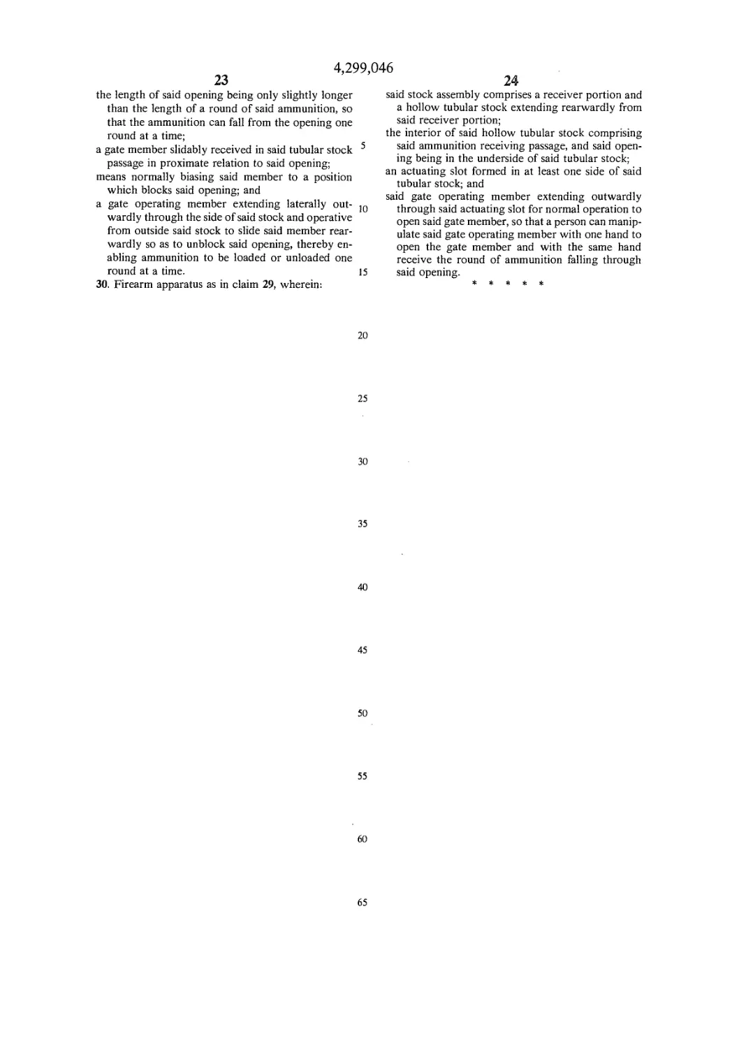
U.S. Patent Nov. 10, i98i
Sheet 1 of 9
4,299,046
U.S. Patent Nov. 10, i98i
Sheet 2 of 9
4,299,046
U.S. Patent Nov. 10, i98i
Sheet 3 of 9
4,299,046
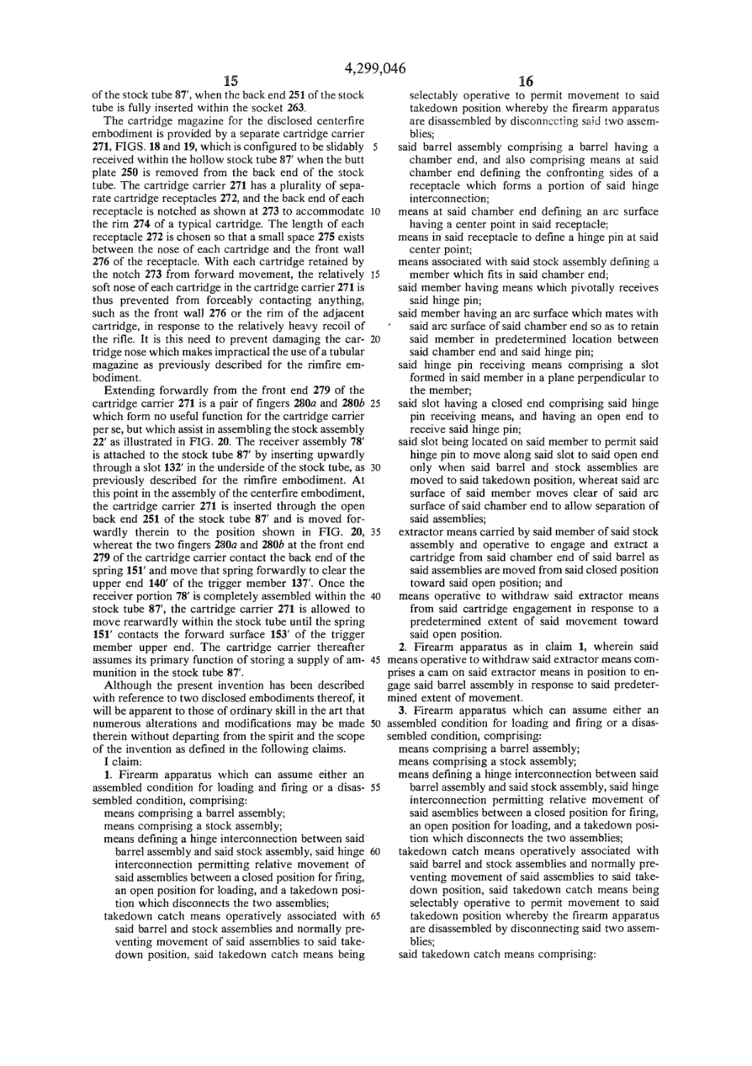
4OR 34R
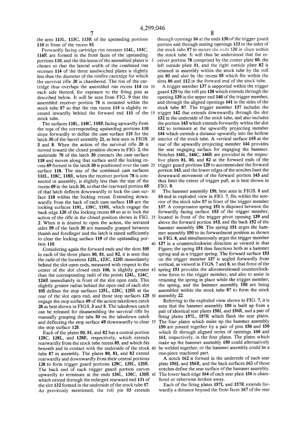
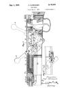
79 l6,° 151 164 \ 133 J41 / 86 in / l56RU \ \T 160 ',62 r l4f144 87 io? J ^4 rX. ^lllll^—P । _JJ -ZuUl jll '"\'" &“ >«4. ,7fi l7\\ I J^V-180 , 176^ \\^[ШК~84С \ '82>' \\ l29C ")R?46C \ \V H0RH3R/ \ 13 RftTX \\85r\Jl ll8R \ ^1R-84R VW I29R 78 W. i II4r\ \\^k J JP4—\ \ Л I28R /7 f" 82' I23R ^srSj.-- 160 /I57L I56L 161 Пб2 i 1 168 ^fc"5hei -Z^z*7'- 7 4^Л1к—167 r ®Г Д172 P-167.^, 150 ll0,L H?L <ч68>'^Ч83 1 > H8L $Si3ol i46L 85ii AJXi|3L 1 84L / И) II4L \zl29L ПЗС J=======inW^ (F< Z88L \XllOC||9C 1 r||8(. |IT \/>SL \\Xjl/Ji / /vIO5L 85сАД 128 L ИГ V 92 ГС > V94 1 \X'93|23U"< 9fil II / YioecWx i25i>> ^L / /Л XXV98 'AikA.101 4L 80 / 1 /\-'Vv* \ 95 y-88R । где 1 A* \ \-IO6R <ЛГ\ XIO5C 100 2g7IO5R 124c MS-96R X-I24R
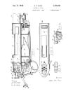
.Patent Nov. 10, 1981 Sheet 4 of 9 4,299,046
U.S. Patent Nov. 10, i98i
Sheet 6 of 9
4,299,046
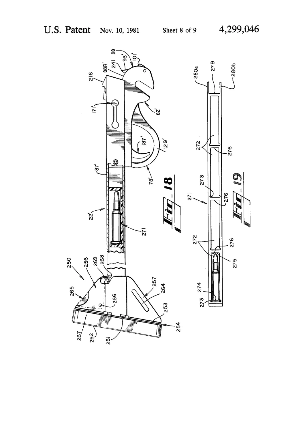
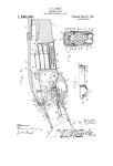
U.S. Patent Nov. 10, 1981 Sheet 7 of 9 4,299,046
U.S. Patent Nov. io, i98i
Sheet 8 of 9
4,299,046
250
U.S. Patent Nov. 10, i98i
Sheet 9 of 9
4,299,046
4,299,046
1
SINGLE-SHOT SURVIVAL RIFLE
DESCRIPTION
1. Technical Field
This invention relates in general to firearms, and in
particular to relatively small, lightweight rifles that are
primarily intended for survival use in emergency situa-
tions.
2. Background of the Invention
The term “survival rifle” is commonly used in refer-
ring to a firearm which is primarily intended for use as
a personal survival weapon in unforeseen or emergency
situations. Persons such as campers, boaters, or flyers
who travel through or over wilderness locations may
not want to carry a conventional rifle due to its weight
and size, but those persons may nonetheless want a
weapon of greater accuracy than a handgun for hunting
small game or for personal protection if they suddenly
become stranded in the wilderness by a mishap such as
a downed airplane or a broken vehicle. The ideal sur-
vival rifle should be relatively lightweight and com-
pact, so as not to add significant weight to a backpacker
and so as to conveniently fit within a pack, a small
airplane, or in some other location not normally sized to
receive a conventional rifle. A survival rifle should also
be relatively inexpensive to manufacture, and should be
capable of quick and easy assembly by the user without
requiring tools or connective parts such as bolts that can
easily become lost in the field. The survival rifle should
also be capable of carrying a supply of ammunition.
Attempts have been made in the prior art to produce
survival rifles which meet some of the foregoing crite-
ria. Known examples of such prior art include the U.S.
Air Force (USAF) M4 .22 Hornet bolt action rifle, the
USAF Мб .22/.410 over/under survival rifle, the Ar-
malite/Charter Arms AR-7 .22 semiautomatic survival
rifle, and the Garcia “Bronco” single shot survival rifle
with a skeleton stock. The foregoing guns are relatively
large, expensive, heavy, complex, and slow to assemble,
particularly in the context of possible assembly and use
under adverse conditions where the user may be wear-
ing mittens or gloves.
SUMMARY OF THE INVENTION
Stated in general terms, the present invention con-
cerns a survival rifle which consists of two basic assem-
blies, a barrel assembly and a stock assembly. The two
assemblies are quickly and easily interconnected or
disconnected by a hinge joint which requires no sepa-
rate fastening elements, and the assembled rifle breaks at
this joint for loading rounds and ejecting spent shell
casings. Stated somewhat more specifically, the rifle of
the present invention has a hinge pin on one assembly
which fits into an open slot on the other assembly to
form the hinge joint, and the assembled rifle pivots
about that hinge joint to provide a breech-loading ac-
tion. A takedown latch normally prevents the breech
action from opening to the extent required for taking
down the rifle into its two separate assemblies. The
survival rifle makes extensive use of sheet-metal parts
that can be fabricated relatively inexpensively, and the
stock assembly includes a hollow stock tube which
functions as an ammunition magazine. The present sur-
vival rifle can be provided in either rimfire or centerfire
configurations.
5
10
15
20
25
30
35
40
45
50
55
60
65
2
Accordingly, it is an object of the present invention
to provide an improved survival rifle.
It is another object of the present invention to pro-
vide a single-shot survival rifle which is relatively com-
pact and lightweight.
It is yet another object of the present invention to
provide a single-shot survival rifle which is quick and
easy to assemble.
It is still another object of the present invention to
provide a survival rifle which is relatively inexpensive
to manufacture.
Other objects and advantages of the present invention
will become apparent from a review of the following
detailed description of the disclosed embodiments and
the appended drawings and claims.
BRIEF DESCRIPTION OF THE DRAWINGS
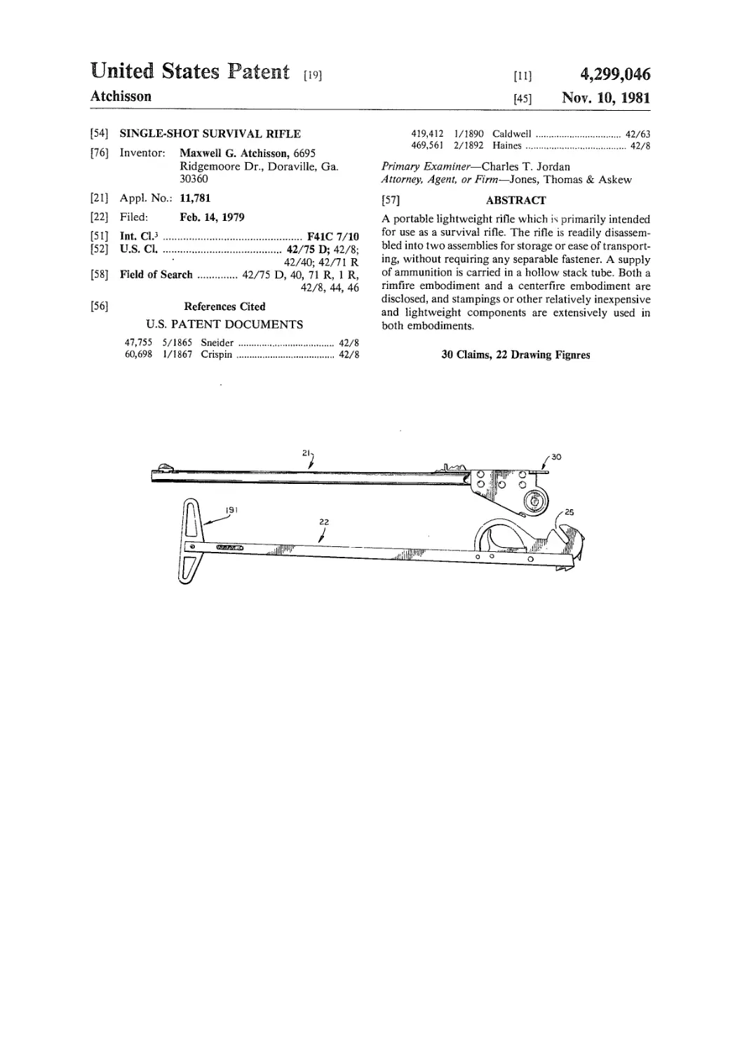
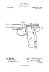
FIG. 1 is a pictorial view showing the two disassem-
bled portions of a survival rifle according to a first
disclosed embodiment of the present invention.
FIG. 2 shows the two components of FIG. 1 assem-
bled to form a survival rifle, with the barrel and stock
being broken for illustrative purposes.
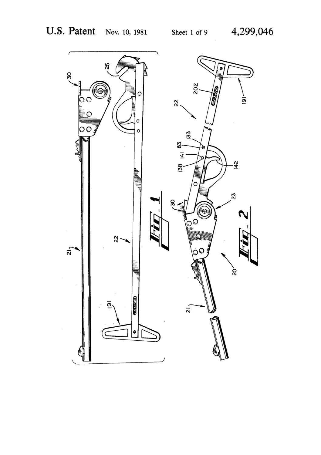
FIG. 3 shows a fragmentary side view of the assem-
bled rifle of FIG. 2, showing the action broken short of
the fully-open position and showing a partially ex-
tracted cartridge.
FIG. 4 is a fragmentary side view as in FIG. 3, show-
ing the action broken to its fully-open position and
showing a round in loading position.
FIG. 5 is a partial side view of the embodiment
shown in FIG. 1, showing the action opened beyond its
fully-open position to facilitate taking down the rifle,
and in phantom showing the stock assembly discon-
nected at the hinge joint.
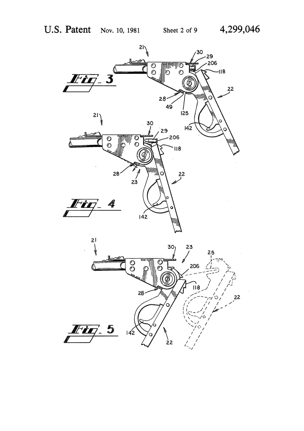
FIG. 6 shows an exploded view of the barrel assem-
bly of the survival rifle shown in FIG. 1.
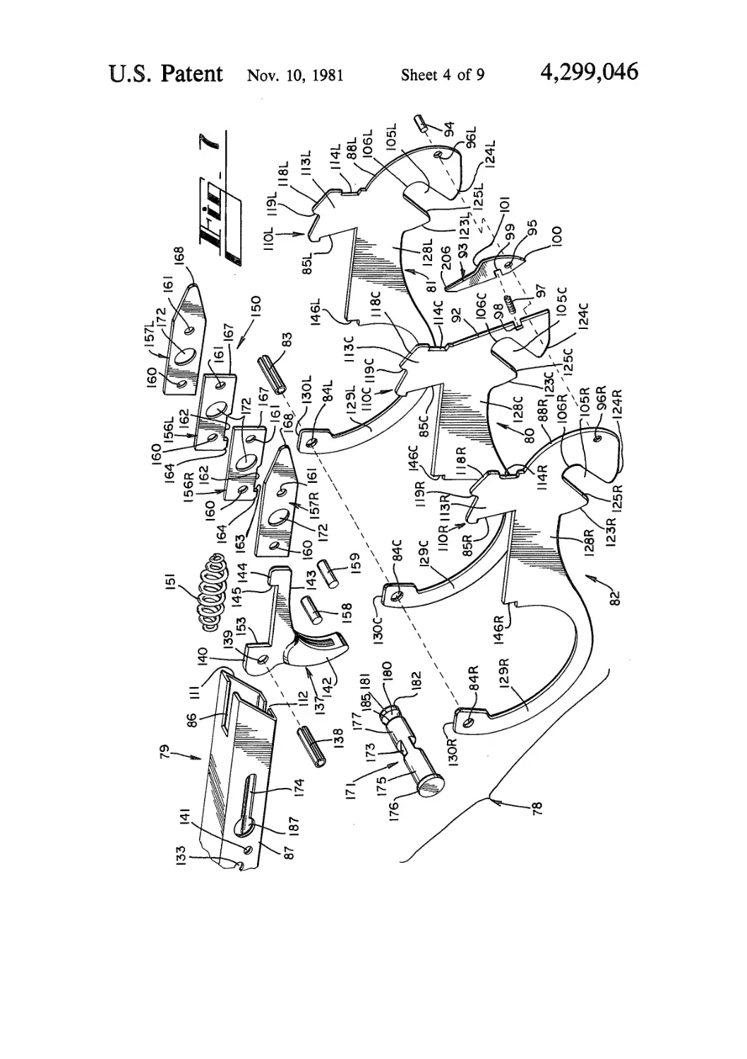
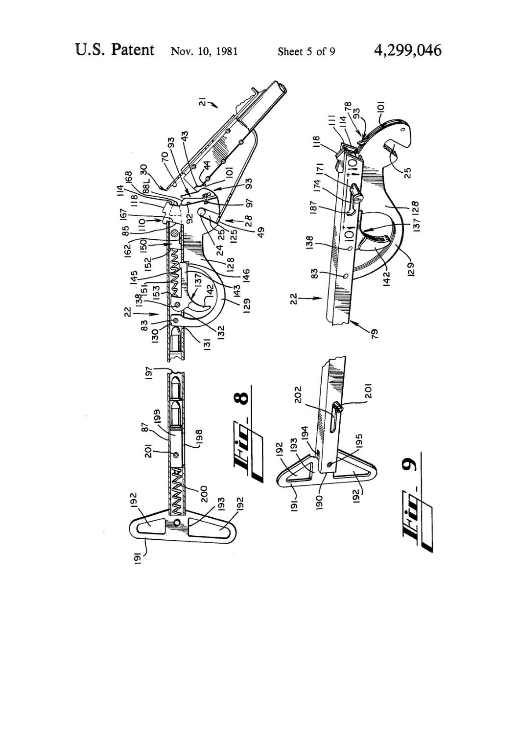
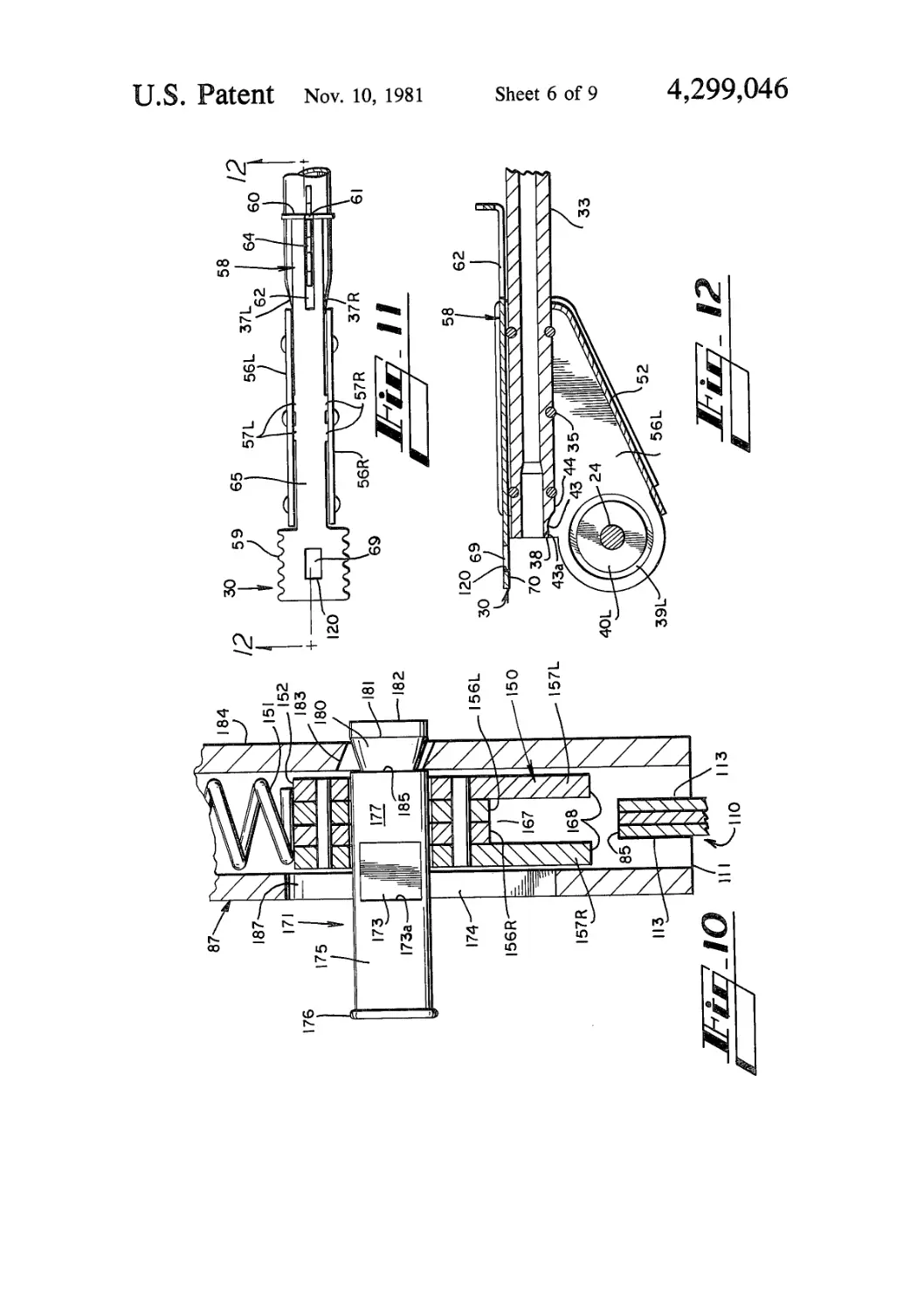
FIG. 7 shows an exploded partial view of the stock
assembly of the rifle shown in FIG. 1.
FIG. 8 shows a right-side elevation view of the rifle
of FIG. 1 with the action fully open, and with the stock
assembly sectioned and broken for illustrative purposes.
FIG. 9 is a broken pictorial view showing the stock
assembly of the rifle in FIG. 1.
FIG. 10 is a section view taken along line 10—10 of
FIG. 9, with the bolt cocked and showing details of the
hammer-firing pin assembly and the safety mechanism.
FIG. 11 is a fragmentary top plan view of the barrel
assembly, showing details of the action latch.
FIG. 12 is a sectioned right-side elevation view of the
barrel assembly fragment shown in FIG. 11.
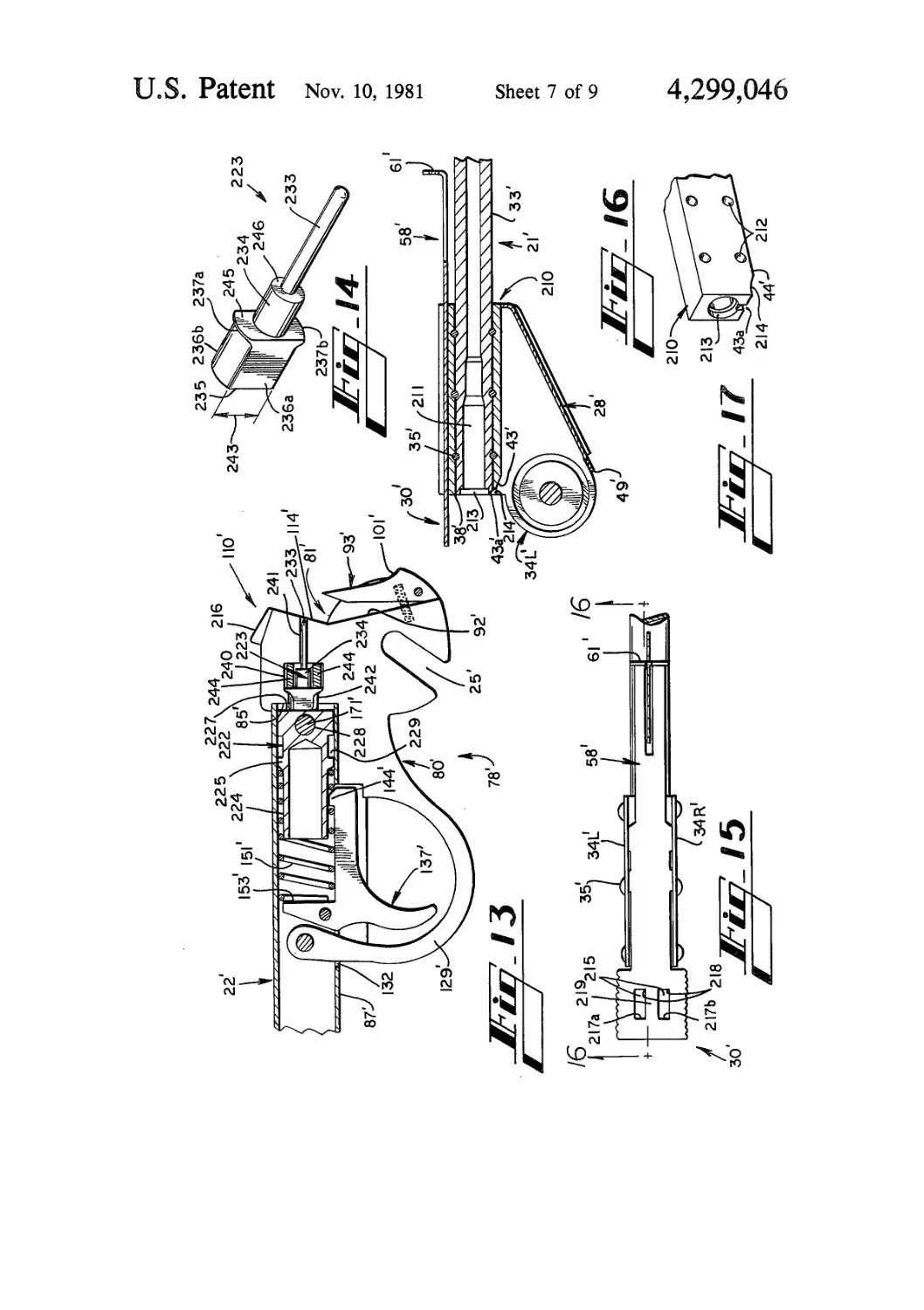
FIG. 13 is a sectioned right-side elevation view show-
ing the stock assembly of a survival rifle according to a
second disclosed embodiment of the present invention.
FIG. 14 is a pictorial view showing the firing pin of
the embodiment depicted in FIG. 13.
FIG. 15 is a fragmentary top plan view of the barrel
assembly for the second embodiment showing details of
the action latch.
FIG. 16 is a sectioned right-side elevation view of the
barrel assembly fragment shown in FIG. 15.
FIG. 17 is a pictorial view of the barrel block shown
in FIG. 16.
FIG. 18 is partially sectioned and broken right-side
elevation view of the stock assembly for the second
embodiment.
FIG. 19 is a top plan view of the cartridge carrier
forming part of the second embodiment.
4,299,046
3
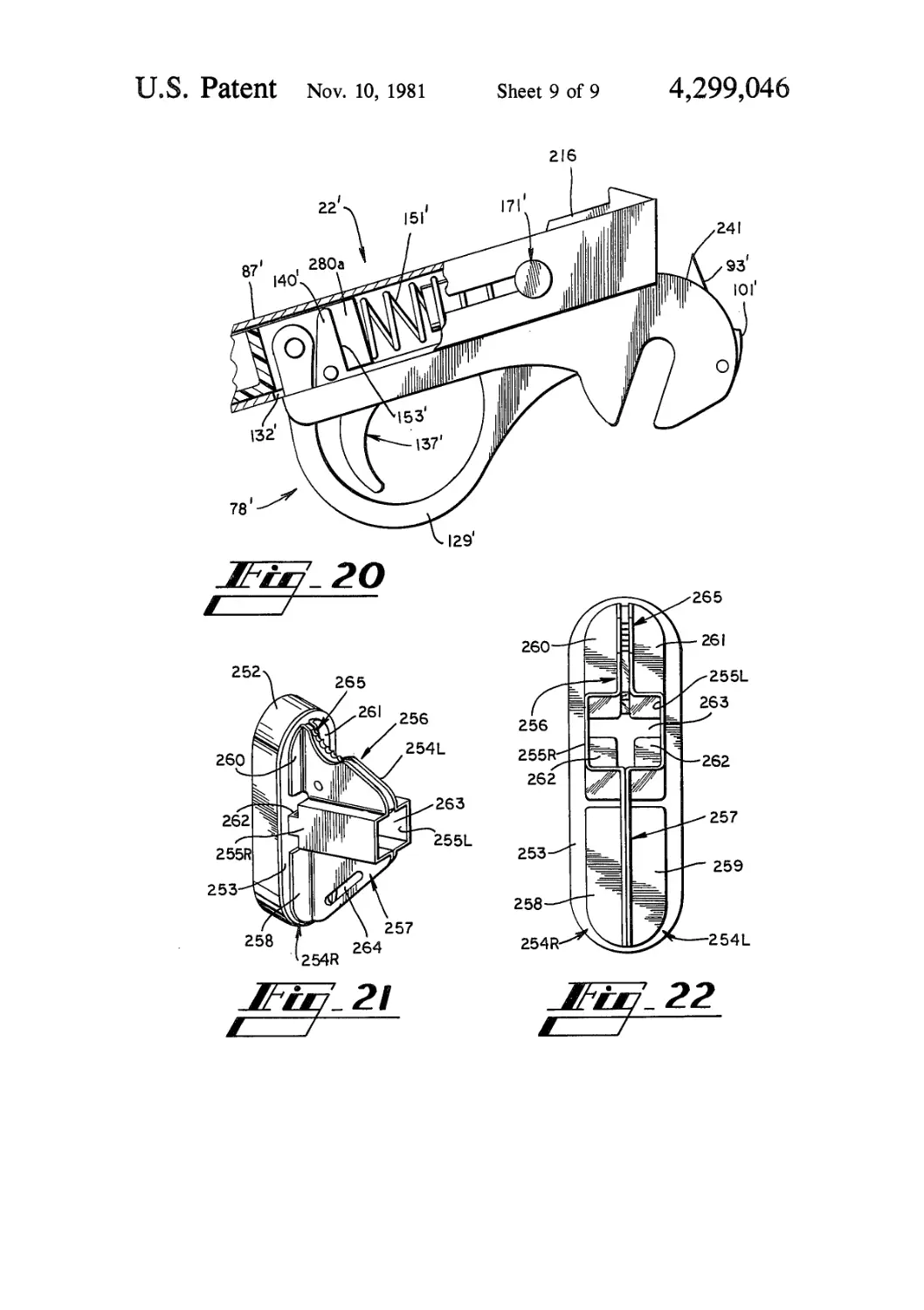
FIG. 20 is a fragmentary and partially sectioned
right-side elevation view of the stock assembly for the
second embodiment, showing the hammer spring com-
pressed for installation of the receiver assembly.
FIG. 21 is a pictorial view of the buttplate assembly 5
for the secondd embodiment.
FIG. 22 is a front elevation view of the buttplate
assembly shown in FIG. 21.
DETAILED DESCRIPTION OF THE „
DISCLOSED EMBODIMENTS
Two embodiments of the present survival rifle are
disclosed and described herein, a rimfire embodiment
shown in FIGS. 1-12 and a centerfire embodiment
shown in FIGS. 13-22. The disclosed rimfire embodi- 15
rnent is chambered for the .22 long rifle cartridge, and
the centerfire embodiment is chambered for the .30—30
Winchester cartridge, although it will be obvious to
those skilled in the art that rifles according to the pres-
ent invention can be constructed for other calibers such 20
as .357 magnum, .223 Remington, and .410 shotgun
ammunition. The rimfire embodiment is described first,
and the centerfire embodiment is next described with
emphasis on differences between it and the disclosed
rimfire embodiment. 25
Turning initially to FIGS. 1-5, there is shown gener-
ally at 20 the disclosed rimfire embodiment of the pres-
ent survival rifle, consisting of a barrel assembly 21 and
a stock assembly 22 that are detachably interconnected
at the hinge joint 23. The hinge joint 23 includes a hinge 30
pin 24 in the barrel assembly 21 and best seen in FIGS.
6 and 8, and an open slot 25 contained in the stock
assembly 22 and best seen in FIGS. 5, 8, and 9. Al-
though a more detailed description of the hinge joint 23
is set forth below, the present description of the hinge 35
joint is sufficient to understand the following general
description of how the survival rifle 20 is assembled for
loading and firing, and is taken down for disassembly.
It should be understood that the survival rifle 20,
when not in use, will typically be broken down into the 40
separate barrel assembly 21 and stock assembly 22 as
shown in FIG. 1, and those two assemblies may be
stowed in a suitable carrying case (not shown) or the
like. When the survival rifle 20 is to be used, the barrel
assembly 21 is aligned with the stock assembly 22 as 45
shown in phantom in FIG. 5, so that the hinge pin slot
25 is aligned with the hinge pin 24. The barrel assembly
and stock assembly are next moved together so that the
stock assembly assumes the position shown in solid line
in FIG. 5, with the hinge pin 24 seated at the closed end 50
of the slot 25. The stock assembly is next rotated coun-
terclockwise to the position seen in FIG. 4, where the
takedown latch 28 engages a surface of the stock assem-
bly to prevent the stock assembly from returning to the
disassembly position shown in FIG. 5. The survival rifle 55
20 is now assembled and ready to be breech-loaded with
a round of ammunition 29.
Once the survival rifle 20 is loaded, the stock assem-
bly is pivoted about the hinge joint 23 to assume the
position shown in FIG. 2, with the breech-loading ac-
tion closed and ready for firing. The latch 30 retains the
action in the closed position shown in FIG. 2.
When it is desired to take down the survival rifle 20,
the foregoing procedure is reversed with the takedown
latch 28 being manipulated as described below and as
shown in phantom in FIG. 4 to permit the barrel assem-
bly 21 and the stock assembly 22 to assume the disas-
sembly position shown in FIG. 5. The hinge joint 23 is
now disconnected simply by moving the stock assembly
to the position shown in phantom, thereby withdrawing
the hinge pin 24 from the slot 25.
The two assemblies which make up the survival rifle
21 are now considered in detail, with reference first to
the barrel assembly 21 as particularly shown in FIG. 6.
The barrel assembly includes a barrel 33 which is re-
tained at its rear or breech end between a right side
plate 34R and a left side plate 34L. The side plates 34L
and 34R form a permanent assembly with the barrel 33,
and are interconnected by the several rivets 35 which
extend through the side plates and through aligned rivet
grooves 36 cut in the top and bottom exterior surface of
the barrel 33. Flat surfaces 37L and 37R are machined
into the exterior of the barrel 33 on opposite sides
thereof, where the side plates 34L and 34R engage the
barrel, so that the side plates firmly and rigidly engage
the barrel in permanent assembly. The underside of the
breech end 38 of the barrel 33 is formed in an arc 43,
FIGS. 6 and 12, and a slot 43a extends upwardly into
the arc portion in alignment with the bore of the barrel.
The purpose of the arc 43 and the slot are discussed
below.
Each of the side plates 34L and 34R has a region
which is deformed or dished inwardly from the outer
surface of the side plate, at a location disposed below
the breech end 38 of the barrel 33. The deformed region
for the right side plate 34R is shown at 39R on FIG. 6,
and at 39L on FIGS. 6 and 12. The deformed regions
39R and 39L form a pair of opposed and parallel
spaced-apart surfaces 40R and 40L, which confront
each other in the space between the side plates; these
confronting surfaces form part of the hinge joint 23,
previously discussed.
A pair of coaxially aligned holes 41L and 41R are
formed in the two deformed regions 39L and 39R, and
the hinge pin 24 extends through those holes. The hinge
pin 24 has a central portion 41 of enlarged diameter
defining the spacing between the surfaces 40L and 40R,
and which forms the hinging surface about which the
hinge joint 23 is received. The hinge pin 24 is preferably
permanently mounted through the deformed regions
39L and 39R of the side plates by way of peened ends
42.
Each of the side plates 34L and 34R has a pair of slots
45L, 45R formed adjacent the lower edges 46L, 46R of
the side plates, and those slots accept the mating tabs
47L, 47R which project outwardly from the sides of the
takedown catch 28. This takedown catch, which is
retained between the side plates and thus forms part of
the permanently-connected barrel assembly 21, is
stamped or otherwise formed from sheet metal and has
a forward end 48 which is bent upwardly from the plane
of the takedown catch to fit against the underside of the
barrel 33. A curved surface 48' is formed at the end of
the upturned portion 48, to accommodate the exterior
surface of the barrel.
The other end of the takedown catch 28 terminates at
a surface 49 which provides a stop for limiting the maxi-
mum opening of the survival rifle action, as previously
discussed relative to FIG. 4 and as set forth below in
further detail. The width of the takedown catch 28
adjacent the stop surface 49 is enlarged to form the
finger tabs 50. These finger tabs of the takedown catch
28 fit behind the cut-away portions 51 of the two side
plates 34L and 34R, and the lateral extent of the finger
tabs is slightly greater than the thickness of the assem-
bled side plates so that the finger tabs extend therefrom
4,299,
5
to permit manual grasping. It will be understood that
the lateral width of the takedown catch 28, at the por- .
tion 52 located between the tabs 50 and the rearward
tabs 47L and 47R, is slightly less than the corresponding
dimension between the two side plates 34L and 34R, so 5
that the takedown catch 28 is supported by the tabs 47
in cantilever fashion to be deformed downwardly when
force is manually applied to the tabs 50.
Another group of slots 55L and 55R are also formed
in the left side plate 34L and the right side plate 34R, 10
respectively, adjacent the upper edges 56L and 56R
thereof. These slots adjacent the upper edges of the side
plates receive mating tabs 57L and 57R which project
outwardly from the sides of the stamped member 58,
which is thereby fixed between the side plates to form 15
the top part of the permanent barrel assembly.
The plate 58 is laterally enlarged at its rear end to
form the latch 30, previously described, and serrations
59 are formed along the sides of the enlarged portion to
aid in manually grasping the latch. 20
The forward end of the plate 58 is upwardly turned at
60 and has an upwardly-facing notch 61 to provide an
open sight of conventional design. A longitudinally-
extending elevator slot 62 is formed in the forward
portion 63 of the plate 58, extending backwardly from 25
the upturned forward end 60, and a conventional eleva-
tor ramp 64 is received within the elevator slot 62 to
provide elevation adjustment of the rear sight 61, in the
conventional manner. The forward portion 63 of the
plate 58, as well as the rearward portion 65 thereof 30
which extends between the tabs 57 and the enlarged
latch 30, have a lateral dimension slightly less than the
spacing between the confronting inner surfaces of the
side plates 34L and 34R, so that both the front end 60
and the latch 30 of the plate 58 can be manually elevated 35
in opposition to the cantilever spring effect provided by
that plate.
A locking recess 69 is formed in the latch 30 at a point
between the serrated sides 59. The underside 70 of the
latch 30 provides a camming surface which rides over 40
the action latch 118 of the stock assembly 22, as de-
scribed below, and the locking recess 69 engages that
action latch to maintain the breech-loading action in
closed and locked condition.
A front sight 73, which may be a standard type of 45
sight, is fitted to the front end of the barrel 33 by any
suitable technique, such as with a dovetail which meets
with a transverse slot cut in the top of the barrel.
The stock assembly 22 is now described with particu-
lar reference to the exploded view shown in FIG. 7 and 50
the sectional view shown in FIG. 8. For descriptive
purposes the stock assembly 22 may be considered as
comprising a receiver portion 78 and a stock portion 79,
identified in FIG. 7, although it will become apparent
that some overlap exists in the structure and function of 55
those receiver and stock portions.
The receiver portion 78, as best seen in FIG. 7, is built
up from a laminated assembly of three plates, being the
center plate 80, the left outside plate 81, and the right
outside plate 82. These three plates are normally sand- 60
wiched together and are held in assembly by a fastener
such as a roll pin 83 which extends through the aligned
openings 84L, 84C, 84R located at the back of the plates
and through the opening 141 in the stock tube 87, and
by the recesses 85L, 85C, and 85R which are formed at 65
the top forward portions of the plates and which engage
the slot 86 extending rearwardly from the top front end
of the stock tube 87.
046
6
Each of the two outside receiver plates 81 and 82 may
be identical in shape, and each of those receiver plates
has at the forward end an arc 88L and 88R, respec-
tively. The arcs 88L and 88R provide a clearance fit
next to the arc 43, FIGS. 6 and 12, which is formed in
the underside of the barrel 33 at its breech end 38, when
the hinge joint 23 is interconnected. The corresponding
front portion of the center plate 80 is cut away as shown
at 92, FIG. 7, thus forming a recess for the extractor 93
between the two outside plates 81 and 82. The extractor
93, which is explained below in greater detail, is
mounted in assembly within the receiver portion 78 by
a pin 94 which extends through an opening 95 in the
extractor member and is received in mating openings
96L and 96R in the left and right outside plates, respec-
tively. An extractor spring 97 is captured between a
forwardly facing recess 98 formed in the cut away por-
tion 92 of the center plate 80, and a confronting rear-
wardly facing recess 99 formed in the back side of the
extractor member. The extractor spring 97 urges the
extractor member 93 to a forwardmost position deter-
mined by abutment of the extractor lower surface 100
with the confronting surface of portion 92 of the center
plate. The forward surface 101 of the extractor member
93 projects slightly outwardly beyond the radii 88L and
88R of the two outside plates 81 and 82, and that surface
101 forms a camming surface which engages the radius
43 at the breech end of the barrel 33 to withdraw the
extractor when the action of the survival rifle is broken
open to a certain extent, as described below.
Respective slots 105L, 105C, and 105R are formed at
the undersides of the forward ends of the left outside
plate 81, the center plate 80, and the right outside plate
82. The slots 105L and 105R extend downwardly from
closed upper ends 106L, 106R, which are substantially
concentric with the radii 88L, 88R, to the open lower
ends, and the slot 105C in the center plate 80 is identical
in configuration to the other two slots. The slots 105 are
mutually aligned when the three plates 81, 80, and 82
are sandwiched together in assembly, and the width of
the slots is sufficient to receive the enlarged portion 41
of the hinge pin 24 on the barrel assembly 21.
It will now be appreciated that the outside surfaces of
the left and right plates 81 and 82 freely fit within the
surfaces 40L and 40R of the barrel assembly side plates
34L and 34R. These mutually confronting surfaces 40L
and 40R, along with the hinge pin 24 and the aligned
slots 105 of the assembled plates which make up the
receiver portion 78, comprise the hinge joint 23. It will
also be apparent that the angular orientation of the
aligned slots 105 determines the relative angular posi-
tion of the barrel assembly 21 and the stock assembly 22
at which the survival rifle can be assembled or disassem-
bled, as previously described with reference to FIG. 5.
The center plate 80 and the outside plates 81 and 82
each have an upstanding portion HOC, HOL, and H0R,
respectively, located at the forward ends of the plates at
a location generally above and in back of the arcs 88L
and 88R. The upstanding portions 110 include rear-
wardly facing surfaces which define the recesses 85,
previously mentioned, that retain the forward end 111
of the stock tube 87, and it will be seen that the surfaces
which make up the recess 85 also serve to stop forward
movement of the hammer assembly. The stock tube 87,
which is a hollow tubular member of square cross-sec-
tion in the disclosed embodiment, has slots 86 and 112
extending inwardly from the upper and lower surfaces
of the forward end 111, and those slots accommodate
4,299,046
7
the area 113L, 113C, 113R of the upstanding portions
110 in front of the recess 85.
Forwardly facing cartridge rim recesses 114L, 114C,
114R are formed in the front faces of the upstanding
portions 110, and the thickness of the assembled plates is
chosen so that the lateral width of the combined rim
recesses 114 of the three sandwiched plates is slightly
less than the diameter of the rimfire cartridge for which
the survival rifle 20 is chambered. The rim of the car-
tridge thus overlaps the assembled rim recess 114 on
each side thereof, for exposure to the firing pins as
described below. It will be seen from FIG. 9 that the
assembled receiver portion 78 is mounted within the
stock tube 87 so that the rim recess 114 is slightly re-
cessed inwardly behind the forward end 111 of the
stock tube.
The surfaces 118L, 118C, 118R facing upwardly from
the tops of the corresponding upstanding portions 110
slope forwardly to define the cam surface 118 for the
latch 30 of the barrel assembly 21, as best seen in FIGS.
3 and 8. When the action of the survival rifle 20 is
moved toward the closed position shown in FIG. 2, the
underside 70 of the latch 30 contacts the cam surface
118 and moves along that surface until the locking re-
cess 69 formed in the latch 30 is positioned over the cam
surface 118. The size of the combined cam surfaces
118L, 118C, 118R, when the receiver portion 78 is con-
nected in assembly, is slightly less than the size of the
recess 69 in the latch 30, so that the rearward portion 65
of that latch deflects downwardly to lock the cam sur-
face 118 within the locking recess. Extending down-
wardly from the back of each cam surface 118 are the
locking surfaces 119L, 119C, 119R, which engage the
back edge 120 of the locking recess 69 so as to lock the
action of the rifle in the closed position shown in FIG.
2. When it is desired to open the action, the serrated
sides 59 of the latch 30 are manually grasped between
thumb and forefinger and the latch is raised sufficiently
to clear the locking surface 119 of the upstanding por-
tion 110.
Considering again the forward ends and the slots 105
in each of the three plates 80, 81, and 82, it is seen that
the radii of the locations 123L, 123C, 123R immediately
behind the slot open ends, measured with respect to the
center of the slot closed ends 106, is slightly greater
than the corresponding radii of the points 124L, 124C,
124R immediately in front of the slot open ends. This
slightly greater radius behind the open end of each slot
105 defines the stop surfaces 125L, 125C, 125R at the
rear of the slot open end, and those stop surfaces 125
engage the stop surface 49 of the action takedown catch
28 as best shown in FIGS. 3 and 8. The takedown catch
can be released for disassembling the survival rifle by
manually grasping the tabs 50 on the takedown catch
and deflecting the stop surface 49 downwardly to clear
the stop surface 125.
Each of the plates 80, 81, and 82 has a central portion
128C, 128L, and 128R, respectively, which extends
rearwardly from the stock tube recess 85, and which fits
beneath and in contact with the underside of the stock
tube 87 in assembly. The plates 80, 81, and 82 extend
rearwardly and downwardly from their central portions
128 to form trigger guard portions 129C, 129L, 129R.
The back end of each trigger guard portion curves
upwardly to terminate at the ends 130L, 130C, 130R
which extend through the enlarged rearward end 131 of
the slot 132 formed in the underside of the stock tube 87.
As previously mentioned, the roll pin 83 extends
5
10
15
20
25
30
35
40
45
50
55
60
65
8
through openings 84 at the ends 130 of the trigger guard
portion and through mating openings 133 in the sides of
the stock tube 87 to secure the ends 130 in place within
the stock tube. It will thus be understood that the re-
ceiver portion 78 comprised by the center plate 80, the
left outside plate 81, and the right outside plate 82 is
retained in assembly within the stock tube by the roll
pin 83 and also by the recess 85 which fits within the
slots 86 and 112 in the forward end of the stock tube.
A trigger member 137 is supported within the trigger
guard 129 by the roll pin 138 which extends through the
opening 139 in the upper end 140 of the trigger member,
and through the aligned openings 141 in the sides of the
stock tube 87. The trigger member 137 includes the
trigger 142 that extends downwardly through the slot
132 in the underside of the stock tube, and also includes
the portion 143 which extends forwardly within the slot
132 to terminate at the upwardly projecting member
144 which extends a distance upwardly into the hollow
interior of the stock tube. A vertical surface 145 at the
rear of the upwardly projecting member 144 provides
the sear engaging surface for engaging the hammer.
Notches 146L, 146C, 146R are provided in the respec-
tive plates 81, 80, and 82 at the forward ends of the
trigger guard portions 129 to accommodate the forward
portion 143, and the lower edges of the notches limit the
downward movement of the forward portion 143 and
thus limit the extent of trigger pull, as is best shown in
FIG. 8.
The hammer assembly 150, best seen in FIGS. 8 and
10 and in exploded view in FIG. 7, fits within the inte-
rior of the stock tube 87 in front of the trigger member
137. A compression spring 151 is disposed between the
forwardly facing surface 153 of the trigger member,
located in front of the trigger pivot opening 139 and
above the forward portion 143, and the back 152 of the
hammer assembly 150. The spring 151 urges the ham-
mer assembly 150 to its forwardmost position as shown
in FIG. 8, and simultaneously urges the trigger member
137 in a counterclockwise direction as viewed in that
Figure; the spring 151 thus functions both as a hammer
spring and as a trigger spring. The forward surface 153
on the trigger member 137 is angled forwardly from
vertical, as viewed in FIGS. 7 and 8, so that force of the
spring 151 provides the aforementioned counterclock-
wise force to the trigger member, and also to assist in
retaining the spring in place while the trigger member,
the spring, and the hammer assembly 150 are being
assembled within the stock tube 87 to form the stock
assembly 22.
Referring to the exploded view shown in FIG. 7, it is
seen that the hammer assembly 150 is built up from a
pair of identical sear plates 156L and 156R, and a pair of
firing plates 157L, 157R which flank the sear plates.
The four plates which make up the hammer assembly
150 are pinned together by a pair of pins 158 and 159
which fit through aligned series of openings 160 and
161, respectively, in the four plates. The plates which
make up the hammer assembly 150 could alternatively
be welded together, or the hammer assembly could be a
one-piece machined part.
A notch 162 is formed in the underside of each sear
plate 156L and 156R, and the back surfaces 163 of those
notches define the sear surface of the hammer assembly.
The lower back edge 164 of each sear plate 156 is cham-
fered or otherwise broken away.
Each of the firing plates 157L and 157R extends for-
wardly a distance beyond the front faces 167 of the sear
4,299
9
plates 156, and the forward end of each firing plate
converges to an edge 168. The edges 168 of the firing
plates extend in front of the surfaces 167 of the sear
plates and are vertically located about mid-height of the
hammer assembly 150.
Referring to FIGS. 8 and 10, it is seen that the front
faces 167 of the sear plates form a surface which
contacts the recess 85 defined on the plates 80, 81, 82 at
the back side of the upstanding portion 110, so that
forward movement of the hammer assembly by the
spring 151 is limited by contact between the surfaces
167 and 85. The firing plates 157 of the hammer assem-
bly pass along the side areas 113 of the upstanding por-
tion 110 as the hammer assembly travels home to its
fully forward position, at which position the edges 168
protrude on both sides of the rim recess 114. Thus, the
edges 168 of the firing plates form double rimfire firing
pins.
A charging handle 171, best seen in FIGS. 7 and 10,
slidably extends through the aligned transverse open- 20
ings 172 in the sear plates and firing plates which make
up the hammer assembly 150. The charging handle 171
is a cylindrical member having a pair of flat surfaces 173
on opposed sides, where the charging handle extends
through the slot 174 in the right side of the stock tube 25
87. The dimension between the flat surfaces 173 of the
charging handle permit sliding longitudinal movement
of the charging handle within the slot 174, and also
permit the charging handle to be moved transversely
within the slot as pointed out below. The charging 30
handle 171 has a shank 175 which extends outwardly
from the slot 174, and which terminates at a rounded
knob 176 at the outer end of the charging handle.
The charging handle 171 includes a hammer assembly
engaging surface 177 which slidably fits within the 35
opening 172 through the hammer assembly 150, and the
charging handle terminates with the tapered surface
180, which tapers from a maximum diameter at the
circumferential location 181, spaced inwardly a short
distance from the end 182 of the charging handle, to the 40
point 185 of minimum diameter which is contiguous to
the hammer engaging surface 177. The end 182 and the
tapered surface 180 of the charging handle 171 are
aligned with the angled opening 183 in the left side 184
of the stock tube 87, when the bolt assembly 150 is at 45
maximum rearward travel within the stock tube, and
the flat surfaces 173 extending through the slot 174 in
the stock tube permit sufficient lateral movement of the
charging handle to selectively insert or to withdraw the
tapered surface 181 from the hole 183. As best seen in 50
FIG. 10, the hole 183 in the stock tube side 184 is raked
backwardly at an angle which is approximately the
same as the taper angle of the tapered surface 180 at the
end of the charging handle 171, so that the surface of
the opening 183 engages the forward side of the tapered 55
surface 180 to inhibit accidental or inadvertent with-
drawal of the charging handle 175 from safety position.
An enlarged opening 187, FIG. 9, joins the rear end
of the slot 174 in the right side of the stock tube 87. The
charging handle 171 is inserted through the enlarged 60
hole 187 and thence through the opening 172 in the
hammer assembly 150, during assembly of the receiver
portion 78 with the stock tube 79. The hammer assem-
bly and charging handle are then slid to the full-forward
position, after which the spring 151 and the trigger 65
member 137 are installed as aforementioned, where-
upon the hammer assembly and the charging handle are
retained in assembly within the stock tube 87.
046
10
The stock tube 87 extends rearwardly from the re-
ceiver portion 78 to terminate at the back end 190, and
the butt plate 191 is attached to the back end of the
stock tube. The butt plate 191 may be stamped from
5 sheet metal, and is shown with portions 192 cut away to
lighten the survival rifle. The butt plate 191 has a solid
central portion 193 which fits within a vertical slot 194
extending inwardly from the end 190 of the stock tube.
A roll pin 195 extends through a hole in the butt plate
10 end through mating holes in the sides of the stock tube,
to secure together the butt plate and the stock tube.
The hollow interior of the stock tube extending rear-
wardly of the trigger guard end 130 provides a car-
tridge magazine 197, and nine rounds of .22 long rifle
15 ammunition can be stored within the magazine of an
actual embodiment of a rimfire survival rifle according
to the present invention. Access to the magazine 197 is
provided through the loading slot 198 formed in the
underside of the stock tube 87, and the slot is normally
kept closed by a gate member 199 which is slidably
received within the stock tube and is biased forwardly
by the compression spring 200. The gate 199 can be
opened by manipulating the gate pin 201 which fits
through a lateral hole in the gate, and which extends
through slots 202 extending along both sides of the
stock tube 87. The loading slot 198 is preferably only
slightly longer than a round of ammunition for which
the survival rifle is chambered, so that ammunition can
be removed from the magazine one round at a time
while wearing gloves or the like.
The operation of the survival rifle 20 is now briefly
described, although that operation may be apparent
from the foregoing detailed description. Once the rifle
has been assembled by interconnecting the hinge joint
23, a round of ammunition is withdrawn from the maga-
zine 197 and is loaded in the open breech, as indicated at
29 in FIG. 4. The action of the survival rifle is then
closed and locked by latch 30, after which the rifle is
cocked by pulling back the charging handle 171 until
the sear engaging surface 145 of the hammer member
engages the sear surface 163 of the hammer assembly.
The rifle is now ready to fire. The safety can be engaged
by sliding the knob end 176 of the charging handle 171
inwardly toward the stock tube, so that the surface 177
slides through the hammer assembly until the tapered
surface 180 at the other end of the charging handle
moves into the angled opening 183 in the wall of the
stock tube. The opening 183 is preferably located so
that the bolt assembly 150 must be retracted a short
distance behind sear position in order to slide the charg-
ing handle inwardly to engage the safety. Inward move-
ment of the charging handle 171 is limited by abutment
of the radial surface 173o, where the flat surfaces 173
meet the outer end of the charging handle, against the
outside of the stock tube 87. The end 182 of the charg-
ing handle extends outwardly from the left side 184 of
the stock tube at this time, as seen in FIG. 10, providing
both a visual and a tactile indication that the survival
rifle is on safety. The bolt assembly is locked against
forward movement at this time. The survival rifle is
taken off safety by sliding the charging handle in the
opposite direction until the end 182 of the charging
handle is withdrawn from the opening 183 in the stock
tube wall.
After the survival rifle 20 has been fired, the action
latch 30 can be opened and the action broken open. As
seen in FIG. 3, the upper end 206 of the extractor mem-
ber 93 engages the rim of the spent cartridge casing to
4,299,046
11
partially extract that cartridge casing from the barrel.
As the action is broken to its fully-open position shown
in FIG. 4, the camming surface 101 of the extractor
member contacts the surface 44 on the underside of the
barrel, located immediately in front of the arc 43, so that
the upper end 206 of the extractor is withdrawn down-
wardly toward the arc 88 of the outside plates 81 and 82
which comprise the receiver portion 78. This with-
drawing of the upper end 206 enables the next round to
be loaded without obstruction by the extractor. When
the action is closed, the extractor member 93 is moved
backwardly by contacting the breech end 38 of the
barrel; the slot 43a accommodates the upper end 206 of
the extractor when the action is closed.
The disclosed centerfire embodiment of the present
survival rifle is now described, and primed numerals are
used in the following description for referring to assem-
blies or components that are like those of the rimfire
embodiment previously described. The centerfire em-
bodiment is described in the context of features which
differ from the rimfire embodiment, and it should be
understood that other features which may be essentially
unchanged from the rimfire embodiment are not de-
tailed in the following description.
Turning first to FIGS. 15 and 16, there is seen the
barrel assembly 21' including the barrel 33' having its
breech end secured in assembly between a pair of side
plates 34L' and 34R'. A plate 58' is positioned above the
barrel 33' at its breech end and is secured in assembly
between the two side plates. This plate 58' provides the
functions of a rear sight 61' and of the action latch 30',
although it will be seen that the construction of the
action latch is somewhat different from that of the em-
bodiment described above. A takedown latch plate 28'
below the barrel 33' is also secured in place between the
two side plates 34L' and 34R', and the rear surface 49' of
the takedown latch provides a stop surface which limits
the maximum extent to which the action of the rifle can
break open.
The barrel assembly 21' of the disclosed centerfire
embodiment differs from the rimfire embodiment with
the inclusion of the barrel block 210 which surrounds
the breech end 38' of the barrel 33'. The barrel block
210, FIG. 16, has a rectangular external shape, and the
side plates 34L' and 34R' are secured in assembly
against the respective lateral sides of the block; the
barrel block extends longitudinally along the barrel
preferably for at least the extent of the cartridge-receiv-
ing chamber 211. Since centerfire embodiments of the
rifle are typically chambered for cartridges that are
more powerful than rimfire cartridges, the barrel block
210 in closely surrounding relation to the breech end of
the barrel 33' provides increased strength necessary to
withstand the relatively high gas pressure within the
breech end of the barrel, without resort to relatively
expensive alternatives such as a tapered barrel or a
barrel which is thicker (and therefore heavier to carry)
along its entire length.
The barrel block 210 is maintained in assembly with
the barrel 33' and the side plates 34L' and 34R' by a
number of rivets 35' which extend through lateral open-
ings 212 in the barrel block and which partly extend
across the barrel-receiving opening 213 through the
barrel block. The rivets 35' also engage corresponding
lateral notches in the exterior surface of the barrel 33',
as shown in FIG. 16, thereby maintaining the barrel and
the barrel block 210 in assembly along with other ele-
ments of the barrel assembly 21'.
5
10
15
20
25
30
35
40
45
50
55
60
65
12
The barrel 33' has an arc 43' cut in the underside of
the breech end 38' of the barrel so as to mate with the
arc 88 (FIG. 18) at the front of the receiver portion 78;
and the barrel block 210 has an arc 214 machined in its
underside to align with the arc 43'. The arc 43' of the
barrel and the arc 214 of the barrel block provide a
clearance fit with the arc 88 on the receiver portion, in
the same manner as previously in the same manner as
previously described with respect to the rimfire em-
bodiment. The camming surface 101' on the extractor
93' contacts the surface 44' on the underside of the
barrel block to withdraw the extractor, and the slot 43a'
is provided at the back of the barrel block to receive the
extractor upper end 206' when the action is closed.
Turning to FIG. 15, it is seen that the action latch 30'
at the back end of the plate 58' has a pair of locking
recesses 215 laterally spaced on the plate and extending
therethrough. These locking recesses 215 mate with a
corresponding pair of locking surfaces 216 on the stock
assembly 22' of the centerfire embodiment. The use of a
pair of locking recesses 215 in the action latch 30 pro-
vides a latch which is stronger than the single-opening
latch described above for the rimfire embodiment, inas-
much as the locking force is distributed across two
locking surfaces 217a and 2176. Although the combined
extent of the surfaces 217a and 2176 could ostensibly be
obtained with a single locking opening 215 in the action
latch 30', the use of the two locking openings also dou-
bles the number of corners 218 at which stress concen-
tration can occur. The use of two locking openings 215
thus reduces the amount of stress which is applied to
each corner 218 of an opening, and also provides the
central portion 219 between the locking openings to
provide additional strength to the action latch 30'. Ac-
cordingly, the increased requirements of the action
latch for the heavier and more powerful centerfire rifle
can still be met by a plate 58' which is stamped from
sheet metal that is sufficiently thin to have the spring
effect desirable both for the action latch and for the rear
sight 61', as discussed above.
Turning next to the stock assembly 22' of the center-
fire embodiment, as shown in FIGS. 13, 18, and 20,
there is a receiver portion 78' that is built up of a center
plate 80' sandwiched between two outside plates in a
manner substantially similar to that of the rimfire em-
bodiment. Only the center plate 80' and the left outside
plate 81' are shown in FIG. 13, and the right outside
plate 82' is shown in FIG. 18. The extractor member 93'
is pivotably mounted within the space provided by the
cutaway portion 92' at the forward end of the center
plate 80', and the extractor member has a forward cam-
ming surface 101' which engages the breech end of the
barrel 33' to retract the extractor during opening of the
action, all as previously described. Because the center
plate 80' and the extractor member 93' are thicker than
the corresponding parts of the disclosed rimfire embodi-
ment, the extractor spring 97' is received in holes drilled
in the center plate and the extractor member.
It is desirable with the centerfire embodiment to have
a hammer 222 that is separate from the firing pin 223,
unlike the combined hammer-firing pin assembly 150 of
the rimfire embodiment. The hammer 222, as seen in
FIG. 13, is a machined cylindrical member which fits
for sliding movement within the open forward end of
the stock tube 87'. The hammer 222 is biased forwardly
by the compression spring 151', which fits about the
rear shank portion 224 of the hammer and engages the
flange 225 which surrounds the hammer slightly for-
4,299,046
13
14
wardly of its longitudinal midpoint. Forward move-
ment of the hammer 222 is stopped by the recessed
surface 85' of the receiver portion 78', into which the
forward end of the stock tube 87' fits.
The hammer 222 has a forward end with a front
surface 227 which actually contacts the firing pin 223,
and a transverse opening 228 extends through the for-
ward end of the hammer to receive the charging handle
171'. The charging handle 171' is laterally slidable
within the hammer, and when cocked mates with an
opening (unshown) in the left side of the stock tube 87'
to provide a safety, in the manner described with re-
spect to the rimfire embodiment. A notch 229 is formed
in the underside of the hammer 222 to receive the up-
wardly projecting member 144' of the trigger member
137', when the hammer is pulled back by the charging
handle to cocked position. It will be seen that the spring
151' functions both as a hammer spring and as a trigger
spring, although the diameter of the spring is large
enough to permit the forward surface 153' of the trigger
member 137 to be vertical rather than forwardly-angled
as in the rimfire embodiment.
The firing pin 223, FIG. 14, includes a pin member
233 which extends forwardly from a body 234 of some-
what enlarged diamter relative to the pin member. Ex-
tending rearwardly from the body 234 of the firing pin
is a retaining member 235 which, unlike the pin member
233 and the body 234, is noncircular and is generally
elongate in the vertical dimension. Retaining member
235 has a pair of laterally spaced-apart flat surfaces 236a
and 2366, and the thickness of the retaining member
defined by those flat surfaces is slightly less than the
thickness of the center plate 80' which forms part of the
receiver portion 78'. The top and bottom of the retain-
ing member 235 have projecting portions with rear-
wardly-facing arcuate surfaces as shown at 237a and
2376.
Returning to FIG. 13, it is seen that the center plate
80' is formed with a firing pin recess 240 in the upper
portion 110' intermediate the recess 85' and the for-
wardly-facing surface 114’ which abuts the rim of the
cartridge to be fired. The surface 114' is a flat surface in
the disclosed centerfire embodiment, and the surface is
defined by portions of the center plate 80' and the two
outside plates of which the receiver portion is fabri-
cated. The height of the recess 240 is sufficient to re-
ceive the retaining member 235 of the firing pin 223 in
the vertical or full-upright position, and an opening 241
extends forwardly through the upstanding portion 110'
from the firing pin recess 240 to the rim abutting surface
114. The pin member 233 of the firing pin extends
through the opening 241, and it will be understood that
the forward terminus of the opening 241 is aligned with
the primer of the centerfire cartridge for which the rifle
is chambered.
Extending rearwardly from the firing pin recess 240
to the recess 85' is the passage 242, whose vertical ex-
tent is slightly greater than the vertical dimension 243
(FIG. 14) of the firing pin retaining member but is less
than the corresponding vertical dimension between the
top portion 237a and bottom portion 2376 of the firing
pin. In assembling the receiver portion 78', the firing pin
223 is inserted in the center plate 80' before either of the
outside receiver plates are assembled. The firing pin is
rotated axially so that the top 237a and bottom 2376 of
the retaining member 235 clear the sides of the passage
242, and the firing pin is then moved forwardly into the
recess 240 while the pin member 233 enters the opening
241. The firing pin is rotated to the full-vertical position
when the top portion 237a and bottom portion 2376 of
the retaining member 235 are within the recess 240, and
the two firing pin springs 244 are positioned between
5 the front wall of the recess and the forwardly-facing
surface 245 of the firing pin. The receiver portion center
plate 80', with the firing pin thus in place, is now
mounted in assembly with the left and right outside
receiver plates, and it will be understood that the firing
10 pin 223 and its springs 244 are slidably retained in place
within the recess 240 since the two outside plates pre-
vent the firing pin from rotating sufficiently to allow the
portions 237a and 2376 to clear the walls of the passage
242 in the center plate.
15 The forwardly-facing vertical surface 246 of the fir-
ing pin 223, where the back end of the pin member 233
joins the body 234, provides a stop surface which limits
forward movement of the firing pin when struck by the
hammer 222. A blow on the firing pin 223 by the ham-
20 mer 222 thus moves the firing pin and its pin member
241 forwardly to an extent which ignites the primer of
the cartridge, and the stop surface 246 prevents exces-
sive forward movement which might rupture the
primer. The firing pin springs 244 return the firing pin
25 to its rest position after the hammer 222 falls.
Although the centerfire embodiment has a stock tube
87' which is fabricated from hollow tube of square
cross-section, similar to the rimfire embodiment, certain
changes in the stock and the cartridge magazine are
30 desirable in view of the substantially greater recoil
forces caused by more powerful centerfire ammunition.
Referring to FIGS. 18, 21, and 22, it is seen that the
buttplate 250 is removably attached to the back end 251
of the stock tube. The buttplate 250 includes a recoil
35 pad 252 made of a suitable resilient material such as
rubber or the like, secured to the pad support plate 253
which forms part of the butt plate.
The butt plate 250 is preferably formed as a weldment
of left and right side members 254L and 254R, respec-
40 tively, as best shown in FIGS. 21 and 22. The weldment
members include opposed channels 255L and 255R
which fit together to form the socket 263 for receiving
the back end 251 of the stock tube 87'. The side mem-
. bers 254L and 254R also form upper and lower triangu-
45 lar supports 256 and 257 which strengthen the buttplate.
Tabs 258, 259 and 260, 261 are bent outwardly from the
lower and upper triangular support members 257 and
256, and the tabs are secured to the plate 253 by spot-
welding or the like. Tabs 262 at the bottom of the chan-
50 nels 255 are bent inwardly, due to space limitations at
the back plate 253 outside of the channels, and are simi-
larly secured to the back plate. A slot 264 is provided in
the lower triangular support 257 to provide a rear at-
tachment for a sling, if desired. A front attachment for
55 a sling may be of conventional design and is not shown
herein.
A catch assembly for securing the butt plate 250 to
the stock tube 87' is provided by the catch member 265
which is received within a spaced-apart portion of the
weldment which defines the upper triangular support
256. The catch member 265 is pivotally mounted by a
pin 266 which extends through the catch member and
through the upper triangular support 256 adjacent its
base, and the catch member is urged forwardly by a
spring 267 disposed between the back plate 253 and the
back of the catch member. A finger 269 is located at the
lower forward portion of the catch member 265 in posi-
tion to engage an opening 268 formed in the top surface
4,299,046
15
of the stock tube 87', when the back end 251 of the stock
tube is fully inserted within the socket 263.
The cartridge magazine for the disclosed centerfire
embodiment is provided by a separate cartridge carrier
271, FIGS. 18 and 19, which is configured to be slidably
received within the hollow stock tube 87' when the butt
plate 250 is removed from the back end of the stock
tube. The cartridge carrier 271 has a plurality of sepa-
rate cartridge receptacles 272, and the back end of each
receptacle is notched as shown at 273 to accommodate
the rim 274 of a typical cartridge. The length of each
receptacle 272 is chosen so that a small space 275 exists
between the nose of each cartridge and the front wall
276 of the receptacle. With each cartridge retained by
the notch 273 from forward movement, the relatively
soft nose of each cartridge in the cartridge carrier 271 is
thus prevented from forceably contacting anything,
such as the front wall 276 or the rim of the adjacent
cartridge, in response to the relatively heavy recoil of
the rifle. It is this need to prevent damaging the car-
tridge nose which makes impractical the use of a tubular
magazine as previously described for the rimfire em-
bodiment.
Extending forwardly from the front end 279 of the
cartridge carrier 271 is a pair of fingers 280a and 2806
which form no useful function for the cartridge carrier
per se, but which assist in assembling the stock assembly
22' as illustrated in FIG. 20. The receiver assembly 78'
is attached to the stock tube 87' by inserting upwardly
through a slot 132' in the underside of the stock tube, as
previously described for the rimfire embodiment. At
this point in the assembly of the centerfire embodiment,
the cartridge carrier 271 is inserted through the open
back end 251 of the stock tube 87' and is moved for-
wardly therein to the position shown in FIG. 20,
whereat the two fingers 230a and 2806 at the front end
279 of the cartridge carrier contact the back end of the
spring 151' and move that spring forwardly to clear the
upper end 140' of the trigger member 137'. Once the
receiver portion 78' is completely assembled within the
stock tube 87', the cartridge carrier 271 is allowed to
move rearwardly within the stock tube until the spring
151' contacts the forward surface 153' of the trigger
member upper end. The cartridge carrier thereafter
assumes its primary function of storing a supply of am-
munition in the stock tube 87'.
Although the present invention has been described
with reference to two disclosed embodiments thereof, it
will be apparent to those of ordinary skill in the art that
numerous alterations and modifications may be made
therein without departing from the spirit and the scope
of the invention as defined in the following claims.
I claim:
1. Firearm apparatus which can assume either an
assembled condition for loading and firing or a disas-
sembled condition, comprising:
means comprising a barrel assembly;
means comprising a stock assembly;
means defining a hinge interconnection between said
barrel assembly and said stock assembly, said hinge
interconnection permitting relative movement of
said assemblies between a closed position for firing,
an open position for loading, and a takedown posi-
tion which disconnects the two assemblies;
takedown catch means operatively associated with
said barrel and stock assemblies and normally pre-
venting movement of said assemblies to said take-
down position, said takedown catch means being
5
10
15
20
25
30
35
40
45
50
55
60
65
16
selectably operative to permit movement to said
takedown position whereby the firearm apparatus
are disassembled by disconnecting said two assem-
blies;
said barrel assembly comprising a barrel having a
chamber end, and also comprising means at said
chamber end defining the confronting sides of a
receptacle which forms a portion of said hinge
interconnection;
means at said chamber end defining an arc surface
having a center point in said receptacle;
means in said receptacle to define a hinge pin at said
center point;
means associated with said stock assembly defining a
member which fits in said chamber end;
said member having means which pivotally receives
said hinge pin;
said member having an arc surface which mates with
said arc surface of said chamber end so as to retain
said member in predetermined location between
said chamber end and said hinge pin;
said hinge pin receiving means comprising a slot
formed in said member in a plane perpendicular to
the member;
said slot having a closed end comprising said hinge
pin receiving means, and having an open end to
receive said hinge pin;
said slot being located on said member to permit said
hinge pin to move along said slot to said open end
only when said barrel and stock assemblies are
moved to said takedown position, whereat said arc
surface of said member moves clear of said arc
surface of said chamber end to allow separation of
said assemblies;
extractor means carried by said member of said stock
assembly and operative to engage and extract a
cartridge from said chamber end of said barrel as
said assemblies are moved from said closed position
toward said open position; and
means operative to withdraw said extractor means
from said cartridge engagement in response to a
predetermined extent of said movement toward
said open position.
2. Firearm apparatus as in claim 1, wherein said
means operative to withdraw said extractor means com-
prises a cam on said extractor means in position to en-
gage said barrel assembly in response to said predeter-
mined extent of movement.
3. Firearm apparatus which can assume either an
assembled condition for loading and firing or a disas-
sembled condition, comprising:
means comprising a barrel assembly;
means comprising a stock assembly;
means defining a hinge interconnection between said
barrel assembly and said stock assembly, said hinge
interconnection permitting relative movement of
said asemblies between a closed position for firing,
an open position for loading, and a takedown posi-
tion which disconnects the two assemblies;
takedown catch means operatively associated with
said barrel and stock assemblies and normally pre-
venting movement of said assemblies to said take-
down position, said takedown catch means being
selectably operative to permit movement to said
takedown position whereby the firearm apparatus
are disassembled by disconnecting said two assem-
blies;
said takedown catch means comprising:
4,299,046
17
means defining a stop surface on one of said barrel
and stock assemblies beneath said hinge intercon-
nection;
a stop member mounted on the other of said assem-
blies beneath said hinge connection;
said stop member normally occupying a first position
which abuts said stop surface and prevents further
relative movement of said assemblies when said
open position is reached;
said stop member being resiliently movable to a sec-
ond position whereat said stop member bypasses
said stop surface means to permit further relative
movement to said takedown position and resiliently
returns to said first position to abut said stop sur-
face when said assemblies are returned to said open
position;
said barrel assembly comprising a barrel having a
chamber end, and also comprising a pair of side
plates secured in mutually confronting relation
alongside said barrel at the chamber end thereof;
said side plates having portions in predetermined
mutually spaced apart relation below said chamber
end;
said stop member being retained between said side
plates below said chamber end, and having a stop
engaging surface facing rearwardly toward said
stock assembly; and
said means defining a stop surface being disposed on
said stock assembly.
4. Firearm apparatus as in claim 3, wherein said stop
member comprises a cantilever spring secured between
said side plates and having a cantilever portion extend-
ing rearwardly from said securement to terminate in
said stop engaging surface, whereby said cantilever
portion normally assumes said first position and can be
resiliently moved downwardly to assume said second
position.
5. Firearm apparatus which can assume either an
assembled condition for loading and firing or a disas-
sembled condition, comprising:
means comprising a barrel assembly;
means comprising a stock assembly;
means defining a hinge interconnection between said
barrel assembly and said stock assembly, said hinge
interconnection permitting relative movement of
said assemblies between a closed position for firing,
an open position for loading, and a takedown posi-
tion which disconnects the two assemblies;
takedown catch means operatively associated with
said barrel and stock assemblies and normally pre-
venting movement of said assemblies to said take-
down position, said takedown catch means being
selectably operative to permit movement to said
takedown position whereby the firearm apparatus
are disassembled by disconnecting said two assem-
blies;
means on said barrel assembly comprising a sight, and
having a latch portion extending from said sight
toward said stock assembly;
said means on said barrel assembly comprising an
elongate member having a front end and a back
end, and secured intermediate its ends to said barrel
assembly;
means at said front end forming said sight;
means at said back end defining at least one latching
recess;
means on said stock assembly operative to engage
said latch portion when said assemblies are moved
5
10
15
20
25
30
35
40
45
50
55
60
65
18
to said closed position, so as to maintain said closed
position;
said means on said stock assembly comprising at least
one latch engaging member operative to enter and
engage said latching recess when said assemblies
are moved to said closed position; and
said elongate member comprising a cantilever spring
extending rearwardly from said intermediate se-
curement so that said back end can be resiliently
moved to selectably disengage said latching recess
from said latch engaging member.
6. Firearm apparatus as in claim 5, wherein said latch
engaging member includes a cam surface which en-
gages and resiliently moves said back end of said elon-
gate member to admit said latch engaging member to
said latching recess as said assemblies move to said
closed position.
7. Firearm apparatus which can assume either an
assembled condition for loading and firing or a disas-
sembled condition, comprising:
means comprising a barrel assembly;
means comprising a stock assembly;
means defining a hinge interconnection between said
barrel assembly and said stock assembly, said hinge
interconnection permitting relative movement of
said assemblies between a closed position for firing,
an open position for loading, and a takedown posi-
. tion which disconnects the two assemblies, and
takedown catch means operatively associated with
said barrel and stock assemblies and normally pre-
venting movement of said assemblies to said take-
down position, said takedown catch means being
selectably operative to permit movement to said
takedown position whereby the firearm apparatus
are disassembled by disconnecting said two assem-
blies;
said stock assembly comprising a receiver portion
including a plurality of plates sandwiched together
in assembly;
stock means connected to said receiver portion and
extending rearwardly therefrom to terminate at a
back end; and
shoulder engaging means at said back end of said
stock means.
8. Firearm apparatus as in claim 7, wherein:
said plurality of plates comprises a pair of outside
plates and an intermediate plate retained between
said outside plates;
said intermediate plate having a portion cut away
relative to the corresponding area of said outside
plates, so that said cut away portion provides a
recess between said outside plates; and
extractor means disposed in said recess and operative
to engage and extract a cartridge casing from said
barrel assembly as said assemblies are moved from
said closed position to said open position.
9. Apparatus as in claim 8, wherein said extractor
means includes a cam which operatively coacts with
said barrel assembly to retract said extractor means
from said cartridge casing engagement as said assem-
blies are moved toward said open position, so that said
extractor means remains retracted for reloading in said
open position.
10. Firearm apparatus as in claim 7, wherein:
said plurality of plates comprises a pair of outside
plates each of which has a barrel assembly engag-
ing portion, said portions in assembly comprising a
4,299,046
19
member which is part of said hinge interconnection
means;
said member having a slot formed therein in a plane
perpendicular to said plates; and
said slot has an open end configured to admit a hinge
pin of said barrel assembly, and a closed end con-
figured to receive the hinge pin, so that said barrel
and stock assemblies can be disassembled by with-
drawing the hinge pin from the open end of said
slot when in said takedown position.
11. Firearm apparatus as in claim 10, wherein:
said barrel assembly engaging portions have arc sur-
faces which mate with corresponding surfaces of
said barrel assembly, so as to maintain said receiver
portion in predetermined location with respect to
said barrel assembly.
12. Firearm apparatus as in claim 7; wherein:
said stock means comprises a hollow stock tube hav-
ing a forward end; and further comprising:
trigger means having a first portion pivotally re-
ceived within said stock tube at a location spaced
backwardly from said forward end, and having a
trigger extending downwardly from said stock
tube;
hammer means slidably received within said stock
tube in front of said first portion of said trigger
means; and
a compression spring disposed between said hammer
means and said trigger means first portion in opera-
tive relation to urge said hammer means forward in
said stock tube and to bias said trigger in opposition
to the directgion of trigger pull.
13. Firearm apparatus as in claim 12, further compris-
ing:
a sear engaging surface on said hammer means; and
said trigger means having a sear member extending
forwardly of said first portion to engage said sear
engaging surface when said hammer is moved rear-
wardly to cocked position, whereat said sear mem-
ber is urged to said sear engagement surface by said
bias on said trigger means.
14. Apparatus as in claim 12, wherein:
said hammer means is movable within said stock tube
to a cocked position; and further comprising:
an aperture formed in said stock tube in proximate
relation to said cocked position of said hammer
means; and
a safety member carried by said hammer means and
selectably movable to enter and engage said stock
tube aperture, so as to provide a safety lock which
prevents movement of said hammer means forward
from said cocked position.
15. Apparatus as in claim 14, wherein:
said stock tube aperture defines an acute angle rela-
tive to said stock tube; and
said safety member has an aperture engaging surface
that mates with said acute angle aperture so as to
inhibit withdrawal of said safety member from said
aperture.
16. Apparatus as in claim 15, further comprising:
a charging handle movably connected to said ham-
mer means and operative to move with said ham-
mer to cocked position; and
said safety member comprises a portion of said charg-
ing handle so that movement of said charging han-
dle relative to said hammer means controls said
safety lock.
5
10
15
20
25
30
35
40
45
50
55
60
65
20
17. Firearm apparatus as in claim 12, further compris-
ing:
means at the forward end of said stock tube to limit
the extent of forward movement of said hammer
means; and
means carried by said hammer means and configured
to protrude in front of said forward movement
limiting means when said hammer means is for-
wardmost, so as to provide a firing pin which en-
gages the rim of a cartridge in said barrel means.
18. Firearm apparatus as in claim 17,- wherein:
said forward motion limiting means has a front por-
tion which defines a seat for the rim of said car-
tridge; and
said means carried by said hammer means is bifur-
cated so as to protrude into said rim seat at two
separate locations, thereby providing dual firing
pins for engaging the cartridge rim.
19. Firearm apparatus as in claim 12, wherein:
said plurality of plates comprises a pair of outside
plates and an intermediate plate retained between
said outside plates; and further comprising:
a recess formed in said intermediate plate in front of
said forward end of said stock tube, said recess
having a rear opening facing said stock tube in
operative relation for impingement by said hammer
means and having a forward opening in operative
relation with the primer of a cartridge in said barrel
assembly when said assemblies are in said closed
position; and
firing pin means received within said recess;
said firing pin having a hammer surface which re-
ceives a blow from said hammer means through
said rear opening, and having a primer engaging
pin which extends through said forward opening to
contact the cartridge primer in response to said
hammer blow.
20. Firearm apparatus as in claim 19, wherein:
said firing pin means is enlarged relative to said rear
and forward openings of said recess, and is some-
what thinner than said intermediate plate,
so that said firing pin is retained within said recess by
said outside plates in laterally surrounding relation
to said recess.
21. Firearm apparatus which can assume either an
assembled condition for loading and firing or a disas-
sembled condition, comprising: means comprising a
barrel assembly;
means comprising a stock assembly including a re-
ceiver portion and a hollow tubular stock extend-
ing rearwardly from said receiver portion;
a cartridge tray removably received in said tubular
stock;
said cartridge tray having means to define a plurality
of serially aligned receptacles, each of which has a
forward end and can receive a round of ammuni-
tion;
means associated with each of said receptacles to
prevent a cartridge therein from contacting the
forward end of the receptacle;
means defining a hinge interconnection between said
barrel assembly and said stock assembly, said hinge
interconnection permitting relative movement of
said assemblies between a closed position for firing,
an open position for loading, and a takedown posi-
tion which disconnects the two assemblies; and
takedown catch means operatively associated with
said barrel and stock assemblies and normally pre-
4,299,046
21
22
venting movement of said assemblies to said take-
down position, said takedown catch means being
selectably operative to permit movement to said
takedown position whereby the firearm apparatus
are disassembled by disconnecting said two assem- 5
blies.
22. Firearm apparatus as in claim 21, wherein said
stock assembly further comprises:
a trigger assembly which is receivable in said tubular
stock in front of said cartridge tray; 10
a hammer spring which fits within said tubular stock
in front of said trigger assembly,, and which in
assembly exerts force against said trigger assembly;
and 15
means extending in front of said cartridge tray to
engage said hammer spring and move said hammer
spring forwardly in said tubular stock when said
cartridge tray is moved forwardly beyond a normal
location within said tubular stock, so that said ham- 20
mer spring is moved forwardly to permit insertion
or removal of said trigger assembly.
23. Firearm apparatus as in claim 21, wherein said
means associated with each receptacle comprises means
to engage the rim of a cartridge disposed in the recepta- 25
cle, so as to prevent the cartridge from moving for-
wardly into contact with the front wall of the recepta-
cle.
24. Firearm apparatus which can assume either an
assembled condition for loading and firing or a disas- 30
sembled condition, comprising:
means comprising a barrel assembly;
means comprising a stock assembly;
means defining a hinge interconnection between said
barrel assembly and said stock assembly, said hinge 35
interconnection permitting relative movement of
said assemblies between a closed position for firing,
an open position for loading, and a takedown posi-
tion which disconnects the two assemblies; and
takedown catch means operatively associated with 40
said barrel and stock assemblies and normally pre-
venting movement of said assemblies to said take-
down position, said takedown catch means being
selectably operative to permit movement to said
takedown position whereby the firearm apparatus 45
are disassembled by disconnecting said two assem-
blies;
said stock assembly comprising a hollow stock tube
having a front end in proximate relation to said 5Q
barrel assembly and having a rear end;
buttplate means which removably attaches to said
back end of said stock tube; and
latch means which releasably retains said buttplate
means in place on said stock tube; 55
said buttplate means comprising a pair of sheet metal
side members each of which is bent to form a chan-
nel, said side members being assembled with said
channels aligned in mutually confronting relation
so as to define a receptacle which receives said go
back end of said stock tube;
said latch means having a portion operatively associ-
ated with said receptacle to engage and retain said
stock tube therein; and
force absorbent means connected to said side mem- 65
bers in rearwardly facing relation thereto, so as to
form a recoil pad to place against the shoulder of a
person who uses the firearm.
25. Firearm apparatus which can assume either a
closed condition for firing or an open condition for
loading and unloading, comprising:
means comprising a barrel assembly having a cham-
ber end to receive a cartridge;
means comprising a stock assembly;
means defining a hinge interconnection between said
barrel assembly and said stock assembly, said hinge
interconnection permitting relative movement of
said assemblies between a closed position for firing,
and an open position for loading;
extractor means carried by said stock assembly and
operative to engage and extract a cartridge casing
from said chamber end of said barrel assembly as
said assemblies are moved from said closed position
toward said open position; and
means operative to withdraw said extractor means
from said cartridge casing engagement in response
to a predetermined extent of said movement
toward said open position, so that said extractor
means remains withdrawn to permit reloading in
said open position.
26. Firearm apparatus as in claim 25, wherein said
means operative to withdraw said extractor means com-
prises a cam on said extractor means in position to en-
gage said barrel assembly in response to said predeter-
mined extent of movement.
27. Firearm apparatus which can assure either a
closed condition for firing or an open condition for
loading and unloading, comprising:
means comprising a barrel assembly having a cham-
ber end to receive a cartridge;
means comprising a stock assembly;
means defining a hinge interconnection between said
barrel assembly and said stock assembly, said hinge
interconnection permitting relative movement of
said assemblies between a closed position for firing,
and an open position for loading;
said stock assembly comprising a receiver portion
including a pair of outside plates and an intermedi-
ate plate retained in sandwiched assembly between
said outside plates;
said intermediate plate having a portion cut away
relative to the corresponding area of said outside
plates, so that said cut away portion provides a
recess between said outside plates; and
extractor means disposed in said recess and operative
to engage and extract a cartridge casing from said
barrel assembly as said assemblies are moved from
said closed position to said open position.
28. Apparatus as in claim 27, wherein said extractor
means includes a cam which operatively coacts with
said barrel assembly to retract said extractor means
from said cartridge casing engagement as said assem-
blies are moved toward said open position, so that said
extractor means remains retracted for reloading in said
open position.
29. Firearm apparatus comprising:
a barrel assembly;
a stock assembly;
said stock assembly includes a hollow tubular passage
having inner length and internal dimension ade-
quate to receive plural rounds of ammunition in
serial configuration;
an opening in the underside of said tubular stock
passage intermediate the ends thereof to insert or
remove said rounds;
4,299,046
23
the length of said opening being only slightly longer
than the length of a round of said ammunition, so
that the ammunition can fall from the opening one
round at a time;
a gate member slidably received in said tubular stock
passage in proximate relation to said opening;
means normally biasing said member to a position
which blocks said opening; and
a gate operating member extending laterally out-
wardly through the side of said stock and operative
from outside said stock to slide said member rear-
wardly so as to unblock said opening, thereby en-
abling ammunition to be loaded or unloaded one
round at a time.
30. Firearm apparatus as in claim 29, wherein:
5
10
15
20
25
30
35
40
45
50
55
60
24
said stock assembly comprises a receiver portion and
a hollow tubular stock extending rearwardly from
said receiver portion;
the interior of said hollow tubular stock comprising
said ammunition receiving passage, and said open-
ing being in the underside of said tubular stock;
an actuating slot formed in at least one side of said
tubular stock; and
said gate operating member extending outwardly
through said actuating slot for normal operation to
open said gate member, so that a person can manip-
ulate said gate operating member with one hand to
open the gate member and with the same hand
receive the round of ammunition falling through
said opening.
*****
65