/


Автор: Diehl D. Donnelly M.P.
Теги: art history culture furniture renaissance medieval
ISBN: 978-0811-7-4879-7
Год: 2007


Текст
ALSO BY DANIEL DIEHL AND MARK P. DONNELLY
Pirates of Maryland
Pirates of Virginia
Death & Taxes
Pirates of New Jersey
Haunted Houses
Inventors & Impostors
The Big Book of Pain
Management Secrets from History
Eat Thy Neighbor
Tales from the Tower of London
Elbert Hubbard
How Did They Manage?
Medieval Celebrations
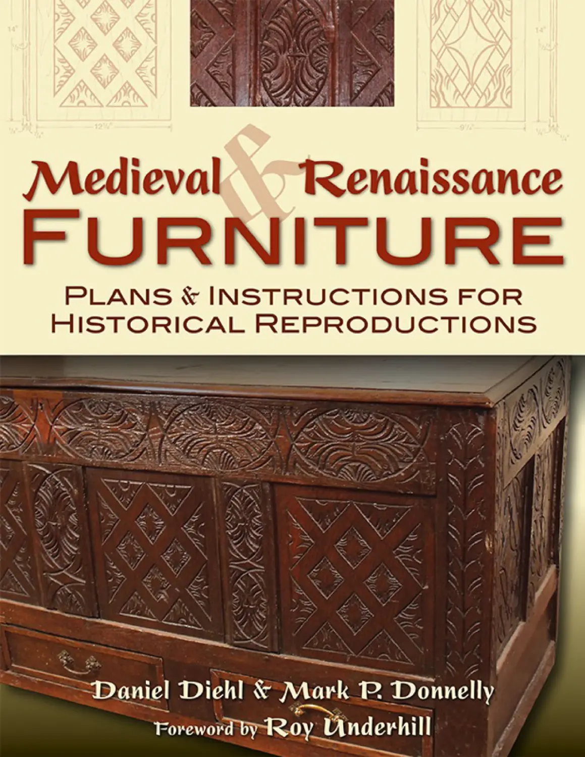
Medieval Furniture
Siege: Castles at War
Constructing Medieval Furniture
Copyright © 2007 by George Bradford
Published by
STACKPOLE BOOKS
5067 Ritter Road
Mechanicsburg, PA 17055
www.stackpolebooks.com
All rights reserved, including the right to reproduce this book or portions thereof in any form or by any
means, electronic or mechanical, including photocopying, recording, or by any information storage and
retrieval system, without permission in writing from the publisher. All inquiries should be addressed to
Stackpole Books.
Printed in the United States of America
10 9 8 7 6 5 4 3 2 1
FIRST EDITION
Cover design by Caroline M. Stover
Library of Congress Cataloging-in-Publication Data
Diehl, Daniel.
Medieval and Renaissance furniture : plans and instructions for historical reproductions / Daniel Diehl and
Mark P. Donnelly. — First edition.
pages cm
Contained herein are most of the projects from Constructing Medieval Furniture and Medieval Furniture, as
well as several new projects that have never been published before.
Includes bibliographical references and index.
ISBN 978-0-8117-1023-7 (pbk.)
1. Furniture—Reproduction. 2. Furniture, Medieval. I. Donnelly, Mark, 1967– II. Title.
TT197.D54 2012
684.1—dc23
2012011468
eBook ISBN 978-0811-7-4879-7
CONTENTS
Foreword by Roy Underhill
Preface
Notes on Furniture Making
Woodworking
Woodcarving
Finishes
Metalworking
Locks
Projects
Benches, Stools, and Chairs
1. Fifteenth-Century Bench
2. Fifteenth-Century Stool
3. Curule Chair
4. Glastonbury Chair
5. Barrel Chair
6. Italian Folding Chair
7. Church Pew
8. Settle
9. Spanish Armchair
Tables and Sideboards
10. Trestle Table
11. High Table
12. Italian Table
13. Worktable
14. Welsh Dresser
Cupboards
15. Fifteenth-Century Ambry Cupboard
16. Wine Cabinet
17. Sixteenth-Century Ambry Cupboard
18. Cathedral Cabon
Trunks, Chests, Coffers, and Boxes
19. Kist
20. Oxford Chest
21. Vestment Chest
22. Tax Box
23. Hewn Timber Chest
24. Paneled Coffer
Beds
25. Monastic Canopy Bed
26. Half-Tester Bed
27. Gothic Cradle
Desks and Bookcases
28. Fourteenth-Century Reading Desk
29. Writing Slope
30. Jacobean Bookcase
31. Oxford Chained Library Shelves
Lighting
32. Candle Stand
33. Mirrored Wall Sconce
Architectural Pieces
34. Fifteenth-Century Window Frame
35. Fifteenth-Century Interior Door
36. Fifteenth-Century Exterior Door
Sources
Furniture Locations
Metric Conversion Chart
Index
FOREWORD
Roy Underhill
O traveler—here is your atlas!
The destinations within are the shapes that gave comfort and convenience to
knights and knaves, merchants and monks. You, however, will travel as an
artisan—steam-bending ash for the barrel chair, draw-knifing elm for the
banqueting table, adze-dubbing oak for the tax box. Fear not, though. You need
not “go native” right at the start of your travels—for the paths are laid out using
turns and measures that you already know. But, if you be bold, if you be
venturesome, the destinations are here. Keep them in sight and soon you will
plot your own course.
In our journey to this foreign land, we trust this, our worthy guide. Here is no
fantasy. No dragons and seamonsters fill blank spaces on these maps. Each shape
presented here, either through accident or excellence, is a rare survivor that we
now study for the truth of its time. Our guides have learned from them, and now
may we.
We want our guides to share a vision for our journey, for these are not just
distant shapes. These destinations were intimate with the people who made and
used them. They made and had babies in them. They sat in them and ate off them
and sometimes threw them. That living connection is here to discover. Our
guides share the context of each piece, helping us see it in its place, see it with
its people.
Our guides need to encourage us, as well as challenge us. For
encouragement, we have easier destinations with the step-by-step path clearly
marked, steps taken with the basic tools familiar to all. But within these pages
are also destinations that can only be reached by riskier approaches. Eventually,
you find a dowel will no longer take you where you want to go—you must
cleave an oak pin. Roaring rotary tools brought you along at first, but now you
need silence as the edge of your adze across the elm speaks to you in ancient
whispers.
Now you are there. You no longer need your translator. Your guide is far
behind. From the grain in the wood the spirit of the piece emerges. The form is
there, and so is the texture. Where once you ventured cautiously, now your bold
adventure begins. The wood becomes a partner with you and your steel. You
emerge as a craftsman in the land ruled by risk, and the working of your tools is
no more premeasured, and no less precise, than a broadsword in action.
The chair, the bed, the table await you at the end of your journey. Rest a
while with the comforts of your own making, peruse this atlas for your next
adventure—and welcome home!
PREFACE
T
his compendium follows our previous books, Constructing Medieval
Furniture (1997) and Medieval Furniture (1999). When we began
researching medieval furniture back in 1992, we had a difficult time finding
good research in existing literature. Certainly there were many good books
regarding the history of furniture through the ages, but information on medieval
and Renaissance furniture in particular was scarce. We could not find much if
anything in the way of plans and schematics for building or re-creating medieval
furniture. Once we had completed the research for the projects we were building,
we wondered if there might be a demand for a book or two on the subject,
because to our knowledge there was nothing available in print. We were
convinced of the demand for instructional books on the design and construction
of medieval furniture, and the overwhelming popular response was gratifying.
After a decade and a half since our first medieval furniture book was
published, we considered putting out a second edition. But we debated whether
we should do a second edition of the first book, a second edition of the second
book, or a new book with additional pieces. In the end we decided to do all
three. The result is the book in your hands. Contained herein are most of the
projects from Constructing Medieval Furniture and Medieval Furniture, as well
as nine new projects that have never been published before.
In assembling this material, we have traveled to museums, castles,
monasteries, stately homes, cathedrals, and universities throughout Europe and
the United States. Once we managed to locate a piece of surviving furniture that
seemed to be suitable as a candidate for inclusion, we set about getting
permission to photograph it, take detailed measurements, and even in a few
cases, carefully disassemble the original piece to detail the construction
techniques. It has proven to be an interesting challenge and a fascinating journey.
We believe it has been a worthwhile and important one, too, for not only has the
general public embraced our previous work, but we have learned that it has
become a permanent part of the libraries of such august institutions as the
Metropolitan Museum of Art in New York, the Victoria and Albert Museum in
London, and the Philadelphia Museum of Art, as well as those of numerous
theatrical houses and film production companies. This response has reinforced
our belief that these rare and fine pieces of our physical past need to be carefully
documented, ensuring that the work and techniques of medieval craftsmen are
preserved for future generations to appreciate and emulate.
Many of the pieces of furniture presented here have never been previously
cataloged, except, of course, in our two previous books. Some, like the
thirteenth-century church pew, were erroneously listed many decades ago. We
have attempted to present you with a wide variety of types and styles of
furniture. Although there is not enough room in this book to take an in-depth
look at the inventory of a complete household’s furniture from any one era, we
hope that we have presented a tantalizing look into the lives of a variety of
people from a wide range of time periods. To augment the furniture pieces
themselves, we have included other sorts of furnishings such as lighting and
architectural pieces. We hope that this will give you a better idea of the settings
in which these wonderful objects were meant to be viewed. Only when we can
envision the Middle Ages as a physical whole can we begin to develop a reliable
image of the lives of the people who lived in it. Certainly we believe that a more
realistic view of the physical world of our medieval ancestors will help us to
understand their way of life and the hardships and limitations their world
imposed on them.
The original pieces of furniture, with few exceptions, were the models for the
drawings in this book. The exceptions were reproductions that had been made
from original models. As in the previous books, we have been forced to make
very slight standardizations in the dimensions to compensate for irregularities in
the original pieces, because of the wear this furniture has suffered, well-meant
but historically inaccurate repairs, and the ravages of time. All of the plans are
drawn to accurate scale, which in many cases will enable the craftsman to
enlarge them to full size, allowing them to be used as templates from which the
work can be copied directly. If such an enlargement would be of specific benefit,
such as in reproducing patterns for carved or cutout work, it is noted in the
specific chapter.
Wherever possible, we have featured the wood grain pattern. This accurately
indicates the direction of the wood grain, an important consideration if there is
some question as to the direction of the grain in a panel or a particular board’s
orientation.
Occasionally when discussing the topic of medieval and Renaissance
furniture and the projects included in our two previous books, we have
encountered the belief among many reenactors that all of these pieces should be
easy to load in the minivan so they can be set up at encampments with
wellfurnished tents. While we agree that a well-furnished campaign tent is a
marvelous—and highly authentic—undertaking, the fact is that precious few
pieces of campaign furniture survive. The pieces from that age that do exist were
designed for castles, cathedrals, and universities, where they have been safely
protected and well cared for over the last five or six centuries. And while we
could well draw up some plans for medieval campaign furniture based on
illustrations, we decided to concentrate solely on surviving originals that could
be measured and photographed. That said, just about any skilled woodworker
worth his sawdust should be able to alter these plans for the originals so that they
can be more easily disassembled, packed, moved, and reassembled anywhere he
wishes, including a campaign tent.
Please note that while this is a book about medieval and Renaissance
furniture and furnishings, the instructions that follow are not medieval or
Renaissance construction techniques. The skills and talents of truly medieval and
Renaissance carpentry are frankly beyond the scope of this volume. If you wish
to construct any of these projects using a drawknife, planking ax, adze, or brace
and bit, then by all means do so and our hats are raised to you. On the other
hand, if you have a wellequipped woodshop and wish to use laser-guided saws
and power planers, then that is fine too. No special gadgets are required for these
projects beyond basic woodworking tools. The idea here is to detail how the
original pieces are put together. We have provided instructions for how an
average woodworker with the most commonly available tools can accomplish
similar results to the originals. If upon examination of the schematics, however,
you decide on a different method for accomplishing the various construction
phases, based on tools or equipment at your disposal, then proceed in whatever
way you deem most expedient.
With all of that having been said, we hope that you find these plans for
reproducing artifacts from our shared medieval and Renaissance legacy to be
both interesting and challenging. And we wish you the very best of luck with
your projects and hope that you succeed in crafting new masterpieces that will
survive for generations, if not centuries, to come.
The authors gratefully acknowledge the assistance of all who helped make this
book a reality. Without their cooperation, compiling the information would not
have been possible.
Our thanks go to His Grace the Duke of Rutland, John O’Brien, and the
management of Haddon Hall; the Right Honorable Harry Orde-Powlett, the
Dean and Chapter of York Minster Cathedral; the Dean and Chapter of Hereford
Cathedral; the Dean and Chapter of Winchester Cathedral; English Heritage;
Jack Hinton and the Philadelphia Museum of Art; the Metropolitan Museum of
Art and the Cloisters Museum; Warwick Castle; and Madame Tussaud’s.
Thanks also to Lucy Johnson of Lucy Johnson Antiques, Dr. Sarah Bendall
and the Warden and Fellows of Merton College at Oxford University, Dr. Dean
Walker of the Philadelphia Museum of Art, Nick Humphrey and the Victoria and
Albert Museum, and Andy Elkin and the management of the Mary Rose Trust.
Individual notes of thanks go to John Leask, for sharing his extensive
knowledge of woodcarving; Dave Greenhaigh and Chris Blythman, for
information on medieval locksets; and Kyle Weaver, our editor at Stackpole, for
guiding our books on medieval furniture through the past sixteen years of
production and sales. We owe you all a debt of gratitude.
NOTES ON
Furniture Making
Woodworking
A few general observations and suggestions about woodworking methods and
materials will facilitate the construction of the furniture described in this book.
General Construction
Medieval construction techniques were of the type that architect Frank Lloyd
Wright once called “cut and butt.” The rudimentary tools and technology of the
Middle Ages necessitated that basic assemblage be simple. Only a few of the
pieces covered in this book include construction techniques that require
advanced woodworking skills.
Doweling
The first step in fastening a wood joint with a dowel is to align the segments to
be joined, clamping them securely. Select a drill bit identical to the size of the
specified doweling on the materials list. If the construction plans do not specify
locations, consult the drawings to determine where to drill the holes. To prepare
the dowel, cut a length no more than 1 inch longer than the depth of its
designated hole. To ease entry, slightly round the end of the dowel. Light
sanding will permit it to be tapped smoothly into place. Tap the dowel gently
into the drilled hole with a wooden mallet. Too snug a dowel may break off
before it is seated or eventually split the surrounding wood. Too loose a dowel
may cause the piece of furniture to wobble and eventually come apart.
Clamps
The use of clamps is frequently recommended in this book to hold segments of
furniture together while a work is being assembled. Best for this purpose are
long bar clamps, or cabinet clamps. They generally extend far enough to press
together even the largest section of furniture. To prevent the metal jaws of
clamps from biting into the wood and leaving deep scars that will need to be
sanded out later, pad the jaws of the clamp with a thin piece of wood slightly
larger than the jaws.
Wood
Oak and pine were the staple woods for the construction of furniture during the
Middle Ages, just as they still are in the furniture industry today. If you live in
the United States or Canada, you might choose to use white oak rather than red
oak unless you are an expert woodcarver, because the uneven grain in red oak
can make the carving more complicated. White oak resembles the English oak
originally used to construct many of our choices for this book. Exotic woods,
such as walnut and limewood, are occasionally suggested for our projects.
Finding these woods may be difficult; alternative materials will also be
recommended. Unlike when we began work on the first two books, the Internet
now has a wealth of information on medieval woodworking. A useful article
listing woods used in medieval carpentry, along with some of their
characteristics, has been compiled by Gary R. Halstead (see the Sources section
on page 321).
Timber
Tree species have not changed much in the past millennium, but the way boards
are cut has changed considerably. In medieval times, carpenters tended to use
axes, rives, and planes to cut their boards to desired thicknesses depending on
the intended purpose. Today, boards are usually milled to preset standards and
dimensions. To precisely replicate surviving medieval pieces, it may be
necessary to have your planks custom milled. Naturally, having wood custom
milled is more expensive than simply picking up some boards at your local DIY
superstore, but to serious medievalists it is worth the extra expense. Using
custom-milled lumber will give your furniture a medieval look. At times the
structural integrity of the piece compels the use of bulkier lumber, or chunkier
boards may be needed so that everything fits together as shown in the
schematics.
Alternatively, recycling old lumber can evoke the period look. In the
demolition of old barns and houses, planks and beams often surface in
dimensions larger than you could obtain in new material at any price. Many
architectural salvage companies across the United States, Canada, and Great
Britain sell recycled building materials. For local firms, look up “salvage,”
“architectural salvage,” or “demolition” in the Yellow Pages or search these
terms online.
Joined Lumber
Another solution for getting modern mill-dimension lumber to approximate
ancient timber is to glue together standard- cut boards to produce thicker or
wider stock without the expense of ordering custom millwork. Many lumber
mills and most cabinet shops will glue up standard-dimension lumber to provide
boards of any width and thickness, executing joints that will be as strong as the
wood itself and inconspicuous when they are incorporated into the furniture. If
you are a practiced woodworker or adventurous beginner, the most cost-effective
solution may be to glue your own boards. Spread a thin, even coat of
cabinetmaker’s glue on the faces that are to be joined, let it set for three or four
minutes, and then press the glued surfaces together, clamping them tightly. Take
care when you tighten the clamps; excess glue may ooze out around the edges as
the boards are being pulled together. An extra pair of hands is a help; keep a
damp rag handy to wipe glue off the edges of the boards. The next day, remove
the clamps to find a board as strong as if it were a single piece.
Gluing boards together for greater width is more challenging. Of the several
ways, the simplest is to glue the edges and clamp them as just described. Take
care not only to clamp the boards tightly together, but also to hold them flat
while the glue dries. The resultant seam will never be as strong as the wood
itself, however, and may fracture with age or if subjected to undue stress.
Dowels or splines can unite the boards to strengthen this seam. Doweling
and splining, though not particularly difficult, do require the proper tools and a
few trial runs. Determine which edges of the boards are to be joined together by
finding the straightest and squarest edges on the boards with which you are
working. Stand the boards in a vise, one at a time, and locate and mark the center
of the board. Set an adjustable square just slightly less than half the width of the
board, then place a pencil on the front edge of the square and slowly move the
square and pencil simultaneously along the length of the board.
When the edges have been marked, place the boards side by side in the vise
so that the edges to be joined together are both facing up. Using the adjustable
square, mark a line across both boards at intervals of 4 to 6 inches. Allow for the
fact that your boards are probably longer than they will be when they are cut to
their final length. Do not dowel closer than 2 inches from the final end of the
board. Designate the location of each dowel with an X.
To ensure that the holes for the dowels are drilled exactly in the center and
perfectly straight, it is best to use a doweling jig. Jigs are available from any
good hardware store, lumberyard, or tool store and are not terribly expensive.
Certainly, if you plan to do much flat doweling, they are a worthwhile
investment. Position the doweling jig directly above the center of the X that
marks the position of the dowel, and drill the pilot hole to the proper depth.
Under normal circumstances, a 3⁄8-inch dowel, sunk 1 inch to 1½ inches into
each board, is adequate. If you are doweling a chest lid or some other structure
that will apply a lot of stress on the joint, sink the dowel 2 to 2½ inches into each
board. For heavy stress joints, use a dowel ½ inch in diameter. If you do not have
access to a doweling jig, use a nail or center punch to mark the center of the X so
that the drill does not slip off-center. Holding the drill plumb and level, drill the
hole to the proper depth as described above. Cut the dowels 1⁄8 to 3⁄16 inch shorter
than the combined depth of the holes and slightly round the ends.
When all the pilot holes have been drilled, place a few drops of white glue in
each hole in one board, and tap the dowels into place. Now place a few more
drops of glue into the corresponding holes on the opposite board and a small
bead along the edge of the board, and set the points of the dowels into the
mouths of the corresponding pilot holes. Gently tap the boards together with a
wooden mallet or pull them together with cabinet clamps. In either case, be
certain that the dowels are pulled together evenly along the length of the board;
if they are forced out of line, they may crack or break. When the boards touch,
pull them snugly together with cabinet clamps if possible.
Nails
There is a persistent belief that nails either did not exist during the Middle Ages
or were never used by skilled cabinetmakers. Neither of these is true. It is true,
however, that during that era, nails were used in securing fewer types of joints
than today, where nails and screws are used for most commercial fastening
applications. Although pegs were the most common medieval fastener for
complex mortise and tenon joints, nails were used on many simple pieces of
furniture; to apply wooden trim molding to even the finest pieces of furniture;
and to attach metal hardware, locks, and trim molding to case furniture of all
types.
Reproduction hand-forged nails should be used in building reproduction
medieval furniture in any instance where the nail head is visible, such as in
attaching locks and hardware, and also where the nail head, even if it is to be
recessed below the surface of the wood and the hole filled with putty, is going to
leave a visible scar on the surface. This will ensure that your reproduction looks
as authentic as possible.
Modern hand-cut nails are available in a limited number of sizes. Medium
and large hand-forged nails are easily obtainable (see the Sources section on
page 321), but very small nails of the type used to apply wooden trim molding
are impossible to find. For these applications, you will need to use small modern
finishing nails or wire brads. For instructions on giving nails an appropriately
medieval look and using them to attach hinges and hardware, see page 11.
Woodcarving
A basic building material for thousands of years, wood was once used to make
everything from kitchen utensils to church decorations, and the traditional skills
of the woodcarver were vital to the community. Much woodcarving was
probably done by ordinary people, who fashioned everything from bowls and
spoons to furniture to ox yokes for their own use. There are clear signs,
nevertheless, of the artistry of woodcarvers in the beautiful wooden boats of the
Nordic Vikings and in early churches.
It was in the Middle Ages and Renaissance, however, that ornamental
carving really flourished, for the thousands of churches that were built in the
fourteenth and fifteenth centuries provided a wealth of opportunities for carvers
to show their skill in decoration. Although they continued to fashion all the items
demanded for everyday life, the medieval woodcarvers began to create the
beautiful rood screens, bench ends, and other ecclesiastic furnishings that made
the Middle Ages a veritable golden age of carving.
Like stonemasons, medieval woodcarvers often worked in teams or schools
under a master carver. It appears from the historical record that many
woodcarvers were stonemasons as well. Some of the carvings they made are
simple scrollwork. Some are religious icons. The medieval church also housed
the unconscious fantasies of the age. With chisel and gouge, master carvers
created weirdly wonderful creatures—dragons, warriors, severed heads,
hermaphrodites, and onelegged sciapods who used their limbs as sunshades—as
well as the common scenes of daily life that they saw all around them. Sadly,
church patronage, which had brought the woodcarvers so much work, halted
abruptly during the widespread reformations in the sixteenth century.
The Carver’s Craft
There are three basic styles of woodcarving: incised or chip carving, relief
carving, and sculptural or in-the-round carving. In incised carving, the design,
usually a very simple one, is cut into the wood. Relief carving is technically the
opposite of incised carving; here the area around the design is cut away to leave
the design standing in high relief. Several projects in this book involve relief
carvings; five of these are linenfold panel carving, which is covered in a separate
section below. Carving in the round is actually the sculpting of wood, an
advanced form of traditional whittling. One of our projects, the Settle from
sixteenth-century Spain, involves fully formed, carved figures.
As with all the techniques described in this book, it is wise to practice your
carving techniques on scrap wood before attempting them on the finished piece.
Creating a prototype certainly takes time, but carving is about patience and
persistence. Whether you are an experienced or inexperienced carver, it will
prove to be time well spent. Nothing is more frustrating than ruining a carving or
even an entire piece of furniture.
Incised Carving
Incised or chip carving involves cutting away portions of the face of a board so
that the carved design lies slightly below the surrounding wood. In its simplest
form, this may be nothing more than cutting away small channels of wood to
produce a simple recessed design. A more sophisticated type of incised carving
is known as gouge carving, where carving gouges are used to remove excess
wood from the surface of the board. Carving gouges come in a variety of shapes.
A flat gouge is no more than a very small chisel; other gouges may be V-shaped
or U-shaped, like a small spoon. No matter what their shape, all carving gouges
are used in the same manner.
To transfer the carving designs onto the wood, first enlarge them on a
photocopier to the size indicated on the drawings. Then tape the paper into place
and slide a second piece of paper, rubbed liberally with a soft pencil to create a
graphite-covered surface, beneath this one. Trace over the design with a pencil or
pen, applying sufficient pressure to transfer the design to the wood.
Now outline the areas to be carved with an X-Acto knife or utility knife.
When establishing your outline, always hold the knife at a 45-degree angle and
pull it toward you, working in the same direction as the grain or across the grain;
do not work against the grain or the knife might slip. Proceed slowly, incising
the surface only a tiny fraction of an inch on the first pass and repeating the
process until the outline is about 1⁄32 inch deep. Using the same knife, remove a
small, V-shaped sliver of wood from the area that will be carved away. Next, use
a gouge to begin removing the excess wood inside the lines.
When working with a gouge, push it away from you, rather than pulling it
toward you like a knife. Only use a light amount of pressure on the gouge and do
not try to remove more than a very small layer of wood at a time, or the gouge
will dig too deeply into the wood and ruin the carving. If the area to be gouge cut
abuts a vertical edge in the carved design, use a straight knife to remove the curl
of wood from the wall of the carving. Once you have established your pattern
with small, shallow gouges, you may then move on to a slightly larger gouge.
Relief Carving
1. Transferring the Design. Enlarge the carving plans in this book on a
photocopier to make an accurate template that can be transferred directly onto
the wooden panel. The exact degree of enlargement varies from piece to piece;
the scale is given in the individual chapter. The hatched part of the drawing, in
all cases, is the area to be cut away. After transferring the design onto the wood,
as described above for incised carving, accurately indicate the hatched areas to
prevent confusion while carving.
2. Establishing an Outline. Begin by cutting around the edges of the design
with a sharp carving knife held at a 90-degree angle to the wood. A first cut of
1⁄32 inch is sufficient; too deep a cut will cause the knife to slip in the tough oak
grain. Penetrate several times; in each instance sink the blade slightly deeper into
the wood, until after three or four passes you have reached a depth of nearly 1⁄8
inch.
Introduce the knife into the area to be cut away by placing the blade at a 45degree angle to the wood, about 1⁄8 inch from the original cut. With several
passes of the knife, remove a V-shaped sliver of wood from the hatched area
around the entire design. Enlarge this initial cut to a depth of 3⁄16 inch. The
width of the cut is irrelevant because the entire hatched area will be eliminated.
3. Removing the Waste Wood. Now that the edges of the carving are
established, remove the entire hatched area of the design to a depth of 3⁄16 inch.
Although using a Dremel tool with a router attachment is easier, the proper
historical approach is to use small chisels or spoon-shaped gouges to remove the
superfluous wood. Chisels require care; do not cut too deep or too fast. The
chisel’s sharp edge can easily pierce the walls of the design, possibly ruining the
sharp edges of the design itself. After removing the excess wood, clean up the
edges and corners of the design with a fine chisel or carving knife. A small chisel
will also remove marks left by a Dremel tool.
4. Texturing the Background. In medieval and later incised carving, the
background area of the design where the wood has been cut away is often
textured with a waffled pattern. Composed of a series of tiny inverted pyramids
arranged in a 1⁄8-inch center grid pattern, this overall field simulates depth and
prevents loose fibers in the carved wood from chipping away. Such texture
appears on the background of the Writing Slope, behind the small carvings at the
top of the Cathedral Cabon, and around the leg designs on the Barrel Chair.
Impress the waffled texture into the wood by tapping a nail lightly into the
surface at close intervals. Several points can be impressed at one time with a
small punchlike tool with a textured face. A leatherworker’s tool designed for
exactly this purpose can be adapted for use on soft wood. Working with oak,
however, calls for a small nail, a tack hammer, and infinite patience. After this
last step is completed, lightly sand the entire carved area to eliminate splinters,
loose wood fibers, and sharp edges.
Sculptural Carving
The only project in this book to use fully rendered sculptural carvings is the
Settle. The process is somewhat complex and is detailed here rather than in the
later chapter.
1. Transferring the Designs. Cut the blocks of wood to the dimensions shown
on the plans. Transfer the drawings of the sculptures—two dogs and two lions—
onto all four faces of the blocks. All four faces of both designs are shown in the
plans, so this should be a relatively easy operation. Note that there are left- and
right-facing versions of each animal, so the drawings have to be turned over to
produce one of each pair.
2. Roughing Out a Figure. Cut away the sharp corners of each block so that
it begins to take the shape of the animal. Cut away only enough wood so that the
carved area meets the outline of the figure. Next, carve away excess wood
around the main elements of the figure, such as between the legs, around the
muzzle, and in front of the lion’s shield. Now begin to shape the animal’s limbs,
rounding the legs and haunches and defining the recesses between the hips and
body. Start to form the lion’s tail and mane.
3. Finishing the Figures. These figures are not terribly lifelike, nor is the
carving fully developed. The lions’ haunches remain rather flat where they touch
the outside of the blocks. Much of the detail on the dogs’ faces has been worn
away by the constant wear of human hands. You can leave the dogs’ faces with a
soft, worn look or give them the detail that they undoubtedly once had. Execute
the finishing details such as the dogs’ collars and lions’ shields with carving
knives or a Dremel tool. Cut between the animals’ toes, around their eyes, and
through the waves in the lions’ manes with a small V-gouge. Also use a V-gouge
for the edges around the dogs’ collars and the wavy incised lines on the collars,
but detail the rounded edges of the collars with a fine file or sandpaper. Finally,
sand the entire surface of each figure to eliminate any knife marks. Smoothly
finished figures will look more like the originals, particularly the worn dogs.
Carving Linenfold Panels
No one knows how the tradition of the linenfold, a common medieval decorative
device intended to look like folded cloth, began. The voluminous folds of heavy
medieval clothing figure prominently in almost all medieval art, from painting to
sculpture to stained glass. The first carved linenfold panels seem to have
appeared sometime before the mid-fifteenth century and remained popular for
another two hundred years. The linenfold design from the front of the Paneled
Coffer serves as a working model for this project. It is a relatively simple pattern
and not terribly different from the linenfold panels used in the Settle. You can
enlarge the drawings to the appropriate sizes and transfer them directly onto the
wood panel. These are not particularly complicated linenfold designs, but if you
are a novice woodcarver, make several practice pieces in a soft wood, such as
pine or fir, before you test your skills on a finished piece of oak.
1. Transferring the Design. Enlarge the front and end views of the design on
a photocopier. Transfer them onto the face and both ends of the panel so you can
see through the peaks and valleys of the design as you carve away excess wood.
Center the design on the board’s face, allowing for the edges and rabbets that
project beyond the design.
2. Roughing Out the Design. With a table saw or radial arm saw, cut the
rabbets around the edges of the panel to firmly establish the area of the board
that will be worked into a linenfold pattern. This eliminates the need to rework
the edges of the board once the delicate carvings have been executed. Work the
undulating shape of the linenfold to the top and bottom edges of the design area;
cutting out the shaped ends comes later.
If you have a radial arm saw, remove some of the excess material from the
face of the panel, as shown in the draw- ing of the preliminary grooves. Using a
table saw necessitates turning the panel on its face; take extra care not to cut too
deep or too close to the finished surface. The original implements were chisels
and gouges. If you use tradition- al tools, be careful not to cut too close to the
finished lines, either on the panel’s face or in the depth of the folds. Remove a
few centimeters of wood with each pass; do not take a large bite.
3. Shaping the Panel. When the bulk of excess wood has been removed, you
can begin to give the folds their final shape. First be certain that the surface that
will form the top of the low-lying ribs (that is, the very center of the three
valleys that run the length of the panel is smooth and even). Plane this area with
a sharp, narrow chisel, a miniature molding plane, or sandpaper. The tops of the
four raised ribs should already be flat and level because they are the original
surface of the board.
Next, redraw the ribs that run down the center of the low-lying areas of the
panel. To delineate the edges of the ribs in the low-lying areas and on the surface
of the panel, follow the instructions for establishing an outline in the section on
relief carving above (page 5). The ribs will stand out in clear, sharp relief from
the surrounding areas.
With a U-shaped gouge or large, round file, shape the concave hollows in the
panel. Use the file if you are unsure of your ability to control a gouge. Be careful
not to remove too much wood; you still have to shape the convex curves on
either side of the ribs. Work the convex curves of the design with a carving
knife, a shallow U-shaped gouge held upside down, or a small triangular file that
fits into the tight recesses next to the low-lying ribs. After all these areas have
been worked, lightly sand the panel surface. Be careful not to soften the
carving’s crisp lines. Some knife marks can show; they still appear on original
pieces after centuries of wear.
4. Carving the Ends. This job is relatively easy because these panels have no
undercuts or complicated back folds. Sketch in the shapes of the top and bottom
ends of the panels, using the templates as reference. The panel is no longer a flat
surface, so you cannot simply trace the template onto it. Again following the
instructions above for establishing an outline (see page 5), establish the edges of
the panel ends. When you have cut the ends free to about half the designated
depth, begin to remove the waste wood at the ends of the panel with a sharp
chisel, taking care not to cut into the delicate ends of the ribs. Repeat the
procedure until you have revealed the panel’s full depth. Use a carving knife to
clean up any rough spots around the edges, and smooth the background with a
sharp chisel and sandpaper with a sharp chisel and sandpaper.
Finishes
Much of the furniture produced during the Middle Ages was ornately painted in
bright colors with designs and figures. Oiled, waxed, and even varnished
furniture did exist, though it depended on the nature of the piece, its intended
purpose or use, and the quality of the wood from which it was made. A finished
surface was achieved by smoothing with sharkskin—a natural and very effective
form of sandpaper—or scraping with the edge of a flat metal fragment. For most
projects, scraping the surface of the wood with a cabinet scraper was sufficient;
only when the finest, smoothest finishes were necessary was sharkskin
employed. Although sharkskin is not available today, sandpaper is a perfectly
acceptable substitute.
Most wood used today has been mill planed and needs only limited sanding
or scraping. But if you have obtained rough wood, you may want to use a
cabinet scraper. These come in a variety of sizes and shapes and are available
from fine woodworking stores and online. The most basic cabinet scraper is a
flat, rectangular piece of metal about 3 by 5 inches. The working edge of the
scraper needs to be honed so that it is perfectly flat, smooth, and at a 90-degree
angle to the sides. To sharpen a new scraper, clamp it to a table with the edge of
the scraper a fraction of an inch beyond the edge of the table. Run a whetstone
along the edge of the scraper, keeping the stone perpendicular to the edge.
Properly sharpened, the edge should be nearly as sharp as a knife.
To use, hold the scraper in one hand and place the sharpened edge near one
end of the piece of wood to be smoothed. Hold the scraper at a 15- to 20-degree
angle to the surface of the wood, with the sharp edge of the scraper pointed away
from your hand. With long, smooth, even strokes, pull the scraper toward you,
moving the blade with (in the same direction as) the grain. Apply enough
pressure to the scraper that it bends slightly in the middle. As with a wood plane,
the scraper will need to be resharpened occasionally.
Clear Finishes
Centuries of use have softened the surface tones of surviving medieval furniture.
To counter the effects of natural oils and dirt transferred to the surface of the
wood from human hands, cleaning was occasionally done with a rag soaked in
olive oil. Repeated applications of oil invested the wood with natural moisture,
prevented it from cracking and splitting, and acted as a natural adhesive for tiny
bits of dust. Alternating layers of oil and dust gathered in corners and crevices
but were worn off the main areas. The patina of centuries-old furniture is
difficult to re-create artificially.
Being true to the original will give the most authentic-looking finish. Using
repeated applications of olive oil, tung oil, or boiled linseed oil, coat the wood
lightly until it repels the oil, then buff to a low luster with a soft cloth. For a
more penetrating finish, mix four parts of one of these oils to one part spirits of
gum turpentine. (Mineral spirits or artificial paint thinner will dry out the wood.)
A slightly warmed (not boiled) mixture penetrates best. Prudence dictates the use
of an electric stove, not gas or other open flame. Apply a second coat of boiled
linseed oil to cover the penetrating coat.
Darkening the natural color of the wood will make it look older. To do so,
add a little wood stain or painttinting color to the plain oil or oil-andturpentine
mixture. Be careful; only a few drops will significantly change the color of a pint
of finishing oil. Test tinted oil on a piece of scrap wood before applying it to
finished furniture.
To prevent the wood from drying out, periodically apply additional coats of
oil. Apply oil every three or four months during the first two years. Once or
twice a year thereafter will suffice. Forced-air heating dries out furniture faster
than hot-water (radiator) heat. Polish your furniture occasionally with a furniture
polish containing lemon oil, which will help the polish soak into the wood. For
oil-finished wood, avoid a polish listing wax on the label. To deepen the antique
look, use the traditional formula of Old English brand furniture oil. The dark
brown tint of Old English Scratch Cover will dramatically darken the wood over
successive applications, enriching the finish.
To stain newly created medieval oak furniture, try this fairly authentic period
recipe (recommended for use on oak only, because the stain reacts with the
tannic acid present in the wood). Submerge well-rusted iron in equal parts of
water and vinegar. Real iron will perform better than modern steel. In one to two
months, the vinegar- and-water solution will absorb the pigmentation from the
rusted iron. After several months, remove the iron from the solution and filter
the liquid through a fine cloth to remove any rust sediment. Staining with the
filtered liquid produces a finish that varies from near black to a mellow silvery
brown. The exact color of the finish depends on the strength of the liquid and the
amount of acid in the oak. Test the stain on scrap wood before applying it to
finished work, but don’t worry about color differences; in furniture that has
survived for centuries, the surface tones vary from board to board. When the
stain has dried, apply a natural oil finish as described above.
Painted Finishes
The articles of furniture in this book have a natural wood finish, but many
medieval pieces were originally painted, the edges and carvings often picked out
in colors that contrasted to the body of the piece. If you are considering painting
your medieval furniture, first paint discarded pieces to see if you like the effect.
If you decide to proceed, a medieval paint recipe follows. Before the invention
of oil-based paint in the late fifteenth century, egg tempera was the most
common medium for painting wood, metal, paper, leather, and cloth. It would be
suitable for use on any project in this book that needs painting.
Artists in the Middle Ages used extremely poisonous ingredients—white
lead, copper sulfate, and many other dangerous pigments. Inexpensive powdered
pigments of the type used in preschool are safe substitutes. They may not
produce a paint with a perfect consistency, but close examination of period paint
and manuscript illuminations shows how historically correct a little variation in
texture and tone can be.
To prime an area for egg tempera, lay in a ground coat of gesso, a waterbased
primer sold in most art supply stores. Apply the brush strokes evenly in the same
direction, especially if a large area is being gessoed. Fresh eggs, pure ground
pigments (available in art supply stores), and distilled water constitute modern
egg tempera. Egg yolk binds the pigment to the gesso ground. To extract pure
yolk, separate an egg and ease the yolk into your palm. Gently roll the yolk
repeatedly from one hand to the other. As you cup the yolk in one hand, wipe the
excess white from the other palm. The drying yolk will toughen after eight to ten
transfers. Gingerly pinch the thickened yolk sac as it rests in one hand, and
suspend it over a spotless shallow bowl. Free the yolk to spill into the bowl by
piercing the yolk sac. Discard the sac.
Blend pure ground pigment into the egg yolk mix to create the desired color.
Pulverize the pigment into the egg with a mortar and pestle or by grinding with
the back of a spoon against the side of the mixing bowl. Thin the paint with a
few drops of water if it becomes too thick to work easily. Water also clarifies the
colors. Using denatured alcohol in place of water hastens the drying and helps
preserve the paint. Egg tempera treated with alcohol must be stored in the
refrigerator and will still have a shelf life of only five or six days. A dried egg
yolk glaze is nearly as hard as many modern varnishes and needs no varnish if it
is sheltered from the weather.
Working with egg tempera takes practice. Painting an entire piece of
furniture or perhaps a wall hanging can be taxing, but it is the correct period
approach to the job. If you want an easier modern alternative, try regular interior
oil or latex paint to embellish furniture or artist’s oil paint or latex paint to
decorate a wall hanging. Choose a commercial paint with a flat finish; flattening
agents are available to kill the natural sheen of oil paints.
Metalworking
Hinges, banding straps, locks, lock plates, forged nails, and several styles of
pulls and handles constitute the hardware used for the projects in this book.
Broad introductory metalworking instructions are provided in this chapter; the
procedure for fabricating these articles does not vary from project to project.
Guidelines for any nonstandard work are given in the individual chapters. If you
feel you lack the skills or equipment to do the metalworking, you can purchase
premade period hardware (see the Sources section on page 321) or engage a
local blacksmith or ironmonger to fashion metal findings for your medieval
furniture. However, the metalworking involved is not too complicated and does
not require any particularly specialized tools, and you will gain a sense of pride
from having crafted every component of your finished piece.
Tools
In the Middle Ages and Renaissance, most cabinet hardware was created by a
smith working with forge and anvil. Reproduction of hardware by the original
methods is ideal, but most of us lack a forge. For some items, you can reproduce
the same look with tools that replicate some of the smith’s methods in your own
shop; other items are made with modern equipment.
The metalwork in this book requires only a few simple tools. A band saw
with a metal cutting blade is ideal, although a jigsaw or reciprocal (saber) saw
with metal cutting blade will do—or even a simple hacksaw in some instances. A
heavy vise and two shaping hammers—ball peen rather than claw—are also
needed. One of the shaping hammers should have a 10- to 12-ounce head and the
other a 16- to 18-ounce head. For finishing the metal, it’s best to have flat,
round, and triangular steel files, each in two different grades—for coarse work
and for finishing—and in medium and small sizes. At the very least, you need
small, finegrade files to get into tight corners.
You probably don’t have access to a real forge (or you would already know
how to do metalwork and would not be reading this chapter); therefore, you need
a welding torch to heat the metal for shaping. Of the two suitable types of
welding torches, the better is a combination oxyacetylene torch. It simplifies
metalworking because it quickly provides great amounts of heat. Acceptable but
less efficient is a singletank acetylene gas torch, which will take a much longer
time to heat the metal to the point of malleability. The ubiquitous handheld
propane torch can be used in a pinch, but it may not provide sufficient heat for
some of the metalworking tasks. A pair of welder’s gloves and goggles will
shield your hands and eyes from the searing metal.
A mandrel is needed to curve the heated metal into decorative shapes. You
can easily make a mandrel consisting of two round metal pins, each 1⁄8 inch in
diameter and 2 inches in length, inserted into a metal base, from stainless or
cold-rolled steel. Cut a steel base that is 1 inch thick and 4 or 5 inches in length
to a width that will conform to the jaws of your vise (at least 1 inch wide). Drill
three ½-inch holes in the mounting block. The first two holes should be spaced
¼ inch apart, and hole three should be ½ inch from hole two. These holes hold
the metal pins, which should fit firmly but remain free enough that they can be
relocated when necessary.
Materials
The metal used in these plans is usually of a type called flat stock, sold in straps
or sheets that are wider than they are thick. Other kinds of metal are round stock,
which is a round bar of steel, and square stock, which is a square steel bar. The
various sizes of the assorted types of metal stock necessary for the projects are
commercially available. The materials list in each chapter details the amounts
and dimensions of the metal stock necessary to manufacture the hardware for the
particular piece of furniture.
Forging Metal
If you are new to forging metal, make several trial pieces before you attempt any
of the finished hardware. Start by bending a piece of flat stock 1¼ inches wide
and 1⁄8 inch thick into a 90-degree angle. Many of the hinges and bands on the
projects in this book need this stock-size piece of metal. Shaping a right angle is
a simple procedure that you have to perform every time a hinge or a band laps
around a corner on an article of furniture.
Bending Right Angles
Insert a segment of flat stock, at least 1 foot in length, vertically into the jaws of
the vise, with 2 or 3 inches of stock protruding below the jaws. To avoid a
crooked bend, the stock must be at right angles (90 degrees) to the top of the
vise. Heat the 2 inches of stock immediately above the jaws in preparation for
bending. As you move the tip of the flame around on the area being heated, do
not hold it on one spot or the stock may melt at the point of contact with the fire.
A pinkred glow indicates that the metal is ready to be formed. It is helpful if one
person heats the metal while another does the actual forging. Preserving the
metal’s heat allows it to be shaped more effectively.
To form the right angle, hammer where the heated stock meets the vise’s
jaws while gently pulling the stock’s free end toward the forging surface (the top
of the vise) with a pair of pliers or vise grips. To clarify this, imagine that the
metal is as flexible as a long, thin piece of wood. If you clamp one end of a thin
piece of wood in a vise, you can easily flex the opposite end. You do essentially
the same thing with a piece of metal by heating it in order to make it flexible.
Strike the surface of the newly formed angle two or three times directly at the
angle of the bend where it lies against the vise. The resultant sharp corner fits
snugly against the wood’s edge. Practice will yield worthy results.
Using the Mandrel
The mandrel is used to shape the loops on each half of the hinge where they are
joined together with a pin and to forge decorative curls on hinges and their
associated straps and bands. A good practice exercise is to heat 1 or 2 inches at
the end of a section of flat stock and insert the end between two closely set
mandrel pins. While steadily applying heat, gently tug on the tip of the bar and
lightly strike the hot metal with a forging hammer. Slowly pull the metal into
loops of any size. The hotter the metal, the more malleable it is. Practice forming
loops that fit snugly around the mandrel pin, the exact dimensions for accepting
hinge pins.
Hinges
Strap hinges, some of them essential to the banding that holds the furniture
together, anchor many of the chest lids. Most are made of 1⁄8-inch-thick flat
stock. Some of the projects use butt hinges, while others use flat hinges. These
hinge styles differ slightly in the shape of the spine, but they are identical in the
arrangement of tangs on the hinge stock and their basic construction.
The two halves of the hinge are usually joined together with three
interlocking loops—one on the hinge’s shorter end and two on the long end.
Joined together with a pin, this section of the hinge is called the spine. Use a
band saw or other saw to cut out the metal fingers (tangs) that are used to shape
the loops, as shown in the drawings on page 11. Mold the loops on the mandrel
after removing the burrs from the sawn edges. To ensure that the hinge operates
properly, follow any variations in the particular project’s directions concerning
the length of the tangs and position of the loops.
Hinge Pins
To fashion the hinge pins, use a section of round stock that fits snugly, but not
tightly, into the holes in the hinge spine. Cut the pin about 1 inch longer than the
hinge’s width. Clamp the pin vertically in a vise so that only about 1⁄8 inch of
metal projects above the vise’s surface. Heat the pin’s tip. Strike the hot end of
the pin with the flat end of the forging hammer until it balloons slightly, like a
mushroom cap. Round the edges with the ball end of the hammer. After the pin
has cooled, insert it into the hinge. Trim the pin, if necessary, so that slightly less
than ¼ inch extends beyond the hinge’s end. Invert the assembled hinge on a
forging area so that the unflared end of the pin faces upward. Heat the exposed
end of the pin and carefully flare it with the forging hammer; beating too tightly
against the hinge might cause it to bind.
Banding
Allow several extra inches of metal when creating hinges or bands that extend
around the sides of a piece of furniture. Some of the length will disappear in the
act of bending the metal at the corners. Be patient when banding a furniture case;
bend one corner and fit it into place before marking the position of the next
bend. Heating and bending alter the length of the metal stock in unpredictable
ways.
Forging Tip
To distress the smooth exterior of metal bar stock, lay it on the vise or an anvil
and heat 3 to 4 inches of its length at a time with the torch, marring the surface
and edges with the round end of your forging hammer. Eliminate the regular
edges of the metal, but do not distort or misshape the stock.
Lock Plates
A lock plate or escutcheon shields the area around the opening in the wood
through which the key is inserted. Escutcheons are usually constructed of 1⁄16inch-thick flat stock, far thinner than the hinges and bands on a chest. Patterns
for lock plates accompany the furniture drawings. These can usually be cut out
of flat stock. Heat the edges, distress them slightly, and file smooth.
Nails
Applying hinges and hardware requires fairly large quantities of handforged
nails. Simple cut nails lack the large heads necessary to secure the hardware.
Medieval nails were often longer than the thickness of the wood into which they
were driven. The expedient solution to this problem was simply to curve over the
end of the nail on the interior of the chest, which also added strength. Such nails
were called clinch nails. Some modern reproduction forged nails are too brittle to
bend without breaking; if you are unsure whether they can be clinched,
experiment on a scrap of wood. It is technically possible to make nails by hand;
we commend your persistence if you do, but we don’t recommend it. Rather,
purchase nails of the right size, length, and head style from a supplier of
reproduction nails (see the Sources section on page 321).
Metal Finishes
To give a uniform dark finish to your newly fashioned metalwork and prevent it
from rusting, we suggest a natural oil finish. There are two ways to finish metal
objects. The first is to clean the forged metal thoroughly with a wire brush, and
then coat the surface evenly with olive oil—the same substance often used as a
finish on medieval woodwork. Apply even heat to the metal for 30 to 45 seconds
with either a torch or a kitchen stove. Heat it just to the point where it cannot be
touched. Blacken the oil; do not burn it off the metal. Allow the metal to cool
naturally, and wipe it with a clean, dry cloth.
The second method is not dissimilar to the first. Fill a large metal pan to a
depth of 1½ to 2 inches with heavyweight oil—used motor oil is perfect for this
purpose. Heat the metalwork with a torch until it is hot but not glowing. Quench
the hot metal in the pan of oil. Wipe the excess oil from the metal.
Locks
The mechanical lock has been used to protect the contents of chests, cabinets,
and trunks since the early Middle Ages. Since the tenth century, they were
common enough that even the Vikings routinely installed them on their sea
chests. The design of these early locks was so successful that, except for minor
refinements, the standard domestic lockset remained almost unchanged until the
end of the nineteenth century. Almost any lock that can be operated with an oldfashioned skeleton key is based on the same design as the medieval lock.
Sadly, virtually all the locks that originally protected the contents of the
chests and cupboards shown in this book have been removed or replaced.
Medieval locks are somewhat rare because the delicate mechanism of a lock can
easily fall victim to rust and corrosion. In many instances, heavy, surfacemounted hasps or simple wooden turn buttons have obviously been retrofitted to
pieces of furniture that still have a lock plate that once covered a lock.
There are two possible approaches to equipping medieval furniture with
working locks. The first, and by far the better, is to reproduce a medieval lock;
the second is to adapt a newer lockset to the piece of medieval furniture. If you
opt for authenticity after investing so much effort in your chest or cabinet, follow
these instructions to re-create a medieval lockset. Although locksets are
relatively simple to build, their limited technology leaves their security factor
lacking. (Translation: These locks will keep honest people honest, but they won’t
keep out the bad guys for long.)
The instructions provided here are for a lockset adapted from a number of
surviving period locks. Although the mechanism is extremely simple, pay
careful attention to both the drawings and text to understand the lockset well
enough to build it. This lock can be adapted for use on any of the cupboards,
chests, or coffers in this book.
Concept of the Medieval Lock
Medieval locks of the type described in this chapter were built differently than
their modern counterparts. Today’s locks are set on the inside of a piece of
furniture (that is, on the inner face of a drawer or chest), and the exterior keyhole
is covered with a decorative lock plate, or escutcheon. The medieval lock was
built directly on the back of the escutcheon plate. A small section of wood was
chiseled away from the chest’s face, creating a hollow into which the locking
mechanism could be recessed. The completed lock and escutcheon were
mounted to the front of the chest with nails. To prevent the escutcheon and its
accompanying lock from simply being pried from the chest’s face, locks were
often mounted with clinch nails, which were longer than the thickness of the
board into which they were driven. The excess nail protruding through the
chest’s inner face could be bent over, or clinched, on the inside, making the lock
far more difficult to remove.
Materials
Most of the lockset, except the spring, lock bar, and key, can be constructed from
steel flat stock that is 1⁄16 inch thick. Shape the spring from a piece of 1⁄32-inchthick spring steel. Using an old hacksaw blade to make the spring seems to work
adequately in modern reproductions of medieval locks. Cut the lock bar from a
¼-inch-thick piece of steel. The key is put together from lengths of 3⁄16-inch
round stock and a piece of 1⁄8-inch-thick flat stock.
Lock Plate and Hasp
The drawing of the exterior view of the lock shows the location of the keyhole
and the opening through which the hasp staple passes. A typical hasp and hasp
staple are shown in the drawings. Specific instructions for constructing hasps
and lock plates or escutcheons appear in those projects requiring locksets. There
are seven rivets on the escutcheon’s face, each bearing a letter or letter-andnumber designation in the drawing. The particular functions of these mounting
points for the locking mechanism will become clear as you build the lock.
Mechanism Overview
The interior view drawing shows the lockset as it appears when completed and
ready to set in place. The jagged bar, shown here as a hatched area and marked
A, is the lock bar, the piece that actually locks the hasp into place. The looped
piece marked B, fitted around the bar, is the spring that prevents the lock bar
from simply falling open if the chest is tilted or jiggled. The rather fish-shaped
plate marked C is no more than the framework that holds two simple gates
(known to the medieval locksmith as wards), around which the key must pass on
its way to the jagged bar, and a small tubular collar that holds the key’s tip in
place. There are no moving parts hidden inside framework C. The small plate
marked D is a third ward around which the key passes.
Key
The key, as shown in the drawing, is designed to fit through the series of three
wards. Locks with different-shaped wards would require keys with different
configurations. How the key passes around the wards is shown in the drawings.
To personalize a lock, alter the size and shape of the key and the wards through
which it must pass on its way to moving the lock bar. Some medieval keys had
amazingly complex wards, but the actual locking mechanism was just as simple
as the one shown here.
Lock Operation
Lock drawings 1, 2, 3, and 4 reveal the key as it opens the lock. Refer to these
drawings before and during the construction of the lock to completely
understand its operation. In drawing 1, the key is inserted through the keyhole
and the collar steadies it. The removal of both the spring and the staple end of
the hasp from drawings 3 and 4 clearly delineates the key in operation. In
drawing 3, the key pushes against the lock bar, moving it out of the hasp staple.
The key continues its journey past the lock bar in drawing 4; after its 360-degree
rotation, it can be removed from the lock. To relock the chest, simply reinsert the
key and turn it in the opposite direction.
Lock Plate Construction
The individual chapters provide lock plate dimensions and design. Be sure that
the keyhole and hasp staple hole are arranged so that they conform to the
dimensions of the particular lockset. Alternatively, adapt the locking mechanism
to the configuration of the holes in the particular lock plate of the piece of
furniture you are building.
Lock Bar Construction
To ensure your chest’s security, cut the lock bar from heavy, ¼-inch-thick stock
to the dimensions indicated in the lock bar drawing. The thickness of the metal
requires the use of a band saw with a metal cutting blade. File any burrs from the
edges of the lock bar.
Next, cut two lock bar supports from the same ¼-inch metal. The lock bar
must pass easily through the slots in the supports. To shape the rivets on the ends
of the lock bar supports, use metal files. Begin with a fairly coarse file and work
down to a fine-toothed file to smooth your rivet enough to pass easily through a
hole in the lock plate. These rivets are square rather than round, which prevents
them from turning once they are riveted to the lock plate. Be sure the shoulder at
the rivet’s base is square and flat. The rivet must pull tightly against the lock
plate so that the lock bar supports will remain firmly in place.
Spring
Now, using a band saw with a metal cutting blade, cut a 43⁄8-inch length of 1⁄32inch-thick spring steel to the configuration shown in the drawing of the spring
before bending. Spring steel is very hard; work slowly to avoid breaking the saw
blade or spring. Note: The original lock-spring shown in the drawing is drilled
for a single rivet, which may loosen over time. Drilling an additional hole for a
second rivet will ensure that the spring remains in place.
Heat 1½ inches at the end of the spring in which you have drilled the
mounting hole or holes until the metal glows red. At a point about ¾ inch from
the end of the spring, twist the spring a quarter turn with a pair of pliers. This
fashions the ear that will attach the spring to the lock plate. Be sure the ear lies
as close as possible to the edge of the spring with the notch cut out of it.
Next, heat and bend the small hook near the spring’s opposite end, according
to the spring drawing. Because you bent the metal a quarter turn before shaping
it into a hook, you will not have to curve the metal laterally. When the spring is
finished, this hook fits over the lock bar. Finally, heat an area of the spring about
1 inch on either side of the large offset, and bend the large loop as shown in the
interior view drawing. A second, very small loop in the narrower end of the
spring allows the spring to hook over the lock bar’s top and exert a slight
downward pressure on it. At this point, all the tensile strength (the springiness)
will have left the spring. To restore it, heat the entire spring until it glows, and
then quench it in a pan of water.
Making the Key
To ensure the smooth operation of the lock, make the key before the locking
mechanism is attached to the lock plate. The shaft of the key is a 3-inch length of
3⁄16-inch round stock. Cut the head, or teeth, of the key from a piece of 1⁄8-inchthick flat stock. When you have cut the teeth, weld them to the shaft at the
location shown in the key drawing. The handle of the key can be as elaborate or
simple as you like. Our handle is a simple ring bent from a heated length of 3⁄16inch round stock and welded to the shaft.
Ward Frame Construction
Cut the ward frame, marked C on the interior view drawing, from 1⁄16-inch thick
flat stock. Heat it and bend it to shape as shown in the drawings of the ward
frame. For instructions on heating and bending metal, see page 9. Drill a 1⁄8-inch
hole in each of the ears to facilitate the attachment of the ward frame to the lock
plate.
Next, cut a ¼-inch length of thin-walled steel tubing, and weld it to the center
of the interior face of the ward frame. The location of this cylinder can be clearly
seen in the ward frame interior and top views. This cylinder holds the key in its
proper position when the lock is being opened or closed; when the ward frame is
riveted to the lock plate, the cylinder must be directly behind the circular opening at the top of the keyhole.
Cut two rectangular ward blocks from 1⁄16-inch flat stock as shown in the
interior and top views. Be sure that the ward blocks pass easily through the
notches in the key. Shaping the rivets on the ends of the blocks resembles
working on the lock bar supports, but these rivets must be round rather than
square. Begin with a fairly coarse file and work down to a fine-toothed file to
give your rivet a smooth surface that will pass easily through a hole in the lock
plate. Again, be certain the shoulders at the base of the rivets are square and flat
to ensure that the ward blocks do not turn once they are riveted in place. The
rivets can be welded to the ward frame once they have been peened in place on
the lock plate.
Drill a 1⁄16-inch mounting hole for the ward block in the ward frame to the
left of the key cylinder, as shown on the interior view of the ward frame. To
ascertain this hole’s exact position, place the end of the key in the cylinder and
position the ward block in the proper notch in the key. Place the ward frame in
position on the interior surface of the lock plate and replace the key in the
cylinder. Position the ward frame so that the key can be removed and reinserted
through the keyhole without difficulty. Clamp the ward frame in place on the
lock plate, and determine the position of the ward block that mounts on the face
of the lock plate. The key must be in the lock for this phase of the operation, or
the ward block may not align with the key. Now remove the key and ward frame,
and drill and mount the second ward block. This rivet is marked C on the
exterior view drawing.
Reposition the ward frame on the lock plate and reinsert the key. Mark the
locations of the ward block’s mounting holes on the lock plate. Remove the ward
frame and drill the holes in the lock plate. These will hold rivets A1 and A2 on
the exterior view drawing. Remount the ward frame and position it with two
small rivets. Again, make sure the key fits into the ward frame and passes both
of the ward blocks.
The final ward, shown as D on the interior view drawing of the lockset and
detailed in the third ward drawing, passes through the small slit in the center of
the key. Bend this ward from a heated piece of 1⁄16-inch-thick flat stock. Be sure
that the key can pass around it when it is fitted against the lock plate. Drill a hole
in the ward’s tail and a corresponding hole through the lock plate’s face (B on
the exterior view drawing), and rivet them together.
Attaching the Lock Bar and Spring to the Lock Plate
To guarantee that the lock bar lines up with the key, first place the key in the
lock. Then position the lock bar on the lock plate so that the end falls across the
hasp staple hole as shown in the interior view drawing. Set the lock bar supports
in place on the lock bar so that the rivets are beneath the lock bar. There must be
enough space between the lock bar supports to allow the spring to set between
the small ear on the upper left corner of the lock bar and the lock bar support on
the right (see the interior view drawing). The lock bar must also be positioned so
that the key will move it from left to right as it is locked and unlocked. The key’s
only contact on the lock bar should be with the downward-pointing teeth; it
should not touch the bottom of the bar itself.
Mark the positions of the rivets on the lock bar supports, and drill 1⁄8-inch
holes in the lock plate. With a small file, rub the holes square, then insert the
rivets and peen them over. Note: If you do not have jeweler’s files, file the rivets
round, mount them in round holes, and weld them into place to ensure that they
do not shift. Place one of the lock bar supports in its proper hole, and peen over
the rivet on the lock plate’s face. Insert the lock bar and the second lock bar
support into place, and peen over the second rivet. These holes correspond with
rivets D1 and D2 on the exterior view drawing. The lock bar should now move
freely back and forth in front of the hasp staple hole.
Set the spring in position on top of the lock bar. Clamp the ear on the end of
the spring to the lock plate, and open the lock with the key. The key should lift
the spring out of the way so that the lock bar can pass beneath it. If the ear on top
of the lock bar is too long to pass under the spring, file it down slightly. Be sure
the key does not require too much effort to turn. When the lock operates
satisfactorily, mark and drill a hole or holes to accept the rivet or rivets that will
hold the spring in place. If you use only one rivet, position the spring so that it
exerts slight pressure on the lock bar before you place the rivet. If you use two
rivets, drill and install one rivet near the spring’s long end, and then, using the
first rivet as a fulcrum, apply slight pressure on the lock bar and mark and drill a
hole for the second rivet.
Now the lock can be locked and unlocked with relative ease. After hollowing
out an appropriately wide and deep trough on the face of the chest, permanently
mount the lock with clinch nails.
Lock Set without a Hasp
Locks such as those on the Cathedral Cabon and Reading Desk do not have
hasps. Instead, the lock bar simply slides behind the stile nearest the lockset,
making it impossible to open the door. We recommend attaching a small metal
plate to the back of the stile to prevent the lock bar from tearing away the wood
on the edge of the stile.
Alternative to the Medieval Lock
If constructing a lock seems too complicated, we have a suggestion. For a
medieval cupboard with standard doors, such as the Cathedral Cabon, adapt a
small surface-mounted lockset, or rim lock, a type that was common on
nineteenth-century interior doors. A rim lock requires only minor modification to
serve on these cupboard doors. Open the lock box and remove the catch
normally operated by the doorknob, leaving only the key-operated dead bolt in
place. Replace the cover on the lock box and screw it to the cupboard door’s
inner surface so that the keyhole in the door aligns with the keyhole in the lock
box. You may need to slightly reposition the keyhole in the door to correspond
with the dimensions of the lock box.
PROJECT 1
Fifteenth-Century Bench
Bench, French or South Netherlandish, fifteenth century. Oak, 21 x 38 x 12¼ inches. The Cloisters
Collection, The Metropolitan Museum of Art 1947 (47.101.70). Metropolitan Museum of Art Image ©The
Metropolitan Museum of Art, New York. Image source, Art Resource, New York.
B
enches, such as this French example, were the single most common type of
furniture at all levels of medieval society. In peasant homes, crude benches
or stools were often the only pieces of furniture other than a table. At the
merchant level of society, benches constituted nearly all of the seating in the
home, with the exception of one chair each for the master and mistress of the
house, and were also used for seating at worktables and in trade stalls.
In abbeys and cloisters, monks sat on benches while they were at prayer and
during mass. Perched on elevated stools, they laboriously executed illuminated
manuscripts, and at long benches, they ate, often in total silence, in communal
dining halls. In the manor houses and castles of the nobility, seating served as a
precise symbol of social status. The lord of the manor, his wife, and honored
guests sat on elaborate armchairs during meals and at local court proceedings.
The marshal of the castle probably had a chair with no arms, as did ranking local
merchants who were often guests of the lord. Lesser guests were seated on
stools, and servants and peasants sat on long benches called bankettes. This
handsome stool is now in the collection of the Metropolitan Museum of Art.
Construction Notes
This finely crafted little bench is simple in construction and is made without
metal fasteners or glue. Only four small dowels hold the structure together. It is a
testament to medieval craftsmanship that after more than five centuries, the
bench is still in good condition. This piece is an excel- lent choice for the
beginner. Although one end of the original bench was sawn off and a notch was
cut out of the other end, the plans here show the piece as it would have appeared
when it was constructed.
Materials
The five boards used in the construction of this stool are all 1-inch-thick white
oak. The leg boards are quite wide for such a small piece of furniture and could
easily be made by gluing two boards together (the materials list reflects this
approach).
Setting Up
Before beginning assembly, cut the legs, side rails, and seat to size and shape
according to the plans. If you wish to cut the chamfer on the bottom edge of the
side rails with a router, do so before fitting the seat into place; once the seat has
been fitted onto the frame, the bench cannot be taken apart again.
Legs and Side Rails
The legs and side rails of the bench interlock with each other. The primary
carrying grooves are in the legs, and there are also small grooves in the side rails
to ensure that the pieces do not shift once the stool has been assembled. Cut the
leg pieces first, making sure that the side rails fit into the grooves snugly enough
that they can be pushed together with the pressure of two fingers.
On the drawings, the tenons are 1⁄8 inch wider at the top than at the bottom.
They must be cut in this manner to hold the seat onto the frame. An easy way to
do this is to square-cut the tenon to the wider dimension, and then finish it to a
slight dovetail shape with a knife or rasp. For the side rails, you can enlarge the
drawing on a photocopier until it is the proper dimension and use it as a pattern.
When you are cutting the legs and side rails, make sure the points at which the
two boards intersect are the same dimension, 3 inches. The side rails and legs
may be assembled and taken apart to check for proper fit at any time before final
assembly of the stool.
Seat
To locate and cut the mortise holes in the seat, first assemble the legs and side
rails and turn them upside down onto the seat. Align the side rails and legs so
that they are in square with the seat and positioned as shown on the plans. Mark
the locations of the tenons on the surface of the seat to indicate the exact
locations of the mortises. When cutting the mortises into the top, make them 1
inch wide, like the leg board, but 1⁄8 inch shorter than the length of the top of the
tenon. Simply put, the mortise should have the same dimensions as the bottom of
the tenon. If you are unsure about cutting such a precise mortise, cut it a bit
smaller than shown and then sand or rasp away excess wood a little at a time.
Compressing the Tenons
To fit the wedge-shaped tenons into the mortise, the wide ends must be
compressed. Position a C-clamp or cabinet clamp around the upper half of each
tenon. Tighten the clamps until the tenons are at least as narrow at the top as they
are at the base. Leave the clamps in place for three or four hours to allow the
wood to settle.
Assembly
Final assembly must be completed within a matter of ten minutes or so, because
once the clamps are removed from the tenons, they will begin to spread and
resume their natural shape. First assemble the legs and side rails. Then, with the
bench in an upright position, align the mortise holes in the seat board over the
ends of the tenons. Place a scrap piece of wood across the tenons on one leg and
tap it firmly with a mallet or hammer. The scrap of wood will protect the top of
the stool from hammer blows. Do not strike too hard. As soon as the tenons on
one leg begin to move into their mortises, repeat the procedure on the other leg.
By moving back and forth from leg to leg, you can tap the seat board into place
without twisting the structure of the stool.
If a tenon will not tap into its mortise, do not force it. You may need to do a
little sanding or shaving, or you may need to recompress the wedges if they have
been out of the clamps for more than a few minutes. Getting the seat board into
place may be a little tricky, especially for the novice cabinetmaker, but the
results will be worth it. Once the mortises and tenons have been fitted together,
the compressed wedges will slowly return to their original shape, locking the
legs tightly and permanently into the top. They should begin to resume their
original shape within three or four hours of being taken out of the clamp. If they
have not expanded enough to lock the stool together within twenty-four hours,
wet the exposed ends of the tenons with water and let them dry slowly overnight.
Doweling
Following the doweling instructions on page 1, pin the side rails and legs
together. Before drilling the holes, ensure that the piece is square by pulling the
legs snugly against the offset shoulders on the side rails with a long cabinet
clamp or bar clamp.
Finish
Although the original bench has been severely weathered over the centuries, we
believe that it had a simple oil finish, except for the chamfered edge at the
bottom of the side rail, which appears to have been painted dark green or
possibly deep blue-green. The original paint was probably an egg tempera, as
described on page 8, but a simple flat or low-sheen oil paint will work. If you
choose to include this decorative detail, gesso the area to be painted and apply
the paint before oiling the rest of the bench. Paint only the chamfer and not the
bottom edge of the side rail.
PROJECT 2
Fifteenth-Century Stool
Stool, French or South Netherlandish, fifteenth century. Oak, 22¾ x 21¾ x 9½ inches. The Cloisters
Collection, The Metropolitan Museum of Art 1947 (47.101.72). Image ©The Metropolitan Museum of Art,
New York. Image source, Art Resource, New York.
T
he precise origin of this stool is unknown, but it was probably made in
Holland or Northern France. Wherever it came from, the quality of this
amazingly well-preserved stool is unquestionable. Unlike the simple bench
shown in the previous chapter, this finely carved stool must have been owned by
a wealthy merchant or member of the petit nobility. Although the squire or lord
never would have sat on such a simple piece of furniture, guests of lower social
standing would have used stools like this both at conference tables and in the
dining hall. It is even possible that this piece originates from a monastery where
some monk once labored in the scriptorium, turning out magnificent illuminated
manuscripts while seated on this outstanding survivor from the late Middle
Ages.
Construction Notes
While this stool is similar in size and use to the simpler fifteenth-century bench
in the previous chapter, the carving work and slightly more complex construction
will give the beginning woodworker practical experience for some of the more
complex projects later in this book. This stool is constructed from just a few
pieces, but getting the angle at which the legs join the top correct makes building
this piece a small challenge.
Materials
All the wood used in constructing this stool is oak. We recommend using white
oak rather than red oak, as white oak will finish more closely in color to the
original piece, which is made of light-colored European oak.
Cutting the Top, Top Braces, Stretcher, and Stretcher Pins
The top, or seat, of the stool is a simple rectangle 22¾ inches long, 9½ inches
wide, and ¾ inch thick. Note in the drawing labeled underside of top that the
corners are rounded to a diameter of about 1½ inches. The two top braces are
used to help support the legs. These are cut from boards 2 inches wide, 11/8
inches thick, and 9½ inches long. The length of the braces is identical to the
width of the seat. Both ends of each top brace are shaped to more smoothly
blend the lines of the top into the leg. These shapes and their measurements are
shown in the illustration of the end of the stool. When the basic top braces have
been cut, lay them aside until you are ready to cut the mortises through which
the tenons on the legs will pass.
The stretcher is cut from a board 22 inches long, 1¾ inches wide, and 15/8
inches thick. At this point, it is best just to cut the basic profile of the stretcher,
including the narrowing from 1¾ to 1½ inches, as shown in the long side
illustration, and the small, V-shaped notch in the center. Do not cut the tenons on
the ends of the stretcher yet.
The two small stretcher pins shown in the end view of the stool are ¾ inch
wide, ½ inch thick, and 4 inches long. At one end, cut a 45-degree angle; this
will allow the pin to be inserted into the mortise on the end of the stretcher more
easily than if the end is left square. One side of the stretcher pins will need to be
sanded to an angle, but this should wait until the exact angle and dimensions of
the mortise in the stretcher have been determined.
Cutting the Legs
Each leg is cut from a board 9 inches wide, 1 inch thick, and 21¾ inches long.
The general shape of the leg is shown in the end view illustration. When laying
out the shape of the leg, leave 1¾ inches at the top from which to cut the tenon
that will fit through the top brace and into the seat of the stool. The body of the
leg—separate from the tenon—should be 20 inches in length.
The general profile of the leg and all associated dimensions are shown in the
end view drawing. A detail drawing of the two small, pointed protrusions in the
upper third of the leg is shown in the leg profile detail. To make this detail as
accurate as possible, we suggest enlarging the drawing on a photocopier until the
1-inch dimension line is as near as possible to 1 inch.
Cutting the Tenons and Mortises on the Legs
The drawing of the long side of the stool shows that the legs are set into the top
braces and top at a 9.5-degree angle. Not only does this angle provide extra
support, but it also helps hold the legs in place on the seat by applying an inward
pressure on the seat.
To create this angle, the tenon on top of the legs must be cut on a 9.5-degree
angle. The angle and length of the tenon and leg are shown in profile in the
cross-section construction detail drawing. Begin laying out the tenon by drawing
a line across the outside face of the leg 1¾ inches below the top. Using a
compass, extend this line across the sides of the leg at a 9.5-degree angle. Next,
connect the lines on the edges of the leg with a line running across the back
(inside) surface of the leg. As the legs are identical, they can both be laid out in
the same way.
Using a table saw or radial arm saw set at a 9.5-degree angle, remove ¼ inch
of wood from the front and back surfaces of the legs. This should give you a ½inch-wide tenon, set at a 9.5-degree angle, running the full width of each leg.
Now remove ¾ inch from each end of the tenon. The remaining tenon should be
4 inches in width, centered on the top of the 5½-inch-wide top of the leg. Finally,
mark and cut a 9.5-degree angle across the top of the tenon. To make this final
cut, you should only need to remove ¼ inch from the front face of the tenon; the
saw blade should barely skim the surface of the back edge of the tenon. The
finished tenon should be 1½ inches in length on both the front and back faces.
Now mark the positions of the mortises through which the stretcher will pass
through the legs, as shown at the left side of the illustration of the long side of
the stool. The bottom of each mortise should be 4¼ inches above the bottom of
the foot and centered across the width of the leg. The mortises are 1½ inches in
height and 5/8 inch in width. Since the legs are set at a 9.5-degree outward angle,
the mortises through which the stretcher will pass must be cut on this same
angle, but this will only affect the top and bottom (the 5/8-inch dimension) of the
stretcher mortises. Excess wood can be removed from the mortise with a drill
and the walls smoothed with a sharp chisel. Make certain when the top and
bottom of the mortises are being cut that they run at a 9.5-degree angle; the angle
should run toward the top of the leg.
Finally, make a 9.5-degree cut across the bottom of each foot, making sure
that the blade barely skims the outside face of the foot. This should allow the
legs to sit flat on the floor when the stool is assembled.
Carving the Legs
The outer faces of the legs are carved in a style known as linenfold, a design
resembling folded cloth. This particular linenfold pattern is much simpler than
many running linenfold designs found in a lot of medieval furniture. Each panel
is cleverly designed to use the cutout area along the bottom edge of the leg to
mirror the shape of the top of the linenfold design.
The design becomes wider as it follows the shape of the leg downward
toward the foot. The dimensions of the carving are given on the carving detail
illustration. The shaded area along the outer edge indicates the deepest point in
the carving. Directly beneath the carving detail is a cross-section drawing of the
panel showing the carving in profile and its depth relative to the overall
thickness of the leg. Note the ridge running along the vertical length of the
center of the carving. The top of the linenfold panel appears to fold back on
itself; this area is only about 1/8 inch deep, making it only half the depth of the
main portion of the carving. For complete instructions on how to carve the
design, see page 6.
Mortising the Top and Top Supports
Again refer to the cross section construction detail to see how the tenons on the
legs pass through the top support and into the top board (seat) of the stool. As
with the leg tenons the mortises into which they fit must be cut on a 9.5-degree
angle.
Mark the locations of the mortises on the bottom side of each of the top
supports. Each mortise should be 4 inches long and ½ inch wide, centered on the
top support. This should leave 1¼ inches of top support on each end of the tenon
and ¾ inch on each of the long sides. Taking care to cut the mortise on a 9.5degree angle, you may remove excess wood with a drill and smooth the walls
and ends with a sharp chisel. Keeping the angle of the mortise true requires
patience; fit the tenon on the leg into the mortise frequently until the top of the
leg fits flush against the bottom surface of the top support. The tenons should fit
snugly enough through the mortises that they can be seated with a gentle tap
from a mallet or several taps with the palm of your hand.
Next, lay the top supports on the bottom face of the seat. As shown in the
drawing of the long side of the stool, the outer edge of the top supports should be
3½ inches from the outside edge of the top. Making sure that the mortises in the
top supports run at an inward angle (facing the center of the seat), clamp the
supports to the seat. Reach inside the mortises with a pencil and mark a line
around each mortise onto the bottom surface of the top board. This should give
you the exact position of the mortise to be cut into the bottom of the seat. After
you remove the top supports, the area to be mortised should match the size and
location indicated on the drawing of the underside of the top.
Cut the mortises into the underside of the seat board at a 9.5-degree angle, to
a depth of 3/8 inch, as indicated in the cross section construction drawing. When
the mortises have been cut, the leg tenons should fit through the top supports and
into the top (seat) board snugly with a gentle tap from a mallet or a few taps with
the palm of your hand. The legs should fit flush against the top support, and the
top support should lie flush with the surface of the seat board. When the legs, top
supports, and top all fit properly, leave the pieces assembled as you carry out the
next step.
Cutting the Tenons and Mortises on the Stretcher
Begin cutting the tenons on the ends of the stretcher. First mark the 5/8-inch
thickness of the tenon on each end of the stretcher. Extend these lines inward,
toward the center of the stretcher, to a depth of 1 inch only. You may remove the
excess wood so that the tenons fit snugly into the mortises on the legs.
Next, draw a line across the face of each leg at the height of both the top and
bottom of each mortise. Position the stretcher so that the top and bottom of the
tenon falls even with these lines. The stretcher must be held in exactly the proper
position and level. It is advisable to have a helper hold the stretcher in position.
Using the inside face of the legs as a guide, draw a line on the stretcher at the
point where the final cuts will be made to create the 9.5-degree angle where the
stretcher meets the inside of the legs. This angle is shown in the stretcher detail
drawing. Cut away excess wood as necessary to allow the stretcher to fit flush
against the legs. To make sure you have the proper fit, disassemble the stool and
insert the stretcher into the mortises on the legs.
With the stretcher in the mortises on the legs, mark the positions of the
mortises on the stretcher tenons through which the stretcher pins will pass.
While the front edge of the mortise is at a 90-degree angle to the top and bottom,
the back edge is on a 9.5-degree angle. This angle will be provided by the face of
the leg. Cut the mortises into the stretcher. Make sure they are not too large; the
stretcher pins need to fit snugly to hold the stool steady. Then place the stretcher
through the mortises in the legs and stand the leg-stretcher assembly upright.
Position the stretcher pins with the longer edge of the angled end of the pin
resting against the leg. Sand the back of the stretcher pins to a 9.5-degree angle
so that the pins can be tapped through the asymmetric mortise holes in the
stretcher.
Assembling the Stool
Place the stretcher through the mortises in the legs but do not insert the stretcher
pins. The legs will need to move back and forth on the stretcher in order to insert
the tenons into the top of the stool. Place the top braces over the tenons on the
legs and turn the entire assembly upside down so that the tenons on the legs rest
on the workbench. Lay the top on the workbench with the bottom side facing
upward.
Place the leg-stretcher assembly on the inverted top of the stool. You will
need to move the legs apart slightly to allow the leg tenons to be seated into the
mortises in the top of the stool. Run a bead of glue into the mortises in the top of
the stool and another bead around the edges of the mortises where the top brace
will rest against the top. Both legs need to be seated into the top simultaneously.
When the legs are firmly in the top of the stool, the mortise and tenon joints in
both the top-leg and leg-stretcher assemblies should pull themselves into
position. Tap the stretcher pins through the mortises in the stretcher. We also
recommend clamping the ends of the top braces to the top to ensure that the glue
joint is tight. When the glue is dry, the stool can be stood upright.
The end view drawing shows two dowels holding each top brace to the tenon
on the top of the leg. These are standard ¼-inch dowels and are spaced 2½
inches apart, each dowel being ¾ inch from the outer edge of the tenon and
roughly centered on the 11/8-inch height of the top brace. Since the tenon is no
longer visible, find the locations of the dowels by measuring outward 1¼ inches
from the center of the 5½-inch-wide top of the leg. Drill a ¼-inch pilot hole
through the entire 2-inch thickness of each top brace, drop a bead of glue into the
hole, and tap a dowel into place. Cut the dowel so that about ¼ inch remains
standing above the surface of the wood. When the glue is dry the excess dowel
may be sanded flush with the surrounding wood.
As far as is visible, the inward pressure of the angled legs on the seat of the
stool is the only thing that originally held the top in place. It is equally evident
that over time, normal usage caused the top to become loose. As some point,
probably during the nineteenth century, wood screws were inserted at about a 45degree angle through each end of the top braces and into the top. While the glue
should make your reproduction stool more stable than the original, you may
want to consider adding screws for extra support.
Finish
The dryness and cracking evident in this piece make it unlikely that any finish
has ever been applied to the wood; the rich, creamy brown color is the result of
six centuries of existence. Assuming that you do not want to wait half a
millennium for your stool to look like the original, we suggest giving it several
coats of a mixture of boiled linseed oil, gum turpentine, and paint tint. (See page
7 for the precise mixing proportions of this finish.)
PROJECT 3
Curule Chair
Curule Chair, English, c. 1500. Oak, 34 x 27¾ x 19¾ inches. Formerly in the collection of Daniel Mehan.
Photo by Ward/Britt Photography.
T
he basic design of curule chairs, or X chairs, as they are frequently called,
dates at least to the dynasties of ancient Egypt. According to Livy, the
curule seat originated in Etruria, but much earlier stools supported on a cross
frame are known from the New Kingdom of Egypt. The curule chair was
traditionally made of or veneered with ivory, with curved legs forming a wide X;
it had no back and low arms. Curule chairs were reserved for use by magistrates
and members of the patrician class in ancient Rome, and during the medieval
period, when chairs in general were reserved for nobility, the curule was
associated with high-ranking clergy and midlevel nobility. It was probably most
popular among these classes because variations in this design of chair allowed it
to be folded, a great advantage for anyone required by his office to travel with a
limited number of wagons for cartage. Although the soft, sling-style seat and
back were more comfortable than the hard seat of a massive throne or clerical
chair, the Roman curule, with its often luxurious construction, was meant to be
uncomfortable to sit on for long periods of time, the double symbolism being
that the official was expected to carry out his public function in an efficient and
timely manner, and that his office was temporary, not perennial.
Although they were produced with a wide variety of detailing, all curule
chairs have a knuckle joint that allows the legs to interlock. Nearly all medieval
versions of the chair have a decorative boss, or rosette, that conceals the knuckle
joint and a floor-level stretcher that runs between front and rear legs. The
underside of the legs forms a slight Gothic arch. This chair is in the collection of
Daniel Mehan of New Orleans, who produces and sells copies of the chair.
Construction Notes
The interlocking knuckle joint in the legs is the only complex detail in the
assembly process. We recommend making cardboard patterns from which to
copy all the pieces. In the drawings, the shape of the legs has been illustrated on
a grid to show the compound curves. Transfer the design for the leg onto a grid
of 1-inch squares to produce a full-scale leg pattern. All four leg blanks are
interchangeable until the knuckle joint and tenons have been executed. The
execution of the knuckle joint is explained in detail later, but it is essential that
you understand the workings of the joint before beginning construction. It is also
important to note that the rear face of the arms has a slight backward slope.
Materials
This chair is constructed of oak, although we have seen examples of the same
piece made from walnut and, at a later period, from mahogany. It is necessary to
use full-dimension lumber to achieve a structurally sound piece of furniture.
Setting Up
Because only ten pieces are necessary to the basic construction of this chair, it is
possible to rough-cut them all before executing any detail or finish work.
Executing all the rough cutting at one time allows you to concentrate on the
detail work later on without worrying about returning to rough work.
Rough Cutting
Following the cardboard patterns, rough-cut four identical leg and arm sections,
two each of the arm and foot sections, and two seat supports. Work the rough-cut
blanks into their final uncarved shape. Because of the complex curves and angles
on some of these parts, it may be necessary to do some initial shaping with a
rasp or a pad sander. The top and bottom edges of the arms can be rounded over.
If you are using a router, use a ¼-inch roundover bit. Also sand the edges of the
leg pieces, seat supports, and feet, as well as the rear edges of the arm blanks,
but do not round them over.
Now cut the tenons on the seat supports. Do the primary shaping of the
tenons on the top and bottom of each leg, but leave an extra 1⁄8 to ¼ inch of
wood around the tenon to allow for final shaping when the pieces are fit
together.
Mortises
Cut out the mortise openings in the foot units and on the bottoms of the arms.
The distances between the mortises on arms and legs must be exactly 10½
inches, the same distance as the length of the seat support, excluding the tenons.
Knuckle Joint
First read the following description of the knuckle joint carefully. When the
concept is clear, execute and sand the knuckle joints. The mechanism that allows
the two leg sections to interlock is an interlocking egg-carton type design. The X
shape of the leg is achieved by crossing two of the leg sections. The left arm
support and the right leg are a single piece of wood, as are the right arm support
and the left leg. The point of juncture, where the legs cross and interlock, is
indicated by the shaded circle on the leg diagram. Half of the thickness of the
wood is cut away from each leg at the point of intersection. On one leg of the X,
the wood is removed from the back side; on the opposite leg, the wood is
removed from the front face. Once this excess wood is removed, the two
sections of the leg unit should interlock so that they are the same thickness at the
point of juncture as they are at every other point along their length.
Before removing the excess wood, the legs are interchangeable. Decide
which leg will be in which position: left and right, front and rear. In the front X
assembly, the left leg–right arm support should be the top half of the knuckle
assembly; in the back X assembly, the right leg–left arm support forms the top
half of the X. This arrangement is critical for the chair to fit together correctly.
When you have determined the position of each leg and arm section, mark each
piece so that you can tell which is which throughout construction.
When you are removing the excess wood from the knuckle joint, follow the
complete outline of the circle. The knuckle will fit and operate properly only if
you accurately follow the circular outline and the faces of the joint where the
sections of leg interlock are smooth. When the knuckle locks together and works
smoothly, adjust the knuckle stops. The stops are the points at which the bottoms
of the arm supports and the tops of the legs rest on each other. They may require
slight sanding or adjustment so that the bottoms of the leg units are the same
distance apart.
Seat Supports
Mark the locations of the seat support mortises on the inside faces of the leg
assemblies. Cut the mortises into the legs. The tenons on the seat supports
should seat snugly into place with a firm rap with the palm of your hand or a
mallet. You should now be able to carry out a trial assembly of the chair frame.
At this point, the frame consists of four leg and arm sections and two seat
supports.
Carving
It is wise to execute any carving before final assembly is begun. Carve the
rosettes on the arms of the chair. Note that they are carved on both the inner and
outer surfaces of each arm. You may also carve the acanthus leaf designs that
cascade down the rear of the arms and the lion’s paws on the front of the feet.
The rosettes are incised carvings, the acanthus leaves are gouge-carved, and the
feet are sculpted. For more information on all these styles of carving, see page 4.
Finishsand the carvings.
Foot Assembly
Working on a level surface, trim the tenons on the bottoms of the legs to fit into
the mortises in the feet. These joints should have the same snug fit as the seat
supports. The tenons must be cut square so that the chair remains level and the
foot units are in line. Dry-fit the pieces one at a time, and then assemble them as
a unit with the seat supports in place. Clamp the frame together so it does not
shift while the arms are being fitted.
Arm Assembly
Trim the tenons on the tops of the arm supports so that they fit squarely into the
mortises on the undersides of the arms. This will include trimming the tops of
the arm supports to fit against the curve on the undersides of the arms. This
procedure requires a lot of careful trimming and fitting.
Final Assembly
Once everything fits snugly together and the chair sits squarely, disassemble the
pieces and give them a final sanding. Then fit them together for final assembly.
It is wise to glue and nail the seat supports into place, rather than peg them.
Disassemble the chair, glue the mortise and tenon joints on the seat supports, and
reassemble the entire chair before the glue sets. Placing a pad under the jaws of
the clamps so that they do not bite into the wood, pull the seat supports into
position with bar clamps stretched across the outside surfaces of the front and
back arm supports. Working from the top side of the arm supports, drill a pilot
hole into the arm support and through the tenon on the seat support. Nail
together with 1¼-inch headless cut nails. Have someone hold a wooden block
against the outside surface of the arm support when you drive the nail into place
to absorb the shock of the hammer that would otherwise be transferred into the
leg. Wipe off any excess glue with a damp cloth.
Doweling
When the glue on the seat supports is dry, clamp the arms and feet in place for
doweling. To keep the chair level, place one end of a bar clamp over the top of
the arms and hook the other end over the underside of the table on which you are
working. In other words, clamp the chair directly to the tabletop so that equal
pressure is applied to the arms and feet. Being clamped onto the table will help
keep the chair level while it is pegged together.
Drill ¼-inch pilot holes through the arms and feet for the dowels. Hammer
the dowels into position and saw them off near the arms and feet. If the dowels
are too tight to be hammered easily into place, either enlarge the pilot hole by
one drill size or sand the dowels slightly. Remove the clamps from the chair and
sand the dowels flush with the surface of the arms and feet.
Large Rosettes
Four large rosettes cover the faces of the knuckle joints on the legs. Latheturn
four rosettes to the profile indicated in the drawings. Finish-sand each piece
while still in the lathe. Carve the florette (flower) design into only one of the
rosettes, which will be used to decorate the front of the chair; the other three are
left uncarved. It is not known how the rosettes were originally attached to the
chair. We recommend gluing a rosette to the surface of each knuckle joint, taking
care not to get any excess glue into the joint, and then nailing it into place with
two small modern finishing nails.
Seat and Back
The sling-style seat and back can be made from heavy leather, tapestry, or velvet.
Take measurements for the seat and back from the chair frame, as every chair
may vary slightly. The seat should be long enough that it can be nailed to the
underside of the seat support rails. The top of the seat should be wide enough
that it extends nearly to the outer edges of the arm supports, about 13 inches
front to back. The portion of the seat that wraps around the seat supports should
only be the width of the supports, 10½ inches. Cut and finish the leather or
fabric. If you are using fabric, sew two pieces back to back so that both sides
have a finished surface. Sandwich a piece of canvas or burlap between the pieces
for extra support. Fit the seat and back into place, but do not nail them to the
chair. If desired, add trim or fringe to the fabric or execute tooling on the leather
before final installation.
Attach the seat cover first. To be sure that the chair does not begin to fold
together while attaching the seat and back, clamp it onto the worktable once
again. Pull the seat cover tightly around the seat supports and nail it into place
with barbed upholstery nails, using seven nails on each side of the seat. Then
nail large-headed decorative upholstery nails into the top surface of the arm
supports at the front and rear corners of the seat. Stretch the back panel across
the back of the chair and approximately 1 inch around the sides of the arms. Nail
the back panel to the rear edges of the arms, using at least three tacks on each
side. Wrap the ends of the back around the outside edges of the arms and tack
into place with large-headed upholstery nails.
PROJECT 4
Glastonbury Chair
Glastonbury Chair replica; original, English, fourteenth century. Oak, 33 x 24 x 20 inches. Original in
the collection of the Bishop of Bath and Wells, Bath, England. Replica in the collection of the George and
Pilgrim Hotel, Glastonbury, England. Photo by D. Tyler Huff.
he basic style of the Glastonbury chair is called a faldstool, meaning folding
seat. When adapted to ecclesiastical use, the style was referred to as a litany
desk. These chairs were built at the medieval abbey at Glastonbury,
England, around 1500, and one of them is on display at the Bishop’s Palace
in Wells, Somerset. Glastonbury Abbey was the richest and oldest Christian
enclave in England, a place of worship since the first century and reputedly the
site of the tomb of King Arthur, and its power and influence were unrivaled.
What sets the Glastonbury chairs apart from others of this style is the richly
decorative Latin script on the arms and back. Across the top of the back of this
chair are the words “Monacus Glastome,” identifying its place of origin, and on
the arms are the phrases “God save him,” “May the Lord give him peace,” and
“Praise be to God.” On the inner face of the right arm is “Johanus Arthurus,” the
Latinized version of the name of John Arthur Thorne, treasurer of the abbey, for
whom the chair was built. When Henry VIII dissolved the monasteries in 1539,
his troops burned Glastonbury Abbey to the ground and killed the abbot and two
of the monks, one of whom was Brother Johanus Arthurus. This chair is an early
period copy of the Glastonbury chair now located in the lobby of the George and
Pilgrim Hotel in Glastonbury.
T
Construction Notes
This marvelous chair may be the most visually striking piece of furniture in this
book. It is also the most difficult to construct. Not only is the carving extensive
and detailed, but some of the joints are trickier than they appear. If you are
willing to take your time, however, the results will be worth the trouble. The
drawings provide all the information necessary to build this chair, but we suggest
making cardboard patterns, at least for the arm and leg pieces. Even slight
deviations from the drawings may alter the angles of some of the miter cuts or
the locations of the dowel holes. To ensure proper fit and maintain the structural
integrity of the chair, it is best to use full-dimension lumber as noted on the
materials list.
Framing Members
With the exception of the arms, all the framing members of the chair pieces can
be planed down from mill-dimension 2-by-4-inch oak. The arms require an 8inch-wide board; by interlocking the narrow ends of the arms when laying them
out before sawing, you can cut both arms from a single 3½-footlong board. The
legs and side rails on the seat and back are all 1 inch thick, but the legs are 2¾
inches wide and the side rails are 3 inches wide.
Seat and Back Panels
On the original chairs, the seat and back panels were made from a single ¾-inchthick oak board, but even in the centuries-old copy shown here, they are made of
two boards glued together along the joining edge. We recommend gluing
together seat and back panels that are three boards wide, rather than two, for
reasons of economy. Do not use oak veneer plywood. When the panels are cut
down to fit into the rabbeted grooves in the frame members, the plywood would
lose strength and the layers of the ply would show on the back side of each
panel.
Use standard mill-dimension 1-by-6-inch and 1-by-8-inch oak boards. The
seat, because it is wider than the back, is made of two 1-by-8-inch and one 1-by6-inch boards. The back is made from two 1-by-6-inch and one 1-by-8-inch
boards. Allow an extra ¾ inch in both the height and width of these panels to
provide the tongue that seats into the rabbeted groove in the frame that goes
around both the seat and back. The chamfers were originally shaped with a
drawknife or plane, but they can more easily be cut on a table saw or router.
Using a drawknife or plane will give the chamfers the slightly irregular surface
found on the original pieces.
The seat and back panels join together along the cross rail located underneath
the back panel. The seat panel intersects this rail at an angle of about 110 degrees
to the back. To allow the seat board to fit properly into the chamfer in the cross
rail, cut the chamfer slot on a 20-degree angle. Notch the rear edge of the seat
panel to fit around the side rails of the back. To ensure a tight fit, assemble the
back structure, place the seat board between its side rails, and slide this unit into
position over the back structure. Once positioned, it should be easy to mark
where the seat needs to be notched.
Framing Construction
The original chairs were made without the use of glue. The large dowels that
extend through the side rails and into the cross rails of the seat and back were
held in place by small dowels, as illustrated in details A and B. This combination
of large and small dowels held the back and seat frames together, which in turn
held the back and seat panels in place. For this procedure to work properly, you
must have a good, snug fit at all the major joints. A snug fit means that the
pieces should go together with a firm tap with the palm of your hand. The small
dowels, of which there are eight (one connecting each large dowel on the seat
and back into the cross members, and one in each of the two dowels in the leg
stretcher), should need to be driven lightly into place with a mallet. Cut the small
dowels 1 or 2 inches longer than necessary, and after you have driven them into
place, trim them off carefully with a knife. If you wish, you can replace the small
dowels with screws. Countersink the heads of the screws ¼ inch beneath the
surface, and plug the hole with a short length of dowel. The finished work will
be virtually indistinguishable from the original, despite the different means of
construction.
Arms
Positioning the arms to fit correctly is the most difficult phase of construction.
Because the seat is 2 inches wider than the back, the arms must rest on a slight
angle. As a result, the holes through which the large dowels pass are also on an
angle. To provide a properly angled surface against which to position the arms,
use the side rails of the seat and back as a jig.
Pre-drill a pair of seat and back side rails to receive the large dowels, and
join them at the point where they would naturally join at the base of the seat by
inserting a short length of 11⁄8-inch dowel through the corresponding holes. Be
sure that the seat rail is resting on top of the back rail. Align the free ends of the
seat and back rails with the top and bottom ends of an arm. The three pieces
should now be positioned in a triangle, in the same way as when attached to the
chair. Clamp the seat and back rails to the workbench so they cannot shift out of
position. They can now be used as a jig against which to fit the ends of the arm.
In order for the arm ends to rest flat against the side rails, the inside surfaces
of both the top and bottom ends of the arm must be worked down at an angle of
about 5 degrees. Achieve the proper fit by slowly removing the excess wood a
little at a time with a rasp or hand sander. Do not drill the holes for the large
dowels in the arm until the arm rests flat against the side rails. Because the arms
lie on an angle, the dowel holes must be drilled at a corresponding angle to slide
over the dowels properly.
Legs
Although all four legs are the same dimensions, the outside legs need to be
notched out to a depth of ¼ inch at the point where the legs cross so that they
will interlock slightly. By interlocking in this manner, the legs rather than the
dowels will support the weight of anyone sitting in the chair.
Dowels and Wedges
The entire chair is held together by eight 11⁄8-inch-diameter dowels. The ends of
six of these dowels must be in- serted into 1¼-inch-thick cross rails; reduce the
2½-inch section of each dowel that will be inserted into the cross rail to a
diameter of ¾ inch. Be very careful when drilling the dowel holes in the ends of
the cross rails. The holes must be straight and drilling into end grain can be
tricky. If possible, use a drill press or boring machine. Those in the top and
bottom rails of the back should be inserted vertically, and those in the front rail
of the seat horizontally.
The wedges in the ends of the large dowels are actually what hold the chair
together. For the greatest strength, cut them from ¼-inch-thick maple or ash. The
slots into which these wedges are seated are difficult to cut. Start these slots by
drilling two ¼-inch-diameter holes in the large dowel. One of them should be a
vertical hole at the rear of the wedge slot, and the other on a 15-or 20-degree
angle at the front. Remove the wood between these holes with a sharp knife. The
rear edge of this slot (the edge closest to the chair) should extend slightly
beneath the surface of the arm or leg against which the inserted wedge will rest.
This way, the wedge is actually pulling against the body of the chair and not just
against the end of the slot.
Carving and Finishing
Executing the carving on this chair is tedious and time-consuming. The complex
arrangement of letters and the difficulty of working with oak make this a job
only for the experienced woodcarver. Although the ornate carvings are an
integral part of this chair, the piece is still both attractive and serviceable if left
uncarved. Undoubtedly it was originally designed to have a pillow or cushion on
the seat. Select the fabric for the cushion cover based on the amount of carving
on the chair and the darkness of the finish. A rich tapestry, damask trimmed in
fringe and tassels, or leather in natural or dyed colors would all be historically
appro- priate seat covers.
PROJECT 5
Barrel Chair
Barrel Chair, Italian, fifteenth century. Pine, walnut, and lime, 27 x 25 x 19½ inches. The Cloisters
Collection. The Metropolitan Museum of Art. Photo by Jay Grayson.
hroughout the Middle Ages, and well into the Renaissance, chairs symbolized
social status. The larger and more ornate the seat, the wealthier and more
powerful its owner. Although peasants and villagers seldom owned anything
more elaborate than a stool, merchants usually had at least one or two chairs
with both backs and arms. Petit nobles and abbots sat on arm-chairs with
carvings suitable to their stations, while kings and popes sat on magnificent
thrones surmounted by upholstered canopies. Now located in the Campin Room
of the Metropolitan Museum’s Cloisters, this ornately carved chair was long the
property of the Church of San Orsto, located in the Val d’Aosta of the Italian
Piedmont. Constructed during the latter half of the fifteenth century, this chair
was probably commissioned for an abbot of a local monastery or one of the
Church of San Orsto’s canons.
More than one craftsman may have worked on this piece, which combines
pine, walnut, and limewood (the European term for linden, a wood similar to
basswood). It is possible that both a furniture builder and a carver worked on the
chair. Curiously, the chair’s decorative work lacks the sophistication of the
Renaissance art that was flowering across Italy at the time. The shop that
produced this chair may have been so provincial that it remained unaffected by
the sweeping changes affecting Italian urban artists and craftsmen.
Notwithstanding its artistic limitations, this chair wonderfully exemplifies
provincial craftsmanship from the late Middle Ages.
T
Construction Notes
Despite this barrel chair’s intimidating appearance, its basic construction is
amazingly simple. The carving details and bentwood slats provide an
opportunity to sharpen your carving skills and learn the art of bending wood
with steam. The completed chair will instantly become the focal point of any
room it occupies.
Materials
The seat, horseshoe-shaped arm unit, and kick panel on the chair’s front are pine;
the two curved splats encircling the back are bent from limewood; and the rest of
the chair is walnut. European walnut is normally much lighter in color, and
rather softer, than the notably hard black walnut familiar to Americans. If
carving black walnut seems too daunting, you can substitute mahogany with
little change to the chair’s finished appearance. The nails, with their impressively
large heads, have to be specially forged.
Frame
Begin constructing the chair frame by roughing out the legs. Cut the three legs to
size according to the materials list. Notch the inside faces of the legs to receive
the back splats There is one long notch along the inside of the left and right legs,
but two separate notches in the rear leg. The notches on the left and right legs
begin 143/8 inches from the bottom, whereas those on the rear leg begin only
133/8 inches from the bottom. Within the notches on the left and right legs are
secondary notches into which the back splats are rabbeted. Cut these notches,
shown in the drawing of the inside face of the right leg, to a depth of 3/8 inch.
Incise mirror-image notches into the left leg.
Now cut the general outline of the legs as shown in the drawings. The
outside faces of all three legs are slightly concave. This curve is more
pronounced on the left and right legs than on the rear leg. The shape of the feet
also differs between the front and rear legs. The heels on the left and right legs
are notched out, while the bottom of the rear leg is curved. This curve begins
approximately 8 inches from the bottom. To cut the general shape of the legs,
enlarge the drawings to full size on a photocopier and trace them directly onto
the wood. If you lay out and cut the rough shape of the leg without the aid of a
pattern, allow for the small head at each leg’s center.
Next, cut the seat support and its accompanying angle brace as shown in the
side view of the seat and support. The seat support has a tenon on only one end.
Mark and cut the tenon as shown in this drawing and the end view of the seat
support tenon. Then cut the corresponding mortise on the inside face of the rear
leg. Cut the tenons on the ends of the angle brace as shown in the small detail
drawing beneath the side view of the seat and support. Aligning the front face of
the angle brace with the front edge of the seat support, locate and cut the mortise
for the angle brace into the bottom of the seat support.
Cut out the large pine kick panel that connects the front legs and supports the
front of the seat. This panel is shown in the front view drawing and in profile in
the side view of the seat and support. Allow for the 1¼-inch tenons on each end.
The tenons, shown in the front view, are ½ inch thick. Simply remove ¼ inch
from the face of the kick panel to create a tenon of the proper thickness and at
the proper location.
Lay the seat support on a workbench with the top of the support facedown on
the work surface. Insert the angle brace into the mortise. Standing the kick panel
in front of the seat support, with the seat support at the center of the kick panel,
locate the position for the mortise and cut. Then fit the three pieces together,
checking for snugness and alignment.
Mark and cut mortises on the inside of the left and right legs to receive the
tenons on the kick panel. These ½-inchwide mortises should be 1 inch behind
the leg’s front surface, as shown in the drawing of the inside face of the right leg.
Locate the kick panel so that its top edge is 1 inch below the long notch on the
inside of each leg. The location of the kick panel is clearly shown in the front
view drawing. The mortise and tenon joints should fit snugly. Now temporarily
fit together the frame of the chair, consisting of the legs, seat support, angle
bracket, and kick panel.
Seat
With the assembled chair before you, make a template for the seat. The front-toback depth of the seat should be 163/8 inches, the width between the front legs 17
inches, and the width behind the legs 19¼ inches. The dimensions can be found
in the side and front views of the seat and support and in the top view with arm
removed. Make sure the seat is deep enough to extend from the rear of the notch
in the back leg to the front edge of the front legs.
The seat is made from two 1-inchthick boards pegged together with three ¼inch-diameter dowels. (See the instructions for doweling on page 1.) After the
seat has been doweled together and cut to shape, it should lie easily on the chair
frame. The side view of the seat and support shows the seat resting on the seat
support, the notch in the rear leg, and the top edge of the kick panel. The seat
should now extend 3/4 inch beyond the front of the kick panel.
Carvings
Disassemble the chair and execute the carvings on the legs as shown in the
drawings (both faces on each leg have identical carvings, so only one is shown).
The depth of the carving is indicated on the drawings by hatched lines. Areas
with crosshatch lines running in two directions, forming a checked pattern, are
carved to a greater depth than surfaces with lines running in only one direction.
The different depths of carved work are particularly noticeable in the
interlocking vine and trefoil pattern on the front face of the left and right legs.
Getting multidepth patterns right can be a little tricky; practice on a scrap before
beginning work on the legs. Techniques for executing the flat, incised carvings
are detailed in the chapter on woodcarving; details for sculpting the more fully
rounded figures are covered at the end of the chapter on the settle under the
heading “Carved Figures.”
On the right leg of the original, the small head near the center has been
carved from a separate piece of wood and attached to the leg, presumably with a
dowel. Did the woodcarver change his mind about the design halfway through
the project or simply replace a ruined head? We will never know. This head, like
most of those on the chair, unfortunately has been nearly worn away over the
centuries. Although we often attempt to rectify the degradation of time in our
projects, we have no idea what the heads originally looked like.
Finally, cut out and carve the skirt board shown in the front view and skirt
board drawings. A profile of this carving is shown in the section A drawing. The
skirt board does not have tenons to hold it in place; it is simply nailed to the
front of the kick panel. The skirt board drawing can be enlarged to full size on a
photocopier.
Arm
Reassemble the frame after the carvings have all been executed. Using the tops
of the legs as a guide, make a template for the arm sections as shown in the top
view with arm and the side view. The arm is made of two pieces of 5/8-inch-thick
pine that form a horseshoe. The pieces meet on the top of the rear leg. Cut the
arm to size and shape, and round the edges with a file or a ½-inch round-over
router bit. Then cut the two back supports as shown in the back support drawing.
Frame Assembly
Since the structure of this chair is not too well engineered, you should glue all
the joints. Note in the side view of the seat and support that the angle bracket is
held in place with two largeheaded 1½-inch nails. A similar nail holds the seat
support tenon into the mortise in the rear leg; four more hold the kick panel to
the front legs. The nails in the front legs are driven through the rear face of the
legs and the tenon in the kick panel; two nails are used on each end of the kick
panel.
The front of the seat support is fastened to the kick panel and skirt board
with another nail. A total of seven nails attach the skirt board to the kick panel,
six of them simply extending through the panel and clinched over on the back.
The nail at the top center, however, continues straight into the seat support.
Judging from the amount of clinch on the other nails, this nail must extend into
the support 1 inch or more.
Set the seat in place after the frame has been assembled. It is not attached to
the frame; the curved splat just above it holds it in place. Immediately attach the
horseshoe-shaped arm sections. The arm will keep the legs in their proper
position and help hold the frame square while the glue dries. The arm sections
are fastened to the legs by the large-headed nails shown in the top view with
arm. In addition to the fourteen nails holding the arm in place, an iron clinch,
like a giant staple, keeps the arm sections from pulling apart. This clinch,
described in the metalwork section above, can be added after the glue on the
frame is dry. Be sure to drill pilot holes for the clinch. Since the clinch is made
from ¼-by-1/8-inch stock, drill two pilot holes, 3/32 inch in diameter, next to each
other. This gives 3/32-by-3/16-inch pilot holes that will accommodate the clinch’s
rectangular shape. This seemingly confusing procedure will become clear when
you hold the clinch in position in the arm.
Back Supports
Install the two back supports after the arm has been secured to the legs. Their
location is indicated in the top view with arm removed and the side view. The
supports are nailed through the top of the arm as shown in the top view with
arm. The bottom edge of the supports, shown in the back support drawing, only
rests on the edge of the seat. Although they are not evident, there must be small
nails driven through the seat bottom and into the supports. Since these nails go
into the end grain of the back support, it is essential that you drill pilot holes to
prevent the wood from splitting.
Back Splats
The two horizontal splats that form the back and sides of the chair are made
from 3/8-inch-thick limewood that is 3½ inches wide and 42 inches long. It is
necessary to bend these splats into a horseshoe shape that nearly conforms to the
curve of the seat and arm. Bending wood is a challenge that most amateur
woodworkers never encounter and, as such, requires some explaining. Although
modern, commercial wood bending requires sophisticated machinery, you can
reproduce traditional medieval methods with simple materials and a little
patience.
Medieval craftsmen bent wood by several methods for a variety of uses. The
simplest, but extremely time-consuming, technique was to train a live sapling to
the desired shape as it grew by slowly bending it around a series of forms, each
bringing the growing tree closer to the desired shape. This method was most
often used to produce agricultural items such as scythe handles. After the sapling
reached the desired length and diameter, it was harvested, allowed to cure, and
further shaped as necessary. This was an interesting approach to the problem, but
one requiring several years. More practical for our purposes is bending a board
to shape by the application of wet heat combined with slow, steady pressure.
The best candidates for bending are limewood and ash, but pine, fir, and
poplar can also be bent without too much danger of splitting. To make the
bending as easy as possible, obtain green wood that has not been cured either by
prolonged exposure to air or by the heat-treating process used on most
commercially available wood. Although thin wood can be bent over several
weeks by the steady application of pressure alone, it will adapt to a shape much
more quickly, and with less chance of breaking, if the wood fibers are softened
by exposure to wet heat for a few hours. We recommend steaming, but first you
need to construct a forming jig against which the wood can be shaped after it has
been softened and a case to hold the wood while the steam is channeled around
it.
The jig is a framework cut to the desired shape and the width of the board
being bent around it; in this case, the shape is the hatched area on the top view
with arm removed, and the width is 3½ inches. The forming jig can be made
from two pieces of 3/4-inch plywood cut to shape and separated with 2-inch-thick
spacers nailed between them. Check the forming jig for proper shape by laying it
in position on the chair seat. It should sit neatly between the legs. Now you need
a means by which to attach the steamed board to the framework. Mark a line
along the curved edge of each face of the forming jig, 1 inch from the edge.
Drive nails along this line at 2-inch intervals, allowing the nails to protrude 1
inch from the jig.
Next, build a long, narrow, open-ended wooden box with interior dimensions
of 8 by 4 inches and a length of 50 inches. Do not use plywood, which would
fall apart when exposed to the steam. After the box is built, cover one end with a
layer of finely woven cotton or linen, such as a strip of an old bed sheet or
pillowcase. On top of the cloth, nail a layer of coarse mesh screen, such as ¼inch hardware cloth, to support the weight of the box’s contents. Since this box
will have to be suspended over a large pot or kettle of boiling water for four to
five hours, decide whether the work is going to be done indoors or out, and
construct a framework to hold the box accordingly. Over an outdoor fire, this can
be a simple tripod of iron pipe. Working over the kitchen stove may require a
more elaborate apparatus. In either case, the bottom of the box (the end covered
with cloth and mesh) will have to be suspended 20 to 24 inches above the flame.
Insert two screw eyes in opposite sides of the box near the top end, and attach to
them 6 to 8 inches of chain. Attach the chain to the tripod or other apparatus,
allowing the box to hang beneath it, directly over the fire.
You also need a large kettle in which to boil water. An old restaurant
spaghetti pot is ideal, but any large pot or even an old metal bucket will do, so
long as it will hold 8 to 10 gallons of water. After finding a suitable kettle,
fabricate a sheet metal funnel to fit loosely over the top. The funnel does not
have to be a perfect fit, nor does the seam where it is joined together need to be
airtight—its purpose is only to direct the steam from the kettle into the wooden
box. Cut off the funnel’s point to form a rectangular hole just large enough for
the box end to fit through. The closer the funnel fits around the box, the more
steam will be directed onto the wood inside the box.
To use, stand the box on a relatively level surface with the cloth-covered end
pointing downward, and pour 1 to 2 inches of clean sand into it. Place one of the
boards to be steamed inside the box so that it rests on the sand and is roughly
centered in the box. Fill the box with sand until it just covers the board. Suspend
the box on the tripod, slide the funnel over the bottom of the box, and set the
kettle in place under the funnel. Adjust the chains so that the bottom of the box
is about halfway between the top of the kettle and the top of the funnel.
Raise the funnel and fill the kettle two-thirds full of water. Build a fire under
the kettle and bring the water to a steady boil. Keep the heat consistent to ensure
a continuous boil. Check the water level every hour, replenishing as necessary. If
possible, add boiling water so that the flow of steam is not interrupted. Continue
this process for four or five hours.
After lifting the steaming box from the tripod, remove the splat. Lash the
board into place on the forming jig with strong twine that will not stretch. The
lashing should run back and forth across the face of the board in a zigzag pattern.
Allow the piece to dry in the sun for two days, then remove the lashing. The
board should be ready to attach to the chair. Trim the ends to length to allow
them to fit into the notches on the inside of the front legs. Repeat the process for
the second board.
Metalwork
Although the lengths of the iron nails vary according to location, all have heads
with a diameter of ½ inch. Most of the nails appear to be about 2½ inches in
length, but those that hold the curved splats to the back supports have to be
considerably shorter. The two nails that hold the angle bracket to the seat support
and kick panel must also be shorter than average, probably no longer than 1½
inches.
The clinch, or large staple, that holds the two halves of the arm unit together
is bent from a length of flat stock that is ¼ inch wide, 1/8 inch thick, and 4½
inches long. Bend the stock so that it forms three sides of a square, 1½ inches to
the side. The metal stock from which this clinch is made is small enough that it
should not require much heat to become malleable. The finished clinch should
resemble a giant staple. Sharpen the ends to points.
Finish
Long years of wear and accumulated oils have colored this barrel chair a rich
amber-black. An initial coat of golden stain, made from equal parts of golden
oak stain, mahogany stain, and turpentine, followed by a second coat of very
dark oak or Jacobean stain brushed into the corners and recesses of the carvings
and then wiped off, should provide the desired color. A final treatment of several
coats of boiled linseed oil will give the chair a durable finish.
PROJECT 6
Italian Folding Chair
Folding Chair, Italian, fifteenth century. 32 x 14 x 193/16 inches. Collection of the Philadelphia Museum
of Art. Photo by Mark P. Donnelly.
lthough a number of medieval chairs, such as the Savonarola and Glastonbury
style chairs, were said to fold, their collapsibility was severely limited at
best. But this marvelous little Italian chair, made during the 1400s, was a
true folding chair. Certainly the Italian Renaissance produced some of the
most advanced and elaborate works of art and engineering that had ever been
seen. And among their many masterpieces, Italian craftsmen were responsible
for producing this clever, innocuous little chair that is strikingly similar in design
to the deck chairs used on ocean liners of the late nineteenth century. Also
unique to this piece (at least, among the projects in this book) is that it is made of
beech wood. Sturdy, easily worked, and durable, beech was and is an ideal wood
for constructing furniture.
We do not know the purpose for which this chair was originally intended, but
its design, as well as the fact that it resides at the Philadelphia Museum of Art
with another, very similar piece probably made in the same workshop, gives us a
few tantalizing clues. We can assume that such a sleek, cleverly designed chair
was too expensive for common people to purchase, so it was probably owned by
a rich merchant or nobleman. But since all rich families had large houses or
palaces with great halls and spacious public rooms, it is unlikely that they would
have needed folding furniture. If, however, the owner was a member of the
military class—as most noblemen were—then having a set of chairs that could
be folded, loaded onto wagons, and taken on campaign makes perfect sense.
A
Construction Notes
This piece is amazingly simple and has only a few different-shaped pieces, but to
understand how the folding mechanism works, we recommend studying the
drawings thoroughly before you attempt assembling the pieces. We also
recommend finishing the chair parts prior to final assembly. The most important
factor in building this chair so that it folds properly is accurately positioning the
holes through which the dowels fit. If the holes do not line up as they should, the
chair either will not collapse or will not unfold in such a way that it will be
sturdy. To help you understand how the scissors fold works, we have included a
drawing of the chair partially folded; this should help you understand the
mechanism. For added clarity, refer to the front view and top view drawings;
these show the relative positions and varying widths of the seat and leg pieces.
Materials
This chair is made entirely of beech. Not long ago, European beech was nearly
impossible to obtain in the United States, but the high cost of oak and maple has
brought beech back into the mainstream of American furniture building. You
may have to hunt beyond your local supplier or even do an online search, but
you should be able to find beech without too much trouble. Alternatively, an
almost indistinguishable copy of this chair can be made from maple or ash, or
you may choose to use white oak instead, but these harder woods will make
incising the designs on the back more difficult. The dowels are commercially
available doweling.
Cutting the Pieces
Begin by cutting all the main component parts of the chair to the dimensions
given on the materials list. This will allow you to lay them in their relative
positions on a workbench and study them to visualize how they will fit together.
The main component parts of the chair are as follows: long legs, which run from
the top back to bottom front; short legs, which run from the front edge of the seat
to the bottom rear; five seat slats A, which are 1¾ inches in width; four seat slats
B, which are 17/8 inches in width; two foot rails, one each in front and back; and
a backrest.
Dowel Holes
Unlike any other piece of furniture in this book, the dowel holes in this chair
should be loose enough that the parts of the chair can move freely, but not so
loose that the chair is wobbly. Since you are using standard ¼-inch doweling, we
recommend drilling your dowel holes 1/32 inch larger than the dowels
themselves, or 9/32 inch in diameter. As long as the dowels can be turned in the
holes without forcing them, this should afford ample freedom of movement.
Also, the holes will become slightly larger with use and wear. If the chair will be
subjected to a damp climate, the wood may swell slightly, causing the dowels to
bind. If you have concerns about the dowels moving freely or the wood swelling,
you might consider drilling the dowel holes to 5/16 inch, but be careful that the
dowels are not too loose in the holes, as this will weaken the structural integrity
of the entire chair.
When the time comes to drill the dowel holes in the legs and seat slats, we
recommend making a template for both legs and both seat slats from ¼-inch
plywood, with guide holes that will allow you to position the holes in all similar
pieces in precisely corresponding positions. Alternatively, drill the holes in one
of the long legs first, and then use this as a template for positioning the holes in
all the other long legs, as well as those nearest the foot end of the short legs.
Similarly, you can drill a hole at the top end of one of the short legs, and then use
this to drill all the holes in the remaining short legs and near the front edge of
seat slats A.
Long Legs
As noted on the materials list, the five long legs are each 32 inches long, 1¾
inches wide, and 11/16 inches thick. While the main body of the legs is 11/16
inches thick, they taper near both ends. The foot end begins to taper on both
sides at a point 8¾ inches from the end. The top end also begins to taper 8¾
inches from the end, but only on one side; the front face remains flush with the
main portion of the leg. The area marked foot end in the long leg drawings
shows the tenons that will fit into the front foot rail; these tenons are the full
width of the leg but only 3/8 inch thick and ¾ inch long. At the opposite end are
the tenons that fit into the backrest; these tenons are also ¾ inch in length, but
they taper from 5/8 to 3/8 inch in width at the extreme end.
There are two dowel holes in the long legs, both of which are located at the
exact center of the 11/16-inch thickness of the leg. The first is 11 inches from the
foot end (or 10¼ inches above the ¾-inch-long tenon), and the second is 8¼
inches above the first. Before drilling these holes, refer to the dowel holes
section above.
Short Legs
Each of the four short legs is 20½ inches long, 17/8 inches wide, and 11/16 inches
thick. Unlike the long legs, only the end of the short legs nearest the bottom
(where the leg fits into the foot rail) has a taper and tenon. The tenons on the
short legs are identical in size and shape to those on the long legs. The top ends
of the short legs are rounded where they form the front edge of the seat and are
cut to a 35-degree angle, allowing the top edge of each leg to be level with the
main portion of the seat.
Like the long legs, the short legs each have two dowel holes located at the
exact center of the 11/16-inch thickness of the leg. The first is 11 inches from the
foot end (or 10¼ inches above the ¾-inch-long tenon), and the second is 831/32
inches above the first. The slightly longer distance between the first and second
holes allows the front edge of the seat to be slightly higher than the back,
providing a more comfortable resting place. Note that the top end dowel hole is
located 17/32 inch from the top edge of the leg; this allows the top of the leg to
fall in line with the level of the seat slats. Before drilling these holes, refer to the
dowel holes section above.
Seat Slats A
The relative positions of the five A style seat slats on the chair seat are marked A
on the top view drawing. Each of these slats is 10 inches long, 11/16 inches thick,
and 1¾ inches wide. The front edge is cut on a 35-degree angle and rounded at
the top edge where it forms the front edge of the seat. The rear edge is cut on a
similar 35-degree angle, but the top edge remains at a sharp angle. Each A slat
has two dowel holes positioned at the exact center of the 11/16-inch thickness of
the slat. The hole nearest the front of the slat is 17/32 inch from the front edge,
and the second is 4½ inches behind the first.
Seat Slats B
The relative positions of these seat slats are marked B on the top view drawing.
Each of these is 10 inches long, 11/16 inches thick, and 17/8 inches wide. Both the
front and rear of these slats are cut at 35-degree angles, and the top edge of each
angle cut remains sharp. Each B slat has two dowel holes at the exact center of
the 11/16-inch thickness of the slat. The hole nearest the rear of the slat is 17/32
inch from the back edge, and the second is 47/8 inches farther forward.
Foot Rails
With the exception of the location and number of mortises, the two foot rails are
identical. Each is 19 inches long, 11/16 inches thick, and 23/8 inches wide. The
bottom edge of each rail is cut to a 35-degree angle, as shown in the foot rail
illustrations. When the chair is assembled, the angled surface on the bottom of
each foot rail will lie flat on the floor, as shown in the side view illustration. It
may be easier to cut the mortises before cutting the angles on the bottoms of the
rails, as this will give you a flat surface on which to stand the rails while cutting
the mortises.
All the mortises in the foot rails are 3/8 inch wide and ¾ inch deep and
centered on the foot rails. As shown in the drawing, the back foot rail has four
mortises 17/8 inches in width and spaced at 1¾-inch intervals. These dimensions
are reversed on the front foot rail, with 1¾-inch-wide mortises spaced 17/8 inches
apart. When the mortise locations have been marked, remove excess wood to a
depth of ¾ inch with a ¼-inch drill bit, finishing the mortise with a small, sharp
chisel. The mortises are complete when the tenons on the leg bottoms fit snugly
enough that they need to be seated into place with a light tap of a mallet or a few
raps with the palm of your hand. When the mortises are complete, cut the 35degree angle on the bottom of each foot rail.
Cutting and Carving the Backrest
Cut the backrest to shape according to the dimensions given on the materials list.
Next, cut the cutout areas on each end, as shown in the front view and backrest
carving detail drawings. Then cut the five mortises shown in the bottom edge
and cross section drawings. Unlike the mortises in the foot rails, those in the
backrest are set on a slight angle and are thicker at the bottom (5/8 inch) than at
the top (3/8 inch). All the mortises are 1¾ inches wide and spaced 17/8 inches
apart. Cutting these mortises will be the most challenging aspect of this project.
We suggest that you work them slowly and carefully, fitting the tenons on the top
ends of the long legs into place frequently to avoid misaligning the mortises or
cutting them too large. The tenons should fit into the mortises snugly, with the
tap of a mallet or a few raps with the palm of your hand. When you can insert
the tenons on the top ends of all five long legs into place, and the legs rest in line
with each other, the mortises are complete.
The designs on the backrest, shown in the carving detail drawing, are not
actually carvings at all, but incised designs scored into the surface of the wood
with a sharp object such as a carpenter’s awl. We know that the concentric,
semicircular designs and the small circles above them were incised with the aid
of a drafting compass because small holes remain in the wood where the point of
the compass was placed. The compass had two metal points, and the larger one
was used to scribe the designs while the smaller, sharper one held the center
location. Ideally, cut off the metal arm of a carpenter’s awl and insert it into a
standard compass in place of a pencil. Alternately, you could use a number 10 or
12 nail for this purpose.
First scribe the horizontal lines ¼ inch down from the top edge and ¼ inch
above the bottom of the backrest using a carpenter’s awl and straightedge. Begin
scribing the semicircles by making a mark at the very center of the backrest, in
the groove located ¼ inch above the bottom edge. Using this point, incise the
four semicircles at the center of the back. Do not attempt to do more than make a
light scratch on the first pass. By repeating the motion again and again, the
scribing point of the compass will make a deep, firm line in the wood. The depth
of the design on the original chair is no more than 1/32 inch and is only slightly
greater in width. When drawing the semicircles and circles, the compass points
should be set at only half the diameter of the circle; for example, for the 43/16inch semicircle at the center of the backrest, place the compass points 23/32
inches apart.
Next, incise the two outer sets of semicircles. If you begin with the largest of
these, which is 5 inches in diameter, and place the scribing point 1/8 inch from
the outermost of the central semicircles, the opposite end of the compass will
automatically fall at the central point of the smaller cluster of semicircles.
Now find a point approximately equidistant between the clusters of
semicircles and the innermost edge of the scooped-out area on the top edges of
the backrest. This should be the center point of the small scribed circles at the
top of the backrest. At the center of each of these circles is a 3/8-inch circle that
has been indented into the wood with a punch. A large center punch will serve
nicely for this. Place the center punch at the center of each small circle and strike
it lightly with a mallet. Strike the punch with only enough force to indent the
wood to the approximate depth of the scribed circles.
Then use the small, tapered end of a ½-inch round file, or rat-tail file, to
shape the semicircular notches along the sides of the backrest. While these
notches only reach ¼ inch onto the front face of the back, they extend 3/8 inch
onto the ends of the backrest. Curiously, for all the precision work done
elsewhere on this chair, there are five of these notches on the left side of the
backrest but six on the right side, and the size of the notches varies from ¼ inch
to 3/8 inch.
Finally, note in the end view drawing that the backrest has been shaped and
tapered toward the top edge. This was obviously done with a drawknife, as the
marks of the blade are still plainly evident on the original chair. Shape the back
surface of the backrest until it is similar in shape to the end view and crosssection illustrations. Do not worry if the taper and shaping are imprecise; the
shaping on the original chair shows considerable variation.
Carving the Back Slats
The portion of the long legs that is exposed above the seat of the chair is
ornamented with incised designs, as shown in the drawing of the back slat
carving. Each of the five back slats has two pairs of straight incised lines. The
outermost of these lines is located ¼ inch inside the outermost edge of the slat,
and another line is ¼ inch inside of these. We suggest using a carpenter’s awl
and a straightedge to incise these lines. The row of circular dimples is located
along the exact center of the board and should be indented into the wood using
the same center punch you used to make the indentations in the small circles on
the backrest.
Assembling the Body of the Chair
Assembling the main body of the chair is simply a matter of sliding the various
pieces onto the dowels in the proper order. While there is no proper order for this
procedure, we suggest starting with the long legs and the B slats of the seat.
Begin by inserting one end of a 165/8-inch-long dowel through the hole nearest
the center of a long leg. Next, place the dowel through the hole nearest the end
of one of the B seat slats. Add another leg and another slat until all five legs and
slats are on the dowel. To hold the pieces together temporarily, we suggest using
a small spring clamp. Position the clamp so that the boards are snug but not so
tight that they are hard to move.
Next, place the A seat slats between the B slats so that the rounded edges of
the slats are facing away from the long legs. See the top view illustration for a
guideline of how the seat slats fit together. Thread a dowel through the
centermost hole of the A and B slats and secure with small spring clamps.
From here on out, the process of assembly becomes a matter of keeping the
boards from becoming entangled while they are being threaded onto the dowels.
Place the top end of the short legs between the extended front ends of the A slats
and thread a dowel through them. Hold the dowel in place with spring clamps.
Finally, interlock the short and long legs and slide a dowel through the holes
nearest the center of the legs. Secure the dowel with a spring clamp. At this
point, you should be able to stand the chair upright and fold and unfold it.
Dowel Caps and Capping the Dowels
When you are satisfied with the operation of the chair, permanently secure the
dowels with dowel caps. The dowel caps shown in the drawing can be made in
several ways. The easiest method is to drill a 3/8-inch-deep, ¼- inch-diameter
hole in the center of a 5/8-inch length of dowel. Cut the dowel to 5/8 inch in
length and round the end with a knife or sander. The other, more akin to the
dowel ends on the original chair, is to whittle a roughly circular peg with a
rounded end, and then drill a ¼-inch hole in the flat end. The dowel caps on the
original chair are badly deteriorated, but what remains indicates that the caps
ranged from nearly round to oval in shape. You will need eight caps that fit
snugly onto a ¼-inch dowel, but we recommend making several extras in case
any split.
Place a small drop of glue into the hole in one cap and replace one of the
spring clamps with a dowel cap. Glue dowel caps on the dowels on one side of
the chair, and allow the glue to dry before putting the caps on the opposite side
of the chair. Before putting the caps on the remaining dowels, make certain that
the caps will fit snug enough that the chair does not wobble, but not so tight that
the chair is difficult to open and close. You may have to file or sand the ends of
the dowels to ensure a snug fit.
Attaching the Foot Rails
With the dowel caps in place, the chair should be very sturdy and the ends of the
legs should all fall into a relatively straight line. Place a few drops of glue into
the mortise holes in one foot rail, tap it into place over the ends of the legs, and
secure it with a strap clamp until the glue is dry. Repeat the process with the
remaining foot rail.
The front view drawing shows that the front foot rail, which is attached to
the ends of the five long legs, has only three dowels holding it in place. Not
shown is the back foot rail, which holds the ends of the four short legs. This foot
rail has only two dowels, one through each of the outermost leg tenons.
Drill ¼-inch holes all the way through the foot rail and a leg tenon, place a
drop of glue into the hole, and tap a dowel through the hole, allowing 1/8 to ¼
inch of dowel to extend above the surface of the wood on both sides. Repeat for
all remaining tenons. When the glue is dry, sand the dowel ends level with the
foot rail.
Attaching the Backrest
The mortises in the backrest should tap easily into place over the top tenons on
the long legs that now form the chair’s back slats. Spread a small amount of glue
over the tenons on the back slats and tap the backrest into place, securing it
tightly with a strap clamp until the glue is dry. The backrest, like the front foot
rail, is secured with three dowels, one through each of the outermost back slats
and one through the center slat. Drill ¼-inch holes all the way through the
backrest and back slat tenons, place a drop of glue into one dowel hole, tap a
dowel into place, and cut the dowel to within 1/8 to ¼ inch of the surface of the
back. Repeat the process for the remaining dowels. When the glue is dry, sand
the dowels flush with the backrest. To ensure that you do not obscure the incised
designs on the front of the backrest, you may want to trim the dowel on the front
flush with a sharp knife.
Finish
Made of unfinished beech, this chair has aged to a mellow, honey brown color.
Whether you use European beech, maple, or some other light-colored hardwood,
we suggest giving the chair an oil finish as described on page 7. You may want
to add a touch of wood stain to your finish to help give your chair the darker,
richer look of age. In order to ensure complete coverage of the parts of the chair,
we recommend applying the finish prior to final assembly. Allow the oil to dry
thoroughly, and check to make sure that the oil finish did not cause the dowel
holes to swell slightly. If the dowels do not move as easily as they should, you
may want to drill out the holes 1/32 inch larger before assembling the chair.
PROJECT 7
Church Pew
Church Pew, English, thirteenth century. Oak, 52 x 12¾ x 20¾ inches. Collection of Winchester
Cathedral, Winchester, England. Photo by D. Tyler Huff.
K
ings of direct Norman lineage had ceased to rule England by the time this
massive thirteenth-century oak church pew was built, but the heavy lines
and simplistic ornamentation that were hallmarks of the Norman style are clearly
evident in its construction. When last cataloged in the 1920s, it was listed as a
bench for invalid monks. The physical evidence suggests, however, an entirely
different purpose.
During the early centuries of the chivalric nobility, it was not uncommon for
great lords to wear their armor to church to show, ostensibly, that they were ever
ready to take up arms in its defense. In reality, this power display reminded the
church of the kingdom’s true rulers. To heighten their grand display, noblemen
often brought their falcons into church with them, while lapdogs accompanied
their wives.
As the knights shifted uncomfortably, the heavy metal elbow and knee
guards of their armor tore at the armrests and seats of their private pews. Such
wear is plainly evident on this bench. Although the seat is certainly a later
replacement, the tops and inner faces of both arms show extraordinarily rough
wear. Some historians have argued that this occurred when the bench was left
outdoors, but there is no such damage on the top rail of the back, nor is there rot
on the leg bottoms, which would be obvious indications of prolonged exposure
to the elements. Consequently, we believe that this magnificent bench was once
the private pew of a family of warrior nobility who ruled England during the
golden years of the age of chivalry. It is one of the many original furnishings still
to be found in Winchester Cathedral, Winchester, England.
Construction Notes
The construction techniques used in this bench are fairly simple, but exercise
care in the order in which you fit the pieces together. The overlapping back slats
and sheer size of the piece will challenge but need not daunt the competent home
craftsman. Although the bench’s chunky lines are essential to its imposing
appearance, a bench half its length would still be an impressive piece of furniture
—adaptable to a space considerably smaller than Winchester Cathedral.
Materials
The massive oak framing members of this bench will almost certainly have to be
specially milled. It is best to cut all the pieces to length before you begin the
relatively simple construction. Allow adequate length for the tenons when you
are cutting the horizontal framing members. Mark each piece lightly with a
pencil or chalk, and lay aside for use as necessary. Readying the pieces
beforehand will cut down on confusion and some of the actual construction time.
Back and Arm Supports: Carvings
Since the back corner posts and front arm supports involve the most detailed
work, make them first. As they are also the only pieces that involve carving, it is
better to tackle them before the bench is assembled. If calamity strikes, it will be
less frustrating to replace a piece if you do not have to disassemble the entire
bench.
Lay out the finial designs on top of the arms and back supports. Enlarge the
drawings on a copier and transfer directly onto the wood. The circular shapes, or
roundels, with the star-shaped designs are the same size on the back supports and
arms. This design is carved only on the outside face of the roundels on the arms
and the front face of the back support posts. The stars are easily drawn with a
compass. Simply set your compass to draw a 4-inch circle, then move the point
to the outer edge of the circle and scribe an arc across the face of the circle.
Place the point at one end of the arc and repeat the process. Repeat six times to
complete the star. Lay out the star before cutting around the roundel so that you
have enough wood around the outer circumference in which to set the point of
the compass.
Once you have drawn the circles, stars, and vertical post on the back
supports, cut away excess wood. In all probability, an ambitious monk originally
chiseled the entire design, but there are more efficient approaches to the work. A
wide-mouthed commercial band saw will provide the cleanest possible cut.
Otherwise, a jigsaw, saber saw, or even coping saw will suffice. Cut around the
outline of the cross on the back supports and the roundels on the arms, being
careful not to pierce the circle.
With sharp chisels, hew away the face of the upright member of the cross on
the back support. As shown in the end view drawing, the front surface of the
vertical post is recessed 5/8 inch behind the rest of the back support. With the
point of the chisel or a carving knife, carefully cut around the outer edge of the
roundels and across the bottom of the cross. Begin to remove the excess wood,
but don’t try to remove too much at a time. The brittle grain of the oak can easily
tear chips out of the roundels. Note that the top of the cross curves outward,
almost to the full 35/8-inch depth of the wood. When you are carving this curve,
begin each cut at the top edge of the cross and work downward, toward the
roundels. When the face of the cross has been incised to its proper depth, you are
ready to cut the ¾-inch-wide chamfers along the edges. The chamfer tapers to a
point at the top of the cross.
Begin each cut of the taper at the topmost point of the cross and work
downward toward the roundel. Work the straight sections of the chamfer
between the roundels and the top edge of the back support with a rasp or file,
then smooth them with a sharp chisel. Also smooth away the saw marks along
the sides of the cross and around the roundels with a chisel or sharp carving
knife.
Carve away the hatched area around the stars on the face of the roundels to a
depth of 1/8 inch. Cut around the design’s edges with a sharp carving knife to
establish an outline as described on page 58. Here the exact width of the outline
cut is irrelevant; the entire hatched area will be removed. After the edges are
established, remove the remaining hatched area to a depth of 1/8 inch. Use small
chisels or a carving knife to remove the excess wood. If you use chisels, cut
neither too deep nor too fast; the sharp edge of a chisel can easily chip the star.
Clean up the edges and corners of the design with a carving knife and sand
lightly.
The final design element is the 1/8-inch band carved across the top of the
back support, just beneath the base of the cross. Lay this out with a ruler and
carve it with a sharp carving knife held at a 45-degree angle. Two cuts 1/8 inch
apart should form a V of the proper depth and width. Round the edges of the V
slightly with a carving knife and sand lightly.
Mortising the Back and Arm Supports
All but one of the framing components of the bench are directly connected to the
back and arm supports’ mortise and tenon joints. The center back rail, however,
which appears as section B in the drawings, is only nailed into place, not
mortised and tenoned. It was not original to the bench and was probably added
later to provide more support. To omit this support would be perfectly accurate.
If you include it, add it when the bench is complete.
The widths of the tenons are clearly marked on the drawings, their height
being the full height of the timbers from which they are formed, except in the
case of the front tenon on the armrest. To prevent this tenon from breaking
through the top of the arm, cut it 1 inch lower than the top surface of the armrest.
If you doubt your ability to cut a tight, neatly fitting mortise or want to hide the
top of the joint, make the tenons ¼ inch narrower than the height of the timber—
but keep in mind that this will cause the bench to lack historical accuracy.
Carefully locate the positions of all the joints in the back and arm supports.
The back supports each have two mortises on the front face and two more on the
inner edge, and the arms each have two on the rear edge and one on the inside
face. Cut the mortises after they are drawn in their proper locations. It is easiest
to drill away most of the excess wood, not penetrating deeper than the tenon’s
length. Remove remaining wood with a sharp chisel. The walls of the mortises
should be smooth and flat, and the corners square.
Joining Front, Sides, and Back
With the top and lower back rails, side rails, and front seat support rail cut to
length, mark out the tenon on each end of each piece. Cut the tenons carefully,
testing them frequently for fit. The tenon should sink into its appointed mortise
with a few sound taps from a mallet and fit snugly. If a tenon is too tight, it will
split the surrounding mortise; if it is too loose, the piece will wobble.
Final Back Assembly
Cut the chamfers on all four edges of the top rail, stopping 1½ inches short of the
back support posts. A cross section of the chamfers can be found in the section B
drawing. They can be most easily cut with a router, but remove the router marks
with a sharp chisel.
Both the upper and lower back rails have troughs that are 1 inch wide and 1½
inches deep to receive the back slats. Cut these troughs with the aid of a table
saw set to the proper depth. After the troughs have been hollowed in both rails,
assemble the rails and back support posts. Now gouge corresponding troughs in
the back support posts to receive the slats on the extreme right and left ends of
the back. Section C shows that the trough in the back support post is only 5/8
inch wide, rather than the full 1-inch width of the troughs in the top and bottom
rails. The trough in the left back support, shown in section C, is flush with the
front edge of the troughs in the top and bottom rails; the trough in the right
support should be flush with the rear edge of the troughs in the upper and lower
rails. This allows the back slats to be held tightly in position when the entire
back is assembled.
Disassemble the back and cut notches in the lower rail to allow insertion of
the seat supports. As shown in section C, the seat supports are spaced at
approximately 12-inch intervals. The notches should be the width of the seat
supports, 3 inches, and the same 1½ inches in depth as the trough for the back
slats. A side view of the notches is found in section B.
Lay the back on a level surface, ensuring that the structure is square. Drill
and dowel the rails to one of the back support posts, following the instructions
on doweling on page 1. Remove the opposite back support post. Slide the first
back slat into position so that it fits snugly into the trough in the back support.
Slide the second slat into position, allowing it to overlap the first slat by about 1
inch. You may have to rasp or plane the ends of the slats to get them to overlap
properly. Then nail the first slat into position by drilling pilot holes in the top and
bottom rails and through the slat. Secure the slat in position with large-headed
forged nails.
Slide the third slat into position, overlapping the second slat by about 1 inch,
and nail the second slat into position. Locating this and all subsequent nails at
the point where two slats overlap allows you to secure two slats with each nail.
Proceed until all the slats are in location. If the final slat is slightly too long,
simply remove it and trim the excess wood. It is impossible to predict whether
the final slat will be a bit too long or too short, because the overlap of the slats
varies on the original piece from ¾ to 1¼ inches. Attach the final support post to
the back assembly and dowel it into place.
Frame Assembly
Temporarily insert the front and side seat support rails into the arms. With a
carpenter’s square, locate the positions where the seat supports will intersect the
front seat support rail. Pencil in these locations and then disassemble the front of
the bench. Cut the seat support notches in the front rail 1 by 1½ by 3 inches, as
shown in sections B and C.
Seat and Seat Supports
Reassemble the bench and cut the seat supports to fit snugly in the notches
provided. The seat supports are tapered in the back but notched in the front.
Then cut the seat itself. The current seat, as was undoubtedly true of the original,
is made of a single oak board 195/8 inches in width. If your search for a similar
board is not successful, glue and peg two or three boards together as described
on page 2.
Next, make a cardboard template of one end of the bench to fit around the
arms and back supports. The seat rests firmly against the back slats and is flush
with the exterior face of the side seat supports. The front edge, however,
overhangs the front support rail by 11/8 inches. Cut the seat to conform to the
lines of the template; it should fit snugly into place inside the arms. The bench
must be disassembled to attach the seat. Remove the front of the bench and
reassemble around the seat. Lift the seat to insert the seat supports. When
everything fits comfortably, remove the seat and shape the front edge as shown
in the end view and section B drawings. The edge can be formed with a molding
plane or a router fitted with a ¾-inch quarter-round bit. In either case, allow for
the 1/8-inch offset at the seat’s top edge. Lightly round the bottom edge with
sandpaper or a fine rasp.
The seat’s span is supported by ten heavy braces spaced at approximately 12inch intervals (see the section B and C drawings). They are cut from lengths of
3-inch-square oak to fit into the notches in the front and back rails. Notch the
front of each seat support as shown in section B. Then cut a 1½-by-5-inch arc
out of the opposite end to lay in the notches in the lower back rail, also shown in
section B.
Final Assembly
To permanently assemble the bench, first insert the side rails and armrests into
the back assembly and place the seat between them. Laying the arm supports and
front rail on a level surface, assemble the arms and seat support. Making certain
that the arms and rail are square, drill and dowel the rail to the arms. Attach the
front assembly to the side rails and the armrests. Ensure that the bench is on a
level surface and is plumb and square, then drill and dowel the remaining joints.
Lift the seat and clamp it to the armrests with cabinet clamps, or raise it as far as
possible above the seat support with wooden blocks. Set the seat supports in
place and nail them to the frame with handforged nails. Lower the seat into place
and nail it to the frame. The original bench has six nails along the front and eight
across the rear of the seat, and one nail on each side between the arm and the
rear support post.
Finish
Lightly sand the entire bench. To match the original as closely as possible, coat it
with an extremely dark stain such as Jacobean, which imbues a rich coffee color
—the ideal. After the stain has dried, polish the entire bench with boiled linseed
oil. If it is still not dark enough, apply several coats of Old English Scratch
Cover polish over several months. This will darken it sufficiently and give it a
lovely warm glow.
PROJECT 8
Settle
Settle, Netherlandish, c. 1550. Oak, 54 x 74½ x 23 inches. The Cloisters Collection. The Metropolitan
Museum of Art. Photo by Jay Grayson.
T
hroughout the Middle Ages and well into the eighteenth century, settles
were the most common form of public seating. By definition, a settle is a
long bench fitted with a back and arms. More elaborate than a simple bench, a
settle—like the furniture found in the waiting rooms of modern banks and law
firms—was intended to impress visitors with its owner’s power and status.
This settle was constructed in the southern part of the Low Countries during
the mid-sixteenth century, probably for the convent of San Benito, located near
the town of Valladolid, Spain. As a fine piece of imported furniture, it may have
been placed in a waiting room outside the abbess’s office as a convenient, but
not too comfortable, place for visitors to sit while they contemplated God’s
power and the impermanence of temporal life.
As is typical of much medieval furniture, this piece is constructed of oak and
decorated with linenfold paneling, but it has a few unusual features as well.
Surmounting the support columns for the arms and back are carvings of dogs
and lions, representations most frequently found on tomb effigies. The lions, at
the highest points of the back, represent bravery and the power of the church and
the king; the dogs, located on the lower level of the arms, represent obedience.
On the inside face of each arm are two panels with curious circular holes. Since
the spaces between these openings and the outside panel are not large enough to
be used as storage compartments, we assume that they were simply handles to
aid in moving the settle from one place to another. Finally, to make the best
possible use of the space occupied by this large piece of furniture, the base does
double duty as both seat and storage chest. The chest may have held important
objects, such as books or vestments, because a small plate now covers the scar
where a lockset once existed. Now a part of the collection of the Cloisters in
New York City, this magnificent settle testifies to the grandeur that was once a
routine part of medieval monastic life.
Construction Notes
Although this is a large unit of furniture, its general construction does not
significantly differ from that of the Paneled Coffer found on page 210. Carving
the fourteen linenfold panels on the settle’s front, back, and sides is timeconsuming and the project’s biggest challenge.
Materials
Made entirely of oak, this settle does not contain any massively oversized
timbers as do many of the articles of furniture featured in this book, and the only
metalwork is the two hinges on the storage compartment lid. Thus obtaining the
materials should not require any special millwork or blacksmithing, but
purchasing the lumber is likely to amass a hefty bill.
Setting Up
Since many of this settle’s components are repeated, the construction will go
more quickly if you first prepare the framing members and linenfold paneling.
Cut to size the five small front panels, the five long panels on the face of the
back, and the four panels for the outside of the arms. All are ¾ inch thick. As
noted on the materials list, the front panels measure 12½ by 13½ inches; the
grain should run with the 12½-inch dimension. The back panels are 12½ by 24½
inches, and the arm panels are 8½ inches by 28½ inches. Also cut the panels for
the settle’s rear, again all ¾ inch thick. The five upper panels are 12½ by 27½
inches; two lower panels are 15¾ by 21½ inches, and one is 15¾ by 23½ inches.
Chalk the locations of the panels and lay them aside. If you wish, also cut the
two panels for the interior of the arms, shown in the interior arm panel drawing,
which are 11¼ inches wide, 18½ inches long, and ½ inch thick. You may also
cut the circular holes in these panels and chamfer the edges with a rasp or router.
With so many panels to keep track of, it is best to stack like panels together.
Carving the Linenfold Panels
Now lay out and carve the linenfold panels. Although the same design appears
on all the panels, note that the four arm panels contain only the central section of
the design; the extreme left and right folds have been eliminated to adapt the
design to the panel’s narrow width. Transfer the design from the drawing labeled
front view of the typical panel onto each panel’s face, with a 1-inch border
around the design. Following the instructions on page 6, execute the linenfold
pattern on all fourteen panels.
Decorative Panel Molding
Cut the decorative molding around the edges of all the panel frames at once to
most efficiently use shop time. Whether you use a molding cutter, molding
planes, or another method to cut the panel molding, cut the molding pattern
along the entire length of each framing member. The intersections of rail and
stiles need not interrupt the pattern. The majority of the framing members are 3½
by 2¼ inches, but there are exceptions, and all four sides of the panel frames are
not molded with the same decorative pattern.
The panel frames on the settle’s front and back each have a consistent
molding pattern around the top and sides, but only a simple chamfer details the
bottom. These moldings and their arrangement around the panels are shown in
the detail A and B drawings. The vertical stiles separating the panels on the front
and the back of the settle are all 3½ by 2¼ inches and have the same molding
pattern cut along both front edges. The typical back stile drawings show top,
front, and side views, which provide a clear pattern for cutting the molding. The
top view of detail B can serve as a template for the molding.
The top rail on the back and the support rail at the front of the seat both are
3½ by 2¼ inches and have the panel mold cut along only one edge. The top edge
of the seat support rail is left square. The molding along the top edge of the top
rail is shown in the cutaway view of the top rail. This last molding differs only
slightly from the panel molding. The divider stiles that separate the panels on the
ends of the settle are shown in the side view and arm section 2 drawings. These
stiles are only 2½ by 2¾ inches but, like the larger stiles on the settle’s front,
display the panel mold design along both front edges (across one of the 2½-inchwide faces). Note in the side view drawing that there is no other decorative
molding around the end panels.
Cutting the Framing Members to Length
If you have cut the panel molding on long lengths of stock, now cut the stock to
the proper length for each individual framing member as indicated on the
materials list. The lengths given allow enough stock to cut tenons as necessary.
Again, since there are so many framing members, chalk the location of each
piece as it is cut, and stack like pieces together for easy identification. While you
are cutting framing members, cut the stiles that separate the lower panels on the
rear of the settle, the central support rail running across the middle of the rear,
and the front and back lower rails that support the bottom edge of the front and
back panels. Also cut the rail at the back of the seat—the rail supporting the
linenfold panels in the back. This rail is only ¾ inch thick. Do not cut the tenons
on the ends of the rails or stiles at this time.
Rabbeting the Panels
With the framing members cut to length, next rabbet out the grooves into which
the panels will be set. All these rabbets are cut ¾ inch deep, but the width varies
from one location to another. Note on the typical back stile drawings and the
cutaway view of the top rail that the rabbet in these members is 11/8 inches wide.
The rails and stiles on the front of the settle, as well as the rail at the back of the
seat and the stiles separating the end panels, are rabbeted to a width of only 3/8
inch. The rail at the back of the seat has an open rabbet (see the detail D
drawing).
The difference in the widths of the rabbets is caused by the addition of
secondary panels on the rear of the settle. This second set of panels can be seen
in section A; how they relate to the framing members is shown in the typical
back stile drawings and cutaway view of the top rail. Keep the narrow, 3/8-inch
rabbets toward the front edge of the rails and stiles to maintain a constant
relationship of the panels to the rails and stiles throughout. The rabbets that hold
the lower panels on the rear of the settle are cut ¾ inch wide. The rabbet in the
top edge of the central support rail, shown in detail D, must be 1½ inches wide.
Don’t worry that the rabbets in the long rails run across the future location of
mortise and tenon joints; the mortises are designed to utilize the rabbets.
Corner Posts, Armrests, and Feet
Next, cut the four corner posts, which include two back support and two arm
support posts. The lengths given for these posts on the materials list do not
provide enough length for the carvings. To ease execution, the carvings will be
made from separate pieces and pegged into place later. With a router or carving
knives and files, mold the tops of the arm and back supports according to the
diagrams beneath the drawings of the animals. Locate the center of the top of
each of the four corner posts, and drill a 3/8-inch hole that is 1 inch deep. These
holes will allow the carved figures to be doweled onto the posts.
Also cut the armrests and feet, as shown in the exterior and bottom views of
the arm construction and the side, top, and front views of the foot. After the feet
have been cut to length, rough out the quarter-round shape of the front of each
foot. As the side view of the foot indicates, the 2-inch quarter-round shape of the
foot begins 1 inch ahead of the front end of the tenon.
Tenons
Next, cut the tenons on the stiles as shown in the various drawings. The drawing
labeled back stile, bottom tenon provides an example. The only tenons that vary
from this model are those on the stiles separating the arm panels. These tenons
are the full 2½- inch width of the stile but only 5/8 inch thick, and they are set 1
inch behind the face of the stile. (See the bottom view of the arm construction.)
There are no drawings of the tenons on the ends of the rails; however, the
tenons on the top rail, seat support rail, and central support rail (the rail in the
middle of the settle’s back) are all 2 inches wide, 1¼ inches long, and ¾ inch
thick. The tenons on the lower front and lower back rails are the same thickness
and length as those mentioned above but only 1½ inches wide. Keeping the front
face of the tenons level with the front edge of the rabbeted panel grooves is
essential for the proper alignment of the panel frames with the carved panels.
The tenon on the rail at the back of the seat is 2 inches wide and 1¼ inches long,
but because the rail is only ¾ inch thick, the tenon can be only ½ inch thick. This
tenon lies flush with the back of the rail, recessed ¼ inch behind the front.
Assembling the Front and Back of the Settle
Now separate the framing members integral to the front of the settle: four stiles,
the seat support rail, and the arm support posts. Arrange the pieces facedown on
a level work surface, in their proper positions. Measure and mark the locations
of the mortises that will connect the stiles to the rails. For proper spacing, refer
to the front view drawing. Bear in mind that the front of the mortises should be
on the same plane as the front of the rabbeted panel grooves. Chisel out the
mortises to a depth of 1¼ inches. Insert the tenons as deep as possible into the
proper mortises, ensuring that the fit is square and snug.
Referring to detail A and the front view of the typical back stile, mark the
panel molds at a 45-degree angle at the point where they intersect. Remove the
excess wedge-shaped pieces of panel molding from each side of the stiles and
the corresponding sections of molding from the rails. Trim the molding
carefully; if too much is cut away, the joints will appear loose and sloppy even if
the mortises fit snugly.
After the entire front assembly has been joined together, insert the linenfold
panels to check for fit. It may be necessary to sand or file the edges of the panels
to allow them to fit easily into the panel frames. To ensure that the entire front
assembly is plumb and square, again lay the assembled front facedown on a level
work surface. Position and mark the mortises on one of the 2¼-inch-wide faces
of the arm support posts. The bottom edge of the arm support should be level
with the bottom edge of the lower front rail. The 2¼-inch gap beneath the lower
front rail, shown in the front view drawing, is created when the feet are attached
to the settle. After the mortises have been marked and opened, assemble the
entire front of the settle to ensure it is plumb and square. Now cut the chamfers
along the bottom edge of each panel frame as shown in the detail B drawing.
Repeat this process for the back assembly. Be sure to lay the pieces of the
back facedown on your work surface when you are laying out the location of the
mortise joints so that the face of the top rail and the rail beneath the back panel
lie on the same plane. The tenons on the stiles should fit precisely inside the
rabbeted panel groove on the top rail, making location of the mortises quite easy.
The mortises on the rail beneath the back panels are slightly unusual. As shown
in the detail D drawing, this rail is only ¾ inch thick; consequently, the mortises
must be cut 3/8 inch deep across the rail’s entire width. The oddly shaped tenons
on the bottom of the stiles should lock easily into place on this rail and the
central support rail.
After the back has been mortised and fitted together, attach the frame to the
back corner support posts in the same manner that you attached the front frame
to the arm support posts. Determine the proper location of the corner posts by
aligning the top rail 1½ inches beneath the top edge of the corner post. When the
entire assembly fits square and plumb, rout or cut the chamfers along the bottom
edge of the panel frames. Next, lay out and cut the mortises for the lower rear
panels. Then assemble the entire back, including both layers of paneling. Note,
however, that the lower back rail does not intersect the corner posts. They will
both be joined to the foot unit during final assembly.
Arm Assembly
Remove the arm support posts and back corner posts from the front and back
assemblies. Lay aside the remaining pieces of the front and back. Mark the feet
and rabbet out the groove for the linenfold panel as shown in the top view of the
foot. Then lay out and cut the front and rear tenons as shown in the side and top
views of the foot. Position the corner posts so that the mortises for the front and
back assemblies are properly aligned in relationship to the feet, and mark and cut
the mortises on the bottom ends of the corner posts. These mortises will be open
on two sides to allow them to slide over the tenons.
Now lay out and cut the mortises to receive the armrest. With the foot and
armrest fitted into place, mark and cut the mortises to receive the central stile.
The face of the stile should lie flush with the face of the frame, so it is best to lay
the end assembly facedown on your work surface to mark the location of the
mortises. After the stile has been fitted into the foot and the armrest, assemble
the side frame and, with a pencil, connect the panel groove in the foot with the
one in the armrest, along the inside faces of the front and rear corner posts.
Disassemble the unit, rabbet out the penciled line to a ¾-inch depth, and
reassemble the frame.
On the bottom of the armrest, there should be a second rabbeted groove.
Extend the line of this rabbet 11¼ inches down the front and back corner posts.
This rabbet will receive the inte- rior arm panel. To insert the panel, however,
you need to cut away a ¾- inch-wide strip from the central back of the stile. This
notch should be 11½ inches long (1 inch longer than the height of the interior
arm panel). The extra inch allows the bottom edge of the notch to serve as a seat
support.
Next, cut a mortise in the foot to receive the lower back rail, as shown in the
top view of the foot. Temporarily assemble the entire frame, including all the
panels, making certain the entire structure fits square, plumb, and snug. Make
any necessary adjustments, then remove the front and end panels and peg
together the back assembly, following the doweling marks in the front and rear
view drawings. Similarly, assemble and dowel together the front. Do not dowel
together the ends at this time.
Interior Floor
The interior of the settle has a floor that serves as the bottom of the storage
compartment, shown in cutaway in the section A drawing. The front edge of the
floor assembly rests on the interior edge of the lower front rail. The rear edge
(also shown in section A) and the ends of the floor rest on 1½-by-1½-inch rails
that are attached to the back assembly and the end panels. Cut to length and
install the rail for the rear edge, making sure it is level with the lower front rail.
When measuring the height of the lower front rail, allow 2¼ inches for the
height of the feet.
The floor is made from randomwidth boards simply laid on the rails. The
materials list suggests appropriately wide boards, but you may use any width
you wish, the wider the better. They need not be pegged together, but do attach
them to the support rails with either pegs or small hand-forged nails. Fit the
floorboards into place before permanently attaching the ends of the settle,
because a notch will have to be cut to allow the central floorboard or boards to
fit around the stile in the middle of the end panel. Attaching the floor to the
support rails should be the last step in construction.
Seat
Now that the settle is temporarily assembled, measure for the seat. The left and
right edges of the seat slide beneath the interior arm panels, as shown in the
interior arm panel drawing; this allows them to rest on the shoulder of the
divider stile in the arm assembly. (See the top view of section B and the arm
section 1 drawings.) The original seat was cut from a single plank, the lid having
been cut out and reattached with hinges. Since it is unlikely that you will find a
19¾-inchwide oak plank, you will probably have to peg and glue several boards
together (see page 2). This allows you to make the lid and surrounding seat
separately. Extra support for the left and right ends of the lid is provided by a lap
joint, visible in the front view drawing. Note that the front corners of the seat
will have to be notched to fit around the front arm supports.
Final Assembly
After the seat has been set in place on the assembled frame, check to ensure that
the settle is square and level. Then peg the end assemblies together and attach
them to the arm supports and rear corner posts. Roll the settle onto its back to
give full access to the interior of the storage compartment. Lay the floorboards
inside the settle, and attach the 1½-by-1½-inch support rails to the stiles and
corner posts on the ends of the settle. Stand the piece upright and arrange the
floorboards on the support rails, then nail them in place.
Hinges
Following the pattern for the hinges shown in the top view of section B, make a
pair of hinges according to the instructions on page 10. Set the lid in place on the
chest’s seat, position the hinges, and attach them to the seat and lid with handforged nails. Drill pilot holes for the nails first to avoid splitting the wood.
Clinch the backs of the nails to prevent the hinges from shifting or working
loose.
Carved Figures
Cut blocks of wood to size, as shown in the animal figure drawings. In the center
of one end of each block, drill a 3/8-inch hole to a depth of 1 inch. This will allow
you to dowel the finished figures onto the tops of the arm supports and corner
posts. Enlarge the drawings of the lion and dog on a photocopier and transfer
them directly onto the wood. Remember that there are left and right sides to each
figure. Following the instructions for sculptural carvings on page 5, execute the
figures as shown in the drawings. Cut four 17/8-inch lengths of 3/8-inch doweling,
and gently insert one into the hole in the base of each carved animal. Tap the
animals into place on the arms and corner posts.
Finish
To give the settle a finish comparable with that of the original, mix three parts
dark oak stain and one part red mahogany stain, combined in equal parts with
boiled linseed oil, and add a touch of turpentine.
PROJECT 9
Spanish Armchair
Armchair, Spanish, sixteenth century. Walnut and leather, 425⁄8 x 195⁄8 x 271⁄16 inches. Collection of
the Philadelphia Museum of Art. Photo by Mark P. Donnelly.
M
ade in Spain sometime during the 1500s, this chair is a fine example of
household furnishings intended for the up-and-coming merchant class,
which was rapidly supplanting the old nobility as society’s dominant economic
force. While the chair is not as grand and ostentatious as the furnishings owned
by kings and grandees, the intricate patterning on the leatherwork indicate that it
was designed as much to impress as to provide a comfortable seat. Gone are the
heavy lines and thick boards common in medieval furniture; in their place came
sleek, lightweight pieces like this. It is possible that this was one of a set of
dining room chairs and may have had four or more companion pieces; if so, this
chair also signals that the old household arrangement of an all-purpose great hall
had given way to a room dedicated specifically to dining.
Construction Notes
The construction of this piece is both simple and straightforward. Like the
Curule chair, found in an earlier chapter, this chair consists of a leather seat and
back supported by a wooden framework. There are a wide variety of techniques
—such as leatherwork, lathe turning, and simple carving—used in the
construction and decoration of this chair but none of them are complicated or
extensive, making this a good project for builders who have mastered the basics
and are looking for a project that will help them develop new skills without
pushing them beyond their abilities. Pay close attention to the shape of the rear
legs; the angles of the lower leg and upper back support are essential for a
comfortable finished product.
Materials
With the notable exception of the leather seat and back, this fine chair is
constructed of European walnut. Its American cousin, black walnut, is a darker
wood, so you may want to consider building the chair from a lighter-colored
hardwood such as maple, oak, or ash. The seat and back are made from heavy
leather of the type used for making horse harnesses.
Rear Legs
Close examination of the side view illustration shows that the back legs, which
also serve as the back supports, are angled away from the central point of the
seat. Each leg is cut from a board that is 4½ inches wide, 1¾ inches thick, and
425⁄8 inches long. The precise angles of the top and bottom ends of the legs are
shown in the rear leg pattern drawing. The upper back support section slopes
away from the center point at a 5-degree angle, while the lower leg section
slopes at a 9-degree angle. To ensure that both legs are identical, we suggest
cutting a pattern from cardboard and using this as a template for laying out both
legs before cutting them from the board.
Next, lay out the five mortises on the legs. The locations and sizes of the five
mortises are shown in the right rear leg drawing. The two mortises shown as
shaded areas will accept the tenons on the top and lower back stretchers. These
mortises are set parallel to the body of the leg and are therefore at slight angles
from true vertical. The three mortises shown as white areas will accept the arm
rest and the seat supports and side stretchers. The mortises for the arm rest and
side stretchers are deeper on one side than on the other because of the angle of
the legs. Remove excess wood with a ¼-or 3⁄8-inch drill bit, and smooth the
inner sides and ends of the mortises with a sharp chisel. The upper and lower
mortises on the front faces of the legs should be shallower on one end, as shown
in the right rear leg drawing.
Front Leg Turnings
The front legs are 29½ inches long and 1¾ inches square. Begin shaping these
legs by executing the lathe turnings on the 4¼-inch-long section just beneath the
arm rests. Details of this turned area are shown in the drawing of the front leg
turnings. When you lay out the area to be turned, leave ¾ inch of wood above
the 1¾-inch blank area above the turned section to provide for the tenon that will
insert into the mortise on the bottom of the arm rest. At the widest point of the
urn-shaped central section of the turned areas are two narrow, incised bands.
These bands are no wider than a pencil line and are just sufficiently deep to
make them clearly visible. Irregularities in the leg turnings on the original chair
indicate that they were probably turned on a pole lathe, so if your legs vary
slightly from the front leg detail drawing, it will only make them appear more
authentic.
Front Leg Mortises and Tenons
Each of the front legs has three mortises and one tenon. The tenon, illustrated in
the arm cross section, is ¾ inch square and ¾ inch in length. It is situated in the
exact center of the top end of the leg. We suggest marking an X across the
corners of the top of the leg with an adjustable square to locate the center.
Measure outward from this point 3⁄8 inch in each direction and mark the top of
the tenon. Cut away the excess wood to form the ¾-by-¾-by-¾ tenon.
Two of the mortises on each front leg will attach to the side stretcher and seat
support. Their locations can be seen in the side view drawing of the chair. The
mortise for the seat support begins 18½ inches above the bottom of the leg. It is
2 inches high, ¾ inch wide, and 1 inch deep. This mortise is located in the center
of the 1¾-inch thickness of the leg, with ½ inch of wood remaining on either
side of the mortise. Refer to the side view and seat support tenon drawings.
The mortise for the side stretcher, located near the bottom of the side of the
chair, begins 37⁄8 inch above the bottom of the leg. It is 1¾ inches high, ¾ inch
wide, and 1 inch deep. The side stretcher mortise is also located in the center of
the leg, with ½ inch of wood remaining on either side of the stretcher. Refer to
the side view and side stretcher front tenon drawings.
The final mortise in the front legs will join to the front stretcher. The front
view drawing shows that this mortise begins 12¾ inches above the bottom of the
leg. It is 37⁄8 inches high, ½ inch wide, and 1 inch deep. It is located in the
center of the leg, with 5⁄8 inch of wood remaining on either side of the mortise.
Refer to the front view and front and back stretcher tenon drawings.
After laying out all three mortises, remove excess wood with a ¼-or 3⁄8-inch
drill bit, and smooth the inner sides and ends of the mortises with a sharp chisel.
Seat Supports and Stretchers
The chair has two seat supports and five stretchers: one stretcher on the front and
two on the back, and one on each side. The front and lower back stretchers are
identical, as are the two side stretchers and the two seat supports. The overall
dimensions of these pieces are given on the materials list.
As shown in the front and back stretcher tenon drawing, the tenons on these
two pieces are offset, with ½ inch of the thickness of the wood being removed
from only one side of the board. The tenons on both ends of the front and lower
back stretchers are 37⁄8 inches high, ¾ inch wide, and 1 inch long. The tenons on
the top back stretcher, shown in the top back stretcher tenon drawing, are also
offset, with ¼ inch of wood removed from one side of the ¾-inch-thick stretcher.
These tenons are 15⁄8 inches high, ½ inch thick, and 1 inch long. The seat
supports, which also serve as additional stretchers, have the tenons centered on
the ends of the supports, with ½ inch of wood removed from each side of the
1¾-inchthick supports. These tenons are ¾ inch thick, 2 inches high, and 1 inch
long.
The side stretchers are a bit more challenging. The front tenon, as shown in
the side stretchers front tenon drawing, is centered in the stretcher’s 1¾-inch
width, with ½ inch of wood removed from each side of the tenon to form a tenon
1 inch in length. The rear tenon, however, is cut on an angle. The end of the rear
tenon is square but the inner face of the stretcher (the point from which the tenon
extends) is cut on a 9-degree angle, making the top of the tenon 1 full inch in
length but the bottom only ¾ inch long. This will allow the tenon to fit squarely
against the outward angle of the rear leg.
Test-fit the tenons into the leg mortises to make sure that they fit snugly with
the tap of a mallet or a few raps with the palm of your hand. Also make sure that
the rear tenons on the side stretchers abut fully against the rear legs; if there is a
gap at the top or bottom, the angled face of the stretcher behind the tenon can be
adjusted slightly to ensure that the stretcher fits flush against the face of the leg.
The Arms
Constructing and fitting the arms is by far the most challenging aspect of this
project. To gain an overall concept of the shape of the arms, study the side and
back view drawings and the left arm outside and arm cross section drawings
carefully. Each arm is cut from a piece of wood 195⁄8 inches long, 3 inches wide,
and 13⁄8 inches thick. The inside face of the arm is plain and square, but the
outside is heavily shaped.
Begin forming each arm by cutting the rounded, slightly oval shape on the
front end and the adjoining quarter-circular notch immediately behind it. If
possible, use a deep-throated band saw for this procedure so that you can stand
the arms on their sides to guarantee an even cut. Alternatively, a router can be
used for this step.
Next, shape the quarter-circular shape that runs along the underside of the
arms shown in the left arm back (end view) drawing. Make sure you form a left
and a right arm rather than two identical arms. Start by cutting away a 3⁄8-by7⁄8-inch sliver of wood from the bottom edge of the area to be shaped. The area
to be cut away is shown in the bottom right corner of the left arm back (end
view) drawing. Next, shape the quarter-circular shape on the bottom of the arms.
If you are skilled with a router, this can help in roughing out the shape; otherwise
use chisels and a bench knife to remove excess wood, and carry out the final
shaping with a rasp. Note in the left arm outside and left arm back (top view)
drawings that this curved area is rounded on both the back and outside edges.
Finally, cut the back end of the small 3⁄8-inch-square flange that extends below
the shaped area into a modified S shape, as shown at the left of the left arm
outside drawing.
Immediately behind the rounded oval shape at the front of the arm, carve
away the wood to accentuate the shape of the oval with a shallow carving gouge.
This carved area is slightly less than ½ inch deep and extends only as far back as
the quarter-circle cutout on the bottom of the arm. The area to be carved is
shown in the left arm outside drawing, as well as in darker shading at the right
side of the right arm bottom detail drawing.
Next, cut the mortises and tenons on the arms. Begin with the mortise that
will attach the arms to the tenon on the top of the front legs. This mortise is
illustrated in both the arm cross section and right arm bottom detail drawings.
These mortises are ¾ inch square and ¾ inch in depth. Note on the right arm
bottom detail drawing that the mortise is situated ½ inch from the inside edge of
the arm so that the inside surface of the front leg will rest flush with the inside
face of the arm, as shown in the front view illustration. The exact location of the
mortise is shown in the right arm bottom detail drawing. Remember to place the
mortises so the mortise on the left arm is a mirror image of the one on the right
arm.
The sides of the arm rests extend 1¼ inches beyond the side of the rear leg
and back supports, as shown in the illustration of the back of the chair. To fit
around the front and side of the back supports, the arm rests each need to have a
tenon cut into the rear face, as shown in the left arm back (top view) drawing.
The various views of the left arm back show the tenon and surrounding arm area
from all angles. The wood can be removed from the open sides of the tenon with
a series of simple saw cuts, but the area between the tenon and projecting section
of arm rest needs to be removed carefully, with either a series of saw cuts or a
very sharp, ½-inch-wide chisel. As you cut this tenon, take care that the tenon
and projecting section of arm rest fit snugly into and around the mortise in the
back support. The arm rest should fit into place with a light tap of a mallet or a
few taps with the palm of your hand.
Seat and Back
The seat and back of this chair are the only leatherwork contained in this book. A
close look at the seat and back drawings, as well as the views of the front, side,
and back of the chair, show clearly that both the seat and back are simple leather
slings fastened to the frame of the chair with large upholstery nails. The seat is
nailed to both the top and outside faces of the seat supports, and the back is
nailed to the front and outside faces of the back support. Small flanges, or ears,
of leather extend upward from the seat to be nailed to the inside faces of the
front and back legs, and similar flanges extend forward from the back to be
nailed to the inside faces of the arm rests.
Begin constructing the seat and back by cutting pieces of 5⁄16-to 3⁄8-inchthick leather to the overall dimensions given on the materials list. Mark and cut
the 1¾-by-1¾-inch areas to be removed from all four corners of the seat and the
two bottom corners of the back, as shown in the seat and back drawings. Then
extend the horizontal cuts on the top and bottom edges of the seat and bottom
edge of the back an additional 1¾ inches to form the flanges that attach to the
legs and arm rests. Finally, cut the ends of the flanges into semicircular shapes as
shown in the drawings.
The front and back edges of the seat and top and bottom edges of the back
are covered with a thin, 1⁄16-inch-thick piece of leather. This edge banding
covers the raw edges of the leather and extends ½ inch onto the front and back of
the seat and back. It is sewn to the leather with saddle stitching, using either a
leather sewing awl or a length of thick, waxed thread with a needle on both ends.
Do not try to force the needle through the three thicknesses of leather; a hole for
each stitch needs to be pierced with a fine awl first. Saddle stitching through
such thick leather takes some practice, so try the technique on scrap leather
before attempting to sew the edge banding to the seat and back. An example of
the stitching is shown in the illustrations. You may find it easier if the banding
has been glued to the seat and back before sewing. Use either Barge cement or
contact adhesive.
An additional piece of heavy leather 20 inches long and 2½ inches wide is
sewn to the underside of the front of the seat as shown in the illustration of the
seat. This extra layer of leather helps prevent the seat from stretching and tearing
under the weight and wear of constant use. Again, we recommend gluing the
support strap to the underside of the seat before sewing it into place. It will be
tempting to skip the work of attaching this strap, but it is insurance that the
highly decorated seat will endure many years of wear.
The various designs shown in the illustration of the back were undoubtedly
stamped into the smooth face of the leather with metal stamps. We have shown
the designs only on the left side of the back, but the right side is decorated in an
identical manner. The design has five main elements as follows. First, a series of
outlines forms rectangles of decreasing sizes. These outlines are composed of a
solid centerline with a dotted line on either side of it, measuring about ¼ inch
between the two outer, dotted lines. Inside the outermost set of outlines is a 1½inchwide running chain of semicircles that looks like Celtic knot work or a series
of interlocking rainbows. Inside the next set of outlines are five rectangles. The
rectangles on the far left and right are each 1¼ inches wide and 5½ inches long
and are filled with a series of wavelike patterns. Inside these wave patterns are 1by-5½-inch rectangles decorated with scrollwork similar to a series of S shapes.
The 5½-by-7½-inch central panel is decorated with a quarter-round sunburst
pattern composed of a series of small ovals separated by lines. Beneath this
sunburst is a double row of 3⁄8-inch circles extending to the bottom of the panel.
The seat is decorated in an identical manner to the back, except that here the
decorative area is 12¼ inches in height (2¾ inches taller than the 9½-inch-high
decorative panel on the back). This additional height allows for two additional
sunbursts in the lower left and right corners of the central panel. Finally, dye the
faces of the seat and back with a leather dye. The leather on the original chair
has been died black.
Upholstery Nails
The seat and back are held in place with a total of 107 large-headed iron nails.
On each side of the front face of the back are double rows of eight nails, and on
the outside face of the back is a single row of eight nails. Similarly, each side of
the top face of the seat has double rows of eight nails, and the outside face of the
seat supports has a single row of eight nails. The positions of these nails are
shown in the front and side view illustrations of the chair.
The original nails have slightly convex, round heads that are 5⁄8 inch in
diameter. Unless you know a skilled blacksmith, it is unlikely that you will find
anything that comes close to the original nails. One alternative is to use roundheaded upholstery nails. As most commercially available upholstery nails are
either brass or silver in color, they could be darkened slightly by heating them
with a torch and dropping the hot nails into a pan of motor oil. Or you might use
small, round metal conchos (sold by many leather companies including Tandy)
to create decorative “nail heads.” Drill a small hole in the center of each concho,
and nail ¾-inch-long brads through these “heads.”
Finish
Prior to assembly, we suggest applying the finish to all the wood components of
the chair. This will avoid the risk of getting any stain or oil on the leather seat
and back. The wood used in the original chair is European walnut, which is
distinctly different in color from American black walnut. While black walnut is
naturally a deep, chocolate brown, its European cousin is a lighter, creamy color.
Over the centuries, the original chair has taken on a rich buttered-toast hue, so if
you are using oak, maple, or ash, you may want to stain your chair a medium or
dark oak color. With black walnut, we suggest leaving the wood its natural color.
In either case, we recommend a simple oil finish as described on page 7.
Assembling the Chair
Begin assembly by nailing the leather seat to the seat supports, because it will be
nearly impossible to provide the support necessary to nail the seat to the supports
once the chair is assembled. You may want to dampen 3 or 4 inches at the left
and right sides of the seat to make them more pliable and easier to bend around
the edges of the seat supports. Immerse the leather in water for thirty seconds to
one minute; complete saturation is not necessary. To attach the seat, first mark
lightly in pencil the two wrap points shown as dotted lines in the drawing of the
seat. Mark a line noting the position of the two rows of nails that will hold the
top face of the seat to the top face of the seat supports. The first of the lines
marking these rows should be 3⁄8 inch inside the wrap point line (toward the
center of the seat), and the second should be ¾ inch inside this line. Now mark a
line in the center of the 1¾-inch-wide strip of leather that lies outside the wrap
point. To ensure equal spacing of the nails, you may want to mark the positions
of the eight nails along each line. Now place the leather on top of the seat
support, making sure the tenons are standing vertically. Nail the seat to the seat
supports. Then wrap the leather around the sides of the seat support and nail it
into place.
Next, assemble the front of the chair by gluing the front stretcher to the front
arms. Note that the tenon on the stretcher is off-center. Insert the tenon into the
front legs so that the ¼-inch shoulder behind the tenon is facing the fronts of the
legs. Run a bead of glue into the mortises, tap the tenons into place on both legs,
and secure with strap clamps until the glue is dry. Next drill two ¼-inch holes to
a depth of 1¼ inches into the face of each front leg, as shown in the illustration
of the front of the chair. Drop a bead of glue into each hole, tap a dowel into
place, and cut the dowel about ¼ inch above the surface of the wood. When the
glue is dry, sand the dowel flush with the face of the leg.
The back of the chair is assembled the same way as the front, except that it
has two stretchers: the lower one, which is parallel to the front stretcher, and the
top back stretcher. The locations of these are shown in both the illustrations of
the back of the chair and the right rear leg. As with the stretcher on the front, the
lower stretcher on the back should be positioned so that the ¼-inch shoulder
behind the tenon is facing the rear (the outside face) of the legs. Glue these
stretchers into place, secure with strap clamps until the glue is dry, and then
dowel in the same manner as the front stretcher. Note that the top back stretcher,
which is only 15⁄8 inches in width, has only one dowel on each end rather than
two.
Place a light coating of glue on the tenons on the tops of the front legs, place
the arm rests on the tenons, and secure them in place with strap clamps, making
sure they are at 90-degree angles to the legs. When the glue is dry, drill a ¼-inchdiameter hole on the inside face of each arm so that it runs through the center of
the tenon on the top of the leg. Drill this hole to a depth of 1½ inches. Drop a
bead of glue into the hole, tap a dowel into place, and cut it slightly above the
surface of the arm rest. When the glue is dry, sand the dowel flush with the
surface of the wood.
Connecting the front and back assemblies to the side stretchers and arms is a
two-person job. Run beads of glue into all ten mortises on the front and back
legs, and then tap the tenons into place. If you dry-fitted all the tenons into the
mortises, this should go relatively smoothly. Secure the chair with one strap
clamp around the seat supports and another under the arm rests. Because of the
slant of the lower portion of the back legs, it is not possible to place a third strap
clamp at the bottom of the legs, but you can secure the lower legs by tying them
with rope. We strongly recommend using a soft cotton rope like sash cord to
avoid scratching the wood.
When the frame of the chair is complete, attach the leather back to the back
supports. Mark the positions of the nails on the leather in the same manner as
with the seat, and then immerse the entire back in water for thirty seconds to one
minute. Lay the back supports flat on a work surface—it is advisable to have a
helper support the weight of the chair during this process. Position the leather
back on the front face of the back supports and nail it into place. Turn the chair
so that the inside face of one back support lies against a sturdy work surface,
wrap the outer edge of the leather around the back support, and nail it into place.
Repeat this process for the other side of the leather back.
Finally, nail the two flanges on the back to the inside face of the arms with
three nails in a triangular pattern, with two nails nearest the body of the back and
one toward the front edge of the flange. Repeat this process with the four flanges
on the seat, nailing the flanges on the back of the seat to the inside face of each
rear leg and the flanges on the front of the seat to the inside face of each front
leg. As with the flanges on the back, place the nails in a triangular pattern, with
two nails nearest the body of the seat and one toward the outermost point of the
flange.
PROJECT 10
Trestle Table
Trestle Table, English, circa 1520. 108 x 30 x 30 inches. Private collection. Reproduced with permission
of Lucy Johnson.
T
his magnificent English trestle table dates from about 1520 and is a rare
survivor of the days when such tables graced banqueting halls in castles and
palaces all across England and Europe. Easily assembled and disassembled,
trestle tables could be set up for feasts and then quickly taken apart and stored
until needed again. While most medieval trestle tables were made of oak (or pine
if they were to be used by servants or common people), this one is made of elm.
Note the wonderfully swirling grain in the photo; this is a grain pattern unique to
elm. Despite its visual appeal, elm is a delicate and perishable wood, and this
table is one of only three such pieces known to survive. The elm tree has not
been so lucky. Once upon a time, Europe and North America were filled with
massive European and American elm trees, but starting in the mid-twentieth
century, the Dutch elm blight devastated both species.
Construction Notes
Disregarding its sheer mass, this table may be the simplest project in this entire
book: no complicated joints, no carving, no metalwork, and only a handful of
nails to contend with. However, to cut the outline profile of the legs, which are
nearly 4 inches thick, you will need to have access to an industrial-size band saw
or be fairly proficient with a saber saw. If shortened to 6 feet in length, this table
would make a fine addition to even the most modern home. To build matching
benches as companion pieces to this table, the legs could easily be scaled down
to 16 inches high and 10 inches wide, and the seats could be constructed of
either one or two boards with a combined width of 12 or 14 inches.
Materials
With the exception of the oak pins that hold the stretchers in place, this table is
made of elm. Because the European elm tree is virtually nonexistent, we suggest
oak as a suitable substitute, but maple or ash would also serve the purpose.
Legs
The leg units to this table are each 18 inches wide, 28 inches high, and 37⁄8
inches thick. Since it is unlikely that you will find boards in these monumental
dimensions, we recommend having the legs glued up by a lumber mill. It will
probably be necessary to join boards for both the thickness and width of the legs
(see the discussion of joined lumber on page 2). Make sure the joints are
staggered to prevent any weak spots.
Lay out the design of the legs following the leg profile drawing, which
shows one side of the leg from the centerline to the edge. Each side of the legs is
a mirror image of the opposite side, so the drawing will provide a complete
image by simply flipping it over. To ensure a perfect mirror image, it may be
wise to make a cardboard pattern of the complete leg and trace it onto each of
the leg boards. Because of the thickness of the legs, cutting the profile will
require either a commercial band saw or very slow and careful use of a saber
saw.
Next, cut the three mortise holes shown in both the leg profile and end view
drawings. Each of these holes is ¾ inch wide by 17⁄8 inches in height Excess
wood can be removed with a drill, but the sides and edges should be smoothed
with a sharp chisel. Make certain that the sides are at a 90-degree angle to the
face of the leg, or the tenons on the stretchers will not fit properly. Because of
the thickness of the leg boards, it is advisable to make a sample tenon, ¾ inch by
17⁄8 inches by 6 inches, with a shoulder at least 2 inches wide on each side, to
use as a gauge when working the finish faces of the mortises. The tenon gauge
should fit easily into the mortises but not so loosely that it can be wiggled.
Upper Stretchers
The three stretcher boards on the materials list all have identical dimensions.
Two of these will be used for the upper stretchers. Because they are identical,
there is no need to worry about a left and right stretcher. A review of upper
stretcher, section A, and end view illustrations shows that the stretchers have a
3⁄8-by-3⁄8 inch cove molding cut along one edge. (See the stretcher molding
detail for the profile of this molding.) It can be cut along the entire length of the
stretchers with a molding plane or a table saw fitted with a molding cutter blade.
As shown in the drawings, the tenons on each end of both stretchers are ¾
inch wide, 17⁄8 inches high, and 6¾ inches long. The tenons should be situated
on the opposite face of the stretcher from the cove molding, but along the same
bottom edge, as shown in the upper stretcher end view. Make certain that the
tenons fit easily into the mortises on the legs but are not so loose that they
wiggle. Note in the stretcher drawing that the saw cut along the top edge of the
tenon extends 11⁄8 inches beyond the back edge of the tenon. Do not cut the
entire tenon to the extra 2 inches in depth. When the tenons have been cut to
length and width, round the ends of the tenon as shown in the profile drawing of
the upper stretcher. Then lay out and cut the 1-by-¾-inch mortise holes at the
locations shown in the upper stretcher drawing. Excess wood can be removed
from the mortises with a drill, but the edges should be finished with a sharp
chisel.
Lower Stretcher
The third stretcher will be located halfway down the legs and differs slightly
from the two upper stretchers. First, cut the same style of cove molding along all
four edges of the lower stretcher as you cut along one edge of the upper
stretchers. Like the tenons on the upper stretchers, those on the lower stretcher
are ¾ inch wide, 17⁄8 inches high, and 6¾ inches long. However, these tenons
are located at the center of the stretcher, 3⁄16 inch in from each side and 9⁄16
inch from the top and bottom edges. Make certain that the tenons fit easily into
the mortises on the legs but are not so loose that they wiggle.
Now round the ends of the tenons as shown in the profile drawings of both
stretchers. Then lay out and cut the 1-by-¾-inch mortise holes at the locations
shown in both stretcher drawings. Excess wood can be removed from the
mortises with a drill, but the edges should be finished with a sharp chisel.
Stretcher Pins
The stretcher pins are simple ¾-by-1-inch rectangles of wood that are 3½ inches
long. The pins on the original table are square on both ends, but they will fit
more easily into the mortise holes on the stretchers if one end is tapered slightly.
The pins should be tight enough that they have to be tapped into the mortises on
the stretchers with a few light taps of a mallet.
Top Supports
The two top supports are 2 inches high, 11⁄8 inches wide, and 29¾ inches long.
These supports will rest in the 11⁄8-inch-wide notches behind the tenons on the
upper stretchers and help support the edges of the top. The ends of the top
supports are cut on a tapering curve, as shown in the top support drawing. The
bottom edges of this shaped area are chamfered to a width of about ½ inch. The
chamfering has been done with a drawknife and is fairly crude and irregular.
Notches 7⁄8 inch deep and 11⁄8 inches wide are cut 5⁄8 inch behind the
bottom edge of the shaped ends of the top supports. These allow the top supports
to nest into the top stretchers. To make certain the positioning of these notches is
correct we recommend assembling the leg and stretcher units, complete with
stretcher pins, and laying the top supports in place before marking and cutting
the notches. You may want to leave the leg and stretcher units assembled for
reference while building the top.
Building the Top
The finished top is made from two boards of different widths. The finished top is
30 inches wide, with one board being 14 inches and the other 16 inches wide.
These boards are held together by four braces, each of which is 1 inch thick, 2
inches wide, and 14 inches long. When cutting these boards to length, make
certain that they fit easily between the top stretchers. Place the top boards
facedown on a level work surface and mark the locations of the braces, as shown
in the top underside drawing. Note that the braces do not extend equally on
either side of the point where the top boards meet but are located an equal
distance from the outer edges of the top. Lay out the braces in their proper
positions and mark their locations in pencil.
The top braces on the original table are each held in place with four forged
nails. The relative positions of these nails are shown in the drawing of the
underside of the top. Before nailing the braces to the top, drill pilot holes through
the top braces. Run a bead of glue along the inner edge of one of the top boards,
lay the top boards facedown on a level work surface, and clamp the boards
together with bar clamps. Working with one top brace at a time, run a bead of
glue on the underside of the brace, place it in position, and nail it to the top.
Assembling the Table
When the top is dry, remove the clamps and, making sure the top supports are in
place, set the top on the leg assembly. The top braces should fit easily between
the upper stretchers. The weight of the top should keep it from moving from end
to end. The table can be assembled and disassembled as often as necessary. Be
careful when removing and replacing the top; it is very heavy, and the braces that
hold it together are only 1 inch thick and could crack if the top is dropped.
Finish
Over centuries of use, polishing, and being treated with oil, this table has aged to
a rich honey-gold color. We suggest staining the table to a rich golden tone and
using an oiled finish, following the instructions on page 7.
PROJECT 11
High Table
High Table, English, fourteenth century. Elm and oak, 34 inches x 16 feet and 6 inches x 29 inches.
Collection of Haddon Hall, Bakewell, Derbyshire, England. Photo by D. Tyler Huff.
T
he great hall in a medieval castle served a variety of functions. It is best
known as the site of magnificent feasts and entertainments. It also
frequently served as the lord’s office, a meeting hall where courts and other
functions were held, and a bedroom for many of the castle’s inhabitants. Because
the great hall served such a broad variety of functions, the long banqueting tables
on which meals were eaten were disassembled, moved out of the hall, and stored
when not in use. One table that stayed in the great hall at all times, however, was
the high table, which was used by the lord of the castle, his family, and honored
guests. It served as the noble’s dining table at meals, his office, and the bench
from which justice was dispensed in local courts. To prevent important legal
documents from winding up covered with gravy spots, one side of the top was
used as a dining surface, the other as a desk; from this practice came the
expression “turning the tables.”
The designation high table came not only from the eminence of its owner,
but also from the fact that it usually rested on a slightly raised dais. In this way,
those seated at the table were kept physically, as well as socially, elevated above
everyone else in the room. This high table, dating from the fourteenth century, is
located in the banqueting hall at Haddon Hall, Bakewell, Derbyshire.
Construction Notes
The number of components in this massive table are few, but their sheer bulk
should present all the challenge any cabinetmaker could want. Under the table
are three pedestal columns, one at the center and the others about 5 feet to either
side. The drawing shows only two, supporting a shortened top, so that it would
fit on one page, but this also indicates how such a table might be scaled down for
use by those who do not have a great hall. The top board on the materials list is
the full length of the original table, but it can be shortened to fit the space
available. The table could even be redesigned as a single-column game table.
The original table seems to have been built incorrectly and repaired shortly
thereafter. The block that rests on top of each column and holds the brace that
supports the tabletop was obviously added after the table was built. Likely the
table had been built too low for comfortable dining and thus a riser was added to
the top of each column, raising the table by 3 inches. The original top braces
were set in the tops of the columns. The rectangular scars of the original braces
are shown in the first drawing, directly under the riser blocks. The original
braces were pegged through the columns. The ends of the pegs can be seen in the
side view of the pedestal on the first page of drawings.
Materials
The top and columns of the table are said to be of elm, but it would have
required an elm of magnificent proportions to produce a slab of wood large
enough to form the top of this table. Either birch or pine would make a perfectly
acceptable substitute. Because of the dimensions of the lumber required to make
this table, it is necessary to glue up stock for the top and columns. The column
feet are made of oak.
Tools
Much of the work on the columns relies on carving away excess wood; you will
need rasps, files, chisels, carving gouges, and a good, sharp drawknife. To keep
from resting the end of the column directly against your stomach while you are
working on it, you need a bench dog, or stop, against which you can seat the
column. A bench dog is simply a heavy block of wood that has been clamped or
bolted along one edge of the workbench. In this case, a 1-foot length of 4-by-4
should be adequate to prevent the column from shifting. To work the drawknife
with ease and efficiency, stand at the bench with the bench stop directly in front
of you, your stomach resting against the back of the bench stop. Lay the column
on the workbench with the base firmly planted against the stop. Pull the
drawknife toward you, across the top of the column, taking a thin shaving of
wood off the surface with each pass. This work could be done with broad-bladed
chisels, but it is easiest with a drawknife.
Top
The massive tabletop, 2 inches thick, 29 inches wide, and 16¼ feet long, might
best be constructed by gluing up several boards. To prevent warping and make
the strongest possible top, use two layers of 1-inch boards and stagger the joints.
If you are making a shorter table, it may be possible to locate a single plank of
sufficient width. Plank doors and old workbench tops can make fine tabletops.
Once the top has been glued up or cut to the desired size, set it aside until the
columns are built.
Columns
Because all the columns are identical, construction directions are given here for
a single column. Repeat the process as often as necessary. Once again, because
of the massive dimensions of the column, you will probably have to glue
together several boards to obtain an adequate-size base block. These boards
should be the full width of the column—10¾ inches—and not less than 1½
inches thick.
The combination molding built up around the base of the column is not
applied work but is carved directly from the full-size column base. On all four
sides of the column base, strike a line at the height of the central foot, at each of
the three elements in the group of combination moldings above the foot, the 2¼inch-wide collar above the main group of moldings, and the single, topmost band
of half-round molding. Then sketch the profile of each section of the column
base in the appropriate area, ensuring that the outlines are clean and the
dimensions accurate.
Now begin to remove excess wood from the column. Start work on the
largest area at the top of the column, above the top of the half-round molding.
With a handsaw or table saw, cut to the depth of the finished dimensions of the
base of this area, 6½ inches. Then use chisels and a drawknife to carefully
remove excess wood and begin to shape the large top section of the column.
When working with a drawknife, it is easiest to remove material from the
corners of the block first. Work slowly and carefully, bearing in mind the gently
curving lines of the column. Do not, however, lose sight of the fact that the
column has four flat sides; it is not round. Be careful not to split the lower
portion of the block with chisels or drawknife.
A more time-efficient approach to removing such a large amount of wood is
to use a circular saw to cut multiple kerfs into each face of the column. The
depth of the kerfs must be adjusted to follow the outline of the column and
should stop at least 1⁄8 inch short of the finished dimensions. The kerfs should
be spaced approximately 1⁄8 inch apart. The shims left from the cutting of the
kerfs can be removed with chisels. An additional aid to shaping the upper
portion of the column is a handheld belt sander. A coarse-grit belt will remove
large amounts of wood from the rough column. When the column has been
roughed into shape, it can be smoothed with a rasp and medium-grit sandpaper.
Do not yet work the inward curve at the uppermost end of the column. Leave
it the full dimensions of the rough block. This will allow the block to sit level on
the workbench while you shape the complex moldings around the base. Next,
make saw cuts beneath the single band of half-round molding and at the base of
the 2¼-inch-wide collar. This collar is just slightly smaller than the bottom of the
column. Remove the excess wood around the halfround molding before you
remove excess wood around the collar. Much of this work can be made easier by
the use of a radial arm saw fitted with a dadohead saw blade. Use a circular saw
to cut another series of kerfs to remove unwanted areas of wood quickly and
without danger of chipping the main block. If you are approaching this with
authentic period technology, just chisel carefully. When you have the collar area
roughed in, smooth it with a rasp and shape the half-round molding with a
combination of carving knives and a rasp. Be careful when shaping the
halfround molding; you will be working across the grain, and the end grain can
break easily.
Now cut out the three areas of compound molding. Starting with the band of
molding nearest the collar, rough in the bands one at a time. Begin with a saw
cut at the bottom of the first section of the molding, and then remove excess
wood with a series of kerf cuts, always being careful to keep the saw blade at
least 1⁄8 inch above the finished surface. The 2-inch-high block at the very base
of the column remains the full dimension of the unworked block and does not
need to be shaped. The three molded areas between the base block and collar are
each capped with a different-shaped molding, but each has a flat-sided base on
which it rests. Chisel or use the dado head to remove excess wood to the level of
the square base on each of these moldings. Then, with carving knives, rasps, and
files, carefully work the top of each of these moldings to its proper shape. Start
concave moldings with the rounded side of a wood rasp and finish with round
files. The flat side of a rasp will easily shape convex moldings.
Next, cut out the pedestal foot at the base of the column. On the sides and
bottom of the column, mark the location of the 4-inch- square foot. Make saw
cuts on each face of the column around the top of the pedestal foot. You can use
a handsaw, radial arm saw, Skilsaw, or chisel to cut out the foot. The difficulty in
sawing out the foot is finding a saw with a blade that will make a deep enough
cut. If you are chiseling it, do not try to wedge off an entire side at one time;
remove the wood a bit at a time to avoid splitting the column or having the chisel
follow an irregularity in the grain of the wood into the body of the foot.
When the foot has been roughed into shape, smooth it with a rasp. Because
the feet rest against the sides of this central foot, it must be as square as possible.
Now work the top end of the column to its final shape. If you so choose, you can
cut a channel in the shaped column for the original top brace (called a column
plug on the materials list) and peg it into place. Into the top of the column, make
two saw cuts to form the sides of a channel, or rabbet, into which the top brace
will be fitted. Chisel the excess wood out of the rabbet. Make certain that the
plug will tap snugly into place. It should require several gentle taps from a
wooden mallet to seat it into place. Drill ¾-inch dowel holes through the column
and column plug, tap the dowels into place, and finish the ends of the dowels so
that they are flush with the sides of the column. Finishsand the entire column in
preparation for attaching the feet.
Feet
Each column has four identical feet, plus a central foot that is part of the column.
The feet are not stable enough to support the weight of the table without the aid
of the central foot. Cut out the four feet according to the drawings and finishsand them. When arranged in the rather swastikalike shape shown in the
drawing, the feet should fit neatly under the edge of the column base. All the feet
must rest evenly on the floor.
Pre-drill two ¾-inch dowel holes from bottom to top in each foot, as shown
in the drawings. Position the feet on the bottom of the column and, using the
holes in the feet as pilots, continue drilling the dowel holes into the column base.
Be careful not to drill the dowel holes too deep into the column, or they might
split through the side of the ornamental moldings. Tap the dowels into place
through the bottoms of the feet and into the column. Saw off the excess so that
the dowels are flush with the feet.
Attaching the feet to the column with vertical dowels may seem like
inadequate support, but the original seems to have survived well enough. If this
table is intended for daily use, you could insert an additional dowel through the
side of each foot and into the central column foot. By being doweled in two
directions, the feet will be less likely to work loose.
Riser Blocks
If you are using risers, cut them to size and insert the top brace in the same
manner that the column plug was set into the top of the column. Into the top face
of the riser, make two saw cuts to form the sides of the rabbet into which the
brace will be fitted. The brace should fit snugly into place. Chisel the excess
wood out of the rabbet. Tap the top brace into place. Note that the top brace is
oriented in the same direction as the grain in the riser block. It is the way the
original table is constructed, but it is bad engineering. The riser block would be
far less likely to break if the top brace were seated across the grain in the riser
block.
Drill two ½-inch-diameter dowel holes through the top brace and on through
the riser block, and two additional ¾-inch dowel holes through the surface of the
riser block. Set the riser block, with the top brace in place, on top of the column.
Center the block on the column. Using the predrilled dowel holes as pilots, drill
dowel holes between 1½ and 2 inches in depth into the top of the column. Start
with the larger dowels, and drill and dowel one hole at a time to avoid getting the
holes out of alignment. Use a mallet to tap the dowels into place. Finish-sand as
necessary, and apply an oil finish to the columns and top. Then simply set the
tabletop on the pedestals.
PROJECT 12
Italian Table
Table, Italian, circa 1500. 67¾ x 25 x 29¼ inches. Collection of the Philadelphia Museum of Art. Photo
by Mark P. Donnelly.
T
his wonderfully sleek table is so elegantly designed that it could easily have
been built in the late twentieth century rather than the early sixteenth
century. By 1500, the Italian Renaissance had already been in full flower for 150
years, and stylish pieces like this far surpassed anything being made in Northern
Europe, where medieval methods and designs still held sway.
While there are no records to tell us what this table was originally used for,
its dimensions and wear marks provide tantalizing hints. At only 25 inches in
width, it is unlikely that this table was intended to be used for dining. Certainly
people could not have sat on both sides of the table, and at only 5½ feet in
length, it is unlikely that it was used as a high table in a nobleman’s palace.
There are wear marks on one side of the stretcher, however, indicating that
generations of users rested their feet on the stretcher, and this tells us that this
was more than just a side table used to display family treasures. We assume that
this may have been designed as a desk and worktable intended for use in the
family’s private quarters, perhaps in the solar, an area where the lady of the
house wrote letters and pored over household accounts or her husband compiled
decrees and documents that determined how his lands were governed. This fine
table is now in the collection of the Philadelphia Museum of Art.
Construction Notes
Although this table has very few parts, it provides several challenges for the
modern builder. There are only a few joints, but several of them are so cleverly
hidden that even the museum curators have been unable to determine exactly
how they are constructed; therefore, some of our construction diagrams and
instructions are based on educated guesses. On a more practical level, to turn the
leg columns, you will need access to a lathe with a 4-inch-radius swing, and to
shape the top supports and feet, access to a commercial band saw that will accept
a board 5¼ inches thick.
Materials
The entire table is constructed of walnut, but even if you could afford this much
walnut, it is highly unlikely that any walnut slabs the size of the top are available
at any price. We suggest obtaining two or three pieces of pine or a readily
available hardwood, such as oak or maple, in the proper length and thickness and
12½ inches wide. Join these boards together with glue and pegs in the manner
described on page 2, or have a local mill build up planks of the desired size.
Top
The top is a single massive slab of walnut 2¼ inches thick, 25 inches wide, and
67¾ inches long. When you have obtained a top of the appropriate dimensions,
by joining as suggested above or some other means, gently round the edges of
the upper surface, as the rounded edges on the original are part of the original
design and not just the result of centuries of wear. Also round the four corners of
the top to a radius of ¾ inch. These rounded edges help give the table the sleek
look that makes its overall design so appealing.
Leg Columns
The main columns of the legs are lathe-turned. When laying out the columns,
leave 2 inches on the top end and 3 inches on the bottom for the tenons that will
go into the top supports and feet; the dimensions given in the material list
provide for these tenons. The actual design of the 185⁄8-inch-long turned section
is shown in the leg detail drawing. Note that 1¼-inch-thick blocks at the top and
bottom of the leg are left the full 5-inch square of the billet of wood from which
the legs are turned. Also note that the upper corners of the base block have had
their outermost corners gently rounded. The rounding of these corners can be
seen in the leg detail and side and end drawings.
Next, cut tenons on both the top and bottom ends of the leg. The top tenon,
shown in the leg detail drawing, is 2 inches square and 2 inches in height and
should be located at the exact center of the 5-inch-square top of the leg. Drawing
an X across the top of the leg with an adjustable carpenter’s square will help you
locate the center. Measure outward 1 inch in all four directions from this point to
make a 2-inch square centered on the top of the leg. Cut away the excess wood
around this square to a depth of 2 inches; what remains is the tenon.
The tenon on the bottom of the leg is 3 inches in length and 4 by 2 inches in
width. Details of this tenon are shown in the foot-leg assembly vertical and
horizontal cross section drawings. Lay out and cut the tenon the same way you
did on the top of the leg.
Top Supports
The top supports, which attach the legs to the top, are 3½ inches thick, 5 inches
wide and 235⁄8 inches in length. The 3½ inch dimension, shown in the leg detail
drawing, forms the sides of the supports, and the 5-inch dimension is their width.
This makes the leg supports the same width as the 5-inch-square block on the top
of each leg.
The shape of the top support is shown in the leg detail drawing. Lay out this
shape on the leg support in pencil before cutting. If you want to copy our
drawing exactly, enlarge the drawing on a copier to the correct size and transfer
the image to the top support. A 1⁄8-inch-deep square shoulder is located ½ inch
beyond the outer edge of the top of the leg. The flat area in the center of the top
support, which rests on the top of the leg, should be 6 inches long and the 5-inch
width of the board. We recommend using a large band saw to cut the shape of
the leg support.
Now cut mortises to receive the tenons on the tops of the legs. Lay out the
area to be mortised by locating the center of the 5-by-6-inch flat area on the
bottom face of the top support. Draw a line 1 inch in both directions beyond this
line; this should define a square 2 inches to the side. Drill out excess wood from
the mortise area to a depth of 2 inches. Remove the remaining wood with a
chisel, until the tenon on the top of the leg fits snugly into the mortise with the
gentle tap of a mallet or a sharp rap with the palm of your hand.
Finally, cut a tenon on each end of both top supports. The tenons are
illustrated in the top support–top molding construction detail horizontal and
vertical cross sections. These tenons are the full 5-inch width of the top support
but only ¼ inch thick and ¾ inch long.
To attach the top supports to the legs, position the supports so that they run in
the same direction as the 4-inch dimension of the tenon on the bottom of the leg.
Place a small amount of glue on all four sides of the tenon and the flat surface on
top of the leg, then tap the top support into place and clamp it. When the glue is
dry, drill a ¼-inch dowel hole in one side of the top support. Position the hole so
that it falls at the center of the tenon on the leg. It should be located 1 inch above
the point where the top support meets the top of the leg and equidistant from the
ends of the top support. The hole should be drilled to a depth of 4 inches to allow
the dowel to pass completely though the tenon, anchoring it securely to the top
support. Place a drop of glue in the hole, then tap a dowel into the hole and cut it
off, leaving about ¼ inch standing above the surface of the top support. Trim off
the excess dowel when the glue is dry.
Stretcher
The stretcher provides stability to the bottom of the legs. On each end of the
stretcher, cut a tenon 1½ inches in width and ¾ inch thick, as illustrated in the
foot-leg assembly vertical and horizontal cross sections. When the tenons have
been cut, round off the top edges of the stretcher. The edges of the stretcher on
the original table were slightly rounded, but wear has made this rounding more
pronounced except on the final 3 or 4 inches at either end, where the original
slightly rounded shape remains intact.
Feet
Cutting the feet is basically the same procedure as cutting the top support. The
shape of the feet is shown in the leg detail drawing, and the dimensions are given
in the drawing of the end of the table. As with the top support, you may wish to
enlarge the drawing of the foot and trace it onto your board. When cutting the
feet to shape, leave a 5-inch flat area where the bottom of the leg will seat
against the foot. You will need to use a commercial-size band saw to cut the
51⁄8-inch-thick foot boards to shape. Then sand the hard edges on the tops of the
feet and the foot pads so that they are slightly rounded.
Next, attach the 4¼-by-55⁄8-by1-inch-thick foot pads to the feet. The proper
foot position is shown in the front and end drawings and also on the foot-leg
assembly horizontal cross section. Note that the pads are flush with the front
edge of the feet and extend ¼ inch to either side of the feet. We recommend
gluing the pads into place and attaching them with 2-inch finishing nails. Always
drill pilot holes before nailing into hardwood.
When the feet are finished, mark out the positions of the two mortises on
each foot that are necessary to attach the leg and stretcher. The mortise for the
leg should be 2 inches wide and 4 inches long, with the long dimension running
parallel to the long dimension of the foot. Drill out excess wood to a depth of 3
inches and finish the mortise with chisels, making sure the tenon on the bottom
of the leg fits snugly into the mortise. You should be able to insert the tenons
into the mortises with a gentle tap of a mallet or a sharp rap with the palm of
your hand.
Follow the same procedure with the mortise for the stretcher. Mark the
position of the stretcher mortise so that it falls in line with the center of the leg
mortise, as shown in the foot-leg assembly horizontal cross section. The
stretcher mortise will be ¾ inch high, 4 inches deep, and 1½ inches wide. The
stretcher tenon will serve to lock the leg into place on the foot. It will be most
effective if you cut the stretcher mortise with the leg tenon inserted into the
mortise on the foot. Using a bar clamp, secure the leg into place on the foot, and
cut the mortise for the stretcher tenon through both the foot and leg tenon at the
same time. We recommend that you cut the stretcher mortises in both feet before
gluing the stretcher into place.
When the stretcher fits snugly into the tenons on both feet, place a small
amount of glue into the mortises and tap the stretcher into place. Secure the
stretcher with a bar clamp or strap clamp. When the glue is dry, turn the legstretcher assembly so that it is standing on the top supports with the feet facing
upward. Drill ¼-inch dowel holes through the bottom of the feet so that they fall
in the center of the stretcher tenon as shown in the footleg assembly vertical and
horizontal cross sections. Drill the holes to a depth of 3½ inches so that the
dowels will reach completely through the stretcher tenons. Place a drop of glue
into each hole and tap the dowels into place, leaving about ¼ inch exposed
above the surface of the foot. When the glue is dry, trim the dowels flush with
the surface of the foot.
Finally, cut and attach the stretcher supports. These small blocks support the
ends of the stretcher so that the pressure of human feet will not crack the tenons
on the ends of the stretchers. The triangular stretcher supports, shown in the leg
detail and foot-leg assembly vertical cross section drawings, are 2½ inches wide
and 1½ inches thick. The exposed undersides of the supports are cut to a concave
shape. As far as we know, these supports are simply glued into place on the
original table, but you may wish to secure them with small headless brads. Drill
pilot holes before nailing into hardwood.
Attaching the Top
The top molding pieces function as stretchers to stabilize the tops of the legs and
also hold the tabletop to the legs. Overall views of these moldings can be seen in
the side and end view drawings. In their function as stretchers, the moldings
attach to the top supports with mortise and tenon joints as shown in the top
support–molding construction detail top view and vertical cross section
drawings. The mortises on the molding that will fit over the tenons on the top
supports should begin 8¼ inches in from each end of the moldings. As shown in
the top support–molding drawings, the mortises are 5 inches long, ¼ inch wide,
and ¾ inch deep, and are located ¼ inch below the top edge of the molding.
Mark the mortises on the molding, and then remove excess wood with a 3⁄16inch drill bit and finish with a sharp chisel. Make sure the mortises fit snugly
onto the tenons on the top supports. Finish the molding by slightly round the
bottom exterior edge with sandpaper. Run a bead of glue into the mortises on the
moldings, tap them into place on the top supports, and clamp them until the glue
is dry.
The dowel pins shown in the top support–molding vertical cross section
drawing extend to a depth of 1 inch into the molding and will be invisible when
the table is assembled. Each mortise joint has two dowels, located on 3-inch
centers and standing 1 inch above the top of the molding. It is our assumption
that these dowels once held the top in place, but they apparently did not prevent
the top from warping and were later replaced by the modern screws shown in the
leg detail drawing. You may use dowels to fasten the top to the frame of the
table, but be cautioned that it will be very difficult to locate the positions of eight
dowels closely enough that the top will seat properly. We suggest that you lay
the top upside down and invert the leg assembly on top of it, then mark the
position of the dowels before drilling ¼-inch dowel holes into the top.
Alternatively, you may simply cut the dowels flush with the top of the top
molding and attach the top with wood screws. There are two wood screws in
each end of each top support located on 3-inch centers. However you choose to
attach the top, run a bead of glue across the top of the top supports and along the
top edge of the top molding before setting the top into place. Clamp the top to
the top supports and molding until the glue is dry.
Finish
The wood used in the original table is European walnut, which is distinctly
different in color from American black walnut. While black walnut is naturally a
deep, chocolate brown, its European cousin is a lighter, creamy color. Over the
centuries, the original table has taken on a rosy, almost mahogany tone, and
unless you are using European walnut or an alternative hardwood, you may want
to stain your table a brownish mahogany color. With black walnut, we suggest
leaving the wood its natural color. In either case, we recommend a simple oil
finish as described on page 7.
PROJECT 13
Worktable
Worktable, French, fifteenth century. Oak and walnut, 27¼ x 54½ x 26½ inches. The Cloisters
Collection, The Metropolitan Museum of Art. Photo by Daniel Diehl.
T
his sturdy-looking table of oak and walnut, probably made in France,
skillfully blends utilitarian efficiency and attractive detail work. Tongueand-groove joints, turned legs, and several styles of ornamented panels remove
any hint of the ordinary. Still, it was intended to be a functional worktable. It
originally had a large drawer in one end and another small drawer in one of the
long sides, but both have been lost. Although the table probably dates from the
fifteenth century, little more is known about it, and looking at the piece raises
more questions than it answers.
It is unlikely that it began life as a table, or even as a single article of
furniture. The top and decorative panels appear to have been taken from doors;
the linenfold carvings in the main panel should run vertically, not horizontally.
The bottom rails on the long sides may once have been shallow drawer fronts. A
carpenter in the distant past may have recycled existing materials from a pile of
discarded furniture to cobble together a practical piece of furniture for the
kitchen or pantry of some great estate. What is certain is that all the structural
elements of the table date from the fifteenth century. It is also possible that the
medieval odds and ends were reassembled in the nineteenth century from a pile
of medieval remnants to cater to American nouveaux riches who were trying to
buy up European culture by the shipload. This piece now resides in the Campin
Room of the Cloisters Museum, where it has been kept since it was purchased at
a private sale in 1949 for the astounding price of $125.
Construction Notes
Since this piece is a bit of a mongrel, we have taken a few liberties in planning
its reproduction. Some of the internal structure in the existing table, which serves
no functional purpose, has been eliminated from the plans. The resultant table
will not differ appreciably in appearance from the original. The rear view of the
table, not shown in the photograph, is divided into a horizontal panel and a
compartment once occupied by a drawer. The horizontal panel on this side of the
table is decorated with linenfold carving, but the carving runs horizontally,
whereas accurate linenfold panels always run vertically. The panel on the
opposite side of the table, shown in the photograph, is peculiarly devoid of
ornamentation. If you wish, you can adapt the table to a more cohesive design.
All the panels can be left uncarved or all can be carved with linenfold
decoration, which should run vertically.
Legs
The partly turned legs are made from 2¾-by-2¾-inch oak stock. The turning
work was probably executed on a pole lathe that was not technologically
sophisticated enough to provide a consistent cut along the length of a turning. As
a result, these legs vary slightly in diameter, all of them being slightly larger
toward the bottom. After turning the legs, groove and mortise them to receive
the side panels and bottom rails. The panels are held in position by rabbets cut
into the bottom and top rails. The panels and bottom rails are then mortised into
the legs. Mark the position of each leg prior to cutting the panel and rail
mortises; note that the bottom rail on the drawer end of the table is different from
those on the other three sides. No mortise is required for the narrow top rails
because they simply rest on top of the legs (see the detail F drawing).
Bottom Rails
Cut to length the three large bottom rails, which can be milled from 2-by-4-inch
oak, and work the tenons into the ends. Also cut and tenon the bottom rail on the
drawer end of the table, shown in detail E. Work the rounded corner onto the
bottom edge of the three rails, which will hold paneling, with a molding plane or
a router fitted with a ½-inch quarter-round bit. Do not yet work the chamfer into
the edge of the rails that will face the inset panel. Cut the decorative double bead
into the drawer end rail with a router or carving knives, as described on page 4.
Work the tenons on the rails so that they fit into the mortises in the legs with
a firm push or a light tap from a mallet. After the mortise and tenon joints fit
together snugly, temporarily reassemble the table and mark out the locations of
the rabbets into which the panels will be mounted. Also mark the locations of the
mortises that hold the vertical stiles separating the decorative panels on the
table’s short end, and the drawer opening on one of the table’s long sides.
Disassemble the legs and rails, then cut the rabbets and mortises. The rabbets
may need to be widened slightly with a sharp chisel to accommodate the slightly
wedgeshaped face of the panels.
Top Rails
Temporarily assemble the bottom rails and legs, then stand the table upright on a
level surface. After making sure that the table is level and all the joints are fitted
squarely, cut the narrow walnut top rails to length and cut lap joints into the ends
as shown in the detail F drawing. Set the top rails into place to ensure a proper
fit. Now cut rabbets into the underside of the top rails to accommodate the
panels, and cut corresponding mortises in the bottom rails.
Interior Frame
While the legs and bottom rails are temporarily assembled, measure and cut both
the rail support and drawer runner as indicated in the drawing of the top view
with tabletop removed. The divider rail is mortised into the front and rear bottom
rails, and the drawer runner is mortised into the drawer-end bottom rail and
divider rail. The exact locations and directions of the mortise and tenon joints
vary from piece to piece; proceed carefully with these steps. Note that the rail
support, obviously a later addition, is simply nailed to the bottom of the front
and rear bottom rails. It is clearly visible beneath the edge of the table in the
front and rear view drawings. After the mortises and tenons are worked to a snug
fit, cut a 3⁄8-inch-wide panel groove into the divider rail’s top face.
Stiles
Cut the two stiles to length, then work the tenons into only their bottom ends.
Now cut rabbets into these stiles to receive the panels as shown in the top view
with tabletop removed. There is a rabbet on only one side of the stile separating
the linenfold panel and the drawer opening. This same rail receives a 3⁄8-inch
rabbet in its rear surface to accommodate the interior divider panel. Carefully
align this panel slot with the corresponding slot on the interior bottom rail. Both
stiles have tenons extending 1¼ inches into the bottom rails as well as tenons
that run completely through the narrow, 7⁄8-inchthick top rail.
Chamfering the Rails
Temporarily assemble one side of the table, consisting of a top and bottom rail
and two legs. Holding the structure in square with cabinet clamps, chamfer
around the bottom and ends of the frame with a router or sharp chisel. The
dimensions and angle of the chamfer are shown in detail A. The chamfer curves
around the corner rather than meeting at a 90-degree angle. After the chamfer is
complete, disassemble the unit. Repeat the procedure for the two remaining sides
of the table that receive decorative panels.
Panels
Cut the four raised panels to the sizes indicated. If you want to work a linenfold
carving into the panels, do it at this time following the instructions on page 6.
Also cut the flat panel separating the interior compartments. Finding a single
panel of 3⁄8-inch-thick wood in this size will be difficult; eliminate this panel
altogether if a suitable alternative cannot be found. This panel is held into
position along only two edges: the divider rail and one stile. The other two edges
float free, simply resting against the underside of the top and the rear surface of
the panel.
Frame Assembly
After the panels are finished, reassemble the table, including the drawer rail and
rail support, and then fit all four panels into place. Brace and clamp the structure
together, making certain it is level, square, and plumb. Now begin final
assembly. The top rails are nailed directly into the tops of the legs with one nail
in each end of each lap joint. Peg together the bottom rails, legs, stiles, and
interior frame members. After drilling the pilot holes, dowel according to the
instructions on page 1. Dowel each joint as it is drilled, before drilling the next
hole, to prevent the possibility of the holes shifting before the dowels have been
driven into place. After the doweling is completed, cut the dowels flush with the
surface of the surrounding wood.
Top
Five boards form the top, three running the table’s length, and the other two
serving as end caps. The three center boards are tongue-and-groove jointed, but
both tongues are on the middle board. The end caps, tongue and grooved to the
main top boards, are irregular, with one end cap having the tongue and the other
the groove (see the front and rear view drawings). Although there is now no glue
in this table, the top pieces originally may have been glued together. The three
main boards would have been held in place by the nails holding the top to the
table’s frame, but in the absence of other forms of fastening, the end caps never
could have remained in place without glue. Therefore, when the tongue-andgroove joints fit well enough to be lightly tapped together with your palm or a
mallet, we recommend gluing them and clamping them together until dry.
Top Installation
After the top is dry, set it into position and drill pilot holes for fastening to the
legs. The four main nails extend through the top and the top rail, fastening
directly into the tops of the legs. Nothing else seems to hold the top in place.
Fashioning the four large square-cut nails that hold the top in place could make
an interesting experiment in nail construction. Make sure their heads are large
enough to hold the top in place.
Options
If you decide to reproduce the missing drawers, make the drawer in the end of
the table match the opposite end—it should look as though its face were divided
into two panels separated by a stile. The drawer on the long side should probably
be a smaller version of the linenfold panel adjacent to it. Install drawer glides
inside the bottom rails of the table where appropriate. The glides will wear better
if they are made from maple rather than oak. Since the table already consists of a
variety of woods, one additional species will scarcely seem out of place.
Finish
Coat the entire table with a medium walnut stain followed by at least one coat of
boiled linseed oil. To make your reproduction look as much like the original as
possible, sparingly stain the tabletop—perhaps thin the stain with spirits of
turpentine. Centuries of constant heavy use kept the top lighter and shinier than
the rest of the table.
PROJECT 14
Welsh Dresser
Dresser, Welsh or English, circa 1650. Oak, 4 feet, 7 inches x 32½ inches x 23½ inches. Private
collection. Photo by Mark P. Donnelly.
T
oday a dresser is a chest of drawers used to store clothes, but four hundred
years ago the word had an entirely different meaning. Then a dresser was
dining room furniture in which tablecloths, silverware, plates, and tankards were
kept before they were set out to “dress” the dining table. This dresser, which
dates from the mid to late 1600s, is missing the set of shelves that once sat on
top of the base. These open-fronted shelves once held the family’s best pewter
plates, tankards, and serving pitchers, where they were constantly on display for
everyone to see and admire.
The surviving base has remained in constant use for three and a half
centuries and as a result has seen numerous repairs. We are unsure whether all
the repairs conform to the original structure of the dresser, but they are all hidden
on the inside of the case, guaranteeing that the outward appearance of the dresser
remains the same as when it was built by seventeenth century craftsmen. The
casework has taken on a mellow, dark oak color, highlighted along the edges
where centuries of dusting and polishing wore away the accumulated dirt that
gives the rest of the case a deeper tone.
Construction Notes
While there is no carving work on this piece, the multiplicity of complex mortise
joints and drawers makes this a challenging project for all but the most
experienced cabinetmaker. Read all the instructions several times and study the
drawings carefully before beginning the actual construction work.
Materials
The case of this piece is made entirely of oak, but the drawers, with the
exception of their faces and trim molding, are made of pine. The divider walls
between the drawers, which are obviously later replacements, are also of pine.
Whether the original divider walls were oak or pine, or even if the piece
originally had divider walls between the drawers, remains a mystery.
Legs
The front and back illustrations show that all four legs are the same dimensions.
The only difference is that the lower portions of the front legs have been turned
on a lathe. Irregularities on the leg turnings indicate that the originals were
probably turned on a pole lathe, so if your legs vary slightly from the lower leg
detail drawing, it will only make them appear more authentic.
After the front legs have been turned, mortises should be cut in all four legs.
There are mortises in both the upper section of the legs, where they are joined to
the side panels and front face rails, and near the bottom, where the stretchers will
be inserted. Altogether, the legs have a total of twenty-two mortises—seven in
each front leg and four in each rear leg.
Begin with the mortises for the stretchers on the rear legs, cutting them 37⁄8
inches above the bottom of each leg. These mortises are all 3⁄8 inch wide and 1½
inches high, but note on the rear leg stretcher cross section drawing that they are
located in different positions for the side and rear stretchers. The mortise for the
side stretcher is located 3⁄8 inch in from the outside face of the leg; the inner face
of the mortise should be 1¼ inches from the inner face of the leg. This should
allow the side stretcher to fall flush with the outside face of the leg. The mortise
for the rear stretcher, however, is 3⁄8 inch in from the inside face of the leg, so
that the stretcher will be flush with the inside surface of the leg, and recessed 1¼
inches inside the outer face of the leg. You may remove much of the excess
wood from the mortise with a drill, but the side walls and ends should be
smoothed with a small, sharp chisel.
There are two mortises on the upper portion of the rear legs that will receive
the top and bottom side panel frames. These mortises are located on the same
face of the leg as the side stretcher mortise near the bottom of the leg. The
positions of these mortises are clearly indicated in the side panel construction
detail and the side panel top view drawings. The top of the upper mortise begins
½ inch below the top end of the leg. The mortise should be 1 inch in depth and 2
inches high. It will be 3⁄8 inch in width and its outer edge should be 3⁄8 inch from
the outside face of the leg, placing it in the same relative position to the outside
face of the leg as the mortise for the side stretcher located farther down the leg.
Measure 9 inches down the length of the leg from the bottom of this mortise; this
marks the top edge of the mortise for the bottom side panel frame. This mortise
is the same 3⁄8 wide, 2 inches high, and 1 inch deep as the mortise for the top side
panel frame.
The mortising on the front legs is slightly more complex, with seven
mortises on each leg. Begin by cutting the mortises for the stretchers. These are
the same dimensions as the stretcher mortises in the back legs: 1 inch deep, 1½
inches high, and 3⁄8 inch wide. The only difference, as shown in the front
stretcher cross section diagram, is that both mortises are located so that the
stretchers will fall flush with the outside surfaces of the legs. Close examination
of the front stretcher cross section drawing shows that the innermost corner of
these two mortises touch each other. Make sure that the stretcher mortises on the
front legs are at the same height as those on the rear legs.
When the stretcher mortises are complete, cut mortises for the top and
bottom side panel frames. These should be the same dimensions and in the same
locations as the corresponding mortises in the back legs. The best way to make
sure all the side panel mortises are in their proper positions is to lay the legs side
by side and copy the locations of the mortises on the rear legs onto the
corresponding surfaces of the front legs with the aid of an adjustable carpenter’s
square. When the side panel frame mortises have been laid out, cut them as
described above.
The final three mortises in each of the front legs will receive the ends of the
front top, front middle, and front bottom rails listed on the materials list and
shown in the illustrations of the front of the dresser and the front face detail.
Each of these mortises is open on two sides of the leg: the side facing the
drawers and the side with the mortises for the side panel rails. Its uppermost end
is also open on the top end of the leg. The proper sizes and locations of these
mortises are shown in the drawings of the bottom rail mortise cross section and
right inside face; center rail mortise cross section and right inside face; and top
rail mortise top view and right inside face. An additional view of the top front
rail and its corresponding mortise are shown in the top view with top removed
drawing. Note that each of these mortises is the full thickness of the board that
fits into it.
The distance between these mortises is the same as the height of the drawers
that will slide between the rails, as shown in the illustration of the front of the
dresser. Their relative positions are as follows: The mortise for the top rail is 11⁄8
inches in height, allowing the top rail to lie flush with the top of the leg. The
middle rail mortise begins 5¼ inches below the bottom of the top mortise and is
¾ inch in height. The bottom rail mortise begins 6 inches below the bottom edge
of the middle rail mortise and is 7⁄8 inch in height. The bottom edge of the
bottom mortise will actually lie against the uppermost turning of the leg. All of
these mortises can be roughed out with a drill, but the finish work needs to be
carried out with small, sharp chisels.
Cutting the Decorative Bead on the Legs
The upper portion of each front leg is decorated by the addition of a small,
incised bead. The position of this beading is shown in the front face detail and
cross sections of the bottom, center, and top rails. The bead’s dimensions are
shown in the corner post cross section drawing. As can be seen in the front face
detail drawing, corresponding beads will be cut later on the front rails and stiles
to form a decorative band running around all six of the drawers.
Using molding cutters or a decorative molding plane, cut the decorative bead
on each front leg to a depth of 1⁄8 inch, with a 1⁄8-inch-wide kerf cut forming the
inner edge. The outer edge of the bead (the edge that abuts the drawers) is
rounded, giving the bead a semicircular shape. Although portions of the bead are
eventually cut away to allow the top, center, and bottom rails of the cabinet face
to fit into place, it should be cut along the entire length of the square upper
portion of the front legs.
Cutting the Side Rails and Stretcher Tenons
The four rails that frame the top and bottom of each side panel are all identical.
Each is ¾ inch thick, 3 inches wide, and 21 inches long. For the best overall
view of these rails, see the side panel construction detail, cross section, and top
drawings. On each end of each of these rails is a tenon that is 3⁄8 inch thick, 2
inches wide, and 1 inch long. The 2-inch width of the tenons is centered on the
3-inch-wide board, requiring that ½ inch of wood be removed above and below
the tenon. The 3⁄8 thickness of the tenon is achieved by removing 3⁄8 inch of
wood from one face of the rail, allowing the tenon to remain flush with the
opposite side of the rail.
Next, cut a rabbet along the bottom inner edge of each rail. As the rails are
symmetrical, the rabbets can go on either edge, but they should be located on the
side of the rail where the tenon is flush with the surface. As shown in the side
panel cross section drawing, the rabbets are ½ inch in width and 3⁄8 inch deep.
The dimensions of the stretcher tenons are shown in the diagrams labeled
rear leg stretcher cross section, front stretcher cross section, and leg stretcher
construction detail. The tenons on both ends of all four stretchers are identical.
These tenons are all the full 1½-inch height of the stretcher, 1 inch in length, and
3⁄8 inch thick. Excess wood is cut from only one side of the stretcher, so that one
side of the tenon is flush with the surface of the stretcher and the other side is
recessed 3⁄8 inch below the face of the stretcher.
Building the Ends
The side rail and stretcher tenons should now fit snugly into the mortises on the
inner faces of the legs. After making sure the faces of the side rails and stretchers
are flush with the outer surface of the legs, as shown in the side panel cross
section and front and rear stretcher cross section drawings, insert a drop of glue
into the appropriate mortises on both front and back legs and tap the side rail and
stretcher tenons into place. Clamp the side assemblies together, making certain
they are square.
The side panels are held in place with a ¼-inch dowel. Drill a ¼-inch
diameter pilot hole through the leg and center of each side panel tenon to a depth
of 1 inch. Tap a dowel into place and cut it off 1⁄8 to ¼ inch above the surface of
the leg. The stretchers are held in place with 7⁄8-or 1-inch-long finishing nails.
Drill a pilot hole into the leg at the center of each stretcher tenon before
hammering the nail into place. Set it a fraction of an inch below the surface of
the leg and then fill with putty.
When the glue on the side assembly has dried, sand the dowels flush with the
face of the legs. Cut the side panels to fit in the panel opening between the rails
and legs, taking care to cut them to the exact length of the opening. There is no
rabbet to cover the joint between the sides of the panels and the legs, so they
should fit snugly but not so tight that they have to be hammered into place.
When the panels fit properly into the panel opening, run a small bead of glue
along the rabbets in the top and bottom side rails, then drop the panels into place.
The panels can be held in place with three or four small brads, about ¾ inch
length, located along the upper and lower side rails. Drill pilot holes for the
brads, angled away from the inner edge and into the thick body of the rails.
When the glue on the entire assembly is dry, add the decorative trim molding
around the face of each panel. A cross section of this molding is shown in the
drawing of the drawer and side panel trim molding. If you do not have molding
cutter blades for your table saw, have a mill cut this molding for you. The trim
molding should be oriented so its 1-inch-wide back lies against the panel and its
3⁄8-inch side abuts the leg. Cut the pieces of trim molding slightly longer than
the size of the exposed panel, with a 45-degree miter cut on one end. Measure
the finished length carefully before cutting the miter on the opposite end; there is
no rabbet to hide any space between the panel and the edge of the leg, so the
molding must serve this purpose. Run a small bead of glue along the outermost
edge of the panel and the inside edge of the leg, and set the trim molding into
place. Fasten the trim molding to the legs with ½-inch headless brads after
drilling pilot holes to avoid splitting the delicate trim molding.
Constructing the Front Rails and Stiles
The construction of the front framework is shown in the illustration of the front
of the dresser and the front face detail. Illustrations of the five component pieces
of this assembly are also shown in the drawings of the drawer divider stiles and
rail and divider stile assembly. The top front rail is most clearly shown in the top
view with top removed. At first glance, this assembly may look very confusing,
but it is not nearly as complex as it seems if you take it piece by piece.
There are three horizontal rails in this front assembly. The uppermost of
these sits directly beneath the top and is 3¼ inches wide, 11⁄8 inches thick, and
51¾ inches long. Between the two rows of drawers is the front middle rail,
which is 3¼ inches wide, ¾ inch thick, and 51¾ inches long. The rail beneath
the bottom row of drawers is 3¼ inches wide, 7⁄8 inch thick, and 51¾ inches
long. Thus all three of these boards are the same width and length, but each is a
different thickness.
The first step in preparing these boards is to run a decorative bead along the
front edge. The top and bottom rails have a bead along just one edge of the front,
but the center rail has identical beads along both front edges. These can best be
seen in the front face detail, and the profile of the center rail will be exactly the
same as the front profile of the divider stile cross section. As you did to form
similar moldings along the inner corner of the front legs cut these moldings with
molding cutters or a molding plane. Then cut matching moldings on the two
vertical divider stiles, which are both 2½ inches wide, ¾ inches thick, and 13¼
inches long. Cut a decorative bead along each front edge of the stiles as shown in
the divider stile cross section.
The stiles and rails will interlock in a manner known as an egg crate grid.
The drawing of the rail and divider stile assembly illustrates that a 1¼-inch-deep
cutout is made in the front face of each divider stile. This cutout is located
between the two rows of drawers: 63⁄8 inches from the top of the divider and 6
inches above the bottom. In the illustration labeled drawer divider stiles, side
view and front view, you can see that the area to be removed is 1¼ inches deep
but only ¼ inch wide. After this area is removed, cut the edges on a 45-degree
angle, just deep enough that the 45-degree miter cut falls flush with the inner
edges of the bead molding. When complete, the outer edges of these mitered
areas should be ¾ inch apart. Before making these cuts, study the drawings of
the divider stiles carefully. Mark the area to be cut out so that it is identical on
each stile, and remove the appropriate area with a saw and chisel. We suggest
that you initially make the miter cuts too small, and then slowly enlarge them
with a very sharp chisel or carving knife when they are ready to be interlocked
with the corresponding cuts on the middle rail described below.
Now cut two corresponding cutouts along the back edge of the middle rail,
both ¼ inch wide and 2 inches deep. One is located 22¼ inches from the left end
of the rail, and the other 21 inches from the right end. This should allow 7 inches
between the areas to be cut out. For an illustration of the locations of these cut
outs see the top view with top removed. After the cutouts have been removed,
miter the edges in the same manner as the corresponding edges on the cutout
areas of the two stiles. When finished, the two stiles and middle rail should all
interlock smoothly and appear like the drawing of the front face detail. If you are
unfamiliar with this complex joint, we suggest you make at least one with scrap
pieces of wood before attempting it with your actual stiles and rails.
Next, cut a 1-inch-wide tenon on the top end of each of the two divider stiles.
As shown in the rail and divider stile assembly and drawer divider stiles side
view drawings, the tenons should be located ¾ inch behind the front edge of the
stile. This tenon is shown from both the side and front in the drawings labeled
drawer divider stiles, side view and front view. The back edge of the tenon is
11⁄8 inches deep, while the front is 1¼ inches deep; this allows for 45-degree
miter cuts on the edges of the tenon similar to those that allow the stile to
interlock with the middle rail. Finally, make a small, ¼-inch-deep and 1½-inchlong notch and similar 45-degree cuts on the bottom edge of each stile. These are
shown at the bottom of the drawer divider stiles side view drawing.
Cut two mortise holes through the top rail at the locations shown in the top
view with top removed drawing. These mortises, ¾ inch square, must allow the
tenons on the tops of the divider stiles to fit through them; the fit should be tight
enough that the stiles have to be lightly tapped into place with a mallet or the
heel of your hand. The mortises must be positioned so that they fall exactly in
line with the cutouts on the middle rail and allow the divider stiles to stand in a
perfectly vertical position.
On the bottom rail, directly below the tenons on the top rail and the cutouts
on the middle rail, chisel out a small trough with 45-degree side walls. This
trough must be ¼ inch deep and will accept the small offset at the front edge of
the stiles.
Cut notches into the ends of the top center bottom rails to allow the rails to
fit into the mortise holes in the legs. The notch on the right end of the top rail is
shown in the top rail drawing. Here you can see how the end of the rail fits into
the mortise on the top of the leg in the adjoining illustration. The notches on both
ends of all three rails are identical.
Now you should be able to fit together the three horizontal rails and the two
stiles. When all five pieces fit together so that the beading around the front edges
forms a consistent band around the front of the drawer openings, you are ready
to assemble the case of the dresser.
Assembling the Front of the Cabinet and Rear Stretcher
This procedure requires two people with the ability to work together with
coordination and speed. Place a few drops of glue in the interlocking egg crate
joints on the stiles and middle front rail. Press the pieces together. Immediately
place a few drops of glue in the mortise holes in the top rail and tap the rail onto
the tenons at the top of the stiles. Then place this assembly facedown on the
floor, put a few drops of glue in each of the mortises in the front leg of one of the
end units (including the mortise for the front leg stretcher) and place the ends of
the top, middle, and bottom rails and the stretcher into the appropriate tenons.
Apply a few drops of glue in the two troughs in the bottom rail before it is set
into place.
Immediately put a few drops of glue in each of the mortises on the front leg
of the remaining end unit and also in the rear leg stretcher mortises on both end
units. Place the rear stretcher in the rear leg of the end unit already attached to
the front face. While one person holds the rear stretcher and braces the end
assembly already attached to the front face, the other person should tap the
remaining end unit into place on all five tenons. When all the tenons have been
properly placed, carefully stand the unit on its feet and use strap clamps to pull it
together, making certain that the entire case is square and plumb.
The tenons on the vertical divider stiles are held in place with ¼ inch dowels.
Drill through the top front rail as shown in the rail and divider stile assembly
drawing, put a few drops of glue in the dowel holes and tap the dowels into
place, allowing ¼ inch of exposed dowel to remain above the face of the rail to
be sanded off later.
As shown in the rail and divider stile assembly drawing, the bottom of the
divider stiles are doweled through the bottom of the bottom rail. This is the
weakest joint in the entire piece, because the weight of the drawers will have a
tendency to pull downward, pulling the bottom rail away from the stiles. We
suggest that these dowels be replaced with common wood screws, providing a
far more effective and sturdy support—and one that was eventually adopted on
the original piece after the doweling pulled apart.
Installing the Back Boards
The case of the dresser is now at its most unstable. The front rails, stiles, and
stretcher are all in place, but the only thing holding the back together is the leg
stretcher. We suggest covering the front of the dresser with two or three
thicknesses of an old blanket or furniture pad and gently sliding the case so that
the padded front rests against a wall. Note on the materials list that the back
boards are only ½ inch thick and are rough-sawn, but you may opt instead to use
smooth finished boards. To get ½-inch-thick boards, you will probably have to
buy standard mill-width boards and have them planed down to ½ inch. When the
boards have been cut to the proper 51¼-inch length, mark a line down the center
of the 2-inch-wide rear legs to a distance of 14 inches from the top of each leg.
An assistant is recommended to help hold the boards in place while they are
being attached to the legs. The back boards are held in place with 1¼-inch-long
common nails (nails with heads). On the original piece, these are hand-forged
nails whose heads were formed by bending the upper ¼ inch at a 90-degree
angle to the body. If you do not have access to hand-forged nails, it is unlikely
that anyone will examine the back of your reproduction closely enough to notice
the difference.
Run a small bead of glue about ½ inch inside the outer edge of the top back
board. Hold the board in place, making sure the top edge is flush with the top of
the legs, and gently clamp it. Drill two pilot holes in each end of the back board
and into the leg to a distance of 11⁄8 inches, with one hole about 1 inch below
the top of the board and the other hole about 1 inch above the bottom. Nail the
board into place. Proceed in a similar manner with the second and third back
boards. When the glue is dry, the case of the dresser should be sturdy enough to
be moved without any danger.
Installing the Divider Walls and Drawer Runners
There are two pine divider walls separating the center drawers from the side
drawers. Runners for the center drawers and the inside edges of the outer
drawers are attached to these divider walls. The existing divider walls and
runners are obviously replacements, but it is equally obvious that some similar
structure must have been included on the piece originally. The locations of these
walls and rails are shown in the top view with top removed and section A
(drawers removed) drawings.
Cut the two ¾-inch-thick divider walls so that they are 14 inches in width,
the same as the height of the body of the case. The grain on the divider walls
should run from the front to back of the dresser. Cut the divider walls to length
so that they will need to be tapped gently into place between the back boards and
front divider stiles. Next, cut out areas of the dividers to fit around the top,
center, and bottom front rails. When these notches have been cut, the divider
walls should lock firmly into position on the front rails.
Now cut the twelve oak boards that will serve as runners for the drawers to
rest on. The four runners for the outermost edges of the long left-and righthand
drawers are 2 inches wide, ¾ inch thick, and 19½ inches long. The eight runners
for the inner edges of the long drawers and for both edges of the small center
drawers are all 1¼ inches wide, ¾ inch thick, and 19½ inches long.
One at a time, tap the divider walls into place and, using a short level, mark
lines running from the top edges of the front middle and bottom rails, along the
full depth of the divider walls. Repeat this process on both sides of the divider
walls so that you have the exact positions of four drawer rails marked on each
divider wall. Then drill three pilot holes into each of the drawer runners; these
holes should be drilled into the ¾-inch thickness of the runners and run the entire
1¼-inch depth. Remove the divider walls, run a bead of glue along one edge of
one drawer rail, set the drawer rail into position, and nail it to the divider walls
with 1¾-inch-long finishing nails. When the glue is dry, repeat the process with
the runners on the opposite side of the divider walls. Make sure the pilot holes in
the rails do not fall at the same locations so that there is no danger of the nails
from the runners on one side of the divider wall hitting the nails from the
corresponding runner on the other side of the divider.
Next, using the procedure outlined above, mark the positions of the runners
on the inside of the ends of the dresser. These runners should be cut so that they
can be tapped into position between the back of the front center and bottom rails
and the inner face of the back boards. Cut notches at the rear corners of these
rails to allow them to fit over the rear legs of the dresser. When these four
runners snap into place, drill two pilot holes in each runner, one located so that a
nail can be driven into the rear leg of the dresser, and another drilled at a 45degree angle about ½ inch back from the front edge of the rail, so that it can be
nailed to the back edge of the front rail. Install the bottom runners first. Run a
small bead of glue along the outside edge and front and rear ends of the runner,
tap it into place, drill the pilot hole into the rear leg and front rail, and nail the
runner into place. Then run a bead of glue along the front and rear edges of one
divider wall and tap it into place. The notches in the front of the wall that fit
around the front rails should hold the wall into place. After drilling pilot holes,
drive small common nails through the back boards of the case and into the end
grain of the divider walls.
Building the Drawers
Each of the six drawers is a different size than the others. The dimensions are
shown in the drawing of the front of the piece, but we also provide them here for
clarity and ease of identification. The three drawers in the top row are all 51⁄8
inches in height, but they vary in width. The drawer on the far left is 21 inches
wide, the center drawer is 7 inches wide, and the one on the right is 19¾ inches
wide. The drawers in the bottom row correspond in width to those located
immediately above them, but these drawers are all 57⁄8 inches in height. All six
drawers are 197⁄8 inches in depth. They are all 1⁄8 inch lower and narrower than
the hole into which they fit, as they are on the original. If you prefer, you can
make them closer to the dimensions of the openings and sand or plane them
slightly if necessary. In either case, we suggest comparing the sizes of the drawer
boards with the sizes of the openings in your reproduction dresser to make sure
they will fit easily. in the bottom row correspond in width to those located
immediately above them, but these drawers are all 57⁄8 inches in height. All six
drawers are 197⁄8 inches in depth. They are all 1⁄8 inch lower and narrower than
the hole into which they fit, as they are on the original. If you prefer, you can
make them closer to the dimensions of the openings and sand or plane them
slightly if necessary. In either case, we suggest comparing the sizes of the drawer
boards with the sizes of the openings in your reproduction dresser to make sure
they will fit easily.
To avoid confusing the pieces for the various drawers, place all five boards
for each drawer in a single pile. Each stack of drawer parts should contain a
bottom board, a back and a front board, and two side boards. As indicated on the
materials list, all the drawer parts are pine except the front boards. Because all
the drawers are constructed in the same manner, we have only provided
illustrations for constructing the small drawer located in the center of the top row
of drawers. If you construct this drawer first, following the diagrams, you should
have little trouble repeating the process on the remaining five drawers.
The first step is to cut a rabbet in each side board ¼ inch above the inside
bottom edge. This rabbet runs the entire length of the side board, cut to a depth
of ¼ inch and a width of ¼ inch. These rabbets are shown in the top center
drawer cross section (with bottom removed) and back drawings.
Next, cut the dovetail joints along the front and rear edges of the side boards.
A detail drawing of a general dovetail joint is shown on page 3. First lay out the
open portions of the dovetail joints, known as the “female” part of the joint, on
the side panels. Each end of each side panel of each drawer has three female
cutouts, and while the drawers vary in height, the relative position of the joints to
the top and bottom of each drawer remains the same; only the spaces between
the dovetails increase slightly on the bottom row of wider drawers. Each of these
female cutouts is 3⁄16 inch wide at its narrowest point (at the outside edge of the
board), 3⁄8 inch wide at its widest point (facing the center of the board), and ½
inch in depth. The sides of these cuts can be made with a coping saw or saber
saw, and the large end can be cut free from the board with a 3⁄8-inch-wide chisel.
Now cut the corresponding “male” sections of the dovetail joints in the
drawer’s back panel. Remember that the back panels are ½ inch narrower than
the side panels; mark the positions of the male dovetails by measuring from the
top of the back board. These must correspond exactly with the locations and
sizes of the female ends of the joints in the side panels, but they should be
relatively easy to cut. We suggest making the male ends slightly larger than
required and slowly carving or rasping them to an exact fit.
The male ends of the dovetails on the front panel are more challenging,
because they are cut from only ½ inch of the ¾-inch thickness of the board. The
front dovetails are shown in the top center drawer side view illustration; a top
view of how the side and front panels will look when joined is shown in the top
center drawer top view diagram. The only way to cut the dovetails into the sides
of the front panel is to mark out their positions carefully with a pencil and cut
them with very small chisels. Remove only a very small amount of wood at a
time, and proceed slowly and carefully so as not to remove too much wood or
split the oak. When the dovetails have been cut so that they fit snugly into the
corresponding female dovetails in the side panels, cut a rabbet that is ¼-inchwide and 3⁄8-inch deep, ¼ inch above the bottom edge of the drawer front.
The next step is to apply the decorative trim molding to the faces of the
drawer fronts. It can be seen in the drawing labeled drawer and side panel trim
molding and is shown in place in the top center drawer front illustration. Miters
are cut onto both ends of each of the four pieces of molding so that when they
are placed on the drawer front, they form a rectangle the exact size of the front
of the drawer. Place a small bead of glue on the 1-inch-wide back of the
molding, and gently clamp it into place on the face of the drawer front. Drill
pilot holes before tacking it to the drawer front with ½-inch-long headless brads.
The small center drawers have two brads in each piece of molding, while the
wider drawers have two brads in the vertical pieces of molding and four brads in
the long, horizontal pieces.
Now plane the outer edges of the bottom panel so that it slides easily into the
¼-inch-wide, ¼-inch-deep rabbet in the side panels and the ¼-inchwide, 3⁄8inch-deep rabbet in the front panel, as shown in the top center drawer back and
cross section (with bottom removed) drawings.
When the frame of the drawer fits together with a gentle tap of a mallet or
the heel of your hand, apply glue to the dovetails, then fit the drawer together,
making certain it is perfectly square, and slide the bottom into place before
allowing the glue to dry. After the glue is dry, turn the drawer upside down, so
that its bottom faces upward. Drill pilot holes and nail the drawer frame to the
back panel with 1-inch common nails. The small center drawers each have only
one nail, while the four wider drawers each have two equally spaced nails. You
should now be able to slide the drawers into place in the dresser. If they bind
slightly, try rubbing the sides and bottom edges of the sides with a bar of soap to
give them a bit of lubrication.
Building and Installing the Top
The underside of the top, shown in the top underside drawing, has been fitted
with four braces that keep the edges of the boards together. These are a later
addition and were probably installed because the pegs that originally held the top
together broke as a result of warping. You may elect to peg the top boards
together in their original manner. But the existing braces do serve a practical
function: the outermost two braces are located 1½ inches from the outer edge of
the top so that they set snugly against the inside of the top side rails,
guaranteeing that the top can be easily set into its proper position. Whichever
approach you decide on, after you have attached the two top boards (11¾ by
54¾ inches and 12 by 54¾ inches) to each other, use a router to cut an ogee edge
around the front and sides of the top as shown in the drawings of the front and
back of the dresser. The offset edge at the top of this ogee is extremely thin,
being no more than 1⁄32 inch in height. As shown in the top underside drawing,
the front corners of the top are rounded enough that they form one-quarter of a
1¼-inch circle.
When the top is complete, set it in place on the base of the dresser so that
there is an overhang of ¾-inch on each side and ½-inch in the front. The back of
the top should be flush with the outer face of the back boards. When you are
satisfied with the positioning of the top, draw a pencil line around both faces of
the front legs on the underside of the top. Remove the top and run a small bead
of glue around the top of the case, then replace the top in its proper position. If
possible, clamp the top into position with cabinet clamps to prevent it from
shifting while you nail it into place. Each board is fixed with three nails. Drill
small pilot holes to a depth of 1¼ inches through the top and into the case as
follows: The front nail in the front board is located in the center of the front leg,
and the rear nail in the rear board is located in the center of the rear leg. There
are additional nails about 1 inch on each side of the joint between the top boards
and at about the center point in each board. Nail the top to the case with 1½-inch
finishing nails, setting the nail heads slightly below the surface and filling the
holes with putty. The original piece shows clear evidence that the top had
handmade, square-cut nails, but if you do not have cut nails, modern finishing
nails will be nearly invisible when the holes are filled.
Hardware
When we acquired this piece, it had a variety of different drawer pulls and
rosettes. Scarring on the drawer fronts also indicated that locks had been added
but later removed, and the mortises plugged with oak. With the help of a
furniture historian and restoration expert, we determined what kind of hardware
was most likely to have been on the dresser originally and had pieces cast to
replace the later additions. Although finding exact duplicates of this 350-yearold cast brass hardware is probably impossible, the illustrations will help you
find appropriate-looking substitutes.
The locations of the pulls are as follows: On the top row of drawers, all the
pulls are centered 2 inches below the top edge. On the four long drawers, they
are 4 inches in from the sides, and on the small middle drawer, they are located
in the center. On the lower row of drawers, all the pulls are centered 2½ inches
below the top edge. In this row, they are also located 4 inches in from the sides
of the longer drawers and centered on the middle drawer.
Finish
After centuries of waxing, polishing, and dusting, this piece has taken on a rich,
medium-dark coloration. As a result of natural wear and handling, the edges of
the top are considerably lighter than the rest of the piece. To approximate the
general all-over tone of the original piece, use a Danish Walnut or Walnutcolored stain. If you want to approximate the light and dark variations that have
resulted from use and polishing, apply a coat of oil to the edges of the top prior
to applying the stain; this will inhibit the stain from penetrating as deeply into
the wood. For details on how to apply an appropriate finish, see page 7.
PROJECT 15
Fifteenth-Century
Ambry Cupboard
Ambry Cupboard, English, fifteenth century. Elm, 29 x 32½ x 17½ inches. Collection of Haddon Hall,
Bakewell, Derbyshire, England. Photo by D. Tyler Huff.
T
he ambry cupboard was in essence the first kitchen cabinet. In its earliest
form, the ambry was a recess in a church wall where vestments, silver, and
other goods were stored. By the high Middle Ages, it had evolved into a
freestanding wooden cabinet and had been adapted to domestic use, utilized for
the storage of food as well as dry goods. In its function as a food cabinet, the
ambry was often referred to as a livery cupboard or sometimes as a dole
cupboard.
Ambries widely varied in size and shape but were generally around 4 feet
high, 3 feet wide, and 1 to 1½ feet deep. They were of plank construction and
had a single door in the center of the front face. Because they were purely
functional, ornamentation was kept to a minimum, usually limited to carved
tracery or spindle work at the ventilation holes, which were necessary to keep
the food inside from molding. This ambry has spent most of the last six centuries
in the kitchens at Haddon Hall, Derbyshire County, England.
Construction Notes
This ambry has been altered at some point in its existence. A piece was added to
the right side of the door, and the bead molding nearest the door, on the left
panel, was cut off. Perhaps the cooks at Haddon Hall found the original 9-inchwide door too narrow for their needs and had it widened. The plans here show
the cabinet in its original proportions. The wheeled castors visible in the
photograph at the corners of the ambry were undoubtedly a nineteenth-century
addition and have been left off. The turn button closure on the door is almost
certainly of much later date than the cabinet; however, there is no evidence of an
earlier closure mechanism. It is possible, though hardly practical, that the door
did not originally have a latch and was simply pushed shut. The treatment is up
to your discretion.
Materials
This cabinet is reportedly made of elm. Elm in any quantity or in dimensions
suitable for the construction of furniture is almost impossible to find today. Pine,
fir, birch, or poplar would be a suitable substitute. Boards of the dimensions
called for in this piece should be readily available, with the exception of the side
panels, which need to be glued together. Because of the light structure of this
piece, we recommend that you have them professionally joined at a lumber mill
or cabinet shop.
Setting Up
Cut all the pieces to size before beginning construction. Mark each board with its
final position so that you can easily locate it as needed. Make all markings in
chalk so they can be removed from the wood.
Frame Construction
Begin construction by assembling the case of the ambry. First mark the relative
locations of the shelves on both the inside and outside faces of the side panels
with chalk. Drill pilot holes through the side panels. Place the shelf boards into
position and nail them to the end panels with forged nails. The shelf boards
should line up flush with the rear edge of the side panels but should be ¼ inch
short of the front edge of the side panels so that the front panels will fit properly.
If your lumber varies from this, adjust the widths of the boards as necessary to
compensate.
Hold the shelves in place with corner clamps while nailing, or have an
assistant hold the pieces together while you assemble them. When both the upper
and bottom shelves have been nailed into place, the rear brace board, shown at
top right in the right side interior view, can be nailed into place. Drill pilot holes
in the brace to avoid splitting the end grain.
Back Panels
Attaching the back panels will stabilize the structure. The back boards overlap
the side panels so that the seam between side panel and back board is visible
when the cabinet is viewed from the side. Check that the frame of the ambry is
square, drill pilot holes, and nail a back board to one edge of the ambry. When
nailing the back boards to the brace board, provide back support under the brace
to absorb the shock of the hammer. Next, nail a back board to the opposite edge
of the ambry. Fit the last two boards between the first two and nail them into
place. The boards need not be pulled tightly together. If the last board does not
drop into place, plane the edges until it is an easy fit. When all the back boards
have been nailed into place, the cabinet should be relatively sturdy. Now install
the front brace board, shown at top left of the right side interior view, first
drilling pilot holes.
Top
Now attach the top boards to the body of the cabinet. Attach the rear top board
first, keeping it flush with the outer edge of the back boards and allowing a ¾
inch overhang on either side of the cabinet. Drill and nail the board into place as
shown. Repeat the process with the front board. The top should extend 1 inch
beyond the front edges of the side panels.
Front Panels
Cutting the Rabbets. Rabbet the two front panels along one edge where they
overlap the side panels (see detail A). The panels are slightly different widths, so
establish left and right panels before cutting the rabbets. Be certain that the
rabbets allow the panels to fit snugly against the side panels and lie flat against
the face of the shelf and bottom.
Moldings. The vertical moldings on the face of the front panels are so
shallow that they cannot be accurately depicted. The basic shape is a convex
half-round central molding surrounded by two concave half-round moldings. In
even simpler terms, the moldings are rounded, W-shaped depressions in the face
of the wood. The molding is only 1⁄8 inch deep and ½ inch wide. The moldings
are about ¾ inch from the edges of the panel. They were probably cut with a
molding plane holding a single wavy-shaped blade. This is still the best way to
cut such shallow moldings. Alternatively, the outer, concave depressions could
be filed or sanded into the wood, and the center, convex shape sanded into the
ridge between the depressions. Whichever approach you use, clamp a guide to
the face of the panel to keep the moldings straight as you cut them.
Carving. Transfer the designs for the carvings onto the front panels and the
door. First enlarge them on a copier to the dimensions indicated on the drawings.
Trace the pattern onto the front panels and door board, and with a coping saw or
reciprocal saw (saber saw), cut out the areas of the designs that are shaded in the
drawings. Although these carvings are wedge shaped, cut the sides of the tracery
vertical at this time. Be concerned only with getting the shapes of the openings
regular, not with tapering the sides.
Then work the sides of the tracery into their wedge shape with a series of
files or small rasps. For flat, straight areas, use flat or triangular files; for curved
and rounded areas, use round files; and for corners, use triangular or square files.
Your wood should be relatively soft, so shaping the edges of the open work
should prove fairly easy. The narrow bands of tracery, especially where it runs
across the grain, will be very fragile, so take care not to break the carvings.
Keep the board on which you are working firmly weighted or clamped to the
workbench. Work only on the first inch of open work nearest the edge of the
workbench, and even less if you are working on an area that is cut across the
grain of the wood. This will require a lot of moving and readjusting of the panel,
but it will prevent breaking the delicate carvings. After the open work has been
filed to shape, finish it with sandpaper.
When the tracery has been completed, lay the panel flat on the workbench
and use carving knives and gouges to carve out the shallow corner decorations
that do not pierce through the wood. The smaller these areas, the shallower the
carving; the deepest ones are no more than half the thickness of the board. For
more information on gouge carving, see page 4. Finish by sanding, being careful
that you do not round over the edges.
Installing the Front Panels. Set the carved and molded front panels in place,
drill pilot holes, and nail. Trim the lintel and doorsill plate to fit snugly between
the left and right side panels. The sill plate should lie flush with the face of the
cabinet and the thickness of the floor board. Nail the sill plate and lintel into
place, providing back support for the lintel while nailing, as there is very little
supporting the brace into which the lintel is being nailed. Then countersink all
the nails in the front, sides, and top of the ambry to a depth of 1⁄8 inch beneath
the surface of the wood, again providing back support when countersinking the
nails in the lintel.
Installing the Door. The door should fit into the opening in the front of the
cabinet so that there is a gap of about 1⁄8 inch on all four sides. Remove the door
and prepare to attach the back braces as shown in the edge view of the door in
the drawings. Note that the braces are 1 inch shorter than the width of the door,
and all four edges of the braces are cut at 30-degree angles. Position the braces
so that they are 5⁄8 inch from the top and bottom edges of the door and ½ inch
from the front and rear edges. Nail the braces into place from the rear, through
the braces and into the back surface of the door. Use nails that are 1¼ inches
long so that they will not pierce the front of the door, and drill pilot holes before
nailing.
Hinges
Precut the butterfly-shaped blanks for the hinges, and bend the tangs to form the
spine as described on page 10.
Finish
This ambry has had a great deal of use over the centuries, but evidence remains
that it may have been painted a rusty ocher, similar to the color of richly oiled
wood. Before finishing, fill the nail holes with white putty or thickened gesso.
When the filler is dry, finish-sand the entire piece.
If you wish to paint the ambry, first give the top, sides, and front a coat of
gesso to serve as primer. When the gesso is dry, sand the cupboard again and
finish with a coat of egg tempera or flat-finish oil paint (see page 8). If you
prefer a natural oil finish, tint the putty in the nail holes with wood stain so that it
matches the color of the wood, and then oil the ambry as described on page 7.
The back, interior, and inside of the door do not appear to have been finished in
any way.
Hanging the Door
Nail the hinges to the door before attaching it to the face of the cupboard. The
short end of the hinge should be attached to the door, and the longer end to the
cabinet. Set the door in place, with equal amounts of space above and below the
door but with the entire ¼-inch gap kept to the left of the door, opposite the side
with the hinges. This will allow the door to swing easily. Nail the hinges to the
side panel.
Insect Screen
Food being stored in ambries was generally protected from insects by backing
the open-work tracery with a piece of loose-weave cloth. This cloth may have
been woven of either linen or horsehair. Cut the cloth into panels about 1 inch
larger than the carved areas they are intended to cover. The cloth panels are
attached to the inside of the ambry behind the tracery carvings. You can tack the
cloth directly to the wood with a few tiny nails, or for a neater appearance, nail
small strips of wood to the inner surface of the cupboard, with the cloth
sandwiched between the strips and the cupboard. If the cloth will be nailed
directly to the wood, the edges should be hemmed to prevent fraying. We
recommend simply tacking the cloth directly to the side panels, because the
interior of the ambry is a difficult area in which to work.
PROJECT 16
Wine Cabinet
Wine Cabinet replica; original, English, fourteenth century. Oak, 62½ x 33 x 26½ inches. Replica in
collection of the Medieval Merchant’s House, Southampton, England. Photo by D. Tyler Huff.
M
edieval merchants frequently fulfilled the functions of both wholesaler
and retailer, and those engaged in the importing and selling of wine were
no exception. For the nobility, rich merchants, and other largescale customers
who kept their own wine cellars, wine merchants kept an ample supply of wine
in kegs and butts. Catering to the needs of smallscale customers such as less
wealthy individuals and neighborhood taverns created a problem. The technique
of storing wine in glass bottles had not yet been discovered, and selling small
quantities was difficult and messy. The solution was to keep several large
pitchers, each filled with a different vintage, in a cupboard in the wine shop.
Customers would bring their own pitchers to the shop and have them filled from
the large storage pitchers, or jacks.
The cupboard in which the wine merchant kept the jacks were specialized in
size and design. The casework had to be attractive enough to grace the sales
room of the shop, and the cabinet had to be spacious enough to hold several
large pitchers, each of which could contain as much as 5 gallons of wine. To
allow the wine to breathe as well as to entice customers with its heady aroma,
the door of the wine cabinet was pierced with openwork carvings.
This handsome reproduction wine cabinet graces the sales room and shop at
the Medieval Merchant’s House in Southampton, one of the oldest surviving
merchant houses in England. John Fortin, a merchant who traded with Bordeaux,
started building this house around 1290. A residence and place of business, it
stood on one of the busiest streets in medieval Southampton. Now restored to its
mid-fourteenth-century appearance by the removal of later additions, it is
equipped with replica period furnishings. This wine cabinet was built based on
both documentary and fragmentary evidence of an original that once resided in
the hall of the house. Ideally, we would have loved to have been able to
photograph the original, but apparently very little of it survives. We debated
whether to include this reproduction, but it is such a lovely piece of furniture and
has been so thoroughly researched by the craftsmen for English Heritage that we
couldn’t resist.
Construction Notes
Although the lines of this wine cabinet are simple, the thickness of the boards
used in construction and the attention to detail in the carving and metalwork
mark this as a fine piece of furniture. There are some surprising subtleties in the
construction of this piece that make it a work of truly fine craftsmanship.
Materials
This cabinet is made of oak, and the dowels used in assembling it may be either
birch or maple. The hardware on the door is metal, but no metal fasteners are
used in construction of the casework. Wood for the framing members, along with
material for about half of the panels, should be readily available from any
lumberyard. The large panels for the door, the primary side panels, and the large
board on the top have to be glued up. To prevent such wide boards from
warping, glue together three or four boards rather than two. Before beginning
construction, study the materials list carefully. Note that the top and bottom
connecting rails on the front, sides, and back, though all the same thickness, are
different widths.
Mortises and Tenons
All the tenons used in the construction of this chest are ½ inch wide and located
slightly off-center on the rails (see corner post and rail assembly, top view).
Likewise, all the tenons are the full height of the rails from which they are cut
(see detail B). Because the tenons are the full height of the rails, take extra care
in cutting the mortises. Any overcutting on the height of the mortises will be
visible after the pieces are joined together.
Framing
Lay out the framing members for the front of the cabinet—corner posts and top
and bottom rails—on a level work surface. The wide sides of the corner posts
should be oriented toward the front and rear faces of the cabinet. Ensure that the
boards are in square, then mark the locations where the top and bottom rails will
join the corner posts. Remove the top and bottom rails from between the corner
posts. On the ends of the rails, mark out the tenons as shown in detail A and
corner post and rail assembly, top view. Mark the locations of the corresponding
mortises on the corner posts. Cut the tenons and the mortises into which they fit.
Because the mortises and tenons are slightly off-center, bear in mind which side
of each board will face the outside of the cabinet, and the fact that the left and
right ends of the top and bottom rails should be mirror images.
The tenons should fit snugly into the mortises so that they can be seated with
several firm taps with the palm of your hand or one or two taps of a wooden
mallet. The joints must also fit squarely. Mark all posts and rails as to their
position, as well as the outside surfaces of the rails and posts. Also mark each
mortise and tenon joint as it is finished, as these hand-cut parts will not be
interchangeable. If the parts are not marked, it can take hours to relocate each
piece in its proper place. Make these markings with chalk or on pieces of
masking tape so that they can be easily removed from the wood.
When the front of the cabinet has been fitted together, repeat the process for
the back. Then disassemble the pieces, lay the top and bottom rails aside, and
repeat the entire process with the side panels (see detail B). Again, because the
bottom rails on the front and back of the cabinet are not the same width, pay
careful attention to which corner posts belong to the front and which belong to
the back. The right side rails connect to the right front and back left corner posts.
When all the mortises and tenons have been cut and finished to a snug fit,
assemble the frame. Set the cabinet on a level work surface so that all the joints
will fit square and plumb. You should now have a framework that is basically the
outline of the finished cabinet.
Panel Rabbets
On the left and right sides of the cabinet frame, mark the locations where the
side panels will be seated (rabbeted) into the top and bottom rails. The side
panels are set into the frame from the inside of the cabinet (see details C and D).
All the rabbets are ¾ inch deep by 1 inch high. Mark an identical rabbet on the
inside of the front bottom rail. This will support the front edge of the cabinet
floor. On the outside face of the back of the cabinet, mark two more rabbets of
the same dimensions. These are for the back panels, which, for reasons
unknown, are fitted to the outside of the cabinet rather than the inside.
Now mark the locations of the bottom braces shown in detail D. These
braces will support the floor boards. Mark the 2-inch outline of the braces on the
inside faces of the front and rear corner posts so that the top surface of the brace
will be on a plane with the bottom of the rabbets into which the side panels will
fit. Disassemble the cabinet frame and cut the rabbets as marked.
Bottom Braces
Cut two 22½-inch bottom braces from 2-inch square stock. On both ends of each
brace, cut a 1-inch-square tenon in the center, leaving a ½-inch-wide shoulder all
around the tenon. Lay out and cut corresponding mortises on the corner posts
inside the outlines of the bottom braces.
Assembling the Frame
Now reassemble the framing members on a level surface, as described above,
but this time include the bottom braces. Make certain that all the joints are
square and the cabinet is plumb. Clamp the cabinet together with bar clamps
positioned near the top and bottom side rails on all four sides, and begin drilling
pilot holes for the ½-inch framing dowels. Drill and dowel one joint at a time.
Cut each dowel about 1 inch longer than necessary, and taper the end slightly so
that it can be driven into the hole more easily. When the dowels are seated, cut
off the ends and sand flush with the cabinet.
When the corners of the cabinet are doweled, dowel the bottom braces to the
side rails. Each brace should be doweled at two equally spaced points along its
length. Drill pilot holes through the bottom brace and about 1 inch deep into the
side rail. These dowels will not come through the outside of the cabinet.
Side Panels
Trim the side panels, two wide and two narrow, so that they drop easily into the
rabbets on the inner face of the side rails. The panels are loosely tongue-andgrooved together and do not quite come into contact with either the front or rear
corner posts of the cabinet (see side wall, cross section). On both sides of the
cabinet, the narrow side panel is located next to the front, and the tongues of the
tongue and groove joints are on the narrow panel. The tongues are ¼ inch wide
with a ¼-inch-wide shoulder on either side. The space between the side panels
and the front and rear corner posts is about 1⁄16 inch. This gap likely was not the
result of sloppy cabinetmaking, but a way to allow the wine inside the cabinet to
breathe.
After the panels have been tongue and grooved and set into position, drill
and dowel them with 3⁄8-inch doweling. There should be two dowels each in the
top and bottom of the narrow board, and five dowels each in the top and bottom
of the wide board. Drill the pilot holes from the inside of the cabinet so that they
go first through the side panels and extend to a depth of ½ inch into the side rail.
The dowels should not come through the outside face of the side rail.
Top
Next, attach the top of the cabinet. Drill and peg the top boards directly into the
top rails at the locations shown in the drawings. The narrow board is located at
the rear of the cabinet. Overhangs are as indicated in the drawings.
Bottom
The bottom of the cabinet is made of two, three, or even four boards of various
widths. Because it is not seen, the exact widths of the boards are not important.
The front board needs to be notched slightly to fit around the corner posts. The
boards should fit easily into place, but they should not be loose or sloppy.
Because they cover the bottom of the side panels, they will help hold them into
place if they are a good fit.
Back Panels
The back panels, as shown in the rear view drawing, are attached from the
outside of the case. There are slight gaps between all the boards in the back, as
there are between the side panels and the front and rear corner posts. After the
panels have been drilled and pegged into place, merely rough-finish the dowels.
They do not need to be cut flush with the panel surface. The exterior surface of
the back boards also remains rough-cut.
Door
The original door is one piece of oak, but you should have the piece glued up at
a mill. A glued door is less likely to warp than one cut from a single plank. Trim
the door so that it is ¼ inch smaller in both height and width than the opening
into which it will be placed. Enlarge the door-carving design on a photocopier to
the size called for. Transfer the design onto the face of the door at the location
indicated in the front view drawing. Then use a coping saw or reciprocal saw
(saber saw) to cut out the twenty-four triangular areas that make up the design.
The triangles should be separated by a 5⁄8-inch-wide latticework of wood. Rasp,
file, and sand the interior edges of the lattice to a smooth finish, taking care not
to break the fragile latticework.
Now carve the face of the finished triangles as shown in the profile of
carving drawing. You can use a small hand router, such as a Dremel tool, or a
carving gouge. Because the lattice is so fragile, we recommend using a hand
router unless you are a very experienced carver. Finish the design by carving the
outer circle and small wedges to a depth of about 3⁄16 inch.
Additional Shelves
You may want to install one or more interior shelves. Attach small blocks to the
inside faces of the corner posts with modern wood screws to support additional
2-by-2-inch braces on which to rest the shelves. Position these braces parallel to
the bottom braces.
Finish
When the cabinetwork is completed, finish-sand the entire piece with sandpaper
and give it an oiled finish as described on page 7.
Hinges
Cut the long straps on the hinges from a section of 2-inch-wide metal stock. On
one end of the hinge strap, cut 1½-inch-long hinge tangs as described on page
10. Cut the decorative head at the other end. The 2-inch-wide metal stock will
not quite accommodate the two outward curls near the head end of the hinge.
The tips can be either welded onto the body of the hinge or cut straight and
forged into the curled shape shown on page 10. If you heatforge the curls in the
proper medieval manner, when you cut the shape of the head, cut the arms that
are to be curled as two long, straight points, like the tines of a fork. The points
should follow along the sides of the small diamond shaped design at the end of
the hinge head. (If you look at the drawing of the hinge and imagine the two
curls being straightened out, the procedure for cutting and bending them should
become clear.) In the space between the tangs and head, taper the shaft of the
hinge from the 2-inch plate near the spine to ¾ inch behind the decorative head,
as shown in the drawing of the hinge. Form the butt (short) end of the hinge in
the same manner.
Catch
Cut and drill the catch plate as shown in the drawings. Form the staple from a
length of 3⁄16-inch round stock, and file the ends to wedges (flat points). Insert
the staple, points facing upward, into the jaws of a vise to a depth of 1¼ inches.
Place the catch plate over the ends of the staple. Heat the ends of the staple and
bend them toward each other as shown in the drawings.
Barrel Bolt
Hasp. Lay out and cut the hasp as shown in the drawings. Then cut the slot in
the center of the hasp, either by heating the metal and cutting it with a chisel, or
by cutting it with a jeweler’s saw. File the edges of the hasp, inside and out, until
they are smooth. Locate the area on the bolt barrel where the hasp is to pass
through. File a flat spot wide enough to allow a drill bit to bite into the surface of
the bolt. Drill several holes, in a straight line, the width and thickness of the
tongue on the hasp. Drilling into the round metal of the bolt is extremely
exacting and is best done with the help of a drill press. When the holes are
drilled, remove the metal between them with small pin files. Insert the tongue of
the hasp through the slot in the bolt barrel, heat it, and crimp it around the
surface of the bolt. The crimped edge will face the front side of the barrel bolt.
Bolt Barrels. Bend a 1-inch ear on one end of one of the three pieces of flat
stock. When bent, you will have an L-shaped piece of metal with one leg 1 inch
long and the other about 3½ inches long. Leave the short end of the L in the vise.
Heat the exposed end of the bracket and, using a piece of round stock just
slightly larger than the bolt as a forming mandrel, shape the long end of the
bracket around the mandrel into a shape similar to a question mark. You will
need an assistant for this procedure, one of you heating and bending the metal,
the other holding the mandrel firmly in place.
When cool, remove the metal from the vise, insert the unworked end into the
vise, heat it, and bend it until the two ears are on a single plane, creating a bolt
barrel similar to the one shown in the drawings. Repeat this process for the
remaining two bolt barrels. Then drill attachment holes in the ears of the three
barrels. Place the three bolt barrels on the face of the cabinet, two on the door
and one on the corner post. The relative positions of the barrels are shown in the
drawing of the barrel bolt assembly. Drill pilot holes for the forged nails that will
hold the barrels in place. Position the bolt and two barrels on the door, and nail
the barrels in place with 1½-inch forged nails. Heat and crimp the nails on the
inside of the door to hold the barrels securely in place.
Attaching the Hinges
Attach the long arm of the hinges to the door with forged nails, again predrilling
the holes and crimping the ends of the nails. When the hinges are attached to the
door, set the door in place, allowing a gap of about 1⁄8 inch above and below the
door and 3⁄16 inch between the door and the corner post on the edge of the door
where the barrel bolt is located (the side of the door that swings open). Attach
the small ends of the hinges to the door frame (corner post) and the final bolt
barrel to the opposite corner post. Latch the door shut and drop the hasp against
the door. The catch should be nailed to the door so that the slot in the hasp falls
over the catch ring when the bolt is in the locked position.
PROJECT 17
Sixteenth-Century
Ambry Cupboard
Ambry Cupboard, English, circa 1500. Oak, 44 ¾ x 42 x 12¾ inches. Collection of Bolton Castle,
Leyburn, North Yorkshire, England. Photo by Daniel Diehl.
T
he original purpose of this oak cabinet, which probably dates from the
1500s, is unknown; its design offers few clues as to its use. The delicate
design and fine craftsmanship shows that it was a quality piece of furniture, and
its small size indicates that it was most likely intended for use by one person
rather than an entire household. The beautiful openwork carving in the door
panels may have been backed with fabric to make the carvings stand out as well
as to conceal the contents of the cabinet. Much of the space that this piece of
furniture occupies is put to no discernible use; thus the original owner was
probably rich enough to invest in an article of furniture that was more decorative
than functional.
Although the piece resembles a small bookcase, it is doubtful that this was its
intended use. The top is too high to use as a reading shelf, a common feature in
the period, and a sixteenth century book owner presumably would not have kept
them in a cabinet that could be moved so easily—books were simply too
valuable to put at risk. One of the most interesting features of this piece is how
strikingly modern it looks. Both the construction and the carved designs are
startling precursors of the craftsman-style furniture that became popular during
the first two decades of the twentieth century. Although the cabinet has long
been in Bolton Castle’s collection, no one has been able to determine how long it
has been there, its place of origin, or its original purpose. This charming piece of
furniture remains a mystery.
Construction Notes
A cautionary note to the builder: Even without its carved decoration, this
cabinet’s apparently simple construction is deceptive. The lines of the cabinet are
clean, but building it is not easy. Although its square-cut lines and edges seem to
be visible, it contains a bewildering array of rabbet joints and lap joints. The use
of excessive rabbeting was undoubtedly an attempt to transform fairly heavy
timbers into a light and delicate piece of furniture. There are no hinges on the
doors, which pivot on dowel pins. The basic construction techniques are simple,
but you should study the plans more than once before beginning work. To
simplify the project, we will give instructions on building the ambry from the
ground up. Note: The current back panel is clearly a replacement from the
nineteenth or even early twentieth century, with no attempt to emulate period
methods or design. We have taken an educated guess about the appearance of the
original back panel based on the construction of the rest of the ambry.
Materials
This ambry is constructed entirely of oak. Surprisingly, the boards are the closest
to modern mill dimensions of those used in any piece in this book; they should
not present physical or economical challenges to the builder.
Feet
Following the front view and end view drawings and the materials list, measure
and cut out the ambry’s feet. The foot detail drawing can be enlarged on a
photocopier and transferred directly onto the wood. When the foot has been cut
to shape, lay out the mortise that receives the end panel. As shown in the end
view drawing, the mortise is 9½ inches long and begins 1 inch from the back end
of the foot. The mortise is 5/8 inch wide and is located in the center of the foot,
leaving 13/16 inch of wood on either side.
Side Panels
Cut the side panels to the dimensions given on the materials list. Lay out and cut
a tenon on the bottom of each side panel. The tenon should fit snugly into the
mortise in the foot and should be the full 2¼-inch depth of the mortise and 5/8
inch in width. To ensure that the side panels sit in the center of the feet, remove
1/8 inch from each face of the side panel when you cut the tenon to width.
Temporarily fit the foot into place to ensure a snug fit. Moving up the side panel,
lay out and cut the mortise that will hold the stretcher that separates the feet.
This 1¼-by-2¾-inch mortise should be located 9¾ inches above the bottom of
the foot.
Now you will cut some of the rabbeted lap joints that make this project so
challenging. Across the top inside corner of the side panel, cut a rabbet ½ inch in
height and ¼ inch in depth. A top view of this rabbet is found in the detail B, top
corner drawing, which clearly shows that the ¼-inch dimension of the rabbet
(the hatched area in the drawing) runs across the 7/8-inch thickness of the board.
The ½-inch dimension (the rabbet’s height) is on the inside face of the panel and
can be seen as the hatched area of the end view with panel removed drawing.
Similar rabbets run down the front and back of the panel. The corner and hinge,
section 3 drawing shows the layout of these rabbets, which are 5/8 inch square
and 165/8 inches long. A fourth rabbet runs across the panel from front to back,
13¾ inches from the top edge of the panel and 13¼ inches beneath the top
rabbet. (See the end view with panel removed drawing.) This rabbet is ½ inch
wide and ½ inch deep.
After cutting the rabbets, trim the bottom corners out square with the edge of
a sharp chisel. Next place the feet on the sides, make sure they are square, and
dowel them into place with two ¼-inch dowels as shown in the end view
drawing. Note that the dowels go completely through the width of the feet.
Stretcher
When the feet have been attached to the side panels, lay them aside and cut a
stretcher as shown in the front view drawing. The tenons, which are the full 1¼inch thickness of the stretcher, are 21/8 inches in length, allowing them to pass
through the 7/8-inch-thick side panel and still have 1¼ inches exposed on the
outside of the case, as shown in the drawing. Be sure to squarely cut the
shoulders, where the tenon joins the stretcher’s body, so that they rest evenly
against the inside faces of the side panels when the stretcher pins are inserted.
The stretcher should fit snugly but easily through the mortises in the side panels.
Copying the stretcher pin drawing, lay out and cut two pins from 7/8inchthick wood. Then lay out and cut corresponding mortises, ½ by 7/8 inch, in
the exposed ends of the stretcher. Situate the mortises very close to the outside
face of the side panels or recess them slightly, so that when the pins are inserted,
they pull the stretcher and end panel firmly together. You should not, however,
have to hammer the pins into place.
Cabinet Floor
Cut the cabinet floor to size as detailed in the materials list. On the front and
back of the cabinet, cut rabbets that are ¾ by ¼ inch. The ¾-inch dimension,
which is visible when you look at the board’s edge, is clearly shown in the end
view with panel removed drawing. On the ends of the floorboard, the rabbets
should be ¾ by ¾ inch. The ½-inch-wide tenons on the ends of the board should
slide gently into the ½-by-¾-inch rabbets in the side panels. When you attach the
back panel, the floor should position itself.
Back Panel
The back panel, as we have re-created it, is made from two boards running
horizontally across the cabinet’s back. The two boards specified on the materials
list are of the proper height and length to make up the back of the cabinet. If you
wish, you may peg the boards together to form a single panel as described on
page 2.
The left and right edges of the back panel are rabbeted 5/8 by ¼ inch. The 5/8inch dimension is visible when you look at the board’s edge, as shown in the end
view with panel removed drawing; the ¼-inch dimension is visible on the back
panel’s interior surface. The rabbet across the top of the panel is ½ by ¼ inch,
with the ¼-inch dimension running across the board’s top edge. The rabbet
across the bottom of the panel is ¼ inch deep and ½ inch wide. It is located 1½
inches above the panel’s bottom edge, as shown in the end view with panel
removed drawing.
When the back panel has been rabbeted, it should fit easily between the
cabinet’s side panels. The left and right edges of the back panel should be flush
with the outside face of the end panels. The floor panel should slide into the
rabbet near the bottom of the panel and automatically position the top edge of
the back flush with the top edge of the side panels. The snug fit of the floor panel
into the back panel should hold both in place.
Frame Assembly
Clamp the cabinet together so that it is square and plumb. Drill and dowel three
¼-inch pilot holes through each side panel and into the end grain of the
floorboard. Tap the dowels into place and cut them off, leaving ¼ inch exposed;
sand this down later. Repeat the process on the back panel, inserting four dowels
along the left and right sides of the panel, and five across the back edge of the
floorboard. Locate two of the floor dowels about 3 inches from the outside
corners of the floor, situate one in the center, and equally space the other two
between the first three. It might be wise to glue the floor and back in place
before doweling, because they do not actually interlock with the side panels.
When the glue is dry, remove the clamps and set aside the frame.
Door Frame
Because the doors swing on dowel pins rather than hinges, they must be
constructed as part of the front assembly, which is then set in place. It will be
easiest to build the doors next and construct the frame around them. We have
only detailed the left door in the drawings, but the doors mirror each other.
The frame of the doors is made from three different widths and two different
thicknesses of wood. Cut the top and bottom rails to length, and cut the tenons
on each end as shown in the left door top view drawing. Trim the excess wood
from the face of the board, leaving the tenon flush with the back of the rail. Then
rabbet a 5/8-by-¾- inch groove on the back of the rail to receive the door panel.
The door panel, sections 1 and 2 drawing shows that the top and bottom rails fit
onto the edge of the carved panel without actually holding it in place.
Next, cut the left and right stiles for the doors. Although both doors are cut
from 7/8-inch-thick stock and both are 12½ inches in length, the stile that carries
the hinge pin is 3 inches wide and the stile on the door’s free end is only 2¼
inches wide. Along the interior edge of both the left and right stiles, plow a ¼by-1¾-inch rabbet. This groove will receive both the carved panel and the top
and bottom rails. This rabbet is illustrated in the left door top view and section B
drawings. On the outer face of the stile that carries the hinge pin, cut a ¼-by-½-
inch rabbet, as shown in the left door top view, left door section B, and left door
detail drawings.
Door Panels
Cut the door panels to the size shown on the materials list, noting that the grain
runs horizontally on the panel once it is installed in the door. Then cut a ½-by1/8-inch rabbet along the left and right edges of each panel. These rabbets are
detailed in the left door section B drawing.
Enlarge the outline of the carvings from the left door detail drawing, and
transfer it onto the fronts of the panels. (The panel’s front is the side on which
you cannot see the rabbets.) Carefully black out those areas of the design that
will be removed from the panel, which are crosshatched on the drawing. A
jigsaw will easily remove these areas, but a scroll saw (coping saw) is the most
historically authentic tool for the job. Several fairly abstract birds and flowers
form the design, but they will appear properly only when the panel has been
fully carved. The design is relatively clear in the photograph.
Next, black out the areas to be carved and then gouge the carvings. The
carvings on the doors can be executed with two gouges, one small and one
medium. Complete instructions on gouge carving are given on page 4. Executing
gouge work in oak requires a steady hand, but the carving on the door panels has
no complex shapes or angles to contend with; all the designs are simple crescent
shapes (half-moons) cut from the panel’s surface. Practice on a scrap of wood
before you begin work on the panel. Because the panel is only ¾ inch thick,
anchor it firmly to the workbench to prevent the wood from splitting when you
work across the grain in delicate areas.
Assembling the Doors
When the rails, stiles, and panels have been completed, they should fit together
easily. Clamp the door together to ensure that it is square, and drill and dowel the
stiles in place on the rails as shown in the drawing of the door panel, sections 1
and 2. Do not be alarmed when you realize that the panels are thicker than the
top and bottom rails; this is the way the original was made. Note in the left door
top view and section B drawings that the stile on the free-swinging end of the
door (in this case, the right-hand stile) has been planed to a 5-degree angle. This
angle allows the door to open and close without binding against the central
panel.
Now locate the positions of the dowels that serve as hinge pins. There is a
dowel on the top and bottom of each of the 3-inch-wide stiles. Position the pin at
the exact center of the board’s thickness, 7/16 inch from either side and 11/8
inches from the outermost edge of the stile. The hinge pin can be seen on both
the left door top view and the corner and hinge, section 3 drawings. The pins on
the top and bottom of the door must be in precisely the same location if the door
is to swing properly. When you have located the center of the hinge pin, drill a
¾-inch-diameter pilot hole that is ¾ inch deep. Tap a length of ¾-inch dowel
into the hole and carefully trim it ½ inch above the surface of the door, as shown
in the left door detail drawing. Sand any burrs from the dowels’ ends.
Door Latch
The photo of this piece clearly shows a pull on one door and on the other door a
scar where the pull has been removed and a lock (now missing) was installed in
the nineteenth century. We suggest using the pull and wooden latch mechanism.
Locate the position of the door handle in the center of the stile at the midpoint
between the top and bottom of the door, and drill the appropriate size hole
through the stile.
Molding
There are two strips of decorative molding on the cabinet’s face, one across the
top and the other across the bottom. These are shown in details A and C;
molding detail, sections 1 and 2; and section 4. Detail A provides the actual
dimensions of the various decorative elements of the molding. All the molding
can be cut from 5/8-by- 2½-inch stock; the bottom section can then be trimmed to
its finished dimensions of ½ by 2 inches as shown in section 4.
Front Panels
There are three vertical panels on the ambry’s front, one on each end and one in
the center between the doors. All are the same thickness and length, but the end
panels are 31/3 inches wide, while the center panel is only 3 inches wide (see the
front view drawing). Cut the panels to length and width as indicated on the
materials list.
Rabbeting the center panel to accept the top and bottom moldings is
relatively easy. Cut simple 21/8-by-¼-inch rabbets across the top and 2-by-¼inch rabbets across the bottom of the panel as shown in the section 4 drawing.
Trim the width of the rabbeted ends as shown in the center panel drawing. The
panel now appears to have a 5/8-by-2-inch tenon on each end. Mark this panel
and lay it aside for the moment.
The left edge of the left panel and right edge of the right panel must be
rabbeted to fit into the rabbets on the front edges of the ambry’s side panels. The
corner and hinge, section 3 drawing illustrates these rabbets, which are 5/8 inch
across the face and ¼ inch deep. The opposite edges of these two front panels
(that is, the edges nearest the doors) must also be rabbeted to mesh with the
rabbets on the stile’s edge. As shown in the corner and hinge, section 3 drawing,
cut a rabbet 5/8 inch across the face and ½ inch in depth.
There is also a rabbet across the back of all three panels that allows them to
lock into position on the floorboard. This rabbet is ½ inch wide and ¼ inch deep
and is located 11/8 inches above the panel’s bottom edge. When these rabbets
have been cut into the boards, temporarily fit them to the ambry’s face. If
properly cut, the top of the front panels will be level with the top of the side
panels.
The rabbeting of the left and right panels to accept the decorative molding is
similar to that on the center panel. In this case, however, the panels are rabbeted
at two different heights. Study details A and C carefully; the 7/8-inch-wide
vertical board that runs the height of the drawing represents the edge of the left
front panel. Beginning 2 inches above the bottom of the panel, a 1/8-by-7/8-inch
rabbet is cut to fit into the end of the bottom molding like a tenon. Beneath this,
an additional 1/8 inch is cut away. To ease the confusion, remember that both the
5/8-inch-wide hatched area and the ¼-inch-wide white area, the surfaces from
which you have just cut the rabbets, are part of this same end panel.
When the bottoms of the panels have been rabbeted, repeat the process on
the top. Begin the rabbeting 21/8 inches from the panel’s top edge. The first
channel is 1/8 inch deep and 7/8 inch wide. The rabbet is then deepened another
1/8 inch and run out to the end of the panel. Lay these panels on the worktable so
that the left and right panels are in their respective positions. Referencing the
center panel, note how the top and bottom of the panel were turned into tenons
by removing ½ inch from either side of the rabbeted area. Similarly, cut away ½
inch from the rabbeted area of the end panels, but only on the inside edge of the
panel—that is, on the edge that will be nearest the door. Do not cut back the
outside edge of the panels.
Carving the Center Panel
Enlarge the drawing of the center panel on a photocopier and transfer it directly
onto the panel. The crescent shaped carvings at the top and bottom of the design
can be cut with a gouge, in the same way that similar designs were made on the
door panels. The remainder of the carvings can be cut with a combination of
gouges and carving knives. Refer to page 4 for additional information. The
vertically shaded lines of the design are cut a little deeper than the rest of the
pattern. Most of the carving is slightly less than 1/8 inch deep, but this 3/16inch-deep area makes a distinct visual difference. The hatched area sprinkled
with tiny triangles is actually textured with tiny pyramid-shaped gouges. A small
Vgouge was probably used to make this pattern. Be careful not to make the
gouges too large; the size shown in the enlarged drawing is very close to the
original size.
Framing in the Front
Cut the top and bottom moldings to the exact 42-inch length, and notch out
rabbets on the outer ends of the moldings to fit accurately over the rabbets
shown in details A and C. Carefully chisel out these notches to avoid splitting
the thin oak molding. Next, cut two lengths of filler strip to bridge the gap
between the front edge of the floor and the back of the molding. Initially rip the
filler strip to a 5/8-inch thickness and a 21/8-inch width. Shape the filler strip
along the top of the cabinet to the same dimension. Cut the filler strip on the
bottom to a width of 2 inches, and then form a ¼-by-½-inch rabbet as shown in
the molding detail, section 2 drawing.
Glue the left and right front panels to the ambry’s face, clamping them in
position while they dry. When the glue is dry, remove the clamps. Clamp the
center panel temporarily in position on the front edge of the cabinet floor. Be
sure to position the panel in the exact center of the cabinet so that the openings
for the doors are identical. Trim the bottom filler strips to fit between the panels,
making certain that they fit neatly around any rabbets on the backs of the panels.
Remove the center panel and the filler strips.
Lightly glue the front and back of the rabbet on the back of the center panel,
the filler strips where they lap over the floorboard, and the entire back face of the
bottom molding. Clamp these pieces in place, checking that the center panel is
square and plumb. Position the clamps so that you can dowel the three front
panels to the floor of the cabinet as shown in the front view. Adding one or two
more dowels to hold the filler strips firmly in place between the cabinet floor and
the molding would not be amiss. When the glue is dry, remove the clamps and
stand the ambry upright, being careful not to jar the center panel, which is only
partly supported.
Set the doors in position, surrounding them with thin cardboard shims to
ensure that they are centered between the front panels. Placing a drop of paint on
the bottom of the lower hinge pin before lowering the door carefully into place
helps establish the point at which a hole needs to be drilled to receive the pin.
Remove the door and drill the hole ½ inch deep. Be sure the hole is large enough
that the dowel can swing freely, without being loose. (Hint: Prevent wear to the
bottom of the door and the hinge pin by placing a thin plastic disk, cut from a
dishwashing liquid bottle with a large paper punch, in the bottom of the lower
hinge pin hole. Alternatively, insert a small thumbtack into the end of the hinge
pin, but take care not to split the dowel in the process.) Lay the doors aside for
the moment. Clamp the top length of molding in place, and cut the top filler
strips to fit neatly between the front panels. Glue the filler strips to the molding,
clamp them together, and allow the glue to dry. Do not glue the molding to the
front panels.
When the glue has dried, remove the molding and filler strips and set the
doors in place, wedging them so that they will remain in position without being
held. Place a drop of paint on top of the upper hinge pins, and lower the molding
and filler strips into place until they touch the hinge pins. Remove the strip and
drill the holes as you did for the bottom of the doors. Now place the doors in
position and set the strip on top of them. Temporarily clamp the molding strip in
place to make sure the doors swing open and shut without binding. When
everything fits, glue the molding in place. The doors are now permanently
attached; the front of the cabinet is complete.
Top
Not only are the boards that make up the ambry’s top of random width, but many
of them are not square; the top view drawing gives precise detail. Although this
may not be the most convenient way to build the top, it adds to the cupboard’s
quirky charm. The boards given on the materials list will reproduce the existing
top.
Like all the other components, the top boards are rabbeted to fit into the
cabinet frame, so it is easiest to cut the rabbets while the boards are still square.
As shown in detail A, the front edges of the top boards are cut with ½-by-½-inch
rabbets. The end boards require similar rabbets where they fit into the side
panels. The rear edge, however, should be cut with a ½-by-¼-inch rabbet, the ½inch dimension being visible on the board’s edge. Cut all the rabbets and begin
to fit the top boards in place. It will probably be easiest if you place the end
boards, both of which are square, on the cabinet and fit the boards between them
one at a time. Make any necessary adjustments to the final board before it is set
in place.
The front of the ambry is not the most stable structure; it is advisable to peg
the top boards together before fitting them permanently. Peg the boards
according to the instructions on page 2. When the top has been pegged together,
make minor adjustments if necessary to fit it in place on the ambry. Glue the
rabbeted area around the edges of the top, set it in place, and clamp it to the
frame. Drill and dowel through the top molding as shown in the front view
drawing.
Finish
The rather mottled look to the cabinet in the photograph probably indicates that
at some time in its life the cabinet was painted. Though much medieval furniture
was painted, this cabinet appears to have been painted white, an unlikely
medieval color. A natural finish will best complement the ambry. Addition of a
stain to darken the piece is entirely up to you. It is likely that the carved door
panels were originally backed with cloth to prevent anyone from seeing directly
into the cabinet. Choose a color that contrasts well with the finished wood, and
tack the fabric into place around the inside face of the door frame. Be careful not
to nail directly into the delicate carved panel. The frames of the doors are also
delicate; have someone apply back pressure with a wooden block before you
tack the material onto the door frame.
PROJECT 18
Cathedral Cabon
Cathedral Cabon, English, circa 1530. Oak, 78½ x 64¼x 295/8 inches. Collection of York Minster, York,
England. Reproduced by kind permission of the Dean and Chapter of York.
abon was the medieval word for closet. If a cabon was large enough to serve as a
private meeting room, it was referred to as a cabonette, which has come down to
us as cabinet, meaning a ruling council (as in a cabinet ministry). More
commonly, cabons were simply cupboards set into a wall. Like many early
cabinets, this cabon was built directly into the stone wall of a building to
keep its contents as secure as possible. During the Middle Ages, cabons and
ambries were designed to hold the treasures of both churches and noble
households. At the time, treasures included not only gold and silver plate, but
also richly worked clothes and ecclesiastical vestments. The poor had little need
of closets and cabinets.
C
The magnificent oak cabon pictured here is located in the Zouche Chapel in
York Minster Cathedral in York, England. Begun in 1350, the chapel was
intended to be used as the tomb of Archbishop William de la Zouche, but when
he died two years later, it was only partly built. From its completion in 1394
until the dissolution of the monasteries in the 1530s, the chapel was used as a
chantry house where monks prayed for the souls of the dead. After the
Reformation, the chapel was turned into a vestry, or sacristy, a church’s storage
area for ecclesiastical vestments and sacramental silver and gold plate. Closets
were built here during this period.
This cabon is one of five similar cabinets that line two walls of the chapel.
The cabinets, all of the same height and design, are made of English oak, but two
are slightly narrower than the one shown here and the other two are considerably
wider, extending just over 11 feet. These larger cabinets have only two ranks of
doors, rather than the three seen here. By examining the door at the far righthand side of the middle row, we can closely date the construction of these
cabinets. Here we find that a crown above a pair of crossed keys has been burned
into the door’s wooden panel. This symbol, the “new” arms of York Minster, was
designed in the 1530s by Cardinal Wolsey, Henry VIII’s chief minister of state
and the papal legate in England, shortly before his own downfall and the final
dissolution of the monasteries. Although it has been repaired and slightly altered
over the centuries, this closet looks much as it did when it was built in the early
sixteenth century.
Construction Notes
This handsome cabinet was built as two separate units: the interior case and the
face. We will approach construction in the same way, first building the interior
case, which is no more than a simple crate with two shelves and one divider, and
then the elaborate facade. The construction of the interior case, the doors, and
even the facade’s frame is extremely simple, but carving the elaborate columns
will challenge even the most experienced woodworker. Adapting the cabinet’s
front to an existing cabinet or closet will handsomely alter it without the need to
retrofit the interior case into an existing wall.
Materials
The cabon is constructed entirely of oak, but the interior case could easily be
made of a lesser wood, such as pine or fir. The original case is constructed of 1inch-thick material; standard ¾-inch wood would serve just as well.
Interior Case
The interior of the case is 56¼ inches wide, 71½ inches high, and 24 inches
deep. To begin construction, separate the boards listed on the materials list
according to their location—back, sides, top, and bottom. Arrange the five back
boards next to each other (the exact order makes no difference), and mark the
locations where the two shelves will be rabbeted into the back, as indicated in
the interior of case, cabinet section, and detail A drawings. Cut the rabbets 1 inch
wide and ½ inch deep. Repeat the rabbeting process on the side panels.
Next, locate and cut the rabbets for the divider panel that sits on the lowest
shelf. This panel is rabbeted only into the cabinet’s floor and the bottom face of
the lowest shelf; it is not rabbeted into the back wall. After all the rabbets have
been cut, lay the back boards facedown on your work surface. To ensure proper
alignment of the panels, cut two ½-by-1-by-60-inch strips of wood and insert
them into the shelf rabbets. Properly align and square the back panel. Place one
of the 58¼-inch-long batten boards across the bottom of the back, allowing 2
inches of the board to extend below the bottom edge of the back boards. Place
the other long batten across the top of the boards, allowing 2 inches to extend
above the top of the back panels. Nail these two boards in place with 1¾-inch
nails.
Now set the bottom boards on the 2¼-by-4-inch skids, as shown in the
drawing labeled interior of case. Allow the two outermost skids to extend 1 inch
beyond the edges of the bottom, as shown in detail B. Place another of the skids
directly beneath the rabbet that will hold the divider panel. The final two skids
should be centered between the first three. Nail the bottom boards to the skids
with 2-inch nails.
The next step is to assemble the left and right sides. Lay the side boards
facedown on the work surface, using the wooden strips to ensure that the rabbets
are aligned. Position the battens on top of the side panels, making sure that the
panels are properly aligned and square. The lower batten should extend 1 inch
below the bottom of the side boards, and the top batten should extend 2 inches
above the top of the sides. Nail the sides together using 1¾-inch nails, then nail
the battens along the front and the rear edges of the sides. The rear batten
extends 2 inches beyond the side panel’s back edge, but the front batten is flush
with the front edge. Be certain to make a left and a right side panel. Lay out and
assemble the top panel, keeping all four of the battens flush with the panel’s
edges.
Final assembly of the interior case requires the aid of several helpers. Before
beginning assembly, move the components to the room in which the cabinet will
be installed; it will prove nearly impossible to move the case once assembled.
Stand one side on the bottom of the cabinet as shown in detail B and nail it to the
bottom. Have someone hold this side upright while you nail the second side in
place. Set the top panel onto the sides and nail it securely. While gently
supporting the structure of the cabinet, slide the shelves and divider panels into
place. Be sure that the shelves and divider are flush with the front of the case
before nailing them. The back panel should set easily in place, and the shelves
should slide into the appropriate rabbets. After checking that the case is square,
nail the back into place.
Framing the Cabinet
Cut the rails and stiles to the sizes indicated on the materials list. Lay the seven
pieces—left and right stiles, top and bottom stiles, two shelf divider rails, and the
divider stile—on a work surface in their proper arrangement. The top and bottom
rails and two shelf divider rails all sit between the stiles; in other words, when
you look at the edge of the cabinet face, you will see only the edge of the left or
right stile. The stiles and top rail are no more than flat boards that serve as a
backing on which the columns and cornice are mounted. Mark the face and
interior edges of each board so that you can relocate them in their proper
positions as necessary.
Mark out the rabbets around the faces of the openings into which the doors
will be recessed. Front views of these rabbets are shown in the construction
detail of the left side of the cabinet front; front and side views are shown in the
cornice and cornice profile drawings. The rabbets are interrupted at the points
where the divider rails join the left and right stiles, as shown in the cabinet front
drawing.
The rabbets in the top and bottom rails stop 4 inches short of the ends of the
boards, as shown in the construction detail of the left side of the cabinet front.
This drawing also shows that only the top edges of the shelf rails are rabbeted.
The divider stile that separates the bottom row of doors must have rabbets on
both front edges to support the locking edges of both the left and right doors. All
these rabbets are 1 inch wide across the face and ¾ inch in depth. After all the
rabbets have been marked and cut, set the pieces back in their proper order to
verify the positions of the rabbets.
Now cut the mortise and tenon joints that hold the face of the cabinet
together. These are open mortise and tenon joints, which are simply interlocking
rabbets. Study the construction detail of the left side of the cabinet front to see
how the finished joint should appear. If you remove the left stile from this
drawing and look down onto the top edge of the bottom rail, as shown in the top
view of the bottom rail, you will see how the pieces fit together. The drawing
labeled left stile, interior edge with rails removed illustrates the opposite member
of this particular joint. All four main corner joints are constructed the same way.
After these have been marked and cut, the four main framing members should fit
together so that the frame appears the way it will be when the cabinet is
complete.
Lay the frame on a level work surface, making sure it is square. Identify the
positions of the shelf rails. Their locations should be clear because of the
interruptions in the rabbet around the cabinet’s face. Looking at the drawing
labeled left stile, interior edge with rails removed, you can see that the shelf rails
fit into the frame with simple mortise and tenon joints. It is not shown in the
drawings, but the tenons on the divider rails are 1½ inches in length and the
mortises are of a corresponding depth. After locating and marking the positions
of the shelf rails, cut the mortises and tenons to fit snugly. Repeat the process
with the stile separating the bottom row of doors.
Now lay out the face of the cabinet on a level work surface and completely
assemble it, fitting the joints snugly and squaring the face. Drill and dowel the
face together according to the instructions on page 1. The locations of the ½inch-diameter dowels are shown in the construction detail of the left side of the
cabinet front. Move the cabinet face to the room in which it is to be installed
before final assembly, because the size of the unit will make it almost impossible
to move through doorways once it is assembled.
Mounting the Case and Frame
The completed frame is ready to mount on the cabinet’s front, but first the
cabinet must be recessed into a properly prepared alcove. First, select an
appropriate location for the cabon. With its 78½-inch height, it can appropriately
be set at floor level, but the original cabinet actually sits on a stone ledge 22
inches above the chapel’s floor. Raising your cabon 8 to 10 inches above the
floor may make it more convenient. If it is raised above floor level, however, a
platform will have to be built to support the cabinet. In either case, to mount the
cabinet in the wall, you need to cut an opening into which the case can be fitted.
When cutting an opening in an existing wall, make the opening as near the size
of the cabinet as possible, as the frame is only 3 inches wider than the exterior
dimensions of the cabinet. Care in cutting will avoid the need for excessive
plasterwork.
After the opening has been cut, build a sturdy frame around the interior edge
of the hole—a surface on which to anchor the cabinet. The frame should be
plumb and square, 1 to 2 inches wider than the cabinet, and ½ to 1 inch taller.
Also make sure the floor or supporting platform is level; shimming the cabinet to
level will be almost impossible after it has been eased into place. Once you are
satisfied that the appropriately dimensioned opening is well framed, plumb,
square, and level, slide the cabinet into place. Make sure that the front edge is
flush with the surrounding wall, and nail the cabinet to the frame. You will
undoubtedly have to fill gaps between the cabinet and frame; use scraps of wood
or shims.
The face can be mounted on the front of the cabinet after it has been secured
to the wall. Nail through the front of the face into the front edge of the case.
Drive a few nails directly into the frame surrounding the cabinet to ensure a snug
fit against the wall. Position the nails so that they will be hidden by the
decorative columns.
Constructing the Doors
Each door is made from several ¾-inch-thick oak boards. The height and width
of the doors are shown in the cabinet front drawing. Construct the face of each
door by doweling two or more boards together, following the instructions on
page 1. The grain on all the doors should run vertically. Splats that run
horizontally across the back support the doors and prevent them from warping.
These splats, shown in the rear and edge views of the door, are all 5/8 inch thick
and 2 inches wide and stop 1½ inches short of the edge of the door that will be
fitted with a latch plate. On those four doors that are hinged to other doors, the
splats at the hinge joints between the doors touch. The splats are located so that
the hinges are nailed through both the door and the splats. This provides
additional support for doors and hinges alike. Take into account the positions of
the hinges, shown in the hardware location A and B drawings, when you mount
the splats to the back of the door.
Hardware
You now need to shift your focus from the woodwork to the construction of the
hardware, as the doors must be mounted on the cabinet before the columns and
crown molding can be installed. You may continue to execute the woodwork, but
do not install the columns or crown molding until the doors are mounted on the
cabinet. Before constructing the decorative hinge straps, decide whether to cut
the entire design out of a piece of flat stock or shape the decorative fleur-de-lis
ends on the hinges. The materials list specifies 2¼-inch-wide stock, which is
sufficient to forge the decorative ends, but cutting them out of a single piece of
flat stock requires 3-inch-wide stock.
In either case, lay out and cut the general shape of the hinges as shown in the
drawings of the butt end and front end of the hinge. For this cabinet, not only are
there twelve hinges connecting the doors to the frame, but there are also four
hinges that connect the center doors to the right-hand doors. Adjust the lengths
of the hinges to fit the specific doors, according to the hardware location A and
B drawings. Cut around both the floret designs and the decorative ornamentation
at the butt ends of the straps. Leave 1½ inches on the outermost ends of the
hinge straps to form the spines of the hinges that connect the doors to the cabinet
frame. Those hinges that connect one door to another require 13/16-inch-long
tangs. Note on the butt end of the hinge drawing that the spines of these hinges
are of a smaller diameter than those on the door-to-frame hinge.
There is no illustration for the end of the hinge buried beneath the decorative
columns. We can assume that this hidden hinge is a simple rectangle that is 2¼
inches wide and no more than 3 inches long. Allow an extra 1½ inches on the 3inch-wide stock for the tangs that form the spine. To be sure that the hinge
supports the weight of the doors, drill holes for four mounting nails.
Form the spines of the hinges, referring to the instructions on page 10. Then
form the decorative fleur-de-lis ends. First, cut the ears of the fleur-delis design
loose from the strap’s center, either sawing them free or heating them and
splitting them loose with a chisel. If the end of the strap is sawn rather than split,
roughly form the tapering ends on the decorative ears, which can then be bent
and shaped. In either case, bend the ears laterally (outward). Be careful when
bending metal laterally; it may break if not heated enough. As the metal ears are
stretched and pulled outward, and then bent around the mandrel, they should
become slightly narrower toward the point. Execute a few sample pieces prior to
working on the finished straps. Do not be concerned if your pieces lack perfect
symmetry; neither do the originals executed by medieval craftsmen.
To give the edges of the hinge straps a truly hand-forged look, heat the metal
until it is glowing and slightly distress the edges with a hammer. Similarly, to
incise the strike lines in the flower petals and create the crosshatched pattern at
the rear of the fleurdelis, heat the metal, set a cold chisel in the appropriate
position, and strike it with a hammer. Do not hit it hard enough to cut the metal
in half, but just hard enough to score the surface of the metal to a depth of 1/32
inch. After the hinges have been shaped, drill holes for the mounting nails at the
positions indicated in the drawings.
Cut the basic shapes of the back plates for the door pulls and lock plate as
shown in the drawings. Drill 3/16-inch-diameter holes for nails at the proper
locations. Drill the hole for the door pull ring, located at the center of the door
pull back plate, to a diameter of 3/8 inch. A skilled metalsmith has obviously
chiseled the handle on the door pull. You can either commission a reproduction
casting or bend a simple ring out of round or square stock. If you decide to bend
your own ring, heat the stock (specified on the materials list) and wrap it around
a 1¾-inchdiameter pipe. Cut the ends of the stock to form a complete circle.
Finally, weld the ends together.
The ring that holds the door pull to the back plate is shaped out of 1/8-inch
round stock bent around a 5/8-inch-diameter pipe. Heat and bend the round stock
to form one complete loop or circle. Straighten the ends of the loop into the
shape shown in the side view of the door pull ring. Cut the ears to a length of ½
inch. The ring should pass fairly easily through the hole in the center of the door
pull plate. Place the handle on the ring, insert it through the back plate, and splay
the ends attached to the ring outward. Cut away a small amount of wood on the
door, directly behind the ears of the door pull ring, to allow the door pull plate to
lie flat against the door. Nail the door pulls and lock plates to the door with ¾inch-long forged nails. The original lock mechanisms on the cabon have been
replaced with modern locksets positioned so that the original keyholes can still
be used.
Hanging the Doors
Attach the hinges to the doors in the positions shown in the hardware location A
and B drawings, paying special attention to the two sets of doors that are hinged
together. Position the hinges so that the splats on the door’s back are directly
behind the hinge nails. All the hardware is held in place with 2-inch clinch nails,
which are bent over on the back of the door to prevent the nails from working
loose over time. (See the detail on the rear view of the door.) Make sure the
doors fit squarely and swing freely so that they will not bind when installed on
the cabinet frame. Next, attach the door pulls and lock plates. Then place the
doors in their proper positions. Shim the bottoms with slips of thin cardboard to
prevent the doors from dragging against the lower rails when they are opened
and closed. Also be certain that the doors do not bind against each other. Drill
pilot holes, then nail the butt ends of the hinges to the face of the cabinet frame.
Carving the Columns
There is no secret shortcut to carving these columns. Because the base shown in
section A is the largest point on the column, the entire length of the column can
be cut to these dimensions. The area between the base and section line D is the
most difficult to deal with. Although it is hard to see in the drawings or
photograph, each facet of this complex pattern is slightly concave. Rough out the
shape with chisels, and finish it with carving knives and spoon-shaped gouges.
If the challenge of carving columns to surround the entire cabinet is too
daunting, consider carving the two bases by hand and having the columns run off
at a mill yard. In either case, note in the cornice profile drawing that the base of
the cornice is the same shape as the side columns and is joined to the columns
with a miter joint, which ensures an unbroken line of columns across the
cabinet’s top.
After you have the bases and sufficient carved column stock to surround the
face of the cabinet, nail them to the cabinet frame with headless nails. Because
headless hand-forged nails are almost impossible to find, it is acceptable to use
modern finishing nails in this instance. Drill pilot holes to prevent splitting the
oak. You will undoubtedly have to rout out depressions on the back side of the
columns to allow the columns to fit over the butt ends of the hinges.
Mount the two side columns in place on the frame, and then cut the top
horizontal section to length. After it has been mitered to fit between the side
columns, rip it to the proper width as shown in the cornice profile drawing. Nail
it to the face of the cabinet frame. Trim the tips of the side columns to length
with a small saw or a chisel.
Carving the Rosettes
The six rosette designs shown in the drawings of the carved cornice blocks
represent the only designs on the cabinet. To fill the thirteen spaces in the
cornice molding, each design needs to be executed twice. Since the rosettes on
the extreme left and right ends of the cornice are only partial blocks, one block
can be split to fill both of these spaces, eliminating the need to carve a thirteenth
rosette.
All the rosettes are carved from oak blocks that are 15/8 inches wide, 15/8
inches long, and 11/8 inches thick. Gouge the carvings to a depth of no more than
¼ inch, as shown by the dotted line in the side view of the cornice block. (See
the instructions on gouge carving on page 4.) It is easier to carve the designs into
a large piece of wood and then trim the blocks to size later. This approach also
avoids the dangers inherent in carving on a small block of wood. You can
enlarge the designs on a copier and transfer them directly onto the wood.
Crown Molding
The crown molding shown in the cornice and cornice profile drawings is simple
enough that it can be executed with molding planes or a molding cutter. The real
challenge is mounting the carved rosettes on the face of the molding. After
cutting the molding to length, lay out the locations of the rosettes, all of which
are visible in the photograph and the cabinet front drawing. Again, note that the
rosettes on the left and right ends of the crown molding are incomplete. The
rosettes fit snugly into the face of the crown mold; cut the sockets carefully. Note
that the sockets pierce entirely through the 1-inch-thick crown mold. This makes
cutting the sockets slightly easier than if they were simply hollows in the face of
the molding. Remove the bulk of excess wood with a jigsaw, and clean up the
edges of the socket with a sharp chisel.
Once the rosettes fit snugly into the sockets, cut the 1-by-23/8-inch filler strip,
shown in the cornice profile drawing, to length. Position the filler strip behind
the cornice molding and mark the position of each of the rosette blocks. Notch
out the positions of the rosettes to a depth of 1/8 inch. These notches can be cut
on a table saw, because they can extend across the entire width of the filler strip.
After ascertaining that all the component parts fit, glue together the cornice
assembly. Glue and clamp the filler strip to the back of the cornice molding, and
then insert the rosettes into place, making certain that the designs repeat in the
intended order.
Arms of York
The armorial device on the center right door was originally burned into the
wood. Short of constructing a branding iron specifically to this design, the
easiest way to reproduce the emblem is with a woodburning set.
Finish
A rich, dark oak finish will replicate the look of the original. We recommend
using a combination of boiled linseed or olive oil, dark oak wood stain, and a
little turpentine, as described on page 7.
PROJECT 19
Kist
Kist, English or Netherlandish, seventeenth century. Oak, 66 x 28½ x 24 inches. Private collection.
Photo by Mark P. Donnelly.
A
kist is a large wooden chest in which linen is stored, especially one used to
store a bride’s trousseau. During the nineteenth and early twentieth
centuries, a trunk used for this purpose was called a hope chest. In either case,
this was a chest in which a young woman would collect linens that she would
later use in her own household after she was married. The word kist is an
English adaptation of the Dutch ‘cist,’ and this piece, which dates from the
second half of the seventeenth century, was built in either England or Holland.
The construction of this kist tells us more about the builder than is the case
with any other piece in this book. The dozens of small dimensional
inconsistencies in the kist’s construction indicate that he did not have access to a
ready supply of boards and probably collected pieces as he could find them,
laying them aside until he had enough material to build the chest as he
envisioned it. Although he was obviously a skilled carpenter, the builder had
only a rudimentary knowledge of woodcarving techniques and executed the
elaborate carvings in a free-flowing, organic style typical of the best in primitive
artwork. Considering that this piece was constructed at the height of the “great
age of sail,” it is possible that the builder was a ship’s carpenter who made this
kist as a present for his daughter during his long months at sea.
Over the years, this kist underwent some major changes. The three drawers
are obviously very late additions, probably dating from the early nineteenth
century, as are the braces on the underside of the top, likely meant to provide
support when the top began to bow. We recommend including the top braces, but
the inclusion of the drawers is purely the choice of the builder. If you choose to
eliminate the drawers, the finished kist will stand on 7¼-inch-tall legs that
originally would have helped keep the contents of the chest away from the
dampness of cold stone floors.
Construction Notes
The dozens of small dimensional inconsistencies in this piece would make
describing or constructing an exact copy amazingly difficult. Therefore, we have
taken the liberty of reconciling these inconsistencies to make construction easier.
The drawers are a very late addition, so you have the option of eliminating them
entirely. If you choose not to include the drawers, do not cut the rabbets for the
lower side panels, lower side rails, or bottom front rail in the corner posts.
Materials
The case of the kist is constructed entirely of oak, but the backs and bottoms of
the added drawers are of pine. All the pine pieces are marked with * on the
materials list.
Cutting the Stiles and Rails
Select boards for the ten vertical stiles and eleven horizontal rails, as listed on
the materials list and shown in the drawings. There should be three long and two
short stiles for the front of the kist, three for the back, and one for each side. The
front and sides of the kist each have three rails, and the back has two. All the
stiles and rails have rabbet channels into which the edges of the flat panels will
be inserted. The three stiles on the front of the kist have Roman ogee edge
moldings. The stiles for the back are identical to the front stiles except that they
do not have the ogee edge molding. Cut this molding on the front stiles with
molding cutters before beginning work on the rabbets.
After the molding has been shaped, the next step is to cut the rabbets and
tenons. Each stile has a rabbet ¼ inch wide by ½ inch deep running along each
long side. The rabbets and their positions are shown in the drawings labeled
front left and right stiles, front center stile, and side stile. Note that they are set
slightly off-center. Next, cut the tenons on each end of each stile. Although the
widths of the tenons differ with the various widths of the stiles, they are all ½
inch thick and 1 inch in length. The dimensions and positions of these tenons are
also shown in the same drawings.
Now cut the rabbets and tenons on the horizontal rails. Details of the
positions and dimensions of the rabbet and tenon for each top rail are shown in
the profile drawing to the right of the carving detail for the top rail. Note that the
rabbet is slightly off-center here, as it was on the stiles. The center rail on the
front of the kist and the bottom rails along the sides and back each have only one
rabbet located along the top edge. The center rails on the side of the kist each
have rabbets on both the top and bottom edges. The bottom rail on the front of
the kist has no rabbets. A close examination of the drawings clearly shows where
these rabbets should be located; the edge of any rail that will attach to a panel
needs a rabbet. Where there is no associated panel, no rabbet is necessary.
Details of the lengths and positions of the tenons on the rails are shown in
the front right construction detail drawing. All four top rails have identical
rabbets and identical tenons on both ends. The tenons on the ends of all rails are
1 inch long, ½ inch thick, and set back ¼ inch from the front and rear faces of
the rail. The widths of the tenons vary with the widths of the rails, but every
tenon is 1 inch narrower than the rail to which it is attached and is positioned ½
inch from each edge of the rail; for example, the 6¾-inch-wide bottom rail on
the back of the kist has a tenon 5¾ inches wide set ½ inch from each edge of the
rail.
Mortises need to be cut into the rails at the points where the stiles fit into the
rails. With the exception of the mortises for the stiles separating the drawers,
these mortises all fall in line with the running rabbets in the rails. Each of these
mortises is ½ inch thick and 1 inch deep, although the width varies with the
particular stile. Note that the side of the mortise nearest the inside of the kist will
be even with the running rabbet, and only the side of the mortise facing the
outside of the kist will require the rabbet to be enlarged from ¼ to ½ inch in
width. To better understand how this will look when finished refer to the
drawings of the rabbets and mortises on the page of corner post drawings.
Although the center and bottom front rails have no rabbets, each has mortises at
the points where the drawer divider stiles are attached.
To widen and deepen the mortised areas, use a sharp chisel to expand the
mortises to the proper ½-inch width; a drill will help remove excess wood to
deepen them to the proper 1-inch depth. As you enlarge the mortises,
periodically check the width and depth by inserting a tenon into the mortise.
Since all the tenons are 1 inch long and ½ inch wide, any tenon will serve this
purpose. Enlarge the mortises slowly and carefully so that they do not become
too large.
Cutting the Panels
The overall dimensions of all the panels are given on the materials list. When the
panels have been cut to size, cut the offset edges as shown in the drawings of the
front and side panels. Note that the edges are cut so that they fit snugly into the
rabbets in the rails and stiles. Each panel edge is cut so that it has a running
tenon ¼ inch thick and ½ inch deep around all four edges of the panel. The front
face of the panel retains the full dimension of the panel while the back of the
panel will be 1 inch smaller in both height and width.
Cutting the Corner Posts
All four corner posts are identical: 27¾ inches in length and 21/8 by 3½ inches
square. Each post has a small, 45-degree chamfer cut along one edge that will
face the inside of the chest. This may seem confusing, but all the dimensions of
the posts are shown in the corner post drawings, and a careful review of these
illustrations, along with the front right construction detail, should provide a clear
picture of how the pieces will ultimately fit together. Two faces of each corner
post contain rabbets and mortises into which the tenons on the panels and rails
will be inserted. The easiest way to cut these rabbets and mortises is to cut a
running rabbet ¼ inch wide by ½ inch deep, ½ inch from the appropriate edge of
the post. The relative position of these rabbets is shown in the four cross section
drawings of the front right corner post. The remaining three legs are similar to
this leg, with slight variations for the sides of the rear corner posts to which the
back panels are attached. We suggest laying out the location of each of the
rabbets and mortises in pencil before actually cutting the rabbets to make certain
that all eight faces with rabbets and mortises correspond with their counterparts.
When the running rabbets have been cut, the mortised areas need to be
enlarged. Use a sharp chisel to expand the mortises to ½ inch wide, and a drill to
remove excess wood to make them 1 inch deep. As you enlarge the mortises,
periodically check their width and depth by inserting a tenon into the mortise.
Since all the tenons are 1 inch long and ½ inch wide, any tenon will serve this
purpose. Enlarge the mortises slowly and carefully to ensure that they do not
become too large. When this is done, you should be able to fit the entire frame of
the kist together with a few taps of a mallet or the palm of your hand.
Carving
We suggest that you execute the carving prior to beginning assembly of the kist.
This will allow you to move the pieces around as much as necessary during the
carving and avoid making a mistake on a piece that is already attached to the
finished cabinet. For your convenience, here is a list of all the pieces with carved
work: four front panels, four side panels, the front top rail, both side top rails, the
front center stile, front left and right stiles, two side stiles, and all four corner
posts. Note that while the front and side faces of the front corner posts are
carved, only the single face that is seen on the side of the chest is carved on each
rear corner post.
Scars in the wood show that the original builder laid out his design with
some kind of template and straightedge, scratching the designs into the wood
before he began carving.
We suggest that you enlarge the images in the carving diagrams on a
photocopier until they are the size indicated, then transfer them onto the wood. If
you want an indelible outline to follow while you are executing the carvings, use
an awl or large nail to scratch the carving into the wood.
All the carving on this piece is executed with either a small or mediumsized
V-shaped carving gouges or a straight carving knife. The carvings range
anywhere from 1/16 to 3/16 inch in depth, depending on their width; the wider the
line, the deeper it tends to be. The carvings have been executed in a very freeflowing manner; the carver was no slave to precision and allowed himself a lot
of latitude in interpreting the designs. We have tried to retain this organic
approach to the designs in our drawings and you should feel just as free in your
own interpretation. Before beginning work, you may want to review the
instructions for gouge carving on page 4.
Building the Front and Back Assemblies
It is probably easiest to begin final assembly with the back, which has the fewest
components. If all the rabbets, mortises, and tenons have been properly cut, the
four panels, three stiles, top and bottom rails, and corner posts should fit together
with a few taps of a mallet or the palm of your hand. The panels should be seated
into the rabbets so that they are flush with the interior surface of the chest and
recessed ½ inch from the outside face. The panels’ proper position is shown in
the section A drawing.
When all the pieces fit together properly, disassemble the back and run a
small bead of glue into each of the three mortises in the top rail (gluing the
panels should not be necessary). Insert the tenons of the stiles into the mortises
and slide the panels into place. Repeat the gluing process on the tenons of the
bottom rail and tap it into place. After making sure the assembly is square, clamp
it together with bar clamps. When the glue is dry, drill two ¼-inch holes through
each rail-stile assembly, about ¼ inch above the edge of the rail as shown in the
drawing of the back. Drop a small bead of glue into each hole and tap in a ¼
inch dowel. When the glue is dry, cut the dowels about 1/8 to ¼ inch above the
surface of the assembly and sand them level with the surface.
Next, drop beads of glue into the mortises on the appropriate side of one of
the rear corner posts. Tap the post into place and repeat the process with the
other post. Use a bar clamp or strap clamp to pull the posts into place and allow
the glue to dry. Finally, drill two ¼-inch holes into each corner post about 1 inch
deep and ¼ inch from the point where it joins each rail. The relative position of
these holes is shown in the illustration of the back of the kist. Tap a ¼-inch
dowel into each hole and allow the glue to dry. Then trim the dowels about 1/8 to
¼ inch above the surface of the post and sand off the excess dowel.
Assemble the front by following the same process. Because the drawers and
bottom rail were added after the kist was built, the drawer divider stiles and
bottom rail do not need to be installed with the rest of the front assembly. The
mortises in the corner posts into which the bottom rail is inserted run through the
bottom of the posts, allowing the rail to be tapped into place after the rest of the
front has been assembled.
Assembling the Case
Now assemble the carved side panels, top and middle rails, and stiles in the same
manner used to assemble the front and back. When both sides have been
assembled, glued, and doweled, the case can be put together. We suggest that the
back assembly be laid on the floor so that the interior of the chest faces upward.
Drop beads of glue into both the left and right corner post mortises where the top
and middle rails will be inserted. Tap the side assemblies into place. Quickly
drop beads of glue into the top and middle mortises on the left and right corner
posts of the front assembly, and tap the front assembly into place on the exposed
ends of the sides. Carefully stand the chest upright and clamp it together with
one or two strap clamps. When the glue is dry, dowel the side rails to the corner
posts in the same manner as on the back and front assemblies. Then slide the
horizontal side panel into place and glue and dowel the bottom rail. The four
sides of the kist are now assembled.
Installing the Drawer Runners
Because the drawers were later additions to the kist, the runners on which they
glide were retrofit into the case. The locations of the runners can most clearly be
seen in the section B drawing. You will need six runners, two runner spacers,
and two runner support walls in the sizes indicated on the materials list. The
support walls are attached to the 45-degree chamfered edges on the inside
corners of the corner posts. Cut the ends of the support walls at a 45-degree
angle to the exact length that will allow them to lie flush with the inner faces of
the corner posts. The support walls on the original kist are attached with a
bewildering array of screws, nails, and metal brackets, but we suggest using
finishing nails. Position the support walls with the top edge 19¼ inches below
the top edge of the kist; this will provide extra support for the floor when it is
installed. Next, ensuring that the support walls are square to the face of the kist,
drill pilot holes through ends of the support walls and into the corner posts. Run
a bead of glue along the 45-degree chamfer, position the support walls one at a
time, and nail them into place.
Now locate the positions of all six runners. As shown in the section C
drawing, the outermost runners should be 2¾ inches below the top of the support
wall and 47/8 inches above the bottom of the wall. Most important, they must be
located so that the drawer clears the front bottom rail but still has enough room
to slide under the front center rail. The final position of the tops of the runners
should be 215/16 inches above the front bottom rail. Drill three pilot holes
through each runner, place it in position, and screw it to the support wall with 1inch wood screws. Using the top edges of the outermost runners as guides, draw
a line across the back bottom rail of the kist and another line across the drawer
divider stiles. This line must be perfectly level or the drawers will not fit
properly. Drill two pilot holes in each of the two drawer runner spacers, position
them beneath the lines on the inside face of the drawer divider stiles, and screw
them into place.
Locate the positions where the four inner drawer runners will come into
contact with the inside of the bottom rail on the back of the kist, as shown in the
section B drawing. Chisel out ½-inch-deep sockets 7/8 inch in height and 9/16
inch in width. With care, the ends of the support rails will fit snugly into the
sockets and be level with the runner spacers on the drawer divider stiles. Drill a
small pilot hole near the front end of each runner, positioned so that you can nail
the runners to the spacers with 1-inch finishing nails. Put a drop of glue in one of
the runner sockets on the back wall of the kist and another drop on the
corresponding end of one of the runner spacers. Place the end of a runner into
the socket and nail the opposite end to the spacer. Repeat the process with the
remaining three runners.
Installing the Floor
Before installing the floor, you need to attach the floor supports to the inside of
the case. The section C drawing shows the locations of these supports, and the
materials list gives their dimensions. All the floor supports are attached to the
inside surface of the middle rail 19¼ inches below the top edge of the chest. The
supports on each end of the kist seem to be original, but the supports on the front
and back are much newer. The end supports run the full length of the side,
between the front and back corner posts, while the four 6-inch supports on the
front and four 6-inch supports on the back are lined up roughly with the center of
the panels. All the floor supports are glued and nailed into place. Drill pilot holes
through the 1¼-inch supports before attempting to nail them to the frame of the
kist. We suggest laying the kist on the floor with the side to which you are
attaching the floor supports facedown. This provides you with a solid surface
against which to nail.
Now the floor boards can be set in place. There are two identical floor
boards, each 64 inches long, 11 inches wide, and ¾ inches thick. Notch the
outside corners of each board so that the boards fit around the corner posts. We
suggest test-fitting the boards into the case individually before attempting to
install the completed floor. The two boards of the floor are joined together with
dowels, following the instructions on page 1. Setting the finished floor into place
will be easiest if you lay the kist on its back, stand the floor on its edge, and
slowly move it into position using the corner posts as guides.
Building the Top
The top, or lid, of the kist is composed of four boards with dimensions as given
on the materials list. The proper order of the boards is shown in the underside of
top drawing. These boards are joined together with dowels, again following the
instructions on page 1.
It is obvious from an examination of the original piece that the braces were
added to the underside of the top fairly recently, probably because the top had
begun to warp. Although your newly made top should be stable, there is always
a chance that it could warp, and the braces guard against the possibility of
breakage along the joined seams. Details of the braces are shown in the top brace
side view and end view drawings. There are three braces, the two outer ones
being 10 inches in from either side of the top and the middle one located in the
exact center of the lid. The relative newness of the braces is evidenced by the
fact that they are attached to the top with screws; if you want the braces to
appear more in keeping with the rest of the kist, you can attach them with 1¼inch-long nails, first drilling pilot holes. We also suggest running a bead of glue
along the underside of each brace for extra stability.
Finally, cut the decorative ogee edge as shown in the top edge detail, using a
router or molding plane. Note that the ogee edge is present only on the front and
sides of the top; the back edge is left square. The top is not attached until later, as
described in the section on hardware below.
Building the Drawers
The drawers were also late additions to this piece, and their construction is not
nearly as sophisticated as that of the rest of the kist. Begin construction by
cutting the 5/8-inch-deep, 1-inchwide channels in each side board as shown in the
drawer construction detail drawings labeled left side and leftright cross section.
Cut corresponding notches in the back board as shown at the far left of the left
side drawing. Then cut the lap joints on the left and right inner edges of the back
board. The notches for the lap should be 1 inch wide and ¼ inch deep as shown
in the top view. The front face of the drawers is not notched to accept the sides
as is the back board. The front face is 3/8 inch wider than the side and back
boards; this excess 3/8 inch should extend beyond the bottom edge of the sides,
leaving the top edges of front, sides, and back level.
Now assemble the front, back, and sides of the drawers. Make certain they
are square, then drill pilot holes, apply glue, and nail with 1-inch common nails.
The nails attaching both the front and back boards to the sides are driven directly
through the face of the boards. Although this may not be unusual in attaching the
back of a drawer to the sides, it is a rare and sloppy way to attach the front. In
this case, the banding strip around the edge of the drawer fronts serves only to
hide the nail heads.
The bottom boards on the original are completely random in width, and we
have standardized them on the materials list. You may choose to use boards of
entirely different widths. As with the rest of the drawer construction, the bottom
boards are simply nailed directly onto the bottoms of the drawers with 1-inch
common nails.
Finally, attach the decorative banding strip around the face of the drawer
fronts. With a very sharp carving or X-Acto knife, cut the 1/8-by-½-inch banding
strip into lengths about 1 inch longer than the edges to which they will be
attached. This should give you six 18-inch-long pieces and six 5¼ to 5½-inchlong pieces. Next, cut a 45-degree angle onto one end of each piece as shown in
the front view drawing of the drawer. Set the first piece along one long edge of a
drawer face so that the long end of the 45-degree angle is even with the side of
the drawer face, and mark and cut the corresponding 45-degree angle on the
opposite end to ensure an exact fit. We suggest cutting only one piece of banding
at a time for each drawer front and attaching it before cutting the next piece.
After drilling small pilot holes, run a bead of glue along the back of the banding
strip, press it into place, and nail it with small headless brads. Set the brads
slightly below the surface, and fill the indentations with putty before finishing
the drawer fronts.
Hardware
The hinges and drawer pulls are obviously nineteenth-century additions. Scars
on the drawer fronts indicate that they were originally opened by a central knob
or pull, but the scars are not definite enough to tell us what this may have looked
like. We have included a sketch of the existing brass pulls only as a reference.
There is no evidence of the size or appearance of the original hinges, but the
three hinges currently on the kist are very new, ¾-by-4-inch brass butt hinges
with the spine exposed along the back edge as shown in the drawing of the back
of the kist. Both arms of each hinge are set into shallow recesses cut into the
wood. The position of the hinges is shown in the drawing of the underside of the
top. The outer two hinges are 5½ inches from the outside edge of the chest, and
the middle hinge is in the exact center. Lay one of the hinges in the proper
location on the edge of the back top rail. Make sure the entire spine of the hinge
extends beyond the back face of the kist. When the hinge is in place, draw a line
around it with a pencil. Remove the hinge and use a hammer and sharp chisel to
incise a line around the edge of the markings. Be careful not to make the recess
larger than absolutely necessary; the hinge should fit snugly into the recess.
Carefully chip away just enough wood to make a channel deep enough for the
thickness of the hinge.
Repeat this process on the underside of the lid, laying the lid on top of the
case and marking the position of each hinge channel on the back edge of the lid.
Then cut the channels just large enough for the hinges to fit snugly. It will be
easiest to screw the hinges to the top first and then to the case of the kist, but you
will probably need someone to hold the top while it is being fastened to the body
of the kist.
Finish
The kist has aged to a deep, rich golden brown similar in color to buttered toast.
After you have oiled or stained the kist to the desired hue, you can approximate
the existing finish by applying several coats of furniture wax to the finished
surface. Waxed finishes require periodic renewal but produce a glow unlike any
other finish. If you live in an area where summer heat is excessive, however,
wax may not be a suitable finish, so you may want to select one of the other
finishes described on page 7.
PROJECT 20
Oxford Chest
Oxford Chest, English, 1276. Oak and iron, 32½ inches x 5 feet, 9 inches x 24 inches. Collection of
Merton College, Oxford University, Oxford, England. Photo by D. Tyler Huff, courtesy of the Warden and
Fellows of Merton College.
T
his sturdy chest from around 1300 is, and probably has been throughout its
existence, the property of Merton College, University of Oxford. In 1276,
Archbishop Kilwardby, known in the records of the college as “the Visitor,”
ordained that the college’s valuables should be kept in chests, two of which were
to have three locks each. Merton historians believe that this is one of those two
chests.
Alterations have been made to the chest over the years. The top, now formed
from two boards rather than a single plank, is unquestionably a replacement.
Evidence that the archbishop’s three locks were added long after the chest was
built can be seen where the banding straps have been cut away to make room for
the lock covers. An earlier single lock, located behind the middle strap, formerly
secured the lid. If this is indeed one of the archbishop’s chests, it must have been
built before 1276 and altered to have three locks.
The chest may have originally been several inches taller than it is now. The
unusual open work on the feet indicates that there may have been more to the
design of the leg than survives. An example of a similar complete leg is shown
in the construction drawings. If one of the feet had become badly damaged or
moisture had caused them to rot, the legs may have been sawn off to a level
above the damage.
Construction Notes
This chest’s massive plank construction and heavy banding straps were intended
to discourage theft. Despite the bulk of the piece, construction methods are fairly
simple. Most of the work involved in the construction of this chest is in making
the assortment of banding iron that encircles its body.
Materials
Like most furniture in this book, this chest is constructed of white oak. In this
case, it will be difficult to find planks large enough for the framing members.
The front and back panels, the bottom, and the end panels can be glued up as
described on page 2. Before ordering wood, decide whether you want to make
the feet the way they probably were originally (see drawing) or as they now
appear. To create the original feet, you need to add 4 inches to the length of each
leg. Because the front and back of the chest taper slightly inward at the bottom,
the length of the lumber for the legs and the width of the panels for the front and
back are slightly greater than the dimensions shown on the drawings.
Framing Members
The entire construction of the chest hangs on the corner posts. These four
columns serve as both structural ties to which all the other boards attach and as
the legs that support the finished chest. Mill the legs to the proper thickness, then
cut and carve the foot decoration before cutting the mortise slots into which the
side panels will fit. The amount of turning and maneuvering necessary to
execute the foot designs could result in the thin walls of the mortise being split
or cracked, and it would be nearly impossible to detail the feet once the chest is
assembled. Carve the foot roughly ½ inch longer than shown in the drawings. If
you are executing the open foot design, wait to chamfer the bottom of the foot
until the chest is assembled.
Once assembled, you need to work the top and bottom edges of the front and
back panels, as well as the legs, to compensate for the slight inward pitch of the
chest. To use a more modern approach to the problem, the legs can simply be cut
to length as shown, at a 2-degree angle. Both ends of each leg must be cut at the
same angle, with the angled cuts parallel to each other.
After the foot designs have been executed, cut the mortise slots into which
the front, back, and side panels will be inserted. Although the mortise slots reach
the level of the bottom of the four panels, they stop below the top edge of the
leg. Not allowing the mortise slots to come through the top of the leg ensures
that the joint construction will not show on the inside of the finished chest.
End Panels
Cut the end panels so that they have the slight taper shown in the drawings.
These panels are longer than they are wide, and the grain runs vertically. Leave
enough extra width on the boards to allow for the tenons. After the end panels
are cut to width, cut the tenons. The tenons should run to the bottom of the panel
but stop short of the top, as shown in the drawings.
Front and Back Panels
When you cut the tenons on the front and back panels, leave an extra ½ inch on
both the top and bottom edges of these panels to allow for the leveling that will
be necessary because of the slight angle of the front and back. Alternatively, you
can precut the top and bottom edges of these panels to the same 2-degree angle
as the top and bottom ends of the legs. As with the legs, make certain the angles
are parallel.
Cut the tenons on the short ends of the front and back panels as shown in the
drawings. Again, the tenons do not go all the way to the top. You should now be
able to attempt a first assembly of the legs and panels. The mortise and tenon
joints should fit together with a light tap from a mallet or a firm rap with the
palm of your hand. If you have achieved a good fit, the pieces of the chest
should have no trouble standing alone as a chest frame without bottom or lid.
Bottom Panel
Note in the drawings that the bottom panel fits into the front, back, and end
panels by dropping into a mortise that is open on the bottom—essentially a
simple rabbet join. The only thing that prevents the bottom from falling out is
the points at which the mortise runs through the legs. If you precut the angles on
the top and bottom edges of the legs and front and back panels, the procedure for
cutting the rabbet for the bottom will be slightly easier, although less true to
medieval technology. Mark the position of the bottom panel onto the inner
surface of the legs. If you did not precut the angles, the bottom will be level with
the inner edge of these panels, not with the outer edge, which will be slightly
lower because of the angle of the front and back.
Disassemble the frame of the chest and cut the channel in the legs into which
the bottom fits. If you precut the angles on the top and bottom ends of the legs,
cut this channel at the same 2-degree angle, ensuring that the angle is parallel to
those on the legs. If you did not precut the angles, cut the rabbet for the bottom
board on a 2-degree angle so that the inner edge of the rabbet slopes away from
the carved foot and toward the top of the leg. The rabbet does not go all the way
through the inner face of the leg; it must stop 7/8 inch from the outside edge of
the leg. If the rabbet runs all the way across the inner surface of the leg, there
will be a hole in the end of each leg when the chest is assembled.
The rabbets in the front, back, and end panels are a bit simpler to deal with.
In the end panels, they are simple, square-cut rabbets the thickness of the bottom
board and 5/8 inch deep. On the front and back panels, the rabbets are the same
width and depth as on the end panels. On these panels, however, the rabbets are
at a 2-degree angle. The side of the rabbet that rests against the inside surface of
the bottom board must be cut at a 2-degree angle. If you precut the angles on the
top and bottom of these panels, the angled side of the rabbet will be parallel to
the angles on the top and bottom of the panel. If you did not precut the angles,
the rabbet must be cut on a 2-degree angle so that the inner edge of the angle of
the rabbet slopes away from the bottom edge of the side panel. Thus the rabbet
will be slightly thicker at its inner face (the center of the side panel) than at its
outer edge. Once the rabbets are cut in the legs, side panels, and end panels, the
chest and bottom can be assembled. The entire piece should be able to stand
without the use of straps or nails.
Lid
The basic assembly of the lid can be accomplished by positioning the lid braces
beneath the outer edges of the lid boards as shown in the drawings. Pull the lid
boards tightly together and nail them onto the braces with largeheaded cut nails
as shown. The nails are driven through the lid boards into the braces and are
visible on the top surface of the lid.
Final Assembly
The large, 1¾-inch-long nails that hold the chest together are rather unusual. The
heads have a diameter of 7/8 inch and are 3/8 inch in height. The heads have a
smooth surface, as if they were cast, but it is unlikely that nails were cast from
steel before 1270. Thus they probably were forged by hand and finished to a
smooth, rounded surface in the same way that weapons and early bits of armor
were formed. To make accurate copies of these nails, they must be forged or
machined on a lathe. To machine the nails, turn the shank of the nail first,
leaving it rather thick in the body, not unlike a turned version of a forged nail.
Then reverse the nail, placing the shank into the chuck and turning the head. If
you do not wish to make your own nails, you can assemble the case with
standard forged or cut nails of the same length, and apply an upholstery tack
with a large, decorative head over the head of each nail.
Clamp the chest together tightly before beginning to nail the corners. Drill
pilot holes before nailing to prevent splitting the oak. Position the nails so that
the large heads do not cross over the seams between the legs and side panels but
still get a good bite into the wood of the tenon. If you have not yet leveled off the
top and bottom edges of the front and back panels and the legs, do so at this
time. First stand the chest upright, and with a plane or drawknife, level off the
top edges of the front and back panels and the legs. Then, with the chest standing
on a level surface, scribe a line around the bottom of each leg to the level of the
inside of the foot—that is, the side of the foot that is raised slightly off the
ground. Turn the chest on its top and plane or rasp the feet to the level of the
scribed lines. Finally, level off the bottom edges of the front and back panels
with a drawknife or plane so that they are level with the bottom board.
Straps and Banding
The bands that wrap the chest vertically help support the insubstantially mounted
bottom board, and three of them form part of the hinges that fasten onto the lid.
These straps are slightly narrower than those that encircle the chest horizontally.
The two outermost straps continue around the chest and form hinges but do not
line up front to back (see drawings). This is because the metal was forged into
place while still hot and twisted as it was being applied. Additionally, these two
straps were cut off on the front of the chest when the two outermost locks were
installed.
The topmost front end of the central band that wraps the chest contains the
keyhole and reveals the location of the original lock on the chest. This enlarged
lock plate, or escutcheon, is the most difficult to form. The straps originally were
forged from much thicker pieces of metal, and their width and thickness could be
controlled fairly easily. If you make the bands from commercially available
banding iron instead of forging them, you have to either cut the entire band from
a wider piece of metal to allow for the width of the escutcheon or weld the
escutcheon onto the strap as a separate piece.
The straps on the underside of the lid not only help strengthen the lid, but
also hold the hasp ends of the locks. Consequently, these inner straps must be
formed with half of a hinge on one end. The top of the hasp forms the other end
of the hinge. The body of each hasp strap is decorated with a spade-shaped end.
These were originally forged into shape, but they can easily be cut to shape from
a length of strap iron. Cut the straps and form them into shape around the chest
as explained on page 9. Then drill holes at the locations shown in the drawings,
and attach the strap work and lock plates with 1-inch forged nails.
PROJECT 21
Vestment Chest
Vestment Chest, English, fourteenth century. Oak and metal, 23½ inches x 8 feet, 10 inches x 31
inches. Collection of Haddon Hall, Bakewell, Derbyshire, England. Photo by D. Tyler Huff.
T
he Roman Catholic Church, with its power and pageantry, was an integral
part of the fabric of the medieval world. While the various feudal states of
Europe and Britain alternately threatened and made treaties with one another, the
Holy Church was one of the few binding threads that ran throughout the fragile
structure of Western civilization.
Vestments are the elaborate gowns worn by members of the clergy. In the
Middle Ages, when the outward display of wealth was equated with the holding
of power, the costlier the clothes, the more power was attributed to the wearer.
For an ambitious churchman to advance himself properly, he had to look the
part. The richly ornamented vestments of the politically powerful clergy were
stored in almost as much grandeur as they were worn, in vestment chests such as
this one. This oak vestment chest belonged to one of the early household
chaplains at Haddon Hall, Derbyshire, England. The simplicity of the coats of
arms on the chest suggests that it is probably from the mid to late fourteenth
century. This chest has probably remained at Haddon Hall throughout its entire
six-hundred-year existence, moved only from the chapel to its current location in
the long gallery.
Construction Notes
This massive vestment chest is monumental in both size and the bulk of
materials necessary to construct it. If you do not have the space for a piece of
furniture this size, it can be scaled down to two-thirds or half size for use as a
storage chest or tea table. Medieval chests were constructed in every size, level
of ornamentation, and degree of security imaginable. It is interesting to find
dovetail corner joints on such an early piece. Although rudimentary in execution,
these joints illustrate an important development in the art of cabinetmaking. The
feet that can be seen in the photo are late additions and thus are not included in
the plans here.
Materials
This chest is made entirely of oak, including the original doweling. The planks
from which it was constructed may have been split with mallets and wedges,
rather than sawn from logs, and then smoothed with a single-∂edged broad ax
and drawknife. Because of the large size of the planks, you will have to glue up
the materials from smaller boards (see page 2).
Lid
The two planks that form the lid of the vestment chest are pegged together. The
stress from the weight of the top caused these pegs to break long ago. You could
compensate for some of this stress by increasing the diameter of the dowel from
5/8 inch to ¾ inch.
Place the two boards of the lid on top of each other with the edges to be
pegged together abutted. At intervals of roughly 4 inches, mark doweling
locations across the face of both boards. The markings on the boards must be
perfectly aligned with each other or the dowels will not line up properly. A
doweling jig will facilitate accurately locating the dowels. Next, drill the dowel
holes. Keep them straight so that they line up from one board to the next. To
ensure enough support to carry the weight of the planks, drill the holes at least
2½ inches deep into each board.
Taper both ends of the dowels slightly so that they seat easily. For the
greatest control in joining the planks, dowels should be alternately seated, first in
one board and then the other. Then place the two boards on a level work surface
and draw them together, either by tapping them with a mallet or preferably by
pulling them together with bar clamps. They must be brought together almost
simultaneously along the entire length. If one end is pulled too far out of line, the
pegs may bind, making it difficult if not impossible to bring the boards back into
square. Pull the boards tightly together; the tighter the seam between the boards,
the less the chance that the pegs holding them together will break.
The pegs and lid boards may or may not have originally been glued into
place. Certainly, using a good cabinet glue along the seam between the boards
would help take some of the strain off the pegs. When the boards are joined, lay
the lid facedown on your workbench and mark the location of the edge chamfer,
which runs along three sides of the lid. The back edge remains flat to
accommodate the hinges. Cut the chamfer with a drawknife to give it the slightly
wavy surface found on the original lid, then set the lid aside.
Dovetailing
Each corner of the chest has a triple dovetail joint. One of the wedgeshaped tails
is visible on the front of the chest at the left and right corners. There are two
additional dovetails on each front corner, but they are covered by the metal
brackets that bind the corners of the chest together. At the top edge of the chest,
there is a slight lap joint where a sliver of the side plank extends to the front of
the chest, as shown in the top and side view drawings of the dovetail.
Lay out the dovetails on the sides and ends of the chest. Cut the dovetails
with a coping saw or reciprocal saw (saber saw). Cutting through the 2½-inchthick oak is not easy, but it is part of what makes this chest so secure. Cut the
dovetails one corner at a time. When a corner fits, mark the location of that
corner and move to the next. Marking the corners is important because
inevitably there will be slight variations from corner to corner, and you need to
know which pieces fit together for the final assembly. When all four corners are
dovetailed, assemble the sides of the chest on a level surface.
At this point, you must decide whether to execute the carvings on the front of
the chest before or after assembly. If you want to do the carving before final
assembly, place the front of the chest on your workbench and skip ahead to the
section on carving. If you prefer to do the carving on the assembled chest,
continue construction with the chest floor.
Floor
The floor of the chest is made from two boards of relatively the same width.
They likely are pegged together in the same manner as the lid, because the
bottom is also pegged to the sides. Check that the chest is square and plumb,
then trim the bottom boards so that they fit snugly into the interior. Remove
them from the chest and peg them together in the same manner as the lid, then
insert the pegged bottom into the frame.
Make certain that the bottom board is flush with the bottom edges of the side
panels, then drill and dowel the bottom into place with 5/8-inch pegs. Dowel the
bottom at six points along the front and back, placing one dowel 4 inches from
either side of the central strap, and two dowels equally spaced between each
outside strap and the chest corner. These dowels should reach a depth of 2½
inches into the floor board. Considering the massive construction of this chest,
these few dowels were probably not intended as the only support for the bottom,
but merely to hold the bottom in place until the metal straps were applied.
Carving
Enlarge the drawings of the coats of arms, by hand or on a photocopier, to the
size called for. The border design is the same on both carvings. Transfer the
designs onto the front of the chest, and execute them as relief carvings. Although
the carvings are relatively flat, they are carved on three different levels. The
designs on the coats of arms are at the same level as the face of the chest. The
shield-shaped background is about ¼ inch below this, and the large circular
background is ¼ inch lower still—½ inch below the surface of the chest. The
shamrock shaped designs around the edge of the circle are only slightly lower
than the face of the chest, but the center of each leaf in the shamrock is dimpled
into a shallow bowl shape. For carving these bowl-shaped areas, refer to the
section on gouge carving on page 4. If you executed the carving before
assembling the chest, now do the floor construction, as explained in the
preceding section.
Straps and Banding
To secure the corners of the chest, forge the horizontal corner brackets. The
straps on the rear corners are 2 inches shorter than those on the front. The
decorative ends on these brackets are wider than the flat stock on the materials
list. Originally, these straps would have been forged from much thicker pieces of
metal so that the width and thickness of the straps could be changed as the straps
were forged. If you make the bands from commercially available flat stock rather
than forging them, you have to either cut the entire band from a wider piece of
metal or weld the decorative ends onto the strap as separate pieces. Drill nail
holes and nail the completed corner brackets in place with 1½-inchlong forged
nails.
The bands that wrap the chest vertically help support the bottom and also
form the back portions of the hinges that connect the lid to the chest. The two
outside bands have the same decorative end designs as the corner brackets and
the top ends of the hasps. The decorative fleur-de-lis-shaped ends of the central
band are applied ornamentation. Cut the fleur-de-lis from flat metal stock, and
place the end under the end of a short, square-ended arm on the central strap.
Heat the top strap and bend it over the ornamental fleur-de-lis so that the central
band and decorative ends lie flat on the face of the chest. On the lid, the butt end
of the large central hinge has two decorative curls. Forge these curls from the
same piece of stock as the body of the hinge (see page 10). The tiny fleur-de-lis
ends at the tips of the curls have to be cut separately and welded into place.
Locate the sections of the hinges that go on the lid, drill pilot holes, and attach
them in place with forged nails, allowing the spine of the hinge to hang over the
rear edge of the lid. Set the lid in place on the chest.
Elevate the chest on blocks of wood so that you can pass the straps under the
chest. Bend the long straps to fit around the body of the chest. The first bend
should locate the spine of the hinge so that it can be pinned to the portion of the
hinge attached to the lid. The remainder of the strap slides snugly under the
bottom. Nail the straps to the back of the chest. Bend each strap around the front
and nail it into place. Always drill pilot holes before nailing into the oak.
Now form the hasps, following the drawings in this chapter and the
instructions on page 10, but conforming them to the offset on the front edge of
the lid. Attach the hasp to the lid of the chest. Cut the lock plates according to
the drawings, and forge four lock plate staples. The staples should be higher than
they are wide. File the ends to points as shown in the drawings. Pierce
rectangular holes in the lock plates to receive the ends of the lock plate staples.
Position the lock plates behind the hasps, and drill pilot holes for the staples and
nails. Nail the lock plates into place on the face of the chest. Insert the staples
through the lock plates and pilot holes, heat the ends of the staples where they
come through the inside face of the chest, and crimp them with a hammer. Coat
the chest with an oil finish as described on page 7.
PROJECT 22
Tax Box
Tax Box, English, circa 1300 and 1600. Oak and wrought iron, 167/8 x 10¾ x 11 inches Collection of
Haddon Hall, Bakewell, Derbyshire, England. Photo by Daniel Diehl.
A
lthough there is nothing visually striking or structurally complex about this
tax box, it is historically an almost unique piece worthy of a place in this
book. The box was hewn from a single block of English oak and fitted with a
rudimentary iron lid and hasps. The workmanship is so basic that the piece is
nearly impossible to accurately date. A reasonable guess places it between 1300
and 1600.
Looking like primitive safes, lockboxes like this were once hauled from
village to village on the estates of great lords, and from town to town by
government tax collectors as they made their rounds to collect tax money from
peasants and merchants. When a tax collector, frequently known as a factor,
arrived in a town or village, he set up temporary headquarters at a convenient
public meeting place, usually an inn or tavern that also offered him
accommodations. Over the next several days local inhabitants were required to
come and pay their taxes. As they paid, the factor checked off their names on the
tax roll. Anyone who failed to make the required appearance without valid
reason found his name on another list, that of the local sheriff.
The small capacity of this box reveals the limited scope of the medieval cash
economy. Tax collectors did not have keys to open the box, and it is unlikely that
a factor had more than one tax box because multiple boxes increased the chances
of robbery. This meant that all the coins collected during the days, or weeks, the
tax man traveled his circuit had to fit in an area 5¾ inches square and 7¾ inches
deep. Neatly filled with modern English pennies, which are slightly smaller than
the American penny, the box holds about 61 pounds sterling, almost $100 at the
time of this writing. Certainly it is reasonable to assume that even as late as
1600, a penny was the largest coin a peasant or simple laborer was ever likely to
see. They probably paid with halfpennies or farthings, which would have made
the final tally even less.
Construction Notes
The numerous irregularities in this tax box make it fairly obvious that it was
cobbled together by the local blacksmith, probably on short notice. Although
asymmetrical, the finished product looks strong and imposing.
Materials
The oak block from which this box was hewn obviously came from a large tree.
The grain pattern tells us that this box was cut from no more than a quarter of the
area of the trunk, possibly less. Although the box could be replicated from a
number of oak planks glued together and worked down, it should really be made
from a single block. The best place to find a piece of wood of suitable size is a
sawmill or slab mill; the owner may cut a piece to your specifications.
Alternatively, find someone who is cutting down a large oak tree and buy a
section of trunk slightly over 2 feet in diameter. If you are lucky, whoever is
cutting down the tree might agree to cut the chunk to 17 inches in length; this
will save later work. Try not to get a section too near the root—the grain
becomes irregular near the ground, making the wood difficult, if not impossible,
to work.
If the tree is dead, the wood may already have begun to dry. If it is
completely green, allow it to dry for a few months, or even a year, before
splitting it into sections. To split the trunk into quarter sections, you need a
sledgehammer and two splitting wedges. Set the section of log on end, with the
most even surface facing down. Be sure it is on a solid surface—thick concrete
is best. With a marking pen and straightedge, divide the face of the log roughly
into quarters. Place one of the splitting wedges on one of the lines, 3 or 4 inches
from the outer edge of the log. Tap it into the surface of the log with the
sledgehammer. When it is far enough into the surface to stand without being
held, drive it into the log with the sledgehammer. After it has sunk to about half
its depth, the log should begin to split (with luck, along a nearly straight line).
Place the second wedge in the split, slightly nearer the center of the log than the
first, tap it into place, and repeat the process. As the crevice in the log opens, the
first wedge can be easily removed. When the log is split in half, split one of the
halves in half again. You should have at least one section of wood of an
appropriate size to make your tax box. If the wood seems fairly dry, begin to
make the box immediately; if not, decide whether to prolong the cure for a few
more months or attempt to work the wood green. Either can be done, but green
wood is harder on modern tools than well-cured wood. Whichever approach you
take, the exterior of the box needs to be shaped immediately with an adze or
hatchet, as detailed below.
Shaping the Exterior
Placing the rough-hewn block on a sturdy work surface, chip away at the
exterior to give it a roughly square shape that tapers slightly inward at the
bottom, as shown in the drawings. Use of a hand planer will cut the time
involved in this job by 90 percent; otherwise, there are few choices but to do it
the traditional way. If you elect to plane the block, give the box an authentic look
by putting a few shallow hatchet marks in the surface and eliminating the plane
marks with a sharp chisel.
When block has attained the basic shape, the next step is to chamfer the
edges with either a router or chisel. If you use a chisel, cut the chamfer in the
direction of the grain so that the chisel does not bite too far into the wood and
cause a large chunk to split off. In this instance, the chisel is the better tool for
the job; with it you can give the chamfer an irregular wavy quality to make it
look like the original.
Note the shallow indentations at the bottom edge of two sides of the box,
which serve no apparent function. Possibly the man who made the original
intended to put them on all four sides as decoration but gave up on the idea; we
will never know. These can be easily cut into the block with chisels. The inner
surfaces of the indentations are not rounded; they are fairly straight—as though
bites had been taken out of the base. We suggest that the hollows be roughed out
with a chisel and finished with a rasp and files of decreasing coarseness.
The final step on the exterior is the narrow offset around the top, intended to
receive a metal band. In the drawing of the front of the box, this offset is clearly
visible because the band has rusted away. In the rear view, you can see that the
band has survived, giving the top of the box a smooth, clean line. The simplest
way to cut this recess is to first mark along the bottom edge with a pencil and
straightedge, and then, laying the box on its side, cut the line to the appropriate
3/16-inch depth with a sharp chisel. Repeat the process on all four sides so that a
narrow line is cut into the surface of the wood all the way around the box, 11/8
inches below the top edge. With a pencil, mark the 3/16 inch depth of the cut
around the top surface of the box, then gently and carefully chisel away the
necessary wood.
Hollowing Out the Interior
With a marker and straightedge, lay out the 5¾-inch-square coin receptacle.
Most of the wood in this hole can be removed with a drill. A large commercial
drill press will ease the job, but a hand drill or even a brace with a spade bit
(closest to the tool used originally) will work well. No matter which type of drill
you use, be sure the block is securely braced before you begin drilling. If the
drill bit catches in the grain of the oak, the block may begin to spin. If you are
using a drill press, the block will have to be clamped; if you are using an electric
hand drill or a brace and bit, a good, strong friend should do nicely. Begin with a
small bit to get as far into the corners as possible, then move to large spade bits
to remove the bulk of the wood. The hole is 7¾ inches deep, so do not drill any
deeper than 7½ inches, or there will be drill marks on the bottom of the interior.
When as much of the wood has been drilled away as possible, remove the
remaining pieces with a chisel. If your chisel is sharp, the walls and corners of
the box should smooth out with relatively little effort. Don’t worry about chisel
marks on the walls; they appear on the original. Cleaning up the bottom of the
box will be a miserable job, but once the drill marks are gone, don’t worry about
getting the bottom smooth; again, the original is not.
Finally, the top view with the lid removed shows a shallow recessed area
around the coin box. This recess is just large enough and deep enough to receive
the lid so that it lies flush with the surface of the box. If you choose to cut it now,
you will have to cut the lid to fit the hole; if you make the lid first, then the
recess can be cut to match the lid shape. We feel the latter is the best approach.
When the time comes, position the lid, with the hinges and hasps attached, on
the box. Mark around the outer line of the lid, then remove the hardware. You
could use a router or Dremel tool with a router attachment to remove the ¼ inch
of excess wood, or you can remove it with a chisel in the same manner as in the
recess around the outer edge of the top. If you use a chisel, be careful; you are
now working into end grain, which is far more likely to split or tear. Without a
router, this may prove to be a miserable little job.
Ironwork
Most of the ironwork on this piece is 1/8 inch thick. The hinges and hasps can be
cut from strap iron, and the lid from a piece of flat stock. Those pieces that are
made of different stock, such as the coin slot and hasp catches, are dealt with
individually below.
Lid
Cut the basic shape of the lid plate from a sheet of 1/8-inch flat stock. Mark the
hole for the coin slot and drill away as much of the excess stock as possible. File
away the remaining metal to the shape of the coin slot.
Hasps and Hinges
Following the instructions on page 10, cut the basic shapes of the hasps and
hinges from strap metal or flat stock. The ends of the hinges that lie on top of the
box have to be shaped to fit across the top of the hasp brace; cut them about ½
inch longer than they appear on the diagram. The ironwork on the original box,
seemingly forged by a smith of limited talent, is very irregular in thickness as
well as shape. You can file or grind away the edges of the metal pieces and sand
them smooth to give them a handforged look. Alternatively, heat the metal and
hammer the edges slightly round and irregular.
Forge the spines on the hinges and hasps as instructed on page 10 and then fit
them together, but do not permanently attach the hinge pins. Mark and cut the
coin slot in the cross brace that attaches to the hasps so that it is the same size as
the coin slot in the lid. Weld the hasp brace to the lid so that the coin slots align.
Limit the welds to the areas that will be covered by the ends of the hinge straps
to prevent their showing on the finished product.
Position the lid and hinges on the box so that you can locate the places where
the ends of the hinges have to be bent to fit across the top of the hasp brace. Heat
and shape the same as you would any bend. Make the first curve at the lid’s rear
in the right place for the spines of the hinges to align properly with the box’s
back. If the front ends of the hinges are slightly longer or shorter than they
appear on the diagram, it will not matter, but the hinges must align properly on
the box. Because the bends that go across the hasp brace are so close together,
this will be tricky—it is best to practice on a scrap of metal before working on
the actual hinges. After the hinges have been bent to fit, weld them onto the hasp
brace. The least conspicuous place to put the welds is on the inside edges nearest
the coin slot.
Coin Slot
The coin slot is made from metal hardly half the thickness of the rest of the lid.
A strip of strap metal 1/16 inch thick and 1¼ inches wide is the best choice. Heat
and form the metal into a rectangle that fits snugly through the coin slot hole in
the lid. It will be easiest if the ends of the rectangle join at one corner, rather than
in the middle of one side of the slot. Weld the ends together and file away the
excess weld. If done well, the junction will remain invisible. Place the
rectangular coin slot in a vise with an open end facing upward, leaving about 1/8
inch of metal sticking above the vise’s surface. Heat the metal and gently
hammer it outward and downward against the surface of the vise to form the
curled lip around the top of the coin slot. Insert the coin slot into the hole in the
lid and weld it to the underside of the lid. File any rough edges from the weld.
Box Top Band
Bend a strip of 11/8-inch-wide strap metal to fit snugly in the recess around the
top of the tax box. Position the loose ends so that they come together underneath
one of the hinges. If the joint in the band falls at the center of the hinge, the two
nails securing the top edge of the hinge will hold the entire band in place.
Lid Attachment
Position the lid on the box. If you have not already done so, cut the recess in the
top of the box to allow the lid to rest flush against the surface. Drill holes in the
long ends of the hinges in the appropriate places, and put the hinge pins in the
hinges and hasps so that the entire lid assembly is joined together. Place the
assembly into position on the box, and nail the hinges to the box with handforged nails.
Hasp Catches
The hasp catch shown in the diagram is taken from the left side of the box.
Although the two catches are the same size, the one on the left side is made from
round stock, while the one on the right is made from square stock. It may be
best, especially for the beginner, to fashion the catches into their horseshoe shape
before working the ends to a point. Form the catches around a mandrel, as
described on page 9, or around a 7/8-inch iron pipe. Once they are bent, cut them
to length and file the ends to dull points with a file or grinding wheel.
To insert them into the box, drill pilot holes, just slightly smaller than the
diameter of the hasp catch, through the sides of the box at the appropriate
locations. Tap the hasp catches to an appropriate depth. The ends of the catches
will protrude into the interior of the tax box. To prevent them from pulling out,
bend the interior ends to the side with a metal bar and a hammer.
Finish
It is doubtful that this box ever had a finish, although time has enhanced it with a
lovely dark patina. A coat of dark wood stain followed by a coat of boiled
linseed oil is all the finish it needs.
PROJECT 23
Tax Box
Hewn Timber Chest, English, fifteenth century. Pine and iron, 27¼ x 52½ x 24 inches. Collection of
Hereford Cathedral. Photo by Daniel Diehl.
T
his massive hewn chest is among the most striking pieces in Hereford
Cathedral’s distinguished collection. The pine planks from which it was
constructed appear to have been riven, or split, with wedges rather than sawn
from the tree trunk. The separated slabs of wood were then smoothed and
finished into thick planks using only rudimentary hand tools. The lid of the chest
was hewn from an entire section of tree trunk, the exterior curve of the lid
following the natural shape of the tree. The tree’s diameter determined not only
the lid’s curve, but also the front-to-back depth of the chest. Unlike the simplistic
design of the chest’s woodwork and strapping, the lock plate is a work of true
craft. The elongated square plate is adorned with a lifelike representation of a
grape cluster carefully executed with considerable skill.
This chest has been at Hereford Cathedral, Hereford, England, for
undetermined centuries, but it may not have originally been designed to be
church property. Although the chest has been dated from the mid-fifteenth
century, its sheer bulk, unsophisticated design, and lack of ornamentation may
indicate that it is actually a century or more older. Whatever its age, it was
almost certainly the property of a minor noble or member of the rising merchant
class, individuals who could not afford the quality of furniture associated with
the baronage. If it belonged to a petit nobleman or merchant, the chest may have
come to the cathedral as a part of an endowment or the property of a novitiate
who joined one of the monastic orders associated with the church.
Construction Notes
Although the chest is massive, its construction is actually quite simple and
straightforward. The only challenges you will face are making the lid and some
intricate metal sculpting on the lock plate decorations. With time and patience,
you will duplicate one of the handsomest chests we have discovered.
Materials
The heavy pine planks used in the sides, ends, and bottom of the chest were split
from massive logs. Assuming you do not have access to timbers of the size
necessary to split the boards, have them specially milled to thickness and width.
The chest’s rather crude look can be best reproduced if you use rough-cut lumber
and sand it with a hand sander until nearly smooth. If you choose to use several
narrow boards and glue them to the proper width, follow the instructions on page
2. To peg together rough-cut lumber, it will be necessary to plane the edges to
ensure a good fit. Although this can be done with a hand plane, using a
commercial grade joiner will ensure the best fit. Any good lumber mill will
accommodate you.
Lid
Making the lid offers more limited possibilities. Since it was hewn from a 5foot-long section of tree trunk that must have been between 28 and 30 inches in
diameter, the only practical way to reproduce it is to follow the example of the
original. The best way to obtain a log of an appropriate size is to visit a sawmill
or slab mill, where the owner may provide you with a section of tree trunk cut to
your needs. He might consent to cut away one side of the log (slightly less than
half of its total mass), leaving you with less wood to remove. If you are working
with an entire log, you will need either a chain saw or a sledgehammer, splitting
wedges, and a good deal of patience. Alternatively, you might find a tree that is
about to be cut down and offer to purchase a section of the trunk. Fortunately, a
large pine tree is easier to find than an oak of similar size. If you cannot find a
log from which to make the lid, have a slab glued up at a lumber mill to the
appropriate thickness and width. The lid can then be shaped with the methods
described below, a task made easier with the help of an electric hand plane.
The first step when working with a section of tree trunk is to remove the
bark. Starting at one end of the log, use a hatchet to chip away a strip of bark the
entire length of the log. Using a chisel or wide putty knife, loosen the bark on
both sides of the stripped area, then peel away the remaining bark. Next, use a
chain saw to cut away one side of the log, leaving a slab slightly over a foot
thick. If you are handy with a chain saw, use it to hollow out the lid’s interior
curve. When most of the excess wood has been removed, begin to smooth and
shape the interior of the lid with an adze. With a blade shaped like a garden
mattock, but sharp like an ax or hatchet, the adze is the only practical tool for
tackling such a project. Mastering this implement takes practice, but if you start
where there is a fair amount of wood to remove, you should be fairly adept by
the time you get to the more precise work. The more wood you can remove at
this stage, the quicker the remaining wood will dry and the easier the final steps
will be. You should be able to work the lid to within 90 percent of its finished
shape with the adze.
If the log is fairly dry, the remaining work will be easier. If the wood is
green, leave it to cure for a minimum of four months (a year is not excessive)
before you begin the finishing work on the lid. Trial and error will determine for
you when the wood has cured adequately—if your tools drag or the wood feels
wet, it has not cured enough. The next step on the lid’s exterior requires a
drawknife; use it to smooth out any large imperfections or rough spots and to
shape the bottom corners. Final finishing work can be done with a carpenter’s
plane. This will remove any large flaws left by the drawknife. Note that the
bottom edges of the lid are rounded. Finish the lid’s interior with a chisel. The
concave interior does not need to be as smooth as the exterior. It is infrequently
seen and it is not as smooth on the original chest.
Setting Up
Since the construction of the body of this chest is so simple, it is possible to cut
all the pieces before beginning the actual construction. Cut the bottom, sides,
and ends as shown in the diagrams, but do not cut the angles on the top edges of
the front and back. The actual thickness of the top may vary slightly from one
end to the other; it may be wise to leave the curved edge of the end boards
slightly longer than shown in the drawings, at least until a final fitting of all the
pieces. Note that the grain on the end panels runs vertically, whereas the grain on
the sides and bottom runs horizontally.
Fitting the Case
When the side, end, and bottom panels have been cut, set the pieces together as
they will appear when the chest is finished. If you have elected to use rough-cut
lumber, sand it before trialfitting. To hold the pieces in their proper position, use
cabinet clamps, strap clamps, or even small nails that can later be removed. If
you use nails, place them so that the nail holes will eventually be covered by the
iron banding. With the chest temporarily assembled, fit the lid into place. Use a
hand plane to begin to cut the angle on the top edges of the front and back
panels, slowly allowing the lid to come to rest on the case. Check the fit
frequently during this step to see if any adjustments in the thickness of the lid,
angle of the top and back, or curve of the ends need to be made. When the lid
rests evenly on the case, it is time to assemble the chest.
Case Assembly
The original chest shows no evidence that anything other than the metal
strapping holds the case together. It is likely, however, that some form of
attachment was used to assemble the chest before the strapping was applied and
that this work is hidden by the strapping itself. We proceed on this assumption.
Mark the centerlines of the straps with a pencil and straightedge on the sides,
bottom, and ends of the chest. These will serve to locate the attachment points.
Use either wooden pegs or nails to join together the pieces of the chest. If you
choose nails, we suggest using hand-forged ones in the spirit of medieval
construction. Sink the nail heads so that they are flush with the chest’s surface
and will not interfere with the application of the strapping. There is no need to
glue the pieces together; the iron banding will adequately support the chest.
With the pieces held together temporarily with cabinet clamps or strap
clamps, be certain that the sides and ends of the chest are square and plumb. Nail
or peg the chest together. The end panels and bottom sit inside the front and back
panels; all the nails or pegs therefore will be on the chest’s front and back. One
nail or peg where each iron band intersects a corner of the chest should be
sufficient. This makes a total of nine nails or pegs each in the front and back
panels.
Lid Banding
The five bands that run across the top of the trunk are each constructed of a
single piece of 1/8-inch strap metal; the rear ends of three of them form the top
end of the hinge that opens the lid, and the front ends form the hinges, the joints
of the hasps, and the lock cover. It will be easiest to begin with the two
outermost bands and progress to the three inner ones. It is a good idea to cut a
wooden template in the shape of the lid’s outer surface and use it as a gauge
against which to fit the straps as you bend them.
Cut the segments of strap metal to the necessary length, allowing enough to
turn 3 inches of the band underneath the bottom edge of the lid. Heat the metal
as for any shaping, but heat a slightly longer area than would be necessary to
make a bend. Placing one end of the strap metal on an anvil or suitable working
surface and holding the opposite end in one hand, gently hammer the heated area
to begin to bend the metal into an arc. Don’t shape too tight an arc or attempt to
bend the metal too fast; it is much easier to incline it farther by reheating than to
have to remove too tight a curve later. After the band has been shaped into an arc
that nicely hugs the template, use a mandrel as described on page 9 to shape the
tight curves around the lid’s bottom edges. Repeat the process for the second
outer band and then for the three inner bands, leaving an excess length of unbent
metal at the front and rear ends of the inner bands to form the hinge and hasp
joints.
Case Banding
The eight short bands that wrap around the corners of the chest are all identical
in size and shape. Cut the stock to length, allowing enough to fit beneath the
entire width of the vertical bands on the front and sides of the chest. Allowing ½
inch of metal to form the corner bend, cut these straps to 18½ inches. Bend the
straps into an L shape following the instructions on page 10, with one leg 11
inches long and the other 7 inches.
Now cut and shape the twelve bands nearest the bottom of the chest, those
that run across the entire front and back, but wrap around the sides only as far as
the short bands. Drill pilot holes through them, position them on the trunk, and
attach them with large-headed forged nails. Also attach the two outermost bands
to the lid.
Next, forge the three bands that run down the chest’s front, across the
bottom, and up the back. Make the bottom section of these bands ¼ inch wider
than the actual depth of the trunk to allow them to slip over the horizontal bands
on the front and rear of the chest. Also allow enough extra stock on one end of
each strap to form the lower ends of the hinges. Do not attach these straps to the
chest until after the formation of the hinges. Now make a template for the lock
plate. Positioning the band and lock plate template on the chest, mark the section
of the center band that will be covered by the lock plate and cut it away.
Hinges
Note in the side view drawing of the hinge that the spine of the hinge wraps
completely around the hinge pin and is buried behind the strap. To accomplish
this, notch the flat stock as shown in the drawings. Place the bands on the chest
in their proper locations. Set the lid, without the bands, on the chest and mark the
level of the lid’s bottom on the hinge straps. This line will be the top of the
hinge’s spine. Lay out the area to be excised from the strap metal according to
the hinge detail A drawing, and remove the band from the chest. Lay out the
rectangle to be cut from the metal, drill out as much of this area as possible, and
file away the remaining excess metal. Following the instructions on page 10,
bend the spines for the hinges and replace the bands on the chest. If the
construction of these hinges seems confusing, make paper models of the hinge
ends illustrated in the hinge details A and B, and bend them to shape until the
concept becomes clear.
Replace the lid and set the bands that form the upper portion of the hinges in
place, with the unformed hinge ends falling behind the finished lower halves of
the hinges. Mark the location of the top line of the lower half of each hinge on
the lid straps. Remove the lid straps and lay out the Hshaped areas to be cut
away according to the hinge detail B drawing; be certain that the notches fall
below the line of the top of the lower half of the hinge. Bend the spine for this
half of the hinge. Repeat the process on the opposite end of each band to form
the top end of the hasp and the lock cover joints according to the hinge detail A
drawing. Cut any excess metal on the back end of each strap to the 2-inch length
indicated in the drawings.
Reposition the straps on the chest’s body and put the lid and lid straps in
place. Check the alignment of the hinges by inserting the hinge pins. Drill and
nail the lid straps to the lid, and then drill and nail the straps onto the chest.
When two or three nails have secured each strap in place, remove the hinge pins
and take off the lid to allow the body to be turned for insertion of the remaining
nails.
Final Case Bands
Bend and attach the bands running down the ends and across the bottom of the
chest. When these bands have been nailed in place, set the lid on the chest and
permanently install the hinge pins.
Hasps and Lock Cover
From 1/8-inch strap metal, cut three identical plates to form the hasps and lock
cover. Heat and shape the curled handle and hinge section. For the two hasps,
mark and cut out two rectangular holes, as shown in the drawings, by drilling
and filing away excess material. For the lock cover, bend a ½-inch-wide piece of
1/16-inch strap metal to form a three-sided, right-angled figure that is 5/8 inch on
the two shorter sides and 1½ inches on the single long side. Weld this piece in
place on the reverse side of the lock cover at the same location as the rectangular
holes on the hasp covers. Then attach these three pieces to the lid with hinge
pins, peening over the pins’ ends.
Hasp Catch
From two 8-inch-long pieces of 1/8-inch-thick strap metal, form the hasp catches
as shown in the drawings. Begin by filing or grinding the ends to points, and
then heat and bend the stock to form open-ended rectangles. Mark the locations
of the hasp catches through the open holes in the hasps. Drill two holes large
enough to allow the hasp catches to be inserted through the metal banding
beneath the hasp. Drill smaller pilot holes through the chest’s wooden face. Tap
the hasp catches through the chest, and bend the ends to lie flat against the
chest’s interior.
Handle Rings and Staples
From a 2-foot length of ¼-inch round stock, bend two rings of the size shown in
the handle ring drawing. Using a 1¾-inch iron pipe as a forming mandrel will
ease this job. Heat the ¼-inch stock and bend it completely around the pipe
twice. Allow the metal to cool, and then saw the rings loose. Reheat the rings
and hammer the ends together. Weld the ends of the rings closed. From
additional ¼-inch round stock, form two horseshoe shapes and cut them to the
length shown in the drawing. File or grind the ends to a point. Drill ¼-inch holes
through the side bands of the chest at the appropriate locations and 1/8-inch holes
through the chest’s wooden ends. Placing the staples through the rings, drive the
staples through the wood and bend the ends to lie against the interior of the
chest.
Lock Plate
Cut the lock plate from 1/8-inch flat stock as shown in the drawing. Lay out the
key and lock holes on the plate, and drill and file the openings to shape. Also
make holes large enough to receive a forged nail in each corner of the lock plate.
The lock plate is decorated with a raised design made from a 1/32-inch-thick
sheet of flat stock. Make a forming tool from a 5/8-inch piece of round stock
about 4 inches in length. Round one end of the tool into a half sphere. Repeat the
process with a ¼-inch length of round stock.
Mark out the lock plate design on the 1/32-inch flat stock. It is easier to make
this design in three pieces: the first with one of the grape clusters and a length of
stem, the second with the second cluster and more stem, and the third with only
the pod shape where the two stems join. Lay the flat stock on a flat piece of
softwood; pine will work best. Place the large forming tool at the center of one
of the grapes and strike it with a hammer. It should indent the shape of one grape
into the metal. After every one or two grapes are indented, turn over the metal
plate to tap out the warps and dents. This is a slow, tedious process.
Form the stems in the same way. A series of taps along the stem line will
eventually form the stem. Alternatively, bend a length of ¼-inch stock to the
shape of the stem. Lay it along the stem line and slowly tap along its length with
a hammer. After the pieces are formed, cut out the shapes and file the edges
smooth. Then solder the decorative shapes onto the lock plate.
Handles
The original handles are gone, but they were undoubtedly formed from lengths
of either heavy plaited leather or braided rope.
Finish
Coat this chest with a dark stain followed by a coat of boiled linseed oil to
closely approximate the original finish.
PROJECT 24
Paneled Coffer
Paneled Coffer, English, circa 1550. Oak and metal, 18¼ x 28¾ x 14¾ inches. Collection of Haddon
Hall, Bakewell, Derbyshire, England. Photo by Daniel Diehl.
T
his marvelous little oak chest probably dates from the middle of the
sixteenth century. It is not as magnificent as the grand examples of Tudor
furniture, but the finely worked linenfold panels on the front, as well as the
overall care that went into its construction, mark it as the property of someone of
importance and means. Neither large enough to have been a clothing chest nor
small enough to have held jewelry, this type of chest typically would have been
used to carry the personal possessions of a nobleman, lady, or rich merchant on
his or her frequent journeys. Medieval travel was an arduous and often extended
undertaking, and wealthy travelers contrived to take as many attractive creature
comforts with them as possible. That the lid doubles as a surprisingly
comfortable seat is an indication that this coffer was intended as a multipurpose
piece of travel furniture.
The small trough or tray built into the top left-hand corner of the box
suggests a storage place for quill pens to keep them apart from the chest’s other
contents. If this is an accurate guess, it is quite possible that this was the
traveling office of a merchant or the steward of a great estate, such as Haddon
Hall, where it currently resides. The portable coffer is certainly attractive enough
to have served equally well as a handsome piece of furniture in the home or
place of business. Although no records of its original owner exist, Haddon Hall
has housed it for several centuries.
Construction Notes
There is nothing complex about the chest’s actual construction, but it has a
plethora of hidden joints: all the framing members are connected with mortise
and tenon joints, and all the panels, as well as the bottom, are held in place with
rabbet joints. If you carefully mark the location of each piece of the chest and
follow the instructions step by step, you should have no trouble producing a
rather extraordinary little piece of furniture that will fit comfortably in any
modern or period home.
Materials
The entire coffer is made of fine English oak. For those in the United States, we
suggest using good white oak; it may cost more than red oak, but this charming
chest deserves the best materials. The small size of this piece requires neither
oversize timbers nor special millwork. The framing members can all be made
from standard-dimension oak, and the panels can be planed down from standard
1-inch stock. The raised panels will require full 1-inch stock, available from any
good lumber mill. All the dowels used in this chest are 3/8 inch in diameter. We
recommend using standard birch or maple doweling, both available at any
lumberyard.
Top Construction
To become accustomed to the frame and panel type construction used throughout
the chest, you will probably find it easiest to begin with the top of the chest. Cut
the two long rails and three stiles to length, allowing an extra 2 inches on each
stile for the tenons. Cut each tenon to the size shown in the front detail drawing:
1 inch long, 2 inches wide, and ½ inch thick.
To accurately cut the mortises, mark the proper location of each tenon on the
corresponding rail. If you cut the tenons by hand, measure each of them
individually, as there might be slight variations. If you cut them on a table saw,
they should be identical. Drill a small hole at each corner of the mortise to a
depth of 1 inch. With chisels, remove the bulk of the material from the mortise.
Be careful not to cut the mortise too large, or the tenon will be too loose. After
removing the bulk of the material, clean up the sides and corners of the mortise
with a small, sharp chisel. During this last phase of work, fit the tenon frequently
to prevent overcutting the mortise. Gently tap the tenon into the mortise with a
wooden mallet or softly smack it with the palm of your hand.
Now cut the chamfering around the edges of the panels with a router,
drawknife, or spokeshave. If you are using a router, you can wait until the top is
complete; if you are using hand tools, you must do this before the top is
assembled. Chamfering dimensions are given in the section A drawing, but note
that, as shown in the top view drawing, they stop ¼ inch short of the corners of
the panel frame. If you cut the chamfers with a router, clean up these corners
with a chisel or sharp knife to make them crisp and clean. Next, cut the panels to
size, allowing ¾ inch of additional stock on each of the four sides so that they
can be mounted into the frame.
For a cross-sectional view of the top panels, see the section A drawing. It is
obvious that the panels are simple, flat pieces of ½-inch-thick wood that have
been rabbeted into the surrounding frame. Disassemble the frame, marking the
edge of each rail and stile that will need to be rabbeted to receive a panel. Set up
your table saw to cut a ½-inch-wide groove in the center of the 1½-inch-thick
framing members. The grooves may run the entire length of the stiles, but be
sure that they do not run through the ends of the long rails. If they do, the saw
cuts will be visible on the lid ends. After cutting the rabbet grooves and checking
the panels for a snug fit into the rabbets, assemble the entire frame of the top,
with the panels in place. If the joints were well cut, the top should need very
little adjustment to be pulled into square. If you are satisfied with the fit,
disassemble the piece. If you wish, put a light coat of glue on the inside of the
frame’s mortises.
Reassemble the lid, pull it into square with cabinet clamps, and drill and
dowel the mortise and tenon joints as explained on page 1. Remove the clamps
after the glue has dried thoroughly. If you were waiting to chamfer around the
panels with a router, do so now. Clean up the corners of the chamfers before
laying the top aside.
Framing the Case
Now that you have a general feel for how to construct the chest, building the
coffer should simply be an extension of the work you did on the lid. Be careful
to mark the proper location of each piece, and be aware that the dimensions of
the rails and panels are slightly different on the chest’s front than on the sides.
Lay out the rails and stiles for the front of the chest in the same way you did for
the lid. The top and bottom rails sit inside the end stiles, which also serve as the
chest’s legs. Allow extra length for the tenons on both rails and the center stile.
Cut the mortises and tenons as described above; use your palm or a wooden
mallet to tap them together gently but firmly. Repeat the process for the chest’s
back. You can simultaneously make the component parts for the front and back,
but unless you are confident that your pieces are fully interchangeable, it is best
to construct one frame at a time.
When the frames are complete, cut the rabbets for the panels. Note that the
sizes and locations of the grooves for the panels differ from those in the lid.
These panels require 3/8-inch-wide, 5/8-inch-deep rabbets located 3/8 inch from
the chest’s inside face. The rabbets are the same size and depth on both the front
and back panels of the chest. Also cut the rabbets to receive the panels on the
ends of the chest. Although they are the same width and depth as the rabbets for
the front and back panels, those for the side panels are ½ inch taller; this
additional length is at the top of the panel.
Decorative Molding
After the panel rabbets have been cut, reassemble the front frame, making sure it
is square and plumb. The bottom rail is ornamented with a simple chamfer of the
same dimensions as that around the panels on the lid. This chamfer also stops ¼
inch short of the panel’s corners. The sides and top of the panel frame are
decorated with an incised bead. The center stile has both a chamfer and a bead.
The front detail and panel section drawings show how the beading and
chamfering are configured. Cut both the chamfers before you begin to work the
beading.
Cut the beading with a molding plane, a molding cutter attachment for a saw,
a router, or carving gouges. If you use a router, avoid selecting a bit that would
round over the edge of the wood along the bead’s outside edge. Note that the
beading on the top rail and outside stiles stops ¼ inch short of the panel frame’s
corner, but the double bead and chamfer both run the entire length of the center
stile.
Bottom
You may want to cut the rabbets to receive the bottom panels at this point. If you
wait until the front and back are assembled, you will have to cut them with a
router, whereas now you can still use a table saw. On the bottom rails of the front
and back panels, mark out the locations of the ½-inch-wide rabbets 1 inch above
the bottom edge, as shown in the section B drawing. Cut the rabbets along the
entire length of each bottom rail. The rabbet’s top will probably open into the
bottom of the mortise into which the center stile will fit, but this will not affect
the strength of the finished piece.
Also run the rabbet into the end stiles; this is best done with chisels or a
router to prevent cutting through the stile’s outer edge. Temporarily reassemble
the frames of the front and back, and mark the locations of the rabbets across the
backs of both end stiles. The rabbeting on the stiles should be 31/8 inches in
length, bringing them 7/8 inch from the stile’s outside edge. If you used a router
for this part of the work, square off the edges of the rabbet with a small chisel.
Panels
The chest’s back has simple ¾-inch-thick flat panels that are fitted into the frame
of the back with an offset lip. Cut the lip as shown in the panel section drawing.
Be sure to install each panel so that its rear lies flush with the frame’s interior
surface. The grain in the back panels should run horizontally, rather than
vertically as on the front panels. Fit the back together and dowel the mortise and
tenon joints in the same manner as described above for the lid assembly.
Carving the Linenfold Panels
The linenfold panels are cut from a 1-inch-thick board. Begin by cutting the lip
around the edges of each panel. You will have to cut away excess wood around
the edges of both the front and back of the panel. As was true of the back panels,
the lip is 3/8 inch wide and 5/8 inch deep. After you cut away extra wood around
the face, remove a 5/8-inch width, as you did on the back. This leaves a raised
face that is ¼ inch high, 8½ inches long, and 8 inches wide. Make sure the wood
grain runs vertically along the 8½-inch length of the face. Now carve the panel,
following the instructions on page 6. When it is finished, the panel should fit
snugly into the frame, the linenfolds just touching the stiles on either side.
Assemble the front of the chest in the same way that you assembled the back and
top. After the glue has dried, remove the clamps.
Interior Tray
Before you lay aside the front and back panels, you need to allow for the small
interior tray, shown in cross section at the top of the section B drawing. On the
back of each panel, mark the locations where the rails on the end of the chest
will be situated. Now mark the locations of the two boards that form the tray.
The bottom of the tray should just touch the inside face of the side rail. With a
router or small chisels, cut ½-inch-deep rabbets to receive the ½-inch-wide
boards of the tray. Neatly square up the corners of the rabbets with a small, sharp
chisel.
Sides
Cut the top and bottom rails for the coffer’s sides. The top rails are only 3½
inches in width, ½ inch narrower than the top rails on the chest’s front and back.
After cutting the rails to length, and cutting the tenons, cut the rabbets that will
receive the panels. These rabbets run the entire length of each rail. Mark and cut
the mortises in the interior face of the front and back panels to receive the side
rails. The exact locations of the mortises are shown in the section C drawing.
Next, cut the beading along the bottom edge of the top rail and the chamfered
edge along the top edge of the bottom rail, as shown in the end view drawing.
Note that although the beading on the top rail runs the full length of the rail, the
chamfer stops ¼ inch short of the ends of the bottom rail.
The lips around the edges of the end panels are similar to those on the
coffer’s front and back, cut so that the interior of the panel lies flush with the
interior surfaces of the top and bottom rails. The grain on the end panels runs
horizontally, as it does on the back panels. After the panels have been cut to fit
snugly into the top and bottom rails, temporarily assemble the chest. Mark the
locations of the rabbeting that will hold the bottom of the chest onto the side
rails, disassemble the chest, and cut the rabbets along the full length of each rail.
Bottom
The original chest bottom is made of two separate boards. These boards are not
doweled together; they simply butt against each other near the chest’s center. Cut
a lip around the outer edges of the bottom boards to fit into the rabbets as shown
in section B.
Final Assembly
Lay the back of the coffer faceup on a worktable and insert both top and bottom
side rails into position. Set the end panels, bottom panels, and two boards of the
interior tray into their appointed rabbets, and tap the front of the chest into place.
If the box fits square and plumb, disassemble it and coat the interior of the
mortises lightly with glue. Then clamp the chest together and dowel the mortise
joints into the end rails. After the glue is dry, remove the clamps.
Lock Plate and Hinges
Following the instructions on page 10, make two hinges from 1/8-inch-thick
strap metal according to the dimensions shown in the hinge and hinge detail
drawings. The hinges are located 15 inches apart on the chest’s back and 5
inches from each end. After determining the proper positions for the hinges, file
a ¼-inch-wide flat spot, called a shoulder, on the top outside edge of the back.
File a corresponding shoulder on the bottom rear edge of the lid. Note that the lid
is slightly longer than the chest; be certain that it is positioned properly on the
chest before you mark the shoulder’s location.
Cutting the narrow slots into which the hinges seat may be this project’s
most challenging aspect. Begin by drilling away as much of the wood as possible
with a 3/32-inch drill bit. With the drill at a 45-degree angle, bore a series of
holes next to each other along the shoulder’s width. The holes should be slightly
more than 1 inch deep. With a sharp chisel or carving knife, remove the
remaining wood from between the holes. Square up the corners of the slots with
a small, fine chisel. Working in these small holes will be time-consuming and
frustrating.
Be sure the hinges fit snugly into the holes in the lid and case, and that the
spines of the hinges rest low enough in the shoulders that the lid lies flush on the
chest’s back edge. Then insert the hinges into their slots, and with a 3/16-inch
drill bit, pierce through the case and lid as shown in the hinge detail drawing.
Press the drill bit gently against the hinge to mark the position of the pin.
Remove the hinges from the coffer and drill 7/32-inch holes through the hinges,
preserving the angle of the pilot holes as shown in the Hinge Detail illustration
on page 216. With the hinges still off, replace the drill into the holes in the lid
and chest, and continue drilling until the holes are slightly more than 1 inch
deep. Replace the hinges in the lid and chest, and tap 3/16-inch steel pins into
the holes to secure the hinges.
The front detail and lock plate cross section drawings show this simple
plate’s dimensions. The wedge-shaped keyhole and surrounding metal ornament
form an almost floral-looking design on the plate’s face. The raised metal
ornament is cut from the same 1/16-inch sheet metal as the lock plate. Cut the
ornament from a ¼-inch-wide strip of metal. It is probably easier to form this
small piece before tapering the top edge, as shown in the lock plate cross section
drawing. After heating and shaping the metal, use a grinding wheel to taper and
shape the top edge. Then weld it into place on the lock plate’s face and clear
away any excess weld. Drill four small holes in the corners of the plate, and
attach it to face of the chest with four small nails.
Finish
After the coffer is completely assembled, sand it lightly. A deep oil finish,
enhanced by the addition of a little wood stain, will give you a lovely periodlooking chest—almost indistinguishable from the original except for the lack of
wear.
PROJECT 25
Monastic Canopy Bed
Monastic Canopy Bed replica; original, English, fifteenth century. Oak, iron, and wool, 6 feet x 35½
inches x 20½ inches. Replica in collection of Mount Grace Priory, Northallerton, North Yorkshire,
England. Photo by Mark Parnaby.
S
everity, humility, and dedication to God were the cornerstones of medieval
monastic life. The furnishings in monks’ cells reflected their Spartan
existence. This monk’s bed is part of a re-created cell at Mount Grace Priory in
North Yorkshire County. Unlike the majority of monastic orders, where the
brothers lived communally, Mount Grace was a monastery of the Carthusian
order, where monks lived in almost total isolation. Here, each monk’s cell was
actually a small house that contained all the brother would need to live and carry
out his appointed work. The cell had an entry passage, living hall, study, work
room, and bedroom.
In the bedroom were a simple canopy bed, storage chest, and stool. The bed
was no more than a box made of oak with a floor only 3 inches above the plank
floor of the cell. The interior of the bed was fitted with a large, rough-woven
cloth sack filled with straw. The canopy, with its coarse cloth curtains, helped
keep out the biting winter winds and snow that undoubtedly swept through the
shuttered, glassless windows of the cell during the cold North Yorkshire winters.
With the dissolution of the monasteries during the reign of Henry VIII, virtually
all physical remnants of English monastic life disappeared, along with the
monastic structure itself.
Construction Notes
This monk’s bed is no more than a paneled box chest without a lid, and its
construction is approached as though it were a simple chest. The bed is made
completely of wood and is put together without the use of either glue or metal
fasteners.
Materials
The monk’s bed is made of oak, although the pegs may be maple or birch. Do
not use oak veneer plywood for the panels; the raised surface of the panels faces
toward the outside of the bed, and the layers of the ply would be plainly visible.
Most of the wood called for on the materials list will be readily obtainable
through a lumber mill, though it may have to be specially planed to width and
thickness. The raised panels, however, will probably have to be glued up from
two or three boards. Only the overall dimensions of the floor of the bed are given
on the materials list. This is not to say that it is one solid board. It would have
been constructed of whatever width boards were lying around the shop. The goal
is simply to provide a level floor.
Getting Started
Cut the four upright corner posts, the long bottom rails, and the long top rails to
length. Because the top and bottom rails are different dimensions, the tenon
positions need to be marked out carefully to prevent making any mistakes in
cutting. Lay two corner posts, a top rail, and a bottom rail in a simple rectangular
shape on a level work surface. The ends of the rails should fit inside the posts.
The top rails should be situated so that one of the 3-inch sides is lying facedown
on the work surface. The bottom rails are square, so their orientation does not
matter. Viewed from above, the surfaces of the posts and rails fall on three
different planes. This uneven face will be the inside of the bed frame. The
bottom of the rectangle, the face lying on the work surface, will be the exterior
face of the bed.
Top Rails
Keeping this arrangement carefully in mind, remove the top rail from between
the corner posts and mark the location of the tenons so that they will intersect the
corner posts in the manner shown in detail C in the drawings. The tenons should
be centered on the top rails so that there is a ¾-inch-wide tenon centered on the
2-inch-wide face of the rail, with a 5/8-inch-wide shoulder on either side of the
tenon. Cut the tenons to this width and trim them to the height indicated in
details A and B. Repeat this process on both ends of all four top rails.
Bottom Rails
The tenons on the bottom rails are situated off-center. Here, as on the top rail, the
tenons are ¾ inch wide and have a 5/8-inch-wide shoulder on the outer face, but
because of the width of the bottom rail, there is a 21/8-inch-wide shoulder on the
inner side of each tenon. The tenons on the bottom rails should be the same 1¼inch length as those on the top rails. Unlike the tenons on the top rail, however,
they are not stepped down from the height of the rail and are the 3½-inch height
of the rail. Once they have been laid out, cut the tenons on both ends of all four
bottom rails.
Corner Posts
Into the top and bottom ends of each corner post, cut mortises to receive the
tenons of the top and bottom rails. Although the tenons on the top rails are
centered, the mortises in the corner posts will be slightly off-center because the
top rails and corner posts are different widths (see detail C). Be certain that the
tenons fit snugly into the mortises. You should be able to seat the tenon into the
mortise with several firm taps with the palm of your hand or one or two taps of a
wooden mallet. The joints must also fit squarely.
Mark all posts and rails as to their position, and also mark the outside faces
(those that fit flush with each other) of the rails and posts. It is wise to mark each
mortise and tenon joint as it is finished, as the parts will not be interchangeable.
If the parts are not marked, it can take hours to relocate each piece in its proper
place. Make all markings with chalk or on pieces of masking tape so that they
can easily be removed from the wood.
Frame Assembly
When all the mortises and tenons have been cut and finished to a snug fit,
assemble the frame of the bed. Because the bottom rails are wider than the
corner posts into which they are tied, you have to cut a notch into an inside edge
on one of the bottom rails at each corner (see drawing labeled bottom rail from
above). Cut these notches in the short rails on the ends of the bed. The
assembled bed should be essentially the wooden outline of a six-sided box.
Stiles
Set the bed frame on a level surface, and check that the structure is square and
plumb in all directions. Locate the panel dividers, or stiles, on the long sides of
the bed frame. The stiles are 2 by 3 inches and should be positioned so that the
exterior face is 3 inches in width. In this position, the stiles should be the same
thickness as the top rail, 2 inches. Mark the locations of the stiles on the top face
of the bottom rail and the bottom side of the top rail. Inside the outlines of the
stiles, mark the locations of the mortises as shown in detail C. Cut the tenon ends
on all four stiles.
Disassemble the bed frame and cut the eight mortises that will receive the
stile tenons. Again, fit each stile into place one at a time and mark its location
with chalk or on masking tape, so that you will be able to easily reassemble the
entire structure. When all the mortises and tenons are cut, reassemble the bed
frame. There should now be a total of sixteen components, all of which must join
square and plumb with each other.
Locating the Panels
Around the interior circumference of all eight panel frames, scribe locator lines
to mark the rabbets that will hold the raised panels (see detail D). These lines
should be marked in pencil and run continuously around the edge of each panel.
One line should be ½ inch from the outside edge of the frame, and the other
should be ½ inch inside the first line, or 1 inch from the outside edge of the
frame.
Now disassemble the frame. Using a mallet and chisel or a table saw, cut a
¾-inch-deep rabbet between each pair of lines scribed on the frame. The rabbets
can run the entire length of the top and bottom rails without regard for the
location of the stile mortises. They should also run the entire length of the stiles.
If they clip away a bit of the tenons on the top and bottom of the stiles, this will
have no effect on the final assembly of the bed. The rabbets in the corner posts,
however, should not extend above the mortise for the top rail; in other words, do
not cut the rabbet through the top of the corner post.
Panels
The panel sizes called for on the materials list allow an extra ¾ inch in both
height and width on all the panels to provide the tongue that seats into the
rabbeted groove in the bed frame. The chamfered edges on these panels were
originally shaped with a drawknife. Although they are easier to cut on a table
saw or with a plane, using a drawknife will give the chamfers the irregular
surface found on the original furniture.
Before you begin to cut the chamfer, mark off the portion of the panel that
will be cut away. Mark the finished width of the panel around its outer edge and
the width of chamfer around the face of the panel. The face of the chamfer is 2
inches wide, including the area that seats into the rabbet. The outer face of the
rabbets may need to be angled slightly with a chisel and mallet to accommodate
the chamfered edge of the panels. Do not cut away more than is necessary, in
order to maintain a snug fit.
Final Assembly
As the panels are chamfered and fitted into the rabbets, begin assembling the
bed. Working on a level surface, assemble one of the short ends first, then the
long sides, and finally the remaining short end. Check that the bed is level and
square. Pull the entire structure together, using strap clamps or bar clamps, and
drill pilot holes for the dowels. Do not drill all the holes at one time. First dowel
the top and bottom rails to the corner posts. When the corners are secure, drill
and dowel the stiles to the top and bottom rails. Tapering the ends of the dowels
will allow them to seat into the pilot holes more easily.
Floor Boards
Now cut the floor boards. For the greatest support, the floor boards should run
across the width of the bed. The boards need not rest tightly against the backs of
the panels, but they should be wide enough that they cannot fall off the bottom
rail. Notch them to fit around the corner posts and stiles. There is no need to
attach the floor boards to the bottom rail.
To adapt the bed for a modern mattress, you can raise the floor to about 10
inches below the top edge of the frame. Attach 2-by-2-inch support rails the
length of the interior of the bed to the inside of the frame at the stiles and corner
posts. These supports are only necessary along the long sides of the bed. Use
modern wood screws to attach them. Lay the floor boards on top of these support
rails.
Finish
When assembly is complete, sand the bed and give it an oil finish as described
on page 7.
Canopy
Frame. The metal canopy is a simple welded frame of round steel stock.
Working on a level surface, arrange two long and two short lengths of ½-inch
round stock into a rectangular shape 71 by 35½ inches. At each corner, stand one
of the 2½-inch pieces of ½-inch round stock as a corner post at the juncture of
the frame members (see the detail drawings of the canopy frame). Check that the
pieces are all at 90-degree angles to each other, then weld the corners of the
frame together. At the center of each long side of the frame, weld another 2½inch-long post to the inside face of the frame.
Onto one of the 71-inch-long, 3/8-inch rods, slide twenty of the 1-inch chain
links, and clamp the rod to the free ends of the corner posts on one of the long
sides of the canopy frame. Arrange the chain links so that there are ten links on
either side of the central divider post. Weld the rod to the corner posts and
central divider post. Repeat this process on the other long side of the canopy
frame. Slide twelve 1-inch chain links onto one of the short, 3/8-inch rods, and
weld the rod between the support posts on one of the short ends of the canopy
frame. Repeat the process on the other end of the frame. You should now have a
frame similar to the one shown in the drawings. Turn the frame so that the chainlink rings are resting on the work surface. The frame is now in the position it
will assume when hung above the bed. On top of each of the four corner posts,
weld a 1-inch chain link. The canopy will be suspended from these rings.
Installing the Frame. Place the assembled bed in its permanent location
before attaching the canopy. The canopy can be hung at any height. The figures
here show it at 96 inches above the floor. Attach eye bolts into the ceiling joists
directly above the corners of the bed. If there are no joists at these locations, use
toggle bolts instead of eye bolts. Tying directly into the ceiling joists will
provide the best support, however.
From the bolts, suspend lengths of chain or rope, attaching one end securely
to the bolts. If you are using chain, cut each to the desired length and hook the
bottom links through the rings on the corners of the canopy frame. If you are
using rope, thread the ends through the four support rings on the canopy frame.
Lift the frame into position and tie off the first rope. Tie off successive ropes,
ensuring that the canopy frame is level, until all four corners have been tied. It
will take a bit of patience to get the frame level.
Drapes. The length of the drapery fabric on the materials list is given for a
bed canopy frame suspended 96 inches above the floor. If the height is more or
less, adjust the length accordingly. You need a total of six drapery panels. We
suggest leaving the manufacturer’s selvage edges on the fabric exposed as the
edges of the draperies; medieval monks would not have made hems
unnecessarily. Along the bottom edge, sew a 1-inch-wide double-turned hem. At
the top end, sew a 1½-inchwide double-turned hem. Sew the draperies to the
drapery rings on the canopy frame. One drape goes at the head of the bed, one at
the foot, and two on each side. The drapes on the side are opened and closed as
required; the single panels on the ends are usually left extended.
Cover. Make a cover for the canopy frame using a single piece of fabric the
size indicated on the materials list. Cut a 4½-inch square from each corner of the
unhemmed canopy cover. This will allow the canopy to extend beyond the
hanging ropes and drop down around the sides of the frame. Hem the edges of
the cover, including around the cutouts, with a ½-inch-wide double-turned hem.
Tie light string or heavy thread across the open top of the canopy frame to
serve as a temporary support for the canopy cover. Only four or five strings are
necessary in each direction—just enough to support the canopy. Place the
canopy cover over the top of the frame and adjust it so that it hangs straight and
even on all four sides. Use heavy thread to sew the canopy in place around the
top edge of the canopy frame with a loose whip-stitch. When all four sides have
been sewn to the frame, cut away the string support.
PROJECT 26
Half-Tester Bed
Half-Tester Bed replica; original, English, fourteenth century. Pine, 8 feet, 4 inches x 78 inches x 54½
inches. Replica in collection of Carlisle Castle, Carlisle, Cumbria, England. Photo by Daniel Diehl.
T
he master bed was often the most elaborate piece of furniture in the
medieval household. Not only did it provide a place to sleep, but the size
and quality of the bed were prime indicators of the owner’s social status. The
larger and more elaborate the bed, the more important its owner. The sleeping
platform of this bed seems unusually high by today’s standards, but until well
into the nineteenth century, it was not unusual for the high beds of the upper
classes to require steps to get into them. The extra height not only kept the
sleepers safe from the cold drafts that were ever present in poorly heated homes,
but also prevented rats, searching for a warm place to sleep, from jumping into
bed with the human occupants.
The presence of a tester, or canopy, indicated that a bed’s occupant was of
high enough rank to be worthy of privacy and also had enough money to afford
the expensive fabric required to make bed curtains. The term half-tester indicates
that the canopy does not run the full length of the bed as it would on a fourposter. This reproduction of a fourteenth-century bed is located in the marshal’s
room at Carlisle Castle on the border between England and Scotland. Because of
Carlisle’s importance in keeping Scottish raiding parties from crossing into
England, its marshal, the head of the castle garrison, would have been a man of
great importance. This fine bed reflected the grandeur of his position.
Construction Notes
Because of the bed’s size, it will be nearly impossible to move even the
assembled headboard from workshop to bedroom, and the fact that it does not
disassemble makes it almost impossible to move it from one place to another.
You may need to build the headboard unit and assemble the bed in the room
where it is going to be located. If you are building this bed for use at home, you
may want to adapt bed hangers to the side rails so that it can be disassembled. It
may also be necessary to attach the canopy with screws so that the headboard
can be broken down to fit through doorways.
Most of the construction is fairly straightforward. The assembling of the
tester canopy and the bed’s large size will present challenges, and the
multiplicity of mortise and tenon joints requires strict attention to the
instructions and plans. To ease into this dauntingly massive project, begin by
building the footboard. After this and the side rails have been built, you will find
the courage to tackle the headboard.
Materials
This reproduction bed is made of pine, although an original bed of this size and
quality would more likely have been built of oak. In either case, all the material
necessary to construct this bed should be available without too much special
milling.
Footboard
Cut to length the five boards that form the main panels of the footboard, as
shown in the footboard drawing, allowing 2 extra inches in length on each board
for the tenons. Note that the two wider boards are used at the top and bottom of
the panel. On each end, mark and cut tenons that are 1 inch in length and ½ inch
in thickness. So that the tenons fit properly into the corner posts, they should be
in the centers of the panels; that is to say, form the ½-inch-thick tenons by
removing ¼ inch of wood from each side of the board. The top edge of the tenon
on the top board and the bottom edge of the tenon on the bottom board are
stepped back 1 inch from the board’s edge.
Following the patterns given in the footboard and footboard decoration detail
drawings, lay out and cut the patterns on the top and bottom boards. These are
simple, flat cuts that can be carried out with a band saw or jigsaw. Next, begin
shaping the corner posts. Lay out the design, shown in the bedpost detail
drawing, on all four sides of both posts. Begin forming the onion-dome-shaped
finials by cutting a 1¼-inch-wide chamfer along the uppermost 5¼ inches of
each post, using a router or drawknife. Then cut the onion-shaped finials on a
band saw or jigsaw. Getting all eight sides symmetrical is a bit tricky; practice on
an expendable wood scrap before cutting into the bedpost.
Next, cut a mortise along the inside face of each post to accept the five
boards of the end panel. Note in the footboard and side rail section drawing that
the mortise is slightly off-center, so that the panels are closer to the outside of the
bed frame. To ensure an accurate fit of the joint, lay the end panel boards on a
flat work surface exactly as they will be when they are fitted into the footboard.
Measure the combined length of the tenons, and cut the mortise in the corner
post to this length. Repeat the process for the other corner post. The combined
tenon length may vary slightly from one side of the bed to the other. After the
tenons have been cut, assemble the end panels and corner posts to ensure that
they are a snug fit for years of sturdy use.
Disassemble the footboard and lay the corner posts on your workbench so
that the mortises face each other and the sides of the corner posts that will be on
the outside of the footboard are facedown on the workbench. On the surface that
is now the top face of the corner posts, mark the positions of the mortises for the
side rails as shown in the side view, side rail, cross section of the side rail, and
footboard and side rail section drawings. The first of these drawings indicates
the height from the floor that the side rails will be, the next establishes the length
of the tenons, the third locates the side rail on the corner post, and the last gives
the width of the tenons. It is difficult to see on the drawings, but the mortise and
tenon on the bottom board of the side rail are 1¾ inches in both width and
height, while those for the top board are 1¼ inches in both width and height. The
mortise for the center panel is the full 1-inch width of the panel. Cut the mortises
to the depth shown in the side rail drawing. Note that the shallow mortise for the
center panel abuts the mortises for the top and bottom rails. The finished mortise
should have the shape of two squares connected by a narrow channel.
Now assemble the footboard. Insert the five panels into the mortises in the
corner posts, making certain that the entire structure is square. Drill 2-inch-deep
pilot holes that are 3/8 inch in diameter for two dowels in each end of the top and
bottom boards of the end panels. Tap 3/8-inch dowels into the holes and cut them
off just above the surface of the post. No dowels are necessary in the three center
panels; the dowels in the top and bottom panels should be strong enough to
securely hold the footboard. If you wish, coat the insides of the mortises lightly
with glue before inserting the panels.
Side Rails
Cut the component parts of the two side rails to length following the side view
drawing. Allow enough extra length on the pieces to accommodate the tenons as
shown in the side rail drawing. The center panel requires an extra ½ inch on each
end, and the top and bottom rails need an extra 1¼ inches on each end. When the
pieces have been cut to length, cut a rabbet that is ½ inch wide and ½ inch deep
in both the top and bottom rails to receive the side panels. The positioning of
these rabbets is shown in the side rail cross section.
Next, cut the corresponding tenons along the top and bottom edges of the
center panels. Fit the center panel into the top and bottom rails to ensure a snug
fit, and then disassemble them, laying the center panels aside. Cut tenons on both
ends of the top and bottom rails. The mortises on the headboard ends of the side
rails are identical to those required to fit into the mortises on the footboard,
shown in the side rail drawing and described above. The tenons should fit into
the mortises on the footboard with just a few taps of a mallet. On the end of each
of the upper rails that will attach to the headboard, cut a mortise 1 inch wide and
1 inch deep. This mortise will be on the top face of the rail and should begin 1
inch from the tenon end of the rail and extend along the rail for 5 inches.
Running the mortise through the tenon will weaken its holding power. When this
mortise has been cut, lay the footboard and side rails aside.
Headboard Construction
Cut the headboard’s corner posts to the length given on the materials list. Note
that these posts run to the top of the molding surrounding the tester. Next, lay out
and cut the mortises into which the side rails will fit. These mortises mirror the
ones on the footboard. Now cut a shallow mortise for the wing panels that
support the tester frame’s sides. These wings, and the mortise into which they fit,
are shown in the tester and wing details drawing. Note that the mortise is only ½
inch deep and 5/8 inch wide, but it must be positioned to allow the 1-inch-thick
wing to lie on the same plane as the side rail’s center panel. In effect, the mortise
for the wings will continue the line of the mortise for the side rail panels along
the entire length of the corner post; it will just be a little narrower. Cutting this
mortise should give you a continuous mortise in the front face of the corner
posts, beginning 18½ inches from the post’s bottom end and extending through
its top end. This mortise’s topmost 5¾ inches must now be deepened to 1¼
inches and widened to 1 inch to receive the tester frame’s rear end. Note that it
must be widened 3/16 inch on each side of the existing mortise so that the wing
and the tester frame fit flush.
Now lay out and cut to length the top and bottom boards of the headboard.
Be sure to allow 1½ inches on each end (3 inches in the overall length) for the
tenons. Cut the tenons to the width and length shown in the headboard detail,
front and side views. Then cut the mortises in the corner posts into which they
fit. Note that the bottom edge of the bottom board is level with the bottom edge
of the side rail, and the top edge of the top board is held 1 inch below the upper
end of the corner post, as shown in the cutaway view of the headboard rear edge.
Final assembly of the headboard will be easier if the mortise into which the top
board fits runs through the top end of the corner posts, as shown in this drawing.
As shown in the cross section C drawing, the bottom board sits flush with the
back of the corner post, as does the top board, which is not shown, placing both
of them ½ inch behind the front face of the posts. Between these two mortises,
cut a connecting mortise that is ¾ inch wide and ½ inch deep to accept the flat
panels that fill in the headboard. Details of these mortises can be found in the
cross section C drawing.
Cut the two divider stiles to length, allowing an extra 1¼ inches on each end
for the tenons. Cut the tenons to the dimensions shown in the front view of the
headboard detail and front and side views of the headboard stile, 2 inches wide
and ¾ inch thick. On both sides of the divider stiles, cut a channel into which the
panels will slide. These channels run the entire length of the stiles and are ¾ inch
wide and ½ inch deep, as shown in cross section C and the side view of the
headboard stile. Note that the channels are set ¾ inch forward of the stile’s rear
edge. Finally, with a router, cut ½-by-½-inch quarterround chamfers along the
full length of the stile’s front edges, as shown in cross section C.
Into the top and bottom boards of the headboard, cut running channels to
accept the panels. These channels, like those in the stiles, are ¾ inch wide, ½
inch deep, and ¾ inch from the board’s back edge. Next, mark the locations of
the stiles on the top and bottom boards. The front view of the headboard shows
that the stiles are 13¼ inches from the corner posts and 15 inches from each
other. Cut the mortises to accept the stiles in both the top and bottom boards. The
stiles should sit flush with the back edge of the bottom and top boards (see cross
section C).
Now assemble the headboard frame. All the mortises should fit together
gently with one or two taps of a mallet. If the mortises and tenons have been
properly cut, the corner posts, top and bottom boards, and stiles should all be
flush on the back surface of the headboard. There should also be a continuous ¾inch-wide channel running around each of the panel spaces. There are five
boards in each of the three panels in the headboard. The widths of the boards
vary greatly, but the widths given on the materials list will add up to the proper
height to fill the space. You may use boards of different widths, because it is
only the end result that matters. Cut the boards in the two outer panels to 14¼
inches in length and those in the center panel to 16 inches.
Final Headboard Assembly
Lay the headboard assembly on a level surface and remove the top board from
the frame. Slide the panels into place in the panel frames. Replace the top board
and ensure that the entire structure fits snugly and squarely. If you want to glue
the mortise and tenon joints, disassemble the entire headboard, glue the joints,
and reassemble the frame. There is no need to glue the panels into the panel
frame. Replace the top board and clamp the headboard together left to right and
top to bottom, making sure it is square. Drill two 3/8-inch pilot holes through the
tenons on each end of the top and bottom boards, and tap the dowels into place.
Cut the dowels slightly above the surface of the surrounding wood. Then drill
one pilot hole through the tenons at each end of the divider stiles and peg them
in place.
Bed Frame Assembly
Before building the tester, it is advisable to assemble the body of the bed;
otherwise, it will be nearly impossible to hold the headboard upright while the
side rails are being attached. Lay the headboard on its back on a level surface.
Fit the center panel of the side rail into the rabbeted channels on the top and
bottom rails. Stand the unit on end and fit it into the mortises on the face of the
headboard. When you are satisfied that the joints on both side rails fit snugly,
drill and dowel them to the headboard. Your biggest problem will be holding
them square while they are being drilled and doweled. You can overcome this by
building a temporary frame in the shape of a right triangle, and clamping it to the
side rails and headboard while they are drilled and pegged. Leave the frame in
place while the glue dries. When the glue is dry, stand the headboard upright
with the triangular brace still in place. Gently allow the headboard to lean
forward, resting its weight on the side rails. With the aid of two helpers,
carefully lift the side rails so that the footboard can be slid into place. After
making sure that the entire bed frame is square, drill and dowel the footboard to
the side rails.
Wings
Following the side view and tester and wing details drawings, cut out the two
wings that support the tester. Allow extra length for the tenon on the bottom of
each wing and the angled tenon on top. Note that the tenon on the bottom,
although the full 1-inch width of the board, has a 1-inch notch on the front edge
and a 1½-inch notch on the edge that fits into the corner post of the headboard.
The tenon on the top is also notched (see the tester and wing details drawing).
The long mortise on the corner post into which the wing fits is only 5/8 inch
wide, so cut 3/16 inch off each side of the ½-inch-deep tenon. When the wings fit
snugly into the mortises in the side rail and corner post, glue them into place and
dowel them through the side rail with 3/8-inch dowels.
Tester Construction
Cut the tester’s two long side rails as shown in the side view, tester and wing
details, and cutaway view of the tester front edge. Allow enough extra length to
cut the tenon on the rear end of each rail. Since the existing mortise at the top of
the corner post is 1 inch wide, the end of the rail should fit easily into place.
Only the bottom corner of the tenon should have to be removed to allow it to fit
into place. Before it falls into place, however, cut a mortise to fit over the tenon
on the top of the wing. When the side rails have been fitted so that their surface
lies flush with the wings, glue and dowel them into place, being sure they rest
tightly against both the wing and the corner post.
To build the tester’s front, cut an L-shaped spacer board as shown in cross
section in the cutaway view of the tester front edge. Cut this board to length so
that it rests between the ends of the side rails. To establish this length exactly,
measure the distance between the side rails at the point where they join the
headboard. Do not yet attach this board. On the bottom rear lip of the spacer
board, drill two 3/8-inch holes that are 1 inch deep. Locate these holes, which
will receive the rod that supports the bed hangings, in the center of the rear lip,
½ inch from the point where the spacer meets the side rail. Drill corresponding
holes that are only ½ inch deep in the top corner of the headboard’s top board.
When these holes have been drilled, attach the spacer board to the side rails with
glue and two small nails.
Finally, cut and fit the small fleur-de-lis that ornaments the corner where the
tester frame joins the wing panels. This decorative element is shown in the tester
and wing details drawing. Note that it is made from the same thickness of wood
as the wings and tester side rails. Simply tack it into place with two small nails.
Cornice Molding
From a length of 1½-by-2¾-inch stock, cut the simple cornice molding that
surrounds the tester. This molding is shown in the tester and wing details,
cutaway view of the tester front edge, and tester front edge drawings. The
molding can be shaped with either a molding cutter or molding plane. It will be
difficult to cut with a router because it is 1¾ inches deep. Attach the molding to
the front, sides, and rear of the tester frame. Its position in relation to the top
edge of the tester can be determined by aligning it with the spacer board on the
front of the tester.
Ceiling Panels
The ½-inch-thick ceiling panels that cover the top of the tester, like the boards in
the headboard panels, are of random widths. We have suggested—and this is
only a guideline—a standard width on the materials list. Note that these boards
are supported by the top of the tester’s side rails. It will be easiest to place these
boards if the board nearest the headboard is installed first. Plane the bottom rear
edge of this board so that it lies flat against the top of the headboard, then tack it
in place with four small nails. Additional boards can simply be laid into place
one after another. The final board at the tester’s front edge, which rests on the
inner edge of the spacer board, will have to be trimmed to width. If cut so that
they fit snugly in place, the ceiling panels will help stabilize the tester. There is
no reason to nail them into place.
Bed Slats
Since there is no accommodation for springs in this bed, the bed slats must form
a nearly solid platform on which to lay the mattress. These slats can be cut from
any width of ¾-inch board, but we suggest a standard width of 6 inches on the
materials list. The boards should be cut so that they lie securely across the wide
bottom side rail. Space them so that there are no gaps larger than 1 inch between
the slats.
Finish
The reproduction bed in the photograph is finished with a clear oil finish. If you
wish to add a bit of color and richness to your bed, simply add a little wood stain
to the oil, as explained on page 7.
Curtain Rod
A length of 5/16-inch iron rod, cut to the length noted on the materials list, will
support the bed hangings. Insert one end of the rod into the 3/8-inch hole on the
rear edge of the spacer bar and slide it into the 1-inch-deep hole. The other end
should easily slide into the hole in the headboard. By simply moving the rod to
the back of the hole in the headboard, gravity should hold it firmly in place.
Bed Hangings
The hangings shown on the bed in the photograph are painted on heavy canvas
in the same manner as painted wall hangings. You can find instructions for
making painted wall hangings in our book Medieval Celebrations. The stiffness
of painted hangings, however, prevents them from being of any real use as bed
curtains. A more practical, and properly medieval, solution would be to use a
good wool fabric embellished with an embroidered decorative band around the
edges.
The length of material given on the materials list will make a drapery that
hangs from the high end of the tester frame to the floor. Cut the fabric to
conform to the angle of the tester. Along only the top and bottom edges, sew a 1inch-wide double-turned hem, leaving the manufacturer’s selvage edges of the
fabric to serve as the drapery’s vertical edges. This is a perfectly medieval
approach to the use of cloth. Attach a pair of 2-inch-long ties along the top edge
of the curtains at 3-inch intervals. These ties can be made from hemmed ¼- to
½-inch-wide strips of the drapery fabric or lengths of leather thong. Tie them
around the curtain rod to attach the hangings in place, secured loosely so that the
curtain can easily be moved forward and backward. If you want the hangings to
be heavier than a single weight of fabric, place two identical panels back-toback. The concept of an inner lining was unknown during the Middle Ages.
Mattress
The mattress on a medieval bed was no more than a straw-filled bag that could
be refilled as the straw broke down and became hard and uncomfortable. With a
little effort, you can fit a modern mattress to this bed’s dimensions or modify the
size of the bed to accommodate one.
PROJECT 27
Gothic Cradle
Gothic Cradle replica; original, English, fourteenth century. Oak, 32 x 36 x 34¾ inches. Collection of
the Medieval Merchant’s House, Southampton, England. Photo by D. Tyler Huff.
E
ven in the Middle Ages, the advantages of being able to rock babies gently
to sleep were well recognized. This beautifully carved cradle, decorated and
ornamented in the restrained Gothic style of the fourteenth century, indicates
parents of considerable wealth and social status. In a cradle similar to this one,
the future Henry V once took his naps. While the majority of medieval furniture
was sturdily constructed, in the case of cradles, durability was a necessity. Not
only were medieval cradles commonly used over the course of several
generations, but people had large numbers of children to compensate for high
infant mortality.
This cradle, made of fine English oak, has a bright, painted finish. The
overall ground color is yellow ocher, and the ornamentation and outlines are red.
Ornate, polychrome finishes such as this were not uncommon in the Middle
Ages and helped brighten up the almost perpetual twilight that existed in
virtually all medieval buildings. This reproduction cradle is part of the collection
at the restored Medieval Merchant’s House in Southampton, England.
Construction Notes
The original cradle is made of oak and painted in yellow ocher and red, but a
variety of options are open to the craftsman. Although the combination of the
finest wood and painted ornamentation is historically correct, so is the practice
of using more humble woods, such as pine, and hiding their mediocrity beneath
a layer of bright paint. Alternatively, you might choose to show off the grain of
the oak with a simple oil finish.
Materials
The original cradle is constructed entirely of oak, but if you plan to paint it, you
may wish to use a wood that is slightly less expensive, such as pine or fir. In
either case, the dowels should be maple or birch. The end panels, side panels,
and bottom will probably have to be glued up, and the braces laminated from
two thinner boards. The side panels in the cradle at the Medieval Merchant’s
House are single panels, but there is no structural reason for this. Because they
are held in position by the end panels, they could just as easily be two boards,
and if the boards were joined behind the line of the central side rail, the
difference would not be visible. All the other materials should be readily
available.
End Panels
Lay out the finished shape of the end panels on the end panel blanks, with the
grain running vertically, and cut them to shape. Then lay out the positions of the
slots (rabbets) into which the side panels are seated. These slots are ½ by ½ inch
square and 14 inches long. Their exact positions are shown in the bed
construction drawings. Although the side panels are seated into the end panels,
the bottom panel of the cradle bed is not joined to other structural members. Cut
the side panel slots. Then lay out the position of the mortise joints into which the
side rails will be fitted. Cut the mortises in both end panels.
Rails
Cut the side and bottom rails to the dimensions called for on the materials list.
Rabbet out the bottom rail as shown in the bed construction drawings so that it
will support the bottom of the cradle. Mark the tenon ends on the side and
bottom rails, and begin to cut the tenons. Fit each tenon into a mortise as it is
finished. They should fit together snugly, such that the tenon can be seated with
several firm raps with the palm of your hand or one or two taps with a mallet.
Mark the location of each matching mortise and tenon joint to aid in the final
assembly of the bed. Make all markings on the wood with chalk or on masking
tape so that they can be removed easily.
When all twelve of the mortise and tenon joints have been fitted, assemble
the frame of the cradle bed. Ensure that the frame is square and plumb, then slide
the side panels into place. If they are tight, or if any of the side rails interfere
with their sliding into position, correct the problem at this time. When you can
slide the side panels into position with relative ease, the bed is ready for final
assembly.
Bed Assembly
Working on a level surface, assemble the rails and end panels. Make certain that
the bed frame is level and square. Pull the side rails snugly into the end panel
mortises with bar clamps. Drill and peg the mortise and tenon joints with 3/8-inch
dowels. Slightly tapering the dowels will allow them to seat more easily. When
all the dowels are in place, trim off the ends near the surface of the wood. Put the
bottom panel into place in the cradle bed, and insert the side panels, which
should hold the bottom panel in place.
Finials
The ball finials on the four corners of the cradle bed serve as locks to hold the
side panels in place. Carve or lathe-turn the finials as shown in the drawings.
The base of the finials should be 2 inches square, sufficient to cover the top of
the side rail and the width of the end panel. On the bottom of each finial, turn or
insert a 3/8-inch dowel pin to a depth of 1 inch, with another 1 inch extending
from the finial base. Drill a dowel hole at a corresponding location on each
corner of the cradle bed. If the dowels fit fairly snugly, they should not need to
be cross-doweled to hold them in place. Set the bed aside.
Leg Units
Cut the main support posts and feet to the dimensions given on the materials list.
Cut the tenons on the bottom of both posts. The tenon on each support post is 2½
inches long so that it will pass completely through the foot. This will provide as
much support as possible for the cradle and help prevent the structure from
wobbling. Throughout the process of constructing the leg units, keep the
components of each leg separate, because the pieces probably will not be
interchangeable.
Lay out the design of the leg braces, allowing plenty of wood from which to
cut the tenons at the top and bottom of each brace. The outline of the brace may
be enlarged, by hand or on a photocopier, from the carving detail drawings. Cut
the tenon on just the top end of each brace. Position the braces on the sides of the
support posts, with the bottoms of the braces and posts level with each other, and
mark the point at which they will join. Then lay out and cut mortises in the
support posts to receive the tenons at the top of the braces. Set the braces into the
support posts but do not dowel them.
With a square, draw a line across the bottom of the support posts and braces
to mark the positions on the braces where the tenons will begin. This line must
be kept at a 90-degree angle to the side of the support post or the entire structure
will be out of square. Mark the tenons on the bottom of the braces, remove the
braces from the support posts, and cut the tenons.
Set the braces back into the support posts, align each post-and-brace unit
with the feet, and mark the positions of the three mortises that need to be cut into
each foot. The tenon on the main support runs completely through the foot, but
those on the braces do not. When both leg units have been brought to this point,
assemble the components and mark the position of the brace panels on the inside
face of the braces and legs and the tops of the feet. Disassemble the leg units and
cut the rabbets into which the panels will be inserted. These rabbets are only ¼
inch deep.
Brace Panels
To cut the brace panels, it may be wise to reassemble the leg units and trace
around the panel openings in order to make templates from which to cut the
panels. Add ¼ inch around the tracing to allow for the portion of the panel that
will be set into the rabbet. Cut the templates from thin plywood or heavy
cardboard so that they can be test-fit into the frame before cutting the final
panels.
Chamfered Edges
With a chisel or hand router, cut the chamfered edges on the tops of the feet,
along the outside edges of the braces, and on the inside face of each support post
above the brace (see side view drawing).
Support Post Carving
Lay out the Gothic spire on the top of the support posts and the details of the
panel carvings, according to the carving detail drawings. The panel carving
appears on only the outside face of each support post, but small triangles are
carved near the top of the spire on the side faces of the posts (see side view
drawing). The panel carving on the outside face of each support post is only ¼
inch deep. The main area of the panels is completely flat. The narrow, ¼-inch
edge banding around the panels is slightly concave. This can be executed with
either a round gouge or a handheld router such as a Dremel tool.
Brace Panel Carving
Enlarge the detail drawing of the panel carvings on a photocopier until it fits
onto the brace panel board, allowing for the ¼-inch rabbet. Use a sharp knife to
cut the pattern around the outline of the panel designs. Trace the pattern onto the
brace panel, and cut out the inside and outside designs with a coping saw. The
designs on this panel are too small to cut with a reciprocal saw (saber saw).
Finish-sand the interior edges of the cutouts. With gouges or a handheld grinder,
shape the concave edging around all the panels. Note in the section B drawing
that the concave edge design is executed on both sides of the panel. When the
cut edges of the design have been carved, you can execute the low relief
carvings, shown in the drawings as shaded areas between the pierced designs.
Rocker Slot
On the inside face of each support post, locate the position of the slot that will
hold the spindle. The opening into which the spindle is dropped is 8 inches
below the top of the support post; the lowest point in the slot is 1¾ inches lower
on the support post. The dimensions of this slot are shown in the rocker
mechanism drawings. The rocker slots should be on the same side of the finished
leg assembly so that they are mirror images of each other, not identical. Cut the
rocker slots.
Leg Assembly
Sand all the pieces, then assemble the leg units in the same manner as
previously. Pull the joints together with cabinet clamps, being careful not to
damage the curved surface of the brace. Drill and peg the support post into the
foot with 3/8-inch doweling. Follow the same procedure with the mortise joints
on both ends of the braces.
Stretcher
Cut a 1-inch-long tenon, ¾ inch thick and 1¼ inches wide on both ends of the
stretcher. Mark an outline for a corresponding mortise on the interior face of
each leg unit. The stretcher should be in the center of the foot, directly in line
with the support post. Position the mortise so that the stretcher will be ¼ inch
above the floor. In cutting the mortise, you may cut into the edge of the tenon on
the support post; this will have no effect on the structure of the cradle. Insert the
stretcher into the mortises and pull the entire structure together, making certain
that it is square and plumb. Drill dowel holes into the underside (bottom) of the
foot and through the stretcher tenons. Dowel the stretcher into place.
Spindles
The original rocker spindles undoubtedly would have been forged by a smith.
You can turn the spindles on a modern metal lathe. Follow the diagram of the
spindle in the drawings, leaving them slightly longer than necessary to allow for
an exact fit when they are installed on the cradle.
Drill eight mounting holes around the outer ring of each spindle. Locate the
spindle on the end of the cradle bed. The center of the spindle should be centered
on the width of the end panel and 4½ inches below the top edge of the panel.
The original spindles are mounted with forged nails, which are probably all the
support that will ever be necessary, although if you are building a cradle for your
child, we recommend attaching them with coarse thread screws.
Before mounting the spindles, measure the combined length of the bed and
spindles, and compare that measurement with the distance between the farthest
points of the rocker slots. The ends of the spindles should just touch the outside
walls of the rocker slots. If they are too short, the frame can wobble; if they are
too long, they will push the frame outward, creating stress on the entire structure.
If necessary, cut a length of 2-by-4 the exact length of the cradle bed and attach
the spindles to the ends. This will allow you to file or grind the ends of the
spindles to the right length without the encumbrance of working around the
cradle. When the spindles are the correct length, drill pilot holes and attach them
to the ends of the cradle. The cradle bed should now drop into position.
Finish
Give the cradle either a painted or oiled finish, following the instructions on
page 7.
PROJECT 28
Fourteenth-Century Reading Desk
Reading Desk, English, fourteenth century. Oak and wrought iron, 38½ x 43 x 18½ inches. Collection
of Philadelphia Museum of Art. Photo by Mark P. Donnelly
T
his interesting desk is probably of ecclesiastical origin. This can be assumed
not only because of the simplicity of construction, but also because so few
people during the Middle Ages, outside of the clergy, knew how to read or write.
The desk’s exact function is less clear. Its height would have made it convenient
for someone of average height to stand behind it while delivering a lecture or
sermon. It could have served dual functions as desk and lectern, so it may have
been in a monastic order’s chapter house (classroom) or dining hall, where
readings from the scriptures were delivered during mealtime.
The slight lip, formed where the back boards extend above the top surface,
prevents books and papers from sliding onto the floor. The interior compartment
provided storage space for books, papers, writing utensils, and parchment when
they were not in use. The piece has been altered and repaired several times over
the centuries. The design of the iron banding suggests that the desk may have
originally been constructed so that it could be disassembled for easy transport
from one location to another. This rare and unusual survivor of medieval literary
endeavors can be seen in the Philadelphia Museum of Art.
Construction Notes
The construction of the wooden case of this attractive desk is extremely simple;
however, the ornamental ironwork adds a bit of challenge to the project as a
whole. This piece was altered several times over the past six or seven centuries,
but the plans given here are based on the original design. Should you wish to
copy the desk as it now stands, the necessary alterations should be relatively
simple to make. The most significant change was to the door on the front. It is
now in two halves, forming an upper and lower door. In its original form,
however, it likely was one full-length door supported by only three hinges. When
the door was divided, it necessitated the addition of a fourth hinge. It is likely
that the upper of the two middle sets of hinges was originally located at the
bottom of the door, and the current bottom hinge was a later addition.
Materials
All the wood used in the body of this desk is English oak. Surprisingly, most of
the boards in this massive-looking piece of furniture are only ¾ inch thick, so
with the exception of the bottom rails, the desk can be constructed with standard
lumber while still retaining historical accuracy. The width of the boards,
however, is quite another matter. Ideally, you will discover a lumber mill that has
access to oak boards 1½ feet wide. Realistically, you will have to butt-join
boards to make the planks used in building this desk (see page 2). The bottom
rails, which are in reality skids, are distinctly oversize lumber, but they could be
made by gluing up an oak 2-by-8 and a standard mill-dimension oak 1-by-8.
All the fasteners, for joining wood to wood (unless specified as a dowel
joint) and for attaching the hardware to wood, are 2-inch hand-forged nails. On
the original piece, where the nails come through the inside face of the wood,
they are crimped over for extra strength (see page 2).
Setting Up
Because the construction of this piece is so simple, it is possible to cut all the
lumber to finished dimensions before beginning any actual construction. Label
each board so that it can be easily located. All markings should be made in chalk
so that they can be removed from the wood. Allow an extra inch on the total
width of the plank selected for the desk top so that the front and rear edges can
be trimmed to the angle necessary to achieve a proper fit. The planks used for
the sides and floor allow extra length at the point where they are to be mortised
into the skids.
Cutting the Mortises
Cutting the mortises in the skids is the most tedious piece of work on this
project, but it needs to be done before any assembly can begin. A router can be
used to cut at least a portion of both the blind mortise, into which the side panels
fit, and the open mortise, into which the floor board fits. Squaring the corners of
the mortises requires careful work with hammer and chisel.
The entire width of the floor board sits in a 1-inch-deep blind mortise, but
there also is an extended tenon that passes completely through a small open
mortise in the foot board. Take care that the mortise for the side panels is both
flat and level on the bottom. The side panels sit directly on the bottom of this
mortise, and if it is uneven or the side panels are sloppy, the finished desk may
wobble or be uneven.
Execute the mortising so that the two skids are mirror images of each other
and not identical; there must be a left skid and a right skid. When the mortising
work is completed, the decorative egg-shaped toe can be cut into the front of the
skids. As the mortises and tenons are being cut, check frequently to ensure that
they will fit snugly together. Seating the tenons into the mortises should require a
firm tap with the palm of your hand or a wooden mallet.
Base
Because the interior shelf cannot be adjusted or removed from the desk, the
entire desk must be built from the ground up, around the bottom and shelf. The
first step is to attach the floor boards to the skids. Turn the skids upside down, so
that the mortise for the side panels faces downward, and seat the floor board into
the mortises in the skids. Pull the assembly together with bar clamps or a strap
clamp. Drill a ½-inch hole through the center of the open mortise and floor board
as shown in the drawings. Tap a maple dowel into the hole and saw it off even
with the bottom of the skid. Turn the assembled bottom unit into its upright
position.
Side Panels
Cut the ½-inch offset at the front and rear of each side panel so that the tenon fits
into the mortise in the skid. Cut the tenon only on the outer face of the panel.
That is to say, the side panels are ¾ inch thick, and the tenon on these panels is
to be ½ inch thick. Remove the necessary ¼ inch entirely from the side of the
panel that will face the outside of the desk.
Next, set the side panels into the mortises in the base. If the mortises and
tenons have been neatly cut, the side panels should tap into place and stand
nearly vertical without additional support. Determine the position of the interior
shelf and mark its location on the inside of each side panel. Remove the side
panels and drill pilot holes for the shelf nails.
Reinstall the side panels into the base and drill two ½-inch holes through the
skids so that they intersect the mortises as shown in the drawings. Drive ½-inch
dowels through the holes and cut them off close to the surface. When the cabinet
is assembled, you can come back and level them with a rasp or sandpaper.
Shelf
Nail the shelf in place. When installing the shelf, avoid placing too much strain
on the dowel joints at the base of the side panels by twisting or pulling the sides.
Rear
On the rear of the desk—the side at which a person would stand to deliver a
lecture—at least the three center boards are replacements, so the widths of the
boards may not correspond exactly to the original ones. Therefore, if yours differ
slightly from the ones in the drawing, it will make little historical difference.
Establish the left and right outside boards. The left board needs to be notched
out at the lower left corner, and the right one at the lower right. The notches
allow the boards to fit over the edge of the skid and extend ½ inch beyond the
edge of the side panels. All the back boards should rise 1¾ inches above the low
edge of the side panels. This will allow the back to rise 1 inch above the bottom
edge of the desk top and provide a book lip.
Before final installation of the rear panel boards, chamfer the inside edge of
the boards where they form the book lip, shown in detail B in the drawings. This
chamfer will probably most closely resemble the original, which is quite uneven,
if it is cut with a drawknife or spokeshave. When the chamfer has been cut,
install the outside panels first and the rest of them sequentially from left to right.
Ensure that each board is square on the frame of the desk and aligned at top and
bottom with the previous board. After drilling pilot holes, nail the back boards
onto both the floor and center shelf. The outside panels are also nailed to the side
panels as shown in the drawings.
Top
The top plank may now be fitted into position. With the plank cut to length, lay it
in position on top of the desk. The book lip will keep it from sliding off. The top
should overhang the sides by ½ inch, making it flush with the outside edges of
the back. The lower edge of the desk top must be cut to allow it to rest squarely
against the book lip. Then cut a corresponding angle at the front edge of the top
so that it is on a plane with the front edge of the side panels. On the original
desk, these two angles appear to have been cut with a spokeshave. The top may
now be drilled and nailed into position into the side and back panels.
Front Panels and Door
As with the back panels, establish the left and right panels and notch them to fit
over the skids and extend ½ inch beyond the side panels. These boards should be
flush with the upper edge of the desk top. The top of these boards are cut square
and not on an angle.
On the inner surface of each panel, mark the position of the floor and shelf
boards. Also determine the point at which the ends of the hinges will pass
through the front panels. Remove the panels, drill pilot holes, and cut the holes
through which the hinges will pass, as shown in detail C. Be very careful when
cutting the hinge slots; working this close to the edge of an oak board with drills
and chisels is courting disaster if you are not careful.
Nail the panels into position and trim the door panel to size. So that there
will be enough play to allow the door to open when attached to the hinges, the
door panel should be about 3/16 inch narrower than the opening into which it
will fit.
Ironwork
Forge the ironwork according to the instructions on page 9. The large, decorative
circles on the ends of the hinges may be formed by using a wider piece of metal
than the rest of the hinge requires and cutting out the overall shape of the hinge.
Alternatively, the circular end of the hinge and, if desired, the fleur-de-lis
decoration may be cut from a separate piece of metal and welded onto a hinge
body made of the specified 1½-inch stock. On the materials list, these are listed
as though the entire section of hinge were being cut from wide stock. If the
entire hinge is cut from a single overwide piece of metal, the fleur-de-lis will
have to be split or sawn, and then bent into position following the instructions
for making lateral bends on page 9.
After the hinges and straps are forged, attach them to the body of the desk.
Set the door panel into place, positioning it so that most of the 3/16-inch gap is
on the left side of the door (the side that swings outward), and attach the loose
ends of the hinge to the door panel. The escutcheon plate and striker plate from
the lock are cut out of lightweight metal as specified on the materials list.
Door Lock
If you want the door to lock, refer to the instructions on page 11. This would be
an ideal place to adapt an antique door lock. If you do not wish to have a
working lock, you may still want to cut a keyhole and make and install an
escutcheon plate. Cut the keyhole in the door before nailing the plate into place.
The turn buttons that currently hold the doors shut were added to the desk in the
1920s. Whether to install them is up to you.
PROJECT 29
Writing Slope
Writing Slope, English, circa 1670. Oak, 123/8 x 29¼ x 19 inches. Collection of Bolton Castle, Leyburn,
North Yorkshire, England. Photo by Daniel Diehl.
F
rom the early Middle Ages onward, writing slopes were common
possessions among those fortunate enough to be literate. Not surprisingly,
the earliest surviving examples are found in monasteries, where monks copied
rare books and works of holy writ and decorated them with the illuminations that
are reproduced in many books about the period. By the late sixteenth century, the
vast majority of the merchant and upper classes had learned to read and write,
and the writing slope, which doubled as a traveling office, had become standard
equipment for the well educated and well heeled.
The writing slope was far more practical than much of the massive furniture
produced during the medieval and Renaissance periods. Lightweight and
portable, it could be moved easily as business took its owner on his travels. The
flat surface above the lid provided a convenient place to set an inkwell and a
sand shaker, which was used like a primitive blotter to dry excess ink from the
page. The slope’s interior was large enough to hold important papers, ledgers,
and personal correspondence, as well as quills, a penknife, ink, and a sand
shaker.
Although writing slopes date from the earliest years of the mercantile
revolution of the thirteenth century, few early examples survive. Fortunately for
us, they changed little over the centuries, but it makes exact dating difficult and
often impossible. Rarely does a furniture maker date his work for the
convenience of future history buffs. However, in the case of this piece, from the
collection of Bolton Castle, that is exactly what happened. Directly beneath the
lock plate is a carved panel bearing the initials R. S. above the date 1670.
Although part of the S is obscured by the lock plate, it is still clearly readable
and tantalizes us with clues about the origins and history of this lap desk. The
initials probably indicate that it was once the possession of a member of the
Scrope family, who held Bolton Castle for many centuries. The date also
indicates that the box was not built until twenty-three years after the castle was
severely damaged by Cromwell’s Roundheads during the English Civil War.
Construction Notes
Made entirely of oak, this elegant piece is easy to construct. Its compact size
suits even the smallest modern home. Built from only ten boards, it is of
amazingly simple construction. Only the carving work adds an element of
challenge, but even that is not too difficult.
Materials
All the boards from which the case is made are 7/16-inch-thick oak. The 13- inchwide section used for the writing surface may be difficult to obtain. This can,
however, be glued and pegged together from two narrower boards, following the
instructions on page 2. The two runners, or feet, on which the chest rests are
slightly thinner, at 3/8 inch thick.
Setting Up
Because this piece is so simple, all the boards can be cut to size before any
assembly begins. Mark each section so that it can be easily located when needed;
use chalk or light pencil for easy removal from the wood before applying a
finish.
Carving
Also execute the carving before assembly. This way, should a carving disaster
occur, you can simply replace one board rather than dismantle an entire unit.
Begin by carving the decorative edging. Cut a series of incised, scooped-out
areas into the lid and the top of the box, as well as along the side edges of the
front. Individually, these areas are the size and shape of a quarter section of a pea
or small berry. The carvings vary in size and spacing; if yours are not perfectly
symmetrical, don’t be concerned—it is the overall effect that counts. The
finished carvings resemble a string of beads surrounding the box. The size,
shape, and spacing of these beads appear in the front carving detail. Although
these beads can be cut with a roundended carving gouge, the easiest way to
shape them is with a round file, known as a rat-tail file. Simply abrade the edge
of the board to the appropriate width and depth, then lightly sand the edges of
the beading.
Enlarge the front carving detail and monogram and date carving illustrations
on a copier to create a template that can be transferred directly onto the wooden
panel. These simple flat carvings are an ideal project for beginning carvers. To
indicate the area to be carved away, follow the instructions for establishing an
outline on page 4. Then remove the entire hatched area of the design to a depth
of 3/16 inch. There are several approaches to removing the excess wood.
Certainly the easiest is to use a Dremel tool with a router attachment. The proper
historical technique, however, is to use small chisels to remove the excess wood.
If you use chisels, cut neither too deep nor too fast; the sharp edge of a chisel can
easily cut through the fine bands of wood that border the areas you are
removing. Regardless of your approach, clean up the edges and corners of the
design with a fine chisel or carving knife. If you used a Dremel tool, remove any
tool marks from the surface of the wood with a small chisel. Lightly sand all the
sharp edges of the carvings.
Case Assembly
With the carving finished, you are ready to assemble the case. Set the sides and
front and back panels together on a level surface, with the front and back panels
overlapping the ends of the side panels. Square the corners, holding them in
position, if possible, with corner clamps. Fasten the case together with smallheaded, forged nails, using four nails along each edge of the front panel and five
nails on each edge of the back panel. After drilling pilot holes for each nail,
hammer the chest together. Two random-width boards, running the length of the
chest, make the bottom of the case. Nail both these boards and the top board into
place. Note that the bottom boards extend ½ inch beyond the sides of the case
but are flush with the front and rear. The top board extends beyond the sides, 1½
inches on one side and 1¼ inches on the other, and ½ inch beyond the back of
the case.
Runners
Cut the runners that support the writing slope on a slight angle so that the
bottoms are slightly narrower than the top. Using a plane or table saw, bevel the
edge of the long side of each runner to approximately a 30-degree angle, to
conform with the dimensions shown in the drawings. Do not bevel the front and
back edges. After drilling pilot holes, attach each runner to the bottom of the
case with six 1-inch-long forged nails. Drive the nails through the runners and
into the bottom of the case. Countersink the heads of the nails so that they are
flush with the bottom of the runners; otherwise, they may scratch the table on
which the writing slope is set. The ends of the nails will protrude about ¼ inch
into the interior of the case. Bend them over, flush with the surface of the bottom
boards.
Hinges
The brass hinges currently holding the lid in place are clearly replacements,
possibly from as late as the nineteenth century. The scars on the lid do not
provide outlines of the originals; we recommend using hinges similar to the
existing ones. For a more period look, however, opt for hinges of a similar shape
made from iron or steel rather than brass. To fabricate iron hinges, follow the
instructions on page 10. Keep the hinges small and delicate, in accord with the
overall look of the writing slope.
Lock Plate and Hasp
Cut the lock plate from a sheet of 1/16-inch flat stock, and nail it to the chest with
four large-headed forged nails. Crimp the nails over on the inside of the case.
Cut and shape the hasp from 1/16-inch sheet metal or flat stock, according to the
forging instructions on page 12. The catch on the back of the hasp fits into the
rectangular slot in the lock plate. The catch should be formed from a piece of flat
stock 1/16 inch thick, 1¼ inches long, and ¼ inch wide. Heat and forge the
corners of the catch, and weld the finished catch to the hasp’s rear face. File
away any excess weld. As is usually the case with locks of this age, the locking
mechanism has disappeared.
Lid Attachment
Fasten the lid to the case with your choice of hinges. Locate the position of the
hasp so that the catch will align with the catch hole in the lock plate. Cut a small
notch in the front edge of the lid at the appropriate location, and attach the hasp
with three small forged nails, bending any protruding nail ends flat against the
undersurface of the lid.
Finish
Lightly sand the entire writing slope and finish with a dark oak stain and a coat
of boiled linseed oil. A smooth writing surface is essential, because this piece is
intended to be used as a desk. You may elect to coat the entire piece with paste
wood filler, which will even out the hollows in the oak grain, prior to staining
and oiling. Read and follow the instructions on the container carefully. If used
properly, paste wood filler gives oak a finish as smooth as pine; if used
improperly or carelessly, it creates a mess. If you decide to use a paste filler,
apply it before you attach any hardware to the chest. Note: Paste wood filler is
not as common as it was some years ago; you may have trouble finding it. If
your paint dealer is unable to obtain it for you, try a good woodworker’s store.
PROJECT 30
Jacobean Bookcase
Jacobean Bookcase, English, seventeenth century. Oak, 59½ x 51½ x 13¼ inches. Private collection.
Photo by Mark P. Donnelly.
U
ntil the end of the Middle Ages, bookcases were virtually unknown outside
monasteries and universities because almost no private individual could
afford more than a handful of handwritten books. But with the invention of the
printing press and movable type, books became plentiful and therefore
affordable. This bookcase was probably built in England sometime between
1640 and 1660 and displays the latest developments in Renaissance construction.
More structurally complex than its purely medieval ancestors, this piece displays
a combination of medieval and modern woodworking techniques. Because a
bookcase is more adaptable to use in the modern world than many of the earlier
pieces in this book, this item has remained in private hands throughout its 350year life.
Centuries of usage resulted in structural changes and adaptations that pose
interesting, if unanswerable, questions. Scars in the wood show that the original
doorknobs were replaced several times and nineteenth-century locksets were
installed in their place. Similarly, the hinges are nineteenth-century
replacements. Most curious are the upper two shelves. It seems clear that while
these shelves are far newer than the rest of the bookcase, there must have been
shelves in similar locations or the piece would not have functioned as a bookcase
or anything else. So why were the shelves replaced? Whatever the answer, this
wonderfully decorative bookcase is a fine and rare survivor of an age of true
craftsmanship.
Construction Notes
While it appears that the most challenging aspect of this bookcase would be the
extraordinarily elaborate carvings that decorate many of its visible elements,
many structural elements are equally challenging, if not nearly as timeconsuming. The back panel contains numerous mortise joints, and the doors
contain mortise joints made complex by the use of integral moldings. Although
there are no aspects of this cabinet that do not appear in other pieces of furniture
in this book, study the plans carefully before you begin construction and refer to
them frequently as you progress. Given the number and complexity of the
carvings and the sophisticated structure of the back panel, this project could
easily consume an entire autumn and winter of the builder’s spare time.
Materials
This bookcase is constructed entirely of oak. With only a few exceptions, the
material width and thickness are the same as modern mill dimensions, so you
should be able to save considerable money by avoiding custom millwork.
Carving
We suggest that you begin by executing all the carved pieces. This will allow
you to move the pieces around as much as necessary while carving them and
avoid making a mistake on a piece that is already attached to the finished
cabinet. For your convenience, here is a list of all the pieces with carved work:
three door panels, two front divider stiles, two front side stiles, four back panel
stiles, and five back panels.
All the carving on this piece is executed with spoon-shaped carving gouges
in a variety of sizes. Follow the instructions for gouge carving on page 4. Do not
try to smooth away all evidence of gouge marks; the carvings on the bookcase
are richly textured with gouge marks, adding to the visual texture of the piece.
All the carvings on this bookcase are bowl shaped, with very shallow outer
edges, where the carved area meets the height of the surface of the board, and
the deeper areas blending gently into the shallower ones. The carvings on the
door and upper rail of the back panel, and the back panels themselves, are never
more than 1/8 inch deep. The fish scale pattern on the front side stiles and door
divider stiles are slightly deeper at their deepest point, about 3/16 inch, where
each row of fish scales abuts the row above. In the illustration of the fish scale
pattern, a darker, crescent-shaped line inside each fish scale indicates a light,
incised line probably originally carved with a straight carving knife.
Feet
Cut the two pieces for the feet to the length indicated on the materials list, and
lay out the shape of the foot, including the cutout area along the bottom edge, as
shown in the foot detail and side of the bookcase drawings. Then lay out the
mortise into which the side panel will be inserted as shown in the skirt molding
and side panel attachment detail and foot–side panel–floor construction detail.
The mortise begins 23/8 inches behind the cutout area behind the decorative ball
on the front of the foot. The finished mortise should be ½ inch wide, 1 inch deep,
and 10¼ inches long.
Side Panels
As indicated on the materials list, the side panels are 11¼ inches wide, but it is
nearly impossible to obtain a single board this width. The easy solution is to
have two boards joined together, or join them yourself following the instructions
on page 2. On the bottom of each panel, cut a tenon 1 inch deep and ½ inch wide
as shown in the foot–side panel–floor construction detail. The ends of the
mortise are cut back ½ inch from the front and rear edges of the side panel
board. Note that this mortise is not in the center of the side panel but is located
on its inner face. Next, lay out the rabbet channels that will receive the three
shelves. The locations of these rabbets are indicated by the distance between the
shelves as shown in both the main front illustration of the bookcase and the
section A drawing. A cross section of the rabbets’ ¼ inch depth is shown in the
shelf side construction detail. The rabbets run across the entire width of the side
panels.
Cabinet Floor
The floor of the cabinet that runs across the bottom of the bookcase is
constructed of two boards. See the materials list for their length and width and
the section A drawing for their relative position. If you wish, you may peg the
boards together to make a single, stronger bottom for the cabinet, but there is no
evidence that they are joined together on the original piece; in fact, time has
warped the boards in slightly different directions, indicating that they were
installed as individual pieces.
BACK PANEL
The overall construction of the large back panel is clearly shown in the
illustration of the back, and the panel is shown in detail in several drawings,
including the back panel assembly rear view, end view, and stile, and the back
panel cross section. Note that the bottom board on the back of the bookcase, best
seen in the illustration of the back, is not an integral part of the back panel
assembly; it was obviously attached to the side panels before setting the back
panel assembly in place, in order to hold the sides in place and provide a resting
place for the main back panel assembly.
Begin by cutting open-ended mortises at the top and bottom of the left and
right end stiles of the back assembly. These mortises, shown clearly in the back
panel assembly end view drawing, are open on three sides and are located
slightly off-center, the front tongue of each mortise being only ¼ inch wide
while the rear tongue is 3/16 inch wide. The mortises should be 21/8 inches deep.
When cutting the mortises, make sure the narrow tongue is on the same side of
the board at both the top and bottom. Next, cut a running mortise along the entire
length of the inside edge of each end stile. These mortises should be ½ inch deep
and 5/16 inch wide, and off-center in the same manner as the open mortise on
each end of each stile; that is, they should be located ¼ inch behind the front
face of the stile and 3/16 inch in front of the back face.
Now cut the back panel upper and lower rails, which are identical in length,
width, and thickness, as indicated on the materials list. The back panel upper rail
is decorated on the front face as shown in the back panel upper rail and back
panel upper rail horizontal cross section drawings. If you choose to cut the
incised designs rather than have a mill do the work, most of this decoration can
be executed with a table-mounted router and table saw. The only hand work
necessary is removing the diamond-shaped wedges with a ½-inch-wide chisel. If
you lay out the location of the diamonds carefully and hold a sharp chisel at a
45-degree angle, a few taps with a mallet should produce neatly cut diamond
shapes. If the spacing is not perfect, don’t worry; it varies on the original piece
too.
Next, cut a tenon on each end of each rail. The tenons should be 2½ inches
long and ¼ inch thick. They should be located off-center, sitting 3/16 inch back
from the back face and ¼ inch back from the front face, so that they fit flush
with the corresponding mortises in the right and left end stiles. Then cut a rabbet
channel along the entire length of one edge of each rail. These mortises, like
those in the end stiles, should be ½ inch deep and 5/16 inch thick, and off-center
in the same manner as the open mortise on each end of each stile; that is, they
should be located ¼ inch behind the front face of the stile and 3/16 inch in front
of the back face. Make sure to place the rabbet on the upper rail so that the
decorative work will face the front of the cabinet when the back panel is
assembled.
Locate the positions of the tenons on the back panel divider stiles on the
upper and lower rails. To make certain that their positions correspond perfectly,
it is best to clamp the upper and lower rails together and mark the positions of
the divider stiles on both pieces at once. As shown in the back panel assembly
rear view and stile drawings, the tenons on the ends of the stiles are located
inside the rabbet channel along the edge of the upper and lower rails. The only
difference is that the mortise for the stiles will have to be 1 inch in depth rather
than the ½ inch depth of the rabbet. Using a ¼-inch drill bit, rough out the extra
½-inch depth of the mortise, then smooth the sides and ends with a small chisel.
On the top and bottom ends of the four back panel divider stiles, cut tenons
that are 5/16 inch thick and located off-center, ¼ inch behind the front face and
3/16 inch from the back of the stile. Make sure the tenon is placed so that the
decorative carving on the top of the front face of the stiles will face the front of
the finished back panel assembly. Rabbet a channel along the entire length of
both edges of the stiles, positioned to correspond with the location of the tenon.
When all the framing pieces of the back panel assembly have been cut and fit
together with a light tap of a mallet or a firm push with the palm of your hand,
work the edges of the five back panels down to fit snugly into the rabbet
channels of the framework. All wood should be removed from the back faces of
these panels, leaving the sides with the carving work undisturbed. As the back
panel cross section drawing shows, the edges of the finished panels should be
5/16 inch thick so that they fit snugly into the rabbet channels of the frame. The
panels of the original bookcase were planed by hand, but you may opt to cut the
edges to the appropriate 5/16-inch width on a table saw, and then carefully
remove the remaining shim of wood and work the shoulder to a gentle angle
with a sharp chisel.
Dry-fit the pieces of the back panel together to make sure they all fit snugly
but not too tight. Then disassemble the pieces and, if you desire, run small beads
of glue into the rabbets and mortises before fitting the pieces back together.
(Gluing is purely optional; the original piece shows no evidence of glue.)
Making sure the back panel assembly is in square, drill ¼-inch diameter holes in
the positions indicated in the back panel assembly rear view. Lightly tap 1-inch
lengths of dowel into the holes, leaving the extra ¼ inch standing above the back
of the panel assembly. Cut the dowels flush and sand them smooth when the glue
is dry.
Assembling the Case
Round off the front edge of the three shelf boards as shown in the shelf-side
construction detail. Standing one of the side panels on its rear edge, set the ends
of the shelves into the rabbets in the side panel so that they are flush with the
back edge and extend about 5/8 inch beyond the front edge of the panel. Place the
remaining side panel in position on the opposite ends of the shelves. Mark the
locations of the 1¼-by-5/8-inch notches that need to be cut from the front edges
of the shelves to accommodate the front side stiles, as well as the two 2-by-5/8inch notches that will receive the top ends of the front divider stiles, as shown in
the drawing of the front view of the bookcase. Cut all four of these notches, then
glue, drill, and peg the shelves into place onto the side panels as shown in the
shelf-side construction detail. The peg hole should extend to a depth of 1 inch: ½
inch through the side panel and ½ inch into the shelf. We recommend that the
entire unit be lying on its back while it is assembled.
With the unit still on its back, the feet can be set in place on the tenons on the
bottom edges of the side panels. Because the feet are ¾ inch longer than the side
panels, you need to place ¾-inch pieces of scrap wood under the side panels to
allow the feet to slide into place. When the feet fit into place with a gentle tap,
glue and peg them into place as shown in the foot–side panel–floor construction
detail and side view drawings. Slide the floor boards into place so that they are
flush with both the front and rear edges of the side panels. Note in the section A
drawing that on the original piece, the narrower of the two floor boards is
located at the front of the cabinet. Next, mark the location where the front board
needs to be notched to accommodate the side and center stiles. Remove both
floor boards and cut the notches into the front board. Stand the cabinet upright
and place small beads of glue along the tops of the feet where the floor boards
rest and along the bottom edges of the side panels. Set the floor boards into place
and drill and peg to a total depth of 13/8 inches: ¾ inch through the side and 5/8
inch into the floor board, as shown in the foot– side panel–floor construction
detail. As the side view illustration shows, the floor boards only have one dowel
each, but you may opt to use two for added strength.
Base Cabinet Divider Walls
As indicated on the materials list, the divider walls are single panels of wood
11¼ inches wide by 15 inches long. It is unlikely that you will find boards of this
size, so you may have to either dowel several boards together, following the
instructions on page 2, or have a local mill glue them together for you. The
finished divider walls should have the grain running vertically.
Set the two cabinet divider walls into place by centering them behind the
notches in the floor and bottom shelf where the front divider stiles will set. Draw
a line on both sides of each divider wall on the floor and underside of the bottom
shelf. Remove the divider walls. Locate the centerline of each divider wall by
drawing a line halfway between the existing lines. Along these centerlines, drill
¼-inch holes, equally spaced along the 11-inch depth of the floor and shelf
boards, so that two dowels can be used to secure the top and bottom of each
divider wall. While drilling, press a piece of scrap wood firmly against the
surface of the shelf and floor where the bit will break through to avoid
splintering the surface of the wood. You should now have a total of eight dowel
holes: four through the bottom shelf and four through the floor boards. Replace
the divider walls and, placing the drill bit through the existing holes in the shelf
and bottom boards, drill into the divider wall to a depth of 5/8 inch.
Installing the Back Panel
The case should now be sturdy enough to be stood upright without any danger of
its shifting. With the case standing on its feet, install the back panel bottom
board as shown in the illustration of the back of the bookcase. The bottom of this
board should rest on top of the back edge of the feet. Before attaching this board
into place, stand the back panel assembly on top of it to make certain that the top
of the back panel is flush with the top of the side panels. If it is a bit too tall, the
bottom board on which the back panel assembly will rest can be trimmed down;
if the back assembly is a bit low, cut a new bottom board to the proper width.
Then run a bead of glue along the bottom 2¾ inches of the side panels and along
the rear edge of the floor board, set the bottom board in place, and nail it to the
side panels and bottom boards with small finishing nails. Because this bookcase
is oak, it is wise to drill a small pilot hole before nailing.
When the bottom board is secured, set the back panel assembly back into
place. You will notice that the back edges of the shelves only touch the divider
stiles, leaving small gaps between the shelves and back assembly panels. Mark a
line on the raised surface of the stiles, along the top edge of the top shelf only.
Remove the back panel and mark a line across the face of all the back panels 13/16
inches above the line of the shelf. Trim the back panel decorative divider rails to
fit across each panel so that the top edge of the divider rail rests beneath the line
across the face of the panel. The proper positions of these divider rails can be
clearly seen in the section B drawing. We have deliberately left them slightly too
long to allow for any discrepancy in the width of the individual panels. Place a
small bead of glue on the back of each decorative divider rail and set it in place.
If you wish, they can be nailed into place with small headless brads after drilling
pilot holes to avoid splitting the thin oak.
Replace the back panel on the cabinet and set the top shelf trim molding on
the top shelf (the proper orientation is shown in the top shelf trim molding
drawing). If you do not have a set of molding cutter blades to make this trim
molding, have a mill make it for you. When measuring for the trim molding, you
may want to hold the back panel assembly in place with one or more strap
clamps to prevent it from falling or shifting position. Approximately ¼ inch of
the decorative divider rail should be exposed above the top of the trim molding.
Mark the position of the top edge of the trim molding across the back panel
assembly and remove the back panel from the cabinet. Run a small bead of glue
along the back edge of the trim molding, replace it along the marked line, and
secure it to the vertical stiles of the back panel assembly with small nails after
first drilling pilot holes.
It may have become obvious that the shelves have no support mechanism to
keep them from sagging in the center. This lack of support may well account for
the fact that the existing shelves are so much newer than the rest of the bookcase.
To prevent your shelves from suffering a similar fate, replace the back panel and
mark the locations of both the top and middle shelves on the divider stiles of the
back panel assembly. Remove the back panel assembly and drill ¼-inch dowel
holes through the divider stiles so that they fall in the center of the shelf width.
Then run a bead of glue along the vertical length of the side panels and the
divider walls, set the back panel assembly in place, and nail it to the side panels
and divider walls with small finishing nails after first drilling pilot holes. If you
have elected to dowel the shelves to the back panel assembly, replace the ¼-inch
drill bit in the existing holes, drill ¾ inch into the shelves, and tap lengths of
dowel rod into place.
Installing the Front Stiles
The front side stiles should set easily into place in the notches cut from the
shelves. When in place, the stiles should be flush with the sides of the bookcase
and should extend approximately 1/8 inch beyond the front of the shelves. When
they fit satisfactorily, run beads of glue along the front edges of the side panels,
set the stiles in place, and drill six pilot holes along their length so that one hole
is about 1 inch from the top edge of the stile, one about 1 inch above the bottom
edge, and the remaining four evenly spaced between them. Nail the stiles into
place with small finishing nails, setting the heads slightly below the surface so
the holes can be filled with putty.
Repeat the procedure with the door divider stiles, which should set easily
into the notches in the bottom shelf and floor board. Attach the door divider
stiles in the same manner as the side stiles, but using only four small finishing
nails in each, the top one driven into the shelf, the bottom one driven into the
floor board, and the two remaining nails equally spaced and attaching the divider
stiles to the front edge of the divider walls. Then attach the narrow end panel
base trim to the base of the side panels. Note in the drawing of the side of the
bookcase that this trim does not extend beyond the front edge of the stiles. We
assume that this trim molding was intended only to hide the dowels attaching the
floor boards to the side panels.
Attaching the Skirt Molding
The skirt molding that runs along the front base of the bookcase is by far the
most complex piece of millwork in this project. Full details of the skirt molding
are shown in the drawings. If cutting the molding seems too difficult, have a mill
do it for you. Chisel out the diamond-shaped spaces in the same manner as
described above for the back panel, although these diamonds are slightly farther
apart. Also cut the sculpted design along the bottom edge of the skirt molding.
The drawings of the skirt molding and the front view of the bookcase show that
there is a delineated center point in this design marked by a quarter circle. The
design to the left of this point runs in one direction and to the right runs in the
opposite direction.
As shown in the skirt molding and skirt molding and side panel attachment
detail drawings, the skirt molding stands higher than the top of the feet, and the
ends of the skirt molding are notched so that the upper ends of the molding
extend across the top of the feet and end flush with the outside edges of the side
panels. When you cut these notches in the skirt molding, take into account that it
will be attached on a 25-degree angle, so the ends that rest on top of the feet
have to be cut on a corresponding angle or they will not rest properly on top of
the feet.
Test-fit the skirt molding on the feet in the position shown in the skirt
molding and side panel attachment detail. When it fits properly, remove it. Run a
small bead of glue along the front edge of the cabinet’s floor boards, replace the
skirt molding, and nail it into place with six or eight small finishing nails,
drilling pilot holes before nailing. You may have to place a small wedge under
the skirt molding to make sure it remains in position while the glue dries. Next,
drill ¼-inch holes through the sides of the feet so that they extend ¾ inch into the
skirt molding. You may want to stand the cabinet on its side for this procedure,
because you have to drill through the entire 23/8-inch thickness of the feet before
reaching the skirt molding, and there is a good chance of running offcourse. As
each hole is drilled, tap a dowel into place before turning the cabinet onto the
other side to repeat the procedure.
Attaching the Top Rail
There are three sections to the decorative top rail. The sections on the left and
right sides of the case, shown in the top rail illustration, are fully formed on both
sides. The section that goes along the top edge of the back panel is only half as
deep as the sections used on the side panels. Miter the left and right ends of the
top rail that goes along the back panel to a length that will allow the rail to rest
flush with the rear edge of the back panel and outermost edges of the side panels.
Position the back top rail, drill five small pilot holes for nails along its length,
run a bead of glue along the top edge of the back panel, and nail the top rail in
place with small finishing nails. Set the heads of the nails slightly below the
surface of the rail so the holes can be filled with putty.
Next, measure the distance from the front edge of the cabinet to the inside
edge of the miter on the back top rail. Add ½ inch to allow the side rails to
extend beyond the front of the front stiles and mark this measurement on the
inside face of each side rail. Beginning at this point, mark a 45-degree miter on
the side rail so that the longer side of the miter cut will extend about 1½ inches
back from your original mark. Cut the miter. When in position, the mitered side
rail should rest against the mitered edge of the back rail, extending ½ inch
beyond the front edge of the front stile and just slightly beyond the back edge of
the back top rail. Attach the side rails in the same manner as the back rail and
sand off the small point that extends beyond the back top rail.
Doors
The illustration of the top edge of the door gives the initial impression that this is
a simple lap joint; this is not the case. In truth, the decorative molding around the
inner edge of the door frame is integral to the frame; this can be clearly seen in
the door top rail cross section and door side rail detail drawings. The door frame
members are all 7/8 inch thick rather than ¾ inch, and the top rails of the doors
are 2½ inches wide, while the vertical stiles and bottom rails are 2¾ inches wide.
Begin by cutting the decorative molding edge on the rails and stiles for all three
doors. This is a fairly simple design and can be executed on a table saw or with a
bench-mounted router. When the molded edges are shaped, cut the vertical stiles
to 15 inches in length, making sure they will fit easily into the opening in the
face of the cabinet.
Now cut the 3/8-inch-deep-by-¼- inch-wide mortises that will hold the door
panels. These mortises are shown in the door side rail detail drawing. In the top
and bottom rails, these mortises are actually rabbets and run the entire length of
the rail, but on the vertical stiles, they stop 21/8 inches from each end of the
board. These mortises can be cut on a table saw, but take extreme care not to
allow the saw blade to run beyond the stopping point of the mortise. Excess
wood at the end of the mortise can be carefully removed with a hammer and ¼inch-wide chisel. Next, cut the mortises at the top and bottom of each vertical
stile. As shown in the top edge of door, door side rail detail, and front face of
door construction detail drawings, these mortises are 5/16 inch wide, 11/8 inches
high, and ¾ inch deep. They should begin 3/8 inch in from each end of the stiles.
There is no easy way to cut these mortises; they have to be cut with a small,
sharp chisel and great care.
When the stiles are finished, measure the exact width of each door opening
in the cabinet. They may vary slightly, and the top and bottom rails will need to
be cut to lengths that allow the doors to open and close easily. The finished doors
should not be more than 1/8 inch smaller than the opening into which they fit.
Using this size as a guide, cut the top and bottom rails to length, making sure
they are exactly 3 inches shorter than the desired width of the finished door. This
will allow for the tenons to be cut on each end of the rails plus the remaining
width of the stiles. When the rails have been cut to length, cut a tenon on each
end of all four rails. The tenons should begin 3/8 inch below the outer edge of the
rail and be 5/16 inch thick and ¾ inch long. When the tenons have been cut, they
should fit snugly into the mortises in the appropriate stile; however, only the first
¼ inch of the tenon will go into the mortise. To allow the tenons to seat fully into
the mortises, three additional steps are necessary. If you are unfamiliar with
complex joints, we suggest you try the entire procedure outlined below on scrap
pieces of wood before attempting it on the actual door.
First, make a 45-degree cut across the decorative edge molding on the rails to
form a miter joint. This miter cut can be seen in the front face of door
construction detail. Next, make a corresponding miter cut through the decorative
molding on the stiles. The highest point of this cut should fall 2 inches below the
top end of the stile and 2¾ inches above the bottom end of the stile, and the cut
should end at the point where the decorative molding meets the flat face of the
stile. Draw a line from the highest point of the miter cut (at the point where the
decorative molding meets the flat face of the stile) to the end of the stile. This
line, which continues along the edge of the decorative molding to the edge of the
door, is shown in the front face of door construction detail drawing. Remove the
excess strip of wood, which should be 2 inches long and ½ inch wide, from the
front face of the stile. Do not remove a corresponding area on the back of the
stile. Finally, from the back of each rail, remove a ½-inch-wide-by-¼-inch-thick
strip of wood immediately behind the location of the tenon. The resulting offset
in the back of the stile is shown in the top edge of door drawing. At this point,
the frame of the doors should fit smoothly and fully together with a light tap of a
mallet or the palm of your hand.
When the door frame fits together and you are satisfied that it will fit easily
into the opening in the cabinet, the edges of the door panels can be worked down
to fit snugly into the frame. All wood should be removed from the back face of
these panels, leaving the side with the carving work undisturbed. Note in the
door top rail cross section drawing that the edges of the finished panels should
be ¼ inch thick so that they fit snugly into the frame. The panels of the original
bookcase were planed by hand, but you may opt to cut the edges to the
appropriate width on a table saw, and then carefully remove the remaining shim
of wood and work the shoulder to a gentle angle with a sharp chisel.
Drop beads of glue into the mortise holes before inserting the tenons.
Assemble the frame around the panel, making certain it is square, and drill ¼inch dowel holes as shown in the front face of door construction detail and top
edge of door drawings. Tap a dowel into place from the back of the door, leaving
about ¼ inch standing above the surface of the back. This can be trimmed off
and sanded smooth when the glue is dry.
Door Latch
The original knob and possible latch mechanism disappeared from the bookcase
long ago and have been replaced with a nineteenth-century lockset, leaving the
doors to be opened only with a key that does double duty as a handle. To provide
something more historically appropriate, we have adapted a typical knob-latch
combination used throughout the Renaissance. This is shown in the drawing of
the doorknob and latch. Into the center of the back of a simple wooden knob,
which can be turned on a lathe or purchased at a hardware store, drill a 3/8- inchdeep, ¼-inch-diameter hole and insert a 2¾-inch-long piece of ¼-inch dowel
into the hole after applying a drop of glue into the hole. When the glue is dry,
make a mark on the exposed dowel 15/16 inch behind the knob. From this point
to the end of the dowel, carefully whittle or file the dowel square.
Next, make a latch plate as shown in the knob and latch drawing, and
carefully cut a corresponding ¼-inchsquare hole into the large end of the latch
plate. Drill a hole just slightly larger than ¼ inch in diameter through the door
stile on the appropriate side of the door. This hole should be located about 8
inches above the bottom of the door and centered in the stile. Insert the dowel
through the door so that the knob is on the front face of the door. Apply a drop of
glue to the squared end of the dowel and tap the latch plate into place. Make sure
no glue touches the door stile.
While the doorknob-latch mechanism will keep the door from falling open,
there is nothing except the hinge to keep it from closing beyond the face of the
surrounding stile. To prevent this, we suggest mounting a small stop block on the
stile just below the bottom edge of the latch. This not only will keep the door
from being closed too far, but also will prevent the latch from falling downward
and allowing the door to fall open.
Hardware and Hanging the Doors
The hinges on this piece are obviously nineteenth-century replacements. This
gives you the option of using commercially available reproductions of
nineteenth- century hinges or making your own more historically appropriate
hinges according to the instructions on page 10. In either case, the hinges should
be common butt hinges that correspond in size and location to those currently on
the bookcase. The hinges are 3 inches in height, and the arms are each ¾ inch in
width. They are mounted 2 inches down from the top of the door and 2 inches
above the bottom edge. The arm of the hinge mounted to the door has been set
into a recess cut into the wood.
Lay the hinge in the proper location on the edge of the door. Note that the
center and right-hand doors will open to the left, and the door on the left side of
the cabinet will open to the right. Make sure the spine of the hinge will be raised
above the front face of the door. When the hinge is in place mark its width and
height with a pencil. Remove the hinge and use a hammer and sharp chisel to
incise a line around the edge of the markings. Be careful not to make the recess
larger than absolutely necessary; the hinge should fit snugly into the recess.
Carefully chip away just enough wood to make a channel deep enough for the
thickness of the hinge. Curiously, only the arm of the hinge attached to the door
has been recessed; the side attached to the cabinet is mounted on the surface of
the wood.
When the hinge has been mounted to the door, align the door with the
cabinet frame, making sure it is perfectly vertical and plumb. Place a tiny shim
of wood under the bottom of the door to keep it raised slightly above the floor of
the cabinet and prevent it from binding when opened and closed. When the door
is in the proper location, mark the position of the holes in the hinge onto the
stile. Remove the door, drill pilot holes, and attach the hinge to the side of the
cabinet. When mounted, only the spine of the hinge should be visible from the
outside of the cabinet.
Finish
Thanks to centuries of use and polishing, this bookcase has become an intense
dark brown. This deep hue is not the result of any applied stain, but an
accumulation of layers of wax and polish mingled with dust and dirt. This gives
you the option of reproducing the existing tone or using a slightly lighter finish
that will better highlight the rich detail in the carvings. See page 7 for detailed
instructions on various finishing options.
PROJECT 31
Oxford Chained Library Shelves
Oxford Chained Library Shelves, English, 1623. Oak, 78½ x 90½ x 18 inches. Private collection. Photo
by Daniel Diehl.
T
hroughout much of the Middle Ages, books were so rare that the idea of
needing special shelves to house a large collection was inconceivable.
Monasteries, schools (usually run by monasteries), record halls, and even the
king’s record keepers simply piled their books on tables and in trunks. The
invention of the printing press in the late 1440s rapidly changed things, and
within a century and a half, even private libraries grew to impressive
proportions.
Universities, schools, and churches, eager to organize and display their
growing collections of books, built shelves on which to arrange the books by
subject, thereby making them easier to access. To protect these valuable books
from theft, school governors ordered that books be chained in place. A book
could be taken off the shelf and placed on a reading ledge in front of the stack—
and moved no farther. Chains were attached to each book by means of a small
metal plate on the bottom corner of the front cover. When the books were
replaced on the shelves, the chain and attachment plate were left exposed. Since
the books were shelved backward, their spines, bearing the title and author’s
name, faced the inside of the shelf and were invisible to the reader. Often, in
those books still remaining in chained collections, we find shelf numbers, titles,
and authors’ names written on the edges of the bindings just above the chain
plates, allowing researchers to find their books without pulling every volume off
the shelf.
These wonderful shelves were built of fine English oak in 1623—as the
Renaissance helped spread learning throughout Europe and the British Isles. The
iron chains and rods were in use until 1792, when they were removed. Of the
dozens of similar shelves in this library at Oxford University, this shelf unit
remains the closest to its original form. The column that can be seen at the left
edge of the picture was a late addition and therefore does not appear in our plans.
Construction Notes
The basic construction of this piece is amazingly simple; only the complexity of
the molding patterns and sheer monumental size of the unit make this project a
bit of a challenge. When cutting the shelves and divider panels, allow enough
extra length to provide for the rabbet joints where the shelves fit into the end
panels and where the divider panels fit into the shelves. The shelves are blindpegged into the end panels; the exact number and locations of the pegs are only
guesswork.
Although the original piece has only two shelves, you may want more. Allow
for any additional shelves from the beginning of the project by adapting the
number of shelves, the rabbet joints, and the lengths of the divider panels to the
desired number of shelves. Because of this unit’s size, it may be difficult to
move from your workshop to its final location, and thus you may need to
construct it in the room where it will be installed.
Materials
Made entirely of oak, this unit has only one board that is extraordinarily oversize
—the 25/8-inch-thick-end panel, shown at the right side of the front view
drawing. It would be unlikely that reducing this panel to the same thickness as
the left end panel would compromise the structure of the bookcase, but doing so
would require shortening the width of the triangular pediment at the top of the
unit by 1¼ inches. Whatever your decision, buy all the wood for the project in
advance. Once you begin construction, you will be amazed at how rapidly the
shelf unit takes shape. If you decide that cutting the moldings as shown in the
drawings is too complicated to tackle, allow time for a local mill or cabinet shop
to make them before you begin construction work.
Frame Preparation
Trim the end panels to length. Note that the end panels do not mortise into the
bottom rails the way the seat does (see the end view drawing). Cut the top panel,
shelves, and divider panels to length, allowing for the rabbet joints where the
shelves intersect with the end panels and where the dividers intersect the shelves.
Note that the top panel does not fit into the end panels with a rabbet joint; it lies
across the top of the end panels, making it the same length as the outside width
of the shelf unit, 90¼ inches.
Mark the positions of the shelves on the inner face of each end panel. The
best way to ensure that they are located at the same height is to lay the end
panels on a level work surface, with their back edges touching and their inner
faces up. Align the panels at top and bottom. Using a carpenter’s square, mark a
centerline for each shelf across the faces of both panels. Move the square 3/8 inch
on either side of the centerline to locate the top and bottom lines of the rabbet.
In the same way, lay the two shelves next to each other on your work surface,
with the underside of the center shelf and the top surface of the bottom shelf
facing upward. With the carpenter’s square, mark the centerlines of the two
divider panels. Move the square 5/32 inch to either side of the centerline to locate
the width of the bottom (the narrowest part) of the rabbet (see the detail D
drawing). Repeat this process to locate the positions of the divider panels on the
top of the center shelf and the underside of the top shelf. Ensure that the upper
and lower divider panels are in alignment by simply continuing the lines from
the underside of the center shelf around the edge and across the top face of the
shelf, and then continuing this line onto the underside of the top panel. Note that
the top panel is longer than either of the two shelves. To ensure that the divider
panels sit vertically when the unit is assembled, be sure that the left end of the
top panel extends ¾ inch beyond the left end of the center shelf before you mark
the locations of the divider panels.
Using a table saw or a radial arm saw guided by a fence, cut the rabbets in
the end panels and shelves to the depth shown in the drawings of details D and
E. Flare the rabbets on the shelves to a 45-degree angle (as shown in the detail D
drawing) with a chisel, molding plane, or router. Using a table saw, molding
plane, or router, chamfer the top and bottom ends of the divider panels to fit into
the rabbets in the shelves.
Next, cut and install the lower shelf supports. These are identical to the
center shelf support shown in the section A drawing, except that they are only
1½ inches thick. Cut two of these supports, with a 1-by-2-inch notch in the top
of each support. Drill pilot holes for three dowels, approximately equally spaced,
completely through the supports. Clamp them to the end panels directly beneath
the rabbet for the lower shelf. To ensure that they are even with the rabbet, put a
board in the rabbet and butt the shelf support gently against the board.
When the supports are in place, mark the locations of the pilot holes by
inserting the pilot drill bit through the holes in the shelf supports and drilling just
enough to mark their locations on the end panels. Remove the shelf supports and
drill ½-inch-deep pilot holes into the end panels. After coating the insides of the
pilot holes on the shelf supports with glue, tap dowels through the holes until
they extend slightly less than ½ inch through the face that fits against the end
panel. Temporarily position the shelf support over the pilot holes to ensure that
the dowels line up with the holes in the end panels. Lightly coat the surface of
the shelf support and the interior of the pilot holes in the end panel with glue,
and tap the shelf support into position. Clamp the support to the end panel until
the glue is dry to ensure good adhesion.
Frame Assembly
The shelves are almost certainly doweled into the end panels. Unfortunately,
since the dowels do not come through the outer face of the panels, we know
neither where the dowels are located nor how many there are. We suggest that
three 3/8-inch dowels be used in each end of a shelf. Aligning the pilot holes will
be tricky because you cannot mark directly across the boards you are joining.
Instead, we recommend that you use doweling centers. Available from better tool
and cabinetmakers’ shops, doweling centers allow you to drill pilot holes in one
board, insert the dowel centers, position the board in the rabbet, and with the tap
of a hammer, punch a small hole in the end panel at the exact center of the
dowel. If you cannot find doweling centers, be careful to locate the dowels at the
exact position on the end of the shelf and in the end panel. In either case, the
dowels should not be sunk into the end panel more than ½ inch. Check to ensure
the depth of the holes.
Before you glue the dowels into place, it is a good idea to dry-fit the dowels
and shelves together to ensure the alignment of the pilot holes. When you are
satisfied that everything fits, glue and tap the dowels into the end of one of the
shelves. After the glue has dried, check the length of the exposed dowels; it
should be slightly under ½ inch. Then place a little glue in the pilot holes and in
the rabbet in the end panel, and tap the shelf into place. Install the 1-by-2-inch
rail that supports the front edge of the bottom shelf into the shelf supports before
you attach the shelf itself. Repeat the process with the other shelf and the
opposite end panel. Be sure that the assembled unit is square and plumb while
the glue is drying. For extra stability, run two dowels down through each end of
the lower shelves into the shelf supports. The original piece seems to have small
dents along the lower shelf’s front edge, indicating points where small nails were
driven through the shelf and into the support rail.
When the glue is dry, gently move the unit to a location where the bottom of
the end panels can be placed against a wall. You will need this extra bit of
support to nail the top onto the end panels without the danger of breaking the
fragile joints that hold the shelves in place. With the bottom of the end panels
firmly against a support, stand the top in position against the end panels, drill
pilot holes for five nails on each end, and nail the top into position. Be aware
that the top panel is 2¼ inches wider than the end panels. This extra width
extends beyond the front face of the unit.
Back Assembly
While the frame is drying, cut the back panels and baseboard, which runs along
the bottom of the back, to length. Be sure to allow 1½ inches for the lap joints
that connect the back panels into the baseboard. Cut the lap joints on one end of
each back panel and along one edge of the baseboard. Although the boards
shown in the drawing are all 8 and 9 inches in width, it is certain that at least one
board will be a slightly odd width to match the exact width of the case. If
anything, allow this odd-width board to be slightly wider than needed. You can
plane it to the exact width when the back has been attached to the case.
Lay the back panels and baseboard on a work surface as they will appear
when attached to the back of the bookcase. Drill and dowel the back panels to
the baseboard, being sure that the boards are tightly butted against each other
before they are pegged into place. Do not worry about trimming the ends of the
dowels flush with the surface of the baseboard. The back is joined together only
at the bottom; the tops are loose, making it very fragile at this stage. Any rough
movement can cause the dowels to break. If you must move the back, slide a
board under the loose ends of the panels so they can be lifted together. It will
require three people to move the back—one on the baseboard and one on each
end of the board supporting the loose ends of the back panels.
When the glue on the shelf unit is completely dry, turn the unit over so it is
lying facedown. Raise the end panels off the floor with 2½-inch-thick blocks so
that the weight is not resting on the top panel’s front edge. Gently lift the back
unit into place on the frame, and arrange it so that it is aligned squarely on the
bookcase. Clamp the back panels to the end panels, and drill 1-inch-deep pilot
holes for dowels along the top and sides of the unit as shown in the back view.
You may want to lift the back off the case and apply a line of glue around the
edge of the case before inserting the dowels. Gently realign the back on the case,
being careful not to smear the glue onto the back panels. Tap the dowels into the
holes and saw them off about ¼ inch above the back’s surface. When the glue
has dried, cut or sand the dowels flush with the back’s surface and plane off any
extra width on the back panel. Now stand the case upright and insert the divider
panels between the shelves.
Bottom Rails
On the original shelves, the bottom rails, which support the bench seat and attach
it to the shelf unit, connect a row of eight shelf units along a wall of the library
building. Assuming you are putting up only a single bookcase, you will probably
want to end the rail 4 or 5 inches beyond the seat support’s rear edge. This is the
length of the rail given on the materials list. For decorative purposes, we suggest
ornamenting the rail’s end with either a simple chamfer to match the one on the
rail’s side or a decorative cut to match the shelf support’s end.
When you have determined the length of the bottom rails, cut them to the
size and shape shown in the front and end views. Next, notch the ends of the
rails that connect with the shelf unit so that the end panels fall in line with the
center of the rail. When in place, the rails should touch the shelf unit’s rear wall.
In the center of each rail, locate the position of the mortise hole that will receive
the seat support. With a chisel, cut a 1-inch-wide mortise to the length shown in
the end view. Note that the mortise goes completely through the rail. When the
mortises have been cut, clamp the rails to the end panels and drill pilot holes
through the side panels and rails. Remove the rails, coat the inner surfaces
lightly with glue, reclamp them to the end panels, and tap dowels through both
pieces. When the glue is dry, trim the ends of the dowels flush with the
surrounding wood. The shelves should now be relatively stable and freestanding.
Center Support and Bookrest Installation
Cut the center leg as shown in the section A drawing. Note that the foot is the
same 2½-inch width as the support but is made from a separate piece of wood.
Since there are no visible dowels, we assume that the dowels run up through the
foot and into the leg. Cut the tenon on top of the leg. We do not know the exact
width of the tenon, but logic dictates that it is between ¾ and 1 inch.
The center shelf support is the same as the two supports at the outer edges of
the shelf, except that it is 2 inches in width rather than 1½ inches. Cut this
support and chisel out the tenon to fit snugly over the mortise on the leg’s end.
Clamp the shelf support in place on the leg, and drill pilot holes as shown in
section A. Remove the shelf support and set it aside until later. There is no
apparent point of attachment to connect the center leg to the shelf unit’s back,
but we assume that they are connected in some way. Our suggestion is to simply
dowel through the back panel and into the center leg. To do this, locate the leg
beneath the lower shelf at its proper position, as shown in the front view
drawing. Lightly mark the position of the leg on the back panel, remove the leg,
and drill pilot holes for three dowels through the back panel along the length of
the leg. Replace the leg. While an assistant holds the leg in place, replace the
drill through the holes in the back panel and mark the dowel locations on the
back of the leg. Remove the leg and sink the pilot holes to a depth of 1½ inches.
Lightly glue the inside of the mortise and the top of the leg. Replace the shelf
support on top of the leg, clamp it in position, and tap in the dowels. When the
glue has dried, cut the dowels flush with the shelf support. Now lightly glue the
insides of the pilot holes, the entire rear of the leg, and the top of the shelf
support. Tilt the shelf unit backward and set the leg unit in place, then return the
shelf unit to the upright position. It will be a bit tricky to keep the leg from
shifting while you are doing this, so we suggest realigning the dowel holes with
a small screwdriver. While an assistant braces the leg, tap three dowels into
place through the back panel and into the leg. You may also want to put one or
two dowels through the shelf into the top of the shelf support to ensure that it
remains square.
The slanted bookrest in front of the bottom shelf is nailed to the shelf support
with small hand-forged nails, the heads being sunk flush with the top of the
bookrest so that they will not snag the delicate leather book covers. The front
corners of the shelf are rounded with a 1-inch-radius curve.
Seat Construction
Cut the two legs for the seat from 1½-inch stock. On the bottom of each leg, cut
the tenon to the size shown in the end view and section B drawings. Again, we
are not sure of the thickness of this tenon, but it is reasonable to assume it is
about 1 inch thick, meaning you need to remove ¼ inch of wood from each side
of the tenon. Insert the legs into the mortises in the rail, and drill and dowel them
into place. Cut the board for the seat 1 inch shorter than the width of the
bookcase. The decorative molding, detailed in section B, encircles all four sides
of the seat. The easiest approach to cutting these moldings is with the aid of a
molding cutter, but you can use molding planes or a router to achieve the same
effect. If the molding is simply too complex for your tools, employ the services
of a local cabinet shop or mill works.
The seat overhangs the legs too far for the top to have been fitted into place
with doweled mortise and tenon joints; it was simply nailed in place with two
large-headed nails in each end. For stability, cut a shallow mortise and tenon
joint, and then nail through the seat and into the top of the tenon. There is
enough extra wood in the stock to allow for this. Situate the seat so that it rests ½
inch inside the outermost dimensions of the shelf unit’s sides, and nail it to the
legs. Here, as with the bookrest, the nails were sunk flush with the seat’s surface,
so that they would not snag the clothes of the library’s users.
Pediment and Crown Molding
Cut the two 3¾-inch-square columns to 14-inch lengths as shown in the
drawings, and set them in place 3½ inches from the back wall of the bookcase in
line with the end panels’ outermost edges. Mark their locations on the top of the
bookcase and remove them. The footed balls that sit on top of the columns were
turned on a footpowered lathe, probably a pole lathe. The marks left by a lathe
that turned at a very low speed are still plainly evident on the turnings. In the
photograph, it is obvious that the balls only vaguely approach a circular shape.
The small feet on which the balls rest are also turned roughly circular. The two
bands that encircle the balls are slightly under ¼ inch wide and of a similar
depth; the bottom of the groove indicates that they were made with a roundended lathe tool. Reproducing these balls must be done on a lathe. If you do not
have one, visit a cabinet shop. Ask that the balls not be made perfectly round; a
little irregularity in shape helps provide the period look of the piece. The
molding around the top of the columns is shown in the molding detail C
drawing. Again, if you cannot execute this yourself, visit a cabinet shop or mill
works. This is this project’s simplest molding, however, and cutting it with a
table saw or router should not be too difficult.
The next step is to assemble the columns. The corners of the molding are
mitered at 45 degrees to fit neatly around the columns and secured in place with
small nails. The balls are simply tacked on top of the columns with four nails set
near the edge of each ball’s foot. It is advisable to drill pilot holes in the foot
before nailing it to the column top to avoid splitting the turning. Then cut the
triangular pediment that sits between the columns. The exact length of the
pediment is the distance between the two columns, whose locations you
previously marked on the bookcase’s top. The backboard for the pediment is
made from a single oak plank, 1 inch thick and 14 inches wide. If you do not
have access to a board of these dimensions, dowel two boards together as
described on page 2. Cut the board to a triangular shape 14 inches in height and
the distance between the columns in length. The moldings that go around the
pediment’s two upper edges are shown in molding detail B. Approach this
molding with the same method you used for the previous moldings. Apply the
finished molding to the pediment.
Simply toenail the columns into place on the top and end panels of the
bookcase. This may not be the most stable method of attachment, but it is the
one that the original craftsmen used. You may elect to provide additional support
by using small metal angle brackets or placing several screws into the column
through the underside of the top. Then fit the pediment between the columns to
see if it needs to be trimmed down.
Run a line of six dowels along the center of the bottom edge of the pediment;
two dowels should fall between each section of shelving. Space the dowels
roughly 1 foot apart and allow them to stick out of the bottom of the pediment by
1½ inches. Stand the pediment between the columns so that its back is in line
with the back of the columns. Mark the location of each dowel. Remove the
pediment and drill pilot holes to receive the dowels in the top of the bookcase.
Set the pediment back in place to ensure proper alignment of dowels and pilot
holes. Lightly coat the bottom of the pediment and the dowels with glue, and tap
the pediment into place against the top of the bookcase.
The molding around the bookcase’s top edge is detailed in molding detail A.
Approach this molding’s manufacture as you did the others. Producing molding
with chamfered rear edges is a little tricky and is best handled by those set up for
the job. When the molding has been completed, apply it to only the front and
exposed side (the left side in the drawings) of the bookcase. Cutting chamfered
edge molding to a perfect 90-degree angle takes a little practice, but once you
have the knack, it can be done on a simple miter box. Experiment on a scrap
before cutting into the best piece of molding. Nail the molding to the bookcase
so that the bottom edge of the molding is flush with the bottom edge of the top
panel.
Cut the two small brackets shown in detail G from 13/8-inch-thick oak, and
nail them to the face of each end panel as shown in the end view drawing. These
brackets should be the same thickness as the left end panel. If the right end panel
is the full thickness shown, align the bracket with the outside edge of the end
panel so that it rests against the wall of the room. The original bracket from this
end is missing, but the scar remains on the end panel.
Finish
A rich, dark oil finish will make this bookcase positively glow. Add a little wood
stain to the first coat; a touch of red added to the brown will bring the
reproduction close to the color of the original.
Metalwork
Rod and Support Brackets. The bookcase has only one rod running along the
center shelf ’s front edge. The chains from both the upper and lower shelves
attached to this one rod. The single remaining chain is clearly visible in the
photograph. The rod is an 89- inch-long piece of ½-inch-diameter brass round
stock. It is supported by four brackets as illustrated in the drawings of the
bracket support and top and side views of the rod bracket. The bracket supports
are cut from 3/32-inch-thick stock. The two center brackets, which will be located
at the junctures of the center shelf and shelf dividers, have four arms of equal
length. The other two brackets, which will be located on the end panels, have
only three arms, the horizontal arm nearest the end panel having been
eliminated.
When the rough shape of the bracket supports has been cut, drill a ¼-inch
hole in the center of each support through which the tangs or ears on the end of
the bracket can pass. Drill holes to accept nails near each arm’s end as shown in
the bracket support drawing. Slightly round all the edges of the bracket support.
The rod brackets are shaped from 1/16-inch-thick flat stock. Begin with a piece
that is 1 inch wide and 45/16 inches long. Allow 1 inch on either end for the small
tangs that attach the bracket to the bracket support. Lay out the tangs so that they
are centered on the bracket. Measuring ¼ inch wide at the base, the tangs nearly
taper to a point. Remove excess metal from around the tangs.
The two ribs that appear on each end of the rod bracket in the top view are
cut into the surface of the metal with an engraver’s tool or round-ended metal
gouge. If you do not have an engraver’s tool, the easiest way to reproduce these
is probably with a Dremel tool. Next, bend the tangs 90 degrees toward the face
of the bracket (the side with the engraved lines). Then heat the metal and shape it
around a 5/8-inch steel bar. Since the bracket is made from 1/16-inch-stock, it
should not take much heat to make it malleable and it should work with relative
ease. When the bracket is shaped, the tangs should lie back-to-back. File away
any sharp edges. Now insert the tangs through the hole in the bracket support’s
center, and bend them outward as shown in the side view of the rod bracket.
Plug the bracket located nearest the wall (that is, the bookcase’s right end) to
prevent the rod from passing completely through it. A small disk of metal seems
to have been soldered across the outside end of the bracket on the original unit.
Nail the brackets into place with small round-headed nails. Be sure the brackets
are in alignment so that the rod will pass through them.
Hasp and Lock Plate. The 24-inch-long hasp is situated on the bookcase so
that the 17/8-inch ear (on the right side of the hasp arm drawing) covers the rod’s
end, ensuring that none of the books are stolen. The hasp is cut from a piece of
1/8-inch-thick stock. Simply enlarge the diagram to create a pattern for the
decorative shapes. Allow enough extra stock on top of the hasp to form the
hinge’s spine. Cut the top end of the hinge from a piece of similar stock.
Following the instructions on page 10, shape and assemble the spine of the
hinge.
Shape the hatched areas along the hasp’s edge with a file. Hold the file at a
45-degree angle to the surface of the metal, and work the designs as shown. The
alternating half-round portions of the design can be made with a large, round rattail file. The other designs require a combination of a small rat-tail file and a
triangular file. Some of these design elements will be a challenge; practice on a
discarded piece of metal before working on the actual hasp.
The small knob on the bottom of the hasp was originally cast. Turning it on a
metal lathe will probably be easier. Leave a 1/8-inch-diameter pin, about ¼ inch
long, on the knob’s bottom to attach it to the hasp. Drill a 1/8-inch hole through
the hasp as shown in the drawing. Insert the pin through the hole and peen over
its end on the hinge’s back. The latch on the back of the hasp is made from a
3/16-inch-wide piece of 1/16-inch-thick flat stock. Cut and bend it to the shape
shown in the drawing, and weld it to the back of the hasp. Nail the hasp to the
end panel of the case with five round-headed forged nails as shown in the hasp
drawing. Be sure to locate the large ear on the hasp so that it covers the rod
bracket.
Cut the lock plate to the shape shown in the drawing from 1/16-inch-thick flat
stock. The latch hole must be large enough to receive the latch on the hasp’s
back. If you want to build a lock, refer to the instructions on page 11. Otherwise,
rout or chisel away enough wood from the end panel so that the latch fits
through and lies flush with the lock plate. Nail the lock plate into position with
six small round-headed nails.
Should you decide to chain your books to the case, the chain holding the one
book in place has rectangular links that are 1½ inches long and ½ inch wide. We
do not know whether this chain is original or a replacement, but it is certainly
old. The chain is attached to the book by a small metal tab fitted with a ring that
holds the last link of chain. This tab wraps around both sides of one cover of the
book and is held in place with two small rivets. Because of the location of the
tab, chained books have to be set on the shelves with the spines toward the rear,
causing the titles and authors to be hidden from view.
PROJECT 32
Candle Stand
Candle Stand, Europe, sixteenth century. Iron, 6 feet, 5 inches x 24 inches across at the base. The
Cloisters Collection, The Metropolitan Museum of Art 1938 (38.168.5). Image ©The Metropolitan Museum
of Art, New York. Image source, Art Resource, New York.
H
eavy wrought-iron candlesticks and hanging chandeliers similar to this
candle stand were used to bring brilliant, shimmering illumination to the
dark, cavernous interiors of churches, manor houses, and castles throughout
England and Europe during the Middle Ages and into the Renaissance. This
candle stand is unusual in that the candles are not held in cups or stuck on
spikes; rather, they sit inside freestanding rings between the drip tray and inner
decorative ring. Though this candle stand does not hold as many candles as some
others that survive, all the side candles would have been nearly 2 feet in length,
and the central candle almost 3 inches across, an extravagant use of expensive
wax.
The entire piece is forged metal, mostly wrought iron, and has a rather bulky
look. Standing over 6½ feet high, it is a most impressive piece of work. The
original probably dates from the sixteenth century, but its place of origin is
unknown. It now stands outside the Fuentiduena Chapel in the Metropolitan
Museum’s Cloisters.
Construction Notes
This room-size candle stand is constructed entirely of hand-forged iron.
Reconstructing it in a home shop will require a few adaptations and a little time,
but the results will be impressive. To shape and bend the various parts of this
candle stand, use the methods described on page 8. The joints and seams that
were originally heat forged can be welded or brazed together.
Materials
All the basic pieces of the candle stand are constructed from standard-dimension
sheet metal and steel bar stock, available from machine shops or ironmongers.
Three kinds of metal, referred to as stock, are used for this piece. The legs,
decorative ornamentation, and support pieces in the crown are made of flat
stock; the main shaft is made of ¾-by-¾-inch square stock; and the drip pan and
decorative ring in the crown are made of sheet metal.
Legs
The first step in forging the legs is to make the feet. Place one end of a piece of
leg stock into your vise to a depth of 1½ inches and bend it to a 90-degree angle.
Repeat for the other two legs. Then reheat the ends of the feet and flatten and
splay them with a forging hammer. Now bend each leg to a 90-degree arc, a
quarter circle 10 inches in height and width. To ensure that all three legs are bent
to the same arc, first cut a wooden pattern against which they can be fitted. Do
not try to forge the hot metal against this pattern; simply use it as a gauge of your
progress in shaping the stock.
When all three legs are bent, the next step is to join them together. The legs
on the original piece were heatforged onto a flat iron disk the same thickness as
the legs, at the center of which was a 5/8-inch hole. For reproduction purposes,
you can weld the legs to a large, flat metal washer. You may, however, have to
manufacture a washer to the necessary specifications. Arrange the ends of the
legs onto the surface of the washer, spaced so that the three legs form an
equilateral triangle at their juncture. The outer ends of the legs should be equally
spaced. Clamp the legs into position on the washer using a C-clamp, and weld
the legs onto the washer. The completed leg unit should stand 10 inches off the
floor and scribe a circle 24 inches across at the tips of the feet.
Main Shaft
The main shaft of the candle stand is formed from a length of square stock. The
bottom of the shaft must be forged to fit through the hole at the juncture of the
legs. Heat 1 inch at the end of the shaft and forge it to as near round as possible.
When the forged portion of the shaft can be fitted into the washer on the leg unit,
weld it to the top and bottom surfaces of the washer, first ensuring that the legs
are resting on a level surface and the shaft is standing as vertical as possible.
The top of the shaft head holds the drip tray and crown. To provide a stable
seat for the frame of the drip tray, this end of the shaft must be larger than the
bottom end. To simulate the heavy forged head on the original shaft, weld a
piece of 1¾-inch round stock to the top of the shaft, with the head in a parallel
line with the body of the shaft so that the crown will sit straight on the completed
piece.
Now turn the entire unit upside down, so that the head is on the ground and
the legs are in the air. To create the cone-shape taper between the shaft and shaft
head shown in the drawings, build up a 1-inch-high pyramid of weld around the
shaft. When it has cooled, work the sides of the pyramid smooth with a grinder
and files to simulate the sloped shoulders beneath the head.
At the center of the shaft head, drill a hole 1/8 inch in diameter and ½ inch
deep. Into this hole, insert a 1-inch-long piece of 1/8-inch steel rod. If you heat
the area around the hole in the shaft head until it begins to glow slightly, the rod
should tap into place easily, and once cooled, it will never come out. This rod
will eventually hold the drip tray and crown in place.
Drip Tray Frame
The four-armed frame of the drip tray is made in much the same manner as the
leg unit. The frame can easily be made in three pieces: one main arm that runs
the entire width of the tray, and two shorter arms welded to either side of the
main arm to form a cross. First bend 1¾-inch tabs on both ends of the main arm
of the drip tray frame. Bend similar tabs on one end of each of the short arms.
Flatten and splay the ends of these arms in the same manner as the feet. In each
of the four tabs, drill a hole large enough to receive a rivet, as shown in the
drawings.
Lay the three arms onto a welding surface so that the short arms rest against
the main arm at its center point. The arms should touch each other but not
overlap. The pieces now form a cross like the one shown in the drawing of the
bottom of the drip tray. When the pieces are in position, weld the short arms onto
the long arm unit, and then file the weld joint flat. When finished, you should
have a four-armed frame with an inner diameter of about 16 inches. At the point
where the four arms cross, drill a 3/16-inch hole so that the drip tray frame will fit
over the pin on the shaft head.
Drip Tray
The drip tray is made in two pieces. The bottom is simply a circle of sheet metal,
and the sides are made from a band of the same sheet metal. To make the bottom
of the tray, mark out a circle of sheet metal 16¾ inches in diameter. Mark
another circle 1 inch smaller than the first, or 15¾ inches, inside the first circle.
The smaller circle is the actual size of the bottom of the drip tray; the larger
circle will provide tabs with which to attach the bottom to the sides. Cut the
large circle out of the metal stock. At ½-inch intervals around the circumference
of the large circle, cut V-shaped notches ½ inch deep. The innermost points of
these notches should just touch the inner circle. If properly spaced, you should
end up with about a hundred notches cut around the circle. Using pliers or a
hammer, bend the tabs at right angles to the circle. The result should be a
shallow tray 15¾ inches in diameter and ½ inch deep.
For the sides of the drip tray, form a piece of the same sheet metal, 3¼ inches
wide by 52 inches long, into a circle around the outside of the shallow tray.
Where the ends overlap, clamp them together with a C-clamp. Drill a hole large
enough to receive a rivet through the lapped ends of the circle. Without
removing the C-clamp, slip the band of metal off the bottom of the tray. Insert a
rivet into the hole and peen the end of the rivet until it is tightly in place. Now
remove the C-clamp. Fit the band back over the bottom of the tray and solder the
tabs on the bottom tray to the inner face of the band. Do not attempt to weld
these pieces together; the heat from the torch may melt the metal.
Now bend the top ¼ inch of the sides of the drip tray outward to a 60- or 70degree angle by resting the outer edge against the edge of a workbench or anvil
and gently hammering it outward. Do not hammer too hard or the solder joints
might break. This flared edge is very uneven on the original piece, so don’t
worry if it looks a little irregular.
Inner Ring Support Legs
Bend the three legs that support the decorative inner ring according to the
dimensions provided in the drawings. Then drill two 1/8-inch holes in the short
side (the foot). Rivets will be placed through these holes to attach the legs to the
bottom of the drip tray. Drill another 1/8-inch hole 1 inch from the end of the
long side of each leg. These holes will receive the rivets that hold the decorative
ring in place.
Inner Ring Support Brackets
These three brackets stabilize the decorative inner ring by attaching it to the
large candle holder at the center of the crown. Bend both ends of the bar stock to
90-degree angles to form feet, the foot on one end being ¾ inch long and the
other 1½ inches. These feet should face in opposite directions.
Central Candle Holder
Form three legs from bar stock as called for on the materials list. Bend a 1¼-inch
foot at one end of each leg. At the other end, bend the last 4 inches of the stock
in the opposite direction from the foot, at about a 30-degree angle, to form the
flaring top of the candle holder as shown in the drawings.
Drill a 1/8-inch hole in each of the three legs of the candle holder, 1 inch
below the point where it begins to flare outward. Drill another hole about 6
inches up from the bottom of the leg. To position this hole exactly, temporarily
bolt together an inner ring support leg and one of the inner ring support brackets.
Set these pieces next to one leg of the central candle holder so that the three
pieces are positioned as they will be when the candle stand is completed. Mark
the location of the rivet hole on the inside foot of the inner ring support bracket
at the point where it rests against the candle holder leg. Mark each part so that
you can fit the same pieces together for final assembly. Slight variations in the
pieces may not allow them to be interchangeable.
Join the three legs of the central candle holder at the base by welding them
onto a washer as you did for the large leg unit. The washer should be on the
inside, not the outside (bottom), of the candle holder. Heat-forge two rings of the
same bar stock used to form the legs of the central candle holder. These rings
should form circles just large enough to slide inside the legs of the central candle
holder. When each ring fits into the candle holder, weld the ends of the ring
together. Drill three holes in each ring to correspond with the holes in the legs of
the candle holder. Rivet the rings into place.
Assembly
At this point, you are ready to undertake the first stage of the assembly of the
crown. Position the three inner ring support legs around the inside edge of the
drip tray at equal intervals. Mark the location of the holes in the feet onto the
floor of the drip tray, remove the legs, and drill 1/8-inch holes through the floor
of the drip tray as marked. Rivet the inner ring support legs into place.
Inner Ring
This decorative ring is made in much the same manner as the sides of the drip
tray. The material is slightly heavier because it carries the weight of twelve
decorative loops, but the construction technique is the same. Bend the metal into
a circle that fits inside the inner ring support legs. Where the ends of the ring
overlap, clamp them with a C-clamp.
Remove the ring from inside the legs, drill, and rivet it together. Then
remove the C-clamp and flare out the top ¼ inch of the ring as you did the side
of the drip tray. Set it into position inside the inner ring support legs. Position the
riveted joint in the ring so that it is located equidistant between two of the
support legs. Mark the location of the rivet holes in the support legs, remove the
decorative ring, and drill the holes.
Decorative Loops
The twelve loops around the decorative ring appear to be purely ornamental in
nature. They are made from strips of the same metal as the decorative ring into
which they are mounted (see materials list). To shape these loops, cut away
enough material from each end of the strips to leave a pin of metal 1 inch long
and no more than ¼ inch wide at the point where it joins the body of the strip of
metal (see detail A).
Bend the pins at right angles to the strip of metal so that both pins point in
the same direction. Then bend the strips of metal into rings. You can heat the
metal slightly to make the process easier, but this is not necessary, as the metal is
lightweight enough that it should bend easily with pliers and a hammer. Don’t
worry if the loops are not perfectly round; the loops on the original piece are far
from perfect.
Small Candle Holders
The frame of the three small candle holders are made from a single piece of flat
stock. The spearhead-shaped decorative device at the top of the candle holder is
easiest to make before the frame is bent to shape. Following the dimensions in
the drawings, cut the point to shape with a jeweler’s saw or band saw, or simply
file it to shape. The original piece seems to have been made by a combination of
heat forging and cutting the hot metal with a chisel.
When the decorative work has been completed, measure 11 inches from each
end of the stock and mark the location of the base of the candle holder. Bend the
holders into their bracket shape, working as close to the lines as possible to
ensure that the two sides of the frame are equal in height.
Form the 1¼-inch support ring for the candle holder following the procedure
for making the rings in the central candle holder. Then drill the ring and bracket
for rivets, insert the rivets, and assemble the piece. Drill an additional 1/8-inch
hole through the center of the base of the bracket so that it can be riveted to the
drip tray.
Crown Assembly
Begin assembly of the crown by attaching the candle holders to the bottom of the
drip tray. They should be positioned between the decorative ring and the side of
the drip tray, at points equidistant between the inner ring support legs. When you
have located this point for each of the three candle holders, drill a 1/8-inch rivet
hole through the bottom of the drip tray. The easiest way to rivet the candle
holder to the drip tray is to drop the rivet downward through the candle holder
and then through the hole in the floor of the drip tray. Drop a steel rod through
the candle holder until it rests against the head of the rivet, and then peen the
rivet into place from the bottom of the drip tray.
The next step is to attach the decorative loops to the inner ring. To locate the
points at which the loops are to be attached, temporarily set the ring into position
on the support legs. The point at which the ring is lapped and riveted should be
located behind one of the three candle holders. Mark locations for four
decorative loops between each of the three candle holders. Then remove the
inner ring from its frame and drill holes in the ring large enough to accommodate
the pins on the backs of the loops. Both pins on a loop should go through a
single hole. Insert the pins on each loop into a hole and gently spread the ends
outward until they rest against the inner face of the inner ring.
Now attach the inner ring support brackets to the central candle holder,
which has not yet been installed in the crown. Place the heads of the rivets on the
inside of the candle holder and peen the rivets over against the outer face of the
support bracket. Next, place the inner ring inside the inner ring support legs.
Place the central candle holder, which has the inner ring support brackets
attached to it, inside the inner ring. Align the three rivet holes in the inner ring
with the holes in the support legs and the support brackets. The decorative ring
should now be sandwiched between the support legs and support brackets. Place
the rivets so that the heads face the central candle holder and the peened end is
exposed to view.
Attaching the Crown
Drill a 3/16-inch hole through the drip tray directly in line with the hole in the
washer at the base of the central candle holder. Set the drip tray into the drip tray
arms. The ½-inch-long pin protruding from the head of the shaft should pass
through the holes in the drip tray frame, the drip tray, and the washer at the base
of the central candle holder.
Drill four holes through the sides of the drip tray in line with the holes in the
drip tray arms. Insert rivets into these holes so that the heads face the inside of
the drip tray and the peened ends are exposed. Peen the end of the pin that sticks
up through the central candle holder by resting the end of a steel rod against it
and tapping the rod with a hammer. You may heat the pin with your torch to
make it easier to peen, but be careful not to melt a hole in the thin metal of the
drip tray.
Decorative Work
Now make the decorative ornamentation at the middle of the central shaft and at
the point where the shaft joins the legs. Form the curls with the use of a mandrel
as described on page 9.
The large curling ornaments on top of the legs are made from the same bar
stock used for the legs. Shape the decorative curls first, then curve the body of
this piece in the same way that the legs were formed. Use either the legs
themselves or the wooden pattern against which the legs were shaped to achieve
the correct curve. The small ornamental curls at the base of the shaft and the
doublecurled ornament in the center of the shaft are shaped the same way as the
leg decorations.
Clamp the completed ornamental pieces into place at the locations shown in
the drawings, and spot-weld them onto the legs and the central shaft. File away
any excess weld to provide a smooth seam where the ornaments meet the
structure of the candle stand.
Finish
The original candle stand is made of wrought iron and has a uniform black
surface. A similar finish can be obtained with old-fashioned stove polish or flat
black spray paint. The drip tray originally would have contained a bed of sand
about ½ inch deep to catch the dripping tallow or wax from the candles.
PROJECT 33
Mirrored Wall Sconce
Mirrored Wall Sconce, German, fifteenth century. Oak, iron, bronze, glass, and egg tempera paint
decoration, 223/8 x 20 x 53/8 inches. The Cloisters Collection, The Metropolitan Museum of Art. Photo by
Mark P. Donnelly.
D
ating from the mid-fifteenth century, this wall sconce is a fine example of
German Gothic-period craft and ingenuity. An iron candle arm is
positioned in front of a convex bronze reflecting mirror, which reflects the
candlelight throughout the room. One such sconce hung near a desk, or several
located around a room, would add greatly to the amount of light provided by
very few candles. In the Middle Ages, beeswax candles were quite expensive,
and inexpensive tallow candles filled the air with oily smoke and an acrid odor.
This piece was originally brightly polychromed to add to its reflective and
decorative qualities. The exposed areas of the wooden face were painted ocher,
the side panels deep green, and the foliate carvings a rich red-brown. The frontfacing edges of the side panels were gilded. Additional decoration and reflective
surface were gained by the insertion of glass panels in the four triangular spaces
outside the large ring on the sconce’s face. Each of these panels is reversepainted with a heraldic device that serves to personalize the piece while adding
to its ornamentation.
This sconce is located in the Campin Room of the Metropolitan Museum’s
Cloisters in New York City. Although the piece has suffered some damage to the
carvings and painted glass, and a few components are probably replacements, it
is a handsome piece. The only other surviving example of such an item is in the
National Museum in Nuremberg.
Construction Notes
The actual construction of this interesting and highly decorative piece is
relatively simple. The ornate carving and brass mirror, however, add challenge to
the project. Study the drawings and photograph well before beginning
construction.
Back Panel
The back panel for this sconce is made of two boards glued together
horizontally. Glue and clamp the two back boards together. Further strength will
be added when the complete structure is assembled. To provide additional
support to the back panel while it is being worked on, attach braces to the back
side of the panel along the left and right outer edges with wood screws. The
screws should not penetrate more than ½ inch into the back panel.
From the appearance of tool marks on the face of the panel, it would seem
that all the circular shapes on the face were turned on a primitive foot-powered
lathe. If you have access to a lathe that will swing the nearly 26-inch diagonal
measurement of this board, it is probably the most historically accurate approach
to the project. If not, use a router. Make separate templates for each inner and
outer cut—one template to scribe the area on which the mirror is seated, and
another for the inner surface of the ring that encircles the mirror. The decorative
moldings on the face of the back board are set slightly off-center. The moldings
scribe an 18-inch-square area on a back board that is 18 by 18½ inches, the extra
½ inch being at the top. Allow for this in laying out the design on the face. If you
plan to turn the piece on a lathe, the mounting plate should be mounted slightly
below center.
The rest of the deep carving on the face of the sconce, including the outside
face of the outermost ring and the inside face of the triangular areas at the four
corners of the board, was executed by hand with small, spoon-shaped gouges.
For more information on this technique, see the instructions on gouge carving on
page 4. If you prefer, you can continue working with the router, but if so, you
need to make templates to follow, as it is incredibly difficult to cut a straight
edge with a router freehand. The corners will have to be worked by hand. Make
the walls of the triangular areas in the corners as straight as possible; glass
panels will be cut to fit into these areas, and uneven or sloped sides will make
that process more difficult.
Side Panels
Each side panel is made from a single piece of wood. The ornate Gothic carving
in the angle of this piece is carved in relief on both the inner and outer faces.
Technically, then, there is no left or right side panel; the pieces are identical on
both sides.
Although the Metropolitan Museum lists the entire sconce as being made of
oak, the delicate carvings in the side panels and top crest would be challenging
to carve from oak. If you are an expert and confident woodcarver and wish to
carve these parts from oak, then by all means do so, but for the less experienced
woodcarver, a softer wood may prove an easier challenge. The gessoed and
painted finish makes identification of the wood difficult, and it would be best to
select a wood that is relatively straight-grained and easy to carve but still
structurally sound, such as pine, poplar, or mahogany.
If the decorative base block on the side panels is made as a separate piece,
the general construction of the sides will be much easier. Rough the base into
shape on a band saw or jigsaw, and then finish it with carving knives and files.
The main shaft of the side panel is in the form of a wedge-shaped column, with
the point of the wedge facing forward. This is easiest to shape by simply cutting
the faces of the wedge on a table saw with the blade set at a 45-degree angle. Do
not cut so far into the board that you cut into the area where you will be
executing the ornamental carving. Once the face of the wedge is cut, carve the
cutouts at the base of the wedge with a carving gouge or utility knife.
Crest Board
The decorative crest board in which the majority of carving is executed is fairly
thin; take care not to break it. Incise the rounded edge along the bottom edge of
this board before beginning the carving.
Carvings
The execution of the carvings on both side panels and crest board will be timeconsuming and laborious, but the results should be well worth the effort. For
stability, execute as much of the carving as possible before cutting away the
excess wood around the outline, or profile, of the side panels and crest. When
you do cut the profile, the board should be lying on a flat work surface, with
only ½ inch or so hanging over the edge of the table at a time. More overhang
than this increases the chances of breaking the delicate carvings along the grain
of the wood. You can use a band saw to cut out the profile, but a coping saw or
jeweler’s saw will allow greater control. For the greatest level of safety, the
board should be clamped firmly in place while it is being sawn, and the position
of the area being cut relative to the edge of the table should be adjusted each
time the cut is extended ½ inch or so. Alternatively, you can clamp a back board
in place behind the carving and simply cut through both of them so that there are
no exposed areas of the carved board to be broken.
The intertwined vines on the crest work are all open work—the area between
the carvings has been cut away. Unfortunately, it is almost impossible to shape
the edges of these vines without first cutting them free of the surrounding wood.
This will require extra caution when carving them so as not to break the delicate
tracery.
The carving on the side panels is not pierced through the wood. All the
carving is in relief as deep as possible, considering that there is carving on both
sides of the panel and the wood is only ¾ inch thick. The relative depth of the
carvings is shown by the degree of darkness in the shading on the drawing; the
darker the shading, the deeper the area is to be carved. All the carving work is
done with small, spoon-shaped gouges.
Priming the Wood
Sand the carved wooden pieces until they are very smooth. This will prepare
them for application of the painted finish. Apply two coats of gesso to all
surfaces before assembly, then sand them again with extremely fine sandpaper.
When finished and sanded, the gesso should provide a surface nearly as smooth
as if the piece were cast in a mold.
Assembly
The pieces are now assembled with cut nails. Drill pilot holes for the nails so
that the wood does not split. The heads of the nails should be countersunk
slightly. Begin by nailing the side panels into place on the back panel using 1½inch cut nails. Next, position the shelf board into place between the side panels,
and nail it into place using the same size nails, nailing first through the side
panels into the ends of the shelf, and then through the top of the shelf and
downward into the back board. Finally, with the sconce lying on its back,
position the crest board into place according to the drawings. Drill pilot holes
and nail the crest board onto the shelf board and end panels with 1-inch cut nails.
Finish
Fill the nail holes with putty, plaster of paris (the most similar to medieval
gesso), or a mixture of sawdust and glue, used in medieval days as nail hole
filler. Sand and gesso the filled holes.
The original piece was probably painted with an egg tempera (see page 8),
but any flat oil-based paint will work. All the carving and the incised cut that
separates the wedge-shaped column from the plane of the side panel are painted
a deep red-brown. Paint this color first so that the green paint and gold leaf can
be applied up to the edge of the brown, which is easier than working the other
way around. The decorative base block is painted the same red-brown as the
carvings. Paint the entire face of the back board a rich ocher color, and the inside
and outside faces of the side panels a soft moss green. Apply gold leaf to the
face of the wedge-shaped column up to the point where it joins into the carving.
The entire crest board is painted with the same red-brown as the carvings on
the side panels, and the underside of the shelf board appears to have been
painted black. It is possible, how ever, that this area has been discolored from
centuries of candle flames and may originally have been painted redbrown as
well.
Mirror
The brass mirror on this piece is almost certainly a replacement. The original
may have been made of brass or bronze. For ease of working and cost
effectiveness, make the mirror of brass .020 inch in thickness. All metal rolled
this thin has a certain hardness, called temper, obtained through the
manufacturing process. To make the brass easily workable, place it on a cookie
tray and put it into a 400-degree oven for two to two and a half hours. When you
remove the brass from the oven, leave it on the cookie tray and let it air-cool; do
not immerse it in water to speed the cooling.
The mirror will be shaped from the back by pressing the metal into a mold.
Carve the mold or turn it on a lathe so that it forms the shape of the mirror, as
shown in the cross section, in reverse. Essentially, the mold should be a shallow
bowl that is the negative of the shape of the mirror. The central portion of the
mirror is slightly convex, the center being about ¼ inch higher than the outer
edge. The decorative ring around the outer edge is ½ inch high and ¾ inch wide.
When the mold has been made, cut a circular piece of brass .020 inch thick
and 14 inches in diameter. The thinner the brass stock, the easier it will stretch
into the mold, but it should not be so thin that it tears during the working process
or when it is trimmed around the edges. Locate the center of this disk and drill a
small hole at the center point. Tack the mirror through this hole to the center
point of the mold. Do not pull the brass tight against the mold, but only tight
enough to draw it down slightly at the center.
Make a forming tool from a piece of 1-inch-diameter wooden dowel or a 1inch-square piece of wood about the length of a pencil. Sand one end so that it is
rounded into a half circle. Beginning at the outer edge of the face of the mirror,
inside the decorative outer ring, gently rub the brass into place against the
surface of the mold with the forming tool. Hold the brass in place with one hand
so that it does not simply turn under the pressure. The brass is thin enough that it
will slowly stretch into place and take the form of the mold. As the metal pulls
into shape, it will become loose on the tack at the center. As it loosens, tap the
tack down against the back, never so much that it pulls the metal, but just
enough for a slight pressure. When the face of the mirror has been pulled
completely into place, the tack should be tight against the face of the mold.
When the face of the mirror has been formed, follow the same procedure to
shape the decorative ring around the outer edge. This will require making two
more forming tools from smaller dowels, one ¾ inch and one ½ inch in diameter.
As the mirror takes shape, the extra metal around the outside of the mold will
twist and wrinkle. As long as the wrinkles do not extend into the mirror itself, do
not be concerned.
When the entire mirror has been shaped, carefully remove the tack at the
center and take the mirror out of the mold. Carefully trim off the wrinkled metal
around the outside edge with a small pair of metal shears. To polish the mirror,
gently press it, faceup, into a bed of sand deep enough that the sand fills the back
of the mirror. This will provide support so that you can polish the thin metal
without danger of denting it. Polish the face with a brass cleaner. After two or
three applications, the mirror should have a soft sheen.
Position the mirror in place on the back board. It is fastened into the back
board at eight points around the outer edge of the brass ring: at the top, bottom,
left, and right of the mirror, and at four points halfway between these. The nails
must not be placed within ½ inch of the seam between the upper and lower back
boards. Drill pilot holes slightly smaller than the diameter of a 1-inch forged
nail. Nail the edge of the brass mirror into the back board at a 45-degree angle. A
fine nail set should allow you to drive the nail snug against the mirror without
denting the brass. The large brass tack at the center of the mirror has a head ¾
inch in diameter and can be simulated with an oversized upholstery tack.
Corner Decorations
The decorative painting work in the triangular areas at the four corners of the
back panel are thought to be later additions to this piece, so their inclusion is
purely a matter of taste. The designs on these panels are heraldic coats of arms,
but they are so deteriorated that copying them exactly would be nearly
impossible. They are painted in reverse on glass panels, but because their age is
unknown, it is uncertain whether they are executed in egg tempera or oil paint.
Egg tempera will adhere fairly well to clean glass, but if you wish to use oil
paint, check at an art store for a material that you spray onto the glass before
painting so that the paint will adhere properly.
Have a professional glass cutter cut pieces of glass to fit into the triangular
areas at the corners of the sconce. Because the triangular areas are probably not
quite symmetrical, be certain that you know which pane fits into which area, and
which is the front and rear face of each pane.
On paper, sketch heraldic designs, based on (or derived from) the surviving
designs shown in the drawings, to fit the triangular glass panes. The painting
process will be easier if the sketches are rendered in full color. Then lay a pane
of glass face-side down on top of the color sketch and paint the design directly
onto the back of the glass. Be sure to paint on the side of the pane that will lie
against the back board, not the surface that will be exposed. To paint in reverse,
you must first paint any fine line details, allow them to dry, then paint the large
color areas over top of them. The process may sound confusing, but a little
practice will make it clear. When finished, the work is turned over and viewed
through the glass.
When the paint is dry, put the panes in place one at a time and drive tiny wire
nails into the sides of the triangular frame to hold them in place. One nail per
side should be sufficient. Then run a narrow bead of glazier’s putty around the
edges of each pane, following the directions on the can. If you do not feel
confident about doing this, have the glazier who cut the glass panes mount the
panels and apply the putty. Do not risk breaking the painted glass panels. In a
week or two, the glazier’s putty will harden. Paint over the white putty with the
same redocher paint used on the rest of the face.
Candle Cup Arm
The main arm of the candle holder is a replacement and does not fit quite
properly through the bracket plate, which is a rectangular piece of 1/16-inch
gauge metal cut to size as shown in the drawings. At the center of this plate, drill
a 3/8-inch hole. As indicated in the drawings, drill four more holes near the
corners of the plate just large enough to accept forged nails. Drill pilot holes into
the back panel, then attach this plate to the face of the back panel with four
large-headed, forged nails.
Make the candle cup arm from the 8¾-inch piece of 3/8-inch square stock.
Form the offsets in the arm by clamping the stock in a vise, heating with a torch,
and bending the heated metal with a hammer. The bends in the arm are not a full
90 degrees and are more for decoration than to serve any function. The elongated
loop at the front end of the arm is beaten to a tapered edge over the last 1½
inches of the length of the arm. Work the stock into a taper before you bend it
into the loop. The taper can be worked by heating the metal and slowly
hammering it out on an anvil or in the vise. Work the metal a little at a time so
that you achieve a nice, smooth taper. As you beat the metal thinner, it will
become wider. When you have achieved a gentle taper, from the original
thickness of the stock to a fine edge over a length of 1½ inches, cool the metal
and then grind or file away the excess width.
Drill a 1/8-inch hole ¼ inch deep in the candle cup arm, ¼ inch behind the
point where it begins to taper. Heat the metal and, using the mandrel, bend the
elongated loop onto the tapered end of the candle cup arm. The pin that connects
the candle holder and candle cup to the candle cup arm is made from a 1-inchlong piece of 3/8-inch round stock. Use a lathe or file to reduce the last ¼ inch of
stock at both ends of the pin to a diameter of 1/8 inch.
Candle Cup
The decorative candle cup is essentially to catch dripping wax as it falls from the
candle. The cup is made from a piece of .020 gauge metal 1½ inches high and
6¾ inches long. Trace the fleur-de-lis design along one edge of the metal. Cut
out the design with very sharp metal shears or, preferably, jeweler’s shears, and
use pin files to file the edges smooth. To keep from bending the metal, it must be
held in a vise very close to the area being worked. This will require frequent
turning and repositioning of the metal. If the metal becomes slightly bent during
the working process, it can be gently hammered flat again.
When the design has been cut out, gently roll the stock into a cylinder 2
inches in diameter. This should allow an overlap of approximately ½ inch.
Clamp the cylinder together, drill two 1/8-inch holes along the overlapped seam,
and insert small rivets into the holes, with the heads on the inside of the cylinder.
Peen the rivets into place and remove the clamp.
The top of this cylinder must now be flared outward. The flaring process
must be done with a mold form in the same way that the mirror was worked into
a mold. Into a 2-inch-thick block of wood, lathe-turn a cup-shaped mold with the
same dimensions and curved sides as the exterior surface of the candle cup, as
shown in the drawing. Set the metal cylinder into the mold, decorative edge
toward the bottom. Using a ¾-inch dowel rod as a tool, slowly work the sides of
the cylinder into the form of the mold by rubbing the dowel rod back and forth
around the inner surface of the cylinder. The metal will slowly stretch to the
form of the mold.
Cut a disk 2¾ inches in diameter from a piece of metal the same weight as
the sides of the candle cup. Inside this disk, draw another circle 2¼ inches in
diameter. At ¼-inch intervals, cut V-shaped notches around the outer edge of the
circle. Cut the notches to the depth of the inner circle. Remove the cutouts, then
bend the remaining tabs at right angles to the metal circle to form a shallow tray,
2¼ inches across and ¼ inch deep. At the center of this tray, drill a hole 1/8 inch
in diameter. Check that the end of the candle cup pin fits through this hole.
Gently press the metal tray inside the candle cup. When it fits snugly, solder
it in place. With a pair of sharp metal shears, remove one of the fleurde-lis
ornaments from the candle cup to the level of the newly installed bottom. This
will allow the cup to fit over the bracket arm.
Assembly of the Candle Cup and Arm
Clamp the candle cup arm into a vise so that the 3/16-inch hole in the arm is 2
inches beyond the vise jaws. Heat the area around the hole. When the metal
begins to glow slightly, set the candle cup onto the candle cup arm so that the
space created by the removal of one fleur-de-lis ornament straddles the arm.
Align the 1/8-inch hole in the bottom of the candle cup with the corresponding
hole in the arm. Holding the candle cup pin with a pair of pliers, place one of the
small ends of the pin through the 3/16-inch hole in the bottom of the candle cup
and into the heated hole in the candle cup arm. If necessary, tap the pin gently
into place with a hammer. When the metal cools, the pin should be permanently
in place.
Candle Holder
Shape the four arms of the candle holder by heating the metal slightly and
bending it with a pair of needlenose pliers. Bend the arms so that they conform
to the design in the drawings. From a piece of 1/8-inch-thick metal, cut a disk 7/8
inch in diameter. In the center of the disk, drill a hole slightly more than 1/8 inch
in diameter so that the disk will slip onto the top of the candle cup pin. To this
disk, weld the four candle holder arms. Position the arms so that they extend ¼
inch below the disk as shown in the drawings. Then place the disk over the
candle cup pin. Place a metal rod or the tip of a screwdriver onto the top of the
pin, and tap on the end with a hammer to bend it over so that the candle holder is
held tightly in place.
Attaching the Candle Cup
The replacement candle cup is held in place simply by having the end of the
candle cup arm ground to a circular point and inserted into a hole drilled into the
back board. The original candle cup was likely fastened in a more complex
manner.
Hanging Straps
The iron hanging straps on the back of this piece are formed in the same way as
all decorative hardware in this book. Using a hacksaw or band saw, cut away a
strip ¼ inch wide and 1½ inches long from each side of one end of the strap to
create a narrow tongue from which to form the loop. Heat the tongue of metal
and bend it around a forming mandrel to produce a 1-inch ring. Leave the ring
open ¼ inch.
From an 18-inch length of 1/8-inch round stock, form two rings 1½ inches in
diameter. First form a ring at one end of the stock, using a mandrel to shape it.
Allow the piece to cool, and then saw off the ring. Reheat the ring and close the
circle. Repeat for the second ring.
Drill holes in the hanger at the locations indicated in the drawings. Insert a
finished ring into the loop at the end of each hanging strap, and tap the loops
closed. Attach the hangers to the sconce, first drilling pilot holes to prevent the
side rails from splitting, then using forged nails to affix the hangers to the back
edges of the side rails, taking care not to damage the paint.
PROJECT 34
Fifteenth-Century Window Frame
Window Frame, English, fifteenth century. Oak, 70 x 78 x 5½ inches. Collection of the Victoria and
Albert Museum, London. Image ©Victoria and Albert Museum, London.
T
he ornate carving in the trefoil headings of this late-fifteenth-century
window frame is identical on both the inner and outer faces, suggesting that
the window was never intended to hold glass. Such a fine window would only
have been made for the house of a rich merchant, and yet there was no attempt at
protecting the occupants of the home from the elements. The inside face of the
frame has rabbets that were probably intended to hold wooden shutters, but this
only gave the homeowners a choice between exposing themselves totally to the
elements and living in near complete darkness.
The window also indicates that the ceiling height of the room from which it
came was hardly grand. Even considering the loss of several inches at the bottom
of the uprights and the elimination of the sill plate on which they rested, the
room cannot have been much more than 6½ feet in height. None of these factors,
however, detract from the impressive workmanship. This beautifully worked
window frame may not serve as much of a window, but it would make an
excellent room divider or screen-wall. This marvelous artifact is currently in
storage in the Victoria and Albert Museum.
Construction Notes
This window frame bears many scars from being built into the frame of a house.
Since these details have no bearing on the use or design of the window, we do
not include them in our re-creation. If you wish to use the re-created window as
an actual window in an exterior wall, some provisions need to be made to
accommodate glass. In this case, we recommend mounting a large, doubleglazed picture window across the entire surface so that the lines and structure of
the piece do not need to be altered. Whether the glass is located on the inside or
outside of the frame is up to you, but because the mullions are set toward the
inside face of the frame, the glass should logically be placed on the outside of
the mullions. If you plan to use the window frame as an interior room screen,
you need to add feet to allow the piece to be freestanding.
Materials
This window frame is made entirely of oak. Obtaining 5½-by-7-inch oak timbers
may prove challenging. If necessary, glue up the structural members of the
window frame as discussed on page 2. Other woods may be used for this project,
but do not use pressure-treated or weatherproofed construction lumber, which
will split and warp in a short period of time.
Framing
The first step in building this window is to lay out and construct the frame. Note
that the sill fits between the side beams, and the lintel fits across the top of the
side beams. Keeping this arrangement in mind, proceed as follows.
Cut the tenons on the top ends of the side beams and both ends of the sill
plate, as shown in the drawings. Then arrange the side beams and lintel on a
level floor in proper relation to each other, at 90-degree angles. Mark the
locations where the tenons should be mortised into the lintel. Remove the lintel
and, following the same procedure, place the sill plate in position against the
side beams, again at 90-degree angles. Mark the locations where the tenons
should be mortised into the side beams. Now cut the mortises into the lintel and
side beams, maintaining a snug fit. The process can be simplified by using a drill
to remove some of the excess wood from the mortise. For the finish work, use a
mallet and chisel.
Assemble the four pieces of the frame, being certain that the fit is snug,
level, and square. Working on a piece of furniture as large as this window
requires some practice. If your frame is slightly out of square, small shims can
be inserted into the mortise and tenon joints to compensate for a slight twist. Do
not, however, rely on shimming and wedging to take the place of careful
craftsmanship. The structure is strongest when the parts fit together well.
Locating the Mullions
With the assembled frame laid out on the work floor, mark the locations of the
four mullions. Note in the drawings that the mullions are against the inside face
of the window frame, not in the center of the frame, and that the two window
openings on the right side of the frame are slightly narrower than the three on the
left. Trace the outline of each mullion on the top surface of the sill plate and the
bottom side of the lintel. For ease in marking the mullion outlines, make a
cardboard template based on the mullion detail drawing. The template does not
need to have the moldings indicated; the general outline is sufficient.
Next, mark the location of the mortise inside the outline of each mullion.
Also mark the location of the molded edges on the side rails and lintel. Mark the
point where the sill plate intersects with the side rail. This locates the bottom
edge of the side rail molding. The molding is broken by a series of returns as it
crosses the lintel. There is a return at each mullion, as well as at the outside
corners of the window. The returns at the outside corners of the window are
square (a 90-degree angle), but those at the mullions are wedge shaped. This can
be seen in detail on the window frame construction drawing. These wedgeshaped returns are important because portions of the molded design on the
mullions do not line up with the molded design on the frame, and the wedge
masks this discrepancy.
Mullions
Leaving the frame temporarily, move on to the mullion bars. Even before the
decorative molding is cut, the blank mullion is closer to diamond shaped than it
is square. For this reason, start with a rectangular blank the size of the greatest
dimensions of the mullion, 4½ by 35⁄8 inches. From this blank, work the
decorative molded edges first, and later cut the wedgeshaped back side of the
mullions.
These moldings are complicated and must be executed slowly and with care.
Portions of them can be cut with a router or handheld grinder, but because of the
extreme convolutions, they are best executed either with an old-fashioned
molding plane or on a professional-quality molding cutter. After you have cut all
the moldings and backs onto the mullions, cut a tenon into the top end of each
mullion (the end that will be fitted into the lintel).
Cutting Rabbets
Now disassemble the frame. In the mullions, lintel, and side beams, cut the
rabbets into which the trefoil decorations are seated. Note in the trefoil detail
drawing that the rabbets run slightly deeper into the side rails than they do in the
lintel. The rabbets do not pass through the mullions; each mullion has separate
rabbets for the trefoils on the left and right. The shaded areas in the section A
drawing show how these rabbets line up across the face of the window. For ease
of cutting, the rabbet in the lintel can be run the entire width of the window
opening. It does not have to stop at each mullion.
Cutting Mortises
Cut the mortises in both sill plate and lintel at the locations you marked
previously. The rabbets and mortises will overlap on the lintel, but this is of no
consequence because the mortises are considerably deeper than the rabbets. Fit
the mullions into the mortises in the lintel. Check that the wedgeshaped returns
line up with the acornshaped bead on the front edge of the mullion, and make
any necessary adjustments. Marking which mullions fit best into which mortises
may save you time in relocating them later. It is unlikely that they will be
interchangeable.
Edge Molding
Now cut the moldings along the inside edges of the side beams and lintel. These
relatively simple moldings can be cut with either a router or molding plane. At
least two cuts must be made: one on the outer surface of the frame, and the other
on the inner face of the window opening. Cut the moldings on the side beams
first, because they are a straight, uninterrupted run from the top of the sill plate
to the end of the beam. Cut the point where the molding stops at the top of the
sill square with small chisels or carving knives.
Next, cut the molding into the lintel using the same process. Pay careful
attention to the returns, all of which will have to be finish-carved with chisels
and carving knives. To execute the final carving around the wedge-shaped
returns, insert the mullions into the lintel to ensure the best alignment of the
returns with the front of the mullions.
Fitting the Mullions
Now reassemble the side beams and sill plate, making certain that they are in
square. Align the lintel, with the mullions in place, on top of the side rails and
rest it on the side rail tenons. The bottom ends of the mullions should be resting
on top of the sill plate. Realign the entire structure to ensure that all pieces are in
square. Position each mullion in line with the proper mortise hole in the sill
plate, and mark the exact length of each mullion bar. Then remove the mullions
from the lintel and cut the bottom tenons. With the exception of the trefoils, the
entire window frame should now fit together snugly with the tap of a mallet.
Trefoils
Cut to length the boards from which the trefoils will be cut, so that they fit
between the mullions. Reassemble and square the entire frame with the trefoil
blanks in their proper places. Then draw a line around the top and side edges of
the trefoils, and mark each trefoil so that it can be returned to the same window
opening after it has been carved. Remove the lintel and lift the trefoils from the
window frame.
Enlarge the trefoil detail drawing on a copier until it fits properly onto the
trefoil board. Using a sharp knife, cut around the decorative outside edge and the
inside piercing of the trefoil design. Trace the pattern onto the trefoil board and
use a coping saw or reciprocal saw (saber saw) to cut out the inside and outside
designs. Finish-sand all the edges.
With gouges, a handheld grinder, or router, cut back the inner and outer faces
of the design as shown in the drawings. These edges are slightly concave and are
worked on both the inside and outside surfaces of the window. Finally, execute
the low relief carvings, shown as shaded areas in the drawings.
Feet
If the window frame will be a freestanding piece, you need to construct feet. The
feet should be the same dimensions as the side beams, 5½ by 7 inches. To
support the height of the window frame, they have to be 38 inches long. Thus
they will extend beyond the front and rear faces of the window a distance of 16
inches. The exposed ends of the feet can be given decorative treatment, such as
the lion’s paws on the Curule Chair, or left simple, like the feet on the Gothic
Cradle. The top edges of the feet can be chamfered slightly to relieve the harsh
edges.
The feet need to have braces running from near the outer edge of each foot to
approximately 16 inches onto the side rails. Cut the bottom 5 inches of each side
rail into a tenon 3 inches square. Cut a corresponding mortise in the center of the
foot. The braces do not need to be cut into a decorative shape. Attach them to the
feet and legs as described for the leg braces on the Gothic Cradle.
Final Assembly
If you are building the window frame without feet, it will have to be assembled
lying flat. Repeat the steps for assembly, be sure the frame is square, and clamp
it together so that it does not shift during pegging. Use bar clamps or strap
clamps, or tie hemp ropes (do not use nylon ropes, which will stretch) around the
frame and tighten them by placing a short stick between the ropes and twisting
the stick until the ropes tighten. Pad the points where the clamps or ropes come
in contact with the frame to avoid scarring the wood.
Doweling
When the window has been squared and clamped, drill pilot holes for the dowels
and drive them into the holes. Tapering the dowels will make them easier to seat.
The dowels used for the main framing members are ¾ inch in diameter, and
those used to hold the mullions in place are only ½ inch. When the dowels are in
place, remove the clamps and finish the ends of the dowels flush with the surface
of the window.
Attaching the Feet
The feet can be attached before or after the window frame has been assembled.
If they are attached to the side beams before assembly, the window must be
assembled in a standing position. In this case, once the feet have been attached to
the side beams, insert the sill plate into the side beams, and then set the mullions
into the sill plate. Set the trefoils in place between the mullions and place the
lintel on top. Then square, clamp together, and drill and dowel the entire frame.
If the window is assembled in a standing position, the drilling and doweling
procedure will be slightly more difficult than if the piece is lying flat.
PROJECT 35
Fifteenth-Century Interior Door
Interior Door replica; original, English, fifteenth century. Oak, 71¼ x 30 x 2 inches. Collection of
Mount Grace Priory, Northallerton, North Yorkshire, England. Photo by D. Tyler Huff.
T
he door has been a primary symbol of security since the concepts of privacy
and personal property first developed. In the Middle Ages, hermetic monks,
sometimes known as anchorites, used doors to protect not property, but privacy.
The Carthusian monks at Mount Grace Priory, Yorkshire County, England, were
no exception in the quest for solitude despite their communal living
arrangement.
The fifteenth century saw tremendous growth in many of the richly endowed
monastic communities, including the one at Mount Grace. Here the community
of monks lived in a complex of individual cells that were as comfortably
appointed as any merchant-class house. Each cell was a fourroom house
complete with an attached walled garden and piped-in water. These pleasant
surroundings, however, did not lessen the physical severity and social
deprivation to which the brothers subjected themselves. Their isolation was
nearly complete. Even their meals were passed through a slot near the entrance
door of the cell. To ensure such privacy, stout doors were needed. This pegged
oak door, from reconstructed cell number eight at Mount Grace, is a masterful
example of the carpenter’s art. Constructed completely of oak, without metal
fasteners or hinges, this heavy door swings as easily as any modern door.
Construction Notes
An interesting feature of this door is that it is held together with wooden nails.
They are not simply pegs, as are most wood-to-wood fasteners, but fully
developed nails, with a head on one end, carved from oak. The door is made
even more interesting by having no visible hinges. The main carrying timber (the
plank on the hinge end of the door) is set with two large pins, one each at the top
and bottom. These pins in turn are set into sockets in the door lintel and the sill
plate, which in medieval buildings usually sat above the floorboards. Though
having the sill plate above the floor may have been a nuisance when someone
moved from room to room, it greatly facilitated the construction of post-andbeam walls.
Because there is no locking mechanism on this door, it may not technically
have an interior and an exterior face; however, judging from its location at
Mount Grace Priory, the flat side of the door should be considered the outer side
and the face with the cross braces the inside. Construction of this piece may
appear quite simple, but brace yourself for a real challenge.
Materials
The door is made entirely of white or red oak, although it could conceivably be
made of a different wood. However, the wooden nails must be made of white
oak, because it is much harder than most other woods. The hinge pins, or swing
pins, should be made of maple or birch, which are more resistant to wear than
oak.
Nails
Because the entire structure is held together with wooden nails, they should be
the first items made. The overall length of the finished nails is 3 inches, but they
will be easier to handle while they are being carved if they are worked, one at a
time, from 1-foot lengths of stock. You should be able to carve about three nails
from a 1-foot length of oak stock.
Mark the location of a nail head at one end of a length of ½-inch-square
stock. The nail head should be the full dimension of the stock and ½ inch in
height, and the body of the nail 3/8 inch in diameter. With a jeweler’s saw, finetooth coping saw, or very sharp carving knife, score a line around the bottom of
the nail head. On the flat sides of the stock, the scoring should be cut to a depth
of only 1/16 inch. Because the body of the nail is round and the head square, the
cut needs to be deeper at the corners of the stock.
Now carefully shape the body of the nail. When you are carving toward the
head of the nail, be careful not to chip away the corners of the head. At some
point in the carving process, you will need to saw the nail free from the length of
stock. When the nail is nearly round, finish shaping it with sandpaper. You need
good, sharp, clean corners where the body of the nail joins the head so that the
nail will seat tightly against the face of the door. When the body of the nail is
complete, sand or carve a bevel around the head and another bevel around the
bottom of the nail. The bottom bevel will allow the nail to be driven into the
pilot holes more easily. You need a total of thirty-four 3-inch-long nails.
Swing Pins
Trim the carrying timber (the thick plank on the hinge side of the door) ½ inch
shorter than the height of the door opening. Locate the positions of the swing
pins on the top and bottom of the carrying timber. The pins should be ½ inch
from the outside edge of the door, as shown in the door mounting drawings, and
at the center of the carrying timber’s 2¼-inch thickness. The pins must be at the
same locations on the top and bottom of the carrying timber so that the door will
operate without binding or twisting.
Drill pilot holes for the swing pins to a depth of 2 inches. The holes must run
perfectly straight into the carrying timber or the door will not swing properly. Set
the swing pins into the pilot holes with a wooden mallet. The pins will drive
more easily if you sand a slight chamfer around the bottom edge. When the
swing pins have been seated, 1¼ inches of the pins should stick beyond the face
of the door. Sand chamfers onto the exposed ends.
To make the swing pins more stable, they can be cross pinned (fastened to
the carrying timber) by inserting a 3/8-inch dowel through the door and swing
pin. The dowel should run through the faces of the door, not into its edge.
Door Boards
The combined widths of the boards allow this door to fit in its frame. The widths
of the boards in your door may vary depending on the width of your door frame.
This door can be widened to 33 or 34 inches without developing any structural
problems. The finished width of the door must be 7/8 inch narrower than the
interior dimension of the door frame to allow it to swing freely on the swing
pins. When the proper widths of the door boards have been established, trim the
boards to the same length as the carrying timber.
Cross Braces
The length of the braces is determined by the width of the door. If your door is
wider or narrower than the door in the drawings, adjust the length of the braces
accordingly. The braces must be long enough to provide a 1¾-inch tenon on one
end and stop ½ inch short of the outside edge of the door on the other. The brace
is 1 inch thick, and its width narrows from 4 inches at the point where it meets
the carrying timber to 3 inches near the outer edge of the door.
Rough the brace into shape, then cut the tenon. The tenon, as shown in the
section A drawing, is flush with the surface of the brace on the side that lies
against the door boards. On the opposite side, the tenon is offset by ¼ inch,
leaving the tenon ¾ inch thick. The tenon should be offset from the top and
bottom edges of the brace by ¼ inch. This slight offset will conceal the edges of
the mortise. Next, chamfer the edges of the braces as shown in the end view of
the brace drawing.
Cutting the Mortises
Lay the carrying timber and door boards on a level work surface. Then lay the
braces on top of the door boards with their tenon ends touching the carrying
timber, spacing the braces along the height of the door as shown in the inside
face drawing, and at a 90-degree angle to the carrying timber. Mark the locations
of the tenons on the carrying timber. Then lay aside the door boards and cross
braces.
Cut the mortises into the carrying timber so that the tenons will fit very
snugly. A very snug fit requires three or four taps with a wooden mallet to seat
the tenons into the mortises. If you have to drive the pieces together, they are too
tight and the wood may split from the pressure. The mortises must be cut square
into the face of the carrying timber. If they are not square or the tenons are not a
good fit, the door may sag. Cut each mortise individually until one of the tenons
fits, and then mark them for reassembly, as the pieces may not be
interchangeable. Markings should be done with chalk or on masking tape so that
they can be easily removed.
Assembling the Door
Lay the carrying timber and door boards in their proper positions on a level work
surface. For the finished door to look right, the edges of the boards must be
absolutely flush against one another. If there are slight gaps or irregularities on
the joining edges of the boards, plane them until the boards fit smoothly. Once
the boards have been placed in their final arrangement, lay the cross braces into
position and tap the tenons into the mortises on the carrying timber. Place bar
clamps across the width of the door and pull the boards together until they are
snug. Pad the ends of the bar clamps with a shim of wood or cardboard so that
they do not bite into the wood.
Nailing the Door
Now lay out the pilot holes for the wooden nails. Mark a line through the center
of the cross braces. A nail will be located ½ inch on either side of the seam
where each pair of door boards abut and in the center of each board, except at
the extreme ends of the cross brace. The nail that ties the cross brace to the
carrying timber is located ¾ inch from the inside edge of the carrying timber, as
shown in the section A drawing. Also, the spacing of the nails on the outside
door board is determined by the length of the cross brace, not by the width of the
board.
With the cross braces set firmly in place, drill pilot holes for the nails that tie
the cross braces to the carrying timber. If you are doubtful about the seating of
the mortise and tenon joint, place an additional bar clamp across the braces and
carrying timbers to hold them in place, but don’t let the clamp get in the way of
drilling the pilot holes. Next, slide one end of the door beyond the edge of the
bench far enough to drive a wooden nail through the pilot hole. Following the
same procedure, attach the remaining cross braces to the carrying timber. It is
important to have someone applying back pressure behind the pilot hole so that
the nail does not splinter the door as it breaks the surface. The wooden nails will
protrude beyond the surface of the door and can be trimmed off later.
Continue the nailing sequence to the door board nearest the carrying timber.
Drill and nail the top and bottom cross braces to the door board. Next, attach the
top and bottom cross braces to the middle door board, and finally to the outside
door board. Throughout the nailing process, have someone applying back
pressure on the cross braces while the nails are being driven through the door. In
order for the door to fit securely, the cross braces must also be held firmly
against the door boards while the pilot holes are drilled and the nails are driven.
When all three door boards have been nailed to the top and bottom cross braces,
attach the outside door board to the remaining cross braces, then drill and nail
the middle cross braces to the interior door boards.
Slide the door back onto the work surface so that all the nail heads rest on the
surface. With a mallet, gently tap around the base of each nail to pull the cross
braces tightly against the surface of the door boards. You may want to take a
small block of wood and drill a hole in it so that it can be placed over the nail. A
firm tap on the block should seat the brace against the door board. Do not
hammer too hard; you might shatter the wooden nail heads. When all the nails
have been seated, saw off the ends of the nails and sand them flush with the
surface of the cross braces.
Chamfering
Using a chisel or router, cut the decorative chamfer on the carrying timber, in the
spaces between the cross braces, as shown in the inside face drawing. Also cut a
¼-inch chamfer along the outside edges of the carrying timber. This will reduce
the clearance necessary to swing the door open and closed.
Latch
Cut the two latch supports, shown in profile in the end view drawing of the latch,
and the latch bolt, shown in the straight-on view of the latch mechanism. Finally,
make two doorknobs. Although the knobs appear fairly round in profile (side,
cutaway view drawing), they are nearly square when viewed straight on. In the
center of the face of the latch bolt, drill a ½-inch hole.
On the inside face of the door, arrange the latch supports and latch bolt in
their proper position, at the height indicated on the inside face drawing of the
door. Making certain that the mechanism is squared to the edge of the door, mark
the position of both latch supports on the surface of the door, and also make a
mark on the door through the hole in the latch bolt. Set aside the pieces of the
latch.
Draw a line that passes through the mark for the hole in the latch bolt across
the width of the outside door board. Make certain that this line is at a 90-degree
angle to the edge of the door. This line is the center of the slot through which the
doorknob shaft will pass. The slot should be 5/8 inch wide and 2½ inches long,
and should begin 2½ inches from the edge of the door. Cut this slot through the
door by drilling out the ends of the slot and removing the wood between the
holes with a chisel or router. Keep the slot neat; it will show on the outside face
of the door.
Drill holes 1 inch deep into the flat end of the doorknobs into which the ½inch shaft can be driven. Tap the shaft into one of the knobs, then tap the shaftand-knob unit through the hole in the latch bolt. Two inches of shaft should
protrude through the opposite side of the latch bolt.
Mounting the Latch
Mark and drill pilot holes in the ends of the latch supports. Replace the latch
supports on the door in the locations previously marked and continue the pilot
holes through the door board. Now remove the latch supports and set the latch
bolt into place with the shaft through the slot in the door. Allow the edge of the
door to hang over the side of the bench so that the shaft can fall through. Replace
the latch supports and nail them to the door, driving the nails through from the
back surface of the door. Cut and sand the ends of the nails, then attach the
remaining knob. Do not force the knob against the face of the door or the bolt
will not move smoothly.
Finish
Sand the door, then give it a natural oil finish as described on page 7.
Hanging the Door
The door as originally constructed was hung at the same time the frame around it
was installed. The upright posts on either side of the door were mortised into the
sill plate, and the lintel above the door was mortised into the upright posts. The
swing pin on the bottom of the door was set into a receiving hole in the sill plate,
and the post and lintel assembly dropped into place from above. As the tenons
on the door posts dropped into the mortises in the sill plate, the swing pin on top
of the door fitted into a receiving hole in the lintel.
The receiving holes must be slightly larger than the swing pins to allow the
door to move easily, but not so large that the door wobbles. A hole 1/16 inch
larger than the swing pin should provide easy operation. The receiving holes
must be centered 1¾ inches from the inner face of the door jamb to allow the
corners of the door to pass between the swing pin and jamb. The swing pin on
the bottom of the door must be about ¼ inch longer than the depth of the
receiving hole into which it fits. This will raise the door off the floor and allow it
to swing freely. Conversely, the swing pin on the top of the door should be
slightly shorter than the depth of the receiving hole.
In a modern application, the door could be mounted against a flush floor
(without an exposed sill plate) as long as there is a float joist beneath the
threshold into which the receiving hole can be drilled. Drop a small washer or
disk of nylon bushing material into the receiving hole to provide a pad on which
the swing pin can rest. This will provide long years of operation without the
bottom of the swing pin wearing down from the friction of rubbing against the
bottom of the hole. Whether the bottom of the door is mounted on a sill plate or
smooth floor, the lintel must be set in place after the door so that the top
receiving hole fits over the swing pin on top of the door.
PROJECT 36
Fifteenth-Century Exterior Door
Exterior Door, French, fifteenth century. Oak and wrought iron hardware, 771/8 x 403/8 x 23/8
inches. The Metropolitan Museum of Art, gift of George Blumenthal, 1935 (35.35.19). Image ©The
Metropolitan Museum of Art, New York. Image source, Art Resource, New York.
E
ver since humans first organized into towns, the security offered by stout
doors has been a necessary component of structures of all types. This
particular door, made in France during the fifteenth century, tells us several
things about the medieval concept of security and decoration. More than 2
inches thick, this door reminds us just how dangerous the medieval world was.
The decoratively carved panels on the outside face indicate the owner’s desire to
display his wealth to all who came seeking entrance, while the plain boards on
the inside show that no matter how rich the owner was, security and keeping out
the elements were the door’s most practical and important functions.
Construction Notes
This door is constructed in two layers. The 1½-inch-thick outer layer is
composed of a sturdy frame, not unlike that on a nineteenth-or early-twentieth
century paneled door, and six carved panels. The interior layer consists of
random-width boards used to reinforce the door’s strength and hold the panels in
place in the outer frame. Cutting and constructing the frame may seem confusing
at first, but if you follow the directions step by step, the component pieces will
fall together as they should. Note that this door is 41 inches in width, much
wider than any standard modern door opening. A little careful planning and
some creative mathematics should allow you to rescale the door for a standard
exterior door opening of 32, 34, or 36 inches.
Materials
This door is made entirely of oak with forged iron hardware.
Laying out the Frame
The outer frame of the door is made from three main components with a total of
nine pieces: two main outside side stiles, four small divider stiles placed between
the carved panels, and three rails, one each at the top and bottom and a slightly
narrower one running across the center of the door. Each component part of the
frame has been channeled out on the back to accept the carved panels. To
understand how the pieces of the frame fit together, lay them out on the floor in
their proper positions as shown in the drawing of the exterior face.
Note in the exterior drawing that a decorative bead molding runs around the
top and sides of all six carved panels; there is no bead across the bottom edge of
either the top or bottom row of panels. With a pencil, mark the edges of the
frame components that will receive this decorative bead. The bead runs
continuously along the length of the panel divider stiles, but it occurs only
intermittently along the outside stiles and top and center rails, and there is no
bead on the bottom rail.
Cutting the Decorative Bead
The first step in preparing these boards for assembly is to cut the decorative
bead. The decorative beading is illustrated in cross section A. The panelstile
detail drawing shows how the bead runs intermittently across the top rail. The
bead is ¾ inch in depth and 7/8 inch in width and is cut in a Roman ogee shape.
The bead can be cut with a table saw using molding cutter blades or a decorative
molding plane, but whichever approach you take, be careful not to run the bead
the full length of the outside stiles or the top and middle rails. If you are cutting
the bead with a table saw, extra care must be taken when the board is lowered
into and lifted from its position on the saw table. However you choose to cut the
bead, you will have to carve it by hand with small, sharp carving knives at any
points where it makes a rightangle turn, as it does at the top and side corners of
each outside panel and the two top corners of the center panels. This carving will
require patience so that the hand-carved work matches the rest of the beading.
Rabbeting the Frame
The next step is to cut a running rabbet channel on the reverse sides of the
boards, directly behind the location of the beading. As shown in cross section A,
these rabbets are all ¾ inch deep and ½ inch in width. The rabbets running along
the length of the divider stiles are continuous, but they run only intermittently
along the outside stiles and all three rails, in the locations where a panel will be
set into place. When measuring for the rabbets on the rails, take into account the
2-inch-long tenons that will connect the rails to the left and right outside stiles;
these tenons are shown in the panel assembly back view drawing. When cutting
the rabbets along the outside stiles, the cut can run continuously except for the
final 1½ inches at each end of the stiles; the space between the panels will be cut
away further when mortises for the rails are cut into the stiles. Details of how the
rails and stiles will fit around the panels, and the points at which the rails mortise
into the stiles, are shown in the panel assembly back view. The rabbets can also
be cut with a table saw, but take extra care when the board is lowered into and
lifted from the bed of the saw table. Again, you will have to use small, sharp
carving knives at any points where the rabbets make a rightangle turn to
accommodate the panels, as they do at various points along the rails.
Joining the Frame
Now you need to cut a total of fourteen tenons on the ends of the four divider
stiles and three horizontal rails, as shown in the panel assembly back view and
cross section C drawings. The tenons on the ends of the panel divider stiles are
the full 2¾-inch width of the stiles, 1¾ inches in length, and ¾ inch thick. These
tenons must be on the back of the stiles, the same side on which you cut the
rabbets. The tenons on the ends of the 7-inch-wide top and bottom horizontal
rails are 5 inches in width, but as shown in the panel assembly back view, they
are offset 1½ inches below the outside edge of the board. The ½-inch-wide
rabbet on the inner edge of the board will account for the odd ½-inch
discrepancy between the 7-inch width of the board and the 6½-inch width shown
in the drawing. The tenons on the horizontal rails are 2 inches long and ¾ inch
thick.
Mark the positions of the six corresponding mortises on the main left and
right side stiles and the eight mortises on the horizontal rails. These mortises are
open on the back, so they should be much easier to cut than the enclosed
mortises used in most of the other projects. Excess wood can be cut away with
the aid of a router, but the sides of the mortises should be finished with a sharp
chisel. Make certain that the tenons fit snugly into the mortises, requiring only a
light tap from a mallet or a few raps with the palm of your hand.
Now you should be able to assemble the complete door frame. Do the
assembly on a level floor. We recommend assembling the four outer framing
pieces of the door first. Make certain that all four pieces of the frame are in
square, and then run a bead of glue into each mortise and tap the tenons into
place. Repeat the process with the middle rail. Clamp all five pieces into place.
When the glue is dry, attach the four panel divider stiles to the door frame in the
same way. Because it will be nearly impossible to clamp the divider stiles to the
middle rail, we recommend using weights to hold the stiles in place while the
glue dries.
When the frame is dry, it is ready for doweling. Each mortise and tenon joint
receives two ¼-inch dowels. With the door lying face up on a level floor, place
small blocks of scrap wood beneath each mortise and tenon joint. Drill a ¼-inch
hole for each of the twenty-eight dowels, the relative position of which is shown
in the panelstile detail drawing. Drop a bead of glue into each dowel hole and tap
the dowel into place. Cut the dowels slightly above the surface of the wood.
When the glue is dry, sand the dowels flush with the surface.
Carving the Panels
Each of the six carved panels is 1 inch thick, 7½ inches wide, and 30¼inches
long. As shown in the exterior, panelstile detail, and cross section A drawings,
the panels are carved in the traditional medieval style known as linenfold. Carve
the linenfold designs following the instructions given on page 6. The top and
bottom ends of the linenfold panels on this door are identical. The outer edges of
the panels should be carved away to a depth of ½ inch, half of the original 1-inch
thickness of the board. This allows the panels to fit flush against the back of the
door when dropped into place in the frame. The finished panels should set easily
into the openings in the frame of the door.
Hinges
The three hinges shown in the drawing of the interior face of the door are
composed of two distinctly different components. The top half, which is attached
to the door, is shown in the hinge top half profile and face illustrations. This
portion of each hinge is bent from a piece of flat stock that is 2 inches wide, 5/32
inch thick, and 14 inches long. Using a mandrel and following the instructions
on page 10, shape one end of the flat stock into a circular shape that will fit
neatly around a ½-inch-diameter length of round stock. The fit should be loose
enough that the hinge swings easily around the round stock. You may wish to
run a bead of weld along the seam to ensure that the end of the hinge will not
twist out of shape, but this is purely optional, as the original hinge has not been
welded.
Now make two bends in the remaining flat stock. The first is a 110- degree
bend at a point 4¼inches from the shaped end. This will make the arm of the
hinge jut out at a 20-degree angle from the surface of the door. The second bend
is made 1 inch farther along the hinge and should be a full 90-degree bend. The
resulting hinge section should look like the hinge top half profile drawing. Note:
It is important that all three hinges have identical top halves in order for the door
to swing properly and without binding. When you have completed three identical
hinge tops, drill five holes in each as shown in the hinge top half face drawing.
As these will be hidden inside the door, we recommend using a countersink drill
to allow the hinges to be attached to the door with wood screws. The diameter of
the holes should be large enough to accept 1-inch-long screws.
Before making the bottom portions of the hinges, the top halves are mounted
on the door. Lay the paneled door on its face on a level floor, and mark the
positions of the hinges as shown in the drawing of the interior face of the door.
The top hinge should be 8 inches from the top of the door, the middle hinge 30
inches below the bottom line of the top hinge, and the bottom hinge 12 inches
above the bottom edge of the door. Using a sharp chisel, cut a mortise for each
hinge just deep enough to allow the 5/32-inch thickness of the hinge to lie flush
with the surface of the door. Drill small pilot holes to a depth of ¾ inch and
screw the hinges to the door. Alternatively, you may choose to mount the hinges
on the surface of the door and cut the mortises into the inner faces of the boards
that will cover the hinge. It may prove slightly more work to locate the positions
of the hinges, but this will allow you to use longer, 1¼-inch screws. Considering
the weight of the finished door, the extra support from the longer screws is well
worth the extra effort.
Now create the bottom sections of the hinges, as shown in the hinge lower
half top view and side view drawings. This portion of the hinge is composed of
three parts: a ¾-by-¾-inch square spike that is 3½ inches in length, a forged
right-angle section 1 inch in diameter, and a hinge pin ½ inch in diameter and 2
inches in length. It is impossible to tell whether the original part was forged or
cast, so you have the option of making them either way. Casting is probably a
more viable option, as forging them will require the skills of an accomplished
blacksmith to make all three pieces similar enough that the door will swing
without binding.
The spike and angled portions can be cast as one piece, making overall
construction easier. When the piece has been cast, drill a ½-inch hole in the exact
center of the top of the angled section to a depth of ¾ inch. Next, cut a 2½-inch
length of ½-inch round stock for the hinge pin. The easiest way to attach a pin to
the base is to “sweat” it into place. Place the hinge pins in a freezer overnight.
Exposure to the cold will cause the metal to contract slightly, so remove each pin
from the freezer just a few minutes before it is to be attached to the base, wrap it
in plastic wrap, and lay it on a bed of ice to keep it cold. Then use an
oxyacetylene torch to heat the base of the hinge, which will cause the cast metal
to expand. Dry the pin thoroughly and tap it into the hole. When the
temperatures of the two pieces equalize, the pin will be impossible to remove.
Latch Set
Because we were (understandably) not allowed to disassemble the latch
mechanism of the door, we do not know exactly how this particular latch works.
You may adapt the instructions for constructing a medieval lock on page 11,
replacing the key with a metal bar approximately 3/8 inch square, or alternatively,
you may wish to substitute an old mortise lock from a late-nineteenth-century or
early-twentieth-century door. This latter alternative gives you a functional lock
already encased in an outer metal box and provides you with a shaft onto which
the doorknobs will be attached.
In either case, mark the area into which the lock box will be inserted on the
edge of the door. Lay a back board on top of the paneled door assembly so that
the lock box falls in the center of the full 23/8-inch thickness of the door. Using a
sharp chisel, cut away the appropriate amount of wood from the front assembly
and back board until the two sections of the door fit snugly around the lock box.
Mark the position where the shaft that connects the doorknobs will pass through
the front and back faces of the door, and drill holes just slightly larger than the
shaft.
Doorknobs
The door has two identical knobs, one attached to each side. The knob assembly
consists of three pieces: a large ring, a handle, and a back plate, also known as an
escutcheon, against which the handle rests. The complete door handle is shown
in the drawing of the door handle assembly. Following the instructions for using
a mandrel on page 9, form a 4½-inchdiameter ring from a 14¼-inch-long piece
of 3/8-by-3/8-inch square stock. The ring is formed with the square stock set at a
45-degree angle (see cross section D), so that it appears to have a diamondshaped profile.
The door handle shown in the door handle assembly and profile drawings is
T-shaped, with both sections of the T being round. This complex shape will need
to be cast if it is to conform to the original decorative shape. The hole through
which the 4½-inch ring passes can be cast into the handle, but the hole into
which the shaft of the latch mechanism will be inserted has to be drilled.
The diameter of the hole for the shaft will depend on the size of the shaft of
the particular latch mechanism you elect to use. Most nineteenth- and earlytwentieth-century latch sets used a ¼-inch-square shaft. If the metal caster is
very good at his craft, he may be able to cast a square hole to accept the shaft; if
not, you will have to drill the hole later. There is virtually no way to make a
square hole in the arm of the handle, so we recommend drilling a hole just
slightly smaller in diameter than the shaft and rounding the corners of the shaft
so that it will fit into the hole. The shaft could be sweated into place on the
handle, but this would mean that the knobs could not be removed if the latch set
ever needed to be repaired. Although they are not medieval, we recommend
using the original set screws that held the knobs onto the shaft. This will require
drilling a hole through the cast door handle so that the set screws can be threaded
into the shaft.
The ring can be inserted through the hole in the handle by bending the ends
slightly to the sides, sliding one end through the hole, and bending the ring back
into shape. The ends of the ring may then be welded together to prevent the ring
from inadvertently being pulled loose.
The escutcheon plate is a flat, circular piece of metal 1/8 inch thick and 2½
inches in diameter. We have shown the hole through the center of the escutcheon
as ½ inch in diameter, but you may wish to make it slightly smaller. The hole
need only be large enough for the shaft to pass through, and it should be small
enough that the rear edge of the door handle rubs against the escutcheon rather
than passing through the escutcheon and rubbing against the wood of the door.
The two small holes that hold the escutcheon in place on the door need only be
large enough for a forged nail to pass through. The escutcheon on the original
door is situated so that the nails fall at a 45-degree angle across the face of the
escutcheon, roughly at the 10 o’clock and 4 o’clock positions.
Back Boards
The 7/8-inch-thick boards on the back of the door are shown in the drawing of the
interior face of the door. These boards are completely random in width, and their
width and the order in which they are attached have no bearing on the structure
of the door. They are attached to the front door assembly with hand-forged nails.
The nails going into the outer frame of the door likely are longer than those
going into the panels, because the carved panels would tend to split if the nails
driven into them were as long as the ones used on the more solid frame. We
assume that the nails going into the frame are 1¾ to 2 inches long, while those
going into the panels are 1¼to 13/8 inches long. The heads on the nails are
roughly ½ inch square and relatively flat on top. We also assume that like most
hand-cut nails, these have square shafts. You may elect to have an ironmonger or
blacksmith make the nails for you or use commercially available forged nails
(see the Sources section at the back of this book), but the latter will not have
heads as large as those used on the original door.
Before attaching the back board that abuts the hinges, you need to cut small
notches in the rear edge to fit around the hinges. Also check that the lock box
can be slid into place when the front and back of the door are nailed together.
When you are ready to attach the boards to the back of the door, lay the door on
a level floor with a piece of cardboard under it to protect the face of the door
from being scarred when you nail the back boards into place. Run a few beads of
glue across the first back board and carefully set it into place, making sure it is
square with the frame of the door. Drill pilot holes for the four nails in the
locations shown in the drawing of the interior of the door, and nail the board into
place. Repeat the process for the remaining back boards.
Next, insert the lock box into place. If the striker plate on the lock box was
drilled for screws, use small forged nails to secure the lock in position. Then
attach the doorknobs and nail the escutcheon plates into place.
Finish
The original door has weathered to a deep shade of brown that is nearly black.
You may stain the door as desired, following the instructions on page 7. If you
plan on using your door on the exterior, where it will be subjected to the weather,
we recommend giving the exterior surface two coats of matte finish varnish.
Remove the door handles prior to staining and varnishing.
Bolt
The bolt is made from a 12-inch length of ¾-inch-diameter round stock. Using a
mandrel and following the instructions on page 9, heat and bend the metal as
shown in the bolt assembly drawing. The 1-by-1½-inch oval knob on the short
end of the bolt can be shaped in either one of two ways. If you have access to a
forge, you may elect to shape the knob directly from the end of a 24-inch length
of ¾-inch hot rolled or iron round stock, and then use the remainder of the rod to
form the bolt. Alternatively, the knob can be shaped on a metal lathe and welded
to the end of the bolt.
When the bolt has been shaped and cut to length, cut a metal flange as shown
in bolt detail A. This flange should be cut from 1-inch-wide-by-3/16-inch-thick
flat stock. We recommend drilling the ½-inch-diameter hole shown in the
drawing before cutting the flange to length, as it is far safer to handle a longer
piece of metal than one that is only 2 inches in length. Next, grind a slight ¾inch-diameter hollow so that the flange fits around the bolt. Then locate the
proper position of the flange, as shown in the bolt assembly drawing, and weld
the flange to the bolt, holding it at a 90-degree angle to the bolt while welding it
into place.
The two sleeves that hold the bolt to the door, and through which the bolt
passes, are bent from 1/16-inchthick- by-1-inch-wide flat stock. For ease of
shaping, we suggest beginning with 12-inch lengths of flat stock and bending
them to shape with the use of a mandrel and a vise prior to cutting them to
length. Note that the rear bolt sleeve is ½ inch longer on one end than the front
bolt sleeve. This provides an area of adequate size to attach the pierced metal ear
through which a padlock can pass to lock the door. When the sleeves have been
shaped, mark out and drill holes for the nails that will hold the sleeves to the
door. The holes should be just large enough to accommodate your forged nails.
Note in the bolt assembly drawing that the lower pair of nail holes runs
vertically, rather than horizontally, to allow for the metal flange through which
the arm of a padlock passes.
The padlock flange intended to be welded to the bolt sleeve is similar in size,
shape, and thickness to the one welded to the bolt, and we recommend making
them at the same time to ensure that they will align neatly. Weld the completed
padlock flange to the side of the rear bolt sleeve as shown in the bolt assembly
and rear bolt sleeve drawings, making sure it is aligned with the flange on the
bolt. When the three component parts of the bolt assembly have been made,
attach the assembly to the door.
Hanging the Door
When the door fits easily into your existing door frame, you need to make
certain that the bottom sections of the hinges are positioned so that when the
door is hung in place, it will open and close without binding on the top or bottom
of the frame. Set the door into place in the frame, and place a 1/16-inch shim
under the bottom of the door to make certain that it does not bind against the
door sill. Mark a line on the door frame under the bottom of each of the three
hinge sections attached to the door; this will be the location of the top edge of
the bottom section of each hinge. Also mark a vertical line on the door frame to
indicate the line of the hinge pins; this line can mark the interior, exterior, or
centerline of the pins, but it must run consistently through all three hinge pins.
We recommend using a carpenter’s adjustable square to justify the positions of
all three pins.
Drill a 2¾-inch-deep, 5/8-inch-diameter pilot hole into the door frame at the
position to receive the spike on the bottom section of each hinge. Drive the hinge
spike into place. With careful measuring and a little luck, you should be able to
hang, open, and close your door without undue problems. If there is slight
binding, you may need to plane away any high spots with a carpenter’s plane.
When the door swings and closes freely, cut a mortise into the door jamb to
receive the latch.
SOURCES
Nails
Online searches for “cut nails,” “square cut nails,” and “hand cut nails” will turn
up a number of companies that supply or manufacture nails appropriate for use
in building reproduction medieval furniture. Here are a few of these companies.
Tremont Nail
PO Box 111
Wareham, MA 02571
(508) 295-0038
www.tremontnail.com
Makes and supplies a variety of historically accurate hand-forged nails.
Jamestown Distributors
12 Narragansett Ave.
PO Box 348
Jamestown, RI 02835
(401) 423-2520 or (800) 423-0030
www.jamestowndistributors.com
Supplies traditional stainless steel boat-building nails that look like hand-forged
ones. Available in 50-pound lots only in sizes from 2 to 5 inches in length.
Period House Shops
141 Corve St
Ludlow
Shropshire SY8 2PG, UK
01584-877-276
www.periodhouseshops.com
Blacksmithing, Hinges, and Hardware
For those of you who want to try your hand at the blacksmith’s craft and forge
your own hinges and hardware in the traditional manner, an online search for
“blacksmith tools” and “blacksmith equipment” will provide a number of
companies that supply the tools of the smith’s trade. If you would prefer to hire a
professional smith to make the hardware for your reproduction medieval
furniture, rest assured that there are more good blacksmiths around than you
might imagine. An online search for “custom blacksmith” and “custom
blacksmithing” will probably lead you to one who is not too far from you.
Following are two blacksmiths we have worked with and who are willing to
make the pieces of hardware shown in this book.
T. W. Moran
Livonia Smithery
3913 Clay St
Livonia, NY 14487
(716) 376-2130
www.livoniasmithery.com
Does top-notch blacksmith work and is willing to provide quotes on any
hardware illustrated in this book. Also supplies medieval-style lanterns and
chandeliers.
Chris Blythman
The Flat
Brook House Farm
Middleton, Ludlow
Shropshire SY8 2DZ, UK
01584-878-591
www.freewebs.com/chris-blythman http://chris-blythman.webs.com
Produces some of the best-looking medieval metalwork available anywhere in
the British Isles and is willing to undertake commissions for any of the hardware
shown in this book.
Woods Used in Medieval Carpentry
Gary R. Halstead, Woods in Use in the Middle Ages & Renaissance, 2001,
www.medievalwoodworking.org/ articles/wood.htm.
Source providing a list of woods used in medieval carpentry, along with brief
descriptions.
FURNITURE LOCATIONS
Bolton Castle
Near Leyburn, North Yorkshire
DL8 4ET, UK
http://boltoncastle.co.uk
Sixteenth-Century Ambry Cupboard, Writing Slope
Carlisle Castle
Bridge Street, Carlisle, Cumbria
CA3 8UR, UK
www.english-heritage.org.uk/daysout/properties/ carlisle-castle
Half-Tester Bed replica
The Cloisters, Metropolitan Museum of Art
1000 Fifth Avenue, New York, NY 10028
www.metmuseum.org/visit/visit-thecloisters
Barrel Chair, Candle Stand, Fifteenth-Century Bench, Fifteenth-Century Stool,
Mirrored Wall Sconce, Settle, Worktable, Fifteenth-Century Exterior Door
George and Pilgrim Hotel
1 High Street, Glastonbury
BA6 9DP, UK
Glastonbury Chair replica
Haddon Hall
Bakewell, Derbyshire DE45 1LA, UK
www.haddonhall.co.uk
High Table, Fifteenth-Century Ambry Cupboard, Paneled Coffer, Tax Box,
Vestment Chest
Hereford Cathedral
5 College Cloisters, Cathedral Close, Hereford HR1 2NG, UK
www.herefordcathedral.org
Hewn Timber Chest
Medieval Merchant’s House
58 French Street, Southampton, Hampshire SO1 0AT, UK
www.englishheritage.org.uk/daysout/properties/medieval-merchants-house
Gothic Cradle replica, Wine Cabinet replica
Mount Grace Priory
Staddle Bridge, Northallerton, North Yorkshire DL6 3JG, UK
www.nationaltrust.org.uk/main/w-mountgracepriory
Fifteenth-Century Interior Door replica, Monastic Canopy Bed replica
Philadelphia Museum of Art
26th Street and the Benjamin Franklin Parkway, Philadelphia, PA 19130
www.philamuseum.org
Italian Folding Chair, Italian Table, Fourteenth-Century Reading Desk, Spanish
Armchair
Victoria and Albert Museum
Cromwell Road, London
SW7 2RL, UK
www.vam.ac.uk
Fifteenth-Century Window Frame
Winchester Cathedral
9 The Close, Winchester, Hampshire
SO23 9LS, UK
www.winchester-cathedral.org.uk
Church Pew
York Minster
Deangate, York YO1 7HH, UK
www.yorkminster.org
Cathedral Cabon
METRIC CONVERSION CHART
INDEX
Bed, half-tester
bed frame assembly, 228, 230
bed hangings, 232
bed slats, 230
ceiling panels, 230
cornice molding, 230
curtain rod, 232
drawings for, 227, 229, 231, 233
finish, 230
footboard, 225–226
headboard, constructing, 226, 228
headboard assembly, 228
materials for, 225
mattress, 232
overview of, 224–225
photograph of, 224
side rails, 226
tester, constructing, 230
wings, 230
Bed, monastic canopy
bottom rails, 218, 220
canopy, 222
corner posts, 220
drawings for, 219, 221, 223
final assembly, 220, 220
finish, 222
floor boards, 222
frame assembly, 220
materials for, 218
overview of, 217–218
panels, constructing, 220
panels, locating, 220
photograph of, 217
setting up, 218
stiles, 220
top rails, 218
Bench, fifteenth-century
assembly, 18–19
doweling, 19
drawings for, 19–20
finish, 19
leg and side rails, 18
materials for, 18
overview of, 17–18
photograph of, 17
seat, 18
setting up, 18
tenons, 18
Bench, settle. See Settle
Blacksmithing, sources for, 321
Bolton Castle, 140, 250, 322
Bookcase, Jacobean
back panel, constructing, 258–260
back panel, installing, 261–262
base cabinet divider walls, 260
cabinet floor, 258
case assembly, 260
carving, 257–258
door latch, 268–269
doors, constructing, 265–268
doors, hanging, 269
drawings for, 259, 261–268
feet, 258
finish, 269
front stiles, installing, 262–263
hardware, 269
materials for, 257
overview of, 256–257
photograph of, 256
side panels, 258
skirt molding, attaching, 263–264
top rail, attaching, 264–265
Box, tax
box top band, 200
coin slot, 200
drawings for, 197, 199, 201
exterior, shaping, 196, 198
finish, 200
hasp catches, 200
hasps and hinges, 198, 200
interior, hollowing out, 198
ironwork, 198
lid, attaching, 200
lid, constructing, 198
materials for, 196
overview of, 195–196
photograph of, 195
Cabinet, wine
back panels, 137
barrel bolt, 137, 139
bottom, 137
braces, bottom, 134
catch, 137
door, 137
drawings for, 133, 135–136, 138
finish, 137
frame assembly, 134
framing, 134
hinges, attaching, 139
hinges, constructing, 137
materials for, 132
mortises, 134
overview of, 131–132
panel rabbets, 134
photograph of, 131
shelves, additional, 137
side panels, 134, 137
tenons, 132, 134
top, 137
Cabon, cathedral
arms of York, 161
cabinet, framing, 155, 157
case and frame, mounting, 157
case interior, 153, 155
columns, carving, 159, 161
doors, constructing, 157
doors, hanging, 159
drawings for, 154, 156, 158, 160, 162–163
finish, 161
hardware, 157, 159
materials for, 152–153
molding, crown, 161
overview of, 152–153
photograph of, 151
rosettes, carving, 161
Candle stand
central candle holder, 285, 287
crown, attaching, 288
crown assembly, 287–288
decorative loops, 287
decorative work, 288
drawings for, 283–284, 286
drip tray, 285
drip tray frame, 285
finish, 288
inner ring, 287
inner ring support brackets, 285
inner ring support legs, 285
legs, 282
main shaft, 282, 285
materials for, 282
overview of, 281–282
photograph of, 281
small candle holders, 287
Carlisle Castle, 224, 322
Chair, barrel
arm, 45
back splats, 46–48
back supports, 46
carvings, 45
drawings for, 43–44, 46–47
finish, 48
frame, constructing, 42, 45
frame assembly, 45–46
materials for, 42
metalwork, 48
overview of, 41–42
photograph of, 41
seat, 45
Chair, curule
arm assembly, 28
back, 29
carving, 28
cutting, rough, 27
doweling, 29
drawings for, 28–32
final assembly, 28–29
foot assembly, 28
knuckle joint, 27–28
materials for, 27
mortises, 27
overview of, 26–27
photograph of, 26
rosettes, large, 29
seat, 29
seat supports, 28
setting up, 27
upholstery material for, 27
Chair, Glastonbury
arms, 36
back panel, 34
carving, 36
dowels, 36
drawings for, 35, 37–40
finish, 36
framing, constructing, 34, 36
framing members, 34
legs, 36
materials for, 34
overview of, 33–34
photograph of, 33
seat panel, 34
wedges, 36
Chair, Italian folding
assembly, of body of chair, 55–56
backrest, attaching, 56
backrest, cutting and carving, 54–55
back slats, carving, 55
cutting the pieces, 50
dowel caps, 56
dowel holes, 50
drawings for, 51–54
finish, 56
foot rails, attaching, 56
foot rails, constructing, 53
legs, long, 50–52
legs, short, 52
materials for, 50
overview of, 49–50
photograph of, 49
seat slats A, 52
seat slats B, 53
Chair, Spanish armarms, 76–78
assembly, 81
back, 78–80
drawings for, 75–77, 79
finish, 80–81
leg mortises, front, 74–75
legs, rear, 74
leg tenons, front, 74–75
leg turnings, front, 74
materials for, 74
nails, upholstery, 80
overview of, 73–74
photograph of, 73
seat, 78–80
seat supports, 75–76
stretchers, 75–76
Chest, hewn timber
case, fitting, 204
case assembly, 204
case banding, 206
drawings for, 205, 207, 209
finish, 208
handle rings and staples, 208
handles, 208
hasp catch, 206, 208
hasps, 206
hinges, 206
lid, 203–204
lid banding, 204, 206
lock cover, 206
lock plate, 208
materials for, 203
overview of, 202–203
photograph of, 202
setting up, 204
Chest, Oxford
back panels, 180
bottom panel, 180
drawings for, 179, 181, 183–186
end panels, 180
final assembly, 180, 182
framing members, 178
front panels, 180
lid, 180
materials for, 178
overview of, 177–178
photograph of, 177
straps and banding, 182
Chest, vestment
carving, 190
dovetailing, 190
drawings for, 189, 191, 193–194
floor, 190
lid, 188, 190
materials for, 188
overview of, 187–188
photograph of, 187
straps and banding, 190, 192
Church of San Orsto, 41
Clamps, overview of, 1
Cloisters, the, 64, 322
Campin Room, 41, 102, 289
Fuentiduena Chapel, 281
Coffer, paneled
bottom, 212, 214
case, framing, 212
drawings for, 213, 215–216
final assembly, 214
finish, 215
hinges, 214
linenfold panels, carving, 212, 214
lock plate, 214, 215
materials for, 210–211
molding, decorative, 212
overview of, 210
panels, 212
photograph of, 210
sides, 214
top, constructing, 211–212
tray, interior, 214
Cradle, Gothic
bed assembly, 235
brace panel carving, 237
brace panels, constructing, 237
chamfered edges, 237
drawings for, 236, 239–242
end panels, 235
finials, 235, 237
finish, 238
leg assembly, 237–238
leg units, 237
materials for, 234–235
overview of, 234
photograph of, 234
rails, 235
rocker slot, 237
spindles, 238
stretcher, 238
support post carving, 237
Cromwell, Oliver, 251
Cupboard, fifteenth-century ambry
back panels, 127
door, hanging, 130
door, installing, 129–130
drawings for, 126, 128–129
finish, 130
frame, constructing, 125, 127’
front panels, 127, 129–130
hinges, 130
insect screen, 130
materials for, 125
overview of, 125
photograph of, 124
setting up, 125
Cupboard, sixteenth-century ambry
back panel, 143
cabinet floor, 143
center panel, carving, 147
door assembly, 145
door frame, 143, 145
door latch, 145
door panels, 145
drawings for, 142, 144, 146, 148, 150
feet, 141
finish, 149
frame assembly, 143
framing in the front, 147, 149
front panels, 145, 147
materials for, 141
molding, 145
overview of, 140–141
photograph of, 140
side panels, 141, 143
stretcher, 143
top, 149
Desk, fourteenth-century reading
base, 246
door, 248
door lock, 248
drawings for, 245, 247, 249
front panels, 248
ironwork, 248
materials for, 244
mortises, cutting, 246
overview of, 243–244
photograph of, 243
rear, 246
setting up, 244, 246
shelf, 246
side panels, 246
top, 246, 248
Door, fifteenth-century exterior
back boards, 318–320
bolt, 320
decorative bead, cutting, 314
doorknobs, 317–318
drawings for, 315, 317–319
finish, 320
frame, joining, 315–316
frame, laying out, 314
frame, rabbeting, 314–315
hanging the door, 320
hinges, 316–317
latch set, 317
materials for, 314
overview of, 313–314
panels, carving, 316
photograph of, 313
Door, fifteenth-century interior
chamfering, 311
cross braces, 308
door assembly, 311
door boards, 308
drawings for, 309–310
finish, 312
hanging the door, 312
latch, constructing, 311–312
latch, mounting, 312
materials for, 307, 308
mortises, cutting, 308, 311
nailing the door, 311
nails, 307–308
overview of, 306–307
photograph of, 306
swing pins, 308
Doweling, overview of, 1
Dresser, Welsh
back boards, installing, 117
divider walls, installing, 117, 118, 120
drawer runners, installing, 117, 118, 120
drawers, constructing, 120–123
drawings for, 112, 114, 116, 118–122
ends, constructing, 113, 115
finish, 123
front cabinet assembly, 117
front rails, constructing, 115, 117
hardware, 123
legs, constructing, 110
legs, cutting decorative bead on, 113
legs, mortises on, 110–111, 113
materials for, 110, 111
overview of, 109–110
photograph of, 109
side rails, cutting, 113
stiles, constructing, 115, 117
stretcher assembly, 117
stretcher tenons, cutting, 113
top, constructing and installing, 123
Finishes, overview of, 7–8
Furniture making, overview of
finishes, 7–8
metalworking, 8–16
woodcarving, 4–7
woodworking, 1–4
George and Pilgrim Hotel, 33, 322
Haddon Hall, 88, 125, 187, 210, 322
Halstead, Gary R., 1
Hardware, sources for, 321
Henry V, king of England, 234
Henry VIII, king of England, 33, 217
Hereford Cathedral, 203, 322
Hinges, overview of, 10, 11
Joined lumber, overview of, 2
diagram of joints, 3
Kilwardby, Archbishop, 177
Kist
back assembly, constructing, 171
carving, 169, 171
case assembly, 171
corner posts, cutting, 169
drawer runners, installing, 171–173
drawers, constructing, 173–175
drawings for, 166–168, 170, 172, 174–176
finish, 176
floor, installing, 173
front assembly, constructing, 171
hardware, 175–176
materials for, 165
overview of, 164–165
panels, cutting, 169
photograph of, 164
rails, cutting, 165–166, 169
stiles, cutting, 165–166, 169
top, constructing, 173
Linenfold panels, overview of, 6–7
Livy, 26
Locks and keys, overview of, 11–16
Medieval Celebrations (Diehl and Donnelly), 232
Medieval Merchant’s House, 132, 234, 322
Mehan, Daniel, 26
Merton College, 177
Metalworking, overview of
forging, 9–10
hinges, 10
locks and keys, 11–16
materials, 9
nails, 11
tools, 8–9
Metric conversion chart, 323
Metropolitan Museum of Art, 18, 290
Cloisters, the, 41, 64, 102, 281, 289, 322
Mount Grace Priory, 217, 306, 307, 322
Nails
overview of, 2, 4, 11
sources for, 321
National Museum, Nuremberg, 289
Old English Scratch Cover, 8, 60
Oxford, University of, 177, 271
Pew, church
back and arm supports, carving, 58–59
back and arm supports, mortises on, 58–59
back assembly, final, 59–60
drawings for, 61–62
final assembly, 60
finish, 60
frame assembly, 60
front, sides, and back, joining, 59
materials for, 58
overview of, 57–58
photograph of, 57
seat and seat supports, 60
Philadelphia Museum of Art, 49, 244, 322
Relief carving, overview of, 5
Sconce, mirrored wall
assembly, 292
back panel, 290
candle cup, attaching, 298
candle cup, constructing, 297
candle cup assembly, 298
candle cup arm, constructing, 297
candle cup arm assembly, 298
candle holder, 298
carvings, 292
corner decorations, 295, 297
crest board, 292
drawings for, 291, 293–294, 296
finish, 292, 295
hanging straps, 298
materials for, 290
mirror, 295
overview of, 289–290
photograph of, 289
priming the wood, 292
side panels, 290, 292
Sculptural carving, overview of, 5
Settle
arm assembly, 69, 71
arm rests, 69
back assembly, 69
corner posts, 67–68
drawings for, 65–66, 68, 70, 72
feet, 69
figures, carving, 71–72
final assembly, 71
finish, 72
floor, interior, 71
framing members, cutting, 67
front assembly, 69
hinges, 71
materials for, 64
overview of, 63–64
panel molding, 67
panels, carving, 67
panels, rabbeting, 67
photograph of, 63
seat, 71
setting up, 65, 67
tenons, 69
Shelves, Oxford chained library
back assembly, 274
bookrest, installing, 276
bottom rails, 274, 276
center support, installing, 276
drawings for, 273, 275, 277, 279
finish, 278
frame assembly, 274
frame preparation, 272, 274
hasp and lock plate, 280
materials for, 271
overview of, 270–271
pediment and crown molding, 276, 278
photograph of, 270
rod and support brackets, 278, 280
seat, constructing, 276
Slope, writing
carving, 251
case assembly, 251–252
drawings for, 253–255
finish, 252
hinges, 252
lid, attaching, 252
lock plate and hasp, 252
materials for, 251
overview of, 250–251
photograph of, 250
runners, 252
setting up, 251
Stool, fifteenth-century
assembly, 25
drawings for, 23–24
finish, 25
legs, carving, 23
legs, cutting, 22
legs, mortises on, 22–23
legs, tenons on, 25
materials for, 21, 22
overview of, 21
photograph of, 21
stretcher, constructing, 22, 24, 25
stretcher, cutting, 22
stretcher, mortises on, 25
stretcher, tenons on, 25
stretcher pins, cutting, 22
top, cutting, 21
top and top supports, mortises on, 23–25
top braces, cutting, 21–22
Table, high
columns, 90, 93
drawings for, 89, 91–92
feet, 93
materials for, 88
overview of, 87–88
photograph of, 87
riser blocks, 93
tools for, 88
top, 88, 90
Table, Italian
drawings for, 97–98, 100
feet, constructing, 96
feet, mortises on, 96
finish, 99
leg columns, 95
materials for, 95
overview of, 94–95
photograph of, 94
stretcher, constructing, 96
stretcher, mortise on, 96, 99
top, attaching, 99
top, constructing, 95
top supports, 95–96
Table, trestle
assembly, 84
drawings for, 85–86
finish, 84
legs, 83
materials for, 83, 84
overview of, 82–83
photograph of, 82
stretcher, lower, 83
stretcher pins, 83
stretchers, upper, 83
top, constructing, 84
top supports, 83–84
Table, work-bottom
rails, 102–103
drawings for, 103–106, 108
finish, 107
frame, interior, 104, 107
frame assembly, 107
legs, 102
materials for, 102
options, 107
overview of, 101–102
panels, 107
photograph of, 101
rails, chamfering, 107
stiles, 107
top, constructing, 107
top, installing, 107
top rails, 103–104
Thorne, John Arthur (Johanus Arthurus), 33
Timber, overview of, 1–2
Victoria and Albert Museum, 300, 322
Winchester Cathedral, 58, 322
Window frame, fifteenth-century
doweling, 304
drawings for, 301, 303, 305
feet, attaching, 304
feet, constructing, 304
final assembly, 304
framing, 300
materials for, 300
mortises, cutting, 302
mullions, cutting, 302
mullions, fitting, 302
mullions, locating, 300, 302
overview of, 300
photograph of, 299
rabbets, cutting, 302
trefoils, 302, 304
Wood
overview of, 1–2
sources for, 321
Woodcarving, overview of, 4–7
Woodworking, overview of, 1–4
York Minster Cathedral, 152, 322
Zouche, William de la, 152