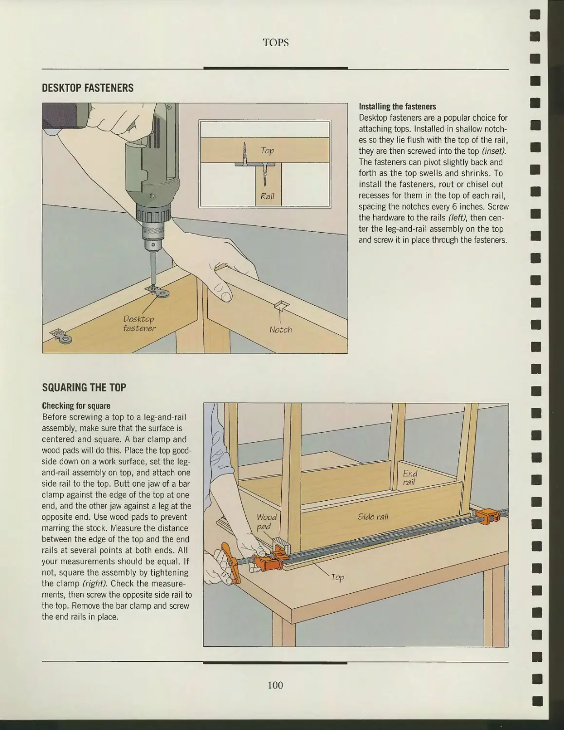
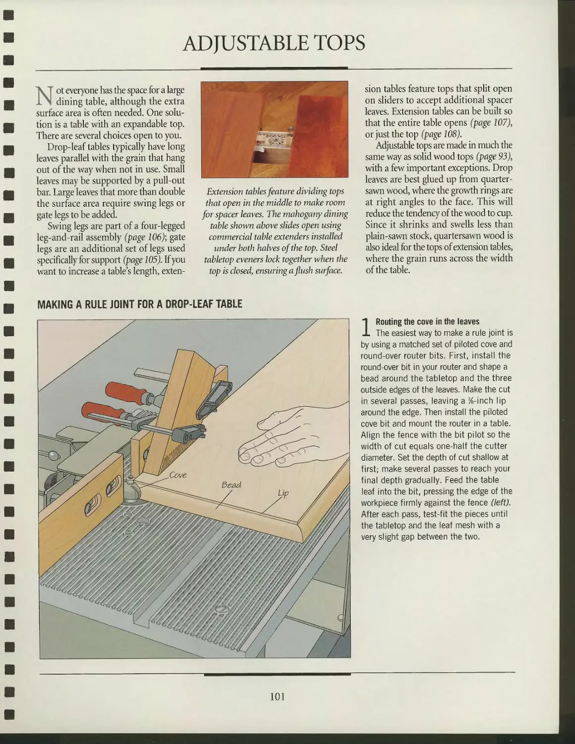
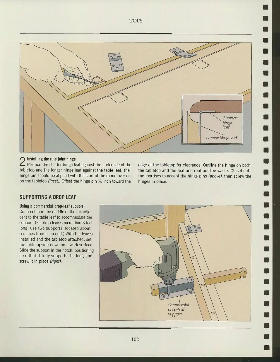
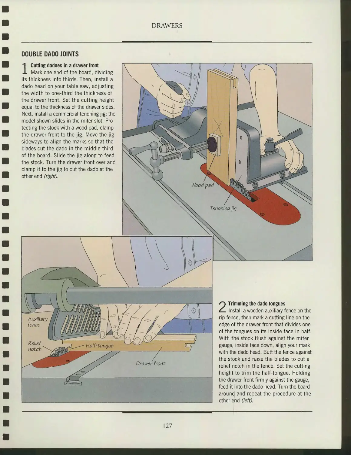
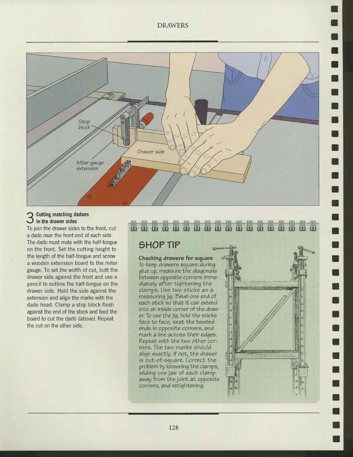
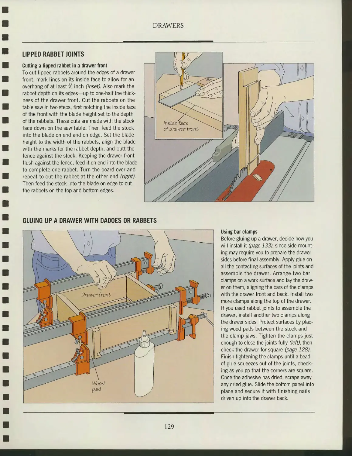
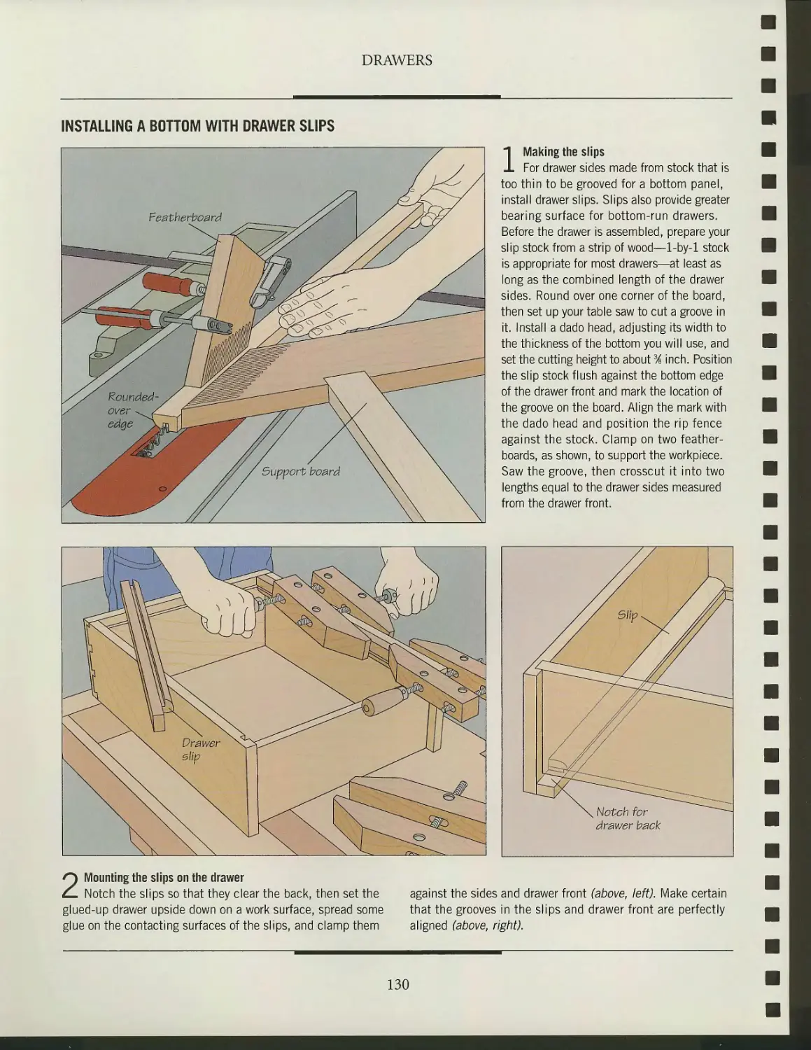
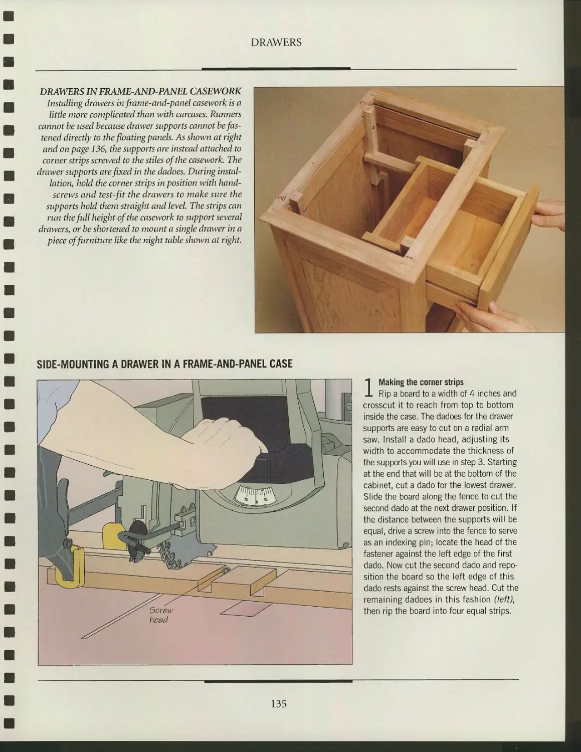
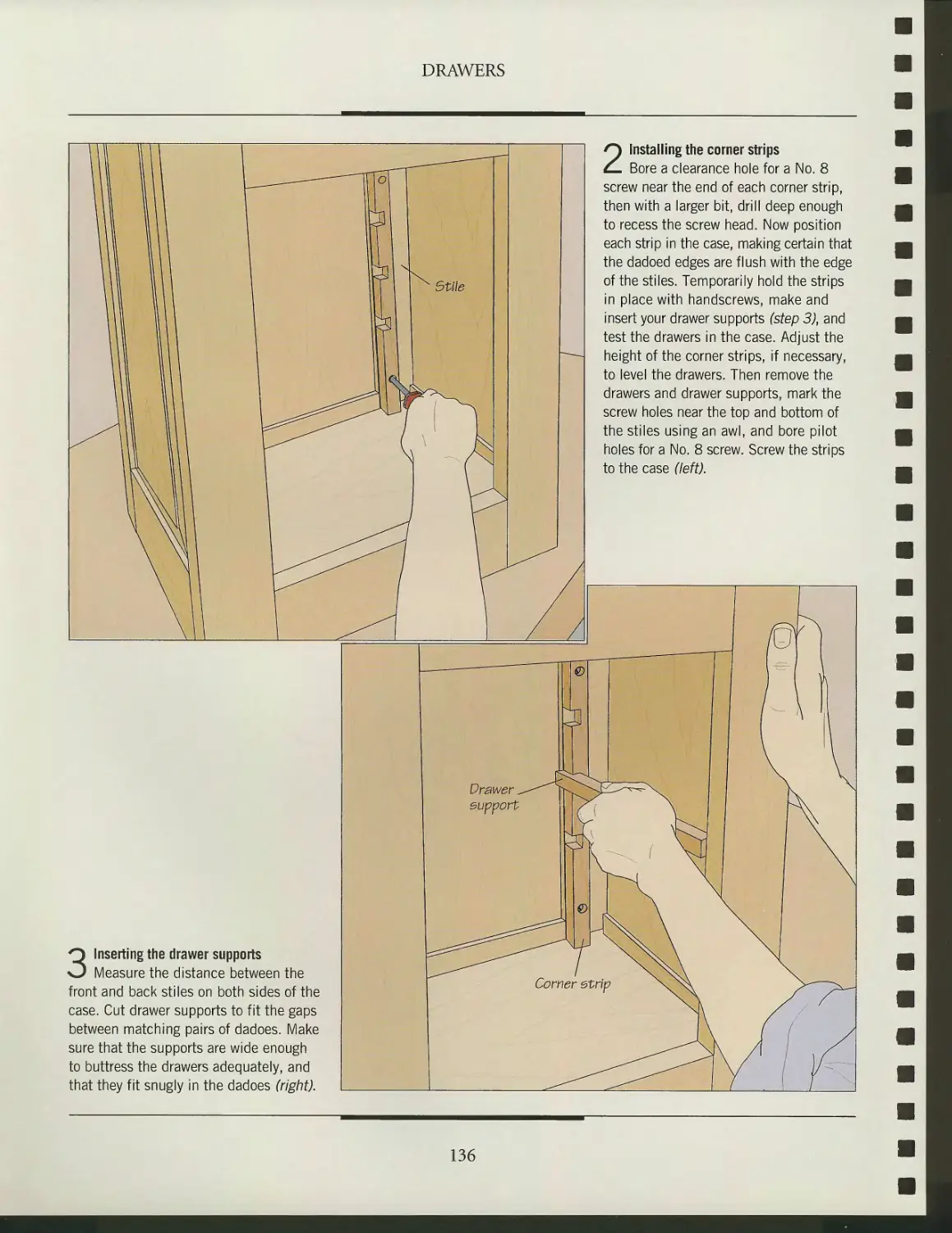
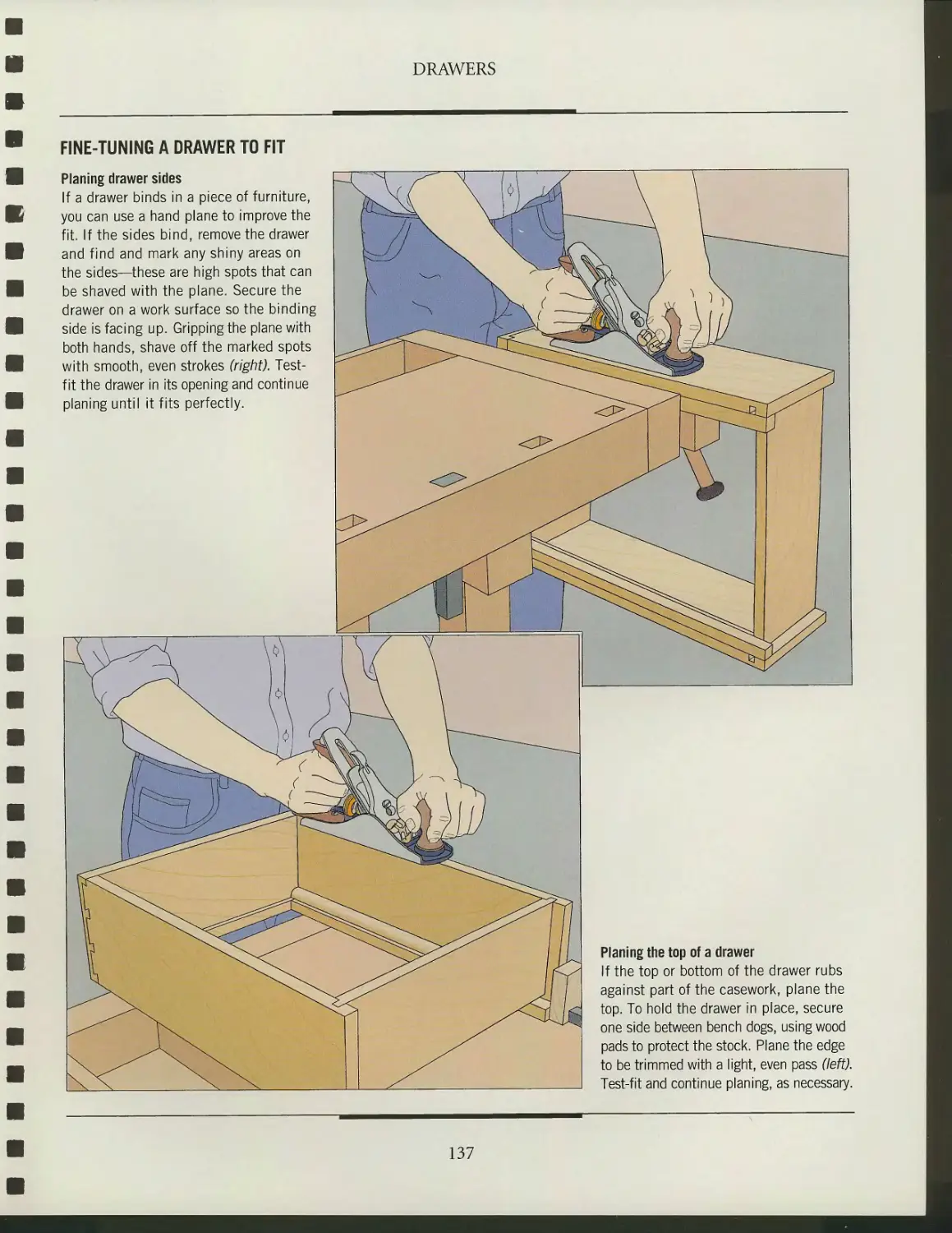
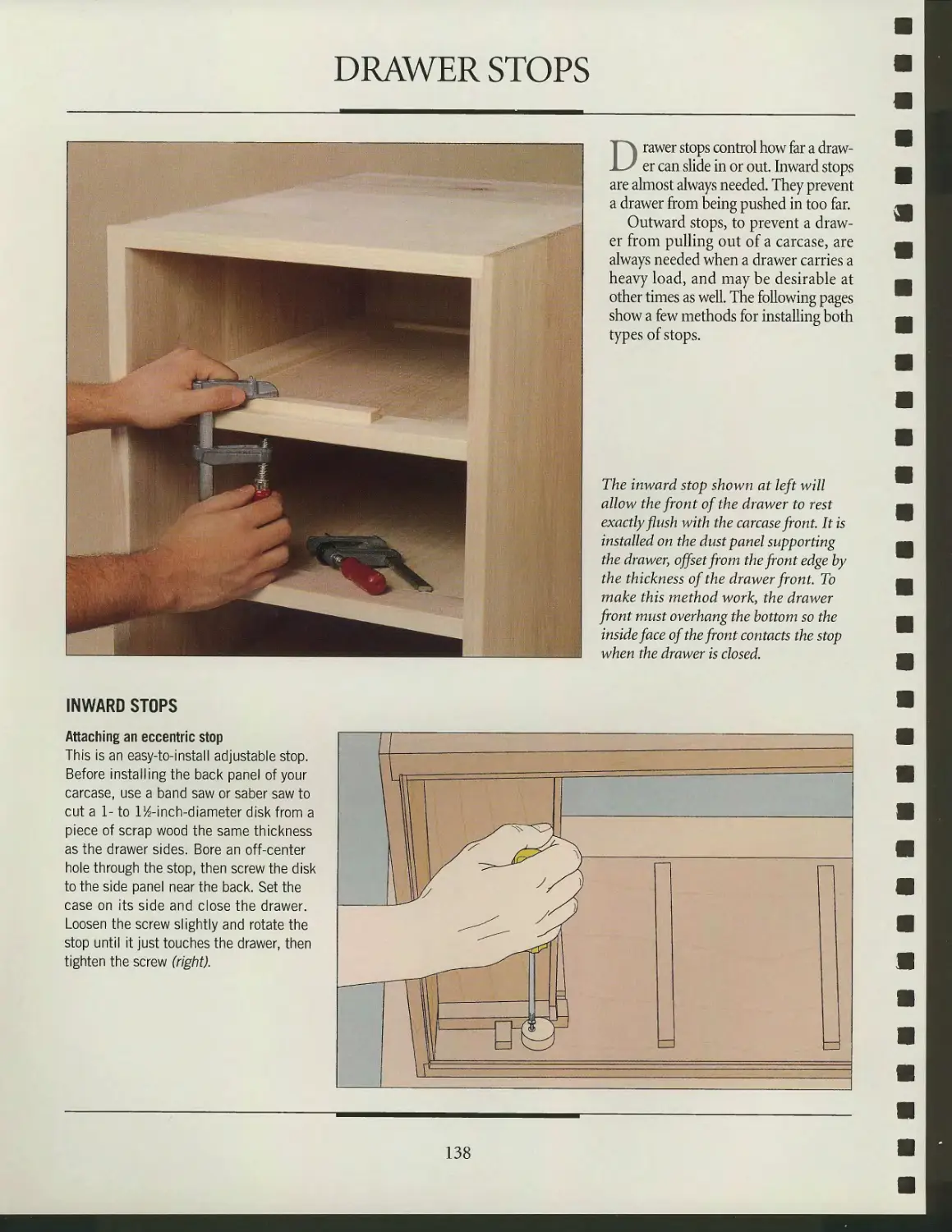
/


Текст
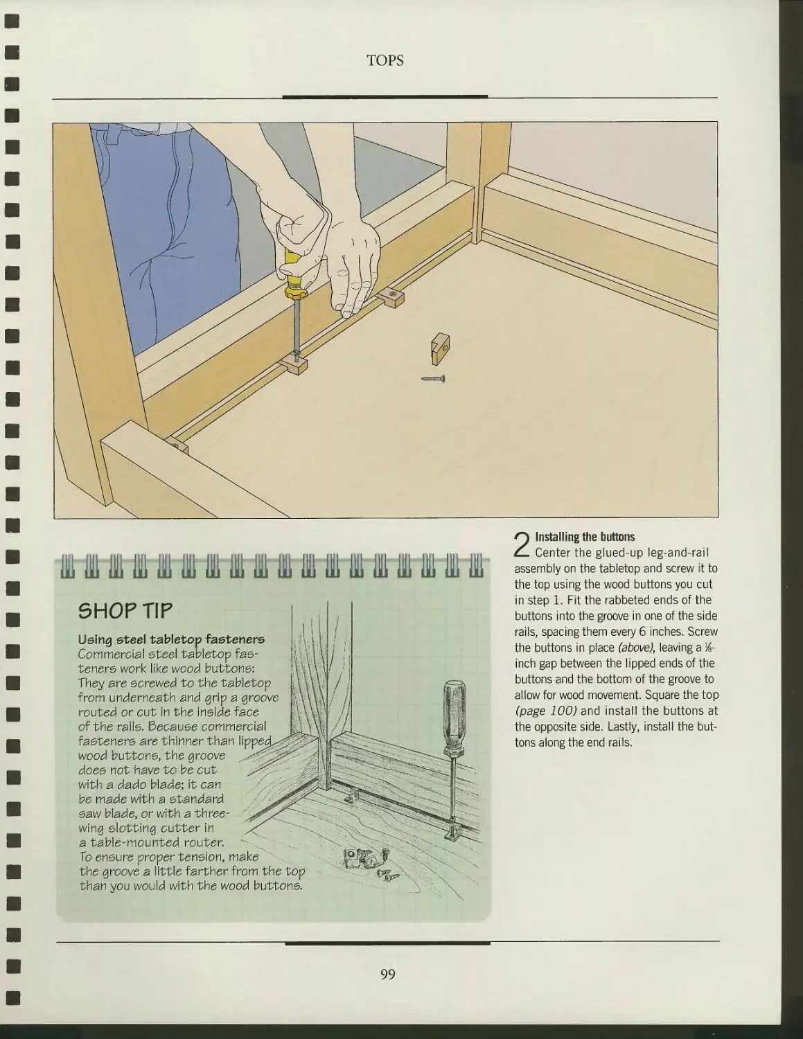
%
!tJ
TIME
ooks THE ART OF WOODWORKING
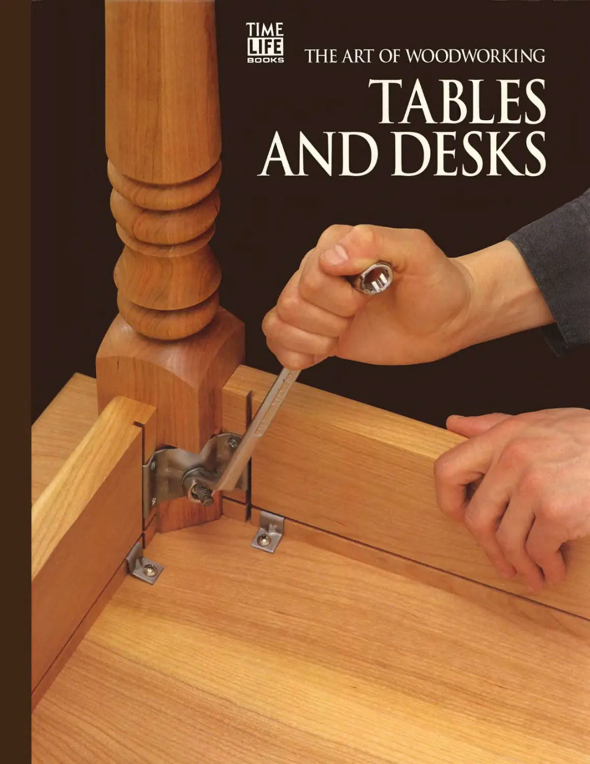
TABLES
AND DESKS
trm*
r\
>m
\m
v
•m
&
$?.
A
/• V-'. •■ ..;
V-.
«
3l
/999-2004
A Tuckerdude Scan 2005
WORKSHOP GUIDE
POWER TOOLS
• Wear appropriate safety gear: safety
glasses, a face shield for extra protection,
and hearing protection. If there is no dust
collection system, wear a dust mask. For
exotic woods such as ebony, use a
respirator; sawdust may cause an allergic
reaction. Wear work gloves when
handling rough lumber.
• Drape the power cord of a portable
power tool over your shoulder to keep
it out of the way.
• Concentrate on the job; do not rush.
SAFETY TIPS
• Never work when you are tired, stressed,
or have been drinking alcohol or using
medications that induce drowsiness.
• Always keep your work area clean
and tidy; clutter can lead to accidents,
and sawdust and wood scraps can be a
fire hazard.
• Keep your hands well away from a
turning blade or bit.
• Do not use a tool if any part is worn
or damaged.
HAND TOOLS
• Use the appropriate tool for the job;
do not try to make a tool do something
for which it was not intended.
• Clamp your workpiece to free both
hands for an operation.
• Cut away from yourself rather than
toward your body.
• Do not force a tool; if possible, try
removing less stock on each pass.
• Keep the edges of cutting tools sharp.
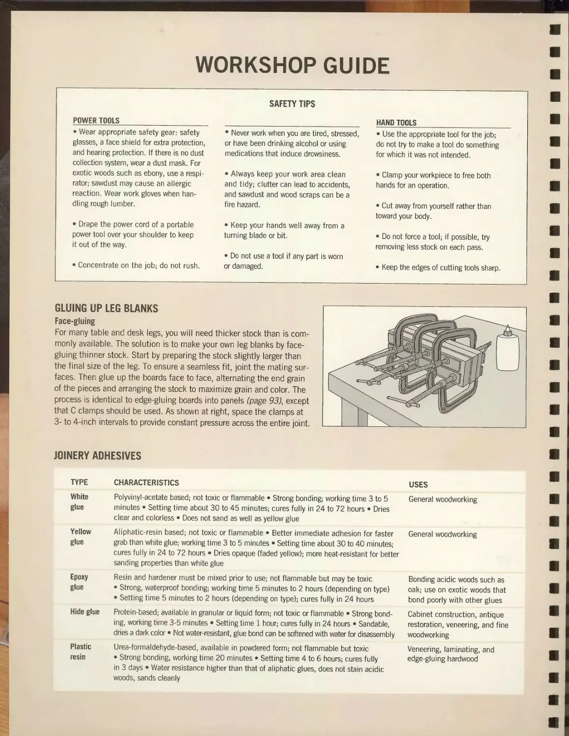
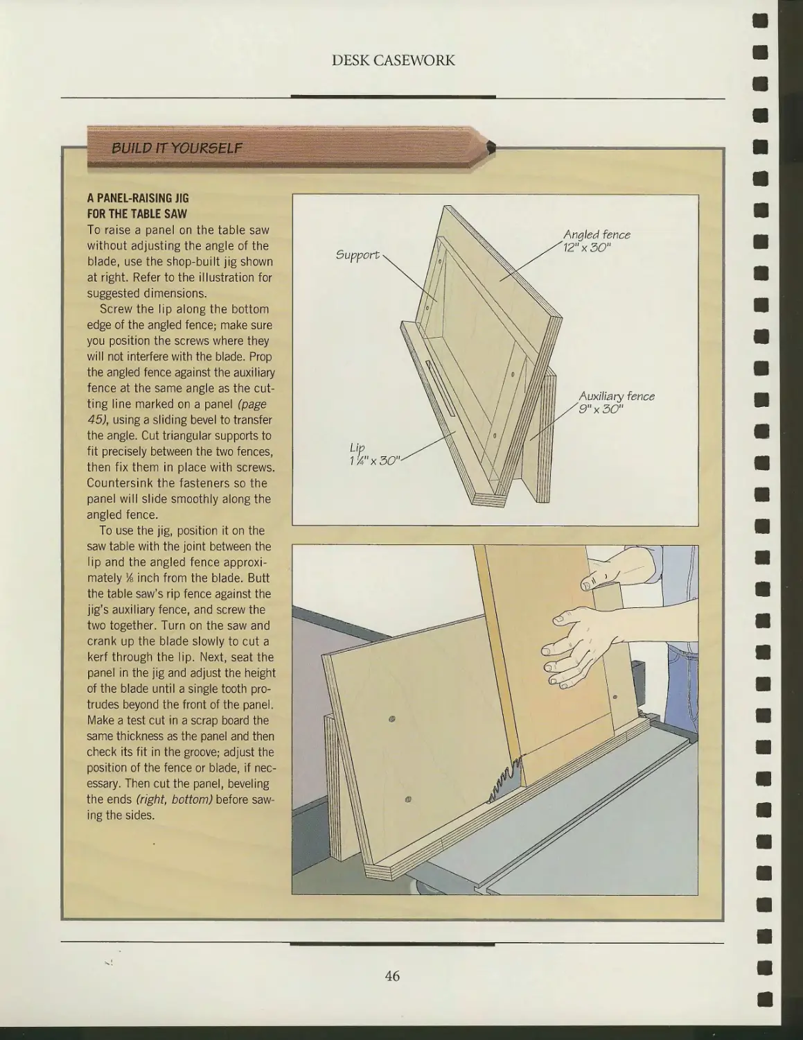
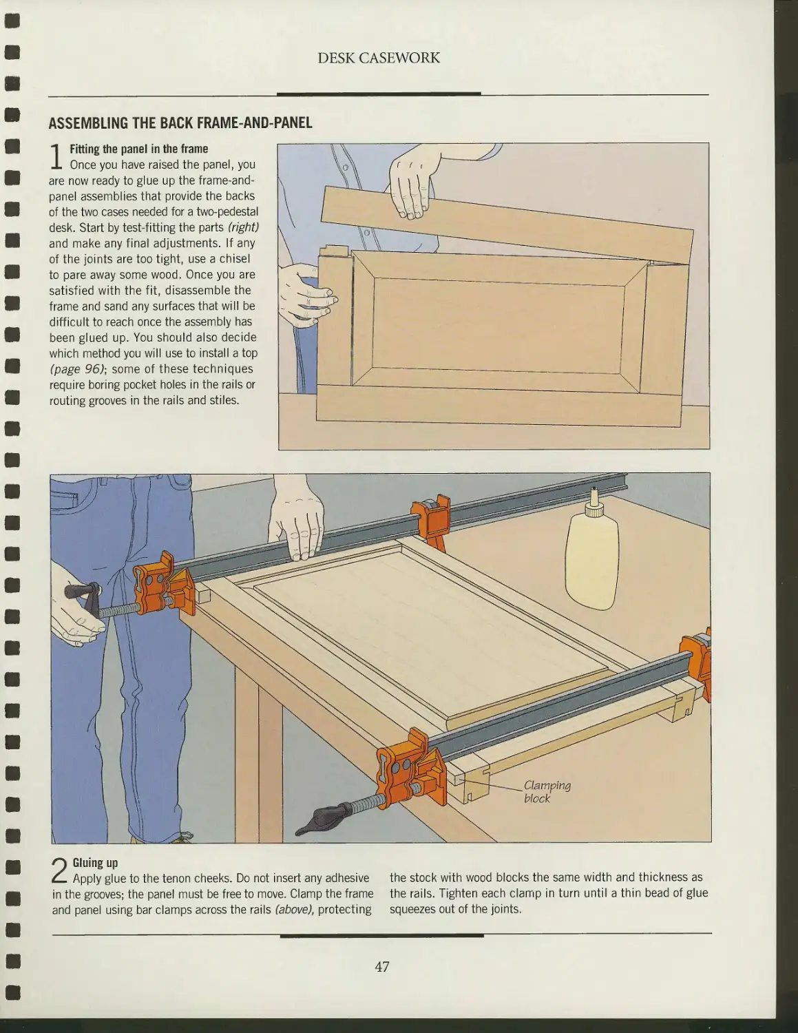
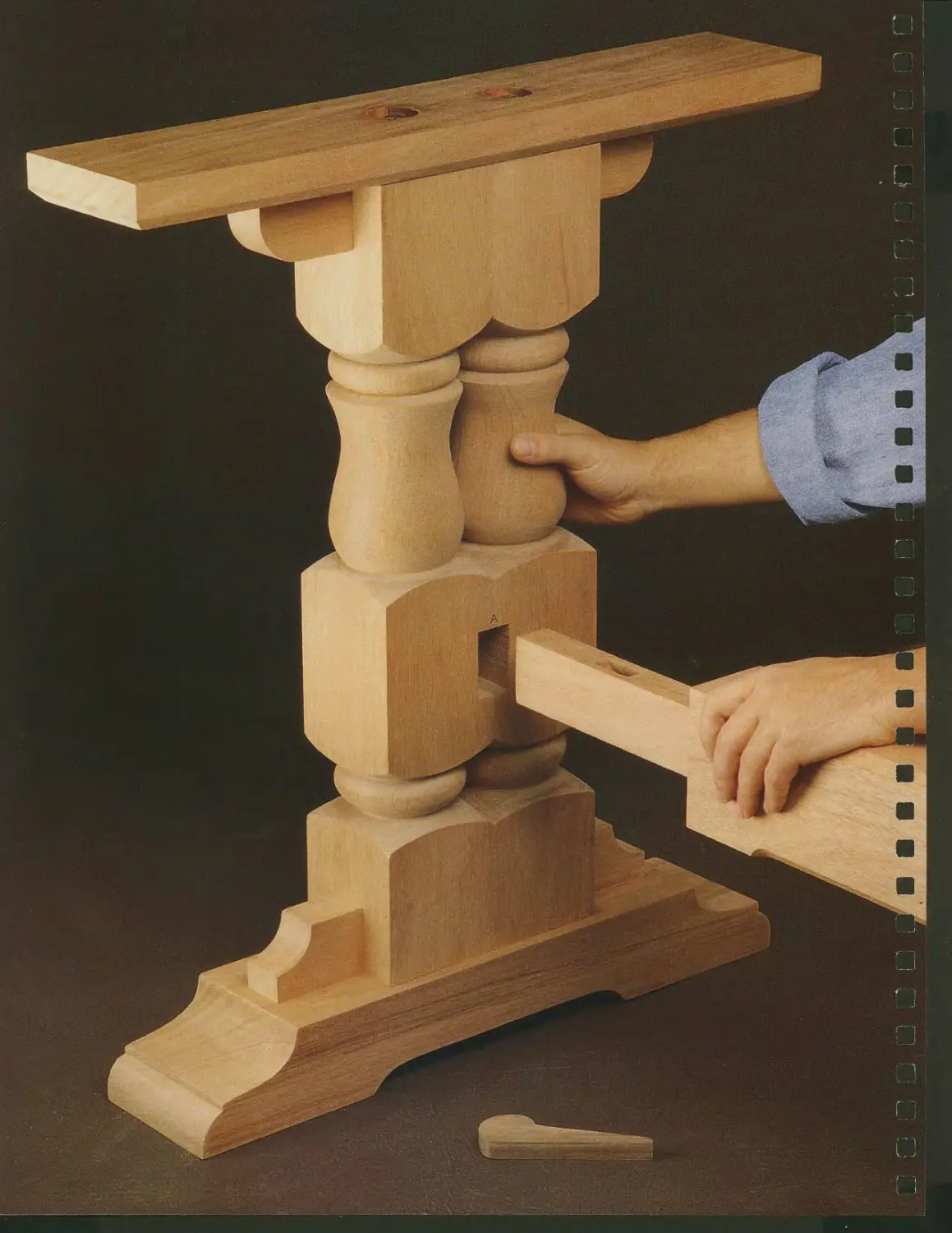
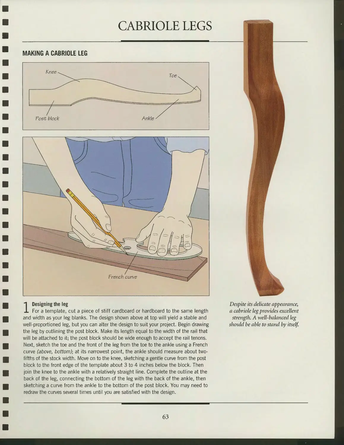
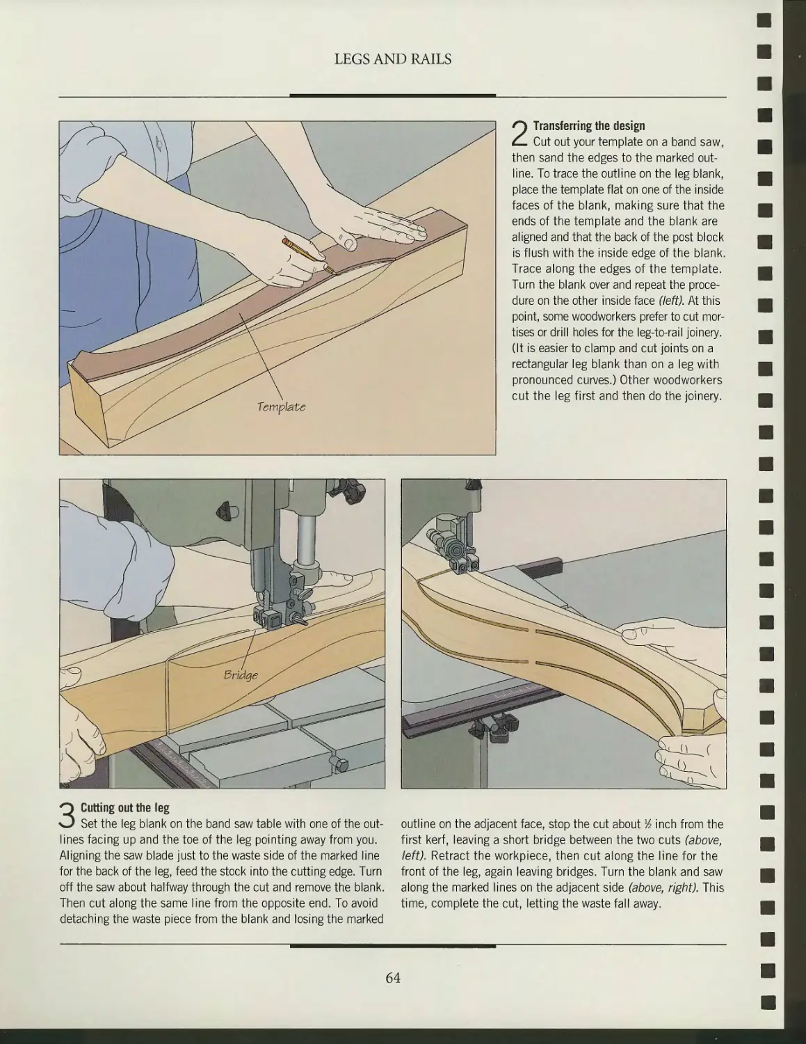
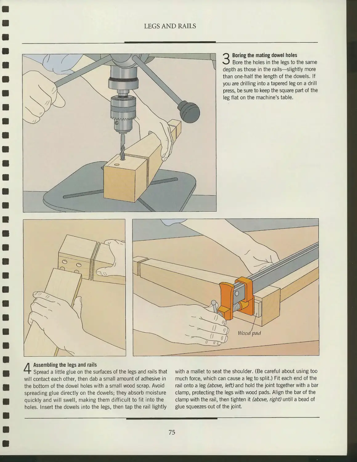
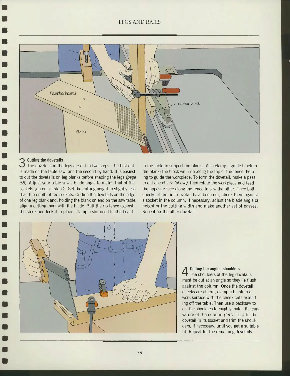
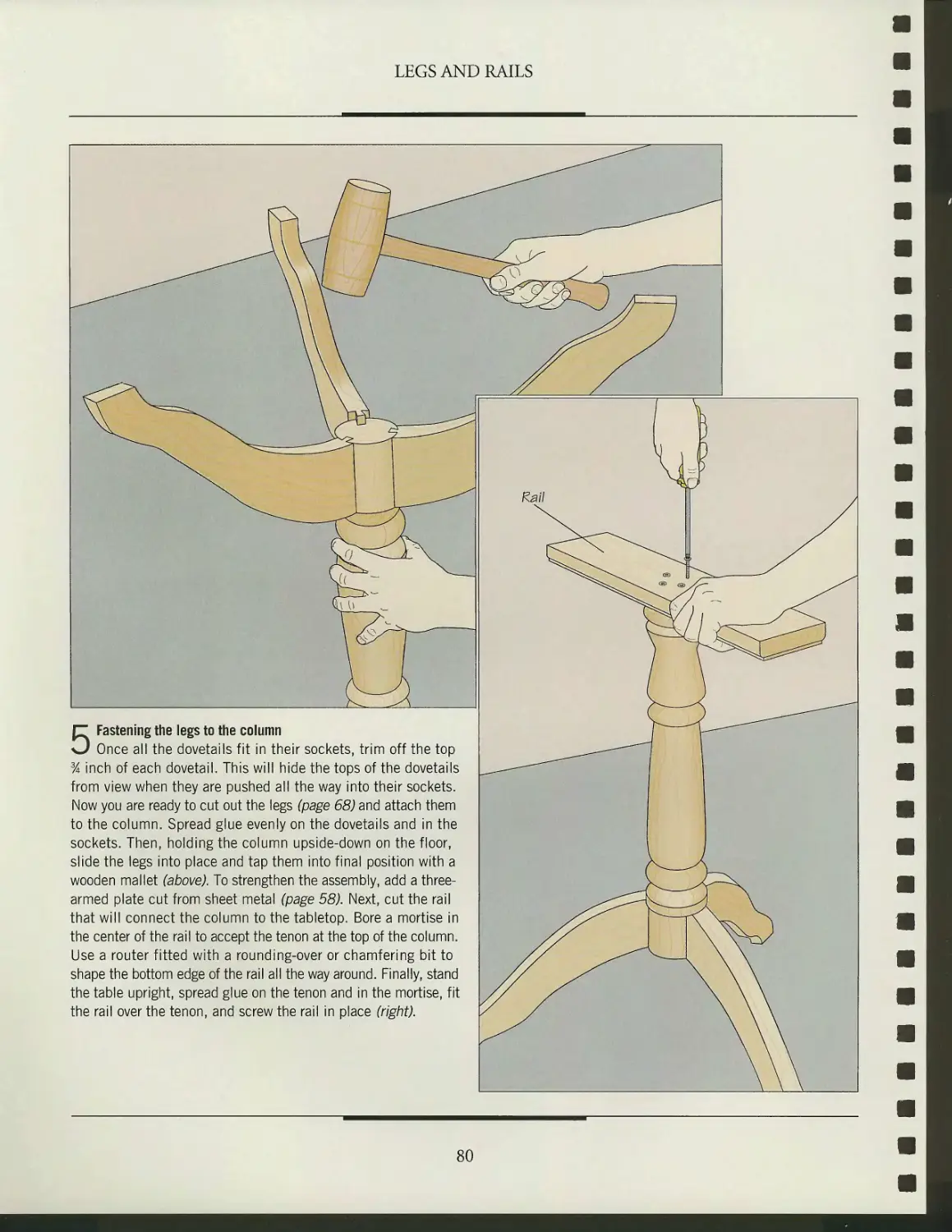
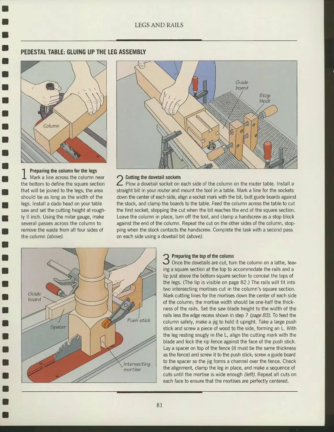
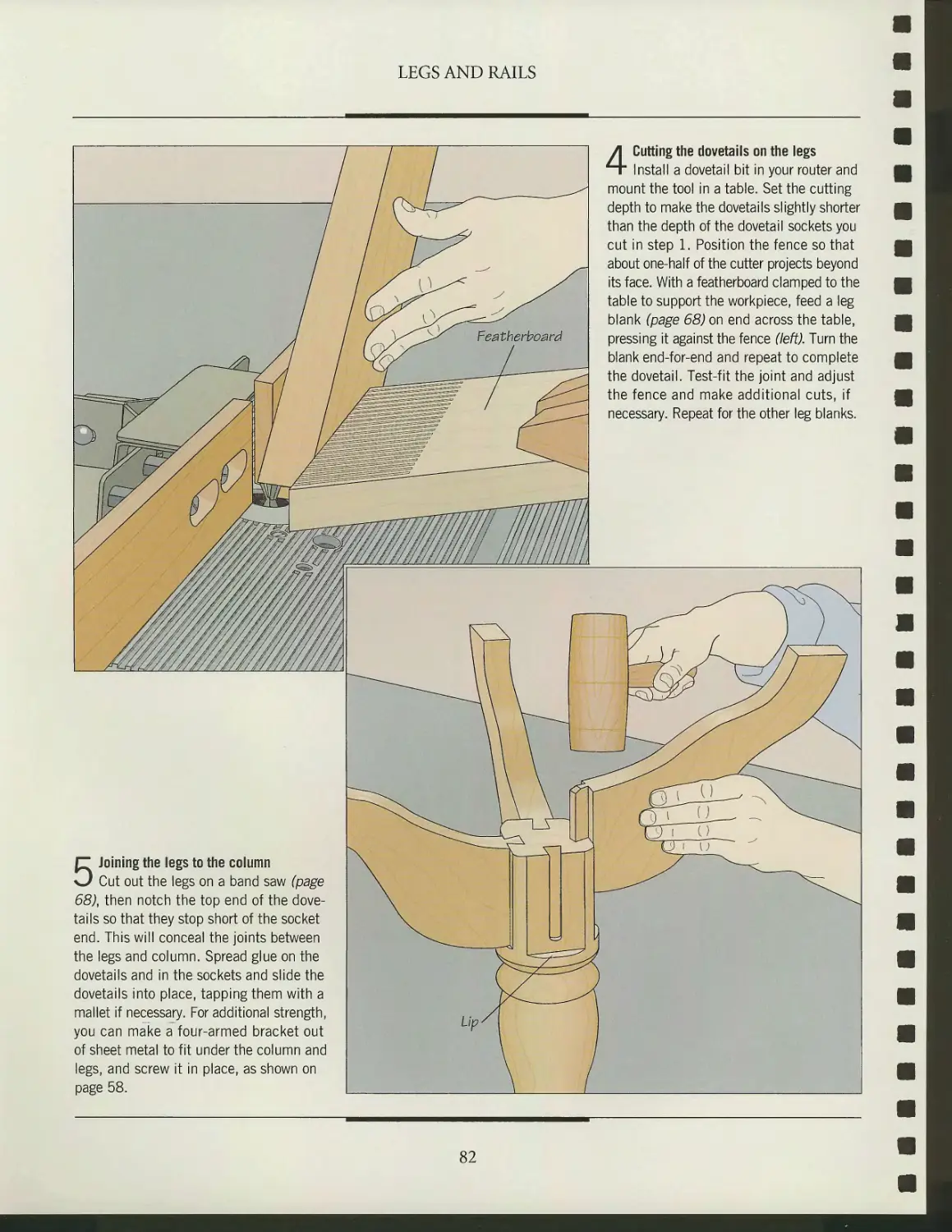
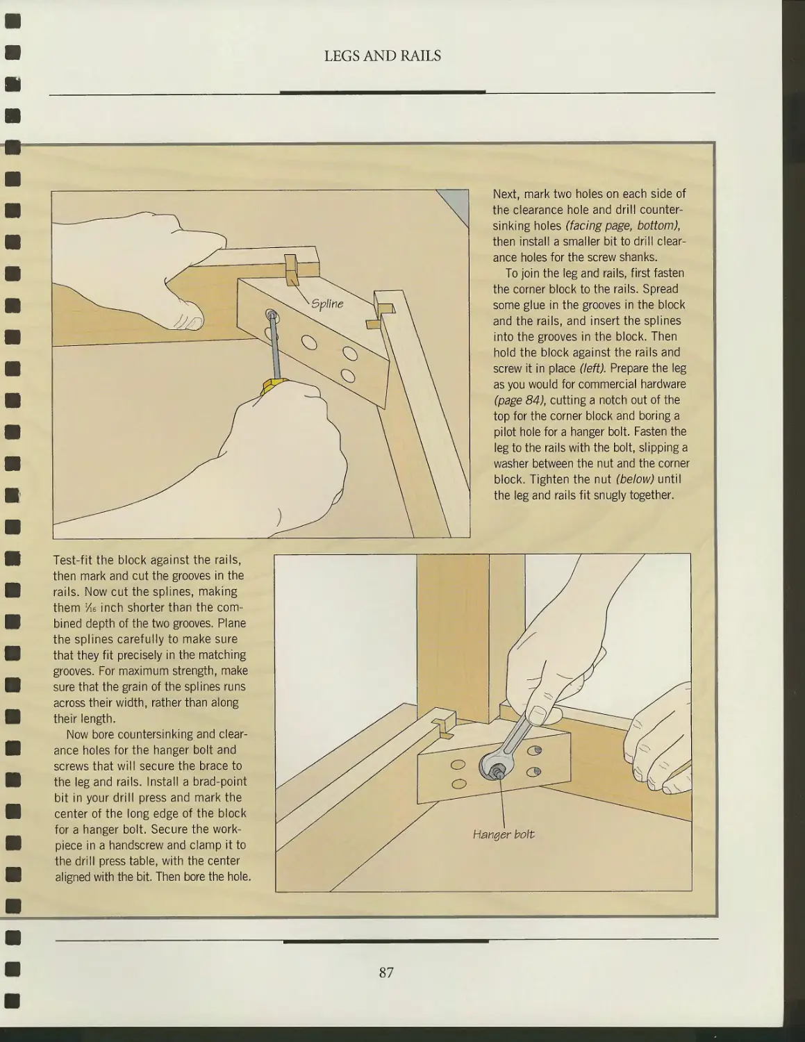
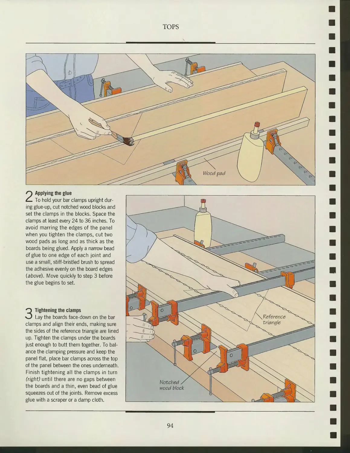
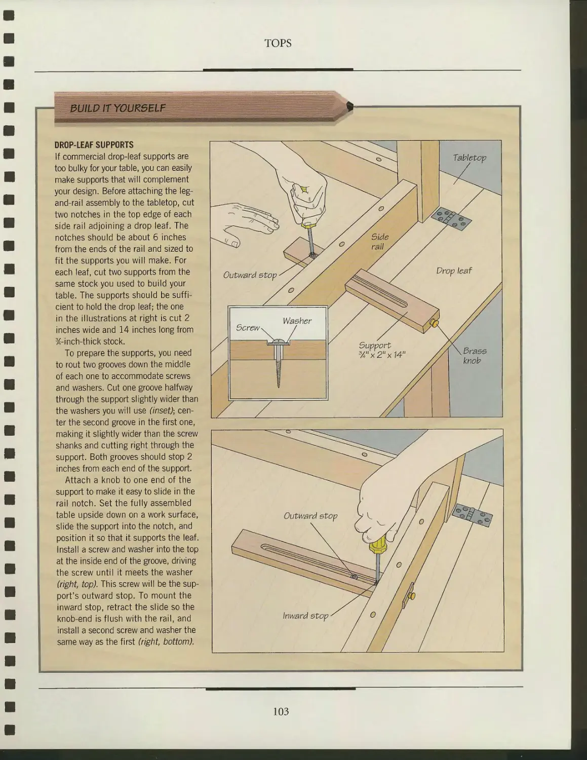
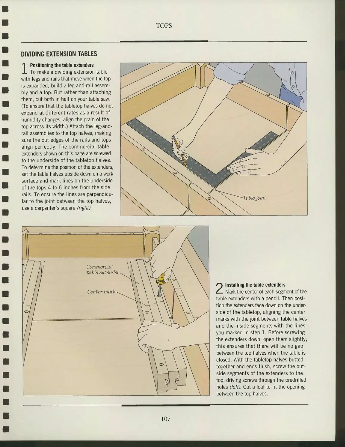
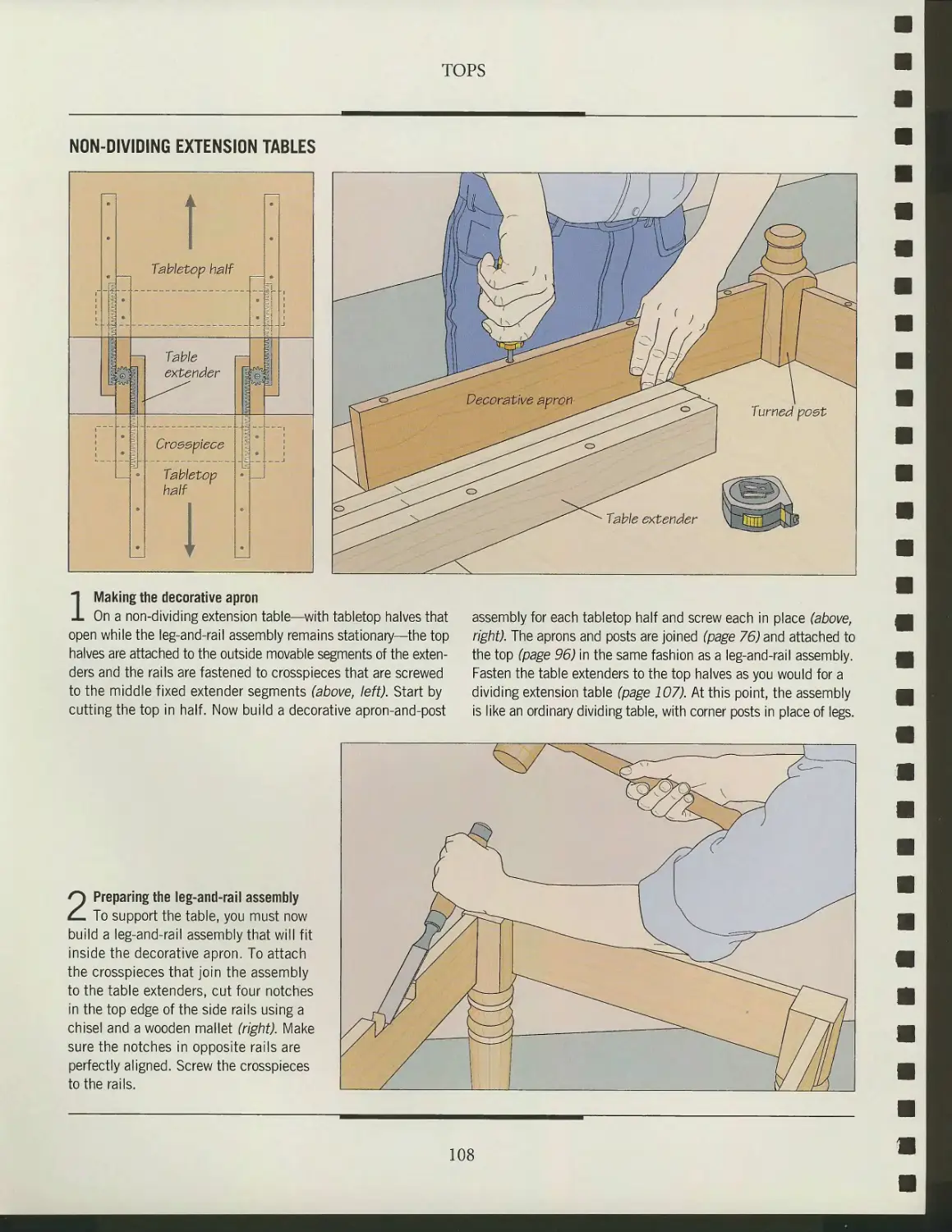
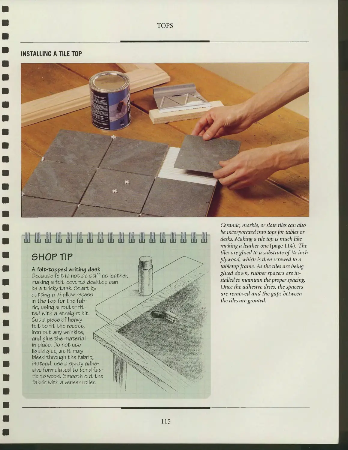
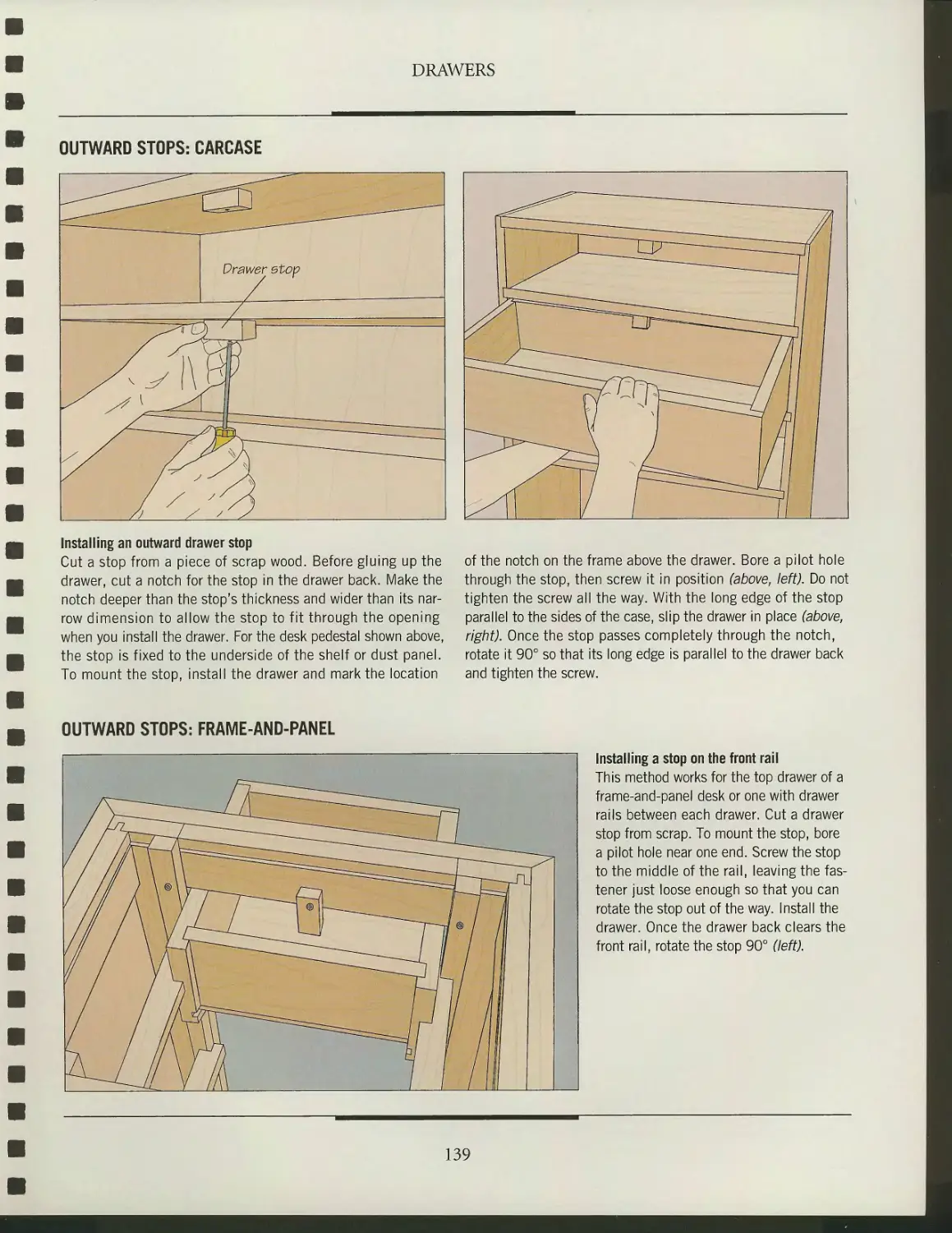
GLUING UP LEG BLANKS
Face-gluing
For many table and desk legs, you will need thicker stock than is
commonly available. The solution is to make your own leg blanks by face-
gluing thinner stock. Start by preparing the stock slightly larger than
the final size of the leg. To ensure a seamless fit, joint the mating
surfaces. Then glue up the boards face to face, alternating the end grain
of the pieces and arranging the stock to maximize grain and color. The
process is identical to edge-gluing boards into panels (page 93), except
that C clamps should be used. As shown at right, space the clamps at
3- to 4-inch intervals to provide constant pressure across the entire joint.
JOINERY ADHESIVES
TYPE CHARACTERISTICS
White Polyvinyl-acetate based; not toxic or flammable • Strong bonding; working time 3 to 5
glue minutes • Setting time about 30 to 45 minutes; cures fully in 24 to 72 hours • Dries
clear and colorless • Does not sand as well as yellow glue
Yellow Aliphatic-resin based; not toxic or flammable • Better immediate adhesion for faster
glue grab than white glue; working time 3 to 5 minutes • Setting time about 30 to 40 minutes;
cures fully in 24 to 72 hours • Dries opaque (faded yellow); more heat-resistant for better
sanding properties than white glue
Epoxy Resin and hardener must be mixed prior to use; not flammable but may be toxic
glue • Strong, waterproof bonding; working time 5 minutes to 2 hours (depending on type)
• Setting time 5 minutes to 2 hours (depending on type); cures fully in 24 hours
Hide glue Protein-based; available in granular or liquid form; not toxic or flammable • Strong
bonding, working time 3-5 minutes • Setting time 1 hour; cures fully in 24 hours • Sandable,
dries a dark color • Not water-resistant, glue bond can be softened with water for disassembly
Plastic Urea-formaldehyde-based, available in powdered form; not flammable but toxic
resin • Strong bonding, working time 20 minutes • Setting time 4 to 6 hours; cures fully
in 3 days • Water resistance higher than that of aliphatic glues, does not stain acidic
woods, sands cleanly
USES
General woodworking
General woodworking
Bonding acidic woods such as
oak; use on exotic woods that
bond poorly with other glues
Cabinet construction, antique
restoration, veneering, and fine
woodworking
Veneering, laminating, and
edge-gluing hardwood
THE ART OF WOODWORKING
TABLES
AND DESKS
THE ART OF WOODWORKING
TABLES
AND DESKS
TIME-LIFE BOOKS
ALEXANDRIA, VIRGINIA
ST. REMY PRESS
MONTREAL* NEW YORK
THE ART OF WOODWORKING was produced by
ST. REMY PRESS
PUBLISHER
PRESIDENT
Series Editor
Series Art Director
Senior Editors
Art Directors
Designers
Research Editor
Picture Editor
Writers
Research Assistant
Contributing Illustrators
Administrator
Production Manager
System Coordinator
Photographers
Administrative Assistant
Proofreader
Indexer
Kenneth Winchester
Pierre Leveille
Pierre Home-Douglas
Francine Lemieux
Marc Cassini (Text)
Heather Mills (Research)
Normand Boudreault, Luc Germain,
Solange Laberge
Lina Desrochers, Helene Dion,
Jean-Guy Doiron, Michel Giguere
Jim McRae
Christopher Jackson
Andrew Jones, Rob Lutes
Bryan Quinn
Gilles Beauchemin, Roland Bergerat,
Michel Blais, Jean-Pierre Bourgeois,
Ronald Durepos, Jacques Perrault,
James Therien
Natalie Watanabe
Michelle Turbide
Jean-Luc Roy
Robert Chartier, Christian Levesque
Dominique Gagne
Judith Yelon
Christine M. Jacobs
Time-Life Books is a division of Time Life Inc.,
a wholly owned subsidiary of
THE TIME INC. BOOK COMPANY
TIME LIFE INC.
President and CEO John M. Fahey
Editor-in-chief John L. Papanek
TIME-LIFE BOOKS
President John D. Hall
Vice-President, Director of Marketing Nancy K. Jones
Executive Editor Roberta Conlan
Executive Art Director Ellen Robling
THE CONSULTANTS
Jon Arno is a consultant, cabinetmaker, and freelance writer
who lives in Troy, Michigan. He also conducts seminars on
wood identification and early American furniture design.
Kam Ghaffari is a freelance writer and editor. He has his own
business in Rhode Island designing and building one-of-a-
kind and limited production furniture. Kam's background
also includes working professionally in furniture
reproduction and fine carpentry and studying with furniture
patriarchs Wendell Castle of the U.S. and England's Fred Baier.
Giles Miller-Mead taught advanced cabiiietmaking at Montreal
technical schools for more than ten years. A native of New
Zealand, he has worked as a restorer of antique furniture.
Tables & Desks
p. cm.—(The Art of woodworking)
Includes index.
ISBN 0-8094-9512-0
I. Tables 2. Desks 3. Furniture making I. Time-Life Books.
II. Title: Tables and desks. III. Series.
TT197.5.T3T33 1994
684.1'3—dc20 93-49732
CIP
For information about any Time-Life book,
please call 1-800-621-7026, or write:
Reader Information
Time-Life Customer Service
P.O. Box C-32068
Richmond, Virginia
23261-2068
© 1994 Time-Life Books Inc.
All rights reserved.
No part of this book may be reproduced in any form or by
any electronic or mechanical means, including information
storage and retrieval devices or systems, without prior
written permission from the publisher, except that brief passages
may be quoted for reviews.
First printing. Printed in U.S.A.
Published simultaneously in Canada.
Consulting Editor
Production Manager
John R. Sullivan
Marlene Zack
TIME-LIFE is a trademark of Time Warner Inc. U.S.A.
CONTENTS
6
12
14
16
18
19
21
22
28
30
32
33
41
54
56
57
58
59
60
63
66
68
69
72
INTRODUCTION
TABLE AND DESK BASICS
Wood movement
Selecting and ordering wood
Lumber defects
Preparing stock
Designing tables and desks
Table and desk styles
DESK CASEWORK
Two types of desk casework
Casework joints
Building a carcase
Building a frame-and-
panel desk
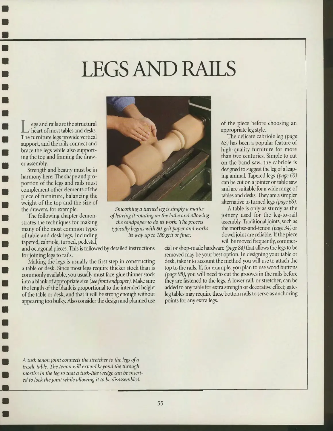
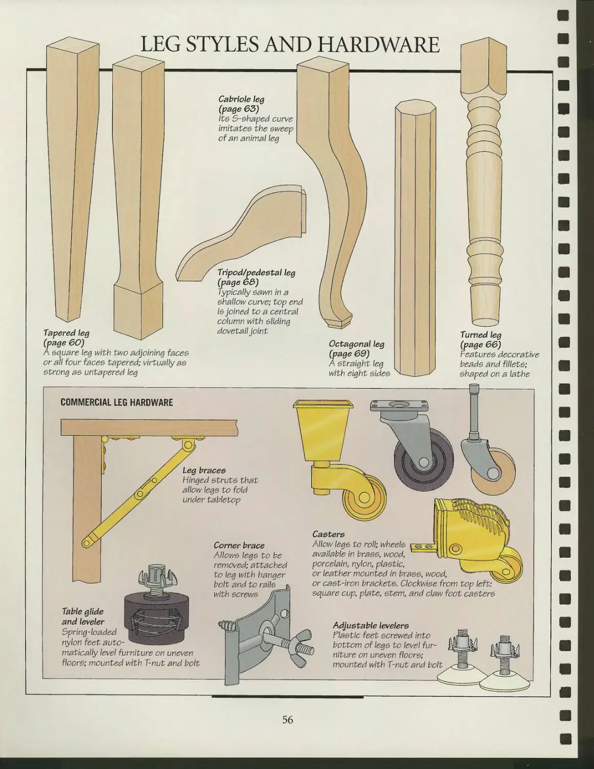
LEGS AND RAILS
Leg styles and hardware
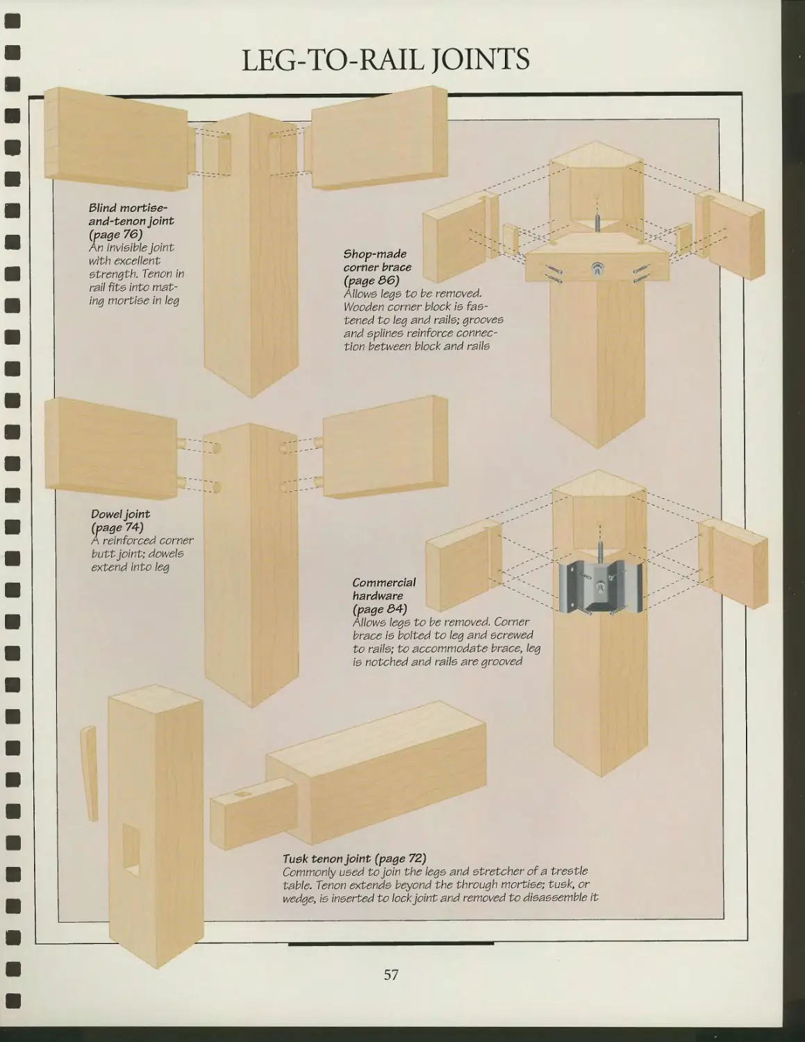
Leg-to-rail joints
Tripod table
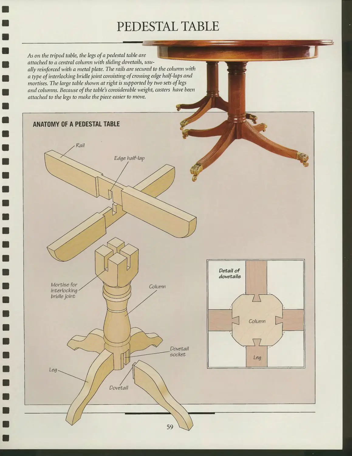
Pedestal table
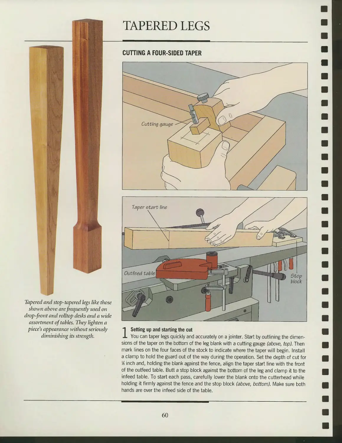
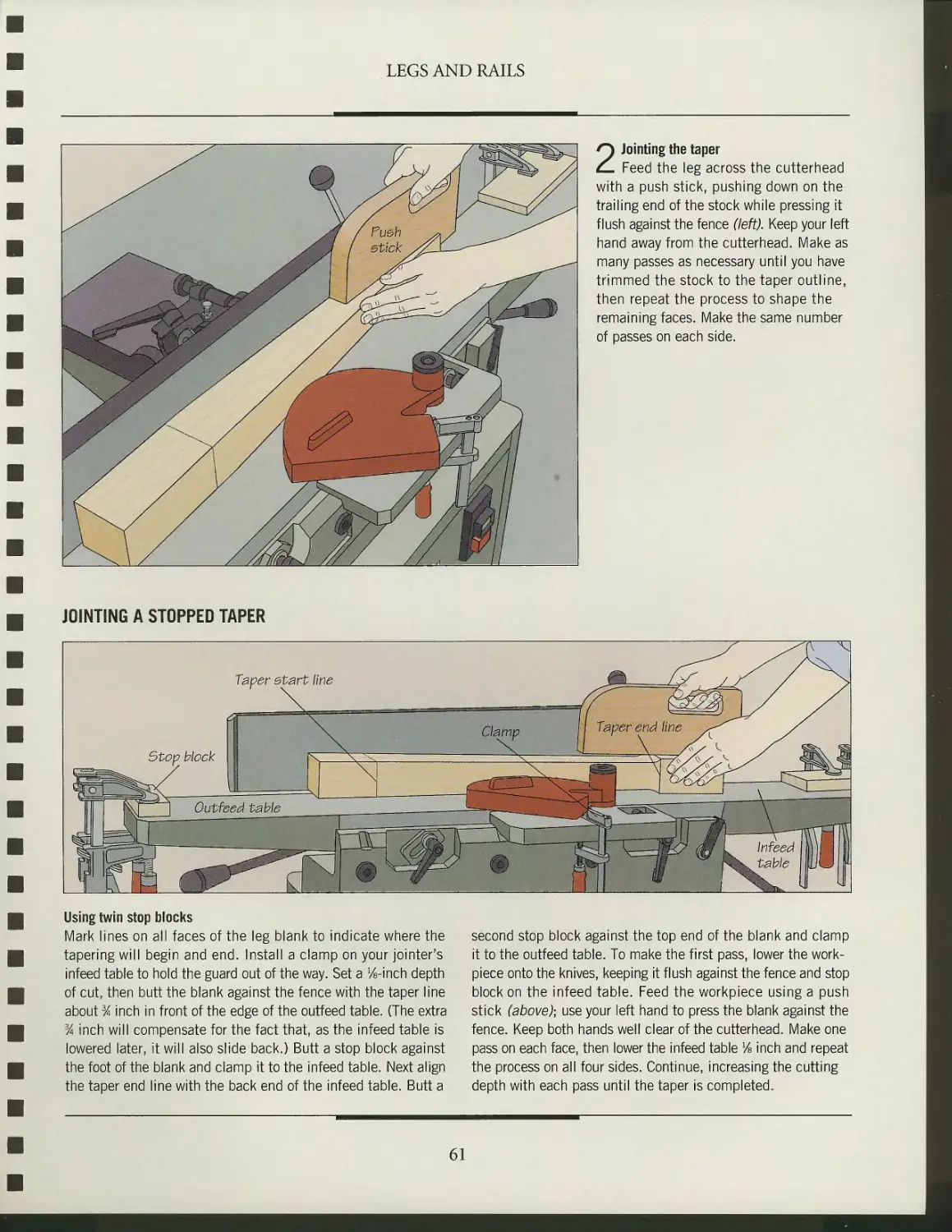
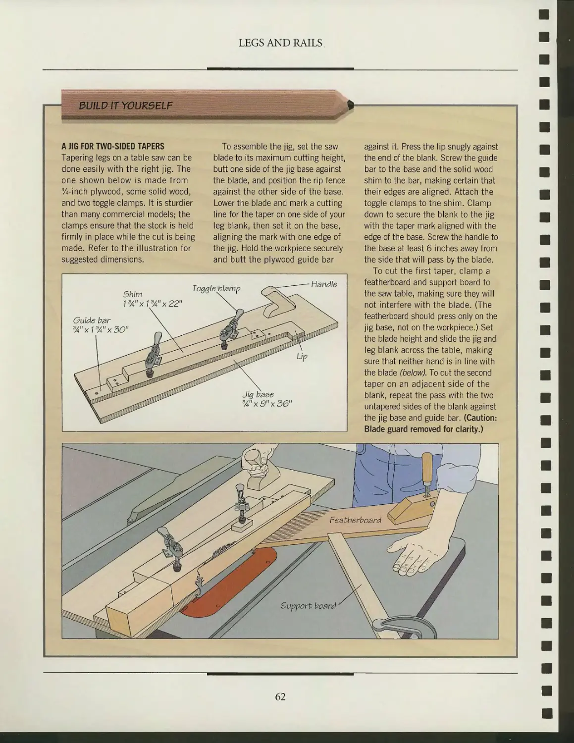
Tapered legs
Cabriole legs
Turned legs
Pedestal legs
Octagonal legs
Leg-to-rail joinery
88
90
92
93
96
101
112
116
118
120
131
133
138
140
142
144
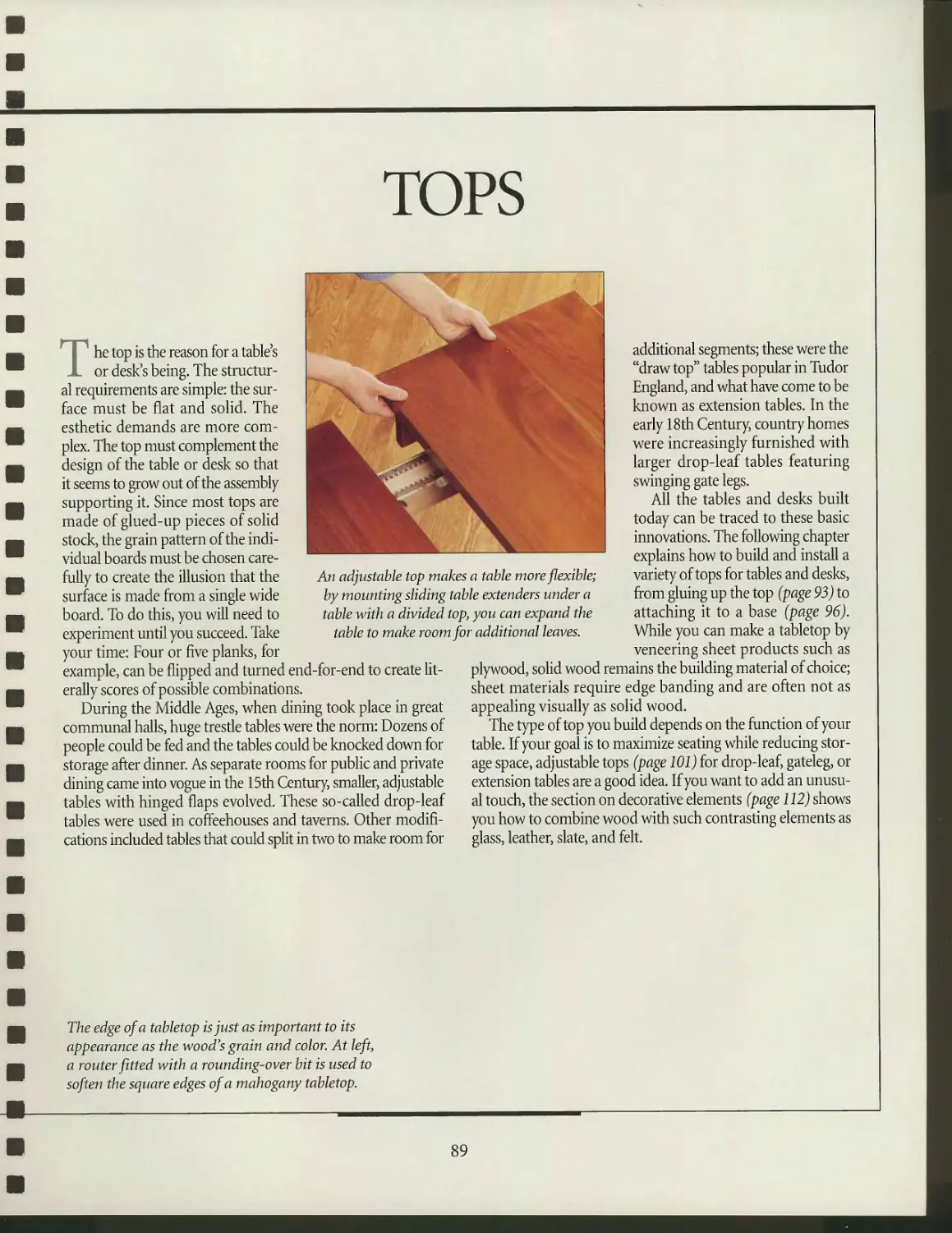
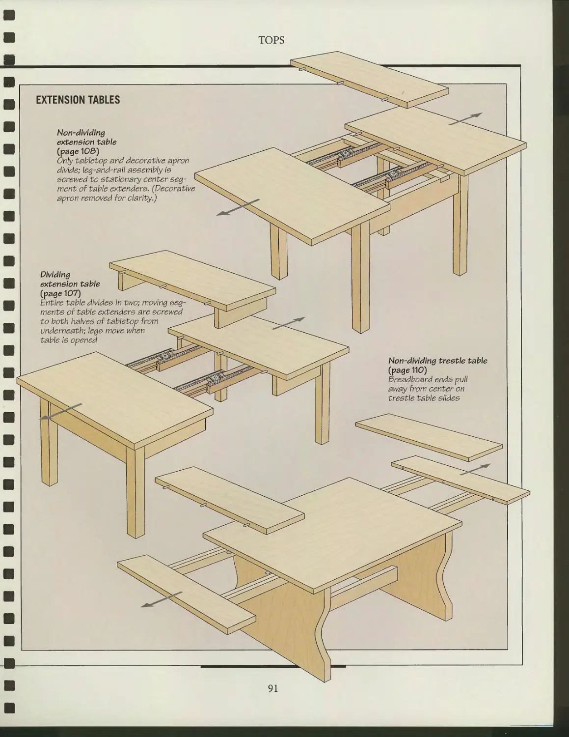
TOPS
Inventory of top designs
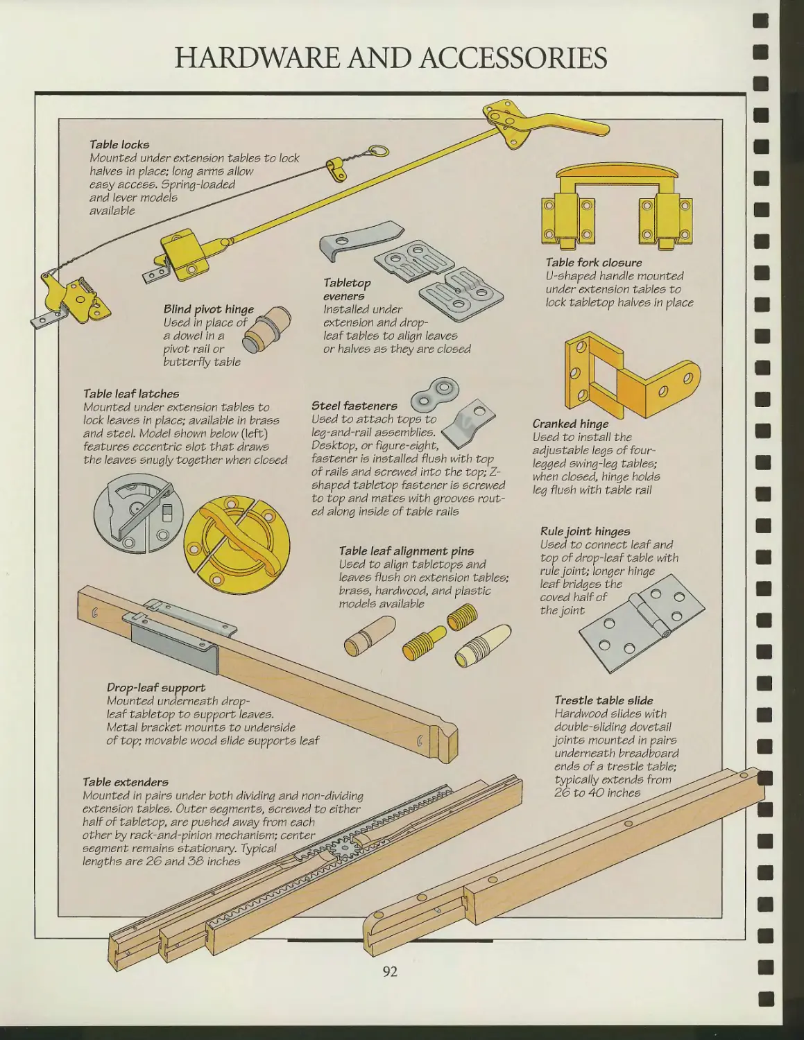
Hardware and accessories
Preparing a top
Attaching a top
Adjustable tops
Decorative elements
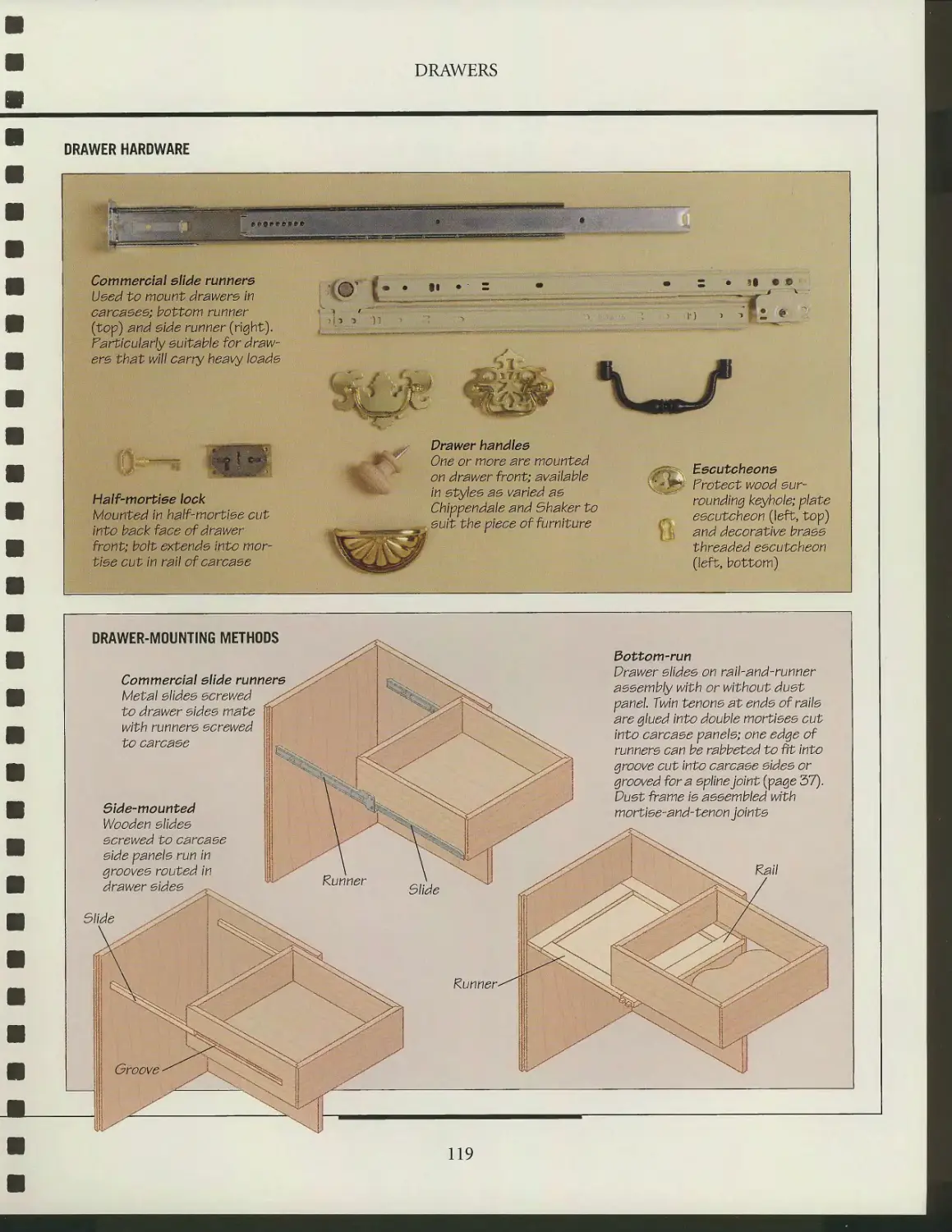
DRAWERS
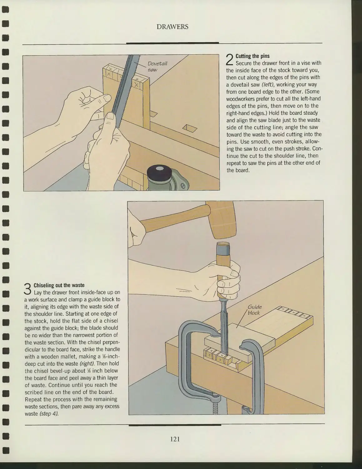
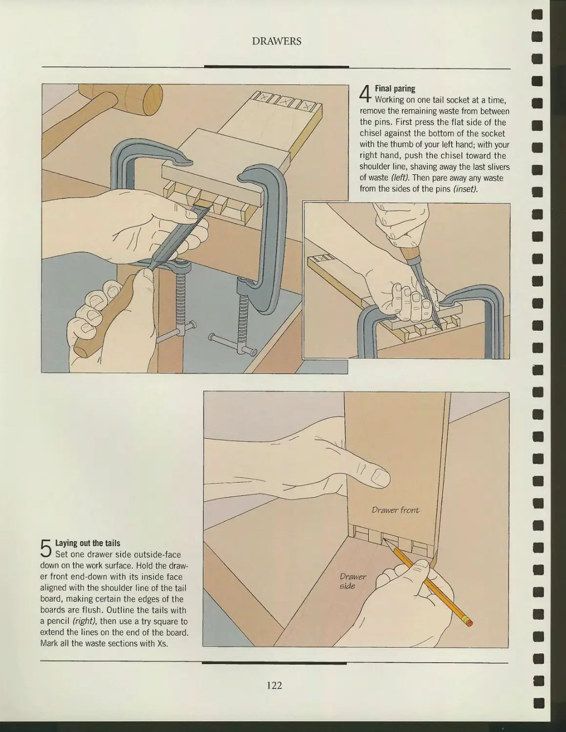
Anatomy of a drawer
Drawer joinery
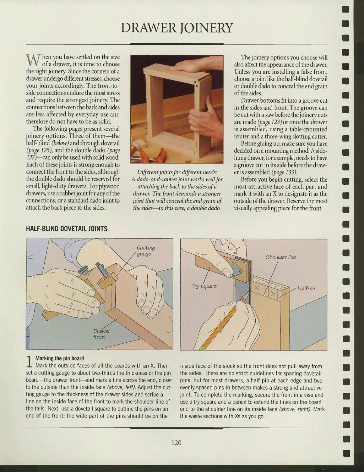
Drawer hardware
Mounting drawers
Drawer stops
GLOSSARY
INDEX
ACKNOWLEDGMENTS
** ; ;|Jj
INTRODUCTION
PI
-- Pi "V'f
Simon Watts talks about
HIS RECYCLED
DESK
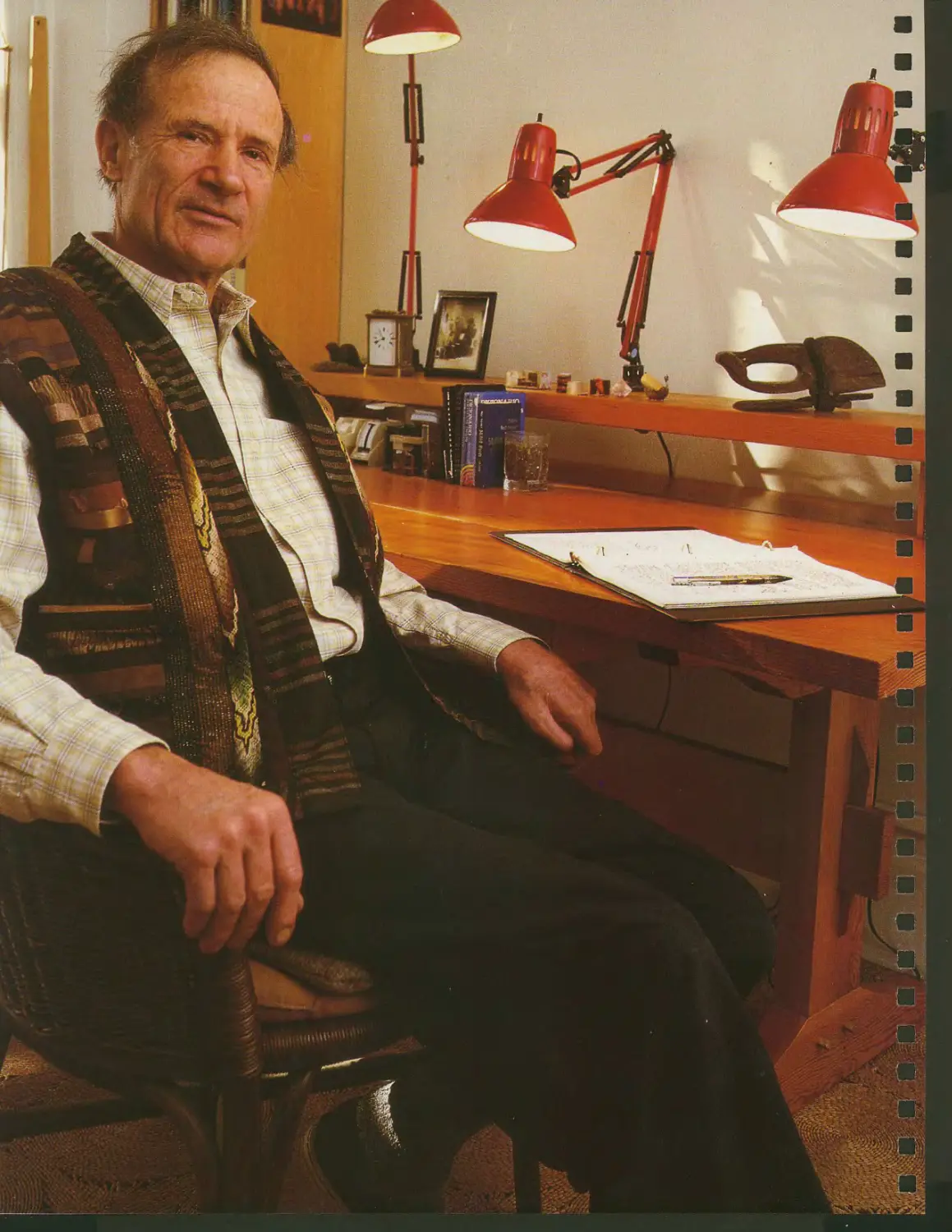
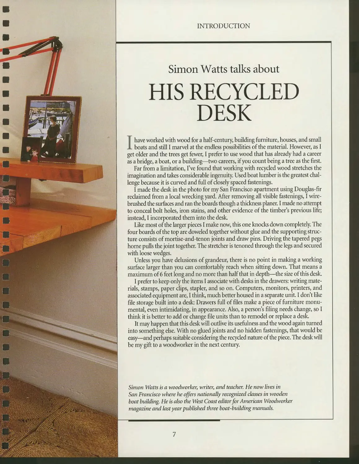
I have worked with wood for a half-century, building furniture, houses, and small
boats and still I marvel at the endless possibilities of the material. However, as I
get older and the trees get fewer, I prefer to use wood that has already had a career
as a bridge, a boat, or a building—two careers, if you count being a tree as the first.
Far from a limitation, I've found that working with recycled wood stretches the
imagination and takes considerable ingenuity. Used boat lumber is the greatest
challenge because it is curved and full of closely spaced fastenings.
I made the desk in the photo for my San Francisco apartment using Douglas-fir
reclaimed from a local wrecking yard. After removing all visible fastenings, I wire-
brushed the surfaces and ran the boards though a thickness planer. I made no attempt
to conceal bolt holes, iron stains, and other evidence of the timber's previous life;
instead, I incorporated them into the desk.
Like most of the larger pieces I make now, this one knocks down completely. The
four boards of the top are doweled together without glue and the supporting
structure consists of mortise-and-tenon joints and draw pins. Driving the tapered pegs
home pulls the joint together. The stretcher is tenoned through the legs and secured
with loose wedges.
Unless you have delusions of grandeur, there is no point in making a working
surface larger than you can comfortably reach when sitting down. That means a
maximum of 6 feet long and no more than half that in depth—the size of this desk.
^™^-,gr- I prefer to keep only the items I associate with desks in the drawers: writing mate-
^S|ftSl rials> stamps, paper clips, stapler, and so on. Computers, monitors, printers, and
associated equipment are, I think, much better housed in a separate unit. I don't like
file storage built into a desk: Drawers full of files make a piece of furniture
monumental, even intimidating, in appearance. Also, a person's filing needs change, so I
think it is better to add or change file units than to remodel or replace a desk.
It may happen that this desk will outlive its usefulness and the wood again turned
into something else. With no glued joints and no hidden fastenings, that would be
easy—and perhaps suitable considering the recycled nature of the piece. The desk will
be my gift to a woodworker in the next century.
Simon Watts is a woodworker, writer, and teacher. He now lives in
San Francisco where he offers nationally recognized classes in wooden
hoot building. He is also the West Coast editor for American Woodworker
magazine and last year published three boat-building manuals.
INTRODUCTION
Kam Ghaffari discusses
DESIGNING
TABLES
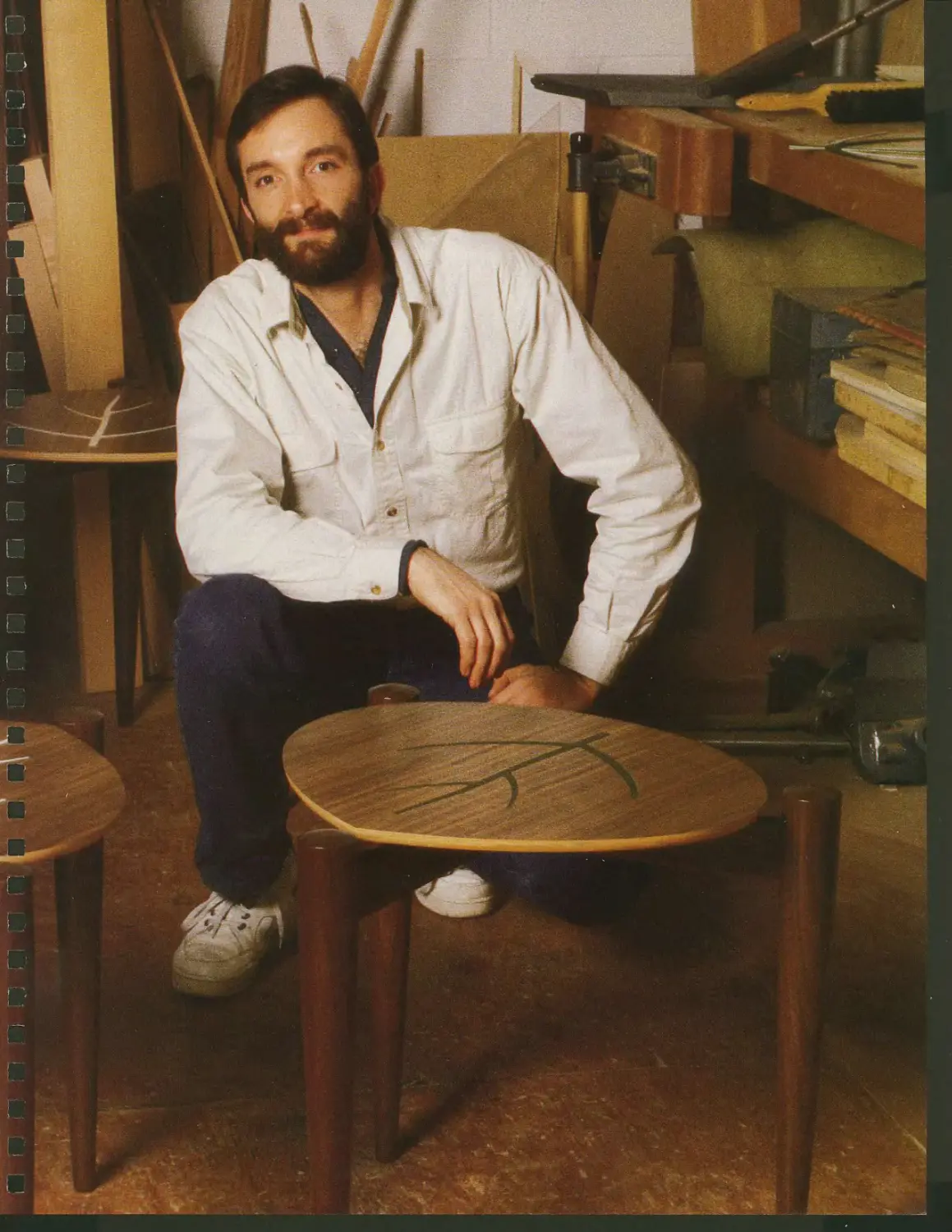
I have built practically every type of furniture, from decorative high-style chairs
to kitchen cabinets, but I'm fascinated by tables. Both the first piece of furniture
I made and the first one I designed were tables. It's an undeniable challenge to
create a beautiful chair that is also comfortable, or an elegant entertainment center
designed specifically around the sizes and functions of its contents. But for sheer
simplicity and design freedom, you can't beat a table.
Sooner or later, many woodworkers want to start designing their own furniture.
It's something I strongly encourage; designing greatly increases the satisfaction
derived from woodworking. A table is a great place to start. A table has relatively
few structural elements and technical requirements: If you've got a flat top and a
solid support system to hold it up, you have got a functional table. The rest is up to
you. Take into account strength requirements, use, and size when planning the piece.
Will this be a heavy-duty kid-proof kitchen table or a delicate decorative hall table,
for example? Then bring in forms and shapes that please you. Subtle points such as
a delicately shaped leg, decorative joinery, a clever handmade mechanism, or a
particularly handsome piece of wood can be showcased in a table.
Your piece can be simple or complex, as austere as Shaker or as ostentatious as
rococo, based on designs of the 1930s or the 1730s—or something unique and
imaginative. Its design can also address a particular need not met by commercially available
furniture, like a telephone table, or a backgammon or chess table.
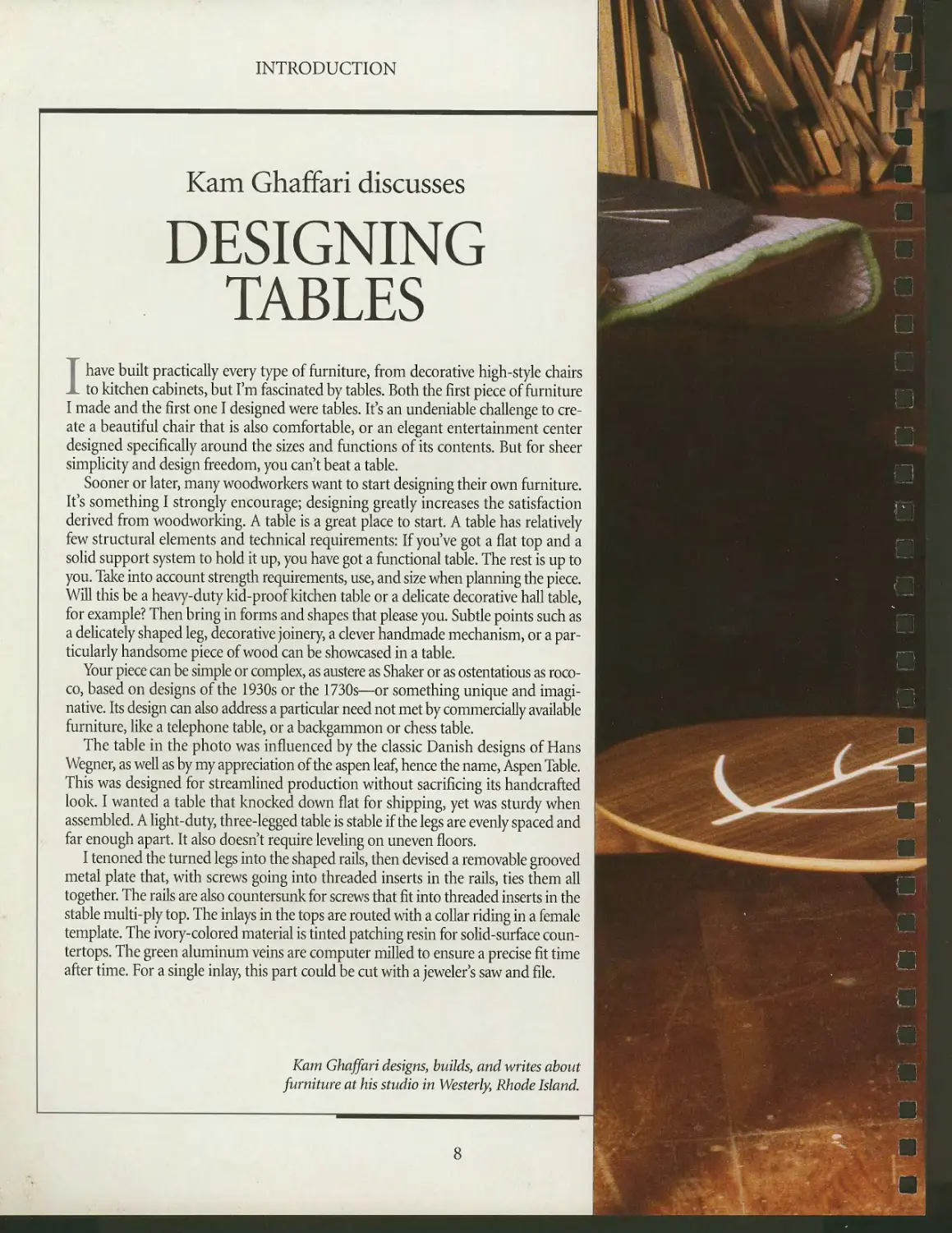
The table in the photo was influenced by the classic Danish designs of Hans
Wegner, as well as by my appreciation of the aspen leaf, hence the name, Aspen Table.
This was designed for streamlined production without sacrificing its handcrafted
look. I wanted a table that knocked down flat for shipping, yet was sturdy when
assembled. A light-duty, three-legged table is stable if the legs are evenly spaced and
far enough apart. It also doesn't require leveling on uneven floors.
I tenoned the turned legs into the shaped rails, then devised a removable grooved
metal plate that, with screws going into threaded inserts in the rails, ties them all
together. The rails are also countersunk for screws that fit into threaded inserts in the
stable multi-ply top. The inlays in the tops are routed with a collar riding in a female
template. The ivory-colored material is tinted patching resin for solid-surface coun-
tertops. The green aluminum veins are computer milled to ensure a precise fit time
after time. For a single inlay, this part could be cut with a jeweler's saw and file.
Kam Ghaffari designs, builds, and writes about
furniture at his studio in Westerly, Rhode Island.
8
^1
*v
m ,y %M
*■ \ ,
\,
'^g*z*
m/
L***'.4 -
*>__ K*n>
^•^% '.T*^
INTRODUCTION
Tony Searer on
A SPANISH-STYLE
DESK
When you run a commercial furniture shop, creating a unique and pleasing
design can be an invigorating challenge. Foremost in the process is listening
to the customer and balancing practical and esthetic considerations.
The buyers of the desk in the photo wanted a handsome sculptural piece of
furniture that would also allow them to display art objects. Other design
considerations involved incorporating three hanging file drawers as well as numerous small
drawers and cubbies with a self-contained light source.
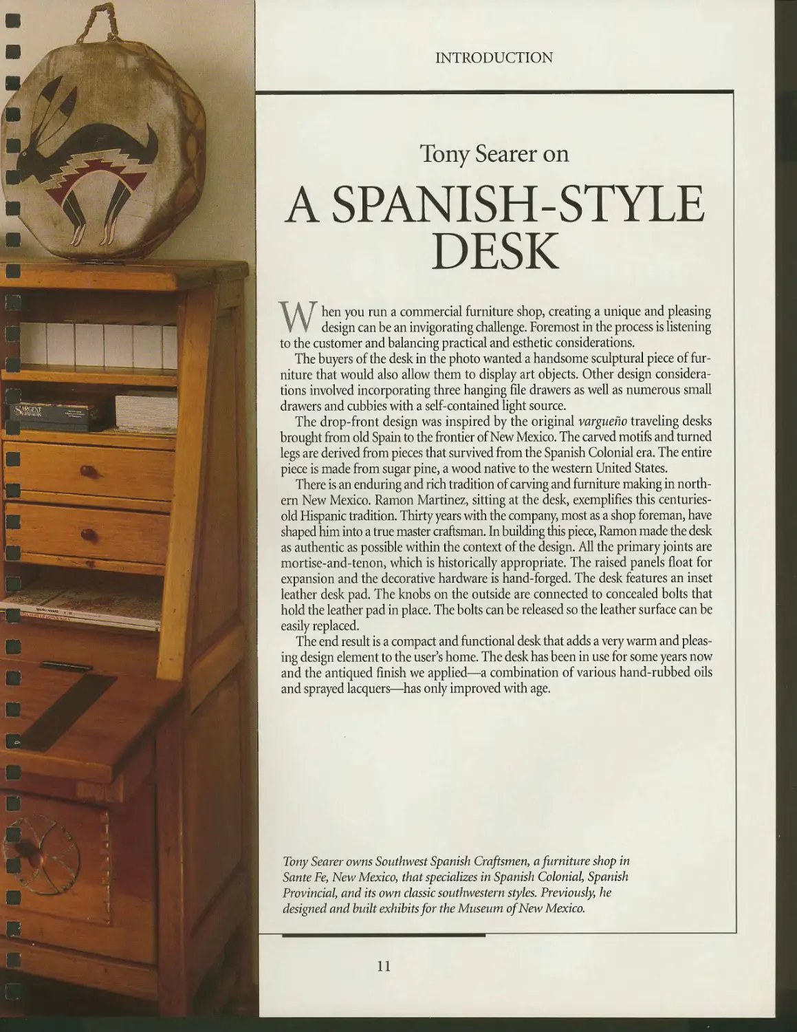
The drop-front design was inspired by the original vargueno traveling desks
brought from old Spain to the frontier of New Mexico. The carved motifs and turned
legs are derived from pieces that survived from the Spanish Colonial era. The entire
piece is made from sugar pine, a wood native to the western United States.
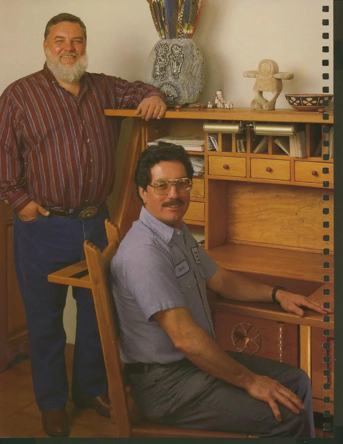
There is an enduring and rich tradition of carving and furniture making in
northern New Mexico. Ramon Martinez, sitting at the desk, exemplifies this centuries-
old Hispanic tradition. Thirty years with the company, most as a shop foreman, have
shaped him into a true master craftsman. In building this piece, Ramon made the desk
as authentic as possible within the context of the design. All the primary joints are
mortise-and-tenon, which is historically appropriate. The raised panels float for
expansion and the decorative hardware is hand-forged. The desk features an inset
leather desk pad. The knobs on the outside are connected to concealed bolts that
hold the leather pad in place. The bolts can be released so the leather surface can be
easily replaced.
The end result is a compact and functional desk that adds a very warm and
pleasing design element to the user's home. The desk has been in use for some years now
and the antiqued finish we applied—a combination of various hand-rubbed oils
and sprayed lacquers—has only improved with age.
Tony Searer owns Southwest Spanish Craftsmen, a furniture shop in
SanteFe, New Mexico, that specializes in Spanish Colonial Spanish
Provincial, and its own classic southwestern styles. Previously, he
designed and built exhibits for the Museum of New Mexico.
11
i
i
I
TABLE AND DESK BASICS
lthough the following chapters of
A 1„ this book focus on the nuts and
bolts of table and desk construction,
there is more to building a piece of
furniture than cutting joints and
assembling components. Before any of this
can happen, some time must be spent
designing the piece, and selecting and
preparing the lumber. This chapter
focuses on the skills you will need to
carry out these preparatory steps. For
some craftsmen, the preliminaries are
among the most enjoyable aspects of a
project. Hand-picking a mahogany
board at the lumberyard, or
unwrapping a package of exotic wood from a
mail-order supplier, for example, can
be rewarding experiences.
First, you need to select the kind of
table or desk that suits your needs. The
illustrated gallery of table and desk styles
beginning on page 22 can provide a starting point in your
search for a suitable design. The dimensions you incorporate
will affect both the appearance and suitability of the piece.
Standard dimensions are discussed in detail on page 21.
Once you have selected a design (or sketched one
yourself), it is time to buy the lumber. The sections on wood
movement (page 14), ordering wood (page 16), and deriving
a cutting list from a sketch (page 17) provide the basic infor-
Lumber quality varies widely, even
within the same grade. Taking the time
to examine and select hoards carefully
at a lumberyard will help you obtain
the best stock for your project.
mation you will need to purchase the
wood for your project.
With your stock in hand, one crucial
step remains before you can start to
put your work together: preparing the
stock (page 19). This process includes
jointing and planing rough wood so it is
smooth and square, and cutting stock to
length and width. For rough, unsurfaced
lumber, first pass one face across the
jointer, then one edge, producing two
surfaces at 90° to each other. Next, plane the
other face of the board to make it
parallel to the first. When the stock is square
and smooth, you are ready to rip it to
width and crosscut it to length. If you
buy S2S stock, which already has both
faces surfaced, pass one edge across the
jointer, then rip and crosscut it to size.
S4S stock, which has all its surfaces
prepared, can be ripped and crosscut
immediately. Only edges that will be joined together, such as boards
being edge-glued to make a tabletop, need to be jointed.
Finally, remember that it is important to tackle your project
methodically. For greatest efficiency, lay out your tools in the
shop so that your wood follows a relatively direct route from
rough stock to final assembly. When you have jointed your
stock and cut it to size, fashion your joints and sand all
components before assembly.
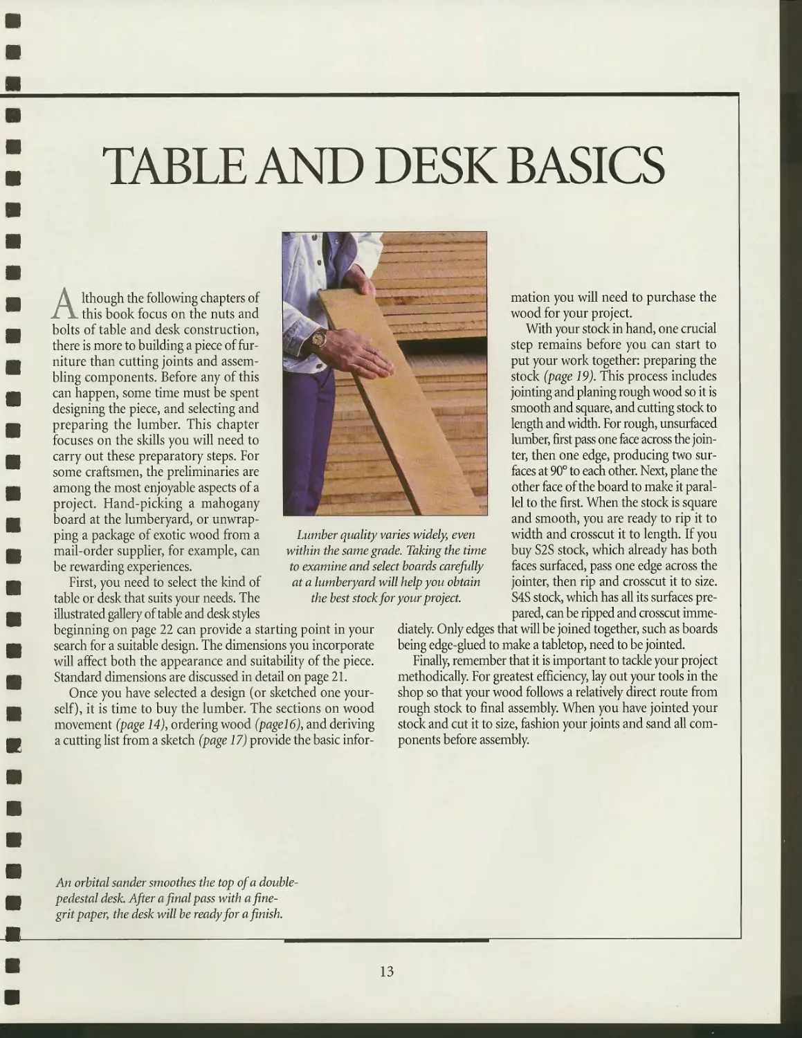
An orbital sunder smoothes the top of a double-
pedestal desk. After a final pass with a fine-
grit paper, the desk will be ready for a finish.
13
WOOD MOVEMENT
Wood gains and loses moisture as
the relative humidity of the
surrounding air changes. And as the
wood's moisture content changes, so
do its dimensions and weight. These
changes can cause problems for a piece
of furniture, some merely irritating,
others much more serious. Knowing
how moisture affects wood and
making the appropriate allowances will help
you avoid difficulty.
The water contained in a piece of
wood is measured as a percentage of
the wood's oven-dry, or water-free
weight. For example, if a 50-pound
piece of wood weighs 40 pounds when
it is oven-dry, the weight of the shed
water—10 pounds—divided by the
woods dry weight—40 pounds—is the
moisture content of the original piece:
in this case, 25 percent.
Wood contains water in two ways:
as free water in its cell cavities and as
bound water in its cell walls. When
wood is cut and exposed to the air, it
sheds its free water first. When all free
water is expelled, the wood is said to
be at its fiber saturation point (FSP),
which is typically between 23 and 30
percent moisture content. Up to this
point, as shown in the illustration at
right, there has been no change in the
dimensions of the piece; it simply
weighs less. As wood dries further,
however, water is removed from the cell
walls, and the board shrinks.
Under normal circumstances, wood
never regains its free water, but changes
in humidity in the air do affect the
amount of moisture in the cell walls.
At 100 percent relative humidity, wood
reaches its FSP, holding as much bound
water as possible. At 0 percent
humidity, wood is devoid of all moisture.
Usually, because the water content of
wood reflects the moisture present in
the atmosphere, the moisture content of
most woods ranges between 5 and 20
percent. The fluctuation in relative
humidity of nearly 80 percent between
typical North American winters and
summers can cause substantial wood
movement over the course of a year.
Because of their size, tabletops and
desktops are especially prone to
movement. A 3-foot-wide top with the wood
grain running along its length can
experience annual movement of more than
1 inch across its width. This can cause
serious difficulties for an extension table,
for example, which relies on the
perfect alignment of various components.
You can do several things to
compensate for the effects of humidity
changes on wood. In your shop, use a
humidifier in winter and a dehumidifi-
er in summer to keep the humidity
level as constant as possible. Also, make
allowances for wood movement in the
construction of your work. With an
extension table (page 90), for example,
orient the wood grain of the top to run
across the width of the table, not along
its length. This way, wood movement
will not affect alignment of the pieces.
The method you use to attach a top is
equally important. Several effective
methods are shown starting on page 96.
Using frame-and-panel construction
(page 31) for the casework of a desk will
allow wood to expand and contract
without affecting the stability of the
piece. Some woods tend to swell and
shrink more than others. Your lumber
dealer can help you select dimensional-
ly stable species for your projects.
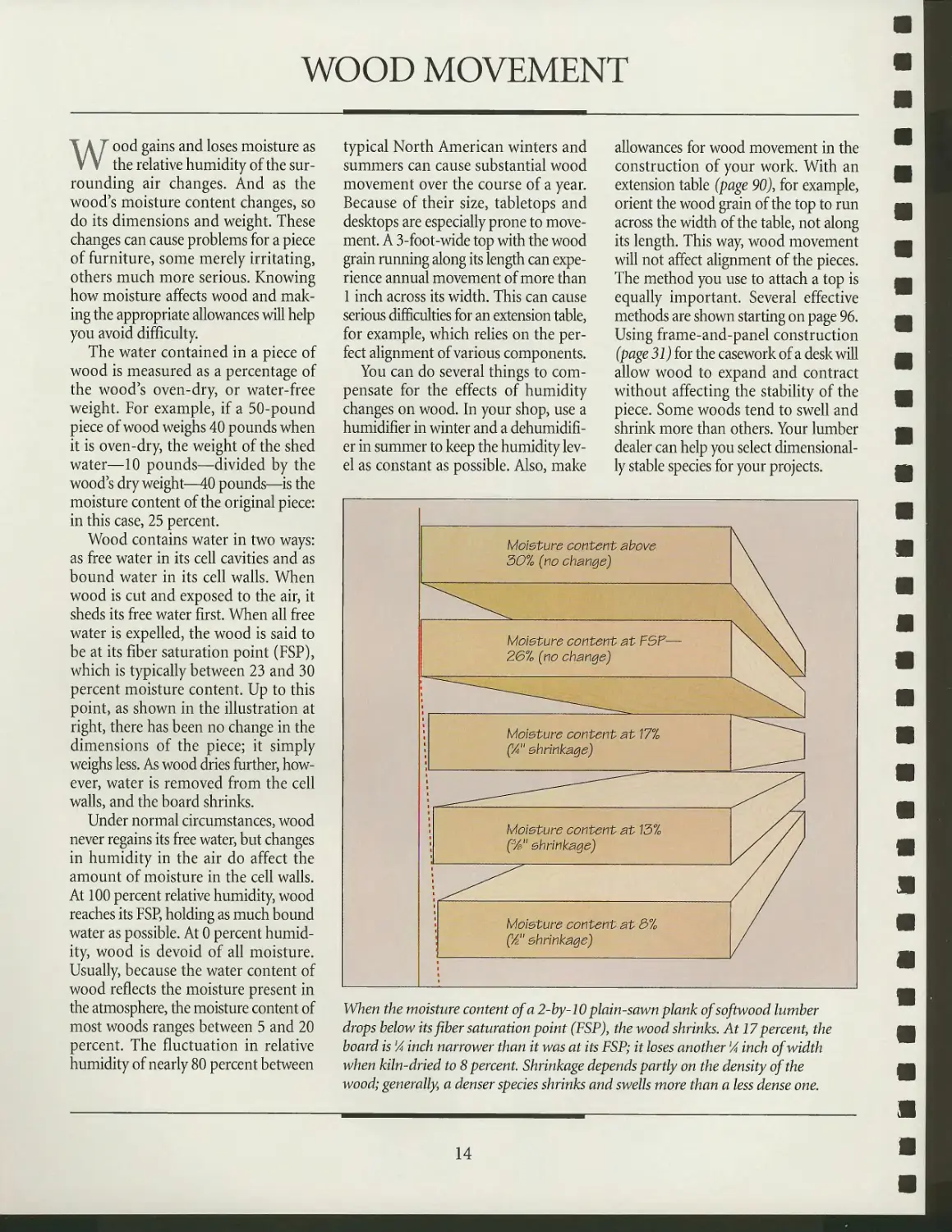
Moisture content above
30% (no change)
Moieture content at F5F-
26% (no change)
Moieture content at 77%
(%" shrinkage)
Moisture content at 13%
C/a" shrinkage)
Moisture content at 3%
(A" shrinkage)
When the moisture content of a 2-by-10 plain-sawn plank of softwood lumber
drops below its fiber saturation point (FSP)y the wood shrinks. At 17 percent, the
board is lA inch narrower than it was at its FSP; it loses another lA inch of width
when kiln-dried to 8 percent. Shrinkage depends partly on the density of the
wood; generally, a denser species shrinks and swells more than a less dense one.
14
TABLE AND DESK BASICS
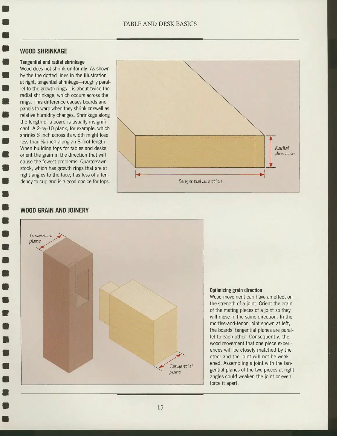
WOOD SHRINKAGE
Tangential and radial shrinkage
Wood does not shrink uniformly. As shown
by the the dotted lines in the illustration
at right, tangential shrinkage—roughly
parallel to the growth rings—is about twice the
radial shrinkage, which occurs across the
rings. This difference causes boards and
panels to warp when they shrink or swell as
relative humidity changes. Shrinkage along
the length of a board is usually
insignificant. A 2-by-10 plank, for example, which
shrinks lA inch across its width might lose
less than Me inch along an 8-foot length.
When building tops for tables and desks,
orient the grain in the direction that will
cause the fewest problems. Quartersawn
stock, which has growth rings that are at
right angles to the face, has less of a
tendency to cup and is a good choice for tops.
xx
^ ^
Tangential direction
A
Radial
direction
f
WOOD GRAIN AND JOINERY
Tangential
plane
Tangential
plane
Optimizing grain direction
Wood movement can have an effect on
the strength of a joint. Orient the grain
of the mating pieces of a joint so they
will move in the same direction. In the
mortise-and-tenon joint shown at left,
the boards' tangential planes are
parallel to each other. Consequently, the
wood movement that one piece
experiences will be closely matched by the
other and the joint will not be
weakened. Assembling a joint with the
tangential planes of the two pieces at right
angles could weaken the joint or even
force it apart.
15
SELECTING AND ORDERING WOOD
T umber for your table or desk project
A-/ can come from several sources, each
with its own advantages and drawbacks.
The local lumberyard is the most
obvious supplier, and often the most
convenient, but the selection may be limited
to construction woods such as pine,
spruce, and other softwoods. Though
you may find the occasional cache of
hardwood, more often than not you will
have to venture farther afield,
consulting the Yellow Pages or woodworking
magazines to find dealers who
specialize in some of the less common
hardwoods used for fine furniture. You will
usually pay more, but the quality of the
wood should be higher too.
There are other less costly options for
finding the wood you need. A lumber
mill may sell you boards at a reasonable
price, but the wood will most often need
to be seasoned and surfaced, which
means that you must own a jointer and
planer. Also, larger mills are often
reluctant to fill small orders. Recycled boards
are becoming increasingly popular with
woodworkers, a result of the scarcity of
certain woods. Salvaged wood is
relatively inexpensive and, because it often
comes from old-growth timber, it can
be visually and structurally superior to
recently harvested lumber. Regardless of
your chosen supply, define your needs
carefully before ordering wood. The tips
that follow will help you get what you
need at a reasonable cost. Being well
prepared will also speed the process
considerably.
• Species: Ask for the specific wood
species, rather than a broad family name.
For example, order Western red cedar,
not simply cedar. To be sure you get what
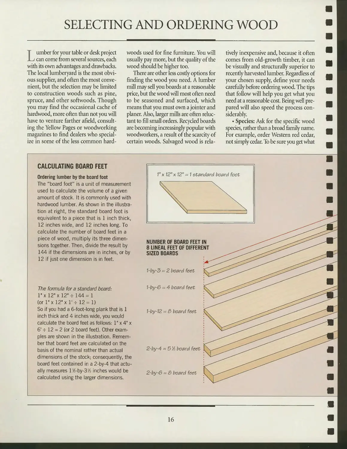
CALCULATING BOARD FEET
Ordering lumber by the board foot
The "board foot" is a unit of measurement
used to calculate the volume of a given
amount of stock. It is commonly used with
hardwood lumber. As shown in the
illustration at right, the standard board foot is
equivalent to a piece that is 1 inch thick,
12 inches wide, and 12 inches long. To
calculate the number of board feet in a
piece of wood, multiply its three
dimensions together. Then, divide the result by
144 if the dimensions are in inches, or by
12 if just one dimension is in feet.
The formula for a standard board:
l"x 12" xl2" -f 144=1
(or 1" xl2"xl'-r 12 = 1)
So if you had a 6-foot-long plank that is 1
inch thick and 4 inches wide, you would
calculate the board feet as follows: 1" x 4" x
6' -r 12 = 2 (or 2 board feet). Other
examples are shown in the illustration.
Remember that board feet are calculated on the
basis of the nominal rather than actual
dimensions of the stock; consequently, the
board feet contained in a 2-by-4 that
actually measures l^-by-SM? inches would be
calculated using the larger dimensions.
NUMBER OF BOARD FEET IN
8 LINEAL FEET OF DIFFERENT
SIZED BOARDS
hby-3 = 2 board feet
1-by-6 = 4 board feet
1-by-12 = 3 board feet
2-by-4 = 5% board feet
2-by-6 = & board feet
16
TABLE AND DESK BASICS
you want, learn the botanical name of
the wood you want and ask for it.
• Quantity: When ordering wood,
specify whether you want the stock in
board feet or lineal feet. A lineal foot
is merely an expression of a board's
length, regardless of its width or
thickness. The board foot is a specific volume
of wood; it is usually necessary for
ordering hardwoods, which are often available
in random widths only. See page 16 for
information about calculating board feet.
• Size: Wood is sold in nominal rather
than real sizes, so make allowances for
the difference when ordering surfaced
lumber. A 2-by-4 is actually lH"-by-3H".
The thickness of hardwoods is often
expressed as an improper fraction in
quarters of an inch. A VA-inch-thick
hardwood board, for example, is
expressed as 64. The nominal and real
dimensions of unsurfaced, green boards
are the same.
• Grade: Within the higher hardwood
grades, the primary difference between
the various grades is appearance rather
than strength. Considering the
difference in price, it is best to reserve the best
stock for the visible parts of your
projects, using less expensive, lower-grade
wood for hidden components. Consult
your lumber dealer for a chart of the
different grades available.
• Seasoning: Lumber is sold either
kiln dried (KD), air dried (AD), or
green. Kiln-dried wood is generally the
most stable. It has a moisture content
(MC) of 8 percent, whereas air-dried
wood has a MC of 12 to 20 percent. Air-
dried wood is often preferred by carvers.
• Surfacing: Surfacing refers to how
the stock is prepared at the mill before
it comes to the lumberyard. Softwood
lumber is usually surfaced on both faces;
hardwood is often sold rough. If you
have a planer and jointer, buying rough
lumber and surfacing it yourself will
prove less expensive.
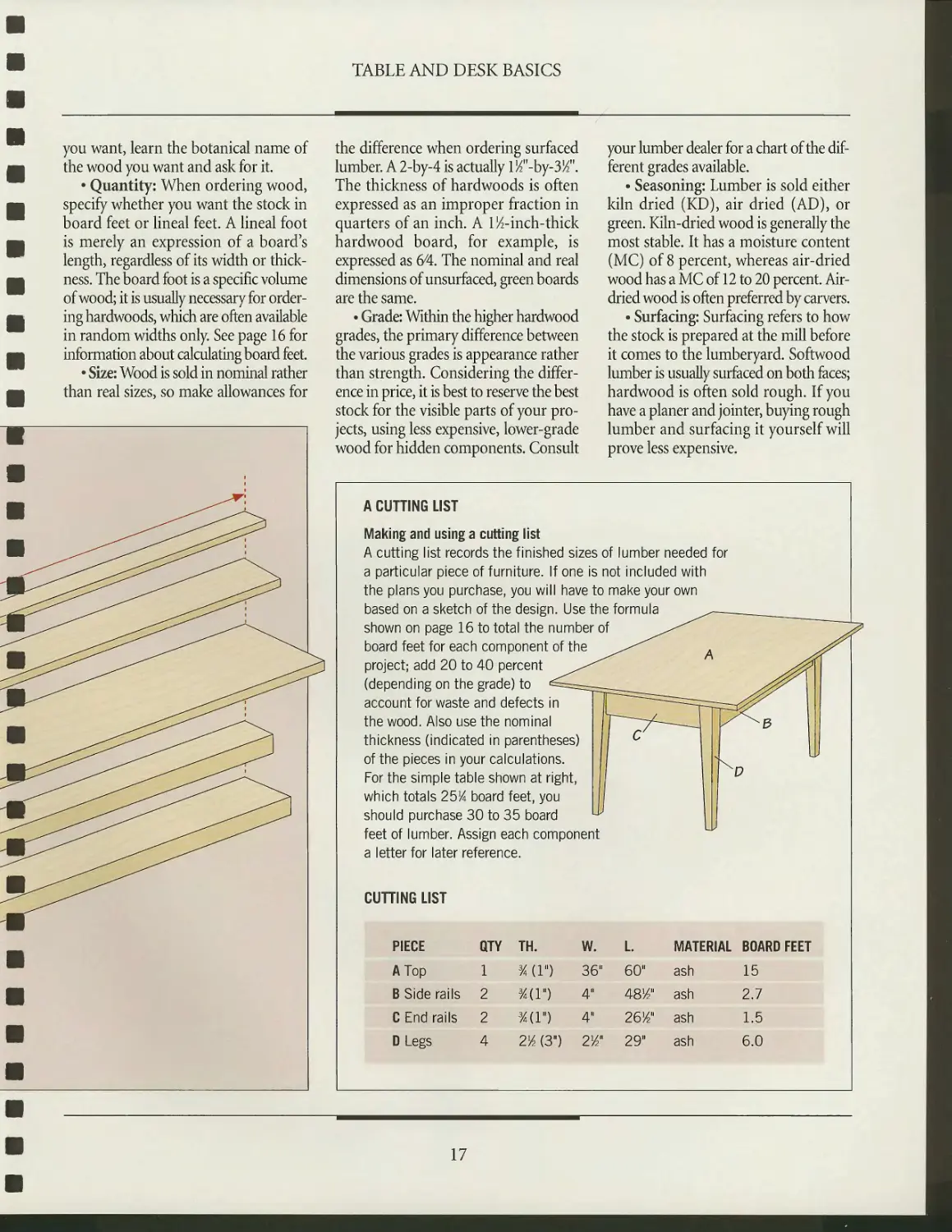
A CUTTING LIST
Making and using a cutting list
A cutting list records the finished sizes of lumber needed for
a particular piece of furniture. If one is not included with
the plans you purchase, you will have to make your own
based on a sketch of the design. Use the formula
shown on page 16 to total the number of ^^ ,
board feet for each component of the ^-^^ . y^\
project; add 20 to 40 percent ^^ ^^n
(depending on the grade) to d^==^===^^_ y^^ 1 1
account for waste and defects in
the wood. Also use the nominal
thickness (indicated in parentheses)
of the pieces in your calculations.
For the simple table shown at right,
which totals 25K board feet, you
C 1
should purchase 30 to 35 board ^ 1
Y^3
D
feet of lumber. Assign each component
a letter for later reference.
CUTTING LIST
PIECE QTY TH. W. L MATERIAL BOARD FEET
A Top 1 %{Y) 36" 60" ash 15
B Side rails 2 %{Y) 4" 48VP ash 2.7
C End rails 2 3/4(l") 4" 261/2" ash 1.5
DLegs 4 2M3") 2W 29" ash 6.0
17
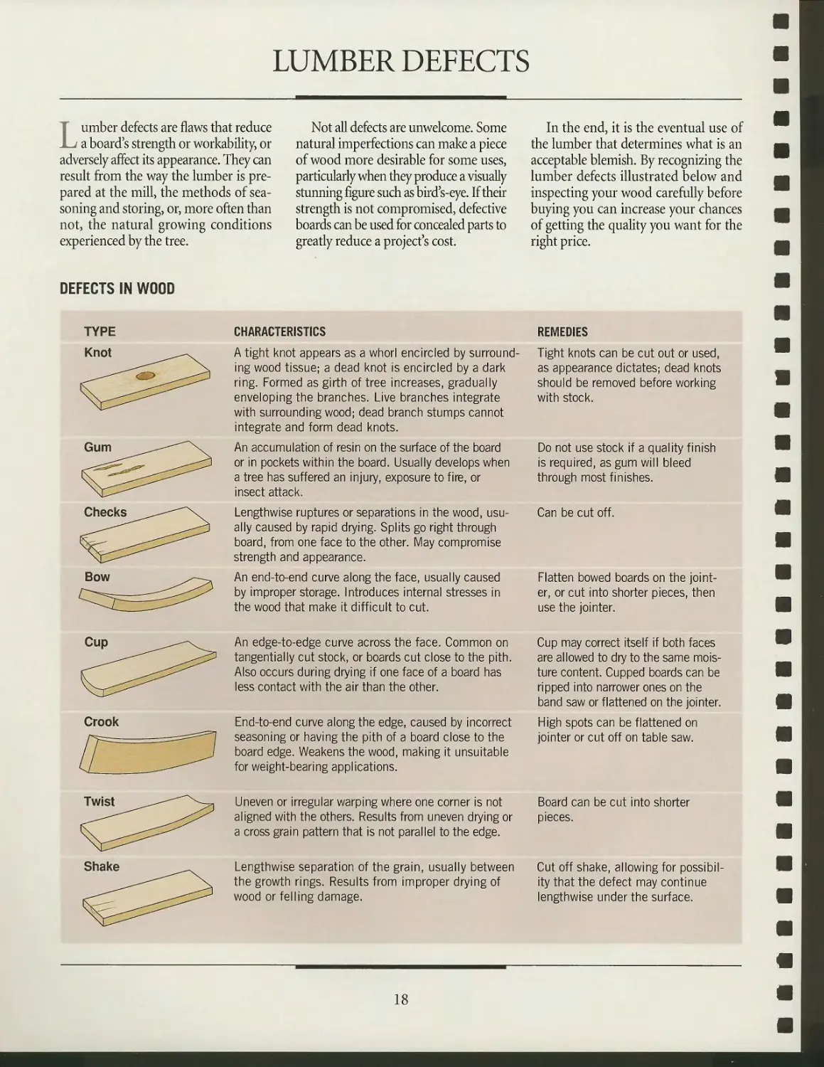
LUMBER DEFECTS
T umber defects are flaws that reduce
jl^- a board's strength or workability, or
adversely affect its appearance. They can
result from the way the lumber is
prepared at the mill, the methods of
seasoning and storing, or, more often than
not, the natural growing conditions
experienced by the tree.
Not all defects are unwelcome. Some
natural imperfections can make a piece
of wood more desirable for some uses,
particularly when they produce a visually
stunning figure such as bird s-eye. If their
strength is not compromised, defective
boards can be used for concealed parts to
greatly reduce a project's cost.
In the end, it is the eventual use of
the lumber that determines what is an
acceptable blemish. By recognizing the
lumber defects illustrated below and
inspecting your wood carefully before
buying you can increase your chances
of getting the quality you want for the
right price.
DEFECTS IN WOOD
TYPE
Knot
<^>
CHARACTERISTICS
A tight knot appears as a whorl encircled by
surrounding wood tissue; a dead knot is encircled by a dark
ring. Formed as girth of tree increases, gradually
enveloping the branches. Live branches integrate
with surrounding wood; dead branch stumps cannot
integrate and form dead knots.
An accumulation of resin on the surface of the board
or in pockets within the board. Usually develops when
a tree has suffered an injury, exposure to fire, or
insect attack.
Lengthwise ruptures or separations in the wood,
usually caused by rapid drying. Splits go right through
board, from one face to the other. May compromise
strength and appearance.
An end-to-end curve along the face, usually caused
by improper storage. Introduces internal stresses in
the wood that make it difficult to cut.
REMEDIES
Tight knots can be cut out or used,
as appearance dictates; dead knots
should be removed before working
with stock.
Do not use stock if a quality finish
is required, as gum will bleed
through most finishes.
Can be cut off.
Flatten bowed boards on the
jointer, or cut into shorter pieces, then
use the jointer.
Cup
Crook
An edge-to-edge curve across the face. Common on
tangentially cut stock, or boards cut close to the pith.
Also occurs during drying if one face of a board has
less contact with the air than the other.
End-to-end curve along the edge, caused by incorrect
seasoning or having the pith of a board close to the
board edge. Weakens the wood, making it unsuitable
for weight-bearing applications.
Uneven or irregular warping where one corner is not
aligned with the others. Results from uneven drying or
a cross grain pattern that is not parallel to the edge.
Lengthwise separation of the grain, usually between
the growth rings. Results from improper drying of
wood or felling damage.
Cup may correct itself if both faces
are allowed to dry to the same
moisture content. Cupped boards can be
ripped into narrower ones on the
band saw or flattened on the jointer.
High spots can be flattened on
jointer or cut off on table saw.
Board can be cut into shorter
pieces.
Cut off shake, allowing for
possibility that the defect may continue
lengthwise under the surface.
18
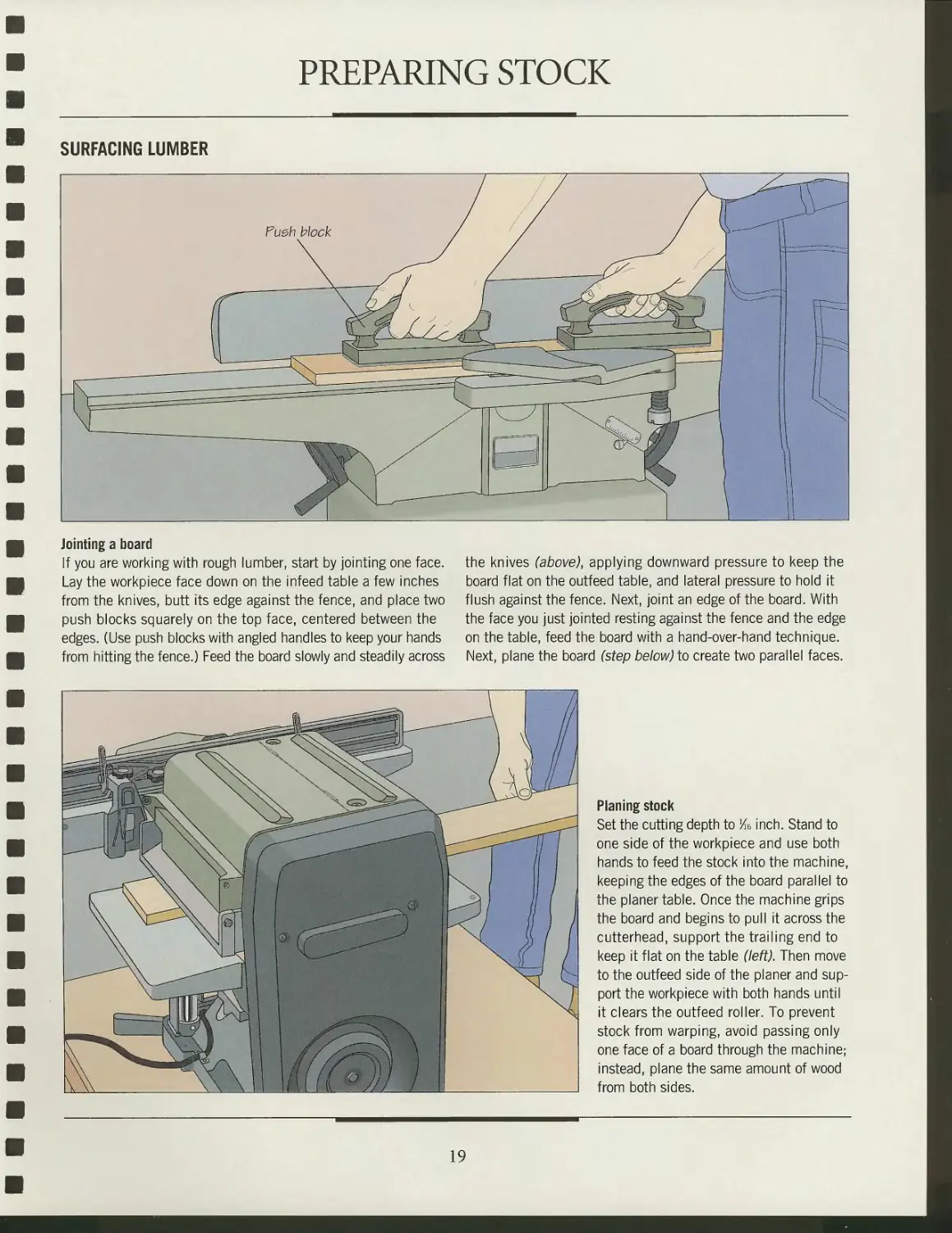
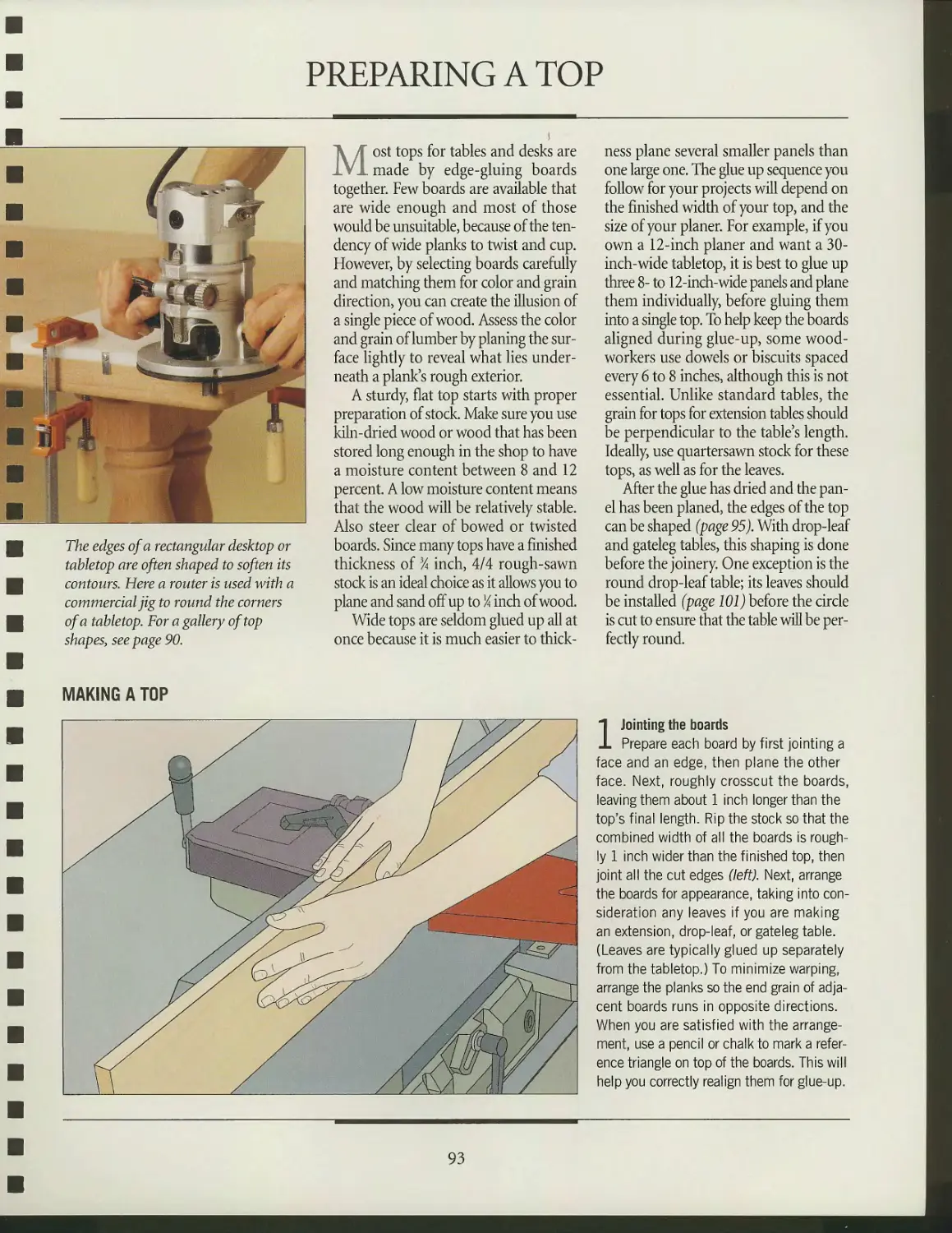
PREPARING STOCK
SURFACING LUMBER
Jointing a board
If you are working with rough lumber, start by jointing one face.
Lay the workpiece face down on the infeed table a few inches
from the knives, butt its edge against the fence, and place two
push blocks squarely on the top face, centered between the
edges. (Use push blocks with angled handles to keep your hands
from hitting the fence.) Feed the board slowly and steadily across
the knives (above), applying downward pressure to keep the
board flat on the outfeed table, and lateral pressure to hold it
flush against the fence. Next, joint an edge of the board. With
the face you just jointed resting against the fence and the edge
on the table, feed the board with a hand-over-hand technique.
Next, plane the board (step below) to create two parallel faces.
Planing stock
Set the cutting depth to Ke inch. Stand to
one side of the workpiece and use both
hands to feed the stock into the machine,
keeping the edges of the board parallel to
the planer table. Once the machine grips
the board and begins to pull it across the
cutterhead, support the trailing end to
keep it flat on the table (left). Then move
to the outfeed side of the planer and
support the workpiece with both hands until
it clears the outfeed roller. To prevent
stock from warping, avoid passing only
one face of a board through the machine;
instead, plane the same amount of wood
from both sides.
19
TABLE AND DESK BASICS
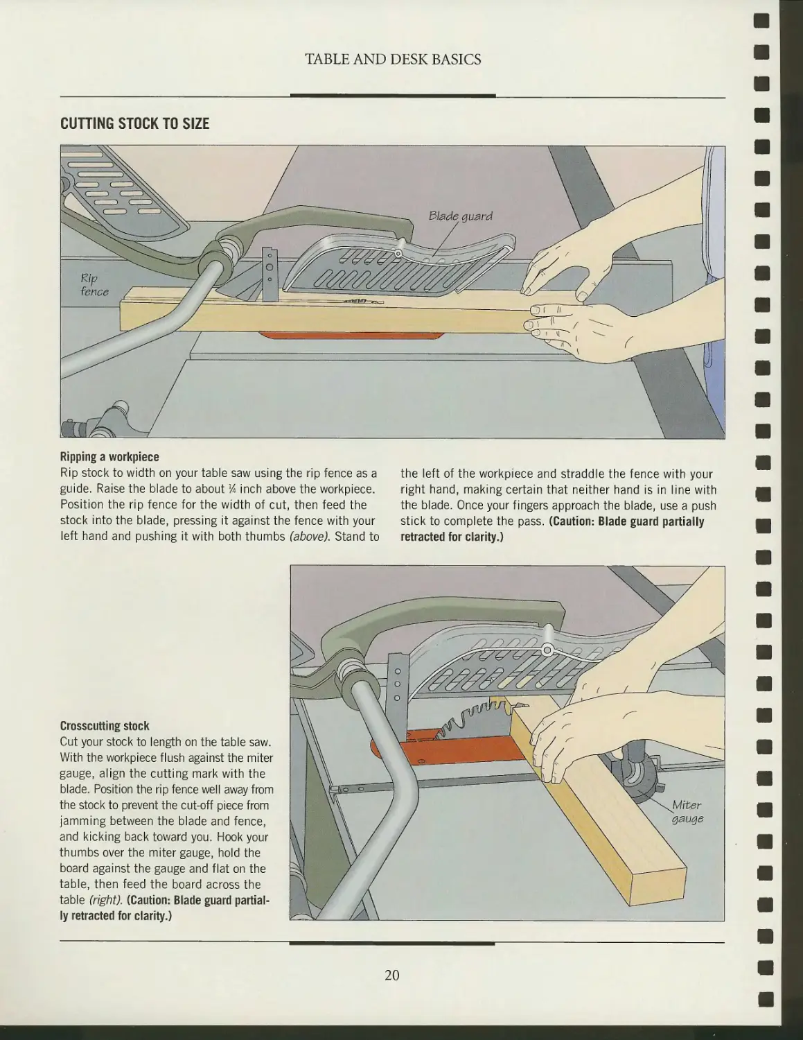
CUTTING STOCK TO SIZE
Ripping a workpiece
Rip stock to width on your table saw using the rip fence as a the left of the workpiece and straddle the fence with your
guide. Raise the blade to about % inch above the workpiece. right hand, making certain that neither hand is in line with
Position the rip fence for the width of cut, then feed the the blade. Once your fingers approach the blade, use a push
stock into the blade, pressing it against the fence with your stick to complete the pass. (Caution: Blade guard partially
left hand and pushing it with both thumbs (above). Stand to retracted for clarity.)
Crosscutting stock
Cut your stock to length on the table saw.
With the workpiece flush against the miter
gauge, align the cutting mark with the
blade. Position the rip fence well away from
the stock to prevent the cut-off piece from
jamming between the blade and fence,
and kicking back toward you. Hook your
thumbs over the miter gauge, hold the
board against the gauge and flat on the
table, then feed the board across the
table (right). (Caution: Blade guard
partially retracted for clarity.)
20
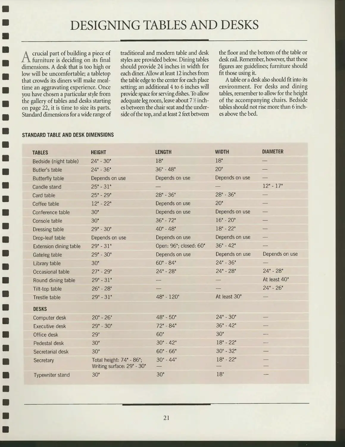
DESIGNING TABLES AND DESKS
A^ crucial part of building a piece of
/jl furniture is deciding on its final
dimensions. A desk that is too high or
low will be uncomfortable; a tabletop
that crowds its diners will make
mealtime an aggravating experience. Once
you have chosen a particular style from
the gallery of tables and desks starting
on page 22, it is time to size its parts.
Standard dimensions for a wide range of
traditional and modern table and desk
styles are provided below. Dining tables
should provide 24 inches in width for
each diner. Allow at least 12 inches from
the table edge to the center for each place
setting; an additional 4 to 6 inches will
provide space for serving dishes. To allow
adequate leg room, leave about 7 Vi
inches between the chair seat and the
underside of the top, and at least 2 feet between
the floor and the bottom of the table or
desk rail. Remember, however, that these
figures are guidelines; furniture should
fit those using it.
A table or a desk also should fit into its
environment. For desks and dining
tables, remember to allow for the height
of the accompanying chairs. Bedside
tables should not rise more than 6
inches above the bed.
STANDARD TABLE AND DESK DIMENSIONS
TABLES
Bedside (night table)
Butler's table
Butterfly table
Candle stand
Card table
Coffee table
Conference table
Console table
Dressing table
Drop-leaf table
Extension dining table
Gateleg table
Library table
Occasional table
Round dining table
Tilt-top table
Trestle table
DESKS
Computer desk
Executive desk
Office desk
Pedestal desk
Secretarial desk
Secretary
Typewriter stand
HEIGHT
24" - 30"
24" - 36"
Depends on use
25" -31"
25" - 29"
12" - 22"
30"
30"
29" - 30"
Depends on
29"-31"
29" - 30"
30"
27" - 29"
29"-31"
26" - 28"
29"-31"
20" - 26"
29" - 30"
29"
30"
30"
Total height:
use
74" - 86";
Writing surface: 29" - 30"
30"
LENGTH
18"
36" - 48"
Depends on use
—
28" - 36"
Depends on use
Depends on use
36" - 72"
40" - 48"
Depends on use
Open: 96";
closed: 60"
Depends on use
60" - 84"
24" - 28"
—
—
48" - 120"
48" - 50"
72" - 84"
60"
30" - 42"
60" - 66"
30" - 44"
—
30"
WIDTH
18"
20"
Depends on
—
28" - 36"
20"
Depends on
16" - 20"
18" - 22"
use
use
Depends on use
36" - 42"
Depends on use
24" - 36"
24" - 28"
—
—
At least 30"
24" - 30"
36" - 42"
30"
18" - 22"
30" - 32"
18" - 22"
—
18"
DIAMETER
—
—
—
12" - 17"
—
—
—
—
—
—
—
Depends on use
—
24" - 28"
At least 40"
24" - 26"
—
—
—
—
—
—
—
—
—
21
TABLE AND DESK STYLES
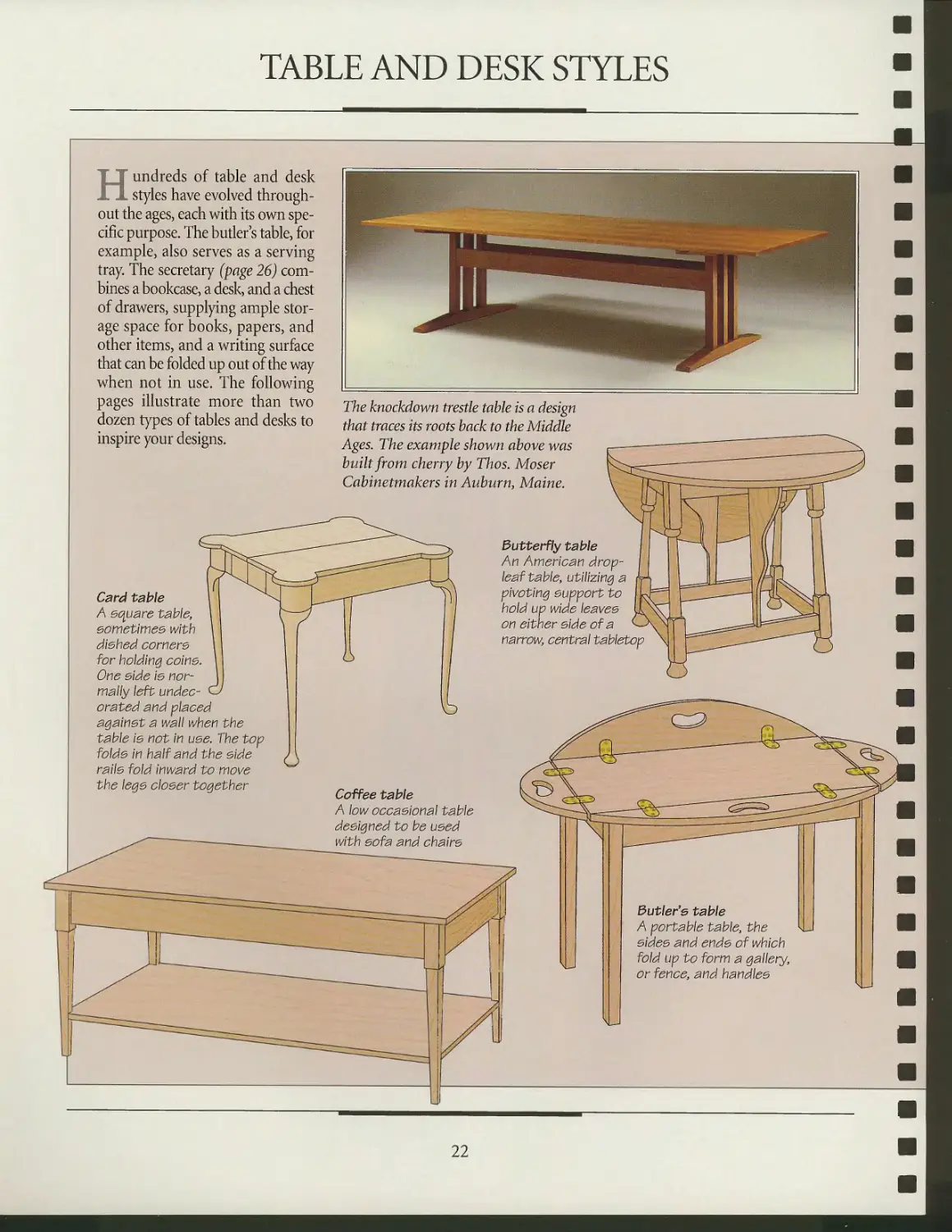
Hundreds of table and desk
styles have evolved
throughout the ages, each with its own
specific purpose. The butler's table, for
example, also serves as a serving
tray. The secretary (page 26)
combines a bookcase, a desk, and a chest
of drawers, supplying ample
storage space for books, papers, and
other items, and a writing surface
that can be folded up out of the way
when not in use. The following
pages illustrate more than two
dozen types of tables and desks to
inspire your designs.
The knockdown trestle table is a design
that traces its roots back to the Middle
Ages. The example shown above was
built from cherry by Thos. Moser
Cabinetmakers in Auburn, Maine.
Card table
A square table,
sometimes with
dished comers
for holding corns.
One side Is
normally left undec-
orated and placed
against a wall when the
table Is not In use. The top
folds in half and the side
rails fold inward to move
the legs closer together
Butterfly table
An American drop-
leaf table, utilizing a
pivoting support to
hold up wide leaves
on either side of a
narrow, central tabletop
Coffee table
A low occasional table
designed to be used
with sofa and chairs
3utler'e table
A portable table, the
sides and ends of which
fold up to form a gallery,
or fence, and handles
22
TABLE AND DESK BASICS
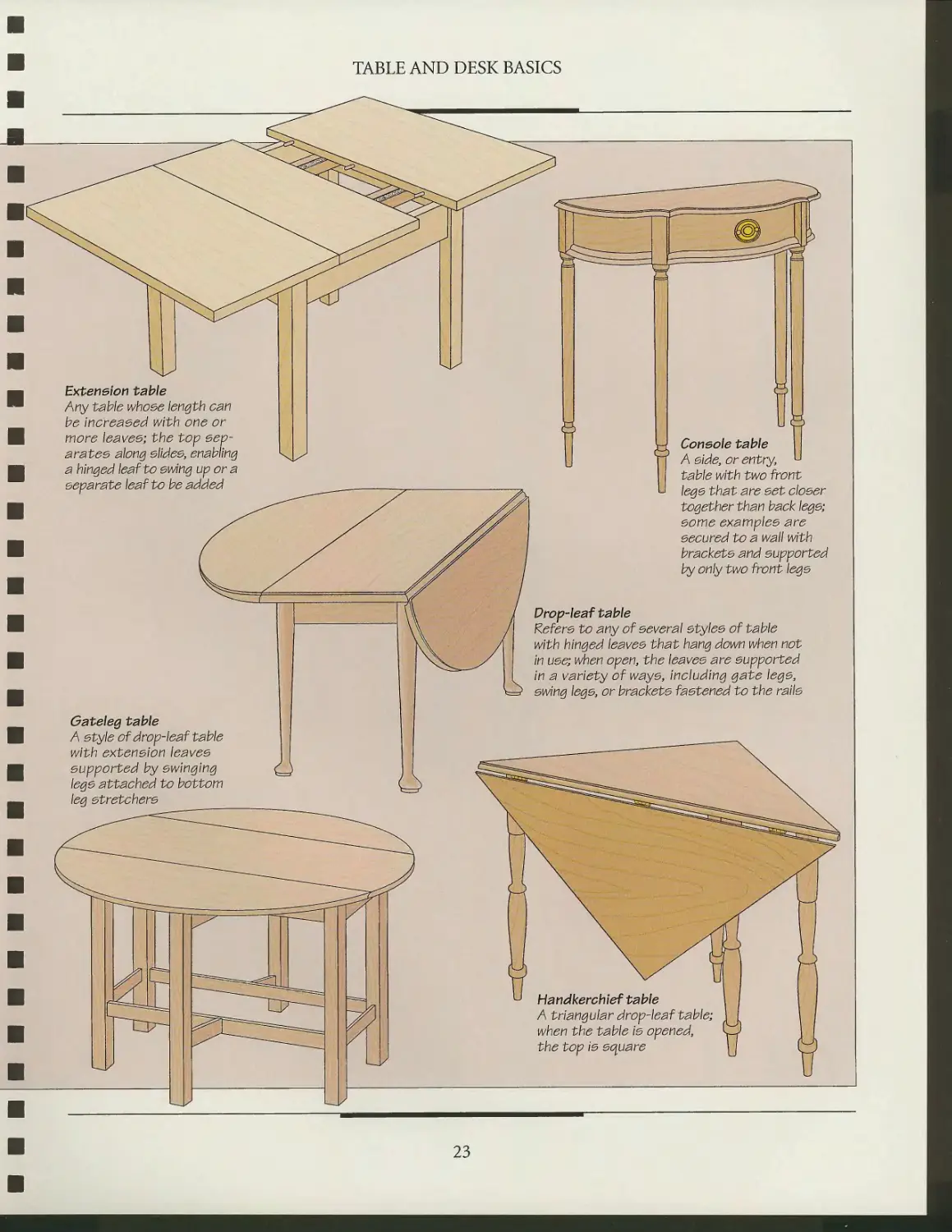
Extension table
Any table whose length can
be increased with one or
more leaves-, the top
separates along slides, enabling
a hinged leaf to swing up or a
separate leaf to be added
Gateleg table
A style of drop-leaf table
with extension leaves
supported by swinging
legs attached to bottom
leg stretchers
Console table
A side, or entry,
table with two front
legs that are s<5t closer
together than back legs;
some examples are
secured to a wall with
brackets and supported
by only two front legs
Drop-leaf table
Refers to any of several styles of table
with hinged leaves that hang down when not
in use; when open, the leaves are supported
in a variety of ways, including gate legs,
swing legs, or brackets fastened to the rails
Handkerchief table
A triangular drop-leaf table;
when the table is opened,
the top is square
23
TABLE AND DESK BASICS
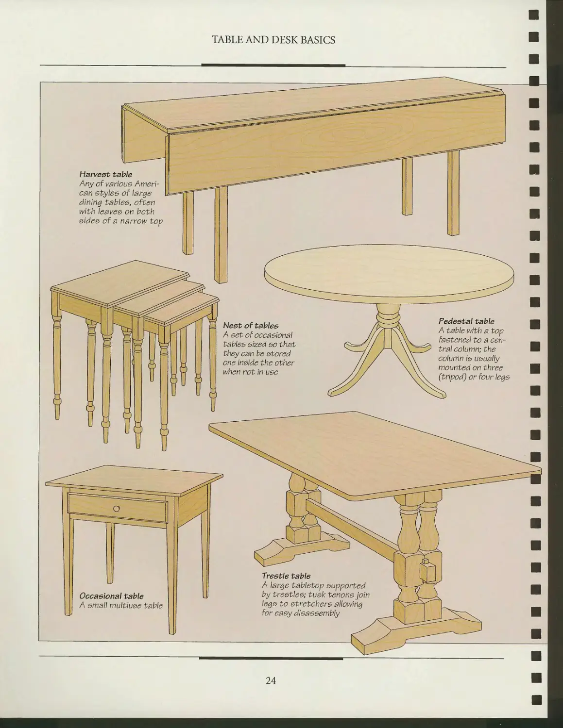
Harvest table
Any of various
American styles of large
dining tables, often
with leaves on both
sides of a narrow top
Neet of tab\ee
A eet of occasional
tables sized so that
they can be stored
one Inside the other
when not in use
Pedestal table
A table with a top
fastened to a
central column; the
column Is usually
mounted on three
(tripod) or four legs
Occasional table
A small multluse table
U>
Trestle table
A large tabletop supported
by trestles; tusk tenons join
legs to stretchers allowing
for easy disassembly
24
TABLE AND DESK BASICS
n
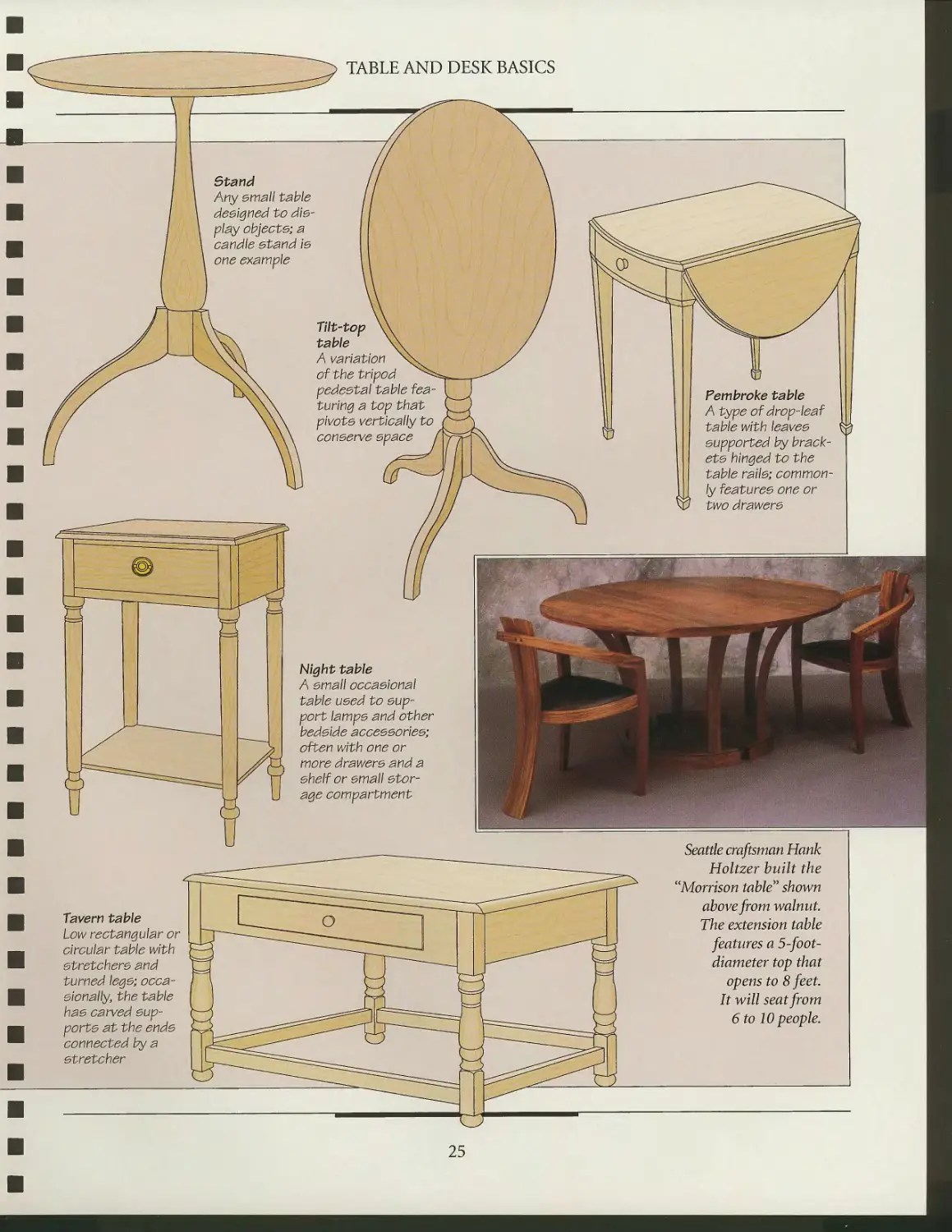
Stand
Any email table
designed to die-
play objects; a
candle stand Is
one example
Tilt-top
table
A variation
of the tripod
pedestal table
featuring a top that
pivots vertically to
conserve space
Night table
A small occasional
table used to
support lamps and other
bedside accessories;
often with one or
more drawers and a
shelf or small
storage compartment
*&g M y
Tavern table
Low rectangular or
circular table with
stretchers and
turned legs;
occasionally, the table
has carved
supports at the ends
connected by a
stretcher
Seattle craftsman Hank
Holtzer built the
"Morrison table" shown
above from walnut.
The extension table
features a 5-foot-
diameter top that
opens to 8 feet.
It will seat from
6 to 10 people.
TABLE AND DESK BASICS
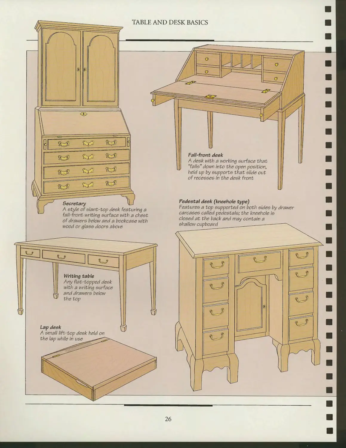
A style of slant-top desk featuring a
fall-front writing surface with a chest
of drawers below and a bookcase with
wood or glass doors above
Pedeetal deek (kneehole type)
Features a top supported on both sides by drawer
carcases called pedestals; the kneehole Is
closed at the back and may contain a
shallow cupboard
Lap deek
A small lift-top desk held on
the lap while i
26
TABLE AND DESK BASICS
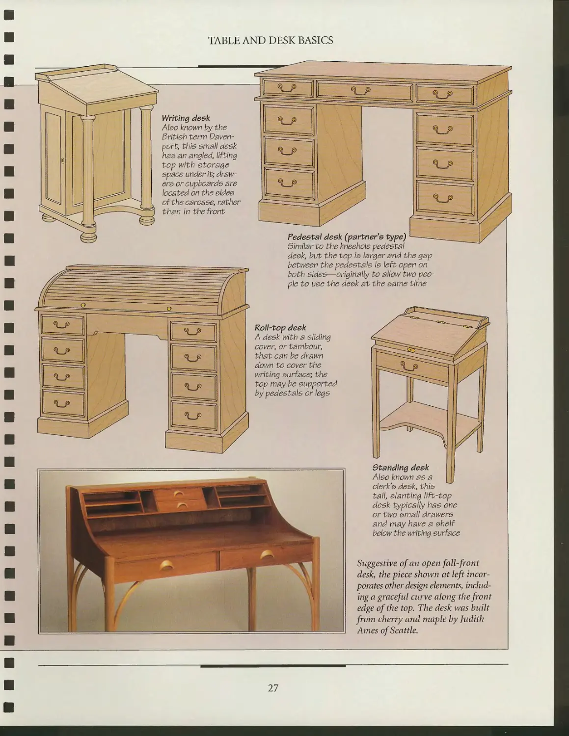
Writing deek
Abo known by the
British term
Davenport, this small desk
has an angled, lifting
top with storage
space under it;
drawers or cupboards are
located on the sides
of the carcase, rather
than in the front
Pedeetal deek (partner's type) '
Similar to the kneehole pedestal
desk, but the top is larger and the gap
between the pedestals is left open on
both sides—originally to allow two
people to use the desk at the same time
Roll-top deek
A desk with a sliding
cover, or tambour,
that can be drawn
down to cover the
writing surface; the
top may be supported
by pedestals or legs
Standing deek
Also known as a
clerk's desk, this
tall, slanting lift-top
desk typically has one
or two small drawers
and may have a shelf
below the writing surface
Suggestive of an open fall-front
desk, the piece shown at left
incorporates other design elements,
including a graceful curve along the front
edge of the top. The desk was built
from cherry and maple by Judith
Ames of Seattle.
27
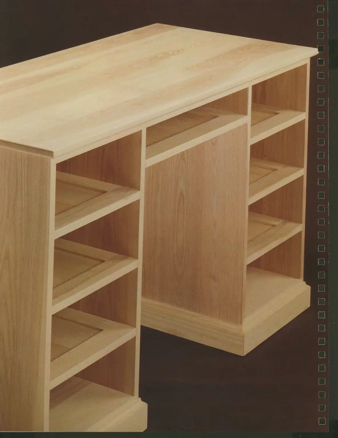
DESK CASEWORK
Casework is the fundamental
building block of most desks.
It can be as simple as a four-sided
box or as elaborate as a frame-and-
panel cabinet. Such elements as
dividers, shelves, drawers, face
frames, and dust panels provide
refinements that transform this
casework into a piece of furniture.
This chapter will show you how
to apply casework techniques to
the construction of a two-pedestal
desk like the one shown opposite.
Carcases are easier to build than
frame-and-panel cabinets. As shown
on page 30, all carcases consist of
four panels joined to form a box.
Make sure that the wood grain of
all the panels runs in the same
direction. This will allow the panels to swell and shrink at the same
rate as relative humidity levels change. If you assemble a
carcase with the grain of adjacent panels at right angles to each
other you risk splitting one of the panels.
The second type of casework—frame-and-panel—solves
the problem of wood movement by allowing space for swelling
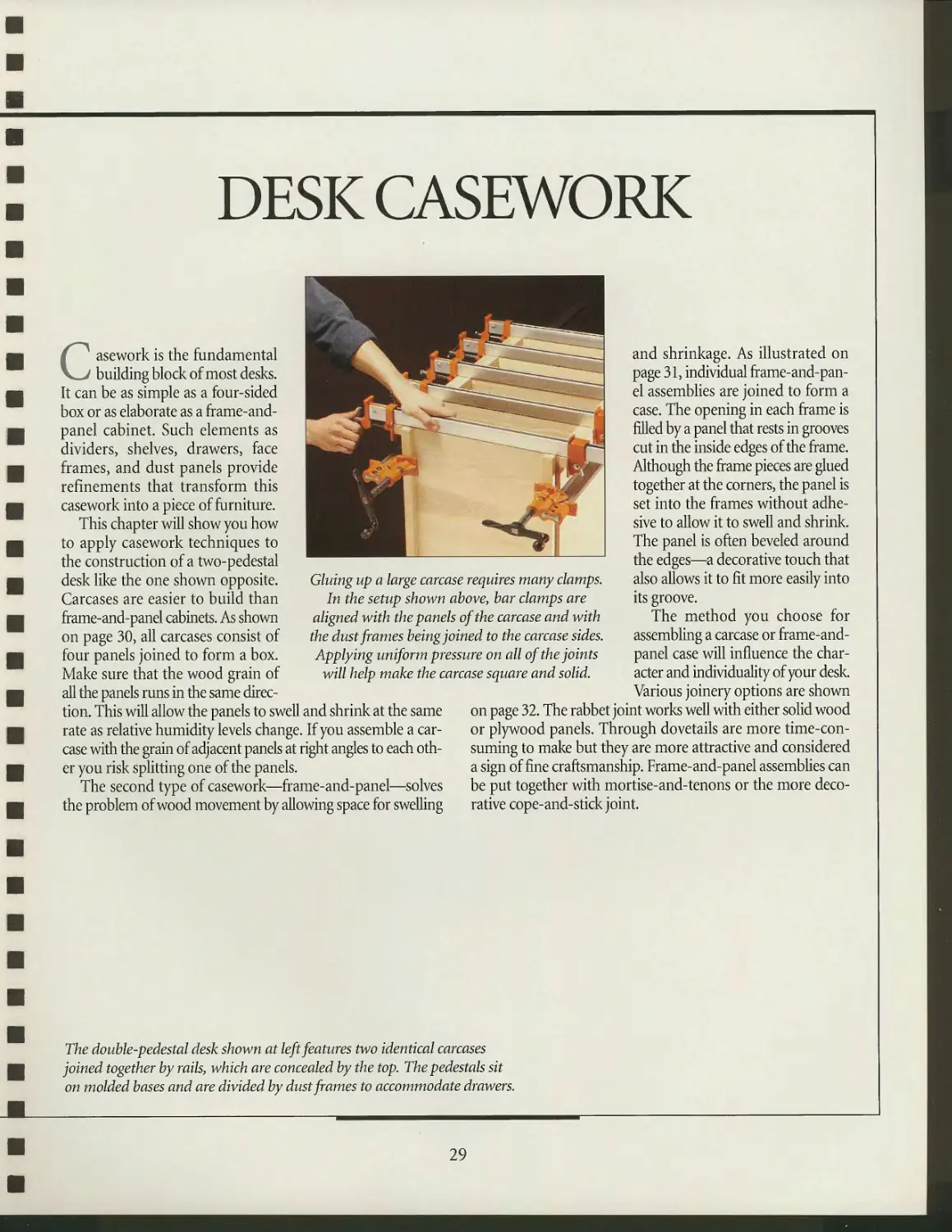
Gluing up a large carcase requires many clamps.
In the setup shown above, bar clamps are
aligned with the panels of the carcase and with
the dust frames being joined to the carcase sides.
Applying uniform pressure on all of the joints
will help make the carcase square and solid.
and shrinkage. As illustrated on
page 31, individual
frame-and-panel assemblies are joined to form a
case. The opening in each frame is
filled by a panel that rests in grooves
cut in the inside edges of the frame.
Although the frame pieces are glued
together at the corners, the panel is
set into the frames without
adhesive to allow it to swell and shrink.
The panel is often beveled around
the edges—a decorative touch that
also allows it to fit more easily into
its groove.
The method you choose for
assembling a carcase or frame-and-
panel case will influence the
character and individuality of your desk.
Various joinery options are shown
on page 32. The rabbet joint works well with either solid wood
or plywood panels. Through dovetails are more
time-consuming to make but they are more attractive and considered
a sign of fine craftsmanship. Frame-and-panel assemblies can
be put together with mortise-and-tenons or the more
decorative cope-and-stick joint.
The double-pedestal desk shown at left features two identical carcases
joined together by rails, which are concealed by the top. The pedestals sit
on molded bases and are divided by dust frames to accommodate drawers.
29
TWO TYPES OF DESK CASEWORK
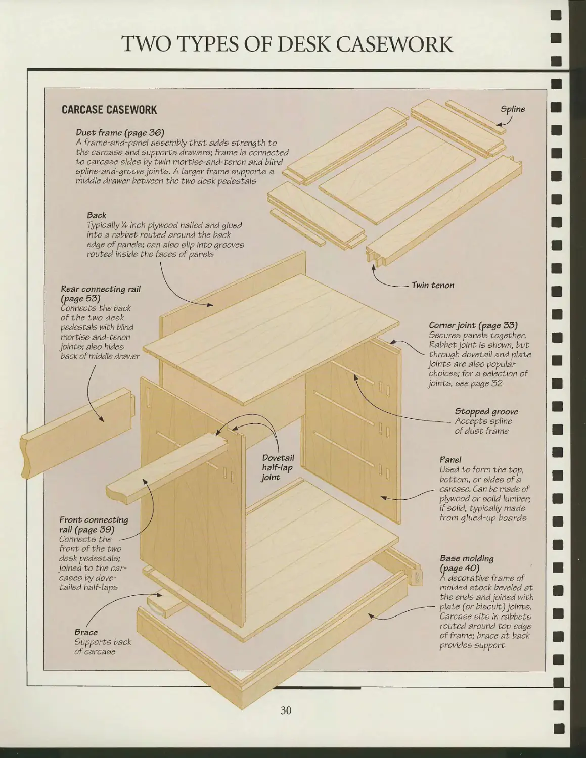
CARCASE CASEWORK
Duet frame (page 36)
A frame-and-panel assembly that adde strength to
the carcase and supports drawers; frame \s connected
to carcase sides by twin mortise-and-tenon and blind
spline-and-groove pints. A larger frame supports a • ^
middle drawer between the two desk pedestals
Spline
3ack
Typically 1A-lnch plywood nailed and glued
into a rabbet routed around the back
edge of panels-, can also slip into grooves
routed Inside the faces of panels
Rear connecting rail
(page 53)
Connects the back
of the two desk
pedestals with blind
mortise-and-tenon
joints; also hides
back of middle drawer
x
Front connecting
rail (page 39)
Connects the
front of the two
desk pedestals;
joined to the
carcases by
dovetailed half-laps
Dovetail
half-lap
joint
brace
Supports back
of carcase
Twin tenon
Corner joint (page 33)
Secures panels together.
Rabbet joint is shown, but
through dovetail and plate
joints are also popular
choices; for a selection of
joints, see page 32
Stopped groove
Accepts spline
of dust frame
Fanel
Used to form the top,
bottom, or sides of a
carcase. Can be made of
plywood or solid lumber;
If solid, typically made
from glued-up boards
Baee molding
(page 40)
A decorative frame of
molded stock beveled at
the ends and joined with
plate (or biscuit) joints.
Carcase sits In rabbets
routed around top edge
of frame; brace at back
provides support
30
DESK CASEWORK
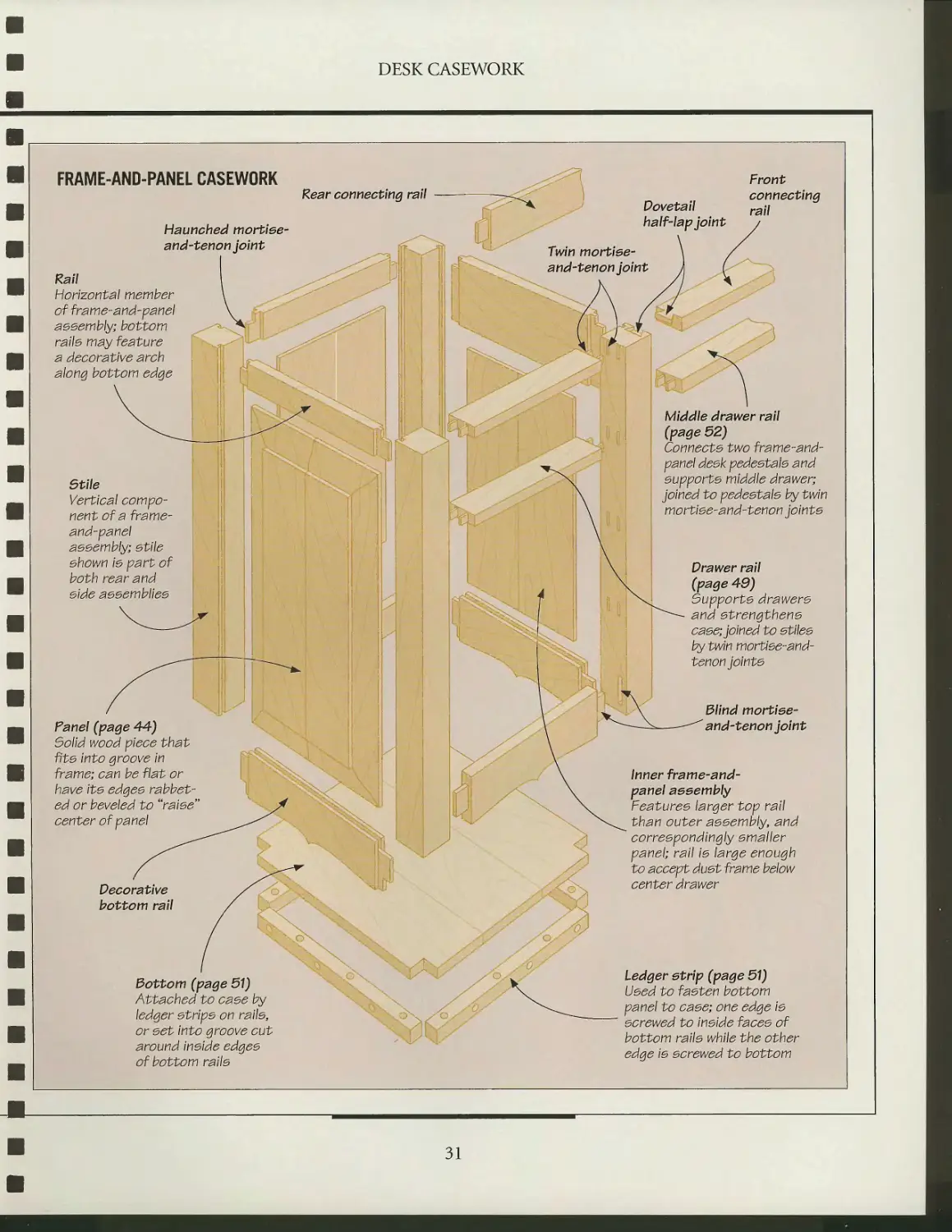
FRAME-AND-PANEL CASEWORK
Rear connecting rail
Dovetail
Haunched mortise-
and-tenon pint
half-lap joint
Front
connecting
rail
Rail
Horizontal member
of frame-arid-panel
assembly, bottom
rails may feature
a decorative arch
along bottom edge
Twin mortise-
and-tenon joint
Stile
Vertical
component of a frame-
and-pane\
assembly] stile
shown Is part of
both rear and
side assemblies
Panel (page 44)
Solid wood piece that
fits Into groove in
frame; can be flat or
have Its edges
rabbeted or beveled to "raise
center of panel
Decorative
bottom rail
Bottom (page 51)
Attached to case by
ledger strips on rails,
or ^<5t Into groove cut
around Inside edges
of bottom rails
Middle drawer rail
(page 52)
Connects two frame-and-
panel desk pedestals and
supports middle drawer;
joined to pedestals by twin
mortise-and-tenon joints
Drawer rail
(page 49)
Supports drawers
and strengthens
case; joined to stiles
by twin mortlse-and-
tenon joints
Blind mortise-
and-tenon joint
Inner frame-and-
panel assembly
Features larger top rail
than outer assembly, and
correspondingly smaller
panel; rail Is large enough
to accept dust frame below
center drawer
Ledger strip (page 51)
Used to fasten bottom
panel to case; one edge Is
screwed to Inside faces of
bottom rails while the other
edge Is screwed to bottom
31
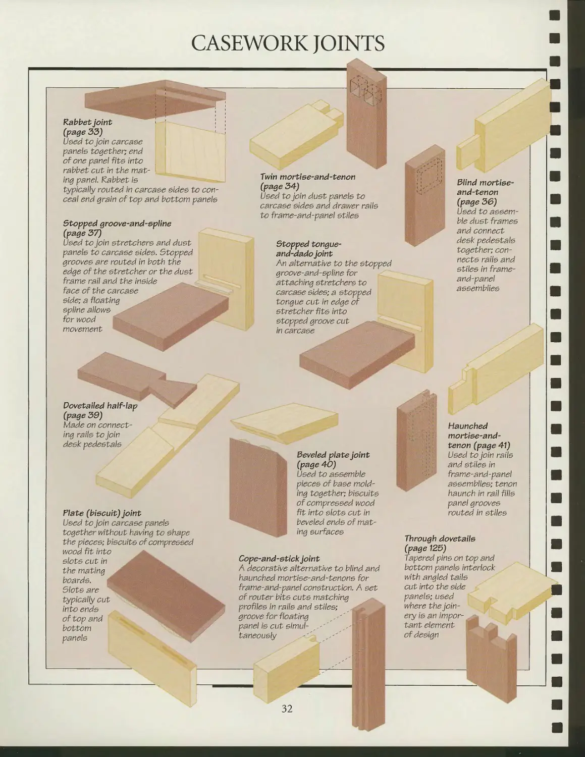
CASEWORK JOINTS
ft
Rabbet joint i '
(page 33)
Used to join carcaee
panels together; end
of one panel fits Into
rabbet cut in the
mating panel. Rabbet is
typically routed in carcaee eidee to
conceal end grain of top and bottom panels
Stopped groove-and-epline
(page 37)
Used to join stretchers and dust
panels to carcase sides. Stopped
grooves are routed in both the
edge of the stretcher or the dust
frame rail and the inside
face of the carcase
side; a floating
spline allows y>r
for wood ; ' . , * 0,< *'
movement
Twin mortiee-and-tenon
(page 34)
Used to join dust panels to
carcase sides and drawer rails
to frame-and-panel stiles
Stopped tongue-
and-dado joint
An alternative to the stopped
groove-and-spline for
attaching stretchers to
carcase sides; a stopped
tongue cut in edge of
stretcher fits into
stopped groove cut
in carcase
Blind mortiee-
and-tenon
(page 36)
Used to
assemble dust frames
and connect
desk pedestals
together;
connects rails and
stiles in frame-
and-panel
assemblies
Dovetailed ha If-lap
(page 39)
Made on
connecting rails to join
desk pedestals
Plate (biscuit) joint
Used to join carcase panels
together without having to shape
the pieces; biscuits of compressed
wood fit into
slots cut in
the mating J V:, ^ ~..:V
boards. :.;",' ,i ' '
Slots are
typically cut ** .
into ends
of top and
bottom
panels
Beveled plate joint
(page 40)
Used to assemble
pieces of base
molding together; biscuits
of compressed wood
fit into slots cut in
beveled ends of
mating surfaces
Cope-and-etick joint
A decorative alternative to blind and
haunched mortise-and-tenons for
frame-and-panel construction. A 5<5t
of router bits cuts matching
profiles in rails and stiles;
groove for floating "'
panel is cut simul- , -' ^'
taneously -'' ^-"'
Haunched
mortiee-and-
tenon (page 41)
Used to join rails
and stiles in
frame-and-panel
assemblies; tenon
haunch in rail fills
panel grooves
routed in stiles
Through dovetails
(page 125)
Tapered pins on top and
bottom panels interlock
with angled tails
cut into the side
panels; used
where the
joinery is an impor-
tant element
of design ■■
32
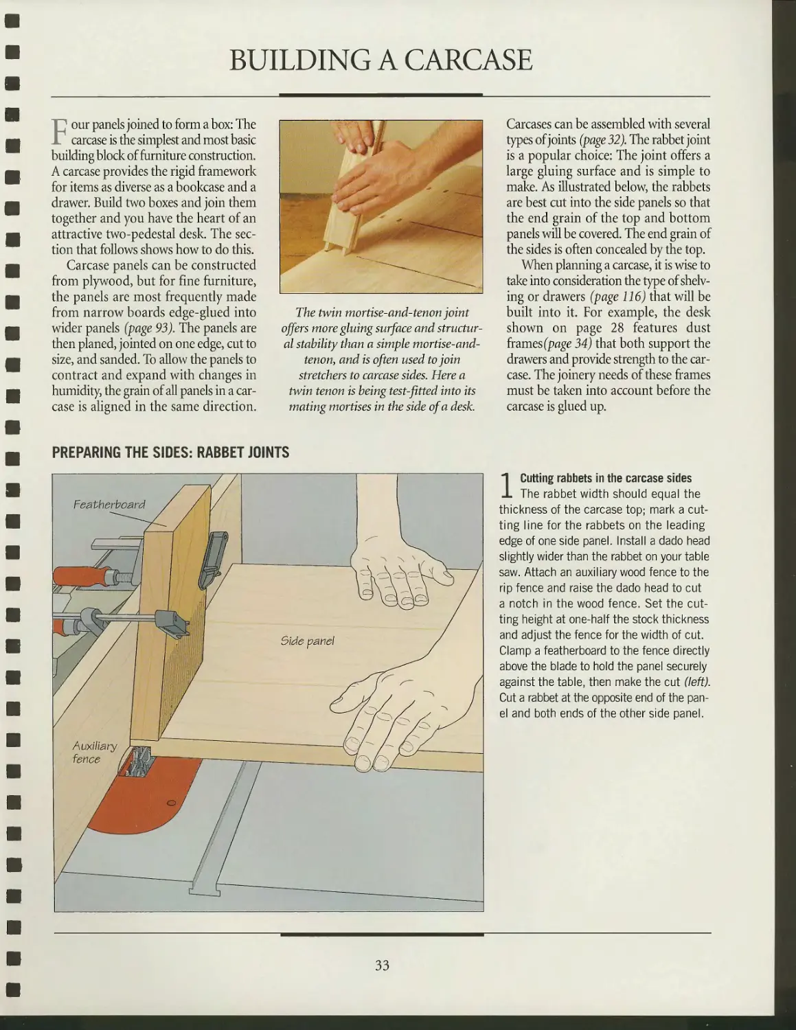
BUILDING A CARCASE
~' our panels joined to form a box: The
_ carcase is the simplest and most basic
building block of furniture construction.
A carcase provides the rigid framework
for items as diverse as a bookcase and a
drawer. Build two boxes and join them
together and you have the heart of an
attractive two-pedestal desk. The
section that follows shows how to do this.
Carcase panels can be constructed
from plywood, but for fine furniture,
the panels are most frequently made
from narrow boards edge-glued into
wider panels (page 93). The panels are
then planed, jointed on one edge, cut to
size, and sanded. To allow the panels to
contract and expand with changes in
humidity, the grain of all panels in a
carcase is aligned in the same direction.
The twin mortise-and-tenon joint
offers more gluing surface and
structural stability than a simple mortise-and-
tenon, and is often used to join
stretchers to carcase sides. Here a
twin tenon is being test-fitted into its
mating mortises in the side of a desk.
Carcases can be assembled with several
types of joints (page 32). The rabbet joint
is a popular choice: The joint offers a
large gluing surface and is simple to
make. As illustrated below, the rabbets
are best cut into the side panels so that
the end grain of the top and bottom
panels will be covered. The end grain of
the sides is often concealed by the top.
When planning a carcase, it is wise to
take into consideration the type of
shelving or drawers (page 116) that will be
built into it. For example, the desk
shown on page 28 features dust
frames (page 34) that both support the
drawers and provide strength to the
carcase. The joinery needs of these frames
must be taken into account before the
carcase is glued up.
PREPARING THE SIDES: RABBET JOINTS
1 Cutting rabbets in the carcase sides
The rabbet width should equal the
thickness of the carcase top; mark a
cutting line for the rabbets on the leading
edge of one side panel. Install a dado head
slightly wider than the rabbet on your table
saw. Attach an auxiliary wood fence to the
rip fence and raise the dado head to cut
a notch in the wood fence. Set the
cutting height at one-half the stock thickness
and adjust the fence for the width of cut.
Clamp a featherboard to the fence directly
above the blade to hold the panel securely
against the table, then make the cut (left).
Cut a rabbet at the opposite end of the
panel and both ends of the other side panel.
33
DESK CASEWORK
^^^^^ T^pSii rgf//////
jit*
Wk^^BB^^^ ^^>\
iSSmB*-"' ^^\s^
^^°L
Top or
bottom
^-—c
*^5y^
^//^
-
~^
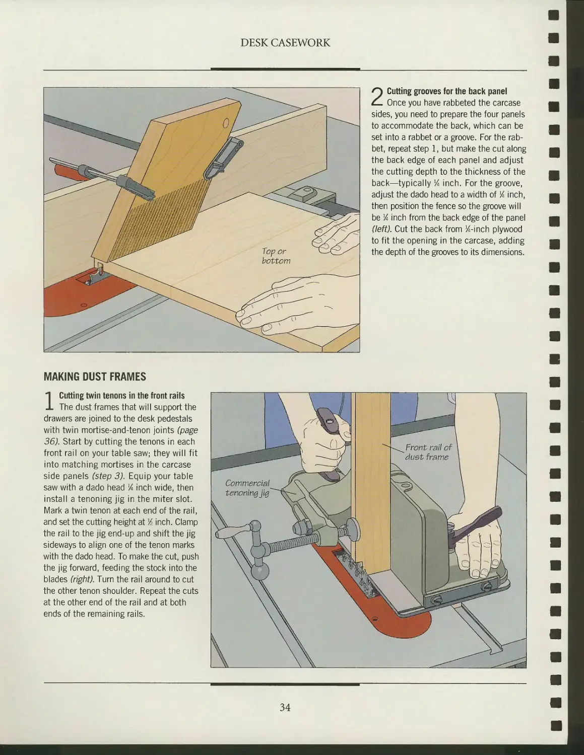
2 Cutting grooves for the back panel
Once you have rabbeted the carcase
sides, you need to prepare the four panels
to accommodate the back, which can be
set into a rabbet or a groove. For the
rabbet, repeat step 1, but make the cut along
the back edge of each panel and adjust
the cutting depth to the thickness of the
back—typically lA inch. For the groove,
adjust the dado head to a width of % inch,
then position the fence so the groove will
be % inch from the back edge of the panel
(left). Cut the back from K-inch plywood
to fit the opening in the carcase, adding
the depth of the grooves to its dimensions.
MAKING DUST FRAMES
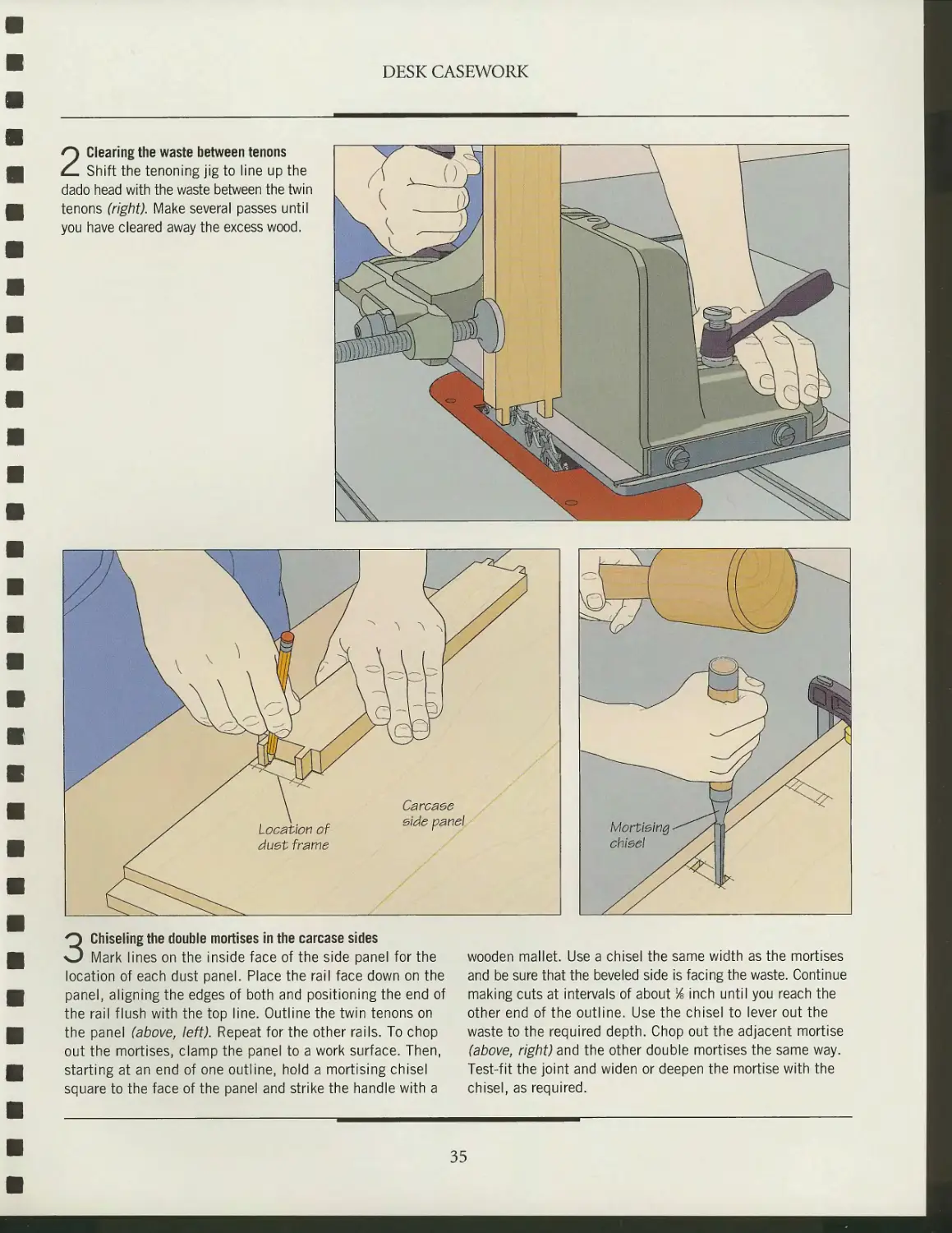
1 Cutting twin tenons in the front rails
The dust frames that will support the
drawers are joined to the desk pedestals
with twin mortise-and-tenon joints (page
36). Start by cutting the tenons in each
front rail on your table saw; they will fit
into matching mortises in the carcase
side panels (step 3). Equip your table
saw with a dado head % inch wide, then
install a tenoning jig in the miter slot.
Mark a twin tenon at each end of the rail,
and set the cutting height at lA inch. Clamp
the rail to the jig end-up and shift the jig
sideways to align one of the tenon marks
with the dado head. To make the cut, push
the jig forward, feeding the stock into the
blades (right). Turn the rail around to cut
the other tenon shoulder. Repeat the cuts
at the other end of the rail and at both
ends of the remaining rails.
34
DESK CASEWORK
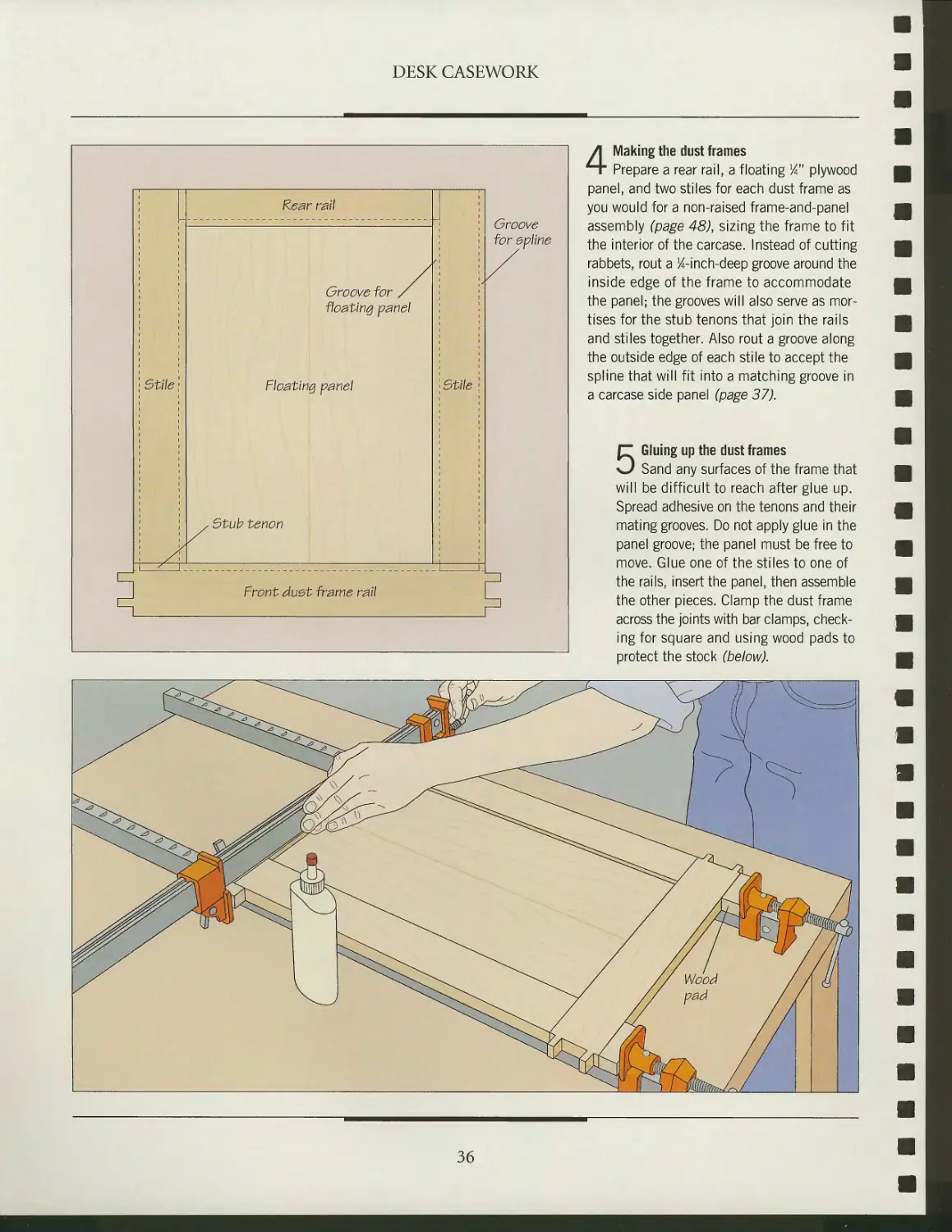
2 Clearing the waste between tenons
Shift the tenoning jig to line up the
dado head with the waste between the twin
tenons (right). Make several passes until
you have cleared away the excess wood.
3 Chiseling the double mortises in the carcase sides
Mark lines on the inside face of the side panel for the
location of each dust panel. Place the rail face down on the
panel, aligning the edges of both and positioning the end of
the rail flush with the top line. Outline the twin tenons on
the panel (above, left). Repeat for the other rails. To chop
out the mortises, clamp the panel to a work surface. Then,
starting at an end of one outline, hold a mortising chisel
square to the face of the panel and strike the handle with a
wooden mallet. Use a chisel the same width as the mortises
and be sure that the beveled side is facing the waste. Continue
making cuts at intervals of about Y& inch until you reach the
other end of the outline. Use the chisel to lever out the
waste to the required depth. Chop out the adjacent mortise
(above, right) and the other double mortises the same way.
Test-fit the joint and widen or deepen the mortise with the
chisel, as required.
35
DESK CASEWORK
Rear rail
Groove for
floating panel
: Stile
* Stile
Groove
for epline
Front duet frame rail
4 Making the dust frames
Prepare a rear rail, a floating lA" plywood
panel, and two stiles for each dust frame as
you would for a non-raised frame-and-panel
assembly (page 48), sizing the frame to fit
the interior of the carcase. Instead of cutting
rabbets, rout a ^-inch-deep groove around the
inside edge of the frame to accommodate
the panel; the grooves will also serve as
mortises for the stub tenons that join the rails
and stiles together. Also rout a groove along
the outside edge of each stile to accept the
spline that will fit into a matching groove in
a carcase side panel (page 37).
5 Gluing up the dust frames
Sand any surfaces of the frame that
will be difficult to reach after glue up.
Spread adhesive on the tenons and their
mating grooves. Do not apply glue in the
panel groove; the panel must be free to
move. Glue one of the stiles to one of
the rails, insert the panel, then assemble
the other pieces. Clamp the dust frame
across the joints with bar clamps,
checking for square and using wood pads to
protect the stock (below).
36
DESK CASEWORK
GLUING UP THE CARCASE
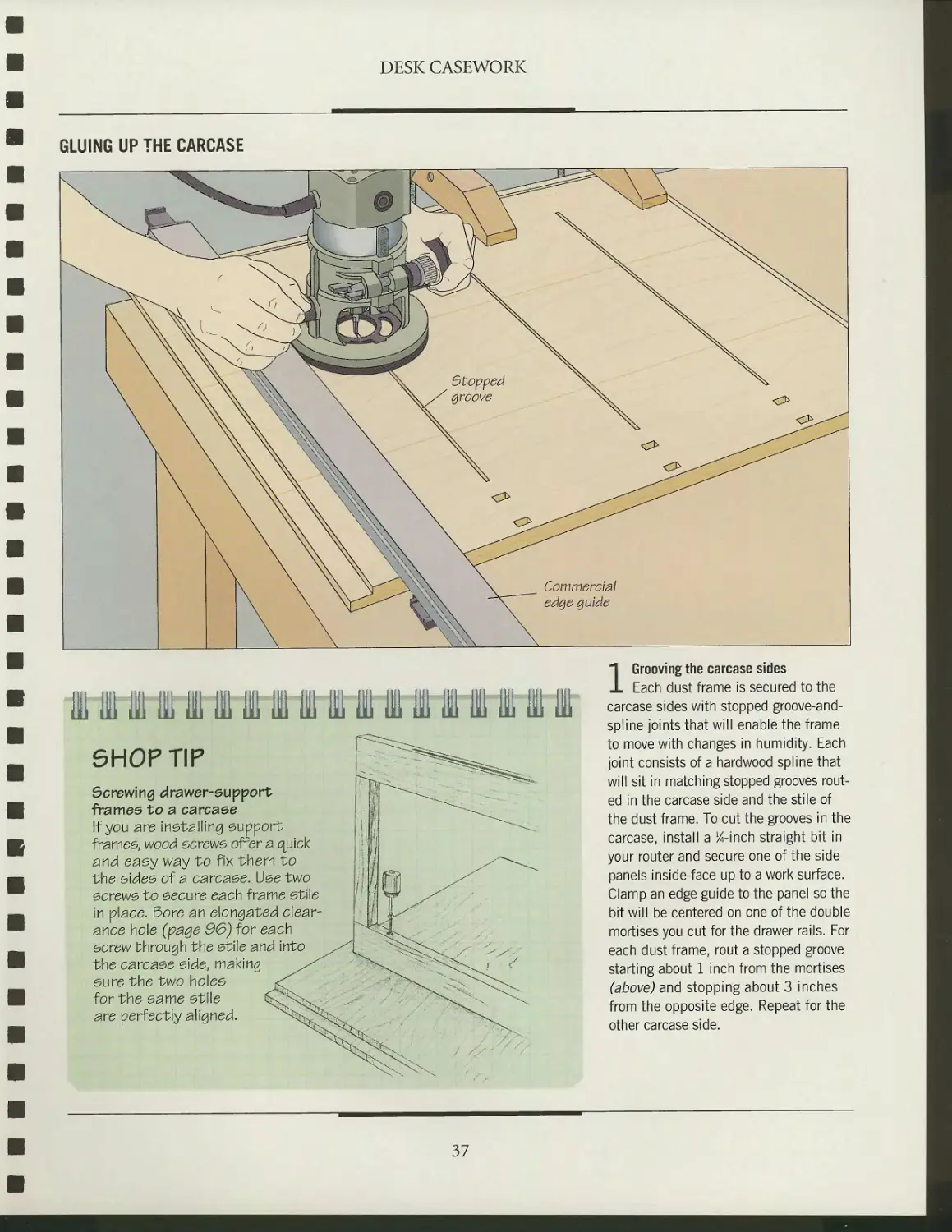
SHOP TIP
Screwing drawer-support
frames to a carcase
If you are installing support
frames, wood screws offer a quick
and easy way to fix them to
the sides of a carcaee. Use two
screws to secure each frame stile
in place. £3ore an elongated
clearance hole (page 96) for each
ecrew through the stile and
the carcaee side, making
sure the two holes
for the same stile
are perfectly aligned.
1 Grooving the carcase sides
Each dust frame is secured to the
carcase sides with stopped groove-and-
spline joints that will enable the frame
to move with changes in humidity. Each
joint consists of a hardwood spline that
will sit in matching stopped grooves
routed in the carcase side and the stile of
the dust frame. To cut the grooves in the
carcase, install a 14-inch straight bit in
your router and secure one of the side
panels inside-face up to a work surface.
Clamp an edge guide to the panel so the
bit will be centered on one of the double
mortises you cut for the drawer rails. For
each dust frame, rout a stopped groove
starting about 1 inch from the mortises
(above) and stopping about 3 inches
from the opposite edge. Repeat for the
other carcase side.
37
DESK CASEWORK
2 Installing the dust frames
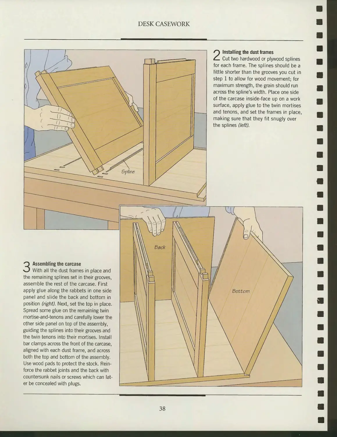
Cut two hardwood or plywood splines
for each frame. The splines should be a
little shorter than the grooves you cut in
step 1 to allow for wood movement; for
maximum strength, the grain should run
across the spline's width. Place one side
of the carcase inside-face up on a work
surface, apply glue to the twin mortises
and tenons, and set the frames in place,
making sure that they fit snugly over
the splines (left).
3 Assembling the carcase
With all the dust frames in place and
the remaining splines set in their grooves,
assemble the rest of the carcase. First
apply glue along the rabbets in one side
panel and slide the back and bottom in
position (right). Next, set the top in place.
Spread some glue on the remaining twin
mortise-and-tenons and carefully lower the
other side panel on top of the assembly,
guiding the splines into their grooves and
the twin tenons into their mortises. Install
bar clamps across the front of the carcase,
aligned with each dust frame, and across
both the top and bottom of the assembly.
Use wood pads to protect the stock.
Reinforce the rabbet joints and the back with
countersunk nails or screws which can
later be concealed with plugs.
38
DESK CASEWORK
INSTALLING A CONNECTING RAIL
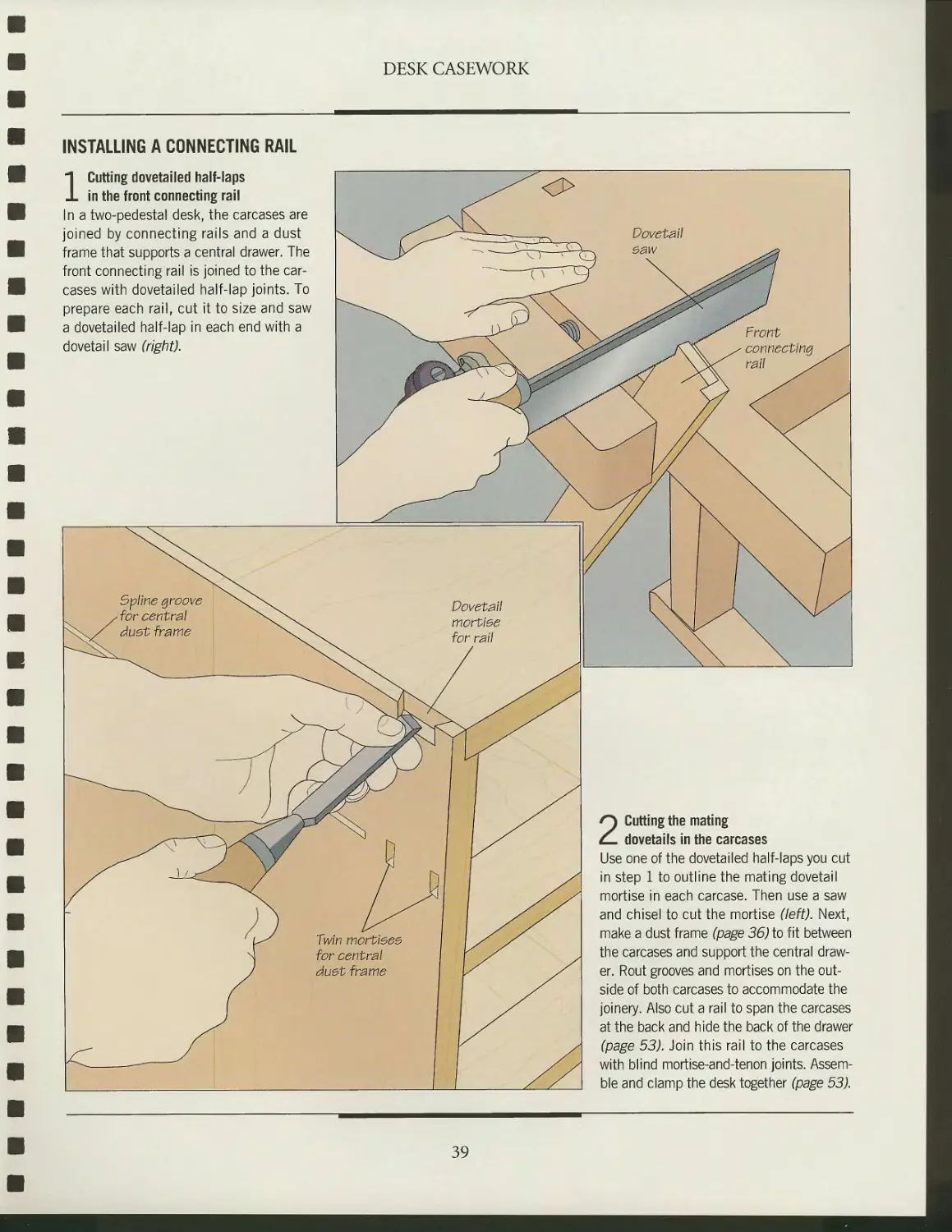
1 Cutting dovetailed half-laps
in the front connecting rail
In a two-pedestal desk, the carcases are
joined by connecting rails and a dust
frame that supports a central drawer. The
front connecting rail is joined to the
carcases with dovetailed half-lap joints. To
prepare each rail, cut it to size and saw
a dovetailed half-lap in each end with a
dovetail saw (right).
Dovetail
mortiee
for rail
2 Cutting the mating
dovetails in the carcases
Use one of the dovetailed half-laps you cut
in step 1 to outline the mating dovetail
mortise in each carcase. Then use a saw
and chisel to cut the mortise (left). Next,
make a dust frame (page 36) to fit between
the carcases and support the central
drawer. Rout grooves and mortises on the
outside of both carcases to accommodate the
joinery. Also cut a rail to span the carcases
at the back and hide the back of the drawer
(page 53). Join this rail to the carcases
with blind mortise-and-tenon joints.
Assemble and clamp the desk together (page 53).
39
DESK CASEWORK
BASE MOLDING
Molded
edge
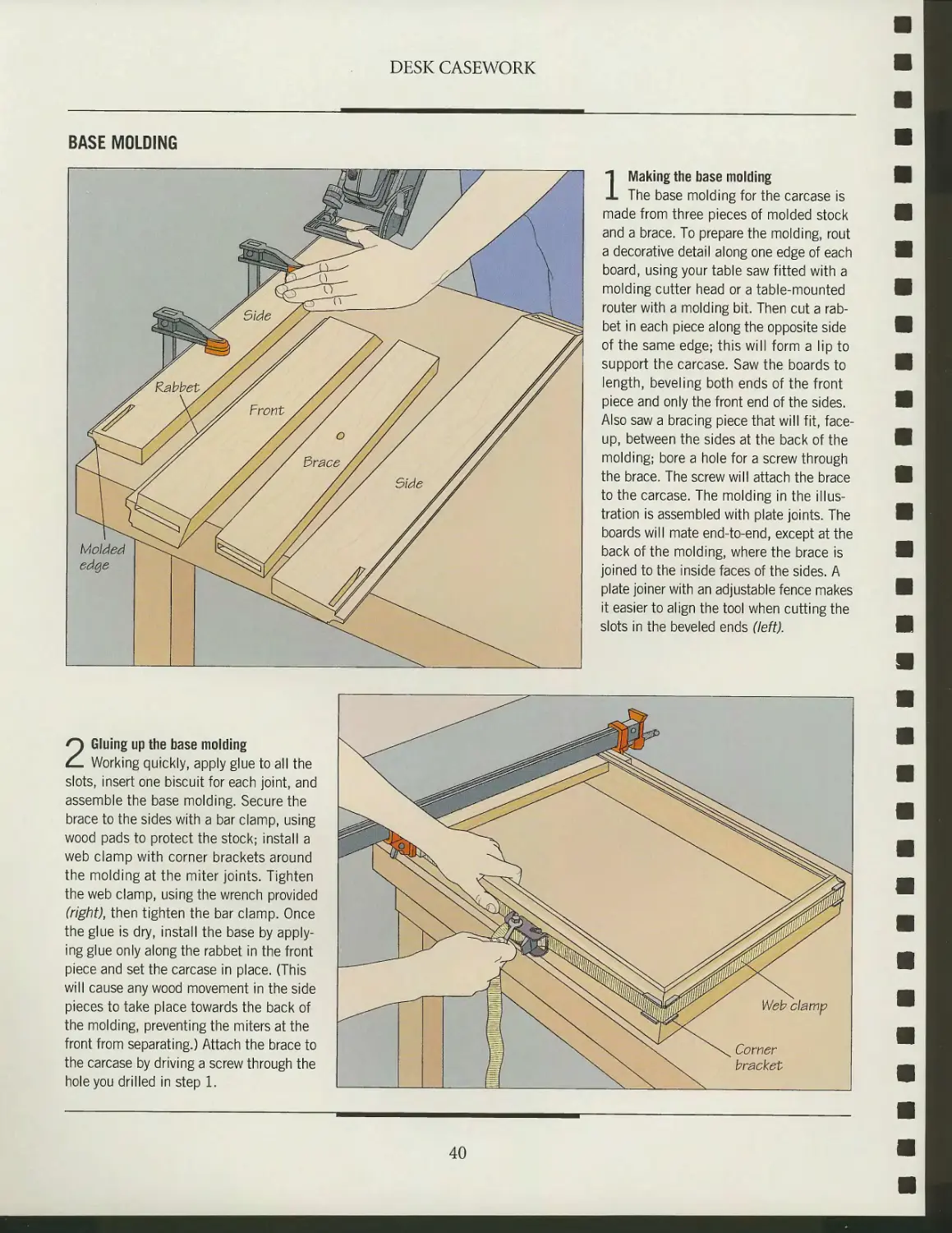
1 Making the base molding
The base molding for the carcase is
made from three pieces of molded stock
and a brace. To prepare the molding, rout
a decorative detail along one edge of each
board, using your table saw fitted with a
molding cutter head or a table-mounted
router with a molding bit. Then cut a
rabbet in each piece along the opposite side
of the same edge; this will form a lip to
support the carcase. Saw the boards to
length, beveling both ends of the front
piece and only the front end of the sides.
Also saw a bracing piece that will fit,
faceup, between the sides at the back of the
molding; bore a hole for a screw through
the brace. The screw will attach the brace
to the carcase. The molding in the
illustration is assembled with plate joints. The
boards will mate end-to-end, except at the
back of the molding, where the brace is
joined to the inside faces of the sides. A
plate joiner with an adjustable fence makes
it easier to align the tool when cutting the
slots in the beveled ends (left).
2 Gluing up the base molding
Working quickly, apply glue to all the
slots, insert one biscuit for each joint, and
assemble the base molding. Secure the
brace to the sides with a bar clamp, using
wood pads to protect the stock; install a
web clamp with corner brackets around
the molding at the miter joints. Tighten
the web clamp, using the wrench provided
(right), then tighten the bar clamp. Once
the glue is dry, install the base by
applying glue only along the rabbet in the front
piece and set the carcase in place. (This
will cause any wood movement in the side
pieces to take place towards the back of
the molding, preventing the miters at the
front from separating.) Attach the brace to
the carcase by driving a screw through the
hole you drilled in step 1.
Web clamp
Corner
bracket
40
BUILDING A FRAME-AND-PANEL DESK
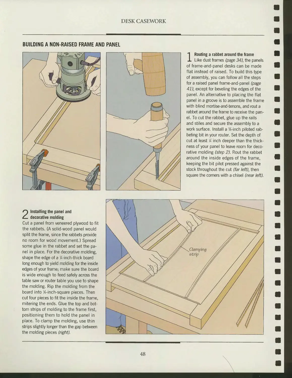
Fl rame-and panel construction offers
one solution to the perennial
problem of wood movement. The principle is
simple: A panel "floats" in a groove cut
on the inside edge of a frame. The
panel can be flat, as in a dust frame (page
48), or "raised" with bevels cut along its
edge. The beveling allows the panel to
fit into a groove in the frame and
presents a decorative face to the public. A
panel can be raised on the router table
(page 44) or the table saw (page 45).
To construct a frame-and-panel desk
like the one shown on page 31, you need
to join four individual frame-and-pan-
el assemblies: a rear assembly (page 47),
a front assembly with drawer slides (page
49), four side rails, and two side panels.
(The stiles in the front and rear
assemblies double as stiles for the side frames.)
Traditionally, panels for frame-and-panel construction were "raised" or beveled,
with specialized hand planes—a time-consuming task. Modern power tools, like
a table saw with a tilting arbor, have made this operation much simpler.
HAUNCHED MORTISE-AND-TENON JOINTS
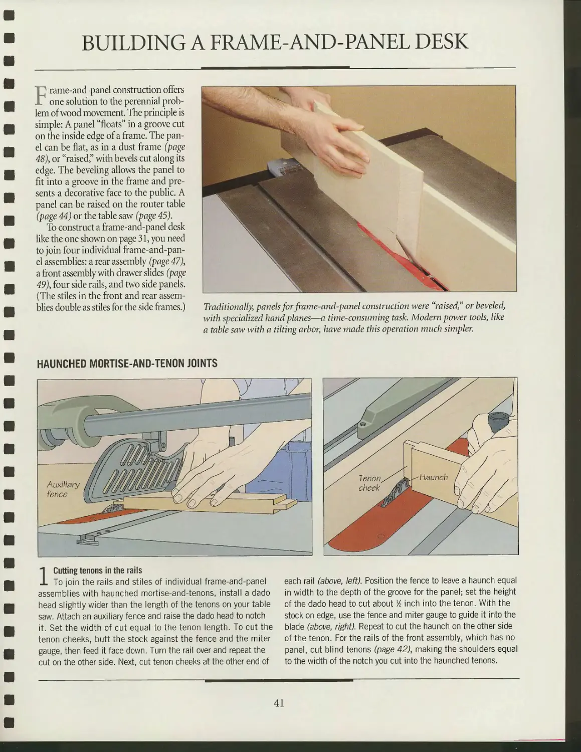
1 Cutting tenons in the rails
To join the rails and stiles of individual frame-and-panel
assemblies with haunched mortise-and-tenons, install a dado
head slightly wider than the length of the tenons on your table
saw. Attach an auxiliary fence and raise the dado head to notch
it. Set the width of cut equal to the tenon length. To cut the
tenon cheeks, butt the stock against the fence and the miter
gauge, then feed it face down. Turn the rail over and repeat the
cut on the other side. Next, cut tenon cheeks at the other end of
yS Tenon//\
/ cheek M
s
^Haunch / / ,
each rail (above, left). Position the fence to leave a haunch equal
in width to the depth of the groove for the panel; set the height
of the dado head to cut about lA inch into the tenon. With the
stock on edge, use the fence and miter gauge to guide it into the
blade (above, right). Repeat to cut the haunch on the other side
of the tenon. For the rails of the front assembly, which has no
panel, cut blind tenons (page 42), making the shoulders equal
to the width of the notch you cut into the haunched tenons.
41
DESK CASEWORK
Ili^^SSSSiSi
y^~
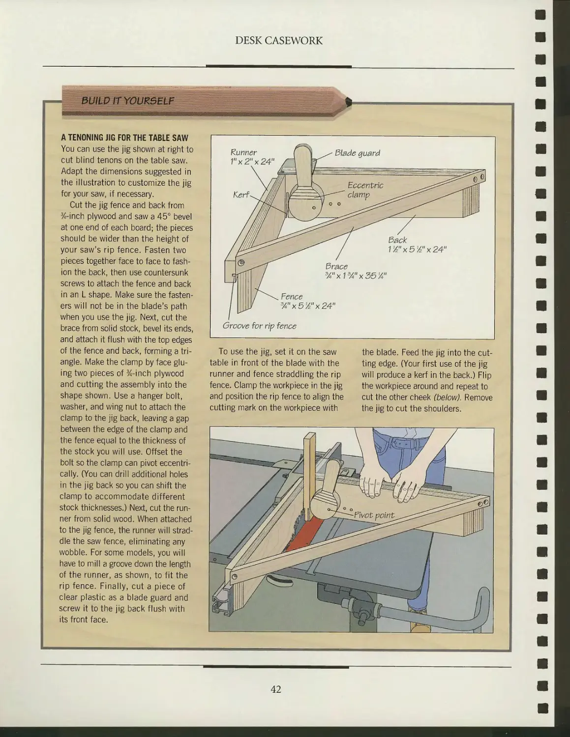
A TENONING JIG FOR THE TABLE SAW
You can use the jig shown at right to
cut blind tenons on the table saw.
Adapt the dimensions suggested in
the illustration to customize the jig
for your saw, if necessary.
Cut the jig fence and back from
%-inch plywood and saw a 45° bevel
at one end of each board; the pieces
should be wider than the height of
your saw's rip fence. Fasten two
pieces together face to face to
fashion the back, then use countersunk
screws to attach the fence and back
in an L shape. Make sure the
fasteners will not be in the blade's path
when you use the jig. Next, cut the
brace from solid stock, bevel its ends,
and attach it flush with the top edges
of the fence and back, forming a
triangle. Make the clamp by face
gluing two pieces of %-inch plywood
and cutting the assembly into the
shape shown. Use a hanger bolt,
washer, and wing nut to attach the
clamp to the jig back, leaving a gap
between the edge of the clamp and
the fence equal to the thickness of
the stock you will use. Offset the
bolt so the clamp can pivot
eccentrically. (You can drill additional holes
in the jig back so you can shift the
clamp to accommodate different
stock thicknesses.) Next, cut the
runner from solid wood. When attached
to the jig fence, the runner will
straddle the saw fence, eliminating any
wobble. For some models, you will
have to mill a groove down the length
of the runner, as shown, to fit the
rip fence. Finally, cut a piece of
clear plastic as a blade guard and
screw it to the jig back flush with
its front face.
Runner
Vx2"x24"
dack
VA"x51A"x24"
3race
3/4nx13/4nx35V4n
Fence
%nx5y2"x24"
Groove for rip fence
To use the jig, set it on the saw
table in front of the blade with the
runner and fence straddling the rip
fence. Clamp the workpiece in the jig
and position the rip fence to align the
cutting mark on the workpiece with
the blade. Feed the jig into the
cutting edge. (Your first use of the jig
will produce a kerf in the back.) Flip
the workpiece around and repeat to
cut the other cheek (below). Remove
the jig to cut the shoulders.
42
DESK CASEWORK
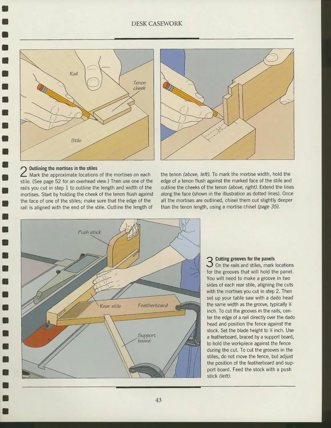
2 Outlining the mortises in the stiles
Mark the approximate locations of the mortises on each
stile. (See page 52 for an overhead view.) Then use one of the
rails you cut in step 1 to outline the length and width of the
mortises. Start by holding the cheek of the tenon flush against
the face of one of the stiles; make sure that the edge of the
rail is aligned with the end of the stile. Outline the length of
the tenon (above, left). To mark the mortise width, hold the
edge of a tenon flush against the marked face of the stile and
outline the cheeks of the tenon (above, right). Extend the lines
along the face (shown in the illustration as dotted lines). Once
all the mortises are outlined, chisel them out slightly deeper
than the tenon length, using a mortise chisel (page 35).
3 Cutting grooves for the panels
On the rails and stiles, mark locations
for the grooves that will hold the panel.
You will need to make a groove in two
sides of each rear stile, aligning the cuts
with the mortises you cut in step 2. Then
set up your table saw with a dado head
the same width as the groove, typically %
inch. To cut the grooves in the rails,
center the edge of a rail directly over the dado
head and position the fence against the
stock. Set the blade height to Vz inch. Use
a featherboard, braced by a support board,
to hold the workpiece against the fence
during the cut. To cut the grooves in the
stiles, do not move the fence, but adjust
the position of the featherboard and
support board. Feed the stock with a push
stick (left).
43
DESK CASEWORK
MAKING A RAISED PANEL ON THE ROUTER TABLE
1 Setting the fence
Start by cutting the panel to size.
Test-fit the rails and stiles of the frame,
then measure the opening between them.
Add lA inch to each of the dimensions to
allow the beveled edges of the panel to
rest in the grooves routed in the frame;
this will leave lA inch on each side to
allow for wood movement. Then fit a router
with a panel-raising bit and mount the tool
in a table. To ensure that the cutting depth
is uniform, position the fence in line with
the edge of the bit pilot. With the tool
switched off, place a scrap board along the
fence. Adjust the fence until the bit pilot
turns as the board touches it (left). Set
the router to make a shallow cut at first,
typically % inch.
2 Making the cut
Lower the guard over the bit and turn
on the router. To minimize tearout, cut
the ends first, beveling the top and
bottom of the panel. Feed the stock into the
bit outside-face down, keeping it butted
against the fence (right). Repeat for the
two sides. Test-fit the panel in the grooves
you cut in the rails and stiles (page 43).
If the panel sits less than % inch deep,
increase the cutting depth by Vie inch
and make another pass around the panel.
44
DESK CASEWORK
MAKING A RAISED PANEL ON THE TABLE SAW
1 Beveling the ends of the panel
Cut the panel to size, then set the
blade angle to yield the proper bevel. The
usual "reveal," or beveled area of a %-inch-
thick panel is approximately VA inches.
For a ^-inch-wide groove, begin by marking
a K-inch square at the bottom corner of the
panel. Then draw a line from the front face
of the panel through the inside corner of
the square to a point on the bottom edge
% inch from the back face (inset). Install a
6-inch-wide auxiliary wood fence, then
adjust the angle of the blade and the
position of the fence until the cutting edge
aligns with the marked line. Next, raise the
blade until one tooth protrudes beyond the
front face of the panel. Clamp a guide block
to the panel so it will ride along the top of
the fence. Make a cut in one end of the
panel (right), and test-fit the cut in a
groove. If the panel rests less than % inch
deep, move the fence a little closer to the
blade and make another pass. Repeat the
cut at the other end of the panel.
^^^^
- <^__
r_L_^p
1 1 1 vlI!^
L
H=
2 Beveling the sides
Beveling the sides after you have
beveled the end grain helps minimize
tearout. Set the panel on edge and feed
it into the blade, keeping the back flush
against the fence. Turn the panel over
to cut the remaining edge (left).
45
DESK CASEWORK
mmm
A PANEL-RAISING JIG
FOR THE TABLE SAW
To raise a panel on the table saw
without adjusting the angle of the
blade, use the shop-built jig shown
at right. Refer to the illustration for
suggested dimensions.
Screw the lip along the bottom
edge of the angled fence; make sure
you position the screws where they
will not interfere with the blade. Prop
the angled fence against the auxiliary
fence at the same angle as the
cutting line marked on a panel (page
45), using a sliding bevel to transfer
the angle. Cut triangular supports to
fit precisely between the two fences,
then fix them in place with screws.
Countersink the fasteners so the
panel will slide smoothly along the
angled fence.
To use the jig, position it on the
saw table with the joint between the
lip and the angled fence
approximately lA inch from the blade. Butt
the table saw's rip fence against the
jig's auxiliary fence, and screw the
two together. Turn on the saw and
crank up the blade slowly to cut a
kerf through the lip. Next, seat the
panel in the jig and adjust the height
of the blade until a single tooth
protrudes beyond the front of the panel.
Make a test cut in a scrap board the
same thickness as the panel and then
check its fit in the groove; adjust the
position of the fence or blade, if
necessary. Then cut the panel, beveling
the ends (right, bottom) before
sawing the sides.
Support v
Up
V/4nx30"-
Angled fence
12"x30"
Auxiliary fence
9"x30"
46
DESK CASEWORK
ASSEMBLING THE BACK FRAME-AND-PANEL
1 Fitting the panel in the frame
Once you have raised the panel, you
are now ready to glue up the frame-and-
panel assemblies that provide the backs
of the two cases needed for a two-pedestal
desk. Start by test-fitting the parts (right)
and make any final adjustments. If any
of the joints are too tight, use a chisel
to pare away some wood. Once you are
satisfied with the fit, disassemble the
frame and sand any surfaces that will be
difficult to reach once the assembly has
been glued up. You should also decide
which method you will use to install a top
(page 96); some of these techniques
require boring pocket holes in the rails or
routing grooves in the rails and stiles.
^3v 1
1 /ill]
^v ~—^ A ^^^^^^^^^^^^^^^^^^^^^^^^^^
\ ^i xTl X N%v \ ^X^X
\
\ \
A
\
yL^»
\
K\\
^atiE0^
^^^^^%
lis
^^^^IF\
^x
^^^-^L^^^-^^^^^^ffi^ffi UA'4
^T f——_ Clamping
Xjjl^ block
2 Gluing up
Apply glue to the tenon cheeks. Do not insert any adhesive the stock with wood blocks the same width and thickness as
in the grooves; the panel must be free to move. Clamp the frame the rails. Tighten each clamp in turn until a thin bead of glue
and panel using bar clamps across the rails (above), protecting squeezes out of the joints.
47
DESK CASEWORK
BUILDING A NON-RAISED FRAME AND PANEL
1 Routing a rabbet around the frame
Like dust frames (page 34), the panels
of frame-and-panel desks can be made
flat instead of raised. To build this type
of assembly, you can follow all the steps
for a raised panel frame-and-panel (page
41), except for beveling the edges of the
panel. An alternative to placing the flat
panel in a groove is to assemble the frame
with blind mortise-and-tenons, and rout a
rabbet around the frame to receive the
panel. To cut the rabbet, glue up the rails
and stiles and secure the assembly to a
work surface. Install a %-inch piloted
rabbeting bit in your router. Set the depth of
cut at least lA inch deeper than the
thickness of your panel to leave room for
decorative molding (step 2). Rout the rabbet
around the inside edges of the frame,
keeping the bit pilot pressed against the
stock throughout the cut (far left), then
square the corners with a chisel (near left).
2 Installing the panel and
decorative molding
Cut a panel from veneered plywood to fit
the rabbets. (A solid-wood panel would
split the frame, since the rabbets provide
no room for wood movement.) Spread
some glue in the rabbet and set the
panel in place. For the decorative molding,
shape the edge of a ^-inch-thick board
long enough to yield molding for the inside
edges of your frame; make sure the board
is wide enough to feed safely across the
table saw or router table you use to shape
the molding. Rip the molding from the
board into %-inch-square pieces. Then
cut four pieces to fit the inside the frame,
mitering the ends. Glue the top and
bottom strips of molding to the frame first,
positioning them to hold the panel in
place. To clamp the molding, use thin
strips slightly longer than the gap between
the molding pieces (right).
48
DESK CASEWORK
3 Installing molding
along the panel sides
Once the glue securing the top and bottom
molding strips has cured, glue the
molding along the sides of the panel (right).
Again, use clamping strips to hold the
molding in place.
BUILDING A FRAME-AND-PANEL CASE
Bottom rail
1 Gluing up the front assembly
To assemble a frame-and-panel pedestal for a desk, begip/
by gluing up the front frame. For the desk shown on page31,
this frame consists of top and bottom rails, two-stil-es, and a
series of drawer rails joined to the stiles with twin mortise-and-
tenons. (The bottom rail is joined with blind mortise-and-
tenons.) Apply glue to all the contacting surfaces of the joints
and assemble the frame. Install a bar clamp across each of the
rails, alternating between the top and bottom of the assembly
where possible. To distribute clamping pressure and protect the
stock, use two clamping strips. Tighten the clamps a little at a
time (above), continuing until glue squeezes out of the joints.
49
DESK CASEWORK
2 Assembling the pedestal
To complete the pedestal, build side
assemblies to fit between the front and rear
assemblies (page 47). Each side assembly
needs only a panel and two rails, since it
will share stiles with the front and rear
assemblies. For a double-pedestal desk,
the top rail of the assembly facing the
second pedestal should be wider than
the height of the central drawer between
the two pedestals (page 31). Once you
have prepared all the parts, test-fit them,
then sand their inside faces. Apply glue to
all the joints—with the exception of the
panel grooves—and assemble the pedestal.
Clamp the pedestal with bar clamps
spanning the side rails (left); use wood
pads to protect the stiles.
3 Checking for square
Measure the diagonals between
opposite corners of the pedestal immediately
after tightening the clamps (right). They
should be equal; if not, the pedestal is
out-of-square. To correct the problem,
install a bar clamp across the longer of
the two diagonals. Tighten this clamp a
little at a time, measuring as you go until
the two diagonals are equal.
50
DESK CASEWORK
INSTALLING THE BOTTOM
1 Installing ledger strips
To install a bottom using ledger strips,
cut four 1-inch-square wood strips to fit
along the rails at the bottom of the case.
The ends of the strips should butt against
the stiles. Bore two sets of countersunk
holes in each strip: one centered along
one edge, for screwing the strip to the rail,
and another along an adjacent edge for
attaching the bottom panel. Stagger the
holes so the fasteners will not contact each
other. With the pedestal upside-down,
position a ledger strip on the inside surface
of a bottom rail about 1 inch from its top
edge. Mark the positions of the screw holes
with an awl and bore pilot holes. Using
clamps to hold the strip in position, screw
the strip in place (right). Repeat for the
other ledger strips.
2 Installing the bottom
Cut a bottom panel to fit the case,
notching its corners to fit around the stiles.
To mount the panel, set the pedestal on
its back. Holding the panel flush against
the strips with one hand, mark the screw
holes with an awl and bore pilot holes.
Then screw the bottom in position (left).
51
DESK CASEWORK
JOINING DESK PEDESTALS
^
n
u
::
Dovetail lap joint \^^
b ::•
n
u
-"-' U
\
\
Kear
connecting rail
Front
connecting rail
1 Planning the joinery
Once both desk pedestals are glued
up, you are ready to join them. The diagram
at left shows the joinery involved. At the
back of the desk, a rear connecting rail is
attached to the stiles of the pedestals with
blind mortise-and-tenons; this rail provides
structural support and hides the back of
the central drawer. At the front, a
connecting rail, which provides support for
the top, is joined to the stiles with
dovetailed half-lap joints. Directly below this
rail is a support board (visible in the
illustration below) for the central drawer. It is
connected to the stiles with twin mortise-
and-tenons.
2 Attaching the connecting rails
and drawer support
Test-fit the rear connecting rail and the
drawer support in the pedestals. For the
front connecting rail, cut a dovetailed half-
lap at each end with a dovetail saw (page
39). Use the half-laps to outline the
mating mortises at the top ends of the stiles,
then cut and chisel them out. Test-fit the
rail in the mortises (right), paring the half-
laps if necessary to ensure a tight fit.
52
DESK CASEWORK
SHOP TIP
Using pipe clamps in pairs
If your pipe clamps are not long enough to glue up a desk, double
up two ehorter clamps to function as a single unit. To do this,
position the two clamps along the desk so the jaws at
the handle end grip the desk while the tail stops
overlap. Tighten one of the clamps until the
tail stops make contact. As you
continue tightening, the desk
will be pulled together just
as if you were using a
single long clamp.
3 Gluing up the desk
Apply glue to all the joints between
the connecting rails and drawer support
and the pedestals and assemble the desk.
Clamp the unit across the back with a long
pipe clamp (above), using wood pads to
protect the stock. Install a second pipe
clamp along the drawer support at the
front of the desk. Check the opening
between the pedestals for square by
measuring across the corners. Install a third
clamp, if needed.
53
-Srftf&F^i**^
s^ftS*'
life
4i
,&i
'&■
»n%:
ftir sfi
:.&f"kil
m
LEGS AND RAILS
Legs and rails are the structural
heart of most tables and desks.
The furniture legs provide vertical
support, and the rails connect and
brace the legs while also
supporting the top and framing the
drawer assembly.
Strength and beauty must be in
harmony here: The shape and
proportion of the legs and rails must
complement other elements of the
piece of furniture, balancing the
weight of the top and the size of
the drawers, for example.
The following chapter
demonstrates the techniques for making
many of the most common types
of table and desk legs, including
tapered, cabriole, turned, pedestal,
and octagonal pieces. This is followed by detailed instructions
for joining legs to rails.
Making the legs is usually the first step in constructing
a table or desk. Since most legs require thicker stock than is
commonly available, you usually must face-glue thinner stock
into a blank of appropriate size (see front endpaper). Make sure
the length of the blank is proportional to the intended height
of the table or desk, and that it will be strong enough without
appearing too bulky. Also consider the design and planned use
Smoothing a turned leg is simply a matter
of leaving it rotating on the lathe and allowing
the sandpaper to do its work. The process
typically begins with 80-grit paper and works
its way up to 180 grit or finer.
of the piece before choosing an
appropriate leg style.
The delicate cabriole leg (page
63) has been a popular feature of
high-quality furniture for more
than two centuries. Simple to cut
on the band saw, the cabriole is
designed to suggest the leg of a
leaping animal. Tapered legs (page 60)
can be cut on a jointer or table saw
and are suitable for a wide range of
tables and desks. They are a simpler
alternative to turned legs (page 66).
A table is only as sturdy as the
joinery used for the leg-to-rail
assembly. Traditional joints, such as
the mortise-and-tenon (page 34) or
dowel joint are reliable. If the piece
will be moved frequently,
commercial or shop-made hardware (page 84) that allows the legs to be
removed may be your best option. In designing your table or
desk, take into account the method you will use to attach the
top to the rails. If, for example, you plan to use wood buttons
(page 98), you will need to cut the grooves in the rails before
they are fastened to the legs. A lower rail, or stretcher, can be
added to any table for extra strength or decorative effect;
gateleg tables may require these bottom rails to serve as anchoring
points for any extra legs.
A tusk tenon joint connects the stretcher to the legs of a
trestle table. The tenon will extend beyond the through
mortise in the leg so that a tusk-like wedge can be
inserted to lock the joint while allowing it to be disassembled.
55
LEG STYLES AND HARDWARE
Cabriole leg
(page 63)
\te> 5-ehaped curve
imitates the eweep
of an animal leg
Tapered leg
(page 60)
A square leg with two adjoining facee
or all four facee tapered; virtually ae
strong ae untapered leg
TripodIpedestal leg
(page 63)
Typically eawn in a
ehallow curve; top end
ie joined to a central
column with eliding
dovetail joint
Octagonal \eg
(page 69)
A straight leg
with eight eidee
Turned leg
(page 66)
Features decorative
beade and fillete;
ehaped on a lathe
COMMERCIAL LEG HARDWARE
Leg braces
Hinged etrute that
allow lege to fold
under tabletop
Comer brace
Allowe lege to be
removed; attached
to leg with hanger
bolt and to raile
with t
Table glide
and leveler
Spring-loaded
nylon feet
automatically level furniture on uneven
floore; mounted with T-nut and bolt
Casters
Allow lege to roll; wheele r
available in braee, wood,
porcelain, nylon, plaetic,
or leather mounted in braee, wood,
or caet-iron brackete. Clockwiee from top left:"
square cup, plate, etem, and claw foot caetere
Adjustable levelere
Flaetic feet ecrewed into
bottom of lege to level
furniture on uneven floore;
mounted with T-nut and bolt
56
LEG-TO-RAIL JOINTS
Blind mortiee-
and-tenon joint
(page 76)
An invisible joint
with excellent
etrength. Tenon in
rail fite> into
mating mortiee in leg
Shop-made "^
corner brace
(page 36)
Allows lege to be removed.
Wooden corner block ie
fastened to leg and raile; grooves
and epiinee reinforce
connection between block and raile
X
Dowei joint
(page 74)
A reinforced corner
butt joint; dowele
extend into leg
Commerciai * ^;'^
hardware ^-.
(page 34)
All owe lege to be removed. Corner
brace ie bolted to leg and ecrewed
to raile; to accommodate brace, lee
ie notched and raile are grooved
Tusk tenon joint (page 72)
Commonly ueed to join the lege and etretcher of a treetle
table. Tenon extende beyond the through mortiee; tuek, or
wedge, ie ineerted to lock joint and removed to dieaeeemble it
57
TRIPOD TABLE
The simple appearance of a tripod table belies the
precise joinery needed to build it. The three legs are
fastened to the central column with sliding dovetails, cut
with angled shoulders to sit tight against the turned column. The
legs must be exactly 120° apart and the column centered under the top. To give
the legs added strength, a metal plate can be mounted under the legs and column.
The top end of the column is joined to the rail with a round mortise-and-tenon.
ANATOMY OF A TRIPOD TABLE
PEDESTAL TABLE
As on the tripod table, the legs of a pedestal table are
attached to a central column with sliding dovetails,
usually reinforced with a metal plate. The rails are secured to the column with
a type of interlocking bridle joint consisting of crossing edge half-laps and
mortises. The large table shown at right is supported by two sets of legs
and columns. Because of the table's considerable weight, casters have been
attached to the legs to make the piece easier to move.
ANATOMY OF A PEDESTAL TABLE
■ Rail
Detail of
dovetails
Column
V7
Leg
\
E
J
TAPERED LEGS
Tapered and stop-tapered legs like those
shown above are frequently used on
drop-front and rolltop desks and a wide
assortment of tables. They lighten a
piece's appearance without seriously
diminishing its strength.
5top
block
1 Setting up and starting the cut
You can taper legs quickly and accurately on a jointer. Start by outlining the
dimensions of the taper on the bottom of the leg blank with a cutting gauge (above, top). Then
mark lines on the four faces of the stock to indicate where the taper will begin. Install
a clamp to hold the guard out of the way during the operation. Set the depth of cut for
lA inch and, holding the blank against the fence, align the taper start line with the front
of the outfeed table. Butt a stop block against the bottom of the leg and clamp it to the
infeed table. To start each pass, carefully lower the blank onto the cutterhead while
holding it firmly against the fence and the stop block (above, bottom). Make sure both
hands are over the infeed side of the table.
60
LEGS AND RAILS
/
;i-v lifcih iifi
, i^riti^B&BB^BU&^
IHfe^^±''* ; "^KrmSf^ /
N^j^jjlj^p^ / /
jtfM 1 etlck
/ / /^£>^ /J
vV
— _^y
/ A
/ '^teSS^
cm m
-~~^&Y
2 Jointing the taper
Feed the leg across the cutterhead
with a push stick, pushing down on the
trailing end of the stock while pressing it
flush against the fence (left). Keep your left
hand away from the cutterhead. Make as
many passes as necessary until you have
trimmed the stock to the taper outline,
then repeat the process to shape the
remaining faces. Make the same number
of passes on each side.
JOINTING A STOPPED TAPER
Taper etart line
Using twin stop blocks
Mark lines on all faces of the leg blank to indicate where the
tapering will begin and end. Install a clamp on your jointer's
infeed table to hold the guard out of the way. Set a %-inch depth
of cut, then butt the blank against the fence with the taper line
about % inch in front of the edge of the outfeed table. (The extra
% inch will compensate for the fact that, as the infeed table is
lowered later, it will also slide back.) Butt a stop block against
the foot of the blank and clamp it to the infeed table. Next align
the taper end line with the back end of the infeed table. Butt a
second stop block against the top end of the blank and clamp
it to the outfeed table. To make the first pass, lower the work-
piece onto the knives, keeping it flush against the fence and stop
block on the infeed table. Feed the workpiece using a push
stick (above); use your left hand to press the blank against the
fence. Keep both hands well clear of the cutterhead. Make one
pass on each face, then lower the infeed table Vb inch and repeat
the process on all four sides. Continue, increasing the cutting
depth with each pass until the taper is completed.
61
LEGS AND RAILS
mm
A JIG FOR TWO-SIDED TAPERS
Tapering legs on a table saw can be
done easily with the right jig. The
one shown below is made from
3/4-inch plywood, some solid wood,
and two toggle clamps. It is sturdier
than many commercial models; the
clamps ensure that the stock is held
firmly in place while the cut is being
made. Refer to the illustration for
suggested dimensions.
To assemble the jig, set the saw
blade to its maximum cutting height,
butt one side of the jig base against
the blade, and position the rip fence
against the other side of the base.
Lower the blade and mark a cutting
line for the taper on one side of your
leg blank, then set it on the base,
aligning the mark with one edge of
the jig. Hold the workpiece securely
and butt the plywood guide bar
Handle
Shim
1 %" x 1 %" x 22"
Guide bar
SA" x 1 %n x 30"
%"x9"x36"
against it. Press the lip snugly against
the end of the blank. Screw the guide
bar to the base and the solid wood
shim to the bar, making certain that
their edges are aligned. Attach the
toggle clamps to the shim. Clamp
down to secure the blank to the jig
with the taper mark aligned with the
edge of the base. Screw the handle to
the base at least 6 inches away from
the side that will pass by the blade.
To cut the first taper, clamp a
featherboard and support board to
the saw table, making sure they will
not interfere with the blade. (The
featherboard should press only on the
jig base, not on the workpiece.) Set
the blade height and slide the jig and
leg blank across the table, making
sure that neither hand is in line with
the blade (below). To cut the second
taper on an adjacent side of the
blank, repeat the pass with the two
untapered sides of the blank against
the jig base and guide bar. (Caution:
Blade guard removed for clarity.)
62
1 Designing the leg Despite its delicate appearance,
For a template, cut a piece of stiff cardboard or hardboard to the same length a cabriole leg provides excellent
and width as your leg blanks. The design shown above at top will yield a stable and strength. A well-balanced leg
well-proportioned leg, but you can alter the design to suit your project. Begin drawing should be able to stand by itself.
the leg by outlining the post block. Make its length equal to the width of the rail that
will be attached to it; the post block should be wide enough to accept the rail tenons.
Next, sketch the toe and the front of the leg from the toe to the ankle using a French
curve (above, bottom); at its narrowest point, the ankle should measure about two-
fifths of the stock width. Move on to the knee, sketching a gentle curve from the post
block to the front edge of the template about 3 to 4 inches below the block. Then
join the knee to the ankle with a relatively straight line. Complete the outline at the
back of the leg, connecting the bottom of the leg with the back of the ankle, then
sketching a curve from the ankle to the bottom of the post block. You may need to
redraw the curves several times until you are satisfied with the design.
63
LEGS AND RAILS
2 Transferring the design
Cut out your template on a band saw,
then sand the edges to the marked
outline. To trace the outline on the leg blank,
place the template flat on one of the inside
faces of the blank, making sure that the
ends of the template and the blank are
aligned and that the back of the post block
is flush with the inside edge of the blank.
Trace along the edges of the template.
Turn the blank over and repeat the
procedure on the other inside face (left). At this
point, some woodworkers prefer to cut
mortises or drill holes for the leg-to-rail joinery.
(It is easier to clamp and cut joints on a
rectangular leg blank than on a leg with
pronounced curves.) Other woodworkers
cut the leg first and then do the joinery.
3 Cutting out the leg
Set the leg blank on the band saw table with one of the
outlines facing up and the toe of the leg pointing away from you.
Aligning the saw blade just to the waste side of the marked line
for the back of the leg, feed the stock into the cutting edge. Turn
off the saw about halfway through the cut and remove the blank.
Then cut along the same line from the opposite end. To avoid
detaching the waste piece from the blank and losing the marked
outline on the adjacent face, stop the cut about Vz inch from the
first kerf, leaving a short bridge between the two cuts (above,
left). Retract the workpiece, then cut along the line for the
front of the leg, again leaving bridges. Turn the blank and saw
along the marked lines on the adjacent side (above, right). This
time, complete the cut, letting the waste fall away.
64
LEGS AND RAILS
4 Cutting the bridges
Turn off the saw and rotate the blank
so that the first side you cut faces up. Slide
the blank forward to feed the blade into the
kerf at the front of the leg. Turn on the
machine and cut through the bridge to
release the waste piece. Then cut through
the bridge between the kerfs at the back
of the leg (left).
5 Shaping and smoothing the leg
To finish shaping the cabriole leg and
remove blemishes left by the band saw
blade, smooth its surfaces with a spoke-
shave, followed by a rasp and sandpaper.
Begin by fixing a bar clamp in your bench
vise, then secure the leg in the clamp.
Holding a spokeshave with both hands at
the top of a curved edge of the leg, pull
the tool slowly toward you, cutting with the
grain (right). Repeat until the surface is
smooth. Turn the leg in the bar clamp to
clean up the other edges. Use a rasp to
smooth an area that the spokeshave cannot
reach. This tool works best when pushed
diagonally across the grain. Finish the job
with sandpaper, using progressively finer
grits until the surface is smooth.
65
TURNED LEGS
TURNING A LEG
Most turned legs for
tables, like the one
shown at right,
feature a square section,
or pommel, at the top.
This enables the leg
to be joined to the
table rails without
cutting or attaching
hardware to the
turned segments.
J 1
\
I W ^-^ ^~—
VI A ; / n. .
\j/\. (^//n^-^ -—/^
Tool reet \ V\ ^^*&
1 j / A
1/ /I i
w /1
^^"\\ A Fommel
kM
y
Of
1 Defining the pommel
To turn a leg on a lathe, start by separating the pommel from the cylindrical
section. The cylindrical section is then turned (step 2) and, finally, the beads and
hollows are added (step 3). Begin by marking the pommel on the leg blank, then
mount the blank on the lathe and move the tool rest as close to the workpiece as
possible without touching it; the pommel should be long enough to accommodate
the leg-to-rail joinery method you will use. Next, use a skew chisel to cut a V-shaped
notch at the marked pommel line. Bracing the blade against the tool rest, begin
with the cutting edge angled slightly to one side so the long point of the tip cuts
into the blank. This will define one side of the V. Now, angle the blade to the other
side to define the other side of the V notch (above). Continue angling the blade
from side to side until you reach the desired depth. As much as possible, keep the
bevel of the blade rubbing against the stock at all times.
2 Turning the cylinder
Use a roughing-out gouge to round
the corners of the blank below the pommel.
With the tip of the gouge tilted up against
the rotating blank, gradually raise the
handle until the bevel under the tip is
rubbing against the stock and the cutting
edge is slicing into the wood. Work from
below the pommel toward the bottom of the
leg (right). Keep the tool at a right angle
to the blank throughout the cut. Continue
until the blank is cylindrical and smooth.
dottom of I
Roughing-
out gouge
66
LEGS AND RAILS
3 Adding beads and hollows
To form beads, work with a skew
chisel and the same technique used to define
the pommel. Starting each cut with the
tool almost horizontal, raise the handle
until the blade slices into the stock. Cut one
side of the bead at a time by tilting the
cutting edge first to one side and then the
other (above). For the hollows, use a spindle
gouge. Start each cut at one edge of the
hollow with the blade on edge so that its
concave side is facing the opposite edge of
the hollow. Raise the handle so the tip
begins slicing into the stock. Then, sweep
the tool toward the hollow's opposite edge,
rolling the blade so that, at the center of
the hollow, the concave side of the blade
is facing up (left). Remove the gouge and
repeat the cut from the opposite edge of
the hollow, with the concave side of the
blade facing toward the hollow. Continue
sweeping and rolling the blade from side
to side, always working downhill, until the
hollow is symmetrical and smooth.
67
PEDESTAL LEGS
The pedestal, or tripod, leg is best cut on the band
saw. The legs have aflat section at the bottom and a
dovetail at the top that fits into the central column.
Because dovetails are more difficult to cut in a
contoured workpiece, it is best to prepare the leg blank
for joinery (pages 79 and 82) before shaping it.
CUTTING A PEDESTAL LEG
Sawing the leg on the band saw
Cut a dovetail on the top end of your leg blank, using either the
table saw (page 79) or a router table (page 82). Then, outline
the leg on your blank; use a pencil and a French curve as you
would for a cabriole leg (page 63). There are three absolute rules
for designing a pedestal leg: The grain should follow the slope of
the leg, the top and bottom ends must be perpendicular to each
other, and the spread of the legs must be less than the diameter
of the tabletop. Once you are satisfied with the design, cut the
first leg on the band saw (above) and use it as a template for
the others. Keep a copy of the template for future projects.
68
OCTAGONAL LEGS
SHAPING AN OCTAGONAL LEG
Cutting the leg on the table saw
To set up this operation, unplug the saw,
crank the blade to its highest setting, and
adjust the cutting angle to 45°. The rip
fence should be positioned so that the
blade is tilted away from it. Lay one face
of the leg blank on the blade with a
corner resting on the saw table, then butt the
fence against the stock (above) and lock
it in place. To make the first cut, butt the
stock face-down against the rip fence a
few inches in front of the blade. Adjust
the cutting height until one tooth just
protrudes beyond the face of the workpiece.
Feed the blank into the blade, straddling
the fence with your hand. Rotate the leg
90° clockwise and repeat the cut on the
adjacent face. Continue in this manner
(right) until the sides are cut.
The attractive
octagonal leg is simple to
cut on the table saw.
69
To cut a straight groove for inlay, use a table saw with a dado head the same width
as the inlay. If you are working with thick shop-made inlay, set the cutting height to
slightly less than the thickness of the inlay; for commercial inlay, set the cutting
height to its exact thickness. Make a cut in a scrap board, test the fit, and adjust
the width and cutting height of the blades, if necessary. Next, mark a line for the
groove on the leading end of the leg and align it with the dado head. Butt the rip
fence against the stock, then feed it across the blades (above).
Using a router
To make a groove that requires more than
one straight cut at different angles, use
a router with a commercial edge guide.
Secure the leg to a work surface, then fit
the router with a straight bit the same
width as the inlay and set the cutting
depth. Remember, the groove should be
slightly shallow for shop-made inlay, but
full-depth for commercial inlay. Outline
the groove on the leg, align the bit over
one of the lines that run along the grain,
and butt the edge guide's fence against
the stock. Gripping the router firmly, cut
the groove; remember to move the tool
against the direction of bit rotation. Repeat
to cut the other grooves (left). For the short
cuts against the grain, clamp a wooden
edge guide across the leg. Finally, square
the corners with a chisel.
70
LEGS AND RAILS
GLUING DOWN THE INLAY
Setting the inlay in the groove
Cut the inlay to length to fit the groove. If
you are using shop-made inlay, use a table
saw or a backsaw in a miter box; for
commercial inlay, use a wood chisel. To install
inlay in the four-sided groove shown, make
miter cuts at the ends of the inlay pieces.
It is easiest to cut and dry-fit one piece at
a time, making sure you align the miter
cuts with the corners of the grooves. With
commercial inlay marquetry, try to match
the pattern at the corners to form one
continuous design. Once all the pieces are
cut to size, spread a thin layer of glue in
the groove and on the mitered ends of the
inlay. Insert one strip at a time. While
the glue dries, secure the inlay with strips
of masking tape.
DETAILING A LEG
Routing edge detail
Secure the leg to a work surface. Mark
lines on the leg for the beginning and end
of the cut, then install a decorative bit
in your router. A piloted quarter-round bit
is shown; this bit will rout a raised bead
along the front corners of the leg. Set a
cutting depth appropriate to the profile
you want to make, then align the bit with
the start line. Holding the tool with both
hands, guide the bit along the corner of
the leg against the direction of bit
rotation. Keep the base plate flat on the top
surface of the leg and the bit pilot pressed
against the stock throughout the operation
(left). Stop when you reach the end line,
reposition the leg on the work surface, and
make a second pass, riding the base plate
on the adjacent face of the leg. This is
usually done only on the leg's outside
corner, but the other corners can also be
routed depending on the leg design.
71
LEG-TO-RAIL JOINERY
TUSK TENON JOINTS
1 Marking the location of the wedge
Cut a four-shouldered tenon (page 76)
long enough to extend beyond the leg by
at least 2 inches; this will provide
sufficient stock to resist being split by the
wedge. Cut a through mortise to
accommodate the tenon and assemble the joint.
Then, holding the pieces together on a
work surface, mark a line on the top of the
cheek where the tenon emerges from the
mortise (left).
A tusk tenon joins the stretcher to the pedestal leg of the
table shown above. Although the tusk joint is assembled
without glue so that the table can be disassembled, it is
as strong as a glued blind mortise-and-tenon.
2 Drilling the hole for the wedge
Disassemble the joint and make a drilling mark Vie inch on the
shoulder side of the scribed line; this will ensure a tight fit when
the wedge is driven into place. Set a mortise gauge to one-third the
thickness of the tenon and use the gauge to outline the hole in the
middle third of the top cheek, bordering on your mark. Using a bit
slightly smaller in diameter than the outline, bore the hole through
the tenon on the drill press (above).
72
LEGS AND RAILS
3 Angling the wedge hole
Using a mortise chisel, enlarge and
square the hole you drilled to
accommodate the wedge. Holding the chisel at a
10° angle away from the tenon shoulders,
cut a tapered slot, as indicated by the
dotted lines in the illustration (left). Then
chop out the waste, holding the chisel
with the bevel facing the waste.
4 Inserting the tusk
Cut an angled hardwood wedge,
called a tusk, that is tapered to fit the
slot you chopped in step 3; its length
can be up to twice the tenon width. To
assemble the joint, slide the tenon into
the mortise and strike the wedge firmly
with a mallet until the joint is tight (right).
Do not use glue, as this joint is designed
to be disassembled.
73
LEGS AND RAILS
DOWEL JOINTS
1 Locating and boring
dowel holes in the rails
Start by marking the location of the dowel
holes. Holding one of the rails end-up, set
a cutting gauge to one-half the thickness
of the stock and scribe a line across the end
of the board. With the gauge at a slightly
wider setting, scribe two lines that intersect
with the first line on the end of the rail
(left). To avoid splitting the stock, use
grooved dowels no more than one-half
the thickness of the rails. Fit a drill press or
an electric drill with a bit the same
diameter as the dowels and bore a hole at each
location point; the depth should be slightly
more than one-half the length of the
dowels. Use the same technique to bore the
dowel holes at the opposite end of the rail
and in the other rails.
2 Pinpointing mating dowel holes
Insert dowel centers in the holes. Then
align the top of the rail with the top of the
leg (right), and swing the rail up so that its
outside face is % to % inch inside the edge
of the leg. A pencil mark like the one
shown will help align the rail. Tap the
other end of the rail with a wooden
mallet. The pointed ends of the dowel
centers will punch impressions on the leg,
providing starting points for boring the
mating dowel holes. Repeat for the other
rails and legs.
74
LEGS AND RAILS
3 Boring the mating dowel holes
Bore the holes in the legs to the same
depth as those in the rails—slightly more
than one-half the length of the dowels. If
you are drilling into a tapered leg on a drill
press, be sure to keep the square part of the
leg flat on the machine's table.
4 Assembling the legs and rails
Spread a little glue on the surfaces of the legs and rails that with a mallet to seat the shoulder. (Be careful about using too
will contact each other, then dab a small amount of adhesive in
the bottom of the dowel holes with a small wood scrap. Avoid
spreading glue directly on the dowels; they absorb moisture
quickly and will swell, making them difficult to fit into the
holes. Insert the dowels into the legs, then tap the rail lightly
much force, which can cause a leg to split.) Fit each end of the
rail onto a leg (above, left) and hold the joint together with a bar
clamp, protecting the legs with wood pads. Align the bar of the
clamp with the rail, then tighten it (above, right) until a bead of
glue squeezes out of the joint.
75
LEGS AND RAILS
HAND-CUT BLIND MORTISE-AND-TENONS
2 Cutting the tenon shoulders
To remove the waste from the tenon cheeks, clamp the rail secure the rail end-up in a vise and saw to the shoulder line on
face-up on a work surface, protecting the stock with a wood both edges of the rail. Finally, clamp the rail edge-up and cut
pad. Cut along the shoulder line on the face of the rail; turn through the shoulder lines on both edges of the rail (above,
over the stock and repeat the operation on the other side right). Repeat steps 1 and 2 to cut the tenon on the other end
(above, left). To cut away the waste on the edges of the tenon, of the rail and at both ends of the remaining rails.
76
LEGS AND RAILS
3 Outlining the mortises
Mark the mortise outline on each leg
in two steps, using one of the rail tenons
as a guide. First, hold the cheek of the
tenon flush against the leg, with the top
of the rail aligned with the end of the leg.
Draw a pencil along the edges of the tenon
to outline the length of the mortise, then
use a try square to extend the lines across
the leg. To mark the width of the mortise,
hold the edge of the tenon centered flush
against the leg and mark along each cheek
(right). With a try square, extend the marks
along the leg until the two outlines
intersect. Repeat the process on the adjacent
face of the leg.
4 Chiseling the mortises
For each mortise, clamp the leg to a
work surface, protecting the stock with a
wood pad. Then, starting at one end of the
outline, hold a mortise chisel square to
the face of the leg and strike it with a
wooden mallet. Use a chisel the same
width as the tenon and be sure that the
beveled side of the blade is facing the
waste. Make another cut Va inch from the
first. Continue until you reach the other
end of the outline, levering out the waste
to a depth that slightly exceeds the length
of the tenon. Test-fit the tenon and widen
or deepen the mortise as required. Repeat
to cut the remaining mortises. Then spread
glue lightly in the mortises and on the
cheeks of the tenons. Fit the legs and rails
together, then close up the joints with the
same clamping setup used for the dowel
joint (page 75).
77
LEGS AND RAILS
TRIPOD TABLE: ASSEMBLING THE LEGS, COLUMN, AND RAIL
1 Turning the tenon on the column
Start by turning the rail tenon at the top of the column, as
shown at right. Then rout the dovetail sockets for the legs at the
column's bottom (step 2). Next, cut the dovetails in the legs
(steps 3 and 4) and assemble the pieces (step 5). Mount the
column blank on your lathe and turn it into a cylinder (page 66),
leaving a lip and enough stock near the bottom for the leg
sockets. To turn the tenon, use a parting tool (right), moving
the blade from side to side. The length of the tenon should be
about one-half the thickness of the mating rail. Its diameter
should be at least % inch and match that of the bit you will use
to drill the mortise in the rail.
XT too\^<^\
)^~^p:
Column
.Tenon
/ /" ^
Drive ehaft
2 Routing the dovetail sockets
Unplug your lathe and turn the column end-for-end to cut
the sockets, using a router and a shop-made jig consisting of a
%-inch plywood box clamped to the lathe bed. Make the box as
wide as the router base plate. Attach the two runners so the
router bit will cut the sockets with its base plate sitting on them.
Next, mark the location of the three sockets on the column; they
should be 120° apart. Also mark the upper ends of the sockets,
about 3 inches from the bottom of the column. To help align
the cuts, transfer the socket marks from the column to the lathe
faceplate. Now, rotate the column by hand until one of the marks
on the faceplate is vertical and clamp the drive shaft with a
handscrew (inset). Cut each socket in two passes, first using a
straight bit, then a dovetail bit. Adjust the router's cutting depth,
align the bit with the socket end mark, butt a stop block against
the router base plate, and screw the block to the jig. Holding
the router in both hands, plunge the bit into the column, starting
at the bottom, and guide the tool along the runners until the
base plate contacts the stop block. Repeat with the dovetail bit
(above). To cut the second and third sockets, rotate the column
so the socket mark for each cut is vertical.
78
LEGS AND RAILS
3 Cutting the dovetails
The dovetails in the legs are cut in two steps: The first cut
is made on the table saw, and the second by hand. It is easiest
to cut the dovetails on leg blanks before shaping the legs (page
68). Adjust your table saw's blade angle to match that of the
sockets you cut in step 2. Set the cutting height to slightly less
than the depth of the sockets. Outline the dovetails on the edge
of one leg blank and, holding the blank on end on the saw table,
align a cutting mark with the blade. Butt the rip fence against
the stock and lock it in place. Clamp a shimmed featherboard
to the table to support the blanks. Also clamp a guide block to
the blank; the block will ride along the top of the fence,
helping to guide the workpiece. To form the dovetail, make a pass
to cut one cheek (above), then rotate the workpiece and feed
the opposite face along the fence to saw the other. Once both
cheeks of the first dovetail have been cut, check them against
a socket in the column. If necessary, adjust the blade angle or
height or the cutting width and make another set of passes.
Repeat for the other dovetails.
5\\a
( XlIv5^
S <jA r^ ^
^3)\ \ ^H|
\
KB)
v r~ET
J^ElL
(IP
1 \v
[o y f
\
4 Cutting the angled shoulders
The shoulders of the leg dovetails
must be cut at an angle so they lie flush
against the column. Once the dovetail
cheeks are all cut, clamp a blank to a
work surface with the cheek cuts
extending off the table. Then use a backsaw to
cut the shoulders to roughly match the
curvature of the column (left). Test-fit the
dovetail in its socket and trim the
shoulders, if necessary, until you get a suitable
fit. Repeat for the remaining dovetails.
79
LEGS AND RAILS
5 Fastening the legs to the column
Once all the dovetails fit in their sockets, trim off the top
% inch of each dovetail. This will hide the tops of the dovetails
from view when they are pushed all the way into their sockets.
Now you are ready to cut out the legs (page 68) and attach them
to the column. Spread glue evenly on the dovetails and in the
sockets. Then, holding the column upside-down on the floor,
slide the legs into place and tap them into final position with a
wooden mallet (above). To strengthen the assembly, add a three-
armed plate cut from sheet metal (page 58). Next, cut the rail
that will connect the column to the tabletop. Bore a mortise in
the center of the rail to accept the tenon at the top of the column.
Use a router fitted with a rounding-over or chamfering bit to
shape the bottom edge of the rail all the way around. Finally, stand
the table upright, spread glue on the tenon and in the mortise, fit
the rail over the tenon, and screw the rail in place (right).
80
LEGS AND RAILS
PEDESTAL TABLE: GLUING UP THE LEG ASSEMBLY
1 Preparing the column for the legs
Mark a line across the column near
the bottom to define the square section
that will be joined to the legs; the area
should be as long as the width of the
legs. Install a dado head on your table
saw and set the cutting height at
roughly Yz inch. Using the miter gauge, make
several passes across the column to
remove the waste from all four sides of
the column (above).
3 Preparing the top of the column
Once the dovetails are cut, turn the column on a lathe,
leaving a square section at the top to accommodate the rails and a
lip just above the bottom square section to conceal the tops of
the legs. (The lip is visible on page 82.) The rails will fit into
two intersecting mortises cut in the column's square section.
Mark cutting lines for the mortises down the center of each side
of the column; the mortise width should be one-half the
thickness of the rails. Set the saw blade height to the width of the
rails less the edge recess shown in step 7 (page 83). To feed the
column safely, make a jig to hold it upright. Take a large push
stick and screw a piece of wood to the side, forming an L. With
the leg resting snugly in the L, align the cutting mark with the
blade and lock the rip fence against the face of the push stick.
Lay a spacer on top of the fence (it must be the same thickness
as the fence) and screw it to the push stick; screw a guide board
to the spacer so the jig forms a channel over the fence. Check
the alignment, clamp the leg in place, and make a sequence of
cuts until the mortise is wide enough (left). Repeat all cuts on
each face to ensure that the mortises are perfectly centered.
2 Cutting the dovetail sockets
Plow a dovetail socket on each side of the column on the router table. Install a
straight bit in your router and mount the tool in a table. Mark a line for the sockets
down the center of each side, align a socket mark with the bit, butt guide boards against
the stock, and clamp the boards to the table. Feed the column across the table to cut
the first socket, stopping the cut when the bit reaches the end of the square section.
Leave the column in place, turn off the tool, and clamp a handscrew as a stop block
against the end of the column. Repeat the cut on the other sides of the column,
stopping when the stock contacts the handscrew. Complete the task with a second pass
on each side using a dovetail bit (above).
81
LEGS AND RAILS
4 Cutting the dovetails on the legs
Install a dovetail bit in your router and
mount the tool in a table. Set the cutting
depth to make the dovetails slightly shorter
than the depth of the dovetail sockets you
cut in step 1. Position the fence so that
about one-half of the cutter projects beyond
its face. With a featherboard clamped to the
table to support the workpiece, feed a leg
blank (page 68) on end across the table,
pressing it against the fence (left). Turn the
blank end-for-end and repeat to complete
the dovetail. Test-fit the joint and adjust
the fence and make additional cuts, if
necessary. Repeat for the other leg blanks.
5 Joining the legs to the column
Cut out the legs on a band saw (page
68), then notch the top end of the
dovetails so that they stop short of the socket
end. This will conceal the joints between
the legs and column. Spread glue on the
dovetails and in the sockets and slide the
dovetails into place, tapping them with a
mallet if necessary. For additional strength,
you can make a four-armed bracket out
of sheet metal to fit under the column and
legs, and screw it in place, as shown on
page 58.
82
LEGS AND RAILS
6 Preparing the rails
To allow the rails to fit the grooves in
the column, cut recesses in the middle of
both faces of the rails. Install a dado head
on your table saw and set the cutting depth
to about one-quarter the rail thickness.
Screw an extension to the miter gauge.
Make test cuts in a piece of scrap to be
sure that the rails will fit snugly in the
mortises. Mark the shoulders of the recesses
on one rail so they are as long as the width
of the square section at the top of the
column. Align a mark with the dado head
and clamp a stop block to the extension,
flush against the rail. Feed the rail with the
miter gauge, pressing the stock against
the stop block. Flip the piece to cut a
shoulder on the other face, then rotate
the piece and cut the shoulders at the
other ends of the recesses. Repeat on the
other rail, then remove the stop block and
remove the remaining waste.
7 Joining the rails to the column
To conceal the mortises once the rails are in place, cut a Vz-
inch-deep recess into the bottom edge of each rail, along the
length of the recess in the face. Next, notch the middle of the
edges. This can be done with the dado head; the width should
equal the thickness of the lapped section of the rails. Adjust the
blade height to cut halfway through the rail, then saw an edge
half-lap in the bottom edge of one rail and the top edge of the
other, making sure the notches are centered between the
shoulders (above, left). Adjust the blade height for the second rail to
account for the edge recess. Once both edge half-laps are cut, round
the ends of the rails on the band saw, spread some glue on the
contacting surfaces of the column and rails, set the column bottom-
end up on the floor, and fit the rails in place (above, right).
83
LEGS AND RAILS
COMMERCIAL LEG HARDWARE
1 Preparing the rails
Commercial hardware that connects
legs and rails should be installed following
the manufacturer's instructions. To use the
hardware shown on the facing page, test-
assemble the leg, rails, and mounting
plate, then mark the location of the plate
flanges on the rails. To cut the slots for the
flanges, align each mark with the blade,
then butt the rip fence against the rail.
Set the blade height to the length of the
flange, adding Ke inch for clearance. Feed
the rail into the blade with the miter gauge
(left). (Caution: Blade guard removed for
clarity.) Repeat for the other rail. Slip the
flanges into the slots and mark the screw
holes on the stock. Bore pilot holes and
screw the mounting plate to the rails.
2 Notching the leg for the mounting plate
A notch must be cut at the top of each
leg to accommodate the mounting plate.
Stand the leg up and hold the rail-and-
plate assembly on top of it, aligning the
ends of the rails with adjacent sides of the
leg. Mark a 45° diagonal line across the
top of the leg along the mounting plate.
Next, align the top of the plate with the
top of the leg and mark a line along the
bottom edge of the plate across the inside
corner of the leg, adding Ke inch for
clearance. To cut the notch, set the leg on a
band saw and tilt the table to 45° to align
the blade with the diagonal line. Butt a
board against the leg and clamp it to the
table as a rip fence. Feed the leg into the
blade, then clamp a stop block in place to
help with repeat cuts (right). Complete
the notch using a handsaw.
84
LEGS AND RAILS
3 Preparing the leg for the hanger bolt
Test-assemble the leg and rail-and-
plate assembly again and mark the hole
on the stock for the hanger bolt provided
with the hardware kit. Fit your drill press
with a brad-point bit and bore a pilot hole
for the bolt using a shop-made V-block
(right). Repeat for the other legs.
4 Fastening the leg to the rails
Insert the screw-thread end of the
hanger bolt into the pilot hole in the leg.
Unlike other fasteners, a hanger bolt has
two types of threads: screw threads at one
end and machine threads at the other; it
also has no head. Screw two nuts onto the
machine-thread end and tighten them
against each other with two wrenches,
forming a temporary head on the bolt.
Tighten the bolt with one of the wrenches
to drive the screw threads into the leg, then
unscrew the nuts from the bolt. Slip the
rail-and-plate assembly over the bolt and
screw a nut on it. Keeping the top of the
rails flush with the top of the leg,
tighten the nut (left).
85
LEGS AND RAILS
BUILD IT YOURSELF:
i^
SHOP-MADE LEG HARDWARE
You can attach a leg to rails using a
wooden corner block, a hanger bolt,
and four screws. Begin by making the
corner block. Cut a piece of wood thin
enough to drive a hanger bolt through
it into the leg. Then make a 45° miter
cut at each end. Next, saw grooves for
splines, which will help join the block
to the rails. Install a dado head on
your table saw with a width and
cutting height equal to one-third the
thickness of the rails. Screw a board to the
miter gauge as an extension, then align
the midpoint of one end of the block
with the blade. Clamp the block to the
extension. Butt a waste piece from
the miter cuts against the workpiece
to serve as a stop block and clamp
it to the extension. Feed the stock
into the blades, then turn it over and
cut a groove in the other end (above).
86
LEGS AND RAILS
Test-fit the block against the rails,
then mark and cut the grooves in the
rails. Now cut the splines, making
them Vie inch shorter than the
combined depth of the two grooves. Plane
the splines carefully to make sure
that they fit precisely in the matching
grooves. For maximum strength, make
sure that the grain of the splines runs
across their width, rather than along
their length.
Now bore countersinking and
clearance holes for the hanger bolt and
screws that will secure the brace to
the leg and rails. Install a brad-point
bit in your drill press and mark the
center of the long edge of the block
for a hanger bolt. Secure the work-
piece in a handscrew and clamp it to
the drill press table, with the center
aligned with the bit. Then bore the hole.
Next, mark two holes on each side of
the clearance hole and drill
countersinking holes (facing page, bottom),
then install a smaller bit to drill
clearance holes for the screw shanks.
To join the leg and rails, first fasten
the corner block to the rails. Spread
some glue in the grooves in the block
and the rails, and insert the splines
into the grooves in the block. Then
hold the block against the rails and
screw it in place (left). Prepare the leg
as you would for commercial hardware
(page 84), cutting a notch out of the
top for the corner block and boring a
pilot hole for a hanger bolt. Fasten the
leg to the rails with the bolt, slipping a
washer between the nut and the corner
block. Tighten the nut (below) until
the leg and rails fit snugly together.
87
&S,a^3F«|
iKl
|»;j'^ f-^v^lb
T^;
^
**--^
TOPS
| he top is the reason for a table s
or desk's being. The
structural requirements are simple: the
surface must be flat and solid. The
esthetic demands are more
complex. The top must complement the
design of the table or desk so that
it seems to grow out of the assembly
supporting it. Since most tops are
made of glued-up pieces of solid
stock, the grain pattern of the
individual boards must be chosen
carefully to create the illusion that the
surface is made from a single wide
board. To do this, you will need to
experiment until you succeed. Take
your time: Four or five planks, for
example, can be flipped and turned end-for-end to create
literally scores of possible combinations.
During the Middle Ages, when dining took place in great
communal halls, huge trestle tables were the norm: Dozens of
people could be fed and the tables could be knocked down for
storage after dinner. As separate rooms for public and private
dining came into vogue in the 15th Century, smaller, adjustable
tables with hinged flaps evolved. These so-called drop-leaf
tables were used in coffeehouses and taverns. Other
modifications included tables that could split in two to make room for
An adjustable top makes a table more flexible;
by mounting sliding table extenders under a
table with a divided top, you can expand the
table to make room for additional leaves.
additional segments; these were the
"draw top" tables popular in Tudor
England, and what have come to be
known as extension tables. In the
early 18th Century, country homes
were increasingly furnished with
larger drop-leaf tables featuring
swinging gate legs.
All the tables and desks built
today can be traced to these basic
innovations. The following chapter
explains how to build and install a
variety of tops for tables and desks,
from gluing up the top (page 93) to
attaching it to a base (page 96).
While you can make a tabletop by
veneering sheet products such as
plywood, solid wood remains the building material of choice;
sheet materials require edge banding and are often not as
appealing visually as solid wood.
The type of top you build depends on the function of your
table. If your goal is to maximize seating while reducing
storage space, adjustable tops (page 101) for drop-leaf, gateleg, or
extension tables are a good idea. If you want to add an
unusual touch, the section on decorative elements (page 112) shows
you how to combine wood with such contrasting elements as
glass, leather, slate, and felt.
The edge of a tabletop is just as important to its
appearance as the wood's grain and color. At left,
a router fitted with a rounding-over bit is used to
soften the square edges of a mahogany tabletop.
89
INVENTORY OF TOP DESIGNS
SWING-LEG AND
GATELEG TABLES
Six-legged gateieg table
(page 105)
Drop-leaf type table featuring two
gate lege in addition to four etationary
lege; receeeee in raile may be required
to allow ewinging lege to be tucked out
of the way when not in uee
Four-legged swing-leg table
(page 106)
Drop-leaf type table
with two of four lege that
ewing out to eupport leavee;
ewinging lege are hinged to
raile of table baee
Tabletops do not have to be
rectangular and wooden—or
predictable. The "Folia Table"
shown at left, built by Rhode
Island cabinetmaker Kam
Ghaffari, features a curly
maple tabletop dyed black and
green, and cut into a stylistic
representation of a leaf The
black half of the leaf is lower
than the green half; it is
covered by a pane of cut glass that
rests on stainless steel "veins."
Rectangular
{ :
Rounded ende
and curved eidei
TOP SHAPES
r~)
Rounded ende
| O <
Round
5
Curved eidee
Oval
Wood
buttone
METHODS OF ATTACHING A TOP
Ledger
etripe
Tabletop
faetenere
90
TOPS
EXTENSION TABLES
Non-dividing
extension table
(page 105)
Only tabletop and decorative apron
divide; leg-and-rail assembly ie
screwed to stationary center
segment of table extenders. (Decorative
apron removed for clarity.)
Dividing
extension table
(page 107)
Entire table divides in two; moving
segments of table extenders are screwed
to both halves of tabletop from
underneath; legs move when
table is opened
Non-dividing trestle table
(page 110)
Breadboard ends pull
away from center on
trestle table slides
91
HARDWARE AND ACCESSORIES
Table locks
Mounted under extension tables to lock
halves in place; long arms allow
easy access. Spring-loaded
and lever models
available
Blind pivot hinge
Used In place of
a dowel In a
pivot rail or
butterfly table
Table leaf latches
Mounted under extension tables to
lock leaves in place; available In brass
and steel. Model shown below (left)
features eccentric slot that draws
the leaves snugly together when closed
Tabletop
eveners
Installed under
extension and drop-
leaf tables to align leaves
or halves as they are closed
Steel fasteners
Used to attach tops to
leg-and-rall assemblies.
Desktop, or figure-eight,
fastener Is Installed flush with top
of rails and screwed Into the top; Z-
shaped tabletop fastener Is screwed
to top and mates with grooves
routed along Inside of table rails
Table leaf alignment pins
Used to align tabletops and
leaves flush on extension tables;
brass, hardwood, and plastic
models available
Table fork closure
U-shaped handle mounted
under extension tables to
lock tabletop halves in place
Cranked hinge
Used to install the
adjustable legs of four-
legged swing-leg tables;
when closed, hinge holds
leg flush with table rail
Rule joint hinges
Used to connect leaf and
top of drop-leaf table with
rule joint; longer hinge
leaf bridges the
coved half of
the joint
Drop-leaf support
Mounted underneath drop-
leaf tabletop to support leaves.
Metal bracket mounts to underside
of top; movable wood slide supports leaf
Table extenders
Mounted In pairs under both dividing and non-dividing
extension tables. Outer segments, screwed to either
half of tabletop, are pushed away from each
other by rack-and-pinion mechanism; center
segment remains stationary. Typical
lengths are 26 and 38 Inches
Trestle table slide
Hardwood slides with
double-sliding dovetail
joints mounted In pairs
underneath breadboard
ends of a trestle table;
typically extends from
26 to 40 Inches
PREPARING A TOP
The edges of a rectangular desktop or
tabletop are often shaped to soften its
contours. Here a router is used with a
commercial jig to round the corners
of a tabletop. For a gallery of top
shapes, see page 90.
\ /jj" ost tops for tables and desks are
IV^made by edge-gluing boards
together. Few boards are available that
are wide enough and most of those
would be unsuitable, because of the
tendency of wide planks to twist and cup.
However, by selecting boards carefully
and matching them for color and grain
direction, you can create the illusion of
a single piece of wood. Assess the color
and grain of lumber by planing the
surface lightly to reveal what lies
underneath a plank's rough exterior.
A sturdy, flat top starts with proper
preparation of stock. Make sure you use
kiln-dried wood or wood that has been
stored long enough in the shop to have
a moisture content between 8 and 12
percent. A low moisture content means
that the wood will be relatively stable.
Also steer clear of bowed or twisted
boards. Since many tops have a finished
thickness of % inch, 4/4 rough-sawn
stock is an ideal choice as it allows you to
plane and sand off up to % inch of wood.
Wide tops are seldom glued up all at
once because it is much easier to
thickness plane several smaller panels than
one large one. The glue up sequence you
follow for your projects will depend on
the finished width of your top, and the
size of your planer. For example, if you
own a 12-inch planer and want a 30-
inch-wide tabletop, it is best to glue up
three 8- to 12-inch-wide panels and plane
them individually, before gluing them
into a single top. To help keep the boards
aligned during glue-up, some
woodworkers use dowels or biscuits spaced
every 6 to 8 inches, although this is not
essential. Unlike standard tables, the
grain for tops for extension tables should
be perpendicular to the table's length.
Ideally, use quartersawn stock for these
tops, as well as for the leaves.
After the glue has dried and the
panel has been planed, the edges of the top
can be shaped (page 95). With drop-leaf
and gateleg tables, this shaping is done
before the joinery. One exception is the
round drop-leaf table; its leaves should
be installed (page 101) before the circle
is cut to ensure that the table will be
perfectly round.
MAKING A TOP
1 Jointing the boards
Prepare each board by first jointing a
face and an edge, then plane the other
face. Next, roughly crosscut the boards,
leaving them about 1 inch longer than the
top's final length. Rip the stock so that the
combined width of all the boards is
roughly 1 inch wider than the finished top, then
joint all the cut edges (left). Next, arrange
the boards for appearance, taking into
consideration any leaves if you are making
an extension, drop-leaf, or gateleg table.
(Leaves are typically glued up separately
from the tabletop.) To minimize warping,
arrange the planks so the end grain of
adjacent boards runs in opposite directions.
When you are satisfied with the
arrangement, use a pencil or chalk to mark a
reference triangle on top of the boards. This will
help you correctly realign them for glue-up.
93
Applying the glue
To hold your bar clamps upright
during glue-up, cut notched wood blocks and
set the clamps in the blocks. Space the
clamps at least every 24 to 36 inches. To
avoid marring the edges of the panel
when you tighten the clamps, cut two
wood pads as long and as thick as the
boards being glued. Apply a narrow bead
of glue to one edge of each joint and
use a small, stiff-bristled brush to spread
the adhesive evenly on the board edges
(above). Move quickly to step 3 before
the glue begins to set.
3 Tightening the clamps
Lay the boards face-down on the bar
clamps and align their ends, making sure
the sides of the reference triangle are lined
up. Tighten the clamps under the boards
just enough to butt them together. To
balance the clamping pressure and keep the
panel flat, place bar clamps across the top
of the panel between the ones underneath.
Finish tightening all the clamps in turn
(right) until there are no gaps between
the boards and a thin, even bead of glue
squeezes out of the joints. Remove excess
glue with a scraper or a damp cloth.
2
TOPS
SIZING A TOP
Cutting a rectangular top
Once the top has been glued up, rip it to
width and trim it to final length. If the top
is too large to cut on your table saw, use a
router fitted with a straight bit. First, secure
the top on a broad work surface and cut it
roughly using a circular saw, leaving about
lA inch to trim on all sides. Clamp an edge
guide to the tabletop near one side so that
the router will remove about one-half the
waste with the first pass; reset the depth
of cut to trim the rest of the waste (right).
Repeat for the other edges.
Making a round top
Scribe a circle on the glued-up top and make the cut with a
router. For small-diameter tops, you can use a commercial
compass jig; to cut larger tops, use the shop-built compass jig shown
in the inset. Make the device from K-inch hardboard, sizing it to
suit your router. Cut the router end of the jig to the size and shape
of your tool's base plate, and make the arm at least 2 inches wide
and longer than the radius of the circle you will be cutting. Bore a
clearance hole for the bit in the center of the router end, and fix
the tool to the jig. Draw a line down the center of the jig arm and
mark the radius of the tabletop on it, measuring from the edge of
the bit. Drill a hole at this center mark and screw the jig to the
center of the workpiece. Secure the stock to a work surface with
cleats and a scrap board underneath. Plunge the bit into the
stock and rout the circle in a clockwise direction (above). Make
the cut in two or more passes, increasing the depth of cut
between each pass.
95
ATTACHING A TOP
Attaching a top to a table or desk is a
straightforward task—so long as you
consider wood movement. Screwing a top
in place without providing for the swelling
and shrinking that occurs with humidity
changes will result in split or cracked wood.
Because wood expands along the grain
much less than it does across it, most tops
are made with the planks running
lengthwise. One exception to this rule is extension
tables, where the grain must be aligned
across the width of the table so that the
two halves do not expand in width at
different rates, causing the slides to bind.
Several popular methods for securing
tops to tables and desks are shown in this
section, including screwing the rails to the
top (see below) and using wood buttons
(page 98), ledger strips (page 97), screws
in pocket holes (page 98), and steel desktop
fasteners (page 100). For each of these
methods, the rails of the leg-and-rail
assembly need to be prepared for the top
before the legs and rails can be glued up.
Trestle tables are often designed to be disassembled. In the
example shown above, the screws attaching the base of the table to
the top can easily be removed. The countersunk screw holes
are elongated to allow for wood movement across the grain.
SCREWING THE RAIL TO THE TOP
1 Drilling the holes
To attach a tabletop or desktop to a
leg-and-rail assembly, bore a series of
countersunk holes in each rail for the
screws, before the legs are joined to the
rail. Drill the holes on a drill press in two
steps. First, bore holes at 6-inch intervals
about halfway through the thickness of
the rail. Clamp an edge guide to the drill
press table to keep the holes in line. To
accommodate the movement of the top,
the holes should be larger than the
diameter of the screw heads you will be using.
In the second step, bore clearance holes
slightly larger than the screw shank all
the way through the rails (right).
96
TOPS
SHOP TIP
Adding ledger strips
If you have a tabletop or desktop
with thin rails that would be
ened by enlarged screw holes,
can screw ledger strips to th
inside faces of the rails. Cut '
strips to fit along the inside
of the rails, and bore two
sets of oversized holes in
adjacent edges of each
strip (page 96). Screw
the ledger strips to all
four rails, then attach
the strips to the top.
2 Attaching the rails to the top
Set the top face-down on a work
surface, and center the leg-and-rail
assembly on it. Screw one side rail to the top
first (above), using washers to allow the
wood to move. Square the top (page 100),
then screw the opposite side rail in place.
Lastly, screw the two end rails to the top.
97
TOPS
POCKET HOLES
Drilling the holes
You can use an electric drill and a
commercial jig to drill pocket holes for attaching the
top to a leg-and-rail assembly. Follow the
manufacturer's instructions to adjust the jig
to the desired depth of cut and clamp it to
a work surface with a backup board against
the stock. Plunge the bit into the wood,
making the pocket cut (left). Then, fit a
drill with the bit supplied with the jig and
bore a clearance hole connecting the
pocket hole to the top of the rail, using the kit's
guide bushing to direct the operation
(inset). Space pocket holes every 6 inches.
Screw the top in place as shown on page 97.
WOOD BUTTONS
1 Making the buttons
To attach a top using wood buttons,
you will need to place a wood button every
6 inches along the rails. Begin by cutting
a groove on the inside face of each rail
about % inch from the top. You can cut
several l"-by-l%" buttons from a single
board; make the thickness of the stock
equal to the gap between the bottom of the
groove and the top of the rails, less Me inch.
Cut a rabbet to fit the groove at each end
of the board, then rip the board into 1-inch
strips on a band saw and cut off the
buttons about 1% inches from the ends (inset).
To make holes in the buttons for
installation, use an L-shaped corner jig
fashioned from a scrap of %-inch plywood and
two pieces of wood. Clamp the jig to your
drill press table and steady the buttons
with a hold-down fashioned from scrap
wood. Bore through the centers on the
unrabbeted portions of the buttons (right).
98
TOPS
SHOP TIP
Using steel tabletop fasteners
Commercial steel tabletop
fasteners work like wood buttons:
They are screwed to the tabletop
from underneath and grip a groove
routed or cut in the inside face
of the rails, because commercial
fasteners are thinner than li
wood buttons, the groove ^
does not have to be cut
with a dado blade; it can
be made with a standard
saw blade, or with a three- '
wing slotting cutter in
a table-mounted router.
To ensure proper tension, make *
the groove a little farther from the top
than you would with the wood buttons.
2 Installing the buttons
Center the glued-up leg-and-rail
assembly on the tabletop and screw it to
the top using the wood buttons you cut
in step 1. Fit the rabbeted ends of the
buttons into the groove in one of the side
rails, spacing them every 6 inches. Screw
the buttons in place (above), leaving a lA-
inch gap between the lipped ends of the
buttons and the bottom of the groove to
allow for wood movement. Square the top
(page 100) and install the buttons at
the opposite side. Lastly, install the
buttons along the end rails.
99
TOPS
DESKTOP FASTENERS
Installing the fasteners
Desktop fasteners are a popular choice for
attaching tops. Installed in shallow
notches so they lie flush with the top of the rail,
they are then screwed into the top (inset).
The fasteners can pivot slightly back and
forth as the top swells and shrinks. To
install the fasteners, rout or chisel out
recesses for them in the top of each rail,
spacing the notches every 6 inches. Screw
the hardware to the rails (left), then
center the leg-and-rail assembly on the top
and screw it in place through the fasteners.
SQUARING THE TOP
Checking for square
Before screwing a top to a leg-and-rail
assembly, make sure that the surface is
centered and square. A bar clamp and
wood pads will do this. Place the top good-
side down on a work surface, set the leg-
and-rail assembly on top, and attach one
side rail to the top. Butt one jaw of a bar
clamp against the edge of the top at one
end, and the other jaw against a leg at the
opposite end. Use wood pads to prevent
marring the stock. Measure the distance
between the edge of the top and the end
rails at several points at both ends. All
your measurements should be equal. If
not, square the assembly by tightening
the clamp (right). Check the
measurements, then screw the opposite side rail to
the top. Remove the bar clamp and screw
the end rails in place.
100
ADJUSTABLE TOPS
N" ot everyone has the space for a large
dining table, although the extra
surface area is often needed. One
solution is a table with an expandable top.
There are several choices open to you.
Drop-leaf tables typically have long
leaves parallel with the grain that hang
out of the way when not in use. Small
leaves may be supported by a pull-out
bar. Large leaves that more than double
the surface area require swing legs or
gate legs to be added.
Swing legs are part of a four-legged
leg-and-rail assembly (page 106); gate
legs are an additional set of legs used
specifically for support (page 105). If you
want to increase a table's length, exten-
Extension tables feature dividing tops
that open in the middle to make room
for spacer leaves. The mahogany dining
table shown above slides open using
commercial table extenders installed
under both halves of the top. Steel
tabletop eveners lock together when the
top is closed, ensuring a flush surface.
sion tables feature tops that split open
on sliders to accept additional spacer
leaves. Extension tables can be built so
that the entire table opens (page 107),
or just the top (page 108).
Adjustable tops are made in much the
same way as solid wood tops (page 93),
with a few important exceptions. Drop
leaves are best glued up from quarter-
sawn wood, where the growth rings are
at right angles to the face. This will
reduce the tendency of the wood to cup.
Since it shrinks and swells less than
plain-sawn stock, quartersawn wood is
also ideal for the tops of extension tables,
where the grain runs across the width
of the table.
MAKING A RULE JOINT FOR A DROP-LEAF TABLE
1 Routing the cove in the leaves
The easiest way to make a rule joint is
by using a matched set of piloted cove and
round-over router bits. First, install the
round-over bit in your router and shape a
bead around the tabletop and the three
outside edges of the leaves. Make the cut
in several passes, leaving a ^-inch lip
around the edge. Then install the piloted
cove bit and mount the router in a table.
Align the fence with the bit pilot so the
width of cut equals one-half the cutter
diameter. Set the depth of cut shallow at
first; make several passes to reach your
final depth gradually. Feed the table
leaf into the bit, pressing the edge of the
workpiece firmly against the fence (left).
After each pass, test-fit the pieces until
the tabletop and the leaf mesh with a
very slight gap between the two.
101
TOPS
2 Installing the rule joint hinge
Position the shorter hinge leaf against the underside of the edge of the tabletop for clearance. Outline the hinge on both
tabletop and the longer hinge leaf against the table leaf; the the tabletop and the leaf and rout out the waste. Chisel out
hinge pin should be aligned with the start of the round-over cut the mortises to accept the hinge pins (above), then screw the
on the tabletop (inset). Offset the hinge pin & inch toward the hinges in place.
SUPPORTING A DROP LEAF
Using a commercial drop-leaf support
Cut a notch in the middle of the rail
adjacent to the table leaf to accommodate the
support. (For drop leaves more than 3 feet
long, use two supports, located about
6 inches from each end.) With the leaves
installed and the tabletop attached, set
the table upside-down on a work surface.
Slide the support in the notch, positioning
it so that it fully supports the leaf, and
screw it in place (right).
102
TOPS
BUltD ITYOMRSELF
s-
DROP-LEAF SUPPORTS
If commercial drop-leaf supports are
too bulky for your table, you can easily
make supports that will complement
your design. Before attaching the leg-
and-rail assembly to the tabletop, cut
two notches in the top edge of each
side rail adjoining a drop leaf. The
notches should be about 6 inches
from the ends of the rail and sized to
fit the supports you will make. For
each leaf, cut two supports from the
same stock you used to build your
table. The supports should be
sufficient to hold the drop leaf; the one
in the illustrations at right is cut 2
inches wide and 14 inches long from
^-inch-thick stock.
To prepare the supports, you need
to rout two grooves down the middle
of each one to accommodate screws
and washers. Cut one groove halfway
through the support slightly wider than
the washers you will use (inset)]
center the second groove in the first one,
making it slightly wider than the screw
shanks and cutting right through the
support. Both grooves should stop 2
inches from each end of the support.
Attach a knob to one end of the
support to make it easy to slide in the
rail notch. Set the fully assembled
table upside down on a work surface,
slide the support into the notch, and
position it so that it supports the leaf.
Install a screw and washer into the top
at the inside end of the groove, driving
the screw until it meets the washer
(right, top). This screw will be the
support's outward stop. To mount the
inward stop, retract the slide so the
knob-end is flush with the rail, and
install a second screw and washer the
same way as the first (right, bottom).
Tabletop
, 3raee
knob
*\^C3 ^\\^^
Outward etop
Inward etop '
-^^o~^\
7 ^
( \__
\s y j
/ 0 /
o i
/ 0 /
r ^r^7
103
TOPS
PIVOTING DROP-LEAF SUPPORTS
Pivoting drop-
''leaf support
SHOP TIP
Leveling drop leaves
Drop leaves that
can be leveled easi
with a shallow
wedge. Glue
the piece of
wood to the
underside of
the leaf In line with
the drop-leaf su
The wedqe will jack
the leaf up when
support is slid
into position.
Making and installing the pivot rail
An alternate method of buttressing drop
leaves is with pivoting supports. Housed
in a notched section of the table rail, the
support pivots on a dowel to hold the
drop leaf when the leaf is extended
(above, left), then aligns with the rail
when the leaf is not needed. Begin by
cutting the supports from the same stock
used for the table: Make one for a drop
leaf that adjoins an end rail, and two for
a leaf adjacent to a side rail. The
supports should be as thick as the rails, one-
half their width, and twice as long as the
distance between the rail and the middle
of the drop leaf when the table is
assembled. Angle the ends of the support and
notch the top edge of the rail to match.
This will allow the support to close almost
flush with the rail. Bore a hole in the
centers of the support and the notch for
a dowel or a blind pivot hinge; each
hole should be slightly deeper than one-
half the dowel or hinge length. Glue the
dowel or install the hinge in the hole in
the rail (inset), place the support on the
dowel, and assemble the table.
104
TOPS
GATE LEGS FOR A SIX-LEGGED TABLE
1 Installing the gate legs
On six-legged gateleg tables, the table leaves are supported
by two swinging gate legs hinged to the table rails and
stretchers. The table shown at right has a standard four-legged leg-and-
rail assembly, an additional set of rails, called stretchers, installed
near the bottom of the legs, and two gate legs. The tabletop is
connected to two leaves with rule joints (pages 101-102). The
central portion of the top can be narrower than on a drop-leaf
table, but the width of the leaves should not exceed the height
of the table, or the leaves will touch the floor when they are not
in use. The gate legs are attached after the base is joined to the
tabletop (pages 96-99). Cut four gateleg rails: two to join the
gate legs to the table rails, and two more to connect the legs to
the stretchers. The rails should be long enough to hold the gate
legs near the center of the leaves. Join the gate rails to the legs
with mortise-and-tenon joints (page 76); use hinges to fasten
the rails near the middle of the stretchers and table rails (right),
making sure the gate legs will rest between the fixed legs
when the leaves are down.
2 Installing gateleg stops
Use wooden stops to hold the gate
legs in place when the leaves are in use.
Set the table upside down on a work
surface and swing open the gate legs until
they are centered on the leaves. Butt a
small wood block against the outside of
each gate leg and screw it to the
underside of the leaf (left).
105
TOPS
Swing legs were traditionally attached
to table rails with wooden hinges.
Sometimes called knuckle joints, these were
made by cutting interlocking fingers into
the hinge rail and the swing-leg rail. The
two rails were then connected by a
wooden or metal pin. These joints are still
used on reproductions of antique swing-
leg tables. On most modern tables, a
metal cranked hinge is now used.
SWING LEGS FOR A FOUR-LEGGED TABLE
Notch
5 wing leg '
>\
1 ?
^ Standard leg
Swing-leg rail
1
\_ \
Hinge
rail
Using a cranked hinge
In a four-legged swing-leg table, there are two fixed legs and
two swing legs that pivot out to support the leaves (above). To
assemble this table, first prepare a top with a rule joint (pages
101-102), then make four legs and rails, making any necessary
preparations for the method you will use later to attach the top
(page 96-99). Join only two legs to the rails at opposite corners;
use mortise-and-tenon joints (page 76). Set the two other legs
aside as swing legs, and join the rails at the two remaining
corners with dovetail or box joints. Next, cut the hinge and
swing-leg rails, one for each swing leg. Cut recesses in the
table rails, the swing-leg rails, and the hinge rails for the
cranked hinge; this will allow the swing-leg rails to sit flush
against the table rails. Also cut a notch in the legs so they will
wrap around the table rails when the leaves are down. Screw
the hinge rails to the table rails and join the swing-leg rails to
the swing legs with mortise-and-tenon joints. Fasten the swing
legs in place with cranked hinges, screwing one leaf of the
hinge to the table rail and the other to the swing-leg rail (left).
Now place the tabletop top-side down, position the swing-leg
assembly in place, and screw the two together.
106
TOPS
DIVIDING EXTENSION TABLES
1 Positioning the table extenders
To make a dividing extension table
with legs and rails that move when the top
is expanded, build a leg-and-rail
assembly and a top. But rather than attaching
them, cut both in half on your table saw.
(To ensure that the tabletop halves do not
expand at different rates as a result of
humidity changes, align the grain of the
top across its width.) Attach the leg-and-
rail assemblies to the top halves, making
sure the cut edges of the rails and tops
align perfectly. The commercial table
extenders shown on this page are screwed
to the underside of the tabletop halves.
To determine the position of the extenders,
set the table halves upside down on a work
surface and mark lines on the underside
of the tops 4 to 6 inches from the side
rails. To ensure the lines are
perpendicular to the joint between the top halves,
use a carpenter's square (right).
Commercial
table extender-^
Center mark
2 Installing the table extenders
Mark the center of each segment of the
table extenders with a pencil. Then
position the extenders face down on the
underside of the tabletop, aligning the center
marks with the joint between table halves
and the inside segments with the lines
you marked in step 1. Before screwing
the extenders down, open them slightly;
this ensures that there will be no gap
between the top halves when the table is
closed. With the tabletop halves butted
together and ends flush, screw the
outside segments of the extenders to the
top, driving screws through the predrilled
holes (left). Cut a leaf to fit the opening
between the top halves.
107
TOPS
NON-DIVIDING EXTENSION TABLES
r
l'
1 1 [
1 1
m Tabletop half I
'§ * 1
la * 1
1V§
• p
-j T^bte r-
extender
• [ Tab/
• j
ll ^
3tOp
1 *
r L;
1 ■ F
1 * H
j |
a * 1
t j
. Jj
1 Making the decorative apron
On a non-dividing extension table—with tabletop halves that
open while the leg-and-rail assembly remains stationary—the top
halves are attached to the outside movable segments of the
extenders and the rails are fastened to crosspieces that are screwed
to the middle fixed extender segments (above, left). Start by
cutting the top in half. Now build a decorative apron-and-post
assembly for each tabletop half and screw each in place (above,
right). The aprons and posts are joined (page 76) and attached to
the top (page 96) in the same fashion as a leg-and-rail assembly.
Fasten the table extenders to the top halves as you would for a
dividing extension table (page 107). At this point, the assembly
is like an ordinary dividing table, with corner posts in place of legs.
2 Preparing the leg-and-rail assembly
To support the table, you must now
build a leg-and-rail assembly that will fit
inside the decorative apron. To attach
the crosspieces that join the assembly
to the table extenders, cut four notches
in the top edge of the side rails using a
chisel and a wooden mallet (right). Make
sure the notches in opposite rails are
perfectly aligned. Screw the crosspieces
to the rails.
^Cv__/^
108
TOPS
3 Attaching the leg-and-rail
assembly to the table extenders
Complete the table with the top upside
down on a work surface. Center the leg-and-
rail assembly inside the decorative apron.
The crosspieces will rest on the fixed
segments of the table extenders. Screw them
in place (right). Cut a leaf to fit the
opening in the table.
PEDESTAL EXTENSION TABLES
Attaching the base to the top
To make an extension table with a pedestal
base, start with a top and an apron-and-
post assembly like that of a non-dividing
extension table (page 108). Attach the
outside sliding segments of two table
extenders to the top halves. You are now
ready to attach the base to the fixed
portion of the extenders. Make sure the rails
of the pedestal base extend beyond the
fixed segments, and bore holes for
countersinking screws through the rails. Align
the holes over the middle fixed segments
of the extenders and screw them together.
109
TOPS
INSTALLING LEAVES ON A TRESTLE TABLE
1 Installing trestle table slides
To install spacer leaves on a trestle
table, first cut and rout two "breadboard"
ends using the same bit you used to shape
the rest of the tabletop. Then set the
table upside down on a work surface,
align the breadboard ends with the end of
the top, and position two commercial
trestle table slides face-down on the top's
underside. The ends of the slides' inside
segments should be flush with the joint
between the table and the breadboard
ends; the slides should also be parallel
to the tabletop edges. Screw the inside
segments of the slides to the tabletop
(left). Before screwing the outside
segments to the breadboard ends, open
the slides slightly to ensure that there
will be no gaps in the top when the table
is closed.
2 Installing the spacer leaves
Cut and shape spacer leaves to fit
between the top and the breadboard ends.
Make the leaves slightly narrower than the
table opening so they can be inserted and
removed easily. To hold each leaf in
alignment when installed, use dowels at its
breadboard-end edge and tabletop eveners
(page 92) at the other edge. For the
dowels, bore holes in the edge of the
breadboard end and the leaf (page 74), then
glue the dowels in the leaf. Screw three
pairs of eveners to the underside of the
leaf at the other edge and the tabletop.
To use the spacer leaves, extend each
breadboard end fully, set the leaf in place
(right), and push the table closed until
the dowels fit into their holes and all the
pieces butt together.
110
TOPS
TABLE-LOCKING HARDWARE
SHOP TIP
Aligning table leaves with dowel centers
To keep table leaves properly aligned with table
tope, mating holes for dowels or alignment pine
must line up precisely. Dowel centers are
Ideal for this task. For the table shown
here, bore holes in one edge of the leaf
and insert dowel centers. Then align
the leaf with the top and butt them
together, making sure their ends
are aligned. The pointed ende
of the dowel centers will
punch impressions on the
edge of the top,
providing starting points
for boring the
mating holes.
Installing a table lock
To prevent an extension table from
sliding open when it is moved, install table-
locking hardware on the underside of
the top. The table lock shown normally
keeps the top halves together. By
simply reaching under the end of the table
and pulling on the wire, the latch is
opened. To install the table lock, center
and screw the latch on the table joint.
Then extend the wire to one end and
fix it in place using the screw and clip
provided (above).
Ill
DECORATIVE ELEMENTS
A glass top can lighten the
look of a large table. The top
can either consist of a single
pane of glass, or incorporate
glass as a design element,
as in the framed-glass top of
the mahogany coffee table
shown at right.
INSTALLING A FRAMED-GLASS TOP
/ '
//%/
i / Z=jF /
^^m9^ ^bbet A
"fy
1 Preparing the frame
Prepare the four frame pieces by shaping their outside edges
and rabbeting the inside edges to hold the glass. Use stock that
is at least % inch thick and 2lk inches wide. For the shaping
cuts, install a decorative molding bit in your router and mount
the tool in a table. Use three featherboards to support the work-
piece: two clamped to the fence on either side of the bit and
one secured to the table. Feed the stock face-down (above,
left). To cut the rabbets, attach an auxiliary wooden fence to
your table saw and install a dado head, adjusting its width to
the rabbet width—about Vi inch. Set the cutting height to the
glass thickness. Using three featherboards to support the work-
piece, position the fence for the width of cut and saw the
rabbets (above, right). (In both illustrations, the featherboard on
the outfeed side of the fence has been removed for clarity.)
112
TOPS
2 Gluing up the frame and
installing the glass
Once you have shaped and rabbeted the
frame pieces, cut them to length with 45°
miters at their ends. For added strength,
join the corners with biscuit joints. Clamp
the pieces to a work surface and use a
plate joiner to cut mating slots in the
mitered ends (above). Insert glue and one
biscuit at each corner (left) and clamp the
frame together. Next, attach the frame to
the leg-and-rail assembly of your table
(page 96). Measure the opening in the
frame and have a sheet of tempered glass
at least %-inch thick cut to fit. To install
the glass, glue strips of felt into the
rabbets to act as a cushion (inset), then set
the glass in the frame.
Frame
\
V x
Glaee
| s
1 «sj
1
V<?/t
113
TOPS
INSTALLING A LEATHER TOP
1 Gluing leather to a base panel
Tops for tables and desks can
incorporate leather in their design. This example
features a leather-covered panel
surrounded by a wood frame. To start, cut a piece
of leather to cover the face and edges of a
base panel, typically 3/4-inch plywood;
using leather that weighs at least 4 ounces
per square foot (about Vie inch thick) wi
prevent the surface of the panel from
showing through the leather. Use contact cement
to attach the material to the face of the
panel and smooth it down (right). To
enable the leather to bond cleanly around
the edges, cut out small squares at each
corner (inset). Then glue it to the edges.
y^ ^^^
^v C)\
CJoTF
:se n o ~~
^^^Zjl
- _
^ \
«^e>
__^v
~^\>®
\^\© /
/ ^y ^-
2 Installing the panel in a frame
Make and glue up a tabletop frame
for the leathered panel as you would for a
glass-framed top (page 112). Fit the panel
in the frame and set the assembly upside
down on a work surface. Fasten the panel
to the frame, spacing screws at 6- to 8-
inch intervals (left).
114
INSTALLING A TILE TOP
TOPS
SHOP TIP
A felt-topped writing desk
Because felt is not as stiff as leather,
making a felt-covered desktop can
be a tricky task. Start by
cutting a shallow recess
in the top for the
fabric, using a router
fitted with a straight bit
Cut a piece of heavy
felt to fit the recess,
iron out any wrinkles,
and glue the material
in place. Do not use
liquid glue, as it may
bleed through the fabric;
Instead, use a spray adh
sive formulated to bond '
ric to wood. Smooth out
fabric with a veneer roller.
Ceramic, marble, or slate tiles can also
be incorporated into tops for tables or
desks. Making a tile top is much like
making a leather one (page 114). The
tiles are glued to a substrate of 3A-inch
plywood, which is then screwed to a
tabletop frame. As the tiles are being
glued down, rubber spacers are
installed to maintain the proper spacing.
Once the adhesive dries, the spacers
are removed and the gaps between
the tiles are grouted.
115
DRAWERS
\ f irtually all desks and many
V tables need drawers. And no
matter what their use, all drawers
must meet essentially the same
requirements. Whether you are
making three or four sturdy
drawers for a desk pedestal, like the one
shown in the photo on page 116, or
a single unit for an end table, each
drawer must fit precisely and
withstand considerable stress, while also
complementing the design of the
furniture that holds it.
The first step in building a
drawer is to consider its use. What will
the drawer contain? How much use
will it receive? These matters will
determine the type of wood and
joinery you choose.
Start with the drawer front. It is
not only the most visible piece, it
also undergoes the most stress. A
solid, durable joint is required to
keep it firmly attached to the sides. Joinery methods are shown
beginning on page 120. The front should also blend
attractively with the grain of the wood surrounding it. For
structural reasons, the grain of the front should run horizontally.
Vertical grain will not produce solid joints; it will also be prone
to greater movement with moisture changes.
The stock you use for the drawer sides and back does not
have to be the same as for the front—provided you choose a
Rather than measuring a drawer opening
with a tape or a rule, use the drawer parts
themselves. Here, a drawer side is inserted into its
opening and a cutting line is marked on the
stock in line with the front edge of the opening
A shim at the back will ensure that the drawer
is slightly shorter than the opening and will
not close against the back of the carcase.
durable wood that is resistant to
warping. Ash, oak, maple, and
cherry are all strong enough to
withstand heavy use. Softer species like
pine and poplar are usable, but only
for smaller drawers. Some
cabinetmakers choose contrasting woods
like walnut and ash for the front and
sides to highlight the joinery when
the drawer is opened.
Beyond appearance and strength,
a drawer must fit perfectly. A
drawer that jams or chatters when it is
opened and closed will wear more
quickly than one that whispers
quietly. There are several ways to
mount drawers, as shown
beginning on page 133. Each method is
designed to support the drawer,
prevent it from tipping as it is pulled
out, and stop it as it slides home.
Preparing dust frames for bottom-
run drawers is shown in the
Casework chapter (page 28). The section on drawer stops (page
138) presents several effective ways to stop drawers from being
pulled out or pushed in too far.
Hardware adds the final touch to a drawer. The selection
shown on page 119 offers some suggestions. Locks are applied
to drawers both for securing valuables and to copy
traditional pieces. Steps for installing a half-mortise lock are shown
starting on page 131.
Combining strength with appearance, half-blind dovetails are
a popular choice for joining drawer fronts to sides. Here, a
dovetailed drawer is slid into one side of a double-pedestal desk.
117
ANATOMY OF A DRAWER
A drawer is essentially an open box,
consisting of a front, a back, two
sides, and a bottom. The front is most
often made from thicker stock than the
sides and back; the bottom is typically
made from 14-inch plywood. Beyond
these general similarities, drawers vary
in style, methods of joinery, and
techniques of mounting. Many
drawer-making options are illustrated below and on
the following page.
Three popular drawer front styles are
shown directly below. Installing a
drawer can be a tricky operation, especially
if the drawer is poorly made. An out-of-
square drawer can sometimes be
concealed with a false front, but if it is badly
twisted, it will be almost impossible to
install so that it opens smoothly. Several
joints for assembling drawers are also
shown below; each possesses different
qualities of strength and durability.
Installing hardware is the final, and
usually the simplest, step in building a
drawer. The selection of drawer
hardware shown on page 119 will provide
you with many options.
Flush front: Allows the drawer
to fit entirely within the carcase;
also known as an inset drawer
Lipped front: A rabbeted front
creates a lip that is useful for
concealing commercial runners when
the drawer is closed. Lip performs
double duty as drawer stop
False front: A separate front is
attached to the structural front;
conceals end grain of drawer sides
DRAWER JOINTS
Rabbet
For back-to-eide
joints; aleo etrong
enough for joining the
front to the eidee
if reinforced with
ecrewe or nails.
Suitable for eolid
wood or plywood
Through dovetail
Strong, decorative
joint for any drawer
corner; end grain of
drawer eidee can be
concealed with falee
front. Appropriate
for eolid wood but
not plywood
Half-blind dovetail
The traditional joint
for connecting the
front to the eidee;
conceale end grain of
eidee. Suitable only
for eolid wood
Dado
Commonly to join
the back to the
eidee; for eolid
wood or plywood
Double dado
For any corner of
a drawer; conceale
end grain of eidee.
Suitable only for
eolid wood
118
DRAWERS
DRAWER HARDWARE
Commercial elide runnere
Used to mount drawers in
carcases; bottom runner
(top) and aide runner (right).
Farticularly suitable for
drawers that will carry heavy loads
"**
Half-mortise lock
Mounted in half-mortise cut
into back face of drawer
front; bolt extends into
mortise cut in rail of carcase
•I
31 • 0
<•> ; %•:
Drawer handles
One or more are mounted
on drawer front; available
in styles as varied as
Chippendale and Shaker to
suit the piece of furniture
a
Escutcheons
Protect wood
surrounding keyhole; plate
escutcheon (left, top)
and decorative brass
threaded escutcheon
(left, bottom)
DRAWER-MOUNTING METHODS
Commercial slide runners
Metal slides screwed
to drawer sides mate
with runners screwed
to carcase
Side-mounted
Wooden slides
screwed to carcase
side panels run in
grooves routed in
drawer sides
Slide
Runner
Bottom-run
Drawer slides on rail-and-runner
assembly with or without dust
panel. Twin tenons at ends of rails
are glued into double mortises cut
into carcase panels; one edge of
runners can be rabbeted to fit into
groove cut into carcase sides or
grooved for a spline joint (page 37).
Dust frame is assembled with
mortise-and-tenon joints
119
DRAWER JOINERY
\ A J ^en ^0U ^ave se^& on the size
V V of a drawer, it is time to choose
the right joinery. Since the corners of a
drawer undergo different stresses, choose
your joints accordingly. The front-to-
side connections endure the most stress
and require the strongest joinery. The
connections between the back and sides
are less affected by everyday use and
therefore do not have to be as solid.
The following pages present several
joinery options. Three of them—the
half-blind (below) and through dovetail
(page 125), and the double dado (page
127)—can only be used with solid wood.
Each of these joints is strong enough to
connect the front to the sides, although
the double dado should be reserved for
small, light-duty drawers. For plywood
drawers, use a rabbet joint for any of the
connections, or a standard dado joint to
attach the back piece to the sides.
Different joints for different needs:
A dado-and-rabbet joint works well for
attaching the back to the sides of a
drawer. The front demands a stronger
joint that will conceal the end grain of
the sides—in this case, a double dado.
The joinery options you choose will
also affect the appearance of the drawer.
Unless you are installing a false front,
choose a joint like the half-blind dovetail
or double dado to conceal the end grain
of the sides.
Drawer bottoms fit into a groove cut
in the sides and front. The groove can
be cut with a saw before the joinery cuts
are made (page 123) or once the drawer
is assembled, using a table-mounted
router and a three-wing slotting cutter.
Before gluing up, make sure you have
decided on a mounting method. A side-
hung drawer, for example, needs to have
a groove cut in its side before the
drawer is assembled (page 133).
Before you begin cutting, select the
most attractive face of each part and
mark it with an X to designate it as the
outside of the drawer. Reserve the most
visually appealing piece for the front.
HALF-BUND DOVETAIL JOINTS
<
V
"Tp
/ /
A
2/^
\.
V ^
\V ^
^ // v
^ ^
^5lT
—iLx
' \. Cutting
\. /gauge
f /^\
^jrVi
Nj/ ^v l / l^
1 1 ^
>J h
)v l hi
Ivy \l A
k.
rP x^x^s^ x
Drawer \v ^v —-
front ^>\ ^\
1 Marking the pin board
Mark the outside faces of all the boards with an X. Then
set a cutting gauge to about two-thirds the thickness of the pin
board—the drawer front—and mark a line across the end, closer
to the outside than the inside face (above, left). Adjust the
cutting gauge to the thickness of the drawer sides and scribe a
line on the inside face of the front to mark the shoulder line of
the tails. Next, use a dovetail square to outline the pins on an
end of the front; the wide part of the pins should be on the
Shoulder line
inside face of the stock so the front does not pull away from
the sides. There are no strict guidelines for spacing dovetail
pins, but for most drawers, a half-pin at each edge and two
evenly spaced pins in between makes a strong and attractive
joint. To complete the marking, secure the front in a vise and
use a try square and a pencil to extend the lines on the board
end to the shoulder line on its inside face (above, right). Mark
the waste sections with Xs as you go.
120
DRAWERS
2 Cutting the pins
Secure the drawer front in a vise with
the inside face of the stock toward you,
then cut along the edges of the pins with
a dovetail saw (left), working your way
from one board edge to the other. (Some
woodworkers prefer to cut all the left-hand
edges of the pins, then move on to the
right-hand edges.) Hold the board steady
and align the saw blade just to the waste
side of the cutting line; angle the saw
toward the waste to avoid cutting into the
pins. Use smooth, even strokes,
allowing the saw to cut on the push stroke.
Continue the cut to the shoulder line, then
repeat to saw the pins at the other end of
the board.
3 Chiseling out the waste
Lay the drawer front inside-face up on
a work surface and clamp a guide block to
it, aligning its edge with the waste side of
the shoulder line. Starting at one edge of
the stock, hold the flat side of a chisel
against the guide block; the blade should
be no wider than the narrowest portion of
the waste section. With the chisel
perpendicular to the board face, strike the handle
with a wooden mallet, making a ^-inch-
deep cut into the waste (right). Then hold
the chisel bevel-up about Ya inch below
the board face and peel away a thin layer
of waste. Continue until you reach the
scribed line on the end of the board.
Repeat the process with the remaining
waste sections, then pare away any excess
waste (step 4).
Ill
DRAWERS
4 Final paring
Working on one tail socket at a time,
remove the remaining waste from between
the pins. First press the flat side of the
chisel against the bottom of the socket
with the thumb of your left hand; with your
right hand, push the chisel toward the
shoulder line, shaving away the last slivers
of waste (left). Then pare away any waste
from the sides of the pins (inset).
5 Laying out the tails
Set one drawer side outside-face
down on the work surface. Hold the
drawer front end-down with its inside face
aligned with the shoulder line of the tail
board, making certain the edges of the
boards are flush. Outline the tails with
a pencil (right), then use a try square to
extend the lines on the end of the board.
Mark all the waste sections with Xs.
122
DRAWERS
6 Cutting the tails
Use a dovetail saw to cut the tails
the same way you cut the pins (step 2).
Angling the board (right), rather than the
saw, makes for easier cutting. Secure the
board so that the right-hand edges of the
tails are vertical. Saw smoothly and
evenly along the edges of the tails, stopping at
the shoulder line. Reposition the board in
the vise to cut the left-hand edges. Once
all the saw cuts have been made, remove
the waste with a chisel as in steps 3 and 4.
To avoid splitting the tails, remove about
half the waste, then flip the workpiece over
to chisel out the remaining waste.
7 Preparing the drawer for a bottom panel
Dry-fit the drawer and mark any spots where the joints bind;
use a chisel to pare small amounts of wood to achieve a good
fit. Loose joints can be tightened (page 124). Next, use your
table saw to cut a groove in the drawer front and sides to
accommodate the bottom. Install a dado head, adjusting its width to
the thickness of the stock you plan to use for the bottom
(typically lA inch). Mark the groove on the drawer front and sides; the
groove should be located just above the half-pin at the bottom
edge of the front. Align the groove mark with the dado head and
position the rip fence against the edge of the stock. Adjust the
blade height for the depth of the groove (no more than one-half
the stock thickness). Feed the drawer front across the table
using a push stick (left). (Caution: Blade guard removed for clarity.)
Repeat the cut on the drawer sides. Then install a combination
blade and trim the bottom of the back flush with the top of the
grooves in the sides and front. This will allow the bottom to
slide into position when the drawer is assembled.
123
DRAWERS
8 Gluing up the drawer
Before assembling the drawer, cut a
bottom panel from %-inch plywood or
solid stock to fit the drawer opening, adding
the depth of the grooves (less Ke inch) to
its width and the depth of one groove
and the thickness of the back panel to its
length. To glue up dovetail joints,
clamping pressure should be applied to the tail
boards. (On the drawer shown above, the
back is joined to the sides with through
dovetails.) To distribute clamping
pressure properly, make a specially notched
clamping block for each joint. Each block
should be as long as the width of the
stock and notched so it only touches the
tails and does not exert pressure on the
pins. Spread glue evenly on all the
contacting surfaces of the boards and
assemble the joints. Install a bar clamp along
each pin board, then tighten the clamps
a little at a time (above). Check the
drawer for square (page 128) and adjust the
clamping pressure, if necessary.
SHOP TIP
Fixing dovetails
Even experienced
woodworkers cut the occasional dove-
ta\\ that fits a little loosely.
In most cases, small gape
can be filled to Improve the
fit and appearance of the
joint. Cut small wooden wedges
from the same wood as the
drawer, tapering them so they
will slide into the openings.
Spread glue on the wedges
and use a wooden mallet to
tap them in place. Sand any
protrusions flush with the
surface of the drawer.
124
DRAWERS
THROUGH DOVETAILS
1 Marking the pin board
The through dovetail is similar to the half-blind joint, except
that the tails extend fully through the pin board. To begin
marking the joints, make an X on the outside faces of all the
boards. Then set a cutting gauge to the thickness of the stock
and scribe a line along both ends of the boards to mark the
shoulder of the pins and tails. Next secure the drawer front
end-up in a vise and use a dovetail square to outline the pins
on the end of the board; the wide part of the pins should be on
the inside face of the stock. As with the half-blind dovetail
(page 120), the spacing is a matter of personal choice, but for
a typical drawer, a half-pin at each edge and two evenly spaced
pins between provide a good combination of strength and
appearance (right). Mark the waste sections with an X as you
go. Finally, use a combination square to extend all the dovetail
marks down both faces of the board to the shoulder lines.
2 Cutting the pins
Leave the drawer front in the vise with its outside face toward
you. Use a dovetail saw to cut along the edges of the pins,
aligning the saw blade just to the waste side of the cutting line. Cut
all the right-hand edges first (left), then complete the left-hand
edges. Use smooth, even strokes, taking care to keep the blade
level as you cut to the shoulder lines. Once the pins are cut, leave
the board in the vise and use a coping saw to remove as much of
the waste as possible between the pins. At the side of each pin,
slide a coping saw blade into the kerf and rotate the frame
without striking the end of the board. Keep the blade about Me inch
above the shoulder line as you cut to the kerf on the edge of the
adjacent pin (above). Pare away any remaining waste with a
chisel as you would for half-blind dovetails (page 122). Repeat the
process at the other end of the drawer front and for the back of
the drawer, then mark and cut out the tails on the drawer sides.
125
DRAWERS
DOVETAIL JIGS
Hand-cutting dovetail joints for a large
number of drawers takes considerable time
and practice. Your router, paired with a
commercial dovetail jig like one of those
shown on this page, provides an efficient
alternative. Although router-and-jig cut
dovetails may lack the hand-crafted look
of sawn and chiseled joints, they are just
as strong, fit together as well and, most
importantly, can be produced in a fraction
of the time. But remember to factor in
setup time for the jigs. If you are making
only a couple of drawers, hand tools may
well be a faster alternative.
Three popular dovetail jigs are shown
below. The model on the left features
interchangeable templates. Depending
on which template is used, the jig enables
a router to cut the pins and tails for half-
blind, through dovetails, or box joints with
a single setup. The jig in the center
consists of two fixed templates for cutting
through dovetails. The templates are
fastened to backup boards that support the
workpiece. One template is used for
cutting the pins, the other for the tails. The
jig on the right can be used for routing
both half-blind and through dovetail joints.
Its single adjustable template allows you
to vary the size and spacing of the pins
and tails, giving the joints more of a
hand-crafted look.
All three jigs work on essentially the
same principle. A router is fitted with a
dovetail bit and a guide bushing—both
usually provided with the jig. By feeding
the tool along the template, the bit is
guided in and out of the slots to cut away
the waste. The fixed-template jig is shown
in action above. Once the templates have
been attached to backup boards, the pin
and tail boards are secured in place. For
several identical joints, a stop block can
be clamped to the backup boards for
repeat cuts. The jig is shown producing
the tails of a joint.
DOUBLE DADO JOINTS
DRAWERS
1 Cutting dadoes in a drawer front
Mark one end of the board, dividing
its thickness into thirds. Then, install a
dado head on your table saw, adjusting
the width to one-third the thickness of
the drawer front. Set the cutting height
equal to the thickness of the drawer sides.
Next, install a commercial tenoning jig; the
model shown slides in the miter slot.
Protecting the stock with a wood pad, clamp
the drawer front to the jig. Move the jig
sideways to align the marks so that the
blades cut the dado in the middle third
of the board. Slide the jig along to feed
the stock. Turn the drawer front over and
clamp it to the jig to cut the dado at the
other end (right).
Drawer front
2 Trimming the dado tongues
Install a wooden auxiliary fence on the
rip fence, then mark a cutting line on the
edge of the drawer front that divides one
of the tongues on its inside face in half.
With the stock flush against the miter
gauge, inside face down, align your mark
with the dado head. Butt the fence against
the stock and raise the blades to cut a
relief notch in the fence. Set the cutting
height to trim the half-tongue. Holding
the drawer front firmly against the gauge,
feed it into the dado head. Turn the board
arounc| and repeat the procedure at the
other end (left).
127
DRAWERS
3 Cutting matching dadoes
in the drawer sides
To join the drawer sides to the front, cut
a dado near the front end of each side.
The dado must mate with the half-tongue
on the front. Set the cutting height to
the length of the half-tongue and screw
a wooden extension board to the miter
gauge. To set the width of cut, butt the
drawer side against the front and use a
pencil to outline the half-tongue on the
drawer side. Hold the side against the
extension and align the marks with the
dado head. Clamp a stop block flush
against the end of the stock and feed the
board to cut the dado (above). Repeat
the cut on the other side.
1111111111 ii 111111
SHOP TIP
(^T=SS"
Checking drawers for square
To keep drawers square during
glue up, measure the diagonals
between opposite corners
Immediately after tightening the
clamps. Use two sticks as a
measuring jig. Bevel one end of
each stick so that it can extend
Into an Inside corner of the
drawer. To use the jig, hold the sticks
face to face, seat the beveled
ends In opposite corners, and
mark a line across their edges.
Repeat with the two other
corners. The two marks should
align exactly. If not, the drawer
is out-of-square. Correct the
problem by loosening the clamps,
sliding one jaw of each clamp
away from the joint at opposite
comers, and retightening.
128
DRAWERS
LIPPED RABBET JOINTS
Cutting a lipped rabbet in a drawer front
To cut lipped rabbets around the edges of a drawer
front, mark lines on its inside face to allow for an
overhang of at least % inch (inset). Also mark the
rabbet depth on its edges—up to one-half the
thickness of the drawer front. Cut the rabbets on the
table saw in two steps, first notching the inside face
of the front with the blade height set to the depth
of the rabbets. These cuts are made with the stock
face down on the saw table. Then feed the stock
into the blade on end and on edge. Set the blade
height to the width of the rabbets, align the blade
with the marks for the rabbet depth, and butt the
fence against the stock. Keeping the drawer front
flush against the fence, feed it on end into the blade
to complete one rabbet. Turn the board over and
repeat to cut the rabbet at the other end (right).
Then feed the stock into the blade on edge to cut
the rabbets on the top and bottom edges.
GLUING UP A DRAWER WITH DADOES OR RABBETS
\ \ \ r (r\
1 1\ /v —"^ \
ir^^^xVvl^
\\ ^=sss^|S§^^^\ ^ ^^%£^^
~~^\mOi
XMo\
S^S^^^ ^^^~J>J3 ^/^f
f^\\ Drawer front
pTofl
fHPCj/
h H ft
r^o/J
^^^^^^^
\: 1
""""^^
1^-irnl
jffo\
^^-^^ mod I
l^^"^ pad
\°
Ml
1
Using bar clamps
Before gluing up a drawer, decide how you
will install it (page 133), since
side-mounting may require you to prepare the drawer
sides before final assembly. Apply glue on
all the contacting surfaces of the joints and
assemble the drawer. Arrange two bar
clamps on a work surface and lay the
drawer on them, aligning the bars of the clamps
with the drawer front and back. Install two
more clamps along the top of the drawer.
If you used rabbet joints to assemble the
drawer, install another two clamps along
the drawer sides. Protect surfaces by
placing wood pads between the stock and
the clamp jaws. Tighten the clamps just
enough to close the joints fully (left), then
check the drawer for square (page 128).
Finish tightening the clamps until a bead
of glue squeezes out of the joints,
checking as you go that the corners are square.
Once the adhesive has dried, scrape away
any dried glue. Slide the bottom panel into
place and secure it with finishing nails
driven up into the drawer back.
129
DRAWERS
INSTALLING A BOTTOM WITH DRAWER SLIPS
Weatherboard
^P^^li>==^^vII»%
^gt^ // I iBiiiiK
/// Rounded- / jggggB-
/ over \^-~^J\:^
edge "\iajl^^^j^B^
f£M7 y^^^^ •—
/ Support board \N
1 Making the slips
For drawer sides made from stock that is
too thin to be grooved for a bottom panel,
install drawer slips. Slips also provide greater
bearing surface for bottom-run drawers.
Before the drawer is assembled, prepare your
slip stock from a strip of wood—1-by-l stock
is appropriate for most drawers—at least as
long as the combined length of the drawer
sides. Round over one corner of the board,
then set up your table saw to cut a groove in
it. Install a dado head, adjusting its width to
the thickness of the bottom you will use, and
set the cutting height to about % inch. Position
the slip stock flush against the bottom edge
of the drawer front and mark the location of
the groove on the board. Align the mark with
the dado head and position the rip fence
against the stock. Clamp on two feather-
boards, as shown, to support the workpiece.
Saw the groove, then crosscut it into two
lengths equal to the drawer sides measured
from the drawer front.
, Notch for
drawer back
2 Mounting the slips on the drawer
Notch the slips so that they clear the back, then set the
glued-up drawer upside down on a work surface, spread some
glue on the contacting surfaces of the slips, and clamp them
against the sides and drawer front (above, left). Make certain
that the grooves in the slips and drawer front are perfectly
aligned (above, right).
130
DRAWER HARDWARE
The faceplate being attached
to the drawer front shown at
right forms part of a half-
mortise lock. The lock holt
extends into a mortise cut in
the rail or casework directly
above the drawer.
INSTALLING A HALF-MORTISE LOCK
1 Centering the lock
Set the drawer on a work surface and
mark the midpoint between the sides on
the top edge of the front. Then use a
combination square to extend the mark onto
the inside face of the front (left). Next,
hold the lock faceplate (see photo above)
against the inside of the drawer front,
aligning the keyhole with the center mark and
keeping the faceplate lip flush with the top
edge of the drawer front. Use a pencil to
outline the faceplate on the inside face
and top edge of the front.
131
DRAWERS
Keceee for
"faceplate lip
2 Cutting the lock mortise
You need to cut three mortises for the lock: one for the
faceplate, another for the lock housing, and a third for the faceplate
lip. This is one of the rare cases when the router is used
freehand. Install a straight bit in the tool, set the cutting depth to
the thickness of the faceplate, and cut a mortise inside the marked
outline for the faceplate. Start by guiding the tool in a clockwise
direction to cut the outside edges of the mortise; clear out the
remaining waste by feeding the tool against the direction of bit
rotation. Use a chisel to square the corners and pare to the line.
For the lock housing, measure the distance between the edges
of the faceplate and housing and transfer the measurement to
the first mortise. Adjust the router's cutting depth to the thickness
of the housing and cut its mortise. Next, use the chisel to cut
the recess in the top edge of the drawer front for the faceplate
lip (above). Test the fit of the lock in the cavity and use the
chisel to deepen or widen any of the mortises, if necessary (left).
3 Cutting the keyhole
Set the lock in the mortise and mark
the location of the keyhole. You need to
drill two holes for the key: one for the shaft
and a smaller hole for the key bit below it.
Bore the wider hole first with a bit slightly
larger than the key shaft. Then use a bit
slightly larger than the thickness of the key
bit to bore the second hole. Use a coping
saw to join the two holes (right). To finish
installing the lock, mount an escutcheon
on the outside face of the drawer to protect
the wood surrounding the keyhole.
132
MOUNTING DRAWERS
Even careful measurement does not
always guarantee a perfect fit. If a
drawer is too snug in its opening, you
can plane down the sides until the
unit opens and closes smoothly.
There are several ways to install
drawers in a desk or table. The method
you choose should suit the design of
your piece and the loads you expect the
drawers to bear.
The simplest way to mount a drawer
is with side runners. Shown below and
on the next pages, this method involves
routing grooves in the drawer sides
before assembly. These mate with
slides mounted on the inside of the
casework. Side-mounting is ideal in
frame-and-panel casework (page 135)
and for small- to medium-sized
drawers that will bear moderate loads.
Commercial slide runners are
another method of side-mounting drawers in
a carcase. Although purists may decry
their use, commercial runners are
stronger than wood runners, and so are a
good choice for drawers that will bear
heavy loads. Commercial runners are
available in different sizes. Buy the
hardware and read the manufacturer's
instructions before you build your
drawers, since runners require specific
clearances between the drawer sides
and the carcase.
The strongest method of securing
drawers is bottom-mounting. Here, the
drawers ride on runners mounted in
grooves milled in the sides of the
casework. The runners are joined at the front
and the rear with stretchers, which
provide both a bearing surface for the
drawers and strengthen the casework.
Dust panels (page 34) can be added to
the frame formed by the runners and
stretchers by setting them in a groove
routed in their inside edges. Some
woodworkers prefer to rout a groove in the
carcase sides and install a shelf, which
serves double-duty as drawer support
and dust panel.
SIDE-MOUNTING A DRAWER IN A CARCASE
1 Cutting grooves in the drawer sides
Cut a groove in the outside face of
each drawer side before final assembly.
There are no rigid guidelines for the groove
width, but it should accommodate slides
that are hefty enough to support the
drawer. On your table saw, install a dado
head the same width as the groove. Draw
cutting lines for the groove width in the
middle of the leading end of one drawer
side. Set the cutting height at no more
than one-half the stock thickness. Butt
the lines for the groove width against the
dado head, position the rip fence flush
against the stock, and make the cut (left).
If the groove width exceeds the width of
the dado head, turn the board end for
end and make another pass. Repeat to
cut the groove in the other drawer side.
133
DRAWERS
2 Making and installing the
drawer slides
On your table saw, rip the drawer slides
from a board that is slightly shorter than
the depth of the carcase. Position the rip
fence to a cutting width slightly narrower
than the grooves in the drawer sides (step
1). Cut two slides for each drawer, using
a push stick (above). (Caution: Blade guard
removed for clarity.) To mount the slides,
insert the drawer in the carcase and hold
it in place while using a pencil to mark
the location of the grooves on the front
edges of the side panels. Then use a
carpenter's square to extend the marks
across the inside faces of the panels.
Bore three countersunk clearance holes
through the slides; make the clearance
holes slightly wider than the screw shanks
to allow for wood movement. Holding
the slides recessed from the front edge
of the carcase between the marked lines
on the side panels, drill pilot holes and
screw the slides in place (inset). Test-
fit the drawer. Use shims under the
slides to tighten it or deepen the grooves
to ease the fit.
1111111111 n 11111111
134
DRAWERS
DRAWERS IN FRAME-AND-PANEL CASEWORK
Installing drawers in frame-and-panel casework is a
little more complicated than with carcases. Runners
cannot be used because drawer supports cannot be
fastened directly to the floating panels. As shown at right
and on page 136, the supports are instead attached to
comer strips screwed to the stiles of the casework. The
drawer supports are fixed in the dadoes. During
installation, hold the corner strips in position with hand-
screws and test-fit the drawers to make sure the
supports hold them straight and level. The strips can
run the full height of the casework to support several
drawers, or be shortened to mount a single drawer in a
piece of furniture like the night table shown at right.
SIDE-MOUNTING A DRAWER IN A FRAME-AND-PANEL CASE
1 Making the corner strips
Rip a board to a width of 4 inches and
crosscut it to reach from top to bottom
inside the case. The dadoes for the drawer
supports are easy to cut on a radial arm
saw. Install a dado head, adjusting its
width to accommodate the thickness of
the supports you will use in step 3. Starting
at the end that will be at the bottom of the
cabinet, cut a dado for the lowest drawer.
Slide the board along the fence to cut the
second dado at the next drawer position. If
the distance between the supports will be
equal, drive a screw into the fence to serve
as an indexing pin; locate the head of the
fastener against the left edge of the first
dado. Now cut the second dado and
reposition the board so the left edge of this
dado rests against the screw head. Cut the
remaining dadoes in this fashion (left),
then rip the board into four equal strips.
135
DRAWERS
2 Installing the corner strips
Bore a clearance hole for a No. 8
screw near the end of each corner strip,
then with a larger bit, drill deep enough
to recess the screw head. Now position
each strip in the case, making certain that
the dadoed edges are flush with the edge
of the stiles. Temporarily hold the strips
in place with handscrews, make and
insert your drawer supports (step 3), and
test the drawers in the case. Adjust the
height of the corner strips, if necessary,
to level the drawers. Then remove the
drawers and drawer supports, mark the
screw holes near the top and bottom of
the stiles using an awl, and bore pilot
holes for a No. 8 screw. Screw the strips
to the case (left).
3 Inserting the drawer supports
Measure the distance between the
front and back stiles on both sides of the
case. Cut drawer supports to fit the gaps
between matching pairs of dadoes. Make
sure that the supports are wide enough
to buttress the drawers adequately, and
that they fit snugly in the dadoes (right).
136
DRAWERS
FINE-TUNING A DRAWER TO FIT
Planing drawer sides
If a drawer binds in a piece of furniture,
you can use a hand plane to improve the
fit. If the sides bind, remove the drawer
and find and mark any shiny areas on
the sides—these are high spots that can
be shaved with the plane. Secure the
drawer on a work surface so the binding
side is facing up. Gripping the plane with
both hands, shave off the marked spots
with smooth, even strokes (right). Test-
fit the drawer in its opening and continue
planing until it fits perfectly.
Planing the top of a drawer
If the top or bottom of the drawer rubs
against part of the casework, plane the
top. To hold the drawer in place, secure
one side between bench dogs, using wood
pads to protect the stock. Plane the edge
to be trimmed with a light, even pass (left).
Test-fit and continue planing, as necessary.
137
DRAWER STOPS
Drawer stops control how far a
drawer can slide in or out. Inward stops
are almost always needed. They prevent
a drawer from being pushed in too far.
Outward stops, to prevent a
drawer from pulling out of a carcase, are
always needed when a drawer carries a
heavy load, and may be desirable at
other times as well. The following pages
show a few methods for installing both
types of stops.
The inward stop shown at left will
allow the front of the drawer to rest
exactly flush with the carcase front. It is
installed on the dust panel supporting
the drawer, offset from the front edge by
the thickness of the drawer front. To
make this method work, the drawer
front must overhang the bottom so the
inside face of the front contacts the stop
when the drawer is closed.
INWARD STOPS
Attaching an eccentric stop
This is an easy-to-install adjustable stop.
Before installing the back panel of your
carcase, use a band saw or saber saw to
cut a 1- to 1 ^-inch-diameter disk from a
piece of scrap wood the same thickness
as the drawer sides. Bore an off-center
hole through the stop, then screw the disk
to the side panel near the back. Set the
case on its side and close the drawer.
Loosen the screw slightly and rotate the
stop until it just touches the drawer, then
tighten the screw (right).
138
DRAWERS
OUTWARD STOPS: CARCASE
^=ErE?^—-—
Drawer etop
^3ZZI /
^3£"I
y//^~~^^F~~:::~:::::^Il
///$
Installing an outward drawer stop
Cut a stop from a piece of scrap wood. Before gluing up the
drawer, cut a notch for the stop in the drawer back. Make the
notch deeper than the stop's thickness and wider than its
narrow dimension to allow the stop to fit through the opening
when you install the drawer. For the desk pedestal shown above,
the stop is fixed to the underside of the shelf or dust panel.
To mount the stop, install the drawer and mark the location
of the notch on the frame above the drawer. Bore a pilot hole
through the stop, then screw it in position (above, left). Do not
tighten the screw all the way. With the long edge of the stop
parallel to the sides of the case, slip the drawer in place (above,
right). Once the stop passes completely through the notch,
rotate it 90° so that its long edge is parallel to the drawer back
and tighten the screw.
OUTWARD STOPS: FRAME-AND-PANEL
Installing a stop on the front rail
This method works for the top drawer of a
frame-and-panel desk or one with drawer
rails between each drawer. Cut a drawer
stop from scrap. To mount the stop, bore
a pilot hole near one end. Screw the stop
to the middle of the rail, leaving the
fastener just loose enough so that you can
rotate the stop out of the way. Install the
drawer. Once the drawer back clears the
front rail, rotate the stop 90° (left).
139
GLOSSARY
ABC
Base molding: A decorative frame
made from molded stock that
supports the bottom of a desk.
Bound water: Moisture held within
the cell walls of wood; see free water.
Breadboard end: A narrow strip of
wood installed across the end grain
of a tabletop to conceal that grain.
Cabriole leg: A type of furniture leg
characterized by rounded contours
designed to imitate the graceful leg
of a leaping animal.
Carcase: A piece of furniture with a
box-like construction; made from
solid panels.
Casework: The framework of a piece
of furniture constructed either from
solid panels or from frame-and-
panel assemblies.
Cope-and-stick joint: A method of
joining stiles and rails in frame-and-
panel construction; the joint features
mating tongues and grooves and a
decorative molding.
Crosscut: A saw cut made across the
grain of a workpiece.
D-E-F-G-H-I
Dado: A rectangular channel cut into
a workpiece.
Desktop fastener: Metal hardware
that fastens the leg-and-rail assembly
of a table or desk to the top; installed
in shallow recesses cut into the
mating pieces.
Dividing extension table: An
extension table with a tabletop and leg-
and-rail assembly that slide apart
to accommodate additional leaves;
see non-dividing extension table.
Double dado joint: A corner joint that
features a tongue in each piece that
interlocks with a groove in the other.
Dovetailed half-lap joint: Used for
joining the connecting rail of a desk
to the carcase; the half-lap at the end
of the rail is cut in a dovetail shape to
lock the joint in tension.
Dowel joint: Any joint relying on
dowels for alignment or reinforcement.
Drawer slide: A type of drawer
support; usually a wood strip fastened to
the side panel of a carcase that mates
with a groove in the drawer side, or a
commercial metal slide fastened to the
drawer side that meshes with a runner
screwed to the carcase.
Drawer slip: A grooved wood strip
fastened along the bottom edge of a
drawer side to support the bottom.
Drawer stop: A wooden block or disk
attached to desk or table casework to
prevent a drawer from being pulled
out or pushed in too far.
Drop-leaf table: A table with a
narrow top and hinged leaves that fold
down when not in use.
Dust frame: A flat frame-and-panel
assembly used to support desk
drawers and prevent dust from entering
the drawers.
Escutcheon: A metal plate installed
around a keyhole for decoration and
protection of the surrounding wood.
Extension table: A table with a top
that opens on table extenders to
accommodate additional spacer
leaves. See dividing and non-dividing
extension tables.
False front: A piece of wood installed
over a drawer front, usually to conceal
the end grain of the sides or to create
a lipped front.
Fiber saturation point (FSP): A
condition in which wood cell cavities are
free of all water, while the cell walls
remain fully saturated.
Flush front: A drawer front that sits
flush with the front edges of the
carcase when the drawer is installed; also
known as an inset drawer.
Frame-and-panel assembly: A
method of casework construction in
which a wood panel sits in grooves in
a frame made of horizontal rails and
vertical stiles.
Free water: Moisture contained
within wood cell cavities; see bound water.
Gateleg table: A six-legged table with
two legs that swing out from the table
rails to support drop leaves.
Grain: The arrangement and
direction of the fibers that make up wood;
grain appearance varies with the wood
species and the sawing technique.
Half-blind dovetail joint: Similar
to a through dovetail joint, except
that the pins are not cut through the
entire thickness of the workpiece,
thereby concealing the end grain
of the tail boards; ideal for joining
drawer fronts to sides.
Haunched mortise-and-tenon joint:
Similar to a standard mortise-and-
tenon joint, except that one edge of
the tenon has a haunch that fills the
groove cut for a panel.
Inlay: A decorative strip of metal,
wood, or marquetry that is glued into
a groove cut into a workpiece.
JKL-M-N-C-P-Q
Lap joint: A joint in which one or
both of the mating boards are dadoed
so that the surfaces of the pieces rest
flush with one another when the joint
is assembled.
140
Ledger strip: A short, narrow piece
of wood used to support the top or
bottom of a table or desk.
Lipped front: A rabbeted drawer
front that overhangs the sides,
concealing drawer-mounting hardware
when the drawer is closed; also serves
as a drawer stop.
Marquetry: Decorative inlay done
with veneers, metal, or other materials.
Mortise-and-tenon joint: A joinery
technique in which a projecting tenon
cut in one board fits into a matching
hole, or mortise, in another.
Nominal size: The dimensions to
which lumber is sawn before
planing; wood is sold according to
nominal size.
Non-dividing extension table: An
extension table with top slides that
open on table extenders while the leg-
and-rail assembly remains fixed; see
dividing extension table.
Outward stop: A wood block that
stops a drop-leaf support in the open
position; also, a block screwed to the
inside of a carcase to prevent a drawer
from being pulled out too far.
Pedestal table: A table with a top
that is supported by a central column
usually mounted on three or four
short legs.
Plain-sawn lumber: Lumber that has
been sawn so that the wide surfaces are
roughly parallel to the annual growth
rings. Also known as flat-sawn
lumber when referring to softwood; see
quartersawn lumber.
Pocket hole: An angled hole bored
into the face of a workpiece and
exiting from its top edge; typically
used to attach a top to the rails of a
table or desk.
Pommel: The square section left on a
turned furniture leg; allows room for
mortises needed to receive rails.
Quartersawn lumber: Wood sawn so
the wide surfaces intersect the growth
rings at angles between 45° to 90°.
Also known as vertical-grained
lumber when referring to softwood; see
plain-sawn lumber.
R-S
Rabbet: A step-like cut in the edge
or end of a board; usually forms part
of a joint.
Rabbet joint: A method of joining
wood in which the end or edge of
one workpiece fits into a channel
cut along the edge or end of another
workpiece; typically used to join
carcases at the corners.
Rail: A board running along the
bottom edge of a tabletop to which the
legs can be attached; also, the
horizontal member of a frame-and-panel
assembly. See stile.
Raised panel: In frame-and-panel
construction, a carcase panel with a
bevel cut around its edges, a
decorative effect that "raises" the center and
allows the panel to fit into the groove
cut in the frame.
Relative humidity: The ratio of the
water vapor present in the air to the
amount the air would hold at its
saturation point, usually expressed as a
percentage figure.
Rip cut: A saw cut that follows the
grain of a workpiece.
Rule joint: A pivoting joint commonly
used in drop-leaf tables; features
mating concave and convex profiles cut
into edges of the table leaf and tabletop.
Seasoning: The process or technique
of removing moisture from green
wood to improve its workability.
Stile: The vertical member of a frame-
and-panel assembly. See rail
Substrate: A piece of plywood or solid
wood used as the foundation for
veneer, leather, felt, or tile that covers
the surface of a table or desk top.
Swing-leg table: A four-legged table
with two legs that swing out from the
rails to support drop leaves.
T-U-V-W-X-Y-Z
Tabletop evener: Hardware installed
on the underside of adjustable tables
to align the table halves or leaves as
they are closed.
Tangential plane: A viewing plane in
wood identification cut along the grain
tangential to the growth rings; plain-
sawn lumber is sawn tangentially.
Template: A pattern cut from
plywood, hardwood, or particleboard to
reproduce multiple copies of a part.
Through dovetail joint: A method of
joining wood at the corners by means
of interlocking pins and tails, both cut
to the thickness of the workpiece.
Trestle table: A knockdown table
with a large top supported by trestles
at each end that are connected to rails
with removable wedged or tusk
tenon joints.
Tripod table: A pedestal table with a
central column supported by three
shorter legs.
Tusk tenon joint: A type of through
mortise-and-tenon joint in which the
tenon extends through the mortise
piece and is fixed, not by glue, but by
a tusk-like wedge.
Wood movement: The shrinking
or swelling of wood in reaction to
changes in relative humidity.
141
INDEX
Page references in italics indicate an
illustration of subject matter. Page references in
bold indicate a Build It Yourself project.
A-B-C-D
Adhesives:
Joinery, front endpaper
Blind mortise-and-tenon joints, 57, 76-77
Board feet, 16-17
Build It Yourself:
Frame-and-panel construction
panel-raising jigs for table saws, 46
tenoning jigs for table saws, 42
Legs
jigs for two-sided tapers, 62
shop-made hardware, 86-87
Tops
drop-leaf supports, 103
Butler's tables, 22
Butterfly tables, 22
Cabriole legs, 56, 63-65
Carcases, 2% 30
Assembly, 37-38
Drawer mounting
positioning drawer slides
(Shop Tip), 134
Drawers, 132-133, 138-39
Joinery
dovetail joints, 32, 39
groove-and-spline joints, 32
mortise-and-tenon joints, 33, 34-36
plate joints, 32
rabbet joints, 32, 33-34
tongue-and-dado joints, 32
Panels, 33
Card tables, 22
Circle cuts:
Round table tops, 95
Clamps:
Using pipe clamps in pairs
(Shop Tip), 53
Coffee tables, 22
Console tables, 23
Cope-and-stick joints, 32
Crosscutting, 20
Cutting lists, 17
Dado joints, 32, 118, 120, 127-128,129
Davenport desks, 27
Decorative techniques:
Inlays, 70-71
Desks:
Assembly
checking for square, 100
Design, 6-7, 10-11,21
styles, 26-27
Repair
patching compounds, back endpaper
Standard dimensions, 21
Tops, 89-90, 93-95
adding ledger strips (Shop Tip), 97
felt-topped writing desks
(Shop Tip), 115
glass, 112-113
gluing up, 94
hardware, 92, 99, 100
leather, 114
methods of attachment, 90, 96-100
tiles, 115
using steel tabletop fasteners
(Shop Tip), 99
See also Pedestal desks
Desktop fasteners, 100
Dining tables, 25
Double-pedestal desks. See Pedestal desks
Dovetail joints:
Fixing loose dovetails (Shop Tip), 124
Half-blind dovetails, 116,118
Half-lap dovetails, 32, 39
Jigs and templates, 126
Sliding dovetails, 58, 59, 78-80, 81-82
Through dovetail joints, 32, 118, 125-126
Dowel joints, 57, 74-75
Drawers, 116,117-118
Adjustment, 133, 137
Assembly, 129
checking for square (Shop Tip), 128
Bottoms, 130
Fronts, 118
Hardware, 119
half-mortise locks, 131-132
Joinery, 118, 120-124
Half-blind dovetails, 116,118
rabbet joints, 118, 129
Measuring, 117
Mounting, 119, 133-136
positioning drawer slides
(Shop Tip), 134
Stops, 138-139
Drop-leaf tables, 23
Tops, 101-102,103, 104
leveling drop leaves (Shop Tip), 104
Dust frames, 34-36
screwing dust frames to a carcase
(Shop Tip), 37
E-F-G
Extension tables, 23
Tops, 89, 101
aligning table leaves with dowel
centers (Shop Tip), 111
dividing, 91, 107
non-dividing, 91, 108-109
pedestal extension tables, 109
table-locking hardware, 111
Fall-front desks, 26, 27
Felt:
Desktops (Shop Tip), 115
Frame-and-panel construction, 29, 31,41
Assembly, 47
Drawer, 135-136, 139
Joinery
cope-and-stick joints, 32
haunched mortise-and-tenon joints,
32, 41-43
Panels
non-raised, 48-49
raised, 41, 44-45, 46
Pedestal desks, 49-51
Gate-leg tables, 23, 90
Assembly, 105
Ghaffari, Kam, 8-9
Glass:
Desk/tabletops, 112-113
Gluing:
Carcases, 29, 37-38
Desk/tabletops, 94
Drawers, 129
Leg blanks, front endpaper
See also Adhesives
Groove-and-spline joints, 32
H-W
Half-blind dovetails, 116,118
Handkerchief tables, 23
Hardware:
Desks, 92, 99, 100
Drawers, 119
Legs, 56, 84-85
shop-made, 86-87
Tables, 92, 99, 100, 102, 106,111
Harvest tables, 24
Haunched mortise-and-tenon joints,
32, 41-43
Inlays:
Legs, 70-71
Jigs:
Dovetail joints, 126
Table saws
jigs for two-sided tapers, 62
panel-raising jigs, 46
tenoning jigs, 42
Joinery:
Adhesives, front endpaper
Cope-and-stick joints, 32
Dado joints, 118, 120, 127-128, 129
Dowel joints, 57, 74-75
Drawers, 118, 120-124
Groove-and-spline joints, 32
Leg-to-rail joints, 57, 72-87
Plate joints, 32
Rule joints, 101-102
Tongue-and-dado joints, 32
Tusk tenon joints, 54, 57, 72-73
Wood grain, 15
See also Dovetail joints; Mortise-and-
tenon joints; Rabbet
joints
Jointing, 19
142
K-L-M
Keyholes, 132
Lap desks, 26
Leather:
Desk/tabletops, 114
Leaves (table extension):
Aligning table leaves with dowel
centers (Shop Tip), 111
Legs, 55
Gate-leg tables, 105
Gluing up leg blanks, front endpaper
Hardware, 56
Joinery, 54-55, 57
blind mortise-and-tenon joints,
57, 76-77
commercial hardware, 84-85
dowel joints, 57, 74-75
shop-made hardware, 86-87
sliding dovetail joints,
58, 59, 78-80, 81-82
tusk tenon joints, 54, 57, 72-73
Pedestal tables, 59, 81-83
Styles, 56
cabriole, 56, 63-65
octagonal, 56, 69
pedestal, 56, 58, 59, 68
tapered, 56, 60-62, 70
Turned, 55, 56, 66-67
Swing-leg tables, 106
Tripod tables, 58, 68, 78-80
Locks, 131-132
Lumber:
Cutting lists, 17
Defects, 18
Measurement, 16-17
Selection, 13,16-17
See also Wood
Martinez, Ramon, 20-11
Measuring and marking tools,
back endpaper
Moldings:
Base moldings, 40
Mortise-and-tenon joints, 32, 33, 34-36
Blind mortise-and-tenon joints,
57, 76-77
Frame-and-panel construction, 41-43
Legs, 57, 76-77
Legs-to-rail joints, 57
N-O-P-Q
Nested tables, 24
Night tables, 25
Occasional tables, 24
Octagonal legs, 56, 69
Panels:
Frame-and-panel construction,
41, 44-45, 46
non-raised panels, 48-49
Patching compounds, back endpaper
Pedestal desks, 12, 26, 27, 29
Assembly, 52-53
using pipe clamps in pairs
(Shop Tip), 53
Base moldings, 40
Carcases, 33
gluing up, 37-38
Connecting rails, 39
Dust frames, 34-36
screwing dust frames to a carcase
(Shop Tip), 37
Frame-and-panel pedestals, 49-51
Pedestal tables, 24
Extension tables, 109
Legs, 59, 68, 72, 81-83
Pembroke tables, 25
Planing, 19
Plate joints, 32
Pocket holes, 98
Power tools:
Safety precautions, front endpaper
R-S
Rabbet joints:
Carcases, 32, 33-34
Drawers, 118,129
Rails, 55, 57
Ripping, 20
Roll-top desks, 27
Round table tops, 95
Routers:
Raised panels, 44
Rule joints, 101-102
Safety precautions:
Tools, front endpaper
Searer, Tony, 10-11
Secretary desks, 26
Shop Tips:
Desk assembly, 37, 53
Drawers, 124, 128, 134
Tops, 15,97,99, 111
Sliding dovetail joints, 58, 59, 78-80, 81-82
Square:
Checking for square
drawers, 128
tables, 100
Standing desks, 27
Stands (tables), 25
Swing-leg tables, 90
Assembly, 106
T-UV
Tables:
Assembly
checking for square, 100
Design, 8-9, 21
styles, 22-27, 90
Repair
patching compounds, back endpaper
Standard dimensions, 21
Tops, 88-90, 93-95
adding ledger strips (Shop Tip), 97
glass, 112-113
gluing up, 94
hardware, 92, 99, 100, 102, 106,111
leather, 114
methods of attachment, 90, 96-100
round, 95
tiles, 115
using steel tabletop fasteners
(Shop Tip), 99
Table saws:
Jigs for two-sided tapers, 62
Raised panels, 45-46
Tenoning jigs, 42
Tabletop fasteners, 99
Tapered legs, 56, 60-62, 70
Tavern tables, 25
Through dovetail joints, 32, 118, 125-126
Tiles:
Desk/tabletops, 115
Tilt-top tables, 25
Tongue-and-dado joints, 32
Tools:
Measuring and marking tools,
back endpaper
Safety precautions, front endpaper
Trestle tables, 22, 24
Legs, 54
Tops, 91, 96
leaves, 110
Tripod tables:
Assembly, 78-80
Legs, 58, 68, 78-80
Turned legs, 55, 56, 66-67
Tusk tenon joints, 54, 57, 72-73
Two-pedestal desks. See Pedestal desks
W-XY-Z
Watts, Simon, 6-1
Wood:
Grades, back endpaper, 13,17
Grain, 15
Moisture content, 14-15
Recycled, 7
Shrinking and swelling, 14-15, 96
See also Lumber
Wood buttons, 98-99
Writing tables, 26
143
ACKNOWLEDGMENTS
The editors wish to thank the following:
TABLE AND DESK BASICS
Judith Ames, Seattle, WA; Delta International Machinery/Porter-Cable, Guelph, Ont.;
Hitachi Power Tools U.S.A. Ltd., Norcross, GA; Hank Holtzer, Seattle, WA;
Thomas Moser Cabinetmakers, Auburn, ME; Shopsmith, Inc., Montreal, Que.
DESK CASEWORK
Adjustable Clamp Co., Chicago, IL; Black 8c Decker/Elu Power Tools, Towson, MD; Delta International
Machinery/Porter-Cable, Guelph, Ont.; Freud Westmore Tools, Ltd., Mississauga, Ont.;
Great Neck Saw Mfrs. Inc. (Buck Bros. Division), Millbury, MA; Griset Industries, Inc., Santa Ana, CA;
Frank Klausz, Frank's Cabinet Shop, Pluckemin, NJ; Sandvik Saws and Tools Co., Scranton, PA;
Stanley Tools, Division of the Stanley Works, New Britain, CT; Steiner-Lamello A.G. Switzerland/Colonial
Saw Co., Kingston, MA; Vermont American Corp., Lincolnton, NC and Louisville, KY;
The Woodworker's Store, Rogers, MN
LEGS AND RAILS
Adjustable Clamp Co., Chicago, IL; American Tool Cos., Lincoln, NE; Black 8c Decker/Elu Power Tools,
Towson, MD; Delta International Machinery/Porter-Cable, Guelph, Ont.; Allan Flegg, Montreal, Que.;
Lee Valley Tools Ltd., Ottawa, Ont.; Robert Sorby Ltd., Sheffield, U.K./Busy Bee Machine Tools,
Concord, Ont.; Sandvik Saws and Tools Co., Scranton, PA; Sears, Roebuck and Co., Chicago, IL;
Vermont American Corp., Lincolnton, NC and Louisville, KY; Wainbee Ltd., Pointe Claire, Que./
De-Sta-Co, Troy, MI; The Woodworker's Store, Rogers, MN
TOPS
American Tool Cos., Lincoln, NE; Black 8c Decker/Elu Power Tools, Towson, MD; Cabot Safety Corp.,
Southbridge, MA; Delta International Machinery/Porter-Cable, Guelph, Ont.; Allan Flegg, Montreal, Que.;
Freud Westmore Tools, Ltd., Mississauga, Ont.; Great Neck Saw Mfrs. Inc. (Buck Bros. Division),
Millbury, MA; Lee Valley Tools Ltd., Ottawa, Ont.; Edna and William Mills, Montreal, Que.;
Sears, Roebuck and Co., Chicago, IL; Stanley Tools, Division of the Stanley Works, New Britain, CT;
Steiner-Lamello A.G. Switzerland/Colonial Saw Co., Kingston, MA; 3M Canada Inc., London, Ont.;
Vermont American Corp., Lincolnton, NC and Louisville, KY; The Woodworker's Store, Rogers, MN
DRAWERS
Adjustable Clamp Co., Chicago, IL; American Tool Cos., Lincoln, NE; Delta International
Machinery/Porter-Cable, Guelph, Ont.; Freud Westmore Tools, Ltd., Mississauga, Ont.; Great Neck Saw
Mfrs. Inc. (Buck Bros. Division), Millbury, MA; Frank Klausz, Frank's Cabinet Shop, Pluckemin, NJ;
Robert Larson Company, Inc., San Francisco, CA; Leigh Industries Inc., Port Coquitlam, B.C.;
Record Tools Inc., Pickering, Ont.; Sandvik Saws and Tools Co., Scranton, PA;
Sears, Roebuck and Co., Chicago, IL; Stanley Tools, Division of the Stanley Works, New Britain, CT;
Vermont American Corp., Lincolnton, NC and Louisville, KY; The Woodworker's Store, Rogers, MN
The following persons also assisted in the preparation of this hook:
Eric Cordeau (Les Bois D'Ecor, Montreal, Que.), Lorraine Dore,
Mr. and Mrs. Richard Ettinger, Graphor Consultation, Genevieve Monette, David Simon
PICTURE CREDITS
Cover Robert Chartier
6,7 Robert Holmes
8,9 Ian Gittler
10,11 Michael Tincher
13 Philip C. Jackson
22 Courtesy Thos. Moser Cabinetmakers
25 Hank Holtzer
27 Judith Ames
90 Dean Powell/Kam Ghaffari Design
144
WORKSHOP GUIDE
HARDWOOD LUMBER GRADES
GRADE
Allowable length
of board
Allowable width
of board
Minimum % of
clear face cuttings
Minimum size of
clear cuttings
Maximum number
of clear cuttings
permitted
FAS
SELECT
8' - 16' 6' - 16'
6" or wider 4" or wider
83fc%
3" x 7*
4" x 5'
83fc%
3" x 7*
4" x 5'
NO. 1 NO. 2A & 2B
COMMON COMMON
4' - 16'
3" x 3'
4" x 2'
4' - 16'
N0.3A
COMMON
4* - 16'
3" x 2'
3" x 2'
Unlimited
N0.3B
COMMON
4'-16'
3" or wider 3" or wider 3" or wider 3" or wider
66%% 50% 33fc% 25%
Not less than
V£ wide
containing 36
square inches
Unlimited
Chart courtesy of National Hardwood Lumber Association
USEFUL MEASURING AND MARKING TOOLS
Utility knife
Sharpened tip scores
lines on wood more
precisely
than a
pencil
Combination square
For checking or marking 45° or
90° angles; detachable blade
doubles as ruler or
straightedge
Carpenter's
square
For checking or
measuring 90°
angles on a flat
surface; can also be
used as a straightedge
Tape
measure
Protractor
Useful for setting
angles of machine
fences and
blades
Compass
For marking
arcs and circles
Try square
For checking or
marking 90° angles.
Dlade available in
6- to 12-inch lengths
Straightedge
For precision marking of straight lines and checking flat
surfaces. Thick metal edges are machined straight
Trammel points
Attached to a
straightedge, one point serves as
the pivot and the other scribes a
circle or an arc around it
Sliding bevel
Adjusts to copy any angle,
then to transfer or measure
it. 3lade stores in handle
French curve
For drawing curved
lines on a workpiece
WOOD PATCHING COMPOUNDS
TYPE CHARACTERISTICS
Wood filler Solvent- or water-based, depending on type.
Can be tinted with stain or purchased pre-tinted
USES
Filling large holes, gouges,
cracks and dents
COMPATIBILITIES
Compatible with most finishes;
apply before or after stain
Wax stick
Shellac stick
Shop-made
filler
Wax- and resin-based; available in a variety
of colors. Sets quickly
Shellac- and resin-based; available
in a variety of colors. Sets quickly
to form a hard surface
Sawdust mixed with binder, such as hide
glue or shellac; can be tinted with stain
Filling small holes,
scratches and cracks
Filling scratches, dents
and gouges
Filling narrow cracks,
gaps, and small holes
May be incompatible with
lacquer; apply after finishing
May be incompatible with alcohol-
or lacquer-based finishes; apply
before or after finishing
Compatible with most finishes