/


Теги: weapons military affairs patent
Год: 1897


Текст
(No Model ) 6 Sheets—Sheet 1.
FERDINAND RITTER VON MANNLICHER.
AUTOMATIC FIEEAEM.
No. 581,296. Patented Apr. 27, 1897.
(No Model.) 6 Sheets—Sheet Й.
FERDINAND RITTER VON MANNLICHER.
AUTOMATIC FIREARM.
No. 581,296.
Patented Apr. 27, 1897.
INVENTOR:
Perd.Ritt.v.Mannlicher
. ATTORNEY,
(No Model ) 6 Sheets—Sheet 3.
FERDINAND RITTER VON MANNLICHER.
AUTOMATIC FIREARM.
No. 581,296. Patented Apr. 27, 1897.
(No Model.) 6 Sheets—Sheet 4.
FERDINAND RITTER‘VON MANNLICHER.
AUTOMATIC FIREARM.
No. 581,296.
PatentedApr. 27, 1897.
(No Model.) 6 Sheets—Sheet 5.
FERDINAND RITTER VON MANNLICHER.
AUTOMATIC FIREARM.
No. 581,296.
Patented Apr. 27, 1897.
INVENTOR:
Ferd. Ritt.v. Mannlicher
by( &3,
ATTORNEY.
(Ko Model.) 6 Sheets—Sheet 6.
FERDINATO BITTER V&N ШЖЫСНЕЕ.
AUTOMATIC FIREARM.
No. 581,296.
Patented Apr. 27, 1897.
Fig.tl.
।
WITNESSES :
INVENTOR:
Ferd. R, v. Mannlicher
ATTORNEY.
United States Patent Office.
FERDINAND RITTER VON MANNLICHER, OF VIENNA, AUSTRIA-HUNGARY...
AUTOMATIC FIREARM-
SPECIFICATION forming part of Letters Patent No. 581,296, dated April 27, 1897,
Application filed March 4,1895, Serial No. 640.556. (No model.) Patented in Austria July 3,1894, No. 44/2,911; in Ger-
many September 19,1894, No. 81,020; in France September 22,1894. No. 235,943 ; in Belgium September 24,1894, No.
111,991 j in Switzerland September 25,1894, No. 9,333; in England September 26,1894, No. 18,281; in Italy November
22; 1894, XXIX, 37,688, LXXIX, 54; in Hungary November 24,J895,No. 4,593, and in Sweden-December 31,1894, No.
7,118.
To all whom, it may concern.:
Be it known that I, Ferdinand Ritter von
Mannlicher, a subject of the Emperor of
Austria-Hungary, and a resident of the city
5 of Vienna, Austria-Hungary, have invented
certain new and useful Improvements in Au-
tomatic Firearms, (patents for which have
been granted to me in Austria July 3,1894,
No.44/2,911; inHungaryNovember24,1895,
io No. 4,593; in Germany September 19,1894,No.,
81,020; in France September. 22, 1894, No.
235,943; in Belgium September 24,1894, No.
111,991; in Italy November 22, 1894, XXIX,
37,688, LXXIX, 54; in Switzerland September
15 25, 1894, No. 9,333; in Great Britain Septem-
ber 26, 1894, No. 18,281, and in Sweden De-
cember 31,1894, No. 7,11g,) of which the fol-
lowing is a specification.
My invention relates to that class of auto-
20 matic firearms in which the barrel, which
rests against a rigid tail or butt plate, is
thrown forward by the action of the project-
ile at the firing of a shot and driven back
again against the tail or butt plate by a spring.
25 In the, annexed drawings a pistol of. this
kind is shown, of which—
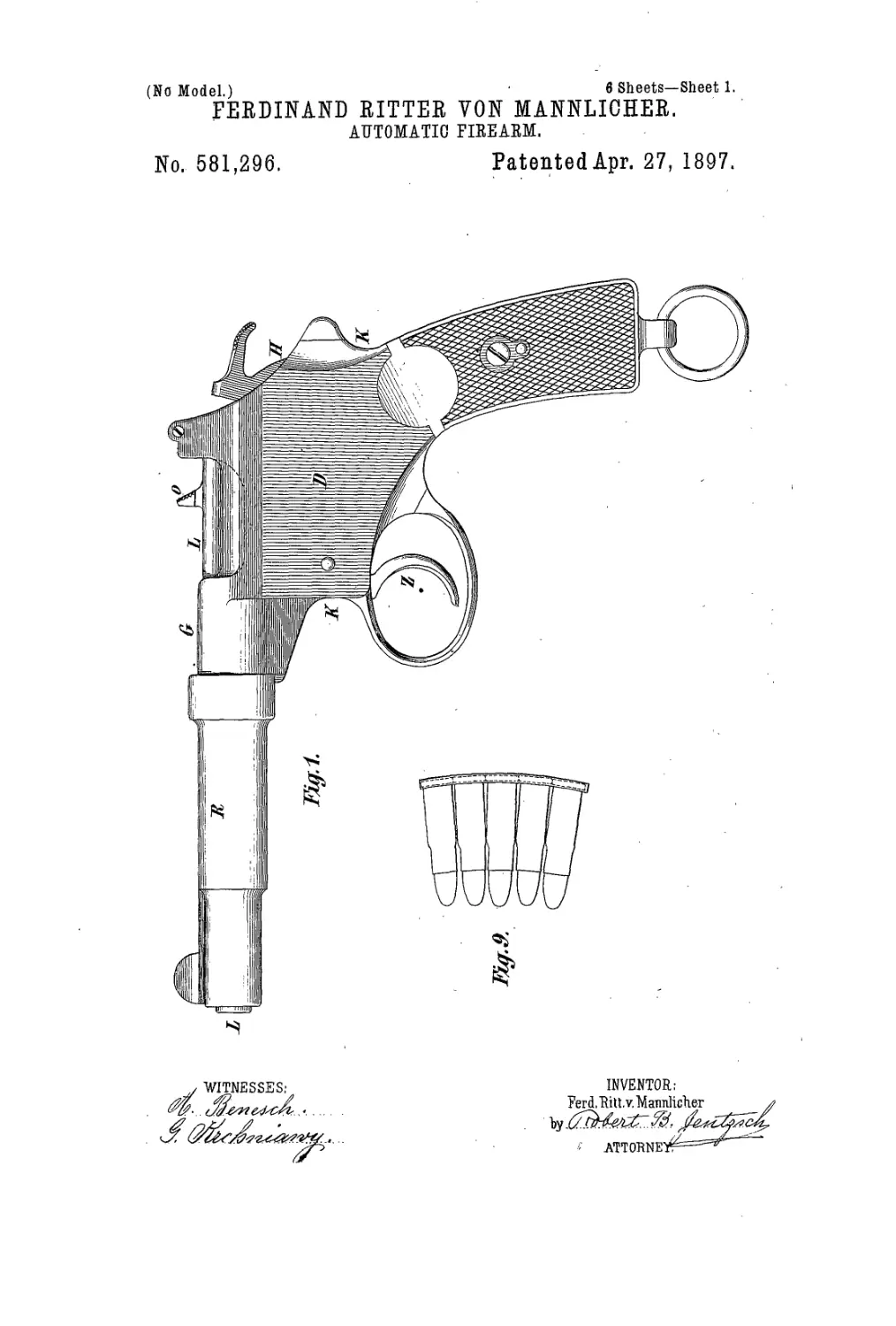
Figure 1 is a side elevation from the left.
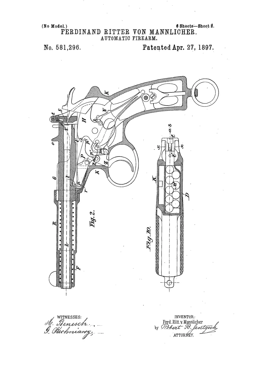
Fig. 2 is a longitudinal central section with
the magazine omitted, showing the internal
30 mechanism in elevation. I Fig. 3 is a similar
view including the magazine, but with the
barrel in its forward position after firing.
Fig. 4 is a view similar to Fig. 3, but with the
parts in the opposite extreme. Fig. 5 is a
35 view taken on the line а Ъ of Fig. 4, looking
to the rearward, but jvith the barrel omitted.
Fig. 6 is a horizontal section through the axis
of the barrel, the mechanism at rest. Fig. 7
is a similar section of the pistol, showing the
40 position of the mechanism at the moment of
ejecting a cartridge-shell. Figs. 8,8a, and 8b
are longitudinal vertical sections, 0u a some-
what enlarged scale, through the rear part of
the pistol on the line of axis of the barrel,
45 showing the head of the ejecting-slide in its
three principal positions. Fig. 9 shows, by
way of example, a side elevation of a car-
tridge holding and charging clasp suited for
being used with this pistol; Fig. 10 shows
in a section similar to that in Fig. 5 a modi- 50
fication of the magazine of this pistol. Figs.
11 and 12 show the hammer II and the lever
P, respectively, alone in separate views.
In all figures similar letters of reference in- .
dicate like parts. 55
The mechanism of this pistol is, the same
as in a revolver, inclosed in a frame K, which-
also forms the butt and which carries the re-
ceiver G. At the side this frame is closed
by a cover or plate D, to which is attached 60
the magazine M, so that both may be taken
off together.
The barrel L is guided partly in-the. re-
ceiver G and partly in a tube R, which is
screwed to the forward end of the receiver. 65
Tube R contain^ the spring F for driving the
barrel rearward and is provided with a suit-
able shoillder or stop on its inside, as indicated
itrthe drawings, to limit and arrest the forward
movement of the barrel. The receiver G is 70
closed at its rear end by the breech or tail
plate B, against which rests the end of the
barrel, ip its closed position, under the pres-
sure of the spring F.
The construction of the lock of this pistol 75
is exactly the same as that of a revolver with
but one slight difference conditioned by the
operation of the barrel, The frame of the
lock must be of such depth that the fifing
mechanism will find place at the side of the 80
magazine, which, as, attached to the cover D,
occupies a central position in theframe. The
same as in revolvers, the hammer H may be
cocked by a long steady pull upon the trig-
ger, at the end of which pull it is released 85
automatically and its point strikes forward
through the breech-plate S. For deliberate
aiming the hammer may also be cocked by
hand the same as in a revolver, similar to
which the hammer also springs back when the 90
trigger is released. .
The principal parts of the lock are the
hammer H, with the link fc, the mainspring
N, the trigger Z, with the sear m, and the le-
ver P, with the spring r. All the parts of the 95
lock being known, with the exception of the
3
581,296
two last-named ones, the lever P and its
spring r, a detail description of only these
parts appears necessary. The lever P has to
perform three different functions—viz., first,
5 to prevent an accidental discharge of the
piece; second, to arrest the barrel in its for-
ward open position, after the firing of a shot,
until the trigger has been released, thereby
giving time for a second cartridge to rise from
io the magazine and take up its position behind
the barrel; third, to keep the barrel in its
open position while the magazine is being re-
charged. These operations are performed in
the foliowing manner:
15 The beak p of the forward arm of the lever
P is pressed against the under side of the
barrel L as this slides backward and forward
by the spring r. At this underside the bar-
rel is provided with two notches or rests I and
20 T, of which the former is about twice as deep
as the latter and forms an incline. The end
p' of the other opposite arm of the lever P
stands in juxtaposition to a projection i of
the hammer H, so as to prevent the latter
25 from striking forward against a cartridge in
all positions except when the beak p of the
lever P has entered the deeper rest I in the
barrel. As the shot is fired the barrel is car-
ried forward, ahd in sliding over the beak p
30 depresses this forward arm of the lever P by
the incline formed by the notch I. The other
opposite arm being thereby raised correspond-
ingly, its end p' operates upon the projection
г of the hammer and swrings this latter back
35 a, certain part of its way. When the barrel
. has nearly completed its forward movement,
the beak p springs into the other rest T in the
barrel, whereby this latter is arrested in a
forward position. The stop or shoulder in
40 the guide-tube R, which limits the forward
. contse of the barrel,is situated somewhat far-
ther forward than the position of the barrel
as conditioned by the engaging of the beak
jp.in the jest I', so that at the firing of a shot
45 the barrel will be thrown first slightly be-
yond this point of rest and will be arrested
on its way back under the influence of, its
spring F by the beak p. The object of this
will be explained farther ou. The spring r,
50 which operates the lever P, may be inserted
from the outside, as shown in the drawings,
and its head r' may spring into a notch in the
! end of the tube R, so as to prevent; this lat-
'ter from turning upon the end of the re-
55 ceiver G.
As long as the barrel is in its forward posi-
tion the forward arm of the Je ver P, engaged
in the rest V of the barrel, is sufficiently de-
• pressed, and in consequence the end p' of
' 60 the other arm of the lever P sufficiently ele-
vated to prevent the hammer from protrud-
ing with its striking-point through the open-
ing in the breech-plate S, as has already been
described. The barrel remains in its forward
65 position as long as the trigger is kept pulled
back. When the trigger is released,it springs
forward, and in doing so a shoulder z on its
hub, with which it is provided, strikes against
a nose p" of lever P, whereby the beak p is
lowered out of the rest V and the barrel is 70
liberated to be driven back against breech-
plate S by its spring. In consequence of its
very rapid movements the arresting of the
barrel in a forward position is necessary in
order to permit the risingof a fresh cartridge 75
from the magazine. This takes place in the.
short interval of time between the final press-
ing of the trigger and the releasing thereof,
•during which time the barrel is arrested in
its forward position. If the barrel is opened 80
by hand by pushing it forward by means of
its thumb-piece o, the hammer being also
cocked by hand, it is evident that the beak p
of the lever P can freely drop into the rest V
in the barrel, the shoulder z of the trigger in 85
this case not being in a position to operate
against the nose ^j" of the lever P, for the
reason that, the same as in any self and hand
cocking firearm, the cocking of the hammer
by hand will throw back the trigger some- 90
what, so as to bring the trigger-shoulder, z
out of contact with the nose_pH of the lever P.
When the barrel has been opened by hand
and is thus arrested, the magazine may be
charged either with single cartridges or, by 95
preference, by means of a charging-clasp, as
shown in Fig. 9.
The magazine itself being of the well-
known construction, a description thereof ap-
pears superfluous. For charging the maga- 100
zine the breech-plat^^is'pfovided with two
vertical grooves x x,in to which fits the charg-
ing-clasp, Fig. 9. In the upper part of the
breech-plate S is fitted «swinging stop-arm t,
which is pressed by a spring и and the head 105
t' of which is straight at the bottom, but
slanting at the top part, so that when a car-
tridge-clasp or a single cartridge is pushed
downward in the breech-plate S it will press
against the upper slanting part of the head no
t', and thereby cause^the arm t to swing in-
ward against the plate 8. In this depressed
position the arm t will permit the passage of
a cartridge or of cartridges into the magazine
below. As soon, however, as they have passed 115
the head t' this latter will spring forward
again and will prevent the topmost cartridge
from being raised any higher by the feeder
than just in line with the bore of the barrel.
Thus when the barrel returns from its for- 120
ward into its closed position it will slide over
and receive the topmost cartridge in its cham-
ber. Below the grooves x x and forming, as
it were, a continuation thereof are two
grooves x' x", adapted to receive and inclose 125
the rim of a cartridge. One of these grooves,
x", is worked into the' breech-plate S, while
the other, x', is in the end of an ejecting-slide
a. When the barrel is in its rearward or for-
ward position of rest, the groove x' in the 130
ejector-slide a stands opposite the groove x",
so that a cartridge may freely pass with its
rim between them.
Supposing the magazine charged and the
681,296
3
5
ю
i5
20
25
3°
35
4°
45
5°
55
60
65
barrel to be in its rearmost closed position,
containing a cartridge, the firing of this car-
tridge will drive the barrel forward and will
cause the ejecting of the emptied cartridge-
shell in the following manner: The ejector-
slide a, the rear end of which contains the
said groove ®', in which rests the cartridge
with one side of its rim, is guided in a lateral
groove Ъ b' of the barrel and extends forward
to the forward end of the receiver G. The
forward part b' of said guide-groove is deeper
than the rear part b, and at the end of the
deeper part b', where the shallower part b„
commences, there is a recess 6"in the barrel,
still somewhat deeper than the deeper part b'
of the groove.
The forward end of the slide a is provided
with a head a', which fits into the said recess
b" and which is of such thickness that it will
stand flush with the surface of the barrel
when it rests in said recess b". When at rest,
the barrel being closed, the slide a occupies
the position shown in Fig. 6, the position of
its head a'being that shown enlarged in Fig.
8. Here head a' is situated at the end of
groove b' and with its projecting part rests in
a recess c in the side of the receiver G. When
the barrel moves forward, the slide a remains
in the position just indicated until the deeper
groove b' has passed over its head d', when
the latter is struck by the forward edge of the
shallower groove b, as indicated in Fig. 8a.
The forward end of the recess c in the re-
ceiver forming an inclined surface, corre-
sponding to which the lower forward edge of
the head a' is chamfered, it follows that as
the slide a is now carried along with the bar-
rel head p' will be pressed inward, so as to
enter the recess b". The forward movement
of the barrel still continuing, the slide a will
still be carried along until its head a'has en-
tered the tube R and arrives in the position
shown in Fig. 7 and enlarged in Fig. 8b. By
this length of way, by which the slide a is
carried forward and which is about equiva-
lent to the length of the head a’, the barrel is
permitted to move forward beyond the point
at which it will be arrested by the beak p ot
the lever P engaging in the! rest V. Imme-
diately upon arriving at its stop in the tube
R, however, the barrel is driven back by its.
spring F and is now arrested in this open po-
sition by the beak p, as has already been de-
scribed and shown in Fig. 3. By this short
return movement of the barrel the head a',
and with it the slide a, has been earned back
again into its original position. The described
forward movement of the slide a, as caused
by the barrel, being a very rapid one, it fol-
lows that the cartridge-shell, the rim of which
rests in the groove x of the slide a, will be
ejected, as indicated in Fig. 7. The slide a
having returned with the barrel its head a' has
again entered the recess c in the receiver and
the groove »' has again taken its position op-
posite the groove x" in the receiver, so that
a fresh cartridge may pass upward from the
magazine and take up its position between
the said two grooves. When the trigger is
now released, so that it can swing, forward, 70
the beak p disengages the. barrel, which is
now driven back by its spring. F over the car-
tridge, held in position by the grooves x' x"
and by the head t' of the stop-arm t. When
the hammer is now cocked, the pistol is ready 75
for the next shot. In order to insure a cor-
rect rectilinear movement of the barrel, this
may be provided with a groove e opposite to
the groove b b', into which fits a guiding pro-
jection e' on the receiver. 80
Instead of the magazine M shown in the
drawings any other magazine may be em-
ployed with this pistol. The free space at the
one side of the magazine M may also be util-
ized for enlarging the magazine, as shown in 85
Fig. 10, so that it will hold a greater number
ofcartridges.
What I claim is—-
1. In automatic firearms ip which the slid-
ing barrel is carried forward by the force of 90
the projectile and driven back against a rigid
tail-plate by a spring, the combination with
the sliding barrel L, having a rest7', of a le-
ver P adapted .to arrest the barrel in its for-
ward, open position. 95'
2. In automatic firearms in Which the slid-
ing barrel is pressed against a rigid tail-plate
by a spring, the combination with thb sliding
barrel L, having a rest T and a deeper rest I,
of a spring-operated lever P, having a beak 100
p adapted to engage alternately into the rest.
I and the rest I' of the barrel and an arm p'
adapted to operate against a projection i of
the hammer; substantially as and for the pur-
pose set forth. .105
3. Tn automatic firearms in which-the slid-
ing barrel is pressed against a rigid tail-plate
by a spring, the combination with the sliding < „
barrel L, having a rest I' and a deeper rest I,
of a spring-operated lever P, having a beak no
? adapted to engage alternately, into the rest
and.the rest V of the barrel, and having an
army' adapted to operate against a projec-
tion г of the hammer, and a nose p", and of
a spring-operated trigger Z having a shoul- 115
der « adapted to operate against the nose p"
of the lever P; substantially aS and for the
purpose set forth.
4. In automatic firearms in which the slid-
ing barrel is pressed against a rigid tail-plate 120
by a spring, the combination with the tail-
plate S of a spring-actuated, swinging stop-
armt, adapted to permit the passage of car-
tridges into the magazine underneath, but to
prevent the rising of a cartridge from the 125
magazine any higher than in line with the
chamber of the barrel; substantially as set
forth. 4
5. Ip automatic firearms in which the slid-
ing barrel is carried forward by the force of 130
the projectile and driven back against a rigid
tail-plate by a spring, the combination with
the sliding barrel L, having a groove b, V of
variable depth and a recess b", of a slide a,
< 581,296
operated by the sliding barrel and provided
at its forward part with a head a' adapted to
slide in the part V of said groove b, b' and to
enter into the recess b", and in its rear part
5 with a groove x' adapted to receive the rim of
a cartridge, of a stationary groove x" oppo-
site to said groove x', and of a recess c in the.
receiver adapted to receive the head a' of said
slide a, substantially as and for the purpose
set forth. io
In testimony whereof I have affixed my sig-
nature in presence of two witnesses.
FERDINAND RITTER VON MANNLICHER.
Witnesses:
Harry Belmont,
Josef Zehetner.